CONTINUED
............................Capacities Chart . 402
.............Carbon Monoxide Hazard . 51
.........................Cargo Area Cover . 114
..........................Cargo Area Light . 124
Battery
Charging System
...........................Indicator . 56, 386
............................Jump Starting . 382
..............................Maintenance . 367
............................Specifications . 403
..............................Before Driving . 281
....................................Belts,Seat .8,18
.........................Beverage Holders . 116
........
HandsFreeLink . 256
..................................Booster Seats . 48
Brakes
...........Anti-lock System (ABS) . 309
.............Break-in, New Linings . 282
....................Bulb Replacement . 349
...........................................Fluid . 342
.......................................Parking . 112
.................System Indicator . 57, 388
........................Wear Indicators . 308
.............................Braking System . 308
.................Break-in, New Vehicle . 282
..Brightness Control, Instruments . 73
Bulb Replacement
..........................Back-up Lights . 349
..............................Brake Lights . 349
.................................Fog Lights . 351
................Front Parking Lights . 347
.................................Headlights . 344
................................Rear Lights . 349
............................Specifications . 403
............Turn Signal Lights . 347, 349
......................Bulbs, Halogen . 344, 351
....................................Accessories . 292
ACCESSORY
...............(Ignition Key Position) . 79
............Accessory Power Sockets . 116
..................Active Head Restraints . 96
....................Additives, Engine Oil . 334
...........................Advanced Airbags . 25
...............................Airbag (SRS) . 9, 21
..........Airbag System Components . 21
..............Air Conditioning System . 128
.........................................Usage . 129
.......................Air Pressure, Tires . 359
......................................Antifreeze . 337
Anti-lock Brakes (ABS)
...............................Indicator . 58, 309
...................................Operation . 309
..............Anti-theft, Audio System . 239
.Anti-theft Steering Column Lock . 79
..............................Audio Antenna . 355
................................Audio System . 136
.....Auto Door Locking/Unlocking . 81
...Automatic Seat Belt Tensioners . 19
.............Automatic Speed Control . 249
..............Automatic Transmission . 302
..........................Capacity, Fluid . 402
.......................................Shifting . 302
Shift Lever Position
...............................Indicators . 302
................Shift Lever Positions . 302
....................Shift Lock Release . 305
......................Auxiliary Input Jack . 238
Bluetooth
Index
A
B
C
INDEX
I

*
.............................Carrying Cargo . 294
.............CAUTION, Explanation of . iii
.........................................CD Care . 233
..........................CD Changer . 151, 199
..................................Ceiling Light . 123
........................Certification Label . 400
............................................Chains . 365
....................Changing a Flat Tire . 373
Changing Oil
........................................How to . 335
......................................When to . 325
...Charging System Indicator . 56, 386
............Check Fuel Cap Message . 285
............Checklist, Before Driving . 300
.....................................Child Safety . 33
..............................Booster Seats . 48
.............................Child Seats . 40, 41
Important Safety
..........................Reminders . 33-50
..........................................Infants . 38
..........................Larger Children . 47
.........................................LATCH . 42
......................Risks with Airbags . 34
.............................Small Children . 39
..........................................Tether . 46
...........................Warning Labels . 52
..........Where Should a Child Sit . 34
.......................................Child Seats . 33
.........................................LATCH . 42
..........Tether Anchorage Points . 46
..................Childproof Door Locks . 87
................Cleaning the Seat Belts . 353
...............Climate Control System . 128
..............................................Clock . 240
..................CO in the Exhaust . 51, 412
............Cold Weather, Starting in . 301
..............................Compact Spare . 372
.........................................Compass . 245
.................Console Compartment . 117
.................Consumer Information . 416
.............Controls, Instruments and . 53
Coolant
........................................Adding . 337
....................................Checking . 288
.........................Proper Solution . 337
...................Temperature Gauge . 66
............................Courtesy Lights . 124
Crankcase Emissions Control
........................................System . 410
................Cruise Control Indicator . 62
............Cruise Control Operation . 249
.........................Customer Service . 416
...............DANGER, Explanation of . iii
...................................Dashboard . 3, 54
..........Daytime Running Lights . 61, 72
Daytime Running Lights
.......................................Indicator . 61
.................................Dead Battery . 382
.........Defects, Reporting Safety . 418
................Defogger, Rear Window . 75
..............Defrosting the Windows . 132
....................................Dimensions . 402
...............Dimming the Headlights . 70
Dipstick
..........Automatic Transmission . 340
..................................Engine Oil . 288
..........................Directional Signals . 70
........Disc Brake Wear Indicators . 308
.....................Disposal of Used Oil . 336
Doors
..........................Auto Door Lock . 81
.......................Auto Door Unlock . 84
..............Childproof Door Locks . 87
..............Locking and Unlocking . 80
..........DOT Tire Quality Grading . 404
...........Driver and Passenger Safety . 5
Index
D
II

CONTINUED
...........................................Driving . 299
....................................Economy . 289
Driving Position Memory
........................................System . 101
..........Dual Temperature Control . 133
..................Dust and Pollen Filter . 354
...................................Fan, Interior . 131
.........................................Features . 127
....................Filling the Fuel Tank . 283
Filters
........................Dust and Pollen . 354
...............................................Oil . 335
.............Flashers, Hazard Warning . 74
...................Flat Tire, Changing a . 373
.....................................Floor Mats . 353
.......Floor Storage Compartment . 121
Fluids
..........Automatic Transmission . 341
..........................................Brake . 342
..........................Power Steering . 343
..................Windshield Washer . 339
........................................Fog Lights . 73
..........................Folding Rear Seats . 97
..........................Four-way Flashers . 74
..............................Front Airbags . 9, 23
..............................Economy, Fuel . 289
Electronic Stability Control (ESC)
........................................System . 311
..................................Emergencies . 371
.............Battery, Jump Starting . 382
...........Brake System Indicator . 388
................Changing a Flat Tire . 373
.....Charging System Indicator . 386
..................Checking the Fuses . 390
Fuel Fill Door, Opening
................................Manually . 389
.........Hazard Warning Flashers . 74
............................Jump Starting . 382
.....Low Oil Pressure Indicator . 386
...Malfunction Indicator Lamp . 387
..................Overheated Engine . 384
.......................................Towing . 398
.........................Emergency Brake . 112
......................Emergency Flashers . 74
......................Emergency Towing . 397
.......................Emissions Controls . 410
........................Emissions Testing . 413
Engine
............Adding Engine Coolant . 337
....Coolant Temperature Gauge . 66
.........................If It Won’t Start . 380
...Malfunction Indicator Lamp . 387
.......................Oil Life Indicator . 325
..............Oil Pressure Indicator . 386
..............Oil, What Kind to Use . 333
...............................Overheating . 384
............................Specifications . 402
............................Speed Limiter . 305
.......................................Starting . 301
...................Engine Speed Limiter . 305
......................Ethanol in Gasoline . 283
.Evaporative Emissions Controls . 410
...............................Exhaust Fumes . 51
Expectant Mothers, Use of Seat
........................................Belts by . 16
Index
INDEX
E
F
III
.................................................Fuel . 282
........Check Fuel Cap Message . 285
......................Fill Door and Cap . 284
...........................................Gauge . 66
.....................Low Fuel Indicator . 61
................Octane Requirement . 282
...............................Oxygenated . 283
........................Tank, Refueling . 283
...............................Fuel Economy . 289
....Fuel Economy (ECO) Indicator . 59
.....................Fuses, Checking the . 390
......Gas Mileage, Improving . 289, 290
.........................................Gasoline . 282
...........................................Gauge . 66
.....................Low Fuel Indicator . 61
................Octane Requirement . 282
........................Tank, Refueling . 283
................Gas Station Procedures . 283
Gauges
...Engine Coolant Temperature . 66
...............................................Fuel . 66
Gearshift Lever Positions
..........Automatic Transmission . 302
......................................Glove Box . 118
Gross Vehicle Weight Rating
.............................(GVWR) . 296, 317
.............Halogen Headlight Bulbs . 344
...........................HandsFreeLink
. 256
..............Hazard Warning Flashers . 74
........................................Headlights . 70
........................................Aiming . 344
..............Automatic Lighting Off . 72
..............Automatic Lighting On . 71
............Daytime Running Lights . 72
..................High Beam Indicator . 61
....................Lights On Indicator . 60
.........................Reminder Chime . 70
Replacing Halogen
..............................Bulbs . 344, 351
...................................Turning on . 70
........................Head Restraints . 13, 94
.............................Heated Mirrors . 106
.................................Heaters, Seat . 100
HomeLink
Universal
................................Transceiver . 252
........Hood, Opening and Closing . 287
..............................................Horn .4,67
...Identification Number, Vehicle . 400
Ignition
..............................................Keys . 77
...........................................Switch . 79
............Timing Control System . 411
........................Immobilizer System . 78
.........Important Safety Precautions . 6
Index
I
G
H
IV
CONTINUED
.......................Label, Certification . 400
.................Lane Change, Signaling . 70
..................Lap/Shoulder Belts . 14, 19
...............................LATCH System . 42
Lights
....................Bulb Replacement . 344
.......................................Indicator . 55
.........................................Parking . 70
............................Turn Signal . 60, 70
....................................Load Limits . 295
......LOCK (Ignition Key Position) . 79
.................Jacking up the Vehicle . 375
.......................................Jack, Tire . 375
................................Jump Starting . 382.........................................Indicators . 56
...............ABS (Anti-lock Brake) . 58
Brake (Parking and Brake
............................System) . 57, 388
................Charging System . 56, 386
.............................Cruise Control . 62
.................................Cruise Main . 62
............Door and Tailgate Open . 60
DRL (Daytime Running
......................................Lights) . 61
...................................Fog Lights . 62
............Fuel Economy Indicator . 59
...................................High Beam . 61
........Key (Immobilizer System) . 62
.....................................Lights On . 60
......................................Low Fuel . 61
................Low Oil Pressure . 56, 386
......................Low Tire Pressure . 59
...Malfunction Indicator Lamp . 387
..........................Security System . 61
...........................Side Airbag Off . 57
.......................................Seat Belt . 56
...............................................SRS . 57
...........................................TPMS . 59
Turn Signal and Hazard
...................................Warning . 60
........................................VSA Off . 58
.................................VSA System . 58
.........Indicators, Instrument Panel . 56
...............................Infant Restraint . 38
......................................Infant Seats . 38
..........Tether Anchorage Points . 46
...................Inflation, Proper Tire . 359
........................Information Display . 64
.................................Inside Mirror . 104
.............................Inspection, Tire . 361
....................Installing a Child Seat . 41
..........Tether Anchorage Points . 46
.............................Using LATCH . 42
............................Instrument Panel . 55
........Instrument Panel Brightness . 73
..............Instruments and Controls . 53
.................................Interface Dial . 179
..................................Interior Care . 369
...............................Interior Lights . 123
........................................Introduction . i
.......................................iPod
. 161, 211
..................................................Keys . 77
Index
INDEX
J
K
L
V

Locks
.......Anti-theft Steering Column . 79
..........................Childproof Door . 87
............................Fuel Fill Door . 283
..................................Glove Box . 118
....................Lockout Prevention . 81
.................................Power Door . 80
........................................Tailgate . 91
........................Low Coolant Level . 288
.........................Low Fuel Indicator . 61
...Low Oil Pressure Indicator . 56, 386
................................Lower Anchors . 42
...Lubricant Specifications Chart . 402
...........Luggage, Storing (Cargo) . 294
..................................Maintenance . 323
........................................Minder . 325
Main Items and Sub
..............................Items . 328, 331
Owner’s Maintenance
...................................Checks . 330
.........................Minder Indicator . 62
..........................................Safety . 324
.......Malfunction Indicator Lamp . 387
...........Memory, Driving Position . 101
.........................Meters, Gauges . 55, 63
...................Methanol in Gasoline . 283
...........................................Mirrors . 104
....................................Adjusting . 105
........................................Heated . 106
...............................Reverse Tilt . 105
.........Modifications Your Vehicle . 293
.......................................Moonroof . 110
...................Neutral Gear Position . 303
..................New Vehicle Break-in . 282
...................NOTICE, Explanation of . i
...............Numbers, Identification . 400
...Octane Requirement, Gasoline . 282
.........................................Odometer . 64
Oil
........................Change, How to . 335
......................Change, When to . 328
......................Checking Engine . 288
..............Pressure Indicator . 56, 386
Selecting Proper Viscosity
......................................Chart . 334
...........ON (Ignition Key Position) . 79
Onboard Refueling Vapor
....................................Recovery . 410
............................Outside Mirrors . 105
....Outside Temperature Indicator . 65
....................Overheating, Engine . 384
....Owner’s Maintenance Checks . 330
.........................Oxygenated Fuels . 283
..............Panel Brightness Control . 73
........................Park Gear Position . 303
...........................................Parking . 307
...............................Parking Brake . 112
Parking Brake and Brake
.................System Indicator . 57, 388
.................................Parking Lights . 70
..Parking Over Things that Burn . 412
....Passenger Airbag Off Indicator . 30
.............................PGM-FI System . 411
...................................Pollen Filter . 354
..........................Power Door Locks . 80
................Power Seat Adjustments . 93
Index
M
N
P
O
VI
*
*
CONTINUED
...............Power Socket Locations . 116
............................Power Windows . 106
.........Pregnancy, Using Seat Belts . 16
.........Protecting Adults and Teens . 11
...Additional Safety Precautions . 17
.....Advice for Pregnant Women . 16
........................Protecting Children . 33
.....................General Guidelines . 33
.......................Protecting Infants . 38
.......Protecting Larger Children . 47
.........Protecting Small Children . 39
Using Child Seats with
.....................................Tethers . 46
.............................Using LATCH . 42
...................Radiator Overheating . 384
.............Radio/CD Sound System . 136
.................Radio Theft Protection . 239
............................Radio, XM
. 145, 192
........................................RDS . 141, 184
...........................Readiness Codes . 413
..Rear Lights, Bulb Replacement . 349
.........................Rear Seats, Folding . 97
...Rearview Camera and Monitor . 280
...........................Rearview Mirror . 104
.................Rear Window Defogger . 75
...............Reclining the Seat Backs . 93
........................................Refueling . 283
.......................Reminder Indicators . 56
................Remote Audio Controls . 236
.......................Remote Transmitter . 87
Replacement Information
................Engine Oil and Filter . 335
..........................................Fuses . 390
................................Light Bulbs . 344
................................Timing Belt . 343
...........................................Tires . 364
.............................Wiper Blades . 355
Replacing Seat Belts After a
............................................Crash . 20
..........Reporting Safety Defects . 418
Reserve Tank, Engine
...............................Coolant . 288, 337
...............................Restraint, Child . 33
..................Reverse Gear Position . 303
................................Rotation, Tire . 363
..................................Safety Belts . 8, 18
.........Safety Defects, Reporting . 418
.................................Safety Features . 7
...........................................Airbags . 9
.......................................Seat Belts . 8
.............Safety Labels, Location of . 52
..............................Safety Messages . iii
.....................................Seat Belts . 8, 18
...............Additional Information . 18
Automatic Seat Belt
...............................Tensioners . 19
.....................................Cleaning . 353
................Lap/Shoulder Belt . 14, 19
................................Maintenance . 20
Reminder Indicator and
................................Beeper . 18, 56
...................System Components . 18
...............Use During Pregnancy . 16
...Wearing a Lap/Shoulder Belt . 19
Seats
......................................Adjusting . 93
.........................................Folding . 97
.......................................Heaters . 100
............................Security System . 243
.........................Select/Reset Knob . 63
Index
INDEX
R
S
VII

*
Tailgate
............................Open Indicator . 60
.................................Opening the . 91
.Taking Care of the Unexpected . 371
Technical Descriptions
......DOT Tire Quality Grading . 404
.....Emissions Control Systems . 410
Three Way Catalytic
.............................Converters . 412
.......................Temperature Gauge . 66
....................Temperature, Outside . 65
..............Tether Anchorage Points . 46
.....................Selecting a Child Seat . 40
...Selector Knob (Disc Changer) . 137
...............................Serial Number . 400
..............................Service Minder . 325
...........................Service Manual . 419
.........Service Station Procedures . 283
..........................Setting the Clock . 240
...Shift Lever Position Indicators . 302
........................Shift Lock Release . 305
................................Side Airbags . 9, 27
...How Your Side Airbags Work . 27
How the Side Airbag Off
......................Indicator Works . 30
..................Side Curtain Airbags . 9, 28
How Your Side Curtain
..........................Airbags Work . 28
...............................Signaling Turns . 70
.....................................Snow Tires . 365
................................Sound System . 136
Spare Tire
......................................Inflating . 372
............................Specifications . 403
....................................Spark Plugs . 402
................................Specifications . 402
................................Speed Control . 249
................................Speed Limiter . 305
...................................Speedometer . 63
..........SRS, Additional Information . 21
...Additional Safety Precautions . 32
.............................Airbag Service . 31
......Airbag System Components . 21
How the Passenger Airbag Off
......................Indicator Works . 30
How the Side Airbag Off
......................Indicator Works . 30
..How the SRS Indicator Works . 29
How Your Front Airbags
.........................................Work . 23
...How Your Side Airbags Work . 27
How Your Side Curtain Airbags
.........................................Work . 28
.............................SRS Indicator . 29, 57
....START (Ignition Key Position) . 79
.......................Starting the Engine . 301
In Cold Weather at High
..................................Altitude . 301
................With a Dead Battery . 382
........Steam Coming from Engine . 384
Steering Wheel
................................Adjustments . 76
.............Anti-theft Column Lock . 79
.......Steering Wheel Buttons . 236, 256
...................Stereo Sound System . 136
......................................Sun Visors . 119
........................Sunglasses Holder . 119
Supplemental Restraint
..................................System .9,21
......................................Servicing . 31
.........................SRS Indicator . 29, 57
...................System Components . 21
SVC (Speed-sensitive
...Volume Compensation) . 144, 191
..................................Synthetic Oil . 334
Index
T
VIII
CONTINUED
................Theft Protection, Radio . 239
Three Way Catalytic
.................................Converters . 412
..........................Time, Setting the . 240
....................................Timing Belt . 343
....................................Tire Chains . 365
.........Tire, How to Change a Flat . 373
...........................Tire Information . 406
.................................Tire Labeling . 406
Tire Pressure Monitoring
............System (TPMS) . 313, 408
Low Tire Pressure
...........................Indicator . 59, 313
Required Federal
............................Explanation . 408
..................TPMS Indicator . 59, 314
...............................................Tires . 359
..............................Air Pressure . 360
........................................Chains . 365
.........................Checking Wear . 361
..........................Compact Spare . 372
......DOT Tire Quality Grading . 404
......................................Inflation . 359
..................................Inspection . 361
...................................Replacing . 364
......................................Rotating . 363
................................Service Life . 362
...........................................Snow . 365
............................Specifications . 403
..............................Terminology . 407
...................Tools, Tire Changing . 373
Towing
.....................................A Trailer . 316
................Emergency Wrecker . 397
....................Pre-Tow Checklist . 320
.............................Weight Limit . 316
Transmission
Checking Fluid Level,
..............................Automatic . 340
...........................Fluid Selection . 341
..............Identification Number . 401
.............Shifting the Automatic . 302
.....................................Treadwear . 361
.......................................Trip Meter . 65
....................................Turn Signals . 70
................................Vanity Mirror . 122
.................Vehicle Capacity Load . 295
......................Vehicle Dimensions . 402
....Vehicle Identification Number . 400
Vehicle Stability Assist (VSA
)
....................................System . 311
...............VSA Off Indicator . 58, 311
.........................VSA Off Switch . 312
........VSA System Indicator . 58, 311
.............................Vehicle Storage . 368
.....................................Ventilation . 134
.................................................VIN . 400
..................................Viscosity, Oil . 334
...........Voice Control System . 129, 179
............Under-floor Storage Area . 120
Unexpected, Taking Care of
...............................................the . 371
....Uniform Tire Quality Grading . 404
........................Unleaded Gasoline . 282
USB Adapter
..................Cable . 163, 173, 213, 224
.USB Flash Memory Device . 170, 221
.......Used Oil, How to Dispose of . 336
Index
INDEX
V
U
IX
*
*
............WARNING, Explanation of . iii
.........Warning Labels, Location of . 52
..................Warranty Coverages . 417
Washers, Windshield
........Checking the Fluid Level . 339
.......................................Indicator . 62
.....................................Operation . 68
Wheels
...............Adjusting the Steering . 76
............Alignment and Balance . 362
..........................Compact Spare . 372
..............................Wrench, Nut . 375
Windows
.............................Auto Reverse . 107
................Operating the Power . 106
...........................Rear, Defogger . 75
Windshield
.......................................Cleaning . 68
...................................Defroster . 132
.......................................Washers . 68
Wipers, Windshield
.......................Changing Blades . 355
.....................................Operation . 68
....................................Worn Tires . 361
.....Wrecker, Emergency Towing . 397
.............................XM
Radio . 145, 192
:U.S.only
Index
W
X
X
The information and specifications included
in this publication were in effect at the time
of approval for printing. Honda Motor Co.,
Ltd. reserves the right, however, to
discontinue or change specifications or
design at any time without notice and
without incurring any obligation whatsoever.
This owner’s manual should be considered
a permanent part of the vehicle and should
remain with the vehicle when it is sold.
This owner’s manual covers all models of
the Accord Crosstour. You may find
descriptions of equipment and features that
are not on your particular model.
Owner’s Identification
POUR CLIENTS CANADIEN
AVIS IMPORTANT: Si vous avez
besoin d’un Manuel du Conducteur en
français, veuillez demander à votre
concessionnaire de commander le
numéro de pièce 33TP6C00 .
OWNER
ADDRESS
V. I. N.
DELIVERY DATE
DEALER NAME DEALER NO.
ADDRESS
OWNER’S SIGNATURE
DEALER’S SIGNATURE
STREET
CITY STATE/PROVINCE/TERRITORY ZIP CODE/
POSTAL CODE
(Date sold to original retail purchaser)
STREET
CITY STATE/PROVINCE/TERRITORY ZIP CODE/
POSTAL CODE

Maintaining your vehicle according to the maintenance minder shown in the
instrument panel helps to keep your driving trouble-free while it preserves
your investment. When your vehicle needs maintenance, keep in mind that
your dealer’s staff is specially trained in servicing the many systems unique
to your vehicle. Your dealer is dedicated to your satisfaction and will be
pleased to answer any questions and concerns.
Several warranties protect your new vehicle. Read the warranty booklet
thoroughly so you understand the coverages and are aware of your rights
and responsibilities.
One of the best ways to enhance the enjoyment of your new vehicle is to
read this manual. In it, you will learn how to operate its driving controls and
convenience items. Afterwards, keep this owner’s manual in your vehicle so
youcanrefertoitatanytime.
As you read this manual, you will
find information that is preceded by
a symbol. This
information is intended to help you
avoid damage to your vehicle, other
property, or the environment.
Congratulations! Your selection of a 2010 Honda Accord Crosstour was a
wise investment. It will give you years of driving pleasure.
Introduction
i

California Proposition 65 Warning
This product contains or emits chemicals known to the State of California to cause cancer and birth
defects or other reproductive harm.
Event Data Recorders
This data belongs to the vehicle owner and may not be accessed by anyone else
except as legally required or with the permission of the vehicle owner.
Service Diagnostic Recorders
This vehicle is equipped with service-related devices that record information about powertrain performance. The data
can be used to verify emissions law requirements and/or help technicians diagnose and solve service problems. It may
also be combined with data from other sources for research purposes, but it remains confidential.
Introduction
WARNING:
This vehicle is equipped with one or more devices commonly referred to as event data recorders. These
devices record front seat belt use, front passenger seat occupancy, airbag deployment data, and the failure
of any airbag system component.
ii
−
−
−
−
−
−
To help you make informed
decisions about safety, we have
provided operating procedures and
other information on labels and in
this manual. This information alerts
you to potential hazards that could
hurt you or others.
You will find this important safety information in a variety of forms,
including:
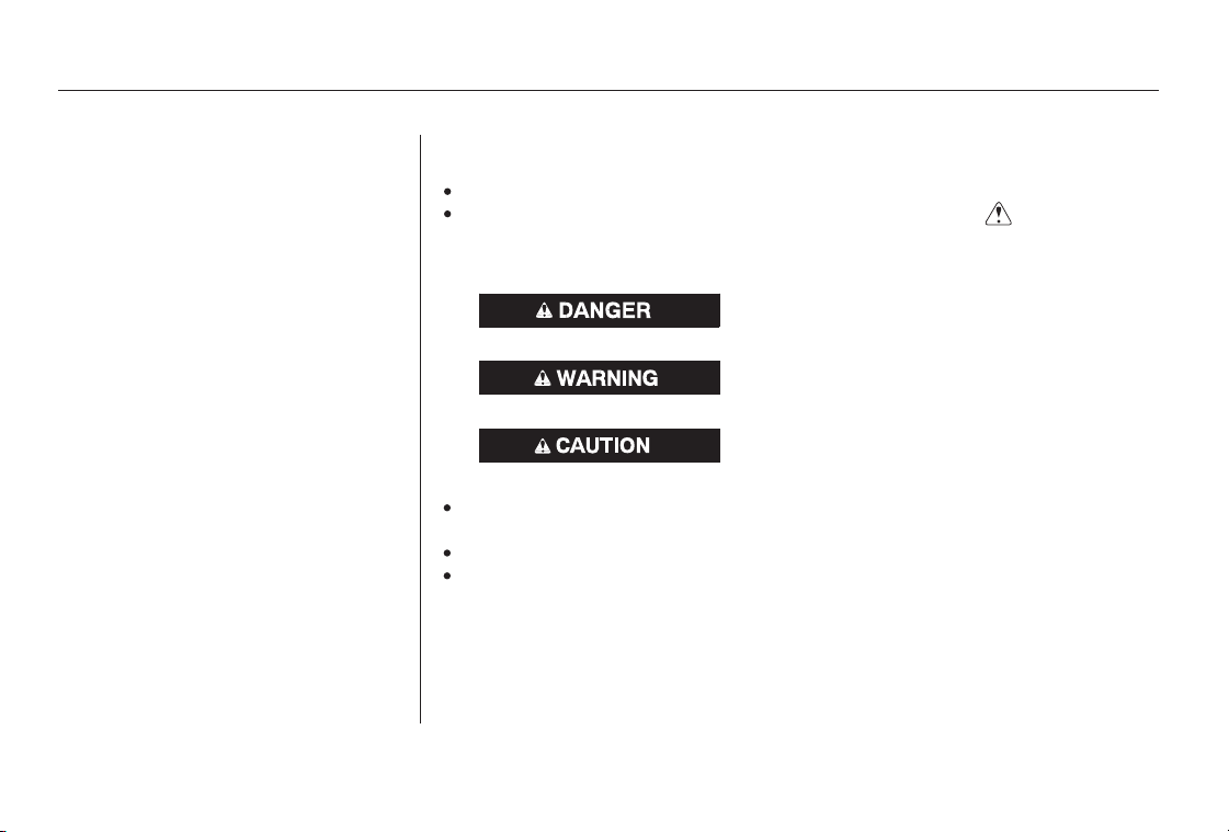
preceded by a safety alert symbol and one of
three signal words: , , or .
These signal words mean:
such as Important Safety Reminders or Important
Safety Precautions.
such as Driver and Passenger Safety.
how to use this vehicle correctly and safely.
This entire book is filled with important safety information please read it
carefully.
Your safety, and the safety of others,
is very important. And operating this
vehicle safely is an important
responsibility.
Of course, it is not practical or
possible to warn you about all the
hazards associated with operating or
maintaining your vehicle. You must
use your own good judgement.
on the vehicle.
Safety Messages
Safety Headings
Safety Section
Instructions
Safety Labels
AFewWordsAboutSafety
DANGER WARNING CAUTION
iii
You WILL be KILLED or SERIOUSLY
HURT if you don’t follow instructions.
You CAN be KILLED or SERIOUSLY
HURT if you don’t follow instructions.
You CAN be HURT if you don’t follow
instructions.

(fluid capacities and tire pressures)
(main controls)
(seat belts, SRS, and child protection)
(indicators, gauges, dashboard, and steering column)
( )
(fuel, vehicle break-in, and cargo loading)
(minder, fluid checking, minor services, and vehicle storage)
(flat tire, jump starting, overheating, and fuses)
(vehicle specifications, tires, and emissions controls)
(warranty and contact information)
(how to order)
(engine and transmission operation)
climate control, audio, steering wheel, security, cruise control, HomeLink , and other convenience items
Contents
................................................................................................................................................Index .I
..................................................Service Information Summary . last page
...............................................................................................Your Vehicle at a Glance .3
............................................................Driver and Passenger Safety .5
..........................................Instruments and Controls .53
..............Features .127
.......................................................................Before Driving .281
.................................................Maintenance .323
........................................Taking Care of the Unexpected .371
..............................................Technical Information .399
..................Warranty and Customer Relations (U.S. and Canada only) . 415
..................................................................................Authorized Manuals (U.S. only) .419
.........................................................................................Driving .299
INDEX
1

A convenient reference to the
sections in this manual.
A quick reference to the main
controls in your vehicle.
Explains the purpose of each
instrument panel indicator and gauge,
and how to use the controls on the
dashboard and steering column.
ID numbers, dimensions, capacities,
and technical information.
How to order manuals and other
technical literature.
A summary of the information you
need when you pull up to the fuel
pump.
A summary of the warranties
covering your new vehicle, and how
to contact us for any reason. Refer to
your warranty manual for detailed
information.
Important information about the
proper use and care of your vehicle’s
seat belts, an overview of the
supplemental restraint system, and
valuable information on how to
protect children with child restraints.
How to operate the climate control
system, the audio system, and other
convenience features.
What gasoline to use, how to break-
in your new vehicle, and how to load
luggage and other cargo.
The proper way to start the engine,
shift the transmission, and park; plus
what you need to know if you’re
planning to tow a trailer.
The maintenance minder shows you
when you need to take your vehicle
to the dealer for maintenance service.
There is also a list of things to check
and instructions on how to check
them.
This section covers several problems
motorists sometimes experience,
and details how to handle them.
Contents
Your Vehicle at a Glance
Driver and Passenger Safety
Instruments and Controls
Features
Technical Information
Warranty and Customer
Relations
(U.S. and Canada only)
Authorized Manuals
(U.S. only)
Index
Service Information Summary
Before Driving
Driving
Maintenance
Taking Care of the Unexpected
Overview of Contents
2

*
*
*
*
*
*
If equipped:
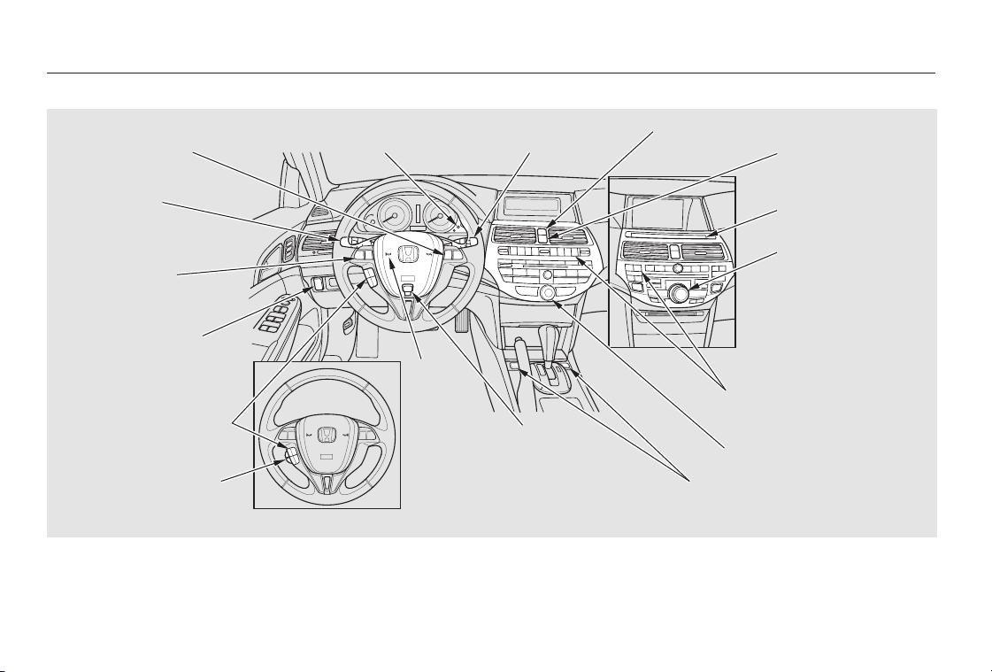
Your Vehicle at a Glance
Your Vehicle at a Glance
3
MIRROR CONTROLS
INSTRUMENT PANEL
INDICATORS
(P.55)
GAUGES (P.63)
DRIVER’S FRONT
AIRBAG
AUXILIARY INPUT JACKACCESSORY POWER SOCKETS
(P.9, 23)
AUDIO SYSTEM
Without navigation system is shown.
AUTOMATIC
TRANSMISSION
HOMELINK BUTTONSMOONROOF SWITCH
POWER WINDOW
SWITCHES
HOOD RELEASE
HANDLE
MIRROR CONTROL
AUTO BUTTON
CLOCK
COMPASS
PASSENGER’S
FRONT AIRBAG
(P.9, 23)
CLIMATE CONTROL
SYSTEM
USB ADAPTER CABLE
(P.110)
(P.252)
DRIVING POSITION
MEMORY SYSTEM
BUTTONS
(P.105)
(P.101)
POWER DOOR LOCK
MASTER SWITCH
(Unlocking Fuel Fill
Door)(P.80)
(P.106)
(P.287)
(P.116, 117)
(P.238)
(P.163, 173, 213, 224)
(P.302)
(P.136)
(P.128)
(P.245)
(P.240)
(P.104)
*
*
*
*
*
*
*
*
*
*
Only on vehicles equipped with navigation system. Refer to the navigation system manual.
If equipped
To use the horn, press the center pad of the steering wheel.
3:
1:
2:
Your Vehicle at a Glance
4
INSTRUMENT PANEL
BRIGHTNESS
(P.30)
HAZARD WARNING
BUTTON
WINDSHIELD WIPERS/
WASHERS
(P.68)
PASSENGER AIRBAG OFF INDICATOR
INTERFACE DIAL
HORN
REMOTE AUDIO
CONTROLS
NAVIGATION SYSTEM
VOICE CONTROL
BUTTONS
HEADLIGHTS/
TURN SIGNALS/
FOG LIGHTS
CRUISE CONTROL
BUTTONS
REAR WINDOW DEFOGGER/
HEATED MIRROR BUTTON
SEAT HEATER SWITCHES (P.100)
STEERING WHEEL
ADJUSTMENTS
BLUETOOTH
HANDSFREELINK VOICE
CONTROL BUTTONS
(P.249)
(P.70, 73)
(P.236)
VEHICLE STABILITY
ASSIST (VSA) SYSTEM
OFF SWITCH
(P.312)
(P.256)
(P.76)
(P.73)
CENTER DISPLAY
SELECTOR KNOB (P.137)
(P.75/106)
(P.74)
(P.179)
3
1
3
2
2
3
2

−
This section gives you important
information about how to protect
yourself and your passengers. It
shows you how to use seat belts. It
explains how your airbags work. And
it tells you how to properly restrain
infants and children in your vehicle.
.........
Important Safety Precautions . 6
.......Your Vehicle’s Safety Features . 7
.......................................Seat Belts . 8
...........................................Airbags . 9
.........Protecting Adults and Teens . 11
.....1. Close and Lock the Doors . 11
...........2. Adjust the Front Seats . 11
............3. Adjust the Seat-Backs . 12
...4. Adjust the Head Restraints . 13
5. Fasten and Position the
.............................Seat Belts . 14
6. Maintain a Proper Sitting
................................Position . 15
.....Advice for Pregnant Women . 16
...Additional Safety Precautions . 17
Additional Information About
.......................Your Seat Belts . 18
..Seat Belt System Components . 18
......................Lap/Shoulder Belt . 19
Automatic Seat Belt
...............................Tensioners . 19
...............Seat Belt Maintenance . 20
Additional Information About
...........................Your Airbags . 21
......Airbag System Components . 21
How Your Front Airbags
.........................................Work . 23
...How Your Side Airbags Work . 27
How Your Side Curtain Airbags
.........................................Work . 28
..How the SRS Indicator Works . 29
How the Side Airbag Off
......................Indicator Works . 30
How the Passenger Airbag Off
......................Indicator Works . 30
.............................Airbag Service . 31
...Additional Safety Precautions . 32
Protecting Children General
................................Guidelines . 33
All Children Must Be
...............................Restrained . 33
All Children Should Sit in a
.................................Back Seat . 34
The Passenger’s Front Airbag
.........Can Pose Serious Risks . 34
If You Must Drive with Several
...................................Children . 36
If a Child Requires Close
..................................Attention . 36
...Additional Safety Precautions . 36
Protecting Infants and
.........................Small Children . 38
.......................Protecting Infants . 38
.........Protecting Small Children . 39
.....................Selecting a Child Seat . 40
....................Installing a Child Seat . 41
...............................With LATCH . 42
.........With a Lap/Shoulder Belt . 44
..............................With a Tether . 46
...........Protecting Larger Children . 47
...............Checking Seat Belt Fit . 47
..................Using a Booster Seat . 48
When Can a Larger Child Sit in
.........................................Front . 49
...Additional Safety Precautions . 50
.............Carbon Monoxide Hazard . 51
...................................Safety Labels . 52
Driver and Passenger Safety
Driver and Passenger Saf ety
5

−You’ll find many safety
recommendations throughout this
section, and throughout this manual.
Therecommendationsonthispage
are the ones we consider to be the
most important.
A seat belt is your best protection in
all types of collisions. Airbags are
designed to supplement seat belts,
not replace them. So even though
your vehicle is equipped with airbags,
make sure you and your passengers
always wear your seat belts, and
wear them properly (see page ).
Children age 12 and under should
ride properly restrained in a back
seat, not the front seat. Infants and
smallchildrenshouldberestrained
in a child seat. Larger children
should use a booster seat and a lap/
shoulder belt until they can use the
belt properly without a booster seat
(see pages ).
While airbags can save lives, they
can cause serious or fatal injuries to
occupants who sit too close to them,
or are not properly restrained.
Infants, young children, and short
adults are at the greatest risk. Be
sure to follow all instructions and
warnings in this manual.
Alcohol and driving don’t mix. Even
one drink can reduce your ability to
respond to changing conditions, and
your reaction time gets worse with
every additional drink. So don’t drink
and drive, and don’t let your friends
drink and drive, either.
Engaging in mobile phone
conversation or other activities that
keep you from paying close attention
to the road, other vehicles and
pedestrians could lead to a crash.
Remember, situations can change
quickly, and only you can decide
when it is safe to divert attention
away from driving.
Having a tire blowout or a
mechanical failure can be extremely
hazardous. To reduce the possibility
of such problems, check your tire
pressures and condition frequently,
and perform all regularly scheduled
maintenance (see page ).
Excessive speed is a major factor in
crash injuries and deaths. Generally,
the higher the speed, the greater the
risk, but serious injuries can also
occur at lower speeds. Never drive
faster than is safe for current
conditions, regardless of the
maximum speed posted.14
33 50
325
Important Safety Precautions
Always Wear Your Seat Belt
Restrain All Children
Be Aware of Airbag Hazards
Don’t Drink and Drive
Pay Appropriate Attention to the
Task of Driving Safely
Keep Your Vehicle in Safe
Condition
Control Your Speed
6
Table of Contents
Your vehicle is equipped with many
features that work together to
protect you and your passengers
during a crash.
The following pages explain how you
cantakeanactiveroleinprotecting
yourself and your passengers.
However, you and your passengers
can’t take full advantage of these
features unless you remain sitting in
the correct position and
. In fact, some safety
features can contribute to injuries if
they are not used properly.
Some features do not require any
action on your part. These include a
strong steel framework that forms a
safety cage around the passenger
compartment, front and rear crush
zones, a collapsible steering column,
and tensioners that tighten the front
seat belts in a crash.
Your Vehicle’s Safety Features
always wear
your seat belts
Driver and Passenger Saf ety
7
(7)
(10)
(1)
(9)
(2)
(5)
(2)
(6)
(8)
(9)
(12)
(3)
(4)
(7)
(11)
(8)
(10)
(1) Safety Cage
(2) Crush Zones
(3) Seats and Seat-Backs
(4) Head Restraints
(5) Collapsible Steering Column
(6) Seat Belts
(7) Front Airbags
(8) Side Airbags
(9) Side Curtain Airbags
(10) Door Locks
(11) Seat Belt Tensioners
(12) Occupant Position Detection
System (OPDS) Sensor
Table of Contents
−
−
−
−
Your vehicle is equipped with seat
belts in all seating positions.
Help protect you in almost every
type of crash, including:
frontal impacts
side impacts
rear impacts
rollovers
Keep you connected to the vehicle
so you can take advantage of the
vehicle’s built-in safety features.
When properly worn, seat belts:
Help keep you from being thrown
against the inside of the vehicle
and against other occupants.
Keep you from being thrown out
of the vehicle.
Help keep you in a good position
should the airbags ever deploy. A
good position reduces the risk of
injury from an inflating airbag and
allows you to get the best
advantage from the airbag.
Of course, seat belts cannot
completely protect you in every
crash.Butinmostcases,seatbelts
can reduce your risk of serious
injury.
Always wear your seat belt, and
make sure you wear it properly.
Your seat belt system also includes
an indicator on the instrument panel
and a beeper to remind you and your
passengers to fasten your seat belts.
Seat belts are the single most
effectivesafetydeviceforadultsand
larger children. (Infants and smaller
children must be properly restrained
in child seats.)
Not wearing a seat belt properly
increases the chance of serious
injury or death in a crash, even
though your vehicle has airbags.
In addition, most states and all
Canadian provinces and territories
require you to wear seat belts.
Seat Belts
Your Vehicle’s Safety Features
What You Should Do:
Why Wear Seat Belts
8
Not wearing a seat belt properly
increases the chance of serious
injury or death in a crash, even
though your vehicle has airbags.
Be sure you and your
passengers always wear seat
belts and wear them properly.
Table of Contents

CONTINUED
Your vehicle has a supplemental
restraint system (SRS) with front
airbags to help protect the heads and
chests of the driver and a front seat
passenger during a moderate to
severe frontal collision (see page
for more information on how
your front airbags work).
Your vehicle also has side airbags to
help protect the upper torso of the
driver or a front seat passenger
during a moderate to severe side
impact (see page for more
information on how your side airbags
work).
In addition, your vehicle has side
curtain airbags to help protect the
heads of the driver, front passenger,
and passengers in the outer rear
seating positions during a moderate
to severe side impact or rollover (see
page for more information on how
your side curtain airbags work).
23
27
28
Your Vehicle’s Safety Features
Airbags
Driver and Passenger Safety
9
Table of Contents

The most important things you need
to know about your airbags are:
Always wear
your seat belt properly, and sit
upright and as far back from the
steering wheel as possible while
allowing full control of the vehicle. A
front passenger should move their
seat as far back from the dashboard
as possible.
The rest of this section gives more
detailed information about how you
can maximize your safety.
Remember, however, that no safety
system can prevent all injuries or
deaths that can occur in a severe
crash, even when seat belts are
properly worn and the airbags deploy.
They are designed to supplement
the seat belts.
To do their job, airbags must
inflate with tremendous force. So
while airbags help save lives, they
can cause minor injuries or more
serious or even fatal injuries if
occupants are not properly
restrained or sitting properly.
Your Vehicle’s Safety Features
What you should do:
Airbags do not replace seat belts.
Airbags offer no protection in rear
collisions, or minor frontal or side
collisions.
Airbags can pose serious hazards.
10
Table of Contents
−
CONTINUED
Adjust the driver’s seat as far to the
rear as possible while allowing you to
maintain full control of the vehicle.
Have a front passenger adjust their
seat as far to the rear as possible.
The following pages provide
instructions on how to properly
protect the driver, adult passengers,
and teenage children who are large
enough and mature enough to drive
or ride in the front.
See pages for important
guidelines on how to properly
protect infants, small children, and
larger children who ride in your
vehicle.
Locking the doors reduces the
chance of someone being thrown out
of the vehicle during a crash, and it
helps prevent passengers from
accidentally opening a door and
falling out.
Locking the doors also helps prevent
an outsider from unexpectedly
opening a door when you come to a
stop.
Your vehicle has a programmable
auto door locking/unlocking feature.
For more information, see page .
Your vehicle has a door and
tailgate open indicator on
the instrument panel to indicate
when a specific door or the tailgate is
not tightly closed.
See page for how to lock the
doors, and page for how the door
and tailgate open indicator works.
After everyone has entered the
vehicle, be sure the doors and the
tailgate are closed and locked.
60
33 50
80
81
Protecting Adults and Teens
Introduction Adjust the Front Seats
Close and Lock the Doors1.
2.
Driver and Passenger Safety
11
Table of Contents
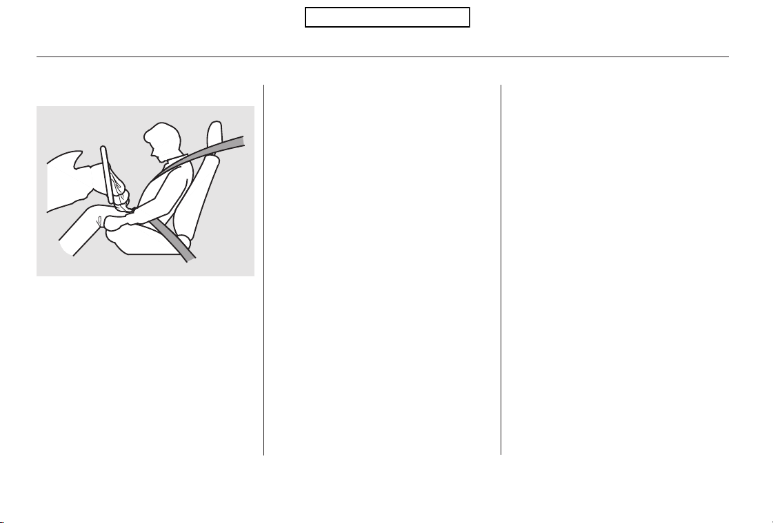
If you sit too close to the steering
wheel or dashboard, you can be
seriously injured by an inflating front
airbag, or by striking the steering
wheel or dashboard.
Adjust the driver’s seat-back to a
comfortable, upright position,
leaving ample space between your
chest and the airbag cover in the
center of the steering wheel.
Passengers with adjustable seat-
backs should also adjust their seat-
back to a comfortable, upright
position.
If you cannot get far enough away
from the steering wheel and still
reach the controls, we recommend
that you investigate whether some
type of adaptive equipment may help.
The National Highway Traffic Safety
Administration and Transport
Canada recommend that drivers
allow at least 10 inches (25 cm)
between the center of the steering
wheel and the chest. In addition to
adjusting the seat, you can adjust the
steering wheel up and down, and in
and out (see page ).
See page for how to adjust the
front seats.
76
93
Protecting Adults and Teens
Adjust the Seat-Backs3.
12
Sitting too close to a front
airbag can result in serious
injury or death if the front
airbags inflate.
Always sit as far back from the
front airbags as possible.
Table of Contents
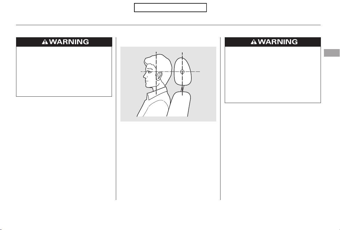
Adjust the driver’s head restraint so
the center of the back of your head
rests against the center of the
restraint.
Properly adjusted head restraints
will help protect occupants from
whiplash and other crash injuries.
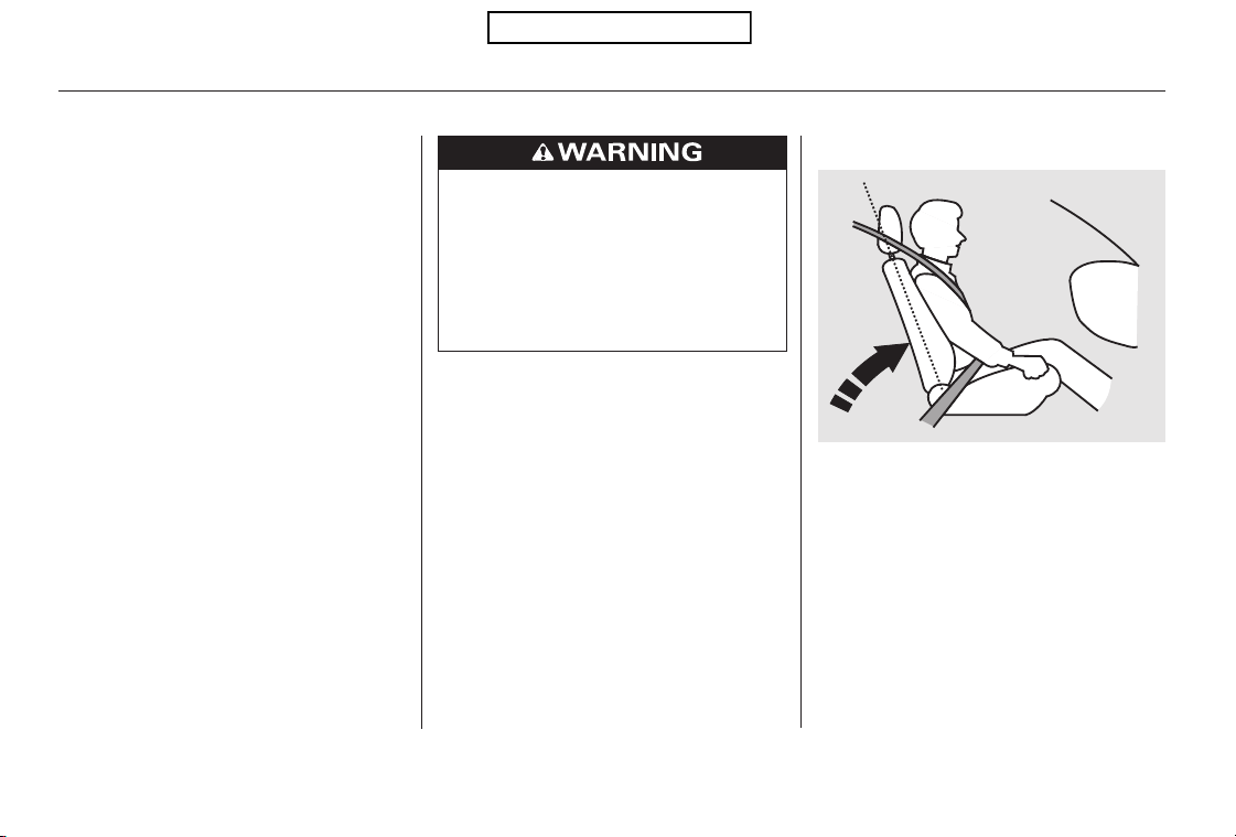
Reclining a seat-back so that the
shoulder part of the belt no longer
rests against the occupant’s chest
reduces the protective capability of
the belt. It also increases the chance
of sliding under the belt in a crash
and being seriously injured. The
farther a seat-back is reclined, the
greater the risk of injury. Have passengers adjust their head
restraints properly as well. Taller
persons should adjust their restraint
as high as possible.
See page for how to adjust the
head restraints and how the driver’s
and front passenger’s active head
restraints work.
See page for how to adjust the
seat-backs.
93
94
Protecting Adults and Teens
Adjust the Head Restraints4.
Driver and Passenger Safety
13
Improperly positioning head
restraints reduces their
effectiveness and you can be
seriously injured in a crash.
Make sure head restraints are
in place and positioned properly
before driving.
Reclining the seat-back too far
can result in serious injury or
death in a crash.
Adjust the seat-back to an
upright position, and sit well
back in the seat.
Table of Contents
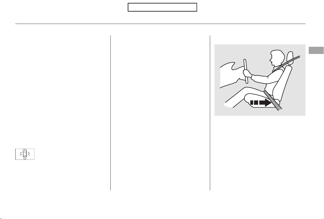
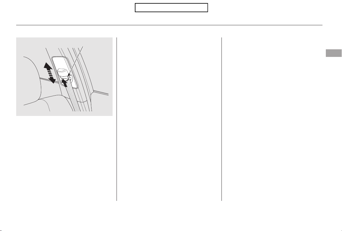
If the seat belt touches or crosses
your neck, or if it crosses your arm
instead of your shoulder, you need to
adjust the seat belt anchor height.
Insert the latch plate into the buckle,
then tug on the belt to make sure the
belt is securely latched. Check that
the belt is not twisted, because a
twisted belt can cause serious
injuries in a crash.
This spreads the forces of a crash
over the strongest bones in your
upper body.
Position the lap part of the belt as
low as possible across your hips,
then pull up on the shoulder part of
the belt so the lap part fits snugly.
This lets your strong pelvic bones
take the force of a crash and reduces
the chance of internal injuries.
If necessary, pull up on the belt again
to remove any slack, then check that
the belt rests across the center of
your chest and over your shoulder.
Protecting Adults and Teens
Fasten and Position the Seat
Belts
5.
14
Improperly positioning the seat
belts can cause serious injury
or death in a crash.
Make sure all seat belts are
properly positioned before
driving.
Table of Contents
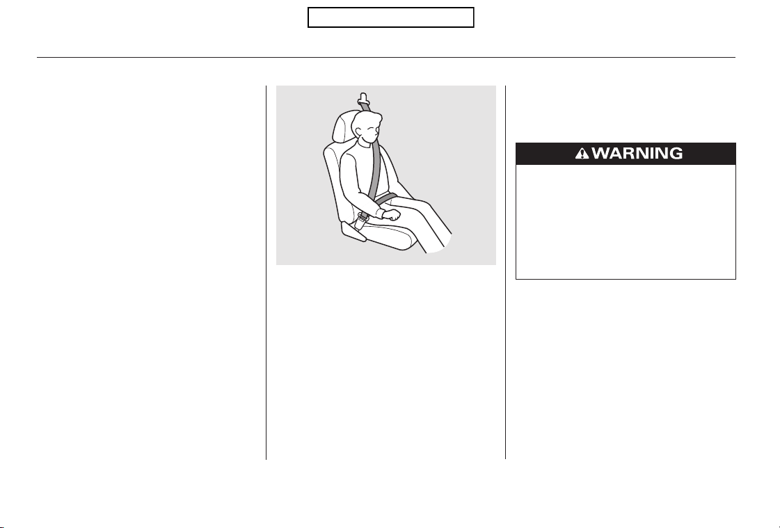
After all occupants have adjusted
their seats and head restraints, and
put on their seat belts, it is very
important that they continue to sit
upright, well back in their seats, with
their feet on the floor, until the
vehicle is safely parked and the
engine is off.
This could cause
very serious injuries in a crash.
See page for additional
information about your seat belts
and how to take care of them.
If a seat belt does not seem to work
properly, it may not protect the
occupant in a crash.
Using a seat
belt that is not working properly can
result in serious injury or death.
Have your dealer check the belt as
soon as possible.
The front seats have adjustable seat
belt anchors. To adjust the height of
an anchor, press and hold the release
button and slide the anchor up or
down as needed (it has four
positions).
Sitting improperly can increase the
chance of injury during a crash. For
example, if an occupant slouches,
lies down, turns sideways, sits
forward, leans forward or sideways,
or puts one or both feet up, the
chance of injury during a crash is
greatly increased.
18
CONTINUED
Maintain a Proper Sitting
Position
6.
Protecting Adults and Teens
Never place the shoulder portion of a
lap/shoulder belt under your arm or
behind your back.
No one should sit in a seat with an
inoperative seat belt.
Driver and Passenger Safety
15
RELEASE BUTTON
Table of Contents
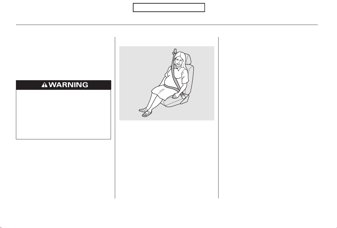
When driving, remember to sit
upright and adjust the seat as far
back as possible while allowing full
control of the vehicle. When riding
as a front passenger, adjust the seat
as far back as possible.
This will reduce the risk of injuries
to both you and your unborn child
that can be caused by a crash or an
inflating front airbag.
Each time you have a checkup, ask
your doctor if it’s okay for you to
drive.If you are pregnant, the best way to
protect yourself and your unborn
child when driving or riding in a
vehicle is to always wear a seat belt,
and keep the lap part of the belt as
low as possible across the hips.
In addition, an occupant who is out of
position in the front seat can be
seriously or fatally injured in a crash
by striking interior parts of the
vehicle or being struck by an
inflating front airbag.
Protecting Adults and Teens
Advice for Pregnant Women
16
Sitting improperly or out of
position can result in serious
injury or death in a crash.
Always sit upright, well back in
the seat, with your feet on the
floor.
Table of Contents

Objects on
the covers marked ‘‘SRS AIRBAG’’
could interfere with the proper
operation of the airbags or be
propelled inside the vehicle and
hurt someone if the airbags inflate.
If a side airbag or a
side curtain airbag inflates, a cup
holder or other hard object
attached on or near the door could
be propelled inside the vehicle and
hurt someone.
Improperly replacing
or covering front seat-back covers
can prevent your side airbags from
inflating during a side impact.
Devices intended to improve
occupant comfort or reposition the
shoulder part of a seat belt can
reduce the protective capability of
thebeltandincreasethechanceof
serious injury in a crash.
Carrying hard or sharp
objects on your lap, or driving with
a pipe or other sharp object in
your mouth, can result in injuries
if your front airbag inflates.
If your
hands or arms are close to an
airbag cover, they could be injured
if the airbag inflates.
If they do, they
could be very seriously injured in a
crash.
A passenger who is not
wearing a seat belt during a crash
or emergency stop can be thrown
against the inside of the vehicle,
against other occupants, or out of
the vehicle.
If they do, they
could be very seriously injured in a
crash.
Protecting Adults and Teens
Additional Safety Precautions
Do not attach or place objects on
the front airbag covers.
Do not attach hard objects on or
near a door.
Do not cover or replace front seat-
back covers without consulting
your dealer.
Do not put any accessories on seat
belts.
Do not place hard or sharp objects
between yourself and a front
airbag.
Keep your hands and arms away
from the airbag covers.
Never let passengers ride in the
cargo area or on top of a folded-
down back seat.
Passengers should not stand up or
change seats while the vehicle is
moving.
Two people should never use the
same seat belt.
Driver and Passenger Safety
17
Table of Contents
Your seat belt system includes lap/
shoulder belts in all seating positions.
The front seat belts are also
equipped with automatic seat belt
tensioners.
If the indicator comes on or the
beeper sounds when the driver’s seat
belt is latched and there is no front
seat passenger and no items on the
front seat, something may be
interfering with the monitoring
system. Look for and remove:
Any items under the front
passenger’s seat.
Any object(s) hanging on the seat
or in the seat-back pocket.
Any object(s) touching the rear of
the seat-back.
If no obstructions are found, have
your vehicle checked by a dealer.
The seat belt system
includes an indicator on the
instrument panel and a beeper to
remind you and your passengers to
fasten your seat belts.
This system monitors the front seat
belts. If you turn the ignition switch
to the ON (II) position before your
seat belt is fastened, the beeper will
sound and the indicator will flash. If
your seat belt is not fastened before
the beeper stops, the indicator will
stop flashing but remain on.
If a front passenger does not fasten
their seat belt, the indicator will
come on about 6 seconds after the
ignition switch is turned to the ON
(II) position.
If either the driver or a front
passenger does not fasten their seat
belt while driving, the beeper will
sound and the indicator will flash
again at regular intervals.
When no one is sitting in the front
passenger’s seat, or a child or small
adult is riding there, the indicator
should not come on and the beeper
should not sound.
Additional Information About Your Seat Belts
Seat Belt System Components
18
Table of Contents
CONTINUED
For added protection, the front seat
belts are equipped with automatic
seat belt tensioners. When activated,
the tensioners immediately tighten
the belts to help hold the driver and
a front passenger in position.
The lap and shoulder belt goes over
your shoulder, across your chest,
and across your hips.
To fasten the belt, insert the latch
plate into the buckle, then tug on the
belt to make sure the buckle is
latched (see page for how to
properly position the belt).
To unlock the belt, press the red
PRESSbuttononthebuckle.Guide
the belt across your body so that it
retracts completely. After exiting the
vehicle, be sure the belt is out of the
way and will not get closed in the
door.
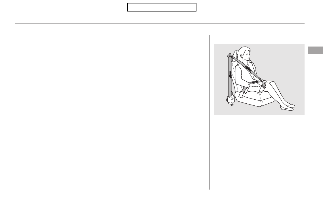
If the shoulder part of the belt is
pulled all the way out, the lockable
retractor will activate. The belt will
retract, but it will not allow the
passenger to move freely.
The seat belts in all positions except
the driver’s have a lockable retractor
that must be activated to secure a
child seat (see page ).
All seat belts have an emergency
locking retractor. In normal driving,
the retractor lets you move freely in
your seat while it keeps some
tension on the belt. During a collision
or sudden stop, the retractor
automatically locks the belt to help
restrain your body.
To deactivate the lockable retractor,
unlatch the buckle and let the seat
belt fully retract. To refasten the
seat belt, pull it out only as far as
needed.
14
44
Additional Information About Your Seat Belts
Automatic Seat Belt TensionersLap/Shoulder Belt
Driver and Passenger Safety
19
Table of Contents
The dealer should also inspect the
anchors for damage and replace
them if needed. If the automatic seat
belt tensioners activate during a
crash, they must be replaced.
For safety, you should check the
condition of your seat belts regularly.
Pull each belt out fully, and look for
frays, cuts, burns, and wear. Check
that the latches work smoothly and
the belts retract easily. If a belt does
not retract easily, cleaning the belt
may correct the problem (see page
). Any belt that is not in good
condition or working properly will
not provide good protection and
should be replaced as soon as
possible.
Honda provides a limited warranty
on seat belts. See your
booklet for
details.
If a seat belt is worn during a crash,
it must be replaced by your dealer. A
belt that has been worn during a
crash may not provide the same level
of protection in a subsequent crash.
If the tensioner is activated, the SRS
indicator comes on and the tensioner
must be replaced.
The tensioners can be activated
during a collision in which the front
airbags . In this case, the
airbags would not be needed, but the
extra tension in the seat belt could
be helpful.
353
Honda
Warranty Information
do not deploy
Additional Information About Your Seat Belts
Seat Belt Maintenance
20
Not checking or maintaining
seat belts can result in serious
injury or death if the seat belts
do not work properly when
needed.
Check your seat belts regularly
and have any problem
corrected as soon as possible.
Table of Contents
CONTINUED
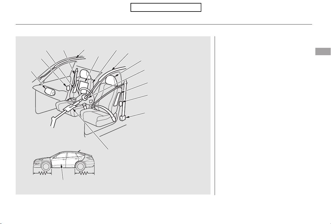
Additional Information About Your Airbags
Airbag System Components
Driver and Passenger Safety
21
(3)
(4)
(6)
(8)
(8)
(1)
(9)
(2)
(11)
(5)
(13)
(10)
(16)
(15)
(14)
(16)
(14)
(5)
(4)
(7)(12)
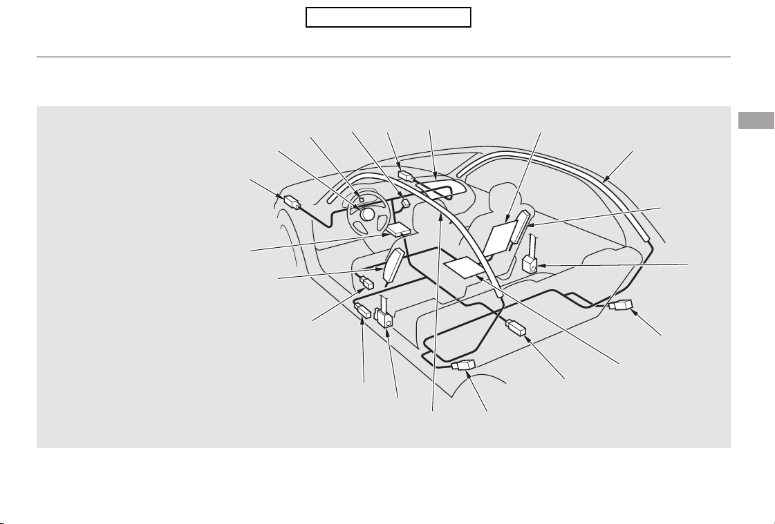
(15) Safing Sensor
(16) Side Impact Sensors (Second)
(6) Driver’s Seat Position Sensor
(7) Front Passenger’s Weight Sensors
(8) Front Impact Sensors
(9) Passenger Airbag Off Indicator
(10) Side Impact Sensors (First)
(1) Driver’s Front Airbag
(2) Passenger’s Front Airbag
(3) Control Unit/Rollover Sensor
(4) Front Seat Belt Tensioners
(5) Side Airbags
(11) Occupant Position Detection System (OPDS) Sensor
(12) Front Passenger’s Weight Sensors Control Unit/
OPDS Sensors Control Unit
(13) SRS Indicator
(14) Side Curtain Airbags
Table of Contents
Automatic front seat belt
tensioners (see page ).
Your airbag system includes:
Two side airbags, one for the
driver and one for a front
passenger. The airbags are stored
in the outer edges of the seat-
backs. Both are marked ‘‘SIDE
AIRBAG’’ (see page ).
Two SRS (supplemental restraint
system) front airbags. The driver’s
airbag is stored in the center of
the steering wheel; the front
passenger’sairbagisstoredinthe
dashboard. Both are marked ‘‘SRS
AIRBAG’’ (see page ).
Two side curtain airbags, one for
each side of the vehicle. The
airbags are stored in the ceiling
above the side windows. The front
and rear pillars are marked ‘‘SIDE
CURTAIN AIRBAG’’ (see page
).
A driver’s seat position sensor that
monitors the distance of the seat
from the front airbag. If the seat is
too far forward, the airbag will
inflate with less force (see page
).
Weight sensors that monitor the
weight on the front passenger’s
seat. If the weight is about 65 lbs
(29 kg) or less (the weight of an
infant or small child), the
passenger’s front airbag will be
turned off (see page ).
A sophisticated electronic system
that continually monitors and
records information about the
sensors, the control unit, the
airbag activators, the seat belt
tensioners, and driver and front
passenger seat belt use when the
ignition switch is in the ON (II)
position.
Sensors that can detect a
moderate to severe front impact,
side impact, or if your vehicle is
about to rollover.
Sensors that can detect whether a
child is in the passenger’s side
airbag path and signal the control
unit to turn the airbag off (see
page ).
Sensors that can detect whether
the driver’s seat belt and the front
passenger’s seat belt are latched
or unlatched (see page ).
A rollover sensor that can detect if
your vehicle is about to roll over
and signal the control unit to
deploy both side curtain airbags
(see page ).
23
27
28
19
25
26
28
18
29
Additional Information About Your Airbags
22
Table of Contents
CONTINUED
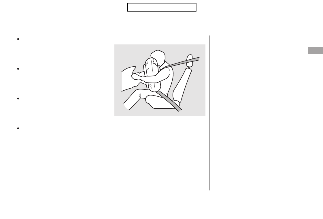
During a frontal crash, your seat belt
restrains your lower body and torso,
and the front airbag helps protect
your head and chest.
Although both airbags normally
inflate within a split second of each
other, it is possible for only one
airbag to deploy.
This can happen if the severity of a
collision is at the margin, or
threshold, that determines whether
or not the airbags will deploy. In
such cases, the seat belt will provide
sufficient protection, and the
supplemental protection offered by
the airbag would be minimal.
If you ever have a moderate to
severe frontal collision, sensors will
detect the vehicle’s rapid
deceleration.
If the rate of deceleration is high
enough, the control unit will inflate
the driver’s and front passenger’s
airbags, at the time and with the
force needed.
Only the driver’s airbag can deploy if
there is no passenger in the front
seat, or if the advanced airbag
system has turned the passenger’s
airbag off (see page ).
An indicator on the instrument
panel that alerts you that the
passenger’s side airbag has been
turned off (see page ).
An indicator on the dashboard that
alerts you that the passenger’s
front airbag has been turned off
(see page ).
Emergency backup power in case
your vehicle’s electrical system is
disconnected in a crash.
An indicator on the instrument
panel that alerts you to a possible
problem with your airbag system
components (see page ).
25
29
30
30
Additional Information About Your Airbags
How Your Front Airbags Work
Driver and Passenger Safety
23
Table of Contents
The total time for inflation and
deflation is one-tenth of a second, so
fast that most occupants are not
aware that the airbags deployed until
they see them lying in their laps.
Your front airbags are dual-stage
airbags. This means they have two
inflation stages that can be ignited
sequentially or simultaneously,
depending on crash severity.
In a crash, both stages
will ignite simultaneously to provide
the quickest and greatest protection.
In a crash, one stage will
ignite first, then the second stage
will ignite a split second later. This
provides longer airbag inflation time
with a little less force.
After a crash, you may see what
looks like smoke. This is actually
powder from the airbag’s surface.
Although the powder is not harmful,
people with respiratory problems
mayexperiencesometemporary
discomfort. If this occurs, get out of
the vehicle as soon as it is safe to do
so.
After inflating, the front airbags
immediately deflate, so they won’t
interfere with the driver’s visibility,
or the ability to steer or operate
other controls.
Additional Information About Your Airbags
Dual-Stage Airbags
more severe
less severe
24
Table of Contents
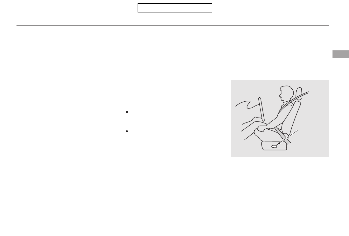
CONTINUED
Your front airbags are also advanced
airbags. The main purpose of this
feature is to help prevent airbag-
caused injuries to short drivers and
children or small-statured adults who
ride in front.
Your front airbags are also dual-
threshold airbags. Airbags with this
feature have two deployment
thresholds that depend on whether
sensors detect the occupant is
wearing a seat belt or not.
If the occupant’s belt is ,
the airbag will deploy at a slightly
lower threshold, because the
occupant would need extra
protection.
If the occupant’s belt is , the
airbag will inflate at a slightly higher
threshold, when the airbag would be
needed to supplement the protection
provided by the seat belt.
The driver’s advanced front airbag
system includes a seat position
sensor under the seat. If the seat is
too far forward, the airbag will
inflate with less force, regardless of
the severity of the impact.
If there is a problem with the sensor,
the SRS indicator will come on, and
the airbag will inflate in the normal
manner regardless of the driver’s
seating position.
Do not spill any liquids on or
under the seats, cover the sensors,
or put any objects or metal items
under the front seats.
Occupants must sit upright and
wear their seat belts properly.
For both advanced airbags to work
properly:
Failure to follow these instructions
could damage the sensors or prevent
them from working properly.
Additional Information About Your Airbags
Advanced AirbagsDual-Threshold Airbags
not latched
latched
Driver and Passenger Safety
25
DRIVER’S
SEAT
POSITION
SENSOR
Table of Contents
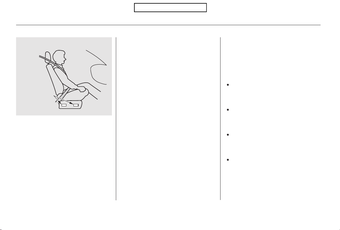
When the passenger airbag gets
turned off by the weight sensors, a
‘‘passenger airbag off’’ indicator in
the center of the dashboard comes
on (see page ).
Be aware that objects placed on the
passenger’s seat can also cause the
airbag to be turned off.
If the weight sensors detect there is
no passenger in the front seat, the
airbag is automatically turned off.
However, the passenger airbag off
indicator in this situation will not
come on.
To ensure that the passenger’s
advanced front airbag system will
work properly,
This includes:
A rear passenger pushing or
pulling on the back of the front
passenger’s seat.
Moving the front seat forcibly
back against cargo on the seat or
floor behind it.
Hanging heavy items on the front
passenger seat, or placing heavy
items in the seat-back pocket.
Moving the front seat or seat-back
forcibly back against the folded
rear seat.
The passenger’s advanced front
airbag system has weight sensors
under the seat. Although Honda
does not encourage carrying an
infant or small child in front, if the
sensors detect the weight of an
infant or small child (up to about 65
lbs or 29 kg), the system will
automatically turn the passenger’s
front airbag off.
30
Additional Information About Your Airbags
do not do anything
that would increase or decrease the
weight on the front passenger’s seat.
26
PASSENGER’S
SEAT WEIGHT
SENSORS
Table of Contents
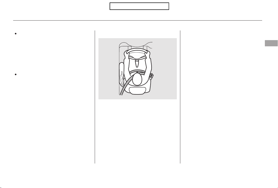
CONTINUED
Only one airbag will deploy during a
side impact. If the impact is on the
passenger’s side, the passenger’s
side airbag will deploy even if there
is no passenger.
To get the best protection from the
side airbags, front seat occupants
should wear their seat belts and sit
upright and well back in their seats.
If you ever have a moderate to
severe side impact, sensors will
detect rapid acceleration and signal
the control unit to instantly inflate
either the driver’s or the passenger’s
side airbag.
Also,makesurethefloormat
behind the front passenger’s seat
is properly positioned on the floor
(see page ). If it is not, the mat
may interfere with the proper
operation of the front passenger’s
seat and its sensors.
Back seat passengers should not
wedge objects or intentionally
force their feet under the front
passenger seat.
353
Additional Information About Your Airbags
How Your Side Airbags Work
Driver and Passenger Safety
27
Table of Contents
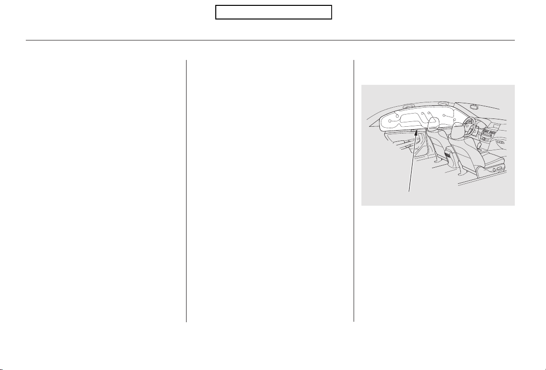
If the side airbag off indicator comes
on (see page ), have the
passenger sit upright. Once the
passenger is out of the airbag’s
deployment path, the system will
turn the airbag back on, and the
indicator will go out.
There will be some delay between
the moment the passenger moves
into or out of the airbag deployment
pathandwhentheindicatorcomes
on or goes off.
A front seat passenger should not
use a cushion or another object as a
backrest. It may prevent the cutoff
system from working properly.
Your vehicle has a side airbag cutoff
system designed primarily to protect
a child riding in the front passenger’s
seat.
Although Honda does not encourage
children to ride in front, if the
position sensors detect a child has
leaned into the side airbag’s
deployment path, the airbag will shut
off.
Thesideairbagmayalsoshutoffifa
short adult leans sideways, or a
larger adult slouches and leans
sideways into the airbag’s
deployment path.
Objects placed on the front
passenger seat can also cause the
side airbag to be shut off.
In a moderate to severe side impact,
sensors will detect rapid acceleration
and signal the control unit to
instantly inflate the side curtain
airbag.
If the impact is on the passenger’s
side, the passenger’s side curtain
airbag will inflate even if there are no
occupants on that side of the vehicle.
30
Additional Information About Your Airbags
Side Airbag Cutoff System
In a Side Impact
How Your Side Curtain Airbags
Work
28
SIDE CURTAIN AIRBAG
Table of Contents
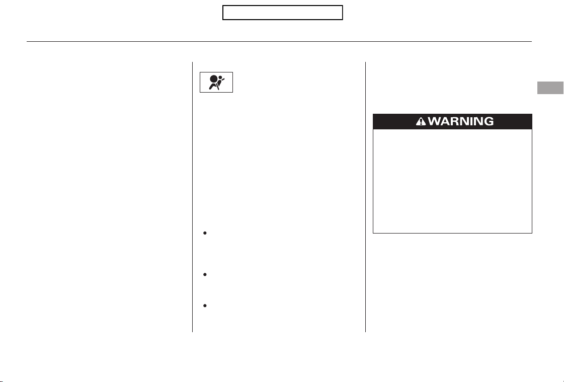
If you see any of these indications,
the airbag system components may
not work properly when you need
them.
When you turn the ignition switch to
the ON (II) position, this indicator
comes on briefly then goes off. This
tells you the system is working
properly.
If the indicator comes on at any
other time, or does not come on at all,
you should have the system checked
by your dealer. For example:
If the SRS indicator does not come
on after you turn the ignition
switch to the ON (II) position.
If the indicator stays on after the
engine starts.
If the indicator comes on or
flashesonandoffwhileyoudrive.
The SRS indicator alerts
you to a potential problem
with your airbag system components.
If the rollover sensor detects your
vehicle is about to roll over, it signals
the control unit, which immediately
deploys both side curtain airbags.
The airbag on the passenger’s side
will deploy, even if there are no
passengers on that side of the
vehicle.
One or both side curtain airbags may
inflate in a moderate to severe
frontal collision which causes the
front airbags to deploy.
To get the best protection from the
side curtain airbags, occupants
should wear their seat belts and sit
upright and well back in their seats.
Additional Information About Your Airbags
How the SRS Indicator Works
In a Rollover
Driver and Passenger Safety
29
Ignoring the SRS indicator can
result in serious injury or death
if the airbag systems or
tensioners do not work properly.
Have your vehicle checked by a
dealer as soon as possible if
the SRS indicator alerts you to
a possible problem.
Table of Contents
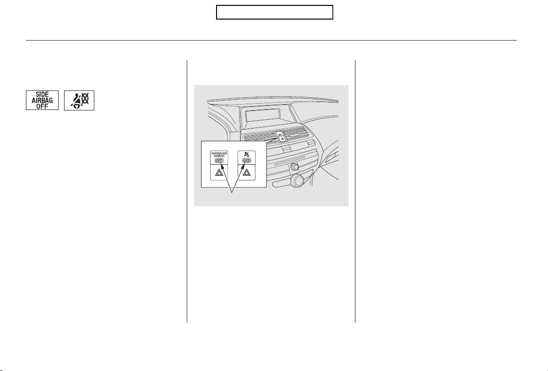
Be aware that objects placed on the
front seat can cause the indicator to
come on.
If no weight is detected on the front
seat, the airbag will be automatically
shut off. However, the indicator will
not come on.
The passenger airbag off indicator
maycomeonandoffrepeatedlyif
the total weight on the seat is near
the airbag cutoff threshold.
If an adult or teenage passenger is
riding in front, move the seat as far
to the rear as possible, and have the
passenger sit upright and wear the
seat belt properly.
This indicator alerts you that the
passenger’s front airbag has been
shut off because weight sensors
detect about 65 lbs (29 kg) or less
(the weight of an infant or small
child) on the front passenger’s seat.
It does there is a problem
with the airbag.
This indicator alerts you that the
passenger’s side airbag has been
automatically shut off. It does
mean there is a problem with your
side airbags.
When you turn the ignition switch to
the ON (II) position, the indicator
should come on briefly and then go
out(seepage ).Ifitdoesn’tcome
on, stays on, or comes on while
driving without a passenger in the
front seat, have the system checked.
57
Additional Information About Your Airbags
How the Passenger Airbag Off
Indicator Works
How the Side Airbag Off
Indicator Works
not mean
not
30
PASSENGER AIRBAG OFF INDICATOR
U.S. Canada
U.S. Canada
Table of Contents

Take your vehicle to an
authorized dealer as soon as
possible. If you ignore this
indication, your airbags may not
operate properly.
Even if your
airbags do not inflate, your dealer
should inspect the driver’s seat
position sensor, the front
passenger’s weight sensors, the
front seat belt tensioners, and all
seat belts and their anchors worn
during a crash to make sure they
are operating properly.
Your airbag systems are virtually
maintenance free, and there are no
parts you can safely service.
However, you must have your
vehicle serviced if:
Any airbag
that has deployed must be
replaced along with the control
unit and other related parts. Any
seat belt tensioner that activates
must also be replaced.
Do not try to remove or replace
anyairbagbyyourself.Thismust
be done by an authorized dealer or
a knowledgeable body shop.
If the indicator comes on with no
front seat passenger and no objects
on the seat, or with an adult riding
there, something may be interfering
with the weight sensors. Look for
and remove:
Any object hanging on the seat or
in the seat-back pocket.
If no obstructions are found, have
your vehicle checked by a dealer as
soon as possible.
Any items under the front
passenger’s seat.
Any object(s) touching the rear of
the seat-back.
Additional Information About Your Airbags
The SRS indicator alerts you to a
problem.
If your vehicle has a moderate to
severe impact.
An airbag ever inflates.
Airbag Service
Driver and Passenger Safety
31
Table of Contents

This could make the
driver’s seat position sensor or the
front passenger’s weight sensors
ineffective. If it is necessary to
remove or modify a front seat to
accommodate a person with
disabilities, first contact Honda
Automobile Customer Service at
(800) 999-1009.
Together, airbags and
seat belts provide the best
protection.
Tampering could cause
the airbags to deploy, possibly
causing very serious injury.
If water or
another liquid soaks into a seat-
back, it can prevent the side airbag
cutoff system from working
properly.
Additional Information About Your Airbags
Do not remove or modif y a f ront
seat without consulting your
dealer.
Donotattempttodeactivateyour
airbags.
Do not tamper with airbag
components or wiring for any
reason.
Do not expose the f ront passenger’s
seat-back to liquid.
Additional Safety Precautions
32
Table of Contents
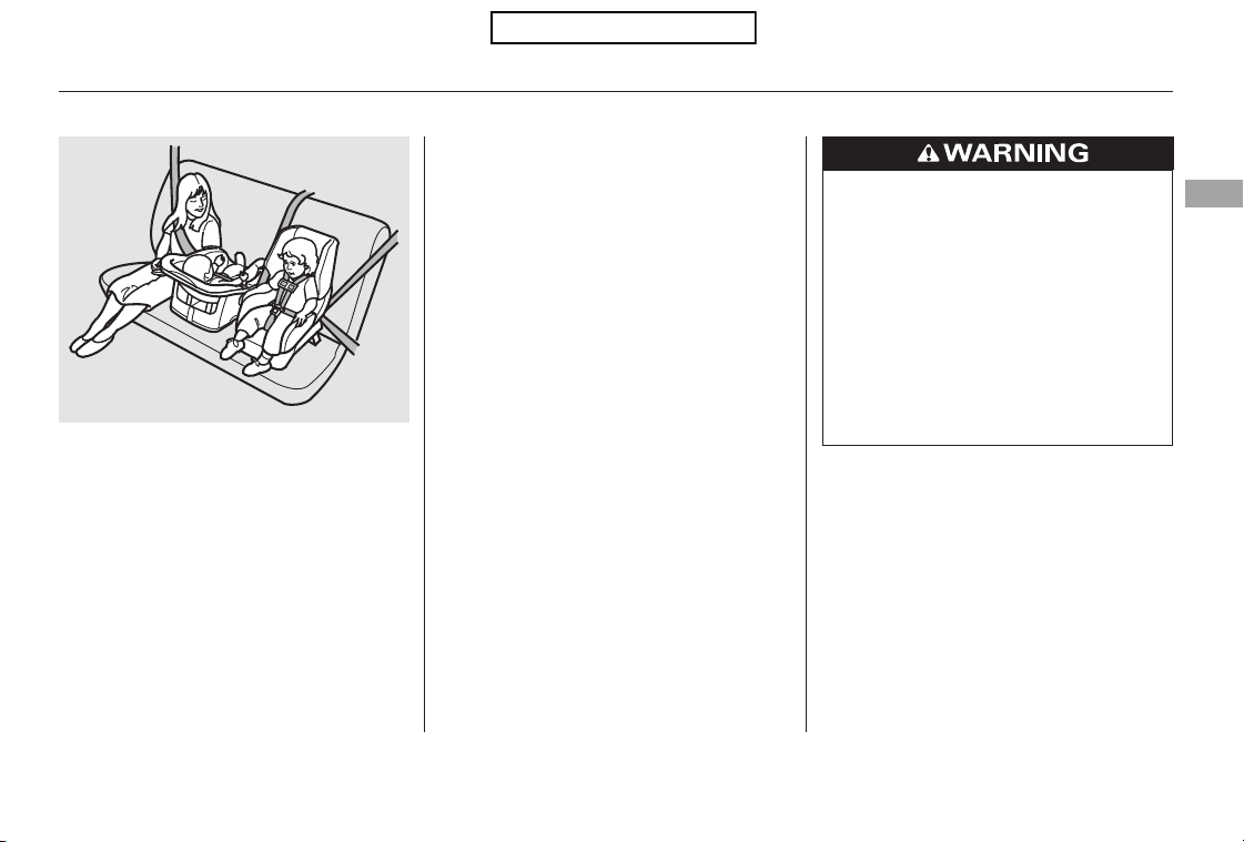
−
−
−
If you have children, or ever need to
drive with a child in your vehicle, be
sure to read this section. It begins
with important general guidelines,
then presents special information for
infants, small children, and larger
children.
Each year, many children are injured
or killed in vehicle crashes because
they are either unrestrained or not
properly restrained. In fact, traffic
accidents are the number one cause
of death of children age 12 and
under.
To reduce the number of child
deaths and injuries, every state,
Canadian province and territory
requires that infants and children be
properlyrestrainedwhentheyridein
a vehicle.
(see pages ).
(see pages ).
Children depend on adults to protect
them. However, despite their best
intentions, many adults do not know
how to protect child
passengers.
38 46
47 50
properly
All Children Must Be Restrained
Infants and small children must be
restrained in an approved child seat
that is properly secured to the
vehicle
Larger children must be restrained
with a lap/shoulder belt and ride on
a booster seat until the seat belt fits
them properly
Protecting Children General Guidelines
Driver and Passenger Safety
33
Children who are unrestrained
or improperly restrained can be
seriously injured or killed in a
crash.
Any child too small for a seat
belt should be properly
restrained in a child seat. A
larger child should be properly
restrained with a seat belt and
use a booster seat if necessary.
Table of Contents

−
Front airbags have been designed to
help protect adults in a moderate to
severe frontal collision. To do this,
the passenger’s front airbag is quite
large, and it can inflate with enough
force to cause very serious injuries.
If the vehicle seat is
too far forward, or the child’s head is
thrown forward during a collision, an
inflating front airbag can strike the
child with enough force to kill or
very seriously injure a small child.
Whenever possible,
larger children should sit in the back
seat, on a booster seat if needed, and
be properly restrained with a seat
belt (see page for important
information about protecting larger
children).
According to accident statistics,
children of all ages and sizes are
safer when they are restrained in a
back seat.
Children who ride in back are less
likely to be injured by striking
interior vehicle parts during a
collision or hard braking. Also,
children cannot be injured by an
inflating front airbag when they ride
in the back.
The National Highway Traffic Safety
Administration and Transport
Canada recommend that all children
aged 12 and under be properly
restrained in a back seat. Some
states have laws restricting where
children may ride.
Even though your vehicle has an
advanced front airbag system that
automatically turns the passenger’s
front airbag off under certain
circumstances (see page ), please
follow these guidelines:
If
the airbag inflates, it can hit the back
of the child seat with enough force
to kill or very seriously injure an
infant.
47
30
Small Children
Placing a forward-facing child seat in
the front seat of a vehicle equipped
with a passenger’s front airbag can
be hazardous.
Larger Children
Children who have outgrown child
seats are also at risk of being injured
or killed by an inflating passenger’s
front airbag.
Never put a rear-f acing child seat in
the front seat of a vehicle equipped
with a passenger’s front airbag.
Infants
All Children Should Sit in a Back
Seat
The Passenger’s Front Airbag
Can Pose Serious Risks
Protecting Children General Guidelines
34
Table of Contents
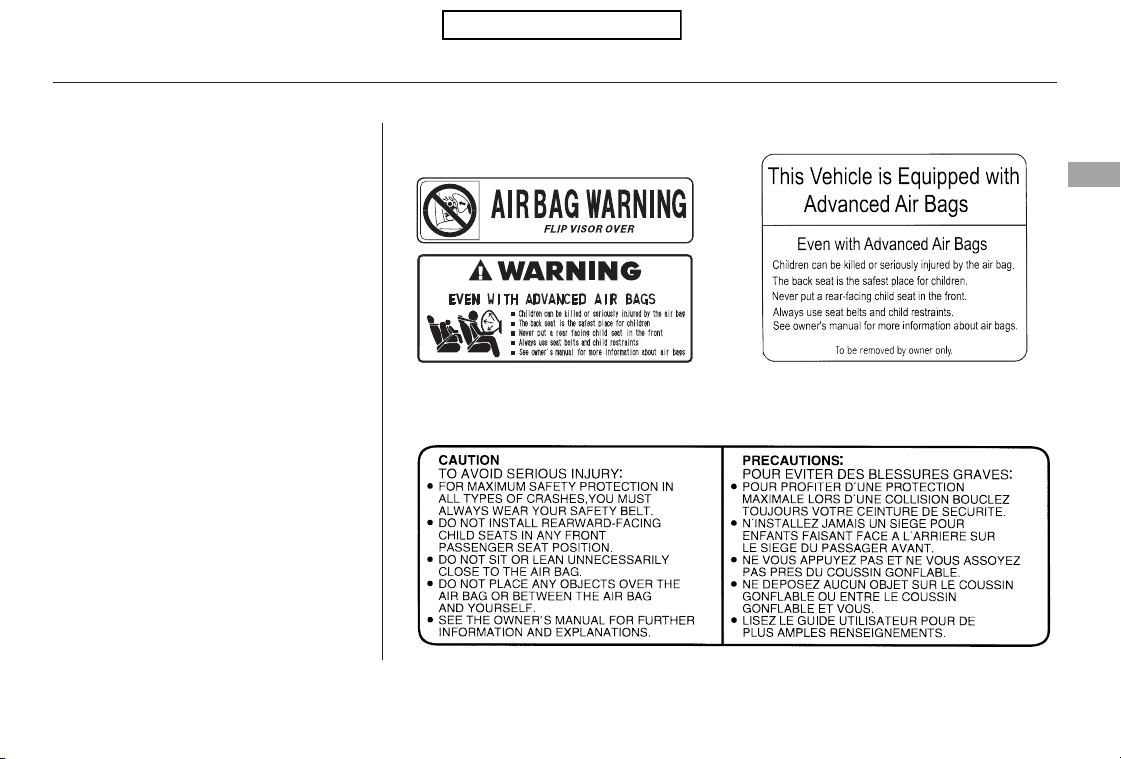
−
To remind you of the passenger’s
front airbag hazards, and that
children must be properly restrained
in a back seat, your vehicle has
warninglabelsonthedashboard
(U.S. models) and on the front visors.
Please read and follow the
instructions on these labels.
U.S. Models
Canadian Models
Protecting Children General Guidelines
Driver and Passenger Safety
35
DASHBOARD
SUN VISORS
SUN VISORS
Table of Contents
−
Many parents say they prefer to put
an infant or a small child in the front
passenger seat so they can watch the
child, or because the child requires
attention.
Placing a child in the front seat
exposes the child to hazards in a
frontal collision, and paying close
attention to a child distracts the
driver from the important tasks of
driving, placing both of you at risk.
Your vehicle has a back seat where
children can be properly restrained.
If you ever have to carry a group of
children, and a child must ride in
front:
Place the largest child in the front
seat, provided the child is large
enough to wear the lap/shoulder
belt properly (see page ).
If a child requires close physical
attention or frequent visual
contact, we strongly recommend
that another adult ride with the
child in a back seat. The back seat
is far safer for a child than the
front.
If you are not wearing a
seat belt in a crash, you could be
thrown forward and crush the
child against the dashboard or a
seat-back. If you are wearing a
seat belt, the child can be torn
from your arms and be seriously
hurt or killed.
During a crash, the
belt could press deep into the child
and cause serious or fatal injuries.
If they do, they
could be very seriously injured in a
crash.
Move the vehicle seat as far to the
rear as possible (see page ).
Have the child sit upright and well
backintheseat(seepage ).
Make sure the seat belt is properly
positioned and secured (see page
).
47
93
15
14
If a Child Requires Close
Attention
If You Must Drive with Several
Children
Additional Safety Precautions
Protecting Children General Guidelines
Neverholdaninfantorchildon
your lap.
Never put a seat belt over yourself
and a child.
Never let two children use the
same seat belt.
36
Table of Contents
−
If a child wraps a loose
seat belt around their neck, they
can be seriously or fatally injured.
(See pages and for how to
activate and deactivate the
lockable retractor.)
This can prevent
children from accidentally falling
out (see page ).
Leaving children without
adult supervision is illegal in most
states, Canadian provinces and
territories, and can be very
hazardous.
For example, infants and small
childrenleftinavehicleonahot
day can die from heatstroke. A
child left alone with the key in the
ignition switch can accidentally set
the vehicle in motion, possibly
injuring themselves or others.
Children who play in vehicles can
accidentally get trapped inside.
Teach your children not to play in
or around vehicles.
Even very young
children learn how to unlock
vehicle doors, turn on the ignition
switch, and open the tailgate,
which can lead to accidental injury
or death.4544
87
Protecting Children General Guidelines
Make sure any unused seat belt
that a child can reach is buckled,
the lockable retractor is activated,
and the belt is fully retracted and
locked.
Use the childproof door locks to
prevent children from opening the
rear doors.
Do not leave children alone in a
vehicle.
Lock all doors and the tailgate
when your vehicle is not in use.
Keep vehicle keys/remote
transmitters out of the reach of
children.
Driver and Passenger Safety
37
Table of Contents
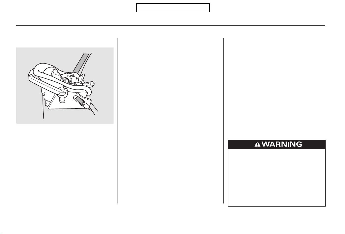
Two types of seats may be used: a
seat designed exclusively for infants,
or a convertible seat used in the rear-
facing, reclining mode.
If placed
facing forward, an infant could be
very seriously injured during a
frontal collision.
Only a rear-facing child seat provides
proper support for a baby’s head,
neck, and back.
An infant must be properly
restrained in a rear-facing, reclining
child seat until the child reaches the
seat maker’s weight or height limit
for the seat, and the child is at least
one year old.
A rear-facing child seat can be placed
in any seating position in the back
seat, but not in the front.
If the passenger’s front airbag
inflates, it can hit the back of the
child seat with enough force to kill or
seriously injure an infant.
When properly installed, a rear-
facing child seat may prevent the
driver or a front passenger from
moving their seat as far back as
recommended, or from locking their
seat-back in the desired position.
It could also interfere with proper
operation of the passenger’s
advanced front airbag system.
In any of these situations, we
strongly recommend that you install
the child seat directly behind the
front passenger’s seat, move the seat
as far forward as needed, and leave it
unoccupied. Or, you may wish to get
a smaller rear-facing child seat.
Protecting Infants and Small Children
Do not put a rear-f acing child seat in
a forward-facing position.
Child Seat Type
Rear-f acing Child Seat Placement
Never put a
rear-facing child seat in the f ront
seat.
Protecting Infants
38
Placing a rear-facing child seat
in the front seat can result in
serious injury or death during a
crash.
Always place a rear-facing child
seat in the back seat, not the
front.
Table of Contents
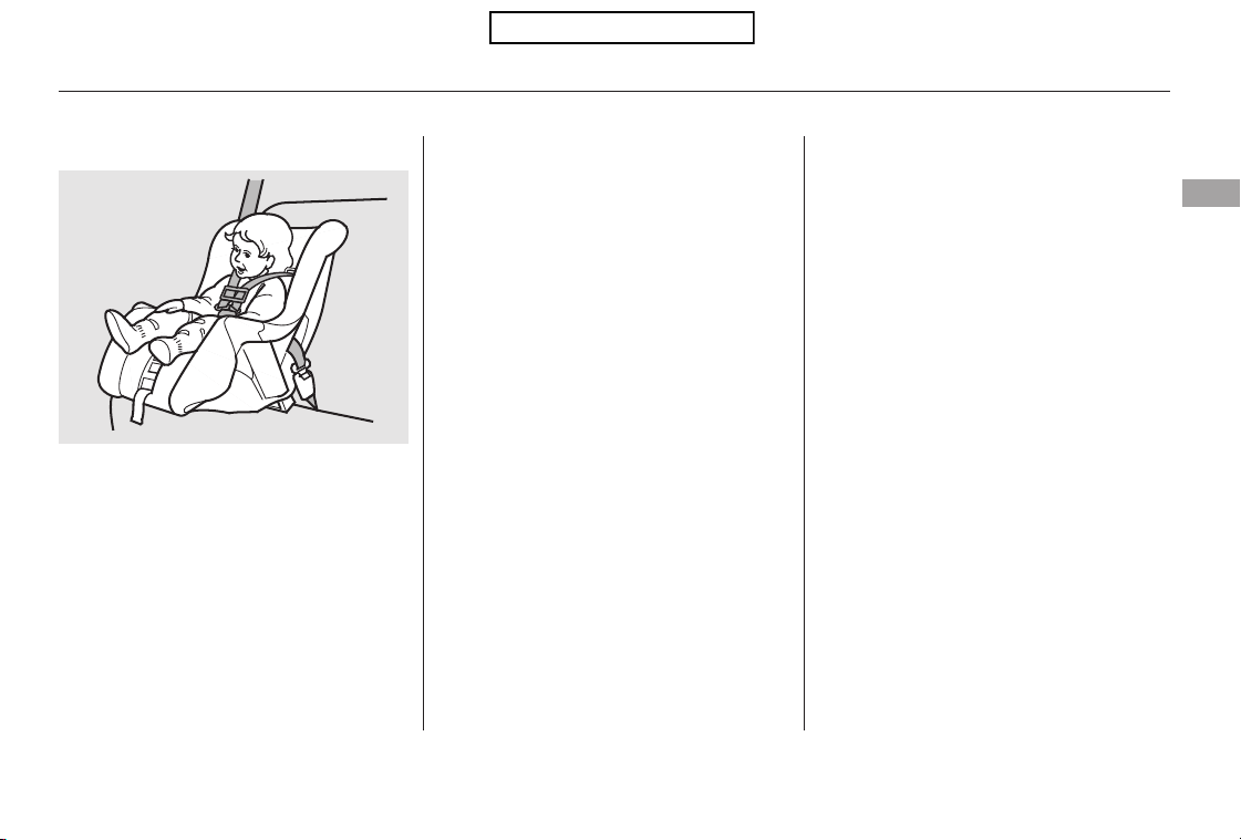
CONTINUED
Many states, Canadian provinces and
territories allow a child one year of
age or older who also meets the
minimum size and weight
requirements to transition from a
rear-facing child seat to a forward
facing seat. Know the requirements
where you are driving and follow the
child seat instructions. Many experts
recommend use of a rear-facing seat
up to age two, if the child’s height
and weight are appropriate for a
rear-facing seat.
Of the different seats available, we
recommend those that have a five-
point harness system as shown.
We also recommend that a small
child use the child seat until the child
reaches the weight or height limit
for the seat.
We strongly recommend placing a
forward-facing child seat in a back
seat, not the front.
If the vehicle seat is too
far forward, or the child’s head is
thrown forward during a collision, an
inflating airbag can strike the child
with enough force to cause very
serious or fatal injuries.
Even with advanced front airbags
that automatically turn the
passenger’s front airbag off (see
page ), a back seat is the safest
place for a small child.
30
Protecting Infants and Small Children
Protecting Small Children
Child Seat Type
Child Seat Placement
Placing a forward-facing child seat in
the front seat of a vehicle equipped
with a passenger’s airbag can be
hazardous.
Driver and Passenger Safety
39
Table of Contents
Since LATCH-compatible child seats
are easier to install and reduce the
possibility of improper installation,
we recommend selecting this style.
In seating positions and vehicles not
equipped with LATCH, a LATCH-
compatible child seat can be installed
using a seat belt.
Whatever type of seat you choose, to
provide proper protection, a child
seat should meet three
requirements:
Look for FMVSS 213 or CMVSS
213 on the box.
When buying a child seat, you need
to choose either a conventional child
seat, or one designed for use with
the Lower Anchors and Tethers for
CHildren (LATCH) system.
Conventional child seats must be
secured to a vehicle with a seat belt,
whereas LATCH-compatible seats
are secured by attaching the seat to
hardware built into the two outer
seating positions in the back seat.
Rear-facing for infants, forward-
facing for small children.
If it is necessary to put a forward-
facing child seat in the front, move
the vehicle seat as far to the rear as
possible, and be sure the child seat is
firmly secured to the vehicle and the
child is properly strapped in the seat.
Selecting a Child Seat
The child seat should meet
Federal Motor Vehicle Safety
Standard 213 or Canadian Motor
Vehicle Safety Standard 213.
The child seat should be of the
proper type and size to fit the child.
1.
2.
Protecting Infants and Small Children, Selecting a Child Seat
40
Placing a forward-facing child
seat in the front seat can result
in serious injury or death if the
front airbag inflates.
Ifyoumustplaceaforward-
facing child seat in front, move
the vehicle seat as far back as
possible, and properly restrain
the child.
Table of Contents

After selecting a proper child seat
and a good place to install the seat,
there are three main steps in
installing the seat:
All child seats must be
secured to the vehicle with the lap
part of a lap/shoulder belt or with
the LATCH (Lower Anchors and
Tethers for CHildren) system. A
child whose seat is not properly
secured to the vehicle can be
endangered in a crash.
After installing a child
seat, push and pull the seat
forward and from side-to-side to
verify that it is secure.
A child seat secured with a seat belt
should be installed as firmly as
possible. However, it does not need
to be ‘‘rock solid.’’ Some side-to-side
movement can be expected and
should not reduce the child seat’s
effectiveness.
If the child seat is not secure, try
installing it in a different seating
position, or use a different style of
child seat that can be firmly secured.
Before purchasing a conventional
child seat, or using a previously
purchased one, we recommend that
you test the seat in the specific
vehicle seating position or positions
where the seat will be used.
Make sure the child is properly
strappedinthechildseat
according to the child seat maker’s
instructions. A child who is not
properly secured in a child seat
can be seriously injured in a crash.
The following pages provide
guidelines on how to properly install
a child seat. A forward-facing child
seat is used in all examples, but the
instructions are the same for rear-
facing child seats.
Installing a Child Seat
Properly secure the child seat to
the vehicle.
Make sure the child seat is firmly
secured.
The child seat should fit the
vehicle seating position (or
positions) where it will be used.
Secure the child in the child seat.
3.
1.
2.
3.
Selecting a Child Seat, Installing a Child Seat
Driver and Passenger Safety
41
Table of Contents

Make sure there are no objects
near the anchors that could
prevent a secure connection
between the child seat and the
anchors.
Move the seat belt buckle or
tongue away from the lower
anchors.
To install a LATCH-compatible child
seat:
Place the child seat on the vehicle
seat, then attach the seat to the
lower anchors according to the
child seat maker’s instructions.
Your vehicle is equipped with
LATCH (Lower Anchors and
Tethers for CHildren) at the outer
rear seats.
Some LATCH-compatible seats
have a rigid-type connector as
shown above.
The lower anchors are to be used
only with a child seat designed for
use with LATCH.
The location of each lower anchor is
indicated by a small button above the
anchor point.
1.
2.
3.
Installing a Child Seat with
LATCH
Installing a Child Seat
42
BUTTON
LOWER ANCHOR
Rigid type
Table of Contents
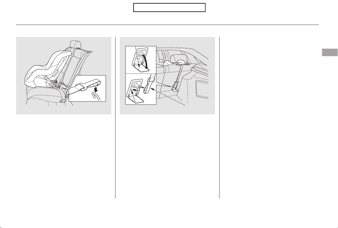
Whatever type you have, follow
the child seat maker’s instructions
for adjusting or tightening the fit.
Other LATCH-compatible seats
have a flexible-type connector as
shown above.
Attach the tether strap hook to the
tether anchor, then tighten the
strap as instructed by the child
seat maker.
If the tether strap is too long and
cannot be tightened firmly, find a
route where the strap can be
tightened securely.
Push and pull the child seat
forward and from side-to-side to
verify that it is secure.
Lift the head restraint (see page
), then route the tether strap
through the legs of the head
restraint and over the seat-back,
making sure the strap is not
twisted.
Remove the front cargo area cover
(see page ).
Open the anchor cover.
4. 5.
7.
6.
8.
94
114
EX-L models
Installing a Child Seat
Driver and Passenger Safety
43
ANCHORFlexible type
TETHER STRAP HOOK
ANCHOR COVER
Table of Contents
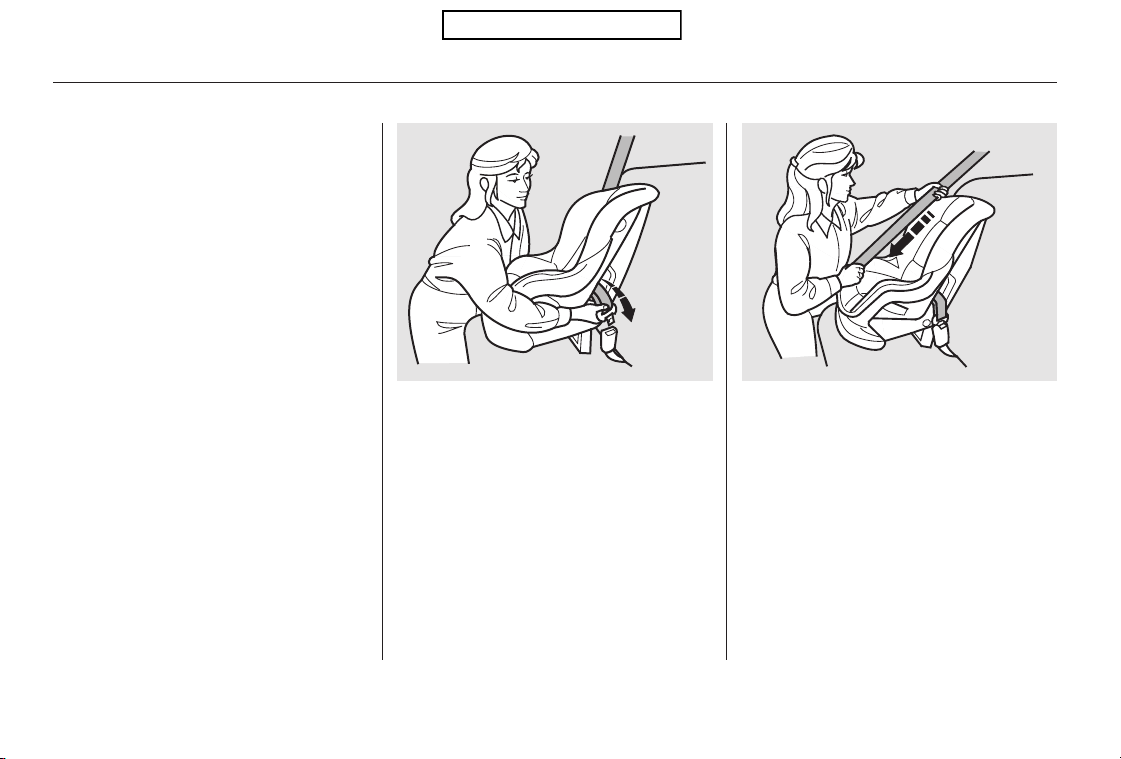
When not using the LATCH system,
all child seats must be secured to the
vehicle with the lap part of a lap/
shoulder belt.
With the child seat in the desired
seating position, route the belt
through the child seat according
to the seat maker’s instructions,
then insert the latch plate into the
buckle and remove any slack from
the lap portion of the belt.
To activate the lockable retractor,
slowly pull the shoulder part of the
belt all the way out until it stops,
then let the belt feed back into the
retractor.
After the belt has retracted, tug on
it. If the belt is locked, you will not
be able to pull it out. If you can pull
thebeltout,itisnotlocked,and
you will need to repeat these steps.
In addition, the lap/shoulder belts in
all seating positions except the
driver’s have a lockable retractor
that must be activated to secure a
child seat.
1. 2.
3.
Installing a Child Seat with a Lap/
Shoulder Belt
Installing a Child Seat
44
Table of Contents

After confirming that the belt is
locked, grab the shoulder part of
the belt near the buckle, and pull
up to remove any slack from the
lap part of the belt. Remember, if
the lap part of the belt is not tight,
the child seat will not be secure.
To deactivate the lockable retractor
and remove a child seat, unlatch the
buckle, unroute the seat belt, and let
the belt fully retract.
Push and pull the child seat
forward and from side-to-side to
verify that it is secure enough to
stay upright during normal driving
maneuvers. If the child seat is not
secure, unlatch the belt, allow it to
retract fully, then repeat these
steps.
To remove slack, it may help to
putweightonthechildseat,or
push on the back of the seat while
pulling up on the belt.
4. 5.
Installing a Child Seat
Driver and Passenger Safety
45
Table of Contents
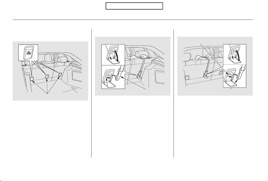
A child seat with a tether can be
installed in any seating position in
the back seat, using one of the
anchorage points shown above.
Since a tether can provide additional
security to the lap/shoulder belt
installation, we recommend using a
tether whenever one is required or
available.
After properly securing the child
seat (see page ), lift the head
restraint, then route the tether
strap over the seat-back and
through the head restraint legs.
Remove the front cargo area cover
(see page ).
For the center seat, lower the
head restraint, then route the
tether strap over the head
restraint and seat-back.
Tighten the strap according to the
seat maker’s instructions.
Open the anchor cover, then
attach the tether strap hook to the
anchor, making sure the strap is
not twisted.
1.
2.
3.
114
44
EX-L models
Installing a Child Seat with a
Tether
Installing a Child Seat
Using an Anchor
46
TETHER STRAP HOOK
Center Position
ANCHOR
ANCHOR COVER
Outer Position
TETHER STRAP HOOK
ANCHOR COVERANCHOR
TETHER ANCHORAGE POINTS
Table of Contents
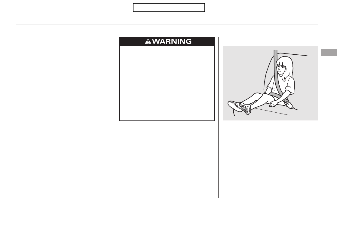
To determine if a lap/shoulder belt
properly fits a child, have the child
put on the seat belt, then ask
yourself:
When a child reaches the
recommended weight or height limit
for a forward-facing child seat, the
child should sit in a back seat on a
booster seat and wear the lap/
shoulder belt.
Does the child sit all the way back
against the seat?
Do the child’s knees bend
comfortably over the edge of the
seat?
The following pages give
instructions on how to check proper
seat belt fit, what kind of booster
seat to use if one is needed, and
important precautions for a child
who must sit in front.
1.
2.
CONTINUED
Protecting Larger Children
Checking Seat Belt Fit
Driver and Passenger Safety
47
Allowing a child age 12 or under
to sit in front can result in injury
or death if the passenger’s front
airbag inflates.
If a child must ride in front,
move the vehicle seat as far
back as possible, use a booster
seat if needed, have the child
sit up properly and wear the
seat belt properly.
Table of Contents
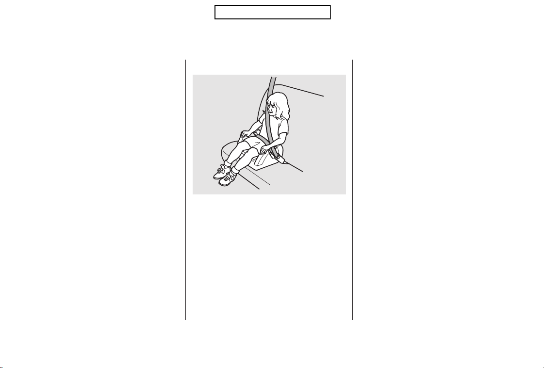
Does the shoulder belt cross
between the child’s neck and arm?
Is the lap part of the belt as low as
possible, touching the child’s
thighs?
Will the child be able to stay
seated like this for the whole trip?
If you answer yes to all these
questions, the child is ready to wear
the lap/shoulder belt correctly. If
you answer no to any question, the
child needs to ride on a booster seat. A child who has outgrown a forward-
facing child seat should ride in a
back seat and use a booster seat
until the lap/shoulder belt fits them
properly without the booster.
Some states, Canadian provinces and
territories also require children to
use a booster seat until they reach a
given age or weight (e.g., 6 years or
60lbs).Besuretocheckcurrent
laws in the states, provinces and
territories where you intend to drive.
Booster seats can be high-back or
low-back. Whichever style you select,
make sure the booster seat meets
federal safety standards (see page
) and that you follow the booster
seat maker’s instructions.
If a child who uses a booster seat
must ride in front, move the vehicle
seat as far back as possible and be
sure the child is wearing the seat
belt properly.
4.
5.
3.
40
Using a Booster Seat
Protecting Larger Children
48
Table of Contents

CONTINUED
Of course, children vary widely. And
while age may be one indicator of
when a child can safely ride in front,
there are other important factors you
should consider.
Physically, a child must be large
enough for the lap/shoulder belt to
properly fit (see pages and ). If
the seat belt does not fit properly,
with or without the child sitting on a
booster seat, the child should not sit
in front.
To safely ride in front, a child must
be able to follow the rules, including
sitting properly, and wearing the seat
belt properly throughout a ride.
The National Highway Traffic Safety
Administration and Transport
Canada recommend that all children
age 12 and under be properly
restrained in a back seat.
If the passenger’s front airbag
inflates in a moderate to severe
frontal collision, the airbag can cause
serious injuries to a child who is
unrestrained, improperly restrained,
sitting too close to the airbag, or out
of position.
A side airbag also poses risks. If any
part of a larger child’s body is in the
path of a deploying side airbag, the
child could receive possibly serious
injuries.
A child may continue using a booster
seat until the tops of their ears are
even with the top of the vehicle’s or
booster’s seat-back. A child of this
height should be tall enough to use
the lap/shoulder belt without a
booster seat.
14 47
Protecting Larger Children
Physical Size
Maturity
When Can a Larger Child Sit in
Front
Driver and Passenger Safety
49
Table of Contents
Devices intended to
improve a child’s comfort or
reposition the shoulder part of a
seat belt can make the belt less
effective and increase the chance
of serious injury in a crash.
This could result
in serious neck injuries during a
crash.
This could
cause very serious injuries during
a crash. It also increases the
chance that the child will slide
under the belt in a crash and be
injured.
If they do, they
could be very seriously injured in a
crash.
If you decide that a child can safely
ride up front, be sure to:
Carefully read the owner’s manual,
and make sure you understand all
seat belt instructions and all safety
information.
Move the vehicle seat to the rear-
most position.
Have the child sit up straight, back
against the seat, and feet on or
near the floor.
Check that the child’s seat belt is
properly and securely positioned.
Supervise the child. Even mature
children sometimes need to be
reminded to fasten the seat belts
or sit properly.
Protecting Larger Children
Do not put any accessories on a
seat belt.Do not let a child wear a seat belt
across the neck.
Do not let a child put the shoulder
part of a seat belt behind the back
or under the arm.
Two children should never use the
same seat belt.
Additional Safety Precautions
50
Table of Contents
Your vehicle’s exhaust contains
carbon monoxide gas. Carbon
monoxide should not enter the
vehicle in normal driving if you
maintain your vehicle properly and
follow the information on this page.
High levels of carbon monoxide can
collect rapidly in enclosed areas,
such as a garage. Do not run the
engine with the garage door closed.
Even with the door open, run the
engine only long enough to move the
vehicle out of the garage.
Have the exhaust system inspected
for leaks whenever:
The vehicle is raised for an oil
change.
You notice a change in the sound
of the exhaust.
The vehicle was in a collision that
may have damaged the underside.
With the tailgate open, airflow can
pull exhaust gas into your vehicle’s
interior and create a hazardous
condition. If you must drive with the
tailgate open, open all the windows,
and set the climate control system as
shown below.
If you must sit in your parked vehicle
with the engine running, even in an
unconfined area, adjust the climate
control system as follows:
Select the fresh air mode.
Select the mode.
Set the fan speed to high.
Set the temperature control to a
comfortable setting.
1.
2.
3.
4.
Carbon Monoxide Hazard
Driver and Passenger Safety
51
Carbon monoxide gas is toxic.
Breathing it can cause
unconsciousness and even kill
you.
Avoid any enclosed areas or
activities that expose you to
carbon monoxide.
Table of Contents
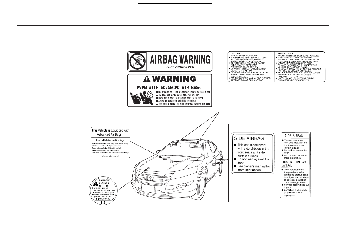
These labels are in the locations
shown. They warn you of potential
hazards that could cause serious
injury or death. Read these labels
carefully.
If a label comes off or becomes hard
to read (except for the U.S.
dashboard label which may be
removed by the owner), contact your
dealer for a replacement.
U.S. models Canadian models
Canadian modelsU.S. models
U.S. models only
Safety Labels
52
DASHBOARD
DOORJAMBS
RADIATOR CAP
SUN VISORS
Table of Contents

This section gives information about
the controls and displays that
contribute to the daily operation of
your vehicle. All the essential
controls are within easy reach.
...........................
Control Locations . 54
............................Instrument Panel . 55
..........Instrument Panel Indicators . 56
.............................................Gauges . 63
....................Information Display . 64
.....................................Odometer . 64
Outside Temperature
...................................Indicator . 65
...................................Trip Meter . 65
..........Check Fuel Cap Message . 66
..................Maintenance Minder . 66
...................Temperature Gauge . 66
..................................Fuel Gauge . 66
Controls Near the Steering
...........................................Wheel . 67
.Windshield Wipers and Washers . 68
.........Turn Signals and Headlights . 70
........................................Fog Lights . 73
........Instrument Panel Brightness . 73
.................Hazard Warning Button . 74
.................Rear Window Defogger . 75
........Steering Wheel Adjustments . 76
...............................Keys and Locks . 77
........................Immobilizer System . 78
................................Ignition Switch . 79
......................................Door Locks . 80
.Auto Door Locking/Unlocking . 81
..............Childproof Door Locks . 87
.......................Remote Transmitter . 87
............................................Tailgate . 91
.................................................Seats . 93
.Front Seat Power Adjustments . 93
..........................Head Restraints . 94
.....................Folding Rear Seats . 97
......................................Armrests . 99
..................................Seat Heaters . 100
Driving Position Memory
........................................System . 101
...........................................Mirrors . 104
............................Power Windows . 106
.......................................Moonroof . 110
...............................Parking Brake . 112
.........Interior Convenience Items . 113
......................Cago Area Cover . 114
.....................Beverage Holders . 116
........Accessory Power Sockets . 116
.............Console Compartment . 117
..................................Glove Box . 118
....................Sunglasses Holder . 119
..................................Sun Visors . 119
........Under-floor Storage Area . 120
.Floor Storage Compartments . 121
............................Vanity Mirror . 122
..................................Coat Hook . 122
..........................Center Pockets . 122
...............................Interior Lights . 123
Instruments and Controls
Instruments and Controls
53
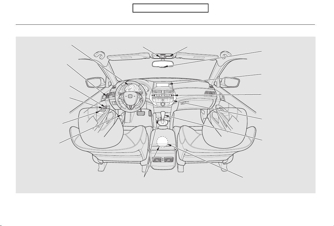
*
*
*
*
*
*
If equipped:
Control Locations
54
(P.55)
(P.63)
ACCESSORY POWER SOCKETS
Without navigation system is shown.
MOONROOF SWITCH
INSTRUMENT PANEL
INDICATORS
GAUGES
MIRROR CONTROLS
POWER WINDOW
SWITCHES
HOOD RELEASE
HANDLE
MIRROR CONTROL
AUTO BUTTON
CLOCK
COMPASS
CLIMATE CONTROL
SYSTEM
AUDIO SYSTEM
AUTOMATIC
TRANSMISSION
DRIVING POSITION
MEMORY SYSTEM
BUTTONS (P.101)
(P.105)
POWER DOOR LOCK
MASTER SWITCH
(Unlocking Fuel Fill
Door) (P.80)
(P.106)
(P.287)
(P.116, 117)
AUXILIARY INPUT JACK
USB ADAPTER CABLE
(P.163,173,213,224)
(P.238)
(P.302)
(P.136)
(P.128)
(P.245)
(P.240)
(P.104)
HOMELINK BUTTONS
(P.110)
(P.252)
Table of Contents
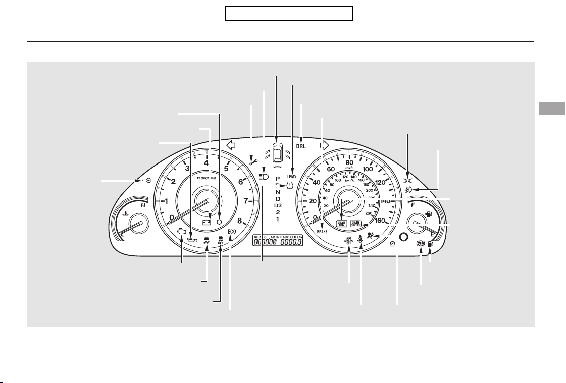
The U.S. instrument panel is shown. Differences for the Canadian models are noted in the text.
Instrument Panel
Instruments and Controls
55
LOW FUEL INDICATOR
ANTI-LOCK BRAKE SYSTEM
(ABS) INDICATOR
LIGHTS ON INDICATOR
CRUISE CONTROL
INDICATOR
(P.61)
(P.57)
(P.58)
(P.62)
CRUISE CONTROL
MAIN INDICATOR
(P.62)
(P.56)
(P.60)
(P.59)
(P.61)HIGH BEAM INDICATOR
MAINTENANCE MINDER INDICATOR (P.62)
(P.60)
TIRE PRESSURE MONITORING
SYSTEM (TPMS) INDICATOR
(P.59)
DAYTIME RUNNING LIGHTS INDICATOR
(P.61)
PARKING BRAKE AND BRAKE SYSTEM INDICATOR
(P.57)
(P.58)
FUEL ECONOMY INDICATOR (P.59)
FOG LIGHT INDICATOR (P.62)
SIDE AIRBAG OFF INDICATOR
LOW TIRE PRESSURE
INDICATOR
SEAT BELT REMINDER
INDICATOR
SUPPLEMENTAL RESTRAINT
SYSTEM INDICATOR (P.57)
DOOR AND TAILGATE OPEN INDICATOR
(P.56, 387)MALFUNCTION INDICATOR LAMP
SECURITY SYSTEM INDICATOR
CHARGING SYSTEM INDICATOR
LOW OIL PRESSURE INDICATOR
(P.56, 386)
IMMOBILIZER SYSTEM
INDICATOR (P.62)
(P.56, 386)
(P.61)
VEHICLE STABILITY ASSIST (VSA) SYSTEM
INDICATOR
VSA OFF INDICATOR
(P.58)
Table of Contents
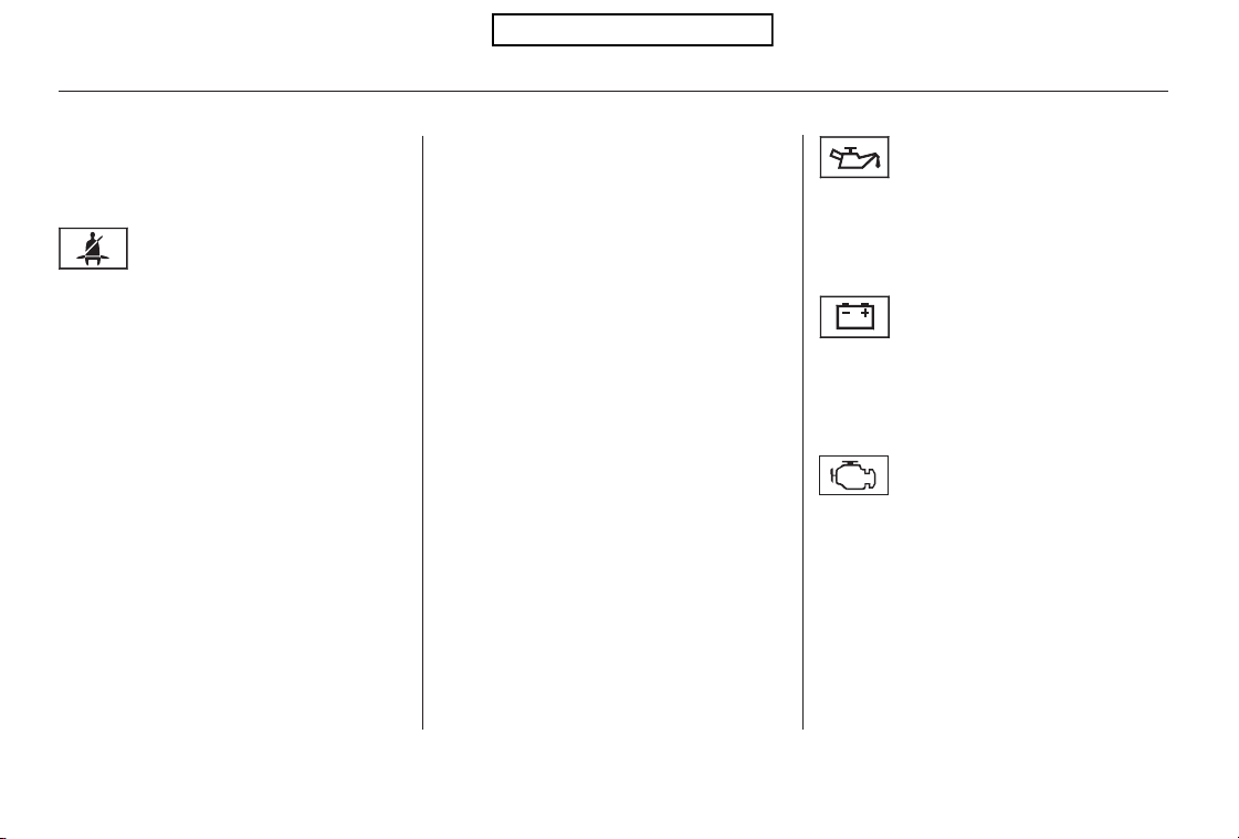
The instrument panel has many
indicators to give you important
information about your vehicle. The engine can be severely damaged
if this indicator flashes or stays on
when the engine is running. For
more information, see page .
If this indicator comes on when the
engine is running, the battery is not
being charged. For more information,
see page .
See page .
If your front passenger does not
fasten their seat belt, the indicator
comes on about 6 seconds after the
ignition switch is turned to the ON
(II) position.
If either of you do not fasten your
seat belt while driving, the beeper
will sound and the indicator will flash
again at regular intervals. For more
information, see page .
This indicator comes on when you
turn the ignition switch to the ON
(II) position. It reminds you and your
passengers to fasten your seat belts.
A beeper also sounds if you have not
fastened your seat belt.
If you turn the ignition switch to the
ON (II) position before fastening
your seat belt, the beeper sounds
and the indicator flashes. If you do
notfastenyourseatbeltbeforethe
beeper stops, the indicator stops
flashing but remains on.
18
386
386
387
Low Oil Pressure
Indicator
Charging System
Indicator
Malfunction Indicator
Lamp
Seat Belt Reminder
Indicator
Instrument Panel Indicators
56
Table of Contents
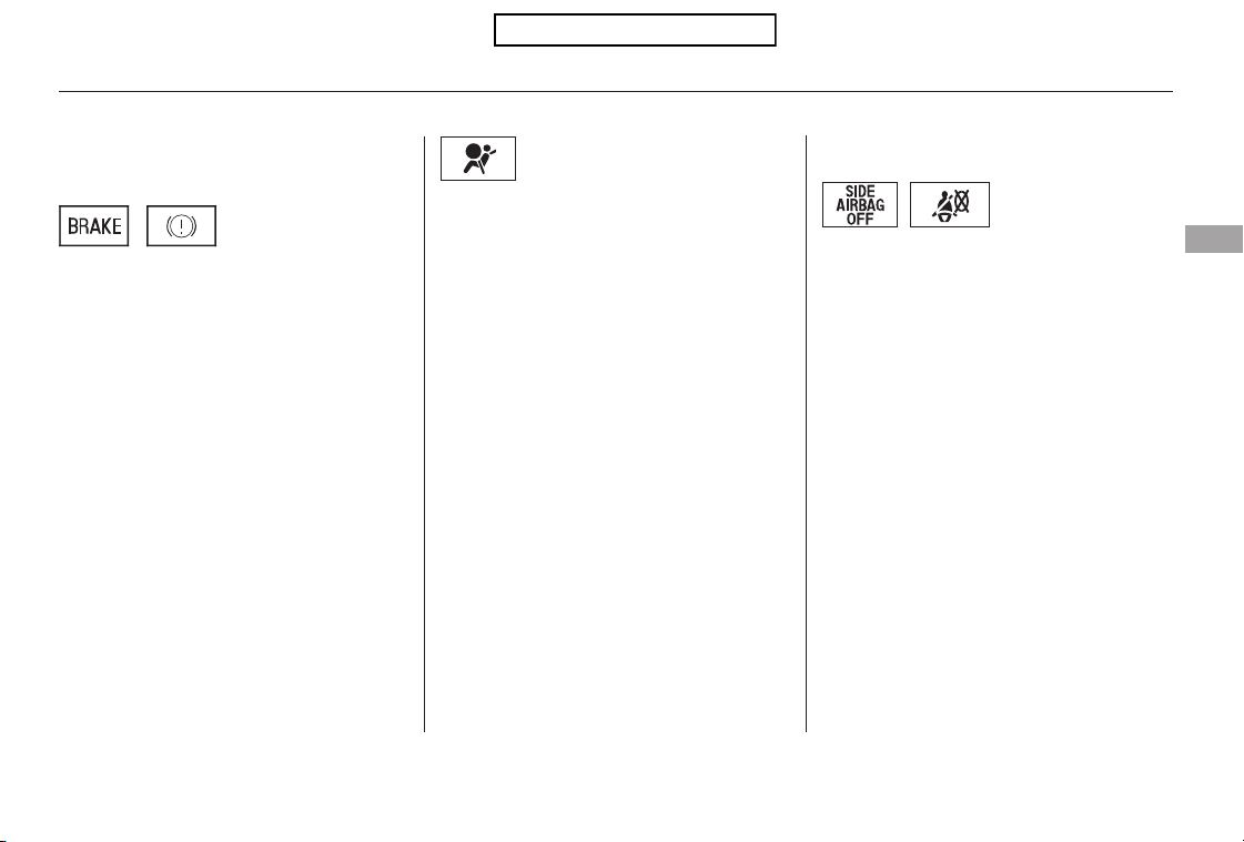
This indicator has two functions:
Itcomesonwhenyouturnthe
ignition switch to the ON (II)
position. It is a reminder to check
the parking brake. A beeper
sounds if you drive with the
parking brake not fully released.
Driving with the parking brake not
fully released can damage the
brakes and tires.
This indicator comes on briefly when
you turn the ignition switch to the
ON (II) position. If it comes on at
any other time, it indicates that the
passenger’s side airbag has
automatically shut off. For more
information, see page .
This indicator comes on briefly when
you turn the ignition switch to the
ON (II) position. If it comes on at
any other time, it indicates a
potential problem with your front
airbags. This indicator will also alert
you to a potential problem with your
airbag system components. For
more information, see page .
If it remains on after you have
fully released the parking brake
while the engine is running, or if it
comes on while driving, there
could be a problem with the brake
system. For more information, see
page .
1.
2.
29
388
30
Supplemental Restraint
System Indicator
Parking Brake and Brake System
Indicator
Side Airbag Off Indicator
Instrument Panel Indicators
Instruments and Controls
57
U.S. Canada
CanadaU.S.
Table of Contents
This indicator normally comes on for
a few seconds when you turn the
ignition switch to the ON (II)
position. If it comes on at any other
time, there is a problem with the
ABS. If this happens, have your
vehicle checked at a dealer. With
this indicator on, your vehicle still
has normal braking ability but no
anti-lock function. For more
information, see page .
This indicator normally comes on for
a few seconds when you turn the
ignition switch to the ON (II)
position.
It flashes when VSA is active (see
page ).
Ifitcomesonandstaysonatany
other time, there is a problem with
the VSA system. Take your vehicle
to a dealer to have it checked.
Without VSA, your vehicle still has
normal driving ability, but will not
have VSA traction and stability
enhancement. See page for more
information on the VSA system.
Itcomesonasareminderthatyou
have turned off the vehicle stability
assist (VSA) system.
This indicator normally comes on for
a few seconds when you turn the
ignition switch to the ON (II)
position. See page for more
information on the VSA system.
309
311
311
311
Instrument Panel Indicators
Vehicle Stability Assist
(VSA) System Indicator
Anti-lock Brake System
(ABS) Indicator
VSA Off Indicator
58
Table of Contents
This indicator normally comes on for
a few seconds when you turn the
ignition switch to the ON (II)
position. If it comes on while driving,
it indicates that one or more of your
vehicle’s tires are significantly low
on pressure.
If this happens, pull to the side of the
road when it is safe, check which tire
has lost the pressure, and determine
the cause. If it is because of a flat tire,
replace the flat tire with the compact
spare (see page ), and have the
flat tire repaired as soon as possible.
If two or more tires are underinflated,
call a professional towing service
(see page ). For more
information, see page .
This indicator normally comes on for
a few seconds when you turn the
ignition switch to the ON (II)
position.
If this indicator comes on and stays
on at any other time, or if it does not
come on when you turn the ignition
switch to the ON (II) position, there
is a problem with the TPMS. With
this indicator on, the low tire
pressure indicator will not come on
when a tire loses pressure. Take the
vehicle to your dealer to have the
system checked.
While the engine is operating in its
most economical range, this
indicator may come on and stay on.
373
397
313
Tire Pressure Monitoring
System (TPMS) Indicator
Low Tire Pressure
Indicator
Fuel Economy Indicator
Instrument Panel Indicators
Instruments and Controls
59
Table of Contents
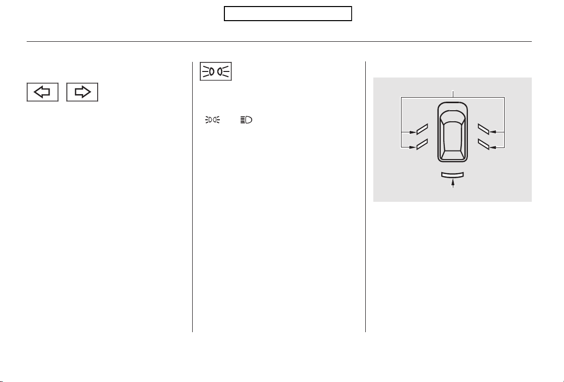
The left or right turn signal indicator
blinks when you signal a lane change
or turn. If an indicator does not blink
or blinks rapidly, it usually means
one of the turn signal bulbs is
burned out (see pages and ).
Replace the bulb as soon as possible,
since other drivers cannot see that
you are signaling.
When you press the hazard warning
button, both turn signal indicators
and all turn signals on the outside of
the vehicle flash.
This indicator reminds you that the
exterior lights are on. It comes on
when the light switch is in either the
or position. If you turn the
ignition switch to the ACCESSORY
(I) or the LOCK (0) position without
turning off the light switch, this
indicator will remain on. A reminder
chime will also sound when you open
the driver’s door.
This indicator will also come on
when the light switch is in AUTO
and the lights turn on automatically.
The appropriate light comes on in
this indicator if the tailgate or any
door is not closed tightly.
All the lights in the indicator come
on for a few seconds when you turn
the ignition switch to the ON (II)
position.
347 349
EX-L models
Instrument Panel Indicators
Turn Signal and Hazard Warning
Indicators
Lights On Indicator Door and Tailgate Open Indicator
60
TAILGATE OPEN INDICATOR
DOOR OPEN INDICATORS
Table of Contents
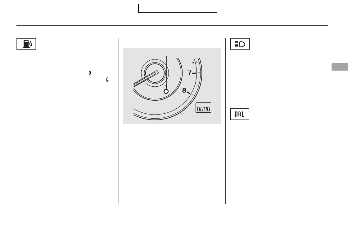
This indicator comes on with the
high beam headlights. For more
information, see page .
This indicator also comes on with
reduced brightness when the
daytime running lights (DRL) are on
(see page ).
If this indicator comes on when you
turn the ignition switch to the ON
(II) position and release the parking
brake, it means there is a problem
with the DRL. There may also be a
problem with the high beam
headlights. Have your vehicle
checked by your dealer.
This indicator comes on as a
reminder that you must refuel soon.
When the indicator comes on, there
are about 2.8 U.S. gal (10.5
)on
2WD models and 2.5 U.S. gal (9.6
)
on 4WD models of fuel remaining in
the tank.
When the needle reaches E, there is
a very small amount of fuel in the
tank.
This indicator comes on when the
security system is set. See page
for more information on the
security system.
70
72
243
High Beam Indicator
Daytime Running Lights
Indicator
Security System IndicatorLow Fuel Indicator
Instrument Panel Indicators
Instruments and Controls
61
SECURITY SYSTEM INDICATOR
Table of Contents
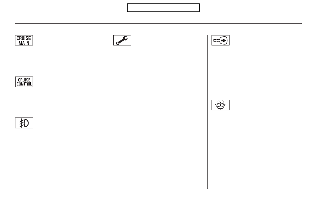
This indicator comes on for a few
seconds when you turn the ignition
switch to the ON (II) position. It
remindsyouthatitistimetotake
your vehicle in for scheduled
maintenance. The maintenance main
items and sub items will be displayed
in the information display. See page
for more information on the
maintenance minder.
This indicator goes off when your
dealer resets it after completing the
required maintenance service.
This indicator comes on when you
turn on the cruise control system by
pressing the CRUISE button (see
page ).
This indicator comes on when you
set the cruise control. See page
for information on operating the
cruise control.
This indicator comes on briefly when
you turn the ignition switch to the
ON (II) position. It will then go off if
you have inserted a properly coded
ignition key. If it is not a properly
coded key, the indicator will blink,
and the engine’s fuel system will be
disabled (see page ).
This indicator comes on when the
washer fluid level is low. Add washer
fluidwhenyouseethisindicator
(see page ).
This indicator comes on when you
turn on the fog lights. For more
information, see page .
249
249
73
325
78
339
Canadian models only
Immobilizer System
Indicator
Maintenance Minder
Indicator
Cruise Control Indicator
Washer Level Indicator
Cruise Control Main
Indicator
Fog Light Indicator
Instrument Panel Indicators
62
Table of Contents
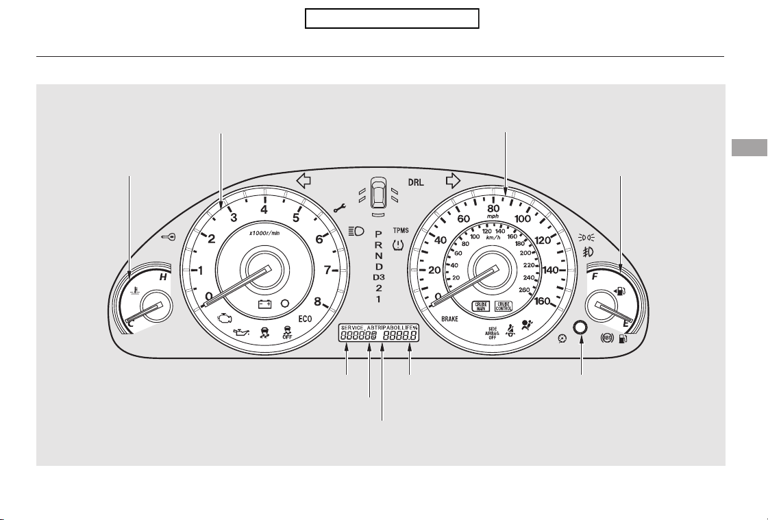
Gauges
Instruments and Controls
63
SELECT/RESET KNOBTRIP METER
ODOMETER/CHECK FUEL CAP MESSAGE
TACHOMETER
TEMPERATURE GAUGE
SPEEDOMETER
FUEL GAUGE
U.S. model is shown.
INFORMATION DISPLAY
OUTSIDE TEMPERATURE INDICATOR
Table of Contents
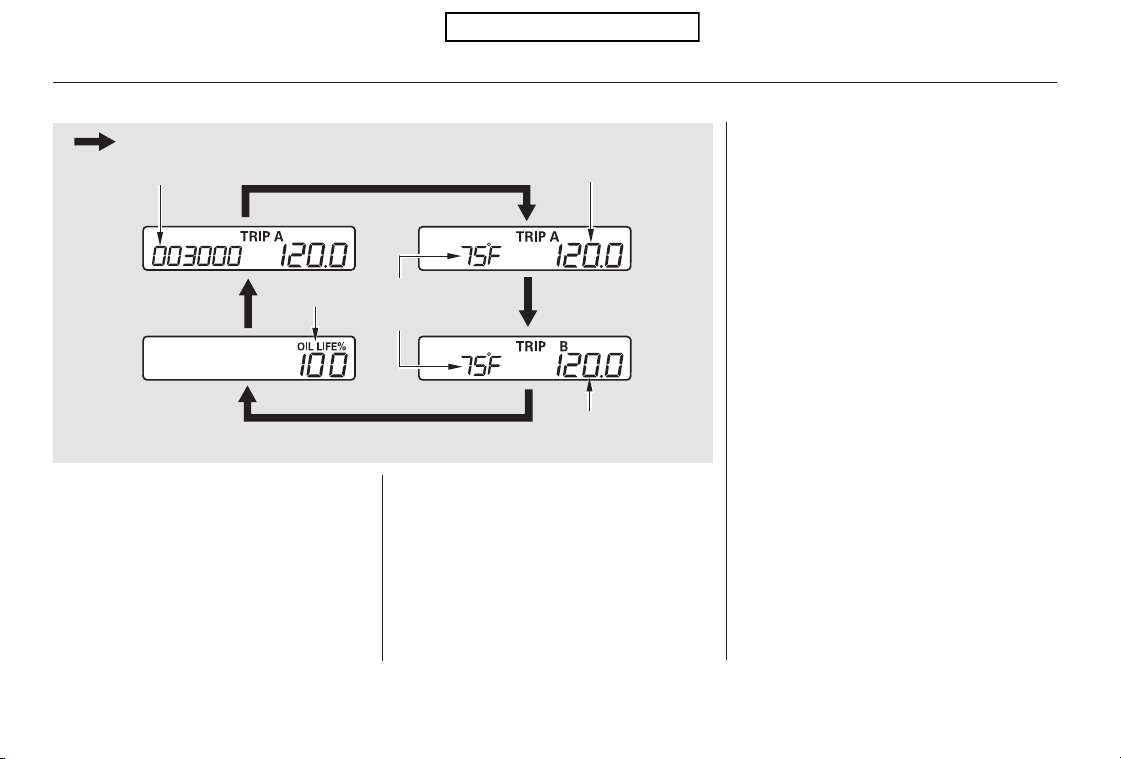
The odometer shows the total
distance your vehicle has been
driven. It measures miles in U.S.
models and kilometers in Canadian
models. It is illegal under U.S.
federal law and Canadian provincial/
territorial regulations to disconnect,
reset, or alter the odometer with the
intent to change the number of miles
or kilometers indicated.
To switch the display, press and
release the select/reset knob
repeatedly. When you turn the
ignition switch to the ON (II)
position, your last selection is
displayed.
The information display shows the
odometer, trip meter, engine oil life,
outside temperature, and
maintenance item code(s).
Gauges
Odometer
Information Display
64
TRIP METER A
TRIP METER B
ENGINE OIL
LIFE
OUTSIDE
TEMPERATURE
INDICATOR
ODOMETER
Press the SELECT/RESET knob.
U.S. model is shown.
Table of Contents

±±
−
−−−−
−−−
The trip meter shows the number of
miles (U.S.) or kilometers (Canada)
driven since you last reset it.
There are two trip meters: Trip A
and Trip B. Switch between these
displays by pressing the select/reset
knob repeatedly.
Each trip meter works independently,
so you can keep track of two
different distances.
When you turn the ignition switch to
the ON (II) position, your last
selection is displayed.
To reset a trip meter, display it, and
then press and hold the select/reset
knob until the number resets to ‘‘0.0’’.
This indicator displays the outside
temperature in Fahrenheit (U.S.
models) or Celsius (Canadian
models). To see the outside
temperature, press and release the
select/reset knob until the
temperature is displayed.
The temperature sensor is in the
front bumper. Therefore, the
temperature reading can be affected
by heat reflection from the road
surface, engine heat, and the
exhaust from surrounding traffic.
This can cause an incorrect
temperature reading when your
speed is under 19 mph (30 km/h).
The sensor delays the display update
until it reaches the correct outside
temperature. This may take several
minutes.
If the outside temperature is
incorrectly displayed, you can adjust
it up to 5°F in U.S. models ( 3°C
in Canadian models) warmer or
cooler.
The temperature must be
stabilized before doing this
procedure.
Select the outside temperature
display, then press and hold the
select/reset knob for 10 seconds.
The following sequence will appear
for1secondeach:0,1,2,3,4,5, 5,
4, 3, 2, 1, 0 (U.S.) or 0, 1, 2,
3, 3, 2, 1, 0 (Canada).
When the temperature reaches the
desired value, release the select/
reset knob. You should see the new
outside temperature displayed.
In certain weather conditions,
temperature readings near freezing
(32°F, 0°C) could mean that ice is
forming on the road surface.
Gauges
Outside Temperature Indicator Trip Meter
Instruments and Controls
65
NOTE:
Table of Contents
This shows the temperature of the
engine’s coolant. During normal
operation, the pointer should rise
from the bottom mark to about the
middle of the gauge. In severe
driving conditions, such as very hot
weather or a long period of uphill
driving, the pointer may rise to the
upper zone. If it reaches the red
(hot) mark, pull safely to the side of
the road. Turn to page for
instructions and precautions on
checking the engine cooling system.
This shows how much fuel you have.
It may show slightly more or less
than the actual amount. The needle
returns to the bottom after you turn
off the ignition.
If your fuel fill cap is loose or
missing, a ‘‘CHECK FUEL CAP’’
message appears on the information
display after you start the engine.
For more information, see page .
The information display in the
instrument panel shows you the
engine oil life and maintenance
service items when the ignition
switch is in the ON (II) position. This
information helps to keep you aware
of the periodic maintenance your
vehicle needs for continued trouble-
free driving. Refer to page for
more information.
285
325
384
Gauges
Temperature Gauge Fuel GaugeCheck Fuel Cap Message
Maintenance Minder
66
Avoid driving with an extremely low
f uel level. Running out of f uel could
cause the engine to misf ire, damaging
the catalytic converter.
Table of Contents
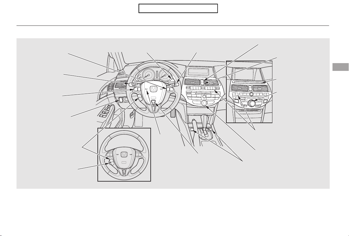
*
*
*
*
*
*
*
*
*
*
If equipped
Only on vehicles equipped with navigation system, refer to the navigation system manual.
To use the horn, press the center pad of the steering wheel.1:
2:
3:
Controls Near the Steering Wheel
Instruments and Controls
67
INSTRUMENT PANEL
BRIGHTNESS
HORN
PASSENGER AIRBAG OFF
INDICATOR
(P.30)
WINDSHIELD WIPERS/
WASHERS
CRUISE CONTROL
BUTTONS
STEERING WHEEL
ADJUSTMENTS
(P.68)
HAZARD WARNING
BUTTON
SEAT HEATER SWITCHES
(P.100)
REAR WINDOW DEFOGGER/
HEATED MIRROR BUTTON
NAVIGATION SYSTEM
VOICE CONTROL
BUTTONS
BLUETOOTH
HANDSFREELINK VOICE
CONTROL BUTTONS
REMOTE AUDIO
CONTROLS
HEADLIGHTS/
TURN SIGNALS/
FOG LIGHTS
(P.249)
(P.70, 73)
(P.236)
VEHICLE STABILITY
ASSIST (VSA) SYSTEM
OFF SWITCH
(P.312)
(P.256)
(P.76)
(P.73)
(P.74)
INTERFACE DIAL
CENTER DISPLAY
(P.179)
SELECTOR KNOB (P.137)
(P.75/106)
1
2
3
2
3
3
2
Table of Contents
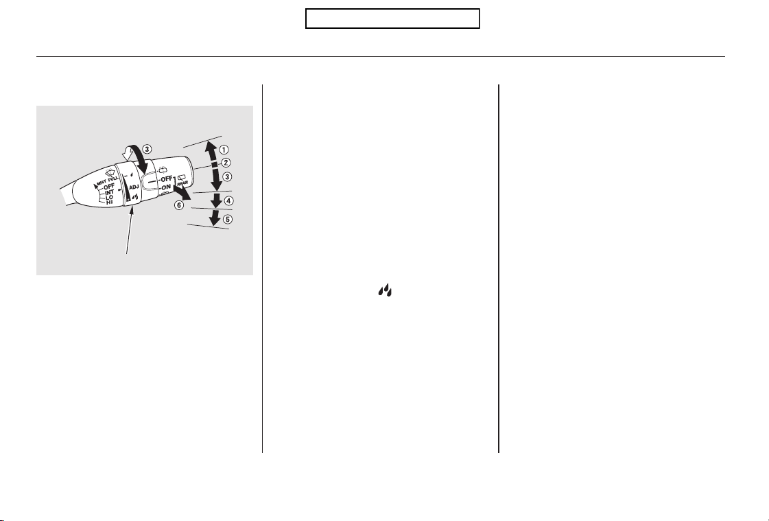
−
−
−
−
−
−
−
−
−
MIST
OFF
INT Intermittent
LO Low speed
HI High speed
Windshield washers
Push the right lever up or down to
select a position.
The wipers run at high
speed until you release the lever.
The wipers are not activated.
The wipers run at low speed.
The wipers run at high speed.
Vary the delay by turning the
adjustment ring. If you turn it to the
shortest delay ( position), the
wipers change to low speed
operation when the vehicle speed
exceeds 12 mph (20 km/h).
The length of the wipe
interval is varied automatically
according to vehicle’s speed.
Pull the
wiper control lever toward you, and
hold it. The washers spray until you
release the lever. The wipers run at
low speed, then complete one more
sweep after you release the lever.
1.
2.
3.
4.
5.
6.
MIST
OFF
LO
HI
INT
Windshield Wipers
Windshield Washers
Windshield Wipers and Washers
68
ADJUSTMENT RING
Table of Contents
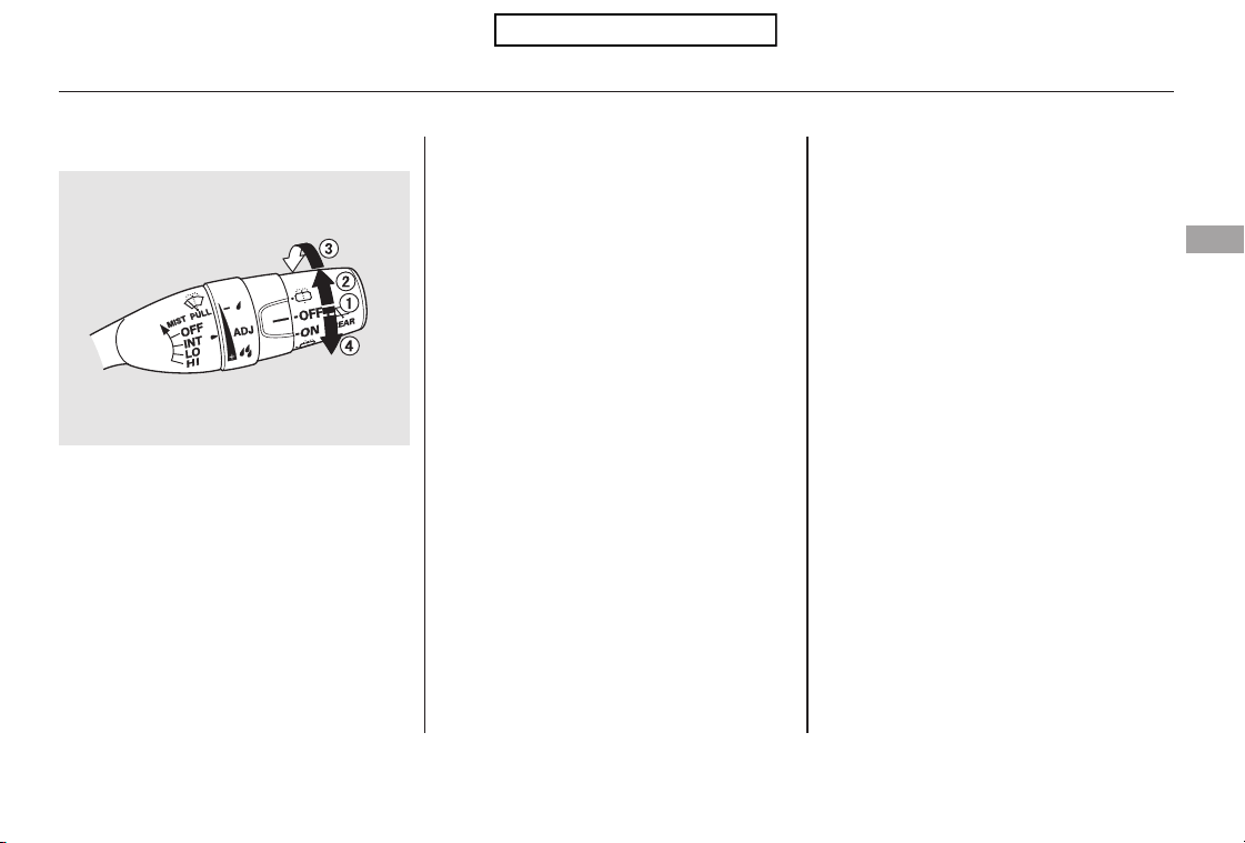
Rotate the switch
counterclockwise also to spray the
window washer and turn the wiper
on.
Hold past ON to activate the rear
window wiper a few times and to
spray the rear window washer.
Rotate the switch clockwise to
turn the rear window wiper ON.
The wiper operates every 7
seconds after completing two
sweeps.
When you turn the wiper switch to
the ‘‘OFF’’ position, the wiper will
return to its parked position.
OFF
Therearwindowwasherusesthe
same fluid reservoir as the wind-
shield washer.
When you shift the transmission to
the reverse position with the front
windshield wiper activated, the rear
wiper operates automatically even if
the rear wiper switch is off.
4.
3.
1.
2.
Rear Window Wiper and Washer
Windshield Wipers and Washers
Instruments and Controls
69
Table of Contents
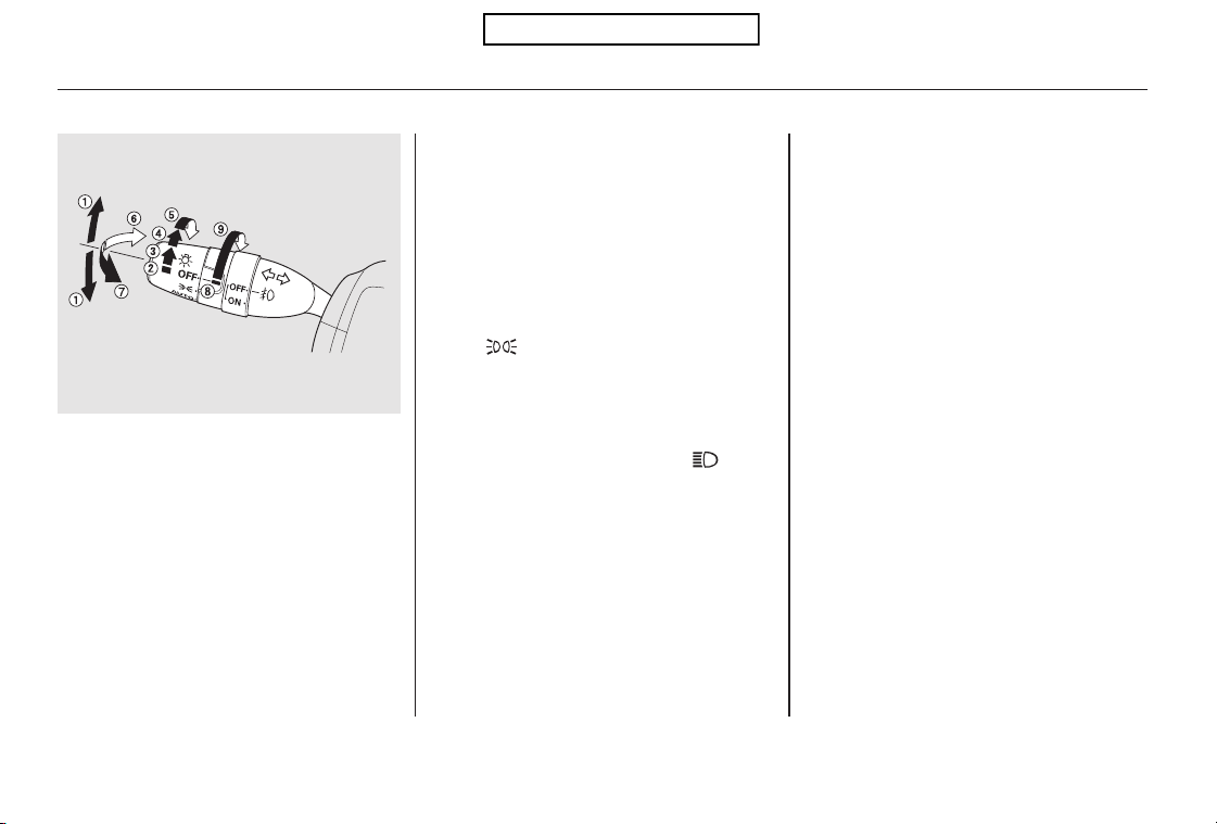
−
−
−
*
*
Push down on the
left lever to signal a left turn and up
to signal a right turn. To signal a lane
change, push lightly on the lever and
hold it. The lever will return to the
center when you release it or
complete a turn.
When the light switch is in either of
these positions, the lights on
indicator comes on as a reminder.
This indicator stays on if you leave
the lights on and turn the ignition
switch to the ACCESSORY (I) or
LOCK (0) position.
To switch from low
beams to high beams, push the left
lever forward until you hear a click.
The blue high beam indicator will
come on (see page ). Pull it back
to return to low beams. To flash the
high beams, pull the lever back
lightly, then release it. The high
beamsstayonaslongasyouhold
the lever back.
If equipped
Turning the switch to
the ‘‘ ’’ position turns on the
parking lights, taillights, instrument
panel lights, side-marker lights, and
rear license plate lights.
Turning the switch to the ‘‘ ’’
position turns on the headlights.
If you leave the lights on with the
key removed from the ignition
switch, you will hear a reminder
chime when you open the driver’s
door.
Turn Signal
OFF
Parking and interior lights
AUTO
Headlights on
High Beams
Flashhighbeams
Fog lights off
Fog lights on
1.
2.
3.
4.
5.
6.
7.
8.
9.
:
61
Turn Signal
High Beams
Headlights
Turn Signals and Headlights
70
EX-L model is shown.
Table of Contents
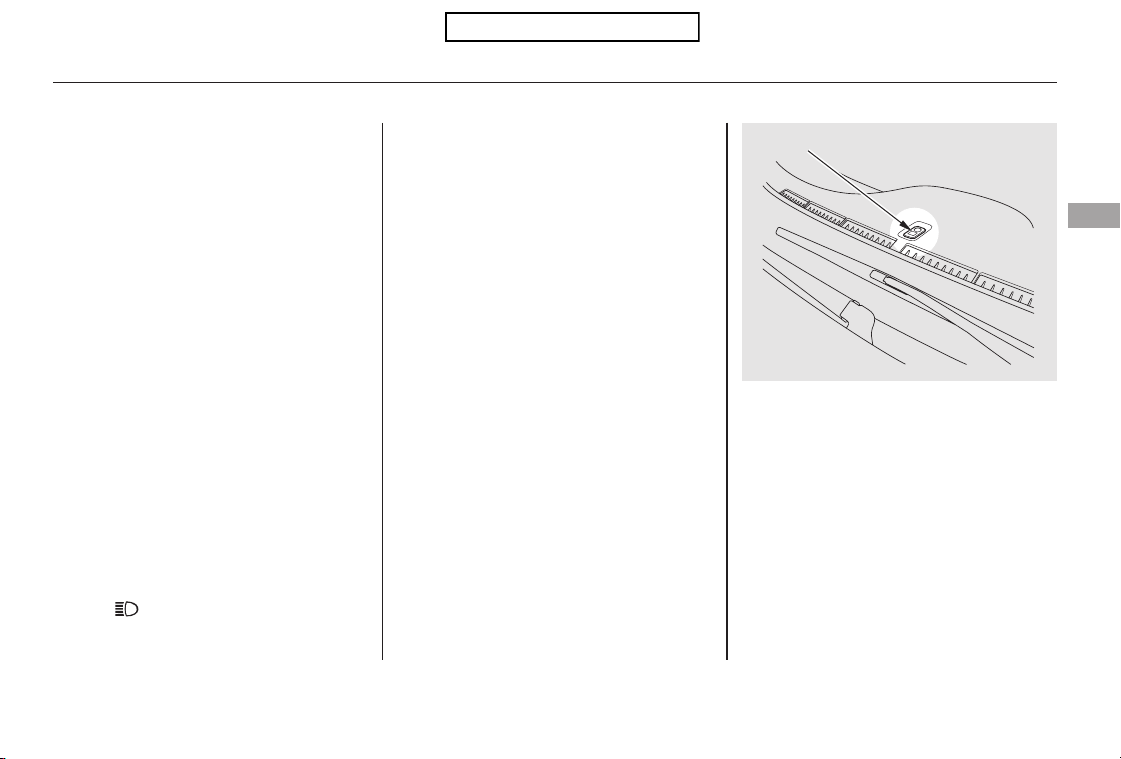
−
Even with the automatic lighting
feature turned on, we recommend
thatyouturnonthelightsmanually
when driving at night or in a dense
fog, or when you enter dark areas
such as long tunnels or parking
facilities.
Do not leave the light switch in
AUTO if you will not be driving the
vehicle for an extended period (a
weekormore).Youshouldalsoturn
off the lights if you plan to leave the
engine idling or off for a long time.
The automatic lighting
feature turns on the headlights and
all other exterior lights, when it
senses low ambient light.
The lights will remain on when you
turn off the ignition switch. They will
turn off automatically when you
remove the key and open the driver’s
door. To turn them on again, either
turn the ignition switch to the ON
(II) position or turn the light switch
to the position.
To turn on automatic lighting, turn
the light switch to AUTO. The lights
will come on automatically when the
outside light level becomes low (at
dusk, for example). The lights on
indicator comes on as a reminder.
The lights and indicator will turn off
automatically when the system
senses high ambient light.
The automatic lighting feature is
controlledbyasensorlocatedontop
of the dashboard. Do not cover this
sensor or spill liquids on it.
EX-L models
AUTO
Turn Signals and Headlights
Instruments and Controls
71
LIGHT SENSOR
Table of Contents
This feature turns off the headlights,
all other exterior lights, and the
instrument panel lights within 15
seconds after you remove the key
and close the driver’s door.
The automatic lighting off feature
activates if you leave the headlight
switch in the ‘‘ ’’ or ‘‘ ’’
position or if the lights are turned on
by setting the switch in the ‘‘AUTO’’
position (if equipped), and you
remove the key, then open and close
the driver’s door.
The headlights revert to normal
operation when you turn them on
with the switch.
With the headlight switch off or in
the position, the high beam
headlights and the high beam
indicator come on with reduced
brightness when you turn the
ignition switch to the ON (II)
position and release the parking
brake. They remain on until you turn
the ignition switch off, even if you
set the parking brake.
If you remove the key from the
ignition switch with the headlight
switch on, but do not open the door,
the lights will turn off after 10
minutes.
If you turn the ignition switch to the
LOCK (0) position with the lights
turned on by setting the switch in
the ‘‘AUTO’’ position, but do not
open the door, the lights turn off
after 3 minutes.
The lights will turn on again when
you unlock or open the driver’s door.
If you unlock the door, but do not
open it within 15 seconds, the lights
will go off. With the driver’s door
open, you will hear a lights-on
reminder chime.
EX-L models
Automatic Lighting Off Feature Daytime Running Lights
Turn Signals and Headlights
72
Table of Contents
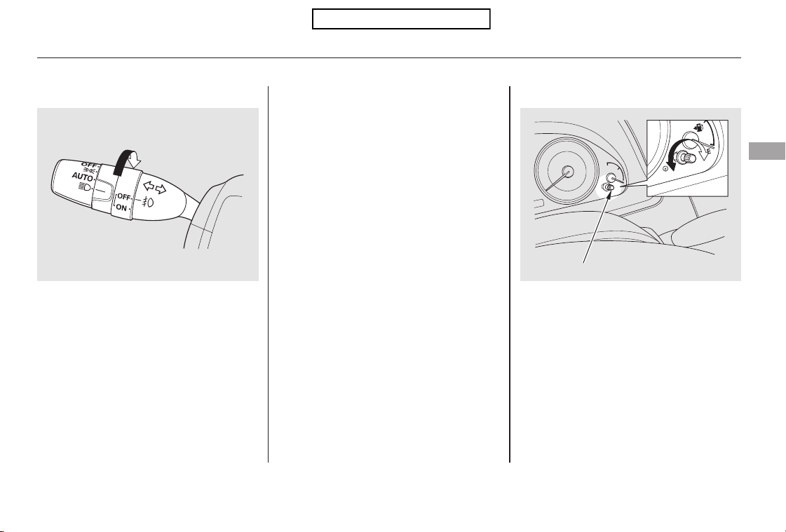
The select/reset knob on the
instrument panel controls the
brightness of the instrument panel
lights. Turn the knob to adjust the
brightness with the ignition switch in
the ON (II) position and the parking
lights on.
You can use the fog lights only when
the headlights are on low beam.
With the light switch in the AUTO
position (if equipped), you can also
use the fog lights when the
headlights turn on automatically.
They will go off when the headlights
turn off, or the daytime running
lights are on.
Turn the fog lights on and off by
turning the switch next to the
headlight switch.
CONTINUED
Fog Lights Instrument Panel Brightness
Fog Lights, Instrument Panel Brightness
Instruments and Controls
73
SELECT/RESET KNOB
EX-L model is shown.
Table of Contents
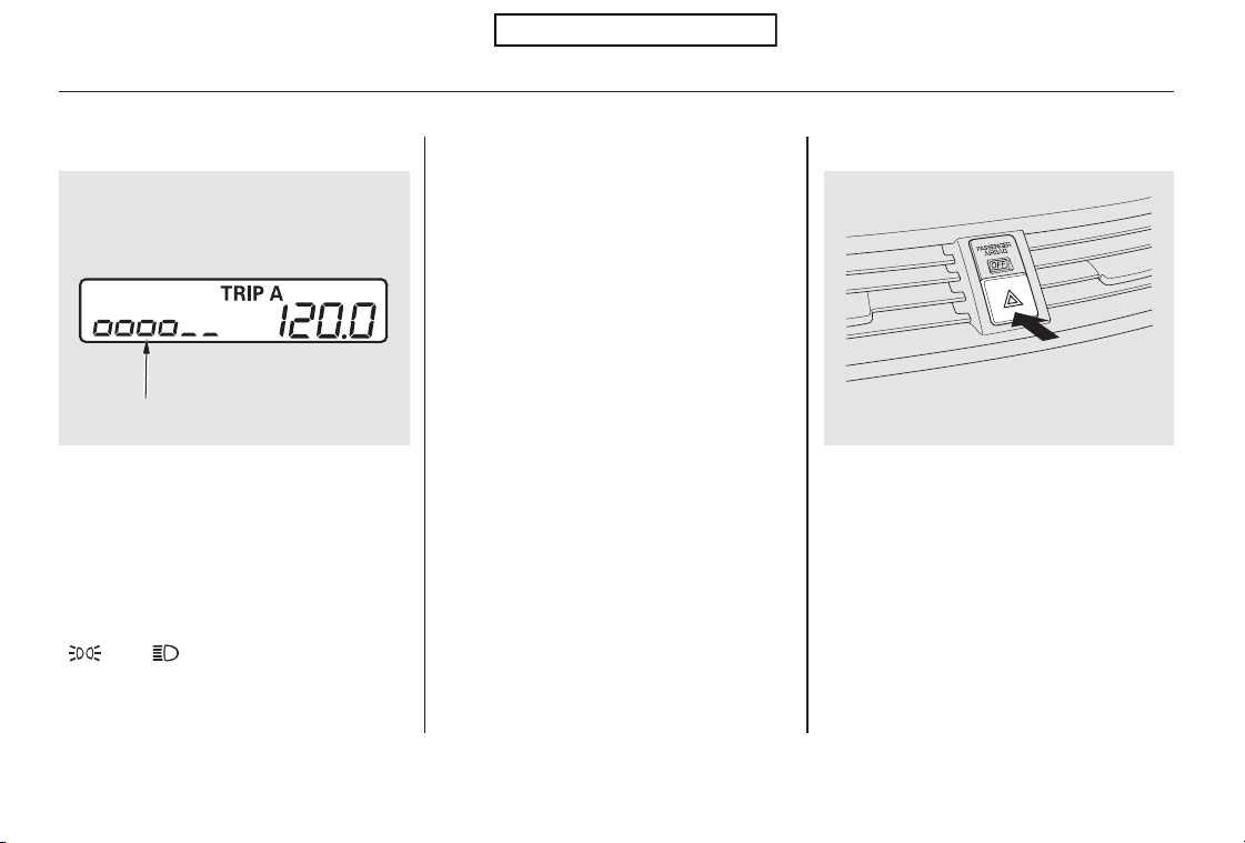
Push the button between the center
vents to turn on the hazard warning
lights (four-way flashers). This
causes all four outside turn signals
and both turn indicators in the
instrument panel to flash. Use the
hazard warning lights if you need to
park in a dangerous area near heavy
traffic, or if your vehicle is disabled.
The instrument panel will illuminate
with reduced brightness when you
unlock and open the driver’s door.
The brightness will increase slightly
when you insert the key in the
ignitionswitch,thengotonormal
brightness when you turn the
ignition switch to the ON (II)
position.
If you insert the key but do not turn
the ignition switch to the ON (II)
position, the illumination turns off in
about 10 seconds.
If you do not insert the key in the
ignition switch after opening the
driver’s door, the illumination turns
off about 30 seconds after you close
the door.
To reduce glare at night, the
instrument panel illumination dims
when you turn the light switch to
or . Turning the select/
reset knob to the right until you hear
a beep will cancel the reduced
brightness.
The level of brightness is shown on
the information display while you
adjust it. It goes out about 5 seconds
after you finish adjusting.
Hazard Warning Button
Instrument Panel Brightness, Hazard Warning Button
74
BRIGHTNESS LEVEL
U.S. model is shown.
Table of Contents
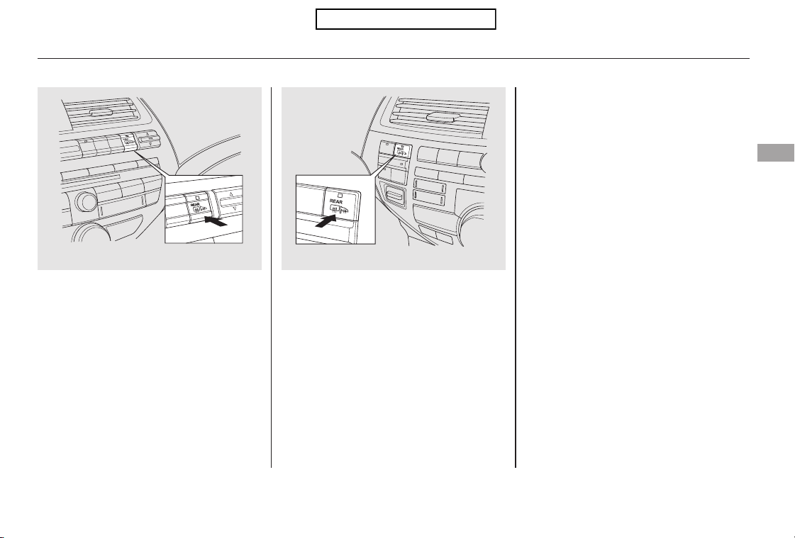
The rear window defogger will clear
fog, frost, and thin ice from the
window. Push the defogger button to
turn it on and off. The indicator in
the button comes on to show the
defogger is on. It also shuts off when
you turn off the ignition switch. You
have to turn the defogger on again
when you restart the vehicle.
The defogger will shut itself off
withinabout10to30minutes
according to the outside temperature
(over 32°F, 0°C).
Make sure the rear window is clear
and you have good visibility before
starting to drive.
The defogger wires on the inside of
the rear window can be accidentally
damaged. When cleaning the glass,
always wipe side-to-side.
Pushing this button also turns the
mirror heaters on or off. For more
information, see page .106
Rear Window Defogger
Instruments and Controls
75
On models without navigation system
On models with navigation system
Table of Contents
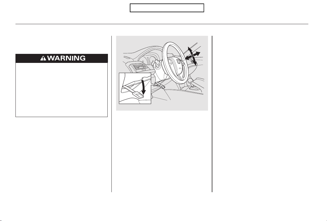
Move the steering wheel up or
down, and in or out, so it points
toward your chest, not toward
your face. Make sure you can see
the instrument panel gauges and
indicators.
Push the lever up to lock the
steering wheel in position.
Make sure you have securely
locked the steering wheel in place
by trying to move it up, down, in,
and out.
Push the lever under the steering
column all the way down.
Make any steering wheel
adjustments before you start driving.
1.
2.
3.
4.
Steering Wheel Adjustments
76
Adjusting the steering wheel
position while driving may
cause you to lose control of the
vehicle and be seriously injured
inacrash.
Adjust the steering wheel only
when the vehicle is stopped.
Table of Contents
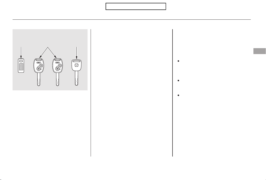
Youshouldhavereceivedakey
number tag with your keys. You will
need this key number if you ever
have to get a lost key replaced. Use
only Honda-approved key blanks.
These keys contain electronic
circuits that are activated by the
immobilizer system. They will not
work to start the engine if the
circuits are damaged.
Protect the keys from direct
sunlight, high temperature, and
high humidity.
Donotdropthekeysorsetheavy
objects on them.
Keep the keys away from liquids.
If they get wet, dry them
immediately with a soft cloth.
The valet key does not contain a
battery. Do not try to take it apart.
The master key fits all the locks on
your vehicle. The valet key works
only in the ignition and the driver’s
door lock. You can keep the glove
boxlockedwhenyouleaveyour
vehicle and the valet key at a parking
facility.
Keys and Locks
Instruments and Controls
77
KEY
NUMBER
TAG
VALET
KEY
(Gray)
MASTER KEY
WITH REMOTE
TRANSMITTER
Table of Contents
If the system repeatedly does not
recognize the coding of your key,
contact your dealer.
If you lose your key and you cannot
start the engine, contact your dealer.
When you turn the ignition switch to
the ON (II) position, the immobilizer
system indicator should come on
briefly, then go off. If the indicator
starts to blink, it means the system
does not recognize the coding of the
key. Turn the ignition switch to the
LOCK (0) position, remove the key,
reinsert it, and turn the ignition
switch to the ON (II) position again.
The system may not recognize your
key’s coding if another immobilizer
key or other metal object (i.e. key
chain) is near the ignition switch
when you insert the key.
The immobilizer system protects
your vehicle from theft. If an
improperly coded key (or other
device) is used, the engine’s fuel
system is disabled. Do not attempt to alter this system
or add other devices to it. Electrical
problems could result that may make
your vehicle inoperable.
As required by the FCC:
This device complies with Part 15 of the
FCC rules. Operation is subject to the
following two conditions: (1) This device
may not cause harmful interference, and
(2) this device must accept any
interference received, including
interference that may cause undesired
operation.
Changes or modifications not expressly
approved by the party responsible for
compliance could void the user’s
authority to operate the equipment.
This device complies with Industry
Canada Standard RSS-210.
Operation is subject to the following two
conditions: (1) this device may not cause
interference, and (2) this device must
accept any interference that may cause
undesired operation of the device.
Immobilizer System
78
Always take the ignition key with you
whenever you leave the vehicle alone.
Table of Contents
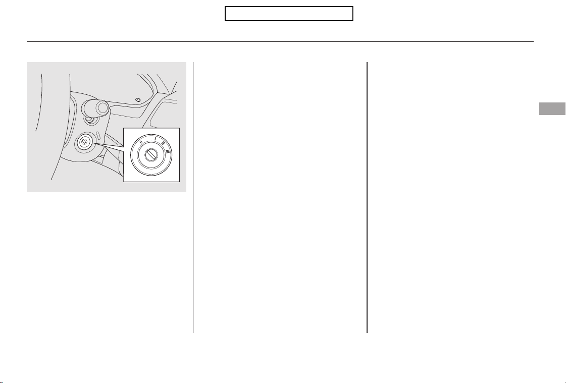
−
−
−
−
You will hear a reminder beeper if
you leave the key in the ignition
switch in the LOCK (0) or the
ACCESSORY (I) position and open
the driver’s door. Remove the key to
turn off the beeper.
If the front wheels are turned, the
anti-theft lock may make it difficult
to turn the key. Firmly turn the
steering wheel to the left or right as
you turn the key.
Use this position
only to start the engine. The switch
returns to the ON (II) position when
you let go of the key.
This is the normal key
position when driving. Several of the
indicators on the instrument panel
come on as a test when you turn the
ignition switch from the
ACCESSORY (I) to the ON (II)
position.
You can
operate the audio system and the
accessory power sockets in this
position.
You can insert or
remove the key only in this position.
To turn the key, the shift lever must
be in Park, and you must push the
key in slightly.
TheshiftlevermustbeinPark
before you can remove the key from
the ignition switch.
The ignition switch has four
positions: LOCK (0), ACCESSORY
(I), ON (II), and START (III).
START (III)
ON (II)
ACCESSORY (I)
LOCK (0)
Ignition Switch
Instruments and Controls
79
Table of Contents
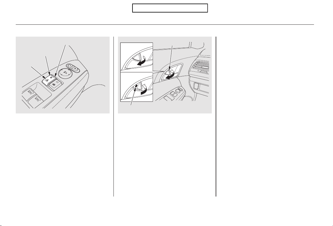
The lock tab on any passenger’s door
locks and unlocks that door.
When the door is unlocked, you can
seetheredindicatoronthelocktab
above the inner door handle.
To lock all doors and the tailgate,
push the front of the master door
lock switch on either front door, pull
the lock tab rearward on the driver’s
door, or use the key on the outside
lock on the driver’s door.
Pushing the rear of either master
door lock switch will unlock all doors
and the tailgate. Pushing forward the
lock tab on the driver’s door unlocks
only that door.
All doors and the tailgate can be
locked from the outside by using the
key in the driver’s door lock. To
unlock only the driver’s door, insert
the key, turn the key, and release it.
The remaining doors and the tailgate
unlock when you turn the key a
second time within a few seconds.
Youcanopenorclosethewindows
and the moonroof by using the key
in the driver’s door (see page ).
To lock any passenger’s door when
getting out of the vehicle, pull the
lock tab rearward and close the door.
To lock the driver’s door, remove the
key from the ignition switch, pull the
locktabrearwardorpushthefront
of the master switch, then close the
door.
Locking and unlocking the driver’s
door will also lock and unlock the
fuel fill door (see page ).283
108
Door Locks
80
POWER DOOR LOCK MASTER SWITCH
RED INDICATOR
Lock
Unlock
Lock
Unlock
LOCK TAB
Table of Contents

The auto door locking feature has
three possible settings:
The auto door locking is
deactivated all the time.
When you customize the setting,
make sure your vehicle is parked
safely, the engine is off, and the
parking brake is applied. Make all
settings before you start driving.
With any door and the tailgate open
and the key in the ignition, locking
with master door lock switches is
disabled. The lock tab on the driver’s
door is not disabled if the driver’s
door is closed. Pulling the driver’s
lock tab rearward will lock all doors
and the tailgate. If you try to lock an
open driver’s door by pulling the lock
tab rearward, the lock tab on the
driver’s door pops out and unlocks
the driver’s door.
Your vehicle has customizable
settings for the doors and tailgate to
automatically lock and unlock. There
are default settings for each of these
features. You can turn off or change
the settings for these features as
described on the following pages. The doors and tailgate lock
whenever you move the shift lever
out of the Park (P) position.
The doors and tailgate lock when
the vehicle speed reaches 9 mph
(15 km/h).
This is the default setting.
CONTINUED
Lockout Prevention
Auto Door LockingAuto Door Locking/Unlocking
Door Locks
Instruments and Controls
81
Table of Contents
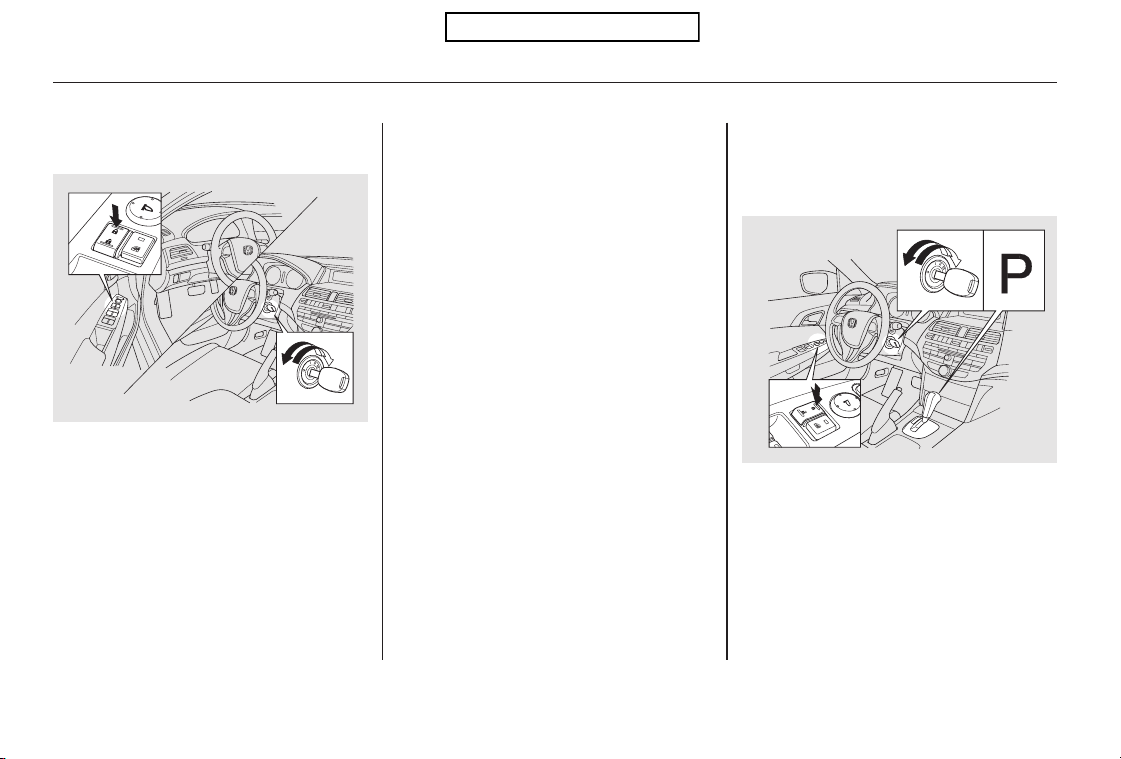
Turn the ignition switch to the ON
(II) position, and open the driver’s
door.
Pushandholdthefrontofthe
master door lock switch on the
driver’s door until you hear a click
(after about 5 seconds).
Turn the ignition switch to the ON
(II) position, and make sure to
close the driver’s door.
Make sure the shift lever is in the
Park (P) position.
Release the switch, and within 20
seconds, turn the ignition switch
to the LOCK (0) position.
Make sure the shift lever is in the
Park (P) position.
1.
2.
1.
2.
3.
4.
Locks all doors and tailgate when the
shift lever is moved out of the Park (P)
position.
To program the Park Lock mode:To turn off the Auto Door Lock
modes:
Door Locks
82
Table of Contents
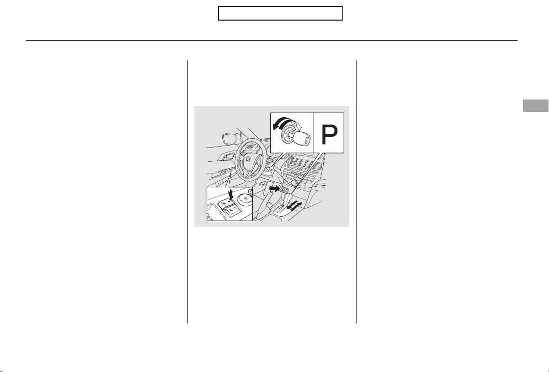
Pushandholdthefrontofthe
master door lock switch on the
driver’s door. You will hear a click.
Keep holding the switch until you
hear another click (after about 5
seconds).
Release the switch, and within 20
seconds, turn the ignition switch
to the LOCK (0) position.
Turn the ignition switch to the ON
(II) position, and make sure to
close the driver’s door.
Make sure the shift lever is in the
Park (P) position.
Push and hold the brake pedal,
and move the shift lever out of the
Park (P) position.
Pushandholdthefrontofthe
master door lock switch on the
driver’s door. You will hear a click.
Keep holding the switch until you
hear another click (after about 5
seconds).
Release the switch, and within 20
seconds, turn the ignition switch
to the ACCESSORY (I) position.
Move the shift lever to the Park
(P) position.
Turn the ignition switch to the
LOCK (0) position.
1.
2.
3.
4.
5.
6.
3.
4.
Locks all doors and tailgate when the
vehicle’s speed reaches about 9 mph
(15 km/h).
To program the Drive Lock mode:
Door Locks
Instruments and Controls
83
Table of Contents
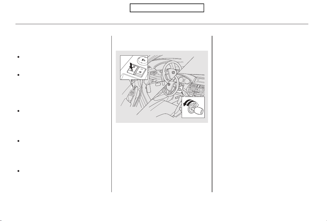
The auto door unlocking feature
has five possible settings:
Turn the ignition switch to the ON
(II) position, and open the driver’s
door.
Pushandholdtherearofthe
master door lock switch on the
driver’s door. You will hear a click,
and after about 5 seconds, you will
hear another click.
Make sure the shift lever is in the
Park (P) position.
The auto door unlocking is
deactivated all the time.
The driver’s door unlocks when
you move the shift lever to the
Park (P) position with the brake
pedal depressed.
This is the default setting.
All doors and tailgate unlock when
you move the shift lever to the
Park (P) position with the brake
pedal depressed.
The driver’s door unlocks
whenever you turn the ignition
switch to the ACCESSORY (I)
position.
All doors and tailgate unlock
whenever you turn the ignition
switch to the ACCESSORY (I)
position.
Release the switch, and within 20
seconds, turn the ignition switch
to the LOCK (0) position.
1.
2.
3.
4.
Auto Door Unlocking
To turn off the Auto Door Unlock
modes:
Door Locks
84
Table of Contents
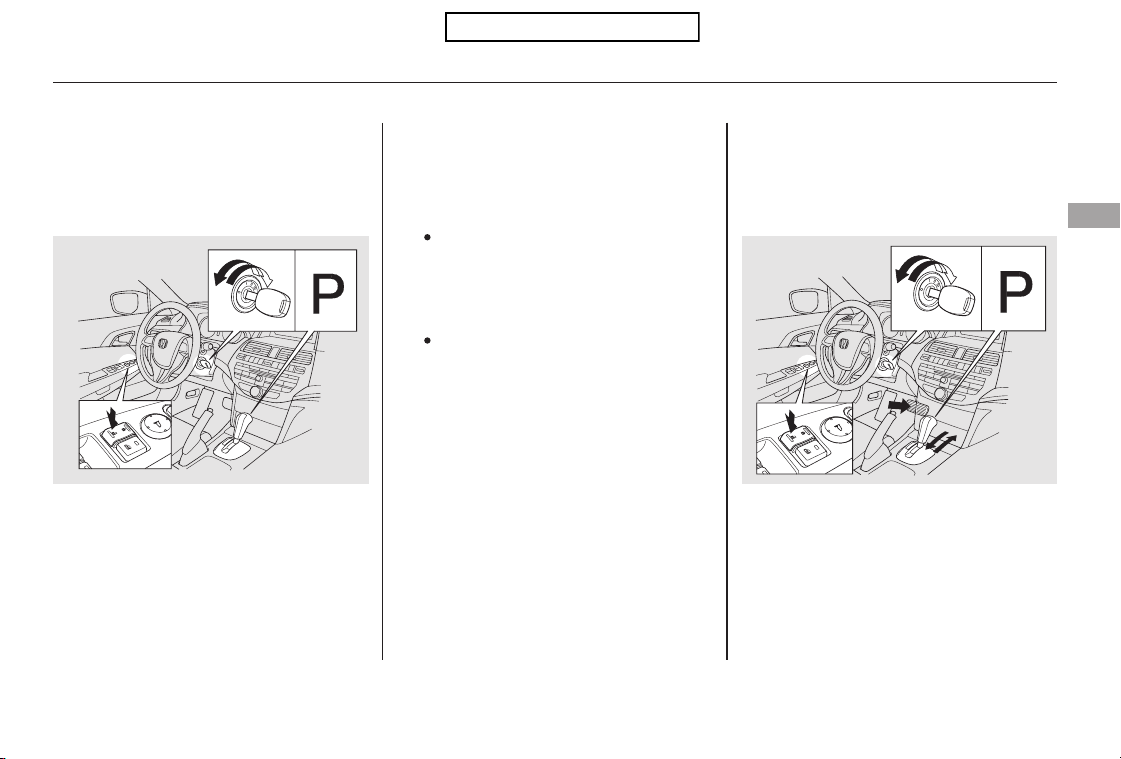
Pushandholdtherearofthe
master door lock switch on the
driver’s door. You will hear a click.
Continue to hold the switch:
Until you hear another click
(after about 5 seconds) to
activate
Turn the ignition switch to the ON
(II) position, and make sure to
close the driver’s door.
Make sure the shift lever is in the
Park (P) position.
Turn the ignition switch to the ON
(II) position, and make sure to
close the driver’s door.
Make sure the shift lever is in the
Park (P) position.
Or, until you hear two more
clicks (after about 10 seconds)
to activate
.
Release the switch, and within 20
seconds, turn the ignition switch
to the LOCK (0) position.
1.
2.
1.
2.
3.
4.
driver’s door unlock
feature.
Unlocks the driver’s door or all doors
and tailgate when the shift lever is
moved to Park (P) position with the
brake pedal depressed.
Unlocks the driver’s door or all doors
and tailgate when the ignition switch is
moved out of the ON (II) position.
all doors and tailgate
unlock feature
CONTINUED
To program the Park Unlock mode: To program the Ignition Switch
Unlock mode:
Door Locks
Instruments and Controls
85
Table of Contents

Turn the ignition switch to the
LOCK (0) position.
Until you hear another click
(after about 5 seconds) to
activate
Pushandholdtherearofthe
master door lock switch on the
driver’s door. You will hear a click.
Continue to hold the switch:
Even if your vehicle’s battery is
removed or goes dead, the system
keeps the auto door lock/unlock
setting which you selected.
Push and hold the brake pedal,
then move the shift lever out of
the Park (P) position.
Or, until you hear two more
clicks (after about 10 seconds)
to activate
.
Release the switch, and within 20
seconds, turn the ignition switch
to the ACCESSORY (I) position.
Move the shift lever to the Park
(P) position.4.
5.
6.
3.
driver’s door unlock
feature.
all doors and tailgate
unlock feature
Door Locks
86
Table of Contents
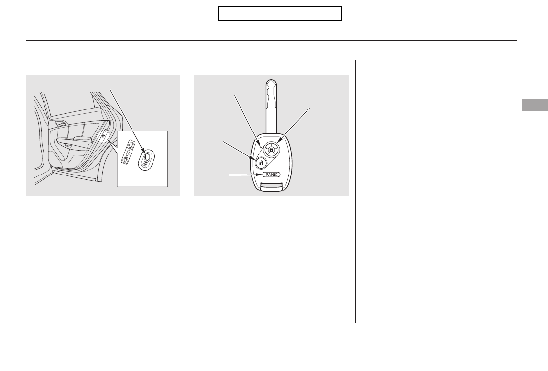
−
−
The childproof door locks are
designed to prevent children seated
in the rear from accidentally opening
the rear doors. Each rear door has a
lock lever near the edge. With the
lever in the LOCK position (lever is
down), the door cannot be opened
fromtheinsideregardlessofthe
position of the lock tab. To open the
door, push the lock tab forward and
use the outside door handle.
Press this button once to
lock all doors and the tailgate. Some
exterior lights will flash. When you
push LOCK twice within 5 seconds,
you will hear a beep to verify that the
doors and tailgate are locked and the
security system has set. This button
does not work if any door or tailgate
is not fully closed.
Pressthisbuttononce
to unlock the driver’s door. Push it
twice to unlock the remaining doors
and the tailgate. Some exterior lights
will flash twice each time you press
the button.
The ceiling light and the door
activated spotlights come on when
you press the UNLOCK button if the
lights are in the door activated
position. If you do not open any door
within 30 seconds, the light(s) will
fade out. If you relock the doors with
theremotetransmitterbefore30
seconds have elapsed, the light(s)
will go off immediately.
If you do not open any door or the
tailgate within 30 seconds, the doors,
thetailgateandthefuelfilldoor
automatically relock and the security
system sets.
CONTINUED
Childproof Door Locks Remote Transmitter
LOCK
UNLOCK
Door Locks, Remote Transmitter
Instruments and Controls
87
Lock
LOCK
BUTTON
UNLOCK
BUTTON
PANIC
BUTTON
LED
Unlock
LEVER
Table of Contents
−
Avoid dropping or throwing the
transmitter.
Protect the transmitter from
extreme temperature.
Do not immerse the transmitter in
any liquid.
If you lose a transmitter, the
replacement needs to be
reprogrammed by your dealer.
If it takes several pushes on the
button to lock or unlock the doors
and the tailgate, replace the battery
as soon as possible.
Battery type: CR1616
Pressthisbuttonfor
about 2 seconds to attract attention:
the horn will sound, and the exterior
lights will flash for about 30 seconds.
To cancel panic mode, press any
other button on the remote
transmitter, or turn the ignition
switch to the ON (II) position.
You can also open all power windows
and the moonroof from outside the
vehicle with the remote transmitter
(see page ).
Locking and unlocking the driver’s
door will also lock and unlock the
fuel fill door (see page ).
108
283
Remote Transmitter Care Replacing the Transmitter Battery
Remote Transmitter
PANIC
88
Table of Contents
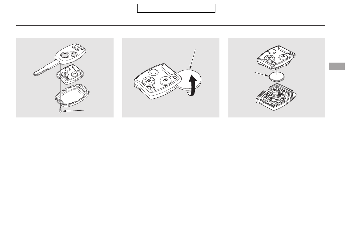
+
To replace the battery:
Remove the screw at the base of
the transmitter with a small
Phillips-head screwdriver.
Separate the transmitter by prying
its middle seam with your
fingernail.
Be careful when removing
this screw as the head of the screw
can strip out.
Inside the transmitter, separate
the inner cover from the keypad
by carefully prying on the edge
with a coin.
Remove the old battery, and insert
a new battery into the back of the
cover with the side facing down.
An improperly disposed of battery
can hurt the environment.
Always confirm local regulations
for battery disposal.
Install the parts in reverse order.
1.
2.
3. 4.
5.
CONTINUED
Remote Transmitter
Instruments and Controls
89
NOTE:
SCREW
COIN
BATTERY
Table of Contents
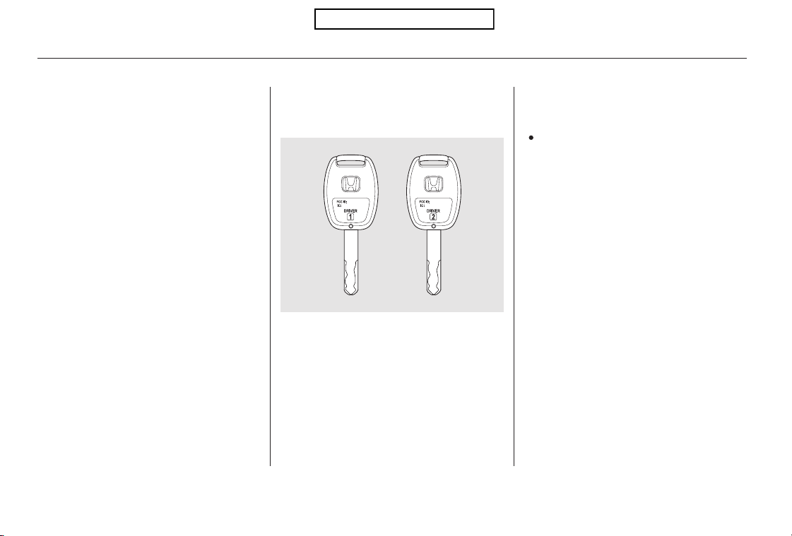
As required by the FCC:
This device complies with Part 15 of the
FCC rules. Operation is subject to the
following two conditions: (1) This device
may not cause harmful interference, and
(2) this device must accept any
interference received, including
interference that may cause undesired
operation.
Changes or modifications not expressly
approved by the party responsible for
compliance could void the user’s
authority to operate the equipment.
This device complies with Industry
Canada Standard RSS-210.
Operation is subject to the following two
conditions: (1) this device may not cause
interference, and (2) this device must
accept any interference that may cause
undesired operation of the device.
EX-L models
Here are the settings activated with
the remote:
Driving position memory
(see page ).
When you unlock and open the
driver’s door with the remote
transmitter, the driver’s seat (except
the power lumbar feature) and
outside mirrors start to move to the
positions stored in memory. The
indicator in the related memory
button to the remote comes on.
When you unlock the door with your
remote, each remote activates the
keyless memory settings related to
that remote. The driver’s ID (Driver
1orDriver2)isshownontheback
of each remote.
101
Recalling a Memorized Driving
Position
Remote Transmitter
90
Table of Contents
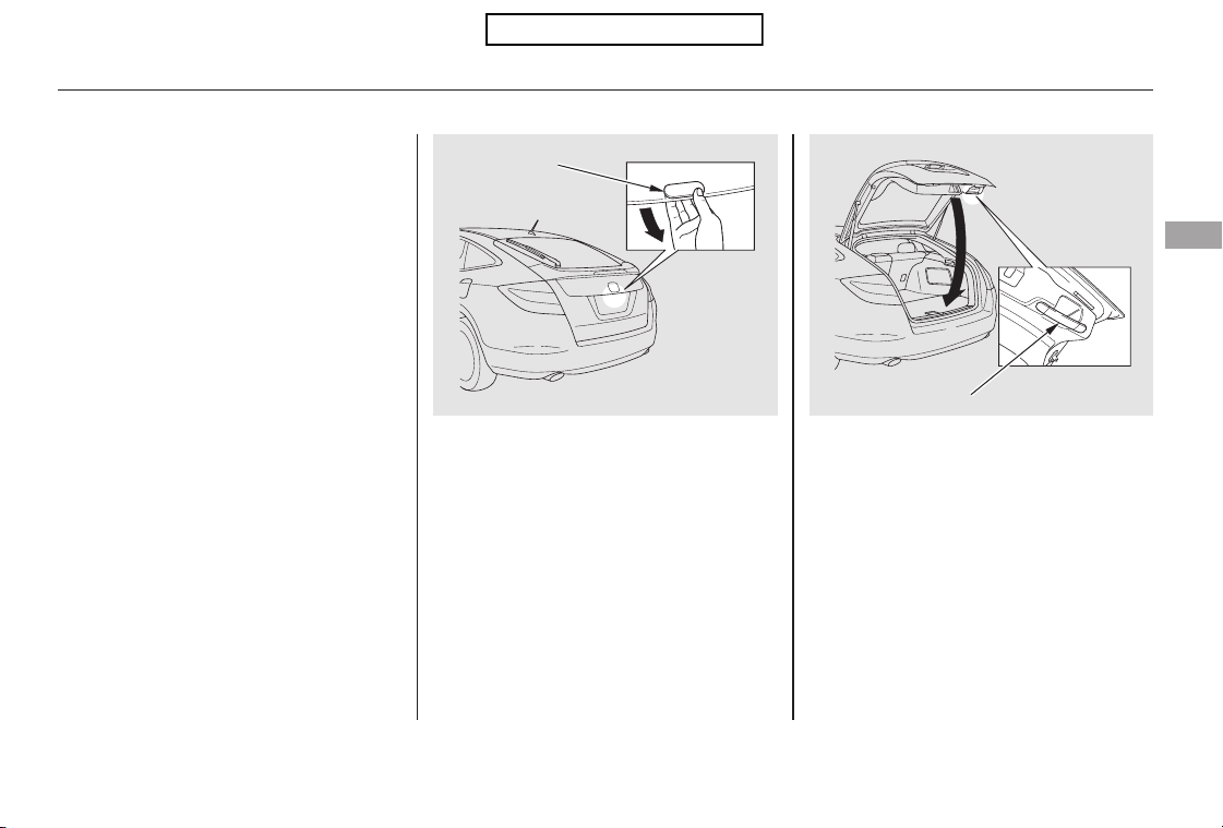
To open the tailgate, push the
release, and lift up. To close the
tailgate, use the tailgate handle to
lower it, then press down on the
back edge.
Keep the tailgate closed at all times
while driving to avoid damaging the
tailgate and to prevent exhaust gas
from getting into the interior. See
on page
.
The tailgate locks and unlocks when
you lock and unlock the driver’s door.
51
Carbon Monoxide Hazard
Tailgate
Instruments and Controls
91
RELEASE
HANDLE
Table of Contents
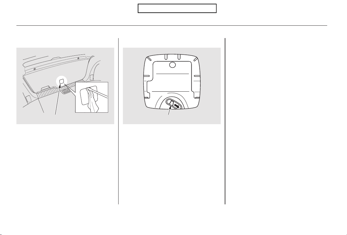
If the power door lock system cannot
unlock the tailgate, unlock it
manually.
Push the release lever to the lower
right as shown.
If you need to unlock the tailgate
manually, it means there is a
problem with the tailgate. Have the
vehicle checked by your dealer.
Placeaclothonthetopsideofthe
cover to prevent scratches, then use
a small flat-tip screwdriver to remove
the cover on the back of the tailgate.
Unlocking the Tailgate
Tailgate
92
RELEASE LEVER
COVER
Table of Contents
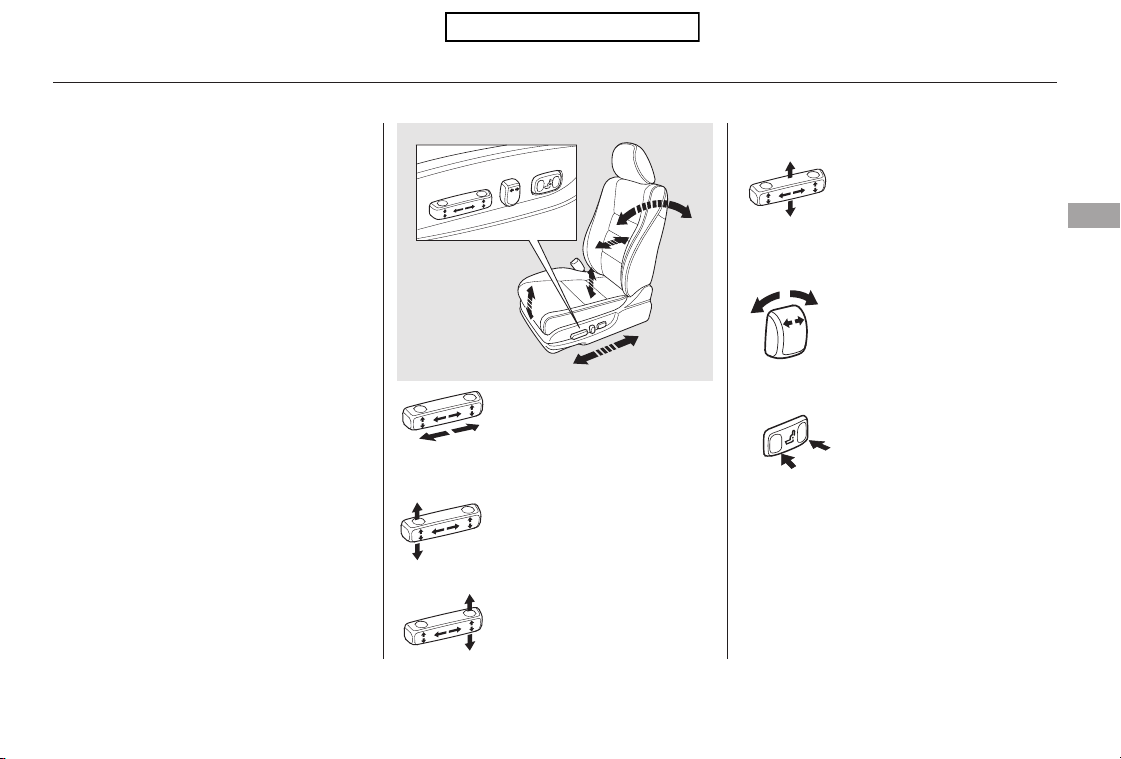
−
Moves the seat forward
and backward.
Raises or lowers the seat.
(Driver’s seat only)
Moves the front of the
seat up or down.
(Driver’s seat only)
Moves the whole seat up
and forward, or down
and backward. The front
of the seat also tilts up or
down at the same time.
(Driver’s seat only)
Adjusts the seat-back
angle forward or
backward.
The controls for the power
adjustable front seats are on the
outside edge of each seat bottom.
You can adjust the seats with the
ignition switch in any position. Make
all seat adjustments before you start
driving.
The passenger seat has the same
adjustments as the driver’s seat but
without any height and lumbar
adjustments.
Increases or decreases
the lumbar support.
See pages for important safety
information and warnings about how to
properly position the seats and seat-
backs.
Driver’s seat only:
11 13
Front Seat Power Adjustments
Seats
Instruments and Controls
93
Table of Contents
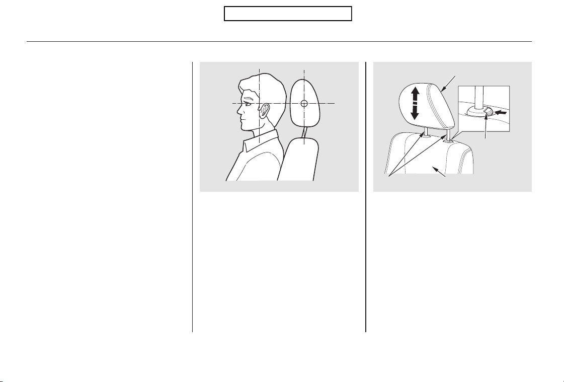
See page for important safety
information and a warning about
improperly positioning head restraints.
13
Your vehicle is equipped with head
restraints in all seating positions to
help protect you and your
passengers from the likelihood of
whiplash and other injuries.
They are most effective when you
adjust them so the center of the back
of the occupant’s head rests against
the center of the restraint.
The head restraints adjust for height.
You need both hands to adjust a
restraint.Donotattempttoadjustit
while driving. To raise it, pull upward.
To lower the restraint, push the
release button sideways, and push
the restraint down.
Head Restraints
Adjusting the Head Restraint
Seats
94
Front CUSHION
LEGS SEAT-BACK
RELEASE
BUTTON
Table of Contents
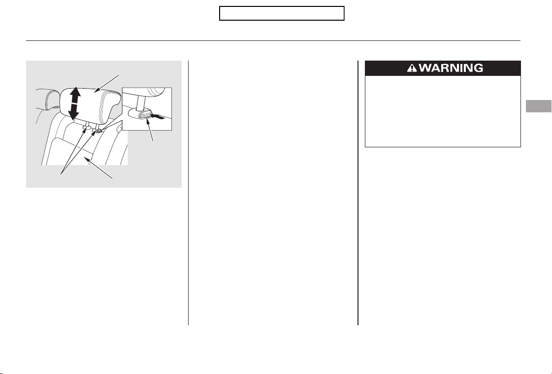
When reinstalling a head restraint,
put the legs back in place. Then
adjust it to the appropriate height
while pressing the release button.
Make sure the head restraint locks
in position when you reinstall it.
To remove a head restraint for
cleaning or repair, pull it up as far as
it will go. Push the release button,
then pull the restraint out of the seat-
back.
When a passenger is seated in the
rear seat, the head restraint should
be adjusted up or down, to match the
passenger’s height.
When removing the rear outer head
restraints, tilt the rear seat first (see
page ).97
CONTINUED
Removing the Head Restraint
Seats
Instruments and Controls
95
CUSHION
LEGS
RELEASE
BUTTON
SEAT-BACK
Rear
Failure to reinstall the head
restraints can result in severe
injury during a crash.
Always replace the head
restraints before driving.
Table of Contents
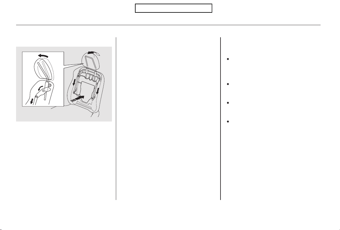
For a head restraint system to work
properly:
Do not hang any items on the head
restraints, or from the restraint
legs.
Do not place any object between
an occupant and the seat-back.
Install each restraint in its proper
location.
Only use genuine Honda
replacement head restraints.
If the restraints do not return to their
normal position, or in the event of a
severe collision, have the vehicle
inspected by a Honda dealer.
After a collision, the activated
restraint should return to its normal
position.
This reduces the distance between
the restraint and the occupant’s head.
It also helps protect the occupants
against the likelihood of whiplash
and injuries to the neck and upper
spine.
The driver’s and front passenger’s
seats have active head restraints. If
the vehicle is struck severely from
the rear, the occupant properly
secured with the seat belt will be
pushed against the seat-back and the
head restraint will automatically
move forward.
Seats
Active Head Restraints
96
Table of Contents
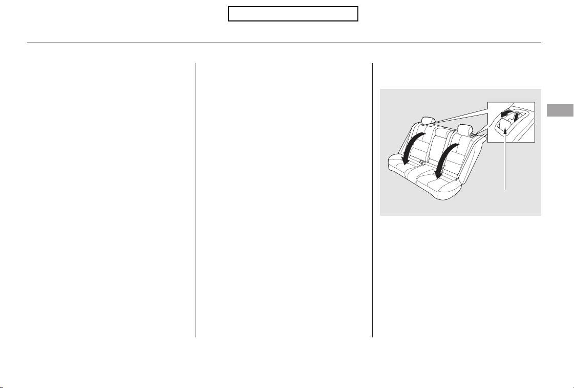
The rear seat-backs can be folded
down for more cargo room.
Each side folds down separately, so
you can still carry one or two
passengers in the rear seat.
You can fold down the seat-back in
two ways.
Lower the rear head restraints to
their lowest positions. If you fold
down the left side seat-back, also
adjust the rear center head
restraint to its lowest position.
Make sure the rear seat armrest is
stored.
How to use the rear seat release
lever.
Remove any items from the seat
before folding down the seat-back.
Make sure that the folded seat-back
does not press against the front
passenger’s seat, as this could cause
the weight sensors to work
improperly.
Fold the seat-back forward.
Unlock the seat-back by pulling up
the release lever on the outer side
of each rear seat-back.
1.
2.
3.
CONTINUED
Folding the Rear Seats Down
Seats
Instruments and Controls
97
RELEASE LEVER
Table of Contents
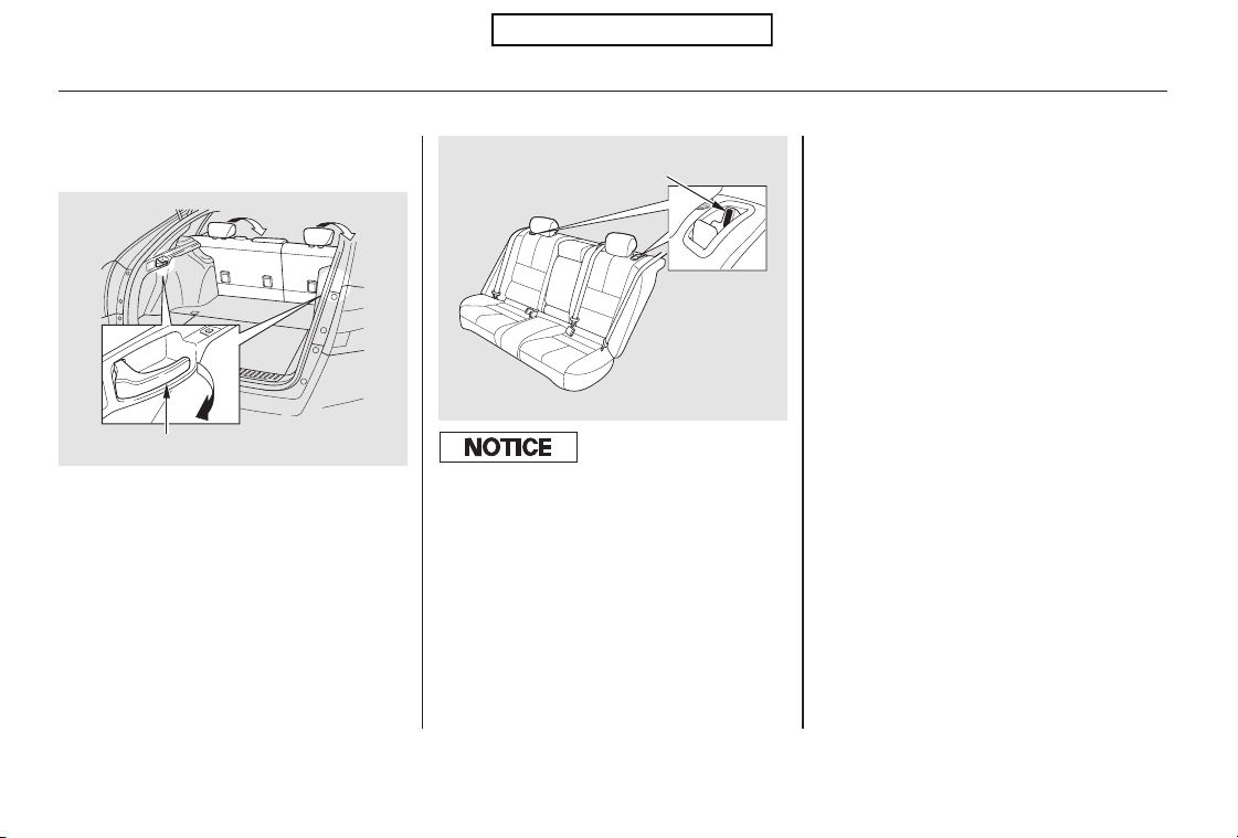
How to use the lever on both sides of
the cargo room.
Do not put any heavy items on the
seat-back when it is folded down.
Make sure the seat-back is locked
securely and all rear shoulder belts
are positioned in front of the rear
seat-backs.
Make sure all items in the cargo area
are secured. Loose items can fly
forward and cause injury if you have
to brake hard. See
on page .
To return the seat-back to the
upright position, raise the seat-back
to make sure it is latched. If the seat-
back is not latched fully, the seat belt
will not work properly and you will
seetheredindicatorbehindthe
release lever as shown.
Make sure there are no passengers
on the rear seats before folding the
seat-backs.
Pull the lever on either side of the
cargo area and the back of the rear
seat on that side folds down
automatically.
294
Seats
Carrying Cargo
98
LEVER
RED INDICATOR
To prevent spilling the contents of cups,
remove them bef ore f olding the seat-
back down.
Table of Contents
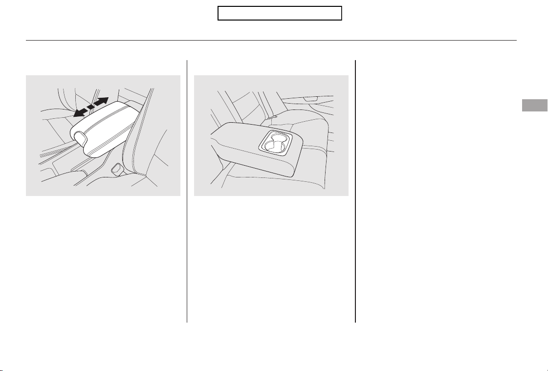
The rear seat armrest is in the
center of the rear seat. Pivot it down
to use it.
A beverage holder is located in the
armrest.
To use the console lid as an armrest,
slide it to one of its three positions.
Armrests
Seats
Instruments and Controls
99
Rear
Front
Table of Contents
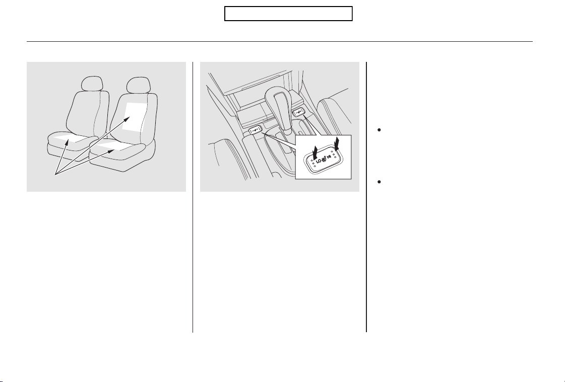
Both front seats are equipped with
seat heaters. Because of the sensors
for the side airbag cutoff system,
there is no heater in the passenger’s
seat-back. The ignition switch must
be in the ON (II) position to use the
heaters.
Push the right side of the switch, HI,
to rapidly heat up the seat. After the
seat reaches a comfortable
temperature, select LO by pushing
the left side of the switch. This will
keep the seat warm.
In the HI setting, the heater turns off
when the seat gets warm, and turns
back on after the seat’s temperature
drops.
In the LO setting, the heater runs
continuously. It does not cycle with
temperature changes.
If the engine is left idling for an
extended period, do not use the
seat heaters even on the LO
setting. It can weaken the battery,
causing hard starting.
Use the HI setting only to heat the
seats quickly, because it draws
large amounts of current from the
battery.
Follow these precautions whenever
you use the seat heaters:
EX-L models
Seat Heaters
100
Driver’s
Seat
Passenger’s
Seat
HEATERS
Table of Contents
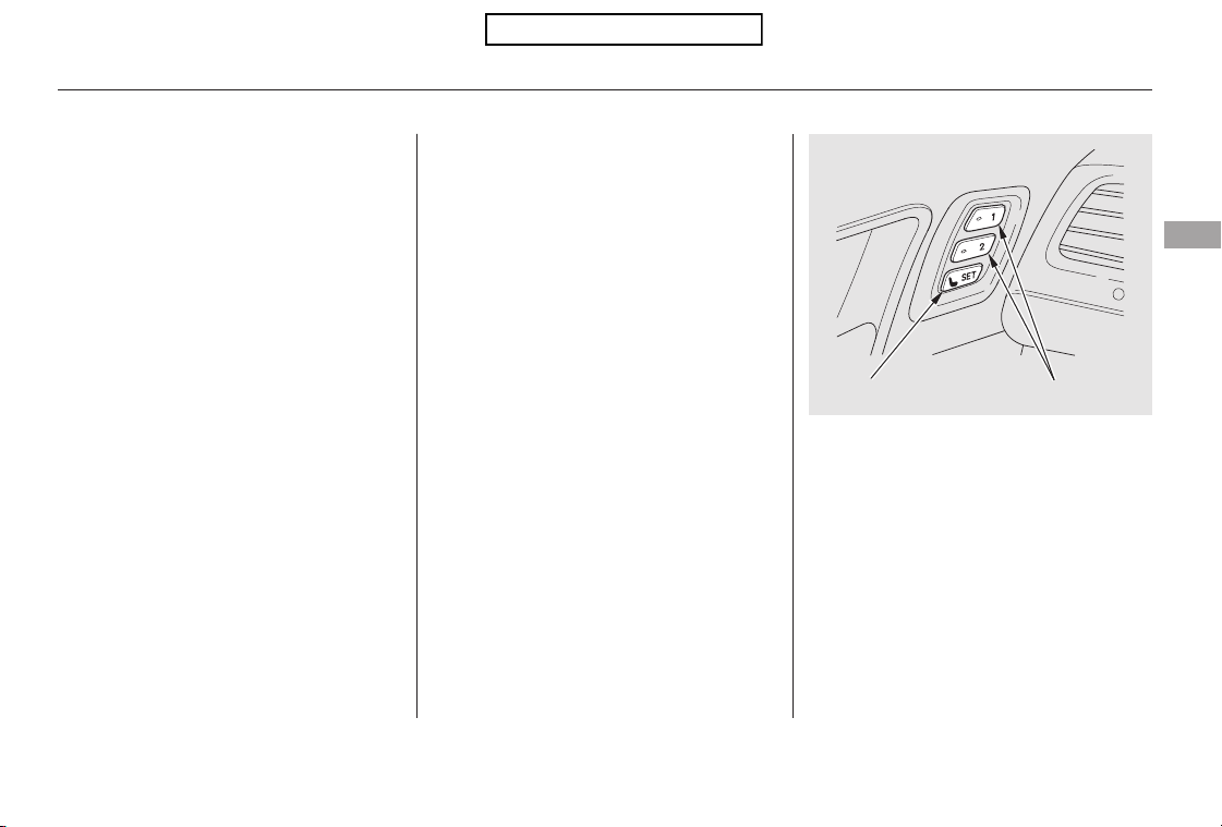
Store a driver’s seat position only
when the vehicle is parked.
Turn the ignition switch to the ON
(II) position. You cannot add a
new seat position in memory
unless the ignition switch is in the
ON (II) position. You can recall a
memorized position with the
ignition switch in any position.
Adjust the seat to a comfortable
position (see page ).
Adjust the outside mirrors for best
visibility (see page ).
Two seat and outside mirror
positionscanbestoredinseparate
memories. You select a memorized
position by pushing the appropriate
button or using the appropriate
remote transmitter (Driver 1 or
Driver 2).
Your vehicle has a memory feature
for the driver’s seat and outside
mirror positions.
Press and release the SET button.
You will hear a beep. Immediately
press and hold one of the memory
buttons (1 or 2) until you hear two
beeps. The indicator in the
memory button will come on. The
current position of the driver’s
seat and outside mirrors are now
stored.
1.
2.
3.
4.
105
93
CONTINUED
EX-L models
Storing a Driving Position in
Memory
Driving Position Memory System
Instruments and Controls
101
MEMORY BUTTONS
SET BUTTON
Table of Contents
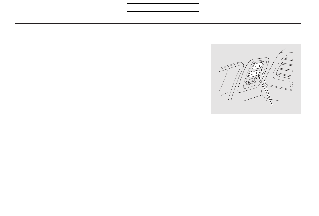
To select a memorized position, do
this:
Make sure the parking brake is set
and the shift lever is in Park.
Press the desired memory button
(1 or 2) until you hear a beep, then
release the button.
To cancel the storing procedure
after pressing the SET button, press
the SET button again within 5
seconds.
Each memory button stores only one
driving position. Storing a new
position erases the previous setting
stored in that button’s memory. If
you want to add a new position while
retaining the current one, use the
other memory button.
All stored driving positions will be
lost if your vehicle’s battery goes
dead or is disconnected.
1.
2.
Selecting a Memorized Position
Driving Position Memory System
102
MEMORY BUTTONS
Table of Contents

If desired, you can use the
adjustment switches to change the
positions of the seat or outside
mirrors after they are in their
memorized positions. If you change
the memorized position, the
indicator in the memory button will
go out. To keep this driving position
for later use, you must store it in the
driving position memory.
To stop the system’s automatic
adjustment, do any of these actions:
Press any button on the control
panel: SET, 1, or 2.
Push any of the adjustment
switches for the seat.
Shift out of Park.
Adjust the outside mirrors.
The system will move the seat and
outside mirrors to the memorized
positions. The indicator in the
selected memory button will flash
during movement. When the
adjustments are complete, you will
hear two beeps, and the indicator will
remain on.
Driving Position Memory System
Instruments and Controls
103
Table of Contents
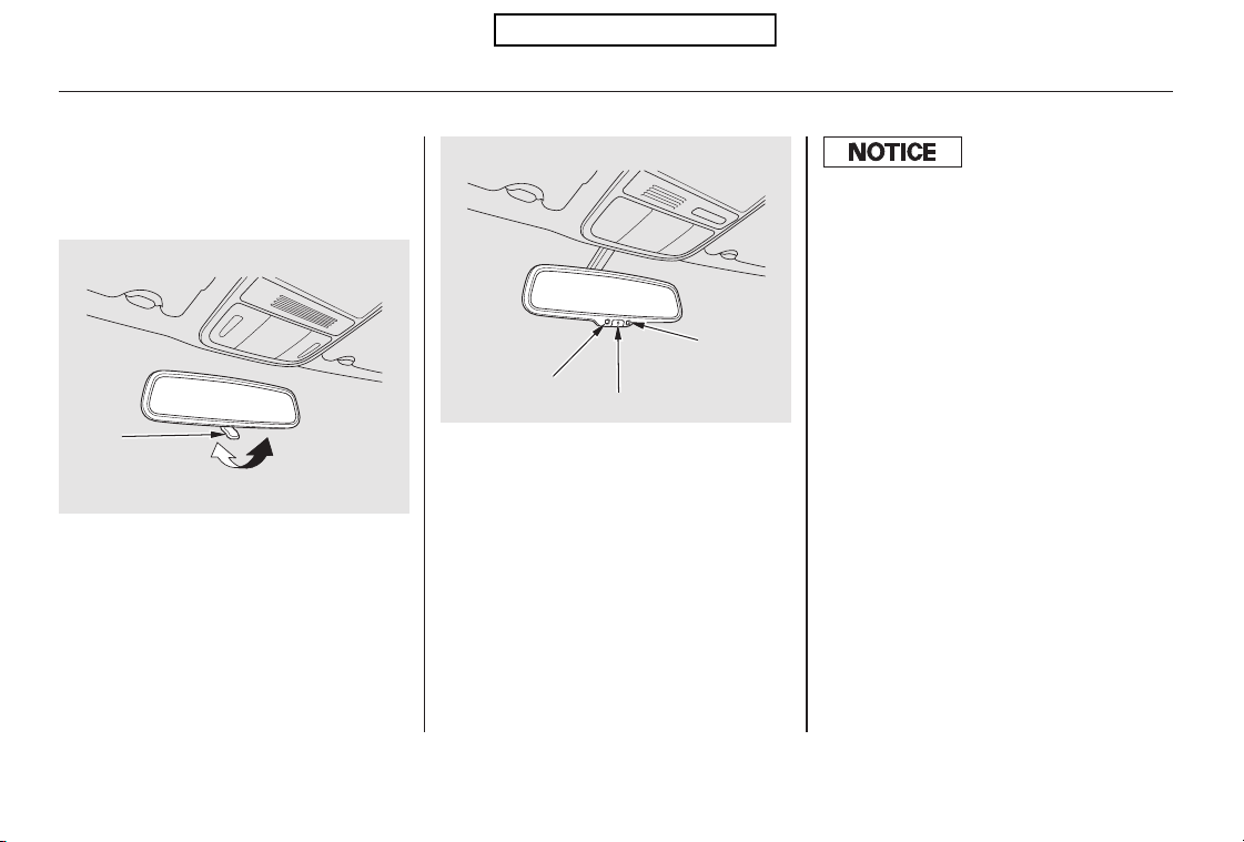
The inside mirror can automatically
darken to reduce glare. To turn on
this feature, press the button on the
bottom of the mirror. The AUTO
indicator comes on as a reminder.
When it is on, the mirror darkens
when it senses the headlights of a
vehicle behind you, then returns to
normal visibility when the lights are
gone. Press the button again to turn
off this feature.
Keeptheinsideandoutsidemirrors
clean and adjusted for best visibility.
Be sure to adjust the mirrors before
you start driving.
The inside mirror has day and night
positions. The night position reduces
glare from headlights behind you.
Flip the tab on the bottom edge of
the mirror to select the day or night
position.
EX model
EX-L models
Mirrors
104
AUTO BUTTON
INDICATOR
SENSOR
TAB
There is also a sensor on the back of
the mirror. Items hung on the mirror
may block this sensor and af f ect its
perf ormance.
Table of Contents
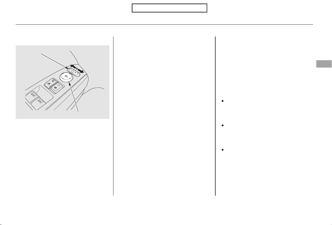
Turn the ignition switch to the ON
(II) position.
Move the selector switch to L
(driver’s side) or R (passenger’s
side).
Push the appropriate edge of the
adjustment switch to move the
mirrorright,left,up,ordown.
When you finish, move the
selector switch to the center (off)
position. This turns the
adjustment switch off to keep your
settings.
To turn the feature off, place the
switch in the center position.
To tilt the passenger’s mirror,
place the switch in the right
position.
To tilt the driver’s mirror, place
the selector switch in the left
position.
Both outside door mirrors have a
reverse tilt feature. When in reverse,
the selected mirror will tilt down
slightly to improve your view as you
parallel park. Shifting out of reverse
will return the mirror to its original
position.
Outside mirror positions can be
stored in the driving position
memory system (see page ).
1.
3.
2.
4.
101
EX-L models
Adjusting the Power Mirrors Reverse Tilt Door Mirror
Mirrors
Instruments and Controls
105
SELECTOR SWITCH
ADJUSTMENT SWITCH
Table of Contents
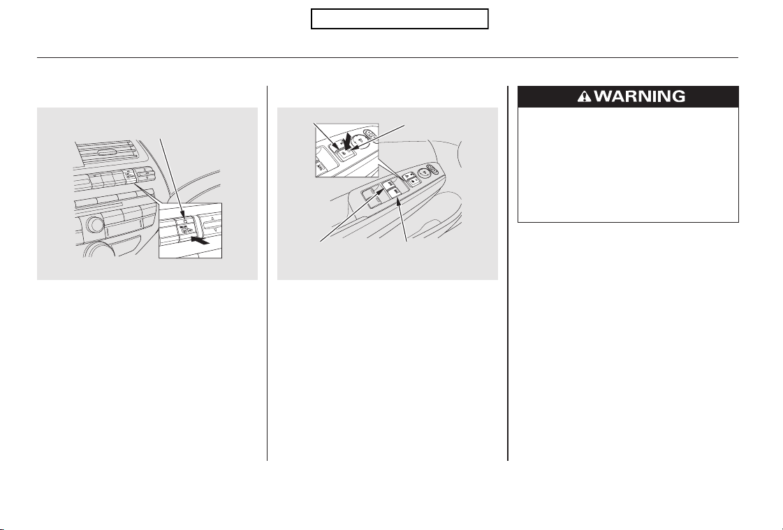
Turn the ignition switch to the ON
(II) position to raise or lower any
window. To open a window, push the
switchdownandholdit.Releasethe
switch when you want the window to
stop. Pull back on the switch and
hold it to close the window.
The outside mirrors are heated to
remove fog and frost. With the
ignition switch in the ON (II)
position, turn on the heaters by
pressing the button. The indicator in
the button comes on as a reminder.
Press the button again to turn the
heaters off. Pressing this button also
turns the rear window defogger on
and off.
PowerMirrorHeaters PowerWindows
Mirrors, Power Windows
106
MAIN SWITCH
FRONT
PASSENGER’S
WINDOW SWITCH
INDICATOR
Without navigation system is shown.
REAR WINDOW DEFOGGER/
HEATED MIRROR BUTTON
DRIVER’S
WINDOW
SWITCH
Closing a power window on
someone’s hands or fingers can
cause serious injury.
Make sure your passengers are
away from the windows before
closing them.
Table of Contents

−−If either front
window senses any obstacle while it
is closing automatically, it will
reverse direction and then stop. To
close the window, remove the
obstacle, then use the window switch
again.
Auto reverse stops sensing when the
window is almost closed. You should
always check that all passengers and
objects are away from the window
before closing it.
The driver’s window auto
reverse function is disabled when
you continuously pull up the switch.
When you push the main switch in,
the indicator comes on and the
passengers’ windows cannot be
raised or lowered. Use the main
switchwhenyouhavechildreninthe
vehicle so they do not injure
themselves by operating the
windows unintentionally. To cancel
this feature, push on the switch
again. The switch will pop out and
the indicator will go off.
The windows and the main switch
feature will operate for up to 10
minutes after you turn off the
ignition switch. Opening either front
door cancels this function.
To open either front
window fully, push the window
switch firmly down to the second
detent, then release it. The window
automatically goes down all the way.
To stop the window from going all
the way down, pull back on the
window switch briefly.
To close either front window fully,
pull back the window switch firmly
to the second detent, then release it.
The window automatically goes all
the way up. To stop the window from
going all the way up, push down on
the window switch briefly.
AUTO REVERSEAUTO
Power Windows
Instruments and Controls
107
NOTE:
Table of Contents
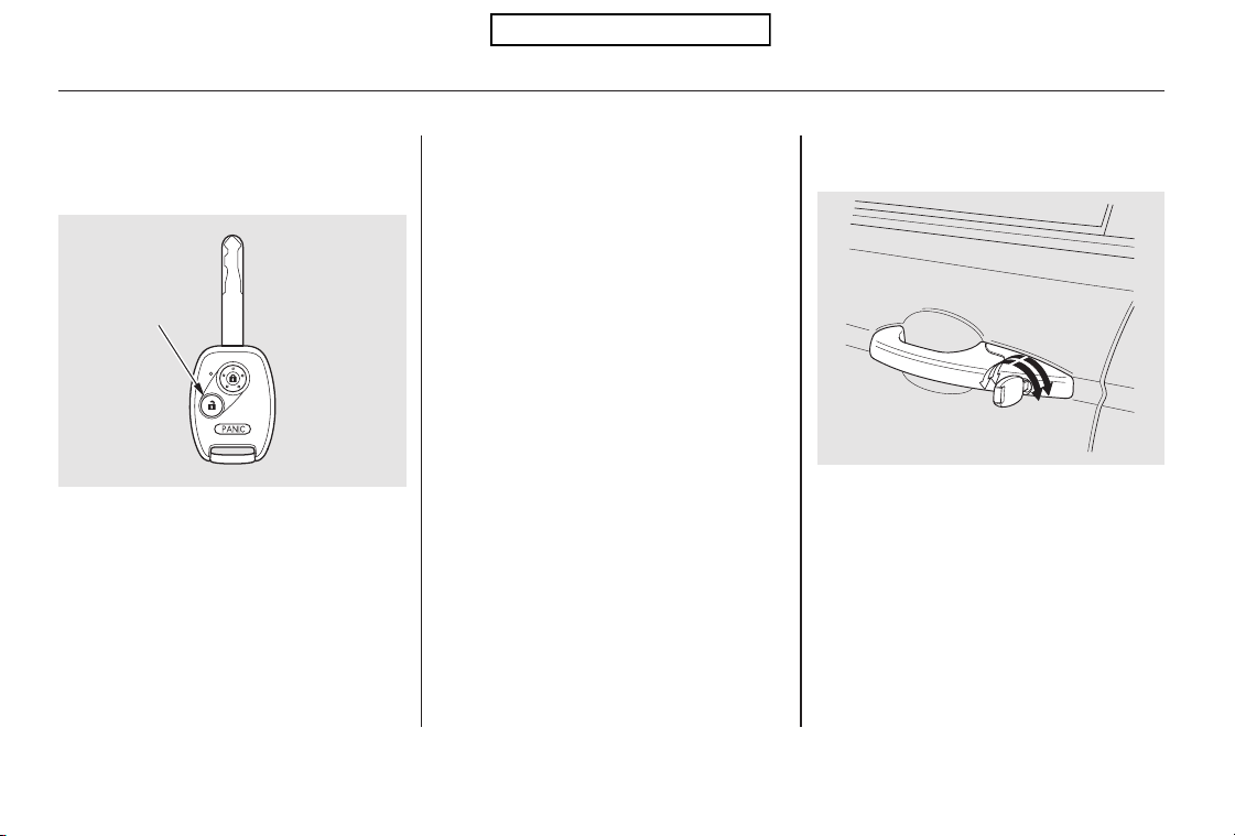
Press the UNLOCK button a
second time, and hold it. The
remaining doors unlock, and all
four windows and the moonroof
start to open. To stop the windows
and moonroof, release the button.
Turn the key clockwise, then
release it.
Insert the key in the driver’s door
lock.
To open:
Press the UNLOCK button once
to unlock the driver’s door.
To open the windows and
moonroof further, press the
button again (within 10 seconds of
step 1) and hold it. If the windows
and the moonroof stop before the
desired position, repeat steps 1
and 2.
You cannot close the windows or the
moonroof with the remote
transmitter.
You can open and close the windows
and moonroof with the key in the
driver’s door lock.
You can open all of the windows and
the moonroof from outside with the
remote transmitter.
1.
2.
3.
1.
2.
Opening the Windows and
Moonroof with the Remote
Transmitter
Opening/Closing the Windows
and Moonroof with the Key
Power Windows
108
Open
Close
UNLOCK
BUTTON
Table of Contents

Turnthekeyclockwiseagain,and
hold it. All four windows and the
moonroof start to open. To stop
the windows and the moonroof,
release the key.
To close:
Insert the key in the driver’s door
lock.
Turn the key counterclockwise,
then release it.
Turn the key counterclockwise
again, and hold it. All four
windows and the moonroof start to
close. To stop the windows and
the moonroof, release the key.
To close the windows and the
moonroof further, turn and hold
the key again (within 10 seconds
of step 2).
To open the windows and the
moonroof further, turn and hold
the key again (within 10 seconds
of step 2).
If the windows and the
moonroof stop before the desired
position, repeat steps 2 and 3.
If the windows and the
moonroof stop before the desired
position, repeat steps 2 and 3.
1.
2.
3.
4.
3.
4.
Power Windows
Instruments and Controls
109
NOTE:
NOTE:
Table of Contents
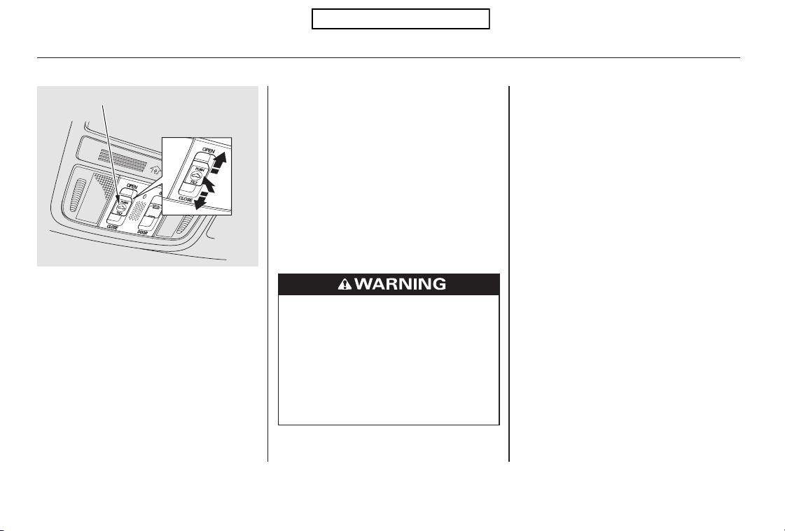
−To open the moonroof
fully, pull back the moonroof switch
firmly, then release it. The moonroof
automatically opens all the way. To
stop the moonroof from opening,
push the switch briefly.
To close the moonroof fully, firmly
push the moonroof switch forward,
then release it. The moonroof
automatically closes all the way. To
stop the moonroof from closing,
push the switch briefly.
To open or close the moonroof
partially, lightly pull the switch back
or push it forward and hold it. The
moonroof will stop when you release
the switch.
To tilt up the moonroof, push on the
center of the moonroof switch. To
stop the moonroof from tilting up
fully, push the switch briefly.
To open the moonroof, pull back on
the switch and hold it. Release the
switch when the moonroof reaches
the desired position. To close the
moonroof, push the switch forward
andholdit.Releasetheswitchto
stop the operation.
The moonroof can be tilted up in the
back for ventilation, or it can be slid
back into the roof. Use the switch on
the front ceiling to operate the
moonroof. You must turn the
ignition switch to the ON (II)
position to operate the moonroof.
AUTO
Moonroof
110
MOONROOF SWITCH
Open
Close
Tilt
Opening or closing the
moonroof on someone’s hands
or fingers can cause serious
injury.
Make sure all hands and fingers
are clear of the moonroof
before opening or closing it.
Table of Contents
You can open and close the
moonroof for up to 10 minutes after
you turn off the ignition switch.
Opening either front door cancels
this function.
You can use the remote transmitter
or the key to operate the moonroof
from the outside. Refer to page
for details.
Auto reverse stops sensing when the
moonroof is almost closed. You
should always check that all
passengers and objects are away
from the moonroof before closing it.
If the moonroof runs into any
obstacle while it is closing
automatically, it will reverse
direction, and then stop. To close the
moonroof, remove the obstacle, then
use the moonroof switch again.
108
Operating the Moonroof with the
Remote Transmitter or the Key
Auto Reverse
Moonroof
Instruments and Controls
111
If you try to open the moonroof in
below-f reezing temperatures, or when
it is covered with snow or ice, you can
damage the moonroof panel or its
motor.
Table of Contents
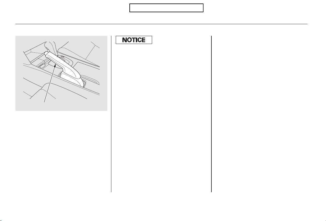
To apply the parking brake, pull the
lever up fully. To release it, pull up
slightly, push the button, and lower
the lever. The parking brake
indicator on the instrument panel
should go out when the parking
brake is fully released (see page ).57
Parking Brake
112
PARKING BRAKE LEVER
Driving the vehicle with the parking
brake applied can damage the rear
brakes and hubs. A beeper will sound if
the vehicle is driven with the parking
brake on.
Table of Contents
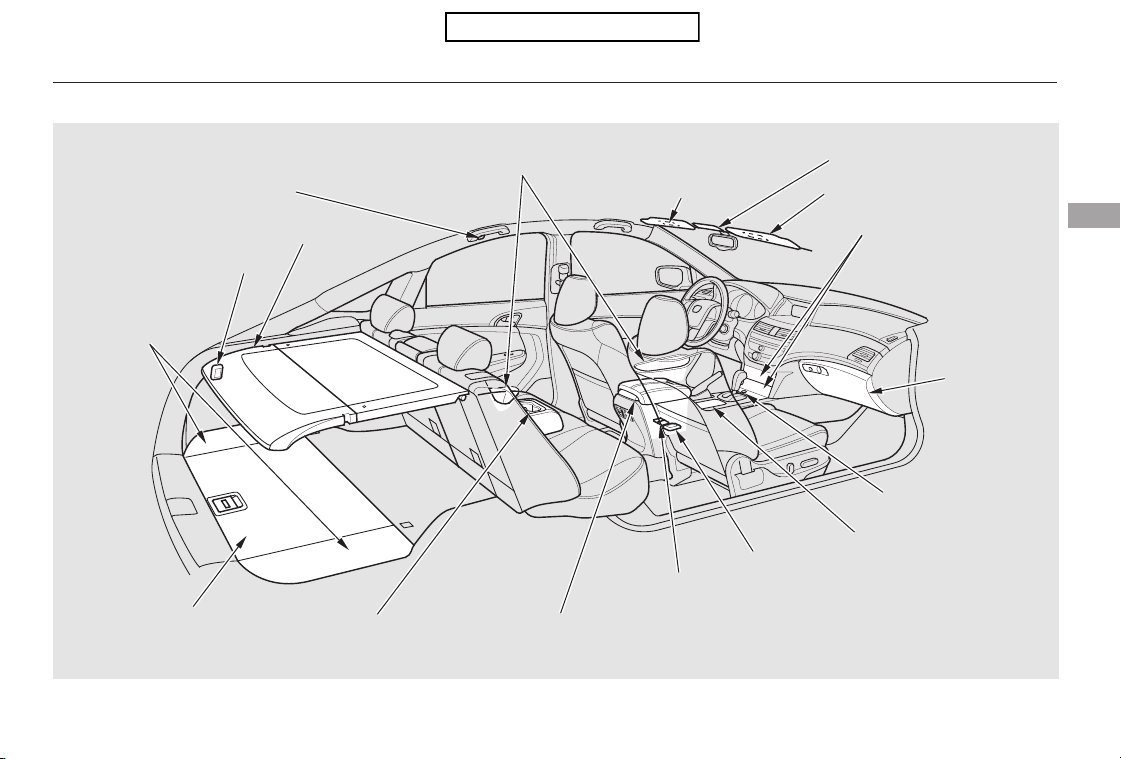
*
*
*
Interior Convenience Items
Instruments and Controls
113
SUNGLASSES HOLDER
VANITY MIRROR
SUN VISOR
CENTER POCKETS
COAT HOOK
BEVERAGE HOLDER in
REAR SEAT ARMREST
BEVERAGE HOLDER
CONSOLE COMPARTMENT
DOOR POCKETS
GLOVE BOX
ACCESSORY POWER SOCKET
AUXILIARY INPUT JACK/
USB ADAPTER CABLE
: If equipped
FLOOR STORAGE
COMPARTMENTS
ACCESSORY
POWER SOCKET
UNDER-FLOOR
STORAGE AREA
CARGO AREA COVER
ACCESSORY POWER
SOCKET
Table of Contents
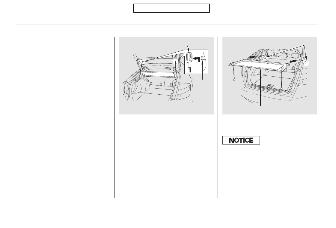
Remove the front cargo area cover
by pulling it out of its hinges.
Open the tailgate.
To remove the front cargo area
cover:
The front and rear cargo area cover
may be removed to give you more
cargo room.
Remove the strap by pushing the
hook up from the pin on both sides
of the tailgate.
1.
2. 3.
EX-L models
Cargo Area Cover
Interior Convenience Items
114
FRONT CARGO AREA COVER
PIN
HINGES
HOOK
Do not close the tailgate with the f loor
lid open because the cargo area covers
might be damaged.
Table of Contents
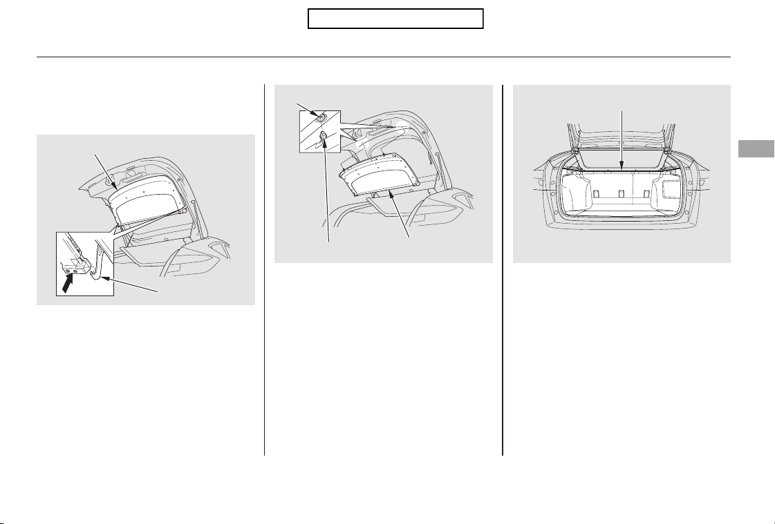
To remove the rear cargo area cover:
Open the tailgate.
Push up on the sides of the rear
cargo area cover to release it from
the hooks.
Pull down on the cover to remove
the mounting pins from the holes
in the tailgate lining.
Do not place items on the cargo area
cover, or stack objects higher than
the top of the back seat. They could
block your view and be thrown about
the vehicle during a crash or sudden
stop.
Reverse this procedure to install the
rear cargo area cover.
Make sure the rear cargo area cover
is latched securely.
Keep all cargo below the bottom of
the reference line shown in the
above illustration.
Do no apply excessive pressure to
the cover, such as leaning on it to
retrieve an item.
2.
1.
3.
Interior Convenience Items
Instruments and Controls
115
REAR CARGO AREA COVER
HOOK
MOUNTING PIN
REAR CARGO
AREA COVER
HOLE
REFERENCE LINE
Table of Contents
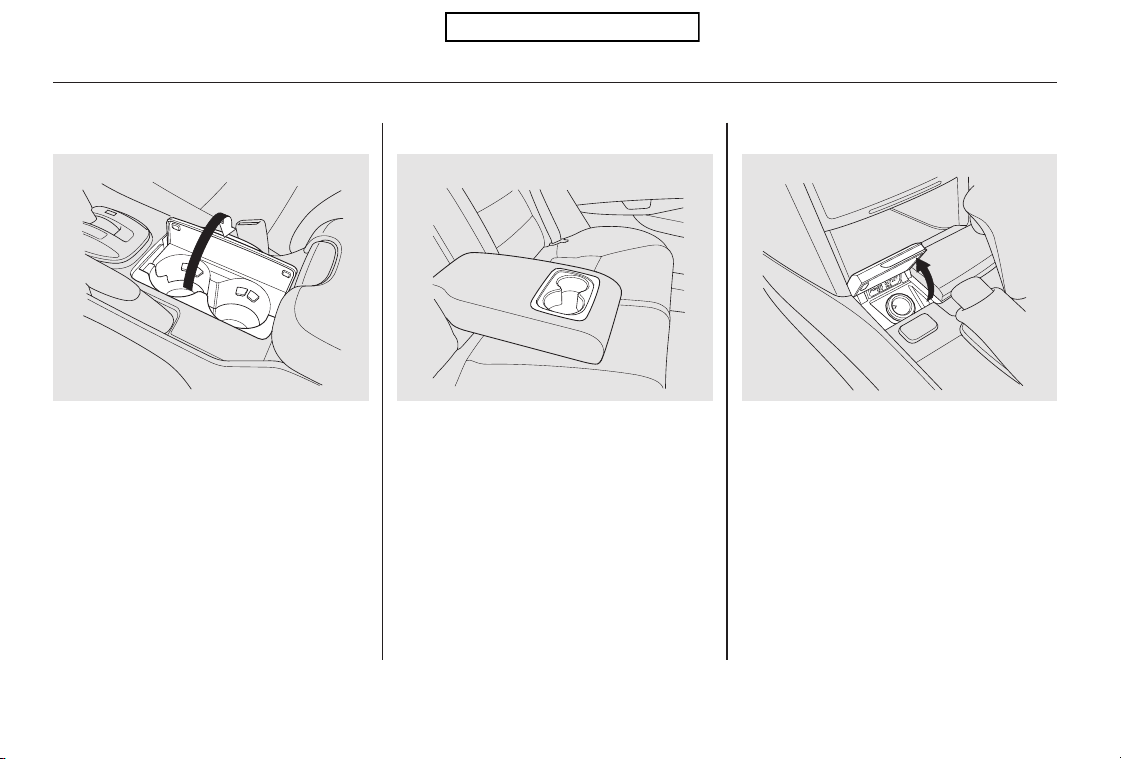
The rear seat also has a beverage
holder in the center armrest. To use
it, pivot the armrest down.
Be careful when you are using the
beverage holders. A spilled liquid
that is very hot can scald you or your
passengers. Spilled liquids can
damage the upholstery, carpeting,
and electrical components in the
interior.
Open the front beverage holder by
pulling up on the lid.
Your vehicle has three accessory
power sockets. These are located on
the front of the center console, in the
console compartment and left side
panel in the cargo area.
To use an accessory power socket,
the ignition switch must be in the
ACCESSORY (I) or ON (II) position.
Beverage Holders Accessory Power Sockets
Interior Convenience Items
116
Front
Rear Front
Table of Contents
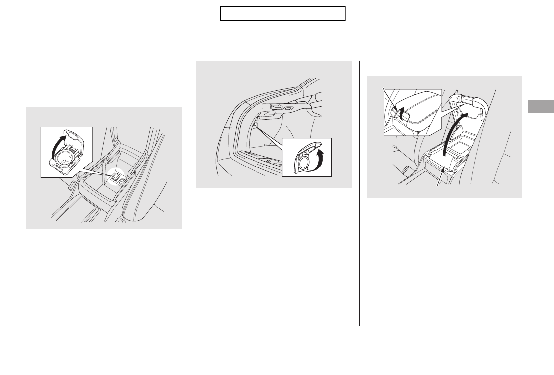
Each socket is intended to supply
power for 12 volt DC accessories
that are rated 120 watts or less (10
amps).
None of the sockets will power an
automotive type cigarette lighter
element.
Make sure to put the socket cover
back in place to prevent any small
foreign objects from getting into the
socket.
To open the console compartment,
pull up on the lever and lift the
armrest.
To close, lower the armrest, and
push it down until it latches.
CONTINUED
Console Compartment
Interior Convenience Items
Instruments and Controls
117
CONSOLE COMPARTMENT
CONSOLE COMPARTMENT
LEVER
CARGO AREA
Table of Contents
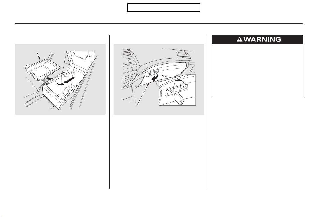
Open the glove box by pulling the
handle to the left. Close it with a firm
push. Lock or unlock the glove box
with the master key.
The glove box light comes on when
the parking lights are on.
The console compartment is
equipped with a detachable tray.
To remove this tray, slide it forward,
then pull it up.
Glove Box
Interior Convenience Items
118
GLOVE BOX
To lock
DETACHABLE TRAY
An open glove box can cause
serious injury to your passenger
inacrash,evenifthe
passenger is wearing the seat
belt.
Always keep the glove box
closed while driving.
Table of Contents
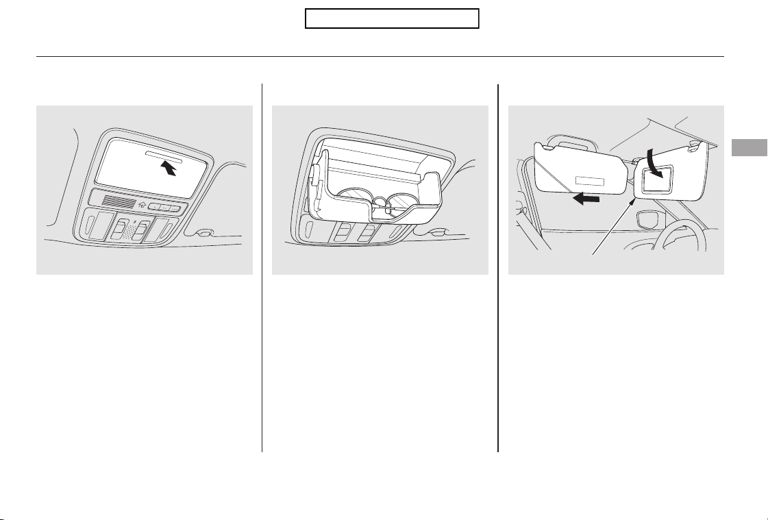
Make sure you put the sun visor
back in place when you are getting
into or out of the vehicle.
In this position, the sun visor can be
adjusted by moving it on its slider.
Do not use the extended sun visor
over the inside mirror.
To use the sun visor, pull it down.
Whenusingthesunvisorforthe
side window, remove the support rod
from the clip, and swing it out.
Some larger styles of sunglasses
may not fit in the holder.
You may also store small items in
this holder. Make sure they are
small enough to let the holder close
and latch, and that they are not
heavy enough to cause the holder to
pop open while driving.
To open the sunglasses holder, push
then release the indent. It will
unlatch and swing down. To close it,
push it until it latches. Make sure the
holder is closed while you are driving.
Sun VisorsSunglasses Holder
Interior Convenience Items
Instruments and Controls
119
SUN VISOR
Slide
Push
Table of Contents
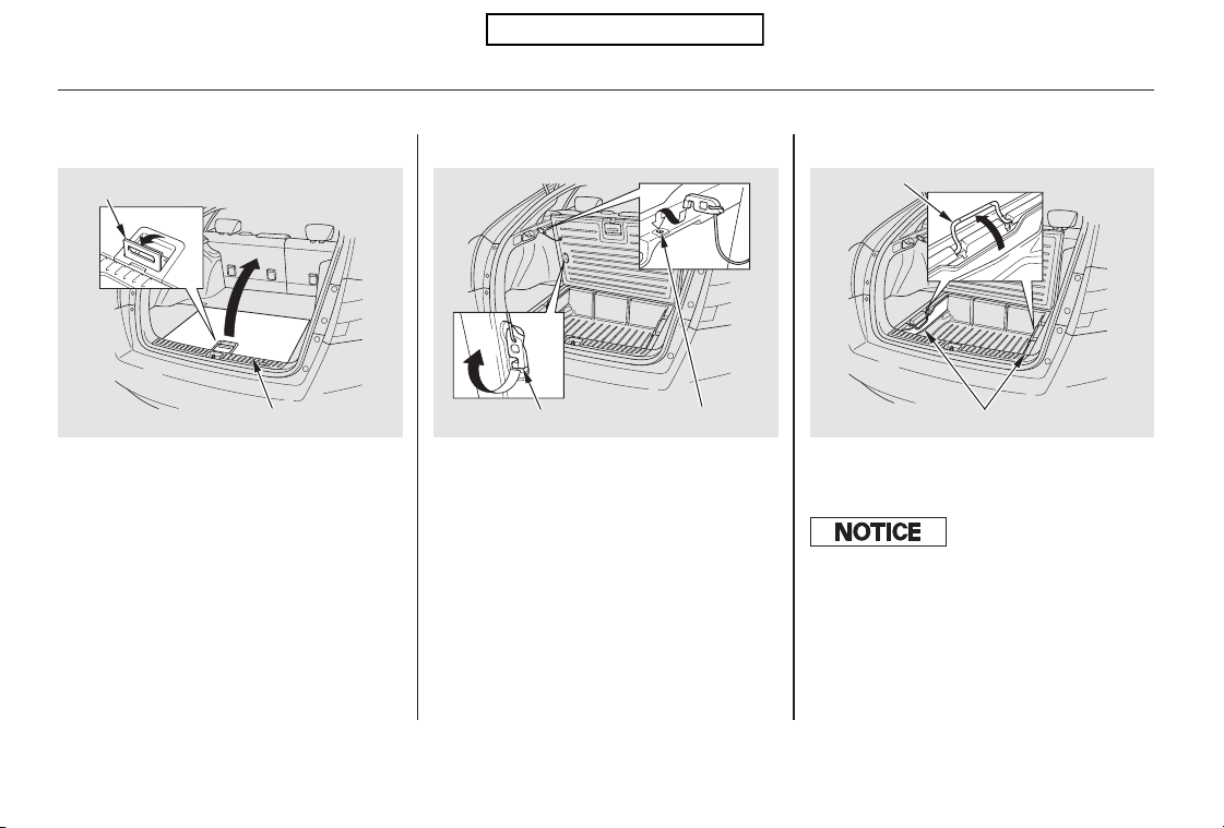
To open the floor lid, raise the lid by
lifting it up with the handle.
The reverse side of the lid is water-
proofed. You can flip the lid to use
the water-proofed side.
Then remove the hook, and hook it
totheholeonthecargosidepanel.
The box under the floor lid can be
partitioned by the pass partition.
Under-floor Storage Area
Interior Convenience Items
120
HANDLE
PASS PARTITIONS
HANDLE
HOOK
HOLE
FLOOR LID
The maximum load in the cargo box is
22.1 lbs on U.S. models, and 10 kg on
Canadian models.
To prevent damage to the cargo box,
do not exceed the maximum load.
Table of Contents
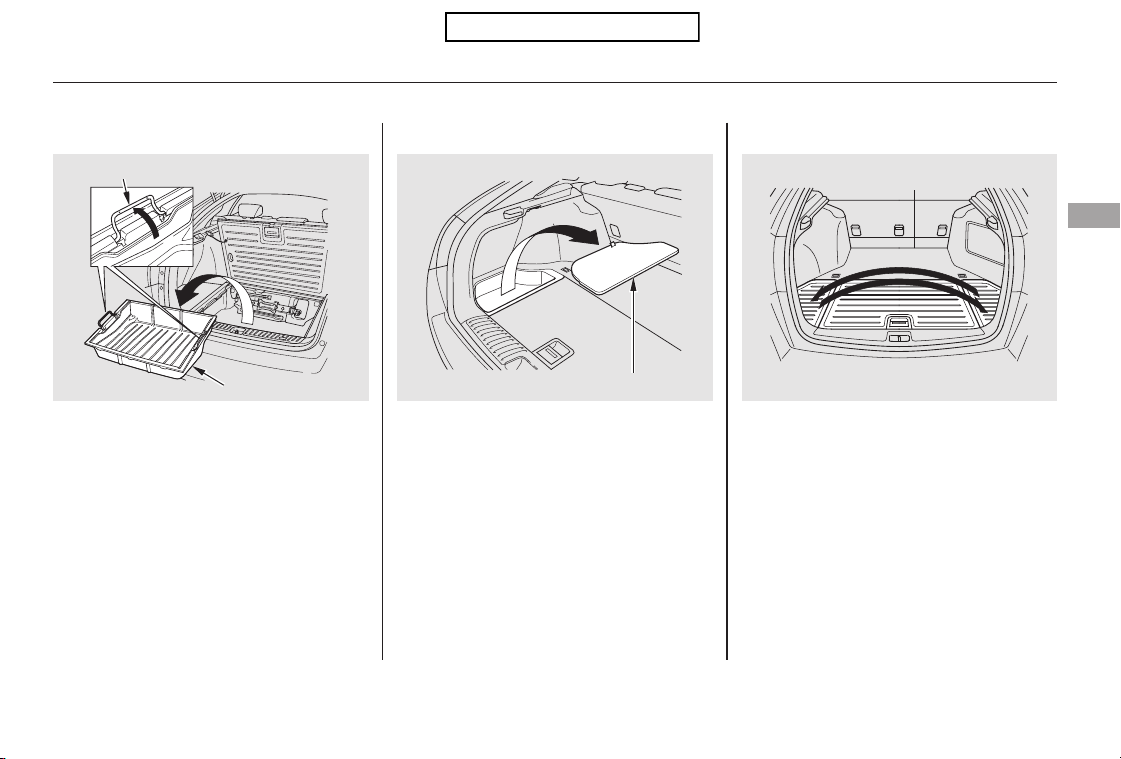
Do not leave water, soil, sand, or
perishable foods in the cargo box.
Rotting food and dirt on the floor
maycausethebreakdownof
electrical equipment.
To use the storage compartment
locatedoneachsideofthecargo
area floor, hold the strap and raise
the lid.
The reverse side of the lids are
water-proofed. To use the water-
proofed side, replace the right lid
and left lid.
Do not set the floor lid with the
handle raised. The handle might be
damaged.
In addition, the cargo box can be
removed to be washed. To remove
the cargo box, lift it up with the
handle.
Floor Storage Compartments
Interior Convenience Items
Instruments and Controls
121
CARGO BOX
HANDLE
LID
Table of Contents
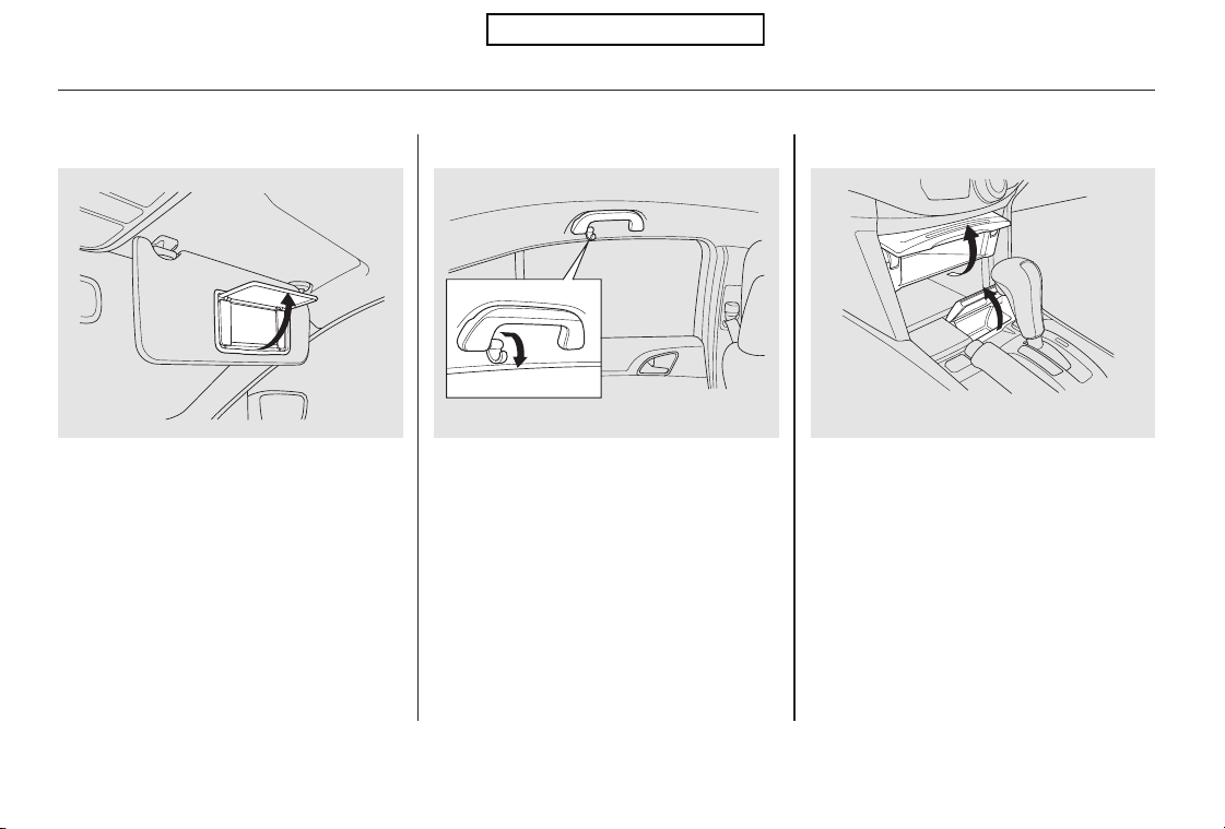
Tousethevanitymirrorontheback
of the sun visor, pull up the cover.
The vanity mirror lights come on
when you pull up the cover.
Touseacoathook,slideitout
slightly, then pull it down.
Make sure the coat hook is folded up
when you are not using it. This hook
is not designed for large or heavy
items.
Pull up the lid to open each pocket.
Vanity Mirror Coat Hook Center Pockets
Interior Convenience Items
122
Without navigation system is shown.
Table of Contents
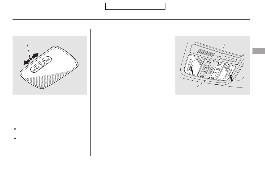
The ceiling light has a three-position
switch: ON, Door Activated, and
OFF. In the Door Activated (center)
position, the light comes on when
you:
After all doors are closed tightly, the
light dims slightly, then fades out in
about 30 seconds.
The ceiling light (with the switch in
the center position) comes on when
you remove the key from the ignition
switch. If you do not open a door, the
light stays on, then fades out in
about 30 seconds.
Turn on a spotlight by pushing the
lens. Push the lens again to turn it
off. You can use the spotlights at all
times.
If you leave any door open without
the key in the ignition switch, the
ceiling light will go off after about 15
minutes.
Unlock the driver’s door with the
keyorremotetransmitter.
Open any door.
CONTINUED
Ceiling Light Spotlights
Interior Lights
Instruments and Controls
123
DOOR ACTIVATED POSITION
DOOR ACTIVATED
OFF POSITION
Table of Contents
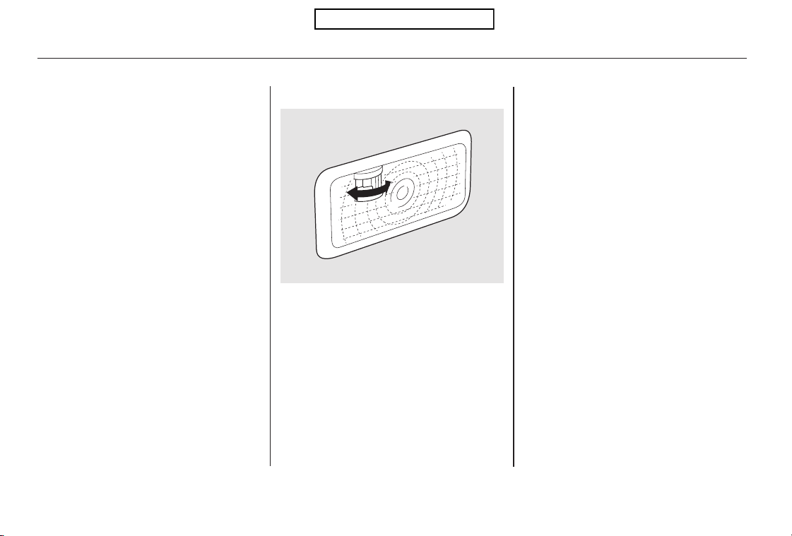
The courtesy light in each front door
comes on when the door is opened,
and goes out when the door is closed.
Your vehicle also has a courtesy light
in the ignition switch. This light
comesonwhenyouopenthedriver’s
door. It fades out in about 30
seconds after the door is closed.
The spotlights have a two-position
switch. In the DOOR position, the
lights come on when you open any
door. The lights fade out in about 30
seconds after the doors are closed
tightly. In the OFF position, the
lights do not come on.
The spotlights (with the switch in
the DOOR position) also come on
when you unlock the door with the
key or the remote transmitter, and
when you remove the key from the
ignition switch.
Your vehicle has a cargo area light
on each side panel in the cargo area.
Each cargo area light has a two
position switch. In the OFF position,
the light does not come on. In the
ON position, the light comes on
when you open the tailgate.
Courtesy LightsCargo Area Light
Interior Lights
124
ON
OFF
Driver’s side is shown.
Table of Contents
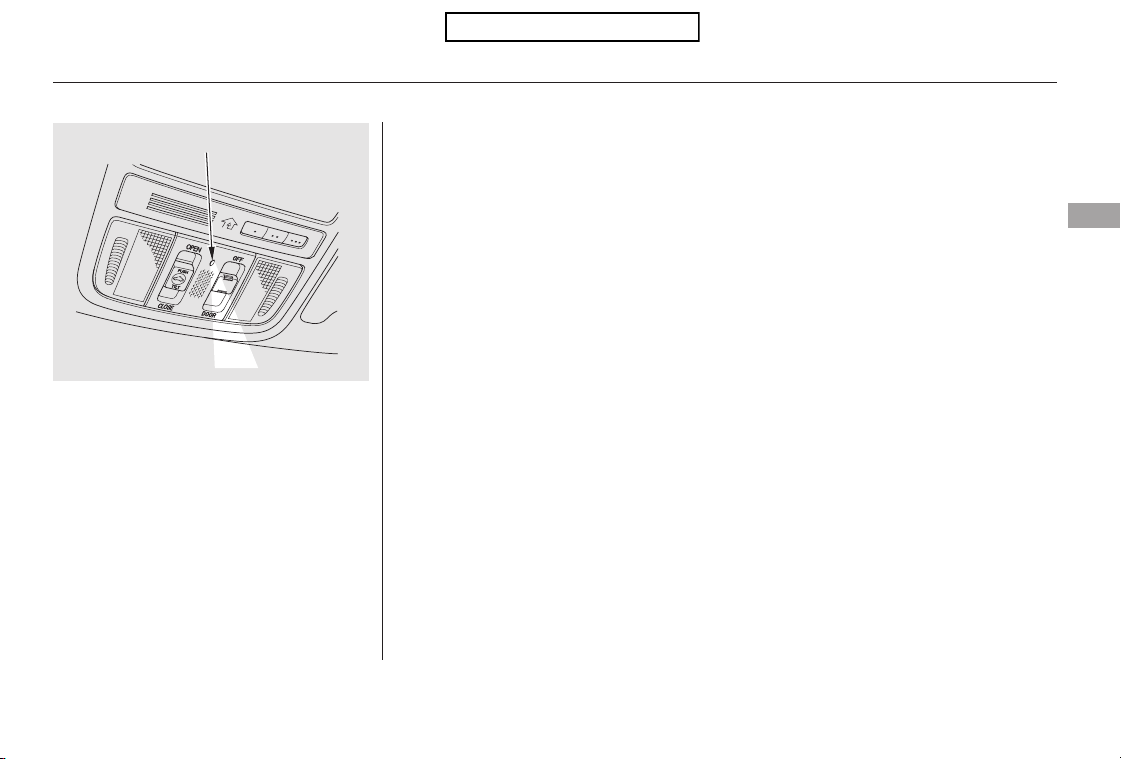
The courtesy light between the
spotlights comes on when you turn
the parking lights on. To adjust its
brightness, turn the select/reset
knob on the instrument panel, with
the ignition switch in the ON (II)
position.
Interior Lights
Instruments and Controls
125
COURTESY LIGHT
Table of Contents
The security system helps to dis-
courage vandalism and theft of your
vehicle.
Your vehicle has an anti-theft audio
system that requires a code number
to enable it.
The standard audio system has
many features. This section
describes those features and how to
use them.
The climate control system in your
vehicle provides a comfortable
driving environment in all weather
conditions.
...............
Climate Control System . 128
................................Audio System . 136
................................Audio System . 137
..........Playing the FM/AM Radio . 138
................Playing the XM
Radio . 145
.................................Playing Discs . 151
...Disc Changer Error Messages . 160
............................PlayinganiPod
. 161
.................iPod
Error Messages . 169
Playing a USB Flash Memory
........................................Device . 170
USB Flash Memory Device
........................Error Messages . 178
................................Audio System . 179
..........Playing the FM/AM Radio . 180
................Playing the XM
Radio . 192
.................................Playing Discs . 199
...Disc Changer Error Messages . 210
............................PlayinganiPod
. 211
.................iPod
Error Messages . 220
Playing a USB Flash Memory
........................................Device . 221
USB Flash Memory Device
........................Error Messages . 230
............FM/AM Radio Reception . 231
..................Protecting Your Discs . 233
................Remote Audio Controls . 236
......................Auxiliary Input Jack . 238
.................Radio Theft Protection . 239
..........................Setting the Clock . 240
............................Security System . 243
.........................................Compass . 245
...............................Cruise Control . 249
HomeLink
Universal
................................Transceiver . 252
........
HandsFreeLink . 256
...Rearview Camera and Monitor . 280
Models without navigation system
Models with navigation system
Bluetooth
Features
Features
127
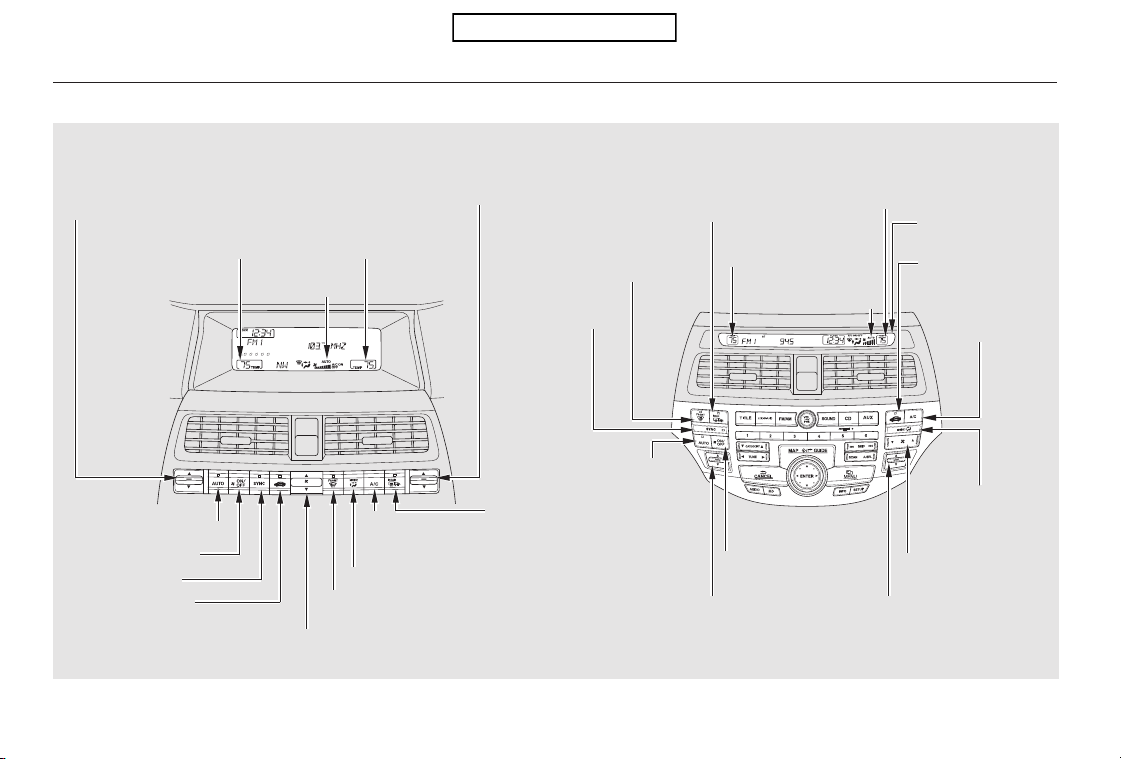
Climate Control System
With navigation systemWithout navigation system
128
AUTO BUTTON
AUTO
INDICATOR
DRIVER’S SIDE
TEMPERATURE
RECIRCULATION
BUTTON
FAN CONTROL SWITCH
WINDSHIELD DEFROSTER
BUTTON
DRIVER’S SIDE
TEMPERATURE
CONTROL SWITCH
DRIVER’S SIDE TEMPERATURE
CONTROL SWITCH
MODE CONTROL BUTTON
REAR WINDOW
DEFOGGER/HEATED
MIRROR BUTTON
PASSENGER’S SIDE
TEMPERATURE
AIR
CONDITIONING
(A/C) BUTTON
PASSENGER’S SIDE
TEMPERATURE
ON/OFF BUTTON
SYNC BUTTON
PASSENGER’S SIDE
TEMPERATURE CONTROL
SWITCH
AIR
CONDITIONING
(A/C) BUTTON
REAR WINDOW DEFOGGER/
HEATED MIRROR BUTTON
MODE CONTROL
BUTTON
FAN CONTROL
BAR
PASSENGER’S SIDE
TEMPERATURE CONTROL
SWITCH
ON/OFF BUTTON
AUTO
BUTTON
SYNC
BUTTON
WINDSHIELD
DEFROSTER
BUTTON
DRIVER’S SIDE
TEMPERATURE
AUTO
INDICATOR
CENTER
DISPLAY
RECIRCULATION
BUTTON
U.S. models are shown.
Table of Contents

The system automatically selects
the proper mix of conditioned
and/or heated air that will, as
quickly as possible, raise or lower
the interior temperature to your
preference.
Press the Auto button. The
indicator in the button also comes
on as a reminder. You will see
AUTO on the display (in the
center display on models with
navigation system).
Set the desired temperature with
the temperature control switch.
You can set the driver’s side
temperature and the passenger’s
side temperature separately.
The driver’s side temperature and
the passenger’s side temperature can
be set separately. Push up the switch
of the appropriate temperature
control to increase the temperature
of airflow. Push down the switch to
decrease it. Each set temperature is
showninthedisplay(inthecenter
display on models with navigation
system).
The automatic climate control
system in your vehicle maintains the
interior temperature you select,
removes moisture from the air and
makes the interior dry. The system
also adjusts the fan speed and
airflow levels.
The climate control system can also
be operated by voice control. See the
navigation system manual for
complete details.
1.
2.
On models with navigation system
CONTINUED
Using Automatic Climate ControlVoice Control System
Temperature Control
Climate Control System
Features
129
Table of Contents
When you set the temperature to its
lower limit ( ) or its upper limit
( ), the system runs at full
cooling or heating only. It does not
regulate the interior temperature.
When you adjust a fan control, the
fan is taken out of AUTO mode.
In AUTO mode, the vehicle’s interior
temperature is independently
regulated for the driver and front
passenger according to each
adjusted temperature. The system
also regulates each temperature
basedontheinformationofthe
sunlight sensor and the sun’s
position which is updated
automatically by the navigation’s
global positioning system (GPS). If
onesideofthevehicleisgettingtoo
much sun, the system lowers the
temperature only on that side.
When you press this button, the
indicator in the button comes on, and
the passenger’s side temperature is
synchronized to the driver’s side set
temperature. Changing the
passenger’s side temperature makes
the indicator go off and takes the
system out of SYNC mode.
Each time you press this button, the
climate control system switches
betweenonandoff.Turningonthe
system with this button selects your
last climate control selection.
To turn the system completely off,
press the ON/OFF button.
Keep the system completely off
for short periods only.
To keep stale air and mustiness
from collecting, you should have
the fan running at all times.
On models with navigation system
To Turn Everything Off
SYNC Button
ON/OFF Button
Climate Control System
130
Table of Contents

▲
▼
When the indicator in the button is
on, air from the vehicle’s interior is
sent through the system again.
When the indicator is off, air is
brought in from the outside of the
vehicle (fresh air mode).
Switch to recirculation mode when
driving through dusty or smoky
conditions, then return to fresh air
mode.
Thesystemshouldbeleftinfresh
air mode under almost all conditions.
Keeping the system in recirculation
mode, particularly with the A/C off,
can cause the windows to fog up.
The outside air intakes for the
climate control system are at the
base of the windshield. Keep this
area clear of leaves and other debris.
You can manually select various
functions of the climate control
system when it is in fully automatic
mode. All other features remain
automatically controlled. Making any
manual selection causes the word
AUTO in the display to go out.
Push the switch up to increase the
fanspeedandairflow.Pushthe
switch down to decrease them.
This button turns the air
conditioningonandoff.Youwillsee
A/C ON or A/C OFF in the display.
When you turn the A/C off, the
system cannot regulate the inside
temperature if you set the
temperature control below the
outside temperature.
Press the side of the bar to
increase the fan speed and airflow.
Press the side of the bar to
decrease them.
On models without navigation system
On models with navigation system
CONTINUED
Recirculation ButtonAir Conditioning (A/C) Button
Semi-automatic Operation
Fan Control
Climate Control System
Features
131
Table of Contents
This button turns the rear window
defogger off and on (see page ).
Pushing this button also turns the
power mirror heaters on and off.
Use the mode control button to
select the vents the air flows from.
Some air will flow from the
dashboard vents in all modes.
To remove fog from the inside of the
windows, set as follows:
Airflow is divided between
the floor and corner vents and the
defroster vents at the base of the
windshield.
Air flows from the floor
vents.
Select . The system
automatically switches to fresh air
mode and turns on the A/C.
Adjust the temperature with the
driver’s side temperature control
so the airflow feels warm.
Select to help clear the
rear window.
To increase airflow to the
windshield, close the corner vents.
For faster defogging, manually set
the fan speed to high.
For your safety, make sure you have
a clear view through all the windows
before driving.
When the indicator in the
button is on, the SYNC
indicator also comes on. The front
passenger’s temperature cannot be
set separately from the driver’s.
Airflow is divided between
the vents in the dashboard and the
back of the center console, and the
floor vents.
Air flows from the center
and corner vents in the dashboard,
and the vents on the back of the
center console.
This button directs the main airflow
to the windshield for faster
defrosting. It also overrides any
mode selection you may have made.
When you select , the system
automatically switches to fresh air
mode and turns on the A/C. For
faster defrosting, manually set the
fanspeedtohigh.Youcanalso
increase airflow to the windshield by
closing the corner vents on the
dashboard. To close the vents, rotate
the wheel under each corner vent.
When you turn off by
pressing the button again, the
system returns to its former settings.
1.
2.
3.
4.
75
Rear Window Defogger Button
Mode Control
Windshield Defroster Button
Climate Control System
132
Table of Contents
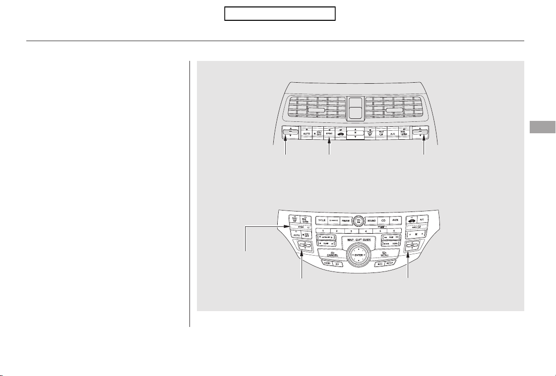
CONTINUED
The temperatures of the driver’s side
and the front passenger’s side are
controlled independently.
Your vehicle has two temperature
control switches, one for the driver,
and one for the front passenger.
Climate Control System
Dual Temperature Control
Without navigation system
With navigation system
Features
133
PASSENGER’S SIDE
TEMPERATURE
CONTROL SWITCH
DRIVER’S SIDE
TEMPERATURE
CONTROL SWITCH
PASSENGER’S SIDE
TEMPERATURE
CONTROL SWITCH
DRIVER’S SIDE
TEMPERATURE
CONTROL SWITCH
SYNC BUTTON
SYNC BUTTON
Table of Contents
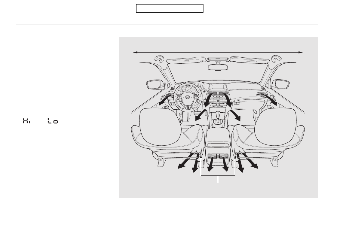
The selected temperatures appear in
the display (in the center display on
models with navigation system).
When the indicator in the SYNC
button is on, you can adjust both
sides to the same temperature by
pushing the driver’s side
temperature control switch up or
down.
When you set the temperature to its
upper or lower limit, it is displayed as
or .
Synchronized Control
Climate Control System
134
DRIVER’S SIDE PASSENGER’S SIDE
REAR POSITION FLOOR VENTS
Table of Contents
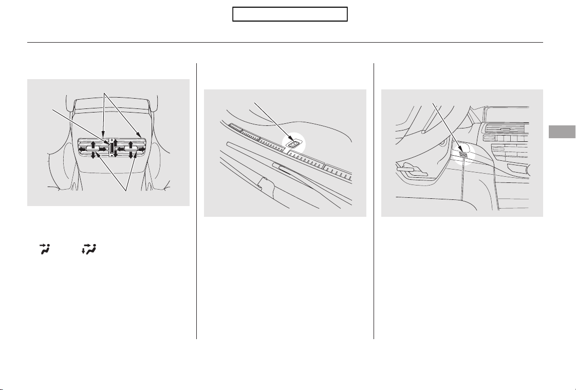
The airflow from the rear vents can
be adjusted when the AUTO mode is
selected or the fan mode is in the
or position.
You can adjust the direction of the
airflowbymovingthetaboneach
vent up-and-down and side-to-side.
You can also open or close the vents
with the dial between them.
Theclimatecontrolsystemhastwo
sensors: a sunlight sensor on top of
the dashboard, and a temperature
and humidity sensor next to the
steering column. Do not cover the
sensors or spill any liquid on them.
Sunlight Sensor/Temperature
Sensor
Rear Ventilation
Climate Control System
Features
135
SUNLIGHT SENSOR
TEMPERATURE SENSOR
Open
DIAL
Close
TABS
REAR VENTS
Table of Contents
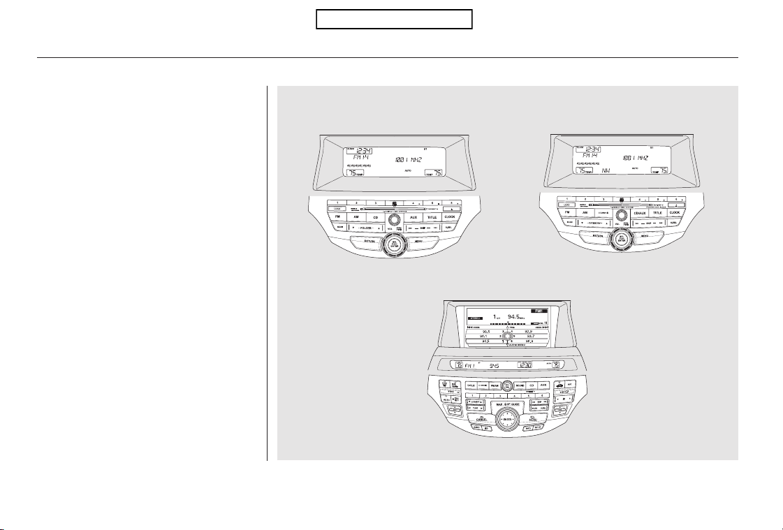
An audio system is standard on all
models. Read the appropriate pages
(as shown below) to use your
vehicle’s audio system.
On models without navigation
system, see pages through .
On models with navigation system,
see pages through .
137
230
178
179
Audio System
Audio system without navigation system
Audio system with navigation system
136
U.S. models are shown.
Without XM Radio
With XM Radio
Table of Contents
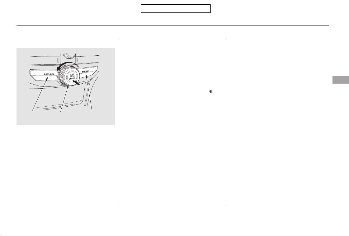
Most audio system functions can be
controlled by standard buttons, bars,
and knobs. In addition, you can
access some functions by using the
selector knob on the audio system.
The knob turns left and right. Use it
to scroll through lists, or to make
selections or adjustments to a list or
menu item on the display. When you
make a selection, push the center of
the selector (ENTER) to go to that
selection.
When the audio system is in XM
Radio mode or playing discs, pushing
the selector (ENTER) knob switches
the display between the normal
display and the extended display.
The extended display has three
segments to display the detailed
information.
To select any setting such as the
clock, sound adjusting, or the
compass (if equipped), press the
MENU button. To use any audio
system function, the ignition switch
must be in the ACCESSORY (I) or
ON (II) position. You can select the
item by turning the selector knob.
To go back to the previous display,
press the RETURN button.
Pressing the MENU button again
will also cancel the menu display
mode.
Selector Knob Menu Display
Audio System (Models without navigation system)
Features
137
SELECTOR
KNOB
MENU
BUTTON
RETURN
BUTTON
Table of Contents
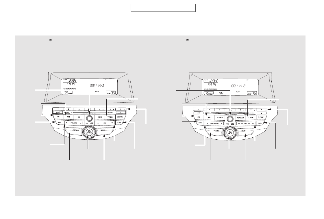
Playing the FM/AM Radio (Models without navigation system)
Without XM Radio
With XM
Radio
138
SKIP BAR
SELECTOR
KNOB
PRESET
BUTTONS
RETURN BUTTON
A.SEL (AUTO
SELECT) BUTTON
SCAN
BUTTON
MENU BUTTON
SKIP BAR
SELECTOR
KNOB
PRESET
BUTTONS
RETURN BUTTON
CATEGORY
BAR
A.SEL (AUTO
SELECT) BUTTON
TITLE
BUTTON
TITLE
BUTTON
MENU BUTTON
FM
BUTTON
SCAN
BUTTON
FOLDER BAR
POWER/
VOLUME
KNOB
AM
BUTTON
POWER/
VOLUME
KNOB
AM
BUTTON
FM
BUTTON
U.S. models are shown.
Table of Contents
−
−
−
The band and frequency that the
radio was last tuned to are displayed.
To change bands, press the AM or
FM button. On the FM band, ST will
be displayed if the station is
broadcasting in stereo. Stereo
reproduction in AM is not available.
On the AM band, AM noise
reduction turns on automatically.
The ignition switch must be in the
ACCESSORY (I) or ON (II) position.
Turn the system on by pushing the
power/volume knob or the AM or
FM button. Adjust the volume by
turning the power/volume knob.
You can use any of five methods to
find radio stations on the selected
band: tune, skip, scan, the preset
buttons, and auto select.
The skip function searches
up and down from the current
frequency to find a station with a
strong signal. To activate it, press
and hold the or side of the
SKIP bar until you hear a beep, then
release it.
On the FM band, you can also use
the features provided by the radio
data system (RDS). For more
information on the RDS, see page
.
Use the selector knob to
tune the radio to a desired frequency.
Turn the knob right to tune to a
higher frequency, or left to tune to a
lower frequency.
The scan function samples
all stations with strong signals on the
selected band. To activate it, press
the SCAN button, then release it.
You will see SCAN in the display.
When the system finds a strong
signal, it will stop and play that
station for about 10 seconds.
If you do nothing, the system will
scan for the next strong station and
play it for 10 seconds. When it plays
a station that you want to listen to,
press the SCAN button again.
141
CONTINUED
To Select a StationTo Play the Radio
SKIP
TUNE
SCAN
Playing the FM/AM Radio (Models without navigation system)
Features
139
Table of Contents

−−Each preset button can
store one frequency on AM and two
frequencies on FM.
If you are
traveling and can no longer receive
your preset stations, you can use the
auto select feature to find stations in
the local area.
You will see a ‘‘0’’ displayed after
pressing a preset button if auto
select cannot find a strong station for
that preset button.
If you do not like the stations auto
select has stored, you can store
other frequencies on the preset
buttons as previously described.
,pressthe
A. SEL (auto select) button. This
restores the presets you originally
set.
Press the A. SEL button. ‘‘A-SEL’’
flashes in the display, and the system
goes into scan mode for several
seconds. It stores the frequencies of
six AM and twelve FM stations in
the preset buttons.
For information on FM/AM radio
frequencies and reception, see page
.
Select the desired band, AM or
FM. FM1 and FM2 let you store
six stations each.
Usethetune,skip,scan,orRDS
function to tune the radio to a
desired station.
Pick a preset button, and hold it
until you hear a beep.
Repeat steps 1 through 3 to store a
total of six stations on AM and
twelve stations on FM.
1.
2.
3.
4.
231
To turn off auto select
Preset AUTO SELECT
Playing the FM/AM Radio (Models without navigation system)
140
Table of Contents
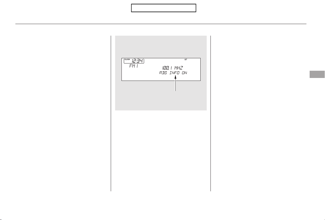
On the FM band, you can select a
favorite station and display the
program service name provided by
the radio data system (RDS).
The RDS information display
function shows the name of the RDS
station you are listening to. With the
audio system on and the FM band
selected, you can turn this function
on or off.
If the station you are listening to is
not an RDS station, the display
continues to show the frequency
with the RDS information display
function on.
When you turn off this function by
pressing the TITLE button, the
display shows ‘‘RDS INFO OFF.’’
To switch the function between on
and off, press and release the TITLE
button. With the system on, you will
see the ‘‘RDS INFO ON’’ message on
the display. If the station you are
listening to is an RDS station, the
display shows the station name.
CONTINUED
Radio Data System (RDS)
RDS INFO Display
Playing the FM/AM Radio (Models without navigation system)
Features
141
RDS INFO DISPLAY ON
Table of Contents
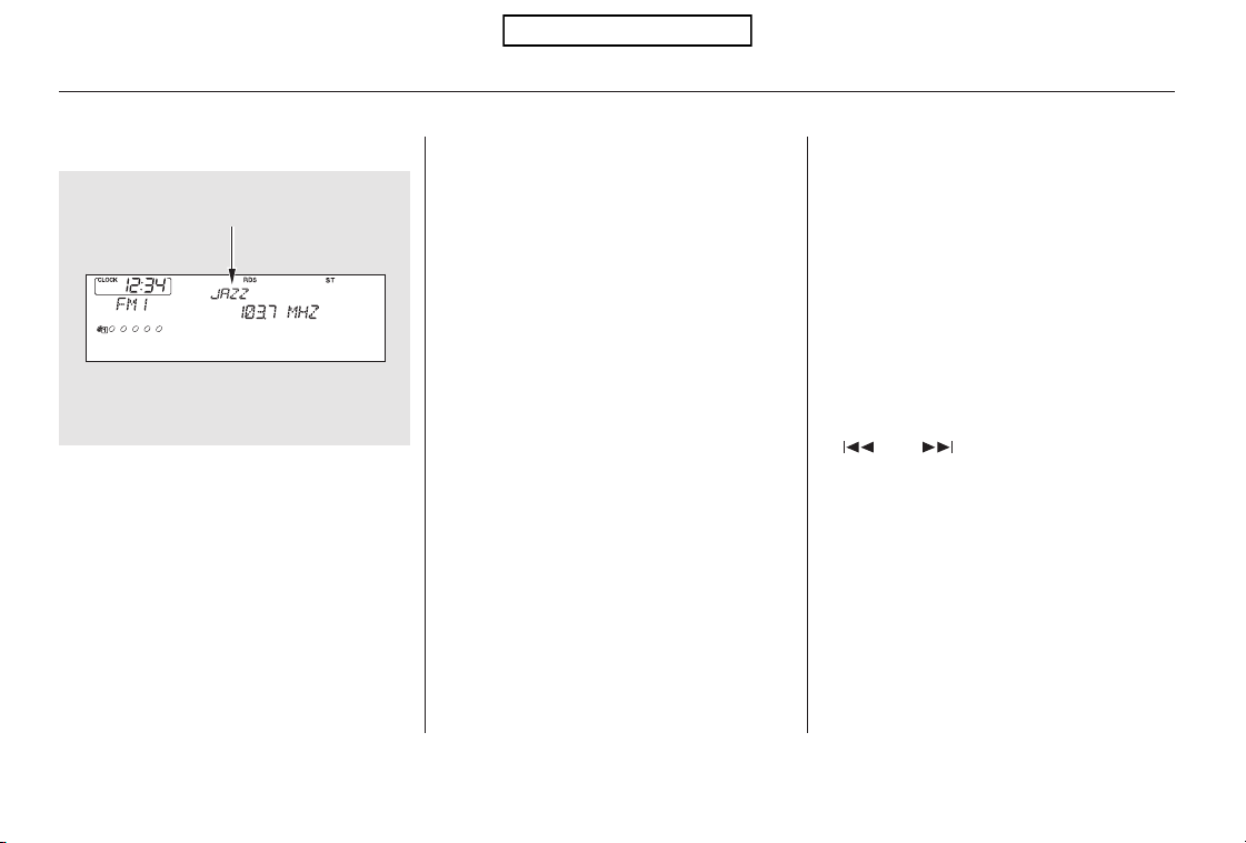
▲▼
On the FM band selected, you can
select the program category
provided by the RDS. Press either
side ( or ) of the CATEGORY
bar (FOLDER bar on models without
XM Radio) to display and select an
RDS category. The principal RDS
categories are shown as follows:
Press either side of the CATEGORY
bar (FOLDER bar on models without
XM Radio) to select a RDS category.
The display shows the selected RDS
category name for about 10 seconds.
You can use the search or scan
function to find radio stations in the
selected RDS category. If you do
nothing while the RDS category
name is displayed, the selected
category is canceled.
TRAFFIC: Traffic information
INFO: News, information, sports,
talk shows, foreign language,
personality, public, college, and
weather
JAZZ: Jazz
CLASSIC: Classical music
RELIGION: Programs concerned
with religion
R & B: Rhythm and blues, and soft
rhythm and blues
OLDIES: Nostalgia music and oldies
TOP 40: Top 40 hits
SOFT: Adult hits and soft music
COUNTRY: Country music
ROCK: Rock, classic rock and soft
rock music
ALL: All RDS category stations
If the system does not find a station,
‘‘NOTHING’’ will be blinking for
about 5 seconds, then the system
goes back to the last selected station.
This function searches up and down
a frequency for the strongest signal
from the frequencies that carry the
selected RDS category information.
This can help you to find a station in
your favorite category. To activate it,
press and release either side
( or ) of the SKIP bar. You
will see the selected RDS category
name blinking while searching it.
When the system finds a station, the
selected RDS category name will be
displayed again for about 5 seconds.
Playing the FM/AM Radio (Models without navigation system)
Radio Data System (RDS) Category
RDS Program Search
142
RDS CATEGORY
Table of Contents
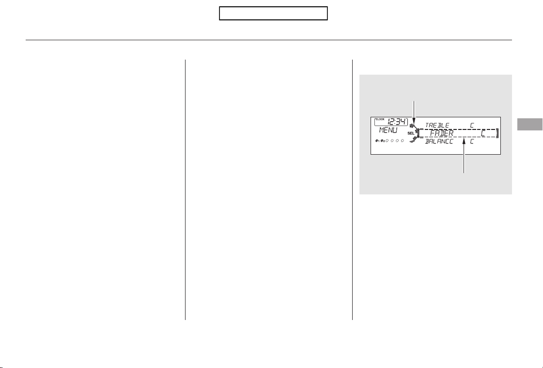
The scan function samples all
stations with strong signals on the
selected RDS category. To activate it,
press and release the SCAN button.
You will see SCAN in the display.
The system will scan for a station
with a strong signal in the selected
RDS category. You will also see the
selected RDS category name
blinking while searching it. When it
finds a strong signal, it will stop and
play that station for about 10 seconds.
If you do nothing, the system will
scan for the next strong station and
play it for 10 seconds. When it plays
a station that you want to listen to,
press the SCAN button again.
If the system does not find a station,
‘‘NOTHING’’ will be blinking for
about 5 seconds, then the system
goes back to the last selected station.
You can use the RDS program
search or scan function even if the
RDS information display function is
off.
Press the MENU button to display
the sound settings. Turn the selector
knob to select an appropriate setting:
bass, treble, fader, balance, SUBW
(subwoofer) and SVC (speed-
sensitive volume compensation).
Press the selector knob (ENTER) to
enter the setting, then turn the
selector knob to adjust the setting.
CONTINUED
Adjusting the Sound
Playing the FM/AM Radio (Models without navigation system)
RDS Program SCAN
Features
143
Selector knob adjustable
direction is shown.
FADER is selectable.
Table of Contents
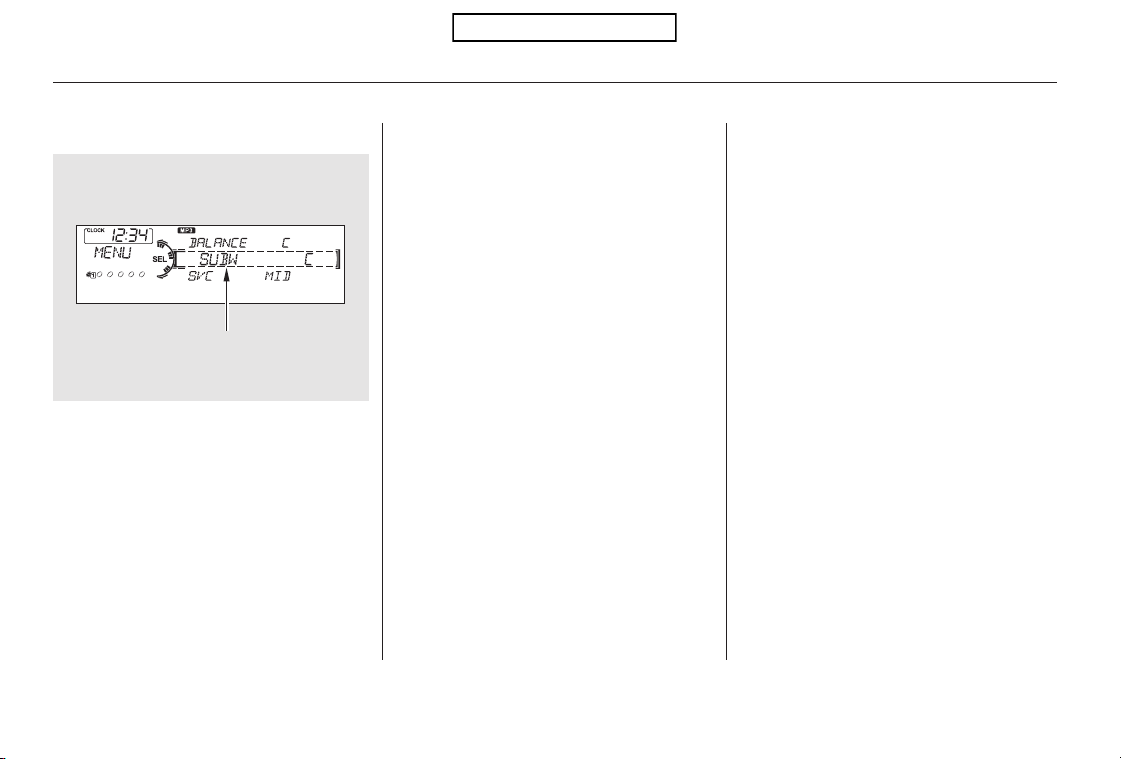
−
−
−
−
−
−
Adjusts the bass.
Adjusts the side-to-
side strength of the sound.
Adjusts the front-to-back
strength of the sound.
Adjusts the treble.
Adjusts the strength of
sound from the subwoofer speaker.
If the fader adjustment is set to F9
(maximum front level), the
subwoofer is turned off.
The SVC mode controls the volume
based on vehicle speed. The faster
you go, the louder the audio volume
becomes. As you slow down, the
audio volume decreases.
To return to the normal play, push
the RETURN or MENU button after
you stop adjusting a mode.
When the level reaches the center,
you will see ‘‘C’’ in the display.
Eachmodeisshowninthedisplayas
it changes. Turn the selector knob to
adjust the setting to your liking.
Adjusts the volume level
basedonthevehiclespeed.
The SVC has four modes: SVC OFF,
SVC LOW, SVC MID, and SVC
HIGH. Turn the selector knob to
adjust the setting to your liking. If
you feel the sound is too loud,
choose low. If you feel the sound is
too quiet, choose high.
You can use the instrument panel
brightness control knob to adjust the
illumination of the audio system (see
page ). The audio system
illuminates when the parking lights
are on, even if the radio is turned off.
73
Except SVC adjustment
BASS
BALANCE
FADER
TREBLE
SUBW
SVC
Audio System Lighting
Speed-sensitive Volume
Compensation (SVC)
Playing the FM/AM Radio (Models without navigation system)
144
SUBWOOFER is selectable.
Table of Contents
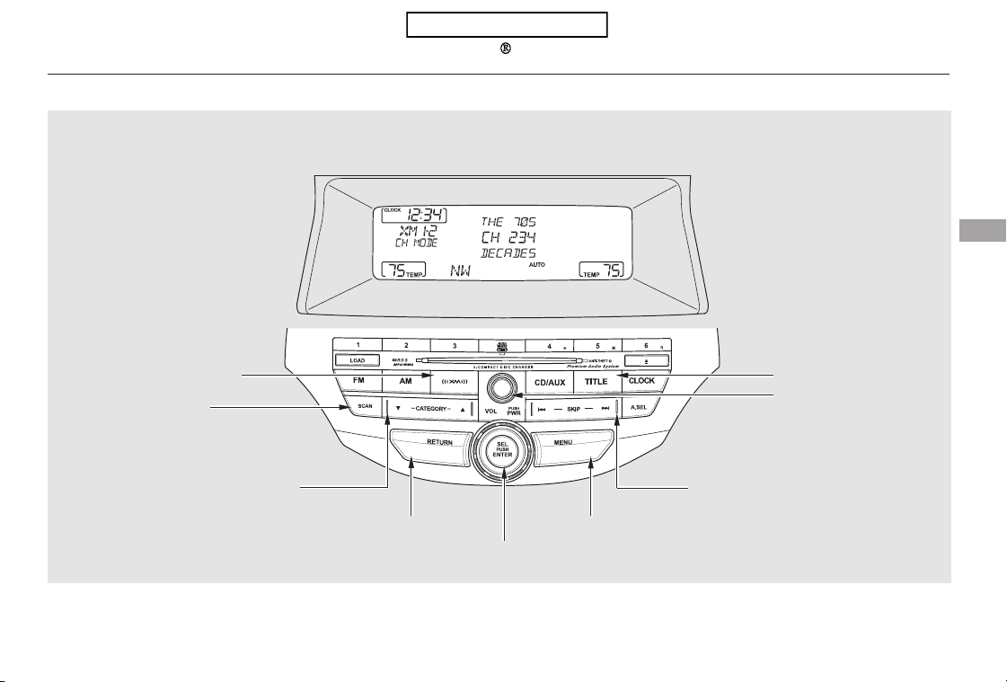
CONTINUED
Playing the XM Radio (Models without navigation system)
Features
EX-L models
145
CATEGORY BAR
SKIP BAR
XM RADIO BUTTON
SELECTOR KNOB
SCAN BUTTON
POWER/VOLUME
KNOB
TITLE BUTTON
RETURN BUTTON MENU BUTTON
U.S. model is shown.
Table of Contents
−
To listen to XM Radio, turn the
ignition switch to the ACCESSORY
(I) or ON (II) position, and press the
button. The last channel you
listened to will show in the display.
Adjust the volume by turning the
power/volume knob.
To switch between
channel mode and category mode,
press and hold the TITLE button
until the mode changes.
In the channel mode, you can select
all of the available channels. In the
category mode, such as Jazz, Rock,
Classical, etc., you can select all of
the channels within that category.
Each time you press and release the
TITLE button, the display changes in
the following sequence: name, title,
and category.
You can also change the mode from
the menu items. Press the MENU
button to display the menu items,
then turn the selector knob to select
MODE/CATEGORY and press the
selector knob (ENTER). Each time
you press and release the selector
knob (ENTER), the display changes
between CHANNEL and
CATEGORY. To enter the setting,
press the TITLE button.
You may experience periods when
XM Radio does not transmit the
artist’s name and song title
information. If this happens, there is
nothing wrong with your system.
XM Radio receives signals from two
satellites to produce clear, high-
quality digital reception. It offers
many channels in several categories.
Along with a large selection of
different types of music, XM Radio
allows you to view channel and
category selections in the display.
Your vehicle is capable of receiving
XM
Radio anywhere in the United
States and Canada, except Hawaii,
Alaska,andPuertoRico.XMisa
registered trademark of Sirius XM
Radio
,Inc.andXMCANADA is a
registered business name of
Canadian Satellite Radio Inc.
EX-L models
Operating the XM Satellite Radio
MODE
Playing the XM Radio (Models without navigation system)
146
Table of Contents
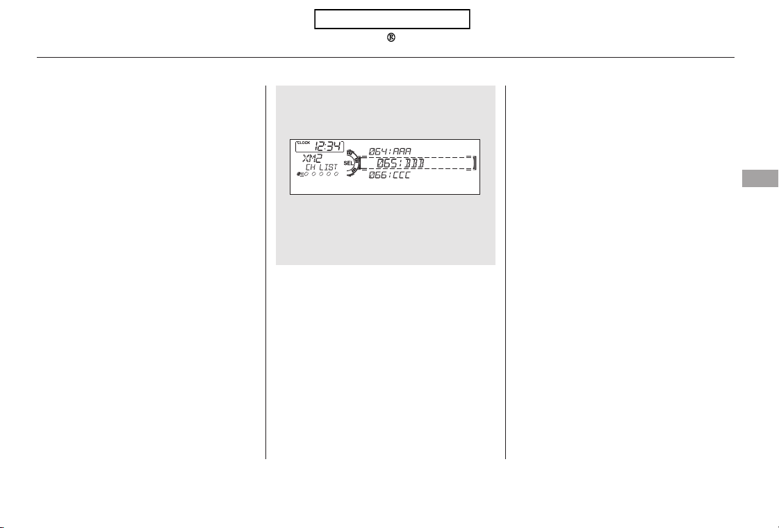
−
▼▲−−
CONTINUED
The SCAN function gives
you a sampling of all channels while
in the channel mode. In the category
mode, only the stations within that
category are scanned. To activate
scan, press the SCAN button. The
system plays each channel in
numerical order for a few seconds,
then selects the next channel. When
you hear a channel you want to
continue listening to, press the
button again.
Press
either side of the CATEGORY bar to
select another category.
You can also select a channel or
category from the list by using the
selector knob. Push the selector
knob (ENTER) to switch the display
to the list displayed with three
segments, then turn the knob to
select a channel or category. Press
the selector knob (ENTER) to set
your selection.
Turn the selector knob to
change channel selections. Turn the
knob right for higher numbered
channels and left for lower
numbered channels. In the category
mode, you can only select channels
within that category.
SCAN
CATEGORY ( or )TUNE
Playing the XM Radio (Models without navigation system)
Features
147
Channel list is shown.
Table of Contents

−−
−
−
−
−
−
−
Youcanstoreupto12
preset channels using the six preset
buttons. Each button stores one
channel from the XM1 band and one
channel from the XM2 band.
To store a channel:
Press the button. Either
XM1 or XM2 will show in the
display.
Use the selector knob, or the
CATEGORYbarorSCANbutton
to tune to a desired channel.
In category mode, only channels
within that category can be selected.
In channel mode, all channels can be
selected.
Pick the preset button you want
for that channel. Press and hold
the button until you hear a beep.
Repeat steps 2 and 3 to store the
first six channels.
Press the XM button again. The
other XM band will show. Store
the next six channels using steps 2
and 3.
Once a channel is stored, simply
press and release the proper preset
button to tune to it.
The encryption
code is being updated. Wait until the
encryption code is fully updated.
Channels 0 and 1 should still work
normally.
The signal is
currently too weak. Move the vehicle
to an area away from tall buildings,
and with an unobstructed view of the
southern horizon.
The selected channel
number does not exist, or is not part
of your subscription, or this channel
has no artist or title information at
this time.
XM is loading the
audio or program information.
The channel
currently selected is no longer
broadcasting.
There is a problem
with the XM antenna. Please consult
your dealer.
The selected
channel has no artist or title
information at this time.3.
4.
5.
2.
1.
Preset
XM Radio Display Messages
‘‘UPDATING’’
‘‘NO SIGNAL’’
‘‘----’’
‘‘LOADING’’
‘‘OFF AIR’’
‘‘ANTENNA’’
‘‘NO INFO’’
Playing the XM Radio (Models without navigation system)
148
Table of Contents
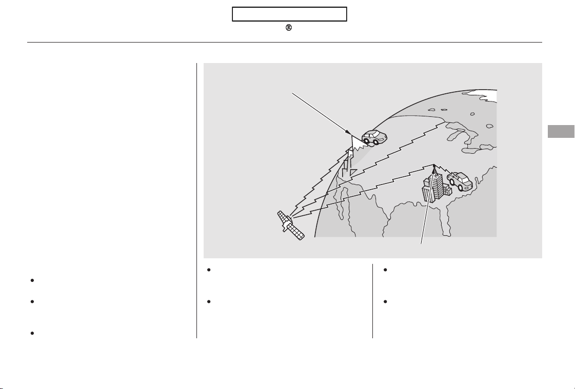
The XM satellites are in orbit over
the equator; therefore, objects south
of the vehicle may cause satellite
reception interruptions. To help
compensate for this, ground-based
repeaters are placed in major
metropolitan areas.
Satellite signals are more likely to be
blocked by tall buildings and
mountains the farther north you
travel from the equator. Carrying
large items on a roof rack can also
block the signal.
Depending on where you drive, you
may experience reception problems.
Interference can be caused by any of
these conditions:
Driving on the north side of an
east/west mountain road.
Driving on the north side of a
large commercial truck on an
east/west road.
Driving in tunnels.
Driving on a road beside a vertical
wall, steep cliff, or hill to the south
of you.
Driving on the lower level of a
multi-tiered road.
Driving on a single lane road
alongside dense trees taller than
50 ft. (15 m) to the south of you.
Large items carried on a roof rack.
CONTINUED
Playing the XM Radio (Models without navigation system)
Features
149
Signal may be blocked by
mountains or large obstacles to
the south.
Signal weaker in
these areas.
SATELLITE
GROUND REPEATER
Table of Contents
There may be other geographic
situations that could affect XM Radio
reception.
After you’ve registered with XM
Radio, keep your audio system in the
XM Radio mode while you wait for
activation. This should take about 30
minutes.
If your XM Radio service has expired
or you purchased your vehicle from
a previous owner, you can listen to a
sampling of the broadcasts available
on XM Radio. With the ignition
switch in the ACCESSORY (I) or the
ON (II) position, press the
button. A variety of music
types and styles will play.
While waiting for activation, make
sure your vehicle remains in an open
area with good reception. Once your
audio system is activated,
‘‘CATEGORY’’ or ‘‘CHANNEL’’ will
appear in the display, and you’ll be
able to listen to XM radio broadcasts.
XM Radio will continue to send an
activation signal to your vehicle for
at least 12 hours from the activation
request. If the service has not been
activated after 36 hours, contact
XM
Radio. In Canada, contact XM
CANADA
.
If you decide to purchase XM radio
service, contact XM Radio at
,orat
1-800-852-9696. In Canada, contact
XM CANADA
at , or
at 1-877-209-0079. You will need to
give them your radio I.D. number
and your credit card number. To get
your radio I.D. number, press the
button, then turn the
selector knob until ‘‘CH 000’’ appears
in the display. Your I.D. will appear
in the display.
As required by the FCC:
Changes or modifications not expressly
approved by the party responsible for
compliance could void the user’s
authority to operate the equipment.
www.xmradio.com
www.xmradio.ca
Receiving XM Radio Service
Playing the XM Radio (Models without navigation system)
150
Table of Contents
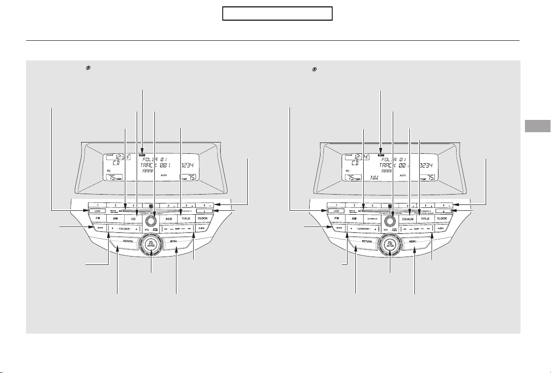
Playing Discs (Models without navigation system)
Features
Without XM Radio
With XM
Radio
151
SCAN
BUTTON
MENU BUTTON
SKIP BAR
POWER/VOLUME KNOB
TITLE BUTTON
FOLDER BAR
SELECTOR
KNOB
PRESET
BUTTONS
RETURN BUTTON
MP3/WMA INDICATOR
DISC LOAD
BUTTON
DISC SLOT
CD BUTTON
DISC
EJECT
BUTTON
SCAN
BUTTON
MENU BUTTON
SKIP BAR
POWER/VOLUME KNOB
TITLE BUTTON
SELECTOR
KNOB
PRESET
BUTTONS
RETURN BUTTON
MP3/WMA INDICATOR
DISC LOAD
BUTTON
DISC
EJECT
BUTTON
DISC SLOT
CD/AUX BUTTON
CATEGORY BAR
U.S. models are shown.
Table of Contents
To load or play discs, the ignition
switch must be in the ACCESSORY
(I) or ON (II) position.
You operate the disc changer with
the same controls used for the radio.
To select the disc changer, press the
CD/AUX or CD button. You will see
‘‘CD’’ in the display. The disc and
track numbers, and the elapsed time
areshowninthedisplay.Youcan
also select the displayed information
with the TITLE button (see page
). The system will continuously
play a disc until you change modes.
This audio system can also play
CD-Rs and CD-RWs compressed in
MP3 or WMA formats. The numbers
of the folder and track playing are
showninthedisplayonthedisc
player. A disc can support more than
99 folders, and each folder can hold
more than 255 playable files. A disc
canholdupto999filesintotal.
Video CDs and DVDs do not work in
this unit.
Depending on the software the files
were made with, it may not be
possible to play some files, or display
some text data.
Your vehicle’s in-dash disc changer
holdsuptosixdiscs.
If a file on a WMA disc is protected
by digital rights management
(DRM), the audio unit displays
UNSUPPORTED, and then skips to
the next file.
Press the LOAD button until you
hear a beep and see ‘‘LOAD’’ in
the display. To load only one disc,
press and release the LOAD
button.
The disc number for an empty
position begins blinking.
Insert the disc into the disc slot
when the green disc load indicator
comes on. Insert it only about
halfway; the drive will pull it in the
rest of the way. You will see
‘‘BUSY’’ in the display while the
disc load indicator turns red and
blinks as the disc is loaded.
153
1.
2.
3.
To Play a Disc
Playing Discs (Models without navigation system)
Loading Discs
152
NOTE:
Do not use discs with adhesive labels.
The label can curl up and cause the
disc to jam in the unit.
Table of Contents

CONTINUED
You cannot load and play 3-inch
(8-cm) discs in this unit.
When the disc load indicator turns
green and ‘‘LOAD’’ appears in the
display again, insert the next disc
in the slot. Do not try to insert a
disc until ‘‘LOAD’’ appears. You
could damage the audio unit.
Repeat this until all six positions
are loaded. If you are not loading
all six positions, the system begins
playing the last disc loaded.
You can also load a disc into an
empty position while a disc is playing
by pressing the appropriate preset
button. The system stops playing the
current disc and starts the loading
sequence. It then plays the disc just
loaded.
Each time you press the TITLE
button, the display shows you the
text, if the disc was recorded with
text data.
You can see the album, artist, and
track name in the display. If a disc is
recorded in MP3 or WMA, you can
see the folder and file name, and the
artist, album, and track tag.
With the folder name, you will see
the FOLDER indicator in the display.
The TRACK indicator is shown with
the file or track name.
When you press and release the
TITLE button while a disc without
text data is playing, you will see ‘‘NO
INFO’’ on the display.
The display shows up to 16
characters of selected text data (the
folder name, file name, etc.).
If the text data has more than 16
characters, you will see the first 16
characters and the indicator in
the display. Press and hold the
TITLE button until the next 16
characters are shown. You can see
up to 32 characters of the text data.
IfyoupressandholdtheTITLE
button again, the display shows the
first 16 characters again.
If any letter is not available, it is
replaced with ‘‘ . ’’ (dot) in the display.
When the disc has no text data, you
will see ‘‘NO INFO’’ on the display.
4.
5.
Playing Discs (Models without navigation system)
Text Data Display Function
Features
153
Table of Contents
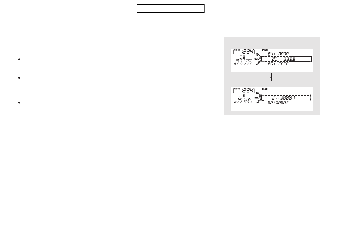
In MP3 or WMA mode, you can also
select a folder or track/file from the
list by using the selector knob. Push
the selector knob (ENTER) to
switch the display to the list
displayed with three segments, then
turn the knob to select a folder.
Press the selector knob (ENTER) to
change the display to the track/file
list, then turn the same knob to
select a track/file. Press the selector
knob (ENTER) to set your selection.
Use the SKIP bar while a disc is
playing to select passages and
change tracks (files in MP3 or WMA
mode).
In MP3 or WMA mode, use the
FOLDER bar (CATEGORY bar on
models with XM Radio) to select
folders in the disc and use either
side of the skip bar to change files.
To select a different disc, use the
appropriate preset buttons (1
through 6). If you select an empty
position, the system will go into the
loading sequence (see page ).
When you insert a disc, and the
system begins to play.
When a new folder, file, or track is
selected.
When you change the audio mode
to play a disc with text data or in
MP3 or WMA.
You will also see some text data
under these conditions:
When playing a CD-DA with text
data, the album and track name are
showninthedisplay.Withadiscin
MP3 or WMA, the display shows the
folder and file name.
152
Playing Discs (Models without navigation system)
To Change or Select Tracks/Files
154
Folder Selection
Track Selection
Press ENTER.
Table of Contents
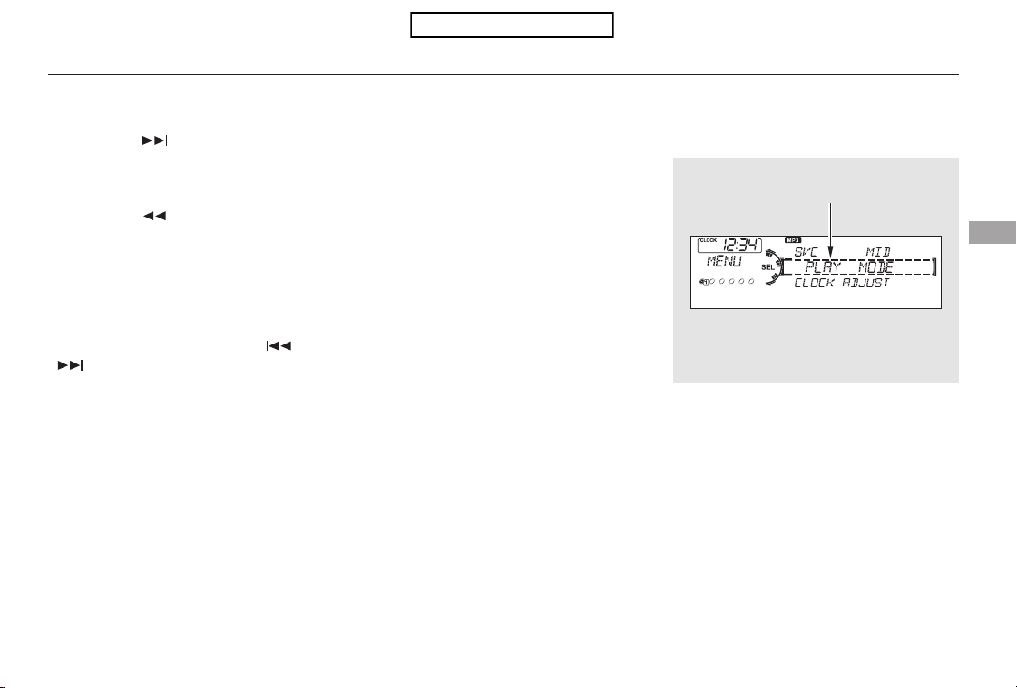
−
−
▲▼
▲
▼
CONTINUED
Each time you press and
releasethe sideoftheSKIPbar,
the player skips forward to the
beginning of the next track (file in
MP3 or WMA mode). Press and
releasethe sideofthebarto
skip backward to the beginning of
the current track. Press it again to
skip to the beginning of the previous
track.
To move rapidly within a track or file,
press and hold either side ( or
) of the SKIP bar.
To
select a different folder, press either
side ( or ) of the FOLDER bar
(CATEGORY bar on models with
XM Radio) to move to the beginning
of the next folder. Press the side
to skip to the next folder, and press
the side to skip to the beginning
of the previous folder.
You can select any type of repeat,
random and scan modes by using the
MENU button and the selector knob.
Push the MENU button to display
themenuitems,thenturnthe
selector knob to select ‘‘PLAY
MODE.’’ Press the selector knob
(ENTER) to set the selection.
In MP3 or WMA mode
Playing Discs (Models without navigation system)
SKIP
FOLDER SELECTION
To Select Repeat, Random or Scan
Mode:
Features
155
MENU ITEMS
Table of Contents

−−
−
−
Turn the selector knob to select an
appropriate repeat, random or scan
mode, then press the selector knob
(ENTER) to set your selection.
To cancel the selected repeat,
random, or scan mode, press the
MENU button to show ‘‘PLAY
MODE,’’ then press the selector
knob (ENTER). When you see
‘‘NORMAL PLAY,’’ press ENTER
again.
To
continuously replay a track (file in
MP3 or WMA mode), select
REPEAT ONE TRK from the menu
items. You will see REPEAT in the
display. Select normal play to turn it
off.
This feature
continuously replays the current disc.
To activate disc repeat, select
REPEAT DISC from the menu items.
You will see D-REPEAT in the
display. Select normal play to turn it
off.
This feature,
when activated, replays all the files
on the selected folder in the order
they are compressed in MP3 or
WMA. To activate folder repeat
mode, select REPEAT ONE FLD
from the menu items. You will see
F-REPEAT in the display. The
system continuously replays the
current folder. Select normal play to
turn it off. Selecting a different
folder with the FOLDER bar
(CATEGORY bar on models with
XM Radio) also turns off the repeat
feature.
Pressing either side of the SKIP bar
also turns off the repeat feature.
This feature,
when activated, plays the files within
the current folder in random order,
rather than in the order they are
compressedinMP3orWMA.To
activate folder random play, select
RANDOM IN FLD from the menu
items. You will see F-RANDOM in
the display. The system will then
select and play files randomly. This
continues until you deactivate folder
random play by selecting normal play,
or you select a different folder with
the FOLDER bar (CATEGORY bar
on models with XM Radio).
In MP3 or WMA mode
In MP3 or WMA mode
Playing Discs (Models without navigation system)
REPEAT ONE TRK REPEAT DISC
REPEAT ONE FLD
RANDOM IN FLD
156
PLAY MODE ITEMS
Table of Contents

−−
−
CONTINUED
This feature
plays the tracks within a disc (the
files in MP3 or WMA mode) in
random order. To activate random
play, select RANDOM IN DISC from
the menu items. You will see
RANDOM in the display. Select
normal play to return to normal play.
The SCAN function
samples all the tracks on the disc in
the order they are recorded on the
disc (all files in the selected folder in
MP3 or WMA mode). To activate the
scan feature, press and release the
SCAN button. You will see SCAN in
the display. You will get a 10 second
sampling of each track/file in the
disc/folder. Press and hold the
SCAN button to get out of scan
mode and play the last track sampled.
This function
samples the first file in each folder in
the order they are stored. To
activate the folder scan feature,
press and release the SCAN button
repeatedly. You will see F-SCAN in
the display. You will get a 10 second
sampling of the first file in each
folder.PressandholdtheSCAN
button to get out of the folder scan
mode and play the last file sampled.
You can also select the scan feature
from the menu items with the
selector knob (see page ).
You can also select the folder scan
feature from the menu items with
the selector knob (see page ).
Pressing either side of the skip bar,
or selecting a different disc (using
the preset buttons) or folder (using
the FOLDER or CATEGORY bar)
turns off the SCAN or F-SCAN
feature.
155 155
In MP3 or WMA mode
RANDOM IN DISC SCAN TRK
SCAN FLD
Playing Discs (Models without navigation system)
Features
157
Table of Contents

−This feature, when
activated, samples the first track on
each disc in order (the first file in
themainfolderoneachdiscinMP3
or WMA mode). To activate the disc
scan feature, press and release the
SCAN button repeatedly until
D-SCAN shows in the display. The
system will then play the first track/
file in the first main folder on the
first disc for about 10 seconds. If you
do nothing, the system will then play
the following first track/file for 10
seconds each. When it plays a track/
file that you want to continue
listening to, press and hold the
SCAN button again.
Each time you press and release the
SCAN button, the mode changes
from scan, disc scan, then to normal
play.
Each time you press and release the
SCAN button, the mode changes
from file scan, folder scan, disc scan,
then to normal play.
When the first track on the last disc,
or the first file in the last main folder
in the last disc begins to play, the
disc scan mode will be canceled.
Pressing either side of the skip bar
or selecting a different folder with
the FOLDER or CATEGORY bar
also turns off the scan feature.
You can also select the disc scan
feature from the menu items with
the selector knob (see page ).
Press the eject button ( ) to
remove the disc. If you eject the disc,
but do not remove it from the slot,
the system will automatically reload
the disc after 10 seconds and begin
playing.
You can also eject the disc when the
ignition switch is off.
To play the radio when a disc is
playing,presstheAM,FMorXM(if
equipped) button. Press the CD
(CD/AUX on models with XM
Radio) button again to switch back to
the disc changer.
You can also press the MODE
buttononthesteeringwheelto
change modes.
155
In MP3 or WMA mode
D-SCAN To Stop Playing a Disc
Playing Discs (Models without navigation system)
158
Table of Contents

If you turn the system off while a
disc is playing, either with the
power/volume knob or by turning
off the ignition switch, the disc will
stay in the drive. When you turn the
system back on, the disc will begin
playing where it left off.
For information on how to handle
and protect compact discs, see page
.
To remove the disc currently in play,
press the eject button. When a disc is
removed from a slot, the system
automatically begins the load
sequence so you can load another
disc in that position. If you do not
remove the disc from the changer
within 10 seconds, the disc will
reload into the slot. Then the system
returns to the previous mode (AM,
FM, or XM Radio).
To remove a different disc from the
changer,firstselectitwiththe
appropriate preset button. When that
disc begins playing, press the eject
button. Continue pressing the eject
button to remove all the discs from
the changer.
You can also eject discs when the
ignition switch is off. The disc that
was last selected is ejected first.
233
Protecting Discs
Removing Discs from the In-dash
Disc Changer
Playing Discs (Models without navigation system)
Features
159
Table of Contents
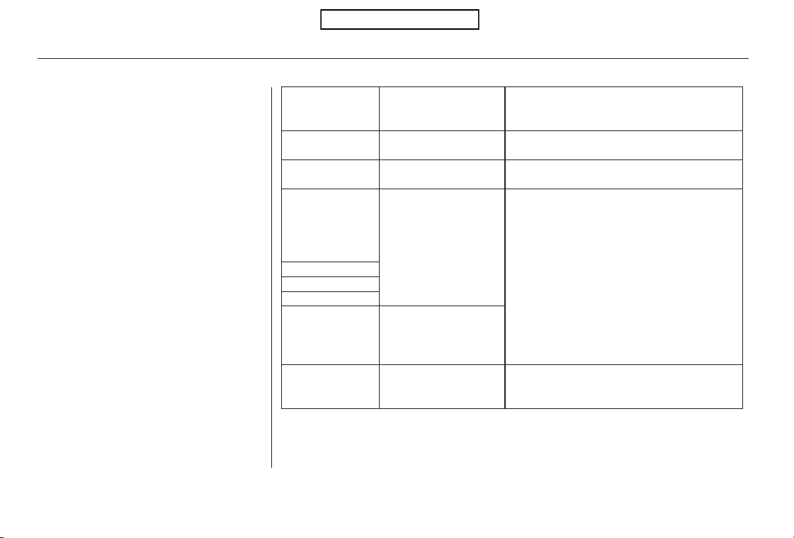
Thechartontherightexplainsthe
error messages you may see in the
display while playing a disc.
If you see an error message in the
display while playing a disc, press
the eject button. After ejecting the
disc, check it for damage or
deformation. If there is no damage,
insert the disc again.
For additional information on
damaged discs, see page .
Theaudiosystemwilltrytoplaythe
disc. If there is still a problem, the
error message will reappear. Press
the eject button, and pull out the disc.
Insert a different disc. If the new
disc plays, there is a problem with
the first disc. If the error message
cycle repeats and you cannot clear it,
take your vehicle to a dealer.
Error Message Cause Solution
234
High temperature
Track/File format not
supported
Mechanical error
Servo error
Disc error
Will disappear when the temperature returns to
normal.
Current track will be skipped. The next
supported track or file plays automatically.
Press the EJECT button and pull out the disc.
Check the disc for serious damage, signs of
deformation, excessive scratches, and/or dirt
(see page 234). Insert the disc again. If the code
does not disappear, or the disc cannot be
removed, consult your dealer. Do not try to
force the disc out of the player.
Check the disc for serious damage, signs of
deformation, excessive scratches, and/or dirt
(see page 234).
Disc Changer Error Messages (Models without navigation system)
160
HEAT ERROR
UNSUPPORTED
BAD DISC
PLEASE CHECK
OWNERS
MANUAL PUSH
EJECT
MECH ERROR
CHANGER ERROR
CHECKDISCLOAD
BAD DISC
PLEASE CHECK
OWNERS
MANUAL
CHECK DISC
Table of Contents
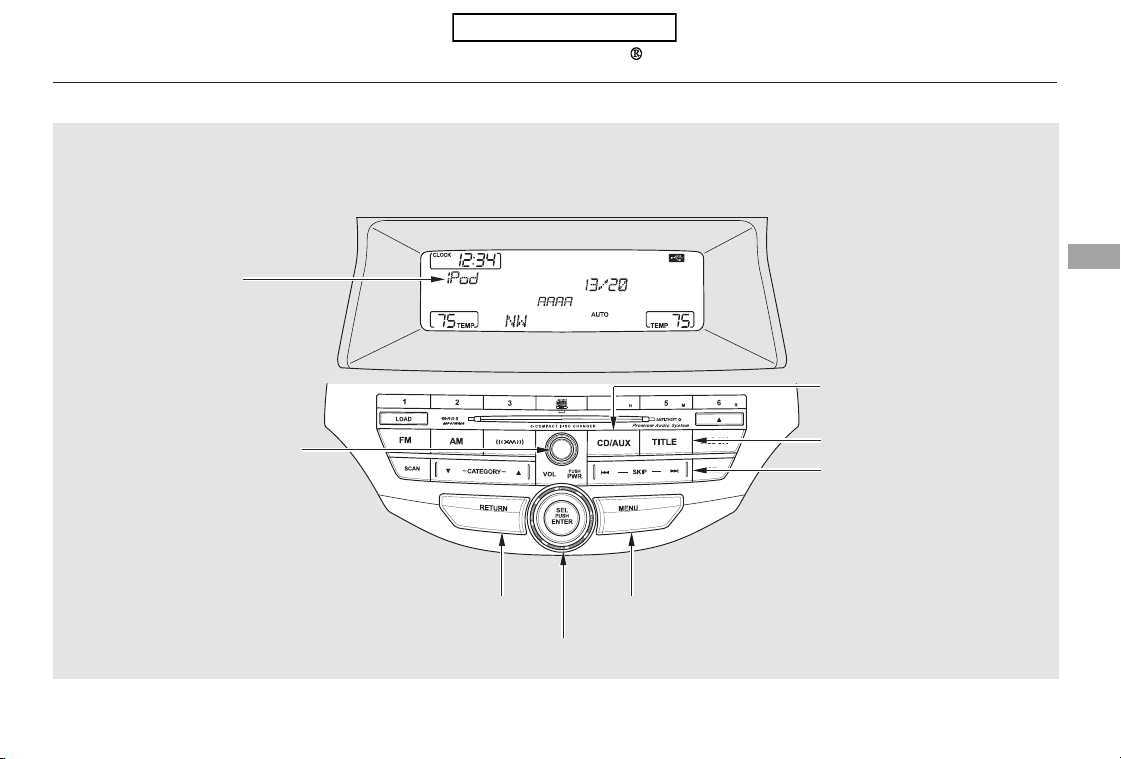
Playing an iPod (Models without navigation system)
EX-L models
Features
161
RETURN BUTTON
SELECTOR KNOB
iPod INDICATOR
SKIP BAR
CD/AUX BUTTON
TITLE BUTTON
POWER/VOLUME KNOB
U.S. model is shown.
MENU BUTTON
Table of Contents
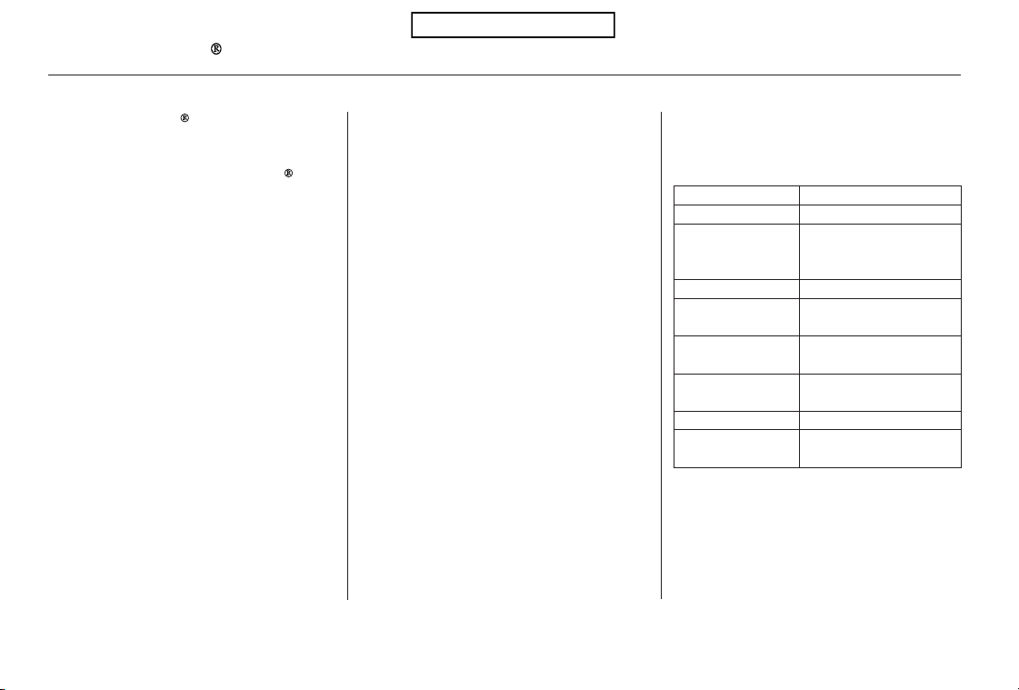
The audio system reads and plays
playable sound files on the iPod. The
system cannot operate an iPod as a
mass storage device. The system will
only play songs stored on the iPod
with iTunes.
iPod and iTunes are registered
trademarks owned by Apple Inc.
iPods compatible with your audio
system using the USB adapter cable
are:
UseonlycompatibleiPodswiththe
latest software. iPods that are not
compatible will not work in this audio
unit.
This audio system can select and
play the audio files on the iPod
with
the same controls used for the disc
player. To play an iPod, connect it to
the USB adapter cable in the console
compartment by using your dock
connector, then press the CD/AUX
button. The ignition switch must be
in the ACCESSORY (I) or ON (II)
position. The iPod will also be
recharged with the ignition switch in
these positions.
Software
Ver. 1.0 or more
Ver. 1.2 or more
Ver. 1.2 or more
Ver. 1.1.2 or more
Ver. 1.0 or more
Ver. 1.0.2 or more
Ver. 1.1.1 or more
Ver. 2.1.1 or more
Model
iPod classic
iPod with video
(iPod 5th
generation)
iPod nano
iPod nano 2nd
generation
iPod nano 3rd
generation
iPod nano 4th
generation
iPod touch
iPod touch 2nd
generation
EX-L models
To Play an iPod
Playing an iPod (Models without navigation system)
162
Table of Contents
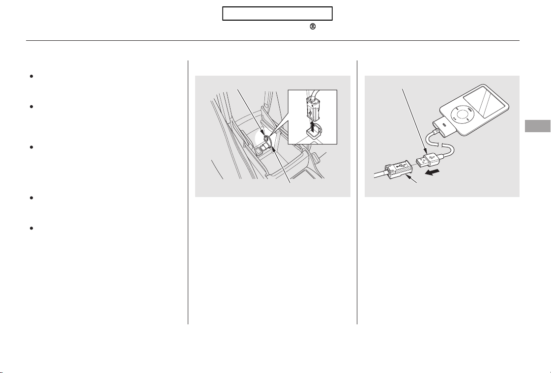
Do not connect your iPod using a
hub.
DonotkeeptheiPodinthe
vehicle. Direct sunlight and high
heat will damage it.
Do not use an extension cable
between the USB adapter cable
equipped with your vehicle and
your dock connector.
We recommend backing up your
data before playing it. Connect your dock connector to
the iPod correctly and securely.
Install the dock connector to the
USB adapter cable securely.
Pull out the USB connector from
the holder.
Some devices cannot be powered
or charged via the USB adapter. If
this is the case, use the accessory
adapter to supply power to your
device.
1. 2.
3.
CONTINUED
Connecting an iPod
Playing an iPod (Models without navigation system)
Features
163
NOTE:
DOCK CONNECTOR
USB ADAPTER CABLE
USB CONNECTOR
USB CONNECTOR
Table of Contents
−
If the iPod indicator does not appear
in the audio display, check the
connections, and try to reconnect the
iPod a few times.
If the audio system still does not
recognize the iPod, the iPod may
need to be reset. Follow the
instructions that came with your
iPod, or you can find reset
instructions online at
Each time you press the TITLE
button the display mode switches
between the album name, the song
name, the artist name, or name off
(which turns off the text display).
Use the SKIP bar while an iPod is
playing to select passages and
change files.
Each time you press and
releasethe sideoftheSKIPbar,
the system skips forward to the
beginning of the next file. Press and
releasethe sideofthebarto
skip backward to the beginning of
the current file. Press it again to skip
to the beginning of the previous file.
To move rapidly within a file, press
andholdeitherside( or )
of the SKIP bar.
Turning the selector knob to the
right or the left also changes the file.
If the text data has more than 16
characters, you will see the first 16
characters and the indicator in
the display. Press and hold the
TITLE button until the next 16
characters are shown. You can see
up to 32 characters of the text data.
www.apple.com/
itunes/
Text Data Display Function To Change or Select Files
SKIP
Playing an iPod (Models without navigation system)
164
Table of Contents
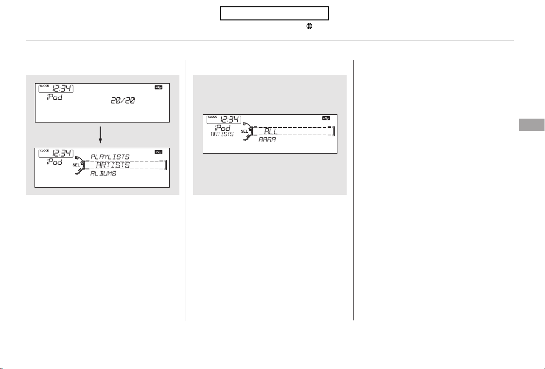
You can also select a file from any
list on the iPod menu: playlists,
artists, albums and songs, by using
the selector knob. Push the selector
knob (ENTER) to switch the display
to an iPod menu, then turn the
selector knob to select a desired list.
Press ENTER to set your selection.
The display shows items on the
selected list. Turn the selector knob
to select an item, then press ENTER
to set your selection.
If you select ‘‘ALL,’’ all available files
on the selected list are played.
Pressing the RETURN button goes
back to the previous display and
pressing the MENU button cancels
this setting mode.
CONTINUED
To Select a File from iPod Menu
Playing an iPod (Models without navigation system)
Features
165
Push ENTER.
Table of Contents
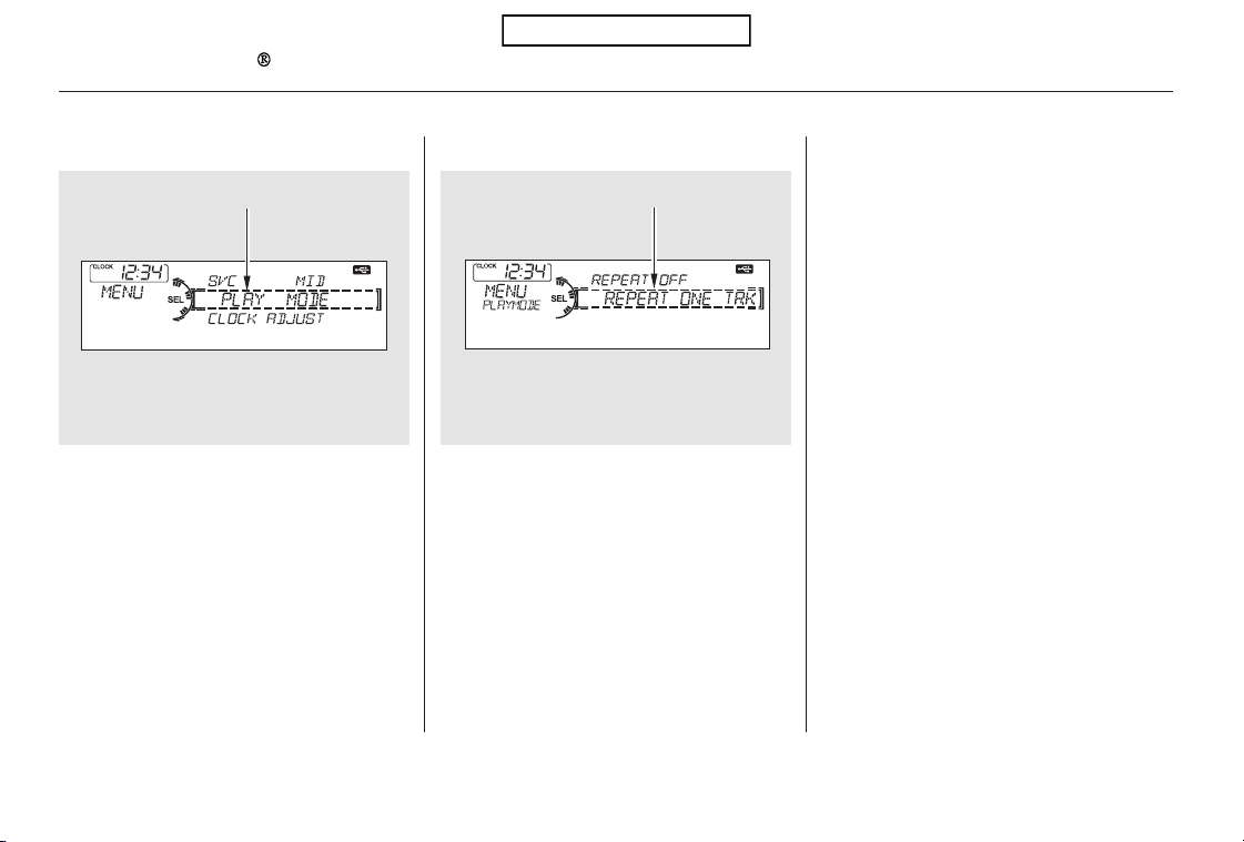
You can select any type of repeat and
shufflemodebyusingtheMENU
button and the selector knob. Press
the MENU button to display the
menu items, then turn the selector
knob to select ‘‘PLAY MODE.’’ Press
ENTER to set the selection.
Turn the selector knob to select a
play mode: normal play, shuffle off,
shuffle all, shuffle album, repeat off,
or repeat one track, then press
ENTER to set your selection.
To cancel the selected mode, press
the MENU button and turn the
selector knob to show ‘‘PLAY
MODE,’’ then press ENTER. When
you see ‘‘NORMAL PLAY,’’ press
ENTER again.
To Select Repeat or Shuf fle Mode:
Playing an iPod (Models without navigation system)
166
MENU ITEMS
PLAY MODE ITEMS
Table of Contents
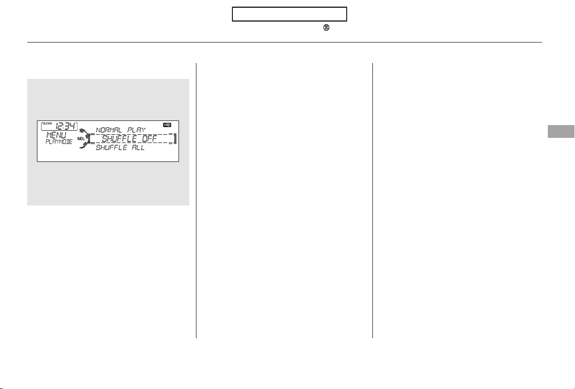
−
−
−
−
−
This feature
plays all available files in a selected
list (playlists, artists, albums or
songs) in random order.
You will see SHUFFLE in the display.
Selectthenormalplaymodeor
SHUFFLE OFF to turn off this
feature.
This feature
plays all available albums in a
selected list (playlists, artists, albums
or songs) in random order. The files
in each album are played in the
recorded order. You will see ALB
SHUF in the display.
Selectthenormalplaymodeor
SHUFFLE OFF to turn off this
feature.
This feature turns
off the repeat mode.
This
feature continuously plays a file. You
will see REPEAT in the display.
Select normal play or REPEAT OFF
to turn it off.
This feature
turns off either of the shuffle modes
(SHUFFLE ALL and SHUFFLE
ALBUM).
Pressing either side of the SKIP bar
or turning the selector knob changes
the file while keeping the repeat
feature.
Pressing either side of the SKIP bar
or turning the selector knob changes
a file while keeping the shuffle
function.
Available operating functions vary on
models or versions. Some functions
may not be available on the vehicle’s
audio system.
SHUFFLE ALL
SHUFFLE ALBUM
REPEAT OFF
REPEAT ONE TRK
SHUFFLE OFF
Playing an iPod (Models without navigation system)
Features
167
NOTE:
Table of Contents
*
*
You can disconnect the iPod at any
time when you see ‘‘OK to
disconnect’’ message in the iPod
display. Always make sure you see
‘‘OK to disconnect’’ message in the
iPod display before you disconnect it.
Make sure to follow the iPod’s
instructions on how to disconnect
the dock connector from the USB
adapter cable.
If you see an error message in the
display, see page .
The displayed message may
vary on models or versions.
On some models, there is no
message to disconnect.
If you reconnect the same iPod, the
system may begin playing where it
left off, depending on what mode the
iPod is in when it is reconnected.
To play the radio, press the AM, FM,
or button. Press the CD/
AUX button to switch between disc
(if a disc is loaded) and the iPod.
You can also press the MODE
buttononthesteeringwheelto
change modes.
:
169
Disconnecting an iPod
To Stop Playing Your iPod iPod Error Messages
Playing an iPod (Models without navigation system)
168
Table of Contents
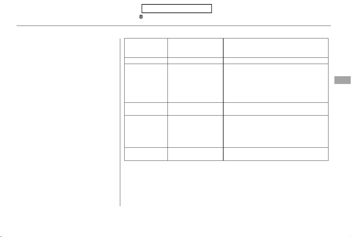
If you see an error message on the
audio display while playing an iPod,
find the solution in the chart to the
right. If you cannot clear the error
message, take your vehicle to your
dealer.
SolutionError Message Cause
There is a problem with the USB adapter unit.
Appears when the overcurrent protection
feature of the system stops supplying power to
USB because an incompatible device is
connected. Disconnect the device. Then, turn
the audio system off, and turn it on again. Do
not reconnect the device that caused the error.
Appears when the iPod is empty. Store some
files in the iPod.
Appears when an unsupported iPod is
connected. See page 162 for the specification
information for iPods. If it appears when a
supported iPod is connected, update the iPod
software to the newer version.
Appears when the system does not
acknowledge the iPod. Reconnect the iPod.
USB ROM Error
Abnormal power
source
No files in iPod
Use of unsupported
iPod
Recognition failure of
iPod
iPod Error Messages (Models without navigation system)
Features
169
USB ERROR
BAD USB
DEVICE
PLEASE CHECK
OWNERS
MANUAL
iPod NO SONG
UNSUPPORTED
VER.
CONNECT RETRY
Table of Contents
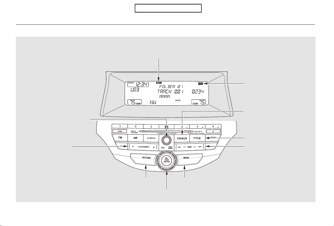
Playing a USB Flash Memory Device (Models without navigation system)
EX-L models
170
MENU BUTTONRETURN BUTTON
TITLE BUTTON
USB INDICATOR
SKIP BAR
FILE TYPE INDICATOR
CD/AUX BUTTON
POWER/VOLUME KNOB
CATEGORY BAR
SELECTOR KNOB
U.S. model is shown.
Table of Contents

*
*
CONTINUED
Do not use a device such as a card
reader or hard drive as the device
or your files may be damaged.
Do not connect your USB flash
memory device using a hub.
Do not use an extension cable to
the USB adapter cable equipped
with your vehicle.
Do not keep a USB flash memory
device in the vehicle. Direct
sunlight and high heat will damage
it.
We recommend backing up your
data before playing a USB flash
memory device.
Some USB flash memory devices
(such as devices with security lock-
out features, etc.) will not work in
this audio unit.
The recommended USB flash
memory devices are 256 MB or
higher, and formatted with the FAT
file system. Some digital audio
players may be compatible as well.
Only AAC format files recorded
with iTunes are playable on this
audio unit.
The audio system reads and plays
the audio files on the USB flash
memory device in MP3, WMA or
AAC formats. Depending on the
format, the display shows MP3,
WMA or AAC when a USB flash
memory device is playing. The USB
flash memory device limit is up to
700 folders or up to 65535 files.
This audio system can select and
play the audio files on a USB flash
memory device with the same
controls used for the disc player. To
play a USB flash memory device,
connect it to the USB adapter cable
in the console compartment, then
press the CD/AUX button. The
ignition switch must be in the
ACCESSORY (I) or ON (II) position.
:
EX-L models
To Play a USB Flash Memory
Device
Playing a USB Flash Memory Device (Models without navigation system)
Features
171
NOTE:
Table of Contents
Depending on the type of
encoding and writing software
used, there may be cases where
character information does not
display properly.
Depending on the type and
number of files, it may take some
time before they begin to play.
Depending on the software the
files were made with, it may not be
possibletoplaysomefiles,or
displaysometextdata.
Some devices cannot be powered
or charged via the USB adapter. If
this is the case, use the accessory
adapter to supply power to your
device.
The order of files in USB playback
maybedifferentfromtheorderof
files displayed in PC or other
devices etc. Files are played in the
orderstoredinUSBflashmemory
device.
Some versions of MP3, WMA, or
AAC format may not be supported. If
an unsupported file is found, the
audio unit displays UNSUPPORTED,
then skips to the next file.
Playing a USB Flash Memory Device (Models without navigation system)
172
Combining a low sampling f requency
with a low bitrate may result in
extremely degraded sound quality.
Table of Contents
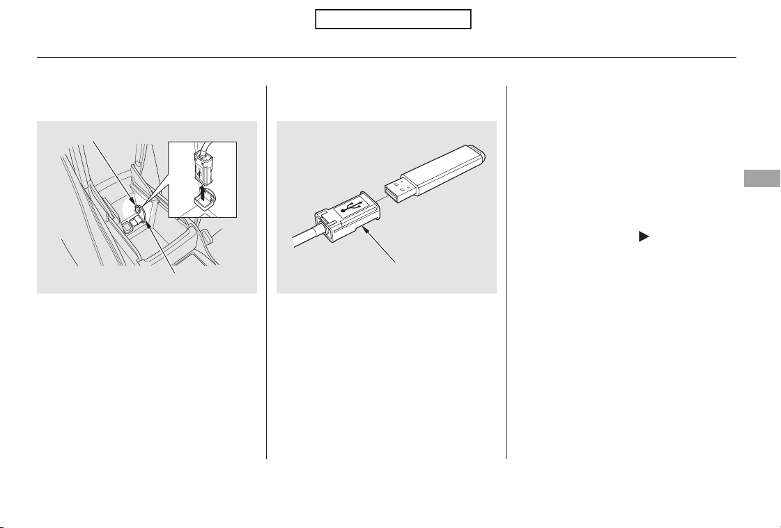
Connect the USB flash memory
device to the USB adapter cable
correctly and securely.
When the USB flash memory device
is connected, the USB indicator is
showninthedisplay.
Each time you press the TITLE
button, the display mode shows you
in sequence, the folder name, the file
name, the artist name, the album
name, the song name, or name off
(which turns off the text display).
Pull out the USB connector from
the holder.
If the text data has more than 16
characters, you will see the first 16
characters and the indicator in
the display. Press and hold the
TITLE button until the next 16
characters are shown. You can see
up to 32 characters of the text data.
1. 2.
CONTINUED
Connecting a USB Flash Memory
Device
Text Data Display Function
Playing a USB Flash Memory Device (Models without navigation system)
Features
173
USB CONNECTOR
USB ADAPTER CABLE
USB CONNECTOR
Table of Contents
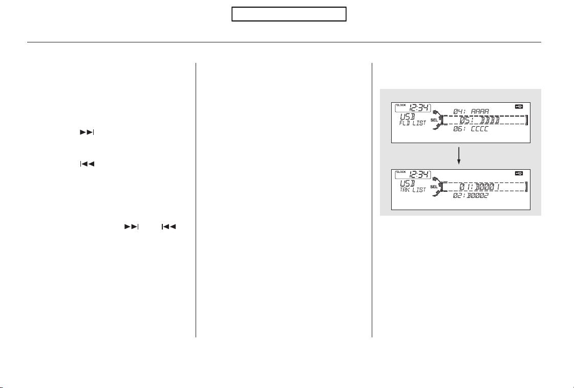
−
−
▲
▼
Use the SKIP bar while a USB flash
memory device is playing to select
passages and change files.
Each time you press and
releasethe sideoftheSKIPbar,
the system skips forward to the
beginning of the next file. Press and
releasethe sideofthebarto
skip backward to the beginning of
the current file. Press it again to skip
to the beginning of the previous file.
To move rapidly within a file, press
andholdeitherside( or )
of the SKIP bar.
Turning the selector knob to the
right or the left also changes the file.
To select a
different folder, press and release
either side of the CATEGORY bar.
Press the side to skip to the next
folder, and press the side to skip
to the beginning of the previous
folder.
You can also select a folder or file
from the list by using the selector
knob. Push the selector knob
(ENTER)toswitchthedisplaytothe
folder list, then turn the selector
knob to select a folder. Press
ENTER to change the display to the
file list, then turn the same knob to
select a file. Press ENTER to set
your selection.
To Change or Select Files To Select a File from Folder and File
Lists
SKIP
Folder Selection
Playing a USB Flash Memory Device (Models without navigation system)
174
Folder Selection
Track Selection
Press ENTER.
Table of Contents
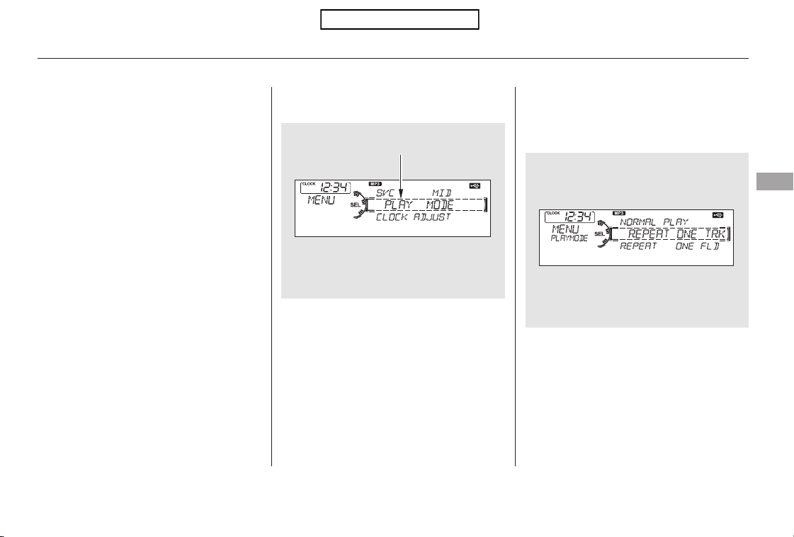
Pressing the RETURN button goes
back to the previous display and
pressing the MENU button cancels
this setting mode.
You can select any type of repeat,
random and scan modes by using the
MENU button and the selector knob.
Push the MENU button to display
themenuitems,thenturnthe
selector knob to select ‘‘PLAY
MODE.’’ Press the selector knob
(ENTER) to set the selection.
Turn the selector knob to select an
appropriate repeat, random or scan
mode, then press the selector knob
(ENTER) to set your selection.
To cancel the selected mode, press
the MENU button and turn the
selector knob to show ‘‘PLAY
MODE,’’ then press ENTER. When
you see ‘‘NORMAL PLAY,’’ press
ENTER again.
CONTINUED
To Select Repeat, Random or Scan
Mode:
Playing a USB Flash Memory Device (Models without navigation system)
Features
175
MENU ITEMS
Table of Contents
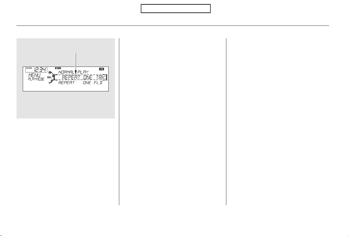
−
−−
−
−
This
feature continuously plays a file.
Select normal play to turn it off.
Pressing either side of the SKIP bar
also turns off this feature.
This function
samples all files in the selected
folder in the order they are stored.
To activate the scan feature, press
and release the SCAN button. You
will see SCAN in the display. You will
get a 10 second sampling of each file
in the folder. Press and hold the
SCAN button to get out of the scan
mode and play the last file sampled.
You can also select the scan feature
from the menu items with the
selector knob (see page ).
This feature
replays all the files on the selected
folder in the order they are stored.
Select normal play to turn it off.
Pressing either side of the
CATEGORY bar also turns off this
feature.
This feature
plays the files in the selected folder
in random order. You will see
F-RANDOM in the display. Select
normal play to turn it off.
This feature
plays all the files in random order.
You will see RANDOM in the display.
Select normal play to turn it off.
175REPEAT ONE TRK
SCAN TRKREPEAT ONE FLD
RANDOM IN FLD
RANDOM ALL
Playing a USB Flash Memory Device (Models without navigation system)
176
PLAY MODE ITEMS
Table of Contents
−
If you see an error message in the
display, see page .
Select normal play to turn either
scan feature off. Pressing either side
of the CATEGORY or SKIP bar also
turns off the feature.
This function
samples the first file in each folder in
the order they are stored. To
activate the folder scan feature,
press and release the SCAN button
repeatedly. You will see F-SCAN in
the display. You will get a 10 second
sampling of the first file in each
folder.PressandholdtheSCAN
button to get out of the folder scan
mode and play the last file sampled.
You can also select the folder scan
feature from the menu items with
the selector knob (see page ).
To play the radio, press the FM, AM,
or button. Press the CD/
AUX button to switch between disc
mode (if a disc is loaded) and the
USB.
You can also press the MODE
buttononthesteeringwheelto
change modes.
If you reconnect the same USB flash
memory device, the system will
begin playing where it left off.
You can disconnect the USB flash
memory device at any time even if
the USB mode is selected on the
audio system. Make sure to follow
the USB flash memory device’s
instructions when you remove it.
178
175
USB Flash Memory Device Error
Messages
To Stop Playing a USB Flash
Memory Device
SCAN FLD
Disconnecting a USB Flash Memory
Device
Playing a USB Flash Memory Device (Models without navigation system)
Features
177
Table of Contents

If you see an error message on the
audio display while playing a USB
flash memory device, find the
solution in the chart to the right. If
you cannot clear the error message,
take your vehicle to your dealer.
CauseError Message Solution
USB ROM Error
Abnormal power
source
Use of unsupported
files
No files in USB flash
memory device
Use of unsupported
USB flash memory
device
There is a problem with the USB adapter unit.
Appears when the overcurrent protection
feature of the system stops supplying power to
USB because an incompatible device is
connected. Disconnect the device. Then, turn
the audio system off, and turn it on again. Do
not reconnect the device that caused the error.
Appears when the files in the USB flash
memory device are DRM or an unsupported
format. This error message appears for about 3
seconds, then plays the next song.
Appears when the USB flash memory device is
emptyortherearenoMP3,WMA,orAACfiles
in the USB flash memory device. Save some
MP3, WMA, or AAC files in the USB flash
memory device.
Appears when an unsupported device is
connected. See page 171 for the specification
information for the USB flash memory device.
If it appears when a supported device is
connected, reconnect the device.
USB Flash Memory Device Error Messages (Models without navigation system)
178
USB ERROR
BAD USB
DEVICE
PLEASE CHECK
OWNERS
MANUAL
UNPLAYABLE
FILE
USB NO SONG
UNSUPPORTED
Table of Contents
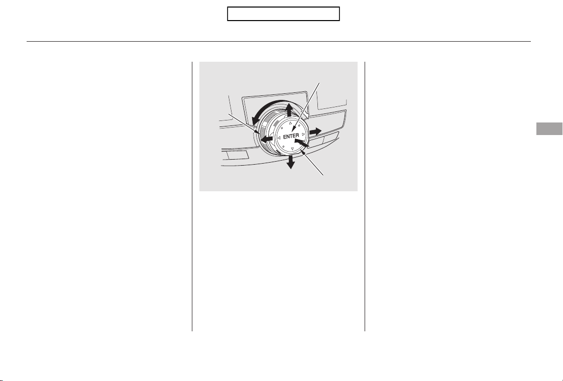
Most audio system functions can still
be controlled by standard buttons,
dials, and knobs, but some functions
can only be accessed using the
interface dial. The interface dial has
two parts, a knob and a selector.
The knob turns left and right. Use it
to make selections or adjustments to
a list or menu on the screen.
The selector can be pushed left,
right, up, down, and in. Use the
selector to scroll through lists, to
select menus, and to highlight menu
items. When you make a selection,
push the center of the selector
(ENTER)togotothatselection.
In addition to the standard audio
controls, the audio system in your
vehicle can be operated using the
voice control system. See the
Navigation System Manual for
complete details.
Interf ace Dial Voice Control System
Audio System (Models with navigation system)
Features
179
ENTER
SELECTOR
KNOB
Table of Contents
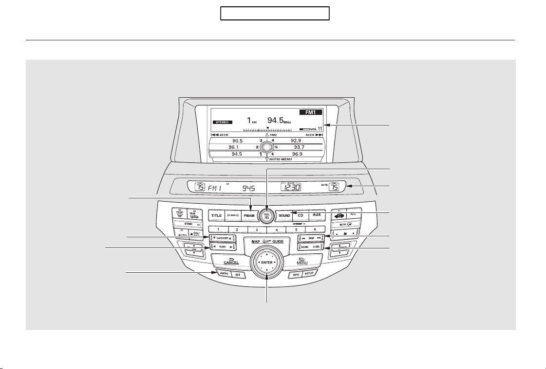
Playing the FM/AM Radio (Models with navigation system)
180
INTERFACE DIAL
CENTER DISPLAY
SCAN/A.SEL (SCAN/AUTO
SELECT) BAR
SKIP BAR
NAVIGATION SCREEN
POWER/VOLUME KNOB
TUNE BAR
FM/AM BUTTON
CATEGORY BAR
AUDIO BUTTON
SOUND BUTTON
U.S. model is shown.
Table of Contents
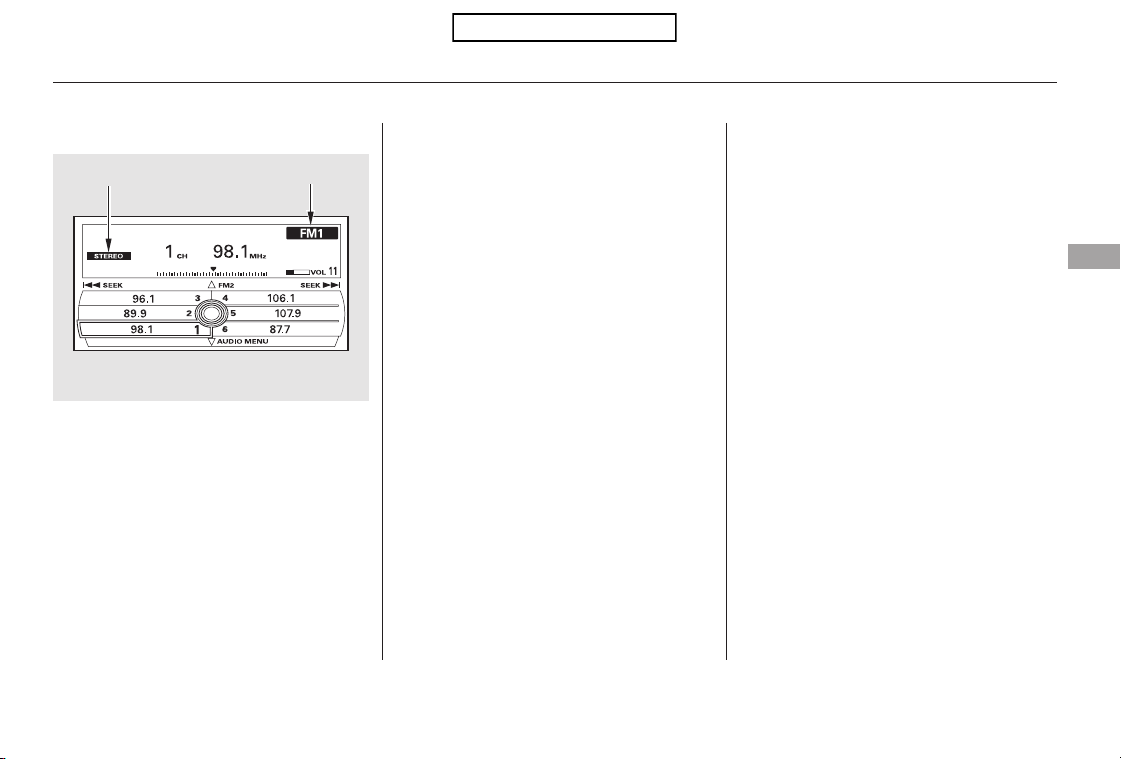
The ignition switch must be in the
ACCESSORY (I) or the ON (II)
position. Press the AUDIO button to
view the audio control display. Turn
the system on by pressing the
power/volume knob or the FM/AM
button. Adjust the volume by turning
the power/volume knob.
The band and frequency that the
radio was last tuned to are shown on
the display. To change bands, press
the FM/AM button. You can also
change bands by pushing the
interface selector up. Each time you
push it up, the band will change to
FM1, FM2, or AM. On the FM bands,
STEREO will be shown on the
navigation screen and ST on the
center display, if the station is
broadcasting in stereo. Stereo
reproduction on AM is not available.
On the AM band, AM noise
reduction turns on automatically.
You can use any of five methods to
find radio stations on the selected
band: tune, skip (seek), scan, the
preset buttons, and auto select.
On the FM band, you can also use
the features provided by the radio
data system (RDS). For more
information on the RDS, see page
.184
CONTINUED
To Play the FM/AM Radio To Select a Station
Playing the FM/AM Radio (Models with navigation system)
Features
181
STEREO ICON BAND
Table of Contents
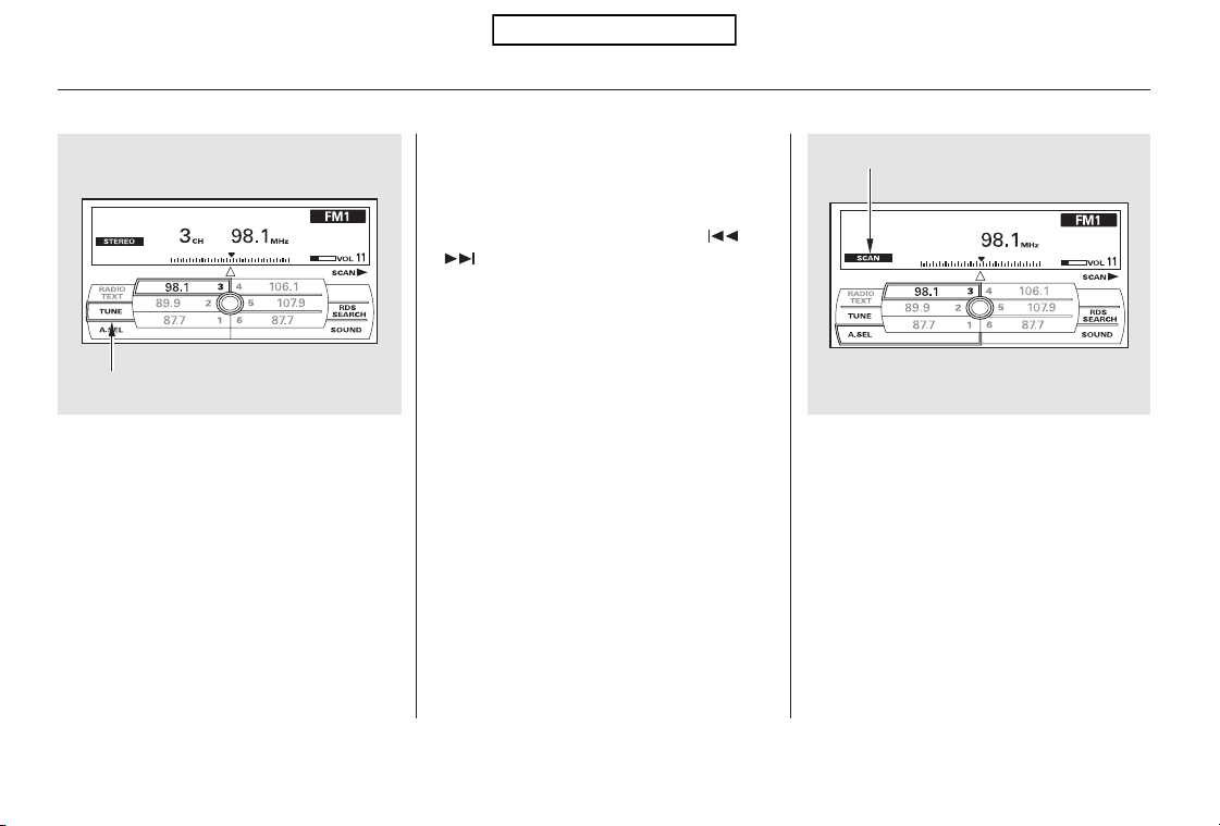
−
−−
The skip (seek)
function searches up and down from
the current frequency to find a
station with a strong signal. To
activate it, press either side ( or
) of the SKIP bar, then release
it. You can also activate the skip
function (SEEK is displayed on the
screen) by pushing the interface
selector to the right or left.
The SCAN function
samples all stations with strong
signals on the selected band. To
activate it, press the SCAN side of
the SCAN/A.SEL bar, then release it.
To scan with the interface dial, push
the selector down, and then push it
to the right. You will see SCAN
flashing on the screen.
Use the TUNE bar to tune
the radio to a desired frequency.
Press the right side of the bar to
tune to a higher frequency, or the
left side to tune to a lower frequency.
To tune with the interface dial, push
the selector down, and turn the knob
to TUNE icon. Then press ENTER
on the selector, and turn the knob to
the desired frequency. To exit the
TUNE mode, press ENTER on the
selector, then push the selector up.
SKIP (SEEK)
SCANTUNE
Playing the FM/AM Radio (Models with navigation system)
182
SCAN ICON
TUNE ICON
Table of Contents
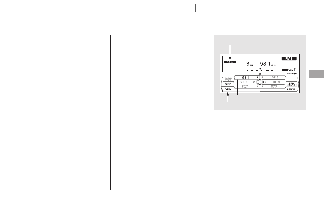
−
−
If you are
traveling and can no longer receive
your preset stations, you can use the
auto select feature to find stations in
the local area.
Push the interface selector down to
scroll down the screen, highlight
A.SEL, then press ENTER on the
interface selector. You will see
A.SEL on the screen, and the system
goes into scan mode for several
seconds.
Usethetune,skip(seek),scan,or
RDS function to tune the radio to a
desired station.
Repeat steps 1 through 3 to store a
total of six stations on AM and
twelve stations on FM.
When the system finds a strong
signal, it will stop and play that
station for about 10 seconds. If you
do nothing, the system will then scan
for the next strong station and play it
for 10 seconds. When it plays a
station that you want to listen to,
press the scan side of the bar again,
or push the interface selector to the
right again.
Each preset button or
preset icon can store one frequency
on AM and two frequencies on FM.
Press the preset button, and hold
it until you hear a beep. You can
also store frequencies with the
interface dial. Select the preset
icon you want to store the
frequency on, then press ENTER
on the interface selector, and hold
it for more than 2 seconds.
Select the desired band, AM or
FM. FM1 and FM2 let you store
twosetsofFMfrequencieswith
the preset buttons (on-screen
icons).
2.
3.
4.
1.
CONTINUED
To store a preset memory location:
AUTO SELECT
Preset
Playing the FM/AM Radio (Models with navigation system)
Features
183
PRESET ICON
A.SEL ICON
A.SEL ICON
Table of Contents

On the FM band, you can select a
favorite station and display the
program service name provided by
the radio data system (RDS).
The RDS INFO display function
shows the name of the station you
are listening to. With the audio
system on and the FM band selected,
you can turn this function on or off.
,pressthe
A. SEL side of the bar. This restores
the presets you originally set.
For information on FM/AM radio
frequencies and reception, see page
.
You will see ‘‘0’’ displayed if auto
select cannot find a strong station for
every preset button.
You can also press the A.SEL side of
the SCAN/A.SEL bar. You will see
A.SEL on the screen, and the system
goes into scan mode for several
seconds. The system stores the
frequencies of six AM and twelve
FM stations in the preset buttons.
press ENTER
on the interface selector.
If you do not like the stations auto
select has stored, you can store
other frequencies on the preset
buttons (icons) as previously
described.
231
To turn off auto selectTo turn off auto select,
Playing the FM/AM Radio (Models with navigation system)
Radio Data System (RDS)
RDS INFO Display
184
Table of Contents
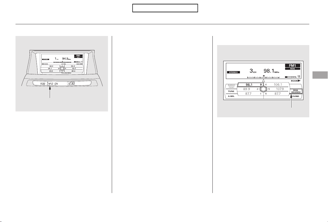
With the FM band selected, you can
select the program type provided by
the RDS. Press the AUDIO button to
display the radio information on the
screen. Push down the selector on
the interface dial, then turn the knob
to select RDS SEARCH icon. Press
ENTER to set your selection. The
principal RDS categories are shown
as follows:
If the station you are listening to is
not an RDS station, the audio screen
and the center display continue to
show the frequency.
When you turn off this function by
pressing the TITLE button, the
center display shows ‘‘RDS INFO
OFF.’’
To switch the function between on
and off, press and release the TITLE
button. With the system on, you will
see the ‘‘RDS INFO ON’’ message on
the display. If the station you are
listening to is an RDS station, the
display shows the station name.
CONTINUED
Playing the FM/AM Radio (Models with navigation system)
Radio Data System (RDS) Category
Features
185
RDS SEARCH ICON
RDS INFO DISPLAY ON
Table of Contents
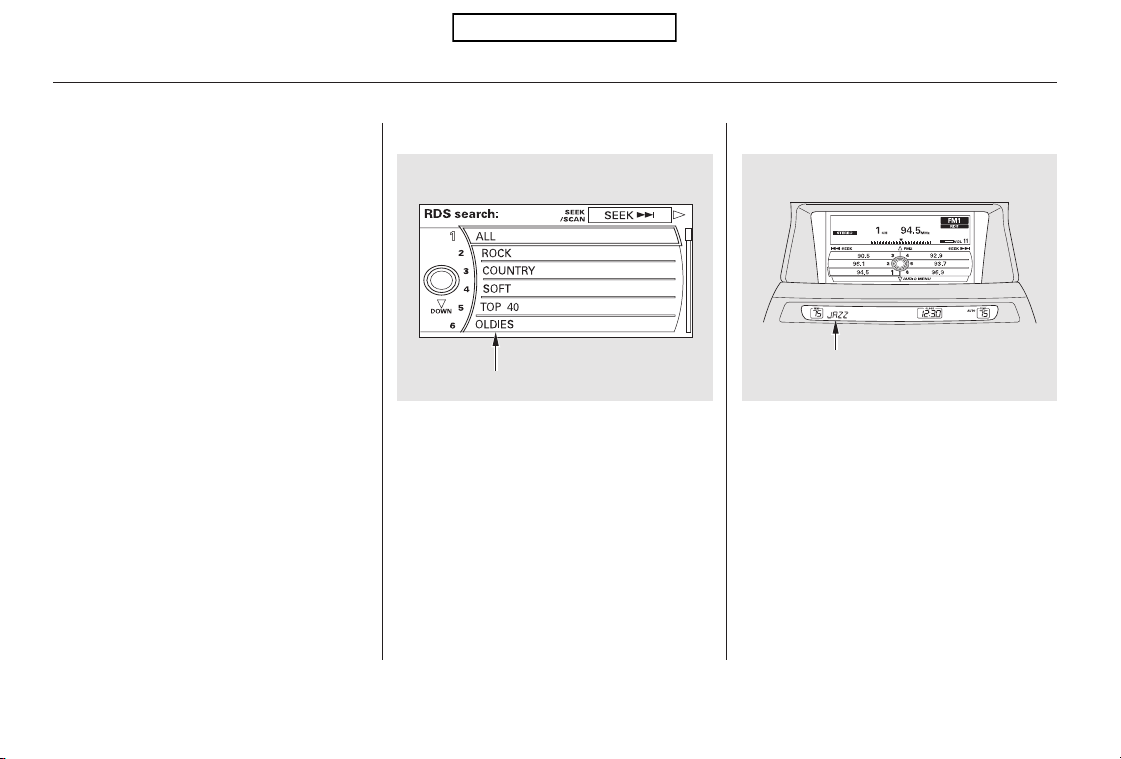
▲▼
You can also select an RDS category
with the CATEGORY bar. Press
either side ( or ) of the
CATEGORY bar to display an RDS
category in the center display. Select
a category by pressing either side of
the bar.
ALL: All RDS category stations
ROCK: Rock, classic rock and soft
rock music
SOFT: Adult hits and soft music
TOP 40: Top 40 hits
OLDIES: Nostalgia music and oldies
R & B: Rhythm and blues, and soft
rhythm and blues
RELIGION: Programs concerned
with religion
CLASSIC: Classical music
JAZZ: Jazz
INFO: News, information, sports,
talk shows, foreign language,
personality, public, college, and
weather
TRAFFIC: Traffic information
COUNTRY: Country music
Turn the selector to select an RDS
category. You can use the search or
scan function to find radio stations
on the selected RDS category by
pressing the selector to the right
repeatedly. Press ENTER to set your
selection. If you do nothing while the
RDS category is selected, the
selected category is canceled.
Playing the FM/AM Radio (Models with navigation system)
186
U.S. model is shown.
RDS CATEGORY
RDS CATEGORY
Table of Contents
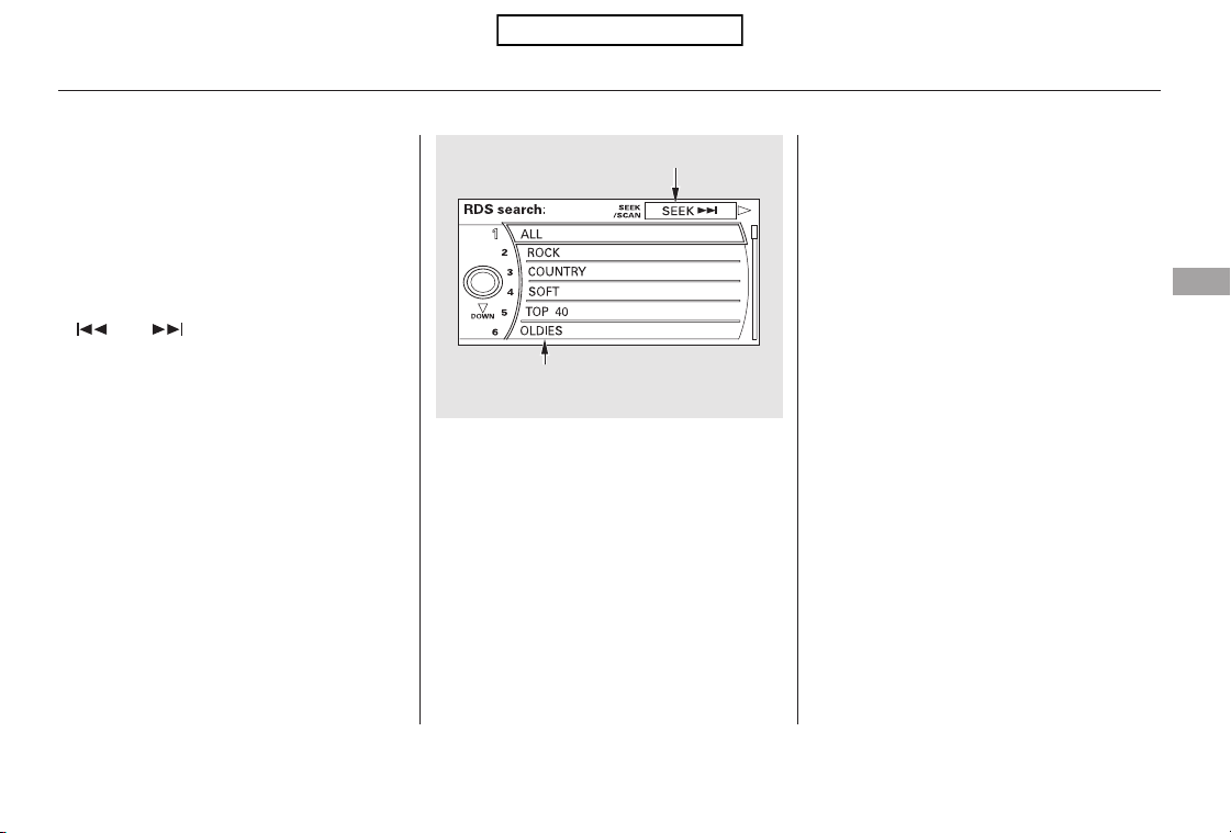
CONTINUED
The scan function samples all
stations with strong signals on the
selected RDS category. To activate it,
press and release the SCAN side of
the SCAN/A.SEL bar. You will see
SCAN in the center display. The
system will scan for a station with a
strong signal in the selected RDS
category. You will also see the
selected RDS category name
blinking in the center display while
searching it. When the system finds
one, it will stop and play that station
for about 10 seconds.
Turn the knob to the desired RDS
category.
While the RDS category is selected,
move the selector knob to the right
to select SEEK in the upper right
corner of the screen. Then press
ENTER to activate the seek function.
This function searches up and down
a frequency for the strongest signal
from the frequencies that carry the
selected RDS category information.
This can help you to find a station in
your favorite category. To activate it,
press and release either side
( or ) of the SKIP bar. You
will also see the selected RDS
category name blinking in the center
display while searching it. When the
system finds a station, the selected
RDS category name will be displayed
again for about 5 seconds in the
center display.
If the system does not find a station,
‘‘NOTHING’’ will be blinking for
about 5 seconds, then the system
goes back to the last selected station.
To activate RDS program search
with the interface dial, push the
AUDIO button to display the FM
radio information on the screen.
Push the selector down, and turn the
knob to select the RDS SEARCH
icon. Press ENTER on the selector.
The screen shows you the RDS
program category list.
Playing the FM/AM Radio (Models with navigation system)
RDS Program Search
RDS Program SCAN
Features
187
SEEK/SCAN ICON
SEEK is selected.
RDS CATEGORY LIST
Table of Contents
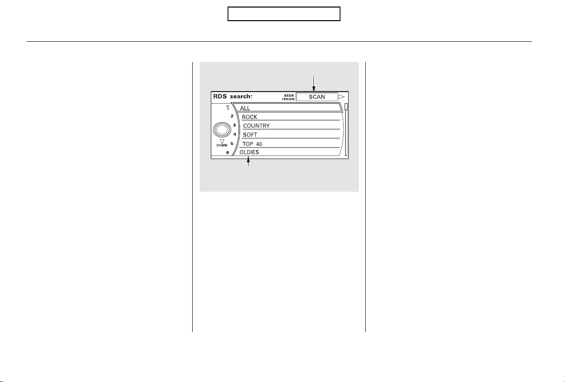
Turn the knob to the desired RDS
category.
If you do nothing, the system will
scan for the next strong station and
play it for 10 seconds. When it plays
a station that you want to listen to,
press the SCAN side of the SCAN/
A.SEL bar again.
If the system does not find a station,
‘‘NOTHING’’ will be blinking for
about 5 seconds, then the system
goes back to the last selected station.
While the RDS category is selected,
move the selector knob to the right
to select SCAN in the upper right
corner of the screen. Then press
ENTER to activate the scan function.
You can use the RDS program
search or scan function even if the
RDS information display function is
off. In this case, the display shows a
frequency in place of a RDS station
name.
To activate RDS program scan with
the interface dial, push the AUDIO
button to display the FM radio
information on the screen. Push the
selector down, and turn the knob to
select the RDS SEARCH icon. Press
ENTER on the selector. The screen
shows you the RDS category list.
Playing the FM/AM Radio (Models with navigation system)
188
SCAN is selected.
SEEK/SCAN ICON
RDS CATEGORY LIST
Table of Contents
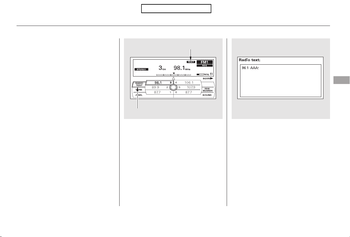
This function displays the radio text
information of the selected RDS
station.
To activate radio text display, use
the interface dial. Push the selector
down, and turn the knob to select
RADIO TEXT icon. Press ENTER on
the selector to enter the setting.
The display shows up to 64
characters on the selected RDS
station.
If the selected RDS station has the
radio text information, you will see
the text indicator on the screen.
Radio Text Display
Playing the FM/AM Radio (Models with navigation system)
Features
189
RADIO TEXT ICON
TEXT INDICATOR
The text is displayed according
to the information from RDS.
Table of Contents
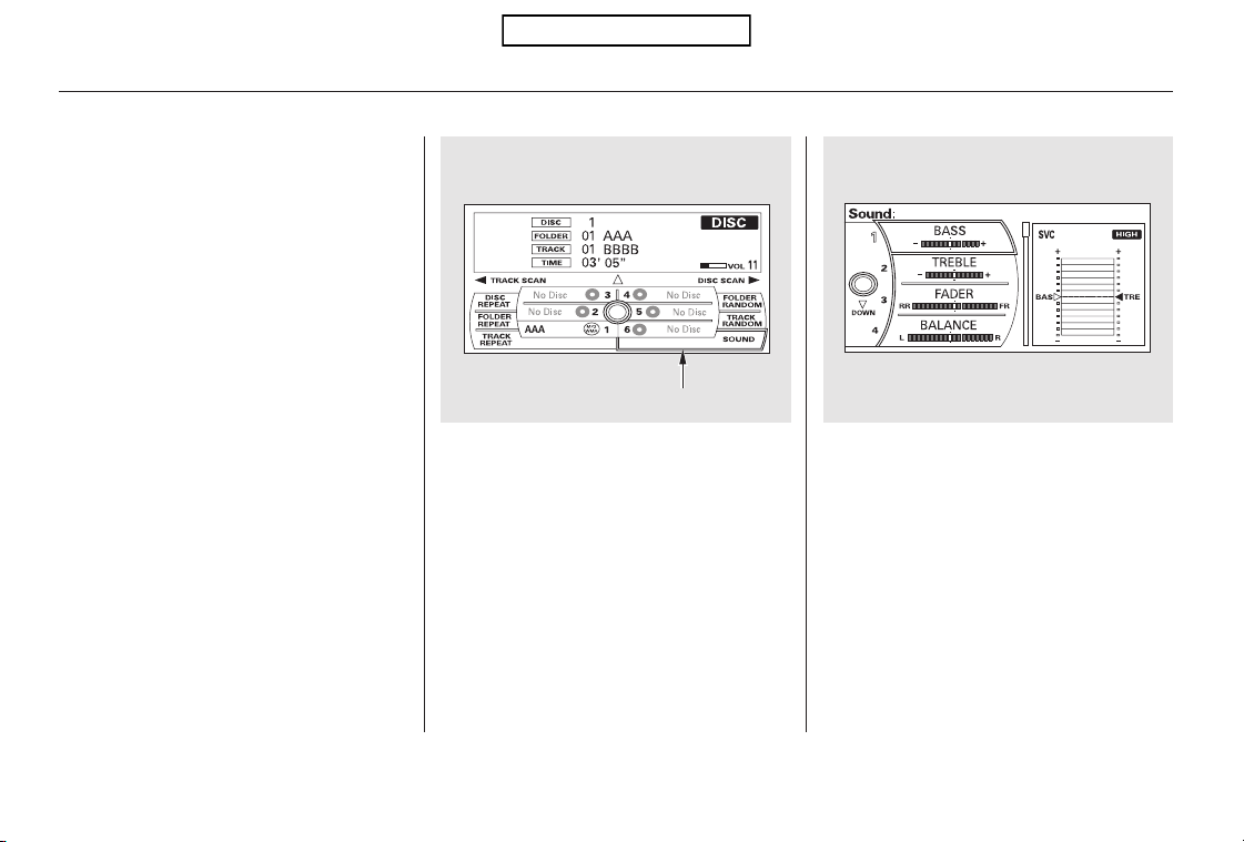
To adjust them, press the AUDIO
button, push the interface selector
down, and turn the interface knob to
SOUND. Then press ENTER on the
selector.
BASS, TREBLE, FADER, and
BALANCE are each adjustable. You
can also adjust the strength of the
sound coming from the subwoofer
speaker. In addition, you can set the
speed-sensitive volume
compensation (SVC).
Theseadjustmentscanbemadeby
the SOUND button or the interface
dial.
Selectthemodeyouwanttoadjust
by turning the interface dial.
You can also adjust the sound by
pushing the SOUND button
repeatedly. Each mode is shown in
the center display as it changes.
Turn the power/volume knob to
adjust the setting to your liking.
When the level reaches the center,
you will see ‘‘C’’ in the display.
The system will return to the audio
playing mode in the center display
about 10 seconds after you stop
adjusting a mode.
Adjusting the Sound
Playing the FM/AM Radio (Models with navigation system)
190
SOUND ICON
Table of Contents

−
−
−To adjust bass
and treble, select BASS or TREBLE,
andpressENTERontheinterface
selector. The current setting is
shownonthedisplay.Turnthe
interface knob to the desired level,
and enter your selection by pressing
ENTER on the interface selector.
The SVC mode controls the volume
based on vehicle speed. The faster
you go, the louder the audio volume
becomes. As you slow down, the
audio volume decreases.
The SVC has four modes: SVC OFF,
SVC LOW, SVC MID, and SVC
HIGH. The default setting is MID.
To change the SVC mode, select
SVC, then press ENTER on the
interface selector. The current
setting is shown on the screen. Turn
the interface knob to the desired
level, and enter your selection by
pressing ENTER on the interface
selector. If you feel the sound is too
loud, choose low. If you feel the
sound is too quiet, choose high.
These
modes adjust the strength of the
sound coming from each speaker.
Fader adjusts the front-to-back
strength, while balance adjusts the
side-to-side strength. To adjust fader
and balance, select FADER or
BALANCE, then press ENTER on
the interface selector. The current
setting is shown on the screen. Turn
the interface knob to the desired
level, and enter your selection by
pressing ENTER on the interface
selector. To equalize the fader or
balance, turn the interface knob until
the marks on the sound grid come to
the center of the adjustment bar.
To adjust the
strength of the sound from the
subwoofer speaker, select it and
press ENTER on the interface
selector. Turn the interface knob to
the desired level, and enter your
selection by pressing ENTER on the
interface selector.
If the fader adjustment is set to F9
(maximum front level), the
subwoofer is turned off.
BASS/TREBLE
FADER/BALANCE
SUBWOOFER
Speed-sensitive Volume
Compensation (SVC)
Playing the FM/AM Radio (Models with navigation system)
Features
191
Table of Contents
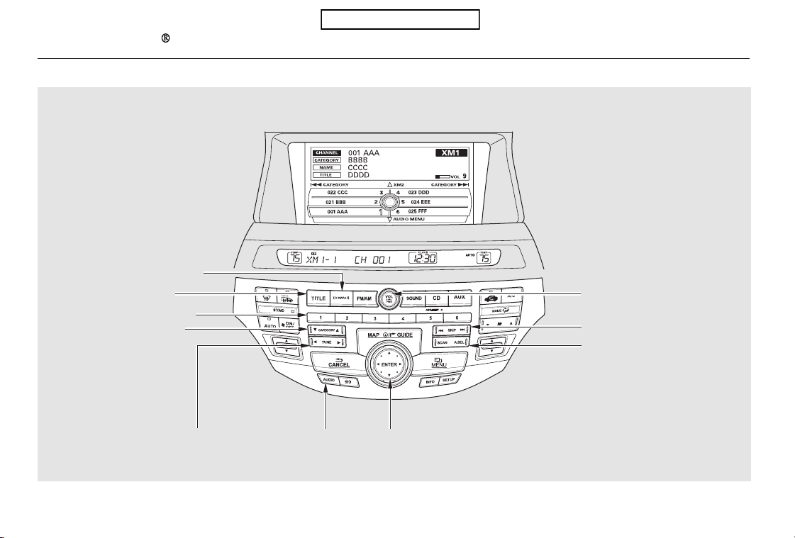
Playing the XM Radio (Models with navigation system)
192
AUDIO BUTTON INTERFACE DIALTUNE BAR
CATEGORY BAR
PRESET BUTTONS
TITLE BUTTON
XM RADIO BUTTON
SKIP BAR
POWER/VOLUME KNOB
SCAN/A.SEL (SCAN/AUTO
SELECT) BAR
U.S. model is shown.
Table of Contents
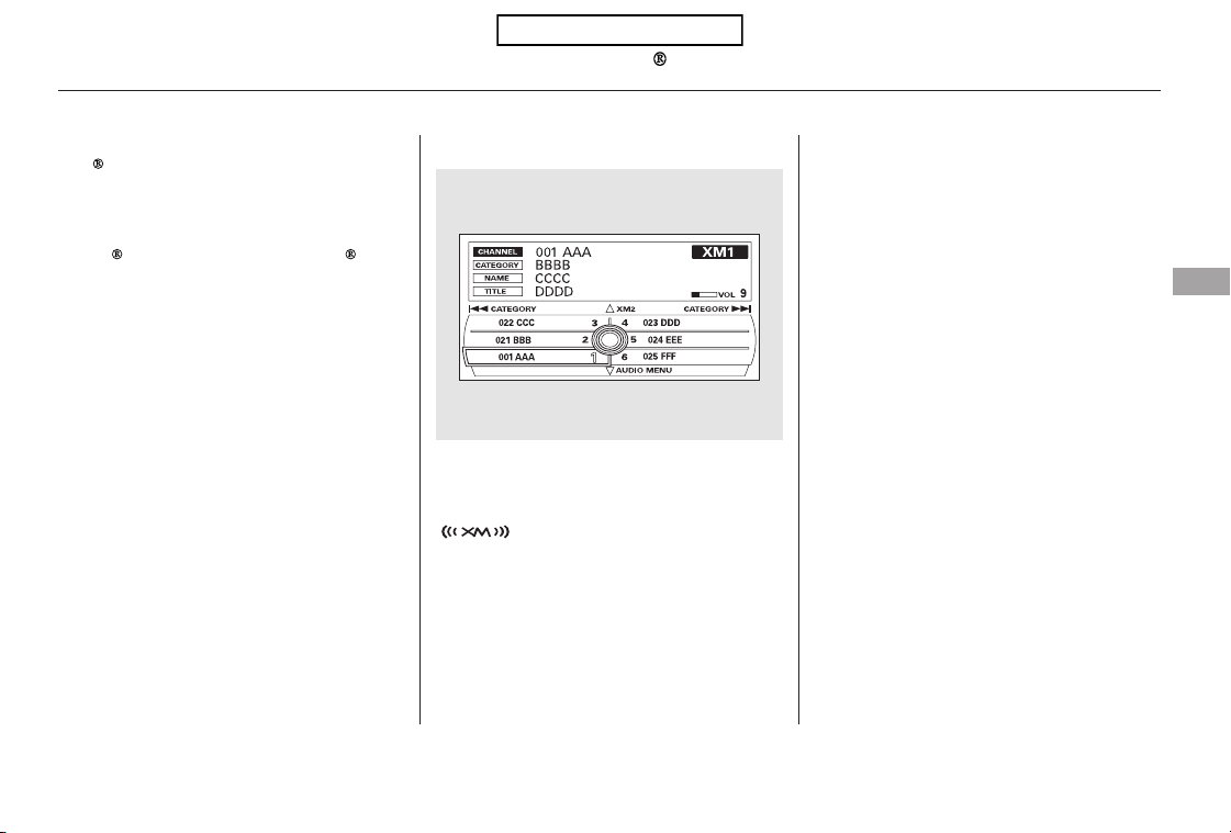
Push the AUDIO button to display
XM information on the screen. You
can operate the XM Radio system
with the interface dial.
To listen to XM Radio, turn the
ignition switch to the ACCESSORY
(I) or ON (II) position, and press the
button. The last channel you
listened to will show in the audio
screen and the center display. Adjust
the volume by turning the power/
volume knob.
Your vehicle is capable of receiving
XM
Radio anywhere in the United
States and Canada, except Hawaii,
Alaska,andPuertoRico.XMisa
registered trademark of Sirius XM
Radio
,Inc.andXMCANADA is a
registered business name of
Canadian Satellite Radio Inc.
XM Radio receives signals from two
satellites to produce clear, high-
quality digital reception. It offers
many channels in several categories.
Along with a large selection of
different types of music, XM Radio
also allows you to view channel and
category selections in the audio
display.
CONTINUED
Operating the XM Radio
Playing the XM Radio (Models with navigation system)
Features
193
Table of Contents
−
−
−To switch between the
category mode and channel mode,
press and hold the TITLE button
until the mode changes. The
CATEGORY or CHANNEL mode is
displayed on the screen. To switch
the mode with the interface dial,
push down the interface selector to
select AUDIO MENU, then turn the
knob to select MODE, and press
ENTER on the selector repeatedly.
In the category mode, such as Jazz,
Rock, Classical, etc., you can
navigate through all of the channels
within that category. In the channel
mode, you can select all of the
available channels.
Each time you press and release the
TITLE button, the center display
changes in the following sequence:
NAME (artist name), TITLE (music
title), and CHANNEL NAME
(channel name).
Onthescreen,youwillseethe
selected CHANNEL (number),
CATEGORY, NAME (artist name),
and TITLE (music title).
Press either side of the
TUNE bar to change channel
selections. Press the side of the
bar for higher numbered channels
and the side for lower
numbered channels. You can also
change channels with the interface
selector, push down the interface
selector to select AUDIO MENU,
then turn the interface knob to
choose TUNE and press ENTER on
the selector. Turn the interface knob
to the appropriate direction. In the
category mode, you can only select
channels within that category.
Push down the
interface selector to select AUDIO
MENU,thenturntheinterfaceknob
to select CHANNEL LIST and press
ENTERontheselector.Turnthe
interface knob to select a channel,
then press ENTER to set your
selection.
MODE
TUNE
CHANNEL LIST
Playing the XM Radio (Models with navigation system)
194
Table of Contents
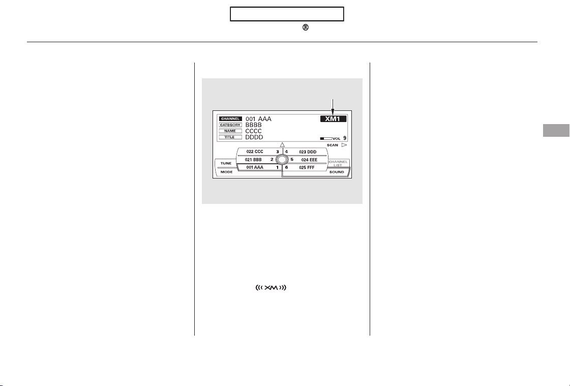
−
▼▲−
−
Youcanstoreupto12
preset channels using the six preset
buttons. Each button stores one
channel from the XM1 band and one
channel from the XM2 band.
To store a channel:
Press the button or scroll
up by pushing the interface
selector up. Either XM1 or XM2
will be shown on the display.
Press
either side of the bar to select
another category. You can also
change a category by pushing the
interface selector left or right.
The scan function gives
you a sampling of all channels while
in the channel mode. In the category
mode, only the channels within that
category are scanned. To activate
SCAN,presstheSCANsideofthe
SCAN/A.SEL bar. To scan with the
interface dial, scroll down, and push
the interface selector to the right.
YouwillseeSCANonthescreenand
center display.
The system plays each channel in
numerical order for a few seconds,
then selects the next channel. When
you hear a channel you want to
continue listening to, push the
interface selector to the right again
or press the SCAN side of the bar to
cancel.
Use the tune, skip (seek), or scan
function to tune to a desired
channel.
Repeat steps 2 and 3 to store the
first six channels.
Pick the preset button you want
for that channel. Press and hold
the preset button until you hear a
beep. You can also pick the
number with the interface dial.
Select your desired number and
press and hold ENTER on the
interface selector.
In category mode, only channels
within that category can be
selected. In channel mode, all
channels can be selected.
1.
2.
3.
4.
CONTINUED
Preset
CATEGORY ( or )
SCAN
Playing the XM Radio (Models with navigation system)
Features
195
XM BAND
Table of Contents

−
−
−
−
−
−
−
Press the button or scroll
up again. The other XM band will
be shown. Store the next six
channels using steps 2 and 3.
Once a channel is stored, press
and release the proper preset
button to tune to it.
XM is loading the
audio or program
information.
The channel
currently selected is
no longer
broadcasting.
The encryption
code is being
updated. Wait
until the
encryption code is
fully updated.
Channels 0 and 1
should still work
normally.
The signal is
currently too
weak. Move the
vehicle to an area
away from tall
buildings, and
with an
unobstructed view
of the southern
horizon.
The selected channel
number does not exist, or
isnotpartofyour
subscription, or this
channel has no artist or
title information at this
time.
The selected
channel has no artist
or title information
at this time.
There is a problem
with the XM
antenna. Please
consult your dealer.
5. XM Radio Display Messages
‘‘LOADING’’
‘‘OFF AIR’’
‘‘UPDATING’’
‘‘NO SIGNAL’’
‘‘----’’
‘‘NO INFO’’
‘‘ANTENNA’’
Playing the XM Radio (Models with navigation system)
196
Table of Contents
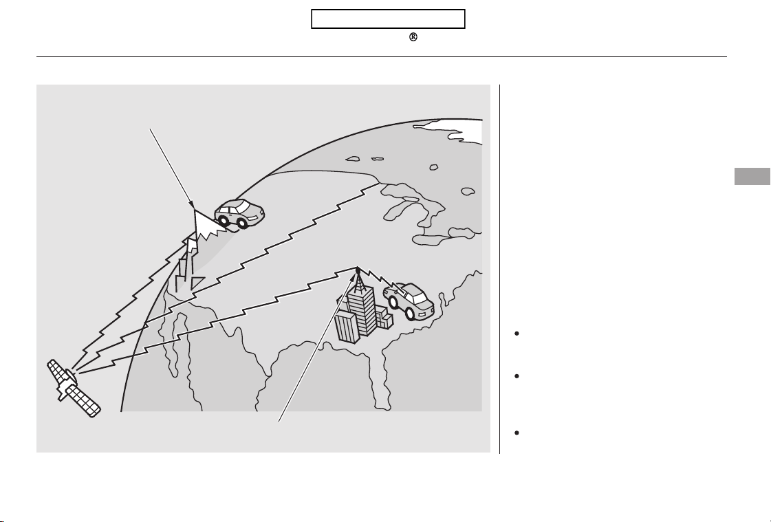
The XM satellites are in orbit over
the equator; therefore, objects south
of the vehicle may cause satellite
reception interruptions. To help
compensate for this, ground-based
repeaters are placed in major
metropolitan areas.
Satellite signals are more likely to be
blocked by tall buildings and
mountains the farther north you
travel from the equator.
Depending on where you drive, you
may experience reception problems.
Interference can be caused by any of
these conditions:
Driving on the north side of an
east/west mountain road.
Driving in tunnels.
Driving on the north side of a
large commercial truck on an
east/west road.
CONTINUED
Playing the XM Radio (Models with navigation system)
Features
197
Signal may be blocked by
mountains or large obstacles to
the south.
Signal weaker in
these areas.
SATELLITE
GROUND REPEATER
Table of Contents
Driving on a road beside a vertical
wall, steep cliff, or hill to the south
of you.
Driving on the lower level of a
multi-tiered road.
Driving on a single lane road
alongside dense trees taller than
50 ft. (15 m) to the south of you.
There may be other geographic
situations that could affect XM Radio
reception.
After you’ve registered with XM
Radio, keep your audio system in the
XM Radio mode while you wait for
activation. This should take about 30
minutes.
If your XM Radio service has expired
or you purchased your vehicle from
a previous owner, you can listen to a
sampling of the broadcasts available
on XM Radio. With the ignition
switch in the ACCESSORY (I) or the
ON (II) position, press the
button. A variety of music
types and styles will play.
If you decide to purchase XM radio
service, contact XM Radio at
,orat
1-800-852-9696. In Canada, contact
XM CANADA
at , or
at 1-877-209-0079. You will need to
give them your radio I.D. number
and your credit card number. To get
your radio I.D. number, press the
side of the TUNE bar until ‘‘0’’
appears in the display. Your I.D. will
appear in the display.
While waiting for activation, make
sure your vehicle remains in an open
area with good reception. Once your
audio system is activated, CAT
(category) or CH (channel) will
appear in the center display, and
you’ll be able to listen to XM Radio
broadcasts. XM Radio will continue
to send an activation signal to your
vehicle for at least 12 hours from the
activation request. If the service has
not been activated after 36 hours,
contact XM
Radio. In Canada,
contact XM CANADA
.
As required by the FCC:
Changes or modifications not expressly
approved by the party responsible for
compliance could void the user’s
authority to operate the equipment.
www.xmradio.com
www.xmradio.ca
Receiving XM Radio Service
Playing the XM Radio (Models with navigation system)
198
Table of Contents
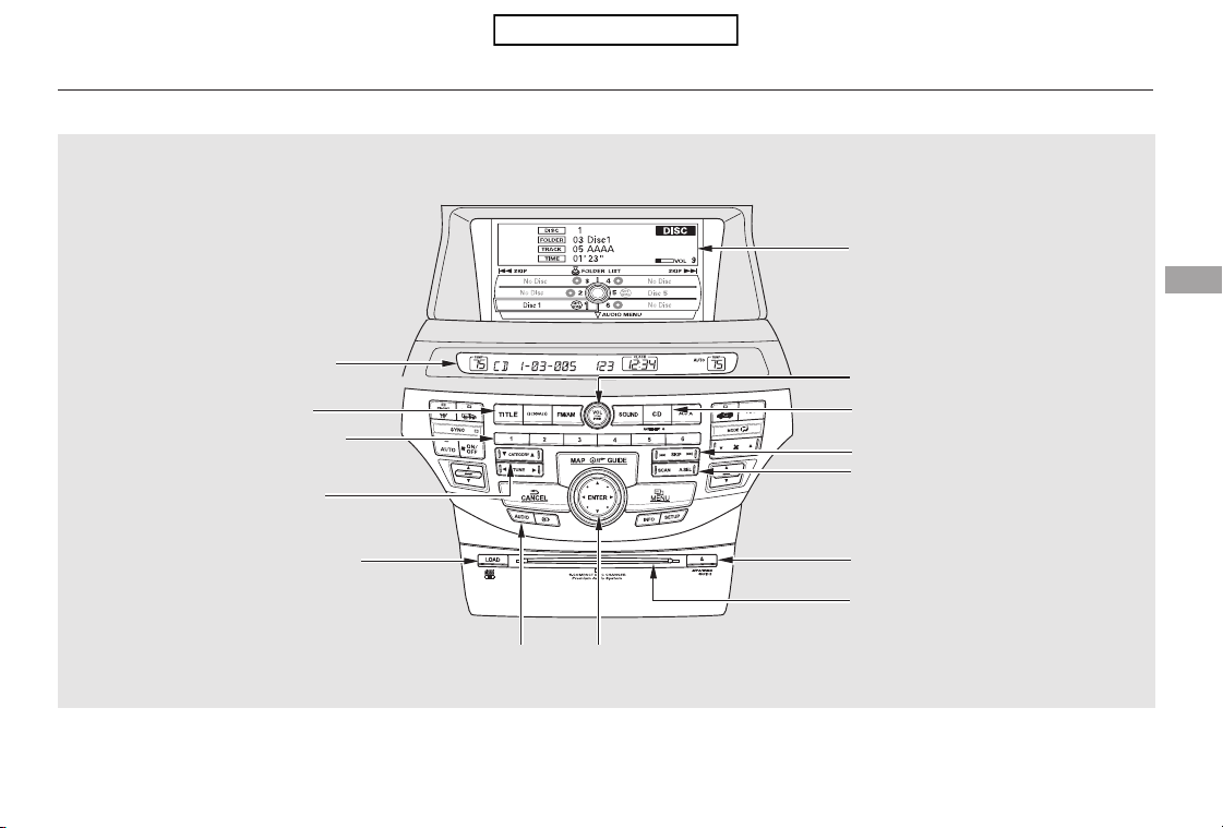
CONTINUED
Playing Discs (Models with navigation system)
Features
199
SKIP BAR
SCAN/A.SEL (SCAN/AUTO
SELECT) BAR
POWER/VOLUME KNOB
CD BUTTON
INTERFACE DIALAUDIO BUTTON
PRESET BUTTONS
NAVIGATION SCREEN
CENTER DISPLAY
TITLE BUTTON
DISC SLOT
DISC LOAD BUTTON DISC EJECT BUTTON
U.S. model is shown.
CATEGORY BAR
Table of Contents
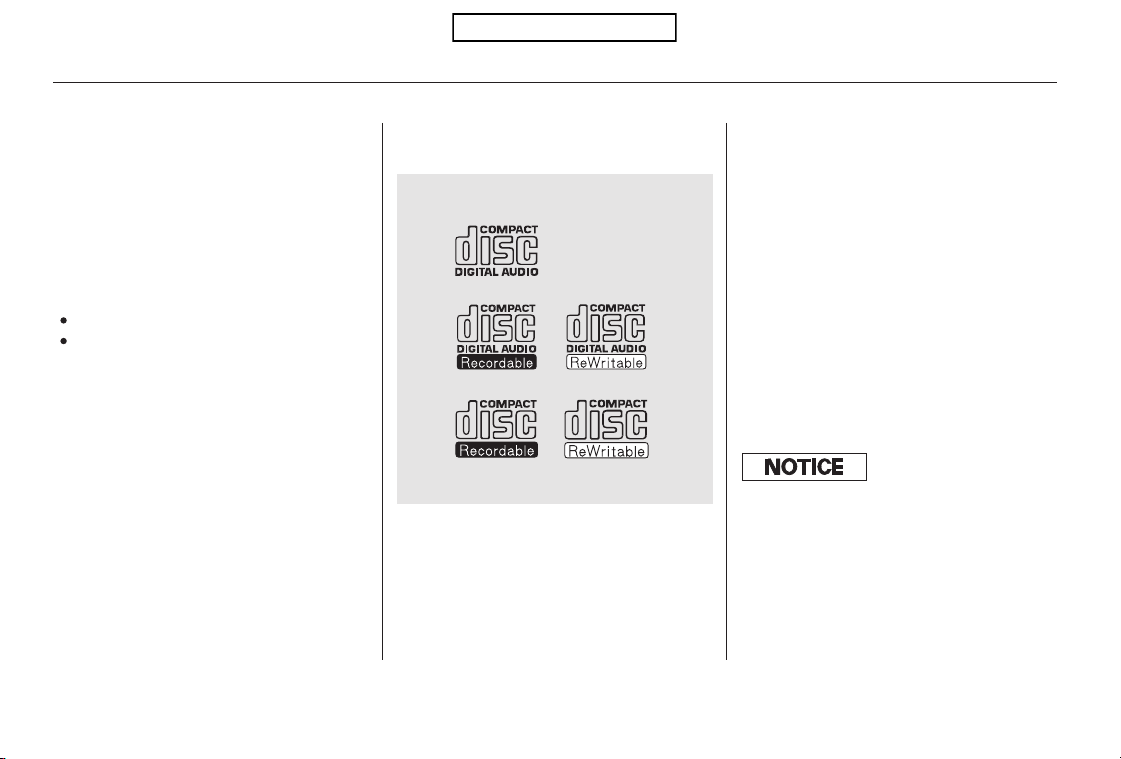
Your vehicle’s audio system has an
in-dash disc changer with the same
controls used for the radio. To
operate the disc changer, the ignition
switch must be in the ACCESSORY
(I) or the ON (II) position.
The disc changer can play these disc
formats:
CD (CD-DA)
MP3/WMA
The disc packages or jackets should
have one of these marks.
When playing a disc in MP3, you will
see ‘‘MP3’’ in the display. In WMA
format, ‘‘WMA’’ will appear in the
display.
The changer can also play MP3 or
WMA format (see page ).
If a file on a WMA disc is protected
by digital rights management
(DRM), the audio unit displays
UNSUPPORTED, and then skips to
the next file.
Video CDs and DVDs do not work in
this unit.
Some CD-DA and CD-ROM mixed
discs are not playable.
You cannot load and play 3-inch
(8-cm)discsinthissystem.
206
Playing Discs (Models with navigation system)
200
NOTE:
Do not use discs with adhesive labels.
The label can curl up and cause the
disc to jam in the unit.
Table of Contents

To load multiple discs in one
operation:
With the ignition in the
ACCESSORY (I) or the ON (II)
position, press and hold the LOAD
button until you hear a beep and
see ‘‘LOAD’’ in the center display,
then release the button.
‘‘NO DISC’’ is shown on the screen
foranemptypositioninthe
changer. When the green load
indicator comes on and you see
‘‘LOAD’’ in the center display,
insert the disc into the slot. Insert
it only about halfway; the drive will
pull it in the rest of the way.
Press and release the LOAD
button.
To load a single disc:
Repeat this until all six positions
are loaded. If you are not loading
all six positions, the system will
then begin playing the last disc
loaded.
If you stop loading discs before all
six positions are filled, the system
will wait for 10 seconds, stop the load
operation, and begin playing the last
disc loaded.
Insert a disc into the slot. Insert it
only about halfway; the drive will
pull it in the rest of the way. You
will see ‘‘BUSY’’ in the center
display. When you insert the first
disc, the changer will start to play
the disc.
Do not try to insert a disc until
‘‘LOAD’’ appears. You could
damage the audio unit.
If you press the LOAD button while
a disc is playing, the system will stop
playing that disc and start the
loading sequence. It will then play
the disc just loaded.
You can select the position to load a
disc. Turn the interface knob or
press a preset button to select the
position, then press ENTER on the
selector. This starts the loading
sequence. If you do not select the
position, the system loads the disc to
the first empty position in numerical
order.
Do not try to insert a disc until
‘‘LOAD’’ appears. You could damage
the audio unit.
When ‘‘LOAD’’ appears in the
center display again, insert the
next disc into the slot.
1.
1.
2.
3.
4.
2.
Loading Discs in the Changer
Playing Discs (Models with navigation system)
Features
201
Table of Contents
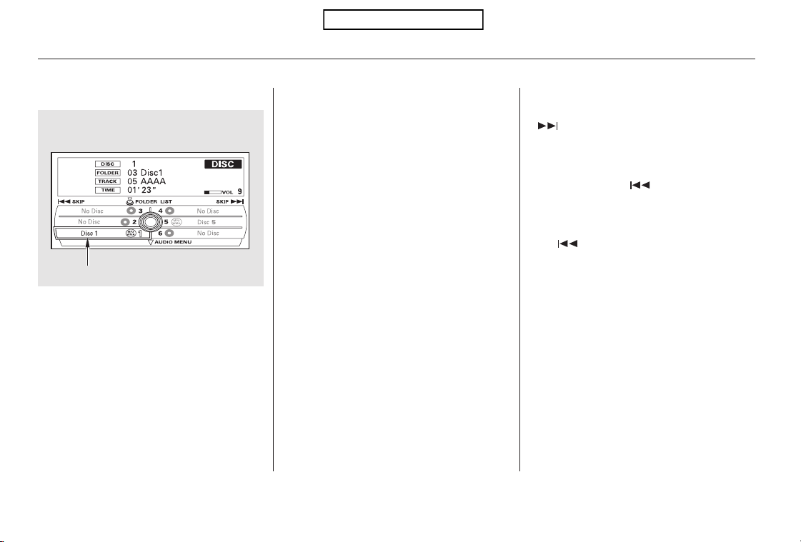
When you play CD-TEXT, you will
see the track name, artist name, and
album name on the screen. When
you play MP3/WMA discs, you will
see the track name and folder name
on the screen. If the disc was not
recorded with this information, it will
not be displayed.
The player can play CD-TEXT, MP3,
and WMA formats.
Select the changer by pressing the
CD button. The system will begin
playing the last selected disc in the
disc changer. You will see the
current disc position highlighted.
To select a different disc, press the
corresponding number on the preset
buttons, or turn the interface knob to
highlight the desired disc number,
then press ENTER on the interface
selector.
Each time you press and release the
side of the skip bar or push the
interface selector to the right, the
player skips forward to the
beginning of the next track. Press
and release the side of the skip
barorpushtheinterfaceselectorto
thelefttoskipbackwardtothe
beginning of the current track. Press
the side or push the interface
selector to the left again to skip to
the previous track. To move rapidly
within a track, press and hold either
side of the skip bar.
To Play a Disc To Change Tracks
Playing Discs (Models with navigation system)
202
CURRENT DISC
Table of Contents
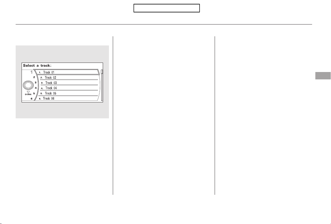
You can also choose a track directly
from a track list. Press ENTER on
the interface selector, and the track
list screen will be shown. If there are
no track names, track numbers are
displayed. You will see the current
track is highlighted. Turn the
interface knob to select the desired
track, then press ENTER on the
interface selector.
To exit the track list display, press
the AUDIO button, or push the
interface selector to the left.
When you press the SCAN side of
the SCAN/A. SEL bar or scroll down
and push the interface selector to
the left, the next track of the current
track plays for about 10 seconds.
You will see SCAN next to TRACK
on the screen and center display. To
listen to the rest of the track, press
andholdtheSCANsideofthebar
until you hear a beep or push the
interface selector to the left again
within 10 seconds.
If you don’t, the system advances to
the next track, plays about 10
seconds of it, and continues through
the rest of the tracks the same way.
When you press the SCAN side of
the SCAN/A. SEL bar repeatedly
until you see D-SCAN in the center
display, or push the interface
selector to the right, the first track of
the current disc plays for about 10
seconds. You will see SCAN next to
DISC on the screen. The disc
number is blinking and SCAN is also
shown in the center display. To listen
to the rest of the disc, press and hold
the SCAN side of the bar until you
hear a beep, or push the interface
selector to the right again within 10
seconds.
If you don’t, the system advances to
the next disc, plays about 10 seconds
of its first track, and continues
through the rest of the discs the
same way. When the system reaches
the last disc, DISC SCAN is canceled,
and that disc continues to play.
To Choose a Track
Track Scan
Disc Scan
Playing Discs (Models with navigation system)
Features
203
Table of Contents
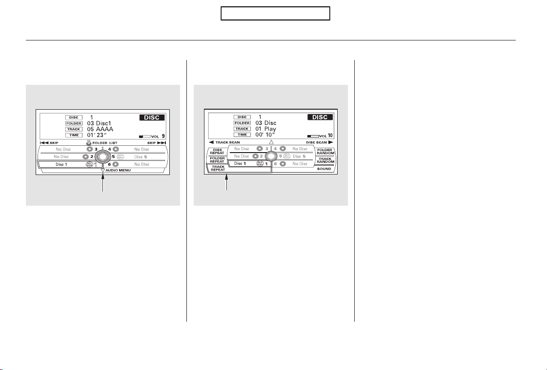
To replay the current track
continuously, select TRACK
REPEAT, and press ENTER on the
interface selector. As a reminder,
you will see REPEAT next to
TRACKonthescreen.Toturnthis
feature off, highlight TRACK
REPEAT (if not already highlighted),
andpressENTERontheinterface
selector again.
You can select any type of repeat and
random modes by using the
interface dial.
Push the AUDIO button to display
the audio information on the screen,
then scroll down by pushing down
the selector to select the audio menu.
To cancel the selected repeat or
random mode, have the selected
mode highlighted, then press
ENTER on the interface selector.
Turn the interface knob to select a
desired repeat or random mode, then
press ENTER to set your selection.
To Select Repeat or Random
Mode:
Track Repeat
Playing Discs (Models with navigation system)
204
Push down the selector. AUDIO MENU SCREEN
Table of Contents
To replay the current disc
continuously, select DISC REPEAT,
andpressENTERontheinterface
selector. As a reminder, you will see
REPEAT next to DISC on the screen.
To turn this feature off, highlight
DISC REPEAT (if not already
highlighted), and press ENTER on
the interface selector again.
To play the tracks on the current
disc in random order, select TRACK
RANDOM, and press ENTER on the
interface selector. As a reminder,
you will see RANDOM next to
TRACKonthescreen.Toturnthis
feature off, highlight TRACK
RANDOM (if not already
highlighted), and press ENTER on
the interface selector again.
To take the system out of disc mode,
press the FM/AM button, the
button, or the AUX button (if
an appropriate unit is connected). To
return to disc mode, press the CD
button.
If you turn the system off while a
disc is playing, either with the
power/volume knob or the ignition
switch, play will continue at the same
point when you turn it back on.
You can also press the MODE
buttononthesteeringwheelto
change modes.
Disc Repeat Random Play To Stop Playing a Disc
Playing Discs (Models with navigation system)
Features
205
Table of Contents

The changer plays MP3/WMA discs
in recorded order. Maximum
playable file layers are 8, and total
playable tracks are 255. If your disc
has a complex structure, the changer
takessometimetoreadthedisc
before beginning play.
While playing an MP3/WMA disc,
you can select a folder within the
disc by pressing either side of the
category bar. Each time you press
either side of the bar, the folder title
and its first file’s information appear
in the display in recorded order.
Depending on the software the files
were made with, it may not be
possible to play some files, or display
some text data.
To play an MP3/WMA disc, use the
disc controls previously described,
along with the following information.
Playing an MP3/WMA Disc Changing the Folders
Playing Discs (Models with navigation system)
206
Table of Contents
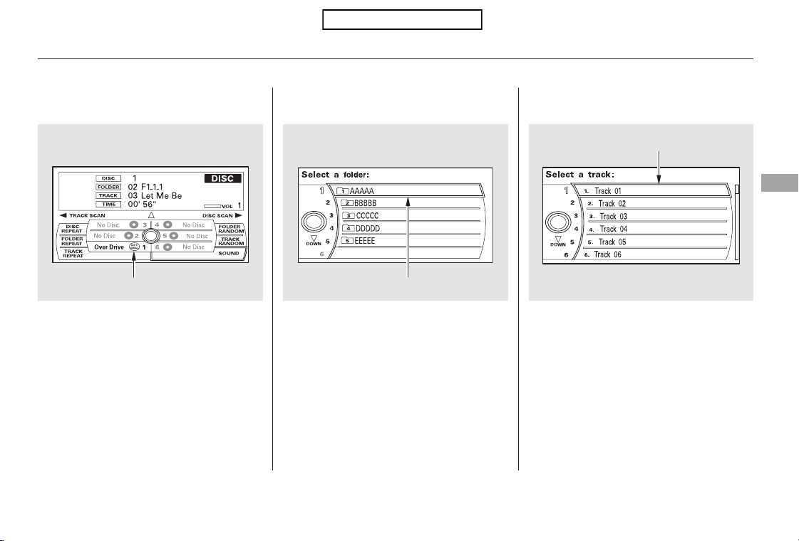
Changing and Selecting the Folders/
Files
Using the interface selector, you can
see the list of all the files and folders
within a disc. While playing a MP3/
WMA disc, press the AUDIO button.
The currently playing folder and file
information comes on the screen. If the root folder has some additional
folders in the lower layer, they will
belistedonthescreen.
You can see the list of all the files in
the selected folder. Turn the selector
knob, then press ENTER to set your
selection.
Push ENTER on the selector to
show the folder list. Turn the
selector knob, highlight the folder
you want to see the information
within, and press ENTER.
Playing Discs (Models with navigation system)
Features
207
MP3/WMA INDICATOR
CURRENT TRACK
CURRENT FOLDER
Table of Contents

This feature, when activated, plays
all files in the current folder in
random order. To activate folder
random play, select FOLDER
RANDOM by using the interface
knob, and press ENTER on the
interface selector. You will see
RANDOM next to FOLDER on the
screen. To turn this feature off,
highlight FOLDER RANDOM (if not
already highlighted), and press
ENTER on the interface selector
again.
This feature, when activated, replays
all files in the selected folder. To
activate folder repeat mode, select
FOLDER REPEAT by using the
interface knob, and press ENTER on
the interface selector. You will see
REPEAT next to FOLDER on the
screen. To turn this feature off,
highlight FOLDER REPEAT (if not
already highlighted), and press
ENTER on the interface selector
again.
This feature, when activated,
samples the first file in each folder
for 10 seconds. To scan a folder,
press the SCAN side of the SCAN/
A. SEL bar repeatedly. You will see
SCAN next to FOLDER and the
folder number blinking.
Toselectanytypeoftherepeat
modes, use the interface dial. For
more information, see page .
To listen to the rest of the folder,
press and hold the SCAN side of the
bar until you hear a beep. If you do
nothing, the system advances to the
next folder, plays 10 seconds of it,
and continues with the remaining
folders in the same way. When the
system has finished sampling the
first file in all folders, folder scan is
canceled, and the last file played
continues to play.
Toselectanytypeoftherandom
modes, use the interface dial. For
more information, see page .
204
204
Folder RandomFolder RepeatFolder Scan
Playing Discs (Models with navigation system)
208
Table of Contents

You can also eject discs when the
ignition switch is off:
To eject one disc, press and release
the eject button.
To remove a different disc from the
changer,firstselectitbypressing
the corresponding number on the
preset button or turning the
interface knob, and pressing ENTER
on the interface selector. When that
disc begins playing, press the eject
button.
When you press the eject button
while listening to the radio, or with
the audio system turned off, the disc
that was last selected is ejected.
After that disc is ejected, pressing
the eject button again will eject the
next disc in numerical order. By
doing this six times, you can remove
all the discs from the changer.
To remove the disc that is currently
playing, press the eject button. You
will see ‘‘EJECT’’ in the center
display. When you remove the disc
from the slot, the system
automatically enters the previous
modeAM,FM1,FM2,orXMRadio.
The system also begins the load
sequence so you can load another
disc. If you do not load another disc,
the load sequence is canceled, and
the system continues playing in the
previous mode.
If you do not remove the disc from
the slot, the system will reload the
disc after 10 seconds. To begin
playing the disc, press the CD button.
To eject all discs, press and hold the
eject button until the first disc begins
to eject.
Removing Discs from the
Changer
Playing Discs (Models with navigation system)
Features
209
Table of Contents
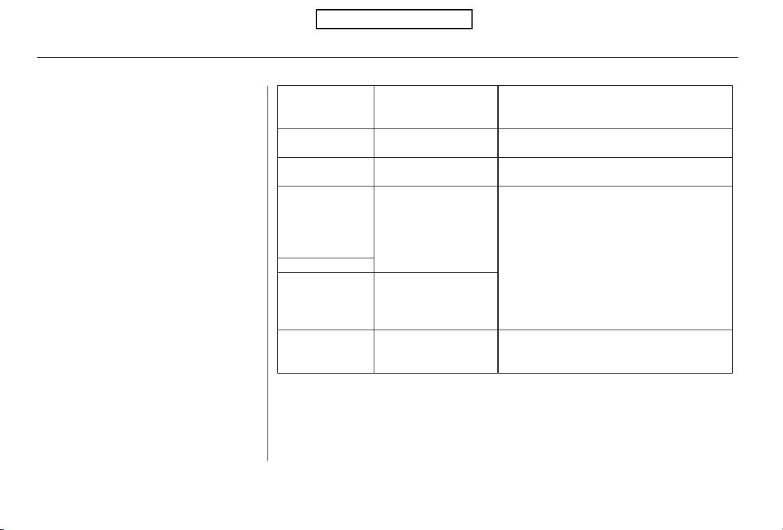
Thechartontherightexplainsthe
error messages you may see in the
center display while playing a disc.
If you see an error message in the
center display while playing a disc,
press the eject button. After ejecting
the disc, check it for damage or
deformation. If there is no damage,
insert the disc again.
For additional information on
damaged discs, see page .
Theaudiosystemwilltrytoplaythe
disc. If there is still a problem, the
error message will reappear. Press
the eject button, and pull out the disc.
Insert a different disc. If the new
disc plays, there is a problem with
the first disc. If the error message
cycle repeats and you cannot clear it,
take your vehicle to a dealer.
CauseError Message Solution
234
High Temperature
Track/File format not
supported
Mechanical Error
Servo Error
Disc Error
Will disappear when the temperature returns to
normal.
Current track will be skipped. The next
supported track or file plays automatically.
Press the EJECT button and pull out the disc(s).
Check the disc for serious damage, signs of
deformation, excessive scratches, and/or dirt
(see page 234). Insert the disc again. If the code
does not disappear, or the disc(s) cannot be
removed, consult your dealer. Do not try to
force the disc out of the player.
Check the disc for serious damage, signs of
deformation, excessive scratches, and/or dirt
(see page 234).
Disc Changer Error Messages (Models with navigation system)
210
HEAT ERROR
UNSUPPORTED
BAD DISC
PLEASE CHECK
OWNERS
MANUAL
PUSH EJECT
MECH ERROR
BAD DISC
PLEASE CHECK
OWNERS
MANUAL
CHECK DISC
Table of Contents
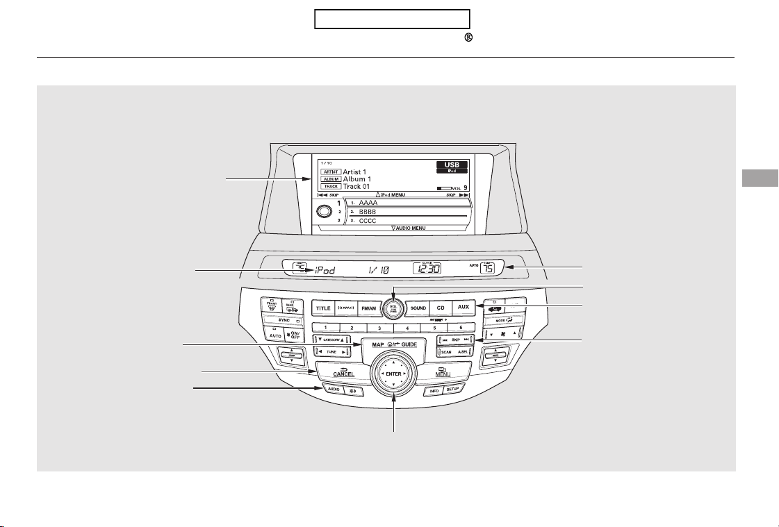
Playing an iPod (Models with navigation system)
Features
211
AUDIO BUTTON
MAP BUTTON
CANCEL BUTTON
CENTER DISPLAY
AUX BUTTON
SKIP BAR
U.S. model is shown.
iPod INDICATOR
NAVIGATION SCREEN
INTERFACE DIAL
POWER/VOLUME KNOB
Table of Contents
This audio system can operate the
audio files on the iPod
with the
same controls used for the in-dash
disc changer. To play an iPod,
connect it to the USB adapter cable
in the console compartment by using
your dock connector, then press the
AUX button. The ignition switch
must be in the ACCESSORY (I) or
ON (II) position. The iPod will also
be recharged with the ignition switch
in these positions.
The audio system reads and plays
playable sound files on the iPod. The
system cannot operate an iPod as a
mass storage device. The system will
only play songs stored on the iPod
with iTunes.
iPod and iTunes are registered
trademarks owned by Apple Inc.
You can select the AUX mode by
using the navigation system voice
control buttons, but cannot operate
theplaymodefunctions.
iPods compatible with your audio
system using the USB adapter cable
are:
UseonlycompatibleiPodswiththe
latest software. iPods that are not
compatible will not work in this audio
unit.
Software
Ver. 1.0 or more
Ver. 1.2 or more
Ver. 1.2 or more
Ver. 1.1.2 or more
Ver. 1.0 or more
Ver. 1.0.2 or more
Ver. 1.1.1 or more
Ver. 2.1.1 or more
Model
iPod classic
iPod with video
(iPod 5th
generation)
iPod nano
iPod nano 2nd
generation
iPod nano 3rd
generation
iPod nano 4th
generation
iPod touch
iPod touch 2nd
generation
To Play an iPod
Voice Control System
Playing an iPod (Models with navigation system)
212
Table of Contents
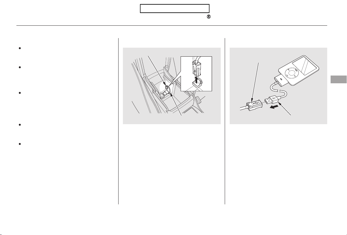
Do not connect your iPod using a
hub.
Do not use an extension cable
between the USB adapter cable
equipped with your vehicle and
your dock connector.
We recommend backing up your
data before playing it.
DonotkeeptheiPodinthe
vehicle. Direct sunlight and high
heat will damage it.
Install the dock connector to the
USB adapter cable securely.
Connect your dock connector to
the iPod correctly and securely.
Pull out the USB connector from
the holder.
Some devices cannot be powered
or charged via the USB adapter. If
this is the case, use the accessory
adapter to supply power to your
device.
1. 2.
3.
CONTINUED
Connecting an iPod
Playing an iPod (Models with navigation system)
Features
213
NOTE:
USB ADAPTER CABLE
USB CONNECTOR
DOCK CONNECTOR
USB CONNECTOR
Table of Contents
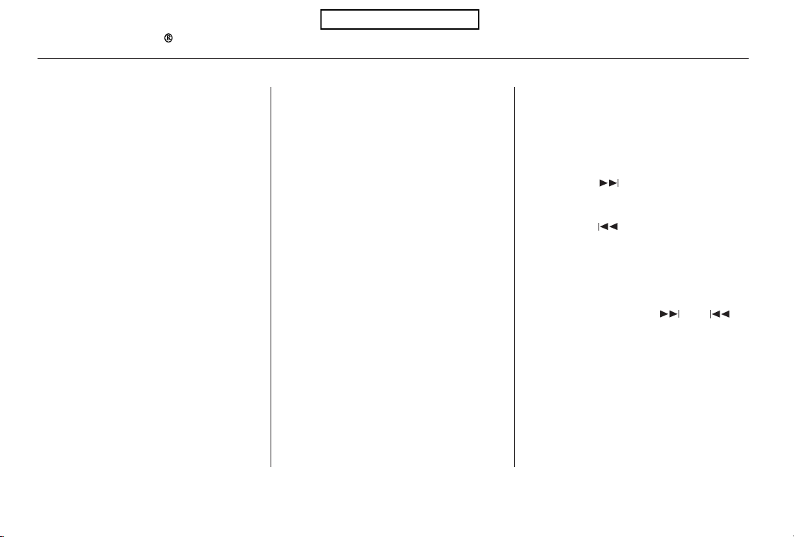
−
If the iPod indicator does not appear
in the audio display, check the
connections, and try to reconnect the
iPod a few times.
If the audio system still does not
recognize the iPod, the iPod may
need to be reset. Follow the
instructions that came with your
iPod, or you can find reset
instructions online at
The current file number and total of
the selected playable files are
displayed in the center display.
Pressing the AUDIO button displays
the artist, album and track (file)
names on the navigation screen.
Use the SKIP bar while an iPod is
playing to select passages and
change files.
Each time you press and
releasethe sideoftheSKIPbar,
the system skips forward to the
beginning of the next file. Press and
releasethe sideofthebarto
skip backward to the beginning of
the current file. Press it again to skip
to the beginning of the previous file.
To move rapidly within a file, press
andholdeitherside( or )
of the SKIP bar.
www.apple.com/
itunes/
To Change or Select Files
SKIP
Playing an iPod (Models with navigation system)
214
Table of Contents
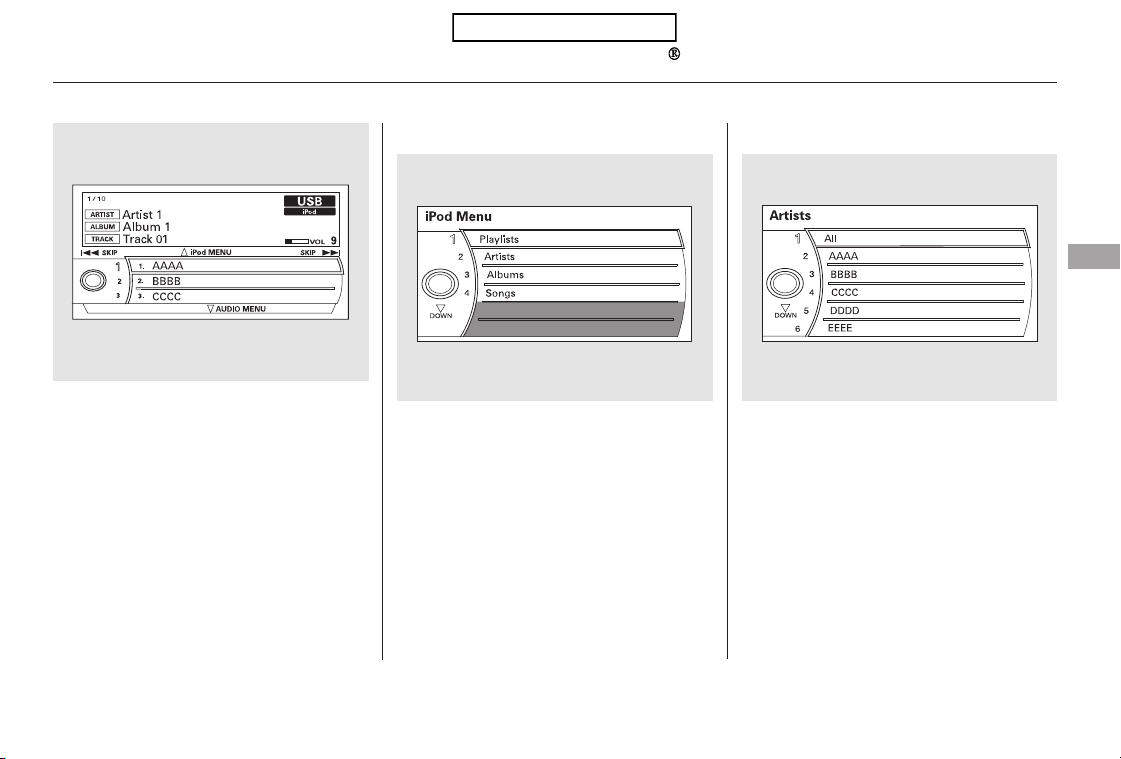
You can also change files with the
interface dial. Press the AUDIO
button to show the audio control
display on the navigation screen.
Push the selector to the right side to
skip forward and to the left side to
skip backward.
You can also select a file from any of
the iPod menus: playlists, artists,
albums and songs, by using the
interface dial. Press the AUDIO
button to display the audio control
display on the navigation screen.
Push up the interface selector to
display the iPod menu. Turn the
knob on the interface dial to select a
desired list.
Push ENTER on the selector to
display the items on that list, then
turn the knob on the interface dial to
select a desired list. Pushing the
selector up or down moves a
selection to the top or bottom of the
screen items. Press ENTER to set
your selection.
CONTINUED
To Select a File from iPod Menu
Playing an iPod (Models with navigation system)
Features
215
Table of Contents
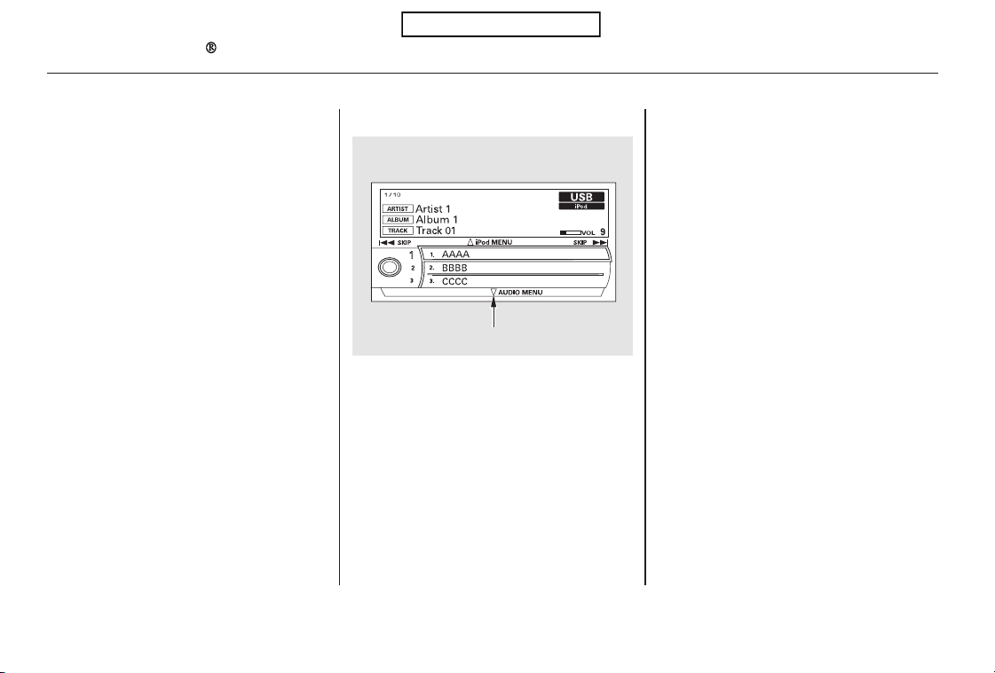
If you select ‘‘ALL’’ on either the
artists or albums list, all available
files on the selected list are played.
PresstheAUDIObuttontogoback
to the normal audio playing display.
Pressing the CANCEL button goes
back to the previous screen, and
pressing the MAP button cancels the
audio control display on the screen.
You can select any type of repeat and
random mode on the audio menu.
Press the AUDIO button to display
the audio control screen, then push
down the selector to display the
audio menu. Turn the knob on the
interface dial to select an audio
mode: repeat, album random, and
track random. Press ENTER to set
your selection.
To cancel the selected mode, press
ENTER again while the highlighted
mode is selected on the audio control
display.
To Select Repeat or Random Mode:
Playing an iPod (Models with navigation system)
216
Push down the selector.
Table of Contents
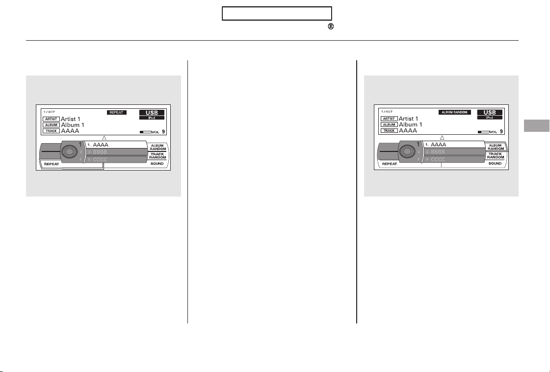
−
−
−This feature
continuously plays a file.
To turn it off, press ENTER again.
Pressing either side of the SKIP bar
changes the file while keeping the
repeat feature.
This feature
plays all available files from the
selected items in the iPod menu list
(playlists, artists, albums or songs)
in random order. You will see
TRACK RANDOM on the screen.
To turn it off, have this mode
highlighted and press ENTER again.
This feature
plays all available albums from the
selected items in the iPod menu list
(playlists, artists, albums or songs)
in random order. The files in each
album are played in the recorded
order. You will see ALBUM
RANDOM on the screen.
CONTINUED
REPEAT
TRACK RANDOM
ALBUM RANDOM
Playing an iPod (Models with navigation system)
Features
217
Table of Contents

*
*
To turn it off, have this mode
highlighted and press ENTER again.
You can also select another list from
theiPodmenuwhilekeepingthe
random function.
Available operating functions vary on
models or versions. Some functions
may not be available on the vehicle’s
audio system.
You can disconnect the iPod at any
time when you see ‘‘OK to
disconnect’’ message in the iPod
display. Always make sure you see
‘‘OK to disconnect’’ message in the
iPod display before you disconnect it.
Make sure to follow the iPod’s
instructions on how to disconnect
the dock connector from the USB
adapter cable.
The displayed message may
vary on models or versions. On
some models, there is no
message to disconnect.
When you disconnect the iPod while
it is playing, the center display and
the audio screen (if selected) show
NO DATA.
To play the radio, press the FM/AM,
or button. Press the CD button
to switch to the disc mode. Press the
AUX button to switch back to the
iPod.
:
To Stop Playing Your iPod
Disconnecting an iPod
Playing an iPod (Models with navigation system)
218
NOTE:
Table of Contents

If you reconnect the same iPod, the
system may begin playing where it
left off, depending on what mode the
iPod is in when it is reconnected.
If you see an error message in the
center display, see page .220
iPod
Error Messages
Playing an iPod (Models with navigation system)
Features
219
Table of Contents
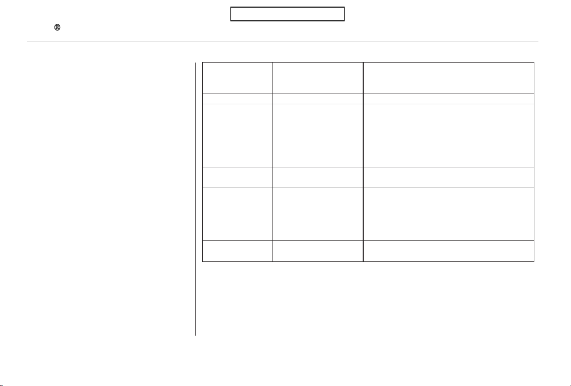
If you see an error message in the
center display while playing an iPod,
find the solution in the chart to the
right. If you cannot clear the error
message, take your vehicle to your
dealer.
SolutionCauseError Message
There is a problem with the USB adapter unit.
Appears when the overcurrent protection
feature of the system stops supplying power to
USB because an incompatible device is
connected. Disconnect the device. Then, turn
the audio system off, and turn it on again. Do
not reconnect the device that caused the error.
Appears when the iPod is empty. Store some
files in the iPod.
Appears when an unsupported iPod is
connected. See page 212 for specification
informationoniPods.Ifitappearswhena
supported iPod is connected, update the iPod
software to the newer version.
Appears when the system does not
acknowledge the iPod. Reconnect the iPod.
USB ROM error
Abnormal power
source
No files in iPod
Use of unsupported
iPod
Recognition failure of
iPod
iPod Error Messages (Models with navigation system)
220
USB ERROR
BAD USB
DEVICE
PLEASE CHECK
OWNERS
MANUAL
iPod NO SONG
UNSUPPORTED
VER.
CONNECT RETRY
Table of Contents
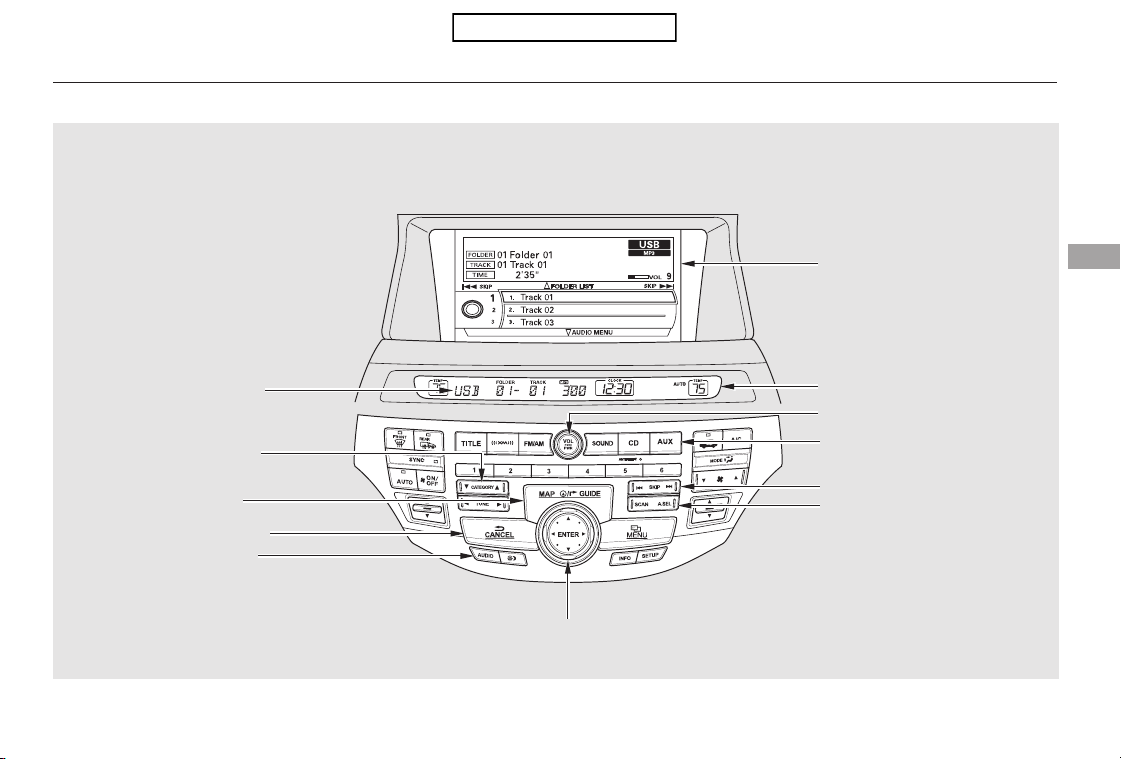
Playing a USB Flash Memory Device (Models with navigation system)
Features
221
SKIP BAR
CENTER DISPLAY
CANCEL BUTTON
AUDIO BUTTON
MAP BUTTON
CATEGORY BAR
USB INDICATOR
AUX BUTTON
U.S. model is shown.
NAVIGATION SCREEN
INTERFACE DIAL
POWER/VOLUME KNOB
SCAN/A.SEL
(SCAN/AUTO SELECT) BAR
Table of Contents
*
*
This audio system can operate the
audio files on a USB flash memory
device with the same controls used
for the in-dash disc changer. To play
a USB flash memory device, connect
it to the USB adapter cable in the
console compartment, then press the
AUX button. The ignition switch
must be in the ACCESSORY (I) or
ON (II) position.
Only AAC format files recorded
with iTunes are playable on this
audio unit.
The recommended USB flash
memory devices are 256 MB or
higher, and formatted with the FAT
file system. Some digital audio
players may be compatible as well.
The audio system reads and plays
the audio files on the USB flash
memory device in MP3, WMA or
AAC formats. Depending on the
format, the display shows MP3,
WMA or AAC when a USB flash
memory device is playing. The USB
flash memory device limit is up to
700 folders or up to 65535 files. Depending on the type and
number of files, it may take some
time before they begin to play.
We recommend backing up your
data before playing a USB flash
memory device.
Do not use a device such as a card
reader or hard drive as the device
or your files may be damaged.
Do not connect your USB flash
memory device using a hub.
Do not use an extension cable to
the USB adapter cable equipped
with your vehicle.
Do not keep a USB flash memory
device in the vehicle. Direct
sunlight and high heat will damage
it.
Some USB flash memory devices
(such as devices with security lock-
out features, etc.) will not work in
this audio unit.
:
To Play a USB Flash Memory
Device
Playing a USB Flash Memory Device (Models with navigation system)
222
NOTE:
Table of Contents
CONTINUED
You can select the AUX mode by
using the navigation system voice
control buttons, but cannot operate
theplaymodefunctions.
Some versions of MP3, WMA, or
AAC format may not be supported. If
an unsupported file is found, the
audio unit displays UNSUPPORTED,
then skips to the next file.
Depending on the software the
files were made with, it may not be
possibletoplaysomefiles,or
displaysometextdata.
Depending on the type of
encoding and writing software
used, there may be cases where
character information does not
display properly.
The order of files in USB playback
maybedifferentfromtheorderof
files displayed in PC or other
devices etc. Files are played in the
orderstoredinUSBflashmemory
device.
Some devices cannot be powered
or charged via the USB adapter. If
this is the case, use the accessory
adapter to supply power to your
device.
Playing a USB Flash Memory Device (Models with navigation system)
Voice Control System
Features
223
Combining a low sampling f requency
with a low bitrate may result in
extremely degraded sound quality.
Table of Contents
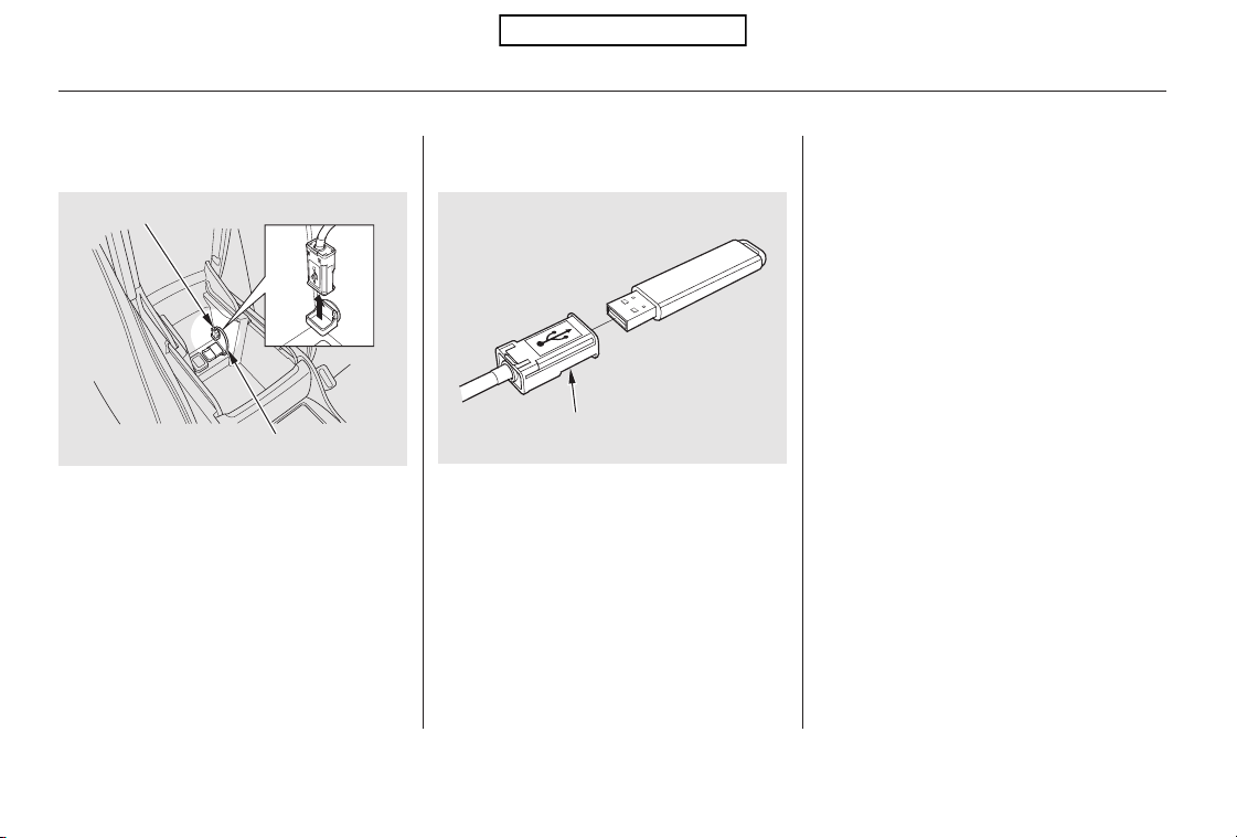
When the USB device is connected
andtheUSBmodeisselectedonthe
audio system, the USB indicator is
showninthecenterdisplay.Italso
shows the folder and file numbers.
Pressing the AUDIO button displays
the folder and file names, and the
elapsed time in the navigation screen.
Connect the USB flash memory
device to the USB adapter cable
correctly and securely.
Pull out the USB connector from
the holder.
2.1.
Connecting a USB Flash Memory
Device
Playing a USB Flash Memory Device (Models with navigation system)
224
USB ADAPTER CABLE
USB CONNECTOR
USB CONNECTOR
Table of Contents
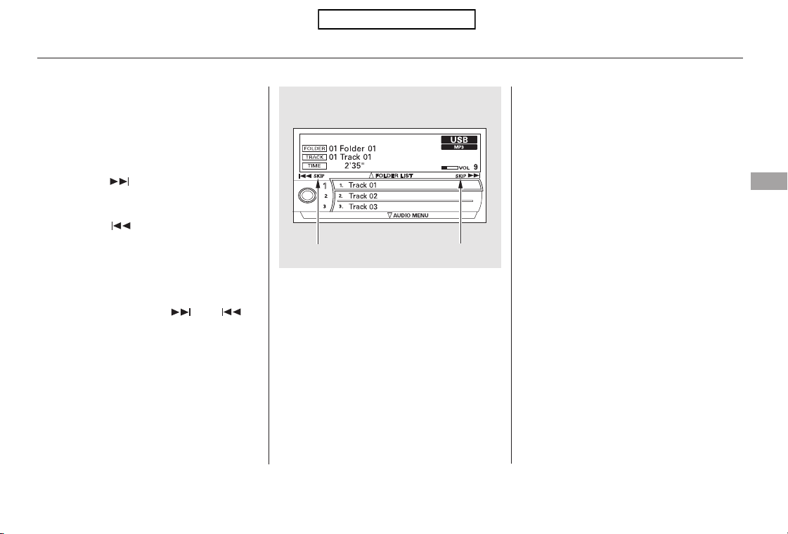
−
−
▲
▼
Use the SKIP bar while a USB flash
memory device is playing to select
passages and change files.
Each time you press and
releasethe sideoftheSKIPbar,
the system skips forward to the
beginning of the next file. Press and
releasethe sideofthebarto
skip backward to the beginning of
the current file. Press it again to skip
to the beginning of the previous file.
To move rapidly within a file, press
andholdeitherside( or )
of the SKIP bar.
You can also change files with the
interface dial. Press the AUDIO
button to show the audio control
display on the navigation screen.
Push the selector knob to the right
side to skip to the beginning of the
next file, and to the left side to skip
to the beginning of the current file.
Pushing it to the left again skips to
the beginning of the previous file.
To select a
different folder, press and release
either side of the CATEGORY bar.
Press the side to skip to the next
folder, and press the side to skip
to the beginning of the previous
folder.
CONTINUED
Playing a USB Flash Memory Device (Models with navigation system)
To Change or Select Files
SKIP
Folder Selection
Features
225
SKIP DIRECTION SKIP DIRECTION
Table of Contents
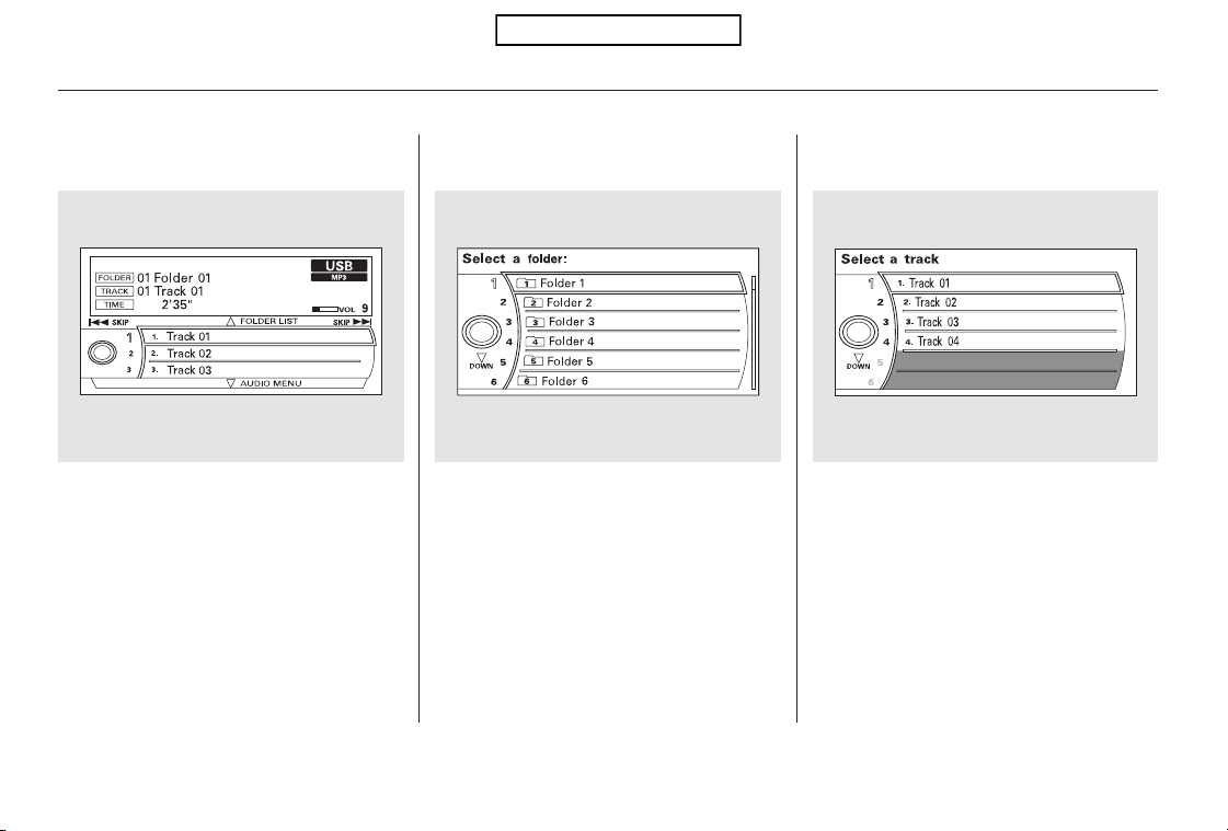
Push up the selector on the interface
dial to switch the display to the
folder list, then turn the knob on the
interface dial to select a folder.
Press ENTER to change the display
to the file list, then turn the knob on
the interface dial to select a file.
Press ENTER to set your selection.
To go back to the normal playing
display, press the AUDIO button.
Pressing the CANCEL button goes
back to the previous screen and
pressing the MAP button cancels the
audio mode display.
You can also select a folder or file
fromthelistbyusingtheinterface
dial. Press the AUDIO button to
show the audio control display on the
navigation screen.
Playing a USB Flash Memory Device (Models with navigation system)
To Select a File from Folder and File
Lists
226
Table of Contents
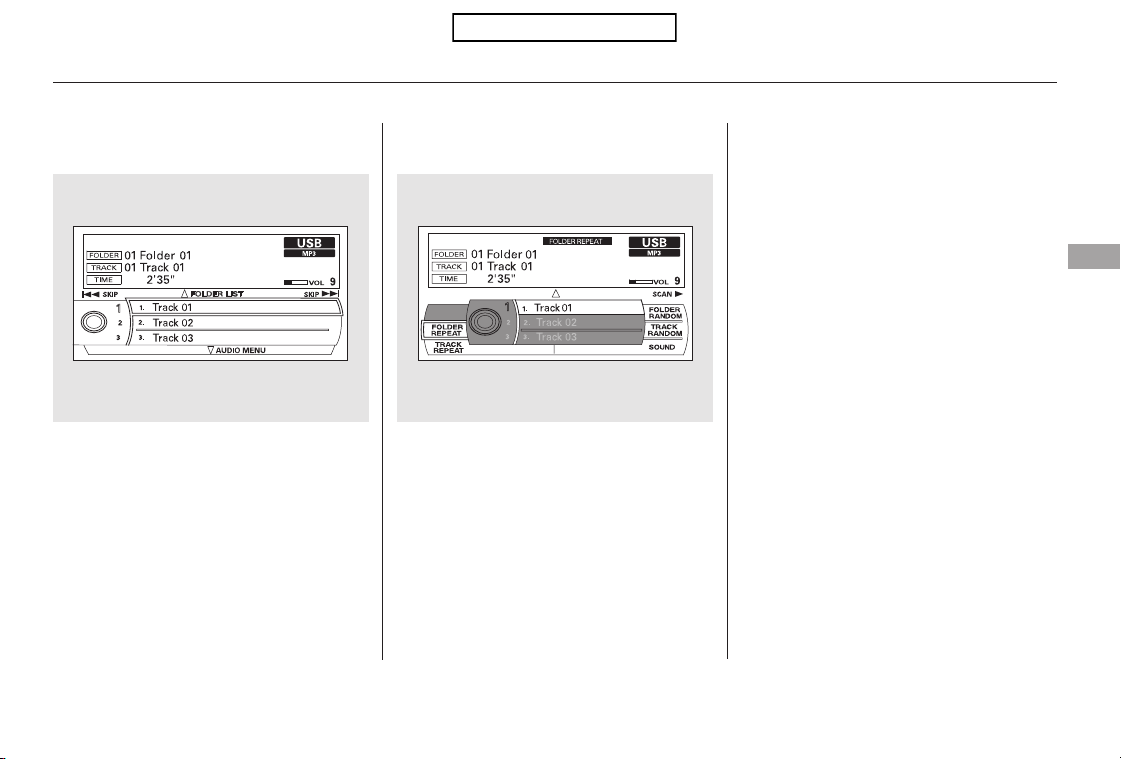
−
−
−
−
You can select any type of repeat,
random and scan modes on the audio
menu screen. Press the AUDIO
button to show the audio control
display on the navigation screen.
Push down the selector on the
interface dial to display the audio
menu items.
Turntheknobontheinterfacedial
to select a play mode: folder random,
track random, folder repeat, track
repeat. Press ENTER to set your
selection.
To cancel the selected mode, push
down the selector to display the
audio menu on the audio control
display. Turn the knob on the
interface dial to select the
highlighted play mode, then press
ENTER to turn off that selected
mode.
This feature
continuously plays a file. Pressing
either side of the SKIP bar also turns
off this feature.
This feature
plays all the files in random order.
This
feature plays the files in the selected
folder in random order.
This feature
replays all the files in the selected
folder in the order they are stored.
Pressing either side of the
CATEGORY bar also turns off this
feature.
CONTINUED
Playing a USB Flash Memory Device (Models with navigation system)
To Select Repeat, Random or Scan
Mode:
TRACK REPEAT
TRACK RANDOM
FOLDER RANDOM
FOLDER REPEAT
Features
227
Table of Contents

−−This function
samples all files in the selected
folder in the order they are stored.
To activate the scan feature, push
the selector to the right. You will see
TRACK SCAN on the screen. You
will also see SCAN on the center
display and the file number blinking.
You will get a 10 second sampling of
each file in the folder. Push the
selector repeatedly to get out of the
scan mode. The system plays the last
file sampled.
Pressing either side of the
CATEGORY or SKIP bar also turns
off the feature.
You can also select the scan feature
with the SCAN side of the SCAN/
A.SEL bar on the control panel.
Press and release the SCAN side of
the bar. Press and hold the SCAN
side of the bar to get out of the scan
mode and play the last file sampled.
This function
samples the first file in each folder in
the order they are stored. To
activate the folder scan feature, push
the selector to the right repeatedly.
You will see FOLDER SCAN on the
screen. You will also see SCAN on
the center display and the folder
number blinking. You will get a 10
second sampling of the first file in
each folder. Push the selector
repeatedly to get out of the scan
mode. The system plays the last file
sampled.
You can also select the folder scan
feature with the SCAN side of the
SCAN/A.SEL bar on the control
panel. Press and release the SCAN
side of the bar repeatedly.
Press and hold the SCAN side of the
bar to get out of the folder scan
mode and play the last file sampled.
Playing a USB Flash Memory Device (Models with navigation system)
TRACK SCAN FOLDER SCAN
228
Table of Contents

You can disconnect the USB flash
memory device at any time even if
the USB mode is selected on the
audio system. Make sure to follow
the USB flash memory device’s
instructions when you remove it.
When you disconnect the USB flash
memory device while it is playing,
the center display and the audio
screen (if selected) show NO DATA.
If you see an error message in the
center display, see page .
To play the radio, press the FM/AM,
or button. Press the CD button
to switch to the disc mode. Press the
AUX button to switch back to the
USB.
If you reconnect the same USB flash
memory device, the system will
begin playing where it left off.
230
Playing a USB Flash Memory Device (Models with navigation system)
To Stop Playing a USB Flash
Memory Device
USB Flash Memory Device Error
Messages
Disconnecting a USB Flash Memory
Device
Features
229
Table of Contents

If you see an error message in the
center display while playing a USB
flash memory device, find the
solution in the chart to the right. If
you cannot clear the error message,
take your vehicle to your dealer.
CauseError Message Solution
USB ROM error
Abnormal power
source
Use of unsupported
files
No files in USB flash
memory device
Use of unsupported
USB flash memory
device
There is a problem with the USB adapter unit.
Appears when the overcurrent protection
feature of the system stops supplying power to
USB because an incompatible device is
connected. Disconnect the device. Then, turn
the audio system off, and turn it on again. Do
not reconnect the device that caused the error.
Appears when the files in the USB flash
memory device are DRM or an unsupported
format. This error message appears for about 3
seconds, then plays the next song.
Appears when the USB flash memory device is
emptyortherearenoMP3,WMA,orAACfiles
in the USB flash memory device. Save some
MP3, WMA, or AAC files in the USB flash
memory device.
Appears when an unsupported device is
connected. See page 222 for the specification
information for the USB flash memory device.
If it appears when the supported device is
connected, reconnect the device.
USB Flash Memory Device Error Messages (Models with navigation system)
230
USB ERROR
BAD USB
DEVICE
PLEASE CHECK
OWNERS
MANUAL
UNPLAYABLE FILE
USB NO SONG
UNSUPPORTED
Table of Contents
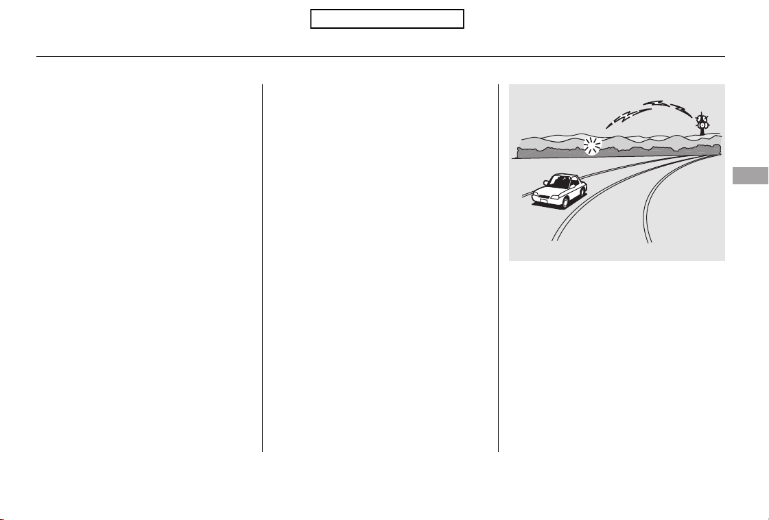
The radio can receive the complete
AM and FM bands.
Those bands cover these frequen-
cies:
AM band: 530 to 1,710 kHz
FM band: 87.7 to 107.9 MHz
How well the radio receives stations
is dependent on many factors, such
as the distance from the station’s
transmitter, nearby large objects,
and atmospheric conditions.
Driving very near the transmitter of
a station that is broadcasting on a
frequency close to the frequency of
the station you are listening to can
also affect your radio’s reception.
You may temporarily hear both
stations,orhearonlythestationyou
are close to.
A radio station’s signal gets weaker
as you get farther away from its
transmitter. If you are listening to an
AM station, you will notice the sound
volume becoming weaker, and the
stationdriftinginandout.Ifyouare
listening to an FM station, you will
see the stereo indicator flickering off
and on as the signal weakens.
Eventually, the stereo indicator will
go off and the sound will fade
completely as you get out of range of
the station’s signal.
Radio stations on the AM band are
assigned frequencies at least 10 kHz
apart (530, 540, 550). Stations on the
FM band are assigned frequencies at
least 0.2 MHz apart (87.9, 88.1, 88.3).
Stations must use these exact
frequencies. It is fairly common for
stations to round-off the frequency in
their advertising, so your radio could
display a frequency of 100.9 even
though the announcer may identify
the station as ‘‘FM101.’’
CONTINUED
FM/AM Radio Frequencies FM/AM Radio Reception
FM/AM Radio Reception
Features
231
Table of Contents
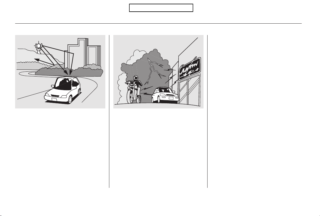
Radio signals, especially on the FM
band, are deflected by large objects
such as buildings and hills. Your
radio then receives both the direct
signal from the station’s transmitter,
and the deflected signal. This causes
the sound to distort or flutter. This is
a main cause of poor radio reception
in city driving.
Radio reception can be affected by
atmospheric conditions such as
thunderstorms, high humidity, and
even sunspots. You may be able to
receive a distant radio station one
day and not receive it the next day
because of a change in conditions.
Electrical interference from passing
vehicles and stationary sources can
cause temporary reception problems.
As required by the FCC:
Changes or modifications not expressly
approved by the party responsible for
compliance could void the user’s
authority to operate the equipment.
FM/AM Radio Reception
232
Table of Contents
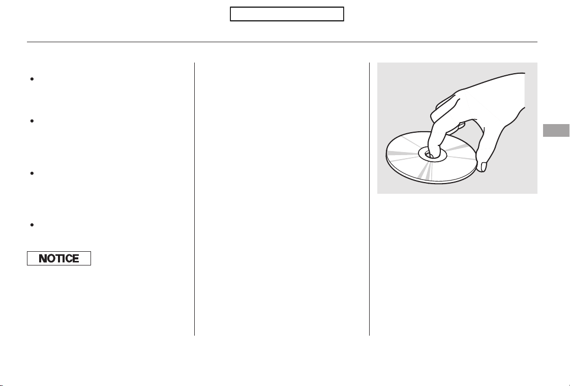
When using CD-R or CD-RW discs,
use only high quality discs labeled
for audio use.
When recording a CD-R or
CD-RW, the recording must be
closedforittobeusedbythedisc
changer.
When a disc is not being played,
store it in its case to protect it from
dust and other contamination. To
prevent warpage, keep discs out of
direct sunlight and extreme heat.
A new disc may be rough on the
inner and outer edges. The small
plastic pieces causing this roughness
can flake off and fall on the
recording surface of the disc,
causing skipping or other problems.
Remove these pieces by rubbing the
inner and outer edges with the side
of a pencil or pen.
Never try to insert foreign objects in
the disc changer.
Handle a disc by its edges; never
touch either surface. Do not place
stabilizer rings or labels on the disc.
These, along with contamination
from finger prints, liquids, and felt-
tip pens, can cause the disc to not
play properly, or possibly jam in the
drive.
To clean a disc, use a clean soft cloth.
Wipe across the disc from the center
to the outside edge.
Play only standard, round, 5-inch
(12 cm) discs. Smaller or odd-
shaped discs may jam in the drive
or cause other problems.
Handle your discs properly to
prevent damage and skipping.
General Information Protecting Discs
Protecting Your Discs
Features
233
Do not use discs with adhesive labels.
The label can curl up and cause the
disc to jam in the unit.
Table of Contents
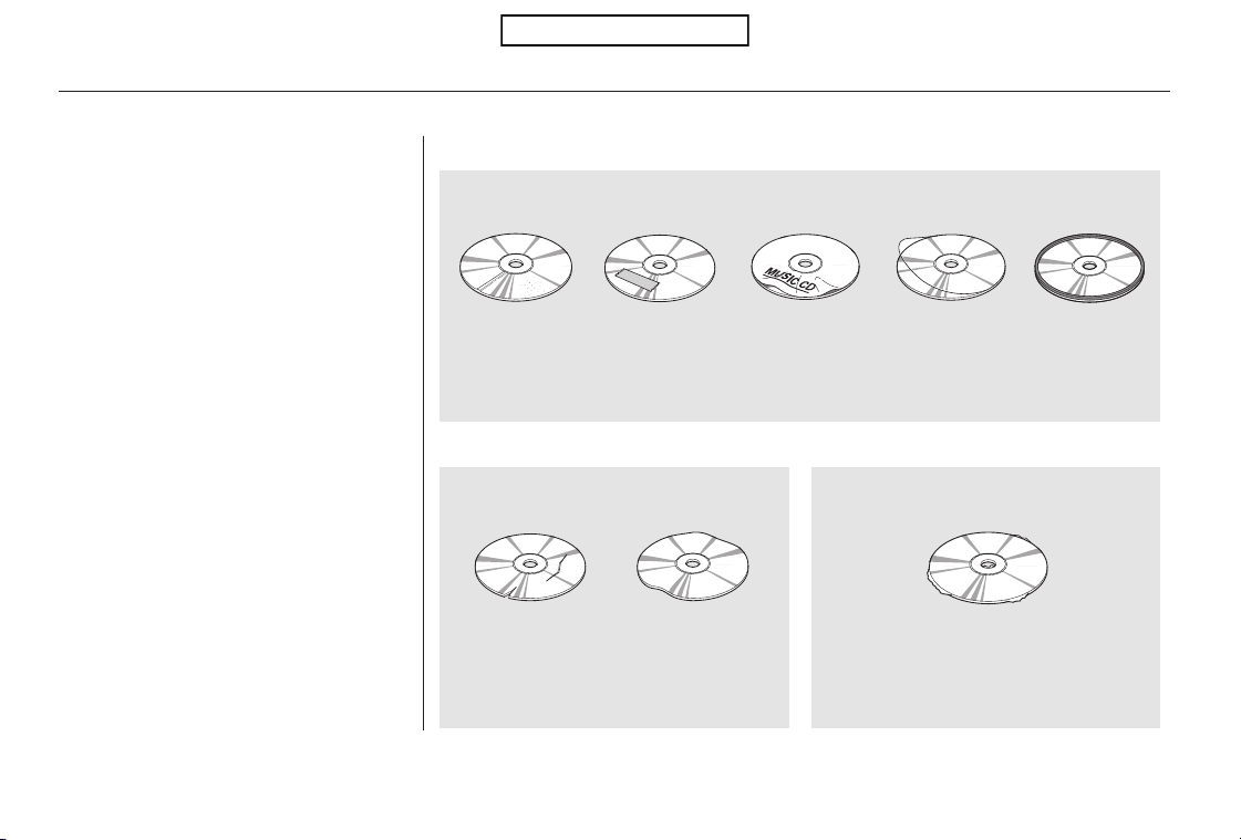
The in-dash disc player/changer has
a sophisticated and delicate
mechanism. If you insert a damaged
disc as indicated in this section, it
maybecomestuckinsideand
damage the audio unit.
Examples of these discs are shown
to the right:
Bubbled, wrinkled, labeled, and excessively thick discs
Damaged discs Poor quality discs
1.
2. 3.
Additional Information on
Recommended Discs
Protecting Your Discs
234
Sealed
Warped
Burrs
Chipped/
Cracked
Bubbled/
Wrinkled
With Label/
Sticker
Using Printer
Label Kit
With Plastic
Ring
Table of Contents
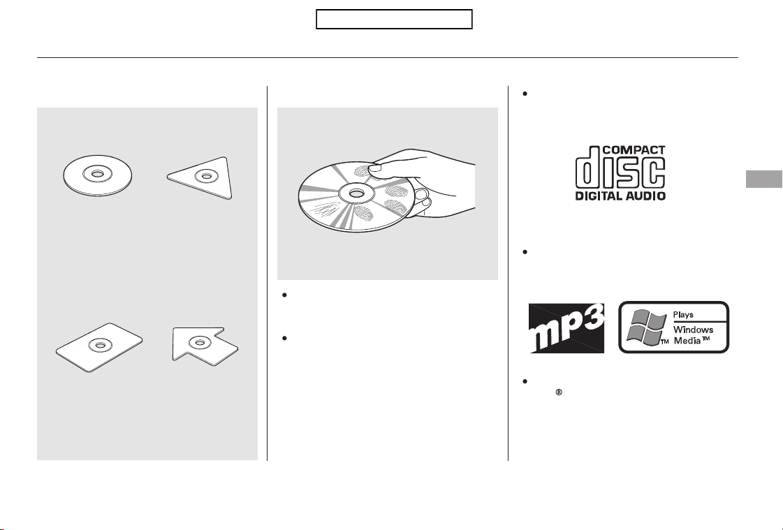
Small, irregular shaped discs Discs with scratches, dirty discs
CD-R or CD-RW may not play due
to the recording conditions.
Scratches and fingerprints on the
discs may cause the sound to skip.
Recommended discs are printed
with the following logo.
Audio unit may not play the
following formats.
This audio unit cannot play a Dual-
disc
.
4. 5.
Protecting Your Discs
Features
235
Fingerprints, scratches, etc.
3-inch (8-cm) CD Triangle Shape
Arrow ShapeCan Shape
Table of Contents
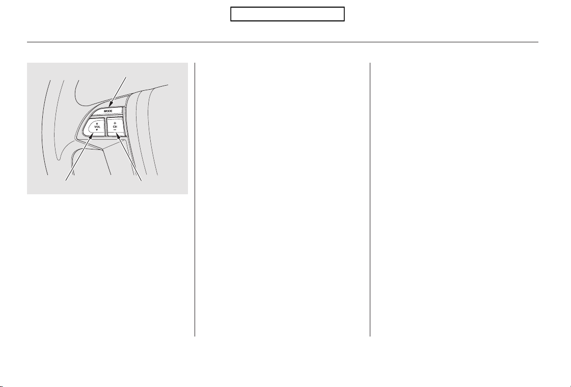
▲▼
+
−
+−
The VOL button adjusts the volume
up ( ) or down ( ). Press the top
or bottom of the button, hold it until
the desired volume is reached, then
release it.
Three controls for the audio system
are mounted in the steering wheel
hub. These let you control basic
functions without removing your
hand from the wheel.
If you are listening to the radio, use
the CH button to change stations.
Each time you press the top ( ) of
the button, the system goes to the
next preset station on the band you
are listening to. Press the bottom
( ) to go back to the previous
preset station. If you press and hold
the CH button ( ) or ( ), the
system goes into the skip (seek)
mode. It stops when it finds a station
with a strong signal.
The MODE button changes the
mode.
Pressing the MODE button
repeatedly cycles through all
possible media sources whether they
are present or not.
Pressing the MODE button
repeatedly cycles through all present,
connected media sources. Media
sources that are not present or
connected will not appear when
cycling with the MODE button.
On vehicles without navigation system
On vehicles with navigation system
Remote Audio Controls
236
MODE BUTTON
VOL BUTTON CH BUTTON
Table of Contents

+
−
+
−
+
−
+
−
If you are playing a disc, the system
skips to the beginning of the next
track (file in MP3 or WMA format)
each time you press the top ( ) of
the CH button. Press the bottom
( ) to return to the beginning of the
current track/file. Press it twice to
return to the previous track/file.
In MP3 or WMA mode, you can use
the skip function to select folders.
Press and hold the top ( ) of the
CH button until you hear a beep, to
skip forward to the first file in the
next folder. Press the bottom ( ) to
skip backward to the previous folder.
IfyouareplayingaconventionalCD
(without the text data and not
compressedinMP3orWMA),you
can use the skip function to select
discs. Press and hold the top ( ) of
the CH button until you hear a beep,
to skip forward to the next disc.
Press and hold the bottom ( ) to
skip backward to the previous disc.
When playing a USB flash memory
device, you can also use the seek
function to skip the folder. To
activate this, press and hold either
side of the CH button until you hear
a beep.
IfyouareplayingaUSBflash
memory device or iPod with the USB
adapter cable, press and release the
top ( ) of the CH button to skip
forward to the beginning of the next
file. Press the bottom ( ) to skip
backward to the beginning to the
current file. Press it twice to return
to the previous file.
EX-L models
Remote Audio Controls
Features
237
Table of Contents
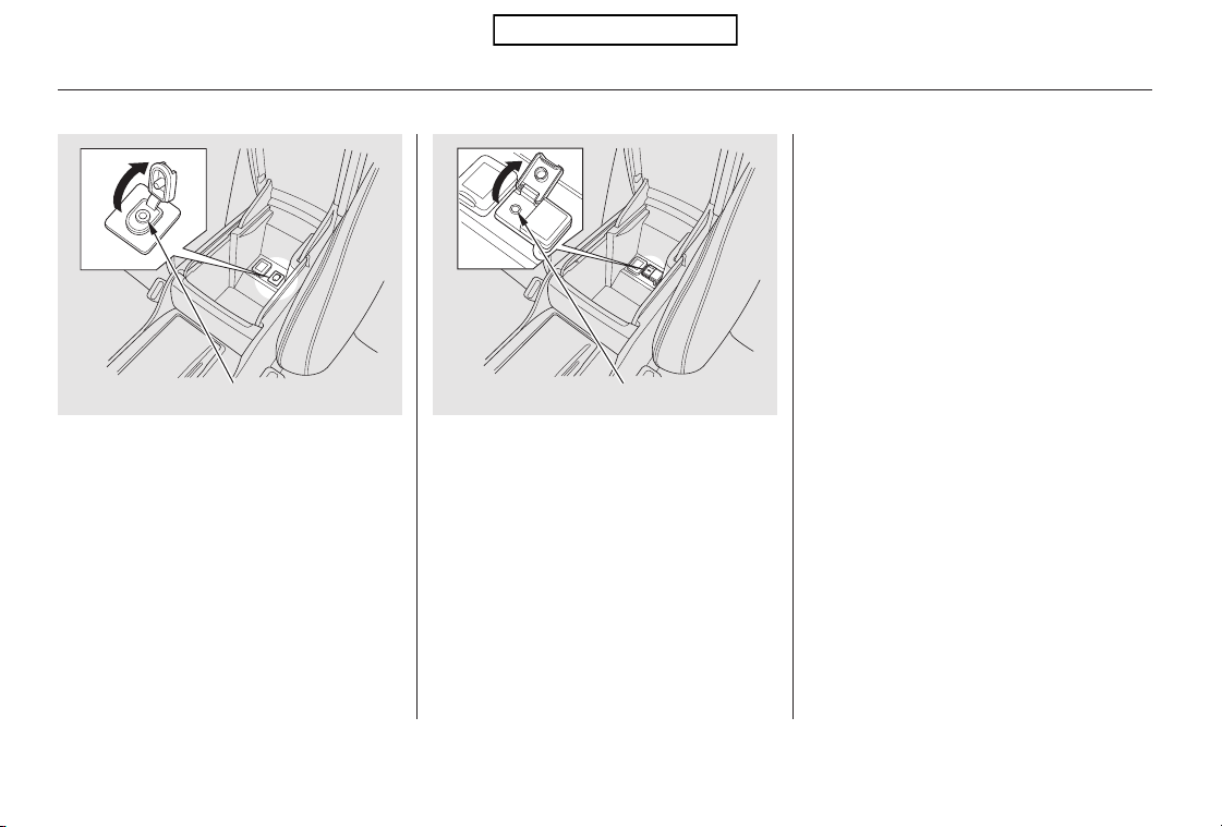
The auxiliary input jack is inside the
console compartment. The system
will accept auxiliary input from
standard audio accessories using a
1/8 inch (3.5 mm) stereo miniplug.
When a compatible audio unit is
connected to the jack, press the AUX
or CD/AUX button to select it.
Auxiliary Input Jack
238
AUXILIARY INPUT JACK
EX-L models AUXILIARY INPUT JACKEX models
Table of Contents

The system will retain your AM and
FM presets even if power is
disconnected.
If your vehicle’s battery is discon-
nected or goes dead, the audio
system will disable itself. If this
happens, you will see
‘‘ENTER CODE’’ in the frequency
display(onthescreenonmodels
with navigation system) the next
timeyouturnonthesystem.Usethe
preset buttons to enter the five-digit
code. The code is on the radio code
card included in your owner’s
manual kit. When it is entered
correctly, the radio will start playing.
If you make a mistake entering the
code, do not start over; complete the
five-digit sequence, then enter the
correct code. You have ten tries to
enter the correct code. If you are
unsuccessful in ten attempts, you
must then leave the system on for 1
hour before trying again.
Your vehicle’s audio system may
disable itself if it is disconnected
from electrical power for any reason.
To make it work again, you must
enter a specific five-digit code with
the preset buttons. Because there
are hundreds of number
combinations possible from the five
digits, making the system work
without knowing the exact code is
nearly impossible.
You should have received a radio
code card that lists your audio
system’s code and serial numbers. It
is best to store this card in a safe
place at home. In addition, you
should write the audio system’s
serial number in this owner’s manual.
If you lose the card, you must obtain
the code number from your dealer.
To do this, you will need the audio
system’s serial number.
Radio Theft Protection
Features
239
Table of Contents
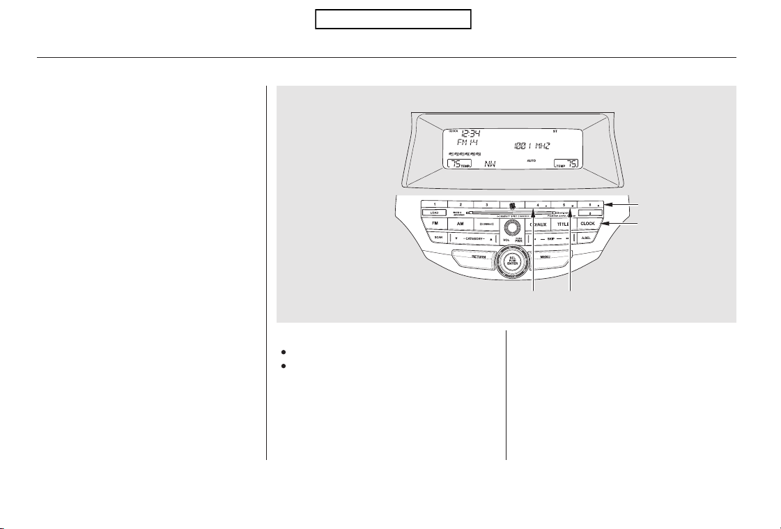
To set the time, press the CLOCK
button until you hear a beep. The
displayed time begins to blink.
Change the hours by pressing the H
(hour) button until the numbers
advance to the desired time. Change
the minutes by pressing the M
(minute) button until the numbers
advance to the desired time.
Press the CLOCK button again to
enter the set time.
You can quickly set the time to the
nearest hour. If the displayed time is
before the half hour, press and hold
the CLOCK button, then press the R
(reset) button to set the time back to
the previous hour. If the displayed
time is after the half hour, the same
procedure sets the time forward to
the beginning of the next hour.
The navigation system receives
signals from the global positioning
system (GPS), and the displayed
time is updated automatically by the
GPS. Refer to the navigation system
manual for how to adjust the time.
1:06 would RESET to 1:00.
1:52 would RESET to 2:00.
For example:
On models with navigation system
On models without navigation system
Setting the Clock
240
On models without navigation system
CLOCK BUTTON
U.S. model is shown.
R (RESET)
BUTTON
H (HOUR) BUTTON M (MINUTE) BUTTON
Table of Contents
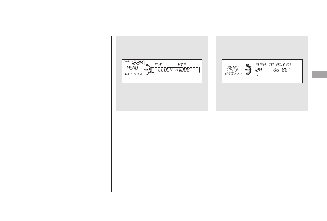
△
Turn the selector knob to select
‘‘CLOCK ADJUST.’’
Press the selector knob (ENTER)
to enter your selection. The
display changes to the clock
adjusting display.
Turn the selector knob to select
the item which you want to adjust.
Turning the selector knob will
change the selected item between
the clock display setting, hours,
minutes, and SET. The selected
item is indicated with in the
display.
You can also adjust the clock and
switch the clock display between 24-
hours and 12-hours in the menu
mode.
To adjust the clock setting:
Press and release the MENU
button. The display shows you the
menu items.
You can adjust the clock setting
with the ignition switch in the
ACCESSORY (I) or ON (II)
position.
1.
2.
3.
4.
CONTINUED
On models without navigation system
Setting the Clock
Adjusting the Clock with MENU
Button
Features
241
Table of Contents
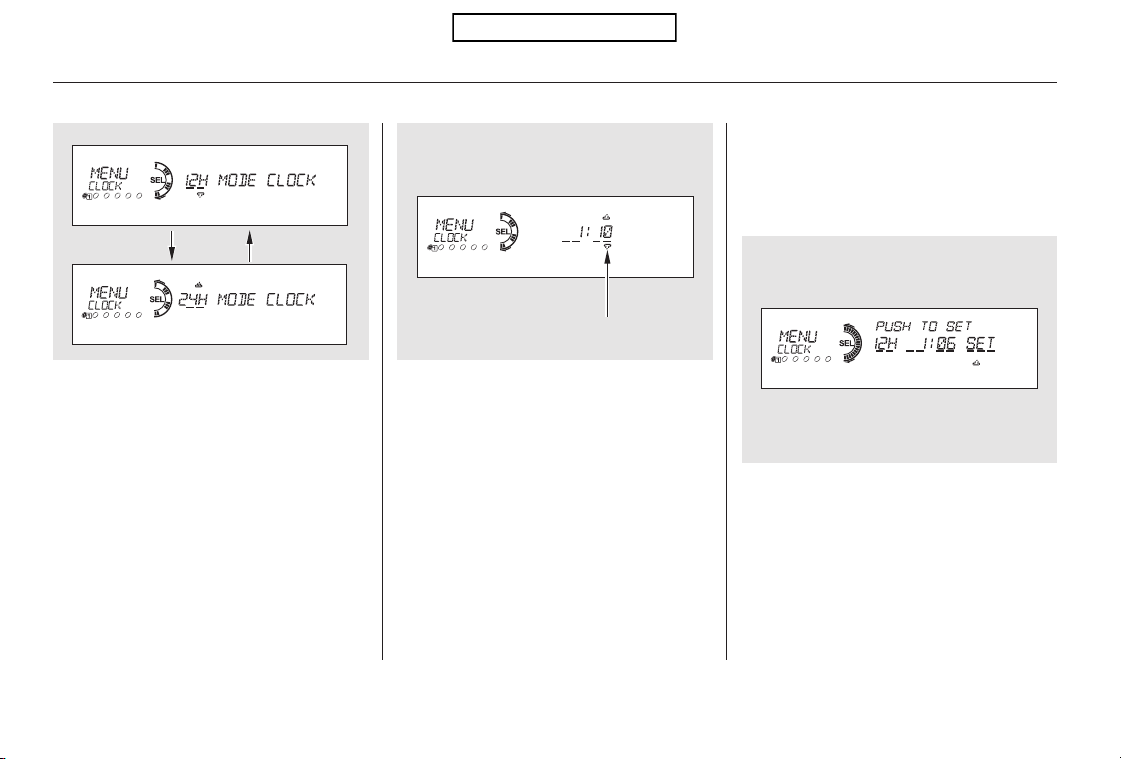
To set the time, turn the selector
knob and select the hours or the
minutes, then press the knob to
enter your selection. The display
changes to the setting display.
Turn the selector knob to count
the numbers up or down.
Press the selector knob (ENTER)
to enter your selection. The
display will return to the clock
adjusting display.
While setting the clock, pressing
the RETURN button will go back
to the previous display.
Pressing the MENU button again
will cancel this setting mode.
Turn the selector knob to change
the setting between 12H and 24H.
Press the selector knob (ENTER)
to enter your selection. The
display will return to the clock
adjusting display.
To enter the clock setting, turn
the selector knob to select ‘‘SET,’’
then press the knob. The display
will return to the menu item
display.
Press either the RETURN or
MENUbuttontogobacktothe
normal display.
5.
6.
7.
8.
9.
10.
11.
Setting the Clock
242
MINUTE SETTING
Table of Contents
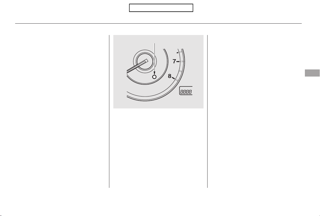
CONTINUED
The security system helps to protect
your vehicle and valuables from theft.
The horn sounds and a combination
of headlights, parking lights, side
marker lights and taillights flashes if
someone attempts to break into your
vehicle or remove the audio unit.
This alarm continues for two
minutes, then the system resets. To
reset an activated system before the
two minutes have elapsed, unlock
the driver’s door with the key or the
remote transmitter.
The security system automatically
sets 15 seconds after you lock the
doors, hood, and the tailgate. For the
system to activate, you must lock the
doorsandthetailgatefromthe
outside with the key, driver’s lock
tab, door lock master switch, or
remote transmitter. The security
system indicator on the instrument
panel starts blinking immediately to
show you the system is setting itself.
The security system will not set if
the hood, tailgate, or any of the
doors are not fully closed. If the
system will not set, check the doors
and the tailgate. You can also check
the open indicator on the instrument
panel (see page ), to see if the
doors and the tailgate are fully
closed. Since it is not part of the
monitor display, manually check the
hood.
Once the security system is set,
opening any door, the tailgate, or the
hood without using the key or the
remote transmitter, will cause the
alarm to activate. It will also activate
if the audio unit is removed from the
dashboard or the wiring is cut.
60
Security System
Features
243
SECURITY SYSTEM INDICATOR
Table of Contents

Do not attempt to alter this system
or add other devices to it.
Use the remote transmitter
to quickly check that the hood, the
tailgate, and all doors are closed.
Push the lock button twice within 5
seconds. There should be an audible
confirmation beep.
Security System
244
NOTE:
Table of Contents
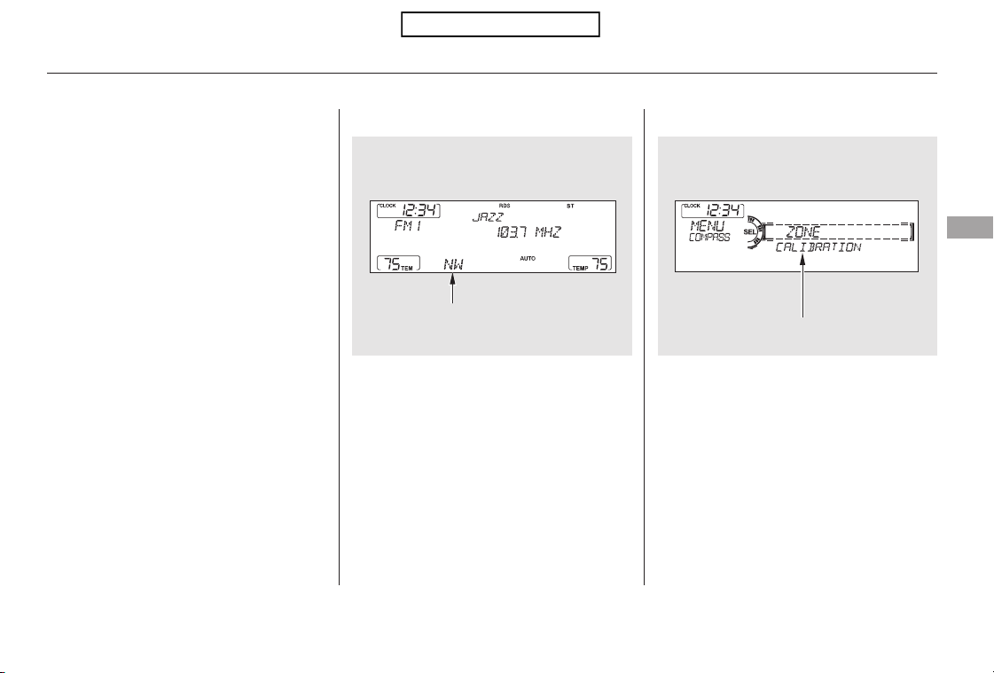
CONTINUED
The compass may need to be
manually calibrated after exposure to
a strong magnetic field. If the
compassseemstobecontinually
showing the wrong direction and is
not self-calibrating, or the compass
display is blinking with the CAL
indicator on, do the following.
Do this procedure in an open
area, away from buildings, power
lines, and other vehicles.
Press and hold the MENU button
for about 5 seconds until you hear
a beep. The display shows you the
compass setting menu items.
Turn the ignition switch to the ON
(II) position.
Compass operation can be affected
by driving near power lines or
stations, across bridges, through
tunnels, over railroad crossings, past
large vehicles, or driving near large
objects that can cause a magnetic
disturbance. It can also be affected
by accessories such as antennas and
roof racks that are mounted by
magnets.
When you turn the ignition switch to
the ON (II) position, the compass is
self-calibrating, then the compass
display is shown in the display.
1.
2.
On models without navigation system
Compass
Compass Calibration
Compass Operation
Features
245
NOTE:
COMPASS
COMPASS SETTING MENU ITEMS
U.S. model is shown.
Table of Contents
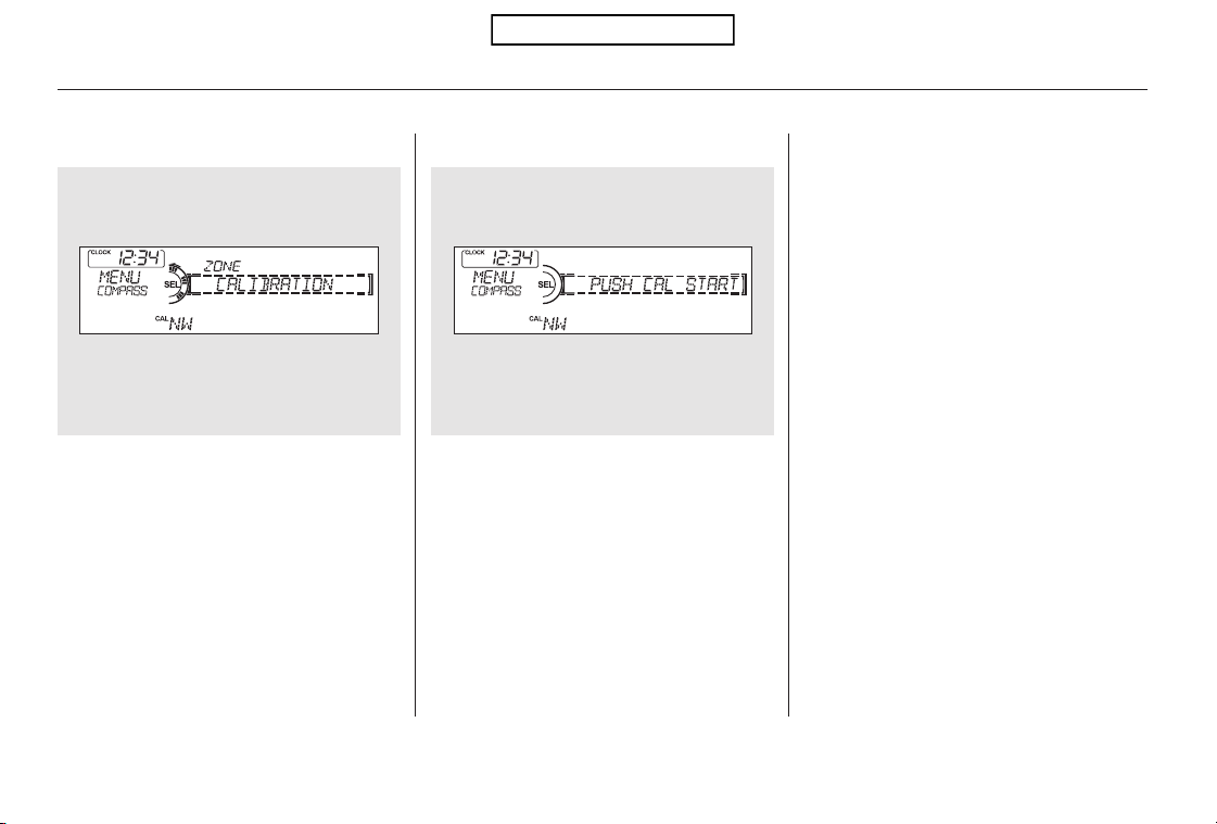
Turn the selector knob to select
‘‘CALIBRATION.’’
Press the selector knob (ENTER)
to enter your selection. The
display shows you ‘‘PUSH CAL
START.’’
The audio system is not related to
the compass system. Even if the
compasssystemiscalibrating,the
display returns to the normal display
which you last selected.
When the calibration is successfully
completed, the CAL indicator goes
off and the compass display will stop
blinking and show an actual heading.
Drive the vehicle slowly in two
complete circles.
Press the selector knob (ENTER).
The compass display is blinking
and the CAL indicator is shown.
While setting the compass,
pressing the RETURN button will
go back to the previous display.
Pressing the MENU button will
cancel the compass setting mode.
5.
6.
4.3.
Compass
246
Table of Contents
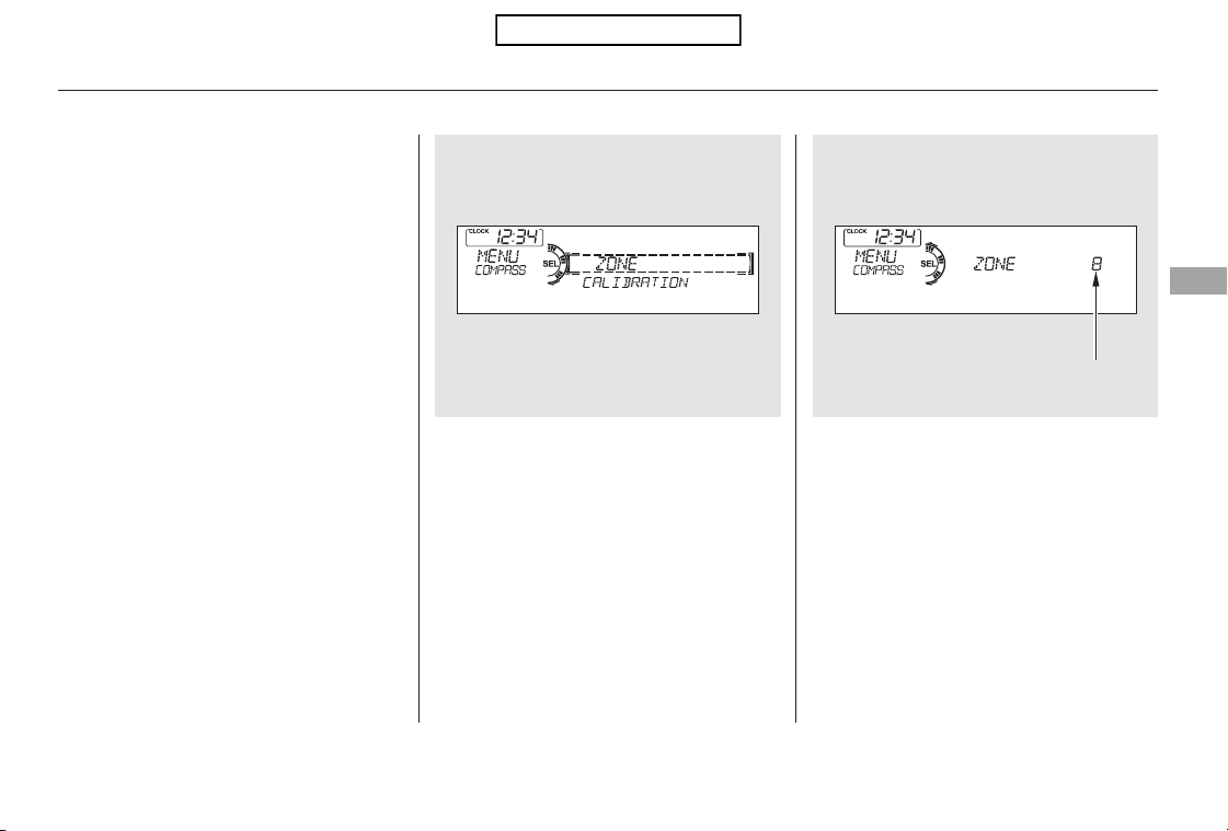
In most areas, there is a variation
between magnetic north and true
north. Zone selection is required so
the compass can compensate for this
variation. To check and select the
zone, do this:
Once the correct zone is displayed,
press the selector knob. The
display then returns to normal.
Turn the ignition switch to the ON
(II) position.
Press and hold the MENU button
for about 5 seconds until you hear
a beep. The display shows you the
compass setting menu items.
Turn the selector knob to select
‘‘ZONE.’’ Press the selector knob
(ENTER) to enter your selection.
The display shows you the
currently selected zone number.
Find the zone for your area on the
map (see page ). If the correct
zone is not shown, turn the
selector knob to cycle the zone
lists up or down.
If necessary, press the RETURN
button to return to the previous
display. Pressing the MENU
button will cancel the compass
setting mode.
4. 5.
1.
2.
3.
248
CONTINUED
Compass
Compass Zone Selection
Features
247
ZONE NUMBER
Table of Contents
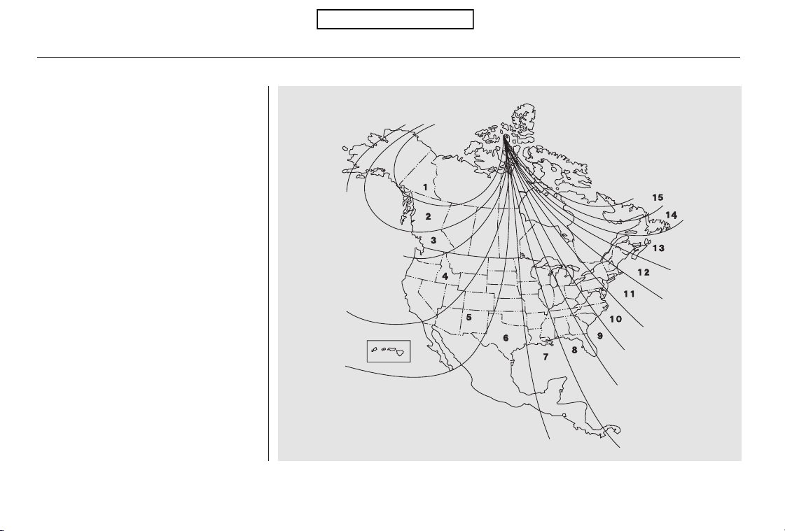
*
*
The audio system is not related to
the compass system. Even if the
compasssystemisinthezone
setting mode, the display returns to
the normal display which you last
selected.
Guam Island: Zone 8
Puerto Rico: Zone 11
Compass
248
Zone Map
Table of Contents
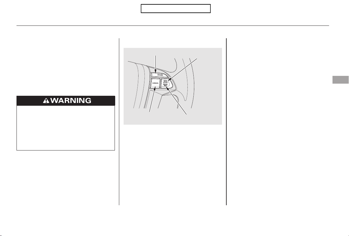
Cruise control allows you to maintain
asetspeedabove25mph(40km/h)
without keeping your foot on the
accelerator pedal. It should be used
for cruising on straight, open
highways. It is not recommended for
city driving, winding roads, slippery
roads, heavy rain, or bad weather.
Press and release the SET/
DECELbuttononthesteering
wheel. The CRUISE CONTROL
indicator on the instrument panel
comes on to show the system is
now activated.
Push in the CRUISE button on the
steering wheel. The CRUISE
MAIN indicator on the instrument
panel comes on.
Accelerate to the desired cruising
speedabove25mph(40km/h).
Thecruisecontrolsystemcanbe
lefton,evenwhenitisnotinuse.
1.
2.
3.
CONTINUED
Using the Cruise Control
Cruise Control
Features
249
RES/
ACCEL
BUTTON
CANCEL BUTTON
CRUISE BUTTON
SET/DECEL
BUTTON
Improper use of the cruise
control can lead to a crash.
Use the cruise control only
when traveling on open
highways in good weather.
Table of Contents
You can decrease the set cruising
speed in any of these ways:
If you need to decrease your
speed quickly, use the brakes as you
normally would.
Press and hold the SET/DECEL
button. Release the button when
you reach the desired speed.
To slow down in very small
amounts, tap the SET/DECEL
button repeatedly. Each time you
do this, your vehicle will slow
down about 1 mph (1.6 km/h).
You can increase the set cruising
speed in any of these ways:
Press and hold the RES/ACCEL
button. When you reach the
desired cruising speed, release the
button.
Push on the accelerator pedal.
Accelerate to the desired cruising
speed, then press the SET/
DECEL button.
To increase the speed in very
small amounts, tap the RES/
ACCEL button. Each time you do
this, your vehicle will speed up
about 1 mph (1.6 km/h).
Cruise control may not hold the set
speed when you are going up and
down hills. If your speed increases
going down a hill, use the brakes to
slow down to the desired speed. This
will cancel cruise control. To resume
the set speed, press the RES/
ACCEL button. The CRUISE
CONTROL indicator on the
instrument panel comes on.
Tap the brake pedal lightly with
your foot. The CRUISE
CONTROL indicator on the
instrument panel goes out. When
the vehicle slows to the desired
speed, press the SET/DECEL
button.
Cruise Control
Changing the Set Speed
250
NOTE:
Table of Contents
You can cancel cruise control in any
of these ways:
Push the CANCEL button on the
steering wheel.
Push the CRUISE button on the
steering wheel.
Even with the cruise control turned
on, you can still use the accelerator
pedal to speed up for passing. After
completing the pass, take your foot
off the accelerator pedal. The vehicle
will return to the set cruising speed.
Resting your foot on the brake pedal
causes cruise control to cancel.
Tap the brake pedal.
When you push the CANCEL button
or tap the brake pedal, the system
remembers the previously set speed.
To return to that speed, accelerate to
above25mph(40km/h),thenpress
and release the RES/ACCEL button.
The CRUISE CONTROL indicator
comes on. The vehicle accelerates to
thesamespeedasbefore.
Pressing the CRUISE button turns
the system completely off and erases
the previous cruising speed.
Cruise Control
Resuming the Set SpeedCanceling Cruise Control
Features
251
Table of Contents

×
The HomeLink
universal
transceiver built into your vehicle
canbeprogrammedtooperateupto
three remotely controlled devices
around your home, such as garage
doors, lighting, or home security
systems.
Before programming your
HomeLink to operate a garage door
opener, confirm that the opener has
an external entrapment protection
system, such as an ‘‘electronic eye,’’
or other safety and reverse stop
features.
Units manufactured between April 1,
1982 and January 1, 1993 may be
equipped with safety stop and
reverse features. If your unit does
not have an external entrapment
protection system, an easy test to
confirm the function and
performance of the safety stop and
reverse feature is to lay a 2 4
under the closing door. The door
should stop and reverse upon
contacting the piece of wood.
As an additional safety feature,
garage door openers manufactured
after January 1, 1993 are required to
have external entrapment protection
systems, such as an electronic eye,
which detect an object obstructing
the door.
If your garage door was
manufactured before April 1, 1982,
you may not be able to program
HomeLink to operate it. These units
do not have safety features that
cause the motor to stop and reverse
it if an obstacle is detected during
closing, increasing the risk of injury.
Do not use HomeLink with any
garage door opener that lacks safety
stop and reverse features.
EX-L models
General Information
HomeLink Universal Transceiver
252
Table of Contents

−
−
CONTINUED
If you just
received your vehicle and have not
trained any of the buttons in
HomeLink before, you should erase
any previously learned codes before
training the first button. To do this,
press and hold the two outside
buttons on the HomeLink
transceiver for about 10 20 seconds,
until the red indicator flashes.
Release the buttons, then proceed to
step 1.
Refer to the safety information that
came with your garage door opener
to test that the safety features are
functioning properly. If you do not
have this information, contact the
manufacturer of the equipment.
Before programming HomeLink to a
garage door or gate opener, make
sure that people and objects are out
ofthewayofthedevicetoprevent
potential injury or damage.
When programming a garage door
opener, park just outside the garage.
HomeLink Universal Transceiver
Training HomeLinkImportant Safety Precautions
Before you begin
Features
253
Table of Contents
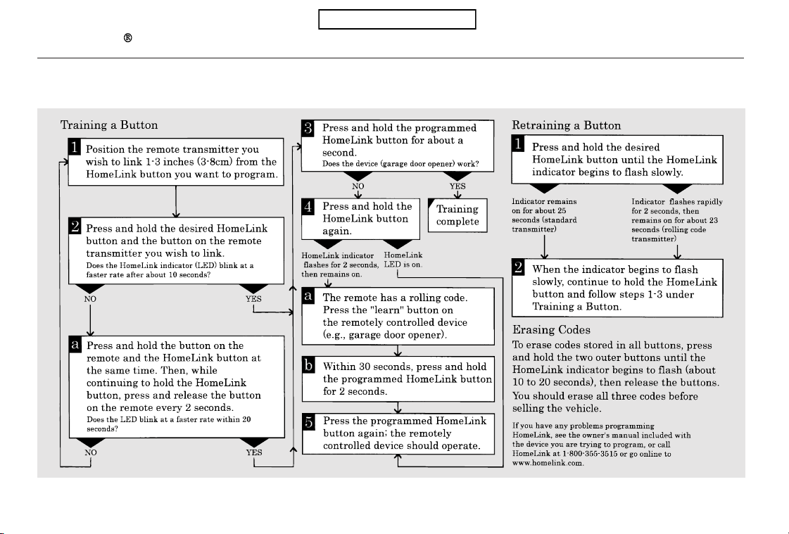
If you are training the second or third buttons, go directly to step 1.
HomeLink Universal Transceiver
254
Table of Contents

HomeLink is a registered
trademark of Johnson Controls, Inc.
As required by the FCC:
This device complies with Part 15 of the
FCC rules. Operation is subject to the
following two conditions: (1) This device
may not cause harmful interference, and
(2) this device must accept any
interference received, including
interference that may cause undesired
operation.
Changes or modifications not expressly
approved by the party responsible for
compliance could void the user’s
authority to operate the equipment.
This device complies with Industry
Canada Standard RSS-210.
Operation is subject to the following two
conditions: (1) this device may not cause
interference, and (2) this device must
accept any interference that may cause
undesired operation of the device.
HomeLink Universal Transceiver
Features
255
Table of Contents

−
−
Bluetooth
If equipped
handsfreelink.honda.
com
www.honda.ca,
HandsFreeLink (HFL)
allows you to place and receive
phone calls using voice commands,
without handling your cell phone.
To use HFL, you need a Bluetooth-
compatible cell phone. For a list of
compatible phones, pairing
procedures, and special feature
capabilities:
In the U.S., visit
or call (888) 528-7876.
In Canada, visit or call
(888) 9-HONDA-9.
Press and
release to give a command or answer
a call.
Press and
release to end a call, go back to the
previous command, or cancel the
command.
Using HFL
HFL Talk button
HFL Back button
HFL Buttons
Bluetooth
HandsFreeLink
256
HFL BACK BUTTON
NAVI
VOICE
CONTROL
BUTTONS
HFL TALK BUTTON
HFL TALK BUTTON
On models with navigation system On models without navigation system
HFL BACK BUTTON
Table of Contents
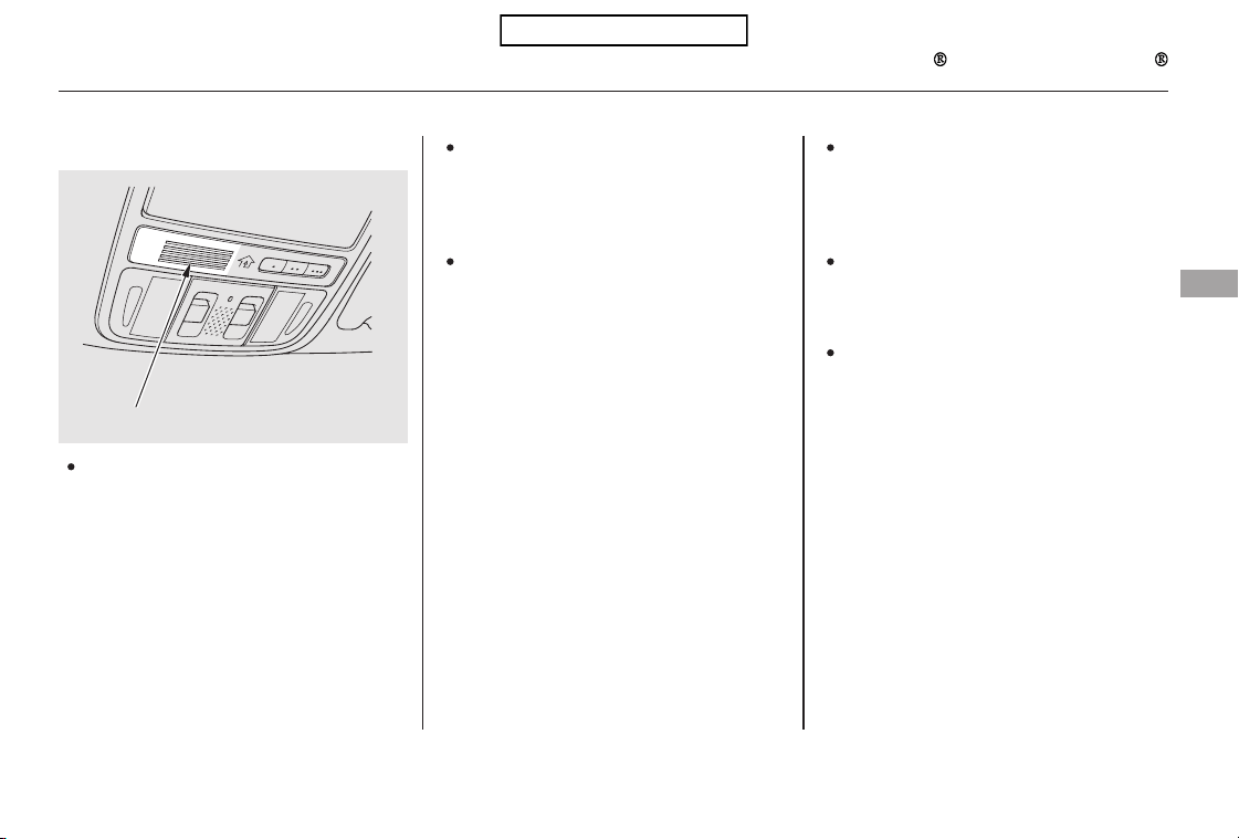
####
Try to reduce all background
noise. If the microphone picks up
voices other than yours,
commands may be misinterpreted.
Many commands can be spoken
together. For example, you can
say ‘‘Call 123-456- ’’ or
‘‘Dial Peter.’’
Press and release the HFL Talk
button each time you want to
make a command. After the beep,
speak in a clear, natural tone.
When HFL is in use, navigation
voice commands cannot be
recognized.
To change the volume level of
HFL, use the audio system volume
knob or the steering wheel volume
controls.
Airorwindnoisefromthe
dashboard and side vents and all
windows may interfere with the
microphone. Adjust or close them
as necessary.
CONTINUED
Voice Control Tips
Bluetooth
HandsFreeLink
Features
257
MICROPHONE
Table of Contents
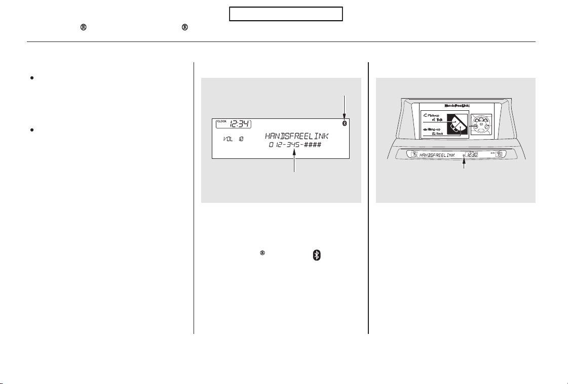
To hear general HFL information,
including help on pairing a phone
or setting up the system, say
‘‘Tutorial.’’
For help at any time, including a
list of available commands, say
‘‘Hands free help.’’
A notification that there is an
incoming call, or HFL is in use, will
appear on the navigation screen
when the audio system is on.
When there is an incoming call, or
HFL is in use, ‘‘HANDSFREELINK’’
will appear on the display.
The
indicator will also
appear on the radio display when a
phone is linked.
On models with navigation system
Bluetooth
Help Features
Bluetooth
HandsFreeLink
Information Display
258
U.S. model with navigation system is
shown.
BLUETOOTH INDICATOR
BLUETOOTH INDICATOR
On models without navigation system
PHONE NUMBER
Table of Contents
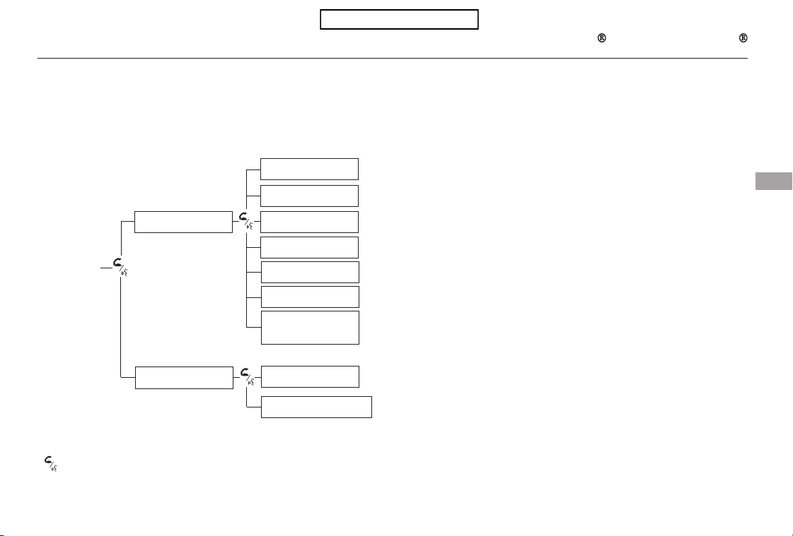
####
CONTINUED
Bluetooth
HandsFreeLink
How to Use HFL
Features
259
‘‘Phone Setup’’
‘‘Call’’ or ‘‘Dial’’
‘‘Pair’’
‘‘Edit’’
‘‘Delete’’
‘‘Set Pairing
Code’’
The ignition switch must be in the ACCESSORY (I) or ON (II) position.
‘‘List’’
‘‘Status’’
‘‘Next Phone’’
Press HFL
Talk button
Press and release the HFL Talk button each time you give a command.
‘‘123-555- ’’
‘‘Jim Smith’’
(See page 262)Pair a phone to the system
(See page 263)
Edit the name of a paired phone
(See page 263)Delete a paired phone from the system
(See page 263)Hear a list of all phones paired to the system
Hear which paired phone is currently linked to the system
(See page 264)
(See page 264)Search for another previously paired phone to link to
Set the pairing code to a ‘‘Fixed’’ or ‘‘Random’’ number
(See page 264)
(See page 265)
Once a phonebook entry is stored, you can say a name here.
(See page 265)
Enter desired phone number
Table of Contents
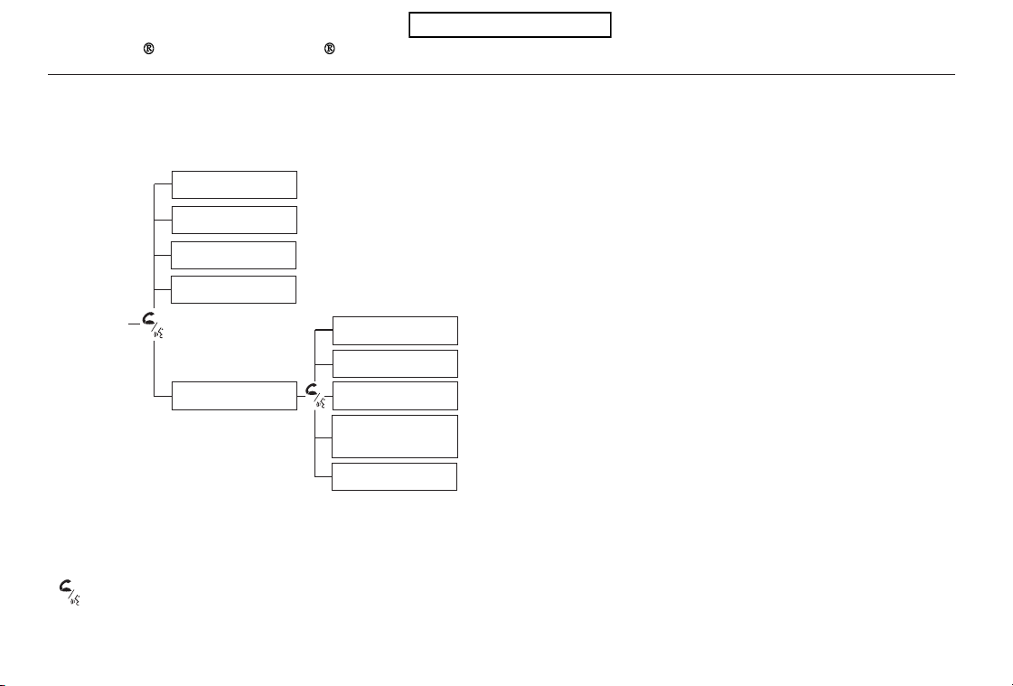
Bluetooth
HandsFreeLink
260
‘‘Redial’’
‘‘Transfer’’
‘‘Mute’’
‘‘Send’’
‘‘Phonebook’’
‘‘Store’’
‘‘Edit’’
‘‘Delete’’
‘‘Receive
Contact’’
‘‘List’’
Press HFL
Talk button
Press and release the HFL Talk button each time you give a command.
Redial the last number called
(See page 269)
Transfer a call from HFL to your phone, or from your phone to HFL
Mute your voice to the person at the other end of the call
(See page 270)Send numbers or names during a call
(See page 271)Store a phonebook entry
(See page 271)Edit the number of an existing phonebook entry
(See page 272)Delete a phonebook entry
(See page 272)
If your phone supports this function, use this to transfer contacts from
your phone to HFL
(See page 272)Hear a list of all stored phonebook entries
(See page 270)
(See page 266)
Table of Contents
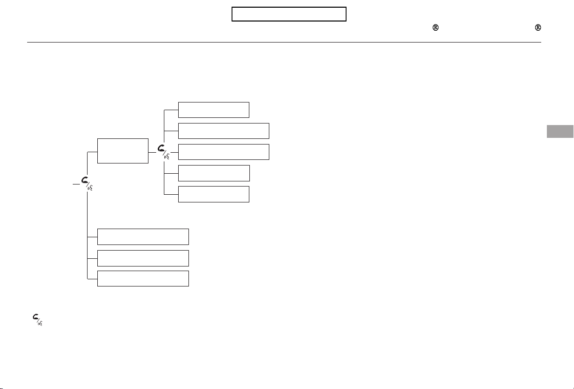
*
*
CONTINUED
Bluetooth
HandsFreeLink
Features
261
‘‘Change Language’’
‘‘Hands Free Help’’
‘‘System
Set up’’
‘‘Tutorial’’
‘‘Clear’’
‘‘Auto Transfer’’
‘‘Call Notification’’
‘‘Security’’
‘‘Change Passcode’’
Press HFL
Talk button
Press and release the HFL Talk button each time you give a command.
: Canadian models
(See page 277)
Apply a security passcode to the system that must be input at each key
cycle to access the system
(See page 278)Change your security passcode
(See page 278)
Set how you would like to be notified of an incoming call
(See page 279)
Change language from English to French
(See page 258)
Hear a tutorial for general rules on using the system
Hear a list of available commands and additional information describing each command
(See page 258)
(See page 279)
Clear the system of all paired phones, phonebook entries and security
passcode
(See page 278)
Set calls to automatically transfer from your phone to HFL when you
enter the vehicle
Table of Contents
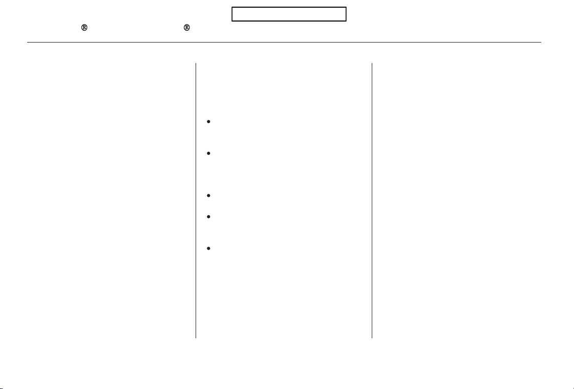
To use HFL, you need to pair your
Bluetooth-compatible cell phone to
the system.
This command group is available for
paired cell phones.
You cannot pair your phone while
the vehicle is moving.
Your phone must be in discovery
or search mode to pair. Refer to
your phone’s manual.
Up to six phones can be paired.
Your phone’s battery may drain
faster when it is paired to HFL.
If after three minutes your phone
is not ready to pair or a phone is
not found, the system will time out
andreturntoidle.
Press and release the HFL Talk
button. If you are pairing a phone
for the first time, HFL will give
you information about the pairing
process. If it is not the first phone
you are pairing, say ‘‘
’’ and say ‘‘ .’’
Follow the HFL prompts and put
your phone in discovery or search
mode. HFL will give you a 4-digit
pairing code and begin searching
foryourphone.
When your phone finds a
Bluetooth device, select HFL from
the options and enter the 4-digit
code from the previous step.
Follow the HFL prompts and
name the newly paired phone.
1.
2.
3.
4.
Phone Setup
Phone
setup Pair
Phone pairing tips
To pair a cell phone:
Bluetooth
HandsFreeLink
262
Table of Contents

Say ‘‘ .’’
Say‘‘ ’’aftertheprompts.
If there is more than one phone
paired to the system, HFL will ask
you which phone’s name you want
to change. Follow the HFL
prompts and rename the phone.
Press and release the HFL Talk
button before a command.
Press and release the HFL Talk
button before a command.
Say ‘‘ .’’
Say‘‘ ’’aftertheprompts.
HFL will ask you which phone you
want to delete. Follow the HFL
prompts to continue with the
deletion.
Press and release the HFL Talk
button before a command.
HFL will read out all the paired
phone’s names.
Say‘‘ ’’aftertheprompts.
Say ‘‘ .’’
1.
2.
3. 3.
1.
2.
1.
2.
3.
CONTINUED
Phone setup
Edit
Phone setup
Delete
List
Phone setup
To hear the names of all paired
phones:
To rename a paired phone: To delete a paired phone:
Bluetooth
HandsFreeLink
Features
263
Table of Contents

Press and release the HFL Talk
button before a command.
Say ‘‘ .’’
Say‘‘ ’’aftertheprompts.
HFL will tell you which phone is
linked to the system.
Press and release the HFL Talk
button before a command.
Say ‘‘ .’’
Say ‘‘ .’’
Press and release the HFL Talk
button before a command.
Say ‘‘ ’’ after the
prompts.
HFL disconnects the linked phone
and searches for another paired
phone.
Once another phone is found, it is
linked to the system. HFL will
inform you which phone is now
linked.
If no other phones are found or
paired, HFL will inform you that the
original phone is linked again.
Say ‘‘ ’’ after the
prompts.
If you want HFL to create a
random code each time you pair a
phone, say ‘‘ .’’ If you want
to choose your own 4-digit code to
be used each time, say ‘‘ ’’
and follow the HFL prompts.
1.
2.
3.
1.
2.
3.
1.
2.
3.
4.
Bluetooth
HandsFreeLink
To hear which paired phone is
currently linked:
To change from the currently linked
phone to another paired phone:
To change the pairing code setting:
Phone setup
Status
Phone setup
Phone setup
Next phone
Set pairing code
Random
Fixed
264
Table of Contents

CONTINUED
Bluetooth is the wireless technology
that links your phone to HFL. HFL
uses a Class 2 Bluetooth, which
means the maximum range between
yourphoneandvehicleis30feet(10
meters).
During a call, HFL allows you to talk
up to 30 minutes after you remove
the key from the ignition switch.
However, this may weaken the
vehicle’s battery.
You can make calls using a name in
the HFL phonebook or any phone
number. You can also redial the last
number called.
Once connected, you will hear the
person you called through the audio
speakers.
Follow the HFL prompts to
confirm the name and make the
call.
Follow the HFL prompts to
confirm the number and say
‘‘ ’’ or ‘‘ .’’
Follow the HFL prompts and say
thenamestoredintheHFL
phonebook that you want to call.
Follow the HFL prompts and say
the phone number you want to dial.
Say ‘‘ ’’ or ‘‘ .’’Say ‘‘ ’’ or ‘‘ .’’
Press and release the HFL Talk
button before a command.
Press and release the HFL Talk
button before a command.
1.
2.
3.
1.
2.
3.
Bluetooth
HandsFreeLink
Making a Call
Call Dial
Call DialCall Dial
Tomakeacallusinganameinthe
HFL phonebook:
To make a call using a phone
number:
Features
265
Table of Contents
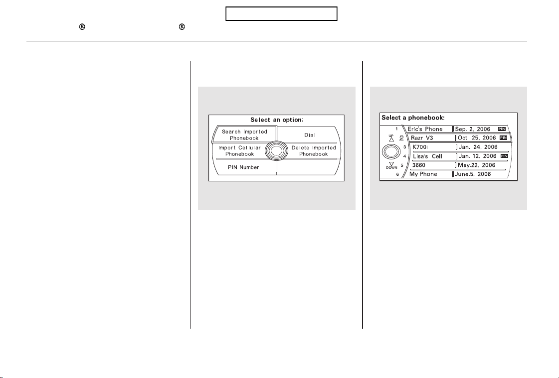
Select a phonebook you want to
choose a phone number from.
If the phonebook you select is PIN-
protected, you will need to enter the
PIN to access it. See page for
more information.
Press and release the HFL Talk
button and say ‘‘ .’’
Select ‘‘
.’’
Press the INFO button, then select
‘‘ .’’
1.
2.
3.
275
On models with navigation system
To redial the last number called by
HFL:
To make a call f rom an imported
phonebook:
Redial
Search Imported
Phonebook
Cellular Phone
Bluetooth
HandsFreeLink
266
Table of Contents
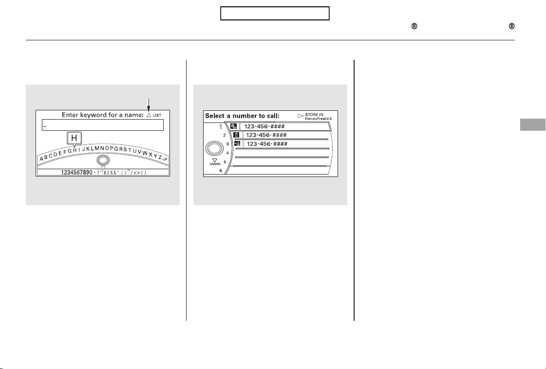
Select the name. All the phone
numbers stored for that name will
be listed.
To search for a specific name in the
phonebook, enter the keyword for
either the first or last name.
To display all names in the
phonebook, select the ‘‘ ’’ option.
Select the phone number and push
the interface selector, HFL begins
dialing.
If you choose ‘‘
,’’ the phone
number will be stored in HFL, so
that you can call it using HFL’s name
tag by voice.
4.
5.
List
Store in
HandsFreeLink
Bluetooth
HandsFreeLink
Features
267
Push up the interface selector to
show a list.
Table of Contents
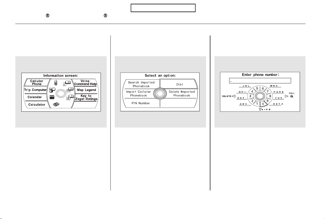
Press the INFO button, and the
INFO screen will be shown.
From the INFO screen, select
‘‘Cellular Phone,’’ then select ‘‘Dial.’’
The navigation display will change
as shown above. Enter a call
number.
To make a call, press the selector
on the interface dial to the right.
To end the call, press the HFL
Back button.
1. 2. 3.
4.
5.
Bluetooth
HandsFreeLink
To make a call using the navigation
display (on models with navigation
system):
268
Table of Contents

When you receive a call, an incoming
call notification (if activated) will
play and interrupt the audio system
if it is on.
Press the HFL Talk button to answer
the call, or the HFL Back button to
hang up.
If your phone has Call Waiting, press
and release the HFL Talk button to
put the original call on hold and
answer the incoming call.
To return to the original call, press
the HFL Talk button again. If you
don’t want to answer the incoming
call, disregard it and continue with
your original call. If you want to hang
up the original call and answer the
new call, press the HFL Back button.
Press and release the HFL Talk
button and say ‘‘ .’’
You can transfer a call from HFL to
your phone, or from your phone to
HFL.
Receiving a Call Transferring a Call
Transfer
Call Waiting
Bluetooth
HandsFreeLink
Features
269
Table of Contents

#
You can mute your voice to the
person you are talking to during a
call.
To mute your voice during a call,
press and release the HFL Talk
button and say ‘‘ .’’
To unmute your voice, press and
release the HFL Talk button and say
‘‘ ’’ again.
HFL allows you to send numbers or
names during a call. This is useful
when you call a menu-driven phone
system.
Press and release the HFL Talk
button before a command.
Say ‘‘ .’’
Follow the HFL prompts and say
the name or number you want to
send.
Follow the HFL prompts to send
the tones and continue the call.
To send a pound ( ), say
‘‘pound.’’ To send a star (*), say ‘‘star.’’
Youcanstoreupto50nameswith
their associated numbers in HFL.
The numbers you store can be not
only phone numbers but other types,
such as account numbers or
passwords, which can be sent during
a menu-driven call.
1.
2.
3.
Muting a Call
Mute
Mute
Send Numbers or Names During
aCall
Send
Phonebook
To send a name or number during a
call:
Bluetooth
HandsFreeLink
270
NOTE:
Table of Contents

Avoid using duplicate name
entries.
Avoid using ‘‘home’’ as a name
entry.
It is easier for HFL to recognize a
multisyllabic or longer name. For
example, use ‘‘Peter’’ instead of
‘‘Pete,’’ or ‘‘John Smith’’ instead of
‘‘John.’’
Press and release the HFL Talk
button before a command.
Say ‘‘ .’’
Say‘‘ ’’aftertheprompts.
Follow the HFL prompts and say
thenameentryyouwanttoedit.
When asked, say the new number
for that name.
Follow the HFL prompts to
complete the edit.
Press and release the HFL Talk
button before a command.
Say ‘‘ .’’
Say‘‘ ’’aftertheprompts.
Say a name you want to list as your
phonebook entry.
Say the number you want to store
for the name entry.
Follow the HFL prompts and say
‘‘ ’’ to store the entry.
1.
2.
3.
4.
5.
1.
2.
3.
4.
5.
CONTINUED
Phonebook
Edit
Phonebook
Store
Enter
To edit the number stored in a name:To store a phonebook entry:
Bluetooth
HandsFreeLink
Features
271
NOTE:
Table of Contents

Press and release the HFL Talk
button before a command.
Press and release the HFL Talk
button before a command.
Say ‘‘ .’’
Say‘‘ ’’aftertheprompts.
Say the name you want to delete
and follow the HFL prompts to
complete the deletion.
Say ‘‘ .’’
Say‘‘ ’’aftertheprompts.
HFL begins reading the names in
the order they were stored.
If you hear a name you want to call,
immediatelypresstheHFLTalk
button and say ‘‘ .’’
Press and release the HFL Talk
button before a command.
Follow the HFL prompts, select a
number from your cell phone, and
send it to HFL.
Say ‘‘ ’’ after the
prompts.
Say ‘‘ .’’
Follow the HFL prompts and
name the number, or say
‘‘ ’’ if it is not the number
you want to store.
Follow the HFL prompts if you
want to store another number.
1.
2.
3.
4.
1.
2.
3.
4.
1.
2.
3.
5.
Phonebook
Delete
Phonebook
List
Call
Receive contact
Phonebook
Discard
To delete a name: To list all names in the phonebook: To store a specific phone number
from your cell phone directly to the
HFL phonebook (available on some
phones):
Bluetooth
HandsFreeLink
272
Table of Contents
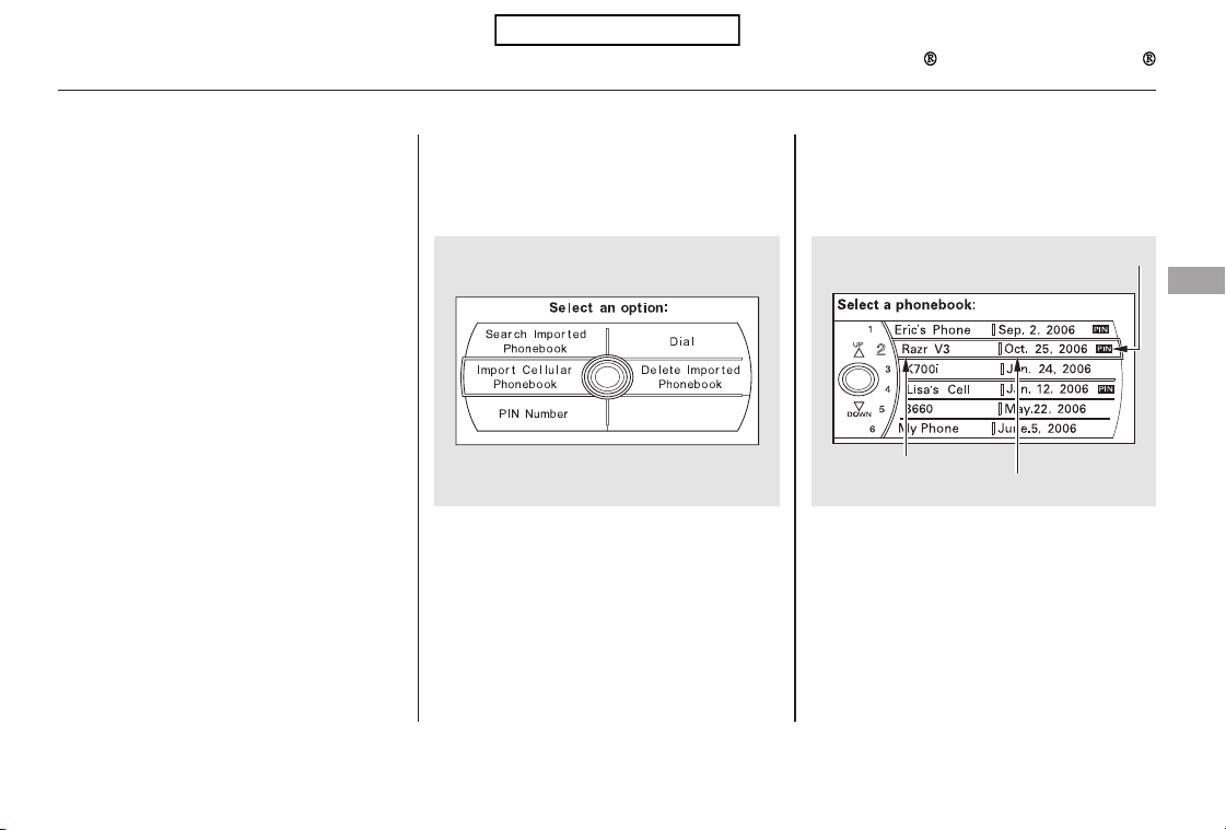
(available on some phones)
www.honda.ca,
handsfreelink.honda.
com
On models with navigation system
The entire phonebook data of the
cell phone that is linked to HFL can
be imported to the navigation system.
Select ‘‘
,’’ and HFL will begin
importing the phonebook. Select
‘‘ ’’ after the import is completed.
Once a phonebook has been
imported, you can search the phone
numbers by the person’s name.
Select ‘‘
,’’ and a list of imported
phonebooks will be displayed.
Select a phonebook from the list.
In Canada, visit or call
(888) 9-HONDA-9.
In the U.S., visit
or call (888) 528-7876.
For a list of cell phones that are
compatible with this feature:
If you select from
the Information screen menu, you
will see five HFL options.
CONTINUED
Cellular Phonebook
Import Cellular
Phonebook
OK
Search Imported
Phonebook
Cellular Phone
Import Cellular Phonebook: Search Imported Phonebook:
Bluetooth
HandsFreeLink
Features
273
IMPORTED DATE
IMPORTED
PHONEBOOK
PIN ICON
Table of Contents
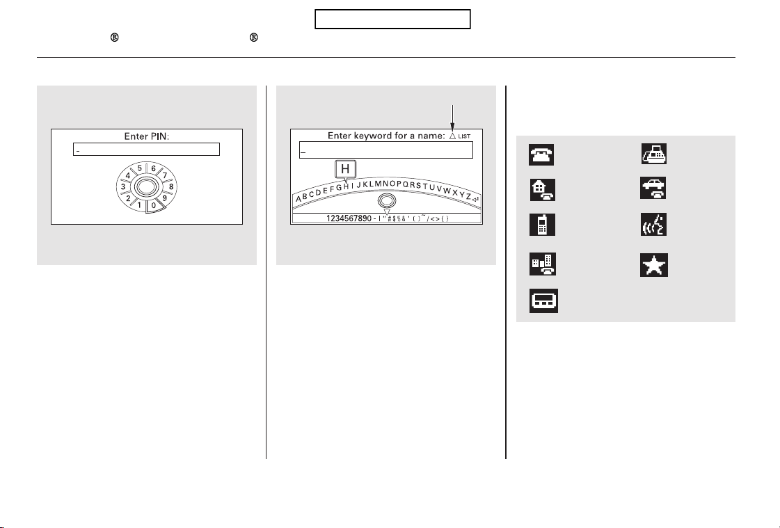
Select a person from the list. Up to
three category icons are displayed in
the left side of the list:
Select the person’s number you want
to call, and press the HFL Talk
button.
These indicate how many numbers
are stored for the name. If a name
has more than three category icons,
‘‘…’’ is displayed.
If the phonebook is PIN-protected,
you will need to enter the 4-digit PIN.
To search for a specific name in the
phonebook, enter the keyword for
either the first or last name.
To display all names in the
phonebook, select the ‘‘ ’’ option.List
Bluetooth
HandsFreeLink
274
Preference
Home
Work
Pager
Fax
Car
Voice
Other
Push up the interface selector to
show a list.
Cell phone
Table of Contents
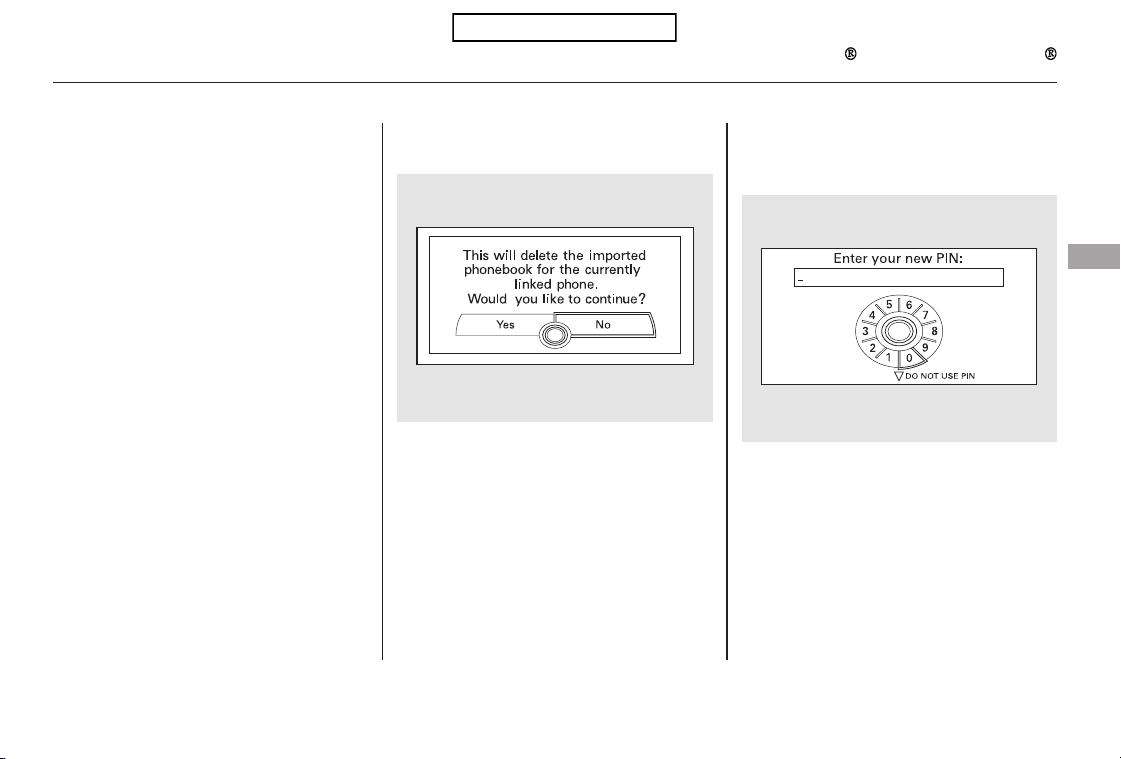
Select ‘‘
,’’ and a list of imported
phonebooks will be displayed.
After making a selection, the
following screen will appear.
Select‘‘ ,’’then‘‘ ’’tocomplete
the deletion.
You can add, change, or remove a
PIN number from any phonebook.
You can delete any imported
phonebook.
Select a phonebook you want to
delete. If the phonebook is PIN-
protected, you will need to enter the
4-digit PIN number.
If you have selected a phonebook
without a PIN, you will see the above
display.
Enter the new 4-digit PIN. You will
have to re-enter the PIN for
confirmation.
CONTINUED
Delete Imported
Phonebook
Yes OK
PIN Number
Delete Imported Phonebook:
To add a PIN:
Bluetooth
HandsFreeLink
Features
275
Table of Contents
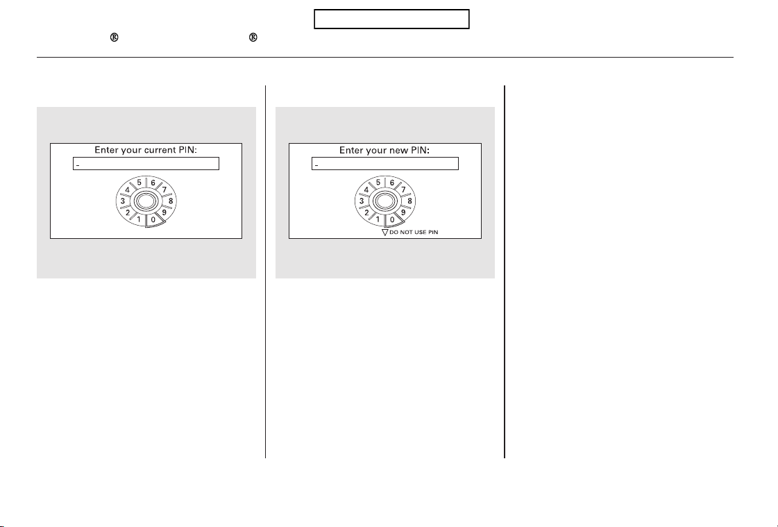
Select ‘‘ ,’’ then select
‘‘ ’’ after you enter
the current PIN.
Enter the new 4-digit PIN number.
You will be asked to re-enter the PIN
for verification.
The display will change as shown
above.
Select the phonebook you want. The
display will change as shown above.
Enter the current PIN for this
phonebook.
To remove a PIN:To change the PIN to a new number:
PIN number
Do not use PIN
Bluetooth
HandsFreeLink
276
Table of Contents

This command group allows you to
change or customize HFL basic
settings.
Press and release the HFL Talk
button before a command.
Say ‘‘ .’’
Once a passcode is set, you
will need to enter it to use HFL each
time you start the vehicle. If you
forget the code, your dealer will have
toresetitforyou,oryouwillhaveto
clear the entire system (see page
).
Follow the HFL prompts and say
the 4-digit passcode you want to
set.
Say‘‘ ’’aftertheprompts.
Follow the HFL prompts to
confirm the number.
1.
2.
3.
4.
279
CONTINUED
System Setup
System setup
Security
To set a 4-digit passcode to lock the
HFL system f or security purposes:
Bluetooth
HandsFreeLink
Features
277
NOTE:
Table of Contents

*
*
If you get into the vehicle while you
are on the phone, the call can be
automatically transferred to HFL
with the ignition switch in the
ACCESSORY (I) or ON (II) position.
Press and release the HFL Talk
button before a command.
Say ‘‘ .’’
Press and release the HFL Talk
button before a command.
Say ‘‘ .’’
Press and release the HFL Talk
button before a command.
Say ‘‘ .’’
Follow the HFL prompts to
confirm the number.
Follow the HFL prompts and say
the new 4-digit passcode.
Say ‘‘ ’’ after the
prompts.
The default setting is a ring tone.
Follow the HFL prompts and say
‘‘ ’’ or ‘‘ .’’ You
can also say ‘‘ ’’ for no audible
incoming call notification.
Say ‘‘ ’’ after the
prompts.
HFL will let you know if auto
transfer is on or off, depending on
the previous setting. Follow the
HFL prompts to change the
setting.
Say ‘‘ ’’ after the
prompts.
2.
3.
4.
1.
2.
3.
1.
2.
3. 1.
:
System setup
System setup
System setupChange passcode
Ring tone Prompt
Off
Call notification
Auto transfer
To change your security passcode: To select either a ring tone or a
prompt as the incoming call
notification :
To activate or deactivate the auto
transfer function:
Bluetooth
HandsFreeLink
278
Table of Contents

This operation clears the passcodes,
paired phones, all names in the HFL
phonebook, and all imported
phonebook data.
Press and release the HFL Talk
button before a command.
Say ‘‘ .’’
Say‘‘ ’’aftertheprompts.
Follow the HFL prompts to
continue to complete the clearing
procedure.
You can also clear the system when
you have forgotten the passcode and
cannot access HFL. When HFL asks
you for the passcode, say ‘‘
.’’ Paired phones, all names in
the HFL phonebook and all imported
phonebook data will be lost.
Press and release the HFL Talk
button before a command.
Follow the HFL prompts.
Say the language you want to
change to in that language.
Press and release the HFL Talk
button before a command.
Say ‘‘ .’’
Follow the HFL prompts to
change the language to English or
French.
If you have not named your paired
phone in the language you just
selected, HFL will ask you to name it
in the current language.
When French is your currently
selected language, you can give voice
commands in French.
1.
2.
3.
2.
1.
1.
2.
Canadian models only Canadian models only
System setup
Clear
System
clear
Quick Language Selection Change Language
Change language
To clear the system:
To quickly change the language: To change the system language
between English and French:
Bluetooth
HandsFreeLink
Features
279
Table of Contents

The name and logos are
registered trademarks owned by
Bluetooth SIG, Inc. and any use of
such marks by Honda Motor Co.,
Ltd. is under license. Other
trademarks and trade names are
those of their respective owners.
Refer to the navigation system
manual for operation of the rearview
camera.
Bluetooth
As required by the FCC:
This device complies with Part 15 of the
FCC rules. Operation is subject to the
following two conditions: (1) This device
may not cause harmful interference, and
(2) this device must accept any
interference received, including
interference that may cause undesired
operation.
Changes or modifications not expressly
approved by the party responsible for
compliance could void the user’s
authority to operate the equipment.
This device complies with Industry
Canada Standard RSS-210.
Operation is subject to the following two
conditions: (1) this device may not cause
interference, and (2) this device must
accept any interference that may cause
undesired operation of the device.
On models with navigation system
Bluetooth
Wireless Technology Rearview Camera and Monitor
Bluetooth
HandsFreeLink , Rearview Camera and Monitor
280
Table of Contents

Before you begin driving your
vehicle, you should know what
gasoline to use and how to check the
levels of important fluids. You also
need to know how to properly store
luggage or packages. The
information in this section will help
you. If you plan to add any
accessories to your vehicle, please
read the information in this section
first.
.............................
Break-in Period . 282
.................Fuel Recommendation . 282
.........Service Station Procedures . 283
....................................Refueling . 283
........Check Fuel Cap Message . 285
Opening and Closing
................................the Hood . 287
...................................Oil Check . 288
.............Engine Coolant Check . 288
...............................Fuel Economy . 289
...Accessories and Modifications . 292
.............................Carrying Cargo . 294
Before Driving
Before Driving
281

Help assure your vehicle’s future
reliability and performance by paying
extra attention to how you drive
during the first 600 miles (1,000 km).
During this period:
Avoid full-throttle starts and rapid
acceleration.
Do not change the oil until the
scheduled maintenance time.
Avoidhardbrakingforthefirst
200 miles (300 km).
Do not tow a trailer.
You should also follow these
recommendations with an
overhauled or exchanged engine, or
when the brakes are replaced.
Your vehicle is designed to operate
on unleaded gasoline with a pump
octane number of 87 or higher. Use
of a lower octane gasoline can cause
a persistent, heavy, metallic rapping
noise that can lead to engine damage.
Use of gasoline with these additives
may adversely affect performance,
and cause the malfunction indicator
lamp on your instrument panel to
come on. If this happens, contact
your dealer for service.
In addition, in order to maintain good
performance, fuel economy, and
emissions control, we strongly
recommend, in areas where it is
available, the use of gasoline that
does NOT contain manganese-based
fuel additives such as MMT.
We recommend using quality
gasolines containing detergent
additives that help prevent fuel
system and engine deposits.
Break-in Period, Fuel Recommendation
Break-in Period Fuel Recommendation
282
Table of Contents
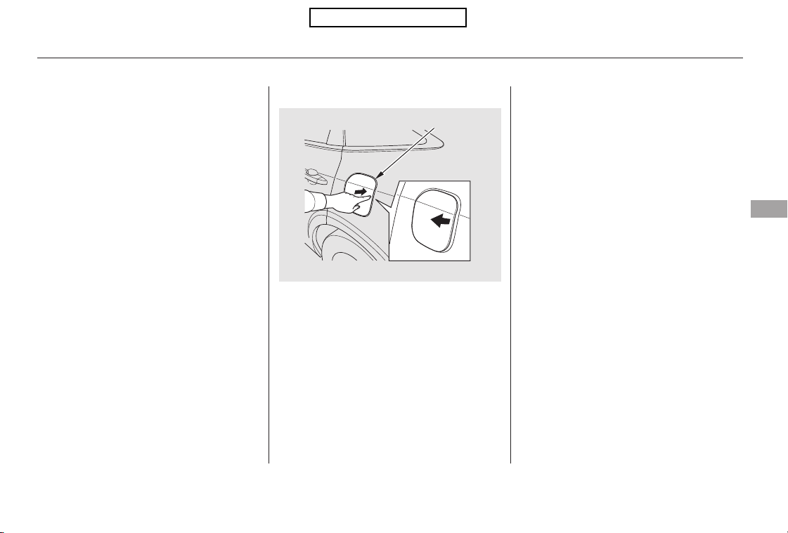
If you notice any undesirable
operating symptoms, try another
service station or switch to another
brand of gasoline.
Some gasoline today is blended with
oxygenates such as ethanol or
MTBE. Your vehicle is designed to
operate on oxygenated gasoline
containing up to 10% ethanol by
volume and up to 15% MTBE by
volume. Do not use gasoline
containing methanol.
Park with the driver’s side closest
to the service station pump.
Make sure the driver’s door is
unlocked. The fuel fill door always
locks or unlocks in conjunction
with the driver’s door.
Outside of the vehicle, push on the
right side edge of the fuel fill door
in the middle. The fuel fill door
will pop up slightly. Pull it outward
to open it.
The vehicle doors and the fuel fill
door will automatically relock if
the remote transmitter unlock
function is used. In this instance,
the security relock function can be
deactivated by briefly opening
then closing the driver’s door.
For further important fuel-related
information for your vehicle, or
information on gasoline that does not
contain MMT, visit Owner Link at
. In Canada, visit
for additional
information on gasoline.
1.
2.
3.
CONTINUED
owners.honda.com
www.honda.ca
Fuel Recommendation, Service Station Procedures
Refueling
Before Driving
283
Push
FUEL FILL DOOR
Pull out
Table of Contents
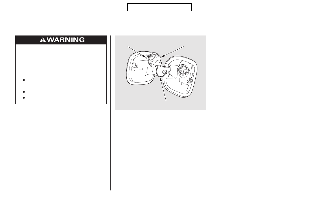
Stop filling the tank after the fuel
nozzle automatically clicks off. Do
not try to ‘‘top off’’ the tank. This
leaves some room in the fuel tank
for the fuel to expand with
temperature changes.
Ifthefuelnozzlekeepsclickingoff
even though the tank is not full,
there may be a problem with your
vehicle’s fuel vapor recovery
system. The system helps keep
fuel vapor from going into the
atmosphere. Try filling at another
pump. If this does not fix the
problem, consult your dealer.
Remove the fuel fill cap slowly.
You may hear a hissing sound as
pressure inside the tank equalizes.
The fuel fill cap is attached to the
fuel filler with a tether. Place the
cap in the holder on the fuel fill
door.
4.
5.
Service Station Procedures
284
HOLDER FUEL FILL CAP
TETHER
Gasoline is highly flammable
and explosive. You can be
burned or seriously injured
when handling fuel.
Stop the engine, and keep
heat, sparks, and flame away.
Handle fuel only outdoors.
Wipe up spills immediately.
Table of Contents
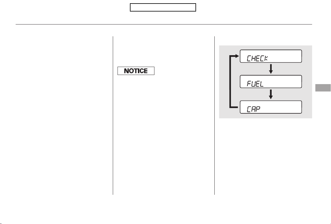
Your vehicle’s onboard diagnostic
system will detect a loose or missing
fuel fill cap as an evaporative system
leak. The first time a leak is detected
a ‘‘CHECK FUEL CAP’’ message
appears on the information display.
Screw the fuel fill cap back on
until it clicks at least once. If you
do not properly tighten the cap,
you will see a ‘‘CHECK FUEL
CAP’’ message on the information
display. If the system still detects
an evaporative system leak after
retightening the cap, the
malfunction indicator lamp may
come on (see page ).
Push the fuel fill door closed until
it latches. If the door won’t close
fully, do not force it. Unlock the
drivers door first.
6. 7.
387
CONTINUED
Check Fuel Cap Message
Service Station Procedures
Before Driving
285
The f uel door and its latching
mechanism can be permanently
damaged if the f uel door is f orced
closed when the driver’s door is locked.
Table of Contents

Turn the engine off, and confirm the
fuel fill cap is installed. If it is, loosen
it, then retighten it until it clicks at
least once. The message should go
off after several days of normal
driving once you tighten or replace
the fuel fill cap. To scroll to another
display, press the select/reset knob.
The ‘‘CHECK FUEL CAP’’ message
will appear each time you restart the
engine until the system turns the
message off.
If the system still detects a leak in
your vehicle’s evaporative emissions
system, the malfunction indicator
lamp (MIL) comes on. If the fuel fill
cap was not already tightened, turn
the engine off, and check or
retighten the fuel fill cap until it
clicks at least once. The MIL should
go off after several days of normal
driving once the cap is tightened or
replaced. If the MIL does not go off,
have your vehicle inspected by a
dealer. For more information, see
page .387
Service Station Procedures
286
Table of Contents
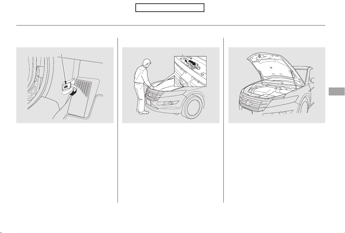
Park the vehicle, and set the
parking brake. Pull the hood
release handle located under the
lower left corner of the dashboard.
The hood will pop up slightly.
If the hood latch handle moves stiffly,
or if you can open the hood without
lifting the handle, the mechanism
should be cleaned and lubricated.
To close the hood, lower it to about a
foot (30 cm) above the fender, then
press down firmly with your hands.
Make sure the hood is securely
latched.
Lift the hood up most of the way.
The hydraulic supports will lift it up
therestofthewayandholditup.
Put your fingers under the front
edge of the hood near the center.
Slide your hand to the left until
you feel the hood latch handle.
Slide this handle to the right to
release the hood. Lift up the hood.
1. 2.
Opening and Closing the Hood
Service Station Procedures
Before Driving
287
HOOD RELEASE HANDLE LATCH
Table of Contents
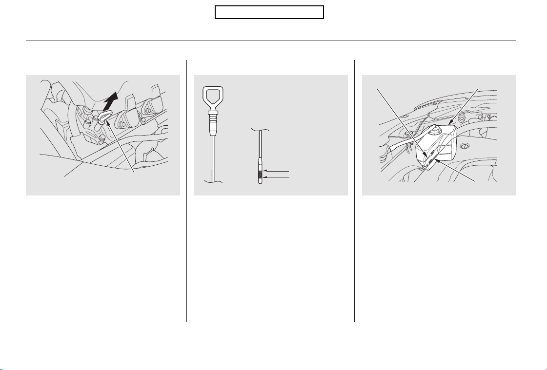
Wait a few minutes after turning the
engine off before you check the oil.
Remove the dipstick again, and
check the level. It should be
between the upper and lower
marks.
If it is near or below the lower mark,
see on page .
Remove the dipstick (orange loop).
Wipe off the dipstick with a clean
cloth or paper towel.
Insert the dipstick all the way back
into its hole.
Look at the coolant level in the
radiator reserve tank. Make sure it is
between the MAX and MIN lines. If
it is below the MIN line, see
on page for
information on adding the proper
coolant.
Refer to
on page for information
about checking other items on your
vehicle.
1.
2.
3.
4.
333
330
337
Oil Check
Adding Engine Oil
Engine Coolant Check
Adding
Engine Coolant
Owner’s Maintenance
Checks
Service Station Procedures
288
LOWER MARK
UPPER MARK
MIN
MAX RESERVE TANK
DIPSTICK
(orange loop)
Table of Contents
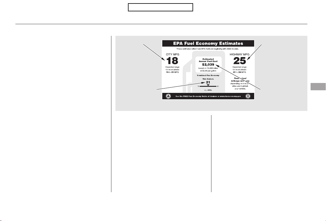
−
−
−
−
Fuel economy is not a fixed number.
It varies based on driving conditions,
driving habits and vehicle condition.
Therefore, it is not possible for one
set of estimates to predict fuel
economy precisely for all drivers in
all environments.
Provides an estimated annual fuel
cost, based on 15,000 miles (20,000
km) per year multiplied by the cost
pergallon(basedonEPAfuelcost
data) divided by the combined fuel
economy.
For more information on fuel
economy ratings and factors that
affect fuel economy, visit
(Canada: Visit
)
Represents urban
driving in light traffic. A range of
miles per gallon achieved is also
provided.
The EPA fuel economy estimates
shownintheexampletotheright
are a useful tool for comparison
when buying a vehicle. EPA
estimates include:
Represents a combination of city and
highway driving. The scale
represents the range of combined
fuel economy for other vehicles in
the class.
Represents a
mixture of rural and interstate
driving, in a warmed-up vehicle,
typical of longer trips in free-flowing
traffic. A range of miles per gallon
achieved is also provided.
www.
fueleconomy.gov www.
vehicles.gc.ca
Actual Mileage and EPA Fuel
Economy Estimates Comparison.
Estimated Annual Fuel Cost
City MPG
Combined Fuel Economy
Highway MPG
Fuel Economy
Before Driving
289
Combined Fuel
Economy
(Sample U.S. EPA label shown)
Estimated Annual
Fuel Cost
City MPG Highway MPG
Table of Contents
−
−−
−
−−
Aggressive driving (hard
acceleration and braking)
Excessive idling, accelerating and
braking in stop-and-go traffic
Cold engine operation (engines
aremoreefficientwhenwarmed
up)
Driving with a heavy load or the
air conditioner running
Improperly inflated tires
The following factors can lower your
vehicle’s fuel economy:
A properly maintained vehicle
maximizes fuel economy. Poor
maintenance can significantly reduce
fuel economy. Always maintain your
vehicle according to the maintenance
messages displayed on the
information display (see
on page ).
For example:
Rapid
acceleration, abrupt cornering,
and hard braking increase fuel
consumption.
Aerodynamic drag has a big effect
on fuel economy at speeds above
45 mph (75 km/h). Reduce your
speed and you reduce the drag.
Trailers, car top carriers, roof
racks and bike racks are also big
contributors to increased drag.
An underinflated tire increases
‘‘rolling resistance,’’ which reduces
fuel economy.
It puts a heavier
load on the engine, increasing fuel
consumption.
In
particular, a build-up of snow or
mud on your vehicle’s underside
adds weight and rolling resistance.
Frequent cleaning helps your fuel
economy.
Idling
results in 0 miles per gallon (0 kms
per liter).
330
Fuel Economy Factors Use the recommended viscosity
motor oil, displaying the API
Certif ication Seal (see page
).
Improving Fuel Economy
Owner’s
Maintenance Checks
Drive moderately
Observe the speed limit
Maintain proper tire inflation
Avoid carrying excess weight in
your vehicle
Keep your vehicle clean Avoid excessive idling
334
Vehicle Maintenance
Drive Ef ficiently
Fuel Economy
290
Table of Contents
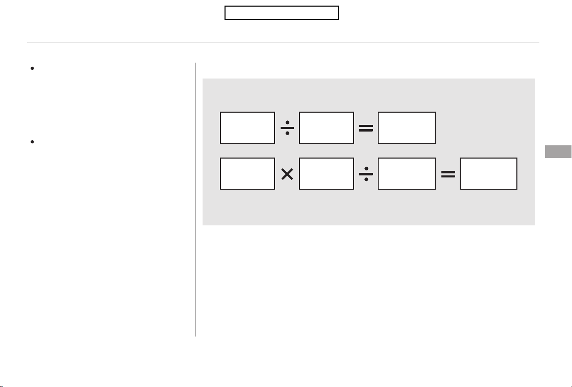
−
−
Fill the fuel tank until the nozzle automatically clicks off.
Reset trip counter to zero.
Record the total gallons (liters) needed to refill.
Follow one of the simple calculations above.
The A/C
puts an extra load on the engine
which makes it use more fuel. Use
the fresh-air ventilation when
possible.
Combine several short trips into
one. A warmed-up engine is more
fuel efficient than a cold one.
Direct calculation is the
recommended source of information
about your actual fuel economy.
Using frequency of fill-ups or taking
fuel gauge readings are NOT
accurate measures of fuel economy.
Fuel economy may improve over the
first several thousand miles
(kilometers).
1)
2)
3)
4)
Checking Your Fuel Economy
Measuring Techniques
Minimize the use of the air
conditioning system
Plan and combine trips
Calculating Fuel Economy
Fuel Economy
Before Driving
291
Miles driven
Gallons of
fuel
Miles per
Gallon
100
Kilometers
L per 100 km
Liter
Table of Contents
Before installing any accessory:
Make sure the accessory does not
obscure any lights, or interfere
with proper vehicle operation or
performance.
Modifying your vehicle, or installing
some non-Honda accessories, can
make your vehicle unsafe. Before
you make any modifications or add
anyaccessories,besuretoreadthe
following information.
Your dealer has Honda accessories
that allow you to personalize your
vehicle. These accessories have
been designed and approved for your
vehicle, and are covered by warranty.
Although non-Honda accessories
may fit on your vehicle, they may not
meet factory specifications, and
could adversely affect your vehicle’s
handling, stability, and reliability.
When properly installed, cellular
phones, alarms, two-way radios, and
low-powered audio systems should
not interfere with your vehicle’s
computer controlled systems, such
as your airbags, anti-lock brakes, and
tire pressure monitoring system.
Be sure electronic accessories do
not overload electrical circuits
(see page ) or interfere with
the proper operation of your
vehicle.
Before installing any electronic
accessory, have the installer
contact your dealer for assistance.
If possible, have your dealer
inspect the final installation.
Do not install accessories on the
side pillars or across the rear
windows. Accessories installed in
theseareasmayinterferewith
proper operation of the side
curtain airbags.
390
Accessories
Accessories and Modifications
292
Improper accessories or
modifications can affect your
vehicle’s handling, stability, and
performance, and cause a
crash in which you can be hurt
or killed.
Follow all instructions in this
owner’s manual regarding
accessories and modifications.
Table of Contents
Herearesomeexamples:
Lowering the vehicle with a non-
Honda suspension kit that
significantly reduces ground
clearance can allow the
undercarriage to hit speed bumps
or other raised objects, which
could cause the airbags to deploy.
Raising your vehicle with a
non-Honda suspension kit can
affect the handling, stability, and
reliability.
If you plan to modify your vehicle,
consult your dealer.
Modifying your steering wheel or
any other part of your vehicle’s
safety features can make the
systems ineffective.
Larger or smaller wheels and tires
can interfere with the operation of
your vehicle’s anti-lock brakes and
other systems.
Non-Honda wheels, because they
are a universal design, can cause
excessive stress on suspension
components, and are not
compatible with the tire pressure
monitoring system (TPMS).
Removing parts from your vehicle,
or replacing components with
non-Honda components could
seriously affect your vehicle’s
handling, stability, and reliability.
Modifying Your Vehicle
Accessories and Modifications
Before Driving
293
Table of Contents
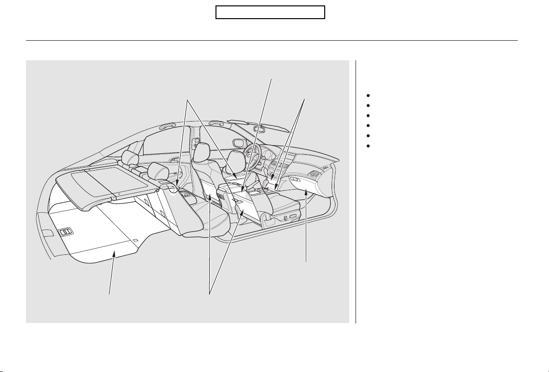
Your vehicle has several convenient
storage areas:
Glove box
Door and seat-back pockets
Center pockets
Console compartment
Cargo area
Roof-rack (if installed)
However, carrying too much cargo,
or improperly storing it, can affect
your vehicle’s handling, stability,
stopping distance, and tires, and
make it unsafe. Before carrying any
type of cargo, be sure to read the
following pages.
Carrying Cargo
294
CONSOLE COMPARTMENT
SEAT-BACK POCKETS
CENTER POCKETS
DOOR POCKETS
GLOVE BOX
CARGO AREA
EX-L model is shown.
Table of Contents
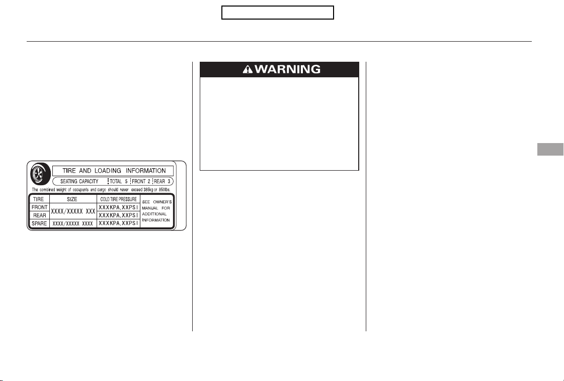
−
−×
The maximum load for your vehicle
is 850 lbs (385 kg).
Label Example
See Tire And Loading Information
label attached to the driver’s
doorjamb.
This figure includes the total weight
of all occupants, cargo, and
accessories, and the tongue load if
you are towing a trailer.
Steps for Determining Correct Load
Limit
Locate the statement ‘‘The
combined weight of occupants and
cargo should never exceed XXX
kg or XXX lbs.’’ on your vehicle’s
placard.
Determine the combined weight
of the driver and passengers that
will be riding in your vehicle.
Subtract the combined weight of
the driver and passengers from
XXX kg or XXX lbs.
The resulting figure equals the
available amount of cargo and
luggage load capacity. For
example, if the ‘‘XXX’’ amount
equals 1,400 lbs. and there will be
five 150 lb. passengers in your
vehicle, the amount of available
cargo and luggage load capacity is
650 lbs.
(1,400 750 (5 150) = 650 lbs.)
Determine the combined weight
of luggage and cargo being loaded
on the vehicle. That weight may
not safely exceed the available
cargo and luggage load capacity
calculated in Step 4.
If your vehicle will be towing a
trailer, load from your trailer will
be transferred to your vehicle.
Consult this manual to determine
how this reduces the available
cargo and luggage load capacity of
your vehicle.
(1)
(2)
(3)
(4)
(5)
(6)
CONTINUED
Load Limits
Carrying Cargo
Before Driving
295
Overloading or improper
loading can affect handling and
stability and cause a crash in
which you can be hurt or killed.
Follow all load limits and other
loading guidelines in this
manual.
Table of Contents
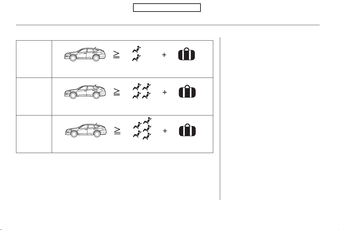
In addition, the total weight of the
vehicle, all occupants, accessories,
cargo, and trailer tongue load must
not exceed the Gross Vehicle
Weight Rating (GVWR) or the Gross
Axle Weight Rating (GAWR). Both
areonalabelonthedriver’s
doorjamb.
Example 1
Example 2
Example 3
Carrying Cargo
296
Max Load (850 lbs) Cargo Weight
(550 lbs)
Max Load (850 lbs)
Max Load (850 lbs)
Cargo Weight
(250 lbs)
Cargo Weight
(100 lbs)
Passenger Weight
(150 lbs x 2 = 300 lbs)
Passenger Weight
(150 lbs x 4 = 600 lbs)
Passenger Weight
(150 lbs x 5 = 750 lbs)
Table of Contents

Store or secure all items that could
be thrown around and hurt
someone during a crash.
Be sure items placed on the floor
behind the front seats cannot roll
under the seats and interfere with
the driver’s ability to operate the
pedals, the operation of the seats,
or the operation of the sensors
under the seats.
Keep all cargo below the bottom
of the windows. If it is higher, it
could interfere with the proper
operation of the side curtain
airbags.
Keep the glove box closed while
driving. If it is open, a passenger
could injure their knees during a
crash or sudden stop.
Do not place items on the cargo
area cover, or stack objects higher
than the top of the back seat. They
could block your view and be
thrown about the vehicle during a
crash or sudden stop.
Distribute cargo evenly on the
floor of the cargo area, placing the
heaviest items on the bottom and
as far forward as possible. Tie
down items that could be thrown
about the vehicle during a crash or
sudden stop.
Ifyoufolddownthebackseat,tie
down items that could be thrown
about the vehicle during a crash or
sudden stop.
If you carry large items that
prevent you from closing the
tailgate, exhaust gas can enter the
passenger area. To avoid the
possibility of
, follow the instructions
on page .51
CONTINUED
Carrying Items in the Passenger
Compartment
Carrying Cargo in the Cargo Area
or on a Roof Rack
carbon monoxide
poisoning
Carrying Cargo
Before Driving
297
Table of Contents
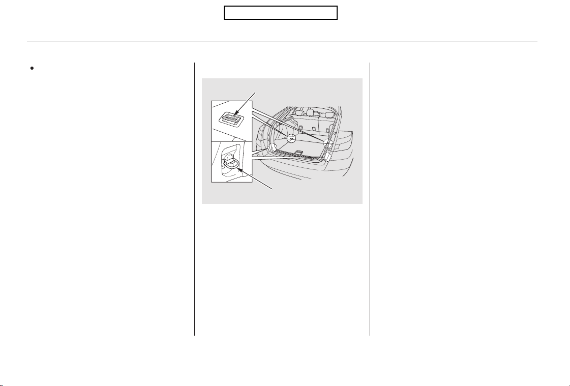
If you carry any items on a roof
rack,besurethetotalweightof
the rack and the items does not
exceed 121 lbs (55 kg).
The four hooks can be used to install
a net for securing items. Each hook
is designed to hold up to 56.2 lbs
(25.5 kg) of weight.
The total weight of the roof rack
and the items should also be
includedinthemaximumload
limits for your vehicle.
Cargo Hooks
Carrying Cargo
298
FLOOR CARGO HOOK
SIDE CARGO HOOK
Table of Contents

This section gives you tips on
starting the engine under various
conditions, and how to operate the
automatic transmissions. It also
includes important information on
parking your vehicle, the braking
system, the vehicle stability assist
(VSA
) system, the tire pressure
monitoring system (TPMS), and
facts you need if you are planning to
tow a trailer.
........................
Preparing to Drive . 300
.......................Starting the Engine . 301
..............Automatic Transmission . 302
...........................................Parking . 307
.............................Braking System . 308
...............Anti-lock Brakes (ABS) . 309
Vehicle Stability Assist (VSA
),
aka Electronic Stability Control
.......................(ESC), System . 311
Tire Pressure Monitoring
........................System (TPMS) . 313
...........................Towing a Trailer . 316
Driving
Driving
299

Youshoulddothefollowingchecks
and adjustments before you drive
your vehicle.
Make sure all windows, mirrors,
and outside lights are clean and
unobstructed. Remove frost, snow,
or ice.
Check that the hood is fully closed.
When you start the engine, check
the gauges and indicators in the
instrument panel (see page ).
Visually check the tires. If a tire
looks low, use a gauge to check its
pressure.
Check that any items you may be
carrying are stored properly or
fastened down securely.
Check the seat adjustment (see
page ).
Check the adjustment of the
inside and outside mirrors (see
pages and ).
Check the steering wheel
adjustment (see page ).
Make sure the doors and the
tailgate are securely closed and
locked.
Fasten your seat belt. Check that
your passengers have fastened
their seat belts (see page ).
3.
2.
1.
4.
5.
6.
7.
8.
9.
14
55
10.
93
104 105
76
Preparing to Drive
300
Table of Contents
Apply the parking brake.
In cold weather, turn off all
electrical accessories to reduce
the drain on the battery.
Make sure the shift lever is in
Park. Press on the brake pedal.
Without touching the accelerator
pedal, turn the ignition key to the
START (III) position. Do not hold
the key in the START (III)
position for more than 15 seconds
at a time. If the engine does not
start right away, pause for at least
10 seconds before trying again.
1.
2.
3.
4.
Starting the Engine
Driving
301
The immobilizer system protects your
vehicle from thef t. If an improperly
coded key (or other device) is used, the
engine’s f uel system is disabled. For
more inf ormation, see page .
The engine is harder to start in cold
weather. Also, the thinner air f ound at
altitudes above 8,000 f eet (2,400
meters) adds to this problem.
78
Table of Contents

These indicators between the
tachometer and speedometer show
which position the shift lever is in.
The ‘‘D’’ indicator comes on for a
few seconds when you turn the
ignition switch to the ON (II)
position. If it flashes while driving (in
any shift position), it indicates a
possible problem in the transmission.
If the malfunction indicator lamp
comes on along with the ‘‘D’’
indicator, there is a problem with the
automatic transmission control
system. Avoid rapid acceleration, and
have the transmission checked by
your dealer as soon as possible.
To shift from Park to any position,
pressfirmlyonthebrakepedal,and
pressthereleasebuttononthefront
of the shift lever, then move the
lever. You cannot shift out of Park
when the ignition switch is in the
LOCK (0) or ACCESSORY (I)
position.
Shift Lever Position Indicators Shifting
Automatic Transmission
302
SHIFT LEVER
RELEASE BUTTON
Table of Contents
−−
−
This position mechani-
cally locks the transmission. Use
Park whenever you are turning off or
starting the engine. To shift out of
Park, you must press on the brake
pedal and have your foot off the
accelerator pedal. Press the release
buttononthefrontoftheshiftlever
to move it.
If you have done all of the above and
still cannot move the lever out of
Park, see on
page .
You must also press the release
button to shift into Park. To avoid
transmission damage, come to a
complete stop before shifting into
Park. The shift lever must be in Park
before you can remove the key from
the ignition switch.
Press the brake
pedal and the release button on the
frontoftheshiftlevertoshiftfrom
Park to reverse. To shift from
reverse to neutral, come to a
completestop,andthenshift.Press
the release button before shifting
into reverse from neutral.
Use neutral if you
need to restart a stalled engine, or if
it is necessary to stop briefly with
the engine idling. Shift to the Park
position if you need to leave your
vehicle for any reason. Press on the
brake pedal when you are moving
the shift lever from neutral to
another gear.
305
To shift from:
PtoR
RtoP
NtoR
DtoD3
D3 to 2
2to1
1to2
2toD3
D3 to D
DtoN
NtoD
RtoN
Do this:
Press the brake pedal and
press the shift lever release
button.
Press the shift lever release
button.
Move the shift lever.
CONTINUED
Park (P)
Shift Lock Release
Reverse (R)
Neutral (N)
Automatic Transmission
Driving
303
Table of Contents

−−−
−
To shift to second,
pressthereleasebuttononthefront
of the shift lever. This position locks
the transmission in second gear. It
does not downshift to first gear
when you come to a stop.
Use second gear:
For more power when climbing.
To increase engine braking when
going down steep hills.
For starting out on a slippery
surface or in deep snow.
To help reduce wheel spin.
When driving downhill with a
trailer.
To shift from second to
first, press the release button on the
front of the shift lever. This position
locks the transmission in first gear.
By upshifting and downshifting
through 1, 2, D3, and D, you can
operate this transmission much like
a manual transmission without a
clutch pedal.
Use this position for
your normal driving. The
transmission automatically selects a
suitable gear (1 through 5) for your
speed and acceleration.
To shift from D to D3,
press the shift lever release button.
This position is similar to D, except
only the first three gears are
selected. Use D3 when towing a
trailer in hilly terrain, or to provide
engine braking when going down a
steep hill. D3 can also keep the
transmission from cycling between
third and fourth gears in stop-and-go
driving.
Second (2) First (1)Drive (D)
Drive (D3)
Automatic Transmission
304
Table of Contents
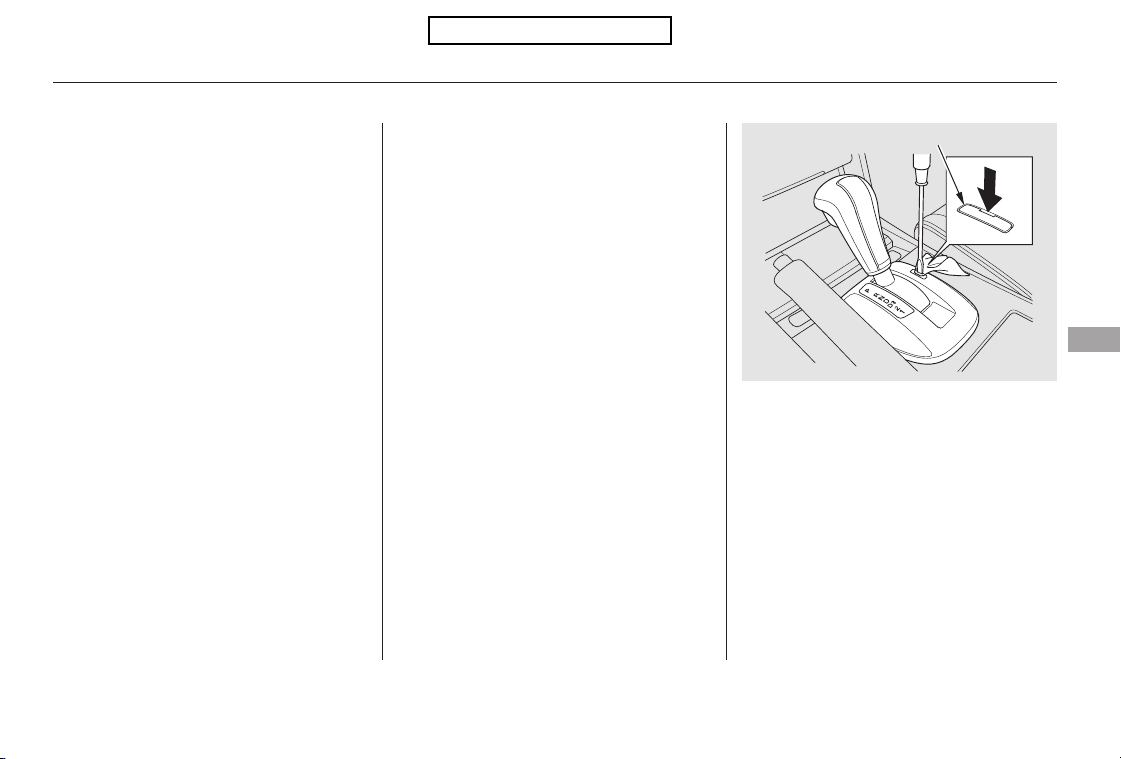
Put a cloth on the edge of the shift
lock release slot cover to prevent
scratches. Use a small flat-tip
screwdriver or metal fingernail file
to carefully pry up the edge of the
cover and remove it from the slot.
Insert the key in the shift lock
release slot.
This allows you to move the shift
lever out of Park if the normal
method of pushing on the brake
pedal and pressing the release
button does not work.
Set the parking brake.
Remove the key from the ignition
switch.
If you exceed the maximum speed
for the gear you are in, the engine
speed will enter into the tachometer’s
red zone. If this occurs, you may feel
the engine cut in and out. This is
caused by a limiter in the engine’s
computer controls. The engine will
run normally when you reduce the
rpm below the red zone.
1.
2.
3.
4.
CONTINUED
Shift Lock ReleaseEngine Speed Limiter
Automatic Transmission
Driving
305
COVER
Table of Contents
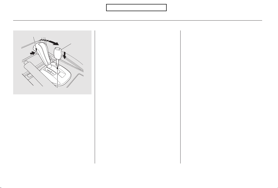
Remove the key from the shift
lock release slot, then reinstall the
cover. Make sure the notch on the
cover is on the right side. Insert
the key back into the ignition
switch, press the brake pedal, and
restart the engine.
Push down on the key while you
pressthereleasebuttononthe
front of the shift lever and move
the shift lever out of Park to
neutral.
If you need to use the shift lock
release, it means your vehicle is
developing a problem. Have it
checked by your dealer.
6.
5.
Automatic Transmission
306
RELEASE BUTTON
SHIFT LOCK RELEASE SLOT
Table of Contents

Always use the parking brake when
you park your vehicle. Make sure
the parking brake is set firmly, or
your vehicle may roll if it is parked
on an incline.
If the vehicle is facing uphill, turn
the front wheels away from the
curb.
Make sure the moonroof and the
windows are closed.
Turn off the lights.
Set the parking brake before you put
the transmission in Park. This keeps
the vehicle from moving and putting
pressure on the parking mechanism
in the transmission.
Place any packages, valuables, etc.,
wheretheycannotbeseenfrom
outsidethevehicleortakethem
with you.
Never park over dry leaves, tall
grass, or other flammable
materials. The hot three way
catalytic converter could cause
these materials to catch on fire.
Check the indicator on the
instrument panel to verify that the
security system is set.
Lock the doors and the tailgate.
Make sure the parking brake is
fully released before driving away.
Driving with the parking brake
partially set can overheat or
damage the rear brakes.
If the vehicle is facing downhill,
turn the front wheels toward the
curb.
Parking Tips
Parking
Driving
307
Table of Contents

The hydraulic system that operates
the brakes has two separate circuits.
Each circuit works diagonally across
the vehicle (the left-front brake is
connected with the right-rear brake,
etc.). If one circuit should develop a
problem, you will still have braking
at two wheels.
Your vehicle is equipped with disc
brakes at all four wheels. A power
assist helps reduce the effort needed
on the brake pedal. The emergency
brake assist system increases the
stopping force when you depress the
brake pedal hard in an emergency
situation. The anti-lock brake system
(ABS) helps you retain steering
control when braking very hard.
Resting your foot on the pedal keeps
the brakes applied lightly, builds up
heat, reduces their effectiveness and
reduces brake pad life. In addition,
fuel economy can be reduced. It also
keeps your brake lights on all the
time, confusing drivers behind you.
Check the brakes after driving
through deep water. Apply the
brakes moderately to see if they feel
normal. If not, apply them gently and
frequently until they do. Be extra
cautious in your driving.
Constant application of the brakes
when going down a long hill builds
up heat and reduces their effective-
ness. Use the engine to assist the
brakes by taking your foot off the
accelerator and downshifting to a
lower gear.
The front and rear disc brakes on all
models have audible brake pad wear
indicators.
If the brake pads need replacing, you
will hear a distinctive, metallic
screeching sound when you apply
the brake pedal. If you do not have
the brake pads replaced, they will
screech all the time. It is normal for
the brakes to occasionally squeal or
squeak when you apply them.
Braking System Design
Brake Pad Wear Indicators
Braking System
308
Table of Contents
If this indicator comes on, the anti-
lock function of the braking system
has shut down. The brakes still work
like a conventional system, but
without anti-lock. You should have
your dealer inspect your vehicle as
soon as possible.
The anti-lock brake system (ABS)
helpspreventthewheelsfrom
locking up, and helps you retain
steering control by pumping the
brakes rapidly, much faster than a
person can do it.
You will feel a pulsation in the brake
pedal when the ABS activates, and
you may hear some noise. This is
normal: it is the ABS rapidly
pumpingthebrakes.Ondry
pavement, you will need to press on
thebrakepedalveryhardbeforethe
ABS activates. However, you may
feel the ABS activate immediately if
you are trying to stop on snow or ice.
The electronic brake distribution
(EBD) system, which is part of the
ABS, also balances the front-to-rear
braking distribution according to
vehicle loading.
Let the ABS work for you by always
keeping firm, steady pressure on the
brake pedal. This is sometimes
referred to as ‘‘stomp and steer.’’
If the ABS indicator comes on while
driving, test the brakes as shown on
page .
388
You should never pump the brake pedal.
CONTINUED
ABS Indicator
Anti-lock Brakes (ABS)
Driving
309
Table of Contents

It only helps with the
steering control during braking.
such as trying to take a
corner too fast or making a sudden
lane change. Always drive at a safe
speed for the road and weather
conditions.
Always steer moderately
when you are braking hard. Severe
or sharp steering wheel movement
can still cause your vehicle to veer
into oncoming traffic or off the road.
on loose or
uneven surfaces, such as gravel or
snow, than a vehicle without anti-
lock.
Test your brakes as instructed on
page . If the brakes feel normal,
drive slowly and have your vehicle
repaired by your dealer as soon as
possible. Avoid sudden hard braking
which could cause the rear wheels to
lock up and possibly lead to a loss of
control.
If the ABS indicator and the brake
system indicator come on together,
and the parking brake is fully
released, the EBD system may also
be shut down.
388
ABS does not reduce the time or
distance it takes to stop the
vehicle.
ABS will not prevent a skid that
results from changing direction
abruptly,
ABS cannot prevent a loss of
stability.
A vehicle with ABS may require a
longer distance to stop
Important Safety Reminders
Anti-lock Brakes (ABS)
310
Table of Contents
The VSA system cannot enhance the
vehicle’s driving stability in all
situations and does not control your
vehicle’s entire braking system. It is
still your responsibility to drive and
corner at reasonable speeds and to
leave a sufficient margin of safety.
The vehicle stability assist (VSA)
system helps to stabilize the vehicle
during cornering if the vehicle turns
more or less than desired. It also
assists you in maintaining traction
while accelerating on loose or
slippery road surfaces. It does this
by regulating the engine’s output and
by selectively applying the brakes.
When VSA is off, the VSA off
indicator comes on as a reminder.
When VSA activates, you will see the
VSA system indicator blink.
If this indicator comes on while
driving, pull to the side of the road
when it is safe, and turn off the
engine. Reset the system by
restarting the engine. If the VSA
system indicator stays on or comes
back on while driving, have the VSA
system inspected by your dealer.
The main function of the
VSA system is generally known as
Electronic Stability Control (ESC).
The system also includes a traction
control function.
When VSA activates, you may notice
that the engine does not respond to
the accelerator in the same way it
does at other times. There may also
be some noise from the VSA
hydraulic system. You will also see
the VSA system indicator blink.
If the low tire pressure indicator or
TPMS indicator comes on, the VSA
system automatically turns on even if
the VSA system is turned off by
pressing the VSA OFF switch (see
page ). If this happens, you
cannot turn the VSA system off by
pressing the VSA OFF switch again.
Without VSA, your vehicle will have
normal braking and cornering ability,
but it will not have VSA traction and
stability enhancement.
312
VSA Off Indicator
Vehicle Stability Assist
(VSA) System Indicator
Vehicle Stability Assist (VSA ), aka Electronic Stability Control (ESC), System
Driving
311
NOTE:
Table of Contents
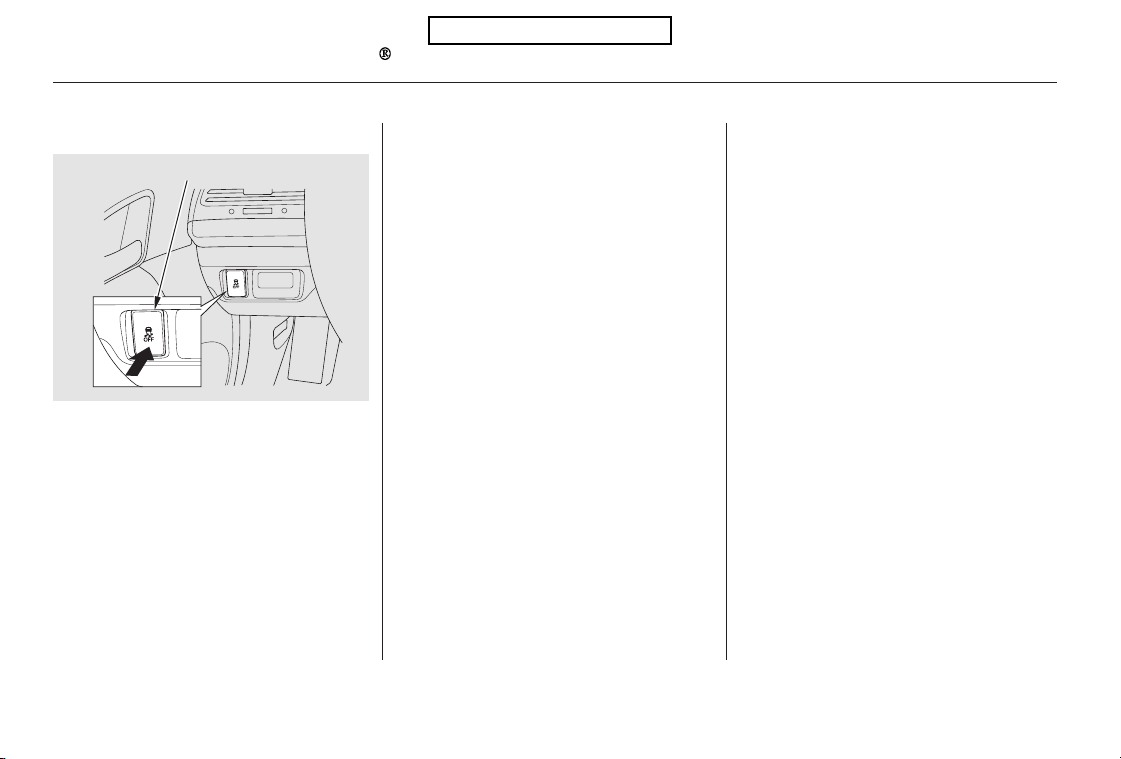
Driving with varying tire or wheel
sizes may cause the VSA to
malfunction. When replacing tires,
make sure they are of the same size
and type as your original tires (see
page ).
VSA is turned on every time you
start the engine, even if you turned it
off the last time you drove the
vehicle.
If you install winter tires, make sure
they are the same size as those that
were originally supplied with your
vehicle. Exercise the same caution
during winter driving as you would if
your vehicle was not equipped with
VSA.
In certain unusual conditions when
your vehicle gets stuck in shallow
mud or fresh snow, it may be easier
to free it with the VSA temporarily
switched off. When the VSA system
is off, the traction control system is
alsooff.Youshouldonlyattemptto
free your vehicle with the VSA off if
you are not able to free it when the
VSA is on.
Immediately after freeing your
vehicle, be sure to switch the VSA on
again. We do not recommend driving
your vehicle with the VSA and
traction control systems switched off.
This switch is under the driver’s side
vent. To turn the VSA system on and
off, press and hold it until you hear a
beep.
When VSA is off, the VSA off
indicator comes on as a reminder.
Press and hold the switch again. It
turns the system back on.
365
VSA and Tire SizesVSA OFF Switch
Vehicle Stability Assist (VSA ), aka Electronic Stability Control (ESC), System
312
VSA OFF SWITCH
Table of Contents
Your vehicle is equipped with a tire
pressure monitoring system (TPMS)
that turns on every time you start the
engine and monitors the pressure in
your tires while driving.
When the low tire pressure indicator
is on, one or more of your tires is
significantly underinflated. You
should stop and check your tires as
soon as possible, and inflate them to
the proper pressure as indicated on
the vehicle’s tire information placard.
If you think you can safely drive a
short distance to a service station,
proceed slowly, and inflate the tire to
the recommended pressure shown
on the driver’s doorjamb.
If the tire is flat, or if the tire
pressure is too low to continue
driving, replace the tire with the
compact spare tire (see page ).
If you cannot make the low tire
pressure indicator go out after
inflating the tires to the specified
values, have your dealer check the
system as soon as possible.
Each tire has its own pressure
sensor (not including the spare tire).
If the air pressure of a tire becomes
significantly low while driving, the
sensor in that tire immediately sends
a signal that causes the low tire
pressure indicator to come on.
Driving on a significantly under
inflated tire causes the tire to
overheat and can lead to tire failure.
Underinflation also reduces fuel
efficiency and tire tread life, and may
affect the vehicle’s handling and
stopping ability.
Becausetirepressurevariesby
temperature and other conditions,
the low tire pressure indicator may
come on unexpectedly.
372
CONTINUED
Low Tire Pressure
Indicator
Tire Pressure Monitoring System (TPMS)
Driving
313
Table of Contents
For example, if you check and fill
your tires in a warm area, then drive
in extremely cold weather, the tire
pressure will be lower than
measured and could be underinflated
and cause the low tire pressure
indicator to come on. Or, if you
check and adjust your tire pressure
in cooler conditions, and drive into
extremely hot conditions, the tire
maybecomeoverinflated.However,
the low tire pressure indicator will
not come on if the tires are
overinflated.
Refer to page for tire inflation
guidelines.
When you restart the vehicle with
thecompactsparetire,theTPMS
indicator may also come on and stay
on after driving several miles
(kilometers).
Although your tire pressure is
monitored, you must manually check
thetirepressuresmonthly.
Each tire, including the spare, should
be checked monthly when cold, and
set to the recommended inflation
pressure as specified on the tire
information label and in the owner’s
manual (see page ).
This indicator comes on and stays on
if there is a problem with the tire
pressure monitoring system.
If this happens, the system will shut
off and no longer monitor tire
pressures. Have the system checked
by your dealer as soon as possible.
If the low tire pressure indicator or
TPMS indicator comes on, the VSA
system automatically turns on even if
the VSA system is turned off by
pressing the VSA OFF switch (see
page ). If this happens, you
cannot turn the VSA system off by
pressing the VSA OFF switch again.
360
312
359
Tire Pressure Monitoring
System (TPMS) Indicator
Tire Pressure Monitoring System (TPMS)
314
Table of Contents

As required by the FCC:
This device complies with Part 15 of the
FCC rules. Operation is subject to the
following two conditions: (1) This device
may not cause harmful interference, and
(2) this device must accept any
interference received, including
interference that may cause undesired
operation.
Changes or modifications not expressly
approved by the party responsible for
compliance could void the user’s
authority to operate the equipment.
This device complies with Industry
Canada Standard RSS-210.
Operation is subject to the following two
conditions: (1) this device may not cause
interference, and (2) this device must
accept any interference that may cause
undesired operation of the device.
If you have a flat tire, the low tire
pressure indicator will come on.
Replace the flat tire with the
compact spare tire (see page ).
The low tire pressure indicator or
the TPMS indicator will go off, after
several miles (kilometers) driving,
when you replace the spare tire with
the specified regular tire equipped
with the tire pressure monitor sensor.
Never use a puncture-repairing agent
in a flat tire. If used, you will have to
replace the tire pressure sensor.
Havetheflattirerepairedbyyour
dealer as soon as possible.
After you replace the flat tire with
thecompactsparetire,thelowtire
pressure indicator stays on. This is
normal; the system is not monitoring
the spare tire pressure. Manually
check the spare tire pressure to be
sure it is correct. After several miles
(kilometers) driving with the
compact spare tire, the TPMS
indicator comes on and the low tire
pressure indicator goes off.
Each wheel (except the compact
sparetirewheel)isequippedwitha
tire pressure sensor. You must use
TPMS specific wheels. It is
recommended that you always have
your tires serviced by your dealer or
qualified technician.
372
Changing a Tire with TPMS
Tire Pressure Monitoring System (TPMS)
Driving
315
Table of Contents
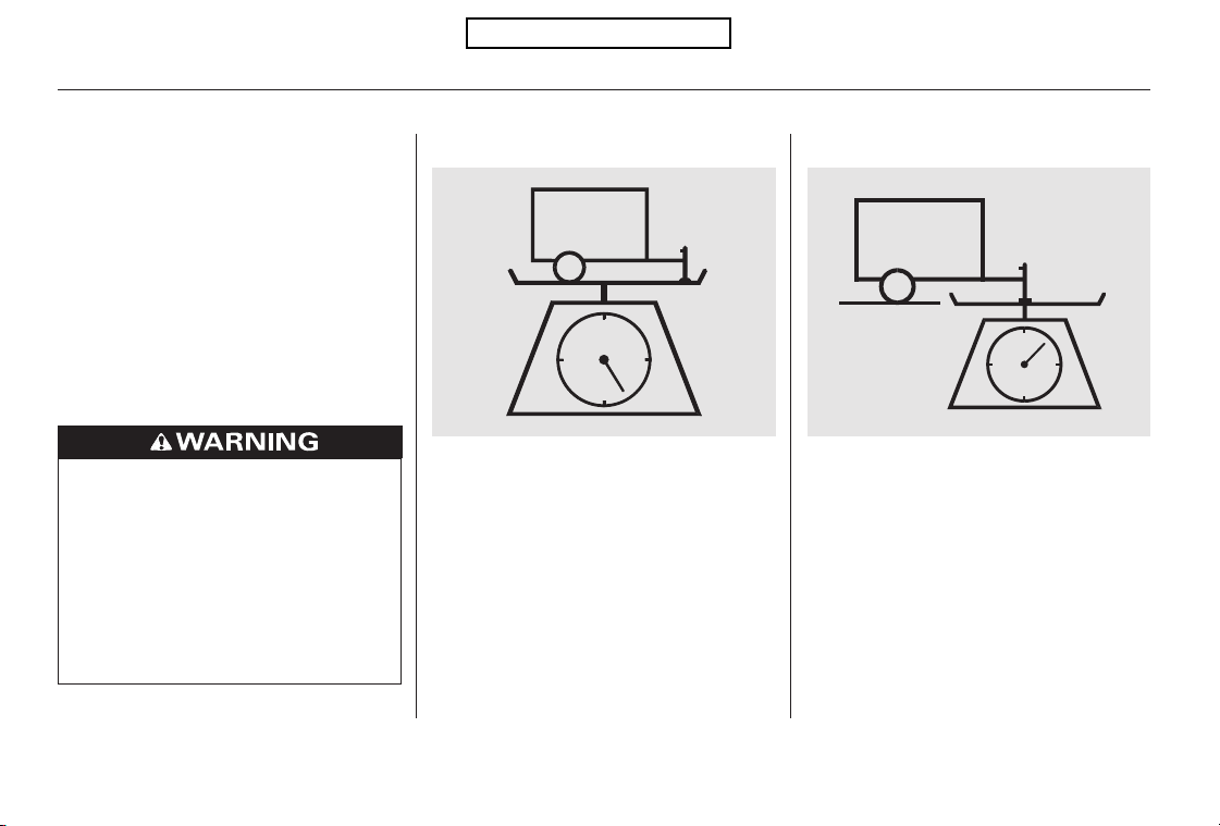
Your vehicle has been designed
primarily to carry passengers and
their cargo. You can also use it to
tow a trailer if you carefully observe
the load limits, use the proper
equipment, and follow the guidelines
in this section.
Avoid towing a trailer during your
vehicle’s first 600 miles (1,000 km)
(see page ).
The
maximum allowable weight of the
trailer and everything in or on it
must not exceed 1,500 lbs (680 kg).
Towing a load that is too heavy
can seriously affect your vehicle’s
handling and performance. It can
also damage the engine and
drivetrain.
Theweightthatthe
tongue of a fully-loaded trailer puts
on the hitch should be approximately
10% of the total trailer weight. Too
much tongue load reduces front-tire
traction and steering control. Too
little tongue load can make the
trailer unstable and cause it to sway.
282
Break-In Period
Load Limits
Total Trailer Weight: Tongue Load:
Towing a Trailer
316
Exceeding any load limit or
improperly loading your vehicle
and trailer can cause a crash in
which you can be seriously hurt
or killed.
Check the loading of your
vehicle and trailer carefully
beforestartingtodrive.
Table of Contents

To achieve a proper tongue load,
start by loading 60% of the load
toward the front of the trailer and
40% toward the rear, then re-adjust
the load as needed.
The maximum allowable weight of
the vehicle, all occupants, all
accessories, all cargo, and the
tongue load is:
The maximum allowable weight at
the vehicle axles is:
Thebestwaytoconfirmthatall
loads are within limits is to check
them at a public scale. For public
scales in your area, check your local
phone book, or contact your trailer
dealer or rental agency for
assistance.
If you cannot get to a public scale,
you can estimate the total trailer
weight by adding the weight of your
trailer (as quoted by the
manufacturer) with everything in or
on the trailer.
If you normally pull the same load
each time you tow a trailer, you can
use a suitable scale or a special
tongue load gauge to check the
tongue load the first time you set up
a towing combination (a fully loaded
vehicle and trailer), then recheck the
tongue load whenever the conditions
change.
on the front axle
on the rear axle
on the front axle
on the rear axle
2WD models :
4WD models :
2WD models :
4WD models :
Gross Vehicle Weight Rating
(GVWR):
Checking LoadsGross Axle Weight Rating
(GAWR):
Towing a Trailer
Driving
317
4,938 lbs (2,240 kg)
2,623 lbs (1,190 kg)
2,381 lbs (1,080 kg)
5,115 lbs (2,320 kg)
2,668 lbs (1,210 kg)
2,513 lbs (1,140 kg)
Table of Contents

If you choose electric brakes, be
sure they are electronically actuated.
Do not attempt to tap into your
vehicle’s hydraulic system. No
matter how successful it may seem,
any attempt to attach trailer brakes
to your vehicle’s hydraulic system
will lower braking effectiveness and
create a potential hazard.
Seeyourtrailerdealerorrental
agency for more information on
installing electric brakes.
Towing can require a variety of
equipment, depending on the size of
your trailer, how it will be used, how
much load you are towing, and
where you tow.
Any hitch used on your vehicle must
be properly bolted to the underbody.
Always use safety chains when you
tow a trailer. Make sure the chains
are secured to the trailer and hitch,
and that they cross under the tongue
and can catch the trailer if it
becomes unhitched. Leave enough
slack to allow the trailer to turn
corners easily, but do not let the
chains drag on the ground.
There are two common types of
trailer brakes: surge and electric.
Surge brakes are common for boat
trailers, since the brakes will get wet.
Discuss your needs with your trailer
sales or rental agency, and follow the
guidelines in the rest of this section.
Also make sure that all equipment is
properly installed and that it meets
federal, state, provincial, territorial,
and local regulations.
Trailer BrakesHitches
Saf ety Chains
Towing Equipment and
Accessories
Towing a Trailer
318
Table of Contents
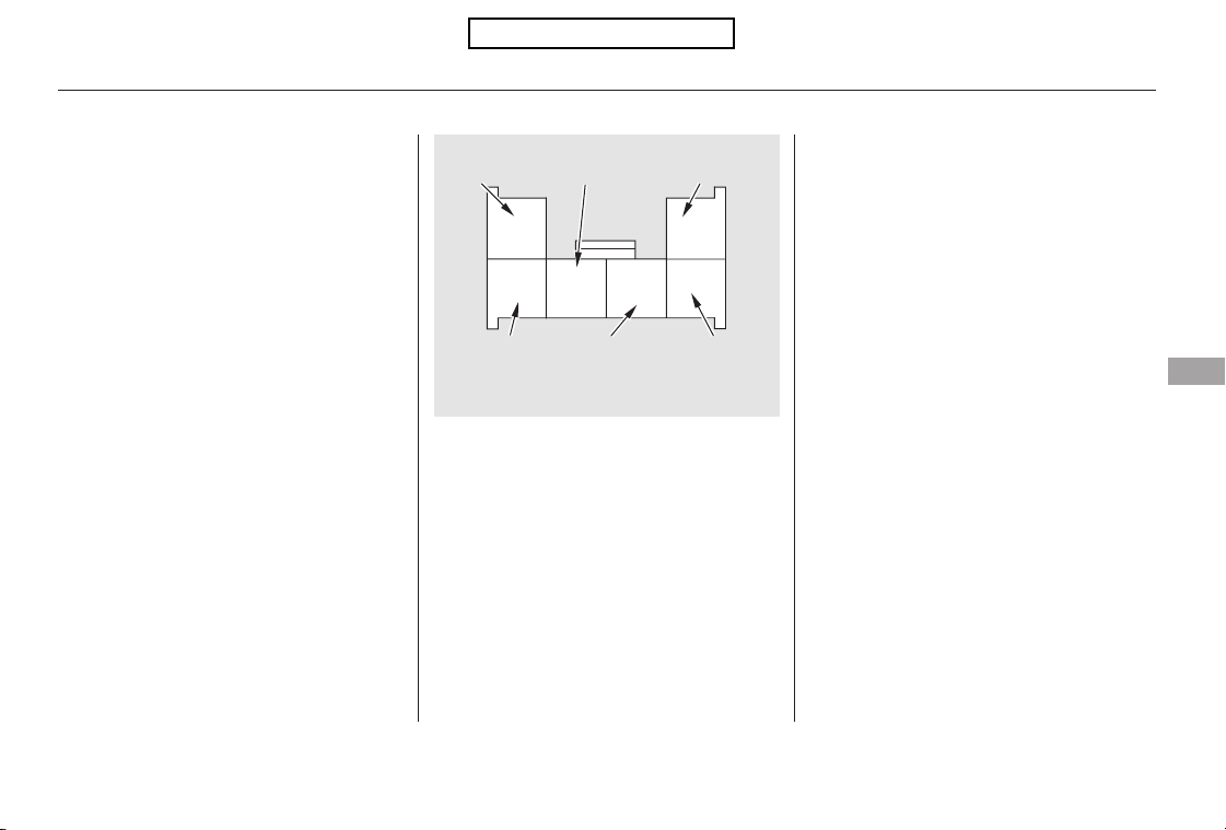
CONTINUED
Trailer lights and equipment must
comply with federal, state, provincial,
territorial, and local regulations.
Check with your local trailer dealer
or rental agency for the
requirements in the area where you
plan to tow, and use only equipment
designed for your vehicle.
Since lighting and wiring vary by
trailer type and brand, you should
have a qualified technician install a
suitable connector between the
vehicle and the trailer. Improper
equipment or installation can cause
damage to your vehicle’s electrical
system and affect your vehicle
warranty.
Your vehicle has a trailer lighting
connector located behind the left
side panel in the cargo area. Refer to
thedrawingaboveforthewiring
color code and purpose of each pin.
If you use a non-Honda trailer
lighting harness and converter, you
can get the connector and pins that
mate with the connector in your
vehicle from your dealer.
Trailer Lights
Towing a Trailer
Driving
319
GROUND
(BLACK)
TRAILER
(YELLOW)
LEFT TURN
SIGNAL (BLUE)
BRAKE
LIGHT
(LIGHT
GREEN)
TAILLIGHT
(RED)
RIGHT TURN
SIGNAL
(GREEN)
Table of Contents
The lights and brakes on your
vehicle and the trailer are working
properly.
Your vehicle tires and spare are
properly inflated, and the trailer
tires and spare are inflated as
recommended by the trailer
maker.
Askyourtrailersalesorrental
agency if any other items are
recommended or required for your
towing situation.
When preparing to tow, and before
driving away, be sure to check the
following:
Many states and Canadian
provinces/territories require special
outside mirrors when towing a trailer.
Even if they don’t, you should install
special mirrors if you cannot clearly
see behind you, or if the trailer
creates a blind spot.
The vehicle has been properly
serviced, and the suspension and
the cooling system are in good
operating condition.
The trailer has been properly
serviced and is in good condition.
All weights and loads are within
limits.
Thehitch,safetychains,andany
other attachments are secure.
All items in or on the trailer are
properly secured and cannot shift
while you drive.
Towing a Trailer
Additional Towing Equipment
Pre-Tow Checklist
320
Table of Contents

When driving down hills, reduce
your speed, and shift down to second
gear. Do not ‘‘ride’’ the brakes, and
remember, it will take longer to slow
downandstopwhentowingatrailer.
Ifyoumuststopwhenfacinguphill,
use the foot brake or parking brake.
Do not try to hold the vehicle in
place by pressing on the accelerator,
as this can cause the automatic
transmission to overheat.
Crosswinds and air turbulence
caused by passing trucks can disrupt
your steering and cause the trailer to
sway. When being passed by a large
vehicle, keep a constant speed, and
steer straight ahead. Do not try to
make quick steering or braking
corrections.
Maketurnsmoreslowlyandwider
than normal. The trailer tracks a
smaller arc than your vehicle, and it
canhitorrunoversomethingthe
vehicle misses. Allow more time and
distance for braking. Do not brake or
turn suddenly as this could cause the
trailer to jackknife or turn over.
When climbing hills, closely watch
your temperature gauge. If it nears
the red (Hot) mark, turn the air
conditioning off, reduce speed and, if
necessary, pull to the side of the
road to let the engine cool.
The added weight, length, and
height of a trailer will affect your
vehicle’s handling and performance,
so driving with a trailer requires
some special driving skills and
techniques.
Foryoursafetyandthesafetyof
others,taketimetopracticedriving
maneuvers before heading for the
open road, and follow the guidelines
in this section.
Drive slower than normal in all
driving situations, and obey posted
speed limits for vehicles with trailers.
Use the D position when towing a
trailer on level roads. D3 is the
proper shift lever position to use
when towing a trailer in hilly terrain.
(See ‘‘ ’’ in the
following column for additional gear
information.)
If the automatic transmission shifts
frequently while going up a hill, shift
to D3.
Towing a Trailer
Handling Crosswinds and Buffeting
Making Turns and Braking
Driving on Hills
Towing Speeds and Gears
Driving on Hills
Driving Safely With a Trailer
Driving
321
Table of Contents

Always drive slowly and have
someone guide you when backing up.
Grip the of the steering wheel,
then turn the wheel to the left to get
the trailer to move to the left. Turn
the wheel to the right to move the
trailer to the right.
Follow all normal precautions when
parking, including firmly setting the
parking brake and putting the
transmission in Park. Also, place
wheel chocks at each of the trailer’s
tires.
Your vehicle is not designed to be
towed behind a motor home. If your
vehicle needs to be towed in an
emergency, see page .397
bottom
Towing a Trailer
Backing Up
Parking
Towing Your Vehicle
322
Table of Contents

This section explains why it is
important to keep your vehicle well
maintained and how to follow basic
maintenance safety precautions.
This section also includes
instructions on how to read the
maintenance minder messages on
the information display, and
instructions for simple maintenance
tasks you may want to take care of
yourself.
If you have the skills and tools to
perform more complex maintenance
tasks on your vehicle, you may want
to purchase the service manual. See
page for information on how to
obtain a copy, or see your dealer.
U.S. Vehicles: ......................
Maintenance Safety . 324
....................Maintenance Minder . 325
..............................Fluid Locations . 332
........................Adding Engine Oil . 333
Changing the Engine Oil and
...........................................Filter . 335
..............................Engine Coolant . 337
....................Windshield Washers . 339
.......................Transmission Fluid . 340
..........Automatic Transmission . 340
....................................Brake Fluid . 342
....................Power Steering Fluid . 343
....................................Timing Belt . 343
.............................................Lights . 344
................Cleaning the Seat Belts . 353
.....................................Floor Mats . 353
..................Dust and Pollen Filter . 354
..............................Audio Antenna . 355
.................................Wiper Blades . 355
...............................................Tires . 359
...................Checking the Battery . 367
.............................Vehicle Storage . 368
..................................Interior Care . 369
419
Maintenance
Maintenance, replacement, or
repair of emissions control
devices and systems may be done
by any automotive repair
establishment or individual using
parts that are ‘‘certif ied’’ to EPA
standards.
Maintenance
323
All service items not detailed in this
section should be performed by a
certified technician or other qualified
mechanic.
To eliminate potential hazards, read
the instructions before you begin,
and make sure you have the tools
and skills required.
Make sure your vehicle is parked
on level ground, the parking brake
is set, and the engine is off.
Some of the most important safety
precautions are given here. However,
we cannot warn you of every
conceivable hazard that can arise in
performing maintenance. Only you
can decide whether or not you
should perform a given task.
Do
not run the engine unless
instructed to do so.
Let the
engine and exhaust system cool
down before touching any parts.
Be sure
there is adequate ventilation
whenever you operate the
engine.
Wear eye protection and
protective clothing when working
with the battery or compressed air.
To reduce the possibility of fire or
explosion, keep cigarettes, sparks,
and flames away from the battery
and all fuel-related parts.
To clean parts, use a commercially
available degreaser or parts
cleaner, not gasoline.
Maintenance Safety
Important Safety Precautions
Injury f rom moving parts.
Burns from hot parts.
Carbon Monoxide poison
from engine exhaust.
Potential Vehicle Hazards
324
Failure to properly follow
maintenance instructions and
precautions can cause you to
be seriously hurt or killed.
Always follow the procedures
and precautions in this owner’s
manual.
Improperly maintaining this
vehicle, or failing to correct a
problem before driving can
cause a crash in which you can
be seriously hurt or killed.
Always follow the inspection
and maintenance
recommendations and
schedules in this owner’s
manual.
Table of Contents
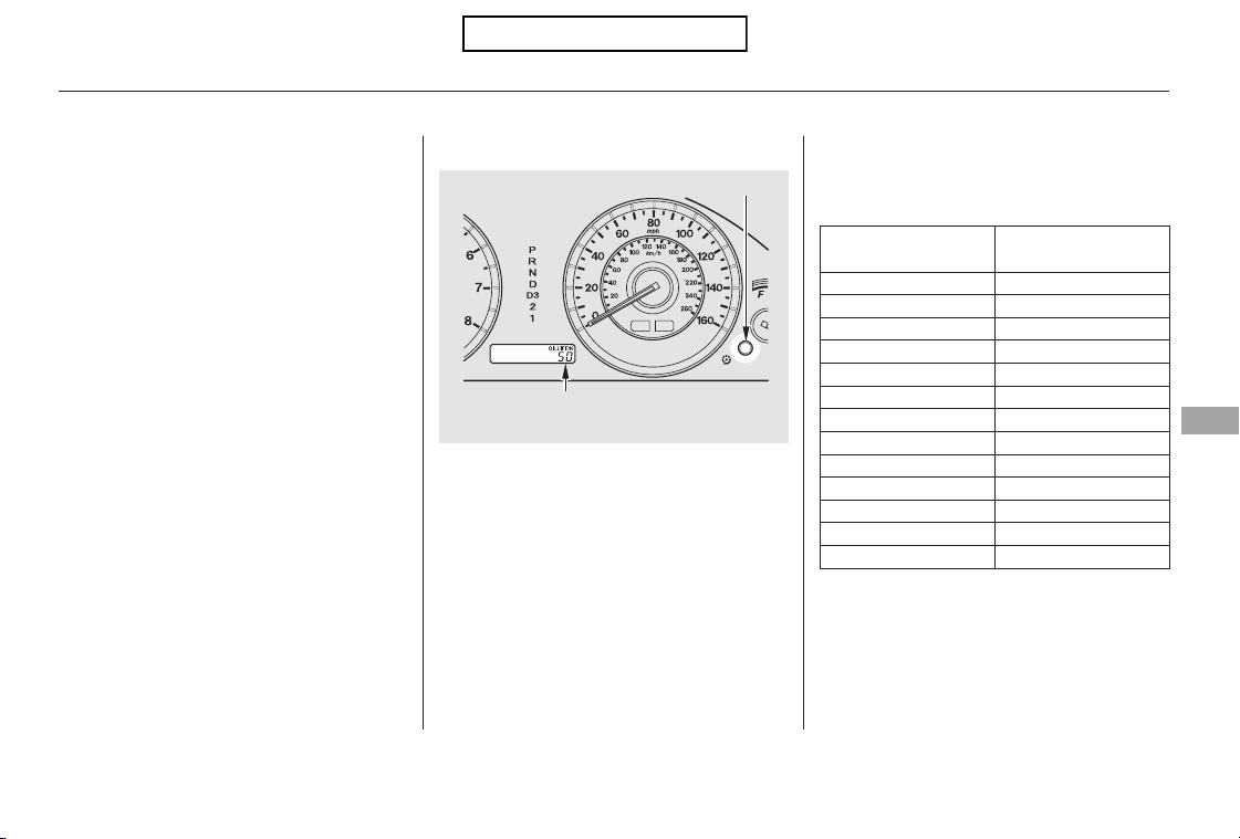
−
−
−
−
−
−
−
−
−
−
−
−
CONTINUED
Calculated Engine
Oil Life (%)
100 % 91 %
90 % 81 %
80 % 71 %
70 % 61 %
60 % 51 %
50 % 41 %
40 % 31 %
30 % 21 %
20 % 16 %
15 % 11 %
10 % 6 %
5% 1%
0%
Displayed
Engine Oil Life (%)
100 %
90 %
80 %
70 %
60 %
50 %
40 %
30 %
20 %
15 %
10 %
5%
0%
Your vehicle displays engine oil life
and maintenance service items on
the information display to show you
when you should have your dealer do
engine oil replacement and indicated
maintenance service.
The remaining engine oil life is
shownonthedisplayaccordingto
this table:
To see the current engine oil life,
turn the ignition switch to the ON
(II) position, then press and release
the select/reset knob repeatedly
until the engine oil life indicator
appears (see page ).
Based on the engine operating
conditions, the onboard computer in
your vehicle calculates the remaining
engine oil life and displays it as a
percentage.
64
Maintenance Minder
Engine Oil Life Display
Maintenance
325
ENGINE OIL LIFE INDICATOR
SELECT/RESET KNOB
U.S. model is shown.
Table of Contents
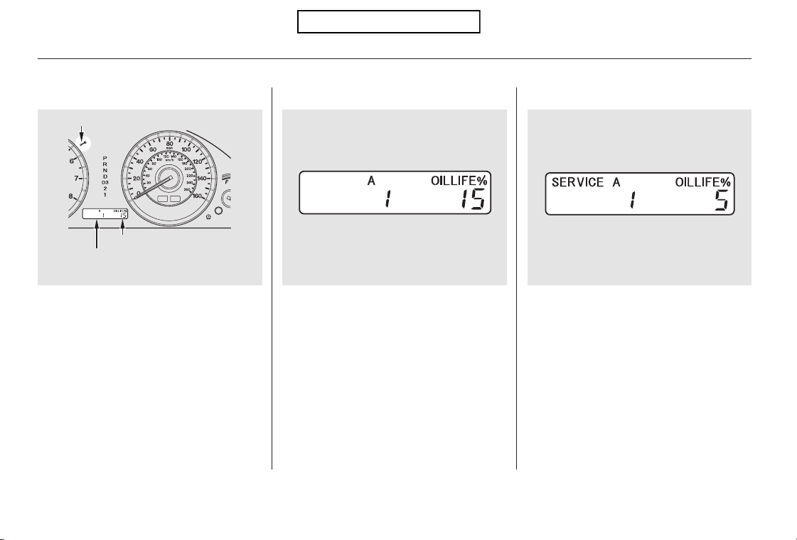
If the remaining engine oil life is 15
to 6 percent, you will see the engine
oil life indicator every time you turn
the ignition switch to the ON (II)
position. The maintenance minder
indicator will also come on, and the
maintenance item code(s) for other
scheduled maintenance items
needing service will be displayed
next to the engine oil life indicator.
When the remaining engine oil life is
5 to 1 percent, you will see a
‘‘SERVICE’’ message along with the
same maintenance item code(s),
everytimeyouturntheignition
switch to the ON (II) position.
The 15 and 10 percent oil life
indicators remind you that your
vehicle will soon be due for
scheduled maintenance.
Maintenance Minder
326
MAINTENANCE MINDER INDICATOR
MAINTENANCE ITEM CODE(S)
ENGINE OIL LIFE INDICATOR
U.S. model is shown.
Table of Contents
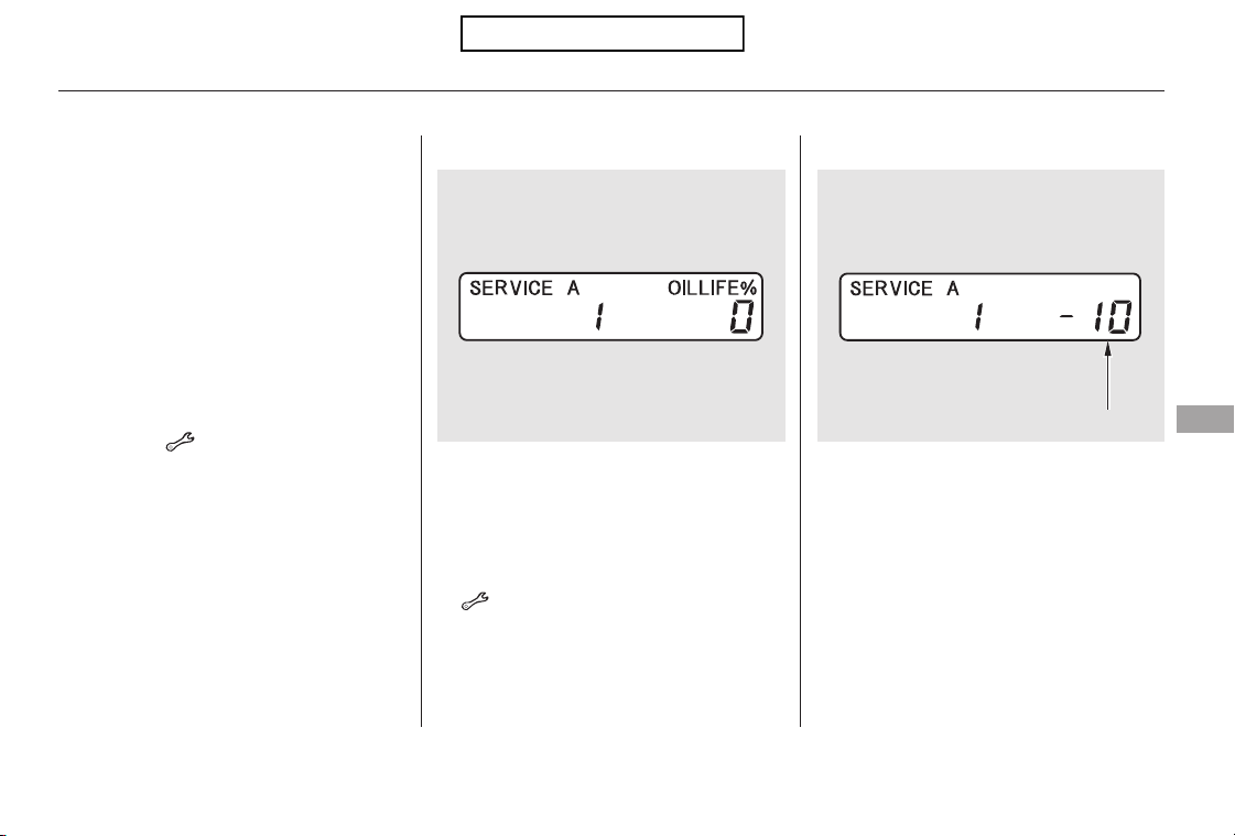
CONTINUED
If you do not perform the indicated
maintenance, negative distance
traveled is displayed and begins to
blink after the vehicle has been
driven 10 miles (10 km) or more.
Negative distance traveled means
your vehicle has passed the
maintenance required point.
When the remaining engine oil life is
0 percent, the engine oil life indicator
will blink. The display comes on
everytimeyouturntheignition
switch to the ON (II) position. The
maintenance minder indicator
( ) also comes on and remains
on in the instrument panel. When
you see this message, immediately
have the indicated maintenance done
by your dealer.
The maintenance item code or codes
indicate the main and sub items
required at the time of the oil change
(see page ).
You can switch the information
display from the engine oil life
display to the odometer or the trip
meter. Press and release the select/
reset knob on the instrument panel.
Whentheengineoillifeis15to1
percent, the maintenance minder
indicator ( ) comes on every
time you turn the ignition switch to
the ON (II) position, then it goes out
if you switch the information display.
When you see this message, have
the indicated maintenance
performed by your dealer as soon as
possible.
Immediately have the indicated
maintenance done by your dealer.
331
Maintenance Minder
Maintenance
327
NEGATIVE DISTANCE TRAVELED
Table of Contents
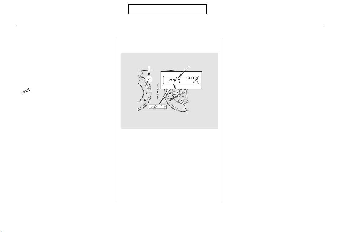
Your dealer will reset the display
after completing the required
maintenance service. You will see
‘‘OIL LIFE 100%’’ on the information
display the next time you turn the
ignition switch to the ON (II)
position.
If maintenance service is done by
someone other than your dealer,
reset the maintenance minder as
follows:
Turn the ignition switch to the ON
(II) position.
Press the select/reset knob
repeatedly until the engine oil life
indicator is displayed.
All maintenance items displayed on
the information display are in code.
For an explanation of these
maintenance codes, see page .
To change the information display
from the engine oil life display to the
odometer or the trip meter, press
and release the select/reset knob.
Immediately have the service
performed, and make sure to reset
the display as described as follows.
When the engine oil life is 0 percent
or negative distance traveled, the
maintenance minder indicator
( )remainsonevenifyou
change the information display.
1.
2.331
Maintenance Minder
Resetting the Engine Oil Life
Display
Maintenance Main Items and Sub
Items
328
MAINTENANCE
MINDER INDICATOR
MAINTENANCE SUB ITEM(S)
MAINTENANCE
MAIN ITEM
U.S. model is shown.
Table of Contents
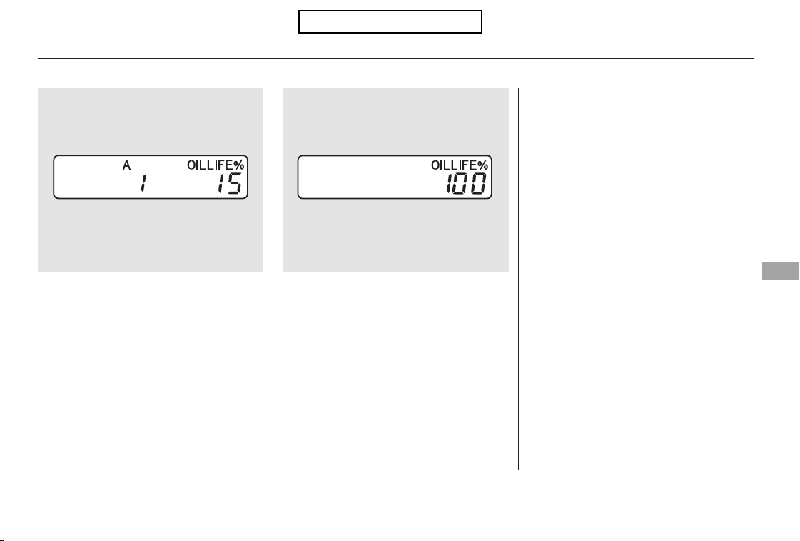
CONTINUED
If you have the required service
done but do not reset the display, or
reset the display without doing the
service, the system will not show the
correct maintenance intervals. This
canleadtoseriousmechanical
problems because you will no longer
have an accurate record of when
maintenance is needed.
Your authorized Honda dealer
knows your vehicle best and can
provide competent, efficient service.
Press the select/reset knob for
about 10 seconds. The engine oil
life and the maintenance item
code(s) will blink.
Press the select/reset knob for
another 5 seconds. The
maintenance item code(s) will
disappear, and the engine oil life
will reset to ‘‘100.’’
4.3.
Maintenance Minder
Important Maintenance
Precautions
Maintenance
329
Table of Contents
−
−
−
−
−
−
#
Engine oil level Check every
time you fill the fuel tank. See
page .
Engine coolant level Check the
radiator reserve tank every time
you fill the fuel tank. See page .
Automatic transmission Check
the fluid level monthly. See page
.
Brakes Check the fluid level
monthly. See page .
Tires Check the tire pressure
monthly. Examine the tread for
wear and foreign objects. See page
.
Lights Check the operation of
the headlights, parking lights,
taillights, high-mount brake light,
and license plate lights monthly.
See page .
However, service at a dealer is not
mandatory to keep your warranties
in effect. Maintenance may be done
by any qualified service facility or
person who is skilled in this type of
automotive service. Make sure to
have the service facility or person
reset the display as previously
described. Keep all receipts as proof
of completion, and have the person
who does the work fill out your
Honda Service History or Canadian
Maintenance Log. Check your
warranty booklet for more
information.
We recommend using Honda parts
and fluids whenever you have
maintenance done. These are
manufactured to the same high
quality standards as the original
components, so you can be confident
of their performance and durability.
According to state and federal
regulations, failure to perform
maintenance on the items marked
with will not void your emissions
warranties. However, all
maintenance services should be
performed in accordance with the
intervals indicated by the
information display.
Youshouldcheckthefollowing
items at the specified intervals. If
you are unsure of how to perform
any check, turn to the appropriate
page listed.
U.S. Vehicles:
288
288
340
342
359
344
Maintenance Minder
Owner’s Maintenance Checks
330
Table of Contents

*
*
#
#
−
−
#
*
Maintenance Minder
331
Maintenance Main Items
Replace engine oil
Replace engine oil and oil filter
Inspect front and rear brakes
Check parking brake adjustment
Inspect these items:
Tie rod ends, steering gear box, and boots
Suspension components
Driveshaft boots
Brake hoses and lines (including ABS/VSA)
All fluid levels and condition of fluids
Exhaust system
Fuel lines and connections
Maintenance Sub Items
Rotate tires
Replace air cleaner element
Replace dust and pollen filter
Inspect drive belt
Replace transmission and transfer fluid (4WD only)
Replace spark plugs
Replace timing belt and inspect water pump
Inspect valve clearance
Replace engine coolant
Replace rear differential fluid (4WD only)
:
A
B
Symbol
1
2
3
4
Symbol
6
5
1
1
Inspect idle speed every 160,000 miles (256,000 km).
If the message ‘‘SERVICE’’ does not appear more than 12 months after the
display is reset, change the engine oil every year.
See information on maintenance and emissions warranty in the center
column on page .
Adjust the valves during services A, B, 1, 2, or 3 if they are noisy.
Independent of maintenance message in the information display, replace
the brake fluid every 3 years.
NOTE:
1:
330
If you drive in dusty conditions, replace every 15,000
miles (24,000 km).
If you drive primarily in urban areas that have high
concentrations of soot in the air from industry and from
diesel-powered vehicles, replace every 15,000 miles
(24,000 km).
If you drive regularly in very high temperatures (over
110°F, 43°C), in very low temperatures (under 20°F,
29°C) or tow a trailer, replace every 60,000 miles
(U.S.)/100,000 km (Canada).
Maintenance Minder
Table of Contents
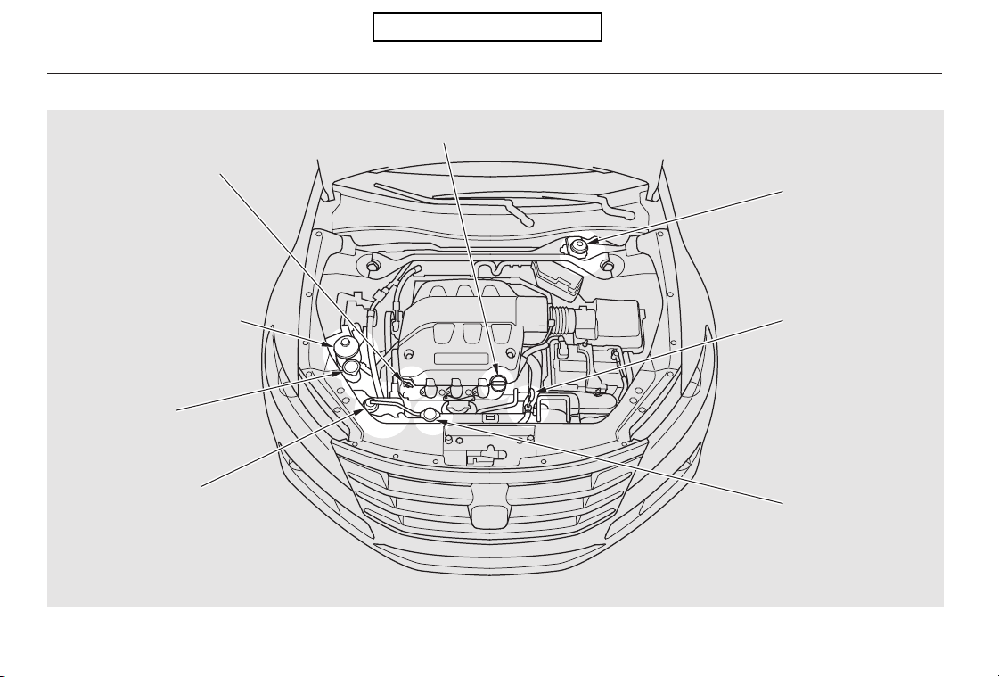
Fluid Locations
332
BRAKE FLUID
(Black cap)
AUTOMATIC
TRANSMISSION
FLUID DIPSTICK
(Yellow loop)
RADIATOR CAP
ENGINE OIL DIPSTICK
(Orange loop)
POWER STEERING FLUID
(Red cap)
WASHER FLUID
(Blue cap)
ENGINE COOLANT
RESERVOIR
ENGINE OIL FILL CAP
Table of Contents
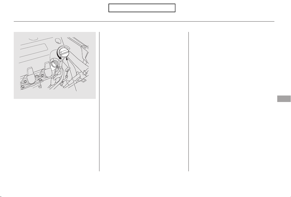
Unscrew and remove the engine oil
fill cap on top of the valve cover.
Pour in the oil slowly and carefully so
you do not spill any. Clean up any
spills immediately. Spilled oil could
damage components in the engine
compartment.
Reinstall the engine oil fill cap, and
tighten it securely. Wait a few
minutes, and recheck the oil level on
the engine oil dipstick. Do not fill
above the upper mark; you could
damage the engine.
Oil is a major contributor to your
engine’s performance and longevity.
Always use a premium-grade 0W-20
detergent oil displaying the API
Certification Seal. This seal indicates
the oil is energy conserving, and that
it meets the American Petroleum
Institute’s latest requirements.
CONTINUED
Recommended Engine Oil
Adding Engine Oil
Maintenance
333
ENGINE OIL FILL CAP
Table of Contents
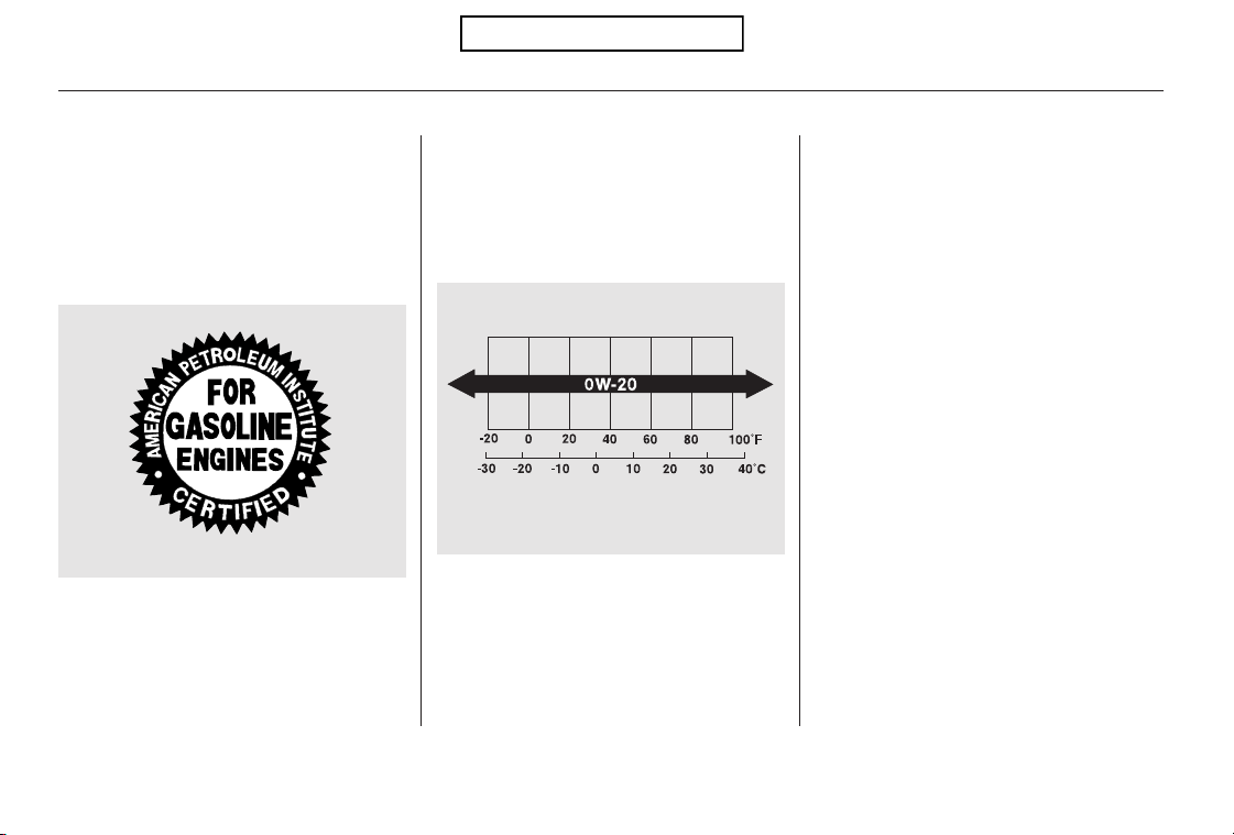
Your vehicle does not require any oil
additives. Additives may adversely
affect the engine or transmission
performance and durability.
You may use a synthetic motor oil if
it meets the same requirements
given for a conventional motor oil: it
displays the API certification seal,
and it is the proper weight. You must
follow the oil and filter change
intervals shown on the information
display.
Honda Motor Oil is the preferred
0W-20 lubricant for your vehicle. It is
highly recommended that you use
Honda Motor Oil in your vehicle for
optimum engine protection. Make
sure the API Certification Seal says
‘‘For Gasoline Engines’’.
The oil viscosity or weight is
provided on the container’s label.
0W-20 oil is formulated for year-
round protection of your vehicle to
improve cold weather starting and
fuel economy.
Synthetic Oil
Engine Oil Additives
Adding Engine Oil
334
API CERTIFICATION SEAL
Ambient Temperature
Table of Contents
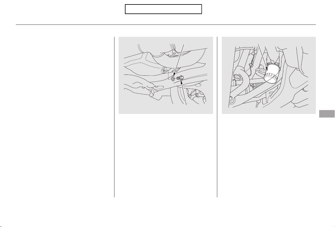
Remove the oil filter and let the
remaining oil drain. A special
wrench (available from your
dealer) is required.
Open the hood, and remove the
engine oil fill cap. Remove the oil
drain bolt and washer from the
bottom of the engine. Drain the oil
into an appropriate container.
Always change the oil and filter
according to the maintenance
messages shown on the information
display. The oil and filter collect
contaminants that can damage your
engine if they are not removed
regularly.
Run the engine until it reaches
normal operating temperature,
then shut it off.
Make sure the oil filter gasket is
not stuck to the contacting surface
of the engine. If it is, remove it
before installing a new oil filter.
Changing the oil and filter requires
special tools and access from
underneath the vehicle. The vehicle
should be raised on a service station-
type hydraulic lift for this service.
Unless you have the knowledge and
proper equipment, you should have
this maintenance done by a skilled
technician.
3.2.
1.
CONTINUED
Changing the Engine Oil and Filter
Maintenance
335
OIL DRAIN BOLT
WASHER
OIL FILTER
Table of Contents
Install a new oil filter according to
the instructions that come with it.
Make sure to clean off any dirt
and dust on the contacting surface
of a new oil filter.
Put a new washer on the drain bolt,
then reinstall the drain bolt.
Tighten the drain bolt to:
Refill the engine with the recom-
mended oil.
Engine oil change capacity
(including filter):
Replace the engine oil fill cap.
Start the engine. The oil pressure
indicator should go out within 5
seconds. If it does not, turn off the
engine, and check your work.
Let the engine run for several
minutes, then check the drain bolt
and oil filter for leaks.
Turn off the engine, let it sit for
several minutes, then check the oil
level on the dipstick. If necessary,
add more oil.
4.
5.
6.
7.
8.
9.
Changing the Engine Oil and Filter
336
29 lbf·ft (39 N·m , 4.0 kgf·m)
4.5 US qt (4.3
)
Improper disposal of engine oil can be
harmf ul to the environment. If you
change your own oil, please dispose of
the used oil properly. Put it in a sealed
container and take it to a recycling
center. Do not discard it in a trash bin
or dump it on the ground.
Table of Contents
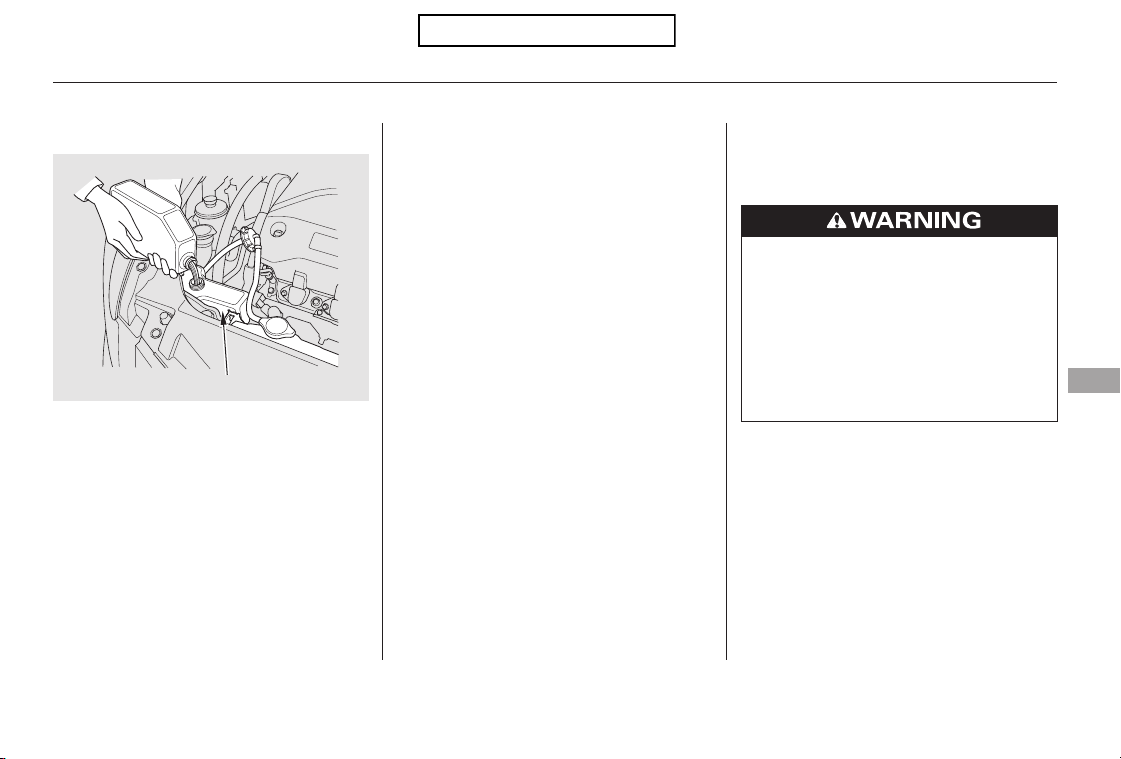
If the coolant level in the reserve
tank is at or below the MIN line, add
coolant to bring it up to the MAX line.
Inspect the cooling system for leaks.
Always use Honda Long-life Anti-
freeze/Coolant Type 2. This coolant
is pre-mixed with 50 percent
antifreeze and 50 percent distilled
water. Never add straight antifreeze
or plain water.
If Honda antifreeze/coolant is not
available, you may use another
major-brand non-silicate coolant as a
temporaryreplacement.Makesureit
is a high-quality coolant
recommended for aluminum engines.
Continued use of any non-Honda
coolant can result in corrosion,
causing the cooling system to
malfunction or fail. Have the cooling
system flushed and refilled with
Honda antifreeze/coolant as soon as
possible.
If the reserve tank is completely
empty, you should also check the
coolant level in the radiator.
CONTINUED
Adding Engine Coolant
Engine Coolant
Maintenance
337
RESERVE TANK
Removing the radiator cap
while the engine is hot can
cause the coolant to spray out,
seriously scalding you.
Always let the engine and
radiator cool down before
removing the radiator cap.
Table of Contents
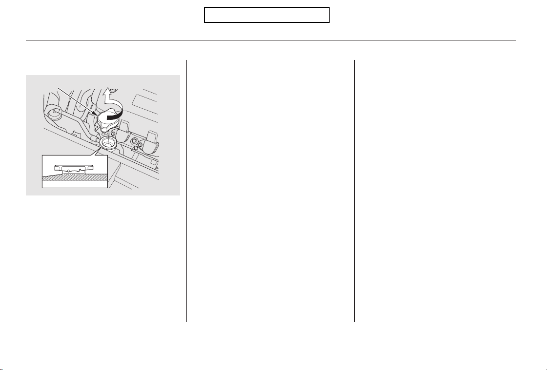
Make sure the engine and radiator
are cool.
Relieve any pressure in the cooling
system by turning the radiator cap
counterclockwise, without
pressing down.
Remove the radiator cap by
turning it counterclockwise.
The coolant level should be up to
the base of the filler neck. Add
coolant if it is low.
Pourthecoolantslowlyand
carefully so you do not spill any.
Clean up any spill immediately; it
could damage components in the
engine compartment.
Put the radiator cap back on, and
tighten it fully.
Pour coolant into the reserve tank.
Fill it to halfway between the MAX
and MIN marks. Put the cap back
on the reserve tank.
Do not add any rust inhibitors or
other additives to your vehicle’s
cooling system. They may not be
compatible with the coolant or
engine components.
4.
1.
2.
3.
5.
6.
Engine Coolant
338
RADIATOR CAP
Table of Contents
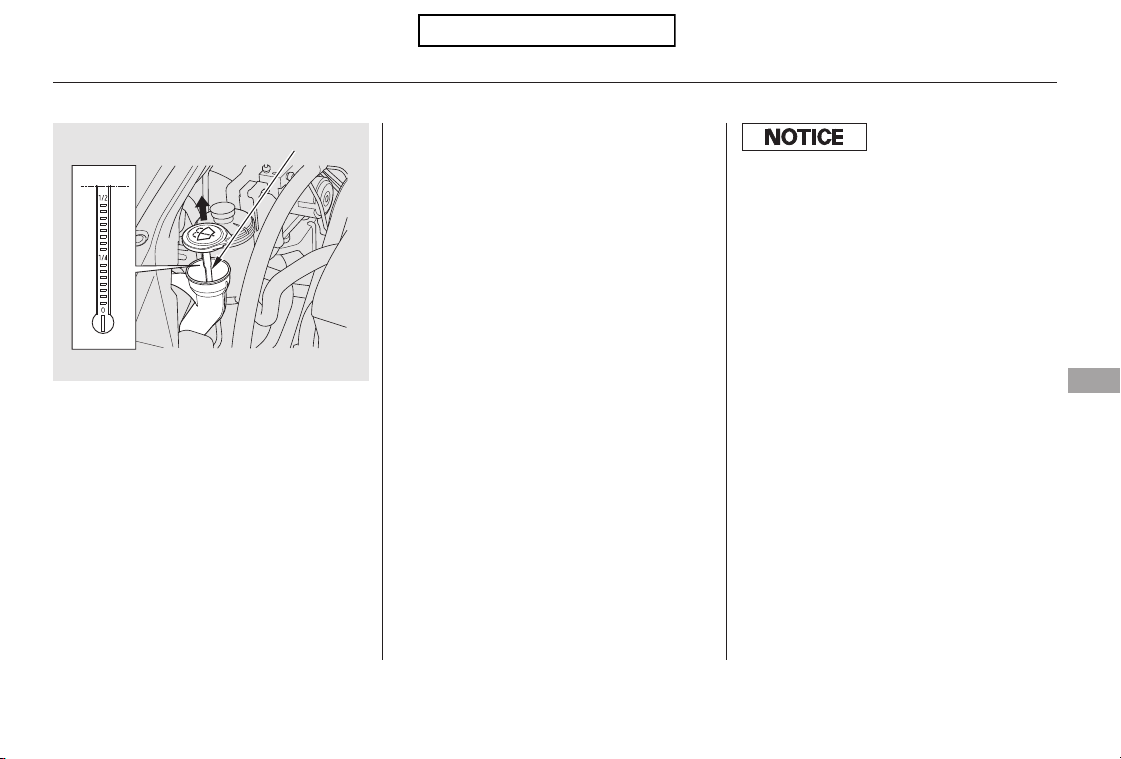
Check the level in the windshield
washer reservoir at least monthly
during normal use.
Check the fluid level by removing
the cap and looking at the level
gauge.
The washer level indicator will come
on when the level is low (see page
).
Fill the reservoir with a good-quality
windshield washer fluid. This
increases the cleaning capability and
prevents freezing in cold weather.
When you refill the reservoir, clean
the edges of the windshield wiper
blades with windshield washer fluid
on a clean cloth. This will help to
condition the blade edges.
62
Canadian models only
Windshield Washers
Maintenance
339
LEVEL GAUGE
Do not use engine antifreeze or a
vinegar/water solution in the
windshield washer reservoir. Antif reeze
can damage your vehicle’s paint, while
a vinegar/water solution can damage
the windshield washer pump. Use only
commercially-available windshield
washer f luid.
Table of Contents
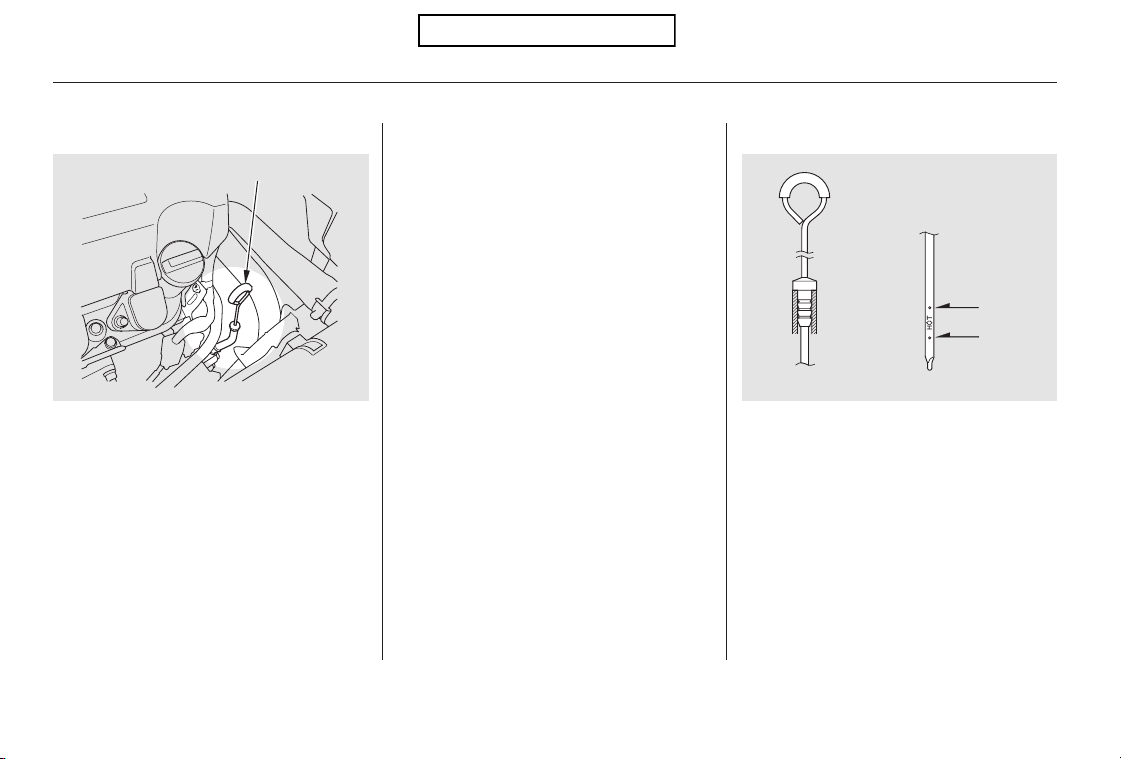
Check the fluid level with the engine
at normal operating temperature.
Park the vehicle on level ground.
Start the engine, let it run until the
radiator fan comes on, then shut
off the engine. For accurate
results, wait about 60 seconds (but
no longer than 90 seconds) before
doing step 2.
Insert the dipstick all the way into
the transmission securely as
shown in the illustration.
Remove the dipstick (yellow loop)
from the transmission, and wipe it
with a clean cloth.
Remove the dipstick and check
the fluid level. It should be
between the upper and lower
marks.
1.
2.
3.
4.
Automatic Transmission
Transmission Fluid
340
UPPER
MARK
LOWER
MARK
DIPSTICK
Table of Contents
If the level is below the lower
mark, add fluid into the dipstick
hole to bring it to the level
between the upper and lower
marks.
Pour the fluid slowly and carefully
so you do not spill any. Clean up
any spill immediately; it could
damage components in the engine
compartment.
Always use Honda Genuine
ATF-Z1 (automatic transmission
fluid).
Insert the dipstick all the way back
into the transmission securely as
shown in the illustration.
The transmission should be drained
and refilled with new fluid according
to the maintenance minder (see page
).
If you are not sure how to add fluid,
contact your dealer.
5. 6.
331
Transmission Fluid
Maintenance
341
Using transmission f luid other than
Honda Genuine ATF-Z1 may cause
deterioration in transmission operation
and durability, and could result in
damage to the transmission.
Use only Honda Genuine ATF-Z1
(automatic transmission f luid). Do not
mix with other transmission fluids.
Damage resulting f rom the use of
transmission f luid other than Honda
Genuine ATF-Z1 is not covered by the
Honda new vehicle warranty.
Table of Contents
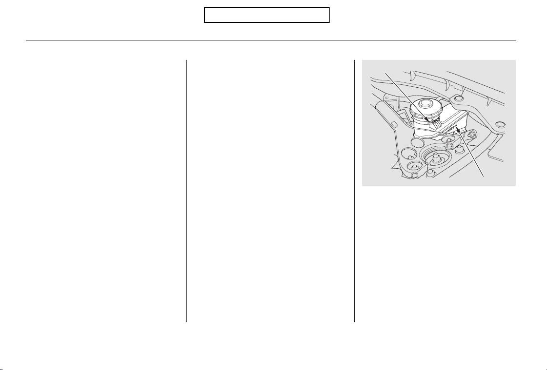
The fluid level should be between
theMINandMAXmarksontheside
of the reservoir. If the level is at or
below the MIN mark, your brake
system needs attention. Have the
brake system inspected for leaks or
worn brake pads.
Always use Honda Heavy Duty
Brake Fluid DOT 3. If it is not
available, you should use only DOT 3
or DOT 4 fluid, from a sealed
container, as a temporary
replacement.
Using any non-Honda brake fluid can
cause corrosion and decrease the life
of the system. Have the brake
system flushed and refilled with
Honda Heavy Duty Brake Fluid
DOT 3 as soon as possible.
Brake fluid marked DOT 5 is not
compatible with your vehicle’s
braking system and can cause
extensive damage.
Check the fluid level in the brake
fluid reservoir monthly.
Independent of the maintenance
minder display, replace the brake
fluid every 3 years.
Brake Fluid
342
MAX
MIN
Table of Contents
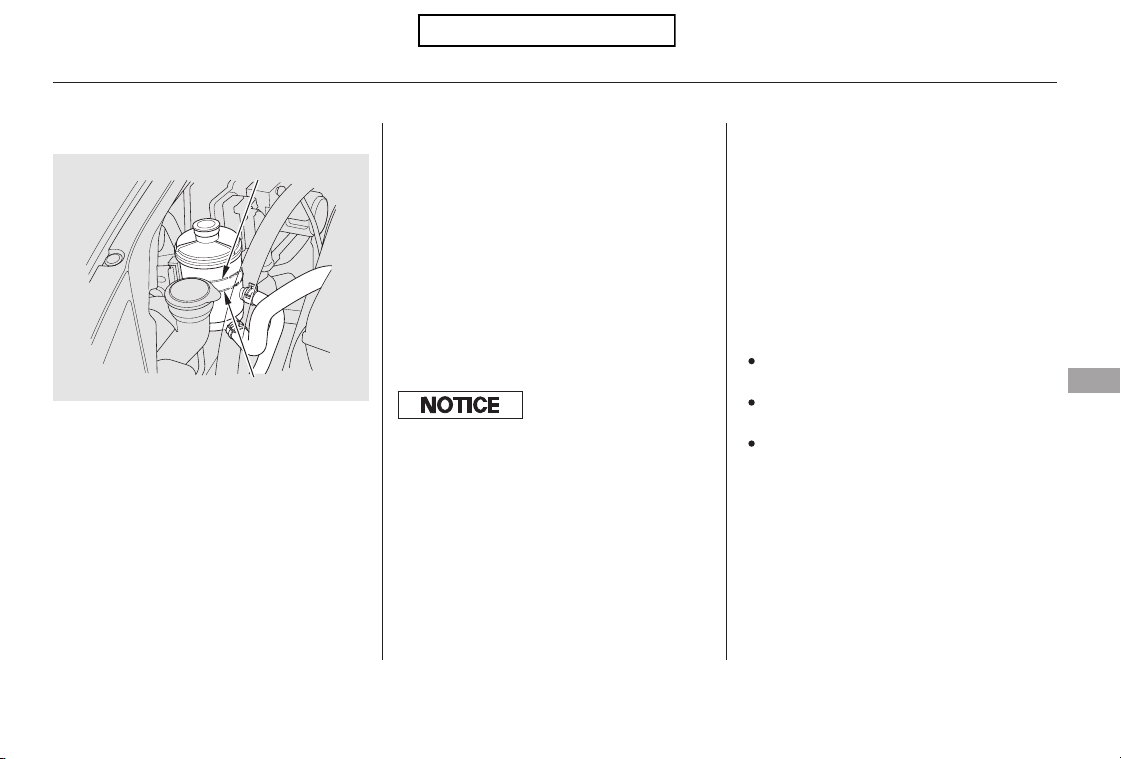
−−
Always use Honda Power Steering
Fluid. You may use another power
steering fluid as an emergency
replacement, but have the power
steering system flushed and refilled
with Honda PSF as soon as possible.
A low power steering fluid level can
indicate a leak in the system. Check
the fluid level frequently, and have
the system inspected as soon as
possible.
Pour the fluid slowly and carefully
so you do not spill any. Clean up
any spills immediately; it could
damage components in the engine
compartment.
Check the level on the side of the
reservoir when the engine is cold.
The fluid should be between the
UPPER LEVEL and LOWER LEVEL.
If not, add power steering fluid to the
UPPER LEVEL.
The timing belt should be replaced
according to the maintenance
minder (see page ).
Replace the timing belt every 60,000
miles (U.S.) or every 100,000 km
(Canada) if you regularly drive your
vehicle in any of the following
conditions:
In very high temperatures
(over 110°F, 43°C).
In very low temperatures
(under 20°F, 29°C).
Frequently towing a trailer.
331
Timing BeltPower Steering Fluid
Power Steering Fluid, Timing Belt
Maintenance
343
UPPER LEVEL
LOWER LEVEL
Turning the steering wheel to f ull lef t
or right lock and holding it there can
damage the power steering pump.
Table of Contents
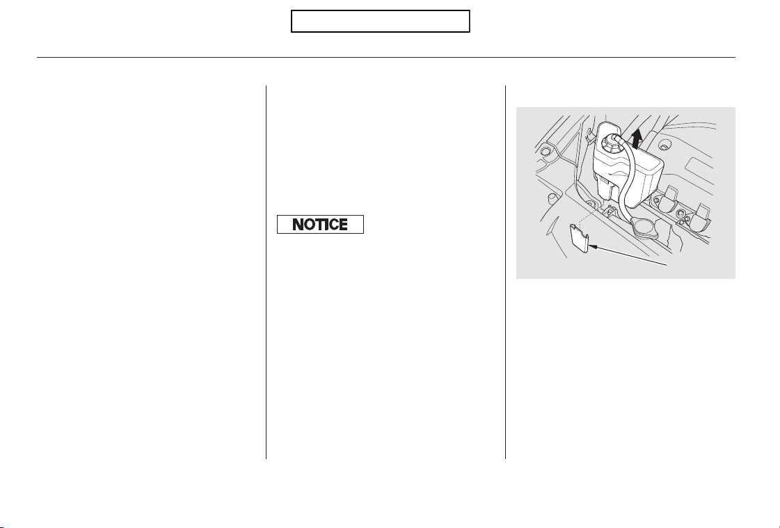
Your vehicle has halogen headlight
bulbs. When replacing a bulb, handle
it by its base, and protect the glass
from contact with your skin or hard
objects. If you touch the glass, clean
it with denatured alcohol and a clean
cloth.
Open the hood.
To change a bulb on the
passenger’s side, remove the
engine coolant reserve tank by
pulling it out of its stay.
Theheadlightswereproperlyaimed
when your vehicle was new. If you
regularly carry heavy items in the
cargo area or pull a trailer,
readjustment may be required.
Adjustmentsshouldbedonebyyour
dealer or another qualified
technician.
1.
Headlight Aiming Replacing a Headlight Bulb
High Beam Headlight
Lights
344
STAY
Halogen headlight bulbs get very hot
when lit. Oil, perspiration, or a scratch
on the glass can cause the bulb to
overheat and shatter.
Table of Contents
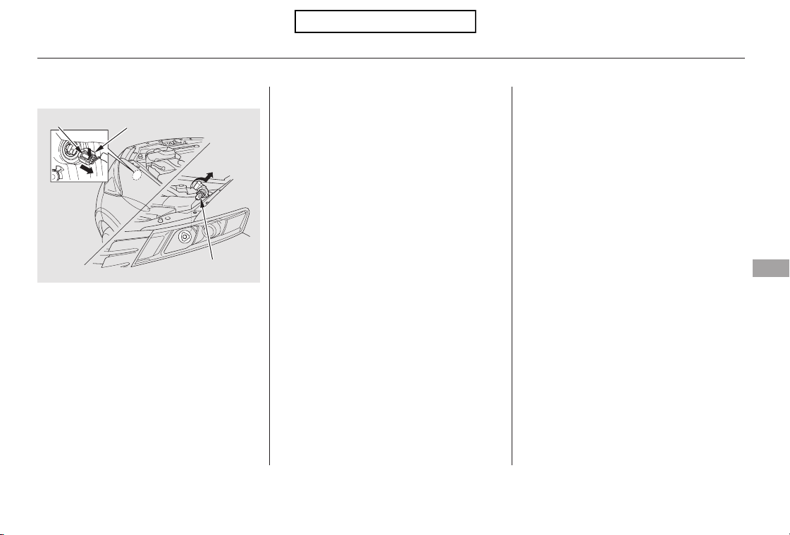
Remove the electrical connector
from the bulb by pushing on the
tab to unlock it, then slide the
connector off the bulb.
Remove the bulb by turning it
approximately one-quarter turn
counterclockwise.
Turn on the headlights to test the
new bulb.
Reinstall the engine coolant
reserve tank.
Push the electrical connector onto
the bulb.
Install the new bulb, and turn it
one-quarter turn clockwise to lock
it in place.
3.
2.
4.
5.
6.
CONTINUED
Passenger’s side
Lights
Maintenance
345
TAB
ELECTRICAL CONNECTOR
BULB
Table of Contents
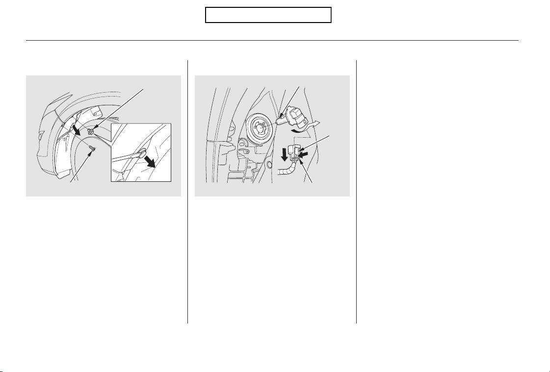
To change the passenger’s side
bulb, start the engine, turn the
steering wheel all the way to the
left, and turn off the engine. To
change the driver’s side bulb, turn
the steering wheel to the right.
Use a flat-tip screwdriver to
remove the holding clip from the
inner fender, and remove the
screw with a Phillips-head
screwdriver.
Pull the inner fender cover away
from the fender and bumper.
Remove the electrical connector
from the bulb by pushing on the
tab to unlock it, then slide the
connector off the bulb.
Remove the bulb by turning it
approximately one-quarter turn
counterclockwise.
Install the new bulb, and turn it
one-quarter turn clockwise to lock
it in place.
Push the electrical connector onto
the bulb.
Turn on the headlights to test the
new bulb.
Put the inner fender cover in place.
Install the holding clip. Lock it in
placebypushingonthecenter.
Tighten the screw securely.
3.
4.
5.
1.
2.
6.
7.
8.
9.
Low Beam Headlight
Lights
346
BULB
TAB
SCREW
HOLDING CLIP
ELECTRICAL CONNECTOR
Table of Contents
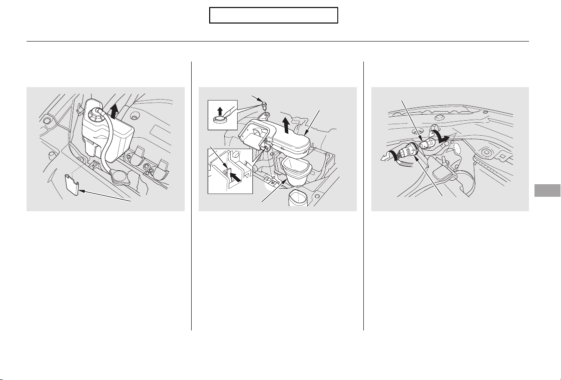
Remove the socket from the
headlight assembly by turning it
one-quarter turn counterclockwise.
To remove the burned out bulb,
push it in and turn it
counterclockwise until it unlocks.
Open the hood.
To change the turn signal bulb on
the passenger’s side, remove the
engine coolant reserve tank by
pulling it out of its stay.
To change a bulb on the driver’s side,
remove the fastener with a flat-tip
screwdriver, and remove the splash
separator by pushing the tab. Then
remove the duct.
1. 2.
3.
CONTINUED
Lights
Replacing a Front Turn Signal/
Parking Light Bulb
Maintenance
347
STAY
DUCT
TAB
BULB
SOCKET
SPLASH
SEPARATOR
FASTENER
Table of Contents
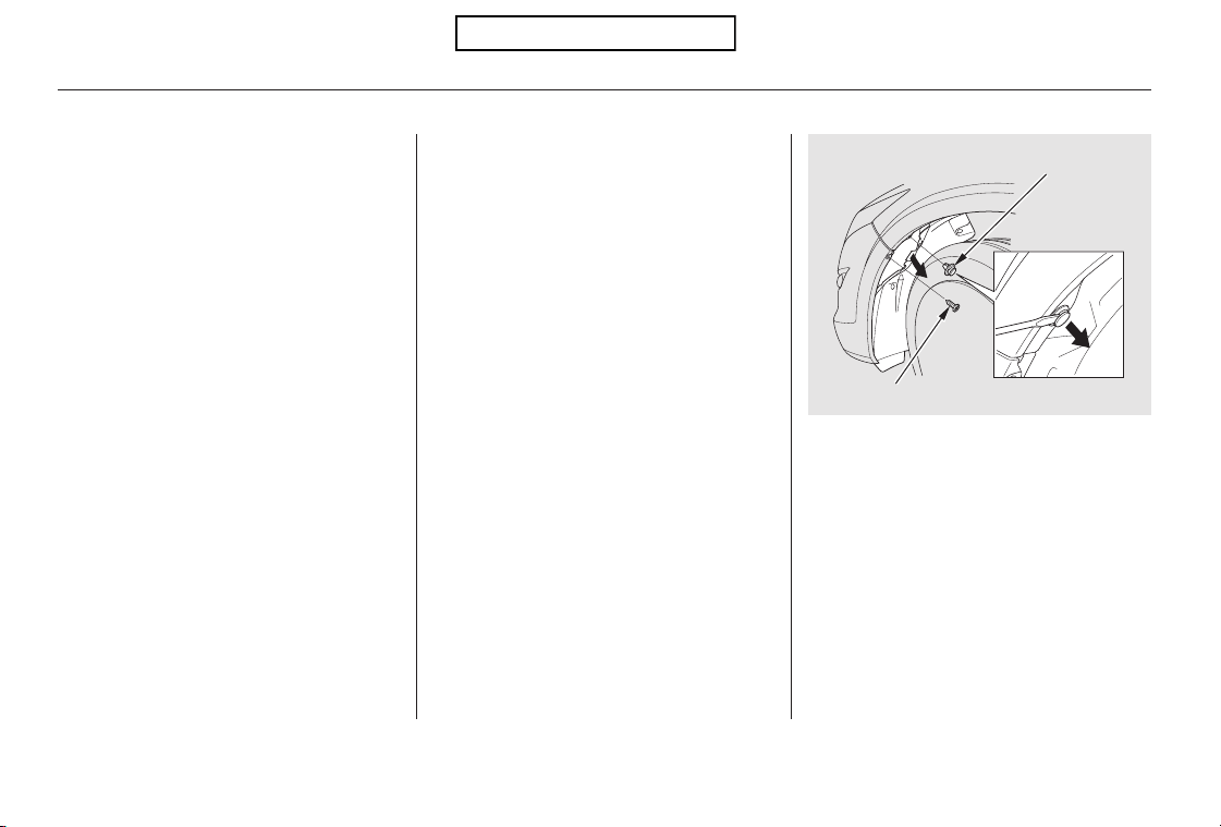
Install the new bulb and turn it
clockwise to lock it in place.
Turn on the lights to make sure
the new bulb is working.
Insert the socket back into the
headlight assembly. Turn it
clockwise to lock it in place.
Reinstall the coolant reserve tank.
Use a flat-tip screwdriver to
remove the holding clip from the
inner fender, and remove the
screw with a Phillips-head
screwdriver.
To change the bulb on the driver’s
side, start the engine, turn the
steering wheel all the way to the
right, then turn off the engine. To
change the bulb on the passenger’s
side, turn the steering wheel to the
left.
Reinstall the splash separator and
duct securely. Reinstall the
fastener and secure it by pushing
on the head until it locks.
6.
1.
7.
5.
4.
2.
Passenger’s side
Driver’s Side
Replacing a Front Side Marker
Light Bulb
Lights
348
SCREW
HOLDING CLIP
Table of Contents
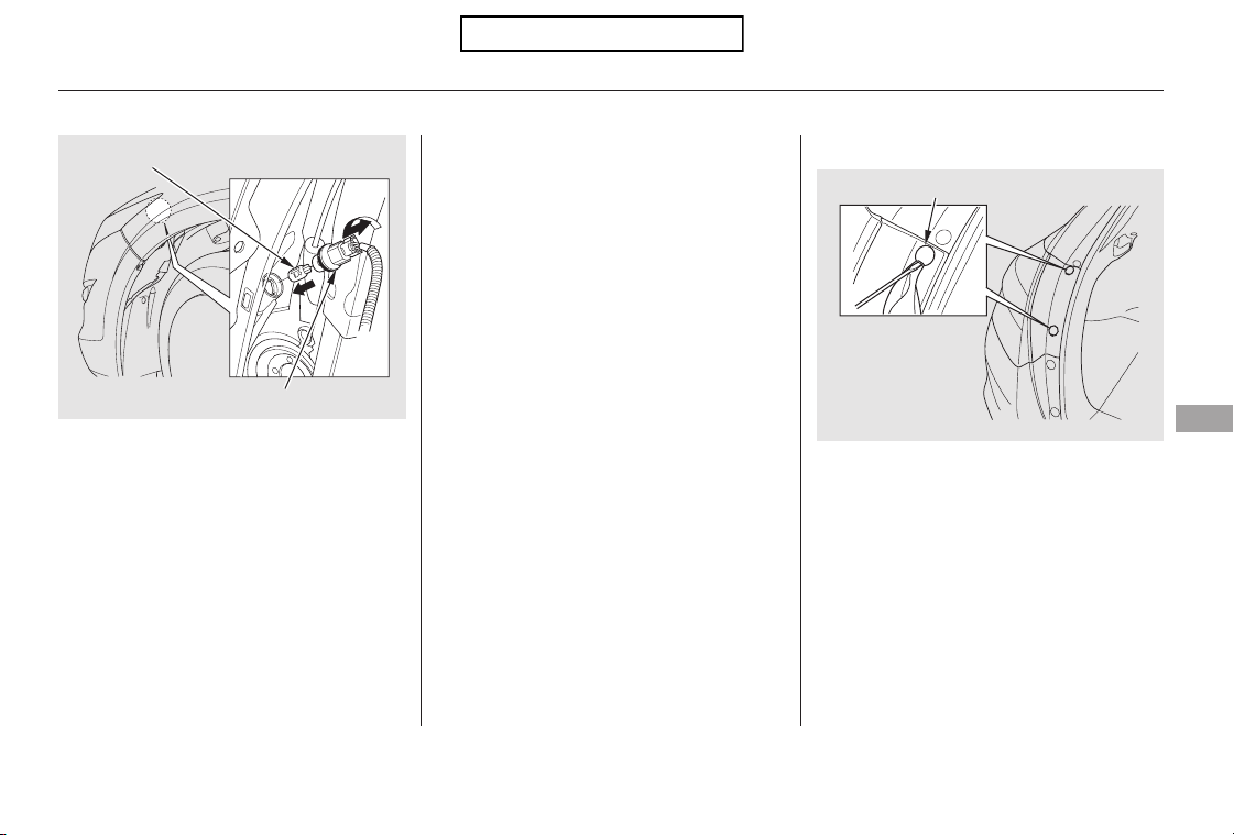
CONTINUED
Open the tailgate. Place a cloth on
the edge of the cover to prevent
scratches. Remove the covers by
carefully prying on the edge with a
small flat-tip screwdriver.
Insert the socket back into the
headlight assembly. Turn it
clockwise to lock it in place.
Turn on the lights to make sure
the new bulb is working.
Put the inner fender cover in place.
Install the holding clip. Lock it in
placebypushingonthecenter.
Tighten the screw securely.
Remove the socket from the
headlight assembly by turning it
one-quarter turn counterclockwise.
Pull the burned out bulb straight
out of its socket.
Push the new bulb straight into
the socket until it bottoms.
5.
6.
7.
1.
3.
4.
Replacing Rear Bulbs
Lights
Maintenance
349
SOCKET
COVER
BULB
Table of Contents
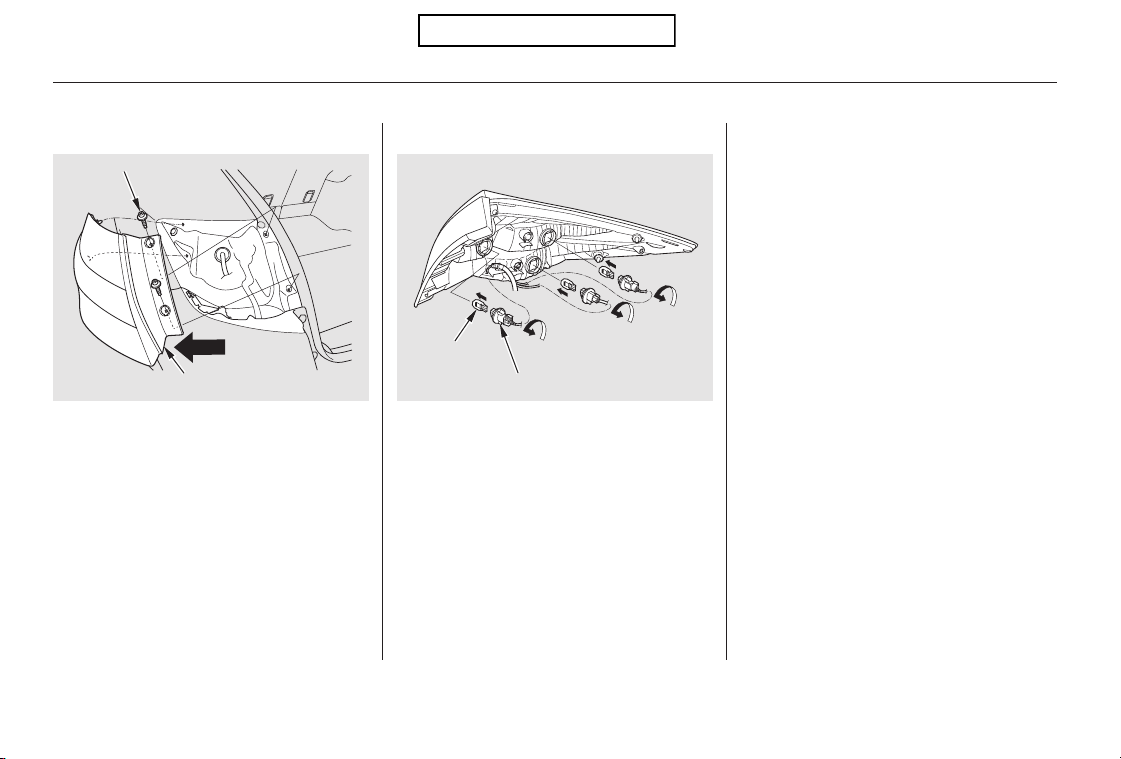
Turn on the lights to make sure
the new bulb is working.
Align the clips on the taillight
assembly with the holes in the
body, then push the taillight
assembly into place. Tighten the
two mounting screws securely and
reinstall the covers.
Use a Phillips-head screwdriver to
remove the taillight assembly
mounting screw under each cover.
Pull the taillight assembly out of
thebodybyslidingitoutside.
Determine which of the three
bulbs is burned out: stop/taillight,
back-up light or turn signal light.
Remove the socket by turning it
one-quarter turn counterclockwise.
Pull the bulb straight out of its
socket. Push the new bulb straight
into the socket until it bottoms.
Insert the socket back into the
light assembly. Turn it clockwise
to lock it in place.
8.
9.
2.
3.
4.
5.
6.
7.
Lights
350
BULB
SCREW
SOCKET
TAILLIGHT ASSEMBLY
Table of Contents
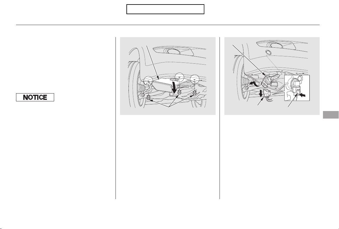
Pull down the under cover from
the bumper carefully.
Remove the electrical connector
from the bulb by pushing on the
tab to unlock it, then slide the
connector off the bulb.
Remove the bulb by turning it
about one-quarter turn
counterclockwise.
Your vehicle uses halogen light
bulbs. When replacing a bulb, handle
it by its plastic case, and protect the
glass from contact with your skin or
hard objects. If you touch the glass,
clean it with denatured alcohol and a
clean cloth.
Thefoglightswereproperlyaimed
when your vehicle was new. If you
regularly carry heavy items in the
cargo area or pull a trailer,
readjustment may be required.
Adjustment should be done by your
dealer or another qualified
technician.
Remove the three holding clips
with a flat-tip screwdriver.
1.
2.
3.
CONTINUED
Passenger’s side
ReplacingaFogLightBulb
Lights
Maintenance
351
ELECTRICAL
CONNECTOR
TAB
UNDER COVER
BULB
HOLDING CLIPS
Halogen light bulbs get very hot when
lit. Oil, perspiration, or a scratch on
the glass can cause the bulb to overheat
and shatter.
Table of Contents

To change the bulb, start the
engine, turn the steering wheel all
the way to the right, then turn off
the engine.
Remove the electrical connector
from the bulb by pushing on the
tab and pulling the connector
down.
Remove the bulb from the fog
light assembly by turning it one-
quarter turn counterclockwise.
Use a flat-tip screwdriver to
remove the holding clip from the
inner fender, and remove the
screw with a Phillips-head
screwdriver.
Push the electrical connector back
onto the bulb. Make sure it is on
all the way.
Turn on the fog lights to test the
new bulb.
Put the inner fender cover in place.
Install the holding clip. Lock it in
placebypushingonthecenter.
Tighten the screw securely.
Insert the new bulb into the hole,
and turn it one-quarter turn
clockwise to lock it in place.
Reinstall the under cover and
holdingclips,andthenpushinthe
head of each clip.
6.
7.
8.
4.
5.
9.
11.
10.
Passenger’s side
Driver’s side
Driver’s side
Driver’s and Passenger’s side
Lights
352
ELECTRICAL CONNECTOR TAB
SCREW
BULB
HOLDING CLIP
Table of Contents
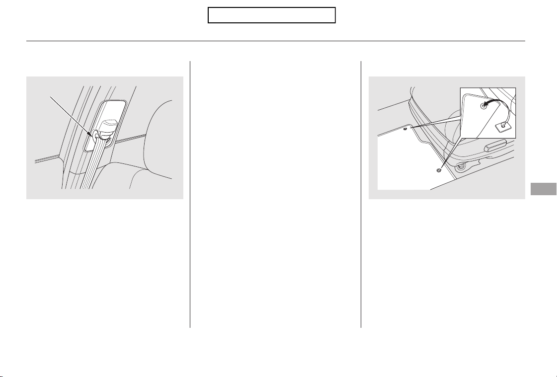
If your seat belts get dirty, use a soft
brush with a mixture of mild soap
and warm water to clean them. Do
not use bleach, dye, or cleaning
solvents. Let the belts air-dry before
you use the vehicle.
Dirt build-up around the openings of
the seat belt anchors can cause the
belts to retract slowly. Wipe the
openings with a clean cloth
dampened in mild soap and warm
water or isopropyl alcohol.
The driver’s floor mat that came
with your vehicle hooks over the
floor mat anchors. This keeps the
floor mat from sliding forward and
possibly interfering with the pedals
or making the front passenger’s
weight sensors ineffective.
CONTINUED
2WD models
Cleaning the Seat Belts Floor Mats
Cleaning the Seat Belts, Floor Mats
Maintenance
353
OPENING
Table of Contents

This filter removes the dust and
pollenthatisbroughtinfromthe
outside through the climate control
system.
Have your dealer replace this filter
when this service is indicated by a
maintenance message on the
information display. It should be
replaced every 15,000 miles (24,000
km) if you drive primarily in urban
areas that have high concentrations
of soot in the air, or if the flow from
theclimatecontrolsystembecomes
less than usual.
If you remove a floor mat, make sure
tore-anchoritwhenyouputitback
in your vehicle.
If you use a non-Honda floor mat,
make sure it fits properly and that it
canbeusedwiththefloormat
anchors. Do not put additional floor
mats on top of the anchored mat.
Make sure the rear floor mats are
properly positioned. If not, the floor
mat will interfere with the seat
operation and make the front
passenger’s weight sensors
ineffective.
When cleaning or replacing, turn the
knob counterclockwise to unhook
the floor mat.
The driver’s floor mat that came
with your vehicle hooks over the
floor mat anchors. To lock each
anchor, turn the knob clockwise.
This keeps the floor mat from sliding
forward and possibly interfering with
the pedals.
4WD models
Floor Mats, Dust and Pollen Filter
Dust and Pollen Filter
354
Unlock
Lock
KNOB
ANCHOR
Table of Contents
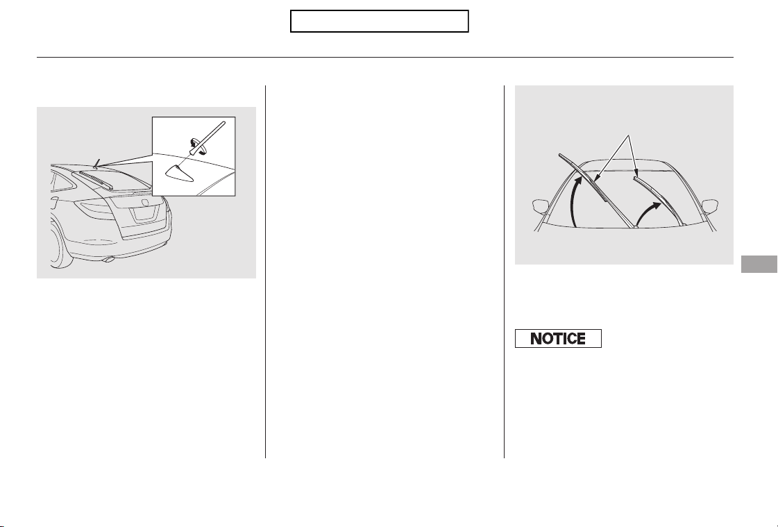
CONTINUED
Beforeusinganautomaticcarwash,
remove the audio antenna so it does
not get damaged. Remove the
antenna by unscrewing it. When you
reinstall the antenna, tighten it
securely.
Before entering or parking in areas
with low ceiling height, remove the
antenna.
Check the condition of the wiper
blades at least every six months.
Replace them if you find signs of
cracking in the rubber, areas that are
getting hard, or if they leave streaks
and unwiped areas when used.
To replace front and rear wiper
blade:
Raise the wiper arm off the
windshield.
Raise the driver’s side first, then the
passenger’s side.
1.
Front wiper arm
Audio Antenna, Wiper Blades
Audio Antenna Wiper Blades
Maintenance
355
WIPER ARMS
Front
Do not open the hood when the wiper
arms are raised, or you will damage the
hood and wiper arms.
Table of Contents
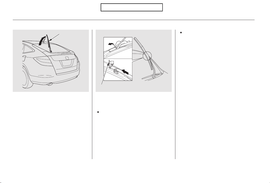
Pivot the blade assembly toward
the wiper arm until it releases
from the wiper arm.
When replacing a wiper blade,
make sure not to drop the wiper
blade or wiper arm down on the
windshield.
Disconnect the blade assembly
from the wiper arm:
Put a cloth on the edge of the lock
tab to prevent scratches, then
push up on the lock tab carefully
with a flat-tip screwdriver.
2.
Wiper Blades
356
WIPER ARM
LOCK TAB
Rear
Table of Contents
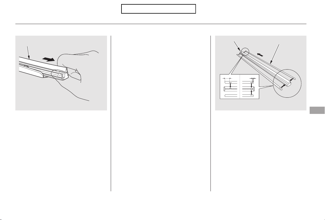
CONTINUED
Remove the blade from its holder
by grabbing the tabbed end of the
blade. Pull firmly until the tabs
come out of the holder.
Make sure the three rubber tabs
inside the blade fit to each notch of
the reinforcement, as shown.
Examine the new wiper blades. If
they have no plastic or metal
reinforcement along the back
edge, remove the metal
reinforcement strips from the old
wiper blade, and install them in
the slots along the edge of the new
blade.
3.
4.
Wiper Blades
Maintenance
357
BLADE
BLADE
REINFORCEMENT
TOP
Table of Contents
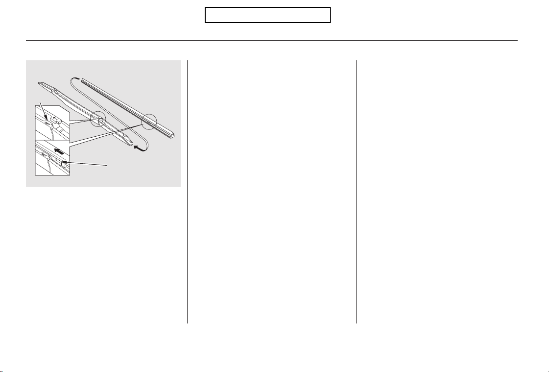
Place the top of the wiper blade on
the end of the blade assembly, and
slide the blade onto the assembly
in the direction pointed to by the
arrow.
Slide the wiper blade assembly
onto the wiper arm. Push down
thelocktab.Makesurethewiper
blade assembly locks in place.
Make sure the tab on the blade
assembly fits in the indent of the
wiper blade and the blade is
completely installed.
Lower the wiper arm down against
the windshield.
Lower the passenger’s side first,
then the driver’s side.
5.
6.
7.
Front wiper arm
Wiper Blades
358
INDENT
TAB
Table of Contents
Keeping the tires properly inflated
provides the best combination of
handling, tread life, and riding
comfort.
Underinflated tires wear unevenly,
adversely affect handling and fuel
economy, and are more likely to
fail from being overheated.
To safely operate your vehicle, your
tires must be the proper type and
size, in good condition with adequate
tread, and correctly inflated.
The following pages give more
detailed information on how to take
care of your tires and what to do
when they need to be replaced.
Overinflated tires can make your
vehiclerideharshly,aremore
prone to damage from road
hazards, and wear unevenly.
Thetirepressuremonitoringsystem
(TPMS) warns you when a tire
pressure is low. See page for
more information.
Use a gauge to measure the air
pressure in each tire at least once a
month. Even tires that are in good
condition may lose 1 to 2 psi (10 to
20 kPa, 0.1 to 0.2 kgf/cm ) per
month. Remember to check the
sparetireatthesametime.
Even though your vehicle is
equipped with TPMS, we
recommend that you visually check
your tires every day. If you think a
tire might be low, check it
immediately with a tire gauge.
Check the air pressures when the
tires are cold. This means the
vehicle has been parked for at least 3
hours, or driven less than 1 mile (1.6
km). Add or release air, if needed, to
match the recommended cold tire
pressures on the next page.
313
CONTINUED
Inflation Guidelines
Tires
Maintenance
359
Using tires that are excessively
worn or improperly inflated can
cause a crash in which you can
be seriously hurt or killed.
Follow all instructions in this
owner’s manual regarding tire
inflation and maintenance.
Table of Contents
*
*
*
*
The following chart shows the
recommended cold tire pressures for
most normal driving conditions.
If you check air pressures when the
tires are hot (driven for several
miles/kilometers), you will see
readings 4 to 6 psi (30 to 40 kPa, 0.3
to 0.4 kgf/cm ) higher than the cold
readings.Thisisnormal.Donotlet
air out to match the recommended
cold air pressure. The tire will be
underinflated.
While tubeless tires have some
ability to self-seal if they are
punctured, you should look closely
for punctures if a tire starts losing
pressure.
Youshouldgetyourowntire
pressure gauge and use it whenever
you check your tire pressures. This
will make it easier for you to tell if a
pressure loss is due to a tire problem
and not due to a variation between
gauges.
Thecompactsparetirepressureis:
For convenience, the recommended
tire sizes and cold tire pressures are
on a label on the driver’s doorjamb.
For additional information about
your tires, see page .406
Tire Size Cold Tire Pressure
for Normal Driving
Front/Rear:
Front/Rear:
1:EX
2:EX-L
Recommended Tire Pressures
Tires
360
60 psi (420 kPa , 4.2 kgf/cm )
225/65R17 102T
32 psi (220 kPa ,
2.2 kgf/cm
)
225/60R18 100H
32 psi (220 kPa ,
2.2 kgf/cm )
2
1
Table of Contents
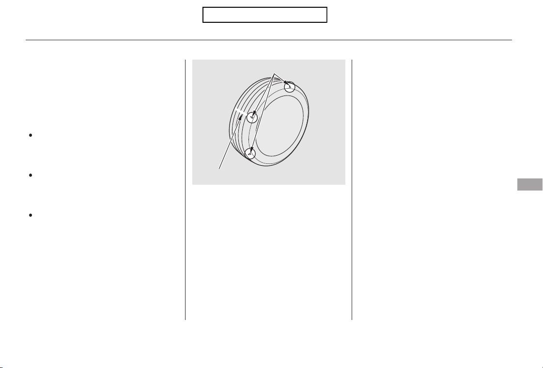
Every time you check inflation, you
should also examine the tires for
damage, foreign objects, and wear.
Youshouldlookfor:
Bumps or bulges in the tread or
side of the tire. Replace the tire if
youfindeitheroftheseconditions.
Cuts, splits, or cracks in the side
of the tire. Replace the tire if you
can see fabric or cord.
Excessive tread wear.
Your tires have wear indicators
molded into the tread. When the
tread wears down, you will see a 1/2
inch (12.7 mm) wide band across the
tread. This shows there is less than
1/16 inch (1.6 mm) of tread left on
the tire.
A tire this worn gives very little
traction on wet roads. You should
replace the tire if you can see three
or more tread wear indicators.
Tires
Tire Inspection
Maintenance
361
TREAD WEAR INDICATOR
INDICATOR LOCATION MARKS
Table of Contents

In addition to proper inflation,
correct wheel alignment helps to
decrease tire wear. If you find a tire
is worn unevenly, have your dealer
check the wheel alignment.
Have your dealer check the tires if
you feel a consistent vibration while
driving. A tire should always be
rebalanced if it is removed from the
wheel. When you have new tires
installed, make sure they are
balanced. This increases riding
comfort and tire life. For best results,
have the installer perform a dynamic
balance.
The service life of your tires is
dependent on many factors,
including, but not limited to, driving
habits, road conditions, vehicle
loading, inflation pressure,
maintenance history, speed, and
environmental conditions (even
when the tires are not in use).
In addition to your regular
inspections and inflation pressure
maintenance, it is recommended that
you have annual inspections
performed once the tires reach five
years old. It is also recommended
that all tires, including the spare, be
removed from service after 10 years
from the date of manufacture,
regardless of their condition or state
of wear.
The last four digits of the TIN (tire
identification number) are found on
the sidewall of the tire and indicate
the date of manufacture (See
on page ).406
Tires
Tire MaintenanceTire Service Life
Tire
Labeling
362
Table of Contents
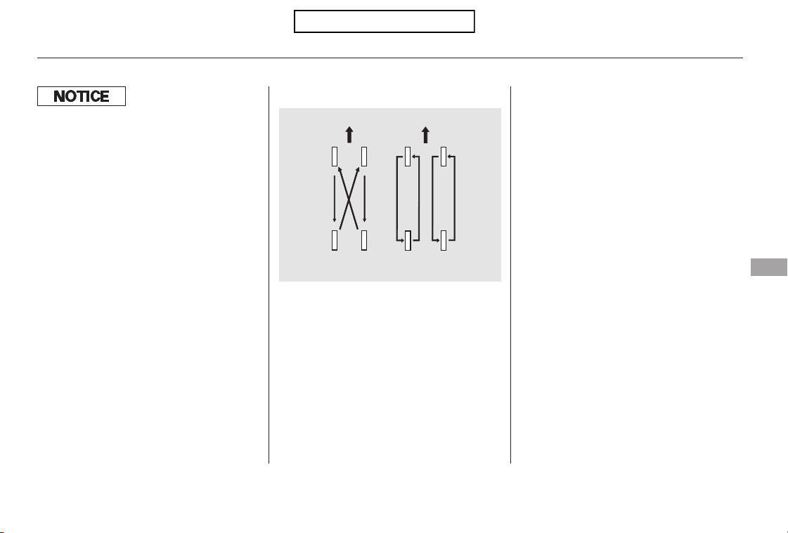
To help increase tire life and
distribute wear more evenly, rotate
the tires according to the
maintenance messages displayed on
the information display.
Move the tires to the positions
shown in the illustration each time
they are rotated. If you purchase
directional tires, rotate only front-to-
back.
When the tires are rotated, make
sure the air pressures are checked.
Tire Rotation
Tires
Maintenance
363
(For Non-directional
Tires and Wheels)
(For Directional
Tires and Wheels)
FrontFront
Improper wheel weights can damage
your vehicle’s aluminum wheels. Use
only Honda wheel weights f or
balancing.
Table of Contents
Replace your tires with radial tires of
the same size, load range, speed
rating, and maximum cold tire
pressure rating (as shown on the
tire’s sidewall).
Mixing radial and bias-ply tires on
your vehicle can reduce braking
ability, traction, and steering
accuracy. Using tires of a different
size or construction can cause the
ABS and vehicle stability assist
system (VSA) to work inconsistently.
Replacement wheels are available at
your dealer.
It is best to replace all four tires at
thesametime.Ifthatisnotpossible
or necessary, replace the two front
tires or two rear tires as a pair.
Replacing just one tire can seriously
affect your vehicle’s handling.
If you ever replace a wheel, make
sure that the wheel’s specifications
match those of the original wheels.
Also be sure you use only TPMS
specific wheels. If you do not, the
tire pressure monitoring system will
notworkonthattire.
The ABS and VSA system work by
comparing the speed of each wheel.
When replacing tires, use the same
size originally supplied with the
vehicle. Tire size and construction
can affect wheel speed and may
cause the system to activate.
Replacing Tires and Wheels
Tires
364
Installing improper tires on your
vehicle can affect handling and
stability. This can cause a crash
in which you can be seriously
hurt or killed.
Always use the size and type of
tires recommended in this
owner’s manual.
Table of Contents

+Tires marked ‘‘M S’’ or ‘‘All
Season’’ on the sidewall have an all-
weather tread design suitable for
most winter driving conditions.
For the best performance in snowy
or icy conditions, you should install
snow tires or tire chains. They may
be required by local laws under
certain conditions.
If you mount snow tires on your
vehicle, make sure they are radial
tires of the same size and load range
as the original tires. Mount snow
tires on all four wheels. The traction
provided by snow tires on dry roads
maybelowerthanyouroriginaltires.
Check with the tire dealer for
maximum speed recommendations.
Mount tire chains on your tires when
required by driving conditions or
local laws. Install them only on the
front tires.
Because your vehicle has limited tire
clearance, Honda strongly
recommends using the chains listed
below, made by Security Chain
Company (SCC).
See page for DOT tire quality
grading information, and page
for tire size information.
Tires
Wheels
Cable-type:
Cable-type:
EX:
EX-L:
EX:
EX-L:
SCC Radial Chain
SC1042
404
406 Radial Chain
TC2111MM
CONTINUED
EX
EX-L
Wheel and Tire Specifications Winter Driving
Snow Tires
Tire Chains
Tires
Maintenance
365
17x61/2J
18x7J
225/65R17 102T
225/60R18 100H
Table of Contents
Clean the wheels as you would the
rest of the exterior. Wash them with
thesamesolution,andrinsethem
thoroughly.
Aluminum alloy wheels have a
protective clear-coat that keeps the
aluminum from corroding and
tarnishing. Cleaning the wheels with
harsh chemicals (including some
commercial wheel cleaners) or a stiff
brush can damage the clear-coat. To
clean the wheels, use a mild
detergent and a soft brush or sponge.
When installing chains, follow the
manufacturer’s instructions, and
mount them as tight as you can.
Make sure they are not contacting
the brake lines or suspension. Drive
slowly with them installed. If you
hear them coming into contact with
the body or chassis, stop and
investigate. Remove them as soon as
you begin driving on cleared roads.
Wheels
Tires
366
Using the wrong chains, or not
properly installing chains, can
damage the brake lines and
cause a crash in which you can
be seriously injured or killed.
Follow all instructions in this
owner’s manual regarding the
selection and use of tire chains.
Traction devices that are the wrong
size or improperly installed can
damage your vehicle’s brake lines,
suspension, body, and wheels. Stop
driving if they are hitting any part of
the vehicle.
Table of Contents
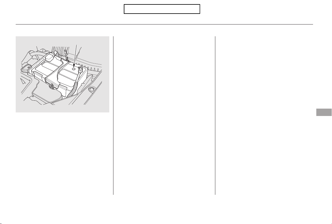
−Check the condition of the battery
monthlybylookingatthetest
indicator window. The label on the
battery explains the test indicator’s
colors.
Battery posts,
terminals, and related accessories
contain lead and lead compounds.
If you need to connect the battery to
a charger, disconnect both cables to
prevent damaging your vehicle’s
electrical system. Always disconnect
the negative ( ) cable first, and
reconnect it last.
If additional battery maintenance is
needed, see your dealer or a
qualified mechanic.
The location of the test indicator
window varies between
manufacturers.
Check the terminals for corrosion (a
white or yellowish powder). To
remove it, cover the terminals with a
solution of baking soda and water. It
will bubble up and turn brown. When
this stops, wash it off with plain
water. Dry off the battery with a
cloth or paper towel. Coat the
terminals with grease to help prevent
future corrosion.
CONTINUED
WARNING:
Wash your hands af ter handling.
Checking the Battery
Maintenance
367
TEST INDICATOR WINDOW
Table of Contents
Fill the fuel tank.
Wash and dry the exterior
completely.
Clean the interior. Make sure the
carpeting, floor mats, etc., are
completely dry.
If you need to park your vehicle for
an extended period (more than 1
month), there are several things you
should do to prepare it for storage.
Proper preparation helps prevent
deterioration and makes it easier to
get your vehicle back on the road. If
possible, store your vehicle indoors.
If your vehicle’s battery is
disconnected, or goes dead, the time
setting may be lost. To reset the time,
see page .
If your vehicle’s battery is
disconnected or goes dead, the audio
system may disable itself. The next
timeyouturnontheradio,youwill
see ‘‘ENTER CODE’’ in the
frequency display. Use the preset
buttons to enter the code (see page
).
The navigation system will also
disableitself.Thenexttimeyouturn
on the ignition switch, the system
will require you to enter a PIN
before it can be used. Refer to the
navigation system manual.
240
239
On models with navigation system
Checking the Battery, Vehicle Storage
Vehicle Storage
368
The battery gives off explosive
hydrogen gas during normal
operation.
A spark or flame can cause the
battery to explode with enough
force to kill or seriously hurt you.
Wear protective clothing and a
face shield, or have a skilled
technician do the battery
maintenance.
Table of Contents
Leave the parking brake off. Put
the transmission in Park.
Block the rear wheels.
If the vehicle is to be stored for a
longer period, it should be
supported on jackstands so the
tires are off the ground.
Leave one window open slightly (if
the vehicle is being stored
indoors).
Disconnect the battery.
Support the front and rear wiper
blade arms with a folded towel or
ragsotheydonottouchthe
windshield.
To minimize sticking, apply a
silicone spray lubricant to all door
and tailgate seals. Also, apply a
vehiclebodywaxtothepainted
surfaces that mate with the door
and tailgate seals.
Cover the vehicle with a
‘‘breathable’’ cover, one made
from a porous material such as
cotton. Non-porous materials, such
as plastic sheeting, trap moisture,
which can damage the paint.
If possible, periodically run the
engine until it reaches full
operating temperature (the
cooling fans cycle on and off
twice). Preferably, do this once a
month.
Vacuum dirt and dust from the
leather frequently. Pay close
attention to the pleats and seams.
Clean the leather with a soft cloth
dampened with a 90% water and 10%
neutral wool detergent solution.
Then buff it with a clean, dry cloth.
Remove any dust or dirt on leather
surfaces immediately.
EX-L models
Vehicle Storage, Interior Care
Leather
Maintenance
369
Table of Contents

This section covers the more
common problems that motorists
experience with their vehicles. It
gives you information about how to
safely evaluate the problem and what
to do to correct it. If the problem has
stranded you on the side of the road,
you may be able to get going again.
If not, you will also find instructions
on getting your vehicle towed.
......................
Compact Spare Tire . 372
....................Changing a Flat Tire . 373
.............If the Engine Won’t Start . 380
................................Jump Starting . 382
..............If the Engine Overheats . 384
.........Low Oil Pressure Indicator . 386
..........Charging System Indicator . 386
.......Malfunction Indicator Lamp . 387
...............Brake System Indicator . 388
Opening the Fuel Fill Door
....................................Manually . 389
..............................................Fuses . 390
..............................Fuse Locations . 394
......................Emergency Towing . 397
Taking Care of the Unexpected
Taking Care of the Unexpected
371
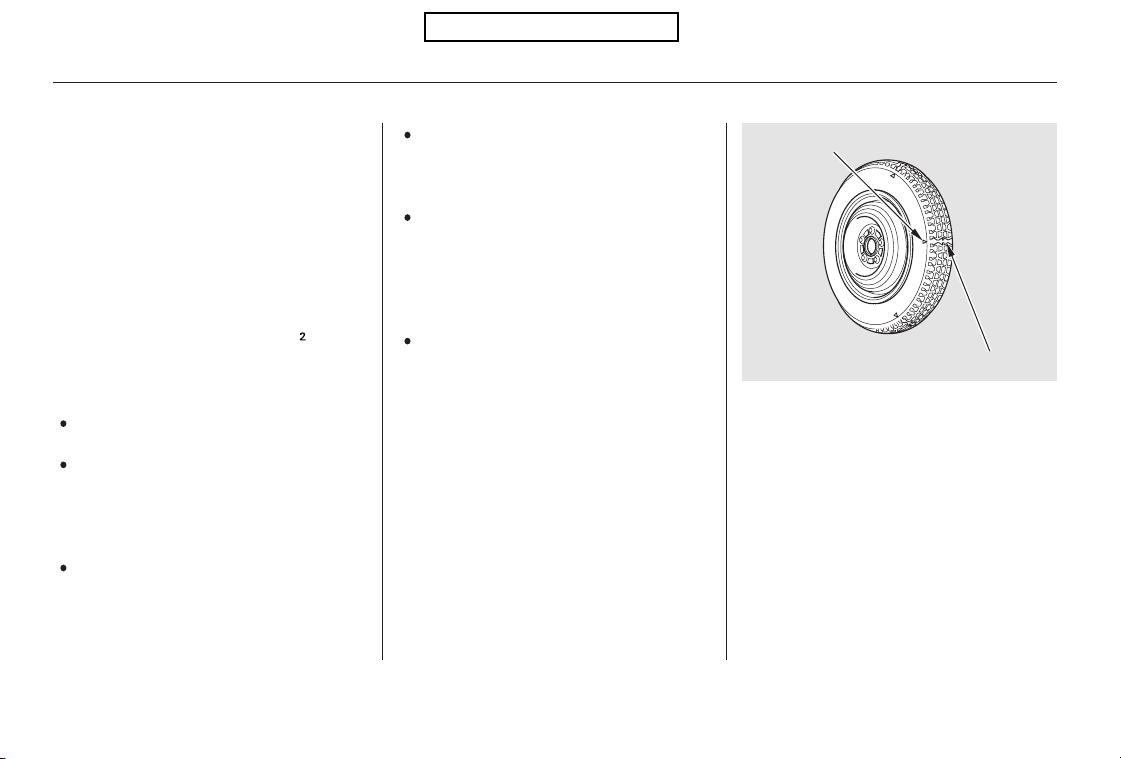
Check the air pressure of the
compact spare tire every time you
check the other tires. It should be
inflated to:
Replace the tire when you can see
the tread wear indicator bars. The
replacement should be the same size
and design tire, mounted on the
same wheel. The spare tire is not
designed to be mounted on a regular
wheel, and the spare wheel is not
designed for mounting a regular tire.
Use the compact spare tire as a
temporary replacement only. Get
your regular tire repaired or replaced,
and put it back on your vehicle as
soon as you can.
Follow these precautions:
Never exceed 50 mph (80 km/h).
This tire gives a harsher ride and
less traction on some road
surfaces. Use greater caution
while driving.
Do not mount snow chains on the
compact spare tire.
Do not use your compact spare
tire on another vehicle unless it is
thesamemakeandmodel.
Do not place the flat tire, a full size
tire of any kind, or a compact
spare from another vehicle in the
sparetireholder.Damagetothe
holder could result.
The low tire pressure indicator
comes on and stays on after you
replace the flat tire with the
compact spare tire. After several
miles (kilometers) driving with the
compact spare tire, the TPMS
indicator comes on and the low
tire pressure indicator goes off.
Compact Spare Tire
372
INDICATOR LOCATION MARK
TREAD WEAR INDICATOR BAR
60 psi (420 kPa , 4.2 kgf/cm )
Table of Contents
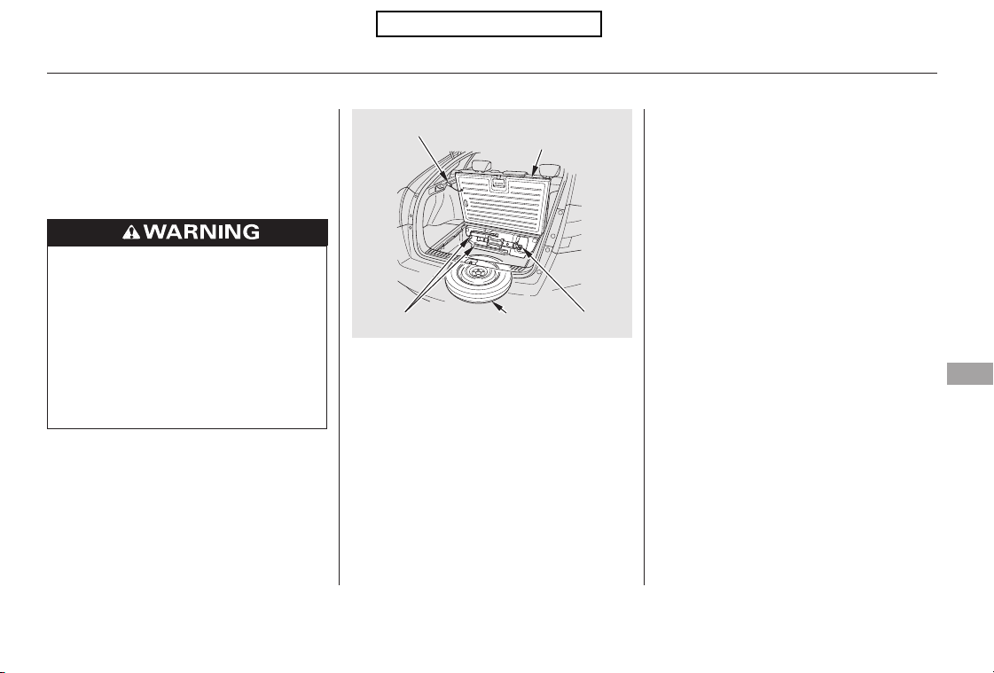
CONTINUED
If you have a flat tire while driving,
stop in a safe place to change it.
Drive slowly along the shoulder until
you get to an exit or an area to stop
that is far away from the traffic lanes.
Open the tailgate. Pull up the
handle on the cargo area floor lid.
Then remove the hook, and hook
it to the hole on the cargo side
panel (see page ).
Thetoolsandjackareunderthe
cargo area behind a cargo box.
Remove the cargo box by lifting it
up with the handle (see page ).
Take the jack, tools and the bag
out of the tool kit case.
Park the vehicle on firm, level, and
non-slippery ground. Put the
transmission in Park. Apply the
parking brake.
If you are towing a trailer, unhitch
it.
Turn on the hazard warning lights,
and turn the ignition switch to the
LOCK (0) position. Have all
passengers get out of the vehicle
while you change the tire.
5.
4.
3.
2.
1.
120
121
Changing a Flat Tire
Taking Care of the Unexpected
373
HOOK
CARGO AREA
FLOOR LID
JACKSPARE TIRE
TOOLS
The vehicle can easily roll off
the jack, seriously injuring
anyone underneath.
Follow the directions for
changing a tire exactly, and
never get under the vehicle
when it is supported only by the
jack.
Table of Contents
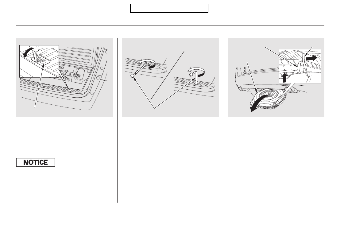
−
Attach the short end of the wheel
nut wrench to the spare tire holder
shaft. Turn the wrench
counterclockwise until the shaft
loosens. Then attach the longer
section of the wrench to the shaft,
andturnituntilyoucanseethe
sparetire(about65 70rotations).
Do not turn the wrench any
further once you feel resistance.
The spare tire is stored
underneath the cargo area.
Remove the plastic cover on the
cargo area lining to access the
shaft for the spare tire holder.
Lift up the spare tire holder, then
slide the hook and lift down the
sparetireholder.
Remove the spare tire from the
sparetireholder.
6.
7.
8.
9.
Changing a Flat Tire
374
WHEEL NUT WRENCH
SPARE TIRE
PLASTIC COVER
SPARE TIRE HOLDER HOOK
The wheel nut wrench supplied with
your vehicle is specially adapted to f it
the holder shaf t. Do not use any other
tool.
Table of Contents
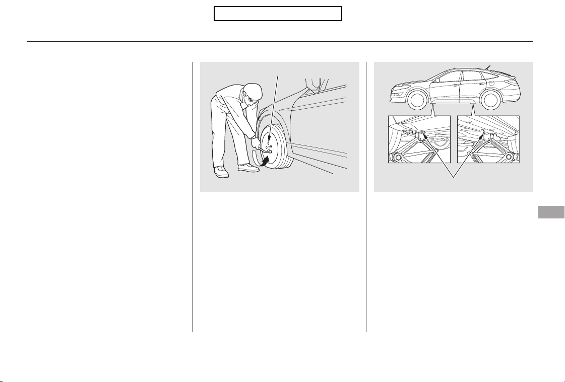
CONTINUED
Placethejackunderthejacking
point nearest the tire you need to
change. Turn the end bracket
clockwise until the top of the jack
contacts the jacking point. Make
sure the jacking point tab is
restinginthejacknotch.
Loosen each wheel nut 1/2 turn
with the wheel nut wrench.
To reinstall the spare tire holder,
slide the hook, lift up the spare tire
holder and attach it to the hook.
Attach the longer section of the
wrench to the spare tire holder
shaft. Turn the wrench clockwise.
Then attach the short end of the
wrench to the shaft, and tighten it
securely.
Reinstall the plastic cover.11.
10.
12. 13.
Changing a Flat Tire
Taking Care of the Unexpected
375
WHEEL NUT
JACKING POINTS
Table of Contents
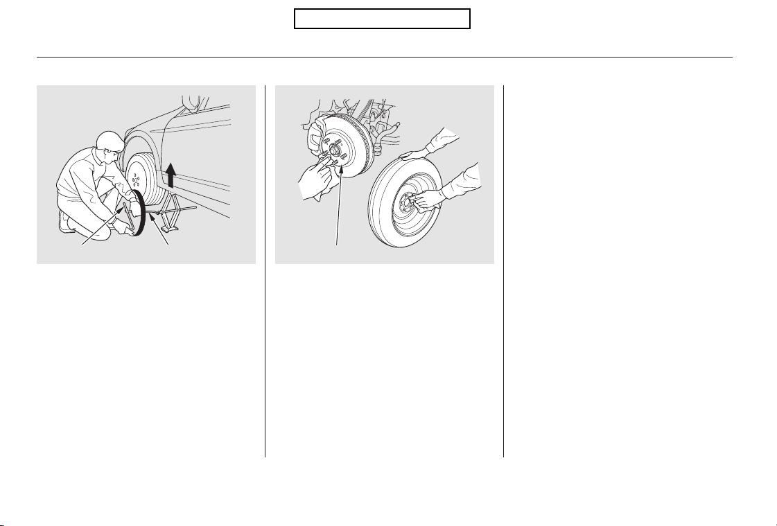
Before mounting the spare tire,
wipeanydirtoffthemounting
surface of the wheel and hub with
a clean cloth. Wipe the hub
carefully;itmaybehotfrom
driving.
Use the extension and the wheel
nut wrench as shown to raise the
vehicle until the flat tire is off the
ground.
Remove the wheel nuts, then
remove the flat tire. Handle the
wheel nuts carefully; they may be
hot from driving. Place the flat tire
on the ground with the outside
surface facing up.
Lower the vehicle to the ground,
and remove the jack.
Put on the spare tire. Put the
wheel nuts back on finger-tight,
then tighten them in a crisscross
pattern with the wheel nut wrench
until the wheel is firmly against
the hub. Do not try to tighten the
wheel nuts fully.
14.
15.
16.
17.
18.
Changing a Flat Tire
376
BRAKE HUB
WHEEL WRENCH
EXTENSION
Table of Contents
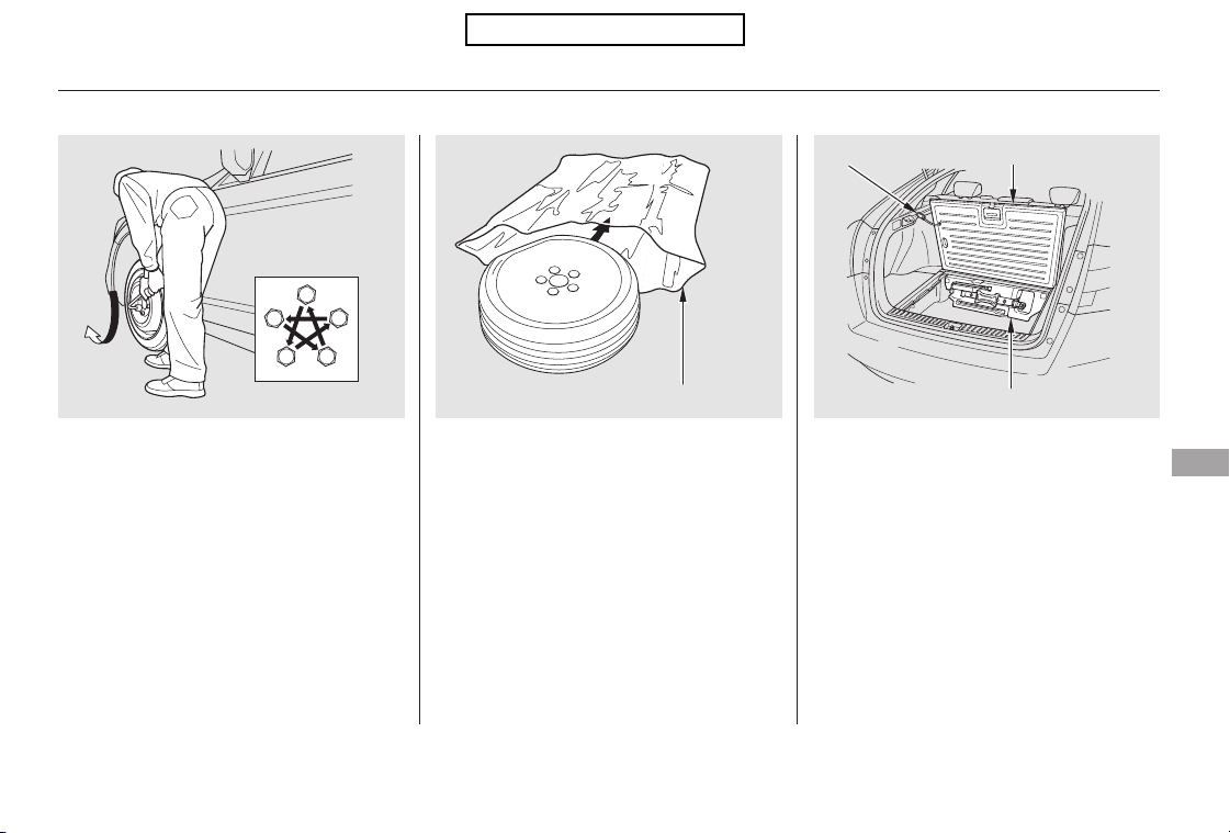
CONTINUED
Store the jack and tools in the tool
kit case.
Replace the cargo box. Remove
the hook and close the cargo area
floor lid.
Put the flat tire into the plastic bag,
whichisstoredinthetoolkitcase.
Knot the top of the plastic bag.
Tighten the wheel nuts securely in
the same crisscross pattern. Have
the wheel nut torque checked at
the nearest automotive service
facility.
Tighten the wheel nuts to:
19. 20. 21.
22.
Changing a Flat Tire
Taking Care of the Unexpected
377
PLASTIC BAG
TOOL KIT CASE
HOOK
CARGO AREA FLOOR LID
80 lbf·ft (108 N·m , 11 kgf·m)
Table of Contents
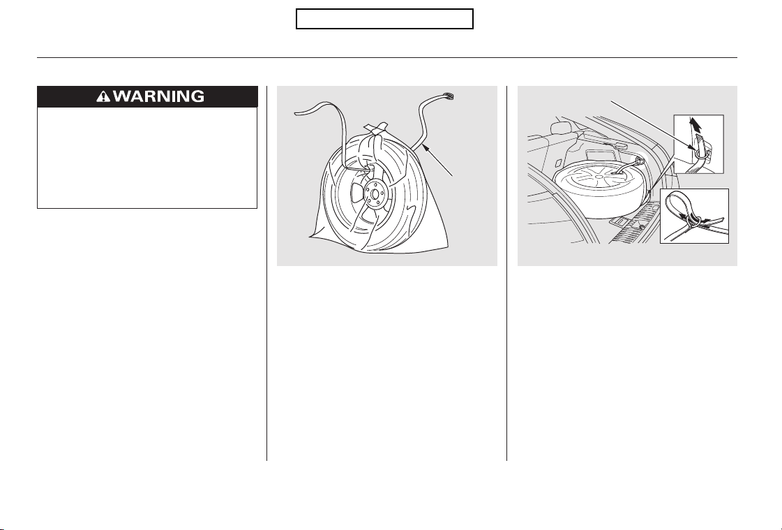
Place the flat tire in the cargo area,
and thread the belt through the
cargo hook as shown in the
illustration. Pass the belt through
the ring, and tighten the belt to
secure the flat tire in place.
Bore through the bag, and pass
the holding belt through the hole
of the bag and the wheel of the flat
tire as shown in the illustration.
This belt is with the bag in the tool
kit case.
23. 24.
Changing a Flat Tire
378
BELT
CARGO HOOK
Loose items can fly around the
interior in a crash and could
seriously injure the occupants.
Store the wheel, jack, and tools
securely before driving.
Table of Contents
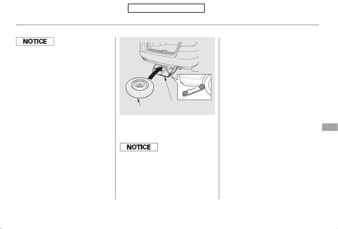
Your vehicle’s original tire has a
tire pressure monitoring system
sensor. To replace a tire, refer to
(see
page ).
When putting back the spare tire,
placethesparetirefacingupon
the spare tire holder.
25.
26.
315
Changing a Flat Tire
Changing a Tire with TPMS
Taking Care of the Unexpected
379
SPARETIREHOLDER
SPARE TIRE
If you store the spare tire face down, it
will be damaged and need to be
replaced.
Always ensure that the spare tire holder
is installed onto the hook and the
holder is then completely raised into
place. If the holder is lef t down, it will
be damaged during driving and will
need to be replaced.
Table of Contents
Diagnosing why the engine won’t
start falls into two areas, depending
on what you hear when you turn the
ignition switch to the START (III)
position:
You hear nothing, or almost
nothing. The engine’s starter
motor does not operate at all, or
operates very slowly.
You can hear the starter motor
operating normally, or the starter
motor sounds like it is spinning
faster than normal, but the engine
does not start up and run.
When you turn the ignition switch to
the START (III) position, you do not
hear the normal noise of the engine
trying to start. You may hear a
clicking sound, a series of clicks, or
nothing at all.
Check these things:
Turn the ignition switch to the
START (III) position. If the
headlights do not dim, check the
condition of the fuses. If the fuses
areOK,thereisprobably
something wrong with the
electrical circuit for the ignition
switch or starter motor. You will
need a qualified mechanic to
determine the problem (see
on page ).
If the headlights dim noticeably or
go out when you try to start the
engine, either the battery is dis-
charged or the connections are
corroded. Check the condition of
the battery connections (see page
). You can then try jump
starting the vehicle from a booster
battery (see page ).
Check the transmission interlock.
The transmission must be in Park
or neutral or the starter will not
operate.
Turn the ignition switch to the ON
(II) position. Turn on the
headlights, and check their
brightness. If the headlights are
very dim or do not come on at all,
the battery is discharged. See
on page .382
397
367
382
IftheEngineWon’tStart
Nothing Happens or the Starter
Motor Operates Very Slowly
Emergency Towing
Jump Starting
380
Table of Contents
In this case, the starter motor’s
speed sounds normal, or even faster
than normal, when you turn the
ignition switch to the START (III)
position, but the engine does not run.
Are you using the proper starting
procedure? Refer to
on page .
Are you using a properly coded
key? An improperly coded key will
cause the immobilizer system
indicator in the instrument panel
to blink rapidly (see page ).
Do you have fuel? Check the fuel
gauge; the low fuel indicator may
not be working.
There may be an electrical
problem, such as no power to the
fuel pump. Check all the fuses
(see page ).
Ifyoufindnothingwrong,youwill
need a qualified technician to find
the problem. See
on page .
301
78
390
397
IftheEngineWon’tStart
The Starter Operates Normally
Starting the
Engine
Emergency
Towing
Taking Care of the Unexpected
381
Table of Contents
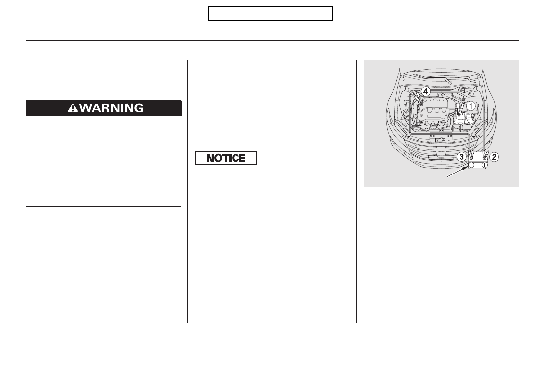
+
+
Although this seems like a simple
procedure, you should take several
precautions. Open the hood, and check the
physical condition of the battery.
In very cold weather, check the
condition of the electrolyte. If it
seems slushy or frozen, do not try
jump starting until it thaws.
To jump start your vehicle:
You cannot start your vehicle by
pushing or pulling it.
Turn off all the electrical
accessories: climate control, audio
system, lights, etc. Put the
transmission in Park, and set the
parking brake.
Connect one jumper cable to the
positive ( ) terminal on your
battery. Connect the other end to
the positive ( ) terminal on the
booster battery.
The numbers in the illustration show
you the order to connect the jumper
cables.
1.
2.
3.
Jump Starting
382
BOOSTER BATTERY
A battery can explode if you do
not follow the correct procedure,
seriously injuring anyone
nearby.
Keep all sparks, open flames,
and smoking materials away
from the battery.
If a battery sits in extreme cold, the
electrolyte inside can f reeze.
Attempting to jump start with a frozen
battery can cause it to rupture.
Table of Contents
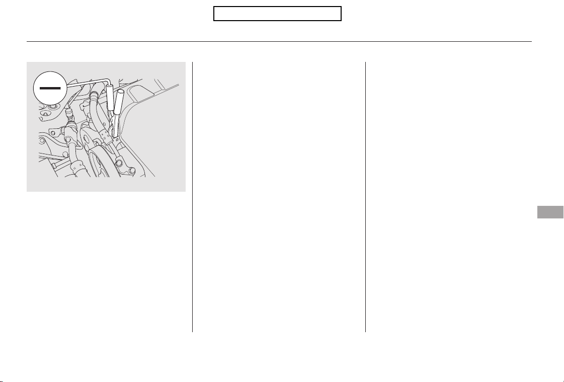
−
Keep the ends of the jumper cables
away from each other and any metal
on the vehicle until everything is
disconnected. Otherwise, you may
cause an electrical short.
If the booster battery is in another
vehicle, have an assistant start
that vehicle and run it at a fast idle.
Start the vehicle. If the starter
motor still operates slowly, check
that the jumper cables have good
metal-to-metal contact.
Once your vehicle is running,
disconnect the negative cable from
your vehicle, then from the
booster battery. Disconnect the
positive cable from your vehicle,
then from the booster battery.
Connect the second jumper cable
to the negative ( ) terminal on
the booster battery. Connect the
other end to the engine hanger as
shown. Do not connect this jumper
cable to any other part of the
engine.
7.
6.
5.
4.
Jump Starting
Taking Care of the Unexpected
383
Table of Contents
If you do not see steam or spray,
leave the engine running and
watch the temperature gauge. If
the high heat is due to overloading,
the engine should start to cool
down almost immediately. If it
does, wait until the temperature
gauge comes down to the midpoint,
then continue driving.
If the temperature gauge stays at
the red mark, turn off the engine.
Look for any obvious coolant leaks,
such as a split radiator hose.
Everything is still extremely hot,
so use caution. If you find a leak, it
must be repaired before you
continue driving (see
on page ).
The pointer of the vehicle’s
temperature gauge should stay in
the midrange. If it climbs to the red
mark, you should determine the
reason (hot day, driving up a steep
hill, etc.).
If your vehicle overheats, you should
take immediate action. The only
indication may be the temperature
gauge climbing to or above the red
mark. Or you may see steam or
spray coming from under the hood.
Safely pull to the side of the road.
Put the transmission in Park, and
set the parking brake. Turn off all
the accessories, and turn on the
hazard warning lights.
If you see steam and/or spray
coming from under the hood, turn
off the engine. Wait until you see
no more signs of steam or spray,
then open the hood.
1.
2.
3.
4.
5.
397
Emergency
Towing
IftheEngineOverheats
384
Steam and spray from an
overheated engine can
seriously scald you.
Do not open the hood if steam
is coming out.
Driving with the temperature gauge
pointer at the red mark can cause
serious damage to the engine.
Table of Contents
Using gloves or a large heavy
cloth, turn the radiator cap
counterclockwise, without pushing
down, to the first stop. After the
pressure releases, push down on
the cap, and turn it until it comes
off.
Put the radiator cap back on
tightly. Run the engine, and check
the temperature gauge. If it goes
back to the red mark, the engine
needs repair (see
on page ).
If the temperature stays normal,
check the coolant level in the
radiator reserve tank. If it has
gone down, add coolant to the
MAX mark. Put the cap back on
tightly.
Start the engine, and set the
temperature to maximum heat
(climate control to AUTO at
‘‘ ’’). Add coolant to the
radiator up to the base of the filler
neck. If you do not have the
proper coolant mixture available,
you can add plain water.
Remember to have the cooling
system drained and refilled with
the proper mixture as soon as you
can.
If you do not find an obvious leak,
check the coolant level in the
radiator reserve tank (see page
). Add coolant if the level is
below the MIN mark.
If there was no coolant in the
reserve tank, you may need to add
coolant to the radiator. Let the
engine cool down until the pointer
reaches the middle of the tempera-
ture gauge, or lower, before check-
ing the radiator.
7.
6. 8.
9.
10.
11.
397
288
Emergency
Towing
IftheEngineOverheats
Taking Care of the Unexpected
385
Removing the radiator cap
while the engine is hot can
cause the coolant to spray out,
seriously scalding you.
Always let the engine and
radiator cool down before
removing the radiator cap.
Table of Contents
This indicator should never
come on when the engine is
running. If it starts flashing or stays
on, the oil pressure has dropped very
low or lost pressure. Serious engine
damage is possible, and you should
take immediate action.
Safely pull off the road, and shut
off the engine. Turn on the hazard
warning lights.
Let the vehicle sit for a minute.
Open the hood, and check the oil
level (see page ). An engine
very low on oil can lose pressure
during cornering and other driving
maneuvers.
If necessary, add oil to bring the
level back to the full mark on the
dipstick (see page ).
Start the engine and watch the oil
pressure indicator. If it does not go
out within 10 seconds, turn off the
engine. There is a mechanical
problem that needs to be repaired
before you can continue driving
(see on page
).
If the charging system
indicator comes on brightly
when the engine is running, the
battery is not being charged.
Immediately turn off all electrical
accessories. Try not to use other
electrically operated controls such as
the power windows. Keep the engine
running; starting the engine will
discharge the battery rapidly.
Go to a service station or garage
where you can get technical
assistance.
1.
2.
3.
4.
288
333
397
Low Oil Pressure Indicator
Emergency Towing
Charging System Indicator
Low Oil Pressure Indicator, Charging System Indicator
386
Running the engine with low oil
pressure can cause serious mechanical
damage almost immediately. Turn of f
the engine as soon as you can saf ely get
the vehicle stopped.
Table of Contents
If this indicator comes on
while driving, it means one
of the engine’s emissions control
systems may have a problem. Even
though you may feel no difference in
your vehicle’s performance, it can
reduce your fuel economy and cause
increased emissions. Continued
operation may cause serious damage.
If you have recently refueled your
vehicle, the indicator coming on
could be due to a loose or missing
fuel fill cap. Tighten the cap until it
clicks at least once. Tightening the
cap will not turn the indicator off
immediately; it can take several days
of normal driving.
If the indicator comes on repeatedly,
even though it may go off as you
continue driving, have your vehicle
checked by a dealer as soon as
possible.
If the battery in your vehicle has
been disconnected or gone dead,
thesecodesmaybeerased.Itcan
take several days of driving under
various conditions to set the codes
again.
To check if they are set, turn the
ignition switch to the ON (II)
position, without starting the engine.
The malfunction indicator lamp will
come on for 20 seconds. If it then
goes off, the readiness codes are set.
If it blinks five times, the readiness
codes are not set. If possible, do not
take your vehicle for an emissions
test until the readiness codes are set.
Refer to for
more information (see page ).
The indicator may also come on with
the ‘‘D’’ indicator.
Your vehicle has certain ‘‘readiness
codes’’ that are part of the on-board
diagnostics for the emissions
systems. In some states, part of the
emissions testing is to make sure
these codes are set. If they are not
set, the test cannot be completed.
413
Malfunction Indicator Lamp
Emissions Testing
Readiness Codes
Taking Care of the Unexpected
387
If you keep driving with the
malf unction indicator lamp on, you can
damage your vehicle’s emissions
controls and engine. Those repairs may
not be covered by your vehicle’s
warranties.
Table of Contents
However, if the brake pedal does not
feel normal, you should take
immediate action. A problem in one
part of the system’s dual circuit
design will still give you braking at
two wheels. You will feel the brake
pedal go down much farther before
the vehicle begins to slow down, and
you will have to press harder on the
pedal. If you must drive the vehicle a short
distance in this condition, drive
slowly and carefully.
Slow down by shifting to a lower
gear, and pull to the side of the road
when it is safe. Because of the long
distance needed to stop, it is
hazardous to drive the vehicle. You
should have it towed and repaired as
soon as possible (see
on page ).
The brake system indicator normally
comes on when you turn the ignition
switch to the ON (II) position, and as
a reminder to check the parking
brake. It will stay on if you do not
fully release the parking brake.
If the brake system indicator comes
on while driving, the brake fluid level
is probably low. Press lightly on the
brake pedal to see if it feels normal.
If it does, check the brake fluid level
thenexttimeyoustopataservice
station (see page ).
If the fluid level is low, take your
vehicle to a dealer, and have the
brake system inspected for leaks or
worn brake pads.
If the ABS indicator and the VSA
system indicator come on with the
brake system indicator, have your
vehicle inspected by your dealer
immediately.
342
397
Emergency
Towing
Brake System Indicator
388
U.S. Canada
Table of Contents
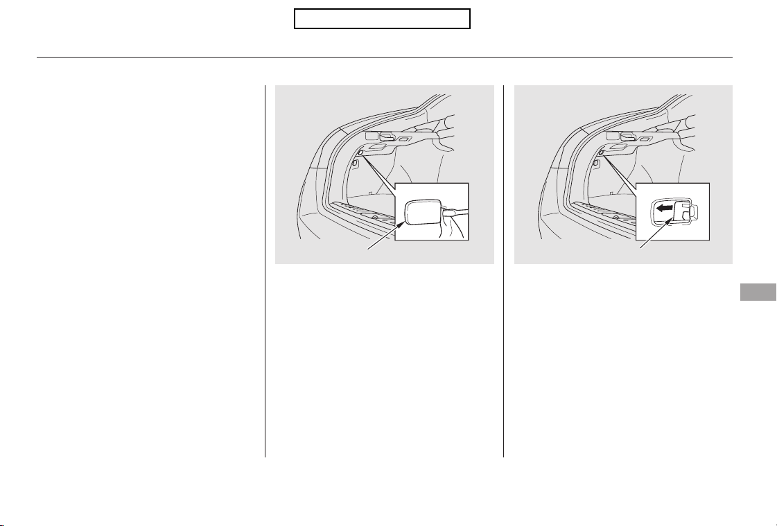
If there is a problem with the power
door lock system and you cannot
unlock the driver’s door, use the
release lever.
If you cannot also unlock the tailgate
due to the power door lock system
malfunction, see page and open
the tailgate manually.
To open the fuel fill door, pull the
release lever rearward.
Place a cloth on the edge of the
cover to prevent scratches. Remove
the cover by carefully prying on its
edge with a small flat-tip screwdriver.
92
Opening the Fuel Fill Door Manually
Taking Care of the Unexpected
389
COVER
RELEASE LEVER
Table of Contents
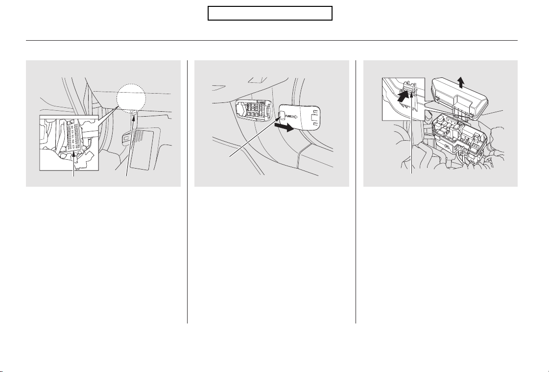
The vehicle’s fuses are contained in
threefuseboxes.
Thedriver’ssideinteriorfuseboxis
under the dashboard on the driver’s
side. The fuse label is attached to the
side panel.
The passenger’s side interior fuse
box is on the lower passenger’s side
panel. To remove the fuse box lid,
put your finger in the notch on the
lid, and pull it upward slightly, then
pull it toward you and take it out of
its hinges.
The under-hood fuse box is on the
driver’s side. To open it, push the
tabs as shown.
Fuses
390
UNDER-HOODINTERIOR (Driver’s side)
FUSE BOX FUSE LABEL
TAB
NOTCH
INTERIOR (Passenger’s side)
Table of Contents
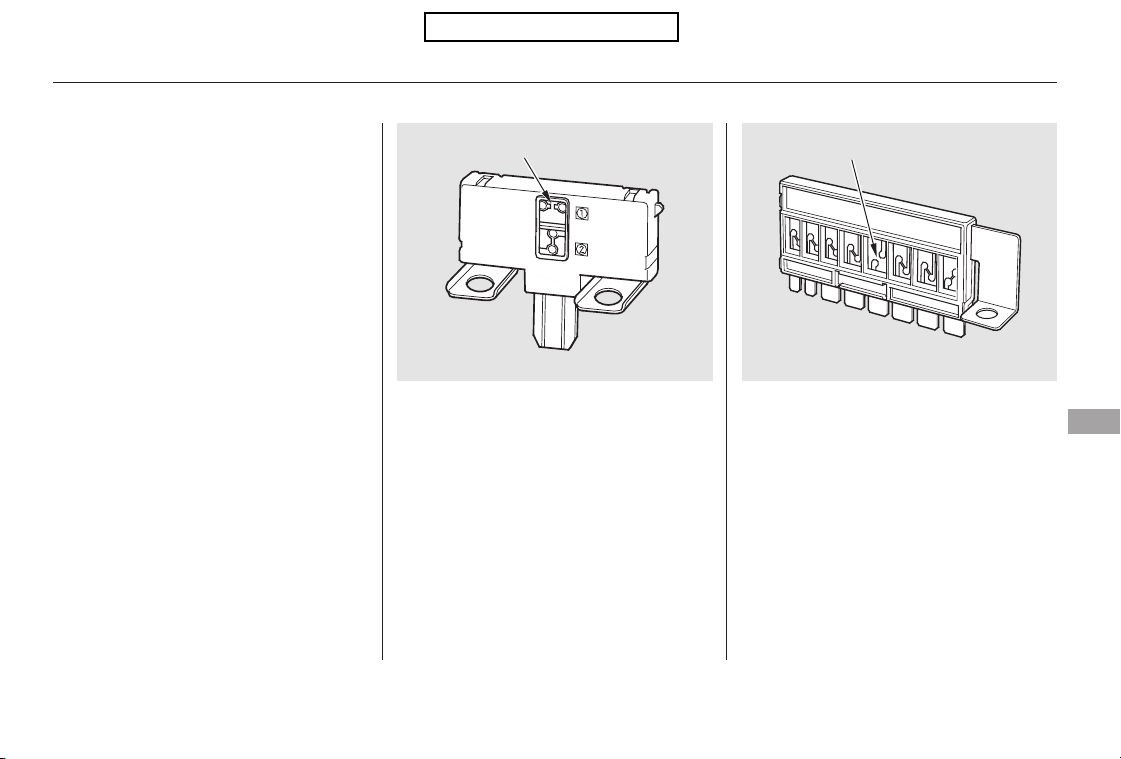
Also check the combined fuse box in
the under-hood fuse box.
If something electrical in your
vehicle stops working, the first thing
youshouldcheckforisablownfuse.
Determine from the chart on pages
, and , or the diagram on
thefuseboxlidorthefuselabel,
which fuse or fuses control that
component. Check those fuses first,
but check all the fuses before
deciding that a blown fuse is not the
cause. Replace any blown fuses and
check if the device works.
Check each of the large fuses in
the under-hood fuse box by
looking at the wire inside.
Removing these fuses requires a
Phillips-head screwdriver.
Turn the ignition switch to the
LOCK (0) position. Make sure the
headlights and all other
accessories are off.
On the under-hood and passenger’s
side interior fuse boxes, remove
the cover from each fuse box.
3.
1.
2.
394 395 396
CONTINUED
Fuses
Checking and Replacing Fuses
Taking Care of the Unexpected
391
FUSE
BLOWN
BLOWN
Table of Contents
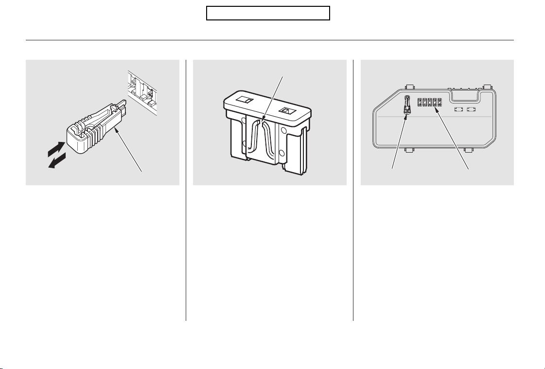
Your vehicle has spare fuses on the
back of the under-hood fuse box
cover.
Look for a blown wire inside the
fuse. If it is blown, replace it with
oneofthesparefusesofthesame
rating or lower.
Check the smaller fuses in the
under-hood fuse box and all the
fuses in the interior fuse boxes by
pulling out each one with the fuse
pullerprovidedonthebackofthe
under-hood fuse box cover.
5.4.
Fuses
392
BLOWN
FUSE PULLER
SPARE FUSES
FUSE PULLER
Table of Contents
If the replacement fuse of the
same rating blows in a short time,
there is probably a serious
electrical problem with your
vehicle. Leave the blown fuse in
that circuit, and have your vehicle
checked by a qualified technician.
If you replace the blown fuse with a
spare fuse that has a lower rating, it
might blow out again. This does not
indicate anything wrong. Replace the
fuse with one of the correct rating as
soon as you can.
If you cannot drive the vehicle
without fixing the problem, and you
do not have a spare fuse, take a fuse
of the same rating or a lower rating
from one of the other circuits. Make
sureyoucandowithoutthatcircuit
temporarily (such as the accessory
power socket).
6.
Fuses
Taking Care of the Unexpected
393
Replacing a f use with one that has a
higher rating greatly increases the
chances of damaging the electrical
system. If you do not have a
replacement f use with the proper rating
f or the circuit, install one with a lower
rating.
Table of Contents
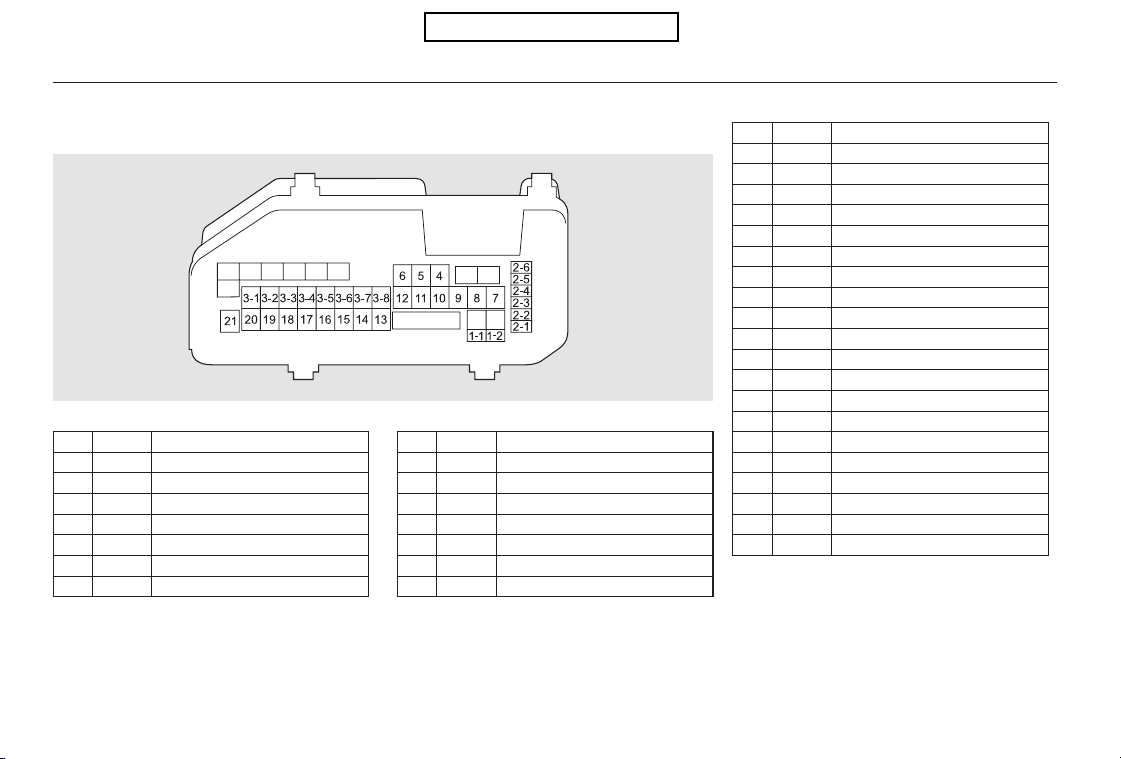
−
−
−
−
−
−
−
−
−
−
−
−
−
−
−
−
−
−
−
−
−
−
−
−
#
#
No. Circuits ProtectedAmps. No. Amps. Circuits Protected
No. Circuits ProtectedAmps.
11
12
21
22
23
24
25
26
31
32
33
34
35
36
37
38
Battery
Passenger’s Side Fuse Box
Not Used
ABS/VSA
ABS/VSA Motor
Passenger’s Side Fuse Box
Not Used
120 A
40 A
40 A
30 A
40 A
30 A
30 A
30 A
30 A
60 A
30 A
Not Used
Sub Fan Motor
Wiper Motor
Main Fan Motor
Driver’s Side Light Main
Driver’s Side Fuse Box
Passenger’s Side Light Main
4
5
6
7
8
9
10
11
12
13
14
15
16
17
18
19
20
21
Not Used
IG Main
Fan Relay
Rear Defroster
Not Used
Hazard
Horn, Stop
Not Used
Trailer
IG Coil
FI Sub
Not Used
Not Used
Back Up
Interior Lights
FI Main
DBW
Back Up, FI ECU
Heater Motor
MG Clutch
50 A
7.5 A
40 A
15 A
20 A
(15 A)
15 A
15 A
10 A
7.5 A
15 A
15 A
7.5 A
40 A
7.5 A
Use this space for the trailer light, if it is
installed.
:
Fuse Locations
394
UNDER-HOOD FUSE BOX
Table of Contents
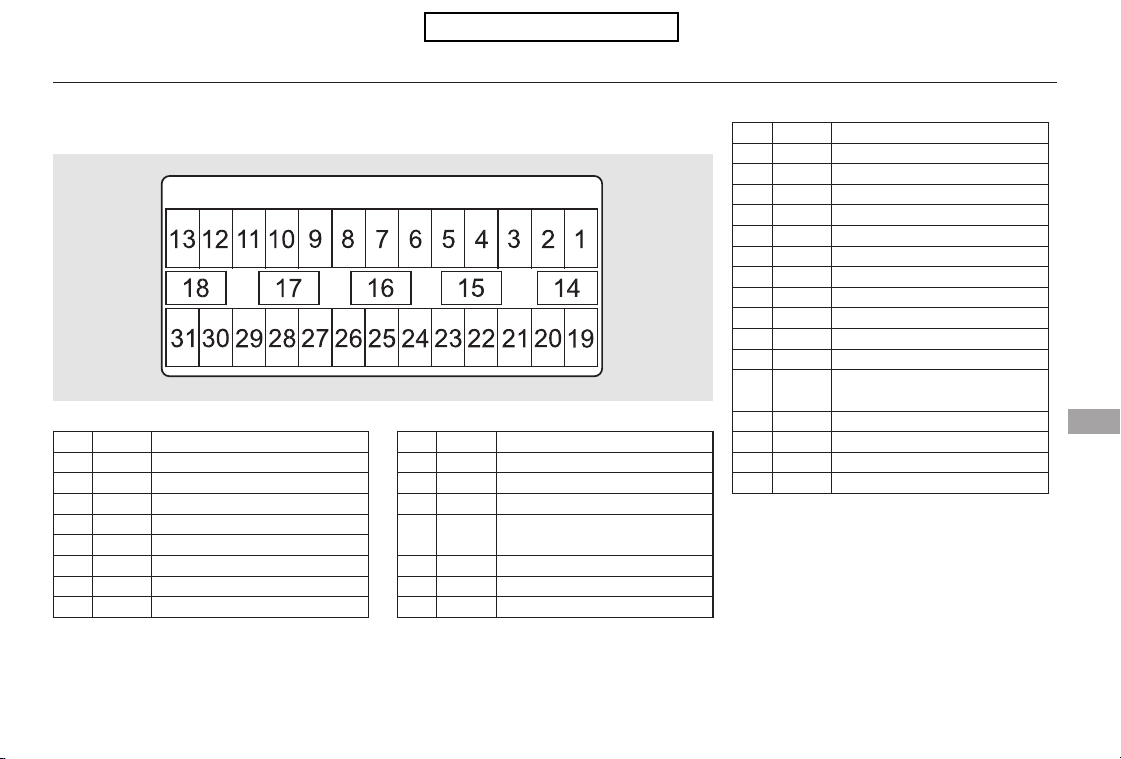
−
−
−
*
*
No. No.
No.
Amps. Circuits Protected Amps.
Amps. Circuits Protected
CONTINUED
Circuits Protected
1
2
3
4
5
6
7
8
9
10
11
12
13
14
15
16
17
18
19
20
21
22
23
24
25
26
27
28
29
30
31
If equipped
7.5 A
15 A
10 A
7.5 A
7.5 A
15 A
7.5 A
Not Used
Seat Memory
Washer
Wiper
Meter
ABS/VSA
ACG
STS
20 A
10 A
10 A
7.5 A
10 A
7.5 A
7.5 A
7.5 A
7.5 A
20 A
20 A
20 A
20 A
15 A
20 A
15 A
10 A
10 A
10 A
7.5 A
15 A
A/C
Accessory, Key, Lock
Accessory
Driver’s Power Seat Sliding
Moonroof
Driver’s Power Seat Reclining
Rear Left Power Window
Front Accessory Power Socket
Driver’s Power Window
Driver’s Side Door Lock
Left Front Fog Light
Left Side Small Lights
(Exterior)
Left Headlight High Beam
TPMS
Left Headlight Low Beam
Not Used
Fuel Pump
VB SOL2
SRS
OPDS (Occupant Position
Detection System)
Not Used
ACM
Daytime Running Lights
:
Fuse Locations
Taking Care of the Unexpected
395
INTERIOR FUSE BOX (Driver’s Side)
Table of Contents
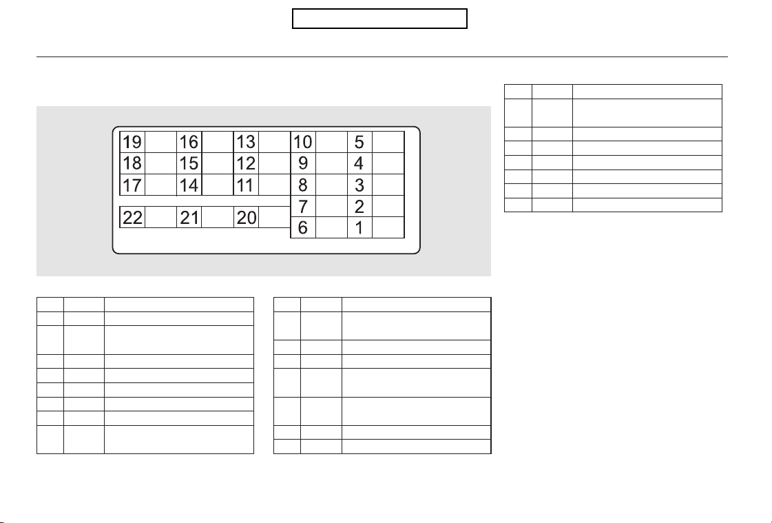
−
−
−
−
−
−
−
*
*
*
No. No.Amps. Circuits Protected Amps.
Circuits ProtectedNo.
Circuits Protected
Amps.
1
2
3
4
5
6
7
8
9
10
11
12
13
14
15
10 A
10 A
10 A
15 A
7.5 A
20 A
Right Headlight High Beam
Right Side Small Lights
(Exterior)
Right Front Fog Light
Right Headlight Low Beam
Not Used
Interior Lights
Not Used
Front Passenger’s Power
Seat Reclining
20 A
10 A
20 A
15 A
20 A
20 A
Accessory Power Socket
(Cargo)
Not Used
Lumbar Support
Seat Heater
Not Used
Not Used
Not Used
16
17
18
19
20
21
22
If equipped
Front Passenger’s Power
Seat Sliding
Right Side Door Lock
Rear Right Power Window
Accessory Power Socket
(Console)
Front Passenger’s Power
Window
Not Used
Premium AMP
15 A
10 A
15 A
:
Fuse Locations
396
INTERIOR FUSE BOX (Passenger’s Side)
Table of Contents
−
−
CONTINUED
If your vehicle needs to be towed,
call a professional towing service or
organization. Never tow your vehicle
with just a rope or chain. It is very
dangerous.
The operator will load
your vehicle on the back of a truck.
Any other method of towing will
damage the drive system. When you
contact the towing agency, inform
them a flat-bed is required.
Therearetwowaystotowyour
vehicle:
The operator
loads your vehicle on the back of a
truck.
If, due to damage, your vehicle must
be towed with the front wheels on
the ground, do this:
Start the engine.
Shift to the D position and hold for
5 seconds, then to N.
Turn off the engine.
Leave the ignition switch in the
ACCESSORY (I) position so the
steering wheel does not lock.
Release the parking brake.
The tow
truck uses two pivoting arms that go
under the front tires and lift them off
the ground. The rear tires remain on
the ground.
On 4WD models
On 2WD models
The only way you can safely tow
your vehicle is with flat-bed
equipment.
This is the best way to
transport your vehicle.
This is an acceptable
way to tow your vehicle.
Flat-bed Equipment
Wheel-lif t Equipment
Emergency Towing
Taking Care of the Unexpected
397
Towing with only two tires on the
ground will damage parts of the
all-wheel-drive system. Your vehicle
should be transported on a f lat-bed
truck or trailer.
Table of Contents
With the front wheels on the ground,
do not tow the vehicle more than 50
miles (80 km), and keep the speed
below35mph(55km/h).
Emergency Towing
398
The steering system can be damaged if
the steering wheel is locked. Leave the
ignition switch in the ACCESSORY (I)
position, and make sure the steering
wheel turns f reely bef ore you begin
towing.
Trying to lif t or tow your vehicle by the
bumpers will cause serious damage.
The bumpers are not designed to
support the vehicle’s weight.
Improper towing preparation will
damage the transmission. Follow the
above procedure exactly. If you cannot
shif t the transmission or start the
engine, your vehicle must be
transported with the f ront wheels of f
the ground.
Table of Contents

−
Thediagramsinthissectiongive
you the dimensions and capacities of
your vehicle and the locations of the
identification numbers. It also
includes information you should
know about your vehicle’s tires and
emissions control systems.
................
Identification Numbers . 400
...............................Specifications . 402
DOT Tire Quality Grading
..........................(U.S. Vehicles) . 404
.................................Tire Labeling . 406
Tire Pressure Monitoring System
(TPMS) Required Federal
............................Explanation . 408
.......................Emissions Controls . 410
Three Way Catalytic
.................................Converters . 412
........................Emissions Testing . 413
Technical Information
Technical Information
399
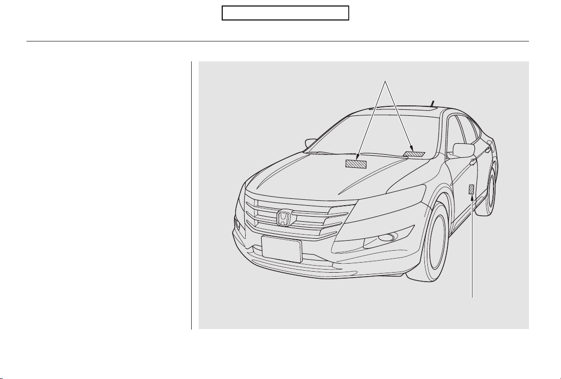
Your vehicle has several identifying
numbers in various places.
The vehicle identification number
(VIN) is the 17-digit number your
dealer uses to register your vehicle
for warranty purposes. It is also
necessary for licensing and insuring
your vehicle. The easiest place to
find the VIN is on a plate fastened to
the top of the dashboard. You can
seeitbylookingthroughthe
windshield on the driver’s side. It is
also on the certification label
attached to the driver’s doorjamb,
and is stamped on the engine
compartment bulkhead. The VIN is
also provided in bar code on the
certification label.
Identification Numbers
400
CERTIFICATION LABEL
VEHICLE IDENTIFICATION NUMBER (VIN)
Table of Contents
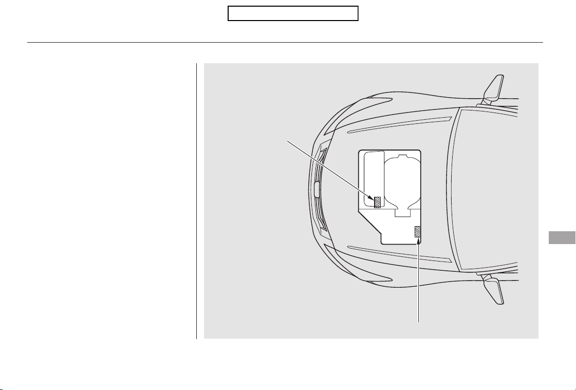
The transmission number is on a
label on top of the transmission.
The engine number is stamped on
the front of the engine block.
Identification Numbers
Technical Information
401
ENGINE NUMBER
TRANSMISSION NUMBER
Table of Contents
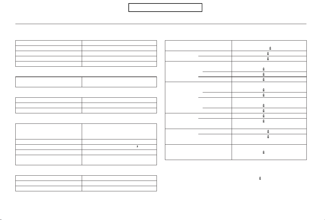
−−
*
*
*
*
Specifications
402
Dimensions
Weights
Air Conditioning
Engine
Seating Capacities
Capacities
110.1 in (2,797 mm)
Length
Width
Height
Wheelbase
Track
Gross vehicle weight rating See the certification label attached
to the driver’s doorjamb.
Refrigerant type
Charge quantity
Lubricant type
HFC-134a (R-134a)
14.1 15.9 oz (400 450 g)
ND-OIL8
196.8 in (4,999 mm)
74.7 in (1,898 mm)
65.7 in (1,670 mm)
64.9 in (1,648 mm)
3.50 x 3.66 in (89.0 x 93.0 mm)
212 cu-in (3,471 cm
)
10.5 : 1
ILZKR7B11
SXU22HCR11
Type
BorexStroke
Displacement
Compression ratio
Spark plugs
Total
Front
Rear
5
2
3
18.5 US gal (70.0
)
1.74 US gal (6.6
)
2.27 US gal (8.6
)
4.5 US qt (4.3 )
4.2 US qt (4.0
)
5.3 US qt (5.0
)
3.5 US qt (3.3 )
3.0 US qt (2.8
)
7.9 US qt (7.5 )
8.3 US qt (7.9
)
Excluding the oil remaining in the engine
Including the coolant in the reserve tank and that remaining in the
engine
Reserve tank capacity: 0.180 US gal (0.68
)
5.3 US qt (5.0
)
Fuel tank
Engine
coolant
Engine oil
Automatic
transmission
fluid
Rear
differential
fluid (4WD)
Transfer
assembly
fluid (4WD)
Windshield
washer
reservoir
1.3 US qt (1.2
)
0.43 US qt (0.41
)
1.5 US qt (1.4
)
0.48 US qt (0.45
)
Water cooled 4-stroke
SOHC i-VTEC VCM 6-cylinder (V6)
gasoline engine
Approx.
1:
2:
Change
Total
Front/Rear
NGK:
DENSO:
Change
Including filter
Without filter
Total
Change
2WD
4WD
Total
2WD
4WD
Change
Total
Change
Total
1
2
Table of Contents
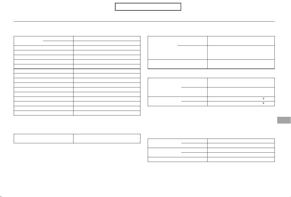
−
−
−
*
*
*
*
*
*
*
*
*
*
*
Specifications
Technical Information
403
Fuses
Battery
Tires
Alignment
Lights
Interior
Under-hood
8W
60 W (HB3)
55 W (H11)
24/2 2 CP
5W
55 W
21 W
21 W
21/5 W
5W
8W
225/65R17 102T
Replacement of a light bulb should be done by your dealer.
Capacity 12 V
12 V
72 AH/20 HR
60 AH/5 HR
See page 395 or the fuse label
attached on the side panel.
See page 396 or the fuse label
attached to the inside of the fuse
box door.
See page 394 or the fuse box
cover.
225/60R18 100H
Size
Pressure
T155/90D16 110M
T155/90D17 101M
32 psi (220 kPa , 2.2 kgf/cm
)
60 psi (420 kPa , 4.2 kgf/cm
)
Toe-in
Camber
Caster
0.00 in (0.0 mm)
0.08 in (2.0 mm)
0°
1°
3°30’
1.4 W
3.8 W
5W
3.8 W
Headlights
Front turn signal/parking lights
Front side marker lights
Front Fog lights
Rear turn signal lights
Back-up lights
Stop/taillights
License plate lights
High-mount brake light
Ceiling light
Spotlights
Glove box light
Courtesy light (Ceiling)
Cargo area lights
Front door courtesy lights
Vanity mirror lights
High
Low
Front
Rear
Front
Rear
Front
Driver’s side
Passenger’s side
1:
2:
3:
4:
EX
EX-L
2WD
4WD
(Amber)
(H11)
(Amber)
LED type
LED type
:
Front/Rear
Spare
Front/Rear
Spare
1
2
4
3
Table of Contents

Quality grades can be found where
applicable on the tire sidewall
between tread shoulder and
maximum section width. For
example:
The treadwear grade is a compara-
tive rating based on the wear rate of
the tire when tested under controlled
conditions on a specified government
test course. For example, a tire
graded 150 would wear one and one-
half (1 1/2) times as well on the
government course as a tire graded
100. The relative performance of
tires depends upon the actual condi-
tions of their use, however, and may
depart significantly from the norm
due to variations in driving habits,
service practices and differences in
road characteristics and climate.
The traction grades, from highest to
lowest, are AA, A, B, and C. Those
grades represent the tire’s ability to
stop on wet pavement as measured
under controlled conditions on
specified government test surfaces
of asphalt and concrete. A tire
marked C may have poor traction
performance.
Warning: The traction grade
assignedtothistireisbasedon
straight-ahead braking traction tests,
and does not include acceleration,
cornering, hydroplaning, or peak
traction characteristics.
The tires on your vehicle meet all
U.S. Federal Safety Requirements.
All tires are also graded for
treadwear, traction, and temperature
performance according to
Department of Transportation
(DOT) standards. The following
explains these gradings.
All passenger car tires must conform
to Federal Safety Requirements in
addition to these grades.
Uniform Tire Quality Grading
Treadwear 200
Traction AA
Temperature A
Treadwear Traction
DOT Tire Quality Grading (U.S. Vehicles)
404
Table of Contents

Warning: The temperature grade for
this tire is established for a tire that
is properly inflated and not
overloaded. Excessive speed,
underinflation, or excessive loading,
either separately or in combination,
can cause heat buildup and possible
tire failure.
The temperature grades are A (the
highest), B, and C, representing the
tire’s resistance to the generation of
heat and its ability to dissipate heat
when tested under controlled
conditions on a specified indoor
laboratory test wheel. Sustained high
temperature can cause the material
of the tire to degenerate and reduce
tire life, and excessive temperature
can lead to sudden tire failure. The
grade C corresponds to a level of
performance which all passenger car
tires must meet under the Federal
Motor Vehicle Safety Standard No.
109. Grades B and A represent
higher levels of performance on the
laboratory test wheel than the
minimum required by law.
Temperature
DOT Tire Quality Grading (U.S. Vehicles)
Technical Information
405
Table of Contents
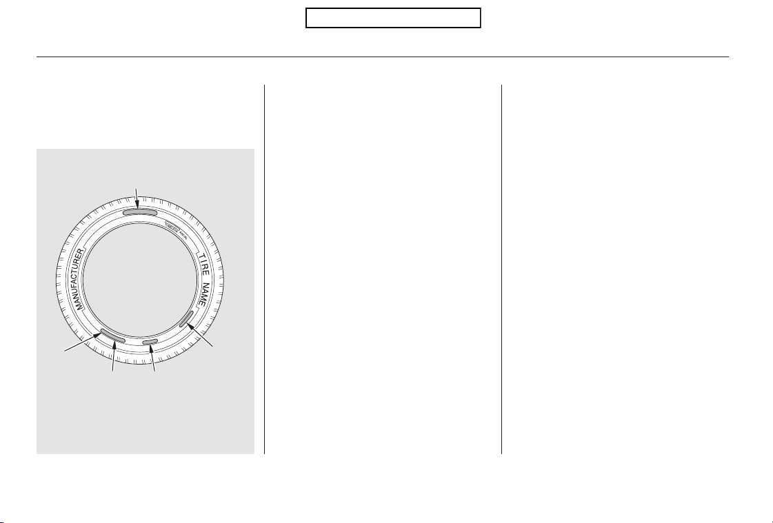
−
−
−
−
−
−
−
The tires that came on your vehicle
have a number of markings. Those
you should be aware of are described
below.
Whenever tires are replaced, they
should be replaced with tires of the
same size. Following is an example
of tire size with an explanation of
what each component means.
Tire width in millimeters.
Aspect ratio (the tire’s section
height as a percentage of its
width).
Tire construction code (R
indicates radial).
Rim diameter in inches.
Load index (a numerical code
associated with the maximum
load the tire can carry).
Speed symbol (an
alphabetical code indicating
the maximum speed rating).
The tire identification number (TIN)
is a group of numbers and letters
that look like the following example.
TIN is located on the sidewall of the
tire.
This indicates that the tire
meets all requirements of
the U.S. Department of
Transportation.
Manufacturer’s
identification mark.
R
DOT
225
60
18
H
100
AP14
Tire Labeling
Tire Size
Tire Identif ication Number (TIN)
406
(3)
(4)
Tire Labeling Example
(1)
(2)
(1)
(2)
(3)
(4)
(1) Tire Size
Tire Identification Number (TIN)
Maximum Tire Pressure
Maximum Tire Load
DOT AP14 002X 2202
225/60R18 100H
Table of Contents
−
−
−
−
−
−−
−
Cold Tire Pressure The tire air
pressure when the vehicle has been
parked for at least three hours or
driven less than 1 mile (1.6 km).
Load Rating Means the maximum
load that a tire is rated to carry for a
given inflation pressure.
Maximum Inflation Pressure The
maximum tire air pressure that the
tire can hold.
Maximum Load Rating Means the
load rating for a tire at the maximum
permissible inflation pressure for
that tire.
Recommended Inflation Pressure
The cold tire inflation pressure
recommended by the manufacturer.
Treadwear Indicators (TWI)
Means the projections within the
principal grooves designed to give a
visual indication of the degrees of
wear of the tread.Week
Date of manufacture.
Year
Tire type code.
2202
002X
Tire Labeling
Glossary of Tire Terminology
Technical Information
407
Table of Contents
−
Each tire, including the spare (if
provided), should be checked
monthly when cold and inflated to
the inflation pressure recommended
by the vehicle manufacturer on the
vehicle placard or tire inflation
pressure label.
(If your vehicle has tires of a
different size than the size indicated
on the vehicle placard or tire
inflation pressure label, you should
determine the proper tire inflation
pressure for those tires.)
Accordingly, when the low tire
pressure telltale illuminates, you
should stop and check your tires as
soon as possible, and inflate them to
the proper pressure.
Driving on a significantly under-
inflated tire causes the tire to
overheat and can lead to tire failure.
Under-inflation also reduces fuel
efficiency and tire tread life, and may
affect the vehicle’s handling and
stopping ability.
Please note that the TPMS is not a
substitute for proper tire
maintenance, and it is the driver’s
responsibility to maintain correct tire
pressure, even if under-inflation has
not reached the level to trigger
illumination of the TPMS low tire
pressure telltale.
As an added safety feature, your
vehicle has been equipped with a tire
pressure monitoring system (TPMS)
that illuminates a low tire pressure
telltale
when one or more of your tires is
significantly under-inflated.
Tire Pressure Monitoring System (TPMS) Required Federal Explanation
408
Table of Contents
−
Always check the TPMS malfunction
telltale after replacing one or more
tires or wheels on your vehicle to
ensure that the replacement or
alternate tires and wheels allow the
TPMS to continue to function
properly.
Your vehicle has also been equipped
with a TPMS malfunction indicator
to indicate when the system is not
operating properly. The TPMS
malfunction indicator is provided by
a separate telltale, which displays the
symbol ‘‘TPMS’’ when illuminated.
When the malfunction indicator is
illuminated,
the system may not be able to detect
or signal low tire pressure as
intended.
TPMS malfunctions may occur for a
variety of reasons, including the
installation of replacement or
alternate tires or wheels on the
vehicle that prevent the TPMS from
functioning properly.
Tire Pressure Monitoring System (TPMS) Required Federal Explanation
Technical Information
409
Table of Contents

*
*
The burning of gasoline in your
vehicle’s engine produces several by-
products. Some of these are carbon
monoxide (CO), oxides of nitrogen
(NOx), and hydrocarbons (HC).
Gasoline evaporating from the tank
also produces hydrocarbons. Con-
trolling the production of NOx, CO,
and HC is important to the environ-
ment. Under certain conditions of
sunlight and climate, NOx and HC
react to form photochemical ‘‘smog.’’
Carbon monoxide does not contri-
bute to smog creation, but it is a
poisonous gas.
The United States Clean Air Act
sets standards for automobile
emissions. It also requires that
automobile manufacturers explain to
owners how their emissions controls
workandwhattodotomaintain
them. This section summarizes how
the emissions controls work.
In Canada, Honda vehicles comply
with the Canadian emission
requirements, as specified in an
agreement with Environment
Canada, at the time they are
manufactured.
Your vehicle has a positive
crankcase ventilation system. This
keeps gasses that build up in the
engine’s crankcase from going into
the atmosphere. The positive
crankcase ventilation valve routes
them from the crankcase back to the
intake manifold. They are then
drawn into the engine and burned.
As gasoline evaporates in the fuel
tank, an evaporative emissions
control canister filled with charcoal
adsorbs the vapor. It is stored in this
canister while the engine is off. After
the engine is started and warmed up,
the vapor is drawn into the engine
and burned during driving.
The onboard refueling vapor
recovery (ORVR) system captures
the fuel vapors during refueling. The
vapors are adsorbed in a canister
filled with activated carbon. While
driving, the fuel vapors are drawn
into the engine and burned off.
The Clean Air Act
Crankcase Emissions Control
System
Evaporative Emissions Control
System
Onboard Refueling Vapor
Recovery
Emissions Controls
410
Table of Contents

The emissions control systems are
designed and certified to work to-
gether in reducing emissions to
levels that comply with the Clean Air
Act. To make sure the emissions
remain low, you should use only new
Honda replacement parts or their
equivalent for repairs. Using lower
qualitypartsmayincreasethe
emissions from your vehicle.
The emissions control systems are
covered by warranties separate from
the rest of your vehicle. Read your
warranty manual for more informa-
tion.The PGM-FI system uses sequential
multiport fuel injection.
It has three subsystems: air intake,
engine control, and fuel control. The
powertrain control module (PCM)
uses various sensors to determine
how much air is going into the
engine. It then controls how much
fuel to inject under all operating
conditions.
This system constantly adjusts the
ignition timing, reducing the amount
of HC, CO, and NOx produced.
The exhaust gas recirculation (EGR)
system takes some of the exhaust
gas and routes it back into the intake
manifold. Adding exhaust gas to the
air/fuel mixture reduces the amount
of NOx produced when the fuel is
burned.
The three way catalytic converter is
in the exhaust system. Through
chemical reactions, it converts HC,
CO, and NOx in the engine’s exhaust
to carbon dioxide (CO ), nitrogen
(N ), and water vapor.
The exhaust emissions controls
include four systems: PGM-FI,
ignition timing control, exhaust gas
recirculation, and three way catalytic
converter. These four systems work
together to control the engine’s
combustion and minimize the
amount of HC, CO, and NOx that
come out the tailpipe. The exhaust
emissions control systems are
separate from the crankcase and
evaporative emissions control
systems.
2
2
Exhaust Emissions Controls Replacement Parts
PGM-FI System
Ignition Timing Control System
Exhaust Gas Recirculation (EGR)
System
Three Way Catalytic Converter
Emissions Controls
Technical Information
411
Table of Contents
Keep the engine well maintained.
Have your vehicle diagnosed and
repaired if it is misfiring, back-
firing, stalling, or otherwise not
running properly.
The three way catalytic converters
contain precious metals that serve as
catalysts, promoting chemical
reactions to convert the exhaust
gasses without affecting the metals.
The catalytic converters are referred
to as three-way catalysts, since they
act on HC, CO, and NOx.
Replacement units must be original
Honda parts or their equivalent.
The three way catalytic converters
must operate at a high temperature
for the chemical reactions to take
place. They can set on fire any
combustible materials that come
near them. Park your vehicle away
from high grass, dry leaves, or other
flammables.
Defectivethreewaycatalytic
converters contribute to air pollution,
and can impair your engine’s
performance. Follow these
guidelines to protect your vehicle’s
three way catalytic converters.
Always use unleaded gasoline.
Even a small amount of leaded
gasoline can contaminate the
catalyst metals, making the three
way catalytic converters
ineffective.
Three Way Catalytic Converters
412
THREE WAY CATALYTIC CONVERTERS
Table of Contents

Make sure the gas tank is nearly,
but not completely, full (around
3/4).
Without touching the accelerator
pedal, start the engine, and let it
idle for 20 seconds.
If you take your vehicle for an
emissions test shortly after the
battery has been disconnected or
gone dead, it may not pass the test.
This is because of certain ‘‘readiness
codes’’ that must be set in the on-
board diagnostics for the emissions
systems. These codes are erased
when the battery is disconnected,
and set again only after several days
of driving under a variety of
conditions.
If the testing facility determines that
the readiness codes are not set, you
will be requested to return at a later
date to complete the test. If you must
get the vehicle retested within the
next two or three days, you can
condition the vehicle for retesting by
doing the following.
Make sure the vehicle has been
parked with the engine off for 6
hours or more.
Make sure the ambient
temperature is between 40° and
95°F (4° and 35°C).
Keep the vehicle in Park. Increase
the engine speed to 2,000 rpm, and
hold it there until the temperature
gauge rises to at least 1/4 of the
scale (about 3 minutes).
Without touching the accelerator
pedal, let the engine idle for 20
seconds.
1.
2.
3.
4.
5.
6.
CONTINUED
Testing of Readiness Codes
Emissions Testing
Technical Information
413
Table of Contents

If the testing facility determines the
readiness codes are still not set, see
your dealer.
Then drive in city/suburban
traffic for at least 10 minutes.
When traffic conditions allow, let
the vehicle coast for several
seconds without using the
accelerator pedal or the brake
pedal.
Make sure the vehicle has been
parked with the engine off for 30
minutes.
Select a nearby lightly traveled
major highway where you can
maintain a speed of 50 to 60 mph
(80to97km/h)foratleast20
minutes. Drive on the highway in
D. Do not use the cruise control.
When traffic allows, drive for 90
seconds without moving the
accelerator pedal. (Vehicle speed
may vary slightly; this is okay.) If
you cannot do this for a
continuous 90 seconds because of
traffic conditions, drive for at least
30 seconds, then repeat it two
more times (for a total of 90
seconds).
7. 8.
9.
Emissions Testing
414
Table of Contents

4WD models only
4WD models only
Service Information Summary
Gasoline:
Fuel Tank Capacity:
Recommended Engine Oil:
Automatic Transmission Fluid:
Rear Differential Fluid:
Transfer Assembly Fluid:
Power Steering Fluid:
Brake Fluid:
Tire Pressure (measured cold):
SpareTirePressure:
Unleaded gasoline, pump octane
number of 87 or higher.
Oil change capacity (including
filter):
Honda Genuine ATF-Z1
(automatic transmission fluid)
(see page ).
Honda Dual Pump Fluid II. Do
not use ATF.
4.5 US qt (4.3
)
API Premium grade 0W-20
detergent oil (see page ).
SAE 90 viscosity hypoid gear oil,
API service classified GL4 or GL5
only.
Honda Power Steering Fluid
preferred, or another brand of
power steering fluid as a
temporary replacement. Do not
use ATF (see page ).
Honda Heavy Duty Brake Fluid
DOT 3 preferred, or a DOT 3 or
DOT 4 brake fluid as a temporary
replacement (see page ).
Front/Rear:
32 psi (220 kPa , 2.2 kgf/cm
)
60 psi (420 kPa , 4.2 kgf/cm
)
1.3 US qt (1.2
)
18.5 US gal (70.0
) Capacity:
333
341
343
342


Honda dealership personnel are
trained professionals. They should
be able to answer all your questions.
If you encounter a problem that your
dealership does not solve to your
satisfaction, please discuss it with
the dealership’s management. The
service manager or general manager
can help. Almost all problems are
solved in this way.
If you are dissatisfied with the
decision made by the dealership’s
management, contact Honda
Customer Service.
U.S. Owners:
Canadian Owners: When you call or write, please give
us this information:
Vehicle Identification Number
(see page )
Name and address of the dealer
who services your vehicle
Date of purchase
Odometer reading of your vehicle
Your name, address, and tele-
phone number
A detailed description of the
problem
Name of the dealer who sold the
vehicle to you
In Puerto Rico and the U.S. Virgin
Islands:
400
Customer Service Information
416
American Honda Motor Co., Inc.
Automobile Customer Service
Mail Stop 500-2N-7A
1919 Torrance Boulevard
Torrance, California 90501-2746
Tel: (800) 999-1009
Honda Canada Inc.
Visit www.honda.ca for contact
information
Tel: 1-888-9-HONDA-9
Fax: 1-877-939-0909
Vortex Motor Corp.
Bella International
P.O. Box 190816
San Juan, PR 00919-0816
Tel: (787) 620-7546
Customer Relations
Table of Contents

−
−
−
−
−
−
−
−
−
Your new vehicle is covered by these
warranties:
covers your new vehicle, except for
the battery, emissions control
systems, and accessories, against
defects in materials and
workmanship.
provides prorated
coverage for a replacement battery
purchased from your dealer.
these two
warranties cover your vehicle’s
emissions control systems. Time,
mileage, and coverage are
conditional. Please read your
warranty booklet for exact
information.
provides
coverageforaslongasthepur-
chaser of the muffler owns the
vehicle.
a seat
belt that fails to function properly is
covered by a limited warranty.
Please read your warranty booklet
for details.
covers all Honda
replacement parts against defects in
materials and workmanship.
Honda accessories are covered
under this warranty. Time and
mileage limits depend on the type of
accessory and other factors. Please
read your warranty booklet for
details.
all exterior body panels are
covered for rust-through from the
inside for the specified time period
with no mileage limit.
this warranty gives up
to 100% credit toward a replacement
battery.
Restrictions and exclusions apply to
all these warranties. Please read the
2010 Honda warranty information
booklet that came with your vehicle
for precise information on warranty
coverages. Your vehicle’s original
tires are covered by their
manufacturer. Tire warranty
information is in a separate booklet.
Please refer to the 2010 warranty
manual that came with your vehicle.
Warranty Coverages
U.S. Owners
Canadian Owners
New Vehicle Limited Warranty
Replacement Battery Limited
Warranty
Emissions Control Systems Def ects
Warranty and Emissions
Performance Warranty
Replacement Muffler Lifetime
Limited Warranty
Seat Belt Limited Warranty
Replacement Parts Limited
Warranty
Accessory Limited Warranty
Rust Perf oration Limited Warranty
Original Equipment Battery Limited
Warranty
Warranty and Customer Relations
417
Table of Contents

If NHTSA receives similar com-
plaints, it may open an investigation,
and if it finds that a safety defect
exists in a group of vehicles, it may
order a recall and remedy campaign.
However, NHTSA cannot become
involved in individual problems
between you, your dealer, or
American Honda Motor Co., Inc.
If you believe that your vehicle has a
defect which could cause a crash or
could cause injury or death, you
should immediately inform the
National Highway Traffic Safety
Administration (NHTSA), in addition
to notifying American Honda Motor
Co., Inc.
To contact NHTSA, you may call the
VehicleSafetyHotlinetoll-freeat
1-888-327-4236
(TTY: 1-800-424-9153); go to
; or write to:
Administrator, NHTSA, 1200 New
Jersey Avenue, SE., Washington, DC
20590.
You can also obtain other
information about motor vehicle
safety from .
Reporting Safety Defects (U.S. Vehicles)
418
http://www.saf ercar.gov
http://www.saf ercar.gov
Table of Contents
The publications shown below can be purchased from Helm
Incorporated. You can order by phone or online:
Call Helm Inc. at 1-800-782-4356 (credit card orders only)
Go online at
If you are interested in other years or models, contact Helm Inc.
at 1-800-782-4356.
Covers maintenance and recommended procedures for
repair to engine and chassis components. It is written
for the journeyman mechanic, but it is simple enough
for most mechanically inclined owners to understand.
Complements the Service Manual by providing in-depth
troubleshooting information for each electrical circuit
in your vehicle.
Describes the procedures involved in the replacement
of damaged body parts.
Authorized Manuals
Purchasing Factory Authorized Manuals Service Manual:
Electrical Troubleshooting Manual:
Body Repair Manual:
(U.S. only)
Authorized Manuals
419
Form Description
2010 Honda Accord Crosstour
Service Manual Basebook
2010 Honda Accord Crosstour
Electrical Troubleshooting Manual
2010 Honda Accord Crosstour
Body Repair Manual
2010 Honda Accord Crosstour Owner’s Manual
2010 Honda Accord Crosstour
Navigation System Owner’s Manual
2010 Honda Accord Crosstour Honda Service History
2010 Honda Accord Crosstour
Technology Reference Guide
Order Form for Previous Years-
Indicate Year and Model Desired
Publication
Form Number
61TP600
61TP600EL
61TP630
31TP6600
31TP6800
31TP6M00
31TP6Q00
HON-R
www. helminc. com
Table of Contents