
MYGUARD
AUTOMATIC HOT WATER HEATER
SHUT-OFF SYSTEM
Installation Guide
2
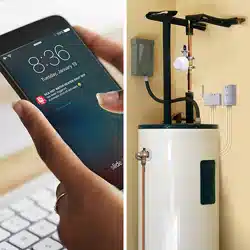
WELCOME!
The MyGuard Automatic Hot Water Heater Shut-Off System puts your mind at ease by protecting your home or business against
water damage. Simply install the control unit and shut-off servo included in this package, and you’re set to stop a disaster before
it happens! This installation guide takes you through the steps to get set up.
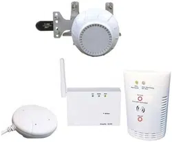
WHAT’S IN THE PACKAGE?
Control unit
with connection wire and sensors attached
Hardware bag
Automatic shut-off servo motor
with connection wire attached
(2) Servo pipe-mounting
brackets
(1) Double-sided tape for control unit
(2) Drywall screws with anchors
(#6 x 1-1/4” Phillips pan-head)
(2) Masonry screws (3/16” flat-head)
(2) Wire ties (100L)
(3) Wire ties with double-sided tape
(1) Large centering ring (20D)
(1) Wire tie (163L)
(1) Screw, M4
(2) Carriage Bolts, M5 x 50 x 0.8(mm)
(2) Carriage Bolts, M5 x 30 x 0.8(mm)
(2) Carriage Bolts, M5 x 24 x 0.8(mm)
(4) Wing nuts
(4) Washers
(4) Spring Washers
(1) Allen Wrench
Floor sensor
(attached to control unit)
Pressure-release output
pipe sensor
(attached to control unit)
Power adapter for the control unit
3-outlet AC wall tap to provide an additional
electrical outlet if needed
Mounting template for the control unit
3
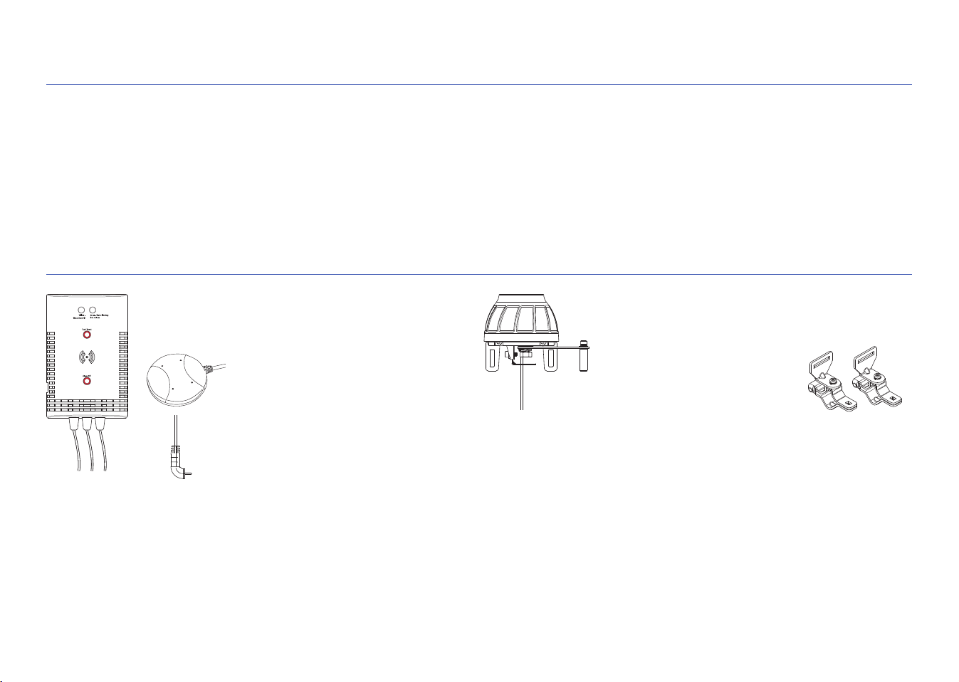
A. Find the shut-off valve for your hot water heater
STEP 1: MOUNT THE CONTROL UNIT TO THE WALL
The shut-off valve for your hot water heater is on the cold water pipe going into the
water heater. The location of this pipe varies, but it’s usually near the top of the water
heater.
Shut-off
valve
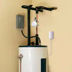
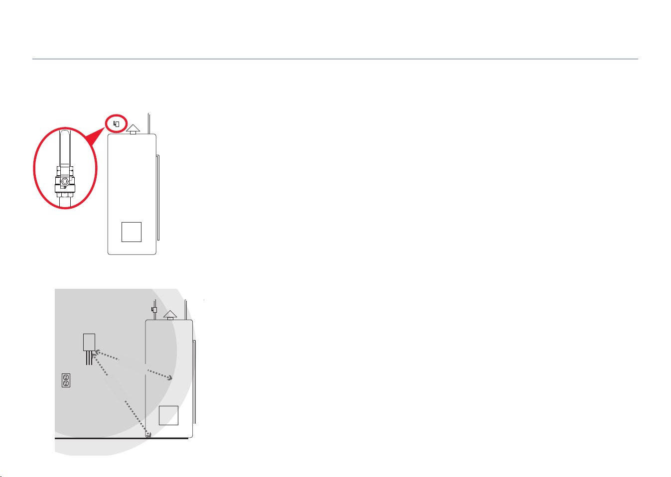
B. Find the best place to mount the control unit
The control unit needs to be close enough to the shut-off valve and floor for the sensor
wires (6ft) and control lead wire (5ft) to reach. It also needs to be close to a power
outlet.
Less than 5ft
Less than 6ft
Control unit
Floor
Shut-off valve
Power
outlet
Hot water
heater
4
C. Mount the control unit to wall
The control unit offers three options for mounting to the wall.
Option 1: Double-sided tape (included, not for masonry applications)
1. Clean the wall where you want to mount the unit.
2. Apply the double-sided sticky tape to the back of the control unit.
3. Peel off the exposed side of the sticky tape.
4. Press the control unit firmly against the wall where you want to mount it.
Option 2: Drywall screws with anchors (included)
1. Place the mounting template on the wall where you want to mount the control unit.
IMPORTANT: Make sure there are no electrical wires where you plan to drill.
2. Draw x’s on the wall where indicated by the mounting template. Drill a 1/4” pilot hole at each
x for the anchors. Tap in gently as needed.
3. Install the dry-wall anchors at the marked location with a #2 Phillips screwdriver
4. Mount the drywall screws in the anchors. Leave some space between the screw heads and
the wall so that you can mount the control unit on the screws.
5. Mount the control unit on the screws.
Option 3: Masonry screws (included)
1. Place the mounting template on the wall where you want to mount the control unit.
2. Draw x’s on the wall where indicated by the mounting template.
3. Use a 5/32” masonry drill bit to drill pilot holes where you marked the x’s. The holes should be about 1-1/2” deep.
4. Mount the masonry screws where you drilled the pilot holes. Leave some space between the screw heads and the wall so
that you can mount the control unit on the screws.
5. Mount the control unit on the screws.
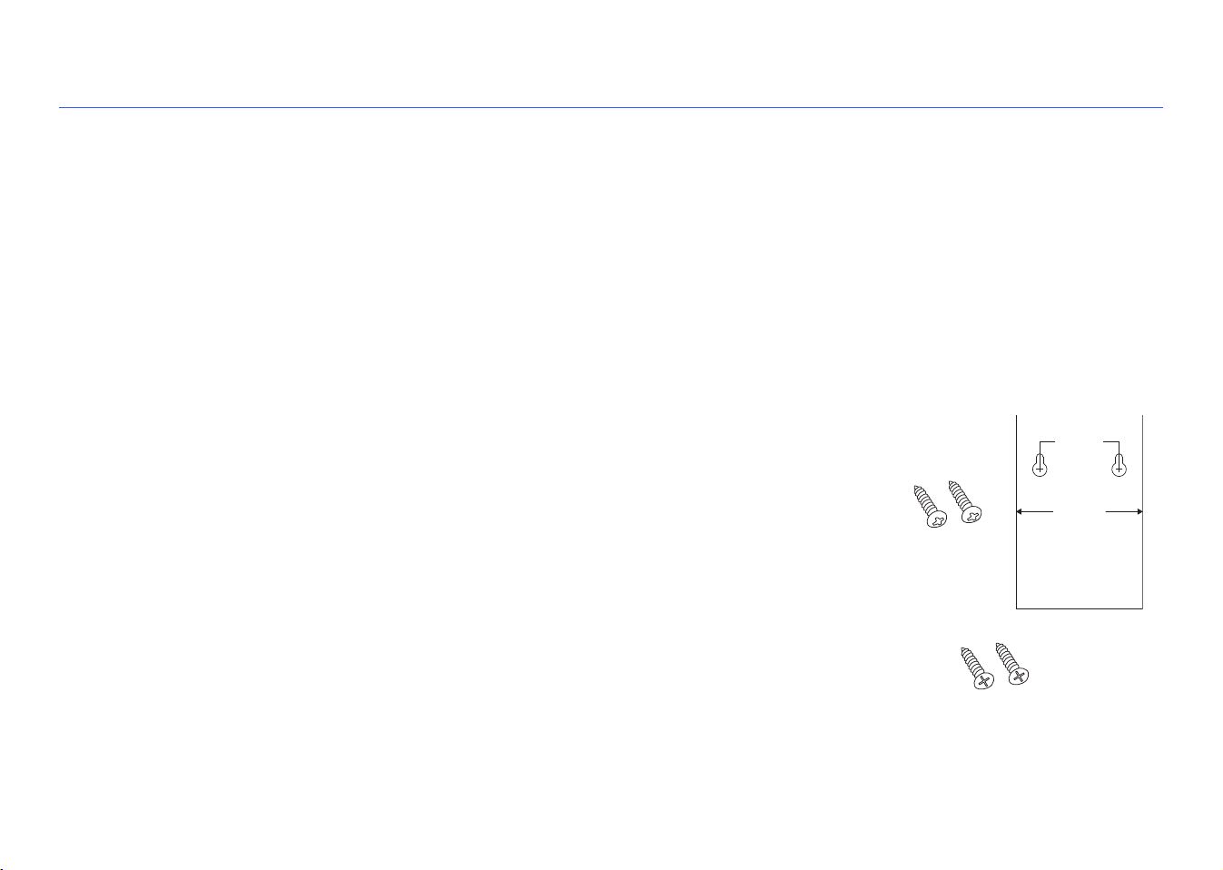
STEP 1 (continued)
45mm(1.77")
72mm(2.83")
MOUNTING TEMPLATE
USE FOR FLAT
WALL MOUNT ONLY
FOR THE CONTROL UNIT
Mounting template
Drywall
screws
Masonry
screws
5
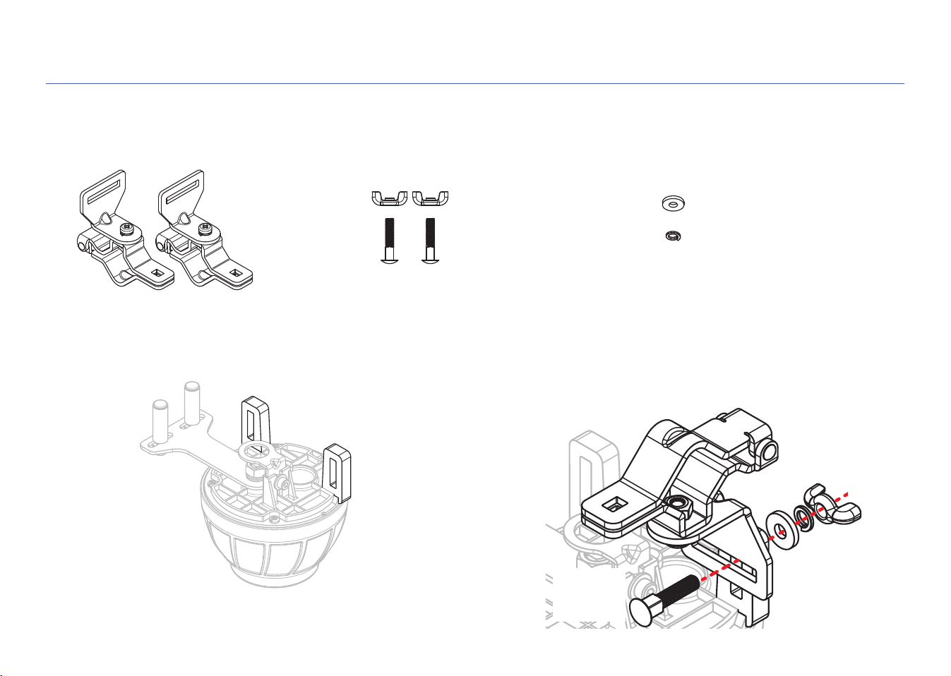
2. ASSEMBLE THE SERVO RING & BRACKETS
A. Install the brackets on the shut-off servo
Find the following pieces in the hardware bag:
2 pipe-mounting
brackets
2 wing nuts
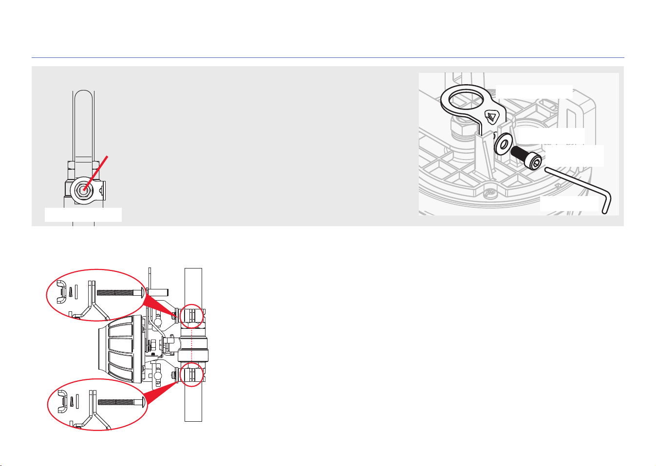
Find the bracket slots on the servo, shown here. The
brackets should be mounted on the inside of these slots.
2 short carriage
bolts (M5 x 24)
2 flat washers
2 lock washers
Place one bracket over the inside of a servo slot. Insert a short
carriage bolt through the bracket and servo slot. Place a flat
washer, lock washer, and wing nut on the end of the bolt and
tighten just enough so that the bracket stays in place. Then
repeat with the other bracket.
Wing nut
Lock washer
Flat washer
Short
carriage
bolt
Bracket
slots
6
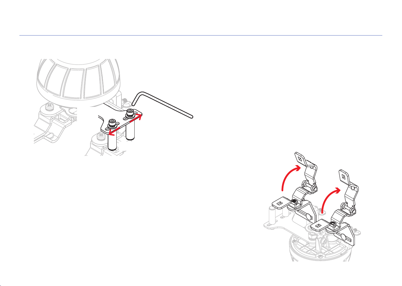
STEP 2 (continued)
B. Move the roller screws on the servo lever all the way to the outside
Use the included Allen wrench to loosen the roller screws on the
servo lever. Then move the roller screws all the way to the outside
position and re-tighten them.
Servo
lever
Roller screws
Allen wrench
C. Open the brackets
Open both brackets completely to prepare to place the shut-off servo on
your inlet pipe and shut-off valve.
7
3. PLACE THE SHUT-OFF SERVO
B. Position the center of the servo motor over the center of the shut-off valve
Carefully place the servo and brackets over your shut-off valve and inlet pipe as shown
here. Close the brackets over your inlet pipe.
Position the servo over your shut-off valve so that the center of the servo’s motor is
directly over the center of your hot water heater’s shut-off valve as shown. The servo’s
centering ring should fit over the shut-off valve’s nut (if it doesn’t fit, see the section at
the top of the next page).
IMPORTANT: Keep the centers of the the servo motor and shut-off valve aligned
throughout the installation and make sure they’re aligned when you’re finished.
Servo
motor
Shut-off
valve
A. Turn your hot water heater’s shut-off valve on and off several times.
Depending on how long it’s been since the shut-off valve was last used, there might be
significant build-up (like mineral deposits) around the valve and handle, which makes
the valve more difficult to close. Opening and closing the valve loosens this build-up
and makes the valve easier to open and close.
IMPORTANT: Leave the shut-off valve in its open position when you’ve finished opening
it and closing it.
8
STEP 3 (continued)
Does the centering ring fit? If not, replace it!
The servo’s centering ring should fit over the shut-off valve’s
nut as shown here. If it doesn’t, replace it with the larger
centering ring provided in the hardware kit.
1. Use the provided Allen wrench to remove the small Allen-
cap screw.
2. Remove the pre-installed (small) centering ring.
3. Install the larger centering ring. Then put the small washer
and Allen-cap screw back in place. Tighten with the Allen
wrench.
Nut
Allen wrench
Small Allen-
cap screw
Small washer
Centering ring
Centering ring
Insert (1) M5 x 30 x 0.8(mm) carriage bolt through each bracket as shown here. (If
these bolts are not long enough, use the M5 x 50 x 0.8(mm) ones instead.)
Place (1) washer, (1) spring washer, and (1) wing nut over each carriage bolt and
tighten just enough so that the servo stays mounted in place.
C. Close the brackets over the pipe
9
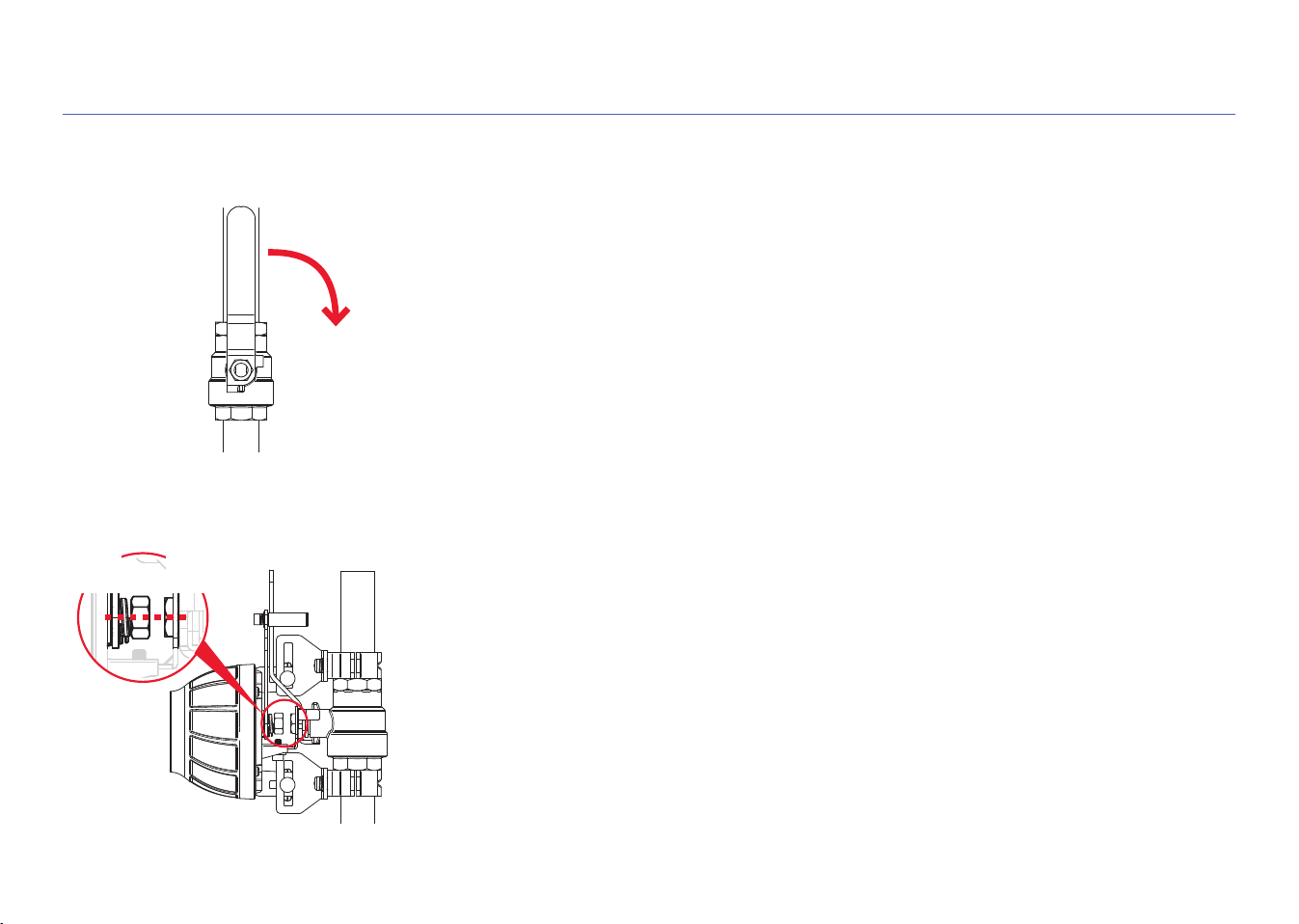
STEP 3 (continued)
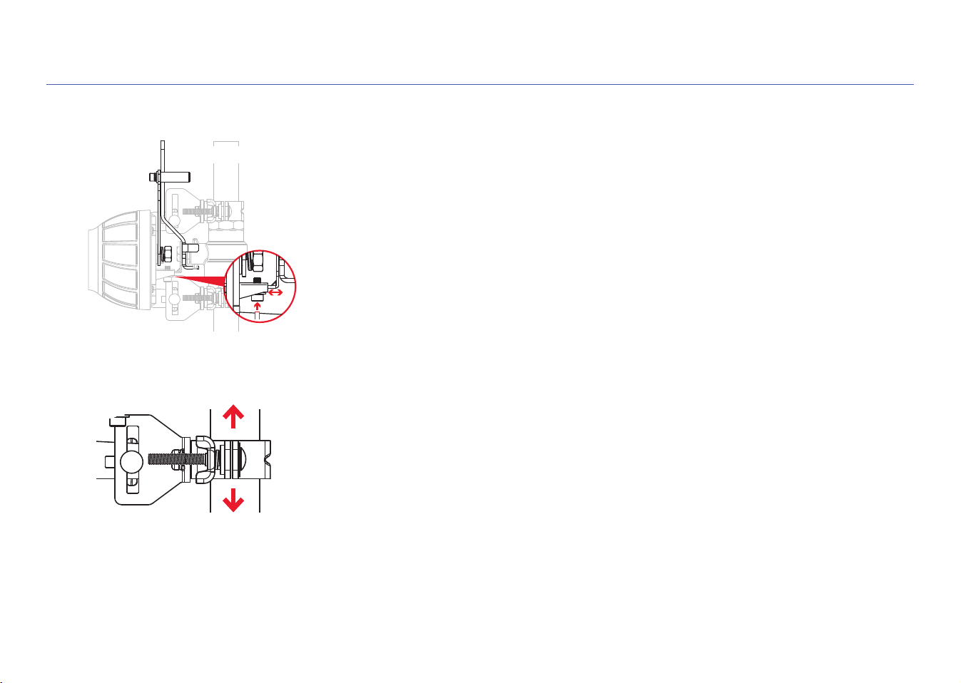
D. Make sure the shut-off valve handle is flat against the servo lever
If the handle for your shut-off valve is already flat against the servo lever, you can
proceed to the next step.
If the handle is at an angle or raised off of the servo lever, you can adjust the height of
the servo from the valve as shown here. Use the Allen wrench provided to loosen the
screw on the servo height adjustment. Then adjust the height so that the shut-off valve
handle is flat on the servo lever. Then tighten the screw again. (Make sure the servo
motor is still positioned over the center of the shut-off valve!)
Servo
lever
Valve handle
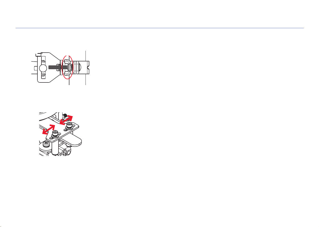
E. Position the brackets so they’re as flat as possible on the pipe
Loosen one bracket slightly on the servo and slide it so that the bracket is as level as
possible on the pipe. Then tighten the bracket on the servo and repeat with the other
bracket.
Once you’ve tightened both brackets, make sure that the servo motor is still centered
over the shut-off valve and the valve handle is still flat against the servo lever.
10
STEP 3 (continued)
F. Tighten the brackets on the pipe
Tighten the wing nuts on the brackets around the pipe.
Tighten
G. Tighten the servo lever around the valve handle
Use the Allen wrench provided to loosen the two roller screws on the servo lever and
position them tight on either side of the shut-off valve handle. Then tighten the two
roller screws in place.
11
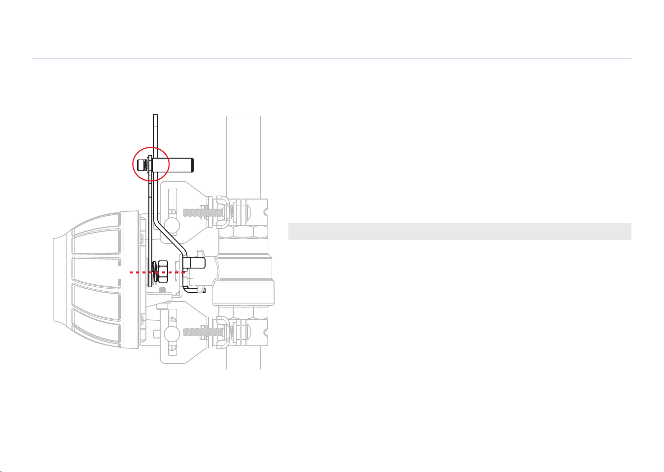
STEP 4: FINAL CHECK OF THE SERVO POSITION
IMPORTANT: The shut-off servo must be aligned correctly to work properly!
A. Do a final check
Make sure that the servo motor is still centered over the shut-off valve
and the valve handle is still flat against the servo lever.
Then make sure that the pipe brackets are secured firmly to the auto
shut-off servo and around the pipe. Make sure the roller screws on the
servo lever are tight against the shut-off valve handle.
Flat
Centered
12
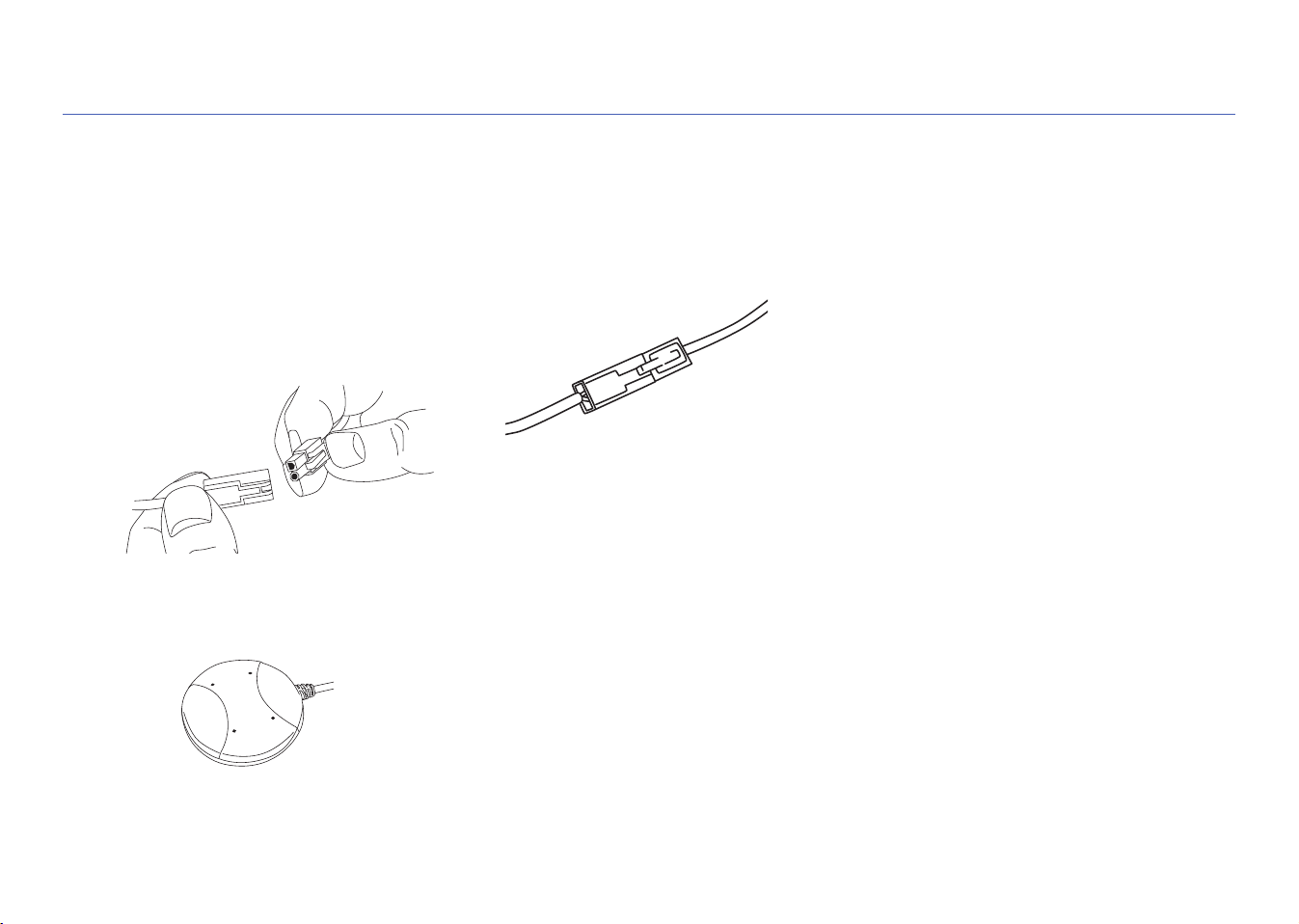
B. Place the floor sensor on the floor near the hot water tank.
Make sure the sensor is sitting flat on the floor near the hot water tank.
A. Connect the servo lead to the control box lead
STEP 5: SET UP THE SENSOR AND CONTROL UNIT
1. Line up the round and square
plugs on the control box lead to
the corresponding round and
square holes on the lead from
the servo.
2. Snap the leads into place.
3. Use the included wire ties to gather
the wires and stick them to the wall so
that they’re out of the way.
Clean the wall first. Then stick the
back of the wire tie to the wall. Use
the other wire tie closer to the control
box to gather the wires there as well.
Note: Additional wire ties are included
to help manage wires in other parts of
the installation.
13
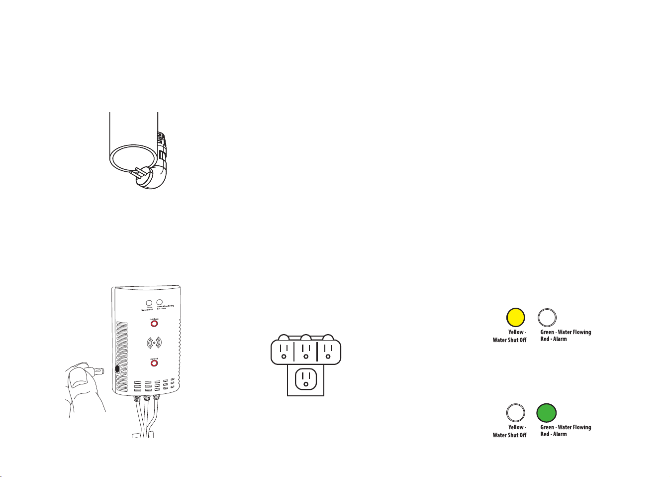
D. Plug in the control unit.
1. Plug the control unit’s power
adapter into the jack on the side of
the control unit.
2. Plug the other end of the power
adapter into an available power outlet.
If both power outlets are in use, use
the included 3-outlet power wall tap
to provide additional outlets.
When the control unit first powers on,
the yellow indicator light on its front
panel flashes—the system is arming.
When the green indicator light comes
on, the system is ready to use.
STEP 5 (continued)
3-outlet
power wall tap
C. Place the pressure-release output pipe sensor over the end of the pipe.
Use a cable tie to secure the sensor cable to the drain pipe so that the sensor hangs
over the end of the pipe as shown.
Note: This sensor activates the alarm and servo motor only after detecting water leakage for 1 minute
continuously on the pressure release output pipe of your water heater. Releasing high pressure is
important but anything longer than a minute can indicate a faulty pressure release valve that’s not
closing properly.
14
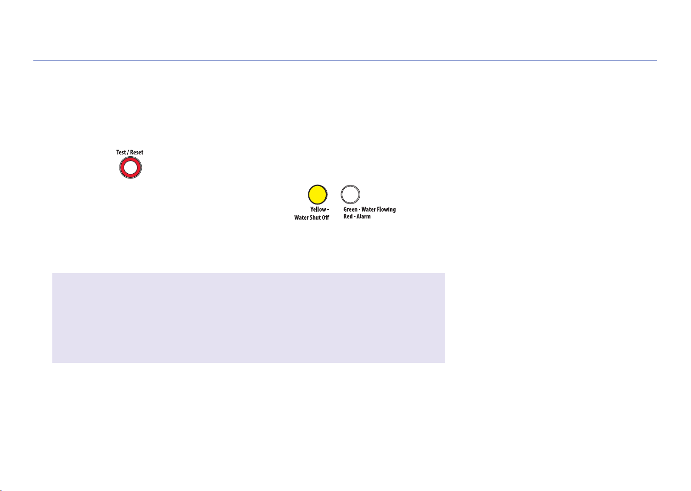
E. Test the system
Press and release the Test/Reset
button on the control unit.
The system’s alarm goes off, the servo
closes your hot water heater shut-off
valve, and the yellow indicator on control
unit starts flashing.
Once the servo has completely closed
your water heater shut-off valve, the
control unit will automatically re-open it
again.
The yellow light flashes while the servo
is reopening the valve. The green
light comes on when it has finished
reopening.
The test process takes about 35 seconds
to complete and return to normal (valve
open and green light) status.
If the green light doesn’t come back on,
unplug the controller and plug it back in.
Then test the system again.
STEP 5 (continued)
IMPORTANT!
You should perform this system test every 6 months to loosen any build-up
that might have accumulated around your hot water heater’s shut-off valve and
make sure that the valve isn’t stuck.
15
USING THE AUTO SHUT-OFF
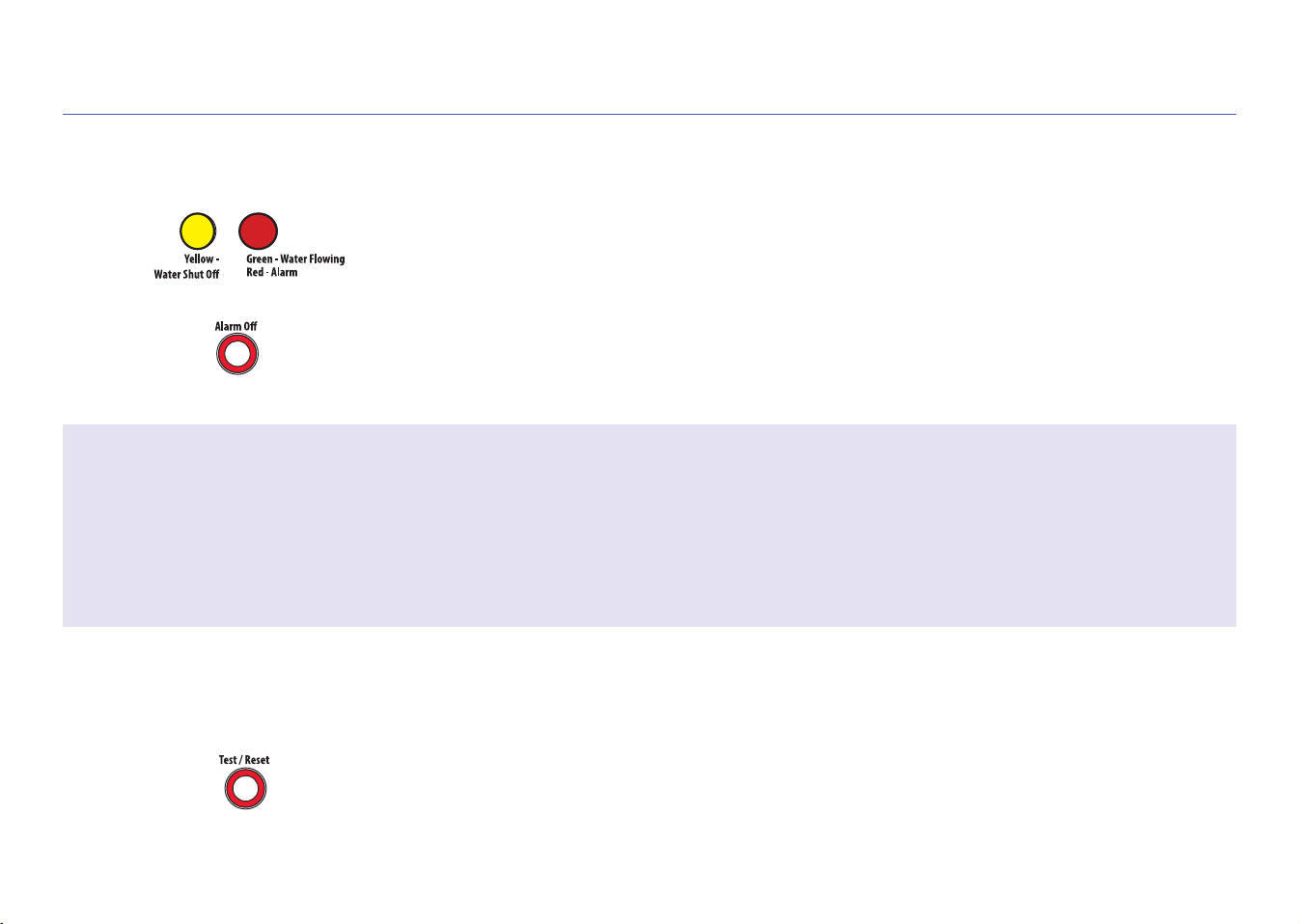
When the alarm goes off...
If either sensor senses water, the alarm sounds and the servo closes your shut-off
valve. The yellow and red indicators on the control box start flashing.
Note: The drain pipe sensor activates the alarm after detecting water leakage for 1 minute
continuously.
To stop the audible alarm: Press the Alarm Off button. (The valve will still be closed.)
Once you’ve fixed the leak and dried off the sensor(s)...
Press and release the Test/Reset button on the control unit. The yellow light flashes
while the valve is being reopened. The green light comes on when the servo has
finished reopening the valve.
Customizing the alarm
By default, the audible alarm keeps sounding until you turn it off (or until the sensors no longer sense water). You can also set
the audible alarm to sound for 10 seconds only.
To change the audible alarm to 10 seconds only: Press and hold the Alarm Off button for 2-3 seconds. The yellow LED flashes to
show that you’ve changed the audible alarm to 10 seconds only. To change back, press and hold the Alarm Off button again.

© 2018 Voxx Accessories Corp.
3502 Woodview Trace, Suite 220
Indianapolis, IN 46268
MGWHTR Install 03
Questions?
Please call our toll-free customer service hotline at 1-800-645-7750