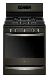
User manual Gas Range
FEATURE GUIDE
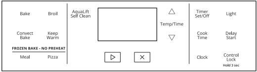
| KEYPAD |
FEATURE |
INSTRUCTIONS |
| CLOCK |
Clock |
The clock uses a 12-hour cycle.
1. Check that the oven is off.
2. Press CLOCK.
3. Press the Temp/Time up or down arrow keypad to set the hours. Press CLOCK to switch to the minutes.
4. Press the Temp/Time up or down arrow keypad to set the minutes.
5. Press CLOCK or the Start keypad
|
| LIGHT |
Oven cavity light |
While the oven door is closed, press LIGHT to turn the light on and off. The oven light will come on when the oven door is opened. The oven light will not come on during the SelfCleaning cycle. |
| TIMER SET/OFF |
Oven timer |
The Timer can be set in hours or minutes up to 9 hours and 59 minutes.
1. Press TIMER SET/OFF.
2. Press the Temp/Time up or down arrow keypad to set the length of time.
3. Press the Start keypad to begin the countdown. If enabled, end-of-cycle tones will sound at end of countdown.
4. Press the Temp/Time up or down arrow keypad to set the minutes.
5. Press TIMER SET/OFF to cancel the Timer. Do not press the Cancel keypad because the oven will turn off.
|
|
Start

|
Cooking start |
The Start keypad begins any oven function. If the Start keypad is not pressed within 10 seconds, a tone will sound and “Start” will blink until pressed or canceled. If the Start keypad is not pressed within 30 seconds after pressing a keypad, the function is canceled and the time of day is displayed. |
Cancel  |
Range function |
The Cancel keypad stops any oven function except the Timer and Oven Control Lockout. |
| TEMP/TIME |
Temperature and time adjust |
The Temp/Time up or down arrow keypads are used to adjust time and temperature settings. |
| BAKE |
Baking and roasting |
1. Press BAKE.
2. Press the Temp/Time up or down arrow keypad until the desired temperature is reached. A tone will sound if the minimum or maximum temperature is reached.
3. Press the Start keypad.
4. To change the temperature, repeat Step 2. Press the Start keypad
5. Press the Cancel keypad when finished.
NOTE: The convection fan will shut off when the oven door is opened. If the oven door remains open for too long, the heating elements will shut off until the oven door is closed. All timers, including any active Cook Time or Timed Cook functions, will continue to count down.
|
| FROZEN BAKE |
Prepackaged food |
1. Position the food on a flat rack in the oven on rack position 3. See the “Positioning Racks and Bakeware” section. NOTE: Cook only one package of frozen food at a time when using Frozen Bake™ Technology.
2. Press FROZEN BAKE MEAL or PIZZA.
3. Press the Temp/Time up or down arrow keypad to set the temperature as recommended on the food packaging.
4. Press COOK TIME.
5. Press the Temp/Time up or down arrow keypad to set the maximum cook time as recommended on the food packaging.
6. Press the Start keypad. The range will calculate the best cook time and display the adjusted bake time on the display.
NOTE: The cook time that appears in the display is the estimated required cook time as calculated by the oven control. It may be different than the time you entered. A beep will alert you to check the food’s doneness with at least 2 minutes remaining on the timer. To add more time, press the Temp/Time up arrow keypad and then press the Start keypad. The time entered is added to the remaining time.
7. Press the Start keypad to start the calculated time.
8. At the end of the cook time, a beep will alert you to check the food’s doneness. To add more time, press the Temp/Time up arrow keypad and then press the Start keypad. Unless more time is selected, the bake element turns off.
9. Press the Cancel keypad when finished.
NOTE: The convection fan will shut off when the oven door is opened. If the oven door remains open for too long, the heating elements will shut off until the oven door is closed. All timers, including any active Cook Time or Timed Cook functions, will continue to count down.
|
| BROIL |
Broiling |
1. Position the cookware in the oven, and then close the door.
2. Press BROIL.
3. Press the Temp/Time up or down arrow keypad until the desired temperature is reached. A tone will sound if the minimum or maximum temperature is reached.
4. Press the Start keypad.
5. To change the temperature, repeat Step 3. Press the Start keypad
6. Press the Cancel keypad when finished.
NOTE: The convection fan will shut off when the oven door is opened. If the oven door remains open for too long, the heating elements will shut off until the oven door is closed. All timers, including any active Cook Time or Timed Cook functions, will continue to count down.
|
| CONVECT BAKE |
Convection cooking |
1. Press CONVECT BAKE.
2. Press the Temp/Time up or down arrow keypad until the desired temperature is reached. A tone will sound if the minimum or maximum temperature is reached.
3. Press the Start keypad.
4. To change the temperature, repeat Step 2.
5. Press the Cancel keypad when finished.
|
| KEEP WARM |
Hold warm |
Food must be at serving temperature before placing it in the warmed oven.
1. Press KEEP WARM.
2. Temperature is set at 170°F (75°C). Press the Temp/Time up or down arrow keypad until the desired temperature is reached. A tone will sound if the minimum or maximum temperature is reached.
3. Press the Start keypad.
4. Press the Cancel keypad when finished.
NOTE: The convection fan will shut off when the oven door is opened. If the oven door remains open for too long, the heating elements will shut off until the oven door is closed. All timers, including any active Cook Time or Timed Cook functions, will continue to count down.
|
| DELAY START |
Delayed start |
The Delay keypad is used to enter the starting time for an oven function with a delayed start. Delay should not be used for foods such as breads and cakes because they may not bake properly.
To set a Timed Cook or a Delayed Timed Cook, see the “Cook Time” section.
|
| COOK TIME |
Timed cooking |
Cook Time allows the oven to be set to turn on at a certain time of day, cook for a set length of time, and/or shut off automatically.
To set a Cook Time or a Delayed Cook Time, see the “Cook Time” section.
|
| CONTROL LOCK |
Oven control lockout |
1. Check that the oven and cooktop are off.
2. Press and hold CONTROL LOCK for 3 seconds. A tone will sound and a lock icon will be displayed.
3. Repeat to unlock. No keypads will function with the controls locked.
NOTE: The control lock cannot be activated or deactivated while the Hot Surface indicator light is on. Wait for the Hot Surface indicator light to turn off before activating or deactivating the control lock.
|
| AQUALIFT SELF CLEAN |
Clean cycle |
See the “Clean Cycle” section in the Owner’s Manual. |
RANGE MAINTENANCE AND CARE
General Cleaning
IMPORTANT: Before cleaning, make sure all controls are OFF and the oven and cooktop are cool. Always follow label instructions on cleaning products.
Soap, water, and a soft cloth or sponge are suggested first, unless otherwise noted.
EXTERIOR PORCELAIN ENAMEL SURFACES (on some models)
Food spills containing acids, such as vinegar and tomato, should be cleaned as soon as the entire range is cool. These spills may affect the finish.
Cleaning Method:
- Glass cleaner, mild liquid cleaner, or nonabrasive scrubbing pad: Gently clean around the model/serial/rating plate because scrubbing may remove numbers.
- Affresh® † Kitchen and Appliance Cleaner Part Number W10355010 (not included): See the Quick Start Guide for ordering information.
STAINLESS STEEL (on some models)
NOTE: To avoid damage to stainless steel surfaces, do not use soap-filled scouring pads, abrasive cleaners, Cooktop Cleaner, steel-wool pads, gritty washcloths, or abrasive paper towels. Damage may occur to stainless steel surfaces, even with one-time or limited use.
Cleaning Method:
- Rub in direction of grain to avoid damaging.
- Affresh® Stainless Steel Cleaner Part Number W10355016 (not included): See the Quick Start Guide for ordering information.
METALLIC PAINT (on some models)
Do not use abrasive cleaners, cleaners with bleach, rust removers, ammonia, or sodium hydroxide (lye) because paint surface may stain.
PORCELAIN-COATED GRATES AND CAPS
Food spills containing acids, such as vinegar and tomato, should be cleaned as soon as the cooktop, grates and caps are cool. These spills may affect the finish.
To avoid chipping, do not bang grates, and caps against each other or hard surfaces such as cast iron cookware.
Do not reassemble caps on burners while wet. Do not clean in the Self-Cleaning cycle.
Cleaning Method:
- Nonabrasive plastic scrubbing pad and mildly abrasive cleanser: Clean as soon as cooktop, grates, and caps are cool.
- Dishwasher (grates only, not caps): Use the most-aggressive cycle. Cooked-on soils should be soaked or scrubbed before going into a dishwasher. Although the burner grates are durable, they may lose their shine and/or discolor when washed in a dishwasher.
- Gas Grate and Drip Pan Cleaner Part Number 31617 (not included): See the Quick Start Guide for ordering information.
Clean Cycle

AquaLift® Technology is an innovative cleaning solution that utilizes heat and water to release baked-on spills from the oven in less than 1 hour. This new cleaning technology is a low-heat, odor-free alternative to traditional self-cleaning options.
Allow the oven to cool to room temperature before using the Clean cycle. If your oven cavity is above 200°F (93°C), it will appear in the display, and the Clean cycle will not be activated until the oven cavity cools down.
To Clean:
1. Remove all racks and accessories from the oven cavity, and wipe excess soil. Use a plastic scraper to remove easily removed soils.
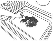
2. Pour 13/4 cups (14 oz [414 mL]) of distilled or filtered water onto the bottom of the empty oven, and close the oven door.
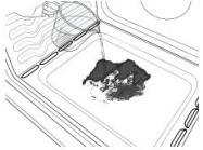
IMPORTANT: Do not use chemicals or other additives with the water. Do not open the oven door during the Clean cycle. The water on the oven bottom is hot.
3. Press CLEAN/AQUALIFT SELF CLEAN and then STARTon the oven control panel.
4. Allow 40 minutes for cleaning and cooldown. A beep will sound when the Clean cycle is complete.
5. Press OFF/CANCEL/CANCEL UPPER at the end of the cycle. Off/Cancel/Cancel Upper may be pressed at any time to stop the Clean cycle.
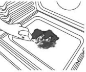
6. Remove the residual water and loosened soils with a sponge or cloth immediately after the Clean cycle is complete. Much of the initial 13/4 cups (14 oz [414 mL]) of water will remain in the oven after the cycle is completed. If additional soils remain, leave a small amount of water in the oven bottom to assist with the cleaning.
7. If any soils remain, remove them with a nonscratch scrubbing sponge or plastic scraper. Additional Clean cycles may be run to help remove the stubborn soils.
IMPORTANT: Do not use oven cleaners. The use of chemicals, including commercial oven cleaners or metal scouring pads, may cause permanent damage to the porcelain surface of the oven interior.
NOTE:
- The range should be level to ensure that the entire surface of the bottom of the oven cavity is covered by water at the beginning of the Clean cycle.
- For best results, use distilled or filtered water. Tap water may leave mineral deposits on the oven bottom.
- Before removing the residual water and loosened soils at the end of the Clean cycle, insert a cloth or paper towel between the lower edge of the oven door and the front frame to keep water from spilling onto the front of the range and the floor.
- Soil baked on through several cooking cycles will be more difficult to remove with the Clean cycle.
- Nonabrasive scrub sponges or eraser-style cleaning pads (without cleaners) can be effective for cleaning the oven cavity walls, oven door, and oven bottom for difficult soils. For best results, moisten the pads and sponges before use.
- Run an additional Clean cycle for stubborn soils
- Affresh® Kitchen Appliance Cleaner and affresh® Cooktop Cleaner may be used to clean the oven bottom, walls, and door when the oven has finished the cycle and returned to room temperature. If affresh® Cooktop Cleaner is used, it is recommended to wipe out the cavity with distilled water as well. Refer to the Quick Start Guide for ordering information.
- Additional AquaLift® Technology Cleaning Kits may be obtained by ordering Part Number W10423113RP. Refer to the Quick Start Guide for ordering information.
INSTALLATION INSTRUCTIONS REQUIREMENTS
Location Requirements
IMPORTANT: Observe all governing codes and ordinances. Do not obstruct flow of combustion and ventilation air.
- It is the installer’s responsibility to comply with installation clearances specified on the model/serial/rating plate. The model/serial/rating plate is located behind the oven door on the top right/left-hand side of the oven frame.
- The range should be located for convenient use in the kitchen.
- Recessed installations must provide complete enclosure of the sides and rear of the range.
- All openings in the wall or floor where range is to be installed must be sealed.
- Cabinet opening dimensions that are shown must be used.
- Given dimensions are minimum clearances.
- The anti-tip bracket must be installed. To install the anti-tip bracket shipped with the range, see “Install Anti-Tip Bracket” section.
- Grounded electrical supply is required. See “Electrical Requirements” section.
- Proper gas supply connection must be available. See “Gas Supply Requirements” section.
- Contact a qualified floor covering installer to check that the floor covering can withstand at least 200°F (93°C).
- Use an insulated pad or 1/4" (6.35 mm) plywood under range if installing range over carpeting.
IMPORTANT: To avoid damage to your cabinets, check with your builder or cabinet supplier to make sure that the materials used will not discolor, delaminate or sustain other damage. This oven has been designed in accordance with the requirements of UL and CSA International and complies with the maximum allowable wood cabinet temperatures of 194°F (90°C).
INSTALLATION
Install Anti-Tip Bracket
1. Remove the anti-tip bracket from where it is taped inside the storage drawer, warming drawer, or premium storage drawer.
2. Determine which mounting method to use: floor or wall. If you have a stone or masonry floor, you can use the wall mounting method. If you are installing the range in a mobile home, you must secure the range to the floor.
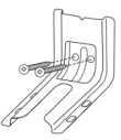
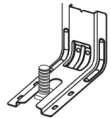
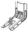
3. Determine and mark centerline of the cutout space. The mounting can be installed on either the left side or right side of the cutout. Position mounting bracket against the wall in the cutout so that the V-notch of the bracket is 129/16" (31.9 cm) from centerline as shown.
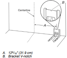
4. Drill two 1/8" (3 mm) holes that correspond to the bracket holes of the determined mounting method. See the following illustrations.
Floor Mounting
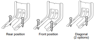
Wall Mounting
5. Using the Phillips screwdriver, mount anti-tip bracket to the wall or floor with the two #12 x 15/8" (4.1 cm) screws provided, mount anti-tip bracket to the wall or floor.
6. Move range close enough to opening to allow for final gas and electrical connections. Remove shipping base, cardboard or hardboard from under range.
7. Move range into its final location, making sure rear leveling leg slides into anti-tip bracket.
8. Move range forward onto shipping base, cardboard or hardboard to continue installing the range using the following installation instructions.
Make Gas Connection
Typical rigid pipe connection
A combination of pipe fittings must be used to connect the range to the existing gas line. Your connections may be different, according to the supply line type, size and location.
1. Apply pipe-joint compound made for use with Propane gas to all pipe thread connections.
2. Using a pipe wrench to tighten, connect the gas supply to the range.
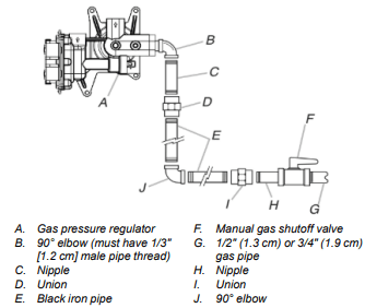
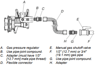
Typical flexible connection
1. Apply pipe-joint compound made for use with propane gas to the smaller thread ends of the flexible connector adapters (see B and G in the following illustration).
2. Attach one adapter to the gas pressure regulator and the other adapter to the gas shut-off valve. Tighten both adapters.
3. Use a 15/16" (23.8 mm) combination wrench and channel lock pliers to attach the flexible connector to the adapters. Check that connector is not kinked.
Complete Connection
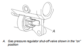
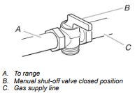
1. Check that the gas pressure regulator shut-off valve is in the “on” position.
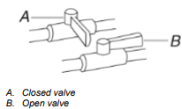
2. Open the manual shut-off valve in the gas supply line. The valve is open when the handle is parallel to the gas pipe.
3. Test all connections by brushing on an approved noncorrosive leak-detection solution. If bubbles appear, a leak is indicated. Correct any leak found.
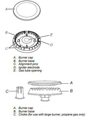
4. Remove cooktop burner caps and grates from parts package. Burner caps should be level when properly positioned. If burner caps are not properly positioned, surface burners will not light. Place burner grates over burners and caps.
For Models WFG775H0H and WFG975H0H
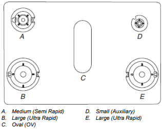
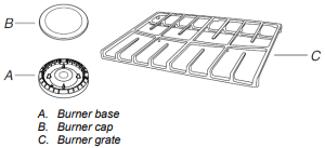
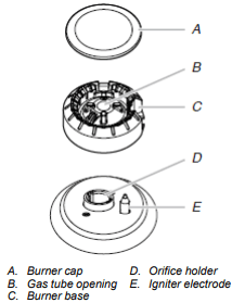
5. Align the gas tube opening in the burner base with the orifice holder on the cooktop and the igniter electrode with the notch in the burner base.
6. Place the burner caps on the appropriate burner bases.
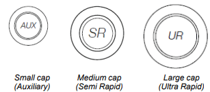
IMPORTANT: The bottom of the small and medium caps are different. Do not put the wrong size burner cap on the burner base. Each round burner cap is marked with an AUX, SR, UR, or ST to match with a letter on the burner base.
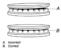
Burner caps should be level when properly positioned. If burner caps are not properly positioned, surface burners will not light. The burner cap should not rock or wobble when properly aligned.
7. Plug into a grounded 3-prong outlet.
8. Slide range into final location, making sure the rear leveling leg slides into the slot of the anti-tip bracket.
Install Griddle (on some models)
1. Place the “FRONT” end of the griddle down, facing the oven door. Verify that the lugs are placed onto the grate.
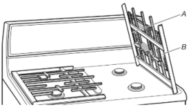
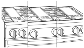
2. Clean the griddle before using. Refer to the “General Cleaning” section for cleaning instructions. The griddle can be placed over the left, right, or center burner.
Verify Anti-Tip Bracket Is Installed and Engaged
On Ranges Equipped with a Storage Drawer:
- Remove the storage drawer. See the “Storage Drawer” section.
- Use a flashlight to look underneath the bottom of the range.
- Visually check that the rear range foot is inserted into the slot of the anti-tip bracket.
On Ranges Equipped with a Warming Drawer or Premium Storage Drawer:
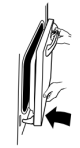
1. Place the outside of your foot against the bottom front of the warming drawer or premium storage drawer, and grasp the lower right or left side of the control panel as shown. NOTE: If your countertop is mounted with a backsplash, it may be necessary to grasp the range higher than is shown in the illustration.
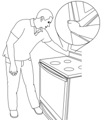
2. Slowly attempt to tilt the range forward. If you encounter immediate resistance, the range foot is engaged in the anti-tip bracket.
3. If the rear of the range lifts more than 1/2" (1.3 cm) off the floor without resistance, stop tilting the range and lower it gently back to the floor. The range foot is not engaged in the anti-tip bracket.
IMPORTANT: If there is a snapping or popping sound when lifting the range, the range may not be fully engaged in the bracket. Check to see if there are obstructions keeping the range from sliding to the wall or keeping the range foot from sliding into the bracket. Verify that the bracket is held securely in place by the mounting screws.
4. Slide the range forward, and verify that the anti-tip bracket is securely attached to the floor or wall.
5. Slide range back so the rear range foot is inserted into the slot of the anti-tip bracket.
IMPORTANT: If the back of the range is more than 2" (5.1 cm) from the mounting wall, the rear range foot may not engage the bracket. Slide the range forward and determine if there is an obstruction between the range and the mounting wall. Changes to the gas supply must be performed by a qualified service technician. If you need assistance or service, refer to the Quick Start Guide for contact informatio
6. Repeat steps 1 and 2 to ensure that the range foot is engaged in the anti-tip bracket.
If the rear of the range lifts more than 1/2" (1.3 cm) off the floor without resistance, the anti-tip bracket may not be installed correctly. Do not operate the range without anti-tip bracket installed and engaged. If you need assistance or service, refer to the Quick Start Guide for contact information.
Level Range
Determine if you have AquaLift® Technology or Steam Clean by referring to the “Range Maintenance and Care” section.
For Ranges with AquaLift® Technology or Steam Clean:
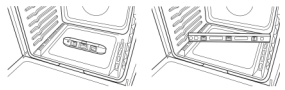
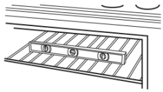
1. Place level on the oven bottom as indicated in one of the two figures below depending on the size of the level. Check with the level side to side and front to back.
2. If range is not level, pull range forward until rear leveling leg is removed from the anti-tip bracket.
3. Follow the directions in Style 1 or Style 2, depending on the style of drawer supplied with the range.
For Ranges without AquaLift® Technolog
1. Place a standard flat rack in oven.
2. Place level on the rack and check levelness of the range, first side to side; then front to back.
3. If range is not level, pull range forward until rear leveling leg is removed from the anti-tip bracket.
4. Follow the directions in Style 1 or Style 2, depending on the style of drawer supplied with the range.
Style 1: Ranges Equipped with a Storage Drawer:
Use a 1/4" (6.4 mm) drive ratchet, wrench or pliers to adjust leveling legs up or down until the range is level. Push range back into position. Check that rear leveling leg is engaged in the anti-tip bracket.
Style 2: Ranges Equipped with a Warming Drawer or Premium Storage Drawer:
Use a wrench or pliers to adjust leveling legs up or down until the range is level. Push range back into position. Check that rear leveling leg is engaged in the anti-tip bracket.
NOTE: Range must be level for satisfactory baking performance and best cleaning results using AquaLift® Technology and Steam Clean functions.
Check Operation of Oven Bake Burner
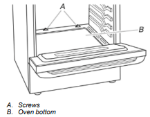
1. Remove the oven rack.
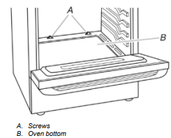
2. To remove the oven bottom: Remove 2 screws at the rear of the oven bottom. Lift the rear of the oven bottom up and back until the front of the panel is away from the front frame. Remove it from oven and place on a covered surface.
3. You can check the burner flame by using a mirror. Insert a mirror to one side of the burner. Look into the mirror to check flame.
4. Push the BAKE pad.
5. Press the START pad.
The oven bake burner should light within 8 seconds. Under certain conditions, it may take the burner up to 50 to 60 seconds to light.
Electronic igniters are used to light the bake and broil burners.
Refer to the Quick Start Guide and online Control Guide for proper operation of the oven controls.
Adjust Oven Bake Burner Flame (if needed)
1. On models with a warming drawer, remove access cover plate (1 screw) located at the back of the warming drawer compartment.
2. Check the oven bake burner for proper flame.
This flame should have a 1/2" (1.3 cm) long inner cone of bluish-green, with an outer mantle of dark blue, and should be clean and soft in character. No yellow tips, blowing or lifting of flame should occur.
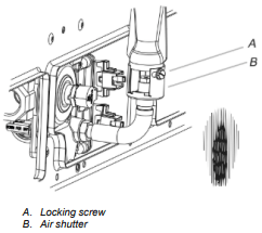
3. If the oven bake flame needs to be adjusted, locate the air shutter near the center rear of the range. Loosen the locking screw and rotate the air shutter until the proper flame appears. Tighten locking screw.
4. Push CANCEL/OFF when finished.
5. Reinstall flame spreader and oven bake burner cover.
Check Operation of Oven Broil Burner
1. Close the oven door.
2. Press the BROIL pad.
3. Press the START pad.
The oven burner should light within 8 seconds. Under certain conditions, it may take the burner up to 50 to 60 seconds to light.
Refer to the Quick Start Guide and online Control Guide for proper operation of the oven controls.
Adjust Oven Broil Burner Flame (if needed)
Look through oven window to check broil burner for proper flame. This flame should have a 1/2" (1.3 cm) long inner cone of bluishgreen, with an outer mantle of dark blue, and should be clean and soft in character. No yellow tips, blowing or lifting of flame should be present.
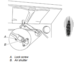
If flame needs to be adjusted:
1. Loosen the lock screw on the air shutter located at the rear of the broil burner.
2. Adjust the air shutter as needed.
3. Tighten lock screw.
4. Press CANCEL/OFF when finished.
Warming Drawer or Premium Storage Drawer (on some models)
Remove all items from inside the baking drawer, warming drawer or premium storage drawer, and then allow the range to cool completely before attempting to remove the drawer.
To Remove:
1. Open the drawer to its fully open position.
2. Using a flat-blade screwdriver, gently loosen the drawer from the glide alignment notch, and then lift up the drawer alignment tab from the glide.
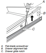
3. Repeat Step 2 on the other side. The drawer is no longer attached to the drawer glides. Using both hands, pick up the drawer to complete the removal.
To Replace:
1. Align the forward drawer notches with the notches in the drawer glides on both sides. Place the rear alignment tabs into the drawer glides on both sides.v
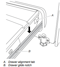
2. Push the warming drawer or premium storage drawer in all the way.
3. Gently open and close the warming drawer or premium storage drawer to ensure it is seated properly on the glides on both sides.
Oven Door
For normal range use, it is not suggested to remove the oven door. However, if removal is necessary, make sure the oven is OFF and cool. Then, follow these instructions. The oven door is heavy
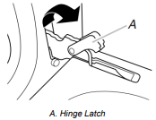
To Remove:
1. Open oven door all the way.
2. Pinch the hinge latch between two fingers and pull forward. Repeat on other side of oven door.
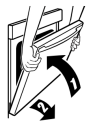
3. Close the oven door as far as it will shut.
4. Lift the oven door while holding both sides. Continue to push the oven door closed and pull it away from the oven door frame.
To Replace:
1. Insert both hanger arms into the door.
2. Open the oven door. You should hear a click as the door is set into place.
3. Move the hinge levers back to the locked position. Check that the door is free to open and close. If it is not, repeat the removal and installation procedures.
Complete Installation
- Check that all parts are now installed. If there is an extra part, go back through the steps to see which step was skipped.
- Check that you have all of your tools.
- Dispose of/recycle all packaging materials.
- Check that the range is level. See the “Level Range” section.
- Use a mild solution of liquid household cleaner and warm water to remove waxy residue caused by shipping material. Dry thoroughly with a soft cloth. For more information, read the “Range Maintenance and Care” section.
- Read the Quick Start Guide and online Control Guide.
- Turn on surface burners and oven. See the Quick Start Guide and online Control Guide for specific instruction on range operation.
If Range Does Not Operate, Check the Following:
- Household fuse is intact and tight; or circuit breaker has not tripped.
- Range is plugged into a grounded 3-prong outlet.
- Gas pressure regulator shutoff valve is in the “on” position.
- Electrical supply is connected.
- See the online “Troubleshooting” section
8. When the range has been on for 5 minutes, check for heat. If the range is cold, turn off the range and check that the gas supply line shut-off valve is open.
- If the gas supply line shut-off valve is closed, open it, and then repeat the 5 minute test as outlined above.
- If the gas supply line shutoff valve is open, press the CANCEL button on the oven control panel and contact a qualified technician.
Natural Gas Conversion
1. Turn manual shutoff valve to the closed position.
2. Unplug range or disconnect power.
To Convert Gas Pressure Regulator (Propane Gas to Natural Gas)
1. Remove the premium storage drawer, warming drawer or baking drawer or premium storage drawer. See the Remove / Replace Drawer, Storage Drawer or Warming Drawer or Premium Storage Drawer section.
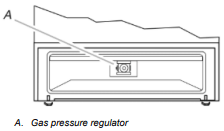
2. Locate gas pressure regulator at rear of the drawer compartment. NOTE: On models with a warming drawer or baking drawer, an access cover must be removed to access the gas pressure regulator.
IMPORTANT: Do not remove the gas pressure regulator
3. Remove plastic cover from gas pressure regulator cap.
4. Turn gas pressure regulator cap counterclockwise with a 5/8" (1.6 cm) combination wrench to remove.
NOTE: Do not remove the spring beneath the cap.
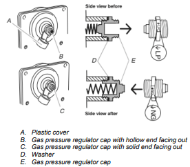
5. Turn over the gas pressure regulator cap and reinstall on regulator so that the solid end faces out and the marking “↓NG” is facing the direction shown in the above drawing.
6. Replace plastic cover over gas pressure regulator cap.
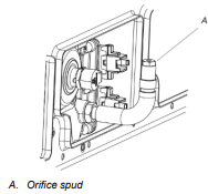
To Convert Surface Burners (Propane Gas to Natural Gas)
1. Remove burner cap.
2. Remove the burner base.
3. Apply masking tape to the end of a 9/32" (7 mm) nut driver to help hold the gas orifice spud in the nut driver while changing it. Press nut driver down onto the gas orifice spud and remove by turning it counterclockwise and lifting out. Set gas orifice spud aside.
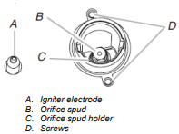
4. Gas orifice spuds are stamped with a number on the side. Replace the propane gas orifice spud with the correct Natural gas orifice spud.
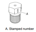
Refer to the following chart for the correct Natural gas orifice spud placement.
Natural Gas Orifice Spud Chart
| Burner Rating |
Size (mm) |
ID Number |
| 18,000 BTU |
2.00 |
200AM |
| 17,000 BTU |
1.96 |
196AM |
| 15,000 BTU |
1.80 |
180AM |
| 9,500 BTU |
1.40 |
140AM |
| 8,000 BTU |
1.30 |
130AM |
| 5,000 BTU |
1.00 |
100AM |
NOTE: Refer to the model/serial/rating plate located on the oven frame behind the top right-hand side of the oven door for proper sizing of spuds for each burner location.
5. Place propane gas orifice spuds in the orifice spud bag.
IMPORTANT: Keep the propane gas orifice spuds in case of reinstallation with propane gas.
6. Replace the burner base using both screws.
7. Replace burner cap.
8. Repeat steps 1 through 7 for the remaining burners.
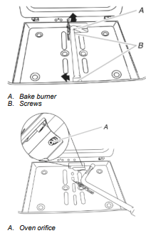
To Convert Oven Bake Burner (Propane Gas to Natural Gas)
1. Remove the oven racks and the oven door. See the “Oven Door” section.
2. Remove two screws and washers at the rear of the oven bottom.
3. Lift the rear of the oven bottom up and back until the front of the panel is away from the front frame. Remove from oven and set it aside on a covered surface
4. Remove two screws from the bake burner.
5. Slide the front of the bake burner to the side to remove tab from front of oven. Lift the back of the bake burner off the oven orifice, and set the bake burner aside. Do not disconnect the wire.
6. Apply masking tape to the end of a 3/8" (9.5 mm) nut driver to help hold the gas orifice spud in the nut driver while changing it. Press nut driver down onto the gas orifice spud and remove by turning the propane gas bake burner orifice spud counterclockwise to remove. The spud will be stamped with a “56.”
7. Replace the “56” spud with a “47” spud. Install the Natural gas bake burner orifice spud, turning it clockwise until snug.
IMPORTANT: Do not overtighten.
8. Position the back of the bake burner over the oven orifice, and then align the holes for the screws.
9. Reattach the bake burner with two screws.
10. Position the front of the oven bottom panel toward the front frame, and then lower the rear of the oven bottom panel into the oven.
11. Reattach the oven bottom panel with two screws and two washers.
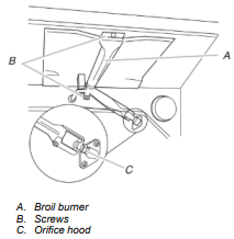
To Convert Oven Broil Burner (Propane Gas to Natural Gas)
1. Remove the screw from the broil burner.
2. Remove the flame spreader.
3. Remove the broil burner from the broil burner orifice hood.
NOTE: The broil burner will hang in the back of the oven while changing the orifice hood.
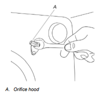
4. Using a 3/8" (9.5 mm) combination wrench, turn the Propane gas broil burner orifice hood counterclockwise to remove. The hood will be stamped with a “100.”
5. Replace the “100” hood with a “155” hood. Install the Natural gas broiler burner orifice hood, turning it clockwise until snug.
IMPORTANT: Do not overtighten.
6. Place the broil burner on the broil burner orifice hood and insert the broil burner ceramic igniter in the hole in the rear of the oven.
7. Position the broil burner against the top of the oven and attach it with 2 screws.
8. Replace storage drawer or warming drawer. See the “Storage Drawer” or “Warming Drawer or Premium Storage Drawer” section.
9. Replace the oven door. See the “Oven Door” section.
10. Replace the oven racks.
Complete Installation (Propane Gas to Natural Gas)
1. Refer to the “Make Gas Connection” section for properly connecting the range to the gas supply.
2. Refer to the “Electronic Ignition System” section for proper burner ignition, operation and burner flame adjustments.
IMPORTANT: You may have to adjust the “LO” setting for each cooktop burner.
Checking for proper cooktop, bake and broil burner flame is very important. The small inner cone should have a very distinct blue flame 1/4" (0.64 cm) to 1/2" (1.3 cm) long. The outer cone is not as distinct as the inner cone. Propane gas flames have a slightly yellow tip.
3. Refer to “Complete Installation” in the “Installation Instructions” section of this manual to complete this procedure.
NOTE: Make sure to save the orifices that have just been replaced in the conversion.
Moving the Range
When moving range, slide range onto cardboard or hardboard to avoid damaging the floor covering.
If removing the range is necessary for cleaning or maintenance:
For power supply cord-connected ranges:
1. Slide range forward.
2. Turn manual shutoff valve to the closed position.
3. Unplug the power supply cord.
4. Disconnect the gas supply tubing.
5. Complete cleaning or maintenance.
6. Reconnect the gas supply tubing.
7. Open the manual shutoff valve in the gas supply line.
8. Plug in power supply cord.
9. Slide range back so rear range foot is under anti-tip bracket.
10. Refer to the “Verify Anti-Tip Bracket Is Installed and Engaged” section to verify engagement.
11. Check that range is level.