Loading ...
Loading ...
Loading ...
8
Customer Service Troubleshooting Tips Care and Cleaning Operating Instructions Safety Instructions
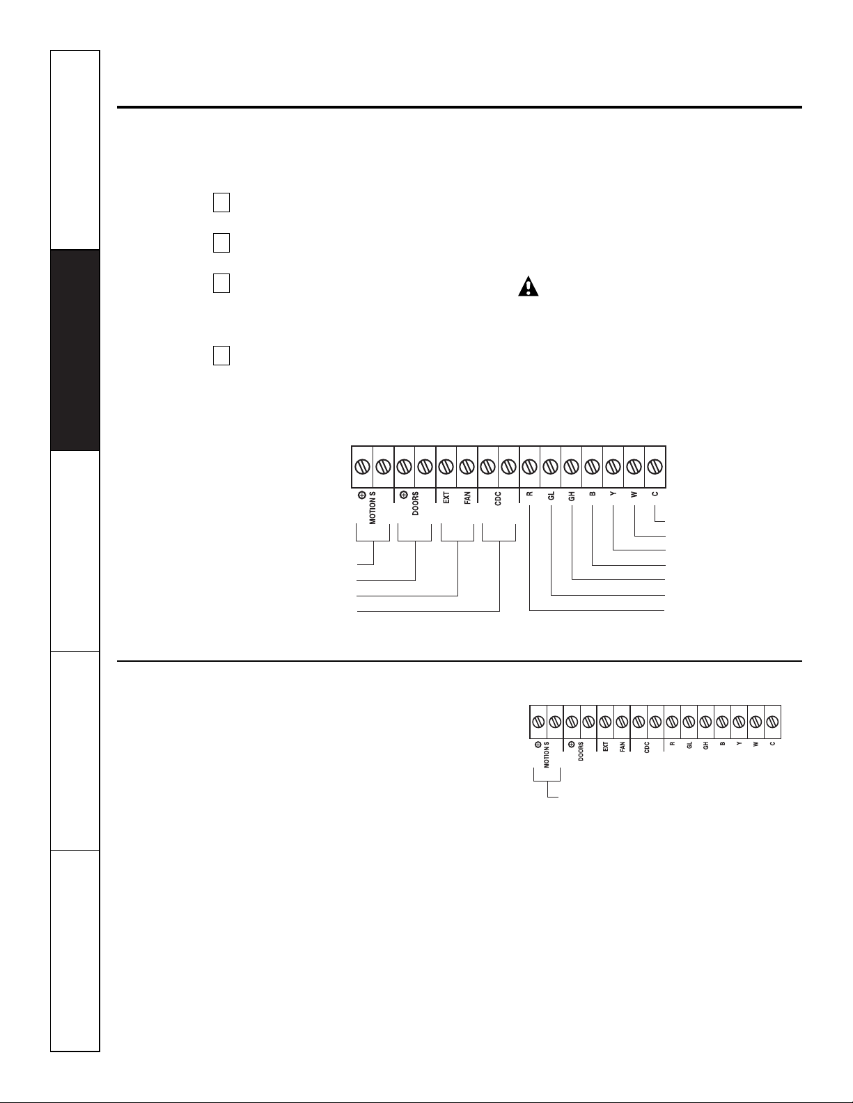
Auxiliary controls on your Zoneline.
Auxiliary Controls–Terminal Connections
The auxiliary controls are located behind the
room cabinet beneath the control panel.
Remove the room cabinet. See the
To Remove the Room Cabinet
section.
Remove the screw from the control panel
corner.
Remove the control panel and knobs by
grasping the control panel on both sides and
pulling forward. The knobs will pull off with
the control panel.
After all desired settings have been made,
replace the control panel, knobs and room
cabinet by reversing steps 1–3.
NOTE:
The
knob stem is D shaped. Install the flat of the
shaft to the flat of the knob.
The owner is responsible for making all
connections and setting the appropriate
dip switches.
Insert the building hook-up wires into the
bottom of the terminal and tighten screw
securely to make the desired connections.
CAUTION:
Improper wiring may damage the Zoneline
electronics. No common busing is permitted.
Damage or erratic operation may result.
A separate wire pair must be run from each
separate controlling switch to each individual
Zoneline.
4
3
2
1
Motion Sensor
Door Sensor
External Fan
Central Desk Control
Common - Ground
White - Heater
Yellow - Compressor
Black - Solenoid
Green - High Speed Fan
Green - Low Speed Fan
Red - 24 V AC only
Motion Sensor (Obtained locally)
When connected, the wall mounted motion
sensor will detect motion in the room and
automatically turn the unit ON or OFF.
The door and motion sensors work together
to automatically turn the unit ON or OFF.
Motion Sensor
Loading ...
Loading ...
Loading ...