■ Drill with 11 /4" (3 cm), 3/8" (9.5 mm), and 3/16" (4.8 mm) drill bits
■ Pencil
■ Wire stripper or utility knife
■ Tape measure or ruler
■ Pliers
■ Caulking gun and weatherproof caulking compound
■ Vent clamps
■ Jigsaw or keyhole saw
■ Flat-blade screwdriver
■ Metal snips
■ Phillips screwdriver
Parts Needed
■ Home power supply cable
■ 1/2" (12.7 mm) UL Listed or CSA approved strain relief
■ Three UL Listed wire connectors For Vented Installations, You Will Also Need:
■ One wall or roof cap
■ Metal vent system For Non-Vented (Recirculating) Installations, You Will Also Need:
■ Recirculation Kit - See the “Assistance or Service” section to order. 6" (15.2 cm) diameter round metal vent duct - length required is determined by ceiling heigh
Parts Supplied
Remove parts from packages. Check that all parts are included.
■ Hood canopy assembly with blower and LED lights installed
■ Vent transition with back draft dampers installed
■ Vent cover support bracket
■ Metal grease filter(s)
■ Mounting template
■ Two piece vent cover
■ Two 2.9 x 6.5 mm screws (Phillips)
■ Two 3.5 x 9.5 mm screws (Phillips)
■ Six 5 x 45 mm mounting screws (#2 Phillips)
■ Four 5.4 x 75 mm screws (Phillips) (for 10 x 60 mm wall anchors)
■ Two 8 x 40 mm wall anchors (masonry)
■ Four 10 x 60 mm wall anchors
Location Requirements
IMPORTANT: Observe all governing codes and ordinances. Have a qualified technician install the range hood. It is the installer’s responsibility to comply with installation clearances specified on the model/serial/rating plate. The model/serial/ rating plate is located behind the left filter on the rear wall of the vent hood.
Canopy hood location should be away from strong draft areas, such as windows, doors, and strong heating vents. Cabinet opening dimensions that are shown must be used. Given dimensions provide minimum clearance.
This range hood is recommended for use with cooktops with a maximum total rating of 65,000 BTUs or less. Grounded electrical outlet is required. See “Electrical Requirements” section.
The canopy hood is factory set for venting through the roof or wall. For non-vented (recirculating) installation, see “For non-vented (recirculating) installation only” in the “Connect Vent System” section. Recirculation Kit is available from your dealer or an authorized parts distributor. See the "Assistance or Service" section to order. All openings in ceiling and wall where canopy hood will be installed must be sealed.
For Mobile Home Installations
The installation of this range hood must conform to the Manufactured Home Construction Safety Standards, Title 24 CFR, Part 328 (formerly the Federal Standard for Mobile Home Construction and Safety, Title 24, HUD, Part 280) or when such standard is not applicable, the standard for Manufactured Home Installation 1982 (Manufactured Home Sites, Communities and Setups) ANSI A225.1/NFPA 501A, or latest edition, or with local codes.
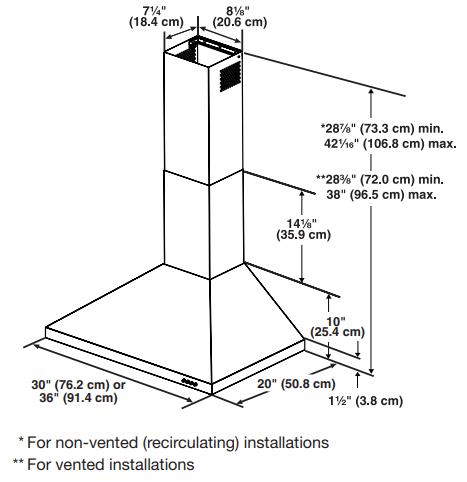
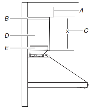
Product Dimensions
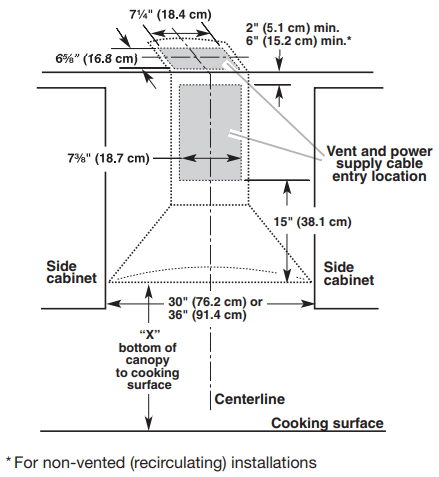
Cabinet Dimensions
IMPORTANT:
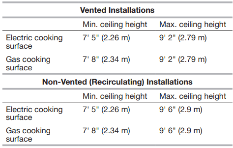
Minimum distance “X”: 24" (61 cm) from electric cooking surface Minimum distance “X”: 27" (68.6 cm) from gas cooking surface Suggested maximum distance “X”: 36" (91.4 cm) The chimneys can be adjusted for different ceiling heights. See the following chart
NOTE: The range hood chimneys are adjustable and designed to meet varying ceiling or soffit heights, depending on the distance “X” between the bottom of the range hood and the cooking surface. For higher ceilings, a Chimney Extension Kit is available from your dealer or an authorized parts distributor. The chimney extension replaces the upper chimney shipped with the range hood. See the “Assistance or Service” section to order
■ Vent system must terminate to the outdoors except for non-vented (recirculating) installations.
■ Do not terminate the vent system in an attic or other enclosed area.
■ Do not use 4" (10.2 cm) laundry-type wall cap.
■ Use metal vent only. Rigid metal vent is recommended. Plastic or metal foil vent is not recommended.
■ The length of vent system and number of elbows should be kept to a minimum to provide efficient performance. For the Most Efficient and Quiet Operation:
■ Use no more than three 90° elbows.
■ Make sure there is a minimum of 24" (61 cm) of straight vent between the elbows if more than one elbow is used.
■ Do not install two elbows together.
■ Use clamps to seal all joints in the vent system.
■ The vent system must have a damper. If the roof or wall cap has a damper, do not use the damper supplied with the range hood.
■ Use caulking to seal exterior wall or roof opening around the cap.
■ The size of the vent should be uniform
Cold Weather Installations
An additional back draft damper should be installed to minimize backward cold air flow and a thermal break should be installed to minimize conduction of outside temperatures as part of the vent system.
The damper should be on the cold air side of the thermal break. The break should be as close as possible to where the vent system enters the heated portion of the house.
Makeup Air
Local building codes may require the use of makeup air systems when using ventilation systems greater than specified CFM of air movement. The specified CFM varies from locale to locale. Consult your HVAC professional for specific requirements in your area
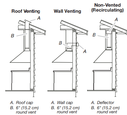
Venting Methods
This canopy hood is factory set for venting through the roof or wall. A 6" (15.2 cm) round vent system is needed for installation (not included). The hood exhaust opening is 6" (15.2 cm) round.
NOTE: Flexible vent is not recommended. Flexible vent creates back pressure and air turbulence that greatly reduce performance. Vent system can terminate either through the roof or wall. To vent through a wall, a 90° elbow is needed.
Rear Discharge
A 90° elbow may be installed immediately above the hood.
For Non-Vented (Recirculating) Installations
If it is not possible to vent cooking fumes and vapors to the outside, the hood can be used in the non-vented (recirculating) version, fitting a charcoal filter and the deflector. Fumes and vapors are recycled through the top grille. See the “Assistance or Service” section for information on ordering.
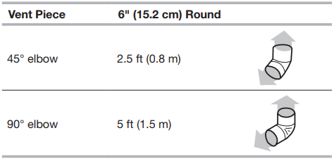
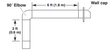
Calculating Vent System Length
To calculate the length of the system you need, add the equivalent feet (meters) for each vent piece used in the system.
Example Vent System
The following example falls within the maximum recommended vent length of 35 ft (10.7 m).
1 - 90° Elbow = 5 ft (1.5 m)
1 - Wall cap = 0 ft (0 m)
8 ft (2.4 m) straight = 8 ft (2.4 m)
Length of system = 13 ft (3.9 m)
Observe all governing codes and ordinances. Ensure that the electrical installation is adequate and in conformance with National Electrical Code, ANSI/NFPA 70 (latest edition) or CSA Standards C22.1-94, Canadian Electrical Code, Part 1 and C22.2 No. 0-M91 (latest edition), and all local codes and ordinances.
If codes permit and a separate ground wire is used, it is recommended that a qualified electrician determine that the ground path is adequate.
A copy of the above code standards can be obtained from: National Fire Protection Association 1 Batterymarch Park Quincy, MA 02169-7471 CSA International 8501 East Pleasant Valley Road Cleveland, OH 44131-5575
■ A 120 volt, 60 Hz., AC only, 15-amp, fused electrical circuit is required.
■ If the house has aluminum wiring, follow the procedure below:
1. Connect a section of solid copper wire to the pigtail leads.
2. Connect the aluminum wiring to the added section of copper wire using special connectors and/or tools designed and UL Listed for joining copper to aluminum. Follow the electrical connector manufacturer’s recommended procedure. Aluminum/copper connection must conform with local codes and industry accepted wiring practices.
■ Wire sizes and connections must conform with the rating of the appliance as specified on the model/serial/rating plate. The model/serial/rating plate is located behind the left filter on the rear wall of the range hood.
■ Wire sizes must conform to the requirements of the National Electrical Code, ANSI/NFPA 70 (latest edition), or CSA Standards C22. 1-94, Canadian Electrical Code, Part 1 and C22.2 No. 0-M91 (latest edition) and all local codes and ordinances.
INSTALLATION INSTRUCTIONS
■ It is recommended that the vent system be installed before hood is installed.
■ Before making cutouts, make sure there is proper clearance within the ceiling or wall for exhaust vent.
■ Check your ceiling height and the hood height maximum before you select your hood.
1. Disconnect power.
2. Determine which venting method to use: roof, wall, or non-vented.
3. Select a flat surface for assembling the range hood. Place covering over that surface
4. Using two or more people, lift range hood onto covered surface.
5. Remove wood base from range hood and dispose of properly
Range Hood Mounting Screws Installation
1. Determine and mark the centerline on the wall where the canopy hood will be installed.
2. Select a mounting height between a minimum of 24" (61 cm) for an electric cooking surface, a minimum of 27" (68.6 cm) for a gas cooking surface, and a suggested maximum of 36" (91.4 cm) above the range to the bottom of the hood. Mark a reference line on the wall.
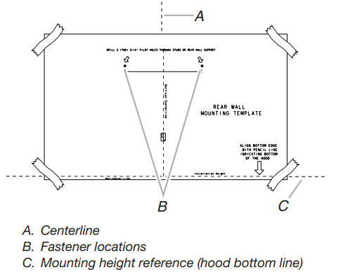
3. Tape template in place, aligning the template centerline and bottom of template with hood bottom line and with the centerline marked on the wall.
A. Centerline
B. Fastener locations
C. Mounting height reference (hood bottom line)
4. Mark centers of the fastener locations through the template to the wall.
IMPORTANT: All canopy mounting screws must be installed into wood where possible. If there is no wood to screw into, additional wall framing supports may be required or use the (4) 10 x 60 mm wall anchors and 5.4 x 75 mm screws. Remove the template.
5. For wood, drill 3/16" (4.8 mm) pilot holes at all locations where screws are being installed into wood. For wall anchors, drill 7/16" (10 mm) holes at all locations where wall anchors are being used.
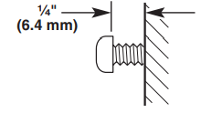
6. For wood, install (2) 5 x 45 mm mounting screws. Leave a 1/4" (6.4 mm) gap between the wall and the back of the screw head to slide range hood into place. For wall anchors, install the 10 x 60 mm wall anchors and install the 5.4 x 75 mm screws into the wall anchors. Tighten until the wall anchors are secure. Back the screws out 1/4" (6.4 mm).
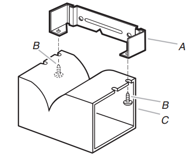
Vent Cover Support Bracket Installation
Installations using telescoping upper and lower vent cover assembly
1. Position vent cover bracket on wall about 1/8" (3 mm) away from the ceiling.
2. Mark the hole locations.
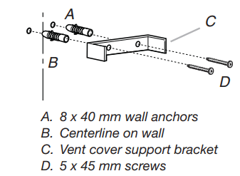
3. Drill (2) 3/8" (9.5 mm) holes for 8 x 40 mm wall anchors and insert anchors flush with the wall.
A. 8 x 40 mm wall anchors
B. Centerline on wall
C. Vent cover support bracket
D. 5 x 45 mm screws
4. Attach vent cover support bracket to wall.
Complete Preparation
1. Determine and make all necessary cuts in the wall for the vent system. Install the vent system before installing the hood. See “Venting Requirements” section.
2. Determine the required height for the home power supply cable and drill a 11 /4" (3.2 cm) hole at this location.
3. Run the home power supply cable according to the National Electrical Code or CSA Standards and local codes and ordinances. There must be enough 1/2" (12.7 mm) conduit and wires from the fused disconnect (or circuit breaker) box to make the connection in the hood’s electrical terminal box.
NOTE: Do not reconnect power until installation is complete.
4. Use caulk to seal all openings
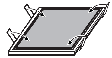
NOTE: Remove protective film from range hood and metal filters.
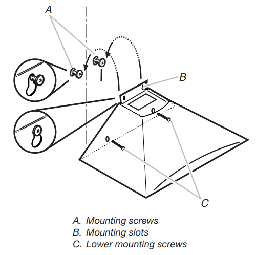
1. Using two or more people, hang range hood on two mounting screws through the mounting slots on back of hood.
A. Mounting screws
B. Mounting slots
C. Lower mounting screws
2. Remove the grease filter. See “Range Hood Care” section.
3. Level the range hood and tighten upper mounting screws.
4. Install (2) 5 x 45 mm lower mounting screws and tighten. Use the optional wall anchors if needed
Connect Vent System
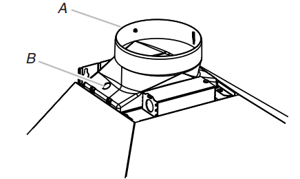
1. Install transition on top of hood (if removed for shipping) with (2) 3.5 x 9.5 mm sheet metal screws
A. Vent transition
B. 3.5 x 9.5 mm screw
For vented installations only:
1. Fit vent system over transition piece.
2. Seal connection with clamps.
3. Check that back draft dampers work properly.
For non-vented (recirculating) installation only:
1. Assemble the air deflector with the duct cover bracket with two assembly screws provided with the Recirculation Kit
A. Vent cover bracket
B. Assembly screws
C. Deflector
2. Measure from the bottom of the air deflector to the bottom of the hood outlet.
A. Air deflector
B. Vent clamp
C. X = length to cut vent duct
D. Vent duct E. Exhaust outlet
3. Cut the duct to the measured size “X.”
4. Remove the air deflector.
5. Slide the duct onto the bottom of the air deflector.
6. Place the assembled air deflector and duct over the exhaust outlet from the hood.
7. Reassemble the air deflector to the duct cover bracket with the two assembly screws.
8. Seal connections with vent clamps.
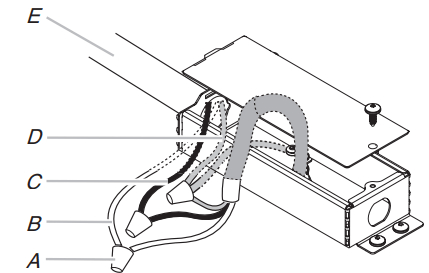
Make Electrical Connection
1. Disconnect power.
2. Remove terminal box cover.
3. Remove the knockout in the terminal box and install a UL Listed or CSA approved 1/2" (12.7 mm) strain relief.
4. Run home power supply wiring through 1/2" (12.7 mm) strain relief into terminal box
A. UL Listed wire connectors
B. White wires
C. Black wires
D. Green (or bare) wire connected to yellow-green wires
E. Home power supply
5. Use UL Listed wire connectors and connect white wires (B) together.
6. Use UL Listed wire connectors and connect black wires (C) together.
7. Connect green (or bare) ground wire from home power supply to the two yellow-green ground wires (D) in terminal box using UL Listed wire connectors.
8. Tighten strain relief screw
9. Install terminal box cover.
10. Reconnect power.
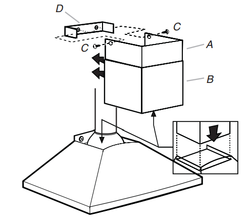
Install Vent Covers
NOTE: Remove protective film from the vent covers.
1. When using both upper and lower vent covers, push lower cover down onto hood and lift upper cover to ceiling and install with (2) 2.9 x 6.5 mm screws.
A. Upper vent cover
B. Lower vent cover
C. 2.9 x 6.5 mm screws
D. Bracket
NOTE: For vented installations, the upper vent cover may be reversed to hide slots
Complete Installation
1. For non-vented (recirculating) installations only, install charcoal filters over the grease filters, using the clips provided in the kit. See the “Range Hood Care” section.
2. Install metal filters. See the “Range Hood Care” section.
3. Check the operation of the range hood blower and light. See the “Range Hood Use” section.
NOTE: To get the most efficient use from your new range hood, read the “Range Hood Use” section
RANGE HOOD USE
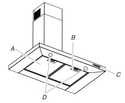
The range hood is designed to remove smoke, cooking vapors, and odors from the cooktop area. For best results, start the hood before cooking and allow it to operate several minutes after the cooking is complete to clear all smoke and odors from the kitchen. The hood controls are located on the front side of the canopy
A. Grease filter
B. Grease filter handle
C. Blower and light controls
D. LED lights
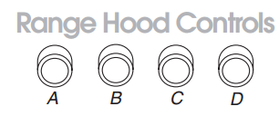
Range Hood Controls
A. On/Off light button
B. Blower off and speed minimum button
C. Blower speed medium button
D. Blower speed maximum butto
Operating the light
The On/Off light button controls both lights. Press once for on and again for off.
Operating the blower
The Blower Speed buttons turn the blower on and control the blower speed and sound level for quiet operation. The speed can be changed anytime during fan operation by pressing the desired Blower Speed button. Press the Blower Off button a second time to turn the blower off
RANGE HOOD CARE
IMPORTANT: Clean the hood and grease filters frequently according to the following instructions. Replace grease filters before operating hood.
Exterior Surfaces
To avoid damage to the exterior surface, do not use steel wool or soap-filled scouring pads.
Always wipe dry to avoid water marks.
Cleaning Method:
■ Liquid detergent soap and water, or all-purpose cleanser
■ Wipe with damp soft cloth or nonabrasive sponge, and then rinse with clean water and wipe dry.
Metal Grease Filter
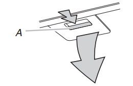
1. Remove the filter by pulling the spring release handle and then pulling down the filter.
A. Spring release handle
2. Wash metal filter as needed in dishwasher or hot detergent solution.
3. Reinstall the filter by making sure the spring release handles are toward the front. Insert aluminum filter into upper track.
4. Push in spring release handle
5. Push up on metal filter and release handle to latch into place. 6. Repeat steps 1-5 for the other filter.
Non-Vented (recirculating) Installation Filters
The charcoal filter is not washable. It should last up to 6 months with normal use. Replace with Charcoal Filter Kit. See the “Assistance or Service” section for information on ordering.
To replace charcoal filter:
1. Remove metal grease filter from range hood. See “Metal Grease Filter” in this section.
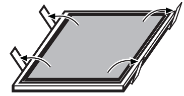
2. Bend spring clips away from metal grease filter
3. Place charcoal filter into top side of metal filter.
4. Bend spring clips back into place to secure the charcoal filter to the metal filter.
5. Replace metal grease filter. See “Metal Grease Filter” in this section
Replacing a LED Lamp
The LED lights are replaceable by a service technician only. See the “Warranty” section for service contact information.