USER MANUALWhirlpool RANGE HOODINSTALLATION INSTRUCTIONS
Prepare Location
- It is recommended that the vent system be installed before hood is installed.
- Before making cutouts, make sure there is proper clearance within the ceiling or wall for exhaust vent.
- Check your ceiling height and the hood height maximum before you select your hood.
- Disconnect power.
- Determine which venting method to use: roof, wall, or non-vented.
- Select a flat surface for assembling the range hood.
- Place covering over that surface
- Using two or more people, lift range hood onto covered surface.
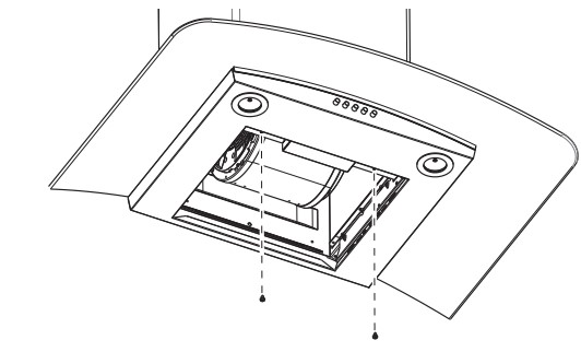
- Remove wood base from range hood and dispose of properly.
- Remove the metal grease filter and the white foam shipping block from inside the range hood located below the blower.
Range Hood Mounting Screws Installation
- Determine and mark the centerline on the wall where the canopy hood will be installed.
- Select a mounting height between a minimum of 24" (61 cm) for an electric cooking surface, a minimum of 27" (68.6 cm) for a gas cooking surface, and a suggested maximum of cm) above the range to the bottom of the hood.
Mark a reference line on the wall. - Tape template in place, aligning the template centerline and bottom of template with hood bottom line and with the centerline marked on the wall
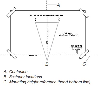
- Mark centers of the fastener locations through the template to the wall.
IMPORTANT: All canopy mounting screws must be installed into wood where possible. If there is no wood to screw into, additional wall framing supports may be required or use the (4) 10 x 60 mm wall anchors and 5.4 x 75 mm screws.
Remove the template. - For wood, drill 3/16" (4.8 mm) pilot holes at all locations where screws are being installed into wood. For wall anchors, drill 7/16" (10 mm) holes at all locations where wall anchors are being used.
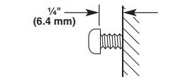
- For wood, install (2) 5 x 45 mm mounting screws. Leave a 1/4" (6.4 mm) gap between the wall and the back of the screw head to slide range hood into place. For wall anchors, install the 10 x 60 mm wall anchors and install the 5.4 x 75 mm screws into the wall anchors.
Tighten until the wall anchors are secure. Back the screws out 1/4" (6.4 mm).
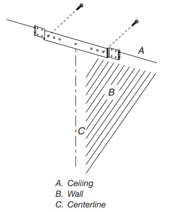
Vent Cover Bracket Installation
- Attach vent cover bracket to wall flush to the ceiling using (2) x 45 mm screws. Use the optional wall anchors if needed.
Complete Preparation
- Determine and make all necessary cuts in the wall for the vent system. Install the vent system before installing the hood. See “Venting Requirements” section.
- Determine the required height for the home power supply cable and drill a 11 cm) hole at this location.
- Run the home power supply cable according to the National Electrical Code or CSA Standards and local codes and ordinances. There must be enough 1/2" (12.7 mm) conduit and wires from the fused disconnect (or circuit breaker) box to make the connection in the hood’s electrical terminal box.
- NOTE: Do not reconnect power until installation is complete.
- Use caulk to seal all openings.
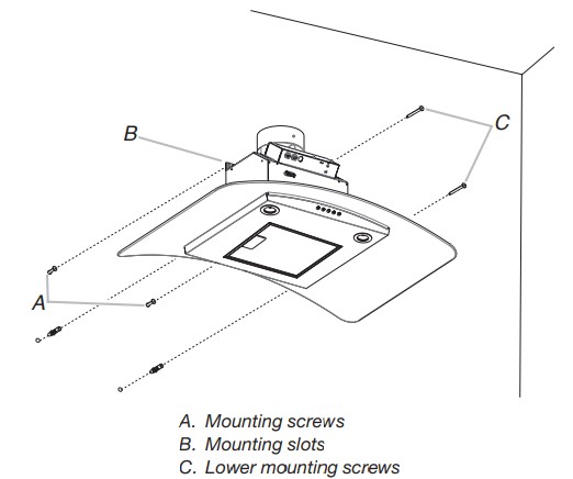
Install Range Hood
NOTE: Remove protective film from range hood and metal filters.
- Using two or more people, hang range hood on two mounting screws through the mounting slots on back of hood
- Remove the grease filter. See “Range Hood Care” section.
- Level the range hood and tighten upper mounting screws.
- Install (2) 5 x 45 mm lower mounting screws and tighten. Use the optional wall anchors if needed.
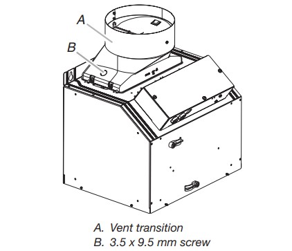
Connect Vent System
- Install transition on top of hood (if removed for shipping) with (2) 3.5 x 9.5 mm sheet metal screws.
For vented installations only:
- Fit vent system over the exhaust outlet.
- Seal connection with clamps.
- Check that back draft dampers work properly
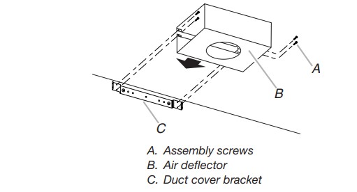
For non-vented (recirculating) installation only:
- Assemble the air deflector with the duct cover bracket using (4) 4.2 x 8 mm screws.
- Measure from the bottom of the air deflector to the bottom of the hood outlet.
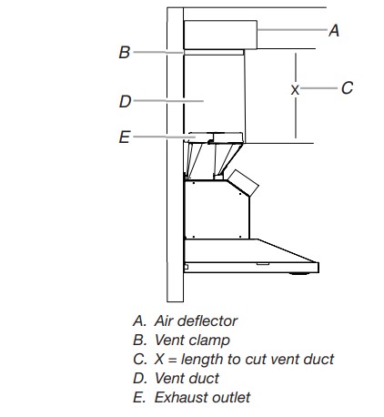
- Cut the duct to the measured size “X.”
- Remove the air deflector.
- Slide the duct onto the bottom of the air deflector.
- Place the assembled air deflector and duct over the exhaust outlet from the hood.
- Reassemble the air deflector to the duct cover bracket with the four assembly screws.
- Seal connections with vent clamps.
Make Electrical Connection
- Disconnect power.
- Remove terminal box cover.
- Remove the knockout in the terminal box and install a UL Listed or CSA approved 1/2" (12.7 mm) strain relief.
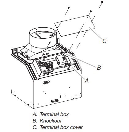
- Run home power supply cable through strain relief into terminal box.
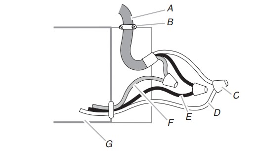
- Use UL Listed wire connectors and connect black wires (E) together.
- Use UL Listed wire connectors and connect white wires (C) together.
- Connect green (or bare) ground wire from home power supply to yellow-green ground wire (F) in terminal box using UL Listed wire connectors.
- Tighten strain relief screw.
- Install terminal box cover.
- Check that all light bulbs are secure in their sockets.
- Reconnect power.
Install Vent Covers
NOTE: Remove protective film from the vent covers.
- When using both upper and lower vent covers, push lower cover down onto hood, and then lift upper cover to ceiling and install with (2) 4.2 x 8 mm screws.
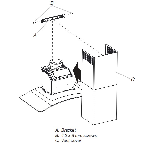
NOTE: For vented installations the upper vent cover may be reversed to hide slots. - Secure the bottom of the duct with (2) 4.2 x 8 mm screws
Complete Installation
- For non-vented (recirculating) installations only, install charcoal filters over metal grease filter. See the “Range Hood Care” section.
- Install metal filters. See the “Range Hood Care” section.
- Check the operation of the range hood blower and light. See the “Range Hood Use” section.
NOTE: To get the most efficient use from your new range hood, read the “Range Hood Use” section.
RANGE HOOD USE
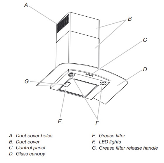
The range hood is designed to remove smoke, cooking vapors, and odors from the cooktop area. For best results, start the hood before cooking, and allow it to operate several minutes after the cooking is complete to clear all smoke and odors from the kitchen. The hood controls are located on the front side of the canopy
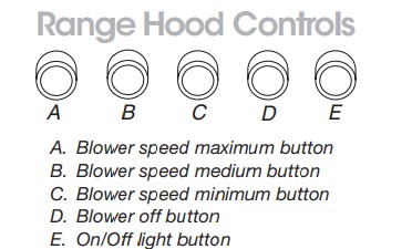
Operating the light
The On/Off light button controls both lights. Press once for On and again for Off.
Operating the blower
The Blower Speed buttons turn the blower on and control the blower speed and sound level for quiet operation. The speed can be changed anytime during fan operation by pressing the desired Blower Speed button. The Blower Off button turns the blower off.
RANGE HOOD CARE
Cleaning
Exterior Surfaces
To avoid damage to the exterior surface, do not use steel wool or soap-filled scouring pads.
Always wipe dry to avoid water marks.
Cleaning Method:
- Liquid detergent soap and water or all-purpose cleanser
- Wipe with damp soft cloth or nonabrasive sponge, and then rinse with clean water and wipe dry.
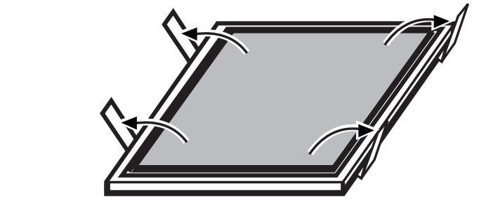
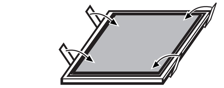
Metal Grease Filter
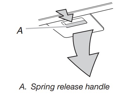
- Remove the filter by pulling the spring release handle and then pulling down the filter.
- Wash metal filter as needed in dishwasher or hot detergent solution.
- Reinstall the filter by making sure the spring release handles are toward the front. Insert aluminum filter into upper track.
- Push in spring release handle.
- Push up on metal filter and release handle to latch into place.
Non-Vented (recirculating) Installation Filters
The charcoal filter is not washable. It should last up to months with normal use. Replace with Charcoal Filter Kit. See the “Assistance or Service” section to order.
To replace charcoal filter:
- Remove metal grease filter from range hood.
- See “Metal Grease Filter” in this section.
- Bend spring clips away from metal grease filter.
- Place charcoal filter into top side of metal filter.
- Bend spring clips back into place to secure the charcoal filter to the metal filter.
- Replace metal grease filter. See “Metal Grease Filter” in this section.
Replacing a LED Lamp
The LED lights are replaceable by a service technician only.
See the “Warranty” section for service contact information.
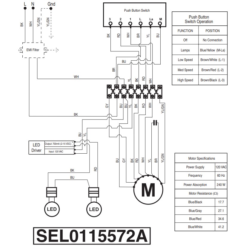
WIRING DIAGRAM
ASSISTANCE OR SERVICE
If You Need Service
Please refer to the warranty page in this manual.
If You Need Replacement Parts
If you need to order replacement parts, we recommend that you use only factory specified parts. Factory specified parts will fit right and work right because they are made with the same precision used to build every new appliance.
To locate factory specified replacement parts in your area, call the following customer assistance telephone number or your nearest designated service center.
In the U.S.A.
Call the Whirlpool Customer eXperience Center toll-free: or visit our website
Our Consultants Provide Assistance With:
- Scheduling of service. Whirlpool designated service technicians are trained to fulfill the product warranty and provide after-warranty service anywhere in the United States.
- Features and specifications on our full line of appliances.
- Referrals to local dealers.
- Installation information.
- Use and maintenance procedures.
- Accessory and repair parts sales.
- Specialized customer assistance (Spanish speaking, hearing impaired, limited vision, etc.).
For Further Assistance
If you need further assistance, you can write to Whirlpool Corporation with any questions or concerns at:
Whirlpool Brand Home Appliances
Customer eXperience Center
553 Benson Road
Benton Harbor, MI 49022-2692
Please include a daytime phone number in your correspondence.
In Canada
Call the Whirlpool Canada Customer eXperience Centre toll-free: or visit our website
Our Consultants Provide Assistance With:
- Scheduling of Service. Whirlpool designated service technicians are trained to fulfill the product warranty and provide after-warranty service anywhere in Canada.
- Features and specifications on our full line of appliances.
- Referrals to local dealers.
- Use and maintenance procedures.
- Accessory and repair parts sales.
For Further Assistance
If you need further assistance, you can write to Whirlpool
Canada with any questions or concerns at:
Whirlpool Brand Home Appliances
Customer eXperience Centre
200 - 6750 Century Ave.
Mississauga, Ontario L5N 0B7
Please include a daytime phone number in your correspondence.
Accessories
Recirculation Kit for non-vented installations only)
Order Part Number W10294733
Charcoal Filter Kit for non-vented installations only)
Order Part Number W10412939
Chimney Extension Kit (Stainless Steel)
Order Part Number EXTKIT10ES
Chimney Extension Kit (Black Stainless Steel)
Order Part Number EXTKIT10HV
6" (15.2 cm) Makeup Air Kit
(consult local building codes)
Order Part Number W10446915