To assure that the electrical installation is adequate and in conformance with National Electrical Code, ANSI/NFPA 70 — latest edition*, or CSA Standards C22.1-94, Canadian Electrical Code, Part 1 and C22.2 No.0-M91 - latest edition** and all local codes and ordinances.
If codes permit and a separate ground wire is used, it is recommended that a qualified electrician determine that the ground path is adequate. A copy of the above code standards can be obtained from:
National Fire Protection Association 1
Batterymarch Park
Quincy, MA 02169-7471
CSA International
8501 East Pleasant Valley Road
Cleveland, OH 44131-5575
A 120 volt, 60 Hz., AC only, 15-amp, fused electrical circuit is required.
If the house has aluminum wiring, follow the procedure below:
1. Connect a section of solid copper wire to the pigtail leads.
2. Connect the aluminum wiring to the added section of copper wire using special connectors and/or tools designed and UL listed for joining copper to aluminum
Follow the electrical connector manufacturer’s recommended procedure. Aluminum/copper connection must conform with local codes and industry accepted wiring practices.
Wire sizes and connections must conform with the rating of the appliance as specified on the model/serial rating plate. The model serial plate is located behind the filter on the rear wall of the range hood.
Wire sizes must conform to the requirements of the National Electrical Code, ANSI/NFPA 70 (latest edition), or CSA Standards C22. 1-94, Canadian Electrical Code, Part 1 and C22.2 No. 0-M91 (latest edition) and all local codes and ordinances.
Venting Requirements (ducted models only)
Vent system must terminate outdoors.
Do not terminate the vent system in an attic or other enclosed area.
Do not use a 4” (10.2 cm) laundry-type wall cap.
Use metal vent only. Rigid metal vent is recommended. Plastic or metal foil vent is not recommended.
The length of the vent system and the number of elbows should be kept to a minimum to provide efficient performance.
For the most efficient and quiet operation:
Use no more than three 90° elbows.
Make sure there is a minimum of 24” (61 cm) of straight vent between the elbows if more than 1 elbow is used.
Do not install 2 elbows together.
Use clamps to seal all joints in the vent system.
The vent system must have a damper. If the roof or wall cap has a damper, do not use the damper supplied with the range hood.
Use caulking to seal the exterior wall or roof opening around the cap.
The size of the vent should be uniform.
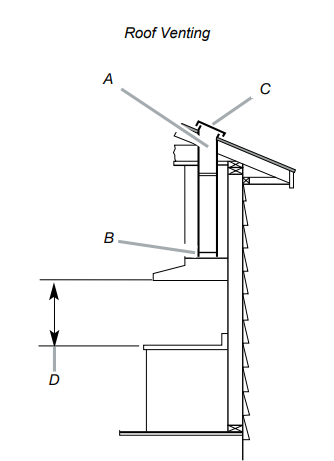
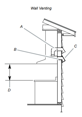
Venting Methods
To use the hood’s top outlet to vent your hood, a 6” (15.2 cm) round vent system is required. To use the hood’s rear outlet, a 31 ⁄4” x 10” (8.25 x 25.4 cm) rectangular vent system is required. Neither of these vent systems are included and must be purchased separately.
NOTE
Flexible vent is not recommended. Flexible vent creates back pressure and air turbulence that greatly reduce performance. The vent system can terminate either through the roof or wall. To vent through a wall, a 90° elbow is needed.
Mounting Height
Select a mounting height between a minimum of 24” (61 cm) for an electric cooking surface, a minimum of 27” (68.6 cm) for a gas cooking surface, and a suggested maximum of 36” (91.4 cm) above the range to the bottom of the hood
Rear discharge
A 90° elbow may be installed immediately above the hood
A. 6” (15.2 cm) round vent
B. 6” (15.2 cm) round transition
C. Roof cap
D. Installation height
A. 6” (15.2 cm) round vent + 90º elbow
B. 31 ⁄4” x 10” (8.25 x 25.4 cm) rectangular vent
C. Wall cap
D. Installation height
Tools and Parts
Removing the packaging
CAUTION
Remove the carton carefully. Wear gloves to protect against sharp edges.
WARNING
Remove the protective film covering the product before putting into operation.
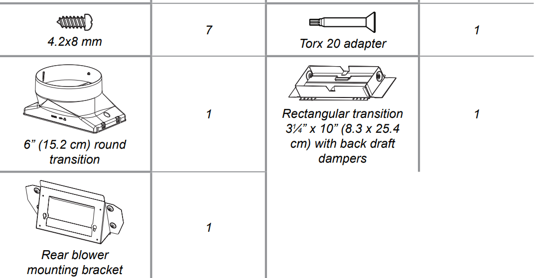
Parts supplied
Hood assembly with blower and LED lamps already installed.
Hardware bag with:
Tools/Materials required
Level
Drill with 1¼” (3.2 cm),1 ⁄8” (3.2 mm), and 1 ⁄16” (4,8 mm) drill bits
Pencil
Wire stripper or utility knife
Tape measure or ruler
Pliers
Caulking gun and weatherproof caulking compound
Vent clamps
Jigsaw or keyhole saw
Flat-blade screwdriver
Metal snips
Phillips & Torx 20 screwdriver
Parts needed
Home power supply cable
½” (12.7 mm) UL listed or CSA approved strain relief
3 UL listed wire connectors
1 wall or roof cap
Metal vent system
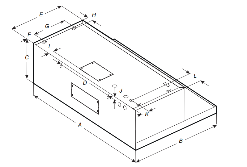
Dimensions and Clearances
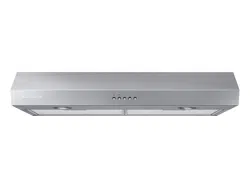
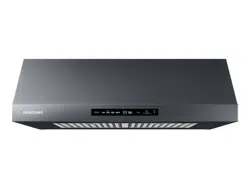
NK30N7000US
NK30N7000UG
NK36N7000US
NK36N7000UG
A
30″ (76 cm)
36″ (91.2 cm)
B
19 6/8 ' (50 cm)
C
9 ¾ ″ (25 cm)
D
13 13⁄16″ (35 cm)
E
12″ (30.5 cm)
F
2 3 ⁄16″ (5.5 cm
G
7 ¼ ″ (18.4 cm)
H
1 3 ⁄16″ (3 cm)
I
1 1 ⁄16″ (2.6 cm)
J
5 ⁄8″ (1.6 cm)
K
1 10⁄16″ (4 cm)
L
3″ (7.6 cm)
5 ¾ ″ (14.6 cm)
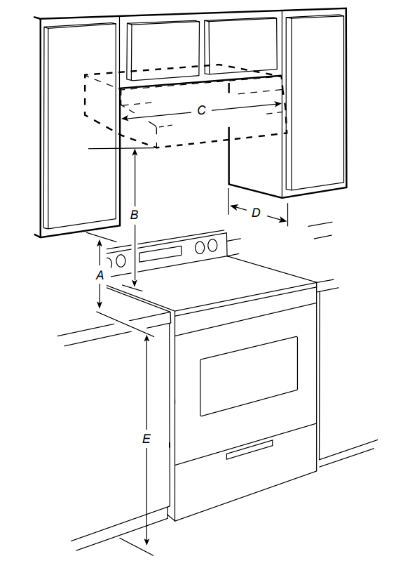
Installation Clearances
A. 18” (45.7 cm) min. clearance - upper cabinet to countertop
B. 24” (61.0 cm) min. for electric cooking surfaces 27” (68.6 cm) min. for gas cooking surfaces 36” (91.4 cm) suggested max. - bottom of range hood to cooking surface
C. 30” (76.2 cm) or 36” (91.4 cm) min. cabinet opening width
D. 12” (30.5 cm) min. cabinet depth
E. 36” (91.4 cm) base cabinet height
Installation Instructions
We recommend that a qualified technician install the range hood. It is the installer’s responsibility to ensure the range hood complies with the installation clearances specified for the product.
Prepare the Location
We recommend you install the vent system before you install the hood.
Before making cutouts, make sure there is proper clearance within the ceiling or wall for vent fittings.
If the cabinet you are attaching the hood to is not mounted on the wall yet, it may be easier to attach the cutout to the bottom of the cabinet before mounting the cabinet on the wall.
1. Disconnect power.
2. Determine which venting method to use: roof or wall.
3. Select a flat surface for assembling the range hood. Place a covering over that surface.
WARNING
EXCESSIVE WEIGHT HAZARD
USE TWO OR MORE PEOPLE TO MOVE AND INSTALL THE RANGE HOOD. FAILURE TO DO SO CAN RESULT IN BACK OR OTHER INJURIES.
4. Using 2 or more people, lift the range hood onto a covered surface.
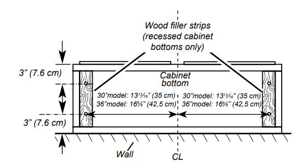
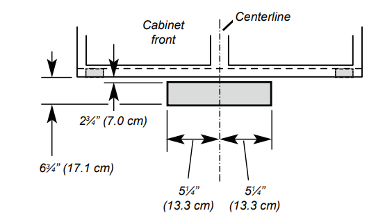
5. If the cabinet has a recessed bottom, add wood filler strips on each side to fill in the space. Install screws to attach filler strips in the locations shown in the illustration at the top of the next column. NOTE: All the screw locations must be measured from the cabinet’s centerline.
6. Determine and clearly mark a vertical centerline on the wall and cabinet in the area the vent opening will be made.
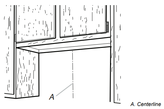
Determine the wiring hole location
Determine the wiring hole location
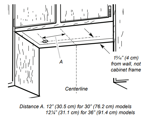
To wire through the top:
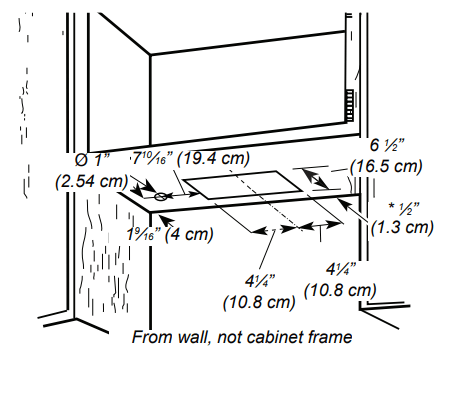
Mark a line Distance “A” (See below) from the left of the centerline on the underside of the cabinet. Mark a point on this line that is 19 ⁄16” (4 cm) from the back wall. Drill a 1¼” (3.2 cm) diameter hole through the cabinet at this point.
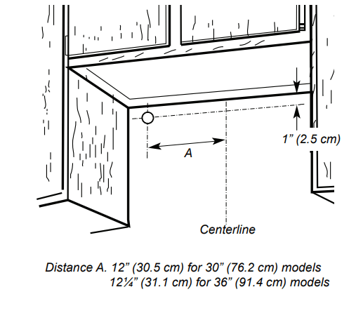
To wire through the wall:
Mark a line Distance “A” (See below) from the left of the centerline on the underside of the cabinet. Mark a point on this line that is 1” (2.54 cm) below the bottom of the cabinet. Drill a 1¼” (3.2 cm) diameter hole through the wall at this point.
Installation
STYLE 1 - CUT OPENINGS FOR 3¼” X 10” (8.3 CM X 25.4 CM) RECTANGULAR VENT SYSTEM
Wall venting
To make a 4” x 10½” (10.2 cm x 26.7 cm) rectangle in the wall:
1. Draw one line 2 3 ⁄4” (7.0 cm) and a second line 63 ⁄4” (17.1 cm) below the underside of the cabinet. Extend these lines through the centerline on the back wall.
2. Draw lines 5¼” (13.3 cm) to the right and left of the centerline on the wall. Make sure these lines intersect with the lines you drew in Step 1.
3. With the lines you drew as a guide, use a saber or keyhole saw to cut a rectangular opening in the wall for the vent.
STYLE 2 - CUT OPENINGS FOR TOP VENT OUTLET
(FROM RECTANGULAR TO 6” (15.2 CM) ROUND VENT SYSTEM)
Roof venting
To make a 6½” x 8½” (16.5 cm x 21.6 cm) rectangle in the cabinet bottom:
1. Draw a line ½” (1.3 cm) from the back wall on the centerline of the underside of the cabinet, and then draw another line 6½” (16.5 cm) from the first line.
2. Draw lines 4¼” (10.8 cm) to the right and left of the centerline on the underside of the cabinet.
3. With the lines you drew as a guide, use a saber or keyhole saw to cut a rectangular opening for the vent.
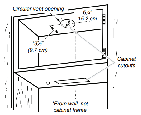
To make a circular vent opening on the underside of the cabinet top:
1. Draw a centerline on the underside of the top of the cabinet.
2. Draw a line 37 ⁄8” (9.7 cm) from the back wall on the underside of the top of the cabinet. Make sure the line intersects with the line you drew in Step 1.
3. Where the two lines intersect, use a compass or a circle template to draw a 6¼” (15.2 cm) circle.
4. With the circle you drew as a guide, use a saber or keyhole saw to cut the circular vent opening.
Install vent system
1. Install the vent through the vent opening in the cabinet or wall. Complete the venting system according to the selected venting method. See the “Venting Requirements” section.
2. Use caulking to seal the exterior wall or roof opening around the cap.
Installing the Range Hood
1. Remove the baffle filters. See the “Range Hood Care” section.
2. Remove the foam shipping pad from behind the blower motor.
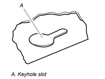
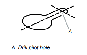
3. Lift the range hood up under the cabinet and determine it’s final location by centering it beneath the cabinet. Mark on the underside of cabinet the location of the 4 keyhole mounting slots on the range hood. Set the range hood aside on a covered surface
4. Use a 1 ⁄8” (3 mm) drill bit and drill 4 pilot holes as shown
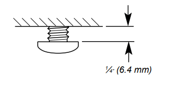
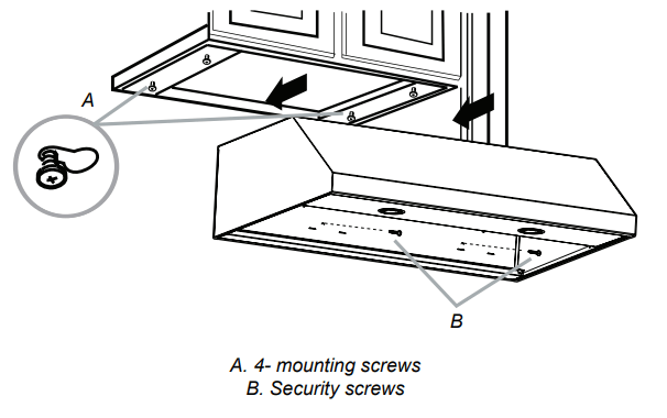
5. Install the 4 - 4.5 x 13 mm mounting screws in the pilot holes. Leave about 1 ⁄4” (6.4 mm) space between the screw heads and cabinet to slide the range hood into place
Connect Vent System
Vent connector installation
The range hood is factory set for use the top vent outlet. Determine whether the range hood will be installed using either a top or rear vent connection.
Rear vent connector installation
NOTE
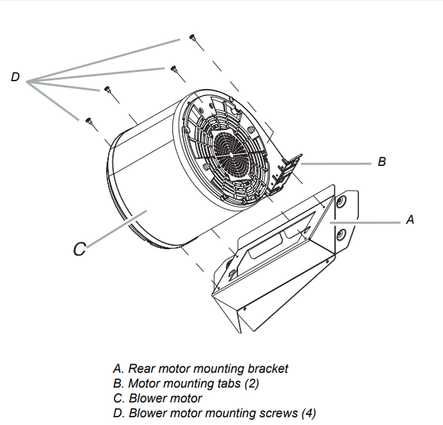
For rear venting, the blower motor position must be changed. You will need the rear motor mounting bracket that is included with the range hood.
1. Remove the baffle filters. See the “Range hood care” section.
2. Place the range hood on its back. Fit the vent system over the exhaust outlet.
3. Disconnect the blower motor electrical connector from the electrical box connector.
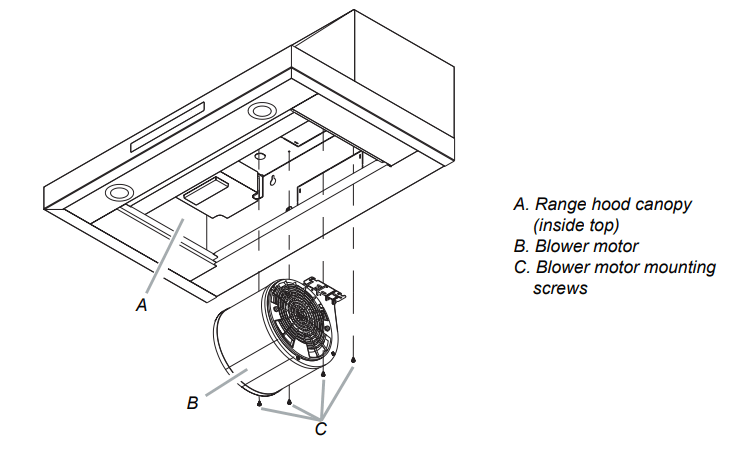
4. Using a T20® adapter, remove the 4 screws holding the blower motor in place. Push up on the blower motor to disengage the tabs from range hood cavity back. Remove the blower motor and set it aside.
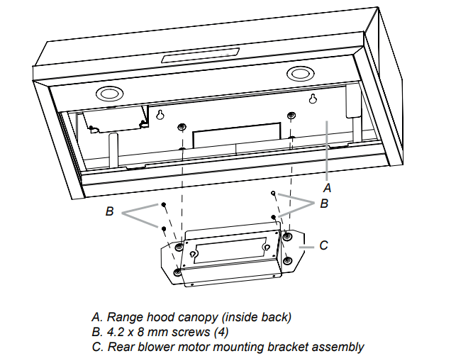
5. Install the rear blower mounting bracket into the range hood and secure it with the (4) 4.2 x 8 mm screws
6. Install the blower motor onto the rear motor mounting bracket (included with the range hood). Engage the motor mounting tabs with the keyhole slots in the rear mounting bracket and push down to secure. Install the 4 screws removed previously and tighten to secure motor bracket.
7. Reconnect blower motor electrical connector to the electrical box connector.
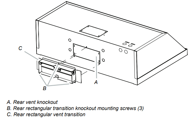
8. Remove the rear vent knockout.
9. Attach the 31 ⁄4” x 10” (8.3 cm x 25.4 cm) rectangular vent damper using 3 - 4.2x8 mm vent transition mounting screws.
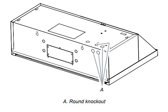
10. Remove one of the round knockouts from the top or back of the range hood (depending on your wiring location) for the wiring strain relief and install a 1 ⁄2” UL listed or CSA approved strain relief
Mounting the Range Hood on a Cabinet
1. Using 2 people, lift the range hood into it’s final location. Feed enough electrical wire through the strain relief to make connections in the terminal box. Tighten the strain relief screws.
2. Position the range hood so that the large end of the keyhole slots are over the mounting screws. Then, push the hood toward the wall so that the screws are in the neck of the slots. The hood should be against the wall. Tighten the mounting screws, making sure the mounting screws are in the narrow neck of the slots.
3. Check that damper, if used, rotates up and down freely.
4. Connect the ventwork to the hood. Seal joints with clamps to make secure and airtight.
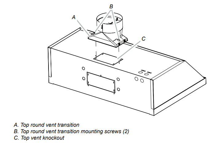
Top vent transition installation
1. Remove the top vent knockout.
2. Attach the round vent transition damper using 2 - 3.5x9.5 mm vent transition mounting screws.
3. Remove the tape from the damper flap
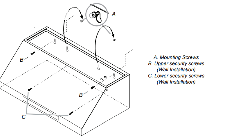
Mounting the Range Hood on the Wall
1. Fix the wiring conduit of the hood.
2. Slide the hood back against the wall. Tighten the mounting screws. Be sure the screw heads are in the narrow neck of the keyhole slot.
3. Insert 2 screws into the upper security screw locations (see B in the image above). Tighten the screws.
4. Insert 2 screws into the lower security screw location (see C in the image above). Tighten the screws.
5. Connect the ductwork to the hood.
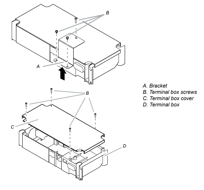
Electrical Connection
1. Disconnect power.
2. Remove the bracket, and then the terminal box cover
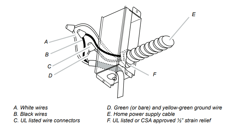
3. Remove the knockout in the terminal box cover, and then install a UL listed or CSA approved 1 ⁄2” strain relief.
4. Use UL listed wire connectors to connect the black wires (B) together.
5. Use UL listed wire connectors to connect the white wires (A) together.
WARNING
Electrical Shock Hazard
Electrically ground blower.
Connect the ground wire to the green and yellow ground wire in the terminal box. Failure to do so can result in death or electrical shock
6. Connect the green (or bare) ground wire from the home power supply to the yellow-green ground wire (D) in the terminal box using UL listed wire connectors.
7. Install the terminal box cover.
8. Reconnect the power.
Range Hood Controls
A. POWER
Press the POWER button and the hood will turn on at default speed (Default Speed : Low).
Press again and the hood will return to sleep mode.
B. LOW
Press the LOW button and the hood will turn on at Low speed
C. MED
Press the MED button and the hood will turn on at Medium speed.
D. HIGH
Press the HIGH button and the hood will turn on at High speed.
E. BOOST
Press the BOOST button and the hood will increase to Maximum speed for 10 minutes.
After 10 minutes, the hood will slow to High speed.
Normal mode High & Boost CFM is the same (390CFM).
Power mode High mode is 390 CFM and Boost mode is 600 CFM. See Performance (CFM) Conversion on page 12.
F. TIMER DISPLAY
Shows the timer settings.
G. Timer
Setting the timer ON
Press the Timer button to set the working time.
• Each time you press the Timer, you add 10 minutes to the displayed time, up to a maximum of 99 minutes. The hood will stay on for the amount of time you have set.
• After the Timer counts down to zero, the Timer LED light will start to blink.
• The Timer LED will blink for 5 seconds, and then the hood will turn off automatically
Setting the timer OFF
Press the Timer button for 3 seconds and the Timer function will turn off
H. Light
Press the Light button and the lamps will turn on.
Press the Light button again and the lamps will turn off.
Sound
Muting / Unmuting the hood
Press and hold the Light button for 3 seconds to turn off the hood sounds.
Press and hold again to turn on the sounds
COOKTOP AND RANGE HOOD CONNECTIVITY
This appliance has a feature which allows you to pair compatible Samsung cooktops and your hood via Bluetooth.
After you enable this function and pair your hood and a compatible cooktop, the hood fan will automatically come on at Low speed when you turn on a cooktop element. The hood fan will also shut off automatically when you turn off the cooktop elements.
In addition, after the hood and compatible cooktop are paired, you can download the Samsung Smart Things app to a mobile device, and then use the Samsung Smart Things app to:
Monitor and control the On/Off status of the hood.
Monitor and control the fan speed.
Monitor and control the lights.
Set the hood shut-off timer with the time-up alarm.
J. Bluetooth
Bluetooth connection (pairing)
1. Press the Bluetooth button on hood. The pairing mode will be activated and the indicator on the Bluetooth button will blink.
2. Press the Bluetooth button on cooktop
NOTE
For a detailed description of the pairing method, see the user manual of a compatible Samsung cooktop.
3. After the pairing process finishes, the Bluetooth light will stay lit and appears in the display.
Bluetooth disconnection (Pairing reset)
1. Press and hold the Bluetooth button on the hood for 3 seconds.
2. The Bluetooth connection disconnects.
I. Auto Connectivity
The Auto Connectivity function lets you quickly connect the hood via Bluetooth with a compatible Samsung cooktop after the hood and cooktop have been paired. To turn the function on, press the Auto Connectivity button. To turn the function off and disconnect the hood and cooktop, press the Auto Connectivity button again.
While the hood and cooktop are connected, the hood fan will automatically come on at Low speed when you turn on a cooktop element. The hood fan will also shut off automatically when you turn off the cooktop elements. You will also be able to control the hood with the Samsung Smart Things app as described above.
1. Press the Auto Connectivity button to activate the function.
2. The hood will turn on/off automatically in conjunction with the cooktop.
3. Press again to deactivate the function.
NOTE
These functions are only available if you have installed a compatible Samsung Bluetooth cooktop.
Performance (CFM) Conversion
Press and hold the HIGH and BOOST button on the hood for 3 seconds to convert Blower performance.
Normal mode: appears in the display. The blower will operate normally (Max 390 CFM).
Power mode: appears in the display. The blower will operate at a more powerful level (Max 600 CFM).
CAUTION
We recommend that a qualified technician install the range hood to ensure it is compatible with Power mode. DO NOT activate Power mode if the installation is not compatible.
It is the installer’s responsibility to ensure the range hood complies with the installation clearances specified for the product. Power mode requires a custom air system.
The Custom Air System
When using ventilation systems with greater than specified air movement CFM, review local building codes as they may require you to install a custom air system.
Consult a HVAC professional for specific requirements for you’re area as CFM requirements can vary between locales
Consult a HVAC professional to select the correct CFM capacity range hood for your application. The CFM capacity depends on the range or cooktop BTU rating, size and location, size of the kitchen and the range hood ductwork in the kitchen.
Cleaning
IMPORTANT: Clean the hood and grease filters frequently according to the following instructions. Replace baffle filters before operating the hood.
Exterior surfaces:
To avoid damage to the exterior surface, do not use steel wool or soap-filled scouring pads.
Always wipe dry to avoid water marks.
Cleaning method:
Liquid detergent soap and water or all-purpose cleanser.
Wipe with damp soft cloth or nonabrasive sponge, and then rinse with clean water and wipe dry. '
Do not use cleaning agents containing bleach
Stainless steel baffle filter:
1. Remove the filter by pulling the spring release handle, and then pulling down the filter
2. Wash the stainless steel baffle filter as needed in a dishwasher or hot detergent solution.
3. To reinstall the filter, first make sure the spring release handle is toward the front. Insert the stainless steel filter into the upper track.
4. Push in the spring release handle.
5. Push up on the stainless steel filter, and then release the handle to latch it into place.
WARNING
When removing the filter, please hold it with both hands to make sure it does not fall.
Replacing the LED lamps
The LED lights are replaceable by a service technician only. See the support contact information in the Warranty section.
 CAUTION
 WARNING
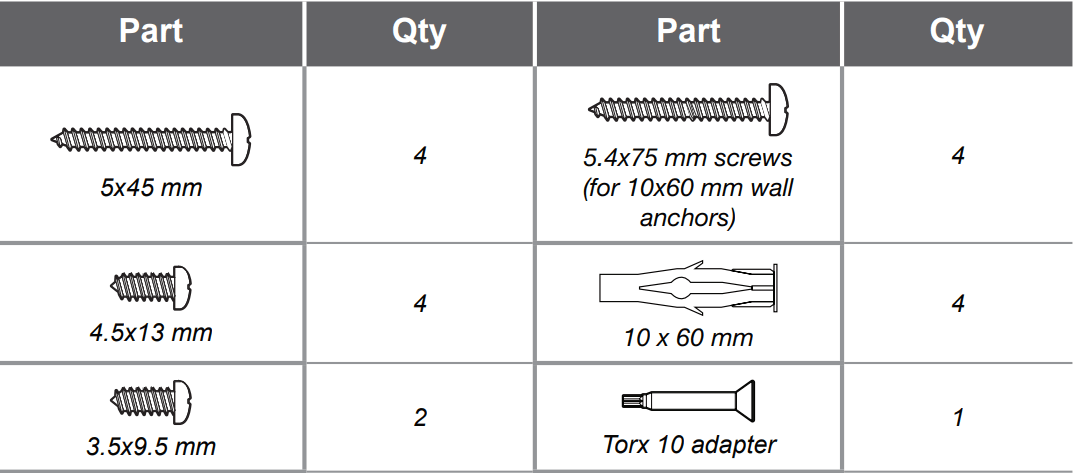
 WARNING
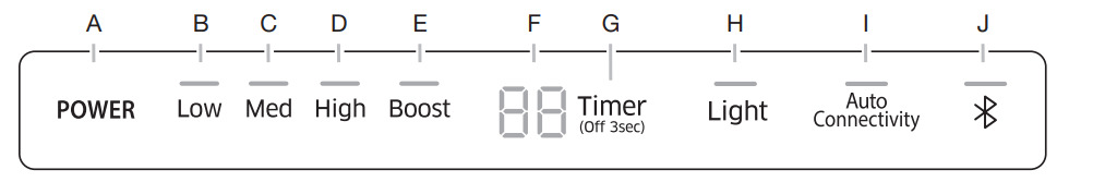
 Bluetooth connection (pairing)
 appears in the display.
 Bluetooth disconnection (Pairing reset)
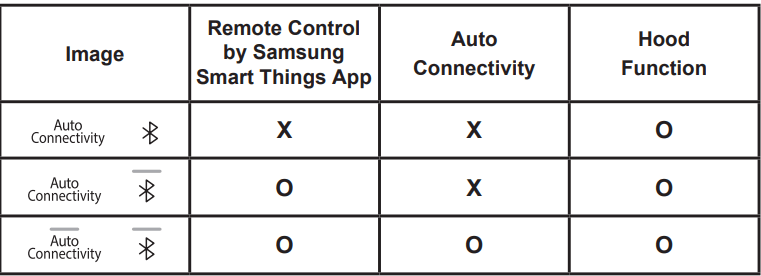
 appears in the display. The blower will operate normally (Max 390 CFM).
 appears in the display. The blower will operate at a more powerful level (Max 600 CFM).
 CAUTION
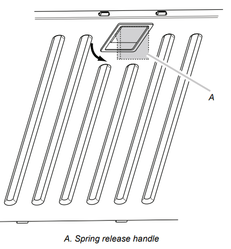
 WARNING