OUTLANDER PHEV
OWNER’S MANUAL
OUTLANDER PHEV - ENGLISH - OGGE19E1
OUTLANDER PHEV - ENGLISH - OGGE19E1

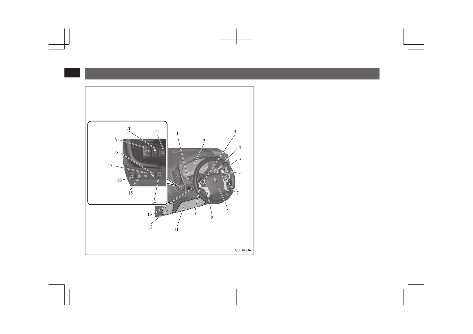
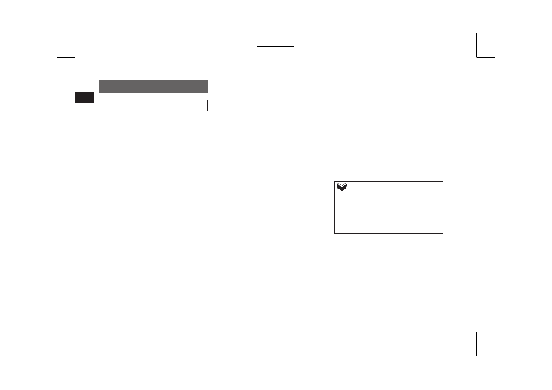
Instruments and controls
E08500102485
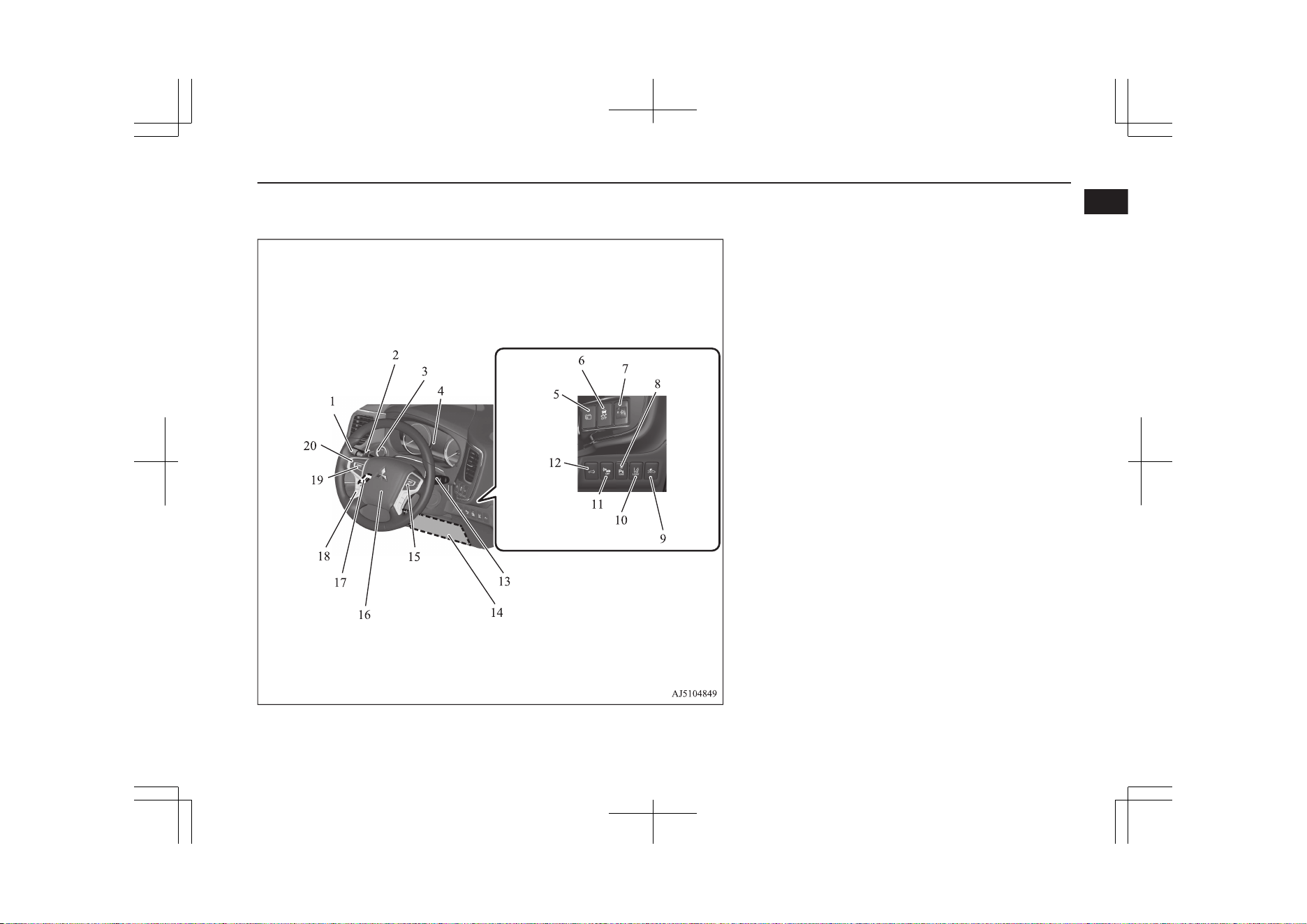
LHD
1. Combination headlamps and dipper switch p. 6-59
Automatic High-Beam (AHB) switch* p. 6-62
Turn-signal lever p. 6-67
Front fog lamp switch p. 6-68
Rear fog lamp switch p. 6-69
2. Instruments p. 6-02
3. Steering wheel audio remote control switches p. 8-28
[For DISPLAY AUDIO, Smartphone Link Display Audio and
MITSUBISHI Multi-Communication System (MMCS), refer to
the separate owner’s manual.]
4. Power switch p. 7-11
5. Regenerative braking level selector (paddle type)* p. 7-19
6. Windscreen wiper and washer switch p. 6-69
Rear window wiper and washer switch p. 6-72
Headlamp washer switch p. 6-73
7. Cruise control switches* p. 7-45, 7-55
8. Supplemental restraint system (SRS) - airbag (for driver’s seat)
p. 5-25, 5-29
Horn switch p. 6-77
9. Bluetooth® 2.0 interface* p. 8-51
10. Camera switch* p. 7-112
11. Supplemental restraint system (SRS) - front knee airbag (for driv-
er’s seat) p. 5-25, 5-29
12. Fuses p. 11-16
13. Steering wheel height and reach adjustment lever p. 7-07
14. Driver’s side electric tailgate switch* p. 4-20
15. Lane Depature Warning (LDW) switch* p. 7-88
16. Forward Collision Mitigation System (FCM) and Ultrasonic mis-
acceleration Mitigation System (UMS) ON/OFF switch* p. 7-72
17. Sonar switch* p. 7-99, 7-103
18. Acoustic Vehicle Alerting System (AVAS) OFF switch p. 7-32
19. Headlamp levelling switch* p. 6-66
20. Active stability control (ASC) OFF switch p. 7-44
21. Multi information display switch p. 6-06
Instruments and controls
1-02
OGGE19E1
Overview
1
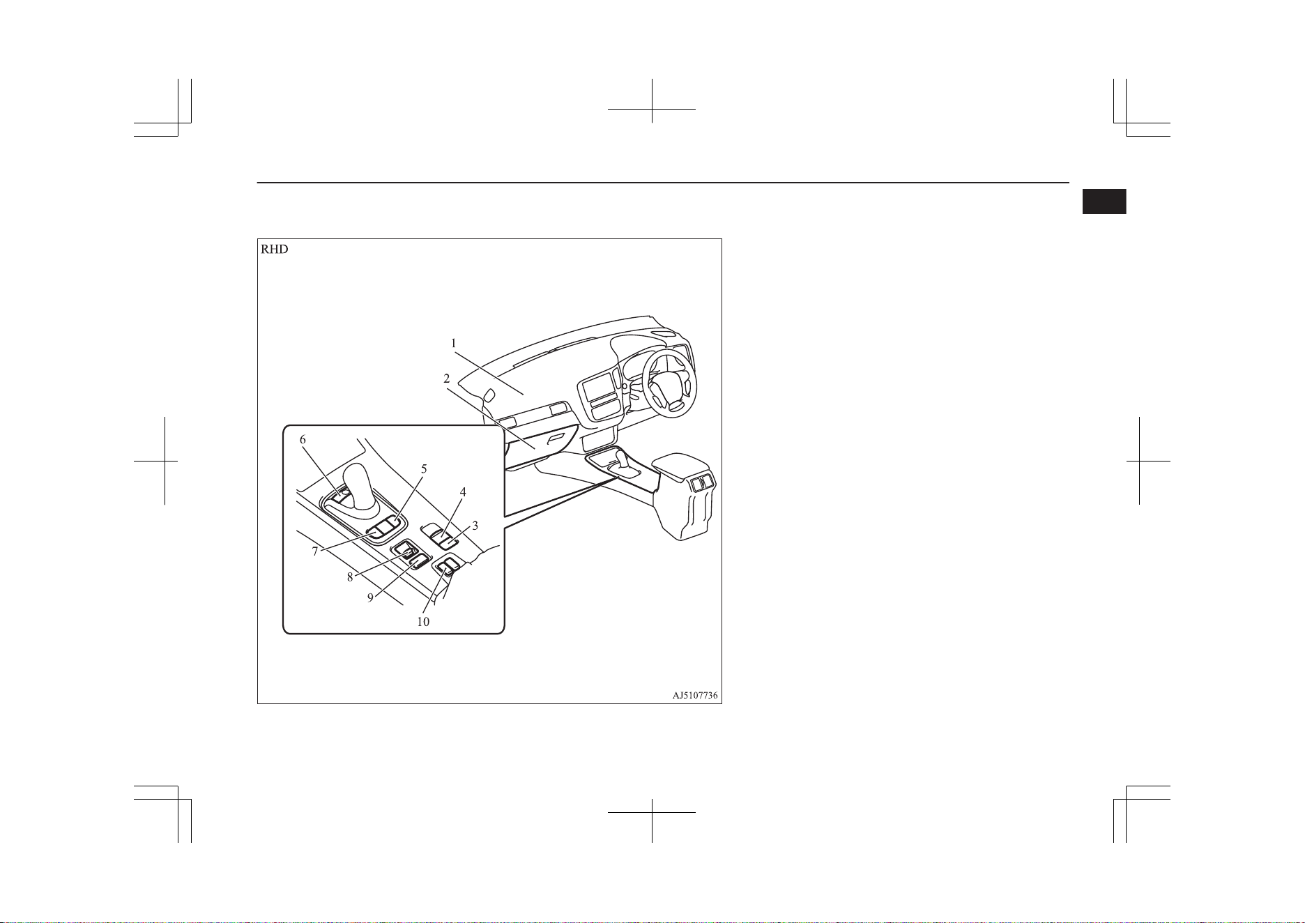
RHD
1. Combination headlamps and dipper switch p. 6-59
Automatic High-Beam (AHB) switch* p. 6-62
Turn-signal lever p. 6-67
Front fog lamp switch p. 6-68
Rear fog lamp switch p. 6-69
2. Regenerative braking level selector (paddle type)* p. 7-19
3. Power switch p. 7-11
4. Instruments p. 6-02
5. Multi information display switch p. 6-06
6. Active stability control (ASC) OFF switch p. 7-44
7. Headlamp levelling switch* p. 6-66
8. Sonar switch* p. 7-99, 7-103
9. Forward Collision Mitigation System (FCM) and Ultrasonic mis-
acceleration Mitigation System (UMS) ON/OFF switch* p. 7-72
10. Lane Depature Warning (LDW) switch* p. 7-88
11. Acoustic Vehicle Alerting System (AVAS) OFF switch p. 7-32
12. Driver’s side electric tailgate switch* p. 4-20
13. Windscreen wiper and washer switch p. 6-69
Rear window wiper and washer switch p. 6-72
Headlamp washer switch p. 6-73
14. Supplemental restraint system (SRS) - front knee airbag (for driv-
er’s seat) p. 5-25, 5-29
15. Cruise control switches* p. 7-45, 7-55
16. Supplemental restraint system (SRS) - airbag (for driver’s seat)
p. 5-25, 5-29
Horn switch p. 6-77
17. Steering wheel height and reach adjustment lever p. 7-07
18. Bluetooth® 2.0 interface* p. 8-51
19. Steering wheel audio remote control switches p. 8-28
[For DISPLAY AUDIO, Smartphone Link Display Audio and
MITSUBISHI Multi-Communication System (MMCS), refer to
the separate owner’s manual.]
20. Camera switch* p. 7-112
Instruments and controls
1-03
OGGE19E1
Overview
1
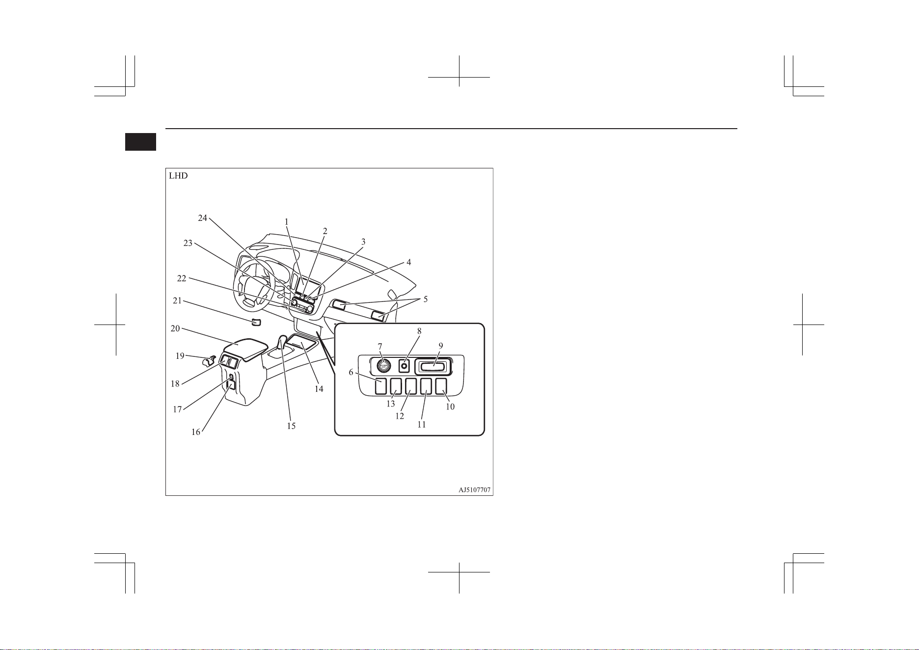
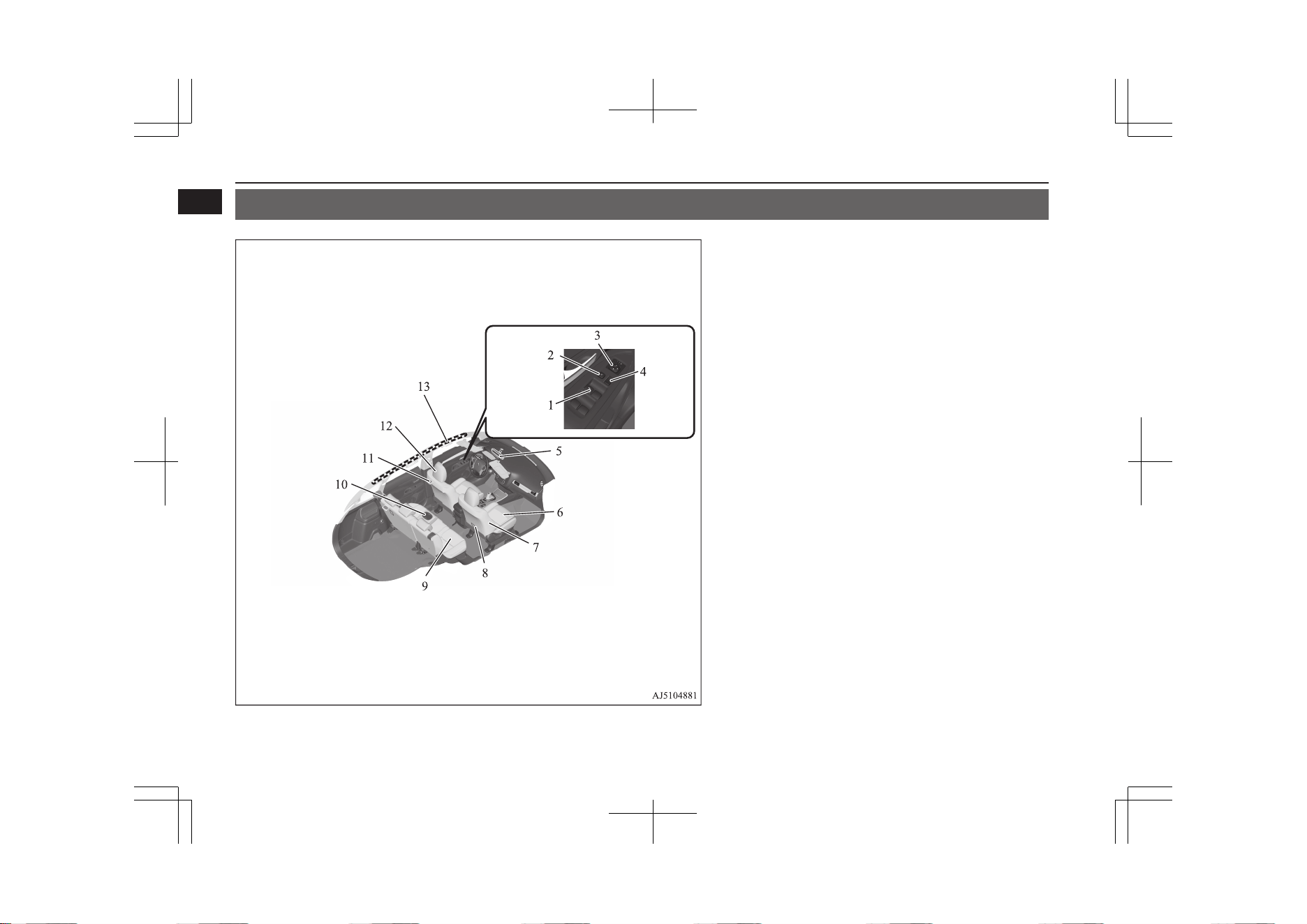
1. Multi Around Monitor* p. 7-109
Audio* p. 8-15
[For DISPLAY AUDIO, Smartphone Link Display Audio and
MITSUBISHI Multi-Communication System (MMCS), refer to
the separate owner’s manual.]
2. Hazard warning flasher switch p. 6-67
3. ECO mode switch p. 6-68
4. Front passenger’s airbag indicator p. 5-28
5. Passenger’s ventilators p. 8-02
6. USB input terminal* p. 8-71
7. Accessory socket* p. 8-75
Cigarette lighter* p. 8-75
8. Electric tailgate power switch* p. 4-20
9. Key slot p. 7-15
10. 220-240 V AC power supply switch* p. 8-76
11. Blind Spot Warning (BSW) switch* p. 7-82
12. Heated steering wheel switch* p. 6-76
13. Heated windscreen switch* p. 6-75
14. Cup holder p. 8-84
15. Selector lever (Joystick type) p. 7-15
16. 220-240 V AC power supply* p. 8-76
17. USB input terminal* p. 8-71
18. Rear ventilators p. 8-02
19. Fuel tank filler door release lever p. 2-15
20. Floor console box p. 8-82
Arm rest
21. Bonnet release lever p. 11-04
22. Rear window demister switch p. 6-74
Wiper de-icer switch* p. 6-74
23. Automatic climate control air conditioner p. 8-06
24. Seat belt reminder p. 5-11
Instruments and controls
1-04
OGGE19E1
Overview
1
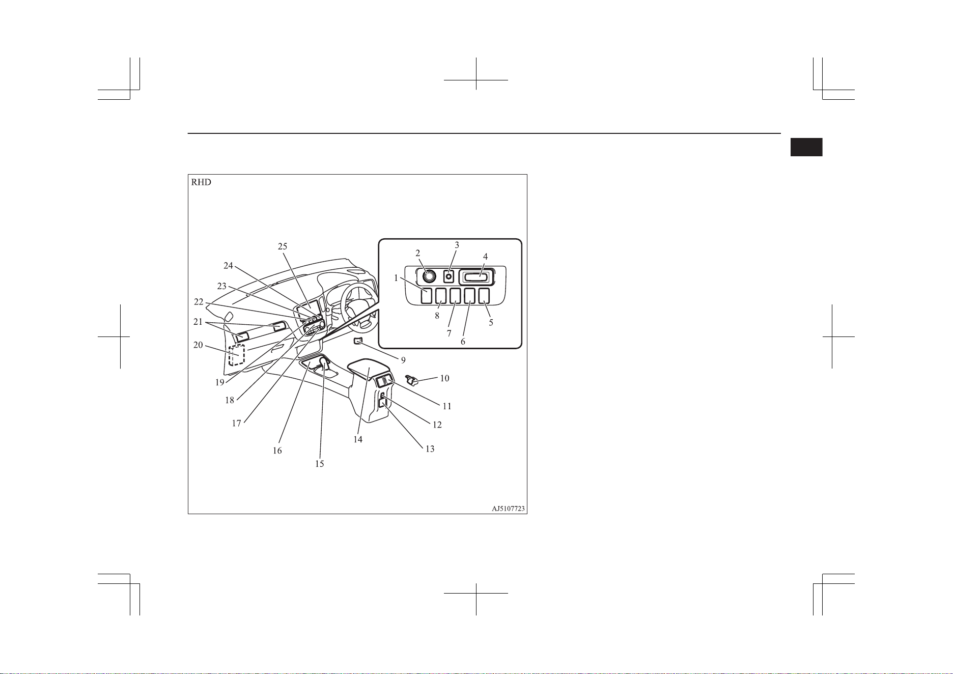
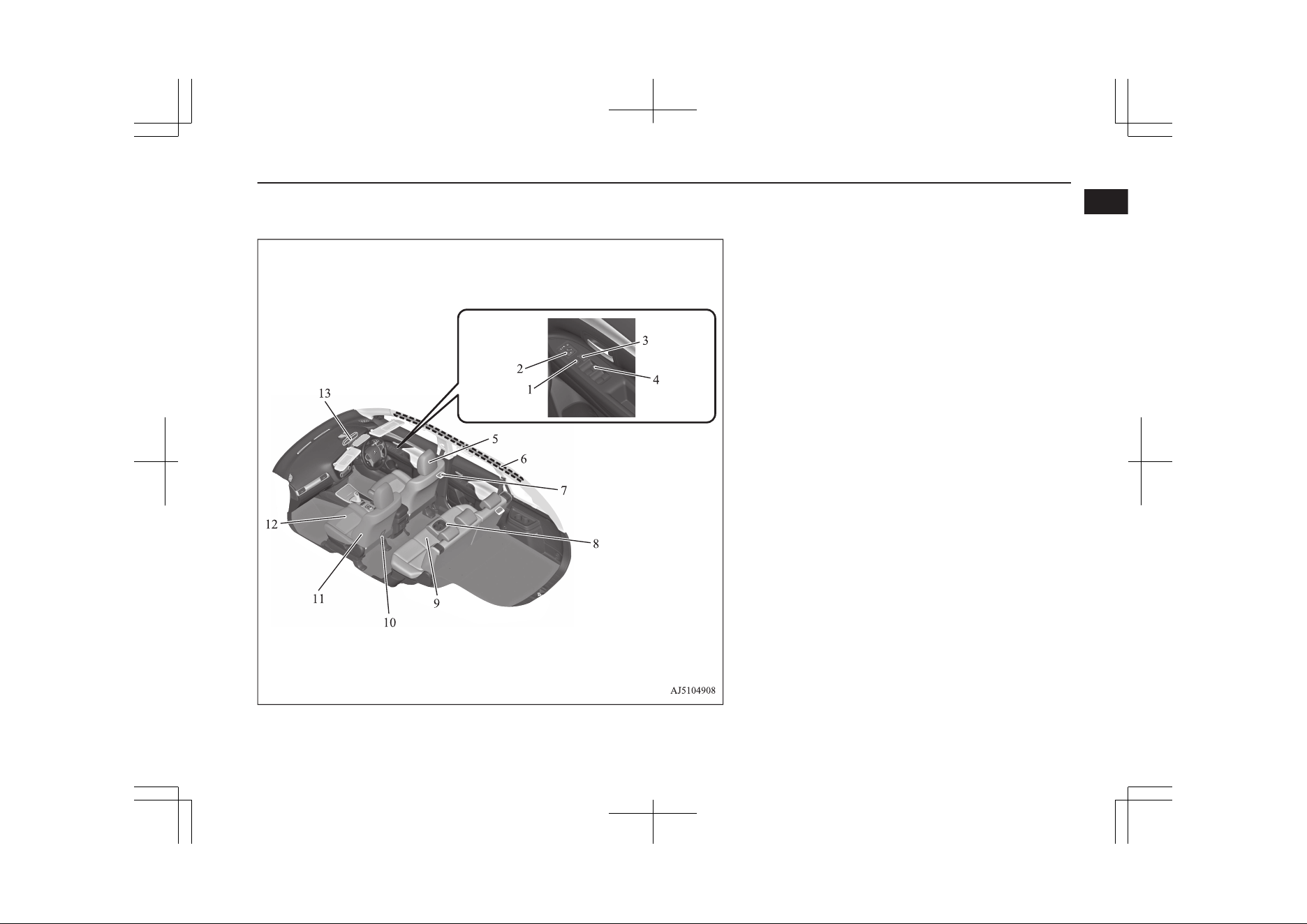
1. USB input terminal* p. 8-71
2. Accessory socket* p. 8-75
3. Electric tailgate power switch* p. 4-20
4. Key slot p. 7-15
5. 220-240 V AC power supply switch* p. 8-76
6. Blind Spot Warning (BSW) switch* p. 7-82
7. Heated steering wheel switch* p. 6-76
8. Heated windscreen switch* p. 6-75
9. Bonnet release lever p. 11-04
10. Fuel tank filler door release lever p. 2-15
11. Rear ventilators p. 8-02
12. USB input terminal* p. 8-71
13. 220-240 V AC power supply* p. 8-76
14. Floor console box p. 8-82
Arm rest
15. Selector lever (Joystick type) p. 7-15
16. Cup holder p. 8-84
17. Rear window demister switch p. 6-74
Wiper de-icer switch* p. 6-74
18. Automatic climate control air conditioner p. 8-06
19. Seat belt reminder p. 5-11
20. Fuses p. 11-16
21. Passenger’s ventilators p. 8-02
22. Hazard warning flasher switch p. 6-67
23. ECO mode switch p. 6-68
24. Front passenger’s airbag indicator p. 5-28
25. Multi Around Monitor* p. 7-109
Audio* p. 8-15
[For DISPLAY AUDIO, Smartphone Link Display Audio and
MITSUBISHI Multi Communication System (MMCS), refer to
the separate owner’s manual.]
Instruments and controls
1-05
OGGE19E1
Overview
1
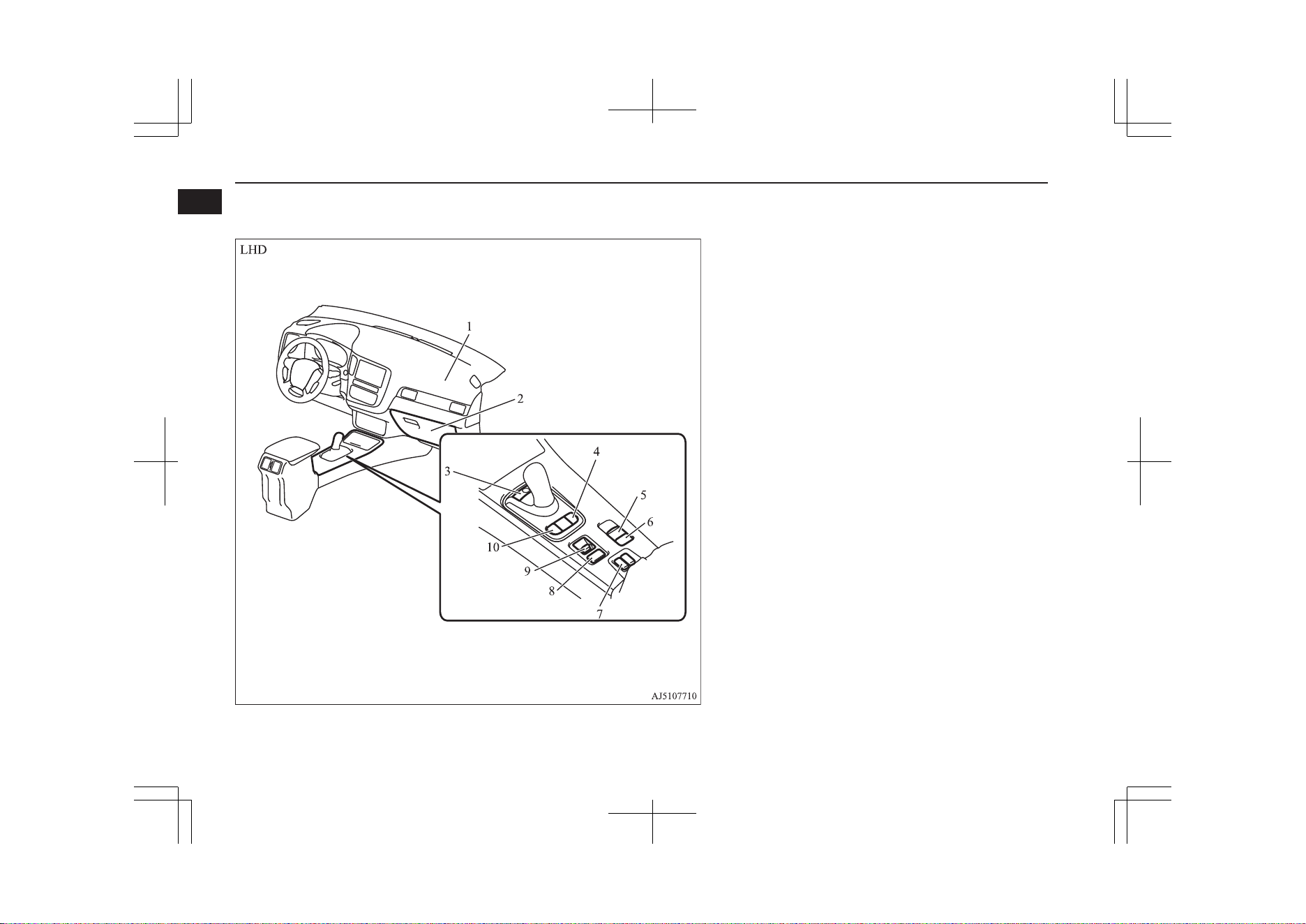
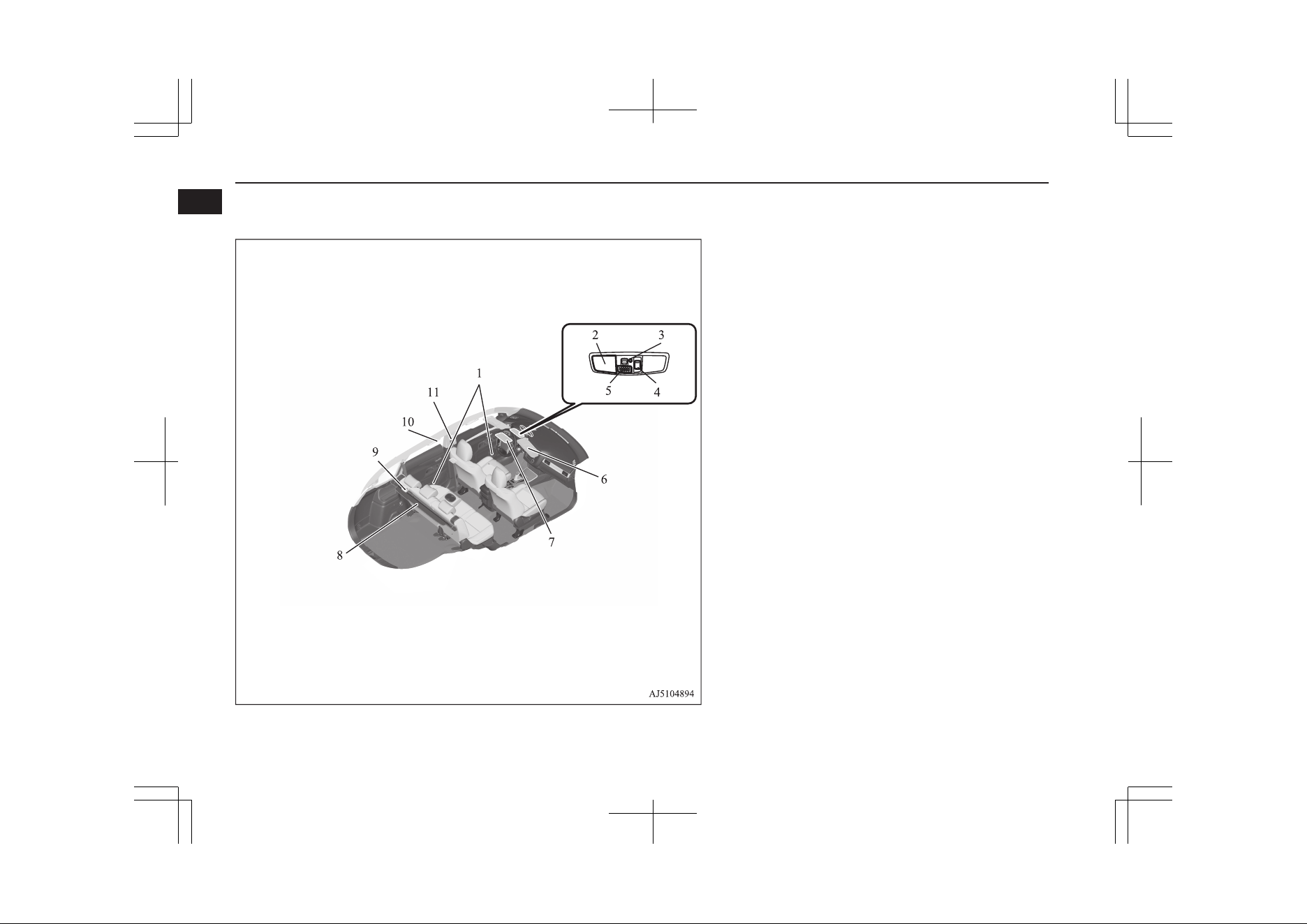
1. Supplemental restraint system (SRS) - airbag (for front passeng-
er’s seat) p. 5-25, 5-29
2. Glove box p. 8-82
Card holder p. 8-82
3. Electrical parking switch p. 7-18
4. EV switch p. 7-25
5. Electric parking brake switch p. 7-03
6. Brake auto hold switch p. 7-35
7. Heated seat switch* p. 5-04
8. SPORT mode switch p. 7-31
9. Drive mode switch p. 7-21
10. SAVE/CHARGE mode switch p. 7-28
Instruments and controls
1-06
OGGE19E1
Overview
1
1. Supplemental restraint system (SRS) - airbag (for front passeng-
er’s seat) p. 5-25, 5-29
2. Glove box p. 8-82
Card holder p. 8-82
3. Brake auto hold switch p. 7-35
4. Electric parking brake switch p. 7-03
5. EV switch p. 7-25
6. Electrical Parking switch p. 7-18
7. SAVE/CHARGE mode switch p. 7-28
8. Drive mode switch p. 7-21
9. SPORT mode switch p. 7-31
10. Heated seat switch* p. 5-04
Instruments and controls
1-07
OGGE19E1
Overview
1
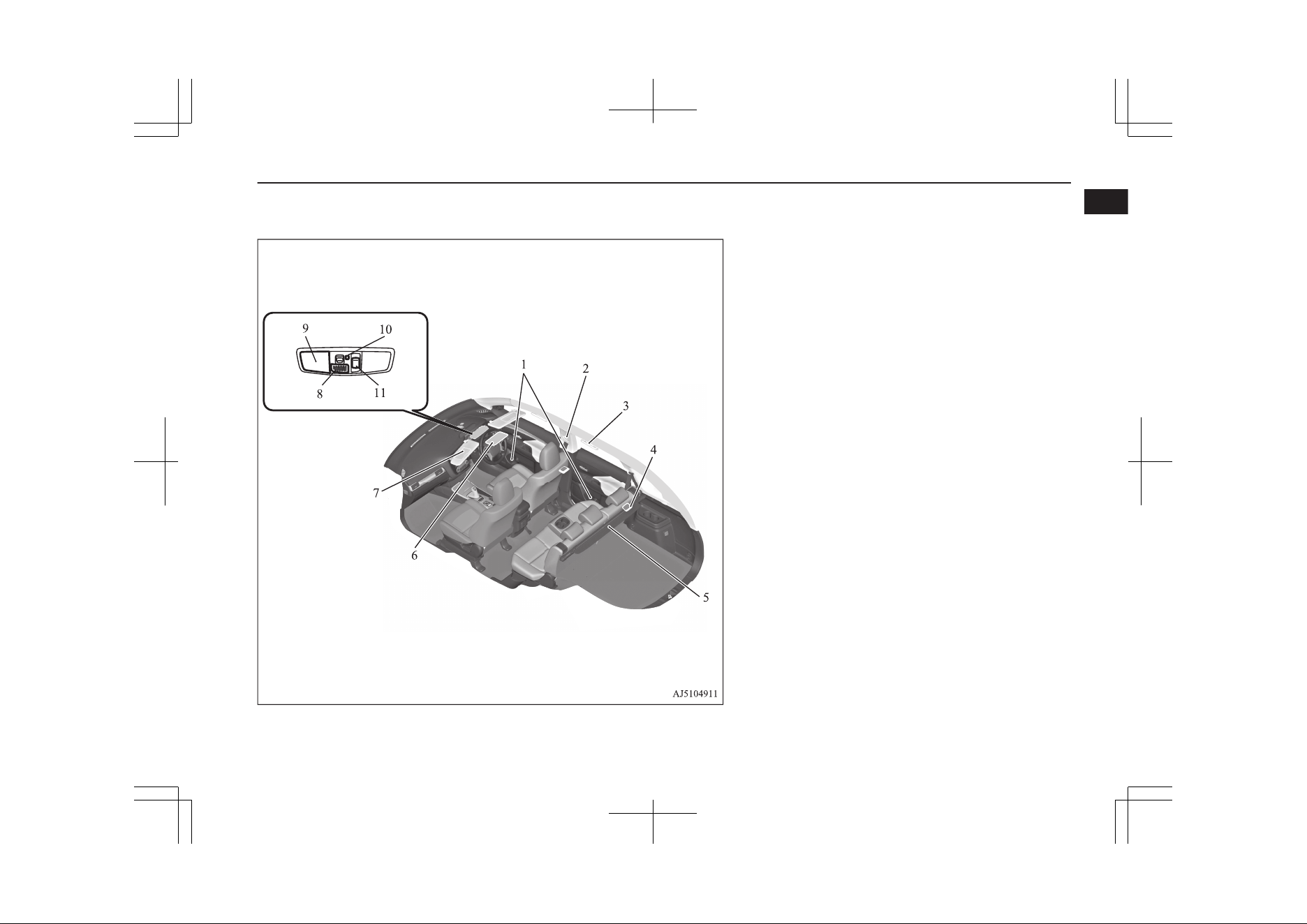
Interior
E08500202112
LHD
1. Electric window control switch p. 4-34
2. Lock switch p. 4-35
3. Electric remote-controlled outside rear-view mirrors switch
p. 7-09
4. Central door lock switch p. 4-16
5. Inside rear-view mirror p. 7-07
6. Front seats p. 5-03
7. Supplemental restraint system (SRS) -side airbag (for front seat)
p. 5-25, 5-32
8. Tether anchorages for child restraint system (for front passenger’s
seat) p. 5-22
9. Rear seats p. 5-05
10. Armrest p. 5-05
Cup holder p. 8-84
11. Room lamp (rear) p. 8-80, 11-26
12. Head restraints p. 5-05
13. Supplemental restraint system (SRS) - curtain airbag p. 5-25,
5-32
Interior
1-08
OGGE19E1
Overview
1
RHD
1. Lock switch p. 4-35
2. Electric remote-controlled outside rear-view mirrors switch
p. 7-09
3. Central door lock switch p. 4-16
4. Electric window control switch p. 4-34
5. Head restraints p. 5-05
6. Supplemental restraint system (SRS) - curtain airbag p. 5-25,
5-32
7. Room lamp (rear) p. 8-80, 11-26
8. Armrest p. 5-05
Cup holder p. 8-84
9. Rear seats p. 5-05
10. Tether anchorages for child restraint system (for front passenger’s
seat) p. 5-22
11. Supplemental restraint system (SRS) - side airbag (for front seat)*
p. 5-25, 5-32
12. Front seats p. 5-03
13. Inside rear-view mirror p. 7-07
Interior
1-09
OGGE19E1
Overview
1
LHD
1. Bottle holder p. 8-84
2. Map & room lamps (front) p. 8-80, 8-80, 11-26
3. Downlight p. 8-81
4. Sunroof switch* p. 4-36
5. Hands-free microphone* p. 8-52
6. Sun visors p. 8-73
Vanity mirror p. 8-73
Card holder p. 8-73
7. Sunglasses holder* p. 8-83
8. Cargo area cover p. 8-85
9. Luggage room lamp p. 8-81, 11-26
10. Assist grips p. 8-86
Coat hook p. 8-86
11. Adjustable seat belt anchor p. 5-12
Seat belts p. 5-09
Interior
1-10
OGGE19E1
Overview
1
RHD
1. Bottle holder p. 8-84
2. Adjustable seat belt anchor p. 5-12
Seat belts p. 5-09
3. Assist grips p. 8-86
Coat hook p. 8-86
4. Luggage room lamp p. 8-81, 11-26
5. Cargo area cover p. 8-85
6. Sunglasses holder* p. 8-83
7. Sun visors p. 8-73
Vanity mirror p. 8-73
Card holder p. 8-73
8. Hands-free microphone* p. 8-52
9. Map & room lamps (front) p. 8-80, 8-80, 11-26
10. Downlight p. 8-81
11. Sunroof switch* p. 4-36
Interior
1-11
OGGE19E1
Overview
1
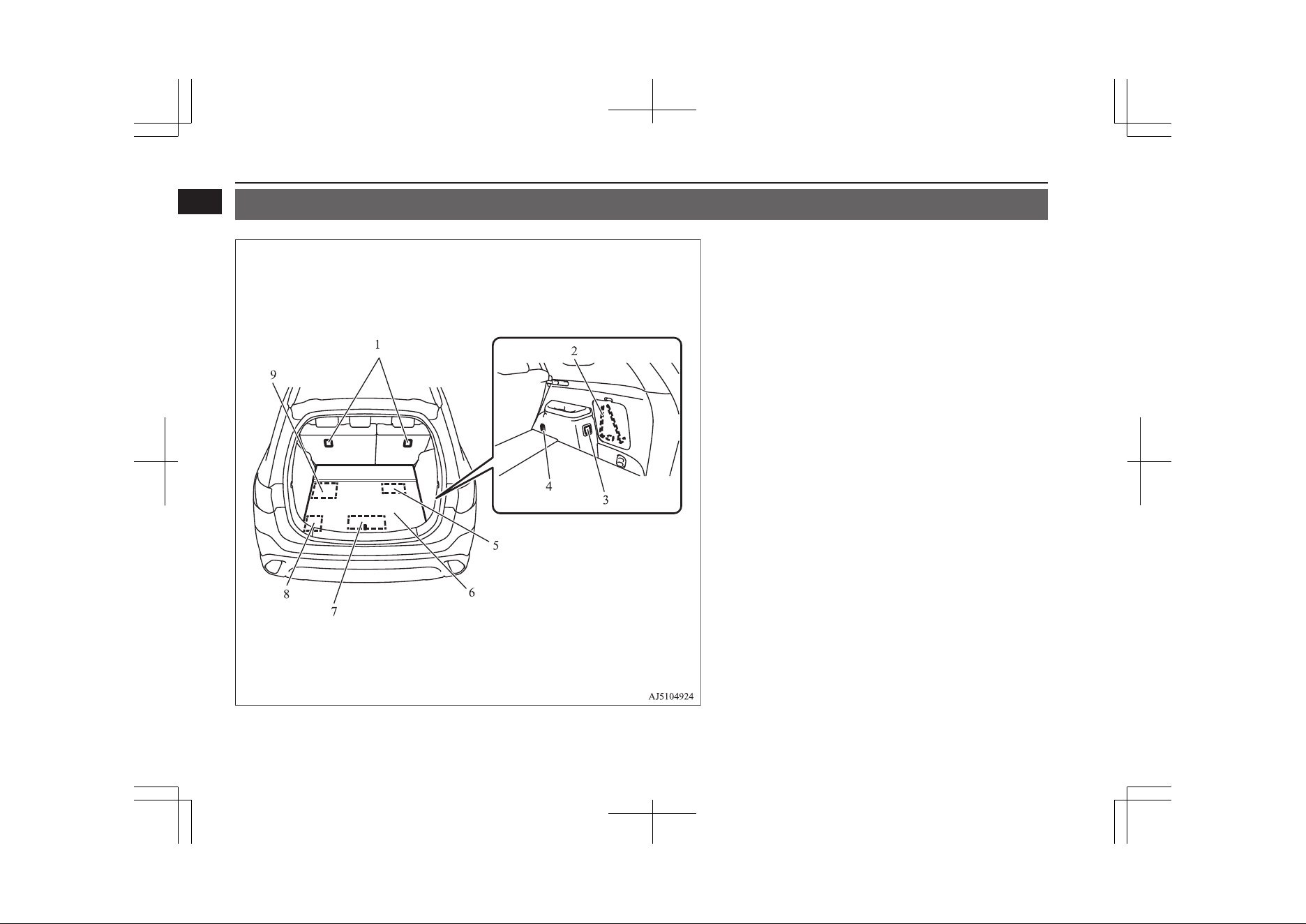
Luggage area
E08500301523
1. Tether anchorages for child restraint system p. 5-22
2. Tools p. 9-06
3. Accessory socket* p. 8-75
220-240 V AC power supply* p. 8-76
4. Luggage hooks p. 8-87
5. Jack p. 9-06
6. Luggage floor box p. 8-83
7. EV charging cable* p. 3-07
8. Auxiliary battery p. 11-09
9. Tyre repair kit p. 9-07
Luggage area
1-12
OGGE19E1
Overview
1
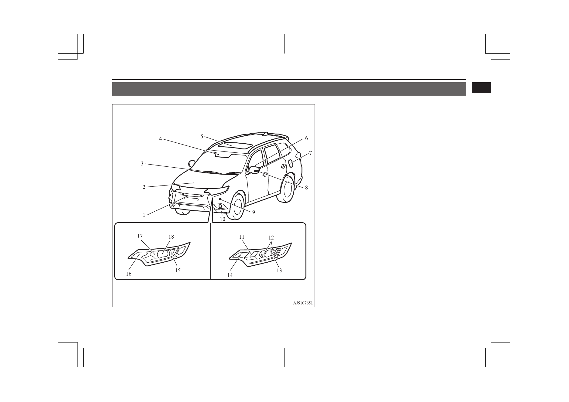
Outside (Front)
E08500402909
Halogen headlamps type LED headlamps type
1. Front-view camera* p. 7-109
2. Bonnet p. 11-04
3. Windscreen wipers p. 6-69
4. Sensor* [for Automatic High-Beam (AHB)*, Forward Collision
Mitigation System (FCM)* and Lane Departure Warning (LDW)*]
p. 6-62, 7-67, 7-88
Rain sensor p. 6-69
5. Sunroof* p. 4-36
6. Electric window control p. 4-34
7. Fuel tank filler p. 2-15
8. Side turn-signal lamps p. 6-67, 11-25
Side-view camera* p. 7-109
9. Ultrasonic misacceleration Mitigation System (UMS)* p. 7-77
Parking sensors* p. 7-101
10. Front fog lamps p. 6-68, 11-25, 11-28
11. Headlamps, high-beam p. 6-61, 11-25, 11-27
12. Headlamps, low beam p. 6-61, 11-25
13. Position lamps p. 6-61, 11-25
Daytime running lamps* p. 11-28, 11-25
14. Front turn-signal lamps p. 6-67, 11-25, 11-28
15. Position lamps p. 6-59, 11-25
Daytime running lamps p. 6-61, 11-25
16. Front turn-signal lamps p. 6-67, 11-25, 11-28
17. Headlamps, high-beam p. 6-61, 11-25, 11-27
18. Headlamps, low beam p. 6-61, 11-25, 11-26
Outside (Front)
1-13
OGGE19E1
Overview
1
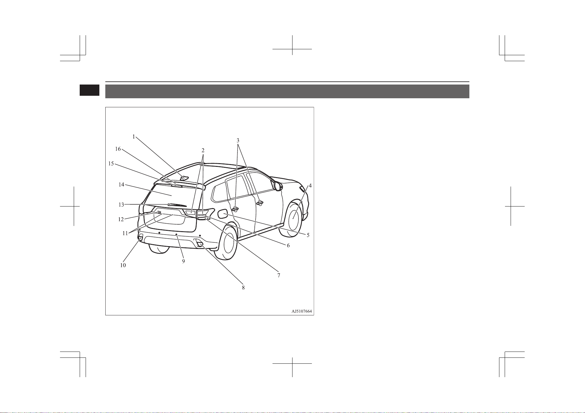
Outside (Rear)
E08500402912
1. Antenna
2. Tail lamps p. 11-25, 11-30
3. Keyless entry system p. 4-03
Keyless operation system p. 4-06
Locking and unlocking the doors p. 4-14
4. Changing tyres p. 9-13
Tyre pressure monitoring system (TPMS) p. 7-92
Tyre inflation pressures p. 11-10
Tyre rotation p. 11-12
Snow traction device (tyre chains) p. 11-13
Size of tyres and wheels p. 12-09
5. Charging lid p. 3-12
Charging port courtesy lamp p. 3-06
6. Stop lamps p. 11-25, 11-30
7. Rear turn-signal lamps p. 6-67, 11-25, 11-30
8. Reversing lamp (LHD vehicles) p. 11-25, 11-30
Rear fog lamp (RHD vehicles) p. 6-69, 11-25, 11-30
9. Ultrasonic misacceleration Mitigation System (UMS)* p. 7-77
Reversing sensor system* p. 7-97
Parking sensors* p. 7-101
10. Rear fog lamp (LHD vehicles) p. 6-69, 11-25, 11-30
Reversing lamp (RHD vehicles) p. 11-25, 11-30
11. Licence plate lamps p. 11-25, 11-31
12. Rear-view camera* p. 7-105, 7-109
13. Rear window wiper p. 6-72
14. Tailgate* p. 4-19
Electric tailgate* p. 4-20
15. High-mounted stop lamp p. 11-25
16. Roof spoiler
Outside (Rear)
1-14
OGGE19E1
Overview
1
Quick guide
E08500500010
Locking and unlocking the
doors and tailgate
E08500601832
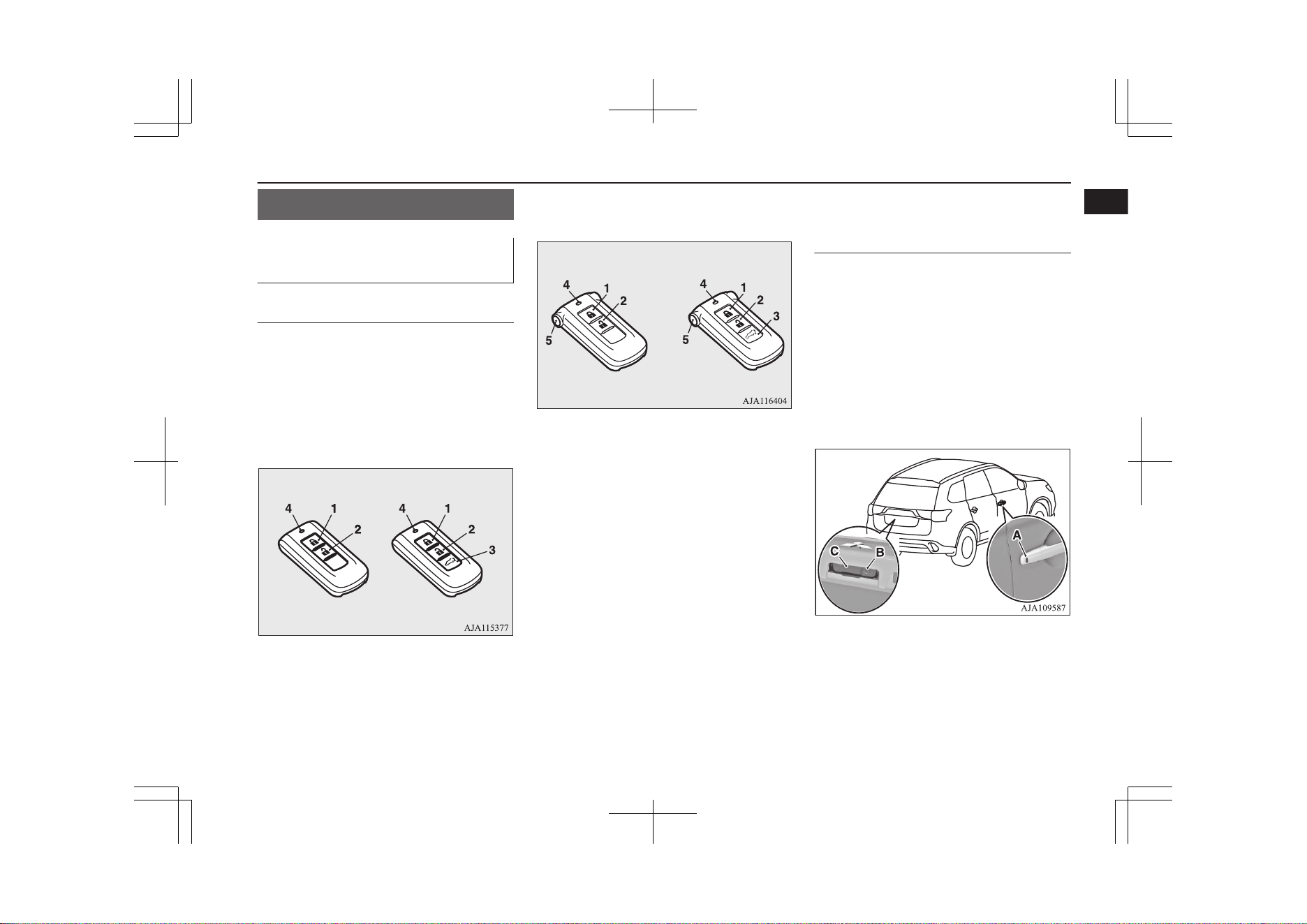
Keyless entry system
Press the remote control switch, and all doors
and the tailgate will be locked or unlocked as
desired.
The remote control switch will operate within
approximately 4 m from the vehicle.
Vehicles without MITSUBISHI Remote
Control
Vehicles with MITSUBISHI Remote Con-
trol
1- LOCK switch
2- UNLOCK switch
3- Electric tailgate switch
4- Indication lamp
5- Charging timer cancel switch*
Refer to “Keyless entry system” on page
4-03.
On vehicles with the electric tailgate, the tail-
gate can be opened automatically if you press
the electric tailgate switch (3) after unlocking
the tailgate.
Refer to “Electric tailgate” on page 4-20.
On vehicles with the MITSUBISHI Remote
Control, the charging timer can be cancelled
if you press the charging timer cancel switch
(5) twice within 2 seconds.
Refer to “MITSUBISHI Remote Control”
on page 3-20
Keyless operation system
When you are carrying the keyless operation
key and within the operating range, if you
press the driver’s or front passenger’s door
lock/unlock switch (A), or the tailgate lock
switch (B) (when locking) and the tailgate
open switch (C) (when unlocking), the doors
and the tailgate are locked/unlocked.
The operating range is approximately 70 cm
from the driver’s door switch, front passeng-
er’s door switch and the tailgate switches.
Refer to “Keyless operation system” on
page 4-06.
Quick guide
1-15
OGGE19E1
Overview
1
Around the driver’s seat
E08500801687
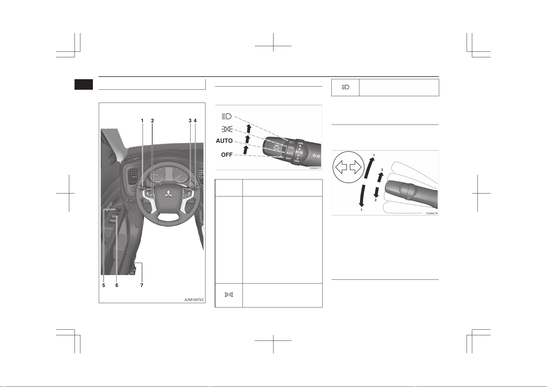
1-Combination headlamps
Rotate the switch to turn on the lamps.
OFF All lamps off {except for day-
time running lamps}
AUTO
With the operation mode of the
power switch in the “ON” posi-
tion, head-lamps, position, tail,
licence plate, instrument panel
lamps and downlight turn on
and off automatically in accord-
ance with outside light level.
{Daytime running lamps will go
on while the tail lamps are off.}
All lamps turn off automatically
when the operation mode is put
in OFF.
Position, tail, licence plate, in-
strument panel lamps and down-
light on
Headlamps and other lamps go
on
Refer to “Combination headlamps and
dipper switch” on page 6-59.
1-Turn-signal lever
The turn-signal lamps flash when the lever is
operated
1- Turn-signals
2- Lane-change signals
Refer to “Turn-signal lever” on page
6-67.
2-Steering wheel height and
reach adjustment
1. Release the lever while holding the
steering wheel up.
2. Adjust the steering wheel to the desired
position.
Quick guide
1-16
OGGE19E1
Overview
1
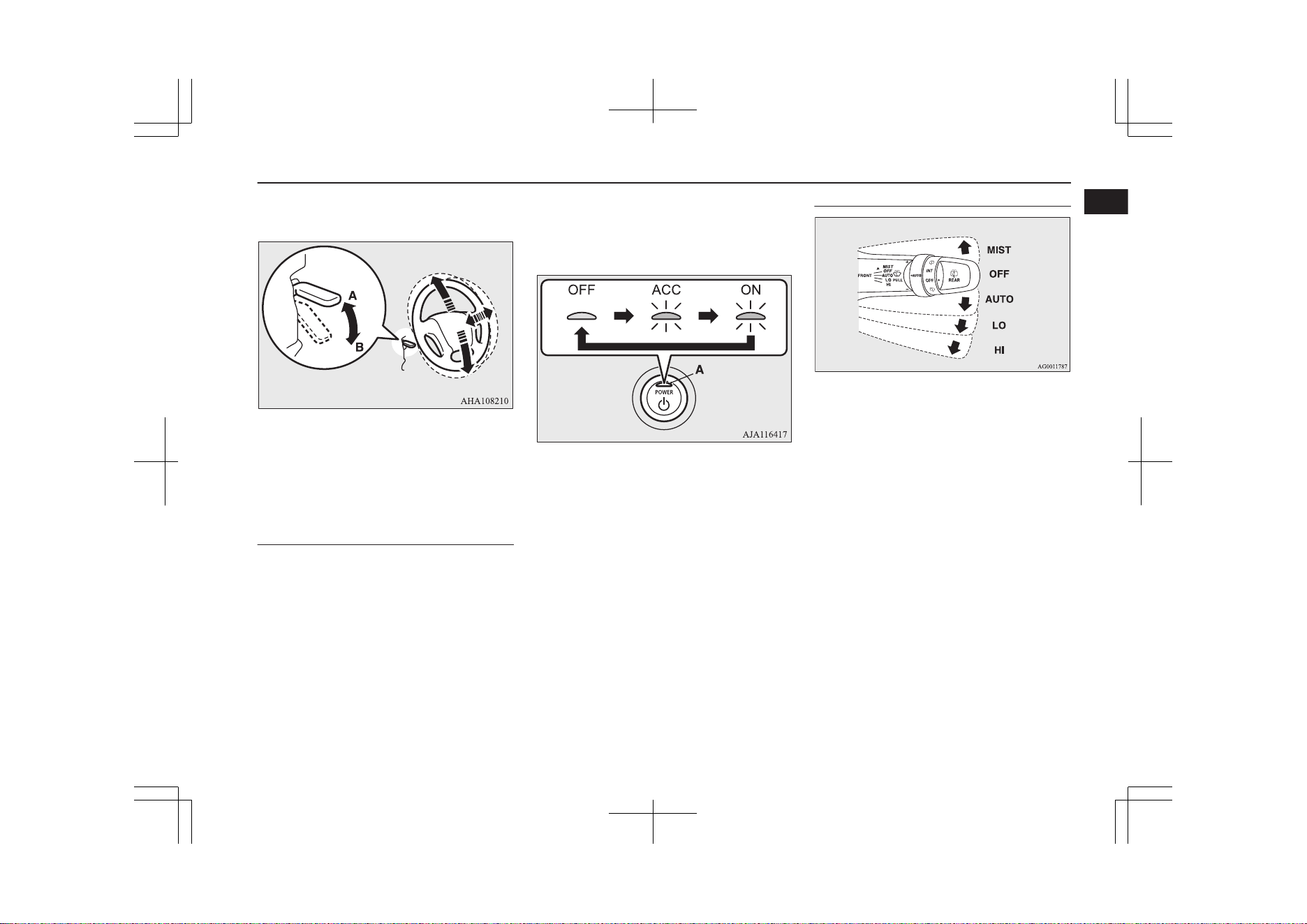
3. Securely lock the steering wheel by pull-
ing the lever fully upward.
A- Locked
B- Release
Refer to “Steering wheel height and reach
adjustment” on page 7-07.
3-Power switch
If you are carrying the keyless operation key,
you can start the Plug-in Hybrid EV System.
If you press the power switch without de-
pressing the brake pedal, you can change the
operation mode in the order of OFF, ACC,
ON, OFF.
OFF- The indication lamp (A) on the
power switch turns off.
ACC- The indication lamp on the en-
gine switch illuminates orange.
ON- The indication lamp on the pow-
er switch illuminates blue.
Refer to “Power switch” on page 7-11.
4-Wiper and washer switch
MIST- Misting function
The wipers will operate
once.
OFF- Off
AUTO- Auto-wiper control
The wipers will automati-
cally operate depending on
the degree of wetness on
the windscreen.
LO- Slow
HI- Fast
The washer fluid will be sprayed onto the
windscreen by pulling the lever towards you.
Refer to “Wiper and washer switch” on
page 6-69.
Quick guide
1-17
OGGE19E1
Overview
1
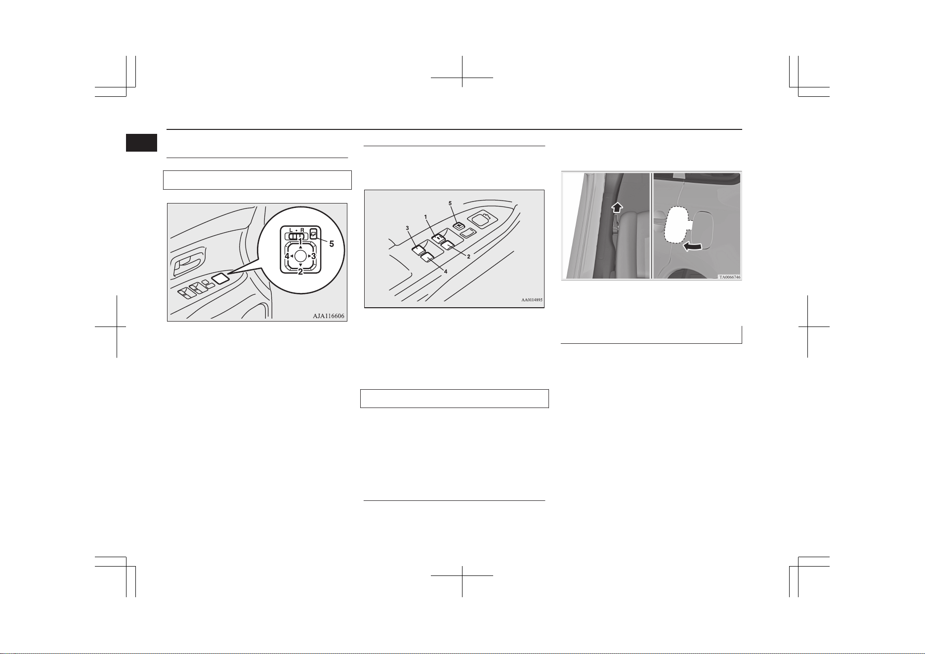
5-Electric remote-controlled
outside rear-view mirrors
To adjust the mirror position
L- Left outside mirror adjustment
R- Right outside mirror adjustment
1- Up
2- Down
3- Right
4- Left
5- Mirror retractor switch
Refer to “Outside rear-view mirrors” on
page 7-09.
6-Electric window control
Press the switch down for opening the win-
dow, and pull the switch for closing.
1- Driver’s door window
2- Front passenger’s door window
3- Rear left door window
4- Rear right door window
5- Lock switch
Lock switch
If you press the switch (5), the passenger’s
switches cannot be operated. To cancel, press
it once again.
Refer to “Electric window control” on
page 4-34.
7-Fuel tank filler door release
lever
Open the fuel tank filler door.
The fuel tank filler is located on the rear left
side of your vehicle.
Refer to “Filling the fuel tank” on page
2-15.
Charging lid
E08502100023
Firmly apply the parking brake, press the
electrical parking switch to shift into the “P”
(PARK) position and put the operation mode
of the power switch in the “OFF” position.
Quick guide
1-18
OGGE19E1
Overview
1
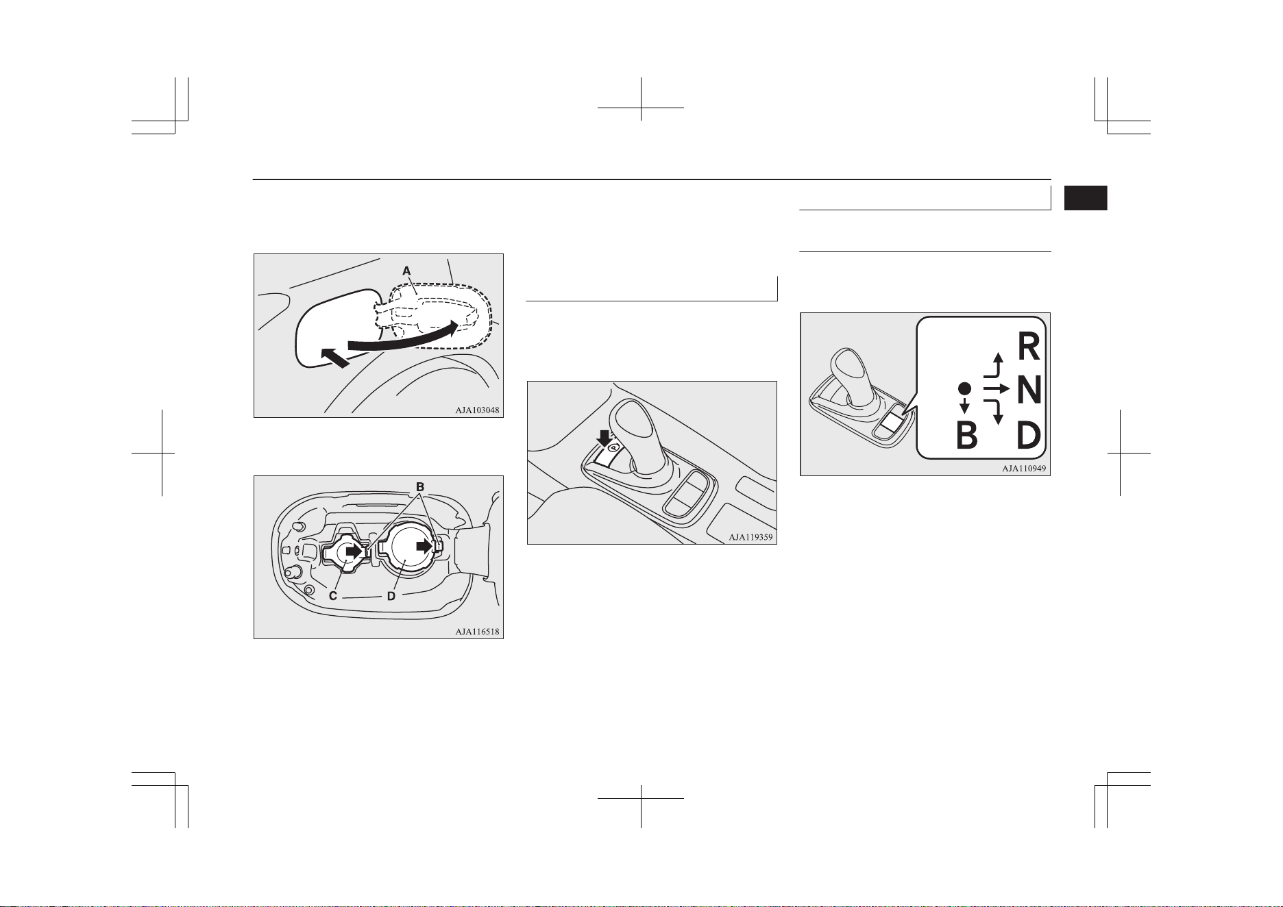
After unlocking the driver’s door, push the
rear portion of the charging lid (A) until it
clicks, and open the charging lid.
Release the tab (B) to open the inner lid.
C- Normal charging lid
D- Quick charging lid
Refer to “Normal charging (charging
method with rated AC 220-240V outlet)”
on page 3-10 and “Quick charging
(charging method with quick charger)” on
page 3-17.
Electrical parking switch
E08502200037
Press the switch to lock the wheels when you
are parking your vehicle. The indication lamp
on the switch illuminates green.
Refer to “Electrical parking switch” on
page 7-18.
Selector lever (Joystick type)
E08502300025
Selector lever operation
The selector lever always returns to its home
(•) position when it is released.
Home
position
Move the selector lever slowly and securely
in the following method.
l
To select “D” (DRIVE) or “R” (RE-
VERSE):
Move the selector lever in the direction
of the arrow.
l
To select “N” (NEUTRAL):
Move the selector lever in the direction
of the arrow and hold it for a while.
l
To select “B” (REGENERATIVE
BRAKE):
Move the selector lever in the direction
of the arrow.
Quick guide
1-19
OGGE19E1
Overview
1
You can shift the selector lever to “B” only
when the select position is in the “D”
(DRIVE) position.
Selector lever positions
“P” PARK
The wheel are locked. When you park your
vehicle, be sure to apply the parking brake
and press the electrical parking switch.
“R” REVERSE
This position is to back up.
“N” NEUTRAL
No power is transmitted to the wheels. The
wheels are not locked.
“D” DRIVE
This position is for normal driving.
“B” REGENERATIVE BRAKE
This position is for the regenerative braking.
You can adjust the regenerative braking force
up to two levels.
Refer to “Selector lever (Joystick type)” on
page 7-15
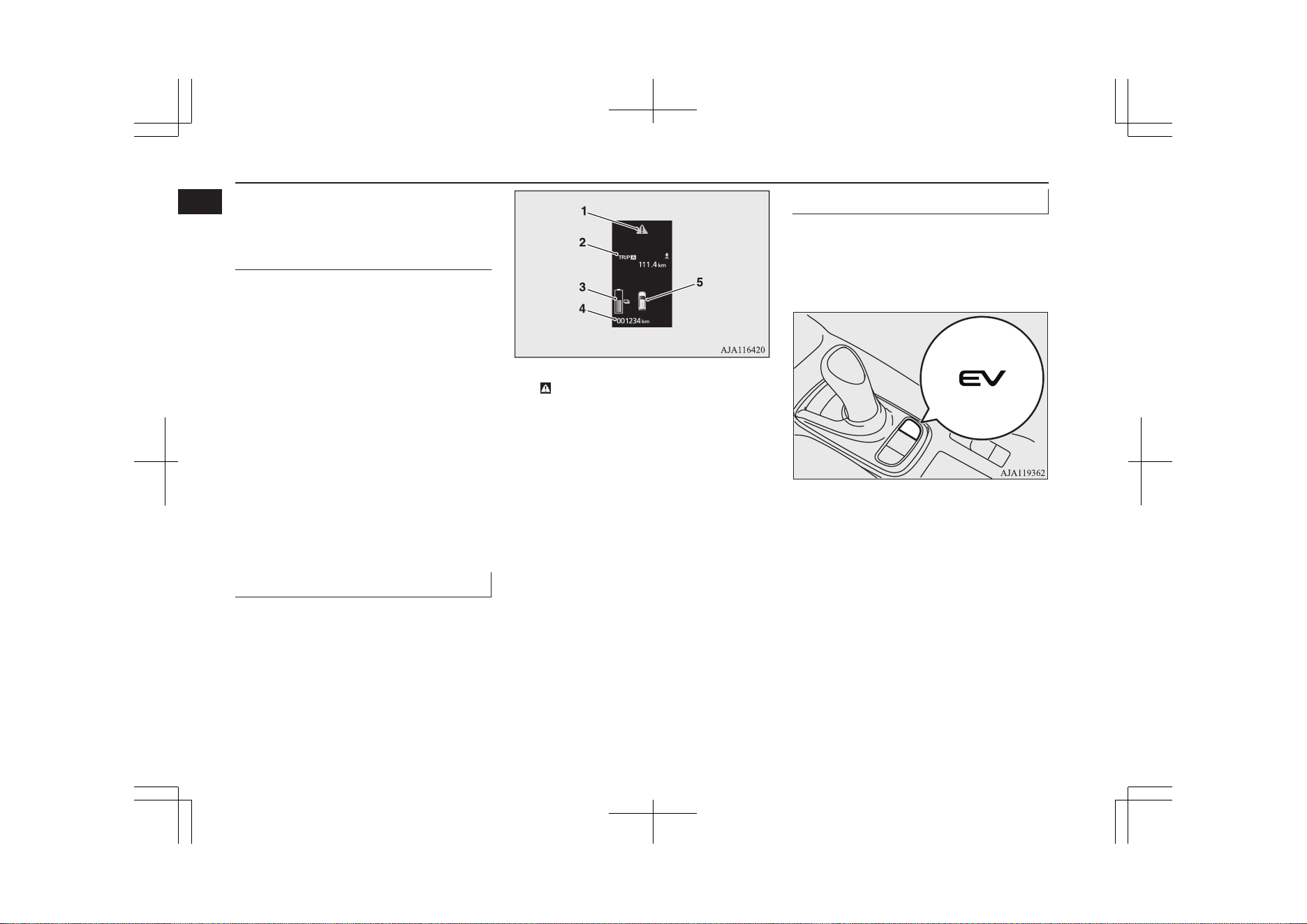
Multi information display
E08501201473
Always stop the vehicle in a safe place before
operating.
The following information is included on the
multi information display: odometer, tripme-
ter, average fuel consumption etc.
1- mark display screen ® p. 6-11
2- Information screen ® p. 6-07
Interrupt display screen ® p. 6-10
3- Drive battery level display screen
® p. 6-11
4- Odometer ® p. 6-13
5- Door ajar warning display screen
® p. 6-11
Refer to “Multi information display” on
page 6-04.
EV switch
E08502400039
When you press the switch, you can drive the
vehicle using only the EV drive mode as
much as possible, even if the accelerator ped-
al is roughly depressed.
Refer to “EV switch” on page 7-25.
Quick guide
1-20
OGGE19E1
Overview
1
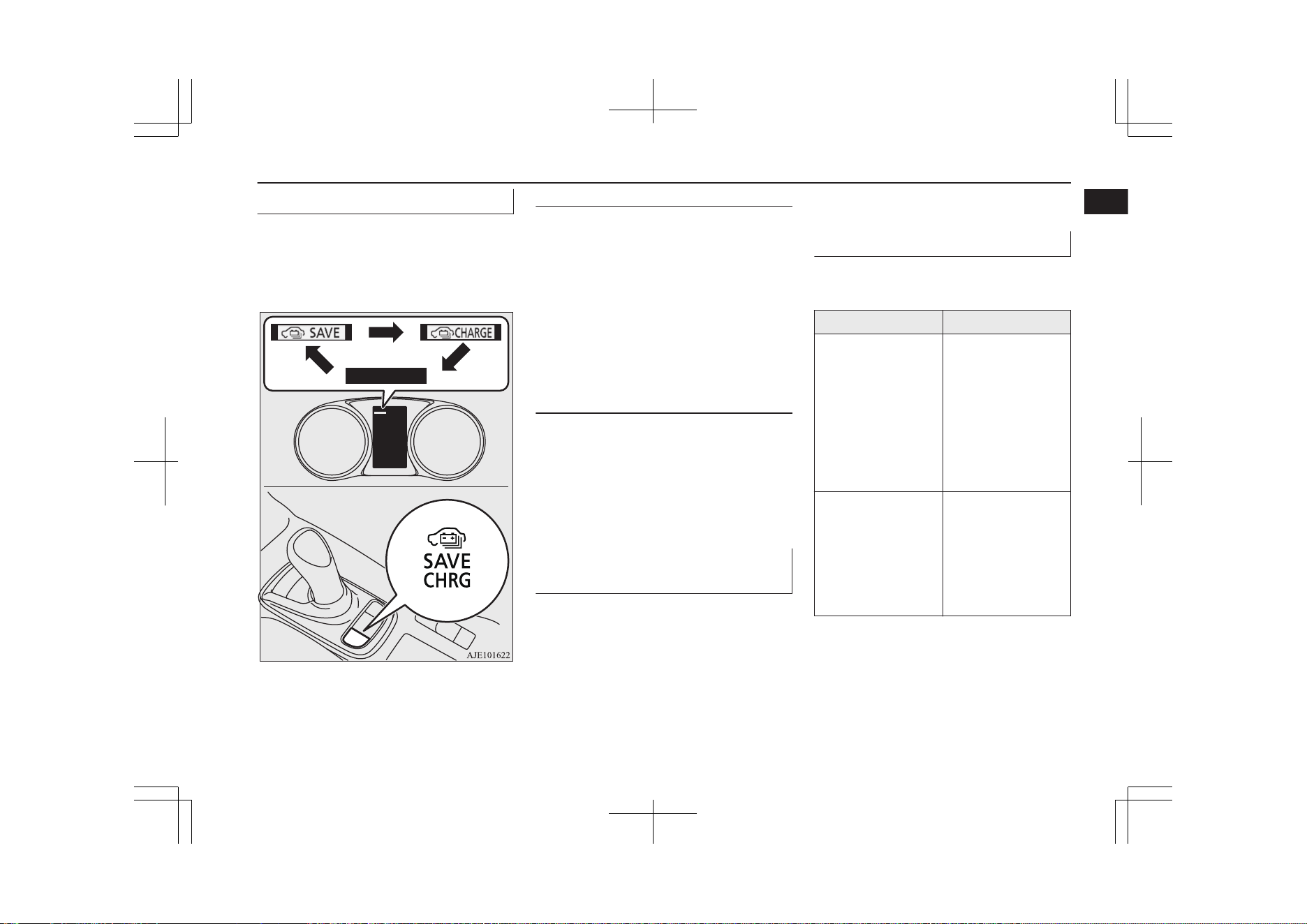
SAVE/CHARGE mode switch
E08503000029
If you press the switch with the operation
mode of the power switch in ON, you can
charge the drive battery mode in the order of
SAVE, CHARGE, OFF, SAVE.
Refer to “SAVE/CHARGE mode switch”
on page 7-28.
Battery save mode
When the READY indicator is illuminated,
operate the SAVE/CHARGE mode switch to
change the battery save mode. The engine
will start in order to preserve the remaining
power of the drive battery and the vehicle
will operate in the series hybrid mode or the
parallel hybrid mode depending on the re-
maining power in the drive battery.
Refer to “Battery save mode” on page
7-29.
Battery charge mode
When the READY indicator is illuminated,
operate the SAVE/CHARGE mode switch to
change the battery save mode. The engine
will start to charge the drive battery to nearly
full.
Refer to “Battery charge mode” on page
7-29.
S-AWC (Super-All Wheel Con-
trol)
E08501900170
S-AWC is an integrated vehicle dynamics
control system that helps enhance driving
performance, cornering performance, and ve-
hicle stability over a wide range of driving
conditions through integrated management of
the twin motor 4WD, the AYC (Active Yaw
Control), the ABS and the ASC.
Refer to “S-AWC (Super-All Wheel Con-
trol)” on page 7-20.
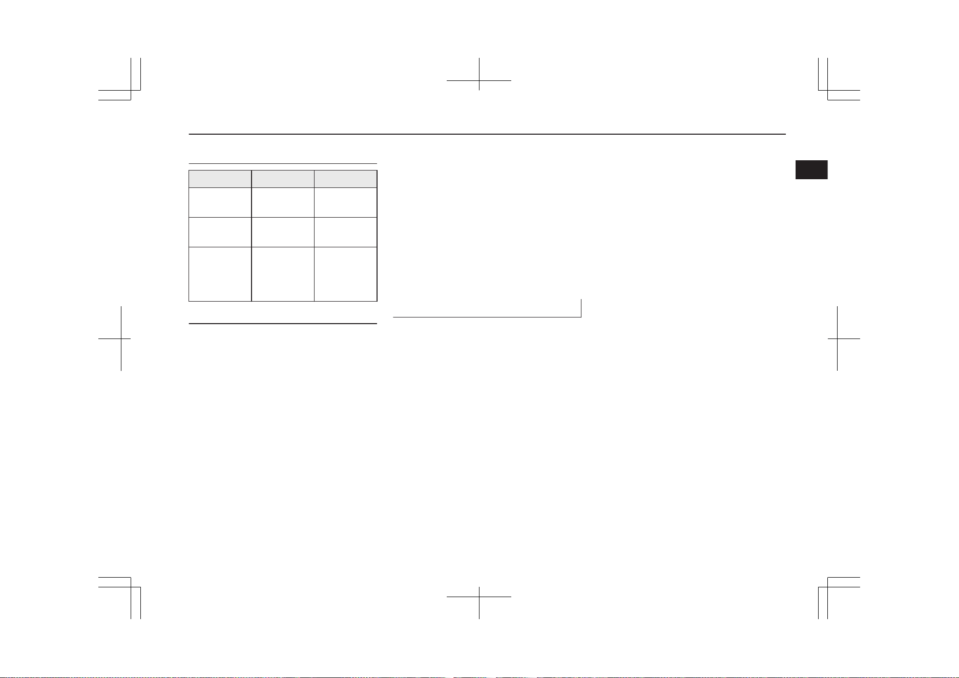
S-AWC drive mode
E08503200021
Select the drive mode from the following
three types to suit the driving conditions.
Drive mode Function
NORMAL
This mode can be
used on both dry and
wet roads. The distri-
bution of driving/
braking torque to
each wheel is auto-
matically controlled
according to the driv-
ing condition.
SNOW
This mode is for
driving on slippery
road surfaces, such
as snow-covered
roads and improves
stability on a slippery
road.
Quick guide
1-21
OGGE19E1
Overview
1
Drive mode Function
LOCK
This mode is for
driving where maxi-
mum traction is re-
quired. This mode is
suitable for driving
on rough roads or
driving in sand or
fresh snow.
Refer to “S-AWC drive mode” on page
7-21.
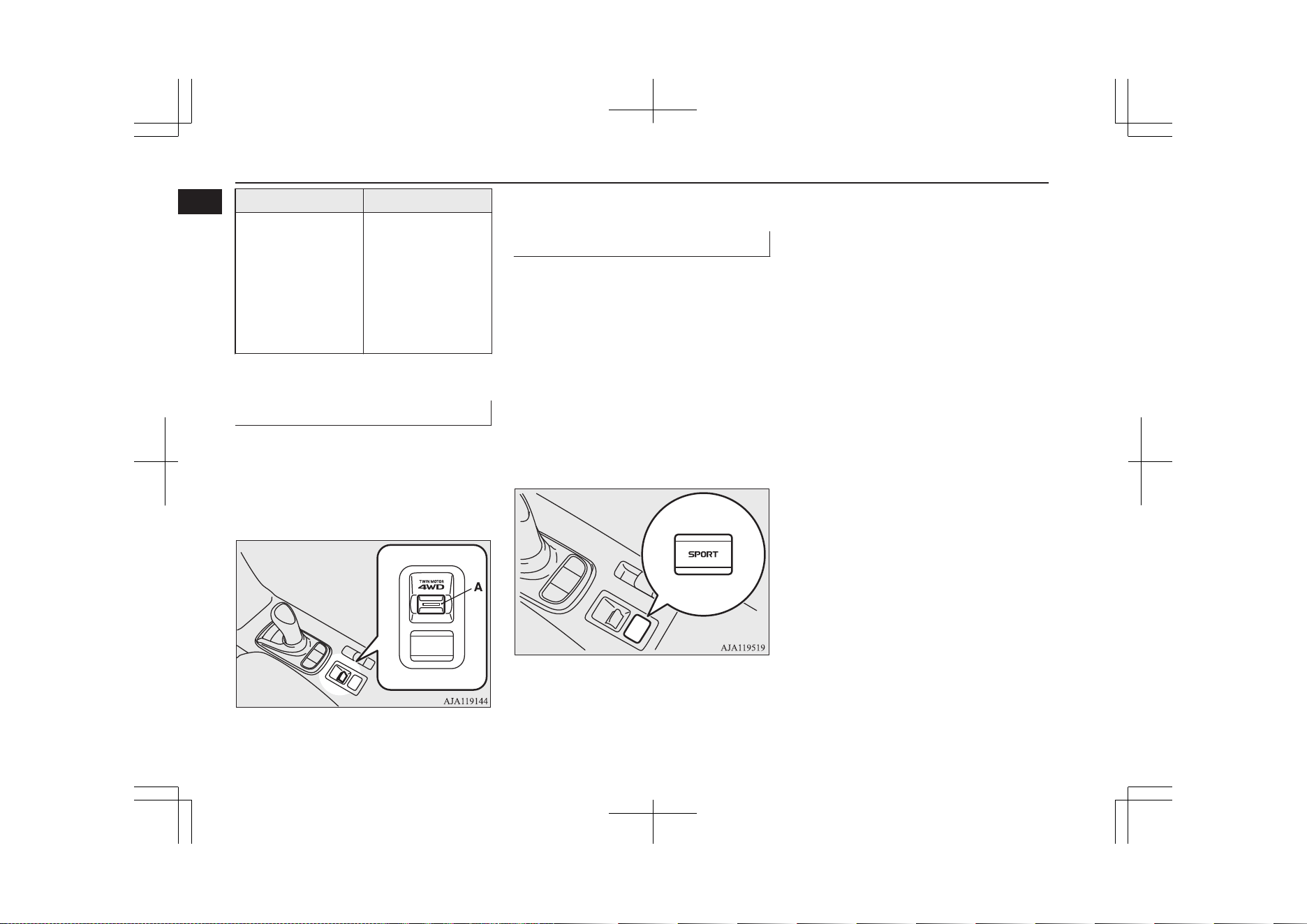
Drive mode switch
E08503100020
When the operation mode of the power
switch is put in ON, operate the drive mode
switch (A) to change the drive mode.
When the operation mode is put in OFF, the
drive mode will return to “NORMAL”.
Refer to “Drive mode switch” on page
7-21.
SPORT mode switch
E08503300022
The SPORT mode switch is used when doing
powerful sporty driving on mountain roads
and uphill slope.
Quick acceleration in response to operation
of the accelerator pedal and quick decelera-
tion by strong regenerative braking force are
possible.
The SPORT mode can be used when the
SPORT mode switch is pressed while the
READY indicator light is on.
To cancel, press the switch again or turn off
the power mode.
Refer to “SPORT mode switch” on page
7-31.
Quick guide
1-22
OGGE19E1
Overview
1

Plug-in Hybrid EV System................................................................. 2-02
Drive battery....................................................................................... 2-05
EV cruising range................................................................................2-05
Acoustic Vehicle Alerting System (AVAS).........................................2-06
Operating sound under charging or Remote Climate Control............ 2-06
In case of a collision............................................................................2-06
Inspection and maintenance................................................................2-08
For persons with electro-medical apparatus such as im-
plantable cardiac pacemaker or implantable cardiovert-
er-defibrillator.................................................................................2-09
Cautions and actions to deal with intense heat................................... 2-10
Cautions and actions to deal with intense cold................................... 2-10
Fuel selection...................................................................................... 2-14
Filling the fuel tank.............................................................................2-15
Installation of accessories................................................................... 2-17
Modification/alterations to the electrical or fuel systems................... 2-18
Genuine parts...................................................................................... 2-18
Safety and disposal information for used engine oil...........................2-18
Disposal information for used batteries.............................................. 2-18
General information
OGGE19E1
2
Plug-in Hybrid EV System
E00203500041
Main features
E00203600244
It is operated as an electric vehicle in the EV
drive mode using the electrical power stored
in the drive battery,
*1
according to the re-
maining amount of the drive battery. It is also
automatic control
*2
for driving in series hy-
brid mode or parallel hybrid mode using en-
gine power from EV drive mode according to
the driving condition or if the charging level
of the drive battery is decreased.
l
With the high performance motor, noise
and vibration during driving is mini-
mized and powerful acceleration can al-
so be obtained.
l
With the regenerative brake, the drive
battery is automatically charged when
the accelerator is released.
*1
If there is a remaining amount in the drive
battery, it is actively driven in the EV
drive mode. The cruising range varies de-
pending on the remaining charge in the
drive battery, vehicle speed, and air condi-
tioner operating conditions.
*2
You can adjust the timing to switch to the
EV drive mode by using the save mode.
Refer to “SAVE/CHARGE mode switch”
on page 7-28. Refer to “Battery save
mode” on page 7-29.
l
The vehicle can be charged from EV
charge power outlets (rated AC
220-240 V).
l
Quick charging using the CHAdeMO
quick charger is possible. CHAdeMO is
a standard for quick charging of electric
vehicles originally started in Japan, and
the contents have also become interna-
tional standard.
EV drive mode
l
The vehicle is driven by the motors us-
ing only electrical power stored in the
drive battery. However, EV drive mode
is cancelled depending on the drive bat-
tery level, vehicle speed, and air condi-
tioner operating conditions. Pay atten-
tion to the following points:
• Check the EV cruising range in the in-
formation screen. Refer to “EV cruis-
ing range display/Total cruising range
display” on page 6-15.
• Drive your vehicle at moderate speeds
avoiding quick acceleration/decelera-
tion. Repeated quick acceleration/
deceleration causes the drive battery
level to decrease quickly, which ex-
tremely reduces the EV cruising
range.
l
If you want to drive the vehicle without
starting the engine as much as possible,
make the switch to the EV priority mode
by pressing the EV switch.
Refer to “EV switch” on page 7-25.
Series hybrid mode
l
The vehicle is driven by the motors us-
ing only the electricity generated by the
engine. This mode is used when the
drive battery level is low, at quick accel-
eration, or when power is required like
climbing uphill.
NOTE
l
While driving the Series hybrid mode, the
engine malfunction diagnostic system may
operate.
If this system operates, the engine sound will
decrease. This does not indicate a malfunc-
tion.
Parallel hybrid mode
l
The vehicle is driven by the power of the
engine, assisted by motors. This mode is
used during high-speed driving with bet-
ter engine efficiency.
Plug-in Hybrid EV System
2-02
OGGE19E1
General information
2
The roles of the motors and en-
gine in each drive mode
Motor Engine
EV Drive
Mode
Drives the
vehicle
OFF
Series Hybrid
Mode
Drives the
vehicle
Generates
electricity
Parallel Hy-
brid Mode
Drives the
vehicle
Drives front
wheels and
generates
electricity
Regenerative braking
Motion energy is converted into electric ener-
gy using the motor as a power generator.
Then a braking force generates and converted
electric energy will be charged to the drive
battery.
l
If you lift your foot off the accelerator
pedal during driving, a braking force that
is equivalent to engine braking of a com-
bustion engine vehicle will be generated.
Also, if you shift the select position into
“B” (BRAKE) from “D” (DRIVE), ef-
fectiveness of the regenerative braking is
getting stronger. Shift the selector lever
into “B” (BRAKE) position according to
the driving condition.
l
When you depress the brake pedal, the
regenerative braking force may be in-
creased.
l
If a problem occurs in the Plug-in hybrid
EV system, or if the ABS and/or the
ASC have been activated, the regenera-
tive braking will be restricted. The foot
brake will still operate.
l
When stronger regenerative braking is
generated, the stop lamps will illuminate
even when the brake pedal is not de-
pressed.
Operation of gasoline engine
E00203700098
l
Even when the vehicle is driving in EV
drive mode, it may be automatically
changed to series hybrid mode or paral-
lel hybrid mode in the following cases:
• The plug-in hybrid EV system is too
hot or too cold.
• Quick acceleration is applied.
• The air conditioner is operating.
• The accelerator pedal is depressed
hard on an uphill road or expressway.
• In cold weather.
• The vehicle has not been refueled for
a long time.
• The drive battery level is low.
In addition to the above, there are more
cases where EV drive mode is automati-
cally changed to series or parallel hybrid
mode.
l
Even while the vehicle is stopped, the
engine may automatically be started in
the following cases:
• The drive battery level is low.
• The plug-in hybrid EV system is too
hot or too cold.
• The air conditioner is used.
• The vehicle has not been used for a
long time.
• The engine has not been operated for a
long time.
• Refuelling has not been performed for
a long time.
Plug-in Hybrid EV System
2-03
OGGE19E1
General information
2
NOTE
l
Depending on the usage of the vehicle, the
engine may not start for a long period of
time and unused fuel will remain in the fuel
tank. Fuel can deteriorate over time, which
can adversely affect the engine and/or the
fuel system.
If the vehicle is not refueled with more than
15 litres at least once every 3 months, the
engine will automatically start, while the
ready indicator is illuminated, to help pre-
vent deterioration of the fuel. At that time,
charging of the drive battery will start and
the battery charge mode display will appear
on the information screen in the multi infor-
mation display. The charging will stop, how-
ever, before the drive battery is fully charg-
ed.
The engine may also start even while the EV
drive mode is selected or the vehicle is sta-
tionary.
To stop the engine from starting automatical-
ly when the vehicle is operated on the drive
battery power only for a long time, start the
engine and drive the vehicle enough to re-
duce the fuel level to approximately half
tank. Refill the fuel tank with at least 15 li-
tres of unleaded petrol.
Refueling (gasoline)
E00203800073
CAUTION
l
If the warning display appears, refuel imme-
diately.
If the vehicle runs out of fuel, the engine
will not start even in a situation need to be
generated electricity, the following condi-
tions will occur.
•
The driving performance falls (since only
the electrical power stored in the drive
battery can be used for the driving).
•
The heating performance is not available
(except vehicles with electric heater).
•
The effectiveness of the heater is insuffi-
cient (vehicles with electric heater).
•
The catalytic converter may be damaged
due to excessive high temperature.
Refer to “Filling the fuel tank” on page
2-15.
Refer to “Fuel remaining display screen” on
page 6-11.
CAUTION
l
The fuel in the fuel tank may not be con-
sumed and it may stagnate for a long time
depending on the use situation of the vehi-
cle, the quality of fuel may change, and it
may have a bad influence on the engine or
the parts of a fuel system.
Observe the following instructions for pre-
vention.
•
Start the engine more than once every 3
months by activating the battery charge
mode.
Refer to “SAVE/CHARGE mode switch”
on page 7-28.
Refer to “Battery charge mode” on page
7-29.
•
Refill the fuel more than 15 litres at once
within 3 months. If the fuel remaining dis-
play will be below half, you can refill the
fuel more than 15 litres certainly.
Refer to “Fuel remaining display screen”
on page 6-11.
Plug-in Hybrid EV System
2-04
OGGE19E1
General information
2
Drive battery
E00205000066
WARNING
l
A sealed lithium ion high voltage battery
(drive battery) is adopted for OUTLAND-
ER PHEV. If the drive battery is disposed
of improperly, there is a risk of severe
burns and electrical shock that may result
in serious injury or death and there is also
a risk of environmental damage.
l
Never attempt to use the drive battery for
any other purpose.
l
It is the battery to operate the motor and
the air conditioning.
In addition to the drive battery, OUT-
LANDER PHEV has the auxiliary bat-
tery to operate lamps, wipers, etc.
l
Compact, light-weight lithium ion bat-
tery with high energy density is used for
the drive battery.
l
The drive battery has the following char-
acteristics.
Please read this carefully paying atten-
tion to the following:
Characteristics
l
The same as ordinary lithium-ion batter-
ies, the battery capacity of the drive bat-
tery gradually reduces with time. As the
drive battery capacity decreases, the ini-
tial EV cruising range and the vehicle
performance will similarly decrease.
Depending on the usage conditions, such
as frequent quick acceleration/decelera-
tion, extremely hot weather, storing the
vehicle in high ambient temperatures,
etc., the rate of battery capacity drop will
increase.
l
The performance may be changed due to
the ambient temperature.
At low ambient temperature, in particu-
lar, the EV cruising range is short and
the charging time is long, compared to
operation at normal temperature. Also,
charging may be stopped before com-
plete charging.
l
When the ambient temperature lowers,
the engine will start frequently, even if
there remains much power in the drive
battery.
l
Because the engine starts frequently, the
fuel consumption will increase.
l
The battery is gradually discharged with-
out use and the battery charge is low-
ered.
l
It is not necessary to consume the bat-
tery completely before charging.
Precautions for operation
l
If your vehicle is not used for a long
time, check the drive battery level dis-
play every 3 months.
If the drive battery level display shows
0, charge the battery until some indica-
tion appears. Alternatively, start the
Plug-in Hybrid EV System and turn on
the ready indicator.
The engine will then automatically start
to charge the drive battery.
Wait until the engine automatically
stops, then put the operation mode of the
power switch in OFF.
l
MITSUBISHI Motors collects drive bat-
teries. If you scrap your vehicle, please
consult a MITSUBISHI MOTORS Au-
thorized Service Point.
EV cruising range
E00205100025
l
Even if the charge level is the same, the
EV cruising range may vary depending
on driving conditions. Since driving at
high speed or climbing on a hill requires
higher consumption of the drive battery
than usual, the EV cruising range is
shortened.
Drive battery
2-05
OGGE19E1
General information
2
l
Since the air conditioning (cooling or
heating) consumes power of the drive
battery, its operation results in a shorter
EV cruising range. Maintain an appro-
priate temperature.
l
Put the selector lever to “B” (BRAKE)
position according to the road condition.
To charge the drive battery with appro-
priate use of the regenerative brake, it
can be increased the EV cruising range.
Acoustic Vehicle Alerting
System (AVAS)
E00205200042
The Acoustic Vehicle Alerting System
(AVAS) is a device that uses sound to alert
pedestrians of the presence of the vehicle.
The system operates when the vehicle speed
is about 35 km/h (22 mph) or less and the en-
gine is not running.
Refer to “Acoustic Vehicle Alerting System
(AVAS)” on page 7-32.
WARNING
l
Even if the Acoustic Vehicle Alerting Sys-
tem (AVAS) sounds, pay special attention
to pedestrians.
Pedestrians may not notice the oncoming
vehicle, which may cause an accident re-
sulting in serious personal injury or
death.
Operating sound under
charging or Remote Climate
Control
E00205700050
Even if the operation mode of the power
switch is OFF, you may hear an operating
sound such as the cooling fan for cooling the
drive battery during charging, the air condi-
tioning compressor and for remote climate
control (if so equipped).
This is not a malfunction.
Refer to “MITSUBISHI Remote control: Re-
mote Climate Control” on page 3-20.
In case of a collision
E00205300085
A crash or impact significant enough to re-
quire an emergency response for convention-
al vehicles would also require the same re-
sponse for Outlander PHEV.
Also follow the instructions described below
to avoid severe burns and electrical shock
that may result in serious injury or death.
WARNING
l
If your vehicle is drivable, pull your vehi-
cle off the road to a safe, nearby location
and remain on the scene.
Also, if possible, do the following opera-
tions and stay out of the way of any on-
coming traffic while awaiting the arrival
of emergency responders.
•
Apply chocks to the wheels.
•
Put the select position in “P” (PARK)
position.
•
Apply the parking brake.
•
Open the windows, doors and tailgate.
•
Put the operation mode in OFF.
•
Turn on the hazard warning flashers.
•
Move the key away from the vehicle to
prevent unintended start-up of the sys-
tem by inadvertent contact with a
switch or impact from the crash.
l
Never touch high-voltage wiring, connec-
tors, and other high-voltage parts, such as
the inverter unit and drive battery. An
electric shock may occur if exposed elec-
tric wires are visible when viewed from
inside or outside of your vehicle. For their
locations, see “High-voltage components”
on page 2-08.
l
If the vehicle receives a strong impact to
the floor while driving, stop the vehicle in
a safe place and check the floor.
Acoustic Vehicle Alerting System (AVAS)
2-06
OGGE19E1
General information
2
WARNING
l
Never start the plug-in hybrid EV system
if you found a leak of a liquid (except wa-
ter of the air conditioner) while checking
the outside of the vehicle because there is
possibility the fuel system has been dam-
aged and causing of fire or exploding.
In such case, immediately contact your
MITSUBISHI MOTORS Authorized
Service Point.
l
Leaks or damage to the drive battery may
result in a fire. If you discover them, con-
tact emergency services immediately.
Since the fluid leak may be lithium man-
ganite from the Lithium-ion battery, nev-
er touch any fluid leaking from the inside
or outside of the vehicle. If the fluid con-
tacts your skin or eyes, wash it off imme-
diately with a large amount of water and
receive immediate medical attention to
help avoid serious injury.
l
If you are unable to safely assess the vehi-
cle due to vehicle damage, do not touch
the vehicle. Leave the vehicle and contact
emergency services. Advise emergency
responders that this is a Plug-in Hybrid
vehicle.
WARNING
l
If a fire occurs in this vehicle, leave the
vehicle as soon as possible and contact
emergency services. Do not attempt to ex-
tinguish a fire by yourself. If the fire in-
volves a lithium-ion battery, it will require
large, sustained volumes of water for ex-
tinguishment. Using a small amount of
water or the incorrect fire extinguisher
can result in serious injury or death from
electrical shock.
l
When you leave the vehicle, if possible,
open the windows, doors and tailgate to
prevent accumulation of poisonous/
combustible gasses. This will also assist in
the rescue and fire fighting process.
l
As with any vehicle fire, the byproducts of
combustion can be toxic. Do not inhale
smoke, vapors, or gas from the vehicle.
Move to a safe distance upwind and uphill
from the vehicle fire and out of the way of
any oncoming traffic while awaiting the
arrival of emergency responders.
l
If you detect leaking fluids, sparks,
smoke, flames, gurgling, popping or hiss-
ing noises originating from the high volt-
age battery compartment, contact emer-
gency services immediately. This may re-
sult in a fire.
l
Physical damage to the vehicle or high
voltage battery may result in immediate
or delayed release of toxic and/or flamma-
ble gases and fire.
WARNING
l
If your vehicle needs to be towed, trans-
port the vehicle on a flatbed truck or tow
the vehicle with all wheels off the ground.
If the any wheels are on the ground when
towing, this may cause damage to the elec-
tric motors. This may also cause a fire, if
wiring in the electric motor unit room be-
comes damaged. Refer to “Towing” on
page 9-17.
l
Do not attempt to repair a damaged Plu-
gin Hybrid vehicle by yourself. Please
contact a MITSUBISHI MOTORS Au-
thorized Service Point for service.
l
In the event of an accident that requires
body repair and painting, the vehicle
should be delivered to a MITSUBISHI
MOTORS Authorized Service Point to
have the drive battery and high voltage
parts such as the inverter, including the
attached wiring harness, removed prior to
painting. If exposed to heat in the paint
booth, the drive battery will experience
battery capacity loss.
A damaged drive battery can also pose
safety risks to untrained mechanics and
repair personnel.
NOTE
l
The emergency shut-off system will be acti-
vated and the high-voltage system will auto-
matically turn off under the following condi-
tions:
In case of a collision
2-07
OGGE19E1
General information
2
NOTE
•
Certain front, side or rear collisions.
•
Certain Plug-in Hybrid EV system mal-
functions.
l
When the emergency shut-off system is acti-
vated, the ready indicator is turned off. Refer
to “Indicator and warning lamp list” on page
6-24.
l
If the emergency shut-off system activates,
contact a MITSUBISHI MOTORS Author-
ized Service Point.
Inspection and maintenance
E00205400031
When performing inspection and mainte-
nance, be careful in the following points.
WARNING
l
Before performing inspection or mainte-
nance, be sure to disconnect the charge
connector from the vehicle and confirm
that put the operation mode of the power
switch in “OFF”.
WARNING
l
Never touch, disassemble, remove or re-
place highvoltage parts, exposed electrical
components, cables or connectors. Failure
to follow this instruction can result in se-
vere burns or electric shock causing seri-
ous injury or death. High-voltage cables
are colored orange. The vehicle high volt-
age system has no user serviceable parts.
Take your vehicle to a MITSUBISHI
MOTORS Authorized Service Point for
any necessary maintenance.
l
Never touch the service plug under the
rear seat. Improper handling of this could
cause an electric shock which result in a
serious injury or death. The service plug
is used to shut off the high voltage from
the drive battery when repairing the vehi-
cle at a MITSUBISHI MOTORS Author-
ized Service Point.
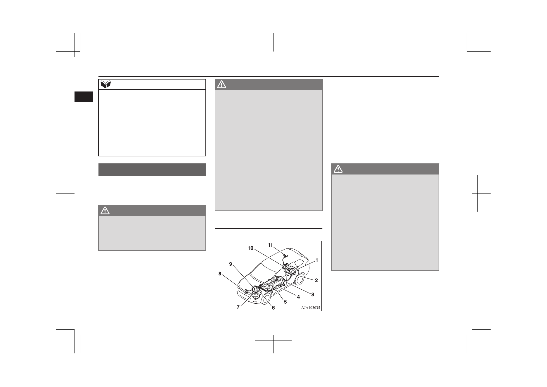
High-Voltage components
E00205500032
1- On board charger/DC-DC converter
2- Rear motor
3- Service plug
4- Electric heater*
5- Drive Battery
6- Front motor
7- Generator
8- Air conditioner compressor
9- Power drive unit (PDU)
10- Rear electric motor control unit (MCU)
11- Normal charge port/Quick charge port
WARNING
l
The Plug-in Hybrid EV System uses high
voltage up to DC 300 volt. The system can
be hot during and after starting and when
the vehicle is shut off. Be careful of both
the high voltage and the high tempera-
ture. Follow the warning labels that are
attached to the vehicle.
l
Always assume the high voltage battery
and associated components are energized
and fully charged.
l
Never perform servicing when READY
indicator is illuminating or when the
charging indicator is illuminating or
flashing because the high-voltage system
is operating.
Inspection and maintenance
2-08
OGGE19E1
General information
2
For persons with electro-medical apparatus such as implantable cardiac pacemaker or im-
plantable cardioverter-defibrillator
E00205600075
WARNING
l
Before normal charging
•
Before you perform charging work, ask the manufacturer of your electro-medical apparatus about the effect from charging work. Charging may
affect the operation of your electro-medical apparatus.
Refer to “Normal charging (charging method with rated AC 220-240V outlet)” on page 3-10.
Refer to “Quick charging (charging method with quick charger)” on page 3-17.
l
When the normal charging
•
Observe the following precautions for normal charging.
•
During charging, do not close the implantation portion of electro-medical apparatus such as implantable cardiac pacemaker or implantable
cardioverter defibrillator to the charge connector, EV charging cable, control box and normal charging station.
•
Do not stay inside the vehicle.
•
Do not get in the vehicle (including the luggage compartment) to take out something or for other purposes.
Refer to “Normal charging (charging method with rated AC 220-240V outlet)” on page 3-10.
l
Do not perform quick charging and keep away from a quick charger
•
Please observe the following precautions.
There is a possibility that electromagnetic waves affect the operation of the electro-medical apparatus.
•
Please do not use a quick charger.
•
Keep away as much as possible from the place where the quick charger is stored.
If you approach it carelessly, leave quickly without standing still.
•
Please ask someone to perform the quick charging if necessary.
Refer to “Quick charging (charging method with quick charger)” on page 3-17.
l
Do not bring your body close to the foot area of the rear seat and do not stay in the luggage compartment while the vehicle is running. Also, do not
allow persons using an electro-medical apparatus to stay in the luggage compartment while the vehicle is running. The operation of electro-medical
apparatus may be affected.
l
When using the keyless operation system, please observe following precautions.
•
People with implantable cardiac pacemakers or implantable cardiovascular-defibrillators should not go near the exterior transmitters (A) or the
interior transmitters. The radio waves used by the keyless operation system could adversely affect implantable cardiac pacemakers or implanta-
ble cardiovascular-defibrillators.
•
When using electro-medical devices other than implantable cardiac pacemakers or implantable cardiovascular-defibrillators, contact the electro-
medical device manufacturer ahead of time to determine the affects of radio waves on the devices. Electromedical device operations could be
adverse effect by radio waves. Refer to “Keyless operation system” on page 4-06.
For persons with electro-medical apparatus such as implantable cardiac pacemaker or implantable cardioverter-defibrillator
2-09
OGGE19E1
General information
2
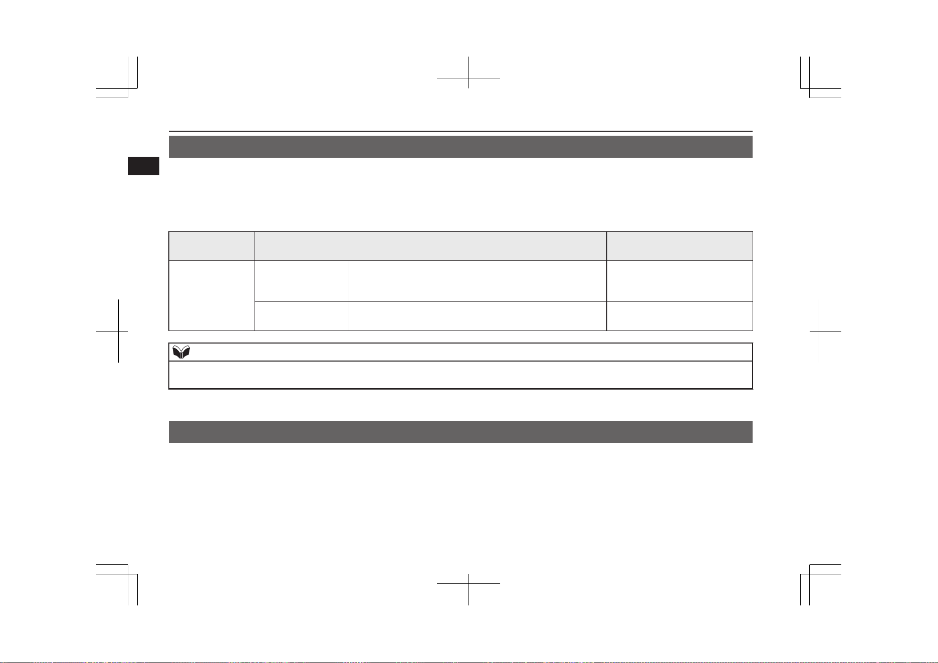
Cautions and actions to deal with intense heat
E00203001128
l
When the ambient temperature is approximately 45 °C or higher, the phenomena described below may occur. Please take the described ac-
tion.
l
Even if the ambient temperature is approximately 45 °C or lower, when performing quick charging, driving at high-speed and uphill repeat-
edly, the phenomena described below may occur. Please take the described actions.
Approx. ambient
temperature
Phenomena
Corrective action
Approx. 45 °C or
higher
Startup and driving
l
The motor output is restricted and the vehicle perform-
ance may be decreased. Then, the “PROPULSION POW-
ER IS REDUCED” warning display* may be displayed.
l
Stop the vehicle at a safe
place if needed with the plu-
gin hybrid EV system started.
Charging and battery
l
Charging time becomes longer, charging may not be pos-
sible or it may stop on the way.
l
Park in a well-ventilated,
shady place.
NOTE
l
*: Refer to “PROPULSION POWER IS REDUCED warning display” on page 6-48. Display of the “PROPULSION POWER IS REDUCED” warning
display does not indicate a malfunction.
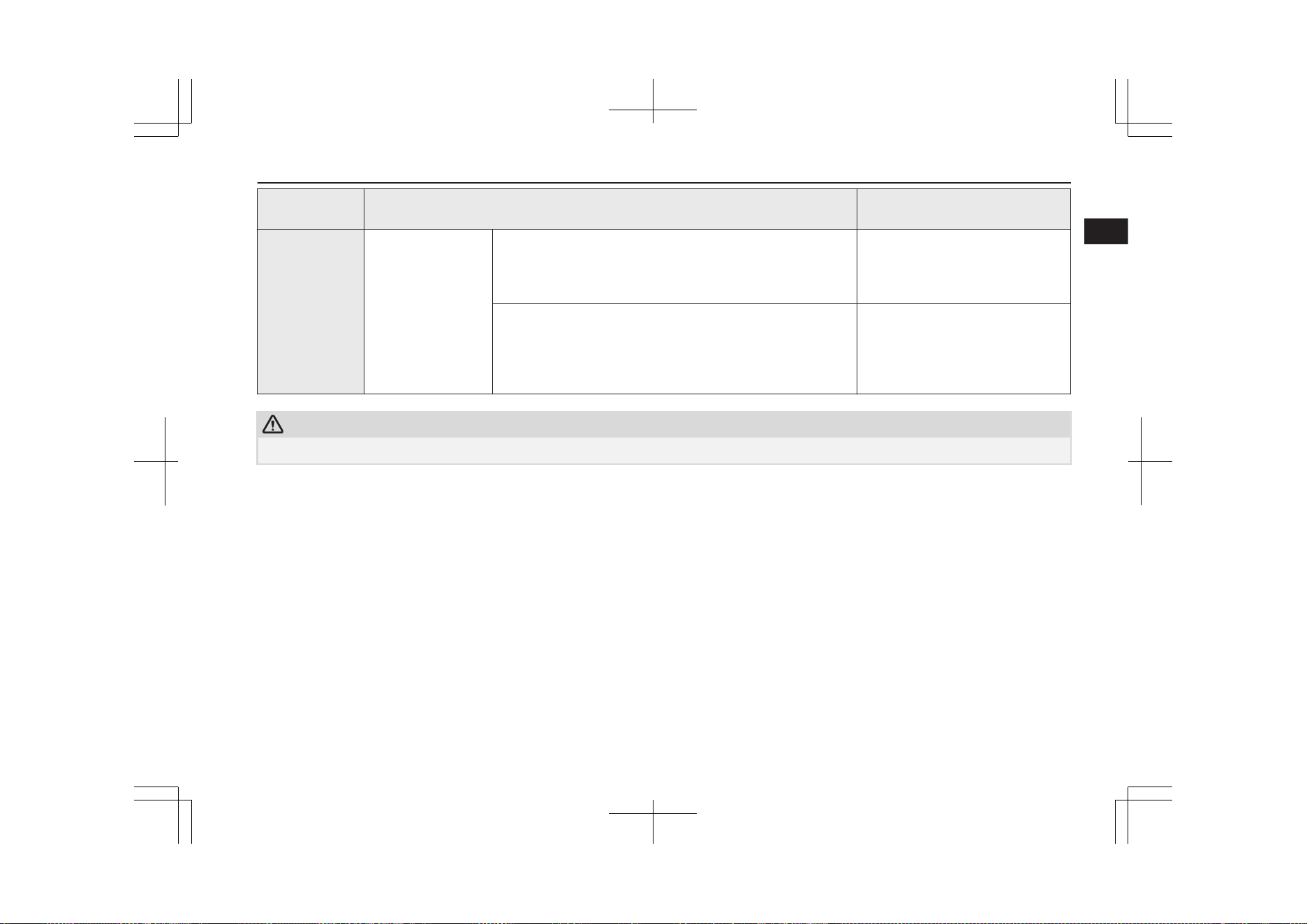
Cautions and actions to deal with intense cold
E00203101288
l
When the ambient temperature is approximately -15 °C or lower, the phenomena described below may occur. Please take the corrective
actions described below.
Cautions and actions to deal with intense heat
2-10
OGGE19E1
General information
2

Approx. ambi-
ent temperature
Phenomena Corrective action
Approx. -15 °C or
lower
Startup and driving
The motor output is restricted and the vehicle performance may
be decreased.
Keep driving if you can drive at a
safe speed.
Then, the “PROPULSION POWER IS REDUCED” warning
display*
1
may be displayed.
If you cannot drive at a safe speed,
stop the vehicle in a safe place and
charge the drive battery.
Regenerative braking performance may decrease. When braking, depress the brake
pedal more strongly.
Charging and battery
l
Charging times get longer.
l
Complete charging may not be possible.
When you have finished driving,
charge the drive battery before the
ambient temperature falls to -15 °C
or lower.
Approx. -28 °C or
lower
Startup and driving
The motor output is restricted and the vehicle performance may
be decreased.
Then, the “PROPULSION POWER IS REDUCED”
warning display*
1
and “BATTERY TOO COLD”
warning display*
2
may appear alternately. (Vehicles with drive
battery warming system)
Keep driving if you can drive at the
same speed as the surrounding vehi-
cles.
If you cannot drive at the same
speed as the surrounding vehicles,
stop the vehicle in a safe place.
The vehicle performance decreases, the “BATTERY TOO
COLD FOR VEHICLE TO OPERATE” warning display*
3
may appear.
In the daytime, wait for the tempera-
ture to rise. When the temperature in
the vicinity of the drive battery has
risen, start up.
Regenerative braking performance may decrease or be elimina-
ted.
When braking, depress the brake
pedal more strongly.
Charging and battery
Charging may become impossible. (Except for vehicles with
drive battery warming system)
When you have finished driving,
charge the drive battery before the
ambient temperature falls to -28 °C
or lower.
Cautions and actions to deal with intense cold
2-11
OGGE19E1
General information
2

Approx. ambi-
ent temperature
Phenomena Corrective action
l
Charging times get longer.
l
Complete charging may not be possible. (Vehicles with
drive battery warming system)
If low temperature is predicted, even
if the drive battery is fully charged,
connect the EV charging cable. The
drive battery will automatically be
warmed.
Approx. -30 °C or
lower
Startup and driving
The Plug-in Hybrid EV system may not be started and the
“BATTERY TOO COLD” warning display*
2
may appear. (Ex-
cept for vehicles with drive battery warming system)
In the daytime, wait for the tempera-
ture to rise. When the temperature in
the vicinity of the drive battery has
risen, start up.
The Plug-in Hybrid EV system may not start.
The ready indicator*
4
blinks and the “BATTERY TOO COLD
PLUG IN NORMAL CHARGER TO
WARM” warning display*
5
may appear. (Vehicles with drive
battery warming system)
If low temperature is predicted, even
if the drive battery is fully charged,
connect the EV charging cable (nor-
mal charger).
The drive battery will automatically
be warmed.
The Plug-in Hybrid EV system can
be started within 1 hour after the EV
charging cable is connected.
Regenerative braking performance may decrease or be elimina-
ted.
When braking, depress the brake
pedal more strongly.
The vehicle performance decreases, the “BATTERY TOO
COLD FOR VEHICLE TO OPERATE” warning display*
3
may appear.
Immediately stop the vehicle in a
safe place.
In the daytime, wait for the tempera-
ture to rise.
When the temperature in the vicinity
of the drive battery has risen, start
up.
Cautions and actions to deal with intense cold
2-12
OGGE19E1
General information
2
Approx. ambi-
ent temperature
Phenomena Corrective action
Charging and battery
Charging may become impossible. When charging is interrup-
ted, the operation mode is automatically turned off.*
6
(Except
for vehicles with drive battery warming system)
In the daytime, wait for the tempera-
ture to rise. When the temperature in
the vicinity of the drive battery has
risen, begin charging.
l
Charging times get longer.
l
Complete charging may not be possible. (Vehicles with
drive battery warming system)
If low temperature is predicted, even
if the drive battery is fully charged,
connect the EV charging cable. The
drive battery will automatically be
warmed.
CAUTION
l
When “BATTERY TOO COLD FOR VEHICLE TO OPERATE” is displayed*
3
, contact a MITSUBISHI MOTORS Authorized Service Point.
Cautions and actions to deal with intense cold
2-13
OGGE19E1
General information
2
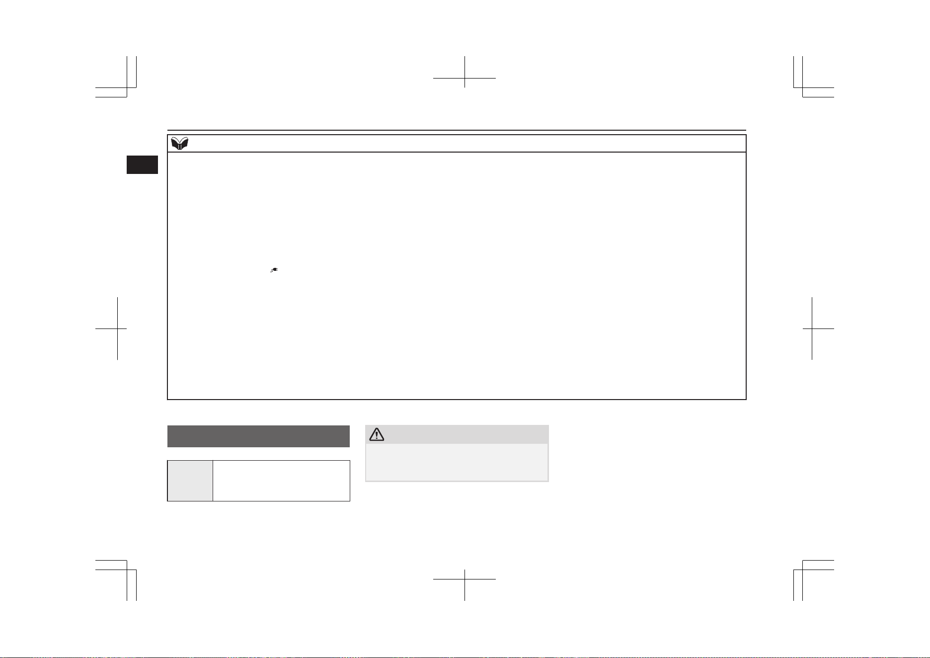
NOTE
l
*
1
: Refer to “PROPULSION POWER IS REDUCED warning display” on page 6-48.
Display of the “PROPULSION POWER IS REDUCED” warning display does not indicate a malfunction.
l
*
2
: Refer to “BATTERY TOO COLD warning display” on page 6-26.
l
*
3
: Refer to “BATTERY TOO COLD FOR VEHICLE TO OPERATE” warning display” on page 6-26.
l
*
4
: Refer to “Ready indicator” on page 6-55.
l
*
5
: Refer to “BATTERY TOO COLD PLUG IN NORMAL CHARGER TO WARM warning display” on page 6-26.
l
*
6
: Refer to “Automatic OFF of operation mode” on page 7-13.
l
To warm up the drive battery, you need to register your wireless LAN device (which conforms to IEEE 802.11 b and iOS or Android) to your vehicle by
MITSUBISHI Remote Control (if so equipped).
If the information of “
” mark on the wireless LAN device is displayed, connect the EV charging cable as soon as possible. Refer to “MITSUBISHI
Remote Control” on page 3-20.
l
When warming the drive battery with the drive battery warming system (if so equipped), use the EV charging cable. When using a home charging device or
a public charging device (EVSE: Electric Vehicle Supply Equipment), charging and warm-up of the drive battery may be stopped. If this happens, disconnect
the charge connector and insert the charge connector again.
Accordingly, the drive battery warming system will be reactivated and you can start the Plug-in Hybrid EV system within 1 hour.
l
The drive battery warming system may not be activated depending on the situation.
l
While warming up the drive battery, the following phenomena may occur.
•
The operation sound of on board equipment and the state of charge is displayed on the multi-information display.
Refer to “Charging from rated AC 220-240 V outlet” on page 3-12.
•
Inside of the vehicle may be heated automatically.
•
The drive battery may not become full charge, or the remaining capacity of drive battery may decrease.
Fuel selection
E00200105344
Recom-
mended
fuel
Unleaded petrol octane number
(EN228)
95 RON or higher
CAUTION
l
The use of leaded fuel can result in serious
damage to the engine and catalytic convert-
er. Do not use leaded fuel.
Fuel selection
2-14
OGGE19E1
General information
2
NOTE
l
Poor quality petrol can cause problems such
as difficult starting, stalling, engine noise
and hesitation. If you experience these prob-
lems, try another brand and/or grade of pet-
rol.
If the check engine warning lamp flashes,
have the system checked as soon as possible
at a MITSUBISHI MOTORS Authorized
Service Point.
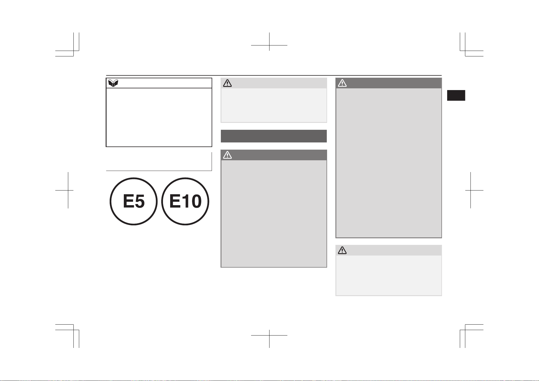
Graphical expression for con-
sumer information
E5: Petrol fuel containing up to 2.7 % (m/m)
oxygen or up to 5.0 % (V/V) ethanol – Eg.
EN 228 compliant unleaded petrol
E10: Petrol fuel containing up to 3.7 %
(m/m) oxygen or up to 10.0 % (V/V) ethanol
– Eg. EN 228 compliant unleaded petrol
The petrol engine are compatible with E5
type petrol (containing 5 % ethanol) and E10
type petrol (containing 10 % ethanol) con-
forming to European standards EN 228.
CAUTION
l
Do not use more than 10 % concentration of
ethanol (grain alcohol) by volume.
Use of more than 10 % concentration may
lead to damage to your vehicle fuel system,
engine, engine sensors and exhaust system.
Filling the fuel tank
E00200204612
WARNING
l
When handling fuel, comply with the safe-
ty regulations displayed by garages and
filling stations.
l
Gasoline is highly flammable and explo-
sive. You could be burned or seriously in-
jured when handling it. When refueling
your vehicle, always put the operation
mode of the power switch in OFF and
keep away from flames, sparks, and
smoking materials. Always handle fuel in
well-ventilated outdoor areas.
l
Before removing the fuel cap, be sure to
get rid of your body’s static electricity by
touching a metal part of the car or fuel
pump. Any static electricity on your body
could create a spark that ignites fuel va-
pour.
WARNING
l
Perform the whole refueling process
(opening the fuel tank filler door, remov-
ing the fuel cap, etc.) by yourself. Do not
let any other person come near the fuel
tank filler. If you allowed a person to help
you and that person was carrying static
electricity, fuel vapour could be ignited.
l
Do not perform charging and refueling at
the same time. If you charged with static
electricity, fuel vapour could be ignited by
the discharge spark.
l
Do not move away from the fuel tank fill-
er until refueling is finished. If you moved
away and did something else (for exam-
ple, sitting on a seat) part-way through
the refueling process, you could pick up a
fresh charge of static electricity.
l
Be careful not to inhale fuel vapour. Fuel
contains toxic substances.
l
Keep the doors and windows closed while
refueling the vehicle. If they were open,
fuel vapour could get into the cabin.
l
If the tank cap must be replaced, use only
a MITSUBISHI MOTORS genuine part.
CAUTION
l
The fuel in the fuel tank may not be con-
sumed and it may stagnate for a long time
depending on the use situation of the vehi-
cle, the quality of fuel may change, and it
may have a bad influence on the engine or
the parts of a fuel system.
Filling the fuel tank
2-15
OGGE19E1
General information
2
CAUTION
Observe the following instructions for pre-
vention.
•
Activate the battery charge mode in order
to start the engine at least once every
three months.
Refer to “Battery charge mode” on page
7-29.
•
Refill the fuel more than 15 litres at once
within three months. If the fuel remaining
display will be below half, you can refill
the fuel more than 15 litres certainly.
Refer to “Fuel remaining display screen”
on page 6-11.
Fuel tank capacity
45 litres
Refueling
1. Before filling with fuel, stop the plug-in
hybrid EV system.
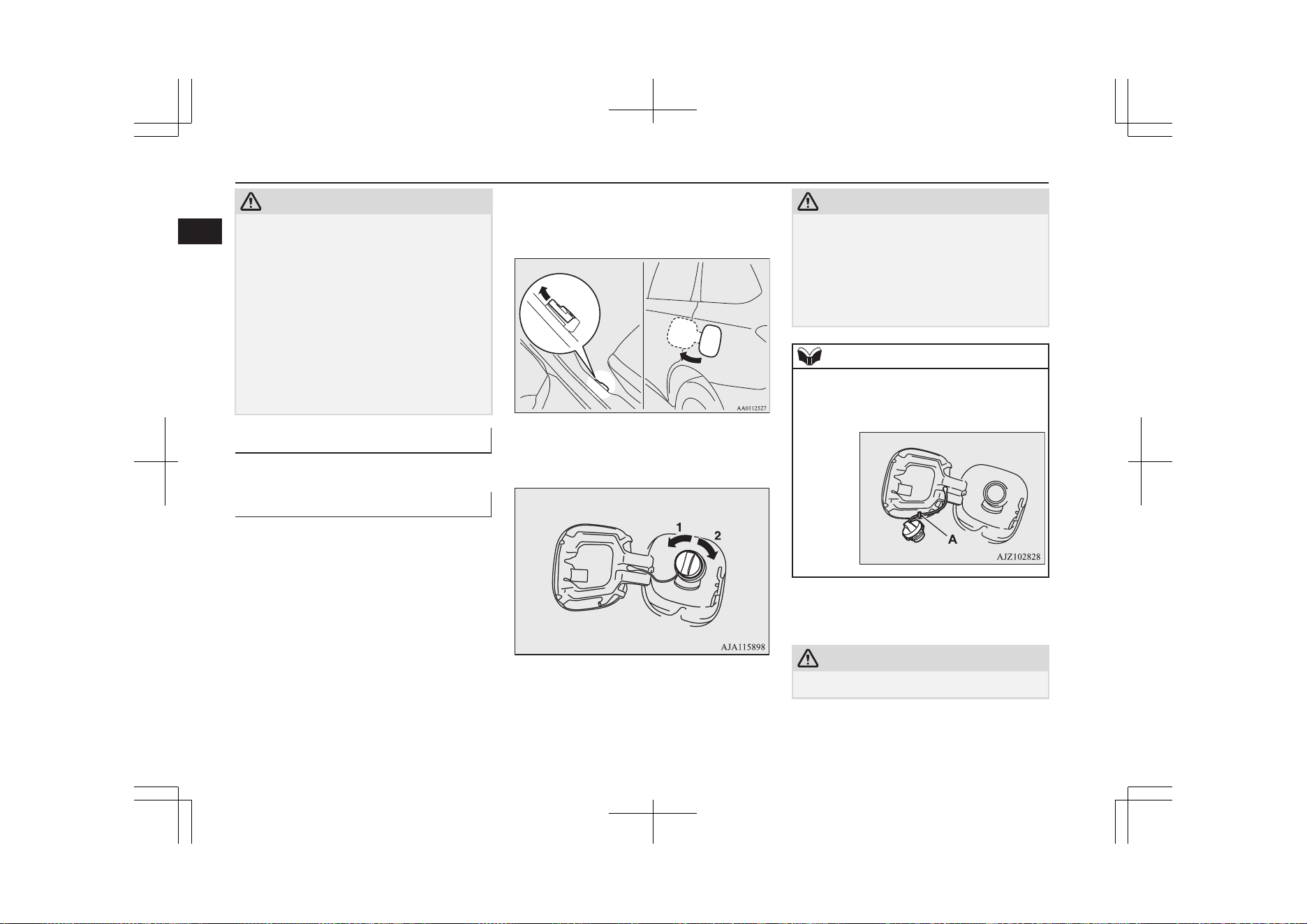
2. The fuel tank filler is located on the rear
left side of your vehicle.
Open the fuel tank filler door by pulling
the release lever located on the side of
the driver’s seat.
3. Open the fuel tank filler tube by slowly
turning the cap anticlockwise.
1- Remove
2- Close
CAUTION
l
Since the fuel system may be under pressure,
remove the fuel tank filler tube cap slowly.
This relieves any pressure or vacuum that
might have built up in the fuel tank. If you
hear a hissing sound, wait until it stops be-
fore removing the cap. Otherwise, fuel may
spray out, injuring you or others.
NOTE
l
While filling with fuel, hang the fuel cap on
the hook (A) located on the inside of the fuel
tank filler door.
4. Insert the gun in the tank port as far as it
goes.
CAUTION
l
Do not tilt the gun.
Filling the fuel tank
2-16
OGGE19E1
General information
2
5. When the gun stops automatically, do
not fill with fuel any more.
6. To close, turn the fuel cap slowly clock-
wise until you hear clicking sounds, then
gently push the fuel tank filler door
closed.
Installation of accessories
E00200302635
We recommend you to consult your
MITSUBISHI MOTORS Authorized Service
Point.
CAUTION
l
Your vehicle is equipped with a diagnosis
connector for checking and servicing the
electronic control system.
Do not connect a device other than a diagno-
sis tool for inspections and service to this
connector. Otherwise, the auxiliary battery
could be discharged, the electronic devices
of the vehicle could malfunction, or other
unexpected problems could result.
In addition, malfunctions caused by connect-
ing a device other than a diagnosis tool may
not be covered under warranty.
l
The installation of accessories, optional
parts, etc., should only be carried out
within the limits prescribed by law in
your country, and in accordance with the
guidelines and warnings contained with-
in the documents accompanying this ve-
hicle.
l
Installing electric components incorrect-
ly could lead to a fire. Refer to the
“Modification/alterations to the electri-
cal or fuel systems” section within this
owner’s manual.
l
When installing the radio, for the re-
quired information (frequency, transmis-
sion output, installing procedure), con-
sult a MITSUBISHI MOTORS Author-
ized Service Point.
If the frequency, transmission output and
installing condition are not appropriate,
it can adversely affect the electronic de-
vices and could lead to unsafe vehicle
operation.
l
Using a cellular phone or radio set inside
the vehicle without an external antenna
may cause electrical system interference,
which could lead to unsafe vehicle oper-
ation.
l
Tyres and wheels which do not meet
specifications must not be used.
Refer to the “Specifications” section for
information regarding wheel and tyre
sizes.
Important points!
Due to large number of accessory and re-
placement parts of different manufactures
available in the market, it is not possible, not
only for MITSUBISHI MOTORS, but also
for a MITSUBISHI MOTORS Authorized
Service Point, to check whether the attach-
ment or installation of such parts affects the
overall safety of your vehicle.
Even when such parts are officially author-
ized, for example by a “general operators per-
mit” (an appraisal for the part) or through the
execution of the part in an officially approved
manner of construction, or when a single op-
eration permit following the attachment or in-
stallation of such parts, it cannot be deduced
from that alone, that the driving safety of
your vehicles has not been affected.
Consider also that there basically exists no li-
ability on the part of the appraiser or the offi-
cial. Maximum safety can only be ensured
with parts recommended, sold and fitted or
installed by a MITSUBISHI MOTORS au-
thorized Service Point (MITSUBISHI
MOTORS GENUINE replacement parts and
MITSUBISHI MOTORS accessories). The
same also pertains to modifications of vehi-
cles with respect to the production specifica-
tions. For safety reasons, do not attempt any
modifications other than those that follow the
recommendations of a MITSUBISHI
MOTORS authorized Service Point.
Installation of accessories
2-17
OGGE19E1
General information
2
Modification/alterations to
the electrical or fuel systems
E00200401583
MITSUBISHI MOTORS CORPORATION
has always manufactured safe, high quality
vehicles. In order to maintain this safety and
quality, it is important that any accessory that
is to be fitted, or any modifications carried
out which involve the electrical or fuel sys-
tems, should be carried out in accordance
with MITSUBISHI MOTORS guidelines.
CAUTION
l
If the wires interfere with the vehicle body
or improper installation methods are used
(protective fuses not included, etc.), elec-
tronic devices may be adversely affected, re-
sulting in a fire or other accident.
Genuine parts
E00200500499
MITSUBISHI MOTORS has gone to great
lengths to bring you a superbly crafted auto-
mobile offering the highest quality and de-
pendability.
Use MITSUBISHI MOTORS GENUINE
Parts, designed and manufactured to maintain
your MITSUBISHI MOTORS automobile at
top performance. MITSUBISHI MOTORS
GENUINE Parts are identified by this mark
and are available at all MITSUBISHI
MOTORS Authorized Service Points.
Safety and disposal
information for used engine
oil
E00200601383
WARNING
l
Prolonged and repeated contact may
cause serious skin disorders, including
dermatitis and cancer.
l
Avoid contact with the skin as far as pos-
sible and wash thoroughly after any con-
tact.
l
Keep used engine oils out of reach of chil-
dren.
Protect the environment
It is illegal to pollute drains, water courses
and soil. Use authorized waste collection fa-
cilities, including civic amenity sites and ga-
rages providing facilities for disposal of used
oil and used oil filters. If in doubt, contact
your local authority for advice on disposal.
Disposal information for
used batteries
E00201301055
Your vehicle contains batter-
ies and/or accumulators.
Do not mix with general
household waste.
For proper treatment, recov-
ery and recycling of used
batteries, please take them to applicable col-
lection points, in accordance with your na-
tional legislation and the Directives
2006/66/EC.
By disposing of these batteries correctly, you
will help to save valuable resources and pre-
vent any potential negative effects on human
health and the environment which could oth-
erwise arise from inappropriate waste han-
dling.
Modification/alterations to the electrical or fuel systems
2-18
OGGE19E1
General information
2

Charging..............................................................................................3-02
Battery.................................................................................................3-04
Basic knowledge for charging.............................................................3-04
EV charging cable*.............................................................................3-07
Normal charging (charging method with rated AC
220-240V outlet).............................................................................3-10
Quick charging (charging method with quick charger)...................... 3-17
MITSUBISHI Remote Control*......................................................... 3-20
How to use an electric device during charging...................................3-24
Charging troubleshooting guide..........................................................3-28
Charging
OGGE19E1
3
Charging
E08303801282
Your vehicle is equipped with a charge port and a charging cable (EV charging cable)*
1
for charging with a AC 220-240 V outlet.
You can also charge your vehicle using 220-240 V home or public charging device (EVSE*
2
) compatible with OUTLANDER PHEV.
Your vehicle come equipped with an additional quick charge port to be used with a CHAdeMO quick charger.
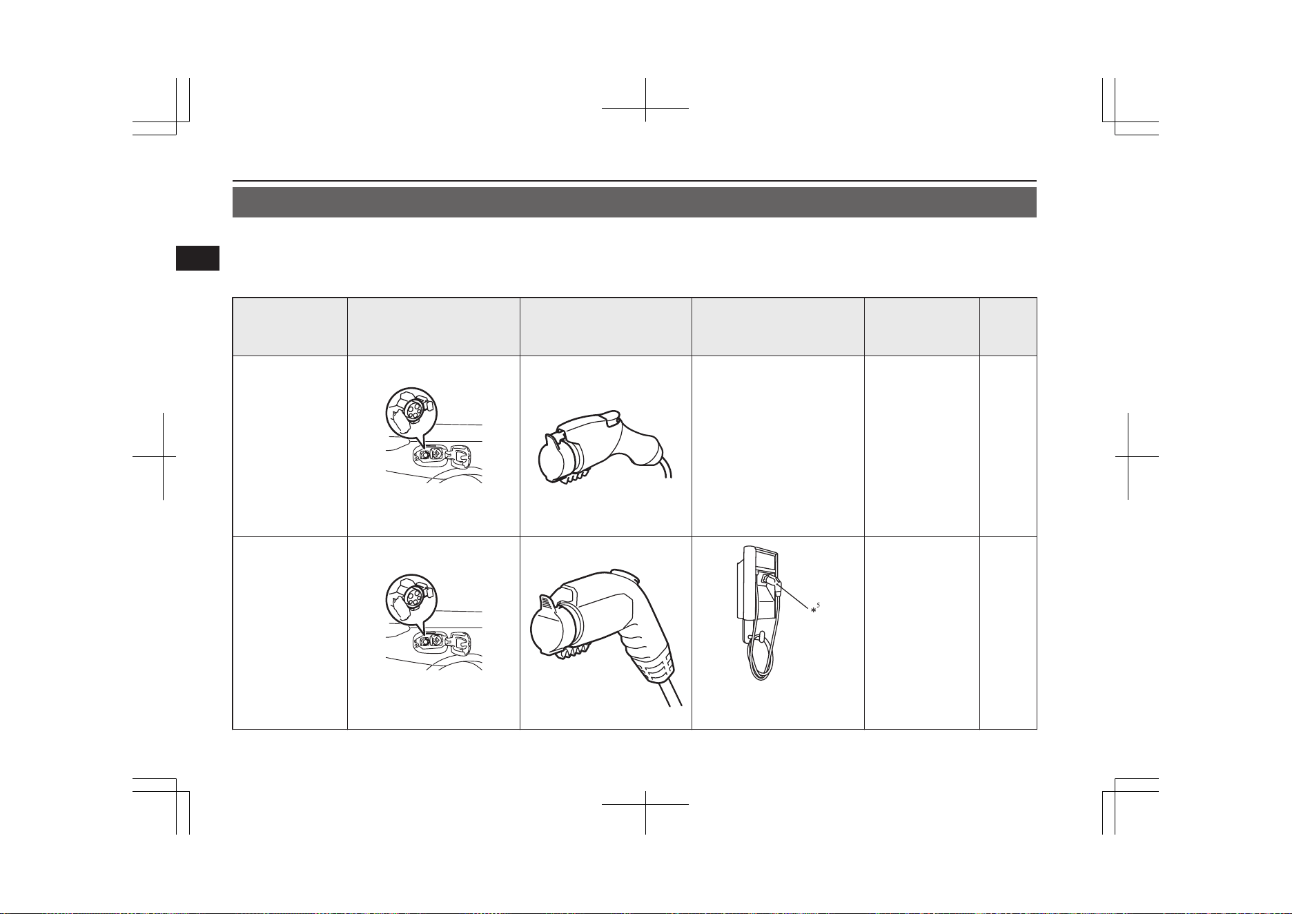
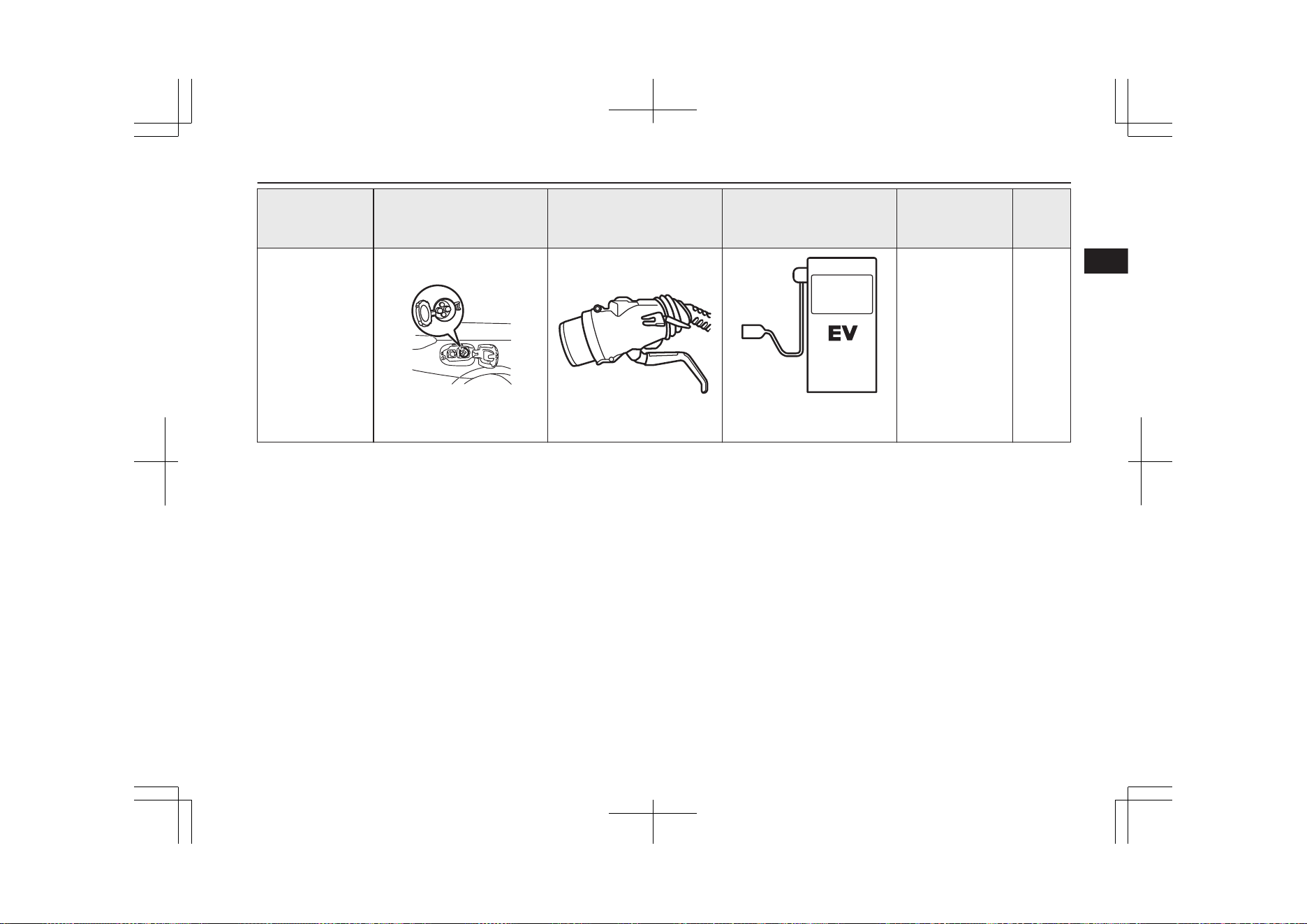
Category Charge port Charge connector Charging Source
Charging time
with fully dis-
charged battery*
3
Refer-
ence
Normal charging
(AC 220-240 V)
When using a gen-
uine charging ca-
ble
*1
Right rear side of vehicle
220-240 V household outlet
(Refer to “Charging from rat-
ed AC 220-240 V outlet” on
page 3-12)
230 V/10 A: Ap-
proximately 5.5
hours
230 V/8 A: Ap-
proximately 7
hours
3-10
Normal charging
(AC 220-240 V)
When using a
home or public
charging device
(EVSE
*2
)
Right rear side of vehicle
Home or public charging de-
vice
230 V/16 A: Ap-
proximately 4
hours
3-10
Charging
3-02
OGGE19E1
Charging
3
Category Charge port Charge connector Charging Source
Charging time
with fully dis-
charged battery*
3
Refer-
ence
Quick charging
(charging method
with quick charger)
Right rear side of vehicle
Public charging stations
where available
Approximately 25
minutes for 80 %
charge
3-17
*1
: Optional equipment
*2
: EVSE = Electric Vehicle Supply Equipment
*3
: Use this time as a guide because the rated AC voltage and the rated current value may differ from country to country.
Also, charging time will vary depending on the condition of the drive battery, air temperature, electric power consumption of electrical devices
during charging and condition of the power source. (such as specifications of the quick charger)
*4
: The charging time will vary depending on the condition of the main drive lithium-ion battery, air temperature, electric power consumption of
electrical devices and condition of the power source (such as specification of the quick charger).
*5
: When using an EVSE to which charging cable is not attached, use a Mode 3 charging cable for OUTLANDER PHEV (Type 2 to 1) -available
separately. For details, please consult a MITSUBISHI MOTORS Authorized Service Point.
Charging
3-03
OGGE19E1
Charging
3
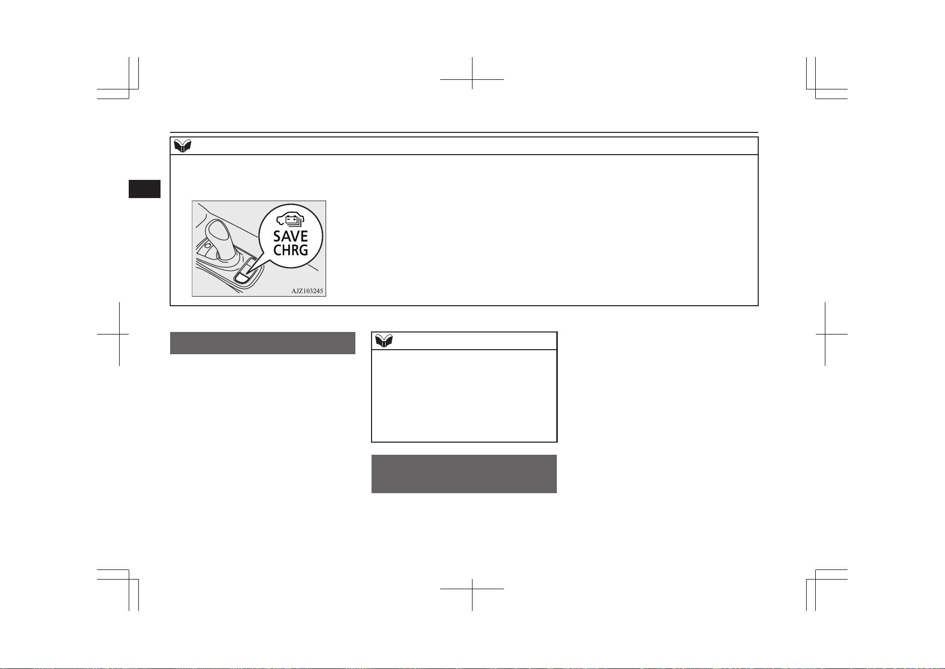
NOTE
l
The drive battery can be charged to nearly full using the battery charge mode switch.
Refer to “SAVE/CHARGE mode switch” on page 7-28.
Refer to “Battery save mode” on page 7-29.
Battery
E08300101079
There are two types of batteries installed in
your vehicle: a drive battery for operating the
motor (electric motor unit) and air condition-
ing as well as an auxiliary battery for starting
the Plug-in Hybrid EV system and operating
the lamps, wipers, etc.
This chapter explains charging of the drive
battery.
NOTE
l
The auxiliary battery is automatically charg-
ed while the ready indicator is illuminated or
during charge for the drive battery.
Refer to “Ready indicator” on page 6-55.
l
If the auxiliary battery is flat, the Plug-in
Hybrid EV system cannot be started.
Refer to “Emergency starting” on page
9-02.
Basic knowledge for
charging
E08300201285
There are two types of charging: normal
charging and quick charging.
Normal charging is performed through the on
board charger using rated AC 220-240V out-
let as the power source
The rated AC voltage may differ from coun-
try to country.
Battery
3-04
OGGE19E1
Charging
3
WARNING
l
To reduce the risk of electric shock or fire
due to electric leak, always use an earthed
outlet protected by a residual current de-
tector, rated for amperage equal to or
greater than the value specified by
MITSUBISHI MOTORS, and that is con-
nected to a dedicated branch circuit. If
the circuit is shared, and another electri-
cal device is being used at the same time
as the vehicle is charging, the circuit may
heat abnormally, the breaker may trip
and the circuit may cause adverse inter-
ference on the household electrical appli-
ances such as TVs and audio systems.
l
It is possible to charge even in rain or
snow. However, be sure to pay attention to
the following:
•
Do not touch normal charge port, nor-
mal charge connector, outlet and plug
with wet hands.
•
Keep away from water when connect-
ing the normal charge port, normal
charge connector, outlet and plug.
•
Do not perform the charging in the out
of doors when heavy rain, heavy snow,
strong winds, and when bad weather is
expected.
•
Do not charge if there is possibility a
lightning strike. When thunder rum-
bling begins suddenly during normal
charging, do not touch the vehicle and
the EV charging cable and turn off the
breaker.
WARNING
l
If water goes into the normal charge port
or the normal charge connector, it could
cause a short circuit, a fire and an electric
shock.
Be sure to completely close the charging
lid and the inner lid and do not leave the
EV charging cable in an outdoors.
l
If the connected part of the charging plug
has been buried in snow while charging,
turn off the hand switch or the breaker
connected with the outlet first, then re-
move the snow and disconnect the charg-
ing plug. If your vehicle body has been
buried in snow while charging, remove
the snow and then disconnect the charge
connector.
l
When you perform the normal charging
at away from home, some normal charg-
ers may not correspond to your vehicle.
Consult an administrator or a maker of
the normal charger that it corresponds to
your vehicle before using it. Also perform
normal charging according to the operat-
ing procedure indicated on the body of
normal charger.
l
Do not open the charging lid for anything
other than charging and using the exter-
nal power feed.
CAUTION
l
Do not attempt to perform a jump start on
the auxiliary battery at the same time that the
drive battery is being charged. Doing so may
damage the vehicle or charging cable and
could cause injury.
Refer to “Emergency starting” on page
9-02.
NOTE
l
If you open the charging lid with the opera-
tion mode of the power switch is ON, a buz-
zer sounds approximately 10 minutes inter-
mittently to alert the charging cannot be star-
ted. If you close the charging lid or put the
operation mode in OFF, the buzzer stops.
l
If you insert the charge connector to the
charge port with the operation mode is ON, a
buzzer sounds continuously approximately
10 minutes to alert the charging cannot be
started.
If you pull the charge connector out or put
the operation mode in OFF, the buzzer stops.
l
Repeatedly performing only quick charging
may reduce the battery capacity.
In usual charge, normal charging is recom-
mended.
l
To maintain the capacity of the drive battery,
the following is recommended:
•
If you repeatedly perform only the quick
charging, fully charge the vehicle in nor-
mal charging every 2 weeks.
Basic knowledge for charging
3-05
OGGE19E1
Charging
3
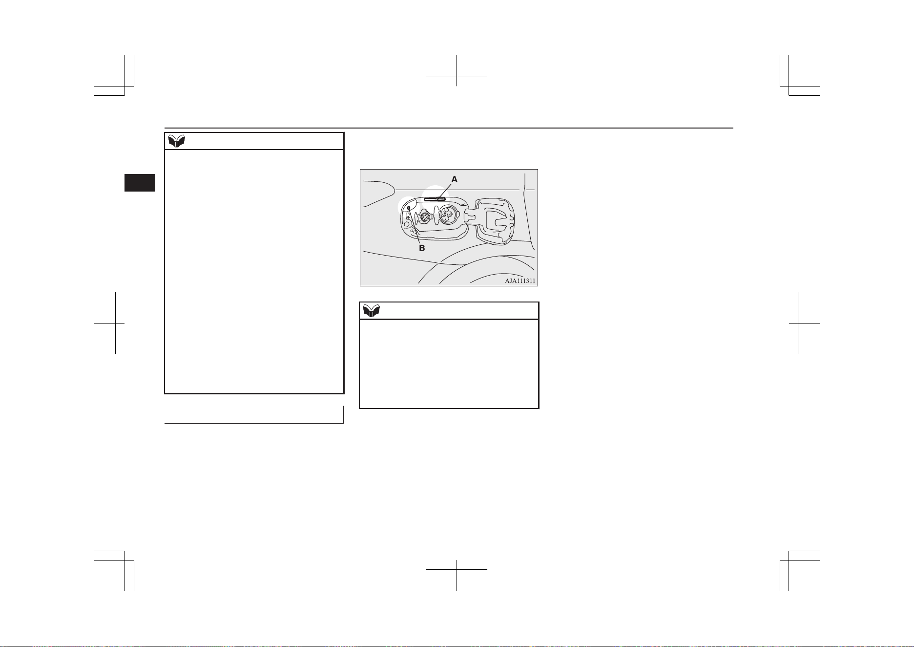
NOTE
•
Do not repeat charging near the full
charge level.
l
The quick charging gives priority when the
normal charging and the quick charging are
performed at the same time. At this time, the
normal charging will be stopped.
l
Even if the operation mode of the power
switch is OFF, you may hear the operating
sound of the cooling fan for cooling the
drive battery during charging.
This is not a malfunction.
l
If your vehicle is not used for a long time,
check the energy level gauge every 3
months. If the gauge shows 0, charge the
drive battery until some indication appears.
Alternatively, start the Plug-in Hybrid EV
System. Then the engine will automatically
start to charge the drive battery. Wait until
the engine automatically stops, then put the
operation mode of the power switch in OFF.
l
In the event of an electrical power outage
while charging, charging restarts automati-
cally with the restoration of electricity.
Charge port courtesy lamp
E08304300157
The charging port courtesy lamp (A) illumi-
nates when the charging lid is opened while
the select position is in “P” (PARK) position.
It goes off automatically after approximately
3 minutes.
If you want to turn on it again, press the
charging port courtesy lamp switch (B).
When charging is started, the charging port
courtesy lamp blinks three times.
NOTE
l
The charging port courtesy lamp illuminat-
ing time can be adjusted.
For details, please consult a MITSUBISHI
MOTORS Authorized Service Point.
l
If the MITSUBISHI Remote Control (if so
equipped) is operated when the charging
port courtesy lamp is off, the lamp may illu-
minate.
Basic knowledge for charging
3-06
OGGE19E1
Charging
3
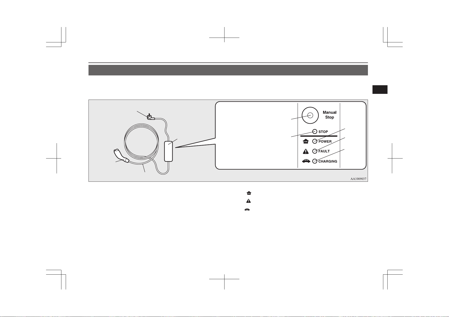
EV charging cable*
E08301101223
Your vehicle is equipped with an EV charging cable that consists of a cable (A), control box (B), EV charging cable plug (C), and normal charge
connector (D).
Indicator (LED) and button
C
B
A
D
G
H
I
E
F
E- Manual stop button G ( )- POWER indicator
F- Stop indicator
H ( )-
FAULT indicator
I ( )- CHARGING indicator
To stop charging, simply press manual stop button (E) and stop indicator (F) is illuminated. Re-connect the EV charging cable plug (C) to charge
again.
POWER (G), FAULT (H) and CHARGING (I) indicators located on the control box will illuminate/blink in response to the following conditions:
EV charging cable*
3-07
OGGE19E1
Charging
3
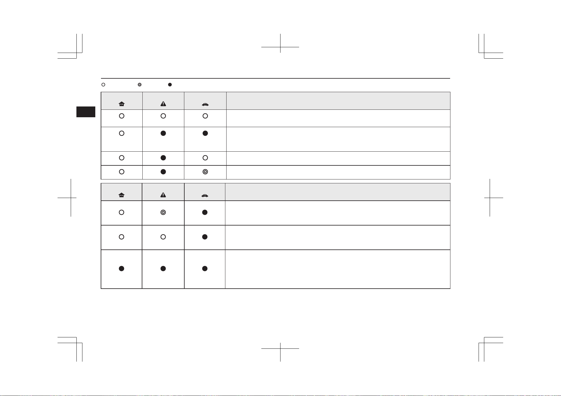
: Illuminates : Blinking : Not illuminates
POWER
FAULT
CHARGING
Operating condition
Every time the charging cable plug (C) is connected to an outlet, all indication lamps illu-
minate for 0.5 seconds.
After initial processing is completed, when the normal charge connector is not connected to
the charge port, or the normal charge connector is connected to the charge port but charging
is not being performed.
While the drive battery is being charged.
When charging is completed.
POWER
FAULT
CHARGING
Abnormal operating condition and corrective action
When an electric leakage occurs or the EV charging cable malfunctions
Stop using the EV charging cable immediately and contact a MITSUBISHI MOTORS Au-
thorized Service Point.
When the EV charging cable malfunctions
Stop using the EV charging cable immediately and contact a MITSUBISHI MOTORS Au-
thorized Service Point.
If the control box indication lamp does not illuminate after connecting the charging cable
plug to the outlet, check the circuit breaker for the outlet. If the breaker has tripped, the cir-
cuit may not be suitable for use with EV charging cable. You should have a licensed electri-
cian inspect and repair the electrical circuit. If the breaker is not tripped, stop using the EV
charging cable and contact a MITSUBISHI MOTORS Authorized Service Point.
EV charging cable*
3-08
OGGE19E1
Charging
3
WARNING
l
If the POWER or CHARGING indicator does not illuminates or the FAULT indicator blinks or illuminates during normal charging, please contact
a MITSUBISHI MOTORS Authorized Service Point.
l
Do not charge when the EV charging cable is coiled up.
The cable may be heated abnormally and resulting in fire.
l
Do not alter or disassemble the EV charging cable. Doing so could cause fire, an electric shock or injury.
l
Be sure to install the cap to the normal charge connector and store the EV charging cable in a place where the cable is not exposed to water or dust.
Entry of foreign matter such as water or dust in the metal terminal of the normal charge connector or charging cable plug may cause a fire or
malfunction.
l
Never force the connection if the EV charging cable or connector shows damage or is not easily connected due to foreign material entering the
connector or the outlet. And never use an outlet that is worn, damaged, or will not hold the plug firmly. Doing so could cause fire, an electric shock,
or short circuit.
l
Pay attention to the following for handling the EV charging cable.
Damage to the cable could cause fire, an electric shock, or short circuit.
•
Do not drop the cable or do not give strong impact to it.
•
Do not pull or bend with undue force.
•
Do not twist.
•
Do not drag.
•
Do not put an object on top.
•
Do not put the cable close to a heating unit including heater.
CAUTION
l
Do not connect the normal charge cable to an outlet that has a lower rating than the current value described on the control box.
NOTE
l
All indicators are illuminated momentarily for confirming operation when the charging cable plug is inserted into an outlet. After that the POWER indicator
and the CHARGING indicator is continuously illuminated.
l
The CHARGING indicator will start to blink when the charging is completed. The POWER indicator is continuously illuminated while the charging cable
plug is inserted into an outlet.
EV charging cable*
3-09
OGGE19E1
Charging
3
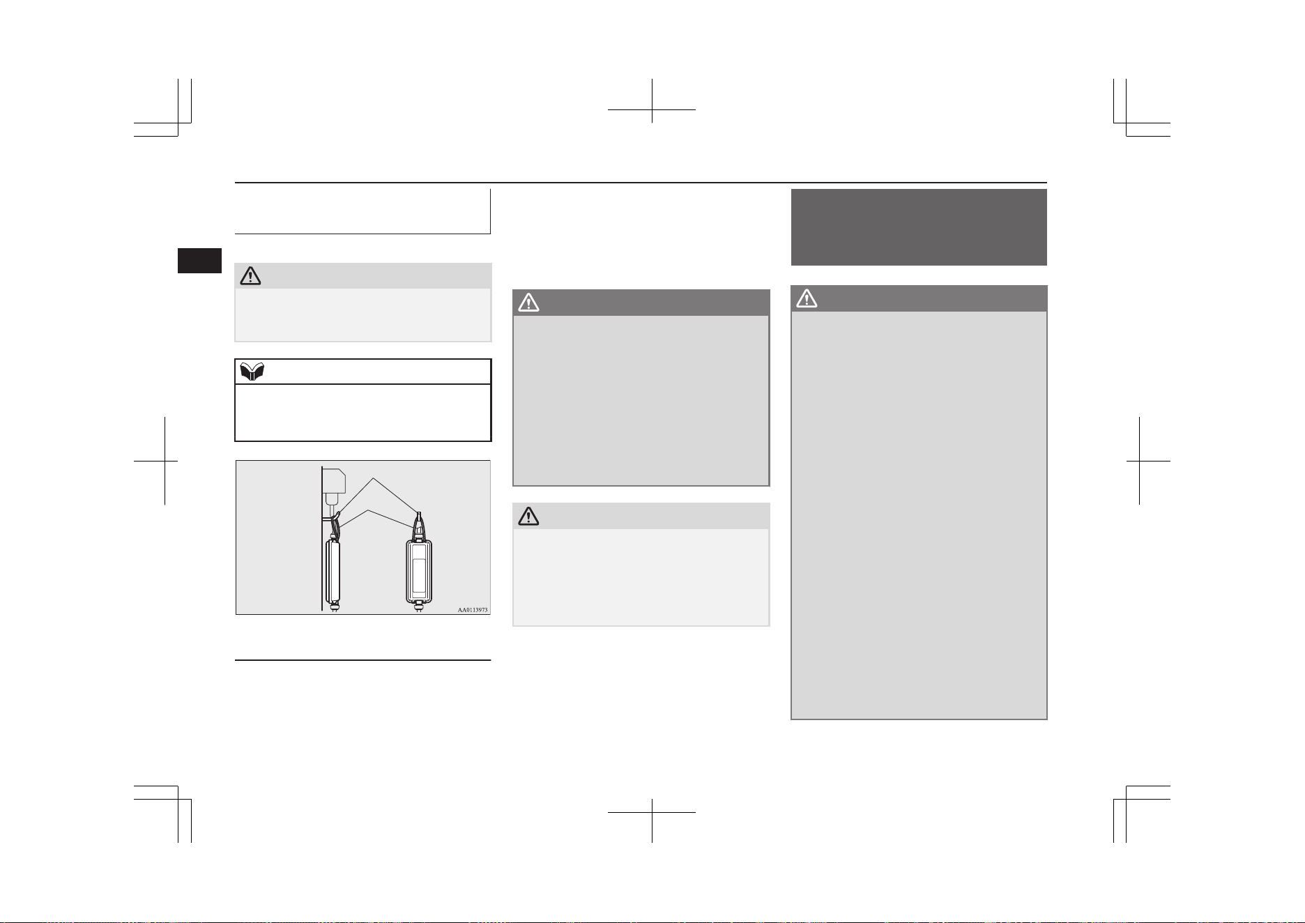
Handling and storing the con-
trol box
E08301201093
CAUTION
l
While charging, prevent damage to the con-
trol box by attaching a rope as shown in the
following illustration.
NOTE
l
Use a hook with a load capacity over 4 kg.
l
Check that the rope and hook have no dam-
age and are not loose before use.
Hook
Rope
Cleaning the EV charging cable
E08301301065
1. Lightly wipe these off with a soft cloth
soaked in a mild soap and water solu-
tion.
2. Wipe off all the detergent with a soft
cloth dipped in fresh water and thor-
oughly wrung out.
3. Wipe all moisture off and dry in a sha-
ded, well-ventilated area.
WARNING
l
When cleaning, be sure to remove the
charging cable plug and the normal
charge connector from the outlet. Do not
connect or disconnect the plug and the
connector with wet hands. Doing so could
cause an electric shock.
l
Do not expose the metal terminal of the
normal charge connector or the charging
cable plug to water or neutral detergent.
Using in wet with water could cause a fire
or an electric shock.
CAUTION
l
Never use benzine, petrol, or other organic
solvents, or acid or alkaline solvents. Doing
so could cause deformation, discolour, or
malfunction. Also, these substances may be
present in various cleaners, so check careful-
ly before using.
Normal charging (charging
method with rated AC
220-240V outlet)
E08300901312
WARNING
l
For safety, do not allow children or people
who are not familiar with charging to
charge for themselves. Also, do not use
the normal charge connector within reach
of children.
l
Persons who use electro-medical appara-
tus such as implantable cardiac pacemak-
er or implantable cardioverter defibrilla-
tor must check effect from charging with
the manufacturer of electro-medical ap-
paratus. Electro-medical apparatus oper-
ations could be affected by charging.
l
If you use electro-medical apparatus such
as implantable cardiac pacemaker or im-
plantable cardioverter-defibrillator, be
careful the following precautions.
•
During charging, do not allow implan-
ted electro-medical apparatus such as
cardiac pacemaker or implantable car-
dioverter defibrillator to be close to the
charge connector, EV charging cable,
control box and normal charging sta-
tion.
•
Do not stay inside the vehicle.
•
Do not get in the vehicle (including the
luggage compartment) to take out
something or for other purposes.
Normal charging (charging method with rated AC 220-240V outlet)
3-10
OGGE19E1
Charging
3
WARNING
•
Do not open the tailgate, for example to
remove or place an item in the cargo
area.
Charging may affect the operation of elec-
tric medical devices and result in serious
personal injury or death.
l
Do not charge when the EV charging ca-
ble is coiled up.
Doing so the cable may be heated abnor-
mally and this might result in fire.
l
Before charging, make sure that there is
no foreign matter such as dust at the nor-
mal charge port and the normal charge
connector.
At this time, do not touch the normal
charge port.
l
When the normal charge connector is
connected to the charge port, prevent for-
eign matter such as water or dust from
entering in the connection.
Connection with foreign matter such as
water or dust may cause fire or an electric
shock. Do not perform charging if there
might be strong exposure to water at the
connection.
l
Never pull the cable to remove the plug.
And never submerge the EV charging
connector, control box or plug in water.
l
Please observe the following in order to
prevent accidents during charging such as
electrocution.
•
Only use the EV charging cable that is
supplied with the vehicle.
WARNING
•
Do not charge another vehicle by the
EV charging cable. The cable may
overheat and this may result in a fire.
•
When charging outdoors, make sure to
use an outlet that is protected from wa-
ter entering.
•
Do not perform charging with the vehi-
cle covered by a car cover, except for
the MITSUBISHI MOTORS GENU-
INE car cover.
•
Do not connect or disconnect the plug
and connector with wet hands.
l
While it is normal for the connector and
charging cable to become warm during
charging, discontinue use immediately if
the connector or charging cable becomes
hot to the touch.
l
While it is normal for the control box to
become warm during charging, discontin-
ue use immediately if the control box be-
comes hot to the touch.
l
If abnormal smells are detected or the ve-
hicle produces smoke, quickly stop charg-
ing.
l
Do not perform charging in a poorly ven-
tilated area or in an enclosed area. Keep
sparks, cigarettes, and flames away from
the auxiliary battery.
Flammable gas generated from the auxili-
ary battery during charging may be trap-
ped, resulting in explosion.
If charging is inevitably required, venti-
late the area well.
WARNING
l
Grasp the normal charge connector when
connecting or disconnecting the EV
charging cable.
Grasping the cable may damage the cable
and could cause an electric shock, short
circuit, and/or fire.
CAUTION
l
During charging, the cooling fans inside the
engine compartment may automatically be
operated even if the operation mode of the
power switch is in OFF.
Keep your hands away from the cooling fan
during charging.
l
Do not perform charging from other power
source like a generator. Doing so could
cause a malfunction.
NOTE
l
If the charge connector is not easily connec-
ted to the charge port due to foreign material
entering, never force the connection. Doing
so could damage the charging equipment or
the vehicle. Please contact a MITSUBISHI
MOTORS Authorized Service Point.
l
The on board charger is only for rated AC
220-240V outlets.
Normal charging (charging method with rated AC 220-240V outlet)
3-11
OGGE19E1
Charging
3
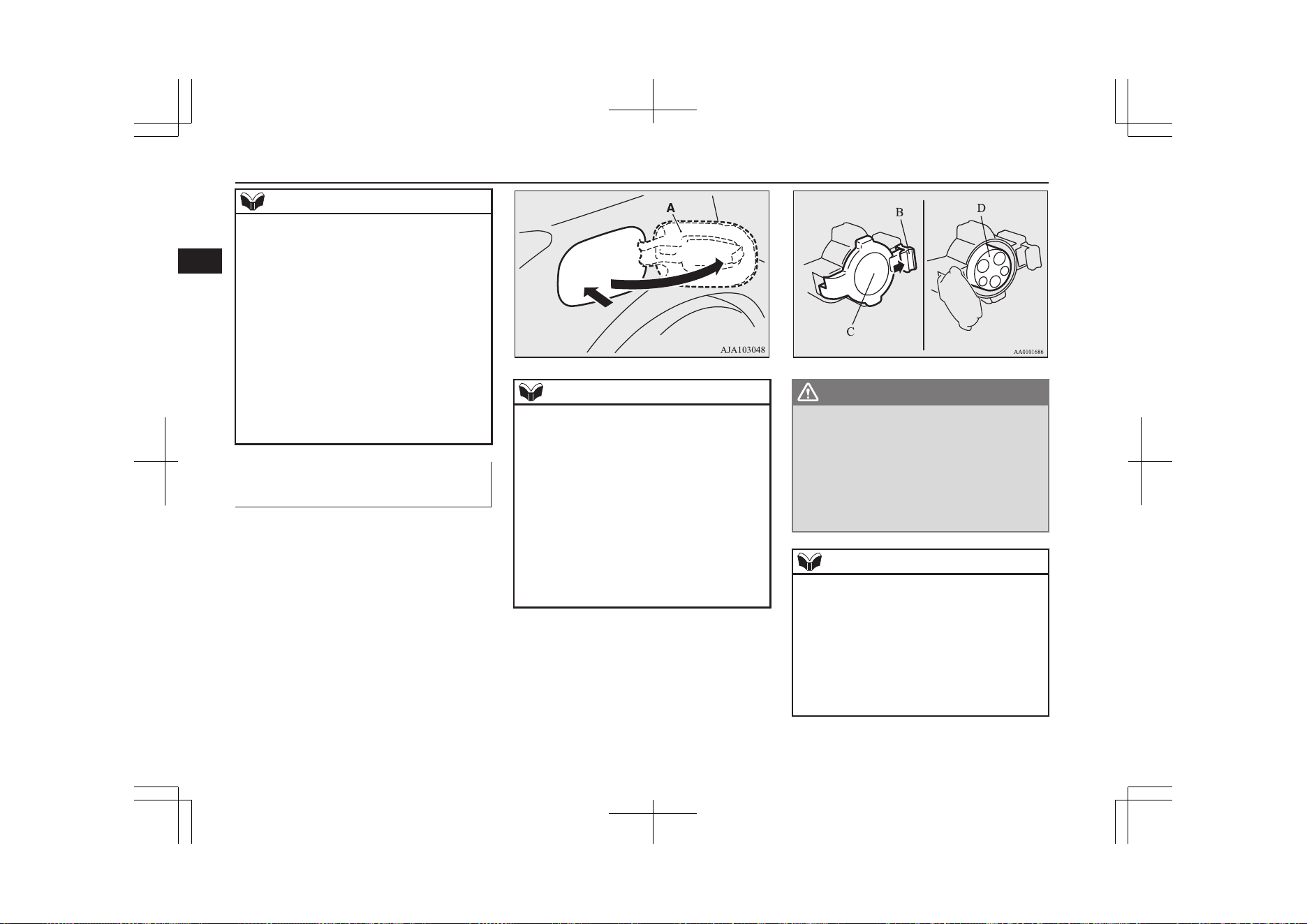
NOTE
l
When connecting or disconnecting the nor-
mal charge connector, insert/pull out the
connector straight.
Also, do not incline or twist the connector.
Doing so could cause a bad connection or
malfunction.
l
Make sure to lock the doors to prevent theft,
etc. during charging.
l
Do not push the rear portion of the charging
lid when the charging lid is locked.
There is a possibility that the charging lid
opens unexpectedly when the doors are un-
locked while using the central door locks,
keyless entry system or keyless operation
function.
Charging from rated AC
220-240 V outlet
E08301001411
1. Firmly apply the parking brake, press the
electrical parking switch to shift into the
“P” (PARK) position and put the opera-
tion mode of the power switch in the
“OFF” position.
2. Unlock the driver’s door to unlock the
charging lid.
3. Push the rear portion of the charging lid
(A) until it clicks, and open the charging
lid.
NOTE
l
The charging lid is unlocked in conjunction
with unlocking of the driver’s door as the
following condition.
•
The operation mode is put in “OFF” or
“ACC”.
•
The selector lever position is “P” (PARK).
l
When the charging lid cannot be unlocked
even if the driver’s door is unlocked. Open
the charging lid manually by using the re-
lease lever inside of the interior trim in the
luggage compartment.
Refer to “If the charging lid cannot be un-
locked” on page 3-16.
4. Press the tab (B) to open the inner lid
(C).
WARNING
l
It could cause electric leak, a fire or elec-
tric shock by entering water or dust into
the normal charge port.
l
Do not touch the metal terminal of the
normal charge port (D) and the normal
charge connector.
Doing so could cause an electric shock
and/or malfunction.
NOTE
l
There is a hole on the charge port for water
drainage. If this hole is blocked and water
gets trapped in the charge port, do not
charge. Please contact a MITSUBISHI
MOTORS Authorized Service Point.
l
If the charge port is frozen, melt the ice us-
ing a hair drier. Forcing the charge connector
to connect while frozen could result in mal-
function.
Normal charging (charging method with rated AC 220-240V outlet)
3-12
OGGE19E1
Charging
3
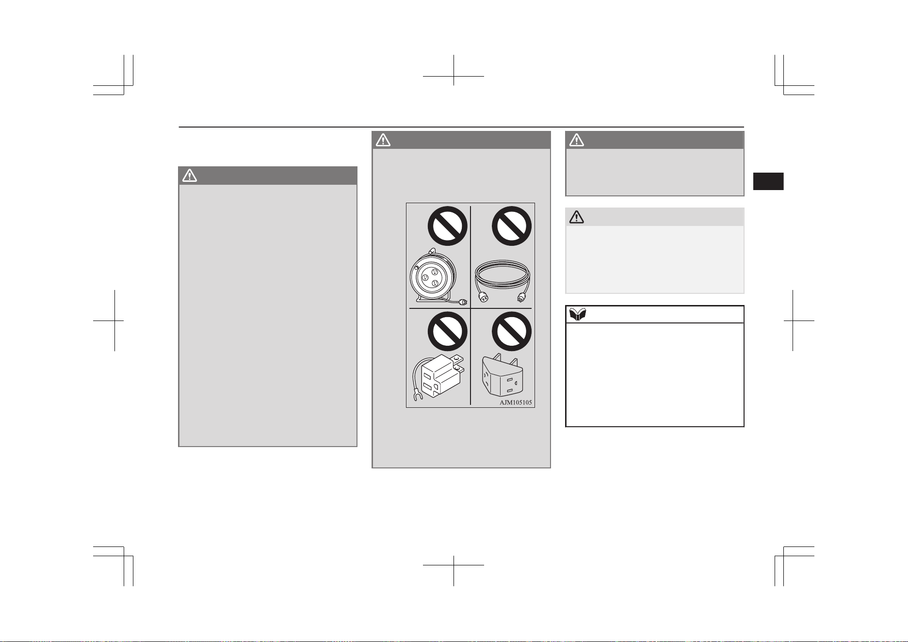
5. Insert the charging cable plug into an
outlet.
WARNING
l
Make sure that the plug is inserted all the
way into the outlet before use. If charging
is continued in the state where it is not
fully inserted the plug, there is a possibili-
ty of generating abnormal heat and re-
sulting in a fire.
l
To prevent an electric shock or fire due to
an electric leak, perform charging using a
waterproofed outlet with earthing which
is connected to an earth leakage circuit
breaker.
l
To reduce the risk of electric shock or fire
due to electric leak, always use an earthed
outlet protected by a residual current de-
tector, rated for amperage equal to or
greater than the value specified by
MITSUBISHI MOTORS, and that is con-
nected to a dedicated branch circuit. If
the circuit is shared, and another electri-
cal device is being used at the same time
as the vehicle is charging, the circuit may
heat abnormally, the breaker may trip
and the circuit may cause adverse inter-
ference on the household electrical appli-
ances such as TVs and audio systems.
WARNING
l
Never use an extension cable, multi-plug
adapter or conversion adapter. Using
them may cause abnormal overheating re-
sulting in a fire.
l
Do not use a multi type outlet to prevent
an electric shock or fire. There is no guar-
antee of safety because you cannot make
an earth connection in some multi type
outlet and it is not a dedicated type outlet.
WARNING
l
Use an outlet for EV charging with water-
proofing processing installed if the instal-
led position is outdoors or may get wet by
rain etc.
CAUTION
l
Use the outlet that is installed approximately
1 meter above the ground. If the outlet posi-
tion is too low, the control box may touch
the ground, which may lead to troubles such
as submersion in water or getting trampled
on.
NOTE
l
The shape of the charging cable plug and
outlet may differ from country to country as
shown in the illustration.
l
Use the following outlets.
l
Check if the outlet on your vehicle corre-
sponds with an outlet that is installed in the
following places.
•
In your house etc.
•
In a parking lot or garage
Normal charging (charging method with rated AC 220-240V outlet)
3-13
OGGE19E1
Charging
3
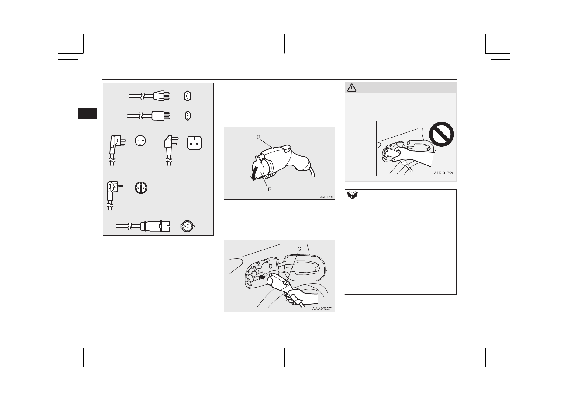
Switzerland 250 V/10 A
Italy 250 V/10 A
Denmark 250 V/13 A UK, Ireland 250 V/13 A
Germany, Spain, France, Sweden, etc.
250 V/16 A
IEC 60309-2/CEE17 (220-250 V/16 A)
AA2002211B
6. Remove the cap (E) on the normal
charge connector (F) and make sure that
there is no foreign matter such as dust at
the end of the normal charge connector
and the normal charge port.
7. Connect the normal charge connector
until a click sound is heard without
pressing the release button (G).
CAUTION
l
Do not clasp the top of normal charge con-
nector. It could cause injury to touch the pro-
trusion on the charging lid.
NOTE
l
If the operation mode of the power switch is
ON with the EV charging cable remains con-
nected to the normal charge port, the plug-in
hybrid EV system does not turn ON.
l
Do not connect or disconnect the normal
charge connector repeatedly in a short peri-
od. Charging may not be started.
l
If you want to turn the operation mode to
“OFF” from the “ACC” or “ON” position in
order to use an electrical device such as au-
dio during charging, make sure that the se-
lect position is in “P”, and press the power
switch to turn “OFF” without depressing the
brake pedal.
8. Make sure that the charging indicator
(H) on the instrument cluster is illumina-
ted.
Normal charging (charging method with rated AC 220-240V outlet)
3-14
OGGE19E1
Charging
3
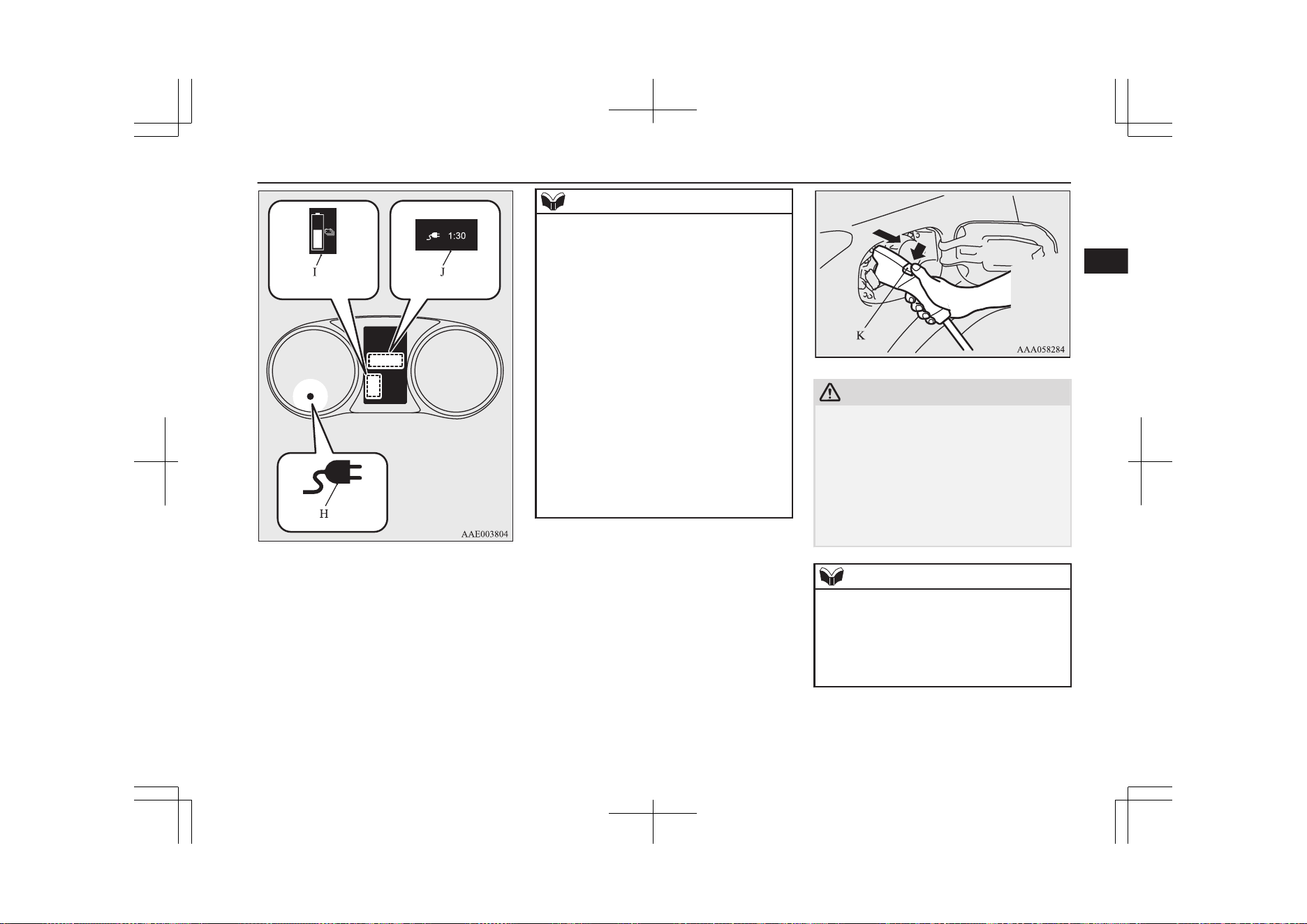
If the charging indicator is not illumina-
ted, charging has not started.
Make sure that the normal charge port
and the plug are correctly connected, and
perform charging from Step 5 again.
NOTE
l
When the normal charge connector is con-
nected to the charge port, the charging indi-
cator will blink. When charging is started,
the charging indicator illuminates and the
charging port courtesy lamp blinks 3 times.
l
If you want to confirm the drive battery level
or the predicted charging time during charg-
ing, one of the doors is opened or the multi
information display switch is operated, the
drive battery level display (I) appears and
the predicted charging time display (J) ap-
pears on the information screen in the multi
information display.
In addition, when the remaining time is less
than 1 hour, the predicted charging time dis-
play (J) appears --:-- and does not indicate a
malfunction.
When an electrical component is used during
charging, the charging time may become
longer.
9. Charging is complete if the charging in-
dicator goes off. Pull out the normal
charge connector while pressing the re-
lease button (K).
CAUTION
l
Be sure to check the normal charge connec-
tor is removed from the normal charge port.
The vehicle can be driven with the charge
connector inserted when it is not locked
completely which may result in a serious ac-
cident.
Be sure the charge connector is removed
completely from the vehicle after the charg-
ing is completed.
NOTE
l
Charging can be stopped half way. In this
case, also pull out the normal charge connec-
tor while pressing the release button. Press-
ing the manual stop button on the control
box can also stop charging.
Refer to “EV charging cable*” on page 3-07.
10. Close the inner lid and press the rear of
the charging lid until it clicks to close it.
Normal charging (charging method with rated AC 220-240V outlet)
3-15
OGGE19E1
Charging
3
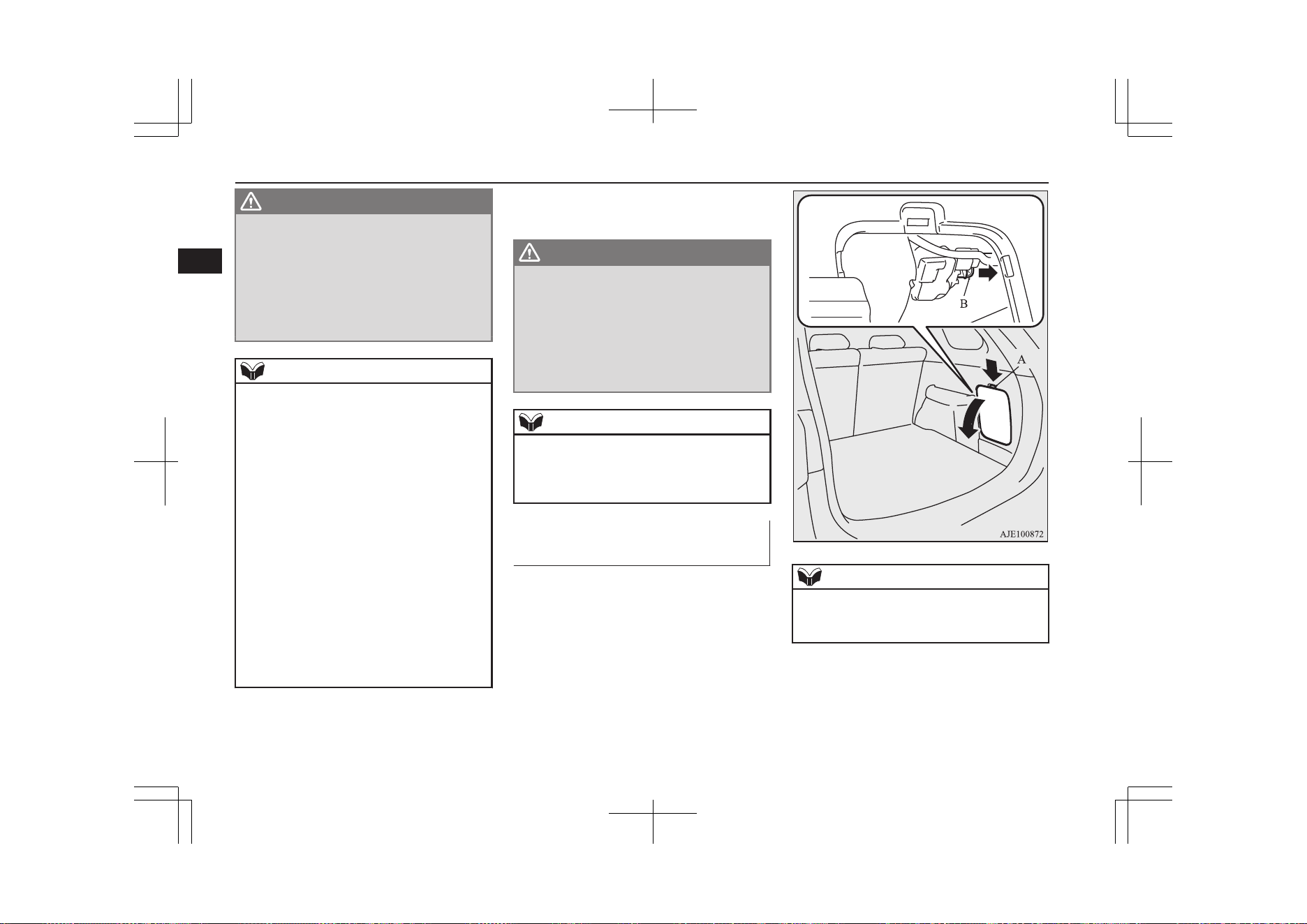
WARNING
l
After charging, be sure to close the inner
lid and charging lid completely.
Be careful that water or dust does not en-
ter in the normal charge port, inner lid
and normal charge connector.
Entry of water or dust could cause an
electric leak, resulting in a fire or electric
shock.
NOTE
l
Make sure that the inner lid is completely
closed.
If the charging lid is forcibly closed without
completely closing inner lid, the hinge on
the inner lid may be broken.
l
While the charging lid is open, if the doors
and tailgate are locked with the central door
lock, the keyless entry system or the keyless
operation system, the charging lid will lock
when the charging lid is closed.
l
When the operation mode is switched to ON
while the charging lid is not completely
closed, a warning may be displayed on the
information screen in the multi information
display.
Refer to “Warning display list” on page
6-26.
l
If the charging lid is closed while the driv-
er’s door is locked, the charging lid will be
locked.
11. Remove the charging cable plug from
the outlet.
12. Install the cap on the normal charge con-
nector.
WARNING
l
After charging, be sure to disconnect the
charge connector from the charge port.
If the charge connector is only partially
engaged and the connector latch is un-
locked, you could put the operation mode
of the power switch in ON and the vehicle
could start moving. It could lead to an un-
expected accident.
NOTE
l
Make sure that the charging lid is completely
closed before using an automatic car wash.
There is a possibility that the charging lid
will be damaged if the lid is open.
If the charging lid cannot be
unlocked
E08304400031
When the charging lid cannot be unlocked
even if the driver’s door is unlocked, take the
following measure to open the charging lid.
1. Press the tab (A) of the lid located on the
right side of the luggage compartment to
remove the lid.
2. Pull the rod (B) in the arrow direction to
unlock the charging lid.
NOTE
l
After taking the emergency measure, please
inspect at a MITSUBISHI MOTORS Au-
thorized Service Point immediately.
Normal charging (charging method with rated AC 220-240V outlet)
3-16
OGGE19E1
Charging
3
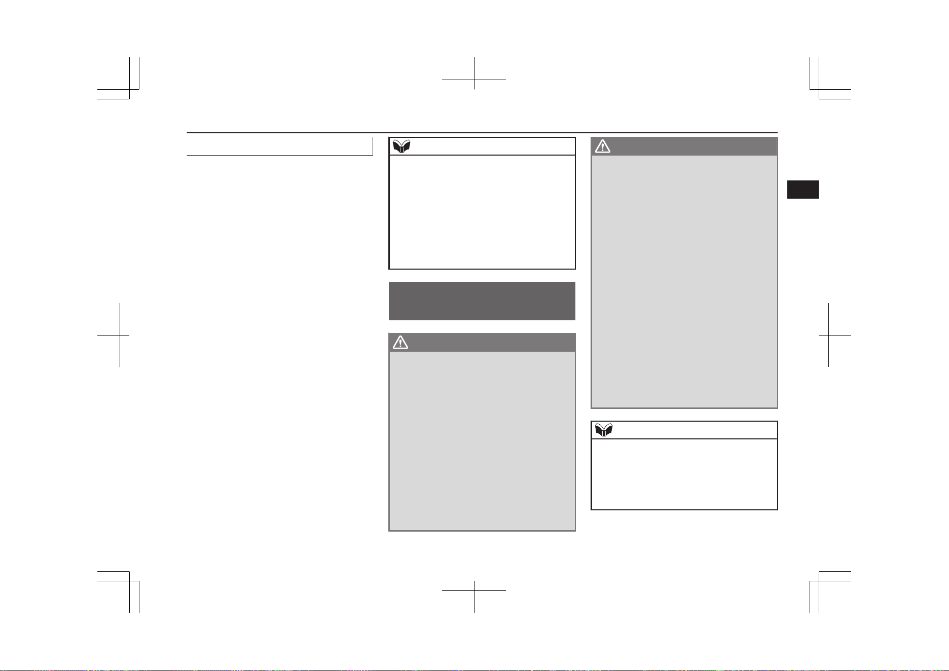
Drive battery warming system*
E08304600020
You cannot start the Plug-in Hybrid EV Sys-
tem and drive when the ambient temperature
is -30 °C or lower. (The warning display is
displayed on the information screen in the
multi-information display.) The drive battery
warming system will automatically operate
and the drive battery will be heated when you
connect the normal charge connector to the
normal charge port.
When the ambient temperature is higher than
-28 °C, you can start the Plug-in Hybrid EV
System and drive. The drive battery warming
system will automatically operate and the
drive battery will be heated when all the fol-
lowing conditions are met.
l
The normal charge connector is connec-
ted to the normal charge port at an ambi-
ent temperature under -30 °C.
l
The Plug-in Hybrid EV System is started
at an ambient temperature between
-29 °C and -10 °C.
The drive battery warming system will auto-
matically stop after the drive battery has been
heated until suitable temperature.
NOTE
l
When the ambient temperature is very cold,
you cannot use the charging timer since the
drive battery warming system is operating.
And when the ambient temperature is -30 °C
or lower, you cannot use the function of the
remote climate control. When the ambient
temperature is higher than -29 °C after oper-
ating the drive battery warming system, you
can use the function of the remote climate
control.
Quick charging (charging
method with quick charger)
E08301401284
WARNING
l
Be sure to use the quick charger applica-
ble to CHAdeMO standard and certified
by CHAdeMO association. Use of the oth-
er quick charger may cause the fire or
malfunction.
l
For operation of quick chargers, follow
the manual of each quick charger.
l
If you use electro-medical apparatus such
as implantable cardiac pacemaker or im-
plantable cardioverter-defibrillator, be
careful the following precautions.
•
Please do not use a quick charger.
•
Keep away as much as possible from
the place where the quick charger is
stored. If you approach it carelessly,
leave quickly without standing still.
WARNING
•
Please ask someone to perform the
quick charging if necessary.
l
Before charging, make sure that there is
no foreign matter such as dust at the
quick charge port and the quick charge
connector.
At this time, do not touch the quick
charge port.
l
When the quick charge connector is con-
nected to the quick charge port, prevent
foreign matter such as water or dust from
entering in the port.
Connection with foreign matter such as
water or dust may cause fire or an electric
shock. Do not perform charging if there
might be strong exposure to water at the
connection.
l
During charging, the cooling fans inside
the bonnet room may automatically be
operated even if the operation mode of the
power switch is in OFF.
Keep your hands away from the cooling
fan during charging.
NOTE
l
If the charge connector is not easily connec-
ted to the charge port due to foreign material
entering, never force the connection. Doing
so could damage the charging equipment or
the vehicle. Contact a MITSUBISHI
MOTORS Authorized Service Point.
Quick charging (charging method with quick charger)
3-17
OGGE19E1
Charging
3
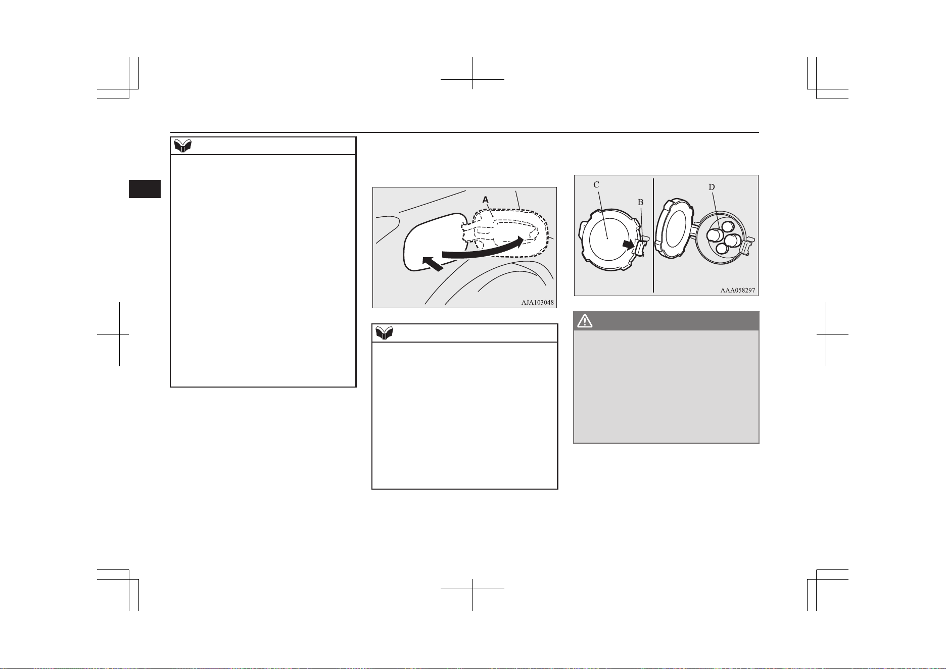
NOTE
l
The quick charger might be installed in the
public parking space, some chargers are not
suitable for this vehicle. Check the manual
of each quick charger when charging.
l
The charge connector and the EV charging
cable stick out of the vehicle body while
charging, so be careful that your body does
not get stuck with them or they do not touch
the next vehicle.
l
The vehicle equipped with a quick charge
port is compatible with most CHAdeMO
*1
connectors on charging stations.
l
Make sure to lock the doors to prevent theft,
etc. during charging.
l
When using a quick charger, make sure that
the time available is enough so that the quick
charging can be finished in the time availa-
ble.
If the power supply of the quick charger is
shut off during quick charging, it could lead
to a vehicle failure.
1. Firmly apply the parking brake, press the
electrical parking switch to shift into the
“P” (PARK) position and put the opera-
tion mode of the power switch in the
“OFF” position.
2. Unlock the driver’s door to unlock the
charging lid.
*1
CHAdeMO is a standard for quick charging of
electric vehicle originally started in Japan, and
the contents have also become an international
standard.
3. Push the rear portion of the charging lid
(A) until it clicks, and open the charging
lid.
NOTE
l
The charging lid is unlocked in conjunction
with unlocking of the driver’s door as the
following condition.
•
The operation mode is put in “OFF” or
“ACC”.
•
The selector lever position is “P” (PARK).
l
When the charging lid cannot be unlocked
even if the driver’s door is unlocked. Open
the charging lid manually by using the re-
lease lever inside of the interior trim in the
cargo room.
Refer to “If the charging lid cannot be un-
locked” on page 3-16.
4. Press the tab (B) to open the inner lid
(C).
WARNING
l
Do not leave the inner lid open for a long
time.
It could cause an electric leak, a fire or an
electric shock by water or dust entering
into the quick charge port.
l
Do not touch the metal terminal of the
quick charge port (D) and the quick
charge connector.
Doing so could cause an electric shock
and/or malfunction.
Quick charging (charging method with quick charger)
3-18
OGGE19E1
Charging
3
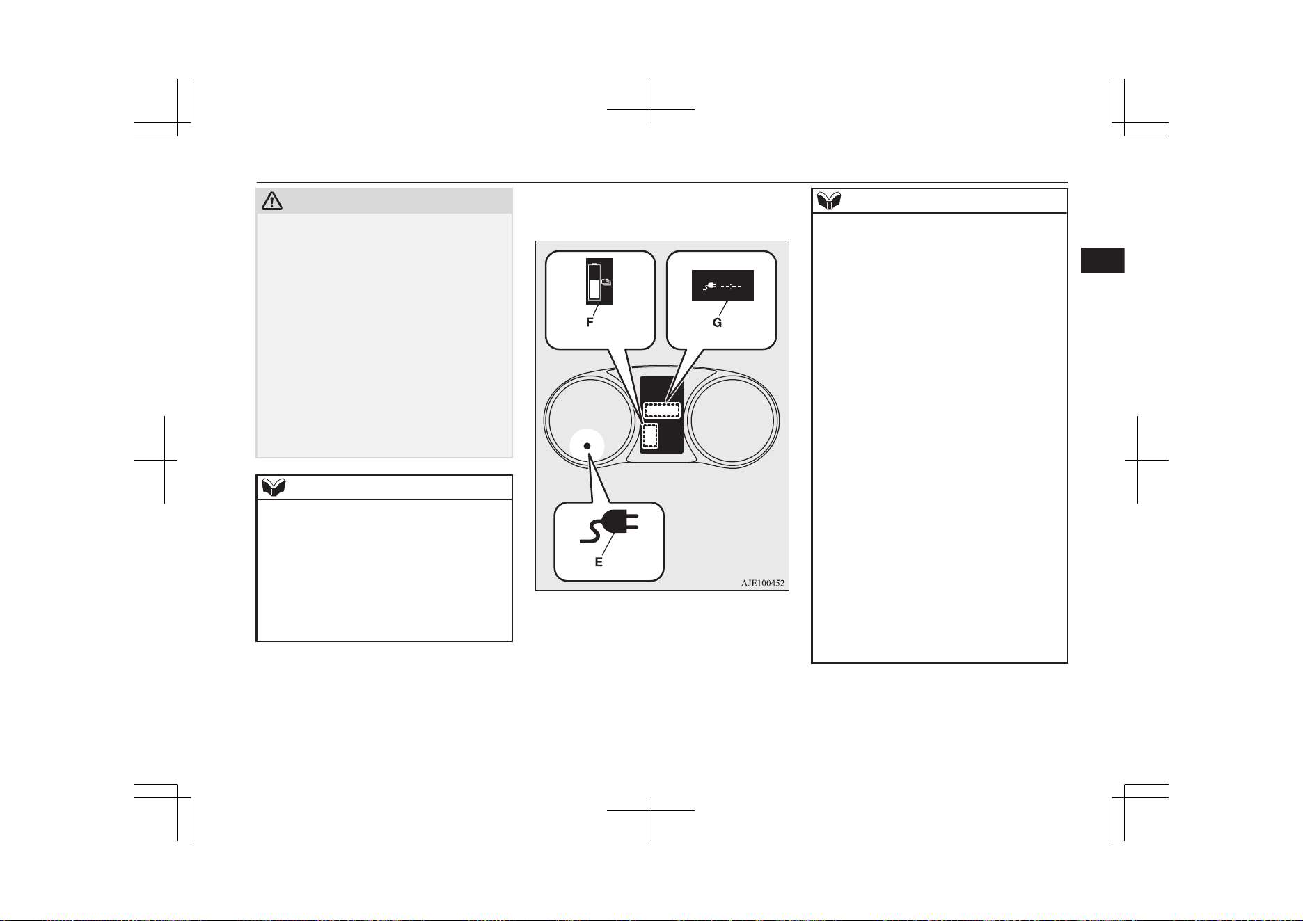
CAUTION
l
Be sure to insert the quick charge connector
straight into the quick charge port right up to
the base.
Failure to do so may result in the drive bat-
tery not charging or could cause damage to
the charging equipment.
l
During quick charging, the quick charge
connector cannot be removed because it is
locked. Do not touch or remove the quick
charge connector during charging. Doing so,
the quick charge connector might be dam-
aged. If you want to stop the quick charging
on the way, stop the charging according to
the procedures of a quick charger, and re-
move the quick charge connector after con-
firming the charging is stopped.
NOTE
l
There is a hole on the charge port for water
drainage. If this hole is blocked and water
gets trapped in the charge port, do not
charge. Contact a MITSUBISHI MOTORS
Authorized Service Point.
l
If the charge port is frozen, melt the ice us-
ing a hair drier. Forcing the charge connector
to connect while frozen could result in mal-
function.
5. Connect the quick charge connector in
the quick charge port to begin charging.
For connecting and disconnecting, fol-
low the instruction manual for each
quick charger.
6. Make sure that the charging indicator (E)
on the instrument cluster is illuminated.
If the charging indicator is not illumina-
ted, charging is not started.
Follow the manual of each quick charg-
er.
NOTE
l
When the quick charge connector is connec-
ted to the charge port, the charging indicator
is blinking. When charging is started, the
charging indicator is illuminated.
l
If you want to confirm the drive battery level
during charging, open one of the doors or
operate the multi information display switch,
the drive battery level display (F) appears on
the information screen in the multi informa-
tion display.
Although the predicted charging time dis-
play (G) appears, the charging time for the
quick charging is approximately 30 minutes
and displayed “--:--” in the screen and you
cannot confirm the remaining charging time.
l
Operation noise may be heard from the vehi-
cle body during quick charging.
This noise comes from the operation of the
drive battery cooling system, and it is not a
malfunction.
l
Since the drive battery cooling system uses
cool air of the air conditioning, the air condi-
tioning is automatically operated.
After quick charging, if the area under the
vehicle is wet, transparent and loose, it is de-
humidified water from the air conditioning
and not a malfunction.
When an electrical component is used during
charging, the charging time may become
longer.
7. Charging is complete when the charging
indicator turns off.
Quick charging (charging method with quick charger)
3-19
OGGE19E1
Charging
3
Disconnect the quick charge connector
according to the manual of the quick
charger.
CAUTION
l
As the quick charge connector is heavier in
comparison to the normal charge connector,
allowing it to drop could cause damage to
the vehicle or charge connector or personal
injury. When removing the connector, be
sure to pull it out straight and as carefully as
possible.
l
Do not leave the quick charge connector
connected to the quick charge port after
charging.
Doing so, someone might stumble and it
could cause an injury or the quick charging
connection might be damaged by playing it.
NOTE
l
Although it is possible to start the electric
motor unit if quick charging has not finished
normally, the charging indicator is continu-
ously blinking. In such a situation, perform
quick charging again and finish it normally
or contact a MITSUBISHI MOTORS Au-
thorized Service Point.
8. Close the inner lid and press the rear of
the charging lid until it clicks to close it.
WARNING
l
After charging, be sure to close the inner
lid and the quick charging lid completely.
Be careful that water or dust does not en-
ter in the quick charge port, inner lid and
quick charge connector.
Entry of water or dust could cause fire,
electric shock or short circuit.
l
After charging, be sure to disconnect the
charge connector from the charge port.
If the charge connector is only partially
engaged and the connector latch is un-
locked, you could put the operation mode
of the power switch in ON and the vehicle
could start moving. It could lead to an un-
expected accident.
NOTE
l
If the operation mode of the power switch is
put in ON with the quick charge connector
connected to the quick charge port, the plu-
gin hybrid EV system cannot be started.
Be sure to disconnect the quick charge con-
nector before start.
l
Charging may be completed before full
charge. This is a control for efficient charge
and not a malfunction.
To achieve full charge, repeat charging from
Step 5 again.
NOTE
l
Make sure that the inner lid is completely
closed.
If the charging lid is forcibly closed without
completely closing inner lid, the hinge on
the inner lid may be broken.
l
While the charging lid is open, if the doors
and tailgate are locked with the central door
lock, the keyless entry system or the keyless
operation system, the charging lid will lock
when the charging lid is closed.
l
When the operation mode is switched to ON
while the charging lid is not completely
closed, a warning may be displayed on the
information display of the multi information
display.
Refer to “Warning display list” on page
6-26.
MITSUBISHI Remote
Control*
E08304200215
The MITSUBISHI Remote Control allows to
operate the vehicle within the communication
range of the wireless LAN device (which
conforms to IEEE 802.11b and supports iOS
or Android). The following operations are
available.
MITSUBISHI Remote Control*
3-20
OGGE19E1
Charging
3
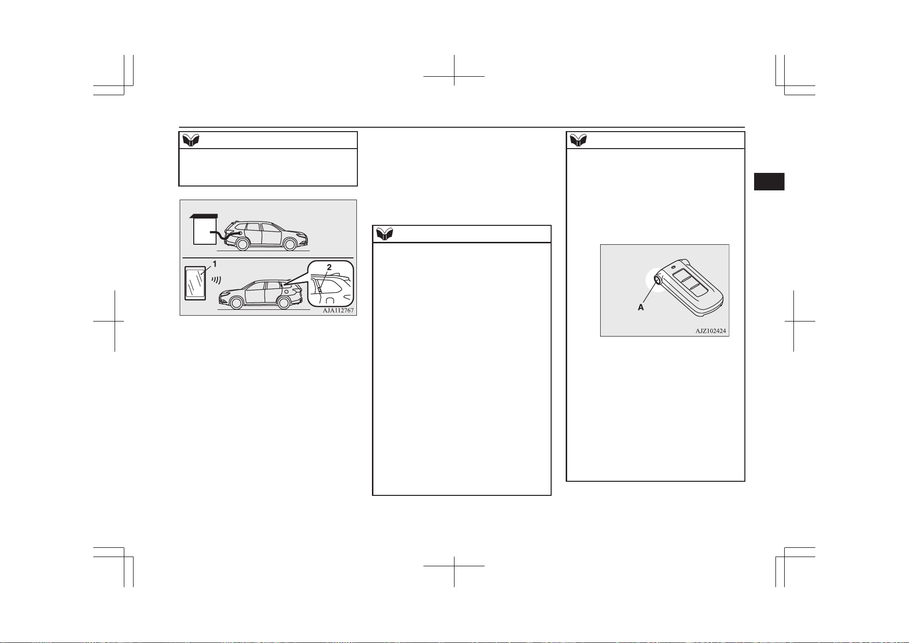
NOTE
l
The communication distance differs depend-
ing on the wireless LAN device, due to this
the communication may go down.
1- Wireless LAN device
2- Antenna
l
Charging timer
If you specify the charge start and/or
stop time with the normal charge cable
connected, charging is started and/or
stopped at that time.
l
Remote Climate Control
By setting the remote climate control to
operate at a predetermined time, cabin
comfort can be improved or visibility
can be ensured (defrosting/demisting)
before getting in the vehicle.
l
Customize (function setting change)
The function setting of the keyless oper-
ation system, outside rear-view mirror,
operation mode of the power switch, air
conditioning, lamps and windscreen
wipers can be changed by MITSUBISHI
Remote Control.
NOTE
l
The electric heater is required to activate the
reservation functions of heater, defroster and
demister.
l
In a vehicle equipped with the Smartphone
Link Display Audio or the MITSUBISHI
Multi-Communication System (MMCS), it
is possible to change the setting by means of
screen operations.
Refer to the separate owner’s manual for de-
tails.
l
If you want to quickly start normal charging
even when the charging timer is already set,
you can cancel the charging timer and start
the normal charging by the following meth-
ods.
[How to temporarily cancel the charging
timer]
You can temporarily cancel the charging
timer by the following methods.
In addition, the predetermined charging tim-
er settings will automatically return after the
charging timer is turned on again or the op-
eration mode of the power switch is put in
ON.
NOTE
•
Keyless operation
After connecting the normal charging ca-
ble and closing all the doors and the tail-
gate, you can cancel the charging timer by
pressing the switch (A) of the keyless op-
eration key twice within 2 seconds. When
the charging timer is cancelled, the hazard
warning lamps will blink four times.
•
Wireless LAN device
[How to cancel the charging timer]
The charging timer can be cancelled by
the following methods.
•
Wireless LAN device
•
Smartphone Link Display Audio*
•
MITSUBISHI Multi-Communication
System (MMCS)*
l
When using the charging timer, use the EV
charging cable. When using a home or pub-
lic charging device (EVSE: Electric Vehicles
Supply Equipment), the charging timer may
not be started.
MITSUBISHI Remote Control*
3-21
OGGE19E1
Charging
3
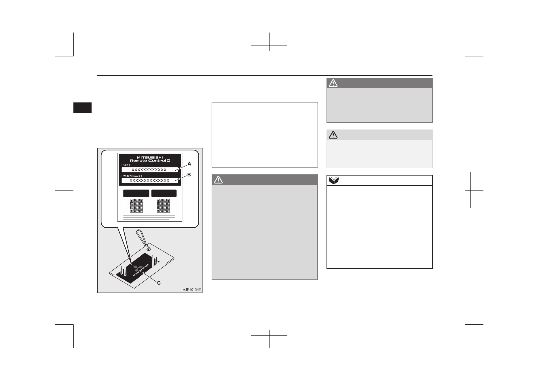
Devices that support wireless LAN are re-
quired to communicate with the vehicle using
the MITSUBISHI Remote Control. Also, an
SSID* (A) and password (B) are required to
connect a wireless LAN device to the vehi-
cle. The SSID and password are described in
the registration information card (C) that is
attached to the key at the time of your pur-
chase of the vehicle.
* The SSID is the identifier of an access
point for IEEE 802.11 series wireless LAN. It
is displayed on wireless LAN devices.
For the function and the operation method
of the MITSUBISHI Remote Control,
please visit the MITSUBISHI MOTORS
Web site:
http://www.mitsubishi-motors.com/en/prod-
ucts/outlander_phev2/app/remote/
l
If you need further information, please
contact a MITSUBISHI MOTORS Au-
thorized Service Point.
WARNING
l
Do not use the MITSUBISHI Remote
Control if children, persons in need of
care, pets, etc. are in the vehicle. Even if
the remote climate control is used, the
cabin may become hot or cold due to some
reasons such as automatic stop of the sys-
tem. The cabin temperature may quickly
rise in sunshine, which poses a risk of heat
stroke and dehydration. In cold weather,
on the other hand, the cabin temperature
may quickly drop. Either of which could
lead to death in the worst case.
In addition, children can activate switches
and controls, resulting in injury or a fatal
accident.
WARNING
l
The cooling fan in the engine compart-
ment may operate automatically when
charging or when operating air condition-
er. Do not bring your hand close to the
cooling fan during charging.
CAUTION
l
Do not use a car cover except for the
MITSUBISHI MOTORS GENUINE car
cover, when using the charging timer or the
remote climate control.
NOTE
l
Keep the following points in mind when us-
ing a wireless LAN device:
•
Communication speed and range vary de-
pending on the wireless LAN devices and
the surrounding conditions (radio environ-
ment, obstacles, parking area environ-
ment, etc.).
•
Due to the characteristics of radio waves,
communication speed tends to decrease as
the communication distance increases.
Use your wireless LAN device at a short
distance from the vehicle for better re-
sponse.
MITSUBISHI Remote Control*
3-22
OGGE19E1
Charging
3

NOTE
•
When a microwave oven or ISM (indus-
trial, scientific and medical) equipment is
being used, the communication speed and
range of wireless LAN devices may de-
crease. Use your wireless LAN device
away from these appliances and equip-
ment.
•
If a wireless LAN device and Bluetooth
(registered trademark of Bluetooth SIG,
Inc.) are used simultaneously, the commu-
nication speed and range of each device
may decrease. Use your wireless LAN de-
vice away from Bluetooth devices.
l
Wireless LAN devices may not communi-
cate with the vehicle, or may not operate
normally or stably in the following environ-
ment or situations. Check that the device can
communicate with your vehicle before use.
•
There is an obstruction such as a concrete
or metal wall between the vehicle and
wireless LAN device.
•
The vehicle is surrounded by tall vehicles
in a parking lot.
•
There are facilities nearby that emit strong
radio waves, such as a TV tower, trans-
former substation, broadcasting station or
airport.
•
There is a communication device such as
a mobile phone or radio, or an electric de-
vice such as a personal computer near the
wireless LAN device.
•
The wireless LAN device is in contact
with or covered by a metal object.
NOTE
•
The battery of the wireless LAN device
has run down.
l
The MITSUBISHI Remote Control cannot
be used under the following conditions:
•
The wireless LAN device is turned off.
•
The MITSUBISHI Remote Control appli-
cation software is not installed.
•
The MITSUBISHI Remote Control appli-
cation software is not running.
•
The wireless LAN device is not registered
on the vehicle or it is not connected to the
vehicle.
•
The wireless LAN device is out of the
communication range.
•
The wireless LAN device is connected to
other wireless LAN device.
•
The wireless LAN device has failed, or its
battery has run out.
l
Some charging facilities have a timer func-
tion that turns the power on or off at a spe-
cific time of the day. When charging at a fa-
cility with a timer function, make sure that
the charging timer is set within the time peri-
od when the power in the charging facility is
on.
l
The auxiliary battery is automatically and
periodically charged using electrical power
stored in the drive battery. A buzzer sounds
in the cabin while the auxiliary battery is be-
ing charged.
l
While the remote climate control is operat-
ing or the charging, the cooling fan or air
conditioner compressor may start operating
and its sound may be heard. This is normal.
NOTE
l
The remote climate control operates in its
own mode based on the mode selected on
the wireless LAN device, regardless of the
switch setting of the vehicle’s air condition-
er.
l
Air conditioning performance may deterio-
rate or the remaining charge in the drive bat-
tery may decrease under the following con-
ditions:
•
In extremely hot weather.
•
In hot sunshine.
•
In extremely cold weather.
l
If the remote climate control is started dur-
ing charging, the time until full charge may
extend or the charging rate may decrease.
l
When the remaining quantity of the drive
battery is decreased, the remote climate con-
trol does not operate or it may stop on the
way.
l
When the auxiliary battery is removed, the
timer control of the MITSUBISHI Remote
Control is reset and each function of the
MITSUBISHI Remote Control cannot be
used. Also the drive battery cannot be
warmed up.
Communicate the wireless LAN device and
your vehicle again.
MITSUBISHI Remote Control*
3-23
OGGE19E1
Charging
3
How to use an electric
device during charging
E08304700021
If you turn the operation mode of the power
switch to “ON” during normal charging,
quick charging, V2H charging, V2H power
supply, you can use the air conditioner, car
navigation system, audio equipment and so
on.
V2H (Vehicle to Home)
The vehicle power can be used as a house-
hold power supply source. Bidirectional
charging of the vehicle or the home is carried
out by using the quick charge connector of
CHAdeMO standard which is the same as
quick charging. “V2H charging” will charge
the vehicle from the V2H main unit. “V2H
power supply” supplies power from the vehi-
cle to the home via the V2H main unit.
For details of V2H, please confirm with the
PHEV to HOME sales catalogue or the in-
struction manual that is issued by the V2H
maker or consult the V2H maker.
WARNING
l
Do not get in the vehicle if the persons
have electro-medical apparatus such as
implantable cardiac pacemaker or im-
plantable cardioverter-defibrillator, when
using the air-conditioner during charging.
It may affect the operation of electro-
medical apparatus.
l
Do not leave children and people who
need nursing care and pets etc. inside the
vehicle.
The inside of the vehicle may become hot
or cold for reasons such as automatic sys-
tem shutdown.
Also, when the outside air temperature is
low, the temperature inside the vehicle
may fall rapidly. In the worst case, there
is a danger of death.
Also, since the wiper and the electric
parking brake can be operated, an error
in operation may lead to unexpected acci-
dents.
l
Please check the surroundings before us-
ing.
l
Do not move the selector lever, the vehicle
may move unintentionally.
NOTE
l
When using electrical devices during charg-
ing, the following cases may occur, since the
charging to the drive battery is restricted.
NOTE
•
During normal charging:
The electricity consumption becomes
larger than the charge amount, the drive
battery may not be charged, and the re-
maining amount of the drive battery may
decrease.
•
During quick charging:
Charging time may be longer. Also, de-
pending on the specifications of the quick
charger, it may not be charged and the re-
maining amount of the drive battery may
decrease.
l
If you use an air conditioner etc. during
charging, you may not be able to hear the ra-
dio due to strong electromagnetic waves or
noise.
When using electrical devices
E08304800022
1. Start the normal charging or the quick
charging.
Refer to “Normal charging (charging
method with rated AC 220-240V out-
let)” on page 3-10.
Refer to “Quick charging (charging
method with quick charger)” on page
3-17.
2. Confirm that the charge lamp in the me-
ter is illuminated.
How to use an electric device during charging
3-24
OGGE19E1
Charging
3
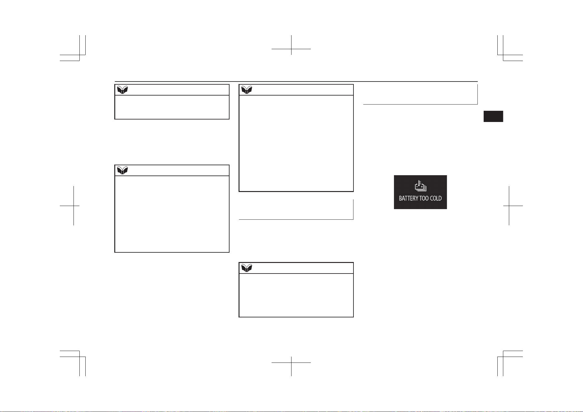
NOTE
l
If the charging lamp is not illuminated, the
electrical devices will not be operated.
Check that the charging is done correctly.
3. Put the operation mode of the power
switch from OFF to ON.
Refer to “Changing the operation mode”
on page 7-12.
NOTE
l
Always put the operation mode of the power
switch in ON after the charge lamp is illumi-
nated. Charging may not start when you put
the operation mode of the power switch in
ON before the charge lamp is illuminated.
l
When the operation mode of the power
switch is ON, the door and tailgate cannot be
locked by the keyless entry or the keyless
operation function. When leaving the vehi-
cle, put the operation mode in OFF and lock
the vehicle.
4. Electric devices such as the air condi-
tioner, car navigation system, audio
equipment can be used.
Refer to “Warning display list” on page
6-26.
NOTE
l
Put the operation mode in ON and use the
electrical devices. If the operation mode of
the power switch is ACC, the air conditioner
cannot be used.
l
For vehicles without the electric heater, the
heating of the air conditioner cannot be used
during charging.
l
220-240 V AC Power Supply (1500 W) can-
not be used during charging.
l
If the meter display screen is switched to the
energy flow display, you can see the state of
charging and discharging of the drive bat-
tery. Refer to “Energy flow indication during
charging” on page 6-16.
When stopping the use of elec-
trical devices
E08304900023
Put the operation mode of the power switch
in OFF.
Refer to “Changing the operation mode” on
page 7-12.
NOTE
l
Charging continues even if the operation
mode of the power switch is put in OFF.
When the operation mode of the power
switch is put to OFF, the air conditioner, car
navigation system, audio equipment etc. are
stopped.
Automatic OFF of the opera-
tion mode
E08305000021
In the following cases, the operation mode
will be turned to OFF automatically.
l
When the remaining amount of the drive
battery decreases further after the air
conditioner is stopped.
l
When the outside air temperature is low
and the following warning display ap-
pears.
l
When charging is completed.
l
When the normal charge connector is
disconnected.
l
When the charging stop operation is per-
formed by the quick charger.
l
When the quick charging time has
passed 60 minutes.
l
When the stop condition (charging
amount/charging time) on the quick
charger is satisfied.
l
When charging stops due to an electrical
power outage.
l
When charging stops due to a failure.
l
When operating the selector lever to the
“N” (NEUTRAL) position. (charging al-
so stops)
How to use an electric device during charging
3-25
OGGE19E1
Charging
3
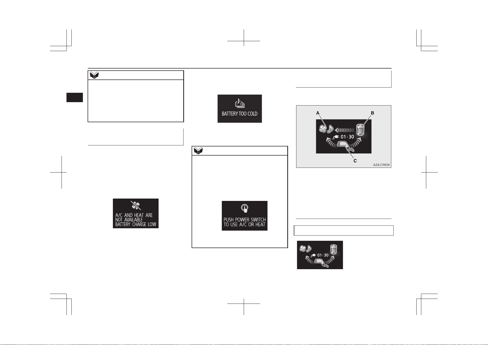
NOTE
l
Even when the operation mode automatical-
ly puts off, air conditioners, car navigation
systems, audio equipment, etc. will stop.
Also, the vehicle status will be the same as
putting the operation mode OFF (for exam-
ple: the lights go off, the room lamp is illu-
minated or the electric mirrors are retracted).
Automatic stop of the air con-
ditioner
E08305100022
In the following cases, the air conditioner au-
tomatically stops. When the air conditioner
stops, the air conditioner control panel turns
off.
l
When the remaining amount of the drive
battery becomes low and the following
warning display appears.
Refer to “Warning display list” on page
6-26.
l
When the temperature of the drive bat-
tery becomes extremely low and the fol-
lowing warning display appears.
Refer to “Warning display list” on page
6-26.
NOTE
l
To use the air conditioner again after the air
conditioner automatically stops, press the
power switch to turn the operation mode
OFF with the following message appeared,
then press the power switch again to turn
ON the operation mode of the power switch
so as to use the air conditioner.
Refer to “Warning display list” on page
6-26.
Energy flow display during
charging
E08305200023
It shows the flow of energy during charging.
A: Various electrical devices
B: Drive battery
C: Charger
Blue arrow: Flow of electric energy
Display of energy flow (exam-
ple)
When charging the drive battery
How to use an electric device during charging
3-26
OGGE19E1
Charging
3
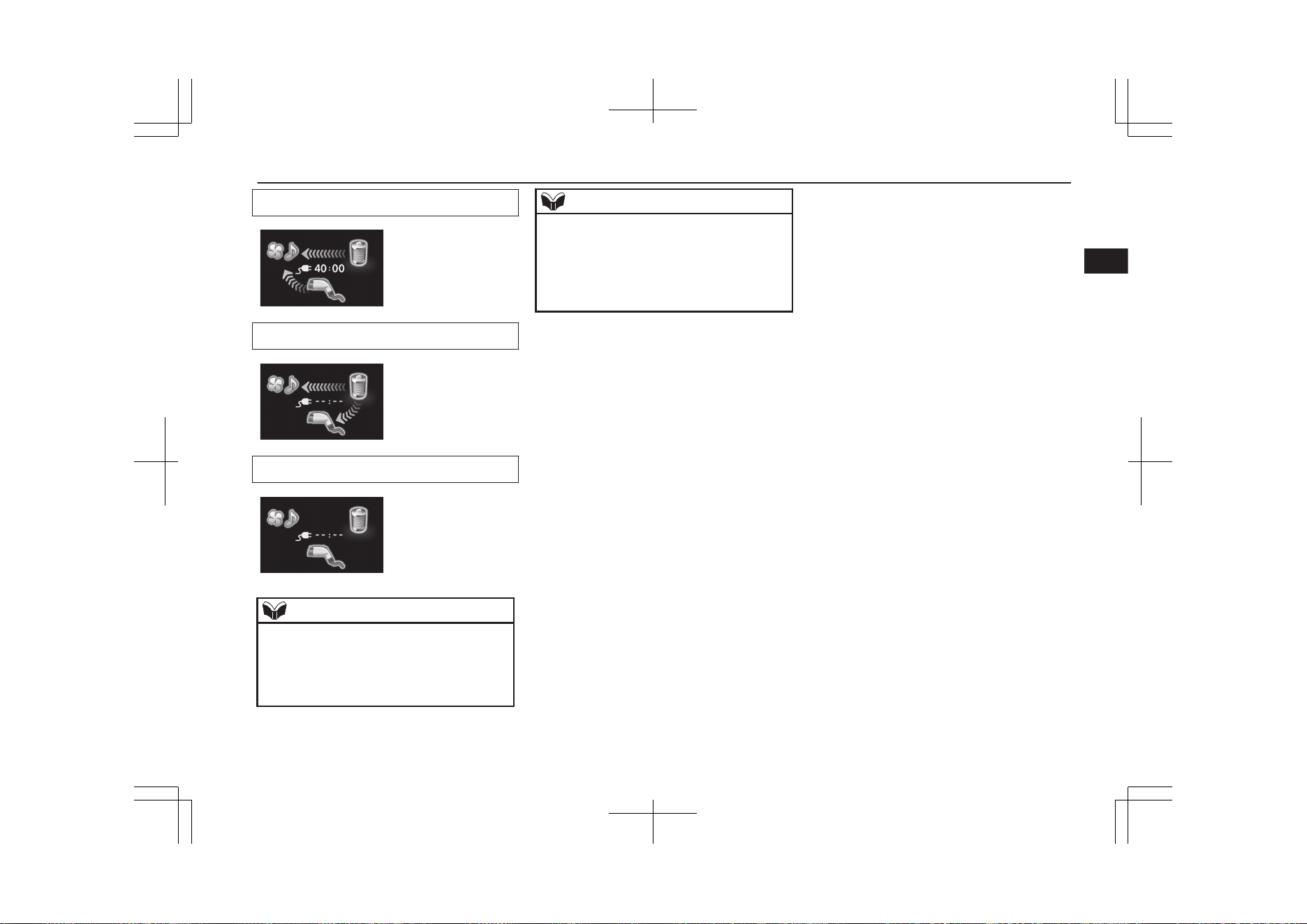
When discharging from the drive battery
V2H power supply
No energy flow
NOTE
l
Even when you are not operating the air con-
ditioner, car navigation system, audio equip-
ment, etc., since the on-board computer con-
sumes electricity, arrows may be displayed
from the charger or the drive battery.
NOTE
l
Energy flow display may change regardless
of the operation of the air conditioner, car
navigation system, audio equipment, etc.
l
If you change the setting of the air condi-
tioner, it may take time until the display of
the energy flow stabilizes.
How to use an electric device during charging
3-27
OGGE19E1
Charging
3

Charging troubleshooting guide
E08301501243
Symptom Possible cause Possible solution
Charging cannot be
started.
The operation mode of the power
switch is in the “ON” position.
Put the operation mode of the power switch in “OFF” before charging.
The drive battery is already fully
charged.
Charging cannot be performed if the drive battery is already fully charged. Charg-
ing automatically turns off if the drive battery is fully charged.
The temperature of the drive bat-
tery is too high or too low to
charge.
Confirm the drive battery temperature.
Refer to “Cautions and actions to deal with intense heat” on page 2-10 and “Cau-
tions and actions to deal with intense cold” on page 2-10.
The auxiliary battery is dis-
charged.
The drive battery cannot be charged if the vehicle electrical systems cannot be
turned on. If the auxiliary battery is discharged, charge or emergency start the aux-
iliary battery.
Refer to “Emergency starting” on page 9-02.
The vehicle or the charging cable
has a malfunction.
The vehicle or charging cable may have a malfunction. Confirm if the warning
lamp on the meter is illuminated. Confirm if the indicator on the control box is in-
dicating a malfunction. If a warning is displayed, stop charging and contact a
MITSUBISHI MOTORS Authorized Service Point.
Normal charging can-
not be started.
There is no electrical power com-
ing from the outlet.
Confirm that there has not been a power failure. Make sure the breaker is on. If an
outlet with a timer device installed is used, power will only be available at the time
set by the timer.
Confirm if the POWER indicator on the control box is illuminated.
The charge connector is not con-
nected correctly.
Confirm the charge connector is connected correctly.
The charge connector was connec-
ted and disconnected repeatedly in
a short time.
Disconnect the charge connector, wait for a while, then start charging procedure
again from the beginning.
Charging troubleshooting guide
3-28
OGGE19E1
Charging
3

Symptom Possible cause Possible solution
A charging cable for other vehicle
is used.
Use the EV charging cable only for your vehicle.
A normal charger which does not
correspond to your vehicles is
used.
Consult an administrator or a maker of the normal charger that it corresponds to
your vehicle. Also perform normal charging according to the operating procedure
indicated on the body of normal charger.
The reservation of Charging timer
is set up by MITSUBISHI Remote
Control (if so equipped), Smart-
phone Link Display Audio (if so
equipped) or by the MITSUBISHI
Multi-Communication System
(MMCS) (if so equipped).
The normal charging cannot be started when the charging cable is connected, if the
charging timer is set. Cancel all the charging timer settings, if you want to start the
normal charging immediately.
Refer to “MITSUBISHI Remote Control” on page 3-20.
For the MITSUBISHI Multi-Communication System (MMCS) refer to the separate
owner’s manuals.
Normal charging is dis-
continued.
There is no power coming from
the outlet.
There may have been a electrical power failure, or the breaker may have failed.
Charging will resume when the power source is reset.
The EV charging cable has been
disconnected.
Check that the EV charging cable has not been disconnected.
The button on the normal charge
connector has been pressed.
If the charge connector button is pressed for a long period of time, charging will be
stopped. Start the charging procedure again.
The temperature of the drive bat-
tery is too high or too low to
charge.
Confirm the drive battery temperature.
Refer to “Cautions and actions to deal with intense heat” on page 2-10 and “Cau-
tions and actions to deal with intense cold” on page 2-10.
Charging is stopped by the normal
charge timer.
Charging will stop depending on the timer function setting of the normal charge de-
vice. Try it again with cancelling the timer settings.
Charging troubleshooting guide
3-29
OGGE19E1
Charging
3

Symptom Possible cause Possible solution
The Charging timer was set up by
the MITSUBISHI Remote Control
(if so equipped), Smartphone Link
Display Audio (if so equipped) or
the MITSUBISHI Multi-Commu-
nication System (MMCS) (if so
equipped) after starting of normal
charging.
Cancel all the charging timer settings. Charging is automatically restarted if you
cancel the charging timer.
Refer to “MITSUBISHI Remote Control” on page 3-20.
For the MITSUBISHI Multi-Communication System (MMCS) refer to the separate
owner’s manuals.
Quick charging cannot
be started.
The charge connector is not con-
nected correctly and/or not locked.
Check that the charge connector is connected correctly and that it is locked.
The self-diagnostic function of the
quick charge device returns a neg-
ative result.
There is a possibility that the vehicle has a malfunction. Stop charging and contact
a MITSUBISHI MOTORS Authorized Service Point.
The power switch of the quick
charger is off.
Check the power switch of the quick charger.
Consult an administrator or a maker of the quick charger.
Quick charge is discon-
tinued.
Charging is stopped by the quick
charge timer.
Charging will stop depending on the timer function setting of the quick charge de-
vice. If you need to charge the drive battery more, start the charging procedure
again.
Charging stops at 80 % capacity. Charging is designed to stop when the drive battery capacity reaches 80 %. If you
need to charge the drive battery more than 80 %, start the charging procedure
again.
The power supply for the quick
charger is off.
Check whether the power supply for the quick charger is off.
Consult an administrator or a maker of the quick charger.
Charging troubleshooting guide
3-30
OGGE19E1
Charging
3

Symptom Possible cause Possible solution
The charging indicator
is continuously blink-
ing even if the quick
charge connector is
not connected into the
quick charge port
when you start the
plug-in hybrid EV sys-
tem after quick charg-
ing.
Quick charging has not finished
normally.
Perform quick charging again and finish it normally or contact a MITSUBISHI
MOTORS Authorized Service Point.
Plug-in Hybrid EV
System does not start
after quick charging.
The vehicle has a malfunction. There is a possibility that the vehicle has a malfunction. After turning the operation
mode of the power switch to “ON” and putting the select position to “N”, ask the
support of the fellow passenger or people nearby to move the vehicle by pushing it
into safety.
After moving, contact a MITSUBISHI MOTORS Authorized Service Point.
Charging troubleshooting guide
3-31
OGGE19E1
Charging
3

OGGE19E1

Keys.................................................................................................... 4-02
Electronic immobilizer (Anti-theft starting system)........................... 4-03
Keyless entry system...........................................................................4-03
Keyless operation system....................................................................4-06
Doors...................................................................................................4-14
Central door locks............................................................................... 4-16
Dead Lock System*............................................................................ 4-17
“Child-protection” rear doors..............................................................4-18
Tailgate*..............................................................................................4-19
Electric tailgate*................................................................................. 4-20
Inside tailgate release..........................................................................4-27
Security alarm system*....................................................................... 4-27
Electric window control......................................................................4-34
Sunroof*..............................................................................................4-36
Locking and unlocking
OGGE19E1
4
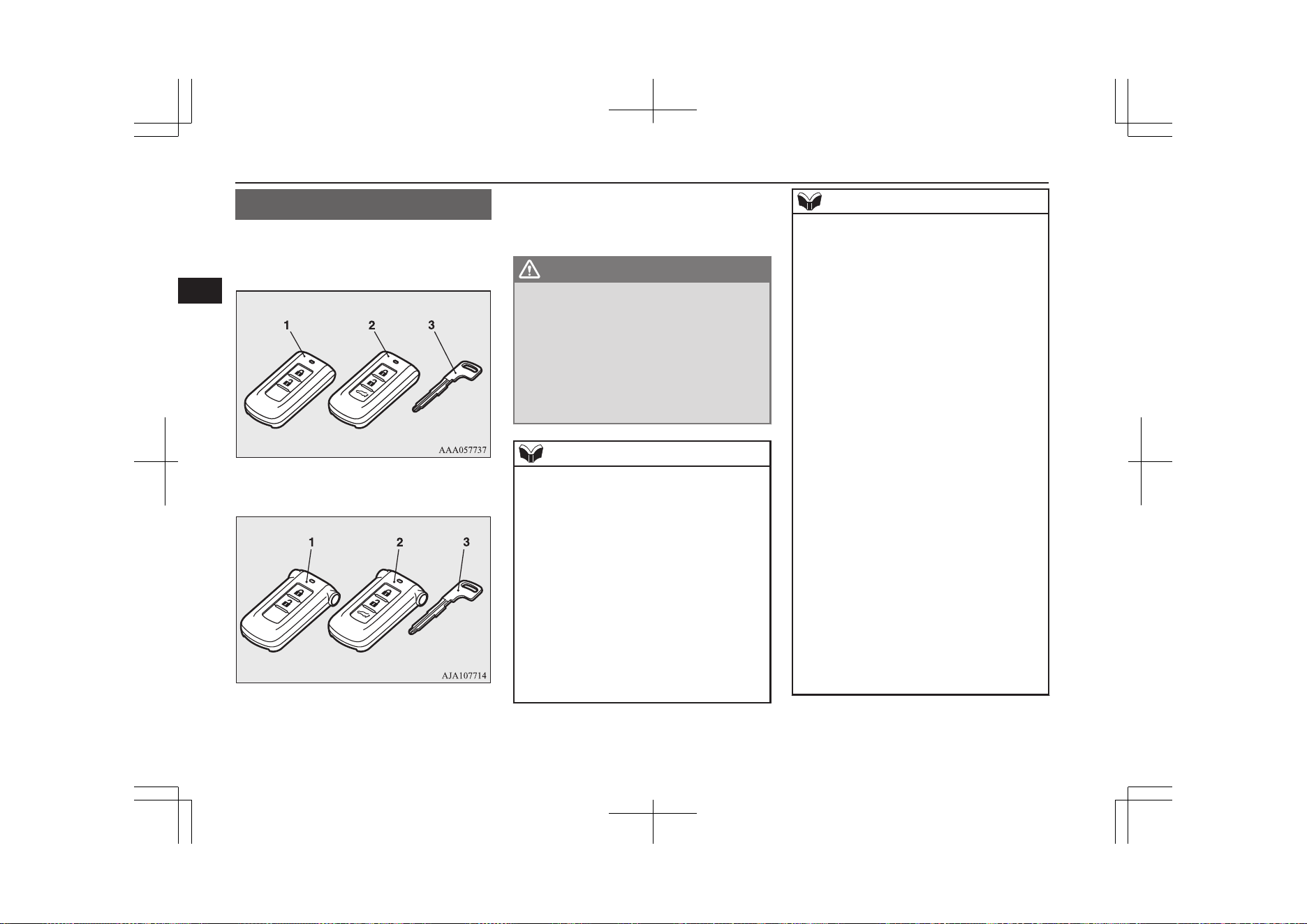
Keys
E00300104540
The key fits all locks.
without MITSUBISHI Remote Control
with MITSUBISHI Remote Control
1- Keyless operation key
2- Keyless operation key (with electric tail-
gate switch)
3- Emergency key
WARNING
l
When taking a key on flights, do not press
any switches on the key while on the
plane. If a switch is pressed on the plane,
the key emits electromagnetic waves,
which could adversely affect the plane’s
flight operation.
When carrying a key in a bag, be careful
that no switches on the key can be easily
pressed by mistake.
NOTE
l
The key (except for the emergency key) is a
precision electronic part with a built-in sig-
nal transmitter. Please observe the following
in order to prevent a malfunction.
•
Do not leave in a place that is exposed to
direct sunlight, for example on the dash-
board.
•
Do not disassemble or modify.
•
Do not excessively bend the key or sub-
ject it to strong impacts.
•
Do not expose to water.
•
Keep away from magnetic key rings.
•
Keep away from audio systems, personal
computers, TVs, and other equipment that
generates a magnetic field.
NOTE
•
Keep away from devices that emit strong
electromagnetic waves, such as cellular
phones, wireless devices and high fre-
quency equipment (including medical de-
vices).
•
Do not clean with ultrasonic cleaners or
similar equipment.
•
Do not leave the key where it may be ex-
posed to high temperature or high humidi-
ty.
l
The plug-in hybrid EV system is designed so
that it will not start if the ID code registered
in the immobilizer computer and the key’s
ID code do not match. Refer to the “Elec-
tronic immobilizer” section for details and
key usage.
l
[For vehicles equipped with the security
alarm system]
Pay attention to the following if the security
alarm is set to “Active”.
Refer to “Security alarm system” on page
4-27.
•
If the security alarm is in the system
armed mode, the alarm will sound if the
doors are opened after being unlocked
with the key, the inside lock knob or the
central door lock switch.
•
Even if the security alarm is set to “Ac-
tive”, the system preparation mode is not
entered if the keyless entry system or the
keyless operation function was not used to
lock the vehicle.
Keys
4-02
OGGE19E1
Locking and unlocking
4
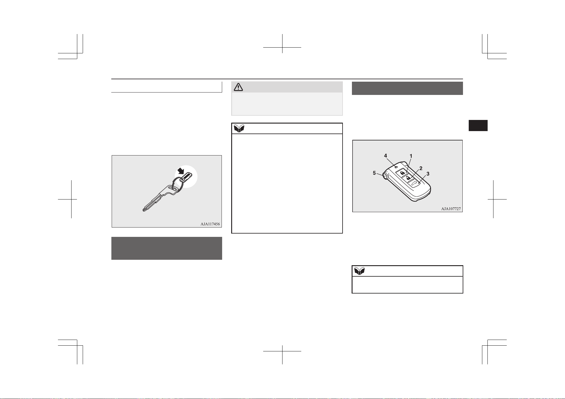
Key number tag
The key number is stamped on the tag as in-
dicated in the illustration.
Make a record of the key number and store
the key and key number tag in separate pla-
ces, so that you can order a key from your
MITSUBISHI MOTORS Authorized Service
Point in the event the original keys are lost.
Electronic immobilizer
(Anti-theft starting system)
E00300203791
The electronic immobilizer has been de-
signed to significantly reduce the possibility
of vehicle theft. The purpose of the system is
to immobilize the vehicle if an invalid start is
attempted. A valid start attempt can only be
achieved by using a key “registered” to the
immobilizer system.
CAUTION
l
Do not modify or add parts to the immobiliz-
er system. Doing so could cause the immo-
bilizer to malfunction.
NOTE
l
If the plug-in hybrid EV system does not
start, we recommend you to contact your
MITSUBISHI MOTORS Authorized Serv-
ice Point.
l
If you lose one of keyless operation keys,
contact your MITSUBISHI MOTORS Au-
thorized Service Point as soon as possible.
To obtain a replacement or extra spare key,
take your vehicle and all remaining keys to
your MITSUBISHI MOTORS Authorized
Service Point. All the keys have to be re-reg-
istered in the immobilizer computer unit.
The immobilizer can register as follows.
•
Keyless operation key: up to 4 different
keys
Keyless entry system
E00300304861
Press the remote control switch, and all doors
and the tailgate will be locked or unlocked as
desired. It is also possible to operate the out-
side rear-view mirrors.
1- LOCK switch
2- UNLOCK switch
3- Electric tailgate switch*
4- Indication lamp
5- Charging timer cancel switch*
NOTE
l
The charging lid is also locked/unlocked,
when the driver’s door is locked/unlocked.
Electronic immobilizer (Anti-theft starting system)
4-03
OGGE19E1
Locking and unlocking
4
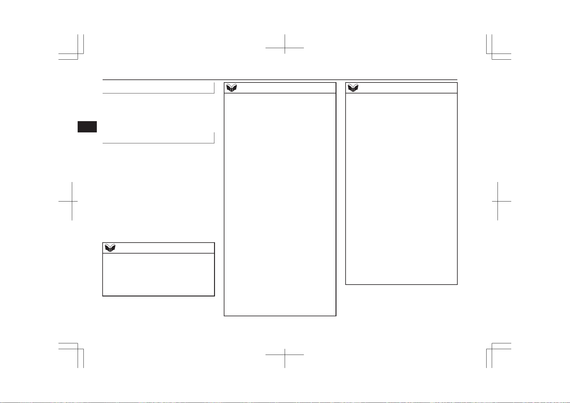
To lock
Press the LOCK switch (1). All the doors and
the tailgate will be locked. The turn-signal
lamps will blink once when the doors and the
tailgate are locked.
To unlock
Press the UNLOCK switch (2). All the doors
and the tailgate will be unlocked. If the doors
and tailgate are unlocked when the front
room lamp switch is in the “DOOR” position
or the rear room lamp switch is in the middle
(•) position, the room lamp will illuminate for
approximately 15 seconds and the turn-signal
lamps will blink twice.
The position and tail lamps can also be set to
turn on for approximately 30 seconds. Refer
to “Instruments and controls: Welcome light”
on page 6-65.
NOTE
l
For the operation of the Electric tailgate
switch (3), refer to “Electric tailgate” on
page 4-20.
l
For the operation of the Charging timer can-
cel switch (5), refer to “MITSUBISHI Re-
mote Control” on page 3-20.
NOTE
l
The door and tailgate unlock function can be
set so that only the driver’s door unlocks
when the UNLOCK switch (2) is pressed
once.
If the door and tailgate unlock function is set
to work as described above, all the doors and
the tailgate unlock when the UNLOCK
switch is pressed two times in succession.
Refer to “Setting of door and tailgate unlock
function” on page 4-05.
l
If the UNLOCK switch (2) is pressed and no
door or tailgate is opened within approxi-
mately 30 seconds, relocking will automati-
cally occur.
l
If either of the following problems occurs,
the battery may be exhausted.
•
The remote control switch is operated at
the correct distance from the vehicle, but
the doors and tailgate are not locked/
unlocked in response.
•
The indication lamp (4) is dim or does not
come on.
For further information, please consult
your MITSUBISHI MOTORS Authorized
Service Point.
If you replace the battery yourself, refer to
“Procedure for replacing the remote con-
trol switch battery” on page 4-05.
l
It is possible to modify functions as follows:
For further information, please contact your
MITSUBISHI MOTORS Authorized Serv-
ice Point.
On vehicles equipped with the Smartphone
Link Display Audio or the MITSUBISHI
NOTE
Multi-Communication System (MMCS),
screen operations can be used to make the
adjustment. Refer to the separate owner’s
manual for details.
•
The time for automatic relocking can be
changed.
•
The confirmation function (flashing of the
turn-signal lamps) can be set to operate
only when the doors and backdoor are
locked or only when the doors and back-
door are unlocked.
•
The confirmation function (this indicates
locking or unlocking of the doors and tail-
gate with the blink of the turn-signal
lamps) can be deactivated.
•
The number of times the turn-signal
lamps are flashed by the confirmation
function can be changed.
l
The outside rear-view mirrors automatically
retract or extend when the doors and tailgate
are locked or unlocked using the remote
control switches of the keyless entry system.
Refer to “Starting and driving: Outside rear-
view mirrors” on page 7-09.
l
The keyless entry system does not operate in
the following conditions:
•
The operation mode is not in OFF.
•
The LOCK switch (1) is pressed while a
door or the tailgate is open.
Keyless entry system
4-04
OGGE19E1
Locking and unlocking
4
NOTE
l
The remote control switch will operate with-
in approximately 4 m from the vehicle.
However, the operating range of the remote
control switch may change if the vehicle is
located near a power station, or radio/TV
broadcasting station.
l
If your remote control switch is lost or dam-
aged, please contact your MITSUBISHI
MOTORS Authorized Service Point for a re-
placement remote control switch.
l
If you wish to add a remote control switch,
we recommend you to contact your
MITSUBISHI MOTORS Authorized Serv-
ice Point.
The below remote control switches are avail-
able for your vehicle.
•
Keyless operation key: up to 4 remote
control switches
Setting of door and tailgate un-
lock function
E00310301531
The door and tailgate unlock function can be
set to the following two conditions.
Each time the door and tailgate unlock func-
tion is set, a chime will sound to tell you the
condition of the door and tailgate unlock
function.
Number of
chimes
Condition
One chime [Fac-
tory setting]
When the UNLOCK
switch, driver’s or front
passenger’s door lock/
unlock switch, or tailgate
open switch is pressed
one time, all doors and
the tailgate unlock.
Two chimes
When the UNLOCK
switch or the driver’s
door lock/unlock switch
is pressed one time, only
the driver’s door un-
locks. When the UN-
LOCK switch or the
driver’s door lock/
unlock switch is pressed
two times in succession,
all doors and the tailgate
unlock.
1. Put the operation mode in OFF.
2. Place the combination headlamps and
dipper switch in the “OFF” position, and
leave the driver’s door open.
3. Press the LOCK switch (1) for 4 to 10
seconds and press the UNLOCK switch
(2) during this time.
4. Release in sequence the LOCK and UN-
LOCK switches within 10 seconds of
pressing the LOCK switch in step 3.
NOTE
l
The charging lid is also unlocked, when the
driver’s door is unlocked.
l
On vehicles equipped with the Smartphone
Link Display Audio or the MITSUBISHI
Multi-Communication System (MMCS),
screen operations can be used to make the
adjustment. Refer to the separate owner’s
manual for details.
Procedure for replacing the re-
mote control switch battery
E00309502022
Before replacing the battery, remove static
electricity from your body by touching a met-
al grounded object.
WARNING
l
Danger of explosion if battery is incor-
rectly replaced.
Replace only with the same battery or an
equivalent type.
CAUTION
l
When the remote control switch case is
opened, be careful to keep water, dust, etc.
out. Also, do not touch the internal compo-
nents.
Keyless entry system
4-05
OGGE19E1
Locking and unlocking
4
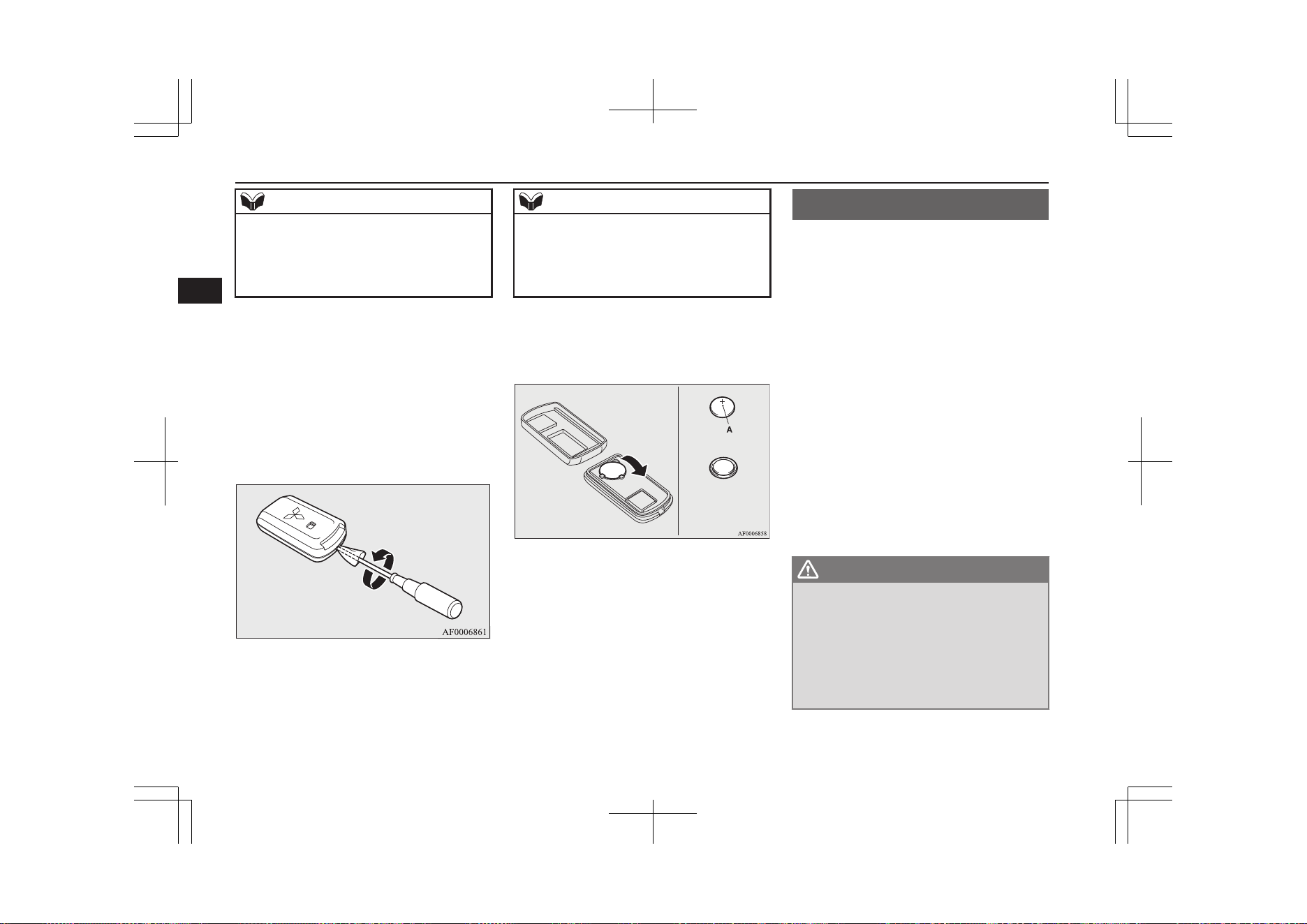
NOTE
l
You may purchase a replacement battery at
an electric appliance store.
l
A MITSUBISHI MOTORS Authorized
Service Point can replace the battery for you
if you prefer.
1. Remove the emergency key from the
key.
Refer to “Emergency key” on page
4-14.
2. With the MITSUBISHI mark facing you,
insert the cloth covered tip of a straight
blade (or minus) screwdriver into the
notch in the remote control switch case
and use it to open the case.
NOTE
l
Be sure to perform the procedure with the
MITSUBISHI mark facing you. If the
MITSUBISHI mark is not facing you when
you open the remote control switch case, the
transmitter may come out.
3. Remove the old battery.
4. Install a new battery with the + side (A)
up.
+ side
- side
Coin type battery
CR2032
5. Close the case firmly.
6. Install the emergency key removed in
step 1.
7. Check the keyless operation function to
see that it works.
Keyless operation system
E00305602432
The keyless operation system allows you to
lock and unlock the doors and tailgate and
start the Plug-in Hybrid EV System simply
by carrying the keyless operation key with
you.
The keyless operation key can also be used as
the keyless entry system remote control
switch.
Refer to “Keyless entry system” on page
4-03.
The driver should always carry the keyless
operation key. This key is necessary for lock-
ing and unlocking the doors and tailgate,
starting the Plug-in Hybrid EV System and
otherwise operating the vehicle, so before
locking and leaving the vehicle, be sure to
check that you have the keyless operation
key.
WARNING
l
People with implantable cardiac pace-
makers or implantable cardiovascular-de-
fibrillators should not go near the exterior
transmitters (A) or the interior transmit-
ters (B). The radio waves used by the key-
less operation system could adversely af-
fect implantable cardiac pacemakers or
implantable cardiovascular-defibrillators.
Keyless operation system
4-06
OGGE19E1
Locking and unlocking
4
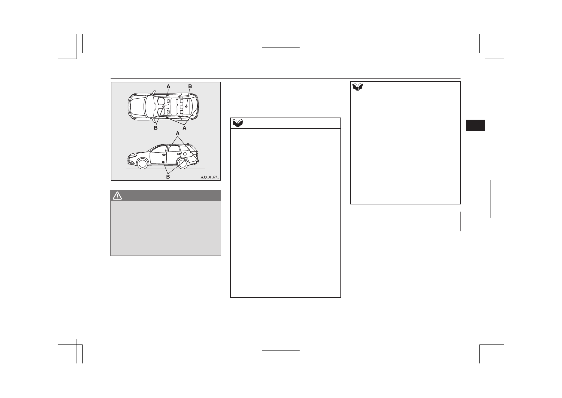
WARNING
l
When using electro-medical devices other
than implantable cardiac pacemakers or
implantable cardiovascular-defibrillators,
contact the electromedical device manu-
facturer ahead of time to determine the
affects of radio waves on the devices. Elec-
tromedical device operations could be ad-
versely effected by radio waves.
You can limit the possible operations of
the keyless operation system in the fol-
lowing ways. (The keyless operation
system can be used as a keyless entry
system.) Please consult a MITSUBISHI
MOTORS Authorized Service Point.
• You can limit operations to locking
and unlocking the doors and tailgate.
• You can limit operations to starting
the Plug-in Hybrid EV System.
• The keyless operation system can be
disabled.
NOTE
l
The keyless operation key uses an ultra-
weak electromagnetic wave. In the following
cases, the keyless operation system may not
operate properly or may be unstable.
•
When there is equipment nearby that
emits strong radio waves, such as: a pow-
er station, a radio/TV broadcasting station
or an airport.
•
The keyless operation system is carried
together with a communications device
such as a cellular phone or radio set, or
with an electronic device such as a per-
sonal computer.
•
The keyless operation key is touching or
covered by a metal object.
•
A keyless entry system is being used
nearby.
•
When the keyless operation key battery is
worn out.
•
When the keyless operation key is placed
in an area with strong radio waves or
noise.
In such cases, use the emergency key.
Refer to “To operate without using the
keyless operation function” on page
4-14.
NOTE
l
Because the keyless operation key receives
signals in order to communicate with the
transmitters in the vehicle, the battery con-
tinually wears down regardless of keyless
operation key use. The battery life is 1 to 3
years, depending on usage conditions. When
the battery wears out, replace the battery ac-
cording to the description in this manual or
have it replaced at your MITSUBISHI
MOTORS Authorized Service Point.
Refer to “Procedure for replacing the remote
control switch battery” on page 4-05.
l
Because the keyless operation key continual-
ly receives signals, strong radio wave recep-
tion could affect battery wear. Do not leave
the key near a TV, personal computer, or
other electronic device.
Operating range of the keyless
operation system
E00305701830
If you are carrying the keyless operation key,
enter the operating range of the keyless oper-
ation system, and press the driver’s or front
passenger’s door lock/unlock switch, the tail-
gate LOCK switch or the tailgate open
switch, the ID code for your key is verified.
Keyless operation system
4-07
OGGE19E1
Locking and unlocking
4
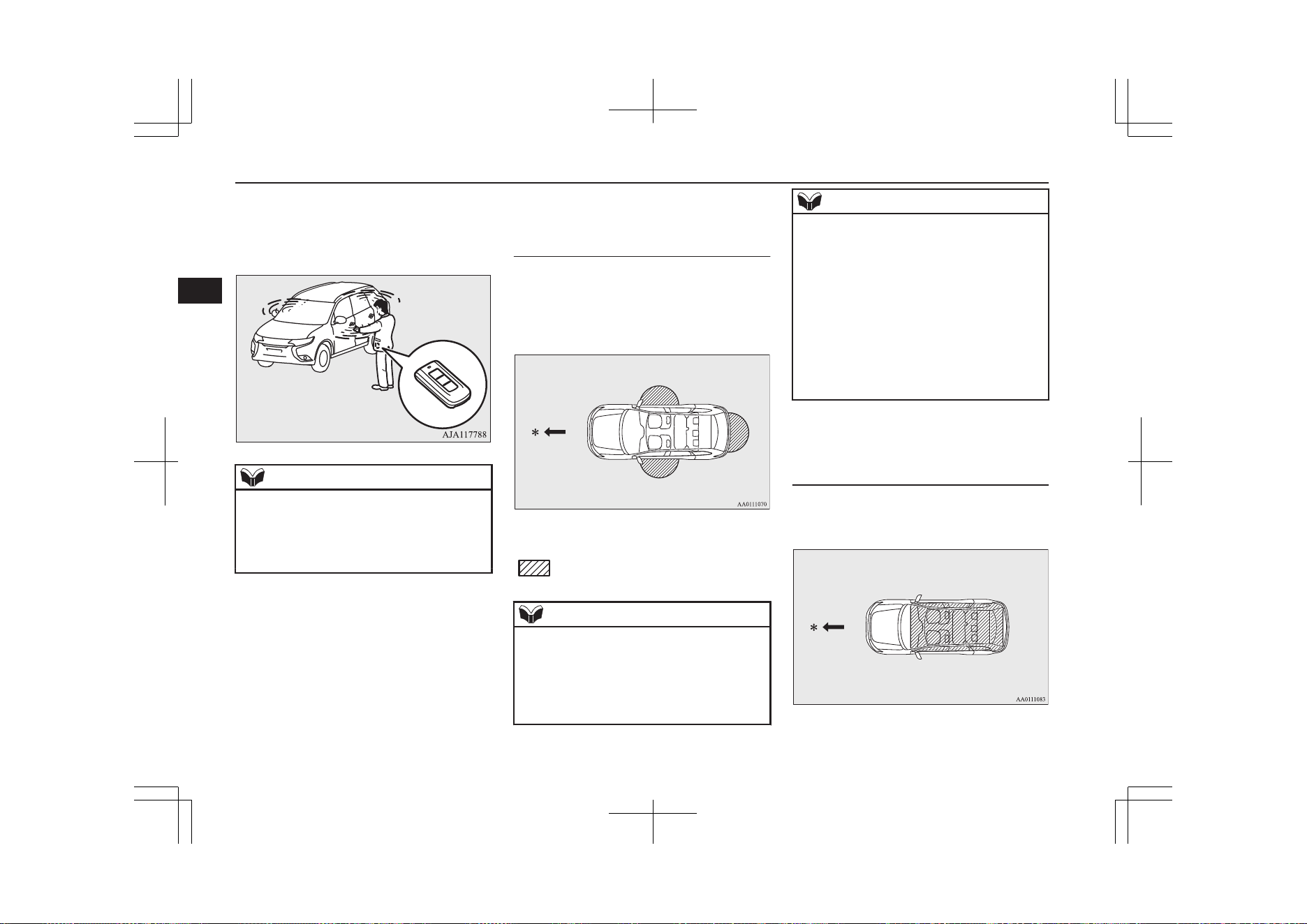
You can lock and unlock the doors and tail-
gate and start the Plug-in Hybrid EV System
only if the ID codes of your keyless operation
key and the vehicle match.
NOTE
l
If the keyless operation key battery is wear-
ing out or there are strong electromagnetic
waves or noise present, the operating range
may become smaller and operation may be-
come unstable.
Operating range for locking
and unlocking the doors and
tailgate
E00306201858
The operating range is approximately 70 cm
from the driver’s door lock/unlock switch,
front passenger’s door lock/unlock switch,
and tailgate lock/unlock switch.
*: Forward direction
:
Operating range
NOTE
l
Locking and unlocking operate only when
you press a door or tailgate switch that de-
tects the keyless operation key.
l
Operation may not be possible if you are too
close to the front door, door window, or tail-
gate.
NOTE
l
Even if the keyless operation key is within
70 cm of the driver’s door lock/unlock
switch, front passenger’s door lock/unlock
switch, or tailgate lock/unlock switch, if the
key is near to the ground or high up, the sys-
tem may not operate.
l
If the keyless operation key is within the op-
erating range, even someone not carrying the
key can lock and unlock the doors and tail-
gate by pressing the driver’s or front pas-
senger’s door lock/unlock switch, the tail-
gate lock switch or the tailgate open switch.
Operating range for starting the
Plug-in Hybrid EV System and
changing the operation mode
E00306301530
The operating range is the interior of the ve-
hicle.
Keyless operation system
4-08
OGGE19E1
Locking and unlocking
4
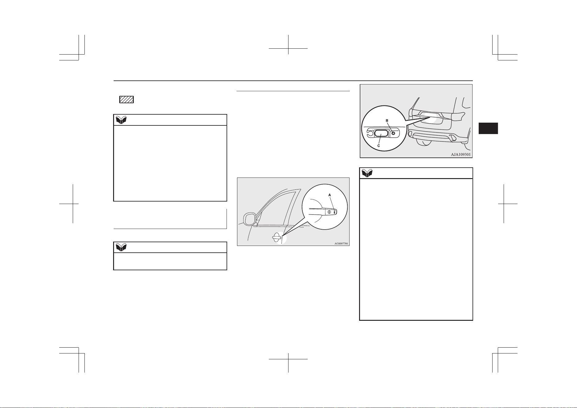
*: Forward direction
:
Operating range
NOTE
l
Even if it is within the operating range, if the
keyless operation key is in a small item
holder such as the glove box, on top of the
instrument panel, door pocket or in the lug-
gage area, it may be impossible to start the
Plug-in Hybrid EV System.
l
If a keyless operation key is too close to the
door or door window, it may be possible to
start the Plug-in Hybrid EV System or
change the operation mode even when the
key is outside the vehicles.
To operate using the keyless
operation function
E00305802870
NOTE
l
The charging lid is also locked/unlocked,
when the driver’s door is locked/unlocked.
Locking the doors and tailgate
When you are carrying the keyless operation
key, if you press the driver’s or front pas-
senger’s door lock/unlock switch (A), or the
tailgate LOCK switch (B) within the operat-
ing range, the doors and the tailgate are
locked.
The turn-signal lamps will blink once.
Also refer to “Locking and unlocking: Doors,
Central door locks, Tailgate” on pages 4-14,
4-16 and 4-19.
Driver’s or front passenger’s door
lock/unlock switches
Tailgate switches
NOTE
l
For vehicles equipped with the mirror retrac-
tor switch, the outside rear-view mirrors au-
tomatically retract when all the doors and
tailgate are locked using the keyless opera-
tion function.
Refer to “Starting and driving: Outside rear-
view mirrors” on page 7-09.
l
The keyless operation function does not op-
erate under the following conditions:
•
The keyless operation key is inside the
vehicle.
•
The operation mode of the power switch
is not in OFF.
•
A door or the tailgate is open or ajar.
l
The tailgate open switch (C) can be used to
check that the vehicle is locked properly.
Press the tailgate open switch within approx-
imately 3 seconds of locking the vehicle. If
you wait longer than 3 seconds and press the
tailgate open switch, the doors and tailgate
will be unlocked.
Keyless operation system
4-09
OGGE19E1
Locking and unlocking
4
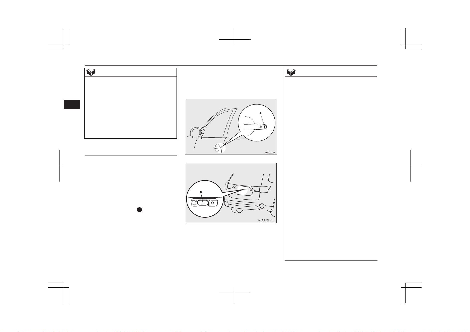
NOTE
l
The time allowed for checking that the vehi-
cle is locked can be adjusted. For further in-
formation, please contact your
MITSUBISHI MOTORS Authorized Serv-
ice Point.
On vehicles equipped with the Smartphone
Link Display Audio or the MITSUBISHI
Multi-Communication System (MMCS),
screen operations can be used to make the
adjustment. Refer to the separate owner’s
manual for details.
Unlocking the doors and tail-
gate
When you are carrying the keyless operation
key, if you press the driver’s or front pas-
senger’s door lock/unlock switch (A), or the
tailgate open switch (B) within the operating
range, all the doors and the tailgate are un-
locked.
If the front room lamp switch is in the
“DOOR” position or the rear room lamp
switch is in the middle (
) position at this
time, the room lamp will turn on for 15 sec-
onds. The turn-signal lamps will blink twice.
If the driver’s or front passenger’s door lock/
unlock switch is pressed and any of the doors
or tailgate is not opened within approximate-
ly 30 seconds, relocking will automatically
occur.
Also refer to “Locking and unlocking: Doors,
Central door locks, Tailgate” on page 4-14,
“Central door locks” on page 4-16 and
“Tailgate*” on page 4-19.
Driver’s and front passenger’s door lock/unlock switches
Tailgate open switch
B
NOTE
l
The outside rear-view mirrors automatically
extend when all the doors and tailgate are
unlocked using the keyless operation func-
tion.
Refer to “Starting and driving: Outside rear-
view mirrors” on page 7-09.
l
The keyless operation function can be set so
that only the driver’s door unlocks when the
driver’s door lock/unlock switch is pressed.
If the keyless operation function is set to
work as described above, all the doors and
the tailgate unlock when the driver’s door
lock/unlock switch is pressed two times in
succession.
Refer to “Setting of door and tailgate unlock
function” on page 4-05.
l
The keyless operation function does not op-
erate when the operation mode of the power
switch is not in OFF.
l
In order to make it possible to check that the
doors and tailgate are locked, you cannot un-
lock them by using the tailgate open switch
for 3 seconds after locking them.
l
The time allowed for checking that the vehi-
cle is locked can be adjusted. For further in-
formation, please contact your
MITSUBISHI MOTORS Authorized Serv-
ice Point.
On vehicles equipped with the Smartphone
Link Display Audio or the MITSUBISHI
Multi-Communication System (MMCS),
screen operations can be used to make the
adjustment. Refer to the separate owner’s
manual for details.
Keyless operation system
4-10
OGGE19E1
Locking and unlocking
4
NOTE
l
The time between unlocking and automatic
locking can be adjusted. Please consult a
MITSUBISHI MOTORS Authorized Serv-
ice Point.
On vehicles equipped with the Smartphone
Link Display Audio or the MITSUBISHI
Multi-Communication System (MMCS),
screen operations can be used to make the
adjustment. Refer to the separate owner’s
manual for details.
Operation confirmation when locking and
unlocking
Operation can be confirmed as shown below.
However, the room lamp will only illuminate
if the front room lamp switch is in the
“DOOR” position or the rear room lamp
switch is in the middle (•) position.
When locking: The turn-signal
lamps will blink
once.
When unlocking: The room lamp illu-
minates for approxi-
mately 15 seconds,
the turn-signal lamps
blink twice.
NOTE
l
Functions can be modified as stated below.
For further information, please contact your
MITSUBISHI MOTORS Authorized Serv-
ice Point.
On vehicles equipped with the Smartphone
Link Display Audio or the MITSUBISHI
Multi-Communication System (MMCS),
screen operations can be used to make the
adjustment. Refer to the separate owner’s
manual for details.
•
Set the confirmation function (blinking of
the turn-signal lamps) to operate only
when the vehicle is locked or only when
the vehicle is unlocked.
•
Disable the operation confirmation func-
tion (blinking of the turn-signal lamps).
•
Change the number of blinks for the oper-
ation confirmation function (blinks of the
turn-signal lamps).
Keyless operation system
4-11
OGGE19E1
Locking and unlocking
4
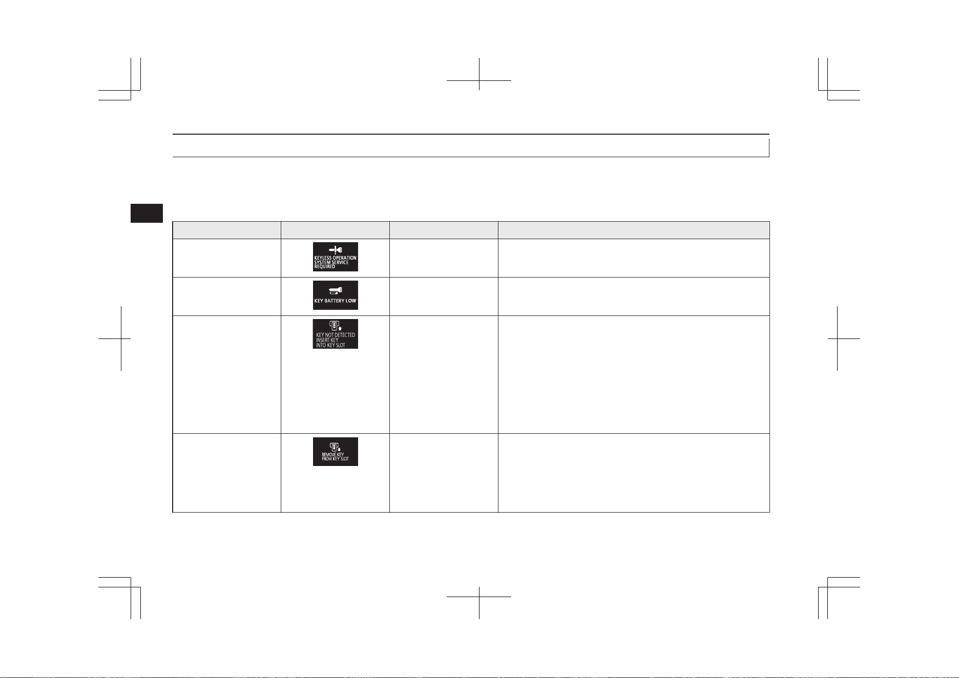
Warning activation
E00305902464
In order to prevent vehicle theft or the accidental operation of the keyless operation system, the buzzer and the display on the information screen
in the multi-information display are used to alert the driver.
If a warning is activated, always check the vehicle and the keyless operation key. The warning is also displayed if there is a fault in the keyless
operation system.
Item Display Buzzer Note (Solution)
Detection of failure Inner buzzer sounds
once.
There is a fault in the keyless operation system.
Fall of battery voltage Inner buzzer sounds
once.
The battery starts to run out, the warning is activated. (The
warning is not activated if the battery is completely dead.)
Key not detected Inner buzzer sounds
once.
When the operation mode of the power switch is put in ACC or
ON from OFF or when the Plug-in Hybrid EV System is started,
the warning is activated, if any of the following conditions is oc-
curred.
l
Carrying another keyless operation key with a different
code, or the keyless operation key could be outside the op-
erating range.
l
The battery of the keyless operation key is dead.
l
Communication is blocked by electric wave environment.
Keyless operation key
reminder
Inner buzzer sounds ap-
proximately 1 minute
Outer buzzer sounds ap-
proximately 3 seconds
intermittently
If the operation mode is in OFF and the driver’s door is opened
with the keyless operation key in the key slot, a warning is is-
sued and the outer buzzer sounds for approximately 3 seconds
and the inner buzzer sounds for approximately 1 minute to re-
mind you to remove the key. If the key removed from key slot,
the buzzer is stopped.
Keyless operation system
4-12
OGGE19E1
Locking and unlocking
4
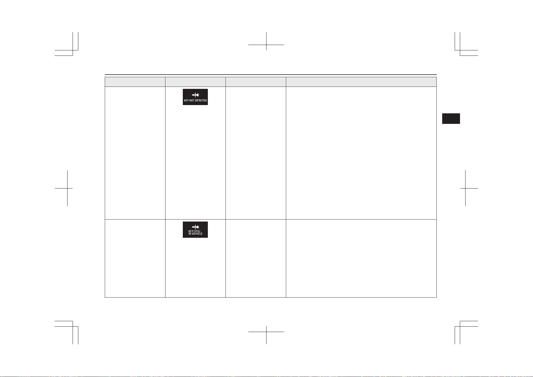
Item Display Buzzer Note (Solution)
Keyless operation key
take-out monitoring sys-
tem
Inner buzzer sounds
once.
Outer buzzer sounds in-
termittently.
l
When the vehicle is parked with the operation mode in any
mode other than OFF, if you close the door after opening
any of the doors and taking the keyless operation key out of
the vehicle, a warning is issued until the key is detected in
the vehicle.
l
If you take the keyless operation key out of the vehicle
through a window without opening a door, the keyless oper-
ation key take-out monitoring system does not operate.
l
It is possible to change the setting to make the keyless oper-
ation key take-out monitoring system operate if you take
the keyless operation key out from the vehicle through a
window without opening a door.
For further information, please contact a MITSUBISHI
MOTORS Authorized Service Point.
l
Even if you have the keyless operation key within the oper-
ating range for starting the Plug-in Hybrid EV System, if
the keyless operation key and vehicle ID codes cannot be
matched, for example due to the ambient environment or
electromagnetic conditions, the warning may be activated.
Key lock-in prevention
system
Inner buzzer sounds
once.
Outer buzzer sounds ap-
proximately 3 seconds
intermittently
l
When the operation mode is in OFF, if you close all the
doors and the tailgate with the keyless operation key left in
the vehicle and you try to lock the doors and tailgate by
pressing the driver’s or front passenger’s door lock/unlock
switch, or the tailgate LOCK switch, a warning is issued
and you cannot lock the doors and tailgate.
l
Make sure you have the keyless operation key with you be-
fore locking the doors. Even if you leave the keyless opera-
tion key inside the vehicle, it is possible that the doors will
lock depending on the surrounding environment and wire-
less signal conditions.
Keyless operation system
4-13
OGGE19E1
Locking and unlocking
4
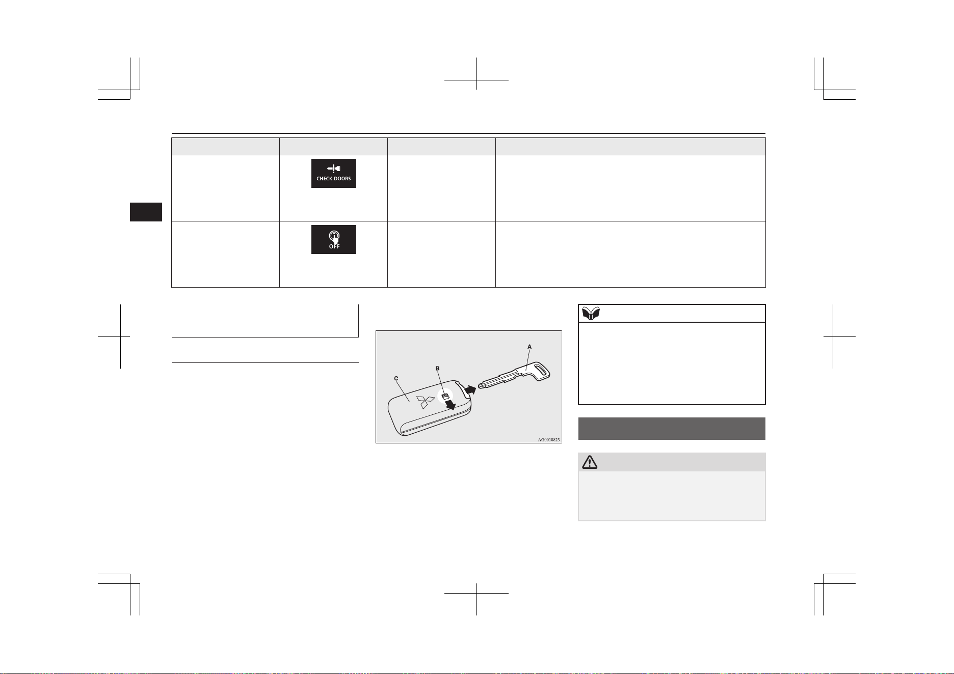
Item Display Buzzer Note (Solution)
Door ajar prevention
system
Inner buzzer sounds
once.
Outer buzzer sounds ap-
proximately 3 seconds
intermittently
When the operation mode in OFF, if you try to lock the doors
and tailgate by pressing the driver’s or front passenger’s door
lock/unlock switch, or the tailgate LOCK switch with one of the
doors or the tailgate not completely closed, a warning is issued
and you cannot lock the doors and tailgate.
Operation mode OFF re-
minder system
Inner buzzer sounds
once.
Outer buzzer sounds ap-
proximately 3 seconds
intermittently
When the operation mode is in any mode other than OFF, if you
try to lock the doors and tailgate by pressing the driver’s or front
passenger’s door lock/unlock switch, or the tailgate LOCK
switch, a warning is issued and you cannot lock the doors and
tailgate.
To operate without using the
keyless operation function
E00306000019
Emergency key
E00307201725
The emergency key is built into the keyless
operation key. If the keyless operation func-
tion cannot be used, for example because the
keyless operation key battery has worn out or
the vehicle battery is flat, you can lock and
unlock the driver’s door with the emergency
key.
To use the emergency key (A), unlock the
lock knob (B) and remove it from the keyless
operation key (C).
Refer to “Doors” on page 4-14.
NOTE
l
Only use the emergency key for emergen-
cies. If the keyless operation key battery
wears out, replace it as quickly as possible
so that you can use the keyless operation
key.
l
After using the emergency key, always re-
turn it into the keyless operation key.
Doors
E00300403719
CAUTION
l
Make sure the doors are closed: driving with
doors not completely closed is dangerous.
l
Never leave children in the vehicle unatten-
ded.
Doors
4-14
OGGE19E1
Locking and unlocking
4
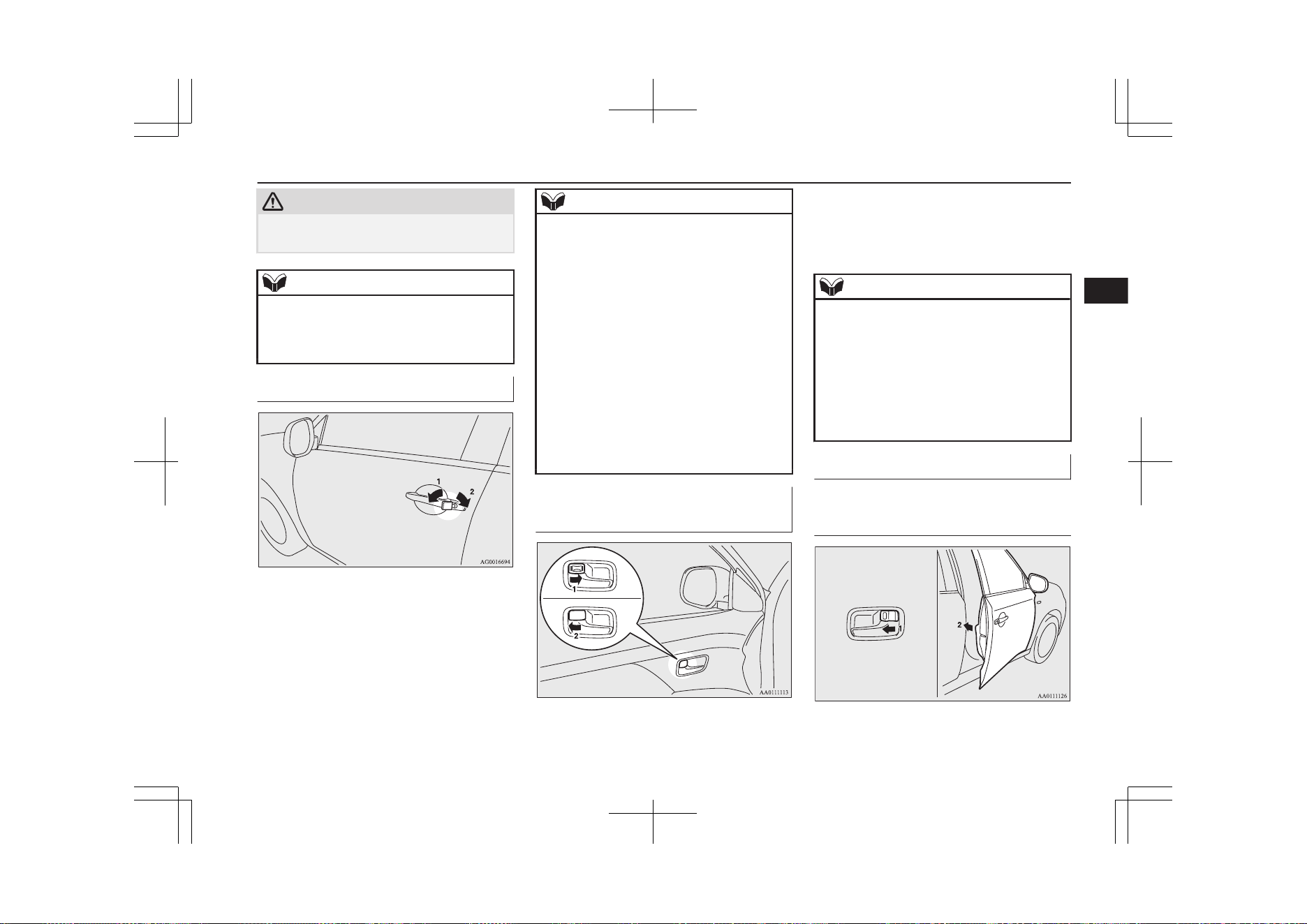
CAUTION
l
Be careful not to lock the doors while the
key is inside the vehicle.
NOTE
l
To prevent the key from being locked inside
the vehicle, neither the lock knob on the
driver’s door nor the key can be used to lock
the driver’s door when it is open.
To lock or unlock with the key
1- Lock
2- Unlock
NOTE
l
When locking or unlocking with the key, on-
ly the driver’s door will be locked or un-
locked.
To lock or unlock all doors, the charging lid
and the tailgate, use the central door lock
switch, the keyless entry system or the key-
less operation function.
Refer to “Central door locks” on page 4-16,
“Keyless entry system” on page 4-03, and
“To operate using the keyless operation
function” on page 4-09.
l
The charging lid can be locked or unlocked
at the same time when the driver’s door is
locked or unlocked using the key.
However, the charging lid cannot be un-
locked while the operation mode of the pow-
er switch is in ON.
To lock or unlock from inside
the vehicle
1- Lock
2- Unlock
Pull the inside door handle towards you to
open the door.
NOTE
l
The driver’s door can be opened without us-
ing the lock knob by pulling on the inside
door handle.
l
The charging lid can be locked or unlocked
at the same time when the driver’s door is
locked or unlocked using the lock knob.
However, the charging lid cannot be un-
locked while the operation mode of the pow-
er switch is in ON.
To lock without using the key
Front passenger’s door, Rear
door
Doors
4-15
OGGE19E1
Locking and unlocking
4
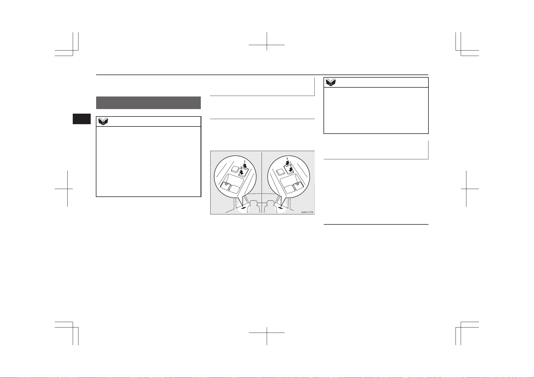
Set the inside lock knob (1) to the locked po-
sition, and close the door (2).
Central door locks
E00300803335
NOTE
l
Repeated continuous operation between lock
and unlock could activate the central door
locking systems built-in protection circuit
and prevent the system from operating. If
this occurs, wait approximately 1 minute be-
fore operating the central door lock switch.
l
When the driver’s door is open, the central
door lock switch cannot be used to lock it.
l
The charging lid is also locked/unlocked,
when the driver’s door is locked/unlocked
using the central door locks.
To lock and unlock the doors
and tailgate
Using the central door lock
switch
Using the central door lock switch on the
driver’s door locks or unlocks all doors and
the tailgate.
LHD RHD
1- Lock
2- Unlock
NOTE
l
The charging lid can be locked or unlocked
at the same time when the driver’s door is
locked or unlocked using the central door
lock switch.
However, the charging lid cannot be un-
locked while the operation mode of the pow-
er switch is in ON.
To unlock the doors and tail-
gate
E00311301336
You can select the function to unlock the
doors and tailgate using the engine switch.
This function is not activated when the vehi-
cle is shipped from the factory. To activate or
deactivate this function, please contact a
MITSUBISHI MOTORS Authorized Service
Point.
Using the power switch
All doors and the tailgate will unlock when-
ever the operation mode is put in OFF.
Central door locks
4-16
OGGE19E1
Locking and unlocking
4
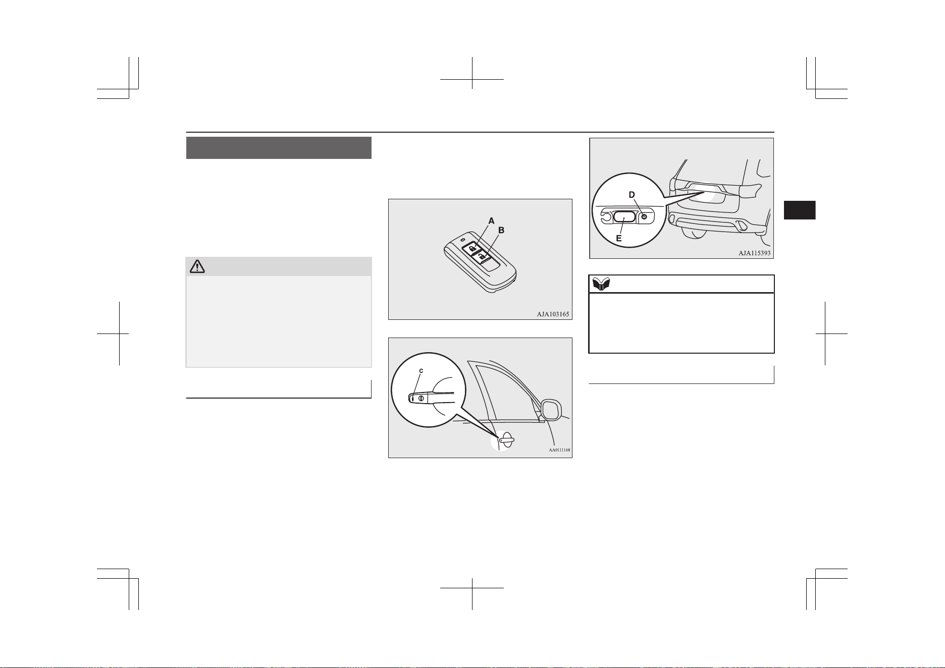
Dead Lock System*
E00305100198
The Dead Lock System helps prevent theft.
When the keyless entry system or the keyless
operation system has been used to lock all of
the doors and the tailgate, the Dead Lock
System makes it impossible to unlock the
doors using the inside lock knobs.
CAUTION
l
Do not set the Dead Lock System when
someone is inside the vehicle. With the Dead
Lock System set, it is not possible to unlock
the doors using the inside lock knobs. If you
erroneously set the Dead Lock System, un-
lock the doors using the UNLOCK switch
on the remote control switch or using the
keyless operation function.
Setting the system
E00305201330
1. Put the operation mode in OFF.
2. Get out of the vehicle. Close all of the
doors and the tailgate.
3. Press the LOCK switch (A) on the re-
mote control switch, the driver’s or front
passenger’s door lock/unlock switch (C),
or the tailgate LOCK switch (D) to lock
all of the doors and the tailgate. The
turn-signal lamps will blink once.
4. Press the switch again within 2 seconds.
The turn-signal lamps will blink three
times to show that the Dead Lock Sys-
tem has been set.
Driver’s and front passenger’s door lock/unlock
switches*
Tailgate switches*
NOTE
l
Pressing the LOCK switch (A) on the re-
mote control switch once while the Dead
Lock System is set causes the turn-signal
lamps to blink three times, so it is possible to
confirm that the Dead Lock System is set.
Cancelling the system
E00305301432
When the following operation is performed,
the doors and tailgate will unlock and the
Dead Lock System will be simultaneously
cancelled.
l
The UNLOCK switch (B) on the remote
control switch is pressed.
l
The drive’s or front passenger’s door
lock/unlock switch (C) or the tailgate
open switch (E) is pressed while you are
carrying the keyless operation key.
Dead Lock System*
4-17
OGGE19E1
Locking and unlocking
4
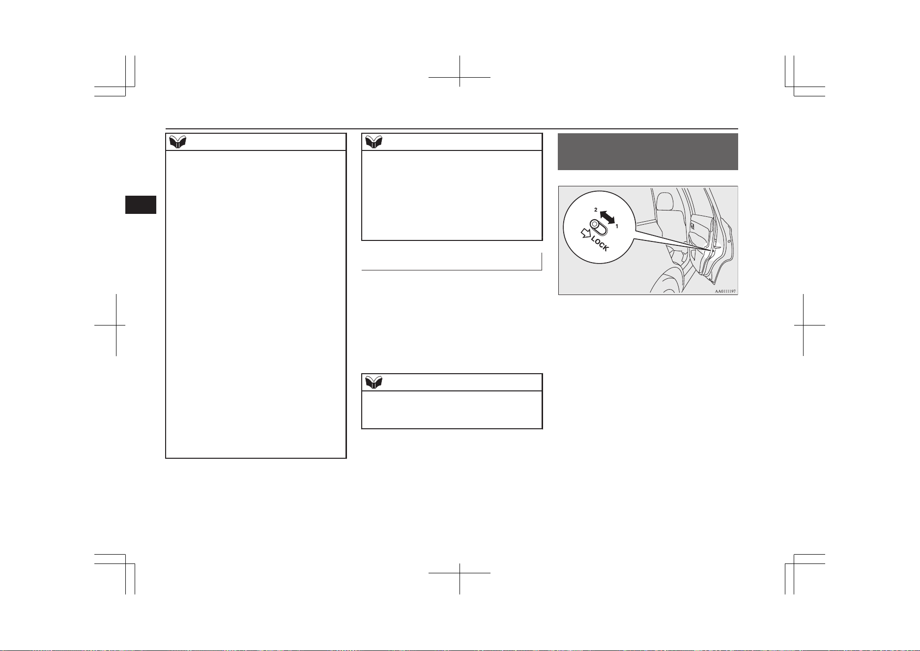
NOTE
l
If neither a door nor the tailgate is opened
within 30 seconds of unlocking (except us-
ing the tailgate open switch), the doors and
tailgate are automatically relocked and the
Dead Lock System is simultaneously set
again.
l
Even when it is not possible to use the key-
less entry system or keyless operation func-
tion to unlock the doors, it is possible to use
the key to unlock the driver’s door. When
the key is used to unlock the driver’s door,
the Dead Lock System is cancelled for only
the driver’s door. If you wish to subsequent-
ly unlock all other doors, turn the ignition
switch to the “ON” or “ACC” position, or
put the operation mode in on or ACC.
l
It is possible to adjust the time between
pressing the UNLOCK switch (B) on the re-
mote control switch or the driver’s or front
passenger’s door lock/unlock switch (C) and
automatic locking. For details, please con-
tact a MITSUBISHI MOTORS Authorized
Service Point.
On vehicles equipped with the Smartphone
Link Display Audio or the MITSUBISHI
Multi-Communication System (MMCS),
screen operations can be used to make the
adjustment. Refer to the separate owner’s
manual for details.
NOTE
l
It is possible to lock the doors and tailgate
and set the Dead Lock System at the same
time with a single push of the LOCK switch
(A) on the remote control switch, the driv-
er’s or front passenger’s door lock/unlock
switch (C), or the tailgate lock switch (D).
For details, please contact a MITSUBISHI
MOTORS Authorized Service Point.
Testing the system
E00305400159
Open all of the door windows, then set the
Dead Lock System.
(Refer to “Setting the system” on page 4-17.)
After setting the Dead Lock System, reach
into the vehicle through a window and con-
firm that you cannot unlock the doors using
the lock knobs.
NOTE
l
If you need advice on how to set the Dead
Lock System, please contact a MITSUBISHI
MOTORS Authorized Service Point.
“Child-protection” rear
doors
E00300901042
1- Lock
2- Unlock
Child protection helps prevent the rear doors
from being opened accidentally from the in-
side.
If the lever is set to the locked position, the
rear door cannot be opened using the inside
handle, but only with the outside handle.
If the lever is set to the “Unlock” position,
the child protection mechanism does not
function.
“Child-protection” rear doors
4-18
OGGE19E1
Locking and unlocking
4
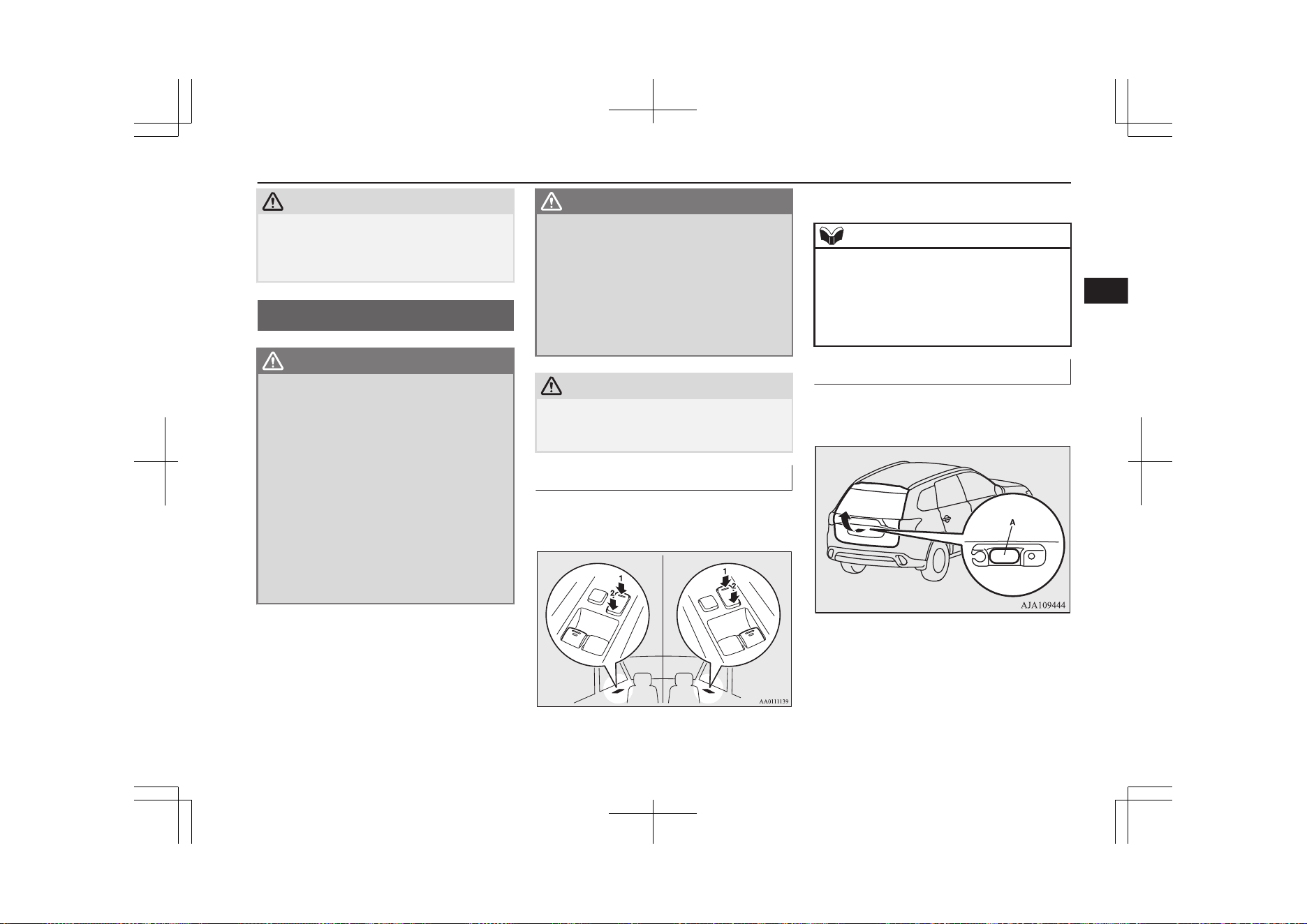
CAUTION
l
When driving with a child in the rear seat,
please use the child protection to prevent ac-
cidental door opening which may cause an
accident.
Tailgate*
E00301402751
WARNING
l
It is dangerous to drive with the tailgate
open, since carbon monoxide (CO) gas
can enter the cabin.
You cannot see or smell CO. It can cause
unconsciousness and even death.
l
When opening and closing the tailgate,
make sure that there are no people nearby
and be careful not to hit your head or
pinch your hands, neck, etc.
l
When there is a build up of snow or ice, it
should be removed before opening the
tailgate. If you open the tailgate without
removing it, there is a possibility that the
tailgate may close suddenly due to the
weight of that snow or ice.
WARNING
l
When you open the tailgate make sure
that the tailgate is opened fully and re-
mains fully open. If you only open the tail-
gate halfway there is a risk that the tail-
gate may drop and slam shut. If you open
the tailgate whilst your vehicle is parked
on an incline it is more difficult to do so
than on the flat and also it may drop and
slam shut.
CAUTION
l
To avoid damage to the tailgate, make sure
the area above and behind the tailgate is
clear before opening it.
To lock/unlock
The tailgate can be locked or unlocked by us-
ing the central door lock switch (driver side).
LHD RHD
1- Lock
2- Unlock
NOTE
l
Repeated continuous operating between lock
and unlock could cause the central door
locks’ built-in protection circuit to prevent
the system from operating. If this occurs,
wait approximately 1 minute before operat-
ing the central door lock switch.
To open
After unlocking the tailgate, push the tailgate
open switch (A) and pull up the tailgate.
Tailgate*
4-19
OGGE19E1
Locking and unlocking
4
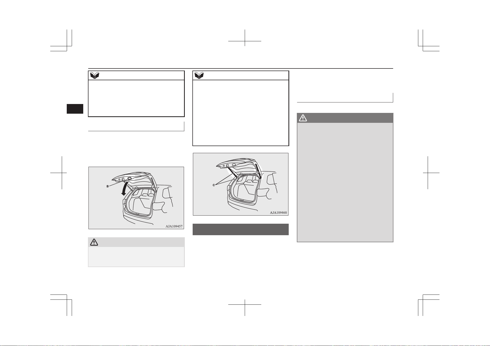
NOTE
l
The tailgate cannot be opened when the aux-
iliary battery is flat or disconnected.
If you want to open the tailgate, it can be
opened by using the inside tailgate release.
Refer to “Inside tailgate release” on page
4-27.
To close
Pull the tailgate grip (B) downward as illus-
trated. Gently shut the tailgate from the out-
side so that it is completely closed. Always
ensure the tailgate is securely closed.
CAUTION
l
When closing the tailgate, always ensure
your or other person’s fingers cannot be
caught by the tailgate.
NOTE
l
Gas struts (C) are installed to support the
tailgate.
To prevent damage or faulty operation.
•
Do not hold the gas struts when closing
the tailgate.
•
Also, do not push or pull the gas struts.
•
Do not attach any plastic material, tape,
etc., to the gas struts.
•
Do not tie string, etc., around the gas
struts.
•
Do not hang any object on the gas struts.
Electric tailgate*
E00312801035
Before operating the electric tailgate, unlock
the tailgate by using the keyless entry system,
keyless operation system, or the central door
locks.
Refer to “Keyless entry system” on page
4-03, “Keyless operation system” on page
4-06, or “Central door locks” on page 4-16.
Operating the electric tailgate
E00312901124
WARNING
l
The luggage area was not designed for
people to ride in it. Do not let your chil-
dren ride in or play in the luggage area.
Riding or playing in the luggage area
could result in a serious accident.
l
Before driving, make sure the electric tail-
gate is securely closed.
If you drive with the tailgate open, there is
a danger of exhaust gas entering the vehi-
cle and causing carbon monoxide poison-
ing.
l
For safety’s sake, the electric tailgate
should be operated by adults and not chil-
dren.
l
When opening and closing the tailgate,
make sure that there are no people nearby
and be careful not to hit your head or
pinch your hands, neck, etc.
Make sure the electric tailgate is com-
pletely open before loading and unloading
luggage.
Electric tailgate*
4-20
OGGE19E1
Locking and unlocking
4
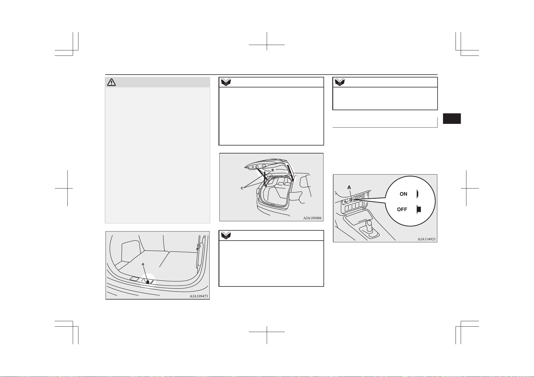
CAUTION
l
Do not stand behind the exhaust pipe when
loading and unloading luggage.
The heat from the exhaust could cause
burns.
l
To avoid damage to the tailgate, make sure
the area above and behind the tailgate is
clear before opening it.
l
Before driving, make sure the electric tail-
gate is closed properly. If the tailgate opens
when driving, luggage could fall onto the
road and cause an accident.
l
Do not install accessories other than
MITSUBISHI MOTORS GENUINE parts
on the electric tailgate. Some accessories
could be too heavy, causing the drop preven-
tion mechanism to operate.
l
When closing the electric tailgate, make sure
there is no foreign matter around the striker
(A).
If foreign matter gets into the striker it could
prevent the electric tailgate from closing
normally.
NOTE
l
When opening and closing the electric tail-
gate, do not place your hands near the arm
(B).
l
Gas struts (C) are installed in the locations
shown below in order to support the electric
tailgate.
l
Make sure not to bump your head in the area
near the arm of the electric tailgate when
loading and unloading luggage.
NOTE
l
Please observe the following in order to pre-
vent damage or faulty operation.
•
Do not pull on the gas struts when closing
the electric tailgate or otherwise push or
pull them.
•
Do not attach any plastic material, tape,
etc., to the gas struts.
NOTE
•
Do not tie string, etc., around the gas
struts.
•
Do not hang anything from the gas struts.
Automatic operation
E00313001177
The electric tailgate can be operated using the
remote control switch on the keyless opera-
tion key, or the close switch on the tailgate
when the electric tailgate power switch (A) is
on.
Electric tailgate*
4-21
OGGE19E1
Locking and unlocking
4
WARNING
l
Turn off the electric tailgate power switch
when not operating the electric tailgate.
If the switch is left on, someone’s hand or
head could get caught if the electric tail-
gate switch or close switch is accidentally
operated, or children play with the con-
trols.
l
If the electric tailgate power switch is
turned off while the tailgate is operating,
it will stop moving and switch to manual
operation.
At this time, the electric tailgate could
open or close suddenly, depending on its
position.
CAUTION
l
Do not apply excessive force on the electric
tailgate when opening or closing it. Doing so
could cause a breakdown.
l
Do not start the Plug-in Hybrid EV System
while the tailgate is operating. The sudden
operation prevention mechanism could oper-
ate, making the electric tailgate stop inter-
mittently while it moves.
NOTE
l
The electric tailgate cannot be opened when
the auxiliary battery is flat or disconnected.
If you want to open the electric tailgate, it
can be opened by using the inside tailgate re-
lease.
Refer to “Inside tailgate release” on page
4-27.
l
If the keyless entry system or close switch is
operated when the electric tailgate power
switch is off, the warning buzzer sounds four
times to notify the driver that the electric
tailgate cannot be operated.
l
The electric tailgate does not operate nor-
mally under the following conditions:
•
When parked on an incline
•
In strong winds
•
When the electric tailgate is covered with
snow
l
Repeated continuous operation between
opening and closing the electric tailgate will
activate the built-in protection circuit and
switch the tailgate to manual operation.
l
If the electric tailgate handle is operated
while the tailgate is operating or immediate-
ly after it is closed, the tailgate will move in
the direction opposite to the one in which it
was operating.
l
If the battery or fuse is replaced while the
electric tailgate is open, it cannot be closed
automatically.
In this case close the electric tailgate man-
ually.
Operating conditions
E00313101224
The electric tailgate can be opened automati-
cally when all of the following conditions are
met.
<Using the keyless operation key>
l
The operation mode is in OFF.
l
The electric tailgate is completely
closed.
l
The electric tailgate is unlocked.
<Using the driver’s side electric tailgate
switch>
l
The operation mode is in ON with the
electrical parking switch is pressed.
l
The electric tailgate is completely
closed.
l
The electric tailgate is unlocked.
The electric tailgate can be closed automati-
cally when all of the following conditions are
met.
<Using the keyless operation key>
l
The operation mode is in OFF.
l
The electric tailgate is completely open.
l
People, luggage, etc., are not touching
the sensors.
<Using the driver’s side electric tailgate
switch or close switch>
l
The operation mode is in ON with the
electrical parking switch is pressed.
Electric tailgate*
4-22
OGGE19E1
Locking and unlocking
4
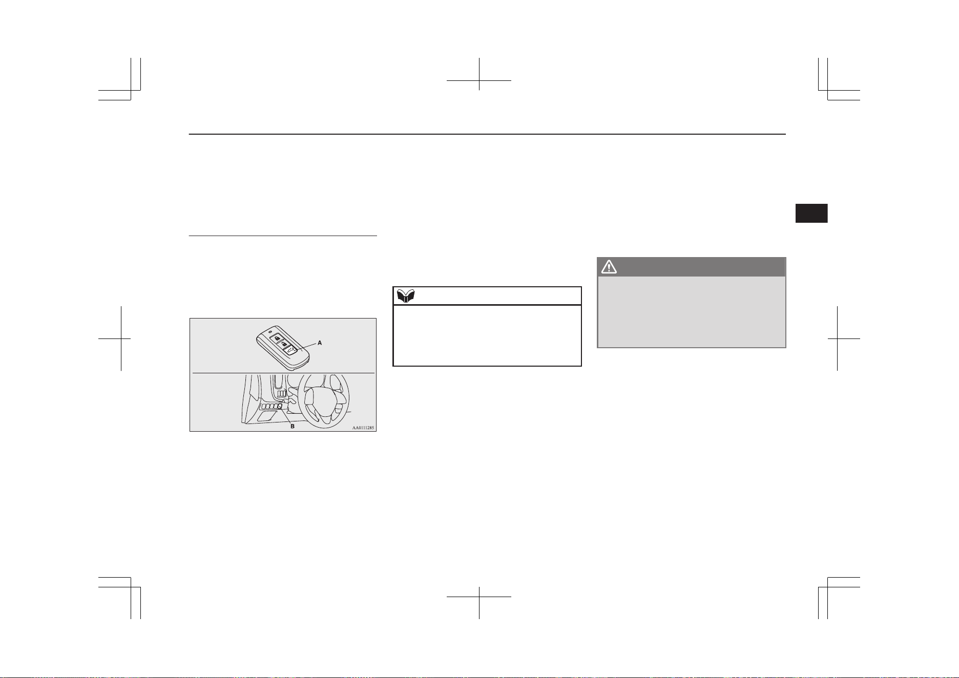
l
The electric tailgate is completely open.
l
People, luggage, etc., are not touching
the sensors.
Operating the electric tailgate
using the keyless operation key
or the driver’s side electric tail-
gate switch
After unlocking the doors and the electric
tailgate, the electric tailgate can be operated
by pressing the switch (A) of the keyless op-
eration key or the driver’s side electric tail-
gate switch (B).
<Using the keyless operation key>
If the electric tailgate switch is pressed twice
in a row, the electric tailgate operates after
the warning buzzer sounds and the hazard
warning flasher blinks.
The electric tailgate operates as follows:
•While
closed:
The warning buzzer sounds
and the tailgate completely
opens.
•While
open:
The warning buzzer sounds
and the tailgate completely
closes.
If the electric tailgate switch is pressed once
while the tailgate is operating, the warning
buzzer sounds and it moves in the direction
opposite to the one in which it was operating.
NOTE
l
If the electric tailgate switch is pressed three
or more times in a row, the tailgate may not
operate normally.
If this occurs, wait a short time before again
pressing the electric tailgate switch twice.
<Using the driver’s side electric tailgate
switch>
If the driver’s side electric tailgate switch is
pressed for more than approximately 1 sec-
ond, the electric tailgate operates after the
buzzer sounds and the hazard warning flasher
blinks.
The electric tailgate operates as follows.
•While
closed:
The warning buzzer sounds
and the tailgate completely
opens.
•While
open:
The warning buzzer sounds
and the tailgate completely
closes.
If the driver’s side electric tailgate switch is
pressed once while the tailgate is operating,
the warning buzzer sounds and it moves in
the direction opposite to the one in which it
was operating.
WARNING
l
When operating the electric tailgate, en-
sure the safety of the surrounding area,
make sure there is sufficient space behind
and above the vehicle, and be careful not
to bump your head or catch your hands
or fingers.
Electric tailgate*
4-23
OGGE19E1
Locking and unlocking
4
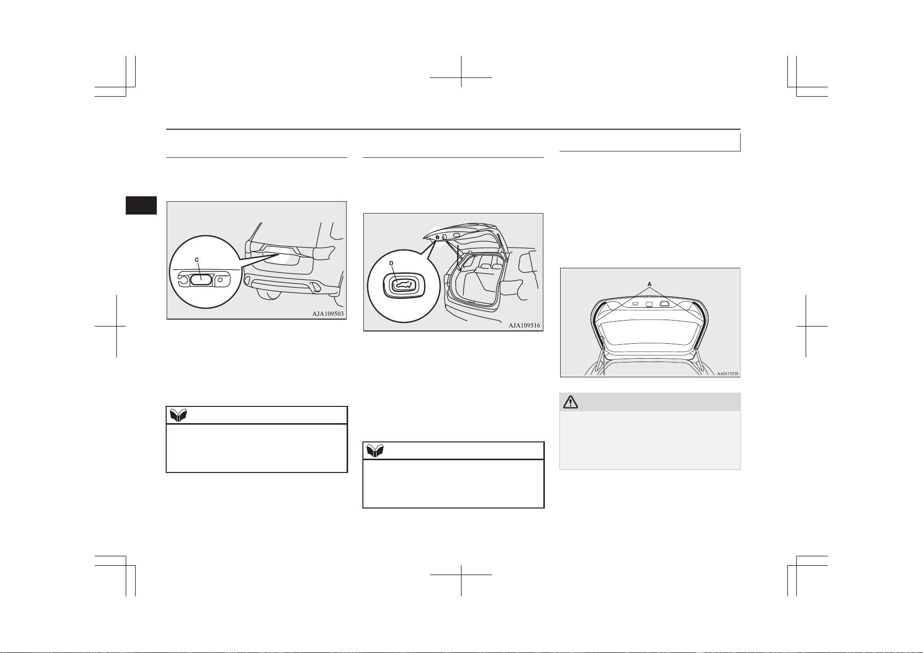
Opening the electric tailgate us-
ing the open switch
The electric tailgate can be opened by press-
ing the open switch (C).
If the open switch is pressed with the tailgate
and all doors are unlocked, the electric tail-
gate opens after the warning buzzer sounds.
When the tailgate and all doors are locked,
the warning buzzer will not sound.
NOTE
l
When the keyless operation key is within the
operation range, the electric tailgate can be
opened by pressing the open switch even if
the tailgate is locked.
Closing the electric tailgate us-
ing the close switch
The electric tailgate can be closed by press-
ing the close switch (D) on the inside of the
electric tailgate.
If the close switch on the inside of the elec-
tric tailgate is pressed, the electric tailgate
closes after the warning buzzer sounds and
the hazard warning flasher blinks.
If the close switch is pressed once while the
tailgate is closing, the warning buzzer sounds
and the electric tailgate opens.
NOTE
l
If the close switch is again pressed once
while the electric tailgate is operating in the
opening direction, the warning buzzer
sounds once and the electric tailgate closes.
Safety mechanism
E00313201036
The safety mechanism is activated if the elec-
tric tailgate should trap a person or an object
during automatic operation, or if the sensors
(A) on either side of the electric tailgate are
hit. The warning buzzer sounds once for safe-
ty and the electric tailgate automatically
moves in the direction opposite to the one in
which it was operating.
CAUTION
l
The safety mechanism will sometimes not
operate depending on the condition of the
trapped object or how it is trapped. There-
fore, be especially careful not to trap a hand,
part of your body or an object at this time.
Electric tailgate*
4-24
OGGE19E1
Locking and unlocking
4
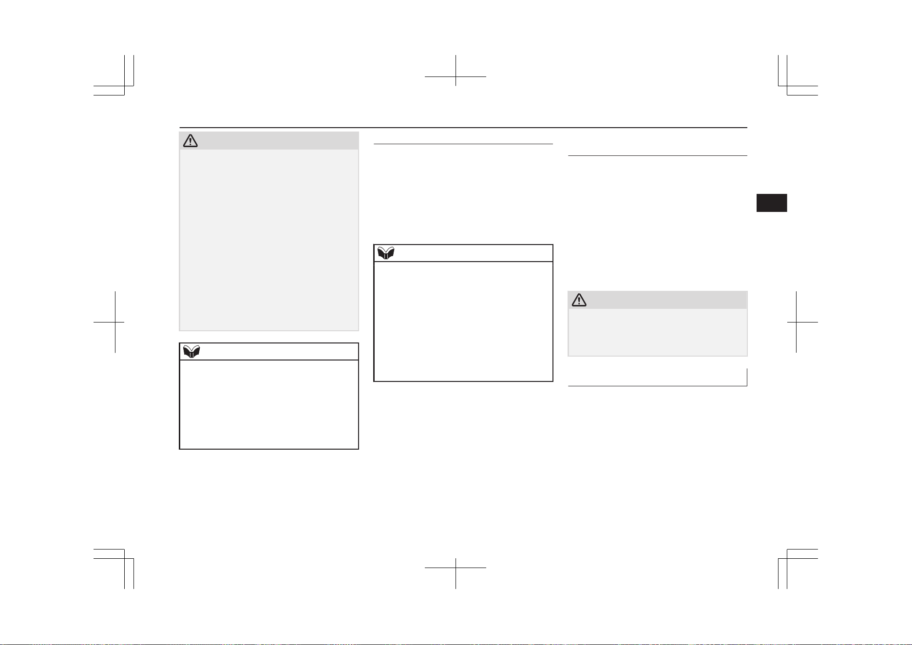
CAUTION
l
The safety mechanism is cancelled just be-
fore the electric tailgate is fully closed to al-
low it to close completely. Therefore be es-
pecially careful not to trap a hand or finger
at this time.
l
The safety mechanism is deactivated when
the electric tailgate is closed manually.
Therefore be especially careful not to trap a
hand or finger at this time.
l
If the safety mechanism is repeatedly operat-
ed, the tailgate could be switched to manual
operation. Be careful at this time, as the
electric tailgate could open or close sudden-
ly, depending on its position.
Once the electric tailgate is completely open
or closed, normal automatic operation is
again possible.
NOTE
l
If the environment or usage conditions sub-
ject the sensors to the same kind of force as
that of trapping a person or object, the safety
mechanism could be activated.
l
Do not damage the sensors when loading or
unloading luggage, or when cleaning the
rear window. Doing so could prevent the
tailgate from closing automatically.
Drop prevention mechanism
After the electric tailgate is opened automati-
cally, if it is detected that the tailgate is drop-
ping due to factors such as accumulated
snow, the electric tailgate is closed automati-
cally.
A warning buzzer sounds continuously while
the drop prevention mechanism operates.
NOTE
l
If snow has accumulated on the electric tail-
gate, remove it before operation.
l
Do not install accessories other than
MITSUBISHI MOTORS GENUINE parts
on the electric tailgate. Some accessories
could be too heavy, causing the drop preven-
tion mechanism to operate.
l
The drop prevention mechanism could be
activated if manual operation is attempted
immediately after the electric tailgate is
completely opened automatically.
Sudden operation prevention
mechanism
If the Plug-in Hybrid EV System is started
while the electric tailgate is operating auto-
matically, it may switch to manual operation
due to insufficient auxiliary battery voltage,
making the electric tailgate stop intermittent-
ly while it moves. This is to stop the electric
tailgate from operating suddenly. When the
tailgate is completely closed or opened, auto-
matic operation is again possible after ap-
proximately 10 seconds.
CAUTION
l
The safety mechanism is deactivated while
the sudden operation prevention mechanism
is operating. Therefore be especially careful
not to trap a hand or finger at this time.
Manual operation
E00313401083
If the electric tailgate power switch is off, the
electric tailgate can be operated by manual
operation.
Electric tailgate*
4-25
OGGE19E1
Locking and unlocking
4
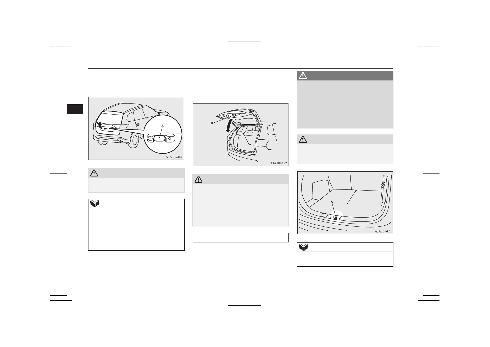
After unlocking the electric tailgate, push the
tailgate open switch (A) and pull up the tail-
gate.
CAUTION
l
Make sure there is no one around the electric
tailgate when opening it.
NOTE
l
If it does not open immediately after pushing
the tailgate open switch, the electric tailgate
cannot be lifted.
If this occurs, push the tailgate open switch
again and pull up the electric tailgate.
l
The electric tailgate cannot be opened when
the auxiliary battery is flat or disconnected.
To close the tailgate, pull the tailgate grip (B)
downward and release it before the tailgate is
completely closed, and then gently slam the
electric tailgate from the outside.
CAUTION
l
Do not fully close the electric tailgate with
your hand still on the tailgate grip. Doing so
could trap and injure your hand or arm.
l
The safety mechanism is deactivated when
the electric tailgate is closed manually.
Therefore be especially careful not to trap a
hand or finger at this time.
Tailgate easy closer
E00313300069
The tailgate easy closer is a mechanism for
assisting the closing of the electric tailgate.
If the electric tailgate is closed to a position
where it is detected as being ajar, it closes au-
tomatically.
WARNING
l
Be careful not to catch your hands or fin-
gers when the electric tailgate closes auto-
matically from the door ajar position. If
you think your hands or fingers could be
caught during the operation of the tailgate
easy closer, pull the handle of the electric
tailgate. The electric tailgate will return to
the door ajar position.
CAUTION
l
Do not touch the latch (A) on the inside of
the electric tailgate. The tailgate easy closer
could operate and catch your fingers.
NOTE
l
The tailgate easy closer operates even when
the electric tailgate power switch is OFF.
Electric tailgate*
4-26
OGGE19E1
Locking and unlocking
4
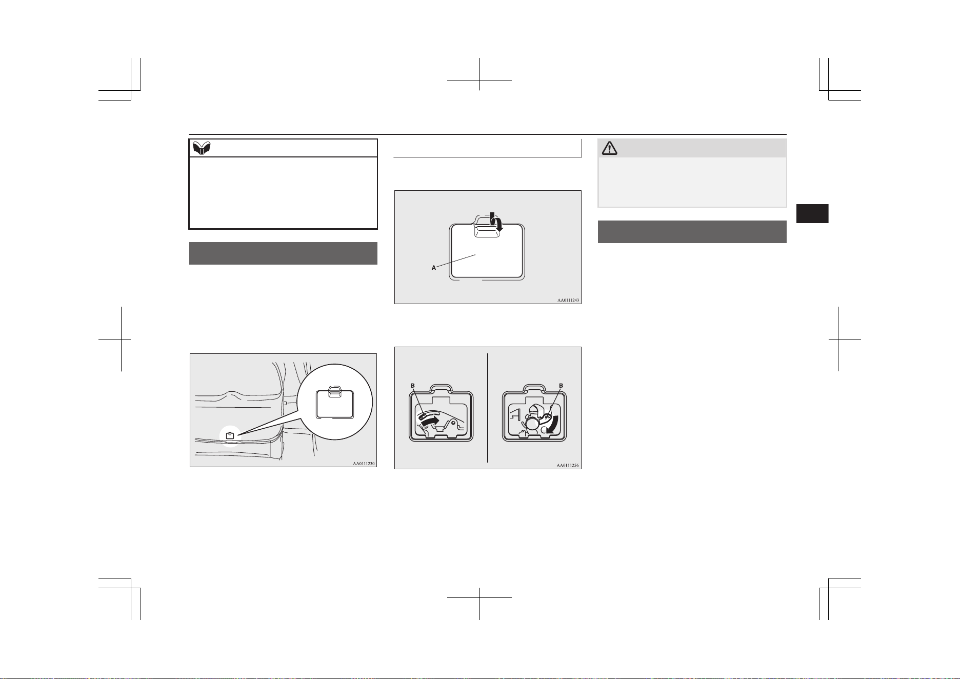
NOTE
l
Repeated continuous operation of the handle
could activate the protection circuit and tem-
porarily prevent the tailgate easy closer from
operating.
If this occurs, wait about 1 minute before
operating the tailgate easy closer again.
Inside tailgate release
E00303401370
The inside tailgate release is designed to pro-
vide a way to open the tailgate in the case of
a discharged auxiliary battery.
The tailgate release (see illustration) is moun-
ted on the tailgate.
You and your family should familiarise your-
selves with the location and operation of the
tailgate release.
To open
1. Open the lid (A) inside of the tailgate.
2. Move the lever (B) to open the tailgate.
Vehicles without
electric tailgate
Vehicles with
electrictailgate
3. Push out on the tailgate to open it.
CAUTION
l
Always keep the release lever lid on the tail-
gate closed when driving so that your lug-
gage cannot accidentally bump against the
lever and open the tailgate.
Security alarm system*
E00301502172
The security alarm system is for alerting the
surrounding area of suspicious behaviour to
prevent unlawful entry into the vehicle by op-
erating an alarm if a door, the tailgate or the
bonnet is opened when the vehicle has not
been unlocked using the keyless entry system
or the keyless operation function.
Also, for vehicles equipped with the interior
alarm sensor, the alarm will be activated if
any of the following occurs:
l
attempt to an unlawful moving of the ve-
hicle (the vehicle inclination detection
function)
l
detection of a motion in the vehicle (the
interior intrusion detection function)
l
disconnection of the battery terminal
The security alarm system is set to “active”.
When making changes to the settings, please
follow the procedure listed in the section ti-
tled “Changing the security alarm settings”
on page 4-30.
Inside tailgate release
4-27
OGGE19E1
Locking and unlocking
4
On vehicles equipped with the Smartphone
Link Display Audio or the MITSUBISHI
Multi-Communication System (MMCS),
screen operations can be used to make the ad-
justment. Refer to the separate owner’s man-
ual for details.
CAUTION
l
Do not modify or add parts to the security
alarm system.
Doing so could cause the security alarm to
malfunction.
NOTE
l
The alarm system will not be activated if the
doors and the tailgate have been locked us-
ing a key, the inside lock knob or the central
door lock switch (instead of the keyless en-
try system or the keyless operation func-
tion).
NOTE
l
For vehicles equipped with the interior alarm
sensor, if the turn-signal lamps do not blink
after the locking and unlocking operation us-
ing the keyless entry system or the keyless
operation function, the security alarm system
may be malfunctioning.
Have the vehicle inspected at a
MITSUBISHI MOTORS Authorized Serv-
ice Point.
If the confirmation function (blinking of the
turn-signal lamps by locking and unlocking
the doors and the tailgate) is deactivated, the
turn-signal lamps do not blink after the lock-
ing and unlocking operation.
For information on the confirmation func-
tion, refer to “Keyless entry system” on page
4-03 and “To operate using the keyless oper-
ation function” on page 4-09.
l
For vehicles equipped with the interior alarm
sensor, the security alarm system could be
activated in the following situations.
•
Using a car wash
•
Taking the vehicle on a ferry
•
Parking in an automated car park
•
Leaving someone or a pet in the vehicle
•
Leaving a window or the sunroof open
•
Leaving an unstable object such as a stuf-
fed toy or accessory in the vehicle
•
Suffering a continuous impact or vibra-
tion by hail, thunder, etc.
NOTE
•
Air flows by the Remote Climate Control.
According to the situations, please deacti-
vate the vehicle inclination detection
function and the interior intrusion detec-
tion function.
Refer to “To deactivate the vehicle incli-
nation detection function and the interior
intrusion detection function” on page
4-32.
l
For vehicles equipped with the interior alarm
sensor, the sensitivity of the interior intru-
sion detection function can be adjusted. For
details, please contact a MITSUBISHI
MOTORS Authorized Service Point.
Security alarm system*
4-28
OGGE19E1
Locking and unlocking
4
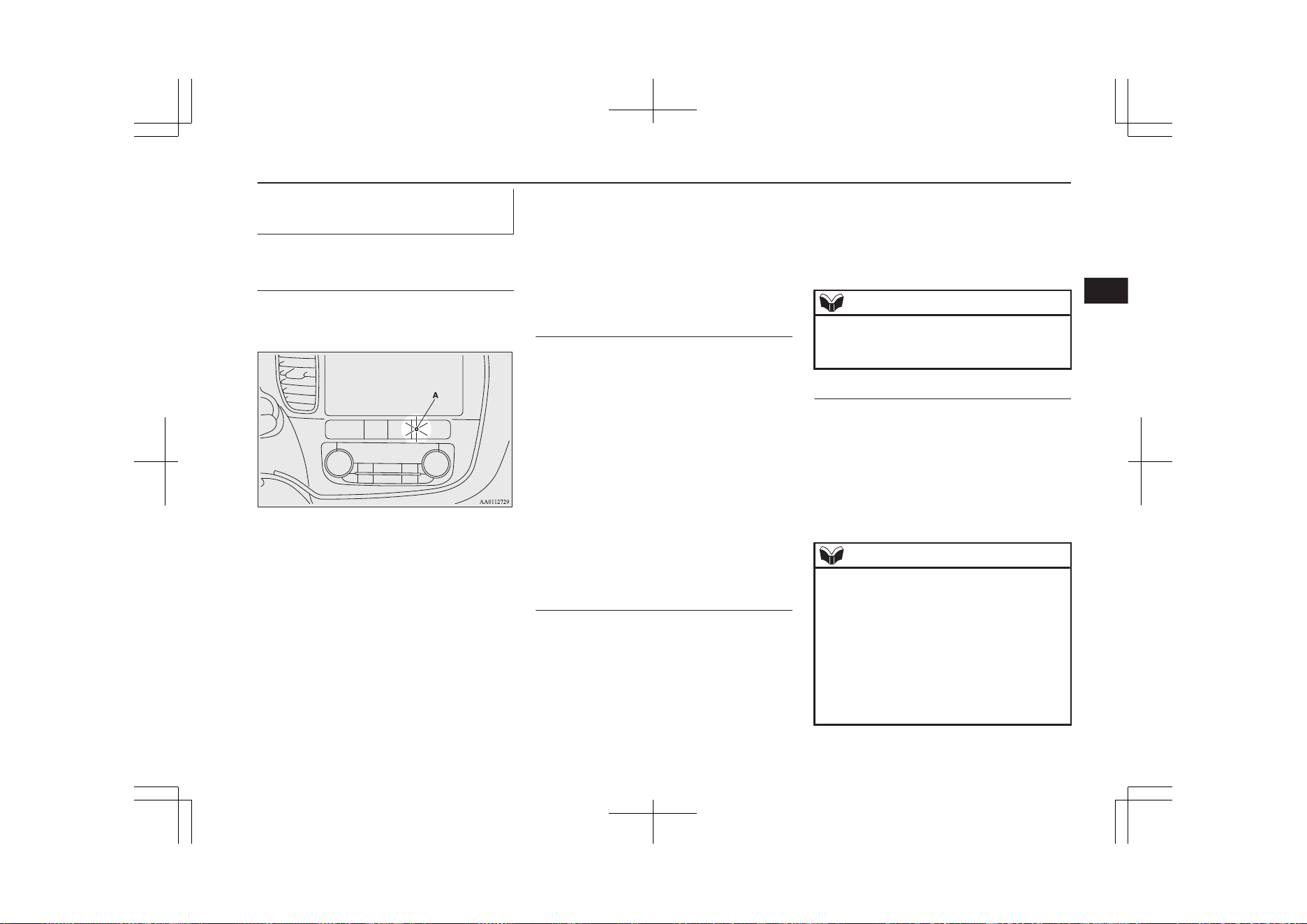
The security alarm has four
modes:
System preparation mode (ap-
proximately 20 seconds)
(The buzzer sounds intermittently and the se-
curity indicator (A) blinks.)
The system preparation time extends from
the point at which all of the doors and the
tailgate are locked by pressing the LOCK
switch on the remote control switch or the
keyless operation function to the point at
which the system armed mode goes into ef-
fect.
During this time, it is possible to temporarily
open a door or the tailgate without using the
keyless entry system or the keyless operation
function and without causing the alarm to
sound (for example, when you forget some-
thing inside the vehicle or realize that a win-
dow is open).
System armed mode
(The buzzer stops and the security indicator
continues to blink with the indicator’s re-
duced lit-up duration time.)
Once the system preparation mode has ended,
the system armed mode starts.
If an unlawful opening of any of the doors,
tailgate or bonnet is detected during the sys-
tem armed mode, the alarm will be activated
to warn people around the vehicle of an ab-
normal condition.
Also, for vehicles equipped with the interior
alarm sensor, if unlawful moving of the vehi-
cle is attempted or a vehicle intrusion is de-
tected, the alarm will be activated.
Alarm activation
Inside alarm (approximately 10 seconds):
The buzzer sounds, warning those inside the
vehicle of an abnormal condition.
(except for vehicles equipped with the interi-
or alarm sensor)
Outside alarm (approximately 30 seconds):
The turn-signal lamps blink and the horn (the
siren for vehicles equipped with the interior
alarm sensor) sounds, warning people around
the vehicle of an abnormal condition.
Refer to “Alarm activation” on page 4-33.
NOTE
l
The alarm will resume if unlawful actions
are taken again, even if the alarm has stop-
ped.
System cancellation
It is possible to cancel the system activation
during the system preparation mode or the
system armed mode.
In addition, it is possible to cancel the alarm
once it has been activated.
Refer to “Cancelling the system” on page
4-32, “Cancelling the alarm” on page 4-34.
NOTE
l
When lending the vehicle to another person
or allowing the vehicle to be driven by
someone who is unfamiliar with the security
alarm system, be sure to give the person a
proper explanation of the security alarm sys-
tem.
If a person who is unfamiliar with the securi-
ty alarm system accidentally unlocked the
vehicle, causing the alarm to sound, the
alarm would be a nuisance to people nearby.
Security alarm system*
4-29
OGGE19E1
Locking and unlocking
4
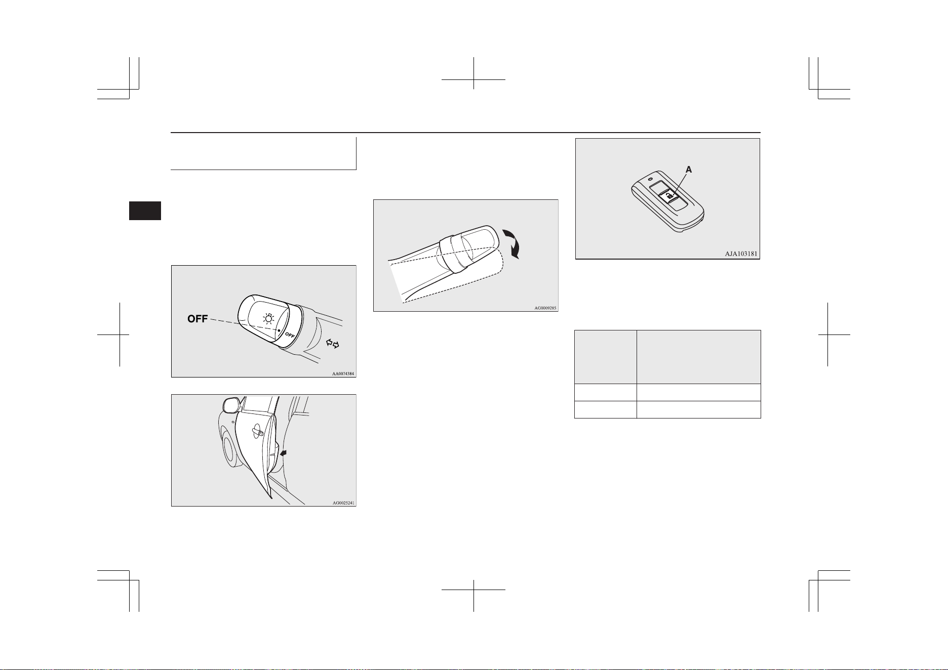
Changing the security alarm
settings
E00301601365
It is possible to set the security alarm to the
“active” mode or “inactive” mode.
Follow the procedure below.
1. Put the operation mode in OFF.
2. Place the lamp switch in the “OFF” posi-
tion, and leave the driver’s door open.
3. Pull the windscreen wiper and washer
switch towards you and hold it there.
(Since the operation mode in OFF, wash-
er fluid will not be sprayed.)
4. After approximately 10 seconds, the
buzzer will make a sound. Keep the
windscreen wiper and washer switch
pulled towards you. (If the windscreen
wiper and washer switch was released,
the setting change mode would be can-
celled. To start over, perform the proce-
dure again from step 3.)
5. When the buzzer stops, with the wind-
screen wiper and washer switch still
pulled towards you, press the UNLOCK
switch (A) on the remote control switch
to select the security alarm settings
mode.
The settings mode can be toggled by
pressing the UNLOCK switch. The
mode can be confirmed from the number
of times the buzzer sounds.
Number of
times the
buzzer
sounds
Security alarm settings
mode
1 Alarm inactive
2 Alarm active
6. Any of the following operations can be
used to terminate the system settings
change mode.
• Releasing the windscreen wiper and
washer switch.
• Closing the driver’s door.
• Put the operation mode in ON or
ACC.
Security alarm system*
4-30
OGGE19E1
Locking and unlocking
4
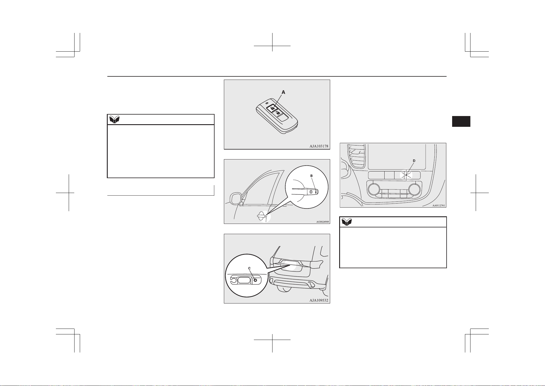
• Placing the lamp switch in any posi-
tion other than “OFF”.
• Allowing 30 seconds to pass without
making any changes to the settings.
NOTE
l
If anything with regard to making changes to
the security alarm system settings is hard to
understand, please consult your
MITSUBISHI MOTORS Authorized Serv-
ice Point.
l
Avoid leaving valuable items inside the ve-
hicle even when the security alarm system
has been set to the “active” mode.
Setting the system
E00301702190
Follow the procedure below to set the system
to the system armed mode.
1. Put the operation mode in OFF.
2. Exit the vehicle and close all of the
doors, tailgate and bonnet.
3. Press the LOCK switch (A) on the re-
mote control switch of the keyless oper-
ation key, the driver’s or front passeng-
er’s door lock/unlock switch (B), or the
tailgate LOCK switch (C) in order to
lock all the doors and the tailgate.
Driver’s and front passenger’s door look/unlock switches*
Tailgate LOCK switch*
By locking the vehicle using the keyless
entry system or the keyless operation
function, the system preparation mode is
activated.
The buzzer makes an intermittent beep-
ing sound and the security indicator (D)
in the centre panel flashes for confirma-
tion.
NOTE
l
The system preparation mode is not activa-
ted when the doors and the tailgate have
been locked using a method other than the
keyless entry system or the keyless operation
function (namely a key, the inside lock knob
or the central door lock switch).
Security alarm system*
4-31
OGGE19E1
Locking and unlocking
4
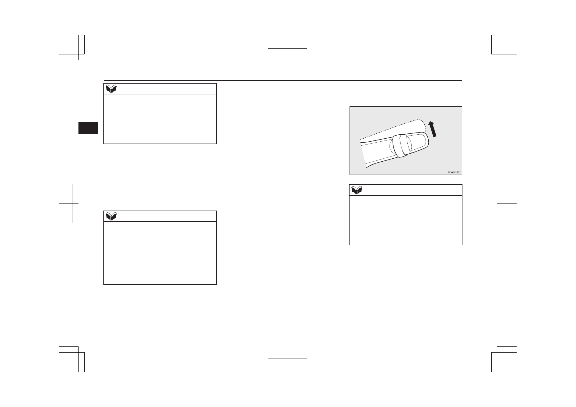
NOTE
l
If the bonnet is open, the security indicator
illuminates, and the system does not enter
the system preparation mode.
When the bonnet is closed, the system enters
the system preparation mode, and after ap-
proximately 20 seconds the system enters
the system armed mode.
4. After approximately 20 seconds, the
buzzer stops, and when the blinking of
the security indicator starts to slow
down, the system armed mode goes into
effect.
The security indicator continues to blink
during the system armed mode.
NOTE
l
The security alarm system can be activated
when people are riding inside the vehicle or
when the windows are open. To prevent ac-
cidental activation of the alarm, do not set
the system to the system armed mode while
people are riding in the vehicle.
l
Avoid leaving valuable items inside the ve-
hicle even when the security alarm system
has been set to the “active” mode.
To deactivate the vehicle incli-
nation detection function and
the interior intrusion detection
function*
E00312101533
The vehicle inclination detection function
and the interior intrusion detection function
can be deactivated when parking in automa-
ted car parks, when leaving pets in the vehi-
cle or when leaving the vehicle with the win-
dows slightly open.
1. Put the operation mode in OFF.
2. Raise and hold the wiper and washer
switch to the “MIST” position for ap-
proximately 3 seconds. The buzzer will
sound twice and the function will be de-
activated.
To activate the function again, raise and hold
the wiper and washer switch to the “MIST”
position for approximately 3 seconds.
The buzzer will sound once and the function
will be activated.
NOTE
l
The function will be activated again if the
following operation is performed.
•
If the doors and the tailgate are unlocked
using the keyless entry system or the key-
less operation function.
•
If the operation mode is put in ON or
ACC.
Cancelling the system
E00301802234
The following methods can be used to cancel
the system when it is in the system prepara-
tion mode or the system armed mode.
l
Pressing the UNLOCK switch on the re-
mote control switch.
l
Putting the operation mode in ON.
Security alarm system*
4-32
OGGE19E1
Locking and unlocking
4
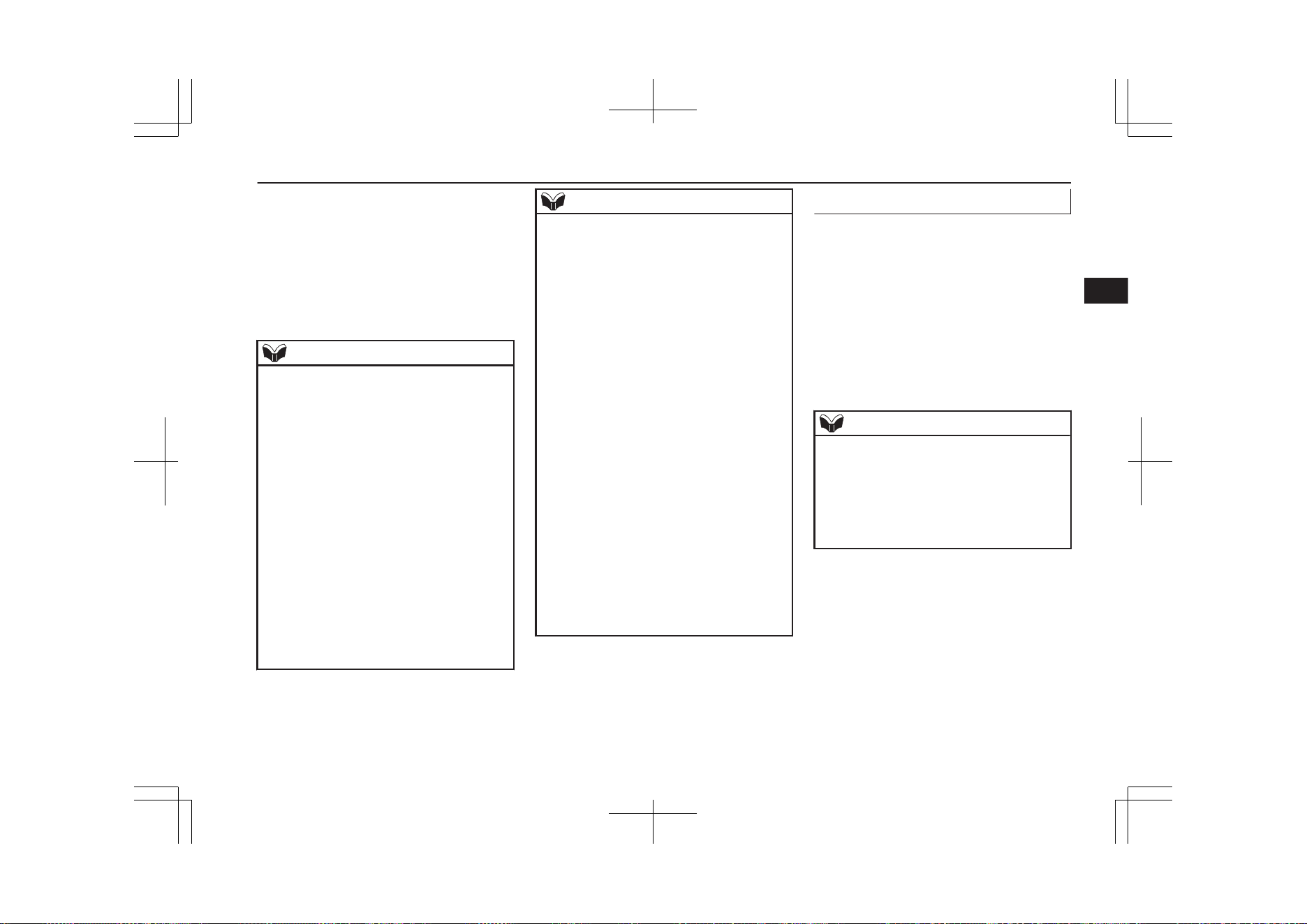
l
Opening any one of the doors or the tail-
gate, when the system is in the system
preparation mode.
l
Holding the keyless operation key and
pressing the driver’s or front passenger’s
door lock/unlock switch, or the tailgate
open switch to unlock the doors and the
tailgate.
NOTE
l
If the bonnet is opened during the system
preparation mode, the system preparation
mode is suspended.
The system returns to the system preparation
mode when the bonnet is closed.
l
If the auxiliary battery terminals are discon-
nected while the system is in the system
preparation mode, the memory will be
erased.
l
It is possible to register up to four remote
control switches for keyless operation sys-
tem.
As long as they are registered, any of the re-
mote control switches, other than the one
used to activate the system, can be used to
cancel the system.
If you want to register additional remote
control switches, please contact a
MITSUBISHI MOTORS Authorized Serv-
ice Point.
NOTE
l
The activation distance for keyless entry sys-
tem is approximately 4 m.
If it is not possible to lock or unlock the ve-
hicle by pressing the switch at the correct
distance or the security alarm system cannot
be set or cancelled using the switch, the bat-
tery may need to be replaced.
Replace the battery at a MITSUBISHI
MOTORS Authorized Service Point.
l
If the UNLOCK switch on the remote con-
trol switch, or the driver’s or front passeng-
er’s door lock/unlock switch is pressed and
no door or the tailgate is opened within 30
seconds, the doors and the tailgate will auto-
matically relock. In this case as well, the
system preparation mode will go into effect.
l
The time between pressing the UNLOCK
switch on the remote control switch, or the
driver’s or front passenger’s door lock/
unlock switch and automatic locking can be
adjusted. Please consult a MITSUBISHI
MOTORS Authorized Service Point.
On vehicles equipped with the Smartphone
Link Display Audio or the MITSUBISHI
Multi-Communication System (MMCS),
screen operations can be used to make the
adjustment. Refer to the separate owner’s
manual for details.
Alarm activation
E00301902408
When the system is in the system armed
mode, the alarm will be activated as follows
if the vehicle is unlocked or if any of the
doors, tailgate or bonnet is opened using a
method other than the keyless entry system or
the keyless operation function.
1. The inside alarm will be activated for
approximately 10 seconds. (except for
vehicles equipped with the interior alarm
sensor)
NOTE
l
If the bonnet is opened during the system
armed mode, the vehicle outside alarm oper-
ates immediately, without the vehicle inside
alarm operating.
l
The time for the vehicle inside alarm can be
adjusted. Please consult a MITSUBISHI
MOTORS Authorized Service Point.
2. The alarm will be activated for approxi-
mately 30 seconds.
The turn-signal lamps will blink, and the
horn (the siren for vehicles equipped
Security alarm system*
4-33
OGGE19E1
Locking and unlocking
4
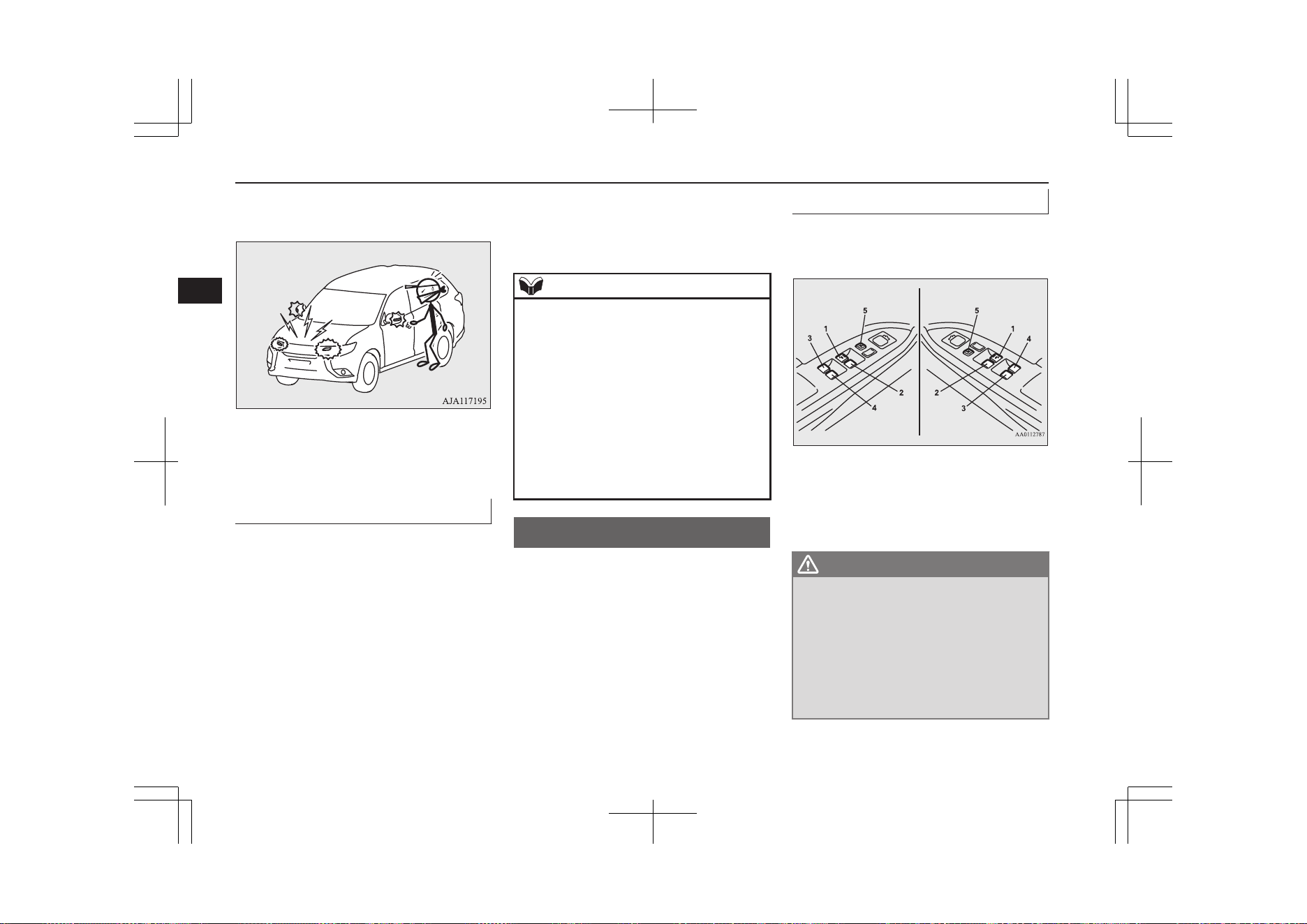
with the interior alarm sensor) will
sound intermittently.
3. The alarm will resume if unlawful ac-
tions are taken again, even if the alarm
has stopped.
Cancelling the alarm
E00302001890
It is possible to halt the activation of an alarm
using the following methods:
l
Pressing the LOCK or UNLOCK switch
on the remote control switch.
(After pressing the LOCK switch, the
vehicle will lock if all the doors and the
tailgate are closed, after which the sys-
tem preparation mode will once again go
into effect.)
l
Putting the operation mode in ON.
l
Holding the keyless operation key and
locking or unlocking the doors and the
tailgate using the keyless operation func-
tion.
NOTE
l
Even if a door or the tailgate is closed while
the inside alarm is activating, this will not
cancel the alarm activation. (except for vehi-
cles equipped with the interior alarm sensor)
l
When the operation mode is put in ON, the
buzzer sounds four times. This operation in-
dicates that the alarm was activated while
the vehicle was parked.
Please check the inside of the vehicle to con-
firm that nothing was stolen.
l
Even if the auxiliary battery is disconnected,
the alarm activation memory will not be
erased.
Electric window control
E00302201632
The electric windows can only be operated
with the operation mode in ON.
Electric window control switch
E00302303507
Each door window opens or closes while the
corresponding switch is operated.
Driver’s switch RHD
Driver’s switch LHD
1- Driver’s door window
2- Front passenger’s door window
3- Rear left door window
4- Rear right door window
5- Lock switch
WARNING
l
Before operating the electric window con-
trol, make sure that nothing can get trap-
ped (head, hand, finger, etc.).
l
Never leave the vehicle without removing
the key.
l
Never leave a child (or other person who
might not be capable of safe operation of
the electric window control) in the vehicle
alone.
Electric window control
4-34
OGGE19E1
Locking and unlocking
4
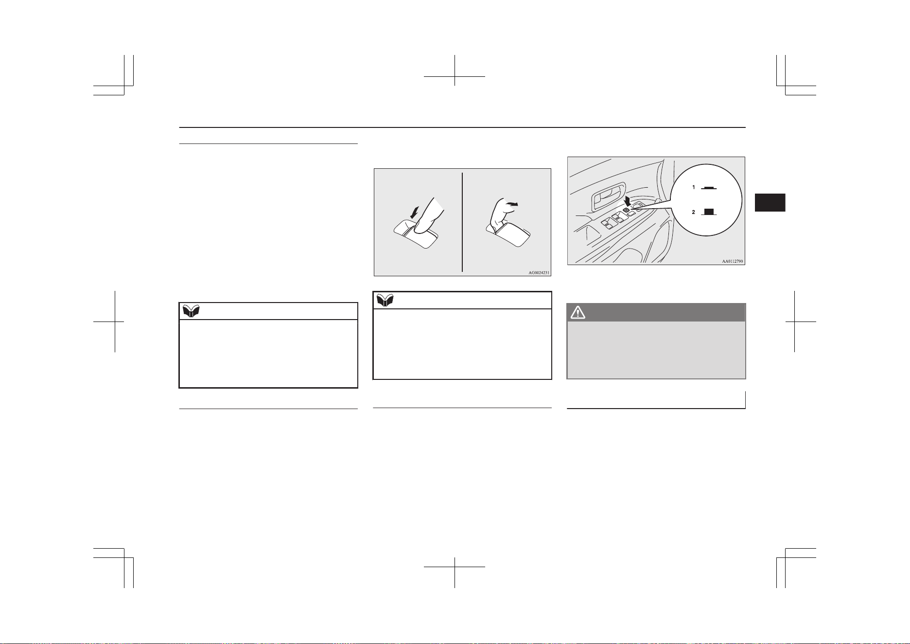
Driver’s switches
The driver’s switches can be used to operate
all door windows. A window can be opened
or closed by operating the corresponding
switch.
Press the switch down to open the window,
and pull up the switch to close it.
If the switch for the driver’s window is fully
pressed down/pulled up, the door window au-
tomatically opens/closes completely.
If you want to stop the window movement,
operate the switch lightly in the reverse direc-
tion.
NOTE
l
When the door window does not close auto-
matically even if the switch is fully pulled
up, pull up the door window switch until the
window has been fully closed.
You should now be able to operate the door
window in the normal fashion.
Passenger’s switches
The passenger’s switches can be used to op-
erate the corresponding passenger’s door
windows.
Press the switch down for opening the win-
dow, and pull up the switch for closing it.
NOTE
l
Repeated operation with the Plug-in Hybrid
EV System stopped will run down the auxil-
iary battery. Operate the window switches
only while the Plug-in Hybrid EV System is
operating.
l
The rear door windows only open halfway.
Lock switch
E00303101263
When this switch is operated, the passenger’s
switches cannot be used to open or close the
door windows and the driver’s switch cannot
open or close any door windows other than
the driver’s door window.
To unlock, press it once again.
1- Lock
2- Unlock
WARNING
l
A child may tamper with the switch at the
risk of its hands or head being trapped in
the window. When driving with a child in
the vehicle, please press the window lock
switch to disable the passenger’s switches.
Timer function
E00302402051
The door windows can be opened or closed
for 30 seconds after putting the operation
mode in OFF or ACC from ON.
However, once the driver’s door or the front
passenger’s door is opened, the windows can-
not be operated.
Electric window control
4-35
OGGE19E1
Locking and unlocking
4
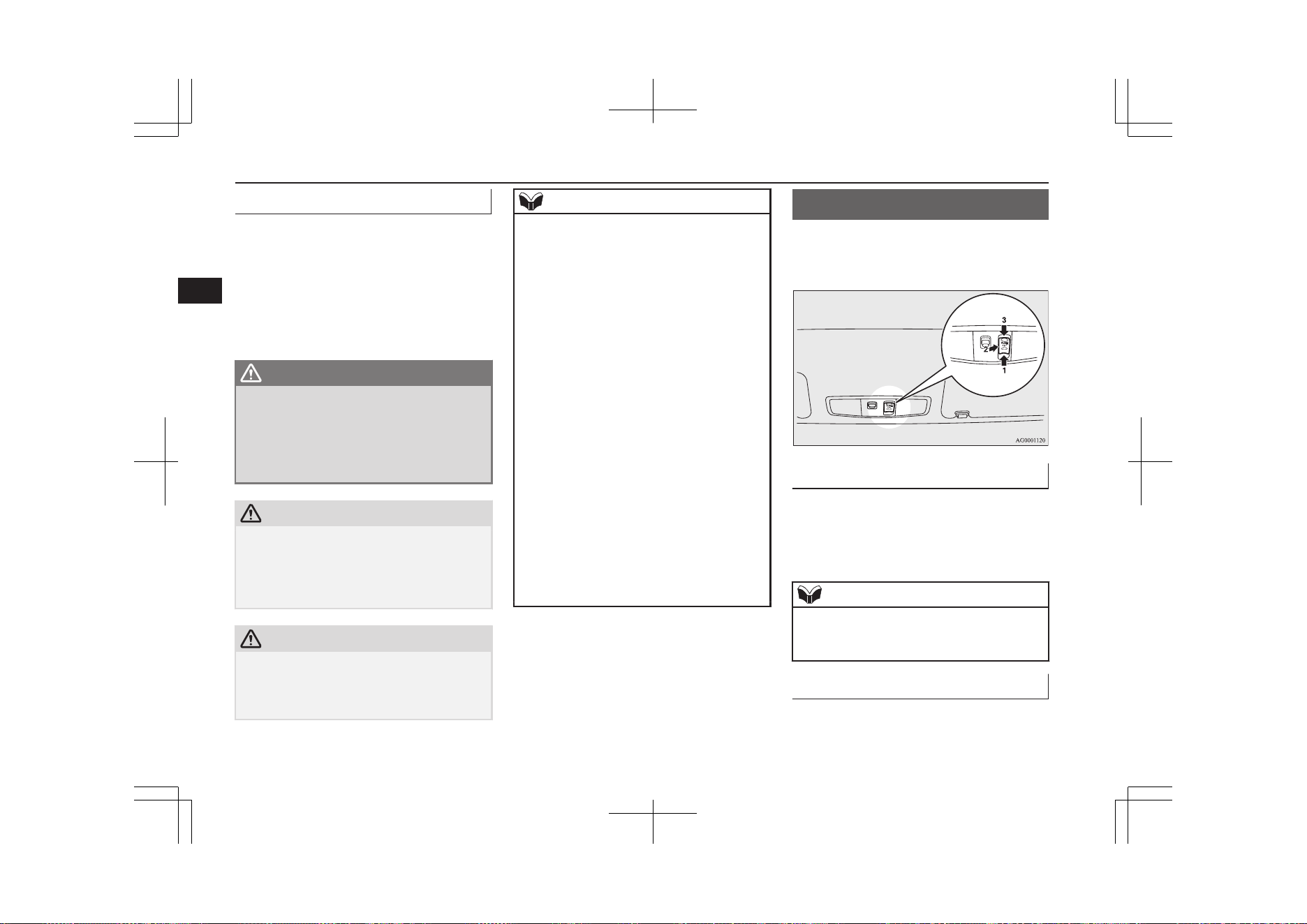
Safety mechanism
E00302502384
If a hand or head is trapped in the closing
window, it will lower automatically.
Nonetheless, make sure that nobody puts
their head or hand out of the window when
closing a window.
The lowered window will become operation-
al after a few seconds.
WARNING
l
If the auxiliary battery terminals are dis-
connected or the fuse for electric window
is replaced, the safety mechanism will be
cancelled.
If a hand or head got trapped, a serious
injury could result.
CAUTION
l
The safety mechanism is cancelled just be-
fore the window is fully closed. This allows
the window to close completely. Therefore
be especially careful that no fingers are trap-
ped in the window.
CAUTION
l
The safety mechanism is deactivated while
the switch is pulled up. Therefore be espe-
cially careful that fingers are not trapped in
the door window opening.
NOTE
l
The safety mechanism can be activated if the
driving conditions or other circumstances
cause the door windows to be subjected to a
physical shock similar to that caused by a
trapped hand or head.
l
If the following operation is performed, the
safety mechanism will be cancelled and the
door window will not automatically open/
close completely.
•
When the auxiliary battery terminals are
disconnected.
•
When the fuse for power window is re-
placed.
•
When the safety mechanism is activated
five or more times consecutively.
In such a case, the following procedure
should be implemented to rectify this situa-
tion.
If the window is open, repeatedly raise the
appropriate window switch until that win-
dow has been fully closed. Following this,
release the switch, raise the switch once
again and hold it in this condition for at least
1 second, then release it. You should now be
able to operate the door window in the nor-
mal fashion.
Sunroof*
E00302702445
The sunroof can only be operated with the
operation mode in “ON”.
To open
The sunroof automatically opens if the switch
(1) is pressed.
To stop the moving sunroof, press switch (2)
or (3).
NOTE
l
The sunroof automatically stops just before
reaching the fully open position.
Press the switch again to fully open it.
To close
The sunroof automatically closes while the
switch (3) is pressed.
Sunroof*
4-36
OGGE19E1
Locking and unlocking
4
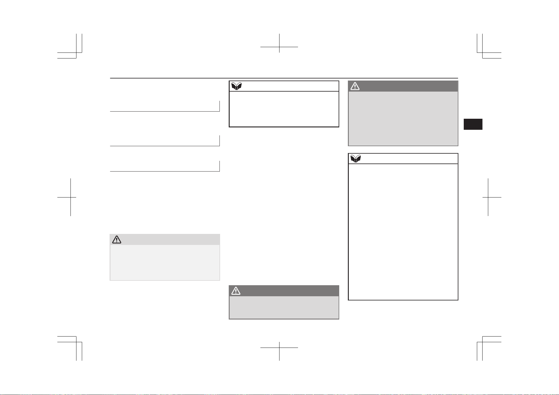
To stop the moving sunroof, press switch (1)
or (2).
To tilt up
When the switch (2) is pressed, the rear edge
of the sunroof rises for ventilation.
To tilt down
Press the switch (3).
Safety mechanism
E00303801521
If a hand or head is trapped in the closing
sunroof, it will re-open automatically.
Nonetheless, make sure that nobody puts
their head or hand out of the sunroof when
opening or closing.
The opened sunroof will become operational
after a few seconds.
CAUTION
l
The safety mechanism is cancelled just be-
fore the sunroof is fully closed. This allows
the sunroof to close completely.
Therefore be especially careful that no fin-
gers are trapped in the sunroof.
NOTE
l
The safety mechanism can be activated if the
driving conditions or other circumstances
cause the sunroof to be subjected to a physi-
cal shock similar to that caused by a trapped
hand or head.
If the safety mechanism should be activated 5
or more times consecutively, normal closing
of the sunroof will be aborted.
As an emergency measure, the sunroof can be
closed bit by bit until the sunroof is com-
pletely closed by repeatedly pressing switch
(2).
After that, the sunroof can be set the initial-
ized state in the following procedure.
1. Move the sunroof in slide open position.
2. Press the tilt up switch (2) continually in
10 seconds.
3. The sunroof will be moved to tilt up po-
sition automatically bit by bit.
4. The initialize is completed when the
sunroof is stopped at tilt up position.
If the sunroof does not return to normal, con-
sult a MITSUBISHI MOTORS Authorized
Service Point.
WARNING
l
Before operating the sunroof, make sure
that nothing is capable of being trapped
(head, hand, finger, etc.).
WARNING
l
Do not put head, hands or anything else
out of the sunroof opening while driving
the vehicle.
l
Never leave the vehicle without removing
the key.
l
Never leave a child (or other person who
might not be capable of safe operation of
the sunroof switch) in the vehicle alone.
NOTE
l
The sunroof stops just before reaching the
fully open position.
If the vehicle is driven with the sunroof in
this position, wind buffeting is lower than
with the sunroof fully open.
l
When leaving the vehicle unattended, make
sure you close the sunroof.
l
Do not try to operate the sunroof if it is fro-
zen closed (after snow fall or during extreme
cold).
l
Do not sit or place heavy luggage on the
sunroof or roof opening edge.
l
Release the switch as soon as the sunroof
reaches the fully open or fully closed posi-
tion.
l
If the sunroof does not operate when the
sunroof switch is operated, release the
switch and check whether something is trap-
ped by the sunroof. If nothing is trapped,
have the sunroof checked at a MITSUBISHI
MOTORS Authorized Service Point.
Sunroof*
4-37
OGGE19E1
Locking and unlocking
4
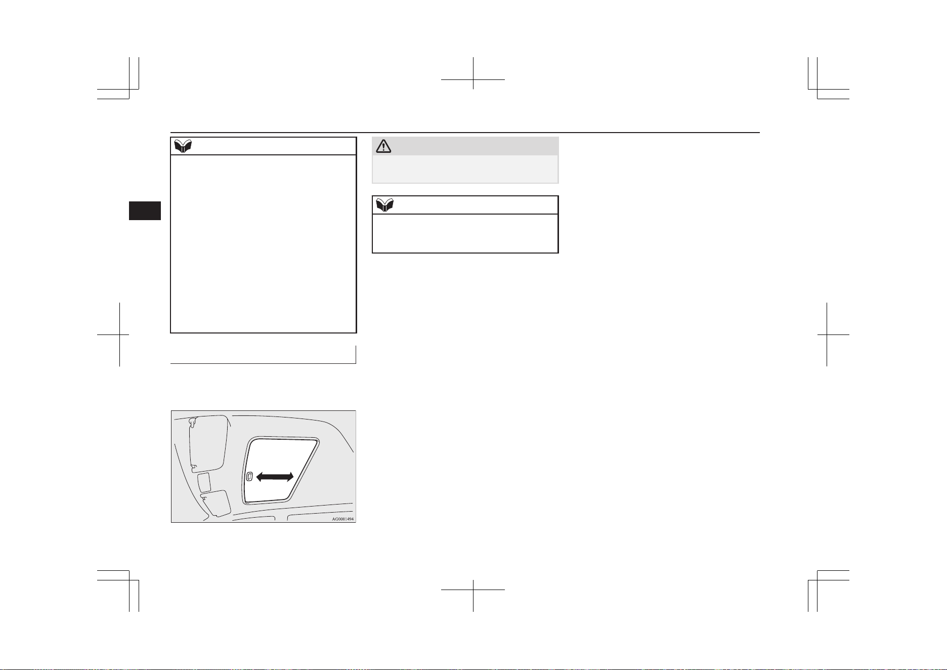
NOTE
l
Depending on the models of ski carriers or
roof carriers, the sunroof may touch the car-
rier when the sunroof is tilted up. Be careful
when tilting up the sunroof if such a ski car-
rier or a roof carrier is installed.
l
Be sure to close the sunroof completely
when washing the vehicle or when leaving
the vehicle.
l
Be careful, not to put any wax on the weath-
erstrip (black rubber) around the sunroof
opening. If stained with wax, the weather-
strip cannot maintain a weatherproof seal
with the sunroof.
l
After washing the vehicle or after it has
rained, wipe off any water that is on the sun-
roof before operating it.
Sunshade
E00307901227
Slide the sunshade manually to open and
close it.
CAUTION
l
Be careful that hands are not trapped when
closing the sunshade.
NOTE
l
The sunshade cannot be closed with the sun-
roof opened. Do not attempt to close the
sunshade when the sunroof is opened.
Sunroof*
4-38
OGGE19E1
Locking and unlocking
4

Seat arrangement.................................................................................5-02
Seat adjustment................................................................................... 5-02
Front seats........................................................................................... 5-03
Rear seats............................................................................................ 5-05
Head restraints.....................................................................................5-05
Making a luggage area........................................................................ 5-06
Making a flat seat................................................................................5-08
Seat belts............................................................................................. 5-09
Pregnant women restraint....................................................................5-14
Seat belt pretensioner system and force limiter system...................... 5-14
Child restraint......................................................................................5-15
Seat belt inspection............................................................................. 5-25
Supplemental restraint system (SRS)-airbag...................................... 5-25
Seats and seat belts
OGGE19E1
5
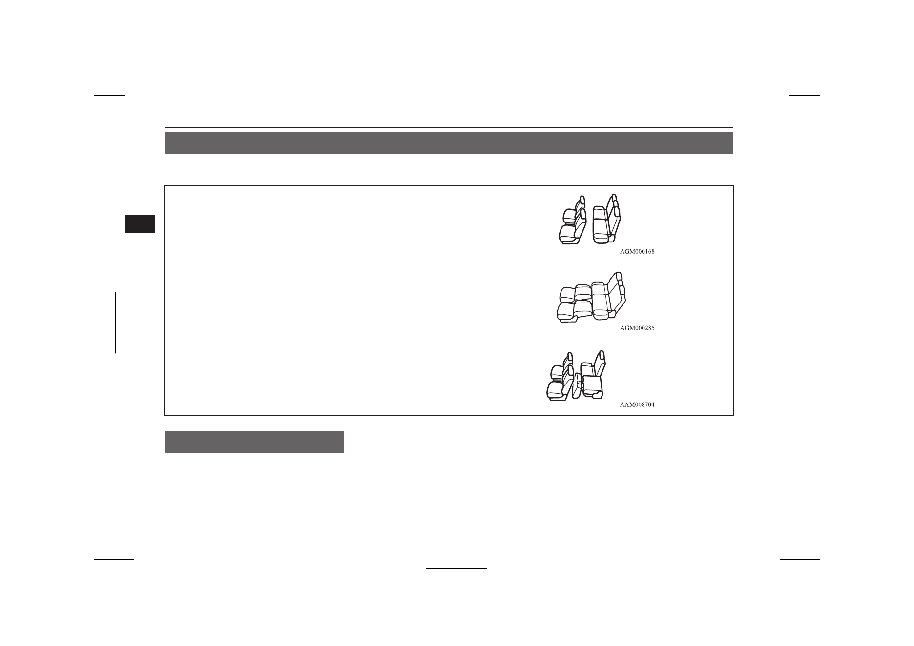
Seat arrangement
E00400201886
By operating the front or rear seat, select the desired seat arrangement.
Normal usage
Flat seat ® p. 5-08
Making a luggage area Folding the rear seats ® p. 5-06
Seat adjustment
E00400302057
Adjust the driver’s seat so that you are com-
fortable and that you can reach the pedals,
steering wheel, switches etc. while retaining
a clear field of vision.
Seat arrangement
5-02
OGGE19E1
Seats and seat belts
5
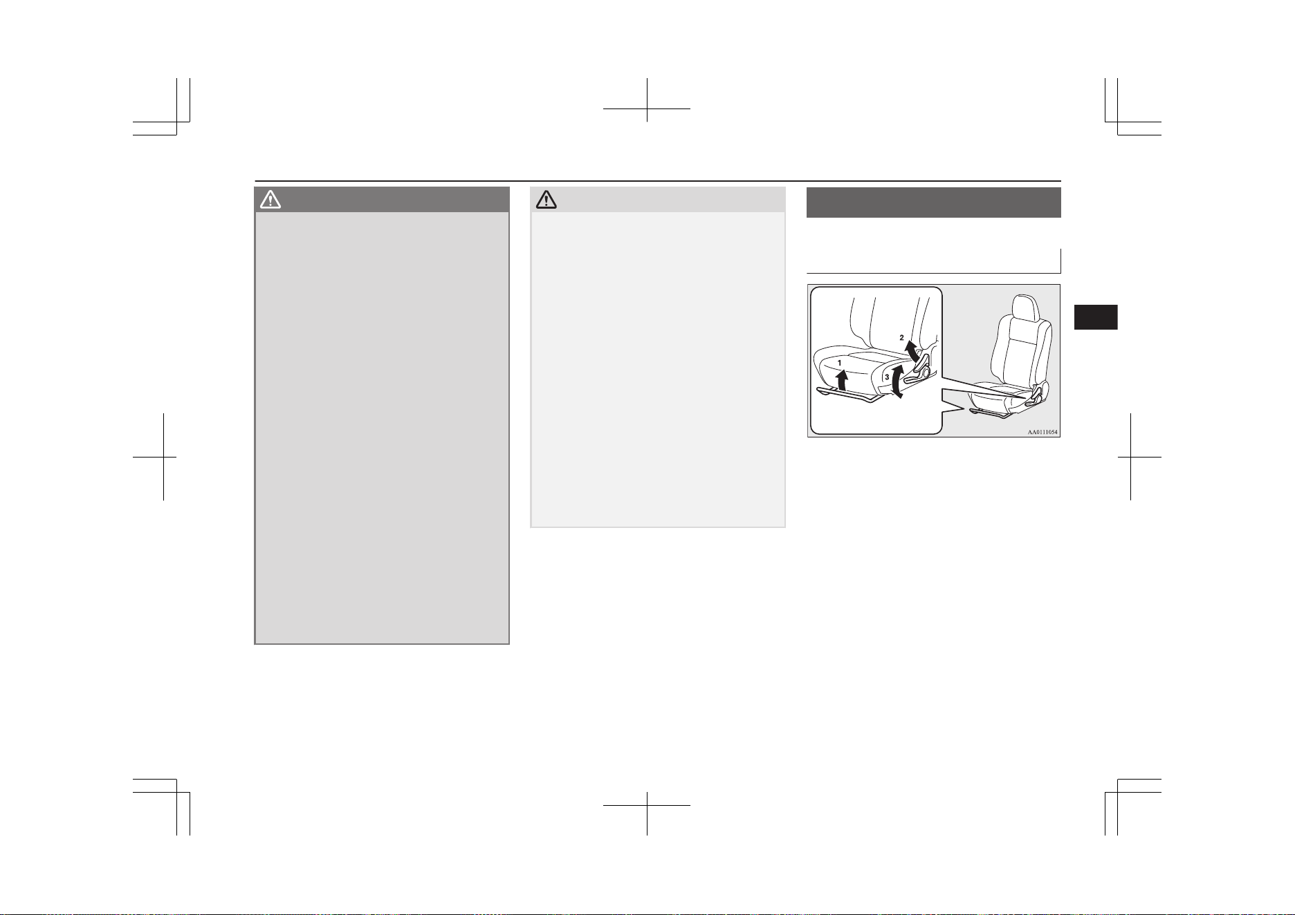
WARNING
l
Do not attempt to adjust the seat while
driving. This can cause loss of vehicle con-
trol and result in an accident. After ad-
justments are made, ensure the seating is
locked in position by attempting to move
the seat forward and rearward without
using the adjusting mechanism.
l
Do not allow people or children to ride in
any area of your vehicle that is not equip-
ped with seats and seat belts, and make
sure that everyone travelling in your vehi-
cle is in a seat and wearing a seat belt, or
in the case of a child is strapped in a child
restraint.
l
To minimize the risk of personal injury in
the event of a collision or sudden braking,
the seatbacks should always be in the al-
most upright position while the vehicle is
in motion. The protection provided by the
seat belts may be reduced significantly
when the seatback is reclined. There is
greater risk that the passenger will slide
under the seat belt, resulting in serious in-
jury, when the seatback is reclined.
l
Do not place objects under the seats. This
could prevent the seat from locking se-
curely, and it could lead to an accident. It
may also cause damage to the seat or oth-
er parts.
CAUTION
l
Make sure the seat is adjusted by an adult or
with adult supervision for correct and safe
operation.
l
Do not place a cushion or the like between
your back and the seatback while driving.
The effectiveness of the head restraints will
be reduced in the event of an accident.
l
The reclining mechanism of the front seat’s
seatback is spring loaded, causing it to return
to the vertical position when the lock lever is
operated. When using the lever, sit close to
the seatback or hold it with your hand to
control its return motion.
l
When sliding the seats, be careful not to
catch your hand or foot.
l
When adjusting the front seat while the rear
seat is folded, be careful not to apply strong
force to the flipped rear seat cushion.
Doing so could cause damage to the cover of
the front seat and the fitting of the rear seat
cushion.
Front seats
E00400401253
Manual type
1- To adjust forward or backward
Lift the handle and adjust the seat to the
desired position, and release the handle.
2- To recline the seatback
Pull the lever up and then lean backward
to the desired position, and release the
lever.
3- To adjust seat height (driver’s side only)
Repeatedly operate the lever and adjust
the seat height to the desired position.
Front seats
5-03
OGGE19E1
Seats and seat belts
5
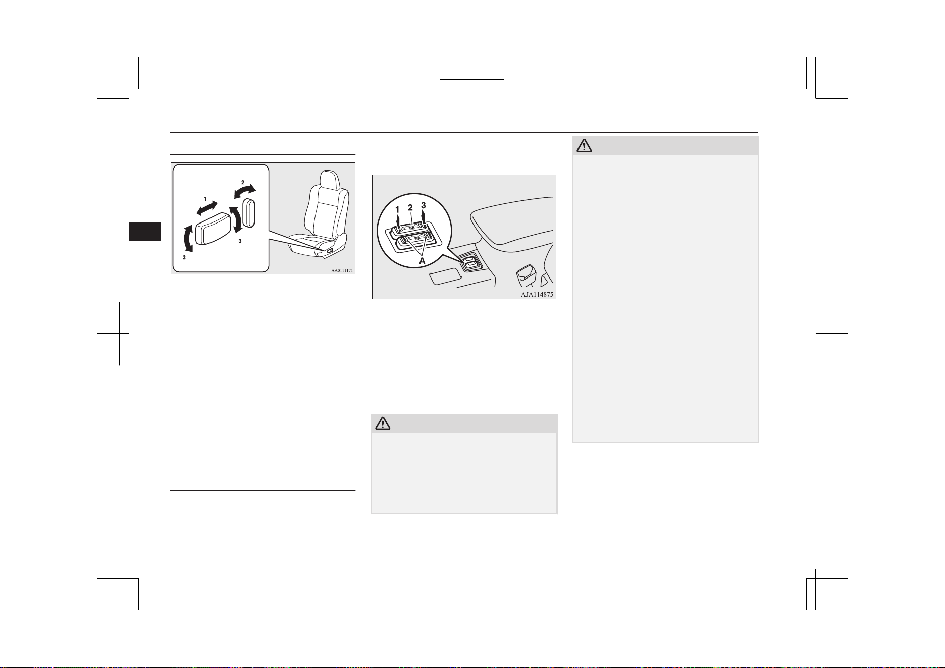
Power type*
1- To adjust forward or backward
Operate the switch as indicated by the
arrows and adjust the seat to the desired
position.
2- To recline the seatback
Operate the switch as indicated by the
arrows and adjust the seatback angle to
the desired position.
3- To adjust seat height
Operate the switch as indicated by the
arrows and adjust the seat height to the
desired position.
If the entire switch is operated, then the
entire seat moves.
Heated seats*
E00401102371
The heated seats can be operated with the op-
eration mode of the power switch in ON. Op-
erate the switch as indicated by arrows.
The indication lamp (A) will illuminate while
the heater is on.
1 (HI) - Heater high (for quick heating).
2 (neu-
tral po-
sition)
- Heater off.
3 (LO) - Heater low (to keep the seat
warm).
CAUTION
l
Operate in the high position for quick heat-
ing. Once the seat is warm, set the heater to
low to keep it warm. Slight variations in seat
temperature may be felt while using the
heated seats. This is caused by the operation
of the heater’s internal thermostat and does
not indicate a malfunction.
CAUTION
l
If the following types of persons use the
heated seats, they might become too hot or
receive minor burns (red skin, heat blisters,
etc.):
•
Children, elderly or ill people
•
People with sensitive skin
•
Excessively tired people
•
People under the influence of alcohol or
sleep inducing medication (cold medicine,
etc.)
l
Do not place heavy objects on the seat or
stick pins, needles, or other pointed objects
into it.
l
Do not use a blanket, cushion, or other mate-
rial with high heat insulation properties on
the seat while using the heater; this might
cause the heater element to overheat.
l
Do not use benzine, kerosene, petrol, alcohol
or other organic solvents when cleaning the
seats. Doing so could damage not only the
seat cover, but also the heater element.
l
If water or any other liquid is spilled on the
seat, allow it to dry thoroughly before at-
tempting to use the heater. Turn the heater
off immediately if it appears to be malfunc-
tioning during use.
Front seats
5-04
OGGE19E1
Seats and seat belts
5
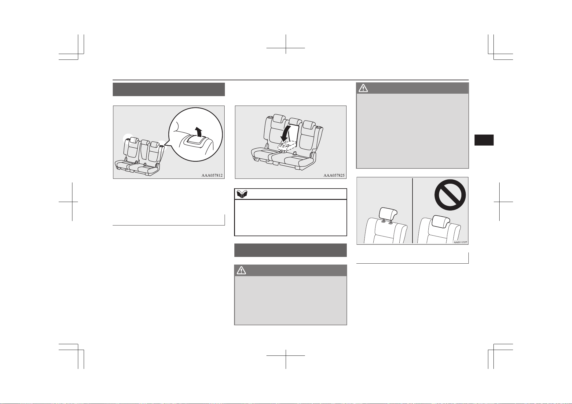
Rear seats
E00401301549
To adjust the seatback, pull the lever up and
adjust the seatback by hand to the desired po-
sition, and release the lever.
Armrest
E00401701732
To use the armrest, fold it down.
To return to the original position, push it
backward level with the seat.
NOTE
l
Do not climb or sit on the armrest.
Doing so could damage the armrest.
l
The top surface of the armrest contains a cup
holder for rear seat occupants.
Refer to “Cup holder” on page 8-84.
Head restraints
E00403302654
WARNING
l
Driving without the head restraints in
place can cause you and your passengers
serious injury or death in an accident. To
reduce the risk of injury in an accident,
always make sure the head restraints are
installed and properly positioned when
the seat is occupied.
WARNING
l
Never place a cushion or similar device on
the seatback. This can adversely affect
head restraint performance by increasing
the distance between your head and the
restraint.
l
When a person sits in the rear seats, pull
up the head restraint to a height at which
it locks in position. Be sure to make this
adjustment before starting to drive. Seri-
ous injuries could otherwise be suffered as
the result of an impact.
To adjust height
Adjust the head restraint height so that the
centre of the head restraint is as close as pos-
sible to ear level to reduce the chances of in-
jury in the event of collision. Any person too
tall for the head restraint to reach their seated
ear level, should adjust the restraint as high
as possible.
Rear seats
5-05
OGGE19E1
Seats and seat belts
5
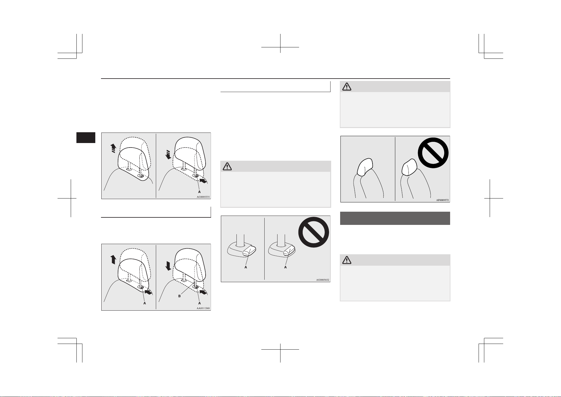
To raise the head restraint, move it upward.
To lower the restraint, move it downward
while pushing the height adjusting knob (A)
in the direction of the arrow. After adjust-
ment, push the head restraint downward and
make sure that it is locked.
To remove
Lift the head restraint with the height adjust-
ing knob (A) pushed in.
To install
Confirm that the head restraint is facing the
correct direction, and then insert it into the
seatback while pressing the height adjusting
knob (A) in the direction indicated by the ar-
row.
The head restraint stalk with the adjustment
notches (B) must be installed in the hole with
the adjusting knob (A).
CAUTION
l
Confirm that the height adjusting knob (A)
is correctly adjusted as shown in the illustra-
tion, and also lift the head restraints to en-
sure that they do not come out of the seat-
back.
CAUTION
l
The shape and size of the head restraint dif-
fers according to the seat. Always use the
correct head restraint provided for the seat
and do not install the head restraint in the
wrong direction.
Making a luggage area
E00403401502
To create luggage space, you can fold the rear
seats.
CAUTION
l
Do not stack luggage above the seatback
height. Secure the luggage firmly.
Serious accidents could result due to unre-
strained objects entering the passenger com-
partment during sudden braking.
Making a luggage area
5-06
OGGE19E1
Seats and seat belts
5
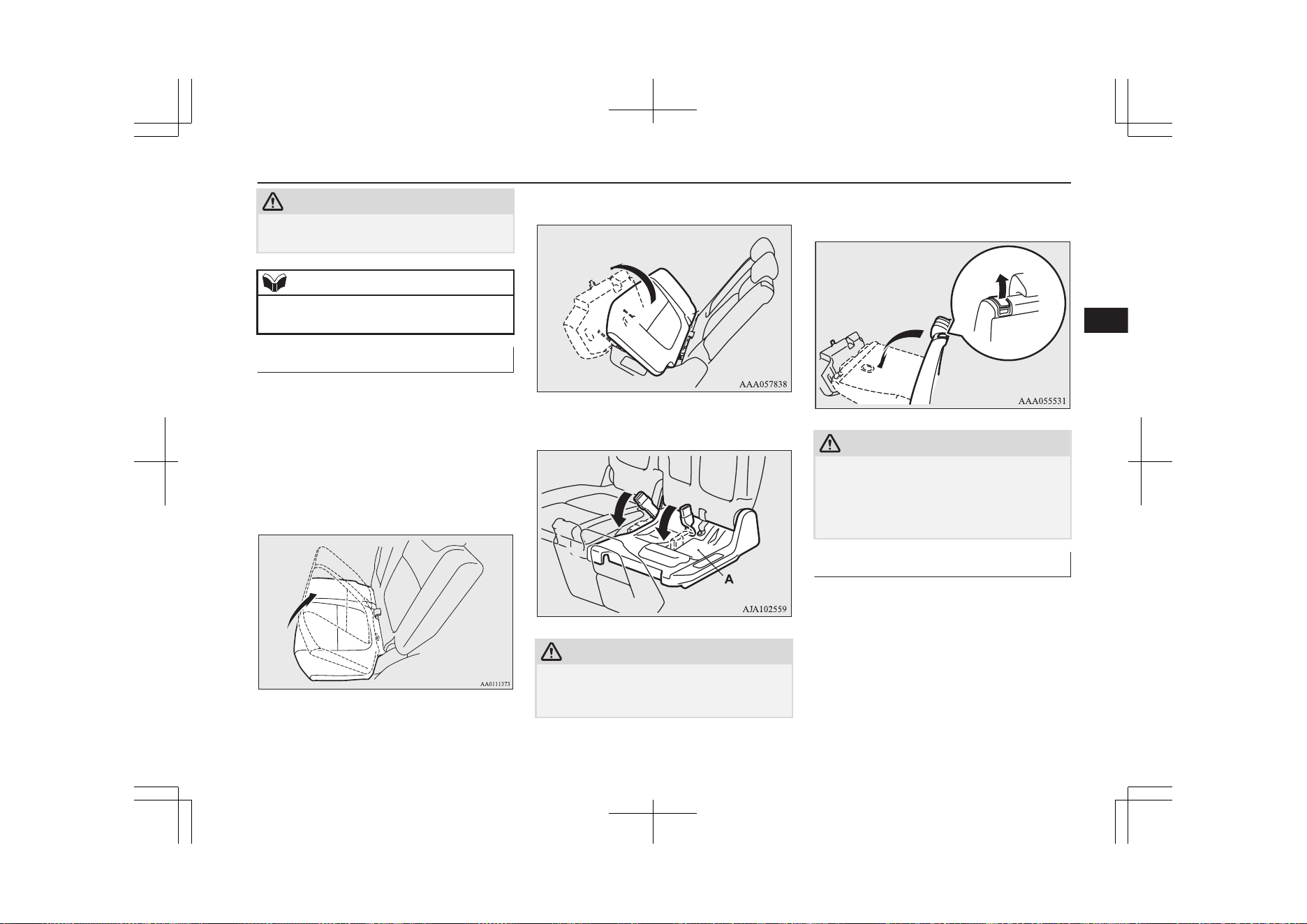
CAUTION
l
When folding the seat, be sure not to catch
your hand or leg.
NOTE
l
It is possible to fold the seat independently
on each side.
To fold
1. Lower the head restraints of the rear seat
to the lowest position.
Refer to “Head restraints” on page 5-05.
2. Store the seat belt for the rear centre
seating position.
Refer to “Rear-centre 3-point type seat
belt” on page 5-13.
3. Lift the front end of the seat cushion.
4. Flip the seat cushion forward.
5. Fold the seat belt buckles forward.
CAUTION
l
Do not allow any person to get on the plastic
cover (A), and do not place luggage on it.
Doing so could damage cover.
6. Pull up the lever, then fold the seatback
forward.
CAUTION
l
Do not allow any person to sit on the flipped
seat cushion, and do not place luggage on it.
The seat’s mounting fittings could bend un-
der the weight, making it impossible for the
seat to be retained on the vehicle.
To return
1. Raise the seatback until it locks securely
into place.
Making a luggage area
5-07
OGGE19E1
Seats and seat belts
5
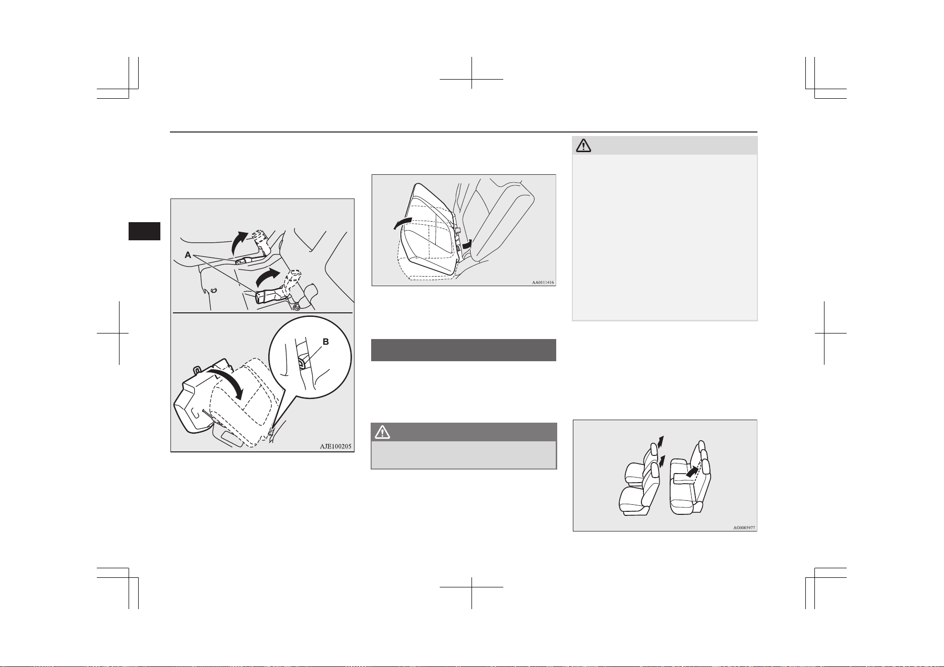
2. While lifting the seat belt’s buckle (A),
gently lower the seat cushion. Make sure
that there is a hook (B) at the position
shown in the illustration.
3. Push down the seat cushion until it locks
into place.
4. Make sure the seat belt’s buckle is on the
seat cushion.
Making a flat seat
E00404301931
By removing the head restraints and fully re-
clining the seatbacks of the seats, one large
flat seat is achieved.
WARNING
l
Never drive with passengers on the flat
seat. This is highly dangerous.
CAUTION
l
To make a flat seat, stop the vehicle in a safe
place.
l
Make sure the seat is adjusted by an adult or
with adult supervision for correct and safe
operation.
l
Do not walk around on top of the seats after
they have been laid flat.
l
To ensure the seats are locked securely, at-
tempt to move them back and forth.
l
Do not jump on, or impact the seatbacks
heavily.
l
To raise the seatback, put a hand on the seat-
back and raise slowly. Never have a child do
this operation, or an unexpected accident
may result.
1. Remove the head restraints from the
front seats, raise the armrest and remove
the cargo area cover. (Refer to “Head re-
straints” on page 5-05, “Armrest” on
page 5-05 and “Cargo area cover” on
page 8-85)
Making a flat seat
5-08
OGGE19E1
Seats and seat belts
5
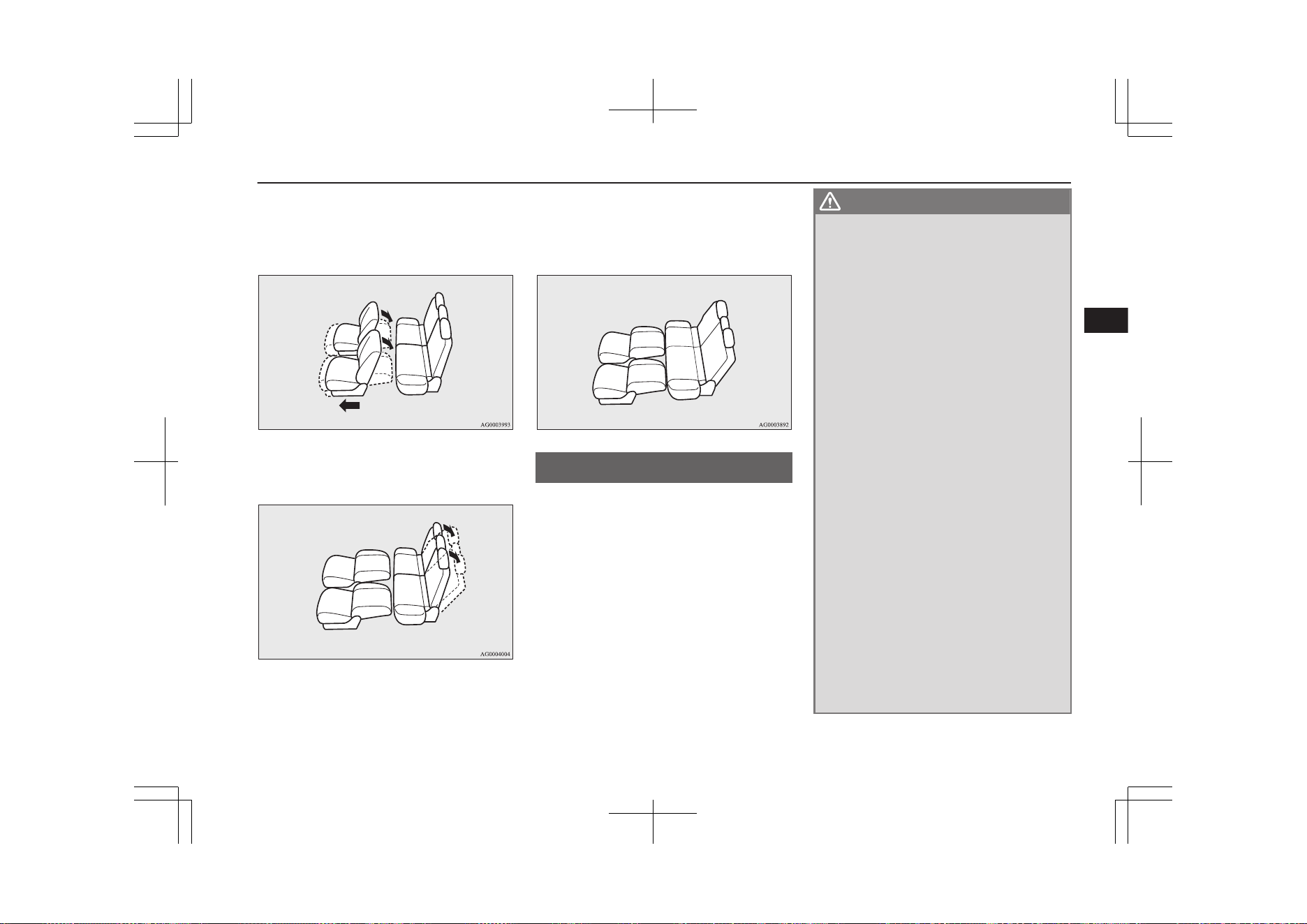
2. Slide the front seats fully forward, then
recline the seatbacks backwards to ach-
ieve a flat surface. (Refer to “Front
seats” on page 5-03)
3. Recline the rear seatbacks backwards.
(Refer to “Rear seats” on page 5-05)
4. The flat seat configuration is now com-
plete. Reverse the above procedures
when returning the seat to the normal
position.
Seat belts
E00404800867
To protect you and your passengers in the
event of an accident, it is most important that
the seat belts be worn correctly while driving.
The front seat belts have a pretensioner sys-
tem. These belts are used the same way as a
conventional seat belt.
Refer to “Seat belt pretensioner system and
force limiter system” on page 5-14.
WARNING
l
Seat belts should always be worn by every
adult who drives or rides in this vehicle,
and by all children who are tall enough to
wear seat belts properly.
Other children should always use proper
child restraint systems.
l
Always place the shoulder belt over your
shoulder and across your chest. Never put
it behind you or under your arm.
l
One seat belt should be used by only one
person. Doing otherwise can be danger-
ous.
l
The seat belt will provide its wearer with
maximum protection if the recliner seat-
back is placed in fully upright position.
When the seatback is reclined, there is
greater risk that the passenger will slide
under the belt, especially in a forward im-
pact accident, and may be injured by the
belt or by striking the instrument panel or
seatbacks.
l
Remove any twists when using the belt.
l
No modifications or additions should be
made by the user which will either pre-
vent the seat belt adjusting devices from
operating to remove slack, or prevent the
seat belt assembly from being adjusted to
remove slack.
l
Never hold a child in your arms or on
your lap when riding in this vehicle, even
if you are wearing your seat belt. To do so
risks severe or fatal injury to the child in
a collision or sudden stop.
Seat belts
5-09
OGGE19E1
Seats and seat belts
5
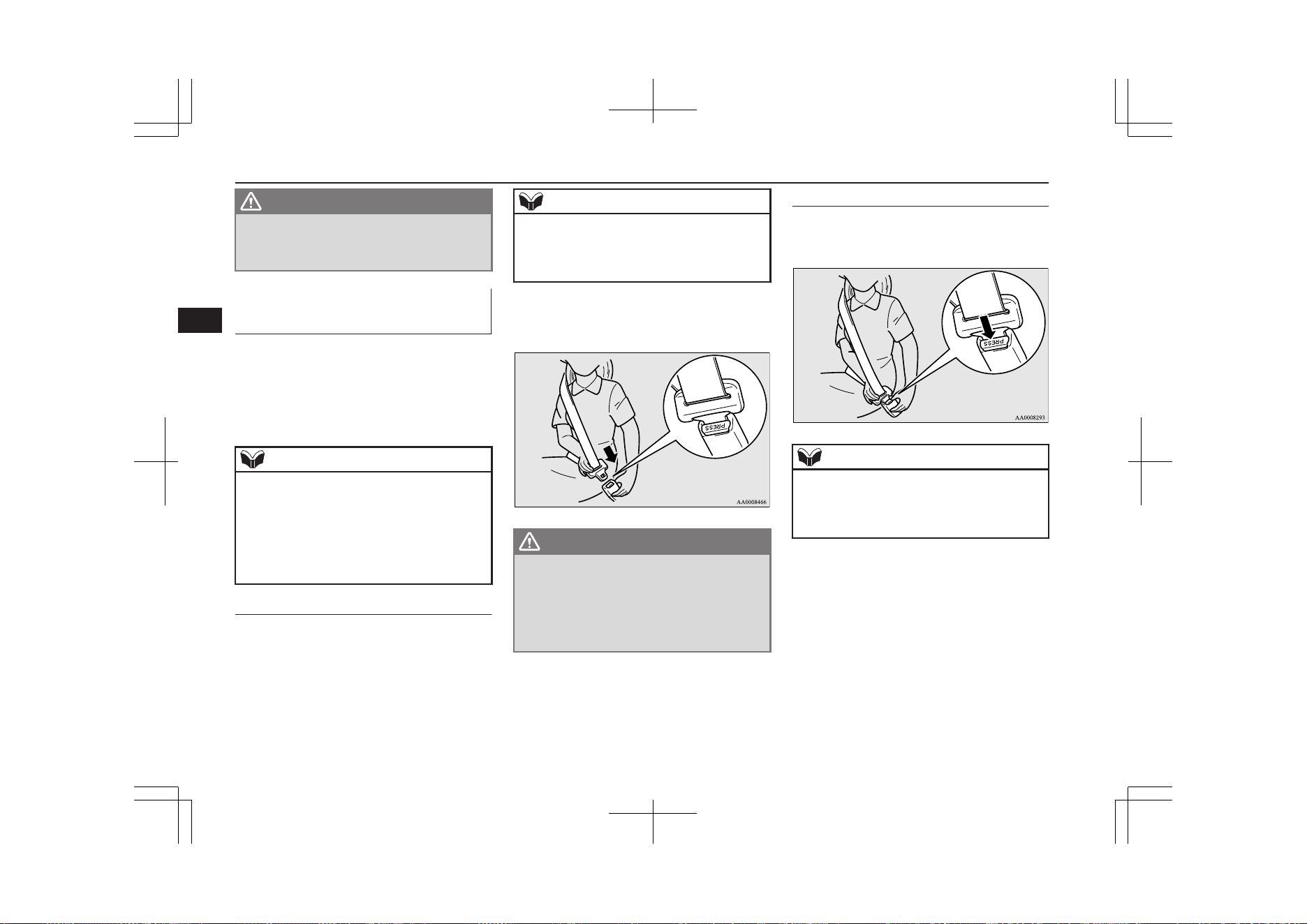
WARNING
l
Always adjust the belt to a snug fit.
l
Always wear the lap portion of the belt
over your hips.
3-point type seat belt (with
emergency locking mechanism)
E00404902918
This type of belt requires no length adjust-
ment. Once worn, the belt adjusts itself to the
movement of the wearer, but in the event of a
sudden or strong shock, the belt automatical-
ly locks to hold the wearer’s body.
NOTE
l
You can check if the belt locks by pulling it
forward quickly.
l
If the seat belt buckles in the rear seating po-
sition are not found, you will find them un-
der the rear seat cushion. Refer to “Making a
luggage area” on page 5-06 for how to put
the seat belt buckles at the proper position.
To fasten
1. Pull the seat belt out slowly while hold-
ing the latch plate.
NOTE
l
When the seat belts cannot be pulled out in a
locked condition, pull the belts once force-
fully and then return them. After that, pull
the belts out slowly once again.
2. Insert the latch plate into the buckle until
a “click” is heard.
WARNING
l
Never wear the lap portion of the belt
across your abdomen. During accidents it
can press sharply against the abdomen
and increase the risk of injury.
l
The seat belts must not be twisted when
worn.
3. Pull the belt slightly to adjust slackness
as desired.
To unfasten
Hold the latch plate and push the button on
the buckle.
NOTE
l
As the belt retracts automatically, keep hold-
ing the latch plate while retracting so that the
belt stows slowly. Failure to do this could
damage the vehicle.
Seat belts
5-10
OGGE19E1
Seats and seat belts
5
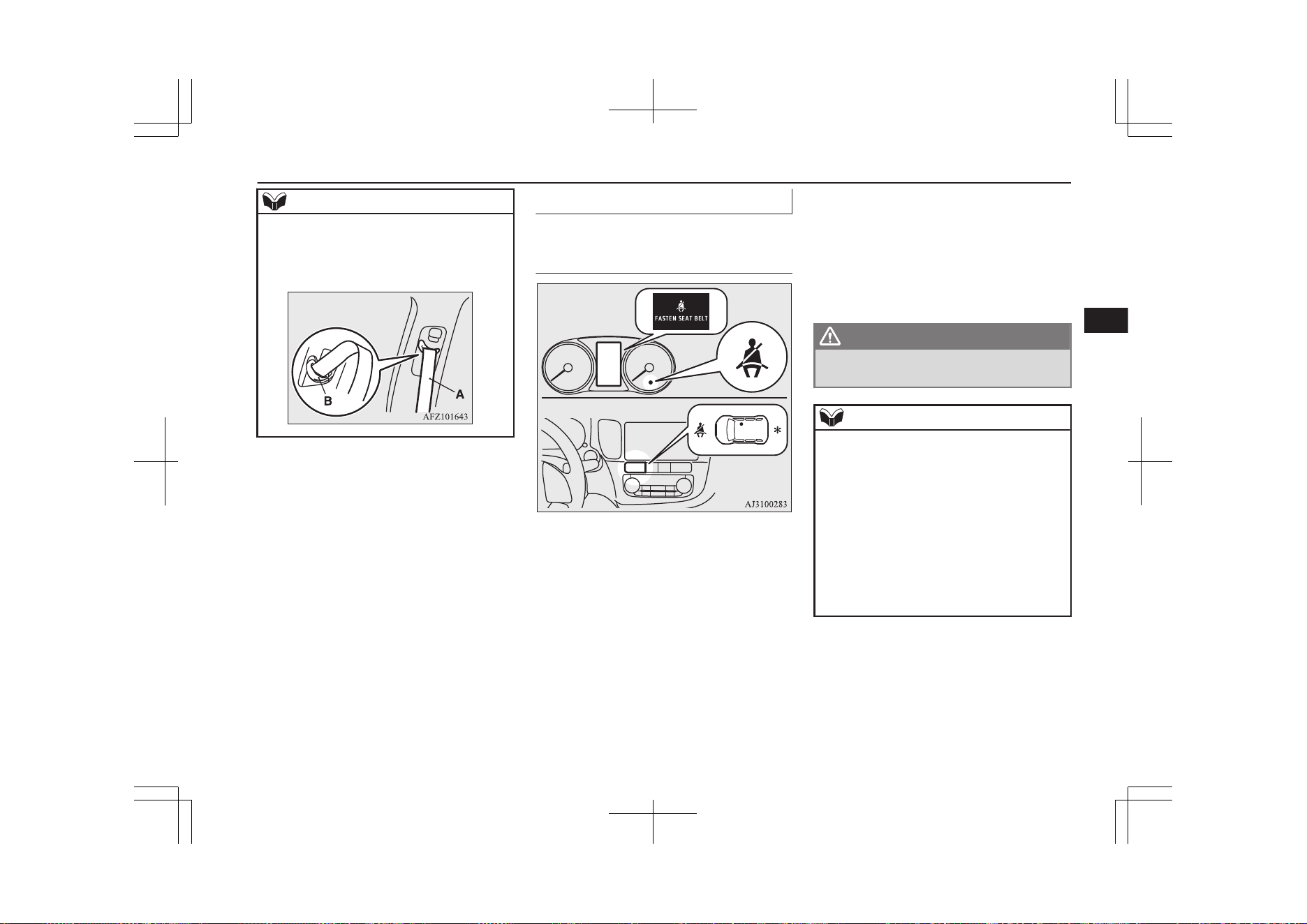
NOTE
l
If the seat belt (A) or ring (B) becomes dirty,
the belt may not retract smoothly. If the seat
belt and ring are dirty, clean them with a
mild soap or detergent solution.
Seat belt reminder
E00409801973
For the driver and the front
passenger’s seat
For the driver
For the front passenger
*- This warning lamp shows the case
of the left-hand drive vehicles.
If the operation mode of the power switch is
put in ON while a seat belt is not fastened,
the warning lamp comes on and the tone
sounds for about 6 seconds to remind the
driver and the front passenger to fasten the
seat belt.
If the vehicle is driven with the seat belt still
unfastened, the warning lamp will blink and
the tone will sound intermittently until the
seat belt is fastened. At the same time, “FAS-
TEN SEAT BELT” is displayed on the infor-
mation screen in the multi information dis-
play for the driver.
WARNING
l
Do not install any accessory or sticker
that makes the lamp difficult to see.
NOTE
l
If the seat belt subsequently remains unfas-
tened, the warning lamp and the tone will is-
sue further warnings each time the vehicle
starts moving from a stop.
l
For the front passenger seat, the warning
function works only while a person is sitting
on the seat.
l
When luggage is placed on the front passen-
ger seat, a sensor in the seat cushion may,
depending on the weight and position of the
luggage, cause the warning tone to sound
and the warning lamp to come on.
Seat belts
5-11
OGGE19E1
Seats and seat belts
5
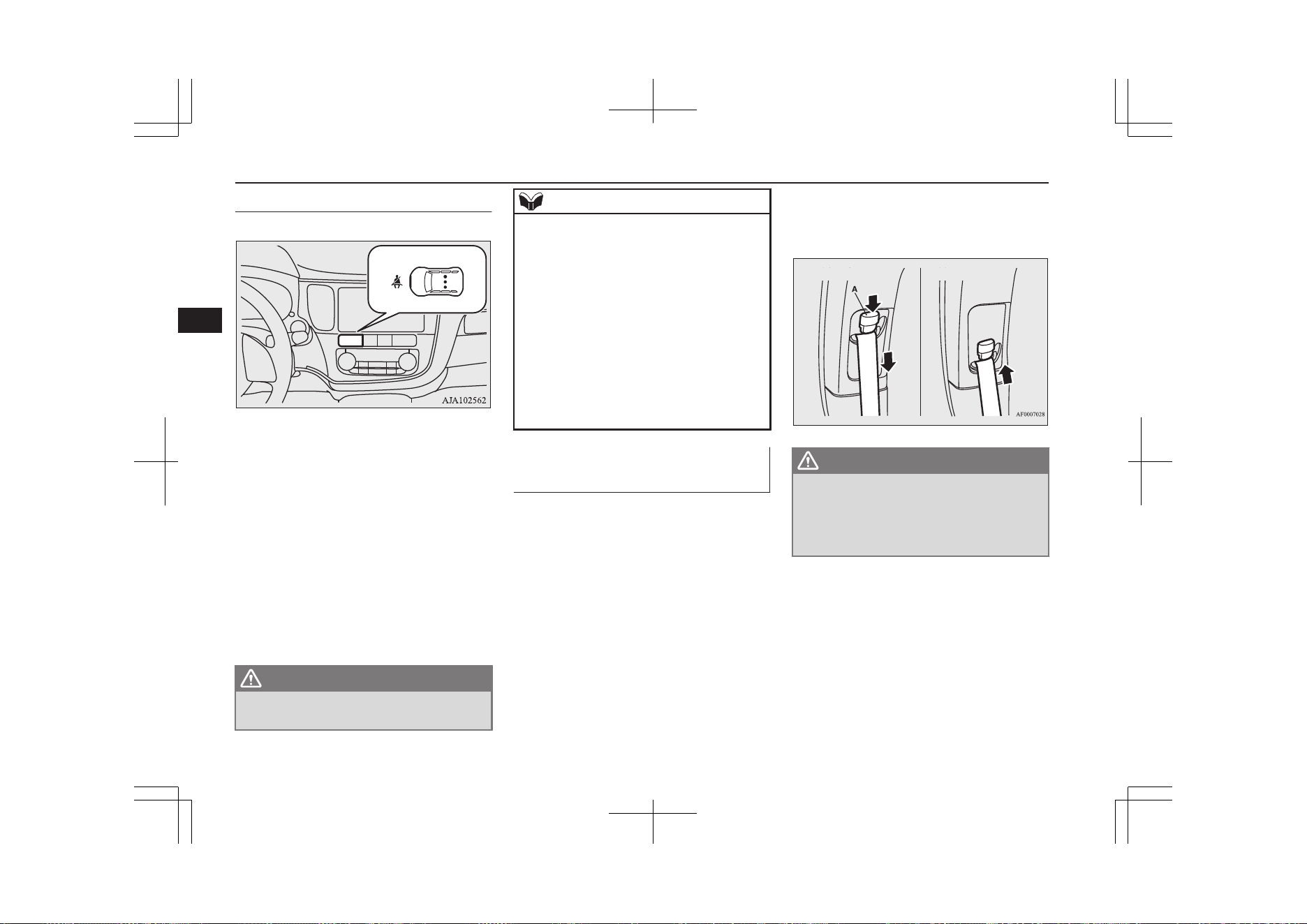
For the rear passenger’s seats
E00415501021
If the operation mode of the power switch is
put in ON while a seat belt is not fastened,
the warning lamp comes on for approximate-
ly 30 seconds to remind the rear passenger to
fasten the seat belt.
If the vehicle is driven with the seat belt still
unfastened, the warning lamps come on for
approximately another 30 seconds. (This illu-
mination happens only the first time the vehi-
cle starts moving with the seat belt still un-
fastened.)
The warning lamps go off when the seat belt
is fastened.
WARNING
l
Do not install any accessory or sticker
that makes the lamp difficult to see.
NOTE
l
The warning lamp comes on even if no one
is sitting on the rear seats.
l
If a seat belt is unfastened while the vehicle
is being driven, the tone sounds for approxi-
mately 1 second and the warning lamp
comes on for approximately 30 seconds. At
the same time, the warning lamp for the seat
where the seat belt is not fastened comes on.
l
If the seat belts are initially fastened but a
seat belt is unfastened while the vehicle is
stationary and the vehicle is then driven with
the seat belt still unfastened, the warning
lamp comes on again for approximately 30
seconds.
Adjustable seat belt anchor
(front seats)
E00405000420
The seat belt anchor height can be adjusted.
Move the seat belt anchor down with the lock
knob (A) depressed. To move the anchor up,
slide it without depressing the lock knob (A).
WARNING
l
When adjusting the seat belt anchor, set it
at a position that is sufficiently high so
that the belt will make full contact with
your shoulder but will not touch your
neck.
Seat belts
5-12
OGGE19E1
Seats and seat belts
5
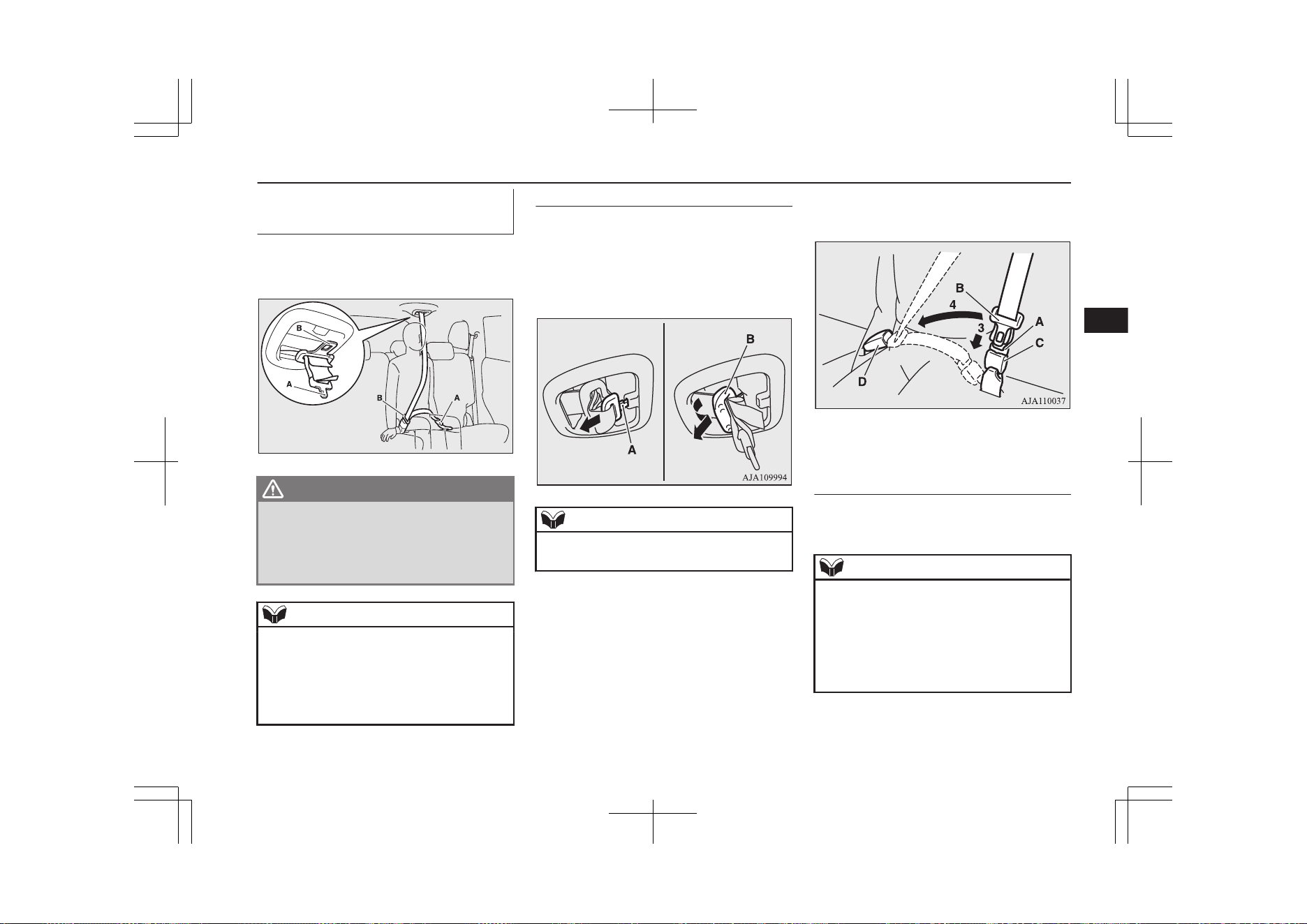
Rear-centre 3-point type seat
belt
E00405201184
The rear-centre 3-point type seat belt must be
worn correctly as illustrated.
AA0111461
WARNING
l
Be sure to securely connect the both latch
plate (A and B). Failing to do so could sig-
nificantly reduce the amount of protection
and cause serious injures in a collision or
a sudden stop.
NOTE
l
If the seat belt buckles in the rear seating po-
sition are not found, you will find them un-
der the rear seat cushion.
Refer to “Making a luggage area” on page
5-06 for how to put the seat belt buckles at
the proper position.
To fasten
1. Pull out the buckle (C) from the seat-
back.
2. Pull out the small latch plate (A) and
then pull out the latch plate (B) by tilting
it as shown in the illustration.
NOTE
l
Pulling out the latch plate by force may
damage the headliner.
3. Pull the seat belt and insert the small
latch plate (A) into the buckle (C).
4. Insert the latch plate (B) into the buckle
(D).
5. Pull the belt slightly to adjust slackness
as desired.
To unfasten
1. Hold the latch plate and push the button
on the buckle.
NOTE
l
As the belt retracts automatically, keep hold-
ing the latch plate while retracting so that the
belt stows slowly. Failure to do this could
damage the vehicle.
l
To release the buckle (C), press the button
(E) with a narrow-tipped object (latch plate
or mechanical key etc.).
Seat belts
5-13
OGGE19E1
Seats and seat belts
5
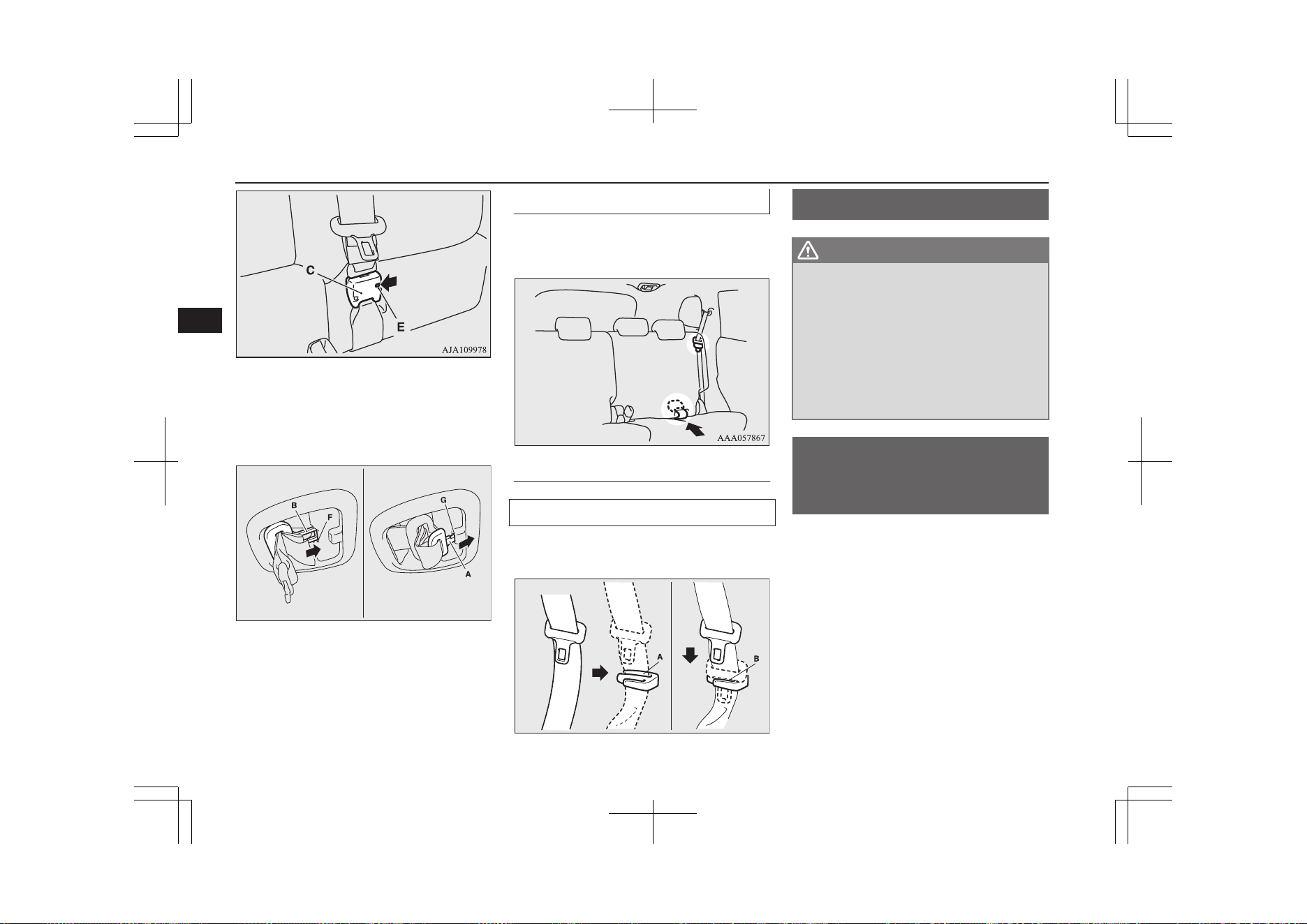
2. After the seat belt is retracted complete-
ly, insert the latch plate (B) into the up-
per slit (F), and then insert the small
latch plate (A) into the lower slit (G).
AA0111487
3. Store the seat belt buckle in the storage
pocket.
(Refer to next column.)
Rear seat belt storage
E00405301521
When the seat belt is not in use, store it as
shown in the illustration.
Seat belt plate storage
Outboard seating position
After passing the belt through the rear notch
(A), insert the plate into the front notch (B).
AA0064860
Pregnant women restraint
E00405600077
WARNING
l
Seat belts work for everyone, including
pregnant women. Pregnant women should
use the available seat belts. This will re-
duce the likelihood of injury to both the
woman and the unborn child. The lap belt
should be worn across the thighs and as
snug against the hips as possible, but not
across the waist. Consult your doctor if
you have any additional questions or con-
cerns.
Seat belt pretensioner
system and force limiter
system
E00405701323
The driver’s seat and front passenger’s seat
each have a seat belt equipped with a preten-
sioner system and force limiter system.
Pregnant women restraint
5-14
OGGE19E1
Seats and seat belts
5
Pretensioner system
E00405802523
When the operation mode of the power
switch is in ON, if there is a frontal impact or
a side impact severe enough to injure the
driver and/or front passenger, the pretension-
er system will retract their respective seat
belts instantaneously, thus maximizing the
seat belt’s effectiveness.
WARNING
l
To obtain the best results from your pre-
tensioner seat belt, make sure you have
adjusted your seat correctly and wear
your seat belt properly.
CAUTION
l
Installation of audio equipment or repairs in
the vicinity of the pretensioner seat belts or
floor console must be performed in line with
MITSUBISHI MOTORS guidelines. It is
important to do so because the work could
affect the pretensioner systems.
l
If you need to scrap the vehicle, please con-
sult a MITSUBISHI MOTORS Authorized
Service Point.
It is important to do so because unexpected
activation of the pretensioner seat belts
could cause injuries.
NOTE
l
The pretensioner seat belts will be activated
if the vehicle suffers a severe impact, even if
the seat belts are not worn.
l
The pretensioner seat belts are designed to
work only once. After the pretensioner seat
belts have been activated, we recommend
you have it replaced by a MITSUBISHI
MOTORS Authorized Service Point.
SRS warning
E00405900360
The same warning lamp/display is shared by
the SRS airbags and the pretensioner seat
belts.
Refer to “SRS warning lamp/display” on
page 5-35.
Force limiter system
E00406000209
In the event of a collision, each force limiter
system will effectively absorb the load ap-
plied to the seat belt to minimize the impact
to the passenger.
Child restraint
E00406403507
When transporting children in your vehicle,
some type of child restraint system should al-
ways be used according to the size of the
child. This is required by law in most coun-
tries.
The regulations concerning driving with chil-
dren in the front seat may differ from country
to country. You are advised to comply with
the relevant regulations.
WARNING
l
When possible, put children in the rear
seat. Accident statistics indicate that chil-
dren of all sizes and ages are safer when
properly restrained in the rear seat rather
than in the front seat.
l
Holding a child in your arms is no substi-
tute for a restraint system. Failure to use
a proper restraint system can result in se-
vere or fatal injury to the child.
l
Each child restraint device or fixing is to
be used only by one child.
l
When attaching a child restraint system
to the rear seat, prevent the front seat-
backs from touching the child restraint
system.
Otherwise, the child could be seriously in-
jured in the event of hard braking or a
collision.
Child restraint
5-15
OGGE19E1
Seats and seat belts
5
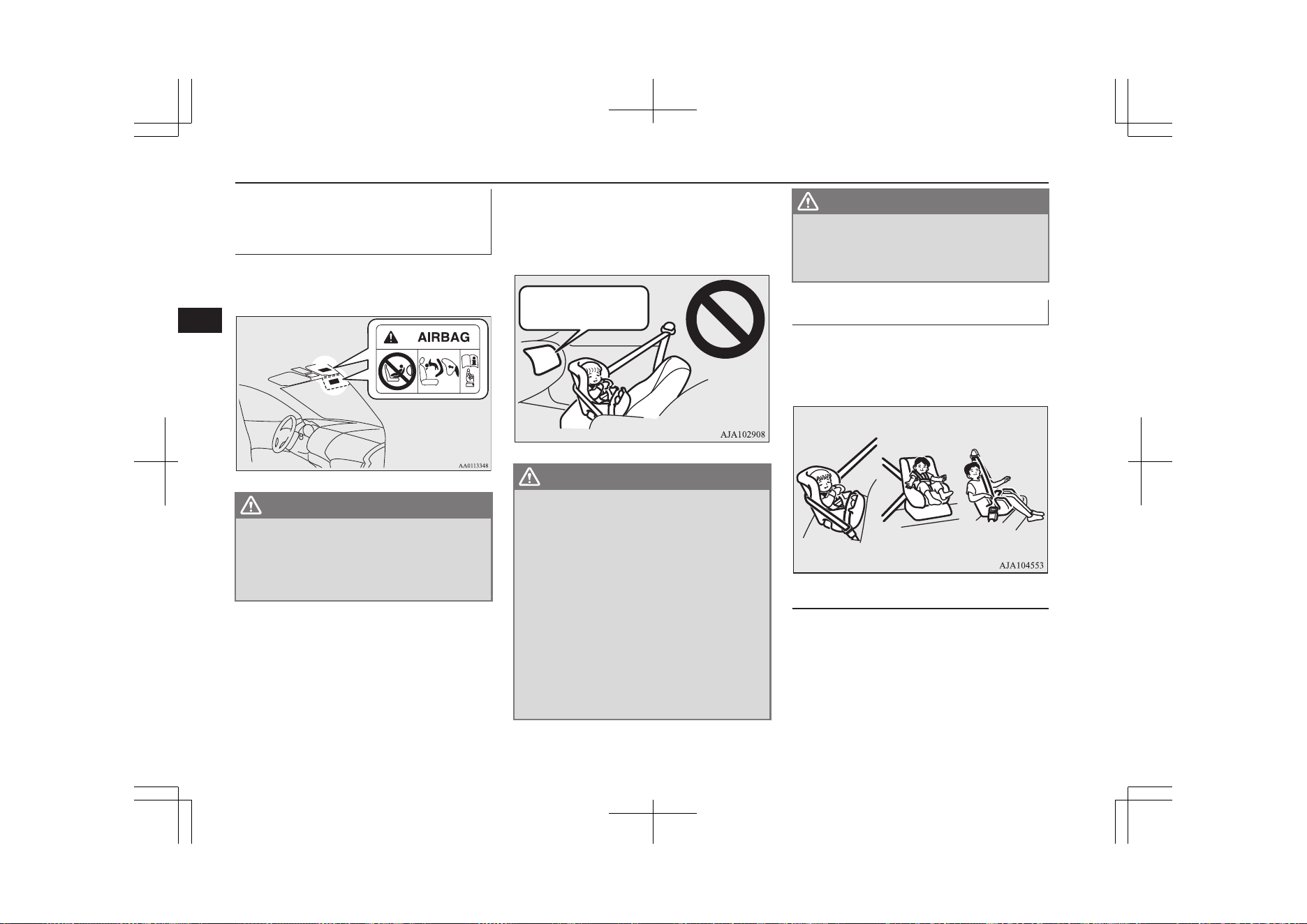
Caution for installing the child
restraint on vehicles with front
passenger’s airbag
The label shown here is attached on vehicles
with a front passenger’s airbag.
WARNING
l
Extreme Hazard!
NEVER use a rearward facing child re-
straint on a seat protected by an ACTIVE
AIRBAG in front of it, DEATH or SERI-
OUS INJURY to the CHILD can occur.
Use rearward facing child restraints in the
rear seat or turn off the front passenger’s air-
bag ON-OFF switch. (Refer to “To turn an
airbag off” on page 5-28)
Front passenger’s
airbag ON
WARNING
l
A REARWARD FACING CHILD RE-
STRAINT must NOT be used in the front
passenger seat if the front passenger’s air-
bag has not been deactivated. The force of
an inflating airbag could kill or cause se-
rious injuries to the child. A rearward
facing child restraint should be used in
the rear seat.
l
A FORWARD FACING CHILD RE-
STRAINT should be used in the rear seat
whenever possible; if it must be used in
the front passenger seat, turn off the front
passenger’s airbag ON-OFF switch.
Failure to do so could kill or cause serious
injuries to the child.
WARNING
l
A REARWARD FACING CHILD RE-
STRAINT must NOT be used in the front
passenger seat when the driver’s visibility
is obstructed.
Infants and small children
E00406602065
When transporting infants and small children
in your vehicle, follow the instruction given
below.
Instruction:
l
For small infants, an infant carrier
should be used. For small children
whose height when seated allows the
shoulder belt to lie in contact with the
face or the throat, a child seat should be
used.
Child restraint
5-16
OGGE19E1
Seats and seat belts
5
l
The child restraint system should be ap-
propriate for the child’s weight and
height and properly fit in the vehicle.
For a higher degree of safety: THE
CHILD RESTRAINT SYSTEM
SHOULD BE INSTALLED IN THE
REAR SEAT.
NOTE
l
Before purchasing a child restraint system,
try installing it to make sure there is a good
fit. Because of the location of the seat belt
buckles and the shape of the seat cushion, it
may be difficult to securely install some
manufacturer’s child restraint systems.
If the child restraint system can be pulled
forward or to either side easily on the seat
cushion after the seat belt has been tight-
ened, choose another manufacturer’s child
restraint system.
WARNING
l
When installing a child restraint system,
refer to the instructions provided by the
manufacturer of the restraint system.
Failure to do so can result in severe or fa-
tal injury to the child.
WARNING
l
After installation, push and pull the child
restraint system back and forth, and side
to side, to see that it is properly secured. If
the child restraint system is not installed
securely, it may cause injury to the child
or other occupants in the case of accident
or sudden stops.
l
When the child restraint system is not in
use, keep your child restraint system se-
cured with the seat belt or remove it from
the vehicle in order to prevent it from be-
ing thrown around inside the vehicle dur-
ing an accident.
Depending on the seating position in the
vehicle and the child restraint system
that you have, the child restraint can be
attached using one of the following two
ways:
• Using the lower anchorage in the front
passenger seat or the rear seat if the
child restraint has ISOFIX mountings
(See page 5-22).
• Using the seat belt (See page 5-24).
Older children
E00406700307
Children who have outgrown the child re-
straint system should be seated in the rear
seat and wear combination lap shoulder belt.
The lap portion of the belt should be snug
and positioned low on the abdomen so that it
is below the top of the hip-bone. Otherwise,
the belt could intrude into the child’s abdo-
men during an accident and cause injury.
Child restraint
5-17
OGGE19E1
Seats and seat belts
5
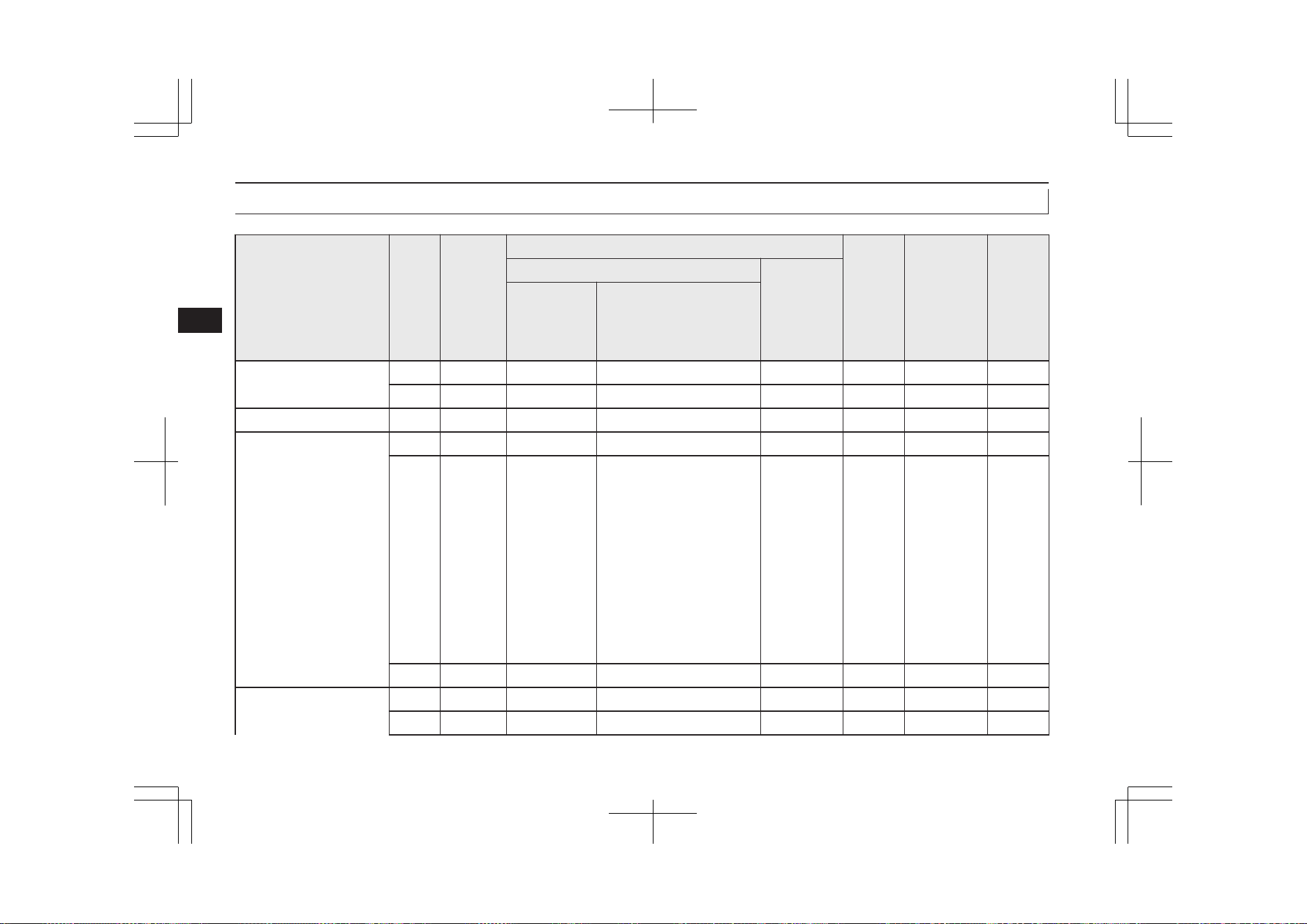
Suitability for various ISOFIX positions
E00411402393
Mass group
Size
class
Fixture
Vehicle ISOFIX positions Recom-
mended
Child
Re-
straint
Sys-
tems
*2
UN-R44 Ap-
proval No.
UN-
R129
Appro-
val No.
Front passenger
Rear out-
board
Activated air-
bag
Deactivated Airbag
*1
Carrycot
F ISO/L1 X X X — — —
G ISO/L2 X X X — — —
0 -Up to 10 kg E ISO/R1 X IL IL — — —
0+ -Up to 13 kg
E ISO/R1 X IL IL — — —
D ISO/R2 X IL, IL# IL, IL#
BABY-
SAFE i-
SIZE:
MZ3150
55
BABY-
SAFE i-
SIZE
FLEX
BASE:
MZ3150
56
—
E1-0000
08
C ISO/R3 X X IL — — —
I -9 to 18 kg
D ISO/R2 X X IL — — —
C ISO/R3 X X IL — — —
Child restraint
5-18
OGGE19E1
Seats and seat belts
5
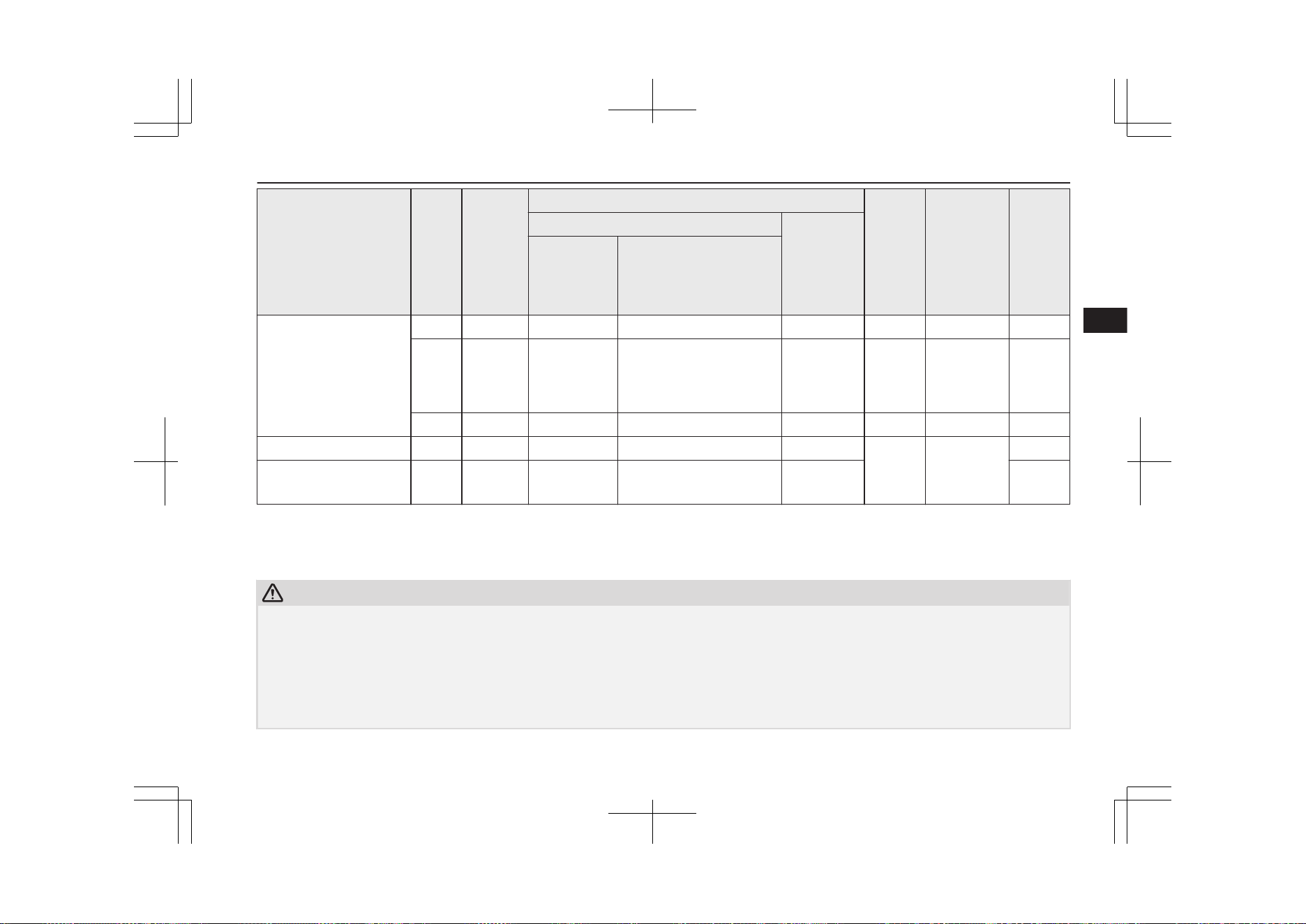
Mass group
Size
class
Fixture
Vehicle ISOFIX positions Recom-
mended
Child
Re-
straint
Sys-
tems
*2
UN-R44 Ap-
proval No.
UN-
R129
Appro-
val No.
Front passenger
Rear out-
board
Activated air-
bag
Deactivated Airbag
*1
B ISO/F2 X IUF IUF — — —
B1 ISO/F2X X IUF, IL# IUF, IL#
DUO
plus:
MZ3130
45
E1-04301133 —
A ISO/F3 X IUF IUF — — —
II - 15 to 25 kg X IL# IL#
KIDFIX
XP:
MZ31502
5
E1-04301304
—
III - 22 to 36 kg
X IL# IL# —
*1
: With front passenger’s airbag deactivated by means of front passenger’s airbag ON-OFF switch.
*2
: MITSUBISHI MOTORS Europe B.V. reserves the right to changes without any prior announcement.
For detailed information, consult your MITSUBISHI MOTORS Authorized Service Point.
CAUTION
l
When installing a child restraint system, remove the head restraint from the seat.
l
When installing a child restraint system on the rear outboard seat, adjust the seatback angle to 4 steps forward from the most reclined position.
l
A rearward facing child restraint system is not recommended for front passenger seat because driver’s visibility may be obstructed. If the driver’s visibility is
obstructed, install a child restraint system on the rear seat.
l
Do not sit in the middle seating position of the rear seat when installing a child restraint system to the left outboard seating position of the rear seat. Because
the child restraint interferes with the seat belt, you cannot fasten the seat belt correctly.
l
“BABY-SAFE i-SIZE” and “BABY-SAFE i-SIZE FLEX BASE” are designed for children 40 to 83 cm in height.
Child restraint
5-19
OGGE19E1
Seats and seat belts
5
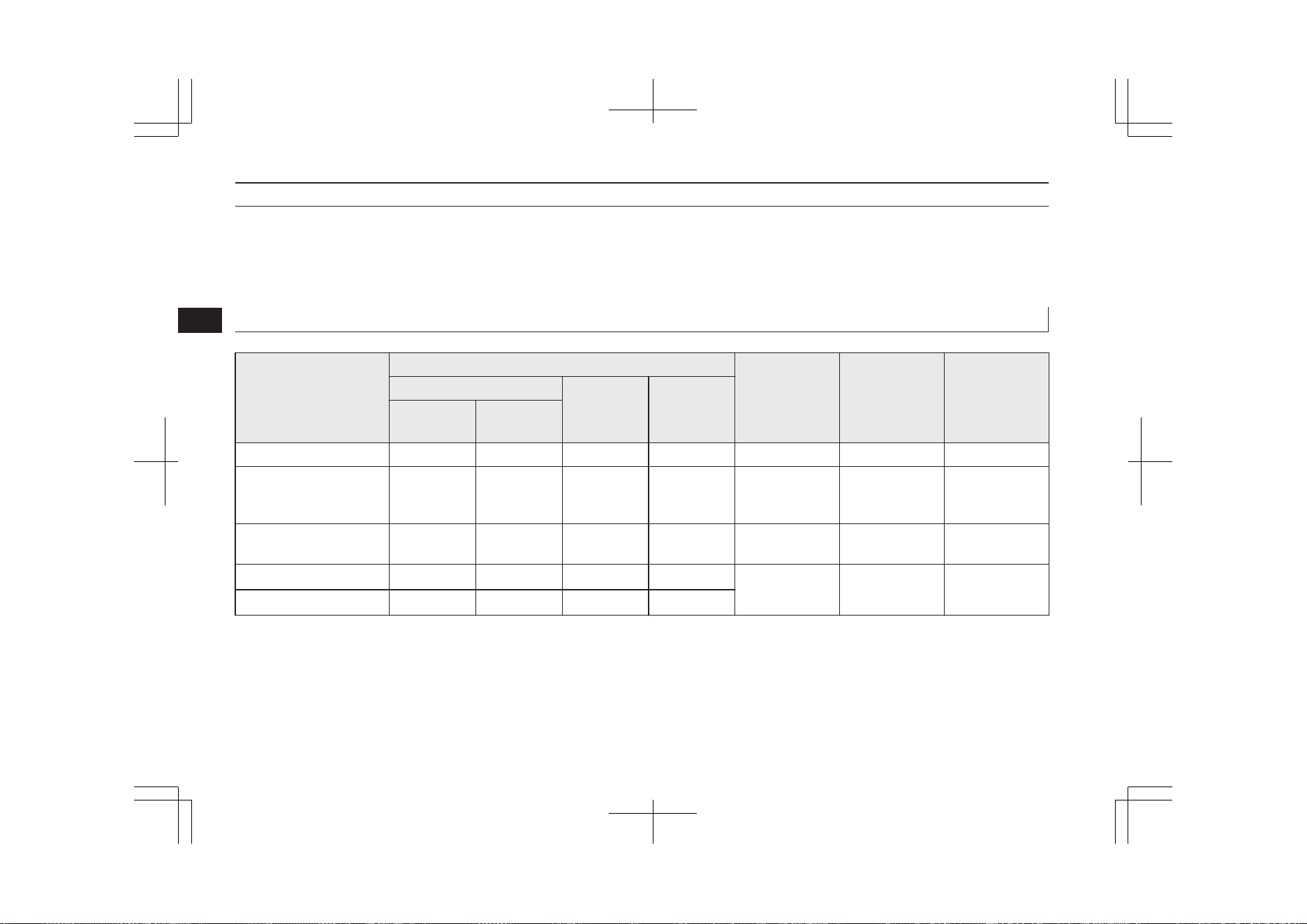
Definition of characters the above table:
l
IUF- Suitable for ISOFIX forward child restraint systems of universal category approved for use in the mass group.
l
IL- Suitable for ISOFIX child restraint systems of semi-universal category approved for use in the mass group.
l
IL#- Suitable for particular ISOFIX child restraint systems. See the above table of “Recommended Child Restraint Systems”.
l
X- ISOFIX position not suitable for ISOFIX child restraint systems in this mass group.
Suitability for various seating positions
E00406803240
Mass group
Seating position
Recommended
Child Restraint
Systems
*2
UN-R44 Appro-
val No.
UN-R129 Ap-
proval No.
Front passenger
Rear out-
board
Rear centre
Activated
airbag
Deactivated
Airbag
*1
0 -Up to 10 kg X U U X — — —
0+ - Up to 13 kg X U, L# U, L# X
BABY-SAFE i-
SIZE:
MZ315055
— E1-000008
I -9 to 18 kg X U, L# U, L# X
DUO plus:
MZ313045
E1-04301133 —
II - 15 to 25 kg X
U
*3
, L# U
*3
, L#
X
KIDFIX XP:
MZ315025
E1-04301304 —
III - 22 to 36 kg X
U
*3
, L# U
*3
, L#
X
*1
: With front passenger’s airbag deactivated by means of front passenger’s airbag ON-OFF switch
*2
: MITSUBISHI MOTORS Europe B.V. reserves the right to changes without any prior announcement.
For detailed information, consult your MITSUBISHI MOTORS Authorized Service Point.
*3
: Do not remove the head restraint when installing a “universal” category booster cushion.
Child restraint
5-20
OGGE19E1
Seats and seat belts
5

CAUTION
l
When installing a child restraint system, remove the head restraint from the seat. However, do not remove the head restraint when installing a booster cush-
ion (see page “Installing a child restraint system to a 3-point type seat belt (with emergency locking mechanism)” on page 5-24).
l
When installing a child restraint system on the front passenger seat, adjust the front seatback angle to 2 steps rearward from the first locking position.
l
Do not sit in the middle seating position of the rear seat when installing a child restraint system to the left outboard seating position of the rear seat. Because
the child restraint interferes with the seat belt, you cannot fasten the seat belt correctly.
l
“BABY-SAFE i-SIZE” is designed for children 40 to 83 cm in height.
Definition of characters the above table:
l
U- Suitable for “universal” category restraints approved for use in this mass group.
l
L#- Suitable for particular child restraint systems. See the above table of “Recommended Child Restraint Systems”.
l
X- Seat position not suitable for children in this mass group.
Child restraint
5-21
OGGE19E1
Seats and seat belts
5
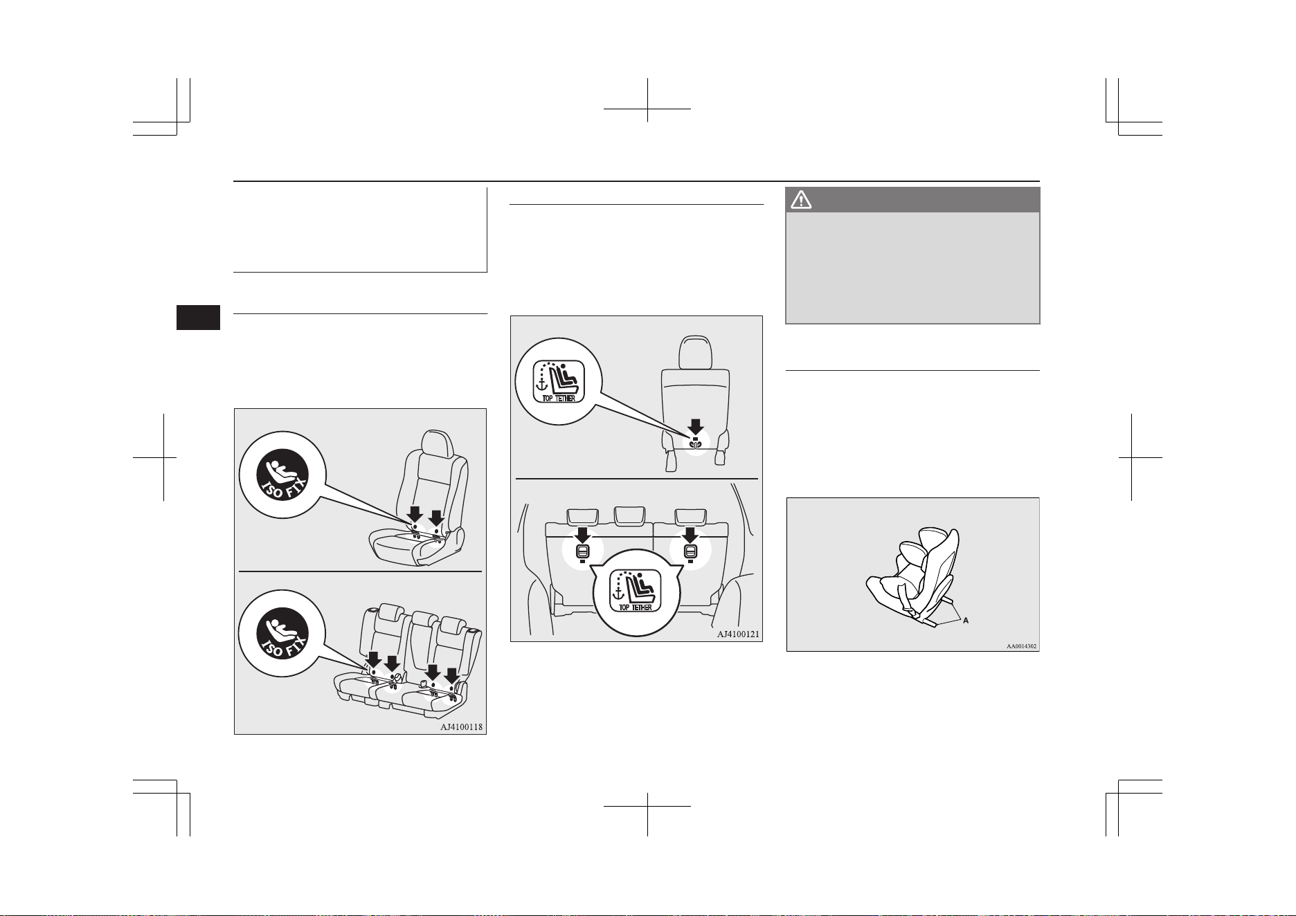
Installing a child restraint sys-
tem to the lower anchorage
(ISOFIX child restraint mount-
ings) and tether anchorage
E00406901944
Lower anchorage location
Your vehicle’s front passenger seat and rear
seat is fitted with lower anchorages for at-
taching a child restraint system with ISOFIX
mountings.
Front passenger seat
Rear seat
Tether anchorage location
Your vehicle has 3 child restraint anchorage
points on the backside of the front passenger
seat and rear seats. These are for securing a
child restraint system tether strap to each of
the 3 seating positions in your vehicle.
Front passenger seat
Rear seat
WARNING
l
Child restraint anchorages are designed
to withstand only those loads imposed by
correctly fitted child restraints. Under no
circumstances are they to be used for
adult seat belts, harnesses, or for attach-
ing other items or equipment to the vehi-
cle.
Child restraint system with
ISOFIX mountings
The child restraint system is designed only
for seats that incorporate lower anchorages.
Retain the child restraint system using the
lower anchorages.
It is not necessary to retain the child restraint
system using the vehicle’s seat belts.
A- Child restraint system connectors
Child restraint
5-22
OGGE19E1
Seats and seat belts
5
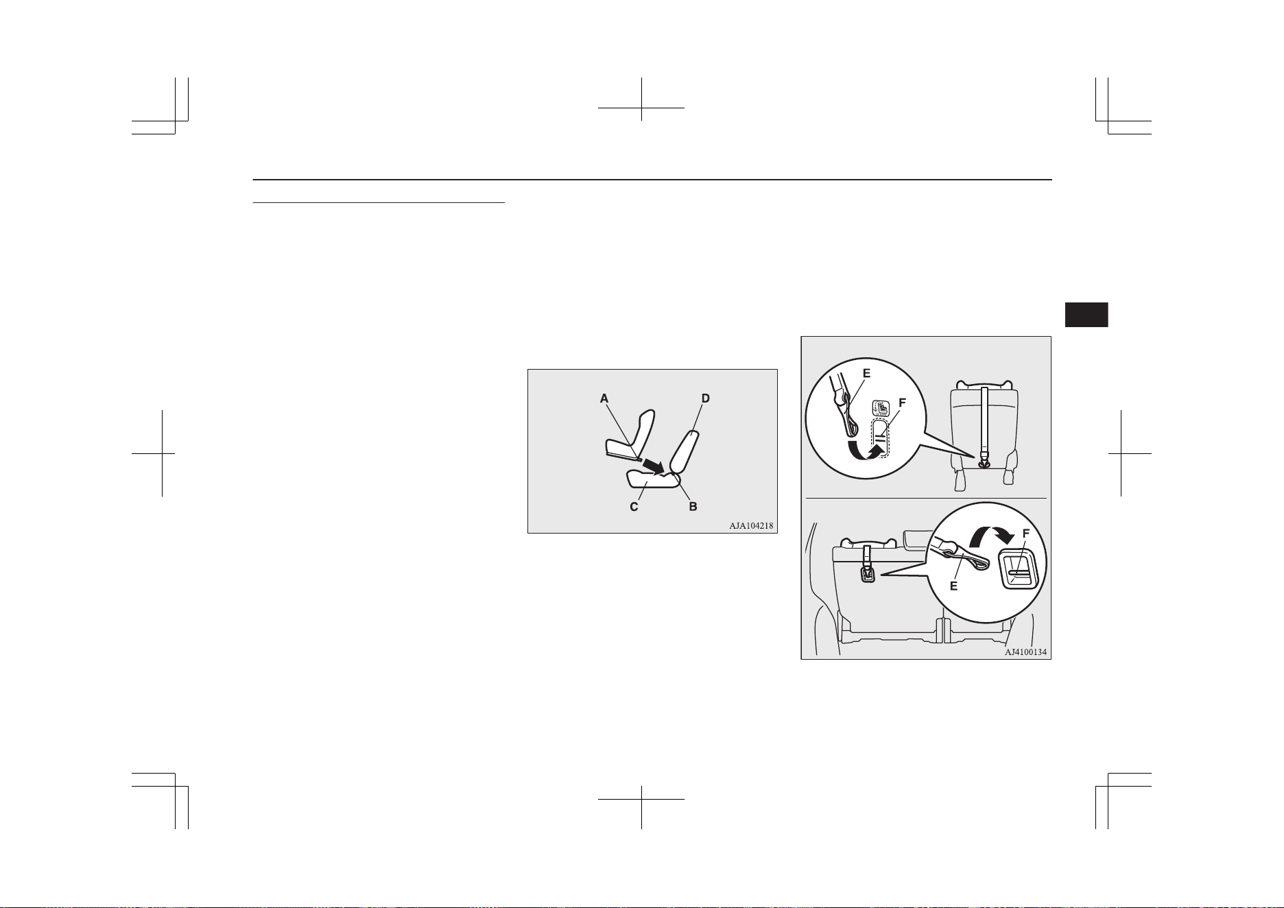
To install
1. Remove any foreign material in or
around the connectors and ensure the ve-
hicle seat belt is in its normal storage po-
sition.
2. Remove the head restraint from the loca-
tion in which you wish to install a child
restraint.
Refer to “Head restraints” on page 5-05.
3. When installing a child restraint system
in the front passenger seat, adjust seat
slide to its most rearward position.
4. Push the child restraint system’s connec-
tors (A) into the lower anchorages (B) in
accordance with the instructions provi-
ded by the child restraint system’s manu-
facturer.
For easier access to the rear seat lower
anchorage, the rear seatback may be re-
cline rearward. After it is security fas-
tened, adjust the seatback to 4 steps for-
ward from most reclined position.
A- Connector
B- Lower anchorage
C- Vehicle seat cushion
D- Vehicle seatback
If your child restraint system has a sup-
port leg, make sure that there is a sup-
port leg at the stable position on the
floor.
If your child restraint system requires the use
of a tether strap, fasten the tether strap in ac-
cordance with step 5.
6.
5. Latch the tether strap hook (E) of the
child restraint system to the tether an-
chorage bar (F) and tighten the top tether
strap hook so it is securely fastened.
Front passenger seat
Rear seat
Child restraint
5-23
OGGE19E1
Seats and seat belts
5
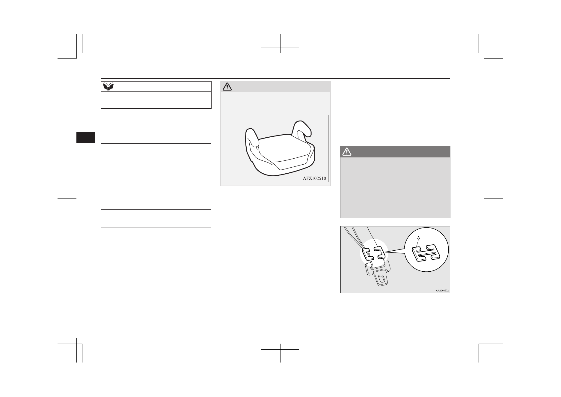
NOTE
l
If it is difficult to latch the tether strap hook
in the rear seat, turn the hook sideways.
6. Push and pull the child restraint system
in all directions to be sure it is secure.
To remove
Remove the child restraint system in accord-
ance with the instructions provided by the
child restraint system’s manufacturer.
Installing a child restraint sys-
tem to a 3-point type seat belt
(with emergency locking mech-
anism)
E00408702060
Installation:
1. Put a child restraint system on the seat in
which you wish to install it, and remove
the head restraint from the seat.
Refer to “Head restraints” on page 5-05.
CAUTION
l
Do not remove the head restraint when in-
stalling a booster cushion.
2. When installing a child restraint system
in the front passenger seat, adjust seat
slide to its most rearward position and
adjust the front seatback angle to 2 steps
rearward from the first locking position.
3. Route the belt through the child restraint
according to the child restraint system
manufacturer’s instructions, then insert
the latch plate into the buckle.
4. Remove all slack of a lap belt by pulling
the webbing through the belt’s adjust-
ment feature.
3-point type seat belt requires no length
adjustment, remove all slack by using
the locking clip.
5. If your child restraint system has a sup-
port leg, make sure that there is a sup-
port leg at the stable position on the
floor.
6. Before putting the child in the restraint,
push and pull the restraint in all direc-
tions to be sure it is secure. Do this be-
fore each use.
WARNING
l
For some types of child restraint, the lock-
ing clip (A) should be used to help avoid
personal injury during a collision or sud-
den manoeuvre.
It must be fitted and used in accordance
with the child restraint manufacturer’s
instructions.
The locking clip must be removed when
the child restraint is removed.
Child restraint
5-24
OGGE19E1
Seats and seat belts
5
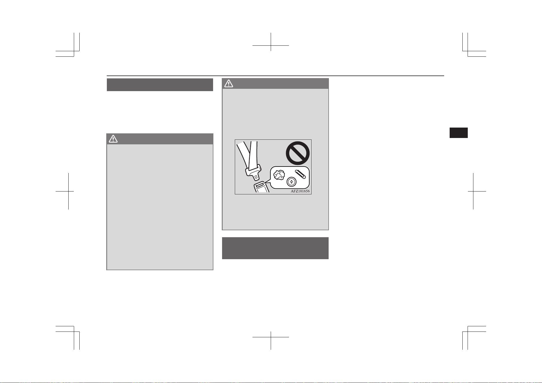
Seat belt inspection
E00406301850
Check the belts for cuts, worn or frayed web-
bing and for cracked or deformed metallic
parts. Replace the belt assembly if it is defec-
tive.
WARNING
l
We recommend you to have all seat belt
assemblies including retractors and at-
taching hardware inspected after any col-
lision. We recommend that seat belt as-
semblies in use during a collision be re-
placed unless the collision was minor and
the belts show no damage and continue to
operate properly.
l
Do not attempt to repair or replace any
part of the seat belt assemblies; we recom-
mend you to have this work done by a
MITSUBISHI MOTORS Authorized
Service Point. Incorrect repair or replace-
ment could reduce the effectiveness of the
belts and could result in serious injury in
the event of a collision.
l
Once the pretensioner has been activated,
it cannot be re-used.
It must be replaced together with the re-
tractor.
WARNING
l
Do not insert any foreign objects (pieces
of plastic, paper clips, buttons, etc.) in the
buckle or retractor mechanism. In addi-
tion, do not modify, remove or install the
seat belt. Otherwise, the seat belt may not
be able to provide adequate protection in
a collision or other situation.
l
A dirty belt should be cleaned with neu-
tral detergent in warm water. After rins-
ing in water, let it dry in the shade. Do not
attempt to bleach or re-dye the belts be-
cause this will affect their characteristics.
Supplemental restraint
system (SRS)-airbag
E00407203645
The information for SRS airbags includes im-
portant information concerning the driver’s
and front passenger’s airbags, the driver’s
knee airbag, the side airbags and the curtain
airbags.
The SRS driver and front passenger airbags
are designed to supplement the primary pro-
tection of the driver and front passenger side
seat belt systems by providing those occu-
pants with protection against head and chest
injuries in certain moderate-to-severe frontal
collisions.
The SRS driver’s knee airbag is designed to
supplement the primary protection of the
driver’s seat belt system. It can reduce the
forward movement of the driver’s lower legs
and provide increased overall body protection
in certain moderate-to-severe frontal colli-
sions.
The SRS side airbags are designed to supple-
ment properly worn seat belts and provide the
driver and front passenger with protection
against chest injuries in certain moderate-to-
severe side impact collisions.
The SRS curtain airbags are designed to sup-
plement properly worn seat belts and provide
the driver and passenger with protection
against head injuries in certain moderate-to-
severe side impact collisions.
The SRS is NOT a substitute for the seat
belts. To ensure the maximum protection dur-
ing all types of collisions and accidents, all
occupants, including the passengers as well
as the driver, must wear their seat belts.
Seat belt inspection
5-25
OGGE19E1
Seats and seat belts
5
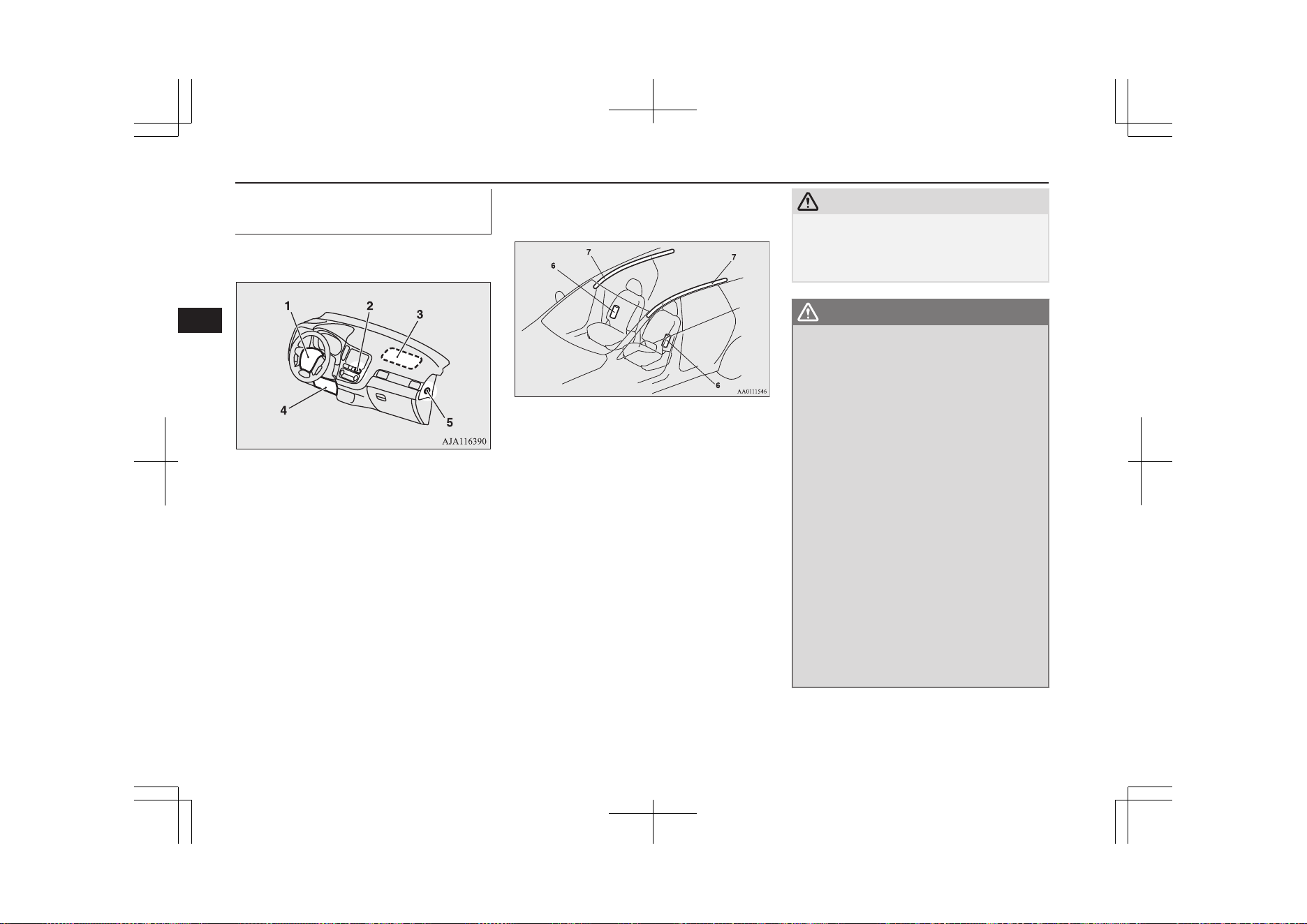
How the Supplemental Re-
straint System works
E00407303460
The SRS includes the following components:
1- Airbag module (Driver)
2- Front passenger’s airbag indicator
3- Airbag module (Passenger)
4- Driver’s knee airbag module
5- Front passenger’s airbag ON-OFF
switch
6- Side airbag modules
7- Curtain airbag modules
Only when the operation mode of the power
switch is in ON, the airbags will operate.
The airbags deployment produces a sudden,
loud noise, and releases some smoke and
powder, but these conditions are not injuri-
ous, and do not indicate a fire in the vehicle.
People with respiratory problems may feel
some temporary irritation from chemicals
used to produce the deployment; open the
windows after airbag deployment, if safe to
do so.
The airbags deflate very rapidly after deploy-
ment, so there is little danger of obscured vi-
sion.
CAUTION
l
Airbags inflate at an extremely rapid speed.
In certain situations, contact with inflating
airbags can result in abrasions, bruises, light
cuts, and the like.
WARNING
l
IT IS VERY IMPORTANT TO BE
PROPERLY SEATED.
A driver or front passenger too close to
the steering wheel or instrument panel
during airbag deployment can be killed or
seriously injured.
Airbags inflate very fast, and with great
force.
If the driver and front passenger are not
properly seated and restrained, the air-
bags may not protect you properly, and
could cause serious or fatal injuries when
it inflates.
l
Do not sit on the edge of the seat, or sit
with your lower legs too close to the in-
strument panel, or lean head or chest
close to the steering wheel or instrument
panel. Do not put feet or legs on or against
the instrument panel.
l
Place all infants and small children in the
rear seat and properly restrained using an
appropriate child restraint system.
The rear seat is the safest place for infants
and children.
Supplemental restraint system (SRS)-airbag
5-26
OGGE19E1
Seats and seat belts
5
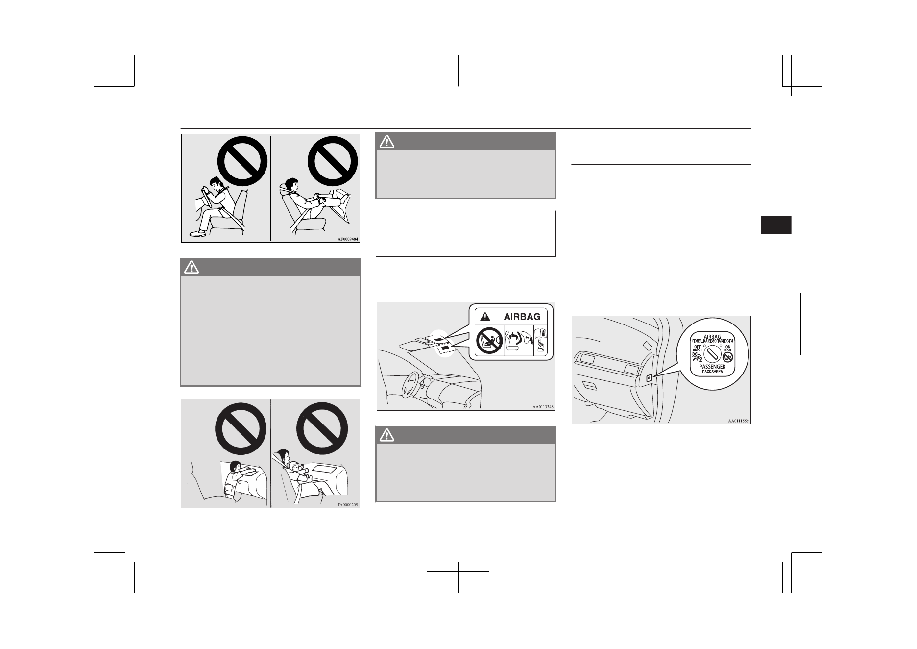
WARNING
l
Infants and small children should never
be unrestrained, stand up against the in-
strument panel or be held in your arms or
on your lap. They could be seriously in-
jured or killed in a collision, including
when the airbag inflates. They should be
properly seated in the rear seat in an ap-
propriate child restraint system. See the
“Child restraint” section of this owner’s
manual.
WARNING
l
Older children should be seated in the
rear seat, properly wearing the seat belt,
with an appropriate booster seat if nee-
ded.
Caution for installing the child
restraint on vehicles with a
front passenger airbag
E00408802016
The label shown here is attached on vehicles
with a front passenger airbag.
WARNING
l
Extreme Hazard!
NEVER use a rearward facing child re-
straint on a seat protected by an ACTIVE
AIRBAG in front of it, DEATH or SERI-
OUS INJURY to the CHILD can occur.
Front passenger’s airbag ON-
OFF switch
E00410100315
The front passenger’s airbag ON-OFF switch
can be used to disable the front passenger’s
airbag. If you have a child restraint system
that cannot be fitted to any seat other than the
front passenger seat, be sure to turn OFF the
front passenger’s airbag ON-OFF switch be-
fore using it.
(Refer to “To turn an airbag off” on page
5-28)
The front passenger’s airbag ON-OFF switch
is located as shown in the illustration.
Supplemental restraint system (SRS)-airbag
5-27
OGGE19E1
Seats and seat belts
5
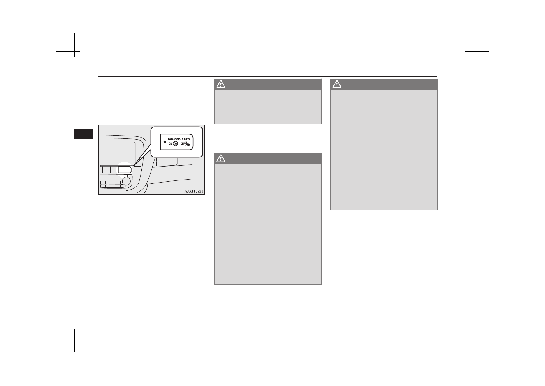
Front passenger’s airbag indi-
cator
E00410201528
The front passenger’s airbag indicator is loca-
ted in the instrument panel.
The both indicator normally comes on when
the operation mode of the power switch is put
in ON, and goes off a few seconds later.
When the front passenger’s airbag ON-OFF
switch is turned OFF, the OFF indicator will
stay on to show that the front passenger’s air-
bag is not operational. When the front pas-
senger’s airbag ON-OFF switch is turned
ON, the OFF indicator goes off, and the ON
indicator comes on for approximately 1 mi-
nute to show that the front passenger’s airbag
is operational.
WARNING
l
Do not fit any accessory that makes the
indication lamp impossible to see, and do
not cover the indication lamp with a stick-
er. You would not be able to verify the sta-
tus of the passenger airbag system.
To turn an airbag off
E00412301259
WARNING
l
To reduce risk of serious or fatal injury:
•
Always put the operation mode of the
power switch in OFF, before operating
the front passenger’s airbag ON-OFF
switch. Failure to do so could adversely
affect the airbag performance.
•
Wait at least 60 seconds to operate the
front passenger’s airbag ON-OFF
switch after putting the operation mode
in OFF.
The SRS airbag system is designed to
retain enough voltage to deploy the air-
bag.
•
Always remove the key from the front
passenger’s airbag ON-OFF switch af-
ter operating that switch. Failure to do
so could lead to improper position of
the front passenger’s airbag ON-OFF
switch.
WARNING
•
Do not turn OFF the front passenger’s
airbag ON-OFF switch except when a
child restraint system is fitted to the
front passenger seat.
•
If the OFF indicator does not come on
when the front passenger’s airbag ON-
OFF switch is turned OFF, do not fit a
child restraint system to the front pas-
senger seat. We recommend you to
have the system inspected by a
MITSUBISHI MOTORS Authorized
Service Point.
•
If the OFF indicator remains on when
the front passenger’s airbag ON-OFF
switch is turned ON, do not allow any-
one to sit on the front passenger seat.
We recommend you to have the system
inspected by a MITSUBISHI
MOTORS Authorized Service Point.
To turn an airbag off, follow these steps:
1. Remove the emergency key from the
keyless operation key.
Refer to “Emergency key” on page 4-14.
2. Insert the emergency key into the front
passenger’s airbag ON-OFF switch, and
turn it to the “OFF” position.
3. Remove the emergency key from the
front passenger’s airbag ON-OFF
switch.
Supplemental restraint system (SRS)-airbag
5-28
OGGE19E1
Seats and seat belts
5
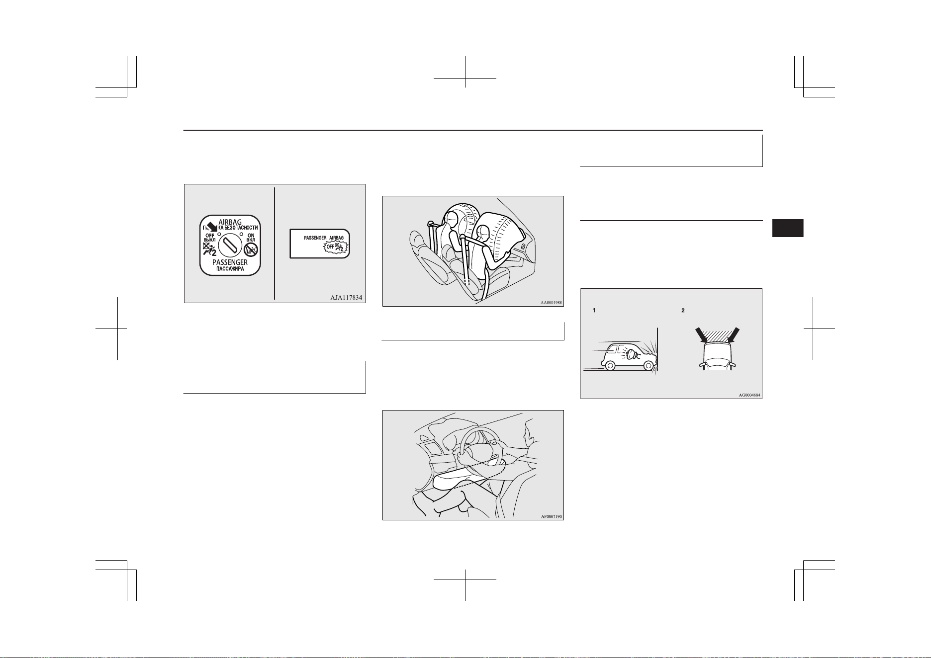
4. Put the operation mode of the power
switch in ON. The front passenger’s air-
bag OFF indication lamp will stay on.
The front passenger’s airbag is now deactiva-
ted and will not deploy until switched on
again.
Driver’s and front passenger’s
airbag system
E00407400792
The driver’s airbag is located under the pad-
ded cover in the middle of the steering wheel.
The front passenger’s airbag is contained in
the instrument panel above the glove box.
The driver’s airbag and the front passenger’s
airbag are designed to inflate at the same
time even if the passenger seat is not occu-
pied.
Driver’s knee airbag system
E00412401104
The driver’s knee airbag is located under the
steering wheel. The driver’s knee airbag is
designed to deploy at the same time as the
driver’s front airbag.
Deployment of front airbags
and driver’s knee airbag
E00407502700
The front airbags and driver’s
knee airbag ARE DESIGNED
TO DEPLOY when…
The front airbags and driver’s knee airbag are
designed to deploy when the vehicle suffers a
moderate-to-severe frontal impact. The typi-
cal condition is shown in the illustration.
1- Head-on collision with a solid wall at a
speed of approximately 25 km/h
(16 mph) or higher
2- Moderate-to-severe frontal impact with-
in the shaded area between the arrows
Supplemental restraint system (SRS)-airbag
5-29
OGGE19E1
Seats and seat belts
5
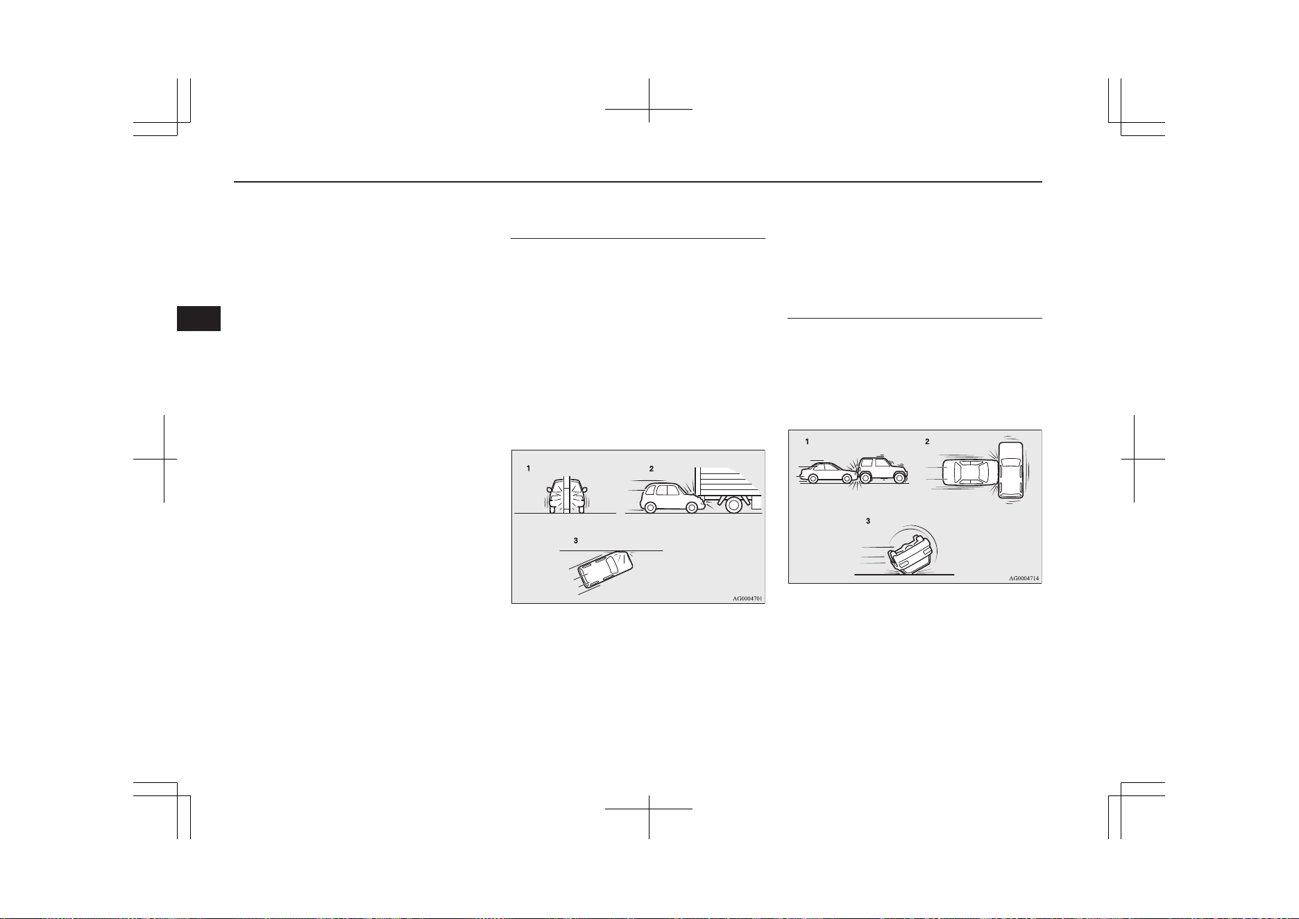
The front airbags and driver’s knee airbag
will deploy if the severity of the impact is
above the designed threshold level, compara-
ble to a collision at approximately 25 km/h
(16 mph) when impacting straight into a solid
wall that does not move or deform. If the se-
verity of the impact is below the above
threshold level, the front airbags and driver’s
knee airbag may not deploy. However, this
threshold speed will be considerably higher if
the vehicle strikes an object that absorbs the
impact by either deforming or moving (for
example, another stationary vehicle, pole or a
guard rail).
Because frontal collisions can easily move
you out of position, it is important to always
properly wear your seat belts. Your seat belts
will help keep you a safe distance from the
steering wheel and instrument panel during
the initial stages of airbag deployment. The
initial stage of airbag inflation is the most
forceful, and can possibly cause serious or fa-
tal injuries. Moreover, the seat belts in your
vehicle are your primary means of protection
in a collision. The SRS airbags are designed
to provide additional protection. Therefore,
for your safety and the safety of all occu-
pants, be sure to always properly wear your
seat belts.
The front airbags and driver’s
knee airbag MAY NOT DE-
PLOY when…
With certain types of frontal collisions, the
vehicle’s body structure is designed to absorb
the shock to help protect the occupants from
harm. (The vehicle body’s front area may de-
form significantly as it absorbs the impact.)
Under such circumstances, the front airbags
and driver’s knee airbag may not deploy irre-
spective of the deformation and damage to
the vehicle body.
Examples of some typical conditions are
shown in the illustration.
1- Collision with a utility pole, tree or other
narrow object
2- Vehicle slides under the rear body of a
truck
3- Oblique frontal impacts
Because the front airbags and driver’s knee
airbag do not protect the occupant in all types
of frontal collisions, be sure to always prop-
erly wear your seat belts.
The front airbags and driver’s
knee airbag ARE NOT DE-
SIGNED TO DEPLOY when…
The front airbags and driver’s knee airbag are
not designed to deploy in conditions where
they cannot typically provide protection to
the occupant.
Such conditions are shown in the illustration.
1- Rear end collisions
2- Side collisions
3- Vehicle rolls onto its side or roof
Because the front airbags and driver’s knee
airbag do not protect the occupant in all types
of collisions, be sure to always properly wear
your seat belts.
Supplemental restraint system (SRS)-airbag
5-30
OGGE19E1
Seats and seat belts
5
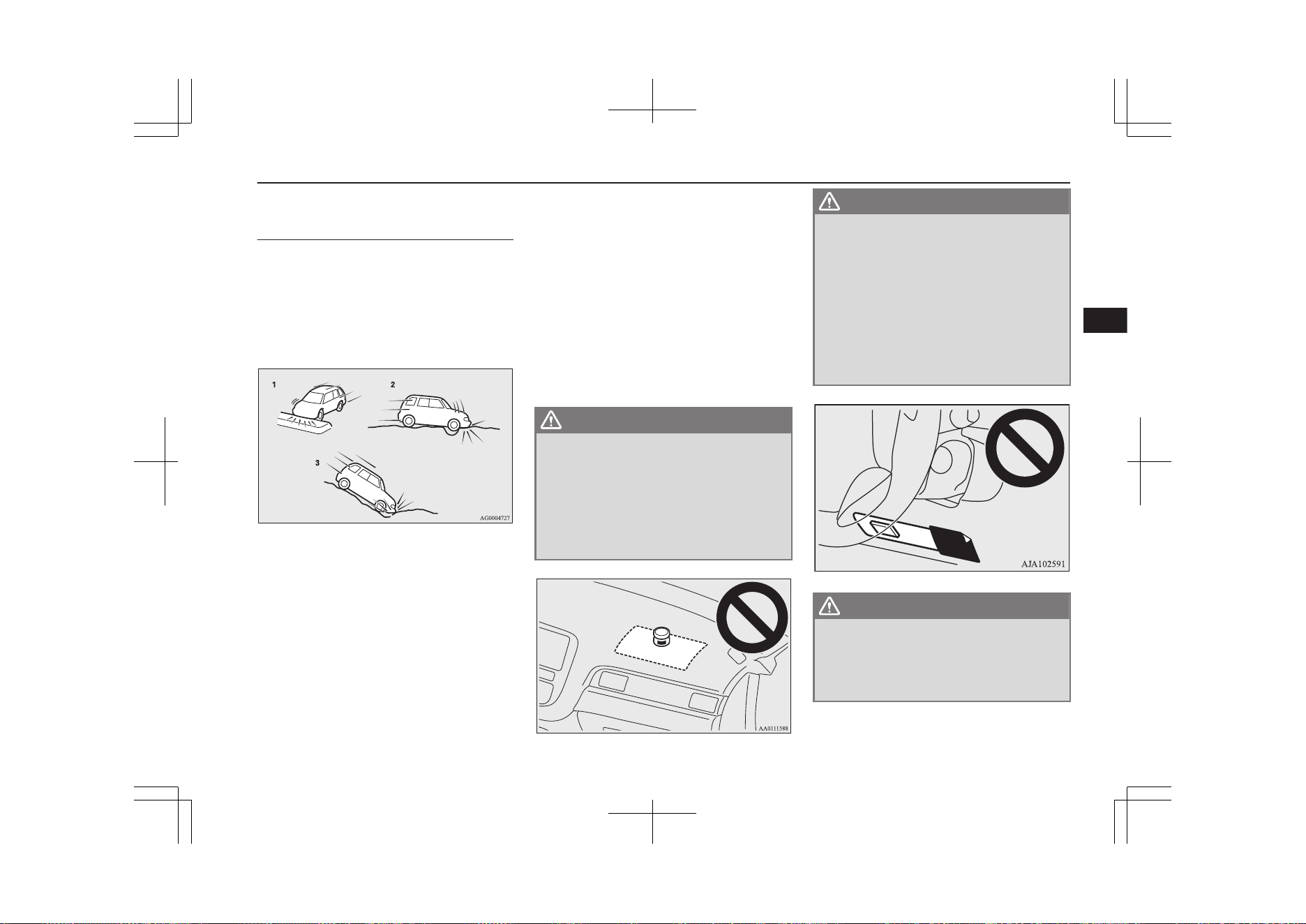
The front airbags and driver’s
knee airbag MAY DEPLOY
when…
The front airbags and driver’s knee airbag
may deploy if the bottom of the vehicle suf-
fers a moderate-to-severe impact (undercar-
riage damage).
Examples of some typical conditions are
shown in the illustration.
1- Collision with an elevated median/island
or kerb
2- Vehicle travels over a deep hole/pothole
3- Vehicle drives down a steep slope and
hits the ground
Because the front airbags and driver’s knee
airbag may deploy in certain types of unex-
pected impacts as shown in the illustration
that can easily move you out of position, it is
important to always properly wear your seat
belts. Your seat belts will help keep you a
safe distance from the steering wheel and in-
strument panel during the initial stages of air-
bag deployment. The initial stage of airbag
inflation is the most forceful and can possibly
cause serious or fatal injuries if you contact it
at this stage.
WARNING
l
Do not attach anything to the steering
wheel’s padded cover, such as badges or
accessories. It might strike and injure an
occupant if the airbag inflates.
l
Do not set anything on, or attach anything
to, the instrument panel above the glove
box. It might strike and injure an occu-
pant if the airbag inflates.
WARNING
l
Do not attach accessories to, or put them
in front of, the windscreen. These objects
could restrict the airbag inflation, or
strike and injure an occupant if the air-
bags inflate.
l
Do not attach accessories to the lower por-
tion of the driver’s side instrument panel.
Such objects could prevent the driver’s
knee airbag from inflating normally or
could be propelled and cause serious in-
jury if the airbag inflates.
WARNING
l
Do not put packages, pets or other objects
between the airbags and the driver or
front passenger. It could affect airbag per-
formance, or could cause injury when the
airbag inflates.
Supplemental restraint system (SRS)-airbag
5-31
OGGE19E1
Seats and seat belts
5
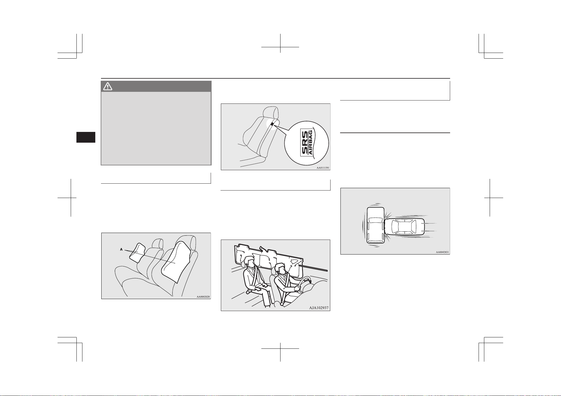
WARNING
l
Right after the airbag inflation, several
airbag system components will be hot. Do
not touch these components. There is a
danger of being burnt.
l
The airbag system is designed to work on-
ly once. Once the airbags have deployed,
they will not work again. They must
promptly be replaced, and we recommend
you to have the entire airbag system in-
spected by a MITSUBISHI MOTORS
Authorized Service Point.
Side airbag system
E00407600619
The side airbags (A) are contained in the
driver and front passenger seatbacks.
The side airbag is designed to inflate only on
the side of the vehicle that is impacted, even
with no passenger in the front seat.
The label shown here is attached to the seat-
backs with a side airbag.
Curtain airbag system
E00409101686
The curtain airbags are contained in the front
pillars and roof side rail. The curtain airbag is
designed to inflate only on the side of the ve-
hicle that is impacted, even with no passen-
ger in the front seat or rear seat.
Deployment of side airbags and
curtain airbags
E00407702731
The side airbags and curtain
airbags ARE DESIGNED TO
DEPLOY when...
The side airbags and curtain airbags are de-
signed to deploy when the vehicle suffers a
moderate-to-severe side impact to the middle
of the passenger compartment.
The typical condition is shown in the illustra-
tion.
The seat belts in your vehicle are your pri-
mary means of protection in a collision. The
SRS side airbags and curtain airbags are de-
signed to provide additional protection.
Therefore, for your safety and the safety of
all occupants, be sure to always properly
wear your seat belts.
Supplemental restraint system (SRS)-airbag
5-32
OGGE19E1
Seats and seat belts
5
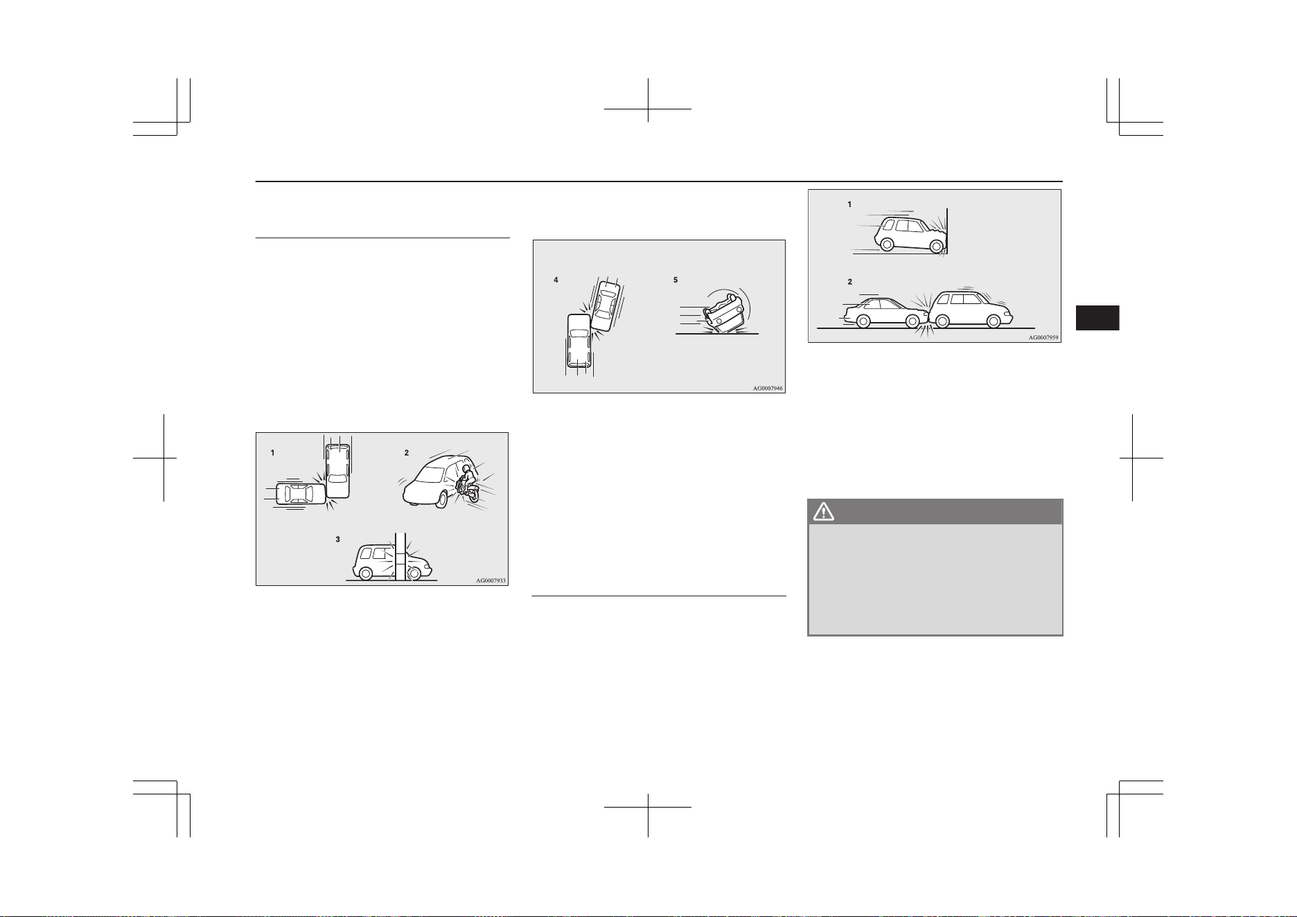
The side airbags and curtain
airbags MAY NOT DEPLOY
when...
With certain types of side collisions, the vehi-
cle’s body structure is designed to absorb the
shock to help protect the occupants from
harm. (The vehicle body’s side area may de-
form significantly as it absorbs the impact.)
Under such circumstances, the side airbags
and curtain airbags may not deploy irrespec-
tive of the deformation and damage to the ve-
hicle body. Examples of some typical condi-
tions are shown in the illustration.
1- Side impacts in an area away from the
passenger compartment
2- Motorcycle or other similar small vehi-
cle collides with the side of vehicle
3- Collision with a utility pole, tree or other
narrow object
4- Oblique side impacts
5- Vehicle rolls onto its side or roof
Because the side airbags and curtain airbags
do not protect the occupant in all types of
side collisions, be sure to always properly
wear your seat belts.
The side airbags and curtain
airbags ARE NOT DESIGNED
TO DEPLOY when...
The side airbags and curtain airbags are not
designed to deploy in conditions where they
cannot usually provide protection to the oc-
cupant. Typical conditions are shown in the
illustration.
1- Head-on collisions
2- Rear end collisions
Because the side airbags and curtain airbags
do not protect the occupant in all types of
collisions, be sure to always properly wear
your seat belts.
WARNING
l
The side airbags and curtain airbags are
designed to supplement the driver and
passenger seat belts in certain side im-
pacts. Seat belts should always be worn
properly, and the driver and passenger
should sit well back and upright without
leaning against the window or door.
Supplemental restraint system (SRS)-airbag
5-33
OGGE19E1
Seats and seat belts
5
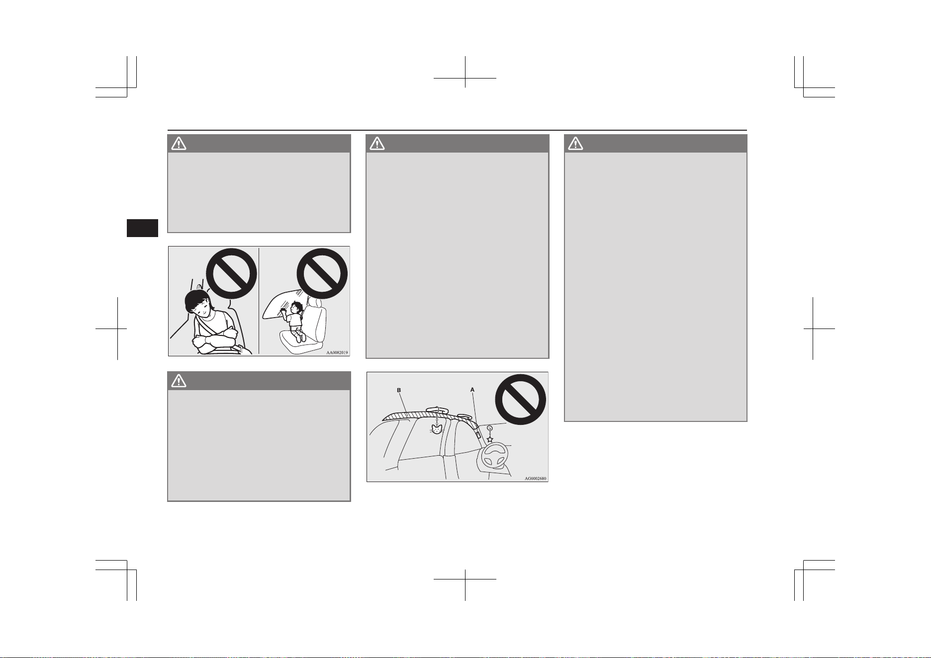
WARNING
l
The side airbag and curtain airbag inflate
with great force. The driver and passen-
ger should not put their arms out of the
window, and should not lean against the
door, in order to reduce the risk of serious
or possible fatal injury from the deploying
side airbag and curtain airbag.
WARNING
l
Do not allow any rear seat occupant to
hold onto the seatback of either front seat,
in order to reduce risk of injury from the
deploying side airbag. Special care should
be taken with children.
l
Do not place any objects near or in front
of the seatback of either front seat. They
could interfere with proper side airbag in-
flation, and also could cause injury if
thrown free by side airbag deployment.
WARNING
l
Do not place stickers, labels or additional
trim on the seatback of either front seat.
They could interfere with proper side air-
bag inflation.
l
Do not install seat covers on seats with
side airbags.
Do not re-cover seats that have side air-
bags. This could interfere with proper
side airbag inflation.
l
Do not attach a microphone (A) or any
other device or object around the part
where the curtain airbags (B) activate
such as on the windscreen, side door glass,
front and rear pillars and roof side or as-
sist grips. When the curtain airbags in-
flate, the microphone or other device or
object will be hurled with great force or
the curtain airbags may not activate cor-
rectly, resulting in death or serious injury.
WARNING
l
Do not put a hanger or any heavy or poin-
ted object on the coat hook. If the curtain
airbag was activated, any such item could
be propelled away with great force and
could prevent the curtain airbag from in-
flating correctly. Hang clothes directly on
the coat hook (without using a hanger).
Make sure there are no heavy or sharp
objects in the pockets of clothes that you
hang on the coat hook.
l
Do not allow a child to lean against or
close to the front door even if the child is
seated in a child restraint system.
The child’s head should also not lean
against or be close to the area where the
side airbag and curtain airbag are loca-
ted. It is dangerous if the side airbag and
curtain airbag inflate.
Failure to follow all of these instructions
could lead to serious or fatal injury to the
child.
l
We recommend work around and on the
side airbags and curtain airbags system to
be done by a MITSUBISHI MOTORS
Authorized Service Point.
Supplemental restraint system (SRS)-airbag
5-34
OGGE19E1
Seats and seat belts
5
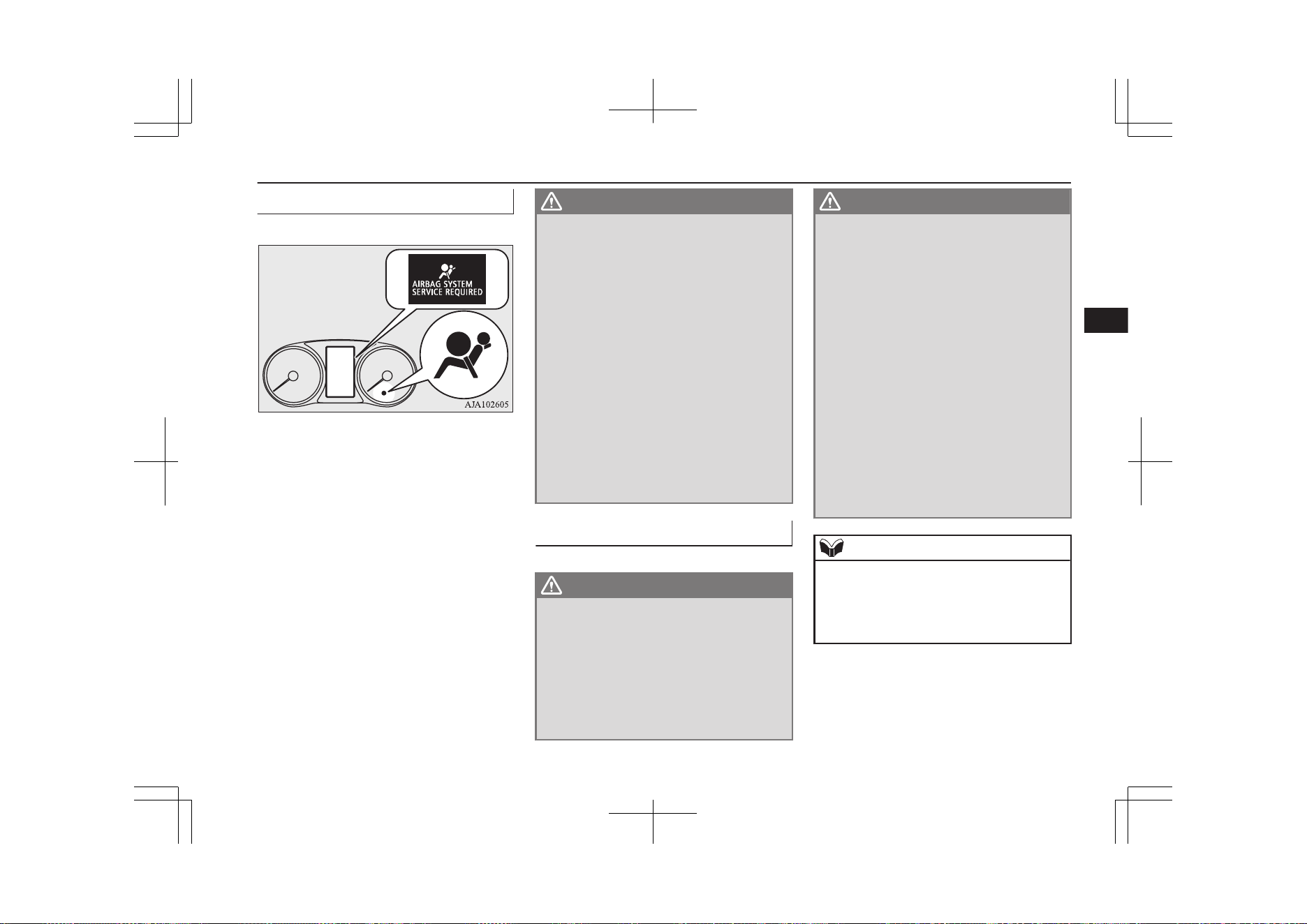
SRS warning lamp/display
E00407803191
There is a Supplemental Restraint System
(“SRS”) warning lamp on the instrument
panel. The system checks itself every time
the operation mode of the power switch is put
in ON. The SRS warning lamp will come on
for several seconds and then go out. This is
normal and means the system is working
properly.
If there is a problem involving one or more of
the SRS components, the warning lamp will
come on and stay on. At the same time, the
warning display will appear on the informa-
tion screen in the multi information display.
The SRS warning lamp/display is shared by
the SRS airbag and the seat belt pretensioner
system.
WARNING
l
If any of the following conditions occur,
there may be a problem with the SRS air-
bags and/or seat belt pretensioners, and
they may not function properly in a colli-
sion or may suddenly activate without a
collision:
•
Even when the operation mode is in
ON, the SRS warning lamp does not
come on or it remains on.
•
The SRS warning lamp and/or the
warning display comes on while driv-
ing.
The SRS airbags and seat belt pretension-
ers are designed to help reduce the risk of
serious injury or death in certain colli-
sions. If either of the above conditions oc-
curs, immediately have your vehicle
checked by a MITSUBISHI MOTORS
Authorized Service Point.
SRS servicing
E00407902658
WARNING
l
We recommend any maintenance per-
formed on or near the components of the
SRS to be performed by a MITSUBISHI
MOTORS Authorized Service Point.
Improper work on the SRS components
or wiring could result in inadvertent de-
ployment of the airbags, or could render
the SRS inoperative; either situation
could result in serious injury.
WARNING
l
Do not modify your steering wheel, seat
belt retractor or any other SRS compo-
nents. For example, replacement of the
steering wheel, or modifications to the
front bumper or body structure can ad-
versely affect SRS performance and lead
to possible injury.
l
If your vehicle has sustained any damage,
we recommend you to have the SRS in-
spected to ensure it is in proper working
order.
l
Do not modify your front seats, centre pil-
lar and centre console.
It can adversely affect SRS performance
and lead to possible injury.
l
If you found any tear, scratch, crack or
damage to the portion where the airbag is
stored, you should have the SRS inspected
by a MITSUBISHI MOTORS Authorized
Service Point.
NOTE
l
If your vehicle has to be scrapped, do this in
line with local legislation and contact a
MITSUBISHI MOTORS Authorized Serv-
ice Point to safely dismantle the airbag sys-
tem.
Supplemental restraint system (SRS)-airbag
5-35
OGGE19E1
Seats and seat belts
5

OGGE19E1

Instruments..........................................................................................6-02
Multi information display................................................................... 6-04
Indication lamp, warning lamp, and information screen
display list.......................................................................................6-24
Indication lamps..................................................................................6-54
Warning lamps.................................................................................... 6-55
Information screen display..................................................................6-58
Combination headlamps and dipper switch........................................ 6-59
Headlamp levelling............................................................................. 6-66
Turn-signal lever................................................................................. 6-67
Hazard warning flasher switch............................................................6-67
ECO mode switch............................................................................... 6-68
Fog lamp switch..................................................................................6-68
Wiper and washer switch.................................................................... 6-69
Wiper de-icer switch*......................................................................... 6-74
Rear window demister switch.............................................................6-74
Heated windscreen switch*.................................................................6-75
Heated steering wheel switch*............................................................6-76
Horn switch.........................................................................................6-77
Instruments and controls
OGGE19E1
6
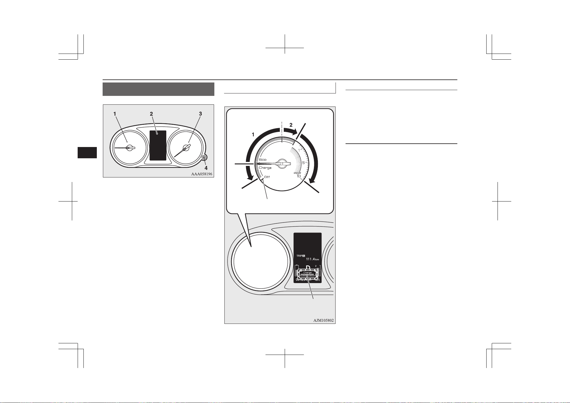
Instruments
E00500103079
1- Energy usage indicator ® p. 6-02
2- Multi information display ® p. 6-04
Information screen display list
® p. 6-25
3- Speedometer (km/h or mph + km/h)
4- Rheostat illumination button ® p. 6-03
Energy usage indicator
E00529601037
EV zone
Engine out-
put zone
Charge
zone
Ready OFF position
Charging power gauge
EV zone details
1: Zone that the EV drive can be maintained
2: Zone that the engine starts in high possibility
Ready OFF position
Indicates that the vehicle cannot run
(READY OFF).
When the vehicle is ready for running, the
needle of the energy usage indicator moves to
the horizontal position.
EV zone
The EV zone shows the output during EV
drive (driving with the engine stopped).
The EV zone is covered by the numbers 1
and 2 in the illustration.
Zone 1 shows the state that the EV drive can
be maintained, while zone 2 shows the state
that the engine starts in high possibility. As
the motor output increases, the movement
range of the needle of the energy usage indi-
cator increases.
In addition, the needle of the energy usage in-
dicator indicates the horizontal position when
the engine is stopped or when there is no
electric energy generated by the motor output
and the regenerative brake.
Instruments
6-02
OGGE19E1
Instruments and controls
6
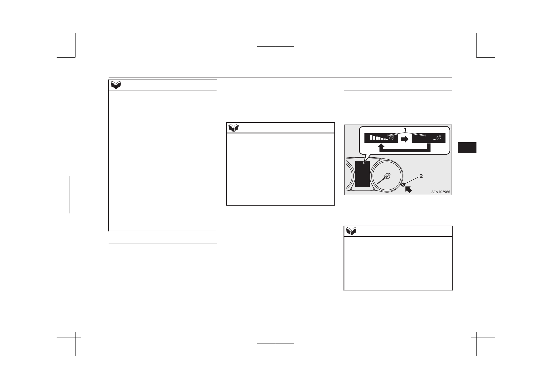
NOTE
l
Depending on the state of the vehicle (such
as during heating of the air conditioner), the
engine may start even if the needle of the en-
ergy usage indicator is indicated before zone
2 (the zone that the engine starts in high pos-
sibility).
l
Even when the EV priority mode is selected
and the engine does not start, the needle of
the energy usage indicator may indicate zone
2 (the zone that the engine starts in high pos-
sibility).
l
When the EV priority mode is selected, even
if the needle of the energy usage indicator
enters zone 2, it will not start the engine un-
less it is over the specified point by pressing
the accelerator pedal.
l
Depending on the vehicle condition, the
movement of the needle of the energy usage
indicator may be different or fluctuate.
l
Economical driving can be achieved by op-
erating in such state that the swing of the
needle is small within zone 1.
Charge zone
Indicates the charging power generated by
the regenerative brake.
The more the needle moves, the more electric
energy is charged.
The needle of the energy usage indicator may
not enter the charge zone when the drive bat-
tery is close to full charge.
Also, if the needle of the energy usage indi-
cator indicates the engine output zone, the
needle does not indicate the charge zone even
when there is charging of the electrical ener-
gy by regenerative braking.
NOTE
l
With the charging power gauge of the multi
information display, you can check the
charging power of electric energy generated
by regenerative braking even while the en-
gine is operating.
l
Both the display of the charge zone by the
energy usage indicator needle and the dis-
play of the charging power gauge in the mul-
ti information display indicate the charging
power of electric energy by regenerative
braking.
Engine output zone
Indicates the instantaneous output (kW) of
the engine.
Meter illumination control
E00531301174
Each time you press the rheostat illumination
button, there is a sound and the brightness of
the instruments changes.
1- Brightness level
2- Rheostat illumination button
NOTE
l
You can adjust to 8 different levels respec-
tively for when the position lamps are illu-
minated and when they are not.
l
When the lamp switch is in a position other
than the “OFF” position, the meter illumina-
tion switches automatically to the adjusted
brightness, depending on the brightness out-
side the vehicle.
Instruments
6-03
OGGE19E1
Instruments and controls
6
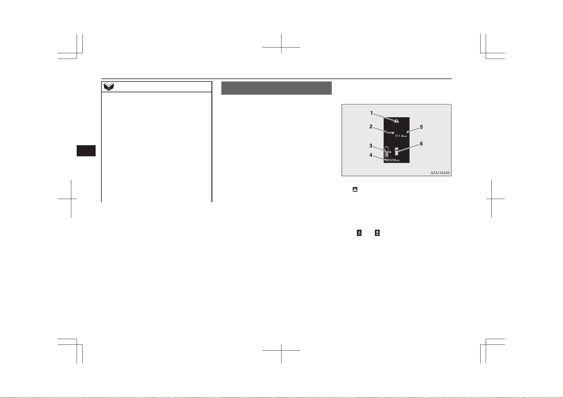
NOTE
l
The brightness level of the instruments is
stored when the operation mode of the pow-
er switch is put in OFF.
l
If you press and hold the button for about 2
seconds or more when the position lamps are
illuminated, the brightness level changes to
the maximum level. Pressing and holding
the button for about 2 seconds or more again
returns the brightness level to the previous
level.
On vehicles equipped with the
MITSUBISHI Multi-Communication Sys-
tem (MMCS), the map screen colour of
MITSUBISHI Multi-Communication Sys-
tem (MMCS) may not be switched to night-
time setting when the meter illumination
brightness level is at the maximum.
Multi information display
E00519903158
Always stop the vehicle in a safe place before
operating.
The following information is included on the
multi information display: warnings, odome-
ter, tripmeter, average fuel consumption, EV
cruising range, total cruising range, EVHV
driving rate, energy flow, etc.
[When the operation mode of the power
switch is OFF]
1- mark display screen ® p. 6-11
2- Information screen ® p. 6-07
Interrupt display screen ® p. 6-10
3- Drive battery level display screen
® p. 6-11
4- Odometer ® p. 6-13
5- “
” or “ ” mark indicator ® p. 6-10
Multi information display
6-04
OGGE19E1
Instruments and controls
6
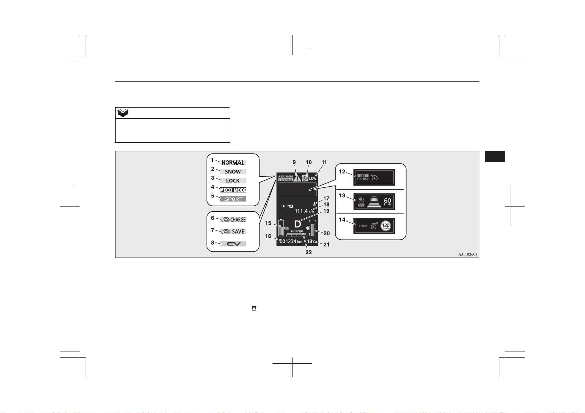
6- Door ajar warning display screen
® p. 6-11
NOTE
l
The drive battery level display screen ap-
pears when any of the doors or the tailgate is
opened during charging.
[When the operation mode of the power
switch is ON]
1- NORMAL mode indicator display
2- SNOW mode indicator display
3- LOCK mode indicator display
S-AWC (Super All Wheel Control)
® p. 7-20
4- ECO mode indicator display
ECO mode switch ® p. 6-68
5- SPORT mode indicator display
SPORT mode switch ® p. 7-31
6- Battery charge mode display screen
® p. 7-29
7- Battery save mode display screen
® p. 7-29
8- EV priority mode display screen
® p. 7-25
9-
mark display screen ® p. 6-11
10- Forward Collision Mitigation System
(FCM) OFF display screen* ® p. 7-67
Ultrasonic misacceleration Mitigation
System (UMS) OFF display screen*
® p. 7-77
11- Lane Departure Warning (LDW) display
screen* ® p. 7-88
12- Cruise control display screen*
® p. 7-45
Multi information display
6-05
OGGE19E1
Instruments and controls
6
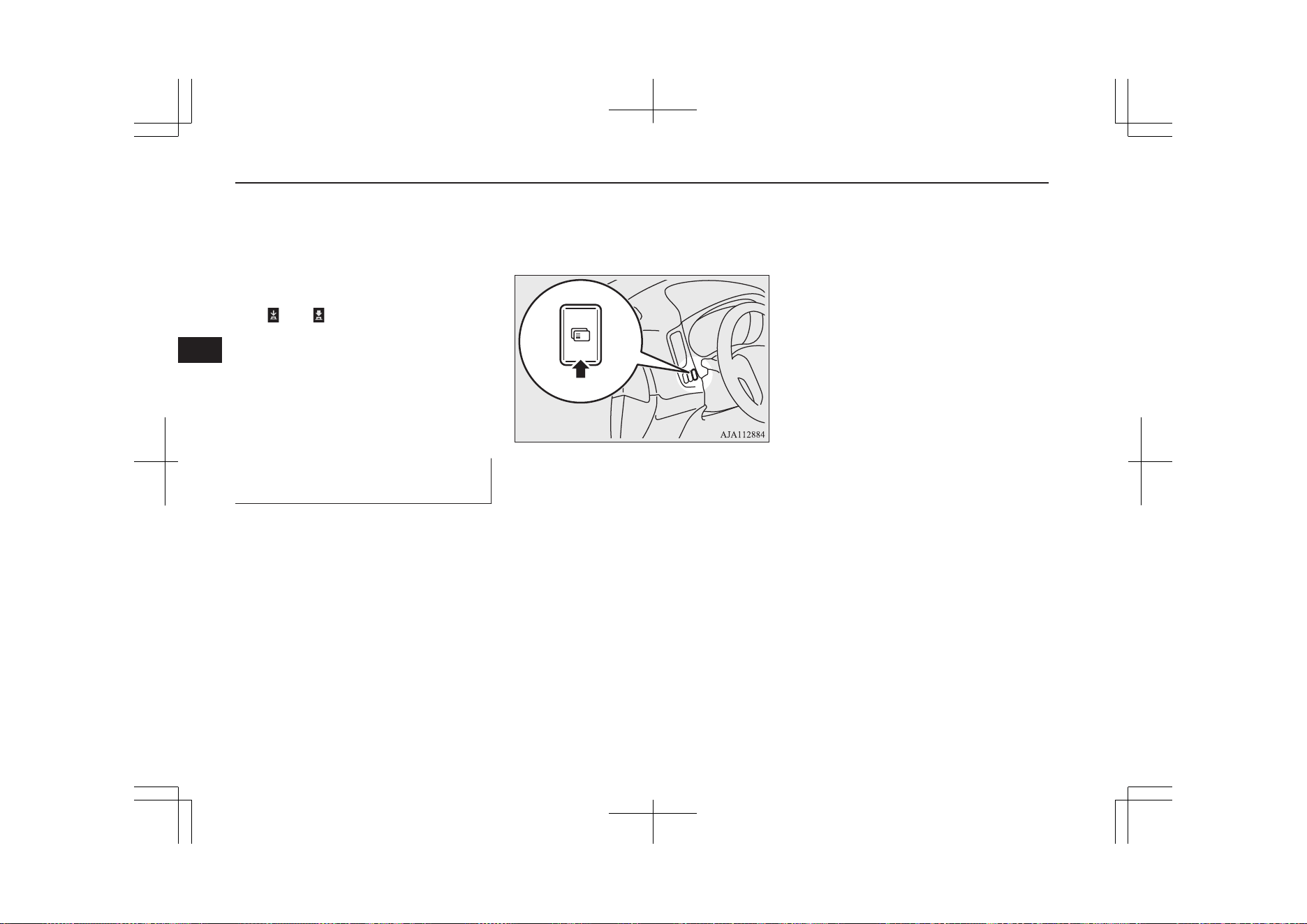
13- Adaptive Cruise Control System (ACC)
display screen* ® p. 7-55
14- Speed limiter display screen*
® p. 7-50
15- Drive battery level display screen
® p. 6-11
16- Odometer ® p. 6-13
17- “
” or “ ” mark indicator ® p. 6-10
18- Information screen ® p. 6-09
19- Select position indicator ® p. 7-17
20- Fuel remaining display screen
® p. 6-11
21- Outside temperature display screen
® p. 6-13
22- Charging power gauge ® p. 6-12
Multi information display
switch
E00520001911
Each time the multi information display
switch is operated, the buzzer sounds and the
multi information display changes between
information such as warnings, tripmeter,
average fuel consumption, EV cruising range,
total cruising range, EVHV driving rate, en-
ergy flow, etc.
It is also possible to change elements such as
the language and units used on the multi in-
formation display by operating the multi in-
formation display switch.
Multi information display
6-06
OGGE19E1
Instruments and controls
6
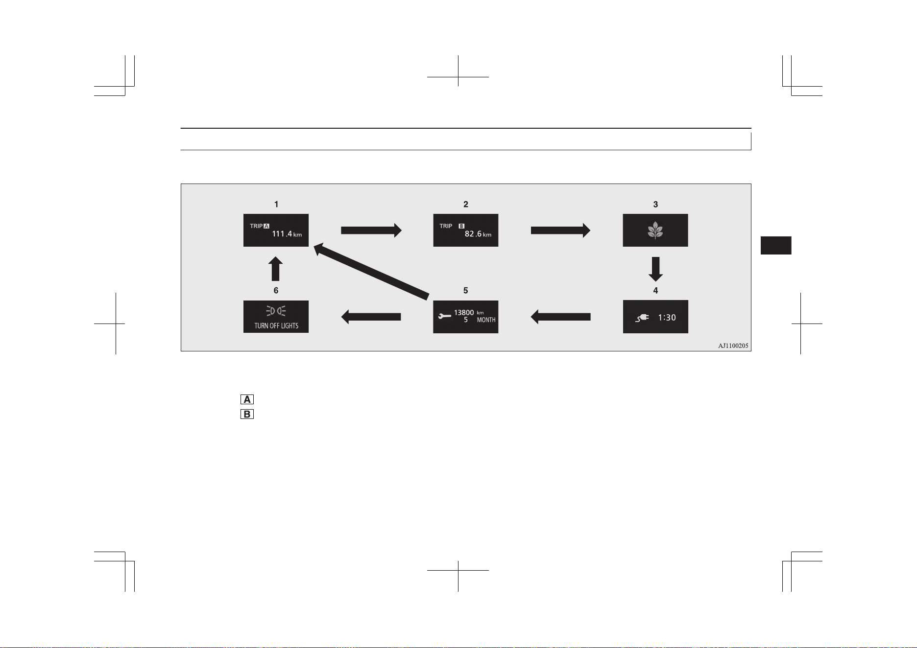
Information screen (when the operation mode is OFF)
E00520201968
Each time you lightly press the multi information display switch, the display screen switches in the following order.
*2
*1
*
1
: When there is no warning display
*
2
: When there is a warning display
1-
Tripmeter ® p. 6-13
2-
Tripmeter
® p. 6-13
3- ECO score display ® p. 6-17
4- Predicted charging time ® p. 3-10, 3-17
5- Service reminder ® p. 6-13
6- Redisplay of a warning display screen
® p. 6-10
Multi information display
6-07
OGGE19E1
Instruments and controls
6
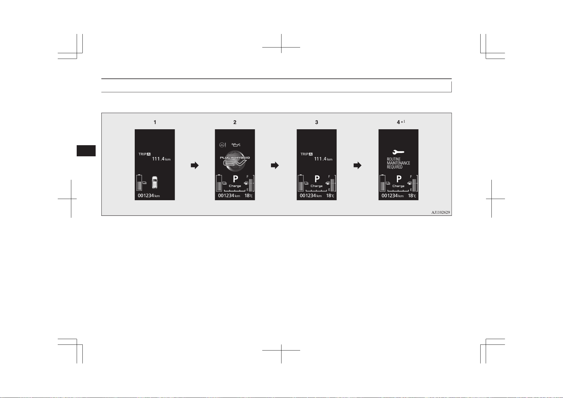
Information screen (when the operation mode is changed from OFF to ON)
E00520702351
When the operation mode is put in ON, the display screen switches in the following order.
*
1
: When the inspection time has arrived
1- Screen when the operation mode is OFF
2- System check screen ® p. 6-15
3- Screen when the operation mode is ON
4- Service reminder ® p. 6-13
Multi information display
6-08
OGGE19E1
Instruments and controls
6
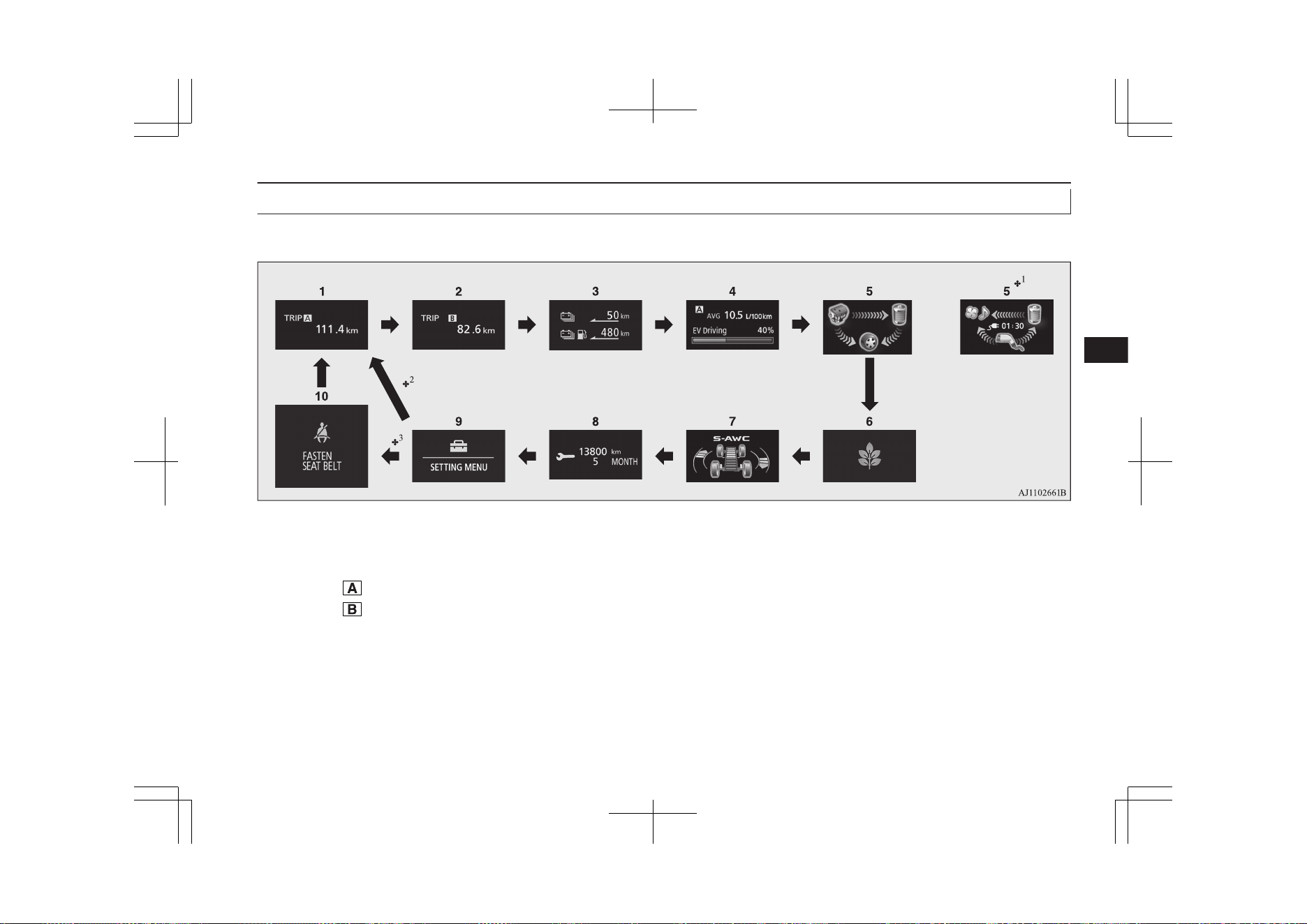
Information screen (when the operation mode is ON)
E00521102192
Each time you lightly press the multi information display switch, the display screen switches in the following order.
or
*
1
: When the vehicle is charged
*
2
: When there is no warning display
*
3
: When there is a warning display
1-
Tripmeter ® p. 6-13
2-
Tripmeter
® p. 6-13
3- EV cruising range display/Total cruising
range display ® p. 6-15
4- Average fuel consumption display
® p. 6-16
EVHV driving rate display ® p. 6-16
5- Energy flow display ® p. 6-16
or
Energy flow display during charging
® p. 3-26
6- ECO score display ® p. 6-17
7- S-AWC (Super-All Wheel Control) op-
eration display ® p. 7-22
8- Service reminder ® p. 6-13
9- Function setting screen ® p. 6-17
10- Redisplay of a warning display screen
® p. 6-10
Multi information display
6-09
OGGE19E1
Instruments and controls
6
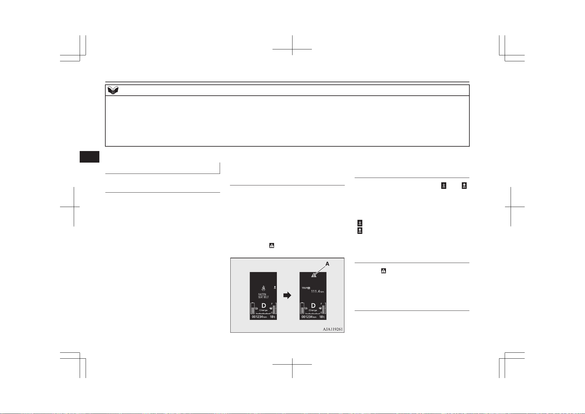
NOTE
l
While driving, the service reminder is not displayed even if you operate the multi information display switch. Always stop the vehicle in a safe place before
operating.
l
While driving, the function setting screen is not displayed even if you operate the multi information display switch.
Before operation, park the vehicle in a safe place, firmly apply the parking brake, press the electrical parking switch, and shift to “P” (PARK) position.
Refer to “Changing the function settings” on page 6-17.
l
When there is information to be announced, such as a system fault, the buzzer sounds and the screen display is switched.
Refer to “Interrupt display screen” on page 6-10.
Interrupt display screen
E00522002084
Warning display
When there is information to be announced,
such as a system fault, the buzzer sounds and
the information screen is switched to the
warning display screen.
Refer to the warning list and take the neces-
sary measures.
Refer to “Warning display list” on page
6-26.
When the cause of the warning display is
eliminated, the warning display goes out au-
tomatically.
To return to the screen dis-
played before the warning dis-
play
Even if the cause of the warning display is
not eliminated, you can return to the screen
that was displayed before the warning dis-
play.
If you press the multi information display
switch, the display screen switches to the
screen that was displayed before the warning
display and the
mark (A) is displayed.
If you want to switch the dis-
play
Warning display screens with a “ ” or “ ”
mark displayed in the upper right of the
screen can be switched. If you want to switch
the display, press the multi information dis-
play switch as follows.
“
”: Press lightly.
“ ”: Press for approximately 2 seconds or
more.
Redisplay of a warning display
screen
When the mark is displayed, if you lightly
press the multi information display switch a
few times, the warning display screen you
switched from is redisplayed.
Other interrupt displays
The operation status of each system is dis-
played on the information screen.
Multi information display
6-10
OGGE19E1
Instruments and controls
6
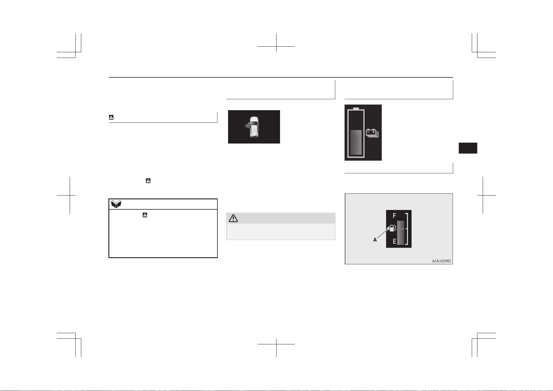
Refer to the appropriate page in the warning
display list for further details.
Refer to “Other interrupt displays” on page
6-48.
mark display screen
E00533901028
This is displayed when you press the multi
information display switch and return from
the warning display screen to the previous
screen.
This mark is also displayed if there is another
warning other than the one displayed.
When the cause of the warning display is
eliminated, the mark goes out automatical-
ly.
NOTE
l
When the mark is displayed, the warning
display screen can be redisplayed on the in-
formation screen.
Refer to “Information screen (when the op-
eration mode is OFF)” on page 6-07.
Refer to “Information screen (when the op-
eration mode is ON)” on page 6-09.
Door ajar warning display
screen
E00522601979
If any of the doors or the tailgate is not com-
pletely closed, this displays the open door or
tailgate.
When the operation mode of the power
switch is ON, if the vehicle speed exceeds
approximately 8 km/h (5 mph) while a door
is ajar, a buzzer sounds 4 times. This notifies
the driver that a door is ajar.
CAUTION
l
Before moving your vehicle, check that the
warning display does not appear.
Drive battery level display
screen
E00537700027
Indicates the remaining pow-
er in the drive battery.
Fuel remaining display screen
E00522201542
This displays the amount of fuel remaining.
F- Full
E- Empty
Multi information display
6-11
OGGE19E1
Instruments and controls
6
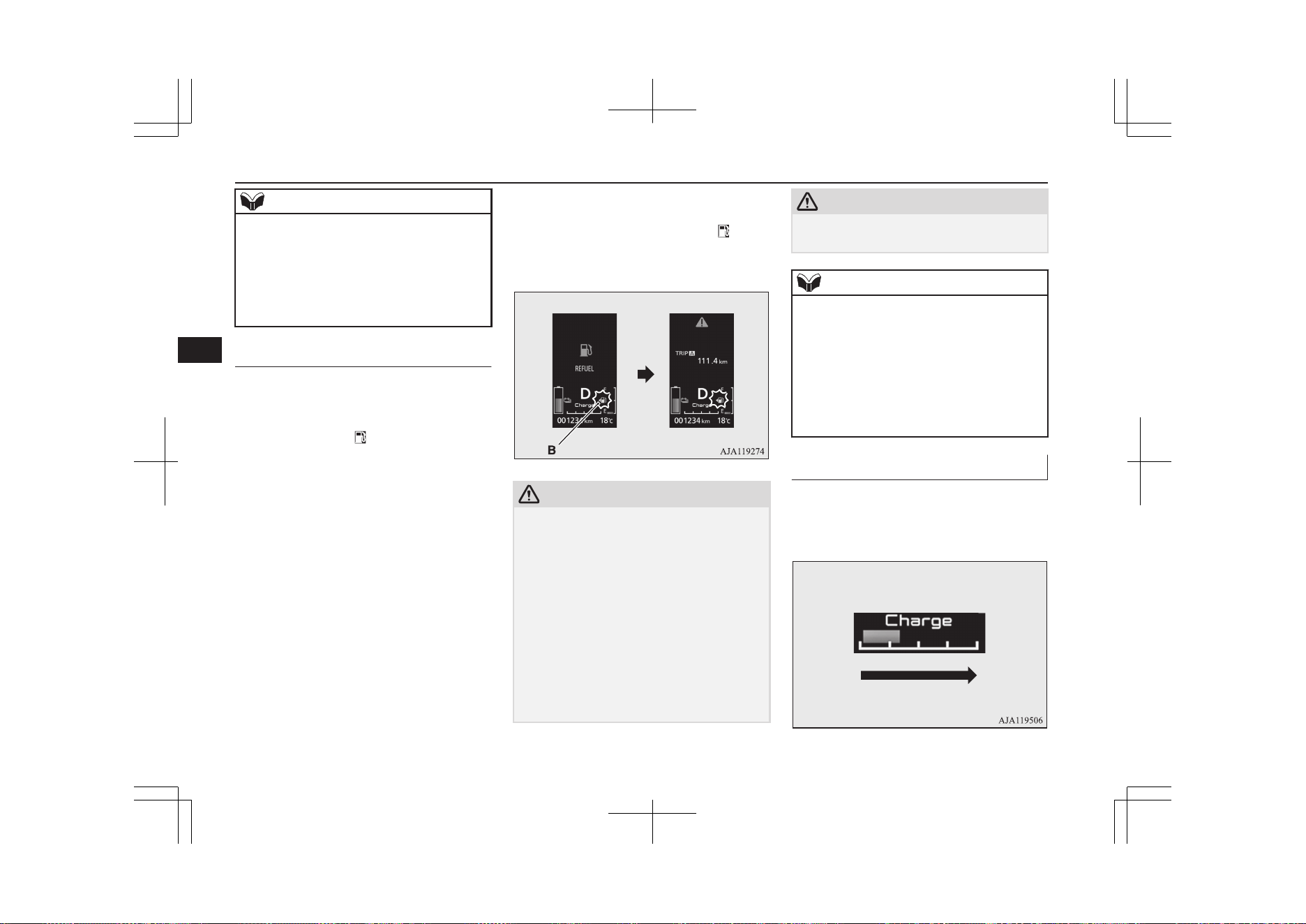
NOTE
l
It may take several seconds to stabilise the
display after refilling the tank.
l
If fuel is added with the operation mode of
the power switch is in ON, the fuel gauge
may incorrectly indicate the fuel level.
l
The arrow (A) indicates that the fuel tank
filler is located on the left side of the body.
Fuel remaining warning display
E00522402495
When the fuel is reduced to approximately 7
litres, the information screen switches to the
interrupt display of the fuel remaining warn-
ing display, and the “
” mark (B) on the fuel
remaining display flashes slowly (approxi-
mately once per second). After a few sec-
onds, the information screen returns from the
fuel remaining warning display to the previ-
ous screen.
If the remaining fuel level is reduced further,
the information screen switches to the fuel re-
maining warning display and the “ ” mark
(B) on the fuel remaining display flashes
quickly (approximately twice per second).
CAUTION
l
If the warning display appears, refuel as
soon as possible.
If the vehicle runs out of fuel, the engine
will not start even in a situation need to be
generated electricity, the following condi-
tions will occur.
•
The driving performance falls (since only
the electrical power stored in the drive
battery can be used for the driving).
•
The heating performance cannot be avail-
able (except for vehicles with an electric
heater).
•
The effectiveness of the heater is insuffi-
cient (vehicles with electric heater).
CAUTION
•
The catalytic converter may be damaged
due to excessive high temperature.
NOTE
l
On inclines or curves, the display may be in-
correct due to the movement of fuel in the
tank.
l
The battery save mode or battery charge
mode are cancelled or may not be activated
even if the battery save mode switch or the
battery charge mode is selected, depending
on the remaining quantity of the drive bat-
tery or the control condition of the system.
Charging power gauge
E00538400021
The charging power gauge shows momentary
charging power of the electric energy that is
generated by regenerative braking.
Charging power with regenerative brake
Low
High
Multi information display
6-12
OGGE19E1
Instruments and controls
6
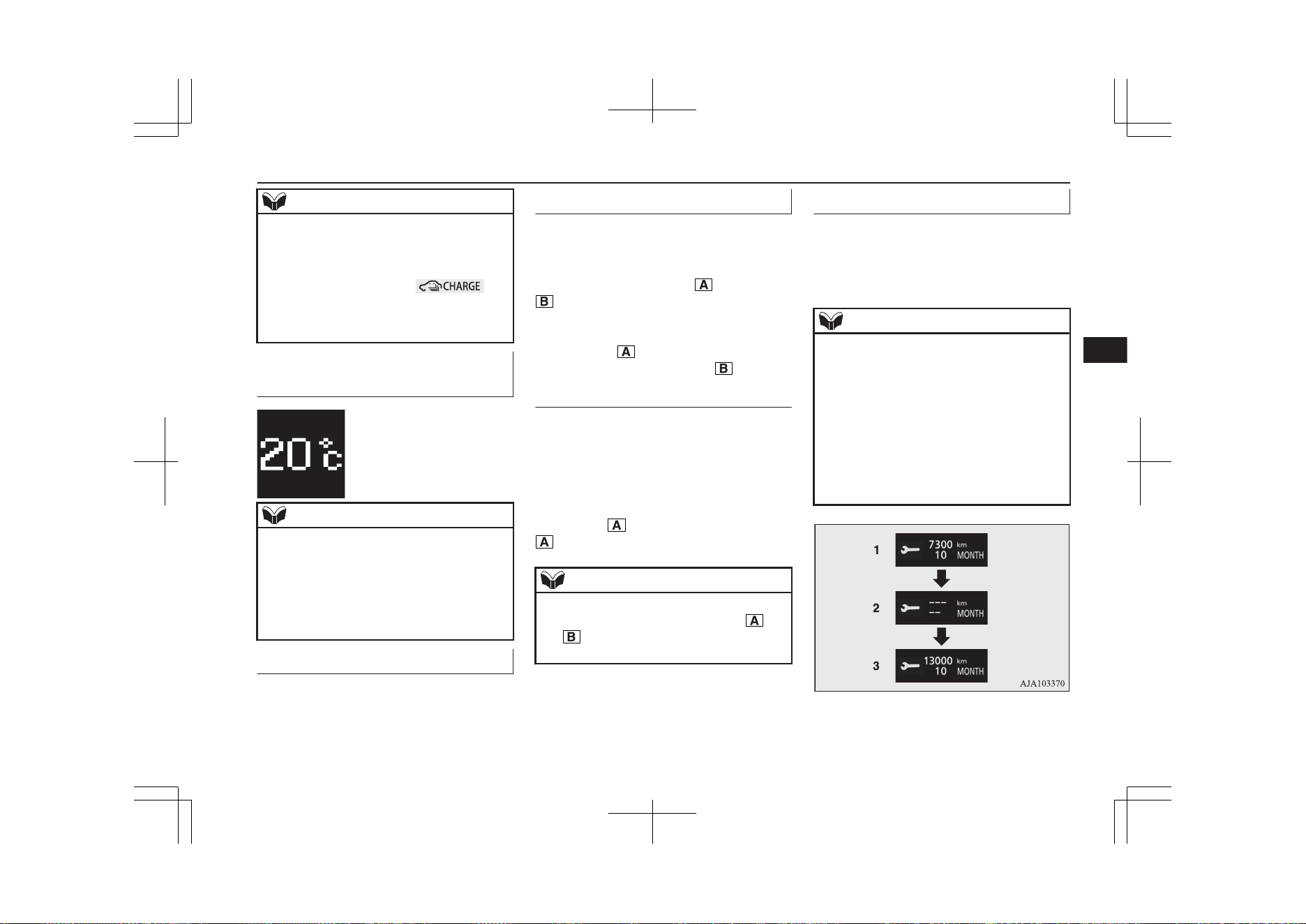
NOTE
l
The charging power gauge does not include
the electric power generation by the engine
operation.
l
The charging power gauge does not indicate
the running condition of bat-
tery charge.
l
The movement of the gauge decreases as the
drive battery level is nearly full.
Outside temperature display
screen
E00522101509
This shows the temperature
outside the vehicle.
NOTE
l
The display setting can be changed to the
preferred units (°C or °F).
Refer to “Changing the function settings” on
page 6-17.
l
Depending on factors such as the driving
conditions, the displayed temperature may
vary from the actual outside temperature.
Odometer
E00527800083
The odometer indicates the distance travel-
led.
Tripmeter
E00527901078
The tripmeter indicates the distance travelled
between two points.
Example usage of tripmeter and tripmeter
It is possible to measure two currently
travelled distances, from home using
tripmeter and from a particular point
on the way using tripmeter
.
To reset the tripmeter
To return the display to 0, hold down the
multi-information display switch for about 2
seconds or more. Only the currently dis-
played value will be reset.
Example
If tripmeter
is displayed, only tripmeter
will be reset.
NOTE
l
When disconnecting the auxiliary battery
terminal, the memory of tripmeter and
are cleared, and the display returns to
“0”.
Service reminder
E00522502021
Displays the approximate time until the next
periodic inspection recommended by
MITSUBISHI MOTORS. “---” is displayed
when the inspection time has arrived.
NOTE
l
Depending on the vehicle specifications, the
displayed time may differ from the next peri-
odic inspection time recommended by
MITSUBISHI MOTORS.
In addition, the display settings for the next
periodic inspection time can be modified.
To modify the display settings, have it adjus-
ted at a MITSUBISHI MOTORS Authorized
Service Point.
For more details, consult a MITSUBISHI
MOTORS Authorized Service Point.
1. Displays the time until the next periodic
inspection.
Multi information display
6-13
OGGE19E1
Instruments and controls
6
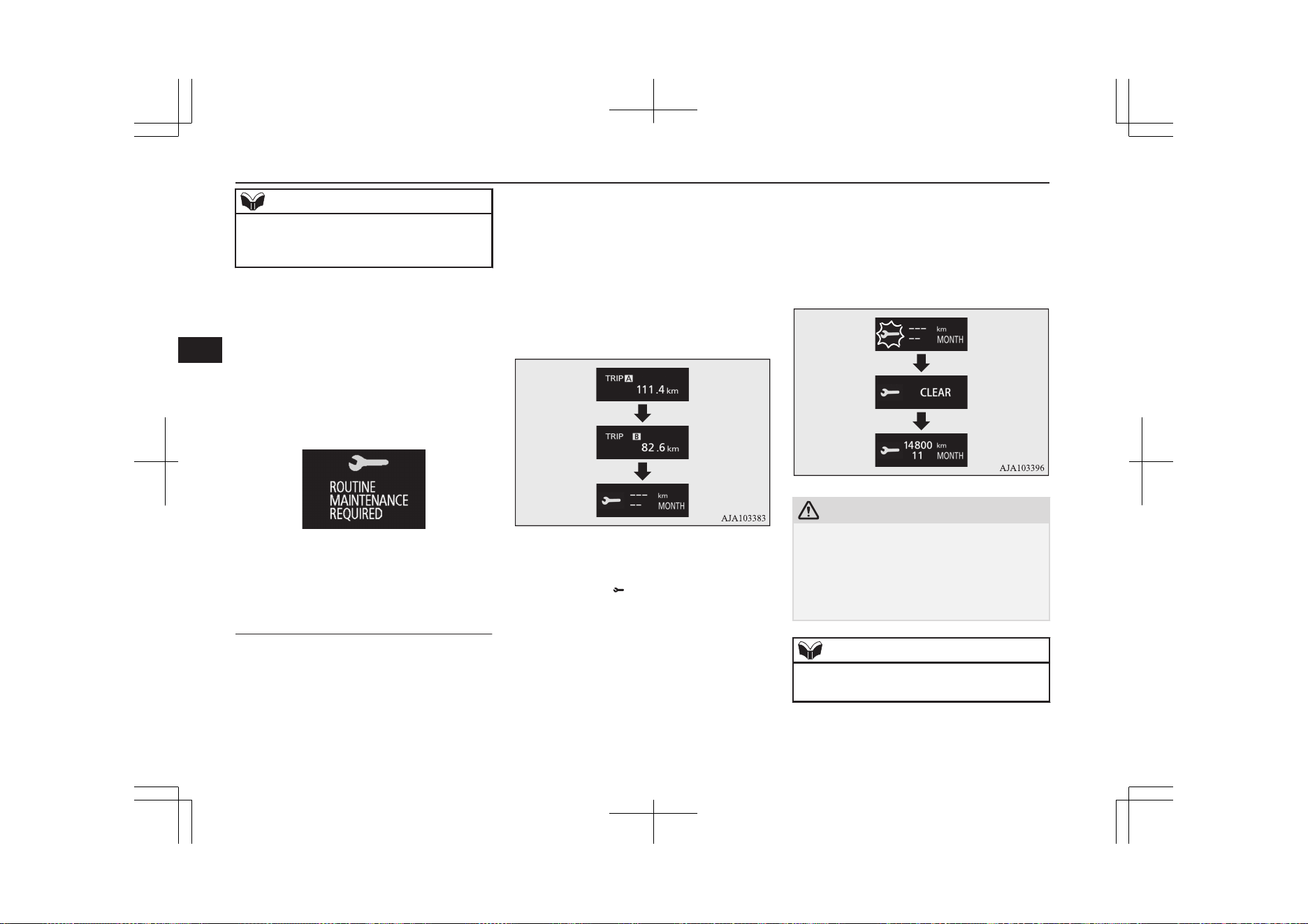
NOTE
l
The distance is shown in units of 100 km
(100 miles). The time is shown in units of
months.
2. This informs you that a periodic inspec-
tion is due. We recommend you to con-
sult a MITSUBISHI MOTORS Author-
ized Service Point.
At that time, when the ignition switch is
switched from “OFF” to “ON”, the
warning display is displayed for a few
seconds on the information screen.
3. After your vehicle is inspected at a
MITSUBISHI MOTORS Authorized
Service Point, it displays the time until
the next periodic inspection.
To reset
The “---” display can be reset while the igni-
tion switch or the opertion mode is in OFF.
When the display is reset, the time until the
next periodic inspection is displayed and the
warning display is no longer displayed when
the ignition switch is switched from “OFF” to
“ON”.
1. When you lightly press the multi infor-
mation display switch a few times, the
information display switches to the serv-
ice reminder display screen.
2.
Press and hold the multi information dis-
play switch for about 2 seconds or more
to display “ ” and make it flash. (If
there is no operation for about 10 sec-
onds with flashing, the display returns to
the previous screen.)
3. Lightly press the multi information dis-
play switch while the icon is flashing to
change the display from “---” to
“CLEAR”. After this, the time until the
next periodic inspection will be dis-
played.
CAUTION
l
The customer is responsible for making sure
that periodic inspection and maintenance are
performed.
Inspections and maintenance must be per-
formed to prevent accidents and malfunc-
tions.
NOTE
l
“---” display cannot be reset when the opera-
tion mode is in ON.
Multi information display
6-14
OGGE19E1
Instruments and controls
6
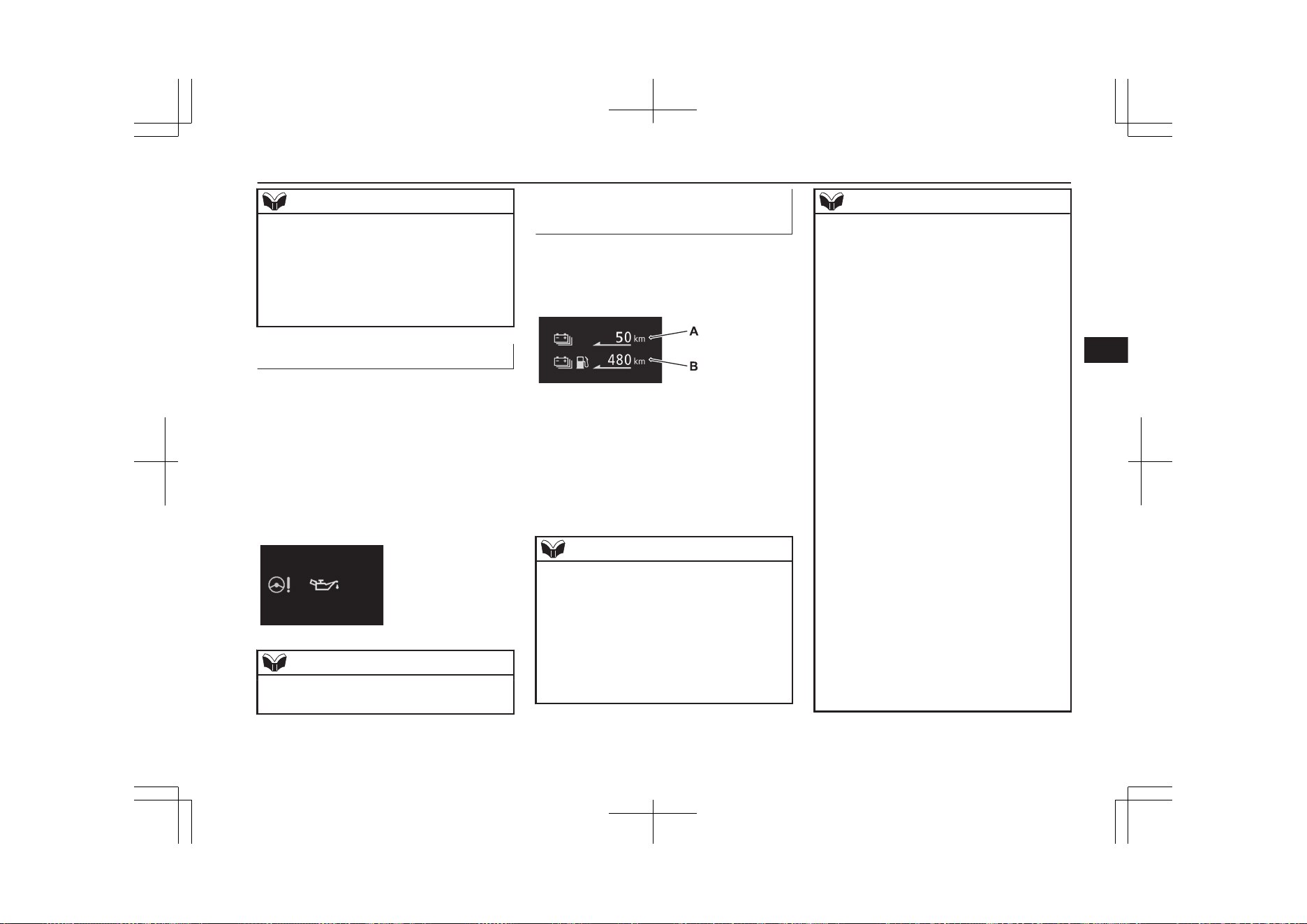
NOTE
l
When “---” is displayed, after a certain dis-
tance and a certain period of time, the dis-
play is reset and the time until the next peri-
odic inspection is displayed.
l
If you accidentally reset the display, we rec-
ommend you to consult a MITSUBISHI
MOTORS Authorized Service Point.
System check screen
E00531001070
When the operation mode is put in ON, the
system check screen is displayed for about 4
seconds. If there is no fault, the information
screen (when the operation mode is ON) is
displayed.
If there is a fault, the screen changes to warn-
ing display.
Refer to “Warning display list” on page
6-26.
NOTE
l
The system check screen display varies de-
pending on the customer’s equipment.
EV cruising range display/
Total cruising range display
E00537600042
This displays the approximate driving range
(how many more kilometres or miles you can
drive).
EV cruising range display (A)
This displays the distance that can be traveled
with the remaining power in the drive battery.
Total cruising range display (B)
This displays the distance that can be traveled
with the remaining power in the drive battery
and the remaining amount of fuel.
NOTE
l
The EV cruising range may vary depending
on the driving conditions and your personal
driving habits.
The EV cruising range is calculated from the
following information.
•
Current remaining power in the drive bat-
tery.
•
The most recent electric power consump-
tion rate.
NOTE
•
Operation status of the air-conditioner.
If the preceding driving condition is in the
following situations, the EV cruising
range display may show less distance than
before even though there is almost the
same level of remaining power in the
drive battery.
•
When much electricity is consumed from
the drive battery, such as in a traffic jam,
hill-climbing or high-speed driving.
•
When the air conditioner is operating.
Treat the distance displayed as just a rough
guideline.
In addition, disconnecting the auxiliary bat-
tery cable will reset the EV cruising range
and the EV cruising range display may show
a different distance from the previous dis-
tance.
l
The learned value for the EV cruising range
can be reset by operating the multi informa-
tion display switch.
If the EV cruising range display shows an
extremely different distance, please reset the
learned value to the initialized value.
For details, refer to “Reset of EV/Total
cruising range” on page 6-22.
l
When the drive battery is charged or the ve-
hicle is refuelled, the cruising range display
is updated. However, if the charge level is
low or the refueling amount is small, it can-
not be updated correctly. Fully charge the
battery or refill to full tank whenever possi-
ble.
Multi information display
6-15
OGGE19E1
Instruments and controls
6
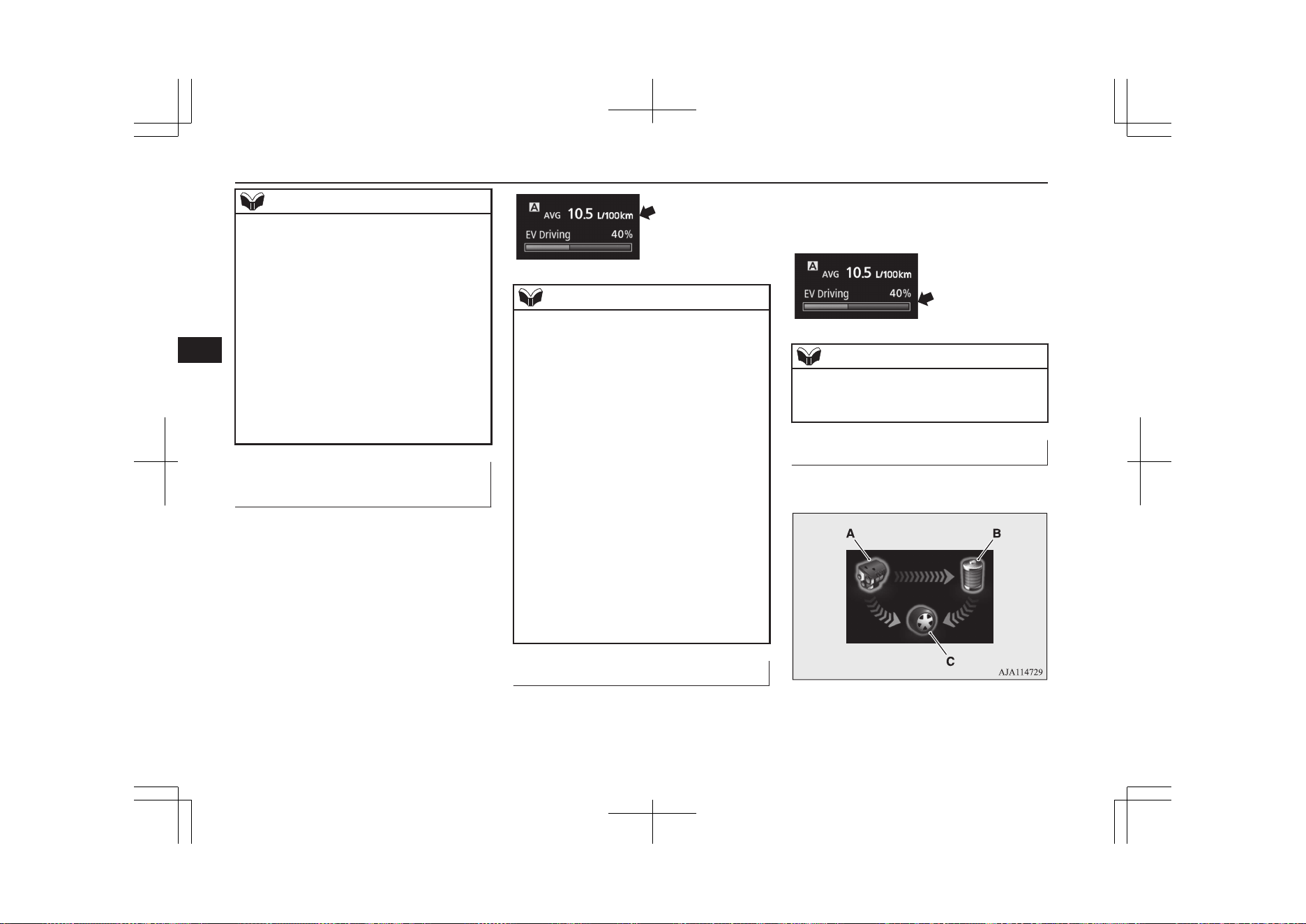
NOTE
l
On rare occasions, the value displayed for
the driving range may change if you are
parked on an extremely steep incline. This is
due to the movement of fuel in the tank and
does not indicate a malfunction.
l
The display setting can be changed to the
preferred units (km or miles).
Refer to “Changing the function settings” on
page 6-17.
l
When the EV cruising range falls below ap-
proximately 1 km (1 mile), the EV cruising
range display shows “---”.
l
When the total cruising range falls below ap-
proximately 50 km (30 miles), the total
cruising range display shows “---”.
Average fuel consumption dis-
play
E00531201128
This displays the average fuel consumption
from the last reset to the present time.
There are the following 2 mode settings.
Refer to “Changing the reset mode for aver-
age fuel consumption” on page 6-18.
For information on how to change the aver-
age fuel consumption display setting, refer to
“Changing the function settings” on page
6-17.
NOTE
l
The average fuel consumption display can
be reset separately for the auto reset mode
and for the manual reset mode.
l
“---” is displayed when the average fuel con-
sumption cannot be measured.
l
The initial (default) setting is “Auto reset
mode”.
l
The average fuel consumption depends on
the driving condition (road condition, driv-
ing behavior, etc.). The displayed fuel con-
sumption may vary from the actual fuel con-
sumption. Treat the fuel consumption dis-
played as just a rough guideline.
l
The memory of the auto reset mode or man-
ual reset mode for the average fuel con-
sumption display is erased if the auxiliary
battery is disconnected.
l
The display setting can be changed to the
preferred units {km/L, mpg (US), mpg (UK)
or L/100 km}.
Refer to “Changing the function settings” on
page 6-17.
EVHV driving rate display
E00537500038
This displays the ratios of the time travelled
with electric power and the time travelled
with both electric power and engine power.
The ratio of the time traveled with electric
power is displayed with a bar graph (blue)
and in a percentage.
NOTE
l
When the drive battery is fully charged,
EVHV driving rate is reset and display be-
comes 100 %.
Energy flow display
E00537400040
This displays the flow of energy.
A- Engine
B- Drive battery
C- Tyre
Multi information display
6-16
OGGE19E1
Instruments and controls
6
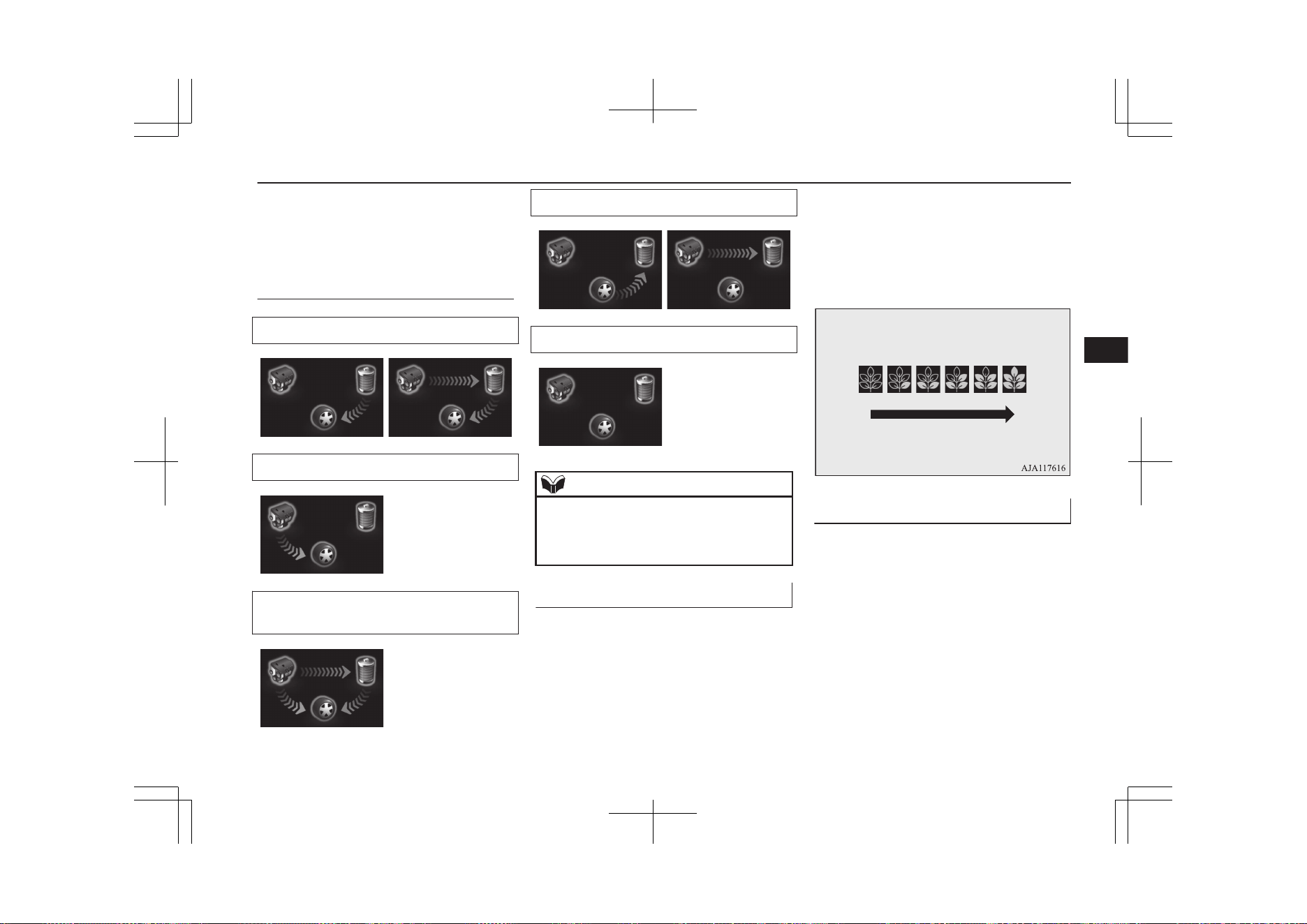
Blue arrow- Flow of electric en-
ergy
Amber arrow- Flow of other energy
Display of energy flow (exam-
ple)
When driving with electric energy
When driving with fuel (petrol) energy
When driving with both electric energy
and fuel (petrol) energy
When charging the drive battery
When there is no energy flow
NOTE
l
During charging, the energy flow display for
charging is displayed. For details, refer to
“Energy flow display during charging” on
page 3-26.
ECO Score
E00531601207
ECO score indicates the points you have
scored on fuel-efficient driving by the num-
ber of leaves as follows:
[When the operation mode is ON]
The display shows the score you achieved in
the last several minutes.
[When the operation mode is put in OFF]
The display shows the overall ECO score the
function has counted from the time when the
operation mode is set to “ON” to the time
when it is set to “OFF”.
ECO drive level
Low High
Changing the function settings
E00522702254
The “Display language”, “Temperature unit”,
“Fuel consumption unit”, and “Average fuel
consumption and speed reset method” etc.
setting can be modified as desired.
1. Stop the vehicle in a safe place.
Firmly apply the parking brake, and
press the electrical parking switch and
shift to “P” (PARK) position.
2. Lightly press the multi information dis-
play switch a few times to switch the in-
formation screen to the function setting
screen.
Multi information display
6-17
OGGE19E1
Instruments and controls
6
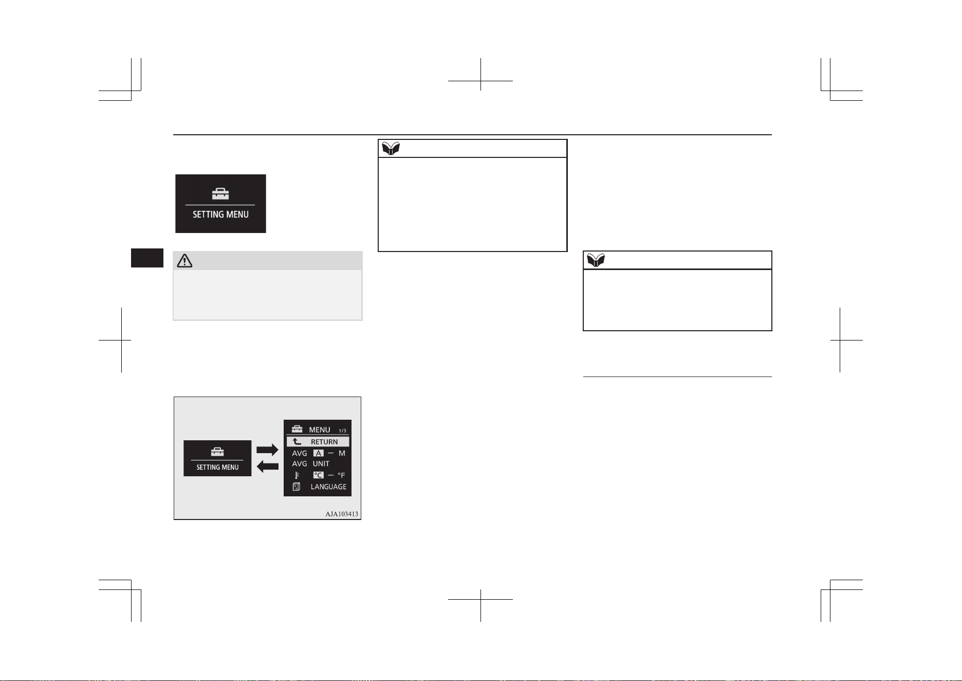
Refer to “Information screen” on page
6-09.
CAUTION
l
For safety, stop the vehicle before operating.
While driving, even if you operate the multi
information display switch, the function set-
ting screen is not displayed.
3. Press and hold the multi information dis-
play switch for about 2 seconds or more
to switch from the setting mode screen
to the menu screen.
NOTE
l
To return the menu screen to the function
setting screen, press and hold the multi in-
formation display switch for about 2 seconds
or more.
l
If no operations are made within about 30
seconds of the menu screen being displayed,
the display returns to the function setting
screen.
4. Select the item to change on the menu
screen and change to the desired setting.
Refer to the following items for further
details on the operation methods.
Refer to “Changing the reset mode for
average fuel consumption” on page
6-18.
Refer to “Changing the fuel consump-
tion display unit” on page 6-19.
Refer to “Changing the temperature
unit” on page 6-20.
Refer to “Changing the display lan-
guage” on page 6-20.
Refer to “Changing the language cooper-
ative control” on page 6-21.
Refer to “Operation sound setting” on
page 6-21.
Refer to “Changing the time until
“REST REMINDER” is displayed” on
page 6-22.
Refer to “Changing the turn-signal
sound” on page 6-22.
Refer to “Reset of low tyre pressure
warning threshold” on page 7-96.
Refer to “Tyre ID set change” on page
7-96.
Refer to “Reset of EV/Total cruising
range” on page 6-22
Refer to “Returning to the factory set-
tings” on page 6-22.
NOTE
l
If the auxiliary battery is disconnected, these
function settings are reset from memory and
return automatically to the factory settings
(except the low tyre pressure warning
threshold and tyre ID set).
Changing the reset mode for
average fuel consumption
E00522902243
The mode conditions for the average fuel
consumption display can be switched be-
tween “Auto reset” and “Manual reset”.
1. Press and hold the multi information dis-
play switch for about 2 seconds or more
to switch from the setting mode screen
to the menu screen.
Refer to “Changing the function set-
tings” on page 6-17.
Multi information display
6-18
OGGE19E1
Instruments and controls
6
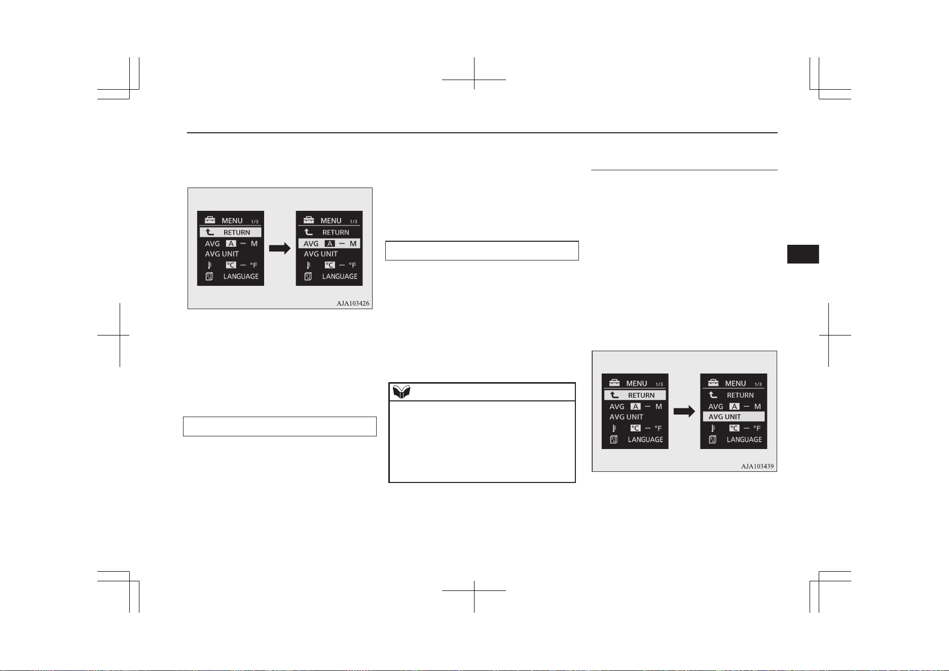
2. Lightly press the multi information dis-
play switch to select “AVG (average fuel
consumption)”.
3. Press and hold the multi information dis-
play switch for about 2 seconds or more
to switch from A/1 (Auto reset mode) to
M/2/P (Manual reset mode), or from
M/2/P to A/1.
The setting is changed to the selected
mode condition.
Manual reset mode
l
When the average fuel consumption is
being displayed, if you hold down the
multi-information meter switch, the
average fuel consumption displayed at
that time is reset.
l
When the operation mode is changed
from ACC or OFF to ON, the mode set-
ting is automatically switched from man-
ual to auto.
Switching to auto occurs automatically.
If switching to manual mode is done,
however, the data from the last reset is
displayed.
Auto reset mode
l
When the average fuel consumption is
being displayed, if you hold down the
multi-information meter switch, the
average fuel consumption displayed at
that time is reset.
l
When the operation mode is in ACC or
OFF for about 4 hours or longer, the
average fuel consumption display is au-
tomatically reset.
NOTE
l
The average fuel consumption display can
be reset separately for the auto reset mode
and for the manual reset mode.
l
The memory of the auto reset mode or man-
ual reset mode for the average fuel con-
sumption display is erased if the auxiliary
battery is disconnected.
Changing the fuel consumption
display unit
E00523001778
The display unit for fuel consumption can be
switched. The distance and amount units are
also switched to match the selected fuel con-
sumption unit.
1. Press and hold the multi information dis-
play switch for about 2 seconds or more
to switch from the setting mode screen
to the menu screen.
Refer to “Changing the function set-
tings” on page 6-17.
2. Lightly press the multi information dis-
play switch to select “AVG UNIT (fuel
consumption display setting)”.
3. Press and hold the multi information dis-
play switch for about 2 seconds or more
to display “AVG UNIT”.
Multi information display
6-19
OGGE19E1
Instruments and controls
6
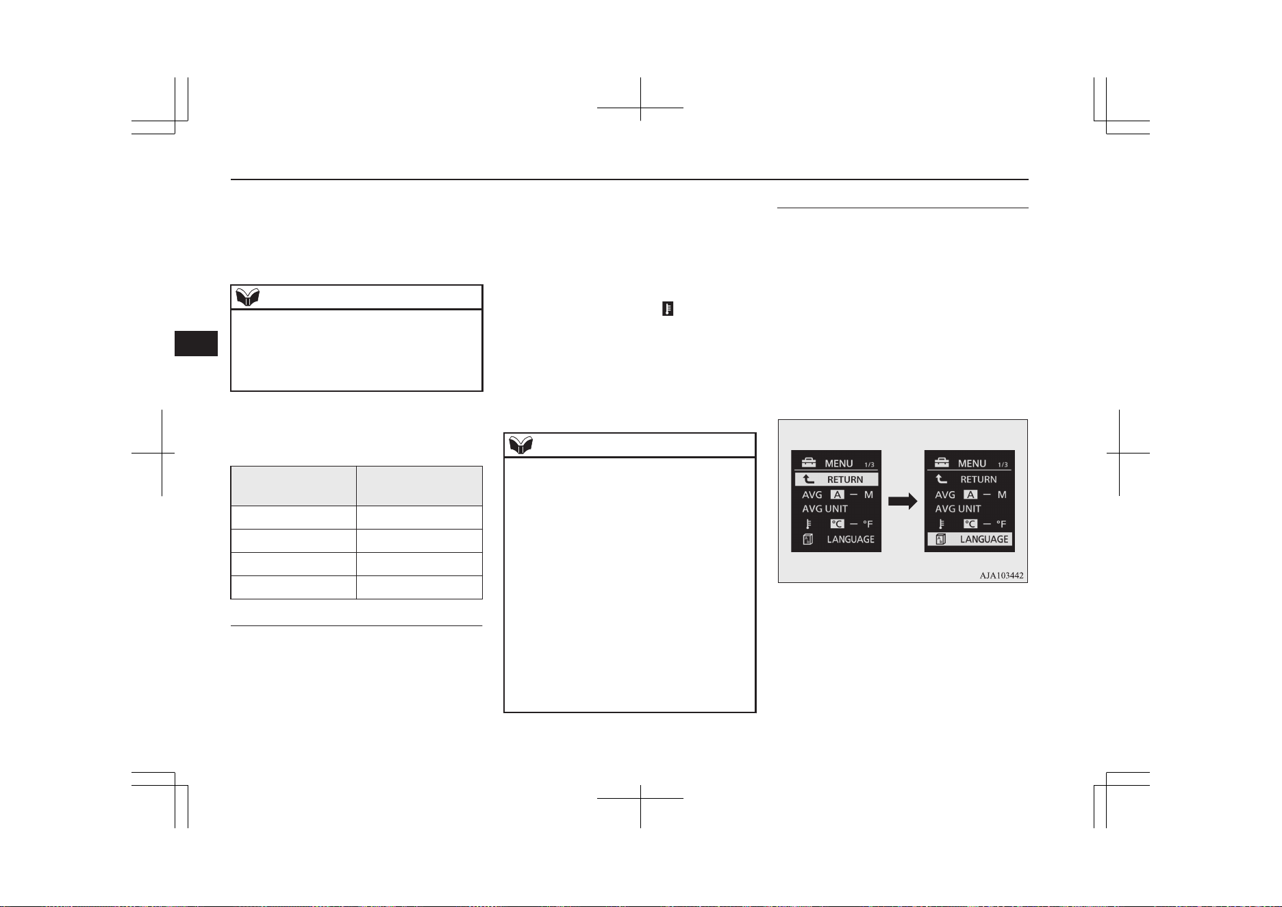
4. Lightly press the multi information dis-
play switch to select the units.
5. Press and hold the multi information dis-
play switch for about 2 seconds or more
to change the setting to the selected unit.
NOTE
l
The display units for the average fuel con-
sumption and the driving range is switched,
but the units for the indicating needle
(speedometer), the odometer and the tripme-
ter will remain unchanged.
The distance units is also switched in the fol-
lowing combinations to match the selected
fuel consumption unit.
Fuel consumption Distance (driving
range)
L/100 km km
mpg (US) mile(s)
mpg (UK) mile(s)
km/L km
Changing the temperature unit
E00523101913
The display unit for temperature can be
switched.
1. Press and hold the multi information dis-
play switch for about 2 seconds or more
to switch from the setting mode screen
to the menu screen.
Refer to “Changing the function set-
tings” on page 6-17.
2. Lightly press the multi information dis-
play switch to select “
” (temperature
unit setting).
3. Press and hold the multi information dis-
play switch for about 2 seconds or more
to switch in from °C to °F, or from °F to
°C. The setting is changed to the selec-
ted temperature unit.
NOTE
l
The temperature value on air conditioner
panel is switched in conjunction with outside
temperature display unit of the multi infor-
mation display.
However, “°C” or “°F” are not shown to
temperature display of an air conditioner.
l
On vehicles equipped with the Smartphone
Link Display Audio or the MITSUBISHI
Multi- Communication System (MMCS),
the temperature value of Smartphone Link
Display Audio or MITSUBISHI Multi-Com-
munication System (MMCS) is switched in
conjunction with the outside temperature
display unit of the multi information display.
However, “°C” or “°F” is not shown to the
air conditioner screen of MITSUBISHI Mul-
ti- Communication System (MMCS).
Changing the display language
E00523201741
The language of the multi information dis-
play can be switched.
1. Press and hold the multi information dis-
play switch for about 2 seconds or more
to switch from the setting mode screen
to the menu screen.
Refer to “Changing the function set-
tings” on page 6-17.
2. Lightly press the multi information dis-
play switch to select “LANGUAGE”
(language setting).
3. Press and hold the multi information dis-
play switch for about 2 seconds or more
to display “LANGUAGE”.
4. Lightly press the multi information dis-
play switch to select the desired lan-
guage.
Multi information display
6-20
OGGE19E1
Instruments and controls
6
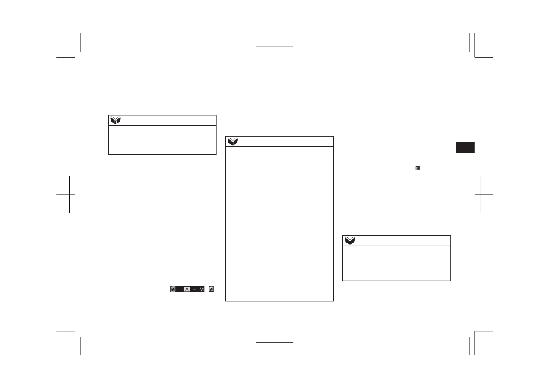
5. If you hold down the multi information
display switch for about 2 seconds or
more, the setting is changed to the selec-
ted language.
NOTE
l
If “---” is selected in the language setting, a
warning message is not displayed when
there is a warning display or interrupt dis-
play.
Changing the language cooper-
ative control
E00523301827
The language used in MITSUBISHI Multi-
Communication System (MMCS) (if so
equipped), Bluetooth
®
2.0 interface (if so
equipped) or Multi Around Monitor (if so
equipped) can be changed automatically to
the same language as that shown in the multi
information display.
1. Press and hold the multi information dis-
play switch for about 2 seconds or more
to switch from the setting mode screen
to the menu screen.
Refer to “Changing the function set-
tings” on page 6-17.
2. Lightly press the multi information dis-
play switch to select
“ ”
(language cooperative control).
3. Press and hold the multi information dis-
play switch to switch from A/1 (lan-
guage cooperation enabled) to M/2/P
(language cooperation disabled), or from
M/2/P to A/1.
The setting is changed to the selected
condition.
NOTE
l
The language display modified with the lan-
guage setting can be switched in the follow-
ing manner.
•
When A or 1 has been selected with the
language cooperative control, the lan-
guage for MITSUBISHI Multi-Communi-
cation System (MMCS), Bluetooth
®
2.0
interface or Multi Around Monitor is au-
tomatically changed to the language se-
lected for the multi information display.
However, this changing function may not
work depending on the language selected
for the multi information display.
•
When M, 2 or P has been selected with
the language cooperative control, the lan-
guage for MITSUBISHI Multi-Communi-
cation System (MMCS), Bluetooth
®
2.0
interface or Multi Around Monitor is not
automatically changed to the language se-
lected for the multi information display.
l
The language on the display of the audio
system (if so equipped) is not automatically
changed even if you select A or 1 of the lan-
guage cooperation control.
Operation sound setting
E00523400690
You can turn off the operation sounds of the
multi information display switch and rheostat
illumination button.
1. Press and hold the multi information dis-
play switch for about 2 seconds or more
to switch from the setting mode screen
to the menu screen.
Refer to “Changing function settings” on
page 6-17.
2. Lightly press the multi information dis-
play switch to select "
" (operation
sound setting).
3. Press and hold the multi information dis-
play switch for about 2 seconds or more
to switch from ON (operation sound on)
to OFF (operation sound off), or from
OFF to ON.
The setting is changed to the selected
condition.
NOTE
l
The operation sound setting only deactivates
the operation sound of the multi information
display switch and rheostat illumination but-
ton. The warning display and other sounds
cannot be deactivated.
Multi information display
6-21
OGGE19E1
Instruments and controls
6
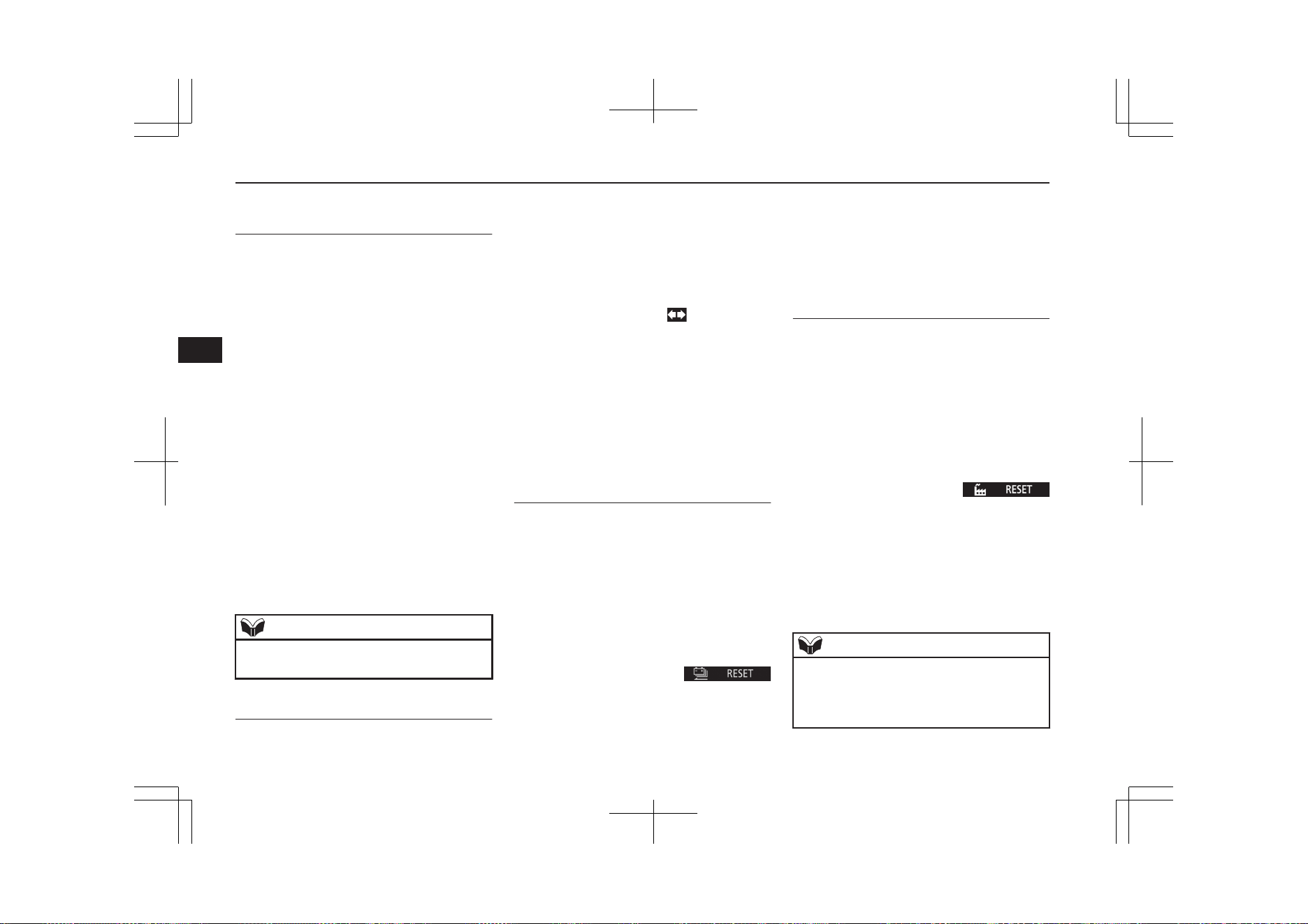
Changing the time until “REST
REMINDER” is displayed
E00523501702
The time until the display appears can be
changed.
1. Press and hold the multi information dis-
play switch for about 2 seconds or more
to switch from the setting mode screen
to the menu screen.
Refer to “Changing the function set-
tings” on page 6-17.
2. Lightly press the multi information dis-
play switch to select “ALARM” (rest
time setting).
3. Press and hold the multi information dis-
play switch for about 2 seconds or more
to display “ALARM”.
4. Lightly press the multi information dis-
play switch to select the time until the
display.
5. Press and hold the multi information dis-
play switch for about 2 seconds or more,
the setting is changed to the selected
time.
NOTE
l
The drive time is reset when the operation
mode of the power switch is put in OFF.
Changing the turn-signal sound
E00529100396
It is possible to change the turn-signal sound.
1. Press and hold the multi information dis-
play switch for about 2 seconds or more
to switch from the setting mode screen
to the menu screen.
Refer to “Changing the function set-
tings” on page 6-17.
2. Lightly press the multi information dis-
play switch to select
(changing the
turn-signal sound).
3. Press and hold the multi information dis-
play switch for about 2 seconds or more
to switch from 1 (turn-signal sound 1) to
2 (turn-signal sound 2), or from 2 to 1.
The setting changes to the selected turn-
signal sound.
Reset of EV/Total cruising
range
E00532200027
The learned value for EV cruising range re-
sets to the initialized value.
1. Press and hold the multi information dis-
play switch for about 2 seconds or more
to switch from the setting mode screen
to the menu screen.
Refer to “Changing the function set-
tings” on page 6-17.
2. Lightly press the multi information dis-
play switch to select “
RESET” (Reset of EV cruising range).
3. When you press and hold the multi in-
formation display switch for about 3 sec-
onds or more, the buzzer sounds and the
learned value resets to the default values.
Returning to the factory set-
tings
E00523602205
Many of the function settings can be returned
to their factory settings.
1. Press and hold the multi information dis-
play switch for about 2 seconds or more
to switch from the setting mode screen
to the menu screen.
Refer to “Changing the function set-
tings” on page 6-17.
2. Lightly press the multi information dis-
play switch to select “
RESET” (returning to the factory set-
tings).
3. When you press and hold the multi in-
formation display switch for about 5 sec-
onds or more, the buzzer sounds and all
of the function settings are returned to
the factory settings.
NOTE
l
The factory settings are as follows.
•
Average fuel consumption reset mode: A
(Auto reset)
•
Fuel consumption display unit: L/100 km
Multi information display
6-22
OGGE19E1
Instruments and controls
6
NOTE
•
Temperature unit: °C (Celsius)
•
Display language: ENGLISH or RUSSI-
AN
•
Cooperative language setting: A (lan-
guage cooperation enabled)
•
Operation sounds: ON (Operation sounds
on)
•
“REST REMINDER” display: OFF
•
Turn-signal sound: Turn-signal sound 1
l
The low tyre pressure warning threshold and
tyre ID set cannot be returned to their facto-
ry settings.
l
The learned value for EV cruising range
does not return to the initialized value.
Multi information display
6-23
OGGE19E1
Instruments and controls
6
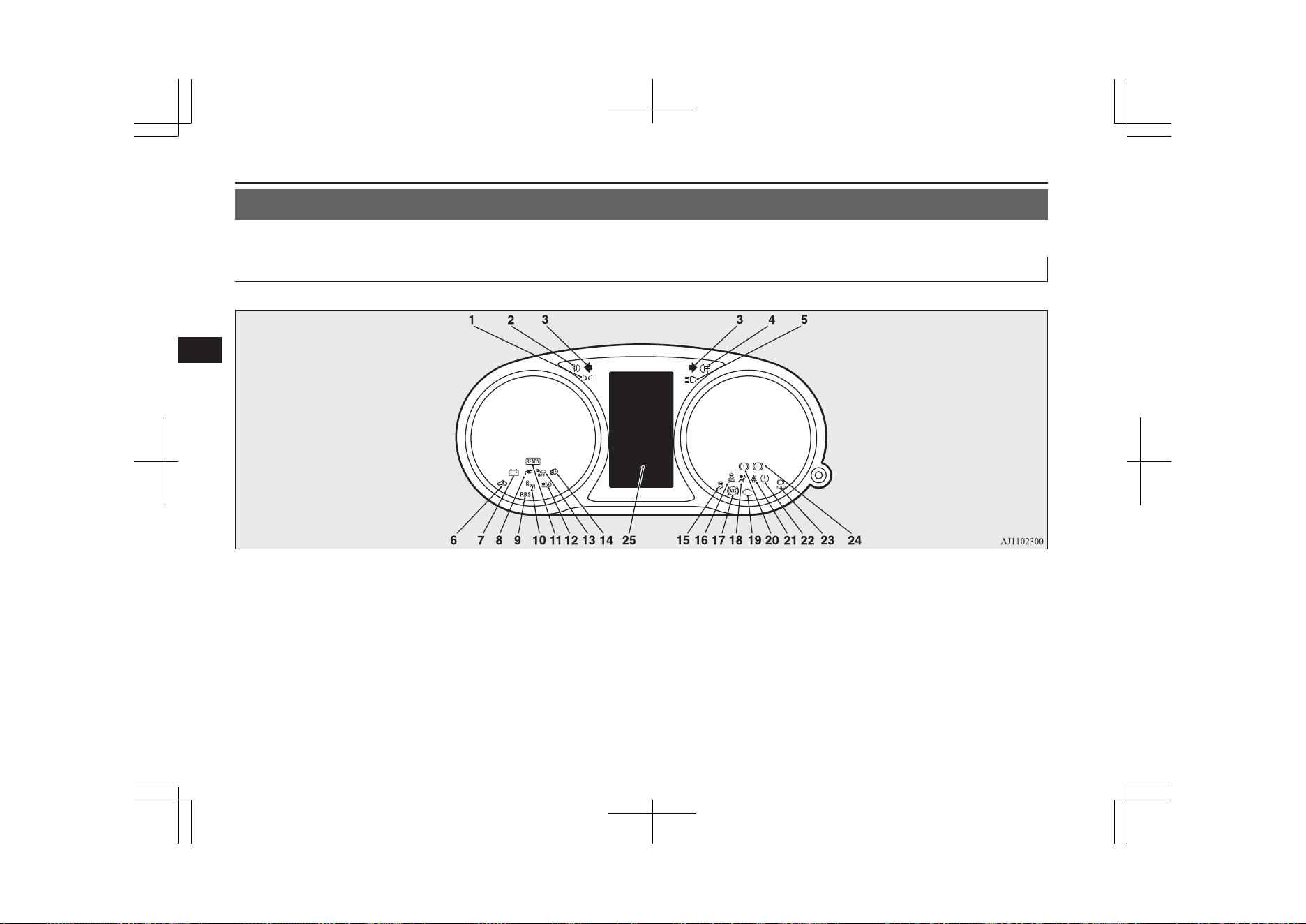
Indication lamp, warning lamp, and information screen display list
E00523701267
Indication and warning lamp list
E00523802539
1- Position lamp indication lamp
® p. 6-55
2- Front fog lamp indication lamp
® p. 6-55
3- Turn-signal indication lamps/Hazard
warning indication lamps ® p. 6-54
4- Rear fog lamp indication lamp
® p. 6-55
5- High-beam indication lamp ® p. 6-54
6- Plug-in Hybrid EV System warning
lamp ® p. 6-57
7- Auxiliary battery charge warning lamp
® p. 6-57
8- Charging indicator ® p. 6-55
9- Regenerative brake warning lamp
® p. 6-58
10- Blind Spot Warning (BSW) indication
lamp* ® p. 7-82
11- Ready indicator ® p. 6-55
12- Automatic High-Beam (AHB) indication
lamp* ® p. 6-62
13- Acoustic Vehicle Alerting System
(AVAS) OFF indication lamp
® p. 7-33
14- LED headlamp warning lamp*
® p. 6-61
15- Active Stability Control (ASC) indica-
tion lamp ® p. 7-45
Indication lamp, warning lamp, and information screen display list
6-24
OGGE19E1
Instruments and controls
6

16- Active Stability Control (ASC) OFF in-
dication lamp ® p. 7-45
17- Anti-lock brake system (ABS) warning
lamp ® p. 7-41
18- Supplement Restraint System (SRS)
warning lamp ® p. 5-35
19- Check engine warning lamp ® p. 6-56
20- Electric parking brake warning lamp
(yellow) ® p. 7-03
21- Seat belt warning lamp ® p. 5-11
22- Tyre pressure monitoring system warn-
ing lamp ® p. 7-93
23- Brake auto hold indication lamp
® p. 7-35
24- Brake warning lamp (red) ® p. 6-55
25- Information screen display list
® p. 6-25
Information screen display list
E00523901344
When there is information to be announced, such as lamp reminder, the buzzer sounds and the screen switches to the displays shown below.
Refer to the appropriate page and take the necessary measures.
When the cause of the warning display is eliminated, the warning display goes out automatically.
Refer to “Warning display list” on page 6-26.
Refer to “Navigation information display” on page 6-47.
Refer to “Other interrupt displays” on page 6-48.
NOTE
l
A warning may be displayed on the information screen and the buzzer may sound in the following rare cases.
This is caused by the system picking up interference such as noise or strong electromagnetic waves, and is not a functional problem.
•
An extremely strong electromagnetic wave is received from a source such as an illegal radio set, a spark from a wire, or a radar station.
•
Abnormal voltage or a static electricity discharge is generated by the operation of installed electrical equipment (including after-market parts).
If the warning display appears many times, we recommend you to consult a MITSUBISHI MOTORS Authorized Service Point.
Indication lamp, warning lamp, and information screen display list
6-25
OGGE19E1
Instruments and controls
6
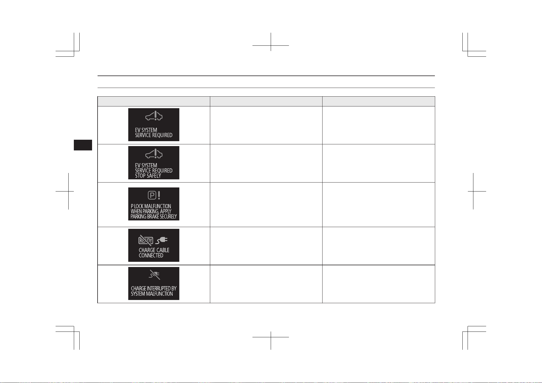
Warning display list
E00524002727
Screen Cause Solution (Reference)
l
One or more failure is occurring in the
Plug-in Hybrid EV System.
l
Have your vehicle inspected by a
MITSUBISHI MOTORS Authorized
Service Point.
l
One or more failure is occurring in the
Plug-in Hybrid EV System.
l
Immediately park the vehicle in a safe
place and contact a MITSUBISHI
MOTORS Authorized Service Point.
l
The parking lock unit is in failure. The
Plug-in Hybrid EV System cannot be kept
in standstill condition without applying
the parking brake.
l
Park the vehicle at a safe, flat place and
apply the parking brake. Contact a
MITSUBISHI MOTORS Authorized
Service Point.
Refer to “Electrical Parking switch” on
page 7-18.
l
You are attempting to set the operation
mode to “ON” when the charge connector
is connected to the charge port.
l
Disconnect the charge connector from the
charge port before operating the power
switch.
l
Charging was interrupted due to system
failure or EV charging cable failure.
l
There is a system failure or the EV charg-
ing charge cable is faulty. Immediately
stop using the cable and contact a
MITSUBISHI MOTORS Authorized
Service Point.
Indication lamp, warning lamp, and information screen display list
6-26
OGGE19E1
Instruments and controls
6
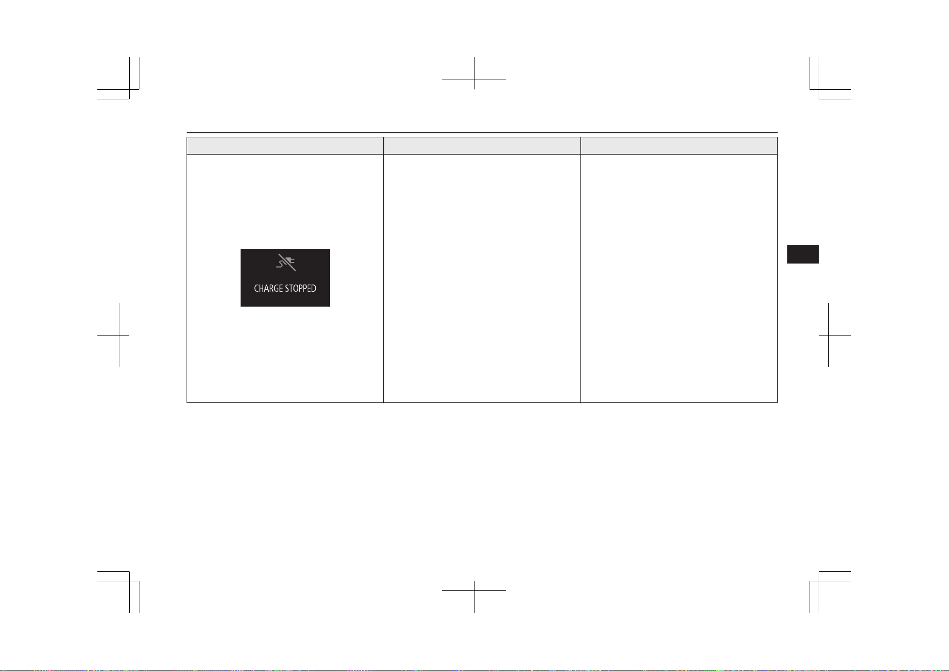
Screen Cause Solution (Reference)
l
Normal charging
• Charging was interrupted due to poor
connection of the EV charging cable or
power failure.
l
Quick charging
• Charging was stopped by your opera-
tion.
• Charging was interrupted after the pre-
determined set time.
• Charging was interrupted due to a poor
connection of the EV charging cable or
an electrical power failure.
• Charging was interrupted because there
is a problem in the vehicle or the quick
charger.
l
Normal charging
• Connect the EV charging cable correct-
ly. Refer to “Normal charging” on page
3-10.
• If charging is interrupted due to a pow-
er failure, charging will resume auto-
matically when the power source is re-
set.
l
Quick charging
• Connect the EV charging cable correct-
ly. Refer to “Quick charging” on page
3-17.
• If charging is interrupted due to a pow-
er failure, start the charging procedure
again from the beginning after the pow-
er source is reset.
• If the warning display appears in the
meter of the vehicle or on the quick
charger display, follow the instructions
and take the necessary measures.
Indication lamp, warning lamp, and information screen display list
6-27
OGGE19E1
Instruments and controls
6
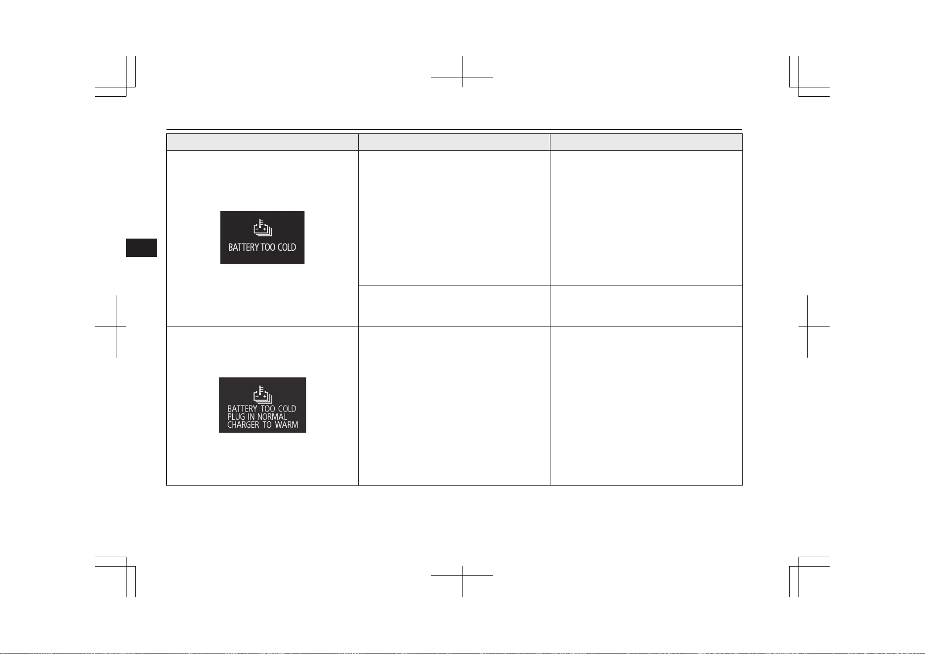
Screen Cause Solution (Reference)
l
The drive battery temperature is too cold.
l
When the vehicle is under running, stop
the vehicle in a safe place and contact a
MITSUBISHI MOTORS Authorized
Service Point.
l
When the vehicle is parked during the
daytime, wait for the outside temperature
to rise and re-start the Plug-in hybrid sys-
tem once the outside temperature has ris-
en.
Refer to “Cautions and actions to deal
with intense cold” on page 2-10.
l
The battery charge mode is selected when
the drive battery temperature is cold.
l
You do not have to take any actions, but
the time needed to charge the drive bat-
tery will become longer.
l
The drive battery is extremely cold. The
Plug-in Hybrid EV System will not start
until the drive battery is warm enough.
l
Even if the drive battery is fully charged,
connect the EV charging cable (normal
charger). Then, the drive battery warming
system is operated and the drive battery is
automatically warmed up. While the drive
battery warning system is operating,
“BATTERY TOO COLD” will be dis-
played. (Vehicles equipped with drive bat-
tery warming system)
Refer to “Charging from rated AC
220-240 V outlet” on page 3-12.
Refer to “Cautions and actions to deal
with intense cold” on page 2-10
Indication lamp, warning lamp, and information screen display list
6-28
OGGE19E1
Instruments and controls
6
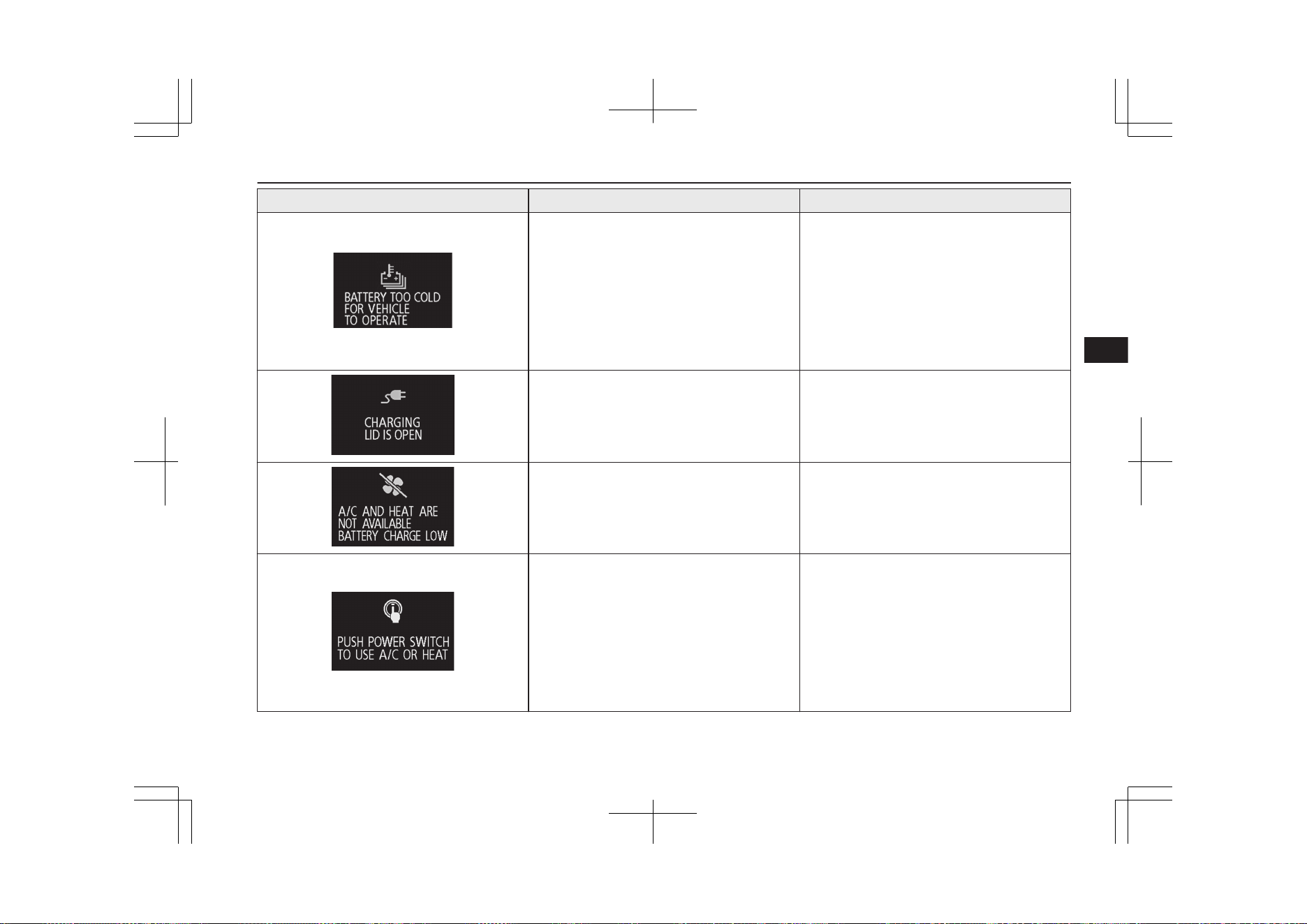
Screen Cause Solution (Reference)
l
The drive battery is extremely cold.
l
Stop the vehicle at a safe place if the vehi-
cle is under running.
When the vehicle has been parked during
the daytime, wait for the outside tempera-
ture to rise and re-start the Plug-in Hybrid
EV system once the outside temperature
has risen.
Refer to “Cautions and actions to deal
with intense cold” on page 2-10
l
Charging lid is open.
l
Close the charge lid.
Refer to “Charging from rated AC
220-240 V outlet” on page 3-12.
l
When the air conditioner stops because
the drive battery level becomes low by us-
ing the air conditioner during charging.
l
Turn the power switch to OFF once the
drive battery has been charged sufficient-
ly, then turn the power switch to ON. The
air conditioner can be used again.
l
When the air conditioner can be used
again in the following conditions.
The drive battery is sufficiently charged
when the “A/C AND HEAT ARE NOT
AVAILABLE BATTERY CHARGE
LOW” indication is displayed or the drive
battery is sufficiently heated when the
“BATTERY TOO COLD” indication is
displayed, etc.
l
Turn the power switch to OFF once, and
then turn the power switch to ON. The air
conditioner can be used again.
Indication lamp, warning lamp, and information screen display list
6-29
OGGE19E1
Instruments and controls
6
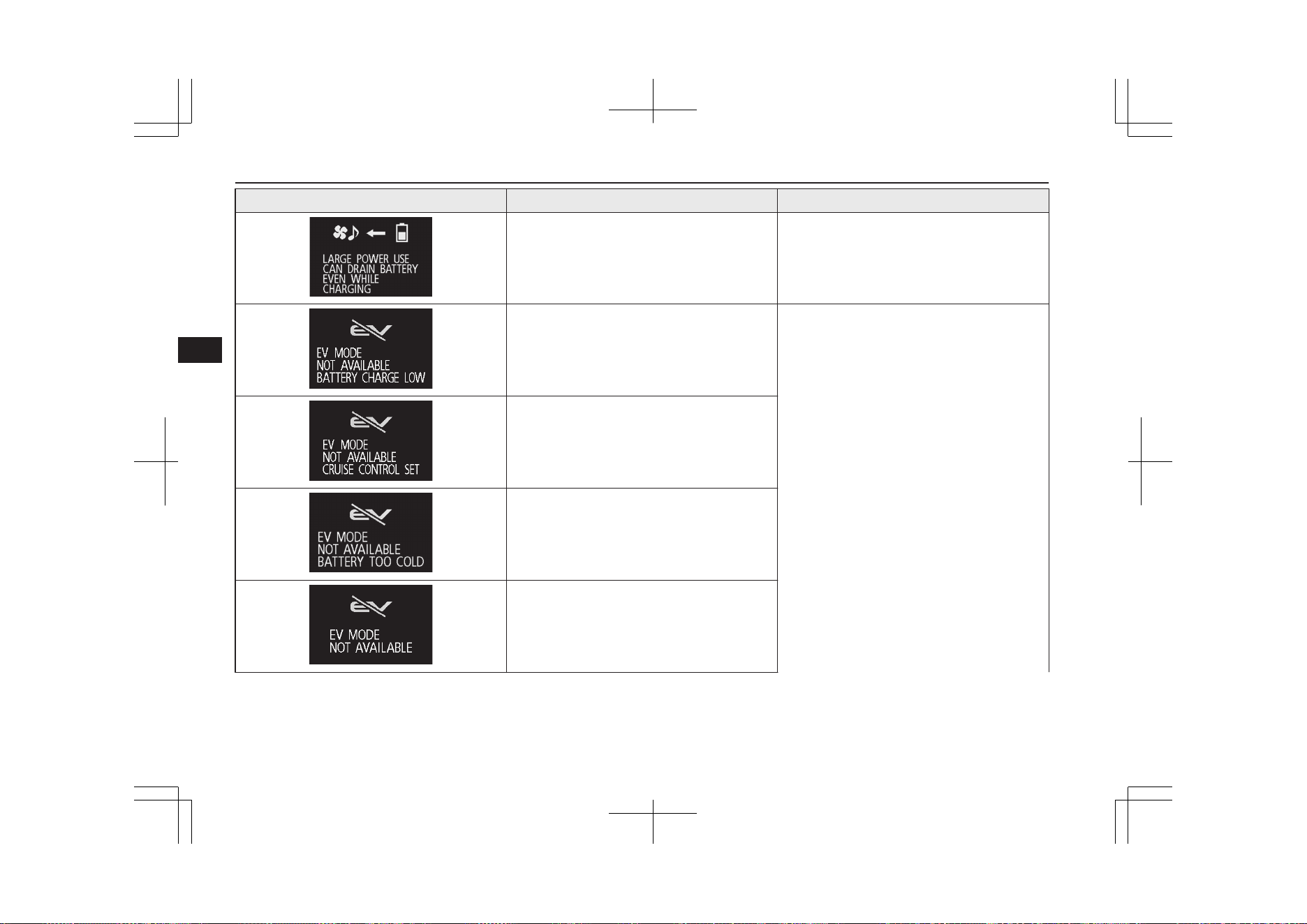
Screen Cause Solution (Reference)
l
When the operation mode of the power
switch is put in ON during charging.
l
The electric devices can be used during
charging. Refer to “How to use an electric
device during charging” on page 3-24.
l
EV priority mode is not available because
the drive battery level is low.
l
Refer to “EV switch” on page 7-25.
l
EV priority mode is not available because
the cruise control or the Adaptive Cruise
Control System (ACC) is operating.
l
EV priority mode is not available because
the drive battery is too cold.
l
EV priority mode is not available because
the EV priority mode is limited to protect
the Plug-in Hybrid EV System or the out-
side temperature is too low.
Indication lamp, warning lamp, and information screen display list
6-30
OGGE19E1
Instruments and controls
6

Screen Cause Solution (Reference)
l
EV priority mode is cancelled because the
drive battery level is low.
l
EV priority mode is cancelled because the
vehicle speed of the cruise control or the
Adaptive Cruise Control System (ACC) is
set.
l
EV priority mode is cancelled because the
drive battery temperature has become too
cold.
l
EV priority mode is cancelled because the
protecting device of the Plug-in Hybrid
EV System is operated.
l
You have selected the warm air with the
air conditioner switch while driving in the
EV priority mode.
(Vehicle without electric heater)
l
If you want to use the heating, cancel the
EV priority mode.
Refer to “EV switch” on page 7-25.
Indication lamp, warning lamp, and information screen display list
6-31
OGGE19E1
Instruments and controls
6

Screen Cause Solution (Reference)
l
You have pressed the EV switch while
heating.
(Vehicle without electric heater)
l
If you want to use the EV priority mode,
stop the heating.
Refer to “Automatic climate control air
conditioner” on page 8-06
l
SPORT mode is not available because the
remaining fuel quantity is low.
l
Refer to “SPORT mode switch” on page
7-31.
l
SPORT mode is cancelled because the re-
maining fuel quantity has become low.
l
Battery save mode or battery charge mode
is not available because the engine cool-
ant temperature is high or the remaining
fuel quantity is low.
l
Refer to “SAVE/CHARGE mode switch”
on page 7-28.
l
Battery save mode or battery charge mode
is cancelled because the engine coolant
temperature has become high or the re-
maining fuel quantity has become low.
Indication lamp, warning lamp, and information screen display list
6-32
OGGE19E1
Instruments and controls
6
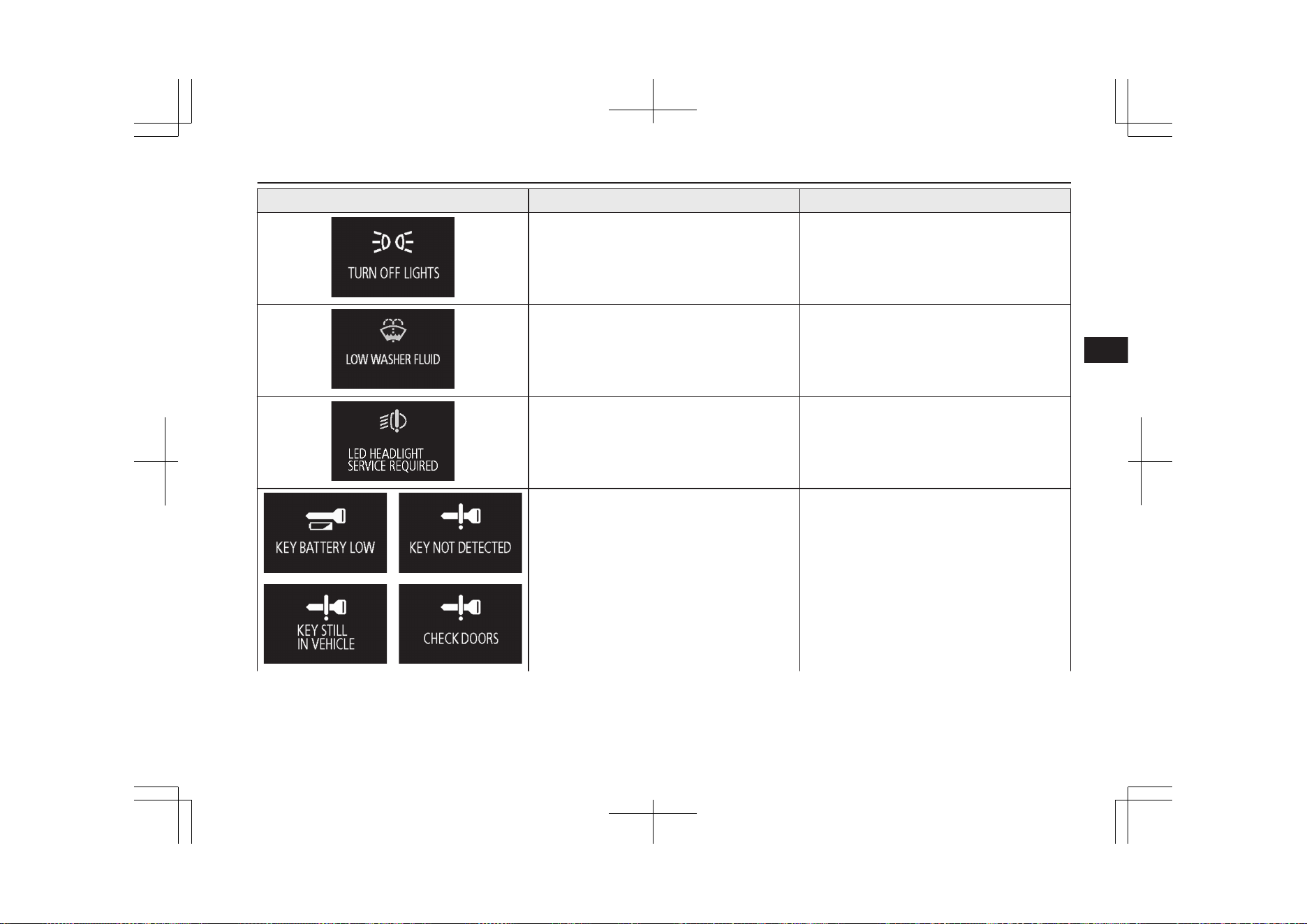
Screen Cause Solution (Reference)
l
You have forgotten to turn off the lamps.
l
Refer to “Lamps (headlamps, fog lamps,
etc.) auto-cutout function” on page 6-59.
l
The washer fluid is running low.
l
Replenish the container with washer fluid.
Refer to “Washer fluid” on page 11-08.
Refer to “Refill capacities” on page
12-10.
l
There is a fault in the LED headlamps.
l
Have your vehicle inspected by a
MITSUBISHI MOTORS Authorized
Service Point.
Refer to “LED headlamp warning lamp”
on page 6-61.
l
There is a fault in the keyless operation
system.
l
Refer to “Keyless operation system” on
page 4-06.
Indication lamp, warning lamp, and information screen display list
6-33
OGGE19E1
Instruments and controls
6

Screen Cause Solution (Reference)
l
The keyless operation key is not detected.
l
Insert the keyless operation key into the
key slot.
Refer to “If the keyless operation key is
not operating properly” on page 7-15.
l
You have forgotten to remove the keyless
operation key from the key slot.
l
Remove the keyless operation key from
the key slot.
Refer to “Keyless operation key remind-
er” on page 7-15.
l
There is a fault in the EPS.
l
Have the vehicle inspected by a
MITSUBISHI MOTORS Authorized
Service Point as soon as possible.
Refer to “Electric power steering system
(EPS)” on page 7-42.
l
The RBS (regenerative brake system) can-
not be used.
l
Have your vehicle inspected by a
MITSUBISHI MOTORS Authorized
Service Point.
Indication lamp, warning lamp, and information screen display list
6-34
OGGE19E1
Instruments and controls
6
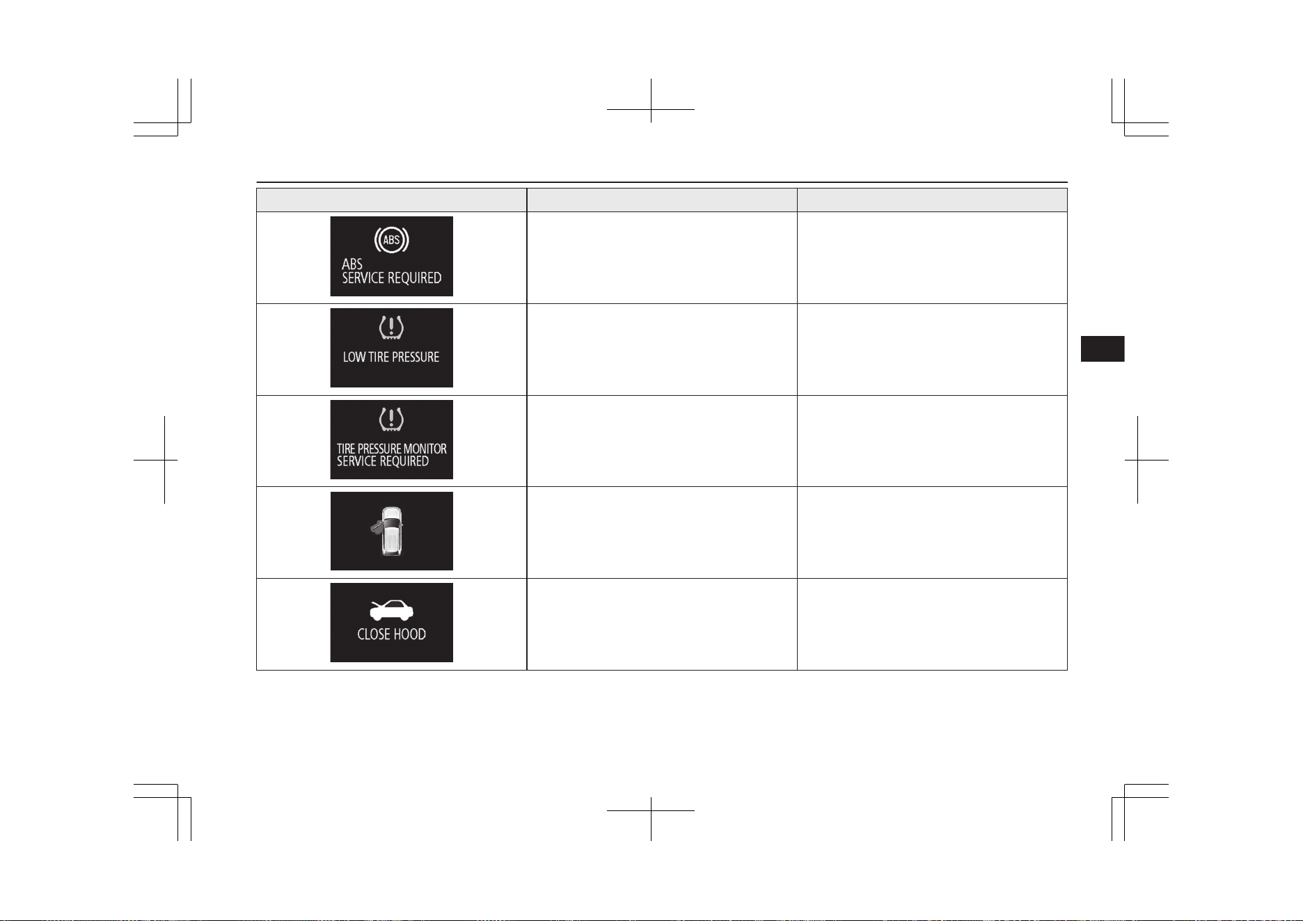
Screen Cause Solution (Reference)
l
There is a fault in the ABS.
l
Avoid sudden braking and high-speed
driving, stop the vehicle in a safe place,
and take corrective measures. Refer to
“ABS warning lamp/display” on page
7-41.
l
The tyre pressure in one of the tyres is
low.
l
Refer to “Tyre pressure monitoring sys-
tem warning lamp/display” on page
7-93.
l
There is a fault in the tyre pressure moni-
toring system.
l
Refer to “Tyre pressure monitoring sys-
tem warning lamp/display” on page
7-93.
l
One of the doors or the tailgate is not
completely closed.
The open door is displayed.
l
Close the door or tailgate.
Refer to “Door ajar warning display
screen” on page 6-11.
l
The bonnet is open.
l
Close the bonnet.
Refer to “Bonnet” on page 11-04.
Indication lamp, warning lamp, and information screen display list
6-35
OGGE19E1
Instruments and controls
6
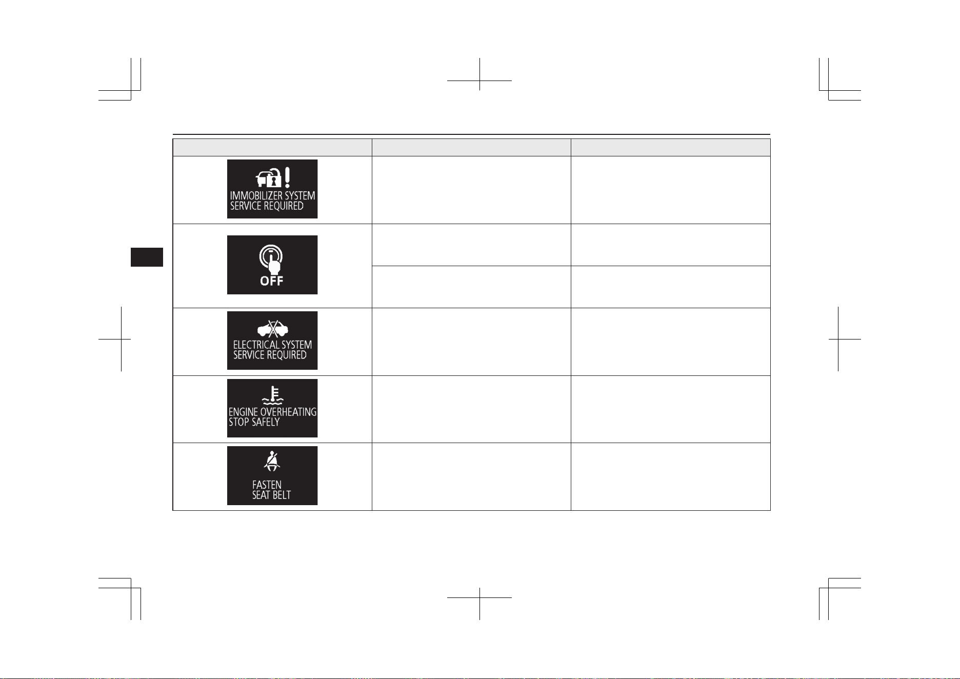
Screen Cause Solution (Reference)
l
There is a fault in the electronic immobil-
izer (Anti-theft starting system).
l
Put the operation mode in OFF, and then
start the Plug-in Hybrid EV System again.
If the warning is not cancelled, please
contact a MITSUBISHI MOTORS Au-
thorized Service Point.
l
The driver’s door is open when the opera-
tion mode is in any mode other than OFF.
l
Put the operation mode in OFF.
Refer to “Operation mode ON reminder
system” on page 7-13.
l
An attempt was made to lock all the doors
and the tailgate when the operation mode
is in any mode other than OFF.
l
Put the operation mode in OFF.
Refer to “Operation mode OFF reminder
system” on page 7-13.
l
There is a fault in the electrical system.
l
Immediately stop the vehicle in a safe
place.
We recommend you to contact a
MITSUBISHI MOTORS Authorized
Service Point.
l
The engine is overheated.
l
Stop the vehicle in a safe place and take
corrective measures.
Refer to “Engine overheating” on page
9-04.
l
You put the operation mode in ON with-
out fastening your seat belt.
l
Fasten your seat belt properly. Refer to
“Seat belt reminder” on page 5-11.
Indication lamp, warning lamp, and information screen display list
6-36
OGGE19E1
Instruments and controls
6
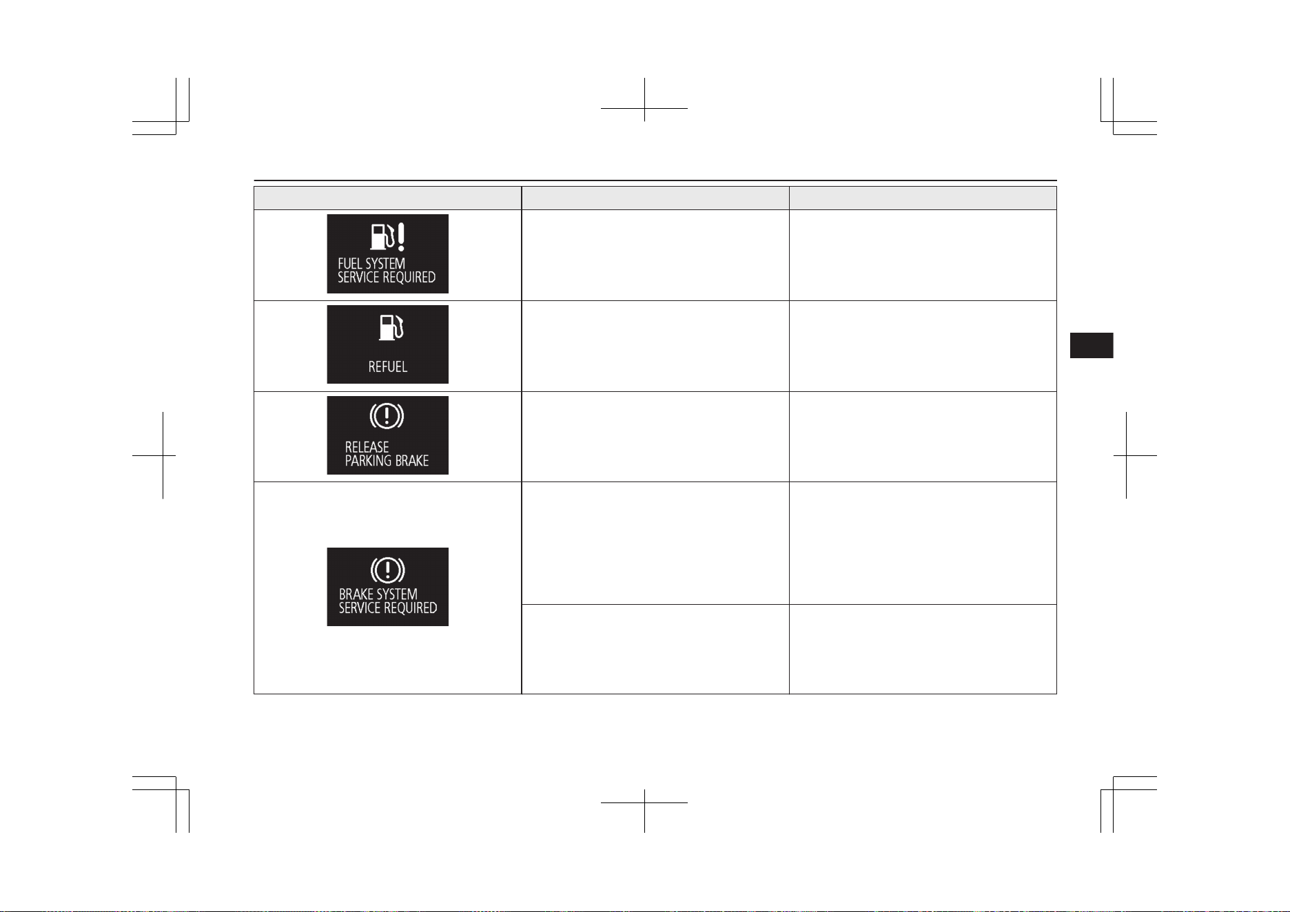
Screen Cause Solution (Reference)
l
There is a fault in the fuel system.
l
We recommend you to have it checked,
immediately.
l
The fuel is running low.
l
Refuel as soon as possible. Refer to “Fuel
remaining warning display” on page 6-12.
l
You are driving with the parking brake
still applied.
l
Release the parking brake. Refer to
“Brake warning display” on page 6-58.
l
The brake fluid level in the reservoir has
fallen to a low level.
l
There is a fault in the brake system.
l
Immediately stop the vehicle in a safe
place.
We recommend you to consult a
MITSUBISHI MOTORS Authorized
Service Point.
Refer to “Brake warning display” on page
6-58.
l
When the brake pedal has been repeatedly
depressed over a short period of time, the
brake warning lamp may come on and the
brake warning buzzer may sound, and this
warning may be displayed.
l
If this warning display has disappeared
and the brake warning lamp goes out and
the buzzer stops a few seconds after stop-
ping the brake operation, there is no ab-
normality.
Indication lamp, warning lamp, and information screen display list
6-37
OGGE19E1
Instruments and controls
6
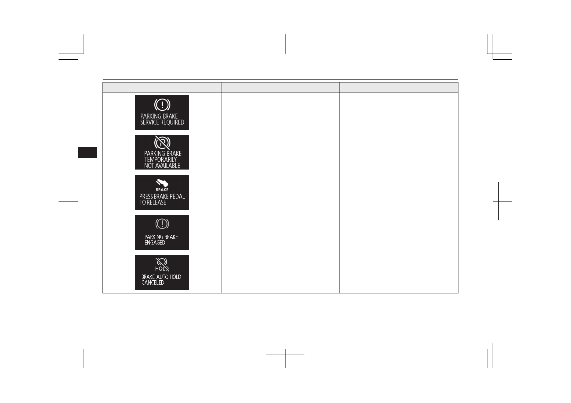
Screen Cause Solution (Reference)
l
There is a fault with the Electric parking
brake.
l
We recommend you to have it checked,
immediately.
Refer to “Electric parking brake” on page
7-03.
l
The parking brake cannot be applied tem-
porarily due to repeated operation of the
Electric parking brake switch within a
short time.
l
Refer to “Electric parking brake” on page
7-03.
l
You try to release the Electric parking
brake switch without depressing the brake
pedal.
l
Refer to “Electric parking brake” on page
7-03.
l
The Electric parking brake has been auto-
matically applied.
l
Refer to “Brake auto hold” on page 7-35.
l
The brake auto hold is automatically can-
celled.
l
Refer to “Brake auto hold” on page 7-35.
Indication lamp, warning lamp, and information screen display list
6-38
OGGE19E1
Instruments and controls
6

Screen Cause Solution (Reference)
l
The brake auto hold is not available.
l
Refer to “Brake auto hold” on page 7-35.
l
The brake auto hold system does not turn
on because the driver’s seat belt is not fas-
tened.
l
Press the brake auto hold switch after fas-
tening the driver’s seat belt.
Refer to “Brake auto hold” on page 7-35.
l
The brake auto hold system does not turn
off because the brake pedal is not pressed.
l
Depress the brake pedal more firmly than
usual with the right foot. Then, press the
brake auto hold switch.
Refer to “Brake auto hold” on page 7-35.
l
There is a fault in the engine oil circula-
tion system.
l
Immediately stop the vehicle in a safe
place. We recommend you to have it
checked.
Refer to “Oil pressure warning display”
on page 6-58.
l
There is a fault in the Supplemental re-
straint system (SRS) airbag or the preten-
sioner system.
l
We recommend you to have it checked,
immediately.
Refer to “SRS warning lamp/display” on
page 5-35.
Indication lamp, warning lamp, and information screen display list
6-39
OGGE19E1
Instruments and controls
6
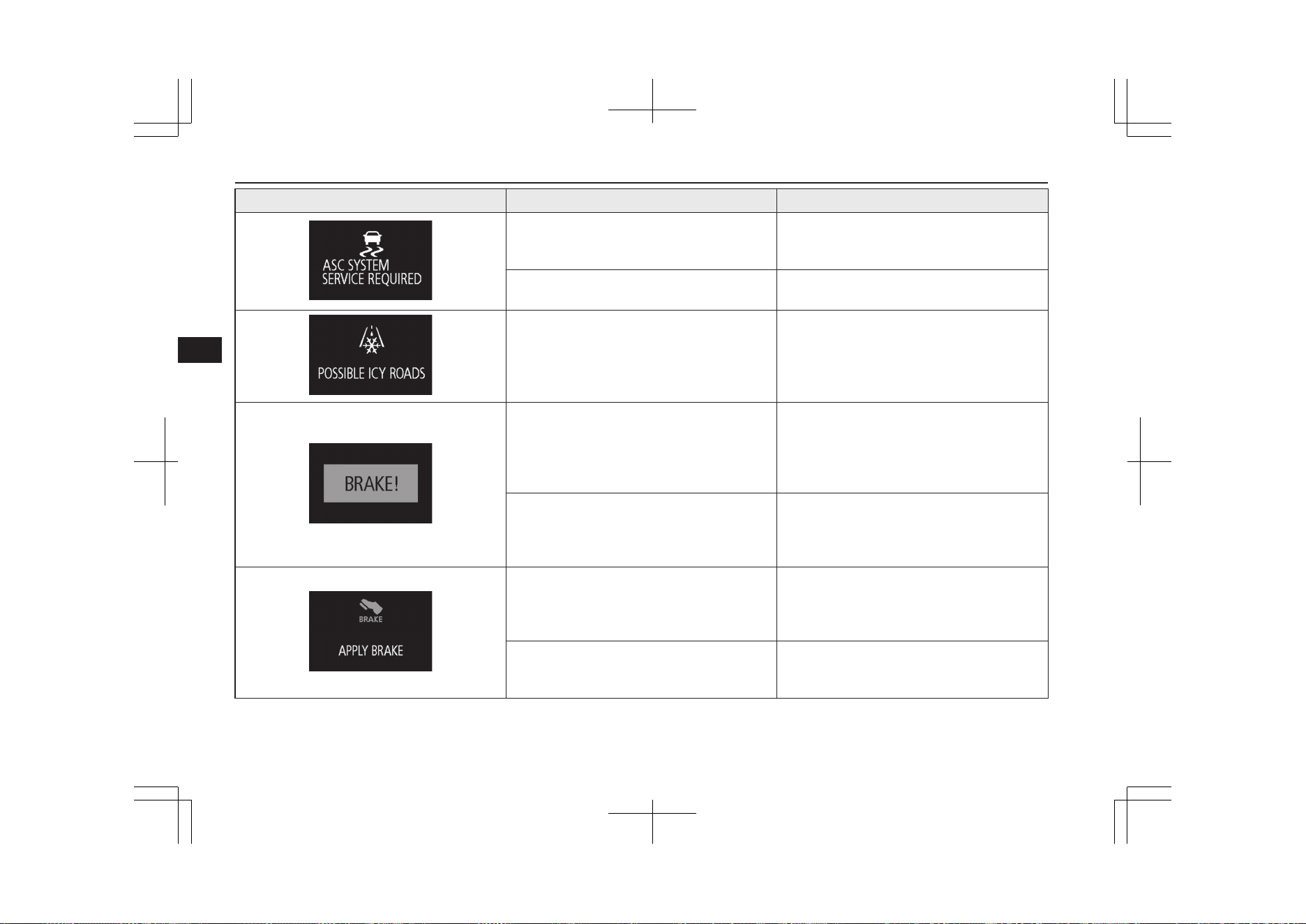
Screen Cause Solution (Reference)
l
There is a fault in the Active Stability
Control (ASC).
l
We recommend you to have it checked.
Refer to “Active stability control (ASC)”
on page 7-43.
l
There is a fault in the hill start assist.
l
We recommend you to have it checked.
Refer to “Hill start assist” on page 7-37.
l
The outside temperature is 3 °C (37 °F) or
less.
l
Be careful of ice on the road.
l
The road can be icy even when this warn-
ing is not displayed, so drive carefully.
l
The Adaptive Cruise Control System
(ACC) has detected the approach of the
vehicles in front.
l
Increase the following distance by de-
pressing the brake pedal or marking other
decelerating control.
Refer to “Adaptive Cruise Control System
(ACC): Proximity alarm” on page 7-58.
l
The Forward Collision Mitigation System
(FCM) has detected the danger of colli-
sion.
l
Take appropriate action such as depress-
ing the brake to avoid collision.
Refer to “Forward collision warning func-
tion” on page 7-68.
l
The Adaptive Cruise Control System
(ACC) detected a stop of the vehicle in
front and stopped your vehicle, but the
brake will be released soon.
l
Depress the brake pedal as soon as your
vehicle comes to a stop.
Refer to “Adaptive Cruise Control System
(ACC)” on page 7-55.
l
The Electric parking brake cannot be ap-
plied automatically.
l
Depress the brake pedal as soon as possi-
ble.
Refer to “Brake auto hold” on page 7-35.
Indication lamp, warning lamp, and information screen display list
6-40
OGGE19E1
Instruments and controls
6
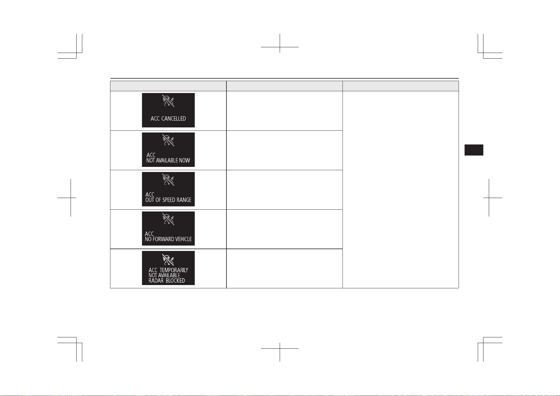
Screen Cause Solution (Reference)
l
The Adaptive Cruise Control System
(ACC) control is automatically cancelled
and the system is placed in the ‘standby’
state.
l
Refer to “How to use ACC” on page 7-61.
l
Conditions for the start of control are not
met, the Adaptive Cruise Control System
(ACC) can not start the control.
l
The Adaptive Cruise Control System
(ACC) can not start the control because
the speed is out of speed range.
l
The Adaptive Cruise Control System
(ACC) can not start the control because
not detected the approach of the vehicles
in front.
l
The Adaptive Cruise Control System
(ACC) is not available temporarily such
as for adhesion of contaminants to the
sensor.
This is not a malfunction.
Indication lamp, warning lamp, and information screen display list
6-41
OGGE19E1
Instruments and controls
6
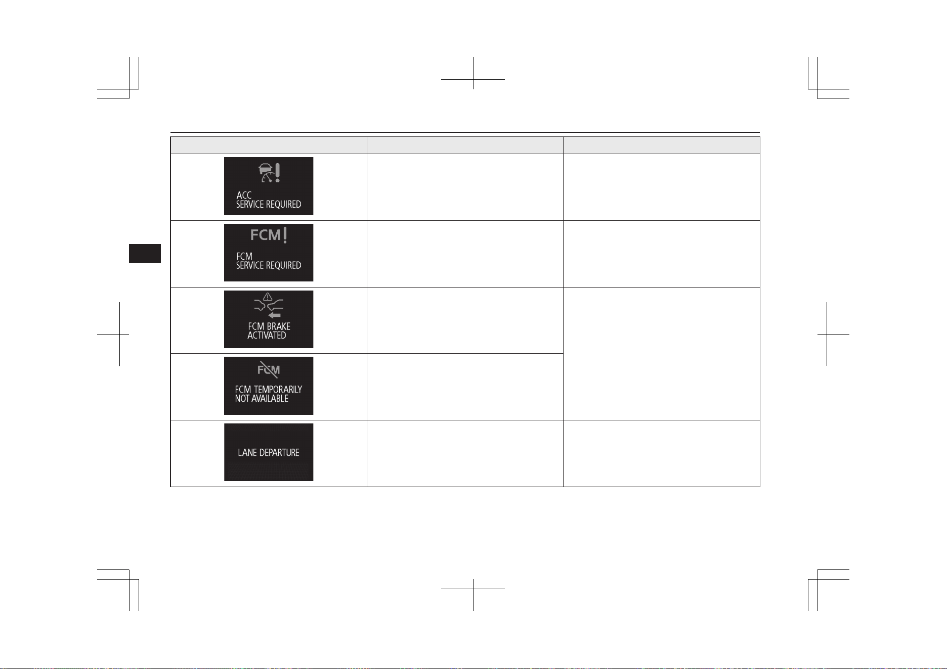
Screen Cause Solution (Reference)
l
There is a fault in the Adaptive Cruise
Control System (ACC).
l
We recommend you to have it checked.
Refer to “Adaptive Cruise Control System
(ACC)” on page 7-55.
l
There is a fault in the Forward Collision
Mitigation System (FCM).
l
We recommend you to have it checked.
Refer to “Forward Collision Mitigation
System (FCM)” on page 7-67.
l
FCM braking function of the Forward
Collision Mitigation System (FCM) has
been activated.
l
Refer to “FCM braking function” on page
7-69.
l
The Forward Collision Mitigation System
(FCM) is temporarily unavailable for
some reason. This is not a malfunction.
l
The Lane Departure Warning (LDW) has
detected that your vehicle is about to
leave or has left the lane.
l
Refer to “Lane Departure Warning
(LDW)” on page 7-88.
Indication lamp, warning lamp, and information screen display list
6-42
OGGE19E1
Instruments and controls
6
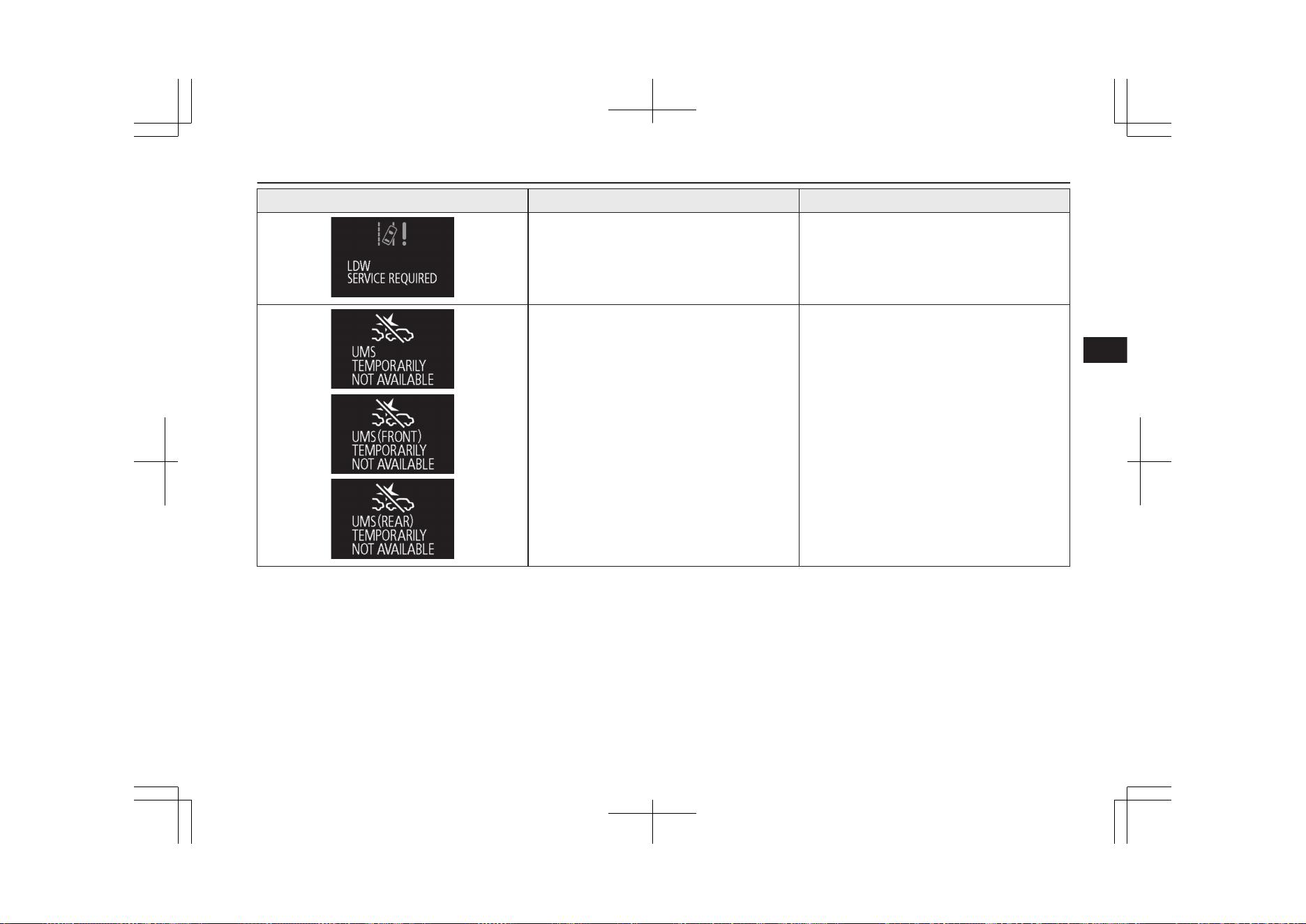
Screen Cause Solution (Reference)
l
There is a fault in the Lane Departure
Warning (LDW).
l
We recommend you to have it checked.
Refer to “Lane Departure Warning
(LDW)” on page 7-88.
l
The Ultrasonic misacceleration Mitigation
System (UMS) sensor is temporarily not
available for some reason such as the en-
vironmental condition or increase of the
sensor temperature.
l
When the warning display does not disap-
pear after waiting for a while, contact a
MITSUBISHI MOTORS Authorized
Service Point.
Refer to “Ultrasonic misacceleration Miti-
gation System (UMS)” on page 7-77.
Indication lamp, warning lamp, and information screen display list
6-43
OGGE19E1
Instruments and controls
6
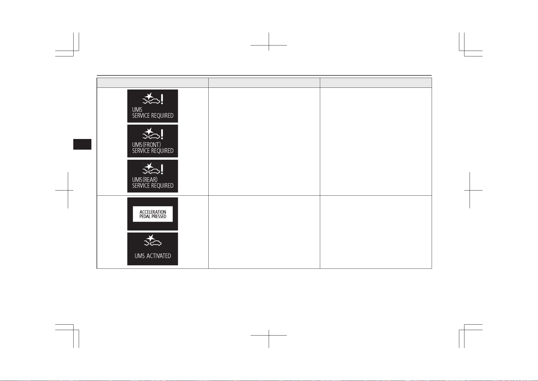
Screen Cause Solution (Reference)
l
The Ultrasonic misacceleration Mitigation
System (UMS) does not operate normally
because there are some malfunctions in
the sensor or the system.
l
Immediately have your vehicle inspected
at a MITSUBISHI MOTORS Authorized
Service Point.
Refer to “Ultrasonic misacceleration Miti-
gation System (UMS)” on page 7-77.
l
The Ultrasonic misacceleration Mitigation
System (UMS) is activated.
l
Refer to “Ultrasonic misacceleration Miti-
gation System (UMS)” on page 7-77.
Indication lamp, warning lamp, and information screen display list
6-44
OGGE19E1
Instruments and controls
6
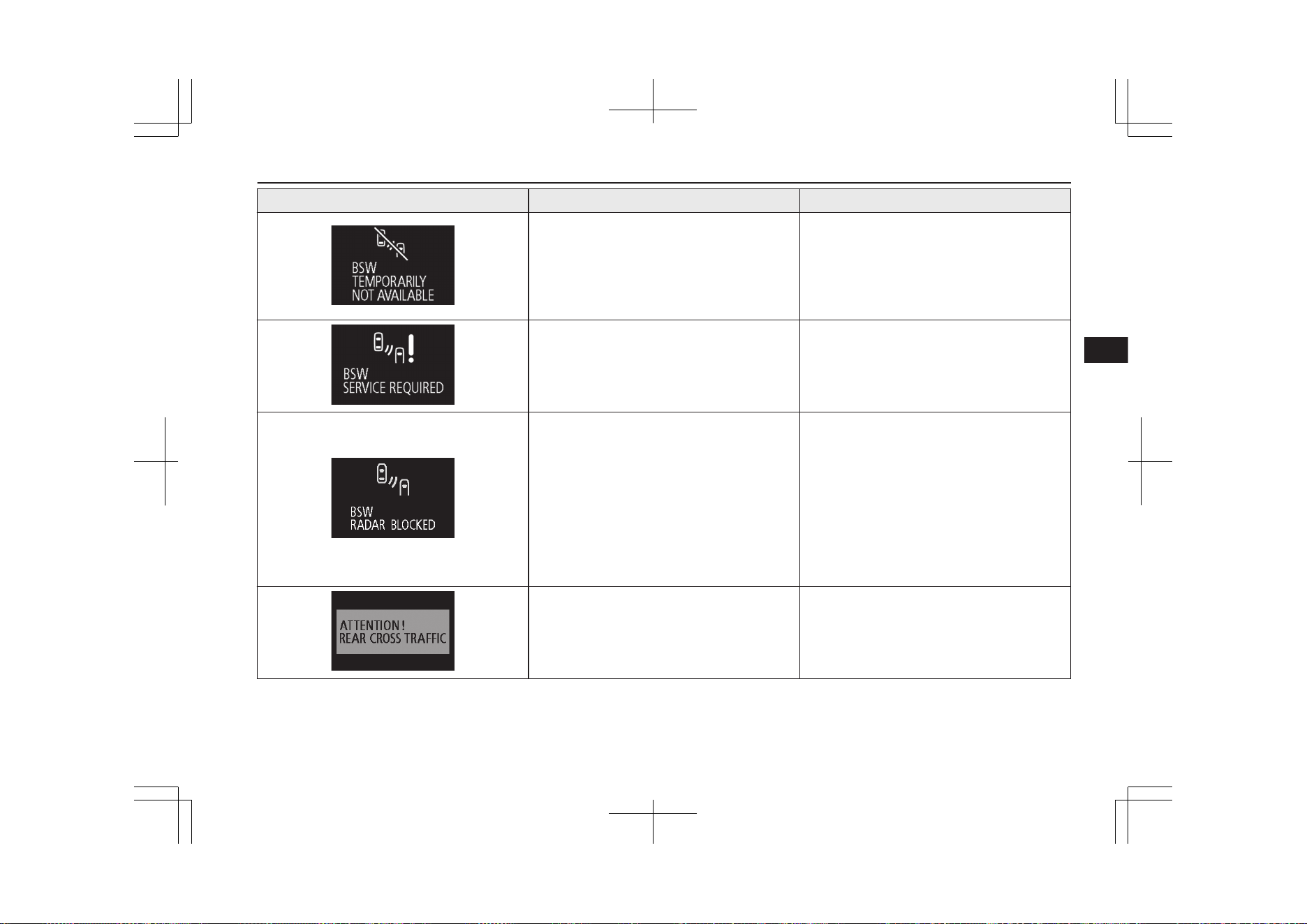
Screen Cause Solution (Reference)
l
The Blind Spot Warning (BSW) sensor is
temporarily not available for some reason
such as the environmental condition or in-
crease of the sensor temperature.
l
When the warning display does not disap-
pear after waiting for a while, contact a
MITSUBISHI MOTORS Authorized
Service Point.
Refer to “Blind Spot Warning (BSW)” on
page 7-82.
l
The Blind Spot Warning (BSW) does not
operate normally because there are some
malfunctions in the sensor or the system.
l
We recommend you to have it checked,
immediately.
Refer to “Blind Spot Warning (BSW)” on
page 7-82.
l
Foreign objects, such as dirt, snow or ice,
adhere to the bumper surface around the
sensor.
l
Remove a foreign object on the bumper
surface around the sensor.
When the warning display does not disap-
pear after having cleaned the bumper sur-
face around the sensor, contact a
MITSUBISHI MOTORS Authorized
Service Point.
Refer to “Blind Spot Warning (BSW):
When there is a foreign objects on the
sensor” on page 7-86.
l
The Rear Cross Traffic Alert (RCTA) has
detected a vehicle that is approaching
your vehicle.
l
Pay special attention to the rear of your
vehicle.
Refer to “Rear Cross Traffic Alert
(RCTA)” on page 7-86.
Indication lamp, warning lamp, and information screen display list
6-45
OGGE19E1
Instruments and controls
6
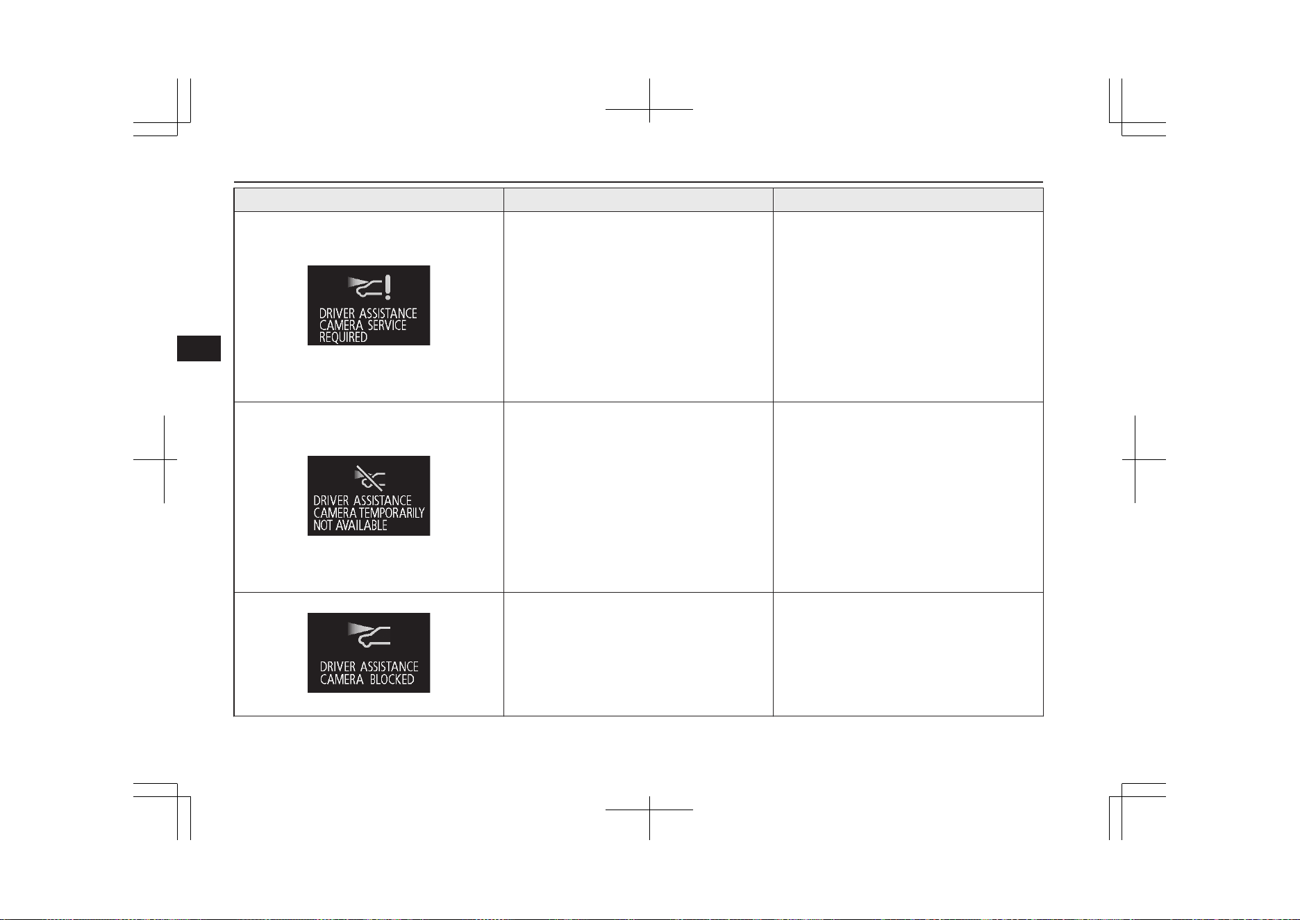
Screen Cause Solution (Reference)
l
There is a fault in the sensor.
l
We recommend you to contact a
MITSUBISHI MOTORS Authorized
Service Point.
Refer to “Forward Collision Mitigation
System (FCM): When a problem is detec-
ted” on page 7-73.
Refer to “Lane Departure Warning
(LDW): System problem warning” on
page 7-90.
Refer to “Automatic High-Beam (AHB):
System problem warning” on page 6-64.
l
The Forward Collision Mitigation System
(FCM), Lane Departure Warning (LDW)
and Automatic High-Beam (AHB) are
temporarily unavailable due to the high or
low temperature of the sensor.
l
After the temperature of the sensor has
been in range, the system will automati-
cally return to operation.
Refer to “Forward Collision Mitigation
System (FCM): When a problem is detec-
ted” on page 7-73.
Refer to “Lane Departure Warning
(LDW): System problem warning” on
page 7-90.
Refer to “Automatic High-Beam (AHB):
System problem warning” on page 6-64.
l
The sensor is temporarily unavailable due
to conditions such as the adhesion of con-
taminants to the sensor or windscreen.
This is not a malfunction.
Refer to “Forward Collision Mitigation System
(FCM): When a problem is detected” on page
7-73.
Refer to “Lane Departure Warning (LDW):
System problem warning” on page 7-90.
Refer to “Automatic High-Beam (AHB): Sys-
tem problem warning” on page 6-64.
Indication lamp, warning lamp, and information screen display list
6-46
OGGE19E1
Instruments and controls
6
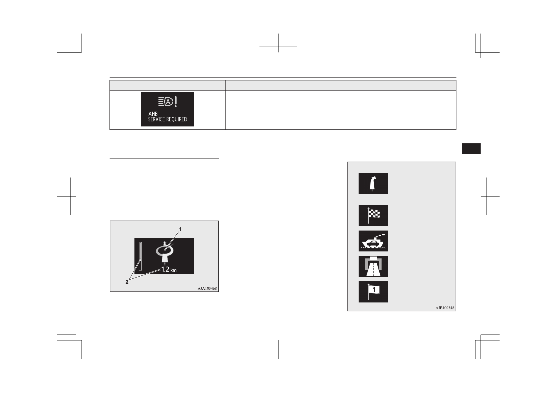
Screen Cause Solution (Reference)
l
There is a fault in the Automatic High-
Beam (AHB).
l
We recommend you to contact a
MITSUBISHI MOTORS Authorized
Service Point.
Refer to “Automatic High-Beam (AHB):
System problem warning” on page 6-64.
Navigation information dis-
play*
E00531401061
On vehicles equipped with MITSUBISHI
Multi-Communication System (MMCS), the
following information on navigation will be
displayed when guidance location such as
junction and destination is approached after
you set the destination and started the route
guidance.
1- Guidance display Shows the direction of vehicle travel and
the guidance location.
Direction of vehicle travel
(Example)
Destination
Ferry terminal
Tollbooth
Intermediate destination
(Example)
Indication lamp, warning lamp, and information screen display list
6-47
OGGE19E1
Instruments and controls
6
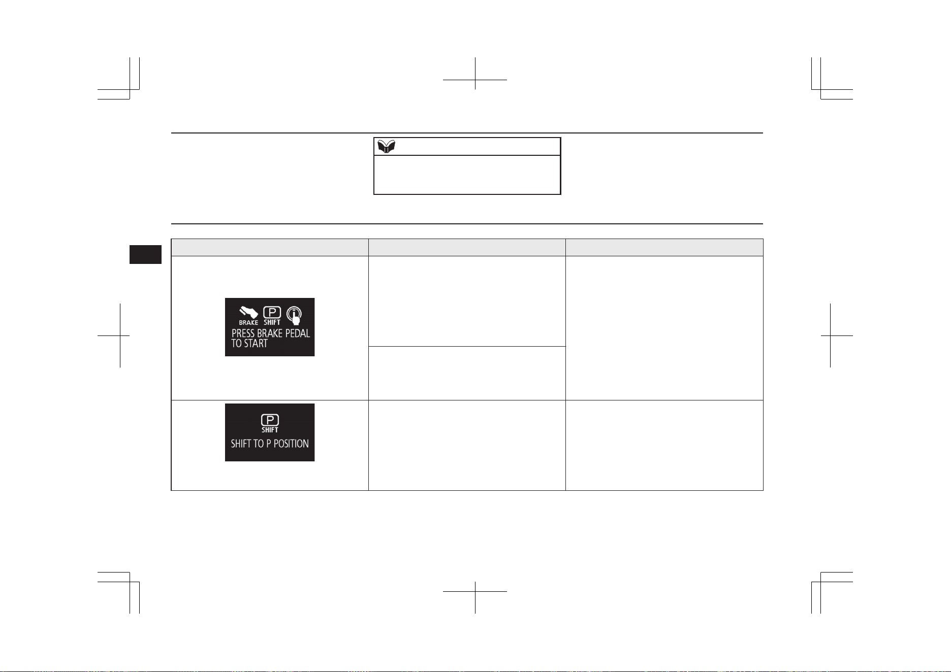
2- Remaining distance display
Shows the distance to the location where
the guidance is displayed.
NOTE
l
Please read this section and also the separate
owner’s manual for MITSUBISHI Multi-
Communication System (MMCS).
Other interrupt displays
E00524202556
Screen Cause Solution (Reference)
l
When you pressed the power switch and
the operation mode become the ACC
without depress the brake pedal, this
screen is displayed.
This screen will be displayed repeatedly
at regular intervals while the operation
mode of the power switch is put in ACC.
l
Place the select position in the “P” (PARK)
position, depress the brake pedal more
firmly than usual with the right foot. Then,
press the power switch.
Refer to “Starting and stopping the Plug-in
Hybrid EV System” on page 7-13.
l
When Plug-in Hybrid EV System does
not start even if the operation mode of the
power switch is put in ON, this screen is
displayed.
l
When starting the Plug-in Hybrid EV Sys-
tem, you pressed the power switch with-
out select position in the “P” (PARK) po-
sition.
l
Place the select position in the “P”
(PARK) position by pressing the electrical
parking switch, depress the brake pedal
more firmly than usual with the right foot.
Then, press the power switch.
Refer to “Starting and stopping the Plug-
in Hybrid EV System” on page 7-13.
Indication lamp, warning lamp, and information screen display list
6-48
OGGE19E1
Instruments and controls
6
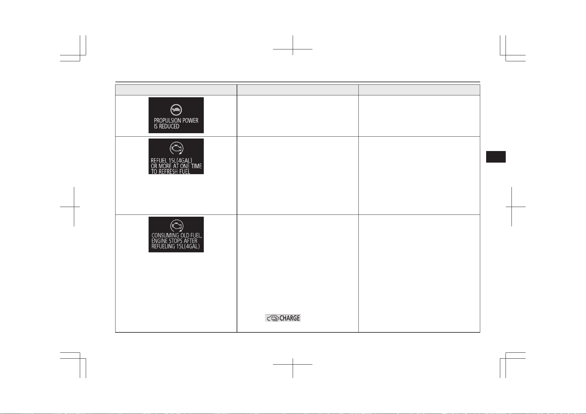
Screen Cause Solution (Reference)
l
Driving power is restricted by the safety
system as the Plug-in Hybrid EV System
has become too hot or too cold.
l
You do not have to take any actions. The
restriction on the driving power will be re-
leased when the Plug-in Hybrid EV Sys-
tem returns to the normal temperature.
l
The vehicle had not been refueled about
15 litres or more at one time for nearly 3
months.
This display may appear frequently de-
pending on the use conditions of your ve-
hicle such as when fuel has been staying
in the fuel tank for a long time.
l
Refill the 15 litres more at one time.
This display will disappear.
If the fuel remaining display will be be-
low half, you can refill the fuel more than
15 litres certainly.
l
If you cannot refill the fuel due to the
large amount of remaining fuel, start the
engine and drive the vehicle enough to re-
duce the fuel level to approximately half
tank.
l
If the vehicle had not been refuelled about
15 litres or more at one time for three
months, the engine starts automatically
for the maintenance of the engine or the
fuel system components while the ready
indicator is illuminated.
This display may appear frequently de-
pending on the use conditions of your ve-
hicle such as when fuel has been staying
in the fuel tank for a long time.
When the engine is running, this display
shows the state where the drive battery is
charged, and the battery charge mode dis-
play (
) is displayed. But the
drive battery will not be full charge.
l
Refill the 15 litres more at one time. This
display and battery charge mode display
will disappear, and the engine will not au-
tomatically start for maintenance.
If the fuel remaining display will be be-
low half, you can refill the fuel more than
15 litres certainly.
l
If you cannot refill the fuel due to the
large amount of remaining fuel, start the
engine and drive the vehicle enough to re-
duce the fuel level to approximately half
tank.
Indication lamp, warning lamp, and information screen display list
6-49
OGGE19E1
Instruments and controls
6
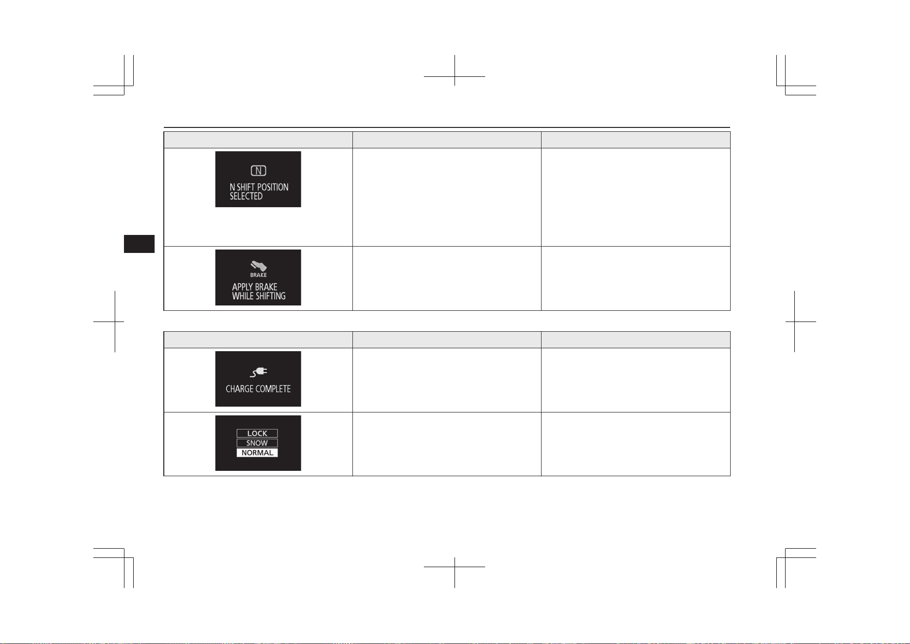
Screen Cause Solution (Reference)
l
The accelerator pedal has been depressed
when the select position is in the “N”
(NEUTRAL) position.
l
When you start the vehicle, be sure to
check the select position indicator and
make sure the select position is in the “D”
(DRIVE) or “R” (REVERSE) position.
Then, please depress the accelerator ped-
al.
Refer to “Select position indicator” on
page 7-17.
l
The selector lever has been operated when
the select position is in “P” (PARK) posi-
tion and the brake pedal is not depressed.
l
Operate the selector lever while depressed
firmly on the brake pedal.
The operation status of each system is displayed on the information screen. Refer to the appropriate page for the system for further details.
Screen System operation status Reference
l
When charging of the drive battery is
completed.
Refer to “Charging” on page 3-02.
l
When “NORMAL” mode of S-AWC is
selected
Refer to “S-AWC drive mode” on page 7-21.
Indication lamp, warning lamp, and information screen display list
6-50
OGGE19E1
Instruments and controls
6
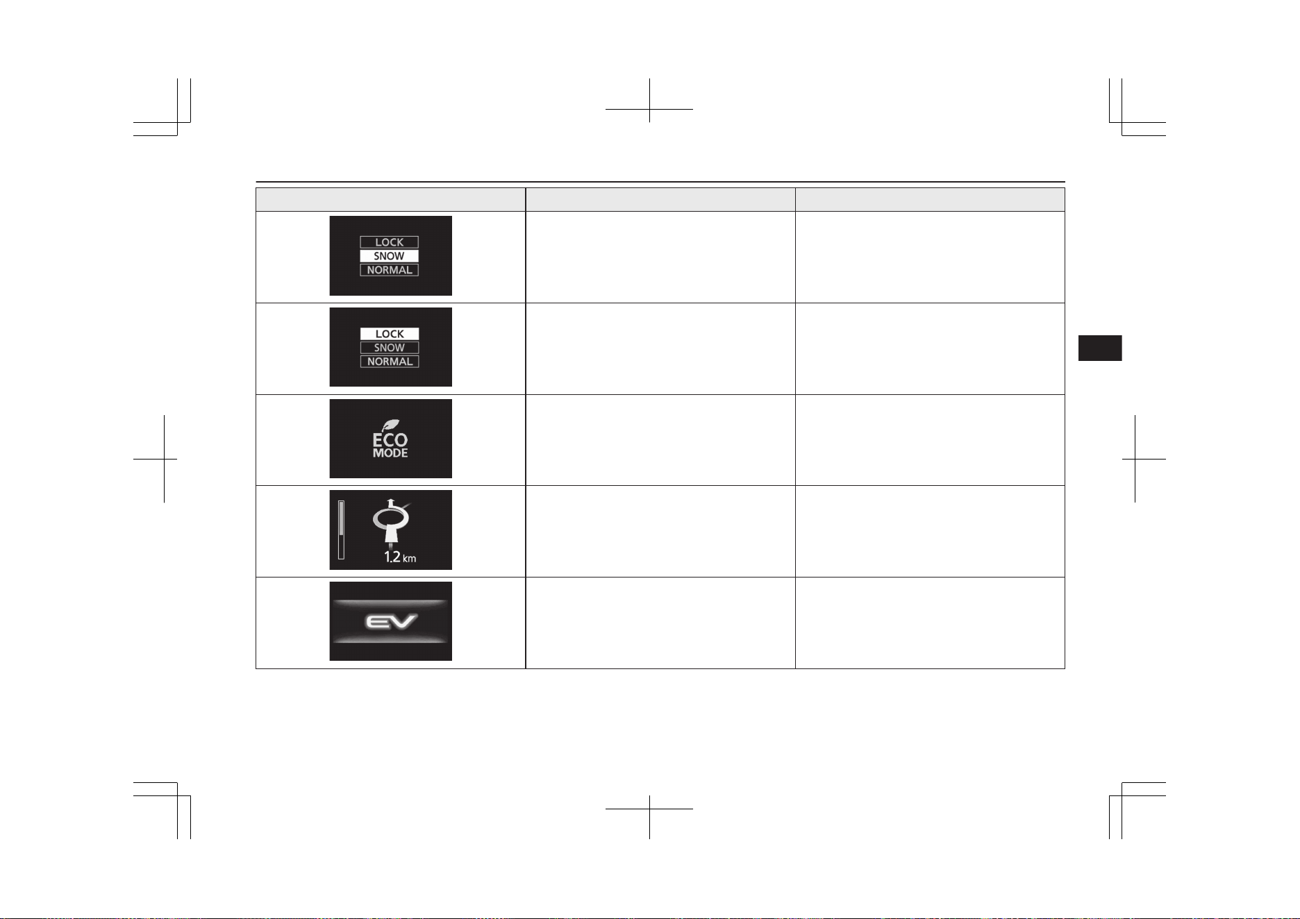
Screen System operation status Reference
l
When “SNOW” mode of S-AWC is selec-
ted
Refer to “S-AWC drive mode” on page 7-21.
l
When “LOCK” mode of S-AWC is selec-
ted
Refer to “S-AWC drive mode” on page 7-21.
l
When the mode is changed by the ECO
mode switch.
Refer to “ECO mode switch” on page 6-68.
l
When approaching the guidance location,
etc.
Refer to “Navigation information display” on
page 6-47.
l
When the EV priority mode is activated. Refer to “EV switch” on page 7-25.
Indication lamp, warning lamp, and information screen display list
6-51
OGGE19E1
Instruments and controls
6
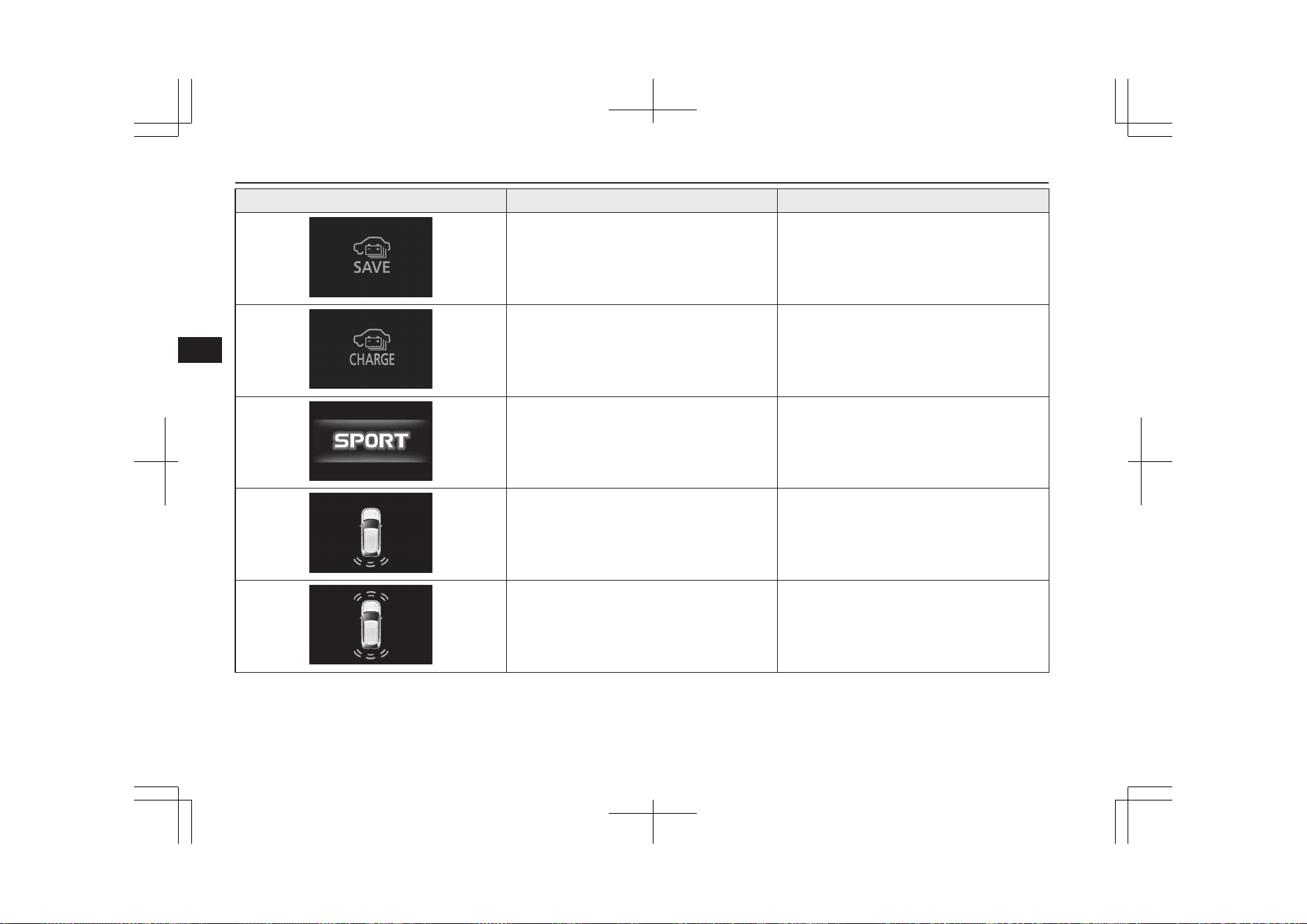
Screen System operation status Reference
l
When the battery save mode is activated. Refer to “Battery save mode” on page 7-29.
l
When the battery charge mode is activa-
ted.
Refer to “Battery charge mode” on page 7-29.
l
When the SPORT mode is activated Refer to “SPORT mode switch” on page
7-31.
l
When the reversing sensor system detects
an obstruction.
Refer to “Reversing sensor system” on page
7-97.
l
When the parking sensors detect an obsta-
cle.
Refer to “Parking sensors (Front/Rear)” on
page 7-101.
Indication lamp, warning lamp, and information screen display list
6-52
OGGE19E1
Instruments and controls
6
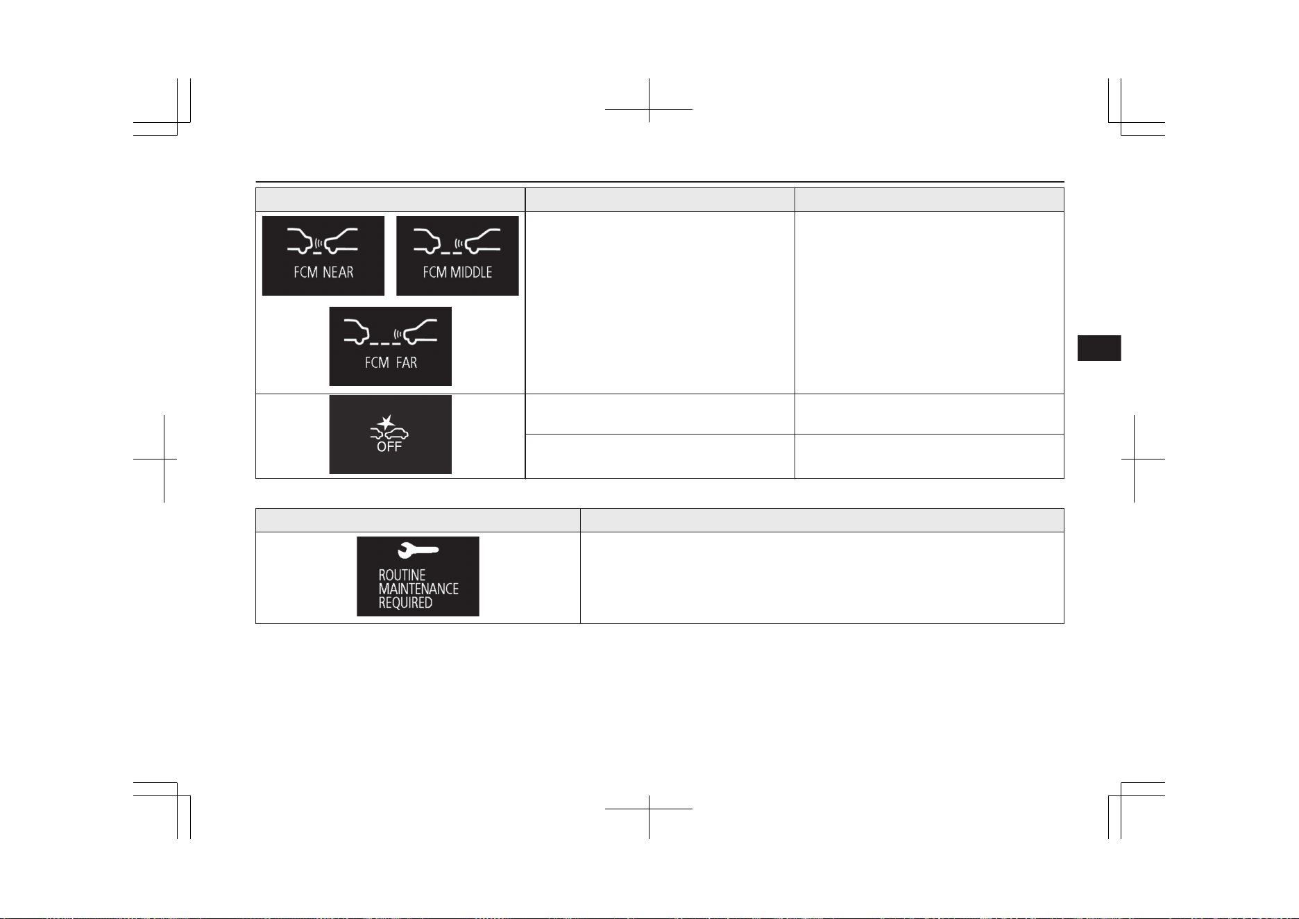
Screen System operation status Reference
l
When the Forward Collision Mitigation
System (FCM) is activated or the timing of
an alarm is changed.
Refer to “FCM and UMS ON/OFF switch” on
page 7-72.
l
When the Forward Collision Mitigation
System (FCM) is deactivated.
Refer to “FCM and UMS ON/OFF switch” on
page 7-72.
l
When the Ultrasonic misacceleration Mit-
igation System (UMS) is deactivated.
Refer to “To turn on/off the UMS” on page
7-82.
This informs you that a periodic inspection is due.
Screen Solution
We recommend you to have it checked. Refer to “Service reminder” on page 6-13.
Indication lamp, warning lamp, and information screen display list
6-53
OGGE19E1
Instruments and controls
6
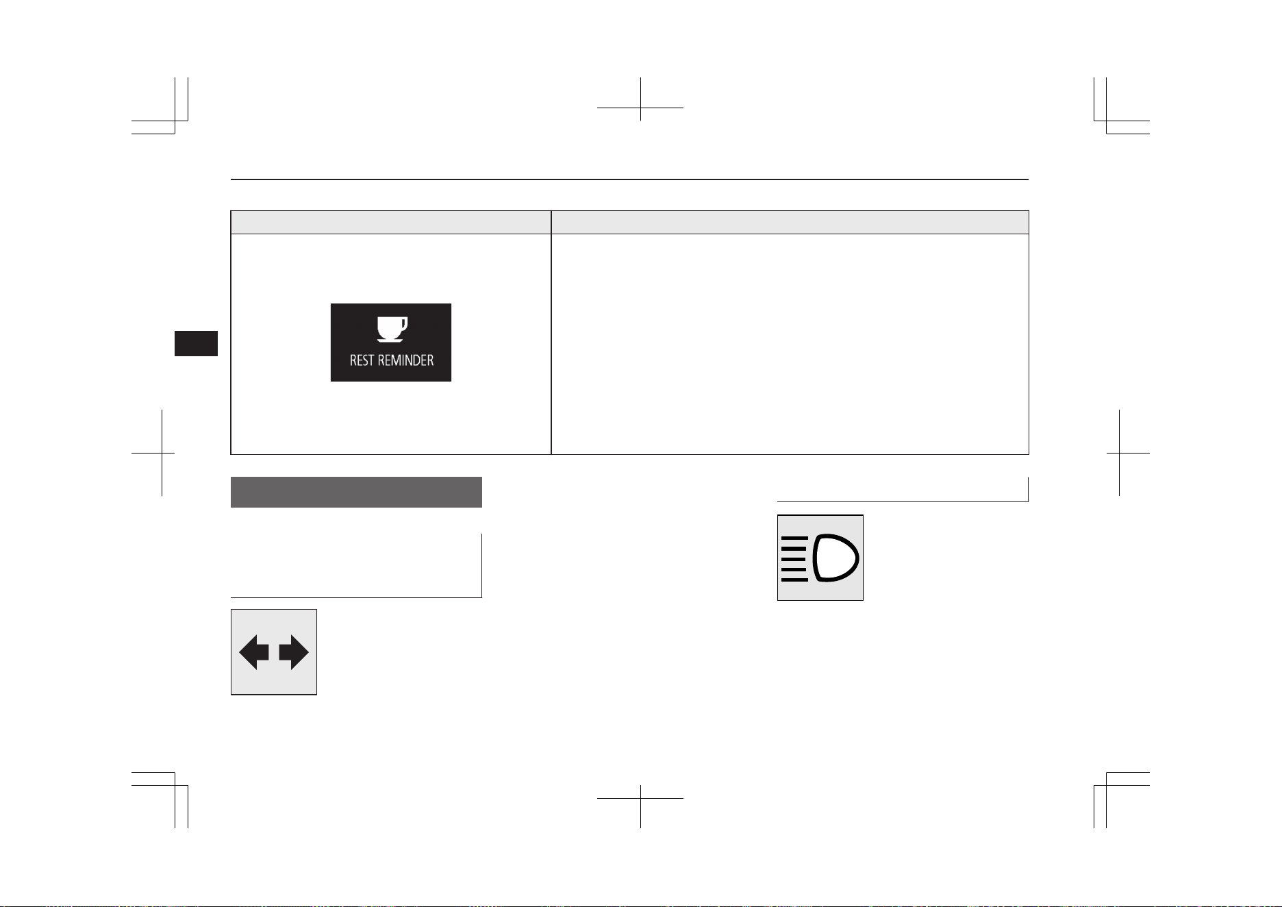
The setting for rest interval can be changed.
Screen Solution
Stop the vehicle in a safe place, stop the Plug-in Hybrid EV system, and take a rest.
Use this display as rough guide for taking rests during a long drive.
The interval from the start of your trip until this message is displayed can be set.
Refer to “Changing the time until REST REMINDER is displayed” on page 6-22.
The display and buzzer alert the driver when the set time is reached. If you continue
to drive without having a rest, the buzzer sounds about every 5 minutes to encourage
you to take a rest.
l
In the following cases, the time driven is reset and the display returns to the pre-
vious display screen. After this, when the set time is reached again, the buzzer
and display encourage you to take a rest.
• The buzzer sounds 3 times.
• Put the operation mode in OFF.
• The multi information display switch is held for about 2 seconds or more.
Indication lamps
E00501600100
Turn-signal indication lamps/
Hazard warning indication
lamps
E00501701427
These indication lamps blink
in the following situations.
l
When the turn-signal
lever is moved to acti-
vate a turn-signal lamp.
Refer to “Turn-signal
lever” on page 6-67.
l
When the hazard warning flasher switch
is pressed to activate the hazard warning
lamps.
Refer to “Hazard warning flasher
switch” on page 6-67.
l
When the hazard warning lamps auto-
matically activate due to sudden braking
while driving. (Vehicle equipped with
emergency stop signal system)
Refer to “Emergency stop signal sys-
tem” on page 7-39.
High-beam indication lamp
E00501800173
This indication lamp illumi-
nates when the high-beam is
used.
Indication lamps
6-54
OGGE19E1
Instruments and controls
6
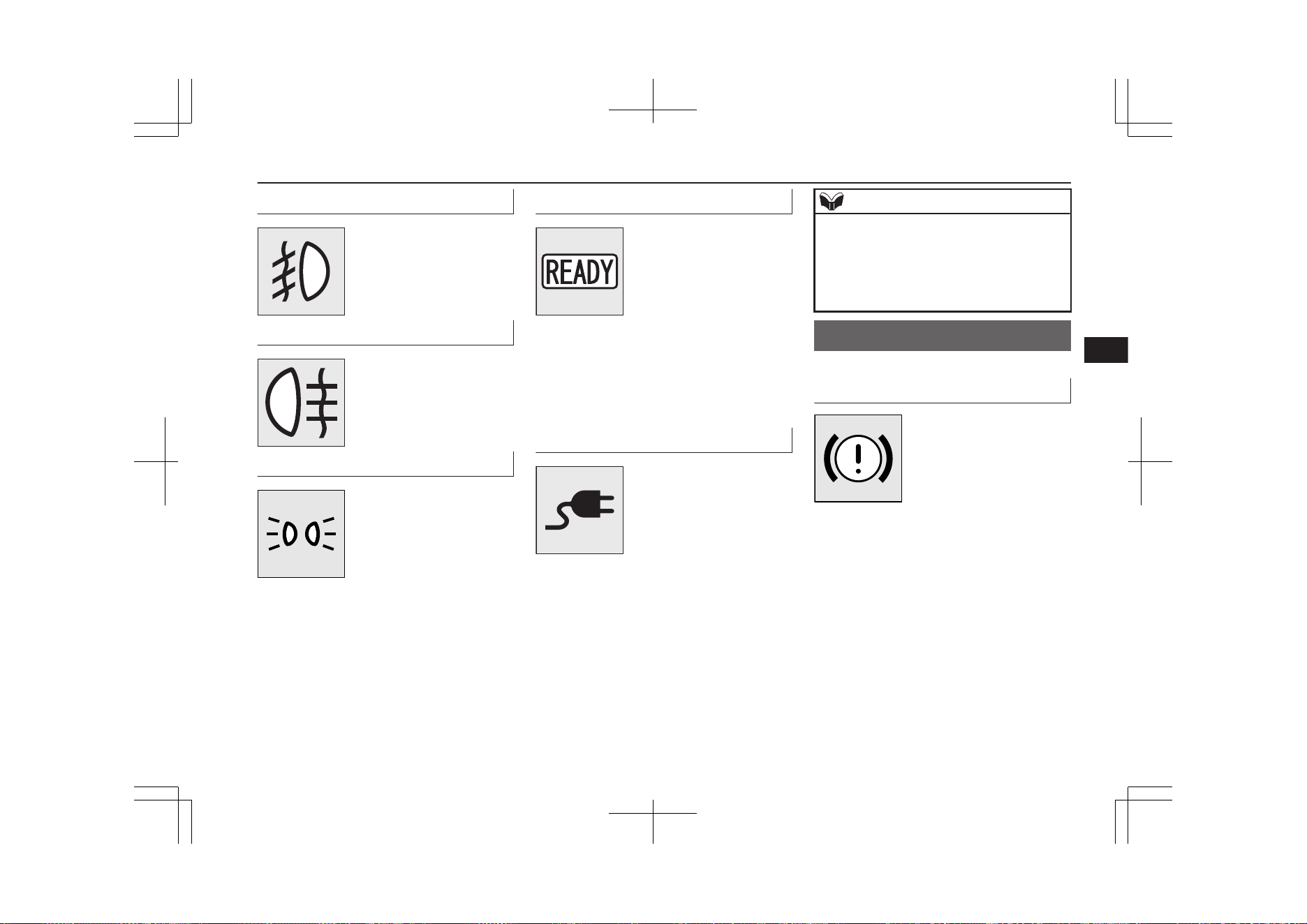
Front fog lamp indication lamp
E00501901650
This lamp illuminates while
the front fog lamps are on.
Rear fog lamp indication lamp
E00502001241
This lamp illuminates while
the rear fog lamp is on.
Position lamp indication lamp
E00508900173
This indication lamp illumi-
nates while the position
lamps are on.
Ready indicator
E00530101061
The ready indicator keeps
flashing until the Plug-in
Hybrid EV System is activa-
ted. When the Plug-in Hy-
brid EV System has activa-
ted normally and the vehicle
becomes ready to run, the lamp stops flashing
and stays lit. Refer to “Starting the Plug-in
Hybrid EV System” on page 7-13.
If the indicator keeps flashing, the vehicle
cannot be driven.
Charging indicator
E00530201062
This indicator flashes when
the EV charging cable or
quick charging cable is con-
nected.
After that, the lamp switches
to being illuminated when
charging starts and goes out when charging is
completed.
NOTE
l
Although it is possible to start the Plug-in
Hybrid EV System if quick charging has not
finished normally, the charging indicator is
continuously blinking.
Refer to “Charging troubleshooting guide”
on page 3-28.
Warning lamps
E00502400147
Brake warning lamp (red)
E00502504016
This lamp illuminates when
the operation mode of the
power switch is put in ON,
and goes off after a few sec-
onds.
Always make sure that the
lamp goes off before driving.
With the operation mode in ON, the brake
warning lamp illuminates under the following
conditions:
l
When the parking brake lever has been
engaged.
l
When the brake fluid level in the reser-
voir falls to a low level.
l
When the braking system is an abnor-
mality.
With the operation mode in ON, a buzzer
sounds under the following condition:
Warning lamps
6-55
OGGE19E1
Instruments and controls
6
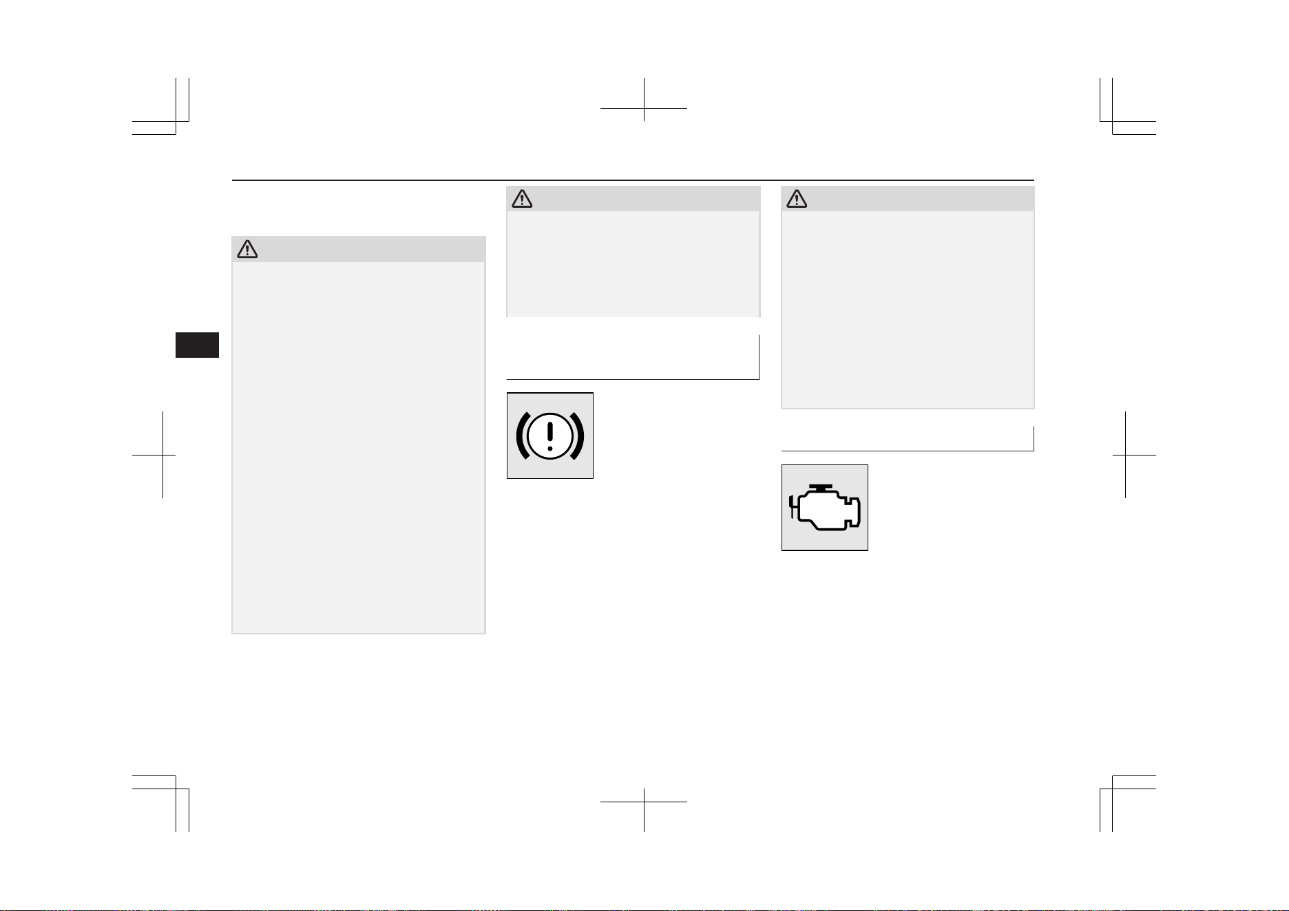
l
The vehicle speed exceeds 8 km/h
(5 mph) with the parking brake applied.
CAUTION
l
In the situations listed below, brake perform-
ance may be compromised or the vehicle
may become unstable if brakes are applied
suddenly; consequently, avoid driving at
high speeds or applying the brakes suddenly.
Furthermore, the vehicle should be brought
to a stop in a safe location and to have it
checked.
•
The brake warning lamp does not illumi-
nate when the parking brake is applied or
does not turn off when the parking brake
is released.
•
The ABS warning lamp and brake warn-
ing lamp illuminate at the same time.
For details, refer to “ABS warning lamp/
display” on page 7-41.
•
The brake warning lamp remains illumi-
nated during driving.
l
The vehicle should be brought to a halt in
the following manner when brake perform-
ance has deteriorated.
•
Depress the brake pedal harder than usual.
Even if the brake pedal moves down to
the very end of its possible stroke, keep it
pressed down hard.
CAUTION
•
Should the brakes fail, use regenerative
braking to reduce your speed and keep
pulling the Electric parking brake switch.
(Refer to “Electric parking brake” on page
7-03.)
Depress the brake pedal to operate the
stop lamp to alert the vehicles behind you.
Electric parking brake warn-
ing lamp (yellow)
E00568900100
This warning lamp will illu-
minate when there is a fault
in the Electric parking brake
system.
Normally, this warning lamp
illuminates when the opera-
tion mode of the power switch is put in ON,
and goes off in a few seconds.
CAUTION
l
When the warning lamp remains on or does
not come on, there is a possibility that the
parking brake cannot be operated or re-
leased. Immediately contact the nearest
MITSUBISHI MOTORS Authorized Serv-
ice Point. When the warning lamp comes on
during driving, immediately stop the vehicle
in a safe place, and contact your
MITSUBISHI MOTORS Authorized Serv-
ice Point. If you inevitably have to park,
park the vehicle on level and stable ground,
press the electrical parking switch and place
chocks or blocks.
Check engine warning lamp
E00502602938
This lamp is a part of an on-
board diagnostic system
which monitors the emis-
sions, engine control system.
If a problem is detected in
one of these systems, this
lamp illuminates or flashes.
Although your vehicle will usually be driva-
ble and not need towing, we recommend you
to have the system checked as soon as possi-
ble.
Warning lamps
6-56
OGGE19E1
Instruments and controls
6
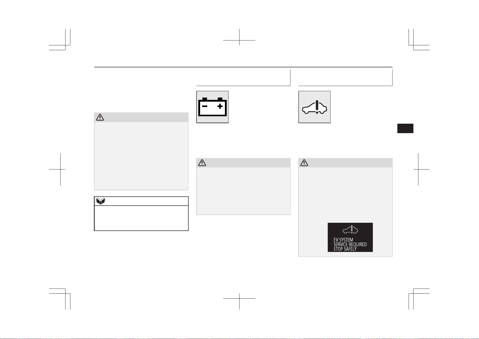
This lamp will also illuminate when the oper-
ation mode of the power switch is put in ON,
and goes off after the Plug-in Hybrid EV Sys-
tem has started. If it does not go off after the
Plug-in Hybrid EV System has started, we
recommend you to have the vehicle checked.
CAUTION
l
Prolonged driving with this lamp on may
cause further damage to the emission control
system. It could also affect fuel economy
and drivability.
l
If the lamp does not illuminate when the op-
eration mode is put in ON, we recommend
you to have the system checked.
l
If the lamp illuminates while the Plug-in Hy-
brid EV System is operating, avoid driving
at high speeds and have the system inspected
by a MITSUBISHI MOTORS Authorized
Service Point as soon as possible.
NOTE
l
The engine electronic control module ac-
commodating the onboard diagnostic system
has various fault data (especially about the
exhaust emission) stored.
This data will be erased if a auxiliary battery
cable is disconnected which will make a rap-
id diagnosis difficult. Do not disconnect a
auxiliary battery cable when the check engine
warning lamp is ON.
Auxiliary battery charge warn-
ing lamp
E00502702287
This warning lamp will illu-
minate when there is a fault
with the charging system of
the auxiliary battery.
Normally, when the opera-
tion mode of the power
switch is put in ON, this warning lamp will
illuminate. Then, when the Plug-in Hybrid
EV System is started and the ready indicator
illuminates, the warning lamp will go out.
CAUTION
l
If the warning lamp stays on after the ready
indicator illuminates, there may be a prob-
lem with the charging system for the auxili-
ary battery.
•
Immediately park your vehicle in a safe
place and we recommend you to have it
checked.
•
Do not charge the auxiliary battery.
Plug-in Hybrid EV System
warning lamp
E00537300049
This warning lamp will illu-
minate when there is a fault
at the Plug-in Hybrid EV
System.
Refer to “Service precau-
tions” on page 11-02.
Normally, this warning lamp illuminates
when the operation mode of the power switch
is put in ON, and goes off after a few sec-
onds.
CAUTION
l
If the warning lamp illuminates and “EV
SYSTEM SERVICE REQUIRED STOP
SAFELY” warning is displayed on the multi
information display while the Plug-in Hy-
brid EV System is running, park your vehi-
cle in a safe place as soon as possible and
contact a MITSUBISHI MOTORS Author-
ized Service Point to have the system
checked.
Warning lamps
6-57
OGGE19E1
Instruments and controls
6
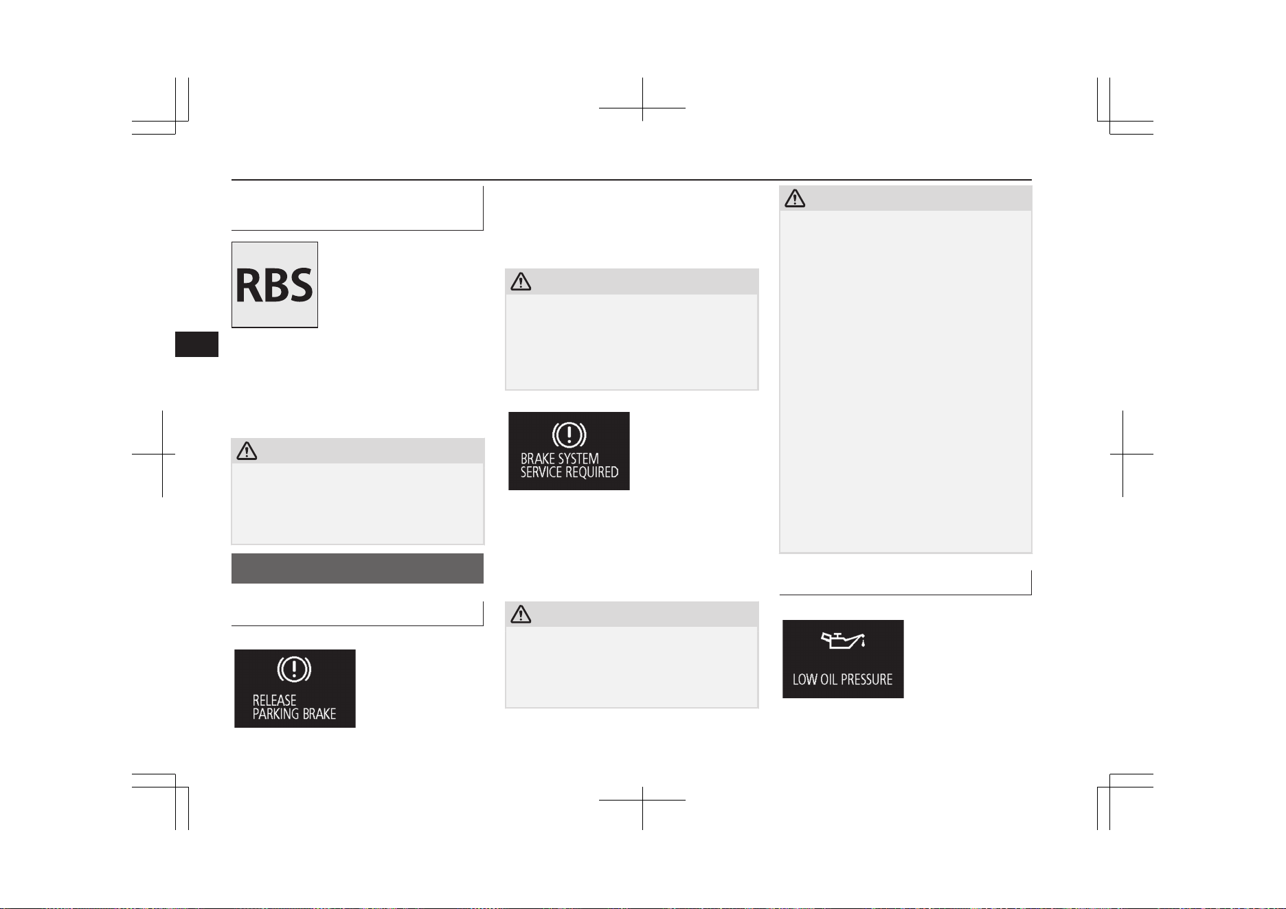
Regenerative brake warning
lamp
E00537200048
This warning lamp will illu-
minate when the regenera-
tive brake cannot be used,
while the Plug-in Hybrid EV
System is operating.
The warning is also dis-
played on the multi information display.
Normally, this warning lamp illuminates
when the operation mode of the power switch
is put in ON, and goes off after the Plug-in
Hybrid EV System is activated.
CAUTION
l
If the lamp illuminates while the Plug-in Hy-
brid EV System is operating, we recommend
you to have the vehicle inspected by a
MITSUBISHI MOTORS Authorized Serv-
ice Point.
Information screen display
E00524601117
Brake warning display
E00524701525
This warning is displayed if you drive with
the parking brake still applied. The warning
lamp in the instrument cluster only illumi-
nates when the parking brake is applied.
CAUTION
l
If a vehicle is driven without releasing the
parking brake, the brake will be overheated,
resulting in ineffective braking and possible
brake failure.
If this warning is displayed, release the park-
ing brake.
When the operation mode of the power
switch is put in ON, if the brake fluid is low,
this warning is displayed.
The warning lamp in the instrument cluster
also illuminates.
CAUTION
l
If this warning stays illuminated and does
not go out while driving, there is a danger of
ineffective braking. In this case, immediately
park your vehicle in a safe place and we rec-
ommend you to have it checked.
CAUTION
l
If the brake warning display is displayed and
the brake warning lamp and the ABS warn-
ing lamp are illuminated at the same time,
the braking force distribution function will
not operate, so the vehicle may be destabi-
lised during sudden braking. Avoid sudden
braking and high-speed driving, stop the ve-
hicle in a safe place, and we recommend you
to have it checked.
l
The vehicle should be brought to a halt in
the following manner when brake perform-
ance has deteriorated.
•
Depress the brake pedal harder than usual.
Even if the brake pedal moves down to
the very end of its possible stroke, keep it
pressed down hard.
•
Should the brakes fail, use the regenera-
tive brake to reduce your speed and keep
pulling the Electric parking brake switch.
(Refer to “Electric parking brake” on page
7-03)
Depress the brake pedal to operate the
stop lamp to alert the vehicles behind you.
Oil pressure warning display
E00524901309
Information screen display
6-58
OGGE19E1
Instruments and controls
6
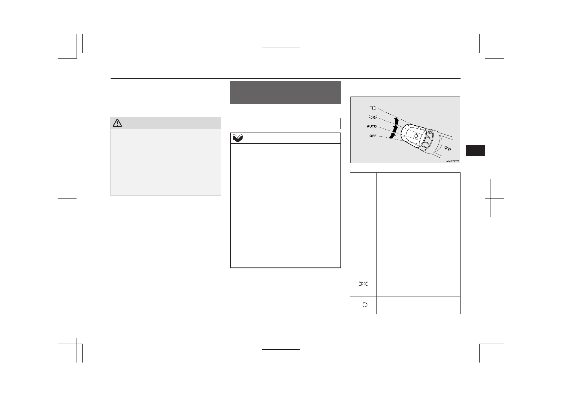
If the engine oil pressure drops while the
Plug-in Hybrid EV System is operating, the
warning display is displayed on the informa-
tion screen in the multi information display.
CAUTION
l
If the vehicle is driven while the engine oil
is low, or the oil level is normal but the
warning is displayed, the engine may burn
out and be damaged.
l
If the warning is displayed while the Plug-in
Hybrid EV System is operating, immediately
park your vehicle in a safe place and check
the engine oil level.
l
If the warning is displayed while the engine
oil level is normal, have it inspected.
Combination headlamps
and dipper switch
E00506004732
Headlamps
NOTE
l
When entering a country in which vehicles
are driven on the opposite side of the road to
the country in which your vehicles is sup-
plied, necessary measures have to be taken
to avoid dazzling oncoming traffic.
However, headlamps on this vehicle do not
need any adjustment.
l
Do not leave the lights on for a long time
while the Plug-in Hybrid EV System is sta-
tionary (not operating). A run-down auxili-
ary battery could result.
l
When it rains, or when the vehicle has been
washed, the inside of the lens sometimes be-
comes foggy, but this does not indicate a
functional problem.
When the lamp is switched on, the heat will
remove the fog. However, if water gathers
inside the lamp, we recommend you to have
it checked.
Rotate the switch to turn on the lamps.
OFF
All lamps off {except daytime
running lamps}
AUTO
When the operation mode of the
power switch is ON, headlamps,
position-, tail-, licence plate-, in-
strument panel lamps and down-
light are turned on and off auto-
matically in accordance with out-
side light level. {The daytime
running lamps will go on while
the tail lamps are off.} All lamps
go off automatically when the
operation mode is put in OFF.
Position, tail, licence plate, in-
strument panel lamps and down-
light on
Headlamps and other lamps go
on
Combination headlamps and dipper switch
6-59
OGGE19E1
Instruments and controls
6
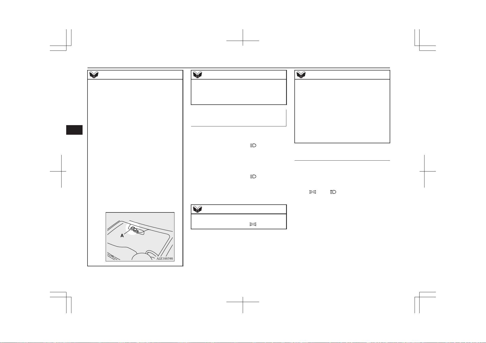
NOTE
l
The sensitivity of the automatic on/off con-
trol can be adjusted. For further information,
contact a MITSUBISHI MOTORS Author-
ized Service Point.
On vehicles equipped with the Smartphone
Link Display Audio or the MITSUBISHI
Multi-Communication System (MMCS),
screen operations can be used to make the
adjustment.
Refer to the separate owner’s manual for de-
tails.
l
When the headlamps are turned off by the
automatic on/off control with the operation
mode in ON, the front fog lamps and rear
fog lamps also go off. When the headlamps
are subsequently turned back on by the auto-
matic on/off control, the front fog lamps also
come on but the rear fog lamp stays off. If
you wish to turn the rear fog lamp back on,
operate the switch again.
l
Do not cover the sensor (A) for the automat-
ic on/off control by affixing a sticker or label
to the windscreen.
NOTE
l
If the lamps do not turn on or off with the
switch in the “AUTO” position, manually
operate the switch and we recommend you
to have your vehicle checked.
Lamps (headlamps, fog lamps,
etc.) auto-cutout function
l
If the operation mode of the power
switch is put in OFF or ACC while the
lamp switch is in the “ ” position, the
lamps will turn off automatically when
the driver’s door is opened.
l
If the operation mode of the power
switch is put in OFF or ACC while the
lamp switch is in the “
” position, the
lamps will remain on for about 3 mi-
nutes while the driver’s door is shut and
will then automatically turn off.
NOTE
l
The lamp auto-cutout will not function when
the lamp switch is in the “ ” position.
NOTE
l
The lamp auto-cutout function can also be
disabled.
For further information, we recommend you
to consult a MITSUBISHI MOTORS Au-
thorized Service Point.
On vehicles equipped with the Smartphone
Link Display Audio or the MITSUBISHI
Multi-Communication System (MMCS),
screen operations can be used to make the
adjustment. Refer to the separate owner’s
manual for details.
When you want to keep the
lamps on:
1. Turn the lamp switch in the “OFF” posi-
tion while the operation mode of the
power switch is in OFF or ACC.
2. Turn on the lamps with the switch in the
“”
or “” position again, then the
lamps will remain on.
Combination headlamps and dipper switch
6-60
OGGE19E1
Instruments and controls
6
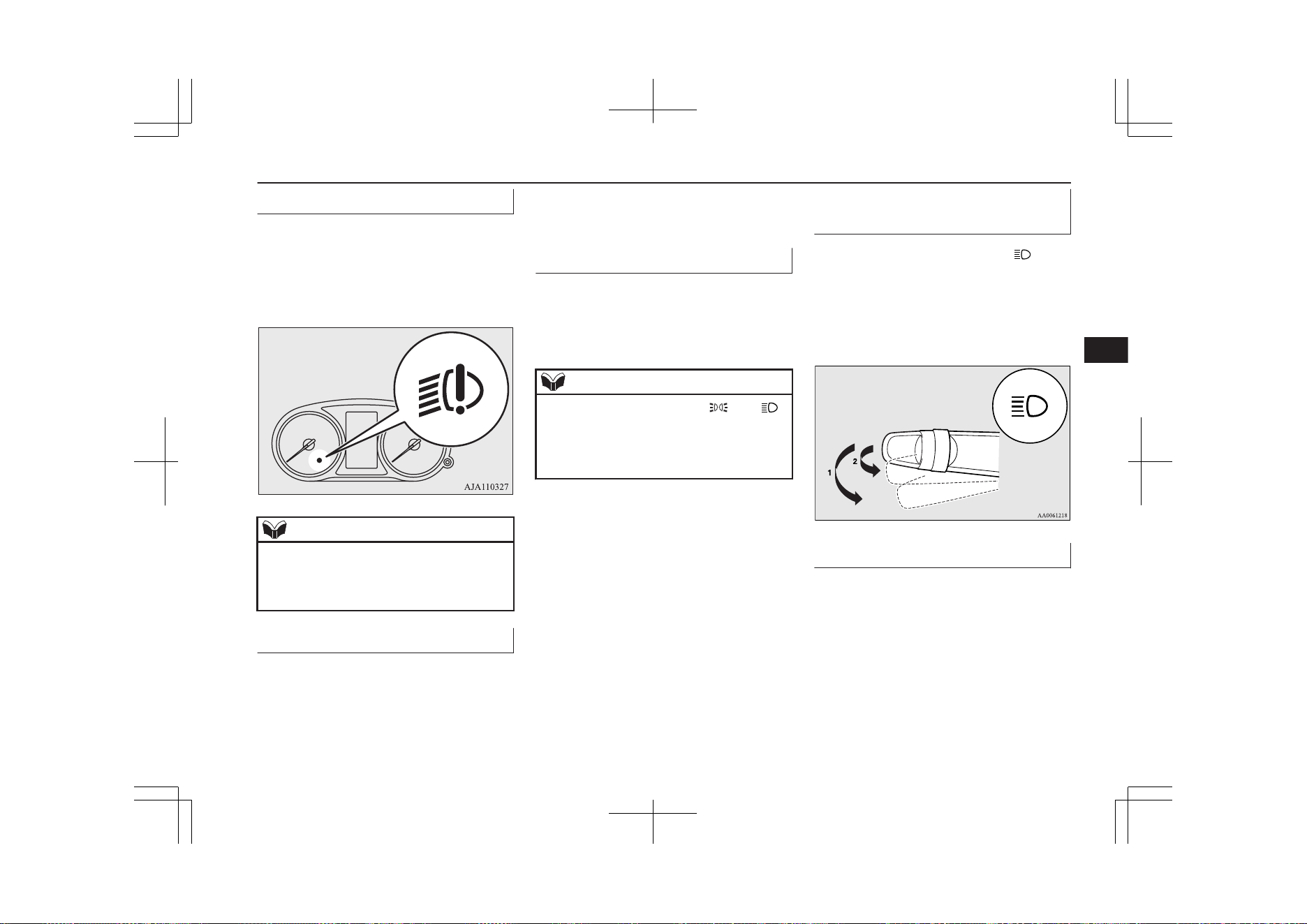
LED headlamp warning lamp*
E00538101041
This warning lamp will illuminate when there
is a fault in the LED headlamps. Also, “LED
HEADLIGHT SERVICE REQUIRED” is
displayed on the information screen in the
multi information display for the driver.
NOTE
l
If the warning lamp illuminates, there may
be a fault on the unit. Have the vehicle
checked at a MITSUBISHI MOTORS Au-
thorized Service Point.
Lamp monitor buzzer
E00506101631
If the driver’s door is opened when the opera-
tion mode of the power switch is put in ACC
or OFF with the lamps illuminated, a buzzer
will sound to remind the driver to turn off the
lamps.
The buzzer will automatically stop if the au-
to-cutoff function is activated, the lamp
switch is turned off, or the door is closed.
Daytime running lamps
E00530601226
The daytime running lamps come on when
the operation mode is ON and the lamp
switch is in the “OFF” or “AUTO” position
and the tail lamps are off.
NOTE
l
If the lamp switch is in the “ ” or “ ”
position, or if the tail lamps are on when the
lamp switch is in the “AUTO” position, the
daytime running lamps come on as position
lamps.
Dipper (High/Low beam
change)
E00506201557
When the lamp switch is in the “
” posi-
tion, the beam changes from high to low (or
low to high) each time the lever is pulled
fully (1). While the high-beam is on, the
high-beam indication lamp in the instrument
cluster will also illuminate.
Headlamp flasher
E00506300199
The high-beams flash when the lever is
pulled slightly (2), and will go off when it is
released.
When the high-beam is on, the high-beam in-
dication lamp in the instrument cluster will il-
luminate.
Combination headlamps and dipper switch
6-61
OGGE19E1
Instruments and controls
6
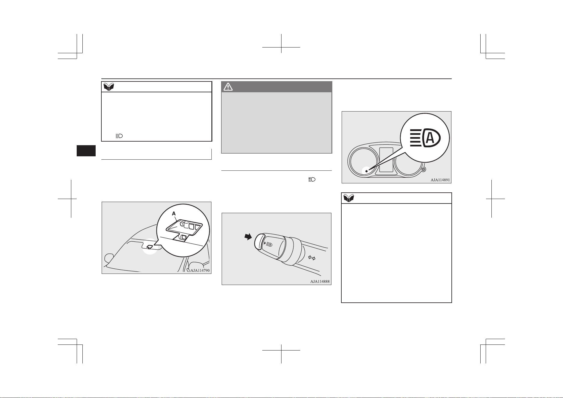
NOTE
l
The high-beams can also flash when the
lamp switch is OFF.
l
If you turn the lamps off with the headlamps
set to high-beam, the headlamps are auto-
matically returned to their low-beam setting
when the lamp switch is next turned to the
“ ” position.
Automatic high-beam system*
E00538200117
The system switches the headlamp beams
(high/low) when the sensor (A) senses an il-
luminant such as lights of a vehicle in front
or oncoming vehicle or street lamp.
WARNING
l
The headlamp beams (high/low) may not
be switched automatically under certain
circumstances. Do not overestimate the
system. It is the responsibility of the driv-
er to switch the headlamp beams (high/
low) manually to suit each driving condi-
tion.
Refer to “Dipper (High/Low beam
change)” on page 6-61
How to use the AHB
E00551500250
1. Rotate the lamp switch to the “ ” posi-
tion or “AUTO” position when the Plug-
in Hybrid EV System is operating.
2. Press the AHB switch.
The AHB is activated and the indicator
will illuminate.
If the AHB switch is pressed again, the
AHB will be deactivated and the AHB
indicator will go off.
NOTE
l
If the headlamps are on when the lamp
switch is in the “AUTO” position, the AHB
works.
l
You can switch the headlamp beams (high/
low) manually by operating the lever even if
the AHB is working.
Refer to “Dipper (High/Low beam change)”
on page 6-61
If the lever is operated manually, the AHB
indicator will go off and the AHB will be de-
activated.
Refer to “Manual switching” on page 6-62.
l
The AHB is not deactivated when you pull
the lever slightly (operation of the headlamp
flasher).
Combination headlamps and dipper switch
6-62
OGGE19E1
Instruments and controls
6
Manual switching
Switching to low beam
1. Pull the lever towards you.
2. The AHB indicator will go off.
3. The AHB switch is pressed again, the
AHB will activated.
Switching to high-beam
1. Pull the lever towards you.
2. The AHB indicator will go off and the
high-beam indicator illuminates.
3. The AHB switch is pressed again, the
AHB will activated.
Automatic switching conditions
E00551600059
The high-beam headlamps illuminate when
all of the following conditions are met:
l
Your vehicle speed exceeds approxi-
mately 40 km/h (25 mph).
l
It is dark ahead of your vehicle.
l
There are no vehicles in front or oncom-
ing vehicles, or none of their exterior
lamps are illuminated.
The low beam headlamps illuminate when
any of the following conditions occur:
l
Your vehicle speed does not exceed ap-
proximately 30 km/h (19 mph).
l
It is bright ahead of your vehicle.
l
An exterior lamp of a vehicle in front or
oncoming vehicle is illuminating.
NOTE
l
The headlamps may not be switched from
high-beam to low beam under the following
circumstances.
•
A vehicle in front or oncoming vehicle is
hindered by any object such as continuous
bends, elevated median/island, traffic
signs, roadside trees.
•
Your vehicle passes an oncoming vehicle
suddenly on a bend with poor visibility.
•
Another vehicle crosses ahead of your ve-
hicle.
l
The headlamps may remain at low beam (or
be switched from high-beam to low beam)
when a reflective object (e.g. street lamp,
traffic signal, noticeboard and signboard) re-
flects light.
l
Any of the following factors may influence
the headlamp beam switching timing:
•
How brightly the exterior lamps of a vehi-
cle in front or oncoming vehicle illumi-
nate.
•
Movement or direction of a vehicle in
front or oncoming vehicle.
•
Only right or left exterior lamp of a vehi-
cle in front or oncoming vehicle is illumi-
nating.
•
A vehicle in front or oncoming vehicle is
a motorcycle.
•
Road conditions (gradient, bends and road
surface).
•
The number of occupants and luggage
load.
NOTE
l
The AHB recognises environmental condi-
tions by sensing a light source ahead of your
vehicle. Therefore, you may feel like some-
thing is not quite right when the headlamp
beams are switched automatically.
l
The system may not detect a light vehicle
such as a bicycle.
l
The system may not detect an ambient
brightness precisely. This causes the traffic
to be dazzled by high-beam or the low beam
to be maintained. In such cases, you should
switch the headlamp beams manually.
•
In bad weather (heavy rain, fog, snow or
sandstorm).
•
The windscreen is dirty or fogged up.
•
The windscreen is cracked or broken.
•
The sensor is deformed or dirty.
•
A light that is similar to the headlamps or
tail lamps is shining around your vehicle.
•
A vehicle in front or oncoming vehicle is
driven without lights, the exterior lamps
are dirty or discoloured, or the direction
of the headlamp beams is adjusted im-
properly.
•
It becomes dark and bright suddenly and
continuously around your vehicle.
•
Your vehicle is driven on uneven surfaces.
•
Your vehicle is driven on a winding road.
•
A reflective object such as a noticeboard
or a mirror reflects a light ahead of your
vehicle.
Combination headlamps and dipper switch
6-63
OGGE19E1
Instruments and controls
6
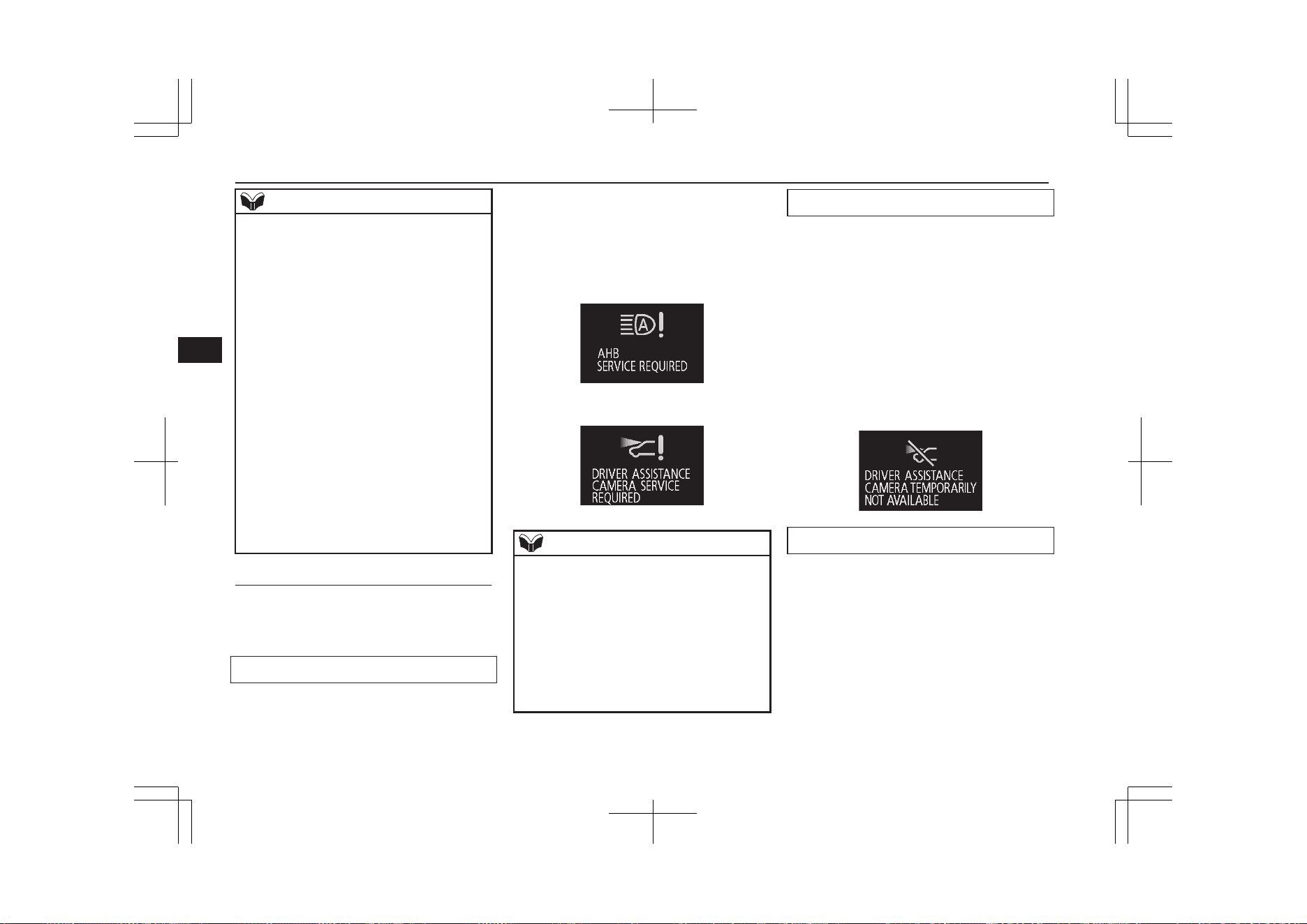
NOTE
•
When lamps of the vehicle in front or
headlamps of an oncoming vehicle blend
into the other lamps.
•
The rear end of a vehicle in front (such as
a container truck) reflect a strong light.
•
Your vehicle’s headlamp is broken or
dirty.
•
Your vehicle is inclined due to a flat tyre
or towing.
•
The warning display appears.
(Refer to “System problem warning” on
page 6-64.)
l
Observe the precautions below to maintain
good usage conditions:
•
Do not attempt to disassemble the sensor.
•
Do not affix a sticker or label on the
windscreen near the sensor.
•
Avoid overload.
•
Do not modify your vehicle.
•
When the windscreen is replaced, use the
MITSUBISHI MOTORS GENUINE
parts.
System problem warning
E00551700063
If a problem occurs with the system, the fol-
lowing warning display will appear to the
type of the problem.
The AHB deactivation due to fault
If a failure is detected in the system, the fol-
lowing warning display will appear and the
AHB will automatically be turned off.
If the warning display remains even after the
operation mode of the power switch is put in
OFF and then turned back to ON, please con-
tact a MITSUBISHI MOTORS Authorized
Service Point.
[When the AHB is malfunctioning]
[When the sensor is malfunctioning]
NOTE
l
If the sensor or its surrounding area reaches
an extremely high temperature when parking
the vehicle under a blazing sun, the “AHB
SERVICE REQUIRED” warning display
may appear.
If the warning display remains even after the
temperature of the sensor or its surrounding
area has been in range, please contact a
MITSUBISHI MOTORS Authorized Serv-
ice Point.
Sensor is too hot or cold
If the system becomes temporarily unavaila-
ble due to a high or low temperature of the
sensor, the following warning display will
appear.
After the temperature of the sensor has been
in range, the system will automatically return
to operation.
If the warning display does not disappear af-
ter waiting for a while, there is a possibility
that the AHB has a malfunction. Contact a
MITSUBISHI MOTORS Authorized Service
Point for inspection of the system.
Windscreen is dirty
If the AHB determines that its performance
has been degraded, the warning display will
appear.
This can occur when:
l
Foreign objects, such as dirt, snow or
ice, adhere to the windscreen of the sen-
sor portion.
l
There are adverse weather conditions,
such as rain, snow, sand storms, etc.
l
A vehicle in front or an oncoming vehi-
cle is splashing water, snow or dirt.
Combination headlamps and dipper switch
6-64
OGGE19E1
Instruments and controls
6
When the sensor performance returns, the
AHB will resume operation.
If the warning display does not disappear af-
ter waiting for a while, there is a possibility
that the sensor has a malfunction. Contact a
MITSUBISHI MOTORS Authorized Service
Point for inspection of the sensor.
Welcome light
E00528902072
This function turns on the position and tail
lamps for about 30 seconds after the UN-
LOCK switch on the remote control transmit-
ter is pressed when the combination head-
lamps and dipper switch is in the “OFF” or
“AUTO” position. The welcome light func-
tion will operate only when it is dark outside
the vehicle.
NOTE
l
While the welcome light function is operat-
ing, perform one of the following operations
to cancel the function.
•
Push the LOCK switch on the remote
control transmitter.
NOTE
•
Turn the combination headlamps and dip-
per switch to the “ ” or “ ” position.
•
Put the operation mode of the power
switch in ON.
l
It is possible to modify functions as follows:
•
The headlamps can be set to come on in
the low beam setting.
•
The welcome light function can be deacti-
vated.
For further information, please contact your
MITSUBISHI MOTORS Authorized Serv-
ice Point.
On vehicles equipped with the Smartphone
Link Display Audio or the MITSUBISHI
Multi-Communication System (MMCS),
screen operations can be used to make the
adjustment. Refer to the separate owner’s
manual for details.
Coming home light
E00529001826
This function turns on the headlamps in the
low beam setting for about 30 seconds after
the operation mode is put in OFF.
1. Turn the combination headlamps and
dipper switch to the “OFF” or “AUTO”
position.
2. Put the operation mode of the power
switch in OFF.
3. Within 60 seconds of putting the opera-
tion mode in OFF, pull the turn signal
lever towards you.
4. The headlamps will come on in the low
beam setting for about 30 seconds. After
the headlamps go off, the headlamps can
be turned on again in the low beam set-
ting for about 30 seconds by pulling the
turn signal lever towards you within 60
seconds of putting the operation mode in
OFF.
To turn on the headlamps again after 60
seconds of putting the operation mode in
OFF, repeat the process from step 1.
NOTE
l
While the coming home light function is op-
erating, perform one of the following opera-
tions to cancel the function.
Combination headlamps and dipper switch
6-65
OGGE19E1
Instruments and controls
6
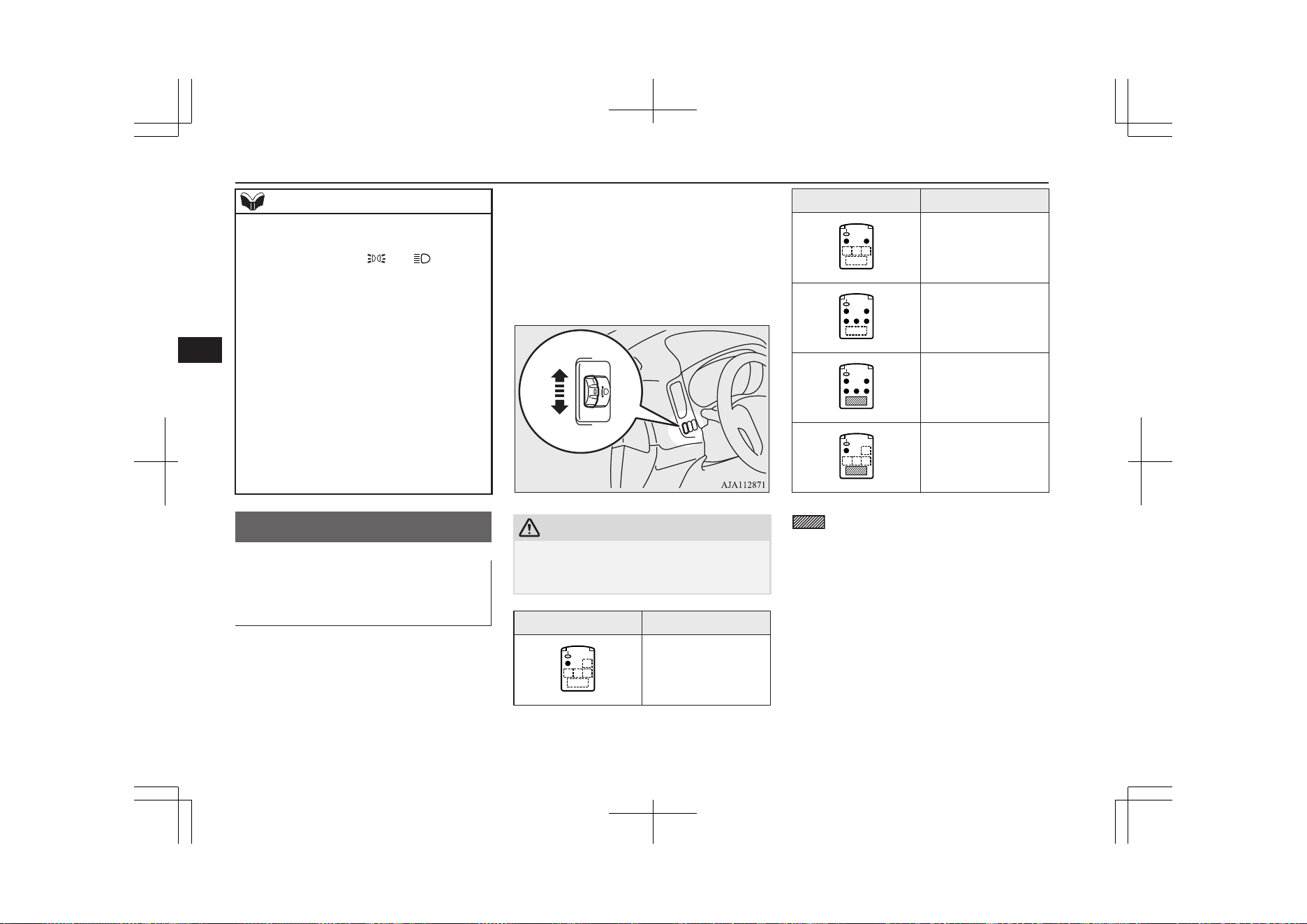
NOTE
•
Pull the lever towards you.
•
Turn the combination headlamps and dip-
per switch to the “ ” or “ ” position.
•
Put the operation mode in ON.
l
It is possible to modify functions as follows:
•
The time that the headlamps remain on
can be changed.
•
The coming home light function can be
deactivated.
For further information, please contact your
MITSUBISHI MOTORS Authorized Serv-
ice Point.
On vehicles equipped with the Smartphone
Link Display Audio or the MITSUBISHI
Multi-Communication System (MMCS),
screen operations can be used to make the
adjustment. Refer to the separate owner’s
manual for details.
Headlamp levelling
E00517400031
Headlamp levelling switch (ex-
cept for vehicle with LED
headlamps)
E00517502023
The angle of the headlamp beam varies de-
pending on the load carried by the vehicle.
The headlamp levelling switch can be used to
adjust the headlamp illumination distance
(when the lower beam is illuminated) so that
the headlamps’ glare does not distract other
drivers.
Set the switch according to the following ta-
ble.
CAUTION
l
Always perform adjustments before driving.
Do not attempt to adjust while driving, as it
could cause an accident.
Vehicle condition Switch position
“0”
Vehicle condition Switch position
“0”
“1”
“2”
“2”
●:1 person
:Full luggage loading
Switch position
0-
Driver only/Driver + 1
front passenger
Switch position
1-
5 passengers (including
driver)
Switch position
2-
5 passengers (including
driver) + Full luggage
loading/Driver + Full lug-
gage loading
Headlamp levelling
6-66
OGGE19E1
Instruments and controls
6
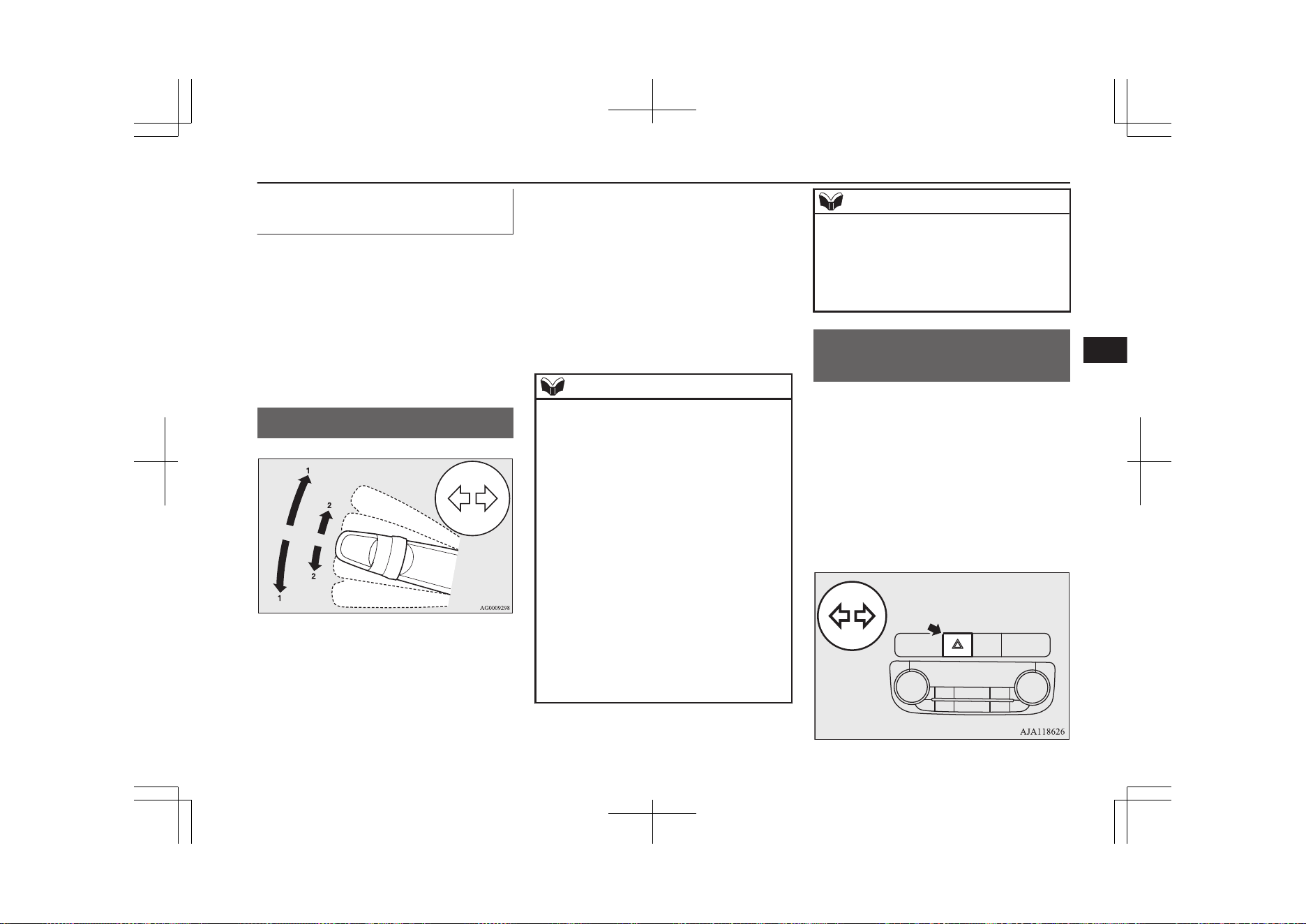
Automatic headlamp levelling
(vehicles with LED headlamps)
E00517601652
This mechanism automatically adjusts the di-
rection of the headlamps (beam position) de-
pending on changes in the condition of the
vehicle, such as the number of occupants or
luggage weight. When the headlamps are il-
luminated with the operation mode of the
power switch in ON, the beam position of the
headlamps is automatically adjusted when the
vehicle stops.
Turn-signal lever
E00506502948
1- Turn-signals
When making a normal turn, use posi-
tion (1). The lever will return automati-
cally when cornering is completed.
2- Lane-change signals
When moving the lever to (2) slightly to
change a lane, the turn-signal lamps and
indication lamp in the instrument cluster
will only flash while the lever is operat-
ed.
Also, when you move the lever to (2)
slightly then release it, the turn-signal
lamps and indication lamp in the instru-
ment cluster will flash 3 times.
NOTE
l
If the lamp flashes unusually quickly, the
bulb in a turn-signal lamp may have burned
out. We recommend you to have the vehicle
inspected.
l
It is possible to activate the following func-
tions.
•
Flashing of the turn-signal lamps when
the lever is operated with the operation
mode is in ACC.
•
Deactivate the turn-signal lamp 3-flash
function for lane changes.
•
The time required to operate the lever for
the 3-flash function can be adjusted.
For further information, we recommend you
to consult a MITSUBISHI MOTORS Au-
thorized Service Point.
On vehicles equipped with the Smartphone
Link Display Audio or the MITSUBISHI
Multi-Communication System (MMCS),
screen operations can be used to make the
NOTE
adjustment. Refer to the separate owner’s
manual for details.
l
It is possible to change the tone of a sound-
ing buzzer as the turn-signal lamps flash.
Refer to “Changing the turn-signal sound”
on page 6-22.
Hazard warning flasher
switch
E00506602457
Use the hazard warning flasher switch when
the vehicle has to be parked on the road for
any emergency.
The hazard warning flashers can always be
operated, regardless of the operation mode.
Push the switch to turn on the hazard warning
flashers, all turn-signal lamps flash continu-
ously. To turn them off, push the switch
again.
Turn-signal lever
6-67
OGGE19E1
Instruments and controls
6
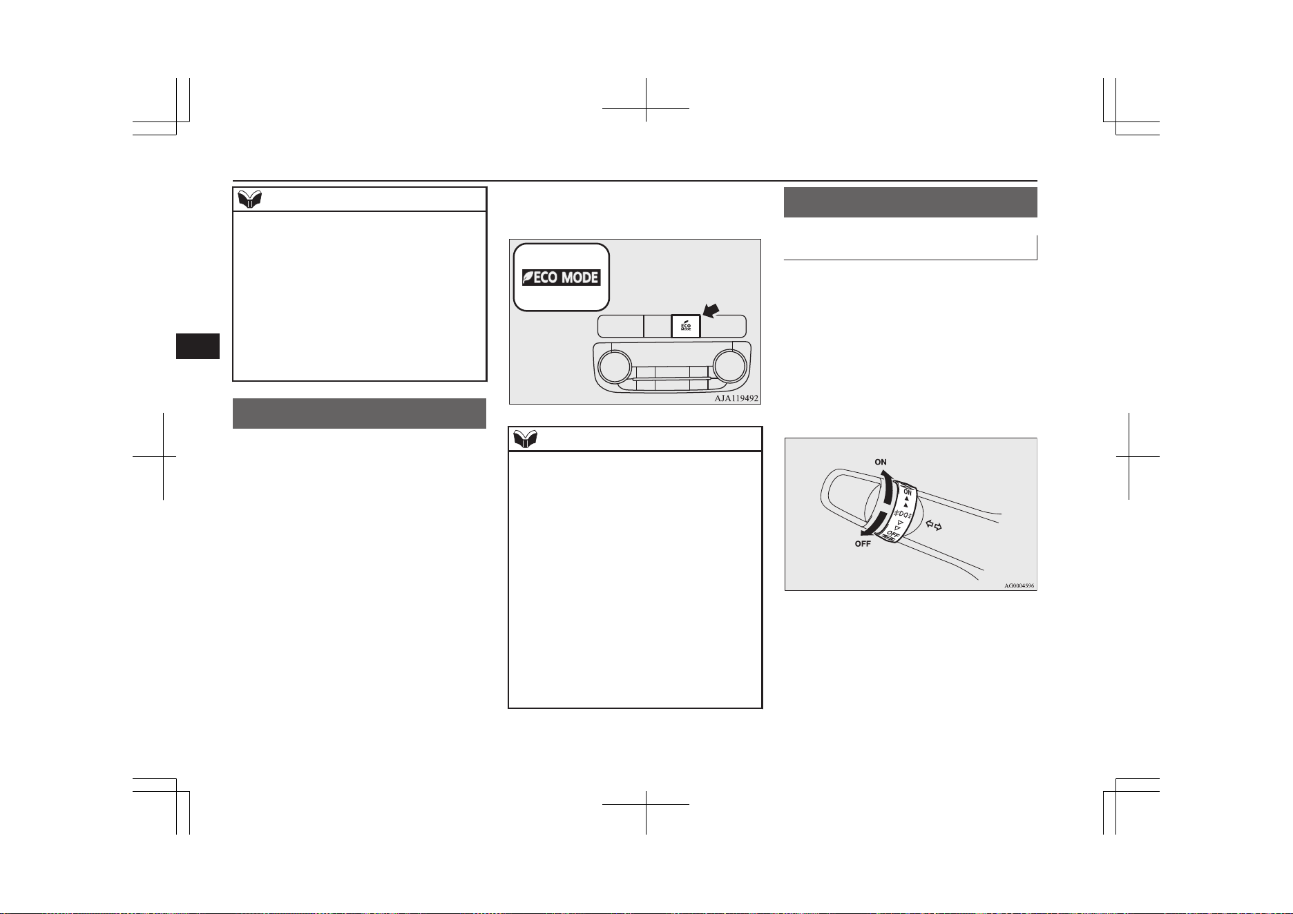
NOTE
l
If the switch is used for a long period while
the ready indicator is not illuminated, the
auxiliary battery could go flat and the Plugin
Hybrid EV System could be impossible to
start.
l
While the hazard warning lamps are blinking
due to having manually pushed the switch,
the emergency stop signal system does not
operate.
Refer to “Emergency stop signal system” on
page 7-39.
ECO mode switch
E00531801270
ECO mode is an eco-driving support system
which automatically controls the Plug-in Hy-
brid EV System and air conditioning system
to improve fuel efficiency.
When the ECO mode is active, your vehicle
will slowly accelerate even when you press
the accelerator pedal.
Refer to “Automatic climate control air con-
ditioner” on page 8-06.
The ECO mode starts working by pressing
the ECO mode switch when the operation
mode of the power switch is in ON. Push the
switch again and the ECO mode will cancel.
While the ECO mode is working, an ECO
mode indicator will be turned on.
NOTE
l
Even if the ECO mode is selected, after turn-
ing the operation mode of the power switch
OFF and turning to ON again, the ECO
mode is set to OFF.
l
Even if the ECO mode is operating, you can
select normal operation of the air condition-
er.
For further information, we recommend you
to consult a MITSUBISHI MOTORS Au-
thorized Service Point.
On vehicles equipped with the Smartphone
Link Display Audio or the MITSUBISHI
Multi-Communication System (MMCS), it
is possible to change the setting by means of
screen operations.
Refer to the separate owner’s manual for de-
tails.
Fog lamp switch
E00506700034
Front fog lamp switch
E00508301754
The front fog lamps can be operated while
the headlamps or tail lamps are on. Turn the
knob in the “ON” direction to turn on the
front fog lamps. An indication lamp in the in-
strument cluster will also come on. Turn the
knob in the “OFF” direction to turn off the
front fog lamps. The knob will automatically
return to its original position when you re-
lease it.
ECO mode switch
6-68
OGGE19E1
Instruments and controls
6
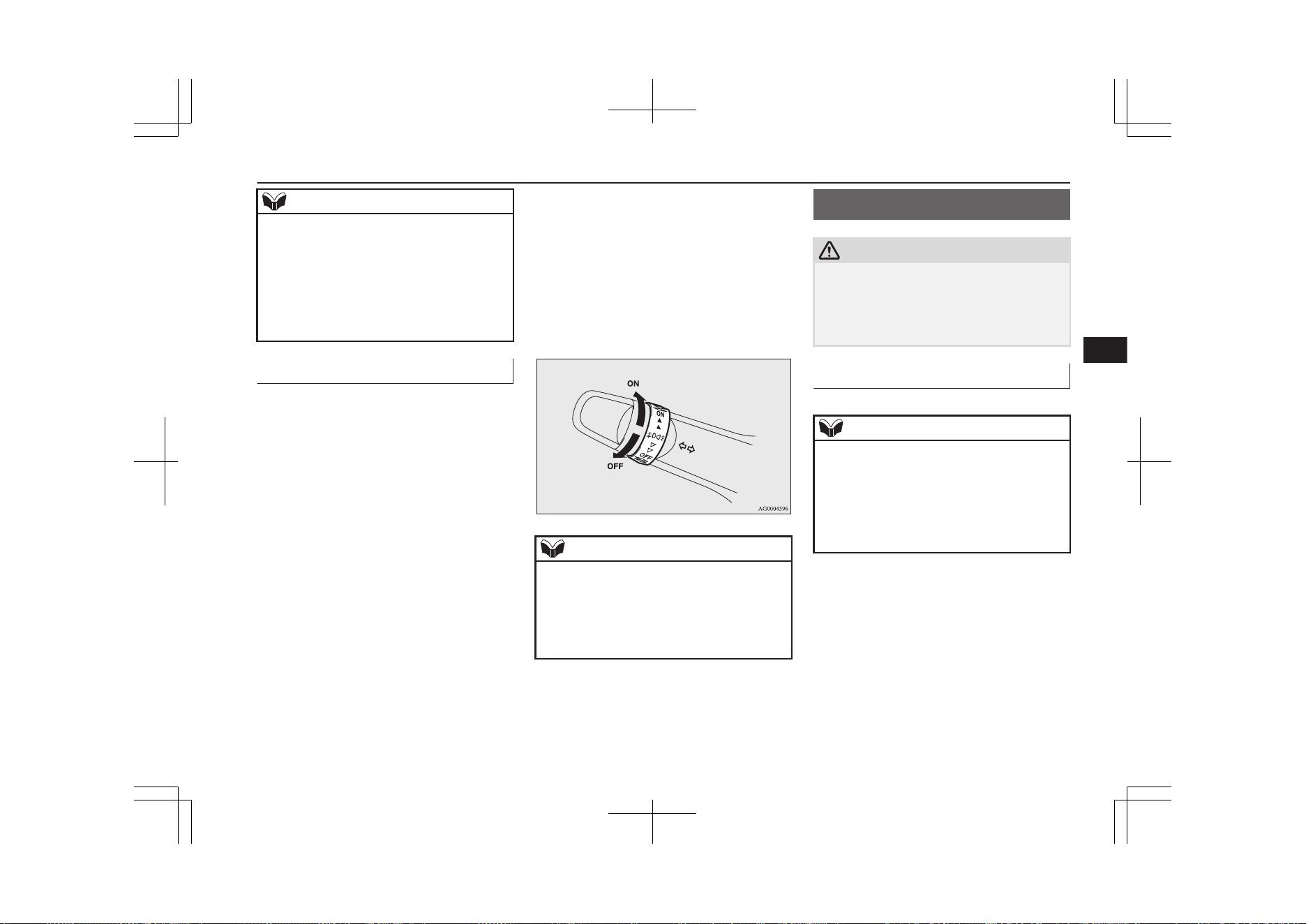
NOTE
l
The front fog lamps are automatically turned
off when the headlamps or tail lamps are
turned off. To turn the front fog lamps on
again, turn the knob in the “ON” direction
after turning on the headlamps or tail lamps.
l
Do not use fog lamps except in conditions of
fog, otherwise excessive lamp glare may
temporarily blind oncoming vehicle drivers.
Rear fog lamp switch
E00508401625
The rear fog lamp can be operated when the
headlamps or front fog lamps turn on.
An indication lamp in the instrument cluster
comes on when the rear fog lamp is turned
on.
Turn the knob once in the “ON” direction to
turn on the front fog lamps. Turn the knob
once more in the “ON” direction to turn on
the rear fog lamp. To turn the rear fog lamp
off, turn the knob once in the “OFF” direc-
tion. Turn the knob once more in the “OFF”
direction to turn off the front fog lamps. The
knob will automatically return to its original
position when you release it.
NOTE
l
The rear fog lamp is automatically turned off
when the headlamps or front fog lamps are
turned off.
l
To turn the rear fog lamp on again, turn the
knob twice in the “ON” direction after turn-
ing on the headlamps.
Wiper and washer switch
E00507101218
CAUTION
l
If the washer is used in cold weather, the
washer fluid sprayed against the glass may
freeze, which may hinder visibility. Warm
the glass with the defroster or rear window
demister before using the washer.
Windscreen wipers
E00516901980
NOTE
l
To ensure a clear rearward view, the rear
window wiper will automatically perform
several continuous operations if the selector
lever is put in the “R” position while the
windscreen wipers are operating.
Refer to “Rear window wiper and washer”
on page 6-72.
The windscreen wipers can be operated with
the operation mode of the power switch in
ON or ACC.
Wiper and washer switch
6-69
OGGE19E1
Instruments and controls
6
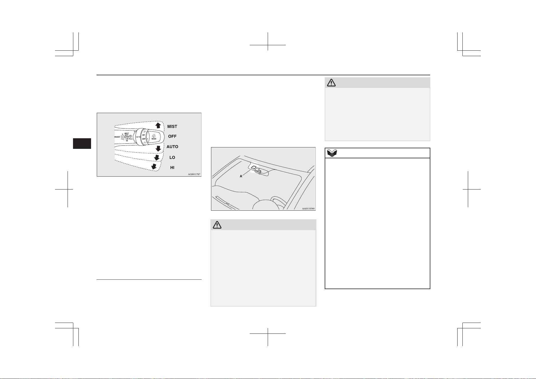
If the blades are frozen to the windscreen or
rear window, do not operate the wipers until
the ice has melted and the blades are freed,
otherwise the wiper motor may be damaged.
MIST- Misting function
The wipers will operate once.
OFF- Off
AUTO- Auto-wiper control
Rain sensor
The wipers will automatically
operate depending on the degree
of wetness on the windscreen.
LO- Slow
HI- Fast
Rain sensor
Can only be used when the ignition switch or
the operation mode is in ON.
If the lever is put in the “AUTO” position,
the rain sensor (A) will detect the extent of
rain (or snow, other moisture, dust, etc.) and
the wipers will operate automatically.
Keep the lever in the “OFF” position if the
windscreen is dirty and the weather is dry.
Wiper operation under these conditions can
scratch the windscreen and damage the wip-
ers.
CAUTION
l
With the ignition switch or the operation
mode in ON and the lever in the “AUTO”
position, the wipers may automatically oper-
ate in the situations described below.
If your hands get trapped, you could suffer
injuries or the wipers could malfunction. Be
sure to put the operation mode in OFF, or
move lever to the “OFF” position to deacti-
vate the rain sensor.
•
When cleaning the outside surface of the
windscreen, if you touch on top of the
rain sensor.
CAUTION
•
When cleaning the outside surface of the
windscreen, if you wipe with a cloth on
top of the rain sensor.
•
When using an automatic car wash.
•
A physical shock is applied to the wind-
screen.
•
A physical shock is applied to the rain
sensor.
NOTE
l
To protect the rubber parts of the wipers, this
operation of the wipers does not take place
even if the lever is put in the “AUTO” posi-
tion when the vehicle is stationary and the
ambient temperature is about 0 °C or lower.
l
Do not cover the sensor by affixing a sticker
or label to the windscreen. Also, do not put
any water-repellent coating on the wind-
screen. The rain sensor would not be able to
detect the extent of rain, and the wipers
might stop working normally.
l
In the following cases, the rain sensor may
be malfunctioning.
For further information, we recommend you
to consult a MITSUBISHI MOTORS Au-
thorized Service Point.
•
When the wipers operate at a constant in-
terval despite changes in the extent of
rain.
•
When the wipers do not operate even
though it is raining.
Wiper and washer switch
6-70
OGGE19E1
Instruments and controls
6
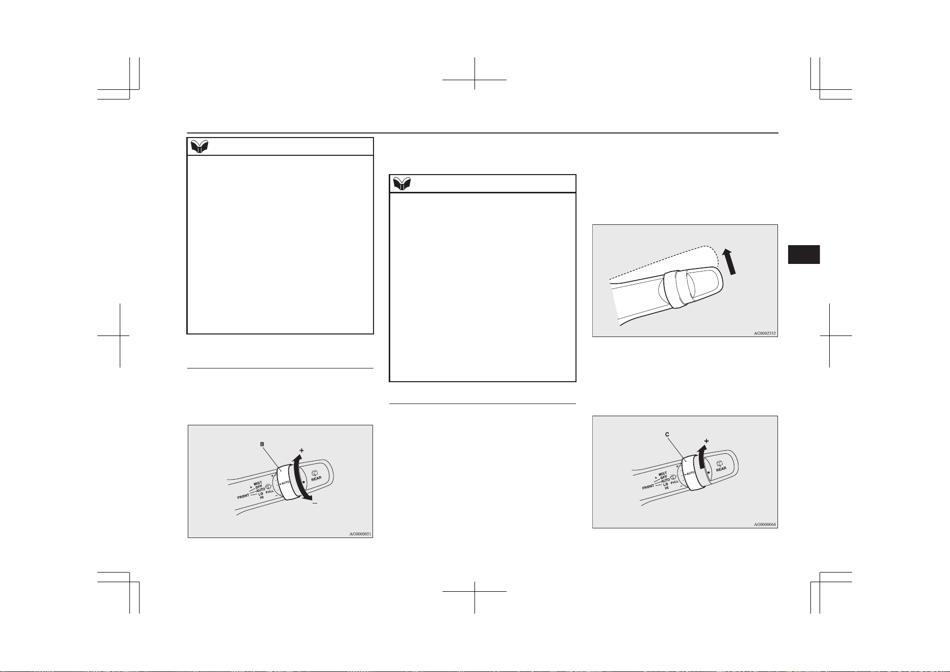
NOTE
l
The wipers may automatically operate when
things such as insects or foreign objects are
affixed to the windscreen on top of the rain
sensor or when the windscreen is frozen.
Objects affixed to the windscreen will stop
the wipers when the wipers cannot remove
them. To operate the wipers again, move the
lever in the “LO” or “HI” position.
Also, the wipers may operate automatically
due to strong direct sunlight or electromag-
netic wave. To stop the wipers, place the lev-
er in the “OFF” position.
l
Contact a MITSUBISHI MOTORS Author-
ized Service Point when replacing the wind-
screen or reinforcing the glass around the
sensor.
To adjust the sensitivity of the
rain sensor
With the lever in the “AUTO” (rain sensor)
position, it is possible to adjust the sensitivity
of the rain sensor by turning the knob (B).
“+”- Higher sensitivity to rain
“-”- Lower sensitivity to rain
NOTE
l
It is possible to activate the following func-
tions.
•
Automatic operation (rain droplet sensi-
tive) can be changed to intermittent opera-
tion (vehicle-speed sensitive).
•
Automatic operation (rain droplet sensi-
tive) can be changed to intermittent opera-
tion (except vehicle-speed sensitive).
For further information, we recommend you
to consult a MITSUBISHI MOTORS Au-
thorized Service Point.
On vehicles equipped with the Smartphone
Link Display Audio or the MITSUBISHI
Multi-Communication System (MMCS),
screen operations can be used to make the
adjustment. Refer to the separate owner’s
manual for details.
Misting function
Move the lever in the direction of the arrow
and release, to operate the wipers once.
Use this function when you are driving in
mist or drizzle.
The wipers will operate once if the lever is
raised to the “MIST” position and released
when the ignition switch or the operation
mode is in the “ON” or “ACC” position. The
wipers will continue to operate while the lev-
er is held in the “MIST” position.
The wipers will operate once if the lever is
moved to the “AUTO” position and the knob
(C) is turned in the “+” direction when the ig-
nition switch is in the “ON” position.
Wiper and washer switch
6-71
OGGE19E1
Instruments and controls
6
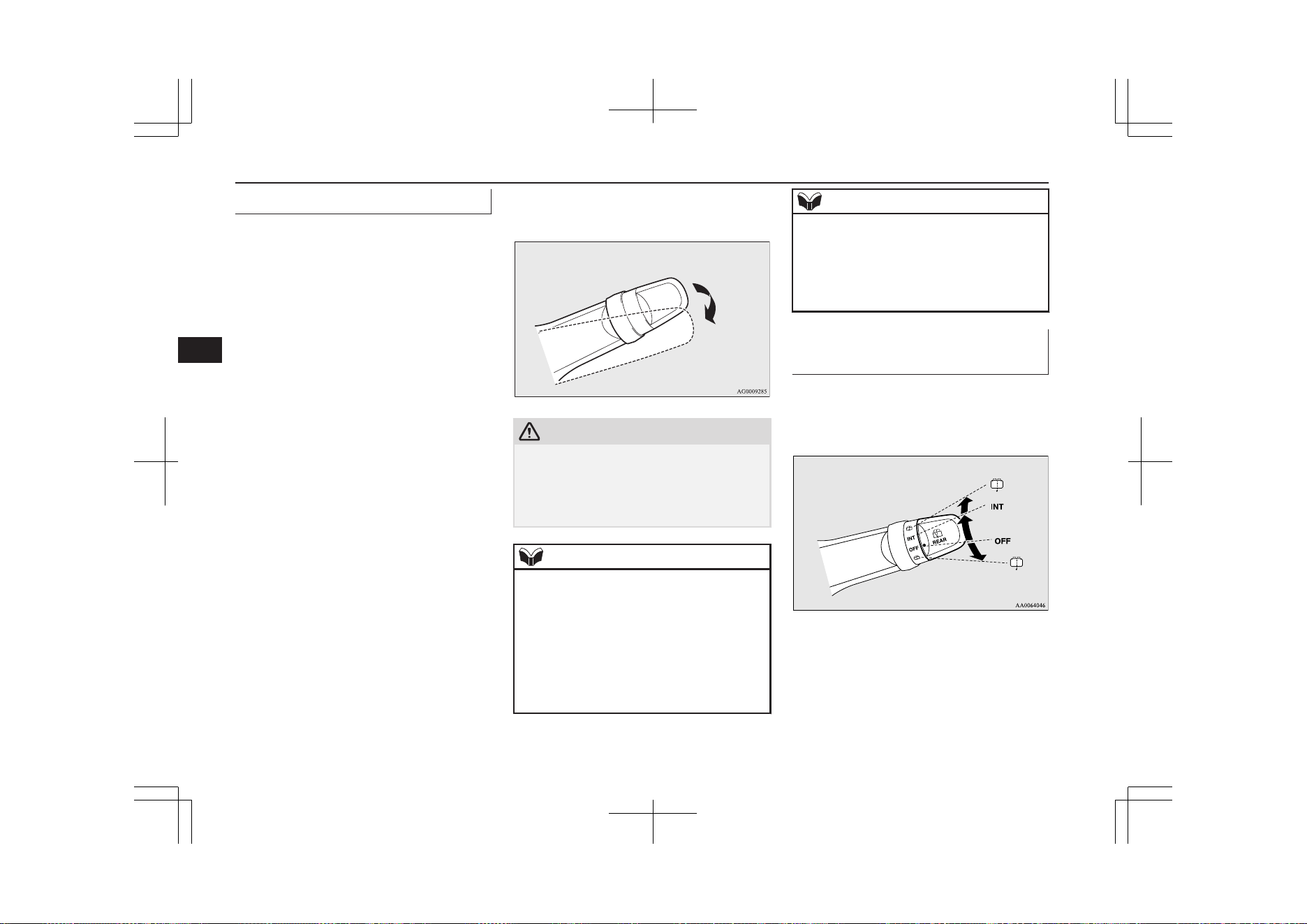
Windscreen washer
E00507202665
The windscreen washer can be operated with
the operation mode of the power switch in
ON or ACC.
The washer fluid will be sprayed onto the
windscreen by pulling the lever towards you.
When the wipers are not in operation or in in-
termittent operation, by pulling the lever to-
wards you, the wipers will operate several
times while the washer fluid is being sprayed.
Then about 6 seconds later, wipers operate
once more.
On vehicles equipped with a headlamp wash-
er, while the headlamps are on, the headlamp
washer will operate once together with the
windscreen washer.
Also, by releasing the lever soon after pulling
it towards you, the washer fluid will be
sprayed several times while the wipers are
operating several times. (Intelligent washer)
Then about 6 seconds later, wipers operate
once more.
Intelligent washer will stop operating with
any operation of the lever.
CAUTION
l
If the washer is used in cold weather, the
washer fluid sprayed against the glass may
freeze resulting in poor visibility. Heat the
glass with the defroster or demister before
using the washer.
NOTE
l
It is possible to modify functions as follows:
•
Causing the wiper never to operate when
washer fluid is sprayed.
•
Deactivating the intelligent washer.
•
Deactivating the function that operates the
wipers once more about 6 seconds later.
For further information, we recommend you
to consult a MITSUBISHI MOTORS Au-
thorized Service Point.
NOTE
On vehicles equipped with the Smartphone
Link Display Audio or the MITSUBISHI
Multi-Communication System (MMCS),
screen operations can be used to make the
adjustment. Refer to the separate owner’s
manual for details.
Rear window wiper and wash-
er
E00507302536
The rear window wiper and washer switch
can be operated with the operation mode of
the power switch in ON or ACC.
INT-
The wiper operates continuously
for several seconds then oper-
ates intermittently at intervals of
about every 8 seconds
OFF- Off
Wiper and washer switch
6-72
OGGE19E1
Instruments and controls
6
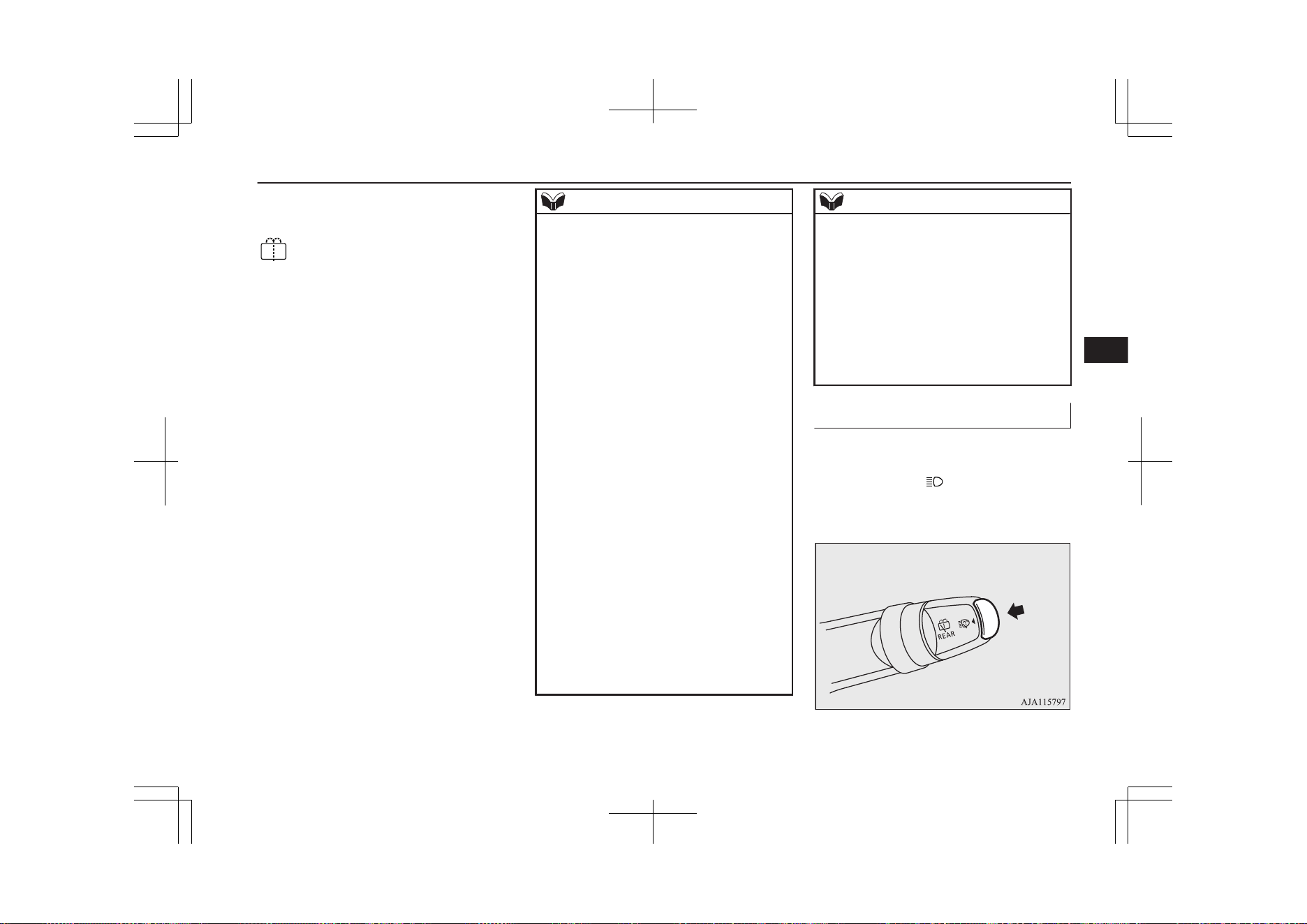
-
The washer fluid will be sprayed
onto the rear window when the
knob is turned fully in either di-
rection.
The wipers operate automatical-
ly several times while the wash-
er fluid is being sprayed.
NOTE
l
The rear window wiper will automatically
perform several continuous operations if the
selector lever is put in the “R” position while
the windscreen wipers or the rear window
wiper is operating. (automatic operation
mode)
After the automatic operation, the rear win-
dow wiper will stop operating if the knob is
in the “OFF” position. If the knob is in the
“INT” position, the rear window wiper will
return to the intermittent operation.
It is possible to set the rear window wiper to
perform the automatic operation only if the
selector lever is put in the “R” position while
the rear window wiper is operating with the
knob in the “INT” position.
For further information, we recommend you
to consult a MITSUBISHI MOTORS Au-
thorized Service Point.
On vehicles equipped with the Smartphone
Link Display Audio or the MITSUBISHI
Multi-Communication System (MMCS),
screen operations can be used to make the
adjustment.
Refer to the separate owner’s manual for de-
tails.
l
If the knob is in the “OFF” position, turn the
knob to the “INT” position twice quickly to
operate the rear window wiper continuously.
(continuous operation mode)
Turn the knob to the “OFF” position to stop
the rear window wiper continuous operation.
NOTE
l
The interval for intermittent operation can be
adjusted.
For further information, we recommend you
to consult a MITSUBISHI MOTORS Au-
thorized Service Point.
On vehicles equipped with the Smartphone
Link Display Audio or the MITSUBISHI
Multi-Communication System (MMCS),
screen operations can be used to make the
adjustment. Refer to the separate owner’s
manual for details.
Headlamp washer switch
E00510101658
The headlamp washer can be operated with
the operation mode in ON or ACC and the
lamp switch at the “
” position.
Push the button once and the washer fluid
will be sprayed on to the headlamps.
Wiper and washer switch
6-73
OGGE19E1
Instruments and controls
6
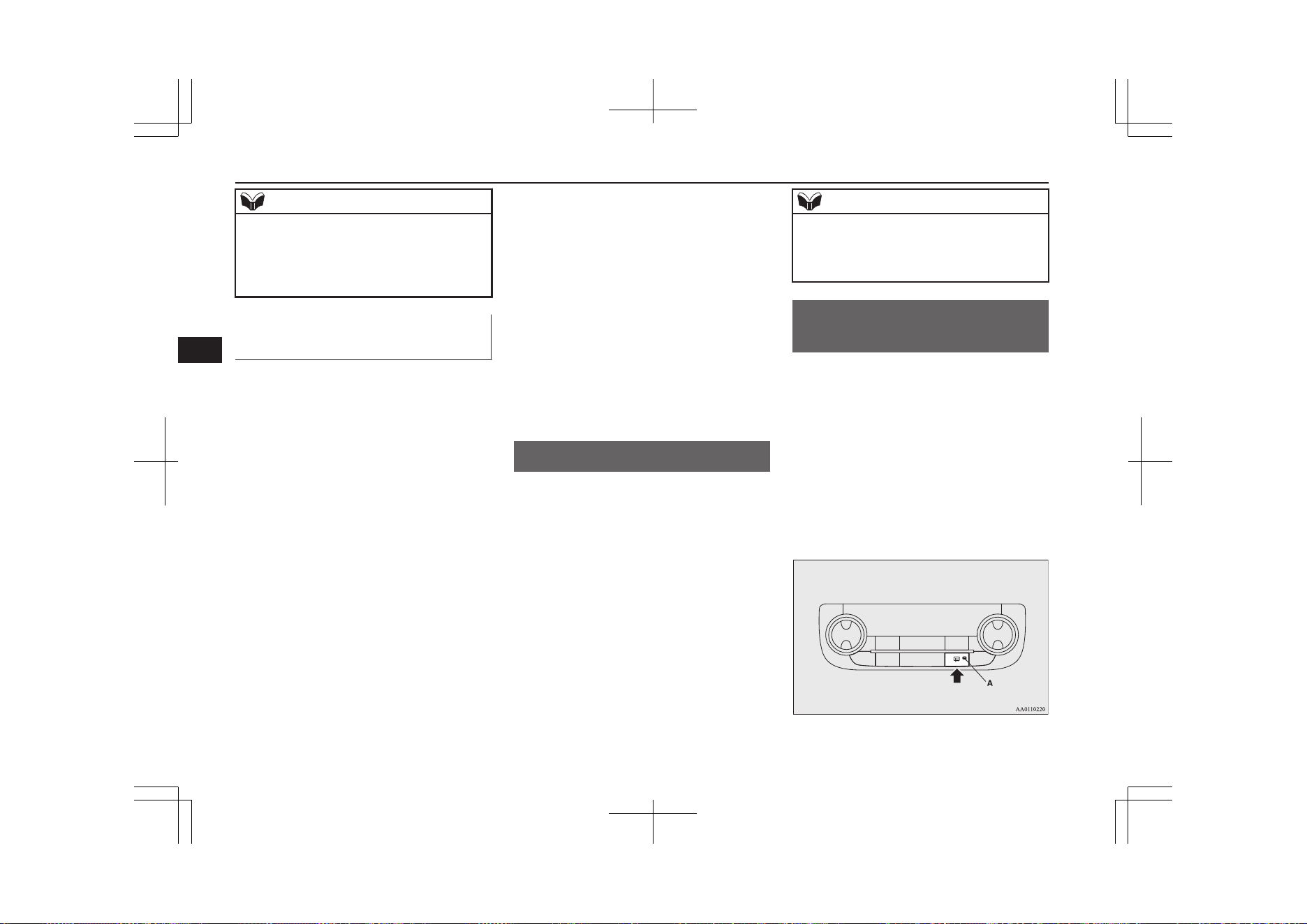
NOTE
l
If the operation mode is in ON or ACC and
the headlamps are on, the headlamp washer
operates together with the windscreen wash-
er the first time the windscreen washer lever
is pulled.
Precautions to observe when
using wipers and washers
E00507601327
l
If the moving wipers become blocked
partway through a sweep by ice or other
deposits on the glass, the wipers may
temporarily stop operating to prevent the
motor from overheating. In this case,
park the vehicle in a safe place, put the
operation mode in OFF, and then remove
the ice or other deposits.
The wipers will start operating again af-
ter the wiper motor cools down, so
check that the wipers operate before us-
ing them.
l
Do not use the wipers when the glass is
dry.
They may scratch the glass surface and
the blades wear out prematurely.
l
Before using the wipers in cold weather,
check that the wiper blades are not fro-
zen onto the glass. The motor may burn
out if the wipers are used with the blades
frozen onto the glass.
l
Avoid using the washer continuously for
more than 20 seconds. Do not operate
the washer when the fluid reservoir is
empty.
Otherwise, the motor may burn out.
l
Periodically check the level of washer
fluid in the reservoir and refill if re-
quired.
During cold weather, add a recommen-
ded washer solution that will not freeze
in the washer reservoir. Failure to do so
could result in loss of washer function
and frost damage to the system compo-
nents.
Wiper de-icer switch*
E00507701142
The rear window demister switch can be op-
erated when the Plug-in Hybrid EV System is
operating.
When the front wipers have frozen to the
windscreen at the parked positions, turning
on this switch will heat the windscreen to
make the wipers operable. Press the rear win-
dow demister switch and the deicer will oper-
ate.
NOTE
l
The wiper de-icer is activated/deactivated,
depending on the operation of the rear win-
dow demister. Refer to “Rear window de-
mister switch” on page 6-74.
Rear window demister
switch
E00507902659
The rear window demister switch can be op-
erated when the operation mode of the power
switch is in ON.
Push the switch to turn on the rear window
demister. It will be turned off automatically
in about 15 to 20 minutes depending on the
outside temperature. To turn off the demister
while it is operating, push the switch again.
The indication lamp (A) will illuminate while
the demister is on.
Wiper de-icer switch*
6-74
OGGE19E1
Instruments and controls
6
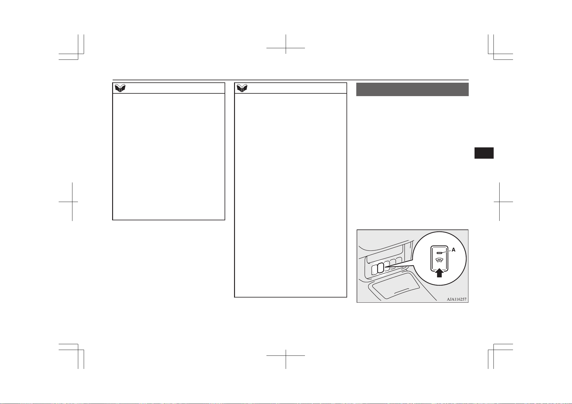
NOTE
l
Do not use this switch when the ready indi-
cation lamp is not illuminated. The auxiliary
battery could go flat, making it impossible to
start the Plug-in Hybrid EV System.
l
Since the demister requires a significant
amount of power, stop the demister as soon
as the window is demisted. Using it for a
long time may reduce the auxiliary battery
voltage, making it impossible to start the
Plug-in Hybrid EV System.
l
When the rear window demister switch is
pressed, the outside rear-view mirrors are
defogged or defrosted. Refer to “Heated mir-
ror” on page 7-10.
l
On vehicles equipped with the wiper de-icer,
when the rear window demister switch is
pushed, the window glass becomes warm
and the wipers become operable. Refer to
“Wiper de-icer switch” on page 6-74.
NOTE
l
It is possible to change the setting to make
the rear window demister operate automati-
cally when ambient temperature becomes
low while the ready indication lamp is illu-
minated, even if you do not push the rear
window demister switch.
It operates automatically only once after put-
ting the operation mode in ON.
If you choose this setting, the heated mirrors
(if so equipped) and wiper de-icer (if so
equipped) will also operate automatically at
the same time.
For further information, we recommend you
to consult a MITSUBISHI MOTORS Au-
thorized Service Point.
On vehicles equipped with the Smartphone
Link Display Audio or the MITSUBISHI
Multi-Communication System (MMCS),
screen operations can be used to make the
adjustment. Refer to the separate owner’s
manual for details.
l
The demister switch is not to melt snow but
to clear mist. Remove snow before use of
the demister switch.
l
When cleaning the inside of the rear win-
dow, use a soft cloth and wipe gently along
the heater wires, being careful not to damage
the wires.
l
Do not allow objects to touch the inside of
the rear window glass, damaged or broken
wires may result.
Heated windscreen switch*
E00532000054
In cold weather windscreen can be heated by
electrical-heat units.
It will speed-up removal of frost and conden-
sate.
The heated windscreen switch can be operat-
ed when the Plug-in Hybrid EV System is
operating and the outside temperature is
about 5 °C or less.
Push the switch to turn on the heated wind-
screen. It will be turned off automatically in
about 5 to 10 minutes depending on the out-
side temperature. To turn off the heated wind-
screen while it is operating, push the switch
again.
The indication lamp (A) will illuminate while
the heated windscreen is on.
Heated windscreen switch*
6-75
OGGE19E1
Instruments and controls
6
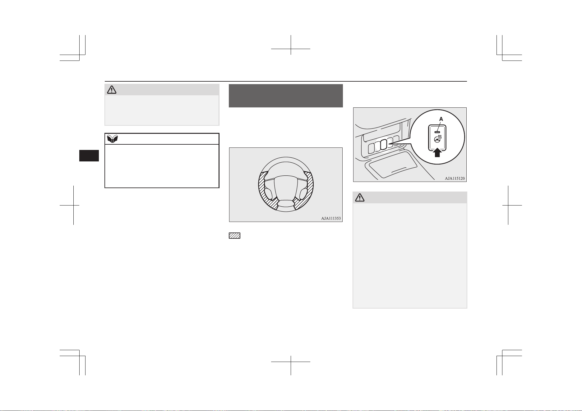
CAUTION
l
While heated windscreen is operating, the
outer surface of the windscreen will be hot.
Do not touch the windscreen to prevent
burns.
NOTE
l
Remove snow before use of the heated
windscreen. It is not possible to melt large
amount of accumulated snow by the heated
windscreen.
l
To avoid the battery runs out, do not use the
heated windscreen continuously.
Heated steering wheel
switch*
E00532100042
The heated steering wheel will warm the grip
portions of the left and right on the steering
wheel by internal heater.
: Heating range
The heated steering wheel can be operated
when the operation mode of the power switch
is in ON.
Push the switch to turn on the heated steering
wheel. It will be turned off automatically in
about 30 minutes. To turn off the heated
steering wheel while operating, push the
switch again.
The indication lamp (A) will illuminate while
the heated steering wheel is on.
CAUTION
l
If the following types of persons use the
heated steering wheel, they might become
too hot or receive minor burns (red skin,
heat blisters, etc.):
•
Elderly or ill people.
•
People with sensitive skin.
•
Excessively tired people.
•
People under the influence of sleep induc-
ing medication (cold medicine, etc.).
l
If water or any other liquid is spilled on the
steering wheel, allow it to dry thoroughly
before attempting to use the heated steering
wheel. Turn the heated steering wheel off
immediately if it appears to be malfunction-
ing during use.
Heated steering wheel switch*
6-76
OGGE19E1
Instruments and controls
6
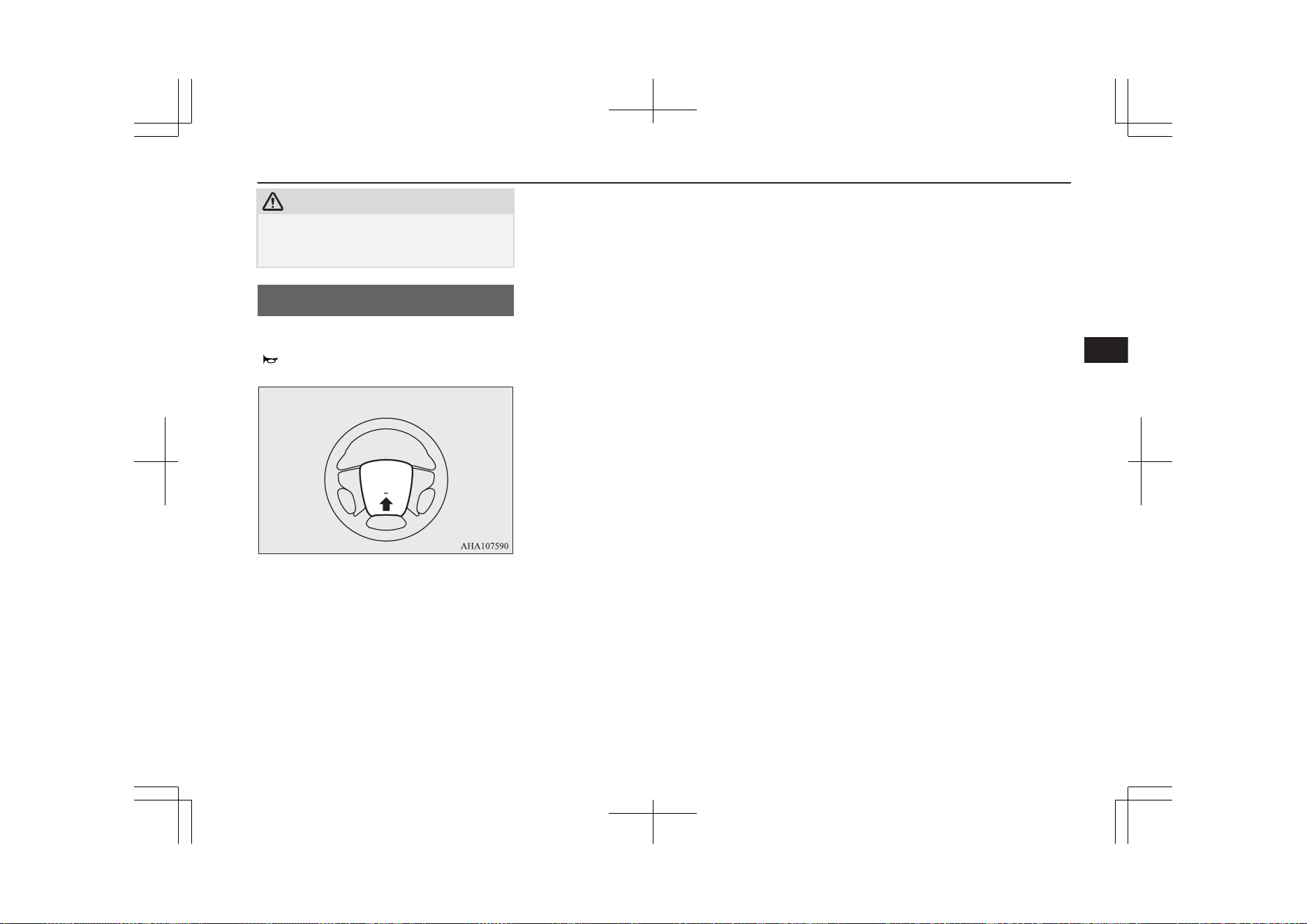
CAUTION
l
Long use of the heated steering wheel when
the ready indicator is not illuminated may
run down the auxiliary battery.
Horn switch
E00508001735
Press the steering wheel on or around the
“ ” mark.
Horn switch
6-77
OGGE19E1
Instruments and controls
6

OGGE19E1

Economical driving.............................................................................7-02
Driving, alcohol and drugs..................................................................7-02
Safe driving techniques.......................................................................7-02
Parking brake...................................................................................... 7-03
Parking................................................................................................ 7-06
Steering wheel height and reach adjustment.......................................7-07
Inside rear-view mirror....................................................................... 7-07
Outside rear-view mirrors................................................................... 7-09
Power switch....................................................................................... 7-11
Starting and stopping the Plug-in Hybrid EV System........................ 7-13
Selector lever (Joystick type)..............................................................7-15
Select position indicator......................................................................7-17
Electrical Parking switch.................................................................... 7-18
Regenerative braking level selector (paddle type)*............................7-19
S-AWC (Super All Wheel Control).................................................... 7-20
4-wheel drive operation...................................................................... 7-23
Inspection and maintenance following rough road operation.............7-24
Cautions on handling of 4-wheel drive vehicles.................................7-25
EV switch............................................................................................7-25
SAVE/CHARGE mode switch............................................................7-28
SPORT mode switch........................................................................... 7-31
Acoustic Vehicle Alerting System (AVAS).........................................7-32
Braking................................................................................................7-34
Brake auto hold................................................................................... 7-35
Hill start assist.....................................................................................7-37
Brake assist system............................................................................. 7-39
Emergency stop signal system............................................................ 7-39
Anti-lock brake system (ABS)............................................................7-40
Electric power steering system (EPS).................................................7-42
Active stability control (ASC)............................................................ 7-43
Cruise control*....................................................................................7-45
Speed Limiter*....................................................................................7-50
Adaptive Cruise Control System (ACC)*...........................................7-55
Forward Collision Mitigation System (FCM)*...................................7-67
Ultrasonic misacceleration Mitigation System (UMS)*.....................7-77
Blind Spot Warning (BSW) (with Lane Change Assist)*...................7-82
Rear Cross Traffic Alert (RCTA)*......................................................7-86
Lane Departure Warning (LDW)*...................................................... 7-88
Tyre pressure monitoring system (TPMS).......................................... 7-92
Reversing sensor system*................................................................... 7-97
Parking sensors (Front/Rear)*.......................................................... 7-101
Rear-view camera*........................................................................... 7-105
Multi Around Monitor*.................................................................... 7-109
Cargo loads........................................................................................7-117
Trailer towing....................................................................................7-118
Starting and driving
OGGE19E1
7

Economical driving
E00600102422
For economical driving, there are some tech-
nical requirements that have to be met. The
prerequisite for low fuel consumption is a
properly adjusted engine. In order to achieve
longer life of the vehicle and the most eco-
nomical operation, we recommend you to
have the vehicle checked at regular intervals
in accordance with the service standards.
Fuel economy and generation of exhaust gas
and noise are highly influenced by personal
driving habits as well as the particular operat-
ing conditions. The following points should
be observed in order to minimize wear of
brakes, tyres and engine as well as to reduce
environmental pollution.
Starting and acceleration
Avoid driving when the accelerator pedal is
pressed way down, such as for unnecessarily
sudden starts, acceleration and deceleration.
Smoothly depress the accelerator pedal.
Observe the speed limit and keep the speed
as constant as possible while driving.
Idling
Parking for a long period with the ready indi-
cator illuminated will shorten the cruising
range.
Speed
The higher the vehicle speed, the more drive
battery is consumed. Avoid driving at full
speed. Even a slight release of the accelerator
pedal will save a significant amount of drive
battery.
Tyre inflation pressure
Check the tyre inflation pressures at regular
intervals. Low tyre inflation pressure increa-
ses road resistance and fuel consumption. In
addition, low tyre pressures adversely affect
tyre wear and driving stability.
Cargo loads
Do not drive with unnecessary articles in the
luggage compartment. Especially during city
driving where frequent starting and stopping
is necessary, the increased weight of the vehi-
cle will greatly affect fuel consumption. Also
avoid driving with unnecessary luggage or
carriers, etc., on the roof; the increased air re-
sistance will increase fuel consumption.
Air conditioning
Too much cooling/heating can affect the
cruising range, so maintain an appropriate
temperature to extend the cruising range.
Driving, alcohol and drugs
E00600200070
Driving after drinking alcohol is one of the
most frequent causes of accidents.
Your driving ability can be seriously im-
paired even with blood alcohol levels far be-
low the legal minimum. If you have been
drinking, don’t drive. Ride with a designated
non-drinking driver, call a cab or a friend, or
use public transportation. Drinking coffee or
taking a cold shower will not make you so-
ber.
Similarly, prescription and nonprescription
drugs affect your alertness, perception and re-
action time. Consult with your doctor or
pharmacist before driving while under the in-
fluence of any of these medications.
WARNING
l
NEVER DRINK AND DRIVE.
Your perceptions are less accurate, your
reflexes are slower and your judgment is
impaired.
Safe driving techniques
E00600301775
Driving safety and protection against injury
cannot be fully ensured. However, we recom-
mend that you pay extra attention to the fol-
lowing:
Economical driving
7-02
OGGE19E1
Starting and driving
7
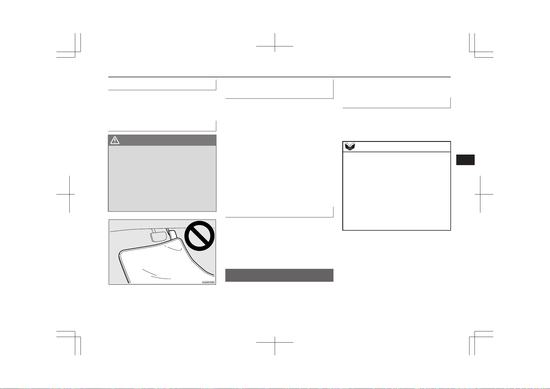
Seat belts
Before starting the vehicle, make sure that
you and your passengers have fastened your
seat belts.
Floor mats
WARNING
l
Keep floor mats clear of the pedals by
correctly laying floor mats that are suita-
ble for the vehicle.
To prevent the floor mats from slipping
out of position, securely retain them using
the hook etc.
Note that laying a floor mat over a pedal
or laying one floor mat on top of another
can obstruct pedal operation and lead to a
serious accident.
Carrying children in the vehi-
cle
l
Never leave your vehicle unattended
with the key and children inside the ve-
hicle. Children may play with the driv-
ing controls and this could lead to an ac-
cident.
l
Make sure that infants and small chil-
dren are properly restrained in accord-
ance with the laws and regulations, and
for maximum protection in case of an
accident.
l
Prevent children from playing in the lug-
gage compartment. It is quite dangerous
to allow them to play there while the ve-
hicle is moving.
Loading luggage
When loading luggage, be careful not to load
above the height of seats. This is dangerous
not only because rearward vision will be ob-
structed, but also the luggage may be projec-
ted into the passenger compartment under
hard braking.
Parking brake
E00600502918
To park the vehicle, first bring it to a com-
plete stop, fully apply the parking brake suffi-
ciently to hold the vehicle.
Make sure the brake warning lamp (red) is il-
luminated.
Electric parking brake
E00642100222
The Electric parking brake is the system that
applies the parking brake by the electric mo-
tor.
NOTE
l
You may hear an operation noise from the
vehicle body when operating the Electric
parking brake. This does not indicate a mal-
function and the Electric parking brake is
operating normally.
l
When the auxiliary battery is weak or dead,
the Electric parking brake cannot be applied
or released. Refer to “Emergency starting”
on page 9-02.
l
You may feel the brake pedal moving when
operating the Electric parking brake.
This does not indicate a malfunction.
Parking brake
7-03
OGGE19E1
Starting and driving
7
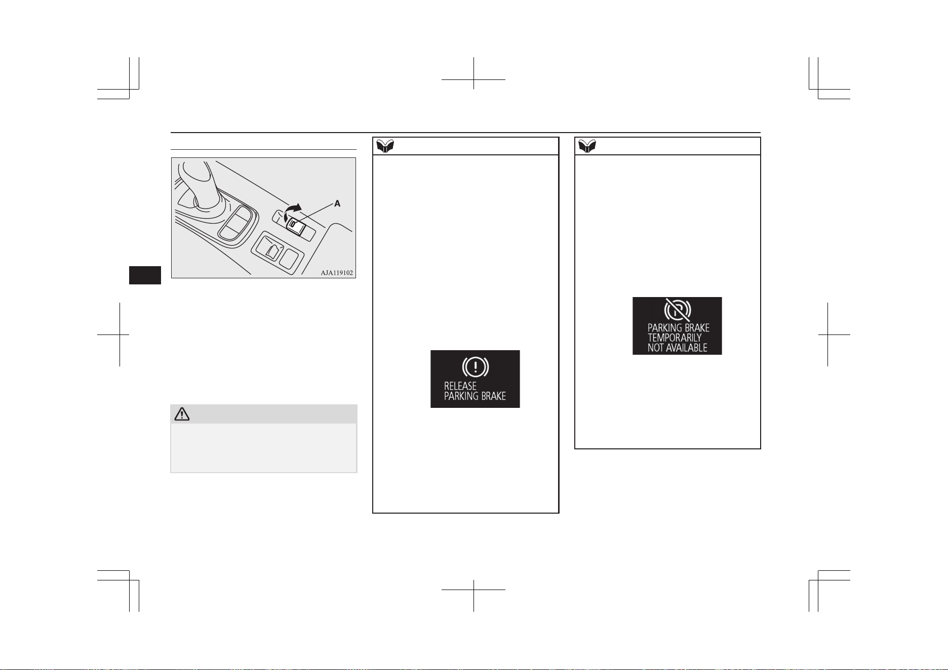
To apply
1. Stop the vehicle completely.
2. Pull up the Electric parking brake switch
while depressing the brake pedal.
When the parking brake is applied, the brake
warning lamp (red) in the instrument cluster
and the indication lamp (A) on the Electric
parking brake switch will come on.
CAUTION
l
While the vehicle is in motion, do not apply
the Electric parking brake. Doing so may
cause overheating and/or premature wear of
brake parts, reducing brake performance.
NOTE
l
In the following conditions, the brake warn-
ing lamp (red) will illuminate for approxi-
mately 15 seconds and then go off.
•
While the Electric parking brake is ap-
plied, the operation mode of the power
switch is put in OFF.
•
While the operation mode of the power
switch is in OFF, the Electric parking
brake switch is pulled up.
l
If the Electric parking brake must be applied
in an emergency situation, pull and hold the
Electric parking brake switch to apply the
Electric parking brake. At that time, the fol-
lowing warning display will appear in the
multi-information display and a buzzer will
sound, however you should continue to pull
and hold the Electric parking brake switch.
l
When parking on steep grades, pull up the
Electric parking brake switch twice (once
more after the operation is completed once).
The maximum effect of the parking brake
will be obtained.
l
If the parking brake does not hold the vehi-
cle stationary after the foot brake is released,
contact a MITSUBISHI MOTORS Author-
ized Service Point.
NOTE
l
When the operation mode of the power
switch is other than ON, if the Electric park-
ing brake is applied, the Electric parking
brake indication lamp comes on for a while.
l
If the Electric parking brake switch is re-
peatedly operated in a short time, the follow-
ing warning display will appear in the multi-
information display and the Electric parking
brake will temporarily stop working. In such
case, wait for approximately 1 minute until
the warning display disappears, and operate
the Electric parking brake switch again.
l
The brake warning lamp (red) and the indi-
cation lamp on the Electric parking brake
switch may blink. This does not indicate a
malfunction, the lamps go off when/if the
Electric parking brake is released.
l
Depending on the situation, the Electric
parking brake may be applied automatically.
Refer to “Brake auto hold” on page 7-35.
Parking brake
7-04
OGGE19E1
Starting and driving
7
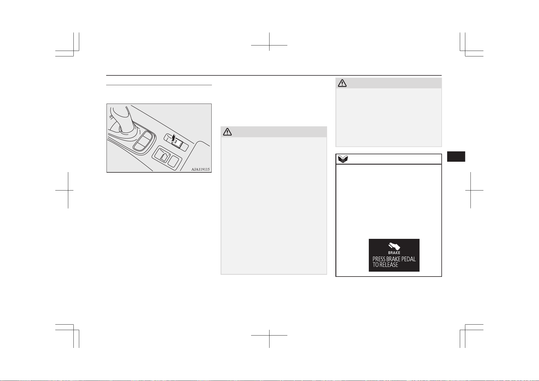
To release
Manual operation
1. Make sure that the operation mode of the
power switch is ON.
2. Press down the Electric parking brake
switch while depressing the brake pedal.
Automatic operation
When the accelerator pedal is depressed
slowly while all of the following conditions
are met, the Electric parking brake is auto-
matically released.
l
The Plug-in Hybrid EV System is oper-
ating.
l
The select position is in the “D”
(DRIVE) or the “R” (REVERSE) posi-
tion.
l
The driver’s seat belt is fastened.
When the parking brake is released, the brake
warning lamp (red) and the indication lamp
on the Electric parking brake switch go off.
Before driving, be sure that the Electric park-
ing brake is released and the brake warning
lamp is off.
CAUTION
l
After the Electric parking brake switch has
been operated to apply or release the Electric
parking brake, if the brake warning lamp
(red) and the indicator on the Electric park-
ing brake switch remain blinking or the
Electric parking brake warning lamp (yel-
low) remains illuminated, the Electric park-
ing brake system may be malfunctioning and
the Electric parking brake may not be ap-
plied or released. Immediately park your ve-
hicle in a safe place and contact the nearest
MITSUBISHI MOTORS Authorized Serv-
ice Point.
l
If a vehicle is driven without releasing the
Electric parking brake, the brake will over-
heat, resulting in ineffective braking and
possible brake failure.
l
If the brake warning lamp (red) does not go
off after the parking brake has been released,
the brake system may be malfunctioning.
Contact the nearest MITSUBISHI MOTORS
Authorized Service Point.
CAUTION
l
If the acceleration of the vehicle seems ab-
normally slow after the vehicle has been
parked with the Electric parking brake ap-
plied in cold weather, stop the vehicle in a
safe place, then apply and release the Elec-
tric parking brake. If the vehicle acceleration
is still slow, contact the nearest
MITSUBISHI MOTORS Authorized Serv-
ice Point.
NOTE
l
When the operation mode of the power
switch is other than ON, the parking brake
cannot be released.
l
If the Electric parking brake does not auto-
matically release, it may be released by man-
ual operation.
l
When the select position is other than the
“P” (PARK) position, if you try to release
the Electric parking brake without depress-
ing the brake pedal, the warning display will
appear.
Parking brake
7-05
OGGE19E1
Starting and driving
7
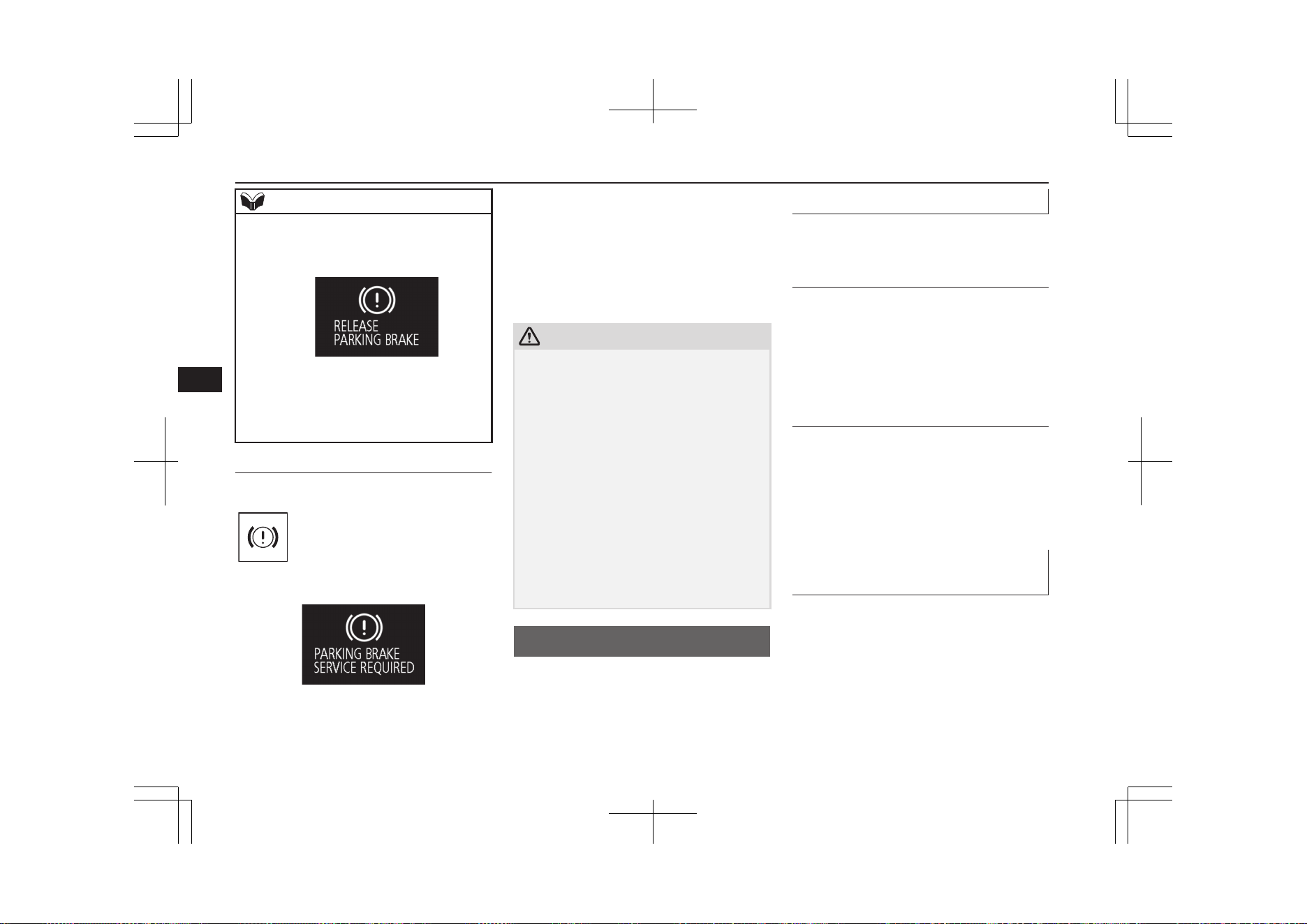
NOTE
l
If you start driving without releasing the
Electric parking brake, the warning display
will appear.
l
If the driver’s foot contacts the accelerator
pedal in the condition that the Electric park-
ing brake can be released by an automatic
operation, the Electric parking brake may be
released automatically.
Warning display
Warning lamp (yellow)
Warning display
If there is a malfunction in the system, the
warning lamp will come on. In addition, the
warning display appears on the information
screen in the multi information display.
Under normal conditions, the warning lamp
only comes on when the operation mode is
put in ON and goes off a few seconds later.
CAUTION
l
When the Electric parking brake warning
lamp (yellow) does not illuminate or remains
illuminated when the operation mode of the
power switch is put in ON, or comes on
while driving, the Electric parking brake
may not be applied or released. Immediately
contact the nearest MITSUBISHI MOTORS
Authorized Service Point. For details, refer
to “Electric parking brake warning lamp
(yellow)” on page 6-56.
When parking your vehicle while the Elec-
tric parking brake warning lamp (yellow) is
illuminated, park the vehicle on level and
stable ground, put the select position to “P”
(PARK) and place chocks, blocks, or stones
behind and in front of the tyres to prevent
the vehicle from moving.
Parking
E00600602818
To park the vehicle, firmly apply the parking
brake, and then press the electrical parking
switch to lock the wheels.
Parking on a hill
To prevent the vehicle from rolling, follow
these procedures:
Parking on a downhill slope
Turn the front wheels towards the kerb and
move the vehicle forward until the kerb side
wheel gently touches the kerb.
Apply the parking brake and press the electri-
cal parking switch.
If necessary, apply chocks to wheels.
Parking on an uphill slope
Turn the front wheels away from the kerb and
move the vehicle back until the kerb side
wheel gently touches the kerb.
Apply the parking brake and press the electri-
cal parking switch.
If necessary, apply chocks to wheels.
Parking with the engine run-
ning
Never leave the engine running while you
take a short sleep/rest. Also, never leave the
engine running in a closed or poorly ventila-
ted place.
Parking
7-06
OGGE19E1
Starting and driving
7
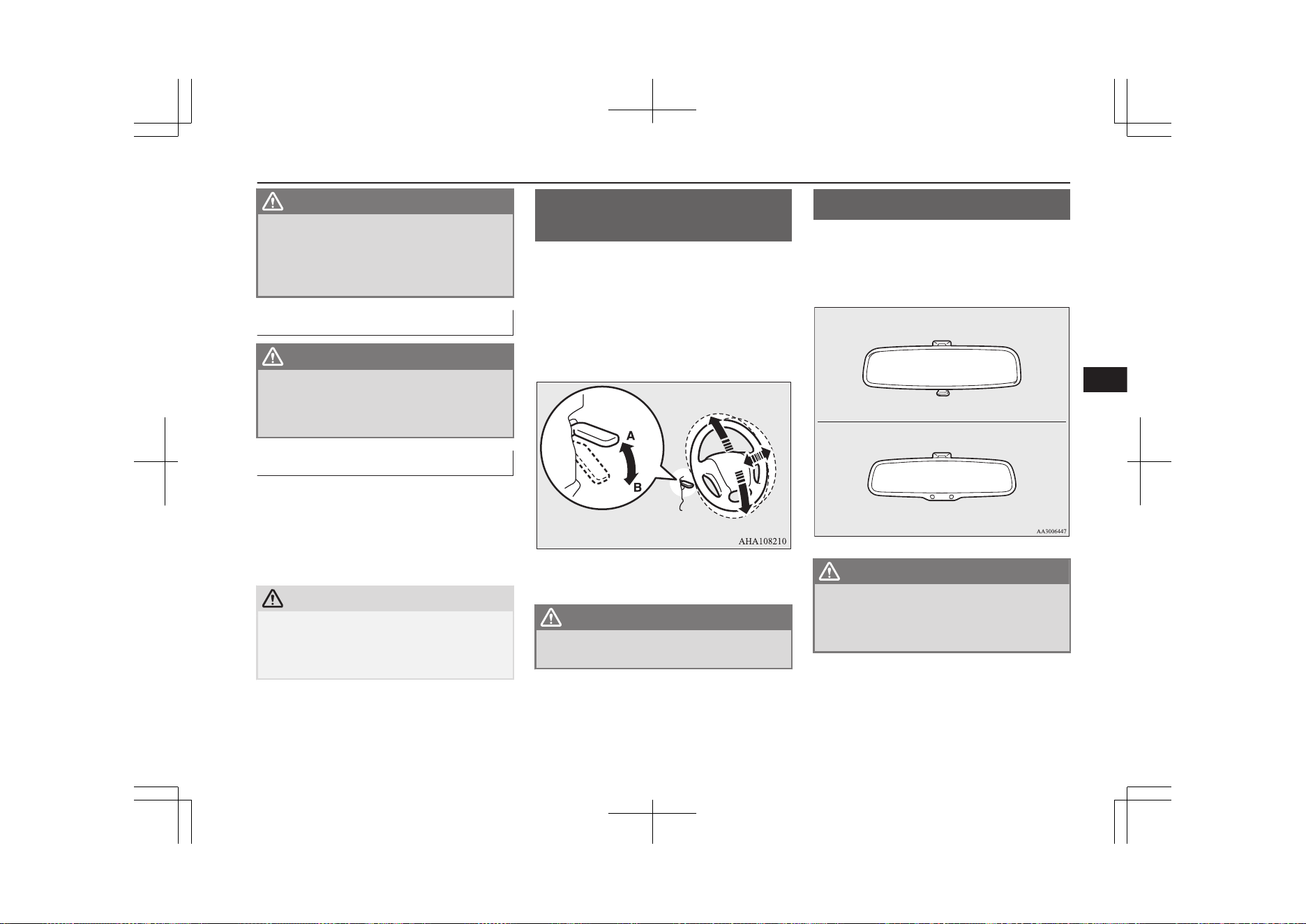
WARNING
l
Leaving the engine running risks injury
or death from accidentally moving the se-
lector lever or the accumulation of toxic
exhaust fumes on the passenger compart-
ment.
Where you park
WARNING
l
Do not park your vehicle in areas where
combustible materials such as dry grass
or leaves can come in contact with a hot
exhaust, since a fire could occur.
When leaving the vehicle
Always carry the key and lock all doors and
the tailgate when leaving the vehicle unatten-
ded.
Always try to park your vehicle in a well lit
area.
CAUTION
l
When you leave the vehicle, be sure that you
have stopped the Plug-in Hybrid EV System.
The engine may start suddenly by a remain-
ing amount decline of the drive battery.
Steering wheel height and
reach adjustment
E00600701652
1. Release the lever while holding the
steering wheel up.
2. Adjust the steering wheel to the desired
position.
3. Securely lock the steering wheel by pull-
ing the lever fully upward.
A- Locked
B- Release
WARNING
l
Do not attempt to adjust the steering
wheel while you are driving the vehicle.
Inside rear-view mirror
E00600802315
Adjust the rear-view mirror only after making
any seat adjustments so you have a clear
view to the rear of the vehicle.
Type 1
Type 2
WARNING
l
Do not attempt to adjust the rear-view
mirror while driving. This can be danger-
ous.
Always adjust the mirror before driving.
Adjust the rear-view mirror to maximize the
view through the rear window.
Steering wheel height and reach adjustment
7-07
OGGE19E1
Starting and driving
7
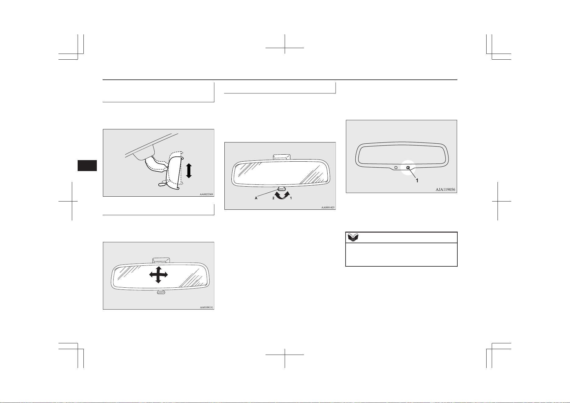
To adjust the vertical mirror
position
It is possible to move the mirror up and down
to adjust its position.
To adjust the mirror position
It is possible to move the mirror up/down and
left/right to adjust its position.
To reduce the glare
Type 1
The lever (A) at the bottom of the mirror can
be used to adjust the mirror to reduce the
glare from the headlamps of vehicles behind
you during night driving.
1- Normal
2- Anti-glare
Type 2
When the headlamps of the vehicles behind
you are very bright, the reflection factor of
the rear-view mirror is automatically changed
to reduce the glare.
When the operation mode of the power
switch is put in ON, the reflection factor of
the mirror is automatically changed.
NOTE
l
Do not hang items on, or spray glass cleaner
on the sensor (1), as reduced sensitivity
could result.
Inside rear-view mirror
7-08
OGGE19E1
Starting and driving
7
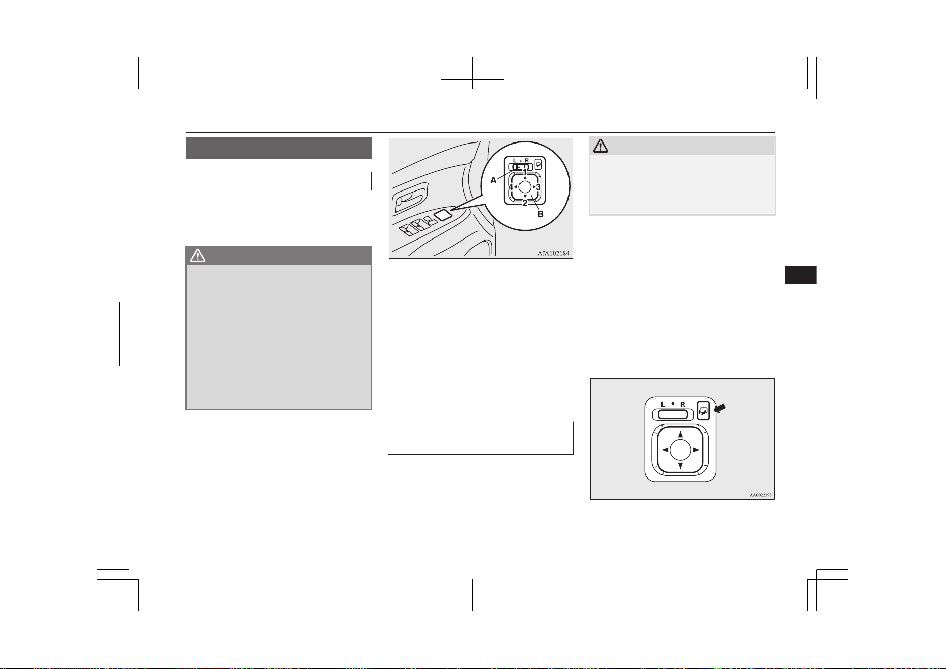
Outside rear-view mirrors
E00600900628
To adjust the mirror position
E00601001737
The outside rear-view mirrors can be operat-
ed when the operation mode is put in ON or
ACC.
WARNING
l
Do not attempt to adjust the rear-view
mirrors while driving. This can be dan-
gerous.
Always adjust the mirrors before driving.
l
Your vehicle is equipped with convex type
mirrors.
Please take into consideration, that ob-
jects you see in the mirror will look small-
er and farther away compared to a nor-
mal flat mirror.
Do not use this mirror to estimate dis-
tance of following vehicles when changing
lanes.
1. Place the lever (A) to the same side as
the mirror whose adjustment is desired.
L- Left outside mirror adjustment
R- Right outside mirror adjustment
2. Press the switch (B) to the left, right, up
or down to adjust the mirror position.
1- Up
2- Down
3- Right
4- Left
3. Return the lever (A) back to the middle
position (•).
Retracting and extending the
outside mirrors
E00601102272
The outside mirror can be folded in towards
the side window to prevent damage when
parking in narrow areas.
CAUTION
l
Do not drive the vehicle with the mirror fol-
ded in.
The lack of rearward visibility normally pro-
vided by the mirror could lead to an acci-
dent.
Retracting and extending the
mirrors using the mirror retrac-
tor switch
With the operation mode in ON or ACC,
push the mirror retractor switch to retract the
mirrors. Push it again to extend the mirrors to
their original positions.
After placing the operation mode in OFF, it is
possible to retract and extend the mirrors us-
ing the mirror retractor switch for approxi-
mately 30 seconds.
Outside rear-view mirrors
7-09
OGGE19E1
Starting and driving
7
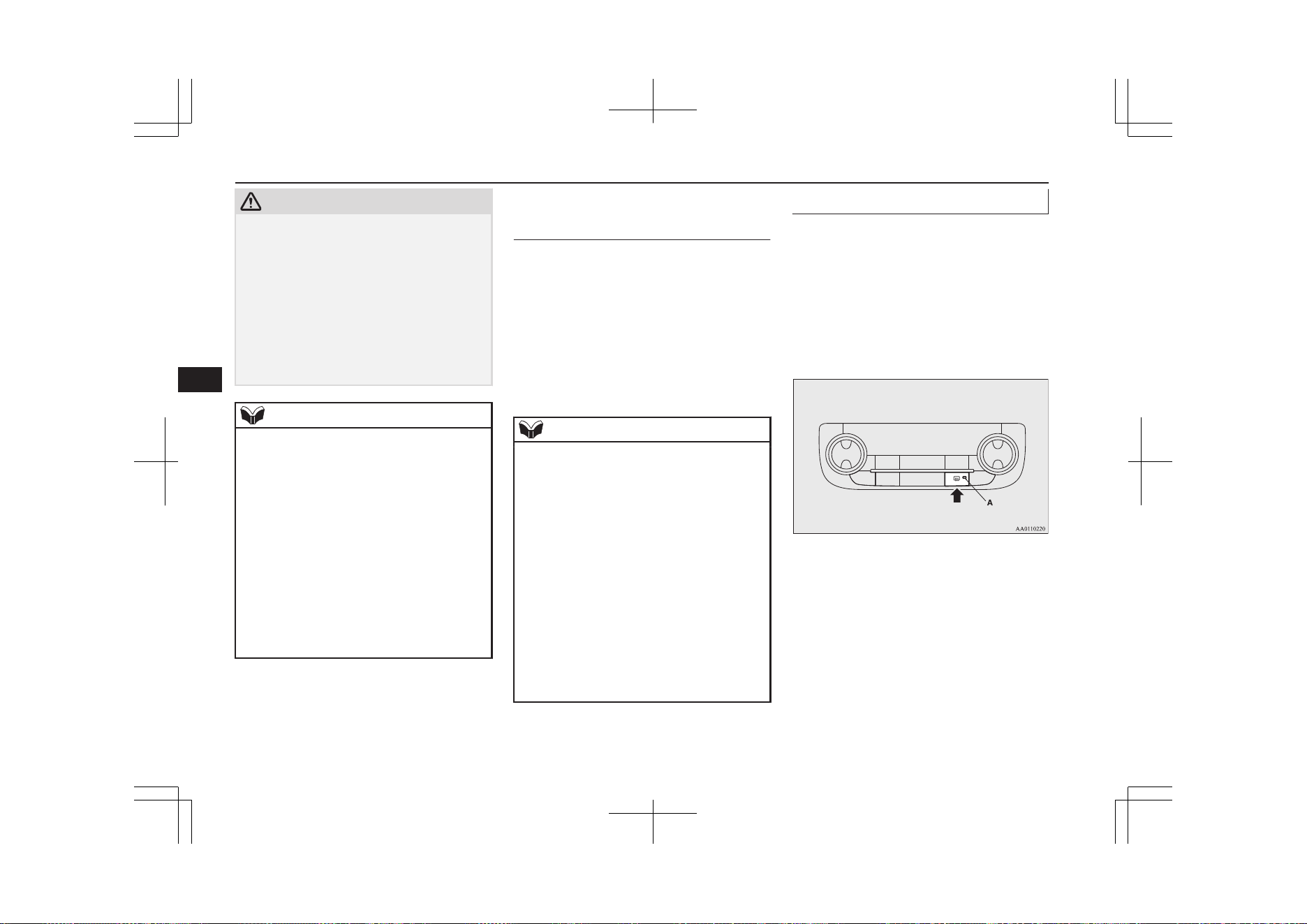
CAUTION
l
It is possible to retract and extend the mir-
rors by hand. After retracting a mirror using
the mirror retractor switch, however, you
should extend it by using the switch again,
not by hand. If you extended the mirror by
hand after retracting it using the switch, it
would not properly lock in position. As a re-
sult, the mirror could move because of the
wind or vibration while you are driving, and
this may limit the driver’s rearward visibili-
ty.
NOTE
l
Be careful not to get your hands trapped
while a mirror is moving.
l
If you move a mirror by hand or it moves af-
ter hitting a person or object, you may not be
able to return it to its original position using
the mirror retractor switch. If this happens,
push the mirror retractor switch to place the
mirror in its retracted position and then push
the switch again to return the mirror to its
original position.
l
When freezing has occurred and mirrors fail
to operate as intended, please refrain from
repeated pushing of the retractor switch as
this action can result in burn-out of the mir-
ror motor circuits.
Retracting and extending the
mirrors without using the mir-
ror retractor switch
The mirrors automatically retract or extend
when the doors and tailgate are locked or un-
locked using the remote control switches or
the keyless operation function of the keyless
operation system.
Refer to “Keyless operation system: To oper-
ate using the key-less operation function,
Keyless entry system” on pages 4-09 and
4-03.
NOTE
l
Functions can be modified as stated below.
Please consult a MITSUBISHI MOTORS
Authorized Service Point.
On vehicles equipped with the Smartphone
Link Display Audio or the MITSUBISHI
Multi-Communication System (MMCS),
screen operations can be used to make the
adjustment. Refer to the separate owner’s
manual for details.
•
Automatically extend when the operation
mode is put in ON, and automatically re-
tract when the driver’s door is opened af-
ter the operation mode is put in OFF.
•
Automatically extend when the vehicle
speed reaches 30 km/h (19 mph).
•
Deactivate the automatic extension func-
tion.
Heated mirror
E00601201755
To demist or defrost the outside rear-view
mirrors, press the rear window demister
switch.
The indication lamp (A) will illuminate while
the demister is on.
The heater will be turned off automatically in
approximately 15 to 20 minutes depending
on the outside temperature.
Outside rear-view mirrors
7-10
OGGE19E1
Starting and driving
7
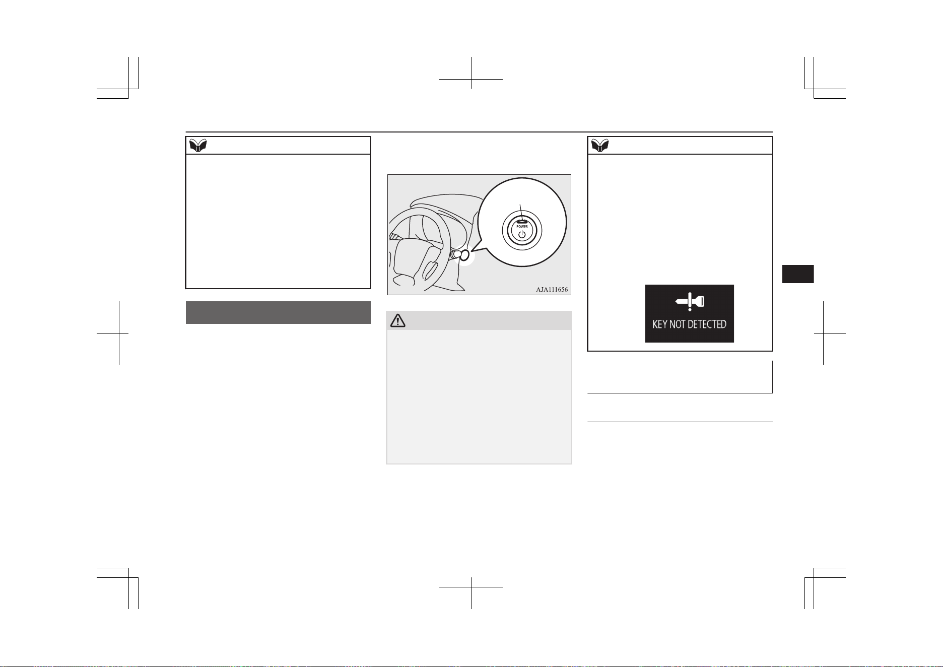
NOTE
l
The heated mirror can be set so that it can
turn on automatically only once if the ambi-
ent temperature becomes low, when the op-
eration mode is put in ON.
For further information, we recommend you
to consult a MITSUBISHI MOTORS Au-
thorized Service Point. On vehicles equipped
with the Smartphone Link Display Audio or
the MITSUBISHI Multi-Communication
System (MMCS), screen operations can be
used to make the adjustment. Refer to the
separate owner’s manual for details.
Power switch
E00631801617
In order to prevent theft, the Plug-in Hybrid
EV System will not start unless a preregis-
tered keyless operation key is used. (Immo-
bilizer function)
If you are carrying the keyless operation key,
you can start the Plug-in Hybrid EV System.
A
CAUTION
l
The indication lamp (A) will flash orange
when there is a problem or malfunction in
the keyless operation system. Never drive if
the indication lamp on the power switch is
flashing orange. Immediately contact a
MITSUBISHI MOTORS Authorized Serv-
ice Point.
l
If the power switch operation is not smooth
and feels like it is sticking, do not operate
the switch. Immediately contact a
MITSUBISHI MOTORS Authorized Serv-
ice Point.
NOTE
l
When operating the power switch, press the
switch all the way in. If the switch is not
fully pressed, the Plug-in Hybrid EV System
may not start or the operation mode may not
change. If the power switch is pressed cor-
rectly, there is no need to hold the power
switch down.
l
When the battery in the keyless operation
key has worn out, or the keyless operation
key is out of the vehicle, a warning display
will appear.
Operation mode of the power
switch and its function
OFF
The indication lamp on the power switch
turns off.
The operation mode cannot be put in OFF
unless the electrical parking switch is press-
ed.
Power switch
7-11
OGGE19E1
Starting and driving
7
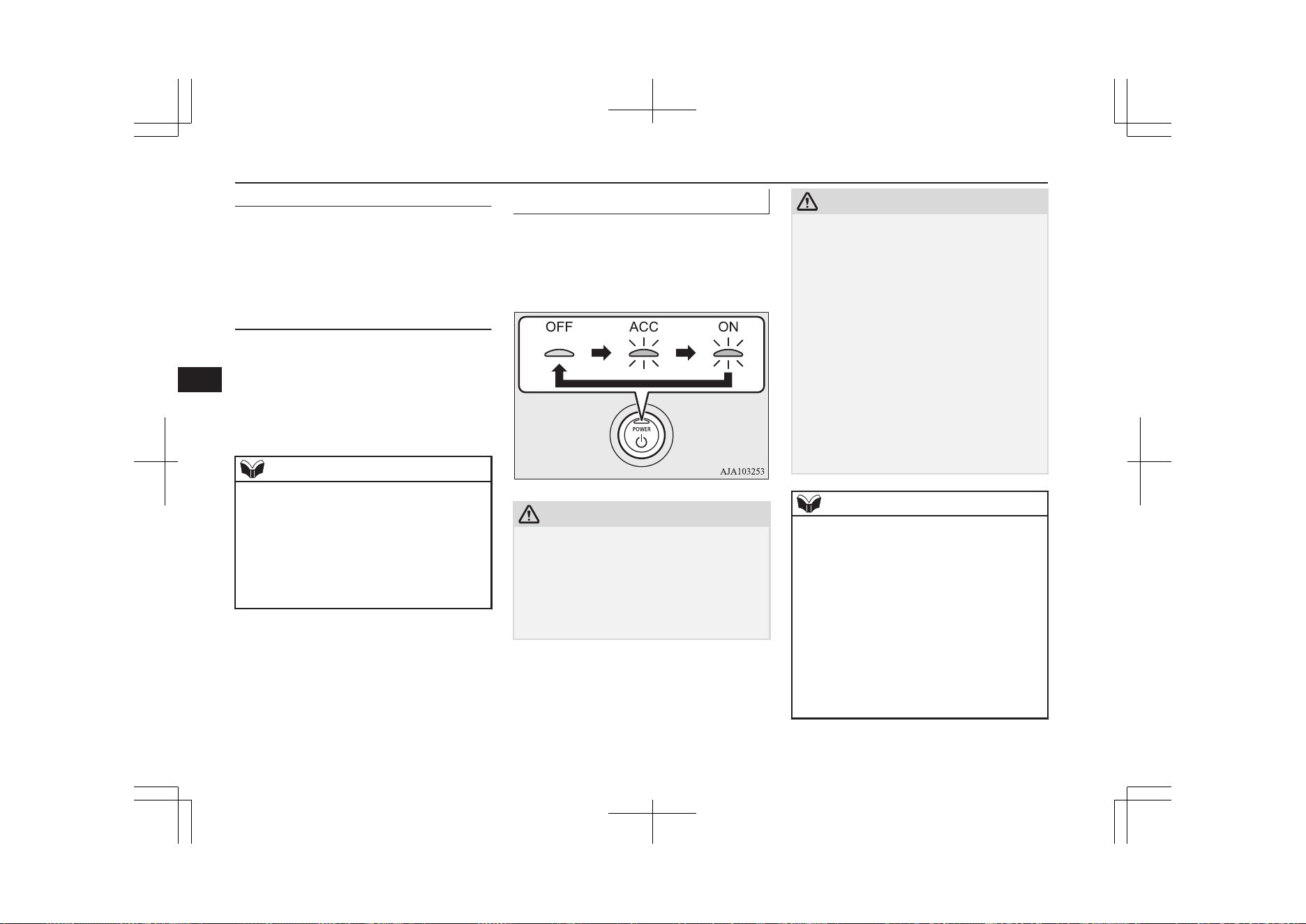
ACC
Electrical devices such as the audio and ac-
cessory socket can be operated. Can be used
when the Ready indicator is off.
The indication lamp on the power switch illu-
minates orange.
ON
All vehicle’s electrical devices can be operat-
ed.
The indication lamp on the power switch illu-
minates blue. The indication lamp goes off
when the Plug-in Hybrid EV System is oper-
ating.
NOTE
l
Your vehicle is equipped with an electronic
immobilizer.
To start the Plug-in Hybrid EV System, the
ID code which the transponder inside the
key sends, must match the one registered in
the immobilizer computer. Refer to “Elec-
tronic immobilizer (Anti-theft starting sys-
tem)” on page 4-03.
Changing the operation mode
E00631901559
If you press the power switch without de-
pressing the brake pedal, you can change the
operation mode in the order of OFF, ACC,
ON, OFF.
CAUTION
l
When the Plug-in Hybrid EV System is not
operating, put the operation mode in OFF.
Leaving the operation mode in ON or ACC
for a long time when the Plug-in Hybrid EV
System is not operating may cause the auxil-
iary battery to discharge, making it impossi-
ble to start the Plug-in Hybrid EV System.
CAUTION
l
When the auxiliary battery is disconnected,
the current operation mode is memorized.
After reconnecting the auxiliary battery, the
memorized mode is selected automatically.
Before disconnecting the auxiliary battery
for repair or replacement, make sure to put
the operation mode in OFF.
Be careful if you are not sure which opera-
tion mode the vehicle is in when the auxili-
ary battery is run down.
l
The operation mode cannot be changed from
OFF to ACC or ON if the keyless operation
key is not detected to be in the vehicle. Refer
to “Keyless operation system: Operating
range for starting the Plug-in Hybrid EV
System and changing the operation mode”
on page 4-08.
NOTE
l
If the operation mode cannot be changed to
OFF, perform the following procedure.
1
.
Press the electrical parking switch
and lock the wheels, then change the
operation mode to OFF.
2
.
One of the other causes could be low
auxiliary battery voltage. If this oc-
curs, the keyless entry system and
keyless operation will also not oper-
ate.
Contact a MITSUBISHI MOTORS Author-
ized Service Point.
Power switch
7-12
OGGE19E1
Starting and driving
7
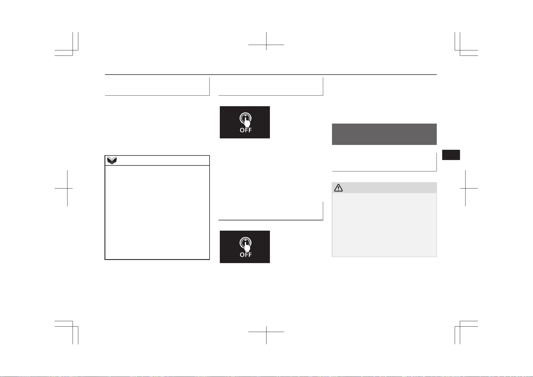
ACC power auto-cutout func-
tion
E00632801265
After approximately 30 minutes have elapsed
with the operation mode in ACC, the func-
tion automatically cuts out the power for the
audio system and other electric devices that
can be operated with that position.
When the power switch operates again, the
power is supplied again.
NOTE
l
It is possible to modify functions as follows:
•
The time until the power cuts out can be
changed to approximately 60 minutes.
•
The ACC power auto-cutout function can
be deactivated.
For details, we recommend you to consult
a MITSUBISHI MOTORS Authorized
Service Point.
On vehicles equipped with the Smart-
phone Link Display Audio or the
MITSUBISHI Multi-Communication Sys-
tem (MMCS), screen operations can be
used to make the adjustment.
Refer to the separate owner’s manual for
details.
Operation mode OFF reminder
system
E00632201445
When the operation mode is in any mode oth-
er than OFF; if you try to lock the doors and
tailgate by pressing the driver’s or front pas-
senger’s door lock/unlock switch, or the tail-
gate LOCK switch, a warning display will
appear, and the outer buzzer will sound pre-
venting you from locking the doors and tail-
gate.
Operation mode ON reminder
system
E00632301068
If the driver’s door is opened while the Plug-
in Hybrid EV System is stopped and the op-
eration mode in any mode other than OFF,
the operation mode ON reminder inner buz-
zer sounds intermittently to remind you to put
the operation mode in OFF.
Starting and stopping the
Plug-in Hybrid EV System
E00620601295
Starting the Plug-in Hybrid EV
System
E00620701661
CAUTION
l
When the Plug-in Hybrid EV System warn-
ing lamp comes on while the READY indi-
cator is on, avoid high-speed driving and
have your vehicle inspected by a
MITSUBISHI MOTORS Authorized Serv-
ice Point as soon as possible. (Refer to
“Plug-in Hybrid EV System warning lamp”
on page 6-57.)
l
Never attempt to start the engine by pushing
or pulling the vehicle.
1. Check that the EV charging cable is not
connected to your vehicle.
2. Fasten the seat belt.
3. Make sure the parking brake is applied.
4. Press and hold the brake pedal down
firmly with your right foot.
Starting and stopping the Plug-in Hybrid EV System
7-13
OGGE19E1
Starting and driving
7
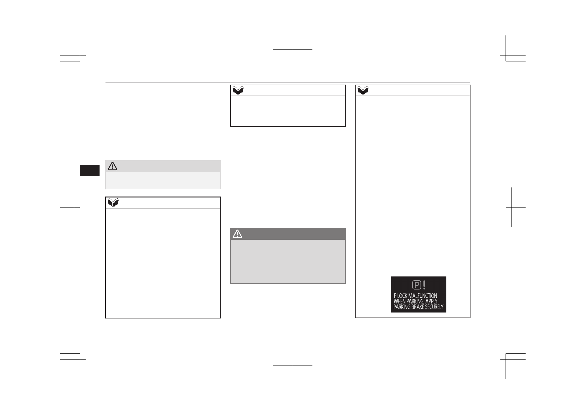
5. When you press the power switch while
depressing the brake pedal, the READY
indicator in the meter blinks and the acti-
vation of Plug-in Hybrid EV System
starts.
6. When the READY indicator changes
from blinking to staying on, the startup
of Plug-in Hybrid EV System is activa-
ted and the vehicle is now ready to drive.
CAUTION
l
Do not press the power switch while holding
the select lever at the operated position.
NOTE
l
Continue to depress the brake pedal until the
READY indicator in the meter stays on.
l
After the Plug-in Hybrid EV System has not
started for a while, the brake pedal effort
needed to start the Plug-in Hybrid EV Sys-
tem may become greater.
If this occurs, depress the brake pedal more
than usual.
l
You can drive your vehicle even if the en-
gine is stopped.
l
The Plug-in Hybrid EV System can be star-
ted in any operation mode.
l
If the READY indicator does not come on,
check the select position indicator. If the in-
dicator does not indicate “P”, press the elec-
trical parking switch to display “P” position.
NOTE
l
If the READY indicator does not come on,
turn the power switch to OFF once and, after
a while, press the power switch to start Plu-
gin Hybrid EV System.
Stopping the Plug-in Hybrid
EV System
E00620801457
1. Stop your vehicle completely.
2. Apply the parking brake firmly while
depressing the brake pedal.
3. After pressing the electrical parking
switch, press the power switch to stop
the Plug-in Hybrid EV System. (Refer to
“Electrical Parking switch” on page
7-18.)
WARNING
l
Never stop the Plug-in Hybrid EV System
during running except in an emergency.
The effectiveness of the brake becomes
very poor and the steering wheel becomes
very heavy, which can easily lead to an ac-
cident.
NOTE
l
Do not operate the power switch during run-
ning except in an emergency. If you have to
stop the Plug-in Hybrid EV System because
of an emergency during operation, continue
to press the power switch for three seconds
or longer or press the power switch three
times or more quickly. The Plug-in Hybrid
EV System stops, the operation mode turns
to ACC, and the selector lever position shifts
to the “P” position at very slow speed.
l
If you press the power switch when the se-
lector lever position is other than the “P” po-
sition while your vehicle is stopped, the se-
lector lever position automatically shifts to
the “P” position, Plug-in Hybrid EV System
stops, and the power mode turns to “OFF”.
l
If the parking lock mechanism is faulty, a
warning is displayed on the information
screen in the multi-information display.
When this warning is displayed, the Plug-in
Hybrid EV System cannot be stopped unless
you apply the parking brake and then press
the power switch. Park on a flat place with
the parking brake securely applied. Have
your vehicle inspected by a MITSUBISHI
MOTORS Authorized Service Point.
Starting and stopping the Plug-in Hybrid EV System
7-14
OGGE19E1
Starting and driving
7

If the keyless operation key is
not operating properly
E00632901237
Insert the keyless operation key into the key
slot. Starting the Plug-in Hybrid EV System
and changing the operation mode should be
now possible.
Remove the keyless operation key from the
key slot after starting the Plug-in Hybrid EV
System or changing the operation mode.
NOTE
l
Do not insert into the key slot anything other
than the keyless operation key. This could
cause damage or a malfunction.
NOTE
l
Remove the object or additional key from
the the keyless operation key before insert-
ing the key into the key slot. The vehicle
may not be able to receive the registered ID
code from the registered key. Therefore, the
Plug-in Hybrid EV System may not start and
the operation mode may not change.
l
The keyless operation key is fixed in the key
slot when inserted in the illustrated direc-
tion. Simply pull out the key to remove it
from the key slot.
Keyless operation key remind-
er
E00633001046
If the operation mode is in OFF and the driv-
er’s door is opened with the keyless operation
key in the key slot, the outer buzzer sounds
for approximately 3 seconds and the inner
buzzer sounds for approximately 1 minute or
a warning display will appear to remind you
to remove the key.
Selector lever (Joystick
type)
E00636100100
Selector lever operation
E00636200097
The selector lever always returns to its home
( ● ) position when it is released.
Selector lever (Joystick type)
7-15
OGGE19E1
Starting and driving
7
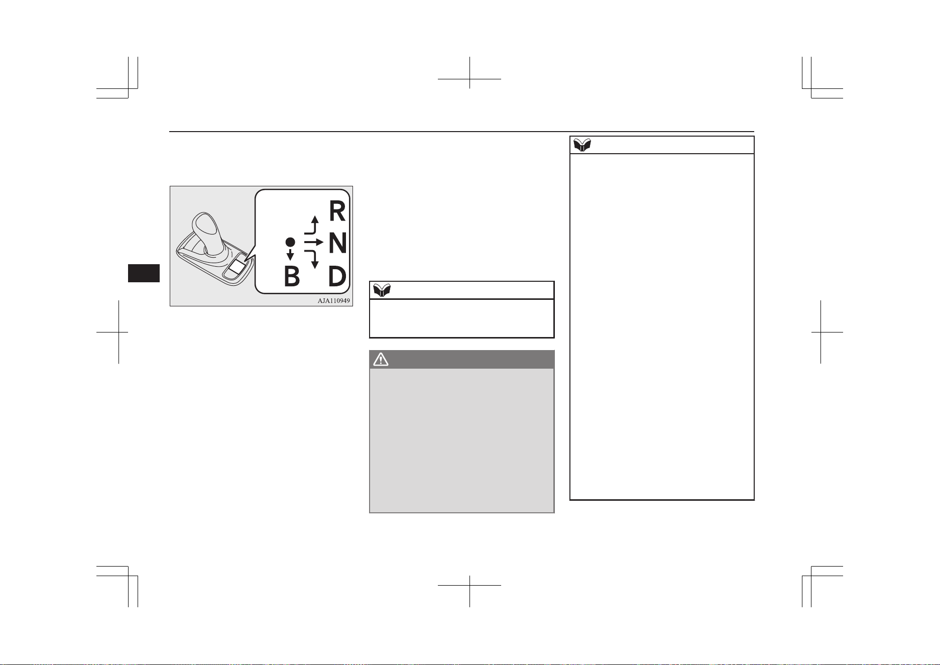
The position you select with the selector lev-
er will be illuminated on the shift position
panel shown in the illustration below.
Home
position
Move the selector lever slowly and securely
in the following method.
l
To select “D” (DRIVE) or “R” (RE-
VERSE):
Move the selector lever in the direction
of the arrow.
l
To select “N” (NEUTRAL):
Move the selector lever in the direction
of the arrow and hold it for a while.
l
To select “B” (REGENERATIVE
BRAKE):
Move the selector lever in the direction
of the arrow.
The “B” (REGENERATIVE BRAKE) posi-
tion can only be selected while the select po-
sition is in the “D” (DRIVE) position. When
the selector lever is moved to the “B” posi-
tion, the regenerative brake force will be-
come stronger.
When the selector lever is again moved to the
“B” position, the maximum regenerative
brake force will be used.
To return to the “D” position, use the selector
lever to select the “D” position.
NOTE
l
If you operate the selector lever to “B” twice
too quickly, the regenerative brake force
may not become the maximum.
WARNING
l
Do not replace the selector lever knob
with anything other than a MITSUBISHI
MOTORS genuine part. In addition, do
not hang an object on the selector lever as
it may be the cause of an accident.
l
When you shift the selector lever to “D”
or “R” position, always depress the brake
pedal with your right foot for your safety.
Never shift the lever while depressing the
accelerator pedal. Doing so will start your
vehicle abruptly, which may lead to a seri-
ous accident. It may also be a cause of
failure of the vehicle.
NOTE
l
You cannot operate the regenerative brake
while the adaptive cruise control system
(ACC) is operating.
l
Every time while operating the selector lev-
er, be sure to check the position displayed on
the indicator.
l
If you perform the following operation, the
buzzer may sound and the select position
may automatically shift to the “N” (NEU-
TRAL) position.
•
If the electrical parking switch is pressed
while the vehicle is in motion.
•
If the selector lever is moved to the “R”
(REVERSE) position while the vehicle is
moving forward.
•
If the selector lever is moved to the “D”
(DRIVE) position while the vehicle is
moving backward.
•
If the selector lever is moved to the “B”
(REGENERATIVE BRAKE) position af-
ter it had been shifted to the “R” (RE-
VERSE) position.
l
If you perform the following operation, the
buzzer sounds and the selector lever opera-
tion is cancelled.
•
When in the “P” (PARK) position, the se-
lector lever is moved without depressing
the brake pedal.
•
When in the “P” (PARK) or “N” (NEU-
TRAL) position, the selector lever is
moved to “B” (REGENERATIVE
BRAKE).
Selector lever (Joystick type)
7-16
OGGE19E1
Starting and driving
7
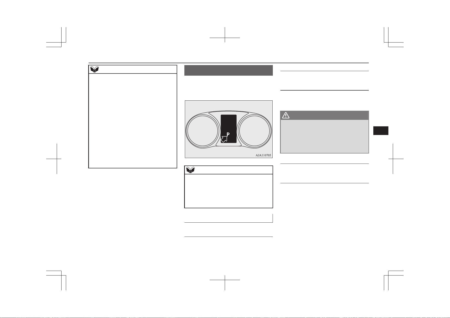
NOTE
•
When the operation mode is in the “ON”
position with the Plug-in Hybrid EV Sys-
tem not operated, the selector lever is
shifted to the “D” (DRIVE) or “R” (RE-
VERSE) position.
l
If you shift and hold the selector lever for
approximately 10 seconds or longer, the buz-
zer sounds.
The buzzer stops sounding when you release
the selector lever.
l
If the driver’s door is opened while the vehi-
cle is stopped or is running at very low
speed with the select position in other than
the “P” (PARK) position and the READY
indicator in the meter is illuminating, the
buzzer sounds. The buzzer stops sounding if
you close the door or shift the selector lever
to “P” (PARK).
Select position indicator
E00636300102
This indicator displays the selector lever po-
sition in the meter.
NOTE
l
When the “B” position is selected, the selec-
ted regenerative brake force position is also
displayed at “B” position.
l
You cannot operate the regenerative brake
while the adaptive cruise control system
(ACC) is operating.
Selector lever positions
E00636400099
“P” PARK
The wheels are locked. When you park your
vehicle, be sure to apply the parking brake
and press the electrical parking switch.
“R” REVERSE
This position is to back up.
“N” NEUTRAL
No power is transmitted to the wheels. The
wheels are not locked.
WARNING
l
Never move the selector lever to the “N”
(NEUTRAL) position while driving, you
will lose regenerative braking.
l
Always keep your right foot on the brake
pedal when shifting into or out of “N”, to
minimize the risk of loss of control.
“D” DRIVE
This position is for normal driving.
“B” REGENERATIVE BRAKE
This position is for the regenerative braking.
You can adjust the regenerative braking force
up to two levels.
Refer to “Selector lever operation” on page
7-15.
Refer to “Braking: When driving downhill”
on page 7-34.
Select position indicator
7-17
OGGE19E1
Starting and driving
7
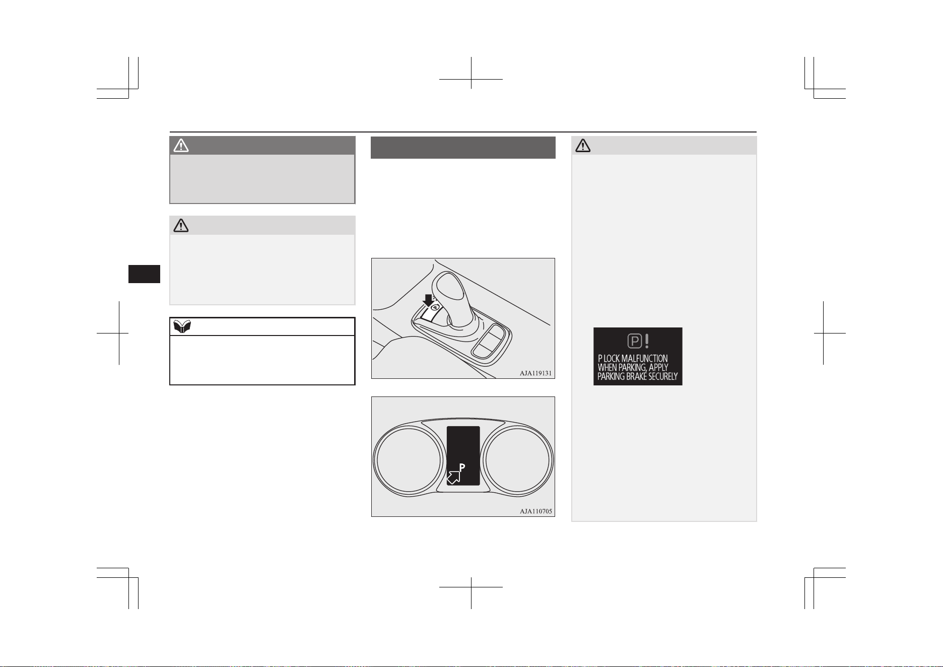
WARNING
l
Sudden regenerative brake may cause the
tyres to skid.
Select this position according to the road
conditions and vehicle speed.
CAUTION
l
When the capacity of the drive battery is
close to full or when the drive battery tem-
perature is low, the regenerative brake will
become less effective.
In such case, depress the brake pedal strong-
ly.
NOTE
l
If a large regenerative braking force is gen-
erated by using the selector lever or the re-
generative braking level selector, the stop
lamps will be automatically illuminated.
Electrical Parking switch
E00636600062
When you park your vehicle, be sure to apply
the parking brake and press the electrical
parking switch to lock the wheels. The indi-
cator on the switch illuminates in green and
the select position indicator displays “P” on
the information screen in the meter.
CAUTION
l
If you operate the electrical parking switch
and the select lever repeatedly within a short
time, the shifting from the “P” position or to
the “P” position is restrained for a certain
period for the system protection. In such a
case, wait for a while and then perform the
operation.
l
If the parking lock mechanism is faulty, a
warning is displayed on the information
screen in the multi-information display.
When this warning is displayed, park on a
flat place with the parking brake securely
applied. Have your vehicle inspected by a
MITSUBISHI MOTORS Authorized Serv-
ice Point.
l
If you press the electrical parking switch be-
fore your vehicle stops completely, the vehi-
cle makes a sudden stop, which may cause
injury to passengers. This also can be a
cause of failure of the vehicle.
l
Do not place an object around the electrical
parking switch. The electrical parking switch
may be pressed by the object when you
place it there or when you somehow touch it.
This will cause unintentional shifting to “P”
or “N” position, which may lead to an acci-
dent.
Electrical Parking switch
7-18
OGGE19E1
Starting and driving
7
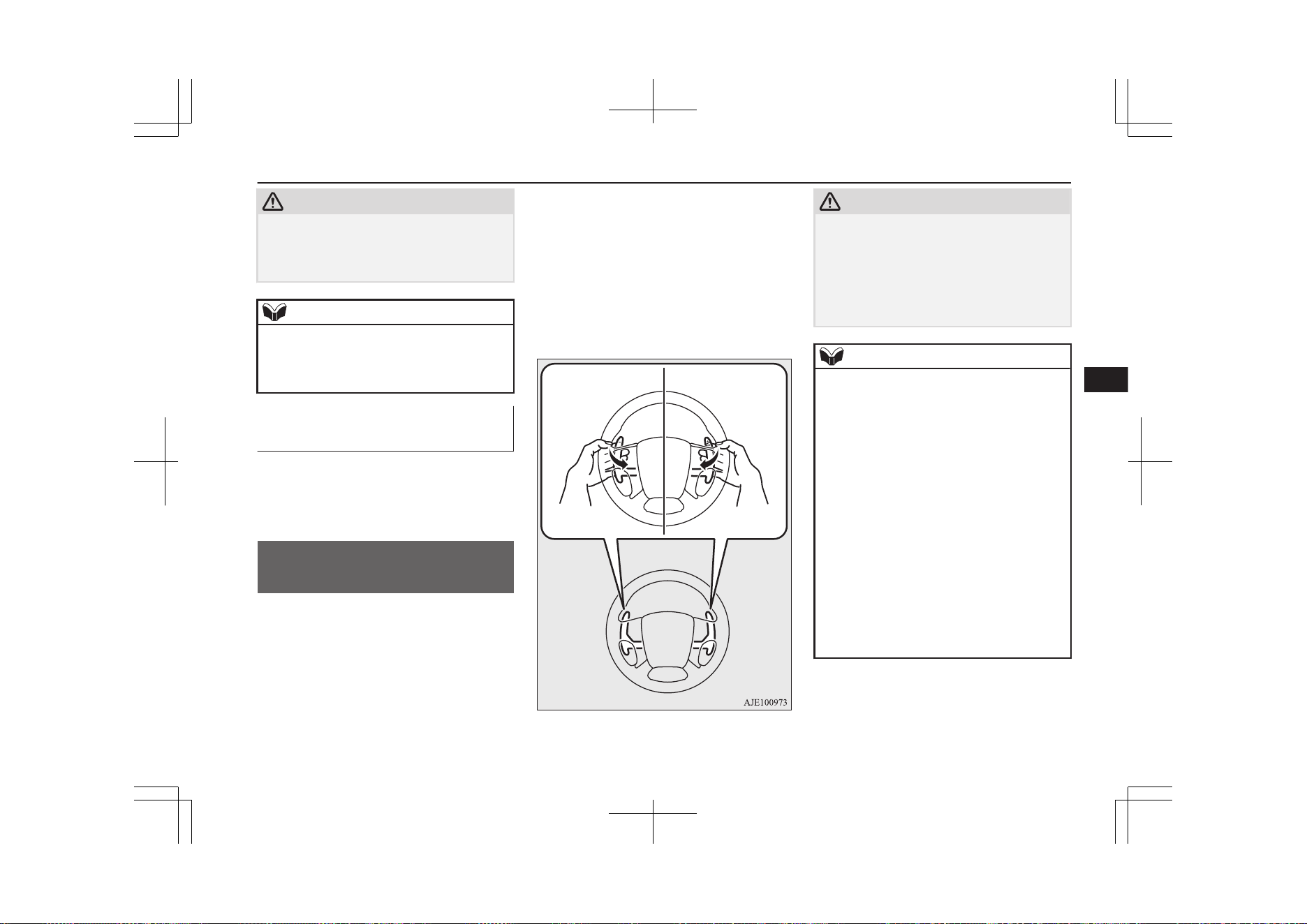
CAUTION
l
Be careful not to spill beverages, etc. around
the electrical parking switch. The electrical
parking switch may be stuck to the pressed
position when it is pressed.
NOTE
l
When the selector lever is shifted from the
“P” position or to the “P” position, operating
noise and vibration of the parking lock are
felt, but this is normal.
Electrical Parking switch re-
minder buzzer
If the driver’s door is opened with the select
position other than “P” when the vehicle is at
a stop, the buzzer sounds to warn to press the
electrical parking switch.
Regenerative braking level
selector (paddle type)*
E00636700148
Regenerative braking level selector can
quickly change the regenerative brake force
keeping your hand on the steering wheel
when you release your foot from the acceler-
ator pedal while driving.
By pulling the regenerative braking level se-
lector, the brake force (amount of electrical
energy to charge the drive battery) can be ad-
justed according to the driving condition such
as before a curve or a downhill.
Regenerative braking level can be switched
in the 6 level from B0 (without regenerative
brake force) to B5 (large regenerative brake
force).
increase in
regenerative force
decrease in
regenerative force
CAUTION
l
If a large regenerative brake force is applied
on a slippery road, tyres may skid. Always
drive safely in accordance with the prevail-
ing road condition.
l
If you operate the right and left paddles si-
multaneously, the regenerative brake force
level may not change.
NOTE
l
Repeated continuous operation of a paddle
will continuously change the brake force
levels.
l
If you turn on the SPORT mode, the regener-
ative braking force level will automatically
switch to B5. After the regenerative braking
force level is switched, the regenerative
braking level can be adjusted by the regener-
ative braking level selector.
l
If you turn on the cruise control when the
level B0 or B1 (smaller regenerative brake
force) is selected, the level is returned to the
normal level B2 automatically.
l
When stronger regenerative braking is gen-
erated, the stop lamps will illuminate even
when the brake pedal is not depressed.
l
Under the cruise control, the level B0 or B1
cannot be selected. The buzzer sounds if you
try to select these levels.
Regenerative braking level selector (paddle type)*
7-19
OGGE19E1
Starting and driving
7
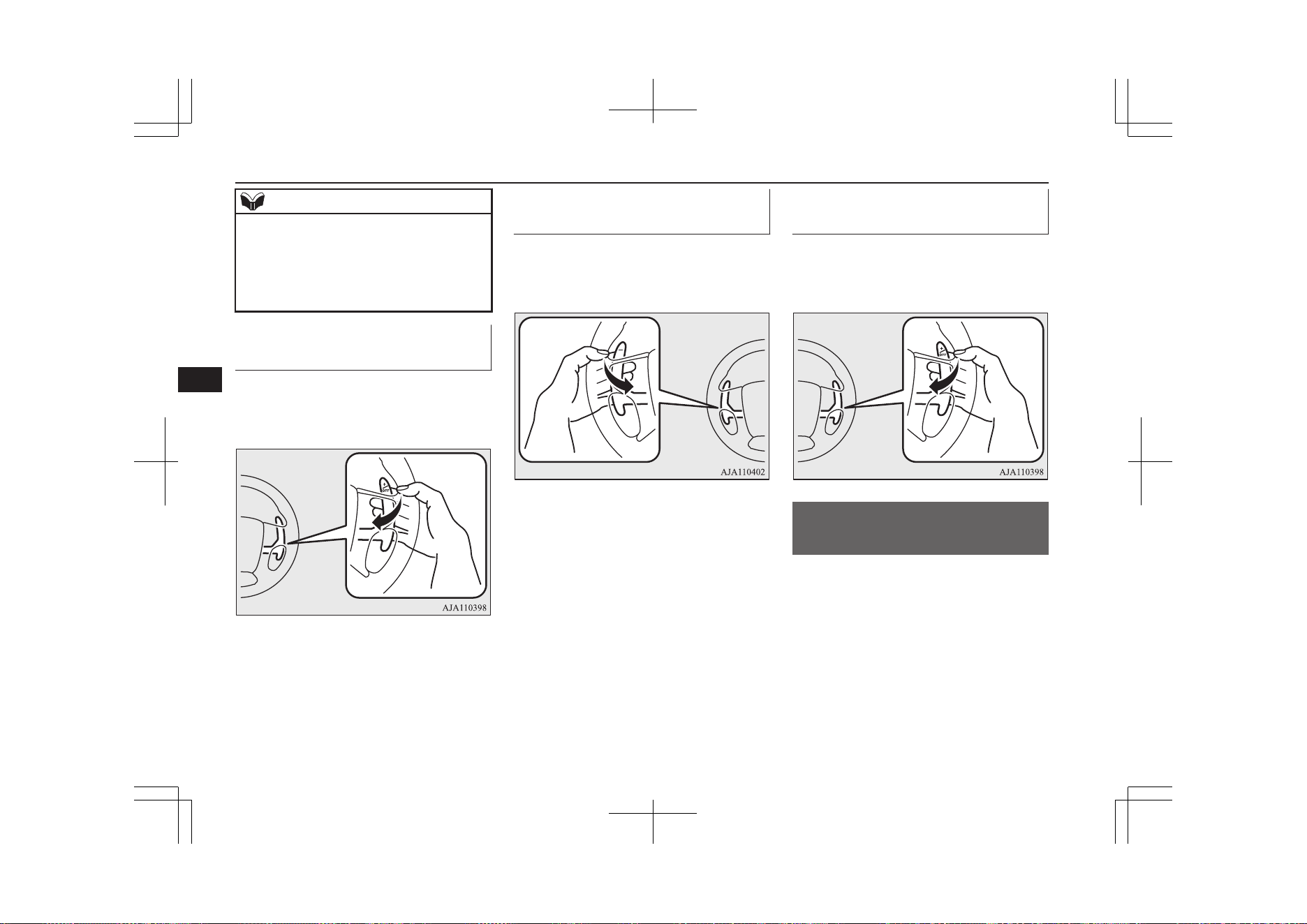
NOTE
l
On vehicles with the adaptive cruise control
system (ACC), you cannot control the regen-
erative brake force level while the adaptive
cruise control system (ACC) is operating.
The buzzer sounds if you operate the pad-
dles.
To decrease regenerative brake
force
Each time you pull the “+” paddle towards
you, the regenerative brake force lowers by
one level.
To increase regenerative brake
force
Each time you pull the “−” paddle towards
you, the regenerative brake force rises by one
level.
To return to the normal regen-
erative brake force level of B2
Pull the “+” paddle for approximately 2 sec-
onds or longer. The select lever position indi-
cator displays “D”.
S-AWC (Super All Wheel
Control)
E00622601185
S-AWC is an integrated vehicle dynamics
control system that helps enhance driving
performance, cornering performance, and ve-
hicle stability over a wide range of driving
conditions through integrated management of
the twin motor 4WD, the AYC (Active Yaw
Control), the ABS and the ASC.
S-AWC (Super All Wheel Control)
7-20
OGGE19E1
Starting and driving
7

CAUTION
l
Do not over-rely on the S-AWC. Even the S-
AWC cannot prevent the natural laws of
physics from acting on the vehicle. This sys-
tem, like any other system, has limits and
cannot help you to maintain traction and
control of the vehicle in all circumstances.
Reckless driving may lead to accidents. It is
the driver’s responsibility to drive carefully.
This means taking into account the traffic,
road and environmental conditions.
Twin Motor 4WD
This system improves vehicle stability per-
formance and fuel economy performance
during acceleration and deceleration by mo-
tors provided at front and rear wheels, re-
spectively, controlling the distribution of a
drive force between the front and rear wheels
optimal for the operation of the driver.
Active yaw control system
(AYC)
E00622801044
The AYC is a system, with a left-right differ-
ential limiting function and yaw control func-
tion, that controls the left-right driving/brak-
ing force by managing the brake.
CAUTION
l
Control of the braking force does not en-
hance the stopping performance of the vehi-
cle, therefore, pay careful attention to the
safety of your surroundings when driving.
Left-right differential limiting
function
The left-right differential limiting function is
a function that enhances driving performance
and vehicle stability by preventing idle spin-
ning of a wheel when driving on a slippery
road or when the road surfaces of left and
right wheels are different.
Yaw control function
The yaw control function is a function that
enhances vehicle cornering performance and
vehicle stability with management of vehicle
turning power (yaw moment) by controlling
the brake force when the vehicle does not
turn in response to steering input, such as
when the steering wheel is turned quickly or
when driving on a slippery road.
S-AWC drive mode
E00653100020
Select the drive mode from the following
three types to suit the driving conditions.
S-AWC drive
mode
Function
NORMAL
This mode can be used on
both dry and wet roads.
The distribution of driv-
ing/braking torque to
each wheel is automati-
cally controlled according
to the driving condition.
SNOW
This mode is for driving
on slippery road surfaces,
such as snow-covered
roads and improves sta-
bility on a slippery road.
LOCK
This mode is for driving
where maximum traction
is required. This mode is
suitable for driving on
rough roads or driving in
sand or fresh snow.
Drive mode switch
E00653200021
When the operation mode of the power
switch is in ON, operate the drive mode
switch (A) to change the S-AWC drive mode.
S-AWC (Super All Wheel Control)
7-21
OGGE19E1
Starting and driving
7
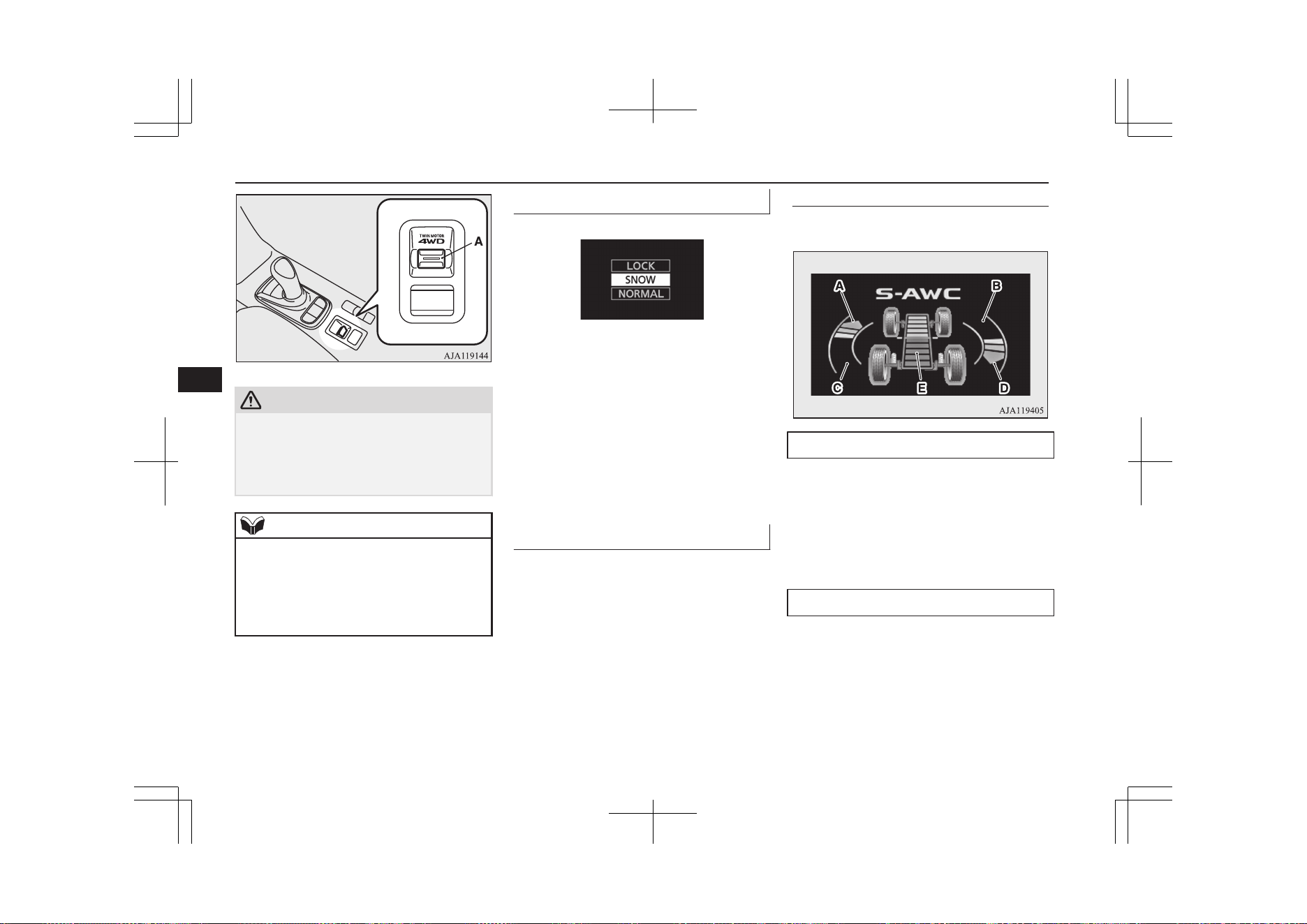
CAUTION
l
Use tyres of the same specified size, same
type, same brand and with no wear differ-
ence. If tyres of a different size, type, brand
or degree of wear are used, a warning of EV
system abnormality may be displayed.
NOTE
l
Even if the S-AWC drive mode is selected,
after turning the operation mode of the pow-
er switch OFF and turning to ON again, the
S-AWC drive mode is set to “NORMAL”.
l
The drive mode can be switched while driv-
ing or stopped.
S-AWC drive mode display
E00653300022
Example: “SNOW” mode is selected.
The currently selected drive mode is dis-
played on the multi-information display.
In addition, when the drive mode is changed,
the selected mode appears on the interrupt
display screen of the information screen in
the multi-information display.
The drive mode display will appear on the in-
formation screen for a few seconds, and then
the original screen will return.
S-AWC operation display
E00623101347
The S-AWC operation status can be dis-
played on the information screen in the multi-
information display.
To display the status, press the multi-infor-
mation display switch to change the informa-
tion screen.
Refer to “Information screen (when the oper-
ation mode is ON)” on page 6-09.
Display example
The S-AWC operation status is displayed.
Yaw control function display
The amount of the yaw moment is displayed
as a bar graph.
A,D- Clockwise yaw moment about the
vehicle’s center of gravity
B,C- Anticlockwise yaw moment about
the vehicle’s center of gravity
Torque distribution function display
The torque distribution between the front and
rear wheels is displayed in section E of the
meter as a bar graph.
If the red line is on the front, the torque of the
front motor will be high. If it is behind it, the
torque of the rear motor will be high.
S-AWC (Super All Wheel Control)
7-22
OGGE19E1
Starting and driving
7
WARNING
l
Always concentrate on your driving first.
Keep your eyes and mind on the road.
Distractions while driving can lead to an
accident.
4-wheel drive operation
E00606602605
Your vehicle has been designed primarily for
use on paved roads.
But its unique 4-wheel drive system allows
you to occasionally travel on unpaved roads,
to campgrounds, picnic sites, and similar lo-
cations.
Not only does this ensure better handling on
dry, paved roads but also permits better trac-
tion when driving on slippery, wet or snow-
covered roads and when moving out of mud.
But it is not suitable for heavy off road use or
towing in rough conditions.
It is particularly important to note that 4-
wheel drive may not give sufficient hill
climbing ability with the regenerative brake
on steep slopes. You should try to avoid driv-
ing on steep slopes.
Also, you must exercise caution when driving
on sand and mud and when driving through
water because sufficient traction may not be
available in certain circumstances.
Please avoid driving the vehicle through
areas where the tyres may get stuck in deep
sand or mud.
WARNING
l
Do not over-rely on the 4-wheel drive ve-
hicles. Even 4-wheel drive vehicles have
limits to the system and ability to main-
tain control and traction. Reckless driving
may lead to accidents. Always drive care-
fully, taking account of the road condi-
tions.
l
Improperly operating this vehicle on or
off-paved roads can cause an accident or
rollover in which you and your passengers
could be seriously injured or killed.
•
Follow all instructions and guidelines in
the owner’s manual.
•
Keep your speed low and do not drive
faster than conditions allow you to.
NOTE
l
Driving on rough roads can be hard on a ve-
hicle. Before you leave paved roads, be sure
all scheduled maintenance and service has
been done, and that you have inspected your
vehicle. Pay special attention to the condi-
tion of the tyres, and check the tyre pres-
sures.
NOTE
l
MITSUBISHI MOTORS is not responsible
for any damage or injury caused or liability
incurred by improper and negligent opera-
tion of a vehicle by the operator. All techni-
ques of vehicle operation depend on the skill
and experience of the operator and other par-
ticipating parties. Any deviation from the
recommended operating instructions above
is at their own risk.
l
Note that the stopping distance required of a
4-wheel drive vehicle differs very little from
that of a 2-wheel drive vehicle. When driv-
ing on a snow-covered road or a slippery,
muddy surface, make sure that you keep a
sufficient distance between your vehicle and
the one ahead of you.
l
The driving posture should be more upright;
adjust the seat to a good position for easy
steering and pedal operation. Be sure to wear
the seat belt.
l
After driving on rough roads, check each
part of the vehicle and wash it thoroughly
with water. Refer to the “Inspection and
maintenance following rough road opera-
tion” section and “Maintenance” section.
4-wheel drive operation
7-23
OGGE19E1
Starting and driving
7
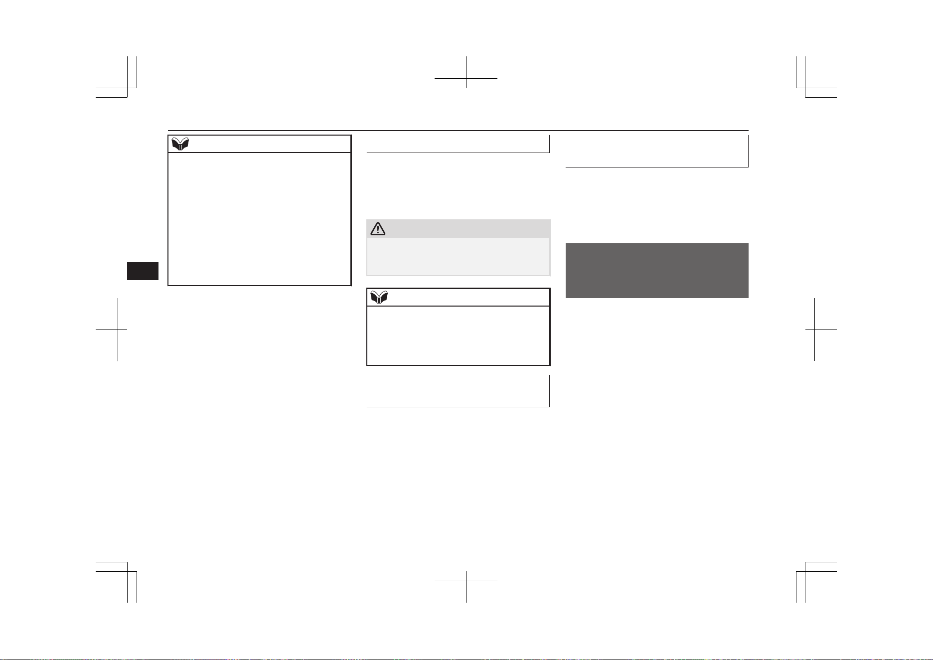
NOTE
l
When moving out of mud, sand or fresh
snow, pressing the accelerator pedal may not
allow the Plug-in Hybrid EV system output
to increase. In such situations, switching to
“LOCK” with the S-AWC drive mode
switch and temporarily turning off the Ac-
tive Stability Control (ASC) with the “ASC
OFF” switch will make it easier to move out
your vehicle.
Refer to “Operation under adverse driving
conditions: If your vehicle becomes stuck in
sand, mud or snow” on page 9-21.
On snowy or icy roads
Set the drive mode to “SNOW” in accord-
ance with the road conditions, and then grad-
ually depress the accelerator pedal for a
smooth start.
CAUTION
l
Avoid sudden braking, sudden acceleration
and sharp turning. Skidding occurs and con-
trol of the vehicle could be lost.
NOTE
l
The use of snow tyres and/or snow traction
device (tyre chains) is recommended.
l
Maintain a safe distance between vehicles,
avoid sudden braking, and use regenerative
braking.
Driving on sandy or rough
roads
Set the drive mode to “LOCK” and then
gradually depress the accelerator pedal for a
smooth start. Keep the pressure on the accel-
erator pedal as constant as possible, and drive
at low speed.
Climbing/descending sharp
grades
Your vehicle may not provide sufficient hill
climbing ability and regenerative brake on
steep slope. Avoid driving on steep slopes
even though the vehicle is a 4-wheel drive
vehicle.
Inspection and maintenance
following rough road
operation
E00606701407
After operating the vehicle in rough road
conditions, be sure to perform the following
inspection and maintenance procedures:
l
Check that the vehicle has not been dam-
aged by rocks, gravel, etc.
l
Carefully wash the vehicle with water.
Drive the vehicle slowly while lightly
depressing the brake pedal in order to
dry out the brakes. If the brakes still do
not function properly, we recommend
you to have the brakes checked as soon
as possible.
l
Remove the insects, dried grass, etc.
clogging the radiator core.
l
Check the inside of the vehicle. If water
entry is found, dry the carpet etc.
Inspection and maintenance following rough road operation
7-24
OGGE19E1
Starting and driving
7
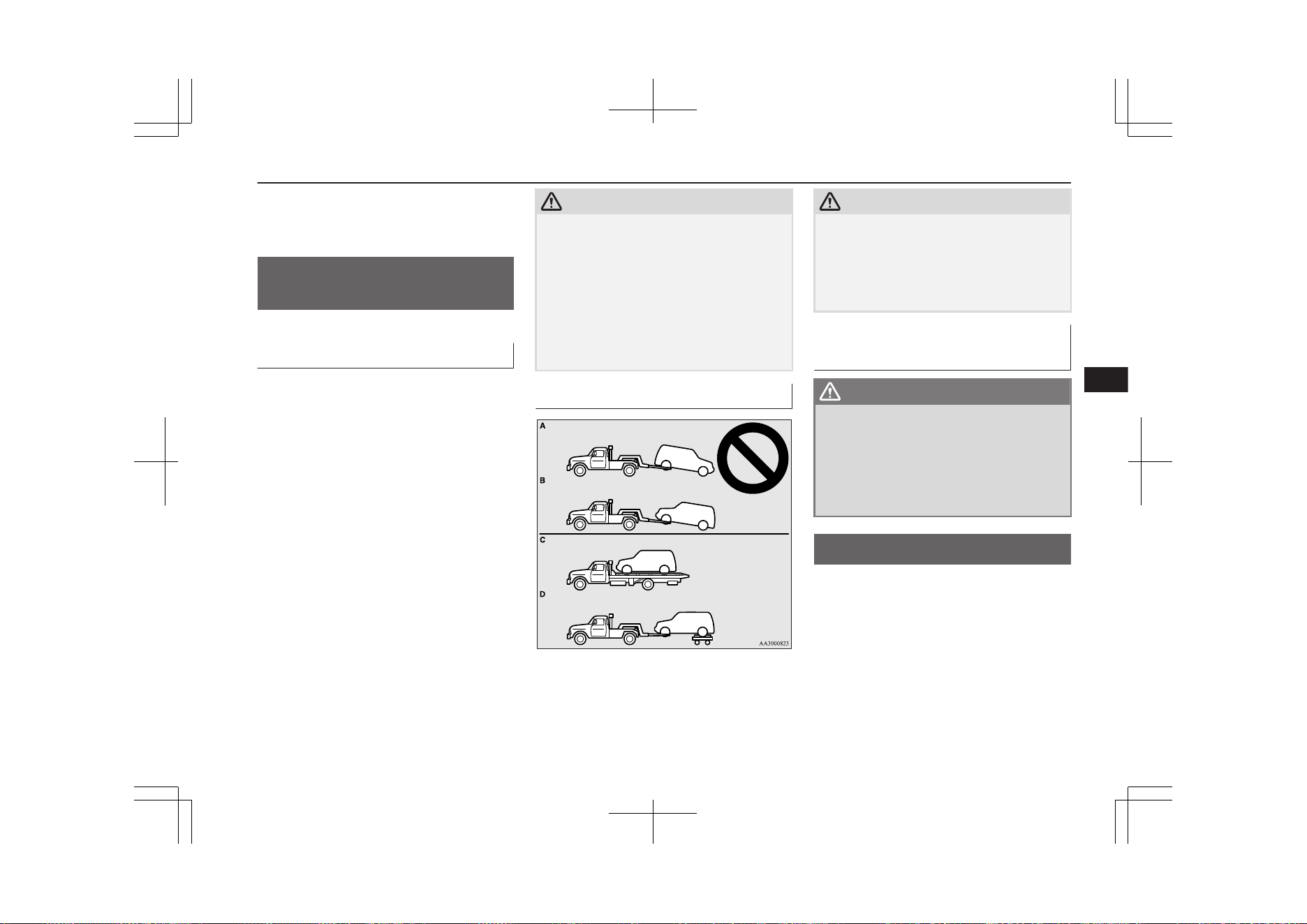
l
Inspect the headlamps. If the headlamp
bulb is flooded with water, we recom-
mend you to have it drained.
Cautions on handling of 4-
wheel drive vehicles
E00606801844
Tyres and wheels
Since the driving torque can be applied to the
4 wheels, the driving performance of the ve-
hicle when operating in 4-wheel drive is
greatly affected by the condition of the tyres.
Pay close attention to the tyres.
l
Install only the specified tyres on all
wheels. Refer to “Tyres and wheels” on
page 12-09.
l
Be sure all 4 tyres and wheels are the
same size and type.
When it is necessary to replace any of
the tyres or wheels, replace all 4 tyres.
l
All tyres should be rotated before the
wear difference between the front and
rear tyres is recognizable.
Good vehicle performance cannot be expec-
ted if there is a difference in wear between
tyres. Refer to “Tyre rotation” on page 11-12.
l
Check the tyre inflation pressure regular-
ly.
CAUTION
l
Always use tyres of the same size, same
type, and same brand, and which have no
wear differences. Using tyres of different
size, type, brands or degree of wear, will in-
crease the differential oil temperature, result-
ing in possible damage to the driving sys-
tem. Further, the drive train will be subjected
to excessive loading possibly leading to oil
leakage, component seizure, or other serious
faults.
Towing
CAUTION
l
Do not tow 4-wheel drive vehicles with the
front or rear wheels on the ground (Type A
or Type B) as illustrated. This could result in
damage to the drivetrain, or unstable towing.
If you tow 4-wheel drive vehicles, use Type
C or Type D equipment.
Jacking up a 4-wheel drive ve-
hicle
WARNING
l
Do not turn on the Plug-in Hybrid EV
System or turn a jacked-up wheel when
the vehicle is jacked up. The tyre in con-
tact with the ground may turn and the ve-
hicle may come off the jack, possibly lead-
ing to an accident. Besides, do not touch
the high-voltage area.
EV switch
E00653000087
To drive the vehicle without starting the en-
gine as much as possible, the EV priority
mode can be used.
This mode helps to drive the vehicle at a
place needed for concern of noises and ex-
haust gas emissions, such as residential areas
etc.
Cautions on handling of 4-wheel drive vehicles
7-25
OGGE19E1
Starting and driving
7
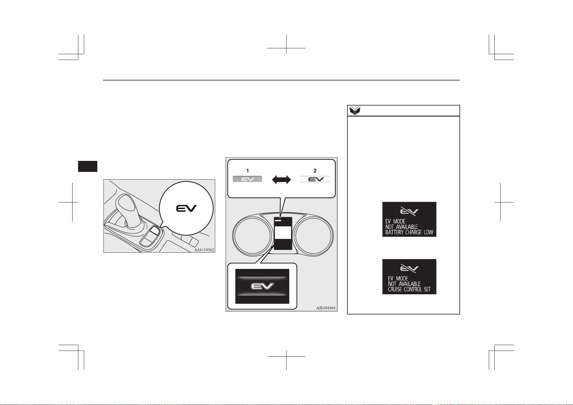
To switch to the EV priority mode, press the
EV switch with operation mode of the power
switch in ON.
If the EV switch is pressed, you can drive the
vehicle by using only the EV drive mode as
much as possible, even if the accelerator ped-
al is roughly depressed.
To cancel the EV priority mode, press the EV
switch again.
When the operation mode of the power
switch is put in OFF, the EV priority mode
will be cancelled.
When switching to the EV priority mode, on
the information screen in the multi informa-
tion display, a screen showing the EV priority
mode is displayed. The EV priority mode in-
dication on the upper left of the screen also
indicates the engine operating state. When
the engine is not running, it is displayed in
blue, and when the engine is running, it is
displayed in gray.
1: Engine is not running (blue)
2: Engine is running (gray)
NOTE
l
While driving the vehicle in the EV priority
mode, if the engine automatically starts
while the vehicle is accelerating, the vehicle
may accelerate more quickly.
l
In the following conditions, the EV priority
mode cannot be used even if the EV switch
is pressed, a buzzer will sound and the mes-
sage will appear in the multi information
display.
•
When the remaining power in the drive
battery is low.
Charge the drive battery.
•
When the cruise control or the adaptive
cruise control system (ACC) is operating.
If you want to use the EV priority mode,
cancel the cruise control or the ACC.
EV switch
7-26
OGGE19E1
Starting and driving
7
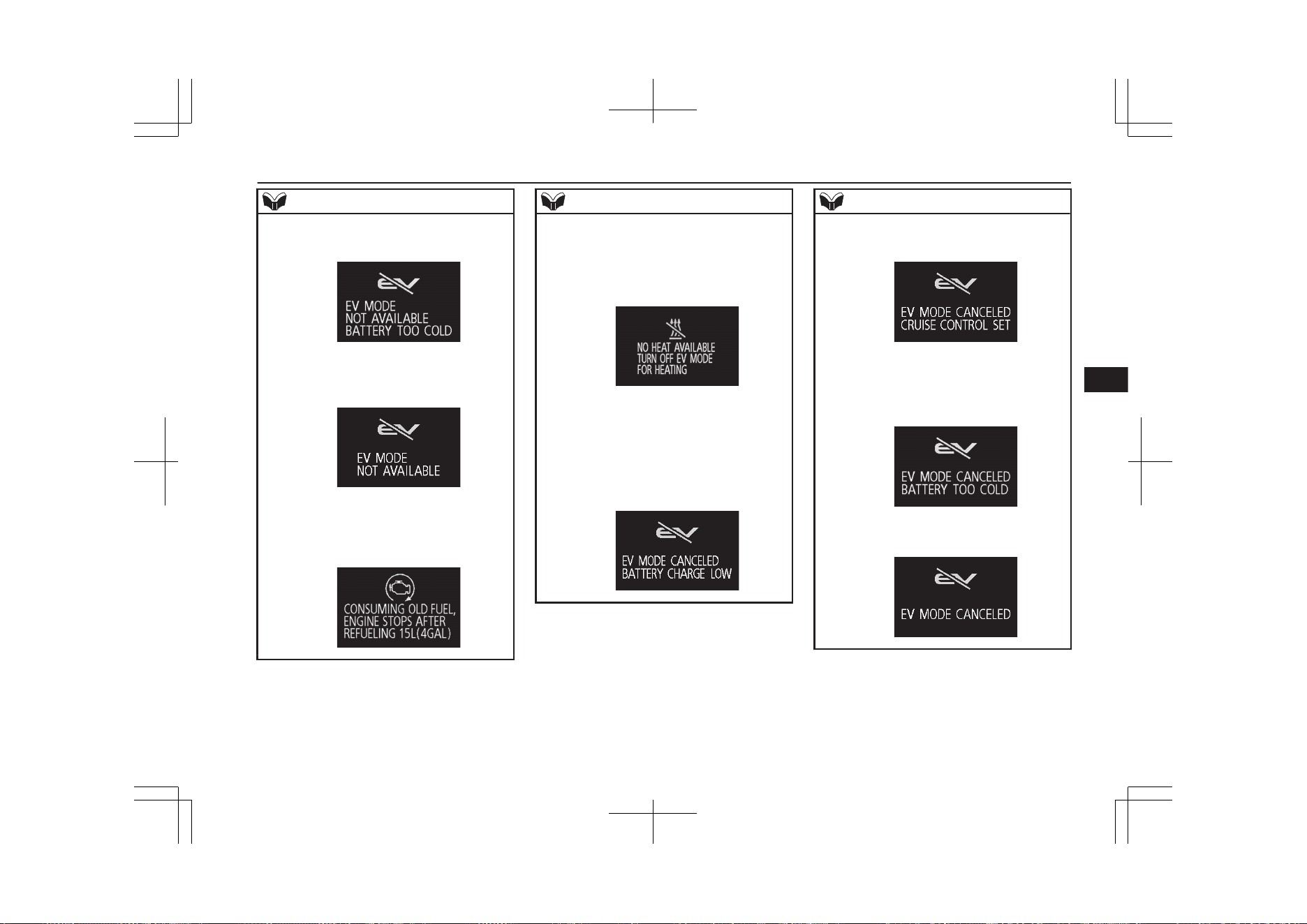
NOTE
•
When the drive battery temperature is too
cold.
•
When using the EV priority mode is limi-
ted to protect the Plug-in Hybrid EV Sys-
tem.
l
While the following message is displayed in
the multi information display, the EV priori-
ty mode cannot be used even if the EV
switch is pressed, a buzzer will sound.
NOTE
l
If you select warm air with the air condition-
er switch during driving in the EV priority
mode, the message will appear in the multi
information display. (except for vehicles
with electric heater)
l
In any of the situations listed below, the EV
priority mode will be automatically cancel-
led and the message will appear in the multi
information display.
•
When the remaining power in the drive
battery becomes low.
Charge the drive battery.
NOTE
•
When the vehicle speed of the cruise con-
trol or the ACC is set.
If you want to use the EV priority mode,
cancel the cruise control or the ACC.
•
When the drive battery temperature be-
comes too cold.
•
When the protecting device of the Plug-in
Hybrid EV System is operated.
EV switch
7-27
OGGE19E1
Starting and driving
7
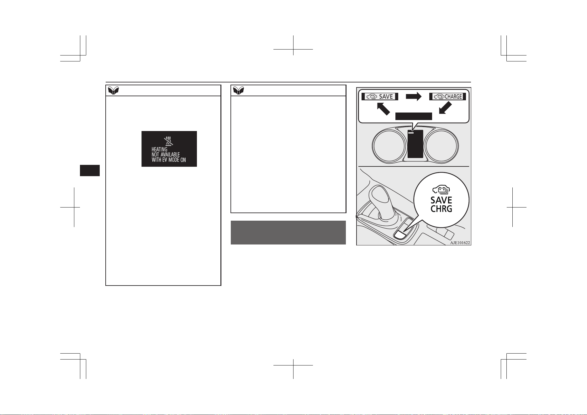
NOTE
l
If the EV switch is pressed during the heat-
ing of the air conditioner, the message will
appear in the multi information display. (ex-
cept for vehicles with electric heater)
l
When the SAVE/CHARGE mode switch or
the SPORT mode switch is pressed while
driving in the EV priority mode, the mode
changes to the selected mode.
If the EV switch is pressed, the mode is re-
turned to the EV priority mode.
However, the mode may not return to the EV
priority mode depending on the remaining
power in the drive battery.
l
In any of the situations listed below, the EV
priority mode continues even if the engine is
automatically started.
•
When the accelerator pedal is fully de-
pressed.
•
When the vehicle speed is over 130 km/h
(80 mph).
•
When the demister switch is pressed.
NOTE
l
If the ambient temperature is low, the engine
may start for heating when the Plug-in Hy-
brid EV system is started with air condition-
er performed.
If you want to stop the engine running, se-
lect the EV priority mode with the operation
mode of the power switch in ON before
starting the Plug-in Hybrid EV system.
l
In the EV priority mode, the accelerator ped-
al response may be negative even if the ac-
celerator pedal is depressed or released.
l
The motor output in the EV priority mode
may decrease due to the deteriorated drive
battery or the ambient temperature falls. In
such a case, start the engine by cancelling
the EV priority mode to secure the motor
output.
SAVE/CHARGE mode
switch
E00653600025
If you press the switch with the operation
mode of the power switch in ON, you can
change the drive battery mode in the order of
SAVE, CHARGE, OFF, SAVE.
SAVE/CHARGE mode switch
7-28
OGGE19E1
Starting and driving
7
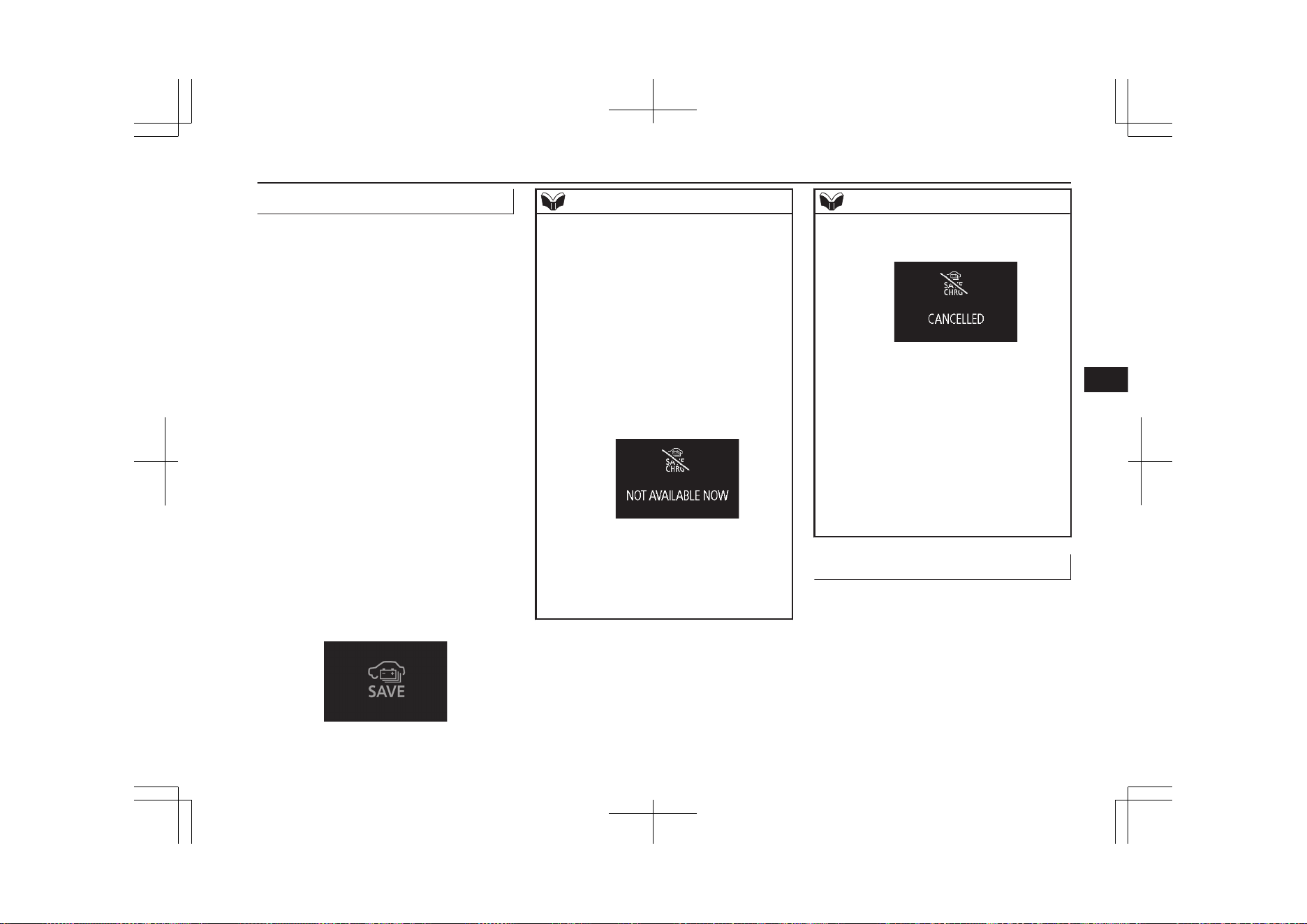
Battery save mode
E00653700026
To save the remaining power in the drive bat-
tery while driving, the battery save mode can
be used. This mode helps preserve the electri-
cal power in the drive battery for later use,
such as in a residential area, or to use at your
destination. The battery save mode can also
be used to reduce electric power consumption
from the drive battery during high-speed
driving.
When the battery save mode is activated, the
engine will start in order to preserve the re-
maining power of the drive battery and the
vehicle will operate in the series hybrid mode
or the parallel hybrid mode depending on the
remaining power in the drive battery.
To cancel the battery save mode, press the
SAVE/CHARGE mode switch twice.
When the operation mode of the power
switch is put in OFF, the battery save mode
will be cancelled.
If the battery save mode is activated, the fol-
lowing image is displayed on the information
screen in the multi-information display.
NOTE
l
The engine may stop when the vehicle stops
or is running.
l
Even if the battery save mode is selected, the
engine may not start depending on the con-
dition of the remaining drive battery capaci-
ty or the Plug-in Hybrid EV system control.
l
In the following conditions, the battery save
mode cannot be used even if the battery save
mode is selected, a buzzer will sound and
the message will appear in the multi-infor-
mation display.
•
When the engine coolant temperature is
high.
•
When the remaining fuel quantity is low.
l
In any of the situations listed below, the bat-
tery save mode will be automatically cancel-
led and the message will appear in the multi-
information display.
•
When the engine coolant temperature be-
comes high.
NOTE
•
When the remaining fuel quantity be-
comes low.
l
When one of the following switches is press-
ed while driving in the battery save mode,
the mode changes to the selected mode.
•
SAVE/CHARGE mode switch
•
EV switch
•
SPORT mode switch
Refer to “Battery charge mode” on page
7-29, “EV switch” on page 7-25 or
“SPORT mode switch” on page 7-31.
If the SAVE/CHARGE mode switch is
pressed once, the mode is returned to the
battery save mode.
Battery charge mode
E00653800027
To charge the drive battery while driving, the
battery charge mode can be used. It is recom-
mended to use this mode before driving up
long hills or mountain roads.
When the battery charge mode is activated,
the engine will start to charge the drive bat-
tery to nearly full.
To cancel the battery charge mode, press the
SAVE/CHARGE mode switch once.
SAVE/CHARGE mode switch
7-29
OGGE19E1
Starting and driving
7
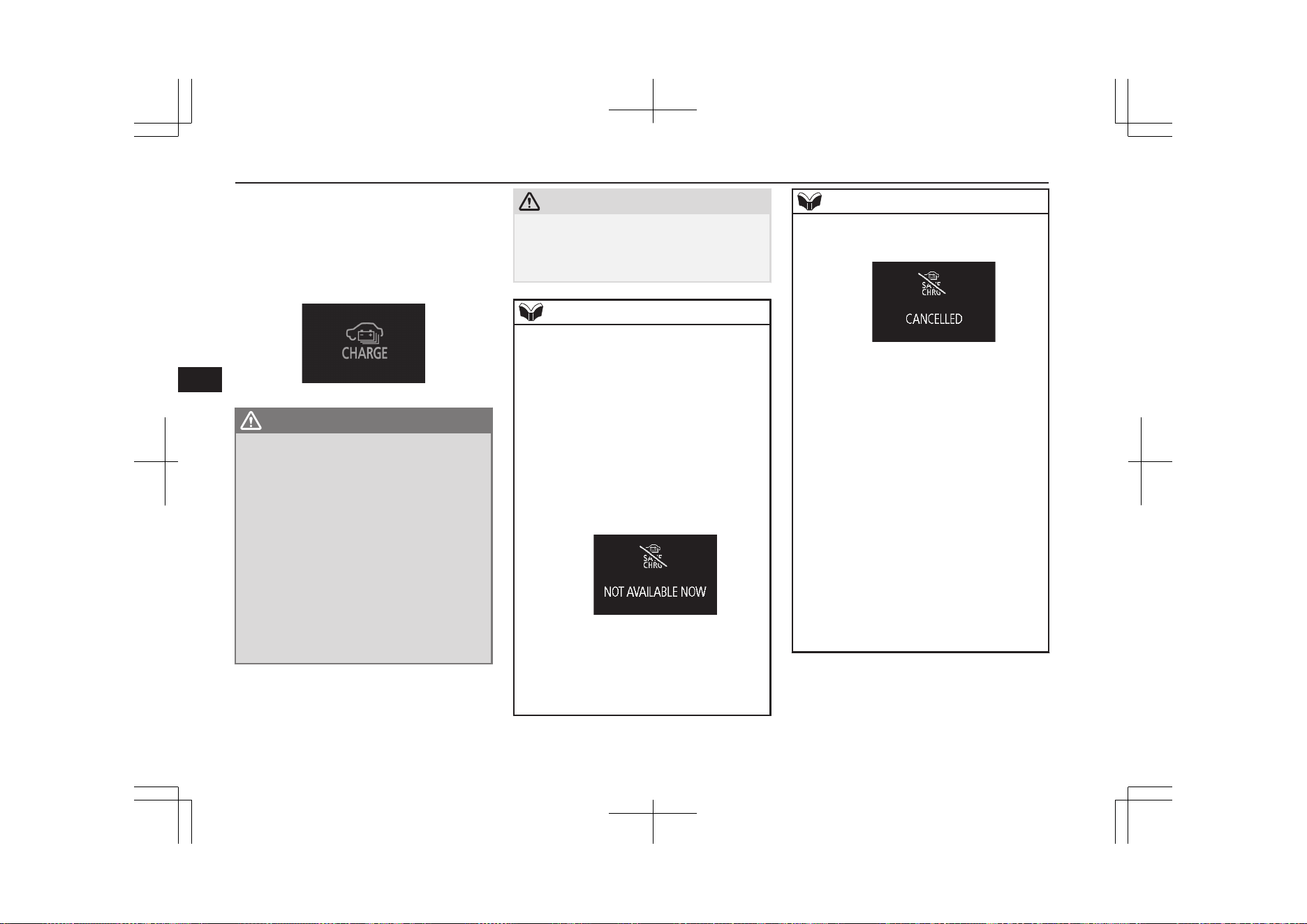
When the operation mode of the power
switch is put in OFF, the battery charge mode
will be cancelled.
If the battery charge mode is activated, the
following image is displayed on the informa-
tion screen in the multi-information display.
WARNING
l
When you leave the vehicle, be sure to
stopped the Plug-in Hybrid EV System.
Refer to “Parking” on page 7-06
l
Only use the battery charge mode in a
well ventilated space.
The engine will start when the vehicle is in
the battery charge mode, and this can
cause carbon monoxide to build up caus-
ing carbon monoxide poisoning. Be sure
to use at the well-ventilated place.
l
Do not use the battery charge mode near
flammable objects such as dried grass or
paper etc. There is a possibility of starting
a fire due to the high exhaust pipe temper-
ature.
CAUTION
l
While the battery charge mode is activated,
do not cover the front of the vehicle with
anything including a car cover. Doing so
could cause the engine to overheat.
NOTE
l
Even if the battery charge mode is selected,
the engine may not start depending on the
condition of the remaining drive battery ca-
pacity or the Plug-in Hybrid EV system con-
trol.
l
In the following conditions, the battery
charge mode cannot be used even if the bat-
tery charge mode is selected, a buzzer will
sound and the message will appear in the
multi-information display.
•
When the engine coolant temperature is
high.
•
When the remaining fuel quantity is low.
l
In any of the situations listed below, the bat-
tery charge mode will be automatically can-
celled and the message will appear in the
multi-information display.
•
When the engine coolant temperature be-
comes high.
NOTE
•
When the remaining fuel quantity be-
comes low.
l
It is recommended to use the battery charge
mode at least 20 minutes before you climb,
in order to continue a speed of more than
100 km/h (62 mph), or when a long slope
(gradient of more than 4 %) is expected.
(According to a towing weight, it may not be
able to continue the speed.)
l
When using the battery charge mode with a
vehicle that has stopped in the heath a long
time, it may not charge.
l
The charging time close to full charge of the
drive battery becomes longer depending on
the condition of the drive battery, a driving
condition or a environment.
l
The engine may stop near full charge.
l
If you use the battery charge mode, in order
to generate electricity using gasoline, the
fuel consumption will suffer.
We recommend you to consider the environ-
ment.
SAVE/CHARGE mode switch
7-30
OGGE19E1
Starting and driving
7
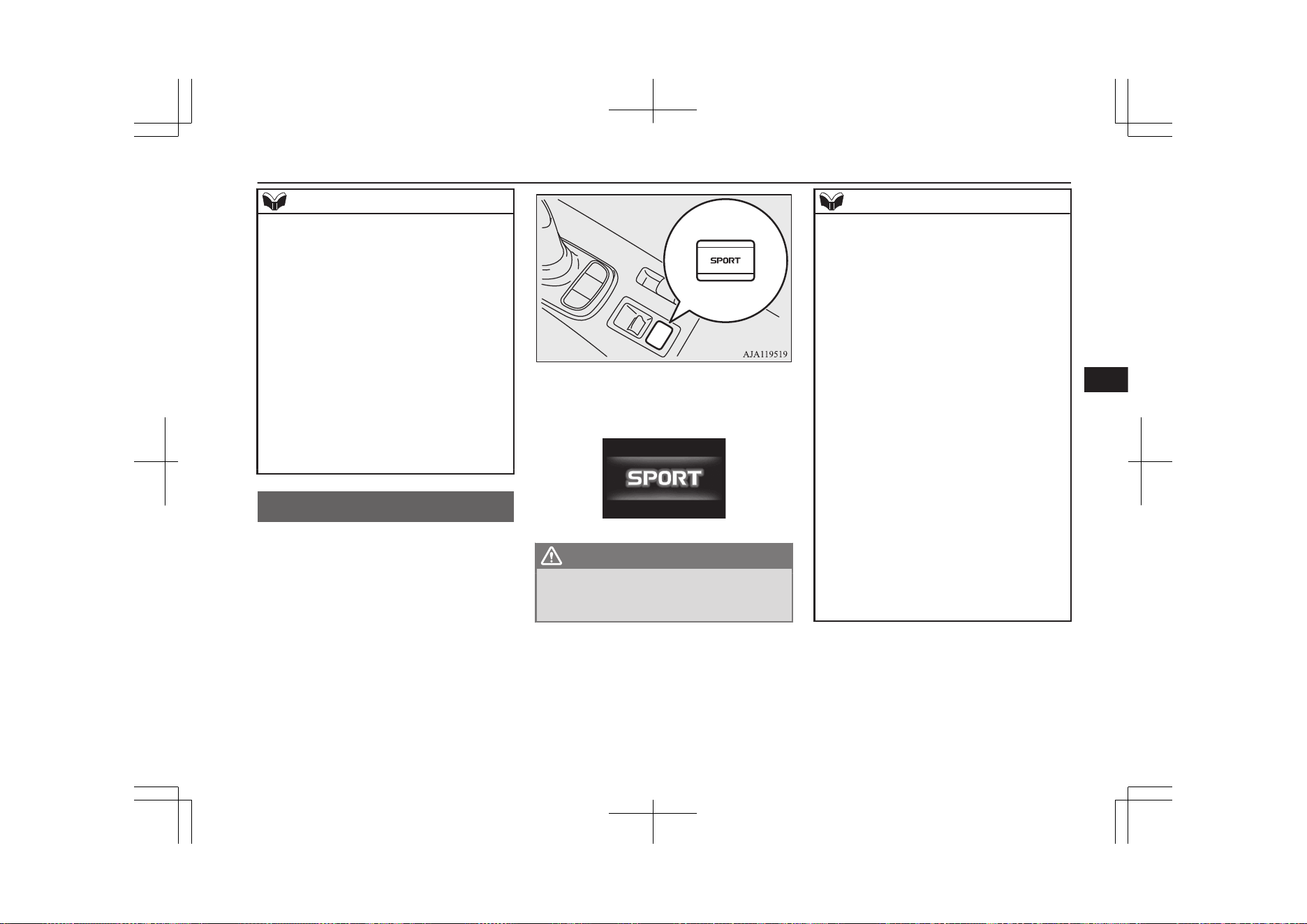
NOTE
l
When the engine is started while parking,
there is a risk of receiving a penalty due to
idling stop ordinances.
You should use the battery charge mode that
conforms to the relevant municipality.
Also, if the engine is started, ensure there is
sufficient fuel in the fuel tank so that the en-
gine does not run out of fuel.
l
When the EV switch or the SPORT mode
switch is pressed while driving in the battery
charge mode, the mode changes to the selec-
ted mode.
Refer to “EV switch” on page 7-25 or
“SPORT mode switch” on page 7-31.
If the SAVE/CHARGE mode switch is
pressed twice, the mode is returned to the
battery charge mode.
SPORT mode switch
E00653900028
The SPORT mode switch is used when doing
powerful sporty driving on mountain roads
and uphill slopes.
Quick acceleration in response to the opera-
tion of the accelerator pedal and quick decel-
eration by strong regenerative braking force
are possible.
The SPORT mode can be used when the
SPORT mode switch is pressed while the
READY indicator light is on.
To cancel, press the switch again or turn off
the power mode.
If the SPORT mode is activated, the follow-
ing display appears on the information screen
in the multi-information display.
WARNING
l
If a large regenerative braking force is ap-
plied, the stop lamps will be automatically
illuminated.
NOTE
l
Selecting the SPORT mode makes the en-
gine easier to start. Also, since the response
to the operation of the accelerator pedal be-
comes better, there may be a shock when
stepping on the accelerator pedal.
l
When SPORT mode is selected, the regener-
ative braking force automatically switches to
B5. After switching, you can change to your
favorite regenerative braking force with the
Regenerative braking level selector. Regen-
erative braking level selector (paddle type)
® p. 7-19
l
When you select the SPORT mode in situa-
tions such as the following, a large regenera-
tive braking force may not work.
•
When the driving battery temperature is
high or low.
•
When the driving battery is close to fully
charged, or when it is fully charged.
l
If you select the cruise control or the Adap-
tive Cruise Control System (ACC), the re-
generative braking level will be D while
driving in the SPORT mode.
The regenerative brake force becomes B5
when the SPORT mode is returned by can-
celling the cruise control or the Adaptive
Cruise Control System (ACC).
SPORT mode switch
7-31
OGGE19E1
Starting and driving
7
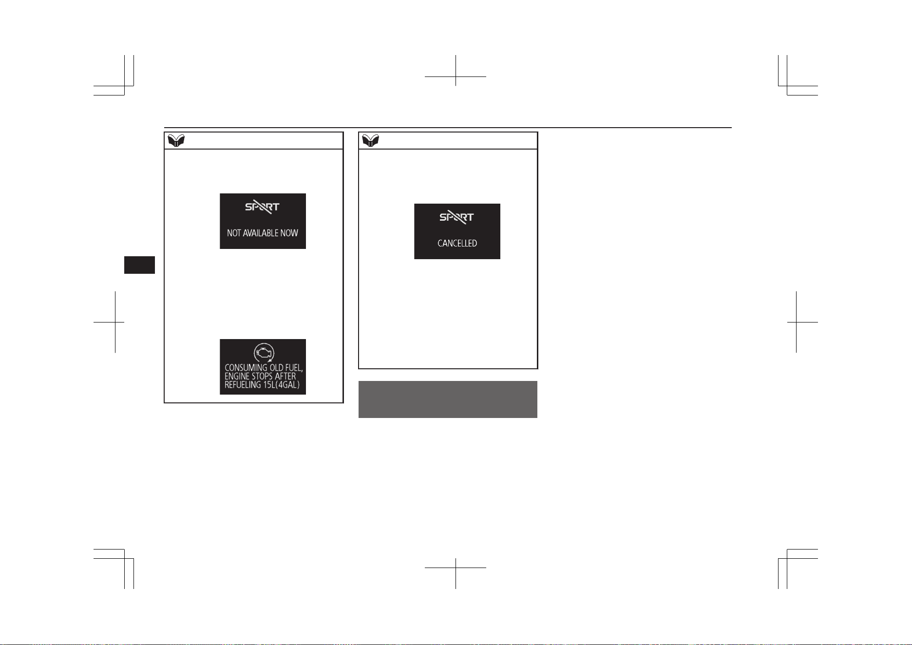
NOTE
l
When the remaining amount of fuel is small,
the SPORT mode cannot be used even if the
SPORT mode switch is pressed.
If you want to use the SPORT mode, refuel
the vehicle.
l
While the following message is displayed in
the multi-information display, the SPORT
mode cannot be used even if the SPORT
mode switch is pressed and a buzzer will
sound.
NOTE
l
When the remaining amount of fuel becomes
little, the SPORT mode will be automatically
cancelled and the message will appear in the
multi-information display.
If you want to use the SPORT mode, refuel
the vehicle.
l
When the following switch is turned on
while driving in the SPORT mode, the mode
changes to the selected mode.
•
EV switch
•
SAVE/CHARGE mode switch
•
Drive mode switch
•
ECO mode switch
Acoustic Vehicle Alerting
System (AVAS)
E00631601107
The Acoustic Vehicle Alerting System
(AVAS) is a device that uses sound to alert
pedestrians of the presence of the vehicle.
The system operates when the vehicle speed
is approximately 35 km/h (22 mph) or less
and the engine is not running.
The sound starts when the AVAS is operated
in the following conditions.
l
When the vehicle speed is approximately
3 km/h (2 mph) or less with engine not
running and the brake pedal is not de-
pressed.
l
When the vehicle speed is approximately
3 km/h (2 mph) to 35 km/h (22 mph) and
engine is not running.
The sound does not start in the following ca-
ses.
l
When the vehicle speed is approximately
3 km/h (2 mph) or less and the brake
pedal is depressed.
l
When the vehicle speed is approximately
35 km/h (22 mph) or more.
l
When the select position is in the “P”
(PARK) position.
l
When the AVAS OFF indicator in the
meter is illuminating.
l
When the engine is running.
Acoustic Vehicle Alerting System (AVAS)
7-32
OGGE19E1
Starting and driving
7
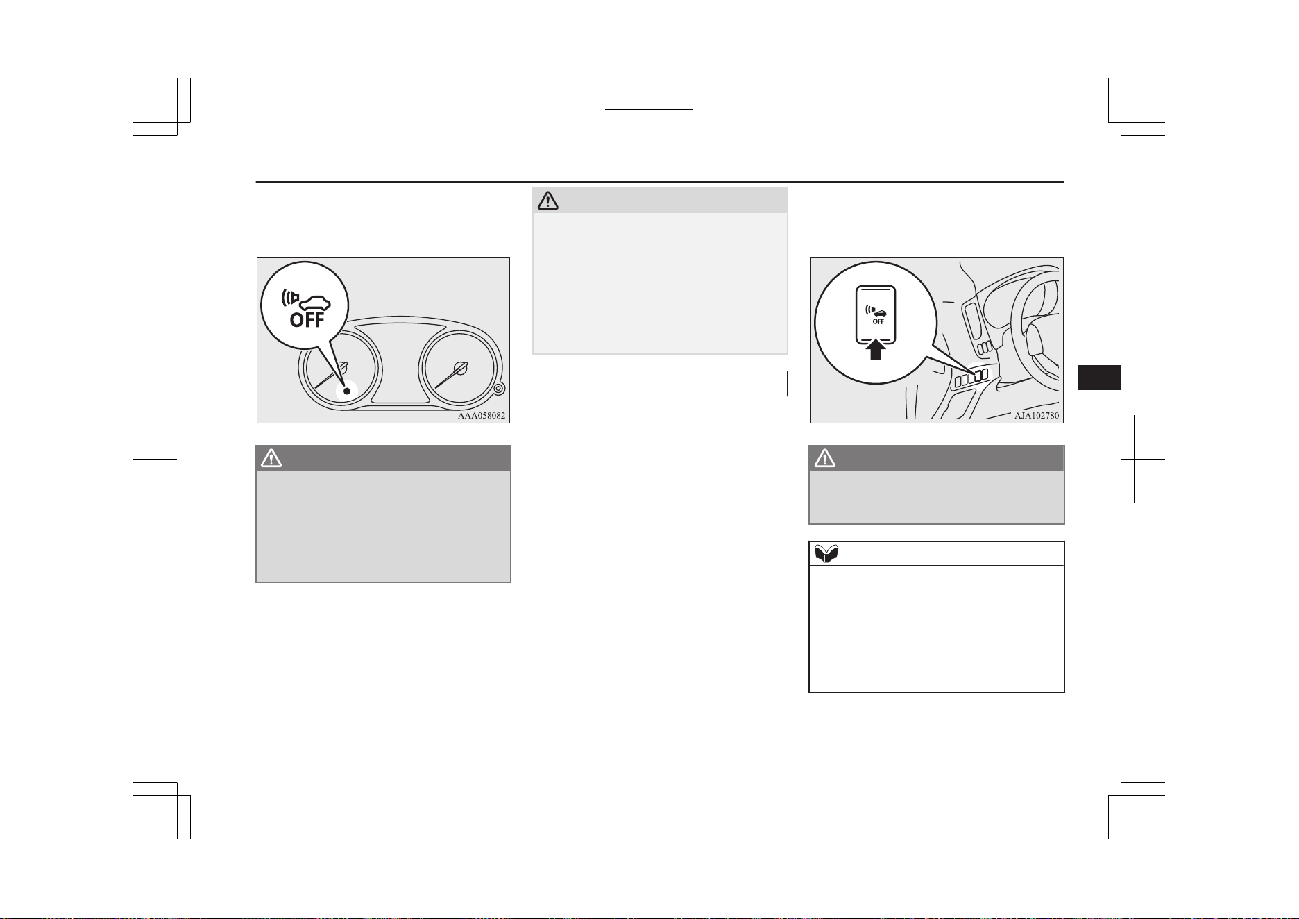
When the operation mode is set to “ON”, the
AVAS OFF indicator comes on and goes out
after a few seconds.
WARNING
l
Even if the Acoustic Vehicle Alerting Sys-
tem (AVAS) sounds, pay special attention
to pedestrians.
Pedestrians may not notice the oncoming
vehicle, which may cause an accident re-
sulting in serious personal injury or
death.
CAUTION
l
Always confirm the indication lamp goes off
before driving.
If the indication lamp blinks, the operation
mode is put in OFF, and the operation mode
is put in ON once again. It is normal if the
indication lamp goes off. If the indication
lamp blinks again, have the vehicle inspec-
ted at a MITSUBISHI MOTORS Authorized
Service Point as soon as possible.
AVAS OFF switch
E00631701094
If the operation mode is put in ON, the AVAS
is automatically turned on.
The AVAS should be turned on while normal
driving.
When driving on the freeway etc., it is possi-
ble to turn off the AVAS by pressing the
AVAS OFF switch.
When pressing the AVAS OFF switch, the au-
dible alarm does not sound and the AVAS
OFF indicator illuminates.
When pressing the AVAS OFF switch once
again, the AVAS is activated and the AVAS
OFF indicator goes off.
WARNING
l
Never turn the Acoustic Vehicle Alerting
System (AVAS) off if there is a possibility
that pedestrians pass by.
NOTE
l
If the operation mode is put in OFF, while
the AVAS has been turned off, and the oper-
ation mode is put in ON once again, the
AVAS is activated.
l
If the AVAS OFF switch is continuously
pressed after the AVAS is turned off, the in-
correct operation prevention function is trig-
gered and the system turns on again.
Acoustic Vehicle Alerting System (AVAS)
7-33
OGGE19E1
Starting and driving
7

Braking
E00607003241
All the parts of the brake system are critical
to safety. We recommend you to have the ve-
hicle checked at regular intervals according
to the service booklet.
CAUTION
l
Avoid driving habits that cause heavy brak-
ing and never “ride” the brakes by resting
your foot on the brake pedal while driving.
It causes brake overheating and fade.
Brake system
The service brake is divided into two brake
circuits. And your vehicle is equipped with
power brakes. If one brake circuit fails, the
other is available to stop the vehicle. If you
should lose the power assist for some reason,
the brakes will still work. In these situations,
even if the brake pedal moves down to the
very end of its possible stroke or resists being
depressed, keep depressing the brake pedal
down harder and further than usual; stop
driving as soon as possible and have the
brake system repaired.
WARNING
l
Do not turn off the Plug-in Hybrid EV
System while your vehicle is in motion. If
you turn off the Plug-in Hybrid EV Sys-
tem while driving, the power assistance
for the braking system will stop working
and your brakes will not work effectively.
l
If the power assist is lost or if either brake
hydraulic system stops working properly,
have your vehicle checked immediately.
Warning display
The brake warning lamp illuminates to indi-
cate a fault in the braking system. A warning
is also displayed on the multi information
display. Refer to “Brake warning lamp (red)”
on page 6-55 and “Brake warning display” on
page 6-58.
When brakes are wet
Check the brake system while driving at a
low speed immediately after starting, espe-
cially when the brakes are wet, to confirm
they work normally.
A film of water can be formed on the brake
discs and prevent normal braking after driv-
ing in heavy rain or through large puddles, or
after the vehicle is washed. If this occurs, dry
the brakes out by driving slowly while lightly
depressing the brake pedal.
When driving downhill
WARNING
l
Do not leave any objects near the brake
pedal or let a floor mat slide under it; do-
ing so could prevent the full pedal stroke
that would be necessary in an emergency.
Make sure that the pedal can be operated
freely at all times. Make sure that the
floor mat is securely held in place.
CAUTION
l
Put the selector lever to “B” position accord-
ing to the grade of a slope or the speed in a
long downward slope, and use the regenera-
tive brake together.
If you depress the brake pedal and slowing
down is repeated frequently, the foot brake
may be overheated and effectiveness may
worsen.
Braking
7-34
OGGE19E1
Starting and driving
7
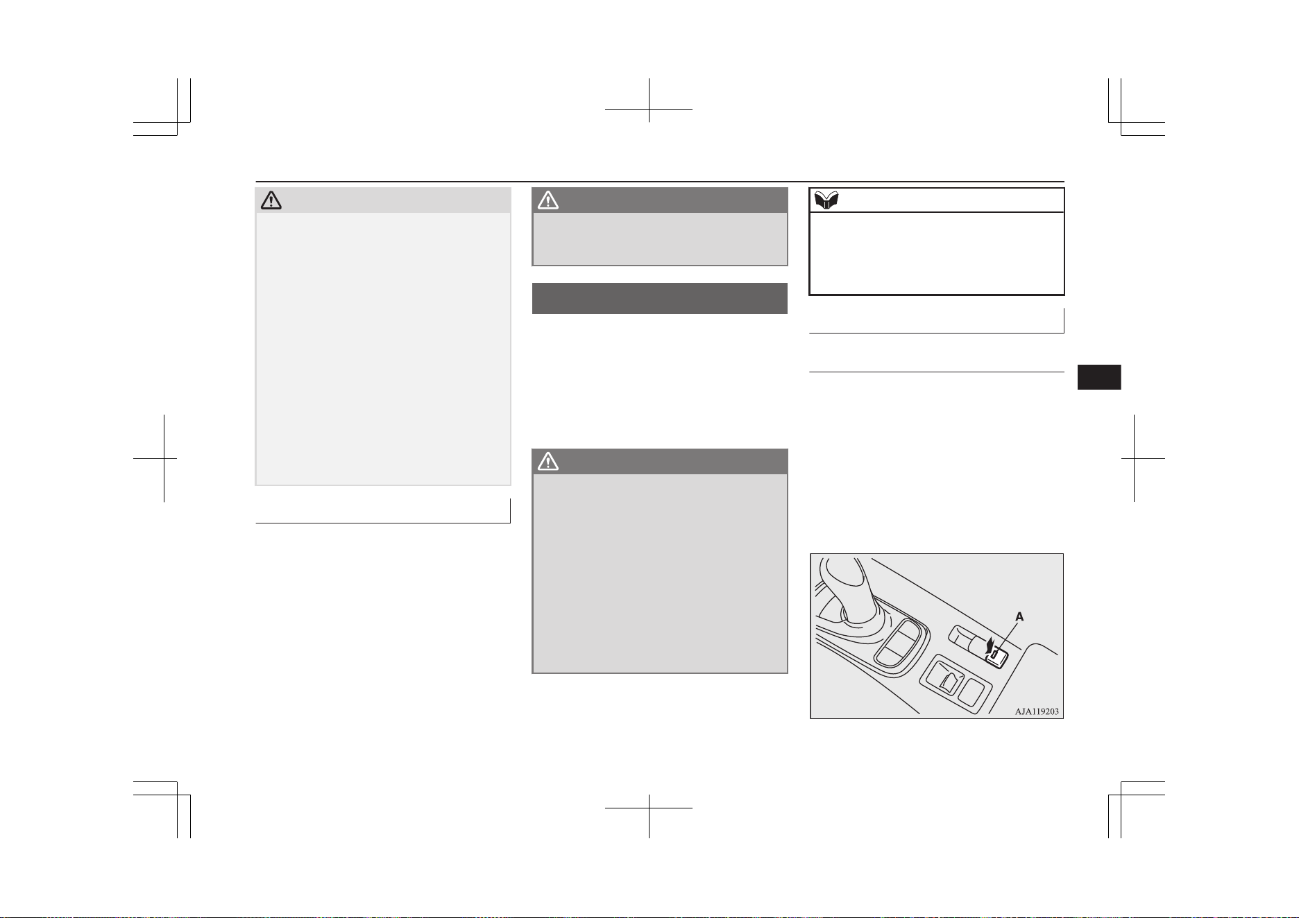
CAUTION
l
Effectiveness of the regenerative brake be-
comes weak when the drive battery is close
to full charge and loses its effect at the full
charge.
In this case, since the foot brake is effective,
use the foot brake and slow down your vehi-
cle speed beforehand.
The energy usage indicator stops swaying in
the charge zone closer to full charge.
Refer to “Energy usage indicator” on page
6-02
In such case, drive at low speed in advance.
And if needed use the foot brake to slow
down the vehicle speed before the vehicle
speed increases.
The regenerative brake comes to be effective
if the drive battery remaining power is con-
sumed.
Brake pad
l
Avoid hard braking situations.
New brakes need to be broken-in by
moderate use for the first 200 km
(124 miles).
l
The disc brakes are provided with a
warning device which emits a shrieking
metallic sound while braking if the brake
pads have reached their wear limit. If
you hear this sound, have the brake pads
replaced immediately.
WARNING
l
Driving with worn brake pads will make
it harder to stop, and can cause an acci-
dent.
Brake auto hold
E00652000136
When the vehicle is stopped at traffic signals
etc., the vehicle can be held stationary with
the brake auto hold system even if you re-
lease your foot from the brake pedal.
When the accelerator pedal is depressed, the
brakes are released.
WARNING
l
Do not overly rely on the brake auto hold
system. On a steep slope, depress the
brake pedal firmly because the system
may not hold the vehicle stationary.
l
Never leave the vehicle while it is being
stopped by the brake auto hold system.
When leaving the vehicle, apply the park-
ing brake and put the select position to
the “P” (PARK) position.
l
Do not use the brake auto hold system
when driving on slippery roads. The sys-
tem may not hold the vehicle stationary
and an accident could occur.
NOTE
l
While operating the brake auto hold system,
you may hear an operation noise to increase
braking force when the system detected the
movement of the vehicle. This does not indi-
cate a malfunction.
How to use brake auto hold
To turn on brake auto hold
If the brake auto hold switch is pressed while
all of the following conditions are met, the
system will change to the standby state and
the indication lamp (A) on the switch comes
on.
l
The operation mode of the power switch
is in the “ON” position.
l
The driver’s seat belt is fastened.
l
The driver’s door is closed.
Brake auto hold
7-35
OGGE19E1
Starting and driving
7
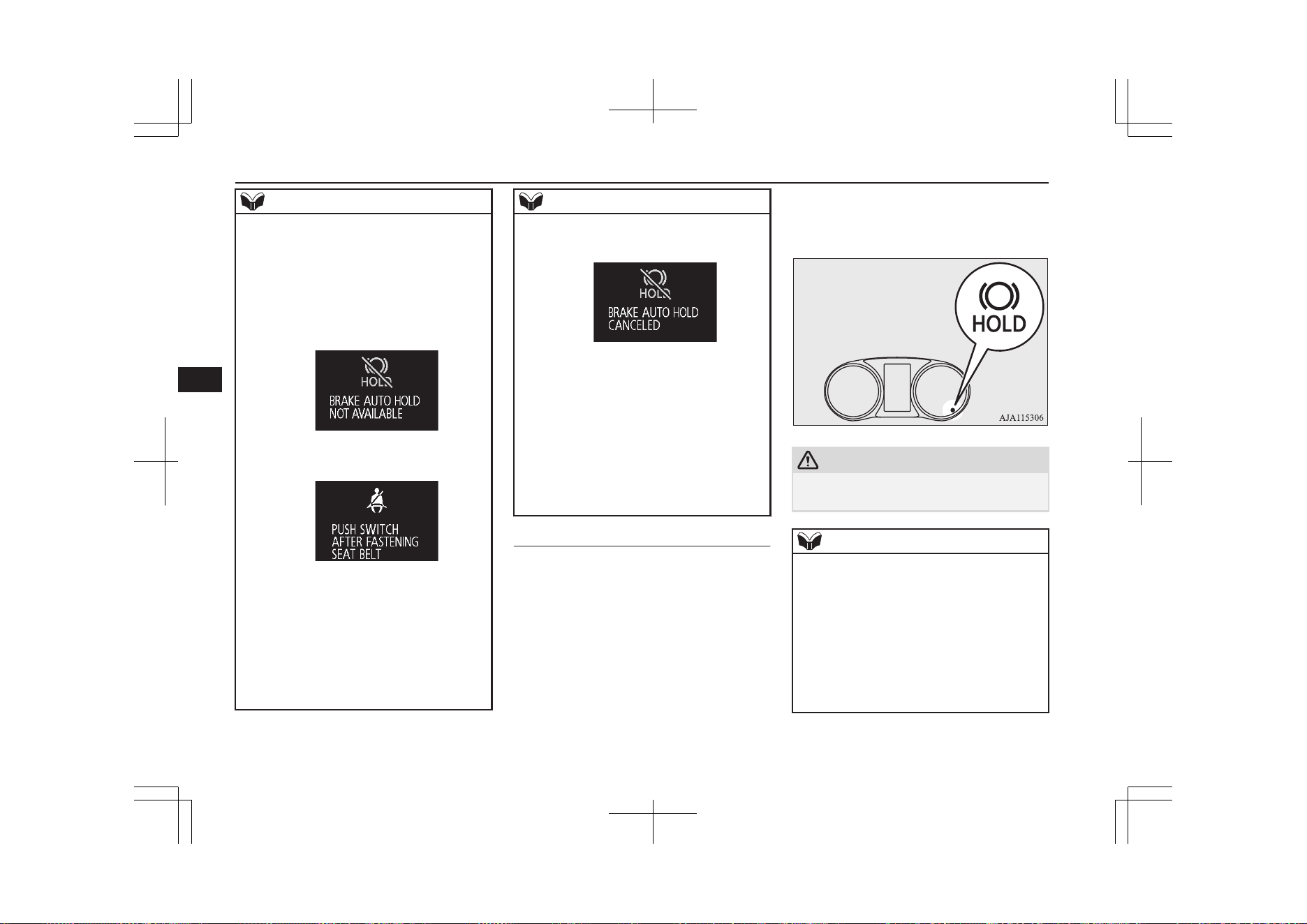
NOTE
l
When the brake auto hold system cannot be
used, a buzzer will sound and the following
warning will appear on the information
screen in the multi information display.
•
If this warning appears, confirm that all of
the conditions for system operation are
met and that there is no malfunction in the
system.
•
If this warning appears, fasten the driver’s
seat belt.
l
If any of the following occurs while the sys-
tem is standby state, the brake auto hold sys-
tem will be turned off automatically and the
indication lamp on the switch goes off.
A buzzer will sound and the message will
appear on the information screen in the multi
information display.
•
When the driver’s seat belt is unfastened.
•
When the driver’s door is opened.
NOTE
•
When there is a malfunction in the sys-
tem.
l
If you keep pressing the brake auto hold
switch after setting the brake auto hold to
ON (stand by), the brake auto hold will re-
turn to OFF as a protection function is oper-
ated.
After returning to OFF, the brake auto hold
will not be switched to ON (stand by) even
if the brake auto hold switch is pressed. To
set the brake auto hold to ON, restart the
Plug-in hybrid EV system and press the
brake auto hold switch again.
To activate brake auto hold
When the vehicle is stopped by depressing
the brake pedal with the select position in any
position other than “P” (PARK) or “R” (RE-
VERSE), the brake auto hold activates and
the vehicle will be held stationary.
The brake auto hold indication lamp in the
instrument cluster will come on while the
system activates.
CAUTION
l
Release the brake pedal after the brake auto
hold indication lamp is illuminated.
NOTE
l
In the following situations, the brake auto
hold system may not operate temporarily.
•
The vehicle is stopped on a slippery road.
•
The vehicle was stopped while the steer-
ing wheel was turned all the way to the
left or right.
•
The vehicle is being turned on a parking
lot turntable.
If this occurs, the brake auto hold system
will return to the normal operation if you de-
Brake auto hold
7-36
OGGE19E1
Starting and driving
7
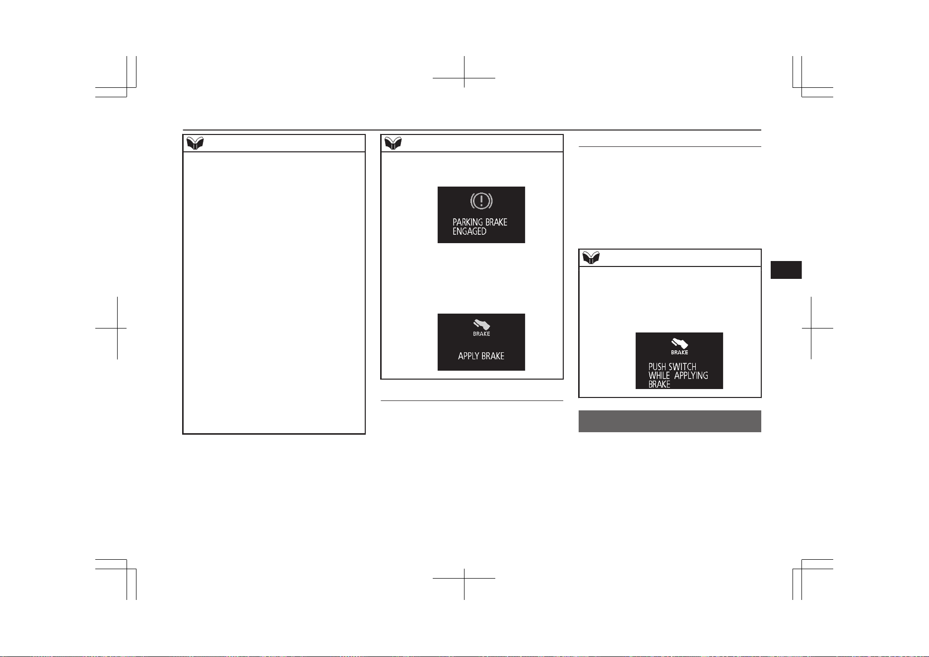
NOTE
press the accelerator pedal and the vehicle
starts moving again.
l
If the following operation is performed, the
brake auto hold will be deactivated and the
brake auto hold indication lamp in the in-
strument cluster goes off.
•
When putting the select position to the
“P” (PARK) or “R” (REVERSE) position
while depressing the brake pedal.
•
When the Electric parking brake is ap-
plied by using the Electric parking brake
switch.
l
While the vehicle is held stationary with the
brake auto hold system, the Electric parking
brake will be automatically applied under
the following conditions, and a buzzer will
sound and the message will appear on the in-
formation screen in the multi information
display.
•
After approximately 10 minutes have
elapsed while applying the brake auto
hold system.
•
When the driver’s seat belt is unfastened.
•
When the driver’s door is opened.
•
When the operation mode of the power
switch is put in OFF.
NOTE
•
When the system detects the vehicle slid-
ing down a slope.
If the Electric parking brake cannot be ap-
plied automatically due to the system mal-
function, the message will appear on the
information screen in the multi informa-
tion display. Depress the brake pedal.
To start the vehicle
Depress the acceleration pedal with the select
position in any position other than “P”
(PARK) or “N” (NEUTRAL).
The brakes are released, and the brake auto
hold indication lamp in the instrument cluster
will go off.
To turn off brake auto hold
Press the brake auto hold switch to turn brake
auto hold off. The indication lamp on the
switch goes off.
If you want to turn off the system while the
brake auto hold indication lamp is illumina-
ted, press the switch while depressing the
brake pedal.
NOTE
l
If the brake auto hold system is turned off
without the brake pedal being depressed, a
buzzer will sound and the message will ap-
pear on the information screen in the multi
information display.
Hill start assist
E00628001237
The hill start assist makes it easy to start off
on a steep uphill slope by preventing the ve-
hicle from moving backwards. It keeps the
braking force for about 2 seconds when you
move your foot from the brake pedal to the
accelerator pedal.
Hill start assist
7-37
OGGE19E1
Starting and driving
7
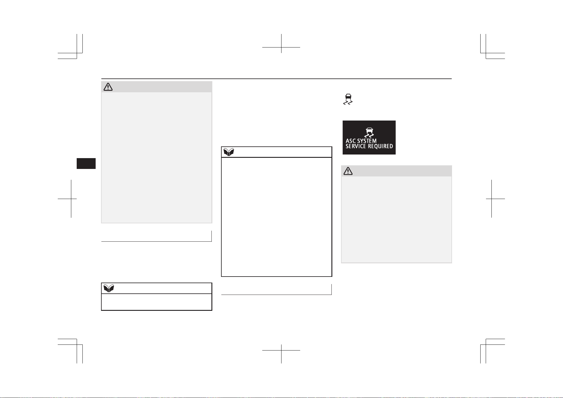
CAUTION
l
Do not overly rely on the hill start assist to
prevent backwards movement of the vehicle.
Under certain circumstances, even when hill
start assist is activated, the vehicle may
move backwards if the brake pedal is not
sufficiently depressed, if the vehicle is heav-
ily loaded, or if the road is very steep or slip-
pery.
l
The hill start assist is not designed to keep
the vehicle stopped in place on uphill slopes
for more than 2 seconds.
l
When facing uphill, do not rely on using the
hill start assist to maintain a stopped position
as an alternative to depressing the brake ped-
al.
Doing so could result in an accident.
l
Do not turn the operation mode in ACC or
OFF while the hill start assist is operating.
The hill start assist could stop operating,
which could result in an accident.
To operate
E00628101498
1. Stop the vehicle completely using the
brake pedal.
2. Put the select position to the “D” posi-
tion.
NOTE
l
When reversing on an uphill slope, put the
select position to the “R” position.
3. Release the brake pedal and the hill start
assist will maintain the braking force ap-
plied while stopped for approximately 2
seconds.
4. Depress the accelerator pedal and the
hill start assist will gradually decrease
the braking force as the vehicle starts
moving.
NOTE
l
The hill start assist is activated when all of
the following conditions are met.
•
The Plug-in Hybrid EV System is operat-
ing.
(The hill start assist will not be activated
while the Plug-in Hybrid EV System is
starting or immediately after the Plug-in
Hybrid EV System has started.)
•
The select position is in any position other
than “P” or “N”.
•
The vehicle is completely stationary, with
the brake pedal depressed.
•
The parking brake is released.
l
The hill start assist will not operate if the ac-
celerator pedal is depressed before the brake
pedal is released.
l
The hill start assist also operates when re-
versing on an uphill slope.
Warning display
E00628201369
If an abnormal condition occurs in the sys-
tem, the following Warning lamp/Warning
display will turn on.
Warning lamp
Warning display
CAUTION
l
If the warning is displayed, the hill start as-
sist will not operate. Start off carefully.
l
Park your vehicle in a safe place and stop
the Plug-in Hybrid EV System.
Restart the Plug-in Hybrid EV System and
check whether the display/indicator goes
out, in which case the hill start assist is
working normally again.
If they remain displayed or reappear fre-
quently, it is not necessary to stop the vehi-
cle immediately, but the vehicle should be
inspected by a MITSUBISHI MOTORS Au-
thorized Service Point as soon as possible.
Hill start assist
7-38
OGGE19E1
Starting and driving
7
Brake assist system
E00627001793
The brake assist system is a device assisting
drivers who cannot depress the brake pedal
firmly when it is necessary to do so (such as
in emergency stop situations) and provides
greater braking force.
If the brake pedal is depressed suddenly, the
brakes will be applied with more force than
usual.
CAUTION
l
The brake assist system is not a device de-
signed to exercise braking force greater than
its capacity. Make sure to always keep a suf-
ficient distance between your vehicle and a
vehicle in front of you without relying too
much on the brake assist system.
NOTE
l
Once the brake assist system is operational,
it maintains great braking force even if the
brake pedal is lightly released.
To stop its operation, completely remove
your foot from the brake pedal.
NOTE
l
When the brake assist system is in use, you
may feel as if the depressed brake pedal is
soft, the pedal moves in small motions in
conjunction with the sound of the ABS oper-
ation, or the vehicle body and the steering
wheel vibrate. This occurs when the brake
assist system is operating normally and does
not indicate faulty operation. Continue to
firmly depress the brake pedal.
l
You may hear an operation noise when the
brake pedal is depressed suddenly while sta-
tionary. This does not indicate a malfunction
and the brake assist system is operating nor-
mally.
l
When the anti-lock brake system warning
lamp or only Active Stability Control warn-
ing lamp illuminate, the brake assist system
in not functioning.
Emergency stop signal
system
E00626001259
This is a device that reduces the possibility of
rear end collisions by the rapid and automatic
blinking of the hazard warning lamps to alert
vehicles approaching from behind during
sudden braking. When the emergency stop
signal system operates, the hazard warning
indication lamp in the instrument cluster
blinks rapidly at the same time.
CAUTION
l
If the ABS warning or ASC warning is dis-
played, the emergency stop signal system
may not operate. Refer to “ABS warning
lamp/display” on page 7-41.
Refer to “ASC warning lamp/display” on
page 7-45.
NOTE
l
[Activating condition for the emergency stop
signal system]
It activates when all of the following condi-
tions are met.
•
The vehicle speed is approximately
55 km/h (34 mph) or higher.
•
The brake pedal has been depressed, and
the system judges that it was sudden brak-
ing from the vehicle deceleration and the
operating condition of the anti-lock brake
system (ABS).
[Deactivating condition for the emergency
stop signal system]
It deactivates when one of the following
conditions is met.
•
The brake pedal is released.
•
The hazard warning flasher switch is
pressed.
•
The system judges that it was not sudden
braking from the vehicle deceleration and
the operating condition of the anti-lock
brake system (ABS).
Brake assist system
7-39
OGGE19E1
Starting and driving
7
Anti-lock brake system
(ABS)
E00607102489
Environmental conditions can have an effect
on braking. During sudden braking when
there is snow, ice, oil, water etc. on the road
surface, a skid may occur. In this situation,
steering control and braking effectiveness is
reduced and the stopping distance is in-
creased. The vehicle may also go into an un-
controlled spin.
The ABS helps prevent the wheels from lock-
ing during braking, thus maintaining direc-
tional stability, ensuring controllability and
providing optimum braking force.
Operating hints
l
Always maintain the same distance from
the vehicle in front of you as you would
for a vehicle not equipped with ABS.
Compared with vehicles not fitted with
ABS, your vehicle may require a longer
stopping distance in the following cases:
• Driving on gravel or snow-covered
roads.
• Driving with snow traction device
(tyre chains) installed.
• Driving on roads where the road sur-
face is pitted or has other differences
in surface height.
• Driving on bumpy roads or other poor
driving surfaces.
l
Operation of ABS is not restricted to sit-
uations where brakes are applied sud-
denly. This system may also operate to
prevent wheel lock when you are driving
over manholes, steel road-work plates,
or the vehicle is driven over steps or lev-
el differences in the road, road markings,
or other surfaces which are difficult for
the wheels to grip.
l
When the ABS is activated, you may
feel the brake pedal pulsation and the vi-
brations of the vehicle body and steering
wheel. You may also hear a characteris-
tic noise. At this time, you may feel as if
the pedal attempts to resist being de-
pressed.
This is a normal result of the ABS oper-
ation, and does not indicate a problem.
If this situation occurs, depress the
brake pedal more firmly in order to
operate the ABS. Do not pump the
brake. This will result in reduced
braking performance.
l
You will hear the operation sound of the
motor coming from the Plug-in Hybrid
EV System compartment immediately
following start off after starting the Plug-
in Hybrid EV System. If the brake pedal
is depressed at that moment, you can
feel the brake pedal pulsating.
This pulsation is due to the self-diagno-
sis operation of the ABS and does not
indicate a malfunction.
l
The ABS will operate after the vehicle
has accelerated to a speed in excess of
approximately 10 km/h (6 mph). It stops
operating when the vehicle decelerates
to a speed below about 5 km/h (3 mph).
CAUTION
l
Even the ABS cannot prevent the natural
laws of physics from acting on the vehicle. It
cannot for instance avoid accidents that may
result from excessive speed on bends or fol-
lowing another vehicle too closely or aqua-
planing. It should remain the driver’s task to
observe safety precautions to judge speeds
and brake applications correctly in such con-
ditions.
l
Be sure to use tyres of the same type and
size on 4 wheels.
If tyre types or sizes are mixed, ABS may
not function normally.
Anti-lock brake system (ABS)
7-40
OGGE19E1
Starting and driving
7
CAUTION
l
Never install a limited-slip differential,
which is not MITSUBISHI MOTORS GEN-
UINE parts, as the ABS may not function
normally.
We recommend you to consult a
MITSUBISHI MOTORS Authorized Serv-
ice Point.
ABS warning lamp/display
E00607202321
Warning lamp
Warning display
If there is a malfunction in the system, the
ABS warning lamp will come on and the
warning display will appear on the informa-
tion screen in the multi information display.
Under normal conditions, the ABS warning
lamp only comes on when the operation
mode is put in ON and goes off a few sec-
onds later.
CAUTION
l
Any of the following warning lamp/display
behaviour indicates that the ABS is not func-
tioning and only the standard brake system
is working. (The standard brake system is
functioning normally.) If this happens, take
your vehicle to a MITSUBISHI MOTORS
Authorized Service Point.
•
When the operation mode is put in ON,
the warning lamp does not come on or it
remains on and does not go off.
•
The warning lamp comes on while driv-
ing.
•
The warning display appears while driv-
ing.
If the warning lamp/display il-
luminate while driving
E00607302494
If only the ABS warning lamp/
display illuminate
l
Avoid hard braking and high-speed driv-
ing. Stop the vehicle in a safe place.
Restart the Plug-in Hybrid EV System
and check to see whether the lamp goes
out after a few minutes driving; if it then
remains off during driving, there is no
problem.
However, if the lamp does not go out, or
if it lights up again when the vehicle is
driven, we recommend you to have the
vehicle checked as soon as possible.
l
If you start Plug-in Hybrid EV System
when the auxiliary battery voltage is in-
sufficient, ABS warning lamp/display
may illuminate, but this is not a failure
of ABS. When the drive battery is charg-
ed, the auxiliary battery is also charged,
and the warning lamp/display will go
out. If the warning lamp/display contin-
ues illuminating even after the battery is
sufficiently charged or the warning
lamp/display illuminates frequently,
have your vehicle inspected by a
MITSUBISHI MOTORS Authorized
Service Point.
If the ABS warning lamp/
display and brake warning
lamp (red)/display illuminate at
the same time
Warning lamp
(red)
Anti-lock brake system (ABS)
7-41
OGGE19E1
Starting and driving
7
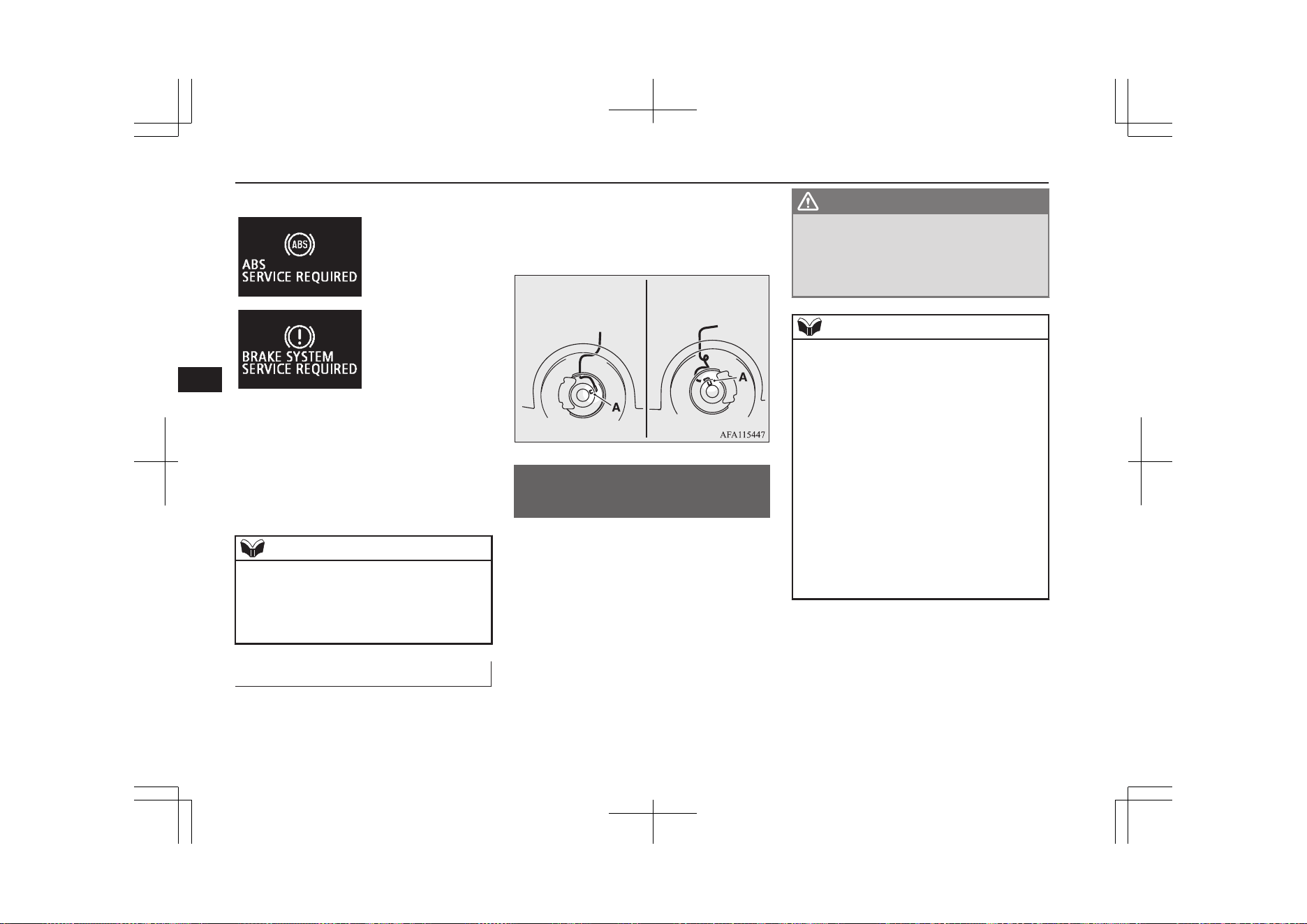
Warning display
The ABS and brake force distribution func-
tion may not work, so hard braking could
make the vehicle unstable.
Avoid hard braking and high-speed driving.
Stop the vehicle in a safe place immediately
and contact a MITSUBISHI MOTORS Au-
thorized Service Point.
NOTE
l
The ABS warning lamp and brake warning
lamp illuminate at the same time and the
warning displays appear alternately on the
information screen in the multi information
display.
After driving on icy roads
E00618801388
After driving on snowy roads, remove any
snow and ice which may have become ad-
hered to the wheel areas.
When doing this, be careful not to damage
the wheel speed sensors (A) and cables loca-
ted at each wheel on vehicles equipped with
an ABS.
Front Rear
Electric power steering
system (EPS)
E00629201294
The power steering system operates while the
Plug-in Hybrid EV System is operating.
It helps reduce the effort needed to turn the
steering wheel.
The power steering system has mechanical
steering capability in case the power assist is
lost. If the power assist is lost for some rea-
son, you will still be able to steer your vehi-
cle, but you will notice it takes much more
effort to steer. If this happens, have your ve-
hicle inspected at a MITSUBISHI MOTORS
Authorized Service Point.
WARNING
l
Do not stop the Plug-in Hybrid EV Sys-
tem while the vehicle is moving. Stopping
the Plug-in Hybrid EV System would
make the steering wheel extremely hard
to turn, possibly resulting in an accident.
NOTE
l
During repeated full-lock turning of the
steering wheel (for example, while you are
manoeuvring the vehicle into a parking
space), a protection function may be activa-
ted to prevent overheating of the power
steering system. This function will make the
steering wheel gradually harder to turn. In
this event, limit your turning of the steering
wheel for a while. When the system has
cooled down, the steering action will return
to normal.
l
If you turn the steering wheel while the vehi-
cle is stationary with the headlamps on, the
headlamps may become dim. This behaviour
is not abnormal. The headlamps will return
to their original brightness after a short
while.
Electric power steering system (EPS)
7-42
OGGE19E1
Starting and driving
7
Electric power steering system
warning display
If there is a malfunction in the system, the
warning display will appear on the informa-
tion screen in the multi information display.
CAUTION
l
If the warning display appears while the
Plug-in Hybrid EV System is operating,
have the vehicle inspected by a
MITSUBISHI MOTORS Authorized Serv-
ice Point as soon as possible.
It may become harder to turn the steering
wheel.
Active stability control
(ASC)
E00616701468
The Active Stability Control (ASC) takes
overall control of the anti-lock brake system,
traction control function and stability control
function to help maintain the vehicle’s con-
trol and traction. Please read this section in
conjunction with the page on the anti-lock
brake system, traction control function and
stability control function.
Anti-lock brake system (ABS) ® p. 7-40
Traction control function ® p. 7-44
Stability control function ® p. 7-44
CAUTION
l
Do not over-rely on the ASC. Even the ASC
cannot prevent the natural laws of physics
from acting on the vehicle.
This system, like any other system, has lim-
its and cannot help you to maintain traction
and control of the vehicle in all circumstan-
ces. Reckless driving may lead to accidents.
It is the driver’s responsibility to drive care-
fully. This means taking into account the
traffic, road and environmental conditions.
l
Be sure to use the same specified type and
size of tyre on all 4 wheels. Otherwise, the
ASC may not work properly.
CAUTION
l
Do not install any aftermarket limited-slip
differential (LSD) on your vehicle. The ASC
may stop functioning properly.
NOTE
l
An operation noise may be emitted from the
Plug-in Hybrid EV System compartment in
the following situations. The sound is asso-
ciated with checking the operations of the
ASC. At this time, you may feel a shock
from the brake pedal if you depress it. These
do not indicate a malfunction.
•
When the operation mode is put in ON.
•
When the vehicle is driven for a while af-
ter the Plug-in Hybrid EV System is
turned on.
l
When the ASC is activated, you may feel a
vibration in the vehicle body or hear a whin-
ing sound from the Plug-in Hybrid EV Sys-
tem compartment.
This indicates that the system is operating
normally. It does not indicate a malfunction.
l
When the anti-lock brake system warning
lamp is illuminated, the ASC is not active.
Active stability control (ASC)
7-43
OGGE19E1
Starting and driving
7
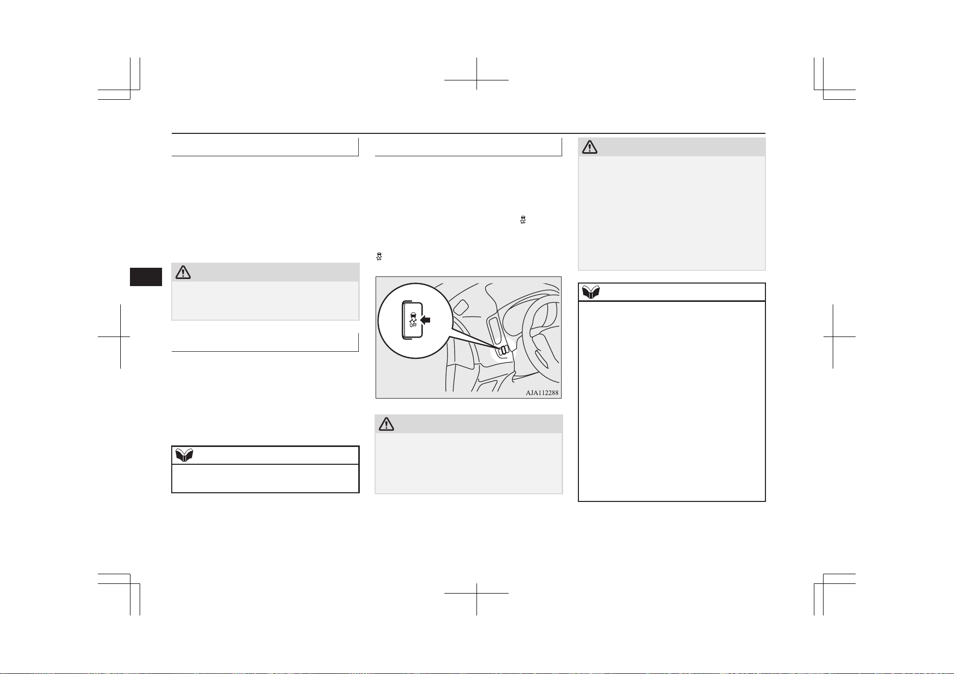
Traction control function
E00619000087
On slippery surfaces, the traction control
function prevents the drive wheels from ex-
cessive spinning, thus helping the vehicle to
start moving from a stopped condition. It also
provides sufficient driving force and steering
performance as the vehicle turns while press-
ing the acceleration pedal.
CAUTION
l
When driving a vehicle on a snowy or icy
road, be sure to install snow tyres and drive
the vehicle at moderate speeds.
Stability control function
E00619101098
The stability control function is designed to
help the driver maintain control of the vehicle
on slippery roads or during rapid steering ma-
noeuvres. It works by controlling the Plugin
Hybrid EV System output and the brake on
each wheel.
NOTE
l
The stability control function operates at
speeds of about 15 km/h (9 mph) or higher.
ASC OFF switch
E00619201871
The ASC is automatically activated when the
operation mode is put in ON. You can deacti-
vate the system by pressing down the ASC
OFF switch for 3 seconds or longer.
When the ASC is deactivated, the display/
indicator will turn on. To reactivate the ASC,
momentarily press the ASC OFF switch; the
indicator is turned off.
CAUTION
l
For safety reasons, the ASC OFF switch
should be operated when your vehicle is
stopped.
l
Be sure to keep the ASC on while driving in
normal circumstances.
CAUTION
l
In case you turn off the ASC to move out
from mud or sand etc., press the ASC OFF
switch to activate the ASC quickly after
moving out, and do not turn off the ASC un-
less it is necessary.
l
If you continue to race the tyre by depress-
ing the accelerator pedal too much while
ASC is turned off, parts such as the transaxle
may be damaged and this could lead to an
accident.
NOTE
l
When moving out of mud, sand or fresh
snow, pressing the accelerator pedal may not
allow the Plug-in Hybrid EV System output
to increase. In such situations, switching to
“LOCK” with the Drive mode switch and
temporarily turning off the Active Stability
Control (ASC) with the ASC OFF switch
will make it easier to move out your vehicle.
Refer to “Operation under adverse driving
conditions: If your vehicle becomes stuck in
sand, mud or snow” on page 9-21.
l
By pressing the “ASC OFF” switch, both the
stability control function and the traction
control function are turned OFF.
l
If you continue to press the ASC OFF switch
after the ASC is turned off, the “mistaken
operation protection function” will activate
and the ASC will turn back on.
Active stability control (ASC)
7-44
OGGE19E1
Starting and driving
7
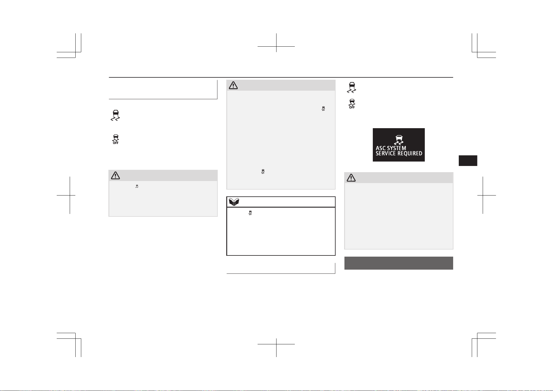
ASC operation indicator or
ASC OFF indicator
E00619301771
-
ASC operation indicator
The indicator will blink when
the ASC is operating.
-
ASC OFF indicator
This indicator will turn on
when the ASC is turned off
with the ASC OFF switch.
CAUTION
l
When indicator blinks, ASC is operating,
which means that the road is slippery or that
your vehicle’s wheels are beginning to slip.
If this happens, drive slower with less accel-
erator input.
CAUTION
l
If the temperature in the braking system con-
tinues to increase due to continuous brake
control on a slippery road surface, the in-
dicator will blink. To prevent the brake sys-
tem from overheating, the brake control of
the traction control function will be tempora-
rily suspended.
The Plug-in Hybrid EV System control of
the traction control function and normal
brake operation will not be affected. Park
your vehicle in a safe place. When the tem-
perature in the braking system has come
down, the indicator will be turned off and
the traction control function will start operat-
ing again.
NOTE
l
The indicator may turn on when you start
the Plug-in Hybrid EV System. This means
that the battery voltage momentarily drop-
ped when the Plug-in Hybrid EV System
was started. It does not indicate a malfunc-
tion, provided that the indicator goes out im-
mediately.
ASC warning lamp/display
E00619401655
If an abnormal condition occurs in the sys-
tem, the following warning lamp/warning
display will turn on.
Warning lamp
- ASC operation indicator
- ASC OFF indicator
Warning display
CAUTION
l
The system may be malfunctioning.
Park your vehicle in a safe place and stop
the Plug-in Hybrid EV System.
Restart the Plug-in Hybrid EV System and
check whether the display/indicator goes
out. If they go out, there is no abnormal con-
dition. If they do not go out or appear fre-
quently, it is not necessary to stop the vehi-
cle immediately, but we recommend you to
have your vehicle inspected.
Cruise control*
E00609102584
Cruise control is an automatic speed control
system that keeps a set speed. It can be acti-
vated at approximately 40 km/h (25 mph) or
more.
Cruise control*
7-45
OGGE19E1
Starting and driving
7
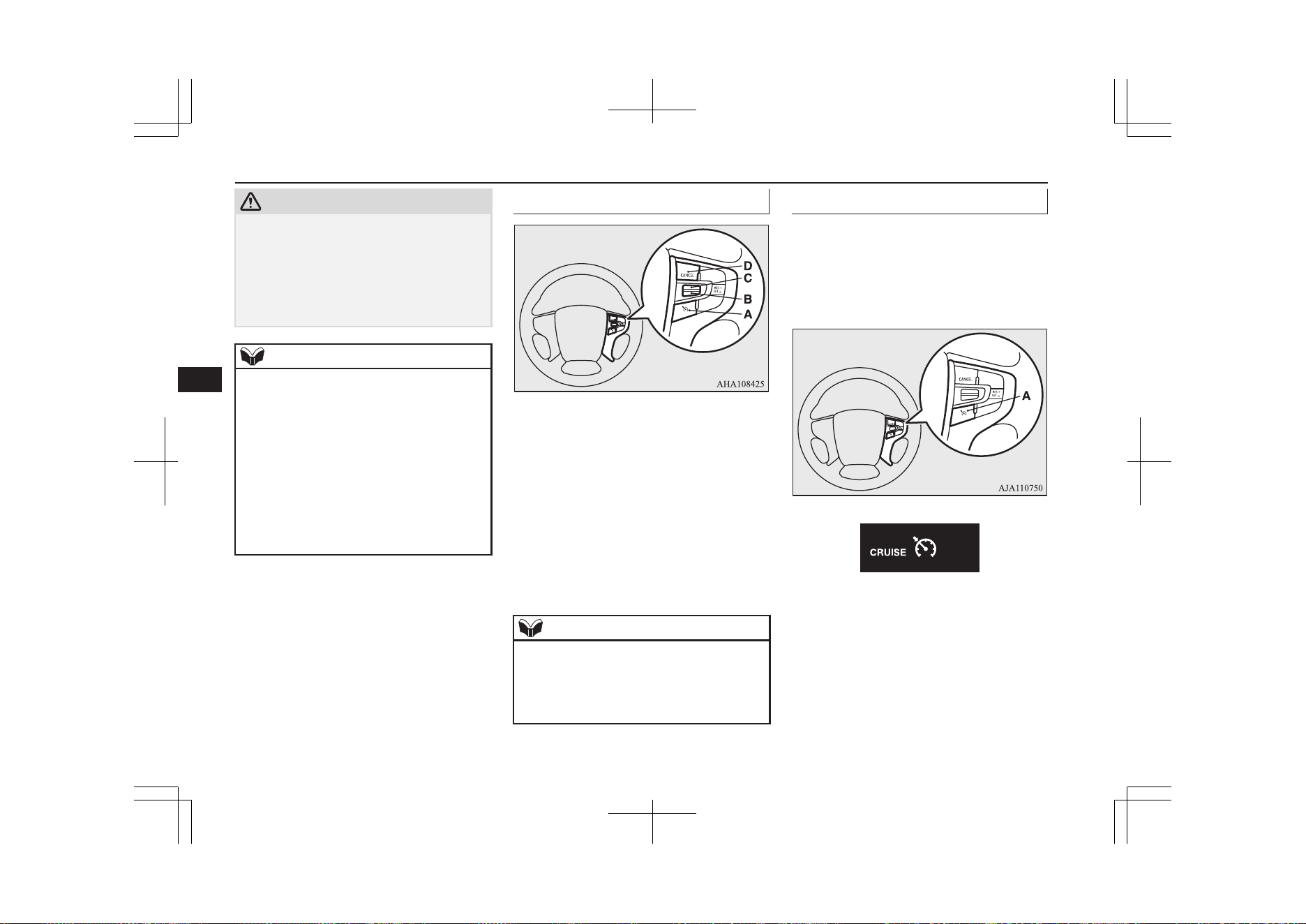
CAUTION
l
When you do not wish to drive at a set
speed, turn off the cruise control for safety.
l
Do not use cruise control when driving con-
ditions will not allow you to stay at the same
speed, such as in heavy traffic or on roads
that are winding, icy, snow-covered, wet,
slippery, on a steep downhill slope.
NOTE
l
Cruise control may not be able to keep your
speed on uphills or downhills.
l
Your speed may decrease on a steep uphill.
You may use the accelerator pedal if you
want to stay at your set speed.
l
Your speed may increase to more than the
set speed on a steep downhill. You must use
the brake to control your speed. As a result,
the set speed driving is deactivated.
l
The regenerative level B0 or B1 cannot be
selected under the cruise control. The buzzer
sounds if you try to select these levels.
Cruise control switches
A- CRUISE CONTROL ON/OFF switch
Used to turn on and off the cruise con-
trol.
B- "SET -" switch
Used to reduce the set speed and to set
the desired speed.
C- "RES +" switch
Used to increase the set speed and to re-
turn to the original set speed.
D- “CANCEL” switch
Used to deactivate the set speed driving.
NOTE
l
When operating the cruise control switches,
press the cruise control switches correctly.
The set speed driving may be deactivated
automatically if two or more switches of the
cruise control are pressed at the same time.
To activate
E00609302690
1. With the operation mode in ON, press
the CRUISE CONTROL ON/OFF
switch (A) to turn on the cruise control.
The indicator display in the meter cluster
will come on.
Cruise control*
7-46
OGGE19E1
Starting and driving
7
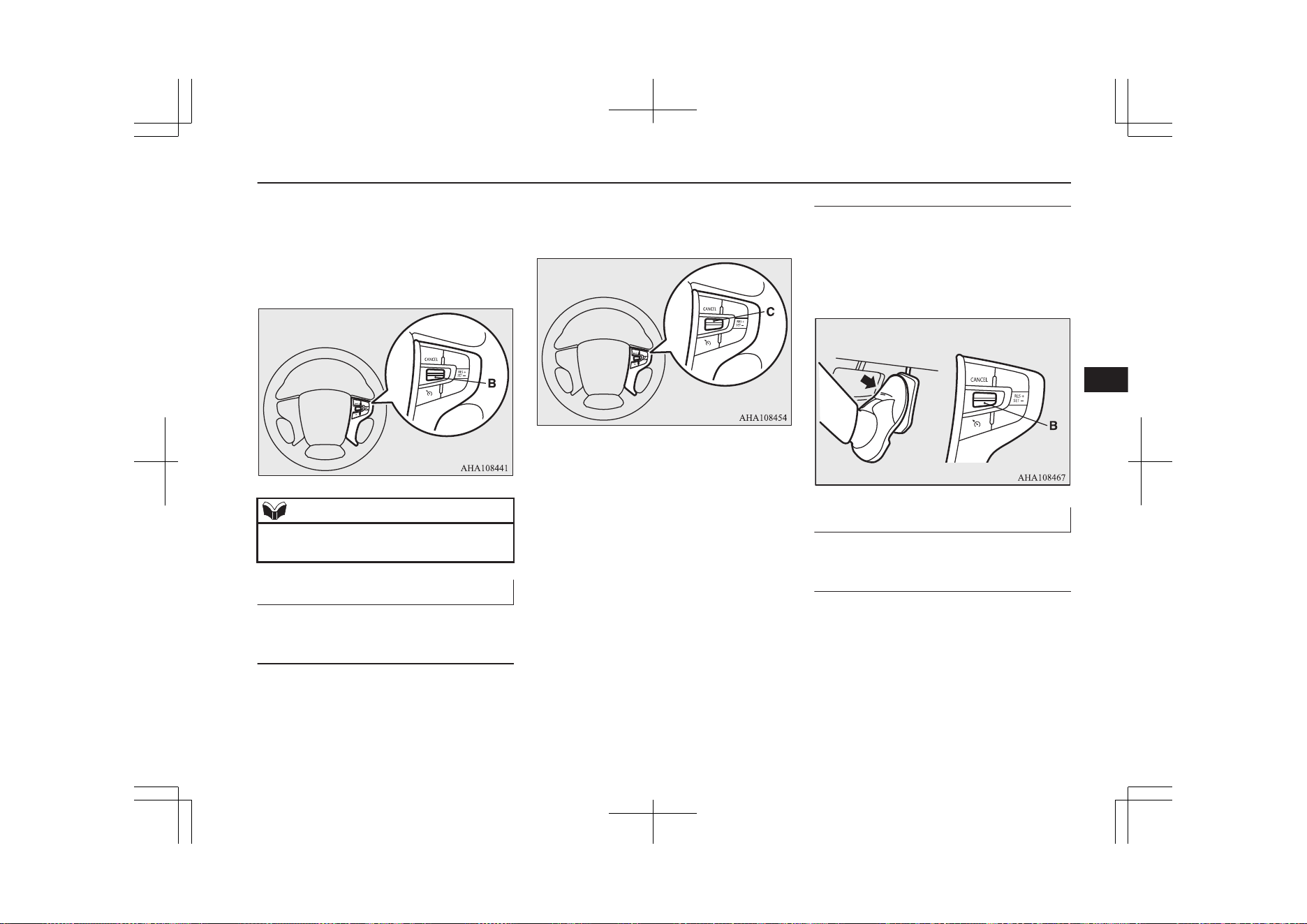
2. Accelerate or decelerate to your desired
speed, then push down and release the
"SET -" switch (B). The vehicle will
then maintain the desired speed.
The “SET” indicator appears on the in-
formation screen in the meter cluster.
NOTE
l
When you release the "SET -" switch (B),
the vehicle speed will be set.
To increase the set speed
E00609402008
There are 2 ways to increase the set speed.
"RES +" switch
Push up and hold the "RES +" switch (C)
while driving at the set speed, and your speed
will then gradually increase.
When you reach your desired speed, release
the switch. Your new cruising speed is now
set.
To increase your speed in small amounts,
push up the "RES +" switch (C) for less than
approximately 1 second and release it.
Each time you press the "RES +" switch (C),
your vehicle will go approximately 1.6 km/h
(1 mph) faster.
Accelerator pedal
While driving at the set speed, use the accel-
erator pedal to reach your desired speed and
then push down the "SET -" switch (B) and
release the switch momentarily to set a new
desired cruising speed.
To decrease the set speed
E00609501930
There are 2 ways to decrease the set speed.
"SET -" switch
Push down and hold the "SET -" switch (B)
while driving at the set speed, and your speed
will slow down gradually.
Cruise control*
7-47
OGGE19E1
Starting and driving
7
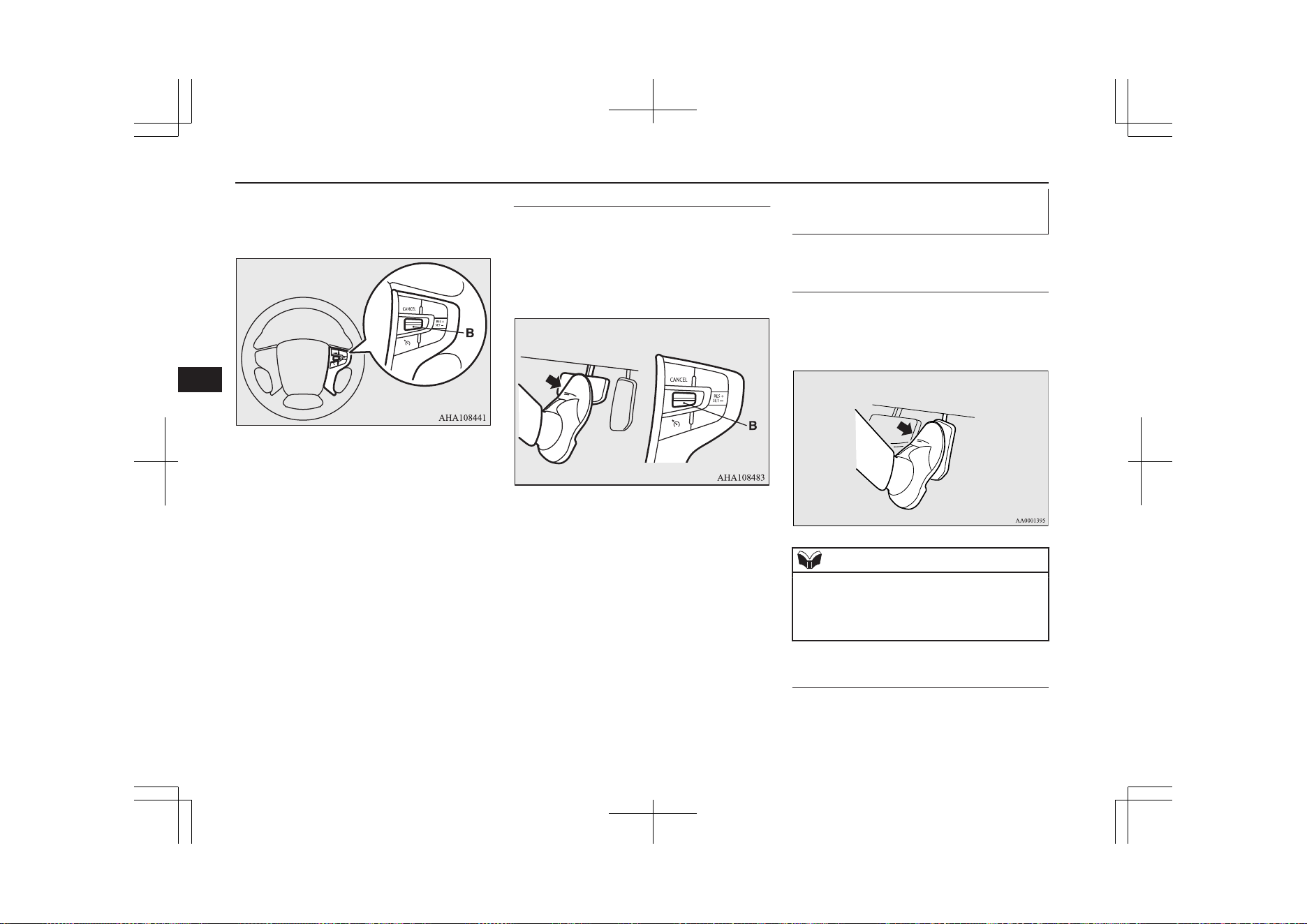
When you reach your desired speed, release
the switch. Your new cruising speed is now
set.
To slow down your speed in small amounts,
push down the "SET -" switch (B) for less
than approximately 1 second and release it.
Each time you push down the "SET -" switch
(B), your vehicle will slow down by approxi-
mately 1.6 km/h (1 mph).
Brake pedal
While driving at the set speed, use the brake
pedal, which disengages the cruise control,
then push down the "SET -" switch (B) and
release the switch momentarily to set a new
desired cruising speed.
To temporarily increase or de-
crease the speed
E00609601481
To temporarily increase the
speed
Depress the accelerator pedal as you would
normally. When you release the pedal, you
will return to your set speed.
NOTE
l
In some driving conditions, the set speed
driving may be deactivated. If this happens,
refer to “To activate” on page 7-46 and re-
peat the speed setting procedure.
To temporarily decrease the
speed
Depress the brake pedal to decrease the
speed. To return to the previously set speed,
push up the "RES +" switch (C).
Cruise control*
7-48
OGGE19E1
Starting and driving
7
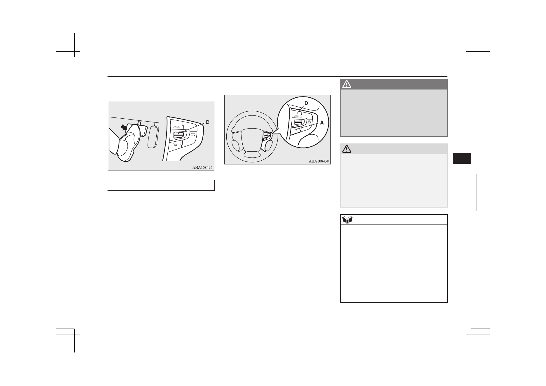
Refer to “To resume the set speed” on page
7-50.
To deactivate
E00609702955
The set speed driving can be deactivated as
follows:
l
Press the CRUISE CONTROL ON/OFF
switch (A) (Cruise control will be turned
off.)
l
Press the “CANCEL” switch (D).
l
Depress the brake pedal.
The set speed driving is deactivated automat-
ically in any of the following ways.
l
When your speed slows to approximate-
ly 15 km/h (9 mph) or more below the
set speed because of a hill, etc.
l
When your speed slows to approximate-
ly 40 km/h (25 mph) or less.
l
When the Active Stability Control
(ASC) starts operating.
Refer to “Active stability control (ASC)”
on page 7-43.
WARNING
l
Although the set speed driving will be de-
activated when shifting to the “N” (NEU-
TRAL) position, never move the selector
lever to the “N” (NEUTRAL) position
while driving.
You would have no regenerative brake
and could cause a serious accident.
CAUTION
l
When the set speed driving is deactivated
automatically in any situation other than
those listed above, there may be a system
malfunction.
Press the CRUISE CONTROL ON/OFF
switch to turn off the cruise control and have
your vehicle inspected by a MITSUBISHI
MOTORS Authorized Service Point.
NOTE
l
You cannot operate the regenerative brake
while the adaptive cruise control system
(ACC) is operating.
l
If you perform the following operation, the
buzzer may sound and the select position
may automatically shift to “N” position.
•
The electrical parking switch is pressed
during driving.
•
The selector lever is shifted to “R” during
driving forward.
•
The selector lever is shifted to “D” during
driving backward.
Cruise control*
7-49
OGGE19E1
Starting and driving
7
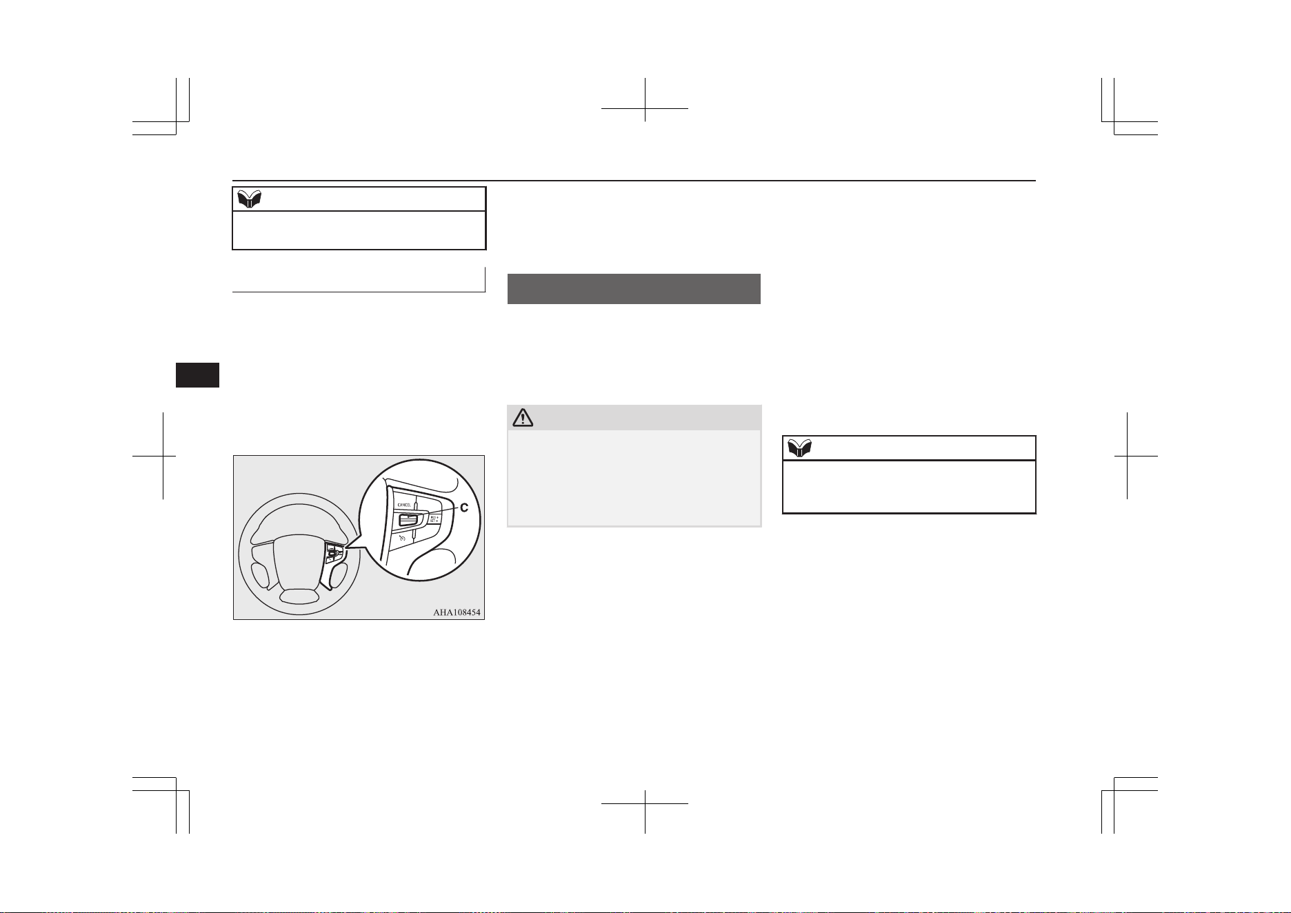
NOTE
•
The selector lever is shifted to “B” when
the select position is in “R”.
To resume the set speed
E00609802161
If the set driving speed is deactivated by the
condition described in “To deactivate” on
page 7-49, you can resume the previously set
speed by pushing up the "RES +" switch (C)
while driving at a speed of approximately
40 km/h (25 mph) or higher. The “SET” indi-
cator appears on the information screen in the
meter cluster.
Under either of the following conditions,
however, using the switch does not allow you
to resume the previously set speed. In these
situations, repeat the speed setting procedure:
l
The CRUISE CONTROL ON/OFF
switch is pressed.
l
The operation mode is put in OFF.
l
The indicator display goes off.
Speed Limiter*
E00633201093
The Speed Limiter is a driver assist function
to prevent from exceeding the speed set by
driver while Plug-in Hybrid EV System pow-
er control.
CAUTION
l
Because the system does not use service
brake (hydraulic brake), the vehicle speed
may exceed the set speed on the downhill.
If a driver wants to keep the vehicle speed in
such a situation, he/she must put on a service
brake.
If the vehicle speed exceeds the set speed
(about 3 km/h (2 mph)), the indicator will
brink in the combination meter.
If the vehicle speed exceeds the set speed
about +3 km/h (2 mph) more than about 5
seconds after indicated alert message, beep
alert is sounded for about 10 seconds at the
most.
While running without alert message, if you
decrease the set speed and vehicle speed is
more than set speed about +3 km/h (2 mph),
alert message is displayed but beep alert is
delayed.
In this case, when vehicle speed keeps ex-
ceeding set speed about +3 km/h (2 mph) for
about 30 seconds after the alert message is
appeared, beep alert is sounded for about 10
seconds at the most.
If the vehicle speeds decreases less than set
speeds after the alert message is appeared,
the message is disappeared. When beep alert
is sounding, the beep alert also goes off.
NOTE
l
However, this gives priority to audio and
visual signal of safety reasons or driver’s de-
mand.
Speed Limiter*
7-50
OGGE19E1
Starting and driving
7
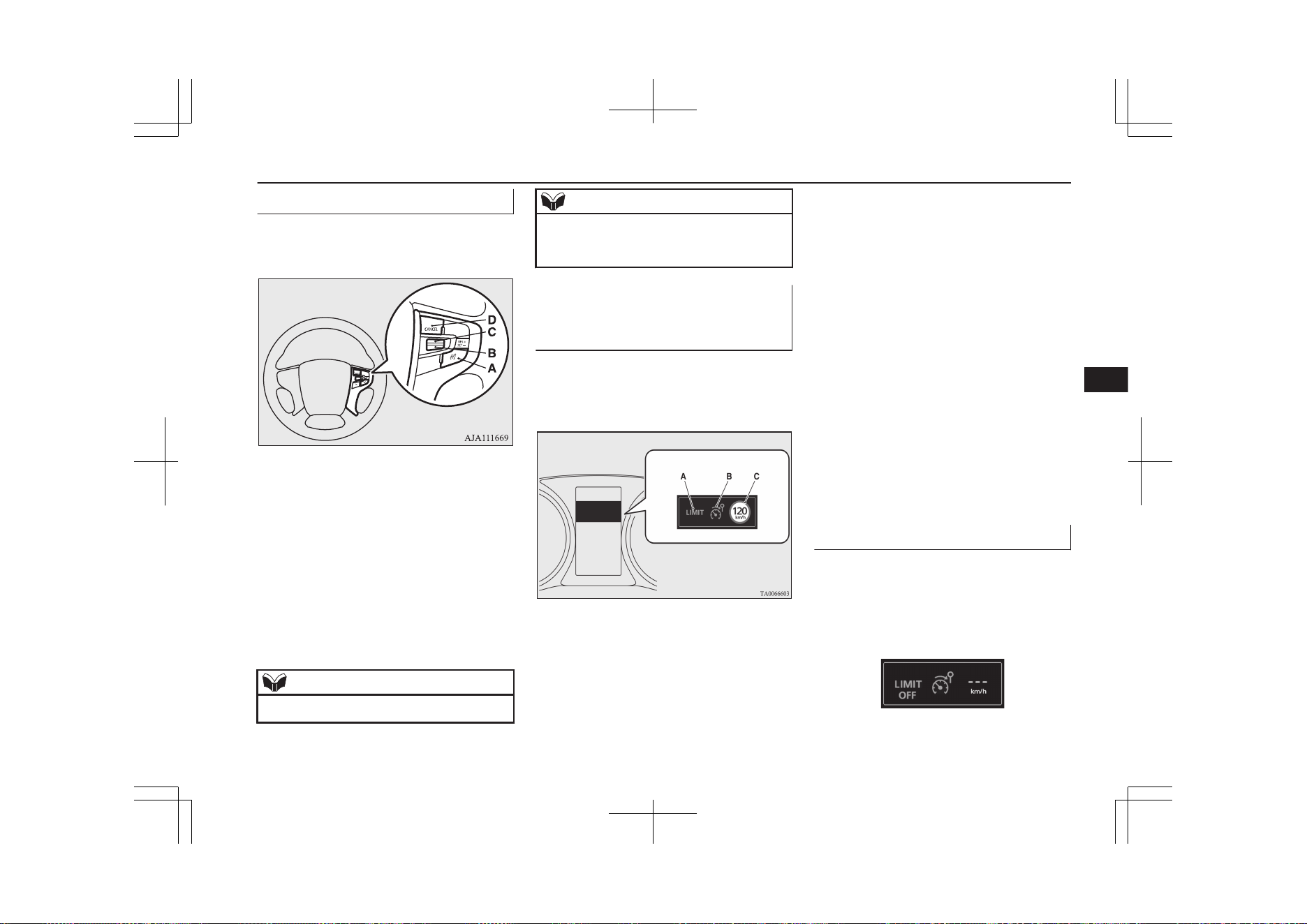
Speed Limiter control switches
E00633301052
There are 4 switches which relate to the
Speed Limiter on the steering wheel.
A- SPEED LIMITER ON/OFF switch
To turn on/off the Speed Limiter.
B- SET - switch
To set the current vehicle speed to a set
speed decrease the set speed.
C- RES + switch
To resume the Speed Limiter with set
speed memorized or increase the set
speed.
D- CANCEL switch
To cancel the Speed Limiter.
NOTE
l
Press the switch one by one.
NOTE
l
The Speed Limiter may be cancelled auto-
matically, if two or more switches are press-
ed at the same time.
Speed Limiter information on
the multi information display
area
E00633401037
The Speed Limiter information is displayed
on the multi information display area in the
combination meter.
A- Control state
There are 3 control states as below.
LIMIT OFF
When the Speed Limiter is in
STANDBY, the vehicle speed can ex-
ceed the set speed
LIMIT
When the Speed Limiter is in opera-
tion. The vehicle is controlled in order
not to exceed the set speed.
OVER LIMIT
When the vehicle speed is exceeding
the set speed by more than about
3 km/h (2 mph)
B- SPEED LIMITER ON indication
When the Speed Limiter is started up,
the Speed Limiter’s symbol appears.
C- Set speed
Set speed appears if it is stored.
To start up
E00633501025
First of all, press the ON/OFF switch in order
to power up the Speed Limiter when the op-
eration mode in ON.
The Speed Limiter indication will be ap-
peared in the combination meter.
Speed Limiter*
7-51
OGGE19E1
Starting and driving
7
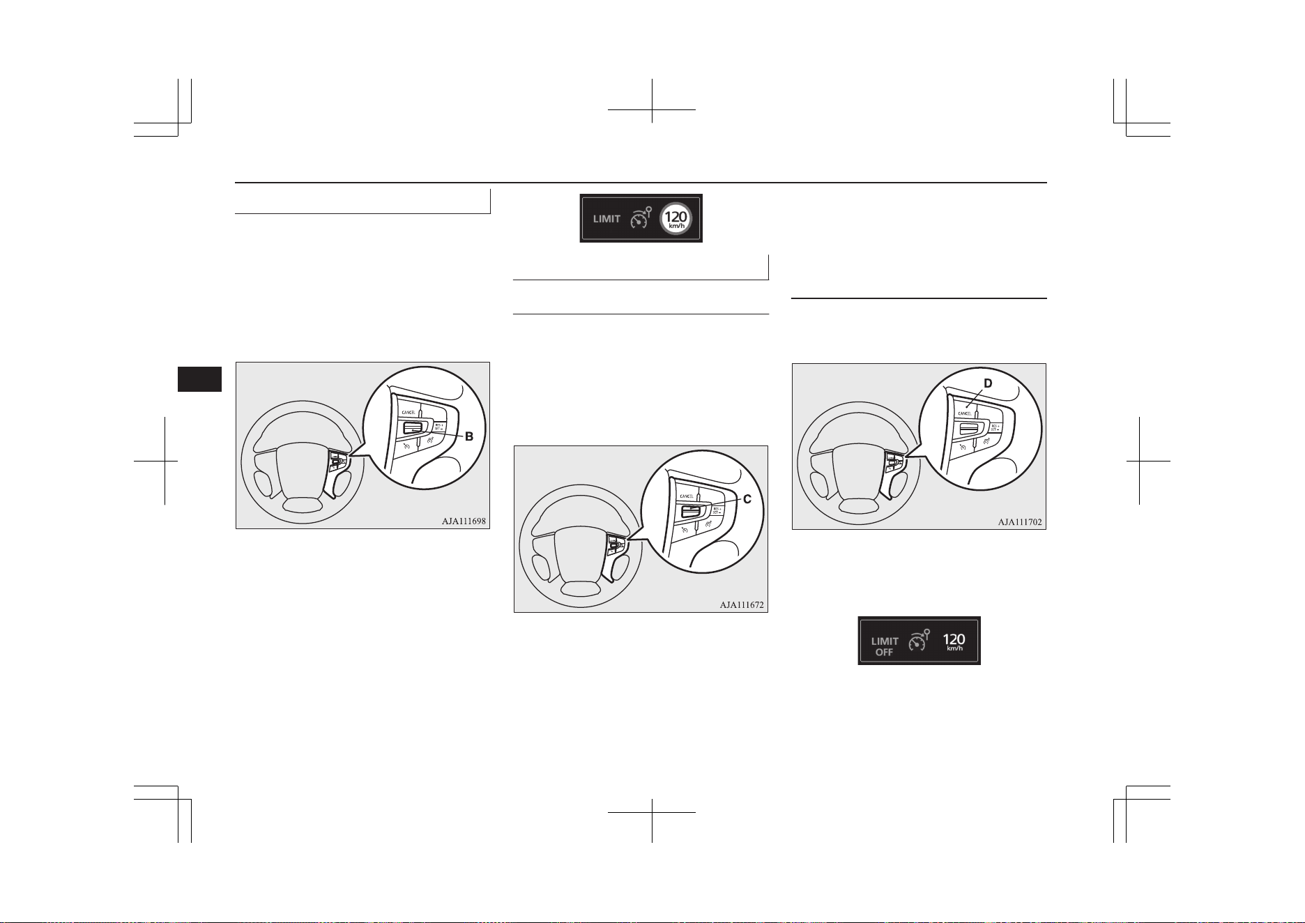
To activate
E00633601055
Accelerate or decelerate to your desired
speed, and push down the SET - switch (B).
the Speed Limiter memorizes the current ve-
hicle speed when you release the SET -
switch (B). Now, the Speed Limiter starts
controlling in order not to exceed the set
speed.
If the current vehicle speed is lower than
about 30 km/h (19 mph) (settable minimum
speed), the set speed is set at about 30 km/h
(19 mph).
The set speed is displayed in the combination
meter.
And, control state “LIMIT” is displayed in
the combination meter.
To increase the set speed
E00633700017
By using the RES + switch
E00633801044
Push up the RES + switch continuously.
Then the set speed displayed in the combina-
tion meter is gradually increased.
If the set speed reaches your desired speed,
release the RES + switch (C).
The set speed is increased each about 5 km/h
(3 mph) per about 0.5 second.
If a driver wants to increase the set speed a
little, push up RES + switch for less than
about 0.5 second and release it.
The set speed is increased 1 km/h (1 mph)
each taps.
By using the CANCEL switch,
the accelerator pedal and the
SET - switch
E00633901058
Press the CANCEL switch (D) to deactivate
the Speed Limiter.
Control state “LIMIT” is disappeared and
change control state “LIMIT OFF” in the
combination meter.
Speed Limiter*
7-52
OGGE19E1
Starting and driving
7
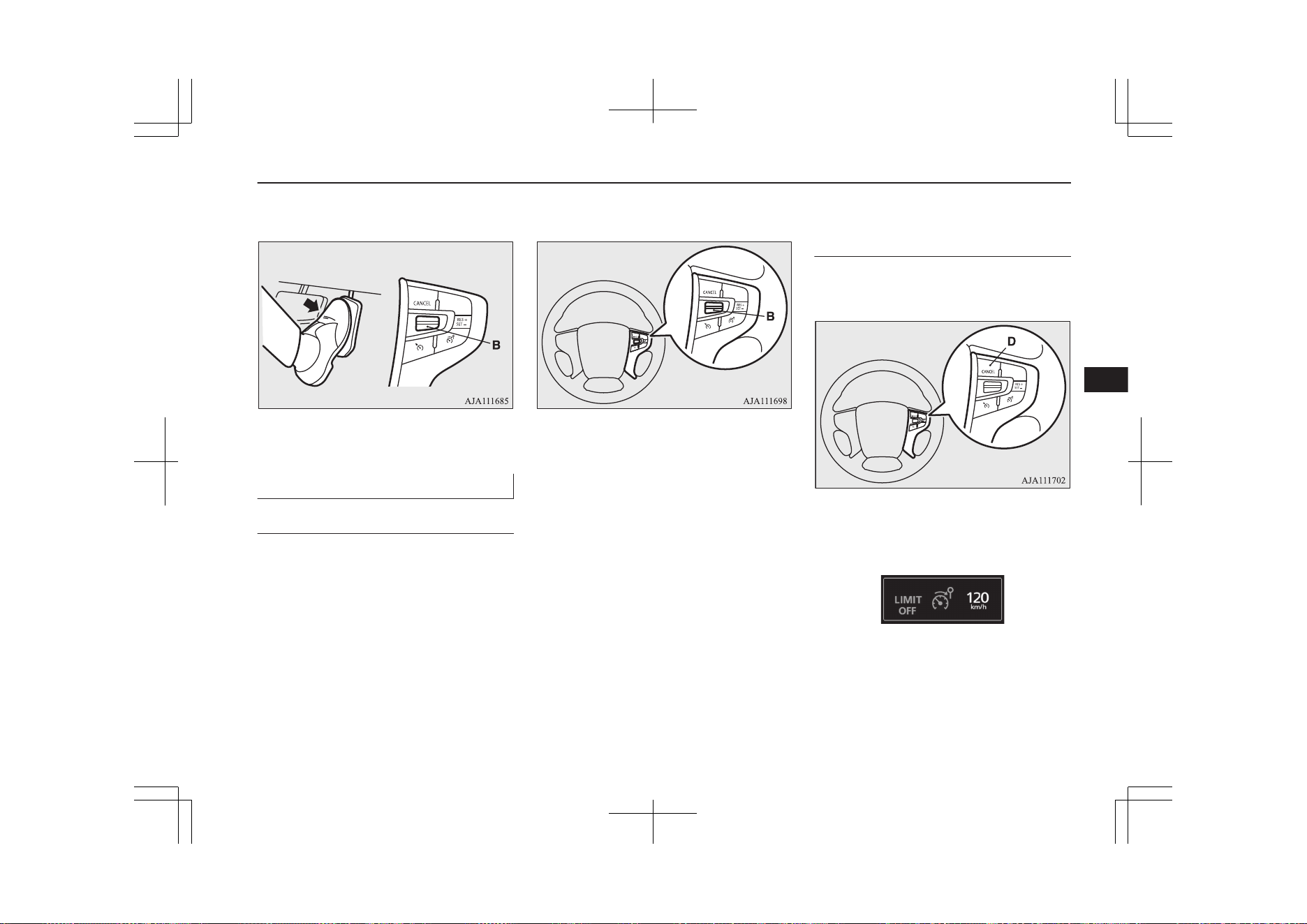
Accelerate to driver’s desired vehicle speed
and push down SET - switch (B) and release.
Control state “LIMIT” is displayed again and
the set speed is updated.
To decrease the set speed
E00634000017
By using the SET - switch
E00634101044
Push down the SET - switch (B).
Then the set speed displayed in the combina-
tion meter is gradually decreased.
If the set speed reaches to your desired speed,
release the SET - switch (B).
The set speed decrease about 5 km/h (3 mph)
per about 0.5 second.
If a driver wants to decrease the set speed a
little, press SET - switch (B) for less than
about 0.5 second and release it.
The set speed is decreased 1 km/h (1 mph)
each taps.
By using the CANCEL switch,
the service brake and the SET -
switch
E00634201058
Press the CANCEL switch (D) to deactivate
the Speed Limiter.
Control state “LIMIT” is disappeared and
change control state “LIMIT OFF” in the
combination meter.
Speed Limiter*
7-53
OGGE19E1
Starting and driving
7
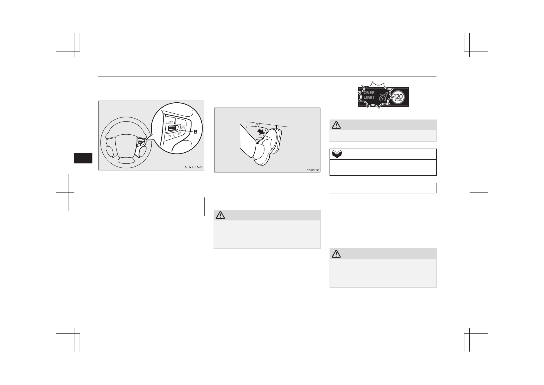
Decelerate to driver’s desired speed and push
down SET-switch - (B) and release.
The Speed Limiter indication is displayed
again and the set speed is updated.
To increase the vehicle speed
temporarily
E00634301020
A driver can temporarily accelerate for emer-
gency use.
The Speed Limiter is temporarily deactiva-
ted, and the vehicle speed can be increased.
The Speed Limiter will resume when the ve-
hicle speed goes down to enough less than
the set speed.
Put on an accelerator pedal to the pedal
stroke end. (over a detent that makes pedal
reaction force bigger before pedal stroke end)
CAUTION
l
There is a possibility for the Speed Limiter
to allow abrupt acceleration corresponding
to accelerator pedal position. So be careful
of the abrupt acceleration.
If vehicle speed exceeds set speed about
+3 km/h (2 mph), alert messages are ap-
peared in the combination meter.
CAUTION
l
Be careful about over speed.
NOTE
l
A driver can change the set speed during this
emergency use.
To deactivate
E00634401122
Use whichever following ways to deactivate.
l
Press CANCEL switch
l
Press the Speed Limiter ON/OFF switch
l
If CRUISE CONTROL ON/OFF switch
or ACC ON/OFF switch is pressed, the
Speed Limiter will be cancelled.
CAUTION
l
There is a possibility for the Speed Limiter
to allow abrupt acceleration corresponding
to accelerator pedal position when the Speed
Limiter is deactivated. Be careful.
Speed Limiter*
7-54
OGGE19E1
Starting and driving
7
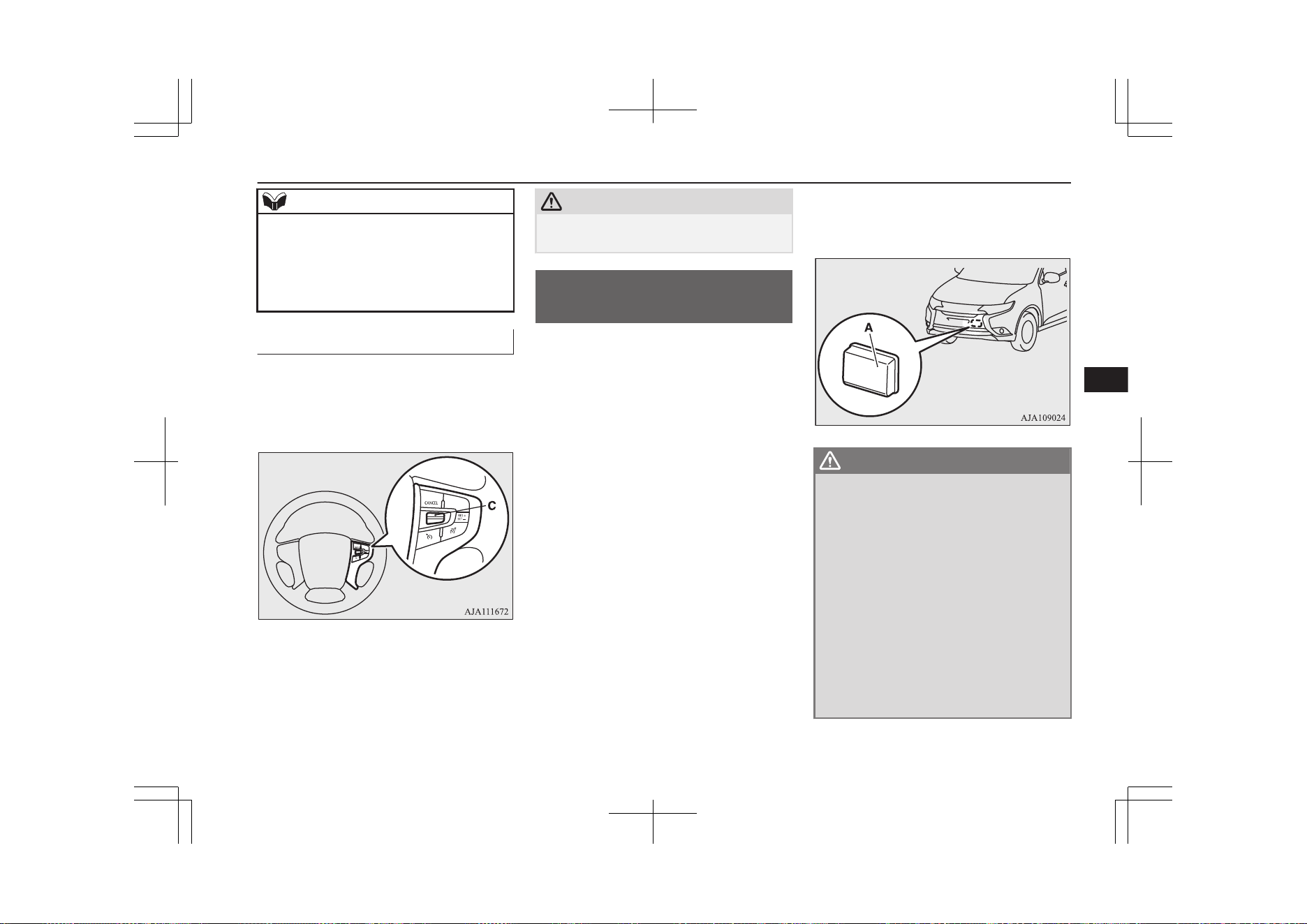
NOTE
l
If the Speed Limiter is cancelled by other
states, it may be a system malfunction.
Stop using the Speed Limiter and turn off
the Speed Limiter. Have your vehicle in-
spected by a MITSUBISHI MOTORS Serv-
ice Point.
To resume
E00634501048
The Speed Limiter memorizes the set speed
when system has been deactivated, the Speed
Limiter can resume by push up the RES +
switch (C).
However, the Speed Limiter immediately
starts controlling and the vehicle decreases as
if an accelerator pedal is closed fully, when
the vehicle speed is higher than the set speed.
CAUTION
l
There is a possibility to occur jerk, depend-
ing on a running resistance. Be careful.
Adaptive Cruise Control
System (ACC)*
E00634601401
The ACC maintains a set speed with no need
for you to use the accelerator pedal. Using a
sensor (A), the system also measures the rela-
tive speed and distance between your vehicle
and a vehicle in front, and maintains a set fol-
lowing distance between your vehicle and the
vehicle in front by automatically decelerating
your vehicle if it becomes too close to the ve-
hicle in front.
The ACC is the driver assist system to make
comfortable on a freeway. Stop lamps are il-
luminated during automatic braking.
If you desire, a cruise control without inter-
vention of the following distance control is
also selectable.
WARNING
l
A driver is responsible for driving safely.
Even if the ACC is in use, always grasp
the surrounding circumstances and pro-
vide for safe driving.
l
Never rely solely on the ACC. The ACC is
the system to reduce load on the driver.
The ACC is not a collision avoidance sys-
tem or an automatic driving system. The
system is not intended to compensate for
driver’s loss of attention to the front dur-
ing driving due to distraction or careless-
ness or supplement a drop in visibility due
to the rain and fog.
It is never a substitute for your safe and
careful driving. Always be ready to apply
the brakes manually.
Adaptive Cruise Control System (ACC)*
7-55
OGGE19E1
Starting and driving
7
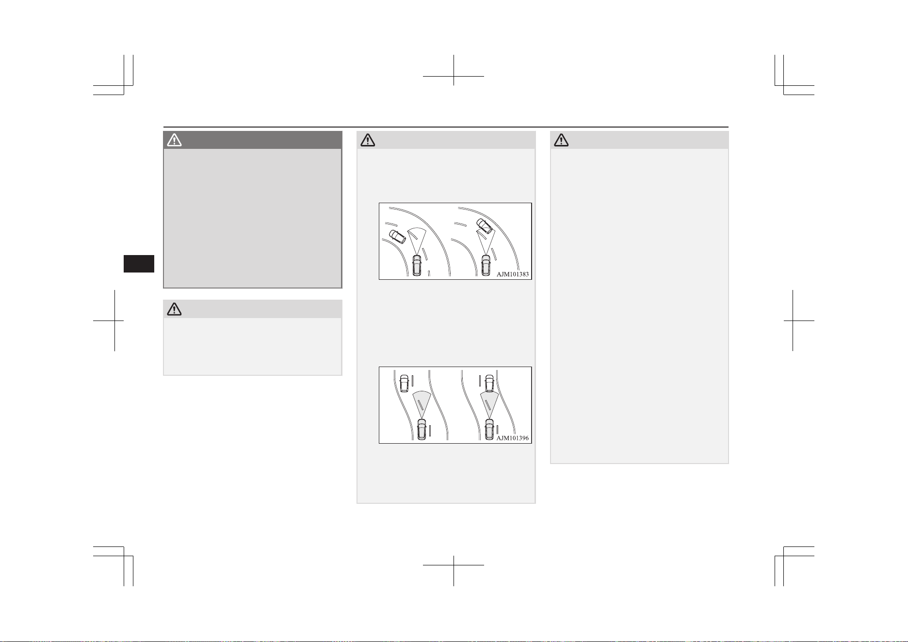
WARNING
l
This system may not correctly detect the
actual situation depending on the type of
vehicle in front and its conditions, the
weather conditions, and the road condi-
tions.
Additionally, the system may be unable to
decelerate sufficiently if the vehicle in
front applies the brakes suddenly or an-
other vehicle cuts into your path, so your
vehicle approaches the front vehicle.
Improper usage of this system or loss of
attention to the front by the over-rely on
the ACC, may result in a serious accident.
CAUTION
l
In the following situations, the system may
become transiently unable to detect a vehicle
in front or triggers its control and alarm
functions by detecting something other than
a vehicle in front.
CAUTION
•
When driving in curved sections of road
including their entrance/outlet or running
beside a closed lane in a traffic work or
similar zone.
•
When your vehicle position in a lane is in-
stable, is frequently steered to right and
left, or running unstably due to a traffic
accident, trouble with some vehicles, etc.
•
When driving on the road that the vehicle
in front runs in offset position from your
vehicle.
l
Never use the ACC in any of the following
situations. Failure to follow this instruction
could lead to an accident.
•
On roads with heavy traffic or roads in-
cluding many windings or steep curves.
CAUTION
•
On roads with slippery surfaces, such as
frozen, snow-covered, and dirt roads.
•
Under adverse weather conditions (rain,
snow, sand storms, etc.).
•
On steep downslopes.
•
On roads including steep up and down
slopes or many changes in inclination.
•
In traffic requiring frequent acceleration
and deceleration.
•
When the proximity alarm sounds fre-
quently.
•
When your vehicle is towed or your vehi-
cle tows another vehicle.
•
When your vehicle is on a chassis dyna-
mometer or free rollers.
•
When the air pressure in the tyres is not
correct.
•
When snow traction device (tyre chains)
are attached.
l
Be sure to take the following precautions to
keep the system in good operating condi-
tions.
Improper handling of the system compo-
nents may result in degraded sensor per-
formance.
•
Avoid application of strong shock loads to
the sensor and never tamper with or re-
move the sensor mounting screws.
•
The cover in front of the sensor and the
sensor should be kept clean.
Adaptive Cruise Control System (ACC)*
7-56
OGGE19E1
Starting and driving
7
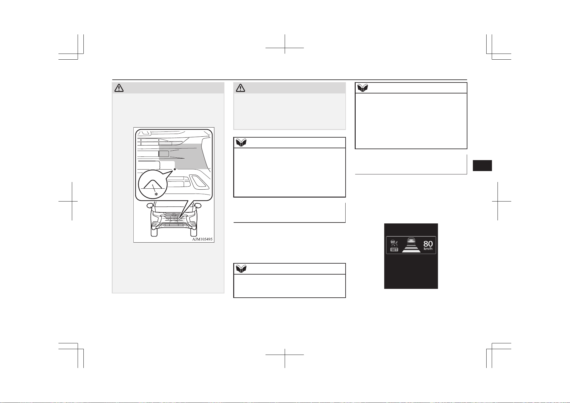
CAUTION
•
Do not cover the sensor mounted area
(shaded area as shown in the illustration)
with a sticker, licence plate or anything
such as a grill guard, etc.
•
The sensor front cover should not be
modified or painted.
•
Avoid using different size tyres from
those specified and maintain even tyre
wear.
•
Do not modify the suspension of your ve-
hicle.
CAUTION
l
When the cover in front of the sensor or the
sensor is deformed by an accident, please do
not use the ACC and contact a
MITSUBISHI MOTORS Authorized Serv-
ice Point.
NOTE
l
You cannot operate the regenerative brake
controls while the ACC is operating. If do-
ing so, the buzzer sounds.
l
If you turn on the ACC when the select posi-
tion is in “B” (including B0 to B5) position,
the select position is changed to “D” posi-
tion.
When ACC detects no vehicle
in front within the set distance
Your vehicle runs at a speed to which you set.
It is possible to set the speed between ap-
proximately 40 km/h (25 mph) and 180 km/h
(112 mph).
NOTE
l
If the vehicle speed exceed the set speed on
down slope, the system automatically ap-
plies the brake to maintain the vehicle speed.
NOTE
l
When depressing the brake pedal while auto-
matic brake is applied, the brake pedal is felt
solidly, but it is not abnormal. You can more
depress the pedal and it provides greater
braking force.
l
Sound is heard while automatic brake, but it
is operated a brake control and not abnor-
mal.
When ACC detects a vehicle in
front within the set distance
The ACC makes control to maintain a fol-
lowing distance (time gap) matched with the
vehicle speed between your vehicle and a ve-
hicle in front while also activating brakes as
necessary.
If the vehicle in front stops, the ACC reacts
to it by stopping your vehicle.
Depress the brake pedal as soon as your vehi-
cle comes to a stop.
Adaptive Cruise Control System (ACC)*
7-57
OGGE19E1
Starting and driving
7
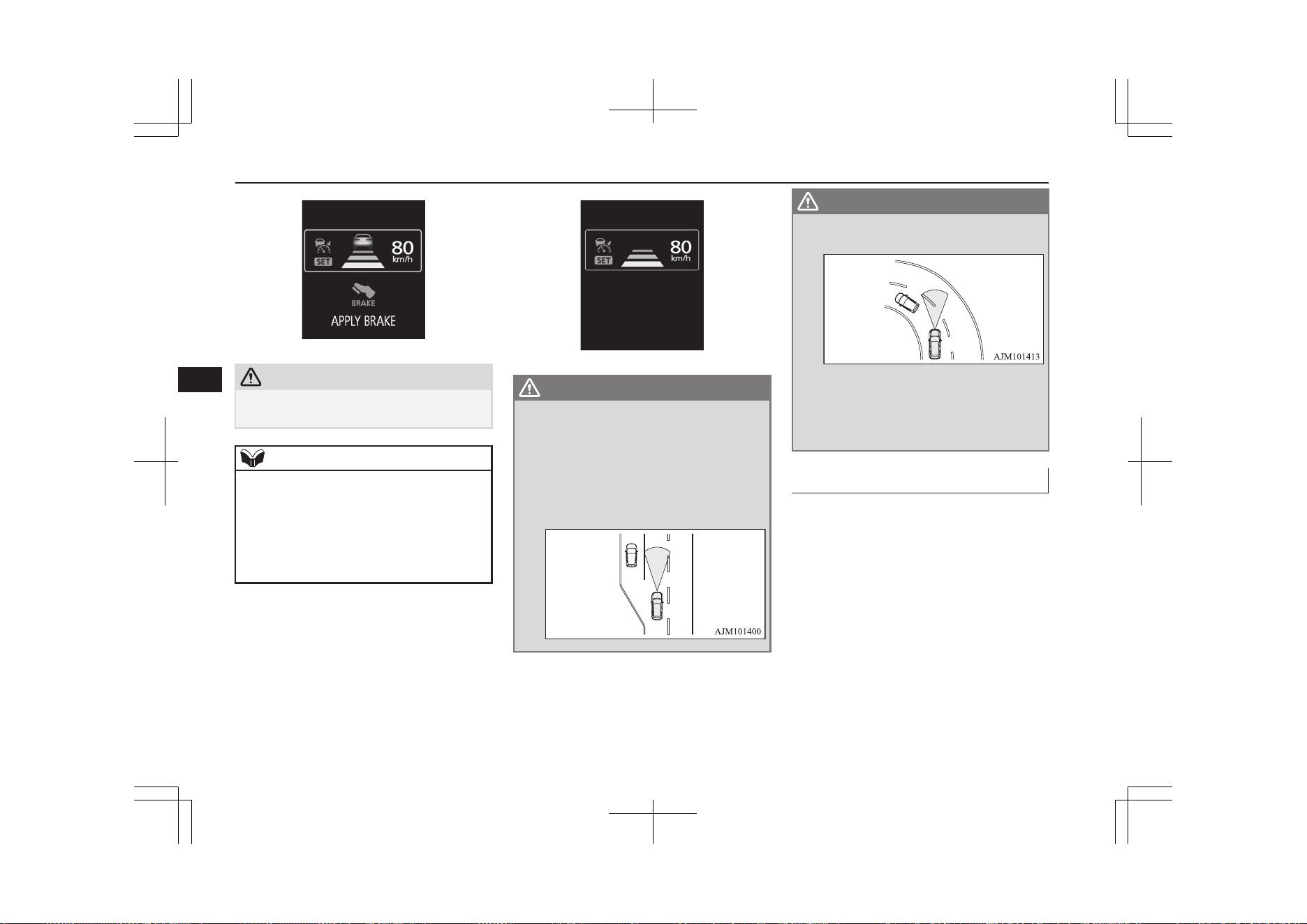
CAUTION
l
Never leave the vehicle when it is stopped
by automatic braking.
NOTE
l
If you do not depress the brake pedal within
2 seconds after an automatic stop, you are
alerted to automatic cancellation of the ACC
by a buzzer and display message and the
ACC shift into the ‘standby state’.
The vehicle will then start creeping as the
brakes are released.
When the ACC no longer detects any vehicle
in front, a buzzer sounds and the symbol of
vehicle running ahead disappears from the
screen. The vehicle is slowly accelerated to
resume the set speed and continues running at
that speed.
WARNING
l
Your vehicle may accelerate up to the set
speed in the following situations. Apply
the brake, if necessary, to slow down.
•
When your vehicle no longer follows
the vehicle in front, e.g. at a freeway ex-
it or when your vehicle or the vehicle in
front changes its lane.
WARNING
•
When driving on a curve.
l
If the vehicle in front turns off or changes
lane and another stationary vehicle is lo-
cated in front of that vehicle, the ACC will
not make deceleration control to the sta-
tionary vehicle.
Proximity alarm
E00634701079
While the ACC is active, if your vehicle ap-
proaches too closely to a vehicle in front be-
cause the ACC cannot allow for an adequate
deceleration in such cases as rapid decelera-
tion of the vehicle in front or apparition of a
vehicle cutting in front of your vehicle, the
ACC gives a warning by sounding a buzzer
and displaying a message.
If this happens, increase the following dis-
tance by depressing the brake pedal or mak-
ing other decelerating control.
Adaptive Cruise Control System (ACC)*
7-58
OGGE19E1
Starting and driving
7
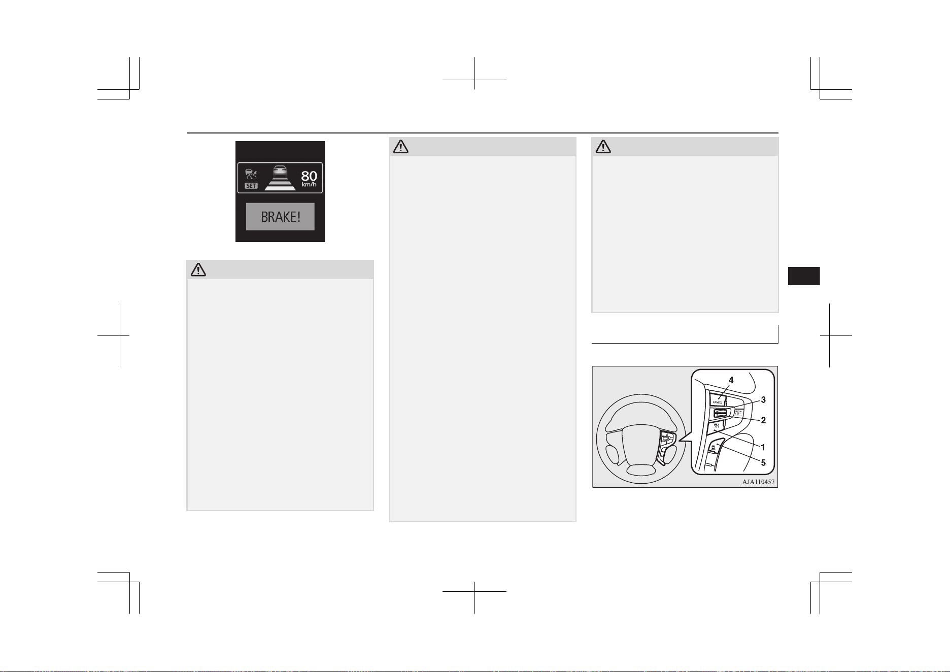
CAUTION
l
When the ACC is not in use, turn off the sys-
tem to prevent it from operating by mistake
and an unexpected accident.
l
Never operate the ACC from outside the ve-
hicle.
l
Neither control nor a warning are performed
in the following situation.
•
Something other than a vehicle ap-
proaches, such as a pedestrian.
•
When there is an abnormality in the sys-
tem (When the ACC detectes an abnor-
mality, “ACC SERVICE REQUIRED” is
indicated.)
l
The ACC makes neither acceleration nor de-
celeration control and only issues warning in
the following situation.
•
The vehicle in front is parked or moving
at an extremely slow speed.
l
The ACC may not be able to maintain the
set speed or the distance to a vehicle in front
and may not alert the driver, if the system
CAUTION
cannot detect the vehicle in front properly, in
the following situations.
•
When a vehicle cuts in front of your vehi-
cle very closely.
•
When a vehicle in front is offset to the left
or right.
•
When a vehicle in front is towing a trailer.
•
The vehicle in front is moving at a speed
much lower than your vehicle’s.
•
A motorcycle or a bicycle.
•
A freight trailer that is not carrying a con-
tainer.
•
The vehicle has a protruding load from
the carrier.
•
When the vehicle has a low weight.
•
When the vehicle has an extremely high
ground clearance.
•
When there is repeated steep uphill and
downhill driving.
•
When driving on an irregular or uneven
road surface.
•
When being driven in a tunnel.
•
When you are carrying extremely heavy
loads in the rear seats or luggage area.
•
When the Plug-in Hybrid EV System is
starting.
•
When driving in curved sections of road
including their entrance/outlet or running
beside a closed lane in a traffic work or
similar zone.
•
When the cover part in front of the sensor
and the sensor become dirty or have snow
and ice adhering to it*.
CAUTION
•
When water, snow or sand on the road are
extorted by the vehicle in front or an on-
coming vehicle*.
*: After the ACC control has been cancelled
automatically due to detection of a state of
decline in performance, the ACC will not
operate in the temporary condition and will
inform the driver by buzzer and indication.
When the ACC is in the state in which it can
operate, indication is cancelled. Should indi-
cations not be cancelled, then there is a pos-
sible abnormality in the system.
Please contact a MITSUBISHI MOTORS
Authorized Service Point.
Cruise control switch
E00634801054
1- “ACC ON/OFF” switch
Used to turn on and off ACC or the
cruise control function.
Adaptive Cruise Control System (ACC)*
7-59
OGGE19E1
Starting and driving
7
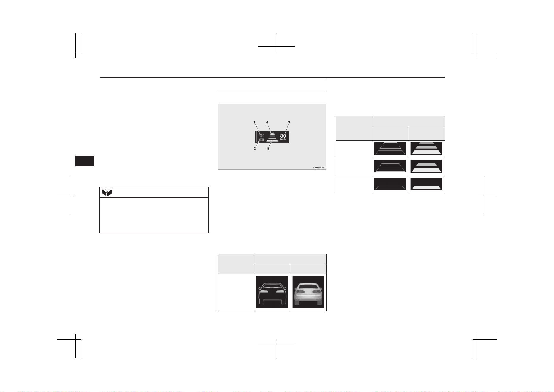
2- “SET -” switch
Used to set a desired speed and to reduce
the set speed.
3- “RES +” switch
Used to make ACC operate at the origi-
nally set speed and also to increase the
set speed.
4- “CANCEL” switch
Used to cancel the control function of
ACC or the cruise control.
5- ACC distance switch
Used to change the setting of the follow-
ing distance between your vehicle and a
vehicle in front.
NOTE
l
Operate the individual switches correctly
and one after another.
The ACC may be turned off or its control
function may be cancelled if two or more
switches are pressed concurrently.
Driving aid display
E00634901042
1- ACC indicator:
Indicate that the ACC is ON.
2- Control state indicator:
Indicate that the ACC is active.
3- Set speed:
Indicate the target speed.
4- Vehicles in front symbol:
Comes on when the radar detects a vehi-
cle ahead. Two types of indication;
“Stand by” and “Active”
Display
State
Stand by Active
Vehicle in
front detected
5- Following distance setting symbol:
Indicate the set following distance. Two
types of indication; “Stand by” and “Ac-
tive”
Following
distance set-
ting symbol
State
Stand by Active
Long
Middle
Short
Adaptive Cruise Control System (ACC)*
7-60
OGGE19E1
Starting and driving
7
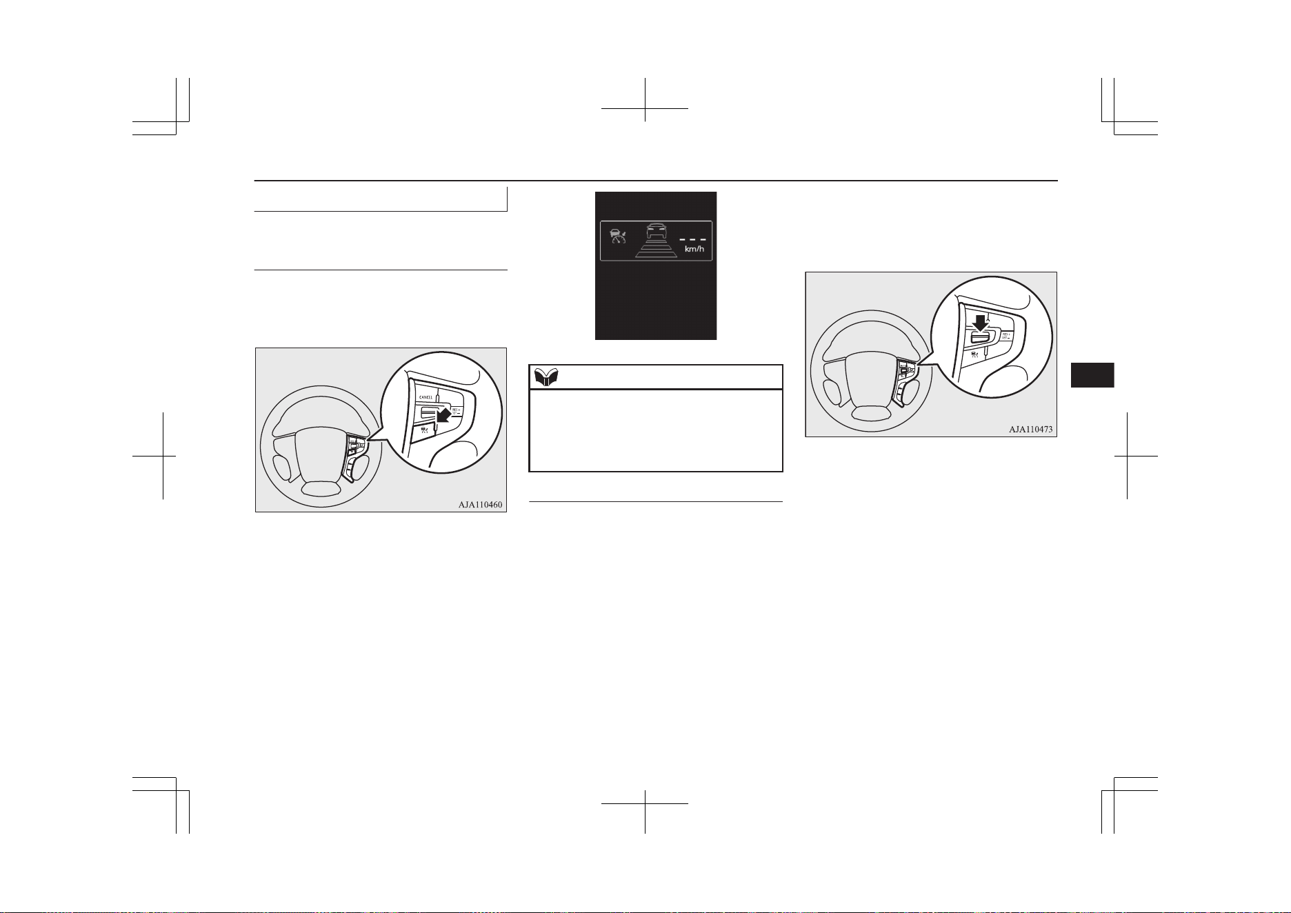
How to use ACC
E00635001486
To start up (place in ‘standby
state’) the system
With the operation mode set to “ON”, press
the “ACC ON/OFF” switch shortly to acti-
vate the ACC.
The display on the information screen of the
multi-information display will switch to show
information on the ACC.
When the ACC is activated, it is placed in the
‘standby state’ at which any control function
is not started.
NOTE
l
Even if the ACC is in the activated state
when the operation mode is set to “OFF”,
the system does not automatically become
activated when the operation mode is set to
“ON” next time.
To activate ACC control
With the ACC turned on (in the ‘standby
state’), push down the “SET -” switch while
driving.
When your desired speed is reached, release
the “SET -” switch; then this speed is set and
the ACC initiates the speed control to the set
speed.
The set speed is indicated on the information
screen of the multi-information display.
The ACC can be selected between approxi-
mately 40 km/h (25 mph) to 180 km/h
(112 mph).
You can set and initiate the speed control
when driving at approximately 10 km/h
(6 mph) to 40 km/h (25 mph) while a vehicle
in front is being detected. In this case, the tar-
get speed is set to 40 km/h (25 mph).
Setting to any speed outside this range does
not cause the ACC to start the control.
Adaptive Cruise Control System (ACC)*
7-61
OGGE19E1
Starting and driving
7
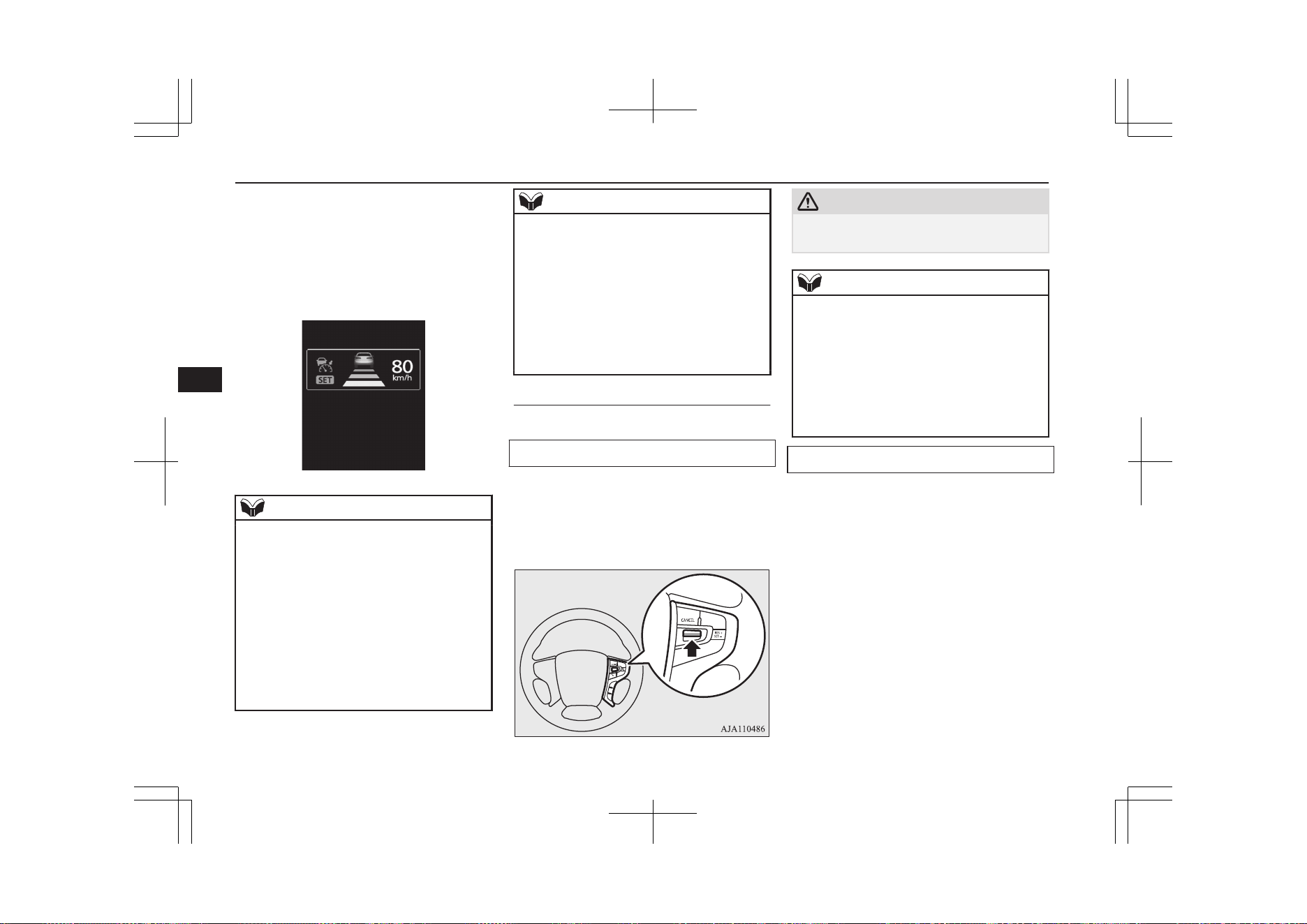
When the ACC is initialized, a buzzer sound
is heard and the “SET” indicator lights up on
the screen. At the same time, the display
showing the following distance setting and
the running-ahead vehicle symbol (only when
the ACC is detecting a vehicle in front) is
switched to the in-control mode display.
NOTE
l
The ACC cannot start the control when any
of the following conditions is present. You
are alerted to this state by a sounding buzzer.
•
When the vehicle speed is lower than ap-
proximately 10 km/h (6 mph) or 180 km/h
(112 mph) or higher.
•
When the vehicle is running at a speed be-
tween approximately 10 km/h (6 mph)
and 40 km/h (25 mph) and the ACC does
not detect a vehicle in front.
•
When ASC is in the OFF state.
•
When ABS, ASC or TCL is working.
NOTE
•
When the select position is in the “P”
(PARK), the “R” (REVERSE) or the “N”
(NEUTRAL) position.
•
While the brake pedal is being depressed.
•
When the parking brake is applied.
•
When the system determines that its per-
formance has been degraded due to con-
taminants adhered to the sensor.
•
When there is any abnormality in the sys-
tem.
To increase the set speed
There are two ways to increase the set speed.
By using the “RES +” switch:
The set speed increases by 1 km/h (1 mph)
every time you push up the “RES +” switch
while the ACC control is working. If you
hold the switch pushed up, the set speed in-
creases in 5 km/h (3 mph) increments.
CAUTION
l
The setting speed should be set up the suita-
ble speed according to a situation.
NOTE
l
There is some time lag between the setting
to a new speed and actually accelerating to
that speed.
l
Speed setting operation is possible even in
presence of a vehicle in front. In this case,
however, the set speed alone increases with-
out actual acceleration taking place.
l
When the switch is held pushed, a buzzer
sounds every time the set speed changes.
By using the accelerator pedal:
When the accelerator pedal is depressed
while driving with the ACC control working,
you can accelerate the vehicle temporarily
beyond the presently set speed.
Adaptive Cruise Control System (ACC)*
7-62
OGGE19E1
Starting and driving
7
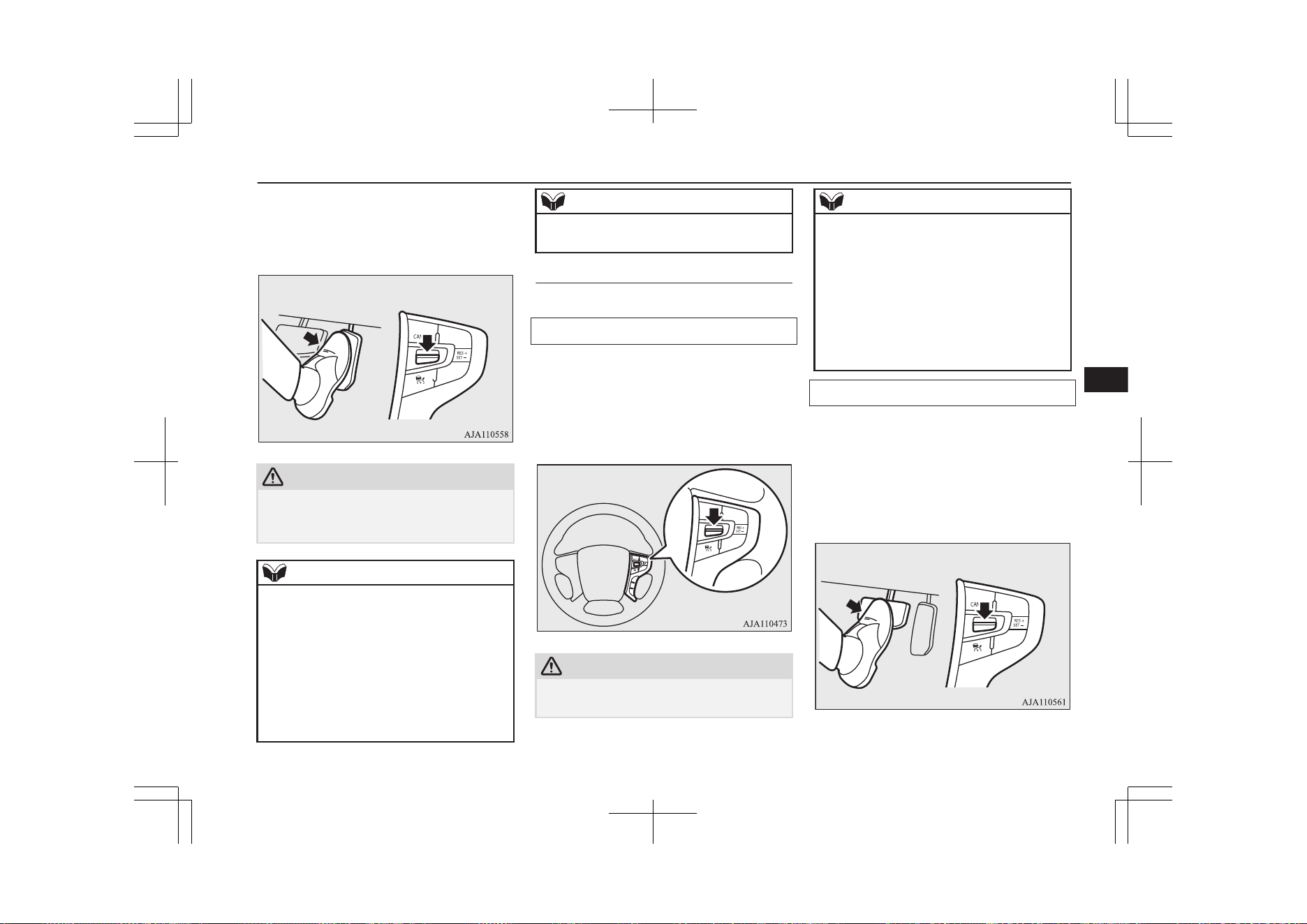
At the point where the vehicle speed is raised
to your desired speed, push down and release
the “SET -” switch; the new speed is then set
in the system.
CAUTION
l
The ACC braking control and proximity
alarm functions will not work while the ac-
celerator pedal is depressed.
NOTE
l
The set speed indication on the display turns
to “---” when the accelerator pedal is de-
pressed. This indication remains as long as
the pedal is in a depressed position.
l
The ACC control at the original set speed re-
sumes as soon as you release the accelerator
pedal. Under certain conditions, however,
the braking control and alarming functions
of ACC may not work for a short while after
releasing the accelerator pedal.
NOTE
l
Set speed adjustment is impossible while the
accelerator pedal is in a depressed position.
To decrease the set speed
There are two ways to decrease the set speed.
By using the “SET -” switch:
The set speed decreases by 1 km/h (1 mph)
every time you push down the “SET -”
switch while the ACC control is working. If
you hold the switch pushed down, the set
speed decreases in increments of 5 km/h
(3 mph).
CAUTION
l
The setting speed should be set up the suita-
ble speed according to a situation.
NOTE
l
There is some time lag between setting to a
new speed and actually decelerating to that
speed.
l
If there is a vehicle in front and your vehicle
is following that vehicle at a speed lower
than the set speed, the set speed alone de-
creases with no actual deceleration taking
place.
l
When the switch is held pushed, a buzzer
sounds every time the set speed changes.
By using the brake pedal:
If you depress the brake pedal while the ACC
control is working, the control is cancelled,
allowing you to decelerate the vehicle.
At the point where the vehicle slows down to
your desired speed, push down the “SET -”
switch; the new speed is then set in the sys-
tem.
Adaptive Cruise Control System (ACC)*
7-63
OGGE19E1
Starting and driving
7
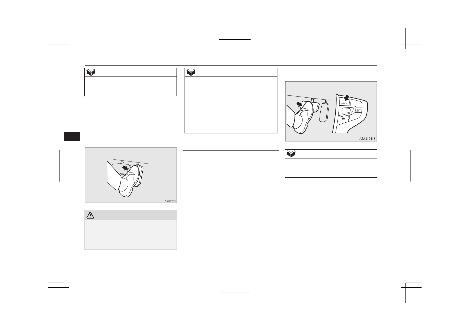
NOTE
l
The ACC control is cancelled if you depress
the brake pedal and the ACC control does
not resume even when you release the pedal.
To temporarily accelerate the
vehicle
Simply depress the accelerator pedal to tem-
porarily accelerate the vehicle. Releasing the
pedal automatically slows down the vehicle
to the set speed and ACC restarts its control.
CAUTION
l
The ACC braking control and proximity
alarm functions will not work while the ac-
celerator pedal is depressed.
l
The setting speed should be set up the suita-
ble speed according to a situation.
NOTE
l
The set speed indication on the display turns
to “---” when the accelerator pedal is de-
pressed. This indication remains as long as
the pedal is in a depressed position.
l
In certain conditions, the braking control and
alarming functions of ACC may not work
for a short while after releasing the accelera-
tor pedal.
l
Set speed adjustment is impossible while the
accelerator pedal is in a depressed position.
To terminate ACC control
To cancel of ACC control
You can cancel the ACC control by using ei-
ther of the methods below.
When the control is cancelled, the system is
placed in the ‘standby state’. You can make
the system restart the control by using the
“SET -” or “RES +” switch if the conditions
for activating the control are met.
l
Press the “CANCEL” switch.
l
Depress the brake pedal.
NOTE
l
You can also cancel the ACC control by
pressing the “ACC ON/OFF” switch. If this
switch is pressed, ACC is turned off.
When the system shifts into the ‘standby
state’ as a result of cancellation of the ACC
control, the“ SET” indicator goes out. At the
same time, the display of the following dis-
tance setting and running-ahead vehicle sym-
bol (only when ACC is detecting a vehicle) is
placed in the standby state of display.
Adaptive Cruise Control System (ACC)*
7-64
OGGE19E1
Starting and driving
7
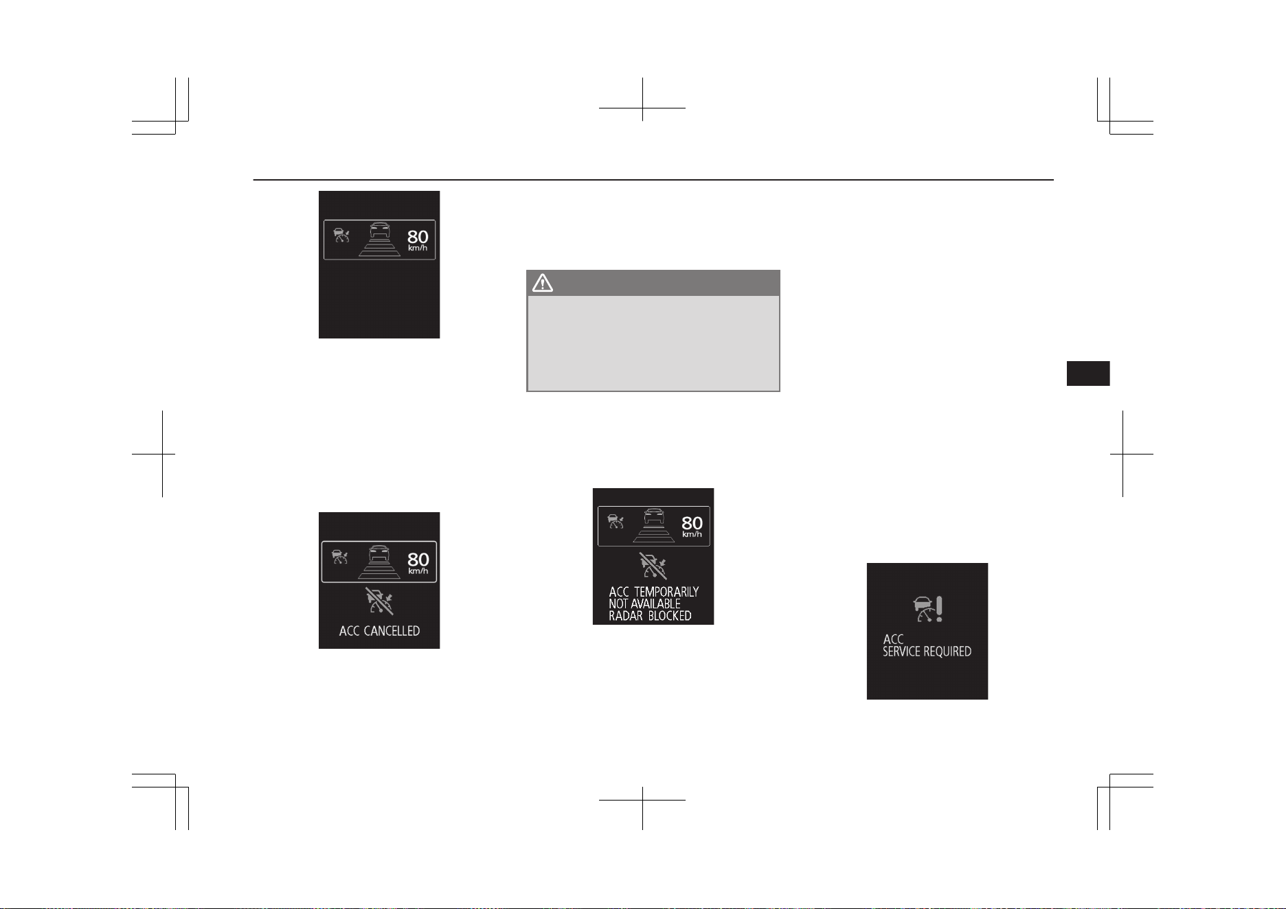
The ACC control is automatically cancelled
and the ACC is placed in the ‘standby’ state
in any of the situations listed below; you are
alerted to this condition by the sound of a
buzzer and a message on the display. You can
make the system restart the control by using
the “SET -” or “RES +” switch if the condi-
tions for resuming the control are reestablish-
ed.
l
When your vehicle stops as the vehicle
in front stops.
l
When ASC is turned off.
l
When ABS, ASC or TCL is in operation.
l
When the select position is in the “P”
(PARK), the “R” (REVERSE) or the
“N” (NEUTRAL) position.
l
When the parking brake is applied.
WARNING
l
Although the set speed driving will be de-
activated when shifting to the “N” (NEU-
TRAL) position, never move the selector
lever to the “N” (NEUTRAL) position
while using regenerative braking as it
could cause a serious accident.
When the ACC system determines that its
performance has been degraded, a buzzer will
sound and a message will be displayed in the
multi information display.
This can occur when:
l
Foreign objects, such as dirt, snow or
ice, adhere to the surface of the sensor.
l
There are adverse weather conditions,
such as rain, snow or sand storms, etc.
l
A vehicle in front or an oncoming vehi-
cle is splashing water, snow or dirt.
l
Driving on a nonbusy road with a few
vehicles and obstacles in front.
l
The brake system is overheating due to
continuous brake control on long down-
hill road.
If the display keeps showing the message,
there is a possibility that the ACC has a mal-
function. Contact a MITSUBISHI MOTORS
Authorized Service Point.
When the ACC system detects an abnormali-
ty in the system, the ACC system will be
turned off, a buzzer will sound and a message
will be displayed in the multi information
display.
If the message remains after the operation
mode has been turned to the “OFF” position
and then turned back to the “ON” position,
contact a MITSUBISHI MOTORS Author-
ized Service Point.
Adaptive Cruise Control System (ACC)*
7-65
OGGE19E1
Starting and driving
7
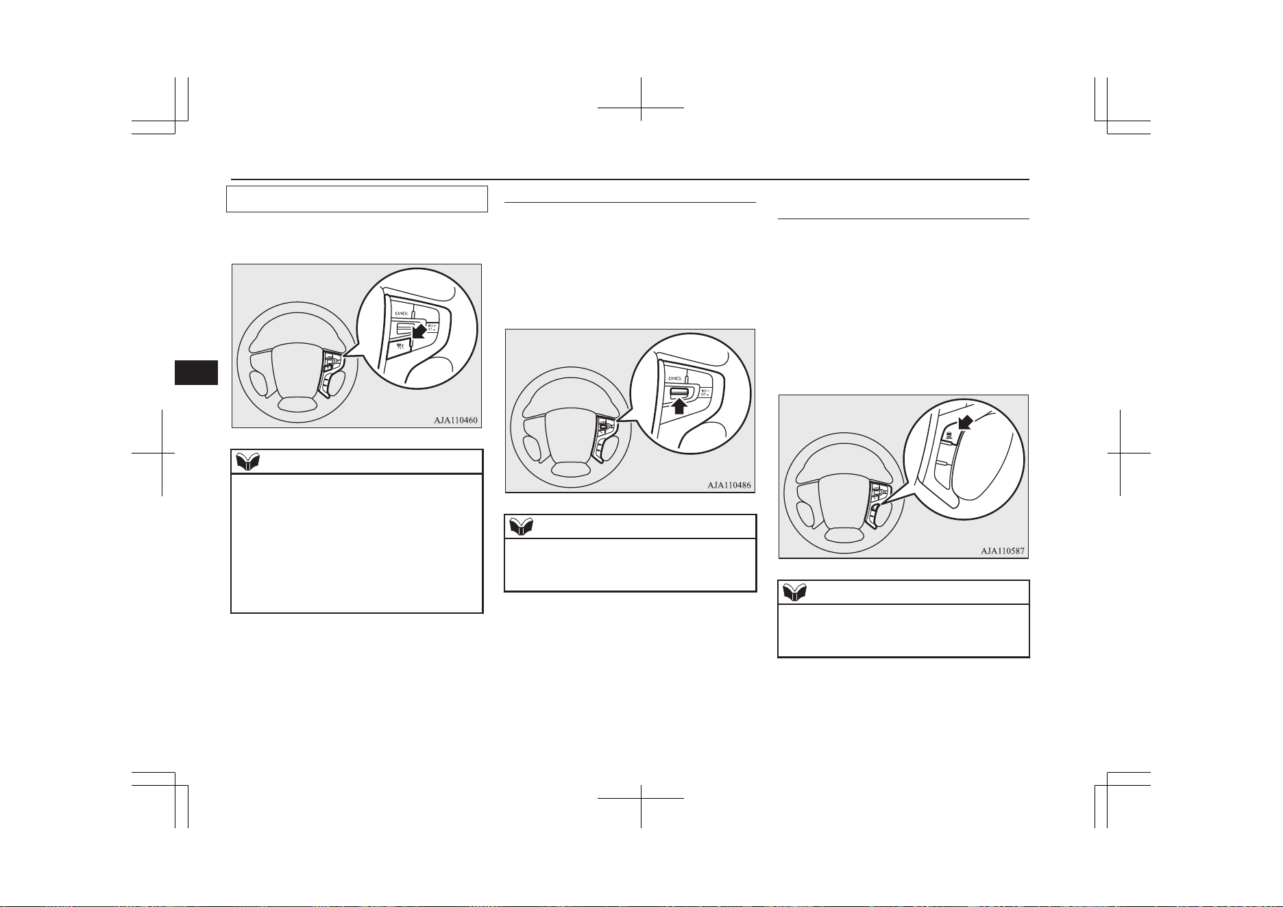
To turn off ACC
Press the “ACC ON/OFF” switch when ACC
is in the ‘ON state’ to turn off ACC.
NOTE
l
Pressing the switch turns off the ACC even
if it is engaged.
l
The set speed is cancelled when the ACC is
turned off or the operation mode is set to
“OFF”.
l
If the ACC is in the ‘ON state’ when the op-
eration mode is set to “OFF”, the system is
set to the ‘OFF state’ when the operation
mode is set to “ON” next time.
To resume the control
After cancelling the ACC control (i.e. placing
the system in the ‘standby state’) by pressing
the “CANCEL” switch or depressing the
brake pedal, you can resume the ACC control
at the originally set speed if you push up the
“RES -” switch.
NOTE
l
The conditions to be met before the ACC
control can be resumed are the same as those
for starting the ACC control.
To change the following dis-
tance setting
Every time you press the following distance
setting switch, the setting changes sequential-
ly through three options “Long”, “Middle”
and “Short”, cycling back to “Long” after
“Short”. The distance setting is reset when
the operation mode is set to “OFF” or when
the ACC is set to “OFF,” and is automatically
set to “long” when you set the ACC to “ON”
next time.
NOTE
l
The following distance varies as a function
of the speed; the faster the set speed, the lon-
ger the following distance.
Adaptive Cruise Control System (ACC)*
7-66
OGGE19E1
Starting and driving
7
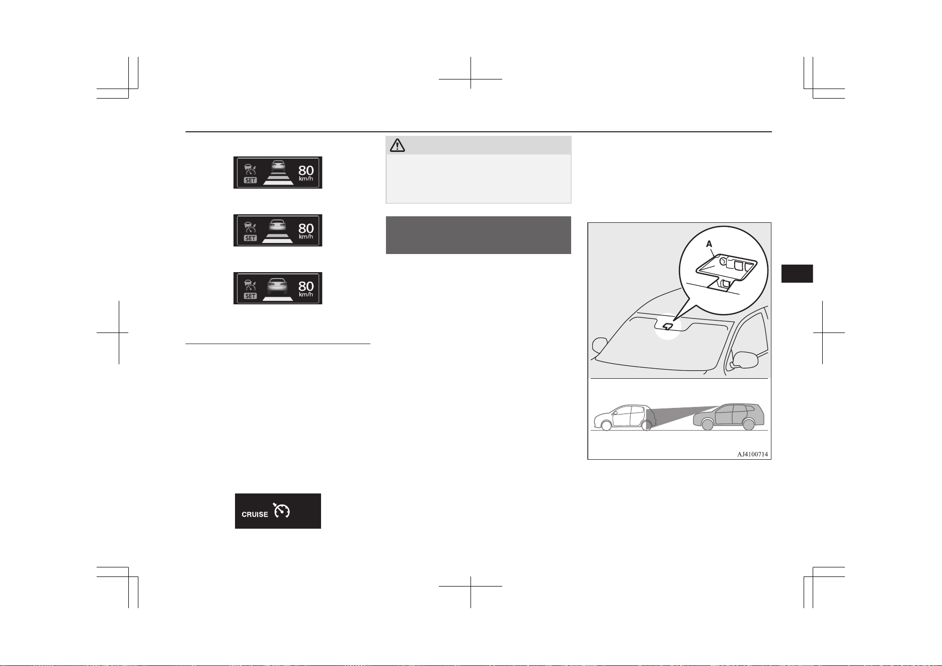
Following distance setting: “Long”
Following distance setting: “Middle”
Following distance setting: “Short”
To activate cruise control (auto-
matic speed control)
If you hold the “ACC ON/OFF” switch
pressed with the operation mode set to “ON”
and the ACC in the ‘OFF state’, the cruise
control is activated. The information screen
of the multi-information display then changes
to the cruise control screen and a buzzer
sounds at the same time.
Cruise control is turned off if you set the op-
eration mode to “OFF”.
→ “Cruise control (automatic speed control
system)” on page 7-45
CAUTION
l
Cruise control (automatic vehicle speed con-
trol system) does not alert by proximity
alarm and control distance between vehicles
to the vehicle in front.
Forward Collision
Mitigation System (FCM)*
E00635101243
The Forward Collision Mitigation System
(FCM) uses a sensor (A) to determine the
distance and relative speed to a vehicle and a
pedestrian in front.
When your vehicle is approaching a vehicle
or a pedestrian straight-ahead in your path
and the FCM judges that there is the risk of a
collision, the system gives audible and visual
warnings (forward collision warning func-
tion), increases the brake fluid pressure
(FCM brake prefill function), and also pro-
vides braking force assistance when you de-
press the brake pedal (FCM brake assist func-
tion) to avoid frontal collision.
When the risk of collision increases more, the
system causes the brakes to work moderately
to encourage you to apply brakes. If the sys-
tem judges that a potential collision is immi-
nent, it initiates emergency braking to miti-
gate collision-caused damages or to avoid
possible collision (FCM braking function).
Stop lamps are illuminated during automatic
braking.
If you turn the FCM ON/OFF, the Ultrasonic
misacceleration Mitigation System (UMS) al-
so turns ON/OFF at the same time. (Vehicles
equipped with the UMS)
Forward Collision Mitigation System (FCM)*
7-67
OGGE19E1
Starting and driving
7
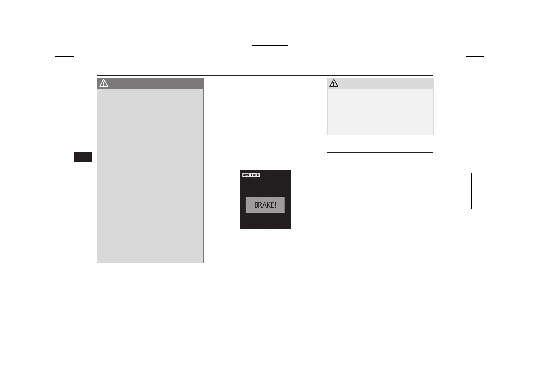
WARNING
l
A driver is responsible for driving safely.
The FCM is the system to mitigate colli-
sion-caused damages or to avoid collisions
as much as possible.
The system is not intended to compensate
for driver’s loss of attention to the front
during driving due to distraction or care-
lessness or supplement a drop in visibility
due to the rain and fog.
It is never a substitute for your safe and
careful driving. Always be ready to apply
the brakes manually.
l
The FCM works to avoid frontal collisions
as much as possible. However, the effect of
its operation varies depending on situa-
tions and conditions, such as driving con-
ditions, road conditions, and steering, ac-
celeration and braking operations, so that
the performance the function can deliver
is not always the same.
If your vehicle is in danger of collision,
take all necessary collision-evading ac-
tions, such as depressing the brake pedal
strongly regardless of whether the system
is activated or not.
l
Never attempt to test the operation of the
FCM. Doing so could cause an accident,
resulting in serious injury or death.
Forward collision warning
function
E00635401129
If the system judges that there is a risk of
your vehicle colliding with a vehicle or a pe-
destrian in front, this function warns you of
the potential hazard with visual and audible
alarms.
When this function is triggered, a buzzer
sounds and, at the same time, a “BRAKE!”
message appears on the information screen of
the multi-information display.
The forward collision warning function oper-
ates at the following vehicle speed:
l
Against a vehicle: Approximately
15 km/h (9 mph) to 140 km/h (87 mph).
l
Against a pedestrian: Approximately
7 km/h (5 mph) to 65 km/h (40 mph).
CAUTION
l
Under certain conditions, the audible alarm
may not work at all or may be scarcely audi-
ble. Do not overly rely on the system; if your
vehicle is in danger of collision, take all nec-
essary collision-evading actions, such as de-
pressing the brake pedal strongly regardless
of whether the system is activated or not.
FCM brake prefill function
E00635201055
If the system judges that there is a risk of
your vehicle colliding with a vehicle or a pe-
destrian in front, this function prefills the
brake line with additional brake fluid to make
the brakes more responsive to your brake
pedal operation.
The FCM brake prefill function operates at
the following vehicle speed:
l
Against a vehicle: Approximately
5 km/h (3 mph) to 80 km/h (50 mph).
l
Against a pedestrian: Approximately
5 km/h (3 mph) to 65 km/h (40 mph).
FCM brake assist function
E00635301072
If the system judges that there is a risk of
your vehicle colliding with a vehicle or a pe-
destrian in front, this function deploys the
brake assist sooner than the brake assist oper-
ation.
Forward Collision Mitigation System (FCM)*
7-68
OGGE19E1
Starting and driving
7
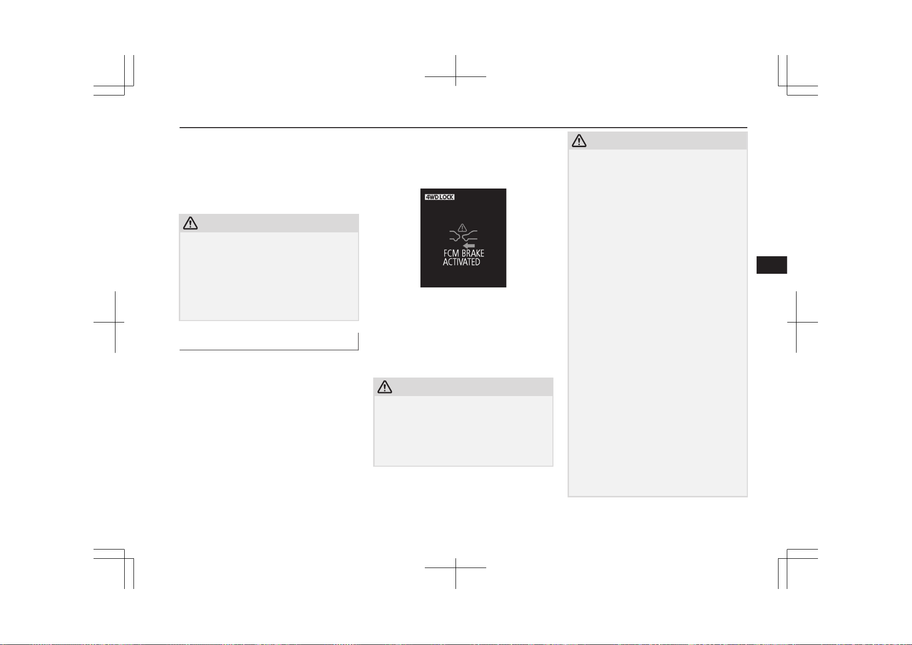
The FCM brake assist function operates at
the following vehicle speed:
l
Against a vehicle: Approximately
15 km/h (9 mph) to 80 km/h (50 mph).
l
Against a pedestrian: Approximately
15 km/h (9 mph) to 65 km/h (40 mph).
CAUTION
l
The brake assist function may not be trig-
gered when the brake pedal is operated in
certain ways.
Do not overly rely on the system; if your ve-
hicle is in danger of collision, take all neces-
sary collision-evading actions, such as de-
pressing the brake pedal strongly regardless
of whether the system is activated or not.
FCM braking function
E00635501380
If the system judges that there is a high risk
of your vehicle colliding with a vehicle or a
pedestrian in front, the system applies the
brakes moderately to encourage you to apply
the brakes.
If the system judges that a collision is un-
avoidable, it initiates emergency braking con-
trol to mitigate collision-caused damages or,
if the situation permits, to avoid a collision.
When the emergency braking control is trig-
gered, you are warned of the hazard with vis-
ual and audible alarms like with the forward
collision warning function.
Once the emergency braking has worked, you
are alerted to this by a message on the infor-
mation screen of the multi-information dis-
play.
The FCM braking function operates at the
following vehicle speed:
l
Against a vehicle: Approximately
5 km/h (3 mph) to 80 km/h (50 mph).
l
Against a pedestrian: Approximately
5 km/h (3 mph) to 65 km/h (40 mph).
CAUTION
l
Do not use the FCM as a normal braking.
l
After your vehicle has stopped following the
activation of the FCM, automatic braking is
released. As the vehicle will then start creep-
ing, be sure to depress the brake pedal to
hold the vehicle stationary.
CAUTION
l
When applying the brake during the auto-
matic braking condition the pedal will feel
firm.
This is not abnormal.
You can apply more pressure to the pedal to
assist in braking.
l
In the following situations, the system pro-
vides neither control nor alarming.
•
When a vehicle or a pedestrian suddenly
cuts in front of your vehicle.
•
When the distance from a vehicle or a pe-
destrian in front is extremely short.
•
To an oncoming vehicle.
•
When the select position is in the “P”
(PARK) or the “R” (REVERSE) position.
•
When the FCM has detected a problem in
the system.
l
If the ASC is deactivated, the FCM braking
function will not operate. Refer to “Active
Stability Control (ASC)” on page 7-43.
l
The FCM may or may not detect a motorcy-
cle, bicycle or wall depending on the situa-
tion. The FCM is not designed to detect
these objects.
l
The forward collision warning function
and/or the FCM braking function may not
activate in the following situations.
•
When a vehicle suddenly appear just in
front of your vehicle.
•
When a vehicle cuts in front of your vehi-
cle very closely.
•
When the vehicle in front is offset to the
left or right.
Forward Collision Mitigation System (FCM)*
7-69
OGGE19E1
Starting and driving
7

CAUTION
•
When the vehicle in front is towing a
trailer.
•
A freight trailer that is not carrying a con-
tainer.
•
The vehicle has a protruding load from
the carrier.
•
The vehicle has a low vehicle height.
•
The vehicle has an extremely high ground
clearance.
•
When a vehicle in front is extremely dirty.
•
When a vehicle in front is covered with
snow.
•
When a vehicle in front has a large glass
surface.
•
When a vehicle in front does not have re-
flectors (lamp reflector) or the position of
the reflector is low.
•
When a vehicle in front is a car carrier or
a similar shaped vehicle.
•
When there is a different object near the
vehicle.
•
When driving on a road with many and
successive curves, including when pass-
ing their entrances and outlets.
•
When accelerating and decelerating
quickly.
•
When the system recognizes driver’s
steering, accelerating, braking or gear
shifting actions as evasive actions to
avoid collision.
•
When you are driving on a road with
steep and alternating up and down slopes.
•
When driving on a slippery road covered
by rain water, snow, ice etc.
CAUTION
•
When a road surface is surging, and there
is unevenness.
•
When driving in dark areas, such as in a
tunnel or at night.
•
When your vehicle changed lanes, and
your vehicle approached immediately be-
hind the vehicle in front.
•
During a certain time after your vehicle
turns left or right.
•
When you are carrying extremely heavy
loads in the rear seats or luggage area.
•
After the Plug-in Hybrid EV System has
been running for an extended period of
time.
•
When using a windscreen washer.
•
If windscreen wipers are not
MITSUBISHI MOTORS GENUINE
parts or equivalent.
•
When the sensor becomes extremely hot
or cold.
•
If the auxiliary battery becomes weak or
runs down.
•
When the sensor is affected by strong
light, such as direct sunlight or the head-
lamps of an oncoming vehicle.
•
Under adverse weather conditions (rain,
snow, sand storms, etc.)
•
When the windscreen of the sensor por-
tion is covered with dirt, water droplets,
snow and ice, etc.
•
When water, snow or sand on the road are
extorted by the vehicle in front or an on-
coming vehicle.
CAUTION
l
The FCM may not detect a pedestrian in cer-
tain situations. Some of these include:
•
It the pedestrian is shorter than approxi-
mately 1 m or taller than approximately 2
m.
•
If the pedestrian is wearing loose-fitting
clothes.
•
If part of a pedestrian’s body is hidden,
such as when holding an umbrella, large
bag, etc.
•
If a pedestrian bends forward, sits or lies
on the road.
•
When a pedestrian is pushing/pulling
something, such as a stroller, bicycle or
wheelchair.
•
When pedestrians gather in a group.
•
When a pedestrian’s clothing appears to
be nearly the same colour or brightness as
its surroundings.
•
When a pedestrian is very close to an ob-
ject, such as a vehicle.
•
When a pedestrian is in a dark area, such
as at night or in a tunnel.
•
When the pedestrian is walking fast or
running.
•
When a pedestrian suddenly rushes in
front of the vehicle.
•
When the position of a pedestrian is close
to the edge of the vehicle.
Forward Collision Mitigation System (FCM)*
7-70
OGGE19E1
Starting and driving
7

CAUTION
l
Factors such as the positional relationship
between your vehicle and a vehicle in front,
driver’s own technique of steering the vehi-
cle and irregularly moving traffic due to ac-
cidents or vehicle trouble may deter the
FCM control and alarm from functioning.
l
When the system recognizes driver’s steer-
ing or accelerating actions as evasive actions
to avoid collision, the FCM control and
alarm functions may be cancelled.
l
The FCM control and alarm functions may
be triggered in the following situations.
•
When there is a structure (B) beside the
entrance of a curve and intersection.
•
When running on a narrow iron bridge.
•
When passing through a gate with small
head or side clearances.
•
When there are metallic objects, steps or
projections on the road surface.
•
When quickly approaching a vehicle in
front to overtake it.
•
When passing an electronic toll collection
gate.
•
When running under an overpass, a pe-
destrian overpass or a small tunnel.
•
When running in Multi-storey car park.
CAUTION
•
When the road gradiently and suddenly
changes while running.
•
When stopping very close to a wall or a
vehicle in front.
•
When passing close to a vehicle, pedes-
trian or object.
•
When driving on the road that the vehicle
in front runs in offset position from your
vehicle.
•
When passing through an area where ob-
jects may contact the vehicle, such as
thick grass, tree branches, or a banner.
•
When there are patterns on the road that
may be mistaken for a vehicle or a pedes-
trian.
•
When a vehicle cuts into your path in the
detecting range of the sensor.
CAUTION
•
When an oncoming vehicle is positioned
straight ahead of your vehicle on a curved
road.
•
When passing through a plastic curtain
etc.
•
When the FCM detects a long object car-
ried on your vehicle, such as skies or a
roof carrier.
•
When driving through fog, steam, smoke
or dust.
•
When the windscreen of the sensor por-
tion is covered with dirt, water droplets,
snow and ice, etc.
l
Turn off the system beforehand when the ve-
hicle is placed in any of the following situa-
tions as the system can operate unexpected-
ly.
•
When using an automatic car wash.
•
When your vehicle’s wheels are driven by
the Plug-in Hybrid EV System on a lift.
•
When your vehicle is towed or your vehi-
cle tows another vehicle.
•
When your vehicle is carried on a truck.
•
When enjoying sports driving on a circuit.
•
When your vehicle is on a chassis dyna-
mometer or free rollers.
•
When the tyre pressure is not correct.
•
When snow traction device (tyre chains)
are attached.
•
If the windscreen on or surrounding the
sensor is cracked or scratched.
Forward Collision Mitigation System (FCM)*
7-71
OGGE19E1
Starting and driving
7
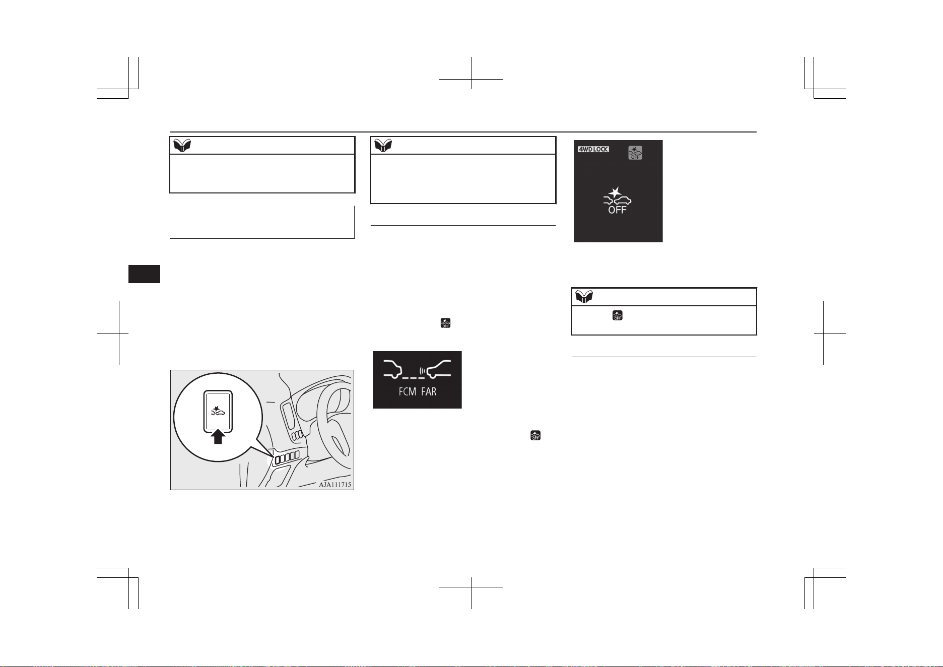
NOTE
l
A sound will be heard during the activation
of automatic braking, this is a function of the
brake control and is not abnormal.
FCM and UMS ON/OFF
switch
E00635601323
This switch is used to turn on and off the
FCM and UMS and also to select your de-
sired collision alarm timing.
When the switch is held pressed, the
ON/OFF state of the FCM and UMS changes
from ON to OFF and vice versa. If you give
the switch a short press with the FCM in the
ON state, you can change the collision alarm
timing.
NOTE
l
When the FCM and UMS ON/OFF switch is
held pressed to change the ON/OFF state of
the FCM, the ON/OFF state of the UMS is
also changed at the same time.
To turn on/off the system
You can switch the system from OFF to ON
or ON to OFF if you hold the FCM and UMS
ON/OFF switch pressed when the operation
mode is set to “ON”.
Once the system is turned on, the information
screen of the multi-information display
shows the collision alarm timing currently se-
lected, and the indicator on the screen
goes out.
When you turn off the system, the following
message appears on the screen and the in-
dicator comes on.
Cycling the operation mode to ON will set
the FCM back ON.
NOTE
l
The indicator is combined with the
“UMS OFF” indicator.
To change alarm timing
Give a short press to the FCM and UMS
ON/OFF switch to change the timing at
which the frontal collision alarm is triggered.
Every time you press the switch, the alarm
timing changes between three levels: “FAR”
(earlier alarming), “MIDDLE” (normally
alarming) or “NEAR” (later alarming).
As you make selection, the selected alarm
timing is displayed on the information screen
of the multi-information display. Even after
turning off the FCM or setting the operation
mode to “OFF”, the system retains your last
selected alarm timing in memory.
When “FAR” is selected
Forward Collision Mitigation System (FCM)*
7-72
OGGE19E1
Starting and driving
7
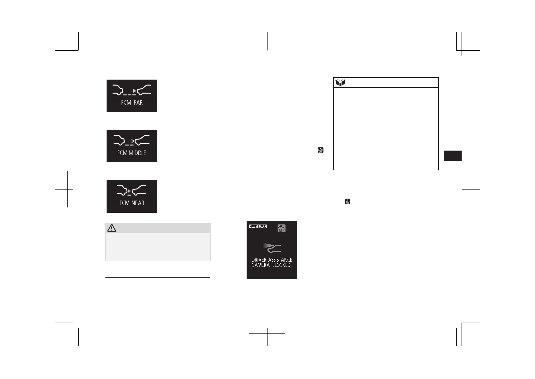
When “MIDDLE” is selected
When “NEAR” is selected
CAUTION
l
For the FCM brake prefill, the FCM brake
assist and the FCM braking functions, the
function triggering timing cannot be
changed.
When a problem is detected
E00652100023
When the FCM system determines that its
performance has been degraded, the FCM
will become inoperative.
This can occur when:
l
Foreign objects, such as dirt, snow or
ice, adhere to the windscreen of the sen-
sor portion.
l
There are adverse weather conditions,
such as rain, snow, sand storms, etc.
l
A vehicle in front or an oncoming vehi-
cle is splashing water, snow or dirt.
The “DRIVER ASSISTANCE CAMERA
BLOCKED” message will appear and the
indicator will appear on the information
screen of the multi-information display.
When the sensor performance returns, the
FCM functions will resume operation.
If the display keeps showing the message,
there is a possibility that the sensor has a
malfunction. Contact a MITSUBISHI
MOTORS Authorized Service Point for in-
spection of the sensor.
NOTE
l
The “DRIVER ASSISTANCE CAMERA
BLOCKED” message may temporarily ap-
pear on the information screen when the sen-
sor cannot detect a vehicle, a pedestrian or
an object within range. This is not a mal-
function. When a vehicle or an object comes
within range, the FCM function will resume
and the message will go off.
l
The “DRIVER ASSISTANCE CAMERA
BLOCKED” message may appear on the in-
formation screen when driving on a non-
busy road with a few vehicles and obstacles
in front.
If the system becomes temporarily unavaila-
ble for some reason, the following message
may appear.
The indicator will appear on the informa-
tion screen of the multi-information display
and the FCM will automatically be turned
off. If the display keeps showing the mes-
sage, there is a possibility that the FCM has a
malfunction. Contact a MITSUBISHI
MOTORS Authorized Service Point for in-
spection of the system.
Forward Collision Mitigation System (FCM)*
7-73
OGGE19E1
Starting and driving
7
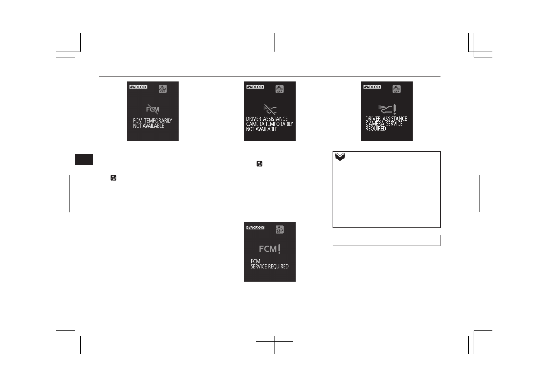
If the system becomes temporarily unavaila-
ble due to a high or low temperature of the
sensor, the following warning message will
appear.
The indicator will appear on the informa-
tion screen of the multi-information display
and the FCM will automatically be turned
off. After the temperature of the sensor has
been in range, the system will automatically
return to operation.
If the display keeps showing the message,
there is a possibility that the FCM has a mal-
function. Contact a MITSUBISHI MOTORS
Authorized Service Point for inspection of
the system.
If the FCM detects a malfunction in the sys-
tem, either one of the following messages
will appear, the indicator will appear on
the information screen of the multi-informa-
tion display and the FCM will automatically
be turned off.
If the message remains even after the opera-
tion mode is put in OFF and then turned back
to ON, please contact a MITSUBISHI
MOTORS Authorized Service Point.
NOTE
l
If the sensor or its surrounding area reaches
an extremely high temperature when parking
the vehicle under a blazing sun, the “FCM
SERVICE REQUIRED” message may ap-
pear.
After the temperature of the sensor or its sur-
rounding area has been in range, if the mes-
sage remains even after restarting the en-
gine, please contact a MITSUBISHI
MOTORS Authorized Service Point.
Handling of the sensor
E00652200125
The sensor (A) is located inside the wind-
screen as shown in the illustration.
The sensor is shared in the following sys-
tems:
l
FCM
l
Lane Departure Warning (LDW)
Forward Collision Mitigation System (FCM)*
7-74
OGGE19E1
Starting and driving
7
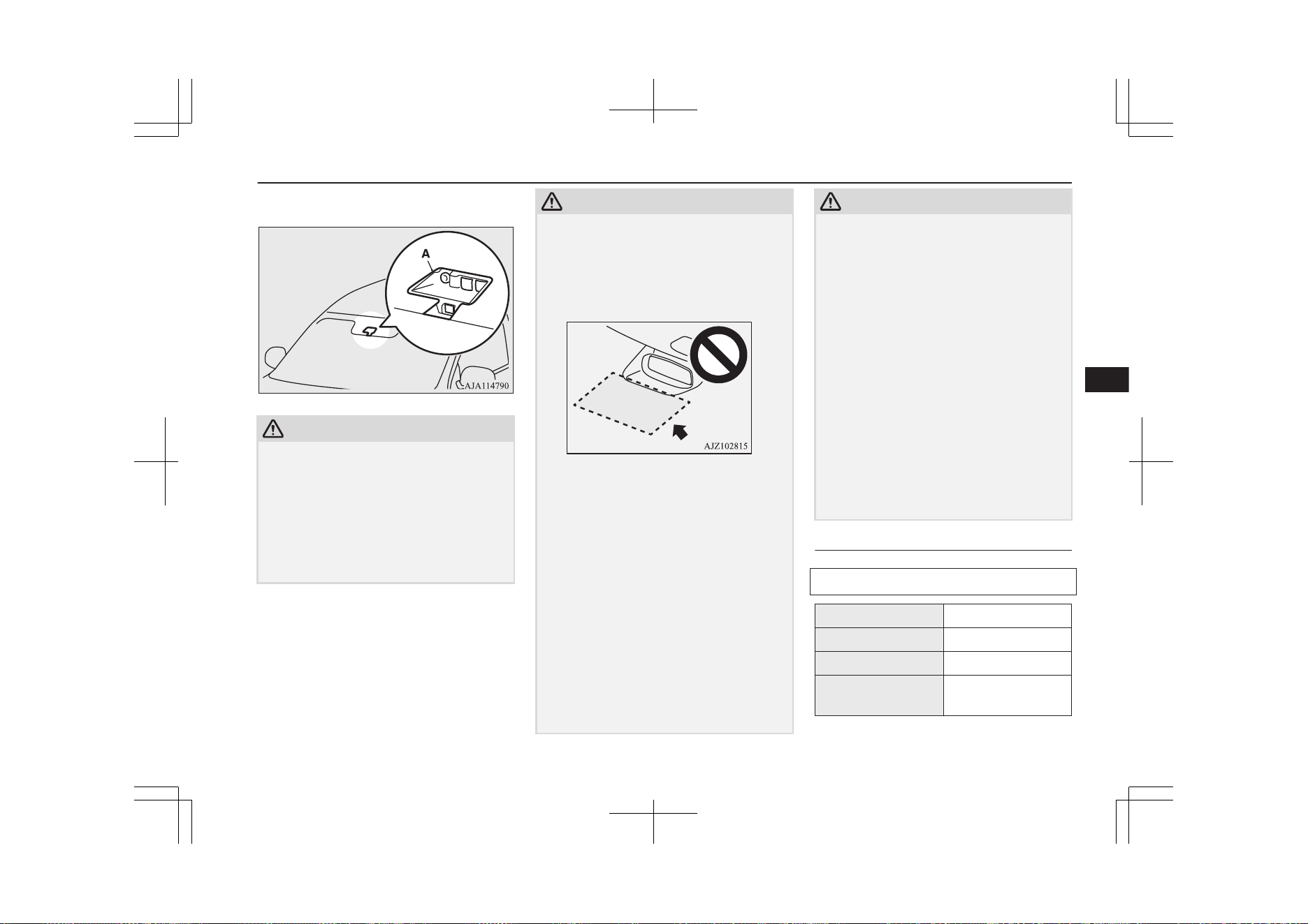
l
Automatic High-Beam (AHB)
CAUTION
l
To maintain proper performance of the
FCM, LDW and AHB;
•
Always keep clean the windscreen.
If the inside of the windscreen where the
sensor is installed becomes dirty or fog-
ged, contact a MITSUBISHI MOTORS
Authorized Service Point.
•
Do not apply an impact or load on the
sensor or its surrounding area.
CAUTION
•
Do not put anything including a sticker or
film to the outer side of the windscreen in
front of or surrounding area of the sensor.
Also, do not put anything including a
sticker or film on the both inner and outer
side of the windscreen under the sensor.
•
Do not attempt to detach or disassemble
the sensor.
•
If the windscreen is misted, remove the
mist from the windscreen by using the de-
mister switch.
•
Maintain the wiper blades in good condi-
tion.
Refer to “Wiper blades” on page 10-06.
When replacing the wiper blades, use on-
ly MITSUBISHI MOTORS GENUINE
parts or equivalent.
•
Do not dirty or damage the sensor.
•
Do not spray glass cleaner on the sensor.
Also, do not spill liquid, such as a bever-
age, on the sensor.
•
Do not install an electronic device, such
as an antenna, or a device that emits
strong electric waves near the sensor.
CAUTION
•
Always use tyres of the same size, same
type and same brand and that have no sig-
nificant wear differences.
•
Do not modify the vehicle’s suspensions.
l
If the windscreen on the sensor or in the sur-
rounding area of the sensor is cracked or
scratched, the sensor may not detect an ob-
ject properly. This could cause a serious ac-
cident. Turn off the FCM and have your ve-
hicle inspected as soon as possible at a
MITSUBISHI MOTORS Authorized Serv-
ice Point.
If you need to replace the windscreen, con-
tact a MITSUBISHI MOTORS Authorized
Service Point.
l
The sensor emits infrared rays when the op-
eration mode is in ON. Do not look into the
sensor by using optical goods such as a mag-
nifying glass. The infrared ray might injure
your eyes.
Laser radar specifications
Laser classification
Max average power 45 mW
Pulse duration 33 ns
Wavelength 905 nm
Divergent angle (ho-
rizon x vertical)
28° x 12°
Forward Collision Mitigation System (FCM)*
7-75
OGGE19E1
Starting and driving
7
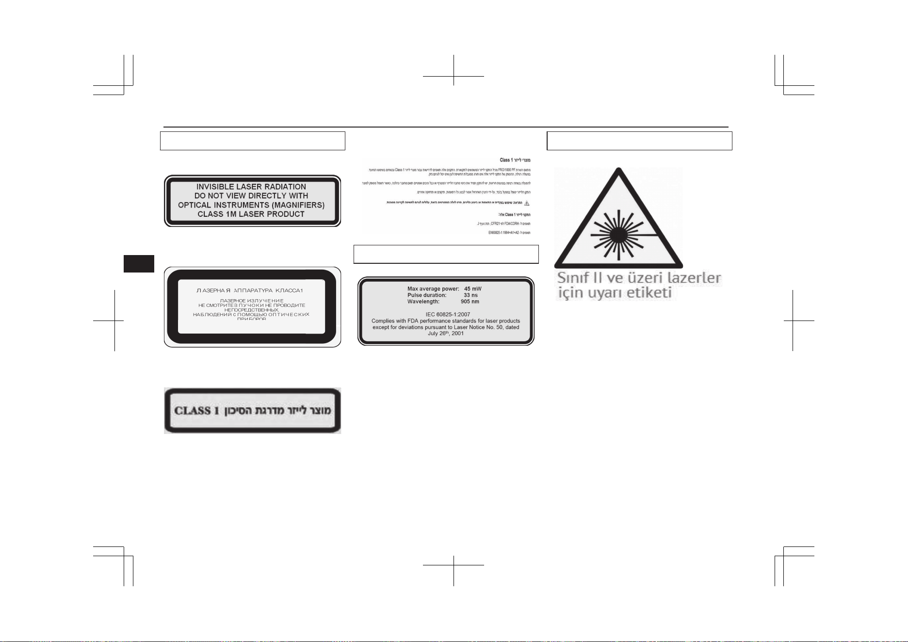
Laser classification label
For Europe
For Kazakhstan and Belarus
For Israel
Laser explanatory label
Laser warning label
Forward Collision Mitigation System (FCM)*
7-76
OGGE19E1
Starting and driving
7
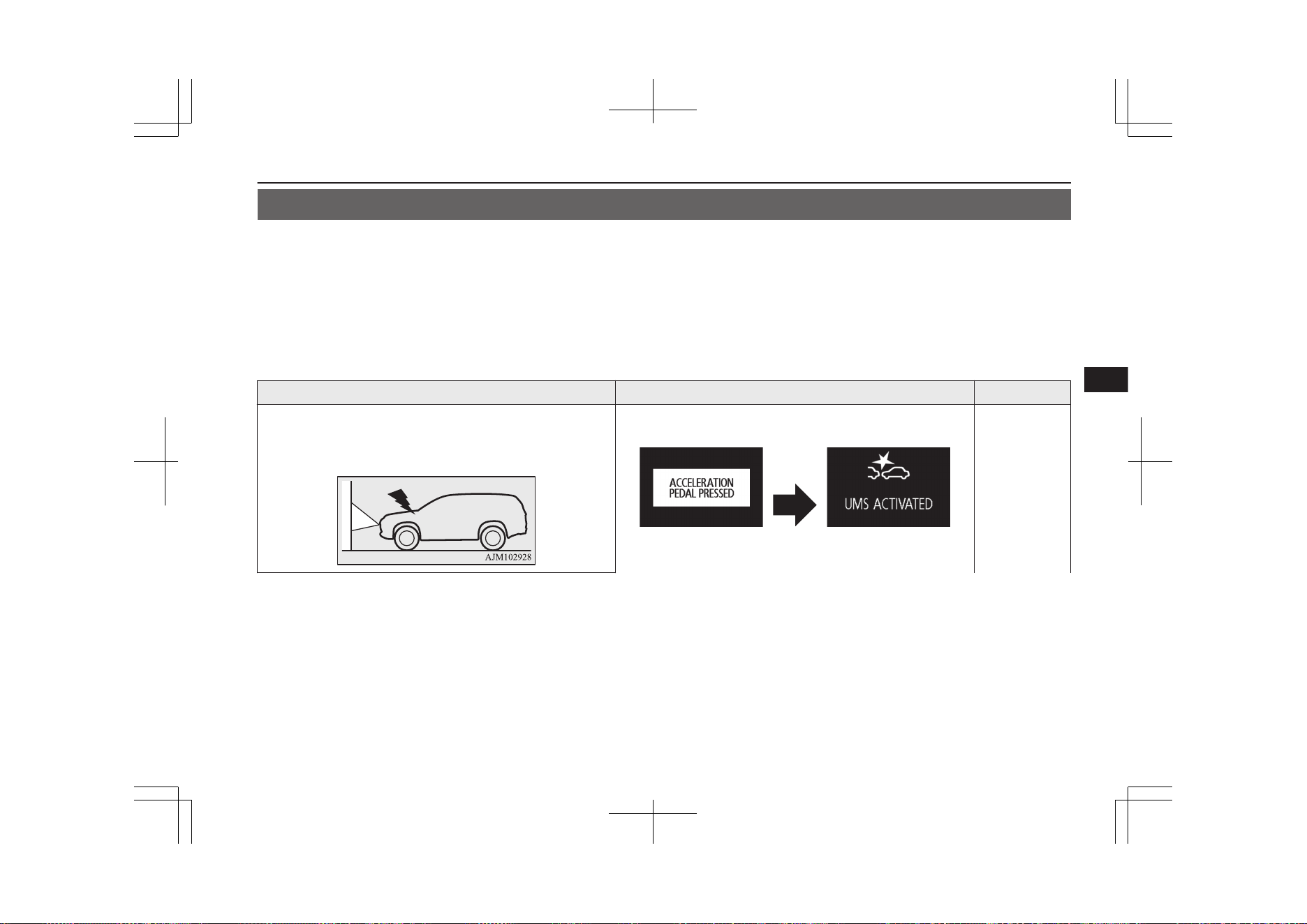
Ultrasonic misacceleration Mitigation System (UMS)*
E00643400280
The Ultrasonic misacceleration Mitigation System (UMS) operates to prevent sudden starts and mitigate collision-caused damages by suppress-
ing the motor output for up to approximately 5 seconds when the system judges that the system is detected the vehicle or obstacles within ap-
proximately 4 m in front and behind your vehicle and judges that accelerator pedal was depressed promptly and too strongly such as misopera-
tion of it. This system operates when the vehicle is at stop or is moving forward or backward at less than approximately 10 km/h.
When the UMS operates, the warning display appears on the information screen of the multi information display, and the buzzer sounds intermit-
tently.
The UMS ON/OFF is switched in conjunction with the ON/OFF state of the Forward Collision Mitigation (FCM). (Vehicles equipped with
FCM)
Situation Operation display Buzzer
When an obstacle is detected in front of your vehicle with the
select position in the “D”, if the accelerator pedal is depressed
promptly and too strongly, the motor output is suppressed for
up to approximately 5 seconds.
Intermittent
beeping sound
Ultrasonic misacceleration Mitigation System (UMS)*
7-77
OGGE19E1
Starting and driving
7
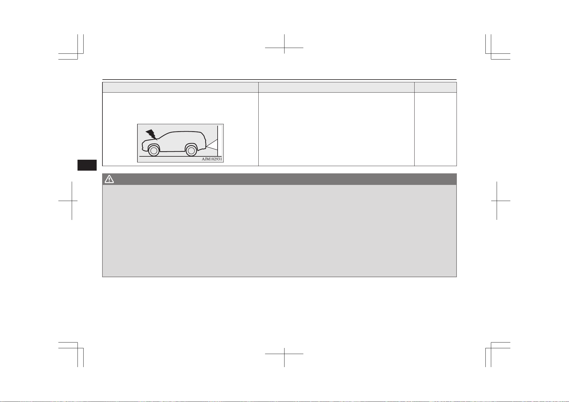
Situation Operation display Buzzer
When an obstacle is detected behind your vehicle with the se-
lector lever in the “R” position, if the accelerator pedal is de-
pressed promptly and too strongly, the motor output is sup-
pressed for up to approximately 5 seconds.
WARNING
l
Do not overly rely on the UMS. It is never a substitute for your safe and careful driving. Always be careful to operate the accelerator pedal perceiv-
ing the environmental conditions. Misoperation can lead to a serious accident.
l
As the UMS is not a function to keep the stop condition of the vehicle, depress the brake pedal according to the environmental condition.
l
Depending on the situation, the system does not operate even if the vehicle or the obstacle in front and behind your vehicle and this may cause the
vehicle to start suddenly and lead to a serious accident.
l
If the vehicle is trapped in the railway crossing because the system is activated as the crossing barrier is misrecognised as an obstacle, escape from
the railway crossing without any panic by one of the following methods.
•
Release the foot from the accelerator pedal and lightly depress the pedal again.
•
Turn the system OFF. (Continuously press the FCM and UMS ON/OFF switch for more than 3 seconds.)
•
Continuously depress the accelerator pedal for more than 5 seconds.
•
Repeat to press the accelerator pedal quickly to its full stroke more than three times.
l
Do not perform inspection of the system operation on your own. Depending on the situation, this may cause the system to not operate properly and
lead to a serious accident.
Ultrasonic misacceleration Mitigation System (UMS)*
7-78
OGGE19E1
Starting and driving
7

CAUTION
l
The UMS does not operate in the following conditions:
•
The operation mode is other than ON.
•
The UMS is set to OFF by operating the FCM and UMS ON/OFF switch.
•
The select position is in the “P” or “N” position.
•
The Active stability control (ASC) is set to OFF by operating the “ASC OFF switch” on page 7-44.
l
It sometimes happens that a motorcycle, bicycle or pedestrian are detected as obstacles, but these are not the object of the UMS operation.
l
The UMS may not operate in the following conditions.
•
The sensors or surroundings have been wiped by hand.
•
The stickers or accessories have been attached to the sensors or surroundings.
•
When driving in the place which the outside temperature changes suddenly (tunnel or garage etc.).
•
Under adverse weather conditions (rain, strong winds, snow, sand storms, etc.).
•
When approaching an obstacle too closely.
•
When a vehicle cuts in front or behind your vehicle very closely.
•
When your vehicle changed the course and approached immediately behind an obstacle.
•
When only a part of the obstacle is within the detection areas of the sensor.
•
When the rain, snow, water or dirt adheres to the sensor.
•
When the sensor is extremely hot or cold (while the vehicle is parked for a long period of time under a blazing sun or in cold weather).
•
Immediately after Plug-in Hybrid EV System starting.
•
When driving on a road with many and successive curves, including when passing their entrances and outlets.
•
When you are driving on a road with steep and alternating up and down slopes.
•
When a road surface is surging, and there is unevenness.
•
When the system judges driver’s steering or gear shifting actions as evasive actions to avoid collision.
•
For a short period after the system judges the repeated depression of the accelerator pedal at a few seconds interval as a release operation.
•
When the vehicle body is extremely inclined by carrying heavy loads or improper adjustment of the tyre pressure.
•
When the driving is unstable due to an accident or trouble.
•
The system receives ultrasonic noise from other sources (the horns of other vehicles, motorcycle engines, brakes, radios, pouring rain, splashing water,
snow traction device (tyre chains), etc.).
•
Obstacle is not vertical to the ground, the obstacle is not at right angles to vehicle traveling direction, or when there is uneven walls and wavy walls.
Ultrasonic misacceleration Mitigation System (UMS)*
7-79
OGGE19E1
Starting and driving
7

CAUTION
l
The UMS operation may be cancelled when the system judges the handle operation as evasive actions or when the obstacle moves out of the detectable area
of the sensor.
l
The UMS may be triggered in the following situations.
•
When water, snow or sand on the road are extorted by the vehicle in front or an oncoming vehicle.
•
When there are objects, steps or projections on the road surface.
•
When the parking gate or railway barrier is raised imperfectly.
•
When running the road, the gradient changes suddenly.
•
When passing through the mass of the steam, fog or smoke.
•
When driving in close to the vehicle ahead, and when stopping in close to the forward/ backward vehicle or a wall.
•
When there is an obstacle in a curb or an intersection.
•
When your vehicle joins the main line from parallel parking.
•
When there is a ultrasonic near your vehicle by horn of other vehicle, engine sound of a motorcycle, air brake noise of a large vehicle, a vehicle detector
and sonar of a vehicle etc.
•
When an electrical equipment on the market (radio antenna etc.) is installed near the sensor.
•
When driving on a gravel road.
•
When the surrounding area is overgrown with weeds.
l
Turn off the system by pressing the FCM and UMS ON/OFF switch beforehand when the vehicle is placed in any of the following situations as the system
can operate unexpectedly.
•
When getting out from a road groove or a mud.
•
When using an automatic car wash.
•
When an elevator for vehicle or a mechanical parking is used.
•
When your vehicle’s wheels are driven by the motor on a lift.
•
When your vehicle is towed or your vehicle tows another vehicle.
•
When your vehicle is carried on a truck.
•
When driving on a circuit.
•
When your vehicle is on a chassis dynamometer or free rollers.
•
When the tyre pressure is not correct.
•
When snow traction device (tyre chains) are attached.
Ultrasonic misacceleration Mitigation System (UMS)*
7-80
OGGE19E1
Starting and driving
7
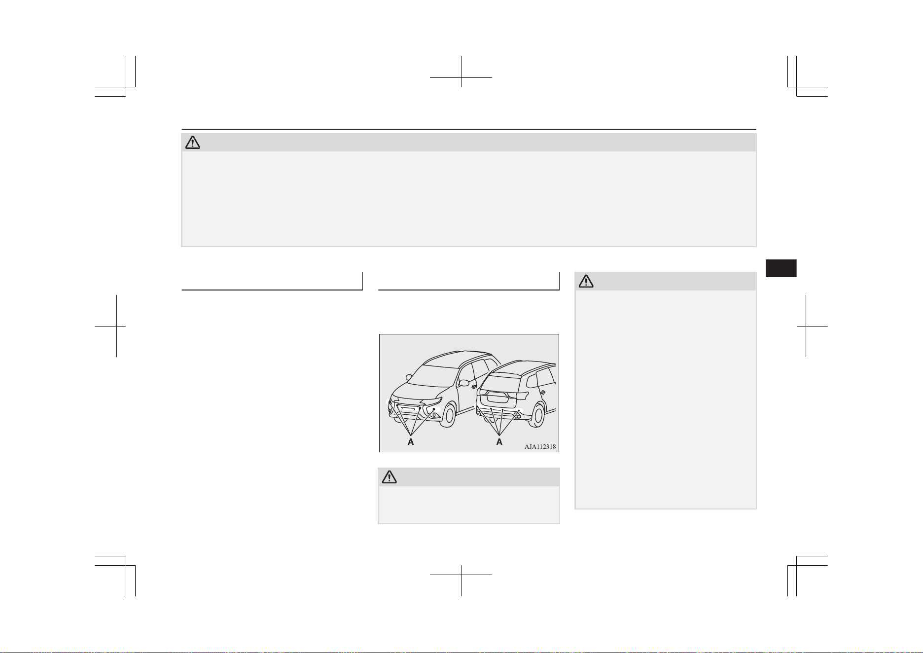
CAUTION
l
Improperly handling the system components may result in such problems as degraded sensor performance and ultimately in an accident.
Be sure to take the following precautions to keep the system in good operating conditions.
•
Avoid application of strong shock loads to the sensor.
•
The sensor should be kept clean.
•
Do not cover the sensor with a sticker or anything.
•
Do not modify the suspension of your vehicle.
l
If the bumper has been exposed to an impact, the sensors may fail and prevent the system from functioning properly. Have the vehicle inspected a
MITSUBISHI MOTORS Authorized Service Point.
Obstacle detection areas
E00643500047
The detection areas of the sensors are limited.
Moreover, the sensors are unable to detect
low or thin objects or objects near the rear
bumper. Make sure to check the surroundings
as you operate the vehicle in a safe manner.
Sensor locations
E00643600165
There are the sensors (A) on each of four pla-
ces of the front bumper and the rear bumper.
CAUTION
l
The UMS may not operate because the sen-
sor cannot detect the vehicle in front or ob-
stacle as follows.
CAUTION
•
Vehicle towing a trailer etc.
•
A freight trailer that is not carrying a con-
tainer.
•
Vehicle that has a protruding load from
the carrier.
•
An obstacle with a low height.
•
Vehicle that has an extremely high ground
clearance.
•
Vehicle that is extremely stained.
•
Vehicle or obstacle that is covered with
snow.
•
The vehicle is the specific shape such as
the carrier car.
•
Obstacles that have the shape of the pole
such as the road marker or the streetlight.
•
Obstacles that exists in the high position
from the ground.
•
Obstacles that are soft and absorb ultra-
sonic easily, such as spongy material or
snow.
Ultrasonic misacceleration Mitigation System (UMS)*
7-81
OGGE19E1
Starting and driving
7
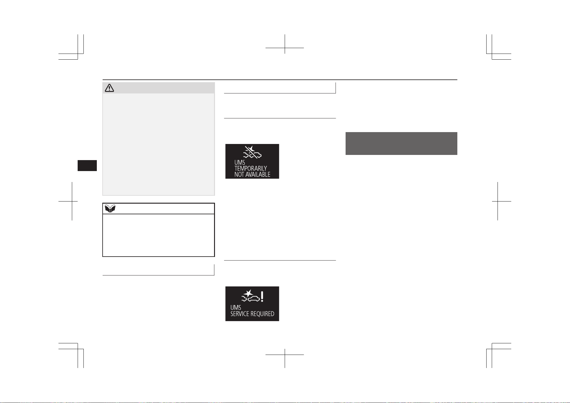
CAUTION
•
Obstacles that are shaped with a sharp an-
gle.
•
A fence with large mesh.
•
Moving object.
•
When there is a loud noise or an ultrason-
ic near your vehicle by horn of other vehi-
cle, engine sound of a motorcycle, air
brake noise of a large vehicle, a vehicle
detector and sonar of a vehicle etc.
•
When an electrical equipment on the mar-
ket (radio antenna etc.) is installed near
the sensor.
•
When there is a obstacle that is not recog-
nized between your vehicle and the obsta-
cle that can be recognized.
NOTE
l
The sensors do not detect objects located in
the area directly below or near the bumper.
If the height of an object is lower than the
mounted position of the sensors, the sensors
may not continue detecting it even if they
detected it initially.
To turn on/off the UMS
E00643800095
The UMS is automatically turned ON by set-
ting the operation mode to ON. In addition,
the UMS ON/OFF is switched in conjunction
with the ON/OFF state of the FCM.
Refer to “FCM and UMS ON/OFF switch”
on page 7-72.
Warning display
E00643900025
When the sensor is temporarily
not available
E00647600033
Example: When the front and/or rear sensors
are temporarily not available
When the warning display appears, the sen-
sors are temporarily not available for some
reason such as the environmental condition
or increase of the sensor temperature. When
the warning display appears continuously,
contact a MITSUBISHI MOTORS Author-
ized Service Point.
When there is a malfunction in
the sensor or the system
E00644000108
Example: When there is a malfunction in
both sensors.
When the warning display appears, the UMS
does not operate normally because there are
some malfunctions in the system. Have the
vehicle inspected at a MITSUBISHI
MOTORS Authorized Service Point as soon
as possible.
Blind Spot Warning (BSW)
(with Lane Change Assist)*
E00644300156
The Blind Spot Warning (BSW) is a driving
aid system that alerts the driver when another
vehicle, which may not be visible through the
outside rear-view mirror, is travelling in the
next lane behind your vehicle.
When a vehicle in the next lane is travelling
at the same speed or faster in the detection
areas, the Blind Spot Warning lamp in the
corresponding outside rear-view mirror will
illuminate. If the turn-signal lever is operated
to the side where the Blind Spot Warning
lamp is illuminated, the Blind Spot Warning
lamp will blink and the system will beep
three times to alert the driver.
Blind Spot Warning (BSW) (with Lane Change Assist)*
7-82
OGGE19E1
Starting and driving
7
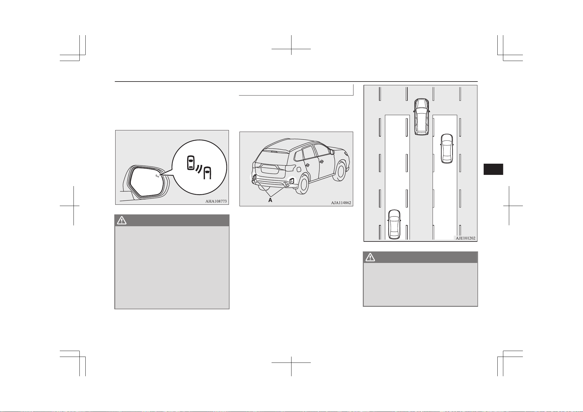
Depending on the relative speed between
your vehicle and a vehicle in the next lane,
the Blind Spot Warning system will detect up
to approximately 70 m from your vehicle.
(Lane Change Assist)
WARNING
l
Before using the BSW, read this entire
section to fully understand the limitations
of this system. Failure to follow instruc-
tions could result in an accident.
l
Never rely solely on the BSW system
when changing lanes. The BSW is an aid
only. It is not a substitute for your safe
and careful driving. Always check visually
behind and all around your vehicle for
other vehicles. The performance of the
BSW may vary depending on driving,
traffic and/or road conditions.
Detection areas
E00644400388
The BSW uses two sensors (A) located inside
the rear bumper.
The detection areas are shown as illustrated.
WARNING
l
In certain situations, the BSW may not
detect a vehicle in the detection areas or
the detection may be delayed. Some of
these include:
•
When a small motorcycle or a bicycle is
behind your vehicle.
Blind Spot Warning (BSW) (with Lane Change Assist)*
7-83
OGGE19E1
Starting and driving
7
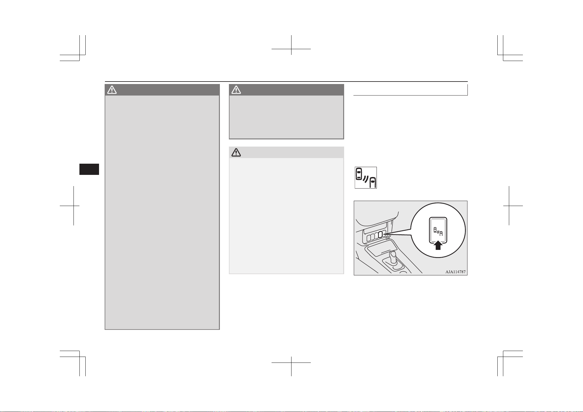
WARNING
•
When a vehicle is travelling alongside
of your vehicle at nearly the same speed
for prolonged periods of time.
•
When the heights of the next lane and
your lane are different.
•
Immediately after the BSW has been
turned on.
•
Immediately after the power switch is
turned on.
•
Under adverse weather conditions,
such as rain, snow, strong winds or
sand storms.
•
When your vehicle comes too close to
another vehicle.
•
While multiple vehicles are overtaking
your vehicle.
•
When driving near a pot hole and
tramline.
•
When a surrounding vehicle or an on-
coming vehicle is splashing water, snow
or dirt.
•
When driving on a curve including the
beginning and the end of the curve.
•
When driving on a road with alternat-
ing up and down steep slopes.
•
When driving on a bumpy or rough
road.
•
When the rear of your vehicle is weigh-
ed down or your vehicle is leaning to
the right or left due to the weight of
passengers and luggage or the improp-
er adjustment of tyre pressure.
•
When the bumper surface around the
sensor is covered with dirt, snow and
ice, etc.
WARNING
•
When the sensor is extremely hot or
cold (while the vehicle is parked for a
long period of time under a blazing sun
or in cold weather).
•
When a bicycle carrier or accessory is
installed to the rear of the vehicle.
CAUTION
l
To maintain proper performance of the
BSW, follow the instructions below.
•
Always keep the bumper surface around
the sensor clean.
•
Avoid impacting the sensor or its sur-
rounding area.
•
Do not put a sticker on the sensor or its
surrounding bumper surface.
•
Do not paint the sensor or its surrounding
bumper surface.
•
Do not modify the sensor or its surround-
ing area.
l
If the bumper has experienced an impact, the
sensor may have been damaged and the
BSW may not function properly. Have the
vehicle inspected at a MITSUBISHI
MOTORS Authorized Service Point.
To operate
E00652300298
When the BSW switch is pressed while the
operation mode is ON, the BSW indication
lamp in the instrument cluster comes on and
the BSW goes into the stand by state. When
the BSW switch is pressed again, the BSW
indication lamp in the instrument cluster goes
off and the BSW turns off.
Indication lamp
If you turn the BSW ON/OFF, the Rear Cross
Traffic Alert (RCTA) also turns ON/OFF at
the same time.
Blind Spot Warning (BSW) (with Lane Change Assist)*
7-84
OGGE19E1
Starting and driving
7
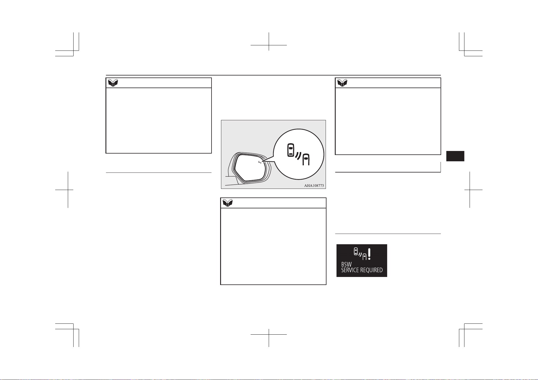
NOTE
l
When the operation mode is set to OFF, the
selected condition just before setting to OFF
is retained.
l
The BSW operates when all of the following
conditions are met.
•
The operation mode is put in ON.
•
The select position is in a position other
than “P” (PARK) and “R” (REVERSE).
•
The speed of your vehicle is approximate-
ly 10 km/h (6 mph) or higher.
When the sensor detects an ap-
proaching vehicle
When the BSW indication lamp in the instru-
ment cluster is on, if a vehicle is approaching
your vehicle in the detection area, the Blind
Spot Warning lamp in the outside rear-view
mirror illuminates.
If the turn-signal lever is operated to the side
where the Blind Spot Warning lamp is illumi-
nated, the Blind Spot Warning lamp will
blink and the system will beep three times to
alert the driver.
NOTE
l
The Blind Spot Warning lamp in the outside
rear-view mirror may come on or blink in
the following conditions.
•
When driving very near the guardrail or a
concrete wall.
•
When driving on the entrance and outlet
of a tunnel or very near to the wall or near
the evacuation area inside a tunnel.
•
When turning at an intersection in a town
area.
•
Under adverse weather conditions (rain,
snow, sand storms etc.).
NOTE
•
When you drive your vehicle with blow-
ing up the water, snow or sand etc. on the
road.
•
When driving near a pothole and tramline.
l
Set the BSW to OFF when towing.
l
The Blind Spot Warning lamp in the outside
rear-view mirror may not be visible due to
strong direct sunlight or the glare from the
headlamps of vehicles behind you during
night driving.
System problem warning
E00692500029
If a problem occurs with the system, a visual
warning specific to the type of the problem is
given together with an audible alarm.
The warnings are combined with the Rear
Cross Traffic Alert (RCTA) system.
When there is a malfunction in
the system or the sensor
E00692600020
Blind Spot Warning (BSW) (with Lane Change Assist)*
7-85
OGGE19E1
Starting and driving
7
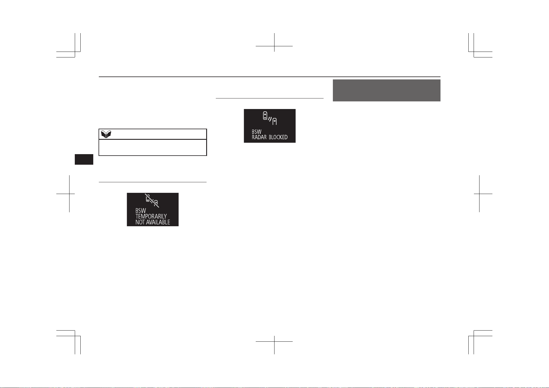
When the warning display appears, the BSW
does not operate normally because there are
some malfunctions in the system or the sen-
sor. Have the vehicle inspected at a
MITSUBISHI MOTORS Authorized Service
Point as soon as possible.
NOTE
l
When the warning display appears, the BSW
will be deactivated.
When the sensor is temporarily
not available
E00692700021
When the warning display appears, the sensor
is temporarily not available for some reason
such as the environmental condition or in-
crease of the sensor temperature. When the
warning display does not disappear after
waiting for a while, contact a MITSUBISHI
MOTORS Authorized Service Point.
When there are foreign objects
on the sensor
E00692800165
When the warning display appears, the sensor
cannot detect a vehicle travelling side by side
or an approaching vehicle, because foreign
objects, such as dirt, snow or ice, adhere to
the bumper surface around the sensor.
Remove dirt, freezing or foreign material on
the bumper surface around the sensor.
When the warning display does not disappear
after having cleaned the sensor, contact a
MITSUBISHI MOTORS Authorized Service
Point.
Rear Cross Traffic Alert
(RCTA)*
E00652400257
The Rear Cross Traffic Alert (RCTA) is an
aid system for backing up. When the RCTA
system detects vehicles approaching from
sides while your vehicle is reversing, the
Blind Spot Warning lamps in the outside rear-
view mirrors on both sides will blink and a
buzzer will sound to alert the driver. A warn-
ing message will also appear on the informa-
tion screen of the multi-information display.
Rear Cross Traffic Alert (RCTA)*
7-86
OGGE19E1
Starting and driving
7
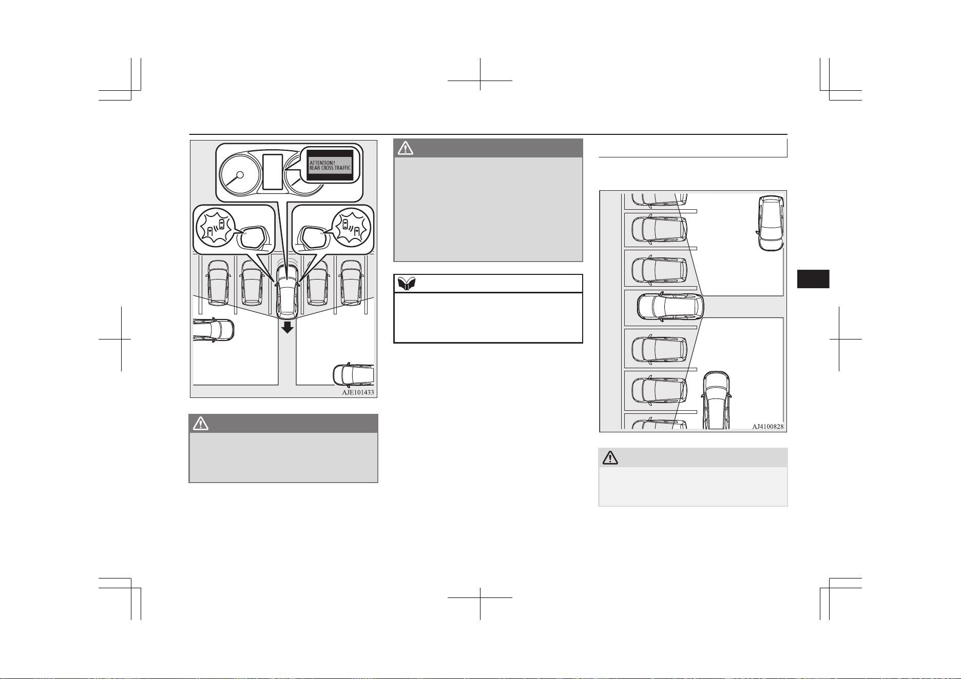
WARNING
l
Before using the RCTA, read this entire
section to fully understand the limitations
of this system. Failure to follow instruc-
tions could result in an accident.
WARNING
l
Never rely solely on the RCTA when
backing up. The RCTA is an aid system.
It is not a substitute for your safe and
careful driving. Always check visually be-
hind and all around your vehicle for other
vehicles, persons, animals or obstructions.
The performance of the RCTA may vary
depending on driving, traffic and/or sur-
rounding conditions.
NOTE
l
The Blind Spot Warning lamps in the outside
rear-view mirrors on both sides will blink,
even when only one vehicle is approaching
from one side.
Detection areas
The detection area is shown as illustrated.
CAUTION
l
In certain situations, the RCTA may not de-
tect a vehicle in the detection areas. Some of
these situations include:
Rear Cross Traffic Alert (RCTA)*
7-87
OGGE19E1
Starting and driving
7
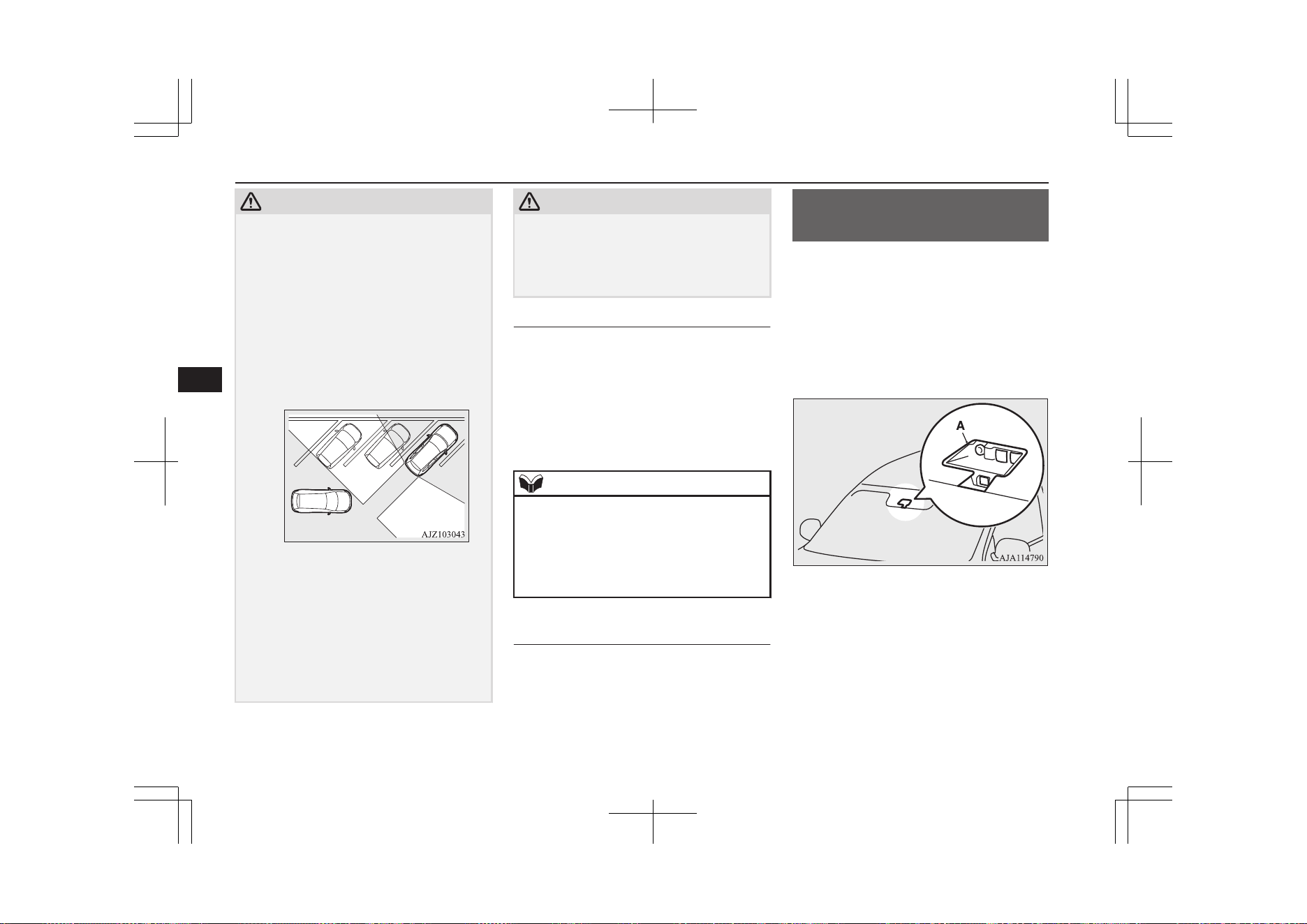
CAUTION
•
When the reversing speed of your vehicle
is approximately 18 km/h (11 mph) or
higher.
•
When the speed of an approaching vehicle
is approximately 7 km/h (5 mph) or less.
•
If the sensor detection area is blocked by
a nearby object, such as a wall or parked
vehicle.
•
When a vehicle is approaching from
straight behind your vehicle.
•
When your vehicle is exiting from an an-
gled parking spot.
•
Immediately after the RCTA has been
turned on.
•
Immediately after the operation mode of
the power switch has been put in ON.
•
When the bumper surface around the sen-
sor is covered with dirt, snow and ice, etc.
•
When the sensor becomes extremely hot
or cold, such as after the vehicle has been
parked for a prolonged time under the
blazing sun or in cold weather.
CAUTION
l
If the bumper has experienced an impact, the
sensor may have been damaged and the
RCTA may not function properly. Have the
vehicle inspected at a MITSUBISHI
MOTORS Authorized Service Point.
To operate
1. Press the BSW switch while the opera-
tion mode is put in ON.
(Refer to “Blind Spot Warning (BSW):
To operate” on page 7-84.)
2. When the select position is put in the
“R” (REVERSE) position, the RCTA
will operate.
NOTE
l
Set the RCTA to OFF when towing.
l
The Blind Spot Warning lamp in the outside
rear-view mirror may not be visible due to
strong direct sunlight or the glare from the
headlamps of vehicles behind you during
night driving.
When a problem is detected in
the system
If the system detects a problem, a warning is
displayed on the information screen in the
multi-information display.
Refer to “Blind Spot Warning (BSW): Sys-
tem problem warning” on page 7-85.
Lane Departure Warning
(LDW)*
E00635701281
By recognizing through a sensor (A) the lane
in which your vehicle is running, the LDW
gives you a warning when your vehicle is
likely to drift from its lane with an audible
alarm and a visual alarm displayed on the in-
formation screen of the multi-information
display.
Lane Departure Warning (LDW)*
7-88
OGGE19E1
Starting and driving
7
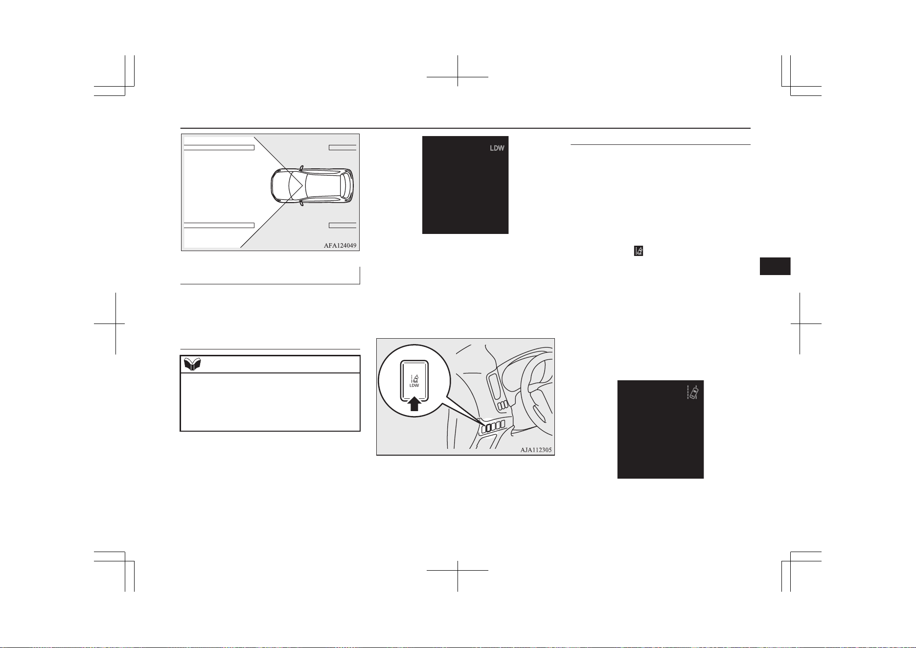
How to operate the LDW
E00635801325
The indication on the information screen of
the multi-information display changes as fol-
lows depending on the state of the system.
To turn on/off the LDW
NOTE
l
The LDW is turned on when the vehicle is
shipped from the factory.
l
The currently selected LDW setting (on or
off) is stored even when the operation mode
of the power switch is put in OFF.
To turn on the LDW, press the LDW switch.
The “LDW” indicator will appear on the in-
formation screen of the multi information
display and the system is placed in the ‘ON
state’.
To turn off the LDW, press the LDW switch.
The “LDW” indicator on the information
screen of the multi information display will
then go out and the system is placed in the
‘OFF state’.
To return the LDW to the ‘ON state’, press
the LDW switch again.
Standby state
In the standby mode, the system is capable of
recognizing the lane in which your vehicle is
positioned and issuing audible warning when
your vehicle goes out of the lane.
The system automatically shifts from the
‘ON state’ to the ‘standby state’ if all of the
following conditions are simultaneously met.
The “LDW” indicator in the information dis-
play changes to
indicator (green).
l
The vehicle speed is approximately
65 km/h (40 mph) or higher.
l
The turn-signal lever is not operated.
l
The hazard lamp is not activated.
l
Environmental conditions are adequate
for the system to recognize the lane
markings on both sides.
l
The system has been placed in the ‘ON
state’.
Lane Departure Warning (LDW)*
7-89
OGGE19E1
Starting and driving
7
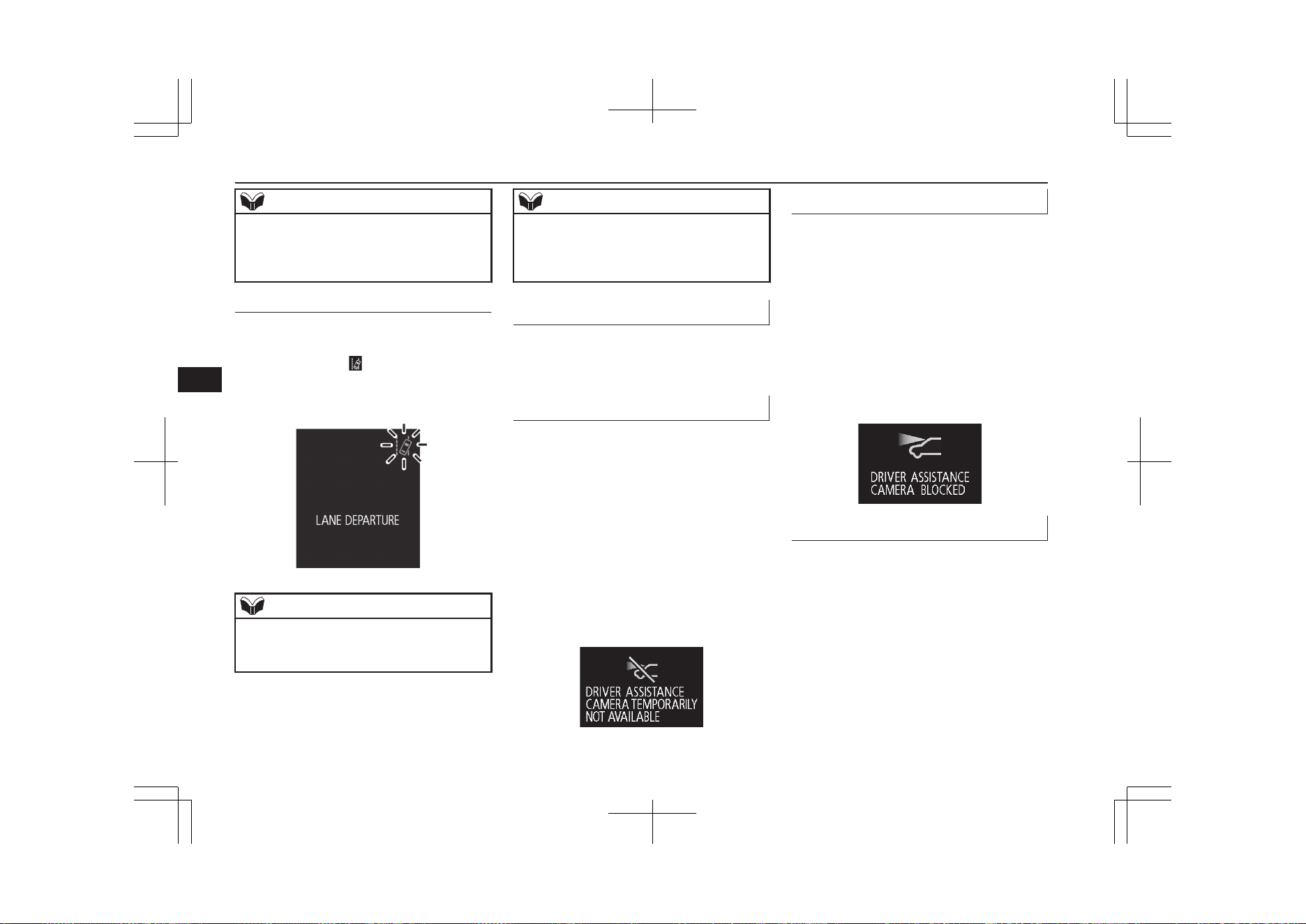
NOTE
l
The system stays in the “ON” state for ap-
proximately 7 seconds after the hazard lamp
has stopped flashing or the turn-signal lever
has returned to the home position.
Lane departure warning
A buzzer sounds intermittently and indication
of “LANE DEPARTURE” appears in the in-
formation display,
indicator flashing in
amber when your vehicle is about to leave or
has left the lane in the standby mode.
NOTE
l
If the warning continues for approximately 3
seconds or more, the system switches to the
standby mode before the warning stops.
NOTE
l
If the lane markers are only on one side of
the road, the LDW will operate only for the
appropriate side where the lane marker is
drawn.
System problem warning
E00635901049
If a problem occurs with the system, a visual
warning specific to the type of the problem is
given together with an audible alarm.
Too hot or cold sensor
E00638700054
The alarm shown below is displayed if the
system becomes temporarily unavailable due
to a too high or low temperature of the sen-
sor.
If the temperature of the sensor reaches the
predetermined value, the system automatical-
ly recovers the normal state.
If the alarm continues showing, there is a
possibility that the LDW has a malfunction.
Contact a MITSUBISHI MOTORS Author-
ized Service Point for inspection of the sys-
tem.
Windscreen is dirty
E00652600028
The alarm shown below is displayed if the
system becomes temporarily unavailable due
to dirt on the windscreen at the sensor por-
tion.
After having cleaned the windscreen, the sys-
tem will automatically return to operation.
If the alarm continues showing, there is a
possibility that the sensor has a malfunction.
Contact a MITSUBISHI MOTORS Author-
ized Service Point for inspection of the sen-
sor.
LDW deactivation due to fault
E00638800114
The alarm shown below is displayed if the
LDW goes into a non-initialized state due to
a fault.
If this happens, please contact a
MITSUBISHI MOTORS Authorized Service
Point for inspection of the system.
Lane Departure Warning (LDW)*
7-90
OGGE19E1
Starting and driving
7
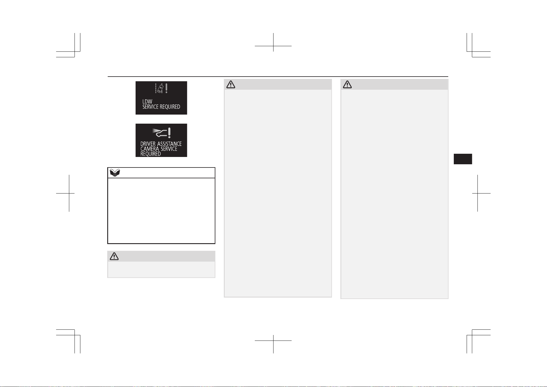
NOTE
l
If the sensor or its surrounding area reaches
an extremely high temperature when parking
the vehicle under a blazing sun, the “LDW
SERVICE REQUIRED” message may ap-
pear.
If the message remains even after the tem-
perature of the sensor or its surrounding area
has been in range, please contact a
MITSUBISHI MOTORS Authorized Serv-
ice Point.
CAUTION
l
LDW has its performance limitations. Do
not over-rely on the system.
CAUTION
l
LDW is not designed to lessen risks associ-
ated with not looking ahead carefully (atten-
tion drawn to something on the side, absent-
mindedness, etc.) or poor visibility caused
by bad weather etc. Keep steering your vehi-
cle correctly and drive safely.
l
The system may not operate correctly in the
following conditions. If required, set the
LDW switch to “OFF.”
•
When driving on a road whose lane mark-
ings (white or yellow) are worn out or
smeared with dirt to an extent not recog-
nizable by the system.
•
When lane markings are vague, typically
during a drive in the rain, snow, fog or
dark area, or when running against the
sun.
•
When the vehicle is moving in a place
where lane markings are interrupted, such
as a toll booth entrance and motorway
junction.
•
When running on a road portion with in-
completely removed old lane markings,
shadows, lingering snow, truck-like pud-
dles mistakable for lane markings (espe-
cially after the rain when road surface is
reflecting light) or similar confusing fac-
tors.
•
When running in a lane other than the
cruising lane and passing lane.
•
When running beside a closed lane sec-
tion or in a provisional lane in a traffic
work zone.
CAUTION
•
When running in an extremely narrow
lane.
•
When the following distance between
your vehicle and a vehicle in front be-
comes extremely reduced (especially
when a marking is hidden by a vehicle in
front this is running too close to the mark-
ing).
•
When entering a junction or other point of
road where lanes are laid out complicated-
ly.
•
When passing a road section where the
number of lanes increases/decreases or
multiple lanes are crossing each other.
•
When the lane is marked by double or
otherwise special lines.
•
When driving on a winding or rough road.
•
When driving on a slippery road covered
by rain water, snow, ice, etc.
•
When passing through a place where the
brightness suddenly changes, like the inlet
or outlet of a tunnel.
•
When turning steep curves.
•
When the road surface is reflecting the
light shining from the direction opposite
to the running direction.
•
Vehicle largely lurches when it is running
over steps or other irregularities of the
road surface.
•
When the headlamp illumination is inade-
quate because of contaminated or deterio-
rated lenses or improperly aimed head-
lamps.
Lane Departure Warning (LDW)*
7-91
OGGE19E1
Starting and driving
7
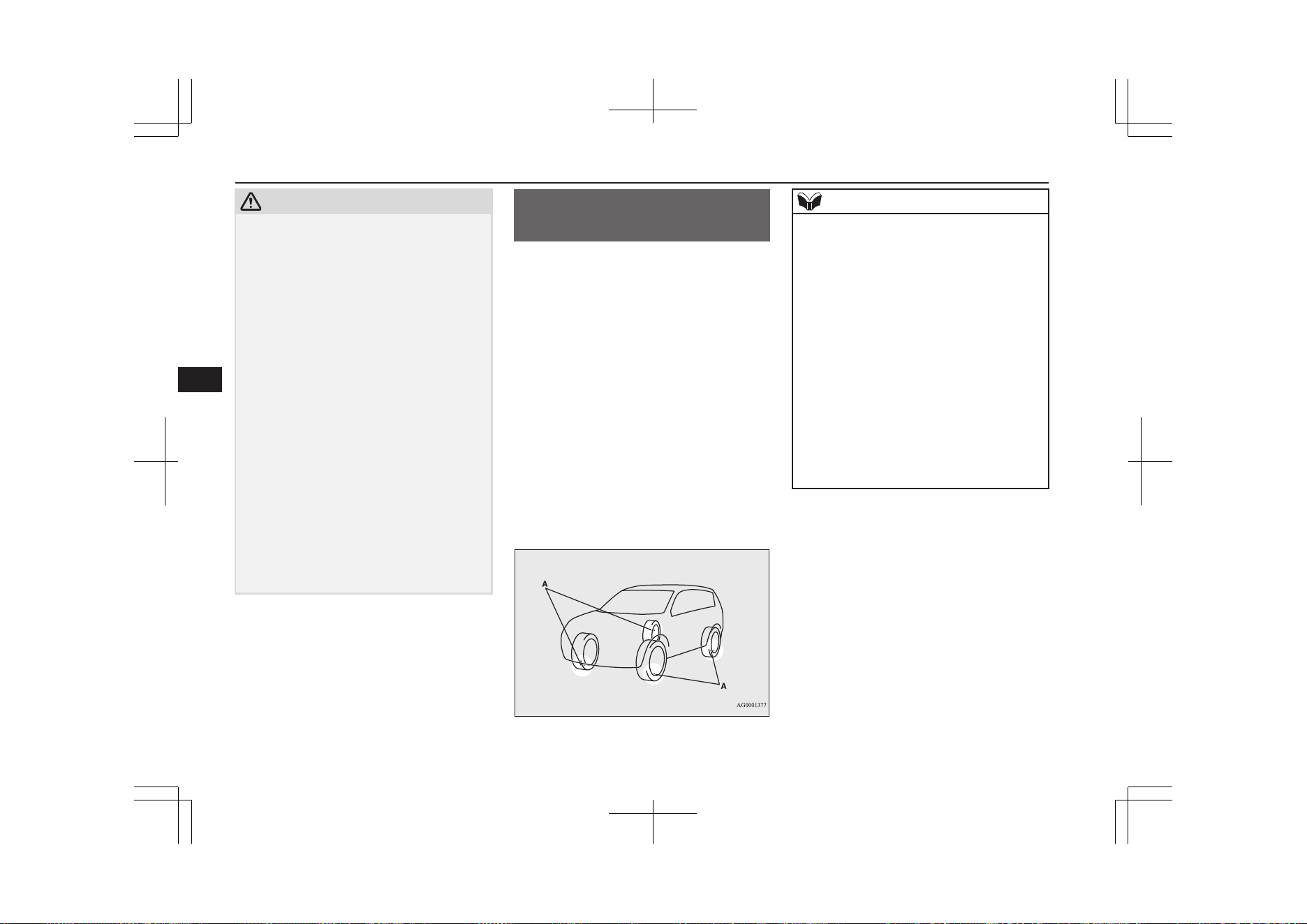
CAUTION
•
When the vehicle is leaning much to one
side due to heavy luggage on it or improp-
erly adjusted tyre pressures.
•
When oncoming vehicles’ headlamps
shine the sensor.
•
When the vehicle is equipped with non-
standard tyres (including excessively
worn tyres), is using a snow traction de-
vice (tyre chains), or has non-specified
components such as a modified suspen-
sion.
•
When the windscreen is covered with wa-
ter droplets, snow, dust, etc.
l
Follow the instructions given below to keep
your LDW in good operating conditions.
•
Always keep the windscreen clean.
•
Avoid applying a strong shock or pressure
to the sensor. Do not attempt to detach or
disassemble it.
•
Do not put anything like a sticker on the
area in front of the sensor lens of the
windscreen.
•
Use only MITSUBISHI MOTORS GEN-
UINE Parts when replacing the wind-
screen wipers.
Tyre pressure monitoring
system (TPMS)
E00637100282
The tyre pressure monitoring system (TPMS)
uses tyre inflation pressure sensors (A) on the
wheels to monitor the tyre inflation pressures.
The system only indicates when a tyre is sig-
nificantly under-inflated.
The base tyre pressure can be set at desired
value by the driver with the reset function ex-
ecution. (The low pressure warning threshold
is set based on the reset.)
The tyre inflation pressure sensor IDs for two
sets of tyres can be registered by a
MITSUBISHI MOTORS Authorized Service
Point, and the valid ID set can be switched by
the Multi-information display switch (It’s
beneficial in case of seasonal tyre change be-
tween summer tyre and winter tyre.)
NOTE
l
The tyre pressure monitoring system
(TPMS) is not a substitute for regularly
checking tyre inflation pressures.
Be sure to check the tyre inflation pressures
as described in “Tyres” on page 11-10.
l
The tyre inflation pressure sensor (B) is in-
stalled in the illustrated location.
•
On vehicles with the type 1 sensor which
has the metallic air valve (C), replace
grommet and washer (D) with the new
ones when the tyre is replaced.
•
On vehicles with the type 2 sensor which
has the rubber air valve (E), replace the
rubber air valve (E) with the new one
when the tyre is replaced.
For details, please contact your
MITSUBISHI MOTORS Authorized Serv-
ice Point.
Tyre pressure monitoring system (TPMS)
7-92
OGGE19E1
Starting and driving
7
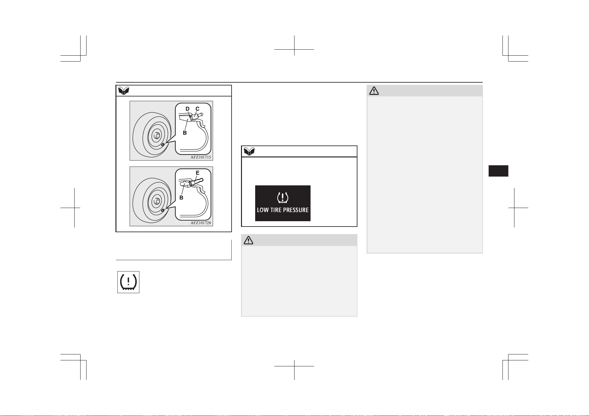
NOTE
Type 1
Type 2
Tyre pressure monitoring sys-
tem warning lamp/display
E00637200078
When the operation mode is put in ON, the
tyre pressure monitoring system warning
lamp normally illuminates and goes off a few
seconds later.
If one or more of the vehicle tyres is signifi-
cantly under-inflated, the warning lamp will
remain illuminated while the operation mode
is in ON.
Refer to “If the warning lamp/display illumi-
nates while driving” on page 7-94 and take
the necessary measures.
NOTE
l
In addition, the warning display will be dis-
played on the information screen in the mul-
ti-information display.
CAUTION
l
If the warning lamp does not illuminate
when the operation mode is put in ON, it
means that the tyre pressure monitoring sys-
tem (TPMS) is not working properly. Have
the system inspected by a MITSUBISHI
MOTORS Authorized Service Point.
In such situations, a malfunctioning of the
system may be preventing the monitoring of
the tyre pressure. Avoid sudden braking,
sharp turning and high-speed driving.
CAUTION
l
If a malfunction is detected in the tyre pres-
sure monitoring system (TPMS), the warn-
ing lamp will blink for approximately 1 mi-
nute and then remain continuously illumina-
ted. The warning lamp will issue further
warnings each time the Plug-in Hybrid EV
System is restarted as long as the malfunc-
tion exists.
Check to see whether the warning lamp goes
off after few minutes driving.
If it then goes off during driving, there is no
problem.
However, if the warning lamp does not go
off, or if it blinks again when the Plug-in
Hybrid EV System is restarted, have the ve-
hicle inspected by a MITSUBISHI
MOTORS Authorized Service Point.
In such situations, a malfunctioning of the
system may be preventing the monitoring of
the tyre pressure. For safety reasons, when
the warning lamp appears while driving,
avoid sudden braking, sharp turning and
high-speed driving.
Tyre pressure monitoring system (TPMS)
7-93
OGGE19E1
Starting and driving
7
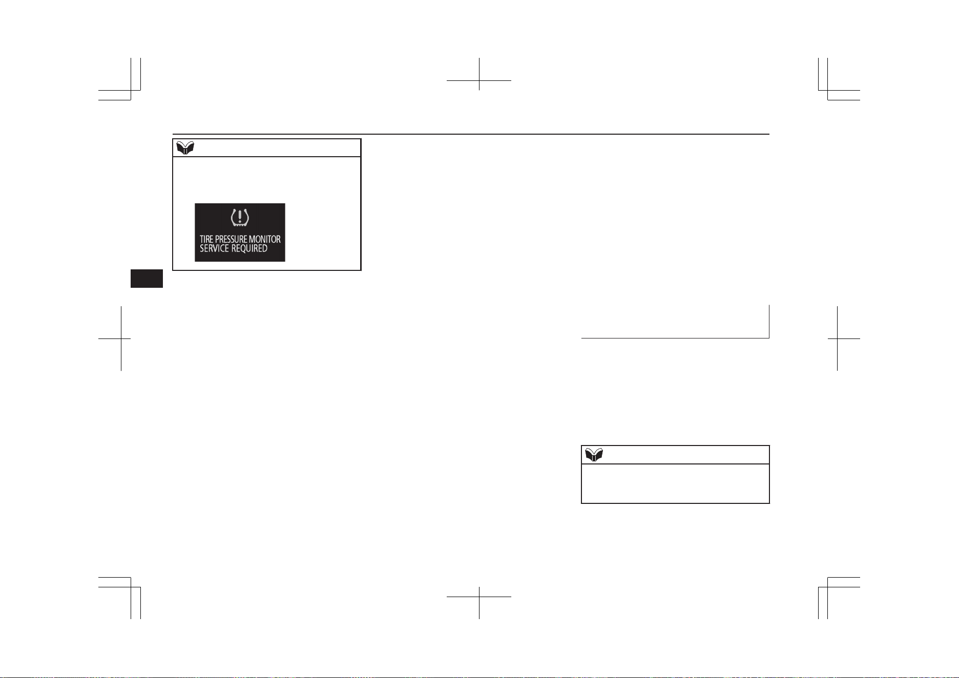
NOTE
l
In addition, the warning display will be dis-
played on the information screen in the mul-
ti-information display.
Each tyre, including the spare (if so equip-
ped), should be checked monthly when cold
and inflated to the inflation pressure recom-
mended by the vehicle manufacturer on the
tyre inflation pressure label. (If your vehicle
has tyres of a different size than the size indi-
cated on the tyre inflation pressure label, you
should determine the proper tyre inflation
pressure for those tyres.)
As an added safety feature, your vehicle has
been equipped with the tyre pressure moni-
toring system (TPMS) that illuminates a low
tyre pressure telltale when one or more of
your tyres is significantly under-inflated.
Accordingly, when the low tyre pressure tell-
tale illuminates, you should stop and check
your tyres as soon as possible, and inflate
them to the proper pressure. Driving on a sig-
nificantly under-inflated tyre causes the tyre
to overheat and can lead to tyre failure.
Under-inflation also reduces fuel efficiency
and tyre tread life, and may affect the vehi-
cle’s handling and stopping ability.
Please note that the tyre pressure monitoring
system (TPMS) is not a substitute for proper
tyre maintenance, and it is the driver’s re-
sponsibility to maintain correct tyre pressure,
even if under-inflation has not reached the
level to trigger illumination of the tyre pres-
sure monitoring system (TPMS) low tyre
pressure telltale.
Your vehicle has also been equipped with a
warning lamp to indicate when the system is
not operating properly.
The warning lamp is combined with the low
tyre pressure telltale.
When the system detects a malfunction, the
telltale will flash for approximately one mi-
nute and then remain continuously illumina-
ted. This sequence will continue upon subse-
quent vehicle start-ups as long as the mal-
function exists.
When the warning lamp is illuminated, the
system may not be able to detect or signal
low tyre pressure as intended.
The tyre pressure monitoring system (TPMS)
malfunctions may occur for a variety of rea-
sons, including the installation of replace-
ment or alternate tyres or wheels on the vehi-
cle that prevent the tyre pressure monitoring
system (TPMS) from functioning properly.
Always check the tyre pressure monitoring
system (TPMS) malfunction telltale after re-
placing one or more tyres or wheels on your
vehicle to ensure that the replacement or al-
ternate tyres and wheels allow the tyre pres-
sure monitoring system (TPMS) to continue
to function properly.
If the warning lamp/display il-
luminates while driving
E00637300079
1. If the warning lamp illuminates, avoid
hard braking, sharp steering manoeuvres
and high speeds. You should stop and
adjust the tyres to the proper inflation
pressure as soon as possible. Adjust the
spare tyre at the same time. Refer to
“Tyres” on page 11-10.
NOTE
l
In addition, the warning display will be dis-
played on the information screen in the mul-
ti-information display.
Tyre pressure monitoring system (TPMS)
7-94
OGGE19E1
Starting and driving
7
NOTE
l
When inspecting or adjusting the tyre pres-
sure, do not apply excessive force to the
valve stem to avoid breakage.
l
After inspecting or adjusting the tyre pres-
sure, always reinstall the valve cap on the
valve stem.
Without the valve cap, dirt or moisture could
get into the valve, resulting in damage to the
tyre inflation pressure sensor.
l
Do not use metal valve caps, which may
cause a metal reaction, resulting in corrosion
and damage of the tyre inflation pressure
sensors.
l
Once adjustments have been made, the
warning lamp will go off after a few minutes
of driving.
2. If the warning lamp remains illuminated
after you have been driving for about 10
minutes after you adjust the tyre infla-
tion pressure, one or more of the tyres
may have a puncture. Inspect the tyre
and if it has a puncture, have it repaired
by a MITSUBISHI MOTORS Author-
ized Service Point as soon as possible.
WARNING
l
If the warning lamp/display illuminates
while you are driving, avoid hard brak-
ing, sharp steering manoeuvres and high
speeds.
Driving with an under-inflated tyre ad-
versely affects vehicle performance and
can result in an accident.
CAUTION
l
The warning lamp/display may not illumi-
nate immediately in the event of a tyre blow-
out or rapid leak.
NOTE
l
To avoid the risk of damage to the tyre infla-
tion pressure sensors, have any punctured
tyre repaired by a MITSUBISHI MOTORS
Authorized Service Point. If the tyre repair is
not done by a MITSUBISHI MOTORS Au-
thorized Service Point, damage to the tyre
inflation pressure sensor is not covered by
your warranty.
l
Do not use an aerosol puncture-repair spray
on any tyre.
Such a spray could damage the tyre inflation
pressure sensors.
Have any puncture repaired by a
MITSUBISHI MOTORS Authorized Serv-
ice Point.
NOTE
l
Using the tyre repair kit may damage the
tyre inflation pressure sensor. The vehicle
must promptly be inspected and repaired by
a MITSUBISHI MOTORS Authorized Serv-
ice Point after using the tyre repair kit.
The tyre pressure monitoring system (TPMS)
may not work normally in the following cir-
cumstances:
l
A wireless facility or device using the
same frequency is near the vehicle.
l
Snow or ice is stuck inside the fenders
and/or on the wheels.
l
The tyre inflation pressure sensor’s bat-
tery is dead.
l
Wheels other than MITSUBISHI
MOTORS GENUINE wheels are being
used.
l
Wheels that are not fitted with tyre infla-
tion pressure sensors are being used.
l
Wheels whose ID codes are not memo-
rized by the vehicle are used.
l
A window tint that affects the radio
wave signals is installed.
Tyre pressure monitoring system (TPMS)
7-95
OGGE19E1
Starting and driving
7
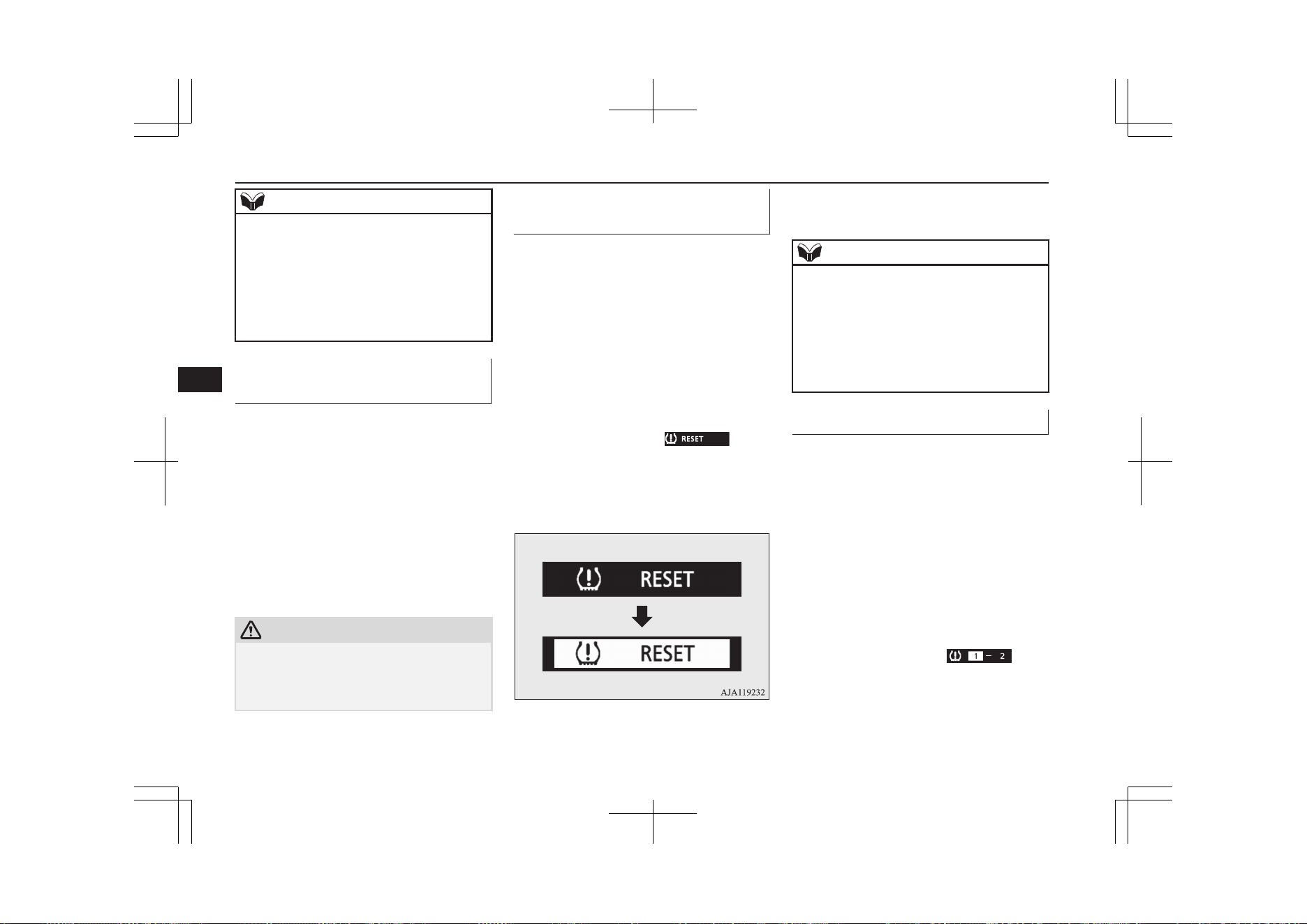
NOTE
l
Tyre inflation pressures vary with the ambi-
ent temperature. If the vehicle is subjected to
large variations in ambient temperature, the
tyre inflation pressures may be underinflated
(causing the warning lamp/display come on)
when the ambient temperature is relatively
low. If the warning lamp/display comes on,
adjust the tyre inflation pressure.
Whenever the tyres and wheels
are replaced with new ones
E00637400025
If new wheels with new tyre inflation pres-
sure sensors are installed, their ID codes must
be programmed into the tyre pressure moni-
toring system. Have tyre and wheel replace-
ment performed by a MITSUBISHI
MOTORS Authorized Service Point to avoid
the risk of damaging the tyre inflation pres-
sure sensors. If the wheel replacement is not
done by a MITSUBISHI MOTORS Author-
ized Service Point, it is not covered by your
warranty.
CAUTION
l
The use of non-genuine wheels will prevent
the proper fit of the tyre inflation pressure
sensors, resulting air leakage or damage of
the sensors.
Reset of low tyre pressure
warning threshold
E00637500169
The threshold is set based on the tyre pres-
sure which the reset function is executed by
following procedure.
1. Operate the multi-information display
switch to switch the information screen
to the menu screen.
Refer to “Multi information display
switch” on page 6-06.
Refer to “Changing the function set-
tings” on page 6-17.
2. Lightly press the multi-information dis-
play switch to select “
” (reset
of low tyre pressure warning threshold).
3. Hold down the multi-information dis-
play switch for about 3 seconds or more,
the buzzer sounds.
4. The warning lamp start flashing slowly.
5. Drive for a while. The reset is completed
if the warning lamp goes out.
NOTE
l
The reset function should be executed every
time when the tyre pressure or tyre rotation
is adjusted.
l
The reset function should be executed when
the tyre is cold. If it is executed when the
tyre is warm (e.g. after driving), there may
be a low tyre pressure warning earlier than
usual.
Tyre ID set change
E00637600173
In case that 2 sets of tyre inflation pressure
sensor ID are registered in the receiver, the
valid tyre ID set can be changed by following
procedure.
1. Operate the multi-information display
switch to switch the information screen
to the menu screen.
Refer to “Multi information display
switch” on page 6-06.
Refer to “Changing the function set-
tings” on page 6-17.
2. Lightly press the multi-information dis-
play switch to select “
” (tyre
ID set change).
Tyre pressure monitoring system (TPMS)
7-96
OGGE19E1
Starting and driving
7
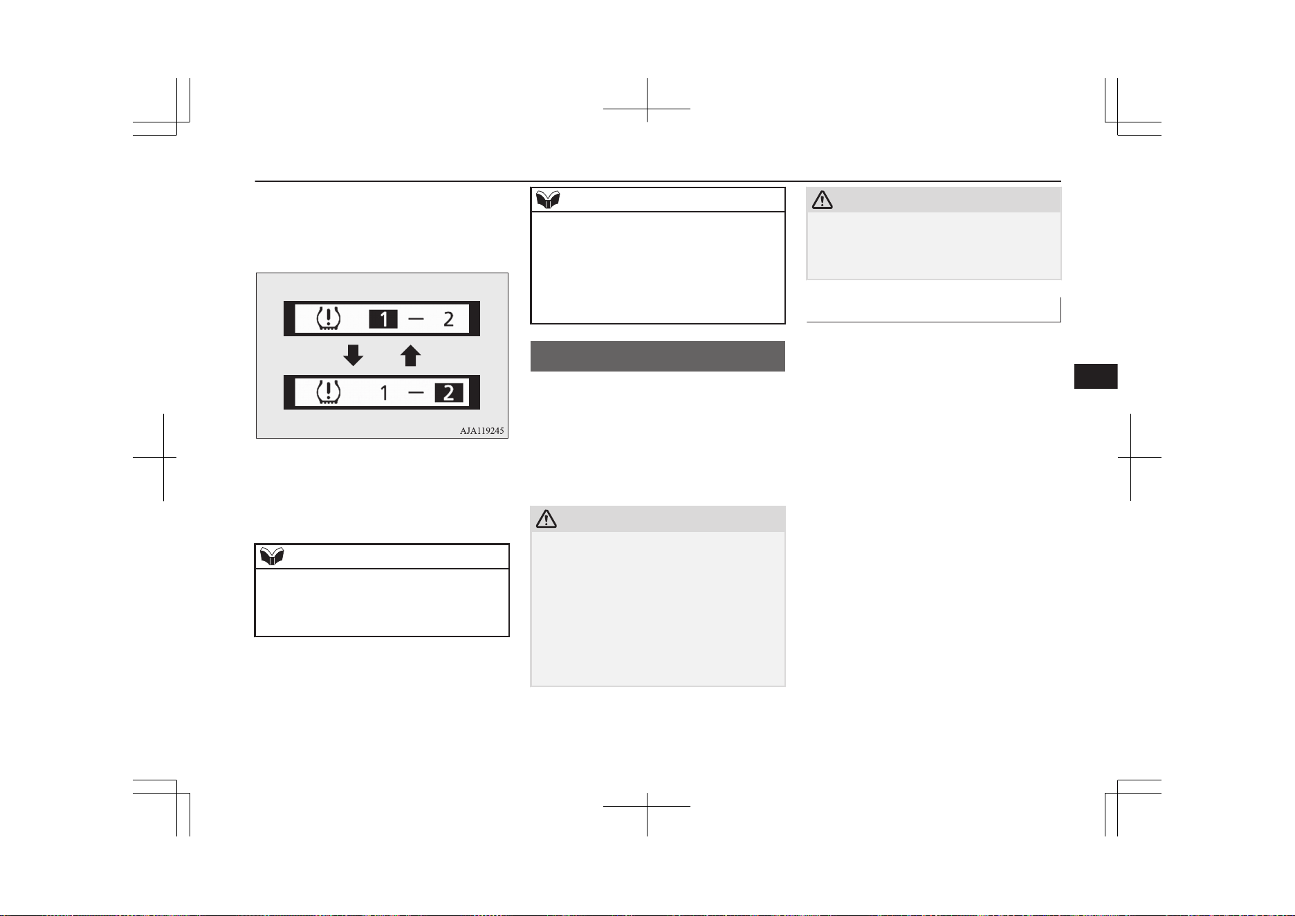
3. Hold down the multi-information dis-
play switch for about 3 seconds or more.
The setting changes the selected tyre ID
set.
4. The valid tyre ID set is changed, and the
number of the tyre pressure monitoring
system (TPMS) SET indicator is
changed.
NOTE
l
Each time this procedure is done, the tyre ID
set is changed. (1 - 2 - 1 - 2 …)
l
The tyre ID set is NOT changed, in case that
only 1 set of ID is registered.
NOTE
l
When changing the tyre ID set, the reset
function of low tyre pressure warning
threshold is automatically started. (The
warning lamp starts flashing slowly.) If the
tyre is warm at this time, the reset function
should be executed again when the tyre is
cold.
Reversing sensor system*
E00615501515
This system operates when you are backing
the vehicle. It uses corner and back sensors to
detect an obstacle and the information screen
in the multi information display and the buz-
zer to inform you of the approximate distance
to the obstacle.
CAUTION
l
The reversing sensor system assists you in
determining the approximate distance be-
tween the vehicle and an obstacle located
behind the vehicle. It has limitations in terms
of detectable areas and objects, and may not
properly detect some objects. Therefore, do
not place excessive confidence in the revers-
ing sensor system and operate the vehicle as
carefully as you would do with a vehicle not
equipped with this system.
CAUTION
l
Make sure to check the surroundings with
your own eyes to ensure safety. Do not oper-
ate the vehicle by relying on the reversing
sensor system alone.
Obstacle detection areas
E00615601718
The detection areas of the corner and back
sensors are limited to those shown in the il-
lustration. Moreover, the sensors are unable
to detect low or thin objects or objects near
the rear bumper. Thus, make sure to check
the surroundings as you operate the vehicle in
a safe manner.
Reversing sensor system*
7-97
OGGE19E1
Starting and driving
7
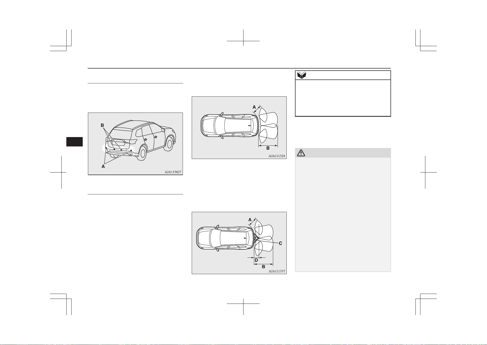
Corner and back sensor loca-
tions
There are two corner sensors (A) at the cor-
ners of the rear bumper, and two back sensors
(B) in the centre of the rear bumper.
Reversing sensor system detec-
tion areas
Depending on whether the vehicle is equip-
ped with a towing bar, you can change the re-
versing sensor system between the standard
mode and the towing bar mode. The towing
bar mode changes the system to exclude the
area in which the towing bar is mounted from
the detection areas.
Vehicles without a towing bar
The detection areas are within approximately
60 cm (A) from the corner sensors, 125 cm
(B) from the back sensors.
Vehicles with a towing bar
The detection areas are within approximately
60 cm (A) from the corner sensors, 125 cm
(B) from the back sensors. The non-detection
areas (C) are within approximately 20 cm (D)
from the bumper.
NOTE
l
The sensors do not detect objects located in
the area directly below or near the bumper.
If the height of an object is lower than the
mounted position of the corner or back sen-
sors, the sensors may not continue detecting
it even if they detected it initially.
For information on how to change the detec-
tion areas, please refer to “Changing the de-
tection areas” on page 7-100.
CAUTION
l
The reversing sensor system may not operate
properly under the following conditions:
•
The sensors or surroundings have been
wiped by hand.
•
The stickers or accessories have been at-
tached to the sensors or surroundings.
•
The sensors or surroundings are covered
with ice, snow, or mud.
•
When the temperature difference is too
large.
•
The sensors are frozen.
•
The system receives ultrasonic noise from
other sources (the horns of other vehicles,
motorcycle engines, brakes, radios, pour-
ing rain, splashing water, snow traction
device (tyre chains), etc.).
•
The sensors are extremely hot or cold
(while the vehicle is parked for a long pe-
riod of time under a blazing sun or in cold
weather).
Reversing sensor system*
7-98
OGGE19E1
Starting and driving
7
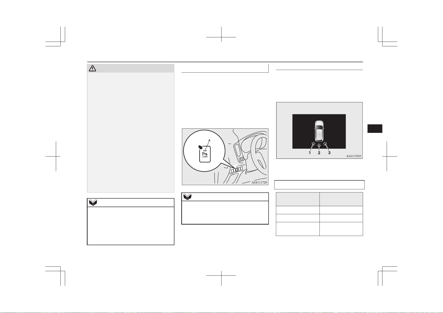
CAUTION
•
The vehicle tilts significantly.
•
The vehicle is driven on a rough road
(with a bumpy, gravel, hilly, or grassy sur-
face).
•
The vehicle is too close to an obstacle.
•
Immediately after Plug-in Hybrid EV
System starting.
l
The reversing sensor system may not proper-
ly detect the following objects:
•
Objects that are thin, such as wire nets or
ropes.
•
Objects that absorb sound waves, such as
snow.
•
Objects that are shaped with a sharp an-
gle.
•
Objects with a smooth surface, such as
glass.
•
Objects that are low, such as kerbstones.
l
If the bumper has been exposed to an im-
pact, the sensors may fail and prevent the
system from functioning properly. Have the
vehicle inspected at a MITSUBISHI
MOTORS Authorized Service Point.
NOTE
l
The buzzer may sound lower than the nor-
mal warning sound when the reversing sen-
sor system is receiving ultrasonic noise from
other sources, but this is not a malfunction.
The buzzer will stop sounding and the sys-
tem will return to normal operation after the
noise is no longer received.
To operate
E00615702136
To operate the system, move the selector lev-
er to the “R” position while the operation
mode is put in ON. When the reversing sen-
sor system is operated, the reversing sensor
system operation indication lamp (A) will
turn on. To stop the operation, push the “SO-
NAR” switch; the reversing sensor system
operation indication lamp (A) goes out.
NOTE
l
Only when the select position is the “R” po-
sition, the reversing sensor system can be
operated or be stopped by using the “SO-
NAR” switch.
Warning for obstacles
If there is an obstacle behind the vehicle, a
warning will be issued with the information
screen in the multi information display and a
warning buzzer.
1- Corner sensor (left)
2- Back sensor
3- Corner sensor (right)
Corner sensor
Vehicle to obstacle
distance
Warning display/
sound cycle
Approx. 60 to 40 cm Intermittent
Approx. 40 to 30 cm Fast intermittent
Within approx.
30 cm
Continuous
Reversing sensor system*
7-99
OGGE19E1
Starting and driving
7
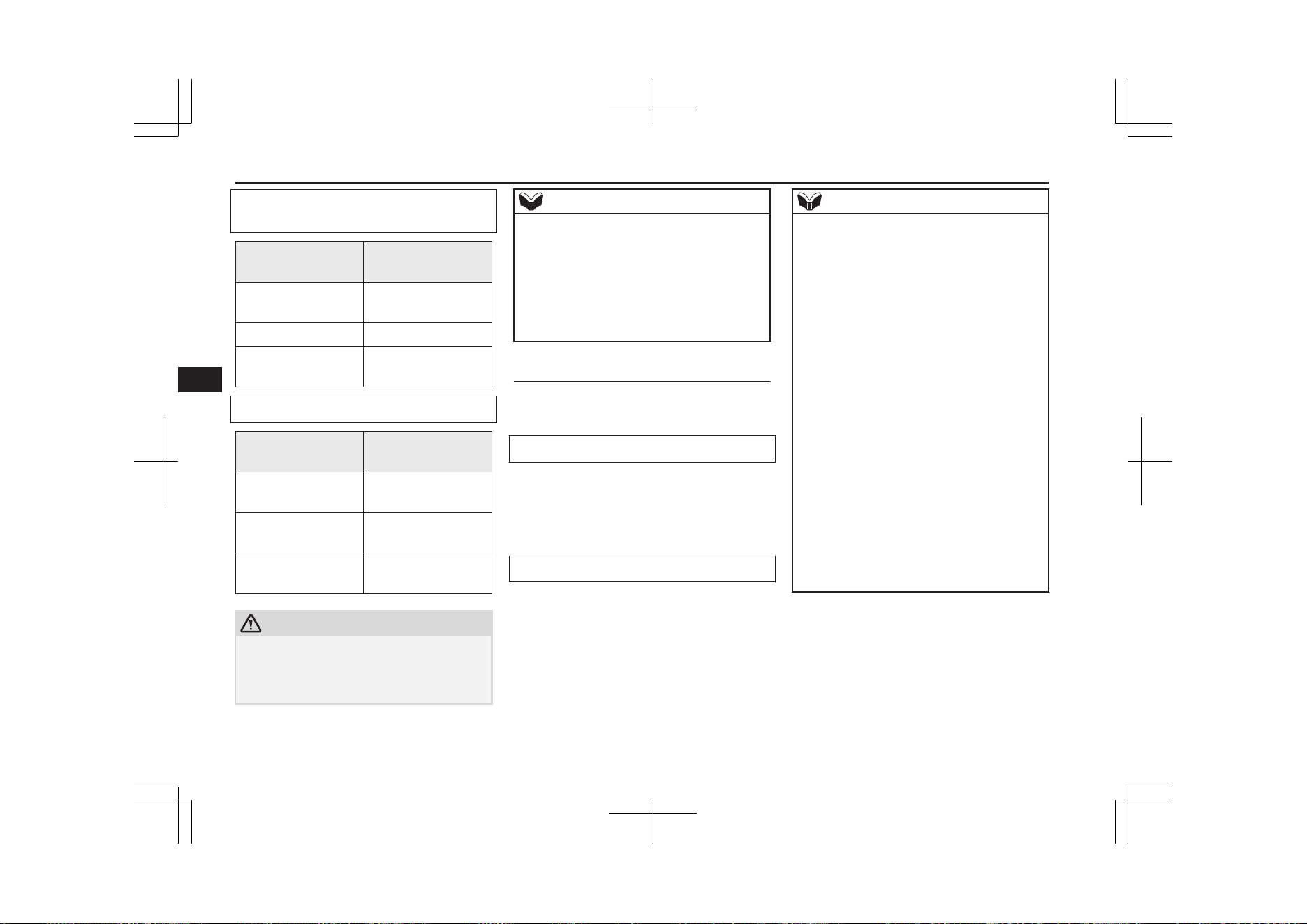
Back sensor (vehicles without a towing
bar)
Vehicle to obstacle
distance
Warning display/
sound cycle
Approx. 125 to
80 cm
Intermittent
Approx. 80 to 40 cm Fast intermittent
Within approx.
40 cm
Continuous
Back sensor (vehicles with a towing bar)
Vehicle to obstacle
distance
Warning display/
sound cycle
Approx. 125 to
100 cm
Intermittent
Approx. 100 to
60 cm
Fast intermittent
Within approx.
60 cm
Continuous
CAUTION
l
The distances given are to be used for refer-
ence only, as errors may be caused by vari-
ous factors, such as temperature, humidity,
or the shape of the obstacles.
NOTE
l
When the sensors are detecting different ob-
stacles at the same time, the information
screen in the multi information display indi-
cates the directions of the obstacles each
sensors are detecting. However, closer obsta-
cles are given priority over other detected
obstacles and the warning buzzer sounds to
inform you of closer obstacles.
Changing the detection areas
E00615801257
The detection areas can be changed as fol-
lows:
Vehicles with a towing bar
While the operation of the system is stopped
at the “SONAR” switch, push the “SONAR”
switch approximately 3 seconds or more, and
release it. The buzzer sounds twice to indi-
cate that the detection area has been changed.
Vehicles without a towing bar
While the operation of the system is stopped
at the “SONAR” switch, push the “SONAR”
switch approximately 3 seconds or more, and
release it. The buzzer sounds once to indicate
that the detection area has been changed.
NOTE
l
The detection area will not change if you
keep the “SONAR” switch pushed for 10
seconds or more.
l
After pushing the “SONAR” switch, revers-
ing sensor system operation differs accord-
ing to the detection area setting.
•
Setting when towing bar is not equipped
When the selector lever is moved to the
“R” position, the reversing sensor system
will operate even if the corner sensor op-
eration was stopped by pushing the “SO-
NAR” switch.
•
Setting when towing bar is equipped
When the reversing sensor system opera-
tion was stopped by pushing the “SO-
NAR” switch, the reversing sensor system
will not operate until the Plug-in Hybrid
EV System has been stopped even if the
selector lever is moved to the “R” posi-
tion.
To resume the reversing sensor system
operation, push the “SONAR” switch or
stop and restart the Plug-in Hybrid EV
System, and then move the selector lever
to the “R” position.
Reversing sensor system*
7-100
OGGE19E1
Starting and driving
7
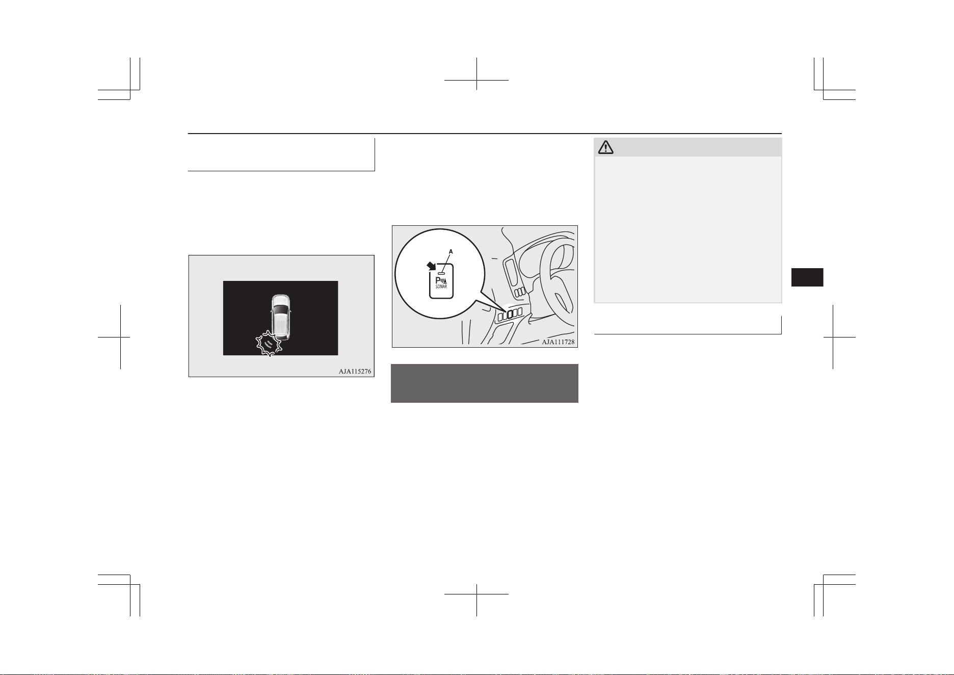
Reversing sensor system warn-
ing display
E00615901519
In case there is a malfunction in the reversing
sensor system, the display for the malfunc-
tioning sensor will blink and the warning
buzzer will sound for approximately 5 sec-
onds.
Example: Corner sensor (left) malfunctioning
Even after the buzzer and display has stopped
warning, the indication lamp (A) on “SO-
NAR” switch will continue blinking until the
system reverts to the normal state. Have the
vehicle inspected at a MITSUBISHI
MOTORS Authorized Service Point.
Parking sensors (Front/
Rear)*
E00647700092
When parking in a garage or during parallel
parking, these sensors alert the driver to any
objects near the vehicle and their distance,
through a buzzer and the sensor display on
the information screen in the multi-informa-
tion display.
CAUTION
l
The parking sensors assist you in determin-
ing the approximate distance between the
vehicle and any objects. It has limitations in
terms of detectable areas and objects, and
may not properly detect some objects.
Therefore, do not place excessive confidence
in the parking sensors, and operate the vehi-
cle as carefully as you would do with vehicle
not equipped with this system.
l
Make sure to check the surroundings with
your own eyes to ensure safety. Do not oper-
ate the vehicle by relying on the parking sen-
sors alone.
Obstacle detection areas
E00647800136
The detection areas of the corner and back
sensors are limited to those shown in the il-
lustration. Moreover, the sensors are unable
to detect low or thin objects or objects near
the front or rear bumper. Thus, make sure to
check the surroundings as you operate the ve-
hicle in a safe manner.
Parking sensors (Front/Rear)*
7-101
OGGE19E1
Starting and driving
7
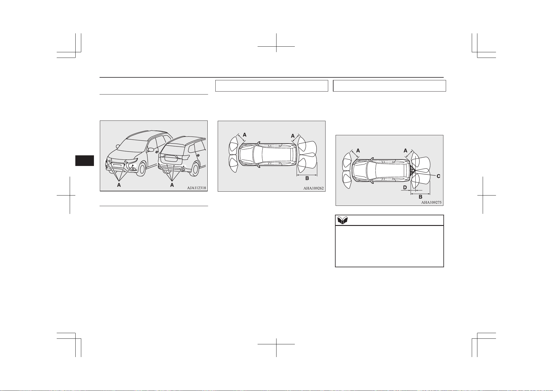
Corner and back sensor loca-
tions
There are 8 sensors (A) in the front and rear
bumper.
Detection areas
Depending on whether the vehicle is equip-
ped with a towing bar, you can change the
parking sensors between the standard mode
and the towing bar mode. The towing bar
mode changes the system to exclude the area
in which the towing bar is mounted from the
detection areas.
Vehicles without a towing bar
The detection areas are within approximately
60 cm (A) from the front and corner sensors
and 125 cm (B) from the back sensors.
Vehicles with a towing bar
The detection areas are within approximately
60 cm (A) from the front and corner sensors
and 125 cm (B) from the back sensors. The
non-detection areas (C) are within approxi-
mately 20 cm (D) from the bumper.
NOTE
l
The sensors do not detect objects located in
the area directly below or near the bumper.
If the height of an object is lower than the
mounted position of the sensors, the sensors
may not continue detecting it even if they
detected it initially.
For information on how to change the detec-
tion areas, please refer to “Changing the de-
tection areas” on page 7-100.
Parking sensors (Front/Rear)*
7-102
OGGE19E1
Starting and driving
7
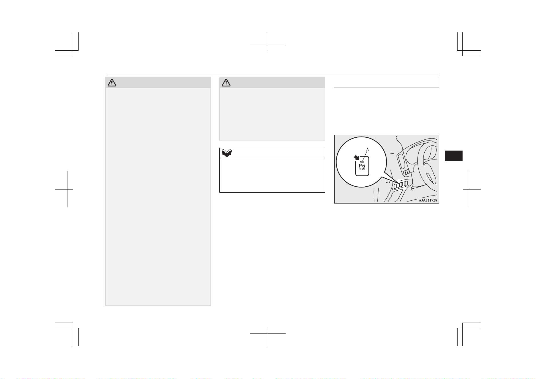
CAUTION
l
The parking sensors may not operate proper-
ly under the following conditions:
•
The sensors or surroundings have been
wiped by hand.
•
The stickers or accessories have been at-
tached to the sensors or surroundings.
•
The sensors or surroundings are covered
with ice, snow, or mud.
•
When the temperature difference is too
large.
•
The sensors are frozen.
•
The system receives ultrasonic noise from
other sources (the horns of other vehicles,
motorcycle engines, brakes, radios, pour-
ing rain, splashing water, snow traction
device (tyre chains), etc.).
•
The sensors are extremely hot or cold
(while the vehicle is parked for a long pe-
riod of time under a blazing sun or in cold
weather).
•
The vehicle tilts significantly.
•
The vehicle is driven on a rough road
(with a bumpy, gravel, hilly, or grassy sur-
face).
•
The vehicle is too close to an obstacle.
•
Immediately after Plug-in Hybrid EV
System starting.
l
The parking sensors may not properly detect
the following objects:
•
Objects that are thin, such as wire nets or
ropes.
•
Objects that absorb sound waves, such as
snow.
•
Objects that are shaped with a sharp an-
gle.
CAUTION
•
Objects with a smooth surface, such as
glass.
•
Objects that are low, such as kerbstones.
l
If the bumper has been exposed to an im-
pact, the sensors may fail and prevent the
system from functioning properly. Have the
vehicle inspected at a MITSUBISHI
MOTORS Authorized Service Point.
NOTE
l
When the sensor is received ultrasonic noise
from outside, the sensor of the correspond-
ing portion will blink at a constant frequen-
cy. When they are not received the noise and
return to normal operation.
To operate
E00648100149
To operate the system, the operation mode is
put in ON. When the parking sensors are op-
erated, the indication lamp (A) will turn on.
To stop the operation, press the “SONAR”
switch and the indication lamp (A) goes off.
Parking sensors (Front/Rear)*
7-103
OGGE19E1
Starting and driving
7
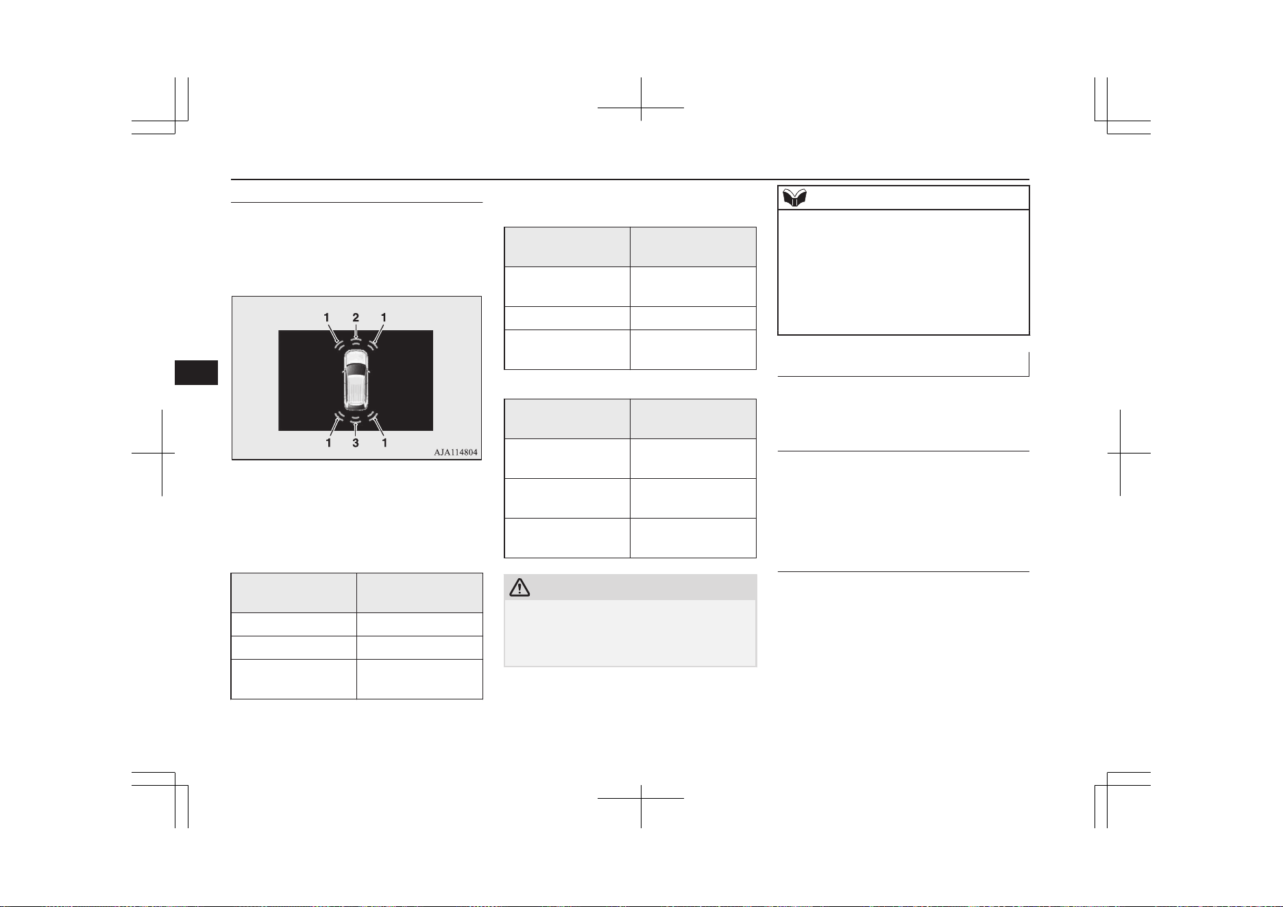
Warning for obstacles
If there is an obstacle in the vicinity of the
vehicle, a warning will be issued with the in-
formation screen in the multi information dis-
play and a warning buzzer.
1- Corner sensor
2- Front sensor
3- Back sensor
Front and corner sensor
Vehicle to obstacle
distance
Warning display/
sound cycle
Approx. 60 to 40 cm Intermittent
Approx. 40 to 30 cm Fast intermittent
Within approx.
30 cm
Continuous
Back sensor (vehicles without a towing
bar)
Vehicle to obstacle
distance
Warning display/
sound cycle
Approx. 125 to
80 cm
Intermittent
Approx. 80 to 40 cm Fast intermittent
Within approx.
40 cm
Continuous
Back sensor (vehicles with a towing bar)
Vehicle to obstacle
distance
Warning display/
sound cycle
Approx. 125 to
100 cm
Intermittent
Approx. 100 to
60 cm
Fast intermittent
Within approx.
60 cm
Continuous
CAUTION
l
The distances given are to be used for refer-
ence only, as errors may be caused by vari-
ous factors, such as temperature, humidity,
or the shape of the obstacles.
NOTE
l
When the sensors are detecting different ob-
stacles at the same time, the information
screen in the multi information display indi-
cates the directions of the obstacles each
sensors are detecting. However, closer obsta-
cles are given priority over other detected
obstacles and the warning buzzer sounds to
inform you of closer obstacles.
Changing the detection areas
E00648200094
The detection areas can be changed as fol-
lows:
Vehicles with a towing bar
While the operation of the system is stopped
at the “SONAR” switch, press the “SONAR”
switch approximately 3 seconds or more, and
release it. The buzzer sounds twice to indi-
cate that the detection area has been changed.
Vehicles without a towing bar
While the operation of the system is stopped
at the “SONAR” switch, press the “SONAR”
switch approximately 3 seconds or more, and
release it. The buzzer sounds once to indicate
that the detection area has been changed.
Parking sensors (Front/Rear)*
7-104
OGGE19E1
Starting and driving
7
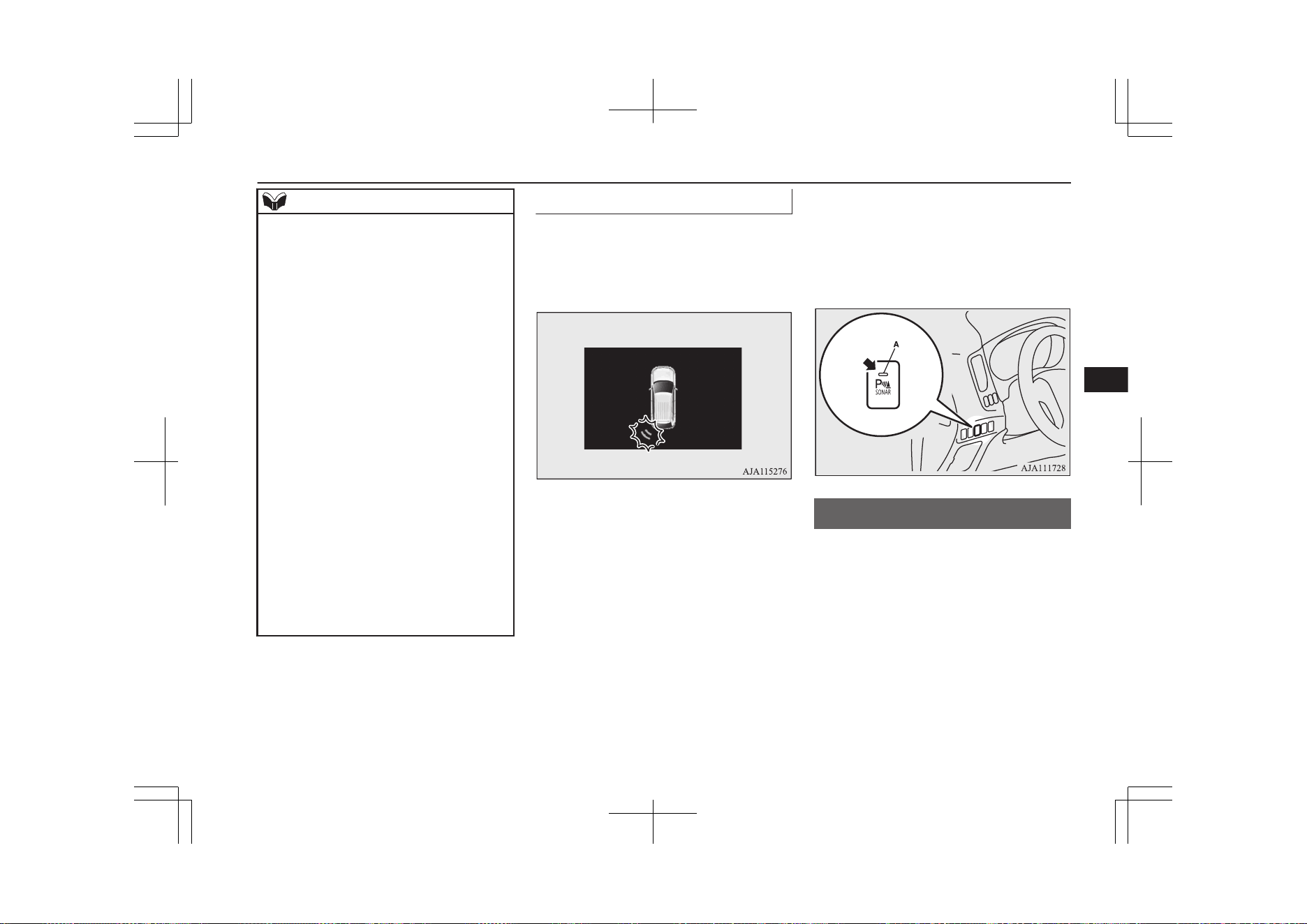
NOTE
l
The mode of the detection area can be
switched only when the select position is in
the “R” (REVERSE) position.
l
The detection area will not change if you
keep the “SONAR” switch pressed for 10
seconds or more.
l
After pressing the “SONAR” switch, the
parking sensors operation differs according
to the detection area setting.
•
Setting when towing bar is not equipped
When the selector lever is moved to the
“R” (REVERSE) position, the parking
sensors will operate even if the parking
sensors operation was stopped by pressing
the “SONAR” switch.
•
Setting when towing bar is equipped
When the parking sensors operation was
stopped by pressing the “SONAR”
switch, the parking sensors will not oper-
ate until the Plug-in Hybrid EV System
has been stopped even if the select posi-
tion is put to the “R” (REVERSE) posi-
tion.
To resume the parking sensors operation,
press the “SONAR” switch or stop and re-
start the Plug-in Hybrid EV System, and
then put the select position to the “R”
(REVERSE) position.
Warning display
E00648300125
In case there is a malfunction in the parking
sensors, the display for the malfunctioning
sensor will blink and the warning buzzer will
sound for approximately 5 seconds.
Example: Corner sensor (left) malfunctioning
Even after the buzzer and display has stopped
warning, the indication lamp (A) on “SO-
NAR” switch will continue blinking until the
system reverts to the normal state. Have the
vehicle inspected at a MITSUBISHI
MOTORS Authorized Service Point.
Rear-view camera*
E00618402684
The rear-view camera is a system that shows
the view behind the vehicle on a screen of the
DISPLAY AUDIO, the Smartphone Link
Display Audio or the MITSUBISHI Multi-
Communication System (MMCS).
Rear-view camera*
7-105
OGGE19E1
Starting and driving
7
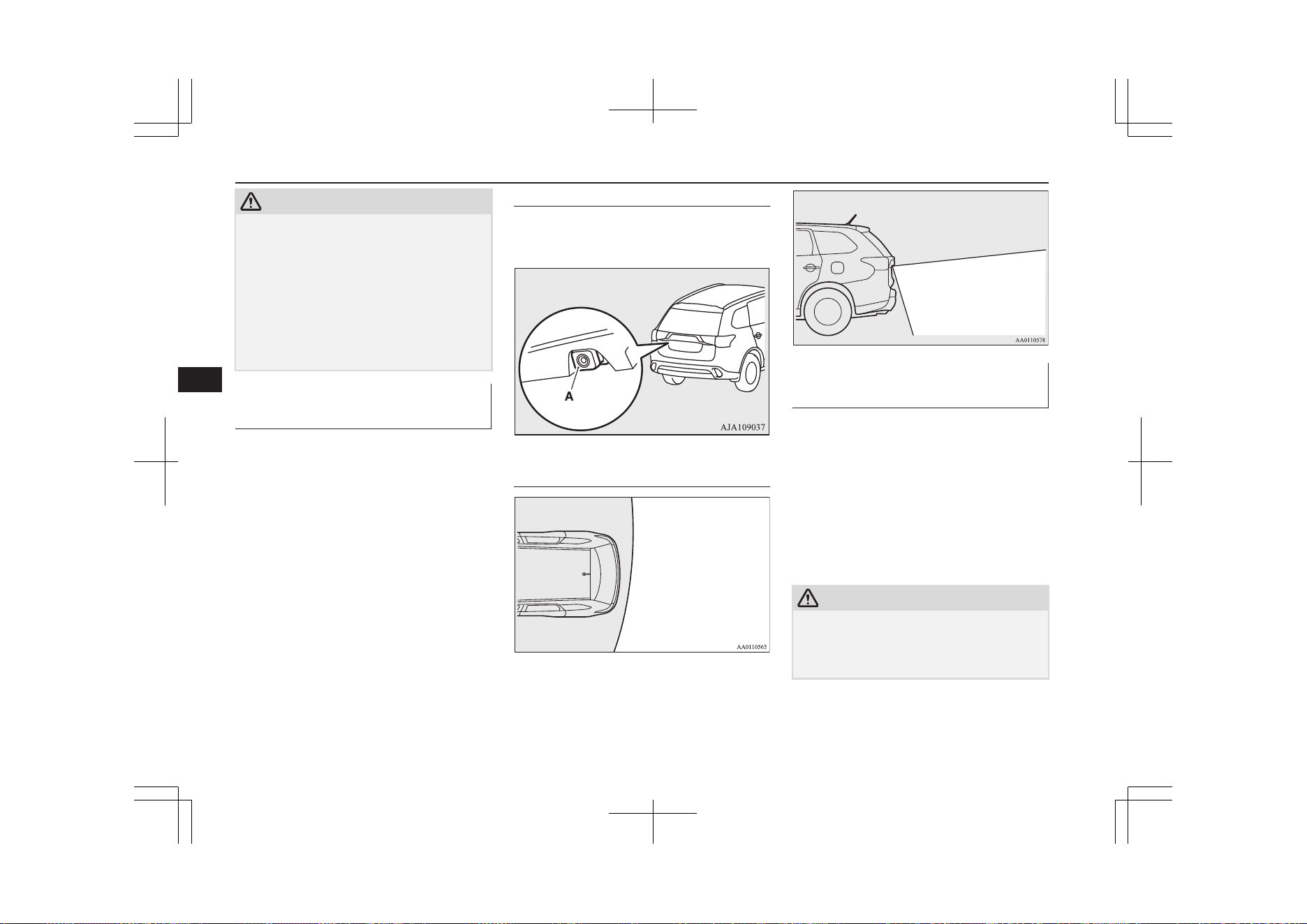
CAUTION
l
The rear-view camera is an assistance sys-
tem that enables the driver to check for ob-
stacles behind the vehicle. Its range of view
is limited, so you should not overly depend
on it. Please drive just as carefully as you
would if the vehicle did not have the rear-
view camera.
l
Be sure to visually confirm safety around the
vehicle with your own eyes. Do not depend
entirely on the rear-view camera.
Range of view of rear-view
camera
The range of view of the rear-view camera is
limited to the area shown in the illustrations.
It cannot show both sides and the lower part
of the rear bumper, etc.
When reversing, be sure to visually confirm
safety around the vehicle.
Location of rear-view camera
The rear-view camera (A) is integrated into
the part near the tailgate handle.
Range of view of rear-view cam-
era
How to use the rear-view cam-
era
When you put the select position to the “R”
position with the operation mode in ON, the
view behind the vehicle will automatically
appear on the screen of the DISPLAY AU-
DIO, the Smartphone Link Display Audio or
the MITSUBISHI Multi-Communication
System (MMCS). When you put the select
position to any other position, the screen will
return to its original indication.
CAUTION
l
The rear-view camera has a special lens that
can make objects shown on the screen ap-
pear to be closer or further away than they
actually are.
Rear-view camera*
7-106
OGGE19E1
Starting and driving
7
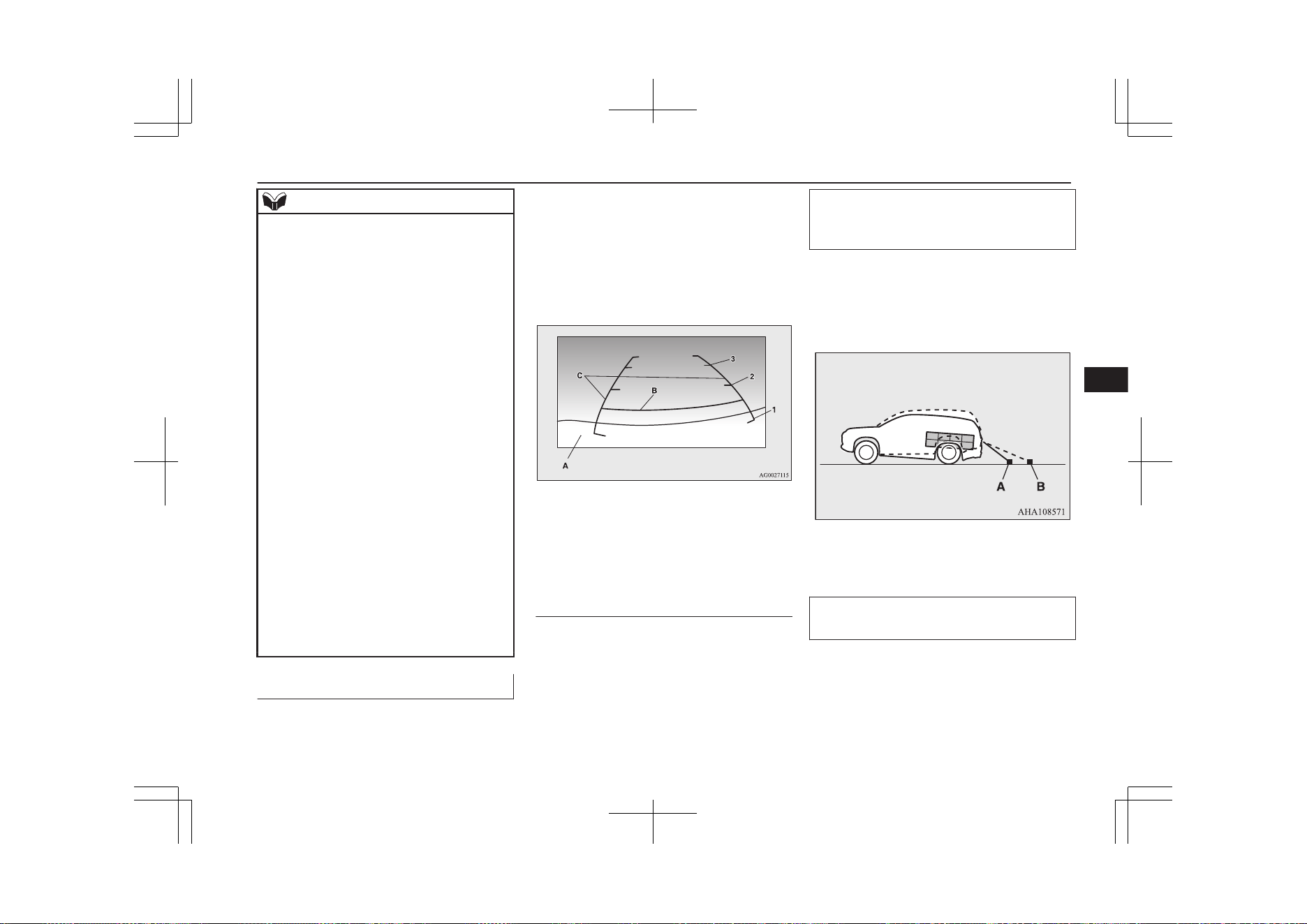
NOTE
l
Because the rear-view camera has a special
lens, the lines on the ground between park-
ing spaces may not look parallel on the
screen.
l
In the following situations, the screen indi-
cation may be difficult to see. There is no
abnormality.
•
Low light (nighttime).
•
When the light of the sun or the light from
a vehicle’s headlamps shines directly into
the lens.
l
If the camera is hot and is then cooled by
rain or a car wash, the lens can mist up. This
phenomenon does not indicate a malfunc-
tion.
l
It is not possible to fully see obstacles when
the lens is dirty. If the lens becomes conta-
minated by water droplets, snow, mud or oil,
wipe off the contamination, taking care not
to scratch the lens.
l
Please observe the following cautions. Ig-
noring them could lead to a camera malfunc-
tion.
•
Do not subject the camera to physical
shock.
•
Do not apply wax to the camera.
•
Do not splash the camera with boiling wa-
ter.
•
Do not disassemble the camera.
Reference lines on the screen
E00649100061
Reference lines and upper surface of the rear
bumper (A) are displayed on the screen.
l
Red line (B) indicates approximately
50 cm behind the rear bumper.
l
Two Green lines (C) indicate approxi-
mately 20 cm outside of the vehicle
body.
l
Short transverse lines (1 to 3) indicate
distance from the rear bumper.
Check surroundings for safety.
1. Approximately at the rear edge of the
rear bumper (if so equipped)
2. Approximately 100 cm
3. Approximately 200 cm
Errors between the display and
the actual road surface
The reference lines for distance and vehicle
width are based on a level, flat road surface.
In the following cases, errors are produced
between the display reference lines and the
distance on the actual road surface.
When the rear of the vehicle is weighed
down with the weight of passengers and
luggage in the vehicle
The reference lines are displayed closer than
the actual distance.
Therefore when there is an obstacle on the
upward slope, it appears farther than its ac-
tual position.
A: Actual objects
B: Objects shown on the screen
When there is an upward slope behind the
vehicle
The reference lines are displayed closer than
the actual distance.
Rear-view camera*
7-107
OGGE19E1
Starting and driving
7
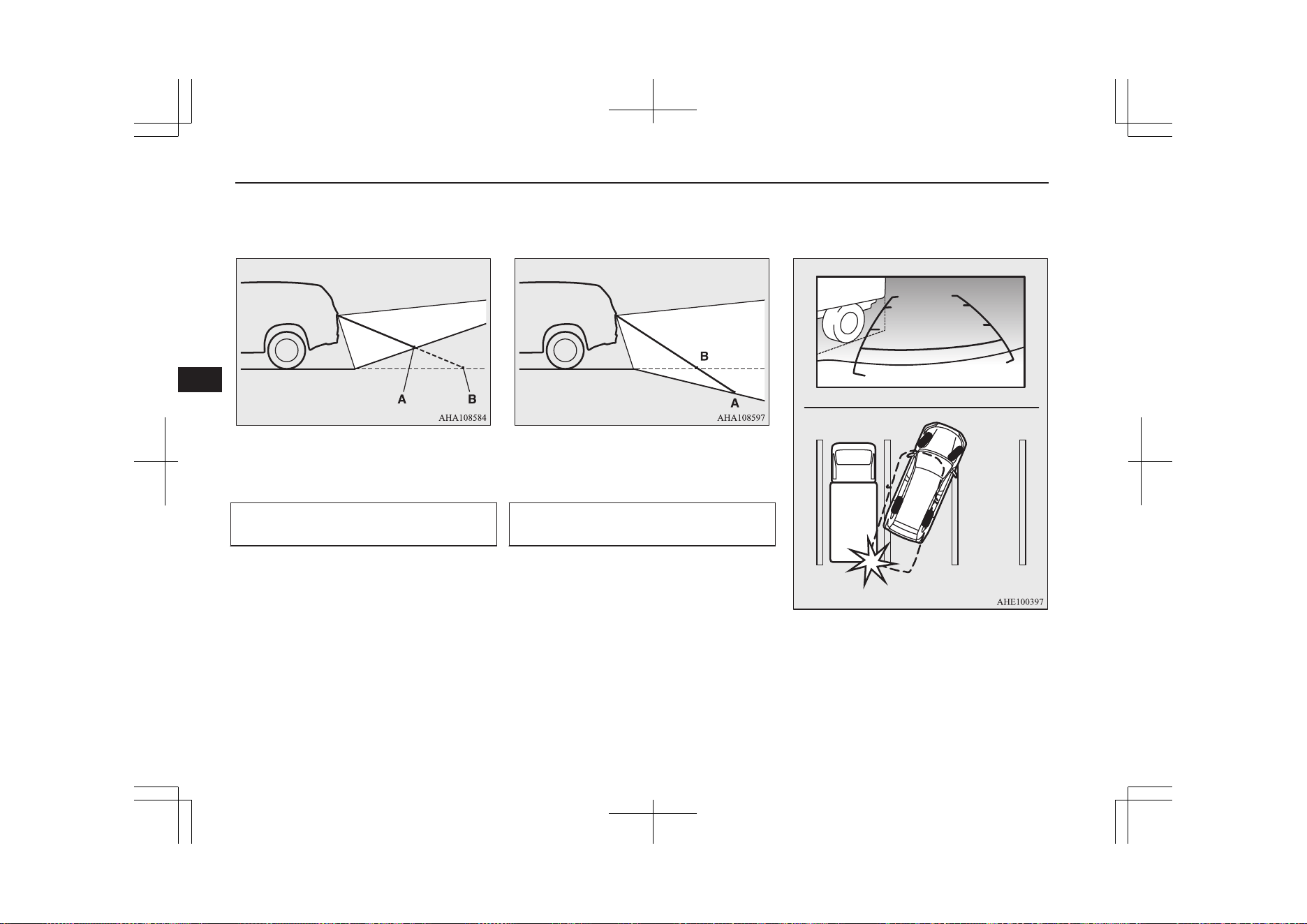
Therefore when there is an obstacle on the
upward slope, it appears farther than its ac-
tual position.
A: Actual objects
B: Objects shown on the screen
When there is a downward slope behind
the vehicle
The reference lines are displayed farther than
the actual distance.
Therefore when there is an obstacle on the
downward slope, it appears closer than its ac-
tual position.
A: Actual objects
B: Objects shown on the screen
When solid objects are located close to the
vehicle
When solid objects are located close to the
vehicle, the displayed distance on the screen
may differ from the actual distance.
Because the reference lines do not contact the
body of the truck, it looks as if it would not
hit the vehicle in following illustration.
However, the vehicle may hit the truck be-
cause the body of the truck strays onto the
course in reality.
Check surroundings for safety.
Rear-view camera*
7-108
OGGE19E1
Starting and driving
7
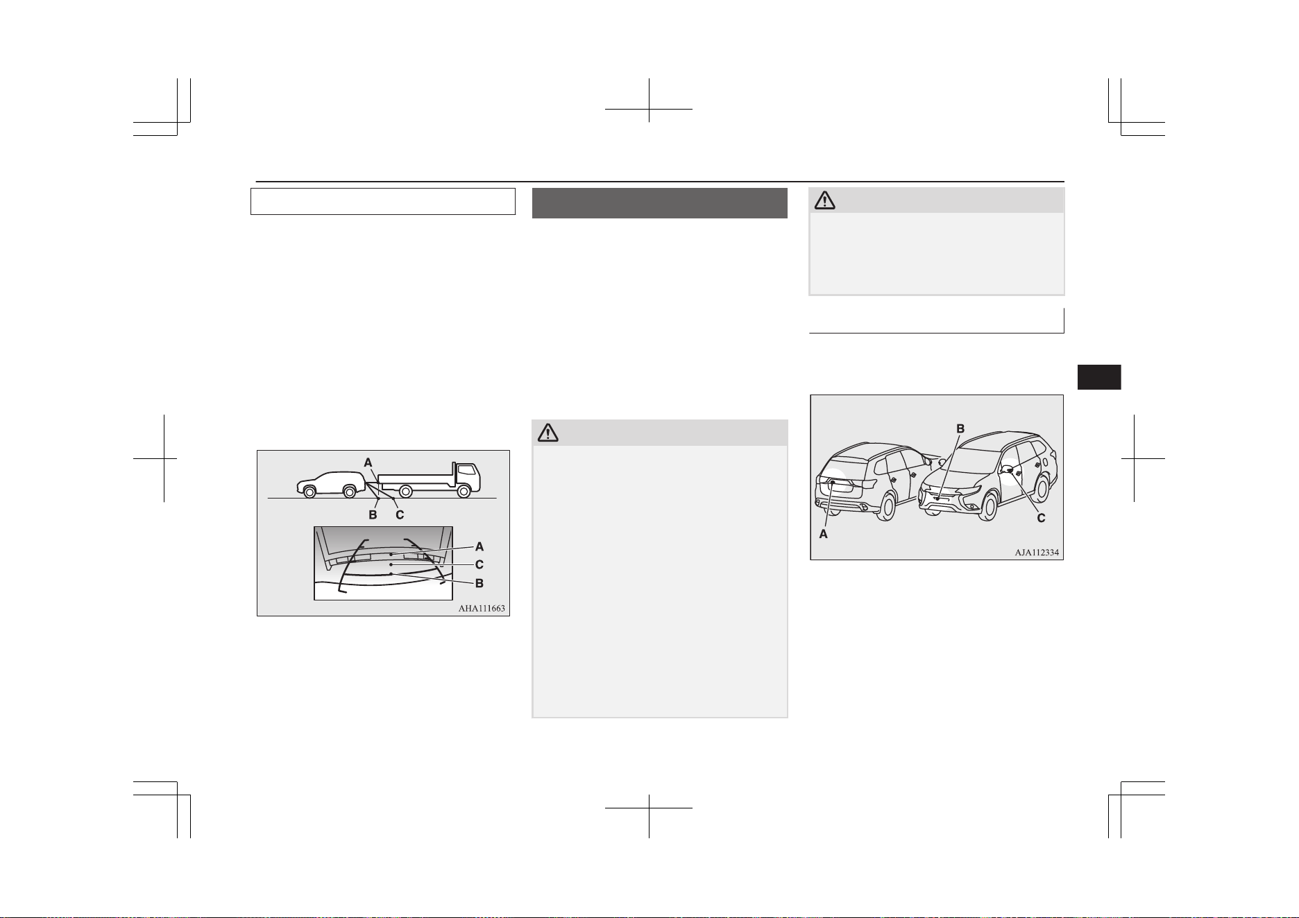
When approaching to solid objects
The reference lines for distance and vehicle
width are intended to indicate the distance to
a flat object such as a level, flat road surface.
This may make the distance to a projecting
object shown on the screen differ from the
actual distance to the projecting object. Do
not use them as a guide for distances to solid
objects.
Example: On the screen the point B appears
the nearest, then the point C and A in order of
distance. The points A and B actually are the
same distances from the vehicle, and the
point C is farther off than the points A and B.
Check surroundings for your safety.
Multi Around Monitor*
E00645000310
The Multi Around Monitor is a system that
shows the view combined with four cameras,
i.e., “Front-view camera”, “Side-view cam-
eras (right and left)” and “Rear-view camera”
on a screen of the DISPLAY AUDIO, the
Smartphone Link Display Audio or the
MITSUBISHI Multi-Communication System
(MMCS). It assists drivers to park their vehi-
cles in parking spaces and to parallel park
their vehicles.
CAUTION
l
The Multi Around Monitor is an assistance
system that enables the driver to check the
safety around the vehicle. The range where
the image can be displayed is limited. Do
not place too much confidence in the Multi
Around Monitor and try to drive carefully in
the same way as for the vehicle not equipped
with the Multi Around Monitor.
Its range of view is limited, so you should
not overly depend on it. Please drive just as
carefully as you would if the vehicle did not
have the Multi Around Monitor.
l
Be sure to visually confirm safety around the
vehicle with your own eyes. Especially, the
four corners of the vehicle become blind
spots where an object is not displayed on the
Multi Around Monitor. Do not depend en-
tirely on the Multi Around Monitor.
CAUTION
l
Do not use the Multi Around Monitor with
the door mirrors folded in and/or with the
doors and/or the tailgate open. It will prevent
the Multi Around Monitor from displaying
the appropriate range.
Location of each cameras
The cameras are integrated into the location
as shown below.
A: Rear-view camera
B: Front-view camera
C: Side-view camera
Multi Around Monitor*
7-109
OGGE19E1
Starting and driving
7
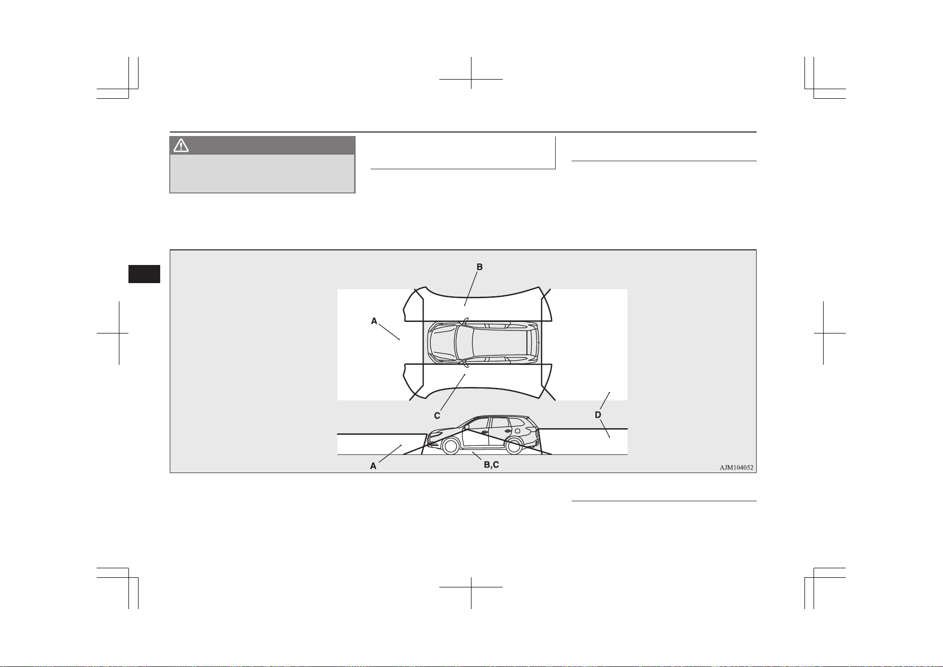
WARNING
l
Do not install anything which will disturb
the operation of the cameras around the
location of them.
Range of view of the Multi
Around Monitor
E00645100252
The range of view of the Multi Around Mon-
itor cameras is limited to the area shown in
the illustrations. It cannot show around the
both sides and the lower part of the front and
rear bumpers, etc. While driving, be sure to
visually confirm safety around the vehicle.
Range of view of the Multi
Around Monitor cameras
A: Front-view camera
B: Side-view camera (Right)
C: Side-view camera (Left)
D: Rear-view camera
Types of views of the Multi
Around Monitor
Two different types of views are displayed on
the left side and the right side respectively.
Multi Around Monitor*
7-110
OGGE19E1
Starting and driving
7
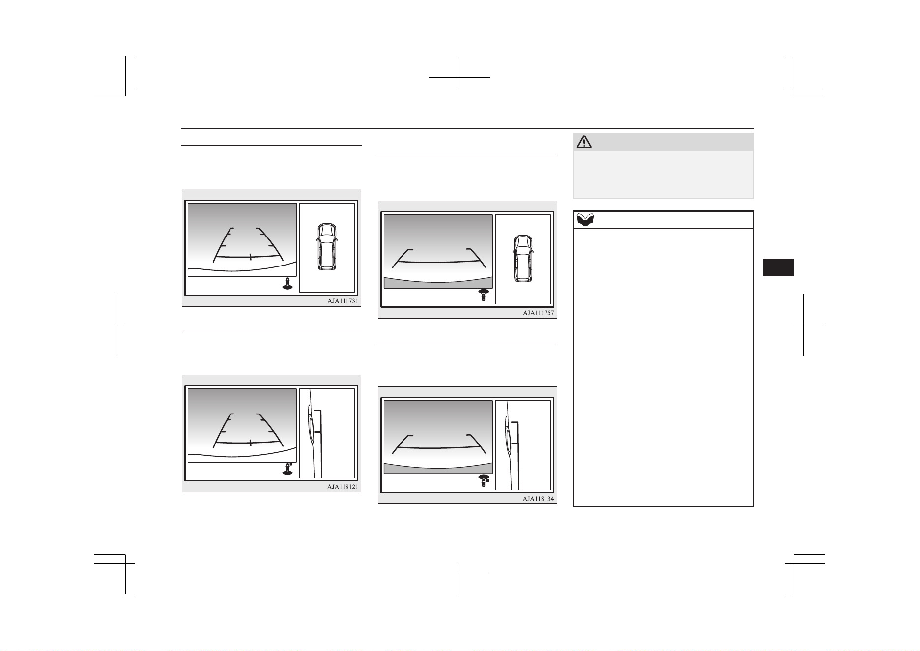
Bird’s eye-view/Rear-view mode
Views of the surroundings of the vehicle and
behind the vehicle are displayed.
Check surroundings for safety.
Side-view/Rear-view mode
Views of the passenger’s side of the vehicle
and behind the vehicle are displayed.
Check surroundings for safety.
Bird’s eye-view/Front-view
mode
Views of the surroundings of the vehicle and
the front of the vehicle are displayed.
Check surroundings for safety.
Side-view/Front-view mode
Views of the passenger’s side of the vehicle
and the front of the vehicle are displayed.
Check surroundings for safety.
CAUTION
l
The cameras have special lenses that can
make objects shown on the screen appear to
be closer or further away than they actually
are.
NOTE
l
Because the cameras have a special lens, the
lines on the ground between parking spaces
may not look parallel on the screen.
l
In the following situations, the screen indi-
cation may be difficult to see. There is no
abnormality.
•
Low light (nighttime).
•
When the light of the sun or the light from
a vehicle’s headlamps shines directly into
the lens.
•
If a fluorescent light shines directly into
the lens, the screen indication may be
flicker.
There is no abnormality.
l
If the camera is hot and is then cooled by
rain or a car wash, the lens can mist up. This
phenomenon does not indicate a malfunc-
tion.
l
If the atmospheric temperature is extremely
hot or extremely cold, the camera images
may not be clear.
There is no abnormality.
l
If a radio set is installed near the camera, the
camera images may cause electrical system
interference and the system may stop func-
tioning properly.
Multi Around Monitor*
7-111
OGGE19E1
Starting and driving
7
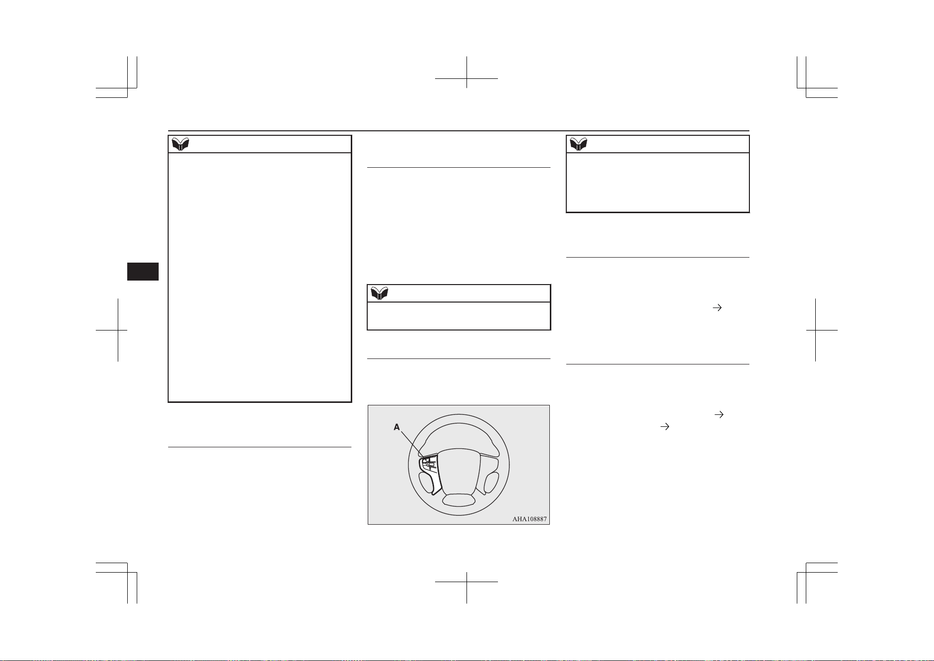
NOTE
l
It is not possible to fully see obstacles when
the lens is dirty. If the lens becomes conta-
minated by water droplets, snow, mud or oil,
wipe off the contamination, taking care not
to scratch the lens.
l
Please observe the following cautions. Ig-
noring them could lead to a camera malfunc-
tion.
•
Do not subject the camera to physical
shook such as striking it strongly or
throwing a thing.
•
Do not adhere organic substances, waxes,
oil remover, and glass cleaner to the cam-
era.
If adhered to them, immediately wipe off.
•
Do not splash the camera with boiling wa-
ter.
•
Never spray or splash water on the cam-
era or around it.
•
Do not disconnect, disassemble or modify
the camera.
•
Do not scratch the camera, as this may
cause damage to the camera images.
How to use the Multi Around
Monitor
E00650000031
The Multi Around Monitor can only be used
when the operation mode is ON.
Operation with the selector lev-
er
E00652700175
When you put the select position to the “R”
(REVERSE) position, the bird’s eye-view/
rear-view is displayed on the screen of the
DISPLAY AUDIO, the Smartphone Link
Display Audio or the MITSUBISHI Multi-
communication System (MMCS). When you
put the select position to any other position,
the display disappears.
NOTE
l
The passenger’s side screen can be switched
to the side-view by pressing the switch.
Operation with the switch
E00652800105
When the switch (A) is pressed, the bird’s
eye view/front-view is displayed.
NOTE
l
If there is no operation for 3 minutes after
the Multi Around Monitor is displayed by
pressing the switch with the select position
in a position other than “R”, the display dis-
appears.
Switching of the screen (Select
position is “R”)
E00652900278
If the switch is pressed, the mode of Multi
Around Monitor is switched as follows.
Bird’s eye-view/Rear-view mode
Side-
view/ Rear-view mode
Switching of the screen (Select
position is other than “R”)
E00652900281
If the switch is pressed, the mode of Multi
Around Monitor is switched as follows.
Bird’s eye-view/ Front-view mode
Side-
view/Front-view mode OFF
Multi Around Monitor*
7-112
OGGE19E1
Starting and driving
7
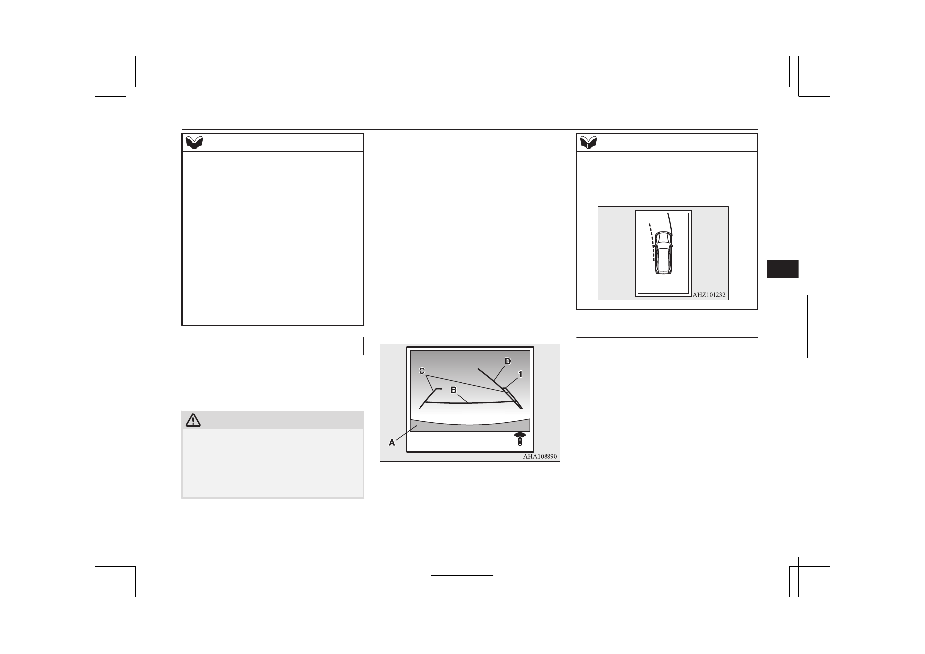
NOTE
l
When you put the select position to the “R”
(REVERSE) position with the front-view
displayed on the driver’s side screen, the
driver’s side screen switches to the rear-view
mode. When you put the select position to
any other position, the driver’s side screen
switches to the front-view mode.
l
When the switch is pressed at the vehicle
speed of approximately 10 km/h (6 mph) or
higher, only the side-view can be displayed
on the passenger’s side screen.
l
The front-view will not be displayed when
the vehicle speed exceeds approximately
10 km/h (6 mph).
l
The display of the view may be delayed dur-
ing switching of the screen.
How to read the screen
E00645400079
In any mode other than the Bird’s eye-view
mode, the lines in the screen give the follow-
ing information. Use them only as a guide.
CAUTION
l
When you accidentally hit the camera and its
circumference against something, the view
and the lines in the screen may not be dis-
played correctly. Be sure to have it inspected
by a MITSUBISHI MOTORS Authorized
Service Point.
Front-view mode
Reference lines for the distance and the vehi-
cle width and upper surface of the front
bumper (A) are displayed on the screen.
l
The Red line (B) indicates approximate-
ly 50 cm from the front edge of the front
bumper.
l
The Two Green lines (C) indicate the ap-
proximate vehicle width.
l
The Orange line (D) indicates an expec-
ted course when the vehicle moves for-
ward with the steering wheel turned. It
disappears when the steering wheel is in
the neutral position.
l
The approximate distance from the vehi-
cle body is as follows:
Check surroundings for safety.
1- Approximately 100 cm from the
front edge of the front bumper
NOTE
l
When the expected course lines are dis-
played in the front-view, the expected course
lines are also displayed in the bird’s eyeview
(Front: solid line, Rear: broken line).
Rear-view mode
E00645600084
Reference lines for the distance and the vehi-
cle width and upper surface of the rear bump-
er (A) are displayed on the screen.
l
The Red line (B) indicates approximate-
ly 50 cm behind the rear edge of the rear
bumper.
l
The Two Green lines (C) indicate the ap-
proximately vehicle width.
l
The Orange line (D) indicates an expec-
ted course when the vehicle is reserved
with the steering wheel turned. It disap-
pears when the steering wheel is in the
neutral position.
l
The approximate distance from the vehi-
cle body is as follows:
Multi Around Monitor*
7-113
OGGE19E1
Starting and driving
7
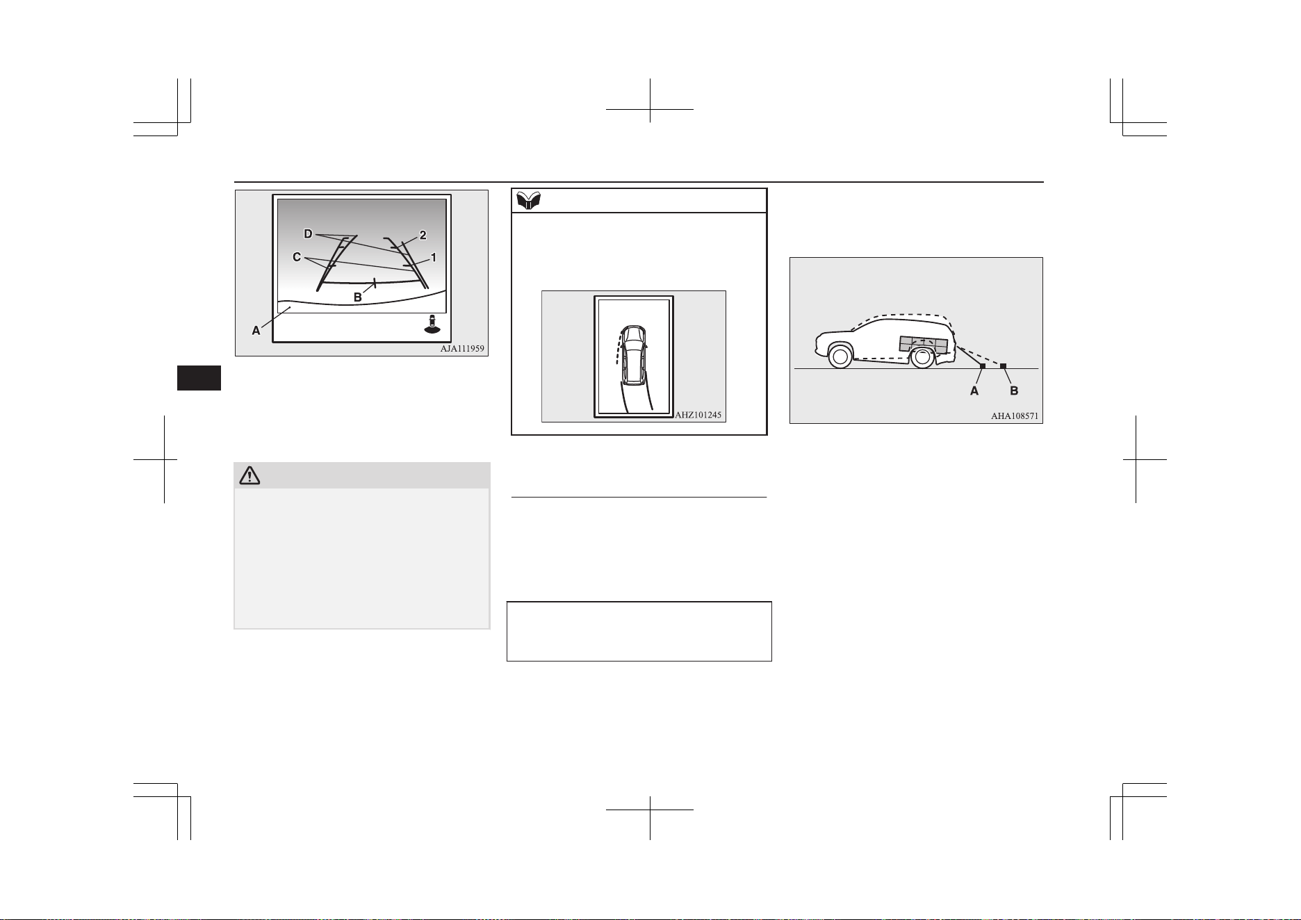
Check surroundings for safety.
1- Approximately 100 cm from the rear
edge of the rear bumper
2- Approximately 200 cm from the rear
edge of the rear bumper
CAUTION
l
Due to the number of people in the vehicle,
the fuel quantity, the weight and positioning
of luggage, and/or the condition of the road
surface, the lines in the view from the rear-
view camera may not be accurately posi-
tioned relative to the actual road.
Use the reference lines only as a guideline,
and always do a safety check of your behind
and surroundings directly while driving.
NOTE
l
When the expected course lines are dis-
played in the rear-view, the expected course
lines are also displayed in the bird’s eye-
view (Front: broken line, Rear: solid line).
Errors between the display and
the actual road surface
E00645900045
The reference lines for distance and vehicle
width are based on a level, flat road surface.
In the following cases, errors are produced
between the display reference lines and the
distance on the actual road surface.
When the rear of the vehicle is weighed
down with the weight of passengers and
luggage in the vehicle
The reference lines are displayed closer than
the actual distance.
Therefore when there is an obstacle on the
upward slope, it appears farther than its ac-
tual position.
A: Actual objects
B: Objects shown on the screen
When there is an upward slope behind the
vehicle
The reference lines are displayed closer than
the actual distance.
Multi Around Monitor*
7-114
OGGE19E1
Starting and driving
7
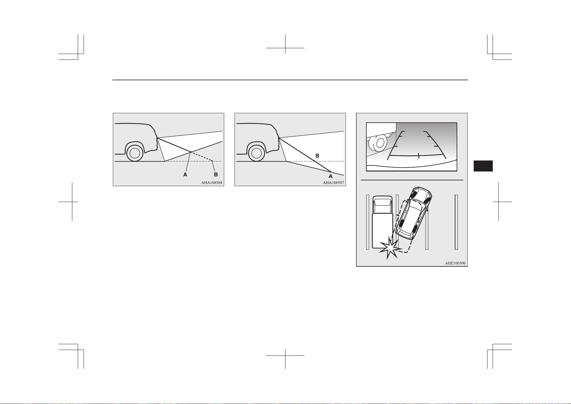
Therefore when there is an obstacle on the
upward slope, it appears farther than its ac-
tual position.
A: Actual objects
B: Objects shown on the screen
When there is a downward slope behind
the vehicle
The reference lines are displayed farther than
the actual distance.
Therefore when there is an obstacle on the
downward slope, it appears closer than its ac-
tual position.
A: Actual objects
B: Objects shown on the screen
When solid objects are located close to the
vehicle
When solid objects are located close to the
vehicle, the displayed distance on the screen
may differ from the actual distance.
Because the reference lines do not contact the
body of the truck, it looks as if it would not
hit the vehicle in following illustration.
However, the vehicle may hit the truck be-
cause the body of the truck strays onto the
course in reality.
Multi Around Monitor*
7-115
OGGE19E1
Starting and driving
7
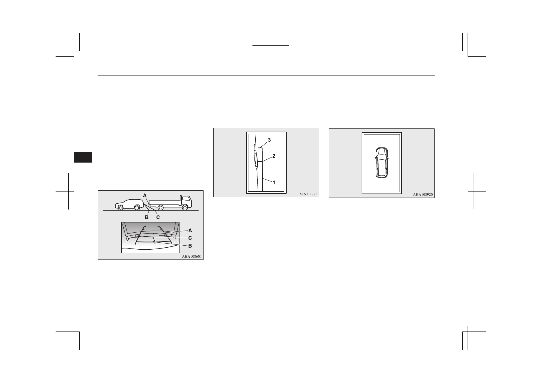
When approaching to solid objects
The reference lines for distance and vehicle
width are intended to indicate the distance to
a flat object such as a level, flat road surface.
This may make the distance to a projecting
object shown on the screen differ from the
actual distance to the projecting object. Do
not use them as a guide for distances to solid
objects.
Example: Example: On the screen the point B
appears the nearest, then the point C and A in
order of distance. The points A and B actual-
ly are the same distances from the vehicle,
and the point C is farther off than the points
A and B.
Side-view mode
E00646100060
Reference lines for the vehicle width and the
front end of the vehicle are displayed on the
screen.
1- Approximate vehicle width including the
door mirror.
2- Approximate location of the axle centre
of the front wheel.
3- Approximate 50 cm from the front edge
of the front bumper.
Bird’s eye-view mode
E00646200058
An overhead view in which the vehicle is
looked down is displayed so that you can
easily identify the location of your vehicle
and the course to enter the parking space.
Multi Around Monitor*
7-116
OGGE19E1
Starting and driving
7
CAUTION
l
The bird’s eye-view is an simulated view
processed by combining view captured by
“Front-view camera”, “Side-view cameras
(right and left)” and “Rear-view camera”.
Because of this, in the Bird’s eye-view
mode, objects will appear to be farther away
than they actually are. In addition, there are
blind spots in the vicinity of the actual vehi-
cle which are not displayed on the screen.
You may crash your vehicle even if there
seems to be a little distance between your
vehicle and an object, and there may be an
object in the area where there seems to be
nothing. Be sure to check the safety around
the vehicle with your own eyes.
l
The vehicle icon displayed in the Bird’s eye-
view mode differs from the actual vehicle in
colour and size. Because of this, an object
near the vehicle may appear to be in contact
with the vehicle, and the positional relation-
ship between the vehicle and the object may
differ from the actual one.
l
The view composition processing regions
are present in the four corners of the Bird’s
eye-view display, mainly at the boundary
sections of views from each camera. Be-
cause of this, in the vicinity of the boundary
sections, the sharpness of the views may de-
crease and an object may disappear and re-
appear on the screen.
NOTE
l
In the Bird’s eye-view mode, since the views
captured by the four cameras, “Front-view
camera”, “Side-view cameras (right and
left)” and “Rear-view camera” are processed
based on a level flat road surface, an image
may be displayed as follows:
•
An object appears to have fallen down
and looks longer or larger.
•
An object having a height from the road
surface may seem to appear from the joint
of the view composition processing re-
gions.
l
The brightness of the views from each cam-
era may vary depending on the illuminance
conditions.
l
An object above the camera is not displayed.
l
The object displayed in the Front-view mode
or the Rear-view mode may not be displayed
in the Bird’s eye-view mode.
l
The view in the Bird’s eye-view mode may
be displaced from its true position when the
mounting location and angle of each camera
are changed.
l
The lines on the road may appear to be dis-
placed or bent at the joint of the views.
Cargo loads
E00609902713
Cargo loads precautions
CAUTION
l
Do not load cargo or luggage higher than the
top of the seatback. Be sure that your cargo
or luggage cannot move once your vehicle is
moving. Having the driver’s vision blocked,
and your cargo being thrown inside the cabin
if you suddenly have to brake can cause a
serious accident or injury.
l
Load heavy cargo or luggage in the front of
the vehicle. If the load in the back of the ve-
hicle is too heavy, steering may become un-
stable.
Loading a roof carrier
CAUTION
l
Use a roof carrier that properly fits your ve-
hicle. Do not load luggage directly onto the
roof.
For installation, refer to the instruction man-
ual accompanying the roof carrier.
Cargo loads
7-117
OGGE19E1
Starting and driving
7
NOTE
l
We recommend you to use a MITSUBISHI
MOTORS GENUINE roof carrier, since the
brackets to be used have a special shape. For
details, we recommend you to consult a
MITSUBISHI MOTORS Authorized Serv-
ice Point.
Roof carrier precaution
CAUTION
l
Make sure that the weight of the luggage
does not exceed the allowable roof load.
If the allowable roof load is exceeded, this
may cause damage to the vehicle.
The roof load is the total allowable load on
the roof (the weight of the roof carrier plus
the weight of luggage placed on the roof car-
rier).
For the specific value, refer to “Maximum
roof load” on page 12-05.
CAUTION
l
When luggage is loaded onto the vehicle,
please make sure to drive slowly and avoid
excessive manoeuvres such as sudden brak-
ing or quick turning.
In addition, place the luggage on the carrier
so that its weight is distributed evenly with
the heaviest items on the bottom. Do not
load items that are wider than the roof carri-
er.
The additional weight on the roof could raise
the vehicle’s centre of gravity and affect ve-
hicle handling characteristics.
As a result, driving errors or emergency ma-
noeuvres could lead to a loss of control and
result in an accident.
l
Before driving and after travelling a short
distance, always check the load to make sure
it is securely fastened to the roof carrier.
Check periodically during your travel that
the load remains secure.
NOTE
l
To prevent wind noise or reduction in fuel
economy, remove the roof carrier when not
in use.
l
Remove the roof carrier before using an au-
tomatic car wash.
l
Be sure that adequate clearance is main-
tained for raising the sunroof (if so equip-
ped) when installing a roof carrier.
NOTE
l
Be sure that adequate clearance is main-
tained for raising the tailgate while loading
luggage on the roof carrier.
Trailer towing
E00610001993
In order to tow a trailer with your vehicle,
have a trailer towing device mounted that
meets all relevant regulations in your area,
consult a MITSUBISHI MOTORS Author-
ized Service Point.
The regulations concerning the towing of a
trailer may differ from country to country.
You are advised to obey the regulations in
each area.
CAUTION
l
Danger of Accident!
A towing bar should be fitted according to
MITSUBISHI MOTORS guidelines.
Maximum towable weight with
brake and maximum trailer-
nose weight
Never exceed the maximum towable weight
with brake and the maximum trailer-nose
weight as listed in the specifications.
Trailer towing
7-118
OGGE19E1
Starting and driving
7
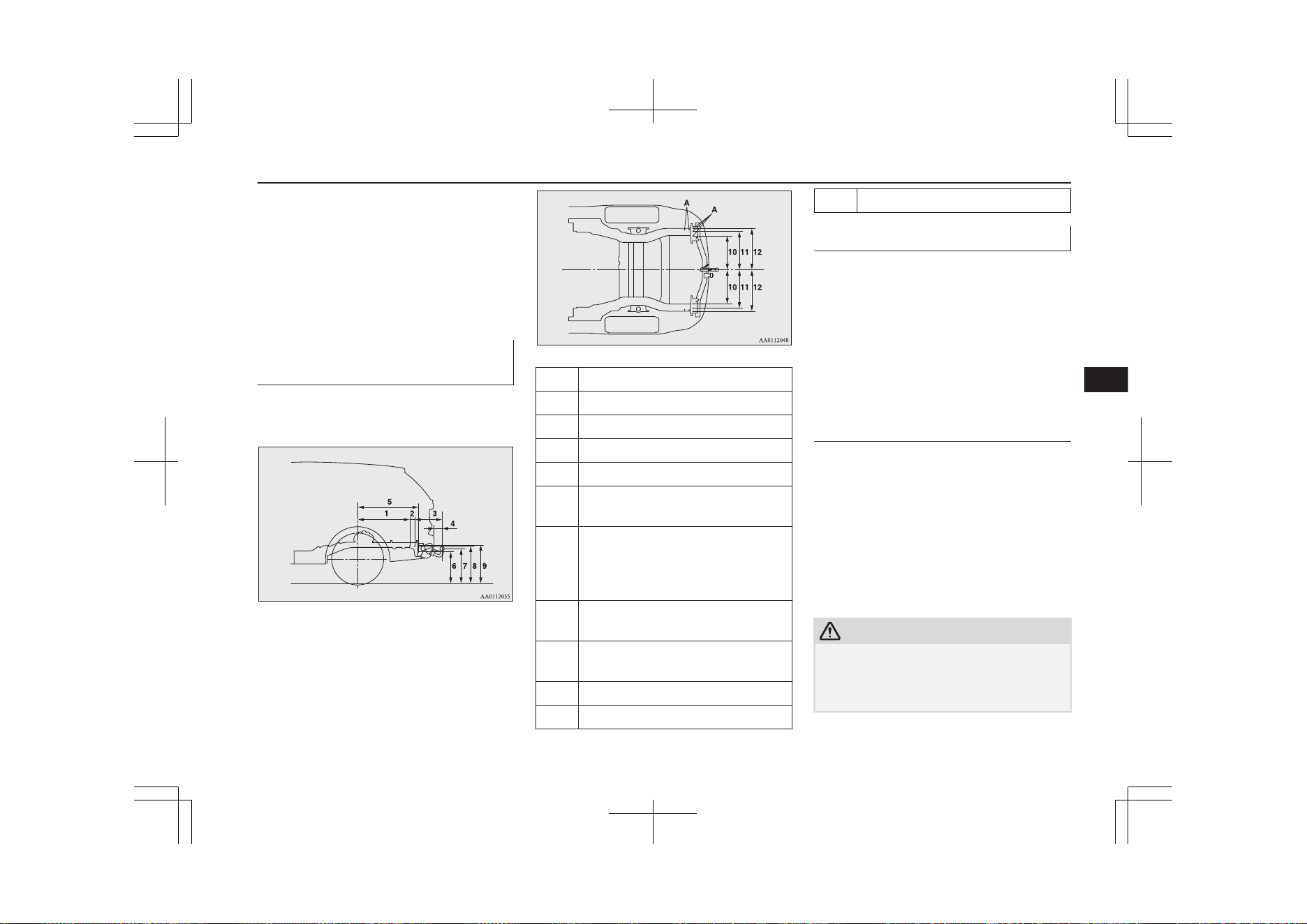
(Refer to page “Vehicle weight” on page
12-05.)
If you tow a trailer at an altitude of more than
1,000 m above sea-level, reduce your weight
by 10 % of the gross combination weight for
every increase of 1,000 m above sea-level, as
the engine output is lowered owing to de-
crease in atmospheric pressure.
Towing bar mounting specifica-
tions
See the following table for fixing points (A)
for the towing bar.
1 698 mm
2 69 mm
3 369 mm
4 101 mm
5 815 mm
6 448 mm
(at kerb weight condition)
7 496 mm
(at kerb weight condition)
384 - 397 mm
(at laden condition)
8 534 mm
(at kerb weight condition)
9 544 mm
(at kerb weight condition)
10 473 mm
11 528 mm
12 583 mm
Operating hints
l
Be sure that the driving speed does not
exceed 100 km/h (62 mph) for trailer op-
eration. It is also recommended that you
obey the local regulations in case driving
speed with a trailer is limited to less than
100 km/h (62 mph).
l
To prevent shocks from the overrun
brake, depress the brake pedal lightly at
first and then more strongly.
Overheating
This will normally occur as a result of some
mechanical failure. If your vehicle should
overheat, stop and check for a loose or bro-
ken water pump/alternator drive belt, a
blocked radiator air intake or a low coolant
level. If these items are satisfactory the over-
heating could be caused by a number of me-
chanical causes that would have to be
checked at a competent service centre.
CAUTION
l
If the engine overheats, reference should be
made to “Engine overheating” section of
“For emergencies” prior to taking any cor-
rective action.
Trailer towing
7-119
OGGE19E1
Starting and driving
7
Parking
It is not recommended to park on a steep
slope while towing trailer.
If parking on a steep slope cannot be avoided,
the road grade should be less than 12% and
the following procedure performed.
1. Apply the parking brake firmly on the
vehicle and the trailer (if fitted).
2. Put the select position in “P”.
3. Place chocks or blocks at the tyres on
both vehicle and trailer.
4. Turn the front wheels into the shoulder
of the road to prevent the vehicle from
moving.
Driving on long up hills while
towing trailer
When the remaining quantity of the drive bat-
tery is low, or high-speed driving on long up
hills at high temperature, the drive battery
output is restricted and the vehicle speed may
be decreased.
The vehicle speed may be recovered if the
drive battery quantity is recovered.
NOTE
l
In charge mode, if the remaining quantity of
the drive battery can be increased in ad-
vance, it can prevent the vehicle speed from
decreasing on long up hills.
Refer to “Battery charge mode” on page
7-29.
Trailer towing
7-120
OGGE19E1
Starting and driving
7

Ventilators........................................................................................... 8-02
Automatic climate control air conditioner.......................................... 8-06
Important operation tips for the air conditioner..................................8-14
Air purifier.......................................................................................... 8-15
Remote Climate Control*................................................................... 8-15
Heating................................................................................................8-15
LW/MW/FM radio/CD player*.......................................................... 8-15
Handling of Discs................................................................................8-20
Audio Files (MP3/WMA/AAC)..........................................................8-21
Important Points on Safety for the Customer......................................8-25
Operation Keys................................................................................... 8-25
Listen to Radio....................................................................................8-28
Listen to DAB*................................................................................... 8-29
Listen to Traffic Messages.................................................................. 8-31
Listen to CDs...................................................................................... 8-31
Listen to MP3s.................................................................................... 8-32
Listen to an iPod................................................................................. 8-33
Listen to Audio Files on a USB Device..............................................8-35
To play iPod/USB memory device tracks via voice opera-
tion (vehicles with Bluetooth
®
2.0 interface)................................. 8-37
Listen to Bluetooth Audio*.................................................................8-40
Display Indicator.................................................................................8-43
Audio Quality and Volume Balance Adjustment................................ 8-44
System Settings...................................................................................8-45
Troubleshooting.................................................................................. 8-49
Link System*...................................................................................... 8-51
Bluetooth
®
2.0 interface*....................................................................8-51
USB input terminal*........................................................................... 8-71
Sun visors............................................................................................8-73
Ashtray*..............................................................................................8-74
Cigarette lighter*.................................................................................8-75
Accessory socket*...............................................................................8-75
220-240 V AC power supplies*..........................................................8-76
Interior lamps...................................................................................... 8-79
Storage spaces.....................................................................................8-82
Cup holder...........................................................................................8-84
Bottle holder........................................................................................8-84
Cargo area cover................................................................................. 8-85
Assist grips..........................................................................................8-86
Coat hook............................................................................................ 8-86
Luggage hooks.................................................................................... 8-87
For pleasant driving
OGGE19E1
8
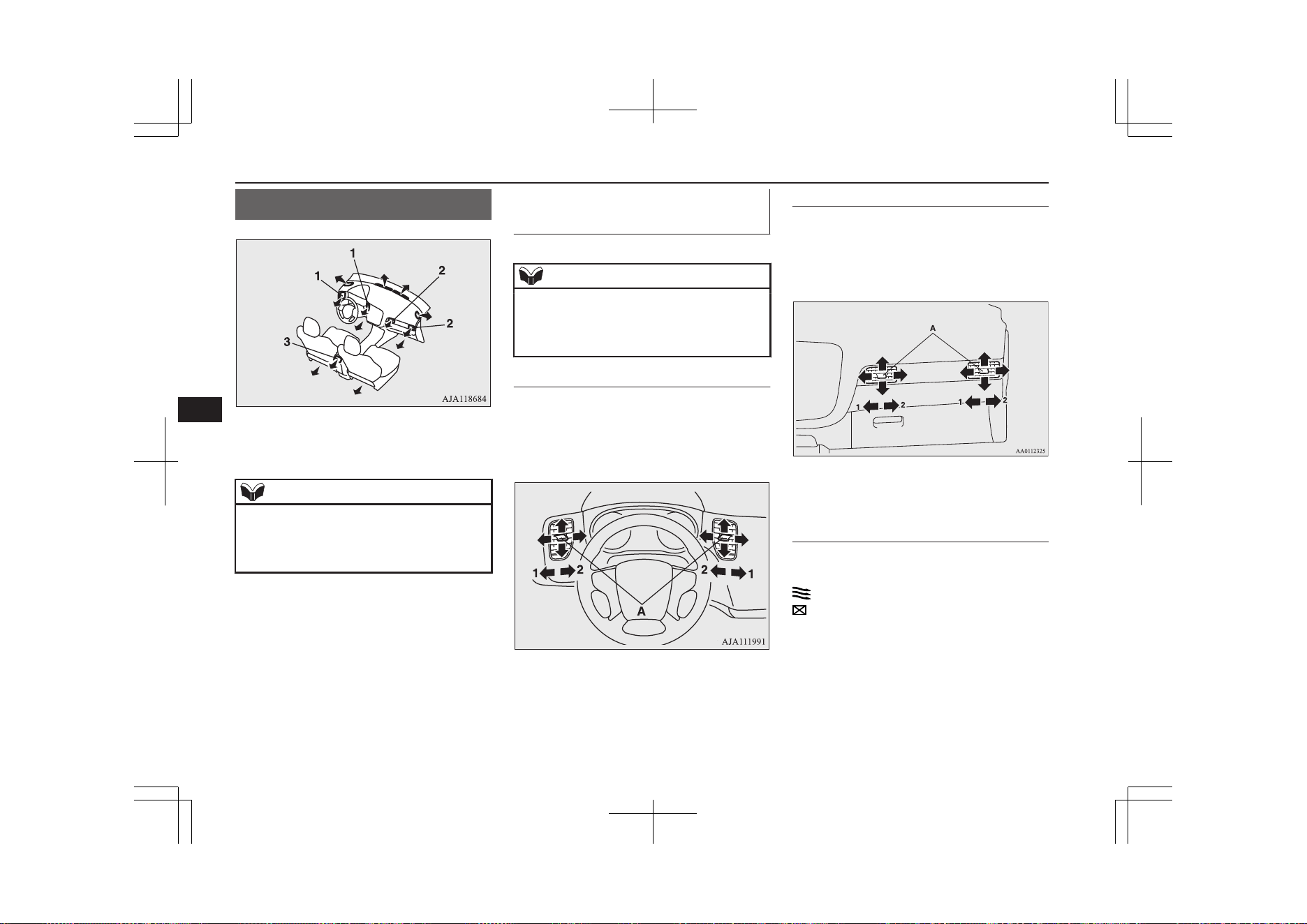
Ventilators
E00700102319
1- Driver’s ventilators
2- Passenger’s ventilators
3- Rear ventilators
NOTE
l
Do not place beverages on top of the instru-
ment panel. If they splash into the air condi-
tioning ventilators, they could damage the
system.
Air flow and direction adjust-
ments
E00700202512
NOTE
l
Be careful not to spill drinks, etc., into the
ventilators.
Doing so might cause the air conditioner not
to function normally.
Driver’s ventilators
Move the knob (A) to adjust the air flow di-
rection.
To close the ventilator, fully move the knob
(A) to the outer side.
1- Close
2- Open
Passenger’s ventilators
Move the knob (A) to adjust the air flow di-
rection.
To close the ventilator, fully move the knob
(A) to the left side.
1- Close
2- Open
Rear ventilators
The ventilators can be opened and closed
with the dial (A).
- Open
- Close
Ventilators
8-02
OGGE19E1
For pleasant driving
8
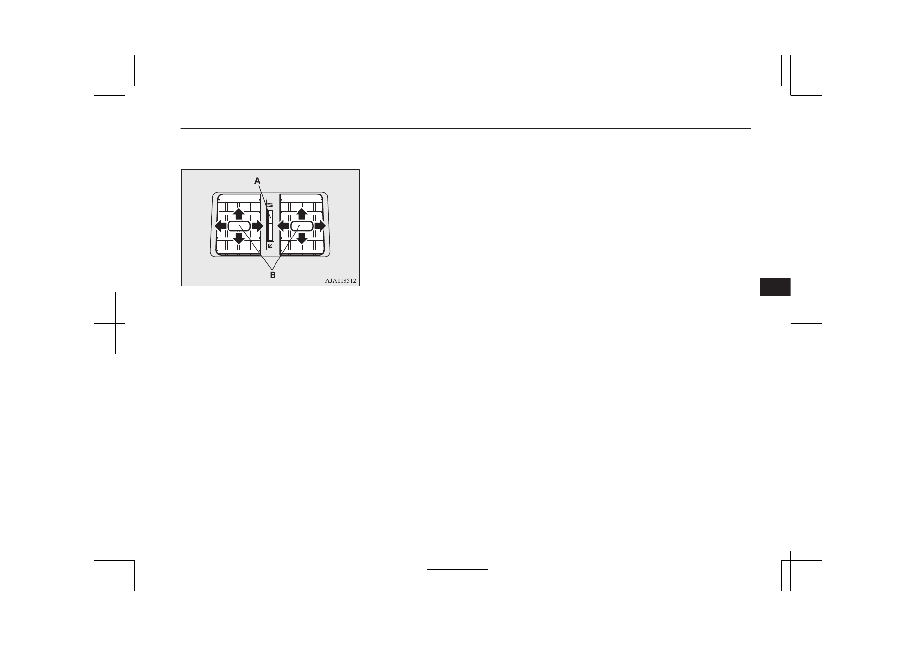
Adjust the direction of the air flow by mov-
ing the knob (B).
Ventilators
8-03
OGGE19E1
For pleasant driving
8
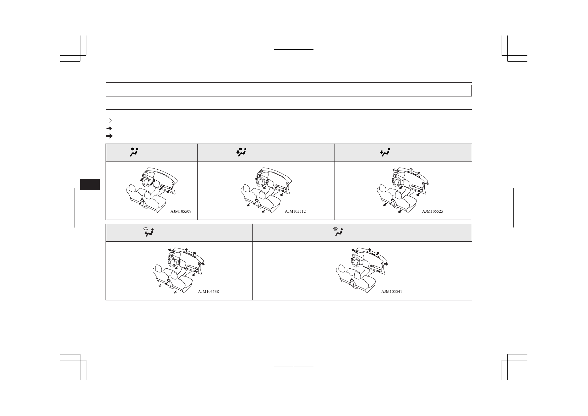
Changing the mode selection
E00700302917
The mode selection and air flowing from the ventilators
These symbols are used in the next several illustrations to demonstrate the quantity of air coming from the ventilators.
: Small amount of air from the ventilators
: Medium amount of air from the ventilators
: Large amount of air from the ventilators
Face position Foot/Face position Foot position
Foot/Demister position
Demister position
Ventilators
8-04
OGGE19E1
For pleasant driving
8
NOTE
l
The foot/face air flow ratio can be adjusted with the mode selection in the “ ” position and the foot/demister air flow ratio can be adjusted with the mode
selection in the “ ” position.
For further information, we recommend you to consult a MITSUBISHI MOTORS Authorized Service Point.
On vehicles equipped with the Smartphone Link Display Audio or the MITSUBISHI Multi-Communication System (MMCS), screen operations can be used
to make the adjustment. Refer to the separate owner’s manual for details.
Ventilators
8-05
OGGE19E1
For pleasant driving
8
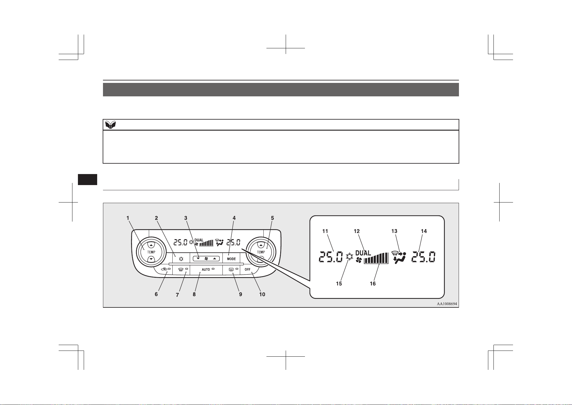
Automatic climate control air conditioner
E00702402026
Cooling or heating can only be performed when ready indicator is illuminating. When the operation mode is ON, only the blower is available.
NOTE
l
If the drive battery level display indicates 0, the cooling performance cannot be obtained even the air conditioner is turned on.
Refer to “Drive battery level display screen” on page 6-11.
l
If the engine cannot be started due to fuel shortage, etc., the heating performance cannot be obtained even the air conditioner is turned on.
l
While the drive battery is being charged, you can use the air conditioner.
Control panel
E00702502984
Automatic climate control air conditioner
8-06
OGGE19E1
For pleasant driving
8

1- Driver’s side temperature control switch
(LHD vehicles)
Passenger’s side temperature control
switch (RHD vehicles)
2- Air conditioning switch
3- Blower speed selection switch
4- MODE switch
5- Passenger’s side temperature control
switch (LHD vehicles)
Driver’s side temperature control switch
(RHD vehicles)
6- Air selection switch
7- Demister switch
8- AUTO switch
9- Rear window demister switch ® p. 6-74
10- OFF switch
11- Driver’s side temperature display (LHD
vehicles) ® p. 8-09
Passenger’s side temperature display
(RHD vehicles) ® p. 8-09
12- DUAL indicator
13- Mode selection display
14- Passenger’s side temperature display
(LHD vehicles) ® p. 8-09
Driver’s side temperature display (RHD
vehicles) ® p. 8-09
15- Air conditioning indicator
16- Blower speed display
Automatic climate control air conditioner
8-07
OGGE19E1
For pleasant driving
8
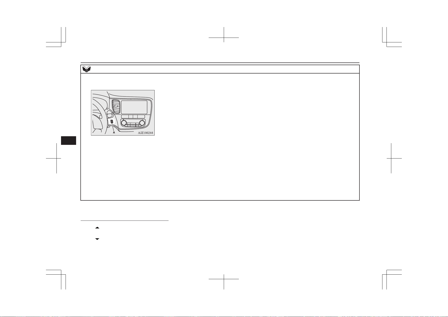
NOTE
l
There is an interior air temperature sensor (A) in the illustrated position.
Never place anything on top of the sensor, since doing so will prevent it from functioning properly.
l
While the EV priority mode is activated, except when pressing the demister switch, the engine does not start.
Therefore, if your vehicle is not equipped with the electric heater, the heating performance cannot be obtained while the EV priority mode is activated.
Also, if your vehicle is equipped with the electric heater, the heating performance may not be sufficiently obtained while the EV priority mode is activated.
In such case, cancel the EV priority mode. Refer to “EV switch” on page 7-25.
l
Since the air conditioning operation is controlled while the ECO mode is operating, you may feel that effectiveness of the air conditioner is weak.
Also, on vehicles without electric heater, the heating performance cannot be obtained while the ECO mode is operating since engine starting is controlled. In
such case, cancel ECO mode. Refer to “ECO mode switch” on page 6-68.
l
Even if the ECO mode is operating, you can select normal operation of the air conditioner.
On vehicles equipped with the Smartphone Link Display Audio or the MITSUBISHI Multi-Communication System (MMCS), screen operations can be used
to change the setting. Refer to the separate owner’s manual for details.
l
In extreme cold, the air conditioning control panel screen may operate sluggishly. This does not indicate a problem.
It will disappear when the vehicle interior temperature rises to a normal temperature.
Blower speed selection switch
E00702801515
Press of the blower speed selection
switch to increase the blower speed.
Press of the blower speed selection
switch to decrease the blower speed.
Automatic climate control air conditioner
8-08
OGGE19E1
For pleasant driving
8
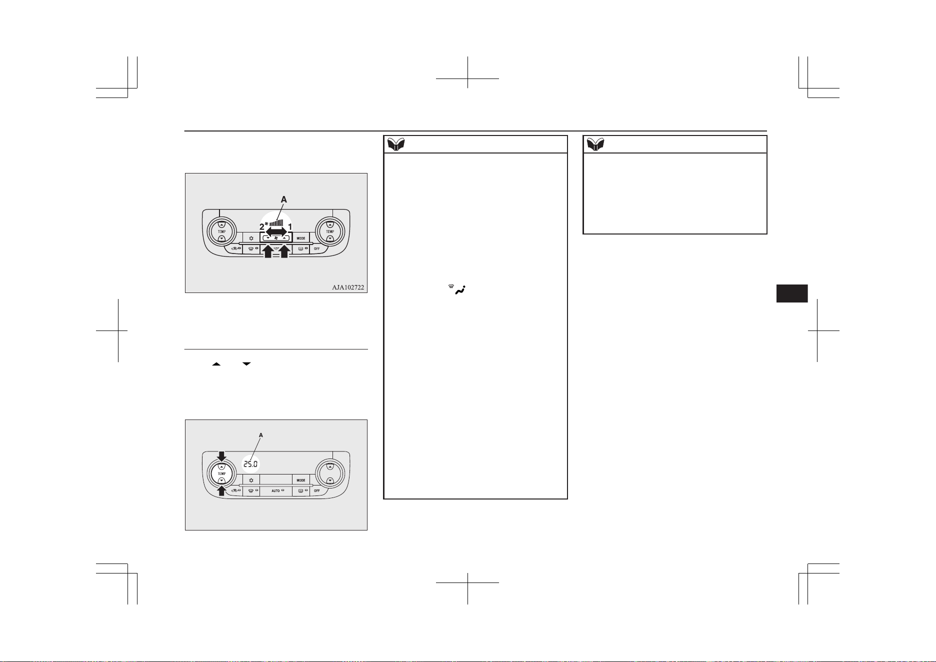
The selected blower speed (A) will be shown
in the display.
1- Increase
2- Decrease
Temperature control switch
E00703001963
Press or of the temperature control
switch to the desired temperature.
The selected temperature (A) will be shown
in the display.
AA0112354
NOTE
l
The temperature value of air conditioning is
switched in conjunction with outside temper-
ature display unit of the multi information
display.
Refer to “Changing the temperature unit” on
page 6-20.
l
While the engine coolant temperature is low,
the temperature of the air from the heater
will not change instantly, even if you have
selected warm air with the switch.
To prevent the windscreen and windows
from fogging up, the ventilator mode will be
changed to “ ” and the blower speed will
be reduced while the system is operating in
the AUTO mode.
l
When you feel that it is hot or cold to the
setting temperature, it is possible to adjust so
that you can feel more comfortable.
For further information, we recommend you
to consult a MITSUBISHI MOTORS Au-
thorized Service Point.
l
When the temperature is set to the highest or
the lowest, the air selection and the air con-
ditioning will be automatically changed as
follows.
Also, if the air selection is operated manual-
ly after an automatic changeover, manual
operation will be selected.
•
Quick Heating (When the temperature is
set to the highest setting)
Outside air will be introduced and the air
conditioner will stop.
NOTE
•
Quick Cooling (When the temperature is
set to the lowest setting)
Inside air will be recirculated and the air
conditioner will operate.
l
When the air conditioner is set to quick heat-
ing, the engine starts running (except vehi-
cles with electric heater).
The settings described above are the factory
settings.
The air selection and air conditioning
switches can be customized (function setting
changed), and the automatic switching of out-
side air and the air conditioner according to
operating conditions can be changed as de-
sired.
For further information, we recommend you
to consult a MITSUBISHI MOTORS Au-
thorized Service Point.
Refer to “Customizing the air conditioning
switch” on page 8-11.
Refer to “Customizing the air selection” on
page 8-10.
Automatic climate control air conditioner
8-09
OGGE19E1
For pleasant driving
8
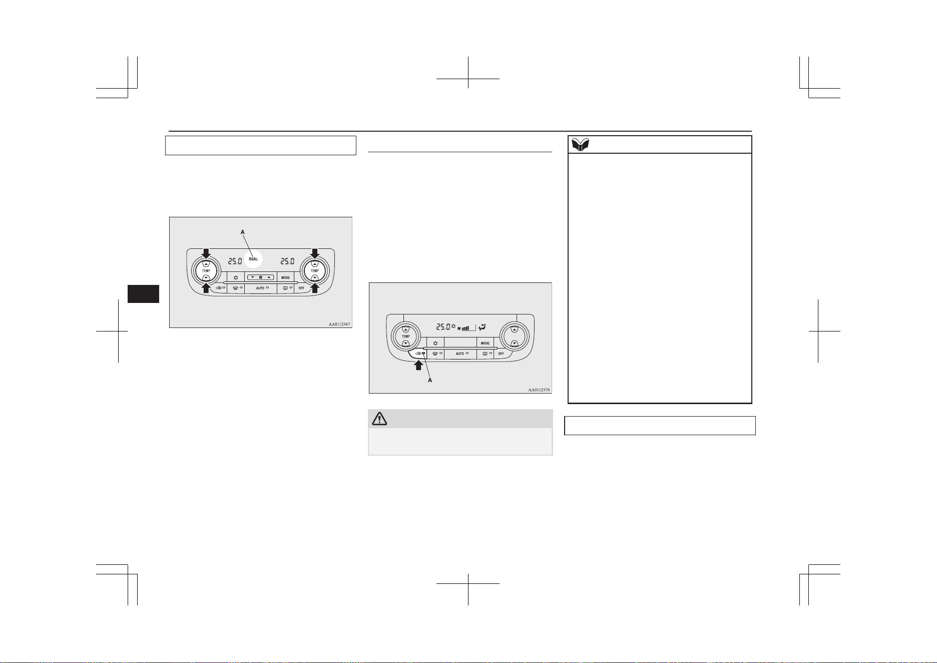
Synchronized mode and dual mode
The driver’s side and the passenger’s side
temperature can be controlled independently.
At this time, the “DUAL” indicator (A) will
be shown in the display.
l
Synchronized mode
If the driver’s side temperature control
switch is pressed, the passenger’s side
temperature will also be controlled to the
same setting temperature as the driver’s
side.
l
Dual mode
If the passenger’s side temperature con-
trol switch is pressed under synchron-
ized mode, the system will switch to du-
al mode. In dual mode, the driver’s side
and the passenger’s side temperature can
be set separately by using each tempera-
ture control switch.
Press the AUTO switch to return to
synchronized mode.
Air selection switch
E00703401808
To change the air selection, simply press the
air selection switch.
l
Outside air: Indication lamp (A) is OFF
Outside air is introduced into the passen-
ger compartment.
l
Recirculated air: Indication lamp (A) is
ON
Air is recirculated inside the passenger
compartment.
CAUTION
l
Use of the recirculation position for exten-
ded time may cause the windows to fog up.
NOTE
l
Normally, use the outside position to keep
the windscreen and side windows clear and
quickly remove fog or frost from the wind-
screen.
If high cooling performance is desired, or if
the outside air is dusty or otherwise contami-
nated use the recirculation position. Switch
to the outside position periodically to in-
crease ventilation so that the windows do not
become fogged up.
l
When the engine coolant temperature rises
to a certain level, the air selection is auto-
matically switched to the recirculation posi-
tion and the indication lamp (A) comes on.
At this time, the system will not switch to
the outside position even if the air selection
switch is pushed.
l
When the outside air temperature is high, the
system will not switch to the outside posi-
tion even if the air selection switch is press-
ed or the air conditioner is operating. This is
to protect the air conditioner compressor and
is not a failure.
Customizing the air selection
E00739600136
Functions can be changed as desired, as sta-
ted below.
l
Enable automatic air selection control
When the AUTO switch is pressed, the
air selection switch is also controlled au-
tomatically.
Automatic climate control air conditioner
8-10
OGGE19E1
For pleasant driving
8
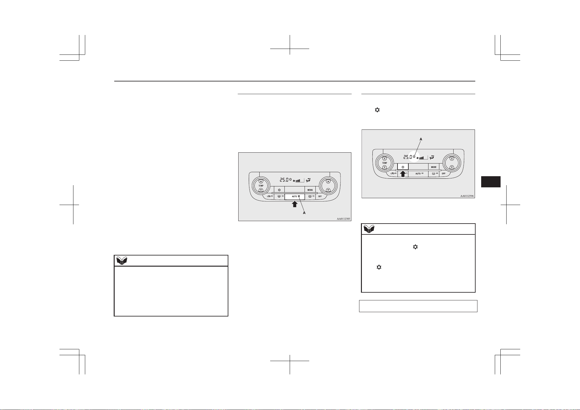
l
Disable automatic air selection control
Even when the AUTO switch is pressed,
the air selection switch is not controlled
automatically.
l
Setting change method
Hold down the air selection switch for
approximately 10 seconds or more.
• When the setting is changed from ena-
ble to disable
3 sounds are emitted and the indica-
tion lamp flashes 3 times.
• When the setting is changed from dis-
able to enable
2 sounds are emitted and the indica-
tion lamp flashes 3 times.
On vehicles equipped with the Smart-
phone Link Display Audio or the
MITSUBISHI Multi-Communication
System (MMCS), screen operations can
also be used to change the setting. Refer
to the separate owner’s manual for de-
tails.
NOTE
l
The factory setting is “Enable automatic air
selection control”.
l
When the demister switch is pressed, in or-
der to prevent misting of the windows the
ventilator automatically switches to outside
air even if “Disable automatic air selection
control” is set.
AUTO switch
E00702601047
When the AUTO switch is pressed, the indi-
cation lamp (A) comes on and the mode se-
lection, blower speed adjustment, recircula-
ted/outside air selection, temperature adjust-
ment, and air conditioner ON/OFF status are
all controlled automatically.
Air conditioning switch
E00703502675
Push the switch to turn the air conditioner on,
the “
” indicator (A) will be shown in the
display.
Push the switch again to switch it off.
NOTE
l
If a problem is detected in the air condition-
ing system, the “ ” indicator blinks. Press
the air conditioning switch once to turn it
off, then once more to turn it back on. If the
“ ” indicator does not blink for a while,
there is nothing wrong. If it starts to blink
again, we recommend you to have it
checked.
Customizing the air conditioning switch
E00739700137
Functions can be changed as desired, as sta-
ted below.
Automatic climate control air conditioner
8-11
OGGE19E1
For pleasant driving
8
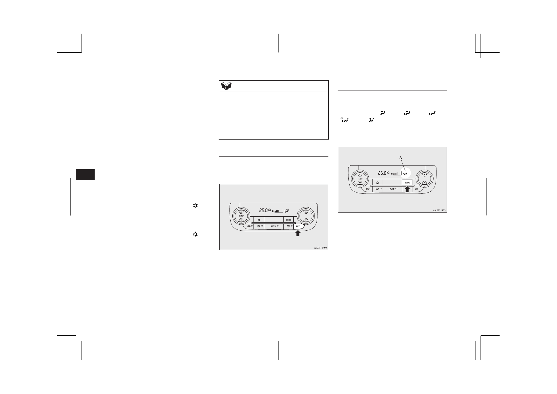
l
Enable automatic air conditioning con-
trol
When the AUTO switch is pressed, or
the temperature control switch is set to
the minimum temperature, the air condi-
tioning switch is controlled automatical-
ly.
l
Disable automatic air conditioning con-
trol
The air conditioning switch is not con-
trolled automatically as long as the air
conditioning switch is not operated.
l
Setting change method
Hold down the air conditioning switch
for approximately 10 seconds or more.
• When the setting is changed from ena-
ble to disable
3 sounds are emitted and the “ ” in-
dicator flashes 3 times.
• When the setting is changed from dis-
able to enable
2 sounds are emitted and the “
” in-
dicator flashes 3 times.
On vehicles equipped with the Smart-
phone Link Display Audio or the
MITSUBISHI Multi-Communication
System (MMCS), screen operations can
also be used to change the setting. Refer
to the separate owner’s manual for de-
tails.
NOTE
l
The factory setting is “Enable automatic air
conditioning control”.
l
When the demister switch is pressed, in or-
der to prevent misting of the windows the air
conditioner operates automatically even if
“Disable automatic air conditioning control”
is set.
OFF switch
E00702701149
Push the OFF switch to turn off the air condi-
tioning system.
MODE switch
E00703301227
Each time the MODE switch is pressed, the
mode changes to the next one in the follow-
ing sequence: “ ” → “ ” → “ ” →
“ ” → “ ”. The selected mode (A) is
shown in the display. (Refer to “Changing the
mode selection” on page 8-04.)
Automatic climate control air conditioner
8-12
OGGE19E1
For pleasant driving
8
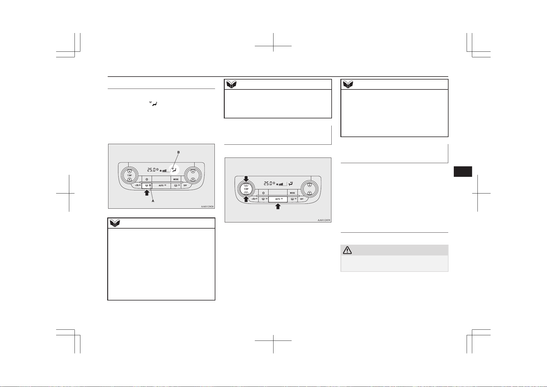
Demister switch
E00703901340
When this switch is pressed, the mode
changes to the “
” mode. The indication
lamp (A) will come on. The selected mode
(B) is shown in the display. (Refer to
“Changing the mode selection” on page
8-04.)
NOTE
l
When the demister switch is pressed, the air
conditioning system automatically operates
and outside air (as opposed to recirculated
air) is selected. This automatic switching
control is carried out to prevent misting of
the windows even if “Disable automatic air
conditioning control” or “Disable automatic
air selection control” is set. (Refer to “Cus-
tomizing the air conditioning switch” on
page 8-11, “Customizing the air selection”
on page 8-10.)
NOTE
l
To ensure a clear view, the engine may start
when the demister switch is pressed even
while the EV priority mode is activated.
Refer to “EV switch” on page 7-25.
Operating the system in auto-
matic mode
E00704102649
In normal conditions, use the system in the
AUTO mode and follow these procedures:
1. Push the AUTO switch.
2. Set the temperature control switch to the
desired temperature.
The mode selection, blower speed ad-
justment, recirculated/outside air selec-
tion, temperature adjustment, and air
conditioner ON/OFF status are all con-
trolled automatically.
NOTE
l
If the blower speed selection switch, air con-
ditioning switch, MODE switch, or air selec-
tion switch is operated while the system is
operating in the AUTO mode, the activated
function overrides the corresponding func-
tion of automatic control. All other functions
remain under automatic control.
Operating the system in man-
ual mode
E00704201308
Blower speed and ventilator mode will be
controlled manually by setting the blower
speed selection switch and the MODE switch
to the desired positions.
To return to automatic operation, press the
AUTO switch.
Demisting of the windscreen
and door windows
E00704302016
CAUTION
l
For safety, make sure you have a clear view
through all the windows.
Automatic climate control air conditioner
8-13
OGGE19E1
For pleasant driving
8
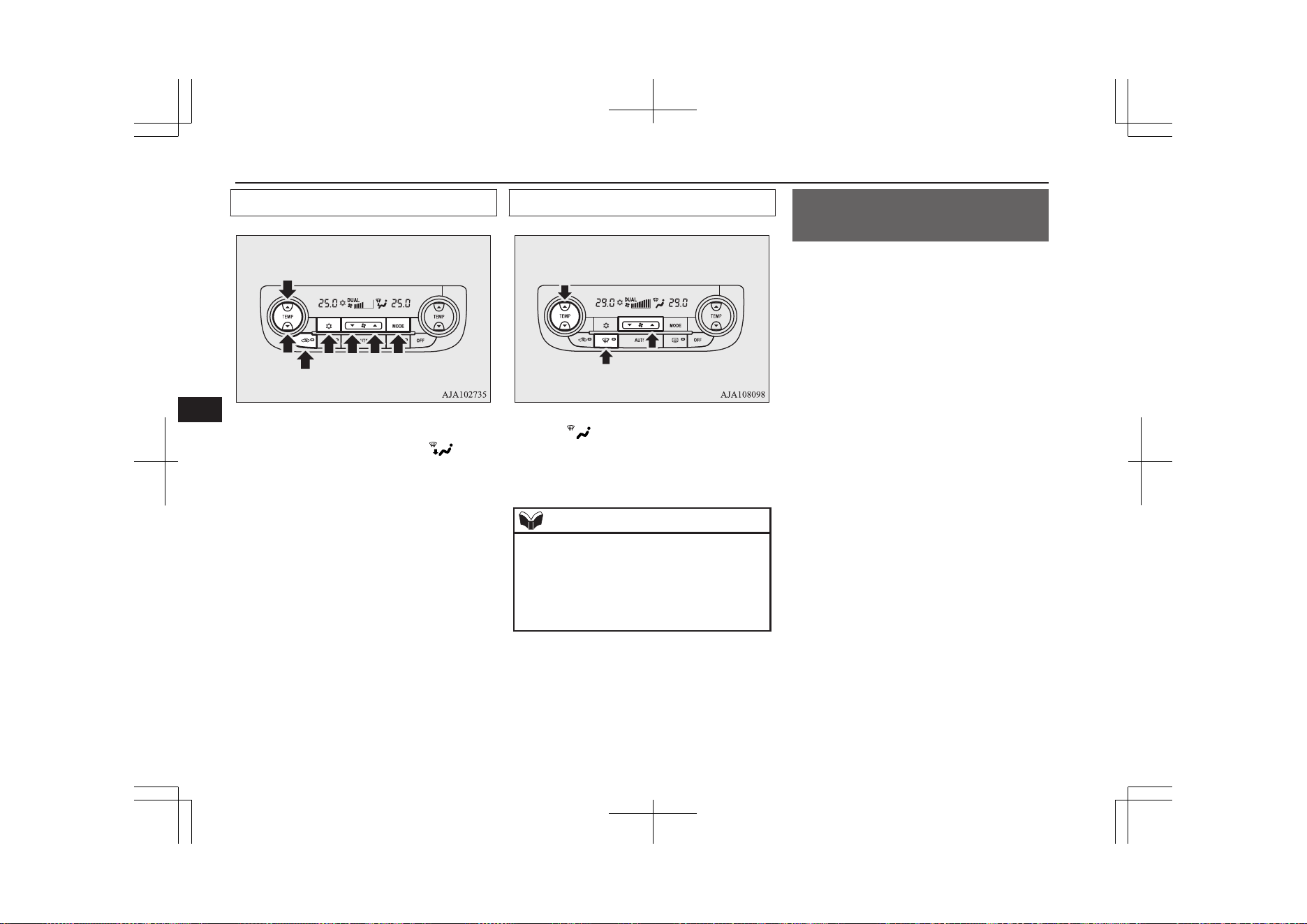
For ordinary demisting
1. Set the air selection switch to the outside
position.
2. Set the MODE switch to the “ ” posi-
tion.
3. Select your desired blower speed by
pressing the blower speed selection
switch.
4. Select your desired temperature by
pressing the temperature control switch.
5. Push the air conditioning switch.
For quick demisting
1. Push the demister switch to change to
the “ ” position.
2. Set the blower to the maximum speed.
3. Set the temperature to the highest posi-
tion.
NOTE
l
To demist effectively, direct the air flow
from the side ventilators towards the door
windows.
l
Do not set the temperature to the max. cool
position. Cool air will blow against the win-
dow glasses and prevent demisting.
Important operation tips for
the air conditioner
E00708302388
l
Park the vehicle in the shade.
Parking in the hot sun will make the ve-
hicle inside extremely hot, and it will re-
quire more time to cool the interior.
If it is necessary to park in the sun, open
the windows for the first few minutes of
air conditioning operation to expel the
hot air.
l
Close the windows when the air condi-
tioner is in use. The entry of outside air
through open windows will reduce the
cooling efficiency.
l
Too much cooling is not good for the
health. Keep the difference between the
vehicle interior temperature and outside
temperature at 5 to 6 °C.
l
When operating the system, make sure
the air intake, which is located in front
of the windscreen, is free of obstructions
such as leaves and snow. Leaves collec-
ted in the air-intake plenum may reduce
air flow and plug the plenum water
drains.
l
Too much cooling/heating can affect the
EV cruising range, so maintain an appro-
priate temperature to extend the EV
cruising range.
Important operation tips for the air conditioner
8-14
OGGE19E1
For pleasant driving
8
Air conditioning system refrig-
erant and lubricant recommen-
dations
If the air conditioner seems less effective
than usual, the cause might be a refrigerant
leak.
We recommend you to have the system in-
spected.
[Except for vehicles for Ukraine]
The air conditioning system in your vehicle
must be charged with the refrigerant
HFO-1234yf and the lubricant POE
MA68EV.
[Vehicles for Ukraine]
The air conditioning system in your vehicle
must be charged with the refrigerant
HFC-134a and the lubricant POE MA68EV.
Use of any other refrigerant or lubricant will
cause severe damage which will result in the
need to replace your vehicle’s entire air con-
ditioning system. The release of refrigerant
into the atmosphere is not recommended.
We recommend you to recover and recycle
the refrigerant for reuse.
During a long period of disuse
The air conditioner should be operated for at
least five minutes each week, even in cold
weather. This is to prevent the compressor
from seizing and to maintain the air condi-
tioner in the best operating condition.
Air purifier
E00708400718
An air filter has been incorporated into this
air conditioner so that dirt and dust are
cleaned from the air.
Replace the air filter periodically as its ability
to clean the air will be reduced as it collects
pollen and dirt. For the maintenance interval,
refer to the “SERVICE BOOKLET”.
NOTE
l
Operation in certain conditions such as driv-
ing on a dusty road and frequent use of the
air conditioner can lead to reduction of serv-
ice life of the filter. When you feel that the
air flow is lower than normal or when the
windscreen or windows start to fog up easi-
ly, replace the air filter.
We recommend you to have it checked.
Remote Climate Control*
E00735401087
You can run the air conditioner in advance of
using the vehicle.
For details, refer to “MITSUBISHI Remote
control: Remote Climate Control” on page
3-20.
Heating
E00733901062
When heating, the engine starts running be-
cause the heating system uses the heat of en-
gine coolant.
On vehicles with electric heater, it can de-
crease the number of times engine starting
because electrical power stored in the drive
battery is also used when heating.
NOTE
l
If you want to stop the engine running for
heating, select the EV priority mode before
operating the air conditioner. Refer to “EV
switch” on page 7-25.
LW/MW/FM radio/CD
player*
E00708503387
The audio system can only be used when the
operation mode of the power switch is in ON
or ACC.
Air purifier
8-15
OGGE19E1
For pleasant driving
8
NOTE
l
To listen to the audio system while the Plug-
in Hybrid EV system is not operating, put
the operation mode of the power switch in
ACC.
If the operation mode of the power switch is
left in ACC, the accessory power will auto-
matically turn off after a certain period of
time and you will no longer be able to use
the audio system. The accessory power
comes on again if the operation mode of the
power switch is operated with is in the ACC.
Refer to “ACC power auto-cutout function”
on page 7-13.
l
If a cellular phone is used inside the vehicle,
it may create noise from the audio equip-
ment. This does not mean that anything is
wrong with your audio equipment. In such a
case, use the cellular phone at a place as far
away as possible from the audio equipment.
l
If foreign objects or water get into the audio
equipment, or if smoke or a strange odour
comes from it, immediately turn off the au-
dio system. We recommend you to have it
checked. Never try to repair it by yourself.
Avoid continuous usage without inspection
by a qualified person.
Important Points on Usage
E00735500023
iPod/iPhone Playback Func-
tion*
l
This product supports audio playback
from iPod/iPhone devices, however dif-
fering versions mean that playback can-
not be guaranteed.
l
Please be aware that depending on the
iPod/iPhone model or version, operation
may differ.
How to Clean
E00735700025
l
If the product becomes dirty, wipe with a
soft cloth.
l
If very dirty, use a soft cloth dipped in
neutral detergent diluted in water, and
then wrung out. Do not use benzene,
thinners, or other chemical wipes. This
may harm the surface.
Trademarks
E00735801238
l
Product names and other proper names
are the trademarks or registered trade-
marks of their respective owners.
l
Furthermore, even if there is no specific
denotation of trademarks or registered
trademarks, these are to be observed in
their entirety.
“Made for iPod”, “Made for iPhone”
mean that an electronic accessory has
been designed to connect specifically to
iPod or iPhone, respectively, and has
been certified by the developer to meet
Apple performance standards.
iPhone, iPod, iPod classic, iPod nano,
and iPod touch are trademarks of Apple
Inc., registered in the U.S. and other
countries.
Apple is not responsible for the opera-
tion of this device or its compliance with
safety and regulatory standards.
NOTE
l
iPod and iTunes licensing allows individual
users to privately reproduce and play back
non- copyrighted material as well as material
that may be legally copied and reproduced.
Infringement of copyright is prohibited.
LW/MW/FM radio/CD player*
8-16
OGGE19E1
For pleasant driving
8
NOTE
l
For vehicles with a Bluetooth
®
2.0 interface,
the types of devices that can be connected
may vary.
For details, access the MITSUBISHI
MOTORS website.
Please read and agree to the “Warning about
Links to the Web Sites of Other Compa-
nies”. The websites mentioned above may
connect you to websites other than the
MITSUBISHI MOTORS website.
http://www.mitsubishi-motors.com/en/prod-
ucts/index.html
LW/MW/FM radio/CD player*
8-17
OGGE19E1
For pleasant driving
8
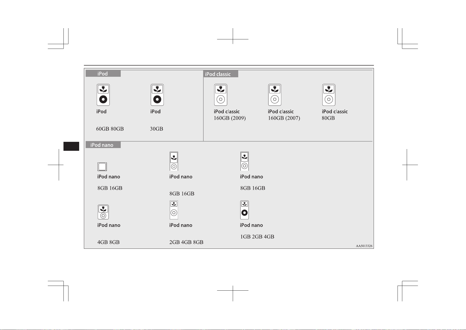
5th generation
(video)
5th generation
(video)
6th generation 5th generation
(video camera)
4th generation (video)
1st generation2nd generation
(aluminium)
3rd generation
(video)
LW/MW/FM radio/CD player*
8-18
OGGE19E1
For pleasant driving
8
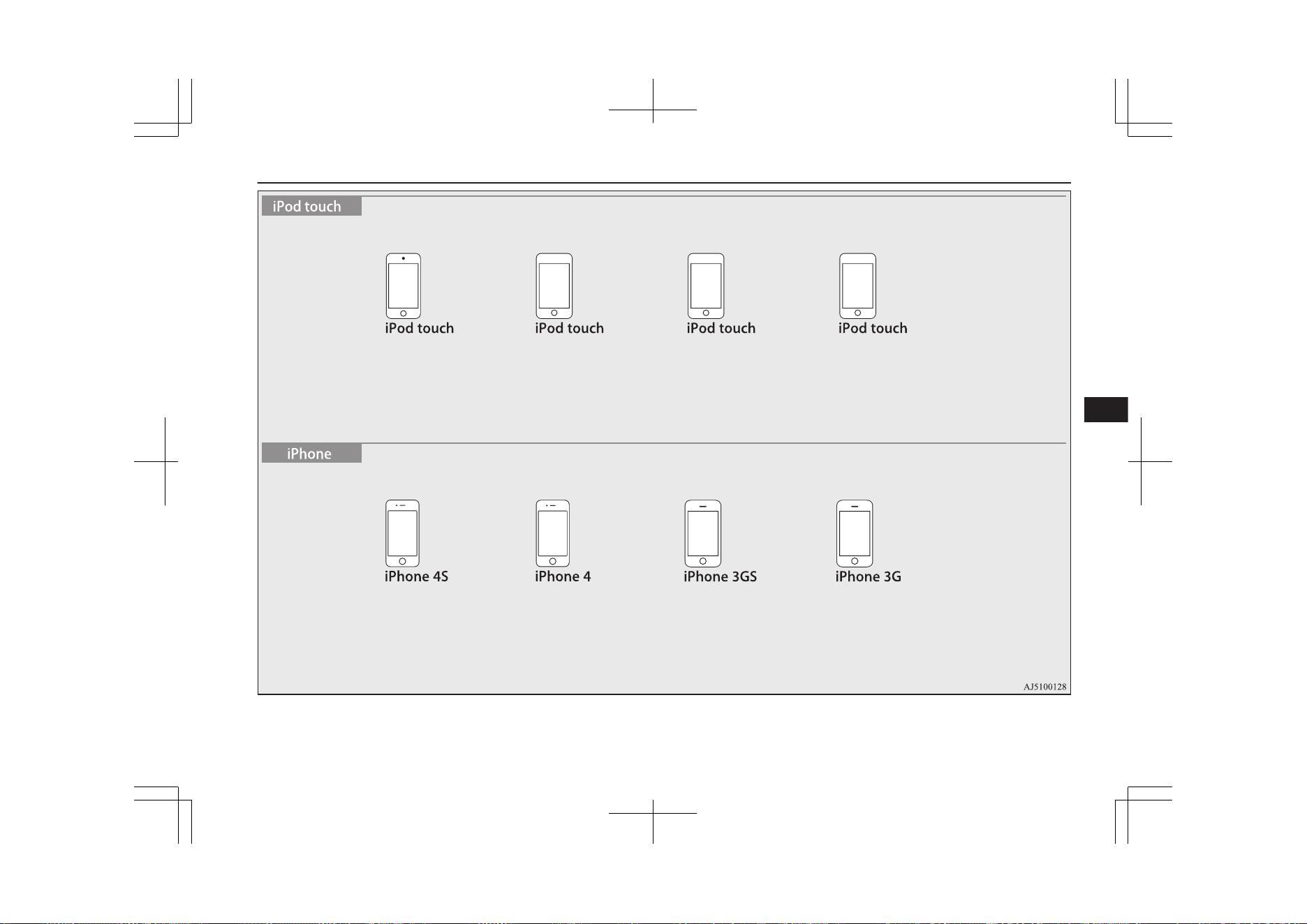
4th generation
8GB 32GB 64GB
16GB 32GB 64GB 16GB 32GB 8GB 16GB 32GB 8GB 16GB
3rd generation
32GB 64GB
2nd generation
8GB 16GB 32GB
1st generation
8GB 16GB 32GB
LW/MW/FM radio/CD player*
8-19
OGGE19E1
For pleasant driving
8
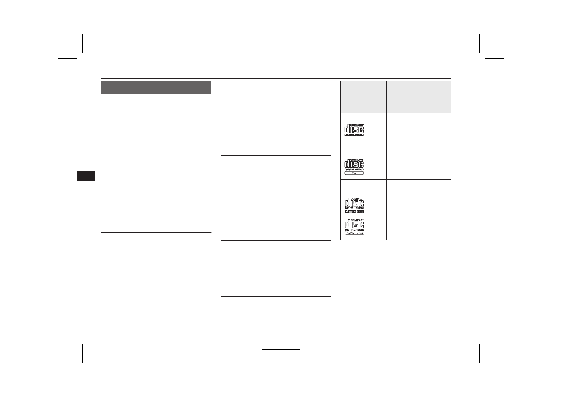
Handling of Discs
E00735901040
This explains care that should be taken in the
handling of discs.
Important Points on Handling
l
Fingerprints or other marks on the read
surface of the disc may result in its con-
tent being more difficult to read. When
holding the disc, grip both edges, or one
edge and the centre hole, in order that
the read surface is not touched.
l
Do not affix paper or stickers, or other-
wise damage the disc.
l
Do not forcefully insert a disc if another
is already within the device. This can re-
sult in damage to discs, or malfunction.
Cleaning
l
Periodically clean the read surface of the
disc. When cleaning, do not wipe in a
circular motion. Instead, wipe gently
outwards from the centre of the disc to
the outer edge.
l
New discs may have burring around the
outer edge or in the hole in the centre.
Ensure you check for these. If there are
burrs, these may lead to faulty operation,
therefore ensure these are removed.
Important Points on Storage
l
When not using discs, ensure these are
kept in cases, and stored out of direct
sunlight.
l
If discs are not going to be used for a
long period of time, remove these from
the product.
Disc Playback Environment
In cold environments such as in mid-winter
when the interior of the vehicle is cold, turn-
ing the heater on and immediately trying to
use the product may cause condensation (wa-
ter droplets) to form on the disc and internal
optical components, and this may prevent the
product from operating correctly.
In these conditions, remove the disc, and wait
a short time before use.
Copyright
Actions such as unauthorized reproduction,
broadcast, public performance, or rental of
discs that comprise other than personal use
are prohibited by law.
Types of Disc That Can Be
Played Back
E00736001035
The following marks are printed on the disc
label, package, or jacket.
Type
Size
Maxi-
mum
playback
time
Comments
CD-DA 12 cm 74 mi-
nutes
—
CD-
TEXT
12 cm 74 mi-
nutes
—
CD-
R/RW
12 cm — •Disc contain-
ing MP3 files
Discs That May Not Be Played
Back
l
Playback of discs other than those de-
scribed in “Types of Disc That Can Be
Played Back” is not guaranteed.
l
8 cm discs may not be used.
Handling of Discs
8-20
OGGE19E1
For pleasant driving
8
l
Do not insert irregularly-shaped discs
(for example, heart-shaped), as these
may result in malfunction. Additionally,
discs that have transparent portions may
not be played back.
l
Discs that have not been finalized cannot
be played back.
l
Even if recorded using the correct for-
mat on a recorder or computer, applica-
tion software settings and environments;
disc peculiarities, damage, or marking;
or dirt or condensation on the lens inside
the product may render the disc unplaya-
ble.
l
Depending on the disc, some functions
may not be used, or the disc may not
play back.
l
Do not use discs with cracks or warps.
l
If the disc has stickers affixed, remains
from removed stickers, or affixed adhe-
sive, then do not use the disc.
l
Discs that have decorative labels or
stickers may not be used.
Nonstandard CDs
This product will play back audio CDs, how-
ever please be aware of the following points
regarding CD standards.
l
Ensure that you use discs with on the
label surface.
l
Playback of other than standard CDs is
not guaranteed. Even if the audio can be
played back, the audio quality cannot be
guaranteed.
l
When playing back other than standard
CDs, the following may occur.
• There may be noise during playback.
• There may be jumping in the audio.
• The disc may not be recognized.
• The first track may not be played
back.
• It may take longer than usual until
start of playback of tracks.
• Playback may start from within the
track.
• Some parts may not be played back.
• Tracks may freeze during playback.
• Tracks may be displayed erroneously.
Audio Files
(MP3/WMA/AAC)
E00736100026
This product can play back MP3/WMA/AAC
format audio files recorded on CD-ROM,
CD-R/RW, and USB devices.
There are limitations on the files and media
that can be used, therefore read the following
prior to recording MP3/WMA/AAC format
audio files on discs or USB devices.
Additionally, ensure you read the user man-
uals for your CD-R/RW drive and the writing
software, and ensure these are used correctly.
If the MP3/WMA/AAC format audio files in-
cludes title information or other data, then
this can be displayed.
CAUTION
l
CD-ROM and CD-R/RW media can only
play back MP3 format audio files.
l
Actions such as copying audio CDs or files
and either distributing these to others for
free or for charge, or uploading files via the
Internet or other means to servers is an in-
fringement of the law.
l
Do not append the file extensions “.mp3”,
“.wma”, or “.m4a”, to other than
MP3/WMA/AAC format files. Playing back
discs with these types of files recorded upon
them may cause the files to be incorrectly
identified for playback, which may lead to
loud noise, resulting in speaker damage or
accident.
NOTE
l
Depending on the condition of the disc re-
corder or recording software used, correct
playback may not be possible. In these ca-
ses, refer to the user manual for your product
or software.
Audio Files (MP3/WMA/AAC)
8-21
OGGE19E1
For pleasant driving
8
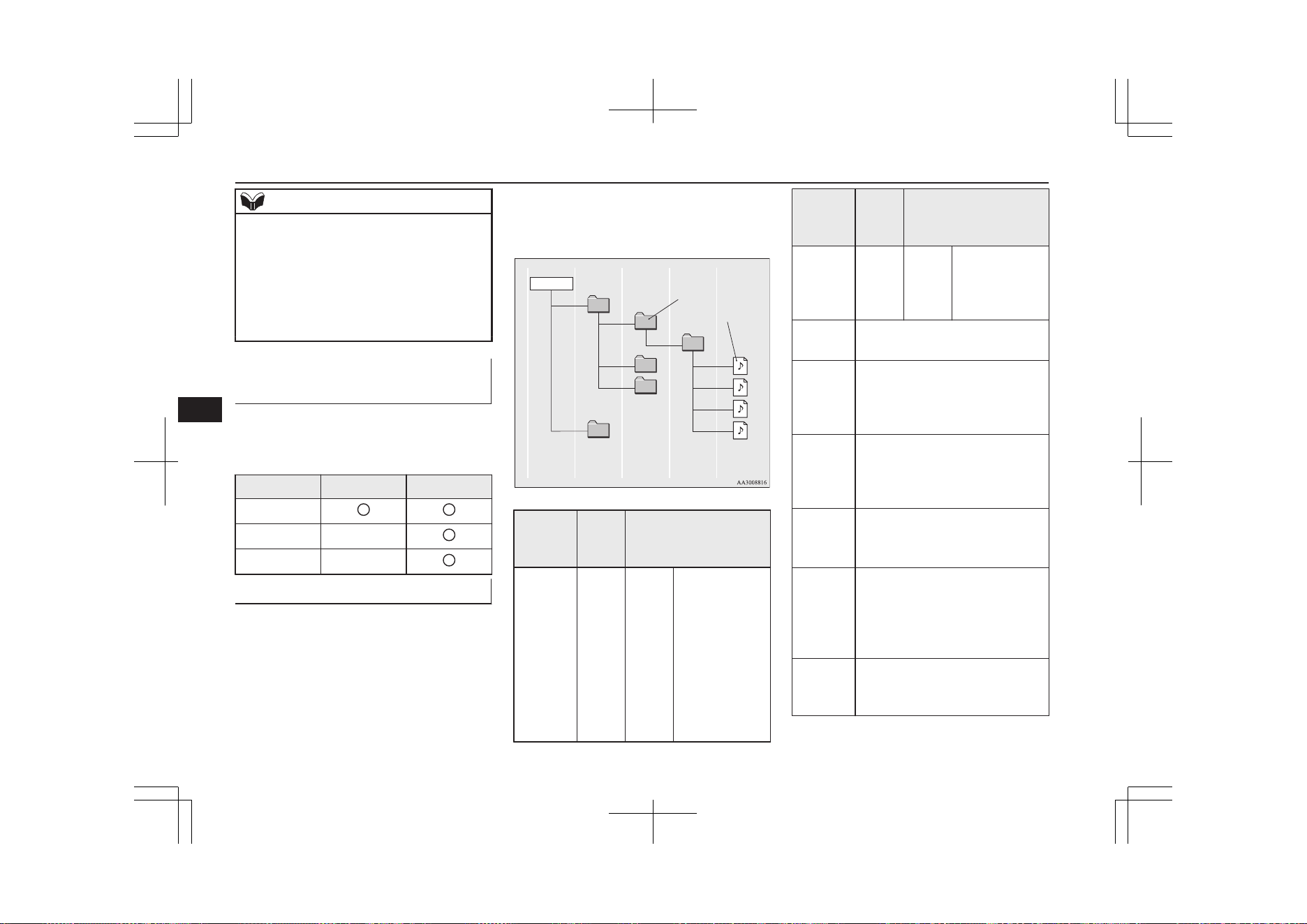
NOTE
l
Depending on your computer’s operating
system, version, software, or settings, files
may not have a file extension appended. In
these cases, append the file extensions
“.mp3”, “.wma”, or “.m4a” when copying
the files.
l
Files larger than 2GB in size cannot be
played back.
Data Formats That Can Be
Played Back
E00736200027
Data formats that can be played on discs
(CD-ROM, CDR/RW) and USB devices dif-
fer.
Data format DISC USB device
MP3
WMA X
AAC X
Folder Structure
E00736300031
Up to 8 folder levels can be recognized.
You can create a folder structure as in Genre -
Artist - Album - Track (MP3/WMA/AAC
format audio files) for management of tracks.
Folder
ROOT
Audio file
1 level
2 level 3 level 4 level 5 level
Name
Speci-
fica-
tion
Explanation
Format
specifica-
tions
ISO96
60
Level
1
Maximum 8
character file
name, and 3
character file
extension. (sin-
gle-byte alpha-
numeric capital
letters, numer-
als, “_” may be
used)
Name
Speci-
fica-
tion
Explanation
Format
specifica-
tions
ISO96
60 ex-
tension
Joliet Files names up
to a maximum
64 characters
can be used.
Multises-
sion
Not supported (only first session
supported)
Maxi-
mum
number
of levels
8 levels (if the root is the 1
st
lev-
el)
Maxi-
mum
folder
number
700 folders (including root)
Maxi-
mum file
number*
1
65,535 files (total number on
media. Other than MP3, WMA,
and AAC files not included)
File name
and fold-
er name
restric-
tions
Maximum 64 bytes (for Uni-
code, 32 characters), files/folders
with file/folder names longer
than this will not be displayed or
played back.
USB sup-
ported
formats
The recommended file system is
FAT32.
1 partition only
Audio Files (MP3/WMA/AAC)
8-22
OGGE19E1
For pleasant driving
8
*
1
:
Do not include other than
MP3/WMA/AAC files. However, if
storing many tracks within the same
folder, these may not be recognized
even if less than the maximum number
of tracks. In these cases, divide the
tracks up into multiple folders.
NOTE
l
The order in which folders and audio files
are displayed on this product may be differ-
ent to how they are displayed on a computer.
What Is MP3?
E00736400029
MP3 is the abbreviation of “MPEG-1 Audio
Layer 3”. MPEG is an abbreviation of “Mo-
tion Picture Experts Group”, and this is a vid-
eo compression standard used in video CDs,
etc.
MP3 is one of the audio compression meth-
ods contained in the MPEG audio standard,
and reduces the quality of sounds that are be-
yond the auditory resolution of the human ear
and that are hidden by louder sounds, thus
creating high-quality data with a lower data
size.
This can compress CD audio to approximate-
ly 1/10 its original data size without percepti-
ble loss, approximately 10 CDs can be writ-
ten to a single CD-R/RW disc.
CAUTION
l
MP3 files different to the standards at right
may not play back correctly, or file/folder
names may not be displayed correctly.
Standards for MP3 Files That
Can Be Played Back
Specifications for MP3 files that can be
played are as shown below.
Item Details
Specification
MPEG-1 AUDIO LAYER3
MPEG-2 AUDIO LAYER3
Sampling fre-
quency [kHz]
MPEG-1: 32/44.1/48
MPEG-2: 16/22.05/24
Bit rate [kbps]
MPEG-1: 32 to 320
MPEG-2: 8 to 160
VBR (varia-
ble bit rate)
Support
Channel
mode
Stereo/ Joint stereo/ Dual
channel/ Monaural
File exten-
sion
mp3
Item Details
Supported tag
information
ID3 tag Ver. 1.0, Ver. 1.1,
Ver. 2.2, Ver. 2.3, Ver. 2.4
(ISO-8859-1, UTF-16 (Uni-
code)), Titles, Artist name,
Album name
Maximum
number of
characters
that can be
indicated on
the display
64 characters
What Is WMA?
E00736601031
WMA is the abbreviation of Windows Media
Audio, and this is an audio compression for-
mat from Microsoft. This is a compression
format that has a higher compression ratio
than MP3.
NOTE
l
Microsoft, Windows Media, and Windows
are registered trademarks of Microsoft Cor-
poration (USA) and in other countries.
CAUTION
l
WMA supports digital rights management
(DRM). This product cannot play back
WMA files protected using this system.
Audio Files (MP3/WMA/AAC)
8-23
OGGE19E1
For pleasant driving
8
CAUTION
l
WMA files different to the standards at right
may not play back correctly, or file/folder
names may not be displayed correctly.
l
“Pro”, “Lossless”, and “Voice” are not sup-
ported.
Standards for WMA Files That
Can Be Played Back
Specifications for WMA files that can be
played are as shown below.
Item Details
Specification Windows Media Audio Ver-
sion7.0/8.0/9.0
Sampling fre-
quency [kHz]
32/44.1/48
Bit rate
[kbps]
48 to 320
VBR
(variable bit
rate)
Support
Channel
mode
Stereo/Monaural
File exten-
sion
wma
Supported tag
information
WMA tags
Title name, Artist name, Al-
bum name
Item Details
Maximum
number of
characters
that can be
indicated on
the display
64 characters
What is AAC?
E00736801033
AAC is the abbreviation of Advanced Audio
Coding, and this is an audio compression
standard used in “MPEG-2” and “MPEG-4”.
This features 1.4x the compression of MP3,
with comparable audio quality.
CAUTION
l
AAC supports digital rights management
(DRM). This product cannot play back AAC
files protected using this system.
l
AAC files different to the standards at right
may not play back correctly, or file/folder
names may not be displayed correctly.
Standards for AAC Files That
Can Be Played Back
Specifications for AAC files that can be
played are as shown below.
Item Details
Specification Advanced Audio
Coding
MPEG4/AAC-LC
MPEG2/AAC-LC
Sampling
frequency
[kHz]
MPEG4 8/11.025/12/16/22.05
/24/32/44.1/48
MPEG2 8/11.025/12/16/22.05
/24/32/44.1/48
Bit rate
[kbps]
MPEG4 8 to 320
MPEG2 8 to 320
VBR (variable bit
rate)
Support
Channel mode Stereo/Monaural
File extension m4a
Supported tag infor-
mation
AAC tags or ID3
tags
Title, Artist name,
Album name
Maximum number of
characters that can be
indicated on the dis-
play
64 characters
Audio Files (MP3/WMA/AAC)
8-24
OGGE19E1
For pleasant driving
8
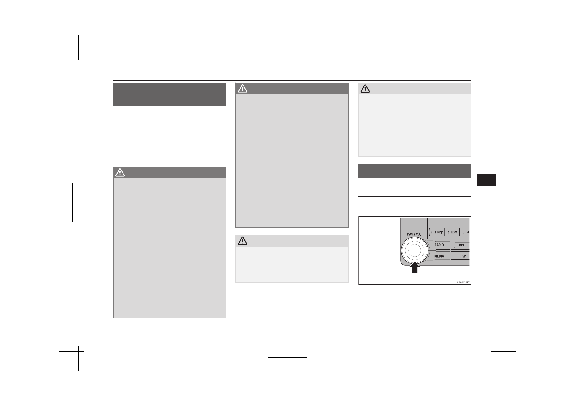
Important Points on Safety
for the Customer
E00737000035
This product features a number of pictorial
indications as well as points concerning han-
dling so that you can use the product correct-
ly and in a safe manner, as well as prevent in-
jury or damage to yourself, other users, or
property.
WARNING
l
The driver should not pay close attention
to the display while driving.
This may prevent the driver looking
where they are going, and cause an acci-
dent.
l
The driver should not perform complica-
ted operations while driving.
Performing complicated operations while
driving may prevent the driver looking
where they are going, and cause an acci-
dent.
Therefore stop the vehicle in a safe loca-
tion before performing such operations.
l
Do not use during malfunctions, such as
when no sound is audible.
This may lead to accident, fire, or electric
shock.
l
Ensure water or other foreign objects do
not enter the product.
This may lead to smoking, fire, electric
shock, or malfunction.
WARNING
l
Do not insert foreign objects into the disc
slot.
This may lead to fire, electric shock, or
malfunction.
l
In the event of abnormalities occurring
when foreign objects or water enter the
product, resulting in smoke or a strange
smell, immediately stop using the product,
and consult a MITSUBISHI MOTORS
Authorized Service Point.
Continuing to use the product may result
in accident, fire, or electric shock.
l
Do not disassemble or modify the prod-
uct.
This may lead to malfunction, fire, or
electric shock.
l
During thunderstorms, do not touch the
antenna or the front panel.
This may lead to electrical shock from
lightning.
CAUTION
l
Do not block ventilation holes or heat sinks
on the product.
Blocking ventilation holes or heat sinks may
prevent heat from escaping from within the
product, leading to fire or malfunction.
CAUTION
l
Do not turn the volume up to the extent that
you cannot hear sounds from outside the ve-
hicle while driving.
Driving without being able to hear sounds
from outside the vehicle may result in an ac-
cident.
l
Do not insert your hand or fingers into the
disc slot.
This may result in injury.
Operation Keys
E00737100023
Turn the Power ON/ OFF
E00737201089
1. Press the PWR/VOL key.
Turn the power on, and resume playback
from the previous status.
Important Points on Safety for the Customer
8-25
OGGE19E1
For pleasant driving
8
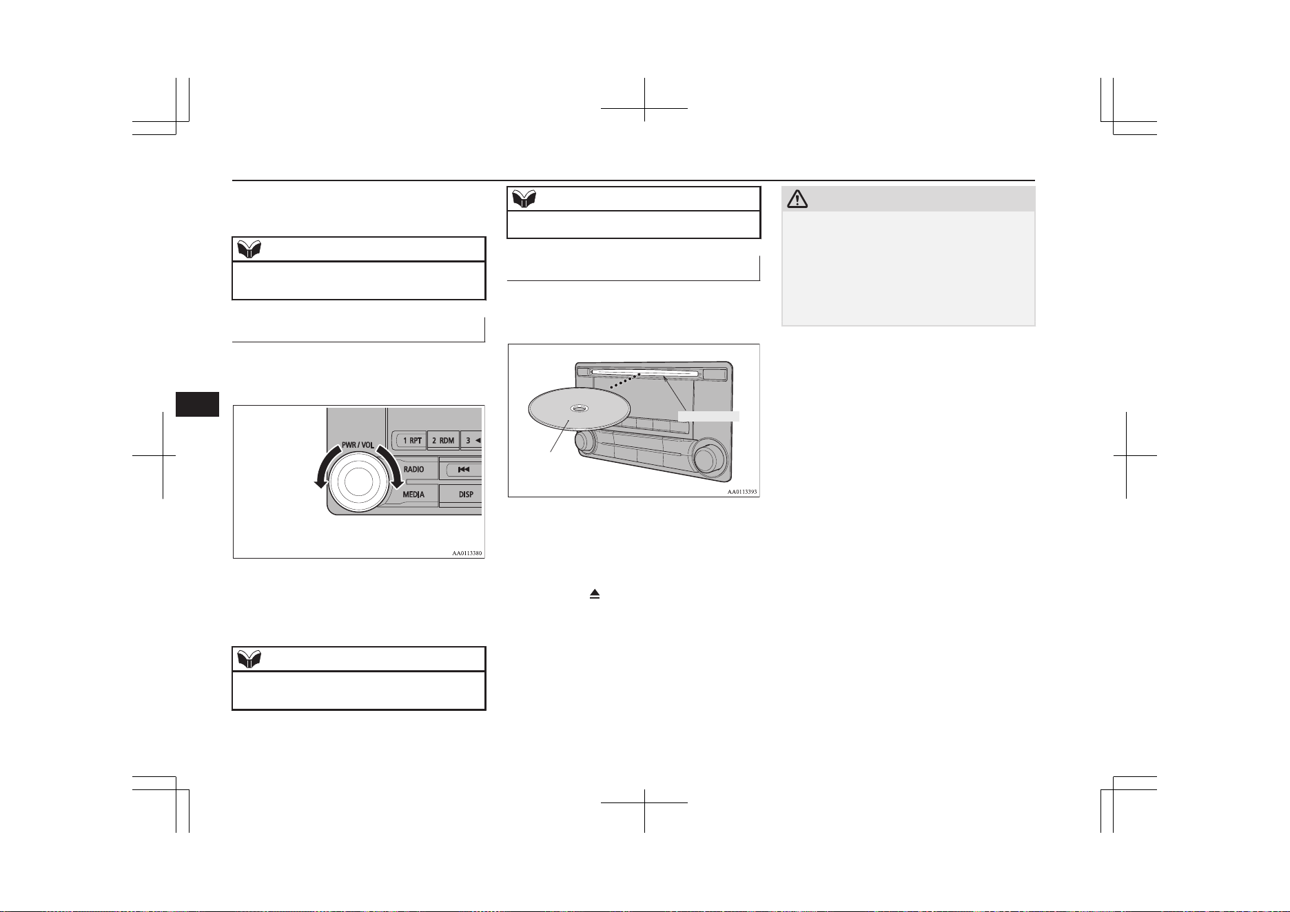
2. Press the PWR/VOL key.
Turn the power OFF.
NOTE
l
Hold down the steering SOURCE button to
also turn the audio function ON/OFF.
Adjust Volume
E00737300025
1. Turn the PWR/VOL key to adjust the
volume.
Turn the PWR/VOL key clockwise to in-
crease, and counter- clockwise to de-
crease the volume.
NOTE
l
The maximum value for volume is 45, and
the minimum is 0.
NOTE
l
The initial setting for volume is “17”.
Insert/Eject Discs
E00737400026
1. Insert the disc into the disc slot with the
label surface up.
Disc
*Label side
Disc slot
Push the disc in a certain amount, and
the product will pull the disc in, and
playback will start.
2. Press the
key.
This will eject the disc from the product,
so remove the disc.
CAUTION
l
When replacing discs, first ensure that the
vehicle is stopped in an area in which stop-
ping is permitted.
l
Do not insert your hand, fingers, or foreign
objects into the disc slot. This may lead to
injury, smoking, or fire.
l
8 cm CDs are not supported.
Operation Keys
8-26
OGGE19E1
For pleasant driving
8
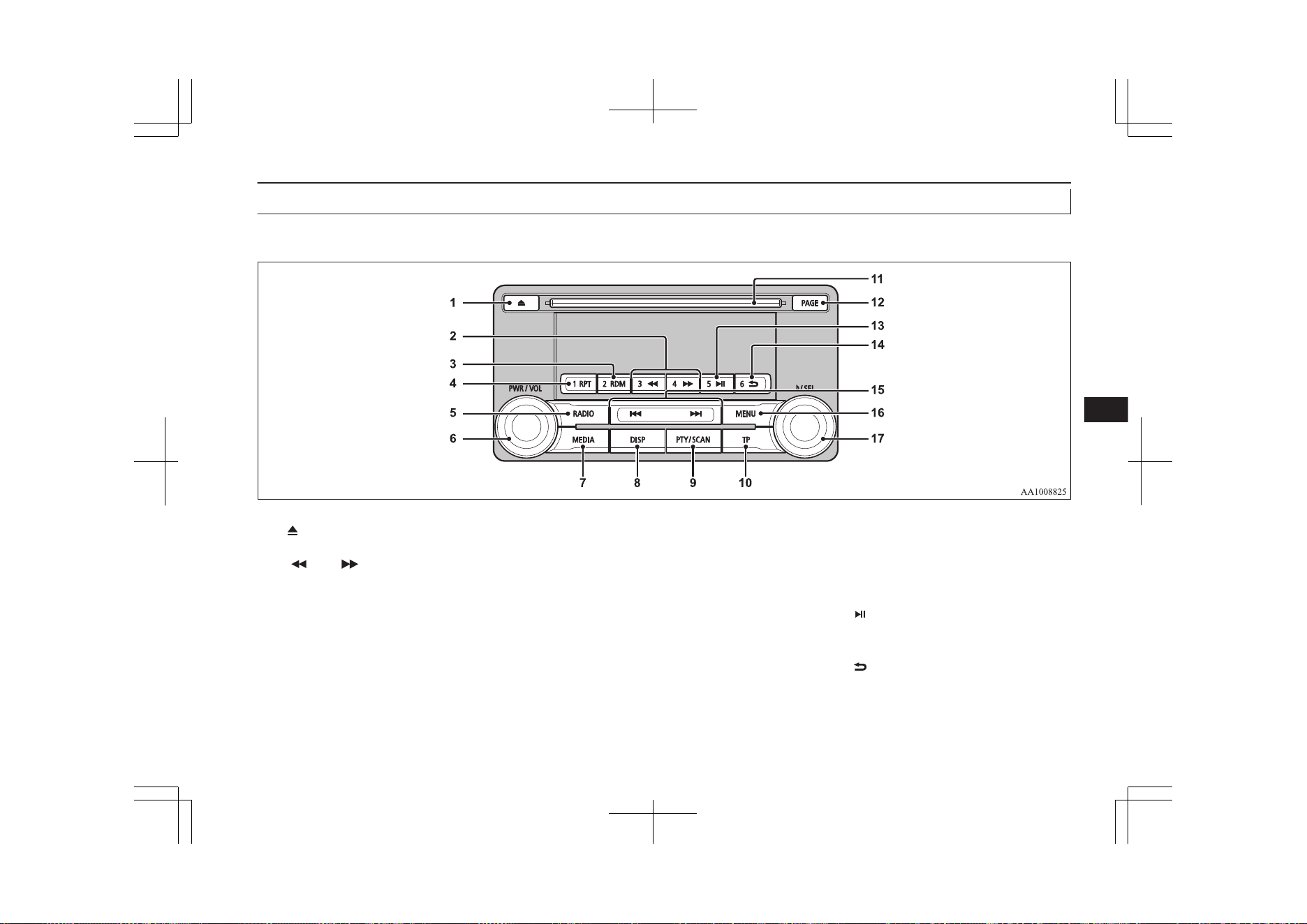
Explanation of Buttons
E00737501255
This explains names and functions of each part.
1- key
Use to eject a disc.
2- 3 key/4 key
For audio, rewind/fast forward.
For radio, use as preset keys 3 and 4.
3- 2RDM key
For audio, play random playback; for ra-
dio, use as preset key 2.
4- 1RPT key
For audio, play repeat playback; for ra-
dio, use as preset key 1.
5- RADIO key
Switch the radio and the band.
6- PWR/VOL key
Adjust the volume, and turn the power
ON/OFF.
7- MEDIA key
Switch between CD and other sources.
8- DISP key
Switch the content of the display.
9- PTY/SCAN key
For audio, play scan playback; for radio,
search PTY.
10- TP key
Receive traffic messages.
11- Disc slot
12- PAGE key
Display indicator page advance.
13- 5
key
Play/Pause Bluetooth Audio
*
, and use as
preset key 5 for radio.
14- 6
key
Return during audio track search, and
stop Bluetooth Audio
*
.
For radio, use as preset key 6.
*
Requires a separately-purchased Bluetooth- capable audio device in equipment by type (vehicles with a Bluetooth
®
2.0 interface).
Operation Keys
8-27
OGGE19E1
For pleasant driving
8
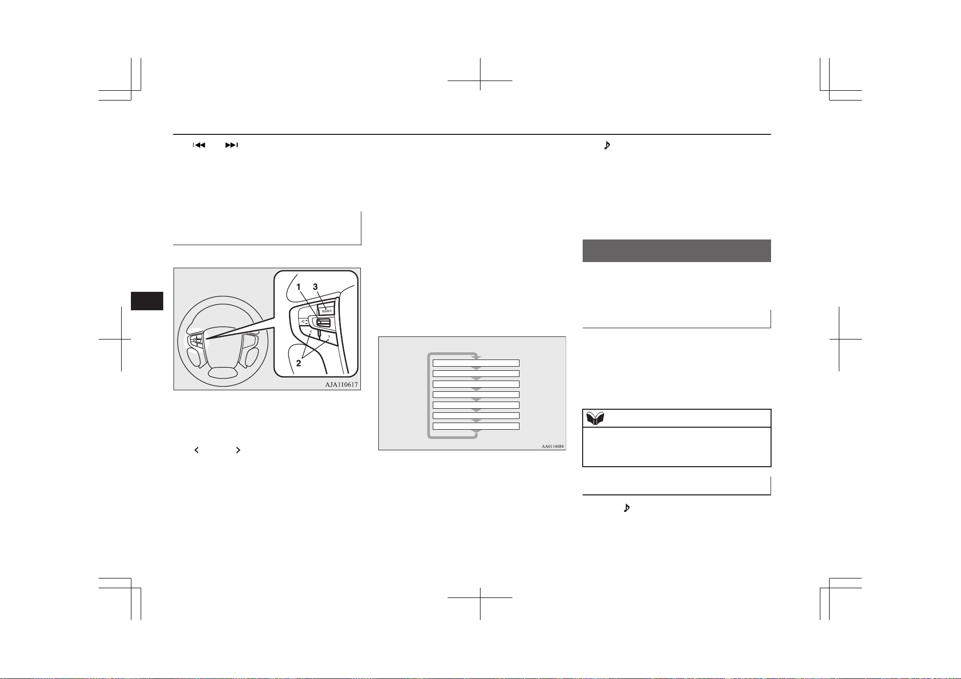
15- key/ key
For audio, select audio track/file; for ra-
dio, perform automatic station selection
or ensemble/service station selection.
16- MENU key
Switch to Menu mode.
17- /SEL key
Adjust audio quality and select items.
For radio, manually select stations.
Steering wheel audio remote
control switches
E00737601517
1- Volume up/down switch
Adjust audio functions and the mobile
phone function volume.
2-
button, button
Select CD and other audio source tracks
and radio stations.
Hold down to skip up and down through
tracks.
3- SOURCE button
Hold down to turn the audio function
ON/OFF. Additionally, each time this is
pressed, this switches the audio source.
The order of switching is as shown be-
low.
If devices are not connected, then these
are to be skipped, and the next source se-
lected.
CD or MP3
MW
LW
DAB1, 2, 3
*3
FM1, 2, 3
Bluetooth Audio
*2
iPod
*1
or USB device
*
1
:
An iPod cable (available separately) is
required.
*
2
:
Requires a separately-purchased Blue-
tooth-capable audio device (vehicles
with a Bluetooth
®
2.0 interface).
*
3
:
Requires DAB tuner connection.
Listen to Radio
E00737700032
This explains how to listen to FM, MW, and
LW radio broadcasts.
To Listen to the Radio
Press the RADIO key to switch the band.
Switch between FM1, FM2, FM3, MW, and
LW bands.
The selected band is indicated on the display.
NOTE
l
This switches in the order FM1, FM2, FM3,
DAB1*, DAB2*, DAB3*, MW, and LW.
*:When a DAB tuner is connected.
Manual/Seek Station Selection
Turn the /SEL key to the frequency to lis-
ten to.
Listen to Radio
8-28
OGGE19E1
For pleasant driving
8
/SEL key
(counter-
clockwise)
Reduces the frequency being
received.
/SEL key
(clockwise)
Increases the frequency be-
ing received.
key
(hold down)
Release the button to start
seek station selection, and
when a station is received,
scanning stops.
key
(hold down)
Preset Memory
Register the broadcast station in advance, and
select this at a later time.
1. Tune in to the frequency to register.
2. Hold down any of the keys from the
1RPT key to the 6
key.
A “Beep” sounds, and the preset key is
registered.
NOTE
l
The preset memory can register a maximum
of 6 stations for each band (FM1, FM2,
FM3).
l
If a preset key that already has a station reg-
istered is selected, then this is overwritten
with the new preset.
NOTE
l
Pressing the preset key will select the previ-
ously registered frequency.
Auto Memory (Auto Store)
The top 6 stations with a strong signal can be
automatically registered in order with preset
keys.
Hold down the RADIO key.
After completion of auto store operations, the
product will receive the station registered in
the preset key [1].
CAUTION
l
Please be aware that the formerly-registered
frequency in the memory will be overwrit-
ten.
NOTE
l
Using auto store for FM1 and FM2 switches
to FM3.
PTY Search
Select PTY (program content), and automati-
cally scan for stations.
1. During FM reception, press the PTY/
SCAN key.
This switches to the PTY selection
mode.
2. Turn the /SEL key to select PTY.
The PTY (program content) indicator
will flash, and station selection will au-
tomatically start. When a station is re-
ceived, the station name is displayed.
NOTE
l
This receives the station detected first.
l
10 seconds after reception, PTY search
mode will be cancelled.
Listen to DAB*
E00739100014
This explains how to listen to DAB.
To listen to DAB
1. Press the RADIO key to switch the
band.
Switch between DAB1, DAB2, and
DAB3 bands.
The selected band is indicated on the
display.
Listen to DAB*
8-29
OGGE19E1
For pleasant driving
8
NOTE
l
This switches in the order FM1, FM2, FM3,
DAB1, DAB2, DAB3, MW, and LW.
Select a Service
1. Hold down the key or the key.
Receives the lead services of the ensem-
bles that can be received.
2. Press the
key or the key to select
the service.
key
(hold down)
Automatically receives low-
er lead services within en-
sembles that can be received.
key
(hold down)
Automatically receives high-
er lead services within en-
sembles that can be received.
key
Switches to lower services.
key
Switches to higher services.
NOTE
l
Going to the first service or last service
within the ensemble switches to the next en-
semble.
Register the Service
Register the service in advance, and select
this at a later time.
1. Tune in to the service to register.
2. Hold down any of the keys from the
1RPT key to the 6
key.
A “Beep” sounds, and the preset key is
registered.
NOTE
l
If a preset key that already has a service reg-
istered is selected, then this is overwritten
with the new preset.
l
Pressing the preset key will select the previ-
ously registered service.
Search for a Service
Search for ensembles and services that can be
received.
1. Turn the /SEL key to select the en-
semble.
2. Press the
/SEL key.
The service name within the selected en-
semble is displayed.
3. Turn the /SEL key to select the serv-
ice.
4. Press the
/SEL key.
Receive the selected service.
NOTE
l
If the text information for the service name
cannot be obtained, then nothing is dis-
played.
l
If there is no operation for 10 seconds, then
service search mode will be cancelled.
PTY Search
Select PTY (program content), and automati-
cally scan for services.
1. Press the PTY/SCAN key.
This switches to the PTY selection
mode.
2. Turn the /SEL key to select PTY.
3. Press the
key or key.
This starts PTY search.
key
Lower PTY search starts.
key
Higher PTY search starts.
NOTE
l
When selecting PTY, press any of the keys
from the 1RPT key to the 6 key to
switch to the PTY registered as a preset.
l
When selecting PTY, select the PTY to reg-
ister, and hold down any of the keys from
the 1RPT key to the 6 key to register the
PTY as a preset.
Listen to DAB*
8-30
OGGE19E1
For pleasant driving
8
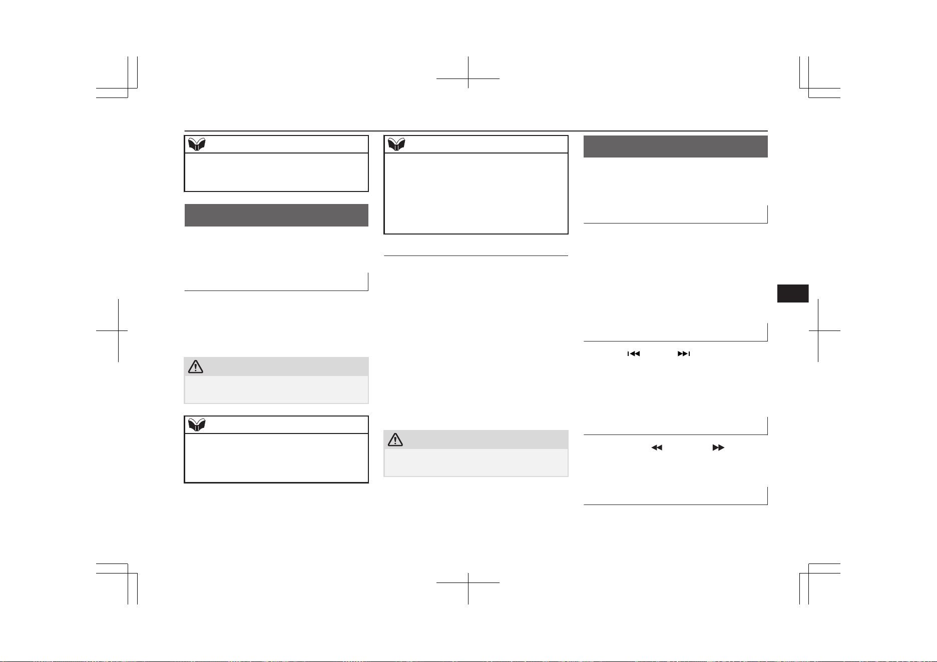
NOTE
l
While in PTY select status, if there is no op-
eration for 2 seconds, then an upwards
search within the selected PTY will start.
Listen to Traffic Messages
E00739200015
This explains how to listen to traffic messag-
es.
To Listen to Traffic Messages
1. When not in MW or LW mode, press the
TP key.
If traffic messages are being broadcast,
these are received.
CAUTION
l
When receiving a MW or LW signal, traffic
messages cannot be received.
NOTE
l
Receiving traffic messages will indicate
“TRAF INF” on the display, and if text in-
formation can be received, the station name
is displayed.
NOTE
l
If traffic messages are received, then this
will switch to the volume of the previously
received traffic messages or emergency
broadcasts. The volume when receiving traf-
fic messages or emergency broadcasts is that
at which subsequent broadcasts will be re-
ceived.
Traffic Message Standby Mode
When the broadcast of traffic messages starts,
this automatically switches to the station that
is broadcasting traffic messages.
1. When not in MW or LW mode, press the
TP key.
“TP” is indicated on the display, and the
product switches to standby mode.
If traffic messages are being broadcast,
these are received.
2. When not in MW or LW mode, press the
TP key.
“TP” disappears from the display, and
standby mode will be cancelled.
CAUTION
l
When receiving a MW or LW signal, traffic
message standby mode will be cancelled.
Listen to CDs
E00737800059
This explains how to listen to audio CDs
(CD-DA/CD-TEXT).
Play CDs
Insert the disc.
Insert a disc to automatically start playback.
→ “Insert/Eject Discs” on page 8-26
If a disc is already within the product, press
the MEDIA key to switch to CD as the
source.
Select the Track
Press the key or key to select the
track.
This enables selection of the next or previous
track.
Fast Forward or Rewind
Hold down the 3 key or the 4 key.
Fast forward/rewind is possible.
Switch Playback Mode
Repeat playback, random playback, and scan
playback are possible.
Listen to Traffic Messages
8-31
OGGE19E1
For pleasant driving
8
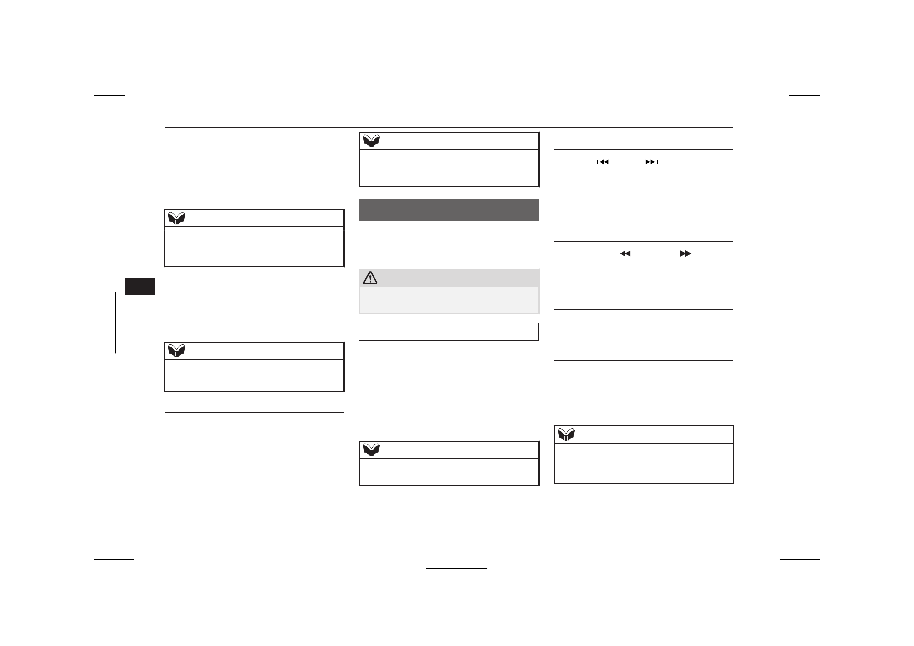
Repeat Playback (RPT)
Press the 1RPT key.
Repeat playback of the track currently being
played.
NOTE
l
Pressing again will cancel.
l
Selecting a track, ejecting, fast forwarding,
or rewinding will cancel.
Random Playback (RDM)
Press the 2RDM key.
Play the tracks on the disc in a random order.
NOTE
l
Pressing again will cancel.
l
Ejecting will cancel this.
Scan Playback (SCAN)
Press the PTY/SCAN key.
Play the first 10 seconds of each of the tracks
on the whole disc in order.
NOTE
l
Press this button again during playback if
you wish to hear that track, and that track
will play normally.
Listen to MP3s
E00737900034
This explains how to listen to audio files on a
disc.
CAUTION
l
CD-ROM and CD-R/RW media can only
play back MP3 format audio files.
To Listen to MP3s
Insert the disc.
Insert a disc to automatically start playback.
→ “Insert/Eject Discs” on page 8-26
If a disc is already within the product, press
the MEDIA key to switch to CD as the
source.
NOTE
l
Depending on the file structure, it may take
some time to read the contents of the disc.
Select the Track (File)
Press the key or key to select the
track.
This enables selection of the next or previous
track.
Fast Forward or Rewind
Hold down the 3 key or the 4 key.
Fast forward/rewind is possible.
Switch Playback Mode
Repeat playback, random playback, and scan
playback are possible.
Repeat Playback (RPT)
Press the 1RPT key.
Repeat playback of the track currently being
played.
NOTE
l
Pressing again will cancel.
l
Selecting a file, ejecting, fast forwarding, or
rewinding will cancel.
Listen to MP3s
8-32
OGGE19E1
For pleasant driving
8
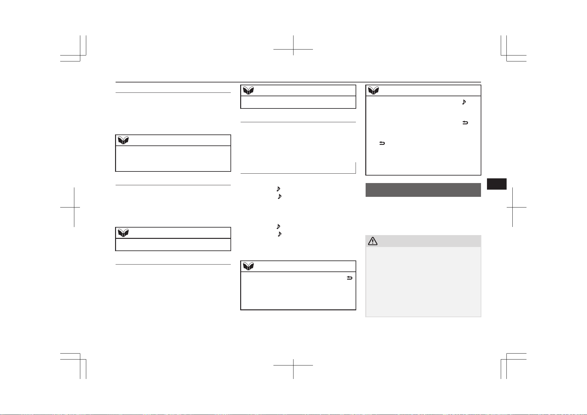
Folder Repeat Playback
Hold down the 1RPT key.
Repeat playback of the tracks within the fold-
er currently being played.
NOTE
l
Pressing again will cancel.
l
Even if the file is selected, folder repeat
playback will not be cancelled.
Random Playback (RDM)
Press the 2RDM key.
Play the tracks in the folder in a random or-
der.
NOTE
l
Pressing again will cancel.
Folder Random Playback
Hold down the 2RDM key.
Play all tracks in folders on the disc in a ran-
dom order.
NOTE
l
Pressing again will cancel.
Scan Playback (SCAN)
Press the SCAN key.
Play the first 10 seconds of each of the tracks
in the folder currently being played in order.
Search Tracks
Search folders and files, and select a track.
1. Turn the /SEL key to select the folder.
2. Press the /SEL key.
Files within the selected folder are dis-
played.
3. Turn the
/SEL key to select the file.
4. Press the /SEL key.
This plays the selected file (track).
NOTE
l
While the folder is selected, press the 6
key to cancel track search mode.
l
If there is no operation for 10 seconds after
selecting the folder, then track search mode
will be cancelled.
NOTE
l
Select the folder, and hold down the /SEL
key to start playback from the first track in
that folder.
l
While the file is selected, press the 6 key
to return to the previous operation.
l
While the file is selected, hold down the 6
key to cancel track search mode.
l
If there is no operation for five seconds after
selecting the file, that file is played back.
l
Disc operations such as selecting a track will
cancel track search mode.
Listen to an iPod
E00738001202
By connecting commercially-available iPod/
iPhone devices to this product, you can play
back tracks on these through the product.
CAUTION
l
Do not leave the iPod/iPhone unattended in
the vehicle.
l
Never hold these devices in your hand to op-
erate while driving, as this is dangerous.
l
No indemnification for data loss resulting
when the iPod/iPhone is connected to the
product will be possible.
l
Depending on how the devices are handled,
audio files being damaged or lost, therefore
it is recommended that data be backed up.
Listen to an iPod
8-33
OGGE19E1
For pleasant driving
8
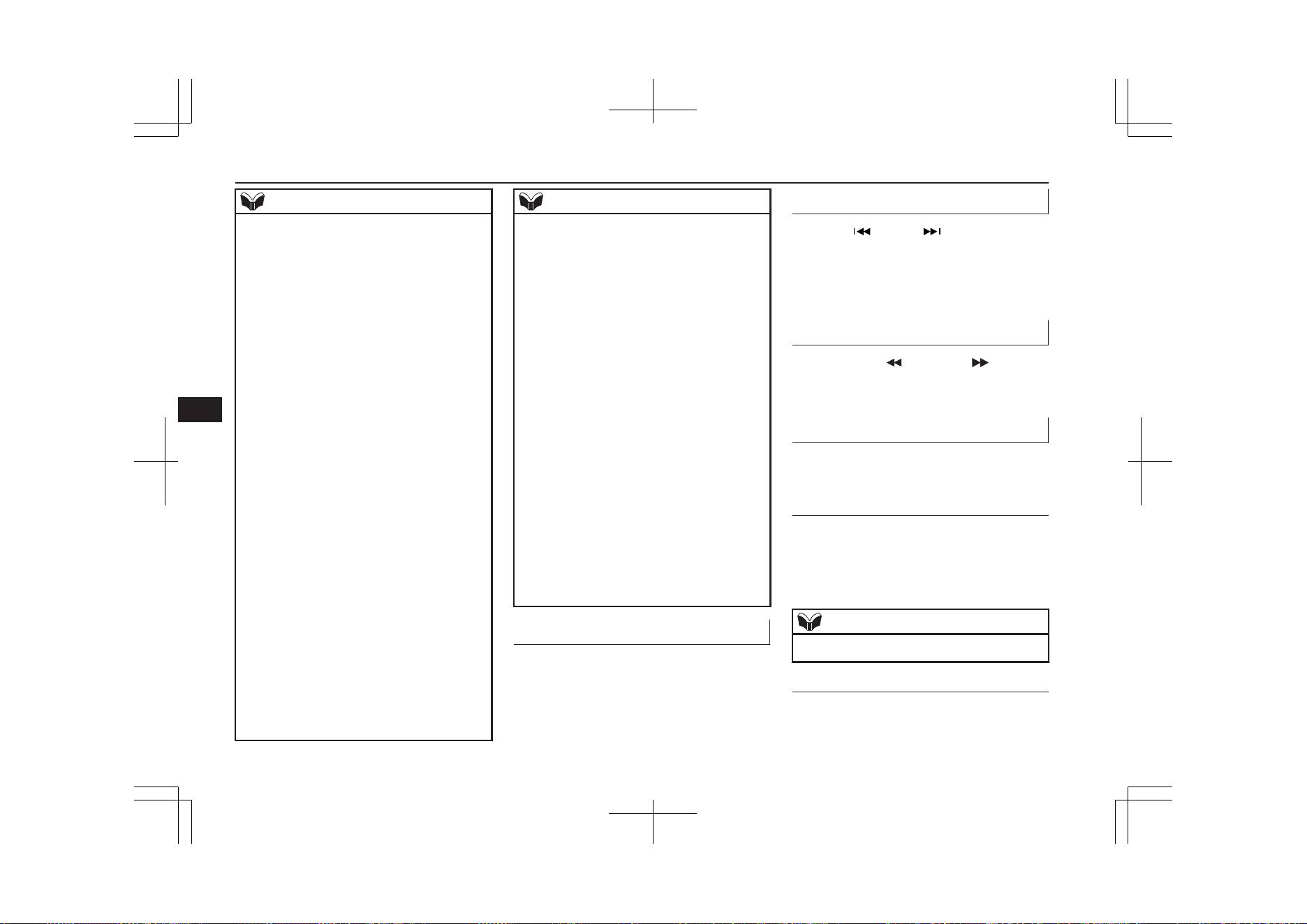
NOTE
l
Depending on the generation, model, or soft-
ware version of the iPod/iPhone, playback
on this product may not be possible.
(→8-16) Additionally, playback as ex-
plained in this document may not be possi-
ble.
l
For vehicles with a Bluetooth
®
2.0 interface,
the types of devices that can be connected
may vary.
For details, access the MITSUBISHI
MOTORS website.
Please read and agree to the “Warning about
Links to the Web Sites of Other Compa-
nies”. The websites mentioned above may
connect you to websites other than the
MITSUBISHI MOTORS website.
http://www.mitsubishi-motors.com/en/prod-
ucts/index.html
l
Usage of iPod/iPhone hardware with the lat-
est software version is recommended.
l
Regarding how to connect the iPod/iPhone,
refer to “How to connect an iPod” on page
8-72.
l
When connecting the iPod/iPhone, use a
commercially available iPod connection ca-
ble.
l
Set up the device in order that no unsafe ac-
tions, such as plugging in the connection ca-
ble are taken while driving.
l
When inserting and removing the iPod/
iPhone, for safety’s sake first stop the vehi-
cle.
l
Depending on the status of the iPod/iPhone,
it may take some time until the device is rec-
ognized, or playback starts.
NOTE
l
Depending on the iPod/iPhone, the button
functions on the product may not operate
while the iPod/iPhone is connected.
l
iPod/iPhone specifications and settings may
mean that connection is not possible, or re-
sult in differences in operation or display.
l
Depending on audio data in the iPod/iPhone,
track information may not be displayed cor-
rectly.
l
Depending on the status of the vehicle and
device, the iPod/iPhone may not play back
after starting the Plug-in Hybrid EV system.
l
Data containing copyright information may
not play back.
l
It is recommended that the iPod/iPhone
equaliser settings be set to flat.
l
Operate the iPod/iPhone while connected to
this product.
l
If the iPod/iPhone is connected via Blue-
tooth as a Bluetooth- capable audio device,
then do not connect the iPod/iPhone using
an iPod cable. Connection using both meth-
ods will result in erroneous operation.
l
If an iPod/iPhone does not operate correctly,
then remove the iPod/iPhone from the prod-
uct, reset, then reconnect.
Play iPod
Press the MEDIA key to set the iPod as the
source.
The selected source is indicated on the dis-
play.
Select the Track (File)
Press the key or key to select the
track.
This enables selection of the next or previous
track.
Fast Forward or Rewind
Hold down the 3 key or the 4 key.
Fast forward/rewind is possible.
Switch Playback Mode
Repeat playback and shuffle playback are
possible.
Repeat Playback (RPT)
Press the 1RPT key.
Repeat playback of the track currently being
played.
NOTE
l
Pressing again will cancel.
Shuffle Playback (RDM)
Press the 2RDM key.
Listen to an iPod
8-34
OGGE19E1
For pleasant driving
8
Play tracks in the category currently being
played in a random order.
NOTE
l
Pressing again will cancel.
Album Shuffle Playback
Hold down the 2RDM key.
Play back the album in a random order
(tracks in any order on the album).
NOTE
l
Pressing again will cancel.
Search Tracks
Search categories or track names, and select a
track.
1. Turn the /SEL key to select the cate-
gory.
2. Press the /SEL key. Categories or
tracks within the selected category are
displayed.
3. Turn the
/SEL key to select the cate-
gory or track.
4. Press the /SEL key.
Repeat steps 1 to 4, and search for
tracks.
Select the track, and press the /SEL
key to play.
NOTE
l
While the category (1
st
level) is selected,
press the 6
key to cancel track search
mode.
l
If there is no operation for 10 seconds after
selecting the category, then track search
mode will be cancelled.
l
Select the category, and hold down the
/SEL key to start playback from the first
track in that category.
l
While the track is selected, press the 6
key to return to the previous operation.
l
While the track is selected, hold down the 6
key to cancel track search mode.
l
If there is no operation for five seconds after
selecting the track, that file is played back.
l
iPod operations such as selecting a track will
cancel track search mode.
Listen to Audio Files on a
USB Device
E00736501261
By connecting commercially-available USB
devices such as USB memory to this product,
you can play back audio files on these
through the product.
CAUTION
l
Do not leave the USB device unattended in
the vehicle.
l
Never hold these devices in your hand to op-
erate while driving, as this is dangerous.
l
Do not use hard discs, card readers, or mem-
ory readers, as damage may occur to these or
to the data contained therein. If these are er-
roneously connected, put the operation mode
of the power switch in OFF and then remove
them.
l
Because of the risk of data loss, it is recom-
mended that files be backed up.
l
No guarantee is made as regards damage to
the USB device, nor regarding loss or dam-
age to data contained therein.
l
Depending on how the devices are handled,
audio files being damaged or lost, therefore
it is recommended that data be backed up.
NOTE
l
Digital audio players that support the mass
storage class specifications can be connec-
ted.
l
For details regarding the types of USB devi-
ces that can be connected and the types of
files that can be played back in vehicles with
a Bluetooth
®
2.0 interface, refer to “Types of
connectable devices and supported file spec-
ifications” on page 8-72.
l
Regarding how to connect USB devices, re-
fer to “How to connect a USB memory de-
vice” on page 8-72.
Listen to Audio Files on a USB Device
8-35
OGGE19E1
For pleasant driving
8
NOTE
l
When connecting a USB device, use a con-
nection cable. Failure to use a connection ca-
ble when connecting may place undue load
on, or damage the USB connector.
l
Set up the device in order that no unsafe ac-
tions, such as plugging in the connection ca-
ble are taken while driving.
l
When inserting and removing the USB de-
vice, for safety’s sake first stop the vehicle.
l
Do not insert other than audio devices into
the USB port. Damage to the device or
equipment may result.
l
Depending on the status of the USB device,
it may take some time until the device is rec-
ognized, or playback starts.
l
Depending on the USB device, the button
functions on the product may not operate
while the USB device is connected.
l
USB device specifications and settings may
mean that connection is not possible, or re-
sult in differences in operation or display.
l
Depending on audio data in the USB device,
track information may not be displayed cor-
rectly.
l
Depending on the status of the vehicle and
device, the iPod/iPhone may not play back
after starting the Plug-in Hybrid EV system.
l
Data containing copyright information may
not play back.
l
This product can play back MP3, WMA, and
AAC format audio files.
l
Depending on the type of USB device, usage
may not be possible, or functions that can be
used may be restricted.
NOTE
l
The recommended file system for USB
memory is FAT32.
l
The maximum supported capacity for USB
memory is 32GB.
l
Operate the USB device containing recorded
audio files while connected to this product.
Play Back of Audio Files on a
USB Device
Press the MEDIA key to set
USB as the source. The selected source is in-
dicated on the display.
Select the Track (File)
Press the key or key to select the
track.
This enables selection of the next or previous
track.
Fast Forward or Rewind
Hold down the 3 key or the 4 key.
Fast forward/rewind is possible.
Switch Playback Mode
Repeat playback, random playback, and scan
playback are possible.
Repeat Playback (RPT)
Press the 1RPT key.
Repeat playback of the track currently being
played.
NOTE
l
Pressing again will cancel.
l
Selecting a file will cancel this.
Folder Repeat Playback
Hold down the 1RPT key.
Repeat playback of the tracks within the fold-
er currently being played.
NOTE
l
Pressing again will cancel.
l
Even if the file is selected, folder repeat
playback will not be cancelled.
Folder Random Playback
(RDM)
Press the 2RDM key.
Listen to Audio Files on a USB Device
8-36
OGGE19E1
For pleasant driving
8
Play tracks in the folder currently being
played in a random order.
NOTE
l
Pressing again will cancel.
l
Even if the file is selected, folder random
playback will not be cancelled.
All Folder Random Playback
Hold down the 2RDM key.
Play the tracks in all folders in a random or-
der.
NOTE
l
Pressing again will cancel.
l
Even if the file is selected, all folder random
playback will not be cancelled.
Scan Playback (SCAN)
Press the PTY/SCAN key.
Play the first 10 seconds of each of the tracks
on the whole USB device in order.
NOTE
l
Press this button again during playback if
you wish to hear that track, and that track
will play normally.
Folder Scan Playback
Hold down the PTY/SCAN key.
Play the first 10 seconds of the first track in
each folder on the USB device in order.
NOTE
l
Press this button again during playback if
you wish to hear that track, and that track
will play normally.
Search Tracks
Search folders and files, and select a track.
1. Turn the /SEL key to select the folder.
2. Press the
/SEL key.
Files within the selected folder are dis-
played.
3. Turn the /SEL key to select the file.
4. Press the /SEL key.
This plays the selected file (track).
NOTE
l
While the folder is selected, press the 6
key to cancel track search mode.
l
If there is no operation for 10 seconds after
selecting the folder, then track search mode
will be cancelled.
l
Select the folder, and hold down the /SEL
key to start playback from the first track in
that folder.
l
While the file is selected, press the 6 key
to return to the previous operation.
l
While the file is selected, hold down the 6
key to cancel track search mode.
l
If there is no operation for five seconds after
selecting the file, that file is played back.
l
Operations such as selecting a track will
cancel track search mode.
To play iPod/USB memory
device tracks via voice
operation (vehicles with
Bluetooth
®
2.0 interface)
E00748700029
Desired tracks on the iPod/USB memory de-
vice which is connected to the USB input ter-
minal can be selected and played via voice
operation.
For information concerning the voice recog-
nition function or speaker registration func-
tion, refer to “Bluetooth
®
2.0 interface” on
page 8-51.
To play iPod/USB memory device tracks via voice operation (vehicles with Bluetooth
®
2.0 interface)
8-37
OGGE19E1
For pleasant driving
8
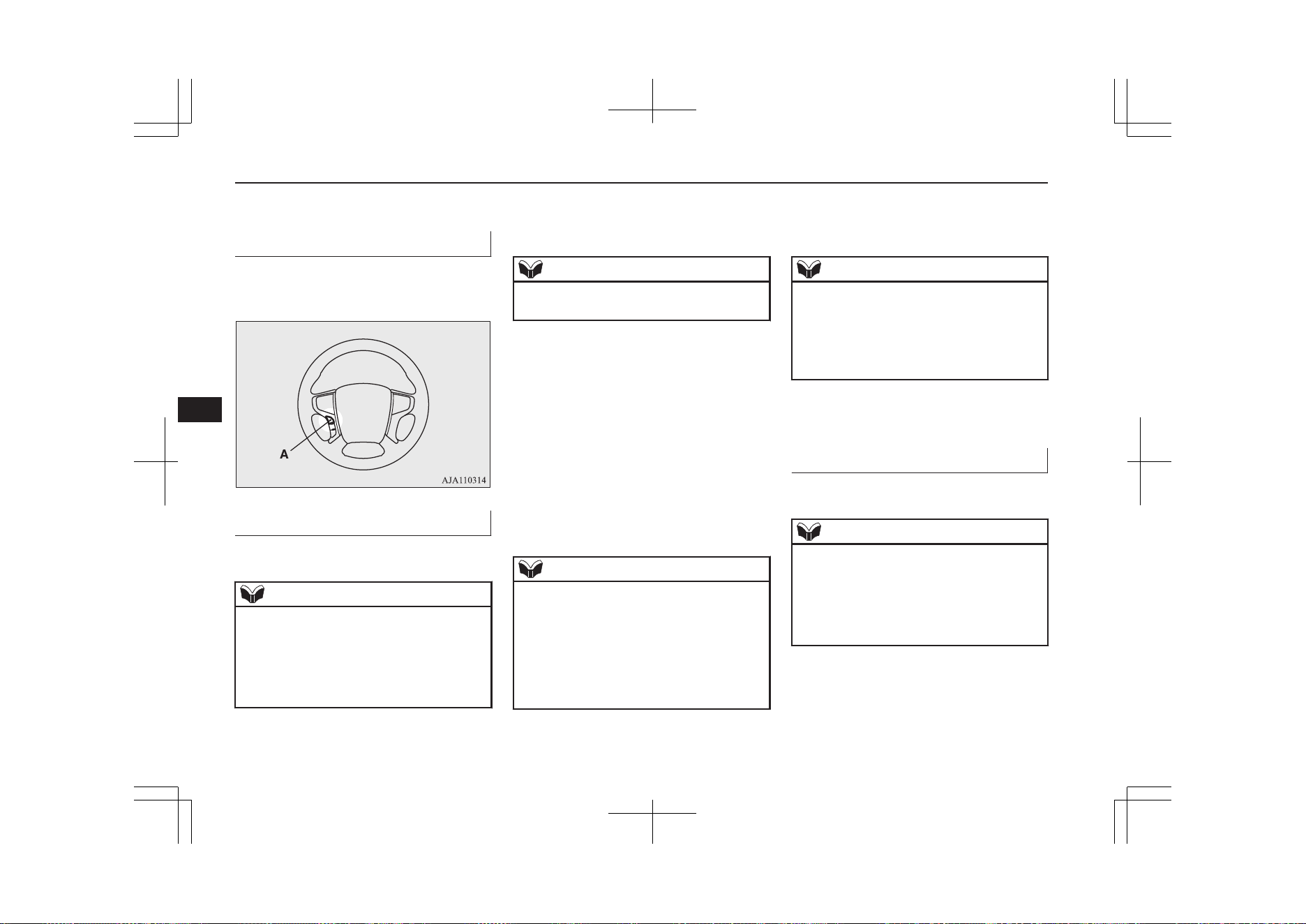
The following explains how to prepare for
voice operation and play the tracks.
Preparation for voice operation
E00748800059
To use the voice operation, press the
SPEECH button (A) first.
To search by artist name
E00748900021
1. Say “Play” on the main menu.
NOTE
l
The Bluetooth
®
2.0 interface starts recogniz-
ing the connected device.
If the connected device cannot be recognized
or a connection error occurs, the Bluetooth
®
2.0 interface starts an appropriate voice
guide. Follow the voice guide.
2. After the voice guide says “Would you
like to play by Artist, Album, Playlist or
Genre?,” say “Artist”.
NOTE
l
If you say “Artist <name>,” you can skip
step 3.
3. After the voice guide says “What Artist
would you like to play?,” say the artist
name.
4. If there is only one match, the system
proceeds to step 6.
5. If there are two or more matches, the
voice guide will say “More than one
match was found, would you like to play
<artist name>?” If you say “Yes,” the
system proceeds to step 6.
If you say “No,” the next matching artist
is uttered by the system.
NOTE
l
If you say “No” to three or all artist names
uttered by the system, the voice guide will
say “Artist not found, please try again” and
the system returns to step 2.
l
Search time is dependant on the number of
songs on your connected device. Devices
containing a large number of songs may take
longer to return search results.
6. After the voice guide says “Playing <ar-
tist name>,” the system creates a playlist
index for the artist.
NOTE
l
If the confirmation function is active, the
voice guide confirms if the artist name is
correct. If the artist name is correct, say
“Yes”. If not, say “No”. After the voice
guide says “Artist not found, please try
again,” the system returns to step 2.
7. The system exits the voice recognition
mode and starts playback.
To search by album title
E00749000029
1. Say “Play” on the main menu.
NOTE
l
The Bluetooth
®
2.0 interface starts recogniz-
ing the connected device.
If the connected device cannot be recognized
or a connection error occurs, the Bluetooth
®
2.0 interface starts an appropriate voice
guide. Follow the voice guide.
2. After the voice guide says “Would you
like to play by Artist, Album, Playlist or
Genre?,” say “Album”.
To play iPod/USB memory device tracks via voice operation (vehicles with Bluetooth
®
2.0 interface)
8-38
OGGE19E1
For pleasant driving
8
NOTE
l
If you say “Album <title>,” you can skip
step 3.
3. After the voice guide says “What Album
would you like to play?” say the album
title.
4. If there is only one match, the system
proceeds to step 6.
5. If there are two or more matches, the
voice guide will say “More than one
match was found, would you like to play
<album title>?” If you say “Yes,” the
system proceeds to step 6.
If you say “No,” the next matching al-
bum is uttered by the system.
NOTE
l
If you say “No” to three or all album titles
uttered by the system, the voice guide will
say “Album not found, please try again” and
the system returns to step 2.
6. After the voice guide says “Playing <al-
bum title>,” the system creates a playlist
index for the album title.
NOTE
l
If the confirmation function is active, the
voice guide confirms if the album title is
correct. If the album title is correct, say
“Yes”. If not, say “No”. After the voice
guide says “Album not found, please try
again,” the system returns to step 2.
7. The system exits the voice recognition
mode and starts playback.
To search by playlist
E00749100020
1. Say “Play” on the main menu.
NOTE
l
The Bluetooth
®
2.0 interface starts recogniz-
ing the connected device.
If the connected device cannot be recognized
or a connection error occurs, the Bluetooth
®
2.0 interface starts an appropriate voice
guide. Follow the voice guide.
2. After the voice guide says “Would you
like to play by Artist, Album, Playlist or
Genre?,” say “Playlist”.
NOTE
l
If you say “Playlist <playlist>,” you can skip
step 3.
If the device has no playlist, the voice guide
will say “There are no playlists stored on de-
vice” and the system returns to step 2.
3. After the voice guide says “What Play-
list would you like to play?,” say the
playlist name.
4. If there is only one match, the system
proceeds to step 6.
5. If there are two or more matches, the
voice guide will say “More than one
match was found, would you like to play
<playlist>?” If you say “Yes,” the sys-
tem proceeds to step 6.
If you say “No,” the next matching play-
list name is uttered by the system.
NOTE
l
If you say “No” to three or all playlist names
uttered by the system, the voice guide will
say “Playlist not found, please try again” and
the system returns to step 2.
6. After the voice guide says “Playing
<playlist>,” the system creates an index
for the playlist.
To play iPod/USB memory device tracks via voice operation (vehicles with Bluetooth
®
2.0 interface)
8-39
OGGE19E1
For pleasant driving
8

NOTE
l
If the confirmation function is active, the
voice guide confirms if the playlist name is
correct. If the playlist name is correct, say
“Yes”. If not, say “No”. After the voice
guide says “Playlist not found, please try
again,” the system returns to step 2. Refer to
“Confirmation function setting” on page
8-54.
7. The system exits the voice recognition
mode and starts playback.
To search by genre
E00749200021
1. Say “Play” on the main menu.
NOTE
l
The Bluetooth
(R)
2.0 interface starts recog-
nizing the connected device.
If the connected device cannot be recognized
or a connection error occurs, the Blue-
tooth
(R)
2.0 interface starts an appropriate
voice guide. Follow the voice guide.
2. After the voice guide says “Would you
like to play by Artist, Album, Playlist or
Genre?,” say “Genre”.
NOTE
l
If you say “Genre <type>,” you can skip
step 3.
3. After the voice guide says “What Genre
would you like to play?,” say the music
type.
4. If there is only one match, the system
proceeds to step 6.
5. If there are two or more matches, the
voice guide will say “More than one
match was found, would you like to play
<genre>?” If you say “Yes,” the system
proceeds to step 6.
If you say “No,” the next matching
genre is uttered by the system.
NOTE
l
If you say “No” to three or all genres uttered
by the system, the voice guide will say
“Genre not found, please try again” and the
system returns to step 2.
6. After the voice guide says “Playing
<genre>,” the system creates an index
for the genre.
NOTE
l
If the confirmation function is active, the
voice guide confirms if the genre is correct.
If the genre is correct, say “Yes”. If not, say
“No”. After the voice guide says “Genre not
found, please try again,” the system returns
to step 2. Refer to “Confirmation function
setting” on page 8-54.
7. The system exits the voice recognition
mode and starts playback.
Listen to Bluetooth Audio*
E00736701234
This product can play back tracks on com-
mercially-available Bluetooth-capable audio
devices.
CAUTION
l
Never hold these devices in your hand to op-
erate while driving, as this is dangerous.
l
Do not leave the Bluetooth audio device un-
attended in the vehicle.
l
Depending on how the devices are handled,
audio files being damaged or lost, therefore
it is recommended that data be backed up.
Listen to Bluetooth Audio*
8-40
OGGE19E1
For pleasant driving
8
NOTE
l
Depending on the type of Bluetooth-capable
audio devices, usage may not be possible, or
functions that can be used may be restricted.
l
Confirm together with the user manuals for
the commercially- available Bluetooth-capa-
ble audio devices.
l
Depending on the type of Bluetooth-capable
audio devices, volume levels may differ.
There is the danger of loud volumes, so prior
to use, it is recommended that you turn the
volume down.
→ “Adjust Volume” on page 8-26
l
Depending on the status of the Bluetooth au-
dio device, it may take some time until the
device is recognized, or playback starts.
l
Bluetooth audio device specifications and
settings may mean that connection is not
possible, or result in differences in operation
or display.
l
Depending on audio data in the Bluetooth
audio device, track information may not be
displayed correctly.
l
Depending on the status of the vehicle and
device, the iPod/iPhone may not play back
after starting the Plug-in Hybrid EV system.
Connect a Bluetooth-capable
Audio Device
Regarding how to connect your Bluetooth de-
vice, refer to “Connecting the Bluetooth® 2.0
interface and Bluetooth® device” on page
8-57.
Operation methods below describe situations
once connection has been completed.
NOTE
l
If the iPod/iPhone is connected via Blue-
tooth as a Bluetooth-capable audio device,
then do not connect the iPod/iPhone using
an iPod connection cable. Connection using
both methods will result in erroneous opera-
tion.
Play Bluetooth Audio
1. Press the MEDIA key to set Bluetooth
Audio as the source.
The selected source is indicated on the
display.
2. Press the 5
key. Bluetooth Audio
playback starts.
NOTE
l
Hold down the 5 key to pause.
l
Press the 6 key to stop.
Select the Track (File)
Press the key or key to select the
track.
This enables selection of the next or previous
track.
Fast Forward or Rewind
Hold down the 3 key or the 4 key.
Fast forward/rewind is possible.
Switch Playback Mode
Repeat playback, random playback, and scan
playback are possible.
Repeat Playback (RPT)
Press the 1RPT key.
Repeat playback of the track currently being
played.
NOTE
l
Each time the 1RPT key is pressed, this
switches in the order Repeat OFF, 1 track re-
peat, All track repeat, and Repeat OFF.
Random Playback (RDM)
Press the 2RDM key.
Play the tracks in the Bluetooth Audio device
in a random order.
Listen to Bluetooth Audio*
8-41
OGGE19E1
For pleasant driving
8
NOTE
l
Pressing again will cancel.
Scan Playback (SCAN)
Press the PTY/SCAN key.
Play the first 10 seconds of each of the tracks
on the whole Bluetooth Audio device in or-
der.
NOTE
l
Press this button again during playback if
you wish to hear that track, and that track
will play normally.
Listen to Bluetooth Audio*
8-42
OGGE19E1
For pleasant driving
8
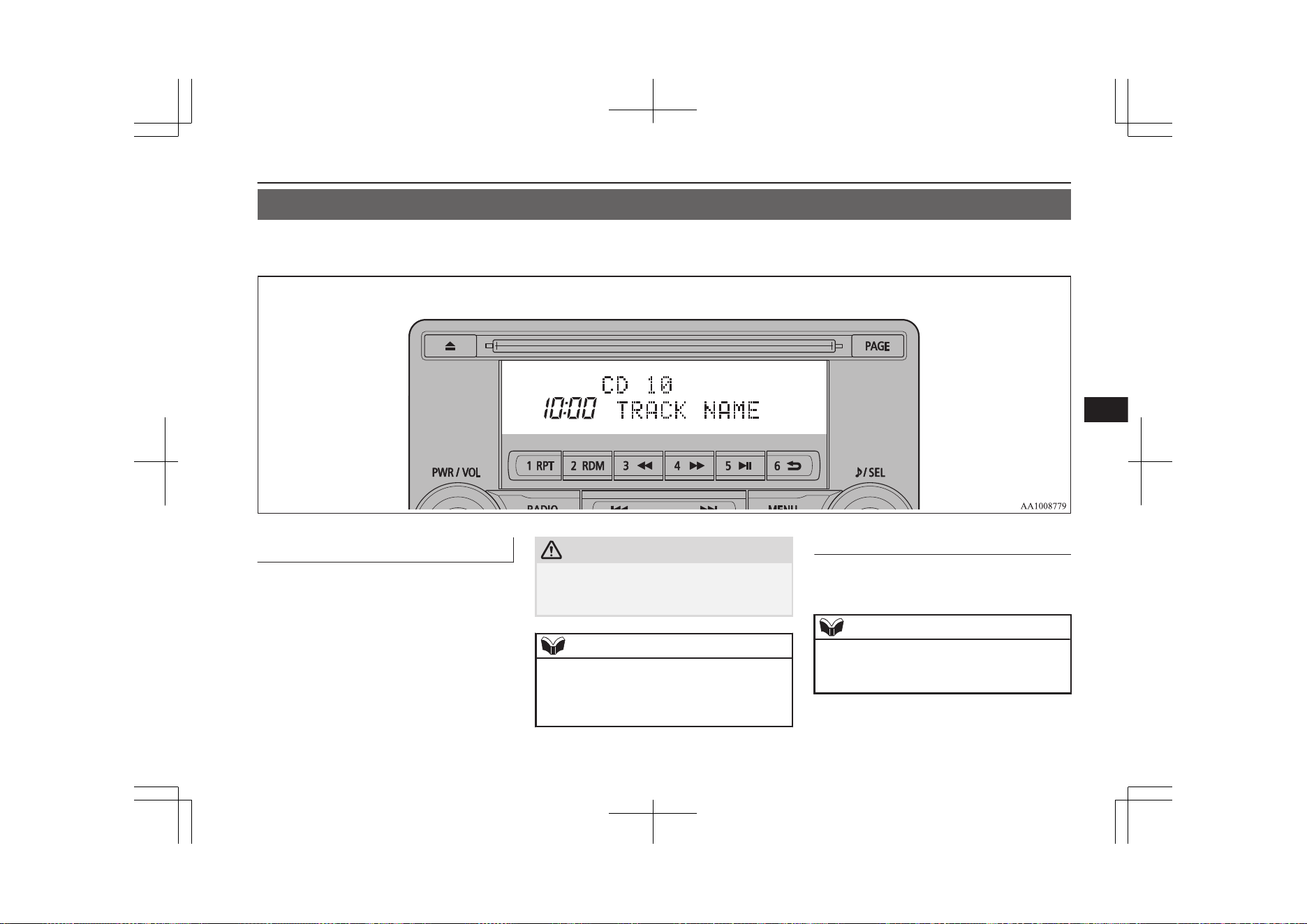
Display Indicator
E00738100033
This explains content of the display indicator.
Change the Display Mode
E00738501177
You can change the content of the display in-
dicator.
Press the DISP key to switch the display con-
tent.
Each time the DISP key is pressed, the dis-
play content changes.
CAUTION
l
The operation of changing display contents
may impede safe driving, therefore check
safety before operation.
NOTE
l
Up to 11 characters may be displayed at one
time. To display 12 or more characters, press
the PAGE key, and subsequent characters
will be displayed.
During DAB Reception*
This switches in the order “Service name”,
“Ensemble name”, and “CH no. (CH ID)”.
NOTE
l
If the text information for the service name
and ensemble name cannot be obtained, then
nothing is displayed.
Display Indicator
8-43
OGGE19E1
For pleasant driving
8
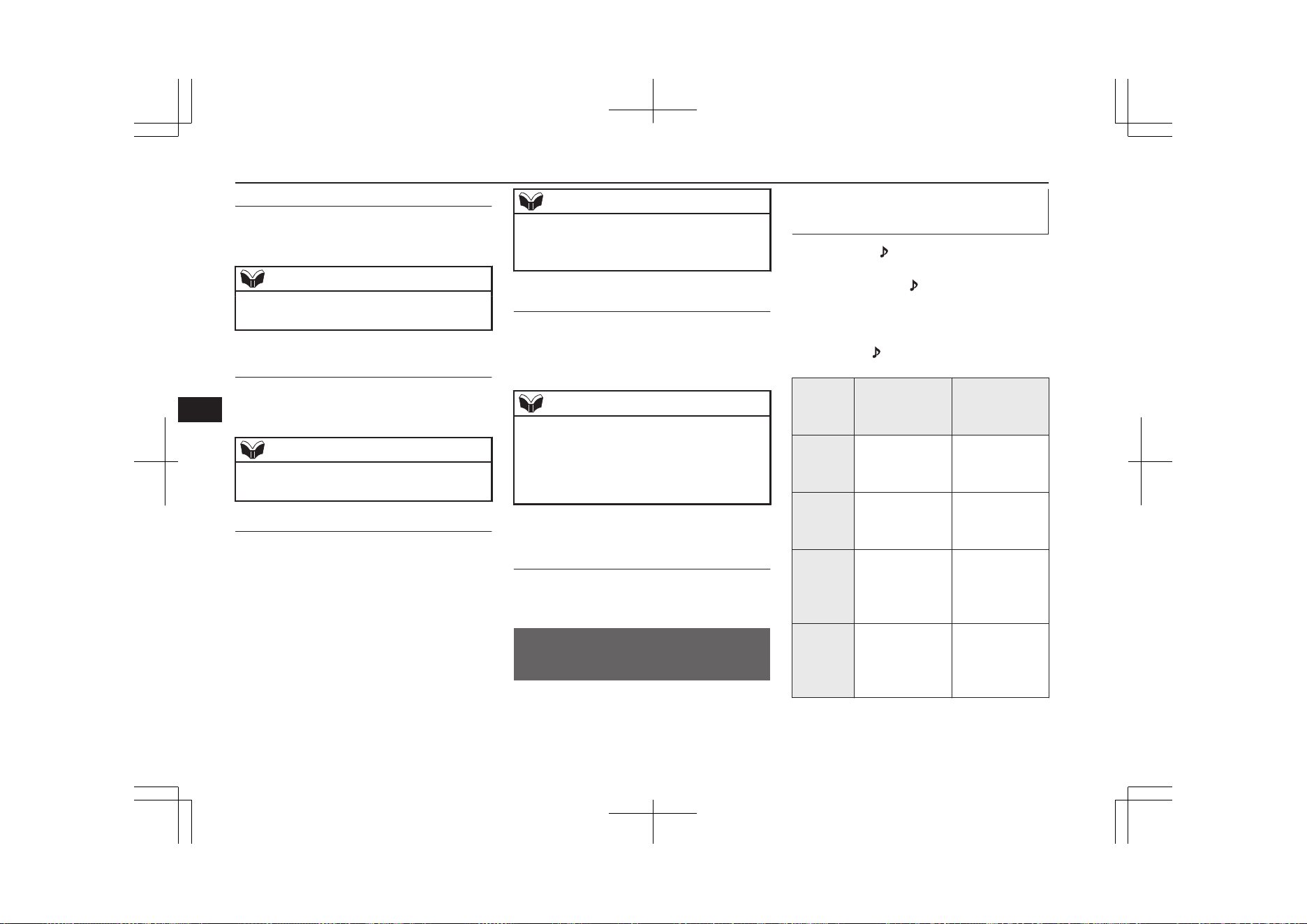
During CD-DA playback
This switches in the order “Disc title”, “Track
title”, and “Operating status”.
NOTE
l
If there is no text information to display,
then “NO TITLE” is displayed.
During MP3/WMA/AAC Play-
back
This switches in the order “Folder title”,
“File title”, and “Operating status”.
NOTE
l
If there is no text information to display,
then “NO TITLE” is displayed.
Display the ID3tag
Hold down the DISP key.
This switches the ID3tag display.
[DISP] Each time the key is pressed, this
switches in the order “Album name”, “Track
name”, “Artist name”, “Genre name”*, and
“Operating status”.
*: Displayed when playing back audio
files on a USB device (vehicles with a
Bluetooth
®
2.0 interface).
NOTE
l
During display of the ID3tag, hold down the
DISP key to switch to the folder title display.
l
The genre name display may not be possible.
During iPod Playback
E00738901096
This switches in the order “Albums”, “Track
name”, “Artist name”, “Genre name”*, and
“Operating status”.
NOTE
l
If there is no text information to display,
then “NO TITLE” is displayed.
l
Displayed genre name in equipment by type
(vehicles with a Bluetooth
®
2.0 interface).
l
The genre name display may not be possible.
During Bluetooth
®
2.0 Audio
Playback*
E00739001036
Operating details are the same as in “During
iPod Playback” on page 8-44.
Audio Quality and Volume
Balance Adjustment
E00738201161
Change audio quality settings.
Adjust Audio Quality and Vol-
ume Balance
1. Press the /SEL key to select settings
items.
Each time the
/SEL key is pressed,
this switches in the order BASS, TRE-
BLE, FADER, BALANCE, SCV (speed
compensated volume), and Cancel.
2. Turn the
/SEL key to adjust.
Adjust-
ment
items
Turn counter-
clockwise
Turn clockwise
BASS -6 to 0
(low low-pass
volume)
0 to +6
(high low-pass
volume)
TREBLE -6 to 0
(Low high-pass
volume)
0 to +6
(High high-pass
volume)
FADER CENTER to
REAR 11
(emphasise
REAR)
FRONT 11 to
CENTER
(emphasise
FRONT)
BAL-
ANCE
LEFT 11 to
CENTER
(emphasise
LEFT)
CENTER to
RIGHT 11
(emphasise
RIGHT)
Audio Quality and Volume Balance Adjustment
8-44
OGGE19E1
For pleasant driving
8
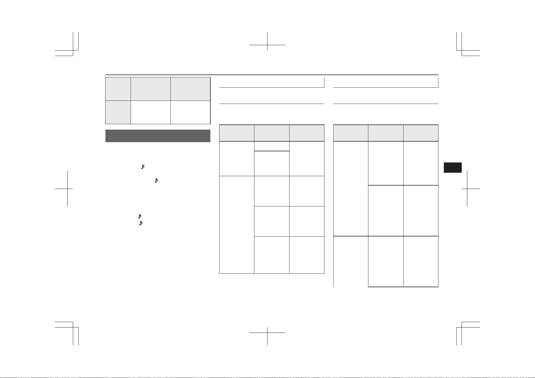
Adjust-
ment
items
Turn counter-
clockwise
Turn clockwise
SCV OFF, LOW
(SCV effect is
OFF/low)
MID, HIGH
(SCV effect is
middle/high)
System Settings
E00738301188
Change system settings such as product time.
1. Press the MENU key.
2. Press the /SEL key to select settings
items.
Each time the
/SEL key is pressed,
this switches in the order DAB setting*
1
,
Gracenote DB*
2
, AF, REG, TP-S, PI-S,
PTY language settings, PHONE settings,
CT, Adjust time, and Cancel.
3. Turn the /SEL key to set.
4. Press the /SEL key to determine.
This completes settings, and displays the
next settings item.
*
1
:
Displayed when a DAB tuner is con-
nected.
*
2
:
Displayed when playing back audio
files (vehicles with a Bluetooth
®
2.0 in-
terface).
DAB Setting*
Change DAB settings
(“Set value” bold typeface indicates factory
default settings.)
Settings
name
Settings val-
ue
Settings con-
tent
DAB-DAB
Link settings
OFF
If low recep-
tion sensitivi-
ty, switch to
another serv-
ice.
ON
DAB Band
settings
BAND III Set used
broadcast
band to 174
to 239 MHz.
L-BAND Set used
broadcast
band to 1452
to 1490 MHz.
BOTH Set used
broadcast
band to Band
III and L-
Band.
RDS Setting
Change RDS settings
(“Set value” bold typeface indicates factory
default settings.)
Settings
name
Settings val-
ue
Settings con-
tent
AF
AF ON Automatical-
ly track the
same station
as the pro-
gram being
received.
AF OFF Do not auto-
matically
track the
same station
as the pro-
gram being
received.
REG
REG ON Do not auto-
matically
track the lo-
cal station for
the program
being re-
ceived.
System Settings
8-45
OGGE19E1
For pleasant driving
8

Settings
name
Settings val-
ue
Settings con-
tent
REG OFF Automatical-
ly track the
local station
for the pro-
gram being
received.
TP-S
TP-S ON Automatical-
ly search for
traffic mes-
sages (TP sta-
tions).
TP-S OFF Do not auto-
matically
search for
traffic mes-
sages (TP sta-
tions).
PI-S
PI-S ON Search for the
same station
or local sta-
tion for that
registered in
the preset
channel.
Settings
name
Settings val-
ue
Settings con-
tent
PI-S OFF Do not search
for the same
station or lo-
cal station for
that regis-
tered in the
preset chan-
nel.
PTY
ENGLISH Set the dis-
play language
for the pro-
gram content
search (PTY
search) to
English.
FRANÇAIS Set the dis-
play language
for the pro-
gram content
search (PTY
search) to
French.
DEUTSCH Set the dis-
play language
for the pro-
gram content
search (PTY
search) to
German.
Settings
name
Settings val-
ue
Settings con-
tent
SVENSK Set the dis-
play language
for the pro-
gram content
search (PTY
search) to
Swedish.
ESPAÑOL Set the dis-
play language
for the pro-
gram content
search (PTY
search) to
Spanish.
ITALIANO Set the dis-
play language
for the pro-
gram content
search (PTY
search) to
Italian.
CT
CT ON Update the
time if time
data is re-
ceived.
System Settings
8-46
OGGE19E1
For pleasant driving
8
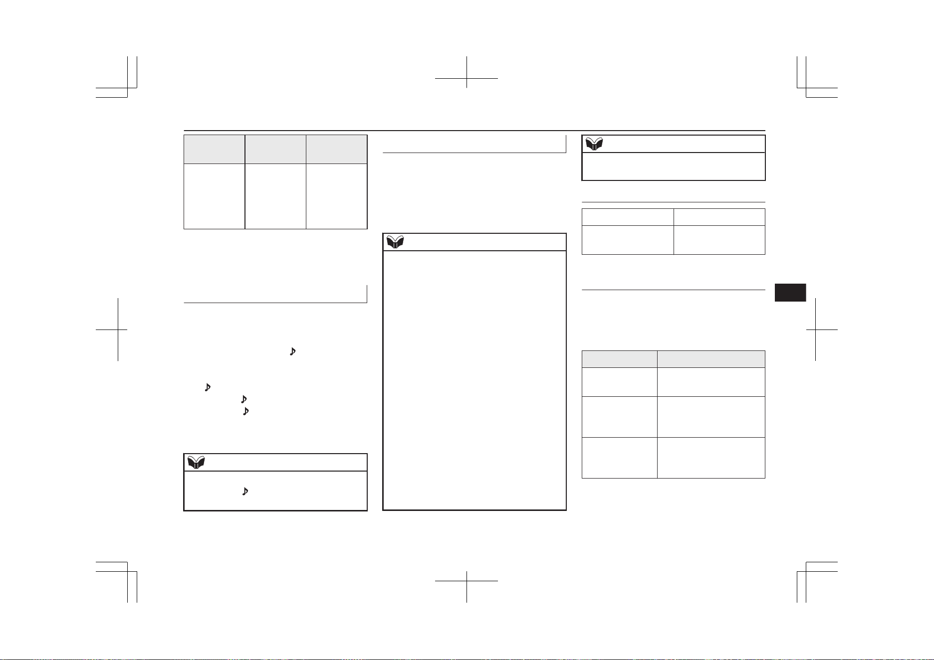
Settings
name
Settings val-
ue
Settings con-
tent
CT OFF Do not up-
date the time
even if time
data is re-
ceived.
*: It is necessary to press the [TP] key and
turn traffic message standby mode
“ON”.
Time Setting
Turning the RDS setting CT setting “CT
OFF” enables manual setting of the time.
1. Select “YES” at the “Adjust time”
screen, and press the
/SEL key.
The hour can be adjusted. Press the
/SEL key again to adjust the minutes.
2. Turn the /SEL key to adjust the time.
3. Press the /SEL key.
This completes the adjustment.
NOTE
l
In order to finish adjusting the time, hold
down the /SEL key until the seconds are
reset to “00”.
PHONE Settings
Change the mobile phone voice cut- in set-
tings and the Bluetooth
®
2.0 interface lan-
guage.
Depending on the vehicle, PHONE settings
may not be possible.
NOTE
l
Cancel functions such as the mobile phone
“dial lock”, and connect while on the stand-
by screen.
l
While connected, mobile phone (receiving
calls, etc.) operations may not function cor-
rectly.
l
Depending on the distance between the
product and the mobile phone, the condi-
tions within the vehicle, and types of screen-
ing, connection may not be possible. In these
cases, situate the mobile phone as close as
possible to the product.
l
Even though a Bluetooth-capable mobile
phone, characteristics and specifications
may mean that correct operation may not be
possible.
l
For safety’s sake, do not operate the mobile
phone while driving. When operating the
mobile phone, first stop the vehicle in a safe
location.
l
Even though a Bluetooth-capable mobile
phone, phone specifications and settings
may result in differences in display, or pre-
vent correct operation.
NOTE
l
Some models may not be confirmed as con-
nected, or may not connect.
Supported profiles
Hands-free HFP(v1.5)
Phone book trans-
fer
OPP(v1.1),
PBAP(v1.0)
Vehicles without a Bluetooth
®
2.0 Interface
A hands-free kit (available separately) is re-
quired.
(“Set value” bold typeface indicates factory
default settings.)
Settings value Settings content
PHONE OFF Do not use mobile phone
voice cut-in.
PHONE MUTE During mobile phone
voice cut-in, mute the au-
dio.
PHONE ATT During mobile phone
voice cut-in, output audio
from all speakers.
System Settings
8-47
OGGE19E1
For pleasant driving
8
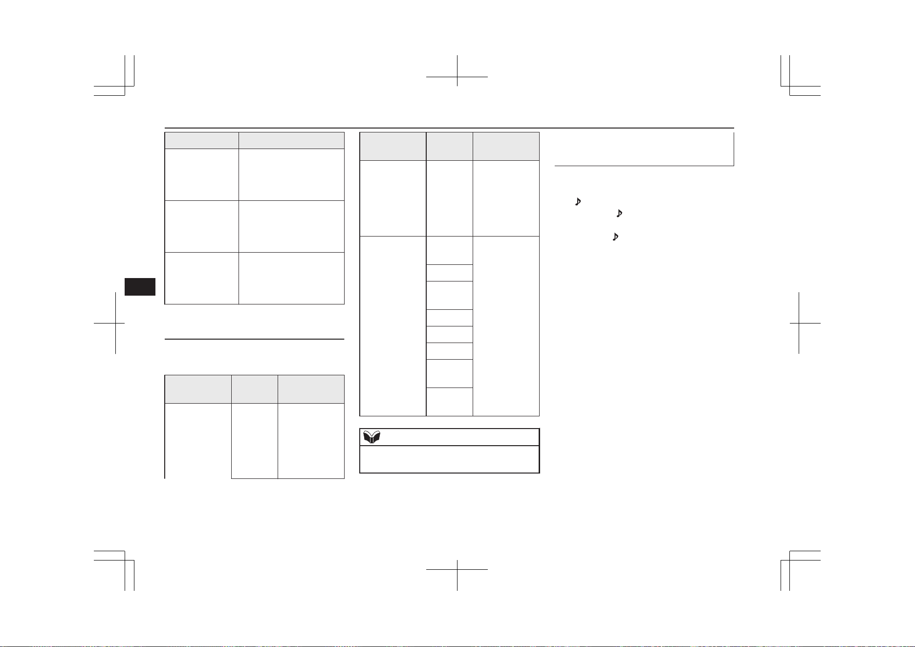
Settings value Settings content
PHONE IN-L During mobile phone
voice cut-in, output
sound from the left front
speaker.
PHONE IN-R During mobile phone
voice cut-in, output
sound from the right
front speaker.
PHONE IN-LR During mobile phone
voice cut-in, output
sound from the left and
right front speakers.
Vehicles with a Bluetooth
®
2.0
Interface
(“Set value” bold typeface indicates factory
default settings.)
Settings name
Settings
value
Settings con-
tent
PHONE IN set-
tings
PHONE
IN-R
During mobile
phone voice
cut-in, output
sound from the
right front
speaker.
Settings name
Settings
value
Settings con-
tent
PHONE
IN-L
During mobile
phone voice
cut-in, output
sound from the
left front
speaker.
HFM voice lan-
guage settings
ENG-
LISH
Change the
hands free mod-
ule voice lan-
guage.
FRENCH
GER-
MAN
SPANISH
ITALIAN
DUTCH
PORTU-
GUESE
RUSSI-
AN
NOTE
l
Depending on the vehicle model, this may
not display.
Gracenote DB (Vehicles with a
Bluetooth
®
2.0 interface)
The version number can be confirmed.
1. Select “Gracenote DB” and press the
/SEL key.
2. Turn the
/SEL key and select “DB
Version”.
3. Press the /SEL key.
The DB Version is displayed.
System Settings
8-48
OGGE19E1
For pleasant driving
8
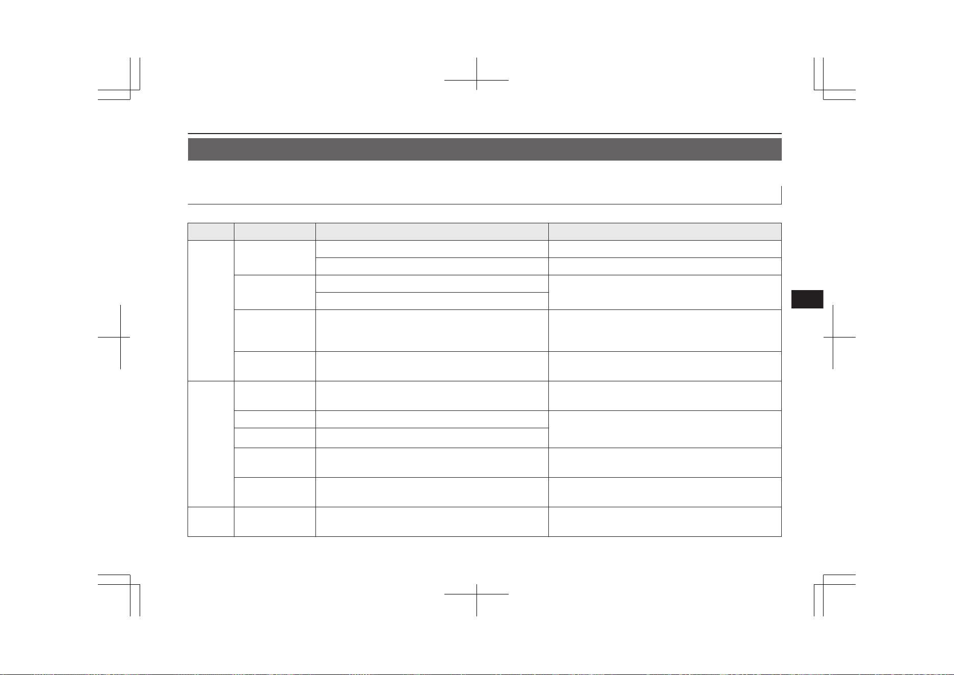
Troubleshooting
E00738401075
Please check these items if a message appears on the display, or if you think something is not working properly.
If This Message Appears...
A message is displayed on this product according to the situation.
Mode Message Cause Response
CD CHECK DISC
The disc is inserted upside down. Insert with the label side up.
The disc has condensation on it. Wait a while before inserting again.
DISC ERROR
The disc is damaged.
Clean the read surface of the disc.
The disc is dirty.
INTERNAL E The drive has malfunctioned for some reason. Check that there is no problem with the disc, and insert
the disc again. If the problem persists, consult a
MITSUBISHI MOTORS Authorized Service Point.
HEAT ERROR The temperature inside the product is high. Remove the disc, and wait for the internal temperature
to return to normal.
USB
FILE ERROR Files that cannot be played are selected. Select files that can be played.
→ “Audio Files (MP3/WMA/AAC)” on page 8-21
USB BUS PWR There is high or low electrical current or voltage.
Turn the power OFF and wait a short while. If the prob-
lem persists, consult a MITSUBISHI MOTORS Author-
ized Service Point.
LSI ERROR There is an internal malfunction for some reason.
UNSUPPORTED
FORMAT
Unsupported audio files have been played. Confirm audio files that can be played.
→ “Audio Files (MP3/WMA/AAC)” on page 8-21
UNSUPPORTED
DEVICE
An unsupported USB device has been connected. Please connect a USB memory device.
iPod NO SONG An iPod/iPhone not containing any tracks has been
connected.
Connect an iPod/iPhone containing tracks.
Troubleshooting
8-49
OGGE19E1
For pleasant driving
8
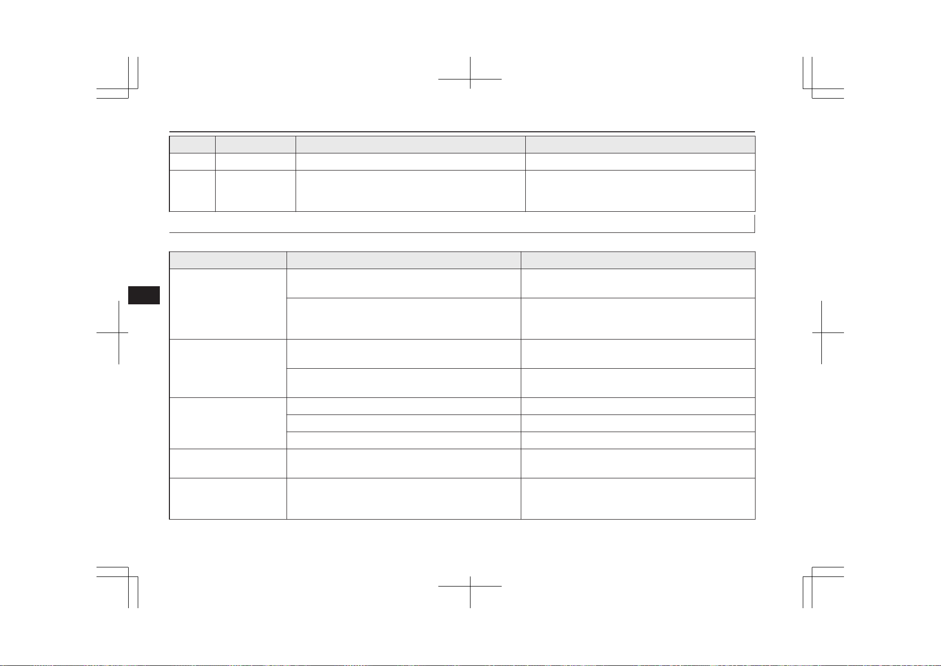
Mode Message Cause Response
iPod VER ERROR This iPod/iPhone software version is not supported. Please change to a supported software version.
Other ERROR DC An abnormal direct voltage has been sent to the speak-
ers.
Turn the power OFF and wait a short while. If the prob-
lem persists, consult a MITSUBISHI MOTORS Au-
thorized Service Point.
If You Think Something Is Not Working Properly...
Here is a list of symptoms, causes and responses if you think something is not working properly.
Symptoms Cause Response
There is no sound or quiet
sound.
The volume is turned to its minimum. Adjust the volume.
→ “Adjust Volume” on page 8-26
The balance or fader is turned to one side. Adjust the balance or fader.
→ “Adjust Audio Quality and Volume Balance” on page
8-44
The disc cannot be inserted.
A disc is already in the product. Eject the disc.
→ “Insert/Eject Discs” on page 8-26
There is no disc in the product, but the product says it is
loading.
Press the eject button once.
→ “Insert/Eject Discs” on page 8-26
The disc cannot be played.
The disc is inserted upside down. Insert with the label side up.
The disc has condensation on it. Wait a while before inserting.
The disc is dirty. Clean the read surface of the disc.
The sound skips in the
same place.
The disc is damaged or dirty. Check the disc.
There is no sound, even if
the disc is inserted.
Damage to or dirt on the disc means that its data cannot
be read.
Check the disc. Additionally, if using CD-R/RW discs,
their characteristics may render them unable to be
played.
Troubleshooting
8-50
OGGE19E1
For pleasant driving
8
Link System*
E00764501569
The Link System takes overall control of the
devices connected via the USB input terminal
or the Bluetooth
®
2.0 interface allowing the
connected devices to be operated by using the
switches in the vehicle or voice commands.
See the following section for details on how
to operate.
Refer to “Bluetooth
®
2.0 interface” on page
8-51.
Refer to “USB input terminal” on page
8-71.
Refer to “Listen to an iPod” on page 8-33.
Refer to “Listen to Audio Files on a USB De-
vice” on page 8-35.
Refer to “To play iPod/USB memory device
tracks via voice operation” on page 8-37.
Refer to “Listen to Bluetooth Audio” on page
8-40.
Bluetooth
®
is a registered trademark of
BLUETOOTH SIG, INC.
Link System End User Licence
Agreement
E00764601111
You have acquired a device that includes
software licensed by MITSUBISHI
MOTORS CORPORATION from Visteon
Corporation, and their subsequent 3
rd
party
suppliers. For a complete list of these 3
rd
par-
ty products and their end user licence agree-
ments, please go to the following website.
http://www.jciblueconnect.com/faq/fulldi-
sclosure.pdf
Bluetooth
®
2.0 interface*
E00726002547
The Bluetooth
®
2.0 interface allows for mak-
ing/receiving hands-free calls in the vehicle
using a Bluetooth
®
compatible cellular phone
based on the wireless communication tech-
nology commonly known as Bluetooth
®
. It
also allows the user to play music, saved in a
Bluetooth
®
music player, from the vehicle’s
speakers.
The system is equipped with a voice recogni-
tion function, which allows you to make
hands-free calls by simple switch operations
and voice command operations using a de-
fined voice tree.
The Bluetooth
®
2.0 interface can be used
when the operation mode is in ON or ACC.
Before you can use the Bluetooth
®
2.0 inter-
face, you must pair the Bluetooth
®
device
and Bluetooth
®
2.0 interface. Refer to “Con-
necting the Bluetooth® 2.0 interface and
Bluetooth® device” on page 8-57.
Bluetooth
®
is a registered trademark of
BLUETOOTH SIG, INC.
WARNING
l
Although the Bluetooth
®
2.0 interface al-
lows you to make hands-free calls, if you
choose to use the cellular phone while
driving, you must not allow yourself to be
distracted from the safe operation of your
vehicle. Anything, including cellular
phone usage, that distracts you from the
safe operation of your vehicle increases
your risk of an accident.
l
Refer to and comply with all state and lo-
cal laws in your area regarding cellular
phone usage while driving.
Link System*
8-51
OGGE19E1
For pleasant driving
8
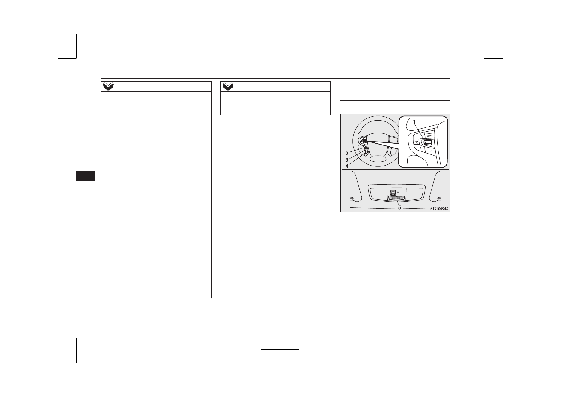
NOTE
l
If the operation mode is left in ACC, the ac-
cessory power will automatically turn off af-
ter a certain period of time and you will no
longer be able to use the Bluetooth
®
2.0 in-
terface. The accessory power comes on
again if the power switch is operated.
Refer to “ACC power auto-cutout function”
on page 7-13.
l
The Bluetooth
®
2.0 interface cannot be used
if the Bluetooth
®
device has a flat battery or
the device power is turned off.
l
Hands-free calls will not be possible if your
phone does not have service available.
l
If you place the Bluetooth
®
device in the
luggage compartment, you may not be able
to use the Bluetooth
®
2.0 interface.
l
Some Bluetooth
®
devices are not compatible
with the Bluetooth
®
2.0 interface.
l
You can confirm the Link System software
version by pressing the HANG-UP button 3
times (press and hold 2 times and then press
briefly) within 10 seconds.
l
For details on the Bluetooth
®
2.0 interface,
you can see them by accessing the
MITSUBISHI MOTORS website.
Please read and agree on the “Warning about
Links to the Web Sites of Other Companies”
because it connects to other than
MITSUBISHI MOTORS website.
http://www.mitsubishi-motors.com/en/prod-
ucts/index.html
NOTE
l
Software updates by cellular phone/digital
audio device manufacturers may change/
alter device connectivity.
Steering control switch and microphone
® p. 8-52
Voice recognition function ® p. 8-53
Useful voice commands ® p. 8-54
Speaker enrollment function ® p. 8-56
Connecting the Bluetooth® 2.0 interface and
Bluetooth® device ® p. 8-57
Operating a music player connected via Blue-
tooth® ® p. 8-62
How to make or receive hands-free calls
® p. 8-62
Phone book function ® p. 8-65
Steering control switch and mi-
crophone
E00727201451
1- Volume up/down switch
2- SPEECH button
3- PICK-UP button
4- HANG-UP button
5- Microphone
Volume up switch
Push up this switch to increase the volume.
Volume down switch
Push down this switch to decrease the vol-
ume.
Bluetooth
®
2.0 interface*
8-52
OGGE19E1
For pleasant driving
8
SPEECH button
l
Press this button to change to voice rec-
ognition mode.
While the system is in voice recognition
mode, “Listening” will appear on the au-
dio display.
l
If you press the button briefly while in
voice recognition mode, it will interrupt
prompting and allow voice command in-
put.
Pressing the button longer will deacti-
vate the voice recognition mode.
l
Pressing this button briefly during a call
will enable voice recognition and allow
voice command input.
PICK-UP button
l
Press this button when an incoming call
is received to answer the telephone.
l
When another call is received during a
call, press this button to put the first call-
er on hold and talk to the new caller.
• In such circumstances, you can press
the button briefly to switch between
callers. You will switch to the first
caller and the other caller will be put
on hold.
• To establish a three-way call in such
situations, press the SPEECH button
to enter voice recognition mode and
then say “Join calls”.
HANG-UP button
l
Press this button when an incoming call
is received to refuse the call.
l
Press this button during a call to end the
current call.
When another call is on hold, you will
switch to that call.
l
If this button is pressed in the voice rec-
ognition mode, the voice recognition
mode will be deactivated.
NOTE
l
When you press the SPEECH button to enter
voice recognition mode with a cellular
phone paired to the system, current informa-
tion on the cellular phone, such as “remain-
ing battery life,” “signal strength” or “roam-
ing,” will be displayed on the audio dis-
play.*
*: Some cellular phones will not send this
information to the Bluetooth
®
2.0 interface.
l
Call waiting and three-way calls can be used
by the Bluetooth
®
2.0 interface, only if it is
possible to use those services with your cel-
lular phone.
Microphone
Your voice will be recognized by a micro-
phone in the overhead console, allowing you
to make hands-free calls with voice com-
mands.
NOTE
l
If a cellular phone is brought close to the mi-
crophone, it may create noise in the voice on
the phone. In such a case, take the cellular
phone at a place as far as possible from the
microphone.
Voice recognition function
E00727300514
The Bluetooth
®
2.0 interface is equipped
with a voice recognition function.
Simply say voice commands and you can
perform various operations and make or re-
ceive hands-free calls.
With the Bluetooth
®
2.0 interface, voice rec-
ognition is possible for English, French,
Spanish, Italian, German, Dutch, Portuguese
and Russian. The factory setting is “English”
or “Russian.”
NOTE
l
If the voice command that you say differs
from the predefined command or cannot be
recognised due to ambient noise or some
other reason, the Bluetooth
®
2.0 interface
will ask you for the voice command again up
to 3 times.
Bluetooth
®
2.0 interface*
8-53
OGGE19E1
For pleasant driving
8
NOTE
l
For best performance and further reduction
of ambient noise, close the vehicle windows,
lower the blower speed and refrain from
conversation with your passengers while en-
gaging the voice recognition function.
l
Some voice commands have alternative
commands.
l
Depending on the selected language, some
functions may not be available.
Selecting the Language
1. Press the SPEECH button.
2. Say “Setup”.
3. Say “Language.”
4. The voice guide will say “Select a lan-
guage: English, French, Spanish, Italian,
German, Dutch, Portuguese or Russian”
Say the desired language. (Example: Say
“English.”)
5. The voice guide will say “English
(French, Spanish, Italian, German,
Dutch, Portuguese or Russian) selected.
Is this correct?” Say “Yes.”
Answer “No” to return to Step 4.
NOTE
l
The voice guide will repeat the same mes-
sage twice. The first message is in the cur-
rent language, and the second message is in
the selected language.
NOTE
l
If many entries are registered in the vehicle
phone book, changing the language will take
longer.
l
Changing the language deletes the mobile
phone book imported to the Bluetooth
®
2.0
interface. If you wish to use it, you will have
to import it again.
6. When the voice guide says “English
(French, Spanish, Italian, German,
Dutch, Portuguese or Russian) selected,”
the language change process will be
completed and the system will return to
the main menu.
Useful voice commands
E00760000019
Help function
E00760100010
The Bluetooth
®
2.0 interface is equipped
with a help function.
If you say “Help” when the system is waiting
for a voice command input, the system will
tell you a list of the commands that can be
used under the circumstances.
Cancelling
E00760201021
There are two cancel functions.
If you are at the main menu, say “Cancel” to
exit from the Bluetooth
®
2.0 interface.
If you are anywhere else within the system,
say “Cancel” to return to the main menu.
NOTE
l
You can return to the previous menu by say-
ing “Go Back.” (if so equipped)
Confirmation function setting
E00760400013
The Bluetooth
®
2.0 interface is equipped
with a confirmation function.
With the confirmation function activated, you
are given more opportunities than normal to
confirm a command when making various
settings to the Bluetooth
®
2.0 interface. This
allows you to decrease the possibility that a
setting is accidentally changed.
The confirmation function can be turned on
or off by following the steps below.
1. Press the SPEECH button.
2. Say “Setup”.
3. Say “Confirmation prompts”.
4. The voice guide will say “Confirmation
prompts are <on/off>. Would you like to
turn confirmation prompts <off/on>”.
Answer “Yes” to change the setting or
answer “No” to keep the current setting.
5. The voice guide will say “Confirmation
prompts are <off/on>” and then the sys-
tem will return to the main menu.
Bluetooth
®
2.0 interface*
8-54
OGGE19E1
For pleasant driving
8
Security function
E00760501242
It is possible to use a password as a security
function by setting a password of your choice
for the Bluetooth
®
2.0 interface.
When the security function is turned on, it is
necessary to make a voice input of a 4-digit
password in order to use all functions of the
Bluetooth
®
2.0 interface, except for recep-
tion.
Setting the password
Use the following procedure to turn on the
security function by setting a password.
1. Press the SPEECH button.
2. Say “Setup”.
3. Say “Password.”
4. The voice guide will say “Password is
disabled. Would you like to enable it?”
Answer “Yes.”
Answer “No” to cancel the setting of the
password and return to the main menu.
5. The voice guide will say “Please say a 4-
digit password. Remember this pass-
word. It will be required to use this sys-
tem”.
Say a 4-digit number which you want to
set as a password.
6. For confirmation purposes, the voice
guide will say “Password <4-digit pass-
word>. Is this correct?” Answer “Yes.”
Answer “No” to return to the password
input in Step 5.
7. When the registration of the password is
completed, the voice guide will say
“Password is enabled” and the system
will return to the main menu.
NOTE
l
After activating Plug-in Hybrid EV system
again and pressing SPEECH button, you are
asked to tell your password.
l
The set password is actually recorded in the
Link system after a while after the ready in-
dicator goes out.
If you set the operation mode to ACC or ON
or activate Plug-in Hybrid EV system soon
after the ready indicator goes out, the set
password may not be recorded in the Link
system in some cases. In such a case, set
your password again.
Entering the password
If a password has been set and the security
function is enabled, the voice guide will say
“Hands-free system is locked. State the pass-
word to continue” when the SPEECH button
is pressed to enter voice recognition mode.
Say the 4-digit password number to enter the
password.
If the entered password is wrong, the voice
guide will say “<4- digit password>, Incor-
rect password. Please try again”. Enter the
correct password.
NOTE
l
You can re-enter the password as many
times as you want.
l
If you have forgotten your password, say
“Cancel” to quit the voice input mode and
then check with a MITSUBISHI MOTORS
Authorized Service Point.
Disabling the password
Use the following procedure to turn off the
security function by disabling the password.
NOTE
l
System must be unlocked to disable the
password.
1. Press the SPEECH button.
2. Say “Setup”.
3. Say “Password.”
4. The voice guide will say “Password is
enabled. Would you like to disable it?”
Answer “Yes.”
Answer “No” to cancel the disabling of
the password and return to the main
menu.
5. When the disabling of the password is
completed, the voice guide will say
“Password is disabled” and the system
will return to the main menu.
Bluetooth
®
2.0 interface*
8-55
OGGE19E1
For pleasant driving
8
Speaker enrollment function
E00727400209
The Bluetooth
®
2.0 interface can use the
speaker enrollment function to create a voice
model for one person per language.
This makes it easier for the Bluetooth
®
2.0
interface to recognise voice commands said
by you.
You can turn a voice model registered with
the speaker enrollment function on and off
whenever you want.
Speaker enrollment
E00727501294
It takes about 2 to 3 minutes to complete the
speaker enrollment process.
To ensure the best results, run through the
process while in the driver’s seat, in an envi-
ronment that is as quiet as possible (when
there is no rain or strong winds and the vehi-
cle windows are closed). Please turn off your
phone while in speaker enrollment to prevent
interruption of the process.
Use the following procedure for speaker en-
rollment.
1. Stop your vehicle in a safe area, firmly
apply the parking brake and push the
electrical parking switch.
NOTE
l
Speaker enrollment is not possible unless the
vehicle is parked. Make sure you park the
vehicle in a safe area before attempting
speaker enrollment.
2. Press the SPEECH button.
3. Say “Voice training”.
4. The voice guide will say “This operation
must be performed in a quiet environ-
ment while the vehicle is stopped. See
the owner’s manual for the list of re-
quired training phrases. Press and re-
lease the SPEECH button when you are
ready to begin. Press the HANG-UP but-
ton to cancel at any time”.
Press the SPEECH button to start the
speaker enrollment process.
NOTE
l
If you do not start the speaker enrollment
process within 3 minutes of pressing the
SPEECH button, the speaker enrollment
function will time out.
The voice guide will say “Speaker Enroll-
ment has timed out”. The system will then
beep and the voice recognition mode will be
deactivated.
5. The voice guide will prompt for phrase
1. Repeat the corresponding phrase lis-
ted in table “Enrollment commands” on
page 8-71.
The system will register your voice and
then move on to the registration of the
next command. Continue the process un-
til all phrases have been registered.
NOTE
l
To repeat the most recent voice training
command, press and release the SPEECH
button.
l
If you press the HANG-UP button anytime
during the process, the system will beep and
stop the speaker enrollment process.
6. When all enrollment commands have
been read out, the voice guide will say
“Speaker enrollment is complete”. The
system will then end the speaker enroll-
ment process and return to the main
menu.
NOTE
l
Completing the speaker enrollment process
will turn on the voice model automatically.
l
The commands “Help” and “Cancel” will
not work in this mode.
Bluetooth
®
2.0 interface*
8-56
OGGE19E1
For pleasant driving
8
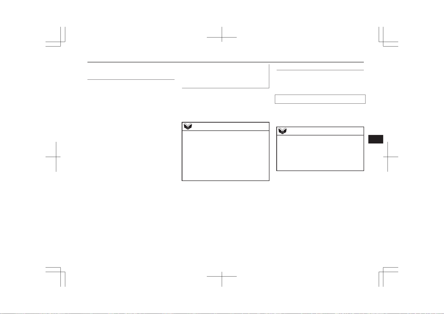
Enabling and disabling the
voice model and retraining
E00727600096
You can turn a voice model registered with
the speaker enrollment function on and off
whenever you want.
You can also retrain the system.
Use the following procedure to perform these
actions.
1. Press the SPEECH button.
2. Say “Voice training”.
3. If you have completed a speaker enroll-
ment process once already, the voice
guide will say either “Enrollment is ena-
bled. Would you like to disable or re-
train?” or “Enrollment is disabled.
Would you like to enable or retrain?”
4. When enrollment is “enabled”, the voice
model is on; when enrollment is “disa-
bled”, the voice model is off. Say the
command that fits your needs.
Say “Retrain” to start the speaker enroll-
ment process and recreate a new voice
model. (Refer to “Speaker enrollment”
on page 8-56.)
Connecting the Bluetooth
®
2.0
interface and Bluetooth
®
de-
vice
E00760601663
Before you can make or receive hands-free
calls or play music using the Bluetooth
®
2.0
interface function, you must pair the Blue-
tooth
®
device and Bluetooth
®
2.0 interface.
NOTE
l
Pairing is required only when the device is
used for the first time. Once the device has
been paired with the Bluetooth
®
2.0 inter-
face, all you need is to bring the device into
the vehicle next time and the device will
connect to the Bluetooth
®
2.0 interface auto-
matically (if supported by the device). The
device must have Bluetooth
®
turned ON to
connect.
Up to 7 Bluetooth
®
devices can be paired
with the Bluetooth
®
2.0 interface.
If multiple paired Bluetooth
®
devices are
available in the vehicle, the cellular phone or
music player most recently connected is auto-
matically connected to the Bluetooth
®
2.0 in-
terface.
You can also change a Bluetooth
®
device to
be connected.
To pair
To pair a Bluetooth
®
device with the Blue-
tooth
®
2.0 interface, use either one of the fol-
lowing 2 methods (Type 1 or Type 2).
Pairing procedure - Type 1*
1. Stop your vehicle in a safe area, firmly
apply the parking brake and push the
electrical parking switch.
NOTE
l
You cannot pair any Bluetooth
®
device with
the Bluetooth
®
2.0 interface unless the vehi-
cle is parked. Before pairing a Bluetooth
®
device with the Bluetooth
®
2.0 interface,
confirm that the vehicle is parked in a safe
location.
2. Press the SPEECH button.
3. Say “Setup”.
4. Say “Pairing Options.”
5. The voice guide will say “Select one of
the following: pair, edit, delete, or list.”
Say “Pair.”
Bluetooth
®
2.0 interface*
8-57
OGGE19E1
For pleasant driving
8
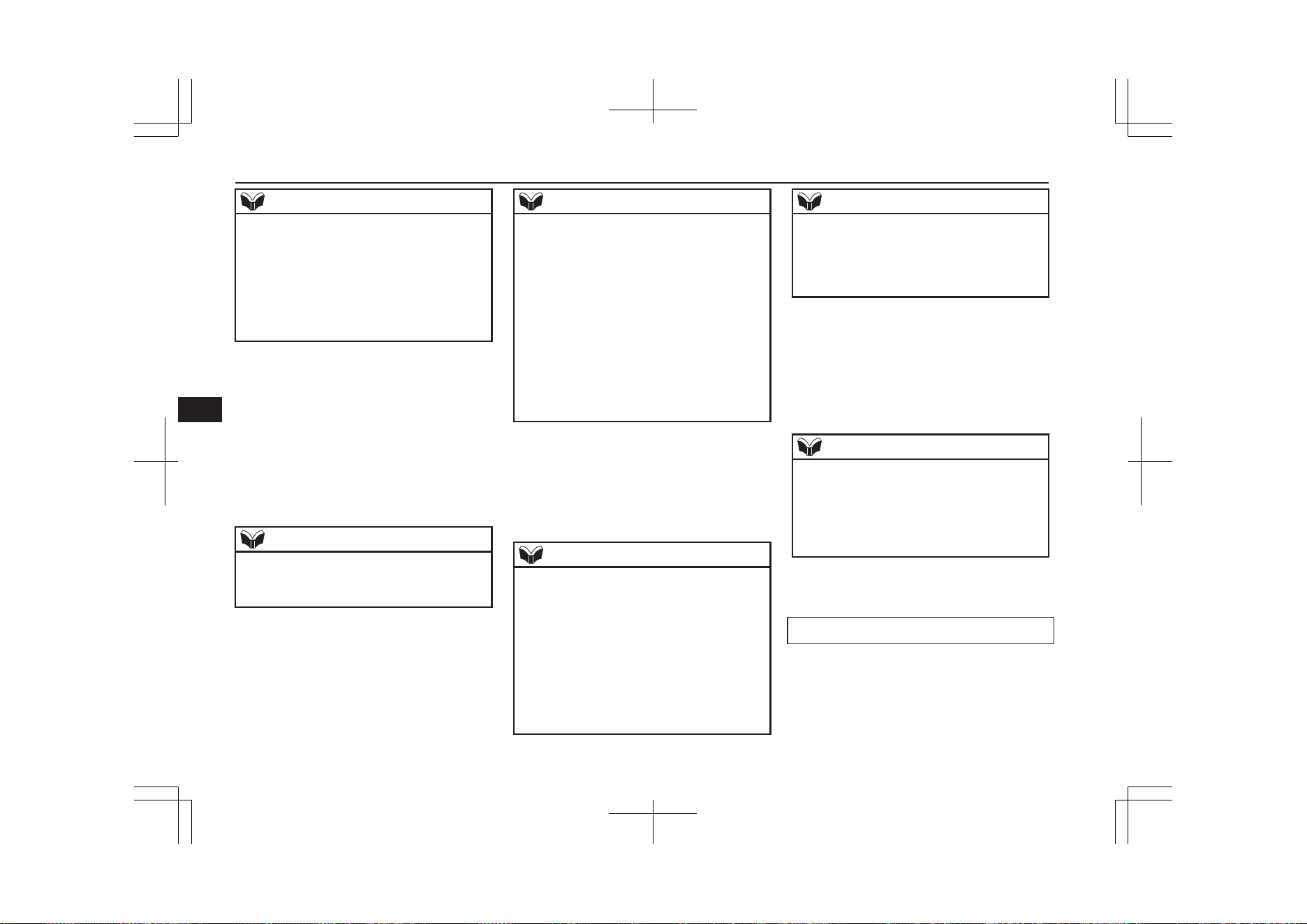
NOTE
l
If 7 devices have already been paired, the
voice guide will say “Maximum devices
paired” and then the system will end the
pairing process. To register a new device,
delete one device and then repeat the pairing
process.
(Refer to “Selecting a device: Deleting a de-
vice” on page 8-60.)
6. The voice guide will say “Please say a 4-
digit pairing code.” Say a 4-digit num-
ber.
When the confirmation function is on,
the system will confirm whether the
number said is acceptable. Answer
“Yes.”
Answer “No” to return to pairing code
selection.
NOTE
l
Some Bluetooth
®
devices require a specific
pairing code. Please refer to the device man-
ual for pairing code requirements.
NOTE
l
The pairing code entered here is only used
for the Bluetooth
®
connection certification.
It is any 4-digit number the user would like
to select.
Remember the pairing code as it needs to be
keyed into the Bluetooth
®
device later in the
pairing process.
Depending on the connection settings of the
Bluetooth
®
device, this code may have to be
entered each time you connect the Blue-
tooth
®
device to the Bluetooth
®
2.0 inter-
face. For the default connection settings, re-
fer to the instructions for the device.
7. The voice guide will say “Start pairing
procedure on the device. See the device
manual for instructions.” Enter in the
Bluetooth
®
device the 4-digit number
you have registered in Step 6.
NOTE
l
According to the corresponding device to
Bluetooth
®
, it might take a few minute to
pair the Bluetooth
®
device with the Blue-
tooth
®
2.0 interface.
l
If the Bluetooth
®
2.0 interface cannot recog-
nize the Bluetooth
®
device, the voice guide
will say “Pairing has timed out” and the
pairing process will be cancelled.
Confirm that the device you are pairing sup-
ports Bluetooth
®
, and try pairing it again.
NOTE
l
If you enter the wrong number, the voice
guide will say “Pairing failed” and the pair-
ing process will be cancelled.
Confirm the number is right, and try pairing
it again.
8. The voice guide will say “Please say the
name of the device after the beep.” You
can assign a desired name for the Blue-
tooth
®
device and register it as a device
tag. Say the name you want to register
after the beep.
NOTE
l
When the confirmation function is on, after
repeating the device tag you have said, the
voice guide will ask “Is this correct?” An-
swer “Yes.”
To change the device tag, answer “No” and
then say the device tag again.
9. The voice guide will say “Pairing com-
plete,” and the pairing process will end.
Pairing procedure - Type 2*
1. Stop your vehicle in a safe area, firmly
apply the parking brake and push the
electrical parking switch.
Bluetooth
®
2.0 interface*
8-58
OGGE19E1
For pleasant driving
8
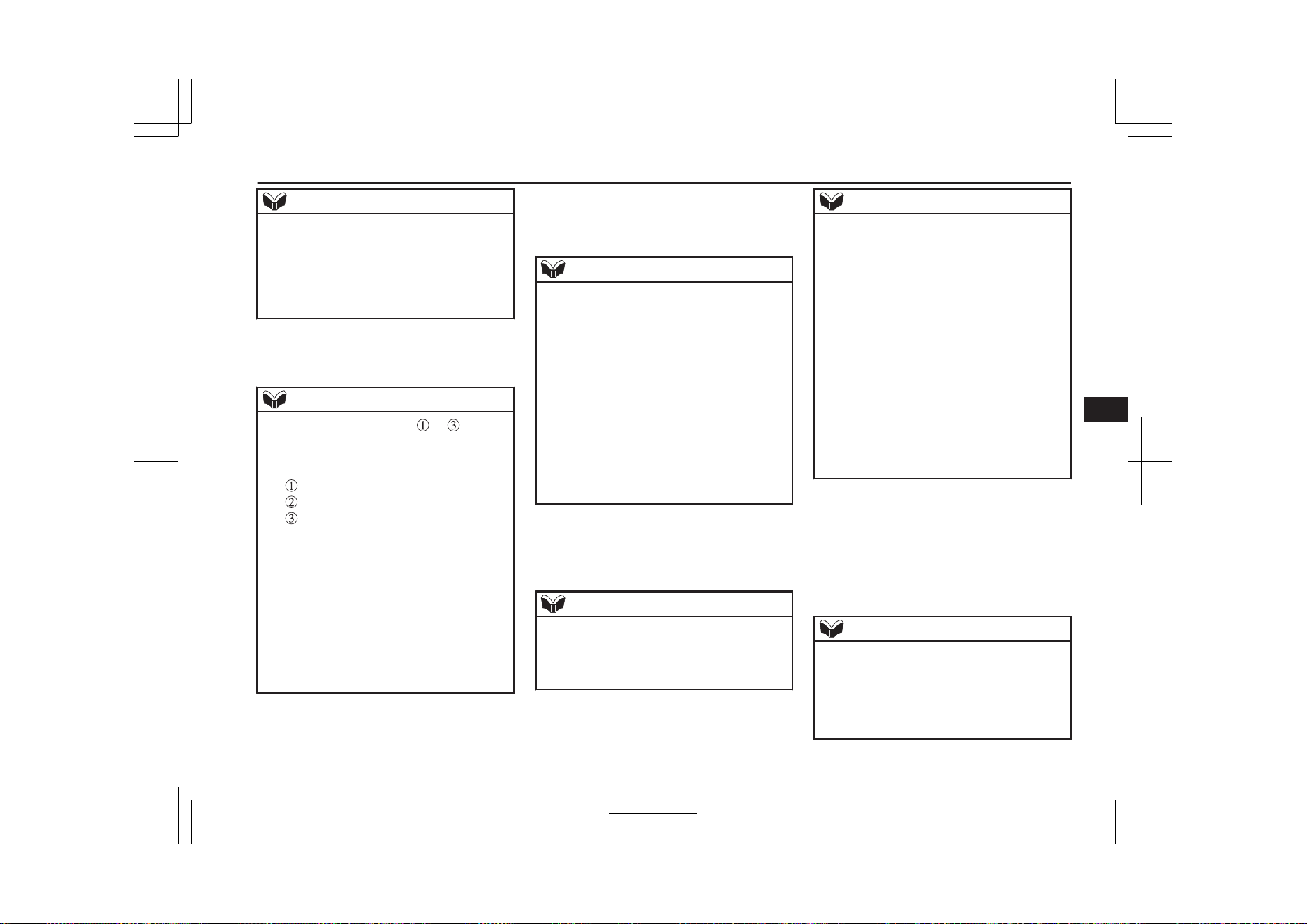
NOTE
l
You cannot pair any Bluetooth
®
device with
the Bluetooth
®
2.0 interface unless the vehi-
cle is parked. Before pairing a Bluetooth
®
device with the Bluetooth
®
2.0 interface,
confirm that the vehicle is parked in a safe
location.
2. Press the SPEECH button.
3. Say “Pair Device.”
NOTE
l
The following procedure ( to ) can also
be used instead of saying “Pair Device.”
Replace this step 3 with the following proce-
dure if you prefer.
Say “Setup.”
Say “Pairing Options.”
The voice guide will say “Select one of
the following: pair, edit, delete, list or set
code.”
Say “Pair.”
l
If 7 devices have already been paired, the
voice guide will say “Maximum devices
paired” and then the system will end the
pairing process. To register a new device,
delete one device and then repeat the pairing
process.
(Refer to “Selecting a device: Deleting a de-
vice” on page 8-60.)
4. The voice guide will say “Start pairing
procedure on the device. See the device
manual for instructions.” and then will
say “The pairing code is <pairing
code>.”
NOTE
l
Some Bluetooth
®
devices require a specific
pairing code.
Please refer to the device manual for pairing
code requirements and read the next section
“If your device requires a specific pairing
code” on page 8-60 to set the pairing code.
l
The pairing code entered here is only used
for the Bluetooth
®
connection certification.
Depending on the connection settings of the
Bluetooth
®
device, this code may have to be
entered each time you connect the Blue-
tooth
®
device to the Bluetooth
®
2.0 inter-
face. For the default connection settings, re-
fer to the instructions for the device.
5.
Enter in the Bluetooth
®
device the 4-dig-
it number that has been read out in Step
4.
NOTE
l
According to the corresponding device to
Bluetooth
®
, it might take a few minute to
pair the Bluetooth
®
device with the Blue-
tooth
®
2.0 interface.
NOTE
l
If the Bluetooth
®
2.0 interface cannot recog-
nize the Bluetooth
®
device, the voice guide
will say “Pairing has timed out” and the
pairing process will be cancelled.
Confirm that the device you are pairing sup-
ports Bluetooth
®
, and try pairing it again.
l
If you enter the wrong number, the voice
guide will say “Pairing failed” and the pair-
ing process will be cancelled.
Confirm the number is right, and try pairing
it again.
If your device requires a specific pairing
code, you need to set the pairing code. Refer
to the device manual for pairing code re-
quirements and read the next section “If
your device requires a specific pairing code”
on page 8-60.
6. The voice guide will say “Please say the
name of the device after the beep.” You
can assign a desired name for the Blue-
tooth
®
device and register it as a device
tag. Say the name you want to register
after the beep.
NOTE
l
When the confirmation function is on, after
repeating the device tag you have said, the
voice guide will ask “Is this correct?” An-
swer “Yes.”
To change the device tag, answer “No” and
then say the device tag again.
Bluetooth
®
2.0 interface*
8-59
OGGE19E1
For pleasant driving
8
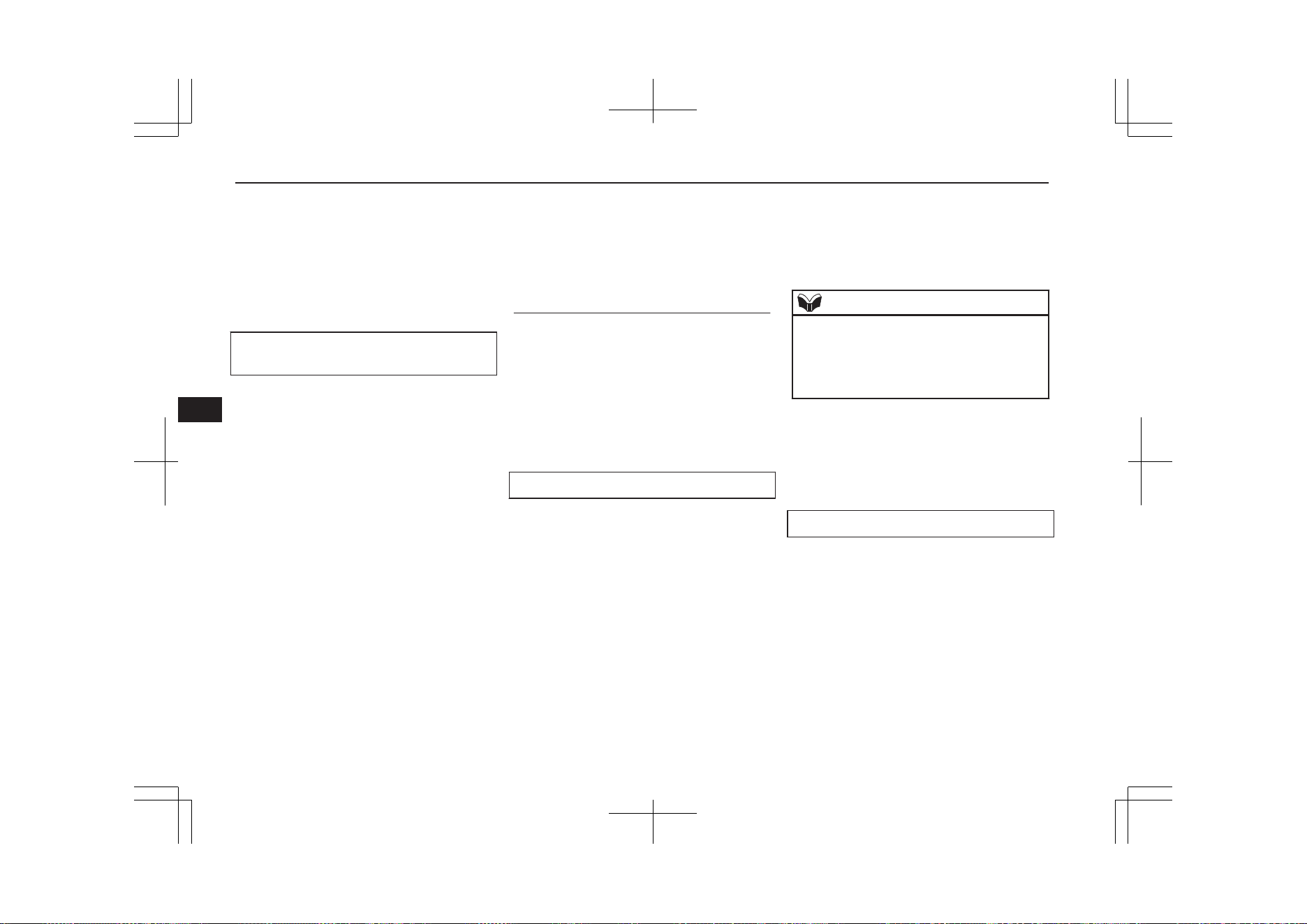
7. The voice guide will say “Pairing Com-
plete. Would you like to import the con-
tacts from your mobile device now?”
Answer “Yes,” and the voice guide will
say “Please wait while the contacts are
imported. This may take several mi-
nutes.” Answer “No” to end the pairing
process.
If your device requires a specific pairing
code
If your device requires a specific pairing
code, you need to set the pairing code. Fol-
low the procedures below.
1. Press the SPEECH button.
2. Say “Setup.”
3. Say “Pairing Options.”
4. Say “Set Code.”
5. The voice guide will say “Do you want
the pairing code to be random or fixed?”
Say “Fixed.”
6. The voice guide will say “Please say a 4-
digit pairing code.” Say a 4-digit num-
ber.
7. The voice guide will say “Pairing code
set to <pairing code>.”
When the confirmation function is on,
the system will confirm whether the
number said is acceptable. Answer
“Yes.”
Answer “No” to return to Step 6.
8. The voice guide will say “Do you want
to pair a device now?” Answer “Yes,”
the system will proceed to Step 3 in the
pairing process. Refer to the “Pairing
procedure- Type 2.”
Selecting a device
E00760700104
If multiple paired Bluetooth
®
devices are
available in the vehicle, the cellular phone or
music player most recently connected is auto-
matically connected to the Bluetooth
®
2.0 in-
terface.
You can connect to the other paired cellular
phone or music player by following setting
change procedures.
To select a cellular phone
1. Press the SPEECH button.
2. Say “Setup”.
3. Say “Select phone.”
4. After the voice guide says “Please say,”
the numbers of the cellular phones and
device tags of corresponding cellular
phones will be read out in order, starting
with the cellular phone that has been
most recently connected.
Say the number of the cellular phone
that you want to connect to.
When the confirmation function is on,
the system will ask you again whether
the phone that you want to connect to is
correct. Answer “Yes” to continue and
connect to the cellular phone.
Answer “No,” and the voice guide will
say “Please say.” Say the number of the
phone that you want to connect to.
NOTE
l
You can connect to a phone at any time by
pressing the SPEECH button and saying the
number, even before all of the paired num-
bers and device tags of corresponding cellu-
lar phones are read out by the system.
5. The selected phone will be connected to
the Bluetooth
®
2.0 interface. The voice
guide will say “<device tag> selected”
and then the system will return to the
main menu.
To select a music player
1. Press the SPEECH button.
2. Say “Setup”.
3. Say “Select music player.”
4. After the voice guide says “Please say,”
the numbers of the music players and de-
vice tags of corresponding music players
will be read out in order, starting with
the music player that has been most re-
cently connected.
Say the number of the music player that
you want to connect to.
Bluetooth
®
2.0 interface*
8-60
OGGE19E1
For pleasant driving
8
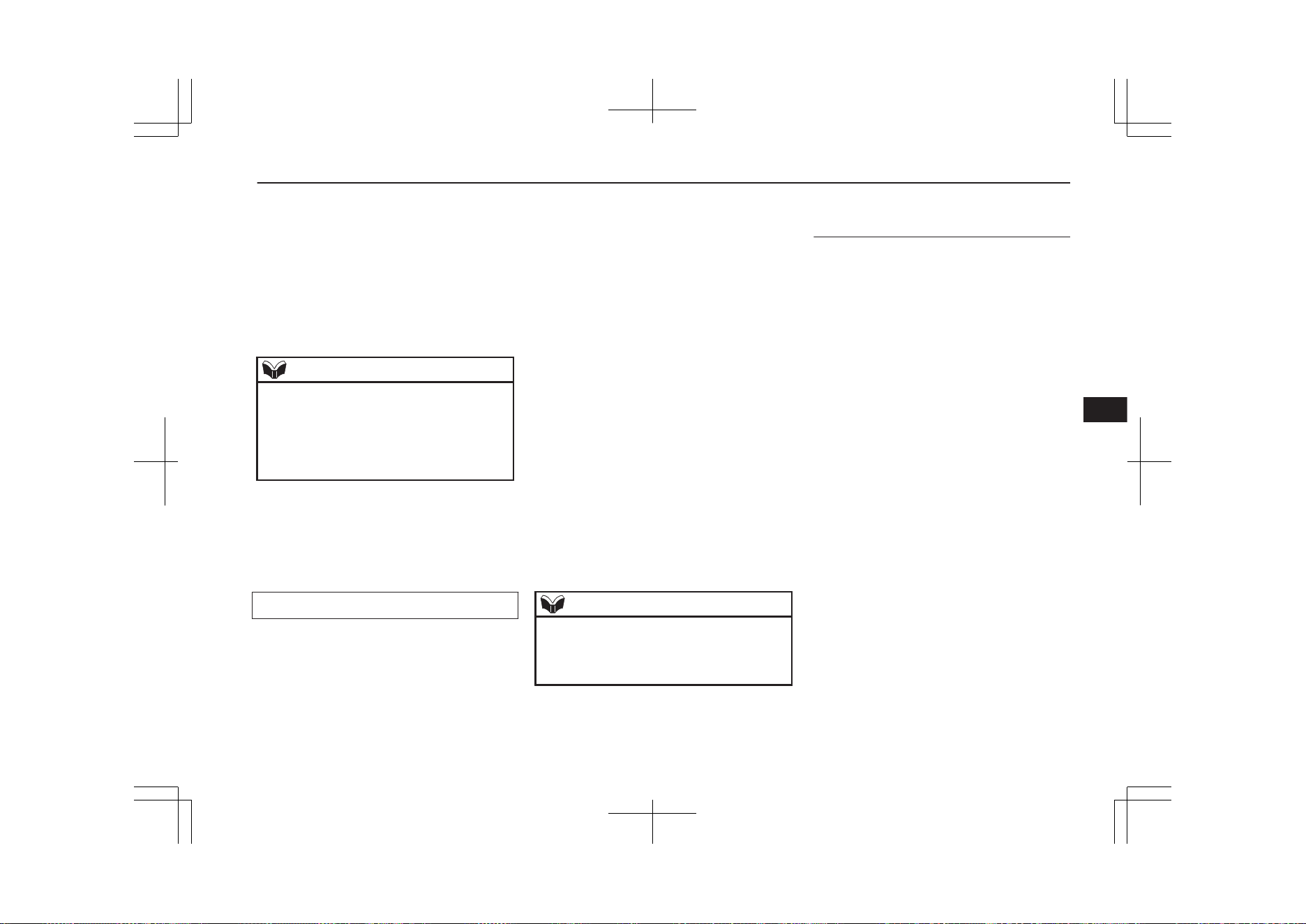
When the confirmation function is on,
the system will ask you again whether
the music player that you want to con-
nect to is correct. Answer “Yes” to con-
tinue and connect to the music player.
Answer “No,” and the voice guide will
say “Please say.” Say the number of the
music player that you want to connect
to.
NOTE
l
You can connect to a music player at any
time by pressing the SPEECH button and
saying the number, even before all of the
paired numbers and device tags of corre-
sponding music players are read out by the
system.
5. The selected music player will be con-
nected to the Bluetooth
®
2.0 interface.
The voice guide will say “<device tag>
selected” and then the system will return
to the main menu.
Deleting a device
Use the following procedure to delete a
paired Bluetooth
®
device from the Blue-
tooth
®
2.0 interface.
1. Press the SPEECH button.
2. Say “Setup”.
3. Say “Pairing options.”
4. The voice guide will say “Select one of
the following: pair, edit, delete, or list.”
Say “Delete.”
5. After the voice guide says “Please say,”
the numbers of the devices and device
tags of corresponding devices will be
read out in order, starting with the device
that has been most recently connected.
After it completes reading all pairs, the
voice guide will say “or all.”
Say the number of the device that you
want to delete from the system.
If you want to delete all paired phones
from the system, say “All.”
6. For confirmation purposes, the voice
guide will say “Deleting <device tag>
<number>. Is this correct?” or “Deleting
all devices. Is this correct?”
Answer “Yes” to delete the phone(s).
Answer “No” to return to Step 4.
7. The voice guide will say “Deleted,” and
then the system will end the device dele-
tion process.
NOTE
l
If the device deletion process fails for some
reason, the voice guide will say “Delete
failed” and then the system will cancel delet-
ing the device.
To check a paired Bluetooth
®
device
E00760800017
You can check a paired Bluetooth
®
device by
following the steps below.
1. Press the SPEECH button.
2. Say “Setup”.
3. Say “Pairing options.”
4. The voice guide will say “Select one of
the following: pair, edit, delete, or list.”
Say “List.”
5. The voice guide will read out device tags
of corresponding devices in order, start-
ing with the Bluetooth
®
device that has
been connected most recently.
6. After the device tags of all paired Blue-
tooth
®
devices have been read, the sys-
tem will say “End of list, would you like
to start from the beginning?”
To hear the list again from the begin-
ning , answer “Yes.”
When you are done, answer “No” to re-
turn to the main menu.
Bluetooth
®
2.0 interface*
8-61
OGGE19E1
For pleasant driving
8
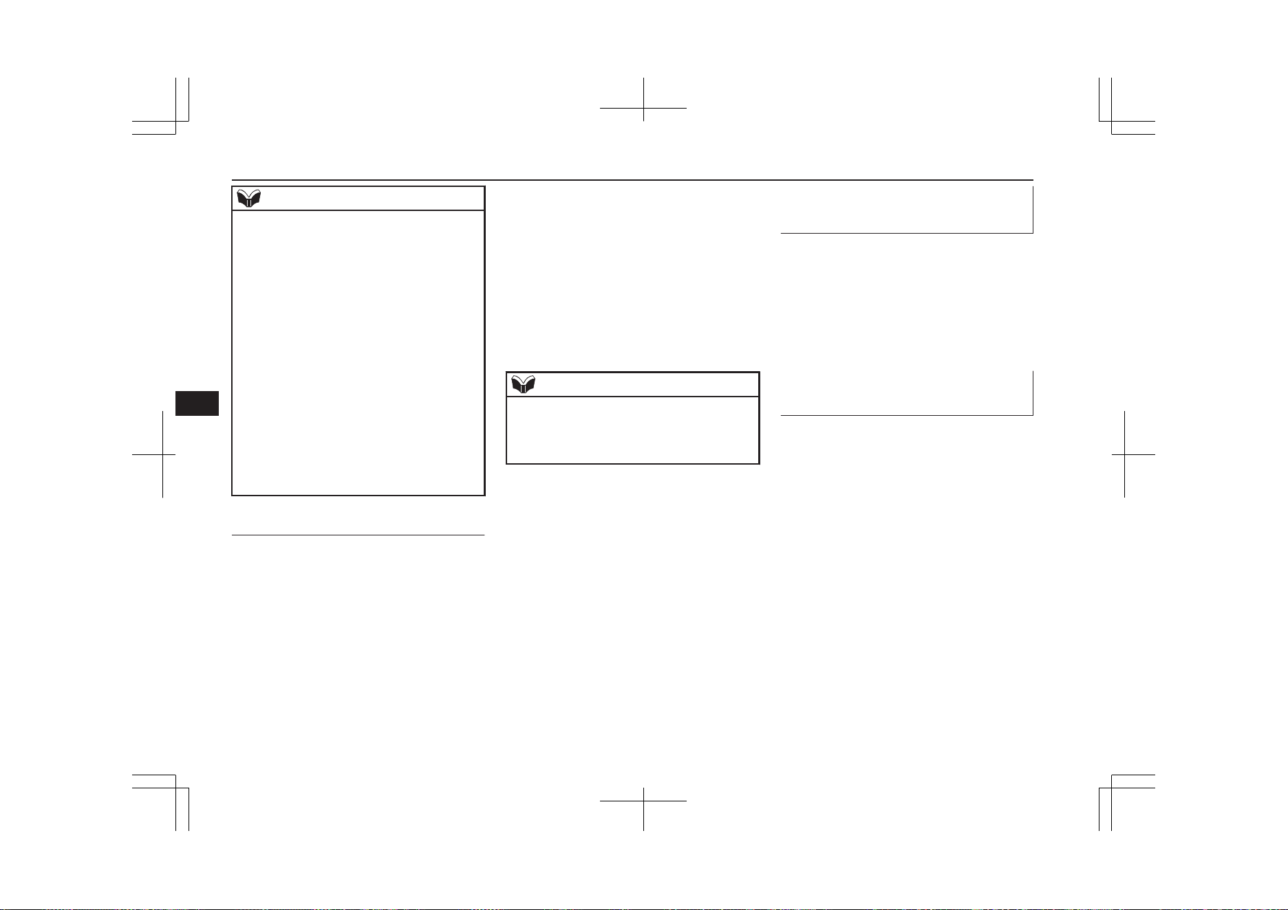
NOTE
l
If you press and release the SPEECH button
and say “Continue” or “Previous” while the
list is being read, the system will advance or
rewind the list.
Say “Continue” to proceed to the device
with the next highest number or “Previous”
to return to the phone with the previous
number.
l
You can change the device tag by pressing
and releasing the SPEECH button and then
saying “Edit” while the list is being read.
l
You can change the phone to be connected
by pressing and releasing the SPEECH but-
ton and then saying “Select phone” while the
list is being read.
l
You can change the music player to be con-
nected by pressing and releasing the
SPEECH button and then saying “Select mu-
sic player” while the list is being read.
Changing a device tag
E00760900018
You can change the device tag of a paired
cellular phone or music player.
Follow the steps below to change a device
tag.
1. Press the SPEECH button.
2. Say “Setup”.
3. Say “Pairing options.”
4. The voice guide will say “Select one of
the following: pair, edit, delete, or list.”
Say “Edit.”
5. The voice guide will say “Please say,”
and read out the numbers of the Blue-
tooth
®
devices and device tags of corre-
sponding devices in order, starting with
the Bluetooth
®
that has been most re-
cently connected.
After all paired device tags have been
read, the voice guide will say “Which
device, please?” Say the number of the
device tag you want to change.
NOTE
l
You can press and release the SPEECH but-
ton while the list is being read, and immedi-
ately say the number of the device tag you
want to change.
6. The voice guide will say “New name,
please.” Say the name you want to regis-
ter as a new device tag.
When the confirmation function is on,
the voice guide will say “<New device
tag>. Is this correct?” Answer “Yes.”
Answer “No,” to say the new device tag
you want to register again.
7. The device tag is changed.
When the change is complete, the voice
guide will say “New name saved” and
then the system will return to the main
menu.
Operating a music player con-
nected via Bluetooth
®
E00761001462
For the operation of a music player connected
via Bluetooth
®
, refer to “Listen to Bluetooth
Audio” on page 8-40. On vehicles equipped
with MITSUBISHI Multi-Communication
System (MMCS), the Smartphone Link Dis-
play Audio or the DISPLAY AUDIO, refer to
the separate owner’s manual.
How to make or receive hands-
free calls
E00761100059
You can make or receive hands-free calls us-
ing a Bluetooth
®
compatible cellular phone
connected to the Bluetooth
®
2.0 interface.
You can also use the phone books in the
Bluetooth
®
2.0 interface to make calls with-
out dialling telephone numbers.
“To make a call” on page 8-63
“SEND function” on page 8-64
“Receiving calls” on page 8-64
“MUTE function” on page 8-64
“Switching between hands-free mode and
private mode” on page 8-65
Bluetooth
®
2.0 interface*
8-62
OGGE19E1
For pleasant driving
8
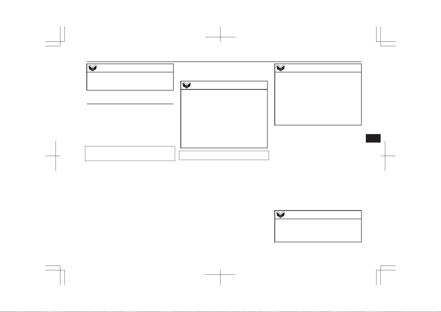
NOTE
l
The hands-free calls might not be operated
correctly when it makes calling or receiving
by operating the cellular phone directly.
To make a call
E00761200148
You can make a call in the following 3 ways
using the Bluetooth
®
2.0 interface:
Making a call by saying a telephone number,
making a call using the Bluetooth
®
2.0 inter-
face’s phone book, and making a call by re-
dialing.
Making a call by using the telephone num-
ber
You can make a call by saying the telephone
number.
1. Press the SPEECH button.
2. Say “Dial.”
3. After the voice guide says “Number
please,” say the telephone number.
4. The voice guide will say “Dialing <num-
ber recognised>.”
The Bluetooth
®
2.0 interface will then
make the call.
When the confirmation function is on,
the system will confirm again the tele-
phone number. To continue with that
number, answer “Yes.”
To change the telephone number, answer
“No.” The system will say “Number
please” then say the telephone number
again.
NOTE
l
In the case of English, the system will recog-
nise both “zero” and “oh” (Letter “o”) for
the number “0.”
l
The Bluetooth
®
2.0 interface supports num-
bers (0 to 9) and characters (+, # and*).
l
The maximum supported telephone number
length is as follows:
•
International telephone number: + and tel-
ephone numbers (to 18 digits).
•
Except for international telephone num-
ber: telephone numbers (to 19 digits).
Making a call using a phone book
You can make calls using the vehicle phone
book or mobile phone book of the Blue-
tooth
®
2.0 interface.
For details on the phone books, refer to
“Phone book function” on page 8-65.
1. Press the SPEECH button.
2. Say “Call.”
NOTE
l
If you say “Call” when the vehicle phone
book and the mobile phone book are empty,
the voice guide will say “The vehicle phone
book is empty. Would you like to add a new
entry now?”
Answer “Yes,” and the voice guide will say
“Entering the phone book - new entry
menu.” You can now create data in the vehi-
cle phone book.
Answer “No,” to return to the main menu.
3. After the voice guide says “Name
please,” say the name you want to call,
from those registered in the phone book.
4. If there is only one match, the system
proceeds to Step 5.
If there are two or more matches, the
voice guide will say “More than one
match was found, would you like to call
<returned name>.” If that person is the
one you want to call, answer “Yes.”
Answer “No,” and the name of the next
matching person will be uttered by the
voice guide.
NOTE
l
If you say “No” to all names read by the sys-
tem, the voice guide will say “Name not
found, returning to main menu” and the sys-
tem will return to the main menu.
Bluetooth
®
2.0 interface*
8-63
OGGE19E1
For pleasant driving
8
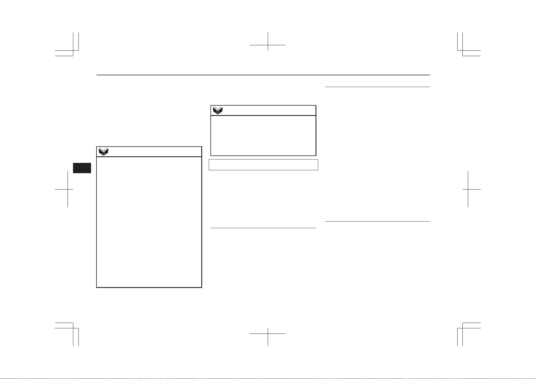
5. If only one telephone number is regis-
tered under the name you just said, the
voice guide proceeds to Step 6.
If two or more telephone numbers are
registered that match the name you just
said, the voice guide will say “Would
you like to call <name> at [home],
[work], [mobile], or [other]?” Select the
location to call.
NOTE
l
If the name you selected has matching data
in the vehicle phone book but no telephone
number is registered under the selected loca-
tion, the voice guide will say “{home/work/
mobile/other} not found for <name>. Would
you like to add location or try again?”
Say “Try again,” and the system will return
to Step 3.
Say “Add location” and you can register an
additional telephone number under the selec-
ted location.
l
If the name you selected has matching data
in the mobile phone book but no telephone
number is registered under the selected loca-
tion, the voice guide will say “{home/work/
mobile/other} not found for <name>. Would
you like to try again?”
Answer “Yes,” and the system will return to
Step 3.
Answer “No,” and the call will be cancelled.
Start over again from Step 1.
6. The voice guide will say “Calling
<name> <location>” and then the sys-
tem will dial the telephone number.
NOTE
l
When the confirmation function is on, the
system will ask if the name and location of
the receiver are correct. If the name is cor-
rect, answer “Yes.”
To change the name or location to call, an-
swer “No.” The system will return to Step 3.
Redialing
You can redial the last number called, based
on the history of dialed calls in the paired cel-
lular phone.
Use the following procedure to redial.
1. Press the SPEECH button.
2. Say “Redial.”
SEND function
E00761300035
During a call, press the SPEECH button to
enter voice recognition mode, then say
“<numbers> SEND” to generate DTMF
tones.
For example, if during a call you need to sim-
ulate the press of a phone button as a re-
sponse to an automated system, press the
SPEECH button and speak “1 2 3 4 pound
SEND” and the 1234# will be sent on your
cellular phone.
Receiving calls
E00761601064
If an incoming phone call is received while
the operation mode is in ON or ACC, the au-
dio system will be automatically turned on
and switched to the incoming call, even when
the audio system was originally off.
The voice guide announcement for the in-
coming call will be output from the front pas-
senger’s seat speaker.
If the CD player or radio was playing when
the incoming call was received, the audio
system will mute the sound from the CD
player or radio and output only the incoming
call.
To receive the call, press the PICK-UP button
on the steering wheel control switch.
When the call is over, the audio system will
return to its previous state.
MUTE function
E00760300041
At any time during a call, you can mute the
vehicle microphone.
Pressing the SPEECH button and then saying
“Mute” during a call will turn ON the MUTE
function and mute the microphone.
Saying “Mute off” in the same way will turn
off the MUTE function and cancel the mute
on the microphone.
Bluetooth
®
2.0 interface*
8-64
OGGE19E1
For pleasant driving
8

Switching between hands-free
mode and private mode
E00761400036
The Bluetooth
®
2.0 interface can switch be-
tween Hands-free mode (Hands-free calls)
and private mode (calls using cellular phone).
If you press the SPEECH button and say
“Transfer call” during a Hands-free call, you
can stop the Hands-free mode and talk in pri-
vate mode.
To return to Hands-free mode, press the
SPEECH button again and say “Transfer
call”.
Phone book function
E00763700017
The Bluetooth
®
2.0 interface has 2 types of
unique phone books that are different from
the phone book stored in the cellular phone.
They are the vehicle phone book and the mo-
bile phone book.
These phone books are used to register tele-
phone numbers and to make calls to desired
numbers via the voice recognition function.
NOTE
l
Disconnecting the battery cable will not de-
lete information registered in the phone
book.
Vehicle phone book
E00763801262
This phone book is used when making calls
with the voice recognition function.
Up to 32 names can be registered in the vehi-
cle phone book per language.
Also, each entry has 4 locations associated
with: home, work, mobile and other. You can
register one telephone number for each loca-
tion.
You can register a desired name as a name for
any phone book entry registered in the vehi-
cle phone book.
Names and telephone numbers can be
changed later on.
The vehicle phone book can be used with all
paired cellular phones.
To register a telephone number in the vehi-
cle phone book
You can register a telephone number in the
vehicle phone book in the following 2 ways:
Reading out a telephone number, and select-
ing and transferring 1 phone book entry from
the phone book of the cellular phone.
To register by reading out a telephone
number
1. Press the SPEECH button.
2. Say “Phone book.”
3. The voice guide will say “Select one of
the following: new entry, edit number,
edit name, list names, delete, erase all, or
import contact.” Say “New entry.”
4. The voice guide will say “Name please.”
Say your preferred name to register it.
NOTE
l
If the maximum number of entries are al-
ready registered, the voice guide will say
“The phone book is full. Would you like to
delete a name?” Say “Yes” if you want to
delete a registered name.
Say “No,” to return to the main menu.
5. When the name has been registered, the
voice guide will say “home, work, mo-
bile, or other?” Say the location for
which you want to register a telephone
number.
NOTE
l
When the confirmation function is on, the
voice guide will say “<Location>. Is this
correct?” Answer “Yes.”
If a telephone number has been registered
for the selected location, the voice guide will
say “The current number is <telephone num-
ber>, number please.”
If you do not want to change the telephone
number, say “cancel” or the original number
to keep it registered.
Bluetooth
®
2.0 interface*
8-65
OGGE19E1
For pleasant driving
8

6. The voice guide will say “Number
please.” Say the telephone number to
register it.
NOTE
l
In the case of English, the system will recog-
nise both “zero” and “oh” (Letter “o”) for
the number “0.”
7. The voice guide will repeat the tele-
phone number you have just read, and
then register the number.
When the telephone number has been
registered, the voice guide will say
“Number saved. Would you like to add
another number for this entry?”
To add another telephone number for a
new location for the current entry, an-
swer “Yes.” The system will return to lo-
cation selection in Step 5.
Answer “No” to end the registration
process and return to the main menu.
NOTE
l
When the confirmation function is on, after
repeating the telephone number you have
read, the voice guide will ask “Is this cor-
rect?” Answer “Yes.”
Answer “No” to return to telephone number
registration in step 6.
To select and transfer one phone book en-
try from the phone book of the cellular
phone
You can select 1 phone book entry from the
phone book of the cellular phone and register
it in the vehicle phone book.
NOTE
l
Transfer is not permitted unless the vehicle
is parked. Before transferring, make sure
that the vehicle is parked in a safe location.
l
All or part of data may not be transferred,
even when the cellular phone supports Blue-
tooth
®
, depending on the compatibility of
the device.
l
The maximum supported telephone number
length is 19 digits. Any telephone number of
20 digits or more will be truncated to the
first 19 digits.
l
If telephone numbers contain characters oth-
er than 0 to 9, *, # or +, these characters are
deleted before the transfer.
l
For the connection settings on the cellular
phone side, refer to the instructions for the
cellular phone.
1. Press the SPEECH button.
2. Say “Phone book.”
3. The voice guide will say “Select one of
the following: new entry, edit number,
edit name, list names, delete, erase all, or
import contact.” Say “Import contact.”
4. The voice guide will say “Would you
like to import a single entry or all con-
tacts?” Say “Single entry.”
The Bluetooth
®
2.0 interface will be-
come ready to receive transferred phone
book data.
NOTE
l
If the maximum number of entries are al-
ready registered, the voice guide will say
“The phone book is full. Would you like to
delete a name?” Say “Yes” if you want to
delete a registered name.
Say “No,” to return to the main menu.
5. After the voice guide says “Ready to re-
ceive a contact from the phone. Only a
home, a work, and a mobile number can
be imported,” the Bluetooth
®
2.0 inter-
face will receive the phone book data
from the Bluetooth
®
compatible cellular
phone.
6.
Operate the Bluetooth
®
compatible cel-
lular phone to set it up so that the phone
book entry you want to register in the
vehicle phone book can be transferred to
the Bluetooth
®
2.0 interface.
Bluetooth
®
2.0 interface*
8-66
OGGE19E1
For pleasant driving
8
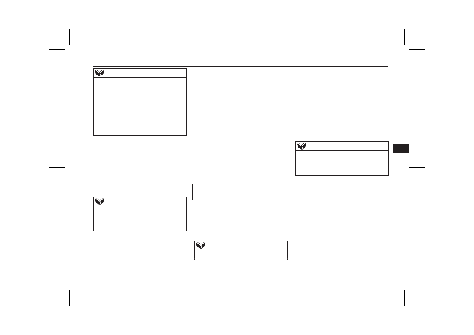
NOTE
l
If the Bluetooth
®
2.0 interface cannot recog-
nise the Bluetooth
®
compatible cellular
phone or the connection takes too much
time, the voice guide will say “Import con-
tact has timed out” and then the system will
cancel the registration. In such case, start
over again from Step 1.
l
Pressing the HANG-UP button or pressing
and holding the SPEECH button will cancel
the registration.
7. When the reception is complete, the
voice guide will say “<Number of tele-
phone numbers that had been registered
in the import source> numbers have
been imported. What name would you
like to use for these numbers?”
Say the name you want to register for
this phone book entry.
NOTE
l
If the entered name is already used for other
phone book entry or similar to a name used
for other phone book entry, that name cannot
be registered.
8. The voice guide will say “Adding
<name>.”
When the confirmation function is on,
the system will ask if the name is cor-
rect. Answer “Yes.”
Answer “No,” and the voice guide will
say “Name please.” Register a different
name.
9. The voice guide will say “Numbers
saved.”
10. The voice guide will say “Would you
like to import another contact?”
Answer “Yes” if you want to continue
with the registration. You can continue
to register a new phone book entry from
Step 5.
Answer “No,” to return to the main
menu.
To change the content registered in the ve-
hicle phone book
E00739800024
You can change or delete a name or tele-
phone number registered in the vehicle phone
book.
You can also listen to the list of names regis-
tered in the vehicle phone book.
NOTE
l
The system must have at least one entry.
Editing a telephone number
1. Press the SPEECH button.
2. Say “Phone book.”
3. The voice guide will say “Select one of
the following: new entry, edit number,
edit name, list names, delete, erase all, or
import contact.” Say “Edit number.”
4. The voice guide will say “Please say the
name of the entry you would like to edit,
or say list names.” Say the name of the
phone book entry you want to edit.
NOTE
l
Say “List names,” and the names registered
in the phone book will be read out in order.
Refer to “Listening to the list of registered
names” on page 8-68.
5. The voice guide will say “Home, work,
mobile or other?” Select and say the lo-
cation where the telephone number you
want to change or add is registered.
When the confirmation function is on,
the system will check the target name
and location again. Answer “Yes” if you
want to continue with the editing.
Answer “No” to return to Step 3.
6. The voice guide will say “Number
please.” Say the telephone number you
want to register.
Bluetooth
®
2.0 interface*
8-67
OGGE19E1
For pleasant driving
8
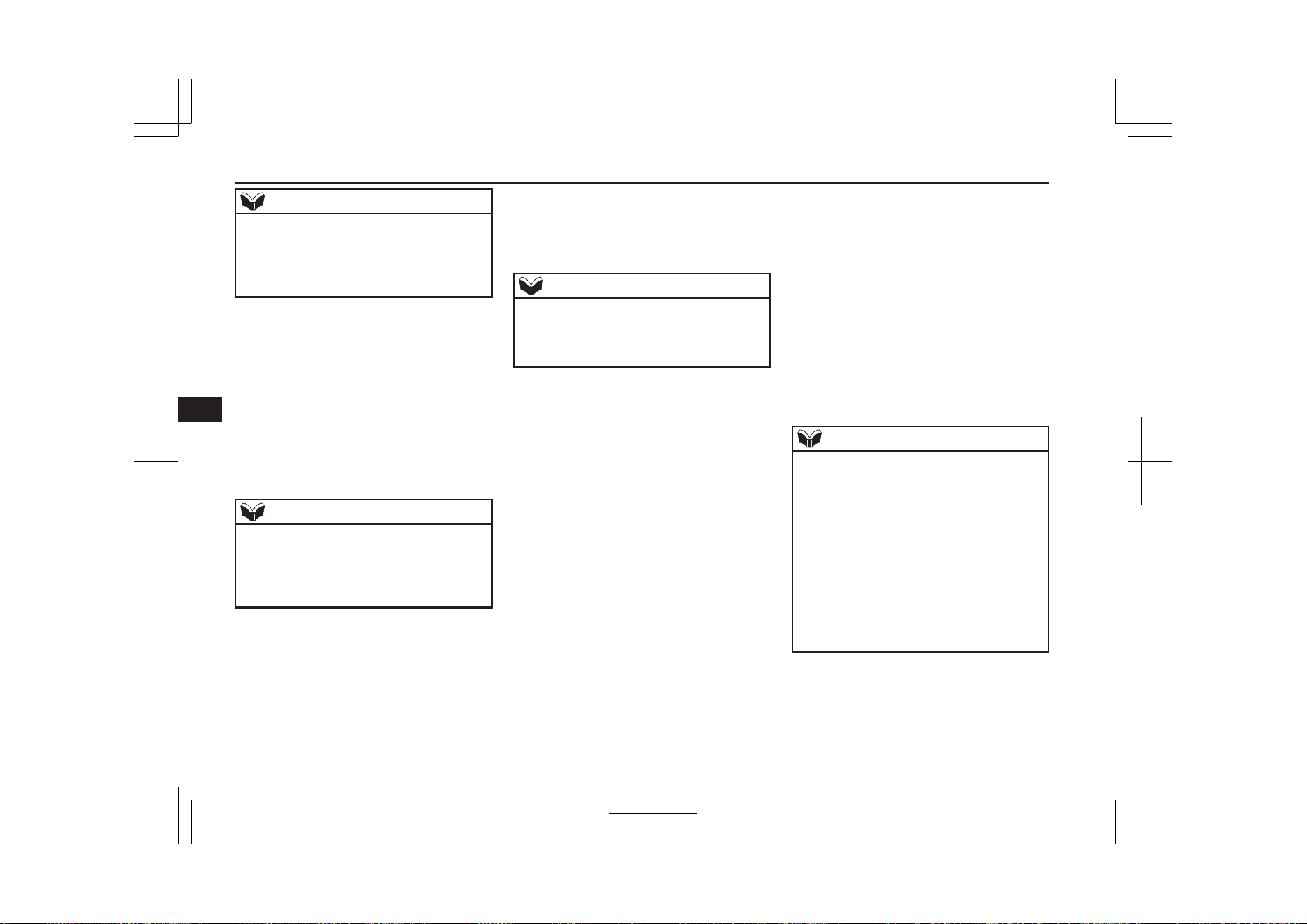
NOTE
l
If the telephone number is already registered
in the selected location, the voice guide will
say “The current number is <current num-
ber>. New number, please.” Say a new tele-
phone number to change the current number.
7. The voice guide will repeat the tele-
phone number.
When the confirmation function is on,
the system will ask if the number is cor-
rect. Answer “Yes.”
Answer “No” to return to Step 3.
8. Once the telephone number is registered,
the voice guide will say “Number saved”
and then the system will return to the
main menu.
NOTE
l
If the location where a telephone number
was already registered has been overwritten
with a new number, the voice guide will say
“Number changed” and then the system will
return to the main menu.
Editing a name
1. Press the SPEECH button.
2. Say “Phone book.”
3. The voice guide will say “Select one of
the following: new entry, edit number,
edit name, list names, delete, erase all, or
import contact.” Say “Edit name.”
4. The voice guide will say “Please say the
name of the entry you would like to edit,
or say list names.” Say the name you
want to edit.
NOTE
l
Say “List names,” and the names registered
in the phone book will be read out in order.
Refer to “Listening to the list of registered
names” on page 8-68.
5. The voice guide will say “Changing
<name>.”
When the confirmation function is on,
the system will ask if the name is cor-
rect. Answer “Yes” if you want to con-
tinue with the editing based on this in-
formation.
Answer “No” to return to Step 4.
6. The voice guide will say “Name please.”
Say the new name you want to register.
7. The registered name will be changed.
When the change is complete, the sys-
tem will return to the main menu.
Listening to the list of registered
names
E00739900025
1. Press the SPEECH button.
2. Say “Phone book.”
3. The voice guide will say “Select one of
the following: new entry, edit number,
edit name, list names, delete, erase all, or
import contact.” Say “List names.”
4.
Bluetooth
®
2.0 interface will read out
the entries in the phone book in order.
5. When the voice guide is done reading
the list, it will say “End of list, would
you like to start from the beginning?”
When you want to check the list again
from the beginning, answer “Yes.”
When you are done, answer “No” to re-
turn to the previous or main menu.
NOTE
l
You can call, edit or delete a name that is be-
ing read out.
Press the SPEECH button and say “Call” to
call the name, “Edit name” to edit it, or “De-
lete” to delete it.
The system will beep and then execute your
command.
l
If you press the SPEECH button and say
“Continue” or “Previous” while the list is
being read, the system will advance or re-
wind the list. Say “Continue” to proceed to
the next entry or “Previous” to return to the
previous entry.
Deleting a telephone number
E00740000026
1. Press the SPEECH button.
2. Say “Phone book.”
Bluetooth
®
2.0 interface*
8-68
OGGE19E1
For pleasant driving
8
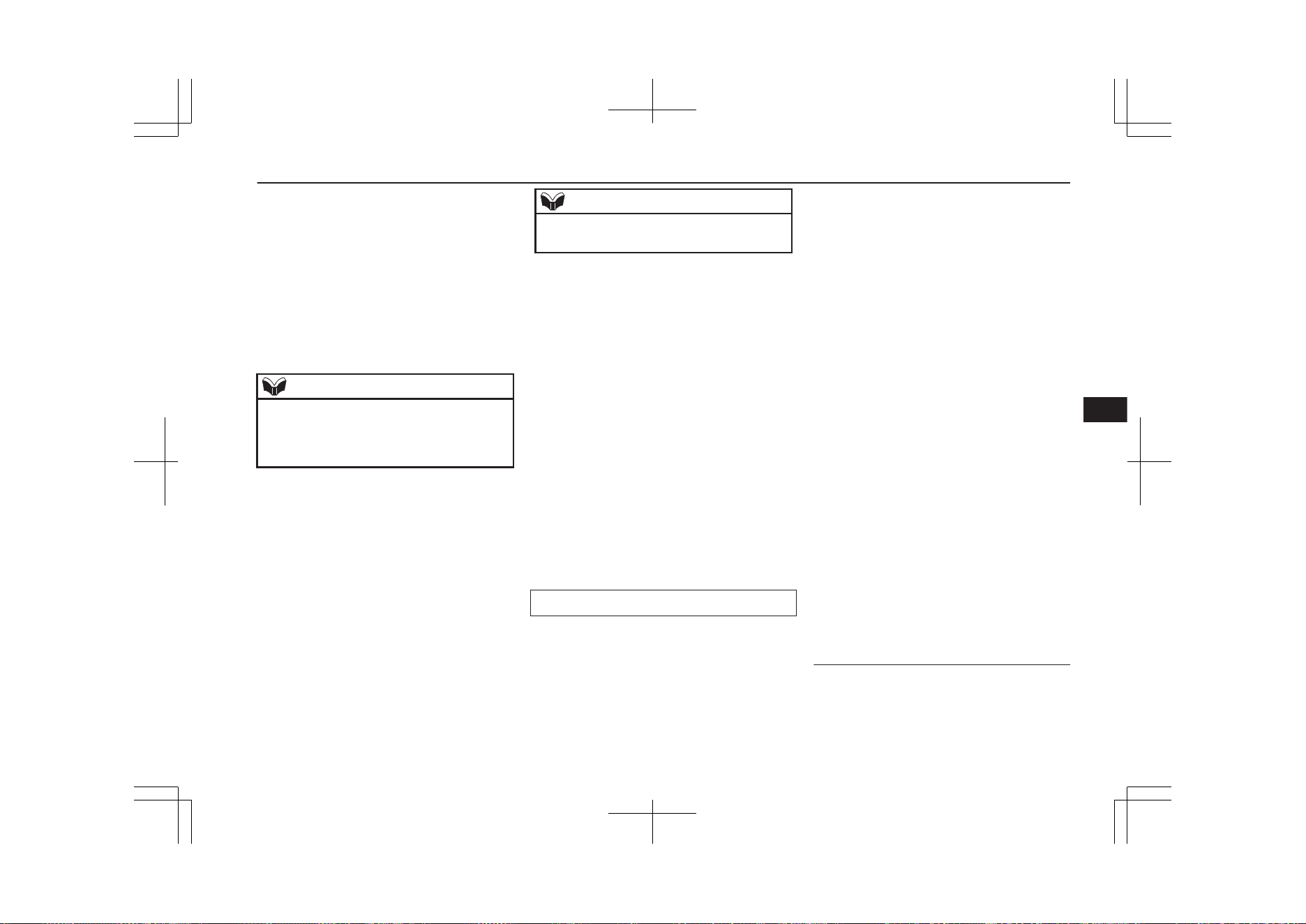
3. The voice guide will say “Select one of
the following: new entry, edit number,
edit name, list names, delete, erase all, or
import contact.” Say “Delete.”
4. The voice guide will say “Please say the
name of the entry you would like to de-
lete, or say list names.” Say the name of
the phone book entry in which the tele-
phone number you want to delete is reg-
istered.
NOTE
l
Say “List names,” and the names registered
in the phone book will be read out in order.
Refer to “Listening to the list of registered
names” on page 8-68.
5. If only one telephone number is regis-
tered in the selected phone book entry,
the voice guide will say “Deleting
<name> <location>.”
If multiple telephone numbers are regis-
tered in the selected phone book entry,
the voice guide will say “Would you like
to delete [home], [work], [mobile], [oth-
er], or all?”
Select the location to delete, and the
voice guide will say “Deleting <name>
<location>.”
NOTE
l
To delete the telephone numbers from all lo-
cations, say “All.”
6. The system will ask if you really want to
delete the selected telephone number(s)
to go ahead with the deletion, answer
“Yes.”
Answer “No,” the system will cancel de-
leting the telephone number(s) and then
return to Step 4.
7. When the deletion of the telephone num-
ber is completed, the voice guide will
say “<name> <location> deleted” and
then the system will return to the main
menu.
If all locations are deleted, the system
will say “<name> and all locations de-
leted” and the name will be removed
from the phone book. If numbers still re-
main under the entry, the name will re-
tain the other associated numbers.
Erasing the phone book
E00740100027
You can delete all registered information
from the vehicle phone book.
1. Press the SPEECH button.
2. Say “Phone book.”
3. The voice guide will say “Select one of
the following: new entry, edit number,
edit name, list names, delete, erase all, or
import contact.” Say “Erase all.”
4. For confirmation purposes, the voice
guide will ask “Are you sure you want to
erase everything from your hands-free
system phone book?” Answer “Yes.”
Answer “No” to cancel the deletion of
all registered information in the phone
book and return to the main menu.
5. The voice guide will say “You are about
to delete everything from your hands-
free system phone book. Do you want to
continue?” Answer “Yes” to continue.
Answer “No” to cancel the deletion of
all registered information in the phone
book and return to the main menu.
6. The voice guide will say “Please wait,
erasing the handsfree system phone
book” and then the system will delete all
data in the phone book.
When the deletion is complete, the voice
guide will say “Hands-free system phone
book erased” and then the system will
return to the main menu.
Mobile phone book
E00763900080
All entries in the phone book stored in the
cellular phone can be transferred in a batch
and registered in the mobile phone book.
Bluetooth
®
2.0 interface*
8-69
OGGE19E1
For pleasant driving
8
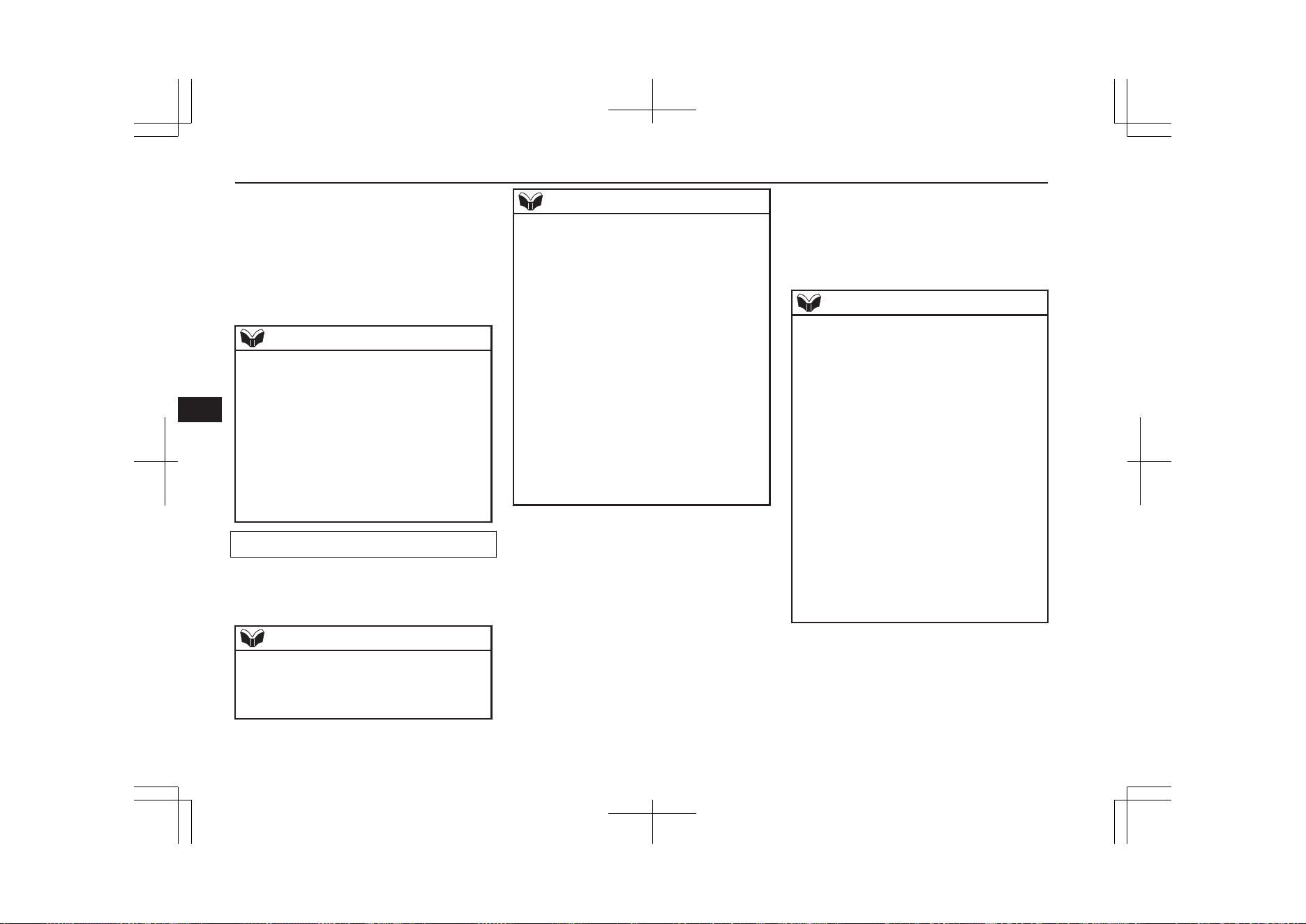
Up to 7 mobile phone books, each containing
up to 1,000 names, can be registered.
The Bluetooth
®
2.0 interface automatically
converts from text to voice the names regis-
tered in the transferred phone book entries,
and creates names.
NOTE
l
Only the mobile phone book transferred
from the connected cellular phone can be
used with that cellular phone.
l
You cannot change the names and telephone
numbers in the phone book entries registered
in the mobile phone book. You cannot select
and delete specific phone book entries, ei-
ther. To change or delete any of the above,
change the applicable information in the
source phone book of the cellular phone and
then transfer the phone book again.
To import a devices phone book
Follow the steps below to transfer to the mo-
bile phone book the phone book stored in the
cellular phone.
NOTE
l
Transfer should be completed while the ve-
hicle is parked. Before transferring, make
sure that the vehicle is parked in a safe loca-
tion.
NOTE
l
The already stored phone book in the mobile
phone book is overwritten by the stored
phone book in the cellular phone.
l
All or part of data may not be transferred,
even when the cellular phone supports Blue-
tooth
®
, depending on the compatibility of
the device.
l
Only a home, a work, and a mobile number
can be imported.
l
The maximum supported telephone number
length is 19 digits. Any telephone number of
20 digits or more will be truncated to the
first 19 digits.
l
If telephone numbers contain characters oth-
er than 0 to 9, *, # or +, these characters are
deleted before the transfer.
l
For the connection settings on the cellular
phone side, refer to the instructions for the
cellular phone.
1. Press the SPEECH button.
2. Say “Phone book.”
3. The voice guide will say “Select one of
the following: new entry, edit number,
edit name, list names, delete, erase all, or
import contact.” Say “Import contact.”
4. The voice guide will say “Would you
like to import a single entry or all con-
tacts?” Say “All contacts.”
5. The voice guide will say “Importing the
contact list from the mobile phone book.
This may take several minutes to com-
plete. Would you like to continue?” An-
swer “Yes,” transferring to the mobile
phone book the phone book stored in the
cellular phone will start.
Answer “No,” to return to the main
menu.
NOTE
l
The transfer may take some time to com-
plete depending on the number of contacts.
l
If the Bluetooth
®
2.0 interface could not be
connected to the Bluetooth
®
compatible cel-
lular phone, the voice guide will say “Un-
able to transfer contact list from phone” and
then the system will return to the main
menu.
l
If you press the HANG-UP button or press
and hold the SPEECH button during the data
transfer, the transfer will be cancelled and
the system will return to the main menu.
l
If an error occurs during the data transfer, all
transfer will be cancelled and the voice
guide will say “Unable to complete the
phone book import” and then the system will
return to the main menu.
l
If there are no contacts in the phone book,
the voice guide will say “There are no con-
tacts on the connected phone.”
6. When the transfer is complete, the voice
guide will say “Import complete” and
then the system will return to the main
menu.
Bluetooth
®
2.0 interface*
8-70
OGGE19E1
For pleasant driving
8
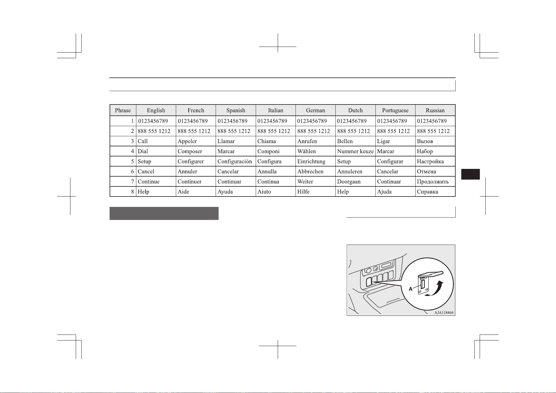
Enrollment commands
E00732401480
USB input terminal*
E00761901878
You can connect your USB memory device
or iPod* to play music files stored in the
USB memory device or iPod.
*: “iPod” is a registered trademark of Apple
Inc. in the United States and other countries.
This section explains how to connect and re-
move a USB memory device or iPod.
See the following section for details on how
to play music files.
Refer to “Listen to an iPod” on page 8-33.
Refer to “Listen to Audio Files on a USB De-
vice” on page 8-35.
Refer to “To play iPod/USB memory device
tracks via voice operation” on page 8-37.
USB input terminal locations
E00778600056
The USB input terminal (A) is located in the
illustrated positions.
Instrument panel
USB input terminal*
8-71
OGGE19E1
For pleasant driving
8
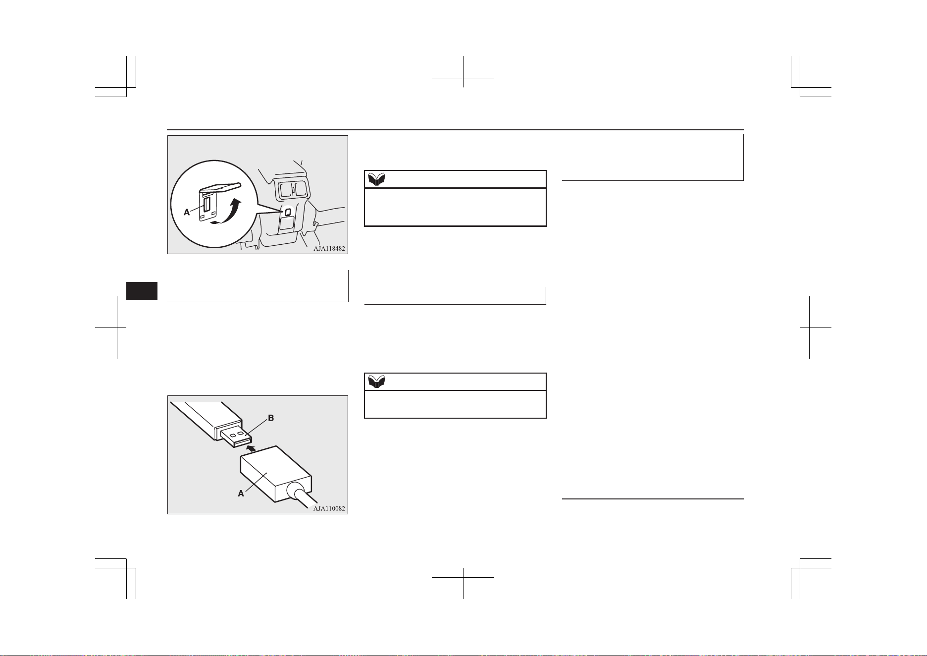
Back of floor console box
How to connect a USB memory
device
E00762001906
1. Park your vehicle in a safe place and put
the operation mode in OFF.
2. Open the USB input terminal cover.
3. Connect a commercially available USB
connector cable (A) to the USB memory
device (B).
4. Connect the USB connector cable to the
USB input terminal.
NOTE
l
Do not connect the USB memory device to
the USB input terminal directly.
The USB memory device may be damaged.
5. To remove the USB connector cable, put
the operation mode in OFF first and per-
form the installation steps in reverse.
How to connect an iPod
E00762101923
1. Park your vehicle in a safe place and put
the operation mode in OFF.
2. Open the USB input terminal cover.
3. Connect the connector cable to the iPod.
NOTE
l
Use a genuine connector cable from Apple
Inc.
4. Connect the connector cable to the USB
input terminal.
5. To remove the connector cable, put the
operation mode in OFF first and perform
the installation steps in reverse.
Types of connectable devices
and supported file specifica-
tions
E00762201399
Except for vehicles equipped with the
Bluetooth
®
2.0 interface
For details about the types of connectable de-
vices and supported file specifications, refer
to the following pages and manuals.
[For vehicles equipped with the
LW/MW/FM radio/CD player]
Refer to “Listen to an iPod” on page 8-33,
“Listen to Audio Files on a USB Device” on
page 8-35 and “Audio Files (MP3/WMA/
AAC)” on page 8-21.
[For vehicles equipped with the
MITSUBISHI Multi-Communication Sys-
tem (MMCS), the Smartphone Link Dis-
play Audio or the DISPLAY AUDIO]
Refer to the separate owner’s manual.
For vehicles equipped with the Bluetooth
®
2.0 interface
For details about the types of connectable de-
vices and supported file specifications, refer
to the following section.
Device types
E00762301723
Devices of the following types can be con-
nected.
USB input terminal*
8-72
OGGE19E1
For pleasant driving
8
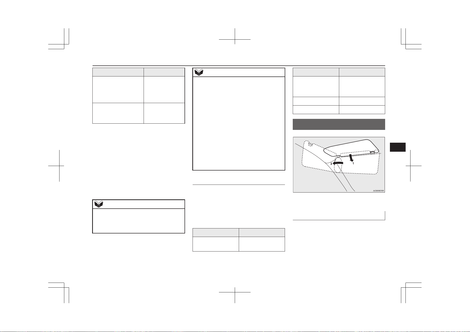
Model name Condition
USB memory device Storage capacity
of 256 Mbytes or
more (File System
is FAT16/32)
Models other than USB
memory devices and
iPods
Digital audio play-
er supporting mass
storage class
For connectable device type for “iPod
*
,”
“iPod classic
*
,” “iPod nano
*
,” “iPod touch
*
”
and “iPhone
*
,” access the MITSUBISHI
MOTORS website.
Please read and agree to the “Warning about
Links to the Web Sites of Other Companies”.
The websites mentioned above may connect
you to websites other than the MITSUBISHI
MOTORS website.
http://www.mitsubishi-motors.com/en/prod-
ucts/index.html
NOTE
l
Depending on the type of the USB memory
device or other device connected, the con-
nected device may not function properly or
the available functions may be limited.
*
“iPod”, “iPod classic”, “iPod nano”, “iPod
touch” and “iPhone” are registered trade-
marks of Apple Inc. in the United States
and other countries.
NOTE
l
It is recommended to use an iPod with firm-
ware updated to the latest version.
l
You can charge your iPod by connecting it to
the USB input terminal when the operation
mode is in ON or ACC.
l
Do not keep your USB memory device or
iPod in your vehicle.
l
It is recommended that you back up files in
case of data damage.
l
Do not connect to the USB input terminal
any device (hard disk, card reader, memory
reader, etc.) other than the connectable devi-
ces specified in the previous section. The de-
vice and/or data may be damaged. If any of
these devices was connected by mistake, re-
move it after putting the operation mode in
OFF.
File specifications
E00762401056
You can play music files of the following
specifications that are saved in a USB memo-
ry device or other device supporting mass
storage class. When you connect your iPod,
playable file specifications depend on the
connected iPod.
Item Condition
File format
MP3, WMA, AAC,
WAV
Item Condition
Maximum number of
levels
(including the root)
Level 8
Number of folders 700
Number of files 65,535
Sun visors
E00711202277
1- To eliminate front glare
2- To eliminate side glare
Vanity mirror
A vanity mirror is fitted to the back of the
sun visor.
Sun visors
8-73
OGGE19E1
For pleasant driving
8
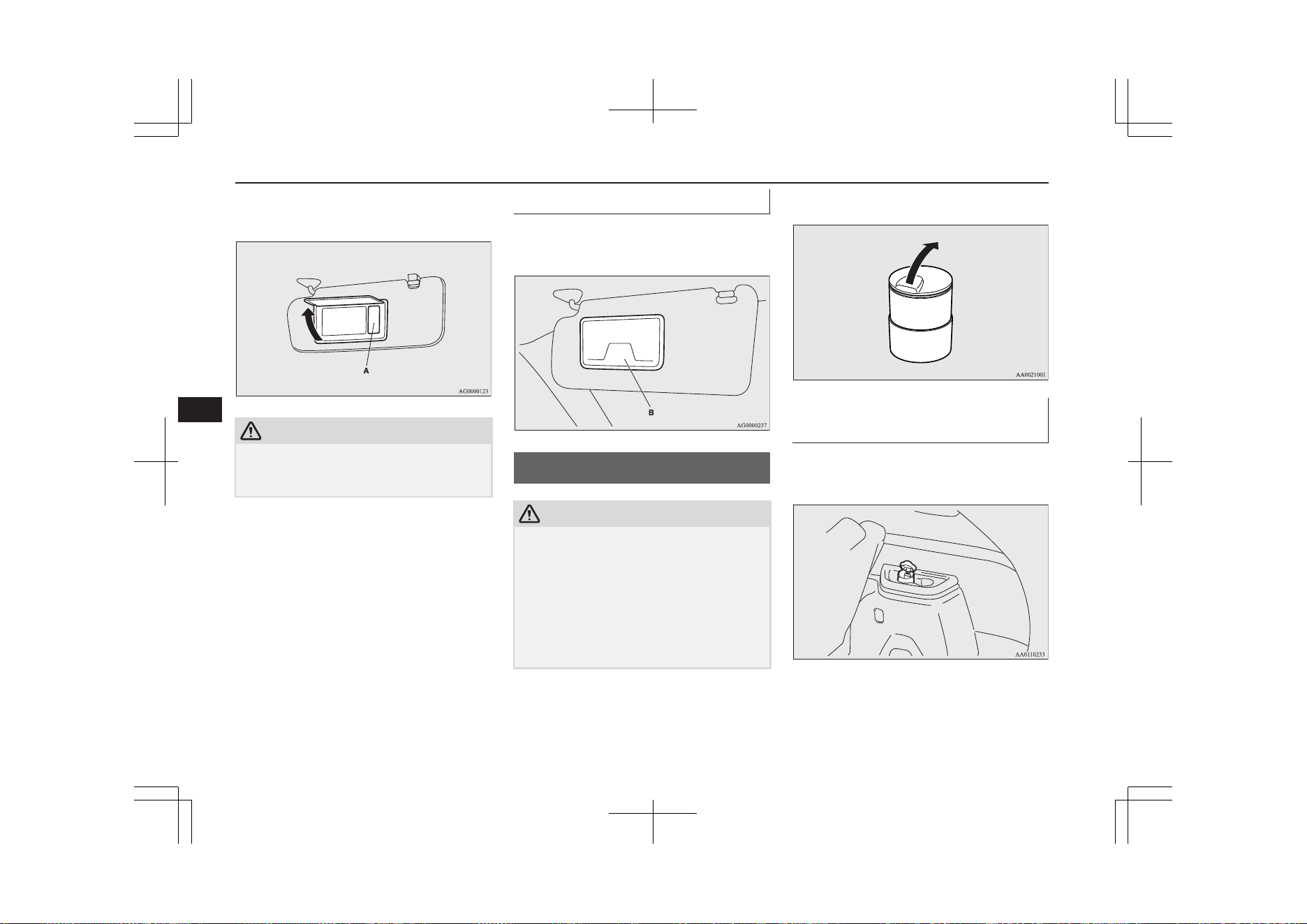
Operating the lid of the vanity mirror will au-
tomatically turn on the mirror lamp (A).
CAUTION
l
If the lid of vanity mirror with lamp is kept
open for prolonged periods of time, the aux-
iliary battery will be discharged.
Card holder
Cards can be slipped into the holder (B) on
the back of the sun visor.
Ashtray*
E00711401100
CAUTION
l
Put out matches and cigarettes before they
are placed in the ashtray.
l
Don’t put papers and other things that burn
into your ashtrays. If you do, cigarettes or
other smoking materials could set them on
fire, causing damage.
l
Always close the ashtray. If left open, other
cigarette butts in the ashtray may be rekin-
dled.
To use the ashtray, open the lid.
Mounting position for movea-
ble ashtray
The moveable ashtray can be fitted at the in-
dicated position.
Ashtray*
8-74
OGGE19E1
For pleasant driving
8
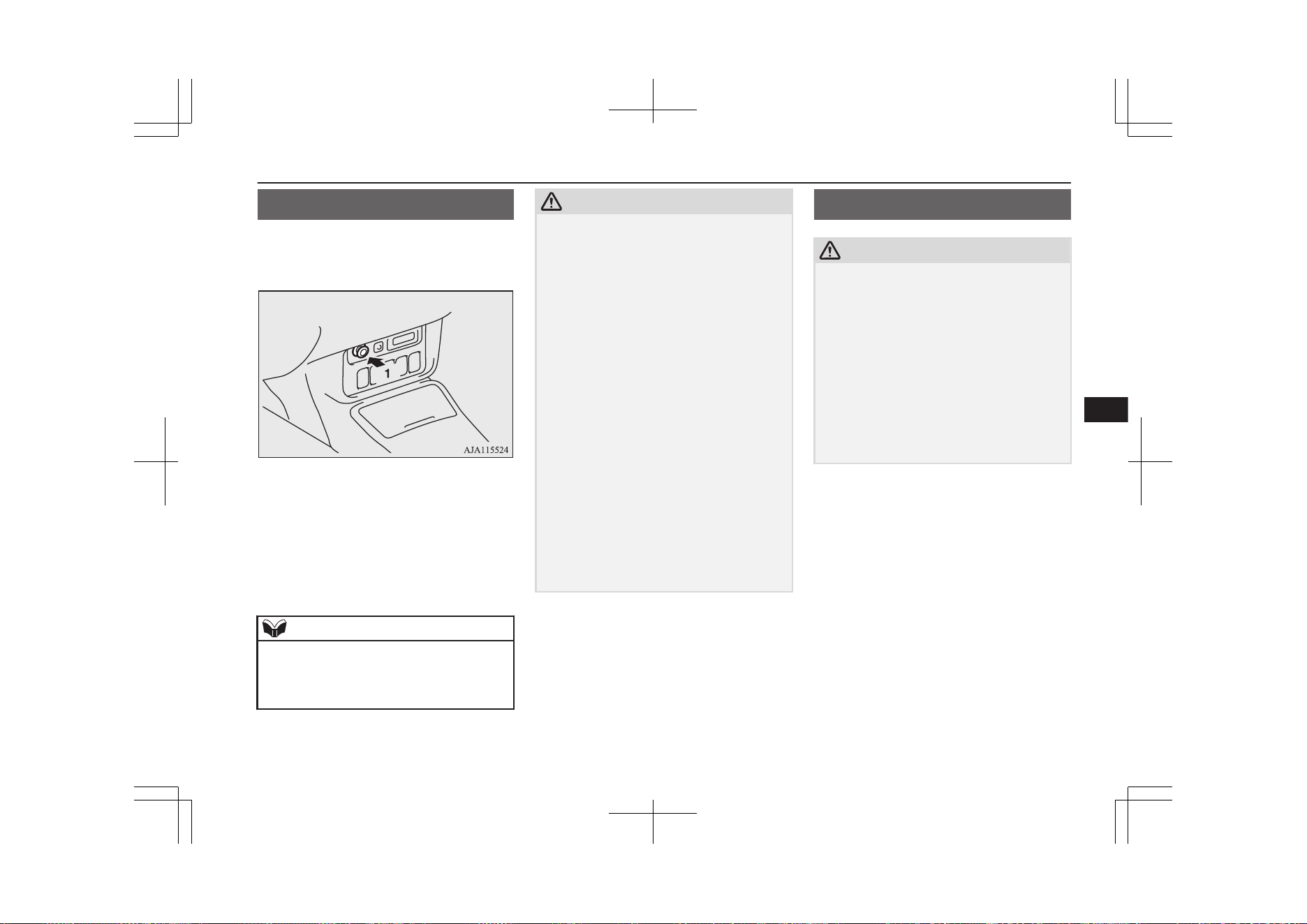
Cigarette lighter*
E00711502759
The cigarette lighter can be used while the
operation mode is in ON or ACC.
1- Push all the way in.
The cigarette lighter will automatically return
to its original position with a “click” when
ready. Pull it out for use.
After use, insert the cigarette lighter to its
original position in the socket.
NOTE
l
Do not leave the cigarette lighter removed
from its socket, because the socket might be-
come clogged by foreign material and be
short-circuited.
CAUTION
l
Do not touch the heating element or the cig-
arette lighter housing, hold the knob only to
prevent burns.
l
Do not allow children to operate or play with
the cigarette lighter as burns may occur.
l
Something is wrong with the cigarette light-
er if it does not pop back out within approxi-
mately 30 seconds of being pushed in.
Pull it out and have the problem corrected at
MITSUBISHI MOTORS Authorized Serv-
ice Point.
l
Do not use any electric appliance that is not
approved by MITSUBISHI MOTORS. Do-
ing so could damage the socket. If you used
the cigarette lighter after damaging the sock-
et, the cigarette lighter might pop out or fail
to come out after being pushed in.
l
When the cigarette lighter socket is used as a
power source for an electric appliance, be
sure that the electric appliance operates at
12 V and has an electric capacity of 120 W
or less. In addition, long use of the electric
appliance when the ready indicator is not il-
luminated may run down the auxiliary bat-
tery.
Accessory socket*
E00711603207
CAUTION
l
Be sure to use a “plug-in” type accessory op-
erating at 12 V and at 120 W or less.
When using the two sockets at the same
time, make sure that the electrical accesso-
ries are 12 V accessories and that the total
power consumption does not exceed 120 W.
l
Long use of the electric appliance when the
ready indicator is not illuminated may run
down the auxiliary battery.
l
When the accessory socket is not in use, be
sure to close the lid or install the cap, be-
cause the socket might become clogged by
foreign material and be short-circuited.
To use a plug-in type accessory, open the lid
or remove the cap, and insert the plug in the
accessory socket.
Cigarette lighter*
8-75
OGGE19E1
For pleasant driving
8
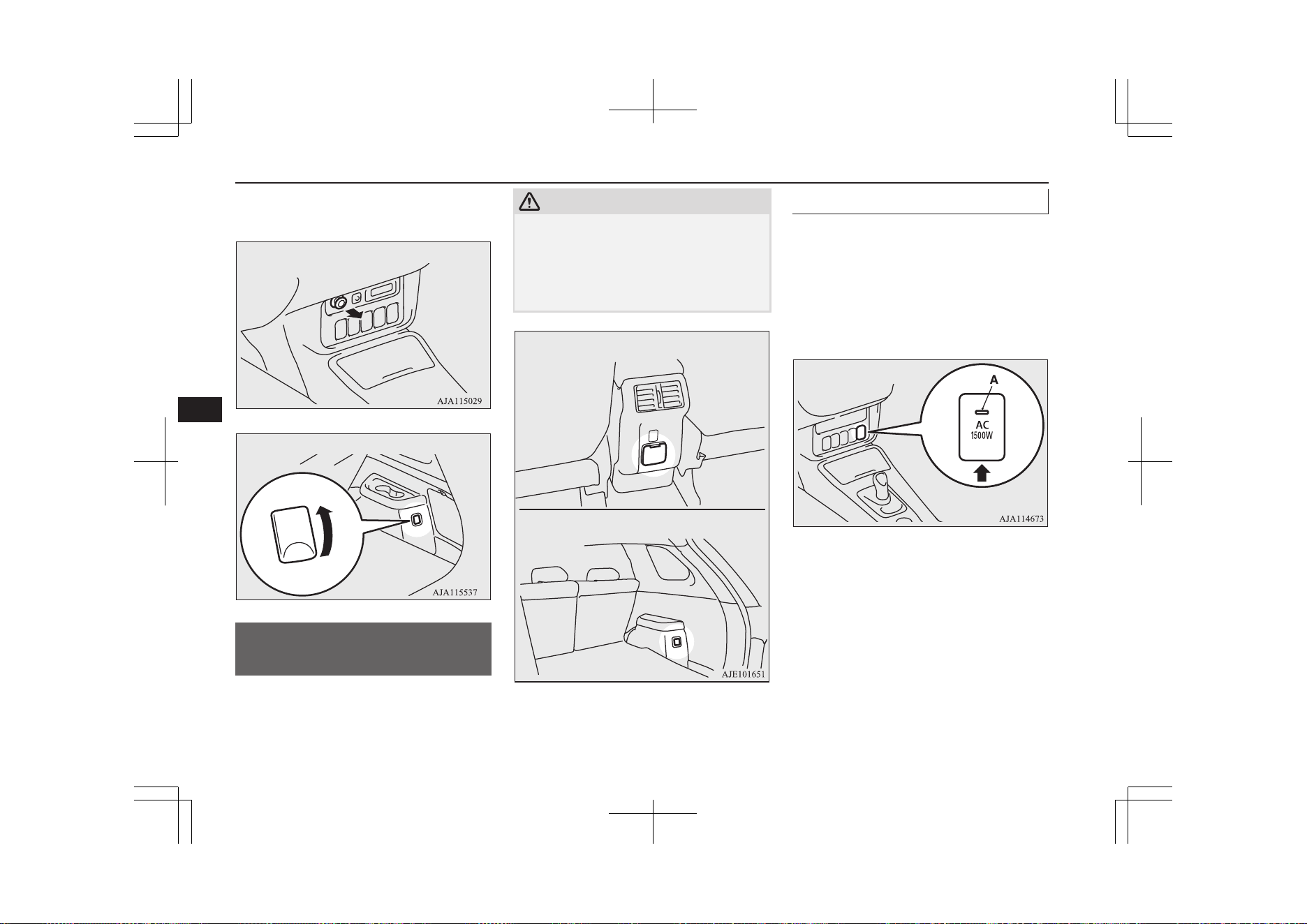
The accessory socket can be used while the
operation mode is in ON or ACC.
Instrument panel
C
Rear
B
220-240 V AC power
supplies*
E00749300093
220-240 V AC power supply can be used as a
power source of household appliances when
the ready indicator illuminates.
CAUTION
l
Be sure to use a “plug-in” type accessory op-
erating at 230 V and at 1500 W or less.
When using more than one socket at the
same time, make sure that the total power
consumption of the electrical appliances
does not exceed 1500 W at 230 V.
Right side of luggage area
Back of floor console box
To use
1. Press the 220-240 V AC power supply
switch. The indication lamp (A) will
come on and the power supply system is
ready for use.
To cancel power supply, press the switch
again and the indication lamp will go
off.
2. Open the lid (B).
220-240 V AC power supplies*
8-76
OGGE19E1
For pleasant driving
8
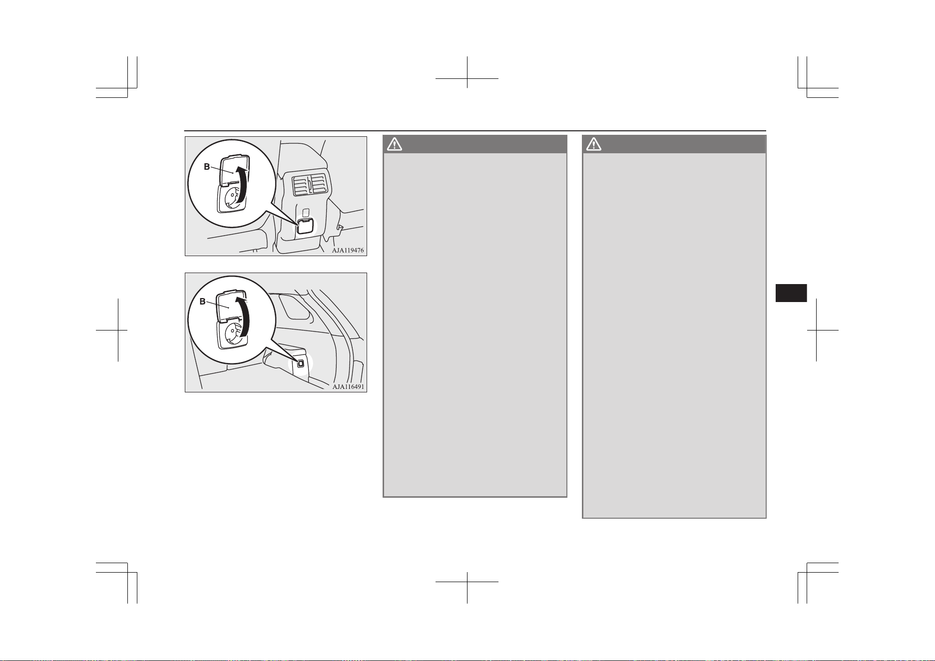
3. Insert the plug in the power outlet firm-
ly. Make sure that the plug is connected
correctly.
4. Disconnect the plug and close the lid af-
ter using the electrical appliance.
WARNING
l
Never use the 220-240 V AC power supply
to charge an electric vehicle or a plug-in
hybrid vehicle. Also, never connect the
220-240 V AC power supply to a house-
hold powerline or a distribution panel.
This may lead to an electric shock or a
malfunction.
l
Do not connect or disconnect the plug
with a wet hand. Doing so can cause an
electric shock.
l
Never pull the cable to remove the plug.
Pull straight while holding the plug of an
electrical appliance.
l
Do not disassemble or modify the 220-240
V AC power supply.
l
When using electrical appliance while
driving, make sure that it is firmly se-
cured. Flying objects entering the passen-
ger compartment during sudden braking
or sharp turning could result in a serious
accident and/or injury.
Refer to “Luggage hooks” on page 8-87.
l
Do not use an electrical appliance which
emits steam while the windows are closed.
Lack of visibility due to steam could lead
to an accident.
l
While using the 220-240 V AC power sup-
ply, even if the engine is not running, the
engine may automatically start later de-
pending on the condition of the Plug-in
Hybrid EV system and/or the drive bat-
tery.
WARNING
•
Before using the 220-240 V AC power
supply while the vehicle is stationary, to
prevent the vehicle from moving
abruptly, apply the parking brake
firmly and press the electrical parking
switch and make sure that the select
position indicator on the multi-infor-
mation displays “P” (PARK).
Also, to avoid activating the selector
lever, do not place a power cord on or
near the lever.
•
Never use the 220-240 V AC power
supply in a closed or poorly ventilated
area, such as in a garage or an area sur-
rounded by snow banks. Carbon mon-
oxide gas, which is odorless and ex-
tremely poisonous, could build up and
cause serious injury or death.
•
When using the 220-240 V AC power
supply while it is raining or snowing,
do not leave the door or tailgate open.
Wetting the 220-240 V AC power sup-
ply may cause overheating resulting in
a fire and/or electrical shock.
l
Never use a multi-plug adapter or conver-
sion adapter. Using them may cause over-
heating resulting in fire.
l
If you use an electrical appliance that
emits light, your visibility at night may be
affected which could impede safe driving.
l
Do not spill a beverage on the 220-240 V
AC power supply. This may cause over-
heating resulting in a fire and/or electrical
shock.
220-240 V AC power supplies*
8-77
OGGE19E1
For pleasant driving
8
WARNING
l
Do not let children touch the 220-240 V
AC power supply.
l
The cooling fan in the engine compart-
ment may automatically operate when us-
ing the 220-240 V AC power supply. Keep
your hands and clothes away from the
cooling fan.
l
Never use the 220-240 V AC power supply
when lightning or thunder is observed or
expected.
l
Never use the 220-240 V AC power supply
for electromedical apparatus.
CAUTION
l
When the 220-240 V AC power supply is
not in use, be sure to cancel power supply by
pressing the 220-240 V AC power supply
switch, disconnect the plug and close the lid.
This will prevent the 220-240 V AC power
supply from becoming clogged and short cir-
cuiting.
l
Do not stand behind the exhaust pipe as the
engine may automatically start depending on
the condition. Heat from the exhaust could
lead to burns.
l
Make sure that the plug is inserted all the
way into the 220-240 V AC power supply
before using an electrical appliance.
l
Do not use an electrical appliance in the ve-
hicle which emits heat such as a heater. Heat
damage to interior parts could result.
CAUTION
l
Do not connect a malfunctioning electrical
appliance to the 220-240 V AC power sup-
ply. Doing so could damage the 220-240 V
AC power supply.
NOTE
l
The accessory socket and 220-240 V AC
power supplies can be used simultaneously.
Refer to “Accessory socket*” on page 8-75.
l
If the plug of the electrical appliance was
loose or wobbled when inserted in the outlet,
have the 220-240 V AC power supply re-
placed at a MITSUBISHI MOTORS Author-
ized Service Point.
l
Never leave the vehicle, perform refueling
or washing the vehicle while using the
220-240 V AC power supply.
l
You may hear operating sounds such as
sounds from the cooling fan near the lug-
gage area when using the 220-240 V AC
power supply. This is normal.
l
Never use electrical appliance that is vulner-
able to vibration or heat in the cabin. When
exposed to strong direct sunlight, the cabin
will become extremely hot. It could cause
product failure.
l
Do not use the 220-240 V AC power supply
with the vehicle covered by a car cover.
l
When closing the window, door or tailgate,
be careful not to trap the power supply cord.
l
220-240 V AC power supply cannot be used
in the following cases.
NOTE
•
When the Plug-in Hybrid EV System
warning lamp is illuminated.
•
When the drive battery level display indi-
cates 0.
•
When the “PROPULSION POWER IS
REDUCED” warning display appears.
l
Electrical appliance may not operate normal-
ly or electricity supply stops under the fol-
lowing conditions. You may hear an opera-
tion noise. This is normal.
•
When the power consumption of the elec-
trical appliance exceeds 1500 W.
•
When the vehicle interior temperature is
too hot or too cold.
l
When the 220-240 V AC power supply can-
not be used or is not returned to operation
automatically after stopping electricity sup-
ply, follow the procedures below.
1
.
Disconnect the plug of electrical ap-
pliance.
2
.
Confirm the remaining quantity of
the drive battery. When it is low,
charge the drive battery by using the
battery SAVE/CHARGE mode
switch, etc.
“Battery SAVE/CHARGE mode
switch” on page 7-28
Normal charging (charging method
with rated AC 220-240V outlet)
® p. 3-10
Quick charging (charging method
with quick charger) ® p. 3-17
220-240 V AC power supplies*
8-78
OGGE19E1
For pleasant driving
8
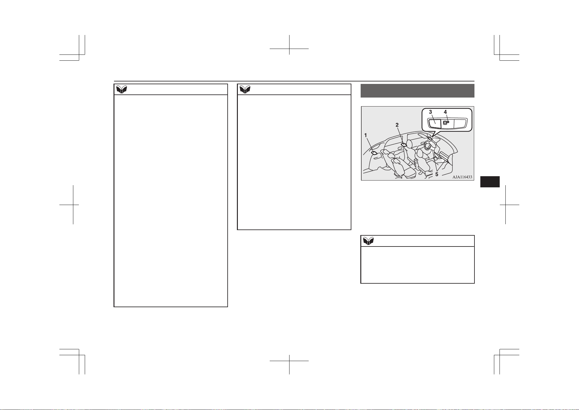
NOTE
3
.
Confirm that the ready indicator illu-
minates. If not, start the Plug-in Hy-
brid EV System.
4
.
When the vehicle interior tempera-
ture is too hot or too cold, adjust it
appropriately by using the air condi-
tioner.
5
.
Press the 220-240 V AC power sup-
ply switch to turn it on.
6
.
Confirm that the indication lamp on
the 220-240 V AC power supply
switch comes on and insert the plug
in the power outlet.
l
The following electrical appliance may not
operate normally even if the power con-
sumption is less than 1500 W. Also be aware
that the electric power that can be used will
vary depending on the drive battery condi-
tion.
•
Electrical appliance to which large
amounts of current flow momentarily
•
Electrical appliance that gauges precise
data
•
Electrical appliance that does not operate
normally when it is not placed horizontal-
ly
•
Electrical appliance that needs extremely
stable operation
•
Electrical appliance with a timer function,
that needs the consecutive output
NOTE
l
The AC power output may shut off and the
electrical appliance may be turned off ac-
cordingly depending on the drive battery
condition even if the battery level display
does not indicate 0.
l
The use of electrical appliance could cause
radio or television noise.
l
The voltage of the 220-240 V AC power
supply cannot be correctly gauged with a
commercially available tester. Consult a
MITSUBISHI MOTORS Authorized Serv-
ice Point when you need measurement of the
voltage.
l
Also refer to the instruction manual and la-
bel accompanying the electrical appliance.
l
When the remaining power in the drive bat-
tery is low, the engine starts and charges the
drive battery automatically. Be careful not to
run out of fuel since it will be consumed
when the engine starts.
Interior lamps
E00712002810
1- Luggage room lamp
2- Room lamp (rear)
3- Map & room lamps (front)
4- Downlight ® p. 8-81
5- Front foot lamps
NOTE
l
If you leave the lamps on when the ready in-
dicator is not illuminated, you will run down
the auxiliary battery.
Before you leave the vehicle, make sure that
the lamps are turned off.
Interior lamps
8-79
OGGE19E1
For pleasant driving
8
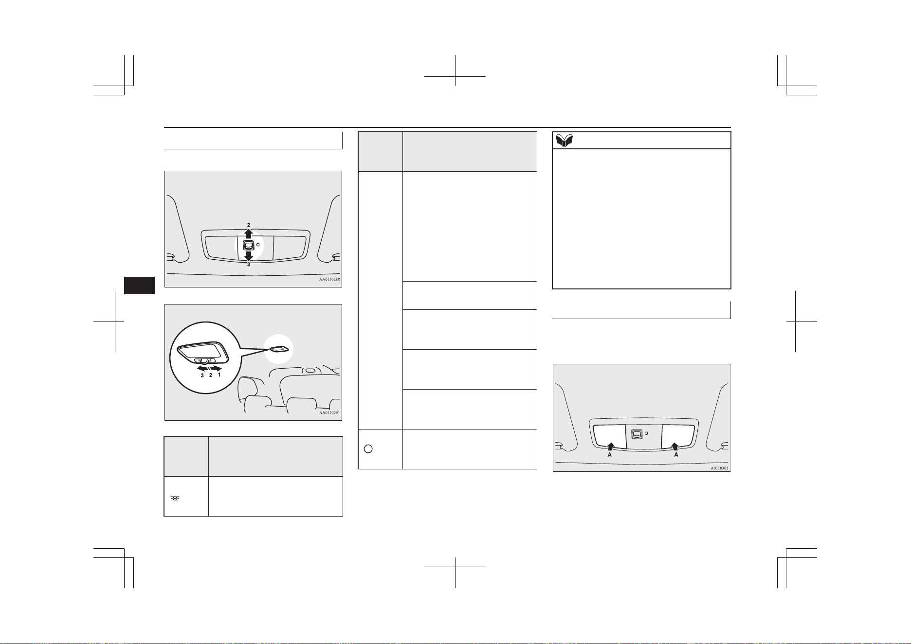
Room lamps
E00712102589
Front
Rear
Position
of lamp
switch
On/off control
1-ON
( )
The lamp illuminates regardless
of whether a door or the tailgate
is open or closed.
Position
of lamp
switch
On/off control
2-DOOR
(•)
The lamp illuminates when a
door or the tailgate is opened. It
goes off approximately 15 sec-
onds after all doors and the tail-
gate are closed.
However, the lamp goes off im-
mediately with all doors and the
tailgate closed in the following
cases:
l
When the operation mode is
put in ON.
l
When the central door lock
function is used to lock the
vehicle.
l
When the keyless operation
key is used to lock the vehi-
cle.
l
When the keyless operation
function is used to lock the
vehicle.
3-OFF
( )
The lamp goes off regardless of
whether a door or the tailgate is
open or closed.
NOTE
l
When the operation mode is put in OFF
while the doors and tailgate are closed, the
lamp illuminates and after approximately 15
seconds it goes off.
l
The time until the lamp goes off can be ad-
justed. For details, please consult a
MITSUBISHI MOTORS Authorized Serv-
ice Point. On vehicles equipped with the
Smartphone Link Display Audio or the
MITSUBISHI Multi-Communication Sys-
tem (MMCS), screen operations can be used
to make the adjustment. Refer to the separate
owner’s manual for details.
Map lamps
E00712400168
Push the lens (A) to turn on the lamp. Push it
again to turn it off.
Interior lamps
8-80
OGGE19E1
For pleasant driving
8
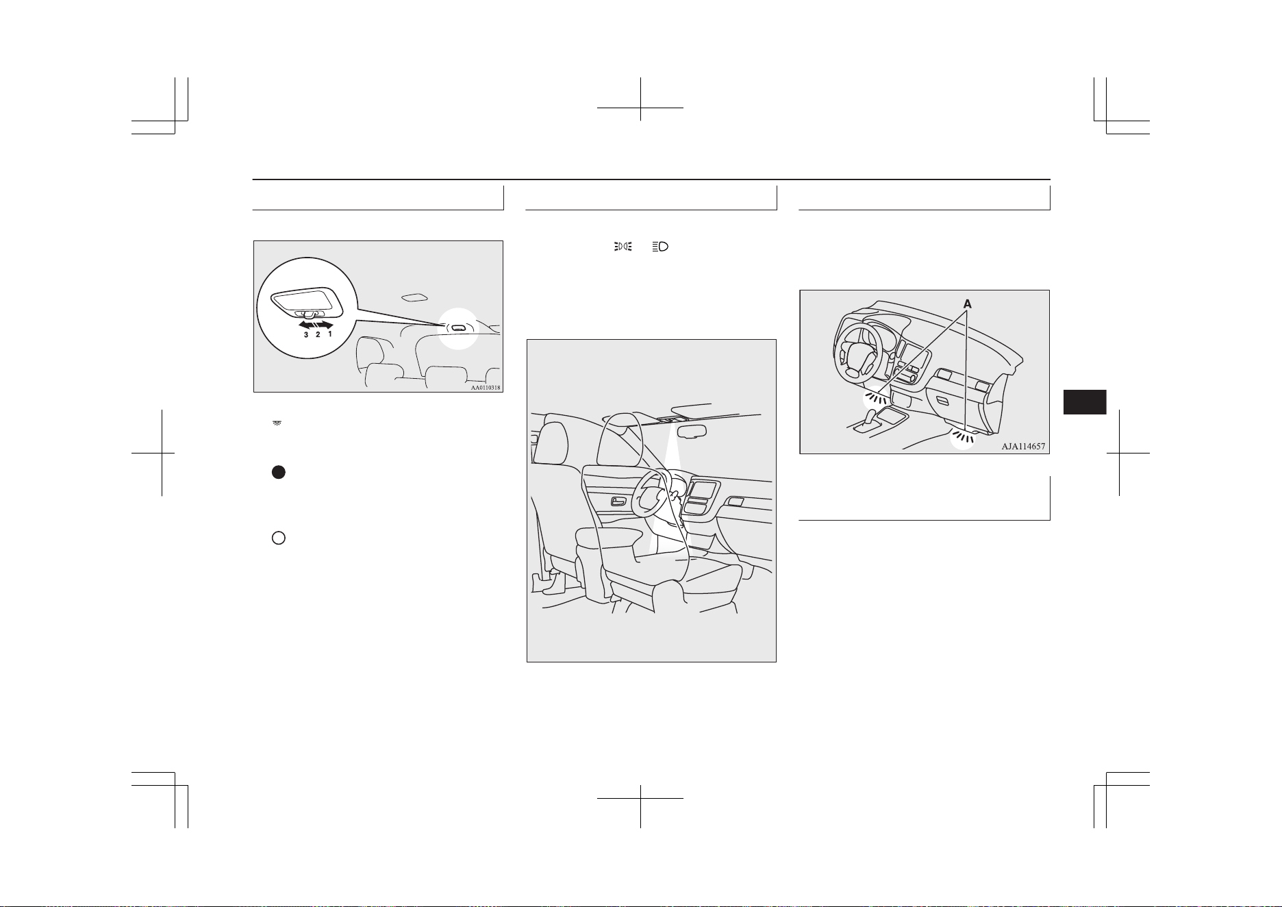
Luggage room lamp
E00712700709
1- ( )
The lamp illuminates regardless of whether
the tailgate is open or closed.
2- ( )
The lamp illuminates when the tailgate is
opened, and goes off when the tailgate is
closed.
3- (
)
The lamp goes off regardless of whether the
tailgate is open or closed.
Downlight
E00778700060
The downlight illuminates when the lamp
switch is in the or position. When the
lamp switch is in the “AUTO” position (vehi-
cles equipped with the automatic lamp con-
trol), the downlight illuminates when the po-
sition lamps and other lamps illuminate.
AJ4100945
Front foot lamps
E00776100073
The front foot lamps (A) come on when the
front door is opened and go off when the
door is closed.
Interior lamp* auto-cutout
function
E00712902587
*: Map & room lamps (front), room lamp
(rear) and luggage room lamp
If any of the interior lamps are left switched
on with the operation mode in OFF, it goes
off automatically after approximately 30 mi-
nutes.
The lamps will illuminate again after they au-
tomatically go off if the power switch is oper-
ated, if one of the doors or the tailgate is
opened or closed, or if the keyless entry sys-
tem or keyless operation system is operated.
Interior lamps
8-81
OGGE19E1
For pleasant driving
8
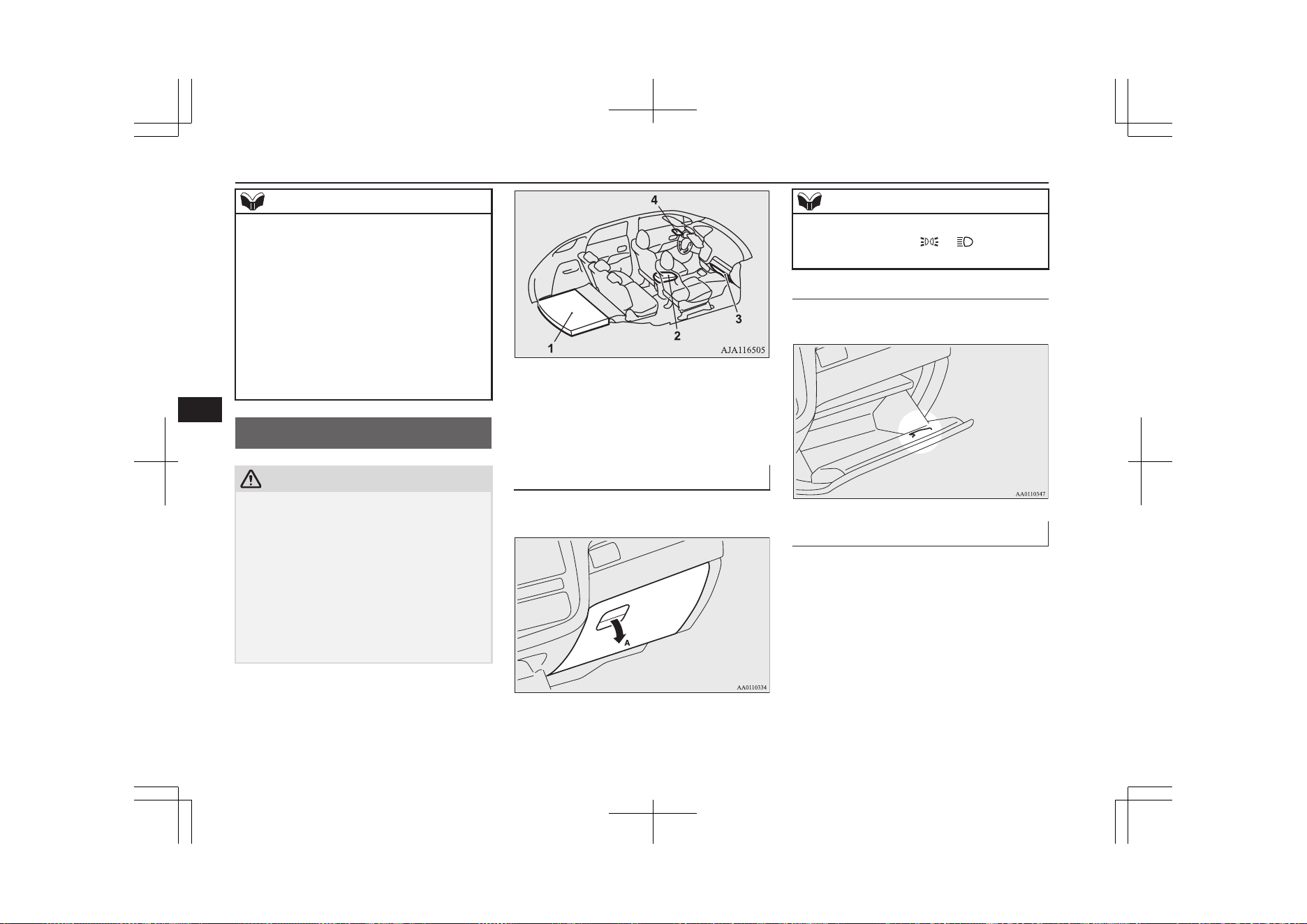
NOTE
l
The interior lamp auto-cut function can be
deactivated. The time until the lamps auto-
matically go off can be adjusted. For details
and support, consult your nearest
MITSUBISHI MOTORS Authorized Serv-
ice Point.
On vehicles equipped with the Smartphone
Link Display Audio or the MITSUBISHI
Multi-Communication System (MMCS),
screen operations can be used to make the
adjustment. Refer to the separate owner’s
manual for details.
Storage spaces
E00713103394
CAUTION
l
Never leave lighters, canned carbonated
drinks, and spectacles in the cabin when
parking the vehicle in hot sunshine. The cab-
in will become extremely hot, so lighters and
other flammable items may catch fire and
unopened drink cans may rupture. Also,
spectacles with plastic lenses or materials
could deform or crack.
l
Keep the lids of storage spaces closed while
driving the vehicle. A lid or the contents of a
storage space could otherwise cause injuries.
1- Luggage floor box
2- Floor console box
3- Glove box
4- Sunglasses holder*
Glove box
E00726201340
To open, pull the lever (A).
NOTE
l
When the lamps are illuminated with the
lamp switch in the “ ”, “ ”, or “AUTO”
position, the glove box lamp illuminates.
Card holder
There is a card holder inside the glove box.
Floor console box
E00723302480
To open the console box, lift the release lever
(A) and raise the lid.
Storage spaces
8-82
OGGE19E1
For pleasant driving
8
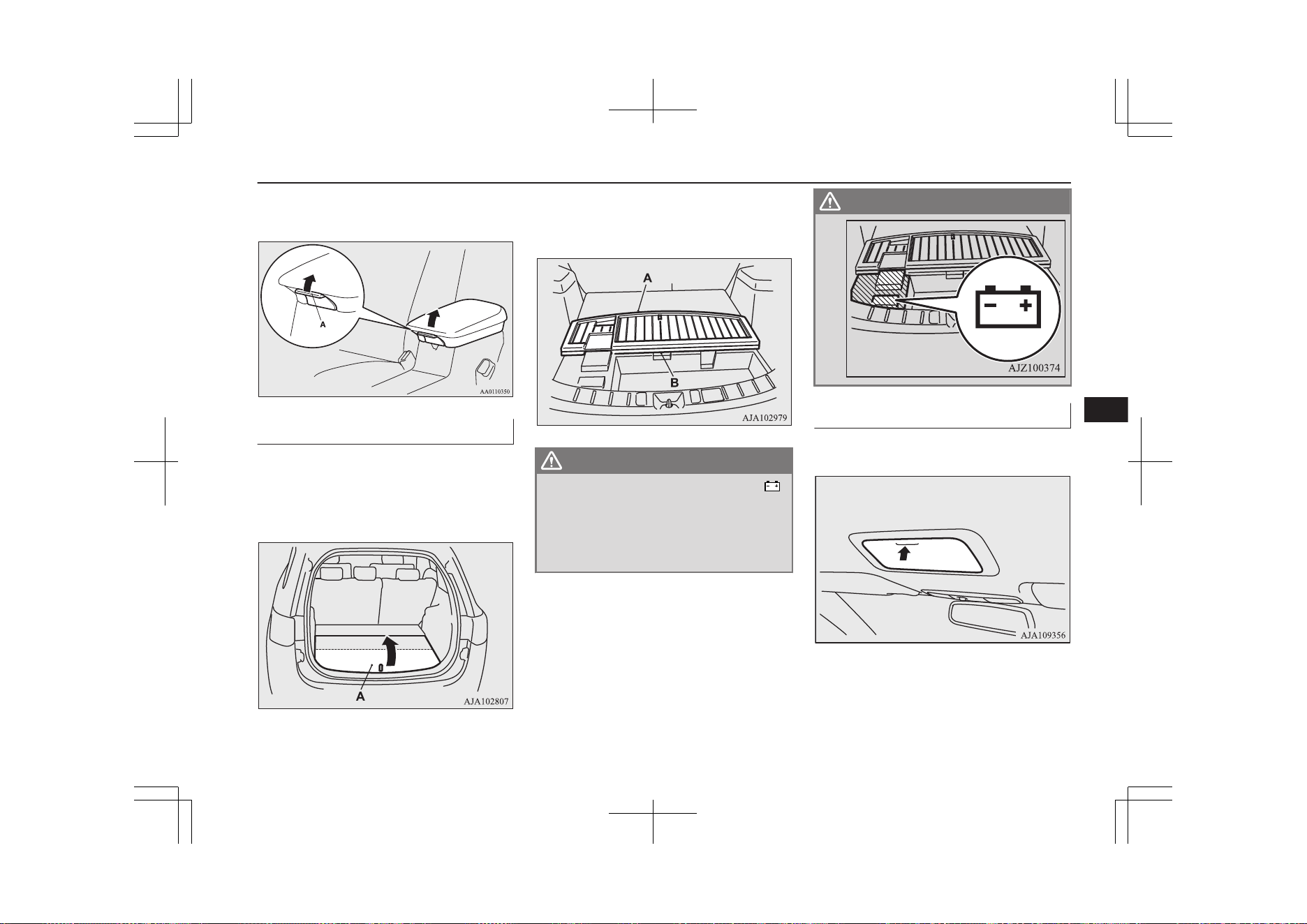
The floor console box can also be used as an
armrest.
Luggage floor box
E00718701968
The box for storing articles is located inside
the luggage compartment.
To use the box, raise the luggage floor board
(A).
To use the luggage floor box in the rear seat
side, insert your hand in the gap (B) and raise
the board (A) to the seat side.
WARNING
l
Do not place any object around the “ ”
mark, since it marks the auxiliary battery
under the luggage floor box. If the battery
cover is broken, battery fluid may leak. If
it adheres to your skin or gets in your
eyes, serious injury may result.
WARNING
Sunglasses holder*
E00718601417
To open, push the lid.
Storage spaces
8-83
OGGE19E1
For pleasant driving
8
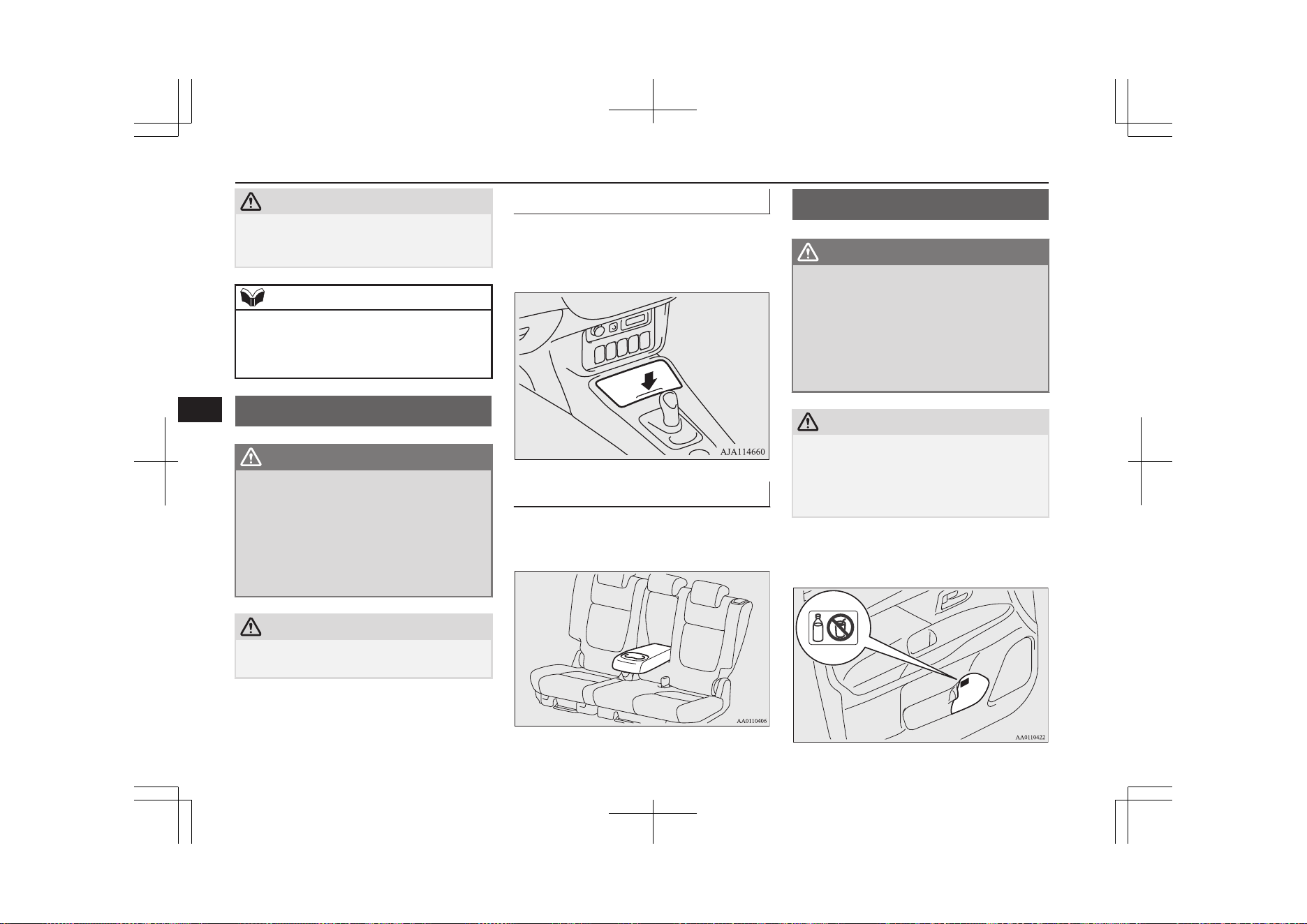
CAUTION
l
The holder should not be used to store any-
thing heavier than sunglasses. These objects
could drop out.
NOTE
l
The holder may not be able to accomodate
every possible size and shape of sunglasses;
it is advisable to check compatibility before
use.
Cup holder
E00714502343
WARNING
l
Do not spray water or spill beverages in-
side the vehicle. If the switches, wires or
electrical components become wet, they
could malfunction or cause a vehicle fire.
If you accidentally spill a beverage, wipe
up as much liquid as possible and imme-
diately consult a MITSUBISHI MOTORS
Authorized Service Point.
CAUTION
l
Do not drink beverages while driving. This
is distracting and could cause an accident.
For the front seat
The cup holder is located in front of the floor
console.
To use the cup holder, push the lid.
For the rear seat
E00716901562
In order to use the cup holder, allow the arm-
rest to drop down.
Bottle holder
E00718201543
WARNING
l
Do not spray water or spill beverages in-
side the vehicle. If the switches, wires or
electrical components become wet, they
could malfunction or cause a vehicle fire.
If you accidentally spill a beverage, wipe
up as much liquid as possible and imme-
diately consult a MITSUBISHI MOTORS
Authorized Service Point.
CAUTION
l
Do not drink beverages while driving. This
is distracting and could cause an accident.
l
Drinks could be spilled by the vibration and
jolts while driving. If the spilt drink is very
hot, you could be burnt.
There are bottle holders located on both sides
of front and rear doors.
Cup holder
8-84
OGGE19E1
For pleasant driving
8
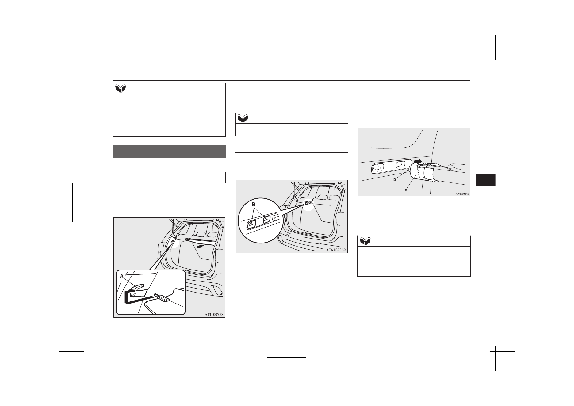
NOTE
l
Do not store cups or drink cans in the bottle
holder.
l
Tightly close the cap on drink bottles before
storing them.
l
Some bottles may be too big or the wrong
shape to fit in the holder.
Cargo area cover
E00733601160
To use
1. Draw out the cover retracted by spring
and insert it in the mounting grooves
(A).
2. Remove the cover from the mounting
grooves, and the cover will roll back into
the retracted position.
NOTE
l
Do not put luggage on the cover.
To change position
There are two installation holes (B) for the
cover.
1. Move one of the sliders (C) towards the
inside of the vehicle, and fit the tab (D)
into the installation hole that is to be
used. Move the opposite slider in the
same fashion.
2. After changing the position, gently
shake the entire cover to make sure it is
securely retained.
NOTE
l
If the rear seatback touches the cover, move
the cover rearward.
The cover could break if it supports the seat-
back of the rear seat.
To remove
1. Roll the cover into the retracted position.
Cargo area cover
8-85
OGGE19E1
For pleasant driving
8
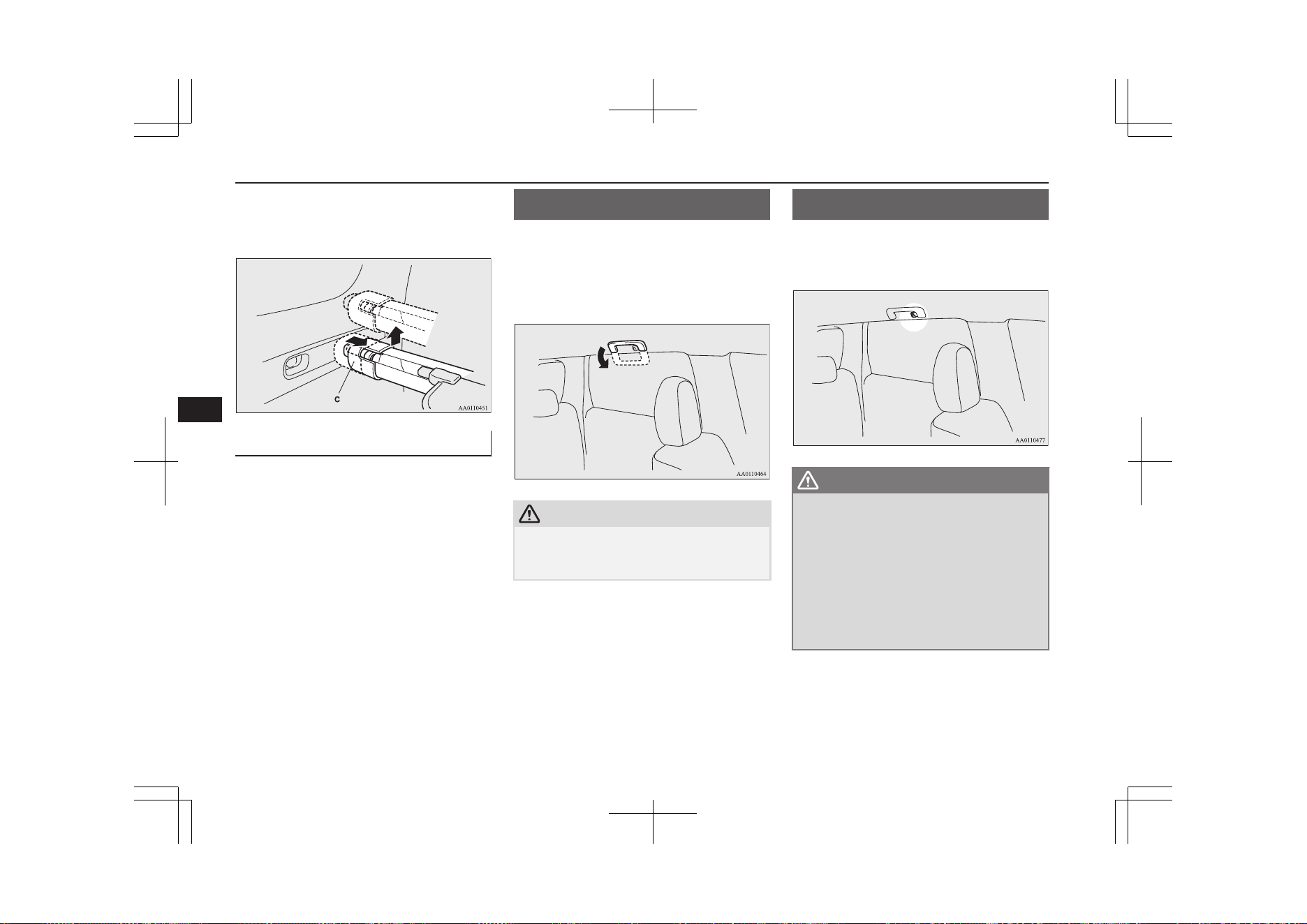
2. Move one of the sliders (C) towards the
inside of the vehicle and lift it to remove
the cover.
To refit
Refit the cover by performing the removal
steps in reverse.
Gently shake the entire cover after fitting it to
make sure it is securely retained.
Assist grips
E00732800298
The assist grips (located above the doors on
the headliner) are not designed to support
body weight. They are intended for use only
while seated in the vehicle.
CAUTION
l
Do not use the assist grips when getting into
or out of the vehicle. The assist grips could
detach causing you to fall.
Coat hook
E00725601640
There is a coat hook on the rear seat assist
grip of the driver’s side.
WARNING
l
Do not put a hanger or any heavy or poin-
ted object on the coat hook. If the curtain
airbag was activated, any such item could
be propelled away with great force and
could prevent the curtain airbag from in-
flating correctly. Hang clothes directly on
the coat hook (without using a hanger).
Make sure there are no heavy or sharp
objects in the pockets of clothes that you
hang on the coat hook.
Assist grips
8-86
OGGE19E1
For pleasant driving
8
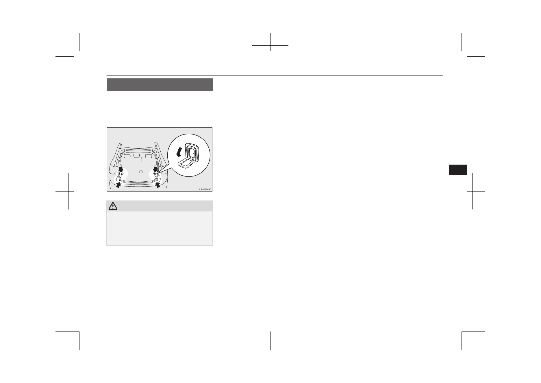
Luggage hooks
E00715700579
There are 4 hooks located on the side walls of
the luggage compartment.
Use the hooks for securing the luggage.
CAUTION
l
Do not pile up the luggage beyond the seat-
back height. Also, firmly secure the luggage.
Otherwise, serious accidents could result due
to hindered rearward view or flying objects
during sudden braking.
Luggage hooks
8-87
OGGE19E1
For pleasant driving
8

OGGE19E1

If the vehicle breaks down.................................................................. 9-02
If the operation mode cannot be changed to OFF...............................9-02
Emergency starting............................................................................. 9-02
Engine overheating............................................................................. 9-04
Tools and jack..................................................................................... 9-06
Tyre repair kit......................................................................................9-07
How to change a tyre.......................................................................... 9-13
Towing................................................................................................ 9-17
Operation under adverse driving conditions....................................... 9-21
For emergencies
OGGE19E1
9
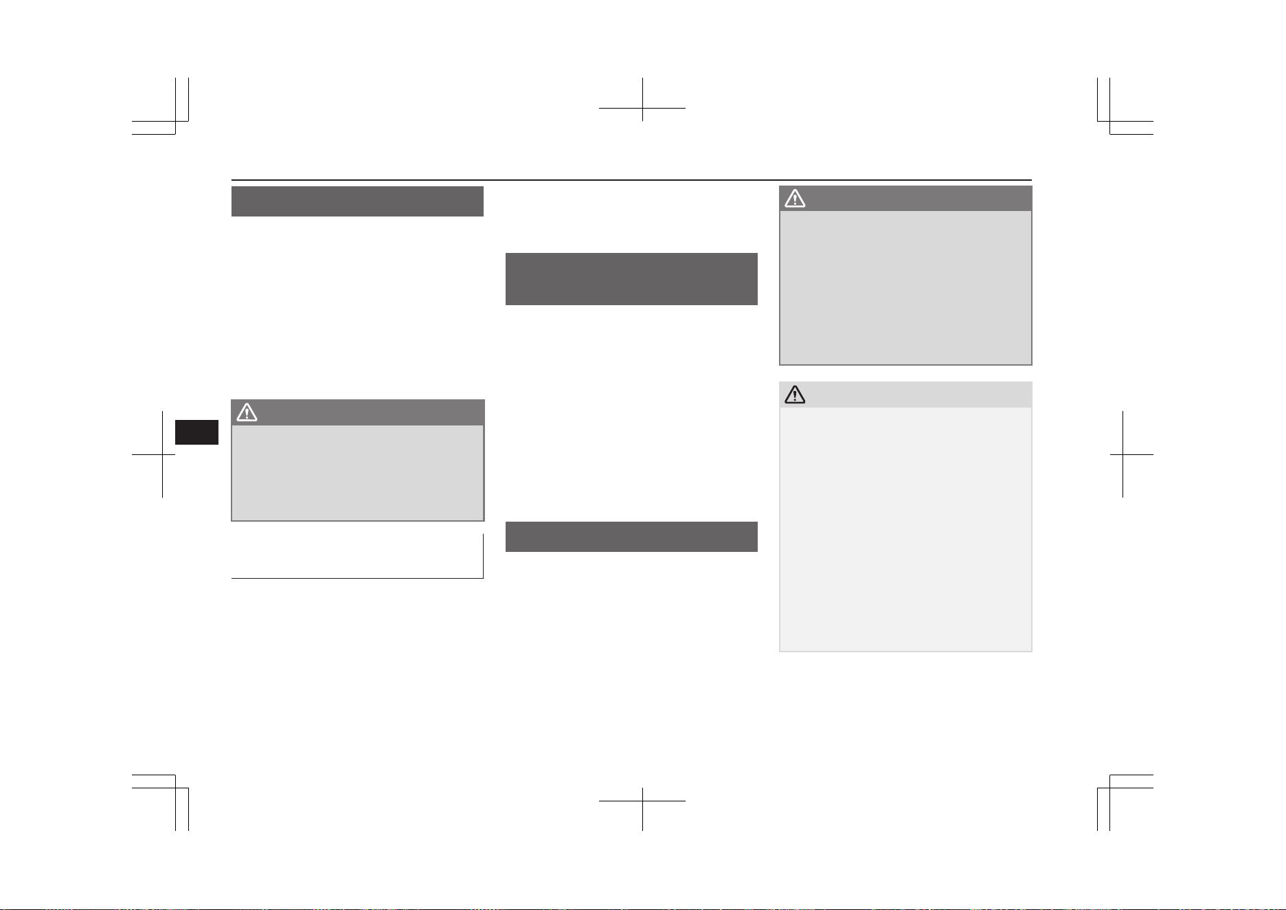
If the vehicle breaks down
E00800102408
If the vehicle breaks down on the road, move
it to the shoulder and use the hazard warning
flashers and/or the warning triangle etc.
Refer to “Hazard warning flasher switch” on
page 6-67.
If you need to push your vehicle, put the op-
eration mode of the power switch in ON and
put the select position in “N” (NEUTRAL)
position.
WARNING
l
If you are unable to safely assess the vehi-
cle due to vehicle damage, do not touch
the vehicle. Leave the vehicle and contact
emergency services. Advise emergency
responders that this is a Plug-in Hybrid
Electric vehicle.
If the ready indicator goes out
while driving
Vehicle operation and control are affected if
the ready indicator goes out while driving.
Before moving the vehicle to a safe area, be
aware of the following:
l
The brake booster may becomes inoper-
ative and the pedal effort will increase.
Press down the brake pedal harder than
usual.
l
The power steering system may not op-
erate, the steering wheel feels heavy
when turning it.
If the operation mode
cannot be changed to OFF
E00804900295
If the operation mode cannot be changed to
OFF, perform the following procedure.
1. Press the electrical parking switch and
lock the wheels, then change the opera-
tion mode to OFF.
2. One of the other causes could be low
auxiliary battery voltage. If this occurs,
the keyless entry system and keyless op-
eration function will also not operate.
Contact a MITSUBISHI MOTORS Au-
thorized Service Point.
Emergency starting
E00800504204
If the Plug-in Hybrid EV system cannot be
started because the auxiliary battery is weak
or dead, the battery from another vehicle can
be used with jumper cables to start the Plug-
in Hybrid EV system.
WARNING
l
To start the Plug-in Hybrid EV system us-
ing jumper cables from another vehicle
and perform the correct procedures ac-
cording to the instruction below. Incorrect
procedures could result in a fire, explo-
sion, electric shock or damage to the vehi-
cles.
l
Keep sparks, cigarettes and flames away
from the battery because the battery may
produce an explosion.
CAUTION
l
The Plug-in Hybrid EV system cannot be
started by pulling or pushing the vehicle.
l
Check the other vehicle. It must have a 12-
volt battery. If the other system isn’t 12-volt,
shorting can damage both vehicles.
l
Use the proper cables suitable for the battery
size to prevent overheating of the cables.
l
Check the jumper cables for damage and
corrosion before use.
l
Always wear protective eye goggles when
working near the battery.
l
Keep the battery out of the reach of children.
l
Do not attempt jump starting the auxiliary
battery while the drive battery is being
charged. Doing so could damage the charg-
ing equipment or the vehicle.
If the vehicle breaks down
9-02
OGGE19E1
For emergencies
9
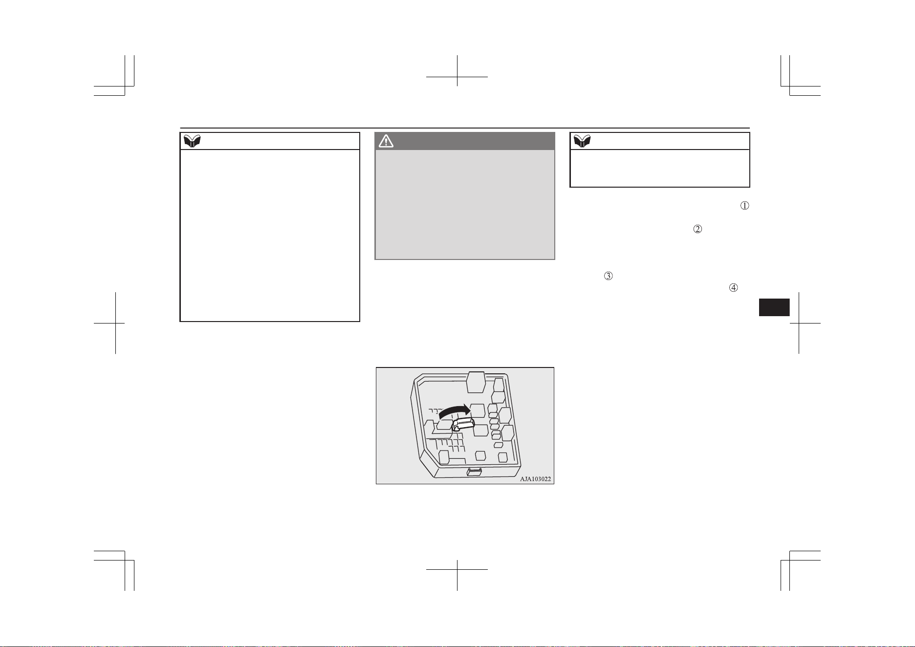
NOTE
l
If the auxiliary battery is disconnected, the
operation mode of the power switch is mem-
orized. When a booster battery is connected
by jumper cables, the operation mode re-
turns to the state it had before the auxiliary
battery ran down.
Pay due attention if you do not know the op-
eration mode before the auxiliary battery
was fully discharged.
l
If the auxiliary battery is fully discharged
with the select position in the “P” (PARK)
position, the select position cannot be
changed to other position from the “P”
(PARK) position in some cases. In such a
case, the front wheels have been locked.
Therefore, the vehicle cannot be moved.
1. Get the vehicles close enough so the
jumper cables can reach, but be sure the
vehicles aren’t touching each other.
2. Turn off all lamps, heater and other elec-
trical loads.
3. Set the parking brake firmly on each ve-
hicle. Set the gear of the other vehicle in
“P” (PARK) position (with A/T) or in
“N” (Neutral) position (with M/T) and
stop the engine.
WARNING
l
When connecting the jumper cable, stop
the engine in the other vehicle. Otherwise,
the cables or your clothes may be caught
by the fan or drive belt and personal in-
jury could result.
l
The cooling fan turns on and off depend-
ing on the coolant temperature. Do not
bring your hands close to the fan while
the engine is running or the Plug-in Hy-
brid EV System is operating.
4. Open the bonnet, remove the fuse cover
of the main fuse block.
Refer to “Bonnet” on page 11-04 and
“Fuses: Engine compartment” on page
11-18.
5. Open the cover of the jumper cable ter-
minal in the main fuse block.
NOTE
l
You cannot rescue another vehicle’s dis-
charged battery by connecting jumper cables
while using this jumper cable terminal.
6. Connect one end of one jumper cable
to the jumper cable terminal (A) of your
vehicle, and the other end
to the posi-
tive (+) terminal of the booster battery
(B).
Connect one end of the other jumper ca-
ble
to the negative (-) terminal of the
booster battery, and the other end to
Emergency starting
9-03
OGGE19E1
For emergencies
9
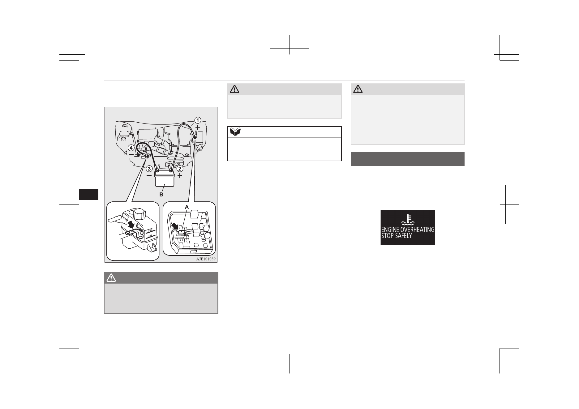
the designated ground location of your
vehicle.
WARNING
l
When connecting the jumper cables, do
not connect the positive (+) cable to the
negative (-) terminal. Otherwise sparks
might cause explosion of the battery.
CAUTION
l
Take care not to get the jumper cable caught
in the cooling fan or other rotating part in
the engine compartment.
NOTE
l
If the jumper cable is connected to any posi-
tion other than the appointed one, it may
cause damage to the vehicle.
7. Start the engine in the vehicle which has
the booster battery, let the engine idle a
few minutes, then start the Plug-in Hy-
brid EV system in your vehicle.
8. Check if the ready indicator illuminates.
If the ready indicator does not illumi-
nate, contact a MITSUBISHI MOTORS
Authorized Service Point.
9. When the ready indicator illuminates,
disconnect the jumper cables in the re-
verse order of connection.
10. Check if the select position can be shif-
ted to all positions other than the “P”
(PARK) position.
11. Have the auxiliary battery inspected by
your nearest MITSUBISHI MOTORS
Authorized Service Point.
CAUTION
l
Your vehicle is equipped with an exclusive
auxiliary battery. Even if the battery type is
the same, the battery may not be correctly
installed in your vehicle. When replacing the
auxiliary battery, request a MITSUBISHI
MOTORS Authorized Service Point to do
so.
Engine overheating
E00800604221
When the engine is overheating, the warning
display will appear on the information screen
in the multi information display.
Warning display
If this occurs, take the following corrective
measures:
1. Stop the vehicle in a safe place.
2. Check whether steam is coming from the
engine compartment.
[If steam does not come from the engine
compartment]
Engine overheating
9-04
OGGE19E1
For emergencies
9
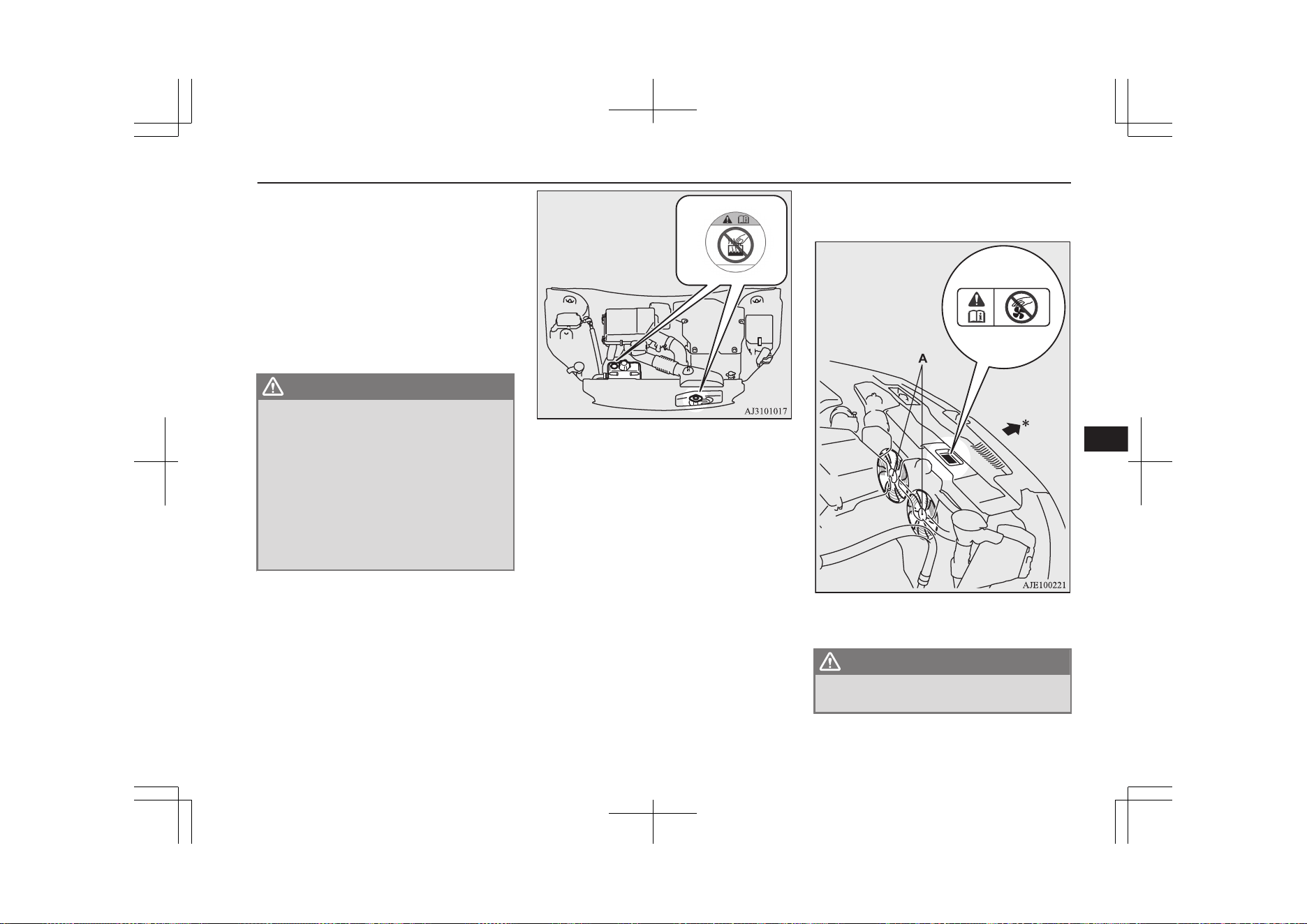
With the Plug-in Hybrid EV system still
starting, raise the bonnet to ventilate the
engine compartment.
[If steam is coming from the engine
compartment]
Stop the Plug-in Hybrid EV system, and
when the steam stops, raise the bonnet to
ventilate the engine compartment. Re-
start the Plug-in Hybrid EV system.
WARNING
l
Do not open the bonnet while steam is
coming from the engine compartment. It
could cause steam or hot water to spurt
out, causing burns. Hot water could spurt
out even when there is no steam coming
out, and some parts will be very hot. Be
very careful when opening the bonnet.
l
Be careful of hot steam, which could be
blowing off the reserve tank cap.
l
Do not attempt to remove the radiator cap
while the engine is hot.
3. Confirm that the cooling fans (A) are
turning.
[If the cooling fans are turning]
After the high coolant temperature warn-
ing has gone off, stop the Plug-in Hybrid
EV system.
[If the cooling fans are not turning]
Stop the Plug-in Hybrid EV system im-
mediately and contact a MITSUBISHI
MOTORS Authorized Service Point for
assistance.
*: Front of the vehicle
WARNING
l
Be careful not to get your hands or clothes
caught in the cooling fan.
Engine overheating
9-05
OGGE19E1
For emergencies
9
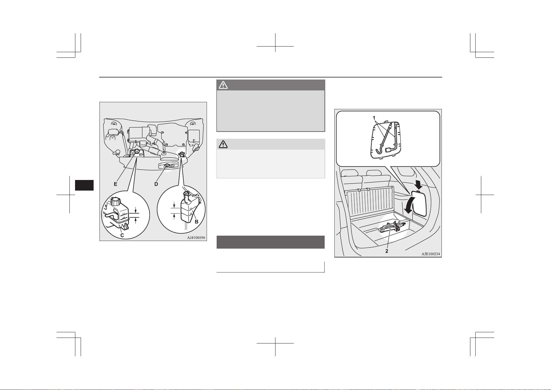
4. Check the coolant level in the reserve
tank (B and C).
Full
Full
Low
Low
B: Reserve tank for engine cooling
C: Reserve tank for EV cooling system
5. Add coolant to the radiator and/or re-
serve tank if necessary. (Refer to the
“Maintenance” section.)
WARNING
l
Make sure that the engine and the Plug-in
Hybrid EV system have cooled down be-
fore removing the radiator cap (D) and
the reserve tank cap (E), because hot
steam or boiling water will otherwise gush
from the filler port and may scald you.
CAUTION
l
Do not add coolant while the engine is hot.
Suddenly adding cold coolant could damage
the engine. Wait for the engine to cool down,
then add coolant a little at a time.
6. Examine the radiator hoses for coolant
leakage and the drive belt for looseness
or damage.
If there is anything wrong with the cool-
ing system or drive belt, we recommend
you to have it checked and repaired.
Tools and jack
E00800902507
Storage
The tools are stowed on the right side of the
luggage area.
The jack is stowed in the luggage floor box.
The storage location of the tools and jack
should be remembered in case of an emer-
gency.
1- Tools
2- Jack
Tools and jack
9-06
OGGE19E1
For emergencies
9
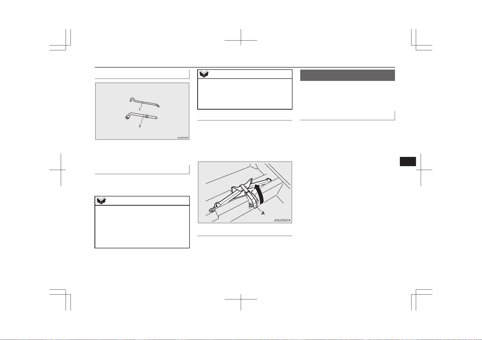
Tools
1- Jack bar
2- Wheel nut wrench
Jack
The jack is used only for the purpose of
changing a tyre when a tyre is punctured.
NOTE
l
The jack is maintenance-free.
l
The jack is in conformity with EC law as ap-
proximated by the Machinery Directive
2006/42/EC.
l
The EC declaration of conformity is attached
to the section “Declaration of Conformity”
in the end of this owner’s manual.
NOTE
•
The business name, full address of the
manufacturer and of his authorized repre-
sentative and the designation of the jack
are described in the EC declaration of
conformity.
To remove
1. Raise the luggage floor board.
Refer to “Luggage floor box” on page
8-83.
2. Remove the band (A) and take out the
jack.
To store
Perform the removal steps in reverse.
Tyre repair kit
E00804501142
This kit enables emergency repair of a small
puncture in the tread area of a tyre that has
run over a nail, screw, or similar object.
Storage
The tyre repair kit is stored beneath the lug-
gage floor board of the luggage compartment.
Tyre repair kit
9-07
OGGE19E1
For emergencies
9
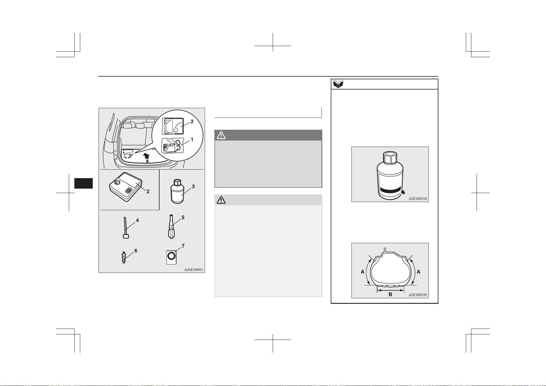
The storage location of the tyre repair kit
should be remembered in case of an emer-
gency.
1- Tyre repair set
2- Tyre compressor
3- Tyre sealant bottle
4- Filler hose
5- Valve remover
6- Valve insert (spare)
7- Speed restriction sticker
How to use the tyre repair kit
E00804601130
WARNING
l
Using the tyre repair kit may damage the
wheel and/or the tyre inflation pressure
sensor for the tyre.
The vehicle must promptly be inspected
and repaired by a MITSUBISHI
MOTORS Authorized Service Point after
using the tyre repair kit.
CAUTION
l
The tyre sealant can cause health damage if
swallowed. If you accidentally swallow it,
drink as much water as possible and imme-
diately consult a doctor.
l
If the tyre sealant gets in your eyes or on
your skin, rinse with lots of water. If you
still sense an abnormality, consult a doctor.
l
Consult a doctor immediately if any allergic
reactions occur.
l
Do not allow children to touch the tyre seal-
ant.
l
Do not breathe in the vapours of tyre sealant.
l
Be sure to use a MITSUBISHI MOTORS
GENUINE tyre sealant.
NOTE
l
The tyre sealant cannot be used in any of the
situations listed below. If any of these situa-
tions occurs, please contact a MITSUBISHI
MOTORS Authorized Service Point or an-
other specialist.
•
The tyre sealant’s expiry date has passed.
(The expiry date is shown on the bottle la-
bel.)
•
More than one tyre is punctured.
•
The puncture hole has a length or width of
4 mm or more.
•
The tyre is punctured in the side wall (A),
not in the tread (B).
Tyre repair kit
9-08
OGGE19E1
For emergencies
9
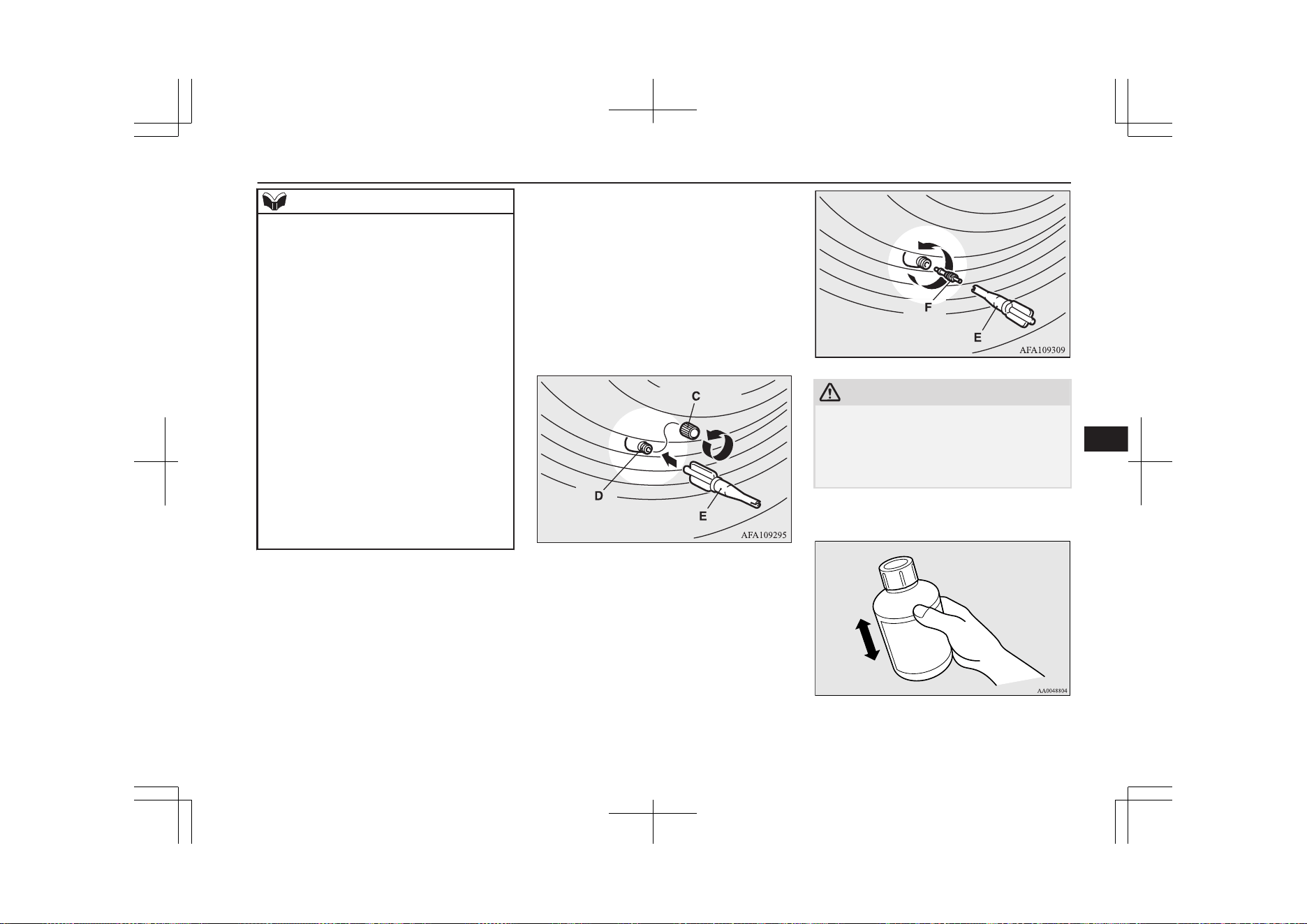
NOTE
•
The vehicle has been driven with the tyre
almost completely flat.
•
The tyre has completely slipped over the
wheel rim and has come off the wheel.
•
The wheel is damaged.
l
Use the tyre sealant only at ambient temper-
atures of -30 °C to + 60 °C.
l
Effect an emergency repair without pulling
out the object (nail, screw, etc.) that is stuck
in the tyre.
l
Do not use the tyre sealant if the tyre has
been damaged by being driven when insuffi-
ciently inflated (e.g. bumps, cuts, cracks etc.
on the tyre).
l
Wipe tyre sealant off the paintwork immedi-
ately with a damp cloth.
l
Immediately wash clothes contaminated
with tyre sealant.
l
Check the tyre sealant’s expiry date regular-
ly, and be sure to purchase a new one from a
MITSUBISHI MOTORS Authorized Serv-
ice Point before the expiry date.
Before repairing a tyre, first stop your vehicle
in a safe, flat location.
1. Park the vehicle on level and stable
ground.
2. Set the parking brake firmly.
3. Put the select position in “P” (PARK)
position and stop the Plug-in Hybrid EV
system.
4. Turn on the hazard warning flashers and
set up a warning triangle, flashing signal
lamp, etc., at an adequate distance from
the vehicle, and have all your passengers
leave the vehicle.
5. Take out the tyre repair kit.
6. Take the valve cap (C) off the tyre valve
(D), then press the valve remover (E)
onto the valve as illustrated. Allow all of
the air in the tyre to escape.
7. Remove the valve insert (F) by turning it
anticlockwise using the valve remover
(E). Put the removed valve insert in a
clean place so it does not get dirty.
CAUTION
l
If there is any air left in the tyre when you
remove the valve insert, the valve insert may
fly out and injure you. Make sure the tyre
contains no air before removing the valve in-
sert.
8. Shake the tyre sealant bottle well.
Tyre repair kit
9-09
OGGE19E1
For emergencies
9
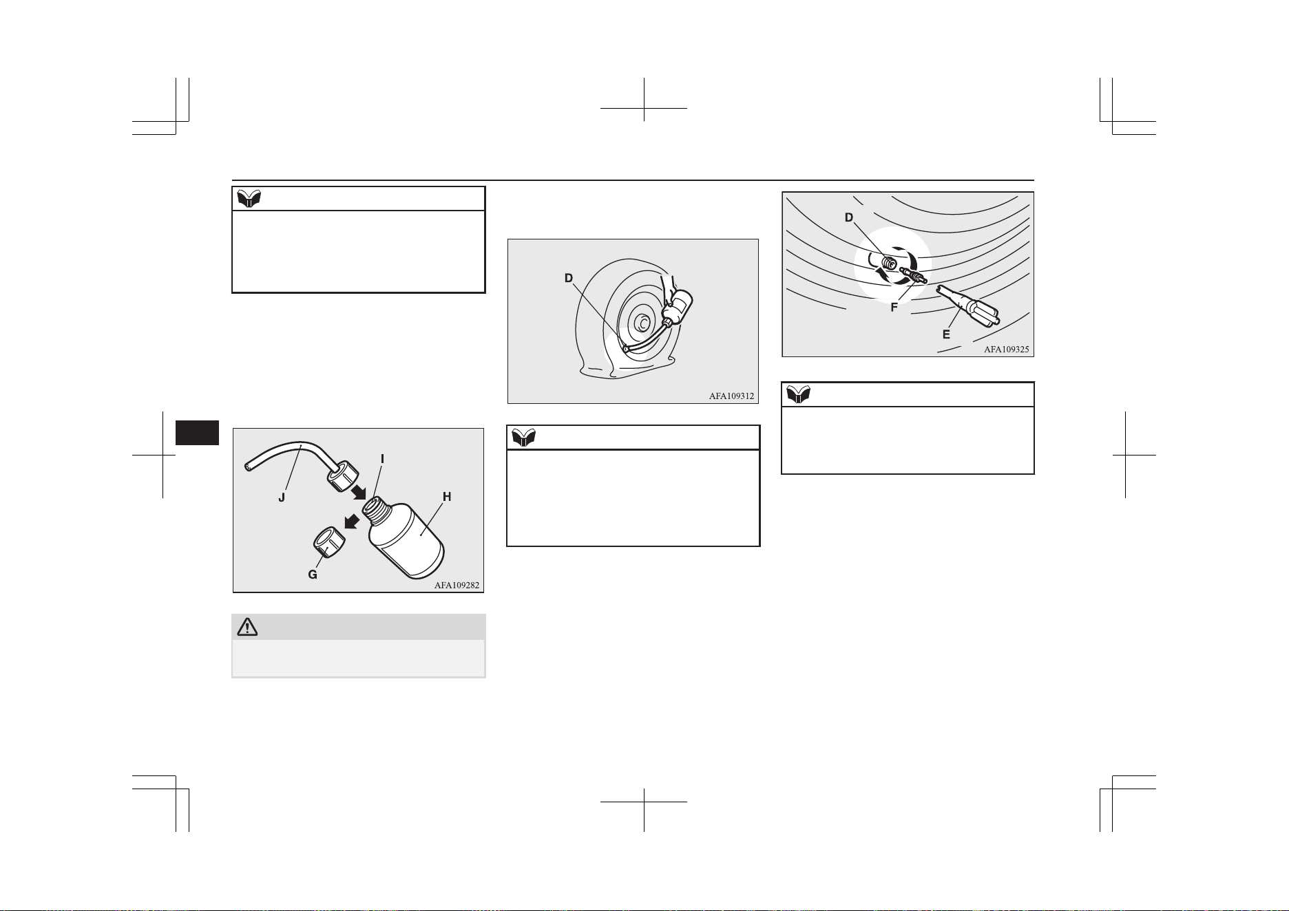
NOTE
l
In cold conditions (when the ambient tem-
perature is 0 °C or lower), thickening of the
tyre sealant can make the tyre sealant hard to
squeeze out of the bottle. Warm the bottle in-
side the vehicle.
9. Take the cap (G) off the tyre sealant bot-
tle (H). Do not remove the seal (I).
Screw the filler hose (J) onto the bottle
(H). As you screw the filler hose onto
the bottle, the seal will break, allowing
the sealant to be used.
CAUTION
l
If you shake the bottle after screwing on the
hose, sealant may spray out of the hose.
10. Press the hose onto the valve (D). Hold-
ing the sealant bottle upside-down,
squeeze it again and again to inject all of
the sealant into the tyre.
NOTE
l
When injecting the sealant, position the
valve away from the bottom, i.e., away from
the point where the tyre touches the ground.
If the valve is near the point where the tyre
touches the ground, the sealant may not go
into the tyre easily.
11. After injecting the sealant, pull the hose
off the valve, remove any residual seal-
ant from the valve, rim and/or tyre. Fit
the valve insert (F) into the valve (D),
and screw the valve insert securely into
place using the valve remover (E).
NOTE
l
When removing and screwing in the valve
insert using the valve remover, turn the
valve remover by hand. Using a tool to turn
the valve remover could damage it.
Tyre repair kit
9-10
OGGE19E1
For emergencies
9
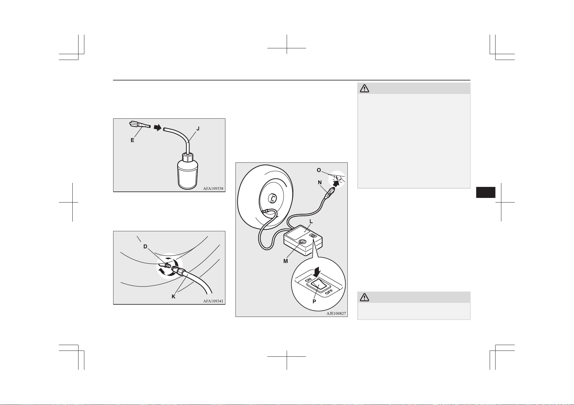
12. After injecting the sealant, securely fit
the valve remover (E) into the end of the
filler hose (J) to prevent sealant from
leaking from the empty bottle.
13. Pull out the compressor hose (K) from
the side of the tyre compressor, and then
securely attach the hose to the tyre valve
(D).
14. Place the compressor (L) with its air
pressure gauge (M) on top.
Pull out the compressor’s power cord
(N), insert the plug on the cord into the
accessory socket (O), and then put the
operation mode of the power switch in
ACC. (Refer to “Accessory socket*” on
page 8-75.)
Turn ON the compressor switch (P) and
inflate the tyre to the specified pressure.
(Refer to “Tyre inflation pressures” on
page 11-10.)
CAUTION
l
The supplied compressor is designed only
for inflation of your vehicle tyres.
l
The compressor is designed to run on a vehi-
cle’s 12 V power supply. Do not connect it
to any other power source.
l
The compressor is not waterproof. If you use
it in rain, make sure water does not get on it.
l
Any sand or dust sucked into the compressor
could make the compressor break down. Do
not place the compressor directly on any
sandy or dusty surface when using it.
l
Do not disassemble or modify the compres-
sor. Also, do not subject the air pressure
gauge to shock. It could malfunction.
15. Check and adjust the tyre pressure with
reference to the air pressure gauge on the
compressor. If you overinflate the tyre,
release air by loosening the hose’s end
fitting.
If there is a gap between the tyre and
wheel because the tyre has moved in-
ward from the wheel rim, press the pe-
riphery of the tyre towards the wheel to
close the gap before running the com-
pressor. (With no gaps, the tyre pressure
will rise.)
CAUTION
l
Be careful not to get your fingers trapped be-
tween the tyre and wheel as the tyre inflates.
Tyre repair kit
9-11
OGGE19E1
For emergencies
9
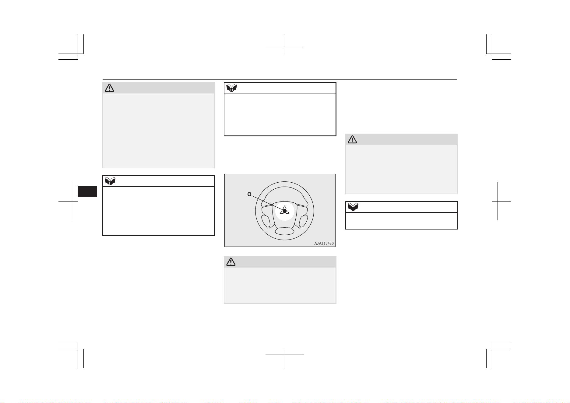
CAUTION
l
The surface of the compressor will get hot
while the compressor is running. Do not
keep the compressor running continuously
for more than 10 minutes. After using the
compressor, wait for the compressor to cool
before using it again.
l
If the compressor becomes sluggish or hot
while operating, it is overheating. Immedi-
ately place the switch in the OFF position
and let the compressor cool down for at least
30 minutes.
NOTE
l
If the tyre pressure does not rise to the speci-
fied level within 10 minutes, the tyre may be
so severely damaged that the tyre sealant
cannot be used to effect an emergency re-
pair. Please contact a MITSUBISHI
MOTORS Authorized Service Point or an-
other specialist in this event.
16. Turn OFF the compressor switch, then
pull the power cord plug out of the sock-
et.
NOTE
l
Simply putting sealant and air into the tyre
using the tyre repair kit does not seal the
puncture hole. Air will leak through the
puncture hole until the emergency repair
procedure is completed (through step 19 or
step 20 of these instructions).
17. Affix the speed restriction sticker (Q) to
the three-diamond mark on the steering
wheel.
CAUTION
l
Do not affix the sticker anywhere except the
specified position on the pad of the steering
wheel. Affixing the sticker in an incorrect
position could prevent the SRS airbag from
working normally.
18. When you have inflated the tyre to the
specified pressure, stow the compressor,
bottle, and other items in the vehicle and
promptly start driving the vehicle so that
the tyre sealant can spread evenly in the
tyre. Drive with great care. Do not ex-
ceed a speed of 80 km/h (50 mph). Ob-
serve local speed limits.
CAUTION
l
If you sense any abnormality while driving,
stop the vehicle and contact a MITSUBISHI
MOTORS Authorized Service Point or an-
other specialist. Otherwise the tyre pressure
may drop before the emergency repair pro-
cedure is completed, rendering the vehicle
unsafe.
NOTE
l
Driving faster than 80 km/h (50 mph) can
make the vehicle vibrate.
19. After driving for 10 minutes or 5 km,
check the tyre pressure using the air
pressure gauge on the compressor. If the
tyre pressure has apparently not drop-
ped, the emergency repair procedure is
complete. Continue the process from
step 21.
If the tyre pressure is not sufficient, in-
flate the tyre to the specified pressure
again and drive the vehicle carefully
without exceeding a speed of 80 km/h.
Tyre repair kit
9-12
OGGE19E1
For emergencies
9
CAUTION
l
If the tyre pressure is lower than the mini-
mum permitted pressure (1.3 bar {130
kPa}), the tyre cannot successfully be re-
paired with the tyre sealant. Do not drive the
vehicle any further. Contact a MITSUBISHI
MOTORS Authorized Service Point or an-
other specialist.
20. After driving for 10 minutes or 5 km,
check the tyre pressure using the air
pressure gauge on the compressor. If the
tyre pressure has apparently not drop-
ped, the emergency repair procedure is
complete. You must still not exceed a
speed of 80 km/h. Observe local speed
limits.
NOTE
l
If the tyre pressure has dropped below the
specified level when you check it at the end
of the repair procedure, do not drive the ve-
hicle any further. Contact a MITSUBISHI
MOTORS Authorized Service Point or an-
other specialist.
NOTE
l
In cold conditions (when the ambient tem-
perature is 0 °C or lower), the time and driv-
ing distance necessary until completion of
the repair can be longer than in warmer con-
ditions, meaning that the tyre pressure can
drop below the specified level even when
you have inflated the tyre a second time and
subsequently driven the vehicle. If this hap-
pens, inflate the tyre to the specified pres-
sure once more, drive for about 10 minutes
or 5 km, then check the tyre pressure again.
If the tyre pressure has again dropped below
the specified level, stop driving the vehicle
and contact a MITSUBISHI MOTORS Au-
thorized Service Point or another specialist.
21. Immediately drive with great care to a
MITSUBISHI MOTORS Authorized
Service Point and have tyre repair/
replacement performed.
CAUTION
l
Be sure to check the tyre pressure for confir-
mation that the emergency repair procedure
is complete.
NOTE
l
Please give the empty sealant bottle to your
MITSUBISHI MOTORS Authorized Serv-
ice Point when you purchase new sealant or
dispose of the sealant bottle according to na-
tional regulations for the disposal of chemi-
cal waste.
l
A tyre in which puncture sealant has been
used should ideally be replaced with a new
one. If you wish to have such a tyre properly
repaired for reuse, please contact a
MITSUBISHI MOTORS Authorized Serv-
ice Point or another specialist. Note that a
proper repair is impossible following an
emergency repair if the puncture hole cannot
be located.
l
The manufacturer is unable to guarantee that
all tyre punctures can be repaired with the
tyre repair kit, in particular cuts or perfora-
tions with a diameter of more than 4 mm or
away from the tyre’s tread. The manufactur-
er is not liable for damage sustained through
improper use of the tyre repair kit.
l
The manufacturer is not liable for damage
sustained through re-use of any tyre in
which tyre sealant has been used.
How to change a tyre
E00801203924
Before changing a tyre, first stop your vehi-
cle in a safe, flat location.
1. Park the vehicle on level and stable
ground, free of loose pebbles, etc.
2. Set the parking brake firmly.
How to change a tyre
9-13
OGGE19E1
For emergencies
9
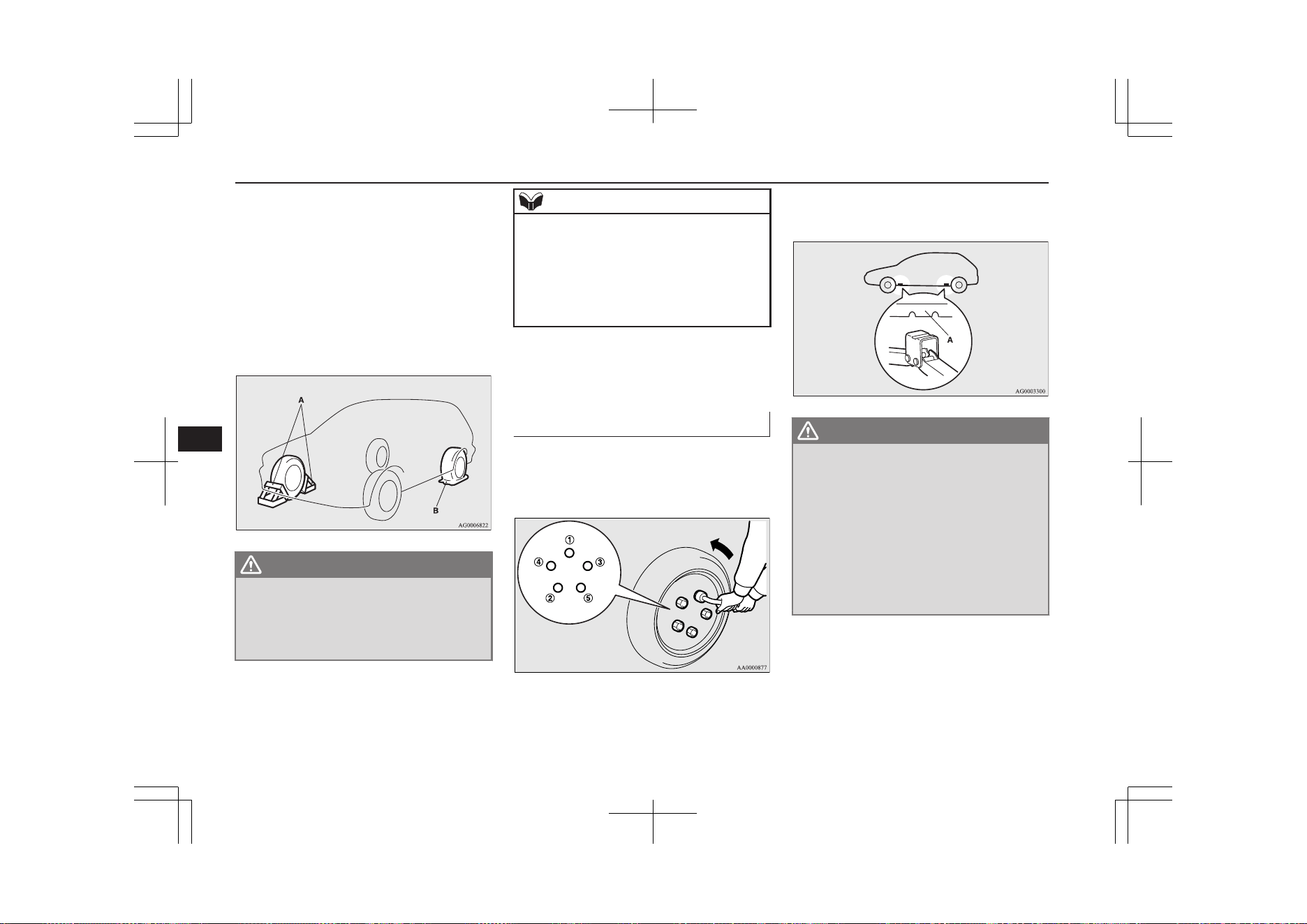
3. Put the select position in “P” (PARK)
position and stop the Plug-in Hybrid EV
system.
4. Have all your passengers get out of the
vehicle.
5. To prevent the vehicle from rolling when
jacking up the vehicle, place chocks or
blocks (A) at the tyre that is diagonally
opposite from the tyre (B) you are
changing.
WARNING
l
Be sure to apply chocks or blocks to the
correct tyre when jacking up the vehicle.
If the vehicle moves while jacked up, the
jack could slip out of position, leading to
an accident.
NOTE
l
The chocks shown in the illustration do not
come with your vehicle. It is recommended
that you keep one in the vehicle for use if
needed.
l
If chocks are not available, use stones or any
other objects that are large enough to hold
the wheel in position.
6. Get the jack, jack bar and wheel nut
wrench ready.
Refer to “Tools and jack” on page 9-06.
To change a tyre
E00803202745
1. Loosen the wheel nuts a quarter turn
with the wheel nut wrench. Do not re-
move the wheel nuts yet.
2. Place the jack under one of the jacking
points (A) shown in the illustration. Use
the jacking point closest to the tyre you
wish to change.
WARNING
l
Set the jack only at the positions shown
here. If the jack is set at a wrong position,
it could dent your vehicle or the jack
might fall over and cause personal injury.
l
Do not use the jack on a tilted or soft sur-
face.
Otherwise, the jack might slip and cause
personal injury. Always use the jack on a
flat, hard surface. Before setting the jack,
make sure there are no sand or pebbles
under the jack base.
How to change a tyre
9-14
OGGE19E1
For emergencies
9
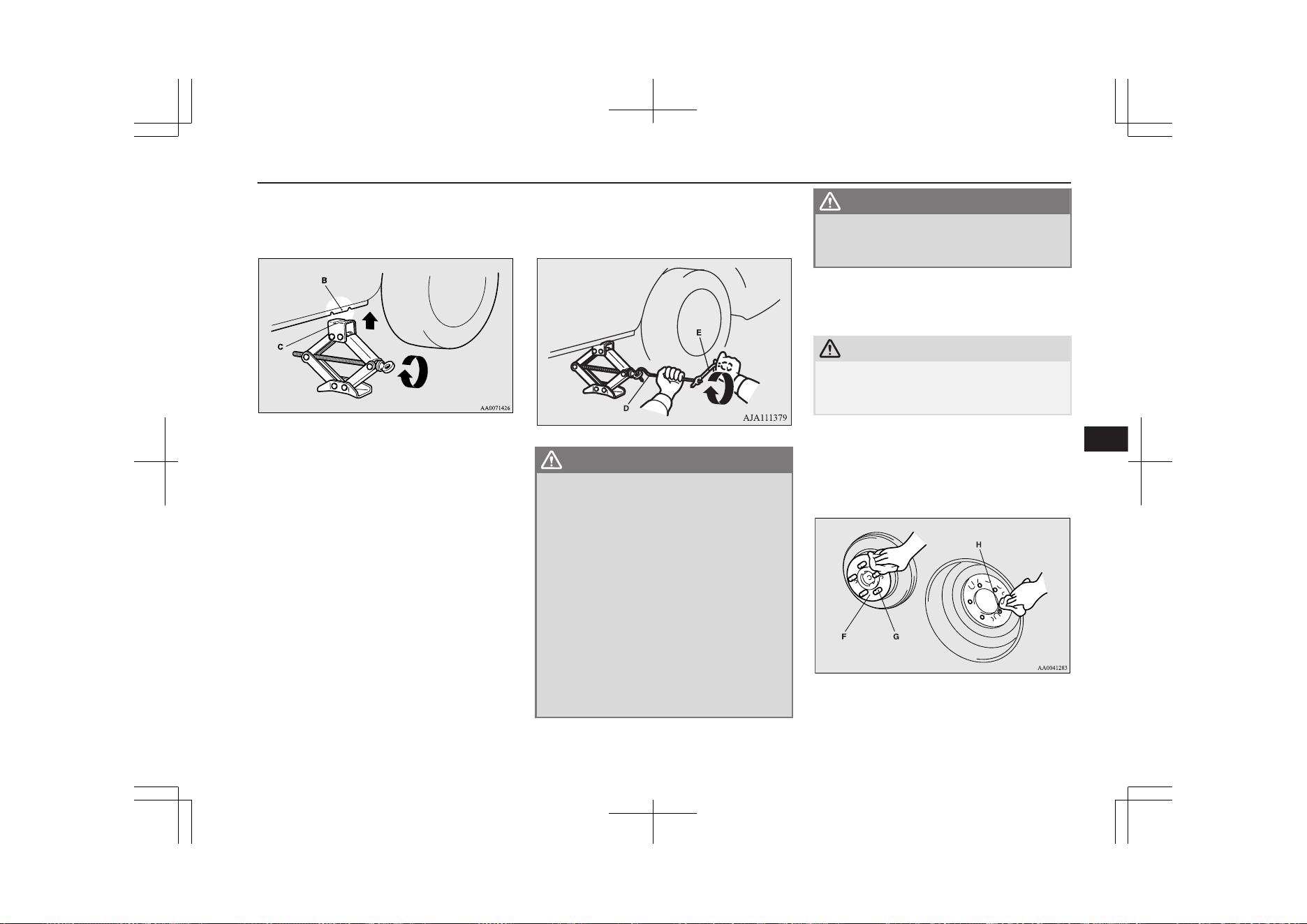
3. Rotate the jack by hand until the flange
portion (B) fits in the groove (C) at the
top of the jack.
4. Check that the flange portion at the jack-
ing point fits in the groove at the top of
the jack.
Insert the jack bar (D) into the wheel nut
wrench (E). Then put the end of the jack
bar into the shaft’s jack end, as shown in
the illustration.
Slowly rotate the wheel nut wrench until
the tyre is raised slightly off the ground
surface.
WARNING
l
Stop jacking up the vehicle as soon as the
tyre is raised off the ground. It is danger-
ous to raise the vehicle any higher.
l
Do not get under your vehicle while using
the jack.
l
Do not bump the raised vehicle or leave it
sitting on the jack for a long time. Both
are very dangerous.
l
Do not use a jack except the one that
came with your vehicle.
l
The jack should not be used for any pur-
pose other than to change a tyre.
l
No one should be in your vehicle when us-
ing the jack.
l
Do not start the Plug-in Hybrid EV sys-
tem while your vehicle is on the jack.
WARNING
l
Do not turn the raised wheel. The tyres
still on the ground could turn and make
your vehicle fall off the jack.
5. Remove the wheel nuts with the wheel
nut wrench, then take the wheel off.
CAUTION
l
Handle the wheel carefully when changing
the tyre, to avoid scratching the wheel sur-
face.
6. Clean out any mud, etc. on the hub sur-
face (F), hub bolts (G) or in the installa-
tion holes (H) in the wheel, and then
mount the tyre.
How to change a tyre
9-15
OGGE19E1
For emergencies
9
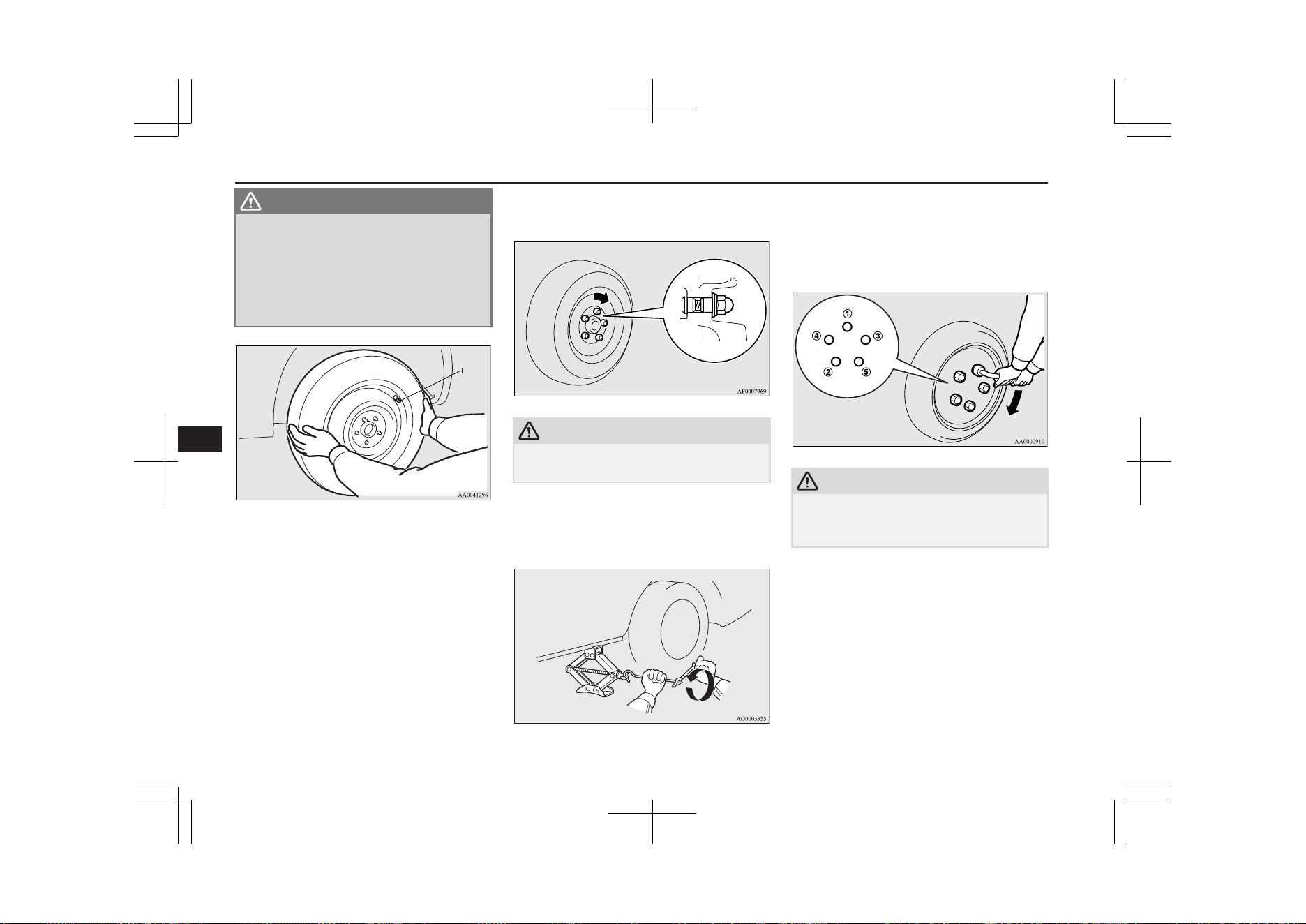
WARNING
l
Mount the wheel with the valve stem (I)
facing outboard. If you cannot see the
valve stem (I), you have installed the
wheel backwards.
Operating the vehicle with the wheel in-
stalled backwards can cause vehicle dam-
age and result in an accident.
7. Turn the wheel nuts clockwise by hand
to initially tighten them.
Temporarily tighten the wheel nuts by
hand until the flange parts of the wheel
nuts make light contact with the wheel
and the wheel is not loose.
CAUTION
l
Never apply oil to either the wheel bolts or
the nuts, or they will tighten too much.
8. Lower the vehicle slowly by rotating the
wheel nut wrench anticlockwise until the
tyre touches the ground.
9. Tighten the nuts in the order shown in
the illustration until each nut has been
tightened to the torque listed here.
Tightening torque: 88 to 108 N•m
CAUTION
l
Never use your foot or a pipe extension for
extra force in the wheel nut wrench. If you
do so, you will tighten the nut too much.
10. Lower and remove the jack, then store
the jack, flat tyre, and chocks. Have your
damaged tyre repaired as soon as possi-
ble.
11. Check your tyre inflation pressure at the
next gasstation. The correct tyre pres-
How to change a tyre
9-16
OGGE19E1
For emergencies
9
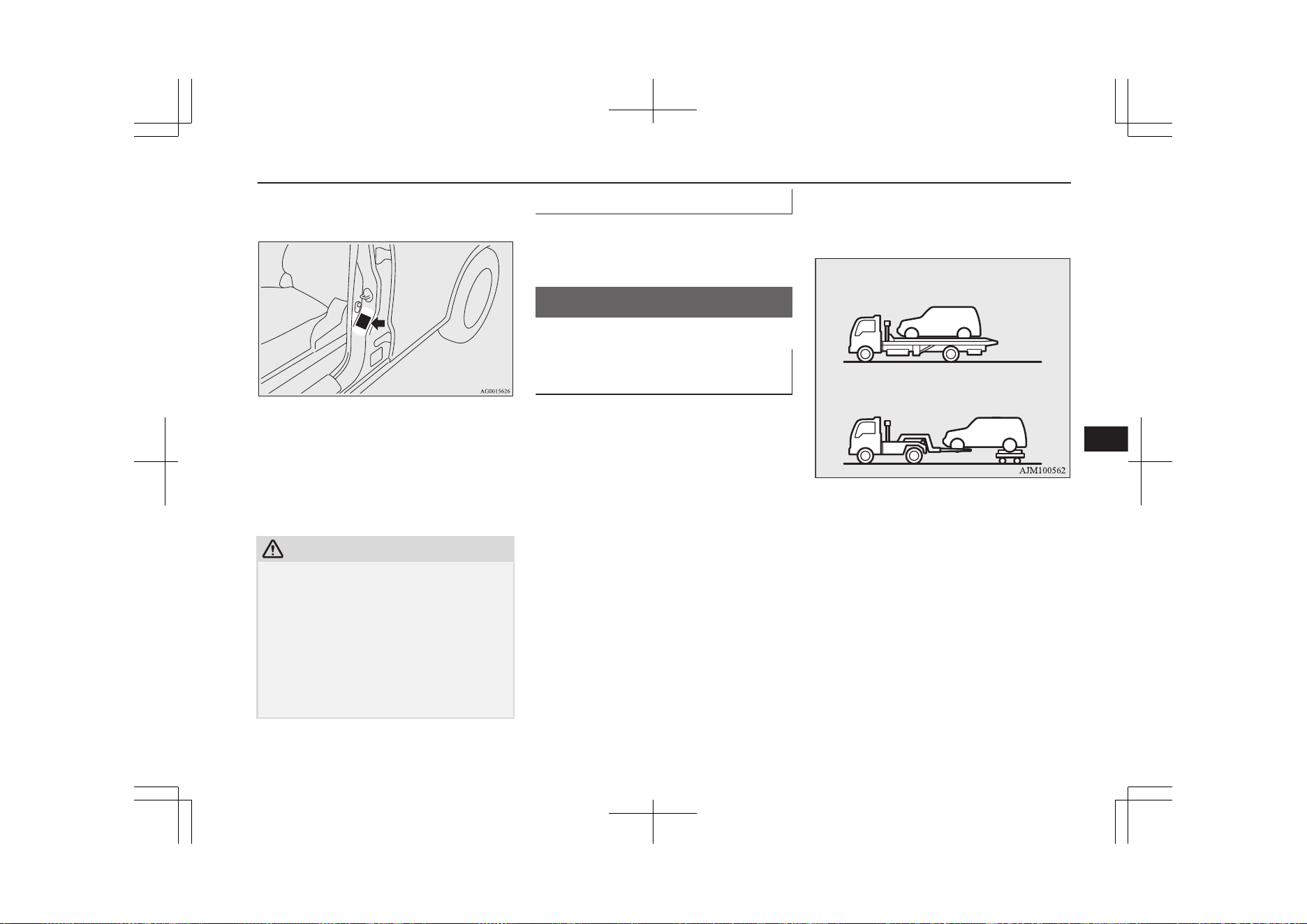
sures are shown on the driver’s door la-
bel. See the illustration.
12. After filling your tyres to the correct
pressure, reset the tyre pressure monitor-
ing system (TPMS).
Refer to “Tyre pressure monitoring sys-
tem (TPMS): Reset of low tyre pressure
warning threshold” on page 7-96.
CAUTION
l
After changing the tyre and driving the vehi-
cle about 1,000 km (620 miles), retighten the
wheel nuts to make sure that they have not
come loose.
l
If the steering wheel vibrates when driving
after changing the tyre, we recommend you
to have the tyres checked for balance.
l
Do not mix one type of tyre with another or
use a different size from the one listed. This
would cause early wear and poor handling.
To store the tools and jack
E00803800037
Reverse the removing procedure when stor-
ing the jack, jack bar and wheel nut wrench.
Refer to “Tools and jack” on page 9-06.
Towing
E00801504953
If your vehicle needs to be tow-
ed
If you need to tow your vehicle, we recom-
mend that you contact a MITSUBISHI
MOTORS Authorized Service Point or a
commercial tow truck service.
Transport the vehicle on a flatbed truck or
tow the vehicle with all wheels off the
ground.
In the following cases, contact a
MITSUBISHI MOTORS Authorized Service
Point and transport the vehicle with all
wheels on a carriage.
l
The ready indicator illuminates but the
vehicle does not move, or an abnormal
noise is produced.
l
A warning lamp in the meter illuminates.
l
Inspection of the vehicle’s underside re-
veals that oil or some other fluid is leak-
ing.
l
Your vehicle body is severely damaged
or deformed in the event of an accident.
Towing
9-17
OGGE19E1
For emergencies
9
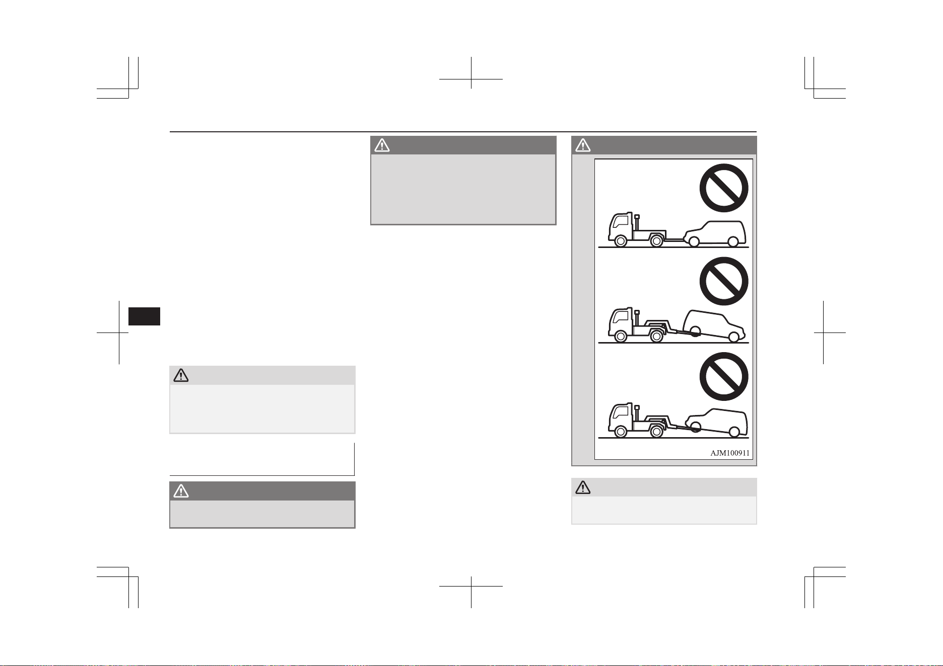
If a wheel gets stuck in a ditch, do not try to
tow the vehicle.
Please contact your MITSUBISHI MOTORS
Authorized Service Point or a commercial
tow truck service for assistance.
Your vehicle may be temporarily towed by
another vehicle with a rope in emergency sit-
uations such as running out of fuel.
If your vehicle is to be towed by another ve-
hicle, carefully tow your vehicle for the
shortest distance possible and in accordance
with the instructions given in “Emergency
towing” in this part.
The regulations concerning towing may dif-
fer from country to country. It is recommen-
ded that you obey the regulations of the area
where you are driving your vehicle.
CAUTION
l
If the drivetrain or suspension has a prob-
lem, do not tow the vehicle with only the
rear wheels or front wheels placed on a dol-
ly.
Towing the vehicle by a tow
truck
WARNING
l
Never get under your vehicle after it has
been lifted by a tow truck.
WARNING
l
Never ride in a vehicle that is being tow-
ed.
l
Never tow the vehicle with front wheels
and/or rear wheels on the ground. This
may cause damage to the electric motors
and transaxle.
WARNING
CAUTION
l
Never tow the vehicle using a sling type
truck.
Towing
9-18
OGGE19E1
For emergencies
9
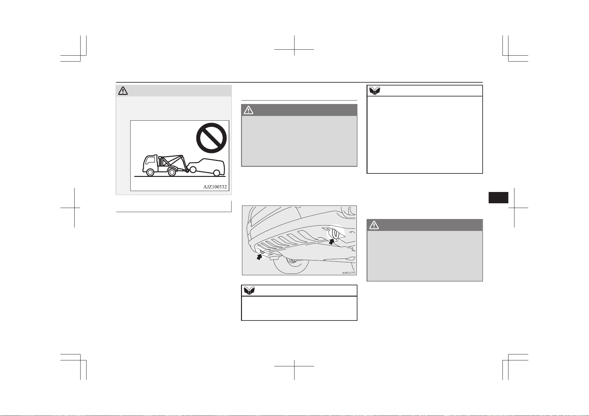
CAUTION
Doing so will damage the bumper and/or
body.
Emergency towing
If your vehicle is temporarily towed by an-
other vehicle with a rope in emergency situa-
tions such as running out of fuel, the towing
distance should be as short as possible and
tow carefully in accordance with the follow-
ing procedure.
If your vehicle is to be towed by
another vehicle
WARNING
l
Never tow your vehicle in this method ex-
cept in emergency situations such as run-
ning out of fuel. If the vehicle is towed in
this method, a problem can occur in the
vehicle damaging the motor, transaxle,
etc. indicated by illuminating warning
lamps.
1. The front towing hooks are located as
shown in illustration. Secure the tow
rope to the front towing hook.
NOTE
l
Using any part other than the designated
towing hook could result in damage to vehi-
cle body.
NOTE
l
Using a wire rope or metal chain can result
in damage to the vehicle body. It is best to
use a non-metallic rope. If you use a wire
rope or metal chain, wrap it with cloth at any
point where it touches the vehicle body.
l
Take care that the tow rope is kept as hori-
zontal as possible. An angled tow rope can
damage the vehicle body.
l
Secure the tow rope to the same side towing
hook, to keep the tow rope as straight as pos-
sible.
2. Start the Plug-in Hybrid EV system.
If the Plug-in Hybrid EV System cannot
be started, put the operation mode of the
power switch in “ON”.
WARNING
l
If the vehicle is towed with the operation
mode in “ON” without starting the Plugin
Hybrid EV System, the auxiliary battery
may be fully discharged during towing. In
this case, the brake performance becomes
very poor and the steering wheel becomes
very heavy.
Towing
9-19
OGGE19E1
For emergencies
9
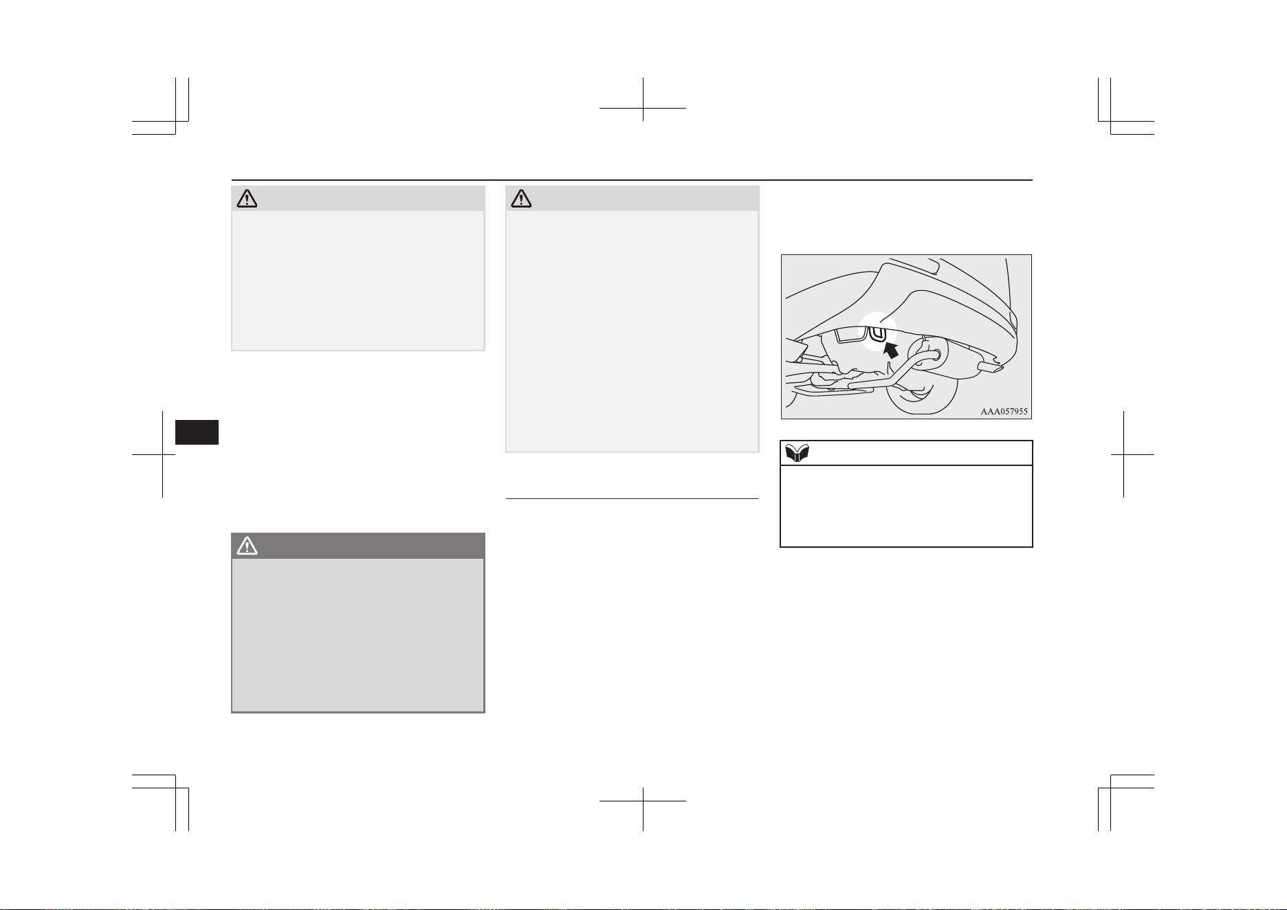
CAUTION
l
For vehicle equipped with the Adaptive
Cruise Control system (ACC) and Forward
Collision Mitigation system (FCM), stop
these systems to prevent an unexpected acci-
dent or unexpected operation during towing.
Refer to “Adaptive Cruise Control system
(ACC)” on page 7-55 and “Forward Colli-
sion Mitigation system (FCM)” on page
7-67.
3. Put the select position in “N” (NEU-
TRAL) position.
4. Turn on the hazard warning lamps if re-
quired by law. (Follow the local driving
laws and regulations.)
5. During towing make sure that close con-
tact is maintained between the drivers of
both vehicles, and that the vehicles trav-
el at low speed.
WARNING
l
Avoid sudden braking, acceleration and
steering wheel movements; such driving
operation could cause damage to the tow-
ing hook or tow rope.
People in the vicinity could be injured as a
result.
l
When going down a long slope, the brakes
may overheat, reducing effectiveness.
Have your vehicle transported by a tow
truck.
CAUTION
l
The person in the vehicle being towed must
pay attention to the brake lamps of the tow-
ing vehicle and make sure the rope never be-
comes slack.
l
When the vehicle is to be towed by another
vehicle with all the wheels on the ground,
make sure that the towing speed and dis-
tance given below are never exceeded,
avoiding damage to the transaxle.
Towing speed: 30 km/h (19 mph)
Towing distance: 30 km
For the towing speed and the towing dis-
tance, follow the local driving laws and reg-
ulations.
If your vehicle tows another ve-
hicle
Only use the rear towing hook as shown in
the illustration.
Secure the tow rope to the rear towing hook.
Otherwise, the instructions are the same as
for “When being towed by another vehicle”.
NOTE
l
Using any part other than the designated
towing hook could result in damage to vehi-
cle body.
l
Do not tow a vehicle heavier than your own
vehicle.
Towing
9-20
OGGE19E1
For emergencies
9
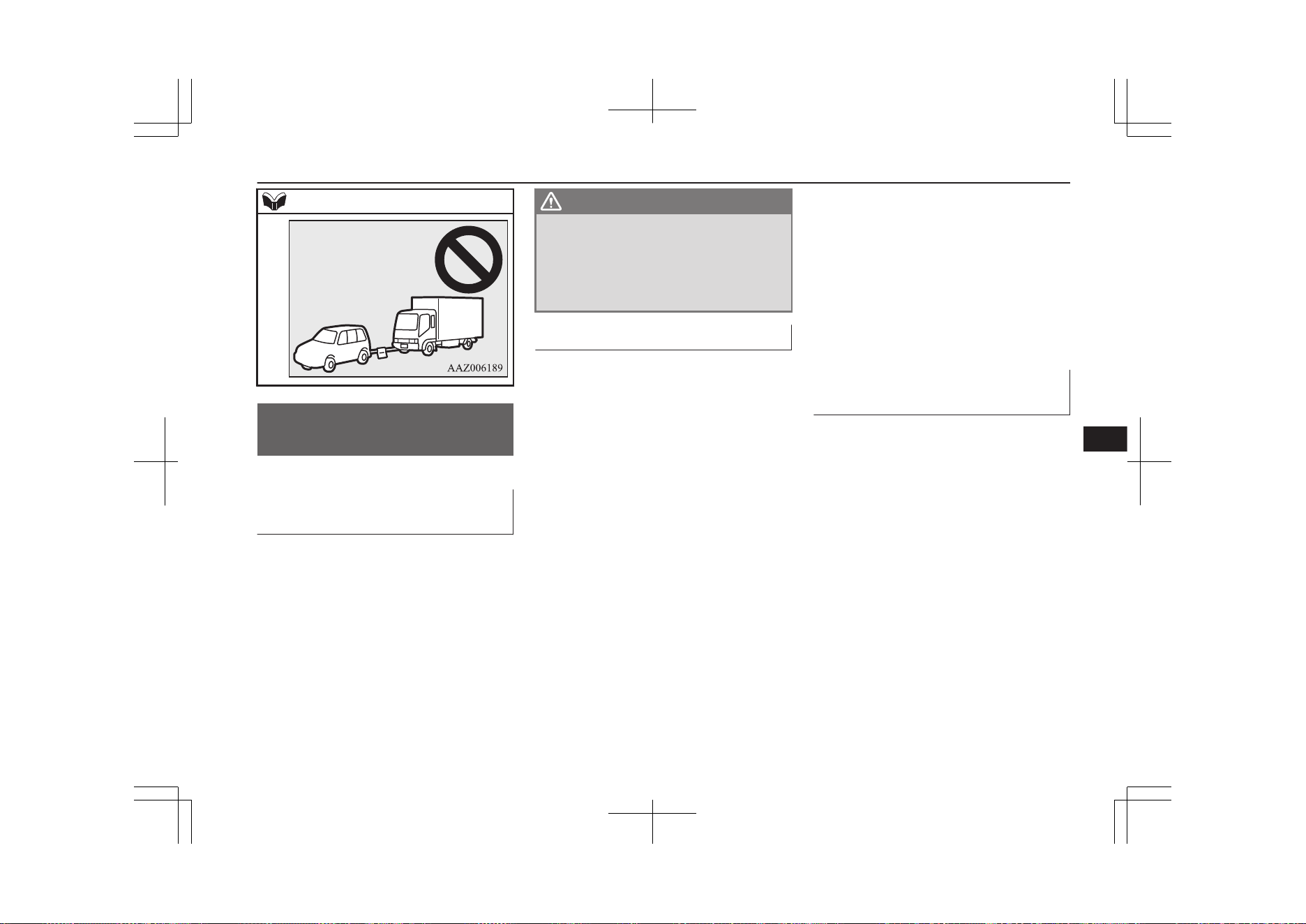
NOTE
Operation under adverse
driving conditions
E00801703828
If your vehicle becomes stuck
in sand, mud or snow
If your vehicle becomes stuck in snow, sand,
or mud, it can often be moved by a rocking
motion. Rock your vehicle back and forth to
free it.
Do not spin the wheels. Constant efforts to
free a stuck vehicle can cause transaxle fail-
ure.
If your vehicle is still stuck after several
rocking attempts, call for a commercial tow
truck service.
WARNING
l
When trying to rock your vehicle out of a
stuck position, make sure that there are
no people nearby. The rocking motion can
make your vehicle suddenly lurch for-
ward or backward, and injure any by-
standers.
On a flooded road
l
Do not drive on a flooded road. If you
drive on a flooded road, not only does
the Plugin Hybrid EV System stop but
there may be a failure like electric leak-
age or short circuit.
If you inevitably had to run on a flooded
road and the vehicle was exposed to wa-
ter, be sure to have your vehicle inspec-
ted by a MITSUBISHI MOTORS Au-
thorized Service Point.
l
If there is water on the brakes after driv-
ing through puddles or washing the vehi-
cle, resulting in temporarily ineffective
brakes. In such cases, lightly depress the
brake pedal to see if the brakes operate
properly. If they do not, lightly depress
the pedal several times while driving in
order to dry the brake pads.
l
When driving in rain or on a road with
many puddles a layer of water may form
between the tyres and the road surface.
This reduces a tyre’s frictional resistance
on the road, resulting in loss of steering
stability and braking capability.
To cope with this, observe the following
items:
A- Drive your vehicle at slow speed.
B- Do not drive on worn tyres.
C- Always maintain the specified tyre
inflation pressures.
On a snow-covered or frozen
road
l
When driving on a snow-covered or fro-
zen road, it is recommended that you use
snow tyres or snow traction device (tyre
chains).
Refer to the “Snow tyres” and “Snow
traction device (tyre chains)” sections.
l
Avoid high-speed operation, sudden ac-
celeration, abrupt brake application and
sharp cornering.
Operation under adverse driving conditions
9-21
OGGE19E1
For emergencies
9

l
Depressing the brake pedal during travel
on snowy or icy roads may cause tyre
slippage and skidding. When traction be-
tween the tyres and the road is reduced
the wheels may skid and the vehicle can-
not readily be brought to a stop by con-
ventional braking techniques. Braking
will differ, depending upon whether you
have anti-lock brake system (ABS). As
your vehicle is equipped with ABS,
brake by pressing the brake pedal hard,
and keeping it pressed.
l
Allow extra distance between your vehi-
cle and the vehicle in front of you, and
avoid sudden braking.
l
Accumulation of ice on the braking sys-
tem can cause the wheels to lock. Pull
away from a standstill slowly after con-
firming safety around the vehicle.
CAUTION
l
Do not press the accelerator pedal rapidly. If
the wheels break free of the ice, the vehicle
could suddenly start moving and possibly
cause an accident.
On a bumpy or rutted road
Drive as slow as possible when driving on
bumpy or rutted roads.
CAUTION
l
The impact on tyres and/or wheels when
driving on a bumpy or rutted road can dam-
age the tyre and/or wheel.
This vehicle is intended for driving mainly
on roads with firm surface.
4WD system makes it possible to drive on
roads without special coverage, on flat and
firm surfaces. Please, remember that off-road
ability of your vehicle is limited. Your vehi-
cle is not intended for driving in heavy off-
road terrain, overcoming the rugged terrain,
deep ruts, etc.
The manufacturer of the vehicle is proceed-
ing from the following assumption: if the
driver makes the decision to keep driving un-
der conditions mentioned above, he takes all
actions at own risk, aware of the possible
consequences.
Operation under adverse driving conditions
9-22
OGGE19E1
For emergencies
9

Vehicle care precautions....................................................................10-02
Cleaning the interior of your vehicle................................................ 10-02
Cleaning the exterior of your vehicle................................................10-03
Vehicle care
OGGE19E1
10
Vehicle care precautions
E00900100548
In order to maintain the value of your vehi-
cle, it is necessary to perform regular mainte-
nance using the proper procedures.
Always maintain your vehicle in compliance
with environmental pollution control regula-
tions.
Carefully select the materials used for wash-
ing, etc., to be sure that they do not contain
corrosives.
If in doubt, we recommend you to consult a
specialist for selection of these materials.
CAUTION
l
Cleaning products can be dangerous. Always
follow the instructions of the cleaning prod-
uct supplier.
l
To avoid damage, never use the following to
clean your vehicle,
•
Petrol
•
Paint Thinner
•
Benzine
•
Kerosene
•
Turpentine
•
Naphtha
•
Lacquer Thinner
•
Carbon Tetrachloride
•
Nail Polish Remover
•
Acetone
Cleaning the interior of your
vehicle
E00900201823
After cleaning the interior of your vehicle
with water, cleaner or similar, wipe and dry
in a shady, well-ventilated area.
NOTE
l
To clean the inside of the tailgate window,
always use a soft cloth and wipe the window
glass along the demister heater element so as
not to cause damage.
CAUTION
l
Do not use organic substances (solvents,
benzine, kerosene, alcohol, petrol, etc.) or
alkaline or acidic solutions.
These chemicals can cause discolouring,
staining or cracking of the surface.
If you use cleaners or polishing agents, make
sure their ingredients do not include the sub-
stances mentioned above.
l
When cleaning the meter cluster panel, use a
thick cloth and be careful not to injure your
hands.
Plastic, vinyl leather, fabric
and flocked parts
E00900301462
1. Lightly wipe these off with a soft cloth
soaked in a mild soap and water solu-
tion.
2. Dip cloth in fresh water and wring it out
well. Using this cloth, wipe off the deter-
gent thoroughly.
NOTE
l
Do not use cleaners, conditioners, and pro-
tectants containing silicons or wax.
Such products can cause discolouring and
when applied to the instrument panels or
other parts, may cause reflections on the
windscreen and obscure vision.
Also, if such products get on the switches of
the electrical accessories, it may lead to fail-
ure of these accessories.
l
Do not use synthetic fiber or dry cloth. They
can cause discolouring or damage the sur-
face.
l
Do not place a deodorizer on the instrument
panel or near lamps and instruments. The in-
gredients for deodorizer can cause discolour-
ing or cracking.
Vehicle care precautions
10-02
OGGE19E1
Vehicle care
10
Upholstery
E00900500207
1. To maintain the value of your new vehi-
cle, handle the upholstery carefully and
keep the interior clean.
Use a vacuum cleaner and brush to clean
the seats. If stained, vinyl and synthetic
leather should be cleaned with an appro-
priate cleaner. Cloth fabrics can be
cleaned with either upholstery cleaner or
a mild soap and water solution.
2. Clean the carpeting with a vacuum
cleaner and remove any stains with car-
pet cleaner. Oil and grease can be re-
moved by lightly dabbing with a clean
colourfast cloth and stain remover.
Genuine leather*
E00900600950
1. To clean, lightly wipe the leather with a
soft cloth soaked in a mild soap and wa-
ter solution.
2. Dip cloth in fresh water and wring it out
well. Using this cloth, wipe off the deter-
gent thoroughly.
3. Apply leather protecting agent to the
genuine leather surface.
NOTE
l
If genuine leather is wet with water or is
washed in water, wipe off water as quickly
as possible with a dry, soft cloth.
If left damp, mildew may grow.
l
Organic solvents such as benzine, kerosene,
alcohol and petrol, acid or alkaline solvents
may discolour the genuine leather surface.
Be sure to use neutral detergents.
l
Remove dirty patches or oil substances
quickly as they can stain genuine leather.
l
The genuine leather surface may harden and
shrink if it is exposed to direct sun for long
hours. When your vehicle is parked, place it
in the shade as much as possible.
l
When the temperature of the vehicle interior
rises in summer, vinyl products left on the
genuine leather seat may deteriorate and
stick to the seat.
Cleaning the exterior of
your vehicle
E00900700108
If the following is left on your vehicle, it may
cause corrosion, discolouration and stains,
wash the vehicle as soon as possible.
l
Seawater, road deicing products.
l
Soot and dust, iron powder from facto-
ries, chemical substance (acids, alkalis,
coaltar, etc.).
l
Droppings from birds, carcasses of in-
sects, tree sap, etc.
Washing
E00900904267
Chemicals contained in the dirt and dust
picked up from the road surface can damage
the paint coat and body of your vehicle if left
in prolonged contact.
Frequent washing and waxing is the best way
to protect your vehicle from this damage.
This will also be effective in protecting it
from environmental elements such as rain,
snow, salt air, etc.
Do not wash the vehicle in direct sunlight.
Park the vehicle in the shade and spray it
with water to remove dust. Next, using an
ample amount of clean water and a car wash-
ing brush or sponge, wash the vehicle from
top to bottom.
Use a mild car washing soap if necessary.
Rinse thoroughly and wipe dry with a soft
cloth. After washing the vehicle, carefully
clean the joints and flanges of the doors, bon-
net and other sections where dirt is likely to
remain.
WARNING
l
Do not wash the vehicle while charging
the traction battery.
Doing so could cause fire or an electric
shock.
Cleaning the exterior of your vehicle
10-03
OGGE19E1
Vehicle care
10
WARNING
l
Before washing the vehicle, make sure
that the charging lid and the inner lid are
completely closed.
If the lid is open, the charging unit is ex-
posed to water, resulting in fire or an elec-
tric shock.
CAUTION
l
When washing the under side of your vehi-
cle or wheel, be careful not to injure your
hands.
l
As your vehicle is equipped with the rain
sensor, place the wiper switch lever in the
“OFF” position to deactivate the rain sensor
before washing the vehicle. Otherwise, the
wipers will operate in the presence of water
spray on the windscreen and may get dam-
aged as a result.
l
Refrain from excessively using a car wash as
its brushes may scratch the paint surface,
causing it to lose its gloss. Scratches will be
especially visible on darker coloured vehi-
cles.
l
Never spray or splash water on the electrical
components in the engine compartment. Do-
ing so could have an adverse effect on the
Plug-in Hybrid EV system startability.
Exercise caution also when washing the un-
derbody; be careful not to spray water into
the engine compartment.
l
Some types of hot water washing equipment
apply high pressure and heat to the vehicle.
They may cause heat distortion and damage
CAUTION
to the vehicle resin parts and may result in
flooding of the vehicle interior.
Therefore:
•
Maintain a distance of approx. 70 cm or
more between the vehicle body and the
washing nozzle.
•
When washing around the door glass,
hold the nozzle at a distance of more than
70 cm and at right angles to the glass sur-
face.
l
After washing the vehicle, drive the vehicle
slowly while lightly depressing the brake
pedal several times in order to dry out the
brakes.
Leaving the brakes wet could result in re-
duced braking performance. Also, there is a
possibility that they could freeze up or be-
come inoperative due to rust, rendering the
vehicle unable to move.
l
When using an automatic car wash, pay at-
tention to the following items, referring to
the operation manual or consulting a car
wash operator. If the following procedure is
not followed, it could result in damage to
your vehicle.
•
The outside mirrors are retracted.
•
The wiper arms are secured in place with
tape.
•
If your vehicle is equipped with roof rails
or a roof spoiler, consult a car wash oper-
ator before using the car wash.
•
As your vehicle is equipped with the rain
sensor, place the wiper switch lever in the
“OFF” position to deactivate the rain sen-
sor.
CAUTION
•
Make sure that the charging lid and the
fuel lid are completely closed.
•
If your vehicle is equipped with the Ultra-
sonic misacceleration Mitigation System
(UMS), turn the system off by using the
“FCM and UMS ON/OFF switch” on
page 7-72.
During cold weather
Salt and other chemicals spread on the roads
in some areas in winter can have a harmful
effect on the vehicle body. You should there-
fore wash the vehicle as often as possible in
accordance with our care-instructions. It is
recommended to have a preservative applied
and the underfloor protection checked before
and after the cold weather season.
After washing your vehicle, wipe off all wa-
terdrops from the rubber parts around the
doors to prevent the doors from freezing.
NOTE
l
To prevent freezing of the weatherstripping
on the doors, bonnet, etc., they should be
treated with silicone spray.
Cleaning the exterior of your vehicle
10-04
OGGE19E1
Vehicle care
10
Waxing
E00901000919
Waxing the vehicle will help prevent the ad-
herence of dust and road chemicals to the
paintwork. Apply a wax solution after wash-
ing the vehicle, or at least once every three
months to assist displacing of water.
Do not wax your vehicle in direct sunlight.
You should wax after the surfaces have
cooled.
For information on how to use wax refer to
the instruction manual of the wax.
CAUTION
l
Waxes containing high abrasive compounds
should not be used.
l
On vehicles with a sunroof, be careful when
waxing the area around the sunroof opening,
not to put any wax on the weatherstrip
(black rubber). If stained with wax, the
weatherstrip cannot maintain a weatherproof
seal with the sunroof.
Polishing
E00901100066
The vehicle should only be polished if the
paintwork has become stained or lost its lus-
tre. Do not polish parts with a mat coating
and the plastic bumpers. Doing so could
cause stains or damage the finish.
Cleaning plastic parts
E00901300808
Use a sponge or chamois leather.
If a car wax adheres on a grey or black rough
surface of the bumper, moulding or lamps,
the surface becomes white. In such a case,
wipe it off using lukewarm water and soft
cloth or chamois leather.
CAUTION
l
Do not use a scrubbing brush or other hard
tools as they may damage the plastic part
surface.
l
Do not bring the plastic parts into contact
with petrol, light oil, brake fluids, engine
oils, greases, paint thinners, and sulphuric
acid (battery electrolyte) which may crack,
stain or discolour the plastic parts.
If they touch the plastic parts, wipe them off
with soft cloth, chamois or the like and an
aqueous solution of neutral detergent then
immediately rinse the affected parts with
water.
Chrome parts
E00901400098
In order to prevent spots and corrosion of
chrome parts, wash with water, dry thorough-
ly, and apply a special protective coating.
This should be done more frequently in win-
ter.
Aluminium wheels
E00901501676
1. Remove dirt using a sponge while sprin-
kling water on the wheels.
2. Use neutral detergent on any dirt that
cannot be removed easily with water.
Rinse off the neutral detergent after
washing the wheels.
3. Dry the wheels thoroughly using a cha-
mois leather or a soft cloth.
CAUTION
l
Do not use a brush or other hard implement
on the wheels.
Doing so could scratch the wheels.
l
Do not use any cleaner that contains an abra-
sive substance or is acidic or alkaline. Doing
so could cause the coating on the wheels to
peel or become discoloured or stained.
l
Do not directly apply hot water using a
steam cleaner or by any other means.
l
Contact with seawater and road deicer can
cause corrosion. Rinse off such substances
as soon as possible.
Window glass
E00901600117
The window glass can normally be cleaned
using only a sponge and water.
Cleaning the exterior of your vehicle
10-05
OGGE19E1
Vehicle care
10
Glass cleaner can be used to remove oil,
grease, insect carcasses, etc. After washing
the glass, wipe it dry with a clean, dry, soft
cloth. Never use a cloth that is used for clean-
ing a painted surface to clean a window. Wax
from the painted surface could get on the
glass and lower glass transparency and visi-
bility.
NOTE
l
To clean the inside of the rear window, al-
ways use a soft cloth and wipe the window
glass along the demister heater element so as
not to cause damage.
Wiper blades
E00901701144
Use a soft cloth and glass cleaner to remove
grease, dead insects, etc., from the wiper
blades. Replace the wiper blades when they
no longer wipe properly. (Refer to page
11-14.)
Cleaning the sunroof*
E00902200051
Use a soft cloth to clean the inner side of the
sunroof. Hard deposits should be wiped away
with a cloth dipped in warm, neutral deter-
gent solution. Wipe away the solution with a
sponge dipped in fresh water.
NOTE
l
The surface treatment on the inside of the
glass may be removed if hard cloth or organ-
ic solvent (benzine, kerosene, thinner, etc.)
is used.
Engine compartment
E00902101565
Clean the engine compartment at the begin-
ning and end of winter. Pay particular atten-
tion to flanges, crevices and peripheral parts
where dust containing road chemicals and
other corrosive materials might collect.
If salt and other chemicals are used on the
roads in your area, clean the engine compart-
ment at least every 3 months.
Never spray or splash water on the electrical
components in the engine compartment, as
this may cause damage.
Do not bring the nearby parts, the plastic
parts and so on into contact with sulphuric
acid (battery electrolyte) which may crack,
stain or discolour them.
If they are in contact, wipe off with soft
cloth, chamois or the like and an aqueous sol-
ution of neutral detergent then immediately
rinse the affected parts with plenty of water.
Cleaning the exterior of your vehicle
10-06
OGGE19E1
Vehicle care
10

Service precautions........................................................................... 11-02
Catalytic converter............................................................................ 11-03
Bonnet............................................................................................... 11-04
Engine oil.......................................................................................... 11-05
Engine coolant/Plug-in hybrid EV system coolant........................... 11-06
Washer fluid...................................................................................... 11-08
Brake fluid.........................................................................................11-08
Auxiliary battery............................................................................... 11-09
Tyres.................................................................................................. 11-10
Wiper blade rubber replacement....................................................... 11-14
General maintenance.........................................................................11-16
Fusible links...................................................................................... 11-16
Fuses..................................................................................................11-16
Replacement of lamp bulbs...............................................................11-24
Maintenance
OGGE19E1
11
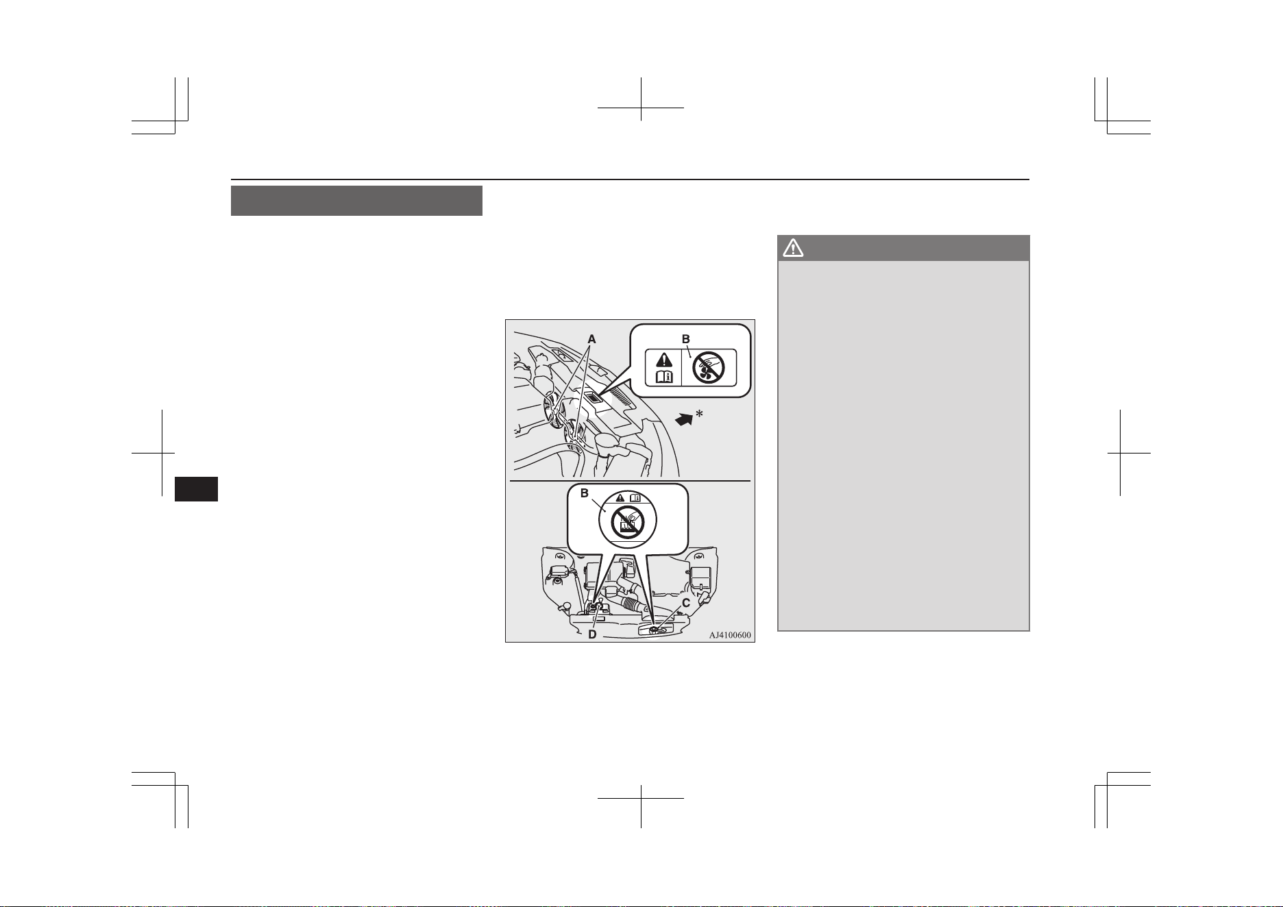
Service precautions
E01000102713
Adequate care of your vehicle at regular in-
tervals serves to preserve the value and ap-
pearance as long as possible.
Maintenance items as described in this own-
er’s manual can be performed by the owner.
We recommend you to have the periodic in-
spection and maintenance performed by a
MITSUBISHI MOTORS Authorized Service
Point or another specialist.
In the event a malfunction or a problem is
discovered, we recommend you to have it
checked and repaired. This section contains
information on inspection maintenance pro-
cedures that you can do yourself. Follow the
instructions and cautions for each of the vari-
ous procedures.
A- Cooling fans
B- Caution label
C- Radiator cap
D- EV cooling reserve tank cap
*: Front of the vehicle
WARNING
l
Before performing inspection or mainte-
nance, be sure to disconnect the normal
charge connector from the vehicle and
confirm that the operation mode of the
power switch is set to “OFF”.
l
Never touch the high-voltage parts in the
engine compartment. Never remove or
disassemble the high-voltage components,
cables (orange) or connectors. Also, never
disassemble normal charging cables, nor-
mal charge connector, plugs or outlet.
Failure to observe this instruction could
cause an electric shock which can result in
a serious injury or death. These parts
have labels that indicate handling precau-
tions. Follow the instruction on these la-
bels. Contact a MITSUBISHI MOTORS
Authorized Service Point for any necessa-
ry maintenance.
Refer to “High-Voltage components” on
page 2-08.
l
When checking or servicing the inside of
the engine compartment, make sure the
plug-in hybrid EV system is switched off
and has had a chance to cool down.
Service precautions
11-02
OGGE19E1
Maintenance
11
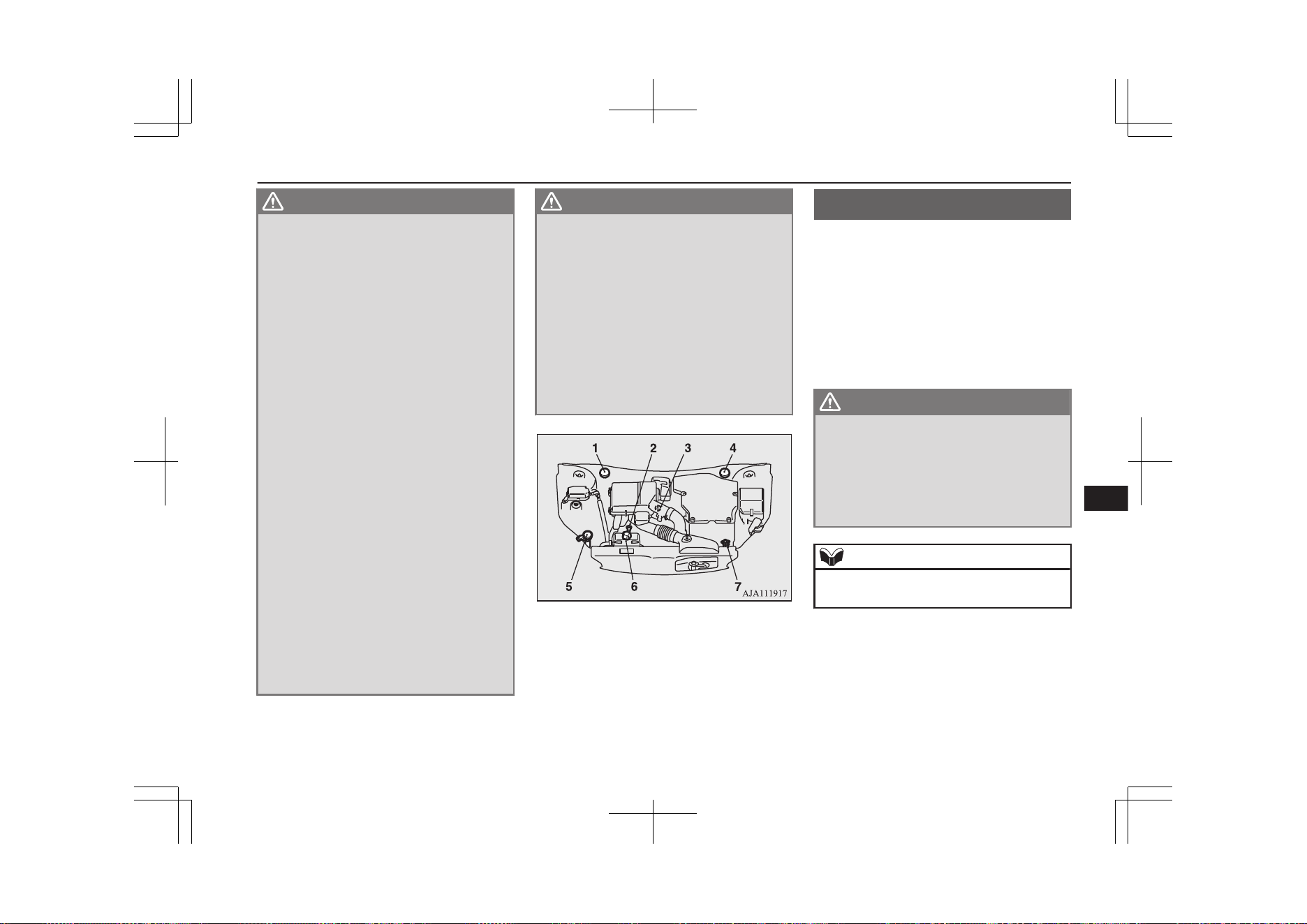
WARNING
l
If it is necessary to do work in the engine
compartment with the plug-in hybrid EV
system starting, be especially careful that
your clothing, hair, etc., does not become
caught by the cooling fans, drive belts, or
other moving parts.
l
After performing the maintenance, make
sure that no tools or cloths are left behind
in the engine compartment. If they are left
behind, a fire or damage to the vehicle
may occur.
l
The cooling fans can turn on automatical-
ly even if the plug-in hybrid EV system is
stopping. Put the operation mode of the
power switch in OFF to be safe while you
work in the engine compartment.
l
Make sure that the engine and Plug-in
Hybrid EV system has cooled down be-
fore removing the radiator cap and EV
cooling system reserve tank cap, because
hot steam or boiling water will otherwise
gush from the filler port and may scald
you.
l
Do not smoke, cause sparks or allow open
flames around fuel or auxiliary battery.
The fumes are flammable.
l
Be extremely cautious when working
around the auxiliary battery. It contains
poisonous and corrosive sulphuric acid.
l
Do not get under your vehicle with just
the body jack supporting it. Always use
automotive jack stands.
WARNING
l
Improper handling of components and
materials used in the vehicle can endanger
your personal safety. We recommend you
to consult a specialist for necessary infor-
mation.
l
The components inside the engine room
might be very hot to the touch.
To avoid being burnt, make sure all com-
ponents have sufficiently cooled before be-
ginning an inspection. These components
are affixed with the label indicating pre-
cautions for handling. Follow the instruc-
tions on the label.
1- Brake fluid reservoir (RHD)
2- Engine oil level dipstick
3- Engine oil cap
4- Brake fluid reservoir (LHD)
5- Washer fluid reservoir
6- EV cooling system reservoir
7- Engine coolant reservoir
Catalytic converter
E01000202495
The exhaust gas scavenging devices used
with the catalytic converter are extremely ef-
ficient for the reduction of noxious gases.
The catalytic converter is installed in the ex-
haust system.
It is important to keep the engine properly
tuned to ensure proper catalyst operation and
prevent possible catalyst damage.
WARNING
l
As with any vehicle, do not park or oper-
ate this vehicle in areas where combusti-
ble materials such as dry grass or leaves
can come in contact with a hot exhaust
since a fire could occur.
l
Paint should not be applied to the catalyt-
ic converter.
NOTE
l
Use fuel of the type recommended in “Fuel
selection” on page 2-14.
Catalytic converter
11-03
OGGE19E1
Maintenance
11
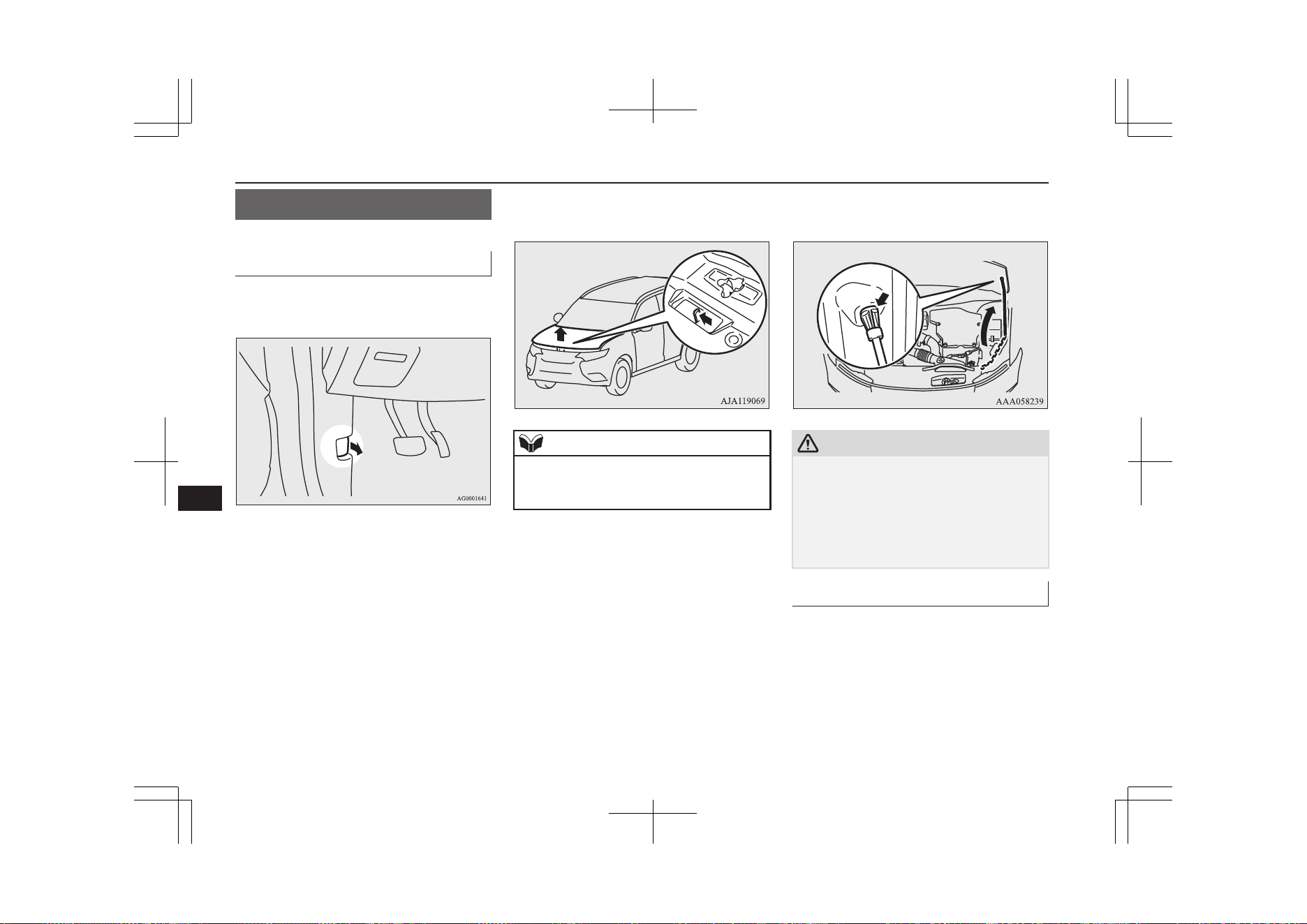
Bonnet
E01000304689
To open
1. Pull the release lever towards you to un-
lock the bonnet.
2. Raise the bonnet while pressing the safe-
ty lock.
NOTE
l
Only open the bonnet when the wipers are in
the original position. In any other position,
the wipers could damage the paint or bonnet.
3. Support the bonnet by inserting the sup-
port bar in its slot.
CAUTION
l
Note that the support bar may disengage the
bonnet if the open bonnet is lifted by a
strong wind.
l
After inserting the support bar into the slot,
make sure the bar supports the bonnet se-
curely from falling down on to your head or
body.
To close
1. Unlatch the support bar and clip it in its
holder.
2. Slowly lower the bonnet to a position
about 20 cm above the closed position,
then let it drop.
Bonnet
11-04
OGGE19E1
Maintenance
11
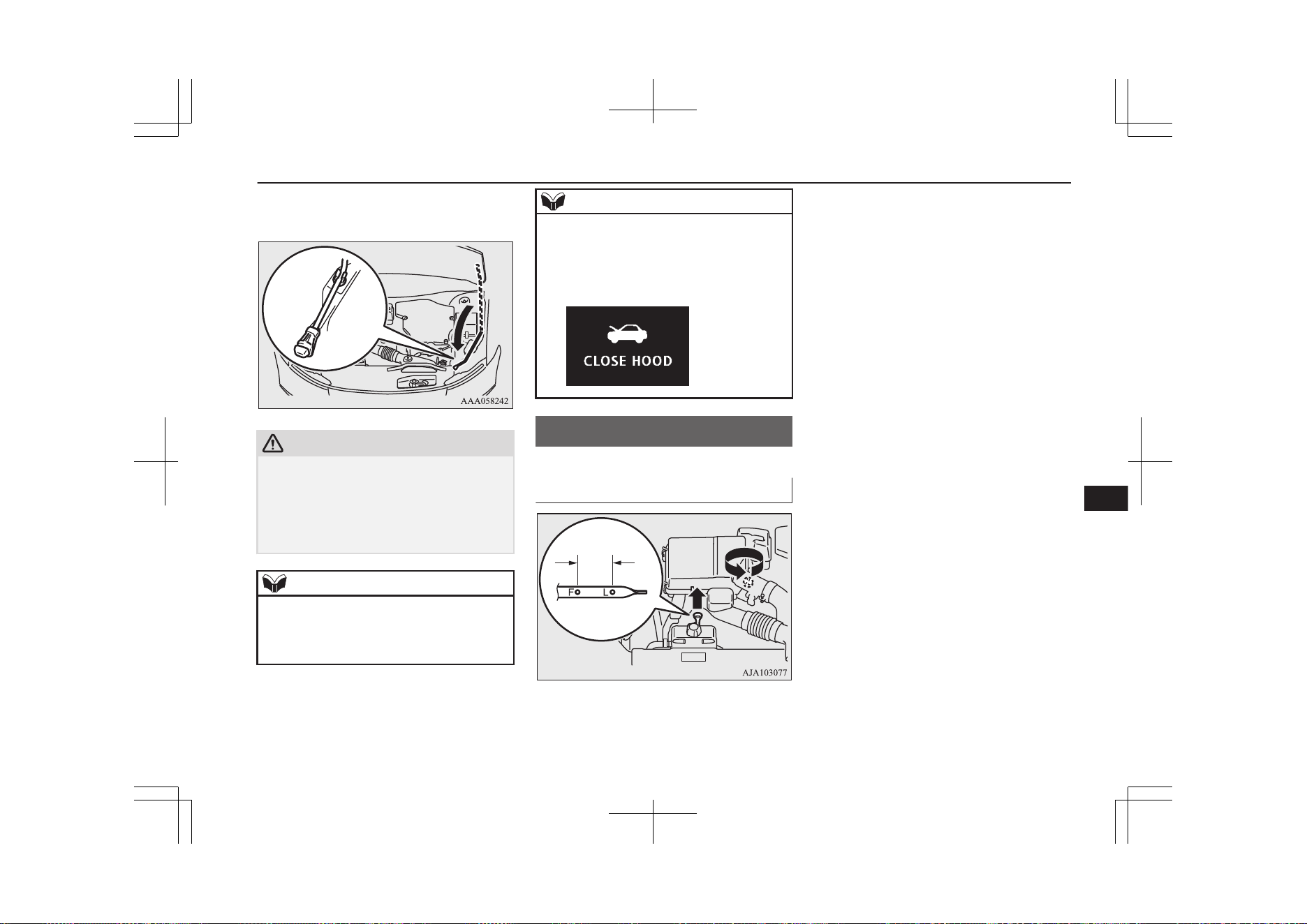
3. Make sure the bonnet is securely locked
by softly lifting the centre of the bonnet.
CAUTION
l
Be careful that hands or fingers are not trap-
ped when closing the bonnet.
l
Before driving, make sure that the bonnet is
securely locked. An incompletely locked
bonnet can suddenly open while driving.
This can be extremely dangerous.
NOTE
l
If this does not close the bonnet, release it
from a slightly higher position.
l
Do not press down firmly on the bonnet as
doing so could damage it.
NOTE
l
For vehicles equipped with the security
alarm system, if you drive with the bonnet
left open, a warning display is displayed on
the information screen in the multi informa-
tion display.
Engine oil
E01000405094
To check and refill engine oil
FULL LOW
The engine oil used has a significant effect on
the engine’s performance, service life and
startability. Be sure to use oil of the recom-
mended quality and appropriate viscosity.
All engines consume a certain amount of oil
during normal operation. Therefore, it is im-
portant to check the oil level at regular inter-
vals or before starting a long trip.
1. Park the vehicle on a horizontal surface.
2. Switch off the engine.
3. Wait a few minutes.
4. Remove the dipstick and wipe it with a
clean cloth.
5. Reinsert the dipstick as far as it goes.
6. Remove the dipstick and read the oil lev-
el, which should always be within the
range indicated.
7. If the oil level is below the specified
limit, remove the cap located on the cyl-
inder head cover and add enough oil to
raise the level to within the specified
range. Do not overfill to avoid engine
damage. Be sure to use the specified en-
gine oil and do not mix various types of
oil.
8. After adding oil, close the cap securely.
9. Confirm the oil level by repeating step 4
to 6.
Engine oil
11-05
OGGE19E1
Maintenance
11
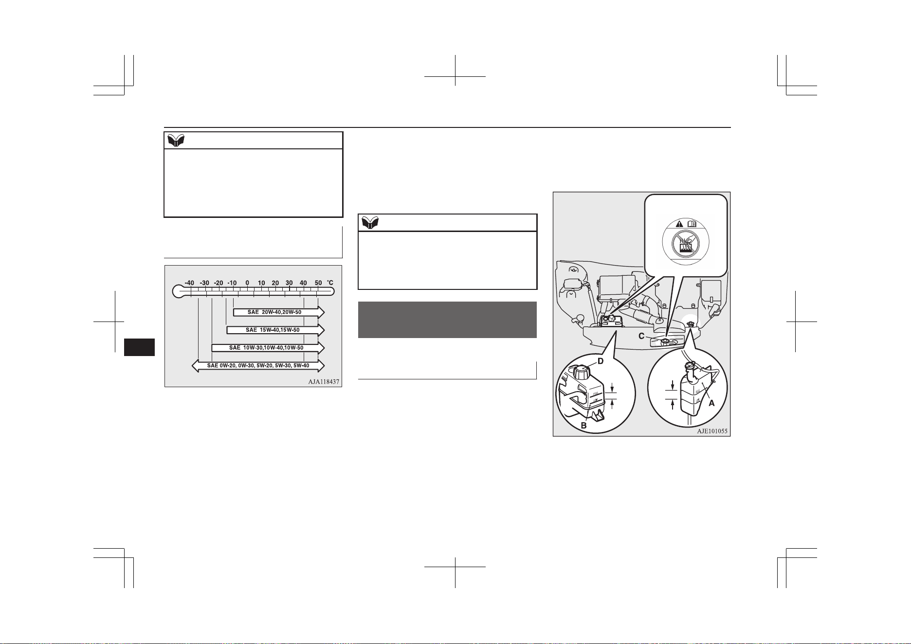
NOTE
l
The engine oil will deteriorate rapidly if the
vehicle is subjected to severe conditions, re-
quiring earlier oil replacement.
Please refer to the maintenance schedule.
l
For information on how to dispose of used
engine oil, refer to page 2-18.
Recommended engine oil vis-
cosity
l
Select engine oil of the proper SAE vis-
cosity number according to the atmos-
pheric temperature.
SAE 0W-20, 0W-30, 5W-20, 5W-30, and
5W-40 engine oils can only be used if
they meet ACEA A3/B3, A3/B4 or
A5/B5 and API SM (or higher) specifi-
cations.
l
Use engine oil conforming to the follow-
ing classification:
• API classification: “For service SM”
or higher
• ILSAC certificated oil
• ACEA classification:
“For service A1/B1, A3/B3, A3/B4 or
A5/B5”
NOTE
l
Use of additives is not recommended since
they may reduce the effectiveness of addi-
tives already included in the engine oil. It
may result in failure of the mechanical as-
sembly.
Engine coolant/Plug-in
hybrid EV system coolant
E01000503466
To check the coolant level
A transparent engine coolant reserve tank (A)
and EV cooling system reserve tank (B) is lo-
cated in the engine compartment.
The coolant level in this tank should be kept
between the “LOW” and “FULL” marks
when measured while the engine and the
plug-in hybrid EV system are cold.
FULL
LOW
FULL
LOW
Engine coolant/Plug-in hybrid EV system coolant
11-06
OGGE19E1
Maintenance
11
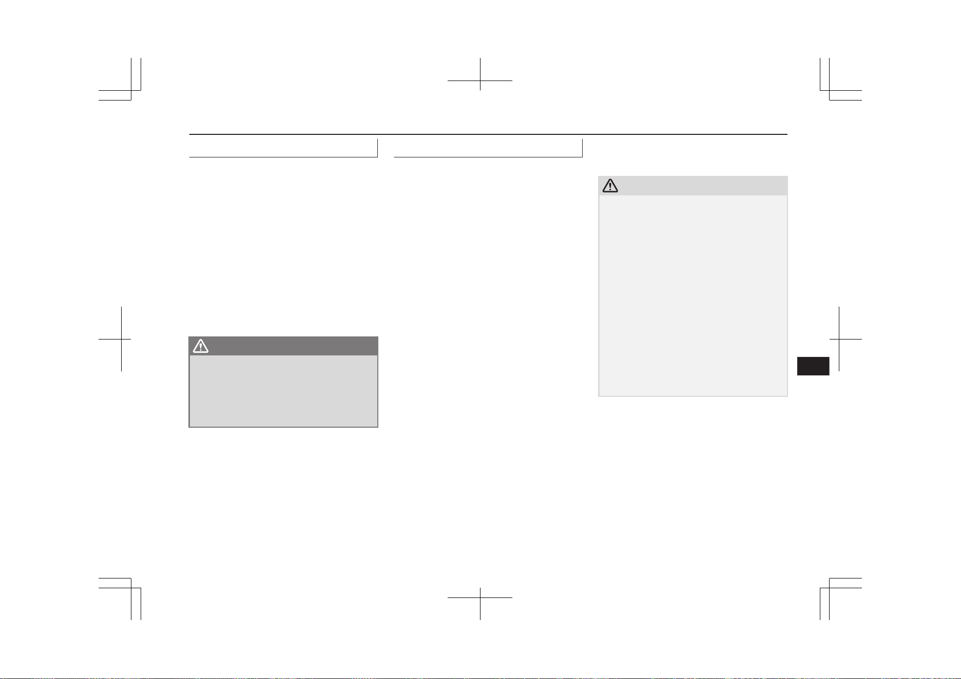
To add coolant
The cooling system is a closed system and
normally the loss of coolant should be very
slight. A noticeable drop in the coolant level
could indicate leakage. If this occurs, we rec-
ommend you to have the system checked as
soon as possible.
If the level should drop below the “LOW”
level on the reserve tank, open the lid and
add coolant.
Also, if the reserve tank is completely empty,
remove the radiator cap (C) or the reserve
tank cap (D) and add coolant until the level
reaches the filler neck.
WARNING
l
Do not open the radiator cap (C) and the
reserve tank cap (D) while the engine and
the plug-in hybrid EV system are hot. The
coolant system is under pressure and any
hot coolant escaping could cause severe
burns.
Anti-freeze
The engine coolant and the plug-in hybrid
EV system coolant contains an ethylene gly-
col anti-corrosion agent. Some parts of the
engine and the plug-in hybrid EV system are
cast aluminium alloy, and periodic changing
of the engine coolant and the plug-in hybrid
EV system coolant are necessary to prevent
corrosion of these parts.
Use “MITSUBISHI MOTORS GENUINE
SUPER LONG LIFE COOLANT PREMI-
UM” or equivalent
*
.
MITSUBISHI MOTORS GENUINE Coolant
has excellent protection against corrosion and
rust formation of all metals including alumi-
nium and can avoid blockages in the radiator,
heater, cylinder head, engine block, etc.
Because of the necessity of this anti-corro-
sion agent, the coolant must not be replaced
with plain water even in summer. The re-
quired concentration of anti-freeze differs de-
pending on the expected ambient tempera-
ture.
Above -35 °C: 50 % concentration of anti-
freeze
*
similar high quality ethylene glycol based
non-silicate, non-amine, non-nitrate and
non-borate coolant with long life hybrid
organic acid technology
Below -35 °C: 60 % concentration of anti-
freeze
CAUTION
l
Do not use alcohol or methanol anti-freeze
or any engine coolants mixed with alcohol
or methanol anti-freeze. The use of an im-
proper anti-freeze can cause corrosion of the
aluminium components.
l
Do not use water to adjust the concentration
of coolant.
l
Concentrations exceeding 60 % will result in
a reduction of both the anti-freeze and cool-
ing performance thus adversely affecting the
engine.
l
Do not top up with water only.
Water by itself reduces the rust-protective
and anti-freeze qualities of the coolant and
has a lower boiling point. It can also cause
damage to the cooling system if it should
freeze. Do not use tapwater, as it can cause
corrosion and rust formation.
During cold weather
If the temperatures in your area drop below
freezing, there is the danger that the coolant
in the engine, plug-in hybrid EV system or
radiator could freeze and cause severe dam-
age to the engine and/or radiator. Add a suffi-
cient amount of anti-freeze to the coolant to
prevent it from freezing.
Engine coolant/Plug-in hybrid EV system coolant
11-07
OGGE19E1
Maintenance
11
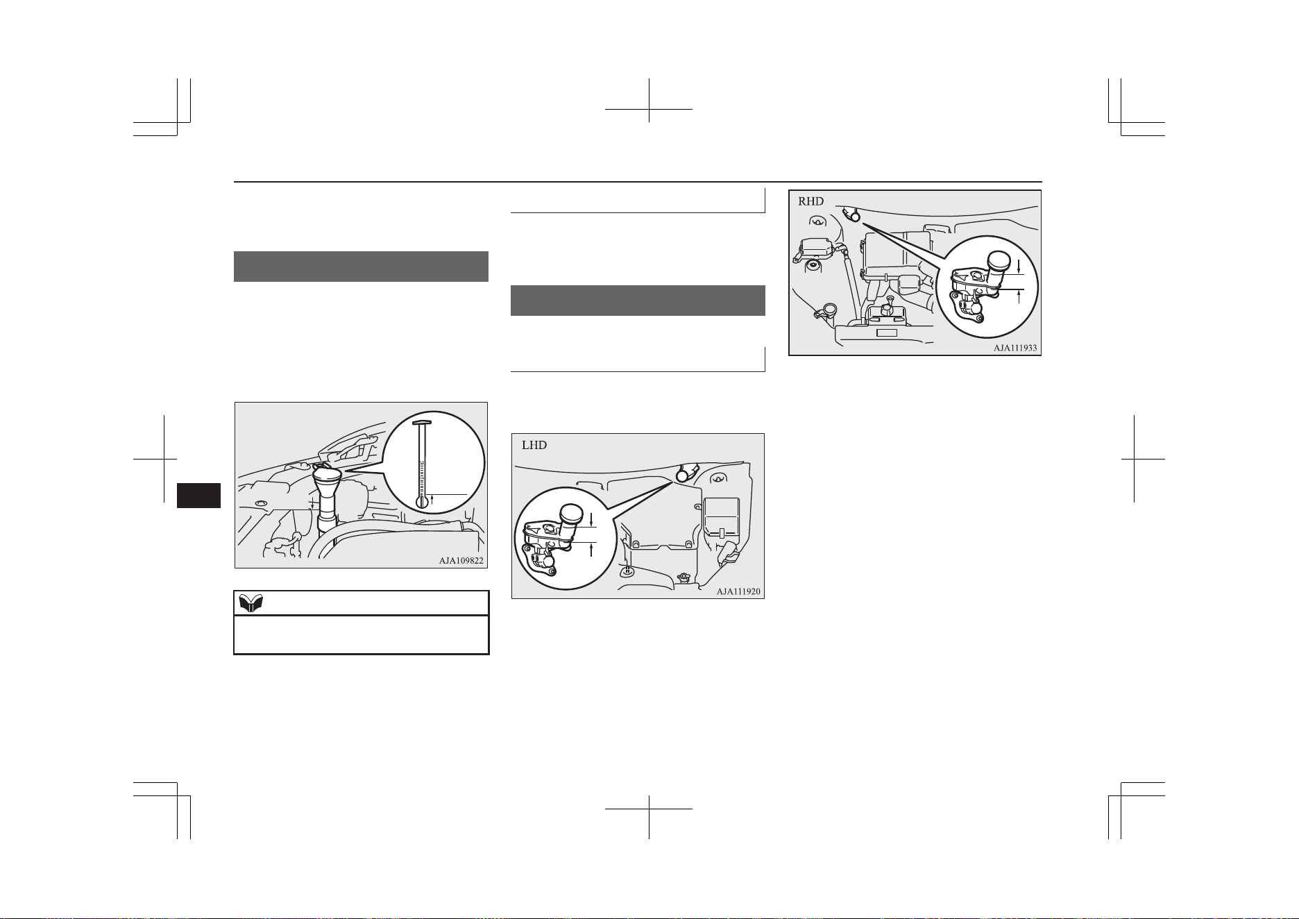
The concentration should be checked before
the start of cold weather and anti-freeze add-
ed to the system if necessary.
Washer fluid
E01000702214
Open the washer fluid reservoir cap and
check the level of washer fluid with the dip-
stick.
If the level is low, replenish the container
with washer fluid.
FULL
EMPTY
NOTE
l
The washer fluid container serves the wind-
screen, rear window and headlamps.
During cold weather
To ensure proper operation of the washers at
low temperatures, use a fluid containing an
anti-freezing agent.
Brake fluid
E01000801827
To check the fluid level
The fluid level must be between the “MAX”
and “MIN” marks on the reservoir.
The fluid level is monitored by a float. When
the fluid level falls below the “MIN” mark,
the brake fluid warning lamp lights up.
The fluid level falls slightly with wear of the
brake pads, but this does not indicate any ab-
normality.
The fluid in the master cylinder should be
checked when doing other work under the
bonnet. The brake system should also be
checked for leakage at the same time.
If the fluid level falls markedly in a short
length of time, it indicates leaks from the
brake system.
If this occurs, we recommend you to have the
vehicle checked.
Washer fluid
11-08
OGGE19E1
Maintenance
11
Fluid type
Use brake fluid conforming to DOT3 or
DOT4 from a sealed container. The brake flu-
id is hygroscopic. Too much moisture in the
brake fluid will adversely affect the brake
system, reducing the performance.
WARNING
l
Take care in handling brake fluid as it is
harmful to the eyes, may irritate your
skin and will damage painted surfaces.
Wipe up any spills immediately.
If brake fluid gets on your hand or in
your eyes, flush immediately with clean
water. Follow up with a doctor as necessa-
ry.
CAUTION
l
Use only the specified brake fluid.
Do not mix or add different brands of brake
fluid to prevent chemical reactions.
Do not let any petroleum-based fluid touch,
mix with, or get into the brake fluid.
This will damage the seals.
l
Keep the reservoir tank cap closed to pre-
vent the brake fluid from deteriorating ex-
cept maintenance.
l
Clean the filler cap before removing and
close the cap securely after maintenance.
Auxiliary battery
E01001203864
The condition of the auxiliary battery is very
important for quick starting of the plug-in hy-
brid EV system and proper functioning of the
vehicle’s electrical system. Regular inspec-
tion is especially important in cold weather.
Be sure to have a MITSUBISHI MOTORS
Authorized Service Point check the auxiliary
battery.
WARNING
l
Be sure to have a MITSUBISHI
MOTORS Authorized Service Point
charge the battery. Do not charge the bat-
tery yourself. Flammable gases may leak
and explode.
CAUTION
l
There is a type of auxiliary battery is not
properly installed in the vehicle, even if the
same specification.
When replacing the auxiliary battery, please
contact a MITSUBISHI MOTORS Author-
ized Service Point.
NOTE
l
When the auxiliary battery is removed, the
controlling timer for forcibly starting the en-
gine may be reset.
Since a fuel injection device may cause a
clogging if the state where the engine does
not operate continues after reset of the timer,
please select the battery charge mode in or-
der to start the engine. However, if the drive
battery level is nearly full, the engine may
not start even though the battery charge
mode is selected.
In that case, activate the battery charge mode
again after the drive battery quantity decrea-
ses. Refer to “SAVE/CHARGE mode
switch” on page 7-28.
l
When the auxiliary battery is removed, since
the timer control of the MITSUBISHI Re-
mote Control is reset and the drive battery
temperature control cannot be used, commu-
nicate the wireless LAN device and your ve-
hicle again.
l
When the auxiliary battery is removed, the
timer control of the MITSUBISHI Remote
Control is reset and each function of the
MITSUBISHI Remote Control cannot be
used. Also the drive battery cannot be
warmed up.
Communicate the wireless LAN device and
your vehicle again.
Auxiliary battery
11-09
OGGE19E1
Maintenance
11
Tyres
E01001300255
WARNING
l
Driving with tyres that are worn, dam-
aged or improperly inflated can lead to a
loss of control or blow out of the tyres
which can result in a collision with serious
or fatal injury.
Tyre inflation pressures
E01001404472
Tyre size Front Rear
215/70R16 100H 2.4 bar (35 psi) [240 kPa], 2.6 bar (38 psi) [260 kPa]*
225/55R18 98H 2.4 bar (35 psi) [240 kPa], 2.6 bar (38 psi) [260 kPa]*
*: Above 160 km/h (99 mph)
Check the tyre inflation pressure of all the tyres while they are cold; if insufficient or excessive, adjust to the specified value.
After the tyre inflation pressure has been adjusted, check the tyres for damage and air leaks. Be sure to put caps on the valves.
Tyres
11-10
OGGE19E1
Maintenance
11
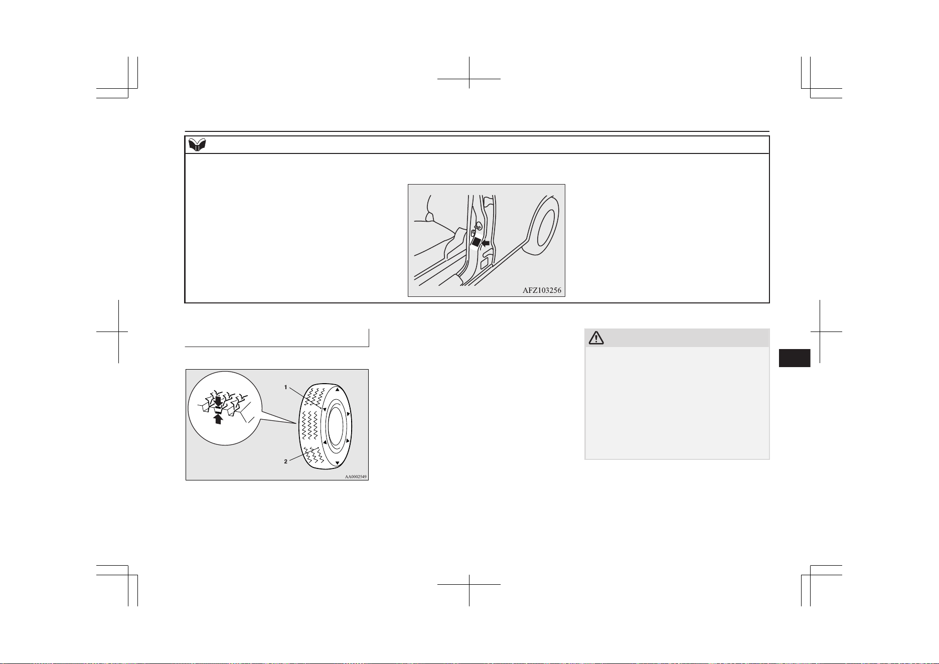
NOTE
l
The tyres that can be installed on your vehicle are shown on the driver’s door label. For details, contact a MITSUBISHI MOTORS Authorized Service Point.
Wheel condition
E01001801970
1- Location of the tread wear indicator
2- Tread wear indicator
Check the tyres for cuts, cracks and other
damage. Replace the tyres if there are deep
cuts or cracks. Also check each tyre for
pieces of metal or pebbles.
The use of worn tyres can be very dangerous
because of the greater chance of skidding or
hydroplaning. The tread depth of the tyres
must exceed 1.6 mm in order for the tyres to
meet the minimum requirement for use.
Tread wear indicators will appear on the sur-
face of the tyre as the tyre wears, thereby in-
dicating that the tyre no longer meets the
minimum requirement for use. When these
wear indicators appear, the tyres must be re-
placed with new ones.
When replacement of any of the tyres is nec-
essary, replace all of them.
CAUTION
l
Always use tyres of the same size, same
type, and same brand, and which have no
wear differences. Using tyres of different
size, type, brands or degree of wear, will in-
crease the differential oil temperature, result-
ing in possible damage to the driving sys-
tem. Further, the drive train will be subjected
to excessive loading, possibly leading to oil
leakage, component seizure, or other serious
faults.
Tyres
11-11
OGGE19E1
Maintenance
11
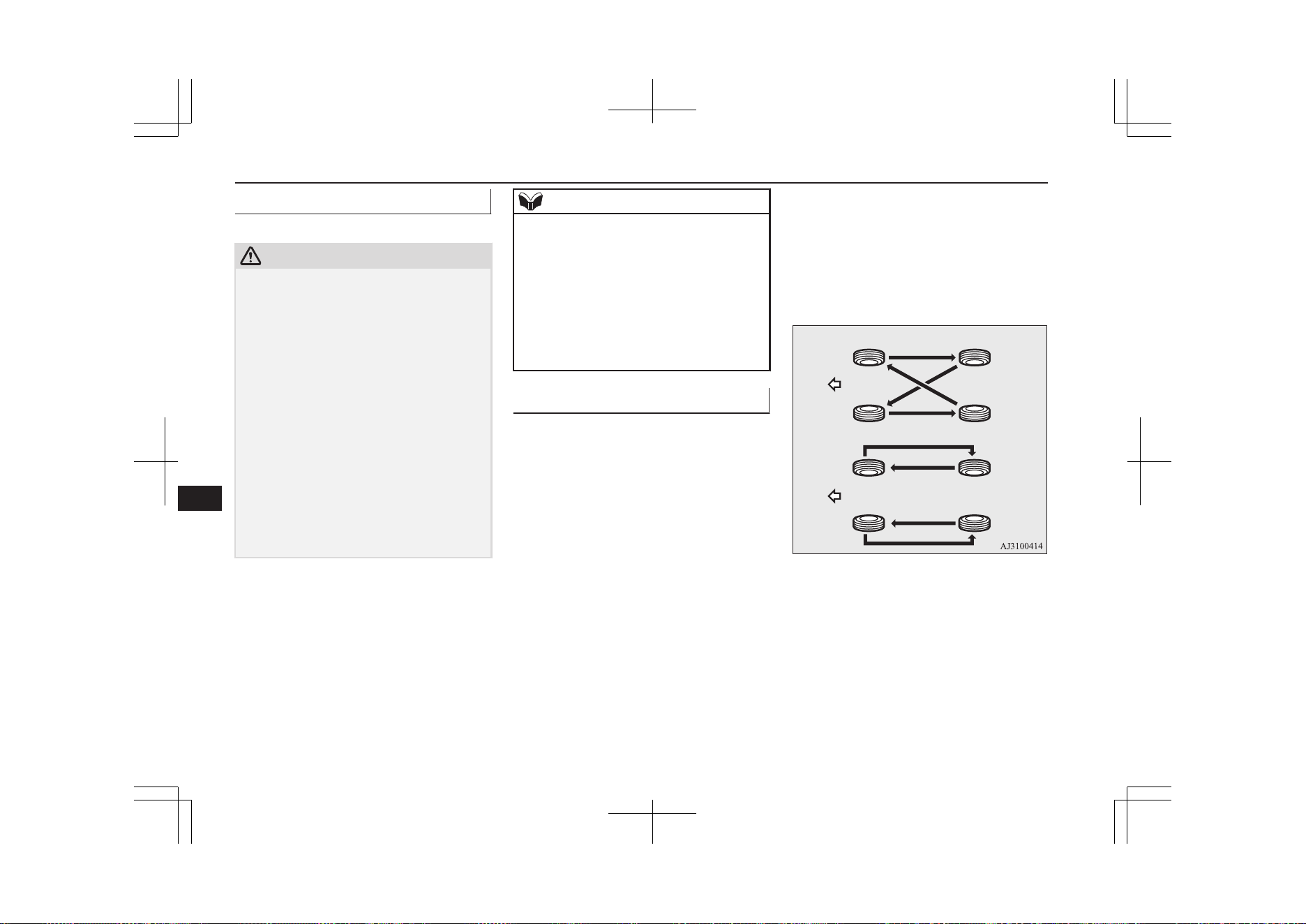
Replacing tyres and wheels
E01007201820
CAUTION
l
Avoid using different size tyres from the one
listed and the combined use of different
types of tyres, as this can affect driving safe-
ty.
Refer to “Tyres and wheels” on page 12-09.
l
Even if a wheel has the same rim size and
offset as the specified type of wheel, its
shape may prevent it from being fitted cor-
rectly. We recommend you to consult a spe-
cialist before using wheels that you have.
l
As your vehicle is equipped with a tyre pres-
sure monitoring system, only MITSUBISHI
MOTORS GENUINE wheels should be
used. Use of another type of wheel risks air
leaks and sensor damage, as it will not be
possible to install the tyre pressure sensor
properly.
Refer to “Tyre pressure monitoring system
(TPMS)” on page 7-92.
NOTE
l
A steel wheel with diameter of 16 inches
cannot be used on your vehicle because it in-
terferes with brake parts.
Additionally, an aluminium wheel with di-
ameter of 16 inches may not be used on your
vehicle depending on its type, even if a
MITSUBISHI MOTORS GENUINE wheel.
Consult a MITSUBISHI MOTORS Author-
ized Service Point before using wheels that
you have.
Tyre rotation
E01001902516
Tyre wear varies with vehicle conditions,
road surface conditions and individual driv-
er’s driving habits. To equalize the wear and
help extend tyre life, it is recommended to ro-
tate the tyres immediately after discovery of
abnormal wear, or whenever the wear differ-
ence between the front and rear tyres is rec-
ognizable.
When rotating tyres, check for uneven wear
and damage. Abnormal wear is usually
caused by incorrect tyre pressure, improper
wheel alignment, out of balance wheel, or se-
vere braking. We recommend you to have it
checked to determine the cause of irregular
tread wear.
Tyres that do not have arrows showing rotation
direction
Front
Tyres that have arrows showing rotation direc-
tion
Front
Tyres
11-12
OGGE19E1
Maintenance
11
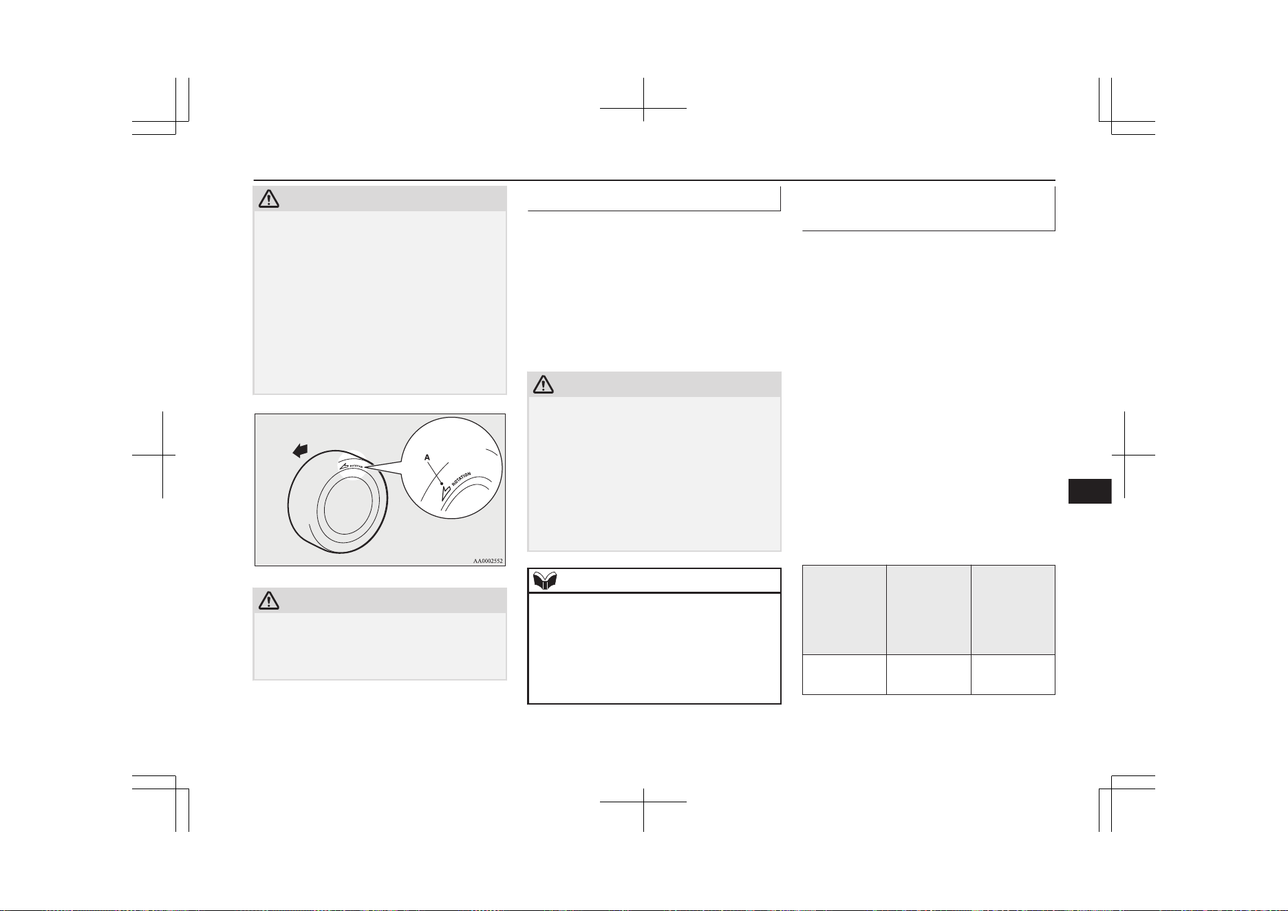
CAUTION
l
If the tyres have arrows (A) indicating the
correct direction of rotation, swap the front
and rear tyres on the left-hand side of the ve-
hicle and the front and rear tyres on the
right-hand side of the vehicle separately.
Keep each tyre on its original side of the ve-
hicle. When fitting the tyres, make sure the
arrows point in the direction in which the
wheels will turn when the vehicle moves for-
ward. Any tyre whose arrow points in the
wrong direction will not perform to its full
potential.
Front
CAUTION
l
Avoid the combined use of different types of
tyres.
Using different types of tyres can affect ve-
hicle performance and safety.
Snow tyres
E01002001979
The use of snow tyres is recommended for
driving on snow and ice. To preserve driving
stability, mount snow tyres of the same size
and tread pattern on all 4 wheels.
A snow tyre that is worn down more than
50% is no longer appropriate to use.
Snow tyres which do not meet specifications
must not be used.
CAUTION
l
Observe permissible maximum speed for
your snow tyres and the legal speed limit.
l
As your vehicle is equipped with a tyre pres-
sure monitoring system, only MITSUBISHI
Motors genuine wheels should be used. Use
of another type of wheel risks air leaks and
sensor damage, as it will not be possible to
install the tyre pressure sensor properly.
Refer to “Tyre pressure monitoring system
(TPMS)” on page 7-92.
NOTE
l
The laws and regulations concerning snow
tyres (driving speed, required use, type, etc.)
vary. Find out and follow the laws and regu-
lations in the area you intend to drive.
l
If flange nuts are used on your vehicle,
change to tapered nuts when steel wheels are
used.
Snow traction device (tyre
chains)
E01002103336
If snow traction device (tyre chains) have to
be used, ensure that they are fitted only on
the drive wheels (front) in accordance with
the manufacturer’s instructions.
On 4WD vehicles in which the driving power
is distributed preferentially to the front
wheels, ensure that the snow traction device
(tyre chains) are fitted on the front.
Use only snow traction device (tyre chains)
which are designed for use with the tyres
mounted on the vehicle: use of the incorrect
size or type of snow traction device (tyre
chains) could result in damage to the vehicle
body.
Contact a MITSUBISHI MOTORS Author-
ized Service Point before putting on a snow
traction device (tyre chains). The max. snow
traction device (tyre chains) height is as fol-
lows.
Tyre size Wheel size Max. snow
traction de-
vice (tyre
chains)
height [mm]
215/70R16
100H
16 x 6 1/2 J 9 mm
Tyres
11-13
OGGE19E1
Maintenance
11
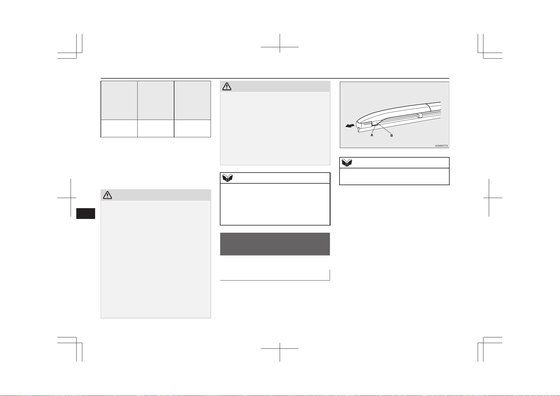
Tyre size Wheel size Max. snow
traction de-
vice (tyre
chains)
height [mm]
225/55R18
98H
18x7 J 9 mm
When driving with a snow traction device
(tyre chains) on the tyres, do not drive faster
than 50 km/h (30 mph). When you reach
roads that are not covered in snow, immedi-
ately remove the snow traction device (tyre
chains).
CAUTION
l
Choose a clear straight stretch of road where
you can pull off and still be seen while you
are fitting the snow traction device (tyre
chains).
l
Do not fit snow traction device (tyre chains)
before you need them. This will wear out
your snow traction device (tyre chains) and
the road surface.
l
After driving around for 100-300 meters,
stop and retighten the snow traction device
(tyre chains).
l
Drive carefully and do not exceed 50 km/h
(30 mph). Remember that preventing acci-
dents is not the purpose of snow traction de-
vice (tyre chains).
l
When snow traction device (tyre chains) are
installed, take care that they do not damage
the disc wheel or body.
CAUTION
l
An aluminium wheel can be damaged by a
snow traction device (tyre chains) while
driving. When fitting a snow traction device
(tyre chains) on an aluminium wheel, take
care that any part of the snow traction device
(tyre chains) and fitting cannot be brought
into contact with the wheel.
l
When installing or removing a snow traction
device (tyre chains), take care that hands and
other parts of your body and not injured by
the sharp edges of the vehicle body.
NOTE
l
The laws and regulations concerning the use
of snow traction device (tyre chains) vary.
Always follow local laws and regulations.
In most countries, it is prohibited by the law
to use of snow traction device (tyre chains)
on roads without snow.
Wiper blade rubber
replacement
E01002600532
Windscreen wiper blades
1. Lift the wiper arm off the windscreen.
2. Pull the wiper blade until its stopper (A)
disengages from the hook (B). Then,
pull the wiper blade further to remove it.
NOTE
l
Do not allow the wiper arm to fall onto the
windscreen; it could damage the glass.
3. Attach the retainers (C) to a new wiper
blade.
Wiper blade rubber replacement
11-14
OGGE19E1
Maintenance
11
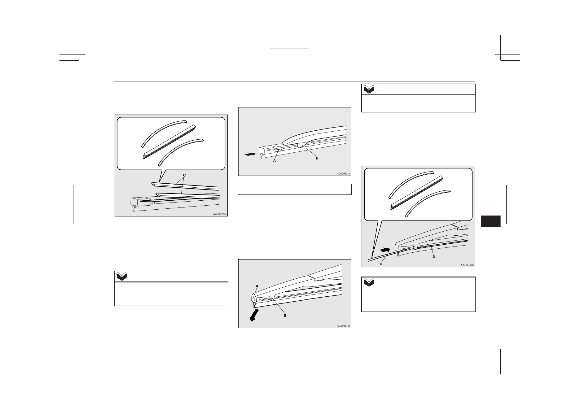
Refer to the illustration to ensure that the
retainers are correctly aligned as you at-
tach them.
4. Insert the wiper blade into the arm, start-
ing with the opposite end of the blade
from the stopper. Make sure the hook
(B) is fitted correctly in the grooves in
the blade.
NOTE
l
If retainers are not supplied with the new
wiper blade, use the retainers from the old
blade.
5. Push the wiper blade until the hook (B)
engages securely with the stopper (A).
Rear window wiper blades
1. Lift the wiper arm off the window glass.
2. Pull the wiper blade downward to disen-
gage it from the stopper (A) at the end of
the wiper arm. Pull the wiper blade fur-
ther to remove it.
3. Slide a new wiper blade through the
hook (B) on the wiper arm.
NOTE
l
Do not allow the wiper arm to fall onto the
window glass; it could damage the glass.
4. Firmly insert the retainer (C) into the
groove (D) in the wiper blade.
Refer to the illustration to ensure that the
retainers are correctly aligned as you in-
sert them into the groove.
NOTE
l
If a retainer is not supplied with the new
wiper blade, use the retainer from the old
blade.
Wiper blade rubber replacement
11-15
OGGE19E1
Maintenance
11

General maintenance
E01002701556
Fuel, engine coolant, oil and ex-
haust gas leakage
Look under the body of your vehicle to check
for fuel, engine coolant, oil and exhaust gas
leaks.
WARNING
l
If you see a suspicious fuel leak or if you
smell fuel, do not operate the vehicle; call
your MITSUBISHI MOTORS Author-
ized Service Point for assistance.
Exterior and interior lamp op-
eration
Operate the combination lamp switch to
check that all lamps are functioning properly.
If the lamps do not illuminate, the probable
cause is a blown fuse or defective lamp bulb.
Check the fuses first. If there is no blown
fuse, check the lamp bulbs.
For information regarding the inspection and
replacement of the fuses and the bulbs, refer
to “Fuses” on page 11-16 and “Replacement
of lamp bulbs” on page 11-24.
If the fuses and bulbs are all OK, we recom-
mend you to have your vehicle checked and
repaired.
Meter, gauge and indicator/
warning lamps operation
Start the plug-in hybrid EV system and check
the operation of all instruments, gauges and
indication and warning lamps.
If there is anything wrong, we recommend
you to have your vehicle inspected.
Hinges and latches lubrication
Check all latches and hinges, and, if necessa-
ry, have them lubricated.
Fusible links
E01002901633
The fusible links will melt to prevent a fire if
a large current attempts to flow through cer-
tain electrical systems.
In case of a melted fusible link, we recom-
mend you to have your vehicle inspected.
For the fusible links, please refer to “Passen-
ger compartment fuse location table” on page
11-19 and “Engine compartment fuse loca-
tion table” on page 11-21.
WARNING
l
Fusible links must not be replaced by any
other device. Failing to fit the correct fusi-
ble link may result in fire in the vehicle,
property destruction and serious or fatal
injuries at any time.
Fuses
E01003003332
Fuse block location
E01011800035
To prevent damage to the electrical system
due to short-circuiting or overloading, each
individual circuit is provided with a fuse.
There are fuse blocks in the passenger com-
partment and in the engine compartment.
Passenger compartment (LHD
vehicles)
The fuse blocks in the passenger compart-
ment are located behind the fuse lid in front
of the driver’s seat at the position shown in
the illustration.
General maintenance
11-16
OGGE19E1
Maintenance
11
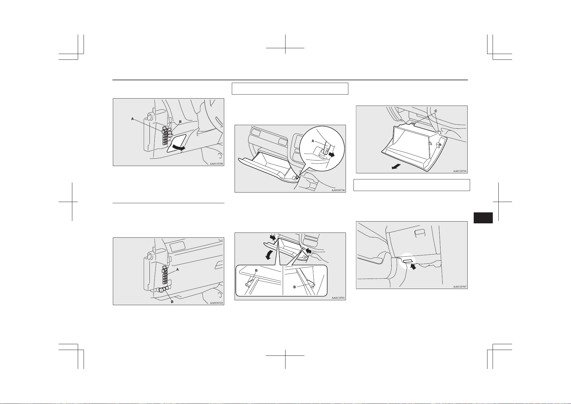
Pull the fuse lid to remove it.
A- Main fuse block
B- Sub fuse block
Passenger compartment (RHD
vehicles)
The fuse boxes in the passenger compartment
are located behind the glove box at the posi-
tion shown in the illustration.
A- Main fuse block
B- Sub fuse block
Main fuse block
1. Open the glove box.
2. Uncouple the rod (A) on the right side of
the glove box.
3.
While pressing the side of the glove box,
unhook the left and right hooks (B) and
lower the glove box.
4. Remove the glove box fastener (C), and
then remove the glove box.
Sub fuse block
When changing the fuse of the sub fuse
block, perform it with the hole of the bottom
cover.
Fuses
11-17
OGGE19E1
Maintenance
11
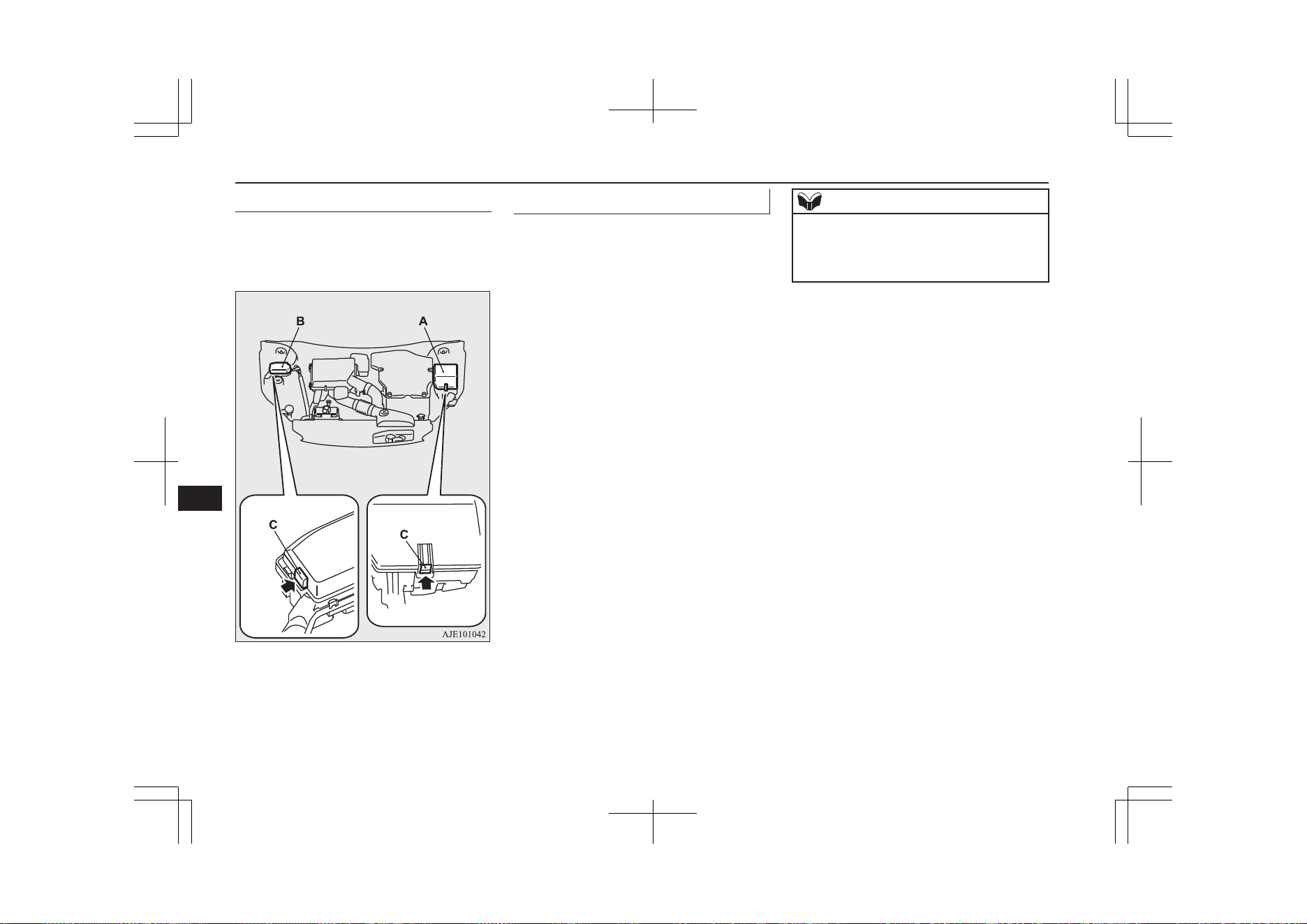
Engine compartment
E01011900036
In the engine compartment, the fuse block is
located as shown in the illustration. While
pressing the tab (C), pull up the cover.
A- Main fuse block
B- Sub fuse block
Fuse load capacity
E01007701753
The fuse capacity and the names of electrical
systems protected by the fuses are indicated
on the inside of the fuse lid (LHD vehicles),
the back side of the glove box (RHD vehi-
cles) and inside of the fuse block cover (in-
side of the engine compartment).
NOTE
l
Spare fuses are provided on the cover of
main fuse block in the engine compartment.
Always use a fuse of the same capacity for
replacement.
Fuses
11-18
OGGE19E1
Maintenance
11
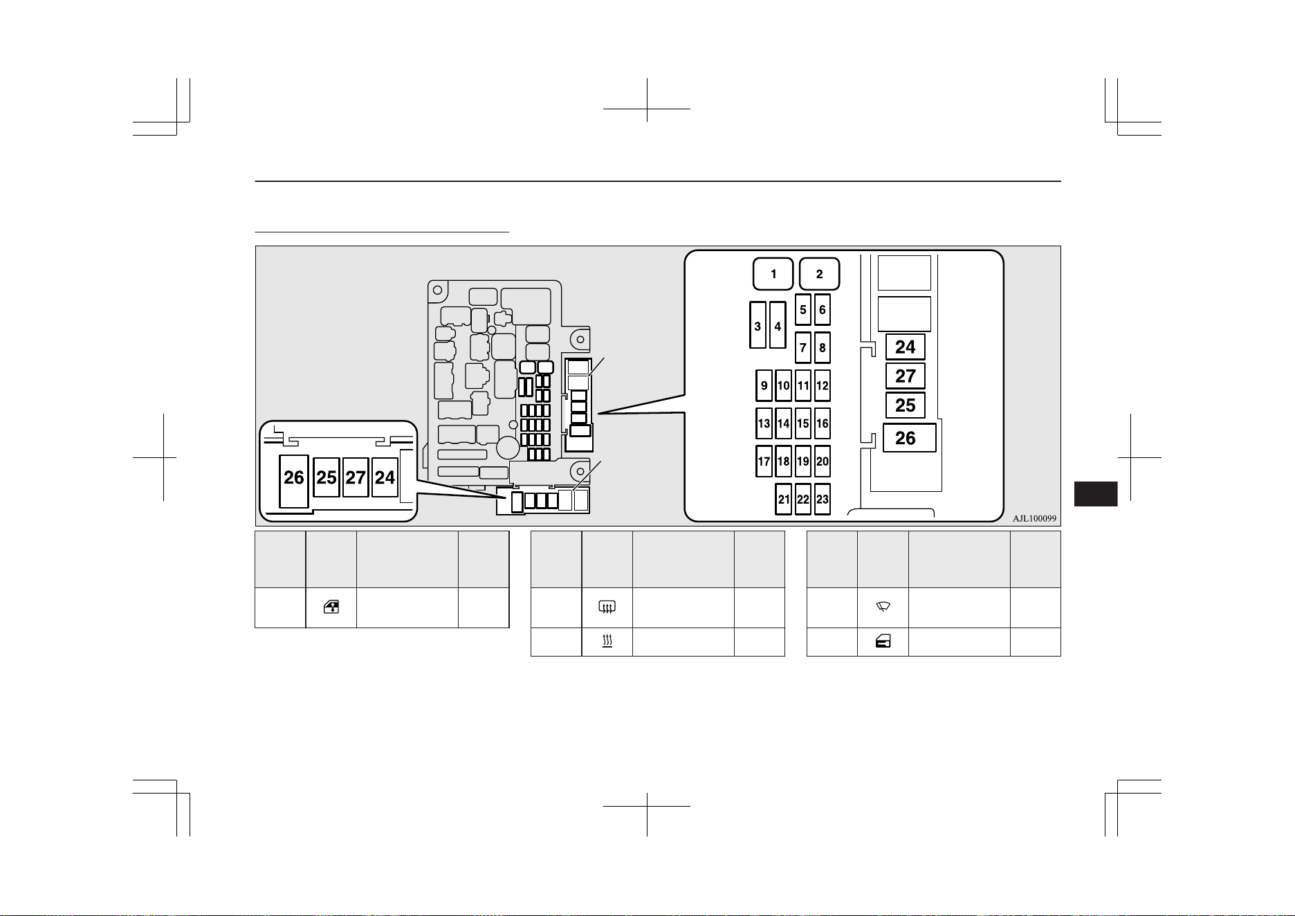
Passenger compartment fuse lo-
cation table
E01007902127
Main fuse block
Sub fuse block
(LHD)
Sub fuse block
(RHD)
No.
Sym-
bol
Electrical sys-
tem
Ca-
paci-
ties
1
Electric window
control
30 A
*1
*1
: Fusible link
*2
: Even if your vehicle is equipped with the
rear fog lamp, the fuse of the rear fog lamp
may not be installed on your vehicle.
No.
Sym-
bol
Electrical sys-
tem
Ca-
paci-
ties
2
Rear window
demister
30 A
*1
3 Heater 30 A
*1
: Fusible link
*2
: Even if your vehicle is equipped with the
rear fog lamp, the fuse of the rear fog lamp
may not be installed on your vehicle.
No.
Sym-
bol
Electrical sys-
tem
Ca-
paci-
ties
4
Windscreen wip-
ers
30 A
5 Door locks 20 A
*1
: Fusible link
*2
: Even if your vehicle is equipped with the
rear fog lamp, the fuse of the rear fog lamp
may not be installed on your vehicle.
Fuses
11-19
OGGE19E1
Maintenance
11
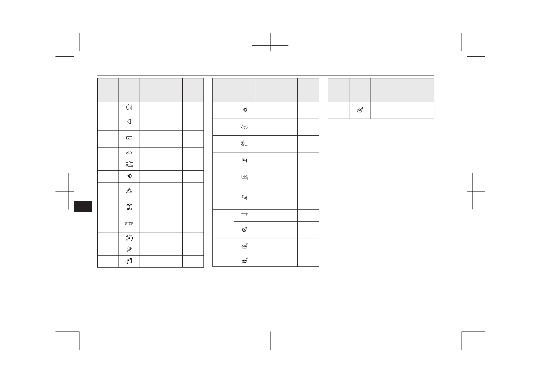
No.
Sym-
bol
Electrical sys-
tem
Ca-
paci-
ties
6 Rear fog lamp
10 A
*2
7
Accessory sock-
et
15 A
8
Rear window
wiper
15 A
9 Sunroof 20 A
10 Ignition switch 10 A
11 Option 10 A
12
Hazard warning
flasher
15 A
13
4-wheel drive
system
10 A
14
Stop lamps
(Brake lamps)
15 A
15 Instruments 10 A
16 SRS airbag 7.5 A
17 Radio 15 A
*1
: Fusible link
*2
: Even if your vehicle is equipped with the
rear fog lamp, the fuse of the rear fog lamp
may not be installed on your vehicle.
No.
Sym-
bol
Electrical sys-
tem
Ca-
paci-
ties
18
Control unit re-
lay
7.5 A
19
Interior lamps
(Room lamps)
15 A
20
Reversing lamps
(Backup lamps)
7.5 A
21
Heated door
mirror
7.5 A
22
Outside rear-
view mirrors
10 A
23
Cigarette lighter/
Accessory sock-
et
15 A
24
Charge 7.5 A
Heated steering
wheel
15 A
25
Power seat
(Driver seat)
30 A
*1
26 Heated seat 30 A
*1
: Fusible link
*2
: Even if your vehicle is equipped with the
rear fog lamp, the fuse of the rear fog lamp
may not be installed on your vehicle.
No.
Sym-
bol
Electrical sys-
tem
Ca-
paci-
ties
27
Power seat (Pas-
senger seat)
30 A
*1
*1
: Fusible link
*2
: Even if your vehicle is equipped with the
rear fog lamp, the fuse of the rear fog lamp
may not be installed on your vehicle.
l
Some fuses may not be installed on your
vehicle, depending on the vehicle model
or specifications.
l
The table above shows the main equip-
ment corresponding to each fuse.
Fuses
11-20
OGGE19E1
Maintenance
11
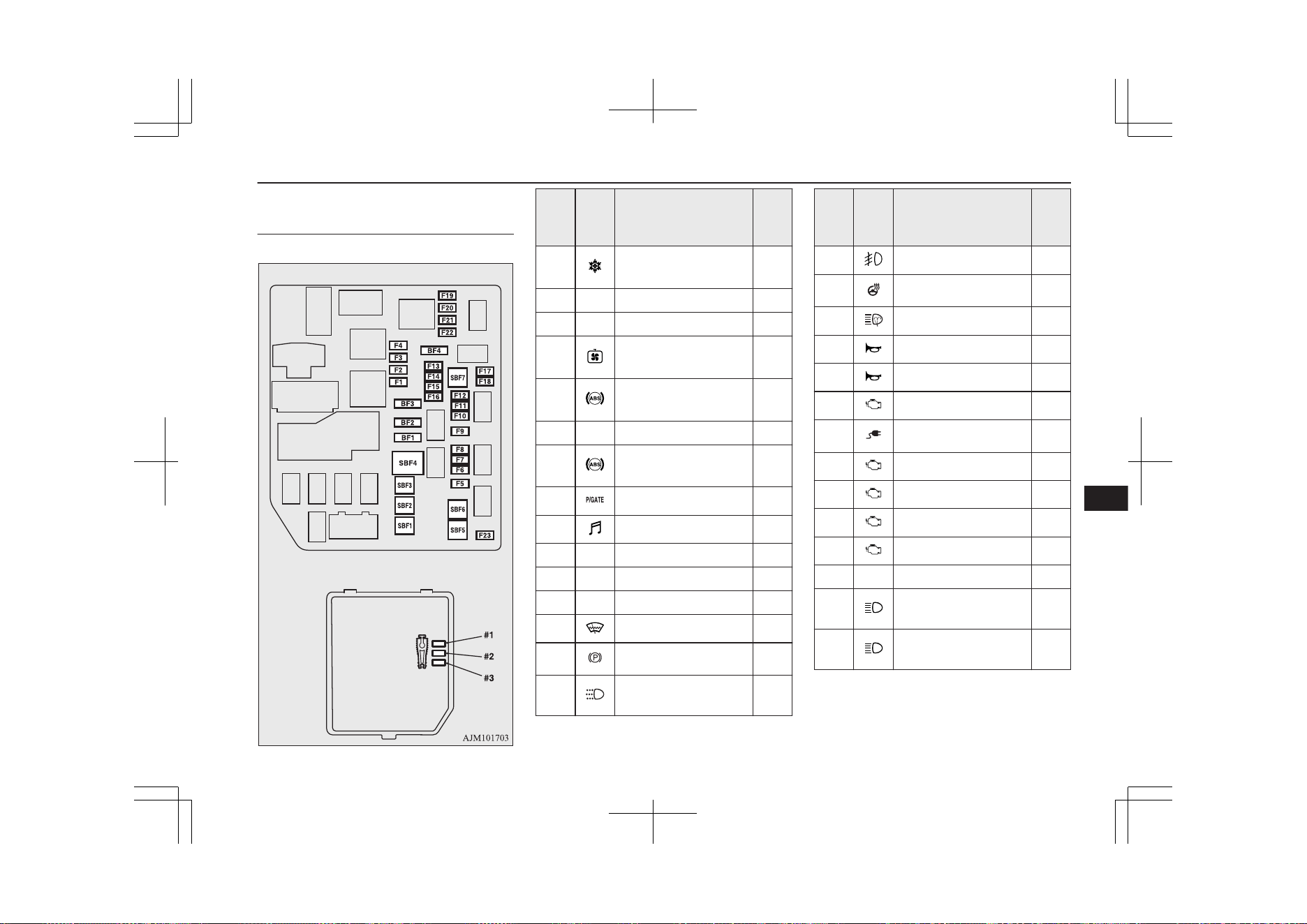
Engine compartment fuse loca-
tion table
E01008002402
Main fuse block
Behind of the fuse block cover
No.
Sym-
bol
Electrical system
Ca-
paci-
ty
SBF1
Air conditioning con-
denser fan motor
30
A
*
SBF2 — — —
SBF3 — — —
SBF4 Radiator fan motor
40
A
*
SBF5 Anti-lock brake system
40
A
*
SBF6 — — —
SBF7 Anti-lock brake system
30
A
*
BF1 Electric tailgate 30 A
BF2 Audio system amp 30 A
BF3 IOD IOD 30 A
BF4 — — —
F1 — — —
F2 Wiper de-icer 15 A
F3 Electric parking brake 7.5 A
F4
Daytime running
lamps
10 A
*
: Fusible link
No.
Sym-
bol
Electrical system
Ca-
paci-
ty
F5 Front fog lamps 15 A
F6 Heated steering wheel 15 A
F7 Headlamp washer 20 A
F8 Security horn 20 A
F9 Horn 10 A
F10 ETV 15 A
F11 Charging lid lock 15 A
F12 Engine 7.5 A
F13 ENG/POWER 20 A
F14 Fuel pump 15 A
F15 Ignition coil 10 A
F16 — — —
F17
Headlamp high-beam
(left)
10 A
F18
Headlamp high-beam
(right)
10 A
*
: Fusible link
Fuses
11-21
OGGE19E1
Maintenance
11
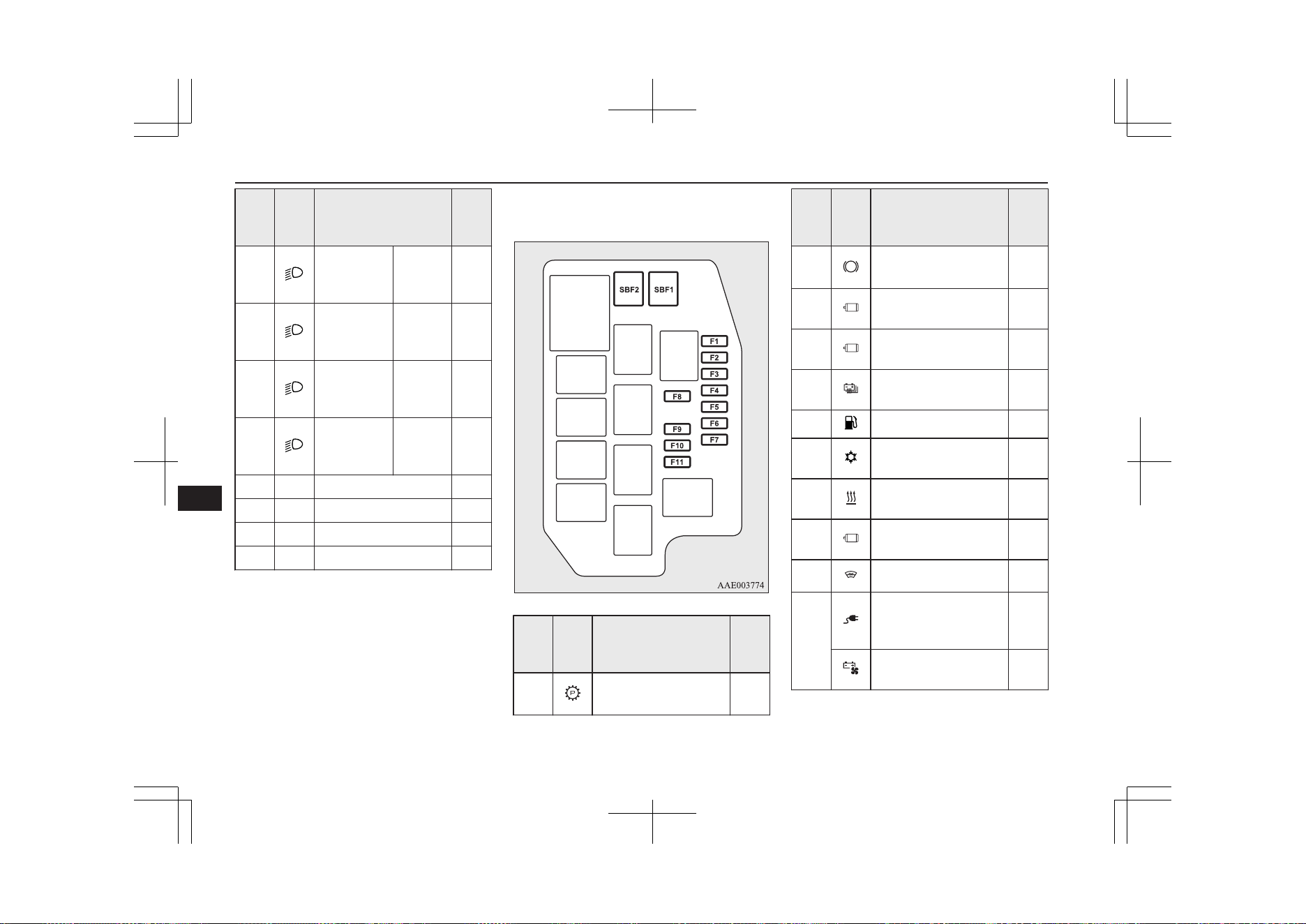
No.
Sym-
bol
Electrical system
Ca-
paci-
ty
F19
Headlamp
low beam
(left)
LED 20 A
F20
Headlamp
low beam
(right)
LED 20 A
F21
Headlamp
low beam
(left)
Halogen 10 A
F22
Headlamp
low beam
(right)
Halogen 10 A
F23 — — —
#1 — Spare fuse 10 A
#2 — Spare fuse 15 A
#3 — Spare fuse 20 A
*
: Fusible link
l
Some fuses may not be installed on your
vehicle, depending on the vehicle model
or specifications.
l
The table above shows the main equip-
ment corresponding to each fuse.
Sub fuse block
No.
Sym-
bol
Electrical system
Ca-
paci-
ty
SBF1
Electrical Parking
Lock
30
A
*
*
: Fusible link
No.
Sym-
bol
Electrical system
Ca-
paci-
ty
SBF2
Vacuum pump (Regen-
erative brake)
30
A
*
F1
Water pump (Electric
motor)
20 A
F2
Battery management
unit
7.5A
F3
Drive battery PTC
heater
15A
F4 Fuel tank filler door 7.5 A
F5
Solenoid valve (Air
conditioning)
7.5 A
F6
Water pump (Air con-
ditioning)
7.5 A
F7
Electric motor unit
control
10 A
F8 Heated windscreen 7.5 A
F9
Power feeder and
charger connector
(12V)
10 A
Drive battery fun mo-
tor
15 A
*
: Fusible link
Fuses
11-22
OGGE19E1
Maintenance
11
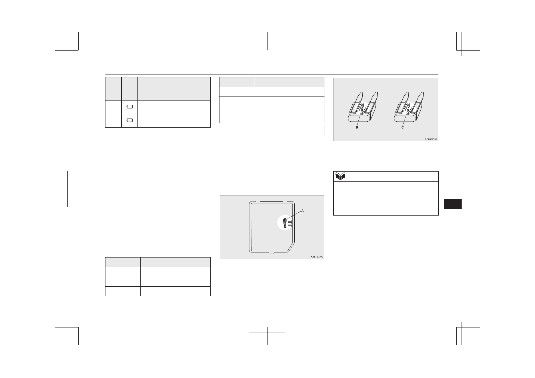
No.
Sym-
bol
Electrical system
Ca-
paci-
ty
F10 Ignition control 15 A
F11 Ignition control 7.5 A
*
: Fusible link
l
Some fuses may not be installed on your
vehicle, depending on the vehicle model
or specifications.
l
The table above shows the main equip-
ment corresponding to each fuse.
The fuse block does not contain spare 7.5 A
or 30 A fuses. If one of these fuses burns out,
substitute with the following fuse.
7.5 A: 10 A spare fuse
30 A: 30 A audio system amp fuse
When using a substitute fuse, replace with a
fuse of the correct capacity as soon as possi-
ble.
Identification of fuse
E01008101389
Capacity Colour
7.5 A Brown
10 A Red
15 A Blue
Capacity Colour
20 A Yellow
30 A
Green (fuse type) / Pink (fu-
sible link type)
40 A Green (fusible link type)
Fuse replacement
E01007801884
1. Before replacing a fuse, always turn off
the electrical circuit concerned and put
the operation mode of the power switch
in OFF.
2. Remove the fuse puller (A) from the in-
side of the main fuse block cover in the
engine compartment.
3. Referring to the fuse load capacity table,
check the fuse pertaining to the problem.
B- Fuse is OK
C- Blown fuse
NOTE
l
If any system does not function but the fuse
corresponding to that system is normal, there
may be a fault in the system elsewhere. We
recommend you to have your vehicle
checked.
Fuses
11-23
OGGE19E1
Maintenance
11
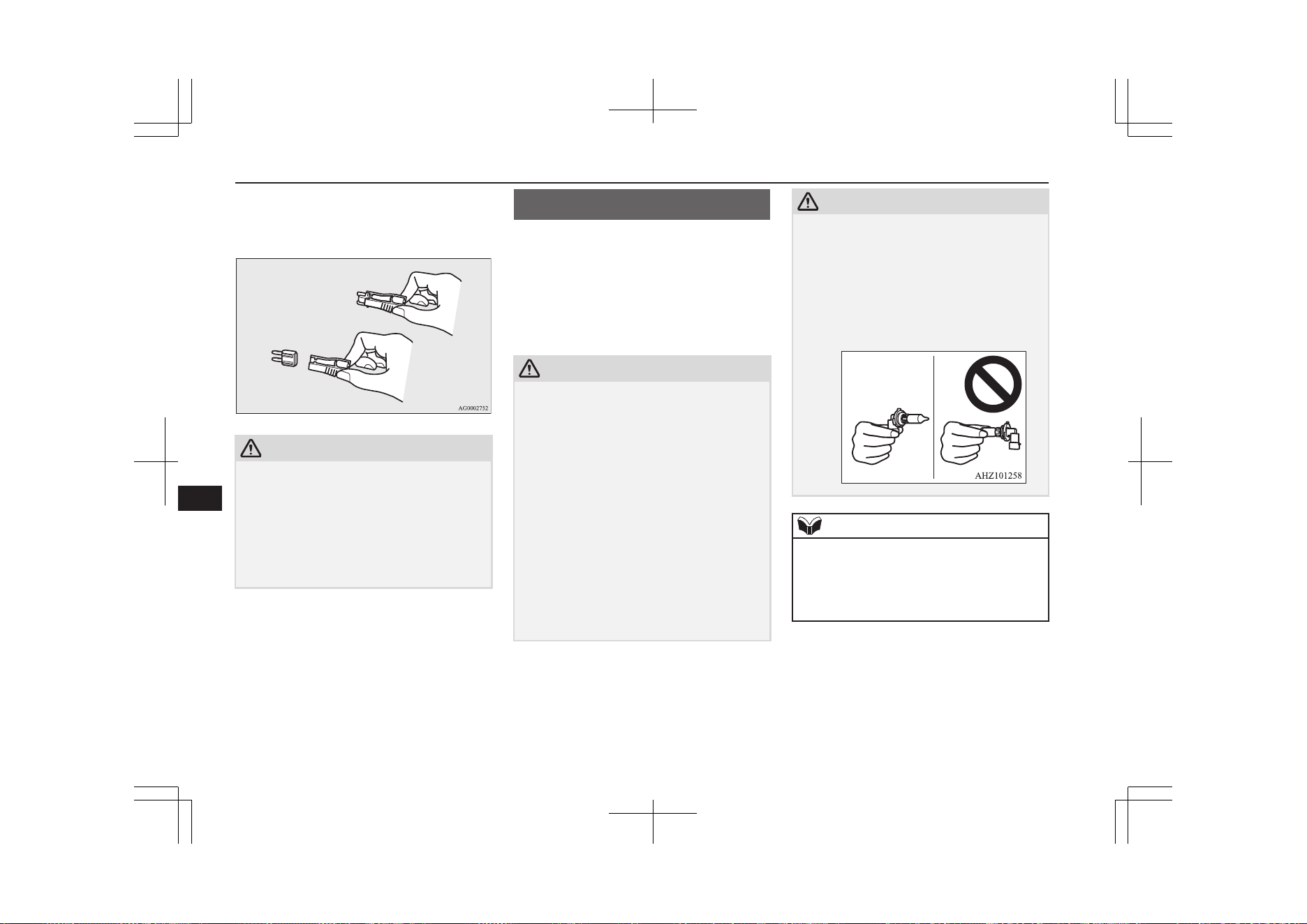
4. Insert a new fuse of the same capacity
by using the fuse puller into the same
place in the fuse block.
CAUTION
l
If the newly inserted fuse blows again after a
short time, we recommend you to have the
electrical system checked to find the cause
and rectify it.
l
Never use a fuse with a larger capacity than
specified or a substitute (such as a cable or
foil). Doing so could cause the circuit wires
to overheat and create a fire.
Replacement of lamp bulbs
E01003102004
Before replacing a bulb, ensure the lamp is
off. Do not touch the glass part of the new
bulb with your bare fingers; the skin oil left
on the glass will evaporate when the bulb
gets hot and the vapour will condense on the
reflector and dim the surface.
CAUTION
l
Do not install commercially available LED-
type bulbs.
Commercially available LED-type bulbs
could adversely affect the operation of the
vehicle, such as by preventing the lamps and
other vehicle equipment from operating
properly.
l
Bulbs are extremely hot immediately after
being turned off.
When replacing a bulb, wait for it to cool
sufficiently before touching it. You could
otherwise be burnt.
l
Handle halogen lamp bulbs with care. The
gas inside a halogen lamp bulbs is highly
pressurized, so dropping, knocking, or
scratching a halogen lamp bulb can cause it
to shatter.
CAUTION
l
Never hold the halogen lamp bulb with a
bare hand, dirty glove, etc.
The oil from your hand could cause the bulb
to break the next time the headlamps are op-
erated.
If the glass surface is dirty, it must be
cleaned with alcohol, paint thinner, etc., and
refit it after drying thoroughly.
NOTE
l
If you are unsure of how to carry out the
work as required, we recommend you to
consult a specialist.
l
Be careful not to scratch the vehicle body
when removing a lamp or lens.
Replacement of lamp bulbs
11-24
OGGE19E1
Maintenance
11
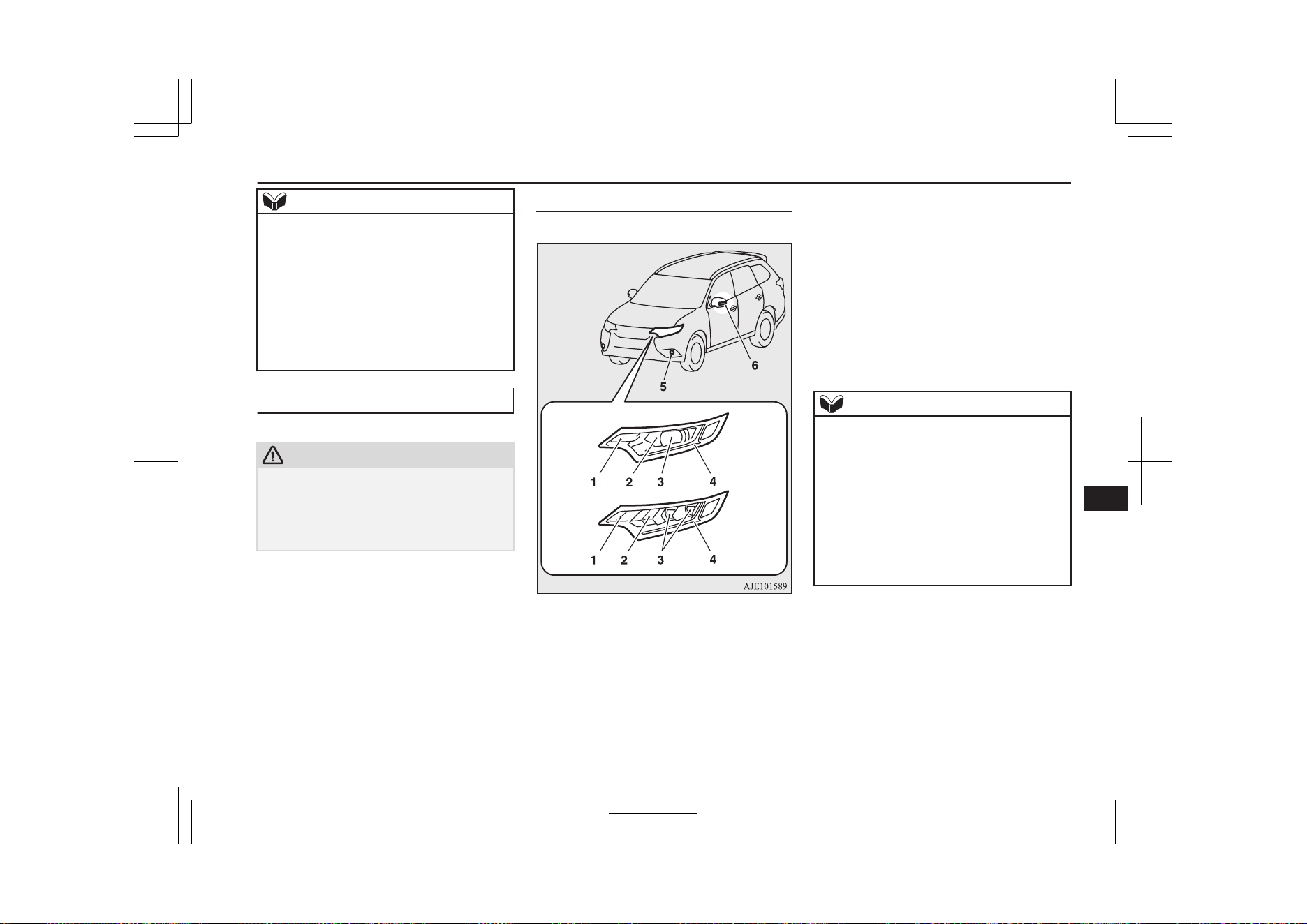
NOTE
l
When it rains or when the vehicle has been
washed, the inside of the lens sometimes be-
comes foggy. This is the same phenomenon
as when window glass mists up on a humid
day, and does not indicate a functional prob-
lem.
When the lamp is switched on, the heat will
remove the fog. However, if water gathers
inside the lamp, we recommend you to have
the lamp checked.
Bulb location and capacity
E01003201747
CAUTION
l
When replacing a bulb, be sure to use a new
bulb of the same type, wattage and colour. If
you install a different bulb, the bulb could
malfunction or fail to come on and could
lead to a vehicle fire.
Outside
E01003305498
Front
Type A
Type B
Type A: Halogen headlamps type
Type B: LED headlamps type
1- Front turn-signal lamps: 21 W (PY21W)
2- Headlamps, high-beam
Halogen: 60 W (HB3)
LED: −
3- Headlamps, low beam
Halogen: 55 W (H7)
LED: −
4- Position lamps: −
Daytime running lamps: −
5- Front fog lamps
Halogen: 19 W (H16)
LED: −
6- Side turn-signal lamps: −
Codes in parentheses indicate bulb types.
NOTE
l
The following lamps use an LED instead of
the bulb. If you need to repair or replace
these lamps, contact a MITSUBISHI
MOTORS Authorized Service Point.
•
Headlamps, high-beam (LED type)
•
Headlamps, low beam (LED type)
•
Position lamps
•
Daytime running lamps
•
Front fog lamps (LED type)
•
Side turn-signal lamps
Replacement of lamp bulbs
11-25
OGGE19E1
Maintenance
11
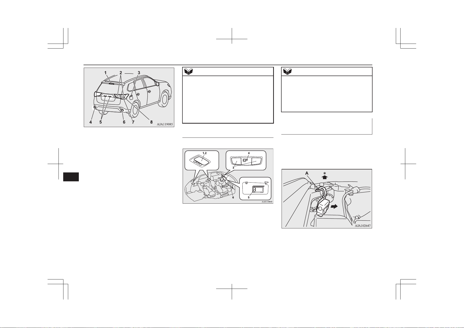
Rear
1- High-mounted stop lamp: −
2- Tail lamps: −
3- Charging port courtesy lamp: 5W
(W5W)
4- Rear fog lamp (LHD vehicles): 21 W
(W21W)
Reversing lamp (RHD vehicles): 16 W
(W16W)
5- Licence plate lamps: 5 W (W5W)
6- Reversing lamp (LHD vehicles): 16 W
(W16W)
Rear fog lamp (RHD vehicles): 21 W
(W21W)
7- Rear turn-signal lamps: 21 W (WY21W)
8- Stop lamps: −
Codes in parentheses indicate bulb types.
NOTE
l
The following lamps use an LED instead of
the bulb.
If you need to repair or replace these lamps,
contact a MITSUBISHI MOTORS Author-
ized Service Point.
•
High-mounted stop lamp
•
Tail lamps
•
Stop lamps
Inside
E01003403756
1- Luggage room lamp: 8 W
2- Room lamp (rear): 8 W
3- Map & room lamps (front): 8 W
4- Downlight
5- Vanity mirror lamps: 2 W
6- Glove box lamp: 1.4 W
NOTE
l
The following lamps use an LED instead of
the bulb. If you need to repair or replace
these lamps, contact a MITSUBISHI
MOTORS Authorized Service Point.
•
Downlight
•
Front foot lamps
Headlamps (low beam, halogen
bulb)
E01009301506
1. When replacing the bulb on the left side
of the vehicle, remove the bolt (A) hold-
ing down the relay box and move the re-
lay box.
*: Front of the vehicle
Replacement of lamp bulbs
11-26
OGGE19E1
Maintenance
11
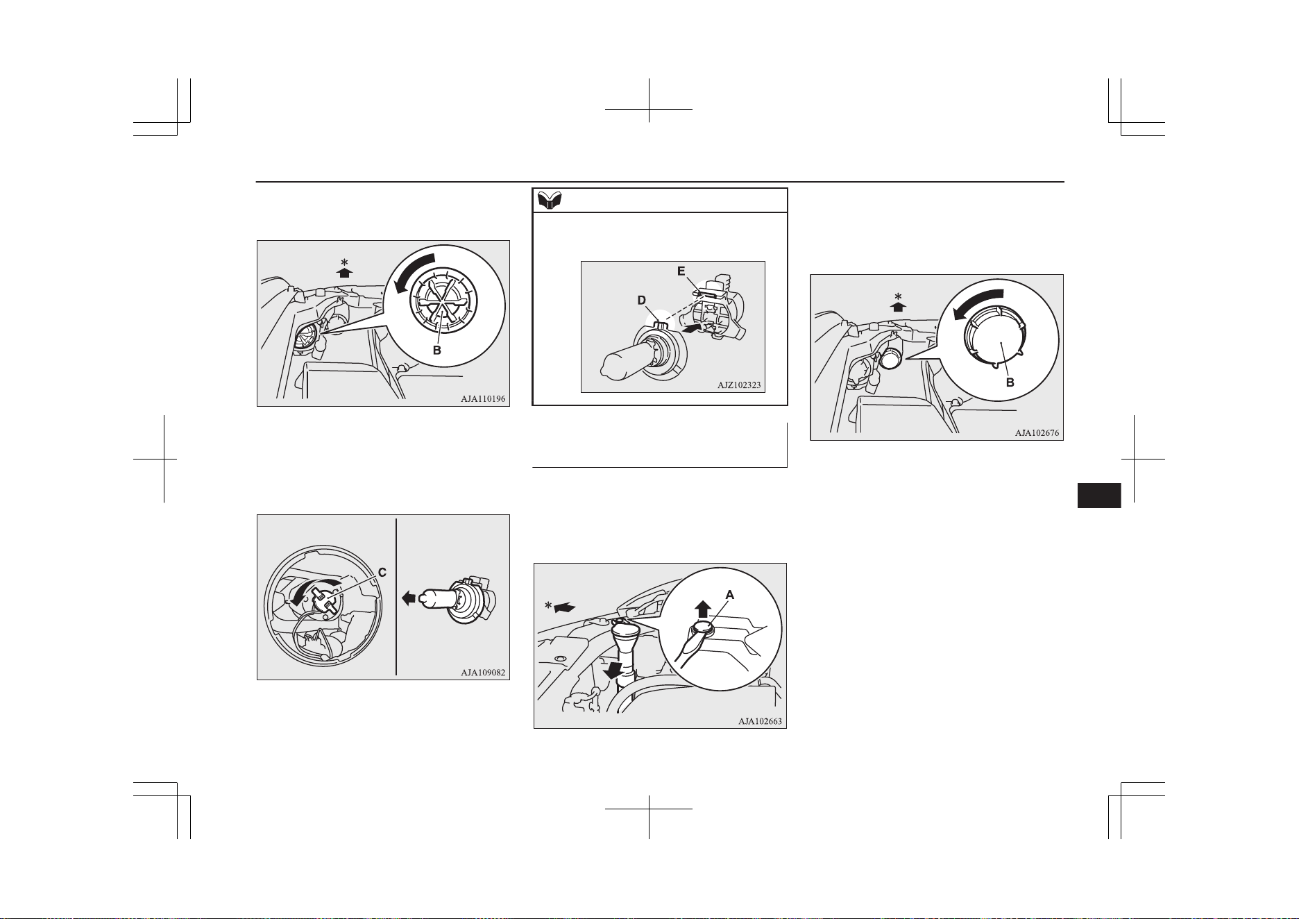
2. Turn the cap (B) anticlockwise to re-
move it.
*: Front of the vehicle
3. Turn the socket (C) anticlockwise to re-
move it, and then pull the bulb out of the
socket.
4. To install the bulb, perform the removal
steps in reverse.
NOTE
l
When installing the bulb, align the tab (D)
with the notch (E) of the socket.
Headlamps (high-beam, halo-
gen bulb)
E01009401376
1. When replacing the bulb on the right
side of the vehicle, remove the clip (A)
holding down the washer tank spout and
then move it.
*: Front of the vehicle
2. Turn the cap (B) anticlockwise to re-
move it.
*: Front of the vehicle
Replacement of lamp bulbs
11-27
OGGE19E1
Maintenance
11
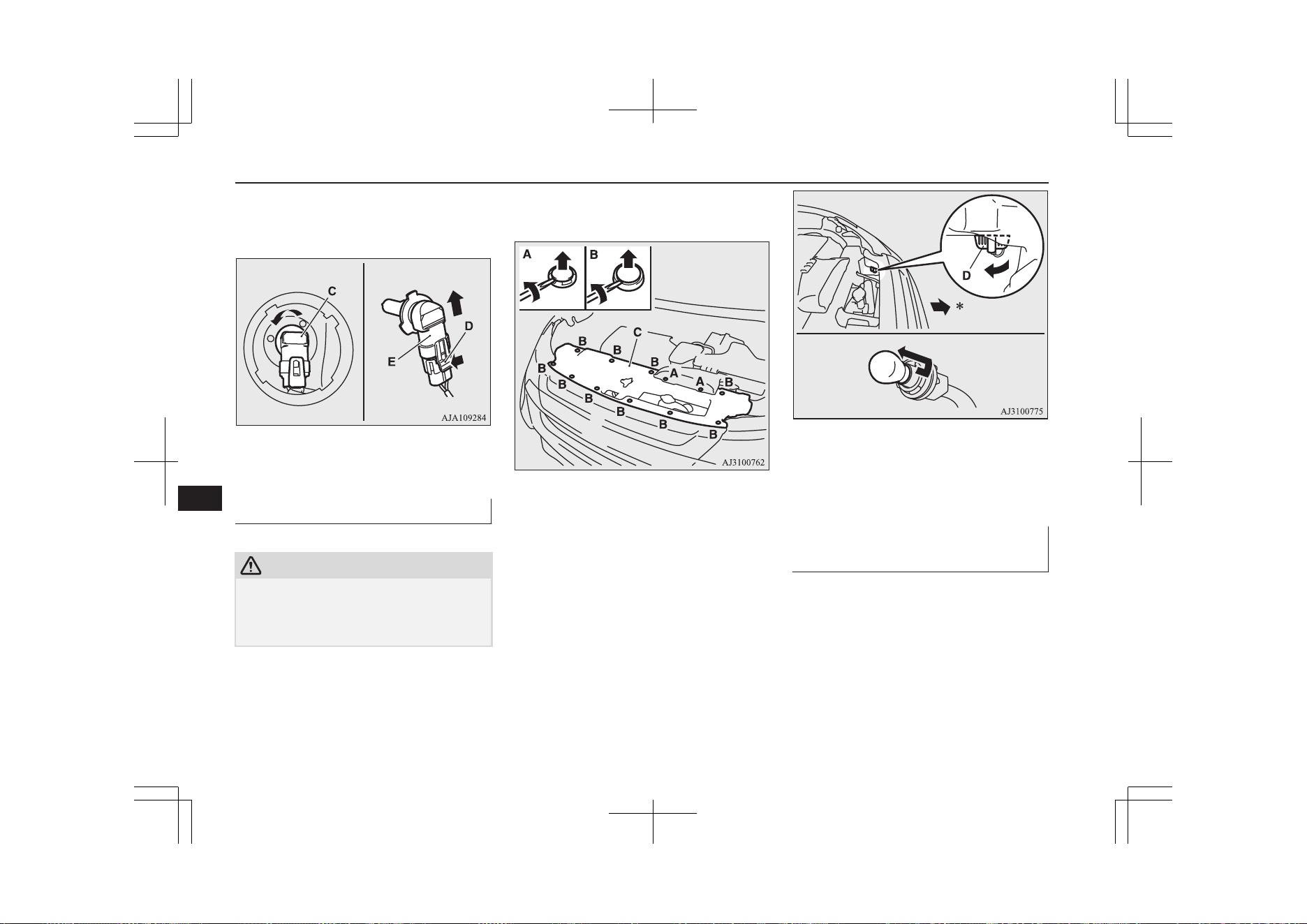
3. Turn the bulb (C) anticlockwise to re-
move it, and then while holding down
the tab (D), pull out the bulb (E).
4. To install the bulb, perform the removal
steps in reverse.
Front turn-signal lamps
E01003802320
CAUTION
l
Make sure that the Plug-in Hybrid EV sys-
tem have cooled down before replacing the
bulb on the right side of the vehicle, other-
wise you could be burnt by the radiator hose.
1. Remove the 12 clips (A, B), and then re-
move the cover (C).
2. Turn the socket (D) anticlockwise to re-
move it, then remove the bulb from the
socket by turning it anticlockwise while
pressing in.
*: Front of the vehicle
3. To install the bulb, perform the removal
steps in reverse.
Front fog lamps (Halogen bulb
type)*
E01004003674
1. Insert a straight blade (or minus) screw-
driver with a cloth over its tip at the
Replacement of lamp bulbs
11-28
OGGE19E1
Maintenance
11
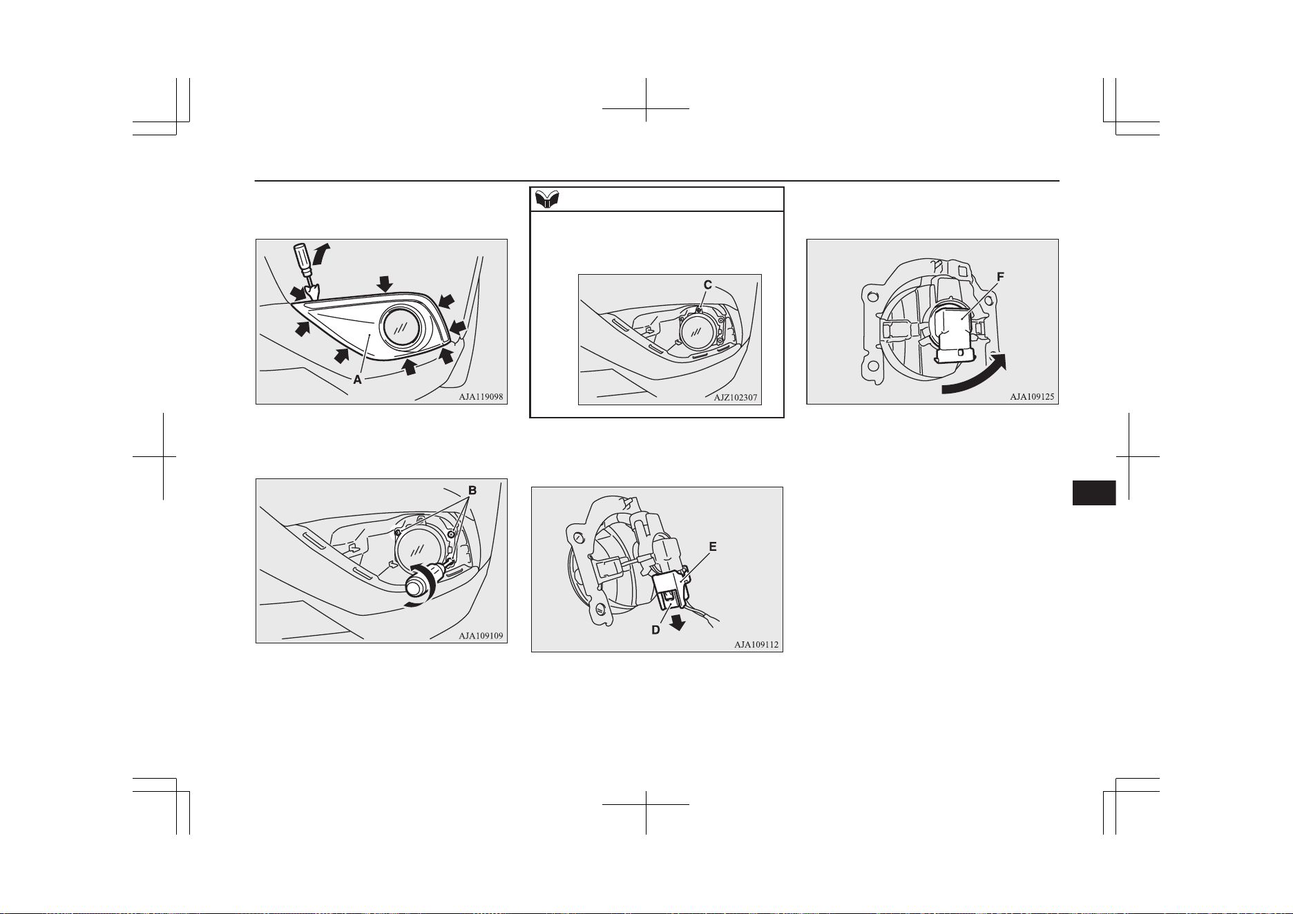
points indicated by arrows and pry gen-
tly to remove the cover (A).
2. Remove the 3 screws (B) and remove
the lamp unit.
NOTE
l
When unfastening the screws of the fog
lamp, be careful not to mistakenly move the
beam position adjustment screw (C).
3. While holding down the tab (D), pull out
the socket (E).
4. Turn the bulb (F) anticlockwise to re-
move it.
5. To install the bulb, perform the removal
steps in reverse.
Replacement of lamp bulbs
11-29
OGGE19E1
Maintenance
11
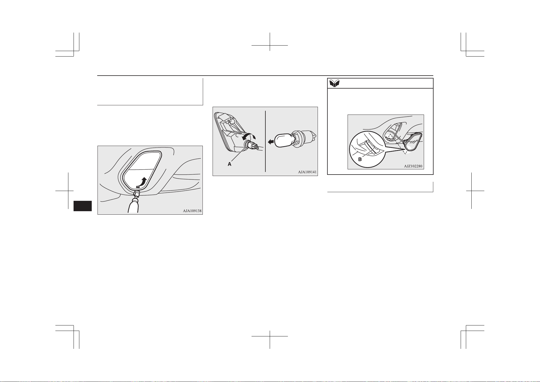
Rear fog lamp (driver’s side)/
Reversing lamp (Passenger’s
side)
E01004101655
1. Insert a straight blade (or minus) screw-
driver with a cloth over its tip at the edge
of the lamp unit, and then push the lamp
unit upward to remove it.
2. Turn the socket (A) anticlockwise to re-
move it, and then pull the bulb out of the
socket.
3. To install the bulb, perform the removal
steps in reverse.
NOTE
l
When installing the lamp unit, first insert the
notch (B) into the hole on the body, and then
push on the lamp unit to fit it into place.
Rear combination lamps
E01004202767
1. Open the tailgate.
Replacement of lamp bulbs
11-30
OGGE19E1
Maintenance
11
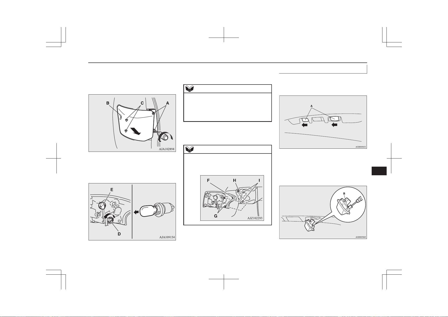
2. Remove the screws (A), and then move
the lamp unit towards the rear of the ve-
hicle to unfix the notch (B) and pins (C)
of the lamp unit.
3. Turn the socket anticlockwise and re-
move it, and then pull the bulb out of the
socket.
D- Rear turn-signal lamp
E- Tail lamp and stop lamp (LED)-cannot
be replaced
NOTE
l
The tail lamp and stop lamp use an LED in-
stead of the bulb.
If you need to repair or replace these lamps,
contact a MITSUBISHI MOTORS Author-
ized Service Point.
4. To install the bulb, perform the removal
steps in reverse.
NOTE
l
When installing the lamp unit, align the
notch (F) and pin (G) on the lamp unit with
the clip (H) and hole (I) in the body.
Licence plate lamps
E01004602325
1. Remove while pressing the lamp unit
(A) to the left side of the vehicle.
2. Insert a minus screwdriver with the end
covered with a cloth or other object to
press the hook (B) aside and remove the
lens.
Replacement of lamp bulbs
11-31
OGGE19E1
Maintenance
11
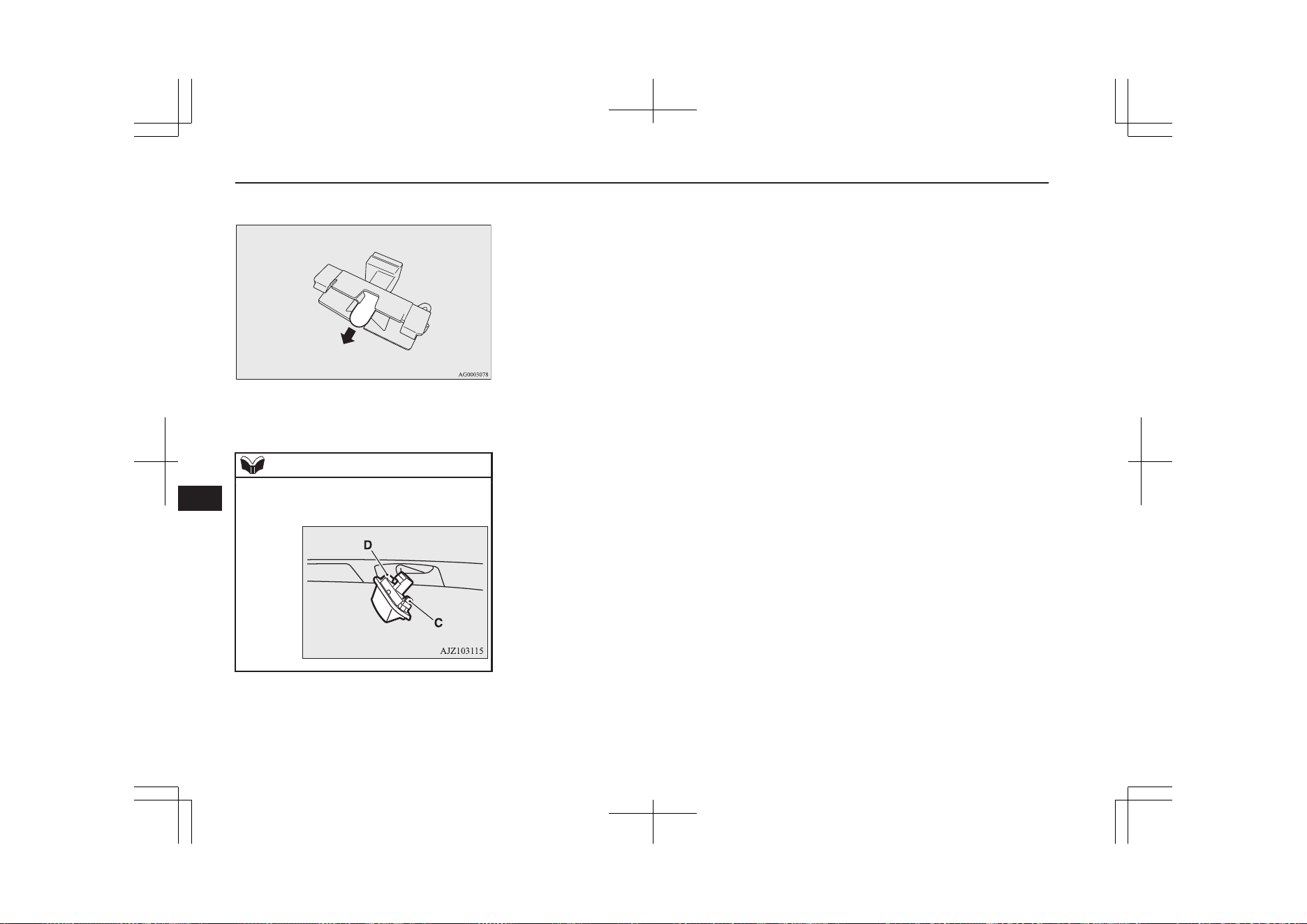
3. Remove the bulb from the socket.
4. To install the bulb, perform the removal
steps in reverse.
NOTE
l
When installing the lamp unit, first insert the
end of tab (C) and then align tab (D).
Replacement of lamp bulbs
11-32
OGGE19E1
Maintenance
11

Vehicle labeling.................................................................................12-02
Vehicle dimensions........................................................................... 12-04
Vehicle performance......................................................................... 12-05
Vehicle weight...................................................................................12-05
Engine specifications........................................................................ 12-06
Charging system specifications.........................................................12-07
Electric motor specifications.............................................................12-08
Low voltage electrical system...........................................................12-08
Tyres and wheels...............................................................................12-09
Fuel consumption..............................................................................12-09
Capacity............................................................................................ 12-10
Specifications
OGGE19E1
12
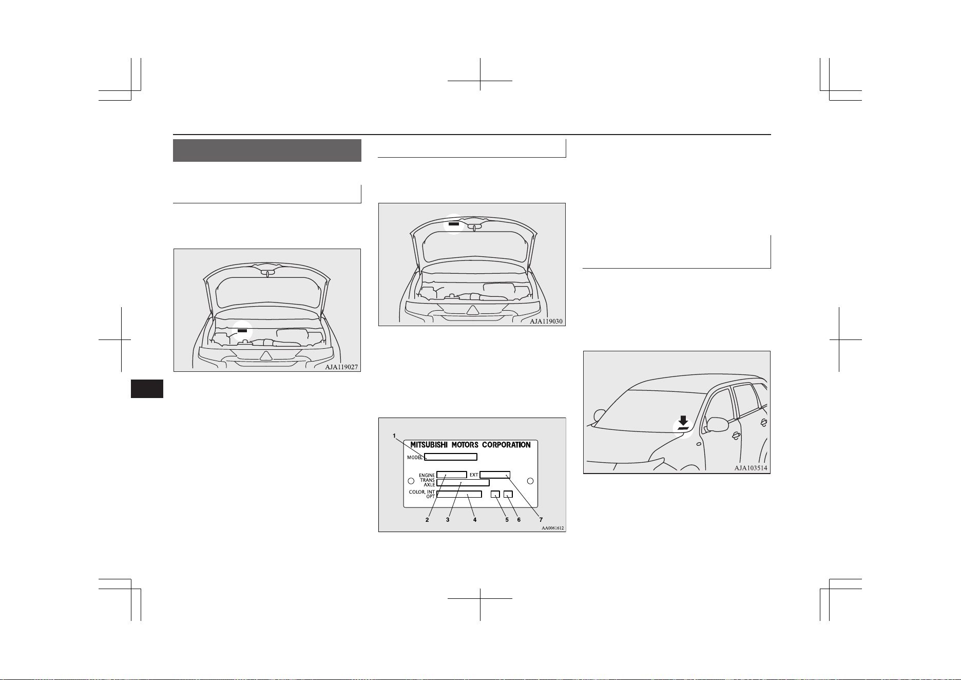
Vehicle labeling
E01100105571
Vehicle identification number
The vehicle identification number is stamped
on the bulkhead as shown in the illustration.
Vehicle information code plate
The vehicle information code plate is riveted
as shown in the illustration.
The plate shows the model code, engine
model, transaxle model and body colour
code, etc.
Please use this number when ordering re-
placement parts.
1- Model code
2- Engine model code
3- Transaxle model code
4- Body colour code
5- Interior code
6- Option code
7- Exterior code
Vehicle identification number
plate (RHD vehicles only)
The vehicle identification number is stamped
on the plate riveted to the left front corner of
the instrument panel pad. It is visible from
outside of the vehicle through the wind-
screen.
Vehicle labeling
12-02
OGGE19E1
Specifications
12
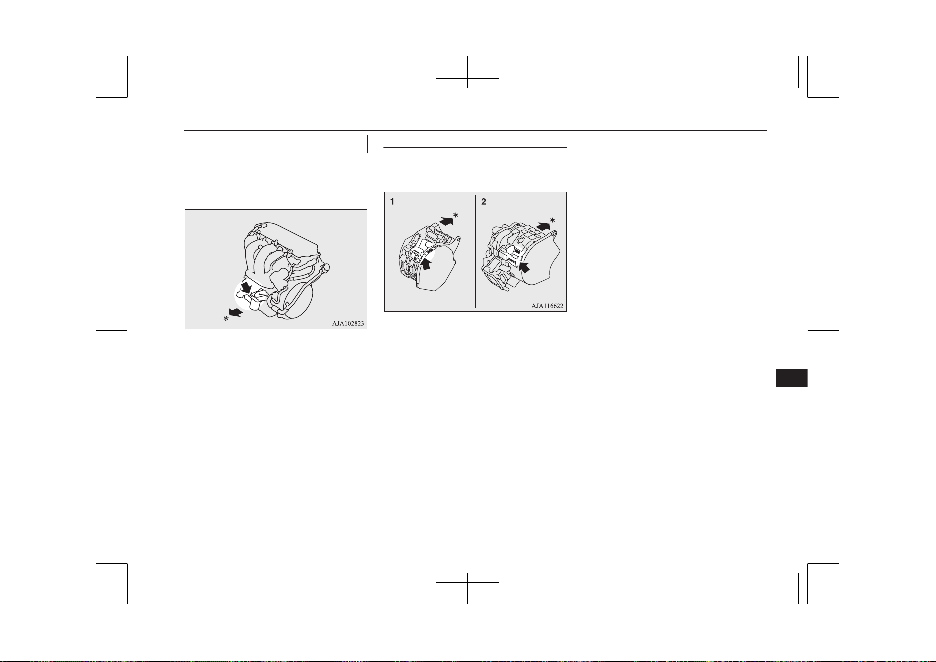
Engine model/number
The engine model and number are stamped
on the engine cylinder block as shown in the
illustration.
*: Front of the vehicle
Electric motor model/number
The electric motor model and number are
stamped as shown in the illustration.
1- Front motor
2- Rear motor
*: Front of the vehicle
Vehicle labeling
12-03
OGGE19E1
Specifications
12
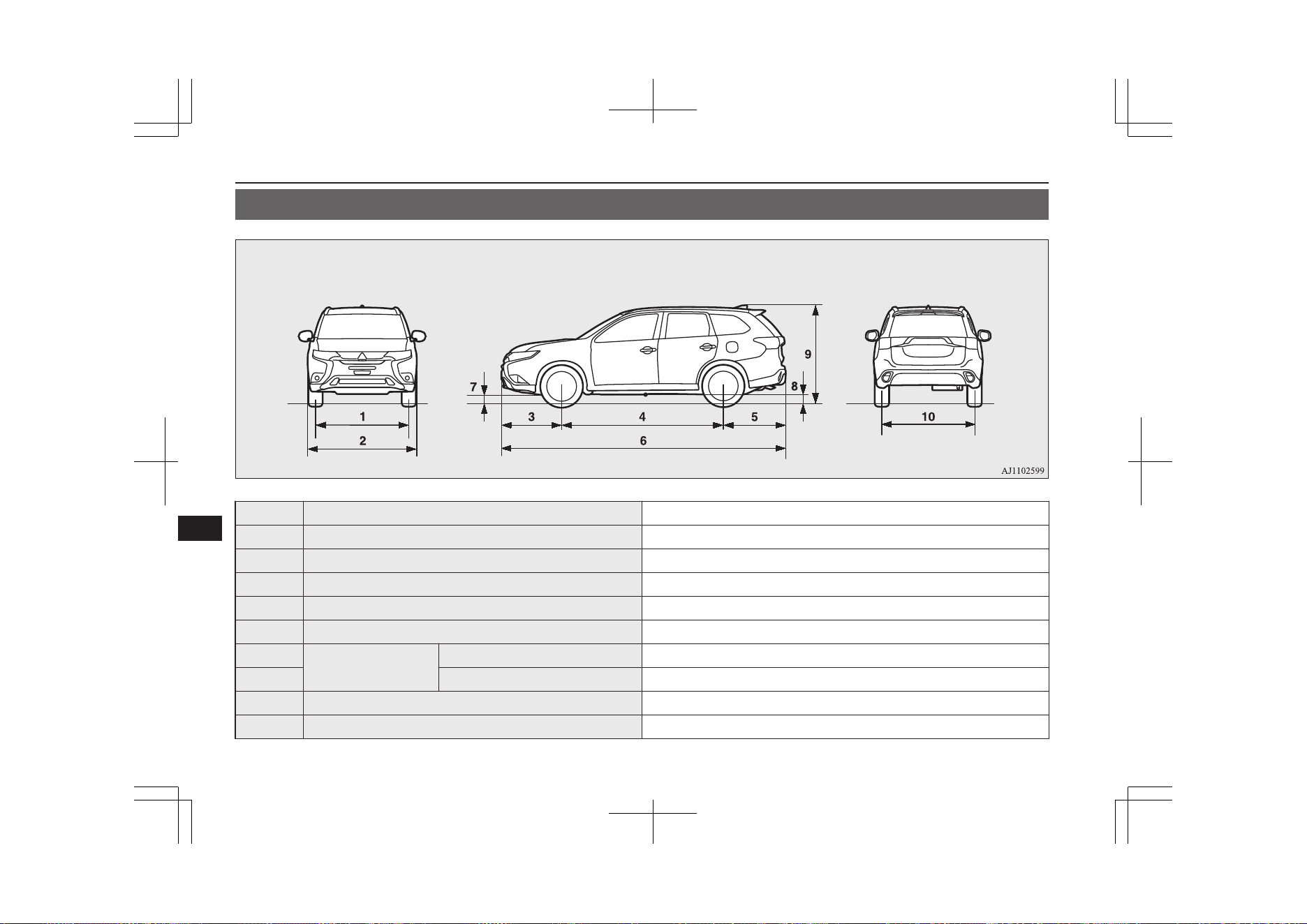
Vehicle dimensions
E01100205178
1 Front track 1,540 mm
2 Overall width 1,800 mm
3 Front overhang 990 mm
4 Wheel base 2,670 mm
5 Rear overhang 1,035 mm
6 Overall length 4,695 mm
7
Ground clearance (un-
laden)
Without exhaust pipe protector 190 mm
8 With exhaust pipe protector 185 mm
9 Overall height (unladen) 1,710 mm
10 Rear track 1,540 mm
Vehicle dimensions
12-04
OGGE19E1
Specifications
12
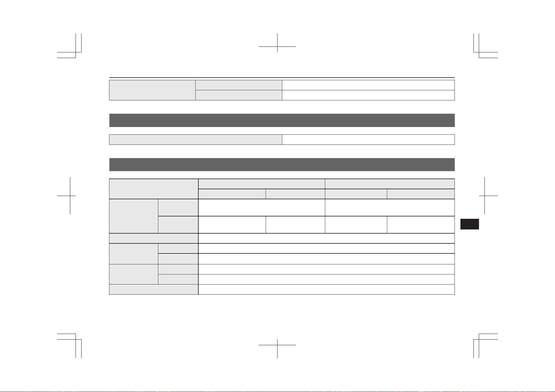
Minimum turning radius
Body 5.76 m
Wheel 5.3 m
Vehicle performance
E01100303553
Maximum speed 170 km/h
Vehicle weight
E01100409309
Item
Except for S Edition S Edition
LHD RHD LHD RHD
Kerb weight
Without op-
tional parts
1,880 kg 1,900 kg
With full op-
tional parts
1,947 kg 1,945 kg 1,957 kg 1,955 kg
Maximum gross vehicle weight 2,390 kg
Maximum axle
weight
Front 1,200 kg
Rear
1,255 kg, 1,365 kg
*
Maximum towable
weight
With brake 1,500 kg
Without brake 750 kg
Maximum trailer-nose weight 75 kg
*
: In case of trailer towing
Vehicle performance
12-05
OGGE19E1
Specifications
12
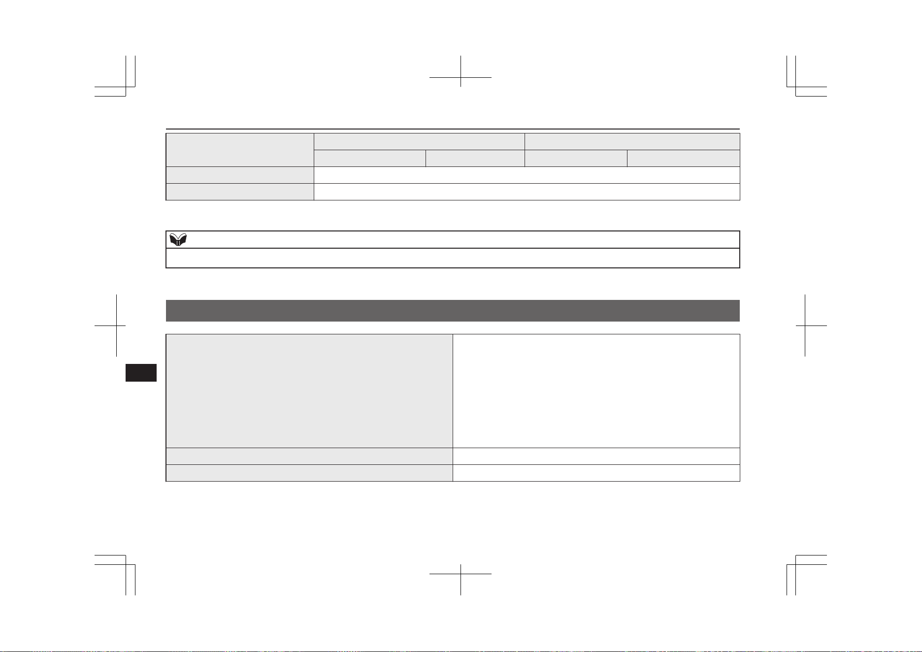
Item
Except for S Edition S Edition
LHD RHD LHD RHD
Maximum roof load 80 kg
Seating capacity 5 persons
*
: In case of trailer towing
NOTE
l
Trailer specifications indicate the manufacturer’s recommendation.
Engine specifications
E01100604856
Engine model 4B12
No. of cylinders 4 in line
Total displacement 2,360 cc
Bore 88.0 mm
Stroke 97.0 mm
Camshaft Double overhead
Mixture preparation Electronic injection
Maximum output (EEC net) 99 kW/4,500 rpm
Maximum torque (EEC net) 211 N•m/4,500 rpm
Engine specifications
12-06
OGGE19E1
Specifications
12
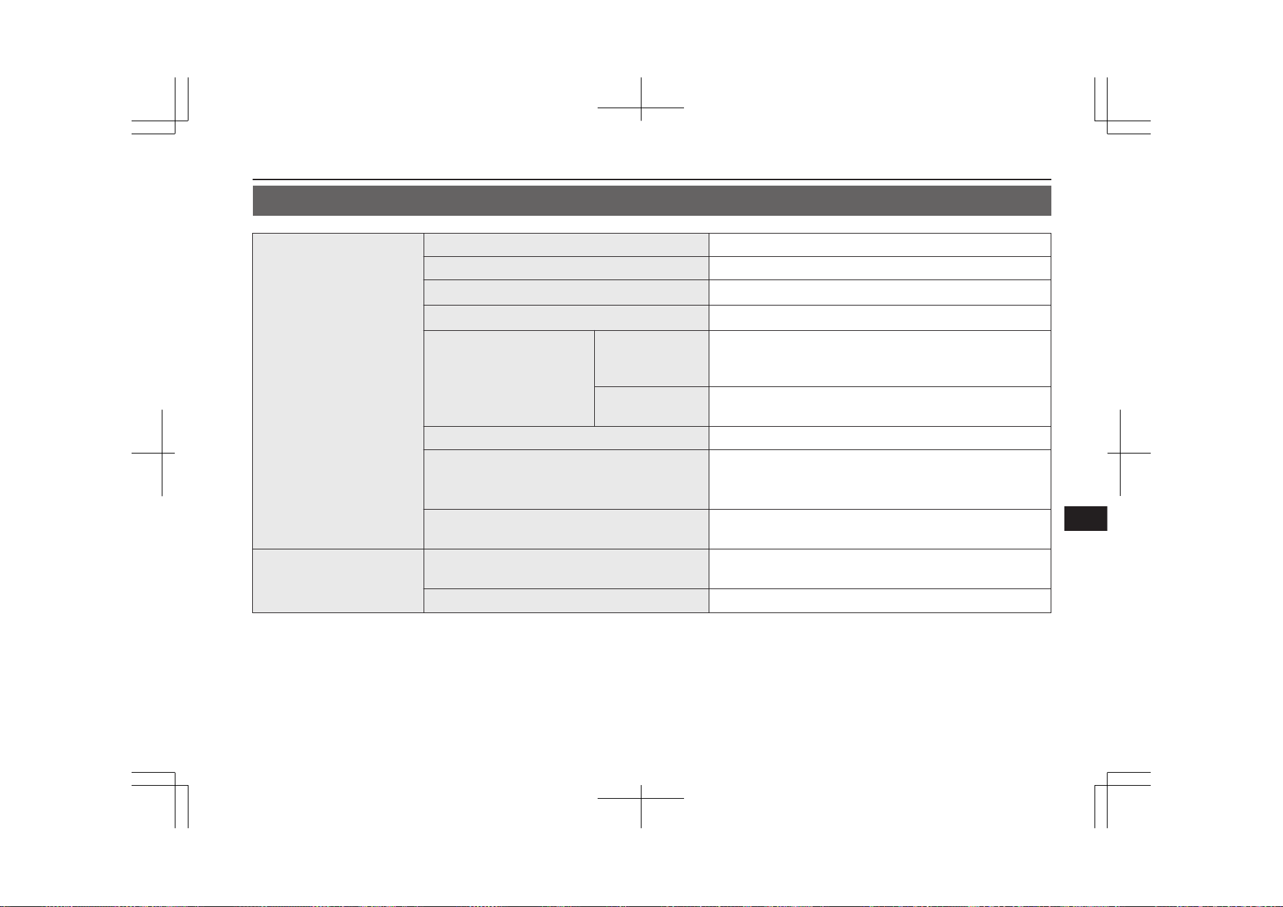
Charging system specifications
E01101901190
Normal charging system
Rated input voltage AC 230V (single phase)
Rated input frequency 50 Hz/60 Hz
Maximum rated current
10 A
*1
, 8 A
*1
Maximum power consumption
3.6 kVA
*2
Applicable standards
Charging cable
(with connector
and control box)
EN61851-1
IEC61851-1
IEC62196-1
On board charger
EN61851-21
IEC61851-21
Leakage current sensitivity in cable control box 20 mA
Charging mode
Based on IEC61851-1
Mode 2/Case B
*1
Mode 3/Case C
*2
IP degrees
IP44: When a charge connector is connected
IP55: When charging lid is closed and vehicle is moving
Quick charging system
Applicable standards
IEC62196-1
CHAdeMO
Maximum input current 60 A
*1
: When using a genuine charging cable with control box
*2
: When using a home or public charging device (EVSE: Electric Vehicles Supply Equipment)
Charging system specifications
12-07
OGGE19E1
Specifications
12
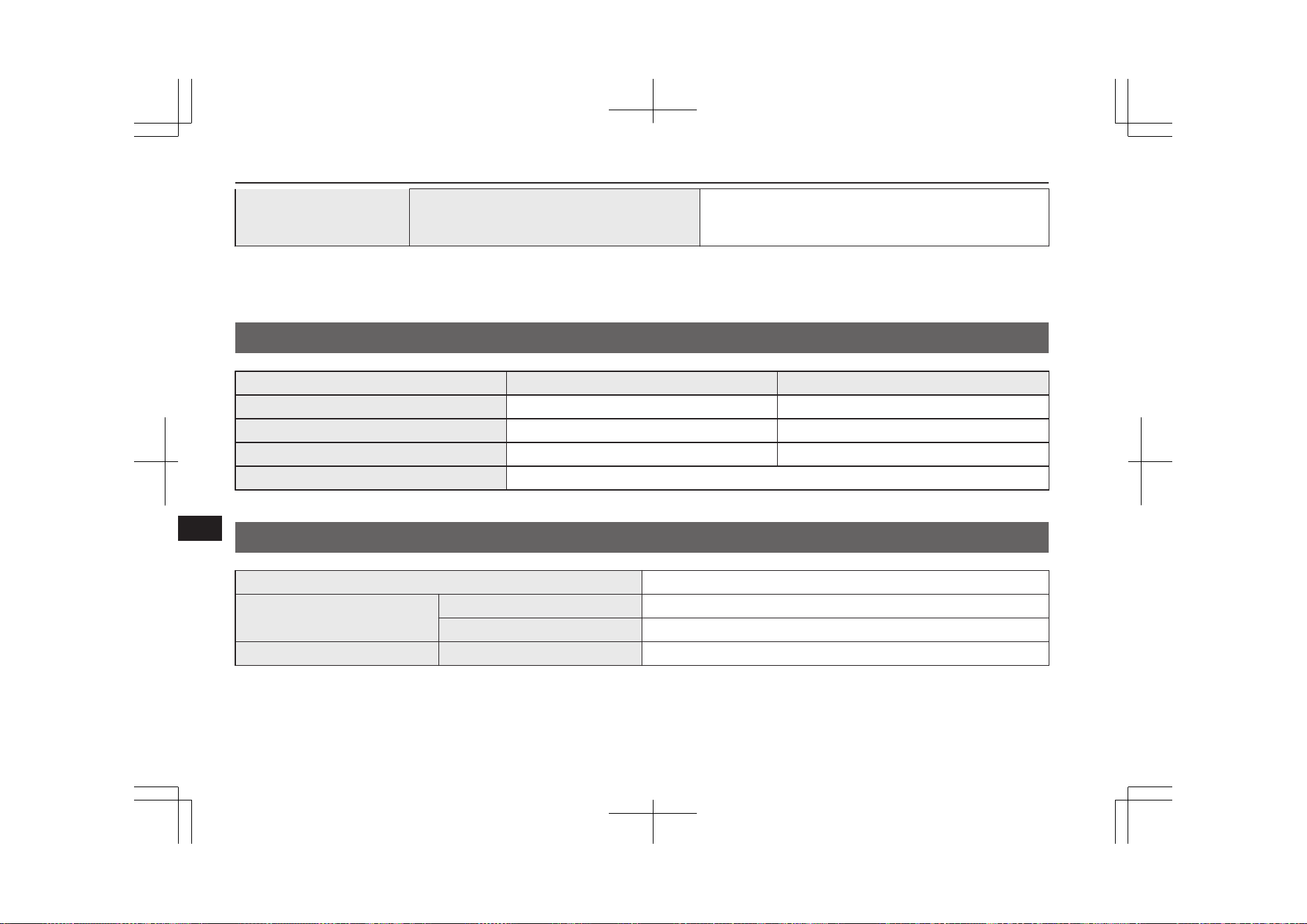
IP degrees
IP44: When a charge connector is connected
IP55: When the charging lid is closed and the vehicle is
moving
*1
: When using a genuine charging cable with control box
*2
: When using a home or public charging device (EVSE: Electric Vehicles Supply Equipment)
Electric motor specifications
E01100604869
Item Front Motor Rear Motor
Electric motor model S61 Y61
Maximum output (ECE net) 60 kW 70 kW
Maximum torque 137 Nm 195 Nm
Maximum 30 minutes power 25 kW
Low voltage electrical system
E01100804151
Voltage 12 V
Auxiliary battery
Type (JIS) S46B24L(S)
Capacity (5HR) 36 Ah
Spark plug type NGK DIFR5E11
Electric motor specifications
12-08
OGGE19E1
Specifications
12
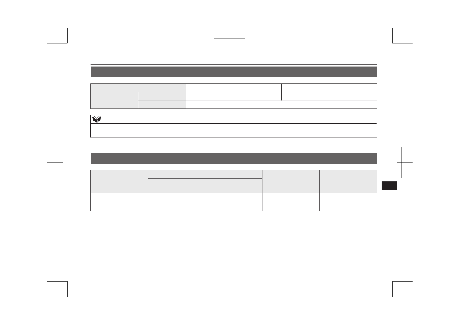
Tyres and wheels
E01100905104
Tyre 215/70R16 100H 225/55R18 98H
Wheel
Size 16x6 1/2J 18x7J
Offset (Inset) 38 mm
NOTE
l
The tyres that can be installed on your vehicle are shown on the driver’s door label, refer to “Tyre inflation pressures” on page 11-10. For details, contact a
MITSUBISHI MOTORS Authorized Service Point.
Fuel consumption
E01102800056
Item
Combined (laden)
Electric consumption
(Wh/km)
Electric range (km)
CO
2
(g/km) Fuel consumption
(L/100 km)
NEDC
*1
40 1.8 148
54
*2
WLTC
*3
46 2.0 169
45
*4
*1
: New European Driving Cycle
*2
: All Electric Range
*3
: Worldwide harmonized Light vehicles Test Cycle
*4
: Equivalent All Electric Range
The values are based on UN R101. It varies depending on driving style, road and traffic conditions, ambient temperature, use of air conditioners
and so forth.
Tyres and wheels
12-09
OGGE19E1
Specifications
12
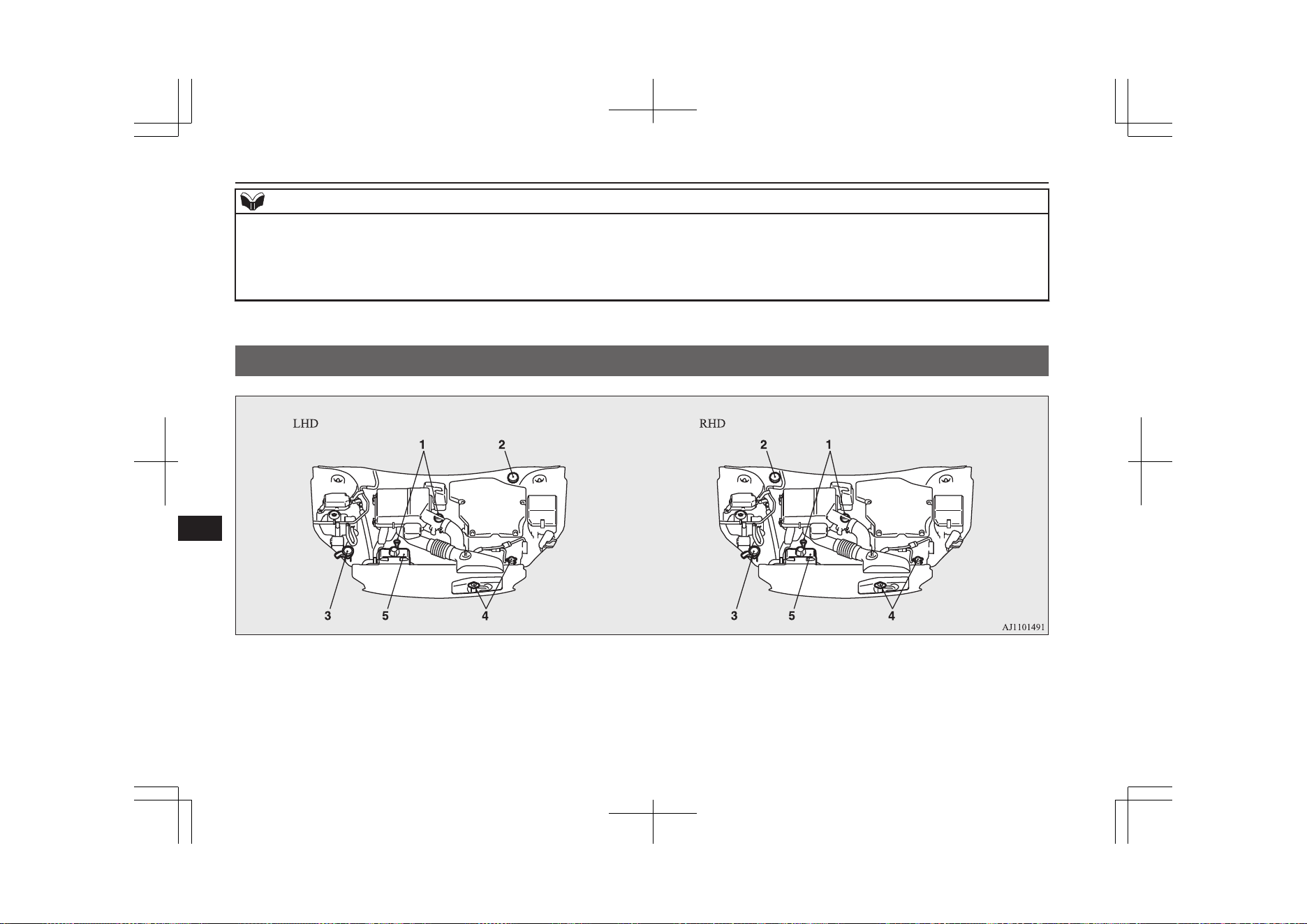
NOTE
l
The results given do not express or imply any guarantee of all the values of the particular vehicle.
The vehicle itself has not been tested and there are inevitably differences between individual vehicles of the same model. In addition, this vehicle may incor-
porate particular modifications. Furthermore, the driver’s style and road and traffic conditions, as well as the extent to which the vehicle has been driven and
the standard of maintenance, will all affect its value.
l
All mentioned values are referring to a new, driven in vehicle.
Capacity
E01101307558
Capacity
12-10
OGGE19E1
Specifications
12
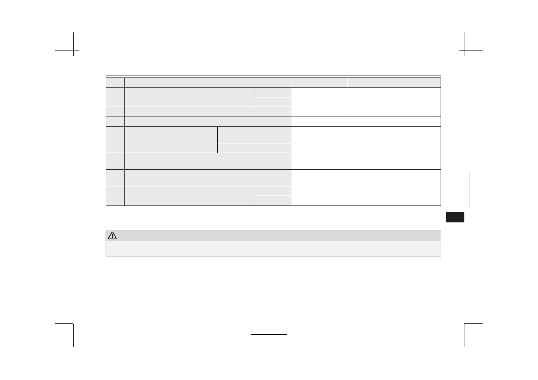
No. Item Quantity Lubricants
1 Engine oil
Oil pan 4.3 litres
Refer to page 11-05.
Oil filter 0.3 litre
2 Brake fluid As required Brake fluid DOT3 or DOT4
3 Washer fluid 4.5 litres —
4 Engine coolant
[includes 0.65 litre in the reserve tank]
Except for vehicles with elec-
tric heater
6.5 litres
MITSUBISHI MOTORS GENUINE
SUPER LONG LIFE COOLANT PRE-
MIUM or equivalent
*
Vehicles with electric heater 7.5 litres
5 Rear Motor coolant
[includes 1.07 litre in the reserve tank]
6.5 litres
6 Front Motor fluid 2.2 litres MITSUBISHI MOTORS GENUINE
CVTF-J4
7 Transaxle fluid
Front 3.46 litres
MITSUBISHI MOTORS GENUINE
ATF SPIII
Rear 0.85 litre
*
: Similar high quality ethylene glycol based non-silicate, non-amine, non-nitrate and non-borate coolant with long life hybrid organic acid tech-
nology
CAUTION
l
For the transaxle fluid, use only the MITSUBISHI MOTORS GENUINE ATF.
Use of a different fluid could damage the transaxle.
Capacity
12-11
OGGE19E1
Specifications
12
No. Item Quantity Lubricants
8 Refrigerant (air conditioner)
520 - 560 g
*1
,
495 - 535 g
HFC-134a
*1
, HFO-1234yf
*1
: Vehicles for Ukraine
Capacity
12-12
OGGE19E1
Specifications
12

Cold
Cautions and actions to deal with
intense cold..................................................2-10
2
220-240 V AC power supplies..........................8-76
4
4-wheel drive operation.....................................7-23
A
Accessory (Installation).....................................2-17
Accessory socket...............................................8-75
Acoustic Vehicle Alerting System (AVAS).......2-06
Active stability control (ASC)...........................7-43
Adaptive Cruise Control System (ACC)...........7-55
Air conditioner
Automatic climate control air conditioner.... 8-06
Important operation tips for the air
conditioner...................................................8-14
Air purifier.........................................................8-15
Airbag................................................................5-25
Caution for installing the child re-
straint in vehicles with front pas-
senger’s airbag.....................................5-15,5-27
Anti-lock brake system (ABS).......................... 7-40
Ashtray.............................................................. 8-74
Assist grips........................................................ 8-86
Audio
CD player...................................................... 8-15
LW/MW/FM radio........................................ 8-15
Troubleshooting............................................ 8-49
Automatic High-Beam (AHB).......................... 6-62
Auxiliary battery..............................................11-09
Auxiliary battery charge warning lamp.............6-57
B
Basic knowledge for charging...........................3-04
Battery
Auxiliary battery charge warning lamp........ 6-57
Discharged battery (Emergency starting)......9-02
Disposal information for used batteries........ 2-18
Specification............................................... 12-08
Blind Spot Warning (BSW)...............................7-82
Bluetooth® 2.0 interface................................... 8-51
Bonnet............................................................. 11-04
Bottle holders.................................................... 8-84
Brake assist system............................................7-39
Brake warning lamp.......................................... 6-55
Brake
Anti-lock brake............................................. 7-40
Brake auto hold............................................. 7-35
Braking..........................................................7-34
Fluid..................................................11-08,12-10
Parking brake................................................ 7-03
Bulb capacity ..................................................11-25
C
Capacities........................................................ 12-10
Card holder................................................8-74,8-82
Cargo area cover................................................8-85
Cargo loads......................................................7-117
Catalytic converter.......................................... 11-03
Cautions and actions to deal with intense cold. 2-10
Cautions on handling of 4-wheel
drive vehicles................................................... 7-25
Central door locks............................................. 4-16
Charging............................................................3-02
Charging indicator.............................................6-55
Charging system specifications.......................12-07
Charging troubleshooting guide........................3-28
Check engine warning lamp..............................6-56
Child restraint....................................................5-15
Caution for installing the child re-
straint in vehicles with front pas-
senger’s airbag.....................................5-15,5-27
Child-protection rear doors............................... 4-18
Cigarette lighter.................................................8-75
Cleaning
Exterior of your vehicle.............................. 10-03
Interior of your vehicle............................... 10-02
Coat hook.......................................................... 8-86
Combination headlamps and dipper switch...... 6-59
Coolant (engine)....................................11-06,12-10
Coolant (plug-in hybrid EV system)............... 11-06
Cruise control.................................................... 7-45
Cup holder.........................................................8-84
D
Daytime running lamps
Bulb capacity...............................................11-25
Demister (rear window).................................... 6-74
Digital clock
Time Setting.................................................. 8-47
Alphabetical index
13- 1
OGGE19E1
Alphabetical index

Dimensions......................................................12-04
Dipper (High/Low beam change)......................6-61
Disposal information for used batteries............ 2-18
Doors
Central door locks......................................... 4-16
Child-protection............................................ 4-18
Dead Lock System........................................ 4-17
Lock and unlock............................................4-14
Drive battery......................................................2-05
Driving, alcohol and drugs................................7-02
E
Economical driving........................................... 7-02
Electric motor model.......................................12-02
Electric motor number.....................................12-02
Electric motor specifications...........................12-08
Electric parking brake....................................... 7-03
Electric power steering system (EPS)............... 7-42
Electric tailgate..................................................4-20
Electric window control.................................... 4-34
Electrical Parking switch...................................7-18
Electronic immobilizer (Anti-theft
starting system)................................................4-03
Emergency starting............................................9-02
Emergency stop signal system.......................... 7-39
Engine specifications.......................................12-06
Engine
Coolant..............................................11-06,12-10
Model.......................................................... 12-02
Number....................................................... 12-02
Oil................................................................11-05
Oil and oil filter...........................................12-10
Overheating...................................................9-04
Specifications..............................................12-06
Used engine oils safety instructions
and disposal information............................. 2-18
EV charging cable............................................. 3-07
EV cruising range..............................................2-05
EV switch.......................................................... 7-25
Exterior and interior lamp operation............... 11-16
F
Fluid capacities and lubricants........................ 12-10
Fluid
Brake fluid........................................ 11-08,12-10
Engine coolant.................................. 11-06,12-10
Front Motor fluid........................................ 12-10
Plug-in hybrid EV system coolant.............. 11-06
Transaxle fluid............................................ 12-10
Washer fluid......................................11-08,12-10
For persons with electro-medical ap-
paratus such as implantable cardiac
pacemaker or implantable cardi-
overter-defibrillator..........................................2-09
Forward Collision Mitigation System (FCM)...7-67
Front fog lamps
Bulb capacity...............................................11-25
Indication lamp............................................. 6-55
Replacement................................................11-28
Switch........................................................... 6-68
Front Motor fluid ............................................12-10
Front room lamp................................................8-80
Bulb capacity...............................................11-26
Front seats......................................................... 5-03
Front turn-signal lamps
Bulb capacity...............................................11-25
Replacement................................................11-28
Fuel consumption............................................ 12-09
Fuel
Filling the fuel tank.......................................2-15
Fuel selection................................................ 2-14
Modification/alterations to the
electrical or fuel systems............................. 2-18
Tank capacity................................................ 2-16
Fuses................................................................11-16
Fusible links.................................................... 11-16
G
General maintenance....................................... 11-16
General vehicle data........................................12-04
Genuine parts.....................................................2-18
Glove box.......................................................... 8-82
Glove box lamp
Bulb capacity...............................................11-26
H
Hazard warning flasher switch..........................6-67
Hazard warning indication lamps......................6-54
Head restraints...................................................5-05
Headlamp levelling switch................................6-66
Headlamp washer switch...................................6-73
Headlamps
Bulb capacity...............................................11-25
Headlamp flasher.......................................... 6-61
Replacement................................................11-26
Switch........................................................... 6-59
Heated mirror.................................................... 7-10
Heated seats.......................................................5-04
Heated windscreen switch.................................6-75
Alphabetical index
13- 2
OGGE19E1
Alphabetical index

Heating.............................................................. 8-15
High-mounted stop lamp.................................11-25
Hill start assist................................................... 7-37
Hinges and latches lubrication........................ 11-16
Horn switch....................................................... 6-77
How to use an electric device during charging. 3-24
I
If the vehicle breaks down................................ 9-02
In case of a collision..........................................2-06
Indication lamps................................................ 6-54
Information screen display................................6-58
Inside rear-view mirror......................................7-07
Inside tailgate release........................................ 4-27
Inspection and maintenance.............................. 2-08
Inspection and maintenance following
rough road operation........................................7-24
Installation of accessories..................................2-17
Instruments........................................................6-02
Intense cold
Cautions and actions..................................... 2-10
Interior lamps.................................................... 8-79
J
Jack....................................................................9-07
Storage.......................................................... 9-06
Jump starting (Emergency starting).................. 9-02
K
Keyless entry system.........................................4-03
Keyless operation system..................................4-06
Keys...................................................................4-02
L
Labeling...........................................................12-02
Lamp monitor buzzer........................................ 6-61
Lane Departure Warning (LDW)...................... 7-88
Leakage (Fuel, engine coolant, oil
and exhaust gas).............................................11-16
LED headlamp warning lamp........................... 6-61
Licence plate lamps
Bulb capacity...............................................11-25
Replacement................................................11-31
Link System.......................................................8-51
Locking and unlocking the doors and tailgate.. 1-15
Low voltage electrical system.........................12-08
Lubricants........................................................12-10
Luggage floor box............................................. 8-83
Luggage hooks.................................................. 8-87
Luggage room lamp.......................................... 8-81
Bulb capacity...............................................11-26
M
Making a flat seat.............................................. 5-08
Making a luggage area...................................... 5-06
Map lamps.........................................................8-80
Bulb capacity...............................................11-26
Meter illumination control................................ 6-03
Mirror
Inside rear-view mirror................................. 7-07
Outside rear-view mirror...............................7-09
MITSUBISHI Remote Control......................... 3-20
Modification/alterations to the electri-
cal or fuel systems............................................2-18
Multi Around Monitor.....................................7-109
Multi information display..................................6-04
N
Normal charging (charging method
with rated AC 220-240V outlet)...................... 3-10
O
Oil
Engine oil..........................................11-05,12-10
Operating sound under charging or re-
mote climate control........................................ 2-06
Operation under adverse driving conditions..... 9-21
Outside rear-view mirrors................................. 7-09
Overheating....................................................... 9-04
P
Parking sensors................................................7-101
Parking.............................................................. 7-06
Parking brake................................................ 7-03
Plug-in Hybrid EV System................................2-02
Coolant........................................................ 11-06
Plug-in Hybrid EV System warning lamp.........6-57
Position lamps
Bulb capacity...............................................11-25
Power switch..................................................... 7-11
Precautions to observe when using
wipers and washers.......................................... 6-74
Alphabetical index
13- 3
OGGE19E1
Alphabetical index

Pregnant women restraint..................................5-14
Puncture
Tyre repair kit................................................9-07
Q
Quick charging (charging method
with quick charger).......................................... 3-17
R
Ready indicator................................................. 6-55
Rear combination lamps
Bulb capacity...............................................11-25
Replacement................................................11-30
Rear Cross Traffic Alert.................................... 7-86
Rear fog lamp
Bulb capacity...............................................11-25
Replacement................................................11-30
Switch........................................................... 6-69
Rear Motor coolant..........................................12-10
Rear room lamp.................................................8-80
Bulb capacity...............................................11-26
Rear turn-signal lamps
Bulb capacity...............................................11-25
Replacement................................................11-28
Rear window demister switch........................... 6-74
Rear-view camera............................................7-105
Rear-view mirror
Inside.............................................................7-07
Outside.......................................................... 7-09
Regenerative braking level selector
(paddle type).................................................... 7-19
Replacement of lamp bulbs............................. 11-24
Reversing lamp
Bulb capacity...............................................11-25
Replacement................................................11-30
Reversing sensor system................................... 7-97
Roof carrier precaution....................................7-118
Room lamp........................................................ 8-79
S
S-AWC (Super-All Wheel Control).................. 7-20
Safe driving techniques..................................... 7-02
Safety and disposal information for
used engine oil................................................. 2-18
Seat belt
Adjustable seat belt anchor........................... 5-12
Child restraint................................................5-15
Force limiter..................................................5-15
Inspection......................................................5-25
Pregnant women restraint............................. 5-14
Pretensioner...................................................5-15
Seat belt reminder..............................................5-11
Seat belts........................................................... 5-09
Seat
Adjustment....................................................5-02
Front seats..................................................... 5-03
Head restraints.............................................. 5-05
Heated seats.................................................. 5-04
Making a flat seat..........................................5-08
Making a luggage area.................................. 5-06
Rear seat........................................................5-05
Security alarm system....................................... 4-27
Select position indicator....................................7-17
Selector lever (Joystick type)............................ 7-15
Service precaution........................................... 11-02
Side turn-signal lamps
Bulb capacity...............................................11-25
Snow traction device (tyre chains).................. 11-13
Snow tyres....................................................... 11-13
Spark plug....................................................... 12-08
Specifications.................................................. 12-02
Speed Limiter.................................................... 7-50
SPORT mode switch......................................... 7-31
Starting and stopping the Plug-in Hy-
brid EV System................................................7-13
Steering
Steering wheel height adjustment................. 7-07
Stop lamps
Bulb capacity...............................................11-25
Storage spaces................................................... 8-82
Sun visors.......................................................... 8-73
Sunglasses holder.............................................. 8-83
Sunroof..............................................................4-36
Super-All Wheel Control (S-AWC).................. 7-20
Supplemental restraint system...........................5-25
Caution for installing the child re-
straint in vehicles with front pas-
senger’s airbag.....................................5-15,5-27
Servicing....................................................... 5-35
System check screen..........................................6-15
T
Tail lamps
Bulb capacity...............................................11-25
Tailgate.............................................................. 4-19
Tank capacity.....................................................2-16
Time Setting...................................................... 8-47
Tools.................................................................. 9-07
Alphabetical index
13- 4
OGGE19E1
Alphabetical index

Storage.......................................................... 9-06
Towing...............................................................9-17
Trailer towing.................................................. 7-118
Transaxle fluid ................................................12-10
Turn-signal indication lamps.............................6-54
Turn/Lane-change signals................................. 6-67
Tyre pressure monitoring system (TPMS)........ 7-92
Tyre repair kit.................................................... 9-07
Tyres................................................................ 11-10
How to change a tyre.................................... 9-13
Inflation pressures....................................... 11-10
Rotation.......................................................11-12
Size (tyre and wheel).................................. 12-09
Snow traction device (tyre chains)..............11-13
Snow tyres...................................................11-13
Tread wear indicators.................................. 11-11
Tyre repair kit................................................9-07
U
Ultrasonic misacceleration Mitigation
System (UMS)................................................. 7-77
USB input terminal............................................8-71
How to connect a USB memory................... 8-72
How to connect an iPod................................ 8-72
V
Vanity mirror lamp
Bulb capacity...............................................11-26
Vehicle care precautions..................................10-02
Vehicle dimensions..........................................12-04
Vehicle identification number......................... 12-02
Vehicle identification number plate.................12-02
Vehicle information code plate........................12-02
Vehicle labeling...............................................12-02
Vehicle performance........................................12-05
Vehicle weight.................................................12-05
Ventilators..........................................................8-02
W
Warning lamps...................................................6-55
Washer
Fluid..................................................11-08,12-10
Switch........................................................... 6-73
Washing...........................................................10-03
Waxing.............................................................10-05
Weight............................................................. 12-05
Wheel
Specification............................................... 12-09
Wiper de-icer switch......................................... 6-74
Wiper
Rear window................................................. 6-72
Windscreen....................................................6-69
Wiper blades................................................11-14
Alphabetical index
13- 5
OGGE19E1
Alphabetical index

OGGE19E1
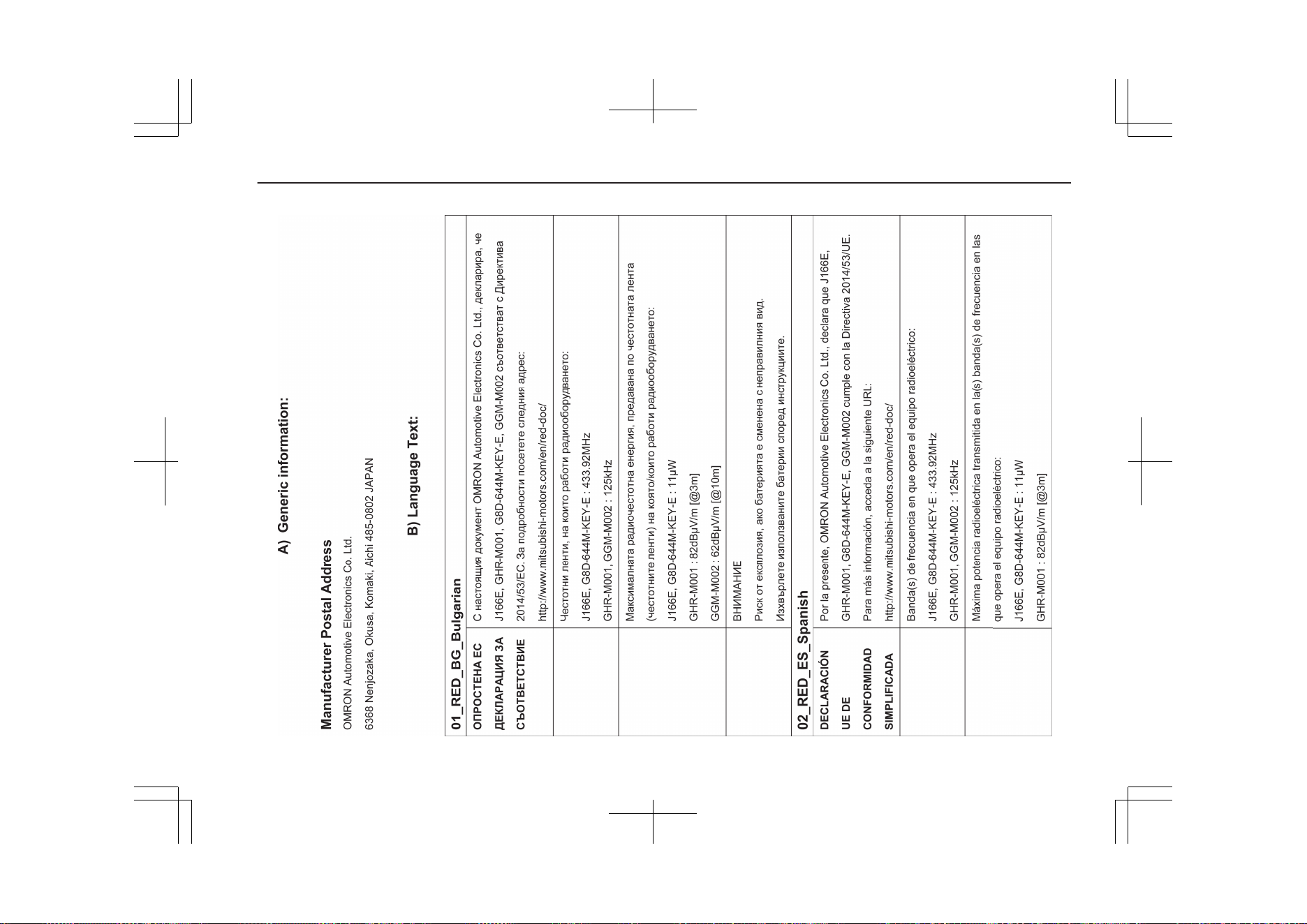
14- 1
OGGE19E1
Declaration of Conformity
14- 2
OGGE19E1
Declaration of Conformity
14- 3
OGGE19E1
Declaration of Conformity
14- 4
OGGE19E1
Declaration of Conformity
14- 5
OGGE19E1
Declaration of Conformity
14- 6
OGGE19E1
Declaration of Conformity
14- 7
OGGE19E1
Declaration of Conformity
14- 8
OGGE19E1
Declaration of Conformity
14- 9
OGGE19E1
Declaration of Conformity
14- 10
OGGE19E1
Declaration of Conformity
14- 11
OGGE19E1
Declaration of Conformity
14- 12
OGGE19E1
Declaration of Conformity
14- 13
OGGE19E1
Declaration of Conformity

14- 14
OGGE19E1
Declaration of Conformity
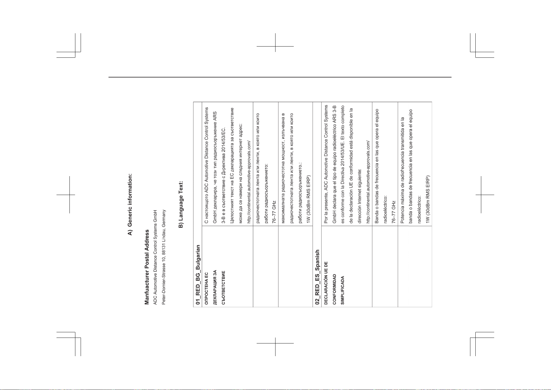
14- 15
OGGE19E1
Declaration of Conformity
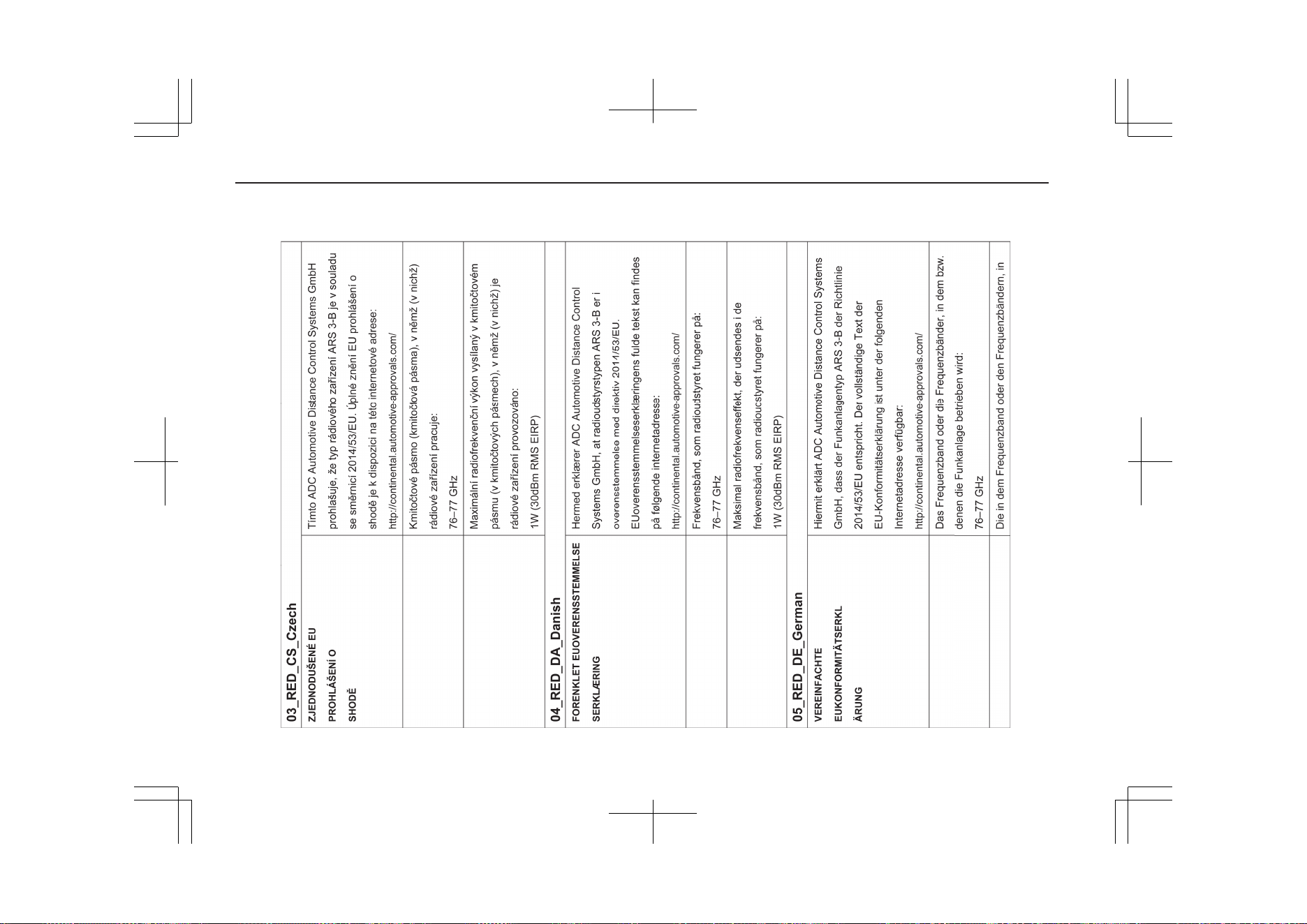
14- 16
OGGE19E1
Declaration of Conformity
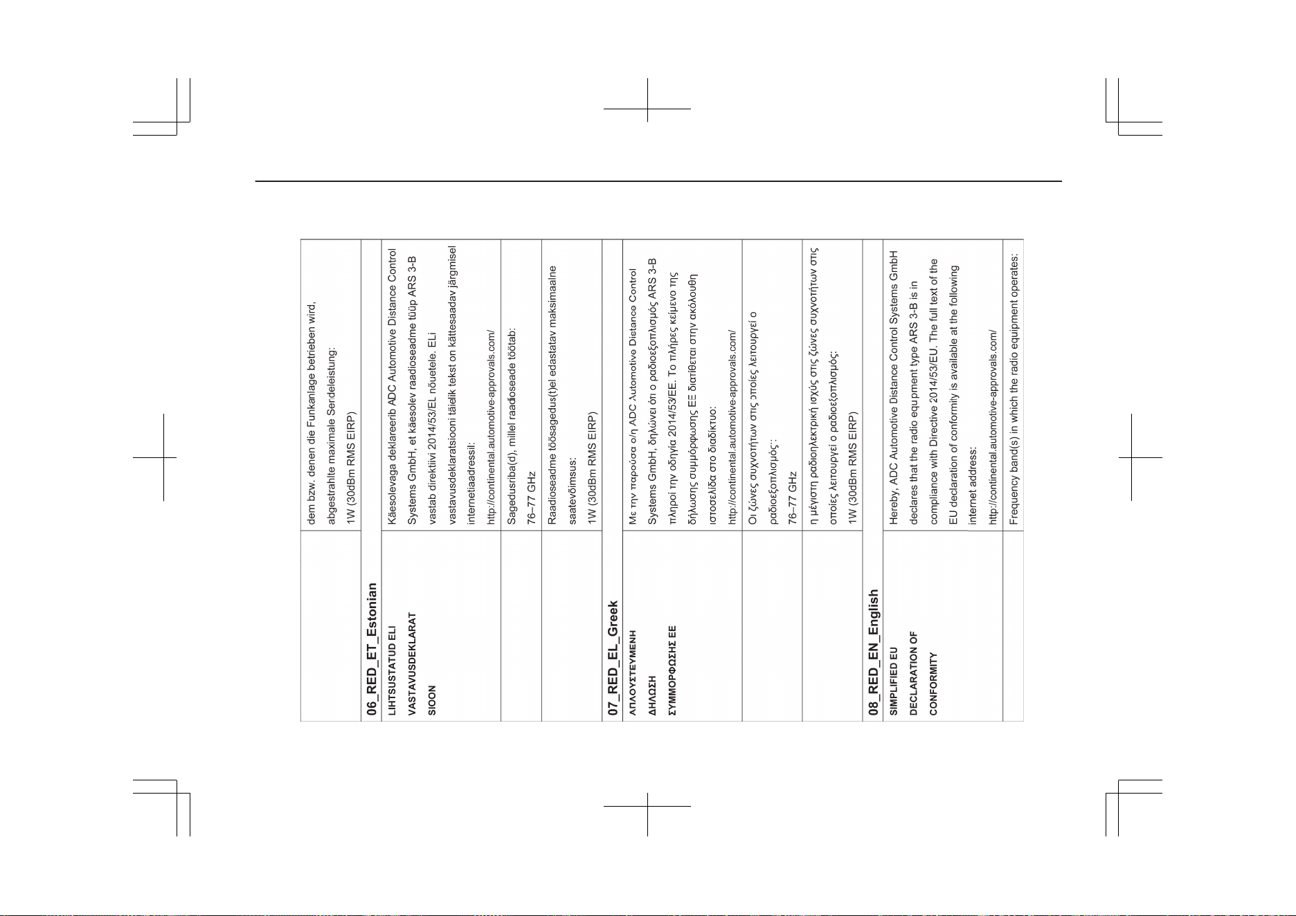
14- 17
OGGE19E1
Declaration of Conformity
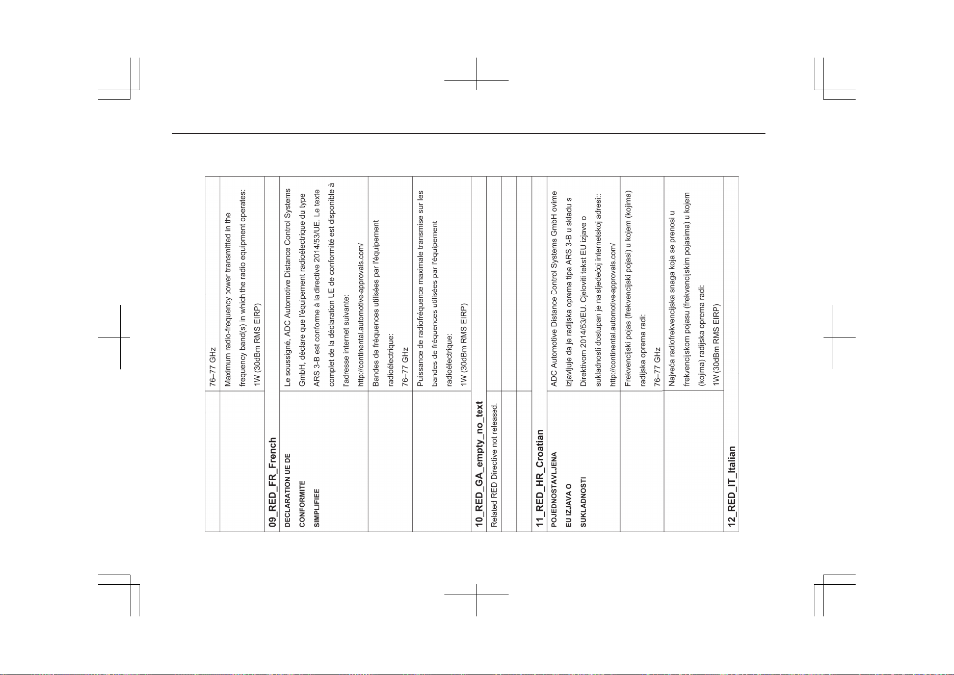
14- 18
OGGE19E1
Declaration of Conformity
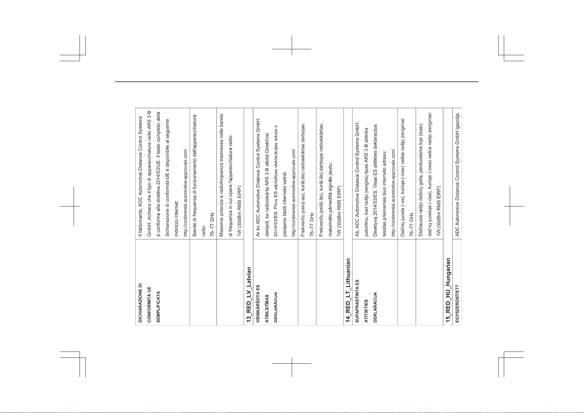
14- 19
OGGE19E1
Declaration of Conformity
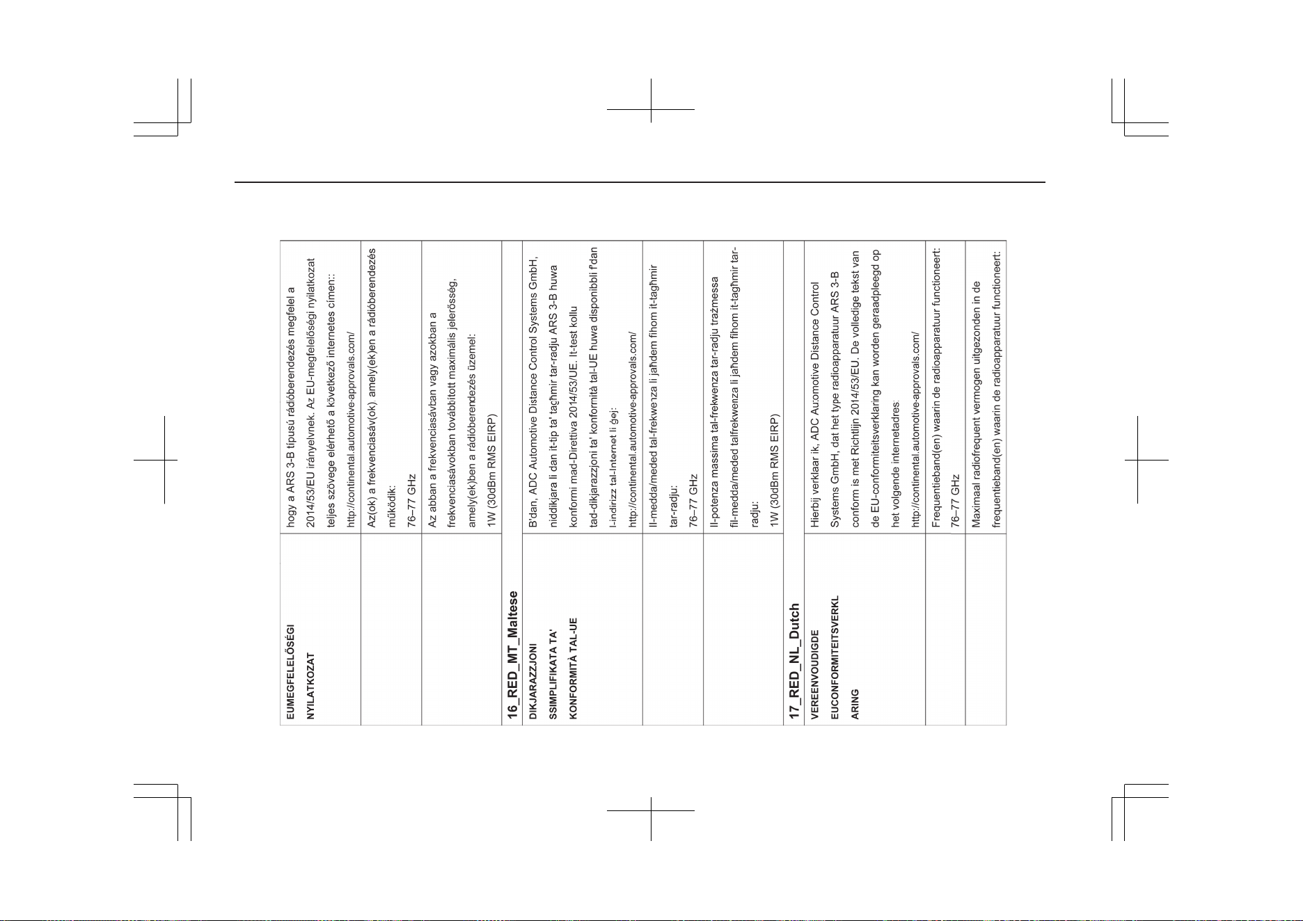
14- 20
OGGE19E1
Declaration of Conformity
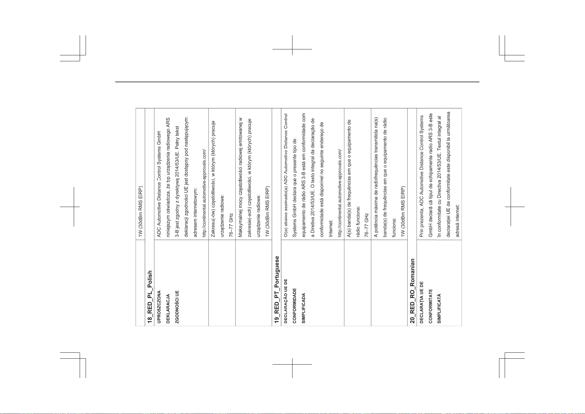
14- 21
OGGE19E1
Declaration of Conformity
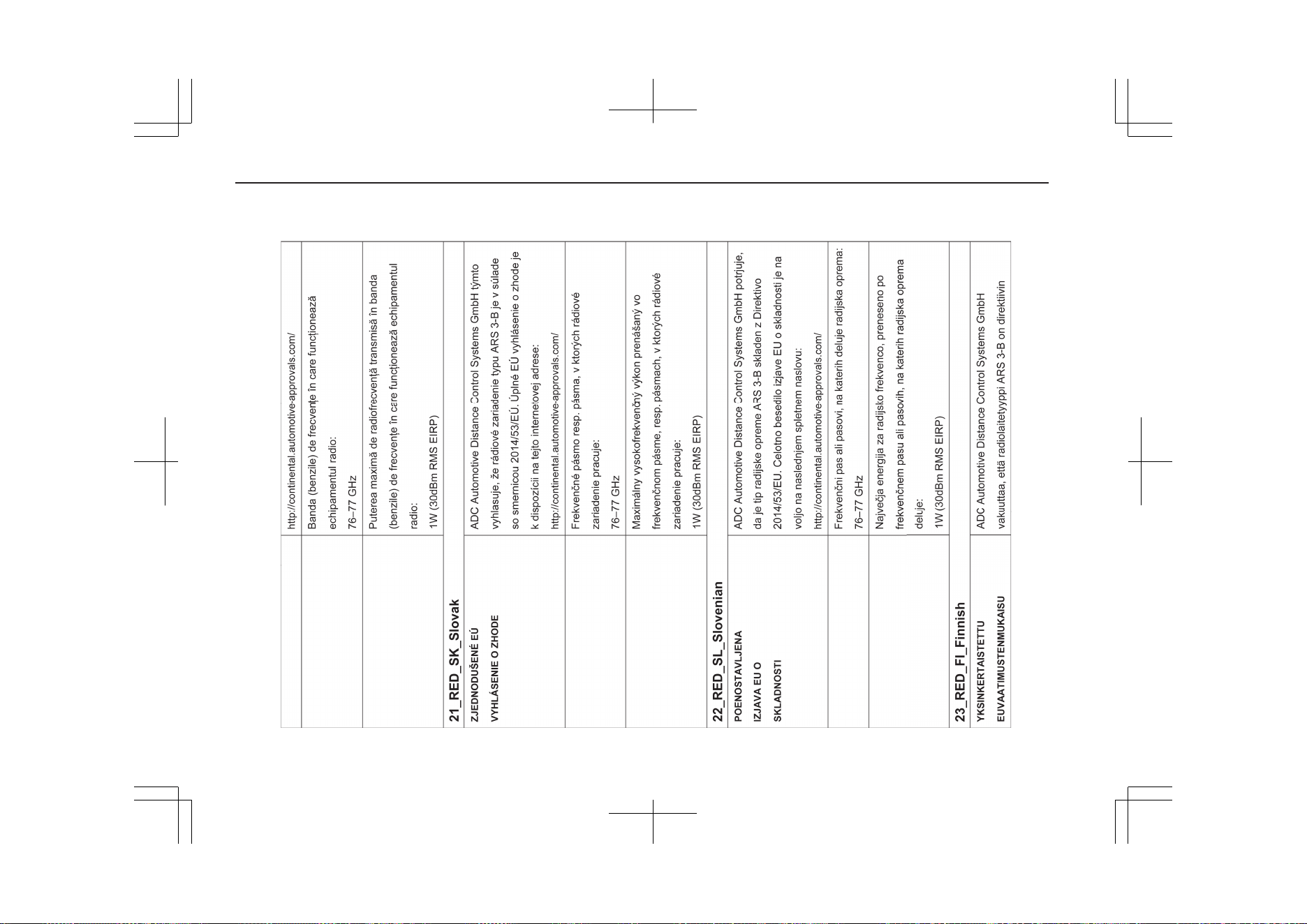
14- 22
OGGE19E1
Declaration of Conformity
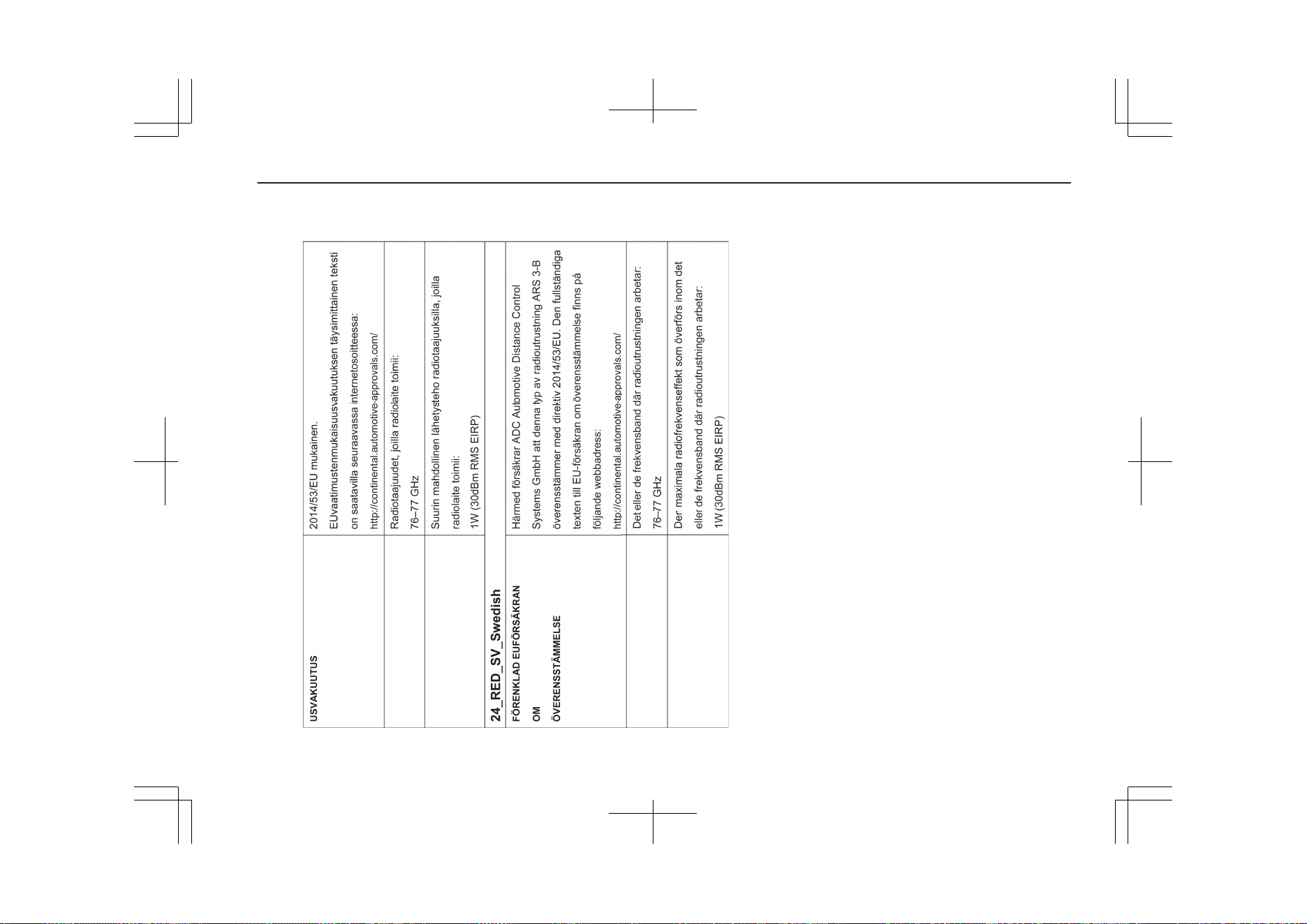
14- 23
OGGE19E1
Declaration of Conformity
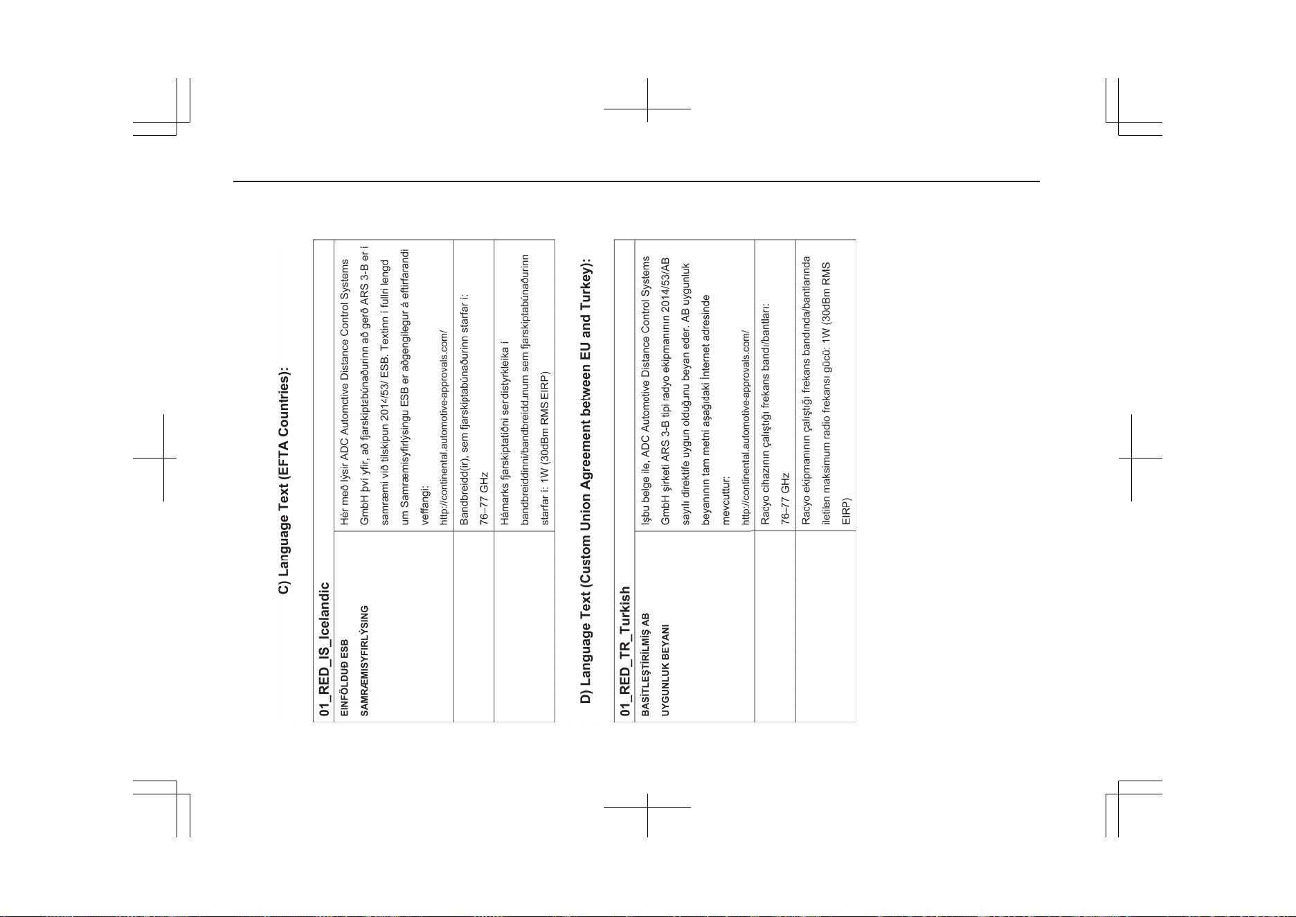
14- 24
OGGE19E1
Declaration of Conformity
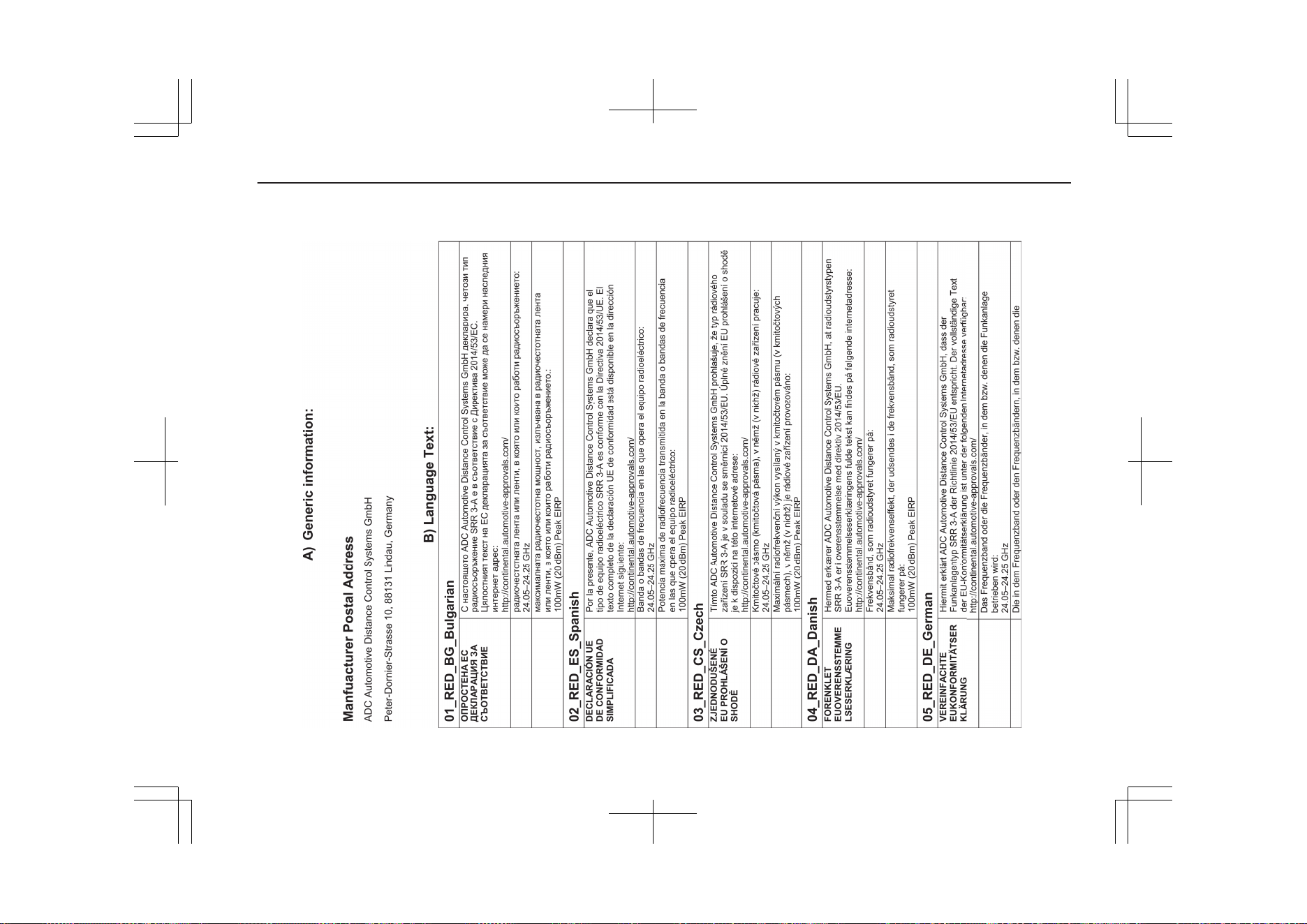
14- 25
OGGE19E1
Declaration of Conformity
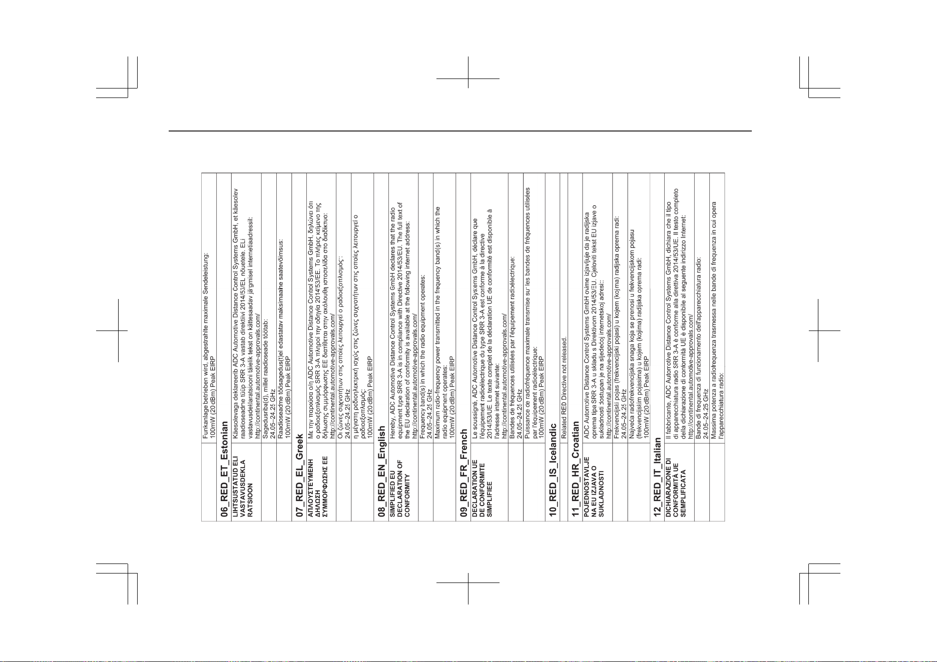
14- 26
OGGE19E1
Declaration of Conformity
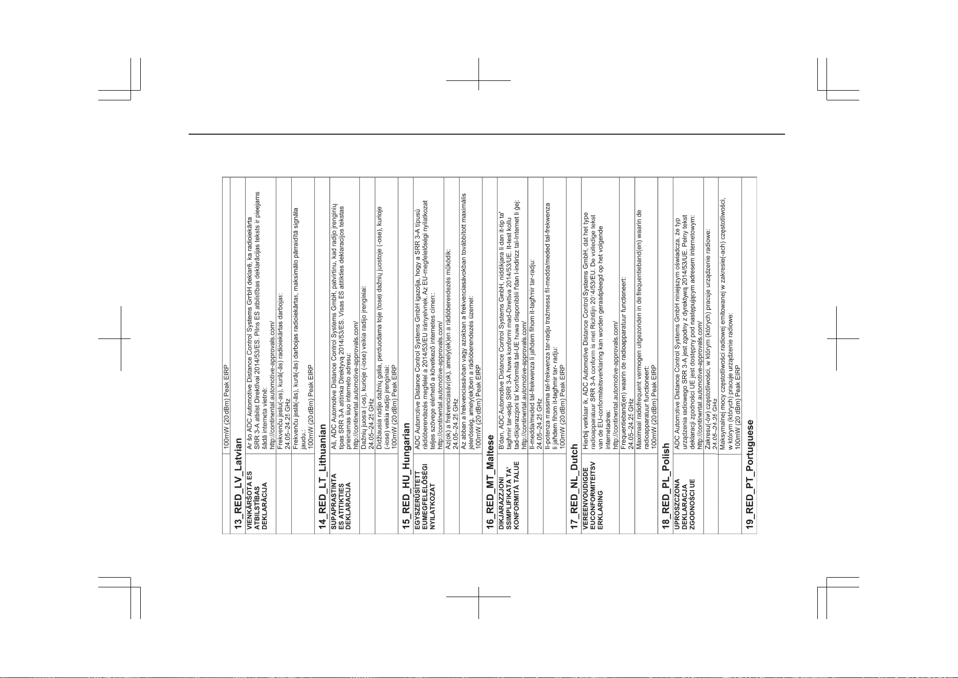
14- 27
OGGE19E1
Declaration of Conformity
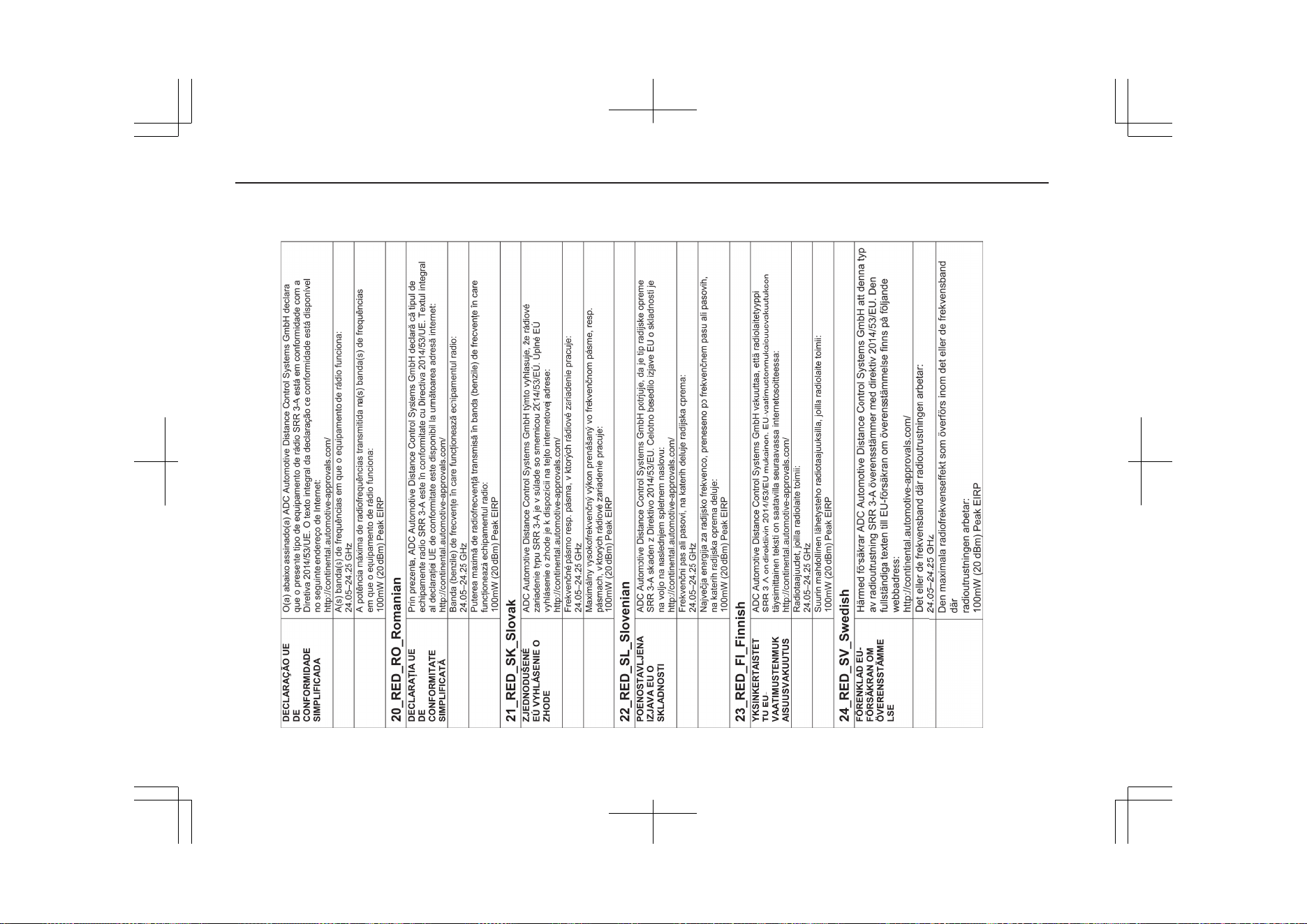
14- 28
OGGE19E1
Declaration of Conformity
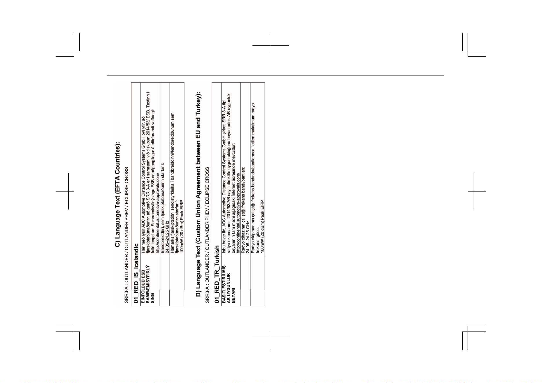
14- 29
OGGE19E1
Declaration of Conformity
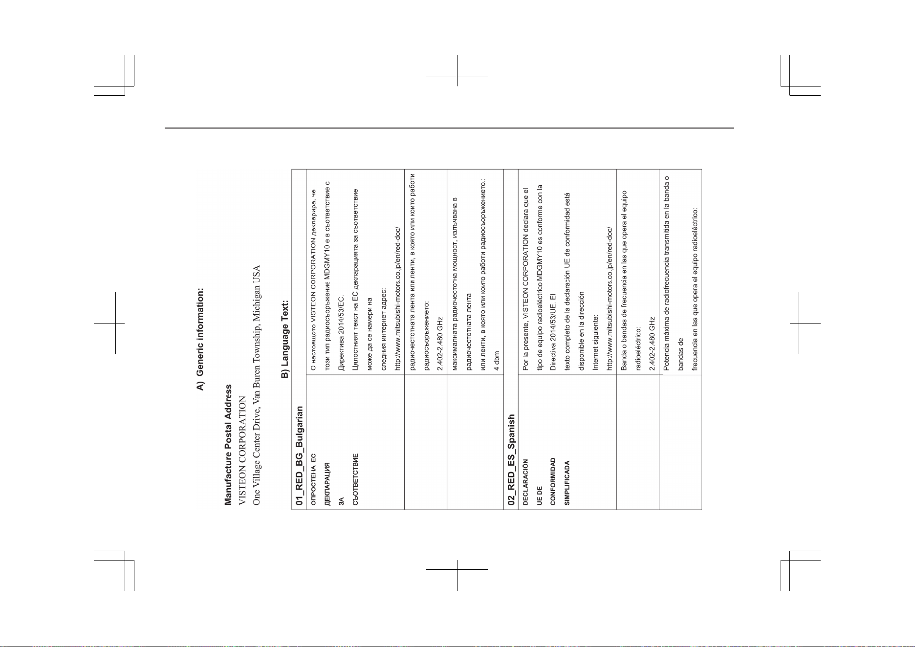
14- 30
OGGE19E1
Declaration of Conformity
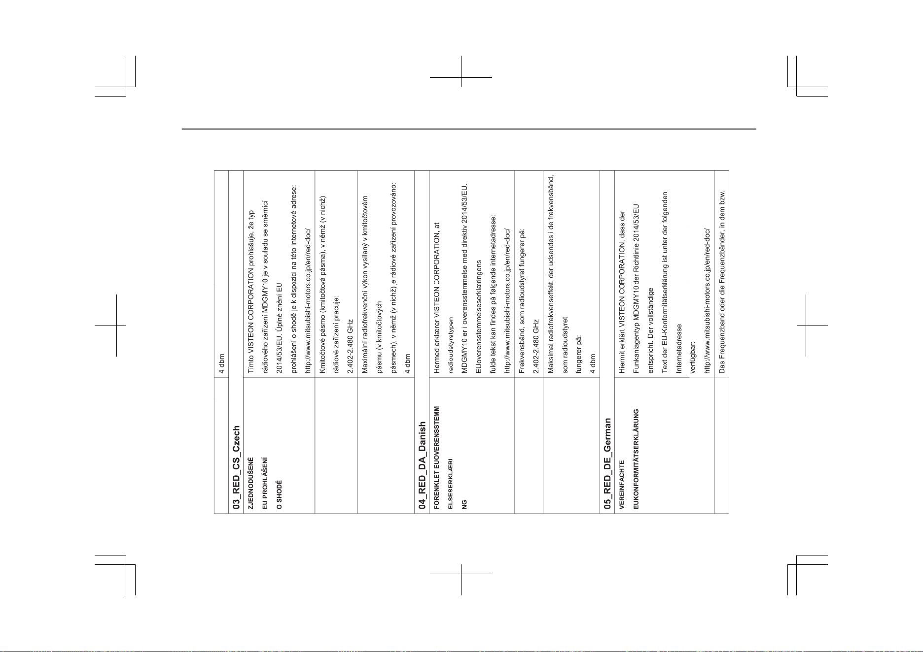
14- 31
OGGE19E1
Declaration of Conformity
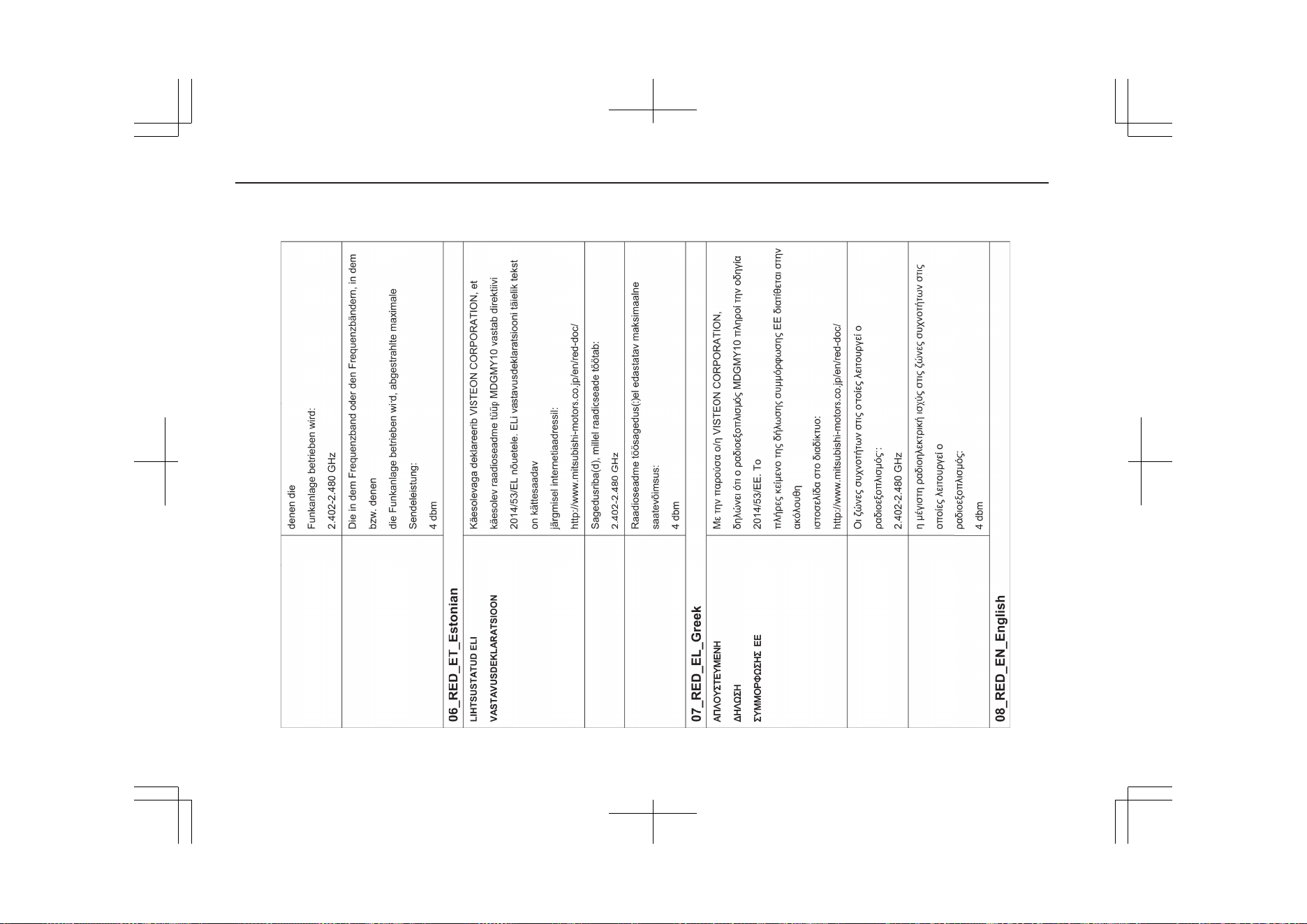
14- 32
OGGE19E1
Declaration of Conformity
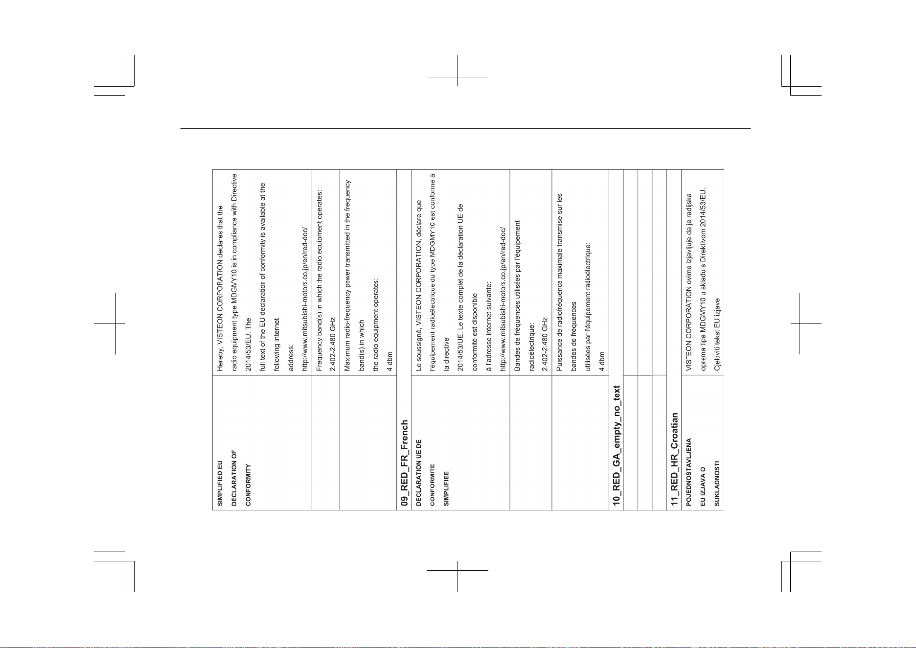
14- 33
OGGE19E1
Declaration of Conformity
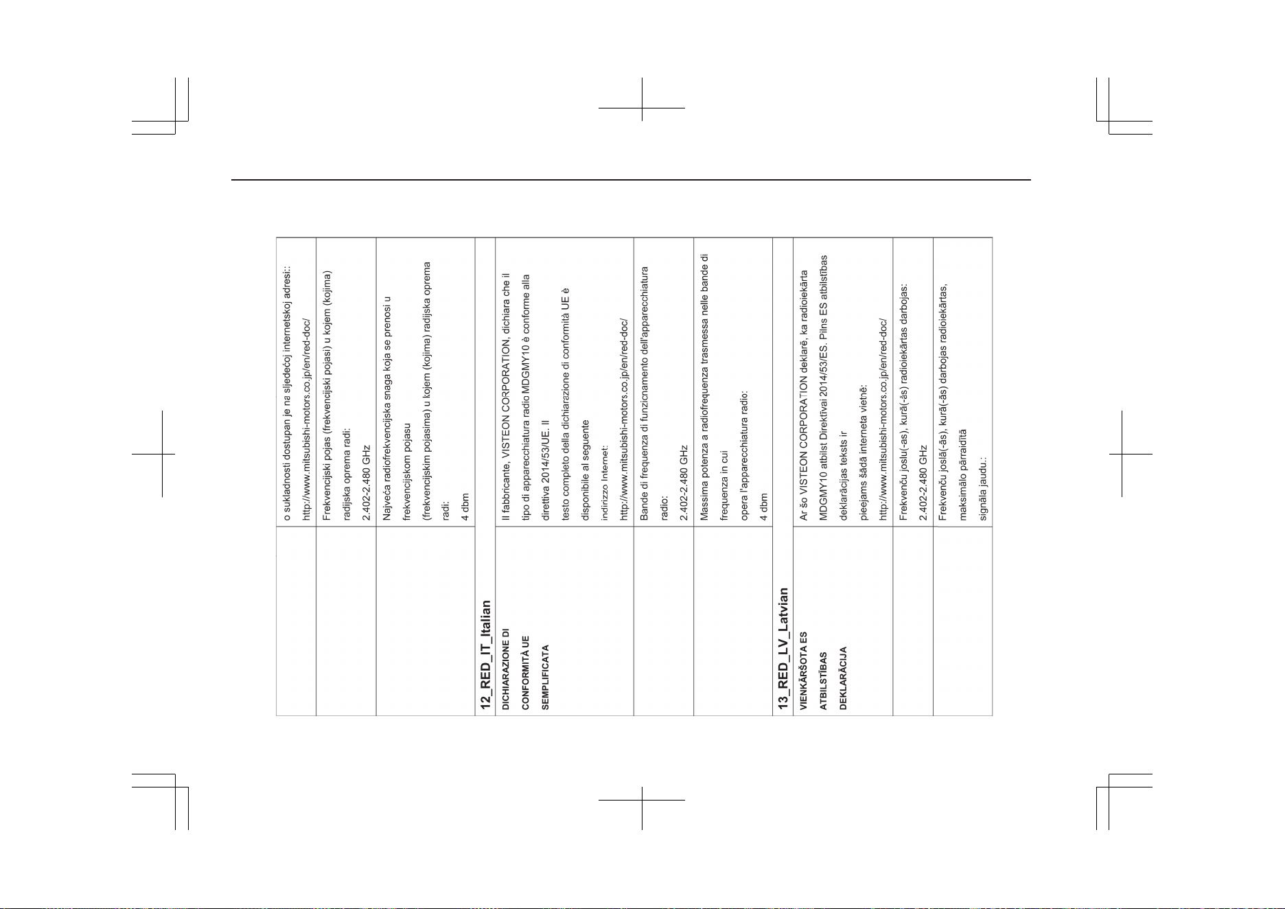
14- 34
OGGE19E1
Declaration of Conformity
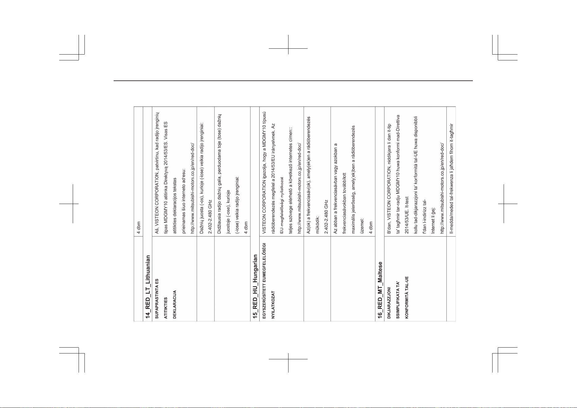
14- 35
OGGE19E1
Declaration of Conformity
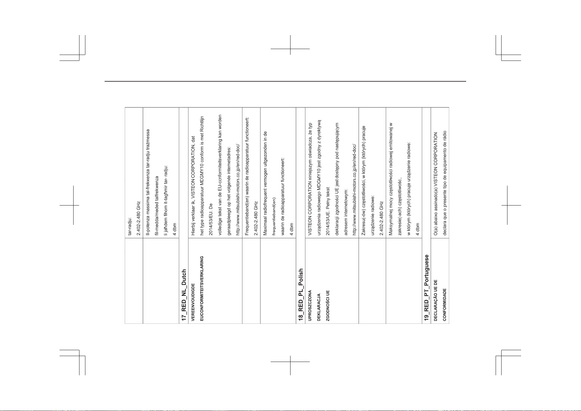
14- 36
OGGE19E1
Declaration of Conformity
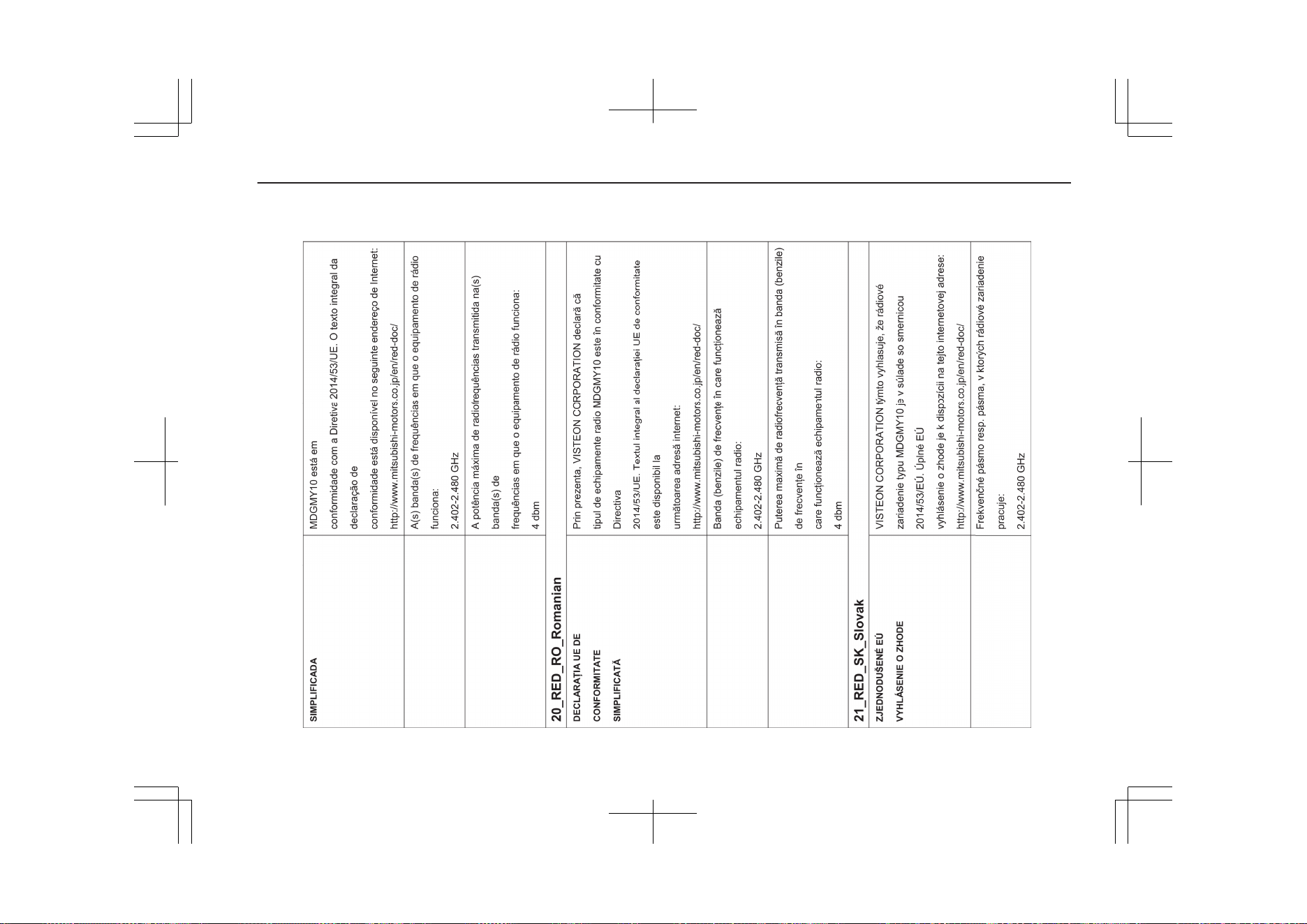
14- 37
OGGE19E1
Declaration of Conformity
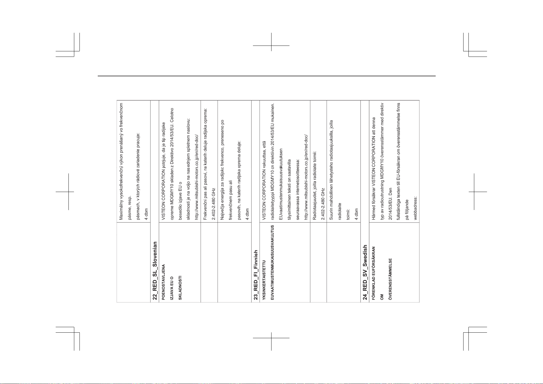
14- 38
OGGE19E1
Declaration of Conformity
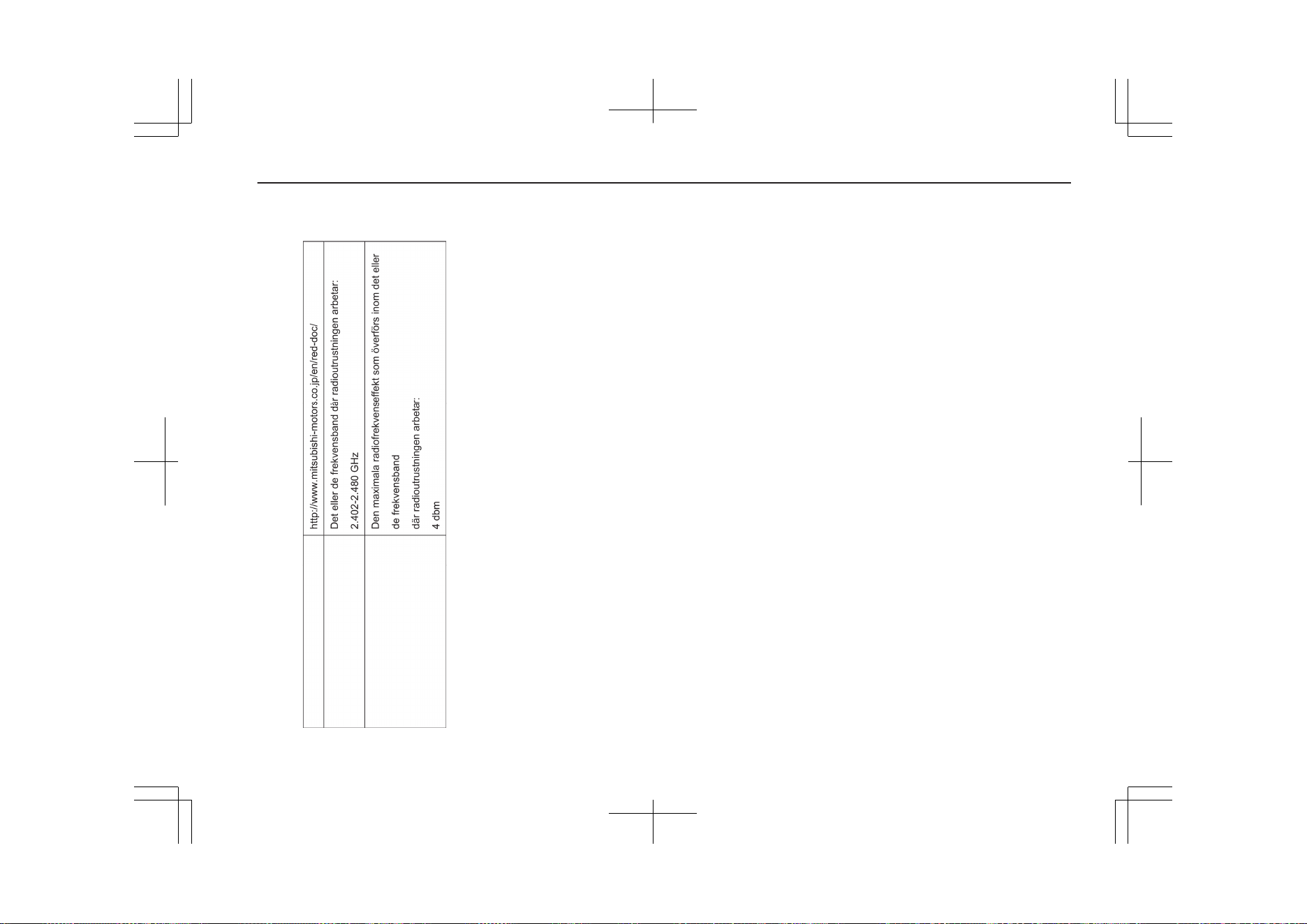
14- 39
OGGE19E1
Declaration of Conformity
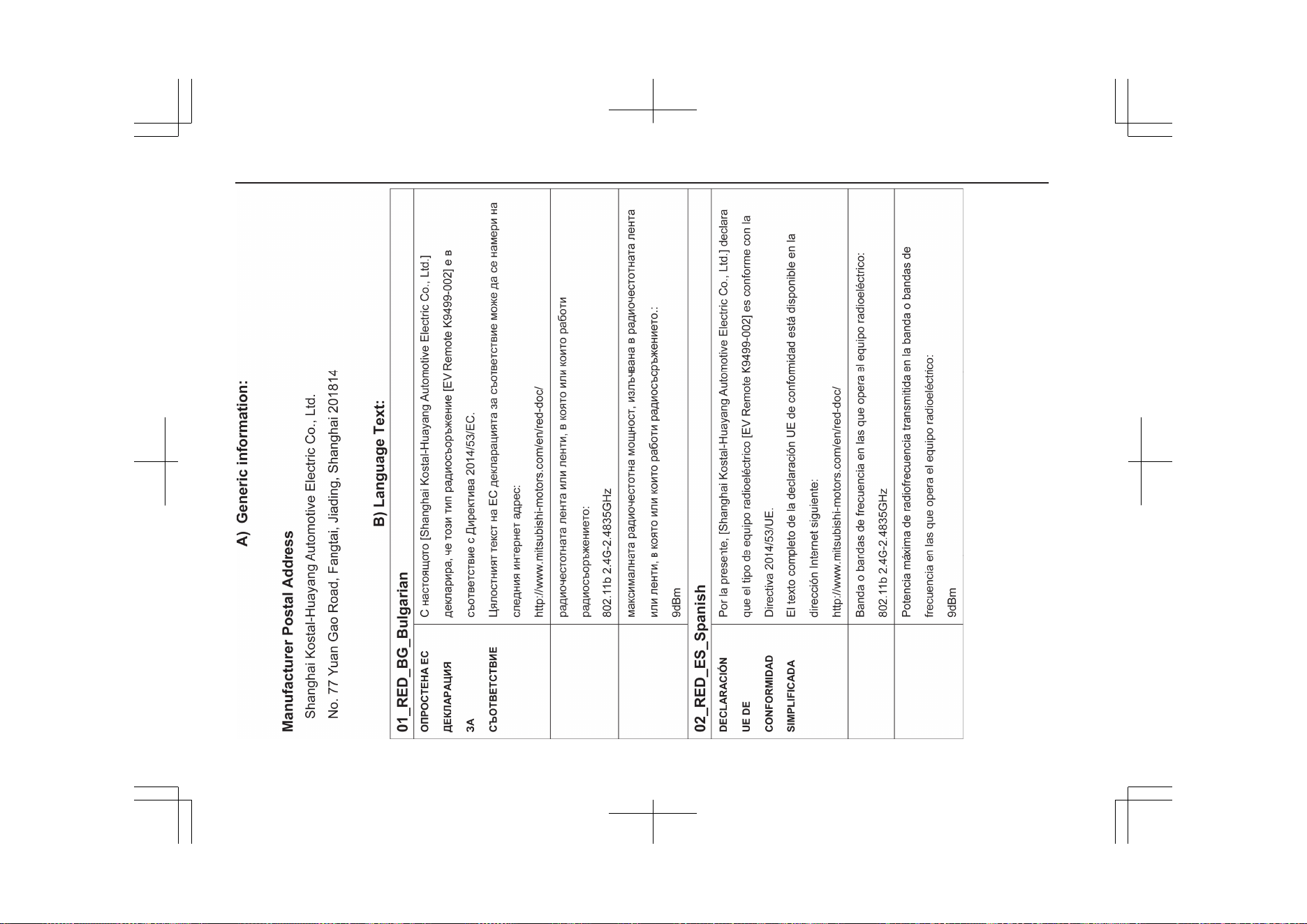
14- 40
OGGE19E1
Declaration of Conformity
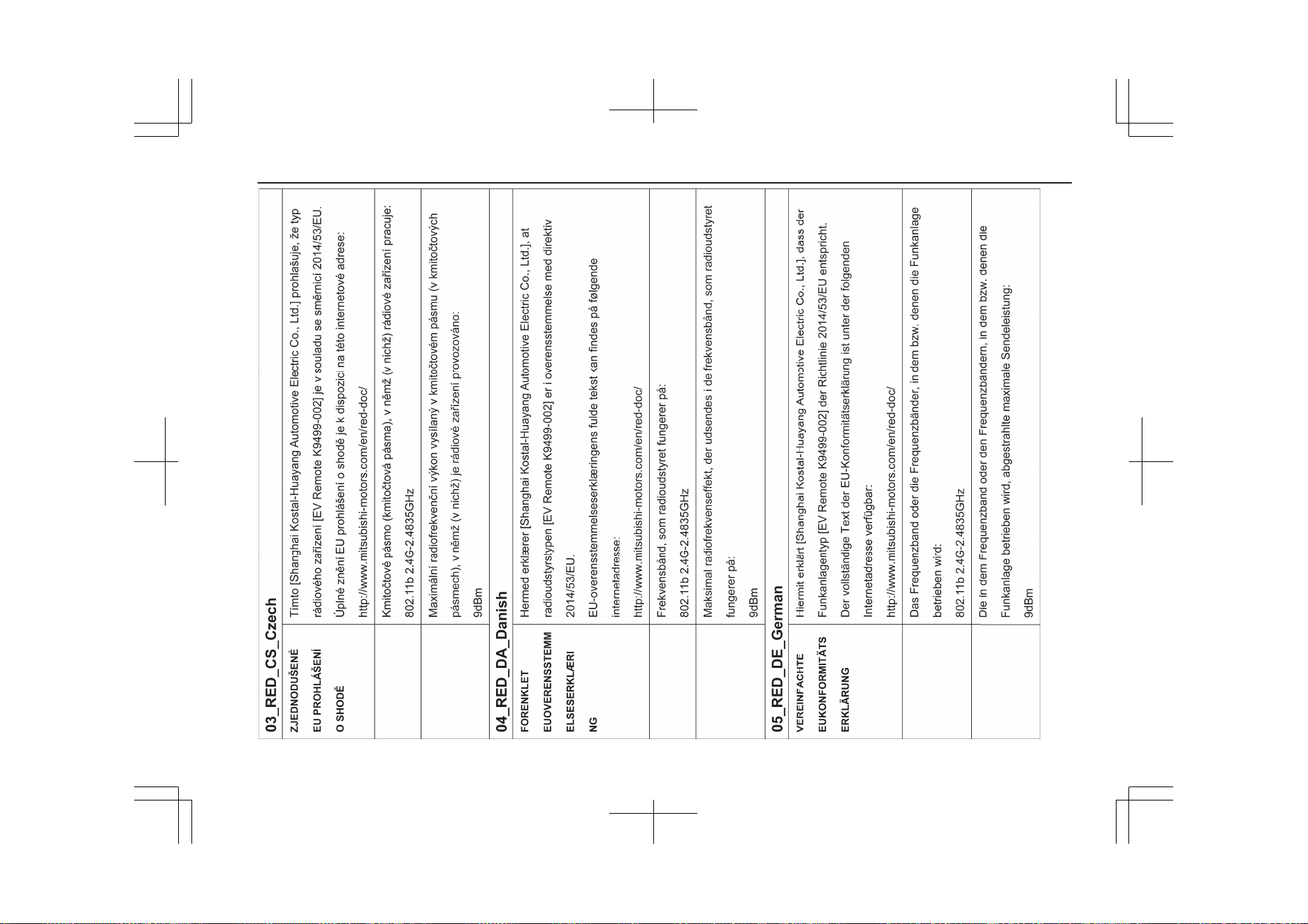
14- 41
OGGE19E1
Declaration of Conformity
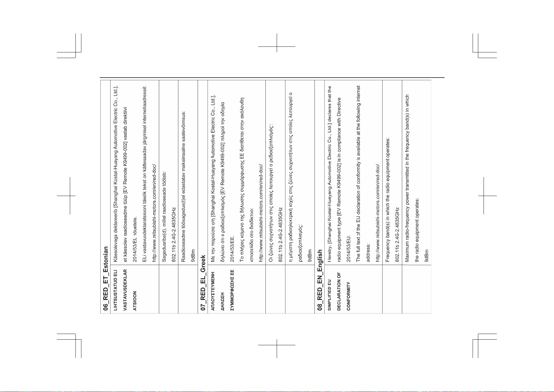
14- 42
OGGE19E1
Declaration of Conformity
14- 43
OGGE19E1
Declaration of Conformity
14- 44
OGGE19E1
Declaration of Conformity
14- 45
OGGE19E1
Declaration of Conformity
14- 46
OGGE19E1
Declaration of Conformity
14- 47
OGGE19E1
Declaration of Conformity
14- 48
OGGE19E1
Declaration of Conformity
14- 49
OGGE19E1
Declaration of Conformity
14- 50
OGGE19E1
Declaration of Conformity
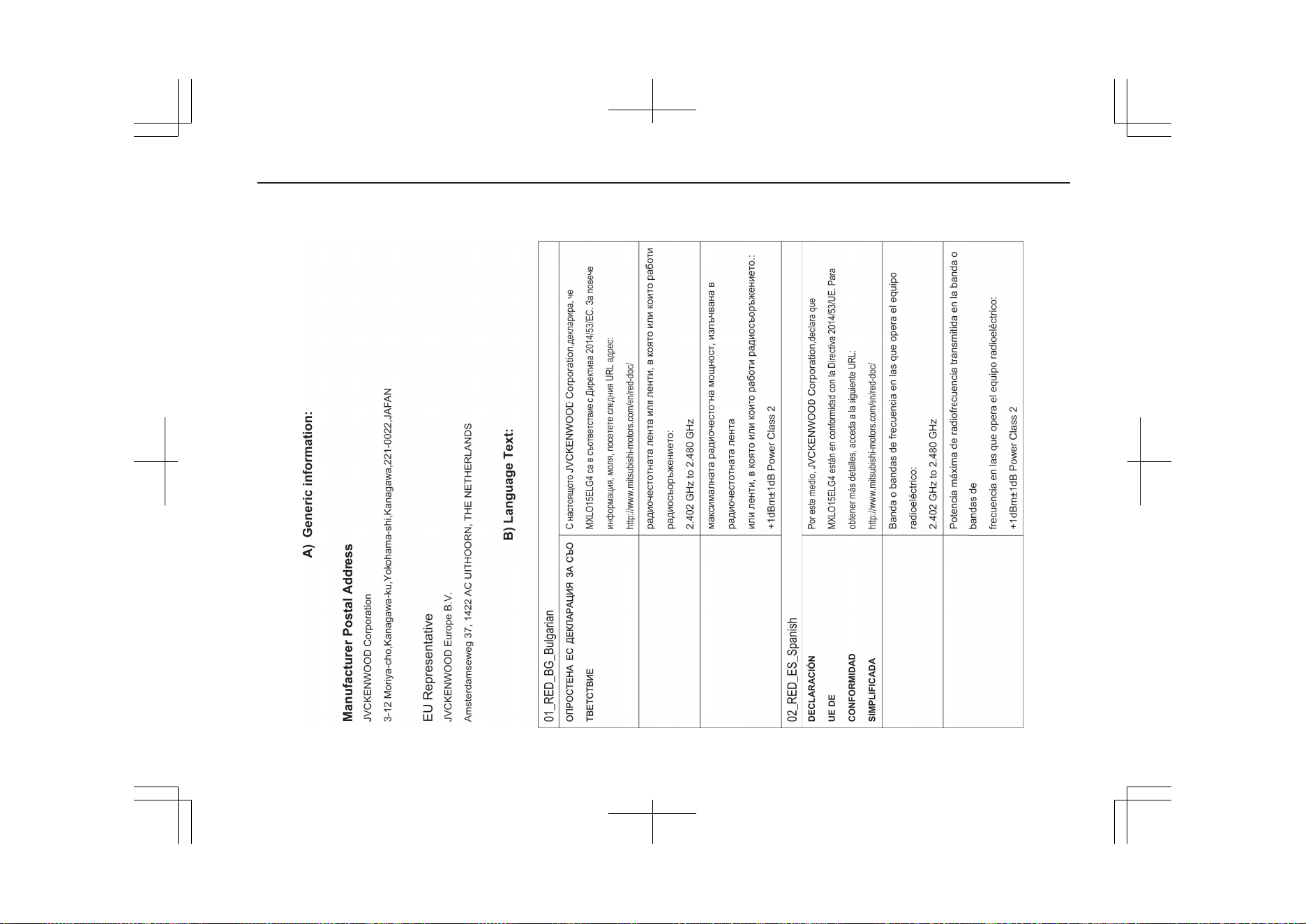
14- 51
OGGE19E1
Declaration of Conformity
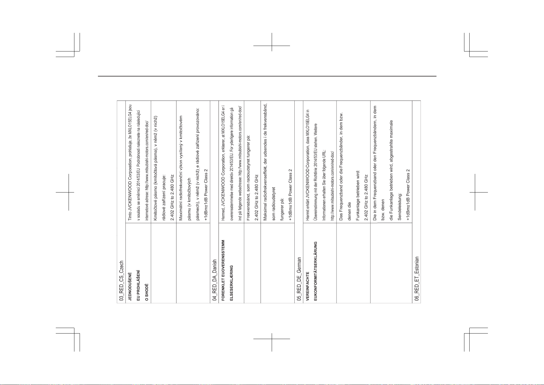
14- 52
OGGE19E1
Declaration of Conformity
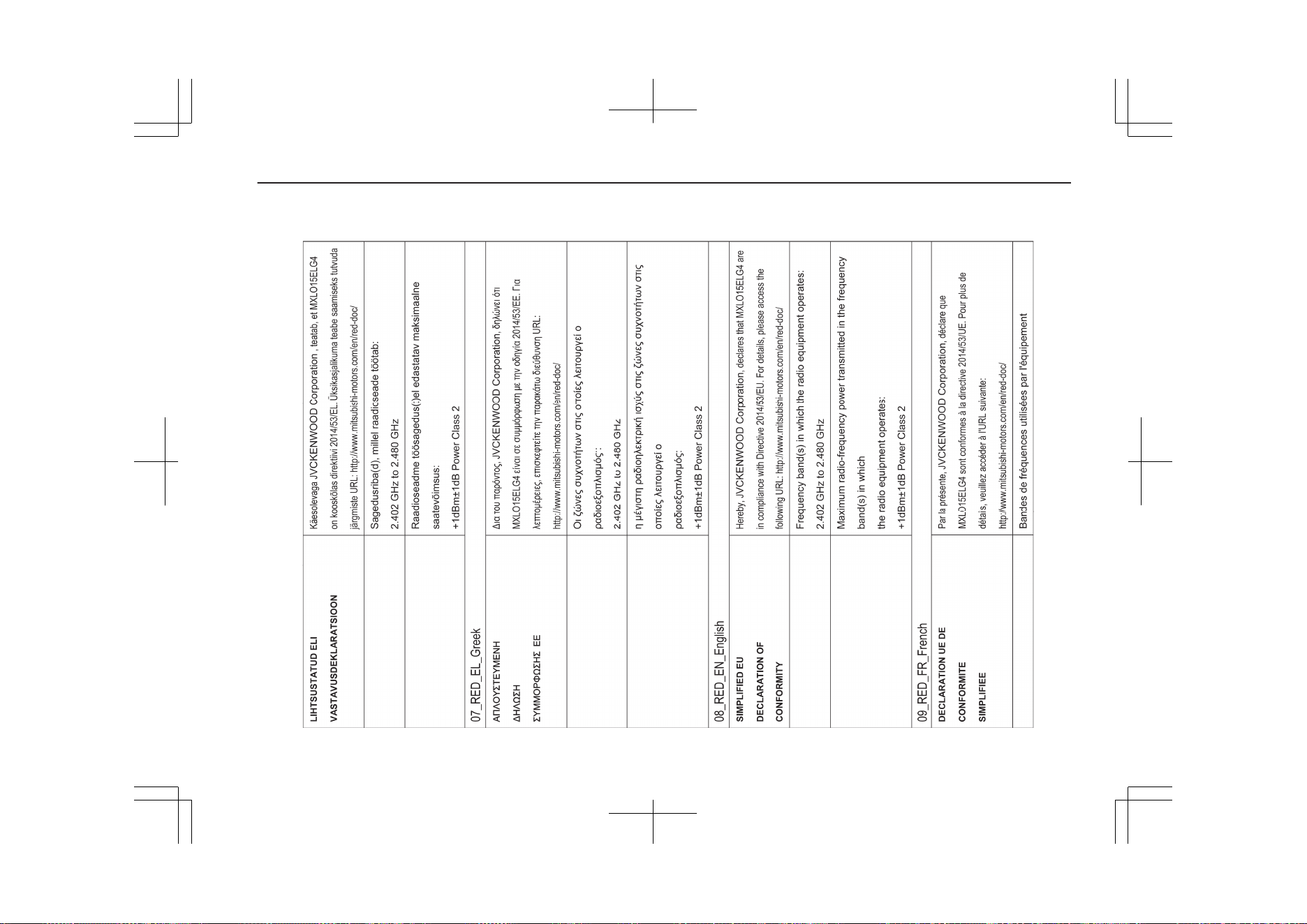
14- 53
OGGE19E1
Declaration of Conformity
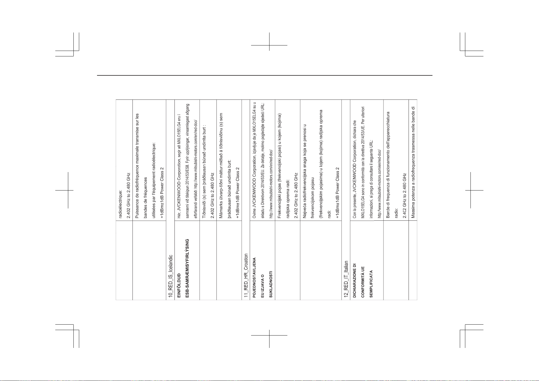
14- 54
OGGE19E1
Declaration of Conformity
14- 55
OGGE19E1
Declaration of Conformity
14- 56
OGGE19E1
Declaration of Conformity
14- 57
OGGE19E1
Declaration of Conformity
14- 58
OGGE19E1
Declaration of Conformity
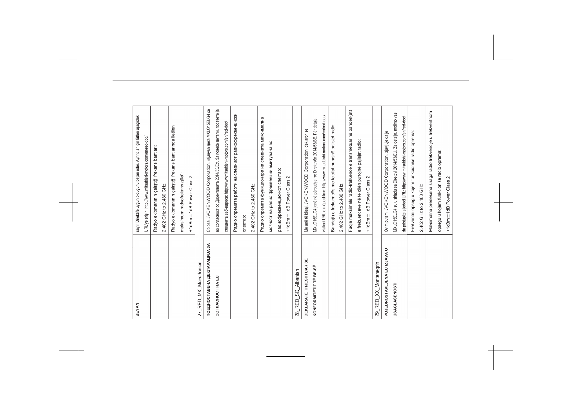
14- 59
OGGE19E1
Declaration of Conformity
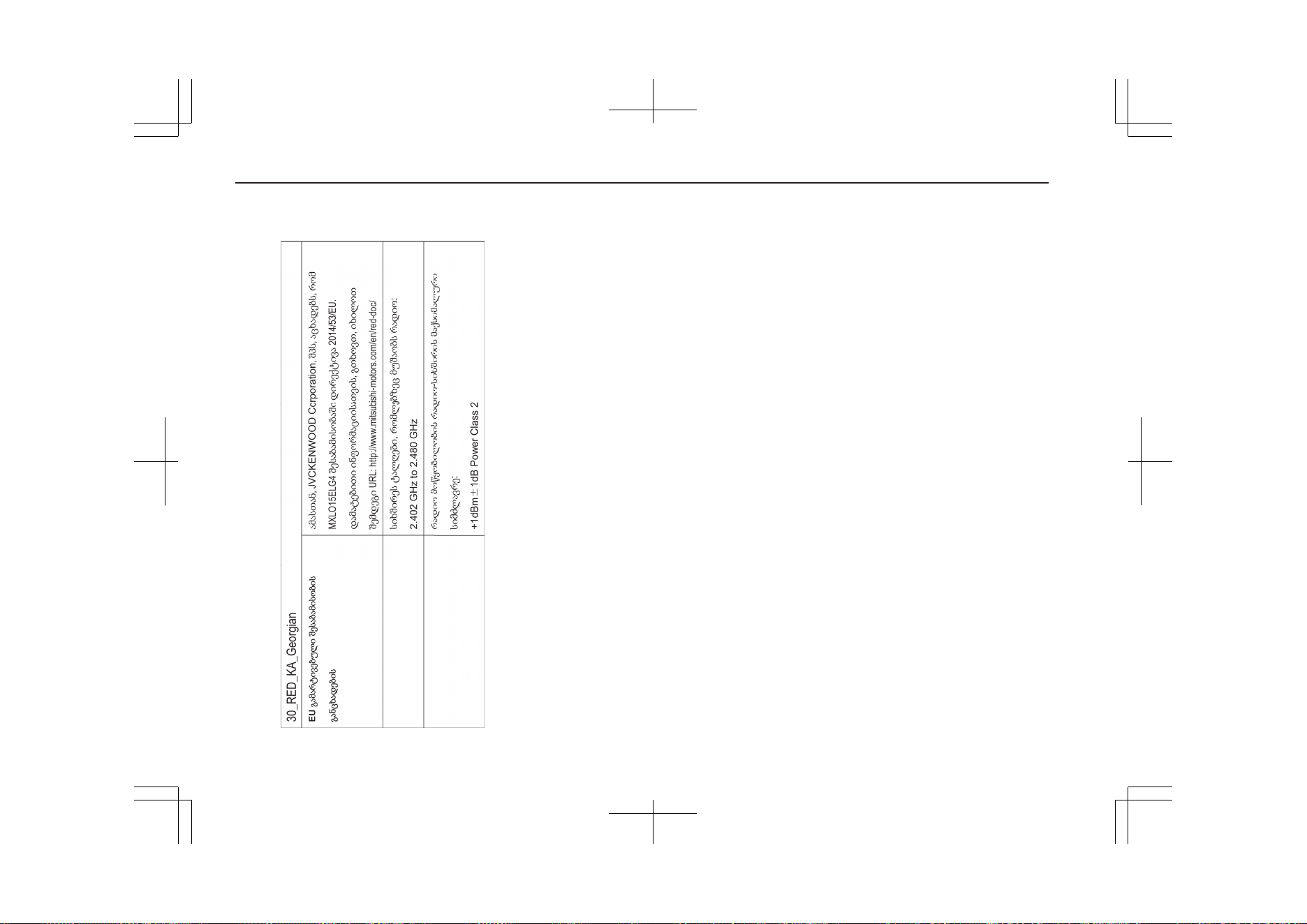
14- 60
OGGE19E1
Declaration of Conformity
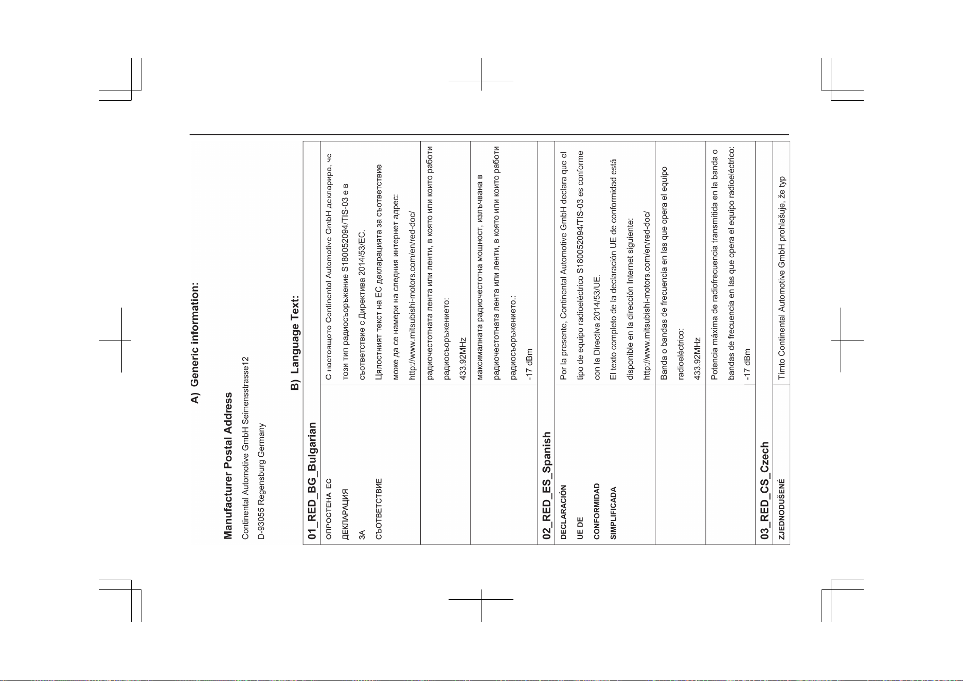
14- 61
OGGE19E1
Declaration of Conformity
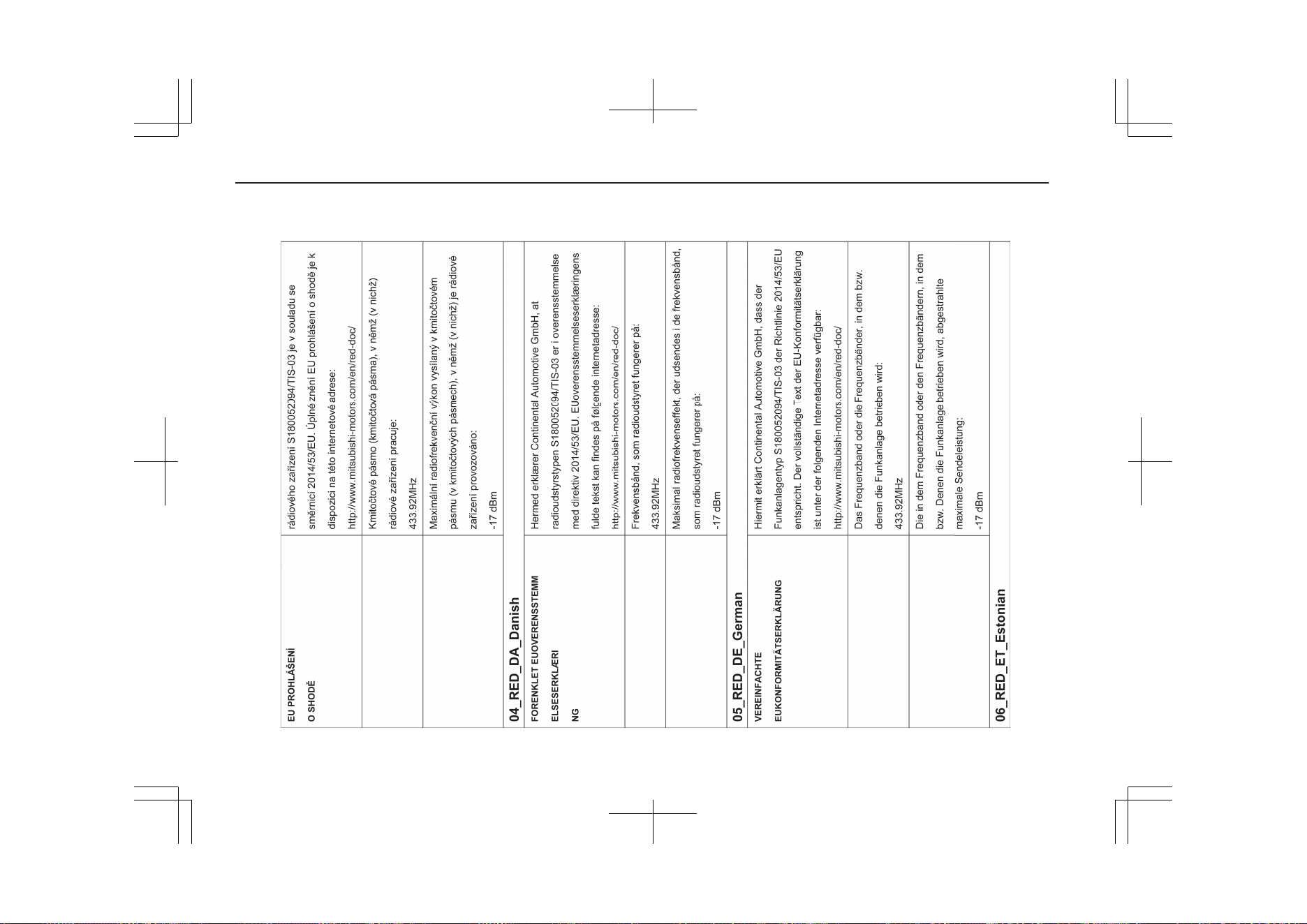
14- 62
OGGE19E1
Declaration of Conformity
14- 63
OGGE19E1
Declaration of Conformity
14- 64
OGGE19E1
Declaration of Conformity
14- 65
OGGE19E1
Declaration of Conformity
14- 66
OGGE19E1
Declaration of Conformity
14- 67
OGGE19E1
Declaration of Conformity
14- 68
OGGE19E1
Declaration of Conformity
14- 69
OGGE19E1
Declaration of Conformity

14- 70
OGGE19E1
Declaration of Conformity
14- 71
OGGE19E1
Declaration of Conformity
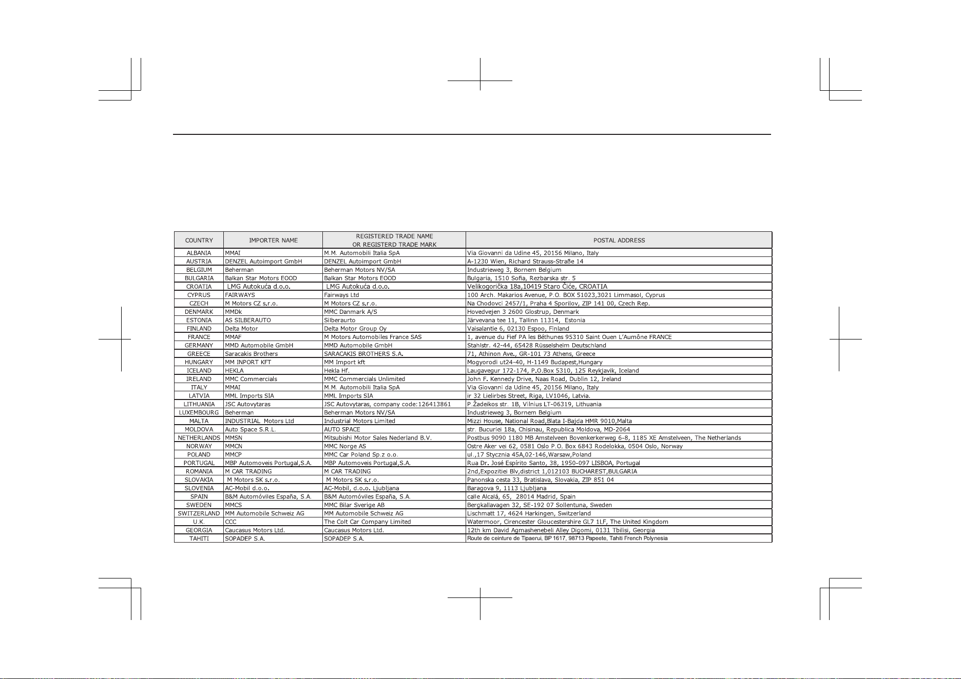
14- 72
OGGE19E1
Declaration of Conformity
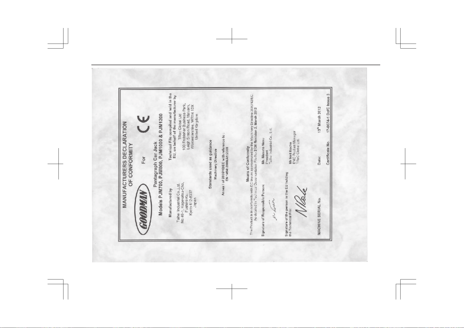
14- 73
OGGE19E1
Declaration of Conformity
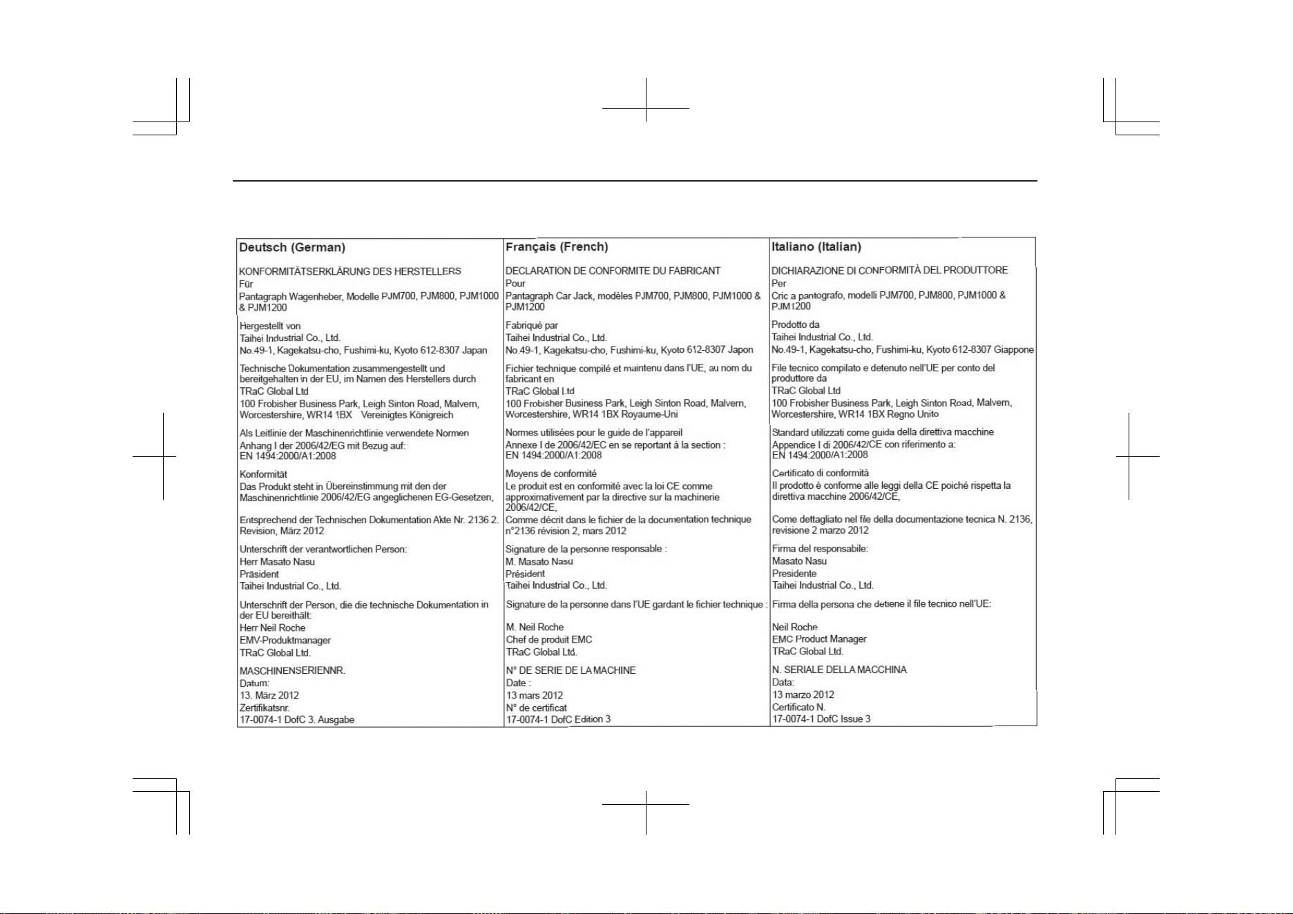
14- 74
OGGE19E1
Declaration of Conformity
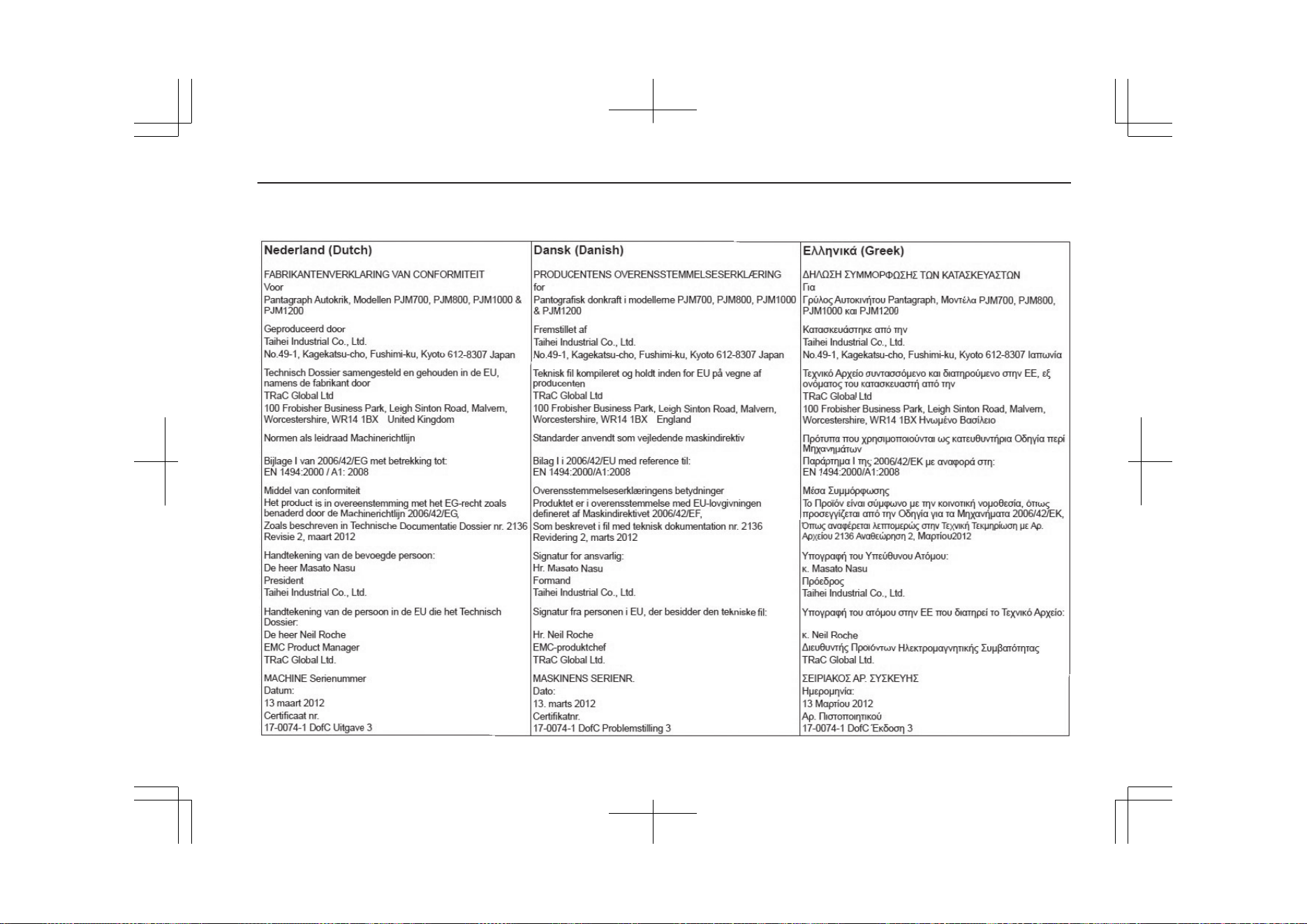
14- 75
OGGE19E1
Declaration of Conformity
14- 76
OGGE19E1
Declaration of Conformity
14- 77
OGGE19E1
Declaration of Conformity
14- 78
OGGE19E1
Declaration of Conformity
14- 79
OGGE19E1
Declaration of Conformity
14- 80
OGGE19E1
Declaration of Conformity
14- 81
OGGE19E1
Declaration of Conformity
14- 82
OGGE19E1
Declaration of Conformity
The approval for Ukraine
Blind Spot Warning (BSW) and Rear Cross Traffic Alert (RCTA)
14- 83
OGGE19E1
Declaration of Conformity
Adaptive Cruise Control System (ACC)
14- 84
OGGE19E1
Declaration of Conformity

MITSUBISHI Remote Control
14- 85
OGGE19E1
Declaration of Conformity
Bluetooth Hands Free System
14- 86
OGGE19E1
Declaration of Conformity
The approval for Serbia
Blind Spot Warning (BSW) and Rear Cross Traffic Alert (RCTA)
14- 87
OGGE19E1
Declaration of Conformity

OGGE19E1

OGGE19E1

OGGE19E1
Foreword
E09200107602
Thank you for selecting an OUTLANDER PHEV as your new vehicle.
This owner’s manual will add to your understanding and full enjoyment of
the many fine features of this vehicle.
It contains information prepared to acquaint you with the proper way to oper-
ate and maintain your vehicle for the utmost in driving pleasure.
MITSUBISHI MOTORS Europe B.V. reserves the right to make changes in
design and specifications and/or to make additions to or improvements in
this product without obligation to install them on products previously manu-
factured.
It is an absolute requirement for the driver to strictly observe all laws and
regulations concerning vehicles.
This owner’s manual has been written in compliance with such laws and reg-
ulations, but some of the contents may become contradictory with later
amendment of the laws and regulations.
Please leave this owner’s manual in this vehicle at time of resale. The next
owner will appreciate having access to the information contained in this
owner’s manual.
Repairs to your vehicle:
Vehicles in the warranty period:
All warranty repairs must be carried out by a MITSUBISHI MOTORS Au-
thorized Service Point.
Vehicles outside the warranty period:
Where the vehicle is repaired is at the discretion of the owner.
Throughout this owner’s manual the words WARNING and CAUTION
appear. These serve as reminders to be especially careful. Failure to follow
instructions could result in personal injury or damage to your vehicle.
WARNING
Indicates a strong possibility of severe personal injury or death if in-
structions are not followed.
CAUTION
Means hazards or unsafe practices that could cause minor personal in-
jury or damage to your vehicle.
NOTE
Gives helpful information.
*: Gives helpful information.
It may differ according to the sales classifications; refer to the sales cata-
logue.
Abbreviations used in this owner’s manual:
LHD: Left-Hand Drive
RHD: Right-Hand Drive
The symbol used on the vehicles:
: See owner’s manual
Information for station service
E09300104543
Fuel
Fuel tank capacity 45 litres
Recommended fuel
Unleaded petrol octane number (EN228)
95 RON or higher
Refer to the “General Information” section for the fuel selection.
Engine oil Refer to the “Maintenance” section for the selection of engine oil.
Tyre inflation pressure Refer to the “Maintenance” section for the tyre inflation pressure.
© 2018 Mitsubishi Motors Corporation
19
OGGE19E1
BLO-18-000312