FLOOR TYPE AIR CONDITIONERS
REFRIGERANT
R32
English
INSTALLATION MANUAL
For INSTALLER
MFZ-KW25VGK MFZ-KW35VGK MFZ-KW42VGK MFZ-KW50VGK MFZ-KW60VGK
EN-1
CONTENTS
ENGLISH
1. BEFORE INSTALLATION
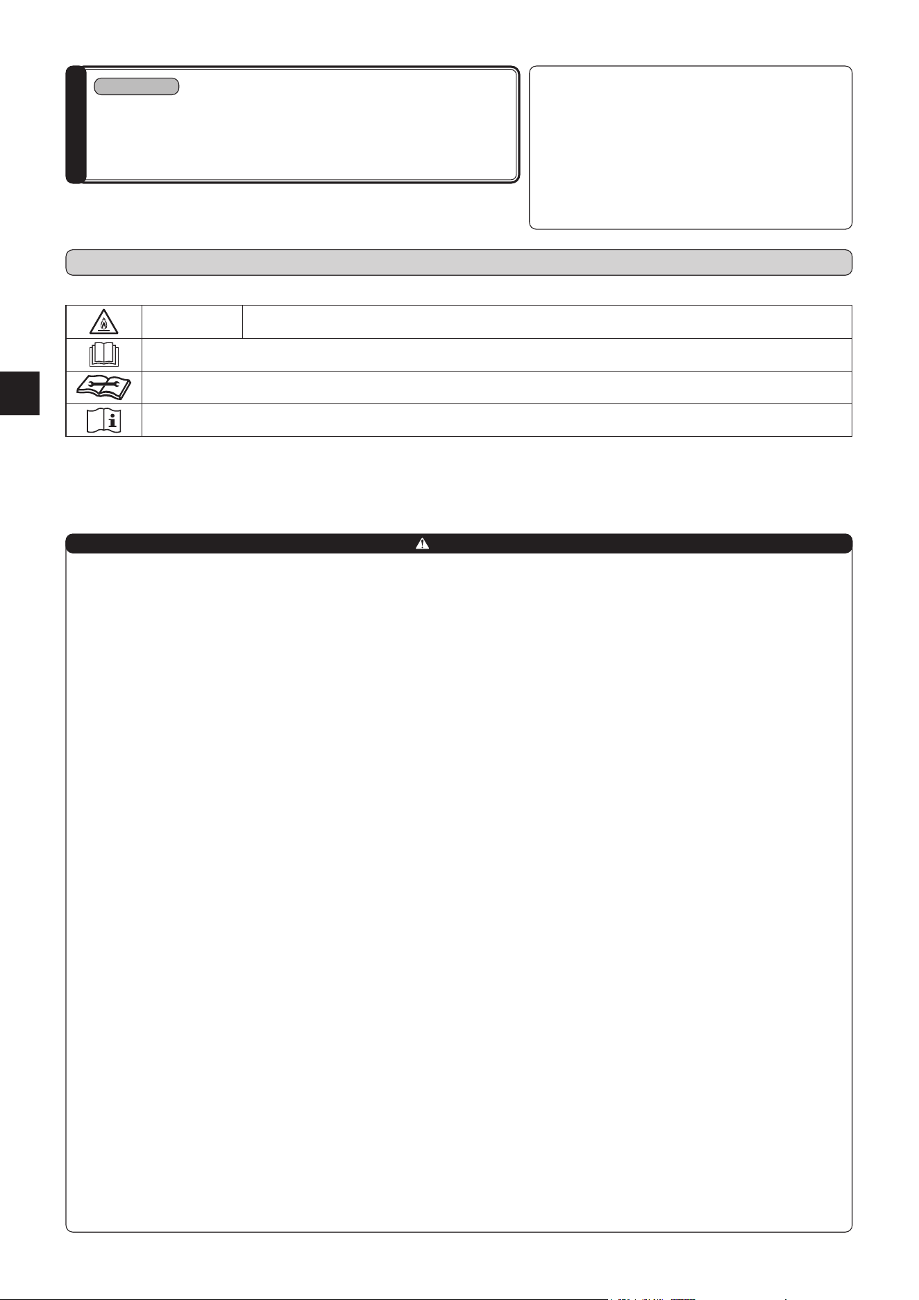
MEANINGS OF SYMBOLS DISPLAYED ON INDOOR UNIT AND/OR OUTDOOR UNIT
WARNING
(Risk of re)
This unit uses a ammable refrigerant.
If refrigerant leaks and comes in contact with re or heating part, it will create harmful gas and there is risk of re.
Read the OPERATING INSTRUCTIONS carefully before operation.
Service personnel are required to carefully read the OPERATING INSTRUCTIONS and INSTALLATION MANUAL before operation.
Further information is available in the OPERATING INSTRUCTIONS, INSTALLATION MANUAL, and the like.
1-1. THE FOLLOWING SHOULD ALWAYS BE OBSERVED FOR SAFETY
• Be sure to read “THE FOLLOWING SHOULD ALWAYS BE OBSERVED FOR SAFETY” before installing the air conditioner.
• Be sure to observe the warnings and cautions specied here as they include important items related to safety.
• After reading this manual, be sure to keep it together with the OPERATING INSTRUCTIONS for future reference.
• When using this product in Australia, carefully read the Australian Institute of Refrigeration and Flammable refrigerants Safety Guide in Air conditioning and Heating
(AIRAH) as well.
n Do not install the unit by yourself (user).
Incomplete installation could cause re or electric
shock, injury due to the unit falling, or leakage of
water. Consult the dealer from whom you purchased
the unit or a qualied installer.
n Perform the installation securely referring to
the installation manual.
Incomplete installation could cause re or electric
shock, injury due to the unit falling, or leakage of
water.
n When installing the unit, use appropriate
protective equipment and tools for safety.
Failure to do so could cause injury.
n Install the unit securely in a place which can
bear the weight of the unit.
If the installation location cannot bear the weight of
the unit, the unit could fall causing injury.
n Electrical work should be performed by a
qualied, experienced electrician, according
to the installation manual. Be sure to use an
exclusive circuit. Do not connect other electri-
cal appliances to the circuit.
If the capacity of the power circuit is insucient or
there is incomplete electrical work, it could result in
a re or an electric shock.
n Earth the unit correctly.
Do not connect the earth to a gas pipe, water pipe,
lightning rod or telephone earth. Defective earthing
could cause electric shock.
n Do not damage the wires by applying excessive
pressure with parts or screws.
Damaged wires could cause re or electric shock.
n Be sure to cut o the main power in case of
setting up the indoor P.C. board or wiring
works.
Failure to do so could cause electric shock.
n Use the specied wires to connect the indoor
and outdoor units securely and attach the
wires rmly to the terminal block connecting
sections so the stress of the wires is not ap-
plied to the sections. Do not extend the wires,
or use intermediate connection.
Incomplete connecting and securing could cause
re.
n Do not install the unit in a place where ammable
gas may leak.
If gas leaks and accumulates in the area around the
unit, it could cause an explosion.
n Do not use intermediate connection of the power
cord or the extension cord and do not connect
many devices to one AC outlet.
It could cause a re or an electric shock due to
defective contact, defective insulation, exceeding
the permissible current, etc.
n Be sure to use the parts provided or specied
parts for the installation work.
The use of defective parts could cause an injury or
leakage of water due to a re, an electric shock, the
unit falling, etc.
n When plugging the power supply plug into the
outlet, make sure that there is no dust, clogging,
or loose parts in both the outlet and the plug.
Make sure that the power supply plug is pushed
completely into the outlet.
If there is dust, clogging, or loose parts on the power
supply plug or the outlet, it could cause electric
shock or re. If loose parts are found on the power
supply plug, replace it.
n Attach the electrical cover to the indoor unit
and the service panel to the outdoor unit
securely.
If the electrical cover of the indoor unit and/or the
service panel of the outdoor unit are not attached
securely, it could result in a re or an electric shock
due to dust, water, etc.
n When installing, relocating, or servicing the
unit, make sure that no substance other than
the specied refrigerant (R32) enters the
refrigerant circuit.
Any presence of foreign substance such as air
can cause abnormal pressure rise and may result
in explosion or injury. The use of any refrigerant
other than that specied for the system will cause
mechanical failure, system malfunction, or unit
breakdown. In the worst case, this could lead to a
serious impediment to securing product safety.
n Do not alter the unit.
It may cause re, electric shock, injury or water
leakage.
n Do not discharge the refrigerant into the atmos-
phere. If refrigerant leaks during installation,
ventilate the room. Check that the refrigerant
does not leak after installation has been com-
pleted.
If refrigerant leaks and comes in contact with re or
heating part of such a fan heater, kerosene heater,
or cooking stove, it will create harmful gas.
n Use appropriate tools and piping materials for
installation.
The pressure of R32 is 1.6 times more than R22. Not
using appropriate tools or materials and incomplete
installation could cause the pipes to burst or injury.
n When the refrigeration circuit has a leak, do
not execute pump down with the compressor.
When pumping down the refrigerant, stop the
compressor before disconnecting the refriger-
ant pipes.
If the refrigerant pipes are disconnected while the
compressor is running and the stop valve is open,
air could be drawn in and the pressure in the refrig-
eration cycle could become abnormally high. This
could cause the pipes to burst or injury.
n
Install an earth leakage breaker depending on
the installation place.
If an earth leakage breaker is not installed, it could
cause electric shock.
n Fix the connecting cable at the prescribed posi-
tion securely.
Incorrect installation may cause electric shock, re,
and/or malfunction.
n When installing the unit, securely connect the
refrigerant pipes before starting the compres-
sor.
If the compressor is started before the refrigerant
pipes are connected and when the stop valve is
open, air could be drawn in and the pressure in the
refrigeration cycle could become abnormally high.
This could cause the pipes to burst or injury.
n Fasten a are nut with a torque wrench as
specied in this manual.
If fastened too tight, a are nut may break after a
long period and cause refrigerant leakage.
n The unit shall be installed in accordance with
national wiring regulations.
n When using a gas burner or other flame-
producing equipment, completely remove all
of the refrigerant from the air conditioner and
ensure that the area is well-ventilated.
If the refrigerant leaks and comes in contact in re
or heating part, it will create harmful gas and there
is risk of re.
n Do not use means to accelerate the defrosting
process or to clean, other than those recom-
mended by the manufacturer.
n The appliance shall be stored in a room without
continuously operating ignition sources (for
example: open ames, an operating gas appli-
ance or an operating electric heater).
n Do not pierce or burn.
n Be aware that refrigerants may not contain an
odour.
n Pipe-work shall be protected from physical
damage.
n The installation of pipe-work shall be kept to a
minimum.
n Compliance with national gas regulations shall
be observed.
WARNING
(Could lead to death, serious injury, etc.)
Required Tools for Installation
1. BEFORE INSTALLATION ..............................................1
2. INDOOR UNIT INSTALLATION .....................................5
3. OUTDOOR UNIT INSTALLATION .................................9
4. TEST RUN ...................................................................10
5. PUMPING DOWN ........................................................10
Model names are indicated
in 1-3.
Phillips screwdriver
Level
Scale
Utility knife or scissors
75 mm hole saw
Torque wrench
Wrench (or spanner)
Flare tool for R32, R410A
Gauge manifold for R32, R410A
Vacuum pump for R32, R410A
Charge hose for R32, R410A
Pipe cutter with reamer
Water bottle
0.9 to 1.0 L water
Appropriate personal protective equipment
The installer should ensure they check the respective Work
Health and Safety (WHS) Act within their jurisdiction as the re-
quirements and obligations may dier.
EN-2
CAUTION
(Could lead to serious injury in particular environments when operated incorrectly.)
n Perform the drainage/piping work securely ac-
cording to the installation manual.
If there is defect in the drainage/piping work, water
could drop from the unit, soaking and damaging
household goods.
n Do not touch the air inlet or the aluminum ns
of the outdoor unit.
This could cause injury.
n Please wear protective equipment when you
touch the base of the outdoor unit.
It could cause injury if you do not wear the protective
equipment.
n Do not install the outdoor unit where small
animals may live.
If small animals enter and touch the electric parts
inside the unit, it could cause a malfunction, smoke
emission, or re. Also, advise user to keep the area
around the unit clean.
n Do not operate the air conditioner during interior
construction and nishing work, or while waxing
the oor.
Before operating the air conditioner, ventilate the
room well after such work is performed. Otherwise, it
may cause volatile elements to adhere inside the air
conditioner, resulting in water leakage or scattering
of dew.
n Do not install the unit in a place where smoke,
gas, or chemicals may ll.
The refrigerant sensor mounted in the indoor unit
may react to it, and display an error of refrigerant
leakage.
n Be careful of the fan rotation when the breaker
is ON.
When the refrigerant sensor detects the refrigerant
leakage, the fan starts rotating automatically. This
may cause injury.
n When using any aerosol sprays for interior
construction, nishing work, or sealing a wall
hole, turn o the breaker and ventilate the room
well. The refrigerant sensor may react to the gas
in the sprays, and it may cause misdetection.
For Wi-Fi interface
n To prevent damage from static electricity,
touch a nearby metal body to discharge static
electricity from yourself before touching the
indoor unit equipped with the Wi-Fi interface.
Static electricity from the human body may damage
the Wi-Fi interface unit.
n Do not use the indoor unit equipped with the
Wi-Fi interface nearby other wireless devices,
microwaves, cordless phones, or facsimiles.
It can cause malfunctions.
WARNING
(Could lead to death, serious injury, etc.)
n Keep any required ventilation openings clear of
obstruction.
n In Australia, only technicians that possess the
appropriate license issued by the Australian
Refrigeration Council (ARC) should install this
product.
n Keep gas-burning appliances, electric heaters,
and other re sources (ignition sources) away
from the location where installation, repair, and
other air conditioner work will be performed.
n The appliance shall be stored in a well-ventilated
area where the room size corresponds to the
room area as specied for operation.
n Do not turn the breaker OFF except the case
of burning smell, or when performing mainte-
nance or inspection.
The power cannot be supplied to the refrigerant
sensor mounted in the indoor unit, and the sensor
cannot detect the refrigerant leakage. This may
cause a re.
For Wi-Fi interface
n Do not install the indoor unit equipped with the
Wi-Fi interface nearby the automatic control
devices such as automatic doors or re alarms.
It can cause accidents due to malfunctions.
n Do not use the indoor unit equipped with the
Wi-Fi interface nearby the medical electrical
equipment or people who have a medical device
such as a cardiac pacemaker or an implantable
cardioverter-debrillator.
It can cause an accident due to malfunctions of the
medical equipment or device.
n This indoor unit equipped with the Wi-Fi inter-
face should be installed and operated with a
minimum distance of 20 cm between the device
and the user or bystanders.
EN-3
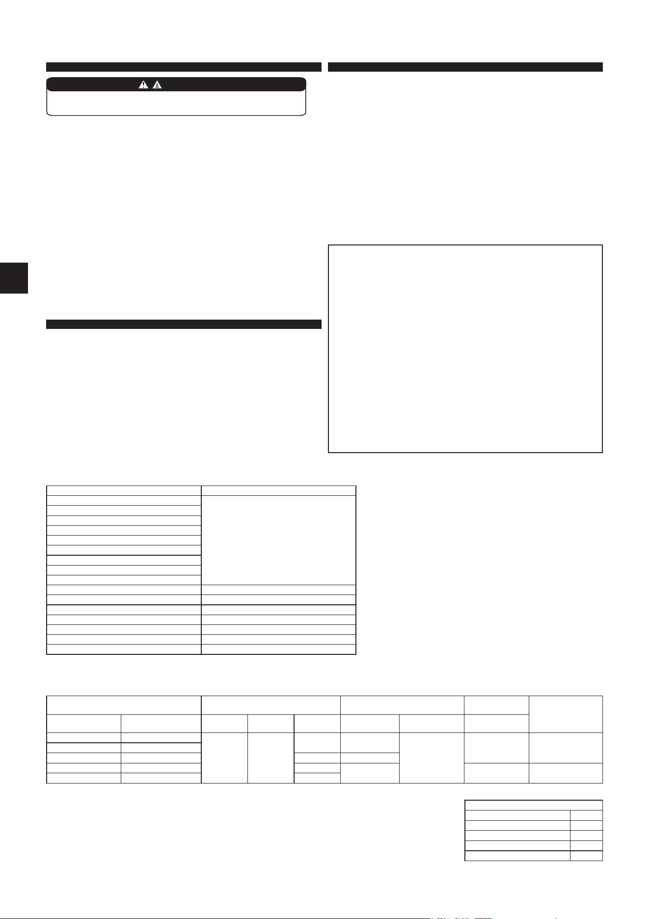
1-3. SPECIFICATIONS
*1 Connect to the power switch which has a gap of 3 mm or more
when open to interrupt the source power phase. (When the
power switch is shut o, it must interrupt all phases.)
*2 Use wires in conformity with design 60245 IEC 57.
*3 Never use pipes with thickness less than specied. The pressure
resistance will be insucient.
*4 Use a copper pipe or a copper-alloy seamless pipe.
*5 Be careful not to crush or bend the pipe during pipe bending.
*6 Refrigerant pipe bending radius must be 100 mm or more.
*7 If pipe length exceeds 7 m, additional refrigerant charge is
required. (No additional charge is required for pipe length less
than 7 m.)
Additional refrigerant = A × (pipe length (m) – 7)
*8 Insulation material : Heat resisting foam plastic 0.045 specic
gravity
*9 Be sure to use the insulation of specied thickness. Excessive
thickness may cause incorrect installation of the indoor unit and
insucient thickness may cause dew drippage.
(KW25, 35, 42/KW50, 60)
Pipe length and height dierence
Max. pipe length 20/30 m
Max. height dierence 12/15 m
Max. number of bends *5, *6 10
Refrigerant adjustment A *7 20 g/m
Insulation thickness *8, *9
8 mm
Model Power supply *1 Wire specications *2
Pipe size
(thickness *3, *4)
Maximum amount of
refrigerant charge
Indoor unit Outdoor unit
Rated
Voltage
Frequency
Breaker
capacity
Power supply
(3-core)
Indoor/outdoor
connecting wire
Gas / Liquid
MFZ-KW25VGK MUFZ-KW25VG2
230 V 50 Hz
10 A 1.0 mm
2
4-core
2.0 mm
2
ø9.52 / 6.35 mm
(0.8 mm)
1260gMFZ-KW35VGK MUFZ-KW35VG2
MFZ-KW42VGK MUFZ-KW42VG2 12A 1.5 mm
2
MFZ-KW50VGK MUFZ-KW50VG(HZ)2 16 A
2.0 mm
2
ø12.7 / 6.35 mm
(0.8 mm)
1760g
MFZ-KW60VGK MUFZ-KW60VG(HZ)2 20 A
1-2. SELECTING THE INSTALLATION LOCATION
INDOOR UNIT
Following conditions should be satised when installing indoor units:
• Where airow is not blocked.
• Where cool (or warm) air spreads over the entire room.
• Rigid wall without vibration.
• Where it is not exposed to direct sunshine. Do not expose to direct sunshine
also during the period following unpacking to before use.
• Where easily drained.
• At a distance 1 m or more away from your TV and radio. Operation of the air
conditioner may interfere with radio or TV reception. An amplier may be required
for the aected device.
• In a place as far away as possible from uorescent and incandescent lights. In
order to make the infrared remote control operate the air conditioner normally.
The heat from the lights may cause deformation or the ultraviolet may cause
deterioration.
• Where the air lter can be removed and replaced easily.
• Where it is away from the other heat or steam source.
• Do not install the unit in the environment where any gas equipment for propane,
butane or methane, sprays such as bug killer, equipment which generates smoke,
paint etc., and chemicals are used, or in the place where sulfur-based gas is
generated.
• The refrigerant sensor mounted in the indoor unit may react to them, and display
an error of refrigerant leakage. This may cause the unit not to operate.
REMOTE CONTROLLER
Followings are preferable conditions to store a remote controller:
• Where it is easy to operate and easily visible.
• Where children cannot touch it.
• Select a position about 1.2 m above the oor and check that signals from the
remote controller are surely received by the indoor unit from that position (‘beep’
or ‘beep beep’ receiving tone sounds). After that, attach remote controller holder
to a pillar or wall and install wireless remote controller.
Note:
In rooms where inverter type uorescent lamps are used, the signal from the
wireless remote controller may not be received.
OUTDOOR UNIT
• Where it is not exposed to strong wind. If the outdoor unit is exposed to a wind
during defrosting, the defrosting time will be longer.
• Where airow is good and dustless.
• Where rain or direct sunlight can be avoided as much as possible.
• Where neighbours are not annoyed by operation sound or hot air.
• Where rigid wall or support is available to prevent the increase of operation sound
or vibration.
• Where there is no risk of combustible gas leakage.
• When installing the unit at a high level, be sure to secure the unit legs.
• Where it is at least 3 m away from the antenna of TV set or radio. Operation of the
air conditioner may interfere with radio or TV reception in areas where reception
is weak. An amplier may be required for the aected device.
• Install the unit horizontally.
• Please install it in an area not aected by snowfall or blowing snow. In areas with
heavy snow, please install a canopy, a pedestal and/or some bae boards.
Note:
It is advisable to make a piping loop near outdoor unit so as to reduce vibration
transmitted from there.
WARNING
This unit should be installed in rooms which exceed the oor space
specied in this installation manual.
Note:
When operating the air conditioner in low outside temperature, be sure to follow the
instructions described below.
• Never install the outdoor unit in a place where its air inlet/outlet side may be
exposed directly to wind.
• To prevent exposure to wind, install the outdoor unit with its air inlet side facing
the wall.
• To prevent exposure to wind, it is recommended to install a bae board on the
air outlet side of the outdoor unit.
Avoid the following places for installation where air conditioner trouble is liable
to occur.
• Where ammable gas could leak.
• Where there is much machine oil.
• Where oil is splashed or where the area is lled with oily smoke (such as cook-
ing areas and factories, in which the properties of plastic could be changed
and damaged).
• Salty places such as the seaside.
• Where sulde gas is generated such as hot spring, sewage, waste water.
• Where there is high-frequency or wireless equipment.
• Where there is emission of high levels of VOCs, including phthalate compounds,
formaldehyde, etc., which may cause chemical cracking.
• The appliance shall be stored so as to prevent mechanical damage from oc-
curring.
M [kg] Amin [m
2
]
1.00
No requirements
1.10
1.20
1.30
1.40
1.50
1.60
1.70
1.80
1.84 3.63
1.90 3.75
2.00 3.95
2.10 4.15
2.20 4.34
2.30 4.54
2.40 4.74
If connecting to the outdoor unit that uses R32 refrigerant, install the indoor unit in a room with a oor area of Amin or more, corresponding to refrigerant M (factory-
charged refrigerant + locally add refrigerant). For refrigerant quantity and additional refrigerant charge, refer to the outdoor unit.
*3
(K)
(J)
EN-4
ACCESSORIES
Check the following parts before installation.
<Indoor unit>
(1) Drain hose* 1
(2) Remote controller holder 1
(3)
Fixing screw for (2) 3.5 × 16 mm
(Black)
2
(4) Pipe cover 1
(5) Band 2
(6) Battery (AAA) for (12) 2
(7) Indoor unit mounting bracket 1
(8) Fixing screw for (7) 4 × 25 mm 5
(9) Wood screw for indoor unit xation 4
(10) Washer of (9) 4
(11) Felt tape (For left or left-rear piping) 1
(12) Wireless remote controller 1
(13) Air cleaning lter 2
(14) Breaker tag 1
(15) Breaker notice 1
<Outdoor unit>
(16) Drain socket (VG type only) 1
* Note:
The Drain hose is connected to the unit.
PARTS TO BE PROVIDED AT YOUR SITE
(A) Indoor/outdoor unit connecting wire* 1
(B) Extension pipe 1
(C) Wall hole sleeve 1
(D) Wall hole cover 1
(E) Pipe xing band 2 to 5
(F) Fixing screw for (E) 4 × 20 mm 2 to 5
(G) Piping tape 1
(H) Putty 1
(J)
Drain hose
(or soft PVC hose, 15 mm inner dia. or
hard PVC pipe VP16)
1 or 2
(K) Power supply cord* 1
* Note:
Place indoor/outdoor unit connecting wire (A) and power
supply cord (K) at least 1 m away from the TV antenna wire.
WARNING
To avoid risk of re, embed or protect the refriger-
ant piping.
External damage on the refrigerant piping can be
cause of re.
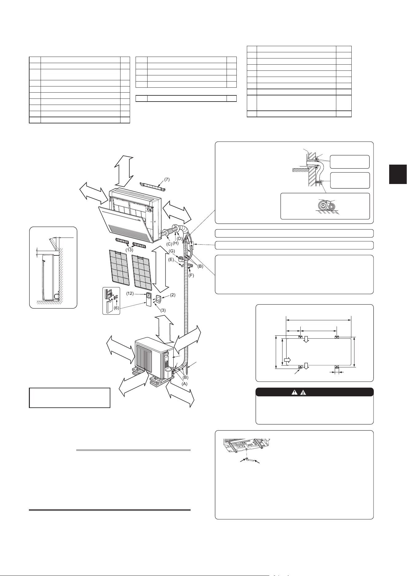
1-4. INSTALLATION DIAGRAM
150 mm or below
from the oor
No obstruc-
tion
100 mm
or more
100 mm
or more
Outdoor unit installation (KW25, 35, 42/KW50, 60)
When the piping is to be attached to a wall containing metals (tin plated) or
metal netting, use a chemically treated wooden piece 20 mm or thicker be-
tween the wall and the piping or wrap of insulation vinyl tape around the piping.
To use existing piping, perform COOL operation for 30 minutes and pump
down before removing the old air conditioner. Remake are according to the
dimension for new refrigerant.
40 mm
or less
30° or less
45 mm or more
Obstacles above
It’s possible to install an
obstacle to the following
area.
100 mm
or more
100 mm
or more
200/500 mm*2
or more
(KW25, 35, 42/KW50, 60)
*1 100/500 mm or more when front
and sides of unit are clear
*2 When any 2 sides of left, right and
rear of unit are clear
*3 The manufacturing year and
month is indicated on the spec
name plate.
clear*1
(KW25, 35, 42/
KW50, 60)
Appearance of the out-
door unit may dier from
some models.
Air inlet
Air outlet
2-10 mm × 21 mm slot
800/840 mm
150/175
mm
500 mm
344.5/390 mm
285/330 mm
304-325/349-371 mm
40 mm
Air inlet
350 mm
or more
Indoor unit
Wall hole
sleeve (C)
Cut o the extra
length.
Pipe xing
band (E)
Wall hole cover (D)
Fixing screw
(F)
Be sure to use wall hole
sleeve (C) to prevent
indoor/outdoor connecting
wire (A) from contacting
metal parts in the wall and
to prevent damage by
rodents in case the wall is
hollow.
Seal the wall hole
gap with putty (H).
Fix the pipe to
wall with pipe
xing band (E).
Units should be installed by licensed
contractor according to local code
requirements.
IMPORTANT NOTES
• Units should be installed by licensed contractor according to local code
requirements.
• To comply with the requirements of Australian standard AS/NZS 3000
electrical installations (wiring rules), the electrical wiring required between
the indoor and outdoor units must be installed by a licenced electrical
contractor.
• Check that cabling will not be subject to wear, corrosion, excessive pres-
sure, vibration, sharp edges or any other adverse environmental eects.
The check shall also take into account the eects of aging or continual
vibration from sources such as compressors or fans.
Note:
Install the unit horizontally.
Do not use drain socket (16) in cold regions. Drain may freeze and make
the fan stop.
The outdoor unit produces condensate during the heating operation.
Select the installation place to ensure to prevent the outdoor unit and/or
the grounds from being wet by drain water or damaged by frozen drain
water.
(16) (J)
Drain piping for outdoor unit
• Provide drain piping before indoor and
outdoor piping connection.
• Connect drain hose (J) I.D.15 mm as shown
in the illustration.
• Make sure to provide drain piping with a
downhill grade for easy drain ow.
After the leak test, apply insulating material tightly so that there is no gap.
Cover the connection part with tape to prevent water from leaking.
EN-5
Wall
Outdoor
side
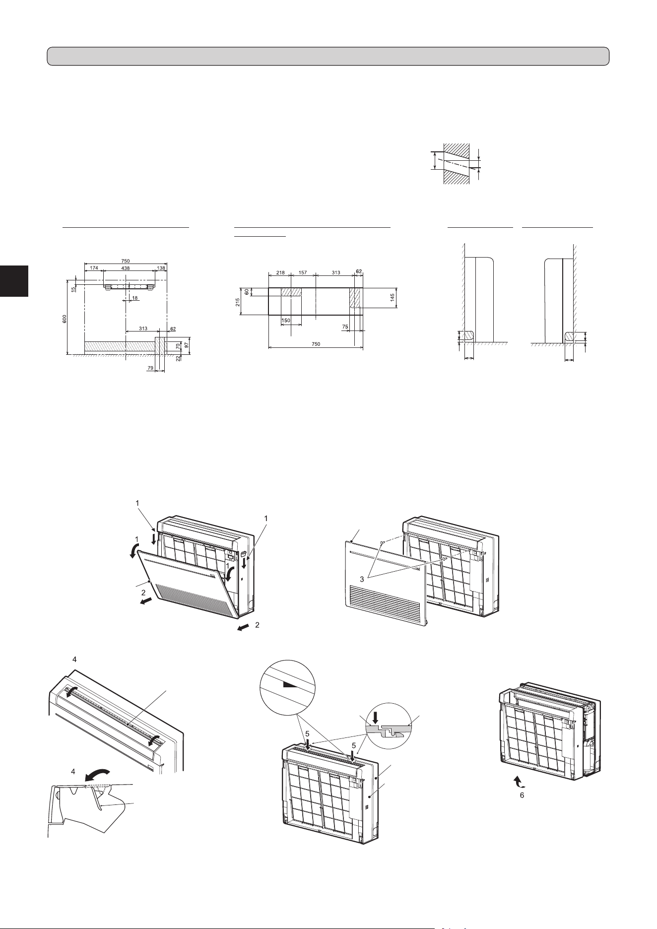
2-2. HOLE DRILLING
1) Determine the wall hole position.
2) Drill a dia. 65 mm hole (dia. 75 ~ 80 mm for KW50/60). The outdoor side should
be 5 to 7 mm lower than the indoor side.
3) Insert wall hole sleeve (C).
2-1. FIXING OF INDOOR UNIT MOUNTING BRACKET
• Do not install the indoor unit at a place higher than 150 mm.
• Find a structural material (such as a stud) in the wall and x bracket (7) horizontally with xing screws (8).
• To prevent bracket (7) from vibrating, be sure to install the xing screws in the holes indicated in the illustration. For added support, xing screws may also be installed
in other holes.
FOR RIGHT DOWNWARD OR LEFT DOWN-
WARD PIPING
(The following gure is a view of the bottom of
the indoor unit from above.)
FOR REAR OR LEFT-REAR PIPING
(The following gure is a front view
of the indoor unit installation location.)
FOR LEFT PIPING FOR RIGHT PIPING
HOLE POSITIONS
ø65 mm (KW25/35/42)
ø75 ~ ø80 mm (KW50/60)
5 - 7 mm
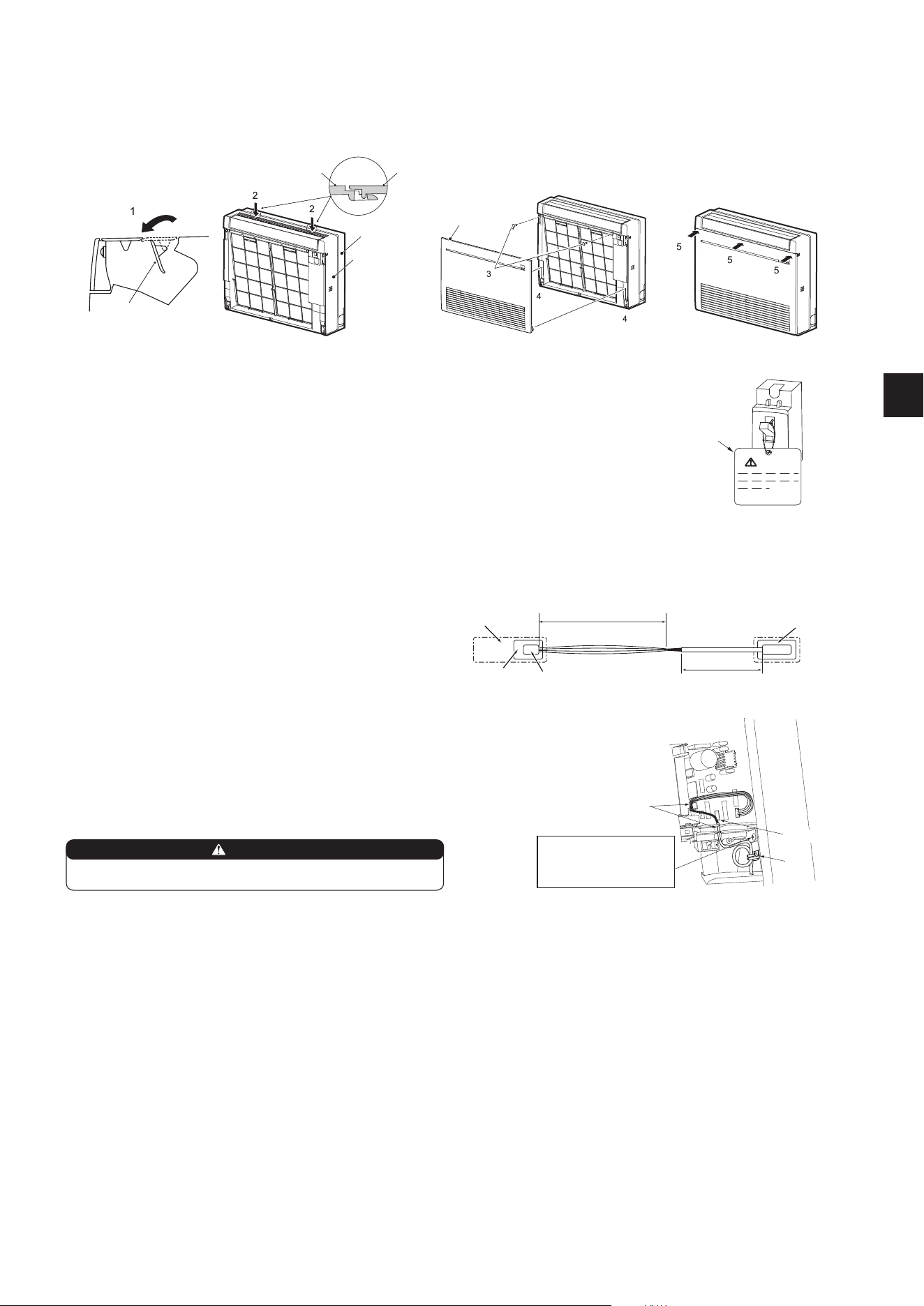
2-3. INDOOR UNIT PREPARATION
Remove the front panel of the indoor unit.
1) Push down the tab on the both sides of the unit to open the front panel.
2) Pull the front panel toward you to remove it.
3) Remove the 2 screws.
4) Open the rear horizontal vane.
5) Push the 2 locations on the top of the panel, and then pull the upper part of the panel toward you.
6) Remove the panel while lifting it up (slightly).
Rear horizontal
vane
Panel
Panel
Push
Indoor unit
60
60
6030
6030
Front panel
Front panel
Indoor unit
Indoor
side
Rear horizontal
vane
2. INDOOR UNIT INSTALLATION
EN-6
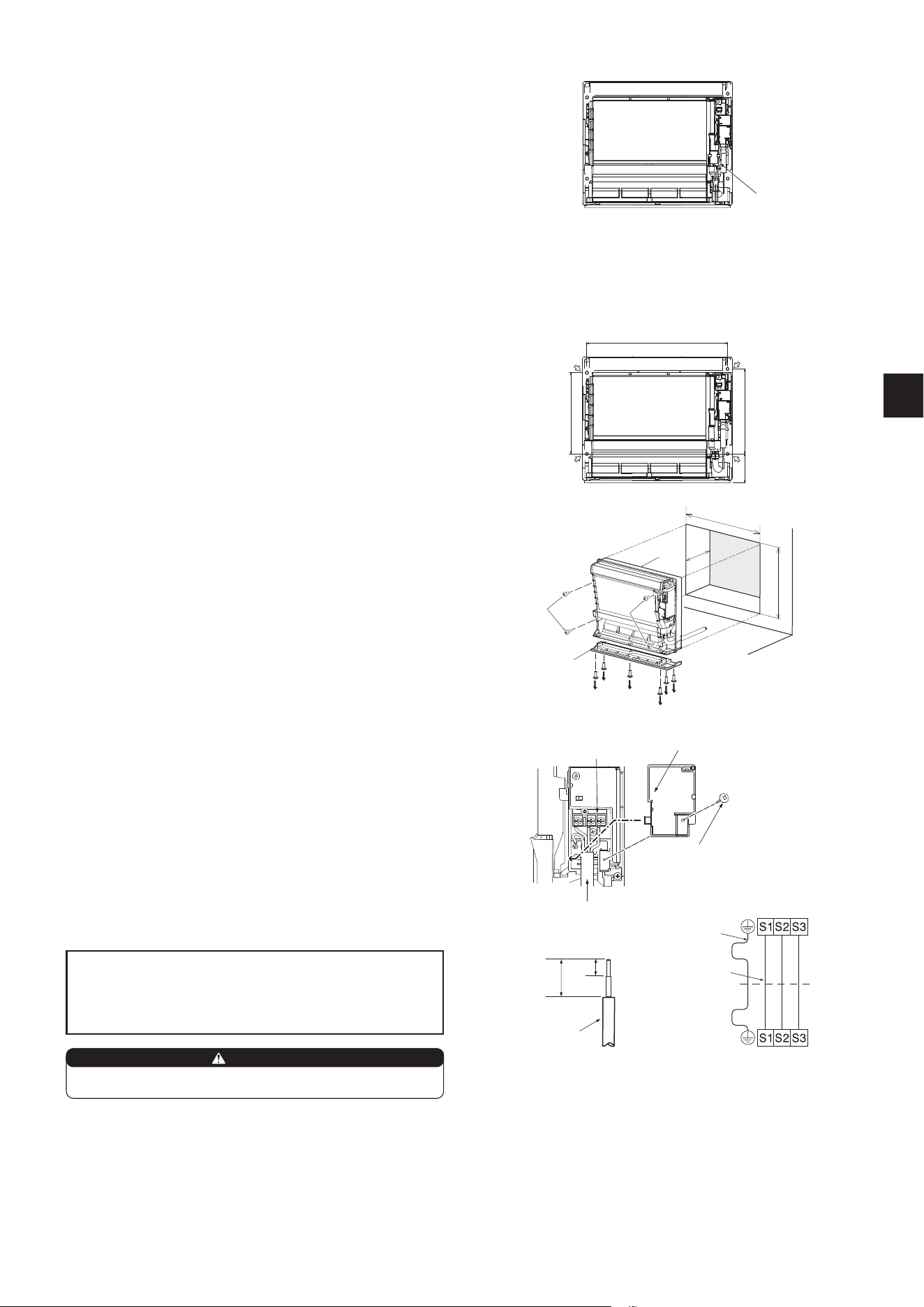
2-4-3. EMBEDDING THE INDOOR UNIT IN A WALL
1) Make a hole in the wall.
2) Using reinforcement material, adjust the depth.
3) Remove 6 screws that x the base to the unit. Remove the base from the unit.
4) Fix the indoor unit at 4 points with the included wood screws (9) and washers
(10). Tighten the screws securely.
4
575
740
70
4
3
3
3
3
3
3
705
2-4. INDOOR UNIT INSTALLATION
2-4-1. INSTALLING THE INDOOR UNIT ON THE FLOOR
1) Place the indoor unit on the at oor.
2) Fix the indoor unit at 4 points with the included wood screws (9) and washers
(10). Tighten the screws securely.
2-4-2. MOUNTING THE INDOOR UNIT ON THE WALL
1) Hook the top of the indoor unit on the indoor unit mounting bracket (7).
2) Fix the indoor unit at 4 points with the included wood screws (9) and washers
(10). Tighten the screws securely.
405
137
387
Indoor terminal block
Indoor/outdoor unit
connecting wire (A)
Outdoor terminal block
Earth wire
(green/yellow)
• Make earth wire a little longer than others. (More than 45 mm)
• For future servicing, give extra length to the connecting wires.
• Do not fold the excess wire, or cram it into small space. Take caution not to
damage the wires.
• Be sure to attach each screw to its correspondent terminal when securing
the cord and/or the wire to the terminal block.
2-5. CONNECTING WIRES FOR INDOOR UNIT
1) Remove VA clamp.
2) Pass indoor/outdoor unit connecting wire (A) from the back of the indoor unit
and process the end of the wire.
3) Loosen terminal screw, and connect rst the earth wire, then indoor/outdoor
unit connecting wire (A) to the terminal block. Be careful not to make mis-
wiring. Fix the wire to the terminal block securely so that no part of its core is
appeared, and no external force is conveyed to the connecting section of the
terminal block.
4) Firmly tighten the terminal screws to prevent them from loosening. After
tightening, pull the wires lightly to conrm that they do not move.
5) Secure indoor/outdoor unit connecting wire (A) and the earth wire with the VA
clamp. Never fail to hook the left claw of the VA clamp. Attach the VA clamp
securely.
Terminal block
Fixing screw
Indoor/outdoor unit
connecting wire (A)
VA clamp
Lead wire
35 mm
15 mm
Reinforcement
material
Unit
Base
When installing the unit, securely connect the refrigerant pipes before
starting the compressor.
WARNING
Note:
Wi-Fi interface is connected to this model.
Be careful not to damage the wires during installation works.
Wi-Fi interface
EN-7
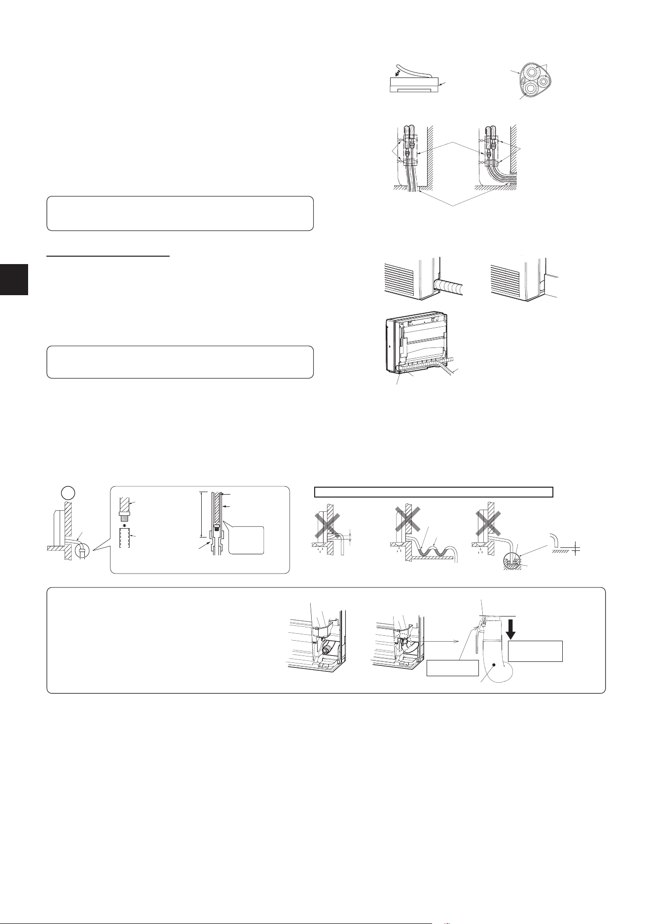
2-6. PIPE FORMING AND INSTALLATION
Note: Refer to 3. FLARE CONNECTION, PIPE CONNECTION.
Pipe Forming
• Route the drain hose diagonally below the connecting pipes.
• Make sure that the drain hose is not routed upward and that there are no
waves in the hose.
• Do not pull the hose when applying the tape.
• Route the piping so that it does not project past the rear of the indoor unit.
(Refer to the gure to the right.)
Connecting Pipe Installation
• Install the connecting pipes so that the piping can move slightly to the
front, back, left, and right.
• When the cover is removed, be sure to cover the pipes so that no piping
is exposed to the room after installing the piping.
• Fill the gap after installing the piping.
Piping
tape
Drain hose
Refrigerant
piping
Piping bent outward
Indoor unit
Push
Remove the cover.
* Fill the gap after installing the piping.
RIGHT DOWNWARD PIPING OTHER PIPING
Band (5)
Pipe cover (4)
Band (5)
• Be sure to insulate the connecting pipes so that they do not contact the
panel.
• Be careful not to crush the connecting pipes when bending them.
Do not make drain piping as shown below.
Accumulated
drain water
Air
Waving
Water
leakage
Do not raise
Water
leakage
Water
leakage
Tip of drain
hose dipped
in water
Ditch
At least
50 mm
gap
Downward
slope
Drain
hose
Soft hose
I.D. 15 mm
Drain hose
Hard vinyl chloride
pipe I.D. 30 mm
Insert
securely
Dierent diam-
eter joint
70 cm or
more
Fig. 1 Fig. 2 Fig. 3
2-7. DRAIN PIPING
• If the extension drain hose has to pass through a room, be sure to wrap it with commercially sold insulation.
• The drain hose should point downward for easy drain ow. (Fig. 1)
• If the drain hose provided with the indoor unit is too short, connect it with drain hose (J) that should be provided at your site. (Fig. 2)
• Use tape or some other material to seal the connection between the product’s drain hose and extension drain hose (16 mm inner diameter) (J).
• When connecting the drain hose to the hard vinyl chloride pipe, be sure to insert it securely into the pipe. (Fig. 3)
Wrap the felt tape (11) tightly around the pipes and hose starting near where
the pipes and hose are routed from the indoor unit. (The overlap width of the
felt tape (11) should not be more than 1/2 of the tape width.)
Felt tape (11)
Start wrapping the piping tape (G)
around the pipes and hose 10 mm inside
the indoor unit.
Fasten the end of the felt tape (11) with
a bandage stopper.
Make sure that the drain hose
is not routed upward.
FOR LEFT OR LEFT-REAR PIPING
Bundle the connecting pipes and drain hose together, and then wrap them in
felt tape (11).
Cut and use the lower side panels on the left and right sides of the indoor unit
as shown below.
Smooth the cut edges of the side panels so that they will not damage the insula-
tion coating.
• For left or right piping
• Installing ush against a wall with molding
Molding
Cut the lower side panels to
match the height of the molding.
Fig. 5
Projection
Make sure to
hook the catch.
Drain hose
Pull the hose to
conrm it is con-
nected securely.
Fig. 4
The Drain hose is removed at installation.
• When routing the drain piping, make sure that the drain hose
(1) is routed as shown. (Fig. 4)
• Insert the drain hose all the way to the base of the drain
pan (end connection). (Fig. 5)
Make sure that the catch of the drain hose is securely
hooked onto the projection on the hose tting of the drain
pan.
• After connecting the drain hose, be sure to pull the hose to
conrm that it is connected securely.
EN-8
2-8. FRONT PANEL INSTALLATION
1) Open the rear horizontal vane.
2) Attach the panel. Make sure that the catches are engaged.
3) Fix the panel with screws.
4) Insert the bottom part of the front panel.
5) Push 3 places on the upper part of the front panel to close it.
Front panel
Indoor unit
Indoor unit
Panel
Panel
2-10. CONNECTING THE INTERFACE (option)/CONNECTOR CABLE (option) TO THE AIR CONDITIONER
Thin part of the connecting cable.
Place this part where customers
cannot touch it.
Room air
conditioner
Main body of an interface
Thick part of the connecting cable
Indoor control
P.C. board
CN105 for interface
CN104 for connector cable
• Connect an interface/connector cable to the indoor control P.C. board of an
air conditioner with a connecting cable.
• Cutting or extending the connecting cable of the interface/connector cable
results in defects in connecting. Do not bundle the connecting cable together
with power supply cord, indoor/outdoor connecting wire, and/or earth wire.
Keep as much distance as possible between the connecting cable and those
wires.
• The thin part of the connecting cable should be stored and placed where
customers cannot touch it.
Rear horizontal
vane
2-9. HOW TO ATTACH THE LABEL AND THE EXPLANATION
The breaker must be always ON except when performing maintenance or inspection. Hang the accompanying label (14) or
(15) on the breaker, and explain it to customers. When turning the breaker OFF, the power is not supplied to the refrigerant
sensor mounted in the indoor unit, and the refrigerant leakage cannot be detected.
WARNING
(14)
1) Remove the panel.
2) Open the cover of the indoor control P.C. board.
3) Join the connecting cable to CN104 on the indoor control P.C. board.
4) Route the connecting cable through this point in the gure.
5) Attach the cable clamp provided with interface/connector cable to the thick
part of the connecting cable with a screw 4×16 as shown in the gure.
6) Close the cover of the indoor control P.C. board. Be careful not to catch the
thin part of the connecting cable in the cover. Reinstall the panel.
5)
4)
WARNING
Fix the connecting cable at the prescribed position securely.
Incorrect installation may cause electric shock, re, and/ or malfunction.
When mounting the
interface and the connector
cable, use this screw to x
the connecting cable.
3) CN104
EN-9
3. OUTDOOR UNIT INSTALLATION
3-4. INSULATION AND TAPING
1) Cover piping joints with pipe cover.
2) For outdoor unit side, surely insulate every piping including valves.
3) Using piping tape (G), apply taping starting from the entry of outdoor unit.
• Stop the end of piping tape (G) with tape (with adhesive agent attached).
• When piping have to be arranged through above ceiling, closet or where the tempera-
ture and humidity are high, wind additional commercially sold insulation to prevent
condensation.
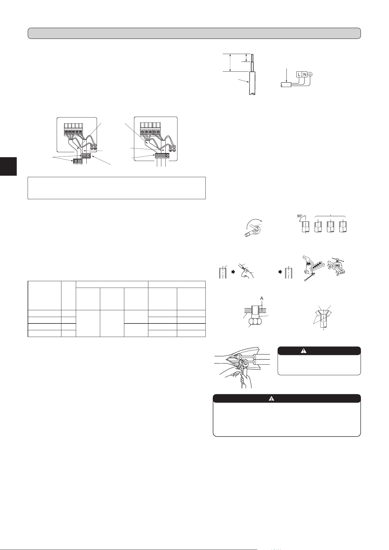
3-2. FLARING WORK
1) Cut the copper pipe correctly with pipe cutter. (Fig. 1, 2)
2) Completely remove all burrs from the cut cross section of pipe. (Fig. 3)
• Put the end of the copper pipe to downward direction as you remove burrs in order
to avoid to let burrs drop in the piping.
3) Remove are nuts attached to indoor and outdoor units, then put them on pipe having
completed burr removal. (Not possible to put them on after aring work.)
4) Flaring work (Fig. 4, 5). Firmly hold copper pipe in the dimension shown in the table.
Select A mm from the table according to the tool you use.
5) Check
• Compare the ared work with Fig. 6.
• If are is noted to be defective, cut o the ared section and do aring work again.
3-3. PIPE CONNECTION
• Fasten are nut with a torque wrench as specied in the table.
• When fastened too tight, are nut may break after a long period and cause refrigerant
leakage.
• Be sure to wrap insulation around the piping. Direct contact with the bare piping may
result in burns or frostbite.
Indoor unit connection
Connect both liquid and gas pipings to indoor unit.
• Do not apply refrigeration oil on screw threads. Excessive tightening torque will result
in damage on the screw.
• For connection, rst align the center, then tighten the rst 3 to 4 turns of are nut.
• Use tightening torque table above as a guideline for indoor unit side union joint section,
and tighten using two wrenches. Excessive tightening damages the are section.
Copper
pipe
Good
Tilted Uneven Burred
No good
Fig. 1 Fig. 2
Burr
Copper pipe
Spare reamer
Pipe cutter
Clutch type
Flaring tool
Fig. 4
Fig. 3
Smooth all
around
Even length
all around
Inside is shining
without any
scratches.
Flare nut
Die
Fig. 5 Fig. 6
Copper
pipe
Wing nut type
WARNING
When installing the unit, securely
connect the refrigerant pipes be-
fore starting the compressor.
WARNING
Reusable mechanical connectors and ared joints are not al-
lowed indoors.
When connecting the refrigerant piping by brazing, rather than
using are connections, complete all brazing prior to connecting
indoor unit to outdoor unit.
Pipe diameter
(mm)
Nut
(mm)
A (mm) Tightening torque
Clutch
type tool
for R32,
R410A
Clutch
type tool
for R22
Wing nut
type tool
for R22
N•m kgf•cm
ø6.35 (1/4”) 17
0 to 0.5 1.0 to 1.5
1.5 to 2.0
14 to 18 140 to 180
ø9.52 (3/8”) 22 34 to 42 340 to 420
ø12.7 (1/2”) 26
2.0 to 2.5
49 to 61 490 to 610
ø15.88 (5/8”) 29 68 to 82 680 to 820
3-1. CONNECTING WIRES FOR OUTDOOR UNIT
1) Open the service panel.
2) Loosen terminal screw, and connect indoor/outdoor unit connecting wire (A) from the
indoor unit correctly on the terminal block. Be careful not to make mis-wiring. Fix the wire
to the terminal block securely so that no part of its core is appeared, and no external
force is conveyed to the connecting section of the terminal block.
3) Firmly tighten the terminal screws to prevent them from loosening. After tightening, pull
the wires lightly to conrm that they do not move.
4) Connect power supply cord (K).
5) Fix indoor/outdoor unit connecting wire (A) and power supply cord (K) with the cord
clamp.
6) Close the service panel securely.
• Make earth wire a little longer than others. (More than 100 mm)
• For future servicing, give extra length to the connecting wires.
• Be sure to attach each screw to its correspondent terminal when securing the cord
and/or the wire to the terminal block.
35 mm
15 mm
Lead wire
Power supply cord (K)
Terminal block
Cord clamp
Cord clamp
Power supply
cord (K)
Terminal block
Indoor/outdoor
unit connect-
ing wire (A)
Always x the power supply
cord on this side.
<KW25, 35, 42> <KW50(HZ), 60(HZ)>
EN-10
4. TEST RUN
4-4. EXPLANATION TO THE USER
• Using the OPERATING INSTRUCTIONS, explain to the user how to use the air conditioner (how to use the remote controller, how to remove the air lters, how to
remove or put the remote controller in the remote controller holder, how to clean, precautions for operation, etc.)
• Recommend the user to read the OPERATING INSTRUCTIONS carefully.
Note:
• After test run or remote signal reception check, turn o the unit with the E.O. SW or the remote controller before turning o the power supply. Not doing so will
cause the unit to start operation automatically when power supply is resumed.
To the user
• After installing the unit, make sure to explain the user about auto restart function.
• If auto restart function is unnecessary, it can be deactivated. Consult the service representative to deactivate the function. Refer to the service manual for details.
4-3. AUTO RESTART FUNCTION
This product is equipped with an auto restart function. When the power supply is stopped during operation, such as during blackouts, the function automatically
starts operation in the previous setting once the power supply is resumed. (Refer to the operating instructions for details.)
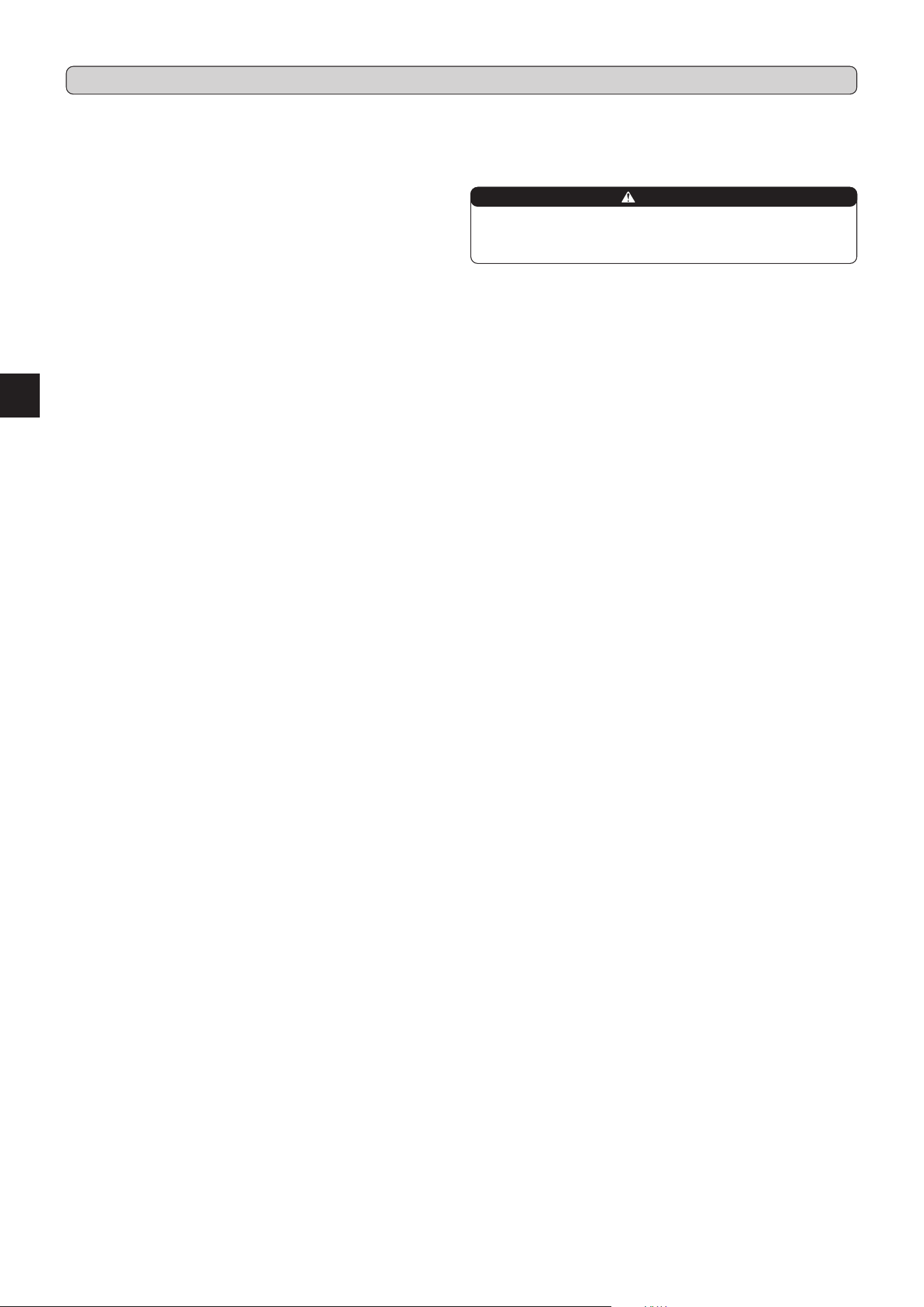
4-2. TEST RUN
Make sure the following is done.
• Panel is installed correctly.
• Indoor and outdoor units are installed correctly, and power is supplied.
1) Press the E.O. SW once for COOL, and twice for HEAT operation. Test run will be performed for 30 minutes. If the left lamp of the opera-
tion indicator blinks every 0.5 seconds, inspect the indoor/outdoor unit connecting wire (A) for mis-wiring. After the test run, emergency
mode (set temperature 24ºC) will start.
2) To stop operation, press the E.O. SW several times until all LED lamps turn o. Refer to operating instructions for details.
Checking the remote (infrared) signal reception
Press the ON/OFF button on the remote controller (12) and check that an electronic sound is heard from the indoor unit. Press the ON/
OFF button again to turn the air conditioner o.
• Once the compressor stops, the restart preventive device operates so the compressor will not operate for 3 minutes to protect the air
conditioner.
Emergency operation
switch (E.O. SW)
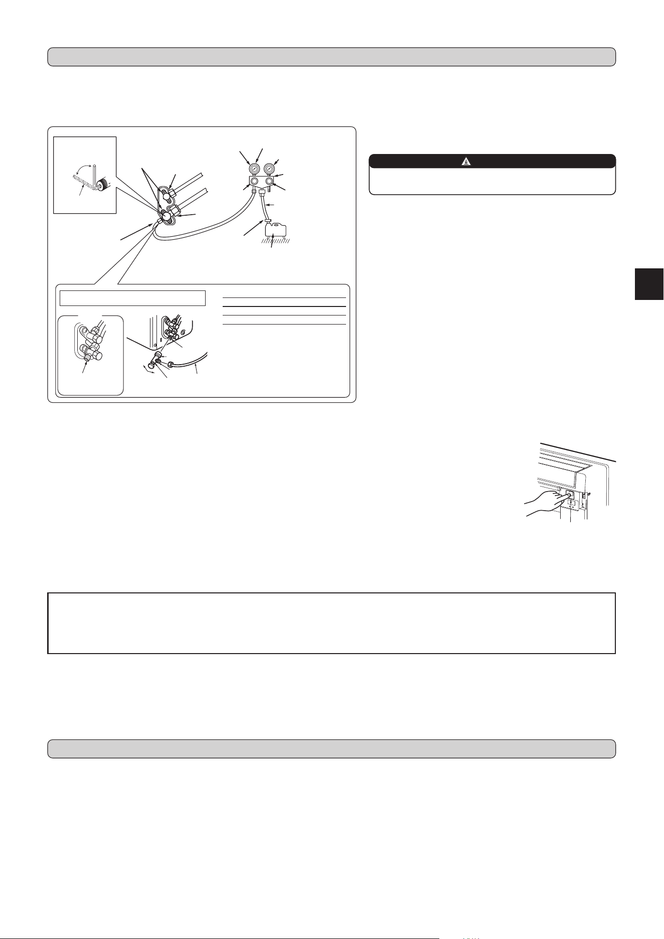
4-1. PURGING PROCEDURES AND LEAK TEST
1) Remove service port cap of stop valve on the side of the outdoor unit gas pipe.
(The stop valves are fully closed and covered in caps in initial state.)
2) Connect gauge manifold valve and vacuum pump to service port of stop valve
on the gas pipe side of the outdoor unit.
Stop valve for
GAS
Stop valve cap
(Torque 21.6 to 27.4 N•m,
220 to 280 kgf•cm)
*If φ12.7, Torque 24.6 to 30.4
N•m, 250 to 310 kgf•cm
Vacuum pump (or the vacuum
pump with the function to
prevent the back ow)
Gauge manifold valve
(for R32, R410A)
Compound pressure gauge
(for R32, R410A)
–0.101 MPa
(
–760 mmHg)
Handle
Low
Handle High
Adapter for
preventing the
back ow
Charge hose
(for R32, R410A)
*Close
*Open
Hexagonal wrench
Precautions when using the control valve
When attaching the control valve
to the service port, valve core may
deform or loosen if excess pressure
is applied. This may cause gas leak.
Service port
Body
Close
<R32>
Open
Control
valve
A
When attaching the control valve to
the service port, make sure that the
valve core is in closed position, and
then tighten part A. Do not tighten
part A or turn the body when valve
core is in open position.
Service port cap
(Torque 14 to
18 N•m, 140 to
180 kgf•cm)
*4 to 5 turns
3) Run the vacuum pump. (Vacuumize until 500 microns is achieved.)
4) Check the vacuum with gauge manifold valve, then close gauge mani-
fold valve, and stop the vacuum pump.
5) Leave as it is for one or two minutes. Make sure pointer gauge manifold
valve remains in the same position. Conrm that pressure gauge shows
–0.101 MPa [Gauge] (–760 mmHg).
6) Remove gauge manifold valve quickly from service port of stop valve.
7) After refrigerant pipes are connected and evacuated, fully open all stop
valves on both sides of gas pipe and liquid pipe. Operating without fully
opening lowers the performance and this causes trouble.
8) Refer to 1-3., and charge the prescribed amount of refrigerant if needed.
Be sure to charge slowly with liquid refrigerant. Otherwise, composition
of the refrigerant in the system may be changed and aect performance
of the air conditioner.
9) Tighten cap of service port to obtain the initial status.
10) Leak test
Stop valve for LIQUID
Pressure gauge
(for R32, R410A)
Charge
hose
Make sure to
replace the cap after
the operation.
WARNING
To avoid risk of re, make sure that there are no ammable hazards
or ignition risks before opening the stop valves.
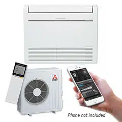
5. CONNECTION SETUP OF THE Wi-Fi INTERFACE
• This product is equipped with the Wi-Fi Interface as standard.
• Refer to the OPERATING INSTRUCTIONS provided with the indoor unit for connection with the router.
• Transcribe the setting information on the Wi-Fi interface to the OPERATING INSTRUCTIONS.
EN-11
When relocating or disposing of the air conditioner, pump down the system follow-
ing the procedure below so that no refrigerant is released into the atmosphere.
1) Connect the gauge manifold valve to the service port of the stop valve on the
gas pipe side of the outdoor unit.
2) Fully close the stop valve on the liquid pipe side of the outdoor unit.
3) Close the stop valve on the gas pipe side of the outdoor unit almost completely
so that it can be easily closed fully when the pressure gauge shows 0 MPa
[Gauge] (0 kgf/cm
2
).
4) Start the emergency COOL operation.
To start the emergency operation in COOL mode, disconnect the power supply
plug and/or turn o the breaker. After 15 seconds, connect the power supply plug
and/or turn on the breaker, and then press the E.O. SW once. (The emergency
COOL operation can be performed continuously for up to 30 minutes.)
5) Fully close the stop valve on the gas pipe side of the outdoor unit when the
pressure gauge shows 0.05 to 0 MPa [Gauge] (approx. 0.5 to 0 kgf/cm
2
).
6) Stop the emergency COOL operation.
Press the E.O. SW several times until all LED lamps turn o. Refer to operating
instructions for details.
6. PUMPING DOWN
When the refrigeration circuit has a leak, do not execute pump down with
the compressor. When pumping down the refrigerant, stop the compres-
sor before disconnecting the refrigerant pipes. The compressor may burst
if air etc. get into it.
WARNING


DG79V608H02
HEAD OFFICE: TOKYO BUILDING, 2-7-3, MARUNOUCHI, CHIYODA-KU, TOKYO 100-8310, JAPAN
This product is designed and intended for use in the residential, commercial and
light-industrial environment.