Loading ...
Loading ...
Loading ...
10
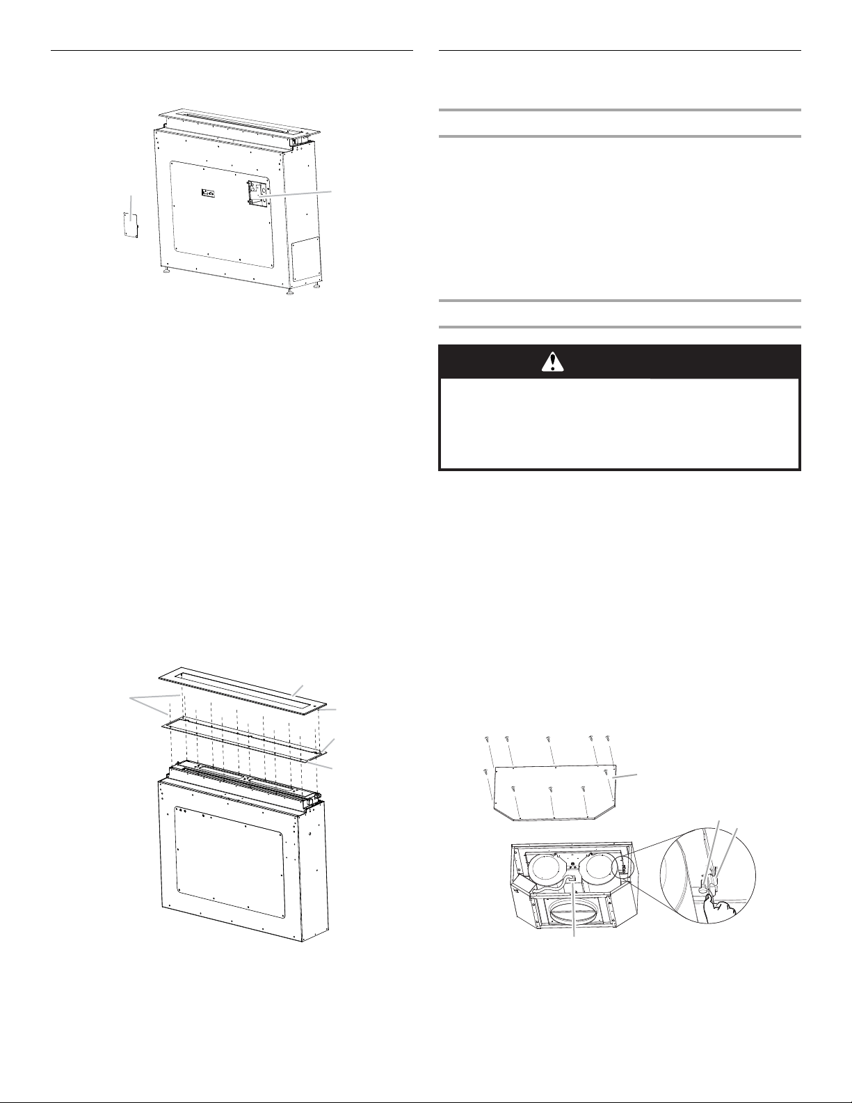
Install Downdraft Vent System
1. Remove the 3 screws from the terminal box cover.
2. Remove the knockout from the front panel and install a ½"
(1.3 cm) UL listed or CSA approved conduit connector.
3. Using 2 or more people, insert the downdraft vent into the
cabinet. Position the downdraft vent so that it is
approximately centered below the countertop cutout
location.
4. If the countertop is not already installed, follow the directions
for the countertop installation to place it onto the cabinets.
5. Using a ½" wrench, screw out the feet on the vent box to
raise the top of the unit until it is flush with the top surface
of the countertop.
6. Center and level the top of the downdraft vent left to right and
front to back. Use a ⁹⁄₁₆" wrench to lock the feet into position
with the locknuts.
7. Secure the hood vent box to the countertop or cabinet sides
with the undercounter mounting brackets attached earlier at
the desired location. If mounting to a countertop, use screws
or mounting method recommended for the specific type of
countertop.
8. Install the top frame support, using the 12 - 3.9 x 9 mm
flat-head screws.
9. Install the top frame.
Install Downdraft Vent In-Line
(External Type) Blower Motor
Prepare for Mounting the In-Line Blower System
The in-line blower system must be fastened to a secure structure
of the roof, ceiling, wall, floor, or new or existing frame
construction. The 4 holes on either the inlet (bottom) side or the
outlet (top) side of the blower must be used to mount the in-line
blower system to the structure.
NOTE: The mounting hole locations must span the studs.
Additional stud framing may be required. Plywood may be used
to span open areas between ceiling or floor joists or roof rafters
to aid installation. This structure must be strong enough to
support the weight of the in-line blower system (50 lb
[22.7 kg] min).
Prepare the In-line Blower System
1. Using 2 or more people, move the in-line blower motor
system to the mounting location.
2. Remove the 10 screws from the front cover of the in-line
blower motor housing and set them aside.
3. Remove the front cover of the in-line blower motor housing
and set it aside.
NOTE: To make the blower motor housing easier to mount,
the blower motor assembly can be removed. If you do not
want to remove the blower motor assembly, proceed to
“Install In-line Blower System” in this section.
4. Disconnect the motor electrical plug from the blower motor
assembly.
5. Remove the screws that secure the blower motor assembly
to the in-line blower housing and set them aside.
6. Pull the spring clip to release the blower motor assembly.
Remove the blower motor assembly from the housing and
place it on a covered surface.
A. Terminal box cover
B. Knockout
A. 12 Flat-head screws
B. Top frame
C. Guide pins in top frame
D. Hole for top frame guide pins
E. Top frame support
A
B
A
B
C
D
E
A. Front cover
B. Blower mounting screws
C. Spring clip
D. Motor electrical plug
WARNING
Excessive Weight Hazard
Use two or more people to move and install in-line
blower motor system.
Failure to do so can result in back or other injury.
A
B
C
D
Loading ...
Loading ...
Loading ...