Loading ...
Loading ...
Loading ...
9
ENGLISH
8
2. Check your timer for pre-installed sensor terminals. If the timer does
not have sensor terminals, proceed to step 3. If it does, take the wire from
rain/freeze receiver and connect the white (common) wire to one sensor
terminal and the yellow (normal closed) wire to the other. (see figure 5)
Skip to step 5.
3. Disconnect the common valve wire from the timer, and attach it (using a
wire nut) to the yellow
(normal closed) wire
from the rain/freeze
receiver.
(see figure 6)
4. Connect the white
(common) wire from
the rain/ freeze
receiver to the
common terminal
of the timer.
5. Connect the (2) red
“24V” wires to the 24V
terminals of the timer.
24V 24V
COM1 COM2
12 345 67 89
PUMP
Controller / Timer
To Val ve
Common From Valves
White
Yellow
Red
Red
Green (not connected)
SENSOR
24-Volt Solenoid Valves with Booster Pump.
Note: The pump circuit output must be 24 volts in this situation; if different,
do not proceed.
1. Remove wire terminal
cover from timer.
2. Check your timer for pre-
installed sensor terminals.
If the timer does not have
sensor terminals, proceed
to step. 3. If it does, take
the wire from the
rain/freeze receiver and
connect the white (com-
mon) wire to one sensor
terminal and the yellow
(normal closed) wire to the
other. (See figure5) Skip
to step 5.
3. Disconnect the common valve wire(s) from the timer and the common
wire lead of the relay that starts the pump from the common terminal of the
timer. Attach them to the yellow (normal closed) wire from the receiver,
24V 24V
COM1 COM2
12 345 67 89
PUMP
Controller / Timer
To Val ve
Red
Red
Green (not connected)
White
Common From Valves
Wire Nut
Yellow
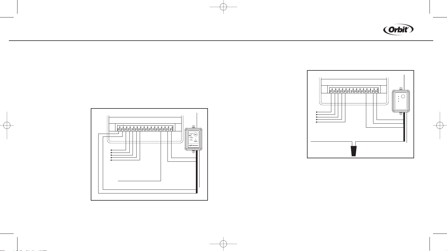
Figure 6: Wiring Sprinkler Timer with out Sensor
terminals and with booster pump
Figure 5: Wiring Sprinkler Timer with Sensor terminals and
with out booster pump.
WTM231279 57071-24 rB.qxd 6/20/03 12:27 PM Page 8
Loading ...
Loading ...
Loading ...