Loading ...
Loading ...
Loading ...
7
ENGLISH
6
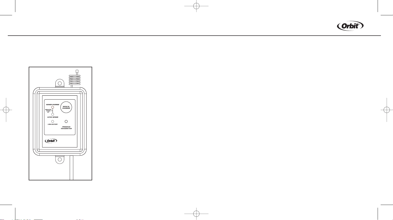
LED Panel Lights
Located on the receiver, the LED lights communicate the current status
of the sensor. (See figure 4)
6. Communication Antenna
Receives Wireless signal from the
Rain/Freeze sensor.
7.Manual Override Button
Functions in 2 ways:
1. Stop timer from watering
2. Allow watering when Rain/Freeze
sensor is active
-See Manual override (Section 4) for
additional detail
8. Sensor Override LED
Indicates when Manual Override is on (see
Manual Override above).
9. Active Sensor LED
Indicates when the rain/freeze sensor is
overriding the sprinkler timer.
10. Low Battery LED
Indicates when battery needs to be replaced.
(Only applicable to models 57071, 57271 and 27681)
6
7
8
9
10
SECTION 2
Installation Instructions
Mounting the Receiver
1. Select a Location within 6” adjacent to your sprinkler timer (receiver
may be located indoor or outdoor).
2. Mount rain/freeze receiver (antenna side up) using screws provided.
3. Extend and straighten the antenna upward.
Wiring the Receiver to Timer
Important: This sensor is designed for 24 Volt Irrigation Timers only do not
connect the receiver to 120/240 VAC. All wiring must conform to applicable
local codes. Disconnect power to the sprinkler timer (unplug timer, turn off
the appropriate circuit breaker or remove fuse) before attempting to connect
the rain sensor receiver.
The two most common wiring situations are detailed below. The green
“normal open” wire is not used in most installations. For non-standard
wiring situations, please contact our customer support hot-line.
24-Volt Solenoid Valves Only (No booster pump).
1. Remove wire terminal cover from timer
Figure 4: Receiver
WTM231279 57071-24 rB.qxd 6/20/03 12:27 PM Page 6
Loading ...
Loading ...
Loading ...