Loading ...
Loading ...
Loading ...
DirectCDTM
v2.5b(s)
5
Front
Panel
Rear
Panel
Location
and
Function
of
Controls
RAD
READ
RITE
WRITE
5
6
12
43
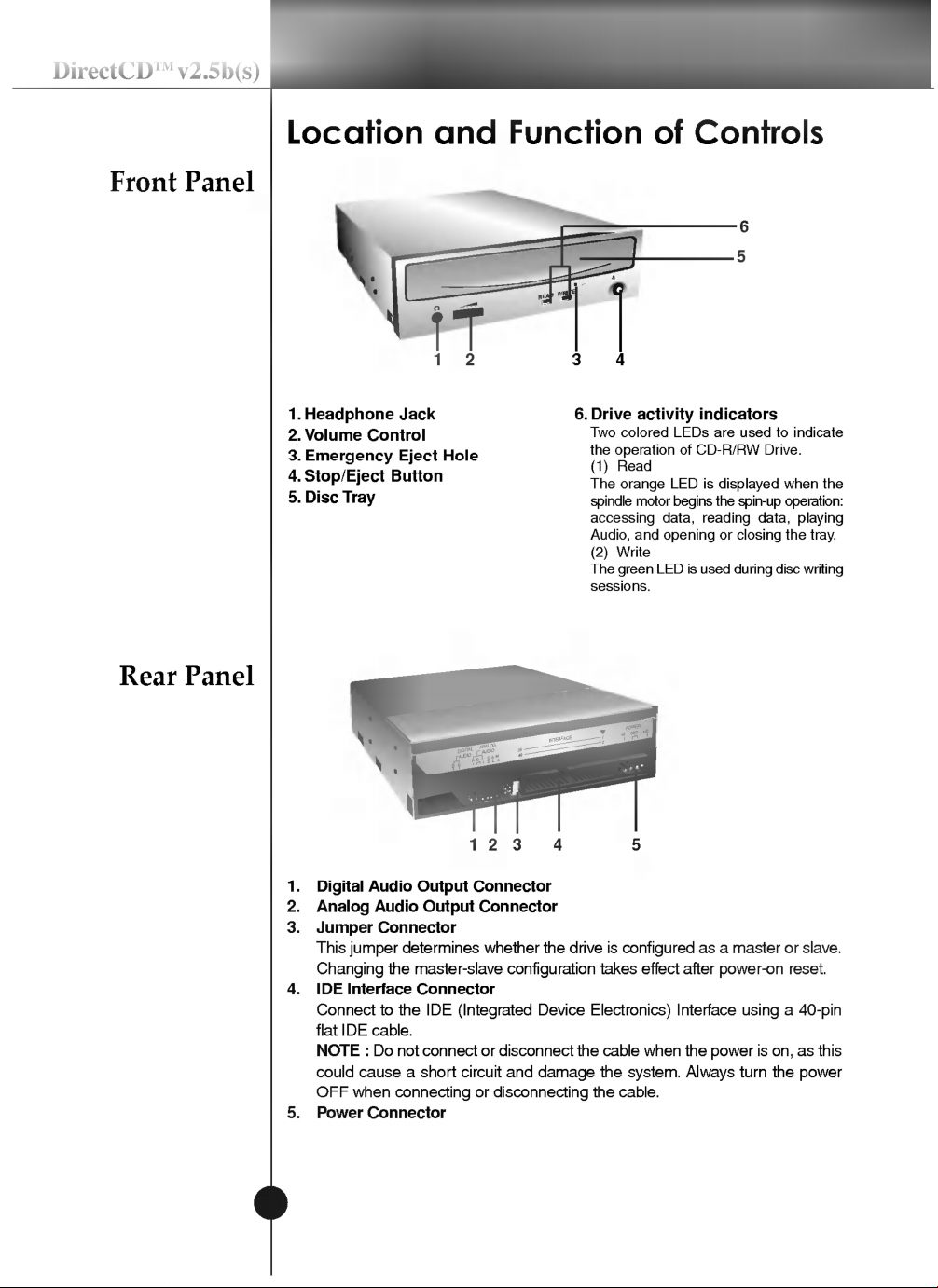
1.
Headphone
Jack
2.
Volume
Control
3.
Emergency
Eject
Hole
4.
Stop/Eject
Button
5.
Disc
Tray
6.
Drive
activity
indicators
Two
colored
LEDs
are
used
to
indicate
the
operation
of
CD-R/RW
Drive.
(1)
Read
The
orange
LED
is
displayed
when
the
spindle
motor
begins
the
spin-up
operation:
accessing
data,
reading
data,
playing
Audio,
and
opening
or
closing
the
tray.
(2)
Write
The
green
LED
is
used
during
disc
writing
sessions.
DIGITAL
AUDIO
ANALOG
AUDIO
INTERFACE
POWER
DG
39
40
1
+5
GND
+12
2
CSM
SLA
RGL
123
4 5
1.
Digital
Audio
Output
Connector
2.
Analog
Audio
Output
Connector
3.
Jumper
Connector
This
jumper
determines
whether
the
drive
is
configured
as
a
master
or
slave.
Changing
the
master-slave
configuration
takes
effect
after
power-on
reset.
4.
IDE
Interface
Connector
Connect
to
the
IDE
(Integrated
Device
Electronics)
Interface
using
a
40-pin
flat
IDE
cable.
NOTE
:
Do
not
connect
or
disconnect
the
cable
when
the
power
is
on,
as
this
could
cause
a
short
circuit
and
damage
the
system.
Always
turn
the
power
OFF
when
connecting
or
disconnecting
the
cable.
5.
Power
Connector
Loading ...
Loading ...
Loading ...