*9001240850*
Ø 0RQWDJHDQOHLWXQJ
Ú ,QVWDOODWLRQLQVWUXFWLRQV
Þ 1RWLFHGHPRQWDJH
â ,VWUX]LRQLSHULOPRQWDJJLR
é ,QVWDOODWLHYRRUVFKULIW
%
&
PLQ
PLQ
$
&
&
%
$%
PLQ
PLQ
& PLQ
D E
F
G
D
PP
E
PP
F
FOLFN
7

991a
99/1a91a
991a
*
<
%.
%1
*1<(
%8
/
1
/
/
1
1
%.
*
<
%1
*1<(
/
/
/
1
%8
%.
*
<
%1
*1<(
/
/
1
%8
D
E
%
% %!
F
D
E F
991a
%1
%.
%8
*<
*1<(
99/1a
91a
%1
%.
%8
*<
*1<(
991a
%1
%.
%8
*<
*1<(
*1<(
%8
%.
%1
*<
991a
%1
%.
%8
*<
*1<(
*1<(
%8
%.
%1
*<
991a
%1
%.
%8
*<
*1<(
*1<(
%8
%.
*<
%1
%1
%.
%8
*<
*1<(
91a
de
Ø
0RQWDJHDQOHLWXQJ
: :LFKWLJH6LFKHUKHLWVKLQZHLVH
'LHVH$QOHLWXQJVRUJIlOWLJOHVHQ1XUGDQQN|QQHQ6LH,KU*HUlW
VLFKHUXQGULFKWLJEHGLHQHQ'LH*HEUDXFKVXQG0RQWDJHDQOHL
WXQJIUHLQHQVSlWHUHQ*HEUDXFKRGHUIU1DFKEHVLW]HUDXIEH
ZDKUHQ
1XUEHLIDFKJHUHFKWHP(LQEDXHQWVSUHFKHQGGHU0RQWDJHDQOHL
WXQJLVWGLH6LFKHUKHLWEHLP*HEUDXFKJHZlKUOHLVWHW'HU,QVWDOOD
WHXULVWIUGDVHLQZDQGIUHLH)XQNWLRQLHUHQDP$XIVWHOOXQJVRUW
YHUDQWZRUWOLFK
7UlJHUYRQHOHNWURQLVFKHQ,PSODQWDWHQ
'DV*HUlWNDQQ3HUPDQHQWPDJQHWHHQWKDOWHQGLHHOHNWURQLVFKH
,PSODQWDWHZLH]%+HU]VFKULWWPDFKHURGHU,QVXOLQSXPSHQEHHLQ
IOXVVHQN|QQHQ'HVKDOEEHLGHU0RQWDJHHLQHQ0LQGHVWDEVWDQG
YRQFP]XHOHNWURQLVFKHQ,PSODQWDWHQHLQKDOWHQ
'HU+HUVWHOOHUEHUQLPPWNHLQH9HUDQWZRUWXQJIU%HWULHEVVW|UXQ
JHQRGHUP|JOLFKH6FKlGHQGLHDXIHLQHIHKOHUKDIWHHOHNWULVFKH
,QVWDOODWLRQ]XUFN]XIKUHQVLQG
1HW]NDEHO(VLVWP|JOLFKHUZHLVHEHUHLWVDQGHU$QVFKOXVV
ER[GHV.RFKIHOGVDQJHVFKORVVHQRGHUZLUGPLWGHP*HUlW
JHOLHIHUW XQG GDUI QXU YRQ HLQHU ]XJHODVVHQHQ )DFKNUDIW E]Z TXD
OLIL]LHUWHP.XQGHQGLHQVW3HUVRQDOLQVWDOOLHUWZHUGHQ'LHHUIRUGHUOL
FKHQ$QVFKOXVVGDWHQVLQGDXIGHP7\SHQVFKLOGXQGLP
$QVFKOXVVELOGDQJHJHEHQ
1XUGDVPLWGHP*HUlWPLWJHOLHIHUWHRGHUYRPWHFKQLVFKHQ.XQ
GHQGLHQVWJHOLHIHUWH.DEHOYHUZHQGHQ
9RU GHU 'XUFKIKUXQJ MHJOLFKHU $UEHLWHQ GLH 6WURP]XIXKU DEVWHOOHQ
)UGLH,QVWDOODWLRQPVVHQGLHDNWXHOOJOWLJHQ%DXYRUVFKULIWHQ
XQGGLH9RUVFKULIWHQGHU|UWOLFKHQ6WURPXQG*DVYHUVRUJHU
EHDFKWHWZHUGHQ
%HLGHU$EOHLWXQJYRQ$EOXIWVLQGGLHEHK|UGOLFKHQXQGJHVHW]OL
FKHQ9RUVFKULIWHQ]%/DQGHVEDXRUGQXQJHQ]XEHDFKWHQ
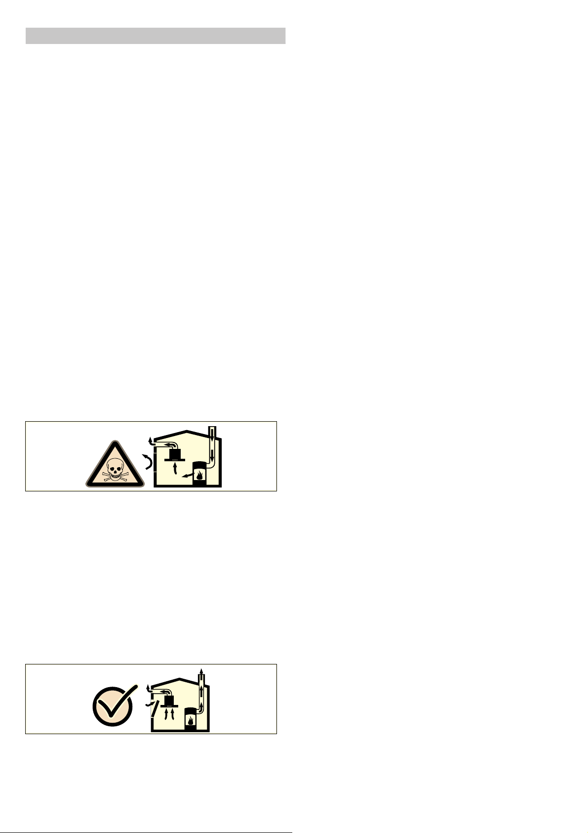
/HEHQVJHIDKU
=XUFNJHVDXJWH9HUEUHQQXQJVJDVHN|QQHQ]X9HUJLIWXQJHQIK
UHQ
,PPHU IU DXVUHLFKHQG =XOXIW VRUJHQ ZHQQ GDV *HUlW LP $EOXIWEH
WULHEJOHLFK]HLWLJPLWHLQHUUDXPOXIWDEKlQJLJHQ)HXHUVWlWWHYHU
ZHQGHWZLUG
5DXPOXIWDEKlQJLJH)HXHUVWlWWHQ]%JDV|OKRO]RGHUNRKOH
EHWULHEHQH+HL]JHUlWH'XUFKODXIHUKLW]HU:DUPZDVVHUEHUHLWHU
EH]LHKHQ9HUEUHQQXQJVOXIWDXVGHP$XIVWHOOUDXPXQGIKUHQGLH
$EJDVHGXUFKHLQH$EJDVDQODJH]%.DPLQLQV)UHLH
,Q9HUELQGXQJPLWHLQHUHLQJHVFKDOWHWHQ'XQVWDE]XJVKDXEHZLUG
GHU.FKHXQGGHQEHQDFKEDUWHQ5lXPHQ5DXPOXIWHQW]RJHQ
RKQHDXVUHLFKHQGH=XOXIWHQWVWHKWHLQ8QWHUGUXFN*LIWLJH*DVH
DXVGHP.DPLQRGHU$E]XJVVFKDFKWZHUGHQLQGLH:RKQUlXPH
]XUFNJHVDXJW
■ (VPXVVGDKHULPPHUIUDXVUHLFKHQGH=XOXIWJHVRUJWZHUGHQ
■ (LQ=XOXIW$EOXIWPDXHUNDVWHQDOOHLQVWHOOWGLH(LQKDOWXQJGHV
*UHQ]ZHUWHVQLFKWVLFKHU
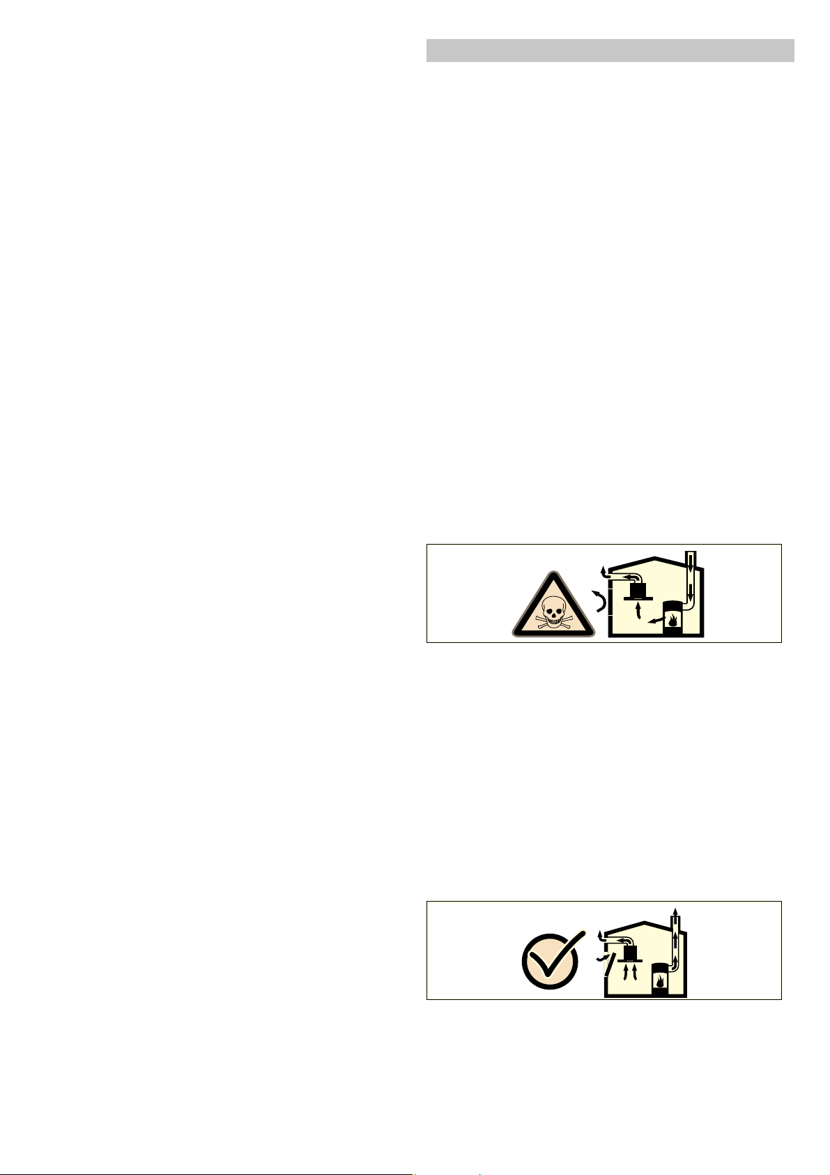
(LQ JHIDKUORVHU %HWULHE LVW QXU GDQQ P|JOLFK ZHQQ GHU 8QWHUGUXFN
LP $XIVWHOOUDXP GHU )HXHUVWlWWH 3D PEDU QLFKW EHUVFKUHL
WHW'LHVNDQQHUUHLFKWZHUGHQZHQQGXUFKQLFKWYHUVFKOLHEDUH
gIIQXQJHQ]%LQ7UHQ)HQVWHUQLQ9HUELQGXQJPLWHLQHP
=XOXIW$EOXIWPDXHUNDVWHQRGHUGXUFKDQGHUHWHFKQLVFKH0D
QDKPHQGLH]XU9HUEUHQQXQJEHQ|WLJWH/XIWQDFKVWU|PHQNDQQ
=LHKHQ6LHLQMHGHP)DOOGHQ5DWGHV]XVWlQGLJHQ6FKRUQVWHLQIH
JHUPHLVWHUVKLQ]XGHUGHQJHVDPWHQ/IWXQJVYHUEXQGGHV+DX
VHVEHXUWHLOHQNDQQXQG,KQHQGLHSDVVHQGH0DQDKPH]XU
%HOIWXQJYRUVFKOlJW
:LUGGLH'XQVWDE]XJVKDXEHDXVVFKOLHOLFKLP8POXIWEHWULHEHLQ
JHVHW]WLVWGHU%HWULHERKQH(LQVFKUlQNXQJP|JOLFK
/HEHQVJHIDKU
=XUFNJHVDXJWH9HUEUHQQXQJVJDVHN|QQHQ]X9HUJLIWXQJHQIK
UHQ%HL,QVWDOODWLRQHLQHU/IWXQJPLWHLQHUUDXPOXIWDEKlQJLJHQ
)HXHUVWlWWHPXVVGLH6WURP]XIKUXQJGHU/IWXQJPLWHLQHUJHHLJ
QHWHQ6LFKHUKHLWVVFKDOWXQJYHUVHKHQZHUGHQ
%UDQGJHIDKU
'LH)HWWDEODJHUXQJHQLP)HWWILOWHUN|QQHQVLFKHQW]QGHQ,QGHU
1lKHGHV*HUlWHVQLHPLWRIIHQHU)ODPPHDUEHLWHQ]%IODPELH
UHQ *HUlW QXU GDQQ LQ GHU 1lKH HLQHU )HXHUVWlWWH IU IHVWH %UHQQ
VWRIIH ]% +RO] RGHU .RKOH LQVWDOOLHUHQ ZHQQ HLQH JHVFKORVVHQH
QLFKWDEQHKPEDUH$EGHFNXQJYRUKDQGHQLVW(VGDUINHLQHQ)XQ
NHQIOXJJHEHQ
9HUOHW]XQJVJHIDKU
■ 9HUlQGHUXQJHQDPHOHNWULVFKHQRGHUPHFKDQLVFKHQ$XIEDX
VLQG JHIlKUOLFK XQG N|QQHQ ]X )HKOIXQNWLRQHQ IKUHQ .HLQH 9HU
lQGHUXQJHQDPHOHNWULVFKHQRGHUPHFKDQLVFKHQ$XIEDXGXUFK
IKUHQ
9HUOHW]XQJVJHIDKU
■ %DXWHLOHGLHZlKUHQGGHU0RQWDJH]XJlQJOLFKVLQGN|QQHQ
VFKDUINDQWLJVHLQ6FKXW]KDQGVFKXKHWUDJHQ
9HUOHW]XQJVJHIDKU
■ 'DV*HUlWLVWVFKZHU=XP%HZHJHQGHV*HUlWHVVLQG
3HUVRQHQHUIRUGHUOLFK1XUJHHLJQHWH+LOIVPLWWHOYHUZHQGHQ
9HUOHW]XQJVJHIDKU
■ 5RWLHUHQGH/IWHUVLQGHLQ9HUOHW]XQJVULVLNR*HUlWQXULQHLQJH
EDXWHP=XVWDQGHLQVFKDOWHQ1LHPDOVLPODXIHQGHQ%HWULHELQ
GLH$EOXIW|IIQXQJDQGHU*HUlWHUFNVHLWHJUHLIHQ
(UVWLFNXQJVJHIDKU
9HUSDFNXQJVPDWHULDOLVWIU.LQGHUJHIlKUOLFK.LQGHUQLHPLW9HU
SDFNXQJVPDWHULDOVSLHOHQODVVHQ
'LHVHV*HUlWQLFKWDXI%RRWHQRGHULQ)DKU]HXJHQHLQEDXHQ
$UEHLWVSODWWH6LHPXVVHEHQKRUL]RQWDOXQGVWDELOVHLQ'LH
$QZHLVXQJHQGHV$UEHLWVSODWWHQ+HUVWHOOHUVEHDFKWHQ
:HQQGLH'LFNHGHU$UEHLWVSODWWHLQGLHGDV.RFKIHOGHLQJHEDXW
ZLUGQLFKWGHQ9RUJDEHQHQWVSULFKWGLH$UEHLWVSODWWHPLWIHXHU
XQGZDVVHUIHVWHP0DWHULDOYHUVWlUNHQELVGLHHPSIRKOHQH0LQ
GHVWGLFNHHUUHLFKWLVW$QGHUQIDOOVLVWNHLQHDXVUHLFKHQGH6WDELOLWlW
JHJHEHQ
+LQZHLVH
■ 'LH$UEHLWVSODWWHLQGLHGDV.RFKIHOGHLQJHEDXWZLUGVROOWH
%HODVWXQJHQYRQFD NJVWDQGKDOWHQ
■ $QSDVVXQJHQ GHU $UEHLWVREHUIOlFKH PVVHQ YRQ HLQHP VSH]LDOL
VLHUWHQ'LHQVWOHLVWHUJHPl(LQEDXVNL]]HYRUJHQRPPHQZHU
GHQ'LH6FKQLWWNDQWHPXVVVDXEHUXQGSUl]LVHVHLQGDGHU
5DQGDXIGHU2EHUIOlFKHVLFKWEDULVW'LH6FKQLWWNDQWHQPLW
HLQHPHQWVSUHFKHQGHQ5HLQLJXQJVPLWWHOVlXEHUQXQGHQWIHWWHQ
$OOJHPHLQH+LQZHLVH
'LH 2EHUIOlFKHQ GHV *HUlWHV VLQG HPSILQGOLFK %HL GHU ,QVWDOODWLRQ
%HVFKlGLJXQJHQYHUPHLGHQ
$EOXIWEHWULHE
+LQZHLV 'LH$EOXIWGDUIZHGHULQHLQHQLQ%HWULHEEHILQGOLFKHQ
5DXFK RGHU $EJDVNDPLQ QRFK LQ HLQHQ 6FKDFKW ZHOFKHU GHU (QW
OIWXQJYRQ$XIVWHOOXQJVUlXPHQYRQ)HXHUVWlWWHQGLHQWDEJHJH
EHQZHUGHQ
6ROOGLH$EOXIWLQHLQHQ5DXFKRGHU$EJDVNDPLQJHIKUWZHUGHQ
GHUQLFKWLQ%HWULHELVWPXVVGLH=XVWLPPXQJGHV]XVWlQGLJHQ
6FKRUQVWHLQIHJHUPHLVWHUVHLQJHKROWZHUGHQ
$EOXIWOHLWXQJ
+LQZHLV )U%HDQVWDQGXQJHQGLHDXIGLH5RKUVWUHFNH]XUFN]X
IKUHQVLQGEHUQLPPWGHU+HUVWHOOHUGHV*HUlWHVNHLQH*HZlKU
OHLVWXQJ
■ 'DV*HUlWHUUHLFKWVHLQHRSWLPDOH/HLVWXQJGXUFKHLQNXU]HV
JHUDGOLQLJHV$EOXIWURKUXQGHLQHQP|JOLFKVWJURHQ5RKUGXUFK
PHVVHU
■ 'XUFKODQJHUDXH$EOXIWURKUHYLHOH5RKUE|JHQRGHU5RKUGXUFK
PHVVHUGLHNOHLQHUDOVPPVLQGZLUGGLHRSWLPDOH
$EVDXJOHLVWXQJQLFKWHUUHLFKWXQGGDV/IWHUJHUlXVFKZLUGODX
WHU
■ 'LH5RKUHRGHU6FKOlXFKH]XP9HUOHJHQGHU$EOXIWOHLWXQJPV
VHQDXVQLFKWEUHQQEDUHP0DWHULDOVHLQ
■ :LUGGLH$EOXIWGXUFKGLH$XHQZDQGJHOHLWHWVROOWHHLQ7HOHV
NRS0DXHUNDVWHQYHUZHQGHWZHUGHQ
5XQGURKUH
(VZLUGHLQ,QQHQGXUFKPHVVHUYRQ PPHPSIRKOHQ

)ODFKNDQlOH
'HU,QQHQTXHUVFKQLWWPXVVGHP'XUFKPHVVHUGHU5XQGURKUHHQW
VSUHFKHQ
PPFDFP
■ )ODFKNDQlOHVROOWHQNHLQHVFKDUIHQ8POHQNXQJHQKDEHQ
■ %HLDEZHLFKHQGHQ5RKUGXUFKPHVVHUQ'LFKWVWUHLIHQHLQVHW]HQ
8POXIWEHWULHE
+LQZHLV 'DV*HUlWGDUIQXULPIHVWLQVWDOOLHUWHQ=XVWDQGXQGPLW
DQJHVFKORVVHQHU9HUURKUXQJEHWULHEHQZHUGHQ
(OHNWULVFKHU$QVFKOXVV
'LHHUIRUGHUOLFKHQ$QVFKOXVVGDWHQVWHKHQDXIGHP7\SHQVFKLOG
DP*HUlW
'LHVHV*HUlWHQWVSULFKWGHQ(*)XQNHQWVW|UEHVWLPPXQJHQ
1XUHLQNRQ]HVVLRQLHUWHU)DFKPDQQGDUIGDV*HUlWDQVFKOLHHQ
'DV*HUlWPXVVJHPlGHUQHXHVWHQ,((5LFKWOLQLHQ,QVWLWXWLRQ
RI(OHFWULFDO(QJLQHHUVLQVWDOOLHUWZHUGHQ%HL)DOVFKDQVFKOXVV
NDQQGDV*HUlWEHVFKlGLJWZHUGHQ
9HUJHZLVVHUQ 6LH VLFK GDVV GHU 6SDQQXQJVZHUW GHV 6WURPQHW]HV
PLWGHPDQJHJHEHQHQ:HUWDXIGHP7\SHQVFKLOGEHUHLQVWLPPW
6WHOOHQ6LHVLFKHUGDVVGDV6WURPQHW]RUGQXQJVJHPlJHHUGHW
LVWXQGGLH6LFKHUXQJXQGGDV.DEHOXQG/HLWXQJVV\VWHPGHV
*HElXGHVIUGLHHOHNWULVFKH/HLVWXQJGHV*HUlWHVDXVUHLFKHQG
GLPHQVLRQLHUWLVW
:HQQ6LHGDV$QVFKOXVVNDEHOYHUOHJHQIROJHQGH3XQNWHEHDFK
WHQ
■ .DEHOQLFKWHLQNOHPPHQRGHUTXHWVFKHQ
■ .DEHOYRQVFKDUIHQ.DQWHQIHUQKDOWHQ
■ .DEHOQLFKWPLWGHP0HWDOOJHKlXVHDQGHU*HUlWHXQWHUVHLWHLQ
%HUKUXQJEULQJHQGDGLHVHVKHLZLUG
9RU*HUlWHDQVFKOXVV+DXVLQVWDOODWLRQEHUSUIHQ$XIJHHLJQHWH
$EVLFKHUXQJ GHU +DXVLQVWDOODWLRQ DFKWHQ 6SDQQXQJ XQG )UHTXHQ]
GHV*HUlWHVPVVHQPLWGHUHOHNWULVFKHQ,QVWDOODWLRQEHUHLQVWLP
PHQVLHKH7\SHQVFKLOG
'DV *HUlW HQWVSULFKW GHU 6FKXW]NODVVH , XQG GDUI QXU PLW 6FKXW]OHL
WHU$QVFKOXVVEHWULHEHQZHUGHQ
,QGHU,QVWDOODWLRQPXVVHLQDOOSROLJHU7UHQQVFKDOWHUPLWPLQGHV
WHQVPP.RQWDNW|IIQXQJYRUKDQGHQVHLQ'LHVHUPXVVQDFK
GHP(LQEDXQRFK]XJlQJOLFKVHLQ
'DV9HUOHJHQRGHUGHU$XVWDXVFKGHU$QVFKOXVVOHLWXQJGDUIQXU
YRP(OHNWURIDFKPDQQXQWHU%HUFNVLFKWLJXQJGHUHLQVFKOlJLJHQ
9RUVFKULIWHQDXVJHIKUWZHUGHQ
%HLP$XVWDXVFKGHU1HW]DQVFKOXVVOHLWXQJNDQQHVYRUNRPPHQ
GDVVGDV*HUlWXPJHGUHKWZHUGHQPXVV,QGLHVHP)DOOGLH)LOWHU
DEGHFNXQJDEQHKPHQXQGGHQ%HKlOWHUXQGGHQ0HWDOOIHWWILOWHU
KHUDXVQHKPHQ 6RPLW YHUKLQGHUQ 6LH GDVV GLHVH %DXWHLOH KHUDXV
IDOOHQ
:HQQGLH1HW]DQVFKOXVVOHLWXQJGLHVHV*HUlWHVEHVFKlGLJWZLUG
PXVVVLHGXUFKHLQH$QVFKOXVVOHLWXQJYRP7\S+99)
HUVHW]WZHUGHQ
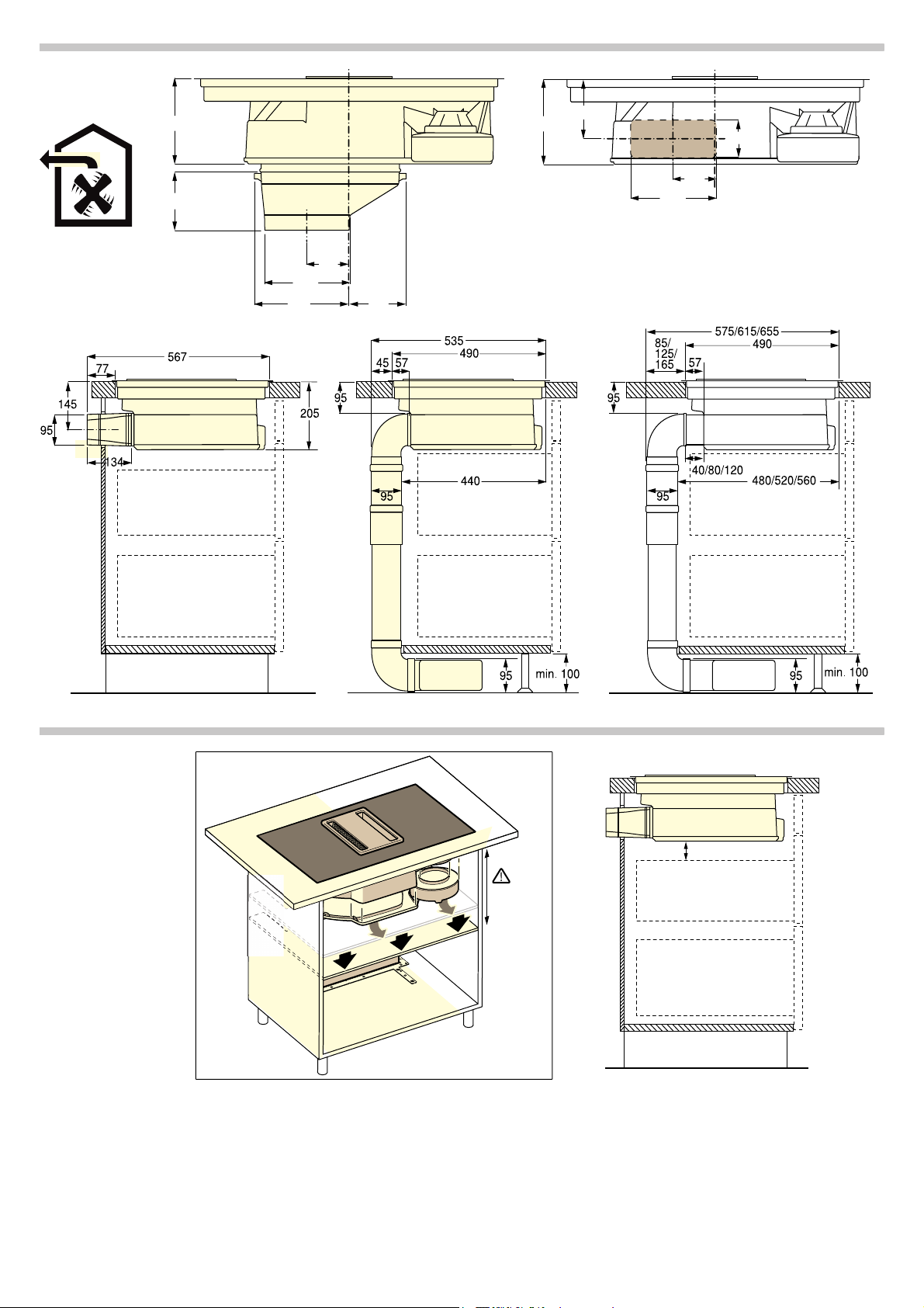
,QVWDOODWLRQYRUEHUHLWHQ
*HUlWHPDHXQG6LFKHUKHLWVDEVWlQGH
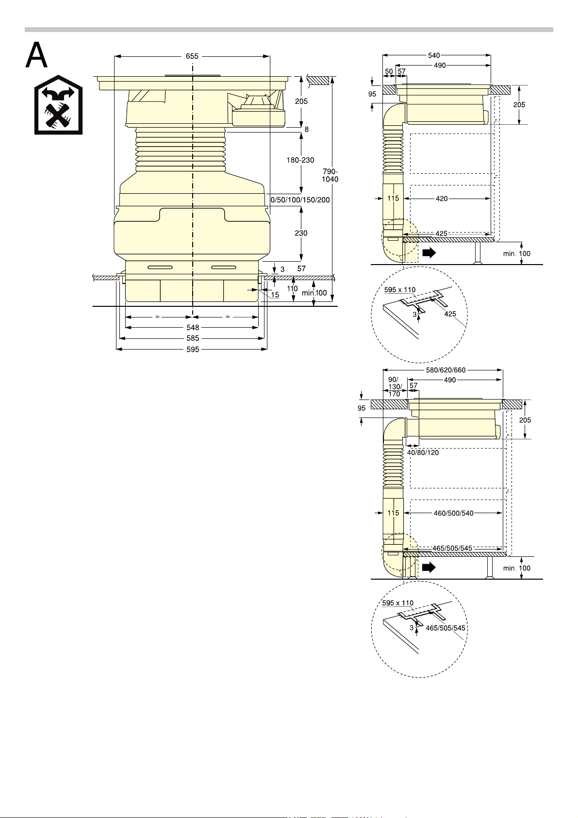
■ *HUlWHPDHIU8POXIWEHWULHEEHDFKWHQ %LOG $
■ *HUlWHPDHIU$EOXIWEHWULHEEHDFKWHQ %LOG %
■ 6LFKHUVWHOOHQ GDVV GDV *HUlW QDFK $EVFKOXVV GHU ,QVWDOODWLRQ IU
GHQ$NWLYNRKOHILOWHUZHFKVHOGLH/HHUXQJGHVhEHUODXIEHKlOWHUV
XQGGLH'HPRQWDJHGHU*HKlXVHDEGHFNXQJDXVUHLFKHQG
]XJlQJOLFKLVW %LOG &
■ 6LFKHUKHLWVDEVWlQGHEHDFKWHQ %LOG &
0|EHOEHUSUIHQ
■ 'DV(LQEDXP|EHOPXVVZDDJHUHFKWDXVJHULFKWHWXQGDXVUHL
FKHQGWUDJIlKLJVHLQ
■ 'DVPD[*HZLFKWGHV*HUlWVEHWUlJWFLUFD NJ
■ 'DV(LQEDXP|EHOPXVVELV&WHPSHUDWXUEHVWlQGLJVHLQ
■ 'LH 6WDELOLWlW GHV (LQEDXP|EHOV PXVV DXFK QDFK GHQ $XVVFKQLW
WDUEHLWHQJHZlKUOHLVWHWVHLQ
■ 'LH7UDJIlKLJNHLWXQGGLH6WDELOLWlWLQVEHVRQGHUHEHLGQQHQ
$UEHLWVSODWWHQLVWGXUFKJHHLJQHWH8QWHUNRQVWUXNWLRQHQVLFKHU
]XVWHOOHQ *HUlWHJHZLFKW LQNO ]XVlW]OLFKHU %HODGXQJ EHUFNVLFK
WLJHQ'DVYHUZHQGHWH9HUVWlUNXQJVPDWHULDOPXVVKLW]HXQG
IHXFKWLJNHLWVEHVWlQGLJVHLQ
■ $EKlQJLJYRQGHU9HUURKUXQJXQGGHU7LHIHGHU$UEHLWVSODWWH
PXVVGLH7LHIHGHU6FKXEIlFKHUXQWHUGHP*HUlWDQJHSDVVW
ZHUGHQ'LHREHUVWH6FKXEODGHPXVVHQWIHUQWZHUGHQXQGLVW
QLFKWQXW]EDU
■ 'HU $EVWDQG ]ZLVFKHQ GHU 2EHUIOlFKH GHU $UEHLWVSODWWH XQG GHP
REHUHQ%HUHLFKGHV6FKXEIDFKVPXVV PPEHWUDJHQ
■ .HLQH%DFN|IHQ.KOJHUlWH*HVFKLUUVSOHU:DVFKPDVFKLQHQ
RGHUDQGHUH*HUlWHXQWHUEDXHQ
+LQZHLV 'LH(EHQKHLWGHV*HUlWHVHUVWQDFKGHU,QVWDOODWLRQLQ
GHU(LQEDX|IIQXQJEHUSUIHQ
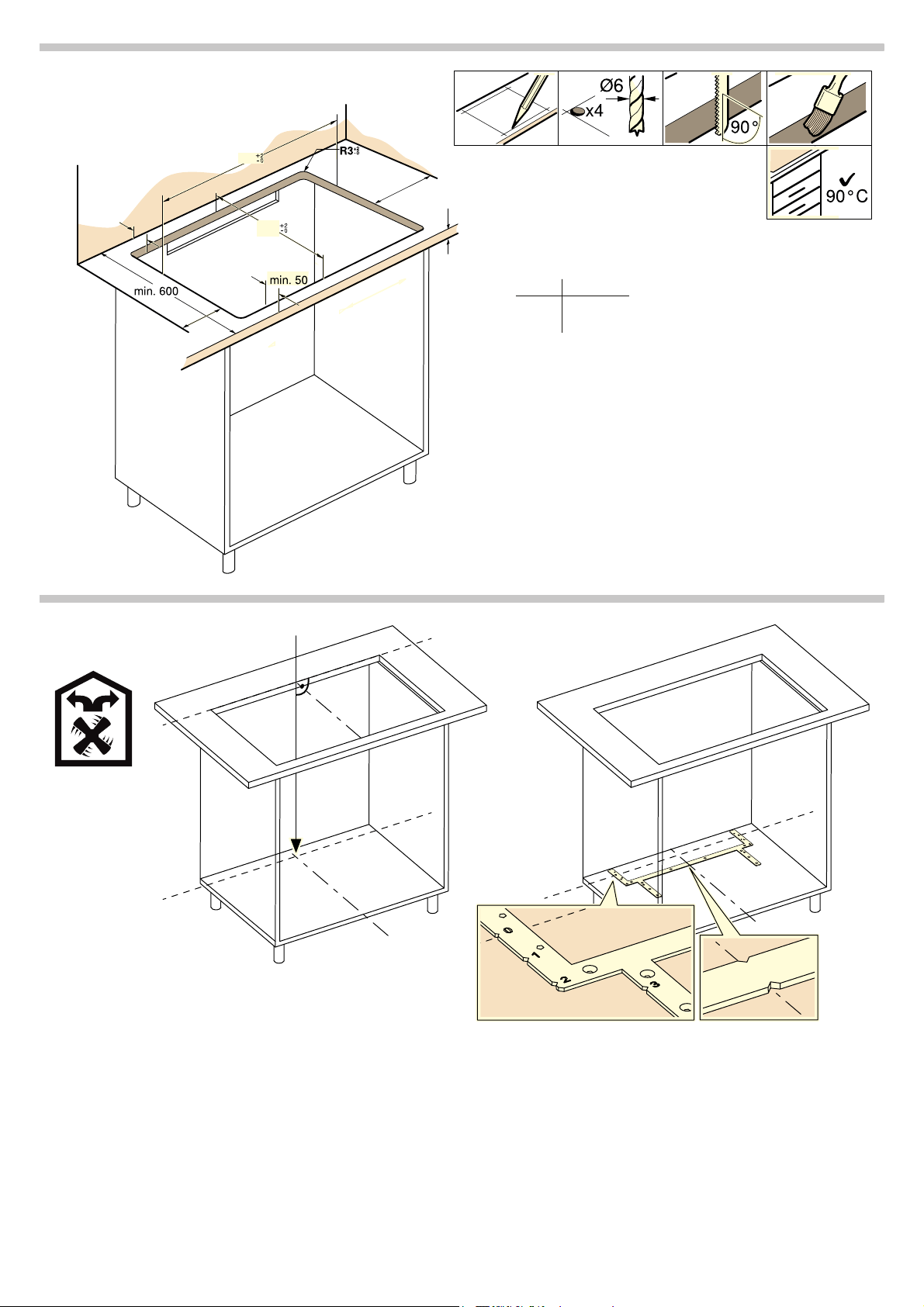
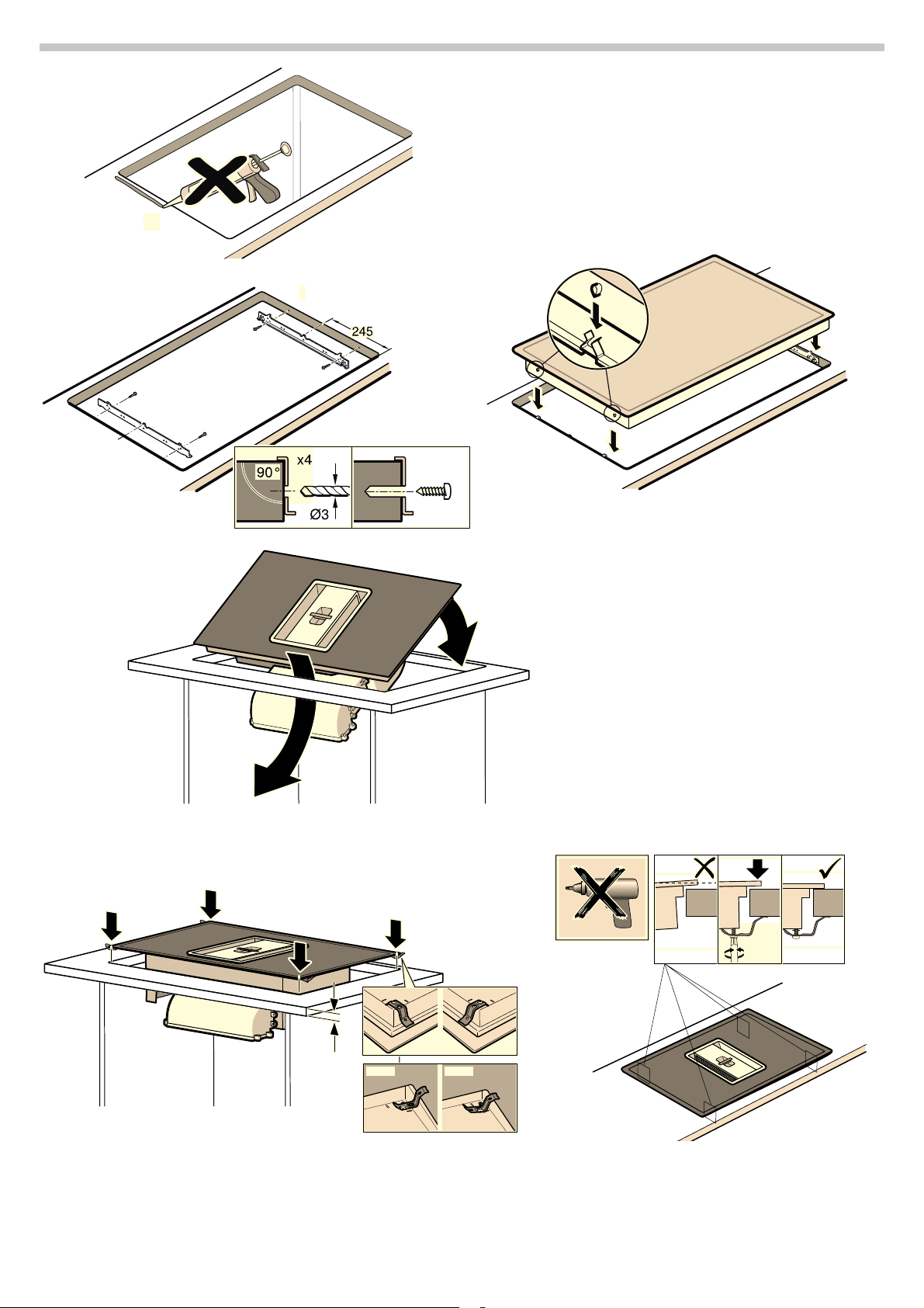
0|EHOYRUEHUHLWHQ
'HQ $XVVFKQLWW LQ GHU $UEHLWVSODWWH JHPl GHU (LQEDXVNL]]H KHU
VWHOOHQ %LOG
+LQZHLV 'HU:LQNHOGHU6FKQLWWIOlFKH]XU$UEHLWVSODWWHPXVV
EHWUDJHQ 'LH VHLWOLFKHQ $XVVFKQLWWNDQWHQ PVVHQ SODQ VHLQ
%HLPHKUVFKLFKWLJHQ$UEHLWVSODWWHQJJI/HLVWHQVHLWOLFKLP$XV
VFKQLWWEHIHVWLJHQ
8PHLQHNRUUHNWH)XQNWLRQVZHLVHGHV*HUlWV]XJDUDQWLHUHQ
PXVVGDV.RFKIHOGDQJHPHVVHQEHOIWHWZHUGHQ'D]XHLQHQ
/XIWDXVODVVLP8QWHUVFKUDQNPLWHLQHP0LQGHVWHVWTXHUVFKQLWW
YRQ FPòKHUVWHOOHQ
%HLP (LQEDX EHU HLQHP 6FKXEIDFK 0LQGHVWDEVWlQGH HLQKDOWHQ
%LOG &
'DVREHUVWH6FKXEIDFKHQWIHUQHQXQGDP0|EHOHLQHHQWVSUH
FKHQGSDVVHQGH9HUEOHQGXQJDQEULQJHQ
0|EHOXQG*HUlWIU8POXIWEHWULHEYRUEHUHLWHQ
0|EHODXVVFKQLWWKHUVWHOOHQ
,QGHU6RFNHOOHLVWHGHV0|EHOVHLQHQ/XIWDXVODVVKHUVWHOOHQ
+LQZHLV (LQHQ0LQGHVWTXHUVFKQLWWGHV/XIWDXVODVVHVYRQ
FD FPòYRUVHKHQ'LH$XVODVV|IIQXQJLQGHU6RFNHOEOHQGH
VRJURZLHP|JOLFKDXVIKUHQXPGHQ/XIW]XJXQGGDV*H
UlXVFKQLHGULJ]XKDOWHQ
0|EHOUFNZDQGHQWIHUQHQ
%HL%HGDUIREHUH/HLVWHDQGHU0|EHOUFNZDQGHQWIHUQHQ
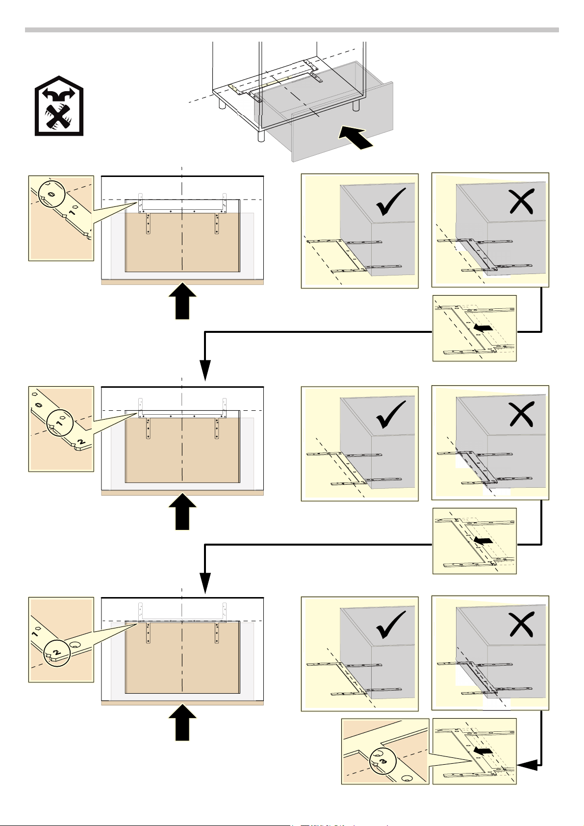
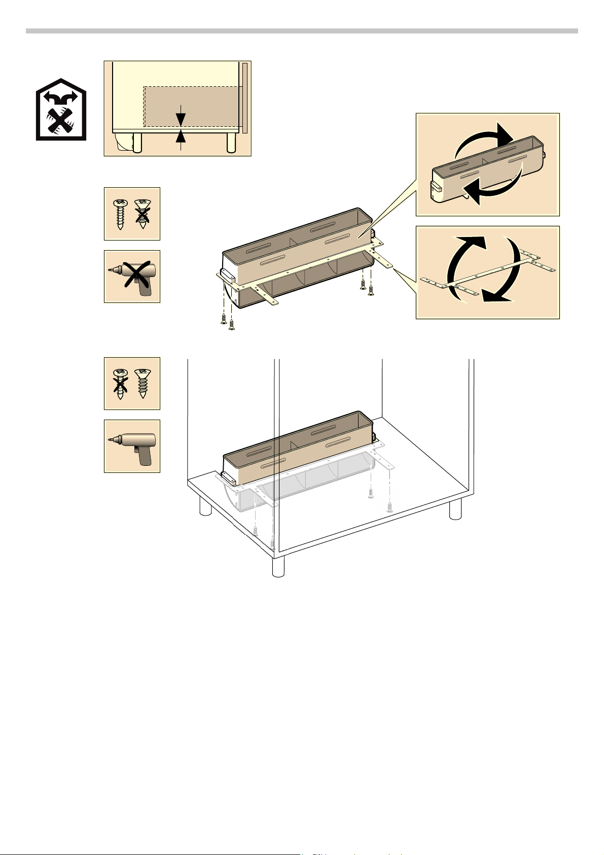
$P KLQWHUHQ 5DQG GHV $UEHLWVSODWWHQDXVVFKQLWWV GHQ 0LWWHOSXQNW
EHVWLPPHQ XQG GLHVHQ XQG GLH EHLGHQ /LQLHQ VHQNUHFKW QDFK XQ
WHQDXIGHP0|EHOERGHQDEELOGHQ %LOG D
)L[LHUXQJVEOHFK DXI GHP 0|EHOERGHQ DQ GHQ 0LWWHOOLQLHQ DXVULFK
WHQ %LOG E
%HL6FKXEODGHQ8QWHUVWH6FKXEODGHYROOVWlQGLJVFKOLHHQ
)DOOVGDV)L[LHUXQJVEOHFK]XZHLWXQWHUGHU6FKXEODGHYHU
VFKZLQGHWGLHVHVLQ5LFKWXQJ0|EHOUFNVHLWHYHUVFKLHEHQ0LW
+LOIHGHU0DUNLHUXQJHQLP)L[LHUXQJVEOHFKGLHVHVSDUDOOHO]XU
0LWWHOOLQLHDXVULFKWHQ %LOG F
+LQZHLVH
■ )DOOVGHU$EVWDQG]ZLVFKHQ6FKXEODGHXQG0|EHOERGHQ]X
NOHLQLVWXPGDV)L[LHUXQJVEOHFKDXIGHP0|EHOERGHQIHVW]X
VFKUDXEHQGDV)L[LHUXQJVEOHFKXPGUHKHQXQGYRQ
XQWHQDP0|EHOERGHQIHVWVFKUDXEHQ %LOG E=XYRUGDV
)L[LHUXQJVEOHFKYRQREHQDXIGHP0|EHOERGHQDXVULFKWHQ
XPGLHNRUUHNWH3RVLWLRQGHV)L[LHUXQJVEOHFKHV]XEHVWLP
PHQ %LOG F
■ $EKlQJLJYRQGHU3RVLWLRQGHV)L[LHUXQJVEOHFKVGLHHQWVSUH
FKHQGH9HUOlQJHUXQJZlKOHQ
■ )DOOVGDV)L[LHUXQJVEOHFKQLFKWZHLWJHQXJQDFKKLQWHQ
JHVFKREHQZHUGHQNDQQ6FKXEODGHQPLWJHULQJHUHU7LHIH
YHUZHQGHQ
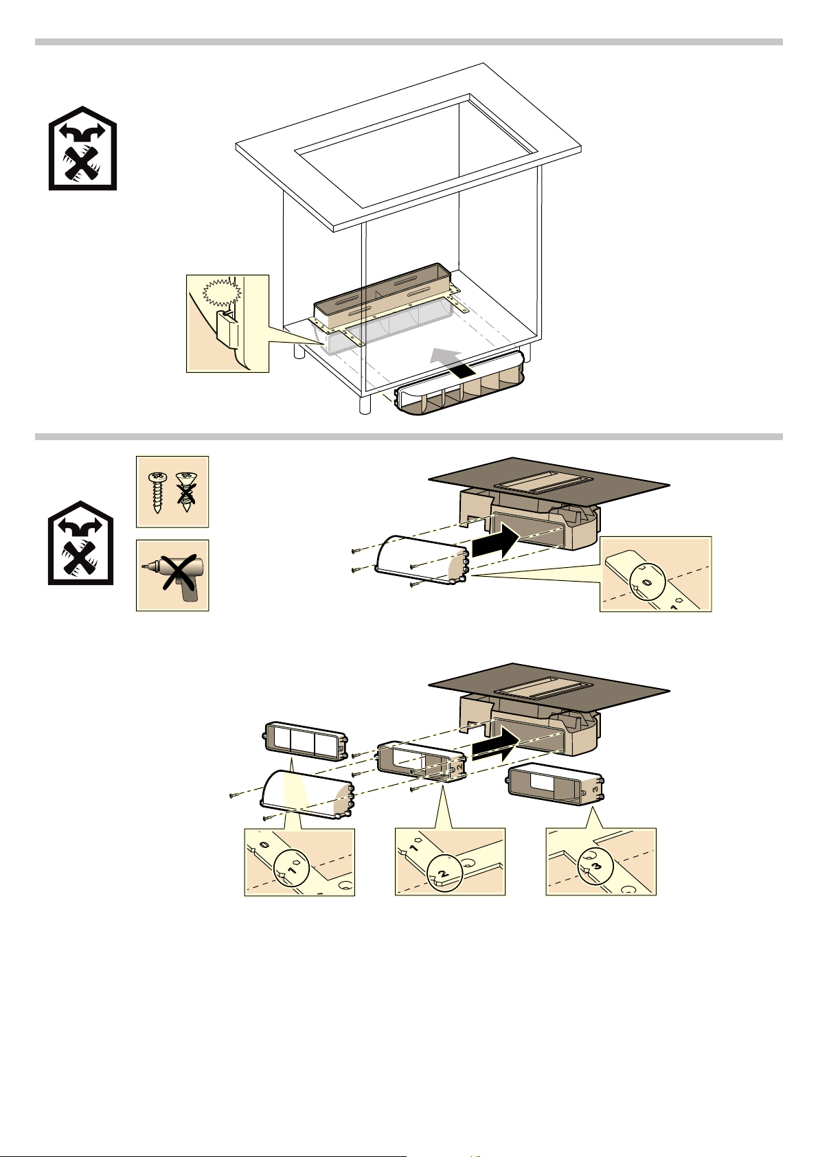
)DOOVQRWZHQGLJ$XVVFKQLWWLP0|EHOERGHQPLW+LOIHGHV)L[LH
UXQJVEOHFKHVDQ]HLFKQHQXQGKHUVWHOOHQ %LOG G
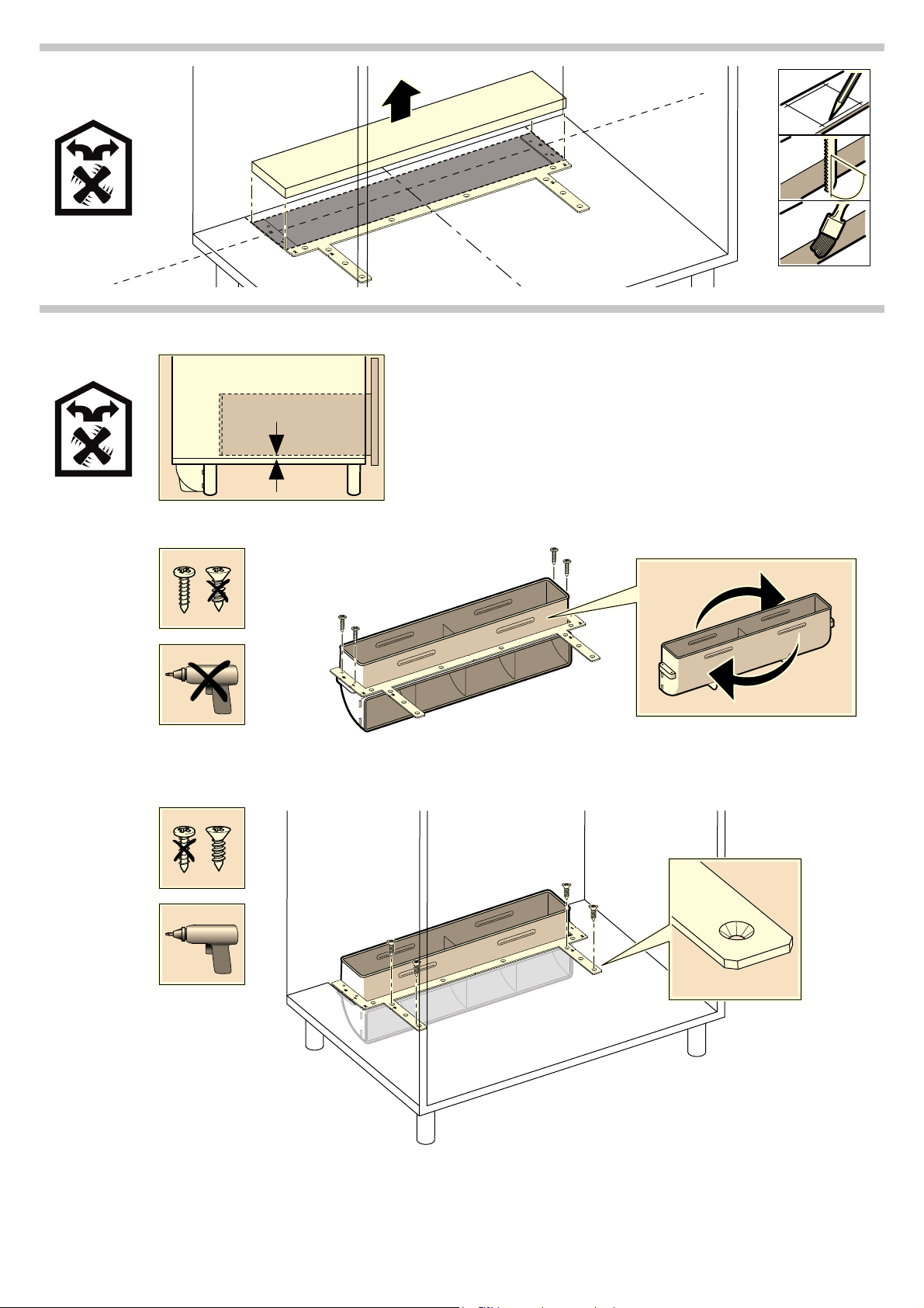
1DFK$XVVFKQLWWDUEHLWHQ6SlQHHQWIHUQHQ
+LQZHLV 6FKQLWWIOlFKHQKLW]HEHVWlQGLJXQGZDVVHUGLFKWYHUVLH
JHOQ
)L[LHUXQJVEOHFKIHVWVFKUDXEHQXQG'LIIXVRUIHVWNOLSVHQ
)DOOVGHU$EVWDQG]ZLVFKHQ6FKXEODGHXQG0|EHOERGHQDXV
UHLFKWGDV)L[LHUXQJVEOHFKPLW.XQVWVWRIIVFKUDXEHQYRQREHQ
DPXQWHUHQ)ODFKNDQDOERJHQIHVWVFKUDXEHQ %LOG D
+LQZHLV %HL%HGDUIXQWHUHQ)ODFKNDQDOERJHQGUHKHQGDPLW
VLFKGHU/XIWDXVODVVDXIGHUJHJHQEHUOLHJHQGHQ6HLWHEHILQGHW
)L[LHUXQJVEOHFKPLW+RO]VFKUDXEHQYRQREHQDP0|EHOERGHQ
IHVWVFKUDXEHQ %LOG D
+LQZHLV )DOOVGHU$EVWDQG]ZLVFKHQ6FKXEODGHXQG0|EHOER
GHQ]XNOHLQLVWXPGDV)L[LHUXQJVEOHFKDXIGHP0|EHOERGHQ
IHVW]XVFKUDXEHQ GDV )L[LHUXQJVEOHFK XP GUHKHQ XQG YRQ
XQWHQDP0|EHOERGHQIHVWVFKUDXEHQ %LOG E
'LIIXVRUDPXQWHUHQ)ODFKNDQDOERJHQIHVWNOLSVHQ %LOG F

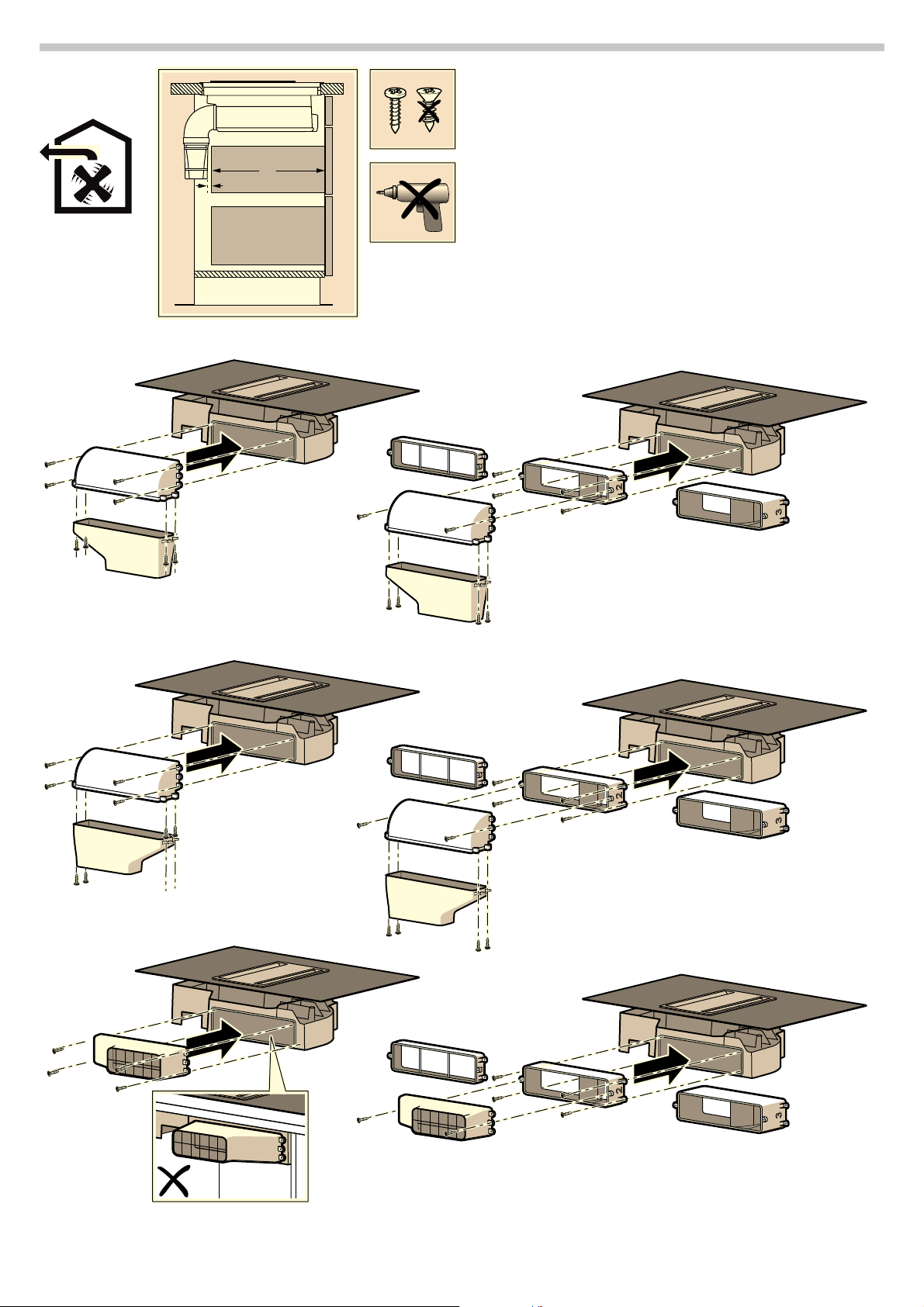
2EHUHQ)ODFKNDQDOERJHQPRQWLHUHQ
%HL%HGDUIGLH9HUOlQJHUXQJDEKlQJLJYRQGHU3RVLWLRQGHV)L
[LHUXQJVEOHFKV XQG GHU 0|EHOWLHIH ZlKOHQ -H OlQJHU GLH 9HUOlQ
JHUXQJXPVRWLHIHUNDQQGLH6FKXEODGHVHLQ9HUOlQJHUXQJPLW
YLHU.XQVWVWRIIVFKUDXEHQDQGHU$XVODVV|IIQXQJGHV.RFKIHOGV
IHVWVFKUDXEHQ %LOG
2EHUHQ)ODFKNDQDOERJHQDQGHU$XVODVV|IIQXQJGHV.RFKIHOGV
RGHUDQGHU9HUOlQJHUXQJIHVWVFKUDXEHQ
0|EHOXQG*HUlWIU$EOXIWEHWULHEYRUEHUHLWHQ
5HGX]LHUVWXW]HQRGHU)ODFKNDQDOERJHQPLWYLHU.XQVWVWRII
VFKUDXEHQDQGHU$XVODVV|IIQXQJGHV.RFKIHOGVRGHUDQGHU
9HUOlQJHUXQJIHVWVFKUDXEHQ %LOG
+LQZHLV %HL %HGDUI GLH HQWVSUHFKHQGH 9HUOlQJHUXQJ DP .RFK
IHOG IHVWVFKUDXEHQ 'LH HUODXEWH 7LHIH 7 GHU 6FKXEODGH PHVVHQ
GDEHL PP$EVWDQG]XP$EOXIWURKUHLQKDOWHQ$EKlQJLJYRQ
GHUYHUZHQGHWHQ9HUOlQJHUXQJNDQQGLH6FKXEODGHQWLHIHYDULLH
UHQ %LOG
-H QDFK $EOXIWNRQILJXUDWLRQ IU GDV $EOXIWURKU HLQHQ $XVVFKQLWW LQ
GHUKLQWHUHQ0|EHOZDQGKHUVWHOOHQ0|EHOUFNZDQGHQWIHUQHQ
RGHUHLQHQ$XVVFKQLWWLP0|EHOERGHQKHUVWHOOHQ
1DFK$XVVFKQLWWDUEHLWHQ6SlQHHQWIHUQHQ
+LQZHLV 6FKQLWWIOlFKHQKLW]HEHVWlQGLJXQGZDVVHUGLFKWYHUVLH
JHOQ
(OHNWULVFKHQ$QVFKOXVVYRUEHUHLWHQ
+LQZHLV $EVFKQLWW (OHNWULVFKHU$QVFKOXVVLQ.DSLWHO $OOJH
PHLQH+LQZHLVHEHDFKWHQ
%HL *HUlWHQ RKQH YRULQVWDOOLHUWHV .DEHO GDV 1HW]NDEHO LQ GLH
$QVFKOXVVGRVHHLQIKUHQ
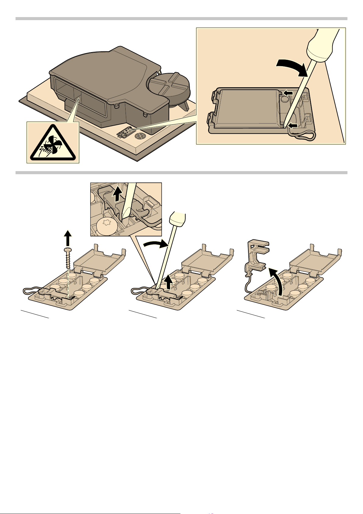
'DV .RFKIHOG XPGUHKHQ XQG DXI GHP %RGHQ GHU 9HUSDFNXQJ HL
QHP 7XFK RGHU HLQHU DQGHUHQ 2EHUIOlFKH DEOHJHQ XP .UDW]HU ]X
YHUPHLGHQ
'HQ 'HFNHO GHU $QVFKOXVVGRVH PLWKLOIH HLQHV 6FKUDXEHQ]LHKHUV
DQKHEHQ %LOG
'LH%HIHVWLJXQJVVFKUDXEHO|VHQXQGGLH6FKODXFKVFKHOOHPLWKLO
IHHLQHV6FKUDXEHQ]LHKHUVDQKHEHQ %LOG
1XUJHPl$EELOGXQJDQGHU$QVFKOXVVGRVHDQVFKOLHHQ %LOG
%1%UDXQ
%8%ODX
*1<(*HOEXQGJUQ
%.6FKZDU]
*<*UDX
+LQZHLVH
■ %HL%HGDUIEHLOLHJHQGH.XSIHUEUFNHQJHPl$QVFKOXVVELOG
PRQWLHUHQ
■ 'DUDXIDFKWHQGDVVGLH6FKUDXEHQDQGHU$QVFKOXVVGRVH
IHVWJH]RJHQZHUGHQQDFKGHPGLH.DEHODQJHVFKORVVHQZXU
GHQ
■ %HL HLQHP $QVFKOXVV 1a1a HQWVSULFKW GLH 3KDVH / *UH\
GHP9HQWLODWRUPRWRU
'DV1HW]NDEHOPLWGHU6FKODXFKVFKHOOHEHIHVWLJHQXQGGLH%H
IHVWLJXQJVVFKUDXEHDQ]LHKHQ %LOG
'HQ'HFNHOGHU$QVFKOXVVGRVHVFKOLHHQ
+LQZHLV 'LH.DEHOLPPLWWOHUHQ%HUHLFKGHU$QVFKOXVVGRVHDQ
RUGQHQXPGHQ9HUVFKOXVV]XHUOHLFKWHUQ
+LQZHLV )DOOVHLQHOlQJHUH1HW]DQVFKOXVVOHLWXQJEHQ|WLJWZLUG
ELWWHGHQ.XQGHQGLHQVWNRQWDNWLHUHQ$QVFKOXVVOHLWXQJHQVWHKHQ
ELV]X P]XU9HUIJXQJ
*HUlWPRQWLHUHQ
: 7UlJHUYRQHOHNWURQLVFKHQ,PSODQWDWHQ
'DV*HUlWNDQQ3HUPDQHQWPDJQHWHHQWKDOWHQGLHHOHNWURQLVFKH
,PSODQWDWHZLH]%+HU]VFKULWWPDFKHURGHU,QVXOLQSXPSHQEHHLQ
IOXVVHQN|QQHQ'HVKDOEEHLGHU0RQWDJHHLQHQ0LQGHVWDEVWDQG
YRQFP]XHOHNWURQLVFKHQ,PSODQWDWHQHLQKDOWHQ
: 6WURPVFKODJJHIDKU
%DXWHLOHLQQHUKDOEGHV*HUlWHVN|QQHQVFKDUINDQWLJVHLQ'DV
$QVFKOXVVNDEHONDQQEHVFKlGLJWZHUGHQ$QVFKOXVVNDEHOZlK
UHQGGHU,QVWDOODWLRQQLFKWNQLFNHQRGHUHLQNOHPPHQ
: 9HUOHW]XQJVJHIDKU
%DXWHLOHGLHZlKUHQGGHU0RQWDJH]XJlQJOLFKVLQGN|QQHQ
VFKDUINDQWLJVHLQ6FKXW]KDQGVFKXKHWUDJHQ
.RFKIHOGHLQVHW]HQ
+DOWHVFKLHQHQDQEULQJHQ %LOG D
%HL$UEHLWVSODWWHQDXV6WHLQGLH6FKLHQHQDQNOHEHQGD]XKLW]H
EHVWlQGLJHQ]XP9HUNOHEHQYRQ0HWDOOXQG6WHLQJHHLJQHWHQ
.OHEVWRIIYHUZHQGHQ
'DV*HUlWLQGHQ$UEHLWVSODWWHQDXVVFKQLWWHLQVHW]HQ %LOG E
'LHPLWJHOLHIHUWHQ+DOWHNODPPHUQDQEULQJHQXQGYRUVLFKWLJIHVW
]LHKHQ'DV.RFKIHOGPLW+LOIHGHU+DOWHNODPPHUQHEHQ]XU
$UEHLWVIOlFKHDXVULFKWHQ %LOG F
+LQZHLV .HLQHHOHNWULVFKHQ6FKUDXEHQGUHKHUYHUZHQGHQ
*HUlWDQVFKOLHHQ
+LQZHLVH
■ %HL$EOXIWEHWULHEVROOWHHLQH5FNVWDXNODSSHPLWHLQHPPD[LPD
OHQgIIQXQJVGUXFNYRQ 3DHLQJHEDXWZHUGHQ,VWGHP*HUlW
NHLQH 5FNVWDXNODSSH EHLJHOHJW NDQQ VLH EHU GHQ )DFKKDQGHO
EH]RJHQZHUGHQ
■ :LUGGLH$EOXIWGXUFKGLH$XHQZDQGJHOHLWHWVROOWHHLQ7HOHV
NRS0DXHUNDVWHQYHUZHQGHWZHUGHQ
$EOXIWYHUELQGXQJKHUVWHOOHQ
$EOXIWURKUDP)ODFKNDQDOERJHQRGHU5HGX]LHUVWXW]HQEHIHVWL
JHQ %LOG
9HUELQGXQJ]XU$EOXIW|IIQXQJKHUVWHOOHQ
9HUELQGXQJVVWHOOHQJHHLJQHWDEGLFKWHQ
8POXIWYHUELQGXQJKHUVWHOOHQ
)LOWHUPRGXODPXQWHUHQ)ODFKNDQDOERJHQIHVWNOLSVHQRGHUEHL
%HGDUIIHVWVFKUDXEHQ %LOG D
+LQZHLV %HL%HGDUI)LOWHUPRGXOGUHKHQGDPLWGDV6FKXEIDFK
IUGHQ$NWLYNRKOHILOWHUYRQGHUJHJHQEHUOLHJHQGHQ6HLWHJH|II
QHWZHUGHQNDQQ
'DVIOH[LEOH9HUELQGXQJVHOHPHQWDPREHUHQ)ODFKNDQDOERJHQ
IHVWNOLSVHQ
)LOWHUPRGXOXQGREHUHQ)ODFKNDQDOERJHQEHUGDVIOH[LEOH9HU
ELQGXQJVHOHPHQWYHUELQGHQ
+LQZHLV %HL %HGDUI 9HUOlQJHUXQJHQ ]ZLVFKHQ GHP )LOWHUPRGXO
XQGGHPIOH[LEOHQ9HUELQGXQJVHOHPHQWPRQWLHUHQ
$OOH9HUVFKOXVVHOHPHQWHDP6FKXEIDFK|IIQHQ6FKXEIDFK|II
QHQ %LOG E
$NWLYNRKOHILOWHUHLQVHW]HQ %LOG F
6FKXEIDFKVFKOLHHQ
$OOH9HUVFKOXVVHOHPHQWHDP6FKXEIDFKVFKOLHHQ
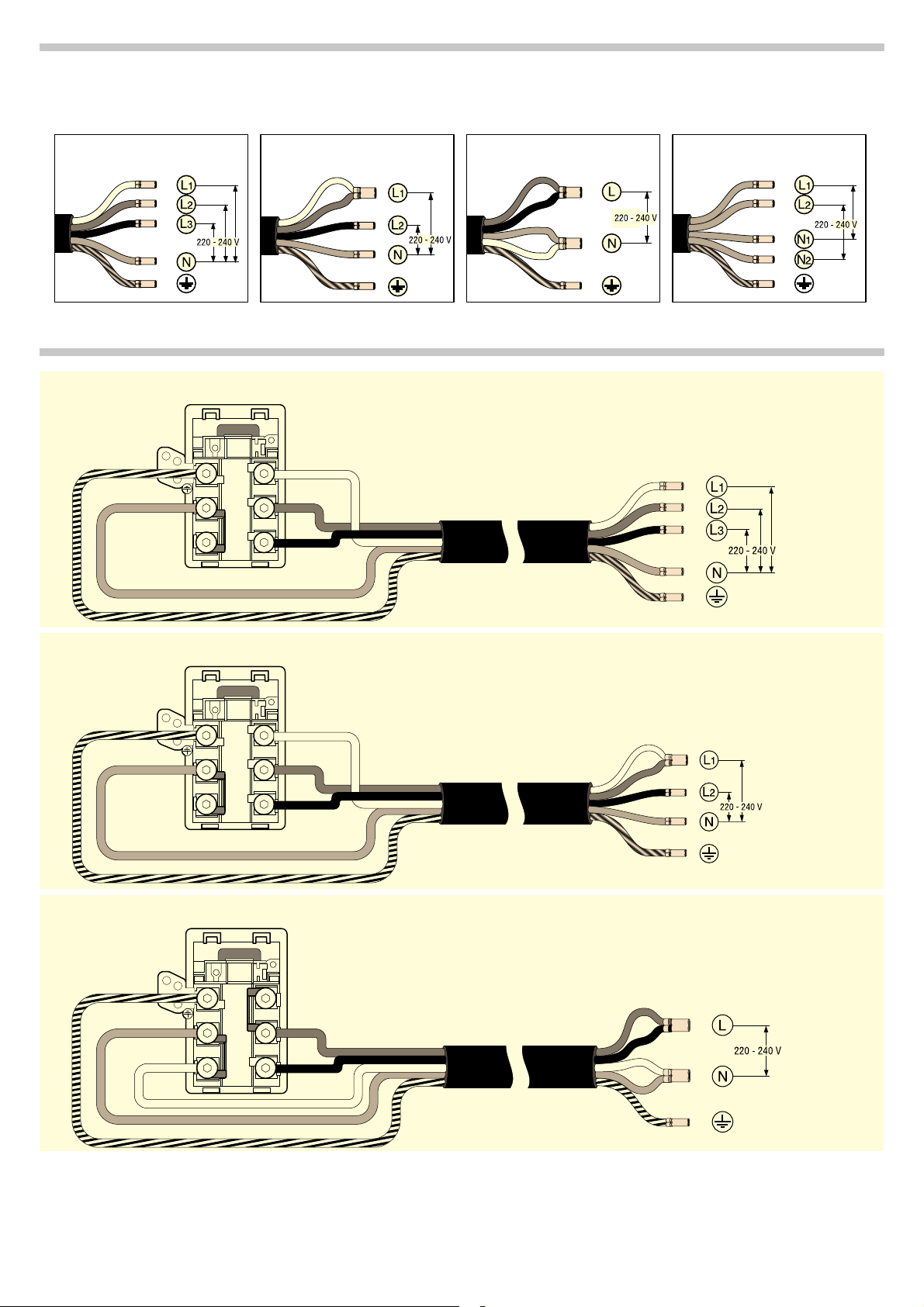
6WURPDQVFKOXVVKHUVWHOOHQ
■ 6SDQQXQJ6LHKH7\SHQVFKLOG
■ 1XUJHPl$QVFKOXVVGLDJUDPPDQVFKOLHHQ %LOG
%1%UDXQ
%8%ODX
*1<(*HOEXQGJUQ
%.6FKZDU]
*<*UDX
■ -HQDFK$QVFKOXVVDUWPXVVHYHQWXHOOGLH$QRUGQXQJGHUYRP
:HUNJHOLHIHUWHQ$GHUHQGKOVHQYHUlQGHUWZHUGHQ'DIUPV
VHQHYHQWXHOOGLH$GHUQJHNU]WXQGGLH,VROLHUXQJHQWIHUQWZHU
GHQXPHLQH$GHUHQGKOVHHLQ]XVHW]HQGLH]ZHL.DEHO
YHUELQGHW
+LQZHLV hEHUSUIHQGHU%HWULHEVEHUHLWVFKDIW(UVFKHLQWLQGHU
$Q]HLJHGHV*HUlWHV
—…‹‹ “‹†‚„ RGHU “LVWHVQLFKWULFKWLJ
DQJHVFKORVVHQ'DV*HUlWYRQGHU6WURPYHUVRUJXQJWUHQQHQXQG
GHQ$QVFKOXVVGHV6WURPNDEHOVEHUSUIHQ
$Q]HLJHDXI$EOXIWEHWULHERGHU8POXIWEHWULHE
XPVWHOOHQ
)UGHQ$EOXIWEHWULHEXQGGHQ8POXIWEHWULHEEHL%HGDUIGLH
$Q]HLJHGHUHOHNWURQLVFKHQ6WHXHUXQJLQGHQ*UXQGHLQVWHOOXQJHQ
HQWVSUHFKHQGXPVWHOOHQ
'D]X.DSLWHO *UXQGHLQVWHOOXQJHQLQGHU*HEUDXFKVDQOHLWXQJ
EHDFKWHQ
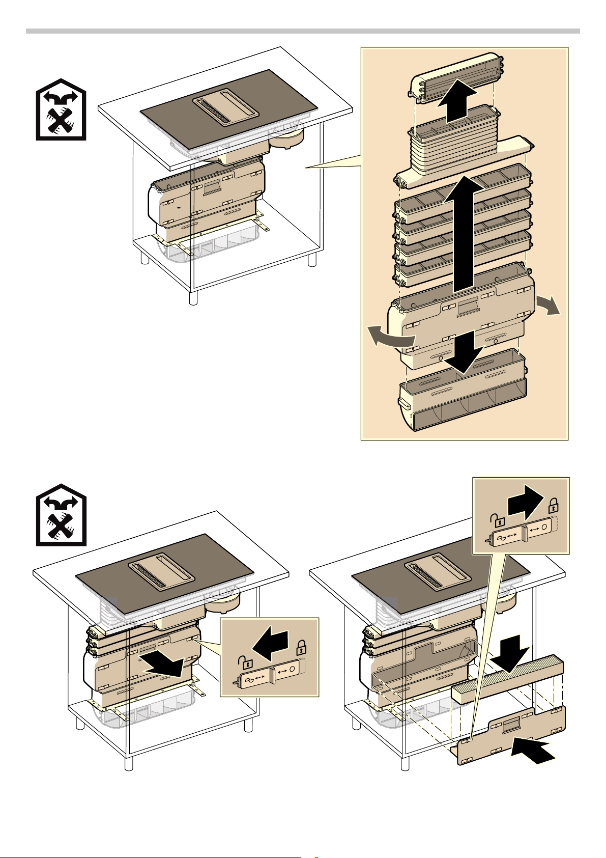
*HUlWGHPRQWLHUHQ
*HUlWYRP6WURPQHW]WUHQQHQ
m 6WURPVFKODJJHIDKU
%HLP$ENOHPPHQGHV.RFKIHOGHVYRP6WURPQHW]N|QQHQGLH
.OHPPHQ 5FNVSDQQXQJ IKUHQ 'HU HOHNWULVFKH $QVFKOXVV GDUI
QXUYRQHLQHPNRQ]HVVLRQLHUWHQ)DFKPDQQGXUFKJHIKUWZHU
GHQ
$EOXIWNDQDOHQWIHUQHQRGHU8POXIWYHUELQGXQJHQO|VHQ
*HUlWYRQXQWHQKHUDXVGUFNHQ
$FKWXQJ
*HUlWHVFKDGHQ *HUlWQLFKWYRQREHQKHUDXVKHEHOQ
en
Ú
,QVWDOODWLRQLQVWUXFWLRQV
: ,PSRUWDQWVDIHW\LQIRUPDWLRQ
5HDGWKHVHLQVWUXFWLRQVFDUHIXOO\2QO\WKHQZLOO\RXEHDEOHWR
RSHUDWH\RXUDSSOLDQFHVDIHO\DQGFRUUHFWO\5HWDLQWKHLQVWUXFWLRQ
PDQXDODQGLQVWDOODWLRQLQVWUXFWLRQVIRUIXWXUHXVHRUIRU
VXEVHTXHQWRZQHUV
7KHDSSOLDQFHFDQRQO\EHXVHGVDIHO\LILWLVFRUUHFWO\LQVWDOOHG
DFFRUGLQJ WR WKH VDIHW\ LQVWUXFWLRQV 7KH LQVWDOOHU LV UHVSRQVLEOH IRU
HQVXULQJWKDWWKHDSSOLDQFHZRUNVSHUIHFWO\DWLWVLQVWDOODWLRQ
ORFDWLRQ
:HDUHUVRIHOHFWURQLFLPSODQWV
7KHDSSOLDQFHPD\FRQWDLQSHUPDQHQWPDJQHWVZKLFKPD\DIIHFW
HOHFWURQLFLPSODQWVHJKHDUWSDFHPDNHUVRULQVXOLQSXPSV
7KHUHIRUHGXULQJLQVWDOODWLRQZHDUHUVRIHOHFWURQLFLPSODQWVPXVW
PDLQWDLQDPLQLPXPGLVWDQFHRIFPIURPWKHDSSOLDQFH
7KHPDQXIDFWXUHUVKDOODVVXPHQROLDELOLW\IRUPDOIXQFWLRQVRU
GDPDJHUHVXOWLQJIURPLQFRUUHFWHOHFWULFDOZLULQJ
3RZHUFDEOH7KLVPD\DOUHDG\EHFRQQHFWHGWRWKH
FRQQHFWLRQER[RQWKHKRERULVVXSSOLHGZLWKWKHDSSOLDQFH
,WPXVWRQO\EHLQVWDOOHGE\DQDXWKRULVHGH[SHUWRUE\DTXDOLILHG
PHPEHURIWKHDIWHUVDOHVVHUYLFHWHDP7KHUHTXLUHGFRQQHFWLRQ
GDWD FDQ EH IRXQG RQ WKH W\SH SODWH DQG LQ WKH FRQQHFWLRQ GLDJUDP
8VHRQO\WKHFDEOHWKDWLVVXSSOLHGZLWKWKHDSSOLDQFHRULV
SURYLGHGE\WHFKQLFDODIWHUVDOHVVHUYLFH
%HIRUHFDUU\LQJRXWDQ\W\SHRIZRUNWXUQRIIWKHHOHFWULFLW\
)RU WKH LQVWDOODWLRQ REVHUYH WKH FXUUHQWO\ YDOLG EXLOGLQJ UHJXODWLRQV
DQGWKHUHJXODWLRQVRIWKHORFDOHOHFWULFLW\DQGJDVVXSSOLHUV
:KHQ FRQYH\LQJ WKH H[KDXVW DLU RIILFLDO DQG OHJDO UHJXODWLRQV HJ
VWDWHEXLOGLQJUHJXODWLRQVPXVWEHIROORZHG
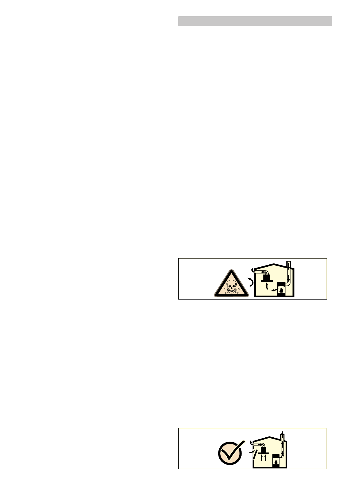
'DQJHURIGHDWK
5LVNRISRLVRQLQJIURPIOXHJDVHVWKDWDUHGUDZQEDFNLQ
$OZD\VHQVXUHDGHTXDWHIUHVKDLULQWKHURRPLIWKHDSSOLDQFHLV
EHLQJRSHUDWHGLQH[KDXVWDLUPRGHDWWKHVDPHWLPHDVURRPDLU
GHSHQGHQWKHDWSURGXFLQJDSSOLDQFHLVEHLQJRSHUDWHG
5RRPDLUGHSHQGHQWKHDWSURGXFLQJDSSOLDQFHVHJJDVRLO
ZRRGRUFRDORSHUDWHGKHDWHUVFRQWLQXRXVIORZKHDWHUVRUZDWHU
KHDWHUVREWDLQFRPEXVWLRQDLUIURPWKHURRPLQZKLFKWKH\DUH
LQVWDOOHGDQGGLVFKDUJHWKHH[KDXVWJDVHVLQWRWKHRSHQDLU
WKURXJKDQH[KDXVWJDVV\VWHPHJDFKLPQH\
,Q FRPELQDWLRQ ZLWK DQ DFWLYDWHG YDSRXU H[WUDFWRU KRRG URRP DLU LV
H[WUDFWHGIURPWKHNLWFKHQDQGQHLJKERXULQJURRPVDSDUWLDO
YDFXXPLVSURGXFHGLIQRWHQRXJKIUHVKDLULVVXSSOLHG7R[LF
JDVHVIURPWKHFKLPQH\RUWKHH[WUDFWLRQVKDIWDUHVXFNHGEDFN
LQWRWKHOLYLQJVSDFH
■ $GHTXDWHLQFRPLQJDLUPXVWWKHUHIRUHDOZD\VEHHQVXUHG
■ $QLQFRPLQJH[KDXVWDLUZDOOER[DORQHZLOOQRWHQVXUH
FRPSOLDQFHZLWKWKHOLPLW
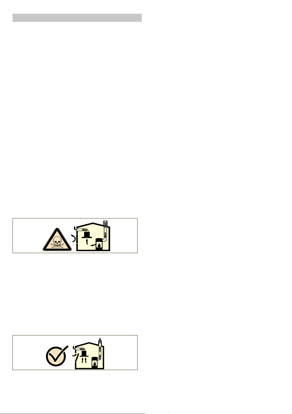
6DIHRSHUDWLRQLVSRVVLEOHRQO\ZKHQWKHSDUWLDOYDFXXPLQWKH
SODFHZKHUHWKHKHDWSURGXFLQJDSSOLDQFHLVLQVWDOOHGGRHVQRW
H[FHHG3DPEDU7KLVFDQEHDFKLHYHGZKHQWKHDLU
QHHGHGIRUFRPEXVWLRQLVDEOHWRHQWHUWKURXJKRSHQLQJVWKDW
FDQQRWEHVHDOHGIRUH[DPSOHLQGRRUVZLQGRZVLQFRPLQJ
H[KDXVWDLUZDOOER[HVRUE\RWKHUWHFKQLFDOPHDQV
,Q DQ\ FDVH FRQVXOW \RXU UHVSRQVLEOH 0DVWHU &KLPQH\ 6ZHHS +H
LVDEOHWRDVVHVVWKHKRXVHVHQWLUHYHQWLODWLRQVHWXSDQGZLOO
VXJJHVWWKHVXLWDEOHYHQWLODWLRQPHDVXUHVWR\RX
8QUHVWULFWHGRSHUDWLRQLVSRVVLEOHLIWKHYDSRXUH[WUDFWRUKRRGLV
RSHUDWHGH[FOXVLYHO\LQWKHFLUFXODWLQJDLUPRGH

5LVNRIGHDWK
5LVNRISRLVRQLQJIURPIOXHJDVHVEHLQJGUDZQEDFNLQ:KHQ
LQVWDOOLQJ D YHQWLODWLRQ V\VWHP LQ DQ RSHQIOXHG ERLOHU WKH HOHFWULFLW\
VXSSO\WRWKHYHQWLODWLRQV\VWHPPXVWEHSURYLGHGZLWKDVXLWDEOH
VDIHW\VZLWFK
5LVNRIILUH
*UHDVHGHSRVLWVLQWKHJUHDVHILOWHUPD\FDWFKILUH1HYHUZRUN
ZLWKQDNHGIODPHVFORVHWRWKHDSSOLDQFHHJIODPEpLQJ'RQRW
LQVWDOO WKH DSSOLDQFH QHDU D KHDWSURGXFLQJ DSSOLDQFH IRU VROLG IXHO
HJZRRGRUFRDOXQOHVVDFORVHGQRQUHPRYDEOHFRYHULV
DYDLODEOH7KHUHPXVWEHQRIO\LQJVSDUNV
5LVNRILQMXU\
■ &KDQJHVWRWKHHOHFWULFDORUPHFKDQLFDODVVHPEO\DUH
GDQJHURXVDQGPD\OHDGWRPDOIXQFWLRQV'RQRWPDNHDQ\
FKDQJHVWRWKHHOHFWULFDORUPHFKDQLFDODVVHPEO\
5LVNRILQMXU\
■ 3DUWVWKDWDUHDFFHVVLEOHGXULQJLQVWDOODWLRQPD\KDYHVKDUS
HGJHV:HDUSURWHFWLYHJORYHV
5LVNRILQMXU\
■ 7KHDSSOLDQFHLVKHDY\7RPRYHWKHDSSOLDQFH SHRSOHDUH
UHTXLUHG8VHRQO\VXLWDEOHWRROVDQGHTXLSPHQW
5LVNRILQMXU\
■ 7KHUHLVDULVNRILQMXU\ZKLOHWKHIDQLVURWDWLQJ'RQRWVZLWFK
WKH DSSOLDQFH RQ XQWLO LW KDV EHHQ LQVWDOOHG 1HYHU UHDFK LQWR WKH
DLUH[WUDFWLRQRSHQLQJRQWKHUHDURIWKHDSSOLDQFHZKLOHLWLVLQ
RSHUDWLRQ
'DQJHURIVXIIRFDWLRQ
3DFNDJLQJPDWHULDOLVGDQJHURXVWRFKLOGUHQ1HYHUDOORZFKLOGUHQ
WRSOD\ZLWKSDFNDJLQJPDWHULDO
'RQRWLQVWDOOWKLVDSSOLDQFHRQERDWVRULQYHKLFOHV
+REIODWKRUL]RQWDOVWDEOH)ROORZWKHKREPDQXIDFWXUHUV
LQVWUXFWLRQV
,IWKHWKLFNQHVVRIWKHZRUNWRSLQWRZKLFKWKHKRELVLQVWDOOHGGRHV
QRWFRPSO\ZLWKWKHVSHFLILFDWLRQVUHLQIRUFHWKHZRUNWRSXVLQJD
ILUHDQGZDWHUUHVLVWDQWPDWHULDOXQWLOLWUHDFKHVWKHPLQLPXP
WKLFNQHVV2WKHUZLVHVXIILFLHQWVWDELOLW\FDQQRWEHJXDUDQWHHG
1RWHV
■ 7KHZRUNWRSLQWRZKLFKWKHKRELVLQVWDOOHGVKRXOGEHDEOHWR
ZLWKVWDQGORDGVRIDSSUR[ NJ
■ $GDSWDWLRQVWRWKHZRUNVXUIDFHPXVWEHFDUULHGRXWE\D
VSHFLDOLVWVHUYLFHSURYLGHULQDFFRUGDQFHZLWKWKHLQVWDOODWLRQ
GLDJUDP7KHFXWHGJHPXVWEHQHDWDQGSUHFLVHEHFDXVHWKH
HGJHLVYLVLEOHRQWKHVXUIDFH&OHDQWKHFXWHGJHVZLWKD
VXLWDEOHFOHDQLQJDJHQWDQGGHJUHDVHWKHP
*HQHUDOLQIRUPDWLRQ
7KHVXUIDFHVRIWKHDSSOLDQFHDUHHDVLO\GDPDJHG$YRLG
GDPDJLQJWKHPGXULQJLQVWDOODWLRQ
([KDXVWDLUPRGH
1RWH 7KHH[KDXVWDLUPXVWQRWEHFRQYH\HGLQWRDIXQFWLRQLQJ
VPRNHRUH[KDXVWJDVIOXHRULQWRDVKDIWWKDWLVXVHGWRYHQWLODWH
URRPVLQZKLFKKHDWLQJDSSOLDQFHVDUHLQVWDOOHG
,IWKHH[KDXVWDLULVWREHFRQYH\HGLQWRDQRQIXQFWLRQLQJVPRNH
RUH[KDXVWJDVIOXH\RXPXVWREWDLQWKHFRQVHQWRIWKHKHDWLQJ
HQJLQHHUUHVSRQVLEOH
([KDXVWGXFW
1RWH 7KHDSSOLDQFHPDQXIDFWXUHUGRHVQRWSURYLGHDQ\ZDUUDQW\
IRUIDXOWVDWWULEXWDEOHWRWKHSLSHVHFWLRQ
■ 7KH DSSOLDQFH DFKLHYHV LWV RSWLPXP SHUIRUPDQFH E\ PHDQV RI D
VKRUWVWUDLJKWH[KDXVWDLUSLSHDQGDVODUJHDSLSHGLDPHWHUDV
SRVVLEOH
■ $V D UHVXOW RI ORQJ URXJK H[KDXVW DLU SLSHV PDQ\ SLSH EHQGV RU
SLSHGLDPHWHUVWKDWDUHVPDOOHUWKDQPPWKHRSWLPXP
H[WUDFWLRQSHUIRUPDQFHLVQRWDFKLHYHGDQGIDQQRLVHLV
LQFUHDVHG
■ 7KH SLSHV RU KRVHV IRU OD\LQJ WKH H[KDXVW DLU OLQH PXVW FRQVLVW RI
QRQFRPEXVWLEOHPDWHULDO
■ ,I WKH H[KDXVW DLU LV FRQYH\HG WKURXJK WKH RXWHU ZDOO D WHOHVFRSLF
ZDOOER[VKRXOGEHXVHG
5LVNRIGDPDJHIURPUHWXUQLQJFRQGHQVDWH,QVWDOOWKHH[KDXVW
GXFW LQ VXFK D ZD\ WKDW LW IDOOV DZD\ IURP WKH DSSOLDQFH VOLJKWO\
VORSH
5RXQGSLSHV
$QLQVLGHGLDPHWHURI PPLVUHFRPPHQGHG
)ODWGXFWV
7KHLQVLGHFURVVVHFWLRQPXVWEHWKHVDPHDVWKHGLDPHWHURIWKH
URXQGSLSHV
GLDPPFDFP
■ )ODWGXFWVVKRXOGQRWKDYHDQ\VKDUSEHQGV
■ 8VHVHDOLQJVWULSVIRUGLIIHUHQWSLSHGLDPHWHUV
&LUFXODWLQJDLUPRGH
1RWH 7KHDSSOLDQFHPXVWRQO\EHRSHUDWHGZKHQLWLVVHFXUHO\
LQVWDOOHGDQGWKHSLSHZRUNLVFRQQHFWHG
(OHFWULFDOFRQQHFWLRQ
7KHUHTXLUHGFRQQHFWLRQLQIRUPDWLRQLVRQWKHDSSOLDQFHV
LGHQWLILFDWLRQSODWH
7KLVDSSOLDQFHFRPSOLHVZLWKWKH(&LQWHUIHUHQFHVXSSUHVVLRQ
UHJXODWLRQV
2QO\DOLFHQVHGSURIHVVLRQDOPD\FRQQHFWWKHDSSOLDQFH7KH
DSSOLDQFHPXVWEHLQVWDOOHGLQDFFRUGDQFHZLWKWKHPRVWUHFHQW
,((,QVWLWXWHRI(OHFWULFDO(QJLQHHUVJXLGHOLQHV7KHDSSOLDQFH
PD\EHGDPDJHGLILWLVQRWFRQQHFWHGFRUUHFWO\
0DNH VXUH WKDW WKH YROWDJH RI WKH SRZHU VXSSO\ PDWFKHV WKH YDOXH
VSHFLILHGRQWKHUDWLQJSODWH
0DNH VXUH WKDW WKH SRZHU VXSSO\ LV SURSHUO\ HDUWKHG WKDW WKH IXVH
SURWHFWLRQLVVXIILFLHQWDQGWKHFDEOHZLULQJV\VWHPLQWKHEXLOGLQJ
LV VXIILFLHQWO\ GLPHQVLRQHG IRU WKH HOHFWULFDO SRZHU RI WKH DSSOLDQFH
&RPSO\ZLWKWKHIROORZLQJZKHQLQVWDOOLQJWKHSRZHUFDEOH
■ (QVXUHWKDWWKHFDEOHLVQRWSLQFKHGRUFUXVKHG
■ .HHSWKHFDEOHDZD\IURPVKDUSHGJHV
■ (QVXUHWKDWWKHFDEOHLVQRWLQFRQWDFWZLWKWKHPHWDOFDVLQJRQ
WKHXQGHUVLGHRIWKHDSSOLDQFHDVWKLVEHFRPHVKRW
&KHFNWKHKRXVHKROGZLULQJEHIRUHFRQQHFWLQJWKHDSSOLDQFH
(QVXUHWKDWWKHUHLVVXIILFLHQWIXVHSURWHFWLRQIRUWKHKRXVHKROG
ZLULQJ 7KH YROWDJH DQG IUHTXHQF\ RI WKH DSSOLDQFH PXVW PDWFK WKH
HOHFWULFDOZLULQJVHHUDWLQJSODWH
7KHDSSOLDQFHFRUUHVSRQGVWRSURWHFWLRQFODVV,DQGPXVWRQO\EH
RSHUDWHGZLWKDSURWHFWLYHHDUWKFRQQHFWLRQ
7KHZLULQJPXVWKDYHDQDOOSROHLVRODWLQJVZLWFKZLWKDFRQWDFW
JDSRIDWOHDVW PP7KLVPXVWVWLOOEHDFFHVVLEOHRQFHWKH
DSSOLDQFHKDVEHHQLQVWDOOHG
2QO\DTXDOLILHGHOHFWULFLDQPD\LQVWDOORUUHSODFHWKHSRZHUFDEOH
WDNLQJWKHUHOHYDQWUHJXODWLRQVLQWRDFFRXQW
:KHQUHSODFLQJWKHSRZHUFDEOHWKHDSSOLDQFHPD\QHHGWREH
WXUQHGRYHU,QWKLVFDVHUHPRYHWKHILOWHUFRYHUDQGWDNHRXWWKH
FRQWDLQHUDQGWKHPHWDOJUHDVHILOWHU'RLQJWKLVZLOOSUHYHQWWKHVH
FRPSRQHQWVIURPIDOOLQJRXW
,IWKLVDSSOLDQFHVSRZHUFDEOHLVGDPDJHGLWPXVWEHUHSODFHG
ZLWKD+99)SRZHUFDEOH
3UHSDULQJIRULQVWDOODWLRQ
$SSOLDQFHGLPHQVLRQVDQGVDIHW\FOHDUDQFHV
■ 7DNHLQWRDFFRXQWWKHDSSOLDQFHGLPHQVLRQVIRUDLUUHFLUFXODWLRQ
PRGH )LJ $
■ 7DNHLQWRDFFRXQWWKHDSSOLDQFHGLPHQVLRQVIRUDLUH[WUDFWLRQ
PRGH )LJ %
■ 0DNHVXUHWKDWRQFHLWLVLQVWDOOHGWKHUHZLOOEHDGHTXDWH
DFFHVVWRWKHDSSOLDQFHIRUUHSODFLQJWKHDFWLYDWHGFKDUFRDO
ILOWHU HPSW\LQJ WKH RYHUIORZ UHVHUYRLU DQG UHPRYLQJ WKH KRXVLQJ
FRYHU )LJ &
■ &RPSO\ZLWKWKHVDIHW\FOHDUDQFHV )LJ &
&KHFNLQJWKHILWWHGXQLW
■ 7KHILWWHGXQLWPXVWEHOHYHODQGKDYHVXIILFLHQWORDGEHDULQJ
FDSDFLW\
■ 7KHPD[ZHLJKWRIWKHDSSOLDQFHLVDSSUR[ NJ
■ 7KHILWWHGXQLWPXVWEHKHDWUHVLVWDQWXSWR&
■ 7KHILWWHGXQLWPXVWVWLOOEHVWXUG\DIWHUWKHFXWRXWVKDYHEHHQ
PDGH
■ 8VHVXLWDEOHVXSSRUWLQJVWUXFWXUDOPHDVXUHVEHQHDWKWKH
ZRUNWRS HVSHFLDOO\ LI WKH ZRUNWRS LV QRW YHU\ WKLFN WR HQVXUH WKDW
LWLVERWKUREXVWDQGFDSDEOHRIEHDULQJWKHUHTXLUHGORDG7DNH
LQWRDFFRXQWWKHZHLJKWRIWKHDSSOLDQFHDQGDQ\DGGLWLRQDO
ORDGV7KHUHLQIRUFLQJPDWHULDOXVHGPXVWEHKHDWDQGPRLVWXUH
UHVLVWDQW
■ 7KHGHSWKRIWKHGUDZHUVXQGHUWKHDSSOLDQFHPXVWEHDGDSWHG
GHSHQGLQJRQWKHSLSHVDQGWKHGHSWKRIWKHZRUNWRS7KHWRS
GUDZHUPXVWEHUHPRYHGDQGFDQQRWEHXVHG
■ 7KH FOHDUDQFH EHWZHHQ WKH VXUIDFH RI WKH ZRUNWRS DQG WKH XSSHU
DUHDRIWKHGUDZHUPXVWEH PP
■ 'RQRWLQVWDOORYHQVUHIULJHUDWRUVGLVKZDVKHUVZDVKLQJ
PDFKLQHVRURWKHUDSSOLDQFHVXQGHUQHDWKWKHDSSOLDQFH
1RWH &KHFNWKDWWKHDSSOLDQFHLVOHYHORQFHLWKDVEHHQLQVWDOOHG
LQWKHLQVWDOODWLRQRSHQLQJ

3UHSDULQJWKHXQLWV
0DNHWKHFXWRXWLQWKHZRUNWRSDVVKRZQLQWKHLQVWDOODWLRQ
GUDZLQJ )LJ
1RWH 7KHDQJOHEHWZHHQWKHFXWVXUIDFHDQGWKHZRUNWRSPXVW
EH 7KH FXWRXW HGJHV DW WKH VLGHV PXVW EH IODW)RU ODPLQDWH
ZRUNWRSV LW PD\ EH QHFHVVDU\ WR VHFXUH VWULSV DW WKH VLGHV LQ WKH
FXWRXW
7RHQVXUHWKDWWKHDSSOLDQFHZRUNVFRUUHFWO\WKHKREPXVWEH
VXIILFLHQWO\YHQWLODWHG7RGRWKLVPDNHDQDLURXWOHWZLWKD
PLQLPXPFURVVVHFWLRQRI FPòLQWKHEDVHXQLW
&RPSO\ZLWKWKHPLQLPXPFOHDUDQFHVZKHQLQVWDOOLQJRYHUD
GUDZHU )LJ &
5HPRYH WKH WRS GUDZHU DQG DWWDFK VXLWDEOH IDFLQJ WR WKH NLWFKHQ
XQLW
3UHSDULQJ WKH XQLW DQG DSSOLDQFH IRU XVH ZLWK DLU UHFLUFXODWLRQ
PRGH
0DNLQJDFXWRXWLQWKHXQLW
0DNHDQDLURXWOHWLQWKHXQLWVWRHNLFN
1RWH 7KHDLURXWOHWPXVWKDYHDPLQLPXPFURVVVHFWLRQRI
DSSUR[LPDWHO\ FPò0DNHWKHRXWOHWRSHQLQJLQWKHEDVH
SDQHO DV ODUJH DV SRVVLEOH LQ RUGHU WR NHHS GUDXJKWV DQG QRLVH WR
DPLQLPXP
5HPRYHWKHXQLWVEDFNSDQHO
,IQHFHVVDU\UHPRYHWKHXSSHUVWULSLQWKHXQLWVEDFNSDQHO
2QWKHUHDUHGJHRIWKHFXWRXWLQWKHZRUNWRSGHWHUPLQHWKH
FHQWUH SRLQW DQG PDUN WKLV DQG WKH WZR OLQHV YHUWLFDOO\ GRZQZDUGV
RQWKHERWWRPRIWKHXQLW )LJ D
&RUUHFWO\ SRVLWLRQ WKH IL[LQJ SODWH DJDLQVW WKH FHQWUH OLQHV RQ WKH
ERWWRPRIWKHXQLW )LJ E
,IGUDZHUVDUHILWWHG&ORVHWKHERWWRPGUDZHUIXOO\,IWKHIL[LQJ
SODWH GLVDSSHDUV WRR IDU XQGHUQHDWK WKH GUDZHU PRYH LW WRZDUGV
WKH UHDU RI WKH XQLW 8VH WKH PDUNLQJV RQ WKH IL[LQJ SODWH WR DOLJQ
LWSDUDOOHOWRWKHFHQWUHOLQH )LJ F
1RWHV
■ ,I WKH FOHDUDQFH EHWZHHQ WKH GUDZHU DQG WKH ERWWRP RI WKH XQLW
LVWRRVPDOOWRVFUHZWKHIL[LQJSODWHWRWKHERWWRPRIWKHXQLW
WXUQ WKH IL[LQJ SODWH DQG VFUHZ LW WR WKH ERWWRP RI WKH XQLW
IURPEHORZ )LJ E%HIRUH\RXGRWKLVDOLJQWKHIL[LQJSODWH
RQWKHXQLWERWWRPIURPDERYHWRHVWDEOLVKZKHUHLWVKRXOGEH
SRVLWLRQHG )LJ F
■ &KRRVH WKH PRVW DSSURSULDWH H[WHQVLRQ EDVHG RQ WKH SRVLWLRQ
RIWKHIL[LQJSODWH
■ ,IWKHIL[LQJSODWHFDQQRWEHSXVKHGEDFNIDUHQRXJKXVH
VKDOORZHUGUDZHUV
,IQHFHVVDU\XVHWKHIL[LQJSODWHWRPDUNRXWDQGPDNHWKHFXW
RXWLQWKHXQLWERWWRP )LJ G
$IWHUPDNLQJWKHFXWRXWUHPRYHDQ\VKDYLQJV
1RWH 6HDOFXWVXUIDFHVZLWKKHDWUHVLVWDQWDQGZDWHUSURRI
PDWHULDO
6HFXUHO\VFUHZLQJRQWKHIL[LQJSODWHDQGFOLSSLQJRQWKH
GLIIXVRU
,I WKH FOHDUDQFH EHWZHHQ WKH GUDZHU DQG WKH ERWWRP RI WKH XQLW LV
VXIILFLHQWXVHSODVWLFVFUHZVWRVHFXUHWKHIL[LQJSODWHWRWKH
ORZHUIODWGXFWEHQGIURPDERYH )LJ D
1RWH ,IQHFHVVDU\WXUQWKHORZHUIODWGXFWEHQGVRWKDWWKHDLU
RXWOHWLVRQWKHRSSRVLWHVLGH
8VHZRRGHQVFUHZVWRVHFXUHWKHIL[LQJSODWHWRWKHERWWRPRI
WKHXQLWIURPDERYH )LJ D
1RWH ,I WKH FOHDUDQFH EHWZHHQ WKH GUDZHU DQG WKH ERWWRP RI WKH
XQLW LV WRR VPDOO WR VFUHZ WKH IL[LQJ SODWH WR WKH ERWWRP RI WKH XQLW
WXUQWKHIL[LQJSODWHDQGVFUHZLWWRWKHERWWRPRIWKHXQLW
IURPEHORZ )LJ E
&OLSWKHGLIIXVRUVHFXUHO\WRWKHORZHUIODWGXFWEHQG )LJ F
)LWWLQJWKHXSSHUIODWGXFWEHQG
,IUHTXLUHGFKRRVHWKHH[WHQVLRQEDVHGRQWKHSRVLWLRQRIWKH
IL[LQJSODWHDQGWKHXQLWGHSWK7KHORQJHUWKHH[WHQVLRQWKH
GHHSHU WKH GUDZHU FDQ EH 8VH IRXU SODVWLF VFUHZV WR VHFXUH WKH
H[WHQVLRQWRWKHKREVRXWOHWRSHQLQJ )LJ
6FUHZWKHXSSHUIODWGXFWHOERZVHFXUHO\WRWKHKREVRXWOHW
RSHQLQJRUWKHH[WHQVLRQ
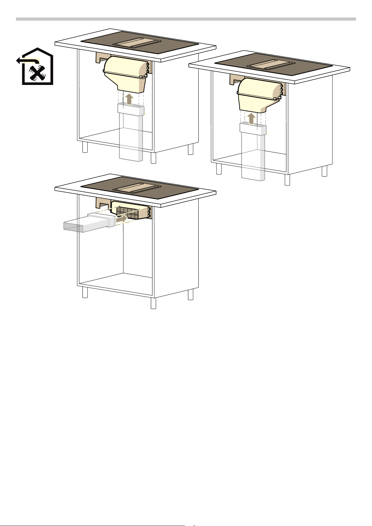
3UHSDULQJWKHXQLWDQGDSSOLDQFHIRUXVHZLWKDLUH[WUDFWLRQ
PRGH
8VHIRXUSODVWLFVFUHZVWRVHFXUHWKHUHGXFLQJFRQQHFWRURUIODW
GXFWHOERZWRWKHKREVRXWOHWRSHQLQJRUWKHH[WHQVLRQ )LJ
1RWH ,IQHFHVVDU\VFUHZWKHDSSURSULDWHH[WHQVLRQWRWKHKRE
0HDVXUHWKHSHUPLWWHGGHSWK7RIWKHGUDZHU²PDNHVXUH\RX
OHDYH D FOHDUDQFH RI PP IURP WKH H[KDXVW DLU SLSH 7KH GHSWK
RIWKHGUDZHUPD\YDU\GHSHQGLQJRQWKHH[WHQVLRQXVHG
)LJ
'HSHQGLQJRQWKHDLUH[WUDFWLRQV\VWHPFRQILJXUDWLRQPDNHD
FXWRXWLQWKHUHDUSDQHORIWKHXQLWIRUWKHH[KDXVWDLUSLSH
UHPRYH WKH UHDU SDQHO RI WKH XQLW RU PDNH D FXWRXW LQ WKH ERWWRP
RIWKHXQLW
$IWHUPDNLQJWKHFXWRXWUHPRYHDQ\VKDYLQJV
1RWH 6HDOFXWVXUIDFHVZLWKKHDWUHVLVWDQWDQGZDWHUSURRI
PDWHULDO
3UHSDULQJIRUWKHHOHFWULFDOFRQQHFWLRQZRUN
1RWH 5HIHUWRWKH (OHFWULFDOFRQQHFWLRQVHFWLRQLQWKH *HQHUDO
LQIRUPDWLRQFKDSWHU
2Q DSSOLDQFHV WKDW GR QRW KDYH D SUHLQVWDOOHG FDEOH LQVHUW
WKHPDLQVFDEOHLQWRWKHVRFNHW
7XUQ WKH KRE RYHU DQG SXW LW GRZQ RQ WKH EDVH RI WKH SDFNDJLQJ
DFORWKRUDQRWKHUVXUIDFHLQRUGHUWRSUHYHQWVFUDWFKHV
8VHDVFUHZGULYHUWROLIWXSWKHVRFNHWVFRYHU )LJ
8QGRWKHIDVWHQLQJVFUHZDQGXVHDVFUHZGULYHUWROLIWWKHKRVH
FODPS )LJ
2QO\ FRQQHFW WR WKH PDLQV VRFNHW DV VKRZQ LQ WKH ILJXUH )LJ
%1%URZQ
%8%OXH
*1<(<HOORZDQGJUHHQ
%.%ODFN
*<*UH\
1RWHV
■ ,IUHTXLUHGILWWKHFRSSHUEULGJHVSURYLGHGDVVKRZQLQWKH
FLUFXLWGLDJUDP
■ (QVXUHWKDWWKHVFUHZVRQWKHPDLQVVRFNHWDUHVFUHZHGLQ
WLJKWO\DIWHUWKHFDEOHVKDYHEHHQFRQQHFWHG
■ )RU D 1a1a FRQQHFWLRQ WKH OLYH ZLUH / JUH\ FRUUHVSRQGV
WRWKHIDQPRWRU
8VHWKHKRVHFODPSWRVHFXUHWKHPDLQVFDEOHDQGWLJKWHQWKH
IDVWHQLQJVFUHZ )LJ
&ORVHWKHFRYHURQWKHVRFNHW
1RWH $UUDQJH WKH FDEOHV LQ WKH FHQWUDO DUHD RI WKH PDLQV VRFNHW
LQRUGHUWRIDFLOLWDWHWKHIDVWHQLQJ
1RWH ,I D ORQJHU SRZHU FRUG LV UHTXLUHG SOHDVH FRQWDFW DIWHUVDOHV
VHUYLFH&RQQHFWLQJFDEOHVXSWR PORQJDUHDYDLODEOH
,QVWDOOLQJWKHDSSOLDQFH
: :HDUHUVRIHOHFWURQLFLPSODQWV
7KHDSSOLDQFHPD\FRQWDLQSHUPDQHQWPDJQHWVZKLFKPD\DIIHFW
HOHFWURQLFLPSODQWVHJKHDUWSDFHPDNHUVRULQVXOLQSXPSV
7KHUHIRUHGXULQJLQVWDOODWLRQZHDUHUVRIHOHFWURQLFLPSODQWVPXVW
PDLQWDLQDPLQLPXPGLVWDQFHRIFPIURPWKHDSSOLDQFH
: 5LVNRIHOHFWULFVKRFN
&RPSRQHQWVLQVLGHWKHDSSOLDQFHPD\KDYHVKDUSHGJHV7KHVH
PD\GDPDJHWKHFRQQHFWLQJFDEOH'RQRWNLQNRUSLQFKWKH
FRQQHFWLQJFDEOHGXULQJLQVWDOODWLRQ
: 5LVNRILQMXU\
3DUWVWKDWDUHDFFHVVLEOHGXULQJLQVWDOODWLRQPD\KDYHVKDUS
HGJHV:HDUSURWHFWLYHJORYHV
,QVWDOOLQJWKHKRE
$WWDFKWKHPRXQWLQJUDLOV )LJ D
)RU VWRQH ZRUNWRSV JOXH WKH UDLOV WR GR WKLV XVH D KHDWUHVLVWDQW
DGKHVLYHVXLWDEOHIRUJOXLQJPHWDODQGVWRQH
,QVHUWWKHDSSOLDQFHLQWRWKHFXWRXWLQWKHZRUNWRS )LJ E
$WWDFKWKHUHWDLQLQJFOLSVVXSSOLHGDQGWLJKWHQWKHPFDUHIXOO\
$OLJQWKHFRRNLQJVXUIDFHZLWKWKHZRUNLQJVXUIDFHXVLQJWKH
UHWDLQLQJFOLSV )LJ F
1RWH 'RQRWXVHDQHOHFWULFVFUHZGULYHU
&RQQHFWLQJWKHDSSOLDQFH
1RWHV
■ )RUDLUH[WUDFWLRQPRGHDEDFNSUHVVXUHIODSZLWKDPD[LPXP
RSHQLQJSUHVVXUHRI 3DVKRXOGEHLQVWDOOHG,IDEDFN
SUHVVXUHIODSLVQRWLQFOXGHGZLWKWKHDSSOLDQFHRQHFDQEH
RUGHUHGIURPDVSHFLDOLVWUHWDLOHU
■ ,I WKH H[KDXVW DLU LV FRQYH\HG WKURXJK WKH RXWHU ZDOO D WHOHVFRSLF
ZDOOER[VKRXOGEHXVHG
&RQQHFWLQJWKHDLUH[WUDFWRU
$WWDFKWKHH[KDXVWDLUSLSHWRWKHIODWGXFWEHQGRUWKHUHGXFLQJ
FRQQHFWRU )LJ
&RQQHFWLWWRWKHH[KDXVWDLURSHQLQJ
8VHVXLWDEOHPHDQVWRVHDOWKHMRLQWV
(VWDEOLVKLQJWKHFRQQHFWLRQIRUWKHFLUFXODWHGDLU
&OLS RU LI QHFHVVDU\ VFUHZ WKH ILOWHU PRGXOH VHFXUHO\ WR WKH ORZHU
IODWGXFWEHQG )LJ D
1RWH ,IQHFHVVDU\WXUQWKHILOWHUPRGXOHWRDOORZWKHGUDZHUIRU
WKH DFWLYDWHG FKDUFRDO ILOWHU WR EH RSHQHG IURP WKH RSSRVLWH VLGH
&OLSWKHIOH[LEOHFRQQHFWLQJHOHPHQWVHFXUHO\WRWKHXSSHUIODW
GXFWEHQG
8VH WKH IOH[LEOH FRQQHFWLQJ HOHPHQW WR FRQQHFW WKH ILOWHU PRGXOH
WRWKHXSSHUIODWGXFWEHQG
1RWH ,IQHFHVVDU\ILWH[WHQVLRQVEHWZHHQWKHILOWHUPRGXOHDQG
WKHIOH[LEOHFRQQHFWLQJHOHPHQW
2SHQ DOO RI WKH ORFNV RQ WKH GUDZHU 2SHQ WKH GUDZHU )LJ E
,QVHUWWKHDFWLYDWHGFKDUFRDOILOWHU )LJ F
&ORVHWKHGUDZHU
&ORVHDOORIWKHORFNVRQWKHGUDZHU
(VWDEOLVKLQJDFRQQHFWLRQWRWKHPDLQV
■ 9ROWDJH6HHWKHUDWLQJSODWH
■ 2QO\FRQQHFWDVVKRZQLQWKHFLUFXLWGLDJUDP )LJ
%1%URZQ
%8%OXH
*1<(*UHHQDQG\HOORZ
%.%ODFN
*<*UH\
■ 'HSHQGLQJRQWKHW\SHRIFRQQHFWLRQWKHDUUDQJHPHQWRIWKH
IHUUXOHWHUPLQDOVVXSSOLHGE\WKHIDFWRU\PD\QHHGWREH
FKDQJHG7RGRWKLVWKHIHUUXOHWHUPLQDOVPD\QHHGWREH
VKRUWHQHG DQG WKH LQVXODWLRQ UHPRYHG LQ RUGHU WR LQVHUW D IHUUXOH
WHUPLQDOWKDWFRQQHFWVWZRFDEOHV
1RWH &KHFNWKDWWKHDSSOLDQFHLVUHDG\IRURSHUDWLRQ,I
—…‹‹
“‹†‚„ RU “ DSSHDUV RQ WKH DSSOLDQFHV GLVSOD\ WKH DSSOLDQFH LV
QRWFRQQHFWHGFRUUHFWO\'LVFRQQHFWLWIURPWKHSRZHUVXSSO\DQG
FKHFNWKHSRZHUFRUGFRQQHFWLRQ
6ZLWFKLQJ WKH GLVSOD\ WR DLU H[WUDFWLRQ PRGH RU DLU
UHFLUFXODWLRQPRGH
)RUDLUH[WUDFWLRQPRGHDQGDLUUHFLUFXODWLRQPRGHLIQHFHVVDU\
VZLWFKWKHHOHFWURQLFFRQWUROXQLWVGLVSOD\DFFRUGLQJO\WRWKHEDVLF
VHWWLQJV
7RGRWKLVUHIHUWRWKH %DVLFVHWWLQJVVHFWLRQLQWKHLQVWUXFWLRQ
PDQXDO
5HPRYLQJWKHDSSOLDQFH
'LVFRQQHFWWKHDSSOLDQFHIURPWKHSRZHUVXSSO\
m 5LVNRIHOHFWULFVKRFN
:KHQGLVFRQQHFWLQJWKHKREIURPWKHSRZHUVXSSO\WKH
WHUPLQDOVPD\FDXVHUHYHUVHYROWDJH7KHHOHFWULFDOFRQQHFWLRQ
PXVWRQO\EHFDUULHGRXWE\DOLFHQVHGH[SHUW
5HPRYHWKHH[KDXVWDLUGXFWRUGLVFRQQHFWWKHDLUUHFLUFXODWLRQ
FRQQHFWLRQV
3XVKRXWWKHDSSOLDQFHIURPEHORZ
&DXWLRQ
'DPDJHWRWKHDSSOLDQFH 'RQRWSULVHRXWWKHDSSOLDQFHIURP
DERYH
fr
Þ
1RWLFHGHPRQWDJH
: 3UpFDXWLRQVGHVpFXULWpLPSRUWDQWHV
/LUHDWWHQWLYHPHQWFHPDQXHO&HQHVWTXDORUVTXHYRXVSRXUUH]
XWLOLVHU YRWUH DSSDUHLO FRUUHFWHPHQW HW HQ WRXWH VpFXULWp &RQVHUYHU
ODQRWLFHGXWLOLVDWLRQHWGHPRQWDJHSRXUXQXVDJHXOWpULHXURX
SRXUOHSURSULpWDLUHVXLYDQW
/DVpFXULWpGHO·DSSDUHLOjO·XVDJHHVWJDUDQWLHV·LODpWpHQFDVWUp
FRQIRUPpPHQWjODQRWLFHGHPRQWDJH/HPRQWHXUHVW
UHVSRQVDEOH GX IRQFWLRQQHPHQW FRUUHFW VXU OH OLHX R ODSSDUHLO HVW
LQVWDOOp
3RUWHXUVGLPSODQWVpOHFWURQLTXHV
/DSSDUHLOSHXWFRQWHQLUGHVDLPDQWVSHUPDQHQWVTXLSHXYHQW
LQIOXHUVXUGHVLPSODQWVpOHFWURQLTXHVSDUH[VWLPXODWHXUV
FDUGLDTXHVRXSRPSHVjLQVXOLQH3RXUFHWWHUDLVRQORUVGX
PRQWDJHUHVSHFWHUXQHGLVWDQFHPLQLPXPGHFPSDUUDSSRUW
DX[LPSODQWVpOHFWURQLTXHV
/HIDEULFDQWGpFOLQHWRXWHUHVSRQVDELOLWpSRXUGHVGpUDQJHPHQWV
RXGRPPDJHVpYHQWXHOVGXVjXQHLQVWDOODWLRQpOHFWULTXH
LQFRUUHFWH
&kEOHUpVHDX LOHVWSHXWrWUHGpMjEUDQFKpjODERvWHGH
UDFFRUGHPHQW GH OD WDEOH GH FXLVVRQ RX IRXUQL DYHF ODSSDUHLO
HWGRLWXQLTXHPHQWrWUHLQVWDOOpSDUXQSHUVRQQHOVSpFLDOLVpHW
DXWRULVp RX XQH SHUVRQQH FRPSpWHQWH GX VHUYLFH DSUqVYHQWH /HV
GRQQpHVGHUDFFRUGHPHQWUHTXLVHVVRQWLQGLTXpHVVXUODSODTXH
VLJQDOpWLTXHHWVXUOHVFKpPDGHUDFFRUGHPHQW
8WLOLVH]XQLTXHPHQWOHFkEOHIRXUQLDYHFODSSDUHLORXFHOXLIRXUQL
SDUOH6HUYLFHDSUqVYHQWHWHFKQLTXH
$YDQWWRXWWUDYDLOFRXSHUODOLPHQWDWLRQpOHFWULTXH
/·LQVWDOODWLRQGRLWDYRLUOLHXHQUHVSHFWDQWOHVSUHVFULSWLRQV
DFWXHOOHPHQWHQYLJXHXUGDQVOHEkWLPHQWDLQVLTXHOHV
SUHVFULSWLRQVSXEOLpHVSDUOHVFRPSDJQLHVGLVWULEXWULFHV
G·pOHFWULFLWpHWGHJD]
/HPRGHGpYDFXDWLRQGHODLUYLFLpGHYUDrWUHFRQIRUPHDX[
DUUrWpV PXQLFLSDX[ SUpIHFWRUDX[ HW DX[ SUHVFULSWLRQV OpJDOHV SDU
H[DX[RUGRQQDQFHVSXEOLTXHVDSSOLFDEOHVDXEkWLPHQW
'DQJHUGHPRUW
,O\DULVTXHGLQWR[LFDWLRQSDUUpDVSLUDWLRQGHVJD]GHFRPEXVWLRQ
(QFDVGXWLOLVDWLRQVLPXOWDQpHGHODSSDUHLOHQPRGHpYDFXDWLRQ
GHODLUHWGXQIR\HUjFRPEXVWLRQDOLPHQWpHQDLUDPELDQWYHLOOH]
LPSpUDWLYHPHQWjFHTXHODSSRUWGDLUVRLWVXIILVDQW
/HVIR\HUVjFRPEXVWLRQDOLPHQWpVHQDLUDPELDQWSDUH[HPSOH
DSSDUHLOVGHFKDXIIDJHDXJD]DXERLVDXILRXORXDXFKDUERQ
OHVFKDXIIHHDXFKDXIIHHDXDFFXPXODWHXUVSUpOqYHQWODLUGH
FRPEXVWLRQGDQVODSLqFHRLOVVRQWLQVWDOOpVHWUHMHWWHQWOHVJD]
GHIXPpHjOH[WpULHXUSDUOHELDLVGXQV\VWqPHVSpFLILTXH
FKHPLQpHSDUH[HPSOH
/RUVTXH OD KRWWH DVSLUDQWH HVW HQ PDUFKH HOOH SUpOqYH GH ODLU GDQV
OD FXLVLQH HW GDQV OHV SLqFHV YRLVLQHV VL ODSSRUW GDLU IUDLV HVW WURS
IDLEOH XQH GpSUHVVLRQ VH IRUPH 'HV JD] WR[LTXHV SURYHQDQW GH OD
FKHPLQpHRXGXFRQGXLWGpYDFXDWLRQVRQWUpDVSLUpVGDQVOHV
SLqFHVGKDELWDWLRQ
■ ,O IDXW GRQF WRXMRXUV VDVVXUHU TXH ODSSRUW GDLU IUDLV HVW VXIILVDQW
■ /DSUpVHQFHGXQHYHQWRXVHWpOHVFRSLTXHGDSSRUWHW
GpYDFXDWLRQGDLUQHVXIILWSDVjDVVXUHUOHUHVSHFWGHODYDOHXU
OLPLWH
/HIRQFWLRQQHPHQWVUGHODSSDUHLOQHVWSRVVLEOHTXHVLOD
GpSUHVVLRQGDQVODSLqFHRHVWLQVWDOOpOHIR\HUQHGpSDVVHSDV
3DPEDU2Q\SDUYLHQWHQSUpVHQFHGRXYHUWXUHVQRQ
REWXUDEOHVDPpQDJpHVSDUH[GDQVOHVSRUWHVIHQrWUHVHWHQ
DVVRFLDWLRQDYHFGHVYHQWRXVHVWpOHVFRSLTXHVGDGPLVVLRQ
pYDFXDWLRQGHODLUjWUDYHUVODPDoRQQHULHRXSDUGDXWUHV
PHVXUHVWHFKQLTXHVSHUPHWWDQWjODLUGDIIOXHUSRXUDVVXUHUOD
FRPEXVWLRQ

'HPDQGH]WRXMRXUVFRQVHLODXPDvWUHUDPRQHXUFRPSpWHQWTXL
SRXUUD pYDOXHU OHQVHPEOH GX UpVHDX GH YHQWLODWLRQ GH OD PDLVRQ HW
YRXVSURSRVHUOHPR\HQOHPLHX[DGDSWpSRXUODpUDWLRQ
6L OD KRWWH DVSLUDQWH HVW XWLOLVpH H[FOXVLYHPHQW HQ PRGH UHF\FODJH
OHIRQFWLRQQHPHQWHVWSRVVLEOHVDQVUHVWULFWLRQV
'DQJHUGHPRUW
,OH[LVWHXQULVTXHGLQWR[LFDWLRQSDUUpDVSLUDWLRQGHVJD]GH
FRPEXVWLRQ/RUVGHOLQVWDOODWLRQGXQHYHQWLODWLRQDYHFXQIR\HU
H[SORLWDQWODLUDPELDQWODOLPHQWDWLRQpOHFWULTXHGHODYHQWLODWLRQ
GRLWrWUHPXQLHGXQFLUFXLWGHVpFXULWpDSSURSULp
5LVTXHGLQFHQGLH
/HV GpS{WV GH JUDLVVH GDQV OH ILOWUH j JUDLVVH SHXYHQW VHQIODPPHU
1H MDPDLV WUDYDLOOHU DYHF XQH IODPPH QXH j SUR[LPLWp GH ODSSDUHLO
SDUH[IODPEHU1·LQVWDOOHUO·DSSDUHLOjSUR[LPLWpG·XQIR\HUj
FRPEXVWLEOHVVROLGHVSDUH[ERLVRXFKDUERQTX·HQSUpVHQFH
G·XQFRXYHUFOHIHUPpHWQRQDPRYLEOH$XFXQHSURMHFWLRQ
G·pWLQFHOOHVQHGRLWDYRLUOLHX
5LVTXHGHEOHVVXUH
■ 'HVPRGLILFDWLRQVVXUODFRQVWUXFWLRQpOHFWULTXHRXPpFDQLTXH
VRQWGDQJHUHXVHVHWSHXYHQWFRQGXLUHjGHV
G\VIRQFWLRQQHPHQWV1HSDVHIIHFWXHUGHVPRGLILFDWLRQVVXUOD
FRQVWUXFWLRQpOHFWULTXHRXPpFDQLTXH
5LVTXHGHEOHVVXUH
■ 'HVSLqFHVDFFHVVLEOHVSHQGDQWOHPRQWDJHSHXYHQWSRVVpGHU
GHVDUrWHVFRXSDQWHV3RUWHUGHVJDQWVGHSURWHFWLRQ
5LVTXHGHEOHVVXUH
■ /DSSDUHLOHVWORXUG SHUVRQQHVVRQWQpFHVVDLUHVSRXU
GpSODFHUODSSDUHLO8WLOLVHUH[FOXVLYHPHQWGHVPR\HQV
DSSURSULpV
5LVTXHGHEOHVVXUHV
■ /HVYHQWLODWHXUVWRXUQDQWVLPSOLTXHQWXQULVTXHGHEOHVVXUH
8WLOLVH]XQLTXHPHQWODSSDUHLOXQHIRLVTXLOHVWPRQWp
1DFFpGH] MDPDLV j OD VRUWLH GDLU DX GRV GH ODSSDUHLO ORUVTXH FH
GHUQLHUIRQFWLRQQH
5LVTXHGDVSK\[LH
/HPDWpULHOGHPEDOODJHHVWGDQJHUHX[SRXUOHVHQIDQWV1H
SHUPHWWH]MDPDLVDX[HQIDQWVGHMRXHUDYHFOHVPDWpULDX[
G·HPEDOODJH
1HSDVLQVWDOOHUFHWDSSDUHLOVXUGHVEDWHDX[RXGDQVGHV
YpKLFXOHV
3ODQGHWUDYDLO SODWKRUL]RQWDOVWDEOH5HVSHFWH]OHV
LQVWUXFWLRQVGXIDEULFDQWGXSODQGHWUDYDLO
6L OpSDLVVHXU GX SODQ GH WUDYDLO PRQWp GDQV OD WDEOH GH FXLVVRQ QH
FRUUHVSRQGSDVDX[LQGLFDWLRQVUHQIRUFHUOHSODQGHWUDYDLODYHF
XQPDWpULDXLPSHUPpDEOHHWUpIUDFWDLUHMXVTXjDWWHLQGUH
OpSDLVVHXUPLQLPDOHUHTXLVH6LQRQDXFXQHVWDELOLWpVXIILVDQWH
QHVWJDUDQWLH
5HPDUTXHV
■ /HSODQGHWUDYDLOTXLHVWPRQWpGDQVODWDEOHGHFXLVVRQGRLW
SRXYRLUVXSSRUWHUHQY NJ
■ /HVPRGLILFDWLRQVGHODVXUIDFHGHWUDYDLOGRLYHQWrWUHUpDOLVpHV
SDUXQIRXUQLVVHXUVSpFLDOLVpVHORQOHFURTXLVGLQVWDOODWLRQ
/DUrWHGHFRXSHGRLWrWUHSURSUHHWSUpFLVHFDUOHERUGHVW
YLVLEOH VXU OD VXUIDFH 1HWWR\HU HW GpJUDLVVHU OHV DUrWHV GH FRXSH
jODLGHGXQGpWHUJHQWDGDSWp
&RQVLJQHVJpQpUDOHV
/HV VXUIDFHV GH O·DSSDUHLO VRQW IUDJLOHV /RUV GH O·LQVWDOODWLRQ pYLWH]
GHOHVHQGRPPDJHU
0RGHeYDFXDWLRQGHO·DLU
5HPDUTXH /·DLUYLFLpQHGRLWSpQpWUHUQLGDQVXQHFKHPLQpHHQ
VHUYLFHGHVWLQpHjpYDFXHUODIXPpHRXGHVJD]EUOpVQLGDQV
XQH JDLQH VHUYDQW j DpUHU OHV ORFDX[ R VRQW LQVWDOOpV GHV IR\HUV j
FRPEXVWLRQ
6LO·DLUYLFLpFLUFXOHSDUXQHFKHPLQpHQRQHQVHUYLFHGHVWLQpHj
pYDFXHUODIXPpHRXGHVJD]EUOpVYRXVGHYUH]GDERUGREWHQLU
O·DFFRUGGXUDPRQHXUFRPSpWHQWGDQVYRWUHTXDUWLHU
&RQGXLWGpYDFXDWLRQ
5HPDUTXH /HIDEULFDQWGHODSSDUHLOQDVVXPHDXFXQHJDUDQWLH
SRXUOHVSUREOqPHVGHIRQFWLRQQHPHQWOLpVjODWX\DXWHULH
■ /DSSDUHLODWWHLQWXQUHQGHPHQWGDXWDQWPHLOOHXUTXHOHWX\DX
GpYDFXDWLRQHVWFRXUWHWGURLWHWTXHVRQGLDPqWUHHVWJUDQG
■ 6LOHVWX\DX[GpYDFXDWLRQVRQWORQJVSUpVHQWHQWGHQRPEUHX[
FRXGHVRXRQWXQGLDPqWUHLQIpULHXUjPPODSXLVVDQFH
PD[LPDOHGDVSLUDWLRQQHVHUDSDVDWWHLQWHHWOHYHQWLODWHXUIHUD
SOXVGHEUXLW
■ /HVWX\DX[ULJLGHVRXVRXSOHVFRQVWLWXDQWOHFRQGXLW
GpYDFXDWLRQGRLYHQWrWUHIDEULTXpVGDQVXQPDWpULDXQRQ
LQIODPPDEOH
■ 6LO·DLUYLFLpWUDYHUVHODSDURLH[WpULHXUHLOIDXGUDLWXWLOLVHUXQH
YHQWRXVHWpOHVFRSLTXH
5LVTXHGHQGRPPDJHPHQWSDUOHUHIOX[GHFRQGHQVDW,QVWDOOHUOH
FRQGXLWGDLUYLFLpOpJqUHPHQWLQFOLQpYHUVOHEDVjSDUWLUGH
ODSSDUHLOGHSHQWH
7X\DX[URQGV
1RXVUHFRPPDQGRQVXQGLDPqWUHLQWpULHXUGH PP
*DLQHVSODWHV
/DVHFWLRQLQWpULHXUHGRLWFRUUHVSRQGUHDXGLDPqWUHGHVWX\DX[
URQGV
PPHQYFP
■ /HV JDLQHV SODWHV QH GRLYHQW SDV SUpVHQWHU GH GpYRLHPHQWV WURS
LPSRUWDQWV
■ 6L GHV WX\DX[ GH SOXVLHXUV GLDPqWUHV VRQW XWLOLVpV LO IDXW SUpYRLU
GHVEDQGHVGpWDQFKpLWp
)RQFWLRQQHPHQWHQPRGHUHF\FODJH
5HPDUTXH /DSSDUHLOGRLWXQLTXHPHQWrWUHH[SORLWpjOpWDW
IHUPHPHQWIL[pHWDYHFODWX\DXWHULHUDFFRUGpH
%UDQFKHPHQWpOHFWULTXH
/HVGRQQpHVGHUDFFRUGHPHQWQpFHVVDLUHVVHWURXYHQWVXUOD
SODTXHVLJQDOpWLTXHVXUODSSDUHLO
&HWDSSDUHLOHVWFRQIRUPHDX[GLVSRVLWLRQV&(UpJLVVDQW
O·DQWLSDUDVLWDJH
6HXOXQVSpFLDOLVWHDJUppHVWKDELOLWpjUDFFRUGHUODSSDUHLO
/DSSDUHLO GRLW rWUH LQVWDOOp FRQIRUPpPHQW DX[ GHUQLqUHV GLUHFWLYHV
,((,QVWLWXWLRQRI(OHFWULFDO(QJLQHHUV/DSSDUHLOULVTXHGrWUH
HQGRPPDJpHQFDVGHUDFFRUGHPHQWLQFRUUHFW
$VVXUH]YRXVTXHODWHQVLRQGDOLPHQWDWLRQFRQFRUGHDYHFOD
YDOHXULQGLTXpHVXUODSODTXHVLJQDOpWLTXH
9HLOOH]jFHTXHOHUpVHDXpOHFWULTXHVRLWFRUUHFWHPHQWPLVjOD
WHUUHHWTXHOHIXVLEOHHWOHV\VWqPHGHFkEOHVHWGHOLJQHVGX
EkWLPHQWVRLHQWVXIILVDPPHQWGLPHQVLRQQpVSRXUODSXLVVDQFH
pOHFWULTXHGHODSSDUHLO
/RUVGHODSRVHGXFkEOHGDOLPHQWDWLRQUHVSHFWH]OHVSRLQWV
VXLYDQWV
■ 1HSDVSLQFHURXpFUDVHUOHFkEOH
■ eORLJQHUOHFkEOHGHVDUrWHVFRXSDQWHV
■ 1HPHWWH]SDVOHFkEOHDYHFOHERvWLHUPpWDOOLTXHHQFRQWDFW
DYHFOHGHVVRXVGHODSSDUHLOFDUFHOXLFLFKDXIIH
$YDQWGHUDFFRUGHUODSSDUHLOYpULILH]OLQVWDOODWLRQGRPHVWLTXH
9HLOOH]jXQHSURWHFWLRQSDUIXVLEOHVXIILVDQWHGHOLQVWDOODWLRQ
GRPHVWLTXH/DWHQVLRQHWODIUpTXHQFHGHODSSDUHLOGRLYHQW
FRUUHVSRQGUHjOLQVWDOODWLRQpOHFWULTXHYRLUODSODTXH
VLJQDOpWLTXH
/DSSDUHLOHVWFRQIRUPHjODFODVVHGHSURWHFWLRQ,HWGRLW
XQLTXHPHQWrWUHXWLOLVpDYHFXQHSULVHjFRQGXFWHXUGHSURWHFWLRQ
8QVHFWLRQQHXURPQLSRODLUHDYHFXQLQWHUVWLFHGRXYHUWXUHGH
FRQWDFWGDXPRLQV PPGRLWrWUHSUpVHQWGDQVOLQVWDOODWLRQ&H
GHUQLHUGRLWHQFRUHrWUHDFFHVVLEOHDSUqVOHQFDVWUHPHQW
6HXOXQpOHFWULFLHQDJUppHVWKDELOLWpjLQVWDOOHURXjUHPSODFHUOH
FkEOH GH UDFFRUGHPHQW HQ UHVSHFWDQW OHV SUHVFULSWLRQV HQ YLJXHXU
/RUV GX UHPSODFHPHQW GX FRUGRQ GDOLPHQWDWLRQ VHFWHXU LO VH SHXW
TXH ODSSDUHLO GRLYH rWUH UHWRXUQp 'DQV FH FDV UHWLUH] OH FDSRW GX
ILOWUHHWOHUpVHUYRLUSXLVUHWLUH]OHILOWUHjJUDLVVHPpWDOOLTXH9RXV
HPSrFKH]DLQVLWRXWHFKXWHGHFHVFRPSRVDQWV
6LOHFRUGRQGDOLPHQWDWLRQDXVHFWHXUGHFHWDSSDUHLOHVW
HQGRPPDJp LO GRLW rWUH UHPSODFp SDU XQ FRUGRQ GH UDFFRUGHPHQW
GXW\SH+99)
3UpSDUHUO·LQVWDOODWLRQ
'LPHQVLRQVGHODSSDUHLOHWGLVWDQFHVGHVpFXULWp
■ 7HQH]FRPSWHGHVGLPHQVLRQVGHODSSDUHLOSRXUOHPRGH
UHFLUFXODWLRQGHODLU ILJ $
■ 7HQH]FRPSWHGHVGLPHQVLRQVGHODSSDUHLOSRXUOHPRGH
pYDFXDWLRQH[WpULHXUH ILJ %
■ $VVXUH]YRXVTXHODSSDUHLOUHVWHVXIILVDPPHQWDFFHVVLEOHXQH
IRLVOHPRQWDJHWHUPLQpSRXUSRXYRLUFKDQJHUOHILOWUHjFKDUERQ
DFWLIYLGHUOHUpVHUYRLUGHWURSSOHLQHWGpPRQWHUOHFDSRWGX
ERvWLHU ILJ &
■ 5HVSHFWH]OHVGLVWDQFHVGHVpFXULWp ILJ &
9pULILHUOpWDWGXPHXEOH
■ /HPHXEOHGHQFDVWUHPHQWGRLWrWUHSRVpjOKRUL]RQWDOHHW
SRVVpGHUXQHFDSDFLWpGHFKDUJHVXIILVDQWH
■ /HSRLGVPD[GHODSSDUHLOHVWGHQYLURQ NJ
■ /HPHXEOHGHQFDVWUHPHQWGRLWUpVLVWHUjGHVWHPSpUDWXUHV
MXVTXj&
■ /DVWDELOLWpGXPHXEOHGHQFDVWUHPHQWGRLWrWUHJDUDQWLHPrPH
DSUqVOHVWUDYDX[GHGpFRXSH

■ /DFDSDFLWpGHFKDUJHHWODVWDELOLWpHQSDUWLFXOLHUHQFDVGH
SODQVGHWUDYDLOILQVGRLYHQWrWUHDVVXUpHVSDUGHVVRXV
VWUXFWXUHV DSSURSULpHV 3UHQH] HQ FRPSWH OH SRLGV GH ODSSDUHLO
\FRPSULVVDFKDUJHVXSSOpPHQWDLUH/HPDWpULDXGH
UHQIRUFHPHQWXWLOLVpGRLWrWUHUpVLVWDQWjODFKDOHXUHWj
OKXPLGLWp
■ 6HORQODWX\DXWHULHHWODSURIRQGHXUGXSODQGHWUDYDLOOD
SURIRQGHXU GHV WLURLUV HQ GHVVRXV GH ODSSDUHLO GRLW rWUH DGDSWpH
/HWLURLUVXSpULHXUGRLWrWUHUHWLUpHWQHVWSDVXWLOLVDEOH
■ /DGLVWDQFHHQWUHODVXUIDFHGXSODQGHWUDYDLOHWODSDUWLH
VXSpULHXUHGXWLURLUGRLWrWUHGH PP
■ 1HSDVLQVWDOOHUGHIRXUUpIULJpUDWHXUODYHYDLVVHOOHODYHOLQJH
RXDXWUHVDSSDUHLOVHQGHVVRXV
5HPDUTXH 9pULILH]ODSODQpLWpGHODSSDUHLOVHXOHPHQWDSUqV
OLQVWDOODWLRQGDQVORXYHUWXUHGHQFDVWUHPHQW
3UpSDUDWLRQGXPHXEOH
5pDOLVH]ODGpFRXSHGDQVOHSODQGHWUDYDLOFRQIRUPpPHQWDX
FURTXLVGLQVWDOODWLRQ ILJ
5HPDUTXH /DQJOH GX FKDQW GH OD GpFRXSH SDU UDSSRUW DX SODQ
GH WUDYDLO GRLW rWUH GH /HV ERUGV GH GpFRXSH ODWpUDX[ GRLYHQW
rWUHSODQV(QFDVGHSODQVGHWUDYDLOPXOWLFRXFKHVIL[H]OHFDV
pFKpDQWOHVEDJXHWWHVGHPDQLqUHODWpUDOHGDQVODGpFRXSH
$ILQGHJDUDQWLUXQIRQFWLRQQHPHQWFRUUHFWGHODSSDUHLOODWDEOH
GHFXLVVRQGRLWrWUHVXIILVDPPHQWYHQWLOpH3RXUFHIDLUHFUpH]
XQH VRUWLH GDLU GDQV OpOpPHQW GX EDV DYHF XQH VHFWLRQ PLQLPDOH
GH FPò
2EVHUYH] OHV GLVWDQFHV PLQLPDOHV HQ FDV GH PRQWDJH DXGHVVXV
GXQWLURLU ILJ &
5HWLUH]OHWLURLUVXSpULHXUHWPHWWH]HQSODFHXQUHFRXYUHPHQW
DSSURSULpVXUOHPHXEOH
3UpSDUDWLRQGXPHXEOHHWGHODSSDUHLOSRXUOHPRGH
5HF\FODJHGDLU
5pDOLVDWLRQGHODGpFRXSHGDQVOHPHXEOH
&UpH]XQHVRUWLHGDLUGDQVODSOLQWKHDYDQWGXPHXEOH
5HPDUTXH 3UpYR\H]XQHVHFWLRQPLQLPDOHGHODVRUWLHGDLU
GHQY FPò&RQIHFWLRQQH]ORXYHUWXUHGHVRUWLHGDQVOH
EDQGHDXGXVRFOHDXVVLJUDQGHTXHSRVVLEOHDILQGHUpGXLUHDX
PD[LPXPOHFRXUDQWGDLUHWOHEUXLW
5HWLUH]ODSDURLDUULqUHGXPHXEOH
5HWLUH] VL QpFHVVDLUH OD EDJXHWWH VXSpULHXUH GH OD SDURL DUULqUH GX
PHXEOH
'pWHUPLQH]OHFHQWUHGXERUGDUULqUHGHODGpFRXSHGXSODQGH
WUDYDLO HW UHSRUWH] FHOXLFL DLQVL TXH OHV GHX[ OLJQHV YHUWLFDOHPHQW
YHUVOHEDVVXUOHIRQGLQIpULHXUGXPHXEOH ILJ D
2ULHQWH] OD W{OH GH IL[DWLRQ HQ IRQFWLRQ GHV OLJQHV PpGLDQHV VXU OH
IRQGLQIpULHXUGXPHXEOH ILJ E
3RXUOHVWLURLUV IHUPH]OHWLURLULQIpULHXU6LODW{OHGHIL[DWLRQ
UHQWUHWURSORLQVRXVOHWLURLUGpSODFH]FHOOHFLHQGLUHFWLRQGHOD
SDURLDUULqUHODLGHGHVPDUTXDJHVGHODW{OHGHIL[DWLRQ
SRVLWLRQQH]FHOOHFLGHIDoRQjFHTXHOOHVRLWSDUDOOqOHjODOLJQH
PpGLDQH ILJ F
5HPDUTXHV
■ 6LODGLVWDQFHHQWUHOHWLURLUHWOHIRQGLQIpULHXUGXPHXEOHHVW
WURSIDLEOHSRXUIL[HUODW{OHGHIL[DWLRQDXIRQGLQIpULHXUGX
PHXEOHWRXUQH]ODSODTXHGHIL[DWLRQGHHWIL[H]OD
GHSXLVOHEDVDXIRQGLQIpULHXUGXPHXEOH ILJ E
3RVLWLRQQH] DXSDUDYDQW OD W{OH GH IL[DWLRQ GHSXLV OH KDXW VXU OH
IRQGLQIpULHXUGXPHXEOHSRXUGpWHUPLQHUODSRVLWLRQFRUUHFWH
GHODW{OHGHIL[DWLRQ ILJ F
■ &KRLVLVVH]ODUDOORQJHFRUUHVSRQGDQWHSRXUOHFRQGXLWGH
UHF\FODJHGDLUHQIRQFWLRQGHODSRVLWLRQGHODW{OHGHIL[DWLRQ
■ 8WLOLVH] GHV WLURLUV PRLQV SURIRQGV VL OD W{OH GH IL[DWLRQ QH SHXW
SDVrWUHVXIILVDPPHQWSRXVVpHYHUVODUULqUH
6L QpFHVVDLUH WUDFH] OHV OLJQHV GH GpFRXSH j ODLGH GH OD W{OH GH
IL[DWLRQVXUOHIRQGLQIpULHXUGXPHXEOH ILJ G
(QOHYH]OHVFRSHDX[DSUqVOHVWUDYDX[GHGpFRXSH
5HPDUTXH 6FHOOH]OHVFKDQWVGHGpFRXSHGHIDoRQ
WKHUPRVWDEOHHWpWDQFKH
9LVVDJHGHOHW{OHGHIL[DWLRQHWFOLSVDJHGXGLIIXVHXU
6LODGLVWDQFHHQWUHOHWLURLUHWOHIRQGGXPHXEOHHVWVXIILVDQWH
IL[H] OD W{OH GH IL[DWLRQ j ODLGH GH YLV SRXU SODVWLTXH GHSXLV OH KDXW
DXFRXGHLQIpULHXUGHJDLQHSODWH ILJ D
5HPDUTXH 6LQpFHVVDLUHWRXUQH]OHFRXGHLQIpULHXUGHJDLQH
SODWHDILQTXHODVRUWLHGDLUVHWURXYHGHF{WpRSSRVp
)L[H]ODW{OHGHIL[DWLRQjODLGHGHYLVjERLVGHSXLVOHKDXWDX
IRQGLQIpULHXUGXPHXEOH ILJ D
5HPDUTXH 6LODGLVWDQFHHQWUHOHWLURLUHWOHIRQGLQIpULHXUGX
PHXEOHHVWWURSIDLEOHSRXUIL[HUODW{OHGHIL[DWLRQDXIRQG
LQIpULHXUGXPHXEOHWRXUQH]ODSODTXHGHIL[DWLRQGHHW
IL[H]ODGHSXLVOHEDVDXIRQGLQIpULHXUGXPHXEOH ILJ E
&OLSVH] OH GLIIXVHXU DX FRXGH LQIpULHXU GH OD JDLQH SODWH ILJ F
0RQWDJHGXFRXGHVXSpULHXUGHJDLQHSODWH
&KRLVLVVH]VLQpFHVVDLUHODUDOORQJHHQIRQFWLRQGHODSRVLWLRQ
GHODW{OHGHIL[DWLRQHWGHODSURIRQGHXUGXPHXEOH3OXVOD
UDOORQJHHVWORQJXHSOXVOHWLURLUSHXWrWUHSURIRQG)L[H]OD
UDOORQJHjODLGHGHTXDWUHYLVSRXUSODVWLTXHDXQLYHDXGH
ORXYHUWXUHGHVRUWLHGHODWDEOHGHFXLVVRQ ILJ
)L[H] OH FRXGH VXSpULHXU GH JDLQH SODWH j ODLGH GH TXDWUH YLV SRXU
SODVWLTXH DX QLYHDX GH ORXYHUWXUH GH VRUWLH GH OD WDEOH GH FXLVVRQ
RXGHODUDOORQJH
3UpSDUDWLRQGXPHXEOHHWGHODSSDUHLOSRXUOHPRGH
eYDFXDWLRQH[WpULHXUH
)L[H]OHPDQFKRQUpGXFWHXURXOHFRXGHGHJDLQHSODWHjODLGH
GH TXDWUH YLV SRXU SODVWLTXH DX QLYHDX GH ORXYHUWXUH GH VRUWLH GH
ODWDEOHGHFXLVVRQRXGHODUDOORQJH ILJ
5HPDUTXH 6LQpFHVVDLUHIL[H]ODUDOORQJHFRUUHVSRQGDQWHj
ODLGHGHYLVjODWDEOHGHFXLVVRQ0HVXUH]ODSURIRQGHXU3
DXWRULVpHGXWLURLUFHIDLVDQWUHVSHFWH]XQpFDUWGH PPSDU
UDSSRUWDXFRQGXLWGpYDFXDWLRQ6HORQOH[WHQVLRQXWLOLVpHOD
SURIRQGHXUGXWLURLUSHXWYDULHU ILJ
(Q IRQFWLRQ GH OD FRQILJXUDWLRQ GX FRQGXLW GpYDFXDWLRQ UpDOLVH]
XQHGpFRXSHGDQVODSDURLDUULqUHGXPHXEOHUHWLUH]ODSDURL
DUULqUH GX PHXEOH RX UpDOLVH] XQH GpFRXSH GDQV OH IRQG LQIpULHXU
GXPHXEOH
(QOHYH]OHVFRSHDX[DSUqVOHVWUDYDX[GHGpFRXSH
5HPDUTXH 6FHOOH]OHVFKDQWVGHGpFRXSHGHIDoRQ
WKHUPRVWDEOHHWpWDQFKH
3UpSDUDWLRQGXEUDQFKHPHQWpOHFWULTXH
5HPDUTXH 2EVHUYHUOHSDUDJUDSKH %UDQFKHPHQWpOHFWULTXH
DXFKDSLWUH 5HPDUTXHVGRUGUHJpQpUDO
(Q FDV GDSSDUHLO VDQV FkEOH SUpLQVWDOOp LQWURGXLUH OH FkEOH
VHFWHXUGDQVODSULVHGHUDFFRUGHPHQW
5HWRXUQHUODWDEOHGHFXLVVRQHWSODFHUXQFKLIIRQRXXQHDXWUH
VXUIDFHVXUOHIRQGGHOHPEDOODJHSRXUpYLWHUWRXWHUD\XUH
6RXOHYH]OHFKDSHDXGHODSULVHGHUDFFRUGHPHQWjODLGHGXQ
WRXUQHYLV ILJ
'HVVHUUH]ODYLVGHIL[DWLRQHWVRXOHYH]OHFROOLHUGHVHUUDJHj
ODLGHGXQWRXUQHYLV ILJ
(IIHFWXH]OHUDFFRUGHPHQWjODSULVHGHUDFFRUGHPHQW
XQLTXHPHQWFRQIRUPpPHQWjODILJXUH ILJ
%1 PDUURQ
%8 EOHX
*1<( MDXQHHWYHUW
%. QRLU
*< JULV
5HPDUTXHV
■ 6LQpFHVVDLUHPRQWH]OHVSRQWVHQFXLYUHMRLQWVVHORQOH
VFKpPDGHUDFFRUGHPHQW
■ 9HLOOH] j FH TXH OHV YLV VRLHQW VROLGHPHQW IL[pHV VXU OD SULVH GH
UDFFRUGHPHQWDSUqVDYRLUUDFFRUGpOHFkEOH
■ (QFDVGHUDFFRUGHPHQW1a1aODSKDVH/*UH\
FRUUHVSRQGDXPRWHXUGXYHQWLODWHXU
)L[H]OHFkEOHVHFWHXUDYHFOHFROOLHUGHVHUUDJHHWVHUUH]ODYLV
GHIL[DWLRQ ILJ
)HUPHUOHFKDSHDXGHODSULVHGHUDFFRUGHPHQW
5HPDUTXH 'LVSRVHUOHVFkEOHVGDQVODSDUWLHFHQWUDOHGHOD
SULVHGHUDFFRUGHPHQWDILQGHIDFLOLWHUODIHUPHWXUH
5HPDUTXH 6LYRXVDYH]EHVRLQGXQFRUGRQGDOLPHQWDWLRQ
VHFWHXUSOXVORQJYHXLOOH]FRQWDFWHUOHVHUYLFHDSUqVYHQWH,O
H[LVWHGHVFRUGRQVGDOLPHQWDWLRQVHFWHXUMXVTXj PqWUHVGH
ORQJXHXU

0RQWHUODSSDUHLO
: 3RUWHXUVGLPSODQWVpOHFWURQLTXHV
/DSSDUHLOSHXWFRQWHQLUGHVDLPDQWVSHUPDQHQWVTXLSHXYHQW
LQIOXHUVXUGHVLPSODQWVpOHFWURQLTXHVSDUH[VWLPXODWHXUV
FDUGLDTXHVRXSRPSHVjLQVXOLQH3RXUFHWWHUDLVRQORUVGX
PRQWDJHUHVSHFWHUXQHGLVWDQFHPLQLPXPGHFPSDUUDSSRUW
DX[LPSODQWVpOHFWURQLTXHV
: 5LVTXHGHFKRFpOHFWULTXH
'HVSLqFHVjOLQWpULHXUGHODSSDUHLOSHXYHQWSUpVHQWHUGHVDUrWHV
YLYHV,O\DULVTXHGHQGRPPDJHPHQWGXFkEOHGDOLPHQWDWLRQ
3HQGDQWO·LQVWDOODWLRQYHLOOHUjQHSDVSOLHUQLFRLQFHUOHFkEOH
G·DOLPHQWDWLRQ
: 5LVTXHGHEOHVVXUH
'HVSLqFHVDFFHVVLEOHVSHQGDQWOHPRQWDJHSHXYHQWSRVVpGHU
GHVDUrWHVFRXSDQWHV3RUWHUGHVJDQWVGHSURWHFWLRQ
0LVHHQSODFHGHODWDEOHGHFXLVVRQ
0RQWH]OHVEDUUHWWHVGHIL[DWLRQ ILJ D
(QFDVGHSODQGHWUDYDLOHQSLHUUHFROOH]OHVUDLOVGHIL[DWLRQ
XWLOLVH] SRXU FHOD XQH FROOH UpVLVWDQWH j OD WHPSpUDWXUH DGDSWpH
DXFROODJHGHPpWDX[HWGHSLHUUH
,QVWDOOH]ODSSDUHLOGDQVODGpFRXSHGXSODQGHWUDYDLO ILJ E
0RQWH]OHVDWWDFKHVGHUHWHQXHIRXUQLHVHWVHUUH]OHVDYHF
SUpFDXWLRQ$OLJQH]ODWDEOHGHFXLVVRQjODLGHGHVDWWDFKHVGH
UHWHQXHDXQLYHDXGHODVXUIDFHGHWUDYDLO ILJ F
5HPDUTXH 1XWLOLVH]SDVGHWRXUQHYLVpOHFWULTXH
%UDQFKHUODSSDUHLO
5HPDUTXHV
■ (QPRGHpYDFXDWLRQH[WpULHXUHXQFODSHWDQWLUHWRXUGRLWrWUH
LQVWDOOpDYHFXQHSUHVVLRQGRXYHUWXUHGH 3D6LXQFODSHW
DQWLUHWRXUQHVWSDVMRLQWjODSSDUHLOLOHVWHQYHQWHGDQVOH
FRPPHUFHVSpFLDOLVp
■ 6L O·DLU YLFLp WUDYHUVH OD SDURL H[WpULHXUH LO IDXW XWLOLVHU XQ FDLVVRQ
WpOHVFRSLTXHPXUDO
5pDOLVHUOHUDFFRUGHPHQWGHOpYDFXDWLRQGHODLU
)L[H]OHFRQGXLWG·pYDFXDWLRQFRQWUHOHFRXGHGHJDLQHSODWHRX
OHPDQFKRQUpGXFWHXU ILJ
5pDOLVH]ODMRQFWLRQYHUVORULILFHGpYDFXDWLRQGDLU
eWDQFKH]OHV]RQHVGHMRQFWLRQGHIDoRQDSSURSULpH
5pDOLVHUOHUDFFRUGHPHQWGHODLUGHFLUFXODWLRQ
&OLSVH] OH PRGXOH GH ILOWUH DX FRXGH LQIpULHXU GH OD JDLQH SODWH RX
IL[H]OHjODLGHGHYLVVLQpFHVVDLUH ILJ D
5HPDUTXH 6L QpFHVVDLUH WRXUQH] OH PRGXOH GH ILOWUH SRXU TXH
OHWLURLUGXILOWUHjFKDUERQDFWLISXLVVHrWUHRXYHUWGHSXLVOHF{Wp
RSSRVp
&OLSVH] OpOpPHQW GH UDFFRUGHPHQW IOH[LEOH DX FRXGH VXSpULHXU GH
JDLQHSODWH
5HOLH]OHPRGXOHGHILOWUHHWOHFRXGHVXSpULHXUGHJDLQHSODWHj
ODLGHGHOpOpPHQWGHUDFFRUGHPHQWIOH[LEOH
5HPDUTXH 6LQpFHVVDLUHPRQWH]GHVUDOORQJHVHQWUHOH
PRGXOHGHILOWUHHWOpOpPHQWGHUDFFRUGHPHQWIOH[LEOH
2XYUH]WRXVOHVYROHWVGHIHUPHWXUHVXUOHWLURLU2XYUH]OHWLURLU
ILJ E
0HWWH]OHILOWUHjFKDUERQDFWLIHQSODFH ILJ F
)HUPH]OHWLURLU
)HUPH]WRXVOHVYROHWVGHIHUPHWXUHVXUOHWLURLU
5pDOLVHUOHUDFFRUGHPHQWpOHFWULTXH
■ 3RXUODWHQVLRQ YRLUODSODTXHVLJQDOpWLTXH
■ 3URFpGH]DXUDFFRUGHPHQWXQLTXHPHQWVHORQOHVFKpPDGH
UDFFRUGHPHQWILJ
%1 PDUURQ
%8 EOHX
*1<( MDXQHHWYHUW
%. QRLU
*< JULV
■ 6HORQOHW\SHGHUDFFRUGHPHQWODGLVSRVLWLRQGHVHPERXWV
IRXUQLVSDUOXVLQHGRLWpYHQWXHOOHPHQWrWUHPRGLILpH3RXUFH
IDLUH LO IDXW pYHQWXHOOHPHQW UDFFRXUFLU OHV FRQGXFWHXUV HW HQOHYHU
OLVRODQWSRXUXWLOLVHUXQHPERXWGHFRQQHFWHXUUHOLDQWGHX[
FkEOHV
5HPDUTXH 9pULILFDWLRQGHODGLVSRQLELOLWpGHVHUYLFH VL
—…‹‹
“‹†‚„ RX “DSSDUDvWGDQVODIILFKDJHGHODSSDUHLOFHGHUQLHU
QHVWSDVFRUUHFWHPHQWUDFFRUGp'pEUDQFKHUODSSDUHLOGH
ODOLPHQWDWLRQVHFWHXUHWYpULILHUFkEOHGDOLPHQWDWLRQ
&RPPXWDWLRQGHO·DIILFKDJHVXUOHPRGH
eYDFXDWLRQH[WpULHXUHRXOHPRGH5HF\FODJHGDLU
3RXUOHPRGHpYDFXDWLRQH[WpULHXUHHWOHPRGHUHFLUFXODWLRQGH
ODLUPRGLILH]VLQpFHVVDLUHODIILFKDJHGHODFRPPDQGH
pOHFWURQLTXHHQFRQVpTXHQFHGDQVOHVUpJODJHVGHEDVH
3RXU FH IDLUH FRQVXOWH] OH FKDSLWUH 5pJODJHV GH EDVH GH OD QRWLFH
GXWLOLVDWLRQ
'pPRQWHUODSSDUHLO
'pEUDQFKH]O·DSSDUHLOGXUpVHDXpOHFWULTXH
m 5LVTXHG·pOHFWURFXWLRQ
/RUVTXH OD WDEOH GH FXLVVRQ HVW GpEUDQFKpH GX VHFWHXU LO SHXW \
DYRLUXQUHWRXUGHWHQVLRQDXQLYHDXGHVERUQHV/H
UDFFRUGHPHQWpOHFWULTXHGRLWXQLTXHPHQWrWUHUpDOLVpSDUXQ
VSpFLDOLVWHFRQFHVVLRQQDLUH
'pWDFKH]OHFRQGXLWGpYDFXDWLRQRXOHVFRQGXLWVGHUHF\FODJH
GDLU
)DLWHVVRUWLUODSSDUHLOHQOHSRXVVDQWSDUOHEDV
$WWHQWLRQ
5LVTXHVGHGpWpULRUDWLRQGHODSSDUHLO 1H[WUD\H]SDV
ODSSDUHLOSDUOHKDXWHQIDLVDQWOHYLHU
it
â
,VWUX]LRQLSHULOPRQWDJJLR
: ,PSRUWDQWLDYYHUWHQ]HGLVLFXUH]]D
/HJJHUHDWWHQWDPHQWHOHSUHVHQWLLVWUX]LRQLSHUOXVR6RORFRVuq
SRVVLELOHXWLOL]]DUHODSSDUHFFKLRLQPRGRVLFXURHFRUUHWWR
&XVWRGLUHFRQODPDVVLPDFXUDOHSUHVHQWLLVWUX]LRQLSHUOXVRHLO
PRQWDJJLRLQFDVRGLXQXWLOL]]RIXWXURRFHVVLRQHDWHU]L
/DVLFXUH]]DGLXWLOL]]RqJDUDQWLWDVRORLQFDVRGLLQVWDOOD]LRQH
VHFRQGROHUHJROHGLEXRQDWHFQLFDULSRUWDWHQHOOHLVWUX]LRQLGL
PRQWDJJLR/LQVWDOODWRUHqUHVSRQVDELOHGHOFRUUHWWR
IXQ]LRQDPHQWRQHOOXRJRGLLQVWDOOD]LRQH
3RUWDWRULGLLPSLDQWLHOHWWURQLFL
/DSSDUHFFKLRSXzFRQWHQHUHPDJQHWLSHUPDQHQWLFKHSRVVRQR
DJLUHVXJOLLPSLDQWLHOHWWURQLFLTXDOLDGHVSDFHPDNHURSRPSHGL
LQVXOLQD3HUWDQWRDOPRPHQWRGHOPRQWDJJLRLSRUWDWRULGLLPSLDQWL
HOHWWURQLFLGHYRQRPDQWHQHUHXQDGLVWDQ]DPLQLPDGLFP
,OFRVWUXWWRUHQRQVLDVVXPHDOFXQDUHVSRQVDELOLWjSHUHYHQWXDOL
JXDVWLRGDQQLULFRQGXFLELOLDXQLQVWDOOD]LRQHHOHWWULFDGLIHWWRVD
&DYRGLUHWHqSRVVLELOHFKHVLDJLjFROOHJDWRDOODVFDWRODGL
DOODFFLDPHQWRGHOSLDQRFRWWXUDRSSXUHYLHQHIRUQLWRLQVLHPH
DOODSSDUHFFKLRHGHYHHVVHUHLQVWDOODWRHVFOXVLYDPHQWHGDXQ
HVSHUWRDXWRUL]]DWRRGDOSHUVRQDOHGHELWDPHQWHTXDOLILFDWRGHO
VHUYL]LRGLDVVLVWHQ]DFOLHQWL,GDWLQHFHVVDULSHUODOODFFLDPHQWR
VRQRLQGLFDWLVXOODWDUJKHWWDGLLGHQWLILFD]LRQHHVXOORVFKHPDGL
DOODFFLDPHQWR
8WLOL]]DUHHVFOXVLYDPHQWHLOFDYRIRUQLWRLQGRWD]LRQHLQVLHPH
DOODSSDUHFFKLRRFRQVHJQDWRGDOVHUYL]LRGLDVVLVWHQ]DWHFQLFD
6WDFFDUHODOLPHQWD]LRQHGLFRUUHQWHSULPDGLSURFHGHUHDGRJQL
WLSRGLLQWHUYHQWR
3HU O·LQVWDOOD]LRQH q QHFHVVDULR ULVSHWWDUH OH GLVSRVL]LRQL LQ PDWHULD
GLHGLOL]LDDWWXDOPHQWHLQYLJRUHHOHQRUPHGHOIRUQLWRUHORFDOHGL
HOHWWULFLWjHJDV
3HU TXDQWR FRQFHUQH OD FRQGX]LRQH GHOODULD HVDXVWD q QHFHVVDULR
ULVSHWWDUHOHQRUPDWLYHGLOHJJHXIILFLDOLDGHVQRUPDWLYH
XUEDQLVWLFKHSURYLQFLDOL
3HULFRORGLPRUWH
,JDVGLFRPEXVWLRQHULDVSLUDWLSRVVRQRFDXVDUHDYYHOHQDPHQWR
ËQHFHVVDULRDVVLFXUDUHVHPSUHXQDOLPHQWD]LRQHGLDULD
VXIILFLHQWHTXDQGRODSSDUHFFKLRLQPRGDOLWjDVSLUD]LRQHYLHQH
XWLOL]]DWRFRQWHPSRUDQHDPHQWHDXQIRFRODUHGLSHQGHQWHGDOODULD
DPELHQWH
,IRFRODULFKHGLSHQGRQRGDOODULDDPELHQWHSHUHVDJDVROLR
OHJQDRFDUERQHVFDOGDEDJQRFDOGDLHHOHWWULFKHULFDYDQRODULD
SHUODFRPEXVWLRQHGDOODVWDQ]DHGHOLPLQDQRLJDVGLVFDULFR
DOOHVWHUQRDWWUDYHUVRXQLPSLDQWRSHUHVFDPLQR
,QFRQFRPLWDQ]DGHOODFDSSDDFFHVDGDOODFXFLQDHGDOOHVWDQ]H
DGLDFHQWLYLHQHVRWWUDWWDGHOODULDVHQ]DXQDOLPHQWD]LRQH
VXIILFLHQWH GL DULD VL FUHD GHSUHVVLRQH , JDV YHOHQRVL GDO FDPLQR R
GDOODFDSSDGLDVSLUD]LRQHYHQJRQRULDVSLUDWLQHOOHVWDQ]H
■ $VVLFXUDUHVHPSUHXQDOLPHQWD]LRQHGLDULDVXIILFLHQWH
■ 8QDSHUWXUDQHOPXURSHUDOLPHQWD]LRQHVFDULFRDULDQRQ
JDUDQWLVFHLOULVSHWWRGHOYDORUHOLPLWH
8Q HVHUFL]LR VLFXUR q SRVVLELOH VROR VH OD GHSUHVVLRQH QHOOD VWDQ]D
LQ FXL q LQVWDOODWR LO IRFRODUH QRQ VXSHUD L 3D PEDU 4XHVWR
qJDUDQWLWRVHODULDQHFHVVDULDDOODFRPEXVWLRQHSXzDIIOXLUHQHOOD
VWDQ]DDWWUDYHUVRDSHUWXUHQRQILVVHSHUHVSRUWHILQHVWUHLQ
FRPELQD]LRQHFRQXQFDQDOHGLDGGX]LRQHVFDULFRDULDRDOWUH
PLVXUHWHFQLFKH
&RQVXOWDWHLQRJQLFDVRORVSD]]DFDPLQRUHVSRQVDELOHFKHqLQ
JUDGRGLJLXGLFDUHODYHQWLOD]LRQHFRPSOHVVLYDLQFDVDHSURSRUUH
PLVXUHDGHJXDWH
6HODFDSSDqXVDWDVRORQHOODPRGDOLWjDULFLUFRORGDULDLOVXR
HVHUFL]LRqSRVVLELOHVHQ]DOLPLWD]LRQL
3HULFRORGLPRUWH
,JDVGLFRPEXVWLRQHULDVSLUDWLSRVVRQRFDXVDUHDYYHOHQDPHQWR
,QVWDOODQGRXQVLVWHPDGLDVSLUD]LRQHFRQXQIRFRODUHGLSHQGHQWH
GDOODULDDPELHQWHODOLPHQWD]LRQHGHOODVSLUD]LRQHGHYHHVVHUH
SURYYLVWDGLXQDGHJXDWRFRPDQGRGLVLFXUH]]D
3HULFRORGLLQFHQGLR
,GHSRVLWLGLJUDVVRSUHVHQWLQHOILOWURSHUJUDVVLSRVVRQR
LQFHQGLDUVL 1RQ ODYRUDUH PDL QHOOH YLFLQDQ]H GHOODSSDUHFFKLR FRQ
ILDPPHOLEHUHDGHVILDPPHJJLDUH/·LQVWDOOD]LRQH
GHOO·DSSDUHFFKLRQHOOHYLFLQDQ]HGLXQIRFRODUHSHUFRPEXVWLELOL
VROLGLDGHVOHJQRRFDUERQHqFRQVHQWLWDVRORVHTXHVWRq
GRWDWRGLFRSHUWXUDFKLXVDHQRQHVWUDLELOH1RQGHYHHVVHUFL
SURGX]LRQHGLVFLQWLOOH
3HULFRORGLOHVLRQL
■ 0RGLILFKHDOOLPSLDQWRHOHWWULFRRPHFFDQLFRVRQRSHULFRORVHH
SRVVRQRFDXVDUHDQRPDOLHQHOIXQ]LRQDPHQWR1RQDSSRUWDUH
PRGLILFKHDOOLPSLDQWRHOHWWULFRRPHFFDQLFR
3HULFRORGLOHVLRQL
■ ,FRPSRQHQWLFRVWUXWWLYLFKHUHVWDQRVFRSHUWLGXUDQWHLO
PRQWDJJLR SRVVRQR HVVHUH DSSXQWLWL ,QGRVVDUH JXDQWL SURWHWWLYL
3HULFRORGLOHVLRQL
■ /DSSDUHFFKLRqSHVDQWH3HUVSRVWDUORRFFRUURQR SHUVRQH
8WLOL]]DUHHVFOXVLYDPHQWHDXVLOLDGHJXDWL
3HULFRORGLOHVLRQL
■ /H YHQWROH URWDQWL UDSSUHVHQWDQR XQ ULVFKLR GL OHVLRQL $FFHQGHUH
ODSSDUHFFKLRVRORTXDQGRqFRUUHWWDPHQWHLQVWDOODWR'XUDQWHLO
IXQ]LRQDPHQWR QRQ LQILODUH PDL OH PDQL QHOODSHUWXUD GHO VLVWHPD
GLYHQWLOD]LRQHVXOUHWURGHOODSSDUHFFKLR
3HULFRORGLVRIIRFDPHQWR
,OPDWHULDOHGLPEDOODJJLRqSHULFRORVRSHULEDPELQL1RQODVFLDUH
PDLFKHLEDPELQLJLRFKLQRFRQLOPDWHULDOHGLLPEDOODJJLR
4XHVWRDSSDUHFFKLRQRQGHYHHVVHUHLQVWDOODWRVXEDUFKHR
YHLFROL
3LDQRGLODYRURSLDWWRRUL]]RQWDOHHVWDELOH$WWHQHUVLDOOH
LVWUX]LRQLGHOIDEEULFDQWHGHOSLDQRGLODYRUR
6HORVSHVVRUHGHOSLDQRGLODYRURDOOLQWHUQRGHOTXDOHYLHQH
LQFDVVDWRLOSLDQRGLFRWWXUDQRQFRUULVSRQGHDLUHTXLVLWLULFKLHVWL
ULQIRU]DUHLOSLDQRGLODYRURFRQPDWHULDOHUHIUDWWDULRHUHVLVWHQWH
DOODFTXDILQRDUDJJLXQJHUHORVSHVVRUHPLQLPRFRQVLJOLDWR,Q
FDVRFRQWUDULRQRQYLHQHJDUDQWLWDXQDVXIILFLHQWHVWDELOLWj
$YYHUWHQ]H
■ ,OSLDQRGLODYRURDOOLQWHUQRGHOTXDOHYLHQHLQFDVVDWRLOSLDQRGL
FRWWXUDGHYHHVVHUHLQJUDGRGLVRVWHQHUHFDULFKLGLFD NJ
■ (YHQWXDOLDGDWWDPHQWLGHOODVXSHUILFLHGLODYRURGHYRQRHVVHUH
HVHJXLWLGDXQIRUQLWRUHVSHFLDOL]]DWRVHFRQGRLGLVHJQLGL
PRQWDJJLR ,O ERUGR GL WDJOLR GHYH HVVHUH SXOLWR H SUHFLVR SRLFKp
LOPDUJLQHqYLVLELOHVXOODVXSHUILFLH3XOLUHHVJUDVVDUHLERUGLGL
WDJOLRFRQXQDSSRVLWRGHWHUJHQWH3XOLUHHVJUDVVDUHLERUGLGL
WDJOLRFRQXQDSSRVLWRGHWHUJHQWH
,QGLFD]LRQLJHQHUDOL
/HVXSHUILFLGHOO·DSSDUHFFKLRVRQRGHOLFDWH(YLWDUHGDQQLGXUDQWH
OLQVWDOOD]LRQH
0RGDOLWjDVSLUD]LRQH
$YYHUWHQ]D /·DULDHVDXVWDQRQGHYHHVVHUHLPPHVVDLQXQ
FDPLQRSHULOIXPRRSHULJDVGLVFDULFRIXQ]LRQDQWHQpLQXQ
SR]]RGLDHUD]LRQHGHLORFDOLGLLQVWDOOD]LRQHGLIRFRODUL
6HO·DULDHVDXVWDYLHQHLPPHVVDLQXQFDPLQRSHUIXPRRJDVGL
VFDULFRQRQLQIXQ]LRQHqQHFHVVDULRRWWHQHUHO·DXWRUL]]D]LRQHGL
XQWHFQLFRVSHFLDOL]]DWR
6FDULFRGHOODULD
$YYHUWHQ]D ,OSURGXWWRUHGHOODSSDUHFFKLRQRQVLDVVXPHDOFXQD
UHVSRQVDELOLWjSHUOHFRQWHVWD]LRQLUHODWLYHDOFRQGRWWR
■ /DSSDUHFFKLR UDJJLXQJH OD PDVVLPD SUHVWD]LRQH FRQ XQ WXER GL
VFDULFRFRUWRHGULWWRFKHKDXQGLDPHWURSRVVLELOPHQWHJUDQGH
■ &RQ WXEL GHVSXOVLRQH DULD OXQJKL FKH SUHVHQWDQR PROWH FXUYH R
FKHKDQQRXQGLDPHWURLQIHULRUHDPPQRQVLUDJJLXQJHOD
SUHVWD]LRQHRWWLPDOHGLDVSLUD]LRQHHLOUXPRUHGHOODYHQWROD
DXPHQWD
■ ,WXELRLWXELIOHVVLELOLSHULOFRQGRWWRGLVFDULFRGHOODULDGHYRQR
HVVHUHLQPDWHULDOHLJQLIXJR
■ 6HO·DULDHVDXVWDYLHQHFRQGRWWDDWWUDYHUVRODSDUHWHHVWHUQDq
QHFHVVDULRXWLOL]]DUHXQDFDVVHWWDPXUDOHWHOHVFRSLFD
3HULFRORGLGDQQLGRYXWLDOULWRUQRGHOODFRQGHQVD,QVWDOODUHLO
FDQDOHGLHVSXOVLRQHLQSRVL]LRQHOHJJHUPHQWHVSLRYHQWHULVSHWWR
DOODSSDUHFFKLRGLGLVOLYHOOR
7XELURWRQGL
6LFRQVLJOLDXQGLDPHWURLQWHUQRGLPP

&DQDOLSLDWWL
/D VH]LRQH LQWHUQD GHYH FRUULVSRQGHUH DO GLDPHWUR GHL WXEL URWRQGL
PPFDFP
■ ,FDQDOLSLDWWLQRQGHYRQRSUHVHQWDUHULQYLLWDJOLHQWL
■ 1HOFDVRGLGLDPHWULGLYHUVLGHOWXERXWLOL]]DUHVWULVFHGLWHQXWD
)XQ]LRQDPHQWRDULFLUFRORGDULD
$YYHUWHQ]D /DSSDUHFFKLRGHYHHVVHUHPHVVRLQIXQ]LRQHVROR
VHOLQVWDOOD]LRQHqDYYHQXWDLQPDQLHUDILVVDHLOFRQGRWWRq
FROOHJDWR
&ROOHJDPHQWRHOHWWULFR
,GDWLQHFHVVDULSHUODOODFFLDPHQWRVLWURYDQRVXOODWDUJKHWWDGL
LGHQWLILFD]LRQHGHOODSSDUHFFKLR
4XHVWRDSSDUHFFKLRqFRQIRUPHDLUHTXLVLWLGLSURWH]LRQH5),
GHOO·8QLRQH(XURSHD
/DOODFFLDPHQWRGHOODSSDUHFFKLRSXzHVVHUHHIIHWWXDWRVRORGDXQ
WHFQLFRDXWRUL]]DWR/DSSDUHFFKLRGHYHHVVHUHLQVWDOODWRLQ
PDQLHUDFRQIRUPHDOOHQXRYHGLUHWWLYH,((,QVWLWXWLRQRI(OHFWULFDO
(QJLQHHUV8QDOODFFLDPHQWRVFRUUHWWRGHOODSSDUHFFKLRSXz
FDXVDUQHLOGDQQHJJLDPHQWR
$FFHUWDUVLFKHLOYDORUHGHOODWHQVLRQHGHOODOLPHQWD]LRQHHOHWWULFD
FRLQFLGDFRQLOYDORUHLQGLFDWRVXOODWDUJKHWWDGLLGHQWLILFD]LRQH
$FFHUWDUVLFKHODPHVVDDWHUUDGHOODOLPHQWD]LRQHHOHWWULFDVLD
FRQIRUPH H FKH LO IXVLELOH H LO VLVWHPD GL FDYL H FRQGRWWL GHOOHGLILFLR
SHUODFRQGXWWXUDHOHWWULFDGHOODSSDUHFFKLRDEELDXQDSRUWDWD
VXIILFLHQWH
3HUODSRVDGHOFDYRGLFROOHJDPHQWRULVSHWWDUHLVHJXHQWLSXQWL
■ 1RQLQFDVWUDUHRVFKLDFFLDUHLOFDYR
■ 7HQHUHORQWDQRLOFDYRGDVSLJROLWDJOLHQWL
■ 1RQIDUHHQWUDUHLQFRQWDWWRLOFDYRFRQXQDOORJJLDPHQWRLQ
PHWDOORSRLFKpTXHVWXOWLPRVLVXUULVFDOGD
3ULPDGHOODOODFFLDPHQWRGHOODSSDUHFFKLRFRQWUROODUHOLPSLDQWR
GRPHVWLFR9HULILFDUHODFRUUHWWDSURWH]LRQHGHOOLPSLDQWR
GRPHVWLFR 7HQVLRQH H IUHTXHQ]D GHOODSSDUHFFKLR GHYRQR HVVHUH
FRPSDWLELOLFRQOLPSLDQWRHOHWWULFRYHGHUHODWDUJKHWWD
LGHQWLILFDWLYD
/DSSDUHFFKLRDSSDUWLHQHDOODFODVVHGLSURWH]LRQH,HGqSXz
IXQ]LRQDUHVRORVHGRWDWRGLXQFRQGXWWRUHGLWHUUD
,QIDVHGLQVWDOOD]LRQHqQHFHVVDULRSUHYHGHUHXQVH]LRQDWRUH
XQLYHUVDOHFRQXQDSHUWXUDGLFRQWDWWRGLDOPHQRPPFKHGHYH
ULPDQHUHDFFHVVLELOHDQFKHGRSRLOPRQWDJJLR
/DSRVDRODVRVWLWX]LRQHGHOFDYRGLFROOHJDPHQWRSRVVRQR
HVVHUHHVHJXLWHXQLFDPHQWHGDXQHOHWWULFLVWDTXDOLILFDWRWHQHQGR
FRQWRGHOOHUHODWLYHLVWUX]LRQL
'XUDQWHODVRVWLWX]LRQHGHOFDYRGLFROOHJDPHQWRDOODUHWHSXz
HVVHUHQHFHVVDULRFDSRYROJHUHODSSDUHFFKLR,QTXHVWRFDVR
ULPXRYHUHODFRSHUWXUDILOWURHGHVWUDUUHLOFRQWHQLWRUHHLOILOWUR
JUDVVLPHWDOOLFR,QTXHVWRPRGRVLHYLWDFKHWDOLFRPSRQHQWL
FDGDQRIXRUL
6H LO FDYR GL FROOHJDPHQWR DOOD UHWH GL TXHVWR DSSDUHFFKLR VXELVFH
XQ GDQQRGHYHHVVHUHVRVWLWXLWRFRQ XQ FDYRGL FROOHJDPHQWRGL
WLSR+99)
3UHSDUD]LRQHGHOOLQVWDOOD]LRQH
'LPHQVLRQLGHOODSSDUHFFKLRHGLVWDQ]HGLVLFXUH]]D
■ 2VVHUYDUH OH GLPHQVLRQL GHOODSSDUHFFKLR SHU LO IXQ]LRQDPHQWR D
ULFLUFRORGDULD ILJ $
■ 2VVHUYDUH OH GLPHQVLRQL GHOODSSDUHFFKLR SHU LO IXQ]LRQDPHQWR D
HVWUD]LRQHGDULD ILJ %
■ $FFHUWDUVLFKHDOWHUPLQHGHOOLQVWDOOD]LRQHSHUODVRVWLWX]LRQH
GHOILOWURDFDUERQHDWWLYRGHOORVYXRWDPHQWRGHOVHUEDWRLRGL
WUDERFFRHGHOORVPRQWDJJLRGHOODFRSHUWXUDGHOODOORJJLDPHQWR
ODSSDUHFFKLRVLDVXIILFLHQWHPHQWHDFFHVVLELOH ILJ &
■ 2VVHUYDUHOHGLVWDQ]HGLVLFXUH]]D ILJ &
&RQWUROODUHLOPRELOH
■ ,OPRELOHGDLQFDVVRGHYHHVVHUHSRVWRLQSRVL]LRQHRUL]]RQWDOH
HGHVVHUHDEEDVWDQ]DUHVLVWHQWH
■ ,OSHVRPD[GHOODSSDUHFFKLRqSDULDFLUFD NJ
■ ,OPRELOHGDLQFDVVRGHYHHVVHUHWHUPRVWDELOHILQRDXQD
WHPSHUDWXUDGL&
■ /DVWDELOLWjGHOPRELOHGDLQFDVVRGHYHHVVHUHJDUDQWLWDDQFKH
GRSRLODYRULGLWDJOLR
■ /DSRUWDWDHODVWDELOLWjLQSDUWLFRODUHSHUTXDQWRULJXDUGDSLDQL
GLODYRURVRWWLOLGHYRQRHVVHUHDVVLFXUDWHJUD]LHDVWUXWWXUH
VRWWRVWDQWL DGDWWH 2VVHUYDUH LO SHVR GHOODSSDUHFFKLR FRPSUHVR
LOFDULFRVXSSOHPHQWDUH,OPDWHULDOHXVDWRSHULOULQIRU]RGHYH
HVVHUHUHVLVWHQWHDOFDORUHHDOOXPLGLWj
■ 6XOOD EDVH GHOOD WXED]LRQH H GHOOD SURIRQGLWj GHO SLDQR GL ODYRUR
GHYHHVVHUHDGDWWDWDODSURIRQGLWjGHLFDVVHWWLVRWWR
ODSSDUHFFKLR ,O FDVVHWWR VXSHULRUH GHYH HVVHUH ULPRVVR H QRQ q
XWLOL]]DELOH
■ /DGLVWDQ]DWUDODVXSHUILFLHGHOSLDQRGLODYRURHODSDUWH
VXSHULRUHGHOFDVVHWWRGHYHHVVHUHGL PP
■ 1RQqFRQVHQWLWRLQFDVVDUHIRUQLIULJRULIHULODYDVWRYLJOLH
ODYDWULFLRDOWULDSSDUHFFKL
$YYHUWHQ]D 9HULILFDUHODSODQDULWjGHOODSSDUHFFKLRVRORGRSR
OLQVWDOOD]LRQHQHOODSHUWXUDGLPRQWDJJLR
3UHSDUD]LRQHGHLPRELOL
5HDOL]]DUHODSHUWXUDQHOSLDQRGLODYRURVHFRQGRORVFKHPDGL
PRQWDJJLR ILJ
$YYHUWHQ]D /DQJROR GHOOD VXSHUILFLH GL WDJOLR ULVSHWWR DO SLDQR GL
ODYRURGHYHHVVHUHGL,ERUGLODWHUDOLGHOODSHUWXUDGHYRQR
HVVHUHOLVFL,QFDVRGLSLDQLGLODYRURDSLVWUDWLILVVDUH
HYHQWXDOPHQWHLOLVWHOOLODWHUDOPHQWHDOODSHUWXUD
3HU JDUDQWLUH LO FRUUHWWR IXQ]LRQDPHQWR GHOODSSDUHFFKLR LO SLDQR
FRWWXUDGHYHHVVHUHDGHJXDWDPHQWHDHUDWR&UHDUHDWDO
SURSRVLWRXQRVFDULFRGHOODULDQHOPRELOHLQIHULRUHFRQXQD
VH]LRQHPLQLPDGL FPò
,Q FDVR GL PRQWDJJLR VRSUD XQR VFRPSDUWR VFRUUHYROH ULVSHWWDUH
OHGLVWDQ]HLQGLFDWH ILJ &
5LPXRYHUHORVFRPSDUWRVFRUUHYROHVXSHULRUHHVXOPRELOH
PRQWDUHXQDFRSHUWXUDDGHJXDWD
3UHSDUD]LRQHGHOPRELOHHGHOODSSDUHFFKLRSHULO
IXQ]LRQDPHQWRDGDULDGLULFLUFROR
3UDWLFDUHLOIRURGLLQFDVVRGHOPRELOH
5HDOL]]DUHXQRVFDULFRSHUODULDQHOOR]RFFRORGHOPRELOH
$YYHUWHQ]D 3UHYHGHUHXQDVH]LRQHPLQLPDGHOORVFDULFRSHU
ODULD GL FLUFD FPò (VHJXLUH ODSHUWXUD GL VFDULFR QHO SDQQHOOR
GHOOR]RFFRORGHOODPDJJLRUGLPHQVLRQHSRVVLELOHSHUOLPLWDUHLO
IOXVVRGDULDHLOUXPRUH
5LPXRYHUHODSDUHWHSRVWHULRUHGHOPRELOH
6HQHFHVVDULRULPXRYHUHLOOLVWHOORVXSHULRUHVXOODSDUHWH
SRVWHULRUHGHOPRELOH
6XOERUGRVXSHULRUHGHOIRURGLQFDVVRGHOSLDQRGLODYRUR
GHWHUPLQDUHLOSXQWRFHQWUDOHHVHJQDUHOHGXHOLQHH
YHUWLFDOPHQWHYHUVRLOEDVVRVXOIRQGRGHOPRELOH ILJ D
$OOLQHDUHODODPLHUDGLILVVDJJLRVXOIRQGRGHOPRELOHEDVDQGRVL
VXOOHOLQHHFHQWUDOL ILJ E
6HFLVRQRFDVVHWWLFKLXGHUHFRPSOHWDPHQWHLOFDVVHWWRSLLQ
EDVVR6HODODPLHUDGLILVVDJJLRVFRPSDUHHFFHVVLYDPHQWH
VRWWRDOFDVVHWWRVSLQJHUODYHUVRLOODWRSRVWHULRUHGHOPRELOH
&RQODXVLOLRGHOOHPDUFDWXUHQHOODODPLHUDGLILVVDJJLRDOOLQHDUOD
SDUDOOHODPHQWHDOODOLQHDFHQWUDOH ILJ F
$YYHUWHQ]H
■ 6HODGLVWDQ]DWUDFDVVHWWRHIRQGRGHOPRELOHqWURSSRFRUWD
SHUDYYLWDUHODODPLHUDGLILVVDJJLRVXOIRQGRUXRWDUHOD
ODPLHUDGLILVVDJJLRGLHDYYLWDUODVXOIRQGRGHOPRELOH
GDOEDVVR ILJ E,QQDQ]LWXWWRDOOLQHDUHODODPLHUDGL
ILVVDJJLRGDOODOWRVXOIRQGRGHOPRELOHSHUGHWHUPLQDUQHOD
FRUUHWWDSRVL]LRQH ILJ F
■ 6FHJOLHUHODSUROXQJDFRUULVSRQGHQWHLQIXQ]LRQHGHOOD
SRVL]LRQHGHOODODPLHUDGLILVVDJJLR
■ 6HODODPLHUDGLILVVDJJLRQRQYLHQHVSLQWDDEEDVWDQ]D
LQGLHWURXWLOL]]DUHFDVVHWWLFRQSURIRQGLWjSLULGRWWD
6HQHFHVVDULRVHJQDUHHUHDOL]]DUHXQDSHUWXUDQHOIRQGRGHO
PRELOHFRQODXVLOLRGHOODODPLHUDGLILVVDJJLR ILJ G
5LPXRYHUHLWUXFLROLGRSRLODYRULGLWDJOLR
$YYHUWHQ]D 6LJLOODUH OH VXSHUILFL GL WDJOLR LQ PRGR UHIUDWWDULR H D
WHQXWDVWDJQD
$YYLWDUH OD ODPLHUD GL ILVVDJJLR H ILVVDUH FRQ FOLSV LO GLIIXVRUH
6HODGLVWDQ]DWUDLOFDVVHWWRHLOIRQGRGHOPRELOHqVXIILFLHQWH
DYYLWDUH OD ODPLHUD GL ILVVDJJLR FRQ YLWL LQ SODVWLFD GDOODOWR H VXOOD
FXUYDLQIHULRUHGHOFDQDOHSLDWWR ILJ D
$YYHUWHQ]D 6H QHFHVVDULR UXRWDUH OD FXUYD LQIHULRUH GHO FDQDOH
SLDWWRDIILQFKpORVFDULFRGHOODULDVLWURYLVXOODWRRSSRVWR
$YYLWDUHODODPLHUDGLILVVDJJLRFRQYLWLSHUOHJQRGDOODOWRHVXO
IRQGRGHOPRELOH ILJ D
$YYHUWHQ]D 6HODGLVWDQ]DWUDFDVVHWWRHIRQGRGHOPRELOHq
WURSSR FRUWD SHU DYYLWDUH OD ODPLHUD GL ILVVDJJLR VXO IRQGR UXRWDUH
OD ODPLHUD GL ILVVDJJLR GL H DYYLWDUOD VXO IRQGR GHO PRELOH GDO
EDVVR ILJ E
)LVVDUH FRQ FOLS LO GLIIXVRUH VXOOD FXUYD LQIHULRUH GHO FDQDOH SLDWWR
ILJ F

0RQWDJJLRGHOODFXUYDGHOFDQDOHSLDWWR
6HQHFHVVDULRVFHJOLHUHODSUROXQJDLQIXQ]LRQHGHOODSRVL]LRQH
GHOODODPLHUDGLILVVDJJLRHGHOODSURIRQGLWjGHOPRELOH3Lq
OXQJDODSUROXQJDSLSURIRQGRSXzHVVHUHLOFDVVHWWR$YYLWDUH
OD SUROXQJD FRQ TXDWWUR YLWL LQ SODVWLFD VXOODSHUWXUD GL VFDULFR GHO
SLDQRFRWWXUD ILJ
$YYLWDUHODFXUYDGHOFDQDOHSLDWWRVXSHULRUHVXOODSHUWXUDGL
VFDULFRGHOSLDQRFRWWXUDRVXOODSUROXQJD
3UHSDUD]LRQH GHO PRELOH H GHOODSSDUHFFKLR SHU OD PRGDOLWj GL
DVSLUD]LRQH
$YYLWDUH L ERFFKHWWRQL GL ULGX]LRQH R OD FXUYD GHO FDQDOH SLDWWR FRQ
TXDWWURYLWLLQSODVWLFDVXOODSHUWXUDGLVFDULFRGHOSLDQRFRWWXUDR
VXOODSUROXQJD ILJ
$YYHUWHQ]D 6HQHFHVVDULRDYYLWDUHODUHODWLYDSUROXQJDVXO
SLDQR GL FRWWXUD 0LVXUDUH OD SURIRQGLWj 7 FRQVHQWLWD GHO FDVVHWWR
ULVSHWWDQGR PP GL GLVWDQ]D GDO WXER GL VFDULFR /D OXQJKH]]D
GHOODSUROXQJDSXzYDULDUHDVHFRQGDGHOOXWLOL]]R ILJ
,Q IXQ]LRQH GHOOD FRQILJXUD]LRQH GHOOR VFDULFR GDULD SHU LO WXER GL
VFDULFRSUDWLFDUHXQDSHUWXUDQHOODSDUHWHSRVWHULRUHGHOPRELOH
ULPXRYHUHODSDUHWHSRVWHULRUHRSUDWLFDUHXQDSHUWXUDQHOIRQGR
GHOPRELOH
5LPXRYHUHLWUXFLROLGRSRLODYRULGLWDJOLR
$YYHUWHQ]D 6LJLOODUH OH VXSHUILFL GL WDJOLR LQ PRGR UHIUDWWDULR H D
WHQXWDVWDJQD
3UHSDUD]LRQHGHOFROOHJDPHQWRHOHWWULFR
$YYHUWHQ]D 2VVHUYDUHLOSDUDJUDIR $OODFFLDPHQWRHOHWWULFRQHO
FDSLWROR $YYHUWHQ]HJHQHUDOL
1HJOL DSSDUHFFKL VHQ]D FDYR SUHLQVWDOODWR LQWURGXUUH LO FDYR
GLUHWHQHOODSUHVDGLFROOHJDPHQWR
&DSRYROJHUHLOSLDQRGLFRWWXUDHGHSRVLWDUORVXOIRQGR
GHOOLPEDOODJJLR VX XQ SDQQR R VX XQDOWUD VXSHUILFLH SHU HYLWDUH
GLJUDIILDUOR
6ROOHYDUHLOFRSHUFKLRGHOODSUHVDGLFROOHJDPHQWRFRQODLXWRGL
XQFDFFLDYLWH ILJ
$OOHQWDUH OD YLWH GL ILVVDJJLR H VROOHYDUH OD IDVFHWWD VWULQJLWXER FRQ
ODLXWRGLXQFDFFLDYLWH ILJ
(IIHWWXDUHODOODFFLDPHQWRDOODSUHVDGLFROOHJDPHQWR
HVFOXVLYDPHQWH LQ FRQIRUPLWj D TXDQWR PRVWUDWR LQ ILJXUD ILJ
%1PDUURQH
%8EOX
*1<(JLDOORHYHUGH
%.QHUR
*<JULJLR
$YYHUWHQ]H
■ 6HRFFRUUHPRQWDUHLSRQWLFHOOLLQUDPHIRUQLWLLQGRWD]LRQHLQ
FRQIRUPLWjDOORVFKHPDGLFROOHJDPHQWR
■ 3UHVWDUHDWWHQ]LRQHDFKHOHYLWLVXOODSUHVDGLFROOHJDPHQWR
YHQJDQRVHUUDWHGRSRFKHVRQRVWDWLFROOHJDWLLFDYL
■ 'XUDQWHLOFROOHJDPHQWR1a1aODIDVH/JULJLR
FRUULVSRQGHDOODYHQWRODPRWRUH
)LVVDUH LO FDYR GL UHWH FRQ OD IDVFHWWD VWULQJLWXER H VHUUDUH OD YLWH
GLILVVDJJLR ILJ
&KLXGHUHLOFRSHUFKLRGHOODSUHVDGLFROOHJDPHQWR
$YYHUWHQ]D 'LVSRUUHLOFDYRQHOODSDUWHLQWHUQDGHOODSUHVDGL
FROOHJDPHQWRSHUIDFLOLWDUQHODFKLXVXUD
$YYHUWHQ]D 6HqQHFHVVDULRXQFDYRGLFROOHJDPHQWRDOODUHWH
HOHWWULFDSLOXQJRVLSUHJDGLFRQWDWWDUHLOVHUYL]LRGLDVVLVWHQ]D
FOLHQWL6RQRDGLVSRVL]LRQHFDYLGLFROOHJDPHQWRILQRDPGL
OXQJKH]]D
0RQWDJJLRGHOO·DSSDUHFFKLR
: 3RUWDWRULGLLPSLDQWLHOHWWURQLFL
/DSSDUHFFKLRSXzFRQWHQHUHPDJQHWLSHUPDQHQWLFKHSRVVRQR
DJLUHVXJOLLPSLDQWLHOHWWURQLFLTXDOLDGHVSDFHPDNHURSRPSHGL
LQVXOLQD3HUWDQWRDOPRPHQWRGHOPRQWDJJLRLSRUWDWRULGLLPSLDQWL
HOHWWURQLFLGHYRQRPDQWHQHUHXQDGLVWDQ]DPLQLPDGLFP
: 3HULFRORGLVFRVVDHOHWWULFD
$OFXQLFRPSRQHQWLDOOLQWHUQRGHOODSSDUHFFKLRSRVVRQRHVVHUH
DIILODWL3RWUHEEHYHQLUHGDQQHJJLDWRLOFDYRGLFROOHJDPHQWR
'XUDQWHO·LQVWDOOD]LRQHIDUHDWWHQ]LRQHDQRQSLHJDUHRVHUUDUHLO
FDYRGLFROOHJDPHQWR
: 3HULFRORGLOHVLRQL
,FRPSRQHQWLFRVWUXWWLYLFKHUHVWDQRVFRSHUWLGXUDQWHLOPRQWDJJLR
SRVVRQRHVVHUHDSSXQWLWL,QGRVVDUHJXDQWLSURWHWWLYL
,QVHULPHQWRGHOSLDQRGLFRWWXUD
0RQWDUHOHJXLGHGLVXSSRUWR ILJ D
3HULSLDQLGLODYRURLQSLHWUDLQFROODUHOHJXLGHXWLOL]]DUHDWDOH
VFRSRGHOODGHVLYRUHVLVWHQWHDOFDORUHHDGDWWRDLQFROODUH
PHWDOORHSLHWUD
,QVHULUHODSSDUHFFKLRQHOIRURGLQFDVVRGHOSLDQRGLODYRUR
ILJ E
$SSOLFDUHHILVVDUHDWWHQWDPHQWHLEORFFDJJLIRUQLWLLQGRWD]LRQH
$OOLQHDUH LO SLDQR GL FRWWXUD DIILQFKp VLD SLDQHJJLDQWH ULVSHWWR DOOD
VXSHUILFLHGLODYRURFRQODXVLOLRGHOOHVWDIIHGLPRQWDJJLR
ILJ F
$YYHUWHQ]D 1RQXWLOL]]DUHDYYLWDWRULHOHWWULFL
&ROOHJDUHODSSDUHFFKLR
$YYHUWHQ]H
■ 1HOIXQ]LRQDPHQWRDHVWUD]LRQHGDULDGHYHHVVHUHPRQWDWRXQ
UDFFRUGRDOHWWDWRFRQXQDSUHVVLRQHGDSHUWXUDPDVVLPDGL
3D6HFRQODSSDUHFFKLRQRQqIRUQLWRLOUDFFRUGRDOHWWDWRq
SRVVLELOHUHSHULUORLQXQQHJR]LRVSHFLDOL]]DWR
■ 6HO·DULDHVDXVWDYLHQHFRQGRWWDDWWUDYHUVRODSDUHWHHVWHUQDq
QHFHVVDULRXWLOL]]DUHXQDFDVVHWWDPXUDOHWHOHVFRSLFD
5HDOL]]D]LRQHGHOFROOHJDPHQWRDOORVFDULFRGHOODULD
)LVVDUHLOWXERGLVFDULFRVXOODFXUYDGHOFDQDOHSLDWWRRDO
PDQLFRWWRGLULGX]LRQH ILJ
5HDOL]]DUHLOFROOHJDPHQWRDOODSHUWXUDSHUORVFDULFRGHOODULD
6LJLOODUHHUPHWLFDPHQWHLSXQWLGLFROOHJDPHQWR
5HDOL]]D]LRQHGHOFROOHJDPHQWRGLULFLUFRORGDULD
)LVVDUHFRQFOLSLOPRGXORILOWURVXOODFXUYDLQIHULRUHGHOFDQDOH
SLDWWRRVHQHFHVVDULRDYYLWDUOR ILJ D
$YYHUWHQ]D 6HQHFHVVDULRUXRWDUHLOPRGXORILOWURSHUSRWHU
DSULUH OR VFRPSDUWR VFRUUHYROH SHU LO ILOWUR D FDUERQH DWWLYR GDO ODWR
RSSRVWR
)LVVDUH FRQ FOLS OHOHPHQWR GL FROOHJDPHQWR IOHVVLELOH VXOOD FXUYD
VXSHULRUHGHOFDQDOHSLDWWR
&ROOHJDUHLOPRGXORILOWURHODFXUYDVXSHULRUHGHOFDQDOHSLDWWR
VXOOHOHPHQWRGLFROOHJDPHQWRIOHVVLELOH
$YYHUWHQ]D 6HQHFHVVDULRPRQWDUHOHSUROXQJKHWUDLOPRGXOR
ILOWURHOHOHPHQWRGLFROOHJDPHQWRIOHVVLELOH
$SULUHWXWWLJOLHOHPHQWLGLFKLXVXUDVXOORVFRPSDUWRVFRUUHYROH
$SULUHORVFRPSDUWRVFRUUHYROH ILJ E
,QVHULUHLOILOWURDFDUERQHDWWLYR ILJ F
&KLXGHUHORVFRPSDUWRVFRUUHYROH
&KLXGHUH WXWWL JOL HOHPHQWL GL FKLXVXUD VXOOR VFRPSDUWR VFRUUHYROH
5HDOL]]D]LRQHGHOFROOHJDPHQWRHOHWWULFR
■ 7HQVLRQHYHGHUHODWDUJKHWWDGLLGHQWLILFD]LRQH
■ (IIHWWXDUHODOODFFLDPHQWRHVFOXVLYDPHQWHLQFRQIRUPLWjDO
UHODWLYRVFKHPD ILJ
%1PDUURQH
%8EOX
*1<(JLDOORHYHUGH
%.QHUR
*<JULJLR
■ $VHFRQGDGHOWLSRGLDOODFFLDPHQWRPRGLILFDUHHYHQWXDOPHQWH
ODGLVSRVL]LRQHGHLPDQLFRWWLWHUPLQDOLIRUQLWLGLIDEEULFD$WDOH
VFRSRSRWUHEEHHVVHUHHYHQWXDOPHQWHQHFHVVDULRDFFRUFLDUHL
FRQGXWWRULHULPXRYHUHOLVRODPHQWRSHULPSLHJDUHXQPDQLFRWWR
FKHXQLVFHGXHFDYL
$YYHUWHQ]D 9HULILFDGHOORVWDWRRSHUDWLYRVHVXOGLVSOD\
GHOODSSDUHFFKLR FRPSDUH
—…‹‹ “‹†‚„ R “ ODSSDUHFFKLR QRQ
qFROOHJDWRFRUUHWWDPHQWH6WDFFDUHODSSDUHFFKLR
GDOODOLPHQWD]LRQHHOHWWULFDHYHULILFDUHODOODFFLDPHQWRGHOFDYR
HOHWWULFR
3DVVDJJLRGHOOLQGLFDWRUHDOODPRGDOLWj
DVSLUD]LRQHDULFLUFRORRDOIXQ]LRQDPHQWRDGDULD
GLULFLUFROR
6HQHFHVVDULRSHULOIXQ]LRQDPHQWRDHVWUD]LRQHGDULDHLO
IXQ]LRQDPHQWRDULFLUFRORGDULDRFFRUUHPRGLILFDUH
RSSRUWXQDPHQWHOLQGLFDWRUHGHOFRQWUROORHOHWWURQLFRQHOOH
LPSRVWD]LRQLGLEDVH
$WDOHVFRSRFRQVXOWDUHLOFDSLWROR ,PSRVWD]LRQLGLEDVHQHOOH
LVWUX]LRQLSHUOXVR
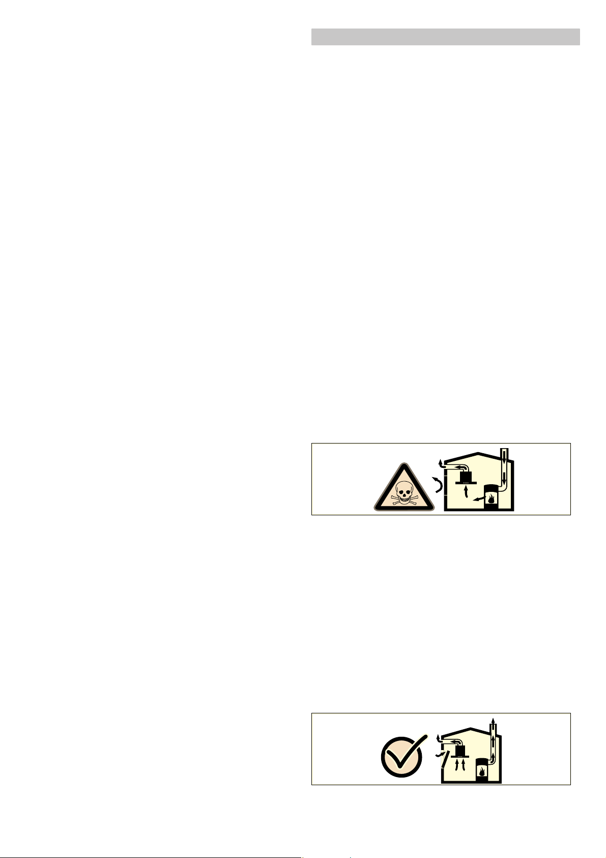
6PRQWDJJLRGHOODSSDUHFFKLR
6WDFFDUHODSSDUHFFKLRGDOODUHWHHOHWWULFD
m 3HULFRORGLVFRVVDHOHWWULFD
6WDFFDQGRLOIRUQRGDOODUHWHGRPHVWLFDLFDYLSRVVRQRFDXVDUH
XQDWHQVLRQHGLULWRUQR/DOODFFLDPHQWRHOHWWULFRGHYHHVVHUH
HVHJXLWRHVFOXVLYDPHQWHGDXQWHFQLFRVSHFLDOL]]DWR
DXWRUL]]DWR
5LPXRYHUHLOFDQDOHGLVFDULFRRLFROOHJDPHQWLGLULFLUFRORGDULD
(VWUDUUHODSSDUHFFKLRVSLQJHQGRORGDOEDVVR
$WWHQ]LRQH
'DQQLDOODSSDUHFFKLR 1RQVROOHYDUHODSSDUHFFKLRWLUDQGROR
GDOODOWR
nl
é
,QVWDOODWLHYRRUVFKULIW
: %HODQJULMNHYHLOLJKHLGVYRRUVFKULIWHQ
/HHVGH]HJHEUXLNVDDQZLM]LQJ]RUJYXOGLJGRRU$OOHHQGDQNXQWX
XZDSSDUDDWJRHGHQYHLOLJEHGLHQHQ%HZDDUGH
JHEUXLNVDDQZLM]LQJ YRRU ODWHU JHEUXLN RI RP GRRU WH JHYHQ DDQ HHQ
YROJHQGHHLJHQDDU
'HYHLOLJKHLGLVDOOHHQJHZDDUERUJGELMHHQGHVNXQGLJHPRQWDJH
YROJHQVGHPRQWDJHKDQGOHLGLQJ'HLQVWDOODWHXULV
YHUDQWZRRUGHOLMNYRRUHHQJRHGHZHUNLQJRSGHSODDWVYDQ
RSVWHOOLQJ
'UDJHUVYDQHOHNWURQLVFKHLPSODQWDWHQ
+HW DSSDUDDW NDQ SHUPDQHQWPDJQHWHQ EHYDWWHQ GLH HOHNWURQLVFKH
LPSODQWDWHQ]RDOVSDFHPDNHUVRILQVXOLQHSRPSHQNXQQHQ
EHwQYORHGHQ+RXGGDDURPELMGHPRQWDJHHHQDIVWDQGYDQ
PLQVWHQVFPWRWHOHNWURQLVFKHLPSODQWDWHQDDQ
'HIDEULNDQWLVQLHWYHUDQWZRRUGHOLMNYRRUEHGULMIVVWRULQJHQRI
PRJHOLMNHVFKDGHDOVJHYROJYDQHHQRQMXLVWHHOHNWULVFKH
LQVWDOODWLH
1HWNDEHOGH]HLVPRJHOLMNDORSGHDDQVOXLWER[YDQGH
NRRNSODDWDDQJHVORWHQRILQEHJUHSHQELMGHOHYHULQJYDQKHW
DSSDUDDWHQPDJDOOHHQGRRUJHNZDOLILFHHUGSHUVRQHHORIHHQ
PHGHZHUNHUYDQGHVHUYLFHGLHQVWZRUGHQJHwQVWDOOHHUG'H
YHUHLVWHDDQVOXLWJHJHYHQVVWDDQRSKHWW\SHSODDWMHHQLQKHW
DDQVOXLWVFKHPD
$OOHHQGHELMKHWDSSDUDDWPHHJHOHYHUGHRIGRRUGHWHFKQLVFKH
VHUYLFHGLHQVWJHOHYHUGHNDEHOJHEUXLNHQ
9yyUDOOHZHUN]DDPKHGHQDDQKHWDSSDUDDWGLHQWKHWDSSDUDDW
VSDQQLQJVYULMWHZRUGHQJHPDDNW
%LMGHLQVWDOODWLHPRHWHQGHDFWXHOHJHOGLJHERXZYRRUVFKULIWHQHQ
GHYRRUVFKULIWHQYDQGHSODDWVHOLMNHVWURRPHQJDVOHYHUDQFLHULQ
DFKWZRUGHQJHQRPHQ
7HQ DDQ]LHQ YDQ GH DIYRHUOXFKW GLHQHQ GH RYHUKHLGV HQ ZHWWHOLMNH
YRRUVFKULIWHQ]RDOVORNDOHERXZYHURUGHQLQJHQLQDFKWWHZRUGHQ
JHQRPHQ
/HYHQVJHYDDU
7HUXJJH]RJHQYHUEUDQGLQJVJDVVHQNXQQHQOHLGHQWRWYHUJLIWLJLQJ
$OWLMG YRRU YROGRHQGH OXFKWWRHYRHU ]RUJHQ ZDQQHHU GH OXFKWDIYRHU
SODDWVYLQGWLQHHQUXLPWHPHWHHQYXXUEURQGLHJHEUXLNPDDNWYDQ
GHDDQZH]LJHOXFKW
9XXUEURQQHQGLHGHOXFKWLQGHUXLPWHYHUEUXLNHQELMYDSSDUDWHQ
GLHRSJDVROLHKRXWRINROHQZRUGHQJHVWRRNWJHLVHUV
ZDUPZDWHUWRHVWHOOHQWUHNNHQGHYHUEUDQGLQJVOXFKWXLWGH
RSVWHOOLQJVUXLPWHHQYRHUHQGHJDVVHQYLDHHQDIYRHUELMY
VFKRRUVWHHQDIQDDUEXLWHQ
,QFRPELQDWLHPHWHHQLQJHVFKDNHOGHDI]XLJNDSZRUGWDDQGH
NHXNHQHQDDQGHUXLPWHVHUQDDVWOXFKWRQWWURNNHQ]RQGHU
YROGRHQGH OXFKWWRHYRHU RQWVWDDW HU HHQ RQGHUGUXN *LIWLJH JDVVHQ
XLW GH VFKRRUVWHHQ RI KHW DIYRHUNDQDDO ZRUGHQ WHUXJJH]RJHQ LQ GH
ZRRQUXLPWH
■ =RUJGDDURPDOWLMGYRRUYROGRHQGHYHQWLODWLH
■ (HQ YHQWLODWLHNDVW LQ GH PXXU DOOHHQ LV QLHW YROGRHQGH RP DDQ GH
PLQLPDOHHLVHQWHYROGRHQ
8NXQWKHWDSSDUDDWDOOHHQGDQ]RQGHUULVLFRJHEUXLNHQZDQQHHU
GHRQGHUGUXNLQGHUXLPWHZDDULQGHYXXUEURQ]LFKEHYLQGWQLHW
JURWHU LV GDQ 3D PEDU 'LW NDQ ZRUGHQ EHUHLNW ZDQQHHU GH
YRRUGHYHUEUDQGLQJEHQRGLJGHOXFKWGRRUQLHWDIVOXLWEDUH
RSHQLQJHQELMYLQGHXUHQUDPHQLQFRPELQDWLHPHWHHQ
YHQWLODWLHNDVW LQ GH PXXU RI DQGHUH WHFKQLVFKH YRRU]LHQLQJHQ NDQ
ZRUGHQWRHJHYRHUG

5DDGSOHHJLQLHGHUJHYDOKHWEHGULMIGDWLQXZKXLV]RUJWYRRUGH
VFKRRUVWHHQUHLQLJLQJ'LWEHGULMILVLQVWDDWKHWWRWDOH
YHQWLODWLHV\VWHHPYDQXZKXLVWHEHRRUGHOHQHQNDQHHQYRRUVWHO
GRHQYRRUSDVVHQGHPDDWUHJHOHQRSKHWJHELHGYDQGH
OXFKWWRHYRHU
,QGLHQGHDI]XLJLQJDOOHHQPHWUHFLUFXODWLHZRUGWJHEUXLNWLVHHQ
RQEHSHUNWJHEUXLNPRJHOLMN
/HYHQVJHYDDU
7HUXJJH]RJHQ YHUEUDQGLQJVJDVVHQ NXQQHQ OHLGHQ WRW YHUJLIWLJLQJ
%LMGHLQVWDOODWLHYDQHHQYHQWLODWLHPHWHHQYXXUEURQGLHJHEUXLN
PDDNWYDQGHDDQZH]LJHOXFKWPRHWGHVWURRPWRHYRHUYDQGH
YHQWLODWLHYRRU]LHQZRUGHQYDQHHQJHVFKLNWH
YHLOLJKHLGVVFKDNHOLQJ
%UDQGJHYDDU
'HYHWDI]HWWLQJHQLQKHWYHWILOWHUNXQQHQRQWEUDQGHQ,QGHEXXUW
YDQKHWDSSDUDDWQRRLWZHUNHQPHWHHQRSHQYODPELMY
IODPEHUHQ +HW DSSDUDDW DOOHHQ LQ GH EXXUW YDQ HHQ YXXUEURQ YRRU
YDVWH EUDQGVWRIIHQ ELMY KRXW RI NROHQ LQVWDOOHUHQ ZDQQHHU HU HHQ
DIJHVORWHQ QLHW YHUZLMGHUEDUH DIVFKHUPLQJ DDQZH]LJ LV (U PRJHQ
JHHQYRQNHQZHJVSULQJHQ
5LVLFRYDQOHWVHO
■ :LM]LJLQJHQDDQGHHOHNWULVFKHRIPHFKDQLVFKHRSERXZ]LMQ
JHYDDUOLMNHQNXQQHQOHLGHQWRWIXQFWLHVWRULQJHQ*HHQ
ZLM]LJLQJHQDDQGHHOHNWULVFKHRIPHFKDQLVFKHRSERXZ
DDQEUHQJHQ
5LVLFRYDQOHWVHO
■ 2QGHUGHOHQGLHWLMGHQVGHPRQWDJHWRHJDQNHOLMN]LMQNXQQHQ
VFKHUSHUDQGHQKHEEHQ'UDDJYHLOLJKHLGVKDQGVFKRHQHQ
5LVLFRYDQOHWVHO
■ +HWWRHVWHOLV]ZDDU(U]LMQWZHH SHUVRQHQQRGLJRPKHW
DSSDUDDW WH EHZHJHQ $OOHHQ JHVFKLNWH KXOSPLGGHOHQ JHEUXLNHQ
*HYDDUYRRUOHWVHO
■ 5RWHUHQGHYHQWLODWRUHQYRUPHQHHQULVLFRRSOHWVHO+HW
DSSDUDDWDOOHHQLQVFKDNHOHQLQLQJHERXZGHWRHVWDQG7LMGHQV
KHW JHEUXLN QRRLW PHW XZ KDQGHQ LQ GH YHQWLODWLHRSHQLQJ DDQ GH
DFKWHUNDQWYDQKHWDSSDUDDWNRPHQ
9HUVWLNNLQJVJHYDDU
9HUSDNNLQJVPDWHULDDOLVJHYDDUOLMNYRRUNLQGHUHQ.LQGHUHQQRRLW
PHWYHUSDNNLQJVPDWHULDDOODWHQVSHOHQ
'LWWRHVWHOQLHWELMERWHQRIYDDUWXLJHQLQERXZHQ
:HUNEODGYODNKRUL]RQWDDOVWDELHO9ROJGHLQVWUXFWLHVYDQGH
IDEULNDQWYDQKHWZHUNEODGRS
:DQQHHUGHGLNWHYDQKHWZHUNEODGZDDULQGHNRRNSODDWZRUGW
JHPRQWHHUG QLHW DDQ GH YHUHLVWH PDDW YROGRHW PRHW KHW ZHUNEODG
PHWKLWWHHQZDWHUEHVWHQGLJPDWHULDDOZRUGHQYHUVWHYLJGWRWGH
DDQEHYROHQ PLQLPDOH GLNWH LV EHUHLNW $QGHUV NDQ JHHQ YROGRHQGH
VWDELOLWHLWZRUGHQJHJDUDQGHHUG
$DQZLM]LQJHQ
■ +HWZHUNEODGZDDULQGHNRRNSODDWZRUGWJHPRQWHHUGPRHW
EHVWDQG]LMQWHJHQHHQEHODVWLQJYDQFD NJ
■ $DQSDVVLQJHQDDQKHWZHUNRSSHUYODNPRHWHQGRRUHHQ
JHVSHFLDOLVHHUGHGLHQVWYHUOHQHUYROJHQVKHWLQERXZVFKHPD
ZRUGHQXLWJHYRHUG'HVQLMNDQWPRHW]XLYHUHQSUHFLHV]LMQ
RPGDWGHUDQGRSKHWRSSHUYODN]LFKWEDDULV'HVQLMNDQWHQPHW
HHQJHVFKLNWUHLQLJLQJVPLGGHOVFKRRQPDNHQHQRQWYHWWHQ
$OJHPHQHDDQZLM]LQJHQ
'HRSSHUYODNNHQYDQKHWDSSDUDDW]LMQJHYRHOLJ9RRUNRP
EHVFKDGLJLQJWLMGHQVGHLQVWDOODWLH
*HEUXLNPHWDIYRHUOXFKW
$DQZLM]LQJ 'HDIYRHUOXFKWPDJQLHWYLDHHQURRNRI
DIYRHUJDVVFKRRUVWHHQ GLH LQ JHEUXLN LV RI YLD HHQ VFKDFKW GLH GLHQW
YRRUGHRQWOXFKWLQJYDQUXLPWHVPHWVWRRNSODDWVHQZRUGHQ
ZHJJHOHLG
.RPW GH DIYRHUOXFKW WHUHFKW LQ HHQ URRN RI DIYRHUJDVVFKRRUVWHHQ
GLHQLHWLQJHEUXLNLVGDQGLHQWXHHQYDNEHNZDPH
VFKRRUVWHHQYHJHUWHUDDGSOHJHQ
/XFKWDIYRHU
$DQZLM]LQJ 9RRUNODFKWHQGLHWHZLMWHQ]LMQDDQGHEHEXL]LQJ
VWDDWGHIDEULNDQWYDQKHWDSSDUDDWQLHWJDUDQW
■ +HWDSSDUDDWZHUNWKHWEHVWZDQQHHUKHWZRUGWDDQJHVORWHQRS
HHQNRUWHUHFKWHDIYRHUEXLVPHWHHQ]RJURRWPRJHOLMNH
GLDPHWHU
■ %LMJHEUXLNYDQODQJHDIYRHUEXL]HQPHWHHQUXZHELQQHQNDQW
YHHOERFKWHQRIEXLVGLDPHWHUVNOHLQHUGDQPPZRUGWGH
RSWLPDOHOXFKWDIYRHUFDSDFLWHLWQLHWEHKDDOGHQLVKHW
YHQWLODWLHJHOXLGKDUGHU
■ 'HEXL]HQRIGHVODQJHQGLHYRRUGHOXFKWDIYRHUZRUGHQ
JHEUXLNWGLHQHQYDQHHQQLHWEUDQGEDDUPDWHULDDOWH]LMQ
■ :RUGW GH DIYRHUOXFKW GRRU GH EXLWHQPXXU JHOHLG GDQ UDGHQ ZLM X
DDQHHQWHOHVFRRSPXXUNDVWWHJHEUXLNHQ
%HVFKDGLJLQJVJHYDDUGRRUFRQGHQVDDWWHUXJORRS
/XFKWDIYRHUNDQDDOYDQXLWKHWDSSDUDDWOLFKWKHOOHQGLQVWDOOHUHQ
YHUORRS
5RQGHEXL]HQ
:LMDGYLVHUHQHHQELQQHQGLDPHWHUYDQ PP
3ODWWHEXL]HQ
'HELQQHQGLDPHWHUPRHWRYHUHHQNRPHQPHWGHGLDPHWHUYDQGH
URQGHEXL]HQ
PPFDFP
■ 3ODWWHEXL]HQPRJHQJHHQVFKHUSHERFKWHQKHEEHQ
■ *HEUXLNELMHHQDIZLMNHQGHEXLVGLDPHWHUHHQDIGLFKWVWULS
*HEUXLNPHWFLUFXODWLHOXFKW
$DQZLM]LQJ +HWDSSDUDDWPDJDOOHHQZRUGHQJHEUXLNWZDQQHHU
KHWJRHGLVJHwQVWDOOHHUGHQGHOHLGLQJHQ]LMQDDQJHVORWHQ
(OHNWULVFKHDDQVOXLWLQJ
'HYHUHLVWHDDQVOXLWJHJHYHQVVWDDQRSKHWW\SHSODDWMHYDQKHW
DSSDUDDW
'LWDSSDUDDWYROGRHWDDQGHRQWVWRULQJVYRRUVFKULIWHQYDQGH(*
$OOHHQ HHQ GDDUWRH EHYRHJG YDNPDQ PDJ KHW DSSDUDDW DDQVOXLWHQ
+HWDSSDUDDWGLHQWYROJHQVGHQLHXZVWH,((ULFKWOLMQHQ,QVWLWXWLRQ
RI (OHFWULFDO (QJLQHHUV WH ZRUGHQ JHwQVWDOOHHUG %LM HHQ YHUNHHUGH
DDQVOXLWLQJNDQKHWDSSDUDDWEHVFKDGLJGUDNHQ
9HU]HNHU X HUYDQ GDW GH VSDQQLQJVZDDUGH YDQ KHW HOHNWULFLWHLWVQHW
RYHUHHQNRPWPHWGHDDQJHJHYHQZDDUGHRSKHWW\SHSODDWMH
=RUJHUYRRUGDWKHWHOHNWULFLWHLWVQHWYROJHQVYRRUVFKULIWJHDDUGLV
HQGH]HNHULQJKHWVQRHUHQKHWOHLGLQJV\VWHHPYDQKHWJHERXZ
YROGRHQGH JHGLPHQVLRQHHUG ]LMQ YRRU KHW HOHNWULVFK YHUPRJHQ YDQ
KHWDSSDUDDW
/HWELMKHWOHJJHQYDQKHWDDQVOXLWVQRHURSGHYROJHQGHSXQWHQ
■ +HWVQRHUPDJQLHWEHNOHPGUDNHQRILQJHGUXNWZRUGHQ
■ +HWVQRHUPDJQLHWLQGHEXXUWNRPHQYDQVFKHUSHUDQGHQ
■ 6QRHUQLHWPHWGHPHWDOHQEHKXL]LQJWHJHQGHRQGHUNDQWYDQ
KHWDSSDUDDWLQFRQWDFWEUHQJHQRPGDWGH]HKHHWZRUGW
9RRUDDQVOXLWLQJYDQKHWDSSDUDDWGHKXLVLQVWDOODWLHFRQWUROHUHQ
/HWHURSGDWGHKXLVLQVWDOODWLHJRHGEHYHLOLJGLV6SDQQLQJHQ
IUHTXHQWLHYDQKHWDSSDUDDWPRHWHQRYHUHHQVWHPPHQPHWGH
HOHNWULVFKHLQVWDOODWLH]LHKHWW\SHSODDWMH
+HWDSSDUDDWYROGRHWDDQEHYHLOLJLQJVNODVVH,HQPDJDOOHHQPHW
HHQJHDDUGHDDQVOXLWLQJZRUGHQJHEUXLNW
'HLQVWDOODWLHGLHQWWHEHVFKLNNHQRYHUHHQVFKDNHODDUPHWHHQ
FRQWDFWRSHQLQJ YDQ PLQVWHQV PP 'H]H GLHQW RRN QD GH LQERXZ
WRHJDQNHOLMNWH]LMQ
+HWDDQEUHQJHQYDQKHWVWRSFRQWDFWRIKHWYHUYDQJHQYDQGH
DDQVOXLWOHLGLQJPDJDOOHHQGRRUHHQHOHNWURWHFKQLFXVPHW
LQDFKWQHPLQJYDQGHJHOGHQGHYRRUVFKULIWHQZRUGHQXLWJHYRHUG
%LMKHWYHUYDQJHQYDQGHQHWDDQVOXLWOHLGLQJNDQKHWJHEHXUHQGDW
KHWDSSDUDDWPRHWZRUGHQRPJHGUDDLG,QGLWJHYDOGH
ILOWHUDIGHNNLQJYHUZLMGHUHQHQKHWUHVHUYRLUHQGHPHWDOHQYHWILOWHU
YHUZLMGHUHQ+LHUGRRUYHUKLQGHUWXGDWGH]HFRPSRQHQWHQHUXLW
YDOOHQ
$OV GH HOHNWULVFKHDDQVOXLWNDEHOYDQ KHWDSSDUDDWEHVFKDGLJG
ZRUGWGDQPRHWGH]HGRRUHHQ VSHFLDOHDDQVOXLWNDEHOYDQKHW
W\SH+99)YHUYDQJHQZRUGHQ
,QVWDOODWLHYRRUEHUHLGHQ
$SSDUDDWDIPHWLQJHQHQYHLOLJKHLGVDIVWDQGHQ
■ +RXGUHNHQLQJPHWGHDSSDUDDWDIPHWLQJHQYRRUOXFKWFLUFXODWLH
$IE $
■ +RXG YRRU GH DIYRHUOXFKW UHNHQLQJ PHW GH DSSDUDDWDIPHWLQJHQ
$IE %
■ =RUJHUYRRUGDWKHWDSSDUDDWQDKHWDIVOXLWHQYDQGHLQVWDOODWLH
YROGRHQGH WRHJDQNHOLMN LV RP GH DFWLHYH NRROILOWHUV WH YHUYDQJHQ
KHWRYHUORRSUHVHUYRLUOHHJWHPDNHQHQGHDIGHNNLQJYDQGH
EHKXL]LQJWHGHPRQWHUHQ $IE &
■ +RXGUHNHQLQJPHWGHYHLOLJKHLGVDIVWDQGHQ $IE &
0HXEHOFRQWUROHUHQ
■ +HW LQERXZPHXEHO PRHW KRUL]RQWDDO XLWJHULFKW ]LMQ HQ YROGRHQGH
GUDDJYHUPRJHQEH]LWWHQ
■ +HWPD[JHZLFKWEHGUDDJWFD NJ
■ +HWLQERXZPHXEHOPRHWEHVWDQG]LMQWHJHQHHQWHPSHUDWXXU
YDQPD[LPDDO&
■ 'HVWDELOLWHLWYDQKHWLQERXZPHXEHOPRHWRRNQDGH
XLWVQLMZHUN]DDPKHGHQJHZDDUERUJG]LMQ
■ 9RRUDOELMGXQQHZHUNEODGHQGLHQWGRRUPLGGHOYDQJHVFKLNWH
RQGHUFRQVWUXFWLHVWHZRUGHQJH]RUJGYRRUYROGRHQGH
GUDDJYHUPRJHQHQVWDELOLWHLW+RXGUHNHQLQJPHWKHWJHZLFKW
YDQKHWDSSDUDDWLQFOEHODGLQJ+HWJHEUXLNWH
YHUVWHUNLQJVPDWHULDDOGLHQWKLWWHHQYRFKWEHVWHQGLJWH]LMQ

■ $IKDQNHOLMNYDQGHEXL]HQHQGHGLHSWHYDQKHWZHUNEODGPRHW
GHGLHSWHYDQGHODGHQRQGHUKHWDSSDUDDWZRUGHQDDQJHSDVW
'HERYHQVWHODGHPRHWYHUZLMGHUGZRUGHQHQLVQLHWEUXLNEDDU
■ 'HDIVWDQGWXVVHQKHWRSSHUYODNYDQKHWZHUNEODGHQGH
ERYHQNDQWYDQGHODGHPRHW PPEHGUDJHQ
■ *HHQ RYHQV NRHODSSDUDWHQ YDDWZDVPDFKLQHV ZDVPDFKLQHV RI
DQGHUHDSSDUDWHQRQGHUERXZHQ
$DQZLM]LQJ 3DV QD LQVWDOODWLH LQ GH LQERXZRSHQLQJ FRQWUROHUHQ RI
KHWDSSDUDDWZDWHUSDVLV
0HXEHOYRRUEHUHLGHQ
0DDNGHXLWVQLMGLQJLQKHWZHUNEODGDDQGHKDQGYDQGH
LQERXZWHNHQLQJ $IE
$DQZLM]LQJ 'H KRHN YDQ KHW VQLMYODN WRW KHW ZHUNEODG PRHW
EHGUDJHQ 'H ]LMUDQGHQ YDQ GH XLWVQLMGLQJ GLHQHQ YODN WH ]LMQ %LM
PXOWLSOH[ZHUNEODGHQHYHQWXHHOOLMVWHQDDQGH]LMNDQWHQLQGH
XLWVQLMGLQJEHYHVWLJHQ
2P HHQ MXLVWH ZHUNLQJ YDQ KHW DSSDUDDW WH JDUDQGHUHQ PRHW GH
NRRNSODDWQDDUEHKRUHQZRUGHQJHYHQWLOHHUG+LHUYRRUHHQ
OXFKWXLWODDWLQGHRQGHUNDVWPDNHQPHWHHQPLQLPDOHGLDPHWHU
YDQ FPò
+RXGELMLQERXZERYHQHHQODGHPLQLPDOHDIVWDQGHQDDQ
$IE &
'H ERYHQVWH ODGH YHUZLMGHUHQ HQ HHQ SDVVHQGH DIVFKHUPLQJ RS
KHWPHXEHODDQEUHQJHQ
0HXEHOHQDSSDUDDWYRRUEHUHLGHQYRRUOXFKWFLUFXODWLH
0HXEHOXLWVQLMGLQJPDNHQ
,QGHYRRUVWHSOLQWYDQKHWPHXEHOHHQOXFKWXLWODDWPDNHQ
$DQZLM]LQJ =RUJYRRUHHQPLQLPDOHGLDPHWHUYDQFD FPò
YRRUGHOXFKWXLWODDW0DDNGHXLWODDWRSHQLQJLQGHSOLQW]RJURRW
PRJHOLMN]RGDWHUZHLQLJWUHNHQJHOXLGRQWVWDDW
$FKWHUNDQWYDQKHWPHXEHOYHUZLMGHUHQ
'HERYHQVWHOLMVWDDQGHDFKWHUNDQWYDQKHWPHXEHO]RQRGLJ
YHUZLMGHUHQ
%HSDDOKHWPLGGHOSXQWRSGHDFKWHUVWHUDQGYDQGH
ZHUNEODGXLWVQLMGLQJ HQ JHHI GLW HQ GH EHLGH OLMQHQ ORRGUHFKW QDDU
EHQHGHQZHHURSGHERGHPYDQKHWPHXEHO $IE D
0RQWDJHSODDWXLWOLMQHQRSGHPLGGHOOLMQYDQGHERGHPYDQKHW
PHXEHO $IE E
%LMODGHQRQGHUVWHODGHYROOHGLJVOXLWHQ9HUGZLMQWGH
PRQWDJHSODDWWHYHURQGHUGHODGHYHUSODDWVKHPGDQLQGH
ULFKWLQJ YDQ GH DFKWHUNDQW YDQ KHW PHXEHO /LMQ KHP PHW EHKXOS
YDQGHPDUNHULQJHQRSGHPRQWDJHSODDWSDUDOOHODDQGH
PLGGHOOLMQXLW $IE F
$DQZLM]LQJHQ
■ ,VGHDIVWDQGWXVVHQODGHHQPHXEHOERGHPWHNOHLQRPGH
PRQWDJHSODDWYDVWWHVFKURHYHQDDQGHERGHPYDQKHW
PHXEHO GUDDL GH PRQWDJHSODDW GDQ HQ VFKURHI KHP YDQ
RQGHUHQYDVWDDQGHERGHPYDQKHWPHXEHO $IE E'H
PRQWDJHSODDW HHUVW YDQ ERYHQDI XLWOLMQHQ RS GH ERGHP YDQ KHW
PHXEHORPGHFRUUHFWHSRVLWLHHUYDQWHEHSDOHQ $IE F
■ $IKDQNHOLMNYDQGHSRVLWLHYDQGHPRQWDJHSODDWGHMXLVWH
YHUOHQJLQJNLH]HQ
■ .DQGHPRQWDJHSODDWQLHWYHUJHQRHJQDDUDFKWHUHQZRUGHQ
JHSODDWVWJHEUXLNGDQODGHQGLHPLQGHUGLHS]LMQ
=R QRGLJ PHW EHKXOS YDQ GH PRQWDJHSODDW LQ GH ERGHP YDQ KHW
PHXEHOHHQXLWVQLMGLQJWHNHQHQHQPDNHQ $IE G
1DXLWVQLMZHUN]DDPKHGHQGHVSDDQGHUVYHUZLMGHUHQ
$DQZLM]LQJ 6QLMYODNNHQKLWWHEHVWHQGLJHQZDWHUGLFKWDIGLFKWHQ
0RQWDJHSODDWHQGLIIXVRUYDVWFOLSVHQ
:DQQHHUHUYROGRHQGHDIVWDQGLVWXVVHQGHODGHHQGHERGHP
YDQKHWPHXEHOGHPRQWDJHSODDWPHWNXQVWVWRIVFKURHYHQYDQ
ERYHQDI YDVWVFKURHYHQ DDQ GH RQGHUVWH ERFKW YDQ GH SODWWH EXLV
$IE D
$DQZLM]LQJ =R QRGLJ DDQ GH RQGHUVWH ERFKW YDQ GH SODWWH EXLV
GUDDLHQ]RGDWGHOXFKWXLWODDW]LFKDDQGHDQGHUHNDQWEHYLQGW
0RQWDJHSODDW PHW KRXWVFKURHYHQ YDQ ERYHQ DDQ GH ERGHP YDQ
KHWPHXEHOEHYHVWLJHQ $IE D
$DQZLM]LQJ ,V GH DIVWDQG WXVVHQ ODGH HQ PHXEHOERGHP WH NOHLQ
RPGHPRQWDJHSODDWYDVWWHVFKURHYHQDDQGHERGHPYDQKHW
PHXEHOGUDDLGHPRQWDJHSODDWGDQHQVFKURHIKHPYDQ
RQGHUHQYDVWDDQGHERGHPYDQKHWPHXEHO $IE E
'LIIXVRUYDVWFOLSVHQDDQGHRQGHUVWHERFKWYDQGHSODWWHEXLV
$IE F
%RYHQVWHERFKWYDQGHSODWWHEXLVPRQWHUHQ
'H YHUOHQJLQJ ]R QRGLJ NLH]HQ DIKDQNHOLMN YDQ GH SRVLWLH YDQ GH
PRQWDJHSODDWHQGHPHXEHOGLHSWH+RHODQJHUGHYHUOHQJLQJ
KRHGLHSHUGHODGHNDQ]LMQ'HYHUOHQJLQJPHWYLHUNXQVWVWRI
YDVWVFKURHYHQDDQGHDI]XLJRSHQLQJYDQGHNRRNSODDW $IE
'HERYHQVWHERFKWYDQGHSODWWHEXLVYDVWVFKURHYHQDDQGH
DI]XLJRSHQLQJYDQGHNRRNSODDWRIDDQGHYHUOHQJLQJ
0HXEHOHQDSSDUDDWYRRUEHUHLGHQYRRUOXFKWDIYRHU
9HUORRSVWXNRIGHERFKWYDQGHSODWWHEXLVPHWYLHUNXQVWVWRI
VFKURHYHQDDQGHXLWODDWRSHQLQJYDQGHNRRNSODDWRIDDQGH
YHUOHQJLQJYDVWVFKURHYHQ $IE
$DQZLM]LQJ =RQRGLJHHQSDVVHQGHYHUOHQJLQJDDQGH
NRRNSODDWYDVWVFKURHYHQ'HWRHJHVWDQHGLHSWH7YDQGHODGH
PHWHQKLHUELMPPDIVWDQGWRWGHDIYRHUEXLVLQDFKWQHPHQ
$IKDQNHOLMNYDQGHJHEUXLNWHYHUOHQJLQJNDQGHGLHSWHYDQGH
ODGHYDULsUHQ $IE
$IKDQNHOLMN YDQ GH FRQILJXUDWLH YDQ GH OXFKWDIYRHU HHQ XLWVQLMGLQJ
YRRUGHDIYRHUEXLVPDNHQLQGHDFKWHUVWHPHXEHOZDQGGH
DFKWHUNDQWYDQKHWPHXEHOYHUZLMGHUHQRIHHQXLWVQLMGLQJLQGH
ERGHPYDQKHWPHXEHOPDNHQ
1DXLWVQLMZHUN]DDPKHGHQGHVSDDQGHUVYHUZLMGHUHQ
$DQZLM]LQJ 6QLMYODNNHQKLWWHEHVWHQGLJHQZDWHUGLFKWDIGLFKWHQ
(OHNWULVFKHDDQVOXLWLQJYRRUEHUHLGHQ
$DQZLM]LQJ 3DUDJUDDI (OHNWULVFKHDDQVOXLWLQJLQKHWKRRIGVWXN
$OJHPHQHDDQZLM]LQJHQLQDFKWQHPHQ
%LMDSSDUDWHQ]RQGHUYRRUDIJHwQVWDOOHHUGHNDEHOGH
QHWNDEHOLQGHDDQVOXLWGRRVVWHNHQ
'HNRRNSODDWRPGUDDLHQHQRSGHYHUSDNNLQJHHQGRHNRIHHQ
DQGHURSSHUYODNOHJJHQRPNUDVVHQWHYRRUNRPHQ
+HWGHNVHOYDQGHDDQVOXLWGRRVRSWLOOHQPHWEHKXOSYDQHHQ
VFKURHYHQGUDDLHU $IE
'H EHYHVWLJLQJVVFKURHI ORVGUDDLHQ HQ GH VODQJNOHP RSWLOOHQ PHW
EHKXOSYDQHHQVFKURHYHQGUDDLHU $IE
$OOHHQYROJHQVGHDIEHHOGLQJDDQVOXLWHQRSKHWVWRSFRQWDFW
$IE
%1%UXLQ
%8%ODXZ
*1<(*HHOHQJURHQ
%.=ZDUW
*<*ULMV
$DQZLM]LQJHQ
■ =RQRGLJGHELMJHYRHJGHNRSHUEUXJJHQPRQWHUHQYROJHQVGH
DDQVOXLWDIEHHOGLQJ
■ /HWHURSGDWGHVFKURHYHQYDQKHWVWRSFRQWDFWZRUGHQ
YDVWJHGUDDLGQDGDWGHNDEHOV]LMQDDQJHVORWHQ
■ %LMHHQDDQVOXLWLQJYDQ1a1aNRPWGHIDVH/JUH\
RYHUHHQPHWGHYHQWLODWRUPRWRU
'HYRHGLQJVNDEHOPHWGHVODQJNOHPEHYHVWLJHQHQGH
EHYHVWLJLQJVVFKURHIDDQWUHNNHQ $IE
'HGHNVHOYDQGHFRQWDFWGRRVVOXLWHQ
$DQZLM]LQJ 'H NDEHOV LQ KHW PLGGHOVWH GHHO YDQ GH FRQWDFWGRRV
SODDWVHQRPKHWVOXLWHQWHYHUJHPDNNHOLMNHQ
$DQZLM]LQJ ,VHUHHQODQJHUHQHWNDEHOQRGLJQHHPGDQFRQWDFW
RSPHWGHVHUYLFHGLHQVW(U]LMQNDEHOVWRW PEHVFKLNEDDU
$SSDUDDWPRQWHUHQ
: 'UDJHUVYDQHOHNWURQLVFKHLPSODQWDWHQ
+HW DSSDUDDW NDQ SHUPDQHQWPDJQHWHQ EHYDWWHQ GLH HOHNWURQLVFKH
LPSODQWDWHQ]RDOVSDFHPDNHUVRILQVXOLQHSRPSHQNXQQHQ
EHwQYORHGHQ+RXGGDDURPELMGHPRQWDJHHHQDIVWDQGYDQ
PLQVWHQVFPWRWHOHNWURQLVFKHLPSODQWDWHQDDQ
: *HYDDUYDQHHQHOHNWULVFKHVFKRN
%HSDDOGHRQGHUGHOHQLQKHWWRHVWHONXQQHQVFKHUSHUDQGHQ
KHEEHQ+LHUGRRUNDQGHDDQVOXLWNDEHOEHVFKDGLJGUDNHQ
$DQVOXLWNDEHOQLHWNQLNNHQRIDINOHPPHQELMGHLQVWDOODWLH
: 5LVLFRYDQOHWVHO
2QGHUGHOHQGLHWLMGHQVGHPRQWDJHWRHJDQNHOLMN]LMQNXQQHQ
VFKHUSHUDQGHQKHEEHQ'UDDJYHLOLJKHLGVKDQGVFKRHQHQ

.RRNSODDWLQEUHQJHQ
%HYHVWLJLQJVUDLOVDDQEUHQJHQ $IE D
%LMZHUNEODGHQYDQVWHHQGHUDLOVYDVWOLMPHQJHEUXLNKLHUYRRU
KLWWHEHVWHQGLJH OLMP GLH JHVFKLNW LV YRRU KHW YHUOLMPHQ YDQ PHWDDO
HQVWHHQ
+HWDSSDUDDWLQGHXLWVQLMGLQJYDQKHWZHUNEODGSODDWVHQ
$IE E
'HPHHJHOHYHUGHEHYHVWLJLQJVNOHPPHQDDQEUHQJHQHQ
YRRU]LFKWLJYDVW]HWWHQ'HNRRNSODDWPHWEHKXOSYDQGH
EHYHVWLJLQJVNOHPPHQLQppQOLMQEUHQJHQPHWKHWZHUNYODN
$IE F
$DQZLM]LQJ *HHQHOHNWULVFKHVFKURHYHQGUDDLHUVJHEUXLNHQ
$SSDUDDWDDQVOXLWHQ
$DQZLM]LQJHQ
■ 9RRUGHDIYRHUOXFKWGLHQWHHQVWXZNOHSPHWHHQPD[LPDOH
RSHQLQJVGUXNYDQ 3DWHZRUGHQLQJHERXZG,VHUJHHQ
VWXZNOHSELMKHWDSSDUDDWJHYRHJGGDQNDQGH]HZRUGHQ
YHUNUHJHQELMVSHFLDDO]DNHQ
■ :RUGWGHDIYRHUOXFKWGRRUGHEXLWHQPXXUJHOHLGGDQGLHQWHU
HHQWHOHVFRRSPXXUNDVWWHZRUGHQJHEUXLNW
/XFKWDIYRHUYHUELQGLQJPDNHQ
/XFKWDIYRHUEXLVEHYHVWLJHQDDQGHERFKWYDQGHSODWWHEXLVRI
KHWYHUORRSVWXN $IE
9HUELQGLQJPDNHQPHWGHOXFKWDIYRHURSHQLQJ
9HUELQGLQJVSXQWHQJRHGDIGLFKWHQ
&LUFXODWLHOXFKWYHUELQGLQJPDNHQ
)LOWHUPRGXOHYDVWFOLSVHQDDQGHRQGHUVWHERFKWYDQGHSODWWH
EXLVRI]RQRGLJYDVWVFKURHYHQ $IE D
$DQZLM]LQJ =R QRGLJ DDQ GH ILOWHUPRGXOH GUDDLHQ ]RGDW GH ODGH
YRRUGHDFWLHYHNRROILOWHUYDQGHDQGHUHNDQWNDQZRUGHQ
JHRSHQG
+HW IOH[LEHOH YHUELQGLQJVHOHPHQW DDQ GH ERYHQVWH ERFKW YDQ GH
SODWWHEXLVYDVWFOLSVHQ
)LOWHUPRGXOH HQ GH ERYHQVWH ERFKW YDQ GH SODWWH EXLV YHUELQGHQ
YLDKHWIOH[LEHOHYHUELQGLQJVHOHPHQW
$DQZLM]LQJ =RQRGLJYHUOHQJLQJHQPRQWHUHQWXVVHQGH
ILOWHUPRGXOHHQKHWIOH[LEHOHYHUELQGLQJVHOHPHQW
$OOHVOXLWLQJVHOHPHQWHQYDQGHODGHRSHQHQ/DGHRSHQHQ
$IE E
$FWLHYHNRROILOWHULQEUHQJHQ $IE F
/DGHVOXLWHQ
$OOHVOXLWLQJVHOHPHQWHQYDQGHODGHVOXLWHQ
6WURRPDDQVOXLWHQ
■ 6SDQQLQJ]LHKHWW\SHSODDWMH
■ 8LWVOXLWHQGDDQVOXLWHQYROJHQVKHWDDQVOXLWVFKHPD $IE
%1EUXLQ
%8EODXZ
*1<(JHHQHQJURHQ
%.]ZDUW
*<JULMV
■ $IKDQNHOLMNYDQGHDDQVOXLWZDDUGHPRHWHYHQWXHHOGHSODDWVLQJ
YDQGHGRRUGHIDEULHNJHOHYHUGHDGHUHLQGKXO]HQZRUGHQ
YHUDQGHUG +LHUYRRU LV KHW ZHOOLFKW QRGLJ GH DGHUV LQ WH NRUWHQ HQ
GHLVRODWLHWHYHUZLMGHUHQ]RGDWHHQDGHUHLQGKXOVNDQZRUGHQ
DDQJHEUDFKWGLHWZHHNDEHOVYHUELQGW
$DQZLM]LQJ &RQWUROHHURIKHWDSSDUDDWNODDULVYRRUJHEUXLN
YHUVFKLMQW
—…‹‹ “‹†‚„ RI “RSKHWGLVSOD\YDQKHWDSSDUDDW
GDQ LV KHW QLHW JRHG DDQJHVORWHQ+DDO GH VWHNNHU YDQ KHW DSSDUDDW
GDQXLWKHWVWRSFRQWDFWHQFRQWUROHHUGHDDQVOXLWLQJYDQGH
HOHNWULFLWHLWVNDEHO
'LVSOD\RPVFKDNHOHQQDDUOXFKWDIYRHURI
OXFKWFLUFXODWLH
9RRUGHOXFKWDIYRHUHQOXFKWFLUFXODWLHPRHWKHWGLVSOD\YDQGH
HOHNWURQLVFKHUHJHOLQJ]RQRGLJLQGHEDVLVLQVWHOOLQJHQZRUGHQ
RPJHVFKDNHOG
=LHKLHUYRRUKHWKRRIGVWXN %DVLVLQVWHOOLQJHQLQGH
JHEUXLNVDDQZLM]LQJ
$SSDUDDWGHPRQWHUHQ
$SSDUDDWORVNRSSHOHQYDQKHWVWURRPQHW
m 5LVLFRYDQHHQHOHNWULVFKHVFKRN
%LMKHWDINOHPPHQYDQGHNRRNSODDWYDQKHWVWURRPQHWNXQQHQ
GHNOHPPHQWHUXJVSDQQLQJYRHUHQ'HHOHNWULVFKHDDQVOXLWLQJ
PDJDOOHHQGRRUHHQJHDXWRULVHHUGHYDNPDQZRUGHQ
XLWJHYRHUG
/XFKWDIYRHUNDQDDOYHUZLMGHUHQRIOXFKWFLUFXODWLHYHUELQGLQJHQ
ORVNRSSHOHQ
+HWDSSDUDDWYDQRQGHUXLWQDDUEXLWHQGUXNNHQ
$WWHQWLH
6FKDGHDDQKHWDSSDUDDW +HWDSSDUDDWHUQLHWYDQERYHQDI
XLWWLOOHQ