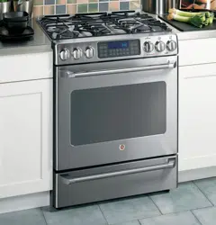
GE Café' C2S980SEM3SS Free Standing Dual-Fuel Range

User Manual

For C2S980SEM3SS. Additionally, the document applies to other GE - General Electric models: C2S980

PDF File Manual, 64 pages, Read Online | Download pdf file

C2S980SEM3SS photo
background
Safety Instructions . . . . . .2–8
Operating Instructions
Convection Oven . . . . . . . . . .19–23
Roasting Guide . . . . . . . . . . . . . .22
Timed Convection Baking . . . . . .23
Gas/Control Lockout . . . . . . . . . . .25
Gas Surface Burners . . . . . . .9, 11
Griddle . . . . . . . . . . . . . . . . . . . . . . . .10
Lower Oven Drawer . . . . . . . . . .28
Thermostat . . . . . . . . . . . . . . . .27, 28
Upper Oven . . . . . . . . . . . . . . .12–27
Aluminum Foil . . . . . . . . . . . . . . .14
Baking or Roasting . . . . . . . . . .14
Broiling Guide . . . . . . . . . . . . . . .15
Clock and Timer . . . . . . . . . . . . .16
Oven Controls . . . . . . . . . . . . . . .12
Preheating . . . . . . . . . . . . . . . . . . .14
Probe . . . . . . . . . . . . . . . . . . . . .18, 21
Sabbath Feature . . . . . . . . . . . .26
Self-Cleaning . . . . . . . . . . . . .29, 30
Special Features . . . . . . . . .24, 25
Timed Baking and
Roasting Features . . . . . . . . . . .17
Care and Cleaning
Burner Grates . . . . . . . . . . . . . . . . .33
Burner Caps and Heads . . . . . .32
Control Panel and Knobs . . . . .37
Cooktop Surface . . . . . . . . . . . . . .33
Griddle . . . . . . . . . . . . . . . . . . . . . . . .34
Lift-Off Oven Door . . . . . . . . . . . .35
Lower Oven Drawer . . . . . . . . . .36
Oven Air Vents . . . . . . . . . . . . . . . .37
Oven Heating Elements . . . . . . .35
Oven Light Replacement . . . . . .38
Oven Shelves . . . . . . . . . . . . . . . . .38
Sealed Burner Assemblies . . . .31
Self-Cleaning . . . . . . . . . . . . . .29, 30
Stainless Steel Surfaces . . . . . . .34
Installation
Instructions . . . . . . . . . . . .39–52
Anti-Tip Device . . . . . . . . . . . . . . . .52
Check Ignition of
Surface Burners . . . . . . . . . . .50, 51
Connect Range
to Electric . . . . . . . . . . . . . . . . .44, 46
Connect Range to Gas . . . . .43, 45
Dimensions and
Clearances . . . . . . . . . . . . . . . . . . . .41
Electrical Connections . . . . . .47–49
Level the Range . . . . . . . . . . . . . . .51
Location Guidelines . . . . . . . . . . .42
LP . . . . . . . . . . . . . . . . . . . . . . . . . . . . .52
Safety Instructions . . . . . . . .39, 40
Accessories . . . . . . . . . . . . . . . . . .57
Troubleshooting Tips .53–56
Consumer Support
Consumer
Support . . . . . . . . . . . . . .Back Cover
Product Registration . . . . . .61, 62
Warranty for Customers
in Canada . . . . . . . . . . . . . . . . . . . . .62
Warranty for Customers
in the U.S.A. . . . . . . . . . . . . . . . . . . .61
Ranges
183D5580P229 49-85147 09-08 JR
C2S980
Owner’s Manual
& Installation
Instructions
ge.com
Self-Cleaning Dual Fuel Convection
Write the model and serial
numbers here:
Model # ____________________
Serial #______________________
You can find them on a label on the
front of the range behind the lower
oven drawer.
In Canada contact us at:
www.GEAppliances.ca
Loading page 2...
Loading page 3...
Loading page 4...
Loading page 5...
Loading page 6...
Loading page 7...
Loading page 8...
Loading page 9...
Loading page 10...
Loading page 11...
Loading page 12...
Loading page 13...
Loading page 14...
Loading page 15...
Loading page 16...
Loading page 17...
Loading page 18...
Loading page 19...
Loading page 20...
Loading page 21...
Loading page 22...
Loading page 23...
Loading page 24...
Loading page 25...
Loading page 26...
Loading page 27...
Loading page 28...
Loading page 29...
Loading page 30...
Loading page 31...
Loading page 32...
Loading page 33...
Loading page 34...
Loading page 35...
Loading page 36...
Loading page 37...
Loading page 38...
Loading page 39...
Loading page 40...
Loading page 41...
Loading page 42...
Loading page 43...
Loading page 44...
Loading page 45...
Loading page 46...
Loading page 47...
Loading page 48...
Loading page 49...
Loading page 50...
Loading page 51...
Loading page 52...
Loading page 53...
Loading page 54...
Loading page 55...
Loading page 56...
Loading page 57...
Loading page 58...
Loading page 59...
Loading page 60...
Loading page 61...
Loading page 62...
Loading page 63...
Loading page 64...

Other documents for GE - General Electric C2S980SEM3SS

The following documents are available:
User Manual Photos

Specifications

GE - General Electric C2S980SEM3SS Questions and Answers


#1 Is there a time limit on returning a part or accessory?

Parts and accessories may be returned for credit up to 90 days from the date the part or accessory was shipped to you from our warehouse. Returns need at least one billing cycle (30 days) to be processed before your account can be credited.
- 30 Day Return Policy Items may be returned within 30 days from the date they were shipped from our warehouse without a restocking fee.
- 31-90 Day Return Policy Items may be returned within 31-90 days from the date they were shipped from our warehouse. A $15 restocking fee will be charged.
- Over 90 Day Return Policy Items that were shipped more than 90 days ago cannot be returned.

#2 Where should returned, damaged, or unneeded parts and accessories be shipped?

In order to return damaged or unneeded parts, you need to complete the online returns process and get a Return Materials Authorization (RMA) number. Through this process, you will be given instructions on how to return the item, including the return shipping address. A RMA number is required for a return and must be visible on the return package or the return will not be processed.

#3 What is the warranty for parts and accessories?

All parts and accessories have a limited one-year warranty, with the exception of water filters, which have a 30-day warranty. If your part fails because of a manufacturing defect within one year from the date of original purchase, we will provide a new or, at our option, rebuilt part without charge. Return the defective part to the vendor from whom it was purchased with a copy of the "proof of purchase." If the part is defective it will be exchanged.
This warranty does not cover parts which are improperly installed, damaged, abused or used for other than the intended purpose. It does not include cost of returning the part to the vendor from which it was purchased, labor to remove, install or diagnose the failure, parts used in commercial applications, incidental or consequential damage caused by possible defects with the parts.
EXCLUSION OF IMPLIED WARRANTIES - Your sole and exclusive remedy is part exchange as provided in this Limited Warranty. Any implied warranties, including the implied warranties of merchantability or fitness for a particular purpose, are limited to one year or the shortest period allowed by law.

User Manual - Transcript

  • Page 1 - English - : Safety Instructions 28 Operating Instructions Convection Oven 1923 Roasting Guide 22 Timed Convection Baking 23 GasControl Lockout 25 Gas Surface Burners 9 11 Griddle 10 Lower Oven Drawer 28 Thermostat 27 28 Upper Oven 1227 Aluminum Foil 14 Baking or Roasting 14 Broiling Guide 15 Clock and Timer 16 Oven Controls 12 Preheating 14 Probe 18 21 Sabbath Feature 26 SelfCleaning 29 30 Special Features 24 25 Timed Baking and Roasting Features 17 Care and Cleaning Burner Grates 33 Burner Caps and Heads 32 Control Panel and Knobs 37 Cooktop Surface 33 Griddle 34 LiftOff Oven Door 35 Lower Oven Drawer 36 Oven Air Vents 37 Oven Heating Elements 35 Oven Light Replacement 38 Oven Shelves 38 Sealed Burner Assemblies 31 SelfCleaning 29 30 Stainless Steel Surfaces 34 Installation Instructions 3952 AntiTip Device 52 Check Ignition of Surface Burners 50 51 Connect Range to Electric 44 46 Connect Range to Gas 43 45 Dimensions and Clearances 41 Electrical Connections 4749 Level the Range 51 Location Guidelines 42 LP 52 Safety Instructions 39 40 Accessories 57 Troubleshooting Tips 5356 Consumer Support Consumer Support Back Cover Product Registration 61 62 Warranty for Customers in Canada 62 Warranty for Customers in the USA 61 Ranges 183D5580P229 4985147 0908 JR C2S980 Owners Manual amp Installation Instructions gecom SelfCleaning Dual Fuel Convection Write the model and serial numbers here Model Serial You can find them on a label on the front of the range behind the lower oven drawer In Canada contact us at wwwGEAppliancesca
  • Page 2 - English - : Operating Instructions Safety Instructions Installation Instructions Troubleshooting TipsConsumer Support IMPORTANT SAFETY INFORMATION READ ALL INSTRUCTIONS BEFORE USING Do not store or use gasoline or other flammable vapors and liquids in the vicinity of this or any other appliance WHAT TO DO IF YOU SMELL GAS Do not try to light any appliance Do not touch any electrical switch do not use any phone in your building Immediately call your gas supplier from a neighbors phone Follow the gas suppliers instructions If you cannot reach your gas supplier call the fire department Installation and service must be performed by a qualified installer service agency or the gas supplier WARNING If the information in this manual is not followed exactly a fire or explosion may result causing property damage personal injury or death
  • Page 3 - English - : Consumer SupportOperating InstructionsSafety Instructions Installation Instructions Troubleshooting Tips WARNING For your safety the information in this manual must be followed to minimize the risk of fire or explosion electric shock or to prevent property damage personal injury or loss of life gecom To reduce the risk of tipping the range the range must be secured by a properly installed antitip bracket See installation instructions shipped with the bracket for complete details before attempting to install To check if the bracket is installed and engaged properly remove the storage drawer or kick panel and look underneath the range to see that the leveling leg is engaged in the bracket On models without a storage drawer or kick panel carefully tip the range forward The bracket should stop the range within 4 inches If it does not the bracket must be reinstalled If the range is pulled from the wall for any reason always repeat this procedure to verify the range is properly secured by the antitip bracket For freestanding or slidein ranges never completely remove the leveling legs or the range will not be secured to the antitip device properly If you did not receive an antitip bracket with your purchase call 18006268774 to receive one at no cost in Canada call 18005613344 For installation instructions of the bracket visit GEAppliancescom in Canada GEAppliancesca ANTITIP DEVICE
  • Page 4 - English - : Operating Instructions Safety Instructions Installation Instructions Troubleshooting TipsConsumer Support IMPORTANT SAFETY INFORMATION READ ALL INSTRUCTIONS BEFORE USING WARNING Have the installer show you the location of the range gas shutoff valve and how to shut it off if necessary Have your range installed and properly grounded by a qualified installer in accordance with the Installation Instructions Any adjustment and service should be performed only by qualified gas range installers or service technicians Do not attempt to repair or replace any part of your range unless it is specifically recommended in this manual All other service should be referred to a qualified technician SAFETY PRECAUTIONS IMPORTANT SAFETY NOTICE The California Safe Drinking Water and Toxic Enforcement Act requires the Governor of California to publish a list of substances known to the state to cause birth defects or other reproductive harm and requires businesses to warn customers of potential exposure to such substances Gas appliances can cause minor exposure to four of these substances namely benzene carbon monoxide formaldehyde and soot caused primarily by the incomplete combustion of natural gas or LP fuels Properly adjusted burners indicated by a bluish rather than a yellow flame will minimize incomplete combustion Exposure to these substances can be minimized by venting with an open window or using a ventilation fan or hood When using electrical appliances basic safety precautions should be followed including the following Use this appliance only for its intended purpose as described in this Owners Manual Be sure your appliance is properly installed and grounded by a qualified technician in accordance with the provided installation instructions Do not attempt to repair or replace any part of your range unless it is specifically recommended in this manual All other servicing should be referred to a qualified technician Before performing any service disconnect the range power supply at the household distribution panel by removing the fuse or switching off the circuit breaker Do not leave children alonechildren should not be left alone or unattended in an area where an appliance is in use They should never be allowed to sit or stand on any part of the appliance Do not allow anyone to climb stand or hang on the door storage drawer or cooktop They could damage the range and even tip it over causing severe personal injury Do not store flammable materials in an oven or near the cooktop CAUTION Items of interest to children should not be stored in cabinets above a range or on the backsplash of a range children climbing on the range to reach items could be seriously injured SAFETY PRECAUTIONS
  • Page 5 - English - : Consumer SupportOperating InstructionsSafety Instructions Installation Instructions Troubleshooting Tips Locate the range out of kitchen traffic path and out of drafty locations to prevent poor air circulation Be sure all packaging materials are removed from the range before operating it to prevent fire or smoke damage should the packaging material ignite Be sure your range is correctly adjusted by a qualified service technician or installer for the type of gas natural or LP that is to be used Your range can be converted for use with either type of gas See the Installation of the range section WARNING These adjustments must be made by a qualified service technician in accordance with the manufacturers instructions and all codes and requirements of the authority having jurisdiction Failure to follow these instructions could result in serious injury or property damage The qualified agency performing this work assumes responsibility for the conversion After prolonged use of a range high floor temperatures may result and many floor coverings will not withstand this kind of use Never install the range over vinyl tile or linoleum that cannot withstand such type of use Never install it directly over interior kitchen carpeting Do not leave children alone or unattended where a range is hot or in operation They could be seriously burned Do not allow anyone to climb stand or hang on the oven door drawer or cooktop They could damage the range and even tip it over causing severe personal injury CAUTION Items of interest to children should not be stored in cabinets above a range or on the backsplash of a rangechildren climbing on the range to reach items could be seriously injured For your safety never use your appliance for warming or heating the room Large scratches or impacts to glass doors can lead to broken or shattered glass Never wear loosefitting or hanging garments while using the appliance Be careful when reaching for items stored in cabinets over the range Flammable material could be ignited if brought in contact with flame or hot oven surfaces and may cause severe burns Do not store flammable materials in an oven a range drawer or near a cooktop Do not store or use combustible materials gasoline or other flammable vapors and liquids in the vicinity of this or any other appliance Do not let cooking grease or other flammable materials accumulate in or near the range Do not use water on grease fires Never pick up a flaming pan Turn the controls off Smother a flaming pan on a surface burner by covering the pan completely with a wellfitting lid cookie sheet or flat tray Use a multipurpose dry chemical or foamtype fire extinguisher Flaming grease outside a pan can be put out by covering it with baking soda or if available by using a multipurpose dry chemical or foamtype fire extinguisher Flame in the upper oven or lower oven drawer can be smothered completely by closing the oven door or drawer and turning the control to off or by using a multipurpose dry chemical or foamtype fire extinguisher Let the burner grates and other surfaces cool before touching them or leaving them where children can reach them Never block the vents air openings of the range They provide the air inlet and outlet that are necessary for the range to operate properly with correct combustion Air openings are located at the rear of the cooktop at the top and bottom of the oven door and at the bottom of the range under the lower oven drawer or kick panel Do not lift the cooktop Lifting the cooktop can lead to damage and improper operation of the range SAFETY PRECAUTIONS gecom
  • Page 6 - English - : SURFACE BURNERS IMPORTANT SAFETY INFORMATION READ ALL INSTRUCTIONS BEFORE USING Operating Instructions Safety Instructions Installation Instructions Troubleshooting TipsConsumer Support Use proper pan sizeavoid pans that are unstable or easily tipped Select cookware having flat bottoms large enough to cover burner grates To avoid spillovers make sure cookware is large enough to contain the food properly This will both save cleaning time and prevent hazardous accumulations of food since heavy spattering or spillovers left on range can ignite Use pans with handles that can be easily grasped and remain cool Always use the LITE position when igniting the top burners and make sure the burners have ignited Never leave the surface burners unattended at high flame settings Boilovers cause smoking and greasy spillovers that may catch on fire Adjust the top burner flame size so it does not extend beyond the edge of the cookware Excessive flame is hazardous Use only dry pot holdersmoist or damp pot holders on hot surfaces may result in burns from steam Do not let pot holders come near open flames when lifting cookware Do not use a towel or other bulky cloth in place of a pot holder When using glass cookware make sure it is designed for topofrange cooking To minimize the possibility of burns ignition of flammable materials and spillage turn cookware handles toward the side or back of the range without extending over adjacent burners Carefully watch foods being fried at a high flame setting Always heat fat slowly and watch as it heats Do not leave any items on the cooktop The hot air from the vent may ignite flammable items and will increase pressure in closed containers which may cause them to burst If a combination of oils or fats will be used in frying stir together before heating or as fats melt slowly Use a deep fat thermometer whenever possible to prevent overheating fat beyond the smoking point Use the least possible amount of fat for effective shallow or deepfat frying Filling the pan too full of fat can cause spillovers when food is added Do not flame foods on the cooktop If you do flame foods under the hood turn the fan on Do not use a wok on the cooking surface if the wok has a round metal ring that is placed over the burner grate to support the wok This ring acts as a heat trap which may damage the burner grate and burner head Also it may cause the burner to work improperly This may cause a carbon monoxide level above that allowed by current standards resulting in a health hazard Foods for frying should be as dry as possible Frost on frozen foods or moisture on fresh foods can cause hot fat to bubble up and over the sides of the pan Never try to move a pan of hot fat especially a deep fat fryer Wait until the fat is cool Do not leave plastic items on the cooktop they may melt if left too close to the vent Keep all plastics away from the surface burners To avoid the possibility of a burn always be certain that the controls for all burners are at the OFF position and all grates are cool before attempting to remove them If range is located near a window do not hang long curtains that could blow over the surface burners and create a fire hazard If you smell gas turn off the gas to the range and call a qualified service technician Never use an open flame to locate a leak Always turn the surface burner controls off before removing cookware When disabling GasControl Lockout make sure the surface controls are set to the OFF position This will preclude gas flow when the range is turned on WARNING
  • Page 7 - English - : The purpose of the warm setting of the lower oven drawer is to hold hot cooked foods at serving temperature Always start with hot food cold food cannot be heated or cooked using the warm setting of the lower oven drawer Do not use the lower oven drawer to dry newspapers If overheated they can catch on fire Do not leave paper products plastics canned food or combustible materials in the drawer Never leave jars or cans of fat drippings in or near your lower oven drawer Do not warm food in the lower oven drawer for more than two hours Do not touch the heating element or the interior surface of the lower oven drawer These surfaces may be hot enough to burn REMEMBER The inside surface of the lower oven drawer may be hot when the drawer is opened Use care when opening the lower oven drawer Open the drawer a crack and let hot air or steam escape before removing or replacing food Hot air or steam which escapes can cause burns to hands face andor eyes Do not use aluminum foil to line the lower oven drawer Foil is an excellent heat insulator and will trap heat beneath it This will upset the performance of the drawer and it could damage the interior finish Never place use or selfclean the lower oven drawer pan in the upper oven LOWER OVEN DRAWER Consumer SupportOperating InstructionsSafety Instructions Installation Instructions Troubleshooting Tips gecom
  • Page 8 - English - : IMPORTANT SAFETY INFORMATION READ ALL INSTRUCTIONS BEFORE USING Operating Instructions Safety Instructions Installation Instructions Troubleshooting TipsConsumer Support READ AND FOLLOW THIS SAFETY INFORMATION CAREFULLY SAVE THESE INSTRUCTIONS Be sure to wipe up excess spillage before selfcleaning operation Before selfcleaning the oven remove the shelves any broiler pan grid and other cookware Never place use or selfclean the lower oven drawer pan in the upper oven Do not clean the door gasket The door gasket is essential for a good seal Care should be taken not to rub damage or move the gasket Clean only parts listed in this Owners Manual If the selfcleaning mode malfunctions turn the oven off and disconnect the power supply Have it serviced by a qualified technician Do not use oven cleaners No commercial oven cleaner or oven liner of any kind should be used in or around any part of the oven Residue from oven cleaners will damage the inside of the oven when the selfclean cycle is used SELFCLEANING UPPER OVEN Do not use the oven for a storage area Items stored in the oven can ignite Keep the oven free from grease buildup Place the oven shelves in the desired position while the oven is cool If shelves must be handled when hot do not let pot holder contact the heating elements Pulling out the shelf to the stoplock is a convenience in lifting heavy foods It is also a precaution against burns from touching hot surfaces of the door or oven walls The lowest position R is not designed to slide Do not heat unopened food containers Pressure could build up and the container could burst causing an injury When using cooking or roasting bags in the oven follow the manufacturers directions Do not use your oven to dry newspapers If overheated they can catch fire Do not leave paper products cooking utensils or food in the oven when not in use Keep the oven vent unobstructed Make sure any broiler pan is in place correctly to reduce the possibility of grease fires If you should have a grease fire in a broiler pan press the CLEAROFF pad and keep the oven door closed to contain fire until it burns out Never place use or selfclean the lower oven drawer pan in the upper oven Stand away from the range when opening the door of a hot oven The hot air and steam that escape can cause burns to hands face and eyes UPPER OVEN COOK MEAT AND POULTRY THOROUGHLY Cook meat and poultry thoroughlymeat to at least an INTERNAL temperature of 160F and poultry to at least an INTERNAL temperature of 180F Cooking to these temperatures usually protects against foodborne illness
  • Page 9 - English - : How to Select Flame Size For safe handling of cookware never let the flames extend up the sides of the cookware Watch the flame not the knob as you reduce heat When fast heating is desired the flame size on a gas burner should match the cookware you are using Flames larger than the bottom of the cookware will not result in faster heating of the cookware and could be hazardous Consumer Support Operating Instructions Safety Instructions Installation Instructions Troubleshooting Tips Throughout this manual features and appearance may vary from your model How to Light a Gas Surface Burner Make sure all the surface burners are placed in their respective positions Push the control knob in and turn it to the LITE position You will hear a little clicking noisethe sound of the electric spark igniting the burner Turn the knob to adjust the flame size If the knob stays at LITE it will continue to click When one burner is turned to LITE all the burners spark Do not attempt to disassemble or clean around any burner while another burner is on An electric shock may result which could cause you to knock over hot cookware Push the control knob in and turn it to the LITE position Before Lighting a Gas Burner Make sure all burners are in place Make sure all grates on the range are properly placed before using any burner If your range has the GasControl Lockout feature make sure it is disabled before attempting to light the surface burners After Lighting a Gas Burner Do not operate the burner for an extended period of time without cookware on the grate The finish on the grate may chip without cookware to absorb the heat Be sure the burners and grates are cool before you place your hand a pot holder cleaning cloths or other materials on them Sealed Gas Burners Your gas range cooktop has five sealed gas burners They offer convenience cleanability and flexibility to be used in a wide range of cooking applications The smallest burner in the right rear position is the simmer burner This burner can be turned down to LO for a very low simmer setting It provides precise cooking performance for delicate foods such as sauces or foods that require low heat for a long cooking time The medium left rear and the large left front burners are the primary burners for most cooking These generalpurpose burners can be turned down from HI to LO to suit a wide range of cooking needs The extra large left front burner also has a special POWER BOIL setting designed to be used with cookware 10 inches or larger in diameter The dual flame extra large burner right front is the maximum output burner Like the other four burners it can be turned down from HI to LO for a wide range of cooking applications however this burner is designed to quickly bring large amounts of liquid to a boil It has a special POWER BOIL setting designed to be used with cookware 10 inches or larger in diameter The center oval burner is the largest in size and is for large oval potspans round potspans 10 or greater in diameter or to be used with the griddle Using the gas surface burners gecom Medium Small Extra large Dual flame extra large Small medium and center burner graphics only Oval Extra large and dual flame extra large burners only
  • Page 10 - English - : Most griddled foods require cooking on a preheated surface Preheat griddle according to the guide below then switch to the desired cook setting IMPORTANT NOTES Avoid cooking extremely greasy foods and be careful of grease spillover while cooking Do not use oil on the griddle for extended lengths of time Permanent staining andor craze lines on the surface could result Never place or store any items on the griddle even when it is not in use The griddle can become heated when using the surrounding burners Do not overheat the griddle Leaving the griddle burner on at HI for an extended amount of time without food can damage the nonstick coating Avoid using metal utensils with sharp points or rough sharp edges that might damage the griddle surface Do not cut foods on the griddle Operating Instructions Safety Instructions Installation Instructions Troubleshooting TipsConsumer Support Your nonstick coated griddle provides an extralarge cooking surface for meats pancakes or other food usually prepared in a frying pan or skillet NOTE Your griddle will discolor over time as it becomes seasoned with use How to Insert the Griddle Using the griddle CAUTION Place and remove the griddle only when all grates and griddle are cool and all surface units are turned OFF The griddle can only be used with the center burner To insert the griddle remove center grate and replace with griddle NOTE Do not clean the griddle in the selfcleaning oven Using the Griddle Type of Food Preheat Cook Setting Conditions Warming none 3 MEDLOW Tortillas Pancakes 4 MED 4 MED 10 min Hamburgers HI 5 MED 5 min Sear on HI for 1 minute each side Fried Eggs HI 4 MED 5 min Bacon None 5 MED Breakfast HI 5 MED Sausage Links 5 min Hot Sandwiches HI HI such as 4 min Grilled Cheese NOTE Griddle settings may need to be adjusted if griddle is used for an extended time
  • Page 11 - English - : In Case of Power Failure In case of a power failure you can light the gas surface burners on your range with a match Hold a lit match to the burner then push in and turn the control knob to the LITE position Use extreme caution when lighting burners this way Surface burners in use when an electrical power failure occurs will continue to operate normally NOTE If GasControl Lockout is in use at the time of a power failure the surface burners cannot be lit Using the gas surface burners gecom Wok This Way We recommend that you use a 14inch or smaller flatbottomed wok Make sure the wok bottom sits flat on the grate They are available at your local retail store Only a flatbottomed wok should be used Do not use a wok support ring Placing the ring over the burner or grate may cause the burner to work improperly resulting in carbon monoxide levels above allowable standards This could be dangerous to your health Use a flatbottomed wok Stove Top Grills Do not use stove top grills on your sealed gas burners If you use the stove top grill on the sealed gas burner it will cause incomplete combustion and can result in exposure to carbon monoxide levels above allowable current standards This can be hazardous to your health TopofRange Cookware Aluminum Mediumweight cookware is recommended because it heats quickly and evenly Most foods brown evenly in an aluminum skillet Use saucepans with tight fitting lids when cooking with minimum amounts of water CastIron If heated slowly most skillets will give satisfactory results Enamelware Under some conditions the enamel of some cookware may melt Follow cookware manufacturers recommendations for cooking methods Glass There are two types of glass cookwarethose for oven use only and those for topofrange cooking saucepans coffee and teapots Glass conducts heat very slowly Heatproof Glass Ceramic Can be used for either surface or oven cooking It conducts heat very slowly and cools very slowly Check cookware manufacturers directions to be sure it can be used on gas ranges Stainless Steel This metal alone has poor heating properties and is usually combined with copper aluminum or other metals for improved heat distribution Combination metal skillets usually work satisfactorily if they are used with medium heat as the manufacturer recommends Consumer SupportOperating InstructionsSafety Instructions Installation Instructions Troubleshooting Tips
  • Page 12 - English - : Operating Instructions Safety Instructions Installation Instructions Troubleshooting TipsConsumer Support Using the upper oven controls Throughout this manual features and appearance may vary from your model BAKE Pad Touch to select the bake function BROIL HILO Pad Touch to select the broil function CONVECTION BAKE MULTI1 RACK Pad Touch to select baking with the convection function CONVECTION ROAST Pad Touch to select roasting with the convection function START Pad Must be touched to start any cooking or cleaning function Display Shows the time of day oven temperature whether the oven is in the bake broil or selfcleaning mode the times set for the timer or automatic oven operations and if the range is locked SELFCLEAN Pad Touch to select selfcleaning function See the Using the selfcleaning oven section If F and a number or letter flash in the display and the oven control signals this indicates a function error code Touch the CLEAROFF pad Allow the oven to cool for one hour Put the oven back into operation If the function error code repeats disconnect the power to the oven and call for service If your oven was set for a timed oven operation and a power outage occurred the clock and all programmed functions must be reset The time of day will flash in the display when there has been a power outage OVEN LIGHT Pad Touch to turn the oven light on or off DELAY START Pad Use along with COOKING TIME or SELF CLEAN pads to set the oven to start and stop automatically at a time you set COOKING TIME Pad Touch and then touch the number pads to set the amount of time you want your food to cook The oven will shut off when the cooking time has run out CLEAROFF Pad Touch to cancel ALL upper oven operations except the clock timer and GasControl Lockout CLOCK Pad Touch before setting the clock Number Pads Use to set any function requiring numbers such as the time of day on the clock the timer the oven temperature the internal food temperature the start time and length of operation for timed baking and selfcleaning KITCHEN TIMER ONOFF Pad Touch to select the timer feature PROBE Pad Touch when using the probe to cook food GASCONTROL LOCKOUT Pad Touch and hold the GASCONTROL LOCKOUT pad for 3 seconds to lockunlock the surface burners oven burners and control panel so they cannot be activated Oven Control Clock Timer and Features Features and appearance may vary
  • Page 13 - English - : To avoid possible burns place the shelves in the desired position before you turn the oven on Before you begin The shelves have stoplocks so that when placed correctly on the supports they will stop before coming completely out and will not tilt When placing and removing cookware pull the shelf out to the bump on the shelf support To remove a shelf pull it toward you tilt the front end up and pull it out To replace place the end of the shelf stoplocks on the support tilt up the front and push the shelf in NOTE The shelf is not designed to slide out at the special low shelf R position Upper Oven Vent Your oven is vented through ducts at the rear of the range Do not block these ducts when cooking in the ovenit is important that the flow of hot air from the oven and fresh air to the oven burner be uninterrupted Avoid touching the vent openings or nearby surfaces during oven or broiler operation they may become hot Handles of pots and pans on the cooktop may become hot if left too close to the vent Do not leave plastic items on the cooktop they may melt if left too close to the vent Do not leave any items on the cooktop The hot air from the vent may ignite flammable items and will increase pressure in closed containers which may cause them to burst Metal items will become very hot if they are left on the cooktop and could cause burns Using the upper oven gecom The oven has 5 shelf positions It also has a special low shelf position R for extra large items such as a large turkey Plastic items on the cooktop may melt if left too close to the vent Vent appearance and location vary Upper Oven Light Touch the OVEN LIGHT pad to turn the light on or off Consumer Support Operating Instructions Safety Instructions Installation Instructions Troubleshooting Tips
  • Page 14 - English - : Operating Instructions Safety Instructions Installation Instructions Troubleshooting TipsConsumer Support How to Set the Upper Oven for Baking or Roasting Touch the BAKE pad Touch the number pads to set the desired temperature Touch the START pad The word ON and 100 will be displayed As the oven heats up the display will show the changing temperature When the oven reaches the temperature you set a tone will sound To change the oven temperature during BAKE cycle press the BAKE pad and then the number pads to get the new temperature Check food for doneness at minimum time on recipe Cook longer if necessary Touch the CLEAROFF pad when cooking is complete Type of Food Shelf Position Frozen pies on cookie sheet C Angel food cake A Bundt or pound cakes C Biscuits muffins brownies B or C cookies cupcakes layer cakes pies Casseroles B or C Turkey R or A Roasting A or B The oven has a special low shelf R position just above the oven bottom Use it when extra cooking space is needed for example when cooking a large turkey The shelf is not designed to slide out at this position Using the upper oven Preheating and Pan Placement Preheat the oven if the recipe calls for it To preheat set the oven at the correct temperature Preheating is necessary when baking cakes cookies pastry and breads For ovens without a preheat indicator light or tone preheat 10 minutes Baking results will be better if baking pans are centered in the oven as much as possible Pans should not touch each other or the walls of the oven If you need to use two shelves stagger the pans so one is not directly above the other and leave approximately 1 2 between pans from the front back and sides of the wall Aluminum Foil Do not use aluminum foil on the bottom of the oven Do not use aluminum foil to catch spillovers when using the CircuWave fan The foil will be sucked toward the convection fan Never entirely cover a shelf with aluminum foil This will disturb the heat circulation and result in poor baking A smaller sheet of foil may be used to catch a spillover by placing it on a lower shelf several inches below the food Oven Moisture As your oven heats up the temperature change of the air in the oven may cause water droplets to form on the door glass These droplets are harmless and will evaporate as the oven continues to heat up
  • Page 15 - English - : gecom How to Set the Upper Oven for BroilingClose the oven door Place the meat or fish on a broiler grid in a broiler pan Follow suggested shelf positions in the Broiling Guide The oven door must be closed during broiling Touch the BROIL HILO pad once for HI Broil To change to LO Broil touch the BROIL HILO pad again Touch the START pad NOTE The display will always automatically remind you to close the door When broiling is finished touch the CLEAROFF pad Serve the food immediately and leave the pan outside the oven to cool during the meal for easiest cleaning Use LO Broil to cook foods such as poultry or thick cuts of meat thoroughly without overbrowning them The size weight thickness starting temperature and your preference of doneness will affect broiling times This guide is based on meats at refrigerator temperature The US Department of Agriculture says Rare beef is popular but you should know that cooking it to only 140F means some food poisoning organisms may survive Source Safe Food Book Your Kitchen Guide USDA Rev June 1985 Quantity and Shelf First Side Second Side Food or Thickness Position Time min Time min Comments Ground Beef 1 lb 4 patties C 13 8 Space evenly 2 to 4 thick 4 lbs 16 patties C 15 11 Beef Steaks Rare 4 to 1 thick E 6 4 Steaks less than 4 thick Medium 1 to 1 2 lbs D 8 6 are difficult to cook rare Well Done D 10 8 Slash fat Rare 1 2 thick C 10 8 Medium 2 to 2 2 lbs C 15 1012 Well Done D 20 20 Chicken 1 whole cut up B 25 25 Brush each side with 2 to 2 2 lbs melted butter split lengthwise Broil skinsidedown first Breast B 25 15 Bakery Product Bread toast 2 to 4 slices D 3 1 Space evenly Place English English Muffin 2 split E 34 muffins cutsideup and brush with butter if desired Lobster Tails 24 B 1820 Do not Cut through back of shell turn Spread open Brush with over melted butter before broiling and after half of broiling time Fish Fillets 1 lb 4 to 2 thick D 5 5 Handle and turn very carefully Brush with lemon butter before and during cooking if desired Salmon Steaks 2 1 thick D 10 5 Turn carefully Do not Fillets 2 2 to 4 thick D 10 turn skin side down Ham Slices 2 thick C 6 6 precooked 1 thick C 8 8 Pork Chops 2 2 thick C 10 10 Slash fat Well Done 2 1 thick about 1 lb C 15 15 Lamb Chops Medium 2 1 thick about 10 D 7 4 Slash fat Well Done to 12 oz D 10 9 Medium 2 1 2 thick about 1 lb D 9 6 Well Done D 14 10 Broiling Guide Consumer Support Operating Instructions Safety Instructions Installation Instructions Troubleshooting Tips Close the door Always broil with the door closed NOTE Broil will not work if the temperature probe is plugged in
  • Page 16 - English - : If a flashing time is in the display you have experienced a power failure Reset the clock To reset the clock touch the CLOCK pad Enter the correct time of day by touching the appropriate number pads Touch the START pad Make sure the clock is set to the correct time of day The timer is a minute timer only The CLEAROFF pad does not affect the timer Not all features are on all models To Set the Clock The clock must be set to the correct time of day for the automatic oven timing functions to work properly The time of day cannot be changed during a timed baking or selfcleaning cycle Touch the CLOCK pad Touch the number pads Touch the number pads the same way you read them For example to set 1234 touch the number pads 1 2 3 and 4 in that order If number pads are not touched within one minute after you touch the CLOCK pad the display reverts to the original setting If this happens touch the CLOCK pad and reenter the time of day Touch the START pad until the time of day shows in the display This enters the time and starts the clock To check the time of day when the display is showing other information simply touch the CLOCK pad The time of day shows until another pad is touched To Set the Timer The timer does not control oven operations The maximum setting on the timer is 9 hours and 59 minutes Touch the KITCHEN TIMER ONOFF pad Touch the number pads until the amount of time you want shows in the display The maximum number of minutes that can be entered is 60 To set additional time you will need to set it by hours and minutes For example to enter 1 hour and 30 minutes touch 1 3 and 0 in that order If you make a mistake press the KITCHEN TIMER ONOFF pad and begin again Touch the START pad After pressing the START pad SET disappears this tells you the time is counting down although the display does not change until one minute has passed When the timer reaches 00 the control will beep 3 times followed by one beep every 6 seconds until the KITCHEN TIMER ONOFF pad is touched The 6 second tone can be canceled by following the steps in the Special features of your oven control section under Tones at the End of a Timed Cycle Using the clock and timer To Reset the Timer If the display is still showing the time remaining you may change it by touching the KITCHEN TIMER ONOFF pad then touch the number pads until the time you want appears in the display If the remaining time is not in the display clock delay start or cooking time are in the display recall the remaining time by touching the KITCHEN TIMER ONOFF pad and then touching the number pads to enter the new time you want To Cancel the Timer Touch the KITCHEN TIMER ONOFF pad twice Power Outage Operating Instructions Safety Instructions Installation Instructions Troubleshooting TipsConsumer Support
  • Page 17 - English - : NOTE Foods that spoil easilysuch as milk eggs fish stuffings poultry and porkshould not be allowed to sit for more than 1 hour before or after cooking Room temperature promotes the growth of harmful bacteria Be sure that the oven light is off because heat from the bulb will speed harmful bacteria growth How to Set an Immediate Start and Automatic Stop The upper oven will turn on immediately and cook for a selected length of time At the end of the cooking time the oven will turn off automatically Touch the BAKE pad Using the number pads enter the desired temperature Touch the COOKING TIME pad NOTE If your recipe requires preheating you may need to add additional time to the length of the cooking time Using the number pads enter the desired baking time The oven temperature and the cooking time that you entered will be displayed Touch the START pad The word ON and 100 will be displayed The cook time will begin to count down As the oven heats up the display will show the changing temperature When the oven reaches the temperature you set 3 beeps will sound At the end of timed baking the oven will turn off The end of cycle tone will sound Touch the CLEAROFF pad to clear the display How to Set a Delayed Start and Automatic Stop You can set the upper oven control to delay start the oven cook for a specific length of time and then turn off automatically Make sure the clock shows the correct time of day Touch the BAKE pad Using the number pads enter the desired temperature Touch the COOKING TIME pad NOTE If your recipe requires preheating you may need to add additional time to the length of the cooking time Using the number pads enter the desired baking time Touch the DELAY START pad Using the number pads enter the time of day you want the oven to turn on and start cooking Touch the START pad NOTE An attention tone will sound if you are using timed baking and do not touch the START pad after entering the baking temperature If you would like to check the times you have set touch the DELAY START pad to check the start time you have set or touch the COOKING TIME pad to check the length of cooking time you have set The oven will turn on automatically The word ON and 100 will be displayed The cook time will begin to count down As the oven heats up the display will show the changing temperature The oven will cook for the programmed cooking time and shut off automatically At the end of timed baking the oven will turn off The end of cycle tone will sound Touch the CLEAROFF pad to clear the display Using the timed baking and roasting features upper oven only gecom Consumer Support Operating Instructions Safety Instructions Installation Instructions Troubleshooting Tips
  • Page 18 - English - : Operating Instructions Safety Instructions Installation Instructions Troubleshooting TipsConsumer Support Use of probes other than the one provided with this product may result in damage to the probe Use the handles of the probe and plug when inserting and removing them from the food and outlet To avoid damaging your probe do not use tongs to pull on the cable when removing it To avoid breaking the probe make sure food is completely defrosted before inserting To prevent possible burns do not unplug the probe from the outlet until the oven has cooled Never leave your probe inside the oven during a selfcleaning cycle Do not store the probe in the oven The temperature probe has a skewerlike probe at one end and a plug at the other end that goes into the outlet in the oven Plug Probe Cable Handles For many foods especially roasts and poultry internal food temperature is the best test for doneness The temperature probe takes the guesswork out of roasting by cooking foods to the exact doneness you want After preparing the meat and placing it on a trivet or on a broiler pan grid follow these directions for proper probe placement Insert the probe completely into the meat It should not touch the bone fat or gristle For roasts with no bone insert the probe into the meatiest part of the roast For bonein ham or lamb insert the probe into the center of the lowest large muscle Insert the probe into the center of dishes such as meat loaf or casseroles Insert the probe into the meatiest part of the inner thigh from below and parallel to the leg of a whole turkey Using the probe How to Set the Upper Oven For Roasting When Using the Probe Insert the probe into the food Plug the probe into the outlet in the oven Make sure its pushed all the way in Close the oven door Touch the PROBE pad Touch the number pads to set the desired internal food or meat temperature Touch the BAKE pad Touch the number pads to set the desired oven temperature Touch the START pad The display will flash if the probe is inserted into the outlet and you have not set a probe temperature and touched the START pad After the internal temperature of the food reaches 100F the changing internal temperature will be shown in the display When the internal temperature of the food reaches the number you have set the probe and the oven turn off and the oven control signals To stop the signal touch the CLEAROFF pad Use hot pads to remove the probe from the food Do not use tongs to pull on itthey might damage it To change the oven temperature during the Roast cycle touch the BAKE pad and then the number pads to set the new temperature If the probe is removed from the food before the final temperature is reached a tone will sound and the display will flash until the probe is removed from the oven You can use the timer even though you cannot use timed oven operations while using the probe
  • Page 19 - English - : Consumer Support Operating Instructions Safety Instructions Installation Instructions Troubleshooting Tips Using the convection oven gecom The convection oven fan shuts off when the oven door is opened DO NOT leave the door open for long periods of time while using convection cooking To help you understand the difference between convection bake and roast and traditional bake and roast here are some general guidelines Convection Bake Preheat the oven See the Using the Oven Preheating and Pan Placement section Ideal for foods cooked on multiple shelves Good for large quantities of baked foods Good results with cookies biscuits brownies cupcakes cream puffs sweet rolls angel food cake and bread The convection fan circulates the heated air evenly over and around the food Convection Roast Good for large tender cuts of meat uncovered The convection fan circulates the heated air evenly over and around the food Meat and poultry are browned on all sides as if they were cooked on a rotisserie Heated air will be circulated over under and around the food being roasted The heated air seals in juices quickly for a moist and tender product while at the same time creating a rich golden brown exterior Roasts or poultry should be cooked on shelf position A When you are convection roasting it is important that you use a broiler pan and grid for best convection roasting results The pan is used to catch grease spills and the grid is used to prevent grease spatters Place the shelf in shelf position A In a convection oven a fan circulates hot air over under and around the food This circulating hot air is evenly distributed throughout the oven cavity As a result foods are evenly cooked and brownedoften in less time than with regular heat NOTE To maximize cooking evenness the fan is designed to rotate in both directions with a pause in between This is normal Auto Recipe Conversion You can use your favorite recipes in the convection oven When using CONVECTION BAKE the oven will automatically convert the oven temperature from regular baking to Convection Bake temperatures Using the number pads enter the temperature recommended in the recipe Touch the START pad The display will show the temperature you entered from your recipe The oven will automatically convert it to the convection cooking temperature Touch the CLEAROFF pad when baking is finished Use pan size recommended in the recipe Some package instructions for frozen casseroles main dishes or baked goods have been developed using commercial convection ovens For best results in this oven preheat the oven and use the temperature for regular baking on the package
  • Page 20 - English - : Operating Instructions Safety Instructions Installation Instructions Troubleshooting TipsConsumer Support When convection baking with only 1 shelf follow the shelf positions recommended in the Using the Oven section Using the convection oven MultiShelf Baking Because heated air is circulated evenly throughout the oven foods can be baked with excellent results using multiple shelves Multishelf baking may increase cook times slightly for some foods but the overall result is time saved Cookies muffins biscuits and other quick breads give very good results with multishelf baking To cook food on more than one rack in convection bake use CONVECTION BAKE MULTI When baking larger foods on 3 shelves place one shelf in the 2nd A position one on the 4th C position and the third shelf in the 6th E position When baking cookies place the shelves in the 3rd B 4th C and 5th D positions How to Set the Upper Oven for Convection Baking or Roasting Touch the CONVECTION BAKE MULTI 1 RACK pad once for multirack convection baking This mode is used for cooking food items on more than one rack ie 2 3 or more racks at the same time in convection bake See the MultiShelf Baking section for more information Touch the CONVECTION BAKE MULTI1 RACK pad twice for one rack convection baking This mode is used for cooking food items on only one rack in convection bake Touch the CONVECTION ROAST pad for convection roasting Touch the number pads to set the desired oven temperature Remember to adjust baking temperature accordingly See the Adapting Recipes section Touch the START pad To change the oven temperature touch the CONVECTION BAKE or CONVECTION ROAST pad and then the number pads to set the new temperature When the oven starts to heat the changing temperature starting at 100F will be displayed When the oven reaches the temperature you set 3 beeps will sound Touch the CLEAROFF pad when finished NOTE You will hear a fan while cooking with convection The fan will stop when the door is opened but the heat will not turn off The fan will not start until the preheat temperature is reached In convection bake modes for maximum cooking evenness the fan is designed to rotate in both directions with a pause in between This is normal Cookware for Convection Cooking Before using your convection oven check to see if your cookware leaves room for air circulation in the oven If you are baking with several pans leave space between them Also be sure the pans do not touch each other or the walls of the oven Paper and Plastic Heatresistant paper and plastic containers that are recommended for use in regular ovens can be used in convection ovens Plastic cookware that is heatresistant to temperatures of 400F can also be used when oven is below 400F Metal and Glass Any type of cookware will work in your convection oven However metal pans heat the fastest and are recommended for convection baking Darkened or mattefinished pans will bake faster than shiny pans Glass or ceramic pans cook more slowly When baking cookies you will get the best results if you use a flat cookie sheet instead of a pan with low sides For recipes like ovenbaked chicken use a pan with low sides Hot air cannot circulate well around food in a pan with high sides
  • Page 21 - English - : gecom How to Set the Upper Oven for Convection Roasting when Using the Probe The display will flash PROBE and the oven control will signal if the probe is inserted into the outlet and you have not set a probe temperature and touched the START pad Place the shelf in the shelf position A Insert the probe completely into the food Plug the probe into the outlet in the oven Make sure it is pushed all the way in Close the oven door Touch the CONVECTION ROAST pad Touch the number pads to set the desired oven temperature Touch the PROBE pad Touch the number pads to set the desired internal food temperature To change the oven temperature during the Convection Roast cycle touch the CONVECTION ROAST pad and then touch the number pads to set the new desired temperature Touch the START pad When the oven starts to heat the word LO will be in the display After the internal temperature of the food reaches 100F the changing internal temperature will be shown in the display When the internal temperature of the food reaches the number you have set the probe and the oven turn off and the oven control signals To stop the signal touch the CLEAROFF pad Use hot pads to remove the probe from the food Do not use tongs to pull on it they might damage it CAUTION To prevent possible burns do not unplug the probe from the oven outlet until the oven has cooled Do not store the probe in the oven NOTE If the probe is removed from the food before the final temperature is reached a tone will sound and the display will flash until the probe is removed from the oven You will hear a fan while cooking with this feature The fan will stop when the door is opened but the heat will not turn off You can use the timer even though you cannot use timed oven operations while using the probe For best results when roasting large turkeys and roasts we recommend using the probe included in the convection oven Consumer Support Operating Instructions Safety Instructions Installation Instructions Troubleshooting Tips
  • Page 22 - English - : Operating Instructions Safety Instructions Installation Instructions Troubleshooting TipsConsumer Support Convection Roasting Guide Meats MinutesLb Oven Temp Internal Temp Beef Rib 3 to 5 lbs Rare 2024 325F 140F Medium 2428 325F 160F Well 2832 325F 170F Boneless Rib Top Sirloin Rare 2024 325F 140F Medium 2428 325F 160F Well 2832 325F 170F Beef Tenderloin Rare 1014 325F 140F Medium 1418 325F 160F Pot Roast 2 2 to 3 lbs chuck rump 3545 300F 170F Pork Bonein 3 to 5 lbs 2327 325F 170F Boneless 3 to 5 lbs 2327 325F 170F Pork Chops 2 to 1 thick 2 chops 3035 total 325F 170F 4 chops 3540 total 325F 170F 6 chops 4045 total 325F 170F Ham Canned 3 lbs fully cooked 1418 325F 140F Butt 5 lbs fully cooked 1418 325F 140F Shank 5 lbs fully cooked 1418 325F 140F Lamb Bonein 3 to 5 lbs Medium 1720 325F 160F Well 2024 325F 170F Boneless 3 to 5 lbs Medium 1720 325F 160F Well 2024 325F 170F Seafood Fish whole 3 to 5 lbs 3040 total 400F Lobster Tails 6 to 8 oz each 2025 total 350F Poultry Whole Chicken 2 2 to 3 2 lbs 2426 350F 180185F Cornish Hens Unstuffed 1 to 1 2 lbs 5055 total 350F 180185F Cornish Hens Stuffed 1 to 1 2 lbs 5560 total 350F 180185F Duckling 4 to 5 lbs 2426 325F 180185F Turkey whole Unstuffed 10 to 16 lbs 811 325F 180185F Unstuffed 18 to 24 lbs 710 325F 180185F Turkey Breast 4 to 6 lbs 1619 325F 170F Stuffed birds generally require 3045 minutes additional roasting time Shield legs and breast with foil to prevent overbrowning and drying of skin The US Department of Agriculture says Rare beef is popular but you should know that cooking it to only 140F means some food poisoning organisms may survive Source Safe Food Book Your Kitchen Guide USDA Rev June 1985 Using the convection oven
  • Page 23 - English - : You will hear a fan while cooking with this feature The fan will stop when the door is opened but the heat will not turn off NOTE Foods that spoil easilysuch as milk eggs fish stuffings poultry and porkshould not be allowed to sit for more than 1 hour before or after cooking Room temperature promotes the growth of harmful bacteria Be sure that the oven light is off because heat from the bulb will speed harmful bacteria growth How to Set an Immediate Start and Automatic Stop The upper oven will turn on immediately and cook for a selected length of time At the end of the cooking time the oven will turn off automatically Touch the CONVECTION BAKE MULTI 1 RACK pad once for multirack convection baking This mode is used for cooking food items on more than one rack ie 2 3 or more racks at the same time in convection bake See the Multi Shelf Baking section for more information Touch the CONVECTION BAKE MULTI 1 RACK pad twice for one rack convection baking This mode is used for cooking food items on only one rack in convection bake Touch the CONVECTION ROAST pad for convection roasting Touch the number pads to set the desired oven temperature Touch the COOKING TIME pad NOTE If your recipe requires preheating you may need to add additional time to the length of the cooking time Touch the number pads to set the desired length of cooking time The minimum cooking time you can set is 1 minute The oven temperature that you set and the cooking time that you entered will be in the display Touch the START pad The display shows the oven temperature that you set and the cooking time countdown The display starts changing once the temperature reaches 100F At the end of timed convection bake the oven will turn off The end of cycle tone will sound Touch the CLEAROFF pad to clear the display if necessary Remove the food from the oven Remember foods that are left in the oven continue cooking after the controls are off How to Set a Delayed Start and Automatic Stop You can set the upper oven control to delay start the oven cook for a specific length of time and then turn off automatically Make sure the clock shows the correct time of day Touch the CONVECTION BAKE MULTI1 RACK pad once for multirack convection baking This mode is used for cooking food items on more than one rack ie 2 3 or more racks at the same time in convection bake See the Multi Shelf Baking section for more information Touch the CONVECTION BAKE MULTI1 RACK pad twice for one rack convection baking This mode is used for cooking food items on only one rack in convection bake Touch the CONVECTION ROAST pad for convection roasting Touch the number pads to set the desired oven temperature Touch the COOKING TIME pad NOTE If your recipe requires preheating you may need to add additional time to the length of the cooking time Touch the number pads to set the desired cooking time Touch the DELAY START pad Touch the number pads to set the time of day you want the oven to turn on and start cooking If you would like to check the times you have set touch the DELAY START pad to check the start time you have set or touch the COOKING TIME pad to check the length of cooking time you have set Touch the START pad NOTE An attention tone will sound if you are using timed baking and do not touch the START pad after entering the baking temperature When the oven turns on at the time of day you have set the display will show the changing temperature starting at 100F and the cooking time countdown At the end of timed convection bake the oven will turn off The end of cycle tone will sound Touch the CLEAROFF pad to clear the display if necessary When baking is finished remove the food from the oven Remember even though the oven shuts off automatically foods continue cooking after the controls are off Using the timed convection baking features upper oven only gecom Consumer Support Operating Instructions Safety Instructions Installation Instructions Troubleshooting Tips
  • Page 24 - English - : Operating Instructions Safety Instructions Installation Instructions Troubleshooting TipsConsumer Support Your new touch pad control has additional features that you may choose to use The following are the features and how you may activate them The special feature modes can only be activated while the display is showing the time of day They remain in the controls memory until the steps are repeated When the display shows your choice touch the START pad The special features will remain in memory after a power failure 12 Hour ShutOff With this feature should you forget and leave the oven on the control will automatically turn off the oven after 12 hours during baking functions or after 3 hours during a broil function If you wish to turn OFF this feature follow the steps below Touch the BAKE and BROIL HILO pads at the same time for 3 seconds until the display shows SF Touch the DELAY START pad The display will show 12 shdn 12 hour shutoff Touch the DELAY START pad again and the display will show no shdn no shutoff Touch the START pad to activate the no shutoff and leave the control set in this special features mode Fahrenheit or Celsius Temperature Selection Your oven control is set to use the Fahrenheit temperature selections but you may change this to use the Celsius selections Touch the BAKE and BROIL HILO pads at the same time for 3 seconds until the display shows SF Touch the BROIL HILO pad The display will show F Fahrenheit Touch the BROIL HILO pad again The display will show C Celsius Touch the START pad Tones at the End of a Timed Cycle At the end of a timed cycle 3 short beeps will sound followed by one beep every 6 seconds until the CLEAROFF pad is touched This continual 6 second beep may be canceled To cancel the 6 second beep Touch the BAKE and BROIL HILO pads at the same time for 3 seconds until the display shows SF Touch the KITCHEN TIMER ONOFF pad The display shows CON BEEP continual beep Touch the KITCHEN TIMER ONOFF pad again The display shows BEEP This cancels the one beep every 6 seconds Touch the START pad Special features of your upper oven control
  • Page 25 - English - : gecom 12 Hour 24 Hour or Clock BlackOut Your control is set to use a 12 hour clock If you would prefer to have a 24 hour military time clock or blackout the clock display follow the steps below Touch the BAKE and BROIL HILO pads at the same time for 3 seconds until the display shows SF Touch the CLOCK pad once The display will show 12 hr If this is the choice you want touch the START pad Touch the CLOCK pad again to change to the 24 hour military time clock The display will show 24 hr If this is the choice you want touch the START pad Touch the CLOCK pad again to blackout the clock display The display will show OFF If this is the choice you want touch the START pad NOTE If the clock is in the blackout mode you will not be able to use the Delay Start function Cook and Hold Your new control has a cook and hold feature that keeps cooked foods warm for up to 3 hours after the cooking function is finished This feature can only be used when timed cooking To activate this feature follow the steps below Touch the BAKE and BROIL HILO pads at the same time for 3 seconds until the display shows SF Touch the COOKING TIME pad The display will show Hld OFF Touch the COOKING TIME pad again to activate the feature The display will show Hld ON Touch the START pad to activate the cook and hold feature and leave the control set in this special features mode Consumer Support Operating Instructions Safety Instructions Installation Instructions Troubleshooting Tips Your control will allow you to lock out the surface burners oven burners and control panel so they cannot be activated To lockunlock the controls Turn all surface burners off Touch and hold the GASCONTROL LOCKOUT pad for 3 seconds until the display shows LOC To unlock the control touch and hold the GASCONTROL LOCKOUT pad for 3 seconds until LOC disappears from the display When this feature is on and the touch pads are touched the control will beep and the display will show LOC The control lockout mode affects all controls No controls will work when this feature is activated The adjustment will be retained in memory after a power failure GasControl Lockout on some models
  • Page 26 - English - : Operating Instructions Safety Instructions Installation Instructions Troubleshooting TipsConsumer Support Using the Sabbath Feature on some models Designed for use on the Jewish Sabbath and Holidays The Sabbath feature can be used for bakingroasting in the upper oven only It cannot be used for convection broiling selfcleaning or Delay Start cooking NOTE The oven light comes on automatically when the door is opened and goes off when the door is closed The bulb may be removed See the Oven Light Replacement section When the display shows the oven is set in Sabbath When the display shows the oven is bakingroasting When the display shows the oven is set in Sabbath When the display shows the oven is bakingroasting How to Set for Regular BakingRoasting Make sure the clock shows the correct time of day and the oven is off Press and hold both the BAKE and BROIL HILO pads at the same time until the display shows SF Tap the DELAY START pad until SAb bAtH appears in the display Touch the START pad and will appear in the display Touch the BAKE pad No signal will be given Using the number pads enter the desired temperature between 170 and 550 No signal or temperature will be given Touch the START pad After a random delay period of approximately 30 seconds to 1 minute will appear in the display indicating that the oven is bakingroasting If doesnt appear in the display start again at Step 4 To adjust the oven temperature touch the BAKE pad enter the new temperature using the number pads and touch the START pad NOTE The CLEAROFF and COOKING TIME pads are active during the Sabbath feature How to Exit the Sabbath Feature Touch the CLEAROFF pad If the oven is cooking wait for a random delay period of approximately 30 seconds to 1 minute until only is in the display Press and hold both the BAKE and BROIL HILO pads at the same time until the display shows SF Tap the DELAY START pad until 12 shdn or no shdn appears in the display 12 shdn indicates that the oven will automatically turn off after 12 hours no shdn indicates that the oven will not automatically turn off Touch the START pad NOTE If a power outage occurred while the oven was in Sabbath the oven will automatically turn off and stay off even when the power returns The oven control must be reset How to Set for Timed BakingRoastingImmediate Start and Automatic Stop Make sure the clock shows the correct time of day and the oven is off Press and hold both the BAKE and BROIL HILO pads at the same time until the display shows SF Tap the DELAY START pad until SAb bAtH appears in the display Touch the START pad and will appear in the display Touch the COOKING TIME pad Touch the number pads to set the desired length of cooking time between 1 minute and 9 hours and 99 minutes The cooking time that you entered will be displayed Touch the START pad Touch the BAKE pad No signal will be given Using the number pads enter the desired temperature No signal or temperature will be given Touch the START pad After a random delay period of approximately 30 seconds to 1 minute will appear in the display indicating that the oven is bakingroasting If doesnt appear in the display start again at Step 7 To adjust the oven temperature touch the BAKE pad enter the new temperature using the number pads and touch the START pad When cooking is finished the display will change from to and 000 will appear indicating that the oven has turned OFF but is still set in Sabbath Remove the cooked food
  • Page 27 - English - : You may find that your new oven cooks differently than the one it replaced Use your new oven for a few weeks to become more familiar with it If you still think your new oven is too hot or too cold you can adjust the thermostat yourself Do not use thermometers such as those found in grocery stores to check the temperature setting of your oven These thermometers may vary 2040 degrees NOTE This adjustment will not affect the broiling or the selfcleaning temperatures The adjustment will be retained in memory after a power failure To Adjust the Thermostat Touch the BAKE and BROIL HILO pads at the same time for 3 seconds until the display shows SF Touch the BAKE pad A two digit number shows in the display Touch BAKE once to decrease the oven temperature or twice to increase The oven temperature can be adjusted up as much as 35F or down as much as 35F Touch the number pads the same way you read them For example to change the oven temperature 15F touch 1 and 5 When you have made the adjustment touch the START pad to go back to the time of day display Use your oven as you would normally NOTE The thermostat adjustment for Baking will also affect Convection Baking or Convection Roasting Most recipes for baking have been developed using high fat products such as butter or margarine 80 fat If you decrease the fat the recipe may not give the same results as with a higher fat product Recipe failure can result if cakes pies pastries cookies or candies are made with lowfat spreads The lower the fat content of a spread product the more noticeable these differences become Federal standards require products labeled margarine to contain at least 80 fat by weight Lowfat spreads on the other hand contain less fat and more water The high moisture content of these spreads affects the texture and flavor of baked goods For best results with your old favorite recipes use margarine butter or stick spreads containing at least 70 vegetable oil Adjust the upper oven thermostatDo it yourself gecom The type of margarine will affect baking performance Consumer Support Operating Instructions Safety Instructions Installation Instructions Troubleshooting Tips
  • Page 28 - English - : Operating Instructions Safety Instructions Installation Instructions Troubleshooting TipsConsumer Support Using the lower oven drawer To Use the Lower Oven Drawer Push in and turn the lower oven drawer knob to any desired setting Allow the lower oven drawer to preheat The ON signal light is located on the upper right side of the knob and glows when the knob is in the ON position It remains ON until the knob is moved to the OFF position The Heating signal light is located below the ON signal light and glows when the heating elements are active Preheat is complete after the Heating signal has turned off for the first time with each use NOTES Always use the included drawer rack when using the Lower Oven Drawer The lower oven drawer cannot be used during a selfclean cycle of the upper oven Do not put food foil or cookware directly on the bottom of the lower oven drawer Always use the included drawer rack If foods require a cover use only foil or lids able to withstand baking temperatures Do not use plastic Maximum height of foods that can be placed in the lower oven drawer is 4 Do not put liquid or water in the lower oven drawer Never place plastics paper canned foods or combustible material in the lower oven drawer The lower oven drawer may be used to bake foods using the same times and temperatures as a standard oven Foods ideal for baking in the lower oven drawer include pizza frozen foods casseroles biscuits rolls and many desserts Push in and turn the lower oven drawer knob to any desired setting The lower oven drawer uses less energy than the upper oven Allow the following approximate times for preheating Desired Lower Preheat Oven Temperature Time WARM 10 minutes 350F 20 minutes 425F 30 minutes Back of Lower Oven Knob Appearance may vary You may find that your new oven cooks differently than the one it replaced Use your new oven for a few weeks to become more familiar with it If you still think your new oven is too hot or too cold you can adjust the thermostat yourself Do not use thermometers such as those found in grocery stores to check the temperature setting of your oven These thermometers may vary 2040 degrees NOTE This adjustment will not affect the broiling temperatures Adjust the oven thermostatDo it yourself Pull the OVEN CONTROL knob off the range and look at the back side To make an adjustment loosen approximately one turn but do not completely remove the two screws on the back of the knob With the back of the knob facing you hold the outer edge of the knob with one hand and turn the front of the knob with the other hand To raise the oven temperature move the top screw toward the right Youll hear a click for each notch you move the knob To lower the temperature move the top screw toward the left Each click will change the oven temperature approximately 10F Range is 60F from the arrow We suggest that you make the adjustment one click from the original setting and check oven performance before making any additional adjustments After the adjustment is made retighten screws so they are snug but be careful not to overtighten Reinstall knob on range and check performance T O M A K E O V E N C O O L E R T U R N D I S K A P P R O X F P E R N O T C H T O M A K E O V E N H O T T E R T U R N D I S K T O A D J U S T O V E N T E M P E R A T U R E L O O S E N S C R E W S A N D R O T A T E
  • Page 29 - English - : Consumer Support Installation Instructions Troubleshooting TipsOperating InstructionsSafety Instructions The oven door must be closed and all controls set correctly for the cycle to work properly Before a Clean Cycle For the first selfclean cycle we recommend venting your kitchen with an open window or using a ventilation fan or hood Remove the shelves any broiler pan broiler grid probe all cookware and any aluminum foil from the oven The oven shelves can be selfcleaned but they will darken lose their luster and become hard to slide Soil on the front frame of the range and outside the gasket on the door will need to be cleaned by hand Clean these areas with hot water soapfilled scouring pads or cleansers such as Soft Scrub Rinse well with clean water and dry Do not clean the gasket The fiberglass material of the oven door gasket cannot withstand abrasion It is essential for the gasket to remain intact If you notice it becoming worn or frayed replace it Wipe up any heavy spillovers on the oven bottom Make sure the oven light bulb cover is in place and the oven light is off IMPORTANT The health of some birds is extremely sensitive to the fumes given off during the selfcleaning cycle of any range Move birds to another wellventilated room NOTE Use caution when opening the upper oven after the selfclean cycle has ended The oven may still be hot Using the selfcleaning upper oven gecom Wipe up heavy soil on the oven bottom How to Set the Upper Oven for Cleaning NOTE The surface burners must be turned off prior to the selfclean start time Touch the SELF CLEAN pad NOTE If the display shows LOC touch and hold the GASCONTROL LOCKOUT pad for 3 seconds to turn it off See the GasControl Lockout section Using the number pads enter the desired clean time if a time other than 4 hours is needed Clean cycle time is normally 4 hours You can change the clean time to any time between 3 hours and 5 hours depending on how dirty your oven is Touch the START pad The door locks automatically The display will show the clean time remaining It will not be possible to open the oven door until the temperature drops below the lock temperature and the LOCKED DOOR light goes off The oven shuts off automatically when the clean cycle is complete When the LOCKED DOOR light is off the door will unlock automatically The words LOCK DOOR will flash and the oven control will signal if you set the clean cycle and forget to close the oven door To stop a clean cycle touch the CLEAROFF pad When the LOCKED DOOR light goes off indicating the oven has cooled below the locking temperature you may open the door Do not use the lower oven drawer during a selfclean cycle
  • Page 30 - English - : Operating Instructions Safety Instructions Installation Instructions Troubleshooting TipsConsumer Support The oven door must be closed and all controls set correctly for the cycle to work properly After a Clean Cycle You may notice some white ash in the oven Wipe it up with a damp cloth after the oven cools If white spots remain remove them with a soapfilled scouring pad and rinse thoroughly with a vinegar and water mixture These deposits are usually a salt residue that cannot be removed by the clean cycle If the oven is not clean after one clean cycle repeat the cycle You cannot set the oven for cooking until the oven is cool enough for the door to unlock While the oven is selfcleaning you can touch the CLOCK pad to display the time of day To return to the clean countdown touch the COOKING TIME pad If the shelves become hard to slide apply a small amount of vegetable oil or cooking oil to a paper towel and wipe the edges of the oven shelves with the paper towel Using the selfcleaning upper oven How to Delay the Start of Cleaning Make sure the clock shows the correct time of day NOTE The surface burners must be turned off prior to the selfclean start time Touch the SELF CLEAN pad NOTE If the display shows LOC touch and hold the GASCONTROL LOCKOUT pad for 3 seconds to turn it off See the GasControl Lockout section Using the number pads enter the desired clean time Touch the DELAY START pad The earliest start time you can set will appear in the display Using the number pads enter the time of day you want the clean cycle to start Touch the START pad The door locks automatically The display will show the start time It will not be possible to open the oven door until the temperature drops below the lock temperature and the LOCKED DOOR light goes off The oven shuts off automatically when the clean cycle is complete When the LOCKED DOOR light is off the door will unlock automatically The words LOCK DOOR will flash and the oven control will signal if you set the clean cycle and forget to close the oven door To stop a clean cycle touch the CLEAROFF pad When the LOCKED DOOR light goes off indicating the oven has cooled below the locking temperature you may open the door
  • Page 31 - English - : Consumer Support Installation Instructions Troubleshooting TipsOperating InstructionsSafety Instructions Care and cleaning of the range gecom Turn all controls OFF before removing the burner parts The round side burner caps and burner heads can be lifted off making them easy to clean The electrodes are not removable The oval center burner head and cap assembly can be lifted off making it easy to clean The burner electrode is not removable CAUTION Do not operate the cooktop without all burner parts and grates in place Be sure electrical power is off and all surfaces are cool before cleaning any part of the range If your range is removed for cleaning servicing or any reason be sure the antitip device is reengaged properly when the range is replaced Failure to take this precaution could result in tipping of the range and cause injury Sealed Burner Assemblies Burner head and cap assembly Center griddle Electrode Electrode Burner cap Burner head Burner base Front right burner Make sure the hole in the burner head is positioned over the electrode and that the burner head is fully inserted inside the burner base A small gap between the base and head is normal Electrode Burner cap Stability chamber Burner base Front left burner back right burner and back left burner Make sure the slot in the burner head is positioned over the electrode Burner head Use a sewing needle or twisttie to unclog the small hole in the burner head The electrode of the spark igniter is exposed when the burner head is removed When one burner is turned to LITE all the burners spark Do not attempt to disassemble or clean around any burner while another burner is on An electric shock may result which could cause you to knock over hot cookware Electrode Electrode Burner head Burner base Front right burner Front left back right and back left burner
  • Page 32 - English - : Operating Instructions Safety Instructions Installation Instructions Troubleshooting TipsConsumer Support Care and cleaning of the range Burner Caps and Heads Before removing the burner caps and heads remember their size and location Replace them in the same location after cleaning NOTE Do not use steel wool or scouring powders to clean the burner parts Burner caps Lift off when cool Wash burner caps in hot soapy water and rinse with clean water You may scour with a plastic scouring pad to remove burnedon food particles Burner Heads and Oval Center Burner HeadCap Assembly The burner heads and the oval burner headcap assembly are removable Simply lift them off the range for cleaning For proper ignition make sure the small hole in the section that fits over the electrode is kept open A sewing needle or wire twisttie works well to unclog it The slits in the burner heads must be kept clean at all times for an even unhampered flame Clogged or dirty burner ports or electrodes will not allow the burner to operate properly Any spill on or around an electrode must be carefully cleaned Take care to not hit an electrode with anything hard or it could be damaged Clean the burner heads routinely especially after bad spillovers which could clog the openings Lift off when cool To remove burnedon food soak the burner heads in a solution of mild liquid detergent and hot water for 2030 minutes For more stubborn stains use a toothbrush After cleaning Before putting the burner caps heads and oval headcap assembly back shake out excess water and then dry them thoroughly by setting in a warm oven for 30 minutes Replacement Burner Heads Replace burner heads over the electrodes on the cooktop in the correct locations according to their size There is one small one medium one extra large and one dual flame extra large burner head Make sure the slot on fromt left back right and back left heads and the hole front right head in the burner head is positioned over the electrode Oval Center Burner HeadCap Assembly Replace the oval center headcap assembly over the electrode on the cooktop Caps Replace the matching size caps onto the burner bases or heads Make sure that the heads and caps are replaced in the correct locations The oval burner headcap assembly is removable Simply lift it off the range for cleaning Use a sewing needle or twisttie to unclog the small hole in the burner heads Burner cap is properly seated Burner cap is NOT properly seated Electrode Slot Front of range Oval head and cap assembly Medium head Front of range Extra large head Small head Dual flame extra large head Medium cap Front of range Extra large cap Small cap Dual flame extra large cap Make sure the slot in the burner head is positioned over the electrode Hole in burner head Slot Electrode Burner head Electrode Burner head Front right head Hole Electrode Burner cap Burner head Burner base Front right burner Make sure the hole in the burner head is positioned over the electrode and that the burner head is fully inserted inside the burner base A small gap between the base and head is normal Electrode Burner cap Stability chamber Burner base Front left burner back right burner and back left burner Make sure the slot in the burner head is positioned over the electrode Burner head Use a sewing needle or twisttie to unclog the small hole in the burner head
  • Page 33 - English - : Consumer Support Installation Instructions Troubleshooting Tips Operating Instructions Safety Instructions gecom Cooktop Surface To avoid damaging the stainless steel surface of the cooktop and to prevent it from becoming dull clean up spills right away Foods with a lot of acid tomatoes sauerkraut fruit juices etc or foods with high sugar content could cause a dull spot if allowed to set When the surface has cooled wash and rinse For other spills such as fat spatterings etc wash with soap and water once the surface has cooled Then rinse and polish with a dry cloth NOTE Do not lift the cooktop Lifting the cooktop can lead to damage and improper operation of the range NOTE Do not store flammable materials in an oven drawer or near the cooktop Do not store or use combustible materials gasoline or other flammable vapors and liquids in the vicinity of this or any other appliance Burner Grates Your range has three professionalstyle double grates These grates are positionspecific For maximum stability these grates should only be used in their proper positions For convenience the undersides of the side grates are marked OUTSIDE Make sure the front portion of both grates is in front The center grate can be interchanged front to back Cleaning GratesSoap and Water Lift grates out when cool Grates should be washed regularly and of course after spillovers Wash them in hot soapy water and rinse with clean water When replacing the grates be sure they are positioned securely over the burners Replace the grates so that straight lines are formed with the center ribs of all three grates Cleaning GratesSelfClean Oven To get rid of burnedon food you may use the selfclean cycle of your range Remove any burnton food particles that you can prior to placing the grates in the oven Place the gray porcelaincoated racks in positions R B and D NOTE Do not clean the griddle in the selfcleaning oven Place one grate each on the oven racks from side to side Follow the instructions for how to set the upper oven for cleaning NOTE Use caution when removing the grates from the oven after the selfclean cycle has ended The grates may still be hot For heavilysoiled grates you may notice some white ash on the grate Wipe it off with a damp cloth after the grate cools If white spots remain remove them with a soapfilled scouring pad and rinse thoroughly with a vinegar and water mixture These deposits are usually a salt residue that cannot be removed by the clean cycle Cleaning GratesDishwasher The grates may be cleaned in the dishwasher Remove any burnton food particles that you can prior to placing the grates in the dishwasher Place them on the lowest rack of the dishwasher and run on a heavy duty cycle Do not operate a burner for an extended period of time without cookware on the grate The finish on the grate may chip without cookware to absorb the heat Although the grates are durable they will gradually lose their shine regardless of the best care you can give them This is due to their continual exposure to high temperatures and abrasion by the cookware Support Bumpers If one or more of the circular silicone grate support bumpers in the cooktop are missing or damaged replacement parts can be obtained by calling 1800GECARES To insert the new bumpers simply insert the cone shaped end and push down while gently twisting or rocking the bumper The grates may be cleaned in a dishwasher Appearance may vary Outside grate Outside grate Center grate The oven has 5 shelf positions Place the gray porcelaincoated racks in positions R B and D for selfcleaning the grates Place one grate each on the oven racks from side to side
  • Page 34 - English - : Operating Instructions Safety Instructions Installation Instructions Troubleshooting TipsConsumer Support Care and cleaning of the range Griddle NOTES The griddle is to be used over the center burner only Do not clean the griddle in a selfcleaning oven Do not clean the griddle in a dishwasher Wash with hot soapy water after each use while using a sponge or dishcloth If oil or food residue is left on the griddle further cooking will harden the residue and cause sticking over time In this case use a nonabrasive cleanser such as Bon Ami or one of the soft scrub cleansers Apply with a sponge Scrunge or other cleaning pad labeled safe for nonstick pans Use only plastic nylon or wooden utensils or SilverStone kitchen tools to prevent marring of the coating Never use knives or cut food on the griddle Wash with hot soapy water after each use Store carefully to prevent scratching Griddle Precautions If something has spilled under the griddle it should be cleaned up as soon as possible to prevent baked on food soil Do not allow grease to accumulate under the griddle as it can be a fire hazard Clean under the griddle as soon as it is cool Clean with hot soapy water Do not place your griddle in the microwave Always turn off all surface burners before removing the griddle Use caution when handling a hot griddle Stainless Steel Surfaces on some models Protecting STAINLESS STEEL has a reputation for withstanding tough abuse for years This is a key reason why it is so popular with the food service industry However stainless steel appliances can have surface imperfections discolorations or blemishes that consumers with a critical eye notice and find unattractive in the home These discolorations or blemishes can be caused by something as simple as leaving fingerprint smudges on the stainless steel surface overnight For stainless steel appliances where blemishes are prone to show on the surface we recommend APPLYING A COAT OF CERAMA BRYTE Stainless Steel Cleaning Polish amp Conditioner purchased separatelyfollow instructions This will help you to maintain the brightness and appearance of your stainless steel appliance Cleaning Do not use a steel wool pad it will scratch the surface In order to avoid any discolorations andor grease stains we recommend cleaning and removing any spills spots and grease from the range after use It is important to use a soft cloth or paper towel every time the range is cleaned to avoid any scratches Read carefully the instructions on the back of the Brightener included with your range for better results Cleaning Instructions Remove grates Wash using warm soapy water Wet soft cloth or paper towel avoid using excessive water Wipe the surface in the direction of the grain following the steel lines Rinse and wring out a soft cloth or paper towel and dry the range Apply a degreaser that does not contain sodium hydroxide or Stainless Steel Cleaner follow instructions Apply Cerama Bryte Stainless Steel Brightener follow instructions Repeat steps 24 as many times as needed Put grates back in place Follow these instructions for any Stainless Steel surface on your range DO NOT USE the following products for cleaning the Cooktop or Stainless Steel parts Caustic Lye Sodium Hydroxide or cleaners containing this chemical Hard or Steel Wool Pads Abrasive Materials or Chemicals To inquire about purchasing stainless steel appliance cleaner or polish or to find the location of a dealer nearest you please call our tollfree number National Parts Center 8006262002 US 8882613055 Canada gecom US wwwGEAppliancesca Canada
  • Page 35 - English - : Oven Heating Elements Do not clean the bake element or the broil element Any soil will burn off when the elements are heated To clean the oven floor gently lift the bake element Clean with warm soapy water LiftOff Oven Door The oven door is removable but it is heavy You may need help removing and replacing the door Do not lift the door by the handle Make sure the oven is completely cool To remove the door open it a few inches to the special stop position that will hold the door open Grasp firmly on each side and lift the door straight up and off the hinges NOTE Be careful not to place hands between the hinge and the oven door frame as the hinge could snap back and pinch fingers To replace the door make sure the hinges are in the special stop position Position the slots in the bottom of the door squarely over the hinges Then lower the door slowly and evenly over both hinges at the same time If the hinges snap back against the oven frame pull them back out To clean the inside of the door Do not allow excess water to run into any holes or slots in the door Because the area inside the gasket is cleaned during the selfclean cycle you do not need to clean this by hand Any soap left on the liner causes additional stains when the oven is heated The area outside the gasket can be cleaned with a soapfilled plastic scouring pad Do not allow food spills with a high sugar or acid content such as milk tomatoes sauerkraut fruit juices or pie filling to remain on the surface They may cause a dull spot even after cleaning To clean the outside of the door Use soap and water to thoroughly clean the top sides and front of the oven door Rinse well You may also use a glass cleaner to clean the glass on the outside of the door Spillage of marinades fruit juices tomato sauces and basting materials containing acids may cause discoloration and should be wiped up immediately When the surface is cool clean and rinse Do not use oven cleaners cleansing powders or harsh abrasives on the outside of the door Lift the door straight up and off the hinges The gasket is designed with a gap at the bottom to allow for proper air circulation Do not rub or clean the door gasketit has an extremely low resistance to abrasion If you notice the gasket becoming worn frayed or damaged in any way or if it has become displaced on the door you should have it replaced gecom Consumer Support Installation Instructions Troubleshooting TipsOperating InstructionsSafety Instructions
  • Page 36 - English - : Operating Instructions Safety Instructions Installation Instructions Troubleshooting TipsConsumer Support Care and cleaning of the range Removable Lower Oven Drawer Most cleaning can be done with the drawer in place However the drawer may be removed if further cleaning is needed Use soap and warm water to thoroughly clean To remove the drawer Pull the drawer straight out until it stops Press the tabs on both sides in while pulling the drawer forward and free To replace the drawer Place the left drawer rail around the inner left rail guide and slide it in slightly to hook it Place the right drawer rail around the inner right rail guide and slide it in slightly to hook it Slide the drawer all the way in NOTE Before performing any adjustments cleaning or service disconnect the range electrical power supply at the household distribution panel by removing the fuse or switching off the circuit breaker Make sure the drawer heating element is cool Removable Lower Oven Drawer Pan NOTE Allow lower oven drawer to cool before removing pan NOTE Wipe spills promptly after each use Never place use or selfclean the lower oven drawer pan in the upper oven Lower oven drawer has a removable pan for easy cleaning Clean with hot soapy water and a sponge or dish towel Dry with a clean cloth An oven cleaner such as EasyOff may also be used Be sure to follow the directions on the oven cleaner Replace the pan in the lower oven drawer NOTE Before performing any adjustments cleaning or service disconnect the range electrical power supply at the household distribution panel by removing the fuse or switching off the circuit breaker Make sure the drawer heating element is cool To clean the outside glass finish use a glass cleaner Rinse and polish with a dry cloth Glass Window
  • Page 37 - English - : gecom Upper Control Panel Lock out the touch pads before cleaning See the GasControl Lockout information in the Special features of your oven control section in this manual Clean up splatters with a damp cloth You may also use a glass cleaner Remove heavier soil with warm soapy water Do not use abrasives of any kind Unlock the touch pads after cleaning See the Control Lockout information in the Special features of your oven control section in this manual Oven Air Vents Never block the vents air openings of the range They provide the air inlet and outlet that are necessary for the range to operate properly with correct combustion Air openings are located at the rear of the cooktop at the top and bottom of the oven door and at the bottom of the range under the lower oven drawer Lower Control Panel and Knobs Its a good idea to wipe the control panel after each use of the oven Clean with mild soap and water or vinegar and water rinse with clean water and polish dry with a soft cloth Do not use abrasive cleansers strong liquid cleaners plastic scouring pads or oven cleaners on the control panelthey will damage the finish A 5050 solution of vinegar and hot water works well The control knobs may be removed for easier cleaning Make sure the knobs are in the OFF positions and pull them straight off the stems for cleaning The knobs can be cleaned in a dishwasher or they may also be washed with soap and water Make sure the insides of the knobs are dry before replacing Replace the knobs in the OFF position to ensure proper placement Metal parts can be cleaned with soap and water Do not use steel wool abrasives ammonia acids or commercial oven cleaners Dry with a soft cloth NOTE The lower oven drawer control knob is not interchangeable with the surface burner knobs Be sure to reinstall the lower oven drawer knob to the original location The lower oven drawer knob may be identified by the increasing numbers from WM to 450 Vent appearance and location vary Consumer Support Installation Instructions Troubleshooting TipsOperating InstructionsSafety Instructions Surface burner knob
  • Page 38 - English - : Care and cleaning of the range Oven Light Replacement CAUTION Before replacing your oven light bulb disconnect the electrical power to the range at the main fuse or circuit breaker panel Be sure to let the light cover and bulb cool completely The oven light bulb is covered with a removable glass cover that is held in place with a bailshaped wire Remove the oven door if desired to reach cover easily To remove Hold a hand under the cover so it doesnt fall when released With fingers of the same hand firmly push back the wire cover holder Lift off the cover Do not remove any screws to remove the cover Do not touch hot bulb with a wet cloth Replace bulb with a 40watt household appliance bulb To replace cover Place it into the groove of the light receptacle Pull the wire forward to the center of the cover until it snaps into place When in place the wire holds the cover firmly Be certain the wire is in the depression in the center of the cover Connect electrical power to the range Oven Shelves and Drawer Racks Clean the shelves with an abrasive cleanser The oven shelves may be cleaned in the selfcleaning oven However the shelves will darken in color lose their luster and become hard to slide if cleaned during the selfcleaning cycle To make the shelves slide more easily apply a small amount of vegetable oil or cooking oil to a paper towel and wipe the edges of the oven shelves with the paper towel Wire cover holder Operating Instructions Safety Instructions Installation Instructions Troubleshooting TipsConsumer Support
  • Page 39 - English - : Read these instructions completely and carefully Installation of the range BEFORE YOU BEGIN Installation of this range must conform with local codes or in the absence of local codes with the National Fuel Gas Code ANSI Z2231NFPA54 latest edition In Canada installation must conform with the current Natural Gas Installation Code ANCGAB1491 or the current Propane Installation Code CANCGAB1492 and with local codes where applicable This range has been designcertified by CSA International according to ANSI Z211 latest edition and Canadian Gas Association according to CANCGA11 latest edition As with any appliance using gas and generating heat there are certain safety precautions you should follow You will find these precautions in the Important Safety Information section in the front of this manual Read them carefully IMPORTANT OBSERVE ALL GOVERNING CODES AND ORDINANCES NOTE This appliance must be properly grounded IMPORTANT Save these instructions for the local electrical inspectors use NOTE TO INSTALLER Leave these instructions with the appliance after installation is completed NOTE TO CONSUMER Keep this Owners Manual and Installation Instructions for future use SERVICER The electrical diagram is in an envelope attached to the back of the range FOR YOUR SAFETY Do not store or use combustible materials gasoline or other flammable vapors and liquids in the vicinity of this or any other appliance If you smell gas Open windows Dont touch electrical switches Extinguish any open flame Immediately call your gas supplier CAUTION FOR PERSONAL SAFETY DO NOT USE AN EXTENSION CORD WITH THIS APPLIANCE REMOVE HOUSE FUSE OR OPEN CIRCUIT BREAKER BEFORE BEGINNING INSTALLATION This appliance must be supplied with the proper voltage and frequency and connected to an individual properly grounded circuit protected by a circuit breaker or timedelay fuse as noted on the rating plate Wiring must conform to National Electric Codes If the electric service provided does not meet the above specifications have a licensed electrician install an approved outlet Because range terminals are not accessible after range is in position flexible service conduit or cord must be used ELECTRICAL REQUIREMENTS This product must be installed by a licensed plumber or gas fitter When using ball type gas shutoff valves they shall be the Thandle type A flexible gas connector when used must not exceed 3 feet IN THE COMMONWEALTH OF MASSACHUSETTS Consumer Support Operating Instructions Safety Instructions Installation Instructions Troubleshooting Tips
  • Page 40 - English - : Operating Instructions Safety Instructions Installation Instructions Troubleshooting TipsConsumer Support Installation of the range WARNING INSTALLATION SAFETY INSTRUCTIONS Improper installation adjustment alteration service or maintenance can cause injury or property damage Refer to this manual For assistance or additional information consult a qualified installer service agency manufacturer dealer or the gas supplier Never reuse old flexible connectors The use of old flexible connectors can cause gas leaks and personal injury Always use NEW flexible connectors when installing a gas appliance IMPORTANT Remove all packing material and literature from oven before connecting gas and electrical supply to range Have your range installed by a qualified installer Your range must be electrically grounded in accordance with local codes or in the absence of local codes in accordance with the National Electrical Code ANSINFPA 70 latest edition In Canada electrical grounding must be in accordance with the current CSA C221 Canadian Electrical Code Part I andor local codes See Electrical Connections in this section Before installing your range on linoleum or any other synthetic floor covering make sure the floor covering can withstand 180F without shrinking warping or discoloring Do not install the range over carpeting unless a sheet of 14 thick plywood or similar insulator is placed between the range and carpeting Make sure the wall coverings around the range can withstand heat generated by the range up to 200F Avoid placing cabinets above the range To reduce the hazard caused by reaching over the open flames of operating burners install a ventilation hood over the range that projects forward at least 5 beyond the front of the cabinets The ventilating hood must be constructed of sheet metal not less than 00122 thick Install above the cooktop with a clearance of not less than 14 between the hood and the underside of the combustible material or metal cabinet The hood must be at least as wide as the appliance and centered over the appliance Clearance between the cooking surface and the ventilation hood surface MUST NEVER BE LESS THAN 24 INCHES EXCEPTION Installation of a listed microwave oven or cooking appliance over the cooktop shall conform to the installation instructions packed with that appliance If cabinets are placed above the range allow a minimum clearance of 30 between the cooking surface and the bottom of unprotected cabinets If a 30 clearance between cooking surface and overhead combustible material or metal cabinets cannot be maintained protect the underside of the cabinets above the cooktop with not less than 14 insulating millboard covered with sheet metal not less than 00122 thick Clearance between the cooking surface and protected cabinets MUST NEVER BE LESS THAN 24 INCHES The vertical distance from the plane of the cooking surface to the bottom of adjacent overhead cabinets extending closer than 1 to the plane of the range sides must not be less than 18 See the Dimensions and Clearances illustration in this section CAUTION Items of interest to children should not be stored in cabinets above a range or on the backsplash of a range children climbing on the range to reach items could be seriously injured
  • Page 41 - English - : Read these instructions completely and carefully DIMENSIONS AND CLEARANCES Provide adequate clearances between the range and adjacent combustible surfaces These dimensions must be met for safe use of your range The location of the electrical outlet and pipe opening see Gas Pipe and Electric Outlet Locations may be adjusted to meet specific requirements 2814 to 29 Depth with door closed includes door handle Depth varies depending on model See specifications sheet for your model 30 3614 14 To cabinets below cooktop and at the range back 30 30 6 Minimum 13 Minimum clearance to right wallMinimum clearance to left wall Maximum depth for cabinets above countertops Front edge of the range side panel forward from cabinet 18 0 14 6 Minimum to cabinets on either side of the range 36 4734 Depth with door open 4638 Height To cabinets below cooktop and at the range back 0 Consumer Support Operating Instructions Safety Instructions Installation Instructions Troubleshooting Tips
  • Page 42 - English - : Operating Instructions Safety Instructions Installation Instructions Troubleshooting TipsConsumer Support Installation of the range IMPORTANT Remove all tape and packaging Make sure the burners are properly seated and level Take the accessory pack out of the oven Check to be sure that no range parts have come loose during shipping LOCATION GUIDELINES Do not locate the range where it may be subject to strong drafts Any openings in the floor or wall behind the range should be sealed Make sure the openings around the base of the range that supply fresh air for combustion and ventilation are not obstructed by carpeting or woodwork Your range like many other household items is heavy and can settle into soft floor coverings such as cushioned vinyl or carpeting Use care when moving the range on this type of flooring It is recommended that the following simple and inexpensive instructions be followed to protect your floor The range should be installed on a sheet of plywood or similar material When the floor covering ends at the front of the range the area that the range will rest on should be built up with plywood to the same level or higher than the floor covering This will allow the range to be moved for cleaning or servicing Also make sure your floor covering will withstand 180F See the Installation Safety Instructions section Make sure the wall coverings around your range can withstand the heat generated up to 200F by the range See the Installation Safety Instructions section TOOLS YOU WILL NEED Phillips and flatblade screwdrivers Pencil and ruler Two pipe wrenches one for backup Openend or adjustable wrench Nut driver or wrench 14 Drill ADDITIONAL MATERIALS YOU MAY NEED Gas line shutoff valve Pipe joint sealant or ULapproved pipe thread tape with Teflon that resists action of natural and LP gases Teflon Registered trademark of DuPont Flexible metal appliance connector 12 ID A 5 foot length is recommended for ease of installation but other lengths are acceptable Never use an old connector when installing a new range Flare union adapter for connection to gas supply line 34 or 12 NPT x 12 ID Flare union adapter for connection to pressure regulator on range 12 NPT x 12 ID Liquid leak detector or soapy water Lag bolt or 12 OD Sleeve anchor for concrete floors only Squeeze Connector matching the size of the bracket opening on the range back behind the wiring cover and the house conduit Obtain only if replacing the power cord with conduit
  • Page 43 - English - : Read these instructions completely and carefully 712 9 3 3 Gas Supply Requirements Recommended Gas Pipe Outlet Locations Recommended area for throughthewall connection of pipe stubshutoff valve Recommended area for throughthefloor connection of pipe stub shutoff valve Provide Adequate Gas Supply Make sure you are supplying your range with the type of gas for which it is designed This range is convertible for use on natural or propane gas If you decide to use this range on LP gas conversion must be made by a qualified LP installer before attempting to operate the range on that gas For proper operation the pressure of natural gas supplied to the regulator must be between 5 and 13 of water column For LP gas the pressure supplied must be between 10 and 13 of water column When checking for proper operation of the regulator the inlet pressure must be at least 1 greater than the operating manifold pressure as given above The pressure regulator located at the inlet of the range manifold must remain in the supply line regardless of whether natural or LP gas is being used A flexible metal appliance connector used to connect the range to the gas supply line should have an ID of 12 and be 5 feet in length for ease of installation In Canada flexible connectors must be single wall metal connectors no longer than 6 feet in length Your range is designed to operate at a pressure of 5 of water column on natural gas or if designed for LP gas propane or butane 10 of water column 2 This area allows flush installation to rear wall Consumer Support Operating Instructions Safety Instructions Installation Instructions Troubleshooting Tips NOTE Make gas connections on the left side of the cutout opening
  • Page 44 - English - : Operating Instructions Safety Instructions Installation Instructions Troubleshooting TipsConsumer Support Installation of the range Electrical Power Supply Requirements Recommended Electrical Outlet Locations Recommended acceptable electrical outlet area Orient the electrical receptacle so the length is parallel to the floor Provide Proper Electrical Supply These ranges must be supplied with 208240 volt 60 Hz and connected to an individual properly grounded circuit protected by a circuit breaker or timedelay fuse 40 amp The receptacle must be NEMA 1450R to accept the 4prong plug supplied with the range If the electrical service provided does not meet the above specifications it is recommended that a licensed electrician install an approved outlet Locate the electric supply as illustrated 712 8 4 30 3 Product is shipped with 4prong plug Recommended outlet is a NEMA 1450R receptacle 214 Wall Mounted NOTE Make electrical connections on the right side of the cutout opening
  • Page 45 - English - : Read these instructions completely and carefully Connect the Range to the Gas Supply Because hard piping restricts movement of the range the use of a CSA Internationalcertified flexible metal appliance connector is recommended unless local codes require a hardpiped connection Never use an old connector when installing a new range If the hard piping method is used you must carefully align the pipe the range cannot be moved after the connection is made To prevent gas leaks put pipe joint compound on or wrap pipe thread tape with Teflon around all male external pipe threads Install a manual gas line shutoff valve in the gas line in an easily accessed location outside of the range Make sure everyone operating the range knows where and how to shut off the gas supply to the range Install male 12 flare union adapter to the 12 NPT internal thread elbow at inlet of regulator Use a backup wrench on the regulator fitting to avoid damage When installing the range from the front remove the 90 elbow for easier installation Install male 12 or 34 flare union adapter to the NPT internal thread of the manual shutoff valve taking care to backup the shutoff valve to keep it from turning Connect flexible metal appliance connector to the adapter on the range Position range to permit connection at the shutoff valve When all connections have been made make sure all range controls are in the off position and turn on the main gas supply valve Use a liquid leak detector at all joints and connections to check for leaks in the system When using test pressures greater than 12 psig to pressure test the gas supply system of the residence disconnect the range and individual shutoff valve from the gas supply piping When using test pressures of 12 psig or less to test the gas supply system simply isolate the range from the gas supply system by closing the individual shutoff valve Teflon Registered trademark of DuPont CAUTION DO NOT USE A FLAME TO CHECK FOR GAS LEAKS Shut off the main gas supply valve before disconnecting the old range and leave it off until the new hookup has been completed Dont forget to relight the pilot on other gas appliances when you turn the gas back on Flexible Connector Hookup Rigid Pipe Hookup Options Pressure regulator Gas Flow into Range Flex connector 6 ft max Adapter Installer Inform the consumer of the location of the gas shutoff valve 12 or 34 Gas pipe Adapter Gas shutoff valve Pressure regulator 45 Elbow Nipple Union 90 Elbow Black iron pipe Union Nipple Gas shutoff valve 12 or 34 Gas pipe Gas Flow into Range Installer Inform the consumer of the location of the gas shutoff valve Gas Flow into Range Gas shutoff valve 12 or 34 Gas pipe Pressure regulator Nipple 90 Elbow 90 Elbow Adapter Adapter 90 Elbow Quick connect or union Installer Inform the consumer of the location of the gas shutoff valve Alternate Hookup Nipple Nipple 90 Elbow Consumer Support Operating Instructions Safety Instructions Installation Instructions Troubleshooting Tips
  • Page 46 - English - : Remove the wire cover on the back of the range by removing two 2 screws using a 14 nut driver Do not discard these screws Remove the 3 lower power cord terminal screws from the terminal block and the ground screw and plate Place the terminal screws and ground screw in safe location for later use Loosen the strain relief screws and remove the power cord NOTE The replacement power cord must be a 3conductor or a 4conductor ULlisted range cord or conduit Cords may be provided with ring terminals on wire and a strain relief device Follow the 3wire power cord option 5A 3wire conduit option 5B or 4wire conduit option 5C sections as appropriate for your application Connect the Range to the Electrical Supply Installation of the range Using an Existing NEMA 1450R Receptacle Plug the range power cord into a properly grounded wall receptacle Skip to Step 6 if the range power cord matches the wall receptacle NOTE Your range is shipped with a 4prong plug to be used in a NEMA 1450R receptacle Should you choose to change your plug use only a 3 wire power cord 3wire conduit or 4wire conduit Follow the appropriate instructions below in Step 5 for your application Effective January 1 1996 the National Electric Code requires that new construction not existing utilize a 4conductor connection to an electric range A range cord rated at 40 amps with 125250 minimum volt range is required A 50amp range cord is not recommended but if used it should be marked for use with nominal 1 8 diameter connection openings Care should be taken to center the cable and strain relief within the knockout hole to keep the edge from damaging the cable NOTE A 4conductor cord is to be used when the appliance is installed in a mobile home or when local codes do not permit grounding through the neutral Skip to Step 5 if the power cord shipped on the range does not match your wall receptacle Wire cover 2 screws to remove wire cover Retaining tab Back of range Replace the Power Cord Optional Terminal block Neutral terminal Ground plate grounding to range Ground screw Perform this step only if the power cord shipped on the range does not match your wall receptacle Operating Instructions Safety Instructions Installation Instructions Troubleshooting TipsConsumer Support
  • Page 47 - English - : WARNING The neutral or ground wire of the power cord must be connected to the neutral terminal located in the center of the terminal block The power leads must be connected to the lower left and the lower right terminals of the terminal block Locate the copper ground strap on the lower back of the range Loosen the upper center screw on the terminal block Slide the open slotted end of the ground strap under the upper center screw on the terminal block Make sure the ground strap is all the way against the upper center screw and tighten it in place Place the ground plate removed earlier over the bottom of the ground strap press them against the range frame and attach them with the ground screw removed earlier Insert the new power cord through the strain relief Allow enough slack to easily attach the wires to the terminal block Insert the 3 terminal screws removed earlier through each power cord terminal ring and into the lower terminals of the terminal block Be certain that the center wire whiteneutral is connected to the center lower position of the terminal block Tighten screws securely approximately 20 inchlbs into the terminal block Secure the strain relief in place in the bracket by tightening the strain relief screws Read these instructions completely and carefully Ground strap Terminal block appearance may vary Neutral terminal Power cord Ground plate Replace the Power Cord Optional Continued Perform this step only if the power cord shipped on the range does not match your wall receptacle Ground strap Open slotted end 3Wire Power Cord Installation Option Consumer Support Operating Instructions Safety Instructions Installation Instructions Troubleshooting Tips
  • Page 48 - English - : Installation of the range Locate the copper ground strap on the lower back of the range Loosen the upper center screw on the terminal block Slide the open slotted end of the ground strap under the upper center screw on the terminal block Make sure the ground strap is all the way against the upper center screw and tighten it in place Place the ground plate removed earlier over the bottom of the ground strap press them against the range frame and attach them with the ground screw removed earlier Remove the strain relief clamp from the bracket Assemble the squeeze connector obtained locally matching the diameter of your conduit in the bracket hole Insert the conduit through the squeeze connector Allow enough slack to easily attach the wires to the terminal block NOTE Do not install the conduit without a squeeze connector Insert the center bare wire whiteneutral tip through the bottom center terminal block opening On certain models the wire will need to be inserted through the ground strap opening and then into the bottom center block opening Insert the two side bare wire tips into the lower left and the lower right terminal block openings Tighten the screws until the wire is firmly secure approximately 20 inchlbs NOTE Make sure the wire is completely inserted into the terminal block and a secure connection is made Secure the squeeze connector in place in the bracket by tightening the squeeze connector screws NOTE ALUMINUM WIRING Aluminum building wire may be used but it must be rated for the correct amperage and voltage to make connection Replace the Power Cord Optional Continued 3Wire Conduit Installation Option Perform this step only if the power cord shipped on the range does not match your wall receptacle Wire tips Terminal block Conduit Bracket Conduit Squeeze connector Bracket Ground strap Open slotted end Wire used location and enclosure of splices etc must conform to good wiring practices and local codes Operating Instructions Safety Instructions Installation Instructions Troubleshooting TipsConsumer Support
  • Page 49 - English - : 4Wire Conduit Installation Option Replace the Power Cord Optional Continued Perform this step only if the power cord shipped on the range does not match your wall receptacle Replace the wire cover on the range back by sliding its right edge under the retaining tab and replacing the two screws removed earlier Make sure that no wires are pinched between the cover and the range back Remove the strain relief clamp from the bracket Assemble the squeeze connector obtained locally matching the diameter of your conduit in the bracket hole Insert the conduit through the squeeze connector Allow enough slack to easily attach the wires to the terminal block NOTE Do not install the conduit without a squeeze connector Insert the ground bare wire tip between the range frame and the ground plate removed earlier and secure it in place with the ground screw removed earlier Insert the bare wire whiteneutral tip through the bottom center of the terminal block opening Insert the two side bare wire tips into the lower left and the lower right terminal block openings Tighten the screws until the wire is firmly secure approximately 20 inchlbs NOTE Make sure the wire is completely inserted into the terminal block and a secure connection is made Secure the squeeze connector in place in the bracket by tightening the squeeze connector screws NOTE ALUMINUM WIRING Aluminum building wire may be used but it must be rated for the correct amperage and voltage to make connection Wire used location and enclosure of splices etc must conform to good wiring practices and local codes Read these instructions completely and carefully Wire cover 2 screws to replace wire cover Retaining tab Back of range Replace the Wire Cover Conduit Squeeze connector Bracket Terminal block Ground plate grounding to range Bracket Wire tips Ground screw Consumer SupportOperating InstructionsSafety Instructions Installation Instructions Troubleshooting Tips
  • Page 50 - English - : Burner Heads on some models Place burner heads over the electrodes on the cooktop in the correct locations according to their size There is one small one medium one extra large and one dual flame extra large burner head Oval Center Burner HeadCap Assembly Place the oval center headcap assembly over the electrode on the cooktop Caps Place the matching size caps onto the burner bases or heads Make sure that the heads and caps are replaced in the correct locations Grates Place the left right and center grates on the cooktop These grates are position specific The undersides of the left and right grates are marked OUTSIDE Place the middle grate with its bowed front toward the front of the range CAUTIONDo not operate the burner without all burner parts in place Installation of the range Seal the Openings Seal any openings in the wall behind the range and in the floor under the range when hookups are completed Assemble Surface Burners Operating Instructions Safety Instructions Installation Instructions Troubleshooting TipsConsumer Support Electrode Slot Front of range Oval head and cap assembly Medium cap Front of range Extra large cap Small cap Dual flame extra large cap Make sure the slot in the burner head is positioned over the electrode Outside grate Outside grate Center grate Burner cap Burner head Burner base Electrode Burner cap Burner head Burner base Electrode Stability chamber Make sure the slot in the burner head is positioned over the electrode Make sure the hole in the burner head assembly is positioned over the electrode and that the burner head is fully inserted inside the burner base A small gap between the base and head is normal Front left back right and back left burners Front right burner Medium head Front of range Extra large head Small head Dual flame extra large head