User manual Window Air Conditioner
Operating Instructions
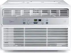
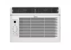
NOTE All the pictures in this manual are for illustrative purposes only. The actual shape of the air conditioner you purchased may be slightly different, but its operations and fuctions are similar.
Air Conditioner Operation
WARNING To reduce the risk of fire, electrical shock, or injury to people or property, read the SAFETY PRECAUTIONS before operating this appliance.
NOTE The cool circuit has an automatic 3 minutes time delayed start if the unit is turned off and on quickly. This prevents overheating of the compressor and possible circuit breaker tripping.
To quickly begin operating the air conditioner, follow these steps:
- Set the thermostat to the lowest number (coldest setting).
- Set the selector control to the highest COOL setting.
- Adjust the louver for comfortable air flow (see Air Directional Louvers).
- Once the room feels colder, adjust the thermostat to the setting you find most comfortable.
- Make sure that the air flow inside and outside are not obstructed by anything.
- This air conditioner is designed to be operated under conditions as follows:
Cooling Operation
- Outdoor temp.: 18-43°C (64°F ~ 109°F)
- Indoor temp.: 17-32°C (62°F ~ 90°F)
NOTES
- The relative humidity of room should be less than 80%. If the unit is used in a condition with a relative humidity over 80%, there will be condensed water on the surface of the unit.
- Performance may be reduced outside of these operating temperatures.
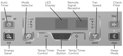
Before you begin, thoroughly familiarize yourself with the control panel as shown below and all its functions, then follow the symbol for the functions you desire. The unit can be controlled by the unit control panel alone or with the remote controller.
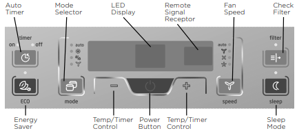
(ON/OFF) Button
The unit will initiate automatically the Energy saver function under Cool, Dry, Auto (only Auto-Cooling and Auto-Fan) modes.
NOTE If the unit turns off unexpectedly due to a power outage, it will restart with its previously set fuctions when the power resumes.
(UP/DOWN) Button
Press or hold either left (-) or right (+) button until the desired temperature is seen on the display. This temperature will be automatically maintained at the set temperature, between 62°F (17°C) and 86°F (30°C). If you want the display to read the actual room temperature, see “To Operate on Fan Only” section.
(MODE) Button
- To choose operating mode, press Mode button. Each time you press the button, a mode is selected in a sequence that goes from Auto, Cool, Dry and Fan. The indicator light beside will be illuminated and remains on once the mode is selected.
- The unit will initiate automatically the Energy Saver function under Cool, Dry, Auto (only Auto-Cooling and AutoFan) modes.
Operating on AUTO mode:
- When you set the air conditioner in AUTO mode, it will automatically select cooling, heating (selected models only) or fan only operation depending on what temperature you have selected and the room temperature.
- The air conditioner will control room temperature automatically to hit the temperature set point you choose.
- In this mode, the fan speed cannot be adjusted, it starts automatically at a speed according to the room temperature.
Operating on FAN mode:
- Use this function only when cooling is not desired, such as for room air circulation or to exhaust stale air (on some models). (Remember to open the vent during this function, but keep it closed during cooling for maximum cooling efficiency.) You can choose any fan speed you prefer.
- During this function, the display will show the actual room temperature, not the set temperature as in the cooling mode.
- In Fan only mode, the temperature can not be adjusted.
Operating on DRY mode:
- In this mode, the air conditioner will operate in the form of a dehumidifier. Since the conditioned space is a closed or sealed area, some degree of cooling will continue.
(FAN SPEED) Button
- Used to select the Fan Speed in four steps - Auto, Low, Med or High. Each time the button is pressed, the fan speed mode is shifted. On Dry mode,the fan speed is controlled at low automatically.
(ENERGY SAVER) Button
- This function is available on COOL, DRY, AUTO (only AUTO-COOL and AUTO-FAN) modes. The fan will continue to run for 3 minutes after the compressor shuts off. The fan then cycles on for 2 minutes at 10 minute intervals until the room temperature is above the set temperature, at which time the compressor turns back on and Cooling Starts.
(SLEEP) Button
- In this mode the selected temperature will increase by 2°F/1°C 30 minutes after the mode is selected. The temperature will then increase by another 2°F/1°C after an additional 30 minutes.
- This new temperature will be maintained for 6 hours before it returns to the originally selected temperature.
- This ends the Sleep mode and the unit will continue to operate as originally programmed. The Sleep mode program can be cancelled at any time during operation by again pressing the Sleep button.
(TIMER) Button
- When the unit is on or off, first press Timer button, the TIMER ON indicator light illuminates. It indicates the Auto Start program is initiated.
- When the time of TIMER ON is displayed, press the Timer button again, the TIMER OFF indicator light illuminates. It indicates the Auto Stop program is initiated.
- Press or hold either left (-) or right (+) button to change the Auto time by 0.5 hour increments, up to 10 hours, then at 1 hour increments up to 24 hours. The control will count down the time remaining until start.
- The selected time will register in 5 seconds, and the system will automatically revert back to display the previous temperature setting or room temperature when the unit is on. (when the unit is off, there is no display.)
- Turning the unit ON or OFF at any time or adjusting the timer setting to 0.0 will cancel the Auto Start/Stop timed program.
(CHECK FILTER) Button
- This feature is a reminder to clean the Air Filter for more efficient operation. The LED (light) will illuminate after 250 hours of operation. To reset after cleaning the filter, press the Check Filter button and the light will go off.
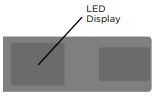
LED Display:
Shows the set temperature in “°C” or “°F” and the Autotimer settings. While on Fan only mode, it shows the room temperature.
Error codes:
AS - Room temperature sensor error - Unplug the unit and plug it back in. If error repeats, call for service. NOTE: In Fan only mode, it will display “LO” or “HI”.
 - Evaporator temperature sensor error - Unplug the unit and plug it back in. If error repeats, call for service. NOTE: “” is displayed as shown in the left picture.
HS - Electric heating sensor error - Unplug the unit and plug it back in. If error repeats, call for service.
Additional Information
Now that you have mastered the operating procedure, here are more features in your control that you should become familiar with.
- The Cool circuit has an automatic 3 minute time delayed start if the unit is turned off and on quickly. This prevents overheating of the compressor and possible circuit breaker tripping.
- The fan will continue to run during this time.
- The control will maintain any set temperature within 1°F/1°C, between 62°F (17°C) and 86°F (30°C).
- The control can display temperature in Fahrenheit or Celsius.
- To convert from one to the other, press and hold the left (-) or right (+) Temp/Timer buttons at the same time, for 3 seconds.
Fresh Air Vent Control (for 10000 BTU/h and 12000 BTU/h)
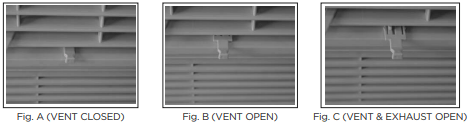
The Fresh Air Vent allows the air conditioner to:
1. Recirculate inside air – Vent Closed (See Fig. A)
2. Draw fresh air into the room - Vent Open (See Fig. B)
3. Exchange air from the room and draws fresh air into the room - Vent and Exhaust Open (See Fig. C).
Air Directional Louvers
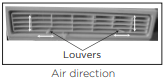
The louvers will allow you to direct the air flow up or down and lefft or right throughout the room as needed. Pivot horizontal louvers until the desired up/down direction is obtained.
Move the levers from side to side until the desired left/right direction is obtained.
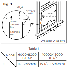
Installation Instructions
Your air conditioner is designed to install in standard double hung windows with opening widths of 23 to 36 inches (584mm to 914mm) (See Fig. D).
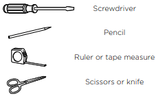
Tool You Will Need
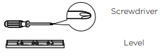
Tool You May Use
NOTE Save Carton and these Installation Instructions for future reference. The carton is the best way to store unit during winter, or when not in use.
1. PREPARE THE WINDOW
Lower sash must open sufficiently to allow a clear vertical opening (H) of following size (see Table 1). Side louvers and the rear of the AC must have clear air space to allow enough airflow through the condenser, for heat removal. The rear of the unit must be outdoors, not inside a building or garage.
CAUTION When handling unit, be careful to avoid cuts from sharp metal edges and aluminum fins on front and rear coils.
NOTE The top rail hardware and the following Fig. E, Fig. F and Fig. G are not applicable to the units over 10,000 Btu/h.

2. PREPARE AIR CONDITIONER
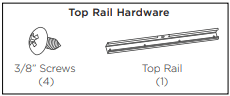
Before installing unit, the top rail must be assembled on the unit for models with a capacity of less than 10,000Btu/h.
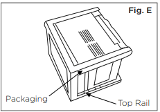
A: Remove the air conditioner from the carton and place on a flat surface.
B: Remove top rail from the bottom of the packaging material as shown in Fig. E.
C: Align the hole in the top rail with those in the top of the unit as shown in Fig. F.
D: Secure the top rail to the unit with the 3/8” screws as shown in Fig. G.
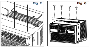
NOTE For safety reasons, all four (4) screws MUST be securely fastened.
How To Install
NOTE Top rail and side panels at each side are offset to provide the proper pitch to the rear of 5/16” (8mm). This is necessary for proper condensed water utilization and drainage. If you are not using the side panels for any reason, this pitch to the rear must be maintained.
1. Place unit on floor, a bench or a table. There is a left and right side filler panel; be sure to use the proper panel for each side. When installed, the flange for securing the panel in place to the window sill will be facing into the room.
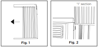
A. Hold the side panel in one hand and gently pull back the center to free the open end. See Fig. 1.
B. Slide the free and “I” section of the panel directly into the cabinet as shown in Fig. 2A. Slide the panel down. Be sure to leave enough space to slip the top and bottom of the frame into the rails on the cabinet.
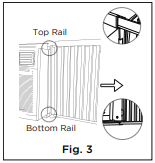
C. Once the panel has been installed on the side of the cabinet, make sure it sits securely inside the frame channel by making slight adjustments. Slide the top and bottom ends of the frame into the top and bottom rails of the cabinet. Fig. 3.
D. Slide the panel all the way in and repeat on the other side.
NOTE If storm window blocks AC, see Fig. 10.
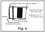
2. While keeping a firm grip on the air conditioner, carefully place the unit into the window opening so the bottom of the air conditioner frame is against the window sill (Fig. 4). Carefully close the window behind the top rail of the unit.
NOTE Check that air conditioner is tilted back about H (Fig. 5) (tilted about 3° to 4° downward to the outside). After propor installation, condensate should not drain from the overflow drain hole during normal use, correct the slope otherside.
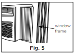
3. Extend the side panels out against the window frame (Fig. 5).
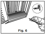
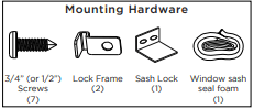
4. Place the frame lock between the frame extensions and the window sill as shown (Fig. 6). Drive 3/4” (19mm) or 1/2” (12.7mm) locking screws through the frame lock and into the sill.
NOTE To prevent window sill from splitting, drill 1/8” (3mm) pilot holes before driving screws.
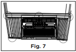
5. Drive 3/4” (19mm) or 1/2” (12.7mm) locking screws through frame holes into window sash (Fig. 7).
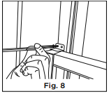
6. To secure lower sash in place, attach right angle sash lock with 3/4” (19mm) or 1/2” (12.7mm) screw as shown (Fig. 8).
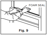
7. Cut window sash seal foam and insert it in the space between the upper and lower sashes (Fig. 9).
If AC is Blocked by Storm Window
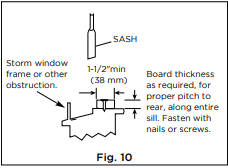
Add wood as shown in Fig. 10, or remove storm window before air conditioner is installed.
If storm window frame must remain, be sure the drain holes or slots are not caulked or painted shut. Accumulated rain water or condensation must be allowed to drain out.
Removing AC From Window
- Turn AC off, and disconnect power cord.
- Remove sash seal from between windows, and unscrew safety lock.
- Remove screws installed through frame and frame lock.
- Close (slide) side panels into frame.
- Keeping a firm grip on air conditioner, raise sash and carefully remove
- Be carefully not to spill any remaining water while lifting unit form window. Store parts WITH air conditioner.
Care and Cleaning
Air Filter Cleaning
The air filter should be checked at least once a month to see if cleaning is necessary. Trapped particles in the filter can build up and cause an accumulation of frost on the cooling coils.
- Push the vent handle to the closed position (where applicable).
- Open the front panel.
- Grasp the filter by the center and pull up and out.
- Wash the filter using liquid dishwashing detergent and warm water. Rinse filter thoroughly.
- Gently shake excess water from the filter. Be sure the filter is thoroughly dry before replacing.
- Or, instead of washing you may vacuum the filter clean.
NOTE Never use hot water over 40°C (104°F) to clean the air filter. Never attempt to operate the unit without the air filter.
Cabinet Cleaning
- Be sure to unplug the air conditioner to prevent shock or fire hazard. The cabinet and front may be dusted with an oil-free cloth or washed with a cloth dampened in a solution of warm water and mild liquid dishwashing detergent. Rinse thoroughly and wipe dry.
- Never use harsh cleaners, wax or polish on the cabinet front.
- Be sure to wring excess water from the cloth before wiping around the controls. Excess water in or around the controls may cause damage to the air conditioner.
- Plug in air conditioner.
Winter Storage
If you plan to store the air conditioner during the winter, remove it carefully from the window according to the installation instructions. Cover it with plastic or return it to the original carton.
Troubleshooting Tips
Before calling for service, review this list. It may save you time and expense. This list includes common occurrences that are not the result of defective workmanship or materials in this appliance.
Air conditioner does not start
- Wall plug disconnected. Push plug firmly into wall outlet.
- House fuse blown or circuit breaker tripped. Replace fuse with time delay type or reset circuit breaker.
- Plug current device tripped. Press the RESET button.
- Control is OFF. Turn control ON and set to desired setting.
- Unit turned off and then on quickly. Turn unit off and wait 3 minutes before restarting.
Air from unit does not feel cold enough
- Room temperature below 17°C (62°F). Cooling may not occur until room temperature rises above 17°C (62°F).
- Temperature sensing element touching cold coil, located behind air filter. Straighten tube away from coil.
- Reset to a lower temperature.
- Compressor shut-off by changing modes. Wait approximately 3 minutes and listen for compressor to restart when set in the COOL mode.
Air conditioner cooling, but room is too warm- ice forming on cooling coil behind decorative front.
- Outdoor temperature below 18°C (64°F). To defrost the coil, set FAN ONLY mode.
- Air filter may be dirty. Clean filter. Refer to Care and Cleaning section. To defrost, set to FAN ONLY mode.
- Thermostat set too cold for night-time cooling. To defrost the coil, set to FAN ONLY mode. Then, set temperature to a higher setting.
Air conditioner cooling, but room is too warm- NO ice forming on cooling coil behind decorative front
- Air filter may be dirty. Clean filter. Refer to Care and Cleaning section. To defrost, set to FAN ONLY mode.
- Temperature is set too High, set temperature to a lower setting.
- Air directional louvers positioned improperly. Position louvers for better air distribution.
- Front of units is blocked by drapes, blinds, furniture, etc. - restricts air distribution. Clear blockage in front of unit.
- Doors, windows, registers, etc. Open- cold air escapes. Close doors, windows, registers.
- Unit recently turned on in hot room. Allow additional time to remove “stored heat” from walls, ceiling, floor and furniture.
Air conditioner turns on and off rapidly
- Dirty air filter- air restricted. Clean air filter.
- Outside temperature extremely hot. Set FAN speed to a higher setting to bring air past cooling coils more frequently
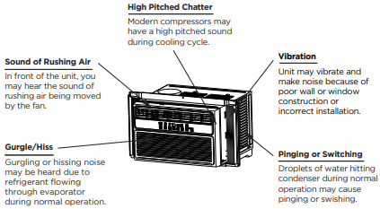
Noise when unit is cooling
- Air movement sound. This is normal . If too loud, set to a slower FAN setting.
- Window vibration - poor installation. Refer to installation instructions or check with installer
Water dripping INSIDE when unit is cooling
- Improper installation. Tilt air conditioner slightly to the outside to allow water drainage. Refer to installation instructions - check with installer.”
Water dripping OUTSIDE when unit is cooling
- Unit removing large quantity of moisture from humid room. This is normal during excessively humid days.
Remote sensing deactivating prematurely (some models)
- Remote control not located within range. Place remote control within 20 feet & 180°, radius of the front of the unit.
- Remote control signal obstructed. Remove obstruction.
Room too cold
- Set temperature too low. Increase set temperature.
Remote Control Operating Instructions
Using The Remote Control
Location of the remote controller
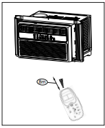
Use the remote controller within a distance of 8 meters / 26 feet from the appliance, pointing it towards the receiver. Reception is confirmed by a beep.
CAUTION
- The air conditioner will not operate if courtains, doors or other materials block the signals from the remote controller to the indoor unit.
- Prevent any liquid from falling into the remote controller. Do not expose the remote controller to direct sunlight or heat.
- If the infrared signal receiver on the indoor unit is exposed to direct sunlight, the air conditioner may not function properly. Use curtains to prevent the sunlight for falling on the receiver.
- If other eletrical appliances react to the remote controller, either move these appliances or call customer support.
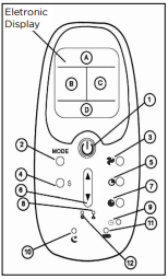
Electronic display displays the following information:
A: Remote control power On/OFF and mode icons
B: Clock and Auto-Timer settings
C: Current set temperature
D: Fan speed setting control buttons
1. Power switch
NOTE The unit will automatically launch the Energy Saver function when it is in Cool, Dry and Auto modes.
2. Mode
3. Fan speed
4. Energy Saver - default setting which allows the fan to cycle on and off (instead of running continuously) when the compressor is not in use
5. Auto-Timer
6. Used to increase or decrease temperature settings in 1° increments on the Celsius or Fahrenheit scale.
7. Cancels current Timer ON/OFF settings.
8. Lock prevents the remote control settings from inadvertently being changed.
9. Clock: Press button for 3 seconds in order to set the clock. Press the up or down arrow to adjust the time in 10 minute intervals.
10. Used to activate the SLEEP program.
11. Toggle the LED backlight on/off.
12. Restore remote control default settings.
NOTE The clock feature is only avaliable on the remote, the unit does not have a clock. The remote clock is a 24 hour clock only.
Changing The Batteries On The Remote
To operate the hand-held remote control will require two “AAA” alkaline batteries (inclueded). Batteries should be replaced when:
a) No signal (beep) is heard when attemptting to program the main unit.
b) The main unit does not respond to a command issue by the remote control.
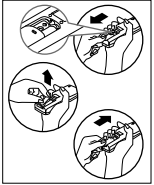
Battery replacement:
- Slide the rear cover on the remote in the directions of the arrow. Continue pulling (gently) until the cover separates completely from the unit.
- Insert (2) batteries (AAA) following the same orientation (polarity) depicted inside the battery chamber (+/-).
- Re-install the real cover.
- If the remote control will not be used for extend periods of time (vacations, etc.), batteries should be removed.
- Protect the remote control from high temperatures, and keep away from radiation exposure.
- Keep the control panel receiver out of direct sunlight.
- Do not mix old and new batteries.
- Do not mix alkaline, standard (carbon-zinc), or rechargeable (Ni-cad, Ni-Mh, etc.) batteries.
- The remote operates within a range of 8 meters (26 ft.) from the receiver located inside the main unit. Any obstruction between the receiver and the remote may cause signal interferance, limiting the ability to program the main unit.
NOTE
This equipament has been tested and found to comply with the limits for Class B digital device, pursuant to Part 15 of the FCC Rules. These limits are designed to provide reasonable protection against harmful interference in a residential installation. This equipament generates, uses and can radiate radio frequency energy and, if not installed and used in accordance with the instructions, may cause harmful interference to radio communications. However, there is no guarantee that interference will not occur in a particular installation. If this equipament does cause harmful interferance to radio or television reception, which can be determined by turning the equipament off and on, the user is encouraged to try to correct the interference by one or more of the following measures:
1) Reorient or relocate the receiving antenna.
2) Increase the separation between the equipment and receiver.
3) Connect the equipment into an outlet on a circuit different from that to which the receiver is connected.
4) Consult the dealer or an experience radio/TV technician for help.
Changes or modifications not approved by the party responsible for FCC compliance could void the user’s authority to operate the equipment.
This appliance complies with Part 15 of the FCC Rules. Operation is subject to the following two conditions:
1) This device may not cause harmful interference.
2) This device must accept any interference received, including interference that may cause undesired operation.