USER’S MANUAL
Serial Number
Decal
CAUTION
Read all precautions and
instructions in this manual before
using this equipment. Keep this
manual for future reference.
Model No. NTEL71220.0
Serial No.
Write the serial number in the space
above for reference.
nordictrack.com
To register your product and
activate your warranty today,
go to my.nordictrack.com.
For service at any time, go to
support.nordictrack.com.
Or call 1-800-TO-BE-FIT
(1-800-862-3348)
Mon.–Fri. 6 a.m.–6 p.m. MT
Sat. 8 a.m.–12 p.m. MT
Please do not contact the store.
ACTIVATE YOUR
WARRANTY
CUSTOMER CARE

2
TABLE OF CONTENTS
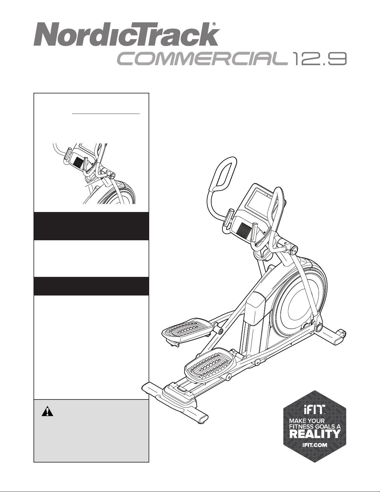
WARNING DECAL PLACEMENT
This drawing shows the location(s) of the warning
decal(s). If a decal is missing or illegible, see
the front cover of this manual and request a
free replacement decal. Apply the decal in the
location shown. Note: The decal(s) may not be
shown at actual size.
WARNING DECAL PLACEMENT . . . . . . . . . . . . . . . . . . . . . . . . . . . . . . . . . . . . . . . . . . . . . . . . . . . . . . . . . . . . . . .2
IMPORTANT PRECAUTIONS ..................................................................3
BEFORE YOU BEGIN. . . . . . . . . . . . . . . . . . . . . . . . . . . . . . . . . . . . . . . . . . . . . . . . . . . . . . . . . . . . . . . . . . . . . . . .6
PART IDENTIFICATION CHART. . . . . . . . . . . . . . . . . . . . . . . . . . . . . . . . . . . . . . . . . . . . . . . . . . . . . . . . . . . . . . . .7
ASSEMBLY . . . . . . . . . . . . . . . . . . . . . . . . . . . . . . . . . . . . . . . . . . . . . . . . . . . . . . . . . . . . . . . . . . . . . . . . . . . . . . . .8
HOW TO USE THE ELLIPTICAL ..............................................................16
HOW TO USE THE CONSOLE. . . . . . . . . . . . . . . . . . . . . . . . . . . . . . . . . . . . . . . . . . . . . . . . . . . . . . . . . . . . . . . .19
FCC INFORMATION . . . . . . . . . . . . . . . . . . . . . . . . . . . . . . . . . . . . . . . . . . . . . . . . . . . . . . . . . . . . . . . . . . . . . . . .30
MAINTENANCE AND TROUBLESHOOTING .....................................................31
EXERCISE GUIDELINES ....................................................................33
PART LIST. . . . . . . . . . . . . . . . . . . . . . . . . . . . . . . . . . . . . . . . . . . . . . . . . . . . . . . . . . . . . . . . . . . . . . . . . . . . . . . .35
EXPLODED DRAWING. . . . . . . . . . . . . . . . . . . . . . . . . . . . . . . . . . . . . . . . . . . . . . . . . . . . . . . . . . . . . . . . . . . . . .37
ORDERING REPLACEMENT PARTS .................................................. Back Cover
LIMITED WARRANTY. . . . . . . . . . . . . . . . . . . . . . . . . . . . . . . . . . . . . . . . . . . . . . . . . . . . . . . . . . . . . . . Back Cover
NORDICTRACK and IFIT are registered trademarks of ICON Health & Fitness, Inc. Google Maps is a trademark
of Google LLC. The Bluetooth
®
word mark and logos are registered trademarks of Bluetooth SIG, Inc. and are
used under license. Wi-Fi is a registered trademark of Wi-Fi Alliance. WPA and WPA2 are trademarks of Wi-Fi
Alliance.

3
IMPORTANT PRECAUTIONS
WARNING: To reduce the risk of burns, fire, electric shock, or injury to persons, read
all important precautions and instructions in this manual and all warnings on your elliptical before
using your elliptical. ICON assumes no responsibility for personal injury or property damage sus-
tained by or through the use of this product.
1. It is the responsibility of the owner to ensure
that all users of the elliptical are adequately
informed of all precautions.
2. Before beginning any exercise program,
consult your physician. This is especially
important for persons over age 35 or persons
with pre-existing health problems.
3. The elliptical is not intended for use by
persons with reduced physical, sensory, or
mental capabilities or lack of experience and
knowledge, unless they are given supervi-
sion or instruction about use of the elliptical
by someone responsible for their safety.
4. Use the elliptical only as described in this
manual.
5. The elliptical is intended for home use only.
Do not use the elliptical in a commercial,
rental, or institutional setting.
6. Keep the elliptical indoors, away from mois-
ture and dust. Do not put the elliptical in a
garage or covered patio, or near water.
7. Place the elliptical on a level surface, with at
least 3 ft. (0.9 m) of clearance in the front and
rear of the elliptical and 2 ft. (0.6 m) on each
side. To protect the floor or carpet from dam-
age, place a mat under the elliptical.
8. Inspect and properly tighten all parts each
time the elliptical is used. Replace any worn
parts immediately.
9. When connecting the power cord, plug the
power cord into a grounded circuit.
10. Do not modify the power cord or use an
adapter to connect the power cord to an
improper receptacle. Keep the power cord
away from heated surfaces. Do not use an
extension cord.
11. Do not operate the elliptical if the power cord
or plug is damaged, or if the elliptical is not
working properly.
12. DANGER: Always unplug the power
cord and switch the power switch to the off
position when the elliptical is not in use and
before cleaning the elliptical. Servicing other
than the procedures in this manual should be
performed by an authorized service repre-
sentative only.
13. Keep children under age 16 and pets away
from the elliptical at all times.
14. The elliptical should not be used by persons
weighing more than 350 lbs. (159 kg).
15. Wear appropriate clothes while exercising;
do not wear loose clothes that could become
caught on the elliptical. Always wear athletic
shoes for foot protection while exercising.
16. Hold the handlebars or the upper body arms
when mounting, dismounting, or using the
elliptical. Before mounting or dismounting,
bring the pedals to a stop with the pedal
on the mounting or dismounting side in its
lowest position.
17. The heart rate monitor is not a medical
device. Various factors may affect the accu-
racy of heart rate readings. The heart rate

8
2. With the help of a second person, place some of
the packing materials (not shown) under the rear
of the Frame (1). Have the second person hold
the Frame to prevent it from tipping while you
complete this step.
If there are shipping supports attached to the
rear of the Frame (1), remove the screws from
the shipping supports, and discard the screws
and the shipping supports.
Next, attach the Rear Stabilizer (2) to the Frame
(1) with two M10 x 114mm Screws (104).
Then, remove the packing materials from under
the rear of the Frame (1).
2
1
2
104
• Assembly requires two persons.
• Place all parts in a cleared area and remove the
packing materials. Do not dispose of the packing
materials until you nish all assembly steps.
• Left parts are marked “L” or “Left” and right parts
are marked “R” or “Right.”
• To identify small parts, see page 7.
• In addition to the included tool(s), assembly
requires the following tools:
one Phillips screwdriver
two adjustable wrenches
one rubber mallet
Assembly may be easier if you have a set of
wrenches. To avoid damaging parts, do not use
power tools.
ASSEMBLY
1
1. Go to my.nordictrack.com on your computer
and register your product.
• documents your ownership
• activates your warranty
• ensures priority customer support if assistance
is ever needed
Note: If you do not have internet access, call
Customer Care (see the front cover of this
manual) and register your product.

9
3
6
4
3. With the help of a second person, place some
of the packing materials (not shown) under the
front of the Frame (1). Have the second per-
son hold the Frame to prevent it from tipping
while you complete this step.
If there are shipping supports attached to the
front of the Frame (1), remove the screws from
the shipping supports, and discard the screws
and the shipping supports.
Next, attach the Front Stabilizer (6) to the Frame
(1) with two M10 x 114mm Screws (104).
Then, remove the packing materials from under
the front of the Frame (1).
1
104
77
59
45
95
4. Using a plastic bag to keep your fingers clean,
apply some of the included grease to the right
Crank Arm (20).
Next, identify the Right Roller Arm (59), orient
it as shown, and slide it onto the right Crank
Arm (20).
Attach the Right Roller Arm (59) with an
M8 x 20mm Screw (95) and a Crank Cover (77).
Repeat this step for the Left Roller Arm (45).
20
Grease

14
14
14. Identify the Right Upper Body Arm (61), orient it
as shown, and insert it into the Right Upper Body
Leg (60).
Attach the Right Upper Body Arm (61) with two
M8 x 45mm Bolts (96) and two M8 Locknuts
(102); make sure that the Locknuts are in the
hexagonal holes (C).
Repeat this step for the Left Upper Body
Arm (47).
60
61
47
96
102
C
75
4
117
101
73, 74
15. Orient the Front Shield Cover (117) and the
Center Shield Cover (75) around the Upright (4)
as shown. Then, attach them to each other with
two M4 x 16mm Screws (101).
Then, press the Front Shield Cover (117) and the
Center Shield Cover (75) onto the Left and Right
Shields (73, 74).
15

15
17
65
60
101
66
17. Orient the Right Arm Front and Rear Covers
(65, 66) around the Right Upper Body Leg
(60) as shown, and then attach them with two
M4 x 16mm Screws (101).
Repeat this step on the other side of the
elliptical.
16. Identify the Right Leg Inner Cover (83), orient it
as shown, and insert it through the Right Upper
Body Leg (60).
Next, identify the Right Leg Outer Cover (69),
orient it as shown, and press it onto the Right
Leg Inner Cover (83).
Attach the Right Leg Outer and Inner Covers
(69, 83) to each other with an M4 x 16mm
Screw (101).
Repeat this step on the other side of the
elliptical.
60
101
69
16
83
18. Make sure that all parts are properly tightened. Extra parts may be included. Place a mat beneath the
elliptical to protect the floor.

16
HOW TO USE THE ELLIPTICAL
HOW TO PLUG IN THE POWER CORD
This product must be grounded. If it should mal-
function or break down, grounding provides a path of
least resistance for electric current to reduce the risk
of electric shock. The power cord has a plug with a
grounding pin.
Plug the power
cord (A) into
an appropriate
outlet (B) that is
properly installed
and grounded in
accordance with
all local codes and
ordinances. The
outlet must be
on a nominal 120-volt circuit.
A temporary
adapter (C) may
be used to con-
nect the power
cord to a 2-pole
receptacle (D)
as shown at the
right if a properly
grounded outlet is
not available.
The lug (E) or wire extending from the adapter must
be connected with a metal screw (F) to a permanent
ground such as a properly grounded outlet box cover.
Some 2-pole receptacle outlet box covers are not
grounded. Before using an adapter, contact a
qualied electrician to determine whether the out-
let box cover is grounded before using an adapter.
The temporary adapter should be used only until
a properly grounded outlet can be installed by a
qualied electrician.
B
A
DANGER: Improper connection of
the power cord increases the risk of electric
shock. Do not modify the plug—if it will not fit
an outlet, have a proper outlet installed by a
qualified electrician. If you are unsure whether
the product is properly grounded, contact a
qualified electrician.
D
C
E
F

18
HOW TO EXERCISE ON THE ELLIPTICAL
To mount the elliptical, hold the handlebars (M) or
the upper body arms (N) and step onto the pedal (O)
that is in the lower position. Then, step onto the other
pedal. Push the pedals until they begin to move with
a continuous motion. Note: The pedals can turn in
either direction. It is recommended that you turn
the pedals in the direction shown by the arrow;
however, for variety, you can turn the pedals in the
opposite direction.
To dismount the elliptical, wait until the pedals (O)
come to a complete stop. Note: The elliptical does
not have a free wheel; the pedals will continue to
move until the flywheel stops. When the pedals are
stationary, step off the higher pedal first. Then, step off
the lower pedal.
THE OPTIONAL TABLET HOLDER
The optional tablet
holder (P) will hold
your tablet securely
in place and enable
you to use your tablet
while you exercise. The
optional tablet holder is
designed for use with
most full-size tablets.
To purchase a tablet
holder, please see the
front cover of this manual.
M
N
O
P
19
Rafe
ELNT71220
NTEL71220
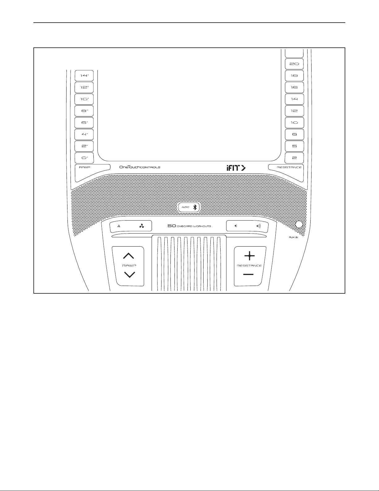
CONSOLE DIAGRAM
FEATURES OF THE CONSOLE
The advanced console offers an array of features
designed to make your workouts more effective and
enjoyable.
The console features wireless technology that enables
the console to connect to iFit. With iFit, you can access
a large and varied workout library, create your own
workouts, track your workout results, and access many
other features.
In addition, the console features a selection of onboard
workouts. Each workout automatically controls the
resistance of the pedals and the incline of the ramp as
it guides you through an effective exercise session.
When you use the manual mode of the console, you
can change the resistance of the pedals and the incline
of the ramp with the touch of a button.
While you exercise, the console will display continu-
ous exercise feedback. You can even measure your
heart rate using the handgrip heart rate monitor or
a compatible heart rate monitor. See page 29 for
information about purchasing an optional chest
heart rate monitor.
You can also listen to your favorite workout music or
audio books with the console sound system while you
exercise.
To turn on the power, see page 20. To learn how
to use the touch screen, see page 20. To set up
the console, see page 20.
HOW TO USE THE CONSOLE

20
HOW TO TURN ON THE POWER
IMPORTANT: If the elliptical has been exposed to
cold temperatures, allow it to warm to room tem-
perature before you turn on the power. If you do
not do this, you may damage the console or other
electrical components.
Plug in the power cord (see
HOW TO PLUG IN THE POWER
CORD on page 16). Next,
locate the power switch on the
frame near the power cord.
Press the power switch to the
reset position (A).
The console will then turn on and be ready for use.
Note: When you turn on the power for the rst time,
the incline system may calibrate automatically. The
ramp will move upward and downward as it calibrates.
When the ramp stops moving, the incline system is
calibrated.
IMPORTANT: If the incline system does not
calibrate automatically, see step 6 on page 20
and manually calibrate the incline system.
HOW TO USE THE TOUCH SCREEN
The console features a tablet with a full-color touch
screen. The following information will help you use the
touch screen:
• The console functions similarly to other tablets. You
can slide or flick your finger against the screen to
move certain images on the screen, such as the
displays in a workout.
• To type information into a text box, first touch the text
box to view the keyboard. To use numbers or other
characters on the keyboard, touch ?123. To view
more characters, touch ~[<. Touch ?123 again to
return to the number keyboard. To return to the letter
keyboard, touch ABC. To use a capital character,
touch the shift button (upward-facing arrow symbol).
To use multiple capital characters, touch the shift
button again. To return to the lowercase keyboard,
touch the shift button a third time. To clear the last
character, touch the clear button (backward-facing
arrow with an X symbol).
HOW TO SET UP THE CONSOLE
Before you use the elliptical for the first time, set up the
console.
1. Connect to your wireless network.
To use iFit workouts and to use several other
features of the console, the console must be con-
nected to a wireless network. Follow the prompts
on the screen to connect the console to your wire-
less network.
2. Customize settings.
Follow the prompts on the screen to set the desired
unit of measurement and your time zone.
Note: To change these settings later, see HOW TO
CHANGE CONSOLE SETTINGS on page 27.
3. Log into or create an iFit account.
Follow the prompts on the screen to log into your
iFit account or to create an iFit account.
4. Tour the console.
The first time you use the console, a tour
presentation will guide you through the features of
the console.
5. Check for firmware updates.
First, touch the menu button (three horizontal lines
symbol), touch Settings, touch Maintenance, and
then touch Update. The console will check for firm-
ware updates. For more information, see HOW TO
CHANGE CONSOLE SETTINGS on page 27.
6. Calibrate the incline system.
First, touch the menu button (three horizontal lines
symbol), touch Settings, touch Maintenance, and
then touch Calibrate Incline. The ramp will rise
and lower as it calibrates. For more information,
see HOW TO CHANGE CONSOLE SETTINGS on
page 27.
A

25
HOW TO CREATE A DRAW-YOUR-OWN-MAP
WORKOUT
1. Touch the screen or press any button on the
console to turn on the console.
See HOW TO TURN ON THE POWER on
page 20. Note: It may take a few moments for
the console to be ready for use.
2. Select a draw-your-own-map workout.
When you turn on the console, the main menu will
appear on the screen after the console boots up.
If you are in a workout, touch the screen and follow
the prompts to end the workout and return to the
main menu. If you are in the settings menus, touch
the back button (arrow symbol) and then touch the
close button (x symbol) to return to the main menu.
To select a draw-your-own-map workout, touch the
Create button at the bottom of the screen.
3. Draw your map.
Navigate to the area on the map where you want
to draw your workout by typing in the search box
or by sliding your fingers on the screen. Touch
the screen to add the start point for your workout.
Then, touch the screen to add the end point for
your workout.
If you want to start and end your workout at the
same point, touch Close Loop or Out & Back in the
map options. You can also select whether you want
your workout to snap to the road.
If you make a mistake, touch Undo in the map
options.
The screen will display the elevation and distance
statistics for your workout.
4. Save your workout.
Touch Save New Workout to save your workout. If
desired, enter a title and description for your work-
out. Then, touch the continue button (> symbol).
5. Start the workout.
Touch Start Workout to start the workout. The work-
out will function in the same way as a map workout
or an onboard workout (see page 23).
6. Follow your progress.
See step 4 on page 21.
7. Measure your heart rate if desired.
See step 5 on page 22.
8. Turn on the fan if desired.
See step 6 on page 22.
9. When you are finished exercising, unplug the
power cord.
See step 7 on page 22.

30
FCC INFORMATION
This equipment has been tested and found to comply with the limits for a Class B digital device, pursuant to part
15 of the FCC Rules. These limits are designed to provide reasonable protection against harmful interference
in a residential installation. This equipment generates, uses, and can radiate radio frequency energy and, if not
installed and used in accordance with the instructions, may cause harmful interference to radio communications.
However, there is no guarantee that interference will not occur in a particular installation. If this equipment does
cause harmful interference to radio or television reception, which can be determined by turning the equipment off
and on, try to correct the interference by one or more of the following measures:
• Reorient or relocate the receiving antenna.
• Increase the separation between the equipment and the receiver.
• Connect the equipment into an outlet on a circuit different from that to which the receiver is connected.
• Consult the dealer or an experienced radio/TV technician for help.
FCC CAUTION: To assure continued compliance, use only shielded interface cables when connecting to
computer or peripheral devices. Changes or modifications not expressly approved by the party respon-
sible for compliance could void the user’s authority to operate this equipment.
IMPORTANT: To satisfy exposure compliance requirements, the antenna and transmitter in the console
must be at least 8 in. (20 cm) from all persons and must not be near or connected to any other antenna or
transmitter.
Note: The console contains FCC ID: OMC402547.

36
Key No. Qty. Description Key No. Qty. Description
101 53 M4 x 16mm Screw
102 6 M8 Locknut
103 11 M6 x 12mm Screw
104 4 M10 x 114mm Screw
105 1 M4 x 25mm Flange Screw
106 1 Lower Ramp Cover
107 1 Crank Spacer
108 2 M6 x 13mm Screw
109 2 M10 x 58mm Bolt
110 1 Upper Wire
111 1 Lower Wire
112 2 M4 x 19mm Self-tapping Screw
113 1 Drive Belt
114 1 Controller
115 4 Standoff
116 2 Disc Ring
117 1 Front Shield Cover
118 1 Rear Shield Cover
119 1 Power Cord
120 2 M8 x 20mm Flat Head Screw
121 8 Frame Bushing
122 1 M10 x 47mm Bolt
123 2 Small Arm Bearing
124 2 M4 x 16mm Machine Screw
125 1 Right Upper Grip
126 2 M4 x 25mm Screw
127 2 Disc Bracket
128 1 Long Bumper
129 2 M8 x 22mm Washer
130 4 M4 x 12mm Screw
131 2 Adhesive Tape
132 1 Left Pedal Plate
133 2 M10 x 158mm Bolt
134 1 Right Lower Grip
135 2 M6 x 26mm Washer
136 1 M10 x 28mm Washer
137 1 Right Pedal Handle
138 2 Pedal Pin
139 2 Pedal Spring
140 2 M6 Acorn Nut
141 4 M6 Washer
142 1 Right Pedal Plate
* – Assembly Tool
* – Grease Packet
* – User’s Manual
Note: Specifications are subject to change without notice. For information about ordering replacement parts, see
the back cover of this manual. *These parts are not illustrated.

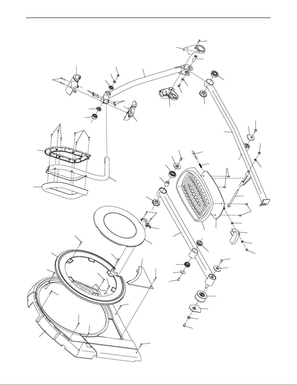
37
EXPLODED DRAWING A
4
35
35
37
81
54
63
71
79
73
75
80
101
101
101
101
92
124
5
101
50
101
101
117
116
118
101
101
101
5
50
46
52
45
44
47
49
68
62
21
67
70
72
76
95
127
7
132
Model No. NTEL71220.0 R1119A
39
EXPLODED DRAWING C
74
124
50
50
5
5
116
5
101
32
95
127
137
138
139
140
141
141
85
133
142
29
26
58
57
57
64
103
103
87
59
57
123
77
95
56
55
120
56
51
53
95
98
95
8
71
60
101
61
66
65
69
83
101
126
126
101
101
101
3
82
96
129
102
82
97
100
100
54
101
101
134
125
Model No. NTEL71220.0 R1119A