Loading ...
Loading ...
Loading ...
Preparing wheel change
1. Observe the safety precautions above.
2. Loosen the lug bolts a half turn.
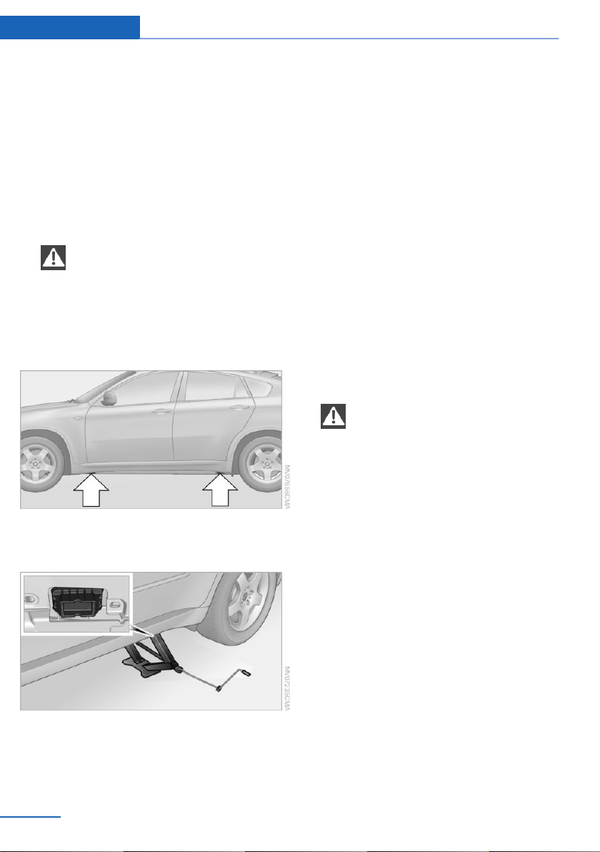
Jacking up vehicle
1. Position the vehicle jack at the jacking
point closest to the wheel so that the entire
surface of the jack base rests on the
ground perpendicularly beneath the jack‐
ing point.
The vehicle jack is designed for
changing wheels only.
The vehicle jack is designed for changing
wheels only. Do not attempt to raise an‐
other vehicle model with it or to raise any
load of any kind. To do so could cause ac‐
cidents and personal injury.◀
2.
Guide the jack head into the rectangular
recess of the jacking point when cranking
up, refer to illustration detail.
3. Jack the vehicle up until the wheel you are
changing is raised from the ground.
Mounting a wheel
1. Unscrew the lug bolts and remove the
wheel.
2. Remove accumulations of mud or dirt from
the mounting surfaces of the wheel and
hub. Also clean the lug bolts.
3. Position the new wheel or compact wheel.
Secure the wheel by screwing at least two
lug bolts into opposite bolt holes.
When you mount wheels other than Genu‐
ine BMW light-alloy wheels, different lug
bolts may also be required.
4. Screw in the remaining lug bolts. Tighten
all the bolts securely in a diagonal pattern.
5. Lower the vehicle and remove the jack
from beneath the vehicle.
After mounting
1.
Tighten the lug bolts in a diagonal pattern.
Checking that the lug bolts are tight
To ensure safety, always have the lug
bolts checked with a calibrated torque
wrench as soon as possible to ensure that
they are tightened to the specified torque.
Otherwise, incorrectly tightened lug bolts
are a hidden safety risk. The tightening tor‐
que equals 101 lb ft/140 Nm.◀
2. Stow the defective wheel in the cargo area.
The defective wheel cannot be stored un‐
der the cargo floor cover due to its size.
3. Check and correct the tire inflation pres‐
sure at the earliest opportunity.
4. Initialize the Flat Tire Monitor, refer to
page 88, or reset the Tire Pressure Moni‐
tor, refer to page 90.
5. Replace the damaged tire as soon as pos‐
sible and have the new wheel/tire bal‐
anced.
Seite 282
Mobility Replacing components
282
Online Edition for Part no. 01 40 2 910 876 - VII/13
Loading ...
Loading ...
Loading ...