Loading ...
Loading ...
Loading ...
www.napoleongrills.com
7
WARNING!
WARNING!
: This must be done before inial use, annually, and whenever any gas components are
replaced or serviced. Do not smoke while performing this test, and remove all sources of ignion. See Leak
Tesng Diagram for areas to check. Turn all burner controls to the o posion. Turn gas supply valve on.
Brush a half-and-half soluon of liquid soap and water onto all joints and connecons of the regulator,
hose, manifolds and valves.
Bubbles will indicate a gas leak. Either ghten the loose joint or have the part replaced with one
recommended by the Napoleon Customer Care department and have the grill inspected by a cered gas
installer.
If the leak cannot be stopped, immediately shut o the gas supply, disconnect it, and have the grill
inspected by a cered gas installer or dealer. Do not use the grill unl the leak has been corrected.
: The piping up to the gas grill is the responsibility of the installer and
piping should be located as shown in the built-in instrucons. A exible metal connector is included
to simplify the installaon of the unit. Connect this connector to the are ng on the end of the
manifold. Connect the other end of the connector to the gas piping. Ensure that the connector does not
pass through a wall, oor, ceiling or paron, and is protected from damage. The installaon must be
performed by a licensed gas er in accordance with AS5601 / AG601, and all connecons must be leak
tested before operang the grill.
Do not use a hose to connect the unit. It must be connected with rigid pipe, copper tube or an approved
exible metal connector which complies with with AS5601 / AG601. The gas supply pipe must be
suciently sized to supply the kPA specied on the rang plate, based on the length of the piping run. If
installing a side burner, a separate line must be branched o to the side burner unit and enter the side
burner opening at the specied locaon.
WARNING!
WARNING!
DANGER!
: The gas grill is designed to operate at an inlet pressure of 1.00 kPA and must be checked aer
installaon by turning all burners on and measuring at the regulator outlet test point provided.
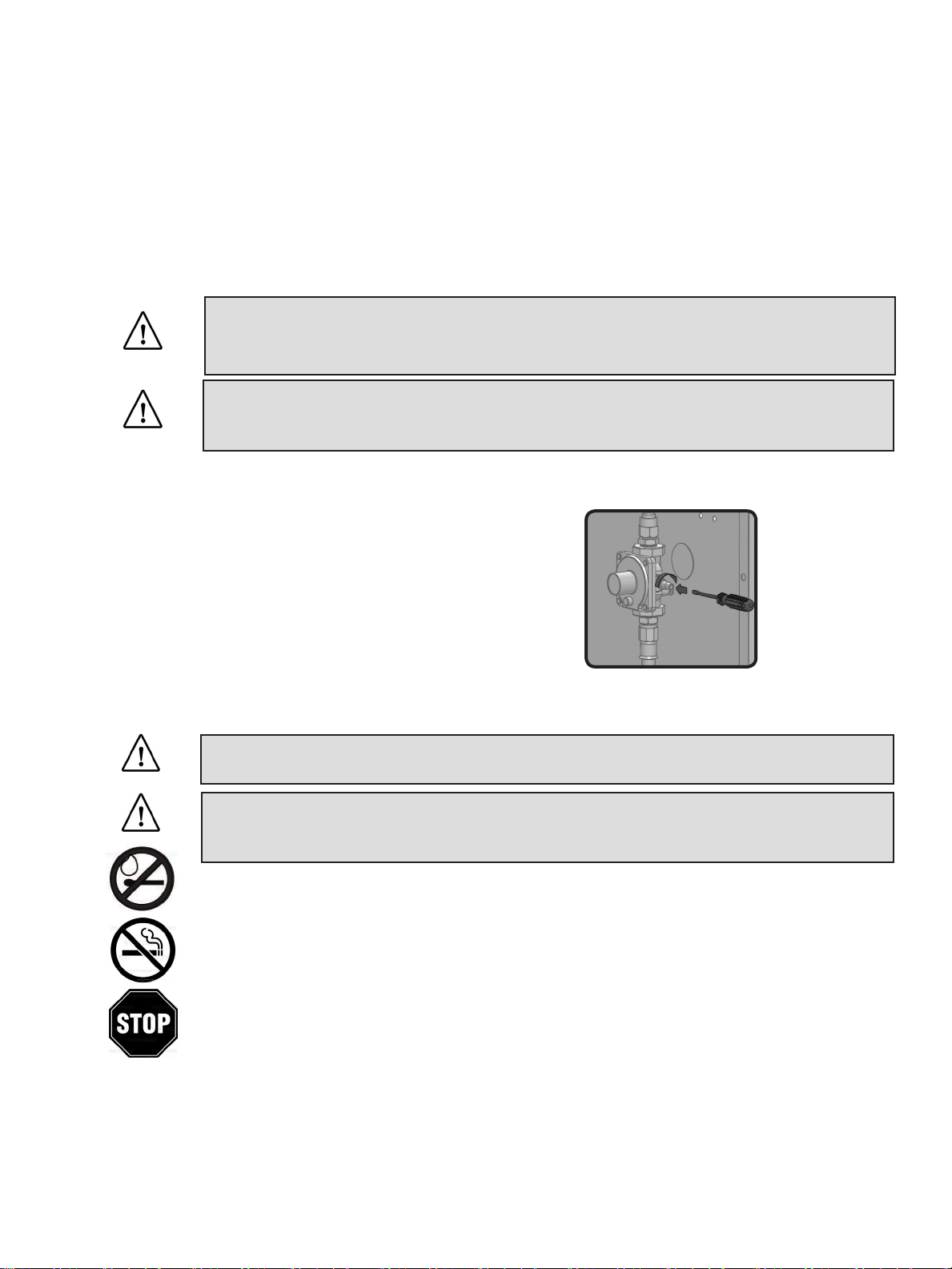
This unit includes an internal regulator which stabilizes
the gas pressure and improves grill performance. This
regulator cannot be adjusted. There is a pressure tap
located on the side of the regulator. It can be used by
a qualied service person when servicing the grill to
determine if the regulator is funconing properly. The
screw within the pressure tap must always be kept ght,
except when performing a pressure test on the regulator
(qualied service personnel only).
Loading ...
Loading ...
Loading ...