File:01fnpi8.ex
Update:Wed Jun 19 15:02:05 1996
File:01fnpi8.ex
Update:Wed Jun 19 15:02:05 1996

i
Table of Contents
File:01fnpi8.ex
Update:Wed Jun 19 15:02:05 1996

ii
File:01fnpi8.ex
Update:Wed Jun 19 15:02:05 1996

iii
File:01fnpi8.ex
Update:Wed Jun 19 15:02:05 1996

iv
File:01fnpi8.ex
Update:Wed Jun 19 15:02:05 1996

1
Introduction
Ford’s Commitment to You
At Ford Motor Company, excellence is the
continuous commitment to achieve the best result
possible. It is dedication to learning what you want,
determination to develop the right concept, and
execution of that concept with care, precision, and
attention to detail. In short, excellence means being
the standard by which others are judged.
Our Guiding Principles
❑
Quality comes first. For your satisfaction, the
quality of our products and services must be our
number one priority.
❑
You are the focus of everything we do. Our
work must be done with you in mind,
providing better products and services than our
competition.
❑
Continuous improvement is essential to our
success. We must strive for excellence in
everything we do: in our products — in their
safety and value — and in our services, our
human relations, our competitiveness, and our
profitability.
❑
Employee involvement is our way of life.
We are a team. We must treat one another
with trust and respect.
❑
Dealers and suppliers are our partners. We
must maintain mutually beneficial relationships
with dealers, suppliers, and our other business
associates.
❑
Integrity is never compromised. Our conduct
worldwide must be pursued in a manner that is
socially responsible and commands respect for
its integrity and for its positive contributions to
society.
File:02fnii8.ex
Update:Wed Jun 19 15:02:10 1996
2
ThingstoKnowAboutUsingThis
Guide
Congratulationsonthepurchaseofyournew
vehicle.Thisguidehasinformationaboutthe
equipmentandtheoptionsforyournewvehicle.
Youmaynothaveboughtalloftheoptions
availabletoyou.Ifyoudonotknowwhich
informationappliestoyourvehicle,talktoyour
dealer.
Thisguidedescribesequipmentandgives
specificationsforequipmentthatwasineffectwhen
thisguidewasapprovedforprinting.Fordmay
discontinuemodelsorchangespecificationsor
designwithoutanynoticeandwithoutincurring
obligation.
NOTESandWARNINGS
NOTESgiveyouadditionalinformationaboutthe
subjectmatteryouarereferencing.
WARNINGSremindyoutobeespeciallycarefulin
thoseareaswherecarelessnesscancausedamageto
yourvehicleorpersonalinjurytoyourself,your
passengersorotherpeople.Pleasereadall
WARNINGScarefully.
WARNING
FindingInformationinThisGuide
Afteryouhavereadthisguideonce,youwill
probablyreturntoitwhenyouhaveaspecific
questionorneedadditionalinformation.Tohelp
youfindspecificinformationquickly,youcanuse
theQuickIndexortheIndex.
TheQuickIndexattheendofthebookprovides
apagenumberfollowingeachitemwhichindicates
wheredetailedinformationcanbefound.
File:02fnii8.ex
Update:Wed Jun 19 15:02:10 1996

3
To use the Index, turn to the back of the book
and search in the alphabetical listing for the word
that best describes the information you need. If the
word you chose is not listed, think of other related
words and look them up. We have designed the
Index so that you can find information under a
technical term.
Canadian Owners — French Version
French Owner Guides can be obtained from your
dealer or by writing to Ford Motor Company of
Canada, Limited, Service Publications, P.O. Box
1580, Station B, Mississauga, Ontario L4Y 4G3.
The Lincoln Commitment
The Lincoln Commitment is more than the prestige
of owning a superior luxury automobile, it is a
comprehensive owner benefits package that is
designed to provide you with services to support
your every driving need. Refer to the Lincoln
Commitment brochure for more information.
Your Maintenance Schedule and
Record Booklet
The Maintenance Schedule booklet lists the services
that are most important for keeping your vehicle in
good condition. A record log is also provided to
help you keep track of all services performed.
About the Warranties
Your vehicle is covered by three types of warranties:
Basic Vehicle Warranty, Extended Warranties
on certain parts, and Emissions Warranties.
Read your Warranty Information Booklet carefully to
find out about your vehicle’s warranties and your
basic rights and responsibilities.
If you lose your Warranty Information Booklet, you
can get a new one free of charge. Contact any Ford
or Lincoln-Mercury dealer, or refer to the addresses
and phone numbers on the first page of this
Owner’s Guide.
File:02fnii8.ex
Update:Wed Jun 19 15:02:10 1996

4
Ford Extended Service Plan
More Protection for Your Vehicle
You can get more protection for your new car or
light truck by purchasing a Ford Extended Service
Plan (Ford ESP). Ford ESP is the only extended
service program with the Ford name on it and the
only service contract backed by Ford Motor
Company.
Ford ESP is an optional service contract, backed and
administered by Ford. It provides:
❑
protection against repair costs after your Bumper
to Bumper Warranty expires;
and
❑
other benefits during the warranty period (such
as: reimbursement for rentals; coverage for
certain maintenance and wear items).
You may purchase Ford ESP from any participating
Ford Motor Company dealer. There are several Ford
ESP plans available in various time-and-mileage
combinations. Each plan can be tailored to fit your
own driving needs, including reimbursement
benefits for towing and rental. (In Hawaii, rules
vary. See your dealer for details.)
When you buy Ford ESP, you receive peace-of-mind
protection throughout the United States and
Canada, provided by a network of more than 5,100
participating Ford Motor Company dealers.
NOTE: Repairs performed outside the United States
and Canada are not eligible for ESP coverage.
This information is subject to change. Ask your
dealer for complete details about Ford ESP coverage.
File:02fnii8.ex
Update:Wed Jun 19 15:02:10 1996

5
Breaking Your Vehicle In
Your new vehicle goes through an adjustment or
break-in period during the first 1,000 miles
(1,600 km) that you drive it. During the break-in
period, you need to pay careful attention to how
you drive your vehicle.
❑
Avoid sudden stops. Because your vehicle has
new brake linings, you should take these steps:
—Watch traffic carefully so that you can
anticipate when to stop.
—Begin braking well in advance.
—Apply the brakes gradually.
The break-in period for new brake linings
lasts for 100 miles (160 km) of city driving
or 1,000 miles (1,600 km) of highway
driving.
❑
Use only the type of engine oil that Ford
recommends. See Engine oil recommendations
in the Index. Do not use special “break-in” oils.
File:02fnii8.ex
Update:Wed Jun 19 15:02:10 1996

7
Instrumentation
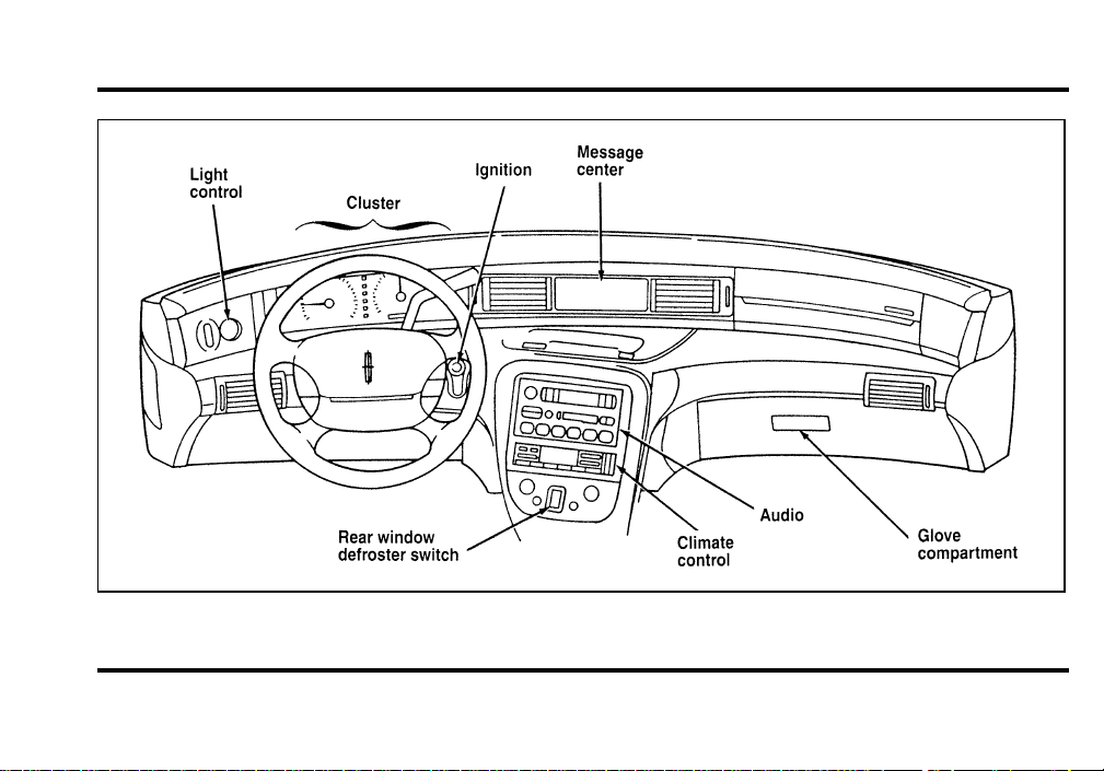
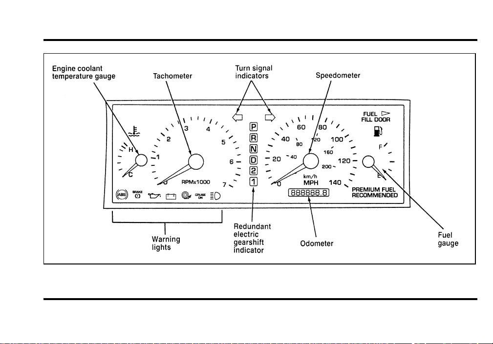
The instrument panel (dashboard) on your vehicle is
divided into several different sections. The
illustrations on the following pages show the major
parts of the instrument panel that are described in
this chapter. Some items shown may not be on all
vehicles.
The main controls for the climate control system,
clock, and radio are on the instrument panel.
If you have radio transmitting equipment in your
vehicle, be aware that it can interfere with your
vehicle’s electrical system and may cause the
instrumentation and/or convenience products to
have temporary, abnormal operation.
NOTE: Any cleaner or polish that increases the
gloss (shine) of the upper part of the instrument
panel should be avoided. The dull finish in this area
is to help protect the driver from undesirable
windshield reflection.
File:03fnis8.ex
Update:Thu Jun 27 10:00:37 1996
8
The Instrument Panel
File:03fnis8.ex
Update:Thu Jun 27 10:00:37 1996
9
The Instrument Cluster
File:03fnis8.ex
Update:Thu Jun 27 10:00:37 1996
10
IndicatorLightsandChimes
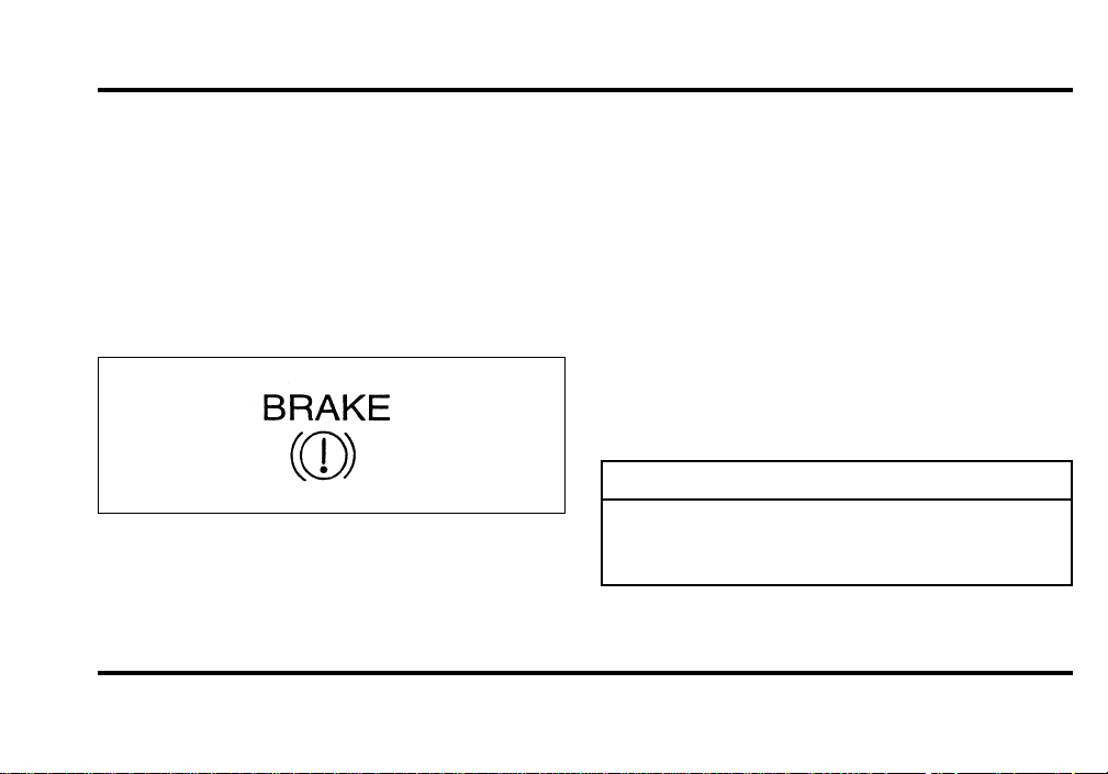
BrakeSystemWarningLight
Thewarninglightforthebrakescanshowtwo
things—thattheparkingbrakeisnotfully
released,orthatthebrakefluidlevelislowinthe
mastercylinderreservoir.Ifthefluidlevelislow,
thebrakesystemshouldbecheckedbyyourdealer
oraqualifiedservicetechnician.
Thislightcomesonwhentheparkingbrakeisset,
orifitisnotset,itcomesonbrieflywhenyou
turntheignitiontotheSTARTposition.Itnormally
goesoffshortlyaftertheenginestartsandthe
gearshifterismovedintoagear.Ifthelightstays
ontheAuto-Releasesystemmayhavefailedto
performasuccessfulrelease,trythemanualparking
brakereleaseleverandhavethebrakesystem
servicedbyyourdealeroraqualifiedservice
technician.
Lowbrakefluidlevelwillturnthelighton.
Excessivebrakeliningwearorasystemleakwill
causelowbrakefluidlevels.
WARNING
TheBRAKElightindicatesthatthe
brakesmaynotbeworkingproperly.
Havethebrakescheckedimmediately.
File:03fnis8.ex
Update:Thu Jun 27 10:00:37 1996
11
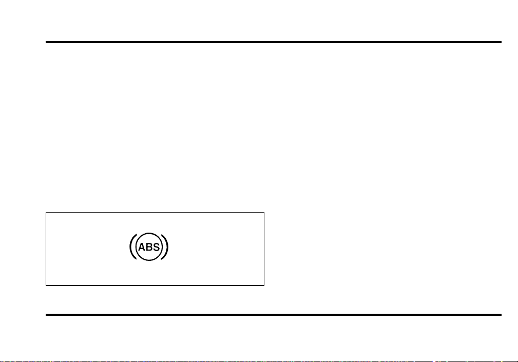
Anti-Lock Brake System Warning Light
This light comes on for a few seconds when you
turn the ignition key to the START position. It
should go off shortly after the engine starts. If it
stays on longer than five (5) seconds, it indicates
that your anti-lock brake system may not be
working properly. Normal braking is not affected
unless the BRAKE system warning light also remains
on for longer than six (6) seconds. You should have
your vehicle serviced immediately by your dealer or
qualified service technician to restore the benefits of
the anti-lock feature. See Anti-lock brakes in the
Index for more information.
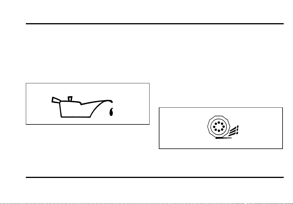
Engine Oil Pressure Warning Light
This light indicates the engine’s oil pressure, not the
oil level. However, if your engine’s oil level is low,
it could affect the oil pressure. The light will come
on briefly when you turn your key to the START
and ON position. The light should stay off when
the engine is running with normal oil pressure. If
the light comes on while the engine is running, you
have lost oil pressure and continued operation will
cause severe engine damage.
If you lose engine oil pressure:
1. Pull off the road as soon as safely possible.
2. Shut off the engine immediately or severe
engine damage could result.
3. Check the engine’s oil level, following the
instructions on checking and adding engine oil,
see Engine Oil in the Index. If you do not
follow these instructions, you or others could
be injured. To assure an accurate reading, your
car should be on level ground.
File:03fnis8.ex
Update:Thu Jun 27 10:00:37 1996
12
4. If the level is low, add only as much oil as
necessary before you start the engine again. Do
not overfill. Do not operate the engine if the
light is on, regardless of the oil level. Contact
your nearest dealer for further service actions.
For more information about adding oil, see Adding
engine oil in the Maintenance and Care chapter.
Traction ControlH Active Light
(If equipped)
This light comes on when the Traction ControlH
system begins applying and releasing the brakes and
adjusting the engine characteristics to limit a
wheelspin condition.
It will be lit for a minimum of six seconds or for
the duration of the Traction ControlH event.
For more information about Traction Control refer
to the Driving chapter.
File:03fnis8.ex
Update:Thu Jun 27 10:00:37 1996
13
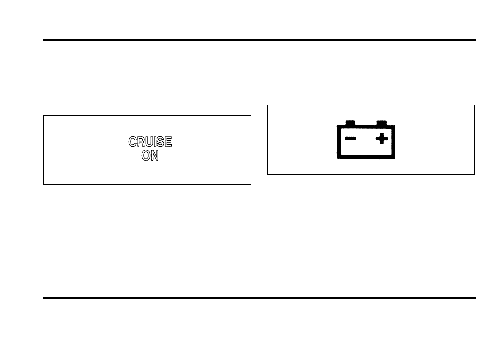
Cruise Control Indicator Light
This light comes on when the speed control system
is actively maintaining the set speed. It will go off
when the brakes are used or if the speed control is
turned off.
Charging System Light
This light indicates that your battery is not being
charged and that you need to have the electrical
system checked.
This light illuminates every time you turn the
ignition to the ON or START position (engine off).
The light should go off when the engine starts and
the alternator begins to charge.
If the light stays on or illuminates when the engine
is running, have the electrical system checked as
soon as possible.
File:03fnis8.ex
Update:Thu Jun 27 10:00:37 1996
14
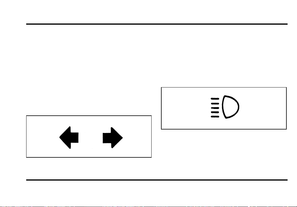
Turn Signal Indicator Lights
When you push the turn signal lever up before
making a right turn, the right side arrow on the
instrument panel flashes.
When you push the turn signal lever down before
making a left turn, the left side arrow on the
instrument panel flashes.
Usually, the turn signals turn off automatically after
you turn your vehicle. If the turn signal continues
to flash after you have made the turn, push the
lever back to the OFF position.
If one or both of your turn indicators do not flash
or stay on continuously, have them serviced as soon
as possible. In the meantime, be sure to use the
accepted hand signals.
High Beam Light
This light illuminates when the headlamps are
turned to high beam or when you flash the lights.
File:03fnis8.ex
Update:Thu Jun 27 10:00:37 1996
15
Chime for Headlamps On
This chime sounds if the driver or any passenger
door is open when the parking lamps or headlamps
are on. The chime sounds until you close the door,
turn off the lamps or turn the ignition to the ON
position.
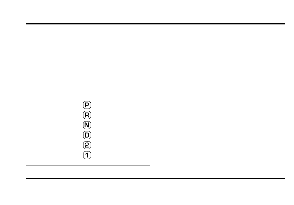
Redundant Electronic Gearshift
Indicator
The redundant electronic gearshift indicator
The instrument cluster is equipped with a
redundant set of gearshift indicator lights located in
the center of the cluster between the speedometer
and the tachometer gauges.
These lights operate with the key in the ON
position only and displays the same gear selection as
the lights located on the floor console next to the
gearshift lever.
The light that is illuminated indicates which
position the transmission gearshifter is in.
NOTE: If the shifter is moved very quickly (less
than one second) over more than one gear selection
(for example from P [PARK] to D [DRIVE]), the
lights in between these positions may not get a
chance to turn on. Only the last selected gear
indicator will light up.
File:03fnis8.ex
Update:Thu Jun 27 10:00:37 1996
16
The Instrument Cluster
In addition to warning lights, the instrument cluster
has an electronic odometer, a speedometer,
tachometer, fuel and coolant temperature gauges.
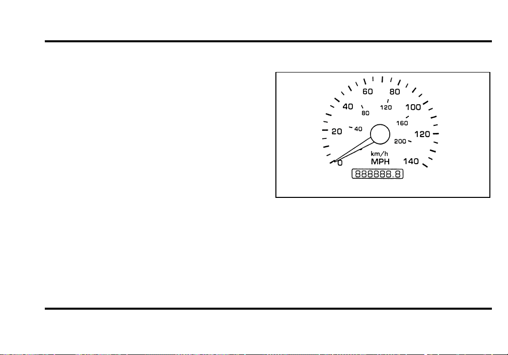
Odometer
The odometer tells you the total number of miles
(kilometers) your vehicle has been driven.
Speedometer
The speedometer
The speedometer tells you how many miles
(kilometers) per hour your vehicle is moving.
File:03fnis8.ex
Update:Thu Jun 27 10:00:37 1996
17
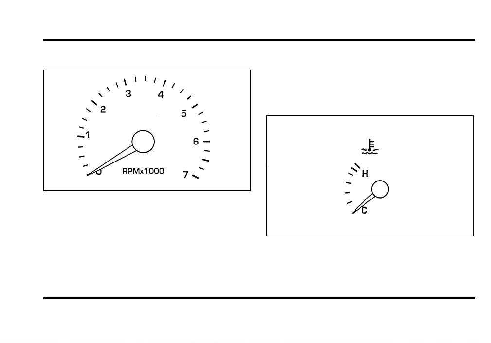
Tachometer
The tachometer
The tachometer displays the approximate engine
revolutions per minute (rpm), or how fast the
engine is running.
You can drive your vehicle at most rpm points on
the tachometer but you must stay out of the red
zone.
Engine Coolant Temperature Gauge
This gauge indicates the temperature of the engine
coolant, not the coolant level. If the coolant is not
at its proper level or mixture, the gauge indication
will not be accurate.
The engine coolant temperature gauge
File:03fnis8.ex
Update:Thu Jun 27 10:00:37 1996

18
The pointer moves from the C (cold) mark into the
NORMAL band as the engine coolant warms up. It
is acceptable for the pointer to fluctuate within the
NORMAL band under normal driving conditions.
Under certain driving conditions such as, heavy stop
and go traffic, or driving up hills in hot weather,
the pointer may indicate at the top of the NORMAL
band.
If, under any circumstances, the pointer moves
above the NORMAL band, the engine is overheating
and continued operation may cause engine damage.
If your engine overheats:
1. Pull off the road as soon as it is safely possible.
2. Turn off the engine.
3. Let the engine cool. DO NOT REMOVE
COOLANT SYSTEM FILL CAP UNTIL THE
ENGINE IS COOL.
4. Check the coolant level following the
instructions on checking and adding coolant to
your engine, see Engine Coolant in the Index.
If you do not follow these instructions, you or
others could be injured.
If the coolant continues to overheat, have the
coolant system serviced as soon as possible.
File:03fnis8.ex
Update:Thu Jun 27 10:00:37 1996
19
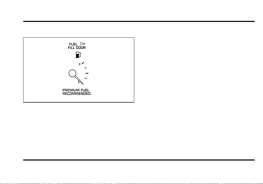
Fuel Gauge
The fuel gauge displays approximately how much
fuel you have in the fuel tank.
For a proper fuel gauge indication after adding fuel,
the ignition switch should be in the OFF position
while the vehicle is being refueled.
The fuel gauge indicator may vary slightly while the
vehicle is in motion. This is the result of fuel
movement within the tank. An accurate reading
may be obtained with the vehicle on smooth, level
ground.
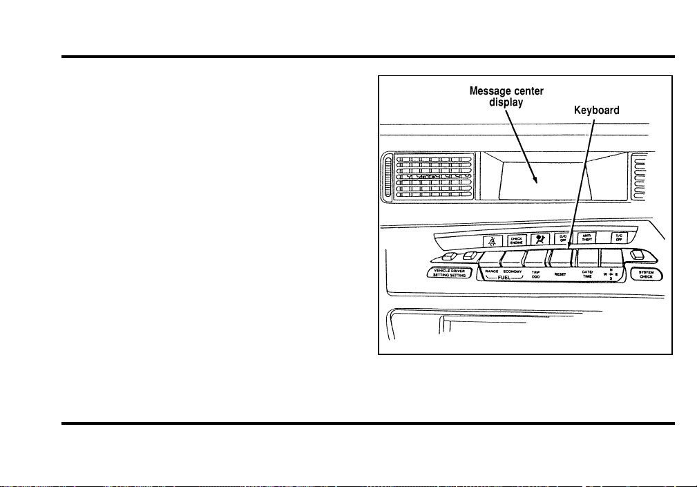
The Electronic Message Center
The Electronic Message Center (M/C) display,
located in the center of the instrument panel, works
only when your ignition is in the ON or ACC
position. Each time that M/C is powered, the
display goes through a self-test by displaying the
time and a blank message for two seconds. This
self-test is used to stabilize the systems before
reporting the status of the systems to you.
The M/C tells you about the condition of your
vehicle by three methods:
❑
Operator selectable features
❑
Vehicle system status displays
File:03fnis8.ex
Update:Thu Jun 27 10:00:37 1996
20
❑
Continuous warning reporting of monitored
systems
You can select different features for the M/C to
display by using the keyboard directly below the
M/C display. You will hear a tone when you press
one of these controls. However, if the M/C detects
a warning from any of the monitored systems then
the M/C will display the appropriate warning
message.
Operator Selectable Features
These features are controlled by the controls in the
keyboard below the M/C display. The following
pages describe the operation of the individual
controls.
The Electronic Message Center
File:03fnis8.ex
Update:Thu Jun 27 10:00:37 1996

21
Vehicle Settings Menu
A press of the VEHICLE SETTINGS control causes
the Message Center to display the menu features
which affect the vehicle regardless of which driver
personality profile is currently selected. Repeated
pressing of the VEHICLE SETTINGS control allows
quick cycling through the menu features. The
displayed feature can be toggled on or off, or reset
by pressing the RESET control as specifically noted
below. If a vehicle setting is changed, the display
stops automatically cycling through the menu
options and exits the vehicle settings menu, unless
the VEHICLE SETTINGS control is pressed again.
❑
TRACTION CONTROL — This system helps
prevent wheel spin to improve tire traction. The
reset button will toggle this feature on or off.
This feature defaults to the ON state after each
key cycle. Note: The Traction Control System is
an optional feature, and this menu option will
not appear in vehicles without this option.
❑
ENGLISH/METRIC — This menu option
allows the Message Center and Automatic
Temperature Control readings to be displayed in
English or Metric units. The modes can be
toggled by using the RESET control.
❑
AUTOLAMP DELAY STATUS — This option
displays the current autolamp delay setting.
Note: To change the delay setting you must
rotate the HEADLAMP CONTROL.
File:03fnis8.ex
Update:Thu Jun 27 10:00:37 1996

22
❑
OIL CHANGE RESET — This option allows
you to reset the oil monitoring system to 100%
(or your Personalized Oil Reset Percentage) after
each oil change. The RESET control must be
pressed and held for 5 seconds while the
display counts down to trigger an oil change
reset. After a successful reset the Message
Center will display “OIL LIFE RESET TO
100%.” If you have established a Personalized
Oil Reset Percentage, the display will show that
percentage instead of 100%. To ensure accurate
oil life indicators, perform this reset procedure
only after an oil change. For more information
on Personalized Oil Reset Percentage see the
section below.
❑
WIPER/HEADLAMP ON — When this
feature is enabled, the headlamps will
automatically switch on when the driver has the
windshield wipers in the intermittent, low or
high speed settings. This feature is toggled off
and on with the RESET control.
Personal Oil Life Percentage:
Your Personalized Oil Reset Percentage allows you
to establish a smaller oil change interval than the
manufacturer’s recommended interval. To establish
your Personalized Oil Reset Percentage perform the
following procedure:
1. Press and hold the reset control from the
VEHICLE SETTINGS menu OIL CHANGE
RESET screen.
2. While holding the reset control as display
counts down the seconds to reset press the
VEHICLE SETTINGS control. The display will
change to “START OIL LIFE AT XXX%” where
XXX is the currently selected Personalized Oil
Reset Percentage. Release both controls.
3. Press the RESET control until the displayed
percentage is the Personalized Oil Reset
Percentage that you desire. Your choices are
100%, 90%, 80%, 70%, 60%, 50%, 40% and
30%.
File:03fnis8.ex
Update:Thu Jun 27 10:00:37 1996

23
4. Press the VEHICLE SETTINGS control to
complete the procedure. A press of any control
besides RESET or VEHICLE SETTINGS will
abort the procedure and will not establish a
new Personalized Oil Reset Percentage.
When your Personalized Oil Reset Percentage has
been established, it will be used beginning with the
completion of your next OIL CHANGE RESET
procedure.
Driver Settings Menu
The DRIVER MENU control allows you to cycle
through seven (if equipped with phone) features
which you can turn on or off by using the RESET
control. These options are saved for each driver
personality profile.
❑
EXPRESS WINDOWS — a short tap of the
control will cause the driver’s window to go
fully down automatically.
❑
AUTO LOCKS — automatically locks all doors
when all doors are closed and the vehicle speed
is at least 3 mph.
❑
HORN CHIRP — sounds an audible “chirp”
when the LOCK button on the Remote Entry
Key Fob is pressed.
❑
EASY ENTRY — moves the driver’s seat back
two inches and the steering column to the up
and forward most position when the key is
removed from the ignition. Moves the driver’s
seat and steering column to the set position
when the driver returns.
❑
REVERSE MIRRORS — when the vehicle is
shifted to R (Reverse), the outside mirrors are
tilted down for an improved view close to the
vehicle for backing up.
❑
AUTO GLIDE — automatically moves the seat
forward when the seatback is tilted forward.
File:03fnis8.ex
Update:Thu Jun 27 10:00:37 1996

24
❑
PHONE SCREEN — (if equipped with a
factory phone) when a call is placed,
information about the call is displayed in the
message center.
Fuel Range
A press of the RANGE switch allows you to display
approximately how many miles (kilometers) you can
drive before you run out of fuel.
To ensure accuracy, turn the ignition OFF when
you fill the fuel tank.
NOTE: RANGE is calculated using a “Running
Average Fuel Economy” initialized by the factory.
This value is not the same as the Average Fuel
Economy Display. The Running Average Fuel
Economy is based on more than 500 miles
(800 km) of driving history. Also, the factory
default for Running Average Fuel Economy is
reinitialized if the battery is disconnected.
If the “FUEL SENSOR SHORT or OPEN” message is
displayed, this means that there is a problem with
the fuel indication system or if any “DATA ERROR”
message is displayed you should contact your dealer
for service as soon as possible.
A second press of the FUEL RANGE control allows
you to display the Fuel Remaining. It will display
the approximate amount of fuel in the tank in
whole numbers (gallons or liters).
If your fuel tank is full or nearly full, the M/C will
display “FULL FUEL TANK” message. If your fuel
tank is empty or nearly empty, the M/C will
display the “EMPTY FUEL TANK” message.
File:03fnis8.ex
Update:Thu Jun 27 10:00:37 1996

25
Fuel Economy
A press of the FUEL ECONOMY control allows you
to display one of two features (Average Fuel
Economy or Instantaneous Fuel Economy). The first
press of the FUEL ECONOMY control will allow
you to display your average fuel economy in
miles/gallons or liters/100 kilometers. Your M/C
computes this figure using the distance traveled and
fuel used information. If you want to reset this
feature, press the RESET control while the average
fuel economy feature is displayed.
A second consecutive press of the FUEL ECONOMY
control will allow you to display the instantaneous
fuel economy, which is the fuel economy that you
get at any particular moment. For example, you can
see what your fuel economy is in heavy traffic or
on an open highway. Your fuel economy is affected
by such factors as braking, acceleration, and the
type of road you are driving on.
Your vehicle must be moving for the M/C to
calculate the instantaneous fuel economy. When
your vehicle is not moving, instantaneous fuel
economy will be displayed at 0 miles/gallon or
99 kilometers/100 liters. When you are moving,
the M/C will display between 0 and 99
miles/gallon or between 1 and 99 kilometers/100
liters.
Trip ODO
A press of TRIP ODO allows you to display one of
two trip odometers: Trip A or Trip B. These
functions allow you to see how far you have
traveled since you last reset.
Trip A and Trip B are completely independent and
must be reset individually.
To reset either trip feature to zero, press the RESET
control while a trip distance feature (Trip A or Trip
B) is displayed.
File:03fnis8.ex
Update:Thu Jun 27 10:00:37 1996

26
Reset
A press of the RESET control will allow you to
reset the current feature being displayed. Warnings,
Average Fuel Economy, Clock Set, Compass
Adjustment, Vehicle Settings, and Driver Settings
are the only features which respond to the RESET
control. Range and Instantaneous Fuel Economy
cannot be reset. That is, these features are
unaffected by pushing the RESET control.
Date/Time
A press of the DATE/TIME control allows you to
display and set/adjust the Day & Date, Time only,
and Elapsed Time features on the Message Center.
❑
Day & Date Display — A press of the
DATE/TIME control displays the Day & Date
Display. From this display the Day & Date can
be set/adjusted if desired. The display will give
instruction to help aid with the process. If the
set/adjustment procedure is started and nothing
is pressed for a minute, the Message Center will
exit the procedure automatically with the
currently selected Day & Date.
O To set/adjust the Day & Date, press the
RESET control.
O Press DATE/TIME repeatedly to select the
correct day of the week.
O Then press RESET to proceed to the month
adjustment display.
File:03fnis8.ex
Update:Thu Jun 27 10:00:37 1996

27
O Press DATE/TIME repeatedly to select the
correct month of the year.
O Then press RESET to proceed to the date
adjustment display.
O Press DATE/TIME repeatedly to select the
correct day of the month.
O Then press RESET to complete the
set/adjustment procedure.
❑
Time Only Display — A second press of the
DATE/TIME control displays the Time Only
Display. From this display Time of Day can be
set/adjusted if desired. The display will give
instruction to help aid with the process. If the
set/adjustment procedure is started and nothing
is pressed for a minute, the Message Center will
exit the procedure automatically with the
currently selected Time.
O To set/adjust the hour, press the RESET
control.
O Press DATE/TIME repeatedly to select the
correct hour. (Note: A = AM/P = PM)
O Then press RESET to proceed to the minute
adjustment display.
O Press DATE/TIME repeatedly to select the
correct minute.
O Then press RESET to complete the
set/adjustment procedure.
❑
Elapsed Time Display — A third press of the
DATE/TIME control displays the Elapsed Time
Display. This feature allows the operator to
monitor elapsed time if desired. The Elapsed
Time continues to run regardless if the vehicle
ignition is ON or OFF.
O To STOP the Elapsed Time count while it is
running without resetting the counter, briefly
press the reset control for less than 2
seconds.
File:03fnis8.ex
Update:Thu Jun 27 10:00:37 1996

28
O To START the Elapsed Time count when it
is stopped without resetting the counter,
briefly press the reset control for less than 2
seconds.
O To reset the elapsed time counter, hold the
reset control down until the count reads
00:00:00 (about 2 seconds).
Compass
Pressing the COMPASS control will display one of
the following eight compass displays: North,
Northeast, East, Southeast, South, Southwest, West
and Northwest.
For additional information on the compass operation
and for instructions to adjust the compass, see
Electronic Compass in this chapter.
System Check
A press of the SYSTEM CHECK control causes the
M/C to cycle through a status of each of the
systems being monitored. For each of the monitored
systems, the M/C will indicate either an OK
message or a warning message for two seconds. The
sequence of the system check report is as follows:
❑
Engine Oil Life Status
❑
Engine Oil Life Left
❑
Engine Oil Level
❑
Voltage Level
❑
Engine Coolant Temperature
❑
Engine Coolant Level
❑
Washer Fluid Level
❑
Doors Closed (Driver and Rightside)
❑
Trunk Closed
❑
Exterior Lamps (Head, Front Turn, Brake and
Tail)
❑
Air Ride System
File:03fnis8.ex
Update:Thu Jun 27 10:00:37 1996

29
❑
Traction Control (If equipped)
❑
Fuel Level
At normal conclusion of the system check sequence,
the M/C will display the last displayed feature
before pressing the SYSTEM CHECK control or the
warnings that are active.
For two of the systems reported in the system
check (Engine Oil Life Left and Fuel Level), there
are two messages to describe the status of the
system. For Engine Oil Life Left, the first message
will indicate the oil change status (OK, SOON,
REQUIRED) and the second message will indicate
the oil life remaining as a percentage. If the second
message is “OIL TEMP SENSOR OPEN or SHORT”,
this means that there is a problem with the oil
temperature sensor system and you should contact
your dealer for service as soon as possible. For Fuel
Level, the first message will indicate the fuel level
status (OK or LOW) and the second message will
indicate the range (distance to empty).
Message center operation during system
check
The M/C controls will operate as follows during
the System Check sequence:
1. A press of the SYSTEM CHECK control will
advance the cycle to the next system message
without waiting the two seconds.
2. A press of the RESET control anytime during
this sequence will cause the SYSTEM CHECK
cycle to conclude immediately and the last
displayed feature before pressing SYSTEM
CHECK will be displayed.
3. A press of the FUEL RANGE, FUEL
ECONOMY, TRIP ODO, DRIVER SETTINGS,
VEHICLE SETTINGS, DATE/TIME, or
COMPASS control will conclude the SYSTEM
CHECK cycle and the requested feature will be
displayed.
File:03fnis8.ex
Update:Thu Jun 27 10:00:37 1996

30
Vehicle System Status Displays
These messages are displayed on the Message
Center when the operator uses one of the vehicle
systems below, or the operation of a vehicle system
occurs.
❑
PHONE SCREEN — This display will show
the status of the cellular phone usage (if the
vehicle is equipped with the factory installed
cellular phone). This display will automatically
appear on the message center during usage of
the cellular phone, unless a warning is being
displayed or the phone screen feature is turned
off in the DRIVER SETTINGS MENU. To return
to an Operator Selectable Feature display during
a phone call, press the corresponding button
(i.e., FUEL STATUS, FUEL ECONOMY, etc.).
This will disable the PHONE SCREEN
temporarily till the next phone event occurs.
❑
AUTO LAMP DELAY STATUS SCREEN —
This display will automatically appear on the
message center during adjustment of the
autolamp delay time when the headlamp switch
is adjusted, unless a warning is being displayed.
This display indicates the amount of time the
lights will stay on after the ignition is turned off
if the autolamps are turned on.
❑
PERSONALITY EVENT SCREEN — These
displays will automatically appear on the
message center when a vehicle system is
adjusted, and saved to the driver’s personality
profile (i.e., seat position is adjusted, etc.) or
when a new driver personality profile is
selected, or the personality feature is turned off.
These messages will not appear if a warning is
displayed on the Message Center.
File:03fnis8.ex
Update:Thu Jun 27 10:00:37 1996

31
System Warnings
System warnings alert you to possible problems or
malfunctions in your vehicle’s operating systems.
There are 23 warning messages which can be
displayed by the Message Center to show the status
of the monitored systems. When a warning occurs,
the warning message is displayed and a tone
sounds. The warning message will appear at a
brighter level if the instrument panel is dimmed.
In the event of a multiple warning situation, the
M/C will cycle the display to show all warnings by
displaying each warning message for 4 seconds.
Using the message center while a warning
is active
If you want to display the operator selectable
features of the M/C while a warning is displayed,
the warning message may be removed from the
M/C display by pressing the RESET control. The
M/C will display the last selected feature if there
are not more warning messages. This allows you to
use the full functionality of the M/C after you
acknowledge the warning by pressing the RESET
control and clearing the warning message. The
DOOR AJAR warning cannot be reset.
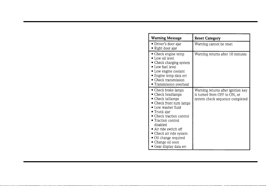
Warning messages which have been reset are
divided into two categories. They will reappear on
the display in 10 minutes from the reset or they
will not reappear until an ignition key OFF-ON
cycle. This reappearing of warning messages is a
reminder that these warning conditions still exist
within the vehicle. Warnings may be repeatedly
reset. All warning messages will reappear after an
entire SYSTEM CHECK sequence has been
completed.
File:03fnis8.ex
Update:Thu Jun 27 10:00:37 1996
32
The following is a list of warning messages and
their associated reset category:
File:03fnis8.ex
Update:Thu Jun 27 10:00:37 1996

33
DRIVER’S DOOR AJAR — This warning message
is displayed when the driver’s door is not
completely closed and the ignition switch is either
ON or in ACC mode.
RIGHT DOOR AJAR — This warning message is
displayed when the right (passenger side) door is
not completely closed and the ignition switch is
either ON or in ACC mode.
CHECK ENGINE TEMP — This warning message
is displayed when the engine coolant is overheating.
Stop the vehicle as soon as safely possible, turn off
the engine and let it cool. Check the coolant and
level, and add coolant as required following the
instructions in the Maintenance and Care chapter.
If you do not follow these instructions, you or
others could be injured. If this warning stays on or
continues to come on, contact your dealer for
service as soon as safely possible.
LOW OIL LEVEL — This warning message is
displayed when your engine oil level is low. If this
warning message is displayed, check the level of the
engine oil.
To check your oil:
1. Park your vehicle on level ground, turn off the
engine and wait at least 5 minutes for the oil
to drain back into the oil pan.
2. Use the dipstick to check the oil. If the level is
low, add oil, but do not overfill.
If you are parked on a steep incline, the LOW OIL
LEVEL warning may come on when you start your
vehicle, even though the oil is at the correct level.
The oil level is monitored while the engine is off,
so that the oil can drain into the oil pan to be
measured. Some after-market devices such as
remote starters, if improperly installed, can cause
File:03fnis8.ex
Update:Thu Jun 27 10:00:37 1996

34
the engine to start without alerting the oil
monitoring system. This may also cause the LOW
OIL LEVEL warning to come on when you start
your vehicle, even though the oil is at the correct
level.
For further information about adding oil, see Engine
oil in the index.
CHECK CHARGING SYSTEM — This warning
message is displayed when the electrical system is
not maintaining a proper voltage. If you are running
electrical accessories when the engine is idling at a
low speed, turn off as many of the electrical loads
as soon as safely possible. If this warning stays on
or comes on when the engine is operating at
normal speeds, have the electrical system checked
as soon as safely possible.
LOW FUEL LEVEL — This warning message is
displayed when you have approximately 50 miles
(80 km) or less left before you run out of fuel.
LOW ENGINE COOLANT — This warning
message is displayed when the engine coolant level
is low. Stop the vehicle as soon as safely possible,
turn off the engine and let it cool. Check the
coolant and level, and add coolant as required
following the instructions in the Maintenance and
Care chapter. If you do not follow these
instructions, you or others could be injured.
ENGINE TEMP DATA ERR — This warning
message is displayed when the engine coolant
temperature information is missing or invalid. Check
the instrument cluster temperature gauge to assure
the engine is not overheating. If it is, stop the
vehicle as soon as safely possible, turn off the
engine and let it cool. Check the coolant and level
following the instructions in the Maintenance and
Care chapter. If you do not follow these
instructions, you or others could be injured. Contact
your dealer for service as soon as safely possible to
correct the engine temperature data error.
File:03fnis8.ex
Update:Thu Jun 27 10:00:37 1996

35
CHECK TRANS-MISSION — This warning
message is displayed when the transmission is not
operating properly. If this warning stays on or
comes on, contact your dealer for transmission
service as soon as safely possible.
TRANS-MISSION OVERHEAT — This warning
message is displayed when the transmission is
overheating. This warning may appear when towing
heavy loads, or driving in a low gear at high speed
for an extended period of time. Stop the vehicle as
soon as safely possible, turn off the engine and let it
cool. Check the transmission fluid and level
following the instructions in the Maintenance and
Care chapter. If this warning stays on or continues
to come on, contact your dealer for transmission
service as soon as safely possible.
CHECK BRAKE LAMPS — This warning message
is displayed when you turn on the brake lamps and
at least one of them is burned out. Check the
lamps as soon as safely possible, and have the
burned out lamp replaced following the instructions
in the Maintenance and Care chapter. Note the
center high mounted stop lamp is not monitored.
CHECK HEADLAMPS — This warning message is
displayed when you turn on the headlamps and at
least one of them is burned out. Check the lamps
as soon as safely possible, and have the burned out
lamp replaced following the instructions in the
Maintenance and Care chapter. Note the high
beam lamps are not monitored.
CHECK TAIL LAMPS — This warning message is
displayed when you turn on the tail lamps and at
least one of them is burned out. Check the lamps
as soon as safely possible, and have the burned out
lamp replaced following the instructions in the
Maintenance and Care chapter.
File:03fnis8.ex
Update:Thu Jun 27 10:00:37 1996

36
CHECK FRT TURN LAMPS — This warning
message is displayed when you turn on the front
turn lamps and at least one of them is burned out.
Check the lamps as soon as safely possible, and
have the burned out lamp replaced following the
instructions in the Maintenance and Care chapter.
LOW WASHER FLUID — This warning message
is displayed when there is less than one quarter of
the container of washer fluid remaining. Check the
washer fluid level, and refill the reservoir following
the instructions in the Maintenance and Care
chapter.
TRUNK AJAR — This warning message is
displayed when the trunk is not completely closed
and the ignition switch is either ON or ACC.
CHECK TRACTION CONTROL — This warning
message is displayed when the Traction Control
system is not operating properly. If this warning
stays on or comes on, contact your dealer for
service as soon as safely possible. For further
information refer to the Traction Control section in
the Driving chapter.
TRACTION CONTROL DISABLED — This
warning message is displayed when the Traction
Control system is temporarily disabled due to an
overheating condition. This may occur in normal
operation due to a prolonged series of high speed
traction control or braking events. This warning is
removed when the traction control system has
cooled down sufficiently to resume normal
operation. If this warning stays on, contact your
dealer for service as soon as safely possible. For
further information refer to the Traction Control
section in the Driving chapter.
File:03fnis8.ex
Update:Thu Jun 27 10:00:37 1996

37
AIR RIDE SWITCH OFF — This warning message
is displayed when the AIR SUSPENSION SERVICE
SWITCH is in the OFF position. The air suspension
service switch is located in the vehicle trunk in the
jack stowage area on the left side. For more
information refer to the Air Suspension section in
the Driving chapter.
CHECK AIR RIDE SYSTEM — This warning
message is displayed when the Air Suspension
System is not operating properly. If this warning
message is displayed while driving, pull off the road
as soon as safely possible. If the vehicle is loaded
beyond the recommended maximum payload, the
“CHECK AIR RIDE SYSTEM” message may be
displayed. This is a normal condition if the vehicle
is overloaded. To correct this condition, remove or
redistribute the payload per the recommended
maximum requirements. Turn the ignition switch
from ON to OFF to ON again. If the warning
message reappears, turn the Air Suspension Service
Switch (located in the vehicle trunk in the jack
stowage area on the left side) OFF and contact your
dealer for service as soon as safely possible. For
further information refer to the Air Suspension
section in the Driving chapter.
CHANGE OIL SOON/OIL CHANGE
REQUIRED — This warning message is displayed
when the engine oil life remaining is 5% or less.
When Oil Life Left is between 5% and 0%, the
“CHANGE OIL SOON” message will be displayed.
When Oil Life Left reaches 0%, the “OIL CHANGE
REQUIRED” message will be displayed.
An oil change is required whenever indicated by
the Message Center. USE ONLY RECOMMENDED
ENGINE OILS (see Engine Oil in the Index).
The Message Center will tell you the percent of oil
left during System Check. This percentage is based
on your driving history and the time since your last
oil change. In order to ensure accurate oil life left
indications, you should only perform the following
OIL CHANGE RESET Procedure after you have the
oil changed.
File:03fnis8.ex
Update:Thu Jun 27 10:00:37 1996

38
OIL CHANGE RESET PROCEDURE — This
procedure allows you to reset the oil monitoring
system to 100% (or your Personalized Oil Reset
Percentage) after each oil change.
1. Press the VEHICLE SETTINGS control until the
“OIL CHANGE RESET” display appears.
2. Then press the RESET switch and hold it for 5
seconds while the display counts down to
trigger an oil change reset.
3. After a successful reset the Message Center will
display “OIL LIFE RESET TO 100%”. If you
have established a Personalized Oil Reset
Percentage, the display will show that
percentage instead of 100%. To ensure accurate
oil life indicators, perform this reset procedure
only after an oil change. For more information
on Personalized Oil Reset Percentage see the
section on Personalized Oil Reset Percentage.
GEAR DISPLAY DATA ERR — This warning
message is displayed when the data used to provide
the redundant gear selection display on the
Instrument Cluster is missing or invalid. In this
case, the Instrument cluster redundant gear
selection display is turned off. The driver should use
the mechanical position indication on the center
console gear selector as temporary indication. If this
warning stays on, contact your dealer for service as
soon as safely possible.
File:03fnis8.ex
Update:Thu Jun 27 10:00:37 1996

39
Function/Status Error Messages
For some functions displayed by the Message
Center, there will be error messages displayed,
instead of the requested information, if that
information is not currently available because of
improper operation of sensor systems, or the vehicle
network communication between electronic
modules. In this case instead of displaying a
warning message which takes control of the display,
a function/status error message will be displayed
when the affected function is requested. These
messages will have 2 formats:
1. Data error messages in the form “DATA
ERROR” or “DATA ERR”. These messages
indicate improper operation of the vehicle
network communication between electronics
modules. If these messages occur on a regular
basis contact your dealer for service as soon as
safely possible.
2. Invalid sensor operation messages with the form
“SENSOR OPEN” or “SENSOR SHORT”. These
messages indicate improper operation of vehicle
sensor systems, or vehicle wiring/connectors
between the sensors and Message Center. If
these messages occur on a regular basis contact
your dealer for service as soon as safely
possible.
Electronic Compass
The electronic compass will be displayed when the
COMPASS switch is pressed. The display shows the
direction your car is traveling as one of the
following directions: North, Northeast, East,
Southeast, South, Southwest, West, or Northwest.
If a warning becomes active, the warning message
will override the compass display.
File:03fnis8.ex
Update:Thu Jun 27 10:00:37 1996
40
Factors Affecting Compass Accuracy
Magnetic mounted devices (antennas, racks, etc.)
should not be located on the front third of the
vehicle roof. Placement of these devices near the
compass will cause the compass to be inaccurate. If
these devices are used, for improved accuracy,
recalibrate the compass with the device(s) installed.
Driving near power lines or large iron or steel
structures can temporarily change the compass
heading. Demagnetize the vehicle and recalibrate
the compass if it remains inaccurate after driving
near such objects.
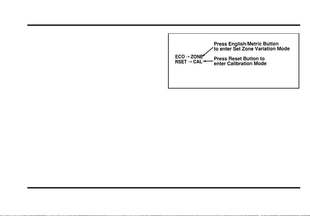
Compass Adjustments
Press and hold the COMPASS control, then press
the RESET control. Next, release both controls. The
display will show the “Compass Menu” (Figure 1).
The letters on the left side of the arrows indicate
the control to press to perform the adjustment
indicated on the right side of the arrows, as shown
in Figure 1.
Figure 1 — Compass Menu Mode
To abort this “compass menu” or any compass
variation adjustment menu, press any control other
than RESET or FUEL ECONOMY.
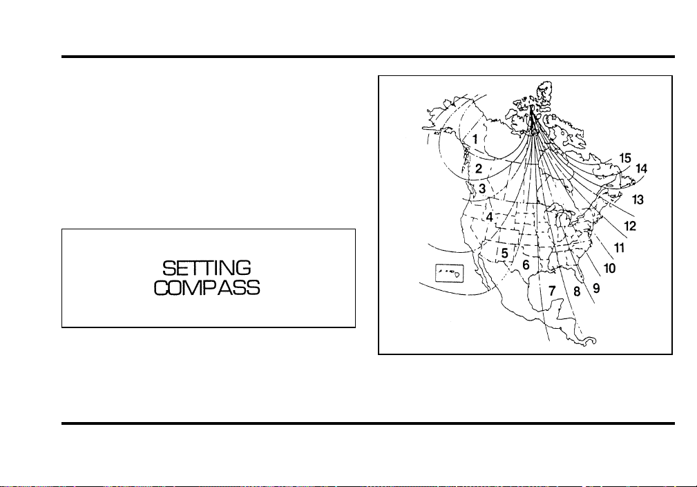
Variation Adjustment
The variation adjustment is only needed if you
travel outside your current zone (see Fig. 2). The
following describes the method available for setting
the variation adjustment:
File:03fnis8.ex
Update:Thu Jun 27 10:00:37 1996
41
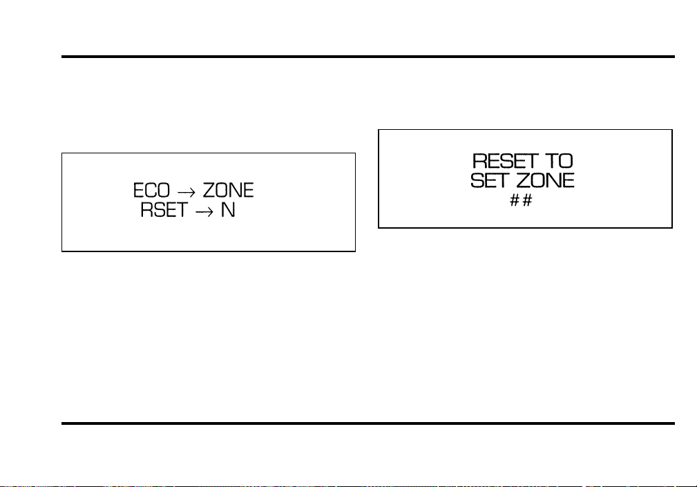
Set zone variation adjustment
1. Press and hold the COMPASS control, press the
RESET control. Next, release both controls. The
display will show:
2. Press the ENGLISH/METRIC control to enter
the Set Zone mode. The display will now
show:
NOTE: The display shows “##” (where ## is a
number from 1-15) when called up, which is the
zone stored internally in the compass computer.
3. Determine which zone of the country you are
in by referring to the zone map shown in
Figure 2.
File:03fnis8.ex
Update:Thu Jun 27 10:00:37 1996
42
4. Press the RESET control until the number
shown in the display is the correct number for
the zone you are in. When the zone number
reaches 15, pressing the RESET control will set
the zone number to 1.
5. Press the COMPASS control to complete the
zone setting. (To exit this mode without setting
a zone, press any control other than RESET
and COMPASS). The M/C may now display:
for a few seconds, and then it will return to the
normal compass heading mode. The zone setting
procedure is now complete.
Figure 2 — Zone map
File:03fnis8.ex
Update:Thu Jun 27 10:00:37 1996
43
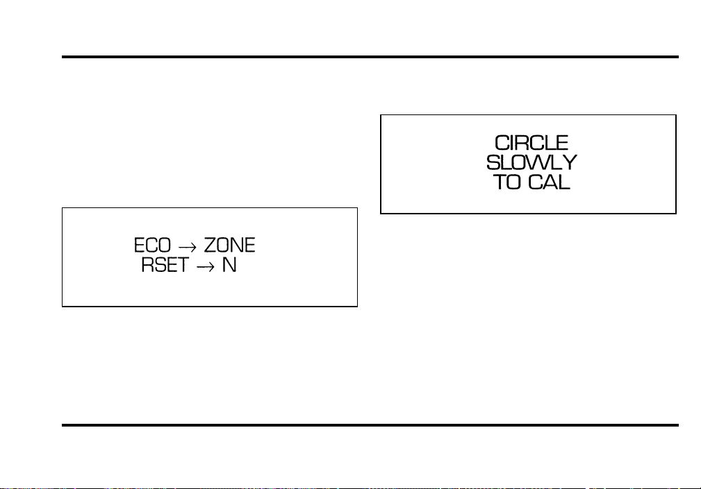
Calibration Procedure
1. Find an open, level area free from steel
structures and high voltage lines. An empty,
level parking lot is recommended.
2. Press and hold the COMPASS control, then
press the RESET control. Next, release both
controls. The display will show:
3. Press the RESET control to enter the
Calibration mode. The display will show:
4. Slowly drive the vehicle at less than 3
mph/5 km/h in a circle, taking at least 20
seconds to complete one circle, until the
display shows a direction instead of the
“CIRCLE SLOWLY TO CAL” message. This
should occur within 3 circles.
5. The compass is now calibrated.
File:03fnis8.ex
Update:Thu Jun 27 10:00:37 1996
44
Troubleshooting
If the display shows the following message during
any of the compass adjustment procedures, contact
your dealer:
If the compass always displays one direction while
turning a full 360-degree circle, perform the
Calibration Procedure.
A system of warning lights are located below the
Message Center. Warning lights are used to monitor
the operation of your vehicle.
Safety Belt Warning Light and Chime
This warning light and chime remind you to fasten
your safety belt. The following conditions will take
place:
❑
If the driver’s safety belt is not buckled when
the ignition is turned to the ON position, the
light will turn on for 1 to 2 minutes and the
chime will sound for 4 to 8 seconds.
❑
If the driver’s safety belt is buckled while the
light is on and the chime is sounding, the light
and the chime will turn off.
❑
If the driver’s safety belt is buckled before the
ignition is turned to the ON position, neither
the light nor the chime will turn on.
File:03fnis8.ex
Update:Thu Jun 27 10:00:37 1996
45
Check Engine Warning Light
This light illuminates when the engine’s Emission
Control System requires service. It will also
illuminate when the ignition key is in the ON
position and the engine is off.
Air Bag Readiness Light
The air bag system uses a readiness light and a tone
to indicate the condition of the system. The
readiness light is in the instrument cluster. When
you turn the ignition key to the ON position, this
light will light up for six (6) seconds and then turn
off. This indicates that the system is operating
normally. NOTE: Regularly scheduled maintenance
of the air bag system is not required.
File:03fnis8.ex
Update:Thu Jun 27 10:00:37 1996
46
If the light fails to illuminate, continues to flash,
remains on, or you hear a beeping sound, have the
system serviced at your Ford or Lincoln-Mercury
dealer immediately.
Overdrive Off Indicator
This light tells you that the Transmission Control
Switch on the gearshift lever has been pushed.
When the light is on, the transmission will not shift
into overdrive. Depressing the button on the shifter
will return the vehicle to “overdrive on” mode. The
transmission will be in the “overdrive on” mode
when the vehicle is started even if the O/D OFF
mode was selected when the vehicle was last shut
off.
File:03fnis8.ex
Update:Thu Jun 27 10:00:37 1996
47
If the light does not come ON when the TCS is
depressed or if the light FLASHES when you are
driving, have your vehicle serviced at the first
opportunity. If this condition persists, damage could
occur to the transmission.
Anti-Theft Alarm Light
This light is used when you set the anti-theft alarm
system. See the Controls and Features chapter later
in this guide for more information.
This light will also flash if the passive anti-theft
system is not functioning correctly. If the light
continues to flash have the system serviced at your
Ford or Lincoln-Mercury dealer immediately.
NOTE: If this light flashes rapidly, the vehicle will
be disabled.
File:03fnis8.ex
Update:Thu Jun 27 10:00:37 1996
48
Traction Control Off Light
This light tells you that the traction control system
has been turned off using the Vehicle Settings menu
in the Message Center. The traction control system
defaults to “ON” (light is not illuminated) whenever
the vehicle is shut off and restarted.
File:03fnis8.ex
Update:Thu Jun 27 10:00:37 1996
49
Electronic Sound Systems
Premium Stereo Cassette
File:04fnas8.ex
Update:Wed Jun 19 10:43:44 1996
50
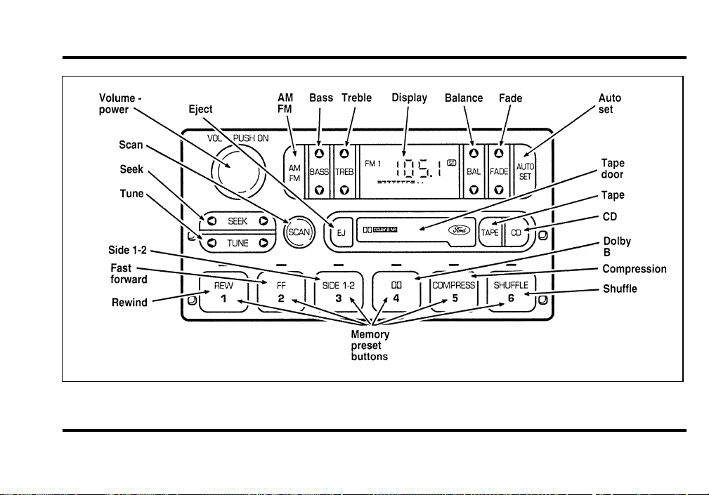
Premium Stereo Cassette and Stereo Cassette with CD DJ
File:04fnas8.ex
Update:Wed Jun 19 10:43:44 1996

51
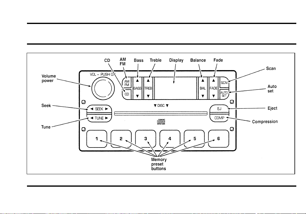
Premium Stereo Cassette, Stereo
Cassette with CD DJ and
Premium Compact Disc Radio
Your vehicle is equipped with either a premium
stereo cassette radio or a premium compact disc
radio. Both systems are available with a JBLH
upgrade system, which includes a Ford 10-CD
changer.
Individual functions of these systems follow:
Using the Controls on Your New Radio
How to turn the radio on and off
Press the “VOL/PUSH” knob to turn the radio on.
Press again to turn it off.
How to adjust the volume
Turn the “VOL/PUSH” knob to the right to
increase the volume and to the left to decrease the
volume. Bars illuminate in the display to show
relative volume level.
NOTE: If the volume level is set above a certain
listening level when the ignition switch is turned
off, when the ignition switch is turned back on, the
volume will come back to a “nominal” listening
level. However, if the radio power is turned off, the
volume will remain in the position it was set at
when radio power was switched off.
Selecting the AM or FM frequency band
Push the “AM/FM” button to select the desired
frequency band or to stop/store cassette tape (when
in cassette mode) or compact disc (when in CD
mode). Pushing the button more than once will
alternate between AM, FM1 and FM2. These
functions are used with the station memory buttons
described under How to tune radio stations.
How to tune radio stations
There are four ways for you to tune in a particular
station. You can manually locate the station using
the “TUNE”, “SEEK”, “SCAN” or selecting the
station by using the memory buttons, which you
File:04fnas8.ex
Update:Wed Jun 19 10:43:44 1996

52
can set to any desired frequency. These four
methods are described below.
❑
Using the “TUNE” function
You can change the frequency up or down one
increment at a time by pressing and releasing either
the left
b
or right
a
side of the “TUNE” button.
To change frequencies quickly, press and hold down
either the right or left side of the button.
Manual tuning adjusts your radio to any allowable
broadcast frequency, whether or not a station is
present on that frequency. (See All About Radio
Frequencies in this section.)
❑
Using the “SEEK” function
Press the right (
a
) side of the “SEEK” button to
select the next listenable station up the frequency
band. Press the left (
b
) side of the button to select
the next listenable station down the frequency
band. By pressing and holding the button, listenable
stations can be passed over to reach the desired
station.
❑
Using the “SCAN” function
Pressing the “SCAN” or “SCN” button will begin
the scan mode up the frequency band, stopping on
each listenable station for approximately five
seconds.
To stop the scan mode on the presently sampled
station, press the “SCAN” or “SCN” button again.
❑
Setting the station MEMORY PRESET buttons
Your radio is equipped with 6 station memory
buttons. These buttons can be used to select up
to 6 preset AM stations and 12 FM stations (6
in FM1 and 6 in FM2)
File:04fnas8.ex
Update:Wed Jun 19 10:43:44 1996

53
Follow the easy steps below to set these buttons to
the desired frequencies:
1. Select a band, then select a frequency.
2. Press one of the memory preset buttons and
hold the button until the sound returns. That
station is now held in memory on that button.
3. Follow the two steps above for each station
memory preset button you want to set.
❑
Using the AUTOSET feature
With AUTOSET, you can continually set strong
stations into your memory buttons without
losing your originally set stations.
Press the “AUTOSET” button once. Your radio
will set the first six strong stations of the band
you are in (AM, FM1, or FM2) into the
memory buttons. The display will show
“AUTO”, then run through the frequencies
setting the memory buttons.
NOTE: If there are fewer than five strong
stations in the frequency band, the remaining
unfilled buttons will store the last strong station
detected on the band.
When all stations are filled, the radio will begin
playing the station stored in memory button 1.
To deactivate the Auto Memory Store mode and
return to manually-set memory button stations,
press the “AUTOSET” button. Display will show
“AUTO” then “OFF”.
Adjusting the tone balance of your radio
❑
Increasing or decreasing bass response
Press the top
c
of the “BASS” button to increase
bass; press the bottom
d
of the “BASS” button to
decrease bass.
File:04fnas8.ex
Update:Wed Jun 19 10:43:44 1996

54
❑
Increasing or decreasing treble response
Press the top
c
of the “TREBLE” button to
increase treble; press the bottom
d
of the treble
button to decrease treble.
❑
Adjusting speaker balance
Balance control allows you to adjust the sound
distribution between the right and left speakers.
Press the top
c
of the “BAL” button to shift the
sound to the right speakers, and press the bottom
d
of the “BAL” button to shift the sound to the
left speakers.
❑
Adjusting speaker fader
Fade control allows you to adjust the sound
distribution between the front and rear speakers.
Press the top
c
of the “FADE” button to shift the
sound to the front speakers, and press the bottom
d
of the “FADE” button to shift the sound to the
back speakers.
NOTE: Illuminated bars in the display show relative
levels of bass and treble, and positions of speaker
balance and fader functions (left to right, front to
rear).
Using the Controls of Your
Cassette Tape Player
(If Equipped)
NOTE: Radio power must be on to use the cassette
tape player.
How to insert a tape
Your cassette tape player is equipped with power
loading. Once you insert a tape and push slightly
(with the open edge to the right), the loading
mechanism draws the tape the rest of the way in
and play will begin after a momentary tape
tightening process. Display indicates “TAPE” while
tape is playing.
File:04fnas8.ex
Update:Wed Jun 19 10:43:44 1996

55
NOTE: A cassette tape can be loaded with the
ignition on whether or not the radio power is on.
However, with radio power off, the cassette tape is
loaded and stored.
NOTE: Noise reduction system manufactured under
license from Dolby Labs Licensing Corporation.
“Dolby” and double-D symbol are trademarks of
Dolby Laboratories Licensing Corporation.
How to locate a desired track on the tape
There are four ways to quickly locate a desired
selection on the tape. You can use the fast forward,
rewind, “SEEK” or “SCAN” function. Following are
brief descriptions of each.
❑
Fast forwarding the tape
To fast forward the tape, press the “FF” button.
The radio will begin playing until fast forward is
manually stopped (by pushing the “TAPE” button)
or the end of the tape is reached.
At the end of the tape, the direction automatically
reverses and plays the other side of the tape.
❑
Rewinding the tape
To rewind the tape, press the “REW” button. The
radio will begin playing until rewind is manually
stopped (by pushing the “TAPE” button) or the
beginning of the tape is reached.
❑
Using the “SEEK” function with your cassette
tape player
While in the tape mode, push the right
a
side of
the “SEEK” button to seek forward to the next
selection on the tape. Push the left
b
side to seek
the previous tape selection.
❑
Using the “SCAN” function with your cassette
tape player
Press the “SCAN” button to begin the forward scan
mode on the tape currently playing, stopping on
each tape selection for approximately an
eight-second sampling (display indicates “SC”).
File:04fnas8.ex
Update:Wed Jun 19 10:43:44 1996

56
To stop the scan mode on the presently sampled
tape selection, press “SCAN” a second time.
❑
How to change the side of the tape being
played
The alternate side of the tape can be selected by
pressing the “SIDE 1-2” button.
How to eject the tape
To stop the tape and eject the cassette, press the
“EJ” button. The radio will resume playing if the
radio power is on. The tape cartridge can be ejected
with radio power (and/or ignition) on or off.
How to store the tape
Press the “AM/FM” button to stop the tape player
and resume radio play.
Using the DolbyH B noise reduction
feature
Push the k button to activate Dolby B Noise
Reduction. Press again to deactivate.
Automatic tape tightening
Your audio system cassette tape player automatically
goes into momentary fast rewind (approximately 1
second) when a tape is first inserted to tighten any
loose tape in the cartridge.
Tips on Caring for the Cassette Player
and Tapes
In order to keep your cassette tape player
performing the way it was meant to, read and
follow these simple precautions:
❑
Using a Ford or equivalent cassette cleaning
cartridge to clean the tape player head after
10-12 hours of play will help maintain the best
playback sound and proper tape operation.
❑
Only cassettes that are 90 minutes long or less
should be used. Tapes longer than 90 minutes
are thinner and subject to breakage or may jam
the tape player mechanism.
File:04fnas8.ex
Update:Wed Jun 19 10:43:44 1996

57
❑
Protect cassettes from exposure to direct
sunlight, high humidity and extreme heat or
cold. If they are exposed to extreme conditions,
allow them to reach a moderate temperature
before playing.
❑
If a tape is loose inside the cassette, tighten it
before playing by putting your finger or a pencil
into one of the holes and turning the hub until
the tape is tight.
❑
Loose labels on cassette tapes can become
lodged in the mechanism. Remove any loose
label material before inserting cassette.
❑
Do not leave a tape in the cassette tape player.
High heat in the vehicle can cause the cassette
to warp.
Using the Controls of Your Compact
Disc Player (If equipped)
NOTE: Radio power must be on to use the CD
player.
How to insert a CD
Your CD player is equipped with power loading.
Once you insert a CD and push slightly, the loading
mechanism draws the CD the rest of the way in
and play will begin after a momentary pause.
Display indicates “TR-__” (track number) while CD
is playing.
NOTE: A CD can be loaded with the ignition on
whether or not the radio power is on. However,
with radio power off, the CD is loaded and stored.
Operating the “SCAN” function
Press the “SCN” button to enter the scan mode.
The CD player will begin scanning the disc,
stopping on each listenable track for approximately
an eight second sampling. This continues until you
press the “SCN” button a second time.
How to stop CD play
While in the CD mode, press the “AM/FM” button
to stop CD play and resume radio play.
File:04fnas8.ex
Update:Wed Jun 19 10:43:44 1996
58
HowtotakecareofandcleantheCD
playeranddiscs
ToensurethecontinuedperformanceofyourCD
player,carefullyreadthefollowingprecautions:
❑
Alwayshandleadiscbytheedge.Nevertouch
theplayingsurface.
❑
Beforeplaying,inspectalldiscsforany
contamination.Ifneeded,cleandiscswithan
approveddisccleaner,suchastheDiscwasherH
CompactDiscCleanerortheAllsop3H
CompactDiscCleaner,bywipingfromthe
centerouttotheedges.Donotuseacircular
motiontoclean.
❑
Donotcleandiscswithsolventssuchas
benzine,thinner,commerciallyavailablecleaners
orantistaticsprayintendedforanalogrecords.
❑
Donotexposethediscstodirectsunlightor
heatsourcesforanextendedperiodoftime.
❑
Donotinsertmorethanonediscintoeachdisc
slotofthediscmagazine.Doingsomaydamage
thediscs,discmagazineorthediscchanger.
❑
Donotinsertanythingotherthandiscsintothe
discmagazine.
WARNING
Thelaserbeamusedinthecompact
discplayerisharmfultotheeyes.Do
notattempttodisassemblethecase.
CDErrorMessages
Yoursystemisequippedtodiagnosecertain
problemsyoumayexperience.Theerrorcodesare:
—NOCD—Emplyslotormagazine,mechanical
error,Disc(s)unreadable,Focuserror,orthermal
shutdown(toohot).
—CDHOT—Mechanismover167˚Fahrenheit,
allowtocoolbeforeplaying.
File:04fnas8.ex
Update:Wed Jun 19 10:43:44 1996
59
— CD-ER 0001 — Disc upside down or
unreadable.
— CD-ER INIT — Mechanism disconnected or
malfunctioning.
— CD-ER 0002 — Eject error.
— CD-ER 0100 — Computer CD loaded.
— CD-ER ____ (other codes) — Mechanism
malfunctions.
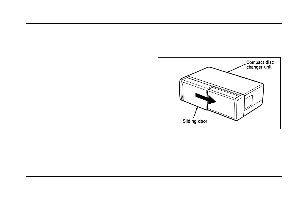
Ford 10-CD Changer (If equipped)
Introduction
The 10-CD Changer Unit is mounted in the trunk
(10-disc capacity) and is remotely controlled through
the Premium Audio System on your instrument
panel.
Be sure to read all of the information provided on
the following pages to get the most out of this
system.
Loading Instructions
1. Open Compact Disc Changer unit by sliding
door to the right (Figure 1).
Figure 1
File:04fnas8.ex
Update:Wed Jun 19 10:43:44 1996
60
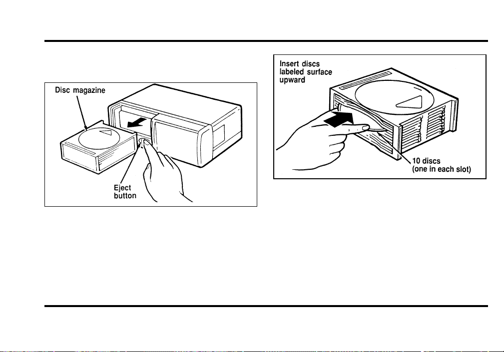
2. Push EJECT button to eject the disc
“magazine” (which holds 10 discs) (Figure 2).
Figure 2
3. Load discs into disc magazine slots (numbered
1 through 10) one at a time with labeled
surfaces upward, starting with bottom slot
number 1 (Figure 3).
Figure 3
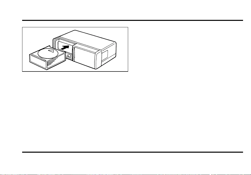
4. Insert loaded disc magazine into chamber unit
with the arrow on top of the disc magazine
pointing toward the changer (Figure 4). Make
sure magazine is fully inserted into changer.
File:04fnas8.ex
Update:Wed Jun 19 10:43:44 1996
61
Figure 4
NOTE: To remove one or more compact disc(s)
from the disc magazine, push the corresponding
lever(s) (numbered 1 to 10 on the side of the disc
magazine) to the left. Disc(s) will partially come out
for easy removal.
5. Close unit by sliding changer panel door to the
left.
The Compact Disc Changer unit is now ready to
play using the controls of your Premium Audio
System.
How to Operate the Ford 10-CD
Changer Using the Controls on the
Radio
If your vehicle is equipped with the Ford 10-CD
Changer System, you operate it through the controls
of your Premium Audio System.
Several of the controls on the radio operate in the
same manner in CD mode as they do in radio or
cassette mode: turning the power on, volume
control and adjusting the bass, treble, speaker
balance or fade.
How to begin CD Changer play
NOTE: Radio power must be on to operate the
Compact Disc Changer.
Push the “CD” button to begin CD play. The CD
Changer will automatically begin playing the first
track (selection) of the first disc loaded in the unit.
The display will indicate “CD-##” for disc number
then display “TR-##” for track number, then
“DD-TT” for disc number and track number.
File:04fnas8.ex
Update:Wed Jun 19 10:43:44 1996

62
If the CD Changer is empty, “NO CD” will flash in
the display and radio play will continue.
If your vehicle is not equipped with the Ford
10-CD system and the “CD” button is pushed, “NO
DJ” will flalsh and radio play will continue.
How to change the disc being played
When in the CD mode, you can change discs by
pressing the right (
a
) side of the “TUNE DISCS”
button (to select the next disc) or the left (
b
) side
of the “TUNE DISCS” button (to select the previous
disc). Play will begin on the first track of the
selected disc.
When either side of the button is pressed and held,
the CD changer will continue fast-forwarding or
reversing through the discs in the disc magazine.
During these functions, the display will indicate the
disc number.
How to change the track being played
Press the right (
a
) side of the “SEEK” button to
seek forward to the next track of current disc. After
the last track has been completed, the CD player
automatically wraps back to the first track of the
current disc.
Press the left (
b
) side of the SEEK button to seek
in reverse to the previous track on the current disc.
If a selection has been playing for three seconds or
more and you press the left (
b
) side of the SEEK
button, the CD Changer will replay that selection
from the beginning.
Operating the CD Compression feature
The compression feature will bring soft and loud
passages closer together for a more consistent
listening level.
To turn the compression on, press the
“COMPRESS”/#5 button. When the compression
feature is activated, the display will indicate “C”.
File:04fnas8.ex
Update:Wed Jun 19 10:43:44 1996

63
Operating the Shuffle feature
While in the CD mode, pressing the
“SHUFFLE”/#6 button will randomly select a track
from the disc currently being played. The display
will indicate “SHF” followed by the disc and track
number (dd-tt).
The CD Changer will continue to randomly select
tracks for play until the shuffle feature is turned off
by pressing the “SHUFFLE” button a second time.
Operating the “SCAN” function
Press the “SCAN” button to enter the scan mode.
The CD player will begin scanning the disc,
stopping on each listenable track for approximately
an eight second sampling. This continues until you
press the “SCAN” button a second time.
Operating the Shuffle and Scan features
simultaneously
Both the shuffle and scan features can be activated
simultaneously. In this mode, the player will
randomly pick a selection and play the first eight
seconds. This process is continued until either the
“SCAN” button or “SHUFFLE” button is pressed a
second time.
How to stop CD play
While in the CD mode, press the “AM/FM” button
to stop CD play and resume radio play. Also,
loading a cassette into the cassette deck will stop
CD play and begin cassette play.
How to take care of and clean the CD
Changer and discs
To ensure the continued performance of your CD
Changer, carefully read the following precautions:
❑
Always handle a disc by the edge. Never touch
the playing surface.
File:04fnas8.ex
Update:Wed Jun 19 10:43:44 1996
64
❑
Beforeplaying,inspectalldiscsforany
contamination.Ifneeded,cleandiscswithan
approveddisccleaner,suchastheDiscwasherH
CompactDiscCleanerortheAllsop3H
CompactDiscCleaner,bywipingfromthe
centerouttotheedges.Donotuseacircular
motiontoclean.
❑
Donotcleandiscswithsolventssuchas
benzine,thinner,commerciallyavailablecleaners
orantistaticsprayintendedforanalogrecords.
❑
Donotexposethediscstodirectsunlightor
heatsourcesforanextendedperiodoftime.
❑
Donotinsertmorethanonediscintoeachdisc
slotofthediscmagazine.Doingsomaydamage
thediscs,discmagazineorthediscchanger.
❑
Donotinsertanythingotherthandiscsintothe
discmagazine.
WARNING
Thelaserbeamusedinthecompact
discplayerisharmfultotheeyes.Do
notattempttodisassemblethecase.
CDErrorMessages
Yoursystemisequippedtodiagnosecertain
problemsyoumayexperience.Theerrorcodesare:
—NOCD—Emplyslotormagazine,mechanical
error,Disc(s)unreadable,Focuserror,orthermal
shutdown(toohot).
—BADCD—Discunreadable.
—TOOHOT—Mechanismover167˚Farenheit
(75˚C),allowtocoolbeforeplaying.
—NODJ—CDChangernotconnected,not
communicating,ornotequipped.
File:04fnas8.ex
Update:Wed Jun 19 10:43:44 1996

65
Common Operating Conditions of the
CD Player
The following information is designed to help you
recognize typical situations that could be mistakenly
interpreted as mechanical malfunctions of the disc
player.
❑
A disc is already loaded.
❑
The disc is inserted with the label surface
downward.
❑
The disc is dusty or defective.
❑
The player’s internal temperature is above
167˚F (75˚C). Allow the player to cool off
before operating.
❑
Different manufacturers of compact discs may
produce discs with different dimensions or
tolerances, some of which may not be within
industry standards or in accordance with the
CD format. Because of this, a new disc that is
free of dust and scratches could be defective
and may not play on your Ford Compact Disc
Player.
If play does not begin after the CD button is
pushed:
❑
The radio is not on.
❑
The unit is in the stop mode.
❑
Moisture may have condensed on the lenses
within the unit. If this occurs, remove the disc
and wait approximately an hour until the
moisture evaporates.
If the sound skips:
❑
Badly scratched discs or extremely rough roads
will cause the sound to skip. Skipping will not
damage the disc player or scratch the discs.
File:04fnas8.ex
Update:Wed Jun 19 10:43:44 1996

66
Antenna
The antenna for the audio system is integral to the
rear window glass. The AM portion of the antenna
uses the same pattern of lines as the grid for the
rear defroster. The FM portion of the antenna uses
the top three lines on the glass, which are indicated
by the word “RADIO.”
Common Radio Reception
Conditions
Several conditions prevent FM reception from being
completely clear and noise-free, such as the
following:
Distance/Strength
The strength of the FM signal is directly related to
the distance the signal must travel. The listenable
range of an average FM signal is approximately 24
miles (40 km). Beyond this distance, the radio is
operating in a “fringe” area and the signal becomes
weaker. Also, “Signal Modulation” is used by some
stations to increase their “loudness” relative to other
stations. The difference in loudness can be a result
of signal modulation as well as signal strength.
Terrain
The terrain (hilly, mountainous, tall buildings) of the
area over which the signal travels may prevent the
FM signal from being noise-free.
If there is a building or large structure between the
antenna and station, some of the signal “bends”
around the building, but certain spots receive almost
no signal. Moving out of the “shadow” of the
structure will allow the station to return to normal.
When the radio waves are reflected off objects or
structures, the reflected signal cancels the normal
signal, causing the antenna to pick up noise and
distortion. Cancellation effects are most prominent
in metropolitan areas, but also can become quite
severe in hilly terrain and depressed roadways.
File:04fnas8.ex
Update:Wed Jun 19 10:43:44 1996

67
To minimize these conditions, a stereo/mono blend
circuit has been incorporated into this system. This
feature automatically switches a weak stereo signal
to a clearer monaural signal, which improves the
quality of reception.
Several sources of static are normal conditions on
AM frequencies. These can be caused by power
lines, electric fences, traffic lights and
thunderstorms.
Another reception phenomenon is Strong Signal
Capture and Overload. This can occur when
listening to a weak station and when passing
another broadcast tower. The close station may
capture the more distant station, although the
displayed frequency does not change. While passing
the tower, the station may switch back and forth a
few times before returning to the original station.
When several broadcast towers are present
(common in metropolitan areas), several stations
may overload the receiver, resulting in considerable
station changing, mixing and distortion.
Automatic gain control circuitry for both AM and
FM bands has been incorporated into this system to
reduce strong signal capture and overload.
All About Radio Frequencies
The Federal Communications Commission (FCC)
and the Canadian Radio Telecommunications
Commission (CRTC) establish the frequencies that
AM and FM radio stations may use for their
broadcasts. The allowable frequencies are, AM: 530,
540...1600, 1610 kHz in 10 kHz steps; FM: 87.9,
88.1...107.7, 107.9 MHz in 0.2 MHz steps.
Not all frequencies will be assigned to a given area.
This radio will tune to each of these frequencies
using manual tune and no fine tuning is necessary
as radio stations may not use other frequencies.
Some FM radio stations advertise a “rounded-off”
frequency which is not the frequency they actually
broadcast on. For example, a radio station that is
File:04fnas8.ex
Update:Wed Jun 19 10:43:44 1996

68
assigned a frequency of 98.7 MHz may call itself
“Radio 99” even though 99.0 MHz is not an
allowable FM broadcast frequency.
Important Warranty and Service
Information
About Your Warranty
Your sound system is warranted for four years or
50,000 miles (whichever occurs first). Consult your
vehicle warranty booklet for further information.
Servicing Your Audio System
At Ford, we stand behind our audio systems with a
comprehensive service and repair program. If
anything should go wrong with your Ford audio
system, return to your dealer for service. There is a
nationwide network of qualified Ford authorized
repair centers to assist you.
File:04fnas8.ex
Update:Wed Jun 19 10:43:44 1996

69
Controls and Features
The Climate Control System
Electronic Automatic Temperature
Control System
The Electronic Automatic Temperature Control
(EATC) module is located at the center of the
instrument panel and operates only when the key is
in the ON position.
The EATC feature maintains the temperature you
select and automatically controls the airflow for
your comfort. It also allows you to override the
automatic operation with manual override buttons.
File:05fncf8.ex
Update:Thu Jun 27 10:02:20 1996
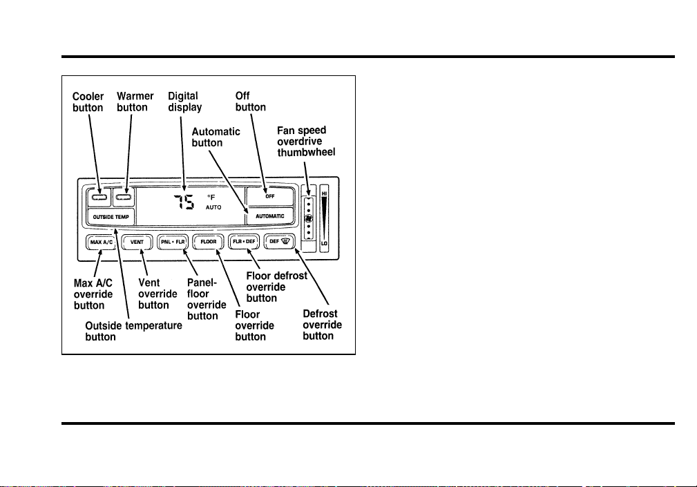
70
The automatic temperature control system
To turn your EATC on, push the AUTOMATIC
button or any of the six override buttons along the
bottom of the control.
To turn your EATC off, press the OFF button.
When the system is off, the display window will be
blank (dark).
If you select AUTOMATIC, the system will
automatically determine fan speed and airflow
location. If an override button is selected, your
selection determines airflow location only. Fan
speed remains automatic unless you override it by
rotating the vertical thumbwheel located at the
extreme right of the control panel.
To change the temperature in the display window,
select any temperature between 65˚F (18˚C) and
85˚F (29˚C) using the BLUE (cooler) or RED
(warmer) buttons. The Electronic Automatic
Temperature Control will do the rest.
File:05fncf8.ex
Update:Thu Jun 27 10:02:20 1996
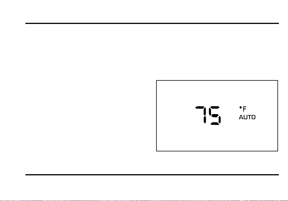
71
If you want continuous maximum cooling, push the
BLUE button until 60˚F (16˚C) is shown in the
display window. Your EATC will cool at maximum
and disregard the 60˚F (16˚C) setting until you
select a warmer temperature with the RED button.
If you want continuous maximum heating, push the
RED button until 90˚F (32˚C) is shown in the
display window. Your EATC will provide maximum
heat regardless of the 90˚F (32˚C) setting until you
select a cooler temperature with the BLUE button.
The display window tells you how the system is
operating. It will indicate the selected temperature
and the operating function you have chosen; AUTO
or one of the six manual overrides. It will also
indicate manual (thumbwheel) control of the fan
speed with the
H
symbol. The display window
with all possible displays and their positions are
shown here. Normally not all are shown at the
same time but are included here to familiarize you
with the names and symbols.
Automatic operation
Push the AUTOMATIC button and select the
desired temperature. The selected temperature and
AUTO will be shown in the display window. The
EATC will automatically heat or cool to achieve the
set temperature. Under normal conditions, your
EATC will need no additional attention.
The AUTO temperature display
File:05fncf8.ex
Update:Thu Jun 27 10:02:20 1996

72
When in AUTOMATIC and weather conditions
require heat, air will be sent to the floor. But, a
feature is included in your EATC to prevent
blowing cold air to the floor if the engine coolant is
not warm enough to allow heating. In 3-1/2
minutes or less, the fan speed will start to increase
and the airflow will change to the floor area.
If unusual conditions exist (i.e., window fogging,
etc.), the six manual override buttons allow you to
select special air discharge locations. A thumbwheel
allows you to adjust the fan speed to suit your
needs.
Temperature selection
The RED and BLUE buttons at the upper left of the
Control are for temperature selection. The RED
Button will increase the set temperature and the
BLUE Button will lower the set temperature.
Pressing a button and releasing it will change the
set temperature one degree. Holding either button
in will rapidly change the temperature setting in
one degree increments to either 65˚F (18˚C)
(BLUE) or 85˚F (29˚C) (RED). Then, the set
temperature will jump 5˚ and stop at either 60˚F
(16˚C) which is maximum cooling or 90˚F (32˚C)
which is maximum heating. When you select 60˚F
(16˚C) or 90˚F (32˚C), the fan will go to HI speed
for maximum air flow.
The average temperature range used is between
68˚F (20˚C) and 78˚F (26˚C). Changing the
temperature setting by several degrees outside this
range or overriding to 60˚F (16˚C) or 90˚F (32˚C)
will not speed up the heating or cooling process.
File:05fncf8.ex
Update:Thu Jun 27 10:02:20 1996
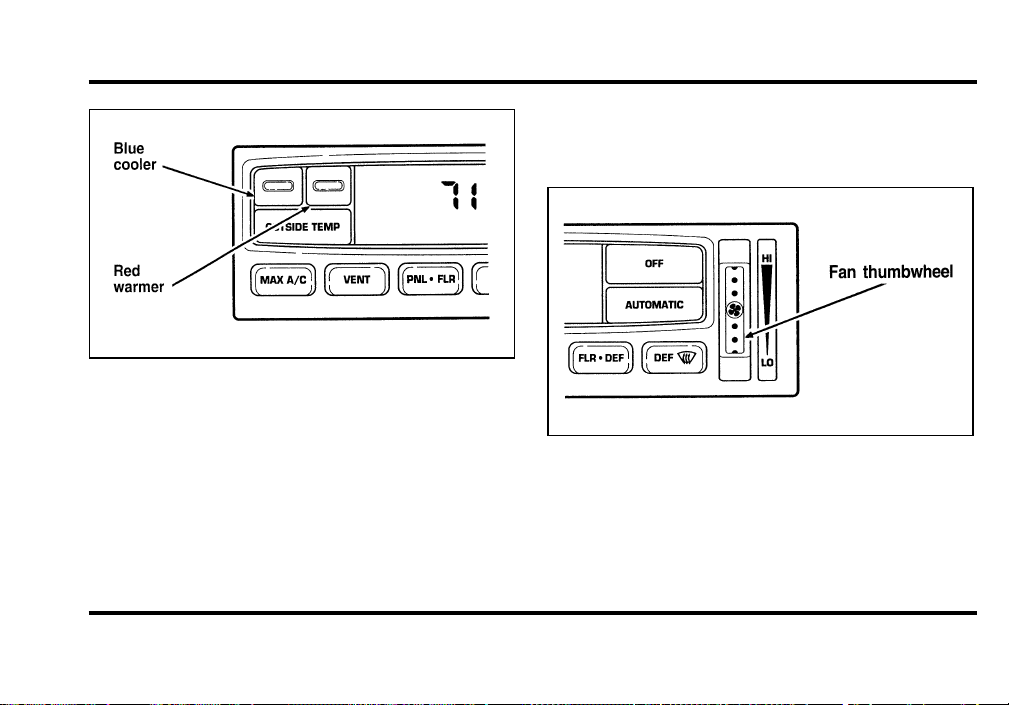
73
Fan speed and thumbwheel
Your EATC automatically adjusts the fan speed to
the existing conditions. You must push
AUTOMATIC for automatic fan speed operation. To
control the fan speed yourself, use the thumbwheel
which will cancel the automatic fan speed control.
The thumbwheel is located at the extreme right
side of the EATC control panel. It is a vertical
control marked with a fan symbol. Rotate up for HI
and down for LO speeds.
When you move the thumbwheel, the fan speed
will go to manual control. The display window will
show the
H
symbol in the upper left corner along
with the selected temperature and operating
function.
File:05fncf8.ex
Update:Thu Jun 27 10:02:20 1996
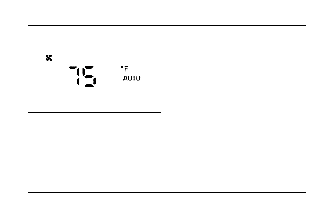
74
You can override the fan speed at any time. If you
use the thumbwheel to override the fan speed, the
EATC will continue to control the temperature but
you control the fan speed. To return to auto fan
control, press the AUTOMATIC button. If you are
operating in one of the override functions (FLOOR,
MAX A/C, etc.), automatic fan control will
continue unless you rotate the fan thumbwheel. To
return to automatic fan control, press the
AUTOMATIC button. The EATC will return to
Automatic operation. If you want to return to any
override function, press the button for that function.
The fan speed will continue to be automatically
controlled.
Manual override buttons
Your EATC has six buttons which allow you to
make special selections. The buttons are located
along the bottom edge of the EATC control and
allow you to determine where the air will be
discharged. Pressing any override button changes
the air discharge location only. It does not affect
the ability of the system to control temperature or
the fan speed. Return to fully Automatic operation
by pushing the AUTOMATIC button.
File:05fncf8.ex
Update:Thu Jun 27 10:02:20 1996

75
MAX A/C button
The MAX A/C feature allows for faster cooling
because air is drawn from inside the vehicle. Using
inside air causes the fan to sound louder which is
normal for this selection. The Display window will
change to indicate 60˚F (16˚C) and MAX A/C. The
fan will run and the airflow will be from the
instrument panel registers. To exit and return to the
previous temperature, push AUTOMATIC or any of
the other five override buttons.
VENT button
Push this button to select outside air through the
instrument panel registers. The display window will
show the set temperature and VENT to the lower
right of the temperature. Your EATC will heat the
air if the temperature you have selected is warmer
than the outside air coming into the vehicle.
However, the air will NOT be cooled regardless of
the temperature setting.
PNL O FLR button
Push this button to get air from the floor and
instrument panel registers at the same time. The
display will show the set temperature and the
words PNL and FLR. Depending on the selected
temperature, the air will be automatically heated or
cooled.
FLOOR button
Airflow will be to the floor when the FLOOR
button is pressed. The display window will show
the set temperature and FLR to the left of the
temperature. The air cannot be cooled in the FLR
position, only heated. Fan speed will be automatic
unless manually controlled. If you override the fan
speed and wish to return to automatic fan control,
push AUTOMATIC. Then, again select FLOOR for
airflow to the floor.
File:05fncf8.ex
Update:Thu Jun 27 10:02:20 1996

76
FLR O DEF button
Push this button to get air to the floor and
windshield defrosters at the same time. The display
will show the set temperature, FLR and the Defrost
symbol. If the outside temperature is about 50˚F
(10˚C) and above, the air will be dehumidified to
remove moisture. This will help to prevent fogging
in humid weather.
DEF button
Press the Defrost Button to obtain maximum airflow
to the windshield. Adjust the temperature setting as
required for defrosting. The Display window will
show the temperature setting with the Defrost
symbol to the left of the temperature. When the
outside temperature is about 50˚F (10˚C) and
above, the air will be dehumidified to remove
moisture. This will help prevent fogging in humid
weather.
OUTSIDE TEMP button
By pressing this button, the temperature of the air
outside of the vehicle will show in the display
window for 4 seconds. Then, the window will
automatically return to the previous display.
NOTE: The outside temperature reading is most
accurate when the vehicle is moving. Higher
readings may be obtained when the vehicle is not
moving. The readings that you get may not agree
with temperatures given on the radio due to
differences in vehicle and station locations.
Operating tips
The following tips will help you to get the most
satisfaction from your Electronic Automatic
Temperature Control system.
❑
In humid weather, select DEF V before
starting your engine. This will help to prevent
windshield fogging. After a few minutes of
operation, switch to AUTOMATIC or an
override selection of your choice.
File:05fncf8.ex
Update:Thu Jun 27 10:02:20 1996

77
❑
To prevent humidity buildup inside your
vehicle, always drive with the EATC System
turned on.
❑
Do not put objects under the front seats that
interfere with the flow of air to the back seat
area.
❑
Remove any snow, ice, or leaves from the air
intake area of your EATC System which could
block the air intake. The intake area is located
at the bottom of the windshield, under the
hood at the passenger side rear corner.
Service
If your EATC is not operating as described here,
take it to your dealer to have it checked. System
diagnostics are built in which will allow your dealer
to readily identify problems that might occur.
Rear Window Defroster and
Heated Sideview Mirrors
The rear window and heated outside mirrors
defroster switch activates the defroster for the rear
window to clear frost, fog, or thin ice from both
the inside and outside of the rear window and
activates the heated outside rearview mirrors.
The switch for the rear window defroster is located
below the climate control panel.
File:05fncf8.ex
Update:Thu Jun 27 10:02:20 1996
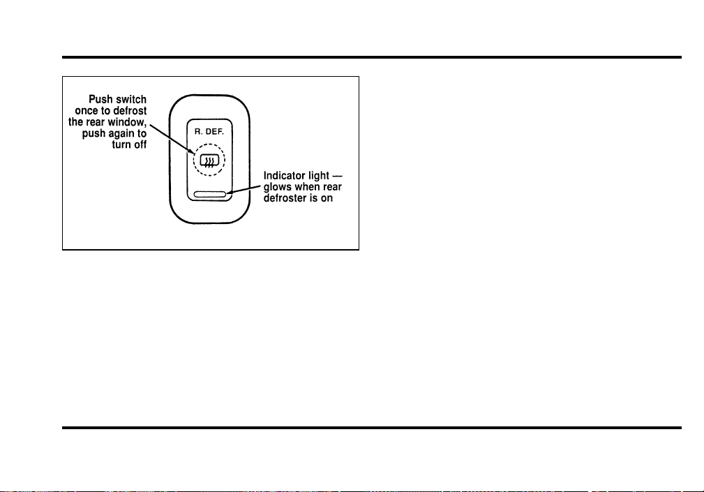
78
The button that controls the rear window
defroster and heated outside rearview mirrors
Before using the defroster, clear away any snow
that is on the rear window and outside rearview
mirrors. With the engine running, push the
defroster button.
After approximately 10 minutes, the defroster will
turn off. If the window or mirrors are still not clear,
turn the defroster on again.
The defroster will turn off when the ignition key is
turned to the OFF or START position.
The heating elements are bonded to the inside of
the rear window. Do not use sharp objects to
scrape the inside of the rear window or use
abrasive cleaners to clean it. Doing so could damage
the heating elements.
The Interior and Exterior Lights
Daytime Running Light System
(Canadian vehicles only)
The Daytime Running Light (DRL) system is
designed to turn the low beam headlamps on when
all of the following conditions are met:
❑
The headlamp system is in the OFF position,
and
❑
The vehicle is running, and
❑
The vehicle has a fully released parking brake.
File:05fncf8.ex
Update:Thu Jun 27 10:02:20 1996
79
NOTE:Ifyouhaveavehiclewithanautomatic
lightingsystem,theDRLsystemisactiveuntilthe
automaticsystemturnsontheheadlamps.
NOTE:Youmaynoticethatthelightsflickerwhen
thevehicleisturnedonoroff.Thisisanormal
condition.
WARNING
TheDaytimeRunningLight(DRL)
systemwillnotilluminatethetail
lampsandparkinglamps.Turnonyour
headlampsatdusk.Failuretodoso
mayresultinacollision.
TurningOntheExteriorLights
Toturnontheheadlamps,parkinglamps,side
markers,licenseplatelampsandtaillamps,usethe
rotarycontrolthatistotheleftofthesteering
wheel.
Theknobthatcontrolstheheadlampsand
parkinglamps
Toturnontheparkinglamps,taillamps,side
markers,andlicenseplatelamps,turnthecontrol
clockwisetothefirstposition.
Formoreinformationabouthowthehighbeams
work,seethehighbeamsectionlaterinthis
chapter.
File:05fncf8.ex
Update:Thu Jun 27 10:02:20 1996

80
Setting the Autolamp On/Off Delay
System
By using the autolamp, you can set the headlamps
to:
❑
turn on the lamps automatically at night
❑
turn off the lamps automatically during daylight
❑
keep the lamps on for up to three minutes after
you turn the key to OFF.
The controls for the autolamp
To use the autolamp:
1. Make sure the headlamp control is in the OFF
position. If the control for the headlamps is
ON, you cancel the autolamp.
2. Turn the ignition key to ON or start your
vehicle.
File:05fncf8.ex
Update:Thu Jun 27 10:02:20 1996

81
3. Rotate the headlamp control counterclockwise
from the OFF position.
NOTE: The Message Center will display the
amount of time that has been set for the autolamp
to turn off the headlamps after turning the key to
off.
4. The autolamp will automatically turn the lamps
on and off for you.
Do not put any articles on top of the photocell that
is located in the top right corner of the instrument
panel. This photocell controls the autolamp. If you
cover it, the photocell reacts as if it is nighttime,
and the lamps turn on.
To turn the autolamp off, rotate the headlamp
control clockwise to the OFF position.
To turn the autolamp off, rotate the headlamp
control clockwise to the OFF position. The message
center will display “AUTOLAMP OFF” message.
❑
The further you rotate the headlamp switch
counterclockwise, the longer the lamps will stay
on after you leave your vehicle. Similarly, if you
rotate the control only slightly, the headlamps
stay on for only a short time after you turn
your vehicle off.
Turning On Interior Lights/Instrument
Panel Illumination
With the light control in the parking lamps or the
headlamps position, you can brighten or dim the
lights in the instrument panel. To do this, use the
thumbwheel to the left of the steering wheel. This
wheel also turns on the interior lights with the light
control on or off.
File:05fncf8.ex
Update:Thu Jun 27 10:02:20 1996
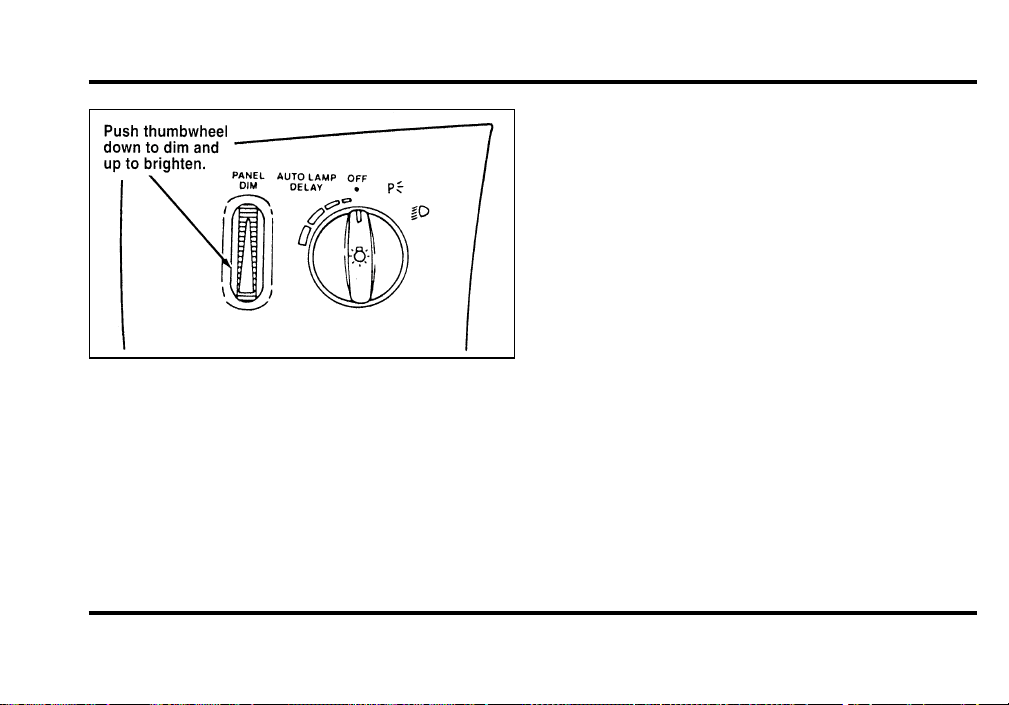
82
The thumbwheel that controls the light on the
instrument panel and the interior light
To dim the instrument panel lights, rotate the
PANEL DIM thumbwheel down. To turn on the
interior lights, turn the PANEL DIM thumbwheel all
the way up. The interior lights also come on when
any side door is opened.
Clock
1. To set the hour, press and hold the hour
button. When the desired hour appears, release
the button.
2. To set the minutes, press and hold the minute
button. When the desired minute appears,
release the button.
File:05fncf8.ex
Update:Thu Jun 27 10:02:20 1996
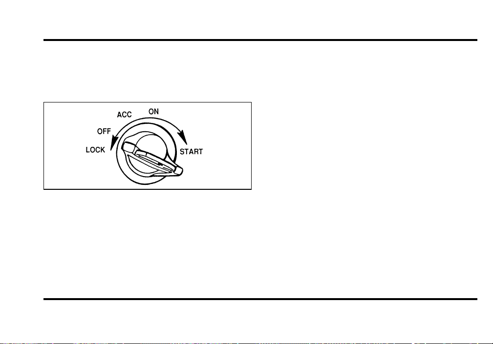
83
Ignition
Understanding the Positions of the
Ignition
The positions of the key in the ignition
ACC allows some of your vehicle’s electrical
accessories such as the radio and the windshield
wipers to operate while the engine is not running.
NOTE: Your vehicle is also equipped with an
accessory timer. This allows some of your
accessories to remain on for up to 10 minutes after
the ignition is turned to the OFF position. The
accessory timer is cancelled if any door is opened,
the dimmer switch is used, or the ignition is turned
to the ON position.
The automatic transmission gearshift must be in P
(Park) to move the key to the LOCK position.
LOCK is the only position that allows you to
remove the key. The LOCK feature helps to protect
your vehicle from theft.
OFF allows you to shut off the engine.
File:05fncf8.ex
Update:Thu Jun 27 10:02:20 1996
84
ONallowsyoutotestyourvehicle’swarninglights
(exceptthebrakesystemwarninglight)tomake
suretheyworkbeforeyoustarttheengine.Thekey
returnstotheONpositiononcetheengineis
startedandremainsinthispositionwhilethe
engineruns.
STARTcrankstheengine.Releasethekeyoncethe
enginestartssothatyoudonotdamagethestarter.
ThekeyshouldreturntoONwhenyoureleaseit.
TheSTARTpositionalsoallowsyoutotestthe
BrakeWarningLight.
KeySystem
Thevehicleisequippedwithamasterkeyandvalet
keylocksystem.Themasterkeywillactuatedoors,
trunk,glovebox,ignitionandremotetrunkrelease.
Thevaletkeywillactuatedoorsandignitiononly.
Thevaletkeyismarked“valet”.
RemovingtheKeyFromtheIgnition
1. PutthegearshiftinP(Park).
2. Settheparkingbrakefully.
3. TurntheignitionkeytoOFF.
4. Removethekey.
IfthekeyisstuckintheLOCKposition,movethe
steeringwheelleftorrightuntilthekeyturns
freely.
Ifthedriver’sdoorisopenwhilethekeyisstillin
theignition,awarningchimesounds.
WARNING
Alwayssettheparkingbrakefullyand
makesurethegearshiftislatchedinP
(Park).Turnofftheignitionwhenever
youleaveyourvehicle.
File:05fncf8.ex
Update:Thu Jun 27 10:02:20 1996
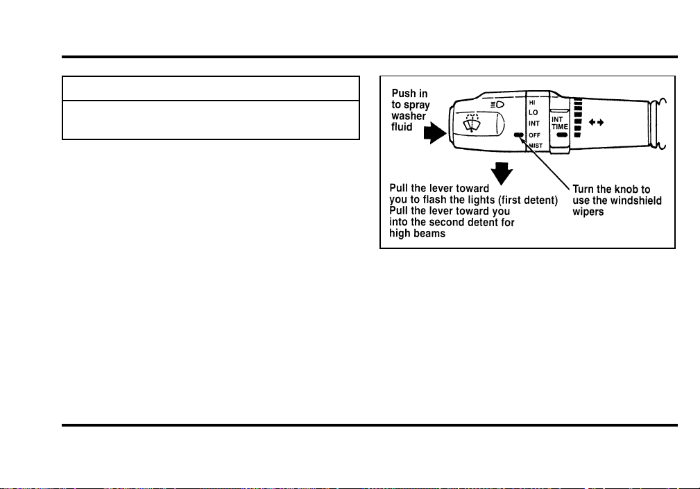
85
WARNING
Donotleavechildren,unreliableadults,
orpetsunattendedinyourvehicle.
TheTurnSignalLever
Youcanusetheturnsignalleverontheleftsideof
thesteeringcolumnto:
❑
operatetheturnsignalsandcorneringlamps
❑
turnthehighbeamson/off
❑
flashthelights
❑
turnthewindshieldwipersandwasheron/off
Theturnsignallever
TurnSignals
Movetheleveruptosignalarightturn.Moveit
downtosignalaleftturn.Thecorresponding
indicatorlightintheinstrumentclusterwillflash.
Usually,theturnsignalsturnoffautomaticallyafter
youturnyourvehicle.Iftheturnsignalcontinues
toflashafteryouhavemadetheturn,pullthelever
backtotheOFFposition.
File:05fncf8.ex
Update:Thu Jun 27 10:02:20 1996

86
For lane changes, move the lever far enough to
signal but not to latch. The lever will return to the
off position when you release it.
When the turn signal is used when the headlamps
are on, the cornering lamps will automatically light
on either the right or left side depending on the
direction of the turn.
High Beams
To turn on the high beams, turn the headlamp
control switch to the headlamp ON position (or
activate the autolamp feature) and pull the turn
signal lever toward you until it latches. When the
high beams are ON, the high beam indicator light
on the instrument cluster comes on.
To turn off the high beams, push the lever away
from you until it latches. The high beam indicator
light turns off.
NOTE: When the headlamps are on low beam, the
outer two headlamps are on. When the headlamps
are on high beam, the two outer headlamps will
turn off and the inner headlamps turn on.
Flashing the Lights
To flash the headlamps, pull the lever toward you
for a moment and then release it. The headlamps
will flash whether the headlamp knob is in the on
or off position.
Windshield Wipers and Washer
The wiper system is controlled by the windshield
wiper control module. The windshield wiper will
operate with the ignition switch in the ACC or ON
position or in the delayed accessory mode. The
wiper system functions are as follows:
INTERMITTENT — Wipers run at low speed at
intervals set by rotating the barrel of the wiper
switch. The interval can be adjusted between one
to twenty seconds.
File:05fncf8.ex
Update:Thu Jun 27 10:02:20 1996
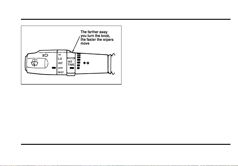
87
LOW — wipers will operate at low speed until
turned off.
HIGH — wipers will run at high speed until
turned off.
MIST — rotate the wiper switch down to the
MIST position; the wipers will operate at low speed
as long as the switch is held in this position. When
released, the switch automatically returns to off.
The wipers will complete the current cycle and
park.
Windshield Washer
To clean the windshield, press the button on the
end of the stalk. The washer system functions as
follows:
LOW or HIGH — the washer will operate as long
as the washer button is held in.
INTERMITTENT — the washer will operate as
long as the button is held in and the wipers will
operate at low speed overriding the intermittent
mode. When the washer button is released the
wipers will return to the previous intermittent mode
setting.
File:05fncf8.ex
Update:Thu Jun 27 10:02:20 1996
88
OFF—thewiperswilloperateatlowspeedas
longasthewasherbuttonisheld.Whenthe
washerbuttonisreleasedthewiperswillcomplete
twotothreecycles,dependingonthepositionof
thewiperswhenreleased,andthenpark.
Ifthewasherdoesnotwork,checkthewasher
fluidlevelandfillitifitislow.Seethe
MaintenanceandCarechapter.Ifthereisenough
fluid,consultyournearestFordorLincoln-Mercury
dealer.
Donottrytocleanthewindshieldwhenthe
washerfluidcontainerisemptyoractivatethe
washersatanytimeformorethan15seconds
continuously.Thiscoulddamagethewasherpump
system.
WARNING
Alwayswarmupthewindshieldwith
thedefrosterbeforeyouusethewasher
fluid.Infreezingweather,thewasher
solutionmayfreezeonthewindshield
andobscureyourvision.
File:05fncf8.ex
Update:Thu Jun 27 10:02:20 1996
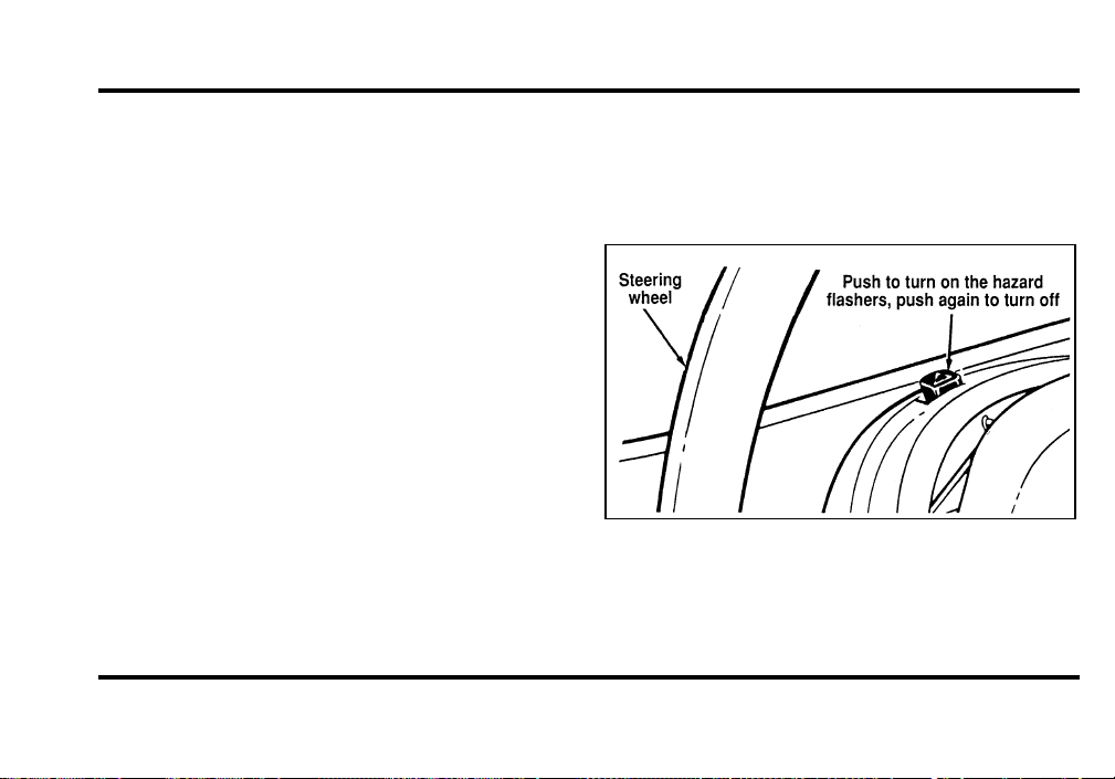
89
For information about refilling the washer fluid or
replacing your windshield wiper blades, see
Windshield washer fluid and Wipers in the Index.
Hazard Flasher
The hazard flasher serves as a warning to other
drivers to be careful when approaching or passing
your vehicle.
The control switch for the hazard flashers
File:05fncf8.ex
Update:Thu Jun 27 10:02:20 1996
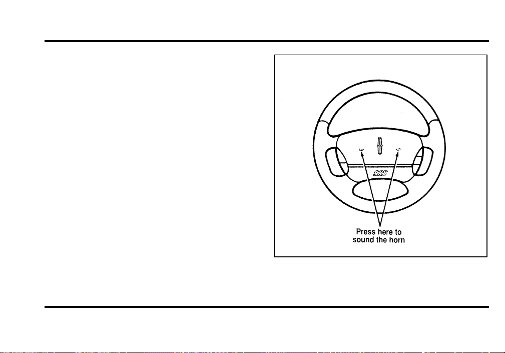
90
Horn
To sound the horn, push the center pad area of the
steering wheel.
The horn on the steering wheel
File:05fncf8.ex
Update:Thu Jun 27 10:02:20 1996
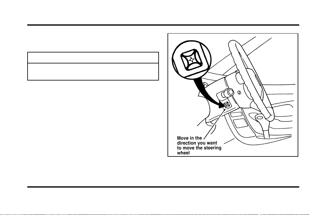
91
PowerTilt/TelescopeSteering
Column
WARNING
Neveradjustthesteeringwheelwhen
thevehicleismoving.
Thesteeringcolumnpositionsareautomatically
savedandcanberecalledalongwiththevehicle
personalityfeatureswhenamemorypositionis
selectedthroughthekeypad,keylessentry
transmitterormemoryswitchonthedriver’sdoor.
Thelevertotiltthesteeringwheel
File:05fncf8.ex
Update:Thu Jun 27 10:02:20 1996

92
During autoglide operation the column will move to
the full in and up position. The column will return
when autoglide is completed.
During easy exit (if activated through the Message
Center) operation the column will move to the full
in and up position. When the key is inserted into
the ignition switch the column will return to the
previous setting. When you remove the key the
column will move away.
If the steering column adjustment switch is pressed
during memory recall the switch position will cancel
automatic operation and the column will respond to
manual adjustment of the switch.
The manual adjustment of the steering column is
adjustable with the ignition switch on or off.
The steering column can be adjusted manually by
using the four-way rocker adjustment switch located
on the multi-function switch below the turn
signal/wiper switch stalk. The switch will adjust the
column as long as held or until the column reaches
the end of travel.
The telescope function is adjusted by pulling the
switch towards the driver to telescope out and
pushing the switch towards the instrument panel to
telescope in.
The tilt function is adjusted by pressing the switch
up to tilt the column up or pressing the switch
down to tilt the column down.
NOTE: If attempting to manually adjust the
steering column and it does not respond see your
local dealer for service.
File:05fncf8.ex
Update:Thu Jun 27 10:02:20 1996
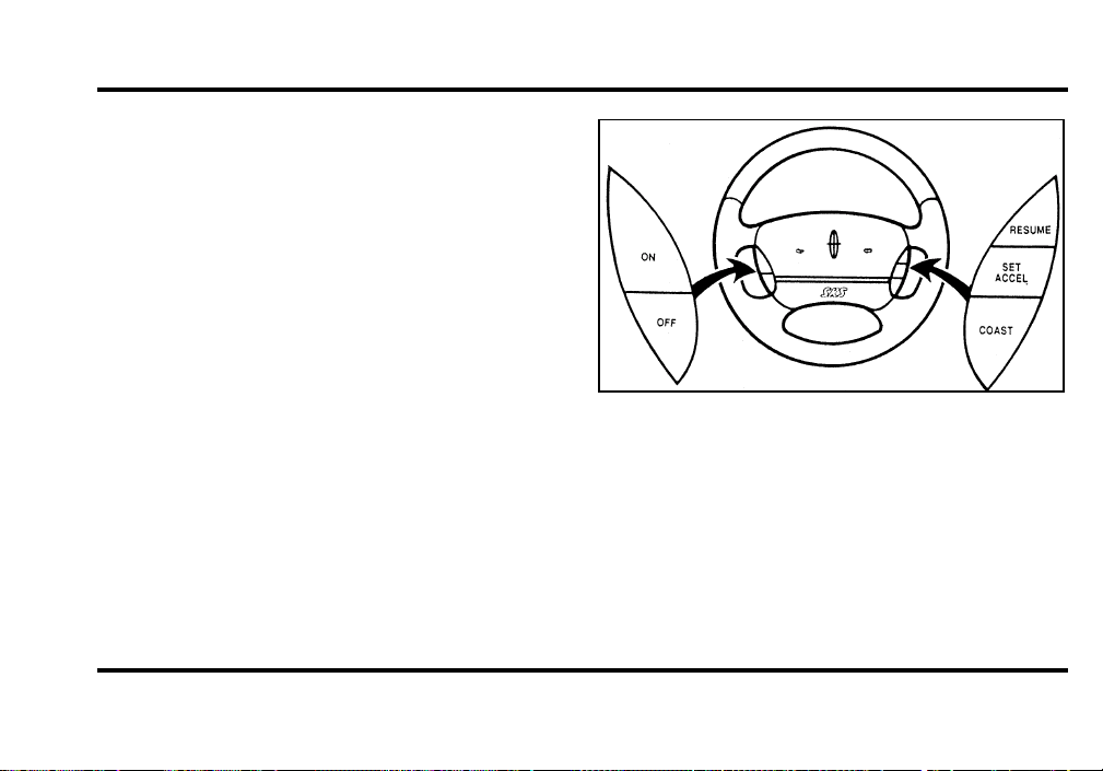
93
Speed Control
The speed of the vehicle cannot be automatically
controlled until the vehicle speed is at or above 30
mph (48 km/h).
Use of radio transmitting equipment that is not
Federal Communications Commission (FCC) or in
Canada the Canadian Radio and
Telecommunications Commission (CRTC) approved
may cause the speed control to malfunction.
Therefore, use only properly installed FCC (CRTC in
Canada) approved radio transmitting equipment in
your vehicle.
NOTE: Do not shift to N (Neutral) when using the
speed control. This will cause the engine to
overspeed.
The speed control switches on the steering
wheel
File:05fncf8.ex
Update:Thu Jun 27 10:02:20 1996
94
ToTurnSpeedControlOff
❑
PressOFF,
❑
Turnoffthevehicleignition.
Oncespeedcontrolisswitchedoff,thepreviously
programmedsetspeedwillbeerased.
ToTurnSpeedControlOn
❑
PressON
ToSetaSpeed
PressSETACCEL.Forspeedcontroltooperate,the
speedcontrolmustbeONandthevehiclespeed
mustbegreaterthan30mph(48km/h).
Ifyoudriveupordownasteephill,yourvehicle
speedmayvarymomentarilyslowerorfasterthan
thesetspeed.Thisisnormal.
Speedcontrolcannotreducethevehiclespeedifit
increasesabovethesetspeedonadownhill.Ifyour
vehiclespeedisfasterthanthesetspeedwhile
drivingdownhillinj(Overdrive),youmaywant
toshifttothenextlowergeartoreduceyour
vehicle’sspeed.
Ifyourvehicleslowsdownmorethan10mph
(16km/h)belowyoursetspeedonanuphill,your
speedcontrolwilldisengage.Thisisnormal.
PressingRES(Resume)willre-engageit.
WARNING
Tokeepyourvehicleundercontrol,do
notusespeedcontrolinheavytrafficor
onroadsthatarewinding,slippery,or
unpaved.
File:05fncf8.ex
Update:Thu Jun 27 10:02:20 1996

95
To Set a Higher Set Speed
❑
Press and hold SET ACCEL. Release the switch
when the desired vehicle speed is reached. OR
❑
Press and release SET ACCEL. Each press will
increase the set speed by 1 mph (1.6 km/h).
OR
❑
Accelerate with your accelerator pedal, then
press SET ACCEL.
You may accelerate with the accelerator pedal at
any time during speed control usage. Releasing the
accelerator pedal will return your vehicle speed to
the previously programmed set speed.
To Set a Lower Set Speed
❑
Press and hold COAST. Release the switch
when the desired vehicle speed is reached. OR
❑
Press and release COAST. Each press will
decrease the set speed by 1 mph (1.6 km/h).
OR
❑
Depress the brake pedal. When the desired
vehicle speed is reached, press SET ACCEL.
To Disengage Speed Control
❑
Depress the brake pedal.
Disengaging the speed control will not erase the
previously programmed set speed.
To Return to a Set Speed
❑
Press RESUME. For RESUME to operate, the
vehicle speed must be faster than 30 mph
(48 km/h).
Indicator Light
❑
Lights when either the SET ACCEL or RESUME
switches are pressed and remains lighted until it
is either disengaged or turned off.
File:05fncf8.ex
Update:Thu Jun 27 10:02:20 1996
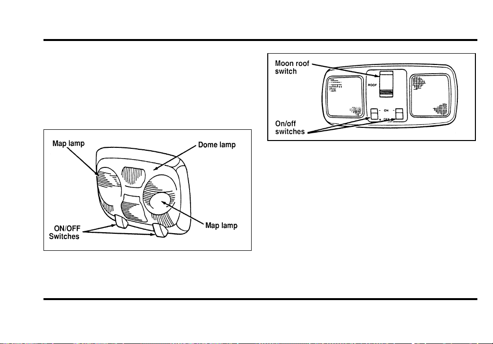
96
Turning On the Lamps
Map and Reading Lamps
Your vehicle has two map lamps for the passenger
and the driver. To turn on the map lamps, push the
switch next to each lamp.
Front seat map and dome lamps
Map lamp (with optional moon roof)
The dual beam map lamps are located on each side
of the dome lamp. Each map lamp can be turned
on by the switches on the lamp.
Rear Courtesy/Reading Lamps
Your vehicle is equipped with two courtesy/reading
lamps in the rear side trim panels. The on/off
switch is located next to the lens and is operated
by pushing in to turn on and pushing again to turn
off.
File:05fncf8.ex
Update:Thu Jun 27 10:02:20 1996
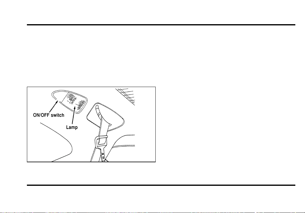
97
With the switch pushed in one position, the
courtesy/reading lamp will illuminate when any
door is opened or when the instrument panel
dimmer switch is rotated to the courtesy lamp
position.
Push the switch to illuminate the lamp
continuously.
Rear seat courtesy/reading lamps
Moon Roof (If equipped)
You can move the moon roof back to open the
glass panel, or you can tilt it up to ventilate the
vehicle.
There is also an intermediate position between
closed and open which can reduce wind noise at
speeds between 30 and 45 miles per hour (50 and
70 km/h).
The rocker type switch is used to open and close
the moon roof. You must press and hold the switch
until the desired position is reached. At fully open,
closed or intermediate positions, the motor will
automatically turn off. Release the switch at this
time to avoid motor damage.
When operating the moon roof, we recommend
that the Electronic Automatic Temperature Control
(EATC) be set to VENT for maximum system
performance.
File:05fncf8.ex
Update:Thu Jun 27 10:02:20 1996
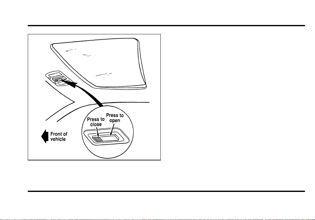
98
The switch for the moon roof
To open the moon roof, press and hold the rear
portion of the switch. The glass panel will move to
the intermediate position and stop. If the rear of the
switch is pressed again the glass panel will move to
the full open position and stop.
To close the moon roof, press and hold the front
portion of the control. The glass panel will move to
the intermediate position and stop. Press and hold
the front of the control again and the panel will
move to the fully closed position and stop.
To tilt the moon roof into vent position when the
glass panel is closed, press the front portion of the
control.
To close from vent position, press and hold the rear
portion of the control.
Occasionally wiping the outside guide rail covers of
the moon roof with a clean cloth will help keep the
moon roof working properly.
File:05fncf8.ex
Update:Thu Jun 27 10:02:20 1996
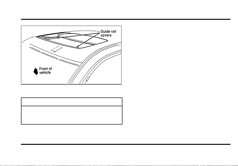
99
Themoonroof
WARNING
Donotletchildrenplaywiththemoon
roof.Theymayseriouslyhurt
themselves.
SlidingShade
Themoonroofhasaslidingshadethatyoucan
manuallyopenorclosetoblockthesunwhenthe
glasspanelisshut.
Toclosetheslidingshade,pulltheshadetoward
thefrontofthevehicle.Theshadeautomatically
opensandlockswhenthemoonroofisopened.
Mirrors
AutomaticDimmingInsideRearview
Mirror
Yourvehicleisequippedwithaninsiderearview
mirrorwhichhasanAuto-Dimmingfunction
(availableasanoptionontheoutsidedriver’sside
mirror).Theseelectronicday/nightmirrorswill
changefromthenormalstatetothenon-glarestate
whenbrightlights(glare)reachthemirrors.These
mirrorsfunctionatnight,andhavealimited
functionatduskordawn.Fromthenon-glarestate,
themirrorswillreturntothenormalstateaftera
File:05fncf8.ex
Update:Thu Jun 27 10:02:20 1996
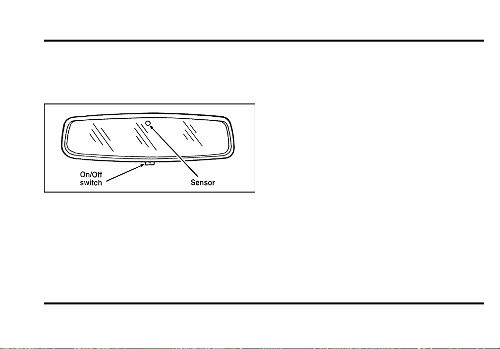
100
short delay. The delay starts when glare goes away.
The delay prevents excessive changing of the
mirrors as traffic moves behind and around the
vehicle, or on rolling hills and curves.
The automatic non-glare mirror
There are two light sensors (photocells) in this
mirror. The sensor that detects rear glare is located
inside a window in the center of the mirror. The
second light sensor which determines outside light
level is located on the backside of the mirror case.
The driver’s side mirror is activated by these sensors
to prevent glare when traffic is behind or around
the vehicle.
NOTE: Do not block the sensor on the backside of
the mirror (i.e., with a parking tag, car deodorizer,
etc.) since this may impair proper mirror
performance.
One important safety feature is that the mirror
automatically returns to the normal position
whenever the vehicle is placed in R (Reverse)
(when the mirror is in the ON position). This
feature ensures a bright clear view in the mirror
when backing up.
Do not clean the housing or glass of any mirror
with harsh abrasives, fuel or other petroleum-based
cleaning products.
File:05fncf8.ex
Update:Thu Jun 27 10:02:20 1996
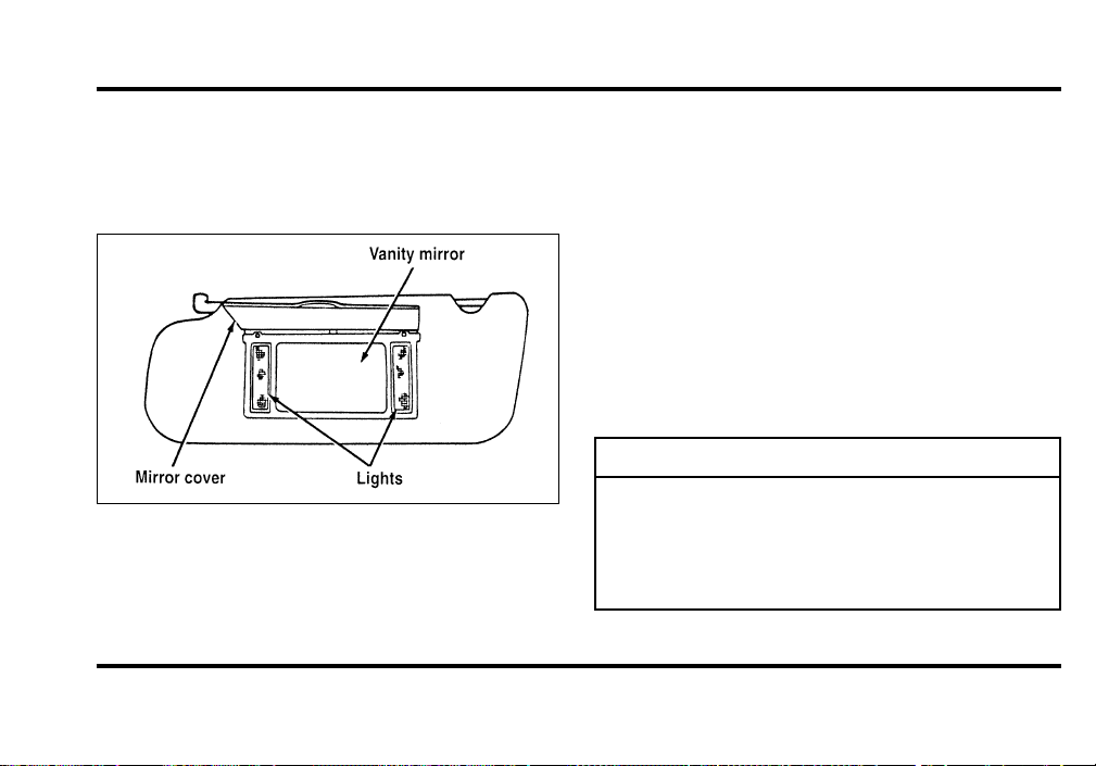
101
SunVisors
IlluminatedVisorMirror(Ifequipped)
Toturnonthevisormirror,liftthemirrorcover.
Themirroronthesunvisor
HomeLinkHUniversalTransmitter
(Ifequipped)
TheHomeLinkUniversalTransmitterprovidesa
convenientwaytoreplaceuptothreehand-held
transmitterswithasinglebuilt-indevice.This
innovativefeaturewilllearntheradiofrequency
codesofmostcurrenttransmitterstooperategarage
doorsandgates.Withtheavailableaccessory
package,theHomeLinkTransmittercanalsocontrol
homeorofficelightingandsecuritysystems.For
reliability,theHomeLinkTransmitterispoweredby
yourvehicle’sbatteryandchargingsystem.
WARNING
WhenprogrammingyourHomeLink
Transmitter,youwillbeoperatingthe
garagedoororgate.Besurethatpeople
andobjectsareoutofthewayto
preventpotentialharmordamage.
File:05fncf8.ex
Update:Thu Jun 27 10:02:20 1996
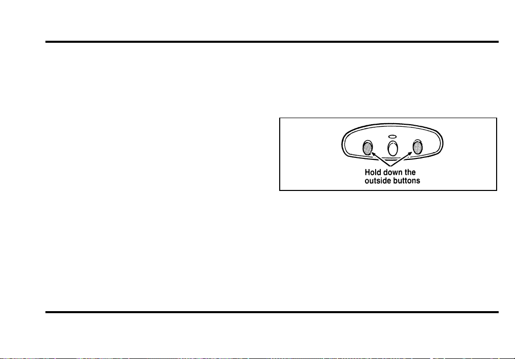
102
Do not use this HomeLink Transmitter with any
garage door opener that lacks safety “stop” and
“reverse” features as required by federal safety
standards, (this includes any garage door opener
model manufactured before April 1, 1982). A garage
door opener which cannot “detect” an object in the
path of a closing door and then automatically “stop”
and “reverse” the door, does not meet current
federal safety standards. Using a garage door opener
without these features increases risk of serious
injury or death. For more information on this
matter, call toll-free: 1-800-355-3515.
Programming
If after repeated attempts you do not successfully
program the HomeLink Universal Transmitter to
learn the signal of the hand-held transmitter, call
toll-free for customer assistance: 1-800-355-3515.
1. If you have previously programmed your
HomeLink Transmitter, proceed to step 2.
Otherwise, hold down the two outside buttons
on the HomeLink Transmitter until the red
light begins to flash. Release both buttons.
2. Decide which one of the three channels you
want to program.
3. Hold the end of your hand-held transmitter
against the front surface of the HomeLink
Transmitter so that you can still see the red
light.
File:05fncf8.ex
Update:Thu Jun 27 10:02:20 1996

103
4. Using both hands, push the hand-held
transmitter button and the desired button on
the HomeLink Transmitter. Continue to press
both buttons through step 5.
5. Hold down both buttons until you see the red
light on the HomeLink Transmitter flash, first
slowly and then rapidly. It indicates that you
have successfully programmed the HomeLink
Transmitter to learn the new frequency signal.
Release both buttons once the rapid flashing
begins.
Note to Canadian Residents
During programming, your hand-held transmitter
may automatically stop transmitting after two
seconds, which may not be long enough to program
the HomeLink Universal Transmitter.
If you are programming from one of these
hand-held transmitters, continue to hold the button
on the HomeLink Transmitter while you re-press
your hand-held transmitter every two seconds.
You may have to repeat this function several times
while programming.
File:05fncf8.ex
Update:Thu Jun 27 10:02:20 1996

104
Operating the HomeLinkH Universal
Transmitter
Once it is programmed, the HomeLink Universal
Transmitter can be used in place of your hand-held
transmitter(s). To operate, simply press the
appropriate button on the HomeLink Transmitter.
The red light comes on while the signal is being
transmitted.
NOTE: If your hand-held transmitter appears to
program the HomeLink Transmitter, but does not
open your garage door, and if your garage door
opener was manufactured after 1995, your garage
door opener may have a “code protected” or
“rolling code” feature.
A “rolling code” type of system will change the
“code” of your garage door opener every time you
open or close your garage door.
To determine if you have one of these systems,
depress the button on the HomeLink Transmitter
that you programmed. If the red light on the
HomeLink Transmitter flashes rapidly for 1-2
seconds, then remains on, your garage door opener
has a rolling code system.
Training a Garage Door Opener
Equipped with “Rolling Codes”
To train your “rolling code” garage door opener to
operate from your HomeLink Transmitter, follow
these steps:
1. Program your hand-held transmitter to the
HomeLink Transmitter by following the
procedures outlined in the “Programming”
section of these instructions. (If you already
completed this programming, proceed to the
next instruction.)
2. Train your garage door opener receiver to
recognize your HomeLink Transmitter. (Your
garage door opener receiver will learn to
recognize the HomeLink Transmitter by
following the same procedures used to train the
hand-held transmitter.)
File:05fncf8.ex
Update:Thu Jun 27 10:02:20 1996

105
❑
Remove the cover panel from your garage door
opener receiver. (The receiver should be located
by the garage door opener motor.)
❑
Locate the training button on the garage door
opener receiver. The exact location and color of
the button may vary by garage door opener
brand. If you have difficulty locating the training
button, reference your garage door opener
manual, or call 1-800-355-3515.
❑
Press the training button on the garage door
opener receiver for 1-2 seconds.
❑
Return to the HomeLink Transmitter in the
vehicle, and depress the programmed HomeLink
button for the duration of the rapid flash of the
HomeLink’s red light, (1-2 seconds). Release the
button, and re-press the button to confirm that
the HomeLink Transmitter has been trained to
the receiver.
❑
Your garage door opener should now recognize
your HomeLink Transmitter. You may use either
your HomeLink Transmitter or your original
hand-held transmitter to open your garage door.
If after following these suggestions you still have
difficulties in programming your HomeLink
Transmitter, call toll-free for customer assistance:
1-800-355-3515.
Erasing Channels
To erase all three programmed channels, hold down
the two outside buttons until the red light begins to
flash. Then release both buttons. Individual channels
cannot be erased, but can be reprogrammed using
the procedures for programming the HomeLink
Transmitter, (steps 2 through 5).
NOTE: Be sure to retain your original transmitter
for future programming procedures (i.e., new
vehicle purchase).
File:05fncf8.ex
Update:Thu Jun 27 10:02:20 1996

106
NOTE: When selling your vehicle, be sure to erase
all channels on the HomeLink Transmitter that you
programmed.
Accessories
Accessories for your HomeLink Universal
Transmitter are available from the manufacturer of
the device. If you would like additional information
or would like to purchase other accessories such as
home lighting or security products that can be
operated by the HomeLink Universal Transmitter,
please call toll-free: 1-800-355-3515.
Doors
Anti-theft front door lock knobs
Anti-theft lock knobs are designed to prevent
unlocking the door by pulling up on the lock knob.
To unlock and open the front door from inside the
vehicle, pull on the inside door handle.%
Using the Power Door Locks
Your vehicle has power door locks. The controls to
lock the doors are on the trim panel of the front
door. When you close the doors after you set the
door locks, the doors remain locked. If the power
mechanism ever fails, the manual door lock will
override the power controls.
File:05fncf8.ex
Update:Thu Jun 27 10:02:20 1996
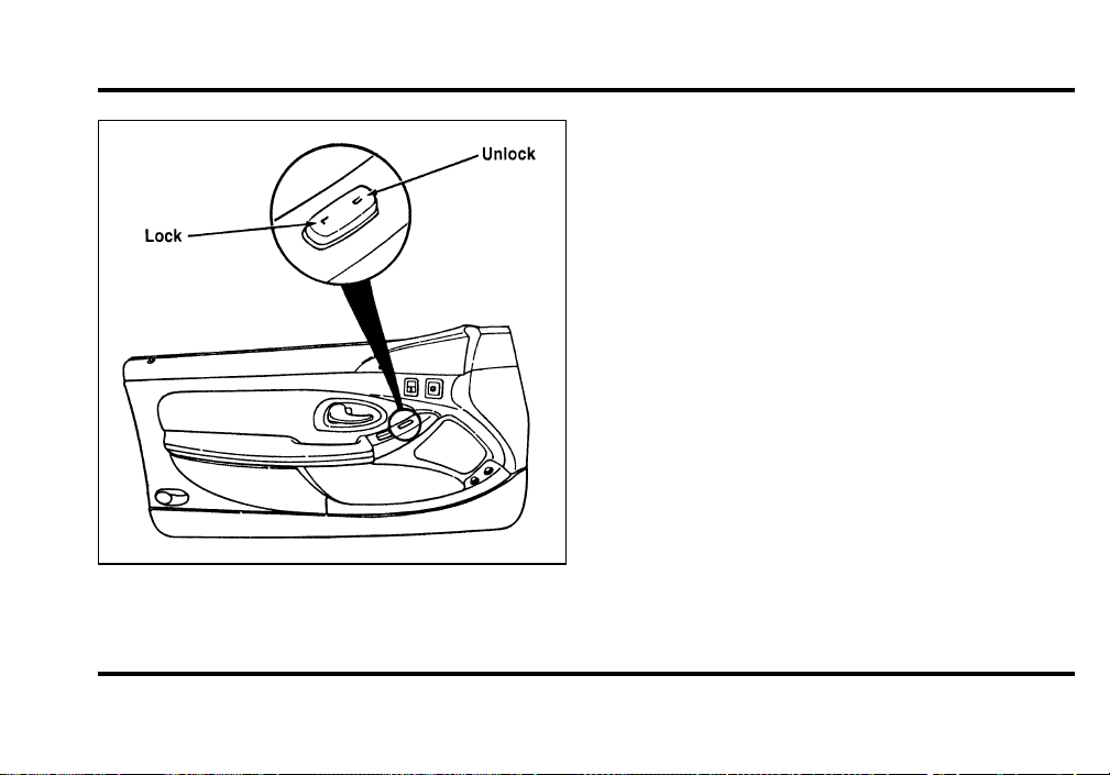
107
The power locks on the driver’s door
Smart Locks
The Smart Locks feature helps prevent you from
locking the keys in your vehicle. With the key in
the ignition (in any switch position) and either the
driver’s or passenger’s door open, the doors cannot
be locked using the front door lock switches.
NOTE: Your vehicle can still be locked, while the
key is in the ignition, by manually pressing down
the lock button or with remote/keyless entry.
Illuminated Entry System with Theater
Lighting
The interior lights will illuminate for approximately
25 seconds when any button on the keyless entry
pad is pressed or the remote entry system UNLOCK
button is pushed.
File:05fncf8.ex
Update:Thu Jun 27 10:02:20 1996
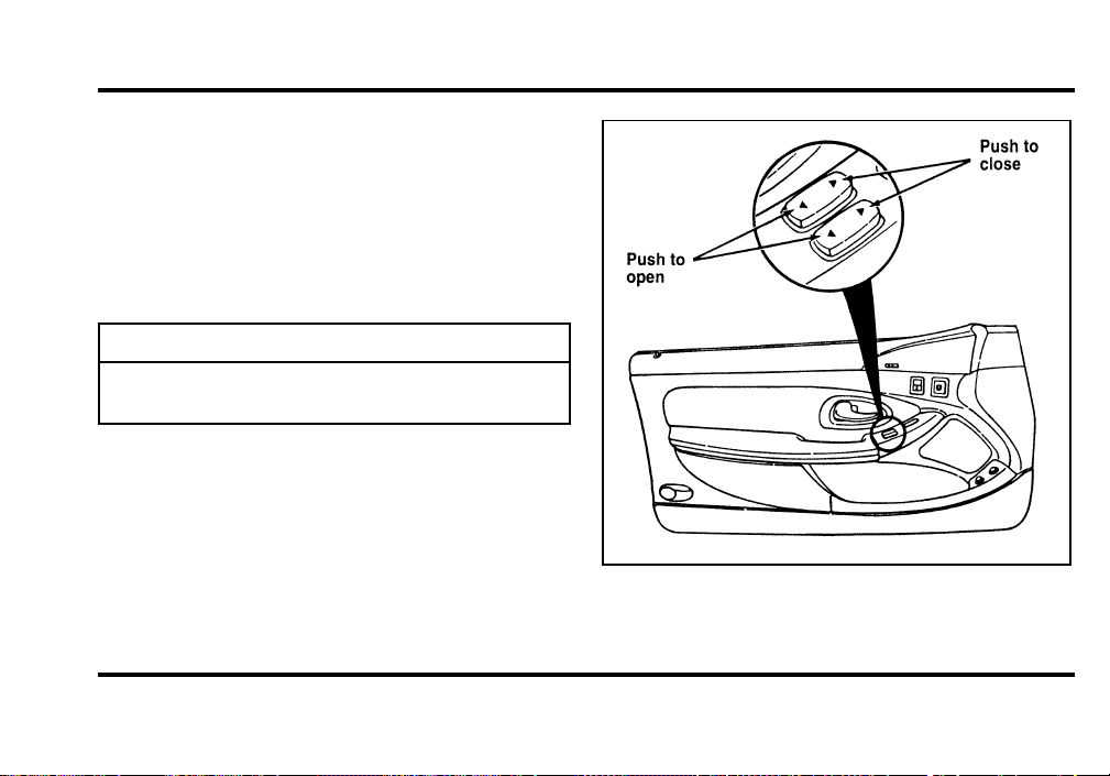
108
UsingthePowerWindows
Eachdoorhasanilluminatedpowercontrolthat
opensandclosesthewindowonthatdoor.The
driver’sdoorhasamastercontrolpanelthat
operatesthewindows.
Powerwindowscanonlybeopenedorclosedwhen
theignitionswitchisintheONorACCposition.
WARNING
Donotletchildrenplaywiththepower
windows.
Themastercontrolsonthedriver’sdoor
File:05fncf8.ex
Update:Thu Jun 27 10:02:20 1996
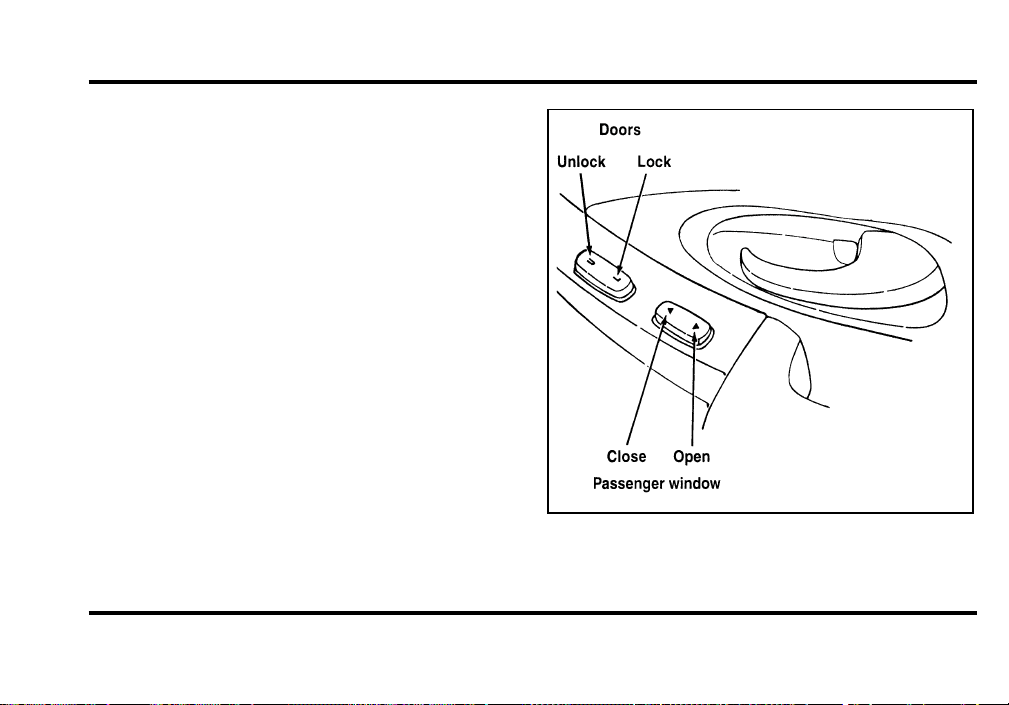
109
There is also an Express Down feature on the
driver’s power window. This feature can be
activated through the menu functions of your
Message Center.
For conventional operation press the driver’s
window control to the first detent in the down
position. For express down operation press the
control to the second detent in the down position.
The controls on the passenger’s door
File:05fncf8.ex
Update:Thu Jun 27 10:02:20 1996

110
Memory Profile System
(If equipeed)
The Personality Memory Feature customizes your
Mark VIII for up to two (2) drivers. The following
features are automatically recalled when unlocking
the doors using the remote entry transmitter,
keyless entry keypad, or by pressing the Memory 1
or Memory 2 switches on the driver’s door:
❑
All driver’s seat positions except power lumbar
and head restraint.
❑
Both left and right outside mirror settings.
❑
Steering column position.
❑
Seven Driver Menu settings
Personality Memory also allows you to customize
settings from the Driver menu located in the
Message Center. Refer to the Message Center for
more information.
Recalling Personality Memory
All of these settings are automatically recalled when
the driver unlocks the door using the remote entry
transmitter, keyless entry keypad or presses either
Memory 1 or Memory 2 switch inside the driver’s
door. The vehicle must be in PARK or NEUTRAL to
recall Personality Memory settings.
Remote Entry
Pressing the UNLOCK button on the remote entry
transmitter unlocks the driver’s door and recalls all
of the Personality Memory settings. Two
transmitters are delivered with the vehicle. One is
programmed to always recall Memory 1 and the
other will always recall Memory 2. Personality
Memory 1 or 2 is indicated on the back of the
transmitter.
File:05fncf8.ex
Update:Thu Jun 27 10:02:20 1996

111
Personality Memory recall from the remote
transmitter can be disabled. This is done by sliding
the switch on the back of the transmitter to OFF.
Personality Memory can still be recalled using
keyless entry code or the Memory 1 or Memory 2
switches.
Keyless Entry
Up to three unique keyless entry codes can be
programmed by the customer. Two of the codes
can be assigned to recall Personality Memory 1 or
Memory 2. Each time the 5-digit code is entered on
the keypad, the driver’s door will unlock and
Personality Memory 1 or Memory 2 will be
recalled.
NOTE: Please note that even though the driver’s
Personality Memory may be recalled using remote
or keyless entry, the seats and mirrors will not
move to the driver’s set positions until the driver’s
door is opened. The steering column will move
when the key is inserted.
Memory Switches
Pressing either the Memory 1 or Memory 2 switch
on the driver’s door will also recall the Personality
Memory settings as selected, providing your vehicle
is in P (Park) or N (Neutral).
Auto Save
Any change made by the driver to one of the above
Personality Memory settings will be updated and
saved automatically. The display, DRIVER 1 (or 2)
SETTING SAVED, will appear on the Message
Center for five (5) seconds as a confirmation of the
update to Personality Memory.
If the driver does not use the remote entry
transmitter, or keyless entry keypad to unlock the
doors upon entering or does not press the Memory
1 or Memory 2 switch, then any change to one of
the Personality Memory settings will not be
automatically saved. Instead the driver will be
prompted by the Message Center. “IDENTIFY
DRIVER TO SAVE”. Press select button (located on
File:05fncf8.ex
Update:Thu Jun 27 10:02:20 1996
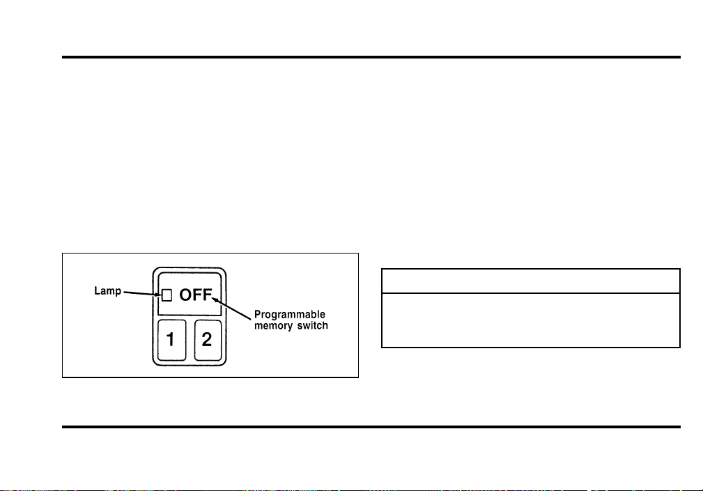
112
therightoftheinstrumentcluster)toidentify
yourself;otherwise,settingwillnotbesavedand
subsequentchangeswillnotbesaved.
TurningPersonalityOFF
ThePersonalityMemoryfeaturecanbeturnedoff
usingtheMemoryOFFswitchonthedriver’sdoor.
Theamberindicatorlightwillbelitwhenthe
featureisturnedOFF.PressingeithertheMemory
1orMemory2switchwillturnonthePersonality
Memoryfeatureandrecallthesavedsettings.
Settingtheprogrammablememoryswitch
WhenPersonalityisOFF,thevehiclewillfunction
asifthePersonalityMemoryfeaturewasnotonthe
vehicle.Also,whenachangeismadetooneofthe
Personalitysettings,therewillbenopromptsonthe
MessageCenteraskingwhichdrivertosavethe
settingto.
SideViewMirrors
Yourvehiclecomeswithelectricsidemirrors.The
sideviewmirrorontherightisaconvexmirror.
Thismirrorgivesyouawiderviewofthelaneson
yourrightandbehindyou.
WARNING
Therightsideviewmirrormakes
objectsappearsmallerandfartheraway
thantheyactuallyare.
File:05fncf8.ex
Update:Thu Jun 27 10:02:20 1996
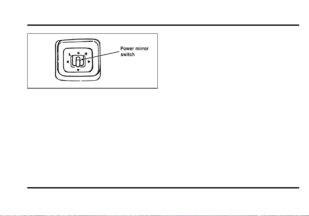
113
The electric remote control switch
To adjust the side mirrors:
1. Find the control switch in the driver’s door
panel.
2. Select the right or left mirror by moving the
selector switch to R or L.
3. Move the mirror switch in the direction you
want to move the mirror.
4. Return the selector switch to the middle
position to keep the mirror in place.
Do not clean the housing or glass of any mirror
with harsh abrasives, fuel or other petroleum-based
cleaning products.
Remote Control Fuel Filler Door
Release Button
Your vehicle has a remote control fuel filler door
which cannot be opened from outside of the
vehicle. To unlatch the fuel filler door, push the
fuel door button on the driver side door. Refer to
theMaintenance and Care chapter for further
information.
File:05fncf8.ex
Update:Thu Jun 27 10:02:20 1996
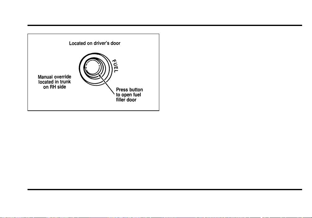
114
The remote control fuel filler door release
button
Cellular Phone (If equipped)
For information about the cellular phone in your
vehicle, refer to the Cellular Phone User’s Manual
provided with your phone. For further questions
about your Lincoln cellular phone, contact the Ford
Cellular System at 1-800-367-3013(U.S.). In
Canada, please contact your dealer.
NOTE: It is recommended that you fold your
cellular phone antenna down onto the back glass
before entering a car wash.
File:05fncf8.ex
Update:Thu Jun 27 10:02:20 1996
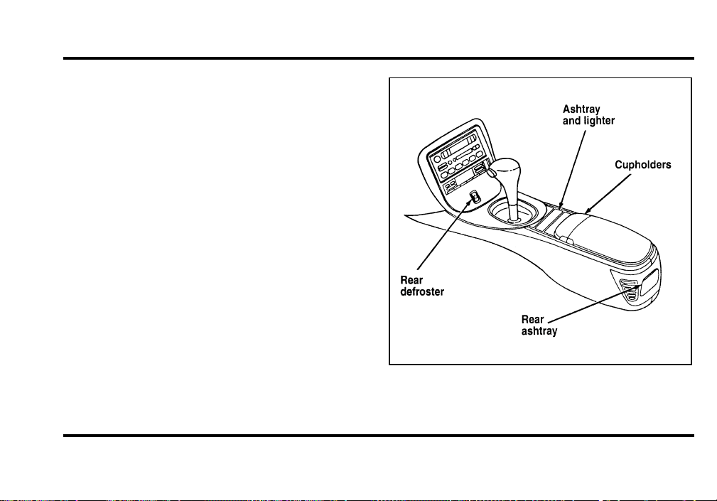
115
Console
Your vehicle has a full console. The full console has
the features shown in the following illustration.
The features on the full console
File:05fncf8.ex
Update:Thu Jun 27 10:02:20 1996
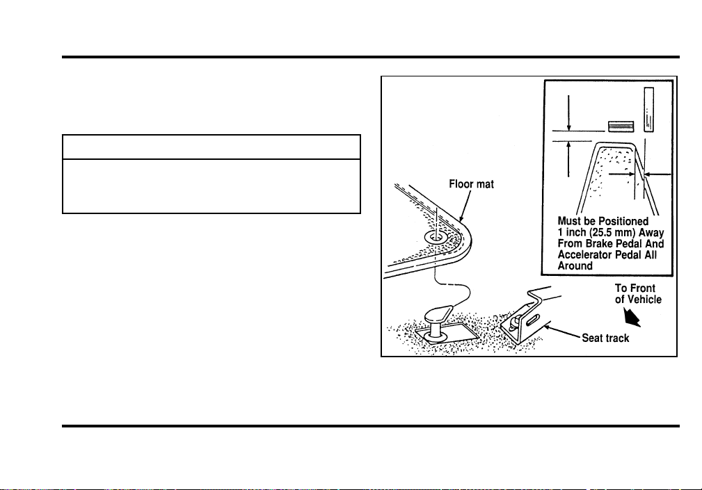
116
CupholderWithFullConsole
Toopenthecupholder,pushdownonthe
cupholderandrelease.
WARNING
Useonlysoftcupsinthecupholder.
Hardobjectscaninjureyouina
collision.
PositiveRetentionDriver’sSide
FloorMat
Wheninstallingorremovingthedriver’ssidefloor
matyoumustattach/detachfromthehookonthe
floor.Thehookisjustforwardofthelefthand
trackofthedriver’sseat.Thisisdonebyrotating
onequarterturn,slippingtheeyeletontothehook,
andslidingittothefloor.
Thepositiveretentionfloormathook
File:05fncf8.ex
Update:Thu Jun 27 10:02:20 1996
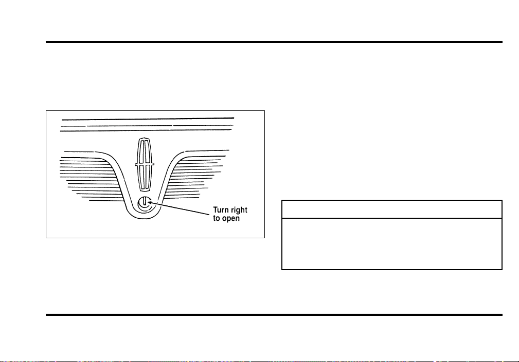
117
Trunk
OpeningtheTrunkManually
Toopenandclosethetrunkfromtheoutside:
Thetrunklockcylinder
1. Insertthekeyintothelockonthetrunk.
2. Turnthekeytotherightuntilthetrunkopens.
3. Removethekeybeforeyoucloseandlockthe
lid.
4. Shutthetrunklidbypushingonthetopofthe
lidwithenoughpressuretoallowthelatchto
engage.
5. Thepowermechanismwillautomaticallypull
downandsecurelylatchthetrunklidshut.A
slightwhirringsoundwillbeheard.
WARNING
Donotattempttostoptheautomatic
pulldownorclearobjectsfromthe
sealingedgesofthedecklidoncethe
initiallatchinghasbeenmade.
File:05fncf8.ex
Update:Thu Jun 27 10:02:20 1996
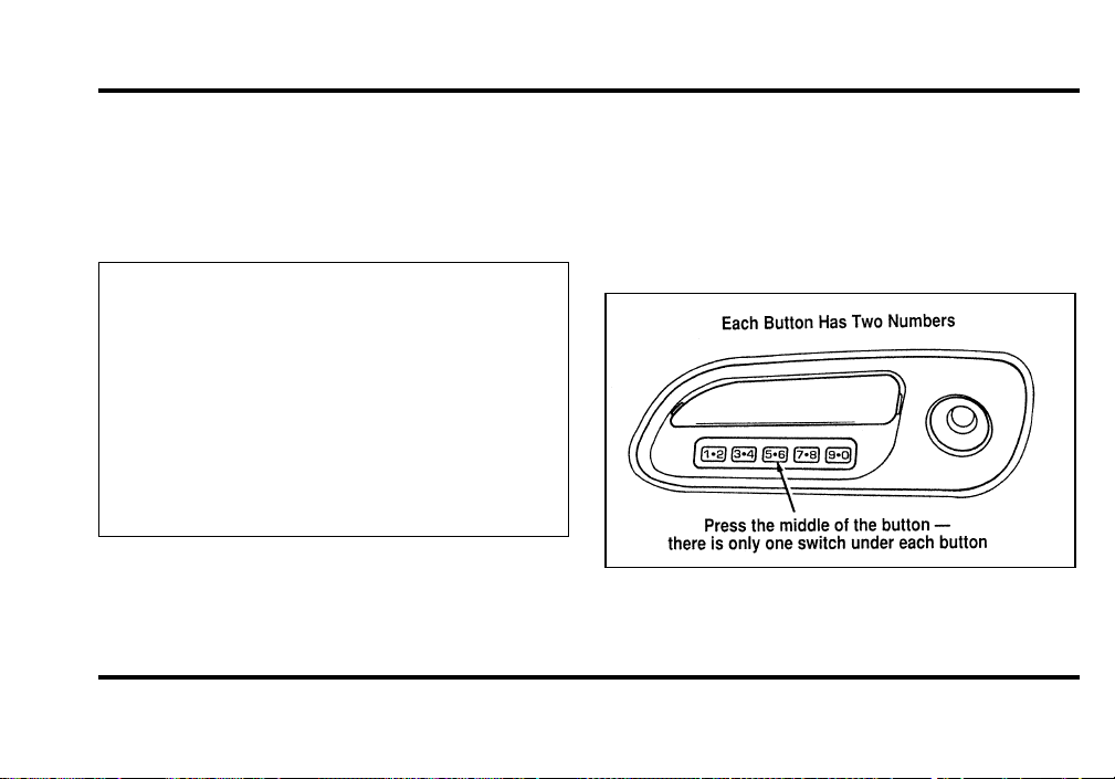
118
Using the Power Trunk Release
The remote trunk lock switch located in the driver’s
door trim panel can be operated at any time unless
you render the switch inoperable by locking the
button with your master key.
The remote control for the trunk
Keyless Entry System
You can lock or unlock the vehicle doors and open
the trunk without using a key. The buttons for the
system are below the outside door handle on the
driver’s side. See also Remote Entry System which
follows this description.
The keyless entry buttons
File:05fncf8.ex
Update:Thu Jun 27 10:02:20 1996

119
When you bought your vehicle, you were given a
computer code that operates the system for your
vehicle. For your convenience, we have duplicated
this code in three places.
The code is:
❑
on your owner’s wallet card found in the glove
compartment
❑
taped to the right hinge of the trunk lid
❑
taped to the computer module inside the
driver’s door panel
When you use keyless entry, the illuminated entry
system turns on the interior lights for 25 seconds
and the buttons on the keypad light up. Do not
push the buttons with a key, ballpoint pen, pencil,
or any other hard object. These objects could
damage the buttons.
Unlocking the Doors with the Keyless
Entry System
You must unlock the driver’s door before you
unlock any of the other doors or trunk. If you let
more than five (5) seconds pass before pressing
numbers, the system shuts down, and you have to
enter the code again. The system has shut down if
the keypad light is out. If the keyless entry system
does not work properly, use the key or
transmitter(s) to lock and unlock the doors or
unlock the trunk.
1. To unlock the driver’s door, enter the factory
code or your personal code. All codes have five
(5) numbers. After you press the fifth number,
the driver’s door unlocks.
2. To unlock the passenger’s door, press the 3/4
button within five seconds of unlocking the
driver’s door or trunk, or re-enter the code to
open the driver’s door, then press 3/4.
File:05fncf8.ex
Update:Thu Jun 27 10:02:20 1996

120
3. To unlock the trunk, press the 5/6 button
within five (5) seconds of unlocking the driver’s
or passenger’s door, or re-enter the code to
open the driver’s door, then press 5/6.
As long as the driver’s door has been unlocked first,
you can open the passenger door or the trunk in
any order.
Locking the Doors with the Keyless
Entry System
Along with unlocking your doors, you can use the
keyless entry system to lock the doors.
To lock all of the vehicle’s doors at the same time,
press 7/8 and 9/0 at the same time. It is not
necessary to first enter the keypad code. This will
also arm your anti-theft system (if equipped).
Autolock
The Autolock feature will automatically lock both
doors when:
❑
the ignition key remains in the ON position
❑
driver’s and passenger’s doors are closed
❑
a door is opened and then closed
❑
the vehicle is in a forward gear, and
❑
you exceed three mph (five km/h).
If you do not want to use the Autolock feature, it
can be deactivated by using the driver’s settings
menu in the Message Center.
Programming Your Own Entry Code
You can program a personal code to unlock your
vehicle. This code does not replace the permanent
code that the dealership gave you. Use your
personal code in the same manner as you would
your original code.
File:05fncf8.ex
Update:Thu Jun 27 10:02:20 1996

121
To program your own code:
1. Select five digits for your personal code.
2. Enter the factory code that the dealership gave
you.
3. Within five (5) seconds, press 1/2.
4. Within five (5) seconds of pressing 1/2, enter
your personal code, pressing each digit within
five (5) seconds of the previous digit.
The keyless entry system registers this second
code. To open your vehicle, you can now use
either code. The module remembers only one
personal code at a time. Entering a second
personal code will erase the first, replacing it
with the new second one.
To erase your personal code:
1. Enter the original permanent code.
2. Press 1/2 within five seconds of Step 1.
3. Wait six seconds.
The keyless entry system automatically erases
your personal code. The system will now only
respond to the permanent code.
Do not set a code that presents the numbers in
sequential order, such as 1/2, 3/4, 5/6, 7/8, 9/0.
Studies show that people who idly press the buttons
usually press a sequential pattern. Also, do not
select a code that uses the same button five times.
Thieves can easily figure out these types of codes.
File:05fncf8.ex
Update:Thu Jun 27 10:02:20 1996
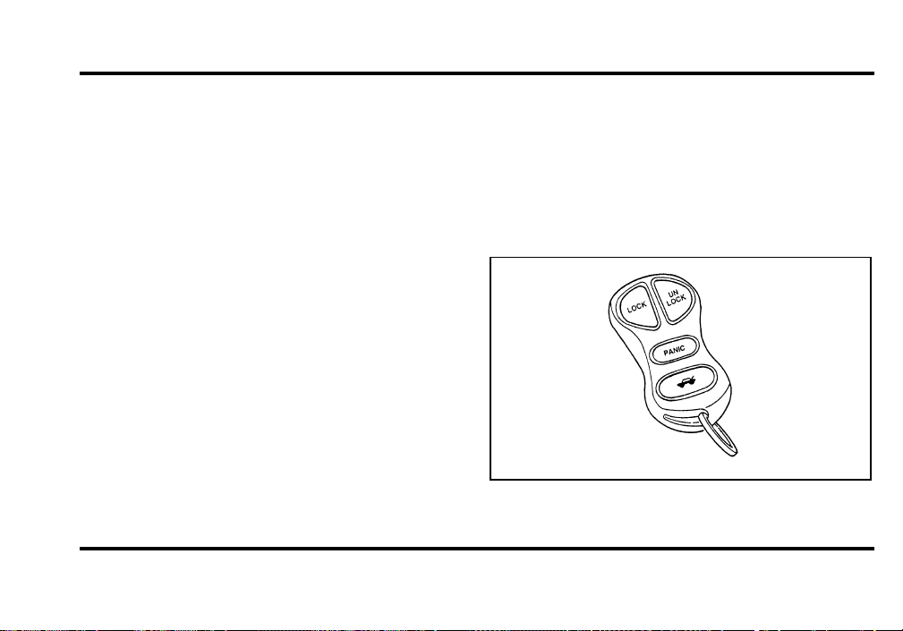
122
Arming, disarming and resetting your
anti-theft system from the keyless entry
pad
The Keyless Entry system will arm the anti-theft
system when you use the 7/8 and 9/0 keys to lock
the doors, and will disarm or reset a triggered
anti-theft alarm when you enter in the five digit
code to unlock the driver’s door.
Remote Entry System
With the remote entry system, you can lock and
unlock the vehicle doors and open the trunk
without using a key. The buttons for the system are
located on the two hand held transmitters that
came with your vehicle. The remote also has a
personal alarm feature.
The system will work with up to four remotes.
Your vehicle came with two remotes. Additional
remotes can be ordered from your dealer.
When unlocking a vehicle with the Programmable
Memory Seat/Outside Rear View Mirrors feature,
the seat, the outside mirrors and steering column
will adjust to position that is set for the transmitter
being used.
The remote entry features only operate with the
ignition in the OFF position.
Remote entry transmitter
File:05fncf8.ex
Update:Thu Jun 27 10:02:20 1996

123
Unlocking the doors and opening the
trunk
To unlock the driver’s door, press the UNLOCK
control.
To unlock the passenger’s door, press the UNLOCK
control a second time within five (5) seconds of
unlocking the driver’s door.
To open the trunk, press the TRUNK button twice
within five (5) seconds.
Locking the doors
To lock all the doors, press the LOCK control. This
will also arm the anti-theft system (if equipped).
To signal that the doors are locked the horn will
chirp if the horn chirp feature is turned ON in the
driver settings menu in the message center.
Activating the remote personal alarm
If you wish to activate the remote personal alarm,
press the PANIC control. This will honk the horn
and flash the parking lamps and tail lamps for
approximately two minutes and forty-five seconds.
You can turn it OFF by pressing the PANIC control
again or by turning the ignition key to the RUN
position.
Arming and Disarming the Alarm
System
Your vehicle is equipped with the factory installed
anti-theft system. The remote entry system will
automatically arm it when the doors are locked
with the remote entry LOCK button. The remote
entry UNLOCK button will disarm or reset a
triggered anti-theft alarm.
The remote entry system is designed to work with
the factory installed anti-theft system. It may not
work with other anti-theft systems.
File:05fncf8.ex
Update:Thu Jun 27 10:02:20 1996

124
When you use the remote entry UNLOCK, TRUNK
or PANIC buttons, the illuminated entry system
turns on the interior lights for 25 seconds. You can
turn these lights off with the LOCK button or by
turning the ignition to the RUN position.
Memory Seat/Mirrors/Steering Column
Feature
Your vehicle allows the remote keyless entry system
to control the Memory Seat/Mirrors/Steering
Column feature. With this feature, each of the first
two transmitters programmed will recall a different
seat position.
Pressing the transmitter UNLOCK button once will
unlock the driver’s door and move the seat to its
corresponding memory seat/mirrors position, just as
if you had pressed the memory button in the
vehicle.
When your dealer programs new transmitters, the
order of programming controls seat recall as follows:
❑
First Transmitter Programmed — Recall
Seat/Mirrors/Steering Column Position #1
❑
Second Transmitter Programmed — Recall
Seat/Mirrors/Steering Column Position #2
❑
Third Transmitter Programmed — NO
Recall/Memory Seat/Mirrors/Steering Column
(allows only three positions)
You may change seat/mirrors positions at any time.
Once programmed, Transmitter #1 will always
move the seat/mirrors/steering column to position
#1.
The feature is turned on at the factory for your
convenience. You can deactivate the system by
using the OFF button or switching the key fob
switch to OFF.
File:05fncf8.ex
Update:Thu Jun 27 10:02:20 1996

125
Replacing the Batteries
The remote entry transmitter is powered by two
coin type three-volt lithium 1616 batteries
(included) that should last for several years of
normal use. If you notice a significant decrease in
operating range, the batteries should be replaced.
Replacement batteries can be purchased at most
pharmacies, watch stores or at your Ford or
Lincoln-Mercury dealer.
NOTE: The operating range of the remote entry
system can also be affected by weather conditions
(such as very cold temperatures) or structures
around the vehicle (buildings, other vehicles, radio
and TV towers, etc.). Typical operating range will
allow you to be up to 33 feet (10 meters) away
from your vehicle.
The remote can be snapped apart to replace the
batteries by twisting a thin coin between the two
halves of the remote. DO NOT TAKE THE FRONT
PART OF THE REMOTE APART. When installing
the new batteries, be sure to place the positive (+)
side down as marked. Snap the two halves back
together.
Replacement/additional remotes
In the event a remote is lost, return the remaining
remotes to your dealer for reprogramming of your
remote entry system. This is necessary to prevent
further unauthorized use of the lost remote.
Additional remotes may be purchased from your
dealer (remote entry system will work with up to
four remotes). Return your existing remotes to your
dealer so the remote entry system can be
reprogrammed with your new and existing remotes.
THIS DEVICE COMPLIES WITH PART 15 OF
THE FCC RULES. OPERATION IS SUBJECT TO
THE FOLLOWING TWO CONDITIONS: (1)
THIS DEVICE MAY NOT CAUSE HARMFUL
INTERFERENCE, AND (2) THIS DEVICE MUST
ACCEPT ANY INTERFERENCE RECEIVED,
INCLUDING INTERFERENCE THAT MAY
CAUSE UNDESIRED OPERATION.
File:05fncf8.ex
Update:Thu Jun 27 10:02:20 1996

126
Battery Saver
When the ignition is turned off, the vehicle will
turn off battery voltage to the courtesy lamps after
10 minutes and the demand lamps after 30
minutes.
This will prevent draining of the battery if those
lights have been left on inadvertently or if a door is
not completely closed. Battery voltage to these
lamps will be restored when the keyless entry
keypad is used, the remote entry transmitter is
used, any door is opened, the trunk is opened, or
the ignition key is turned to the ON position.
Perimeter Anti-Theft System
When armed, this system helps to protect your
vehicle against break-ins or theft.
When an unauthorized entry occurs, the system
triggers and will:
❑
flash the headlamps, parking lamps, and alarm
indicator light
❑
honk the horn
❑
prevent the engine from starting
NOTE: The factory installed Remote Entry System
has a PANIC feature that also honks the vehicle
horn and flashes the interior/exterior lamps when
the PANIC button on the remote entry transmitter
is pushed. The PANIC alarm and the Anti-Theft
alarm are two separate features. Both the
anti-theft alarm and the PANIC feature can be
active at the same time.
To tell the difference between a PANIC alarm and
a triggered Anti-Theft alarm:
❑
only the Anti-Theft alarm will cause the alarm
indicator light (located in the center of the
instrument cluster) to flash on and off.
❑
only the Anti-Theft alarm will prevent the
engine from starting.
For more information on the PANIC alarm, see
Remote Entry System in the Index.
File:05fncf8.ex
Update:Thu Jun 27 10:02:20 1996

127
Arming the System
To arm the system, do the following four steps in
sequence.
1. Remove the key from the ignition.
2. Open any door. The alarm indicator light will
start flashing to remind you to arm the system.
3. Lock the doors by using the power door lock
switch, pressing the remote entry transmitter
LOCK control or pressing the last two buttons
(7/8, 9/0) of the keyless entry keypad.
4. Close all doors. The alarm indicator light will
then remain on steadily for approximately 30
more seconds and then go out. When the light
goes out the system is armed.
NOTE: Be sure to close all doors completely. If
not, the alarm indicator light will remain on.
Remember, your anti-theft system is armed only
after the alarm indicator light remains on steadily
for approximately 30 seconds after the last door is
closed, and then goes out.
You can also arm the anti-theft system with the
factory installed remote entry system or the keyless
entry system by following this sequence:
1. Remove the key from the ignition.
2. Close all of the doors.
3. Press the remote entry transmitter LOCK
control or press the last two buttons (7/8, 9/0)
of the keyless entry keypad to lock the doors.
The alarm indicator will come on for 30
seconds to show the alarm is arming and then
turn off to show that the alarm has armed.
File:05fncf8.ex
Update:Thu Jun 27 10:02:20 1996

128
The anti-theft system is designed to work with the
factory installed remote entry system. It may not
work with other remote entry systems.
Disarming an Untriggered Anti-Theft
System
You can disarm the system by:
❑
unlocking a front door with the key (turn the
key all the way to the end of travel or the
system will not disarm).
❑
using the keyless entry unlock code.
❑
using the UNLOCK button of the remote entry
transmitter.
❑
turning the ignition to ON or ACC.
If you armed the system while inside your vehicle,
you can disarm it by turning the ignition to the ON
or ACC position. This allows you to open the front
door and exit without triggering the system.
Triggering the Alarm System
The armed system will be triggered if:
❑
any door is opened without disarming the
system (see previous paragraphs), or
❑
the hood is opened.
Disarming a Triggered System
The alarm can be disarmed by:
❑
unlocking a front door with the key
❑
using the keyless entry unlock code
❑
using the UNLOCK control on the remote entry
transmitter
NOTE: The flashing lights and honking horn will
shut off automatically approximately three minutes
after the system is triggered. It will trigger again if
another intrusion occurs. However, the engine will
not be allowed to start until the system is disarmed.
File:05fncf8.ex
Update:Thu Jun 27 10:02:20 1996
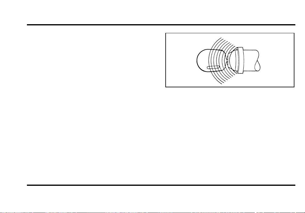
129
Coded Key Anti-Theft System
Your vehicle is equipped with a coded key anti-theft
system, you can only use an electronically coded
key to start the vehicle. During each vehicle start
sequence, the coded key is read by the anti-theft
system. If the key’s ID code matches that in the
anti-theft system, the vehicle is enabled to start. If
the key’s ID code does not match the anti-theft
system, or if no coded key is detected, then the
vehicle is not able to start. Your vehicle was
equipped with two electronically coded keys. The
coded ignition key is larger than normal due to the
electronics located in the head of the key.
Additional spare keys, maximum of eight, can be
purchased either through your dealership or selected
retailers. Be sure to purchase only coded keys with
a Ford or Mercury logo on it to ensure proper
functionality. If both supplied keys are lost or
stolen, the vehicle must be brought to the
dealership for re-initialization. (All keys must be
brought to the dealer, if any.)
Theft Indicator
The indicator pprovides system proveout and
operating status. The system activates the indicator
when the ignition switch is placed in the ON or
START position. This indicator helps to determine
possible fault conditions and/or normal operating
proveout. The system will illuminate the indicator
for three seconds then go out to acknowledge
normal operating conditions. If the indicator does
not illuminate at key ON or flashes, have the
system serviced.
File:05fncf8.ex
Update:Thu Jun 27 10:02:20 1996

130
Spare Key Programming Procedure
Two electronically coded keys were supplied with
your vehicle, use one of these with the procedure
below:
❑
Using a coded key that you can start your
engine with, turn the ignition from the ON to
the OFF position.
❑
Within 15 seconds, insert a new key into the
ignition and turn it to ON or START. The
vehicle does not have to be started.
If the key has been coded, the theft indicator will
illuminate for two seconds. The key can then be
used to start the vehicle.
Repeat until all chosen keys have been coded
(max=8).
If the key coding failed, the theft indicator will flash
and the vehicle cannot be started. One of 3 causes
are possible:
❑
The new key was not inserted within 15
seconds or
❑
All 8 key codes have been stored or
❑
The key does not have an electronic code
File:05fncf8.ex
Update:Thu Jun 27 10:02:20 1996
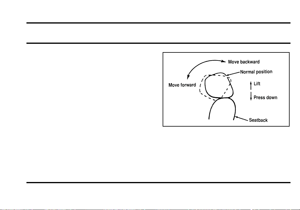
131
Seating and Safety Restraints
Seats
Head Restraints
If you use them properly, head restraints will help
protect your head and neck in a collision.
A head restraint should be placed as high as
possible behind your head without interfering with
your vision.
You can adjust the head restraints for your comfort
and protection.
Four-way head restraints
Your vehicle has the four-way head restraint. You
can adjust it in four directions. You can raise it two
(2) inches (50 mm) from its normal position, or you
can move it forward up to 60˚ until you reach the
desired position.
The four-way head restraint
File:06fnss8.ex
Update:Wed Jun 19 15:04:39 1996
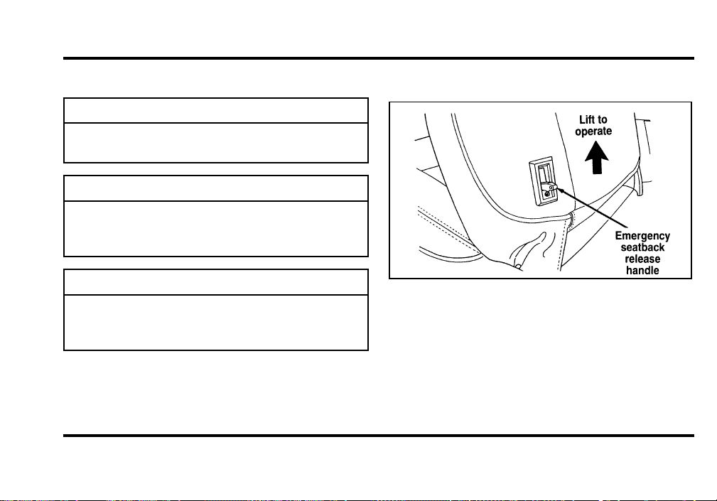
132
AdjustingtheSeats
WARNING
Neveradjustthedriver’sseator
seatbackwhenthevehicleismoving.
WARNING
Alwaysdriveandridewithyour
seatbackuprightandthelapbeltsnug
andlowacrossthehips.
WARNING
Donotpilecargohigherthanthe
seatbackstoavoidinjuringpeopleina
collisionorsuddenstop.
SeatbackRecline
Frontseatbackreleaselever
I t i s no t necessar yt o us e th e emergenc yseatback
releas e leve r fo r rea r sea t entr yo r exit . The
seatbac k remain s unlocke dwit h norma l usag e and
lock s onl ydurin g emergenc ystopping , upo n impact,
o r o n stee p downhil l grades . Th e inerti a seatback
File:06fnss8.ex
Update:Wed Jun 19 15:04:39 1996
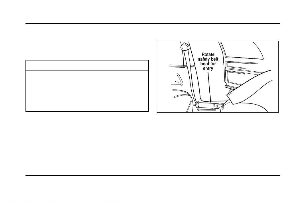
133
latc h wil l allo wth e seatbac k t o rotat e approximately
5 ˚ forwar dbefor e i t locks . Th e releas e i s provided
onl yt o unloc k th e seatbac k whe n parke do n steep
downhil l grade s o r afte r a collision.
WARNING
Checktoseethattheseatandseatback
arelatchedsecurelyinposition.Keep
floorareafreeofobjectsthatwould
preventproperseatengagement.Never
attempttoadjusttheseatwhilethe
vehicleisinmotion.
RearSeatEntry
Enteringtherearseat
File:06fnss8.ex
Update:Wed Jun 19 15:04:39 1996
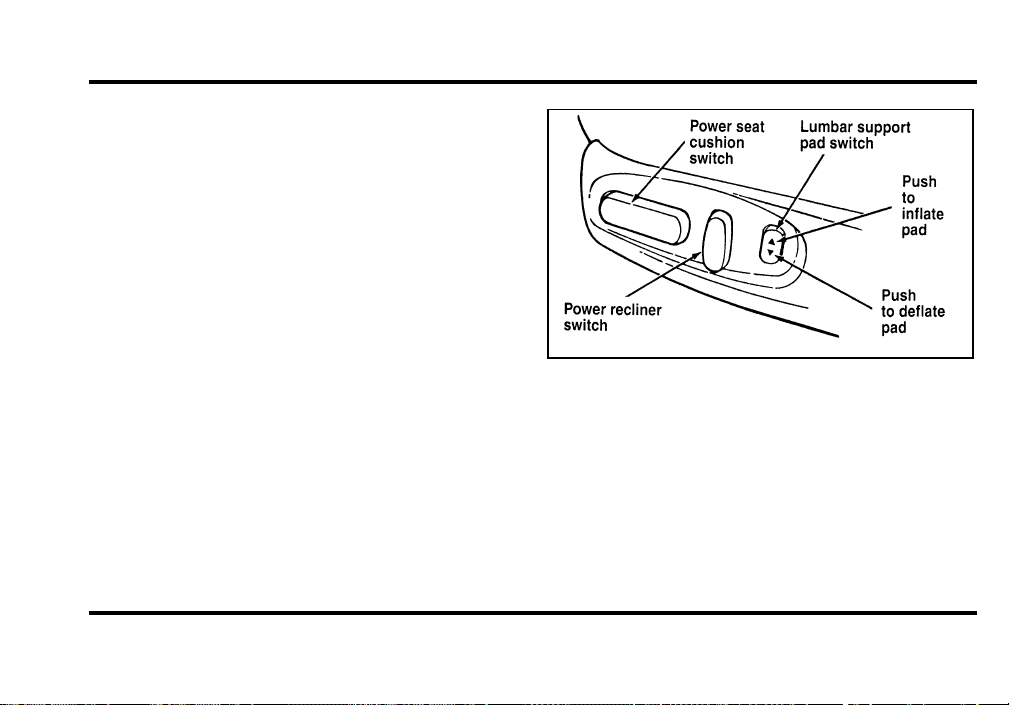
134
The rotating boot on the lap belt is designed to
allow both rear seat entry/exit and access to the
front seat passengers. To enter the rear seat:
1. Rotate the safety belt boot rearward.
2. Enter the rear seat in front of the safety belt.
3. Rotate the safety belt boot forward to allow use
by the front seat passengers.
Using the Power Seats
Your vehicle’s power seats can be adjusted in
several directions. You can raise or lower the whole
seat, move the seat forward or backward and tilt
the front and back of the seat up or down.
The controls to operate the power seats are located
on the outside of each front seat.
The power seat controls
Power Lumbar Support
With this feature, you can position a lumbar
support pad in the seatback.
File:06fnss8.ex
Update:Wed Jun 19 15:04:39 1996
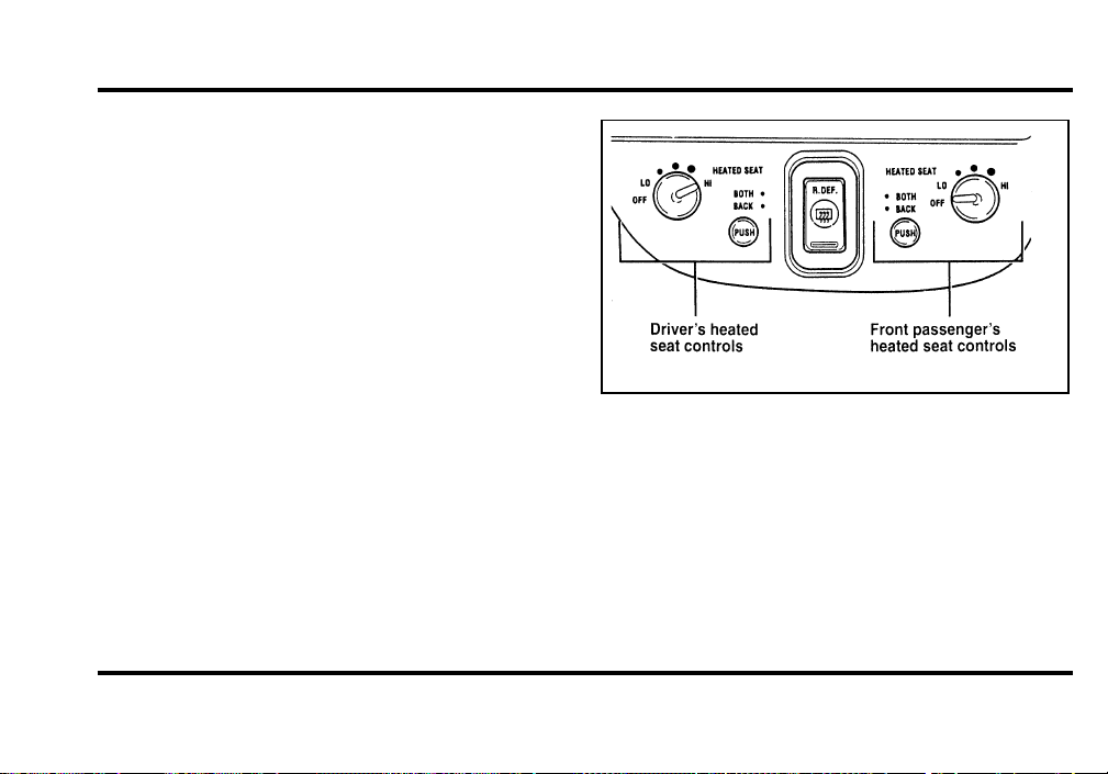
135
Heated Seats (If equipped)
The driver’s and front passenger’s Heated Seats are
controlled by the HEATED SEATS panel, which is
located directly below the climate control panel.
The Heated Seat System will only operate with the
ignition key in the ON position and will maintain a
temperature automatically once it is selected.
NOTE: Leaving the Heated Seat turned on when
you shut the vehicle off will not continue to heat
the seat.
The heated seat controls
File:06fnss8.ex
Update:Wed Jun 19 15:04:39 1996

136
To operate the Heated Seat System:
1. Select mode.
❑
“Both” to heat the seat back and seat cushion
❑
“Back” to heat the seat back only
2. Turn the knob to “LO” (the lowest heat level).
Allow five minutes for the heat level to
stabilize.
3. If the heat level is not high enough for
comfort, select increased heat levels. Allow at
least two minutes for the heat level to stabilize
at any new level selected.
4. If the heated seat is not turned off, the seat
will heat up to the selected temperature level
each time the car is started.
NOTE: Cooling the seat down takes considerably
longer than increasing its heat level.
Auto-Glide Seats
Auto-Glide is a feature which automatically moves
the seat forward or rearward when the seatback is
tilted forward or rearward to allow ease of entry
into the rear seat.
NOTE: This feature can turned off. For more
information see the Message Center Driver Settings
section in the Instrumentation chapter.
With the ignition OFF, the driver’s seat Auto-Glide
will only function when the gearshift is in N
(Neutral) or P (Park), and at least one of the
vehicle’s doors is open. If the ignition is ON,
Auto-Glide will function with the transmission
selector in N (Neutral) or P (Park).
With the ignition OFF, the passenger seat
Auto-Glide will only function when at least one of
the vehicle’s doors are open. If the ignition is ON,
Auto-Glide will function. However, Auto-Glide will
operate while occupied during rear travel.
File:06fnss8.ex
Update:Wed Jun 19 15:04:39 1996

137
If the seatback is moved from its forward stop angle
while the seat is traveling forward, the seat will
stop. If the seatback is returned to the forward stop
angle position, the seat will resume its forward
travel. If the seatback is returned to its upright
position, the seat will return to the original position.
If the transmission is shifted from N (Neutral) or P
(Park) while the driver’s seat is moving, the seat
will stop where it is. Returning the gearshift to N
(Neutral) or P (Park) will allow seat movement to
continue. To allow movement without returning to
P (Park) or N (Neutral) will require the use of the
electric seat controls.
If you sit in the seat while the Auto-Glide is
moving rearward, the seat will continue to move.
If the seat stalls, or if any seat switch is
momentarily activated (excluding the lumbar switch)
while the seat is traveling forward, the seat will
stop. If the seatback is returned to its upright
position, the seat will return to the position it was
at when the ease of entry cycle was started. To
resume forward travel will require moving the
seatback off of its forward stop angle position and
returning it back to the same. Repositioning the seat
at this time using the seat controls will cancel
Auto-Glide.
If the ignition is off, and the last open door is
closed while a seat is moving, 30 seconds will be
allowed for the forward or rearward movement to
be completed.
Easy Access/Easy Out (driver side
only)
The easy in/easy out feature of the driver seat
moves the seat two inches back when:
❑
the transmission is in N (Neutral) or P (Park)
❑
the driver safety belt is buckled
❑
the ignition switch is turned to OFF.
File:06fnss8.ex
Update:Wed Jun 19 15:04:39 1996

138
The easy in/easy out feature of the driver seat
moves the seat two inches forward when:
❑
the transmission is in N (Neutral) or P (Park)
❑
the driver safety belt is buckled
❑
the ignition switch is turned to ON.
Important Safety Belt Information
The use of safety belts helps to restrain you and
your passengers in case of a collision. In most states
and in Canada, the law requires their use.
Safety belts provide best restraint when:
❑
the seatback is upright
❑
the occupant is sitting upright (not slouched)
❑
the lap belt is snug and low on the hips
❑
the shoulder belt is snug against the chest
❑
the knees are straight forward
To help you remember to fasten your safety belt, a
warning light may come on and a chime may
sound. See Safety Belt Warning Light and Chime in
the Instrumentation chapter.
See the following sections in this chapter for
directions on how to properly use these safety belts.
Also see Safety Restraints for Children in this
chapter for special instructions about using safety
belts for children.
File:06fnss8.ex
Update:Wed Jun 19 15:04:39 1996
139
WARNING
Itisextremelydangeroustorideina
cargoarea,insideoroutsideofa
vehicle.Inacollision,peopleridingin
theseareasaremorelikelytobe
seriouslyinjuredorkilled.Donot
allowpeopletorideinanyareaofyour
vehiclethatisnotequippedwithseats
andsafetybelts.Besureeveryonein
yourvehicleisinaseatandusinga
safetybeltproperly.
WARNING
Alwaysdriveandridewithyour
seatbackuprightandthelapbeltsnug
andlowacrossthehips.
WARNING
Eachseatingpositioninyourvehicle
hasaspecificsafetybeltassembly
whichismadeupofonebuckleand
onetonguethataredesignedtobeused
asapair.1)Usetheshoulderbelton
theoutsideshoulderonly.Neverwear
theshoulderbeltunderthearm.2)
Neverswingitaroundyourneckover
theinsideshoulder.3)Neverusea
singlebeltformorethanoneperson.
File:06fnss8.ex
Update:Wed Jun 19 15:04:39 1996
140
WARNING
Fordrecommendsthatallsafetybelt
assembliesandattachinghardware
shouldbeinspectedbyaqualified
technicianafteranycollision.Safety
beltassembliesnotinuseduringa
collisionshouldalsobeinspectedand
replacedifeitherdamageorimproper
operationisnoted.
WARNING
Childrenshouldalwaysridewiththe
seatbackinthefullyuprightposition.
WARNING
Neverletapassengerholdachildon
hisorherlapwhilethevehicleis
moving.Thepassengercannotprotect
thechildfrominjuryinacollision.
WARNING
Lockthedoorsofyourvehiclebefore
drivingtolessentheriskofthedoor
comingopeninacollision.
CombinationLapandShoulder
Belts
Whil e you r vehicl e i s i n motion , th e combination
la p an dshoulde r bel t adjust s t o you r movement.
However , i f you brak e hard , corne r har do r i f your
vehicl e receive s a n impac t o f 5 mp h ( 8km/h ) or
more , th e la p an dshoulde r bel t lock s an dhelps
reduc e you r forwar dmovement.
Afte r you ge t int o you r vehicle , clos e th e doo r and
loc k it . The n adjus t th e sea t t o th e positio n that
suit s you best.
File:06fnss8.ex
Update:Wed Jun 19 15:04:39 1996
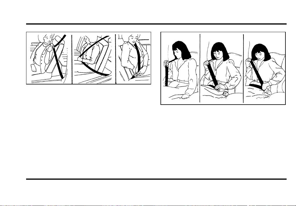
141
Fastening the combination lap and shoulder
belt
Fastening the rear seat lap and shoulder belt
NOTE: Be sure to read and understand Important
Safety Belt Information in this chapter.
To adjust the lap part of the belt, pull up on the
shoulder belt until the lap belt fits snugly and as
low as possible around your hips.
File:06fnss8.ex
Update:Wed Jun 19 15:04:39 1996
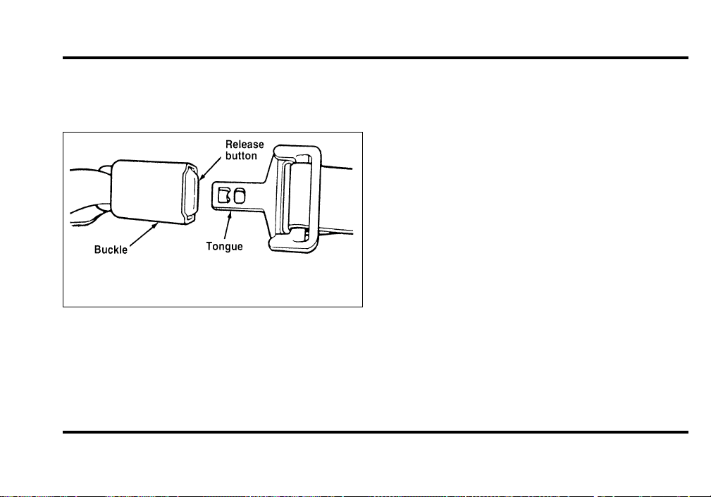
142
While the belt retracts, guide the tongue to its
original position to prevent it from striking you or
the vehicle.
Unfastening the lap/shoulder belts
Right Front or Rear Window Seating
Positions
Your vehicle is equipped with a dual locking mode
retractor on the shoulder belt portion of the
combination lap/shoulder safety belt for front seat
passenger and rear outboard passengers.
Dual locking mode retractors operate in two
ways:
Vehicle sensitive (emergency) locking
mode
In this operating mode, the shoulder belt retractor
will allow the occupant freedom of movement,
locking tight only on hard braking, hard cornering
or impacts of approximately 5 mph (8 km/h) or
more. The retractor can also be made to lock by
pulling the belt out quickly.
File:06fnss8.ex
Update:Wed Jun 19 15:04:39 1996
143
Automaticlockingmode
I n thi s operatin g mode , th e shoulde r bel t retractor
wil l b e automaticall ylocke dan dwil l remai n locked
whe n th e combinatio n lap/shoulde r safet ybel t is
buckled , an ddoe s no t allo wth e occupan t freedom
o f movement . Thi s mod e provide s th e following:
❑
Atigh t lap/shoulde r bel t o n th e occupant.
❑
Chil dsea t installatio n restraint.
WARNING
Rear-facingchildseatsorinfantcarriers
shouldneverbeplacedinthefront
seats.
Thi s mod e mus t b e use dwhe n installin g a child
sea t o n th e fron t pasenge r sea t an drea r window
seat s wher e dua l lockin g retractor s ar e provided . To
switc h th e retracto r fro mth e emergenc ylocking
mod e t o th e automati c lockin g mode , perfor mthe
followin g steps:
1. Buckl e th e lap/shoulde r combinatio n belt.
2. Gras p th e shoulde r portio n o f th e bel t an dpull
downwar dunti l al l o f th e bel t i s extracte dand
a clic k i s heard . At thi s time , th e retracto r i s in
th e automati c lockin g mod e (chil drestraint
mode).
3. Aclickin g soun dwil l continu e t o b e hear das
th e bel t i s allowe dt o retract.
NOTE:Whe n th e combinatio n lap/shoulde r bel t is
unbuckle dan dallowe dt o retrac t completely , the
retracto r wil l switc h t o th e vehicl e sensitive
(emergency ) lockin g mode . Se e th e detailed
instruction s unde r SafetySeatsforChildreni n this
chapter.
LapBelts
Th e la p bel t i n th e cente r o f th e rea r sea t doe s not
adjus t automatically . Yo u mus t adjus t i t t o fi t snugly
an da s lo wa s possibl e aroun dyou r hips . Do not
wea r i t aroun dyou r waist.
File:06fnss8.ex
Update:Wed Jun 19 15:04:39 1996
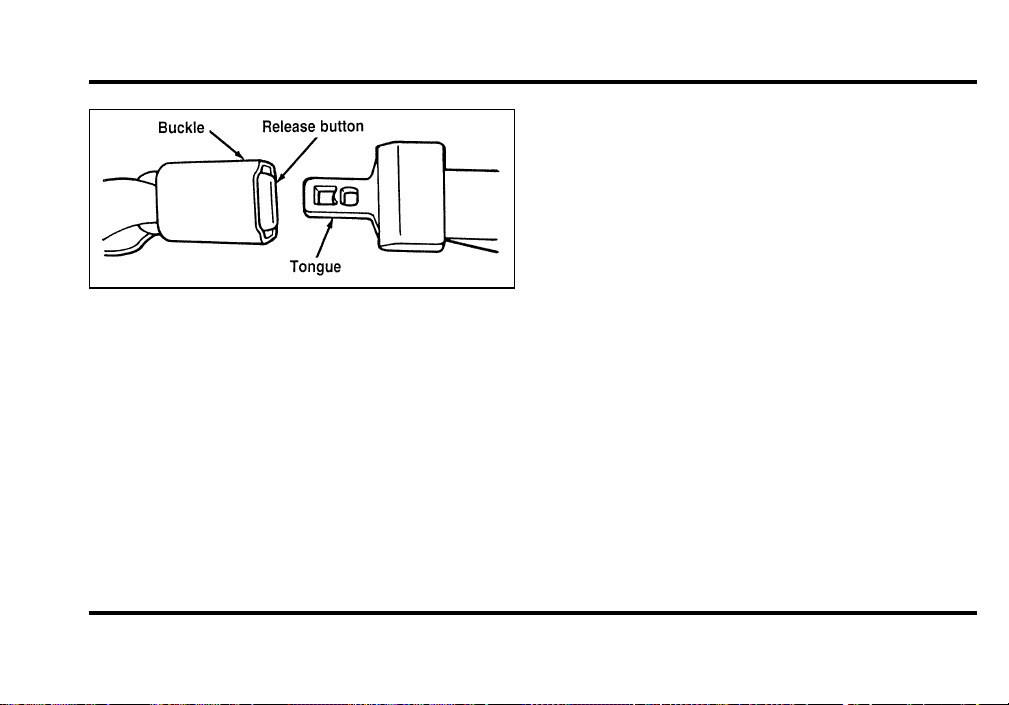
144
Unfastening the center rear lap safety belt
NOTE: Be sure to read and understand Important
Safety Belt Information in this chapter.
Pull the belt across your hips and insert the tongue
into the correct buckle on your seat until you hear
a snap and feel it lock. Make sure the buckle is
securely fastened.
If you need to lengthen the belt, unfasten it and tip
the belt tongue at a right angle to the belt. Pull the
belt tongue over your lap until it reaches the
buckle.
If you need to shorten the belt, pull on the loose
end of the webbing until the belt fits snugly.
To unfasten the belt, push the release button on
the buckle. This allows the tongue to unlatch from
the buckle.
Safety Belt Extension Assembly
For some people, the safety belt may be too short
even when it is fully extended. You can add about
eight inches (20 cm) to the belt length with a
safety belt extension assembly (part number
611C22). Safety belt extensions are available at no
cost from your dealer.
Use only extensions manufactured by the same
supplier as the safety belt. Manufacturer
identification is located at the end of the webbing
on the label. Also, use the safety belt extension only
if the safety belt is too short for you when fully
extended. Do not use extension to change the fit of
the shoulder belt across the torso.
File:06fnss8.ex
Update:Wed Jun 19 15:04:39 1996
145
WARNING
Failuretofollowtheseinstructionswill
affecttheperformanceofthesafety
beltsandincreasetheriskofpersonal
injury.
SafetyBeltMaintenance
Chec k th e safet ybel t system s periodicall yt o make
sur e tha t the ywor k properl yan dar e no t damaged.
Al l safet ybel t assemblies , includin g retractors,
buckles , fron t sea t bel t buckl e suppor t assemblies
(slid e bar ) (i f equipped) , shoulde r bel t height
adjuster s (i f equipped) , chil dsafet ysea t tether
bracke t assemblie s (i f equipped) , an dattaching
hardware , shoul db e inspecte dafte r an ycollision.
For drecommend s tha t al l safet ybel t assemblies
use di n vehicle s involve di n a collisio n b e replaced.
However , i f th e collisio n was mino r an da qualified
technicia n find s tha t th e belt s do no t sho wdamage
an dcontinu e t o operat e properly , the ydo no t need
t o b e replaced . Safet ybel t assemblie s no t i n use
durin g a collisio n shoul dals o b e inspecte dand
replace di f eithe r damag e o r imprope r operatio n is
noted.
AirBagSupplementalRestraint
System(SRS)
ImportantAirBagPrecautions
You r vehicl e i s equippe dwit h a supplemental
restrain t syste mdesigne dt o wor k wit h th e safety
belt s t o hel p protec t you an dyou r righ t fron t seat
passenge r i n th e even t o f a collision . Th e Ai r Bag
Supplementa l Restrain t Syste mi s primaril ydesigned
t o reduc e certai n uppe r bod yinjuries.
File:06fnss8.ex
Update:Wed Jun 19 15:04:39 1996
146
WARNING
Alloccupantsofthevehicle,including
thedriver,shouldalwaysweartheir
safetybelts,failuretodosomay
increasetheriskofpersonalinjuryin
theeventofacollision.
WARNING
Therightfrontpassengerairbagisnot
designedtorestrainoccupantsinthe
centerfrontseatingposition.
WARNING
Donotplaceobjectsormount
equipmentonorneartheairbagcovers
thatmaycomeintocontactwithan
inflatingairbag.Failuretofollowthese
instructionsmayincreasetheriskof
personalinjuryintheeventofa
collision.
WARNING
Donotattempttoservice,repair,or
modifytheairbagSupplemental
RestraintSystemoritsfuses.Seeyour
FordorLincoln-Mercurydealer.
File:06fnss8.ex
Update:Wed Jun 19 15:04:39 1996
147
WARNING
Ifyouareclosetoaninflatingairbag,
itcouldseriouslyinjureyou.Position
yourseatsuchthatitisasfarback
fromthesteeringwheelaspossiblebut
stillallowsyoutoproperlycontrolthe
vehicle.
ChildrenandAirBags
NOTE : Fo r additiona l importan t safet yinformation
o n th e prope r us e o f sea t belts , chil dseats , and
infan t seats , pleas e rea dth e entir e Safet yRestraints
chapte r i n thi s owne r guide.
WARNING
Childrenshouldalwaysweartheir
safetybelts.Failuretofollowthese
instructionsmayincreasetheriskof
personalinjuryintheeventofa
collision.
WARNING
Rear-facingchildseatsorinfantcarriers
shouldneverbeplacedinthefront
seats.
HowDoestheAirBagSupplemental
RestraintSystemWork?
Th e Ai r Ba g Supplementa l Restrain t Syste mis
designe dt o activat e whe n th e vehicl e i s i n a
collisio n simila r t o hittin g a fixe dbarrie r hea do n at
8-1 4 mp h (13-2 3 km/h) . Th e fac t tha t th e ai r bags
di dno t inflat e i n a collisio n doe s no t mea n that
somethin g i s wron g wit h th e system . Rather , it
mean s th e force s wer e no t o f th e typ e sufficien t to
caus e activation.
I f th e vehicl e i s i n a moderat e o r sever e frontal
collision , th e syste mi s activate dan dth e ai r bags
inflat e rapidly . Afte r th e ai r ba g inflates , i t will
quickl ydeflate . Afte r th e ai r ba g deployment , you
ma ynotic e a smoke-like , powder yresidu e o r smell
File:06fnss8.ex
Update:Wed Jun 19 15:04:39 1996
148
th e burn t propellant . Thi s i s normal . Th e
ma yconsis t o f cornstarc h o r talcu mpowde r
i s use dt o lubricat e th e ai r bag ) o r sodium
compounds , suc h a s sodiu mcarbonate s (e.g . baking
soda ) tha t resul t fro mth e combustio n proces s that
inflate s th e ai r bag . Smal l amount s o f sodium
hydroxid e ma yb e presen t whic h ma yirritat e the
ski n an deyes , bu t non e o f th e residu e i s toxic . The
Ai r Ba g Supplementa l Restrain t Syste mwil l reduce,
bu t no t eliminat e al l injurie s i n a n accident.
WARNING
Severalairbagsystemcomponentsget
hotafterinflation.Donottrytotouch
themafterinflation.
WARNING
Theairbagwillinflateonlyonce.The
systemisdesignedtofunctionona
one-time-onlybasis.Iftheairbagis
inflated,THEAIRBAGWILLNOT
FUNCTIONAGAINANDMUSTBE
REPLACEDIMMEDIATELY.Iftheair
bagisnotreplaced,thiswillincrease
theriskofinjuryinasubsequent
collision.
Th e Ai r Ba g Supplementa l Restrain t Syste mconsists
of:
❑
drive r an dpassenge r ai r ba g module s (which
includ e th e inflator s an dai r bags),
❑
on e o r mor e impac t an dsafin g sensors,
❑
a syste mdiagnosti c module,
❑
a readines s ligh t an dtone,
File:06fnss8.ex
Update:Wed Jun 19 15:04:39 1996

149
❑
and the electrical wiring which connects the
components.
The diagnostic module monitors its own circuits,
the air bag electrical system, the air bag readiness
light, the air bag power, and the air bag inflators.
Determining if System Is Operational
The Air Bag Supplemental Restraint System uses a
readiness light and a tone to indicate the condition
of the system. The readiness light is in the
instrument cluster. When you turn the ignition key
to ON, this light will illuminate for approximately
six (6) seconds and then turn off. This indicates
that the system is operating normally. NOTE:
Routine maintenance of the air bag system is not
required.
A problem with the system is indicated by one or
more of the following:
❑
the readiness light will either flash or stay lit,
❑
the readiness light will not light immediately
after ignition is turned on,
❑
a group of five beeps will be heard. The tone
pattern will repeat periodically until the problem
and light are repaired.
If any of these things happen, even intermittently,
have the Air Bag Supplemental Restraint System
serviced at your Ford or Lincoln-Mercury dealer
immediately. Unless serviced, the system may not
function properly in the event of a collision.
File:06fnss8.ex
Update:Wed Jun 19 15:04:39 1996
150
DisposalofAirBagsandAirBag
EquippedVehicles
Fo r disposa l o f ai r bag s o r ai r ba g equippe dvehicles,
se e you r loca l For do r Lincoln-Mercur ydealer . Air
bag s MUS T B E dispose do f b yqualifie dpersonnel.
SafetyRestraintsforChildren
I n th e U.S . an dCanada , you ar e require db yla w
us e safet yrestraint s fo r children . I f smal l children
rid e i n you r vehicl e —thi s generall yincludes
childre n who ar e fou r year s ol do r younge r and
who weig h 4 0 pound s (1 8kg ) o r les s —you must
pu t the mi n safet yseat s tha t ar e mad e speciall yfor
children . Safet ybelt s alon e do no t provide
maximu mprotectio n fo r thes e children . Chec k your
loca l an dstat e law s fo r specifi c requirements.
WARNING
Neverletapassengerholdachildon
hisorherlapwhilethevehicleis
moving.Thepassengercannotprotect
thechildfrominjuryinacollision.
WARNING
Cargoshouldalwaysbesecuredto
preventitfromshiftingandcausing
damagetothevehicleorharmto
passengers.
Whe n possible , pu t childre n i n th e rea r sea t o f your
vehicle . Acciden t statistic s sugges t tha t childre n are
safe r whe n properl yrestraine di n th e rea r seating
position s tha n i n th e fron t seatin g positions.
File:06fnss8.ex
Update:Wed Jun 19 15:04:39 1996
151
WARNING
Carefullyfollowallofthe
manufacturer’sinstructionsincluded
withthesafetyseatyouputinyour
vehicle.Ifyoudonotinstallanduse
thesafetyseatproperly,thechildmay
beinjuredinasuddenstoporcollision.
WARNING
Safetybeltsandseatscanbecomehot
inavehiclethathasbeenclosedupin
sunnyweather;theycouldburnasmall
child.Checkseatcoversandbuckles
beforeyouplaceachildanywherenear
them.
WARNING
Donotleavechildren,unreliableadults,
orpetsunattendedinyourvehicle.
SafetySeatsforChildren
Us e a safet ysea t tha t i s recommende dfo r th e size
an dweigh t o f th e child . Alway s follo wth e safety
sea t manufacturer’ s instruction s whe n installin g and
usin g th e safet yseat.
For drecommend s th e us e o f a chil dsafet yseat
havin g a to p tethe r strap . Instal l th e chil dsafety
sea t i n a seatin g positio n whic h i s capabl e of
providin g a tethe r anchorage . Fo r mor e information
o n to p tethe r strap s se e AttachingSafetySeatsWith
TetherStrapsi n thi s chapter.
Whe n installin g a chil dsafet yseat , b e sur e t o use
th e correc t safet ybel t buckl e fo r tha t seating
position , an dmak e sur e th e tongu e i s securely
fastene di n th e buckle . Fo r a shoulder/la p belt
combinatio n wit h a slidin g tongue , mak e sur e the
retracto r i s i n th e automati c lockin g mode.
File:06fnss8.ex
Update:Wed Jun 19 15:04:39 1996
152
WARNING
Rear-facingchildseatsorinfantcarriers
shouldneverbeplacedinthefront
seats.
WARNING
Whenusingforward-facingchildseats
movethepassengerseatasfarback
fromtheinstrumentpanelaspossible.
Neversecurerear-facingchildseatsor
infantcarriersinthefrontseat.
Al l chil drestrain t system s ar e designe dt o be
secure di n vehicl e seat s b yla p belt s o r b yth e lap
portio n o f a lap-shoulde r belt.
WARNING
Ifyoudonotproperlysecurethesafety
seat,thechildoccupyingtheseatmay
beinjuredduringacollisionorsudden
stop.Anunsecuredsafetyseatcould
alsoinjureotherpassengers.
WARNING
Carefullyfollowallofthe
manufacturer’sinstructionsincluded
withthesafetyseatyouputinyour
vehicle.Ifyoudonotinstallanduse
thesafetyseatproperly,thechildmay
beinjuredinasuddenstoporcollision.
File:06fnss8.ex
Update:Wed Jun 19 15:04:39 1996
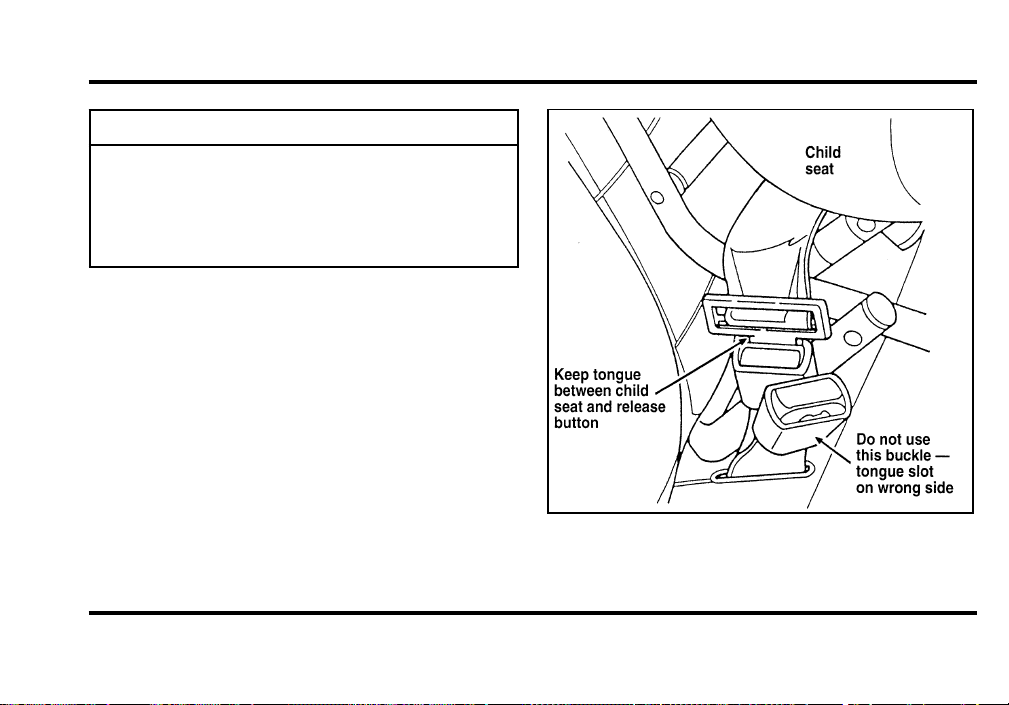
153
WARNING
Alwayskeepthebucklereleasebutton
pointingupwardandawayfromthe
childseat,withthetonguebetweenthe
childseatandthereleasebuttonas
showninthefollowingillustration.
Safetybeltbuckleplacementforchildseats
File:06fnss8.ex
Update:Wed Jun 19 15:04:39 1996
154
WARNING
Carefullyfollowallofthe
manufacturer’sinstructionsincluded
withthesafetyseatyouputinyour
vehicle.Ifyoudonotinstallanduse
thesafetyseatproperly,thechildmay
beinjuredinasuddenstoporcollision.
InstallingChildSafetySeatsinthe
FrontSeatandRearWindowPassenger
SeatingPositions
You r vehicl e i s equippe dwit h a dua l lockin g mode
retracto r o n th e shoulde r bel t portio n o f the
combinatio n lap/shoulde r bel t fo r th e fron t seat
passenge r an da dual-lockin g mod e retracto r fo r the
rea r windo wpassengers.
I f you choos e t o instal l a forward-facin g chil dsafety
sea t i n th e fron t seatin g positions , mov e vehicl e seat
a s fa r bac k a s possible.
Fo r seatin g position s equippe dwit h a dual-locking
mod e retractor , us e th e followin g procedure:
1. Positio n th e chil dsea t i n cente r o f passenger
seatin g position.
File:06fnss8.ex
Update:Wed Jun 19 15:04:39 1996
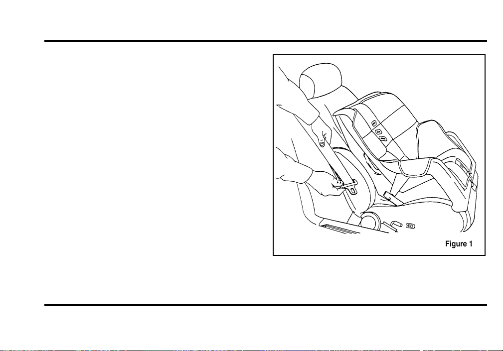
155
2. Pull down on shoulder belt, then grasp
shoulder belt and lap belt together. See Figure
1.
File:06fnss8.ex
Update:Wed Jun 19 15:04:39 1996
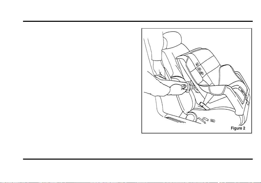
156
3. While holding the shoulder and lap belt
portions together, route the tongue through the
child seat according to the child seat
manufacturer’s instructions. See Figure 2. Be
sure that the belt webbing is not twisted.
Routing the lap/shoulder belt
File:06fnss8.ex
Update:Wed Jun 19 15:04:39 1996
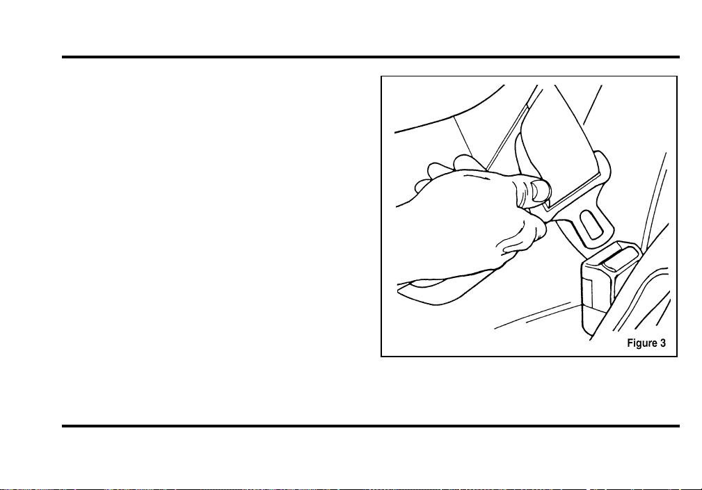
157
4. Insert the belt tongue into the proper buckle
for that seating position until you hear and feel
the latch engage. See Figure 3. Make sure
tongue is latched securely to buckle by pulling
on tongue.
Buckling the belt.
File:06fnss8.ex
Update:Wed Jun 19 15:04:39 1996
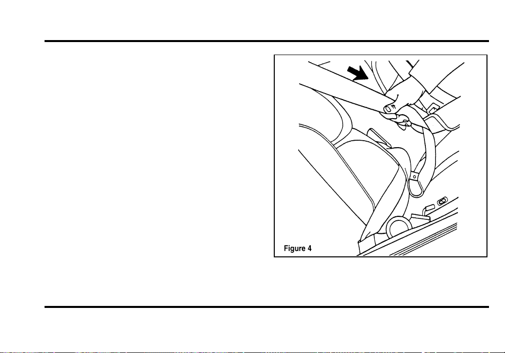
158
5. Grasp the shoulder portion of the belt and pull
downward until all of the belt is extracted and
a click is heard. At this time, the retractor is in
the automatic locking mode (child restraint
mode). See Figure 4.
NOTE: The dual locking mode retractor must be in
the automatic locking mode to properly restrain a
child seat.
Setting the retractor to automatic locking
mode
File:06fnss8.ex
Update:Wed Jun 19 15:04:39 1996
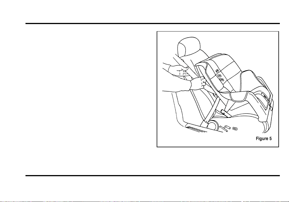
159
6. Allow the belt to retract. A clicking sound will
be heard as the belt retracts. This indicates the
retractor is in the automatic locking mode. Pull
on the lap belt portion across the child seat
towards the buckle and continue to pull up on
the shoulder belt portion while pushing down
on the child seat allowing the shoulder belt to
retract to remove any slack in the seat belt. See
Figures 5 and 6.
File:06fnss8.ex
Update:Wed Jun 19 15:04:39 1996
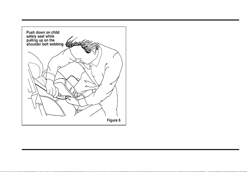
160
7. Before placing the child in the child seat,
forcibly tilt the seat from side to side and in
forward directions to make sure that the seat is
securely held in place. See Figure 7.
File:06fnss8.ex
Update:Wed Jun 19 15:04:39 1996
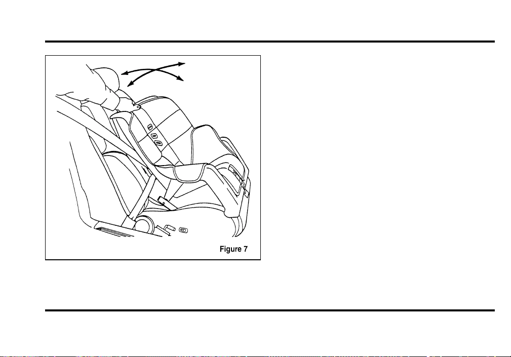
161
Checking that the seat is secure
8. Double check that the retractor is in the
automatic locking mode. Try to pull more belt
out of the retractor. If you cannot, the belt is
in the automatic locking mode. See Figure 8.
File:06fnss8.ex
Update:Wed Jun 19 15:04:39 1996
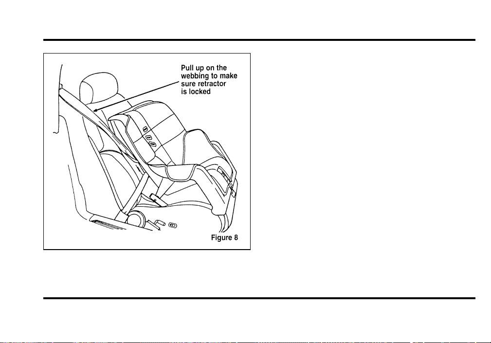
162
Checking the retractor
9. Check to make sure that the child seat is
properly secured prior to each use. If the
retractor is not locked, repeat steps 6 through
8.
NOTE: To remove the retractor from automatic
lock mode, allow seat belt to retract fully to its
stowed position and the retractor will automatically
switch back to the vehicle sensitive locking mode
for normal adult usage.
Attaching Safety Seats With Tether
Straps
Some manufacturers make safety seats that include
a tether strap that goes over the back of the vehicle
seat and attaches to an anchoring point. Other
manufacturers offer the tether strap as an accessory.
Contact the manufacturer of your child safety seat
for information about ordering a tether strap.
File:06fnss8.ex
Update:Wed Jun 19 15:04:39 1996

163
Tetheranchoragehardware
Attachmen t hole s (a t eac h rea r outboar dseating
position ) hav e bee n provide di n you r vehicl e to
attac h ancho r hardware , i f required . Tethe r anchor
hardwar e kit s (par t numbe r 613D74) , including
instructions , ma yb e obtaine da t n o charg e fro many
For do r Lincoln-Mercur ydealer . Al l vehicle s built
fo r sal e i n Canad a includ e a tethe r ancho r hardware
kit.
SafetyBeltsforChildren
Childre n who ar e to o larg e fo r chil dsafet yseats
shoul dalway s wea r safet ybelts . (Se e instructions
wit h you r chil dseat , o r contac t it s manufacturer , to
determin e maximu msiz e o f chil dtha t wil l safel yfit
i n th e seat.)
WARNING
Ifsafetybeltsarenotproperlyworn
andadjustedasdescribed,theriskof
seriousinjurytothechildinacollision
willbemuchgreater.
I f th e shoulde r bel t portio n o f th e lap/shoulde r belt
ca n b e positione ds o tha t i t doe s no t cros s o r rest
i n fron t o f th e child’ s fac e o r neck , th e chil dshould
wea r th e lap/shoulde r belt . Movin g th e chil dcloser
t o th e sea t bel t buckl e ma yhel p provid e a good
shoulde r bel t fit.
File:06fnss8.ex
Update:Wed Jun 19 15:04:39 1996
164
T o improv e th e fi t o f la p an dshoulde r belt
childre n who hav e outgrow n chil dsafet yseatsd
recommend s us e o f a belt-positionin g booste r seat
tha t i s labelle da s conformin g t o al l Federa l motor
vehicl e safet ystandards . Belt-positionin g booster
seat s rais e th e chil dan dprovid e a shorter , firmer
seatin g cushio n tha t encourage s safe r seatin g posture
an dbette r fi t o f la p an dshoulde r belt s o n th e child.
Abelt-positionin g booste r shoul db e use di f the
shoulde r bel t rest s i n fron t o f th e child’
neck , o r i f th e la p bel t doe s no t fi t snugl yo n both
thighs , o r i f th e thigh s ar e to o shor t t o le t th e child
si t al l th e waybac k o n th e sea t cushio n whe n the
lowe r leg s han g ove r th e edg e o f th e sea t cushion.
Yo u ma ywis h t o discus s th e specifi c need s o f your
chil dwit h you r pediatrician.
WARNING
Donotuseabelt-positioningbooster
withalap-onlybelt.
La p belt s an dth e la p bel t portio n o f la p and
shoulde r belt s shoul dalway s b e wor n snugl yand
belo wth e hips , touchin g th e child’ s thighs.
Childrenshouldalwaysridewiththe
seatbackinthefullyuprightposition.
File:06fnss8.ex
Update:Wed Jun 19 15:04:39 1996
165
Starting
Fuel-InjectedEngines
Whenstartin gafuel-injecte dengine ,themost
importantthingtorememberistoavoid
pressingdownontheacceleratorbeforeor
duringstarting.Onlyusetheaccelerato rwhenyou
haveproblem sgettin gyourvehicl estarted .See
StartingYourEngineinthischapte rfordetails
abou twhentousetheaccelerato rwhileyoustart
yourvehicle.
StartingYourVehicle
PreparingtoStartYourVehicle
WARNING
Donotstartyourvehicleinaclosed
garageorinotherenclosedareas.
Exhaustfumescanbetoxic.Always
openthegaragedoorbeforeyoustart
theengine.
Befor eyoustar tyourvehicle ,dothefollowing:
1. Makesurealloccupant sinthevehicl ebuckle
theirsafet ybelts .SeeSafetyRestraintsinthe
Inde xformoredetails.
2. Makesuretheheadlamp sandothe raccessories
areturne doffwhenstarting.
File:08fnto8.ex
Update:Wed Jun 19 15:04:46 1996

166
3. Make sure that the gearshift is in P (Park) and
the parking brake is set before you turn the
key.
Before you start your vehicle, you should test the
warning lights on the instrument panel to make
sure that they work. Refer to the Instrumentation
chapter.
Starting Your Engine
To start your engine:
1. Follow the steps under Preparing to Start Your
Vehicle at the beginning of this section.
2. Turn the ignition key to the ON position.
3. DO NOT depress the accelerator pedal when
starting your engine. DO NOT use the
accelerator while the vehicle is parked.
4. Turn the key to the START position (cranking)
until the engine starts. Allow the key to return
to the ON position after the engine has started.
For a cold engine:
❑
At temperatures 10˚F (-12˚C) and below: If
the engine does not start in fifteen (15)
seconds on the first try, turn the key to OFF,
wait approximately ten (10) seconds so you do
not flood the engine, then try again.
❑
At temperatures above 10˚F (-12˚C): If the
engine does not start in five (5) seconds on
the first try, turn the key to OFF, wait
approximately ten (10) seconds so you do not
flood the engine, then try again.
For a warm engine:
❑
Do not hold the key in the START position for
more than five (5) seconds at a time. If the
engine does not start within five (5) seconds on
the first try, turn the key to the OFF position.
Wait a few seconds after the starter stops, then
try again.
File:08fnto8.ex
Update:Wed Jun 19 15:04:46 1996

167
Whenever you start your vehicle, release the key as
soon as the engine starts. Excessive cranking could
damage the starter.
After you start the engine, let it idle for a few
seconds. Keep your foot on the brake pedal and put
the gearshift lever in gear. Release the parking
brake. Slowly release the brake pedal and drive
away in the normal manner.
NOTE: Your vehicle has an interlock that prevents
you from shifting out of P (Park) unless your foot is
on the brake pedal.
If the engine does not start after two attempts:
1. Turn the ignition key to the OFF position.
2. Press the accelerator all the way to the floor
and hold it.
3. Turn the ignition key to the START position.
4. Release the ignition key when the engine starts.
5. Release the accelerator gradually as the engine
speeds up.
If the engine still does not start, the fuel pump
shut-off switch may have been activated. For
directions on how to reset the switch see Fuel
Pump Shut-Off Switch in the index.
A computer system controls the engine’s idle speed.
When you start your vehicle, the engine’s idle
speed normally runs higher than when it is warmed
up. These faster engine speeds will make your
vehicle move slightly faster than its normal idle
speed. It should, however, slow down after a short
time. If it does not, have the idle speed checked.
If the engine idle speed does not slow down
automatically, do not allow your vehicle to idle for
more than 10 minutes. Have the vehicle checked.
File:08fnto8.ex
Update:Wed Jun 19 15:04:46 1996
168
WARNING
Extendedidlingathighenginespeeds
canproduceveryhightemperaturesin
theengineandexhaustsystem,creating
theriskoffireorotherdamage.
WARNING
Donotpark,idle,ordriveyourvehicle
indrygrassorotherdrygroundcover.
Theemissionsystemheatsupthe
enginecompartmentandexhaust
system,whichcanstartafire.
EngineBlockHeater(Ifequipped)
Engin eblockheater sarestrongl yrecommende dif
youliveinaregio nwher etemperature sreac h-10˚F
(-23˚C )orbelow .Anengin eblockheate rwarms
theengin ecoolant ,whichimprove sstarting ,warms
uptheengin efaster ,andallow stheheater-defrost
syste mtorespon dquickly.
Toturntheheate ron,simpl yplugitintoa
grounde d110-vol toutlet .Fordrecommend sthat
youusea110-vol tcircui tthatisprotecte dbya
groun dfaultcircui tinterrupter.
WARNING
Topreventelectricalshock,donotuse
yourheaterwithungroundedelectrical
systemsortwo-pronged(cheater)
adapters.
Forbes tresults ,plugtheheate rinatleas tthree
hoursbefor eyoustartyourvehicle .Usin gthe
heate rforlonge rthanthreehourswillnotdamage
theengine ,soyoucanplugitinatnighttostart
yourvehicl ethefollowin gmorning.
File:08fnto8.ex
Update:Wed Jun 19 15:04:46 1996
169
Pushing
Vehicle swithautomati ctransmission scanno tbe
starte dbypushing .Follo wthedirection sunde rIf
YourVehicleNeedsaJump-StartintheRoadside
EmergenciesChapter.
GuardingAgainstExhaustFumes
Carbo nmonoxide ,althoug hcolorles sandodorless,
ispresen tinexhaus tfumes .Takeprecaution sto
avoiditsdangerou seffects.
WARNING
Donotstartyourvehicleinaclosed
garageorinotherenclosedareas.
Exhaustfumescanbetoxic.Always
openthegaragedoorbeforeyoustart
theengine.
WARNING
Ifyousmellexhaustfumesinsideyour
vehicle,haveyourdealerinspectyour
vehicleimmediately.Donotdriveif
yousmellexhaustfumes.
File:08fnto8.ex
Update:Wed Jun 19 15:04:46 1996

170
Have the exhaust and body ventilation systems
checked whenever:
❑
your vehicle is raised for service
❑
the sound of the exhaust system changes
❑
your vehicle has been damaged in a collision
Improve your ventilation by keeping all air inlet
vents clear of snow, leaves, and other debris.
If the engine is idling while you are stopped in an
open area for long periods of time, open the
windows at least one inch (2.5 cm). Also, adjust
the heating or air conditioning system to bring in
outside air.
If you use the Electronic Automatic Climate
Control, set the fan speed selector dial to a medium
or high blower speed with the VENT or PNL-FLR
function buttons pressed.
File:08fnto8.ex
Update:Wed Jun 19 15:04:46 1996

171
Driving
Brakes
Applying the Brakes
Your vehicle has anti-lock disc brakes on all four
wheels. They adjust automatically as the brake pads
wear down.
When you press down hard on the brake pedal, the
wheels will not lock and slide. The Anti-Lock Brake
System (ABS) automatically starts releasing and
reapplying the brakes at each wheel independently
whenever your wheels start to lock. When this
happens, you will feel the brake pedal pulsate. This
is an indication that the ABS is working correctly
and is normal.
Do not drive with your foot resting on the brake
pedal; you will wear out the linings and increase
your vehicle’s stopping distance. Brake rotor damage
may also eventually occur.
NOTE: If you are driving down a long or steep hill,
shift to a lower gear and do not apply your brakes
continuously. If you apply your brakes continuously,
they may overheat and become less effective.
Occasional brake squeal during light to moderate
stops does not affect the function of the brake
system and is normal. However, if the squeal
becomes louder or more frequent, have your brakes
inspected by your dealer or a qualified service
technician.
Ford Motor Company has not found any
detrimental effects of popular mobile radio
transmitting equipment installed on vehicles with
the anti-lock brake system, if the equipment is
installed according to the manufacturer’s
instructions. However, if mobile radio transmitting
equipment is installed in your vehicle and, if either
the anti-lock brake system cycles or the ANTI-LOCK
File:09fngf8.ex
Update:Wed Jun 19 10:45:23 1996
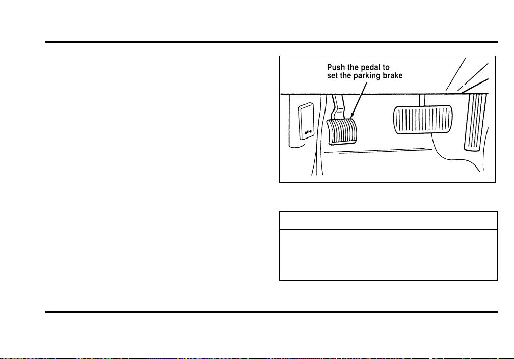
172
lightcome sonatanytimeotherthanrightafter
youturnthekeytotheONpositio nordurin ga
sudde nstop ,haveyourmobil eradi odeale rinspect
theinstallation.
ParkingBrakeandAuto-Release
ParkingBrake
Theparkingbrakeshouldbeusedwhenever
youparkyourvehicle.
Theparkin gbrak eissuspende djustbelo wthe
lowe rleftcorne roftheinstrumen tpanel.
Tosettheparkin gbrake:
1. Movethegearshifte rtoP(Park).
2. Pushtheparkin gbrak epeda ldownfirml yand
fullywithyourleftfoot.
TheBrak eSyste mLightinthewarnin glightswill
glowoncetheparkin gbrak eisset.
Theparkingbrake
WARNING
Alwayssettheparkingbrakefullyand
makesurethegearshiftislatchedinP
(Park).Turnofftheignitionwhenever
youleaveyourvehicle.
File:09fngf8.ex
Update:Wed Jun 19 10:45:23 1996
173
WARNING
Iftheparkingbrakeisfullyreleased,
buttheBrakeSystemlightremainson,
havethebrakescheckedimmediately.
Theymaynotbeworkingproperly.
WARNING
Topreventpersonalinjury,donot
releasetheparkingbrakewhileoutside
thevehicle.
Todisengag etheparkin gbrake:
1. Theignitio nkeymustbeintheRUNposition.
2. Theengin emustberunning.
3. Thebrak epeda lispressed.
4. Thegearshifte rmustbeintheP(Park)
position .Movethegearshifte rintoeithe rR
(Reverse )oroneoftheforwar dgear sD
(Overdrive) ,2(Second) ,or1(First) .Thebrake
peda lmustremai npresse dwhilethegearshifter
ismoved.
Aftertheparkin gbrak ehasbee nrelease dtheBrake
Syste mLightwillbeturne doff.
Iftheparkin gbrak efailstoreleas eaftercompleting
theabov eprocedur eusethemanua lparkin gbrake
releas eleve rtoreleas etheparkin gbrake .The
manua lparkin gbrak ereleas eleverislocate donthe
floorbetwee nthedriver’ sseatandthedoor.
Toreleas etheparkin gbrak ewiththemanual
releas eliftupTabAandpushrearward.
File:09fngf8.ex
Update:Wed Jun 19 10:45:23 1996
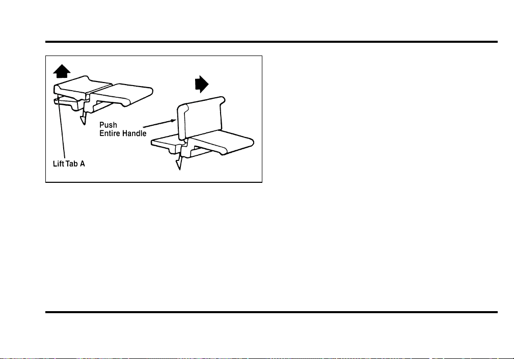
174
Manual parking brake release lever
The parking brake is not designed to stop a moving
vehicle, but you can use the parking brake to stop
your vehicle in an emergency if the normal brakes
fail. However, since the parking brake applies only
the rear brakes, the stopping distance will increase
greatly and the handling of your vehicle will be
adversely affected.
Always check the Brake Warning Light each time
you start your engine. Driving with the parking
brake on will cause the brakes to wear out quickly
and will reduce the fuel economy.
Traction Control
TM
(If equipped)
Your vehicle may be equipped with the optional
Traction Control
TM
system. This system helps
prevent wheel spin in order to improve tire traction
and is an especially useful feature when you drive
in hilly areas or on slippery, icy or snowy roads.
When the Traction Control system is controlling
wheelspin, an electric motor sound may be heard
from the engine compartment and engine
acceleration may seem slower. This is normal.
Traction Control
TM
works automatically by rapidly
applying and releasing the brakes and reducing
engine torque to prevent one or both of the rear
drive wheels from spinning during acceleration.
File:09fngf8.ex
Update:Wed Jun 19 10:45:23 1996

175
NOTE: Engine torque reduction is NOT active
when engine coolant temperature is below -10˚F
(-23˚C).
During the Traction Control
TM
function, which most
often occurs during low speed acceleration on
slippery surfaces, a noise may be heard coming from
the engine compartment. This is normal and may
last for a few seconds during the acceleration of the
vehicle.
In general, this system improves your vehicle’s
stability and acceleration performance when road
conditions warrant. Traction Control
TM
is fully
effective at all vehicle speeds.
If the Traction Control
TM
system is cycled
excessively, the brake portion of the system will
shut down to prevent the rear brakes from
overheating. A limited Traction Control
TM
function
using engine torque will still control wheels from
spinning. A cooling down period is required to
prevent damage to the brakes. This time period
varies and depends on brake usage during the
cooling down period. Anti-Lock braking is not
affected and will function normally during the cool
down period.
After the cool down period, the full Traction
Control
TM
function is restored.
Air Suspension System
Your vehicle is equipped with an automatic load
leveling air suspension system. This system
maintains the vehicle height at a constant level by
automatically adding air or releasing air from the air
springs to offset changes in vehicle loads.
A shutoff switch is located in the trunk behind the
left hand vertical trim panel. If this switch is in the
OFF position, the automatic leveling system will not
operate. The switch should be OFF whenever
jacking up the vehicle. “AIR RIDE SWITCH OFF”
will appear in the Message Center when the
File:09fngf8.ex
Update:Wed Jun 19 10:45:23 1996
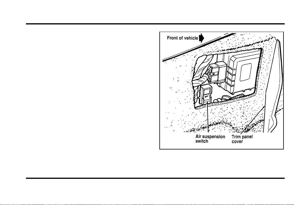
176
ignition switch is in the ON position and the
shutoff switch is in the OFF position. “CHECK AIR
RIDE” will appear when a system fault has been
detected and the ignition switch is in the ON
position.
Normal vehicle operation does not require any
action by the driver.
The air suspension switch — located behind
the left-hand vertical trim panel in the trunk
File:09fngf8.ex
Update:Wed Jun 19 10:45:23 1996
177
NOTE:Ifthetemperatur edrop sovernight ,the
vehicl emayappea rlowbecaus etheairintheair
sprin gcontracts .Thisisnormal !Thevehicl ewill
retur ntoregula rheigh tsoonafterthevehicl eis
started.
SteeringYourVehicle
Yourvehicl ecome swithpowe rsteering .Power
steerin gusesenerg yfromtheengin etohelpsteer
yourvehicle.
Thesteerin gsyste minyourvehicl eisspeed
sensitive .Thismean sthatthesteerin geffor tislight
forparkin gandheavie rforhighwa ydriving.
However ,ifyouhavetoswerv earoun danobject
oranothe rvehicle ,yoursteerin gwillhavefull
powe rassist.
Neve rholdthesteerin gwhee ltotheextrem eright
orleftformorethanfivesecond siftheengin eis
running .Thiscandamag ethepowe rsteerin gpump.
Iftheamoun tofeffor tneede dtostee ryourvehicle
change sataconstan tvehicl espeed ,havethe
powe rsteerin gsyste mchecked .Ifthepower
steerin gsyste mbreak sdown(oriftheengin eis
turne doff),youcanstee rthevehicl emanuall ybut
ittake smoreeffort.
DrivingwithanAutomatic
OverdriveTransmission
Theautomati coverdriv etransmissio noperate svery
muchlikearegula rautomati ctransmission ,except
itoffer stheextraoverdriv efeature.
PuttingYourVehicleinGear
WARNING
Holdthebrakepedaldownwhileyou
movethegearshiftleverfromposition
toposition.Ifyoudonotholdthe
brakepedaldown,yourvehiclemay
moveunexpectedlyandinjuresomeone.
File:09fngf8.ex
Update:Wed Jun 19 10:45:23 1996

178
To move the shifter out of P (Park), the ignition
key must be turned to the ON position. This
vehicle is also equipped with the brake shift
interlock safety feature which prevents shifting the
transmission out of the P (Park) position without
the brake pedal being depressed if the key is in the
ON position.
To operate:
1. Start the engine.
2. Depress and hold the brake pedal.
3. Move the gearshift lever out of P (Park).
Your vehicle is equipped with a Brake Shift
Interlock safety feature. This feature prevents the
gearshift from being moved from the P (Park)
position until the brake pedal is depressed. This
feature is active when the ignition is in the ON
position. If the gearshift lever CANNOT be moved
from P (Park) with the brake pedal depressed:
1. Turn the engine off and remove the ignition
key.
2. Apply parking brake.
3. Reinsert the ignition key and turn clockwise to
the first position.
4. Depress the brake pedal, move the gearshift
lever to N (Neutral) and start the engine.
If you need to shift out of P (Park) by using the
alternate procedure described above, it is possible
that a fuse has blown and that your brakelamps
may also not be functional. Please refer to the
Servicing Your Mark VIII chapter for instructions on
checking and replacing fuses.
File:09fngf8.ex
Update:Wed Jun 19 10:45:23 1996
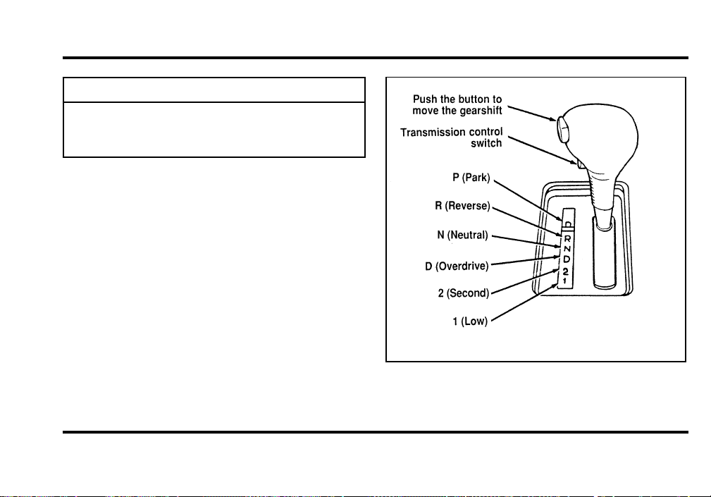
179
WARNING
DONOTDRIVEYOURVEHICLE
UNTILYOUVERIFYTHATTHE
BRAKELAMPSAREWORKING.
Onceyouplacethegearshif tsecurel yintoposition,
graduall yreleas ethebrak epeda landusethe
accelerato rasnecessary.
Thepositionsoftheconsole-mountedgearshift
File:09fngf8.ex
Update:Wed Jun 19 10:45:23 1996

180
R (Reverse)
With the gearshift in the R (Reverse) position, the
vehicle will move backward. You should always
come to a complete stop before shifting into or out
of R (Reverse).
N (Neutral)
With the gearshift in the N (Neutral) position, the
vehicle can be started and is free to roll. Hold the
brake pedal down while in this position.
Driving
Your vehicle’s gearshift is console-mounted on the
floor. The Transmission Control Switch (TCS) is
located on the gearshift handle. The Transmission
Control Indicator Light is located on the instrument
panel. You can put the gearshift lever in any of the
several positions.
The O/D OFF light is off (not illuminated) during
normal vehicle operation. This allows the
transmission to upshift and downshift from 1st
through 4th gears. When the TCS is pressed, the
Transmission Control Indicator Light will illuminate
(O/D OFF) on the instrument panel. When this
O/D OFF is illuminated, the transmission will
upshift and downshift from 1st through 3rd gears.
If O/D OFF light does not come “ON” when TCS
is depressed or if the light flashes when you are
driving, have your vehicle serviced at the first
opportunity. If this condition persists, damage could
occur to the transmission.
To return the transmission to normal operation (1st
through 4th gear) depress the TCS again. This
switch may be used to cancel overdrive any time
the vehicle is being driven. Each time your vehicle
is started, the overdrive system will automatically be
in the normal overdrive mode and the light will not
be illuminated.
File:09fngf8.ex
Update:Wed Jun 19 10:45:23 1996

181
When to use D (Overdrive)
Overdrive is the usual driving position for an
automatic overdrive transmission. It works the same
way Drive works, automatically upshifting or
downshifting as the vehicle speeds or slows.
However, Overdrive also shifts into a fourth gear —
an overdrive gear — when your vehicle cruises at
an appropriate consistent speed for any length of
time. This fourth gear will increase your fuel
economy when you travel at cruising speeds.
When to use Drive (D — with
Transmission Control Switch activated)
Overdrive may not be appropriate for certain
terrain. If the transmission shifts back and forth
between Third and Fourth gears while you are
driving on hilly roads or if your vehicle does not
have adequate power for climbing hills, depress the
TCS.
You can depress the TCS at any speed.
When to use 2 (Second)
Use 2 (Second) for start-up on slippery roads or to
give you more engine braking to slow your vehicle
on downgrades.
When to use 1 (Low)
Use 1 (Low) when driving down steep grades. It
gives more engine braking to slow your vehicle than
2 (Second) on the downgrades. You can upshift
from 1 (Low) to 2 (Second) or from 1 (Low) to
Overdrive at any speed.
P (Park)
Always come to a complete stop before you shift
into P (Park). Make sure that the gearshift is
securely latched in P (Park). This locks the
transmission and prevents the rear wheels from
rotating.
Always set the parking brake fully and make sure
the gearshift is latched in P (Park). Turn off the
ignition whenever you leave your vehicle.
File:09fngf8.ex
Update:Wed Jun 19 10:45:23 1996
182
Youcantellaconsole-mounte dgearshif tissecurely
latche dinP(Park )iftheleve risadjacen ttotheP
(Park )andyoucanno tmoveitwithou tpushin gin
thethumbbutton.
WARNING
Neverleaveyourvehicleunattended
whileitisrunning.
DrivingWithaHeavyLoad
Ther earelimit stotheamoun tofweigh tyour
vehicl ecancarryortow.Thetotalweigh tofyour
vehicle ,plustheweigh tofthepassenger sand
cargo ,shoul dneve rbemorethantheGros sVehicle
Weigh tRatin g(GVWR) .Also ,theweigh tthatyour
vehicl ecarrie soverthefron taxleandrearaxle
shoul dneve rbemorethantheGros sAxleWeight
Ratin g(GAWR )fortherespectiv eaxle.
Youcanfindyourvehicle’ sGVWRandGAWRon
theSafet yComplianc eCertificatio nLabe lontheleft
frontdoorlockfacin goronthedoorlatchpost
pillar.
Theweigh tlimit sofyourvehicle’ stiresaffec tthe
GVWRorGAWRlimitations .Usag eofreplacement
tireswithhighe rweigh tlimit sthanoriginal sdoes
notincreas eGVWRorGAWR.Usag eoflower
capacit yreplacemen ttiresmaylowe rGVWRand
GAWRlimitations.
WARNING
DonotexceedtheGVWRorthe
GAWRspecifiedontheSafety
ComplianceCertificationLabel.
File:09fngf8.ex
Update:Wed Jun 19 10:45:23 1996

183
Limiting Your Vehicle’s Load
The load that you add to your vehicle must not
exceed the maximum load stated on the Safety
Compliance Certification Decal attached to the left
front door pillar.
To figure the weight of your vehicle’s load, add the
weights of:
❑
the driver and passengers
❑
luggage and any other items that you put in
your vehicle
❑
the tongue load of the loaded trailer
❑
the weight of any equipment that has been
added to your vehicle since it was delivered to
your dealer
If you do not know the actual weights of these
items, use the following procedure to figure the
weight of a load:
1. Weigh your vehicle without the driver,
passengers and luggage. You might take your
vehicle to a shipping company or an inspection
station for trucks.
2. Then weigh your vehicle with the driver,
passengers and luggage.
3. Subtract the first reading from the second to
figure the total weight of the load.
After determining this load, you must also make
sure that the total weight of your vehicle, plus the
load it carries, is less than its GVWR. Also, make
sure that the weight your vehicle carries over each
axle is less than the GAWR for the respective axle.
File:09fngf8.ex
Update:Wed Jun 19 10:45:23 1996
184
IfyourvehicleexceedstheGVWR,removecargo
fromyourvehicleaccordingly.Ifyourvehicle
exceedstheGAWRforeitheraxle,shifttheloador
removecargoaccordingly.
WARNING
Improperdistributionofyourvehicle’s
loadorcarryingweightinexcessofthe
amountshownonthetiredecalcan
causerapidtirewearorlossofvehicle
control.
TrailerTowing
Yourvehicledoesnotcomefromthefactoryfully
equippedtotow.Notowingpackagesareavailable
throughFordorLincoln/Mercury dealers.
Becausetowingatrailerputsextrastrainonyour
vehicle,youmustfollowcertainprecautionsfor
yoursafetyandthegoodofyourvehicle:
❑
Staywithintheloadlimitsfortowingyour
vehicle.(SeeTrailertowingspecificationsinthis
chapter.)
❑
Carefullyandthoroughlyprepareyourvehicle
fortowing,makingsuretousetheright
equipmentandtoattachitproperly.(See
PreparingtoTowinthischapter.)
❑
Useextracautionwhendrivingyourvehicle
whileyoutow.(SeeDrivingwhileyoutowin
thischapter.)
❑
Serviceyourvehiclemorefrequentlyifyoutow
atrailer.(SeeServicingyourvehicleifyoutow
inthischapter.)
File:09fngf8.ex
Update:Wed Jun 19 10:45:23 1996
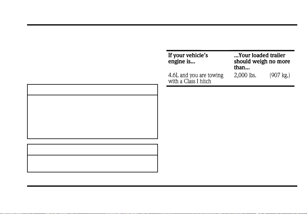
185
Tento15%oftheloadedtrailer’sweightshouldbe
onthetongue.However,thetongueloadshould
neverexceed10%ofthemaximumweightthat
yourvehiclecansafelytow.
Newvehiclesshouldbedriven2,000miles
(3,200km)beforetowingatrailer.
WARNING
Towingtrailersbeyondthemaximum
recommendedgrosstrailerweightcould
resultinenginedamage,
transmission/axledamage,structural
damage,lossofcontrol,andpersonal
injury.
WARNING
Donottowatrailerwhenusinga
temporarysparetire.
Seethefollowingchartfortheamountofweight
yourvehiclecantow.
Youshouldalsolimityourtrailer’sloadwhenyou
towinhighaltitudes.
PreparingtoTow
Foryoursafetyandforthegoodofyourvehicle,
usetherightequipmentforthetypeoftraileryou
tow.Also,makesurethatalltowingequipmentis
properlyattachedtoyourvehicle.Ifyouarenot
certainthatyouareusingtherightequipmentin
thepropermanner,seeyourFordor
Lincoln-Mercurydealer.
File:09fngf8.ex
Update:Wed Jun 19 10:45:23 1996

186
Do not use hitches that clamp onto your vehicle’s
bumper. The bumper is not designed to bear the
load.
Always check the pressure in all your vehicle’s tires
when preparing to tow (see inflation
recommendation on the tire label).
Using the hitch
Your vehicle uses a load carrying hitch. Because
this type of hitch places the tongue load of a trailer
on the rear wheels of your vehicle, you must
distribute the load in your trailer so that only 10 to
15% of the total weight of the trailer is on the
tongue.
Tie down the load so that it does not shift and
change the weight on the hitch. This will prevent
damage to your vehicle and make your vehicle
easier to handle.
Connecting the safety chains
Always attach the trailer’s safety chains to your
vehicle. They help protect your trailer if the hitch
breaks.
To connect the trailer’s safety chains:
1. Cross the chains under the trailer tongue and
attach them to your vehicle’s frame or hook
retainers. Never attach the safety chains to your
vehicle’s bumper. The bumper is not designed
to bear the weight of a trailer.
2. Make sure that you leave enough slack in the
chains to allow you to turn corners.
If you use a rental trailer, follow the instructions
that the rental agency gives you.
File:09fngf8.ex
Update:Wed Jun 19 10:45:23 1996
187
Connectingthetrailer’sbrakes
Electricbrakesandmanual,automatic,orsurge-type
hydraulicbrakesaresafeifyouinstallthemproperly
andadjustthemaccordingtothemanufacturer’s
instructions.Besurethatyourtrailer’sbrakesmeet
localandfederalregulations.
Separatetrailerbrakesofadequatesizeshould
beusedfortrailersweighingover1,000lbs.
(454kg)loadedweight.
WARNING
Donotconnectatrailer’shydraulic
brakesystemdirectlytoyourvehicle’s
brakesystem.Yourvehiclemaynot
haveenoughbrakingpowerandyour
chancesofhavingacollisiongreatly
increase.
Connectingthetrailer’slights
Donotconnectatrailer’slightingsystem
wiringdirectlytoyourvehicle’slightingsystem
wiring.Togettheproperequipmentforhooking
upyourtrailer’slights,seeyourlocaltrailerdealer
andyourForddealer.Besuretofollowtheir
instructionscarefully.
Ifyoudonotinstalltrailerlightscorrectly,youmay
causedamagetothevehicle’slightingsystem.
DrivingWhileYouTow
Beespeciallycarefulwhendrivingwhileyoutowa
trailer.Neverdrivefasterthan45mph(70km/h)
whenyoutowinhillycountryonhotdays.Also,
anticipatestopssothatyoucanbrakegradually.
Whenyoutowdownsteepgrades,movethe
gearshiftto1(Low).Itgivesmoreenginebraking
toslowyourvehiclethanDriveonthedowngrades.
File:09fngf8.ex
Update:Wed Jun 19 10:45:23 1996

188
If you tow in D (Overdrive) while riding through
hilly country, your vehicle may frequently shift
between Overdrive and Third gears. To prevent
your vehicle from shifting too much, press the
Transmission Control Switch located on the shift
lever. This will also give the engine more power
going up hills and better engine braking going down
hills.
If you use the speed control while you are towing
on very long, steep grades, the speed control may
shut off.
Servicing Your Vehicle If You Tow
If you tow a trailer for a long distance, your vehicle
will need to be serviced more frequently than usual.
Refer to the Maintenance Schedule booklet for
additional information.
File:09fngf8.ex
Update:Wed Jun 19 10:45:23 1996

189
Roadside Emergencies
Hazard Flashers
The flashers work whether your vehicle is running
or not. The flashers work for up to two hours
when the battery is fully charged and in good
condition without draining the battery excessively. If
the flashers run for longer than two hours or if the
battery is not fully charged, the battery can be
drained.
If the Engine Cranks but Does
Not Start or Does Not Start After
a Collision
Fuel Pump Shut-off Switch
If the engine cranks but does not start even after a
small collision, the fuel pump shut-off switch may
have been actuated. The shut-off switch is a device
intended to stop the fuel pump when your vehicle
has been involved in a substantial jolt.
Once the shut-off switch is actuated, you must reset
the switch by hand before you can start your
vehicle. The switch is on the left side of the trunk.
File:10fner8.ex
Update:Thu Jun 20 14:27:22 1996
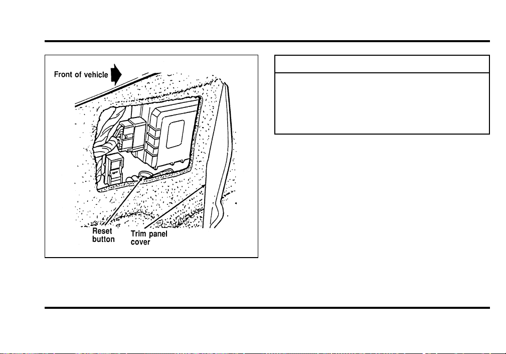
190
Thefuelpumpshut-offswitch
WARNING
Ifyouseeorsmellfuel,donotreset
theswitchortrytostartyourvehicle.
Haveallthepassengersgetoutofthe
vehicleandcallthelocalfire
departmentoratowingservice.
Ifyourenginecranksbutdoesnotstartaftera
collisionorsubstantialjolt:
1. TurntheignitionkeytotheOFFposition.
2. Checkunderthevehicleforleakingfuel.
3. Ifyoudonotseeorsmellfuel,pushthered
resetbuttondown.Ifthebuttonisalreadyset,
youmayhaveadifferentmechanicalproblem.
4. TurntheignitionkeytotheONpositionfora
fewseconds,thenturnittotheOFFposition.
File:10fner8.ex
Update:Thu Jun 20 14:27:22 1996
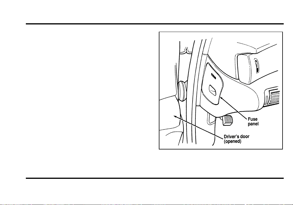
191
5. Check under the vehicle again for leaking fuel.
If you see or smell fuel, do not start your
vehicle again. If you do not see or smell fuel,
you can try to start your vehicle again.
Fuses
Fuses (miniature and high current) protect your
vehicle’s wiring system from overloading. If
electrical parts in your vehicle are not working, the
system may have been overloaded and blown a
fuse. Before you replace or repair any electrical
parts, check the appropriate fuses (miniature and
high current).
The following charts tell you which fuses or circuit
breakers protect the wiring for each electrical part
of your vehicle. If a fuse blows or a circuit breaker
opens a circuit, all the parts of your vehicle that
use that circuit will not work.
Once you have determined which fuses to check,
follow the procedures under Checking and
replacing fuses in this chapter.
The instrument panel fuse panel location
File:10fner8.ex
Update:Thu Jun 20 14:27:22 1996
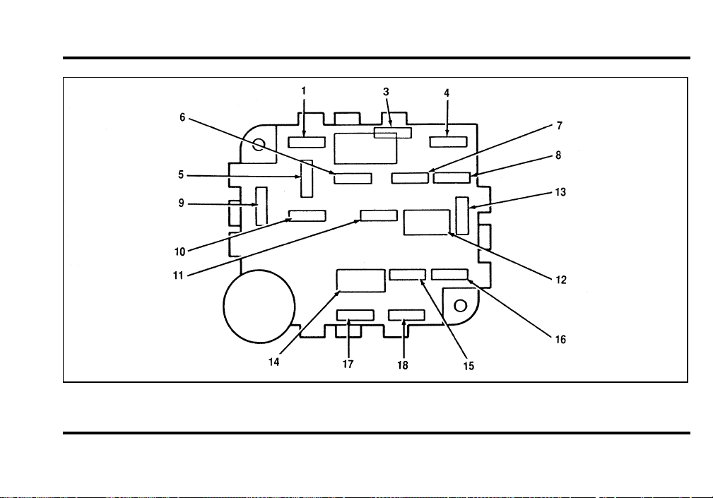
192
The instrument panel fuse box
File:10fner8.ex
Update:Thu Jun 20 14:27:22 1996

193
The Instrument Panel Fuses, Circuit Breakers and Relays
File:10fner8.ex
Update:Thu Jun 20 14:27:22 1996
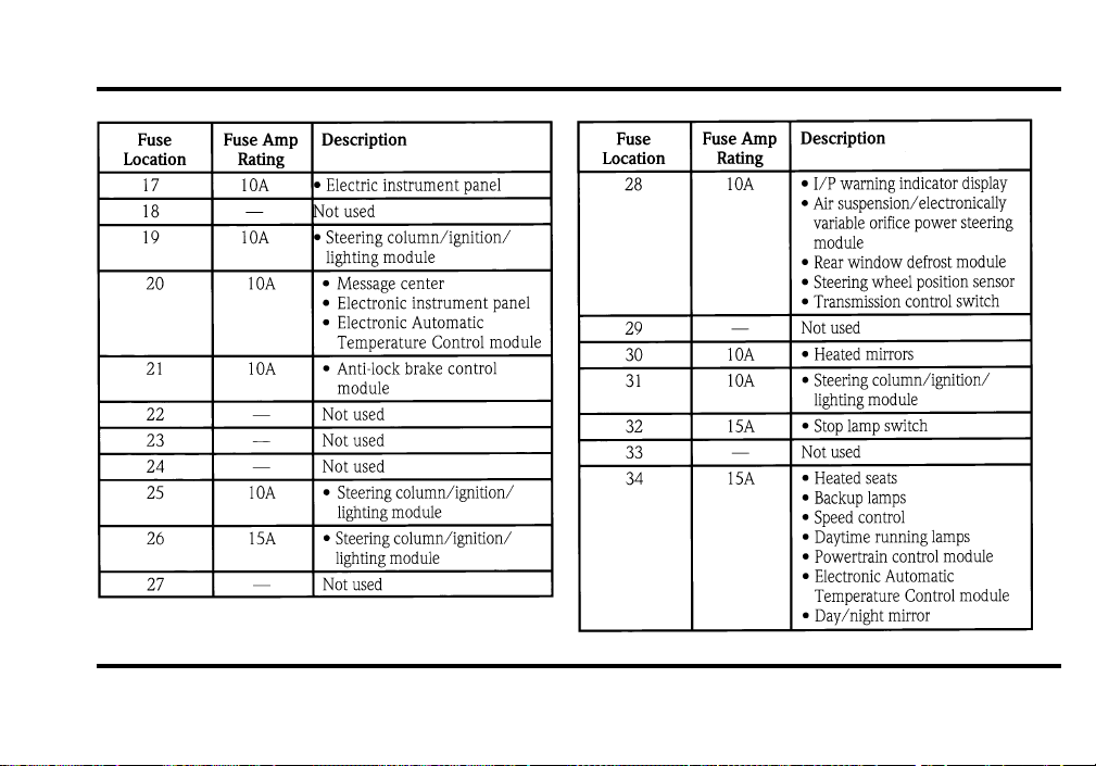
194
File:10fner8.ex
Update:Thu Jun 20 14:27:22 1996
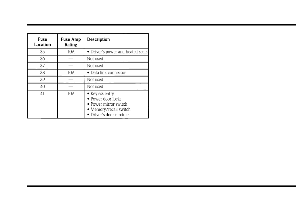
195
High Current Fuses
High current fuses are circuit protectors that are
part of the wiring harness for some electrical
equipment. These, like fuses, open when the circuit
load exceeds their amperage rating. High current
fuses may be purchased from your Ford or
Lincoln-Mercury dealer.
File:10fner8.ex
Update:Thu Jun 20 14:27:22 1996
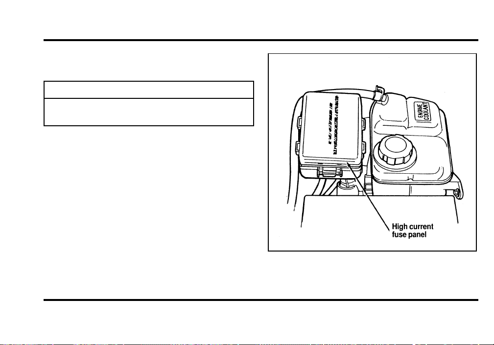
196
Thehighcurrentfusepanelislocatedintheengine
compartmentontheleft-handfenderapron.
WARNING
Alwaysdisconnectthebatterybefore
servicinghighcurrentfuses.
Fordrecommendsthathighcurrentfusesbe
replacedbyaqualifiedtechnician.
Thehighcurrentfusepanellocation
File:10fner8.ex
Update:Thu Jun 20 14:27:22 1996
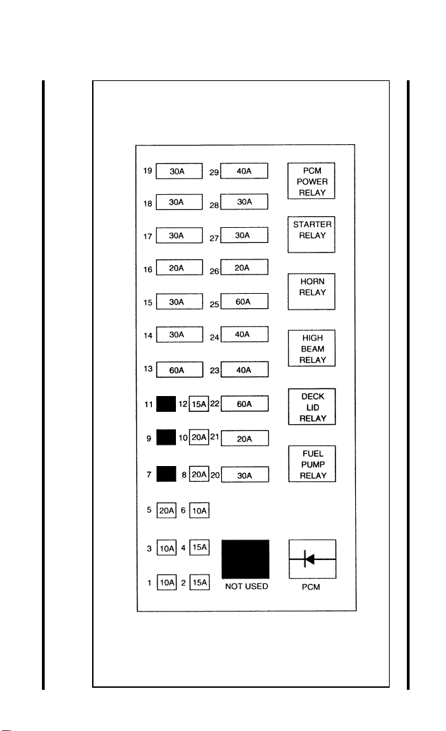
197
File:10fner8.ex
Update:Thu Jun 20 14:27:22 1996
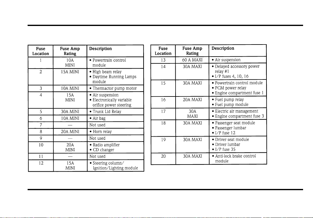
198
The high current fuses
File:10fner8.ex
Update:Thu Jun 20 14:27:22 1996
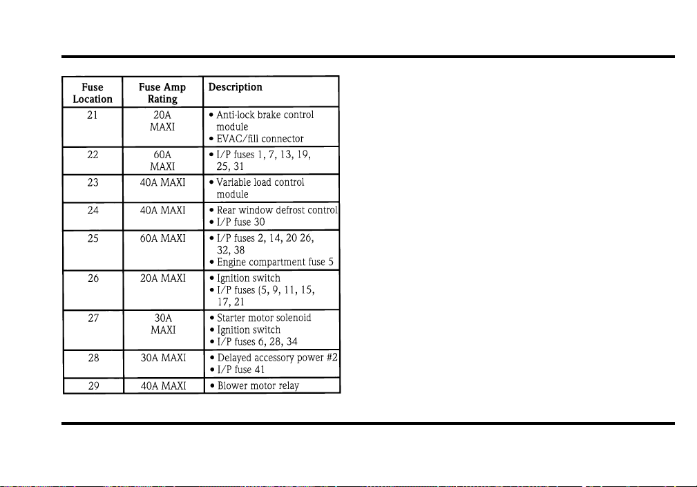
199
Checking and Replacing Fuses
If you need to check a fuse, follow these steps:
1. Find the fuse panel on driver’s side end of the
instrument panel by opening the door. Unsnap
cover from the instrument panel.
2. Find the fuse you want to check (fuses are
numbered on the fuse panel) and remove it
with the fuse pulling tool that is provided.
3. Check the fuse to see if it is blown. Look
through the clear side of the fuse to see if the
metal wire inside is separated. If it is, the fuse
should be replaced.
File:10fner8.ex
Update:Thu Jun 20 14:27:22 1996
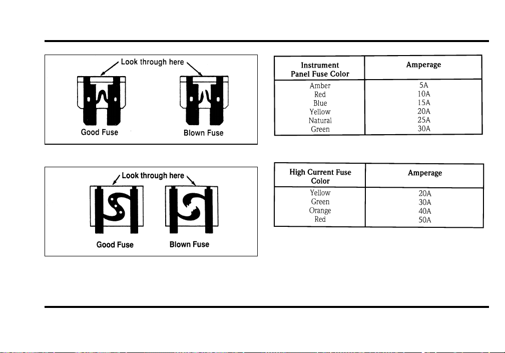
200
The side view of a Blade type fuse
The side view of a high current fuse
4. Replace the fuse with one that has the right
amperage rating. (See the following charts.)
File:10fner8.ex
Update:Thu Jun 20 14:27:22 1996
201
WARNING
Alwaysreplaceafusewithonethathas
thespecifiedamperagerating.Usinga
fusewithahigheramperageratingcan
causeseverewiredamageandcould
startafire.
5. Replacethecover.
Evenafteryoureplaceafuse,itmaycontinueto
blowifyoudonotfindwhatcausedtheoverload.
Ifthefusecontinuestoblow,haveyourelectrical
systemchecked.
ChangingaTire
Ifyougetaflattirewhileyouaredriving,donot
applythebrakeheavily.Instead,graduallydecrease
thespeed.Holdthesteeringwheelfirmlyand
slowlymovetoasafeplaceonthesideoftheroad.
Parkonalevelspot,turnofftheignition,setthe
parkingbrake,andturnonthehazardflashers.
TheTemporarySpareTire
Youmayhaveahighpressuretemporarysparetire.
Thissparetireissmallerthanaregulartireandis
designedforemergencyuseonly.Useitonlywhen
yougetaflattireandreplaceitassoonasyoucan.
Thissparetireismarkedwiththewords
“TEMPORARYUSEONLY”sothatyoucaneasily
identifyit.
NOTE:Extendeduseofotherthanconventional
sparetiresonaTraction-Lokrearaxlecouldresult
inapermanentreductionineffectiveness.Thisloss
ofeffectivenessdoesnotaffectnormaldrivingand
shouldnotbenoticeabletothedriver.
WARNING
Ifyouusethetemporarysparetire
continuouslyordonotfollowthese
precautions,thetirecouldfail,causing
youtolosecontrolofthevehicle,
possiblyinjuringyourselforothers.
File:10fner8.ex
Update:Thu Jun 20 14:27:22 1996

202
When you drive with the temporary spare tire,
DO NOT:
❑
exceed 50 mph (80 km/h) under any
circumstances.
❑
load your vehicle so that it is heavier than the
maximum vehicle load rating listed on the tire
decal.
❑
tow a trailer.
❑
use tire chains on this tire.
❑
try to repair the temporary spare tire or remove
it from its wheel.
❑
use the wheel for any other type of vehicle.
❑
drive through an automatic car wash with this
tire. Because the temporary spare tire is smaller
than a conventional tire, it reduces the ground
clearance. Your vehicle may get caught in the
rails and it could be damaged.
Spare Tire Location
The spare tire is stored under the carpet on the
floor of the trunk.
You will find additional instructions for the spare
tire on the warning label located on the wheel and
the jacking instructions located on the spare tire
cover.
File:10fner8.ex
Update:Thu Jun 20 14:27:22 1996
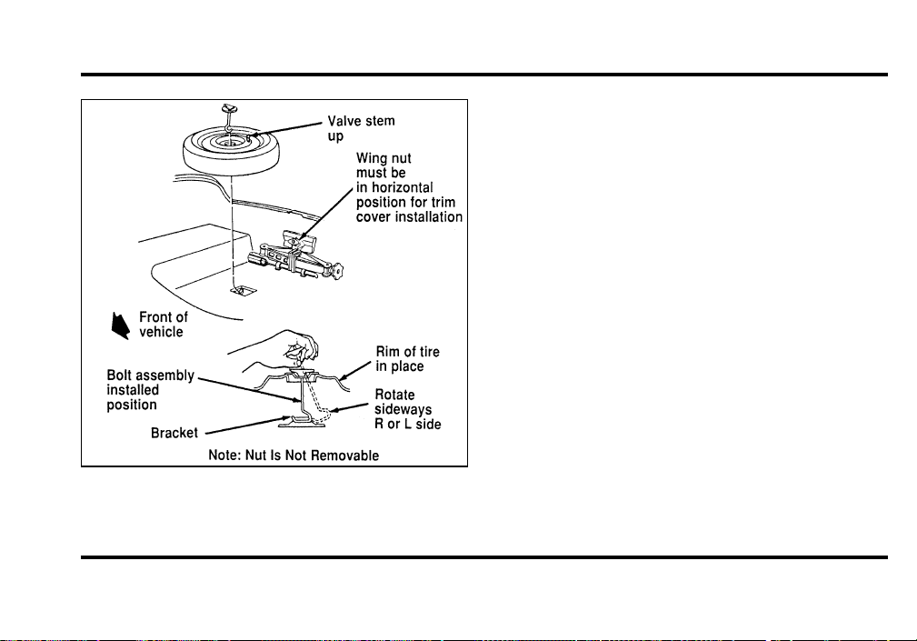
203
The spare tire location
To remove the spare tire:
1. Remove the spare tire cover.
2. Unscrew the wing-nut holding down the spare
tire.
NOTE: Wing-nut is not removable.
3. Unscrew the wing-bolt holding down the jack
and handle.
4. Lift out the spare tire, jack, and lug wrench.
Preparing to Change the Tire
1. Make sure that your vehicle will not move or
roll. Put the gearshift in P (Park). Set the
parking brake and block the wheel that is
diagonally opposite the tire that you are
changing.
Turn off the air suspension switch prior to
jacking.
File:10fner8.ex
Update:Thu Jun 20 14:27:22 1996
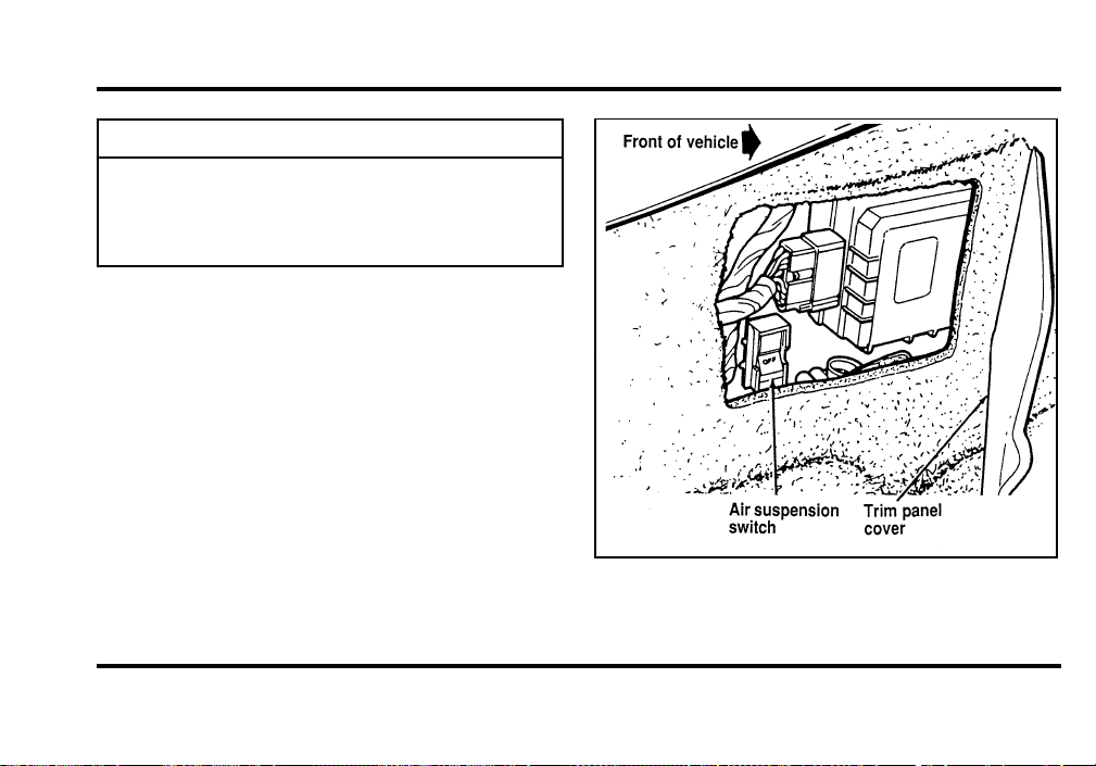
204
WARNING
OnvehiclesequippedwithAir
Suspension,turnOFFtheAir
Suspensionswitchpriortojacking,
hoistingortowingyourvehicle.
Theairsuspensionswitch—locatedinthe
trunk
File:10fner8.ex
Update:Thu Jun 20 14:27:22 1996

205
WARNING
Ifthevehicleslipsoffthejack,youor
someoneelsecouldbeseriously
injured.
2. Getoutthesparetireandjack.
WARNING
Toavoidinjury,neverruntheengine
withonewheelofftheground,suchas
whenchangingatire.
3. Removethecenterornamentfromthe
aluminumwheelwiththetaperedendofthe
wheelnutwrenchwhichcamewithyour
vehicle.Insertandpryagainstthewheel.
4. Looseneachwheellugnutone-halfturn
counterclockwise,butdonotremovethem
untilthetireisraisedofftheground.You
shouldpulluponthehandleratherthanpush
todevelopmaximumforcetoloosenwheellug
nuts.SeeAnti-TheftWheelLugNutslaterin
thischapterforinformationonremoving
anti-theftlugnuts.
RemovingandReplacingtheTire
1. Placethescissors-typejackunderthesideof
thevehicleandadjustthejackheightwiththe
jackhandle.Thejackshouldfitinthenotchin
theverticalrockerpanelflangewhichisnearest
tothewheeltobechanged.
File:10fner8.ex
Update:Thu Jun 20 14:27:22 1996
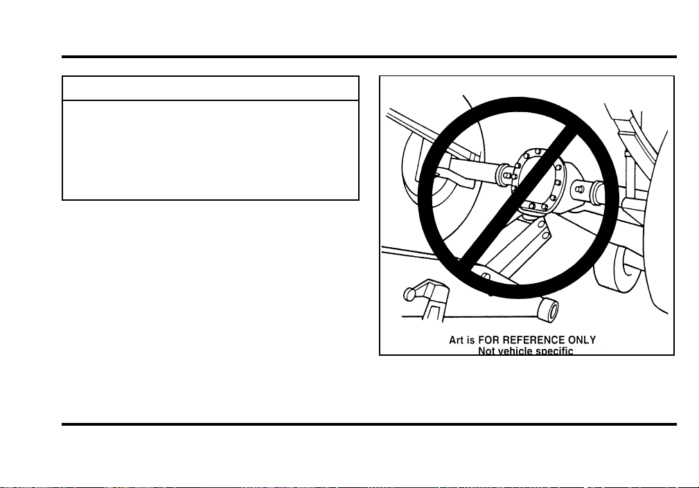
206
WARNING
Tolessentheriskofpersonalinjury,
donotputanypartofyourbodyunder
thevehiclewhilechangingatire.Do
notstarttheenginewhenyourvehicle
isonthejack.Thejackisonlymeant
forchangingthetire.
Theimproperliftpoint
File:10fner8.ex
Update:Thu Jun 20 14:27:22 1996
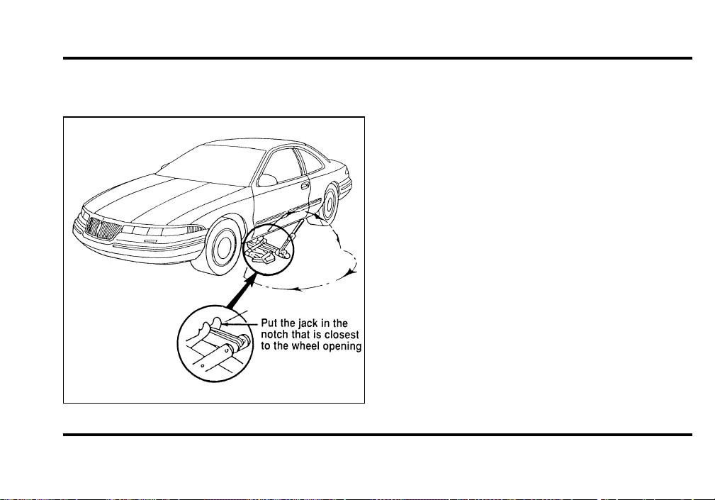
207
NOTE: Never use the differential housing as a lift
point.
The slot for the jack
2. Turn the jack handle clockwise until the wheel
clears the ground. Remove the wheel lug nuts.
3. Replace the flat tire with the spare tire, making
sure that the air valve stem is facing outward.
4. Reinstall the lug nuts, tightening until the
wheel is snug against the hub. The beveled
edges on the lug nuts face inward. Do not fully
tighten the lug nuts until you lower the
vehicle. If you do, you could force the vehicle
off the jack.
5. Lower the vehicle by turning the jack handle
counterclockwise.
6. Remove the jack and fully tighten the lug nuts
in the order shown in the following illustration.
As soon as possible, have your dealer or a
qualified service technician check the lug nuts
for proper torque specifications.
File:10fner8.ex
Update:Thu Jun 20 14:27:22 1996
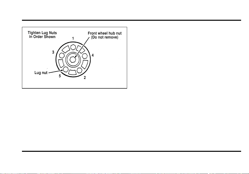
208
The lug nuts on the wheel
7. Place any ornaments in the trunk.
8. Put the tire, jack, and wrench away. Make sure
the jack is securely fastened so it does not
rattle when you drive.
9. Unblock the wheels.
10. Turn on the air suspension switch.
After replacing a flat tire with the temporary spare
tire, the flat tire can be secured in the trunk tub by
placing the “J” hook through a lug nut hole in the
wheel with the tire and wheel lying at an angle.
Anti-Theft Wheel Lug Nuts
(If equipped)
If your vehicle has this option, one of the lug nuts
on each wheel locks and must be unlocked with a
special key. The key and registration card are
attached to the lug wrench and stored with the
spare tire. If you lose the key, send the registration
card to the manufacturer (not the dealer) to get a
replacement key.
NOTE: If entire lug wrench/lug nut key assembly
is lost, see your nearest Ford or Lincoln-Mercury
dealer who has access to a master set of keys.
NOTE: DO NOT USE A POWER IMPACT
WRENCH ON THE LUG NUT KEY.
File:10fner8.ex
Update:Thu Jun 20 14:27:22 1996
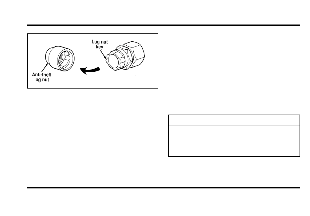
209
Theanti-theftlugnutandkey
Removingtheanti-theftlugnut
Insertthekeyoverthelockinglugnut.Makesure
thatyouholdthekeysquaretothelugnut.Ifyou
holdthekeyonanangle,youmaydamagethekey
andthelugnut.
Placethelugnutwrenchoverthelugnutkeyand
applypressureonthekeywiththewrench.Turn
thewrenchinacounterclockwisedirectionto
removethelugnut.
Reinstallingtheanti-theftlugnut
Insertthekeyoverthelockinglugnut.Placethe
lugnutwrenchoverthelugnutkeyand,while
applyingpressureonthekey,installthelugnut.
Jump-StartingYourVehicle
Yourvehicle’sbatterymaydieifyouleavethe
lightsonoranyelectricalequipmentonafteryou
turntheengineoff.Ifthishappens,youmaybe
abletojump-startyourvehiclewithabooster
battery.
WARNING
Thegasesaroundthebatterycan
explodeifexposedtoflames,sparks,or
litcigarettes.Anexplosioncouldresult
ininjuryorvehicledamage.
File:10fner8.ex
Update:Thu Jun 20 14:27:22 1996
210
WARNING
Toprotectyourselfwhencharginga
battery,alwaysshieldyourfaceand
eyes.Makesurethatyoucanbreathe
freshair.
WARNING
Applyingtoomuchpressureonthe
endswhenliftingabatterycouldcause
acidtospill.Liftthebatterywitha
carrierorwithyourhandsonthe
oppositecorners.
WARNING
Batteriescontainsulfuricacidwhich
burnsskin,eyes,andclothing.
Iftheacidtouchessomeone’sskin,eyes,or
clothing,immediatelyflushtheareawithwaterfor
atleast15minutes.Ifsomeoneswallowstheacid,
havehimorherdrinklotsofmilkorwaterfirst,
thenMilkofMagnesia,abeatenegg,orvegetable
oil.Calladoctorimmediately.
Toavoiddamagingyourvehicleoryourbattery,
andtoavoidinjurytoyourself,followthese
directionsforpreparingyourvehicletojump-start
andconnectingthejumpercablesintheorderthey
aregiven.Ifindoubt,callforroadservice.
PreparingYourVehicle
1. Yourvehiclehasa12-voltstartingsystem,so
youneedtousea12-voltjumpersystem.You
willdamageyourstartingmotor,ignition
system,andotherelectricalpartsifyouconnect
themtoa24-voltpowersupply(eithertwo
12-voltbatteriesinseriesora24-voltgenerator
set).
File:10fner8.ex
Update:Thu Jun 20 14:27:22 1996

211
2. Do not disconnect the battery of the disabled
vehicle. You could damage the vehicle’s
electrical system.
3. Park the booster vehicle close to the hood of
the disabled vehicle. Make sure the vehicles
do not touch each other. Set the parking
brake on both vehicles and stay clear of the
engine cooling fan and other moving parts.
4. Check all battery terminals and remove any
excessive corrosion before you attach the
jumper cables.
5. Turn on the heater fan in both vehicles. Press
the DEFROST button. Turn off all other
switches and gauges.
Connecting the jumper cables
1. Connect one end of the first jumper cable to
the positive (+) terminal of the discharged
battery. (You can connect either jumper cable
to the positive (+) terminal, as long as you use
the same cable for both positive terminals.)
Most jumper cables have a red cable and a
black cable. The red cable is generally used for
the positive terminals and the black for the
negative ones.
2. Connect the other end of the first cable to the
positive (+) terminal of the booster battery.
3. Connect one end of the second cable to the
negative (s) terminal of the booster battery —
NOT to the discharged battery.
4. Connect the other end of the second cable to a
good metallic surface on the engine or frame of
the disabled vehicle.
File:10fner8.ex
Update:Thu Jun 20 14:27:22 1996

212
WARNING
Donotconnecttheendofthesecond
cabletothenegative(s)terminalofthe
batterytobejumped.Asparkmay
causeanexplosionofthegasesthat
surroundthebattery.
Jump-Starting
1. Makesurethatthejumpercablesarenotin
thewayofmovingengineparts,thenstartthe
boostervehicle.Runtheengineatamoderate
speed.
2. Letthedischargedbatterychargeforafew
minutesandthenstartthedisabledvehicle.It
maytakeacoupleoftriesbeforethevehicle
starts.Ifthevehicledoesnotstartafterseveral
attempts,theremaybeadifferentproblem.
3. Whenbothvehiclesarerunning,letthemidle
forafewminutestochargethedischarged
battery.
Removingjumpercables
1. Alwaysremovethejumpercablesinthe
reverseorder.Removethenegative(s)end
ofthejumpercablefromthemetallicsurface
ontheengineorframeofthedisabledvehicle.
2. Removethenegative(s)cablefromthe
boosterbattery.
3. Removethepositive(+)cablefromthebooster
battery.
4. Removetheotherendofthepositive(+)cable
fromthedischargedbattery.
File:10fner8.ex
Update:Thu Jun 20 14:27:22 1996
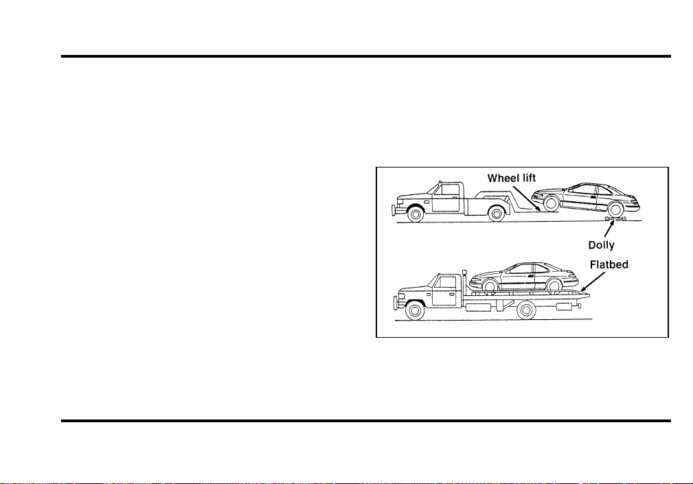
213
After the vehicle is started, let it idle for a while to
let the engine “relearn” its idle conditions. Drive it
around for a while with all electrical accessories
turned off to let the battery recharge. Driveability
may be deteriorated slightly until all drive modes
are “relearned.” You may need to use a battery
charger to fully recharge the battery.
If you need to replace your battery, see Battery in
the Maintenance and Care chapter.
Towing Your Vehicle
If you need to have your vehicle towed, contact a
professional towing service or, if you are a member,
your roadside assistance center. Typical towing
options include wheel lift towing or flat bed towing.
Front towing
File:10fner8.ex
Update:Thu Jun 20 14:27:22 1996
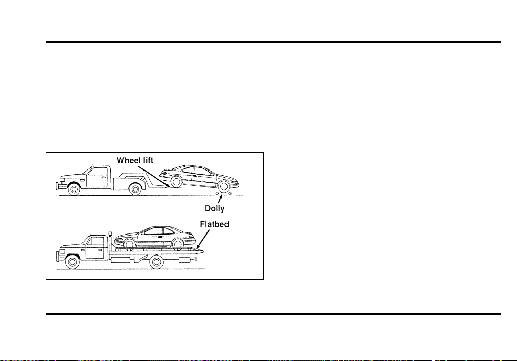
214
DO NOT TOW WITH SLINGBELT EQUIPMENT.
Ford Motor Company has not developed or
approved a T-hook sling-type procedure. Use wheel
lift or flatbed equipment. When towing your Mark
VIII with wheel lift equipment, be sure dollies are
in place under the trailing wheels if the air
suspension is deflated to prevent damage to the air
deflector.
Rear towing
When calling for a tow truck, tell the operator what
kind of vehicle you have. A towing manual is
available from Ford Motor Company for all
authorized tow truck operators. Have your tow
truck driver refer to this manual for the proper
hook-up and towing procedures for your vehicle.
File:10fner8.ex
Update:Thu Jun 20 14:27:22 1996

215
Maintenance and Care
Service Made Easy
Ford has two goals for servicing your vehicle.
1. When we can, we design parts that do not
need to be serviced.
2. We want to make servicing your vehicle as
easy as possible. To help you:
❑
We highlight do-it-yourself items in yellow in
the engine compartment so that you can find
them easily.
❑
When possible, we design parts that can be
replaced without tools.
❑
We give you a Maintenance Schedule that
makes tracking routine service for your vehicle
easy. The maintenance schedule is located in
the Maintenance Schedule booklet.
This chapter tells you about the basic parts that you
need to check and service regularly.
If your vehicle needs professional servicing, your
dealership can provide the parts and service
required. Check your Warranty Information Booklet
to find out which parts and services are covered.
Also see the Customer Assistance chapter of this
Owner Guide.
Ford Motor Company recommends that the Owner
Maintenance Checks listed in the Maintenance
Schedule booklet be performed for the proper
operation of your vehicle. In addition to the
conditions listed in the Owner Maintenance
Checklist, be alert for any unusual noise, vibration,
or other indication that your vehicle may need
service. If you do notice something unusual, see
that your vehicle is serviced promptly.
File:11fnmc8.ex
Update:Thu Jun 20 14:28:32 1996

216
Use only recommended fuels, lubricants, fluids, and
service parts conforming to Ford specifications.
Motorcraft parts are designed and built to provide
the best performance in your vehicle. Using these
parts for replacement is your assurance that
Ford-built quality stays in your vehicle.
NOTE: Always dispose of used automotive fluids in
a responsible manner. Follow your community’s
standards for disposing of these types of fluids. Call
your local recycling center to find out about
recycling automotive fluids.
Accident Damage
Should your vehicle suffer accident damage
requiring new sheet metal or plastic replacement
parts, be sure your repair shop uses only genuine
Ford replacement parts.
While imitation body parts may appear similar to
genuine Ford parts on the surface, differences in
quality become obvious when both are subjected to
standard Ford quality tests.
Ford tests indicate that you should be concerned
with the quality of the fit and finish, corrosion
resistance and structural integrity of these imitation
replacement parts, and how their use will affect
your warranty.
How Can You Protect Yourself?
Before any repair work begins, tell your adjuster
that you want your vehicle repaired using only
genuine Ford body parts. If the adjuster refuses,
contact your insurance agent for help. If your agent
and your insurance company refuse to repair your
vehicle with original factory parts, you should
contact your state insurance commissioner, the
National Highway Traffic Safety Administration or a
local consumer protection agency.
In Canada, contact provincial insurance
commissioners, Transport Canada or local consumer
protection groups.
File:11fnmc8.ex
Update:Thu Jun 20 14:28:32 1996
217
PrecautionsWhenServicingYour
Vehicle
Beespeciallycarefulwheninspectingorservicing
yourvehicle.Herearesomegeneralprecautionsfor
yoursafety:
❑
Donotworkonahotengine.Theengine
coolingfanmaycomeonunexpectedly.Always
turntheengineoffandletitcool.
WARNING
Thecoolingfanisautomaticandmay
comeonatanytime.Alwaysdisconnect
thenegativeterminalofthebattery
beforeworkingnearthefan.
❑
Ifyoumustworkwiththeenginerunning,
avoidwearinglooseclothingorjewelrythat
couldgetcaughtinmovingparts.Take
appropriateprecautionswithlonghair.
❑
Donotworkonavehicleinanenclosedspace
withtheenginerunning,unlessyouaresure
youhaveenoughventilation.
❑
Nevergetunderavehiclewhileitissupported
byajackonly.Ifyoumustworkundera
vehicle,usesafetystands.
❑
Keepalllitcigarettesandothersmoking
materialsawayfromthebatteryandall
fuel-relatedparts.
Ifyoudisconnectthebattery,theenginemust
“relearn”itsidleconditionsbeforeyourvehiclewill
driveproperly.Tofindouthowtheenginedoes
this,seeBatteryinthischapter.
Workingwiththeengineoff:
1. Settheparkingbrakefullyandmakesurethat
thegearshiftissecurelylatchedinP(Park).
2. Removethekeyfromtheignitionafteryou
turntheengineoff.
File:11fnmc8.ex
Update:Thu Jun 20 14:28:32 1996
218
3. Blockthewheels.Thiswillpreventyour
vehiclefrommovingunexpectedly.
Workingwiththeengineon:
1. Settheparkingbrakefullyandmakesurethat
thegearshiftissecurelylatchedinP(Park).
2. Blockthewheels.Thiswillpreventyour
vehiclefrommovingunexpectedly.
WARNING
Donotstartyourenginewiththeair
cleanerremovedanddonotremoveit
whiletheengineisrunning.
WARNING
Thecoolingfanisautomaticandmay
comeonatanytime.Alwaysdisconnect
thenegativeterminalofthebattery
beforeworkingnearthefan.
Ifthebatteryisdisconnected,thecomputermust
relearnitsidlecontrol.SeeBatteryintheIndex.
File:11fnmc8.ex
Update:Thu Jun 20 14:28:32 1996
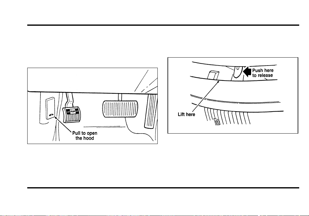
219
Opening the Hood
1. Inside the vehicle, pull the hood release handle
located under the bottom left corner of the
instrument panel.
The hood release under the instrument panel
2. Go to the front of the vehicle and release the
auxiliary latch that is located under the hood at
the center of the vehicle.
The auxiliary latch under the front edge of the
hood
3. Lift the hood until the counterbalanced hinges
hold it open.
File:11fnmc8.ex
Update:Thu Jun 20 14:28:32 1996

220
Whenever you close the hood, latch it securely.
NOTE: Apply lubricant to the hood latch at
six-month intervals to maintain smooth and
trouble-free operation.
NOTE: Read and understand Precautions When
Servicing Your Vehicle at the beginning of this
chapter before opening the hood.
If the battery is disconnected, the computer must
relearn its idle control. See Battery in the Index.
Engine Compartment
Your vehicle has a 4.6 liter 4V SFI engine. The
following page shows a diagram of where to find
items that you should regularly service.
File:11fnmc8.ex
Update:Thu Jun 20 14:28:32 1996
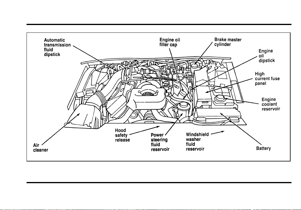
221
A 4.6 Liter 4V SFI engine
File:11fnmc8.ex
Update:Thu Jun 20 14:28:32 1996
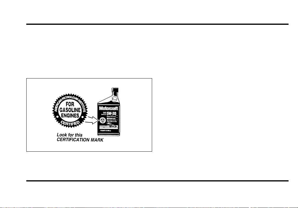
222
Engine Oil Recommendations
We recommend using Motorcraft oil or an
equivalent oil meeting Ford Specification
WSS-M2C153-F and displaying the American
Petroleum Institute CERTIFICATION MARK on the
front of the container.
The API Certification Mark
Never use:
❑
“Non-Detergent” oils
❑
Oils labeled API SA, SB, SC, SD, SE, SF or SG
❑
Additional engine oil additives, oil treatments or
engine treatments
Engine oils with an SAE 5W-30 viscosity are
PREFERRED for your vehicle. They provide the
best engine performance, fuel economy and engine
protection for all climates down to -15˚F (-25˚C).
Synthetic engine oils which are CERTIFIED and of
the preferred viscosity may be used in your engine.
The engine oil and oil filter must still be changed
according to the maintenance schedule.
File:11fnmc8.ex
Update:Thu Jun 20 14:28:32 1996
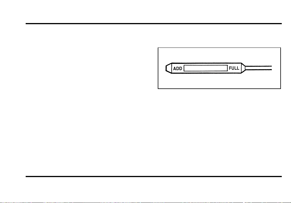
223
Checking and Adding Engine Oil
Since the proper amount of engine oil is important
for safe engine operation, check the oil using the
dipstick each time you put fuel in your vehicle.
Remember the engine must be off, the oil must be
warm and the vehicle must be parked on level
ground.
Checking the engine oil level:
1. Turn the engine off after it has warmed up and
allow a few minutes for the engine oil to drain
back into the oil pan.
2. Set the parking brake, making sure the gearshift
is securely latched in P (Park).
3. Open the hood. Protect yourself from engine
heat.
4. Locate the engine oil dipstick (highlighted in
yellow) and carefully pull it out of the engine.
5. Wipe the dipstick clean and put it back into
position, making sure it is fully seated.
Engine oil dipstick
6. Carefully, pull the dipstick out again and read
it. If the oil level is below the MIN line, add a
half quart of engine oil as necessary. If the oil
level is above the MAX line, engine damage or
high oil consumption may occur and some oil
must be removed from the engine.
7. Put the dipstick back in and make sure it is
fully seated.
File:11fnmc8.ex
Update:Thu Jun 20 14:28:32 1996

224
It may be necessary to add some oil between oil
changes. Make sure you use a CERTIFIED engine
oil of the preferred viscosity. Your vehicle’s
warranty coverage may not apply if engine damage
is caused by the use of improper engine oil.
Add engine oil through the oil filler cap highlighted
in yellow. To add oil, remove the filler cap and use
a funnel to pour oil into the opening. Be careful not
to overfill the engine. Recheck the oil level after
you finish adding oil.
Changing the Engine Oil and the Oil
Filter
Your vehicle has an OIL LIFE LEFT function as part
of the Vehicle Message Center (M/C). This device
displays the percent of useful engine oil life left and
when an oil change is required. Use of a
CERTIFIED oil of the preferred viscosity is required
for this device to work properly. Change your
engine oil and oil filter when the message center
displays CHANGE OIL SOON or OIL CHANGE
REQUIRED. If the Message Center malfunctions,
you may determine your oil change interval based
on the following guidelines.
Change your engine oil and oil filter according to
these mileage and time requirements, whichever
occurs first.
File:11fnmc8.ex
Update:Thu Jun 20 14:28:32 1996
225
RefertotheMaintenanceSchedulebookletfor
additionalinformation.
TheVehicleMessageCentermaybemanuallyreset
bydepressingtheOilChangeResetSwitchforfive
seconds.
Protectyourskinbywashingwithsoapandwater.
WARNING
ContinuouscontactwithUSEDmotor
oilhascausedcancerinlaboratory
mice.
BrakeFluid
Undernormalcircumstances,yourvehicleshould
notuseupbrakefluidrapidly.However,expectthe
levelofthebrakefluidtoslowlyfallasyouput
moremileageonyourvehicleandthebrakelinings
wear.
Youshouldcheckthebrakefluidatevery
scheduledengineoilchange,butbesuretocheck
itatleastonceayear.Youcandothisbylooking
atthefluidlevelintheplasticreservoironthe
mastercylinder.(SeeTheEngineTypeinthis
chaptertolocatethemastercylinder.)Thefluid
levelshouldbebetweentheMAXandMINmark.
WARNING
Brakefluidistoxic.
Ifbrakefluidcontactseyes,flusheyeswithrunning
waterfor15minutes.Getmedicalattentionif
irritationpersists.Iftakeninternally,drinkwater
andinducevomiting.Getmedicalattention
immediately.
Ifthefluidislow,carefullycleanandremovethe
capfromthereservoir.Fillthereservoirtothe
MAXlinewithFordHighPerformanceDOT3
BrakeFluidC6AZ-19542-ABorequivalentDOT3
fluidmeetingFordspecificationESA-M6C25-A.
File:11fnmc8.ex
Update:Thu Jun 20 14:28:32 1996
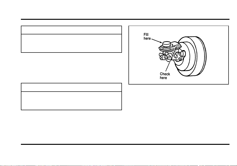
226
WARNING
Ifyouuseabrakefluidthatisnot
DOT3,youwillcausepermanent
damagetoyourbrakes.
DonotfillthereservoirabovetheMAXline.
Ifyoufindthatthefluidlevelisexcessivelylow—
belowtheseamorridgeontheoutsideofthe
plasticreservoir—havethebrakesysteminspected.
WARNING
Donotletthereservoirforthemaster
cylinderrundry.Thismaycausethe
brakestofail.
Theanti-lockbrakesystemfluidreservoir
File:11fnmc8.ex
Update:Thu Jun 20 14:28:32 1996
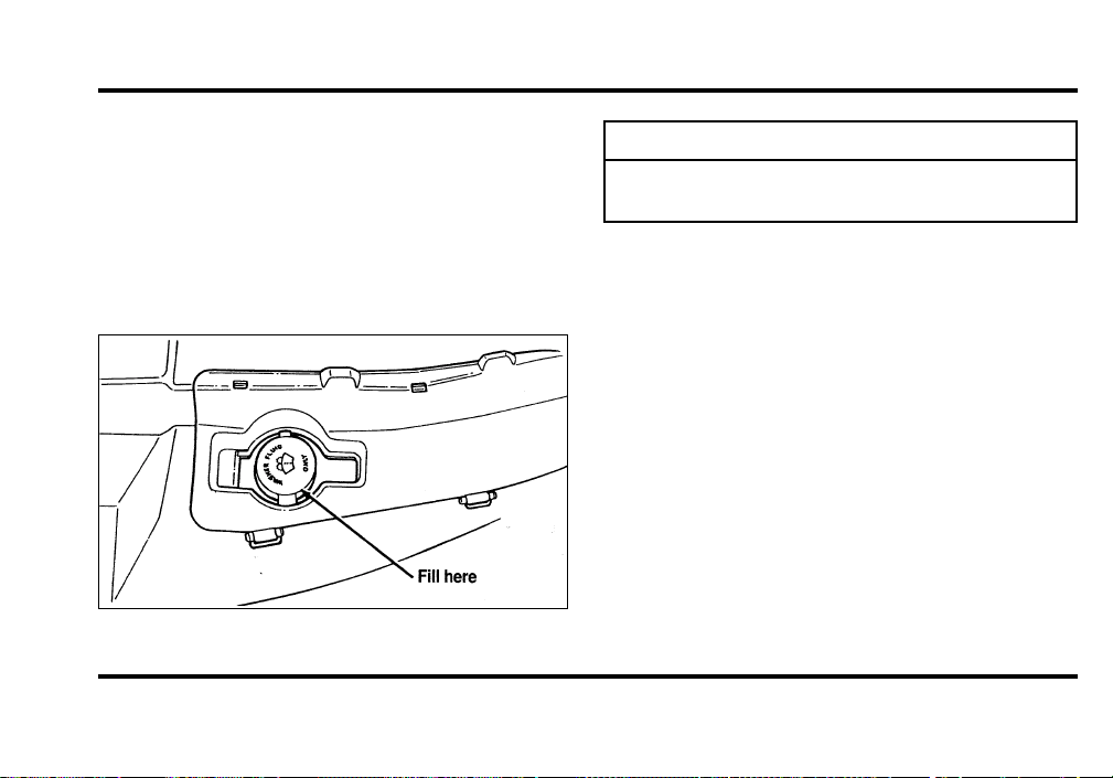
227
WindshieldWasherFluid
WasherFluid
Checkthelevelofthewindshieldwasherfluid
periodically,orwhenthewarningmessageindicates
lowfluid.Thereservoirforwasherfluidislocated
infrontoftheenginecompartmentbehinddriver’s
sideheadlamp.
Thereservoirforthewindshieldwasherfluid
WARNING
Donotputwindshieldwasherfluidin
thecontainerfortheenginecoolant.
Usespeciallyformulatedwindshieldwasherfluid
ratherthanplainwater,becausespecially
formulatedwasherfluidscontainadditivesthat
dissolveroadgrime.Forsafetyreasons,washer
fluidscontaininganappropriateantifreezesuchas
methanolshouldbeusedinfreezingweather
(temperaturesbelow32˚F[0˚C]).Stateorlocal
regulationsonVolatileOrganicCompounds(VOCs)
mayrestrictuseofthemostcommonantifreeze,
methanol.Washerfluidscontainingnon-methanol
antifreezeagentsshouldbeusedonlyifthey
providecoldweatherprotectionwithoutdamaging
thevehicle’spaintfinish,wiperblades,and
windshieldwashersystem.
File:11fnmc8.ex
Update:Thu Jun 20 14:28:32 1996
228
EngineCoolant
CheckingtheEngineCoolant
NOTE:Besuretoreadandunderstand
PrecautionsWhenServicingYourVehicleatthe
beginningofthischapter.
WARNING
Thecoolingfanisautomaticandmay
comeonatanytime.Alwaysdisconnect
thenegativeterminalofthebattery
beforeworkingnearthefan.
Yourvehicle’scoolantprotectsyourenginefrom
overheatinginthesummerandfromfreezinginthe
winter.Checkthelevelofthecoolantatleastonce
amonth.Simplylookattheenginecoolant
reservoirlocatedintheenginecompartment.To
locatethereservoir,seethediagramofyour
vehicle’sengineunderEngineType,inthischapter.
Checktheenginecoolantlevelintheengine
coolantreservoiratleastonceamonthusingthe
followingguidelines.
Whenyourvehicle’sengineiscool,thecoolant
levelintheenginecoolantreservoirshouldbeat
theCOLDFILLlevelmarkedonthecoolant
reservoir.Ifthelevelisbelowthecoldfilllevel,
coolantmayneedtobeadded.
Thecoolantadditivesalsoprotecttheentirecooling
systemfrominternalpassagewaycorrosionand
theseadditiveslubricatethewaterpump.The
coolantshouldbeservicedasnotedinthe
MaintenanceSchedulebooklet.
File:11fnmc8.ex
Update:Thu Jun 20 14:28:32 1996
229
AddingEngineCoolant
WARNING
Donotputenginecoolantinthe
containerforthewindshieldwasher
fluid.
Ifsprayedonthewindshield,enginecoolantcould
makeitdifficulttoseethroughthewindshield.
Whentheengineiscool,adda50/50mixtureof
enginecoolantandwatertotheenginecoolant
recoveryreservoir—DONOTADDDIRECTLYTO
THERADIATOR.Addstraightwateronlyinan
emergency,butyoushouldreplaceitwitha50/50
mixtureofcoolantanddistilledwaterassoonas
possible.
Checkthecoolantlevelinthecoolantrecovery
reservoirthenextfewtimesyoudrivethevehicle.
Ifnecessary,addenoughofa50/50mixtureof
coolantandwatertobringtheliquidleveltothe
filllineonthereservoir.
WARNING
Neverremovethecoolantrecoverycap
whiletheengineisrunningorhot.
Ifyoumustremovethecoolantrecoverycap,
followthesestepstoavoidpersonalinjury:
1. Beforeyouremovethecap,turntheengineoff
andletitcool.
2. Whentheengineiscool,wrapathickcloth
aroundthecap.Slowlyturncap
counterclockwisetothefirststop.
3. Stepbackwhilethepressurereleases.
4. Whenyouaresurethatallthepressurehas
beenreleased,usetheclothtopressthecap
down,turnitcounterclockwise,andremoveit.
File:11fnmc8.ex
Update:Thu Jun 20 14:28:32 1996

230
Use Ford Premium Cooling System Fluid
E2FZ-19549-AA (in Canada, Motorcraft CXC-8-B) or
an equivalent premium engine coolant that meets
Ford specification ESE-M97B44-A. Ford Premium
Engine Coolant is an optimized formula that will
protect all metals and rubber elastomers used in
Ford cooling systems for 4 years or 50,000 miles
(80,000 km).
Do not use alcohol or methanol antifreeze or any
engine coolants mixed with alcohol or methanol
antifreeze. Do not use supplemental coolant
additives in your vehicle. These additives may harm
your engine cooling system. The use of an improper
coolant may void the warranty of your vehicle’s
engine cooling system.
Recycled engine coolant
Ford Motor Company recommends that Ford and
Lincoln-Mercury dealers use recycled engine coolant
produced by Ford-approved processes. Not all
coolant recycling processes produce coolant which
meets Ford specification ESE-M97B44-A, and use of
such coolant may harm engine and cooling system
components.
Always dispose of used automotive fluids in a
responsible manner. Follow your community’s
regulations and standards for recycling and disposing
of automotive fluids.
Coolant refill capacity
To find out how much fluid your vehicle’s cooling
system can hold, refer to Refill capacities in the
Capacities and specifications chapter.
Have your dealer check the engine cooling system
for leaks if you have to add more than a quart
(liter) of engine coolant per month.
Severe winter climate
If you drive in extremely cold climates (less than
-34˚F [-36˚C]), it may be necessary to increase the
coolant concentration above 50%. Refer to the chart
on the coolant container to ensure the coolant
File:11fnmc8.ex
Update:Thu Jun 20 14:28:32 1996

231
concentration in your vehicle is such that the
coolant will not freeze at the temperature level in
which you drive during winter months. Never
increase the engine coolant concentration above
60%. Leave a 50/50 mixture of engine coolant and
water in your vehicle year-round in non-extreme
climates.
Proper procedures for a complete coolant drain and
flush of the cooling system can be found in the Car
Service Manual. Following these recommended
procedures will ensure that the specified coolant
level and a 50/50 or appropriate mixture of coolant
and water is maintained.
Engine Coolant Refill Procedure
When the entire cooling system is drained and
refilled, the following procedure should be used to
ensure a complete fill:
NOTE: It is imperative the following procedure be
adhered to. Failure to do so could result in damage
to your engine.
❑
Remove coolant reservoir pressure cap.
❑
Remove the engine coolant outlet tube fill plug
on the engine.
❑
With the engine off and cool, add a 50/50
mixture of recommended cooling system fluid
and water to the coolant outlet tube fill neck
until the reservoir is full.
NOTE: DO NOT FILL COOLANT SYSTEM
THROUGH COOLANT RESERVOIR. COOLANT
WILL NOT ENTER ENGINE, WHICH CAN LEAD
TO ENGINE DAMAGE.
NOTE: Avoid spilling coolant on the front end
accessory drive belt, as this will allow the belt to
slip and become noisy.
❑
Reinstall the pressure cap to the coolant
reservoir.
❑
Continue filling at the engine coolant tube fill
neck slowly while allowing air to escape.
File:11fnmc8.ex
Update:Thu Jun 20 14:28:32 1996

232
❑
Reinstall the engine coolant tube fill plug when
the system is full.
❑
Select maximum heater temperature and fan
speed settings. Position control to discharge air
at A/C vents in instrument panel.
❑
Start engine and allow to idle. While engine is
idling, feel for hot air at A/C vents.
NOTE: IF AIR DISCHARGE REMAINS COOL AND
ENGINE TEMPERATURE GAUGE DOES NOT
MOVE, SHUT ENGINE OFF IMMEDIATELY.
This is an indication of low coolant level and/or air
pockets in coolant system. Allow engine to cool and
repeat the previous steps.
❑
Allow to idle until normal operating temperature
is reached. Hot air should discharge from A/C
vents. The engine temperature gauge should
maintain a stabilized reading in the middle of
the “NORMAL” range and the lower radiator
hose should feel hot to the touch.
❑
Shut off the engine and allow to cool down.
❑
After the engine cools down, recheck the
engine coolant level. Fill reservoir to the
COLD-FULL level as required.
❑
Check for leaks at the draincock, block plug
and vent plug.
❑
Recheck the engine coolant level, using the
recommended procedure, after one or two
occasions of vehicle use. Fill to COLD-FULL
level as required.
File:11fnmc8.ex
Update:Thu Jun 20 14:28:32 1996

233
Power Steering Fluid
Check the level of the power steering fluid at least
twice a year (i.e., every Spring and Fall).
Checking and Adding Power Steering
Fluid
1. Start the engine and let it run until the power
steering fluid reaches normal operating
temperature. The power steering fluid will be at
the right temperature when the engine coolant
temperature gauge in the instrument cluster is
near the center of the NORMAL operating
temperature range.
2. While the engine idles, turn the steering wheel
back and forth several times. Make sure that
the cap assembly is installed at this time.
3. Turn the engine off and check the level on the
power steering reservoir.
4. The fluid level is viewed through the sight
window on the power steering reservoir. If the
power steering fluid is below the middle line,
add fluid in small amounts, continuously
checking the level. Do not overfill.
File:11fnmc8.ex
Update:Thu Jun 20 14:28:32 1996
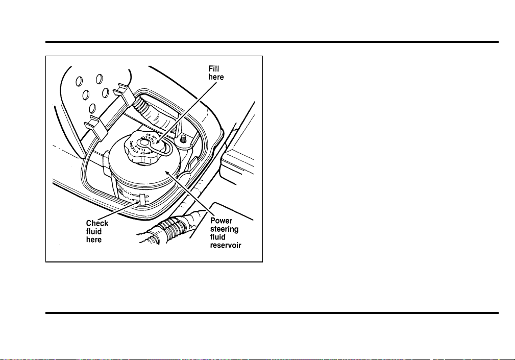
234
Fluid level for power steering
Use only MERCONH ATF power steering fluid.
If the power steering fluid is low, do not drive your
vehicle for a long period of time before adding fluid.
This can damage the power steering pump.
Automatic Transmission Fluid
Under normal circumstances, you do not need to
check the fluid level of the transmission, since your
vehicle does not use up transmission fluid. Refer to
the Maintenance Schedule booklet for replacement
intervals. However, if the transmission is not
working properly — for instance, the transmission
may slip or shift slowly, or you may notice some
sign of fluid leakage — the fluid level should be
checked.
It is preferable to check the transmission fluid level
at normal operating temperature 150˚F-170˚F
(66˚C-77˚C), after approximately 20 miles (30 km)
of driving. However, if necessary, you can check
the fluid level without having to drive 20 miles
(30 km) to obtain a normal operating temperature if
outside temperatures are above 50˚F (10˚C).
File:11fnmc8.ex
Update:Thu Jun 20 14:28:32 1996

235
NOTE: If the vehicle has been operated for an
extended period at high speeds or in city traffic
during hot weather, or pulling a trailer, the vehicle
should be turned off for about 30 minutes to allow
the fluid to cool before checking.
Checking the Automatic Transmission
Fluid
With the vehicle on a level surface and the brake
fully applied, start the engine and move the gear
shift selector through all of the gears allowing
sufficient time for each position to engage. Securely
latch the gear shift selector in the P (Park) position.
Fully set the parking brake and leave the engine
running.
NOTE: Your vehicle should not be driven if the
fluid level does not appear on the dipstick tip and
outside temperatures are above 50˚F (10˚C).
Wipe off the dipstick cap and pull the dipstick out.
Wipe the indicator end clean. Put the dipstick back
into the filler tube and make sure it is fully seated.
Pull the dipstick out and read the fluid level.
When checking fluid at normal operating
temperatures 150˚F-170˚F (66˚C-77˚C), the fluid
level should be within the “HOT” notched area on
the dipstick. When the vehicle has not been driven,
and outside temperatures are above 68˚F (20˚C),
the fluid levels should be between the “HOT”
notch and the tip end of the dipstick.
Adding Automatic Transmission Fluid
Before adding any fluid, be sure that the correct
type will be used. Use only MerconH Fluid, as
shown on handle.
Add fluid in 1/2 pint (250ML) increments through
the filler tube to bring the level to the correct area
on the dipstick. DO NOT OVERFILL. If the level is
above the top hole on the dipstick, excess fluid
should be removed by a qualified technician.
File:11fnmc8.ex
Update:Thu Jun 20 14:28:32 1996
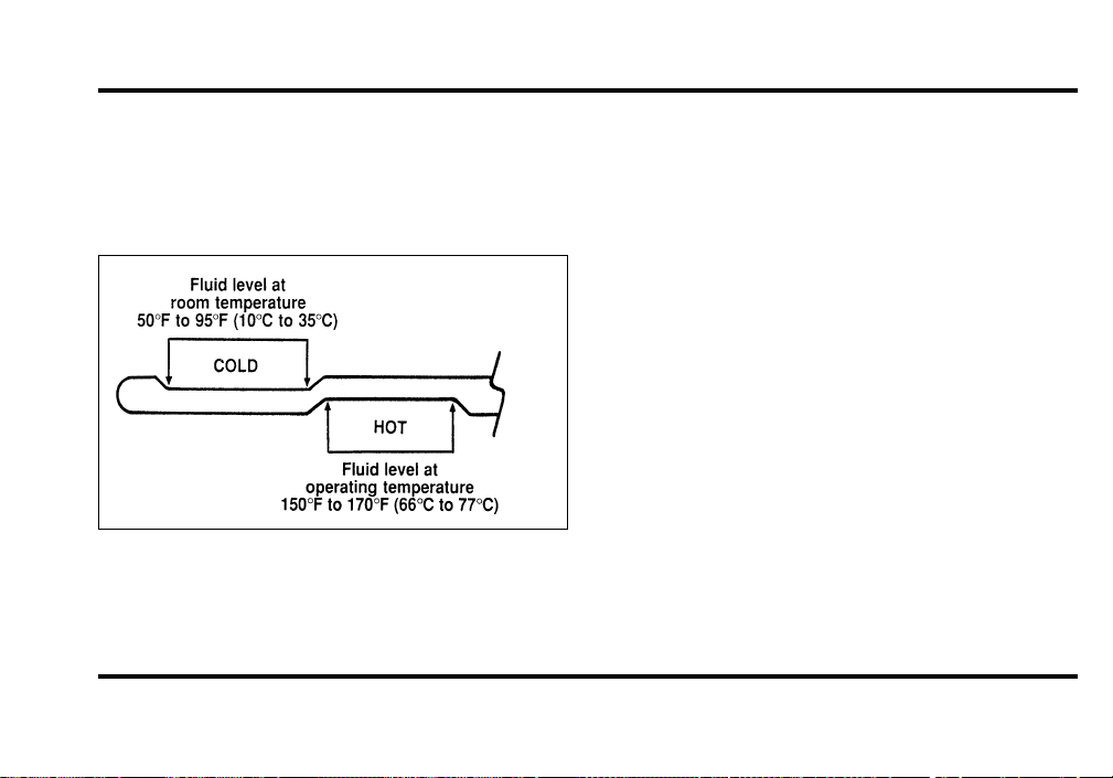
236
NOTE: Always dispose of used automotive fluids in
a responsible manner. Follow your community’s
standards for disposing of these types of fluids. Call
your local recycling center to find out about
recycling automotive fluids.
Automatic transmission dipstick
Battery
Your vehicle may have a Motorcraft
maintenance-free battery. When the original
equipment battery is replaced under warranty it
may be replaced by a low-maintenance battery. See
Motorcraft Parts at the end of this chapter for the
proper replacement battery.
The low-maintenance battery has removable vent
caps for checking the electrolyte level and adding
water. The electrolyte level should be checked at
least every 24 months or 24,000 miles
(40,000 km) in temperatures up to 90˚F (32˚C)
and more often in temperatures above 90˚F (32˚C).
Keep the electrolyte level in each cell up to the
level indicator. Do not overfill.
If the level gets low, refill the battery with distilled
water. If necessary, you can add tap water to the
battery, provided the water is not hard or does not
have a high mineral or alkali content. If the battery
needs water quite often, have the charging system
checked for a possible malfunction.
File:11fnmc8.ex
Update:Thu Jun 20 14:28:32 1996

237
Help Us Protect Our Environment
Ford Motor Company strongly recommends that
used lead-acid batteries be returned to an
authorized recycling facility for disposal.
Battery recycling symbol
Because your vehicle’s engine is electronically
controlled by a computer, some control conditions
are maintained by power from the battery. If you
ever disconnect the battery or install a new battery,
you must allow the computer to “relearn” its idle
conditions before your vehicle will drive properly.
To let the engine do this, put the gearshift in P
(Park), turn off all the accessories, and start the
vehicle. Let the engine idle for at least one minute.
(Engine must be warm in order to “learn.”) Also,
allow approximately 10 miles (16 km) of stop and
go traffic for your vehicle’s engine to completely
“relearn” its idle.
If you do not let the engine relearn its idle, the idle
quality of your vehicle may be adversely affected
until the idle is relearned. Your vehicle will
eventually relearn its idle while you drive it, but it
takes much longer than if you use the previous
procedure.
Wiper Blades
Check the windshield wiper blades at least twice a
year. Also check them whenever they seem less
effective than usual. Substances such as tree sap
and some hot wax treatments used by commercial
car washes reduce the effectiveness of wiper blades.
If the blades do not wipe properly, clean both the
windshield and the wiper blades. Use undiluted
windshield washer solution or a mild detergent.
File:11fnmc8.ex
Update:Thu Jun 20 14:28:32 1996
238
Rinsethoroughlywithclearwater.Donotusefuel,
kerosene,paintthinner,orothersolventstoclean
yourwiperblades.Thesewilldamageyourblades.
Tomakereachingthewiperbladeseasy,simply
turntheignitiontotheACCpositionandturnyour
wiperson.Waitforthemtoreachavertical
positionandturntheignitiontotheOFFposition.
Donotmovethewipersmanually.Manually
movingthewipersacrossthewindshieldmay
damagethem.
Wiperbladereplacement
Ifthewiperbladesstilldonotworkproperlyafter
youcleanthem,youmayneedtoreplacethewiper
bladeassemblyorthebladeelement.When
replacingthewiperbladeassembly,bladerefill,or
wiperarmalwaysuseaMotorcraftpartor
equivalent.Toreplacetheblades,followthe
instructionsthatcomewiththem.
Tires
❑
Useanaccuratetirepressuregauge.
❑
Checkthetirepressurewhentiresarecold,
afterthevehiclehasbeenparkedforatleast
onehourorhasbeendrivenlessthan3miles
(5km).
❑
Adjusttirepressuretorecommended
specificationsfoundontheSafetyCompliance
CertificationLabel.
WARNING
Improperlyinflatedtirescanaffect
vehiclehandlingandcanfailsuddenly,
possiblyresultinginlossofvehicle
control.
File:11fnmc8.ex
Update:Thu Jun 20 14:28:32 1996
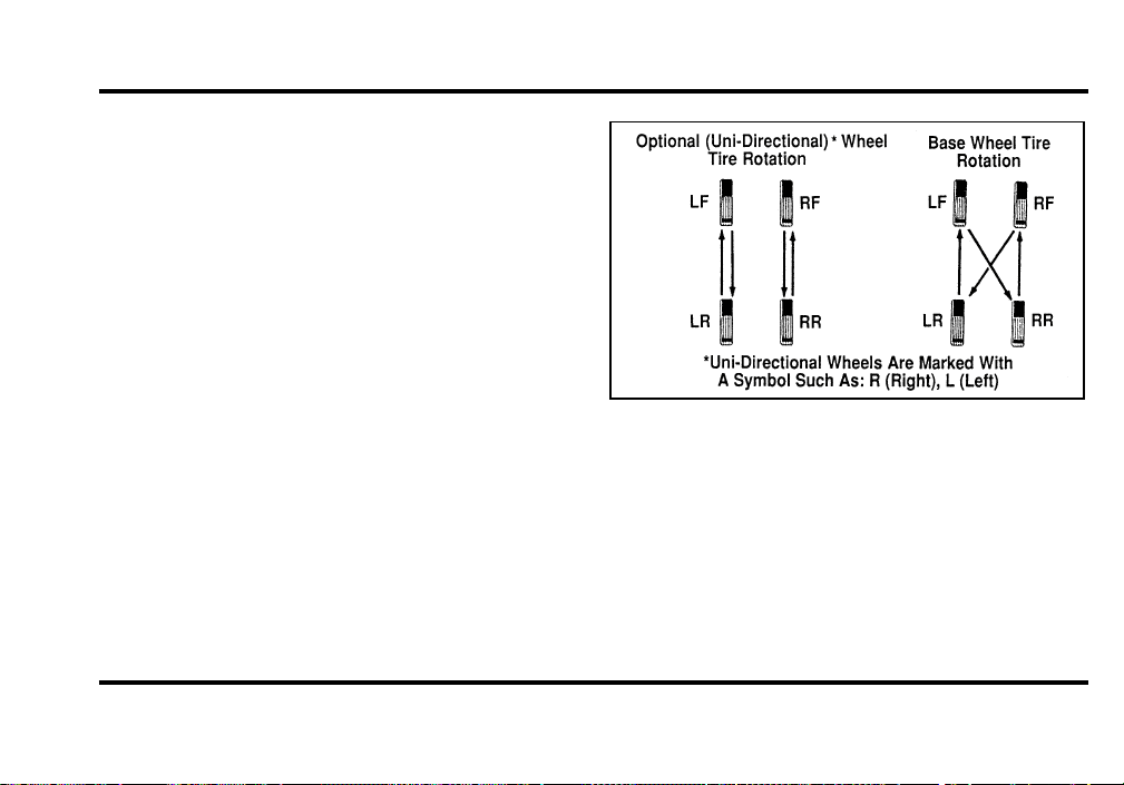
239
Tire Rotation
Because your vehicle’s front and rear tires perform
different jobs, they often wear differently. To make
sure your tires wear evenly and last longer, rotate
them as indicated in the following diagram.
Do not include the spare tire as part of your
rotation.
For tire rotation intervals, see the Maintenance
Schedule. If you notice that the tires wear
unevenly, have them checked.
Rotating the tires
File:11fnmc8.ex
Update:Thu Jun 20 14:28:32 1996
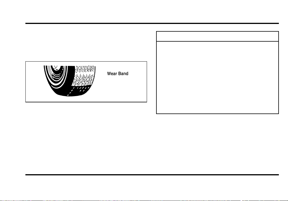
240
ReplacingtheTires
Replaceanytiresthatshowwearbands.Whenyour
tireshowsawearband,ithasonly1/16inch(2
mm)oftreadleft.
Aworn-outtire
Becauseyourvehicle’stiresmaywearunevenly,
youmayneedtoreplacethembeforeawearband
appearsacrosstheentiretread.
WARNING
Whenreplacingfullsizetires,never
mixradial,bias-belted,orbias-type
tires.Useonlythetiresizesthatare
listedonthetirepressuredecal.Make
surethatalltiresarethesamesize,
speedrating,andload-carryingcapacity.
Useonlythetirecombinations
recommendedonthedecal.Ifyoudo
notfollowtheseprecautions,your
vehiclemaynotdriveproperlyand
safely.
Tiresthatarelargerorsmallerthanyourvehicle’s
originaltiresmayalsoaffecttheaccuracyofyour
speedometer.
File:11fnmc8.ex
Update:Thu Jun 20 14:28:32 1996

241
Information About Tire Quality Grades
New vehicles are fitted with tires that have their
Tire Quality Grade (described below) molded into
the tire’s sidewall. These Tire Quality Grades are
determined by standards that the United States
Department of Transportation has set.
Tire Quality Grades apply to new pneumatic tires
for use on passenger cars. They do not apply to
deep tread, winter-type snow tires, space-saver or
temporary use spare tires, tires with nominal rim
diameters of 10 to 12 inches or limited production
tires as defined in Title 49 Code of Federal
Regulations Part 575.104(c)(2).
U.S. Department of Transportation — Tire
quality grades: The U.S. Department of
Transportation requires Ford to give you the
following information about tire grades exactly as
the government has written it.
Treadwear
The treadwear grade is a comparative rating based
on the wear rate of the tire when tested under
controlled conditions on a specified government test
course. For example, a tire graded 150 would wear
one and one-half (1 1/2) times as well on the
government course as a tire graded 100. The
relative performance of tires depends upon the
actual conditions of their use, however, and may
depart significantly from the norm due to variations
in driving habits, service practices and differences in
road characteristics and climate.
Traction A B C
The traction grades, from highest to lowest, are A,
B, and C, and they represent the tire’s ability to
stop on wet pavement as measured under controlled
conditions on specified government test surfaces of
asphalt and concrete. A tire marked C may have
poor traction performance.
File:11fnmc8.ex
Update:Thu Jun 20 14:28:32 1996
242
WARNING
Thetractiongradeassignedtothistire
isbasedonbraking(straightahead)
tractiontestsanddoesnotinclude
cornering(turning)traction.
TemperatureABC
ThetemperaturegradesareA(thehighest),B,and
C,representingthetire’sresistancetothe
generationofheatanditsabilitytodissipateheat
whentestedundercontrolledconditionsona
specifiedindoorlaboratorytestwheel.Sustained
hightemperaturecancausethematerialofthetire
todegenerateandreducetirelife,andexcessive
temperaturecanleadtosuddentirefailure.The
gradeCcorrespondstoalevelofperformance
whichallpassengercartiresmustmeetunderthe
FederalMotorVehicleSafetyStandardNo.109.
GradesBandArepresenthigherlevelsof
performanceonthelaboratorytestwheelthanthe
minimumrequiredbylaw.
WARNING
Thetemperaturegradeforthistireis
establishedforatirethatisproperly
inflatedandnotoverloaded.Excessive
speed,underinflation,orexcessive
loading,eitherseparatelyorin
combination,cancauseheatbuildup
andpossibletirefailure.
Snowtires
WARNING
Drivingtoofastforconditionscreates
thepossibilityoflossofvehiclecontrol.
Drivingatveryhighspeedsfor
extendedperiodsoftimemayresultin
damagetovehiclecomponents.
File:11fnmc8.ex
Update:Thu Jun 20 14:28:32 1996
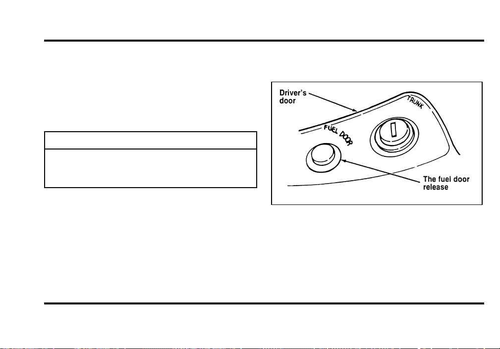
243
Theallweathertreadpatternonyourtireshelps
maintaintractioninrainorsnow.However,to
achievethebesttractioninsnowandice
conditions,youmayneedtousesnowtires.
Topreventbodydamage,donotusesnowchains
onyourMarkVIII.
WARNING
Snowtiresmustbethesamesizeand
gradeasthetiresyoucurrentlyhaveon
yourvehicle.
FillingtheFuelTank
Yourvehicleisequippedwithalockingfueldoor,
openthefueldoorbypressingthereleasebutton
locatedonthedriver’ssidedoor,forwardofthe
armrest.
Thefueldoorisoutsidethecaronthepassenger
sideneartheback.Tofillthefueltank:
Theremotefueldoorrelease
File:11fnmc8.ex
Update:Thu Jun 20 14:28:32 1996
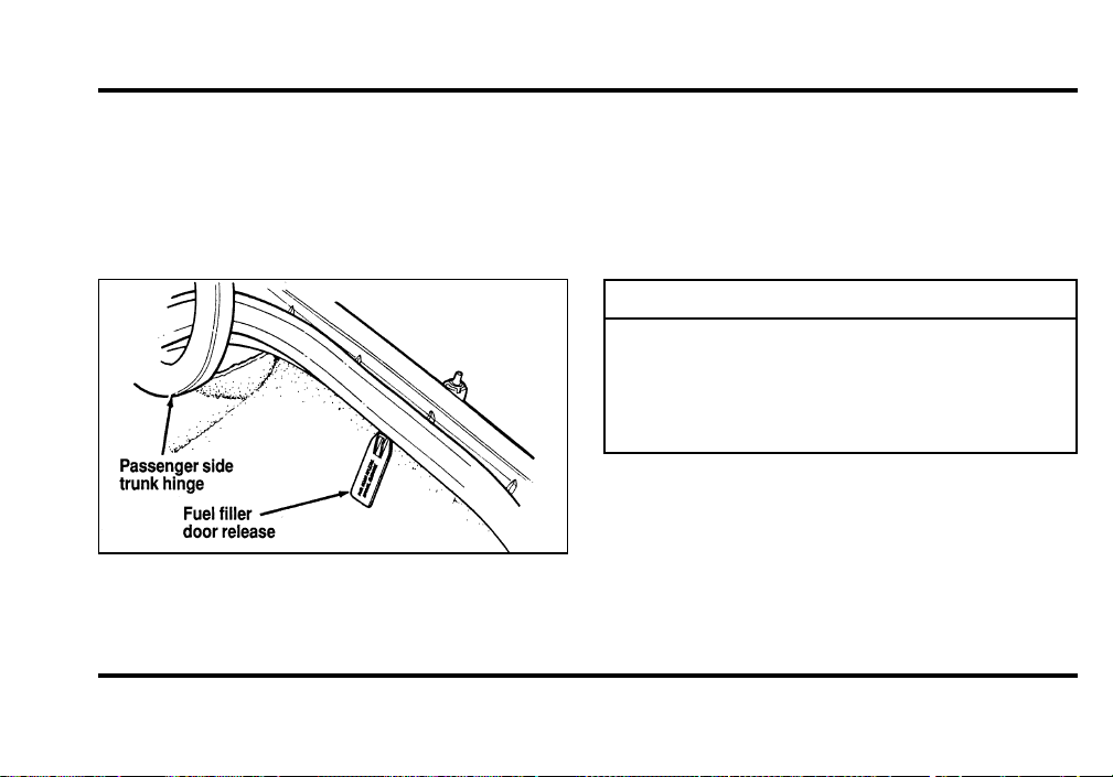
244
Ifthefueldoordoesnotopenwhenyoupushthe
releasebutton,openthetrunkandfindtheoverride
releaseontherightside.Theoverridereleaseisa
handlewhichsaysFUELFILLERDOORRELEASE
MANUALOVERRIDE.Openthefueldoorby
pullingonthehandle.
Thefuelfillerdoormanualrelease—located
insidethetrunk
1. Turntheengineoff.Afteropeningthefuel
door,removethecapcarefullyandslowlyby
pushingitdownandturningit
counterclockwise1/8turnuntilitstops.Pullto
removethecap.Atetherattachesthecapto
thefuelfillerpipe.
WARNING
Thefuelsystemmaybeunderpressure.
Ifthefuelcapisventingvapororif
youhearahissingsound,waituntilit
stopsbeforecompletelyremovingthe
cap.
2. Makesurethatyoupumppremiumunleaded
fuelandputthenozzleallthewayinsidethe
fuelfillerpipe.
NOTE:Ifyouspillanyfuelonthebodyofyour
vehicle,cleanitoffimmediately.Thefuelmaydull
orsoftenthepaintifyoudonotwashitoff.
File:11fnmc8.ex
Update:Thu Jun 20 14:28:32 1996

245
3. Toreplacethefuelcap,alignthetabsonthe
capwiththenotchesonthefillerpipe.Push
downandturnitclockwiseuntilitstops.
4. Pushthefueldoorclosed.
WARNING
Ifyoudonotusetheproperfuelcap,
thepressureinthefueltankcan
damagethefuelsystemorcauseitto
workimproperlyinacollision.
NOTE:Ifyoureplaceyourfuelcapwithan
aftermarketfuelfillercap,thecustomerwarranty
maybevoidforanydamagetothefueltank
and/orfuelsystem.
ChoosingtheRightFuel
UseonlyUNLEADEDFUEL.Theuseofleadedfuel
isprohibitedbylawandcoulddamageyourvehicle.
Yourvehiclewasnotdesignedtousefuel
containingmanganese-basedadditivessuchasMMT.
Additionally,vehiclescertifiedtoCaliforniaemission
standards(indicatedontheunderhoodVehicle
EmissionsControlInformationlabel)aredesignedto
operateonCaliforniareformulatedgasolines.If
Californiareformulatedgasolineisnotavailable
whenyourefuel,yourvehiclecanbeoperatedon
non-Californiafuels.However,eventhoughyour
enginewillperformadequatelyonothergasolines,
theperformanceoftheemissioncontroldevicesand
systemsmaybeadverselyaffected.Repairofdamage
causedbyusingafuelthatyourvehiclewasnot
designedformaynotbecoveredbyyourwarranty.
File:11fnmc8.ex
Update:Thu Jun 20 14:28:32 1996
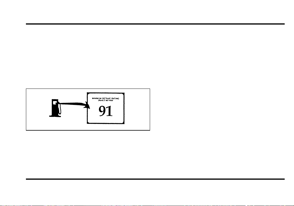
246
Octane recommendation
Your vehicle is designed to use premium gasoline
for optimum performance with an (R+M)/2 octane
rating of 91 or higher. Gasolines with lower octane
ratings can be used, but performance and fuel
economy may decrease. We do not recommend
gasolines labeled as “premium” in high altitude
areas that are sold with octane ratings less than 91.
Typical octane rating label
Do not be concerned if your vehicle sometimes
knocks lightly. However, if it knocks heavily under
most driving conditions on the recommended
octane fuel, see your dealer or a qualified service
technician to prevent any engine damage.
Fuel quality
If you are experiencing starting, rough idle or
hesitation problems try a different brand of fuel. If
the condition persists, see your dealer or a qualified
service technician.
The American Automobile Manufacturers
Association (AAMA) issued a gasoline specification
to provide information on high quality fuels that
optimize the performance of your vehicle. We
recommend the use of gasolines that meet the
AAMA specification if they are available.
It should not be necessary to add any aftermarket
products to your fuel tank if you continue to use a
high-quality fuel.
File:11fnmc8.ex
Update:Thu Jun 20 14:28:32 1996
247
CleanerAir
Fordapprovestheuseofgasolinestoimproveair
quality,includingreformulatedgasolinesthatcontain
oxygenatessuchasamaximumof10%ethanolor
15%MTBE.Thereshouldbenomorethan5%
methanolwithcosolventsandadditivestoprotect
thefuelsystem.
SafetyInformationRelatingto
AutomotiveFuels
WARNING
Automotivefuelscancauseserious
injuryordeathifmisusedor
mishandled.
❑
Turnvehicleoffwhenrefueling.
❑
Donotsmokewhenrefueling.Fuelsare
extremelyflammable.
❑
Donotsiphonanyfuelbymouth.
WARNING
Gasolineorgasolineblendedwith
methanolcancauseblindnessand
possibledeathwhenswallowed.Ifany
fuelisswallowed,callaphysicianor
poisoncontrolcenterimmediately.
❑
Avoidbreathingvaporswhilerefueling.
❑
Iffuelissplashedontheskin,washwithsoap
andwater.
❑
Iffuelissplashedintheeyes,removecontact
lenses(ifworn),flushwithwaterfor15
minutes,andseekmedicalattention.
Gasolineandgasolineblendsmaycontainsmall
amountsofcarcinogens,suchasbenzene.Long-term
exposuretounleadedgasolinevaporshascaused
cancerinlaboratoryanimals.
File:11fnmc8.ex
Update:Thu Jun 20 14:28:32 1996
248
Ifyouaretakingthemedication“Antabuse”or
otherformsofdisulfiramforthetreatmentof
alcoholism,vapororskincontactwitha
gasoline-methanolblend,maycausethesamekind
ofadversereactionasdrinkinganalcoholic
beverage.Insensitiveindividuals,seriouspersonal
injuryorsicknesscouldresult.Consultaphysician
promptlyifyouexperienceanadversereaction.
RunningOutofFuel
NOTE:Avoidrunningoutoffuelbecausethis
situationmayhaveanadverseeffectonmodern
powertraincomponents.
Youmayneedtocranktheengineseveraltimes
beforethefuelsystemstartstopumpfuelfromthe
tanktotheengine.
Iftheenginedoesnotstart,checkthefuelpump
shut-offswitchandresetasrequired.SeeFuel
pumpshut-offswitchintheIndex.
WARNING
Neverpourfuelinthethrottlebodyor
attempttostarttheenginewiththeair
cleanerremoved.Doingsocouldresult
infireandpersonalinjury.
FuelEconomy
Fueleconomyisanestimateoftheefficiencyof
yourvehicleandcanbecalculatedasMilesPer
Gallon(MPG)orLitersPer100Kilometers
(L/100K).
Donotcalculatefueleconomyduringyourvehicle’s
break-inperiod.Thiswouldnotbeanaccurate
estimateofhowmuchfuelyourvehiclewill
normallyuse.
File:11fnmc8.ex
Update:Thu Jun 20 14:28:32 1996

249
To calculate fuel economy:
1. Fill the tank completely and record the initial
odometer reading.
2. Every time you buy fuel record the amount (in
gallons or liters) purchased.
3. After at least three to five tankfuls, fill the fuel
tank and record the final odometer reading.
4. Use these equations to calculate your fuel
economy.
❑
English: MPG = (total miles)/(gallons used).
❑
Metric: L/100K = (liters used) x 100/(total
kilometers)
Comparisons With Environmental
Protection Agency (EPA) and Transport
Canada (TC) Fuel Economy Estimates
EPA fuel economy figures are obtained from
laboratory tests under simulated road conditions and
may not reflect the actual conditions you experience
or your style of driving. The EPA fuel economy
estimate is not a guarantee that you will achieve
the fuel economy shown.
The following decrease fuel economy:
❑
Lack of regular, scheduled maintenance
❑
Rapid acceleration and excessive speed
❑
Driving with your foot on the brake
❑
Sudden stops
❑
Extended engine idling
❑
Using speed control in hilly terrain
File:11fnmc8.ex
Update:Thu Jun 20 14:28:32 1996

250
❑
ExtendeduseoftheA/C,defroster,rear
windowdefrosterandotheraccessories
❑
Underinflatedtires
❑
Heavyloads
❑
Aftermarketadd-onssuchasbike,skiorluggage
racks,bugdeflectors,etc.
Self-ServicePointers
Ifyouchoosetodoyourownfueling,youshould
alsoperformafewsimplemaintenanceroutines.
Thisextraeffortwillsaveyouadditionalmoneyand
contributetothedrivingefficiencyofyourvehicle.
Thefollowingproceduresrequireonlyatiregauge,
arag,anoilcanspoutandwindshieldwasherfluid.
❑
Checktheengineoilateveryrefuelingstop
❑
Cleanthewindshield,outsidemirrorsand
headlights
❑
Checkwindshieldwasherfluid
❑
Checktiresforexcessivewearorwornedges
❑
Checkthetirepressureatleastmonthly
EmissionControlSystem
Yourvehicleisequippedwithacatalyticconverter
whichenablesyourvehicletocomplywith
applicableexhaustemissionrequirements.
WARNING
Exhaustleaksmayresultintheentryof
harmfulandpotentiallylethalfumes
intothepassengercompartment.Under
extremeconditionsexcessiveexhaust
temperaturescoulddamagethefuel
system,theinteriorfloorcovering,or
othervehiclecomponents,possibly
causingafire.
File:11fnmc8.ex
Update:Thu Jun 20 14:28:32 1996

251
To make sure that the catalytic converter and the
other emission control parts continue to work
properly:
❑
Use only premium unleaded fuel.
❑
Avoid running out of fuel.
❑
Do not turn off the ignition while your vehicle
is moving, especially at high speeds.
❑
Do not push start your vehicle.
❑
Have the services listed in the Maintenance
Schedule booklet performed according to the
specified schedule. The scheduled maintenance
services are required because they are
considered essential to the life and performance
of your vehicle and to its emissions system.
In general, maintenance, replacement, or service of
the emissions control devices or systems in your
new Ford Motor Company vehicle or engine may
be performed at your expense by any automotive
repair establishment or individual using automotive
parts equivalent to those which your vehicle or
engine was originally equipped.
Ford strongly recommends the use of genuine Ford
replacement parts. If other than Ford or Motorcraft
parts or Ford authorized remanufactured parts are
used for maintenance replacements or for the
service of components affecting emission control,
such non-Ford parts should be equivalent to genuine
Ford Motor Company parts in performance and
durability. It is the owner’s responsibility to
determine the equivalency of such parts. Please
consult your warranty booklet for complete
warranty information.
File:11fnmc8.ex
Update:Thu Jun 20 14:28:32 1996

252
WARNING
Donotpark,idle,ordriveyourvehicle
indrygrassorotherdrygroundcover.
Theemissionsystemheatsupthe
enginecompartmentandexhaust
system,whichcanstartafire.
Watchforfluidleaks,strangeodors,smoke,lossof
oilpressure,thechargewarninglight,thecheck
enginelight,orthetemperaturewarninglight.
Thesesometimesindicatethattheemissionsystem
isnotworkingproperly.
Donotmakeanyunauthorizedchangestoyour
vehicleorengine.Changesthatcausemore
unburnedfueltoreachtheexhaustsystemcan
increasethetemperatureoftheengineorexhaust
system.
Bylaw,anyonewhomanufactures,repairs,services,
sells,leases,tradesvehicles,orsupervisesafleetof
vehiclesisnotpermittedtointentionallyremovean
emissioncontroldeviceorpreventitfromworking.
InsomeoftheUnitedStatesandinCanada,
vehicleownersmaybeliableiftheiremission
controldeviceisremovedorispreventedfrom
working.
Donotdriveyourvehicleifitdoesnotoperate
properly.Seeyourdealeriftheenginerunsonfor
morethanfivesecondsafteryoushutitofforifit
misfires,surges,stalls,orbackfires.
Informationaboutyourvehicle’semissioncontrol
systemisontheVehicleEmissionControl
Informationdecallocatedonorneartheengine.
Thisdecalidentifiesenginedisplacementandgives
sometune-upspecifications.
File:11fnmc8.ex
Update:Thu Jun 20 14:28:32 1996

253
How to Prepare Your Vehicle for
Inspection/Maintenance (I/M) Testing
In some localities it may become a legal
requirement to pass an Inspection/Maintenance
(I/M) test of the On-Board Diagnostic (OBD) II
system. If the vehicle’s powertrain system or its
battery has just been serviced, the OBD II system is
reset to a not ready for I/M testing condition. To
prepare for I/M testing, the law specifies that
additional mixed city and highway driving is
required to complete the check of the OBD II
system.
The driving modes required to reach the ready
condition consist of a minimum of 30 minutes of
city and highway driving as described below:
❑
At least twenty minutes driving in stop and go,
city type traffic with at least four idle periods.
❑
At least ten minutes of driving on an
expressway or highway.
Before completing the above driving modes, the
engine must be warmed up and at operating
temperature. Once started, the vehicle must not be
turned off during these driving modes.
Lights and Bulb Replacement
It is a good idea to check the operation of the
following lights frequently:
❑
headlamps
❑
high-mount brakelamp
❑
tail lamps
❑
brakelamps
❑
hazard flasher
❑
turn signals
❑
license plate lamps
File:11fnmc8.ex
Update:Thu Jun 20 14:28:32 1996
254
Thealignmentofyourheadlampsshouldbe
checkedif:
❑
oncomingmotoristsfrequentlysignalyoutoturn
offyourvehicle’shighbeamswhenyoudonot
havethehighbeamson
❑
theheadlampsdonotseemtogiveyouenough
lighttoseeclearlyatnight
❑
theheadlampbeamsarepointedsubstantially
awayfromapositionslightlydownandtothe
right
HeadlampBulb
Thelowbeamheadlampsonyourvehicleusea
“highintensitydischarge”source.Theselamps
operateatahighvoltage.ThebulbisNOT
replaceable.Whenthebulbisburnedout,thelamp
assemblymustbereplacedbyyourdealerora
qualifiedtechnician.
Thehighbeamheadlampsonyourvehicleuse
halogenbulbs.Whenthelampburnsout,simply
replacethebulb,ratherthanthewholelamp.
WARNING
Handleahalogenheadlampbulb
carefullyandkeepoutofchildren’s
reach.Graspthebulbonlybyitsplastic
baseanddonottouchtheglass.Theoil
fromyourhandcouldcausethebulbto
breakthenexttimetheheadlampsare
operated.
Donotremovetheburned-outbulbunlessyoucan
immediatelyreplaceitwithanewone.Ifabulbis
removedforanextendedperiodoftime,
contaminantsmayentertheheadlamphousingand
affectitsperformance.
File:11fnmc8.ex
Update:Thu Jun 20 14:28:32 1996
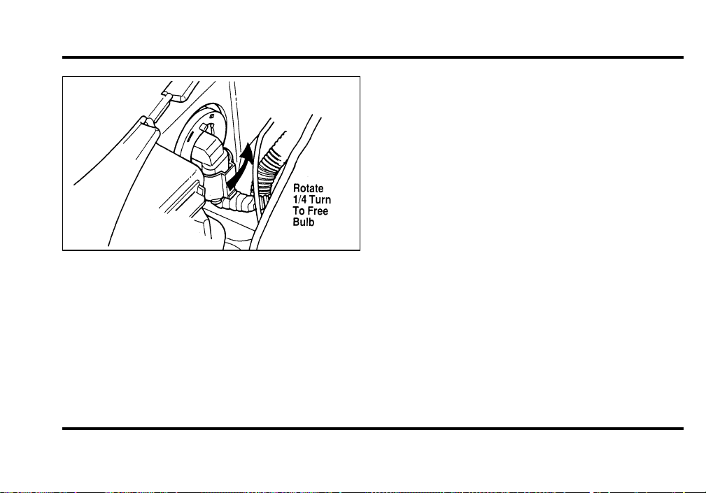
255
Headlamp bulb removal
Removing the high beam headlamp bulb
1. Make sure that the headlamp switch is in the
OFF position.
2. Lift the hood, remove the sight shield above
the headlamp and find the bulb in the
headlamp socket.
3. Remove the high beam dust cap by rotating
counterclockwise 1/4 turn. Pull back to
exposes wiring and connector.
4. Remove the bulb connector by pulling rearward
to free it from the lamp assembly.
5. Remove the electrical connector by pulling off
the bulb base.
Installing the high beam headlamp bulb
1. Push the electrical connector into the rear of
the plastic base of the bulb until it snaps,
locking it into position.
2. Insert the glass envelope of the bulb into the
lamp assembly socket while aligning the locking
tabs.
3. Rotate the bulb 1/4 turn to lock.
File:11fnmc8.ex
Update:Thu Jun 20 14:28:32 1996

256
4. Replace the high beam dust cap by aligning
tabs and rotating clockwise 1/4 turn.
5. Replace the sight shield.
Aiming Headlamps
Your vehicle is equipped with a Vehicle Headlamp
Aim Device (VHAD) on each headlamp body. Each
headlamp may be properly aimed in the horizontal
direction (left/right) and the vertical position
(up/down).
NOTE: A non-zero bubble reading does not
necessarily indicate out-of-aim headlamps. If your
vehicle is not positioned on a level surface, the
slope will be included in the level indicator.
Therefore, vertical headlamp adjustment should be
performed only when beam direction appears to be
incorrect or a level surface can be verified.
Tools required: One 6mm socket and ratchet.
The Horizontal aim must be adjusted first.
NOTE: The following procedure assumes that the
vehicle’s front structure is in factory alignment
condition. If the vehicle has been in an accident
requiring the front end of the vehicle to be
repaired, the horizontal indicator should be
recalibrated by the servicing facility.
File:11fnmc8.ex
Update:Thu Jun 20 14:28:32 1996

257
Before adjusting your headlamps, you must make
sure that the air suspension has been adjusted to
the proper ride height. In order to do this:
1. Position the vehicle on a level surface.
2. Make sure the air suspension switch in the
luggage compartment is in the ON position.
3. Turn the ignition key to the ON position.
4. Open and close the driver’s door to allow the
air suspension to fully level.
File:11fnmc8.ex
Update:Thu Jun 20 14:28:32 1996

258
Horizontal aim adjustment
1. Open the hood and lift the front end cover
from its velcro attachments. Locate the
horizontal level indicator and adjustment screw.
2. Use a 6mm socket and ratchet to turn the
horizontal adjusting screw until the horizontal
indicator is in line with the “0” reference.
Vertical aim adjustment
NOTE: The numbers shown on the vial indicate
beam direction in degrees up or down.
1. Locate the vertical level indicator and
adjustment screw.
2. Use a 6mm socket and ratchet to turn the
vertical adjustment screw until the bubble in
the horizontal level indicator is centered in the
vial.
3. Replace the sight shield and close the hood.
File:11fnmc8.ex
Update:Thu Jun 20 14:28:32 1996

259
Bulb specifications
File:11fnmc8.ex
Update:Thu Jun 20 14:28:32 1996

260
Cleaning Your Vehicle
Washing and Polishing Your Vehicle
Wash the outside of your vehicle, including the
underside, with a mild detergent.
DO NOT:
❑
Wash your vehicle with hot water
❑
Wash your vehicle while it sits in direct
sunlight
❑
Wash your vehicle while the body is hot
Pollen, bird droppings and tree sap can damage the
paint, especially in hot weather. Wash your vehicle
as often as necessary to keep it clean.
Take similar precautions if your vehicle is exposed
to chemical industrial fallout.
Paint damage resulting from fallout is not related to
a defect inpaint materials or workmanship and
therefore is not covered by warranty. Ford,
however, believes that continual improvement in
customer satisfaction is a high priority. For this
reason, Ford has authorized its dealers to repair, at
no charge to the owner, the surfaces of new
vehicles damaged by environmental fallout within
12 months or 12,000 miles (20,000 km) of
purchase, whichever comes first. Customers may be
required to bring their vehicle in for inspection by a
Ford representative.
Polish your vehicle to remove harmful deposits and
protect the finish.
Cleaning Chrome and Aluminum Parts
Wash chrome and aluminum parts with a mild
detergent. Do not use steel wool, abrasive cleaners,
fuel, or strong detergents.
File:11fnmc8.ex
Update:Thu Jun 20 14:28:32 1996

261
Cleaning Plastic Parts
Some of your vehicle’s exterior trim parts are
plastic. Clean with a tar and road oil remover if
necessary. Use a vinyl cleaner for routine cleaning.
Do not clean plastic parts with thinners, solvents or
petroleum-based cleaners.
If you have your vehicle rustproofed, remove
oversprayed rustproofing with a tar and road oil
remover. If rustproofing is not removed from plastic
and rubber parts, it can cause deterioration.
Cleaning the Safety Belts
Clean the safety belts with any mild soap solution
that is recommended for cleaning upholstery or
carpets. Do not bleach or dye the belt webbing
because this may weaken it.
Clean the instrument panel lens and woodtone trim
with a soft cloth and a glass cleaner. Do not use
paper towel or any abrasive cleaner to clean either
the lens or the woodtone trim as these may cause
scratches.
Cleaning the Exterior Lamps
Do not use dry paper towel, chemical solvents or
abrasive cleaners to clean the lamps, as these may
cause scratches or crack the lamps.
File:11fnmc8.ex
Update:Thu Jun 20 14:28:32 1996

262
Cleaning the Interior Lamps
Your interior dome lamps and map lamps are plastic
and should be cleaned with a mild detergent
diluted in water. Rinse them with clear water.
Cleaning the Seats
Leather
For routine cleaning, wipe the surface with a soft,
damp cloth. For more thorough cleaning, wipe the
surface with a leather and vinyl cleaner or a mild
soap.
Wipe the surface with a damp, soft cloth, then dry
and buff with a dry, soft cloth.
Cleaning the Wheels
Wash the wheels with the same detergent you use
to wash your vehicle’s body. Do not use acid-based
wheel cleaners, steel wool, abrasives, fuel, or strong
detergents. These substances will damage protective
coatings. Use tar and road oil remover to remove
grease and tar.
NOTE: Before going to a car wash, find out if the
brushes are abrasive.
File:11fnmc8.ex
Update:Thu Jun 20 14:28:32 1996
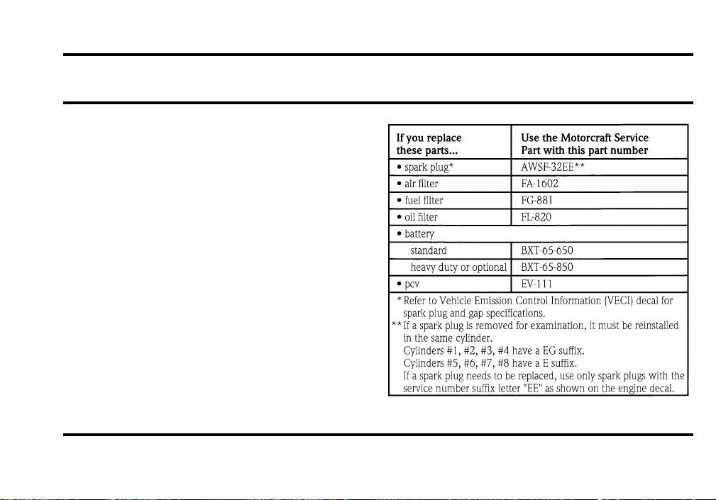
263
Capacities and Specifications
Refill Capacities, Motorcraft Parts,
and Lubricant Specifications
Motorcraft Parts
File:12fncs8.ex
Update:Thu Jun 20 14:28:48 1996
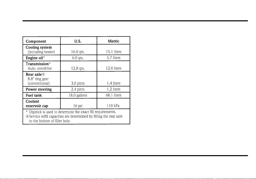
264
Fluid Specifications and Capacities
NOTE: Rear axle lube quantities must be replaced
every 100,000 miles (160,000 km) or if the axle
has been submerged in water. Otherwise, the lube
should not be checked or changed unless a leak is
suspected or repair required.
File:12fncs8.ex
Update:Thu Jun 20 14:28:48 1996
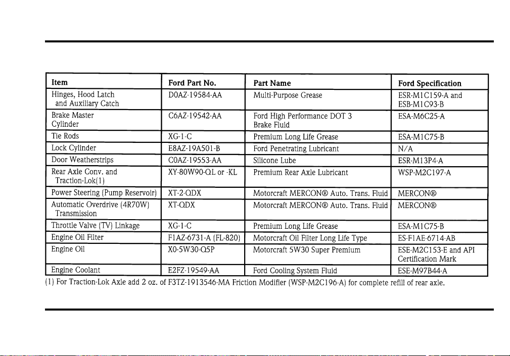
265
Lubricant Specifications
File:12fncs8.ex
Update:Thu Jun 20 14:28:48 1996

266
NOTE: Rear axle lube quantities must be replaced
every 100,000 miles (160,000 km) or if the axle
has been submerged in water. Otherwise, the lube
should not be checked or changed unless a leak is
suspected or repair required.
Vehicle Storage
Maintenance Tips
If you plan on storing your vehicle for an extended
period of time (60 days or more), refer to the
following maintenance recommendations to ensure
your vehicle stays in good operating condition.
General
❑
Store all vehicles in a dry, ventilated place.
❑
Protect from sunlight, if possible.
❑
If vehicles are stored outside, they require
regular maintenance to protect against rust and
damage.
Body
❑
Wash vehicle thoroughly to remove dirt, grease,
oil, tar or mud from exterior surfaces, rear
wheel housing and underside of front fenders.
❑
Periodically wash vehicles stored in exposed
locations.
❑
Touch-up raw or primed metal to prevent rust.
❑
Cover chrome and stainless steel parts with a
thick coat of auto wax to prevent discoloration.
Re-wax as necessary when the vehicle is
washed.
❑
Lubricate all hood, door and trunk lid hinges
and latches with a light grade oil.
❑
Cover interior soft trim to prevent fading.
❑
Keep all rubber parts free from oil and solvents.
File:12fncs8.ex
Update:Thu Jun 20 14:28:48 1996

267
Engine
❑
Start engine every 15 days. Run at fast idle
until it reaches normal operating temperature.
❑
With your foot on the brake, shift through all
the gears while the engine is running.
Fuel system
❑
Fill fuel tank with high-quality, premium
unleaded fuel until the first automatic shutoff of
the fuel pump nozzle.
NOTE: During extended periods of vehicle storage
(60 days or more), fuel may deteriorate due to
oxidation. This can damage rubber and other
polymers in the fuel system and may also clog small
orifices.
Ford Gas Stabilizer should be added whenever
actual or expected storage periods exceed 60 days.
Follow the instructions on the label. The vehicle
should then be operated at idle speed to circulate
the additive throughout the fuel system.
A volatile corrosion inhibitor added to the fuel
system will protect the fuel system’s inner surfaces
from corrosion. Follow the instructions packaged
with the product.
Cooling system
❑
Protect against freezing temperatures.
File:12fncs8.ex
Update:Thu Jun 20 14:28:48 1996

268
Battery
❑
Check and recharge as necessary.
❑
Keep connections clean and covered with a
light coat of grease.
❑
If storing your vehicle for more than 30 days
without recharging the battery, disconnect the
battery cables to ensure battery charge is
maintained for quick starting. NOTE: If battery
cables are disconnected, it will be necessary to
reset any memory features (eg. radio presets).
Brakes
❑
Make sure brakes and parking brake are fully
released.
Tires
❑
Maintain recommended air pressures.
Miscellaneous
❑
Make sure all linkages, cables, levers and clevis
pins under vehicle are covered with grease to
prevent rust.
❑
Move vehicles at least 25 feet (8 m) every 15
days to lubricate working parts and prevent
corrosion.
File:12fncs8.ex
Update:Thu Jun 20 14:28:48 1996

269
Reporting Safety Defects (U.S. Only)
Reporting Safety Defects
(U.S. Only)
If you believe that your vehicle has a defect which
could cause a crash or could cause injury or death,
you should immediately inform the National
Highway Traffic Safety Administration (NHTSA) in
addition to notifying Ford Motor Company.
If NHTSA receives similar complaints, it may open
an investigation, and if it finds that a safety defect
exists in a group of vehicles, it may order a recall
and remedy campaign. However, NHTSA cannot
become involved in individual problems between
you, your dealer, or Ford Motor Company.
To contact NHTSA, you may either call the Auto
Safety Hotline toll-free at 1-800-424-9393 (or
366-0123 in the Washington, D.C. area) or write
to: NHTSA, U.S. Department of Transportation, 400
Seventh Street, Washington D.C. 20590. You can
also obtain other information about motor vehicle
safety from the Hotline.
File:13fnrd8.ex
Update:Wed Jun 19 15:06:10 1996
271
Customer Assistance
If You Have a Service Problem
Ford Motor Company has authorized Ford and
Lincoln-Mercury dealerships that can service your
vehicle for you. This chapter tells you how to get
service or maintenance for your vehicle.
Service/Maintenance Concerns
(U.S. or Canada)
Ford recommends taking your vehicle to your
selling dealer who wants to ensure your continued
satisfaction. You may, however, take your vehicle to
any authorized Ford or Lincoln-Mercury dealer. In
most cases, your dealer will be able to resolve your
concern.
If you are not satisfied with the service you
received from your dealership’s service department,
talk to the service manager at the dealership, or if
you still are not satisfied, talk to the owner or
general manager of the dealership. In most cases,
you will have your concern resolved at this level.
If you are away from home when your vehicle
needs to be serviced, or if you need more help than
the dealer gave you, contact the Ford Customer
Assistance Center to find an authorized dealership
that may be able to help you.
File:14fnhs8.ex
Update:Wed Jun 19 15:06:24 1996

272
If you have any questions or concerns that the
dealership cannot answer, contact the Customer
Assistance Center.
If you still have a complaint involving a warranty
dispute, you may wish to contact the Dispute
Settlement Board (U.S. only) or the Canadian Motor
Vehicle Arbitration Plan (CAMVAP) in Canada.
A warranty dispute must be submitted to the
Dispute Settlement Board before taking action under
the Magnuson-Moss Warranty Act, or to the extent
allowed by state law, before pursuing replacement
or repurchase remedies provided by certain state
laws. This dispute handling procedure is not
required prior to enforcing state created rights or
other rights which are independent of the
Magnuson-Moss Warranty Act or state replacement
or repurchase laws.
The Dispute Settlement Board
(U.S. Only)
The Dispute Settlement Board is:
❑
an independent, third-party arbitration program
for warranty disputes
❑
available free to owners and lessees of qualifying
Ford Motor Company vehicles
The Dispute Settlement Board may not be available
in all states. Ford Motor Company reserves the right
to change eligibility limitations, modify procedures
and/or to discontinue this service without notice
and without incurring obligations.
File:14fnhs8.ex
Update:Wed Jun 19 15:06:24 1996

273
What Kind of Cases Does the Board
Review?
The Board reviews all warranty performance
complaints on Ford, Mercury and Lincoln cars and
Ford and Mercury light trucks under the new
vehicle limited warranty that have not been
resolved by either a dealer or Ford Motor Company,
except those involving:
❑
a non-Ford product
❑
a non-Ford dealership
❑
a vehicle sales transaction
❑
request for reimbursement of consequential
expenses. Expenses incidental to the warranty
complaint being reviewed are eligible for
consideration.
❑
items not covered by the new vehicle limited
warranty
❑
items covered by a service contract
❑
alleged liability claims
❑
property damage where the damage is
significant when compared to the economic loss
alleged under the warranty dispute
❑
cases currently in litigation
❑
vehicles not used primarily for family, personal,
or household purposes (except in states where
the Dispute Settlement Board is required to
review commercial vehicles)
Complaints involving vehicles in which applicable
new vehicle limited warranties have expired at
receipt of your application are not eligible. Eligibility
may differ according to state law. For example, see
the unique brochures for California and Wisconsin
purchasers/lessees.
File:14fnhs8.ex
Update:Wed Jun 19 15:06:24 1996

274
How does the Board Work?
The Board consists of:
❑
three consumer representatives
❑
a Ford or Lincoln/Mercury dealer
Consumer candidates for Board membership are
recruited and trained by an independent consulting
firm. Dealers are chosen because of their business
leadership qualities.
What the Board needs
To have your case reviewed you must complete the
application in the DSB brochure and mail it to the
address provided on the application form.
Your application is reviewed and, if it is determined
to be eligible, you will receive an acknowledgment
indicating:
❑
the file number assigned to your application
❑
the toll-free phone number of the DSB’s
independent administrator
Your dealership and a Ford Motor Company
representative are asked to submit statements at this
time.
To review your case properly, the Board needs the
following information:
❑
legible copies of all documents and maintenance
or repair orders relevant to the case
❑
the year, make, model, and Vehicle
Identification Number (VIN) listed on your
vehicle ownership license
❑
the date of repair(s) and mileage at the time of
occurrence(s)
❑
the current mileage
❑
the name of the dealer who sold or serviced the
vehicle
❑
a brief description of your unresolved concern
File:14fnhs8.ex
Update:Wed Jun 19 15:06:24 1996

275
❑
a brief summary of the action taken with the
dealer and Ford Motor Company
❑
the names (if known) of all the people you
contacted at the dealership
❑
a description of the action you expect to resolve
your concern
Should your case NOT qualify for review, a letter of
explanation will be mailed to you.
Oral presentations
If the involved vehicle is within 36 months and
36,000 miles of the warranty start date, you have
the right to make an oral presentation before the
Board. Indicate your choice to do so on the
application. Oral presentations may also be
requested by the Board.
Making a decision
Board members will review all available information
related to the complaint, including oral
presentations, if necessary. They then arrive at a fair
and impartial decision, decided by a simple majority
vote.
Because the Board usually meets only once a
month, some cases may take longer than 30 days to
be reviewed. The Board makes every effort to
resolve each case within 40 days of receiving the
consumer application form.
After your case is reviewed, the Board mails you a
decision letter. The Board also provides a form on
which to accept or reject the Board’s decision. The
decisions of the Board are binding on the dealer
and Ford, but not on consumers who may elect to
pursue other remedies available to them under state
or federal law. Decisions of the Board may be
presented as evidence by any party in subsequent
legal proceedings that may be initiated, where
allowed by law.
File:14fnhs8.ex
Update:Wed Jun 19 15:06:24 1996
276
To Request a DSB
Brochure/Application
For a brochure/application, speak to your dealer or
write to the Board at the following address:
Ford of Canada Customer
Assistance
If you live in Canada and have any questions or
concerns that the dealership cannot answer, contact
the Lincoln Centre.
Please have the following information available
when contacting the Lincoln Centre:
❑
your telephone number (both business and
home)
❑
the name of the dealer and the city where the
dealership is located
❑
the year and make of your vehicle
❑
the date purchased
❑
the current mileage on your vehicle
❑
your Vehicle Identification Number (VIN) listed
on your vehicle ownership license
File:14fnhs8.ex
Update:Wed Jun 19 15:06:24 1996
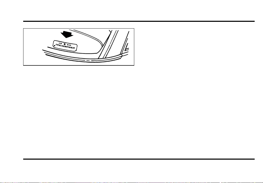
277
Vehicle Identification Number (VIN/Serial
Number)
Mediation/Arbitration Program
(Canada Only)
In those cases where you continue to feel that the
efforts by Ford and the dealer to resolve a
factory-related vehicle service concern have been
unsatisfactory, Ford of Canada participates in an
impartial third party mediation/arbitration program
administered by the Canadian Motor Vehicle
Arbitration Plan (CAMVAP).
The CAMVAP program is a straight-forward and
relatively speedy alternative to resolve a
disagreement when all other efforts to produce a
settlement have failed. This procedure is without
cost to you and is designed to eliminate the need
for lengthy and expensive legal proceedings.
In the CAMVAP program, impartial third-party
Arbitrators conduct hearings at mutually convenient
times and places in an informal environment. These
impartial Arbitrators review the positions of the
parties, make decisions and, where appropriate,
render awards to resolve disputes. CAMVAP
decisions are fast, fair and final as the arbitrator’s
award is binding on both you and Ford of Canada.
CAMVAP services are available in all territories and
provinces, except Quebec. For more information,
without charge or obligation, call your CAMVAP
Provincial Administrator directly at 1-800-207-0685.
File:14fnhs8.ex
Update:Wed Jun 19 15:06:24 1996

278
Getting Help Outside the U.S.
and Canada
Before you export your vehicle to a foreign country,
contact the appropriate foreign embassy or consulate
to make sure local regulations do not prevent you
from registering your vehicle. Officials at the
embassy can also help you decide whether you
should import your vehicle to that country.
Officials at the embassy or consulate can tell you
where to get unleaded fuel. If you cannot get
unleaded fuel or can get only fuel with an
anti-knock index that is lower than your vehicle
needs, contact a district or owner relations office
before you leave the U.S. or Canada.
Use of leaded fuel in your vehicle without a proper
conversion may damage the effectiveness of your
emissions control system and may cause engine
knocking or serious engine damage. Ford Motor
Company is not responsible for any damage that is
caused by use of improper fuel.
You may also have difficulty importing your vehicle
back into the U.S. if you use leaded fuel.
File:14fnhs8.ex
Update:Wed Jun 19 15:06:24 1996
279
If your vehicle must be serviced while you are
traveling or living in Central or South America, the
Caribbean, or the Middle East, contact the nearest
Ford dealership. If the dealership cannot help you,
write to:
If you are in other foreign countries, contact the
nearest Ford dealership. If the dealership cannot
help you, they can direct you to the appropriate
Ford affiliate office.
If you buy your vehicle in North America and then
relocate outside of the U.S. or Canada, register your
Vehicle Identification Number and new address
with Ford Motor Company Export Operations.
File:14fnhs8.ex
Update:Wed Jun 19 15:06:24 1996
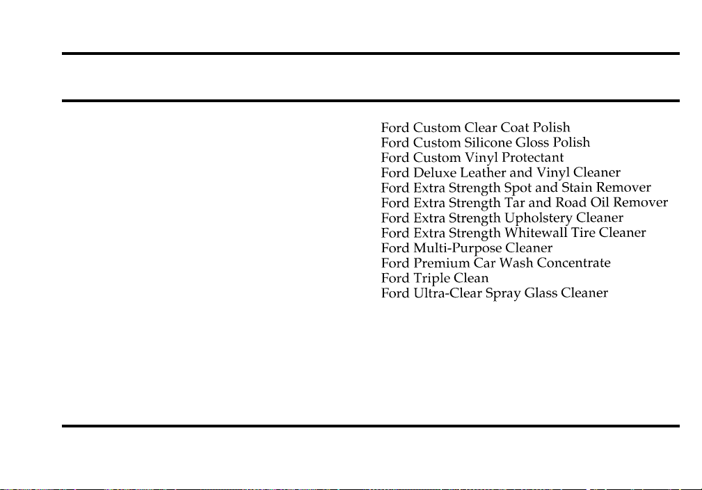
281
Accessories
Ford Accessories for Your Vehicle
A wide selection of accessories is available through
your local authorized dealer. These fine accessories
have been engineered specifically to fulfill your
automotive needs. They are custom designed to
complement the style and aerodynamic appearance
of your Ford-built vehicle. In addition, each
accessory is made from high quality materials and
meets or exceeds Ford’s rigid engineering and safety
specifications. That is why Ford brand accessories
are warranted for up to 12 months or 12,000 miles
(20,000 km), whichever comes first. See your
dealer for complete warranty information and
accessory availability.
Ford has many fine products available from your
dealer to clean your vehicle and protect its finishes.
For best results, use the following, or products of
equivalent quality:
File:15fnac8.ex
Update:Wed Jun 19 15:06:40 1996
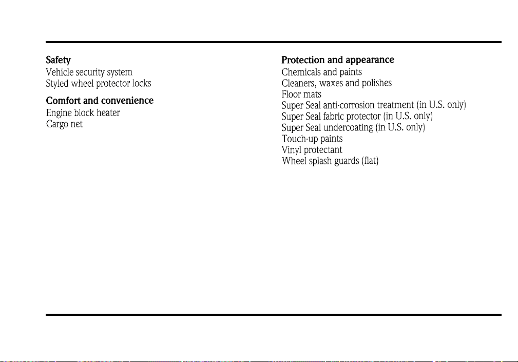
282
NOTE: When adding accessories, equipment,
passengers, and luggage to your vehicle, do not
exceed the total weight capacity of the vehicle or of
the front or rear axle (GVWR, GAWR as shown on
the Safety Compliance Certification Label). Consult
your dealer for specific weight information.
File:15fnac8.ex
Update:Wed Jun 19 15:06:40 1996

283
NOTE: The Federal Communications Commission
(FCC) or the Canadian Radio Telecommunications
Commission (CRTC) regulates the use of mobile
communications systems — such as two-way radios,
telephones, and theft alarms — that are equipped
with radio transmitters. Any such equipment
installed in your vehicle should comply with FCC
or CRTC regulations and should be installed only by
a qualified technician.
NOTE: Mobile communications systems may harm
the operation of your vehicle, particularly if they are
not properly designed for automotive use or are not
properly installed. For example, when operated,
such systems may cause the engine to stumble or
stall. In addition, such systems may themselves be
damaged or their operation affected by operating
your vehicle. (Citizens band [CB] transceivers,
garage door openers, and other transmitters whose
power output is 5 watts or less will not ordinarily
affect your vehicle’s operation.)
NOTE: Because we have no control over the
installation, design, or manufacture of such systems,
Ford cannot assume responsibility for any adverse
effects or damage that may result if you use this
equipment.
File:15fnac8.ex
Update:Wed Jun 19 15:06:40 1996

284
File:15fnac8.ex
Update:Wed Jun 19 15:06:40 1996

287
File:15fnac8.ex
Update:Wed Jun 19 15:06:40 1996

288
File:15fnac8.ex
Update:Wed Jun 19 15:06:40 1996

289
File:15fnac8.ex
Update:Wed Jun 19 15:06:40 1996

290
File:15fnac8.ex
Update:Wed Jun 19 15:06:40 1996

291
File:15fnac8.ex
Update:Wed Jun 19 15:06:40 1996

292
File:15fnac8.ex
Update:Wed Jun 19 15:06:40 1996

293
File:15fnac8.ex
Update:Wed Jun 19 15:06:40 1996

294
File:15fnac8.ex
Update:Wed Jun 19 15:06:40 1996

295
Index
A
ABS warning light (see Anti-lock
brake system) ............ 11
Accessory position on the ignition .... 83
Accident damage ............ 216
Air bag supplemental restraint system . . . 145
and child safety seats ......... 151
description ............. 145
driver air bag ............ 145
indicator light ............ 45
operation .............. 147
passenger air bag........... 145
tone generator............ 149
Air cleaner filter
location............... 220
specifications ............ 263
Air conditioning, electronic automatic
temperature control system....... 69
Air suspension
air ride switch off, message center . . . 37
description .............175
Alarm, activating remote personal.....123
Aluminum wheels ...........242
Antenna, radio (see Electronic
sound system) ............ 66
Antifreeze (see Engine coolant) ......228
Anti-lock brake system (ABS)
description .............171
see also Brake ............171
warning light ............ 11
Anti-theft lug nuts and key........208
File:fnix8.ex
Update:Thu Jun 27 10:02:38 1996

296
Anti-theft system
arming the system .......... 127
description ............. 127
disarming an untriggered system .... 128
disarming a triggered system...... 128
triggering .............. 128
Appeals (see Dispute settlement board) . . 272
Assistance (see Customer assistance) . . . 271
Audio system (see Electronic
sound system) ............ 49
Autolamp system (see Headlamps) .... 78
Automatic transmission
driving an automatic overdrive ..... 177
fluid, adding............. 235
fluid, checking............ 235
fluid, refill capacities ......... 264
fluid, specification .......... 265
Axle
lubricant specifications ........ 265
refill capacities............ 264
B
Basic vehicle warranty........... 3
Battery................236
acid, treating emergencies .......237
battery saver.............126
charging system warning light ..... 13
disconnecting ............212
how to service............236
jumping a disabled battery.......209
maintenance-free ...........236
proper disposal, recycling .......237
replacement, specifications.......263
servicing ..............236
when storing your vehicle.......268
Brake fluid...............225
brake warning light.......... 10
checking and adding .........225
description .............225
specifications ............265
File:fnix8.ex
Update:Thu Jun 27 10:02:38 1996

297
Brakes
adjustment ............. 171
anti-lock .............. 171
anti-lock brake system (ABS)
warning light ........... 11
applying the brakes.......... 171
brake warning light.......... 10
fluid, checking and adding....... 225
fluid, refill capacities ...... 225, 264
fluid, specifications .......... 265
front disc .............. 171
if brakes do not grip well ....... 171
master cylinder ........... 225
new brake linings ........... 5
noise................ 171
parking brake and auto-release ..... 172
servicing .............. 225
trailer ............... 187
when storing your vehicle....... 268
Break-in period.............. 5
Brights (high beams) .......... 14
Bulbs, replacing ............253
halogen ...............254
headlamps..............254
C
Canada, customer assistance .......276
Canada, warranty information ....... 3
Canadian Motor Vehicle Arbitration Plan
(CAMVAP)..............277
Capacities for refilling fluids .......264
Carbon monoxide in exhaust.......169
Car seats for children
(see Child safety seats) ........151
Catalytic converter ...........250
File:fnix8.ex
Update:Thu Jun 27 10:02:38 1996

298
Chains, tires.............. 242
Changing a tire ............ 201
Charging system warning light ...... 13
Child safety restraints .......... 150
child safety belts ........... 163
child safety seats........... 151
Child safety seats............ 151
and air bags ............. 151
attaching with tether straps ...... 162
automatic locking mode (retractor) 143, 151
in front seat............. 151
in rear outboard seat ......... 151
in rear seat ............. 151
tether anchorage hardware . . . 162, 163
Chime
headlamps on ............ 15
key in ignition............ 84
safety belt.............. 44
Cleaning your vehicle ..........260
chrome and aluminum parts ......260
exterior...............260
exterior lamps ............261
fabric................262
headlamps..............261
instrument panel......... 7,261
interior ...............262
interior lamps ............262
mirrors ...............100
plastic parts .............261
polishing ..............260
rustproofing .............261
safety belts .............261
tail lamps ..............261
upholstery and interior trim ......262
washing...............260
waxing ...............260
wheels ...............262
File:fnix8.ex
Update:Thu Jun 27 10:02:38 1996

299
Climate control system
air conditioning ........... 69
electronic automatic temperature
control .............. 69
heating ............... 69
Clock ................. 82
Clutch
fluid reservoir ............ 225
specifications ............ 265
Combination lap and shoulder belts .... 138
Console, description .......... 115
Controls, mirrors ............ 99
Convenience kit in cargo area ...... 202
Coolant (see Engine coolant) ....... 228
checking and adding ......... 228
preparing for storage ......... 267
refill capacities............ 264
specifications ............265
temperature gauge .......... 17
warnings ..............228
Cooling fan ..............217
Crankcase emission filter ........263
Cruise control indicator light ....... 13
Customer Assistance Centre,
Ford of Canada ............276
D
Daytime running light system ...... 78
Defects, reporting............269
Dipstick ................223
automatic transmission fluid ......234
engine oil ..............223
power steering fluid .........233
Disabled vehicle (see Towing) ......213
Dispute Settlement Board ........272
Doors .................106
lubricant specifications ........265
File:fnix8.ex
Update:Thu Jun 27 10:02:38 1996

300
Driving under special conditions
heavy load ............. 182
towing a trailer ........... 184
E
Electrical system, fuses ......... 191
Electronic sound system
antenna............... 65
tuning the radio ........... 50
warranty and service information.... 68
Emergencies, roadside
fuel ................ 247
jump-starting ............ 209
towing ............... 213
Emergency brake (parking brake) ..... 171
Emission control system ......... 250
catalytic converter .......... 250
emissions warranty .........3,250
Engine
check engine warning light ...... 45
does not start ......... 167, 189
fuel injected engine, starting......165
fuel pump shut-off switch .......189
preparing to start...........165
refill capacities............264
service points ............220
starting ...............166
starting after a collision ........189
storing your vehicle .........266
Engine block heater...........168
Engine coolant .............228
checking and adding .........228
disposal...............235
preparing for storage .........267
File:fnix8.ex
Update:Thu Jun 27 10:02:38 1996

301
proper solution ........... 235
recovery reservoir .......... 228
refill capacities............ 264
specifications ............ 265
temperature gauge .......... 17
Engine coolant temperature gauge..... 17
Engine fan............... 217
Engine knocking ............ 246
Engine oil ............... 222
“break-in” oils ............. 5
changing oil and oil filter ....... 224
checking and adding ......... 223
check oil warning light ........ 11
dipstick............... 223
disposal............... 216
engine oil pressure warning light.... 11
filter, specifications ..........263
refill capacities............264
specifications ......... 222, 265
synthetic oil .............222
viscosity ..............222
Exhaust fumes .............169
Extended Service Plan, Ford ........ 4
F
Fan..................217
engine fan, avoiding injury ......217
Flashers, hazard ............ 89
Flashing the lights ........... 86
Flat tire ................201
Fluid refill capacities ..........264
Ford Dispute Settlement Board ......272
Ford Extended Service Plan ........ 4
Ford Motor Company of Canada .....276
File:fnix8.ex
Update:Thu Jun 27 10:02:38 1996

302
Ford of Canada Customer
Assistance Centre........... 276
Foreign registration ........... 278
French owner guides, how to obtain .... 3
Fuel ................. 243
calculating fuel economy ..... 25,248
capacity............... 264
choosing the right fuel ........ 245
comparisons with EPA fuel
economy estimates ......... 249
filling your vehicle with fuel...... 243
filter, specifications.......... 263
fuel filler door release lever ...... 243
fuel gauge.............. 19
octane rating ............ 246
quality ............... 246
running out of fuel.......... 248
safety information relating to
automotive fuels ..........247
storing your vehicle .........267
treating emergencies .........247
Fuel cap................243
removing ..............243
replacing ..............243
Fuel filler door .............243
remote release ............243
Fuel filter, specifications .........263
Fuel gauge............... 19
Fuel pump shut-off switch
engine does not start .........189
starting after a collision ........189
Fuse panels ..............191
engine compartment .........195
instrument panel...........199
Fuses
charts ...............191
checking and replacing ........199
File:fnix8.ex
Update:Thu Jun 27 10:02:38 1996

303
G
Gas cap (see Fuel cap) ......... 243
Gas mileage (see Fuel economy) . . . 25, 248
Gasoline (see Fuel) ........... 243
Gauges
engine coolant temperature gauge . . . 17
fuel gauge.............. 19
odometer .............. 16
speedometer............. 16
tachometer ............. 17
GAWR (Gross Axle Weight Rating)
calculating ............. 183
definition .............. 182
driving with a heavy load ....... 182
location............... 182
Gearshift
automatic operation..........177
locking the gearshift ......... 83
positions ..............177
shifting the gears...........177
GVWR (Gross Vehicle Weight Rating) . . . 182
calculating..............183
definition ..............182
driving with a heavy load .......182
location...............182
H
Hazard flashers............. 89
Headlamps
aiming ...............256
autolamp system ........... 80
checking alignment..........253
cleaning...............261
daytime running lights ........ 78
File:fnix8.ex
Update:Thu Jun 27 10:02:38 1996

304
Headlamps (continued)
flashing............... 86
high beam ............. 86
replacing bulbs ........... 253
turning on and off .......... 79
warning chime............ 15
Head restraints............. 131
Heated seats .............. 135
Heating
electronic automatic temperature
control system ........... 69
High beams
indicator light ............ 14
operation .............. 86
Hitch ................. 186
Hood ................. 219
latch location ............ 219
lubrication specifications ....... 265
release lever............. 219
working under the hood ....... 217
Horn ................. 90
I
Idle, relearning.......... 212, 217
Ignition
chime ............... 84
positions of the ignition........ 83
removing the key .......... 84
Indicator lights and chimes (see Lights) . . . 7
Infant seats (see Safety seats).... 150, 151
Instrument panel ............. 7
Interval wipers ............. 86
J
Jack..................202
operation ..............203
positioning .............205
storage ...............202
Jump-starting your vehicle
attaching cables ...........211
disconnecting cables .........212
File:fnix8.ex
Update:Thu Jun 27 10:02:38 1996

305
K
Keyless entry system
locking and unlocking doors ...... 119
programming entry code ....... 120
Keys
key in ignition chime......... 84
positions of the ignition........ 83
removing from the ignition ...... 84
stuck in lock position......... 83
L
Lamps
autolamp delay system ........ 80
checking .............. 253
daytime running light system ..... 78
dome lamps ............. 96
flashing the lamps .......... 86
hazard flashers............ 89
headlamps ............. 79
high beams ............. 86
interior lamps ............ 78
map lamps ............. 96
replacing bulbs............253
trailer ...............187
Lane change indicator (see Turn signal) . . 85
Lap belts ...............143
Lights, warning and indicator
airbag............... 45
anti-lock brakes (ABS)......... 11
brake................ 10
charging system ........... 13
check engine ............ 45
engine oil pressure .......... 11
hazard warning light ......... 89
high beam ............. 14
overdrive off............. 46
safety belt.............. 44
turn signal indicator ......... 14
File:fnix8.ex
Update:Thu Jun 27 10:02:38 1996

306
Load limits .............. 182
GAWR ............... 182
GVWR ............... 182
trailer towing ............ 184
Lubricant specifications ......... 265
Luggage compartment .......... 117
Lug nuts ............... 203
anti-theft .............. 208
standard .............. 205
tightening sequence ......... 203
M
Maintenance schedule and record
(see separate Maintenance Schedule
and Record booklet)........... 3
Maintenance (see Servicing) ....... 215
Master cylinder, brakes .........225
Memory profile system .........110
Message center............. 19
Mileage, calculating fuel economy. . . 25, 248
Mirrors
automatic dimming rearview mirror. . . 99
side view mirrors ..........112
Moon roof............... 97
Motorcraft parts ............263
N
National Highway Traffic
Safety Administration .........269
New vehicle break-in ........... 5
File:fnix8.ex
Update:Thu Jun 27 10:02:38 1996

307
O
Octane rating ............. 246
Odometer ............... 16
Oil filter ............ 224, 263
Oil (see Engine oil) ........... 222
Oil viscosity .............. 222
On-board diagnostic (OBD II) system . . . 253
Overdrive ............... 181
Overseas offices ............ 278
P
Panic alarm feature, remote entry system . 123
Parking brake, warning light ....... 10
Parking brake and auto-release ...... 10
Parts (see Motorcraft Parts) ....... 263
PCV valve, specifications ........ 263
Phone, cellular ............. 114
Power features
antenna............... 65
doors................ 106
mirrors ............... 99
moon roof.............. 97
seats ................134
windows ..............108
Power steering
dipstick ...............233
driving with power steering ......177
fluid, checking and adding.......233
fluid, refill capacity ..........264
fluid, specifications ..........265
servicing ..............177
Prop rod, hood .............219
R
Radio (see Electronic sound systems) . . . 49
Rear axle
lubricant specification.........265
refill capacity ............264
Rear window defroster ......... 77
Rearview mirror ............ 99
Redundant electronic gearshift indicator . . 15
Refill capacities for fluids ........264
Regulations, National Highway Traffic Safety
Administration ............269
File:fnix8.ex
Update:Thu Jun 27 10:02:38 1996

308
Remote entry system
arming and disarming the
anti-theft system .......... 123
locking/unlocking doors........ 123
opening the trunk .......... 123
panic alarm ............. 123
replacement/additional transmitters. . . 125
replacing the batteries ........ 125
Reporting safety defects ......... 269
Restraints, safety (see Safety restraints)
adult ................ 138
child ................ 150
head ................ 131
infant ............... 150
Reverse ................ 180
Roadside emergencies .......... 189
Rotating the tires............ 239
S
Safety belts (see Safety restraints) .....138
Safety chains, when towing a trailer....186
Safety Compliance Certification Label . . . 182
Safety defects, reporting .........269
Safety information relating to
automotive fuels ...........247
Safety restraints
adjusting the safety belts .......140
automatic locking mode ........143
center rear lap belt..........143
cleaning the safety belts........261
extension assembly ..........144
for adults ..............138
for children .............150
File:fnix8.ex
Update:Thu Jun 27 10:02:38 1996

309
for infants........... 150, 151
head ................ 131
lap and shoulder belts ........ 138
lap belt ............... 143
maintenance............. 145
proper use ............. 138
replacement ............. 145
warning light and chime ....... 44
Safety seats for children ......... 151
and air bags ............. 151
attaching with tether straps ...... 162
automatic locking mode (retractor) . . . 154
in front seat............. 151
in rear outboard ........... 151
tether anchorage hardware ...... 162
Seat belts (see Safety restraints) ..... 138
Seats .................131
adjusting the seats, power .......134
auto-glide ..............136
child safety seats ...........151
cleaning upholstery..........262
head restraints............131
heated ...............135
rear seat access ...........133
reclining the seat...........132
Service concerns ............271
Servicing your vehicle ..........215
precautions when servicing ......217
servicing when you tow........213
Shift positions (see Gearshift).......177
Shoulder and lap belts
(see Safety restraints) .........138
Side mirrors
adjusting ..............112
File:fnix8.ex
Update:Thu Jun 27 10:02:38 1996

310
Sliding moon roof (see Moon roof) .... 97
Snow tires and chains.......... 242
Spare tire ............... 201
changing the tire........... 201
finding the spare........... 202
removing the spare tire ........ 203
storing the flat tire .......... 205
temporary spare ........... 201
Spark plugs, specifications ........ 263
Specification chart, lubricants ...... 265
Speed control
turning off ............. 94
when towing a trailer......... 187
Speedometer.............. 16
Starting your vehicle
preparing to start your vehicle ..... 165
starting after a collision ........ 189
starting your vehicle if the battery
is disabled............. 209
Steering, power ............177
Steering wheel
horn ................ 90
locking ............... 83
Storage compartments, center console . . . 115
Storing your vehicle...........266
Sunroof (moon roof)........... 97
Sun visor ...............101
Supplemental air bag readiness light.... 45
Supplemental Restraint System (SRS) . . . 145
T
Tachometer .............. 17
Tail lamps
bulb replacement...........253
cleaning...............261
Temperature control (see Climate control) . 69
Tether anchor installation
(see Child restraints) .........162
Tilt/Telescope steering column ...... 91
File:fnix8.ex
Update:Thu Jun 27 10:02:38 1996

311
Tires ................. 238
changing .............. 201
checking the pressure......... 238
cleaning .............. 262
inspection and maintenance ...... 238
replacing .............. 240
rotating............... 239
snow tires and chains ........ 242
spare tire .............. 202
storing your vehicle ......... 268
tire grades ............. 241
treadwear .............. 241
wear bands ............. 240
Towing a trailer (see Trailer towing) . . . 184
Towing your vehicle .......... 213
using wheel dollies.......... 213
with a tow truck........... 213
Traction Control active light ....... 12
Trailer towing .............184
calculating maximum trailer weight . . . 184
safety chains.............186
tips ................187
trailer brakes ............187
trailer lamps.............187
Transmission
automatic operation..........177
fluid, checking and adding.......235
fluid, refill capacities .........264
lubricant specifications ........265
Transmission control switch .......180
Trunk, using the remote entry system
to open ...............123
Trunk, power release ..........118
Tune-up specifications (VECI).......252
Turn signal .............. 85
indicator lights............ 14
lever ................ 85
File:fnix8.ex
Update:Thu Jun 27 10:02:38 1996

312
V
Variable interval wipers ......... 86
VECI (Vehicle Emission Control Information)
decal ................ 252
Vehicle loading
automatic transmissions ........ 183
calculating the load.......... 183
manual transmissions ......... 183
understanding loading information . . . 182
Vehicle storage............. 266
Ventilating your vehicle (see Climate
control) ............... 69
Viscosity (see Engine oil) ........ 222
Visor (see Sun visor) .......... 101
W
Warning chimes
headlamps on ............ 15
key in ignition............ 84
safety belt.............. 44
Warning lights (see Lights)......... 7
Warranties................ 3
basic ................. 3
Canada ................ 3
radio ................ 68
Warranty Information Booklet ....... 3
Washer fluid ..............227
windshield ............. 86
Weight limits (GAWR, GVWR) ......182
Wheel bearings, lubricant specifications . . 265
Wheel dollies (see Towing) .......213
File:fnix8.ex
Update:Thu Jun 27 10:02:38 1996

313
Wheels
anti-theft lugnuts........... 208
cleaning .............. 262
covers ............ 203, 205
inspection and maintenance ...... 238
lug nuts .............. 203
Windows, power windows, operating . . . 108
Windshield, washing .......... 86
Windshield washer fluid and wipers.... 86
checking and adding fluid .......227
checking and replacing wiper blades . . 237
operation .............. 86
reservoir ..............227
specifications ............265
variable interval wipers ........ 86
Windshield wipers and washer ...... 86
Wrecker towing ............213
File:fnix8.ex
Update:Thu Jun 27 10:02:38 1996
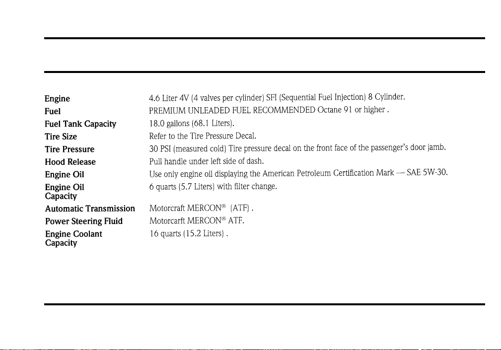
314
Service Station Information
File:17fngs8.ex
Update:Thu Jun 27 10:02:28 1996