FAMILIARISATION
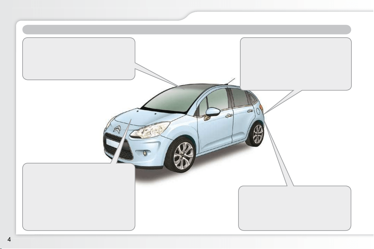
Rear parking sensors
This system provides a warning when
reversing by detecting obstacles located
behind the vehicle.
120
Stop & Start
This system puts the engine temporarily
into standby during stops in the traffi c (red
lights, traffi c jams, etc...). The engine
restarts as soon as you want to move
off. The Stop & Start system reduces
fuel consumption and exhaust emis-
sions, and provides the comfort of total
silence when stationary.
113
Temporary puncture repair kit
This kit is a complete system consisting
of a compressor and a sealant cartridge,
for the temporary repair of a tyre.
129
Zenith windscreen
This large windscreen provides incom-
parable visibility and light in the passen-
ger compartment.
6
EXTERIOR
FAMILIARISATION
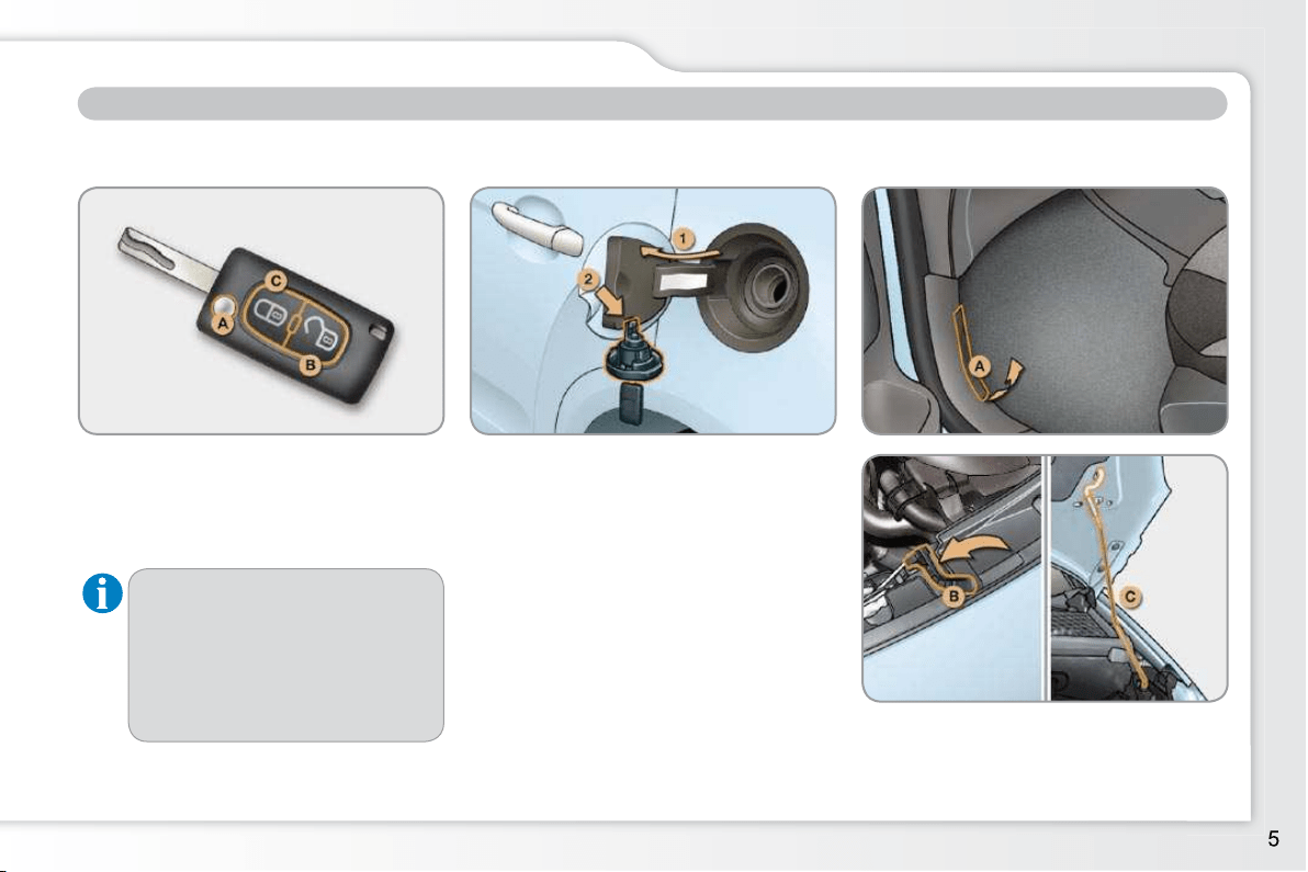
Remote control key Fuel tank
1. Opening the fuel fi ller fl ap.
2. Opening and hooking the fuel fi ller
cap.
A. Unfolding/Folding the key.
B. Unlocking the vehicle.
60
71
A. Interior release lever.
B. Exterior safety catch.
C. Bonnet stay.
123
Bonnet
ACCESS
Other functions...
C. Normal locking of the vehicle.
or
Deadlocking of the vehicle.
Vehicle location.
Tank capacity:
- approximately 50 litres (petrol),
- approximately 48 litres (Diesel).
FAMILIARISATION
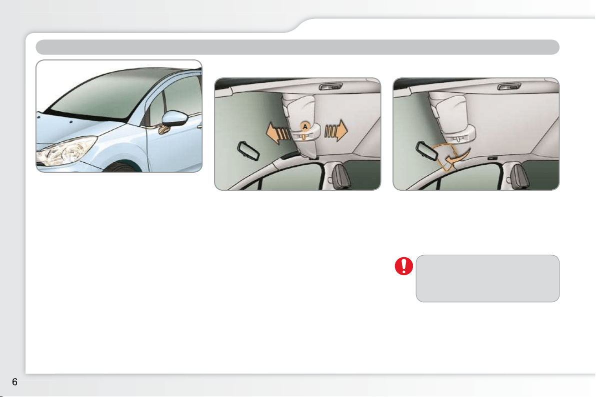
ZENITH WINDSCREEN
System comprising a panoramic tinted
glass area to increase lighting and vi-
sion in the cabin.
Fitted with a manual blind to improve
thermal comfort and sun visors to avoid
dazzle.
To open the blind, take it by its cen-
tral grip A , then pull it backward
guiding it to the desired position.
To close the blind, take it by its cen-
tral grip A , then pull it forwards guid-
ing it to the desired position.
Lower the sun visors to avoid dazzle.
Do not attach or hang heavy
objects to the blind or its guide
rails.
Blind Sun visors
Before moving the blind, the sun visors
must be in the folded position.
FAMILIARISATION
INTERIOR
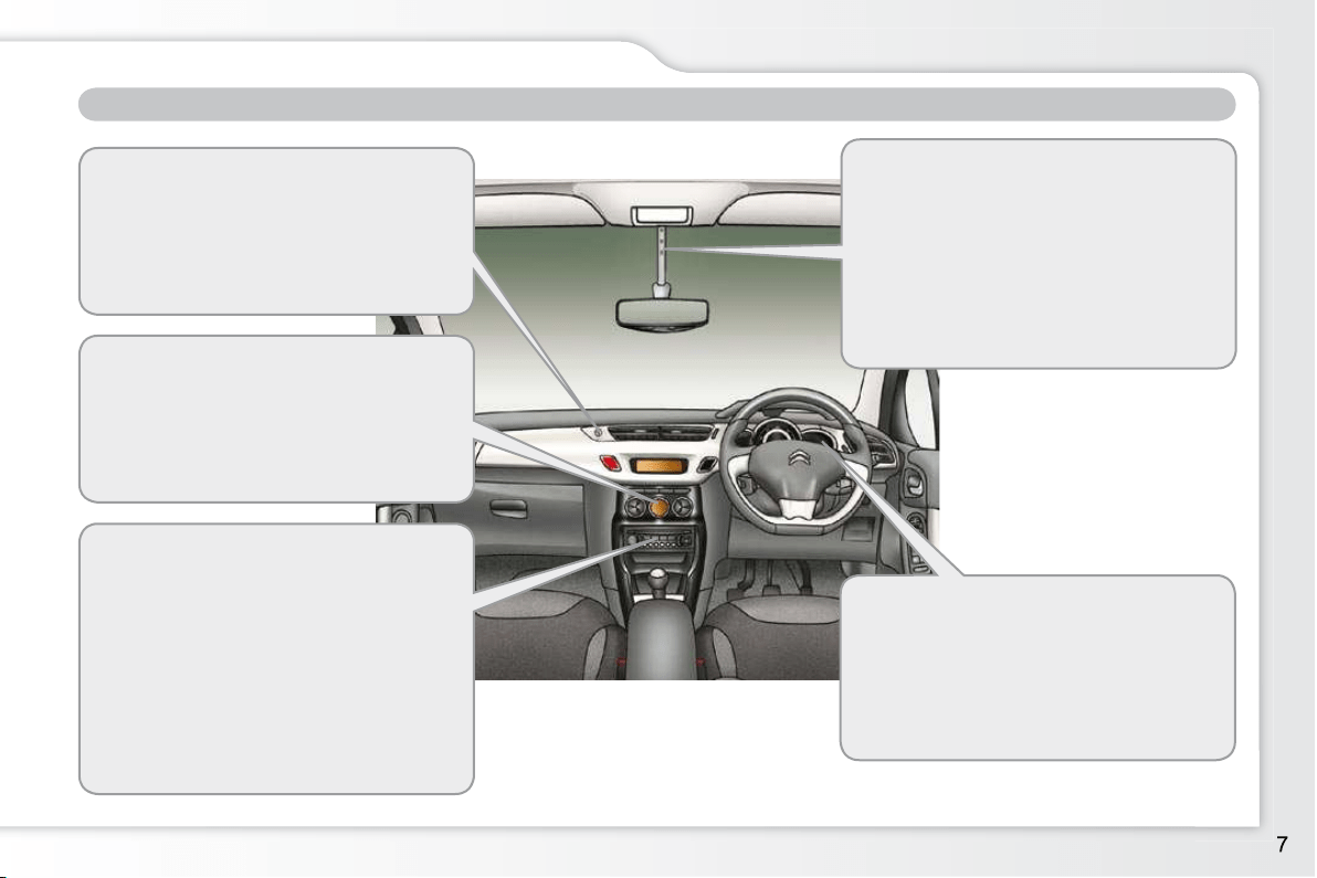
Interior mood lighting
This subdued passenger compart-
ment lighting improves visibility inside
the vehicle in low lighting conditions. It
comprises 4 lamps, located in the au-
tomatic day/night mirror support, in the
footwells and in the lower dashboard
storage compartment.
81
Gear effi ciency indicator
Associated with the manual gearbox,
this system suggests when to change
up to obtain optimum fuel consumption.
106
Scented air freshener
The scented air freshener diffuses the
selected fragrance throughout the pas-
senger compartment from its location in
the ventilation system.
54
Digital air conditioning
After setting the desired level of com-
fort, the system then automatically con-
trols this level according to the ambient
conditions.
51
Audio and communication systems
These systems benefi t from the latest
technology: MP3 compatible Audio sys-
tem, USB port, Bluetooth hands-free
system, MyWay with 16/9 colour screen,
auxiliary inputs, Hi-Fi audio system.
MyWay
171
Audio system
203
FAMILIARISATION
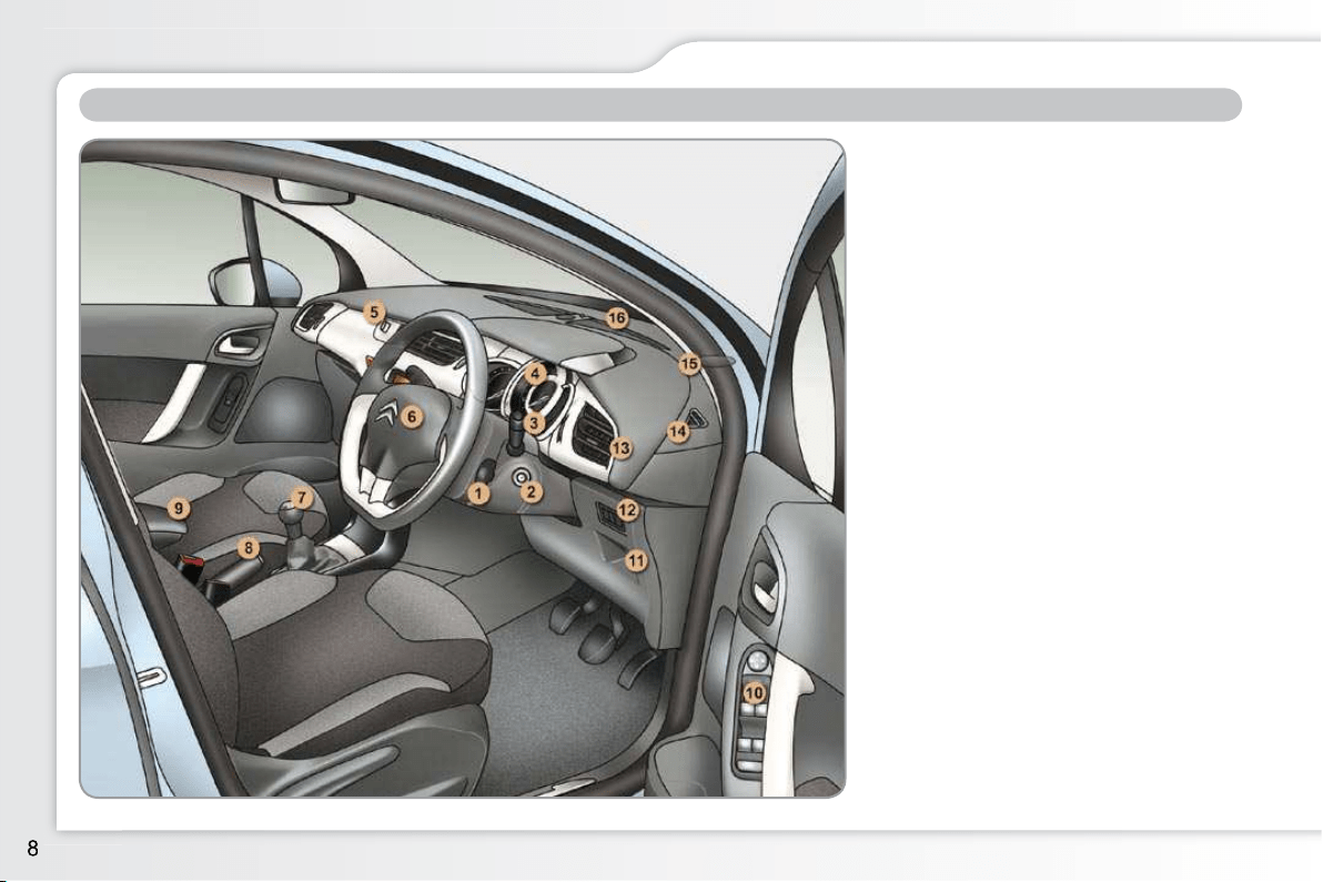
INSTRUMENTS AND CONTROLS
1. Audio equipment steering mounted
controls.
2. Steering lock and ignition.
3. Wipers/screenwash/trip computer
control stalk.
4. Instrument panel.
5. Scented air freshener.
6. Driver’s airbag.
Horn.
7. Gear lever.
8. Parking brake.
9. Central armrest with storage.
10. Door mirror controls.
Electric window controls.
Rear doors and electric windows
deactivation control.
11. Storage compartment.
12. Electric child lock button or
alarm button.
Electronic stability programme
button (ESP/ASR).
Stop & Start button.
13. Side adjustable air vent.
14. Front door window demisting/
defrosting vent.
15. Speaker (tweeter).
16. Windscreen demisting/defrosting
vent.
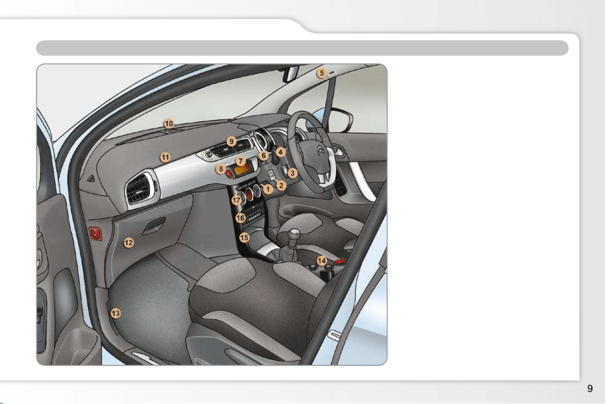
FAMILIARISATION
INSTRUMENTS AND CONTROLS
1. Steering wheel adjustment control.
2. Headlamp height adjustment.
3. Cruise control/speed limiter
switches.
4. Lighting and direction indicator
control stalk.
5. Microphone.
6. Central locking button.
7. Multifunction screen.
8. Hazard warning lamps switch.
9. Central adjustable air vents.
10. Sunshine sensor.
Hi-Fi audio system central speaker.
11. Passenger’s airbag.
12. Glove box/Passenger’s airbag
deactivation/Fusebox.
13. Bonnet release lever.
14. 12 V accessory socket.
USB port/auxiliary socket.
15. Upper and lower storage.
16. MyWay or Audio system.
17. Heating/air conditioning controls.
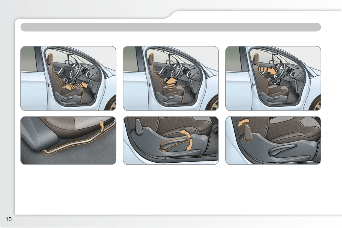
FAMILIARISATION
Front seats
SITTING COMFORTABLY
1. Forwards-backwards adjustment. 2. Height adjustment. 3. Seat back angle adjustment.
55

FAMILIARISATION
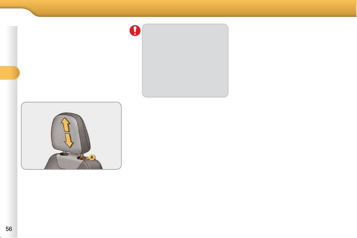
Other adjustments
4. Head restraint height adjustment.
56
Steering wheel adjustment
1. Unlocking the steering wheel adjust-
ment.
2. Height and reach adjustment.
3.
Locking the steering wheel adjustment.
59
For reasons of safety, these op-
erations must only be carried out
with the vehicle stationary.
SITTING COMFORTABLY
FAMILIARISATION
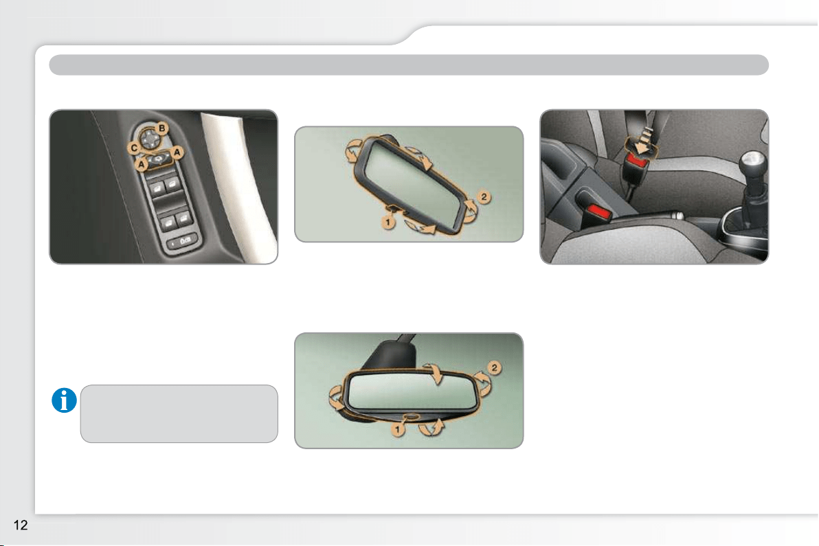
SITTING COMFORTABLY
Door mirrors
Adjustment
A. Selecting the mirror.
B. Adjusting the position of the mirror.
C. De-selecting the mirror.
Rear view mirror
Manual day/night type
1. Selecting the "day" position of the
mirror.
2. Adjusting the mirror.
59
58
Automatic day/night type
Front seat belts
A. Fitting the belt.
B. Fastening.
C. Check that the belt is correctly fas-
tened by pulling on the belt webbing.
99
1. Automatic detection of day/night
mode.
2. Adjusting the mirror.
59
Other functions...
Folding/Unfolding.
FAMILIARISATION
SEEING CLEARLY
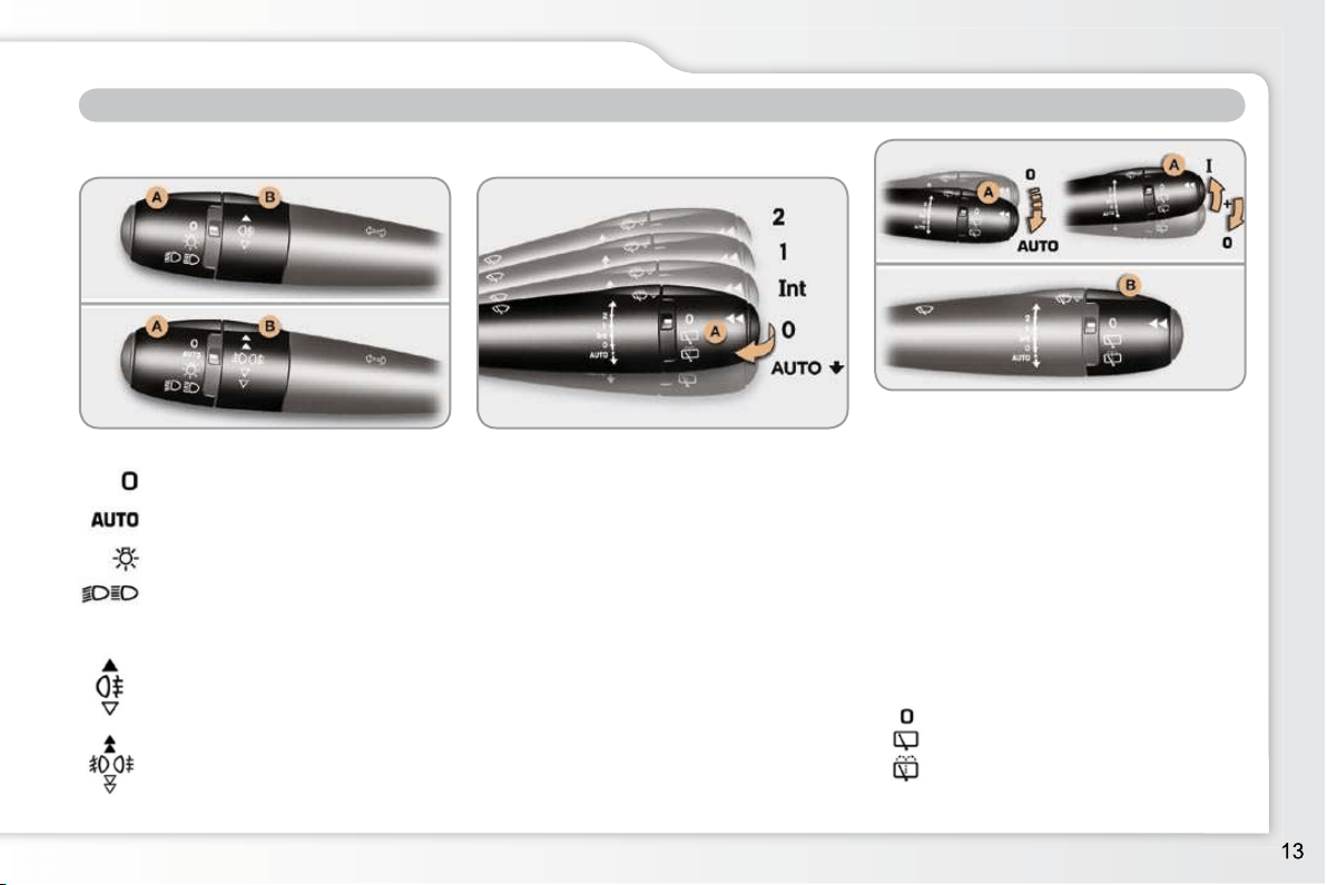
Lighting
Ring A
Ring B
73
Lighting off.
Automatic illumination of head-
lamps.
Sidelamps.
Dipped/main beam headlamps.
Rear foglamps.
or
Front and rear foglamps.
Wipers
2. Fast wipe.
1. Normal wipe.
Int. Intermittent wipe.
0. Park.
AUTO Automatic rain sensitive wipers
or single wipe.
77
78
Park.
Intermittent wipe.
Wash-wipe.
Stalk A: windscreen wipers
Wash-wipe: pull the stalk towards you.
Switching on "AUTO" mode
Push the stalk downwards and re-
lease it.
Switching off "AUTO" mode
Push the stalk upwards and return it
to position "0" .
Ring B: rear wiper
79
FAMILIARISATION
VENTILATION
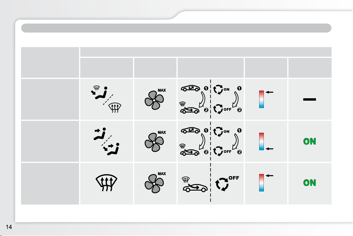
Advice on interior settings
Digital air conditioning: use of the fully automatic mode by pressing the "AUTO" button is recommended.
I require...
Heating or Manual air conditioning
Air distribution Air fl ow
Air recirculation /
Exterior air intake
Temperature Manual A/C
HEAT
COOL
DEMISTING
DEFROSTING
FAMILIARISATION
MONITORING
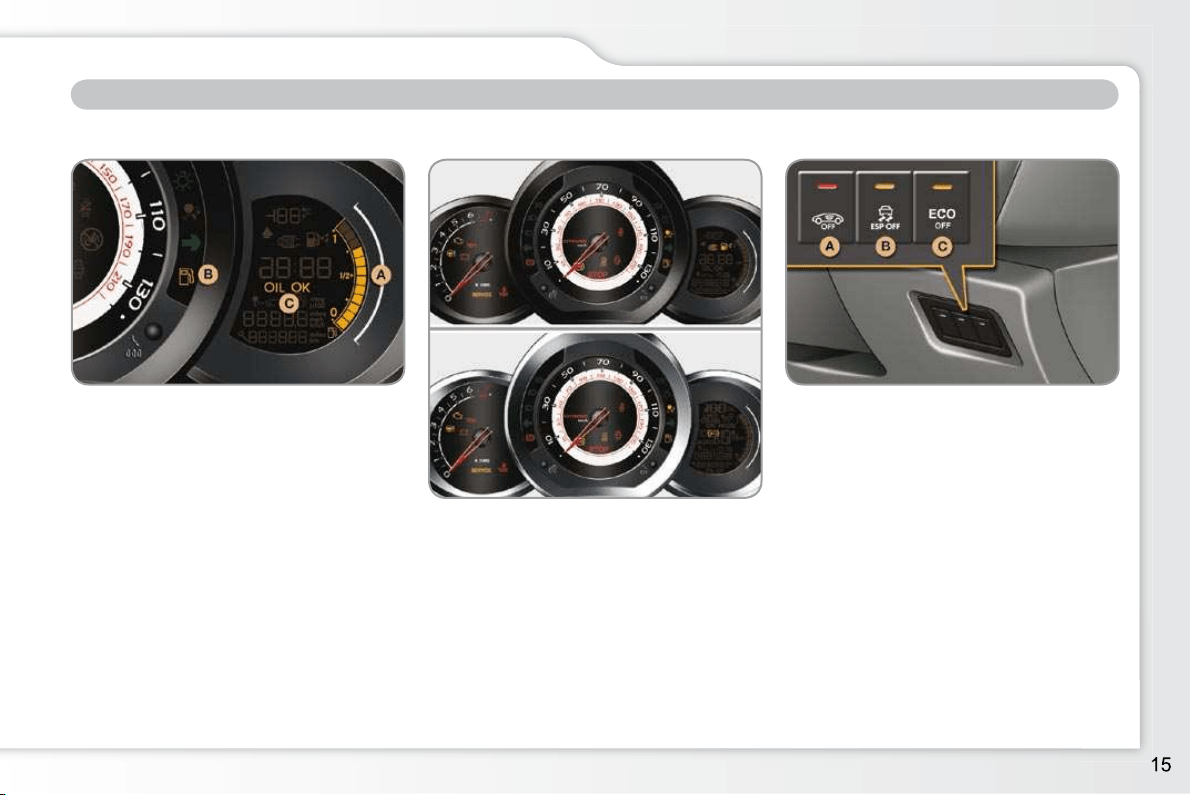
Instrument panel
A. With the ignition on, the fuel gauge
bars for the fuel remaining should
come on.
B. With the engine running, the associ-
ated low level warning lamp should
go off.
C. With the ignition on, the oil level in-
dicator should display "OIL OK" for
a few seconds.
If the levels are not correct, top up the
level which is low.
19
Warning lamps
1. With the ignition on, the orange and
red warning lamps come on.
2. With the engine running, these
warning lamps should go off.
If a warning lamp remains on, refer to
the page concerned.
21, 26
Switch panel
Lighting of the indicator lamp indicates
the status of the corresponding function.
A. Activation of the electric child lock.
95
64
B. Deactivation of the ESP/ASR system.
or
Deactivation of the interior volumet-
ric alarm.
C.
Deactivation of the Stop & Start system.
98
114
FAMILIARISATION
PASSENGER SAFETY
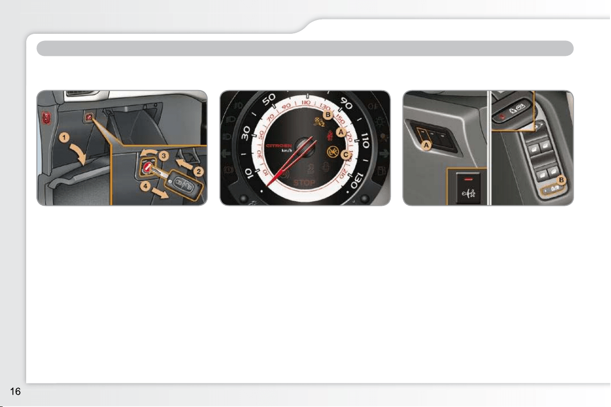
Front passenger’s airbag
1. Open the glove box.
2. Insert the key.
3. Select position:
"ON" (activation), with front passen-
ger or "forwards facing" child seat,
"OFF" (deactivation), with "rear fac-
ing" child seat.
4. Remove the key keeping the switch
in the new position.
101
Front seat belts and
passenger’s front airbag
A. Front seat belts not fastened or un-
fastened warning lamp.
102
Electric child lock
The lighting of the indicator lamp indi-
cates the status of the corresponding
function.
A. Deactivation of the rear door controls.
or
B. Deactivation of the rear door and
rear electric window controls.
95
B. Front passenger’s airbag deactiva-
tion indicator lamp.
C. Front passenger’s airbag activation
indicator lamp.
99
FAMILIARISATION
DRIVING SAFELY
Stop & Start
Going into engine STOP mode
The "ECO" warning lamp comes
on in the instrument panel and
the engine goes into standby:
- with a manual gearbox; at speeds
below 12 mph (20 km/h), put the
gear lever into neutral, then release
the clutch pedal.
In certain circumstances, STOP may
not be available; the "ECO" warning
lamp fl ashes for a few seconds, then
goes off.
113
Going into engine START mode
The "ECO" warning lamp goes
off and the engine restarts:
- with a manual gearbox; depress
the clutch pedal.
In certain circumstances, START mode
may be invoked automatically; the
"ECO" warning lamp fl ashes for a few
seconds, then goes off.
114
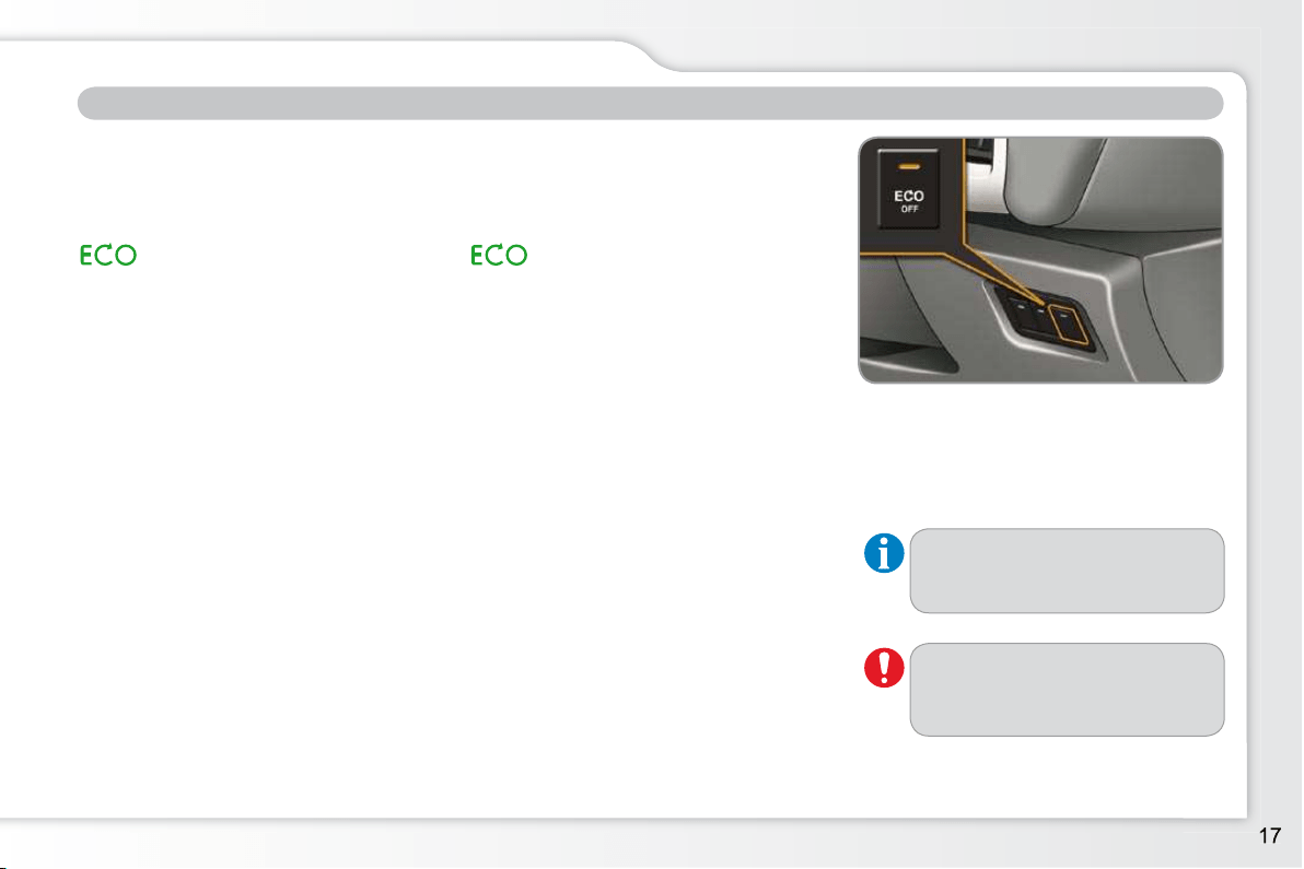
Deactivation/Reactivation
You can deactivate the system at any
time by pressing the "ECO OFF" button;
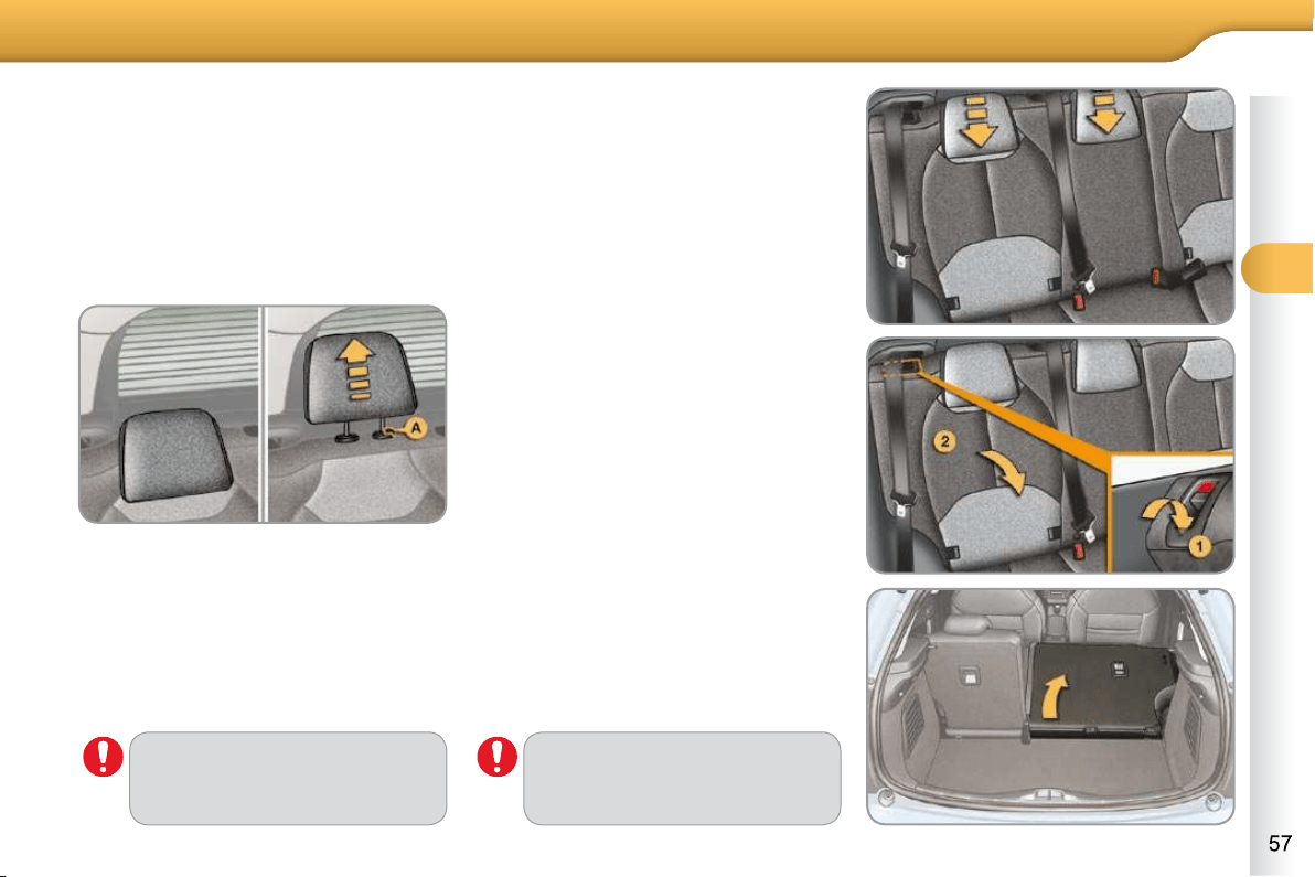
the warning lamp in the button comes
on.
The system is reactivated auto-
matically every time the engine
is started with with the key.
Before refuelling or doing any-
thing under the bonnet, you
must switch off the ignition with
the key.
115
FAMILIARISATION
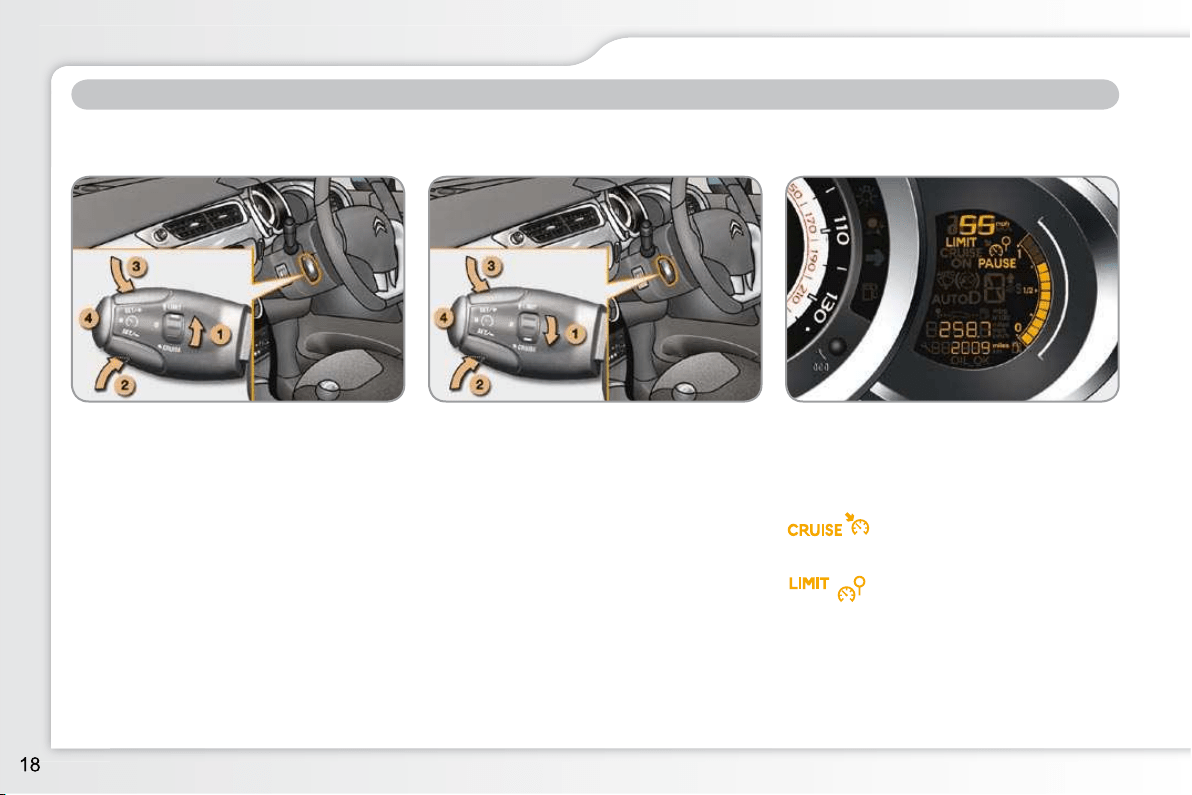
Speed limiter "LIMIT"
1. Selecting/Switching off speed limiter
mode.
2. Decrease the programmed value.
3. Increase the programmed value.
4. Speed limiter on/off.
116
DRIVING SAFELY
Cruise control "CRUISE"
1. Selecting/Switching off cruise con-
trol mode.
2. Decrease the programmed value.
3. Increase the programmed value.
4. Cruise control Off/Resume.
118
The values must be set with the engine
running.
Display in the instrument panel
The cruise control or speed limiter mode
appears in the instrument panel when it
is selected.
In order to be programmed or activated,
the vehicle speed must be higher than
25 mph (40 km/h), with at least fourth
gear engaged on a manual gearbox
(second gear on a "SensoDrive" or au-
tomatic gearbox).
Cruise control
Speed limiter
1
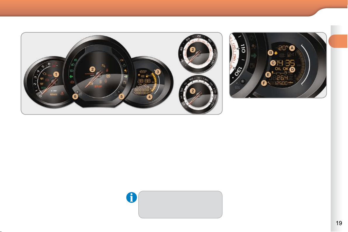
MONITORING
Panel grouping together the vehicle operation indication dials and warning lamps.
PETROL - DIESEL MANUAL GEARBOX INSTRUMENT PANELS
5. Display management button
Servicing information.
Adjust the time and choose units.
Reset the service indicator.
6. Instrument panel lighting button.
Adjusts the brightness of the lighting
of the instruments and controls.
For more information, refer to the
section on the button or function
and its associated display.
Dials
1. Rev counter.
Indicates the speed of rotation of the
engine (x 1 000 rpm).
2. Vehicle speed.
Indicates the current speed of the
moving vehicle (mph or km/h).
3. Fuel level.
Indicates the quantity of fuel remain-
ing in the tank.
4. Screen.
A. Ambient temperature.
(°Celsius or °Fahrenheit)
B. Gear effi ciency indicator.
C. Time.
D. Engine oil level indicator.
Appears a few seconds after switching
on the ignition, then disappears.
E. Trip computer.
F. Service indicato r.
(miles or km) then,
Total mileage.
These two functions are displayed
successively when switching on the
ignition.
Screen

1
MONITORING
PETROL - DIESEL MANUAL, SENSODRIVE OR AUTOMATIC
GEARBOX INSTRUMENT PANELS
Panel grouping together the vehicle operation indication dials and warning lamps.
Depending on the version, the instrument panel may have permanent back-lighting.
Dials
1. Rev counter.
Indicates the speed of rotation of the
engine (x 1 000 rpm).
2. Vehicle speed.
Indicates the current speed of the
moving vehicle (mph or km/h).
3. Fuel level.
Indicates the quantity of fuel remain-
ing in the tank.
4. Screen.
5. Display management button
Alternates display between range
and trip mileage recorder.
Servicing information.
Resets the selected function to zero
(trip distance recorder or service in-
dicator).
6. Instrument panel lighting button.
Adjusts the brightness of the lighting
of the instruments and controls.
For more information, refer to the
section on the button or function
and its associated display.
A. Speed limiter
(mph or km/h) or
Cruise control.
B. Gear effi ciency indicator.
C. SensoDrive or automatic gearbox
information.
D. Range
(miles or km) or
Trip mileage recorder.
E. Service indicator
(miles or km), then
Total mileage recorder
These two functions are displayed
successively when switching on the
ignition.
F. Engine oil level indicator
Appears a few seconds after switch-
ing on the ignition, then disappears.
Screen
1
MONITORING
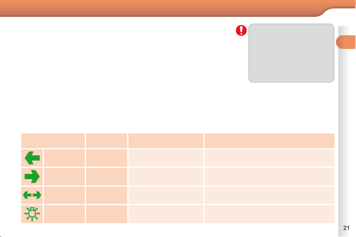
Indicator and warning lamps
Visual indicators informing the driver that a system is in operation (operation or
deactivation indicator lamps) or of the occurrence of a fault (warning lamp).
When the ignition is switched on
Certain warning lamps come on for a few seconds when the vehicle's ignition is
switched on.
When the engine is started, these same warning lamps should switch off.
If they remain on, before moving off, refer to the information on the warning lamp concerned.
Operation indicator lamps
If one of the following indicator lamps comes on, this confi rms that the corresponding
system has come into operation.
The warning lamps may come
on continuously (fi xed) or fl ash.
Certain warning lamps may
come on in two different modes.
Only by relating the type of ligh-
ting to the operating status of
the vehicle can it be ascertained
whether the situation is normal
or whether a fault has occurred.
Associated warnings
The switching on of certain warning lamps may be accompanied by an audible
signal and a message on the multifunction screen.
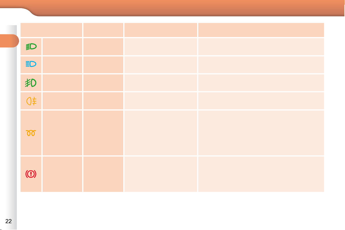
Warning lamp is on Cause Action/Observations
Left-hand
direction
indicato r
fl ashing with
buzzer.
The lighting stalk is pushed
down.
Right-hand
direction
indicator
fl ashing with
buzzer.
The lighting stalk is pushed up.
Sidelamps fi xed.
The lighting stalk is in the
"Sidelamps" position.
Hazard
warning lamps
fl ashing with
audible signal.
The hazard warning lamps
switch, located on the
dashboard, has been operated.
The left-hand and right-hand direction indicators
and their associated indicator lamps fl ash
simultaneously.
1
MONITORING
Front
foglamps
fi xed.
The front foglamps are
switched on.
Turn the ring on the stalk rearwards twice to
switch off the front foglamps.
Rear
foglamps
fi xed.
The rear foglamps are
switched on.
Turn the ring on the stalk rearwards to switch off
the rear foglamps.
Diesel engine
pre-heating
fi xed.
The ignition switch is
at the 2nd position
(ignition on).
Wait until the warning lamp goes off before
starting.
The period of illumination of the warning lamp is
determined by the climatic conditions (up to about
thirty seconds in extreme climatic conditions).
If the engine does not start, switch the ignition off
and then on, wait until the warning lamp goes off
again, then start the engine.
Parking brake fi xed.
The parking brake is
applied or not properly
released.
Release the parking brake to switch off the
warning lamp, keeping your foot on the brake
pedal.
Observe the safety recommendations.
For further information on the parking brake, refer
to the "Driving" section.
Dipped beam
headlamps
fi xed.
The lighting stalk is in the
"Dipped beam headlamps"
position.
Main beam
headlamps
fi xed.
The lighting stalk is pulled
towards you.
Pull the stalk to return to dipped beam
headlamps.
Warning lamp is on Cause Action/Observations

1
MONITORING
Stop & Start
fi xed.
The Stop & Start system
has put the engine in STOP
mode at a vehicle stop
(traffi c lights, traffi c jam,
or other...).
The warning lamp goes off and the engine
restarts automatically in START mode, as soon
as you want to move off.
fl ashes for a
few seconds,
then goes off.
STOP mode is temporarily
unavailable.
or
START mode is invoked
automatically.
Refer to "Driving - § Stop & Start" for special
cases with STOP mode and START mode.
Passenger's
airbag
system
fi xed.
The control switch, located
in the glove box, is in
the " ON " position.
The passenger's front
airbag is activated.
In this case, do not install a
rear-facing child seat.
Turn the control switch to the " OFF " position
to deactivate the front passenger's airbag.
In this case you can install a rear-facing child
seat.
Engine
coolant
temperature
fi xed blue .
On starting the engine, it
indicates that the engine
is cold.
After a few minutes driving, it swiches off to
indicate that the engine temperature is normal.
In order to protect your engine, avoid driving too
hard until the warning lamp has switched off.
Warning lamp is on Cause Action/Observations
1
MONITORING
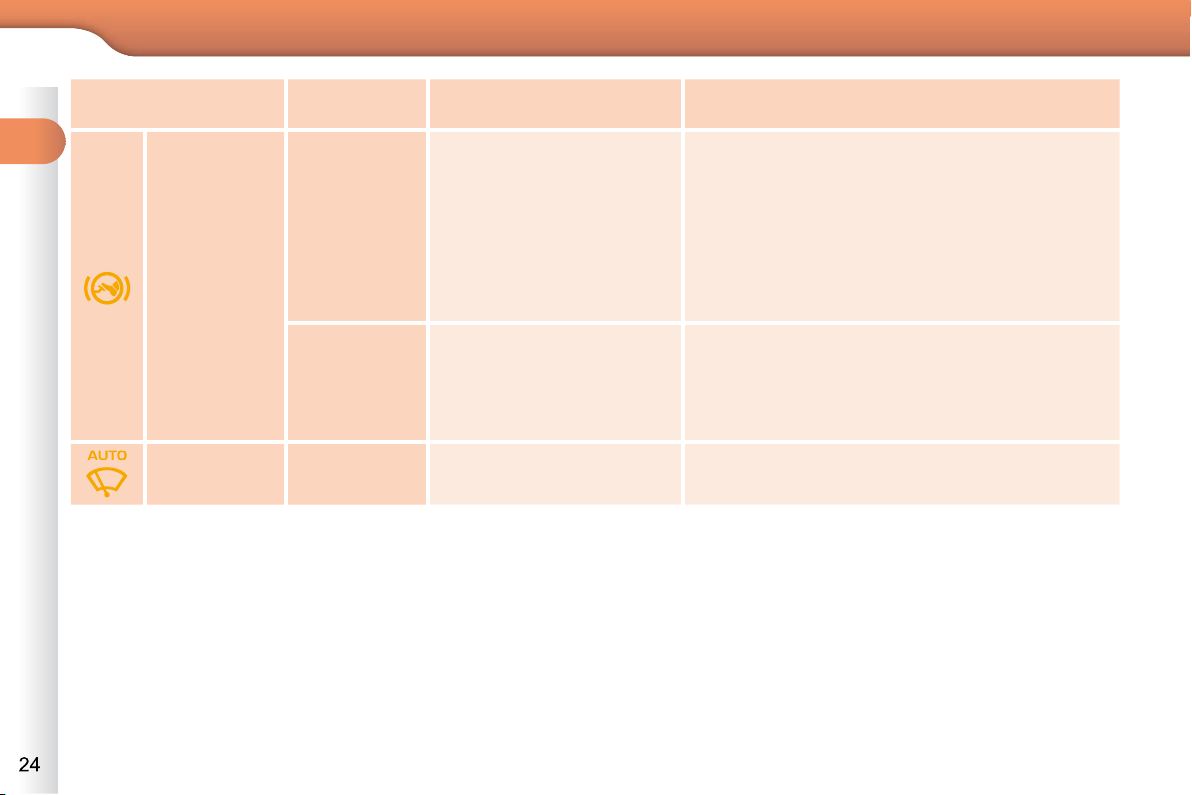
Foot on the
brake pedal
fi xed.
The brake pedal must be
pressed.
With the SensoDrive gearbox, press the brake
pedal to start the engine (lever in position N ).
With an automatic gearbox, with the engine
running, press the brake pedal before releasing
the parking brake, to unlock the lever and come
out of position P .
If you wish to release the parking brake without
pressing the brake pedal, this warning lamp will
remain on.
fl ashing.
With a SensoDrive gearbox,
if you hold the vehicle on an
incline using the accelerator
for too long, the clutch
overheats.
Use the brake pedal and/or the parking brake.
Automatic
wiping
fi xed.
The wiper control is pushed
downwards.
Automatic front wiping is activated.
Warning lamp is on Cause Action/Observations
1
MONITORING
Deactivation indicator lamps
If one of the following indicator lamps comes on, this confi rms that the corresponding system has been switched off intentionally.
This is may be accompanied by an audible signal and a message on the multifunction screen.
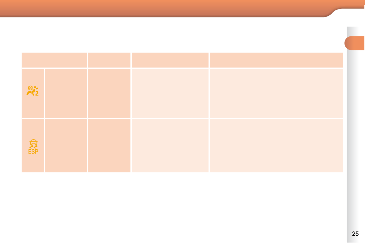
Passenger's
airbag
system
fi xed.
The control, located in the
glove box, is set to the OFF
position.
The passenger's front
airbag is deactivated.
In this case you can install
a "rear facing" child seat.
Set the control to the ON position to activate
the passenger's front airbag.
In this case, do not fi t a child seat in the
rear-facing position.
ESP/ASR fi xed.
The button, located at
the bottom left of the
dashboard, is pressed. Its
indicator lamp is on.
The ESP/ASR is
deactivated.
ESP: electronic stability
programme.
ASR: anti-skid regulation.
Press the button to activate the ESP/ASR. Its
indicator lamp goes off.
The ESP/ASR system is activated automatically
when the vehicle is started.
If deactivated, the system is reactivated
automatically from around 30 mph (50 km/h).
Warning lamp is on Cause Action/Observations
1
MONITORING
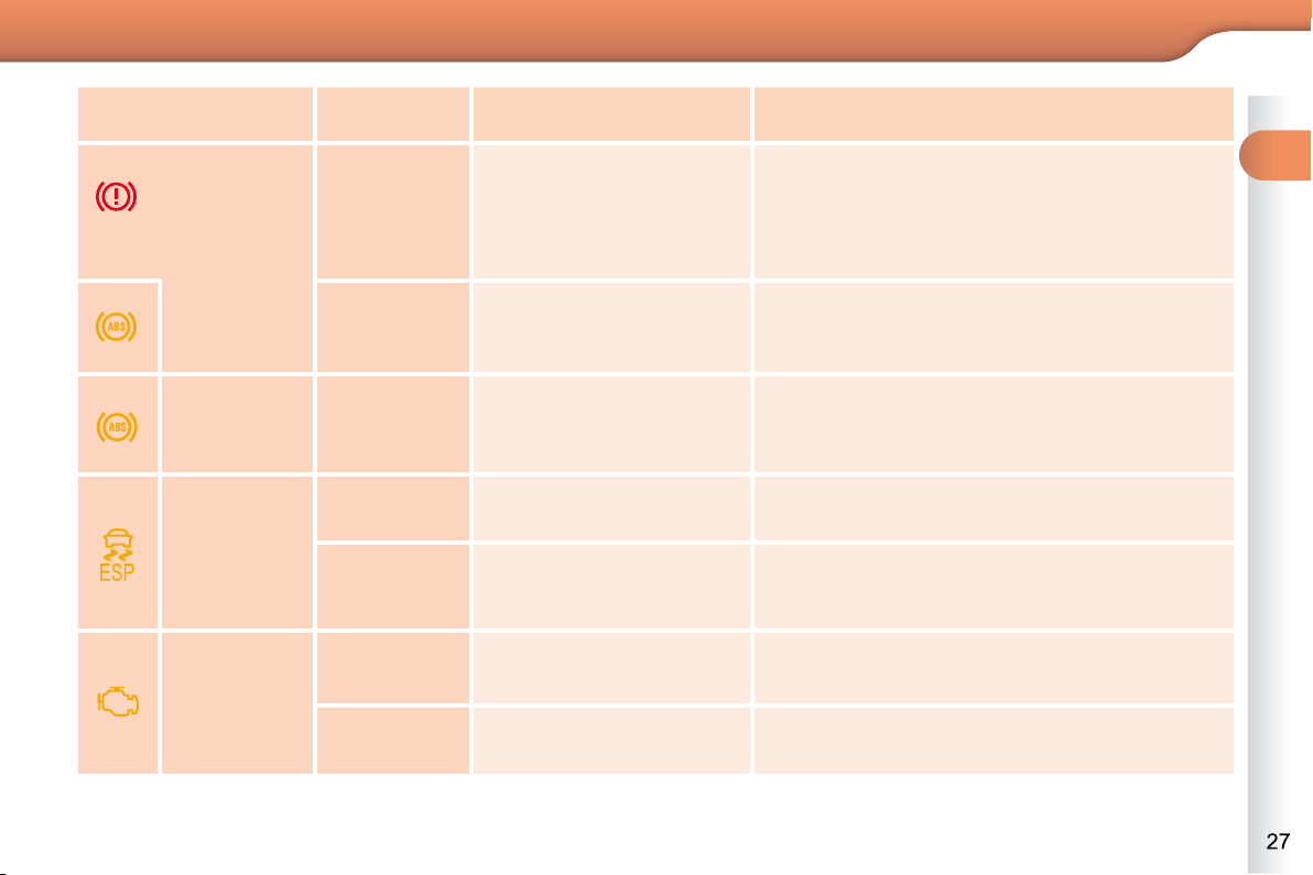
Warning lamps
When the engine is running or the ve-
hicle is being driven, the switching on
of one of the following warning lamps
indicates a fault which requires action
on the part of the driver.
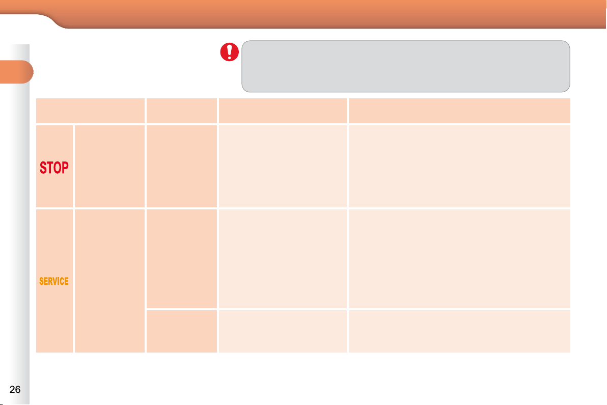
Any fault resulting in the illumination of a warning lamp must be investigated
further by reading the associated message in the multifunction screen.
If you encounter any problems, do not hesitate to contact a CITROËN
dealer or a qualifi ed workshop.
STOP
fi xed, alone
or associated
with another
warning lamp,
accompanied
by an audible
signal and a
message on
the screen.
Illumination of the warning
lamp is associated with a
serious braking system or
engine coolant temperature
problem.
Stop as soon as it is safe to do so as the engine
may cut out when driving.
Park, switch off the ignition and call a CITROËN
dealer or a qualifi ed workshop.
Service
temporarily.
Minor problems have
occurred for which there is
no specifi c warning lamp.
Identify the problem by reading the message
shown in the screen, such as, for example:
- the engine oil level,
- the screenwash level,
- the remote control battery,
- saturation of the particle emission fi lter on
Diesel vehicles (see "Checks - § particle
emissions fi lter").
For any other faults, contact a CITROËN dealer or
a qualifi ed workshop.
fi xed.
Major problems have
occurred for which there is
no specifi c warning lamp.
Identify the problem by reading the message
shown in the screen and contact a CITROËN
dealer or a qualifi ed workshop.
Warning lamp is on Cause Action/Observations
1
MONITORING
Anti-lock
Braking
System
(ABS)
fi xed.
The anti-lock braking
system has a fault.
The vehicle retains conventional braking.
Drive carefully at reduced speed and contact
a CITROËN dealer or a qualifi ed workshop
without delay.
Dynamic
stability
control
(ESP/ASR)
fl ashing.
The ESP/ASR regulation is
active.
The system optimises traction and improves
the directional stability of the vehicle.
fi xed.
Unless it has been
deactivated with the indicator
lamp in the button on, the
ESP/ASR system has a fault.
Have it checked by a CITROËN or a qualifi ed
workshop.
Engine
autodiagnosis
system
fi xed.
The emission control
system has a fault.
The warning lamp should go off when the engine is started.
If it does not go off, contact a CITROËN dealer or qualifi ed
workshop without delay.
fl ashing.
The engine management
system has a fault.
Risk of destruction of the catalytic converter.
Have it checked by a CITROËN dealer or a
qualifi ed workshop.
Braking
fi xed,
associated
with the STOP
warning lamp.
The braking system fl uid
level is too low.
You must stop as soon as it is safe to do so.
Top up with brake fl uid recommended by
CITROËN.
If the problem persists, have the system checked
by a CITROËN dealer or a qualifi ed workshop.
+
fi xed, associated
with the STOP
and ABS
warning lamp.
The electronic brake force
distribution (EBFD) system
has a fault.
You must stop as soon as it is safe to do so.
Have it checked by a CITROËN or a qualifi ed
workshop.
Warning lamp is on Cause Action/Observations

1
MONITORING
Maximum
coolant
temperature
fi xed red.
The temperature of the
cooling system is too high.
Stop as soon as it is safe to do so.
Wait until the engine has cooled down before
topping up the level, if necessary.
If the problem persists, contact a CITROËN
dealer or qualifi ed workshop.
Engine oil
pressure
fi xed.
There is a fault with the
engine lubrication system.
You must stop as soon it is safe to do so.
Park, switch off the ignition and contact a
CITROËN dealer or a qualifi ed workshop.
Battery
charge
fi xed.
The battery charging circuit
has a fault (dirty or loose
terminals, slack or cut
alternator belt, ...).
The warning lamp should go off when the engine
is started.
If it does not go off, contact a CITROËN dealer or
a qualifi ed workshop.
Low fuel
level
fi xed.
When it fi rst comes on there
remains approximately
5 litres of fuel in the tank.
You must refuel as soon as possible to avoid
running out of fuel.
This warning lamp will come on every time the
ignition is switched on, until a suffi cient addition
of fuel is made.
Fuel tank capacity: approximately 50 litres
(petrol) or 48 litres (Diesel).
Never continue to drive until you run out of fuel
as this could damage the emission control and
injection systems.
Warning lamp is on Cause Action/Observations
1
MONITORING
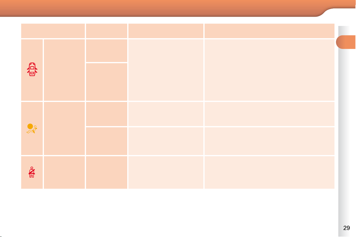
Airbags
temporarily.
This lamp comes on for
a few seconds when you
turn on the ignition, then
goes off.
This lamp should go off when the engine is
started.
If it does not go off, contact a CITROËN dealer or
a qualifi ed workshop.
fi xed.
One of the airbag or seat
belt pretensioner systems
has a fault.
Have it checked by a CITROËN dealer or a
qualifi ed workshop.
Seat belt not
fastened/
unfastened
fi xed then
fl ashing
accompanied
by
an increasing
audible signal.
The driver and/or the front
passenger has not fastened
or has unfastened their seat
belt.
Pull the strap then insert the tongue in the
buckle.
Door(s)
open
fi xed if the
speed is
below 6 mph
(10 km/h).
A door or the boot is still
open.
Close the door or boot.
fi xed and
accompanied
by an audible
signal if the
speed is
above 6 mph
(10 km/h).
Warning lamp is on Cause Action/Observations
1
MONITORING
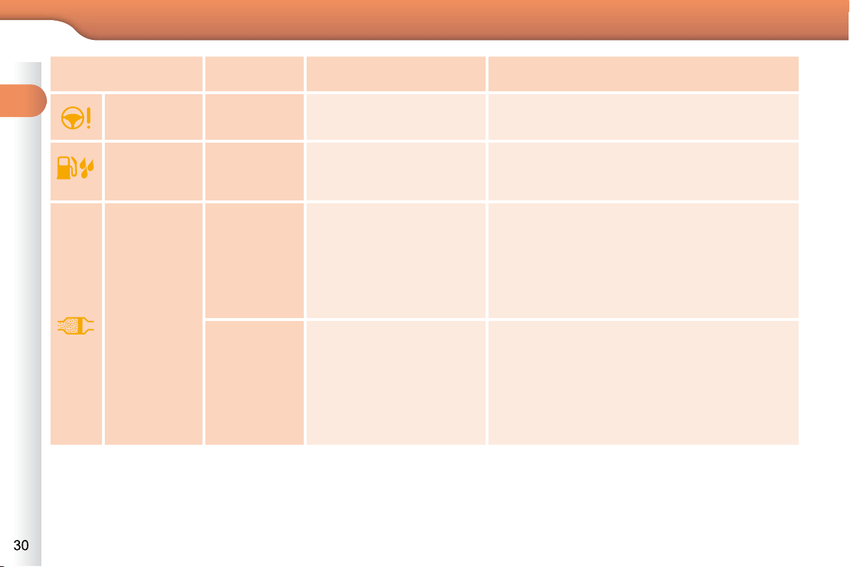
Water in
Diesel
fi xed.
The Diesel fuel fi lter
contains water.
Risk of damage to the injection system on Diesel
engines.
Contact a CITROËN dealer or a qualifi ed
workshop without delay.
Power
steering
fi xed.
The power steering has a
fault.
Drive carefully at reduced speed.
Have it checked by a CITROËN dealer or a
qualifi ed workshop.
Particle
emissions
fi lter (Diesel)
fi xed,
accompanied
by an audible
signal
message on
the risk of
blockage of
the particle
emissions fi lter.
This indicates that the
particle emissions fi lter
is starting to become
saturated.
As soon as driving conditions allow, regenerate
the fi lter by driving at a speed of at least 35 mph
(60 km/h) until the warning lamp goes off.
fi xed,
accompanied
by an audible
signal
and and a
message that
the particle
emissions fi lter
additive level
is too low.
This indicates the low level
of the additive reservoir.
Have the reservoir topped up as soon as
possible by a CITROËN dealer or a qualifi ed
workshop.
Warning lamp is on Cause Action/Observations
1
MONITORING
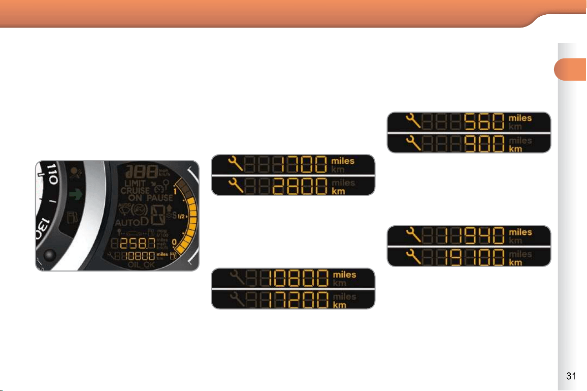
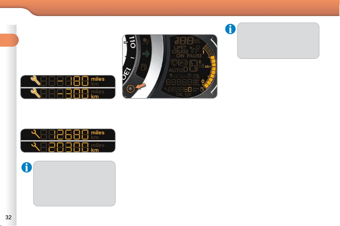
Service indicator
System which informs the driver when
the next service is due, in accordance
with the manufacturer's servicing
schedule.
The point at which the service is due is
calculated from the last indicator zero re-
set. It is determined by two parameters:
- the distance travelled,
- the time elapsed since the last
service.
Between 600 miles (1 000 km) and
1 800 miles (3 000 km) remain before
the next service is due
For a few seconds after the ignition is
switched on, the spanner symbolising
the service operations comes on. The
distance recorder display line indicates
the distance remaining before the next
service is due.
Example: 1 700 miles (2 800 km) re-
main before the next service is due.
For a few seconds after the ignition is
switched on, the screen indicates:
Less than 600 miles (1 000 km)
remain before the next service is due
Example: 560 miles (900 km) remain
before the next service is due.
For a few seconds after the ignition is
switched on, the display indicates:
A few seconds after the ignition is
switched on, the spanner goes off ; the
distance recorder resumes its normal
operation. The screen then indicates
the total and trip distances.
A few seconds after the ignition is switched
on, the distance recorder resumes its nor-
mal operation. The spanner remains on
to indicate that a service must be carried
out soon.
More than 1 800 miles (3 000 km)
remain before the next service is due
When the ignition is switched on, no ser-
vice information appears in the screen.
1
MONITORING
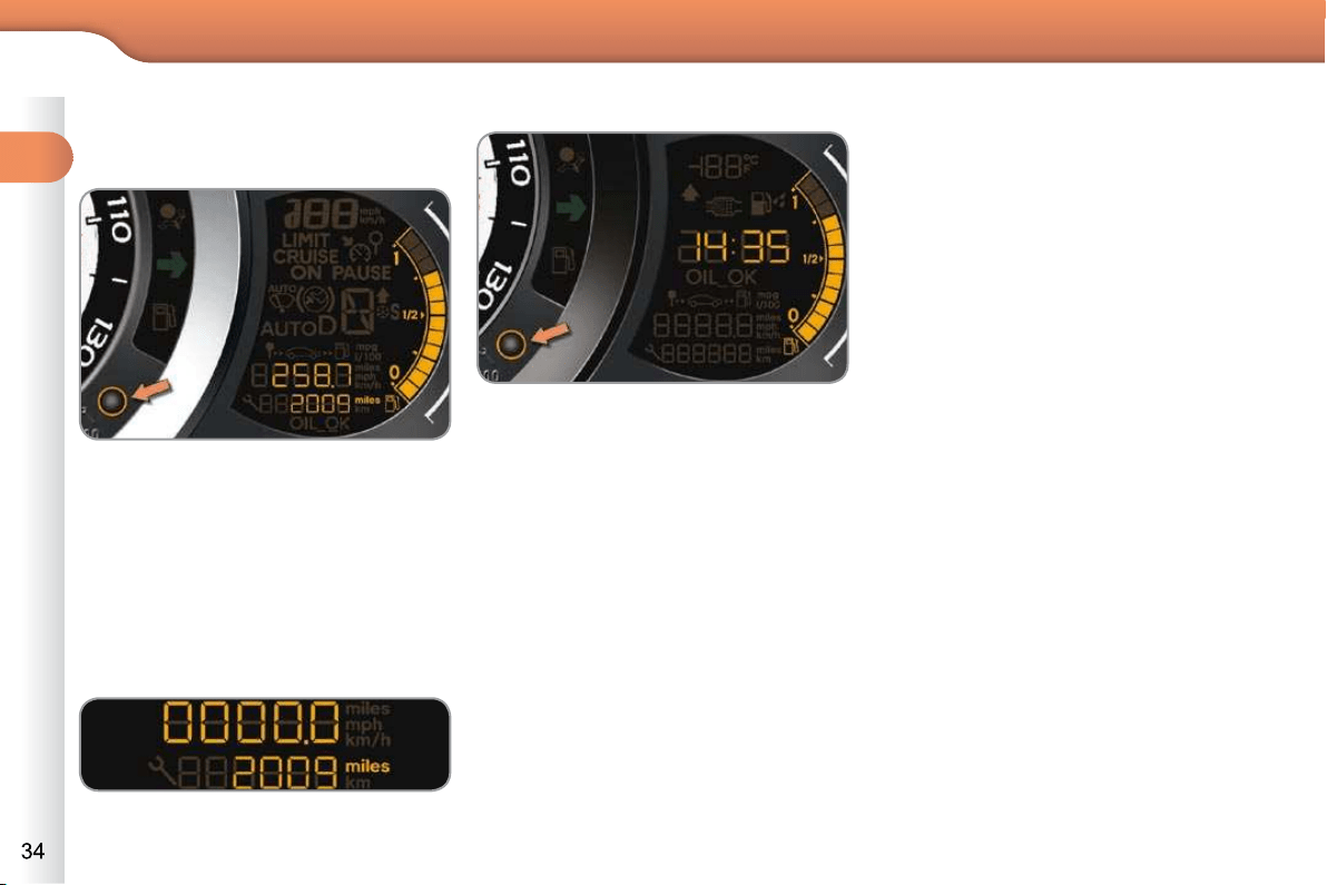
Service overdue
For a few seconds after the ignition is
switched on, the spanner fl ashes to
indicate that the service must be carried
out as soon as possible.
Example: the service is overdue by
180 miles (300 km).
For a few seconds after the ignition is
switched on, the display indicates:
A few seconds after the ignition is switched
on, the distance recorder resumes its nor-
mal operation. The spanner remains on .
The distance remaining may be
weighted by the time factor, de-
pending on the driver's driving
habits.
Therefore, the spanner may also
come on if you have exceeded
the two year service interval.
Service indicator zero reset
After each service, the service indicator
must be reset to zero.
The procedure for resetting to zero is as
follows:
switch off the ignition,
press and hold the trip distance re-
corder zero reset button,
switch on the ignition; the distance re-
corder display begins a countdown,
when the display indicates "=0" ,
release the button; the spanner dis-
appears.
Retrieving the service information
You can access the service information
at any time.
Press the trip distance recorder zero
reset button.
The service information is displayed
for a few seconds, then disappears.
Following this operation, if you
wish to disconnect the battery,
lock the vehicle and wait at least
fi ve minutes for the zero reset to
be taken into account.

1
MONITORING
Service overdue
For a few seconds after the ignition is
switched on, the spanner fl ashes to
indicate that the service must be carried
out as soon as possible.
Example: the service is overdue by
180 miles (300 km).
For a few seconds after the ignition is
switched on, the display indicates:
A few seconds after the ignition is switched
on, the distance recorder resumes its nor-
mal operation. The spanner remains on .
The distance remaining may be
weighted by the time factor, de-
pending on the driver's driving
habits.
Therefore, the spanner may also
come on if you have exceeded
the two year service interval.
Service indicator zero reset
After each service, the service indicator
must be reset to zero.
The procedure for resetting to zero is as
follows:
switch off the ignition,
press and hold the trip distance re-
corder zero reset button,
switch on the ignition; the distance re-
corder display begins a countdown,
when the display indicates "=0" ,
release the button; the spanner dis-
appears.
Retrieving the service information
You can access the service information
at any time.
Press the trip distance recorder zero
reset button.
The service information is displayed
for a few seconds, then disappears.
Following this operation, if you
wish to disconnect the battery,
lock the vehicle and wait at least
fi ve minutes for the zero reset to
be taken into account.
1
MONITORING
The level shown will only be
correct if the vehicle is on level
ground and the engine has been
off for more than 30 minutes.
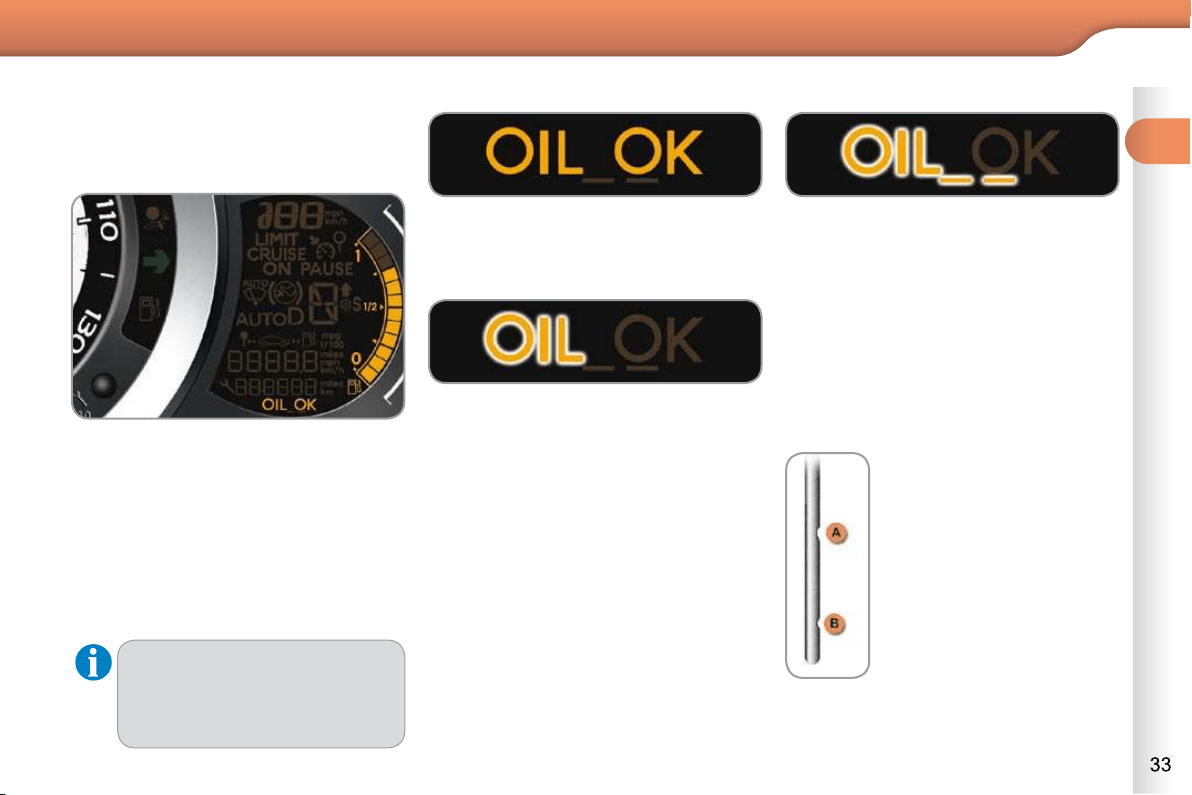
Engine oil level indicator
System which informs the driver whether
the engine oil level is correct or not.
This information is indicated for a few
seconds when the ignition is switched
on, after the service information.
Oil level correct
This is indicated by the fl ashing of "OIL" ,
linked with the service warning lamp, ac-
companied by an audible signal and a
message in the multifunction screen.
If the low oil level is confi rmed by a
check using the dipstick, the level must
be topped up to prevent damage to the
engine.
Oil level low
This is indicated by the fl ashing of "OIL--" .
Contact a CITROËN dealer or a qualifi ed
workshop.
Oil level indicator fault
Dipstick
There are 2 marks on the
dipstick:
- A = max; never exceed
this level (risk of dam-
age to the engine),
- B = min; top up the level
via the oil fi ller cap, using
the grade of oil suited to
your engine.
Refer to the "Checks" section to locate
the dipstick and the oil fi ller cap on your
engine.
1
MONITORING
Total distance recorder
System which measures the total distance
travelled by the vehicle during its life.
The total and trip distances are dis-
played for thirty seconds when the
ignition is switched off, when the driver's
door is opened and when the vehicle is
locked or unlocked.
With the ignition on, press the button
until zeros appear.
Trip distance recorder
System which measures a distance
travelled during a day or other period
since it was reset to zero by the driver.
Clock
Adjusting the time - Choice of units
press the button for more than
two seconds: °C or °F is displayed,
press the button to select °C or °F,
press the button for more than
two seconds to complete the adjust-
ments.
After approximately 30 seconds without
any action, the screen returns to the
normal display.
To adjust the time of the clock and
choose the units used by the screen,
use the right-hand button on the instru-
ment panel, carrying out the operations
in the following order:
press the button for more than
two seconds: the minutes fl ash,
press the button to increase the
minutes,
press the button for more than
two seconds: the hours fl ash,
press the button to increase the hours,
press the button for more than
two seconds: 24 H or 12 H is dis-
played,
press the button to select 24 H or 12 H,
1
MONITORING
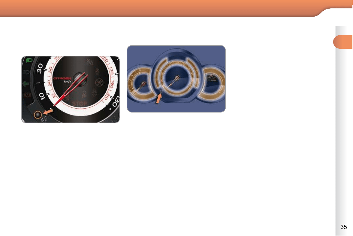
The instrument panel remains illumi-
nated with only the vehicle speed and
cruise control or speed limiter informa-
tion, if in use.
If there is an alert or a change in a func-
tion or to a setting, the black panel mode
is interrupted.
Activation
With the lighting on, press the left
hand button of the instrument panel
several times to progressively re-
duce the dashboard lighting level.
Press the button again to reduce the
lighting to the minimum level and
switch off the interior mood lighting.
Press the button again to activate
the black panel.
Black panel
System allowing certain displays to be
switched off for night driving.
Activation
When the lighting is on:
press the button to change the
brightness of the instruments and
controls,
when the level of brightness required
is reached, release the button.
Deactivation
When the lighting is off, or in day mode
on vehicles fi tted with daytime running
lamps, pressing the button does not
have any effect.
Lighting dimmer
System for manual adjustment of the
brightness of the instruments and con-
trols in relation to the exterior brightness.
1
MONITORING
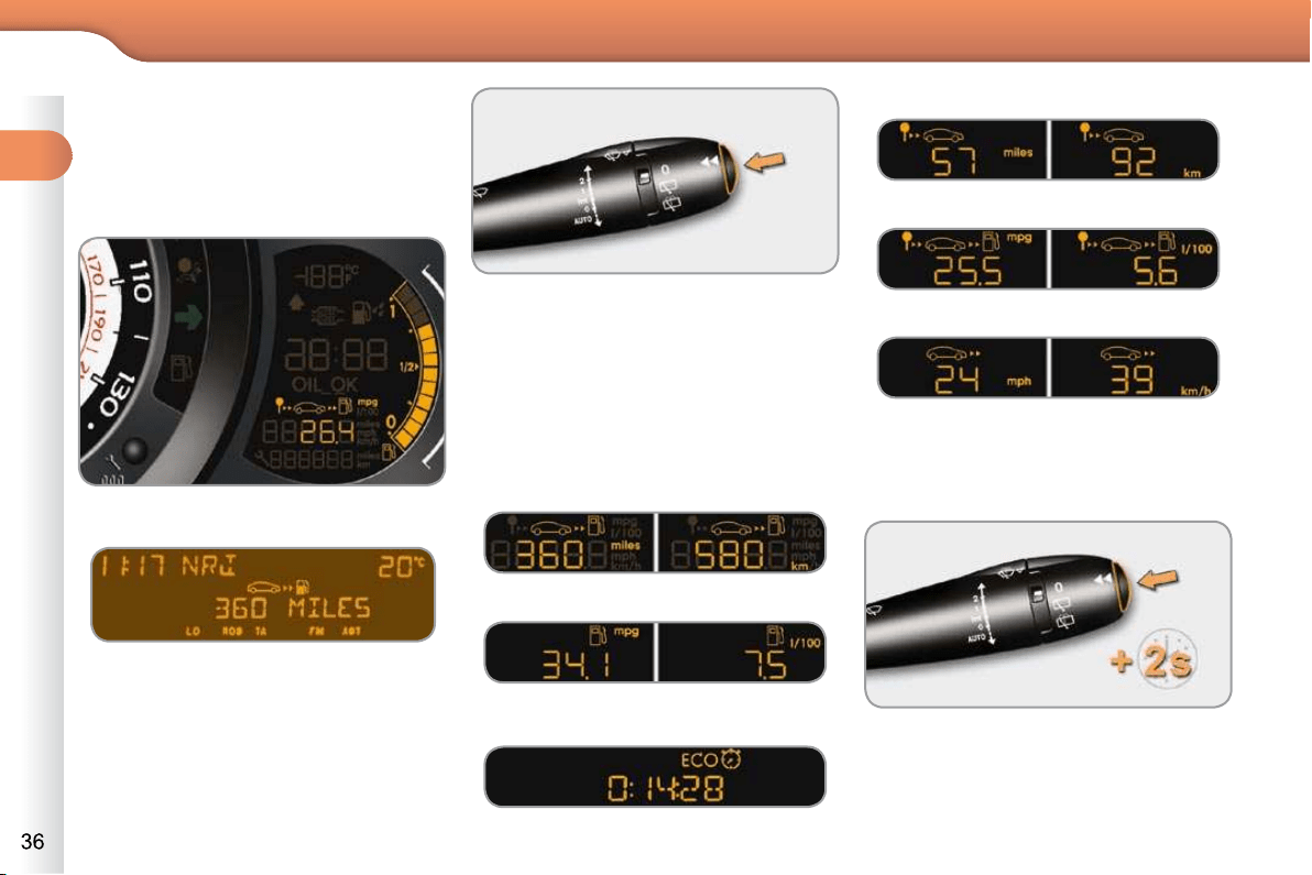
Screen in the instrument panel
Monochrome screen A
Zero reset
Information displays
Press the button, located at the end
of the wiper stalk , to display the
various items of trip computer infor-
mation in succession.
Press the control for more than
two seconds to reset to zero the
distance travelled, the average
fuel consumption and the average
speed.
The trip computer provides the following
information:
- range,
- current fuel consumption,
- the Stop & Start time counter * ,
- distance travelled,
- average fuel consumption,
The next press then returns you to
the normal display.
TRIP COMPUTER
System that gives you current infor-
mation on your journey (range, fuel
consumption…).
- average speed.
* Available only with the monochrome
screen A.
1
MONITORING
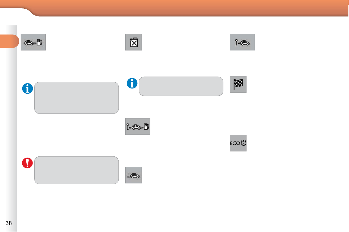
A few definitions…
Range
(miles or km)
This indicates the distance
which can still be travelled
with the fuel remaining in the tank in
relation to the average fuel consump-
tion over the last few miles (kilometres)
travelled.
Current fuel consumption
(mpg or l/100 km or km/l)
This is the average fuel con-
sumption during the last few
seconds.
Average fuel consumption
(mpg or l/100 km or km/l)
This is the average fuel con-
sumption since the last trip
computer zero reset.
Average speed
(mph or km/h)
This is the average speed calcu-
lated since the last trip computer
zero reset (ignition on).
Distance travelled
(miles or km)
This indicates the distance
travelled since the last trip
computer zero reset.
This value may vary following a
change in the style of driving or
the relief, resulting in a signifi -
cant change in the current fuel
consumption.
If dashes are displayed continu-
ously while driving in place of the
digits, contact a CITROËN dealer
or a qualifi ed workshop.
This function is only displayed
from 20 mph (30 km/h).
When the range falls below 20 miles
(30 km), dashes are displayed. After fi l-
ling with at least 5 litres of fuel, the range
is recalculated and is displayed when it
exceeds 60 miles (100 km).
Distance remaining to
destination
(miles or km)
This is the distance remaining
to be travelled to the fi nal destination. It
can be entered by the user.
If the distance is not entered, dashes
are displayed in place of the digits.
Stop & Start time counter
(minutes/seconds or hours/minutes)
If your vehicle is fi tted with Stop &
Start, a time counter calculates the
time spent in STOP mode during a journey.
It resets to zero every time the ignition
is switched on with the key.
1
MONITORING
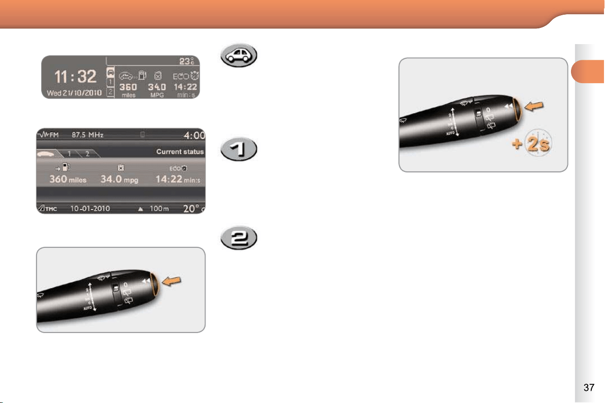
Monochrome screen C
16/9 colour screen (MyWay)
Information displays
Press the button, located at the end
of the wiper stalk , to display the
various trip computer tabs in suc-
cession:
- the current information
tab with:
the range,
the current fuel
consumption,
the distance
remaining to be
travelled or the Stop &
Start time counter,
- the trip "1" tab with:
the distance travelled,
the average fuel
consumption,
the average speed,
for the fi rst trip.
- the trip "2" tab with:
the distance travelled,
the average fuel
consumption,
the average speed,
for the second trip.
Pressing the button again returns
you to the normal display.
When the trip required is displayed,
press the button on the end of the wi-
per stalk for more than two seconds.
Trips "1" and "2" are independent but
their use is identical.
For example, trip "1" can be used for
daily fi gures, and trip "2" for monthly
fi gures.
Trip zero reset

1
MONITORING
A few definitions…
Range
(miles or km)
This indicates the distance
which can still be travelled
with the fuel remaining in the tank in
relation to the average fuel consump-
tion over the last few miles (kilometres)
travelled.
Current fuel consumption
(mpg or l/100 km or km/l)
This is the average fuel con-
sumption during the last few
seconds.
Average fuel consumption
(mpg or l/100 km or km/l)
This is the average fuel con-
sumption since the last trip
computer zero reset.
Average speed
(mph or km/h)
This is the average speed calcu-
lated since the last trip computer
zero reset (ignition on).
Distance travelled
(miles or km)
This indicates the distance
travelled since the last trip
computer zero reset.
This value may vary following a
change in the style of driving or
the relief, resulting in a signifi -
cant change in the current fuel
consumption.
If dashes are displayed continu-
ously while driving in place of the
digits, contact a CITROËN dealer
or a qualifi ed workshop.
This function is only displayed
from 20 mph (30 km/h).
When the range falls below 20 miles
(30 km), dashes are displayed. After fi l-
ling with at least 5 litres of fuel, the range
is recalculated and is displayed when it
exceeds 60 miles (100 km).
Distance remaining to
destination
(miles or km)
This is the distance remaining
to be travelled to the fi nal destination. It
can be entered by the user.
If the distance is not entered, dashes
are displayed in place of the digits.
Stop & Start time counter
(minutes/seconds or hours/minutes)
If your vehicle is fi tted with Stop &
Start, a time counter calculates the
time spent in STOP mode during a journey.
It resets to zero every time the ignition
is switched on with the key.
2
MULTIFUNCTION SCREENS
MONOCHROME SCREEN A
Displays on the screen
This displays the following information:
- time,
- date,
- ambient temperature (this fl ashes if
there is a risk of ice),
- status of the doors and boot,
- audio sources (radio, CD...),
- trip computer (refer to the "Instru-
ments and Controls" section).
Warning messages (e.g.: "Emission
control system faulty") or information
messages (e.g.: "Boot open") may ap-
pear temporarily. These can be cleared
by pressing the "ESC" button.
Controls
From the control panel of your Audio
system, you can:
press the "MENU" button to gain
access to the main menu ,
press the " " or " " buttons to scroll
through the items on the screen,
press the "MODE" button to change
the permanent application (date, au-
dio source...),
press the " " or " " buttons to
change a setting value,
press the "OK" button to confi rm,
or
press the "ESC" button to abandon
the operation in progress.
Main menu
Press the "MENU" button to gain
access to the main menu , then
press the " " or " " buttons to
scroll through the various menus:
- radio-CD,
- vehicle confi guration,
- options,
- display settings,
- languages,
- units.
Press the "OK" button to select the
menu required.
Radio-CD
With the Audio system switched on,
once the "Radio-CD" menu has been
selected you can activate or deacti-
vate the functions linked with use of the
radio (RDS, REG), or the CD (introscan,
shuffl e, CD repeat).
For more information on the "Radio-
CD" application, refer to the Audio sys-
tem part of the "Audio and Telematics"
section.
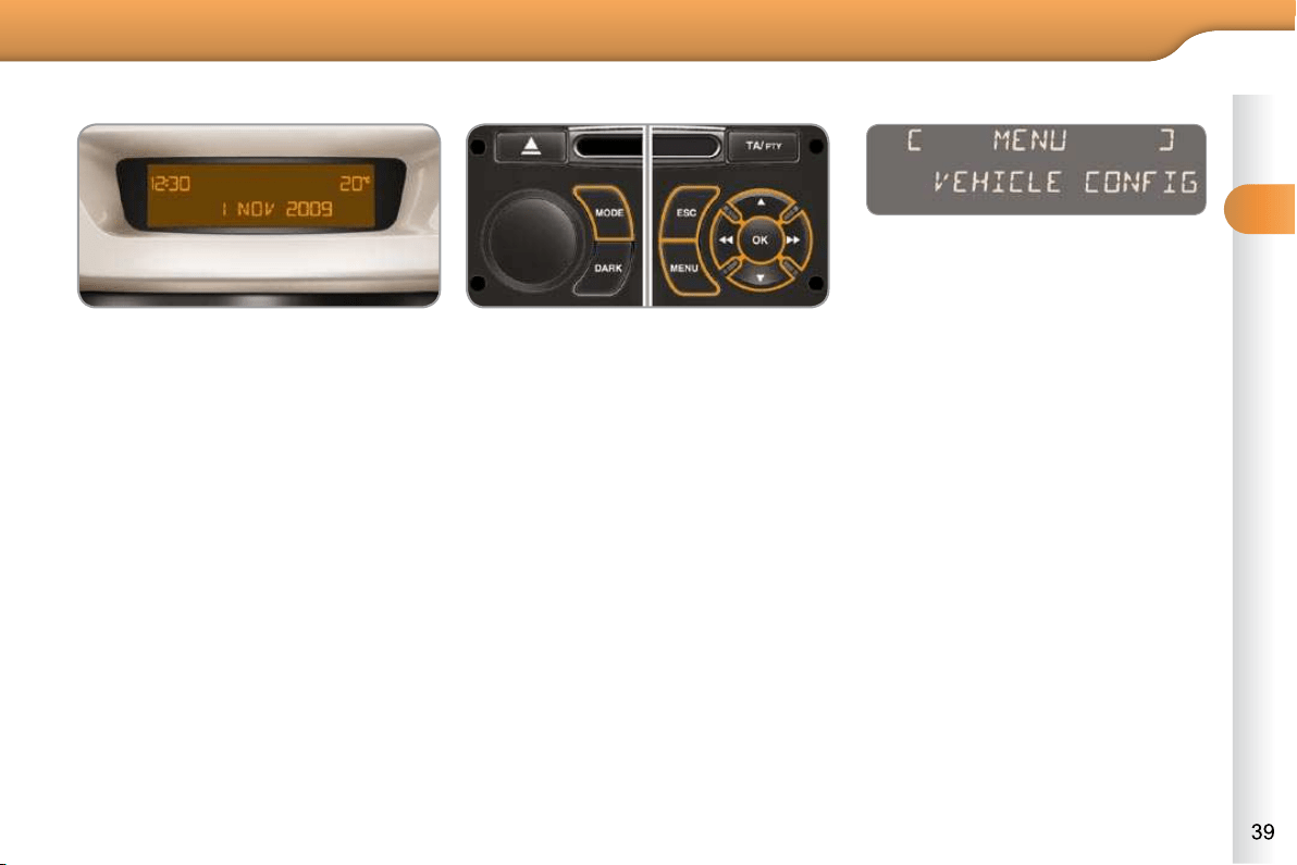
2
MULTIFUNCTION SCREENS
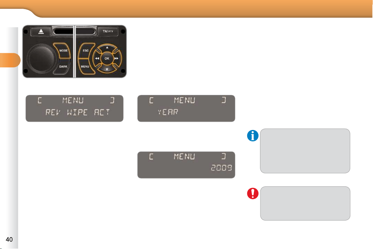
Vehicle confi guration
Once the "Vehicle Confi guration" menu
has been selected, you can activate or
deactivate the following equipment:
- wiper linked with reverse gear (refer
to the "Visibility" section),
- guide-me-home lighting (refer to the
"Visibility" section),
- parking sensors (refer to the
"Driving" section).
Options
Once the "Options" menu has been
selected, you can start diagnostics of
the status of the equipment (active, not
active, faulty).
Display settings
Once the "Display settings" menu has
been selected, you can gain access to
the following settings:
- year,
- month,
- day,
- hour,
- minutes,
- 12 or 24 hour mode.
Once you have selected a setting,
press the " " or " " buttons to
change its value.
Press the " " or " " buttons to
switch respectively to the previous
or next setting.
Press the "OK" button to save the
change and return to the normal
display or press the "ESC" button
to cancel.
Languages
Once the "Languages" menu has been
selected, you can change the language
used by the display (Français, Italiano,
Nederlands, Portugues, Portugues-
Brasil, Deutsch, English, Espanol).
Units
Once the "Units" menu has been se-
lected, you can change the units of the
following parameters:
- temperature (°C or °F),
-
fuel consumption (l/100 km, mpg or km/l).
Once the fuel consumption units
have been set to mpg, the infor-
mation in the instrument panel
screen on speed and distance
will also be in mph and miles.
For safety reasons, confi guration
by the driver of the multifunction
screen must only be done when
stationary.
2
MULTIFUNCTION SCREENS
MONOCHROME SCREEN C
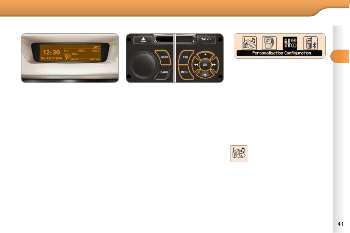
Displays on the screen
This displays the following information:
- time,
- date,
- ambient temperature (this fl ashes if
there is a risk of ice),
- status of doors and boot,
- audio sources (radio, CD, USB port,
jack socket etc.),
- trip computer (refer to the "Instruments
and controls" section).
Warning messages (E.g. "Emisions
control system faulty") or information
messages (E.g.: Automatic headlamps
active") may appear temporarily. These
can be cleared by pressing the "ESC"
button.
Controls
From your Audio system control panel,
you can:
press the "MENU" button to gain
access to the main menu ,
press the " " or " " buttons to scroll
through the items on the screen,
press the "MODE" button to change
the permanent application (trip com-
puter, audio source...),
press the " " or " " buttons to
change a setting value,
press the "OK" button to confi rm,
or
press the "ESC" button to abandon
the operation in progress.
Main menu
Press the "MENU" button to gain
access to the main menu :
- audio functions,
- the trip computer,
- personalisation-confi guration,
- telephone (hands-free kit).
Press the " " or " " buttons to se-
lect the menu required, then confi rm
by pressing the "OK" button.
"Audio functions" menu
With the Audio system switched on,
once this menu has been selected you
can activate or deactivate the functions
linked with use of the radio (RDS, REG,
RadioText), the CD (introscan, shuffl e,
CD repeat) or the MP3 player (USB
port/jack socket).
For more information on the "Audio
functions" application, refer to the
Audio system part of the "Audio and
Telematics" section.
2
MULTIFUNCTION SCREENS
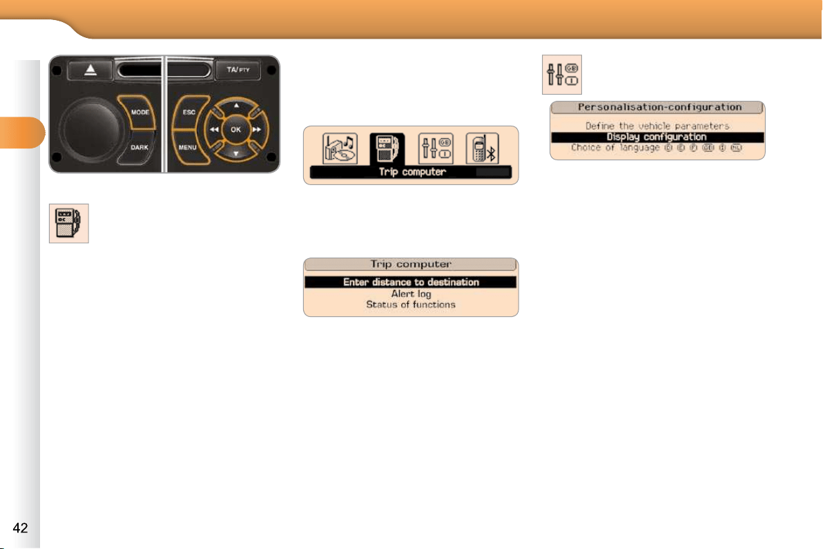
"Trip computer" menu
Once this menu has been selected, you
can consult information concerning the
status of the vehicle (warnings log, sta-
tus of functions, etc.)
Alert log
This summarises the active warning
messages, displaying them in succes-
sion on the multifunction screen.
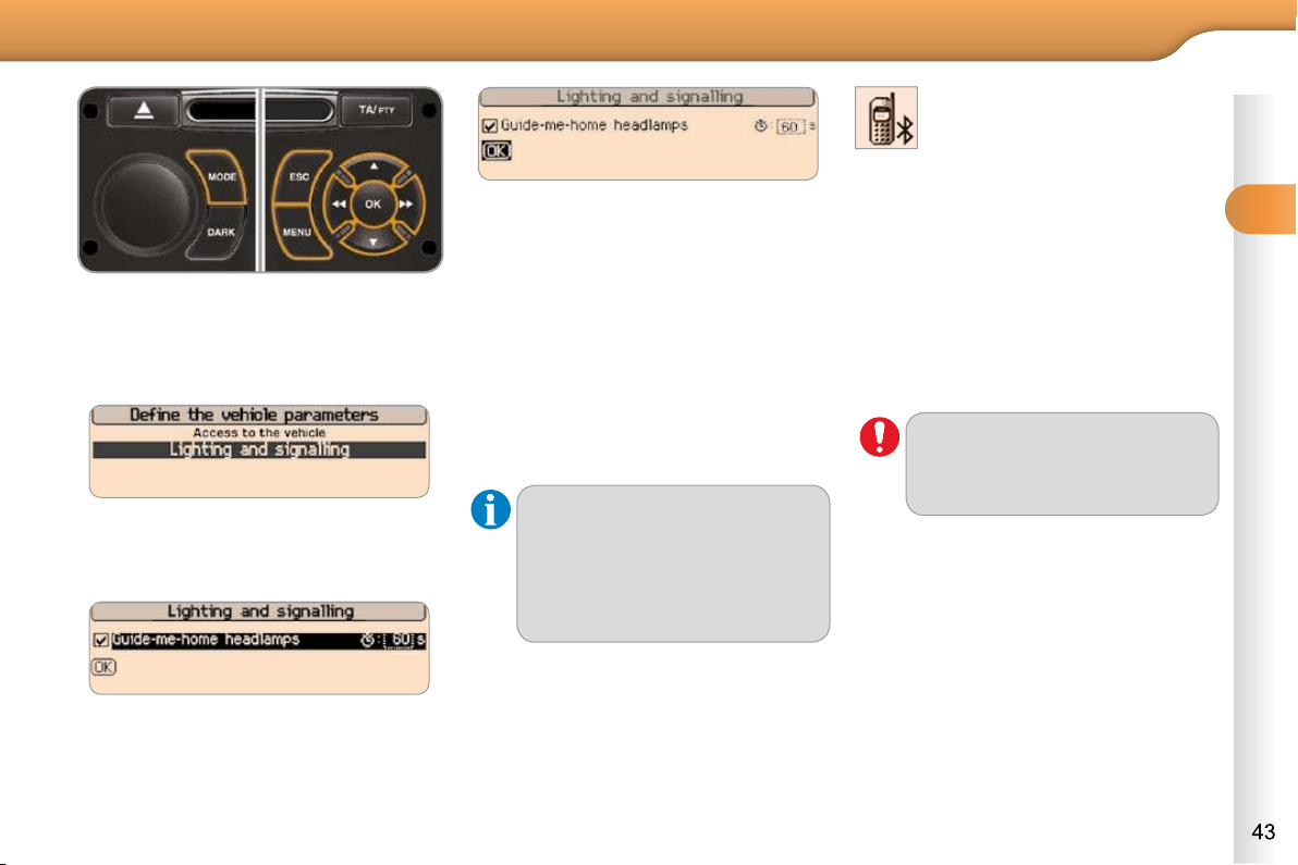
"Personalisation-
Configuration" menu
Defi ne the vehicle parameters
Once this menu has been selected, you
can activate or deactivate the following
equipment:
- wiper linked to reverse gear (refer to
the "Visibility" section),
- guide-me-home lighting
- parking sensors (refer to the
"Driving" section).
In the " Trip computer " menu, se-
lect one of the following applica-
tions:
Press the "MENU" button to gain
access to the general menu.
Press the arrows, then the "OK" but-
ton to select the " Trip computer "
menu.
Once this menu has been selected, you
can gain access to the following func-
tions:
- defi ne the vehicle parameters,
- display confi guration,
- choice of language.
Status of functions
This summarises the status (active or
inactive) of the vehicle's functions.
Enter distance to destination
This allows you to enter an approximate
distance until your fi nal destination.
2
MULTIFUNCTION SCREENS
Example: setting of the duration of the
guide-me-home lighting
Press the " " or " " buttons, then
the "OK" button to select the menu
required.
Press the " " or " " buttons,
then the "OK" button to select the
"Guide-me-home headlamps" line.
Press the " " or " " buttons to set
the value required (15, 30 or 60 sec-
onds), then press the "OK" button
to confi rm.
Press the " " or " " buttons, then
the "OK" button to select the "OK"
box and confi rm or press the "ESC"
button to cancel.
Choice of language
Once this menu has been selected,
you can change the language used
by the display (Deutsch, English,
Espanol, Français, Italiano, Nederlands,
Portugues, Portugues-Brasil, Türkçe * ).
"Telephone" Menu
For safety reasons, confi guration
by the driver of the multifunction
screen must only be done when
stationary.
Display confi guration
Once this menu has been selected, you
can gain access to the following settings:
- brightness-video setting,
- date and time setting,
- selection of units.
Once the fuel consumption units
have been changed to mpg, the
information in the screen rela-
ting to speed and distance also
changes to mph and miles re-
spectively.
With Audio system on, once this menu
is selected you can confi gure your
Bluetooth hands-free system (pairing),
view the various telephone directories
(list of calls, services...) and manage
your calls (call, hang up, second call,
secret mode...).
For more information on the "Telephone"
function, refer to the Audio system part
of the "Audio and telematics" section.
* According to country of destination.
2
MULTIFUNCTION SCREENS
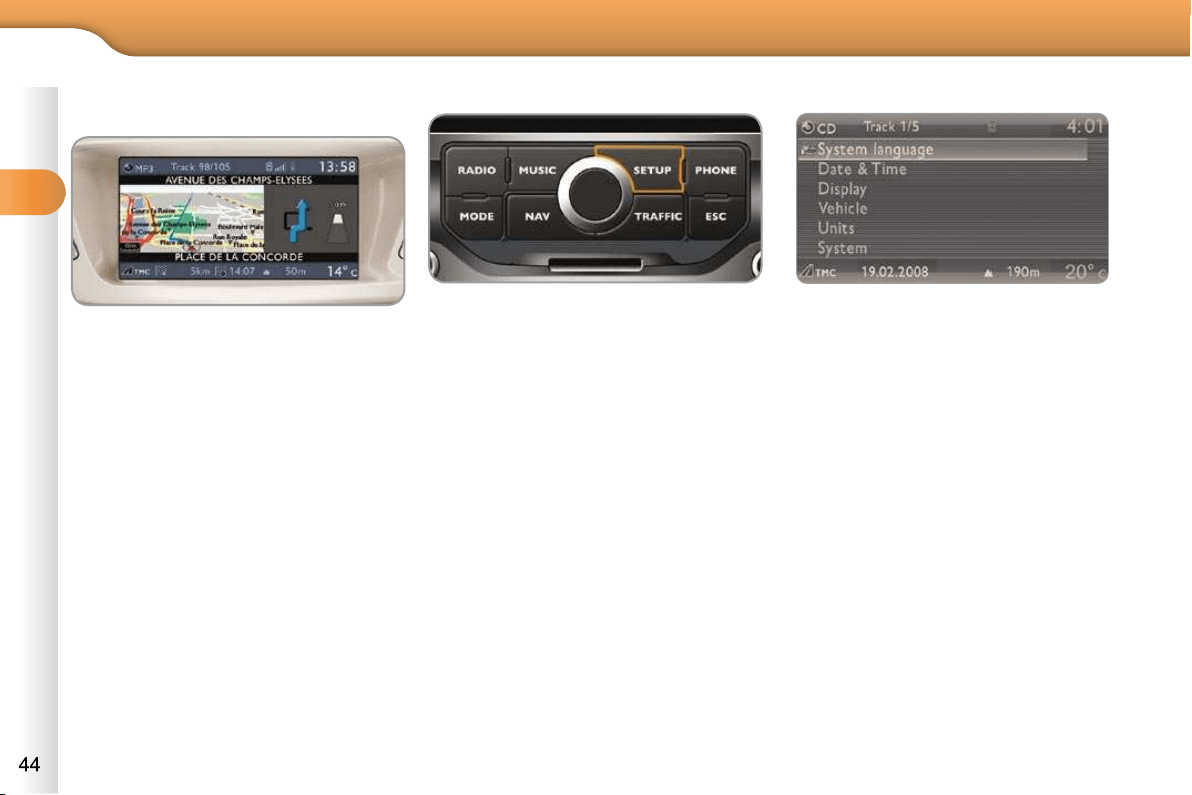
16/9 COLOUR SCREEN
(MYWAY)
Displays on the screen
It displays the following information au-
tomatically and directly:
- time,
- date,
- altitude,
- ambient temperature (the value dis-
played fl ashes if there is a risk of
ice),
- check of the doors,
- warning and vehicle function status
messages, displayed temporarily,
- audio functions,
- trip computer information (see the
"Monitoring" section),
- satellite navigation system informa-
tion.
Controls
MyWay To select one of the applica-
tions, at the control panel:
press the dedicated "RADIO" ,
"MUSIC" , "NAV" , "TRAFFIC" ,
"SETUP" or "PHONE" button for
access to the corresponding menu,
turn the dial to change the selection,
press the dial to confi rm the selection,
or
press the "ESC" button to abandon
the current operation and return to
the previous display.
For more information on these applica-
tions, refer to the "Audio and Telematics"
section or to the specifi c user guide given
to you with the other owner's documents.
"SETUP" menu
Press the "SETUP" button to gain
access to the "SETUP" menu. This
allows you to select from the follo-
wing functions:
- "System language",
- "Date and time",
- "Display",
- "Vehicle",
- "Units",
- "System".
2
MULTIFUNCTION SCREENS
* According to country.
System language
This menu allows you to select the lan-
guage used by the display: Deutsch,
English, Espanol, Français, Italiano,
Nederlands, Polski, Portugues, Türkçe * .
Date and time
This menu allows you to set the date
and time, the format of the date and the
format of the time (refer to the "Audio
and Telematics" section or to the specifi c
user guide given to you with the other
owner's documents).
Display
This menu allows you to set the bright-
ness of the screen, the screen colour
scheme and the colour of the map (day/
night or auto mode).
Vehicle
This menu allows you to activate or
deactivate certain driving and comfort
equipment:
- wiper linked with reverse gear (refer
to the "Visibility" section),
- guide-me-home lighting and dura-
tion (refer to the "Visibility" section),
- parking sensors (refer to the "Driving"
section).
Units
This menu allows you to select the
units: temperature (°C or °F) and fuel
consumption (km/l, l/100 or mpg).
System
This menu allows you to restore the fac-
tory confi guration, display the software
version and activate scrolling text.
For safety reasons, confi gura-
tion of the multifunction screen
by the driver must only be done
when stationary.
3
COMFORT
VENTILATION
Air intake
The air circulating in the passenger com-
partment is fi ltered and originates either
from the outside via the grille located at
the base of the windscreen or from the
inside in air recirculation mode.
Air treatment
The incoming air follows various routes
depending on the controls selected by
the driver:
- direct arrival in the passenger com-
partment (air intake),
- passage through a heating circuit
(heating),
- passage through a cooling circuit
(air conditioning).
The temperature control enables you to
obtain the level of comfort required by
mixing the air of the various circuits.
The air distribution control enables you
to diffuse the air in the passenger com-
partment combining several air vents.
The air fl ow control enables you to
increase or reduce the speed of the
ventilation blower.
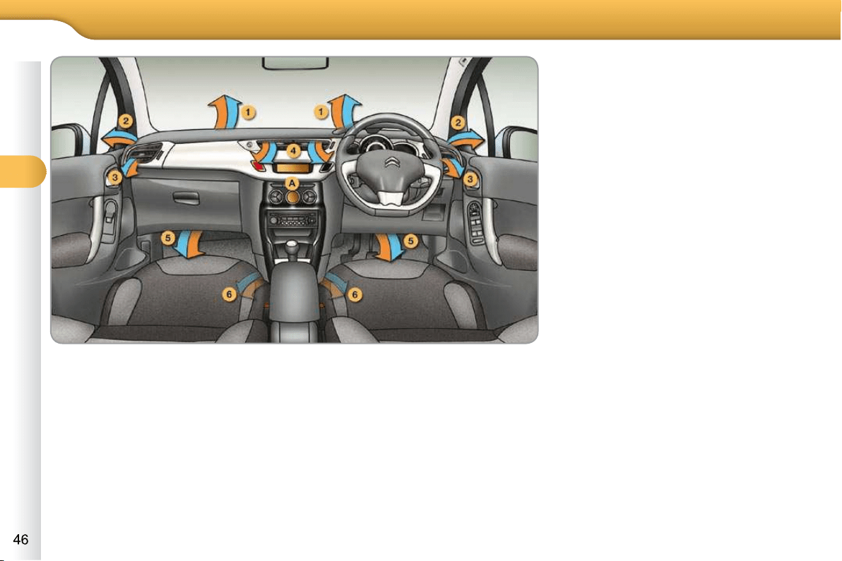
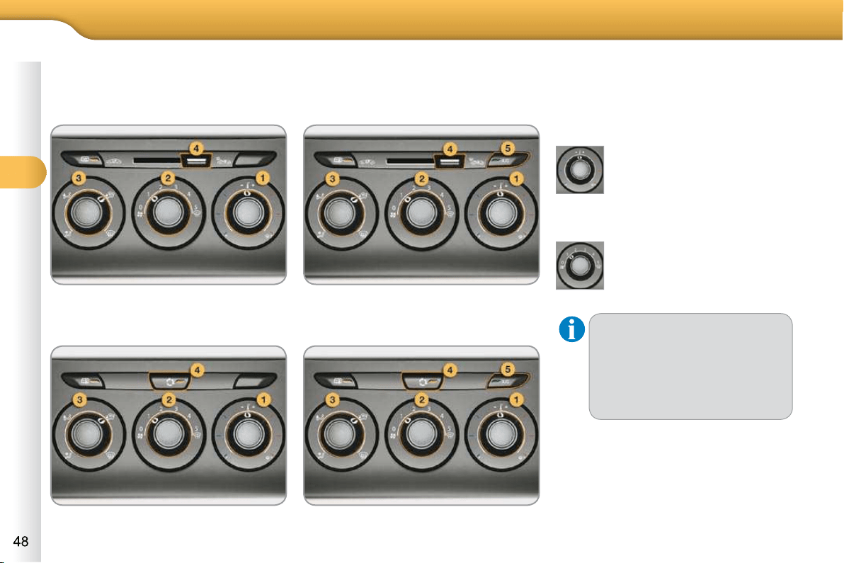
Control panel
The controls of this system are grouped
together on control panel A on the cen-
tre console. Depending on the model,
the functions offered are:
- the level of comfort required,
- air fl ow,
- air distribution,
- demisting-defrosting,
- manual or digital air conditioning
controls.
Air distribution
1.
Windscreen demisting-defrosting vents.
2. Front side window demisting-defrost-
ing vents.
3. Side adjustable air vents.
4. Central adjustable air vents.
5. Air outlets to the front footwells.
6. Air outlets to the rear footwells.
3
COMFORT
RECOMMENDATIONS FOR VENTILATION AND AIR CONDITIONING
In order for these systems to be fully effective, follow the operation and
maintenance guidelines below:
To obtain an even air distribution, take care not to obstruct the exterior
air intake grilles located at the base of the windscreen, the nozzles,
the vents and the air outlets, as well as the air extractor located in
the boot.
Do not cover the sunshine sensor, located on the dashboard; this is
used for regulation of the digital air conditioning system.
Operate the air conditioning system for at least 5 to 10 minutes, once or
twice a month to keep it in perfect working order.
Ensure that the passenger compartment fi lter is in good condition
and have the fi lter elements replaced regularly (refer to the "Checks"
section).
We recommend the use of a combined passenger compartment fi lter.
Thanks to its special active additive, it contributes to the purifi cation of
the air breathed by the occupants and the cleanliness of the passenger
compartment (reduction of allergic symptoms, bad odours and greasy
deposits).
To ensure correct operation of the air conditioning system, you are also
advised to have it checked regularly as recommended in the Mainte-
nance and Warranty Guide.
If the system does not produce cold air, switch it off and contact a
CITROËN dealer or a qualifi ed workshop.
When towing the maximum load on a steep gradient in high temperatures,
switching off the air conditioning increases the available engine power and
so improves the towing ability.
If after an extended stop in sun-
shine, the interior temperature is
very high, fi rst ventilate the pas-
senger compartment for a few
moments.
Put the air fl ow control at a setting
high enough to quickly change
the air in the passenger compart-
ment.
The air conditioning system
does not contain chlorine and
does not present any danger to
the ozone layer.
The condensation created by
the air conditioning results in a
discharge of water under the ve-
hicle which is perfectly normal.
3
COMFORT
HEATING/VENTILATION
MANUAL AIR CONDITIONING
The heating/ventilation or air condition-
ing systems operates with the engine
running, as well as in STOP mode with
Stop & Start.
1. Temperature adjustment
2. Air fl ow adjustment
Turn the dial from blue
(cold) to red (hot) to adjust
the temperature to your re-
quirements.
Turn the dial from posi-
tion 1 to position 5 to ob-
tain a comfortable air fl ow.
If you place the air fl ow con-
trol in position 0 (deactivation
of the system), the tempera-
ture is no longer maintained
at a comfortable level. How-
ever, a slight fl ow of air, due to
the movement of the vehicle,
can still be felt.
Manual control panel
Electric control panel
Manual control panel
Electric control panel
3
COMFORT
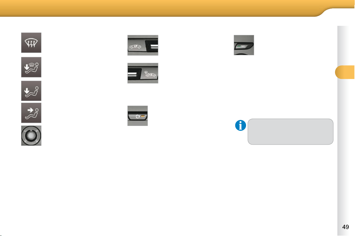
3. Air distribution adjustment
4. Air intake/Air recirculation
The intake of exterior air avoids the for-
mation of mist on the windscreen and
side windows.
The recirculation of interior air insulates
the passenger compartment from exte-
rior odours and smoke.
Return to exterior air intake as soon as
possible to prevent deterioration of the
air quality and the formation of mist.
Windscreen and side windows.
Windscreen, side windows
and footwells.
Footwells.
Central and side vents.
The air distribution can be
adapted by placing the dial in
an intermediate position.
Move the manual con-
trol to the left to be in
the "recycling interior
air" position.
Move the manual con-
trol to the right to re-
turn to the "fresh air
intake" position.
Manual control panel
Electric control panel
Press the button to recir-
culate the interior air. The
indicator lamp comes on
to confi rm this.
Press the button again to allow fresh
air into the passenger compartment.
The indicator lamp goes off to con-
fi rm this.
5. Air conditioning On/Off
Switching off
Press the "A/C" button again, the
button's indicator lamp goes off.
Switching off may affect comfort levels
(humidity, condensation).
The air conditioning is de-
signed to operate effectively in
all seasons, with the windows
closed.
It enables you to:
- lower the temperature, in summer,
- increase the effectiveness of the
demisting in winter, above 3 °C.
Switching on
Press the "A/C" button, the button's
indicator lamp comes on.
The air conditioning does not
operate when the air fl ow adjust-
ment control 2 is in position " 0 ".
3
COMFORT
With the heating/ventilation
system
Put the temperature and air fl ow
controls to the dedicated marked
position.
Put the air intake control to the
"Exterior air intake" position
(manual control to the right or electric
control with indicator lamp off).
Put the air distribution control to the
"Windscreen" position.
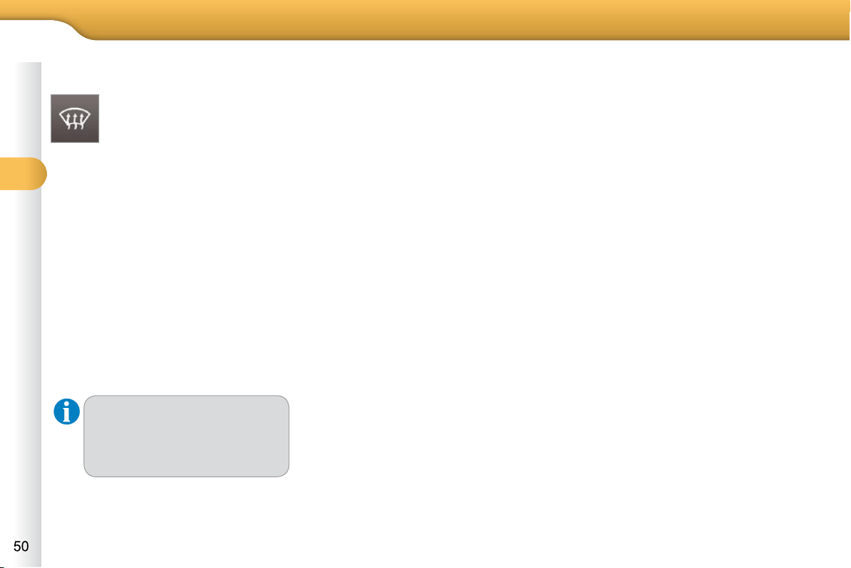
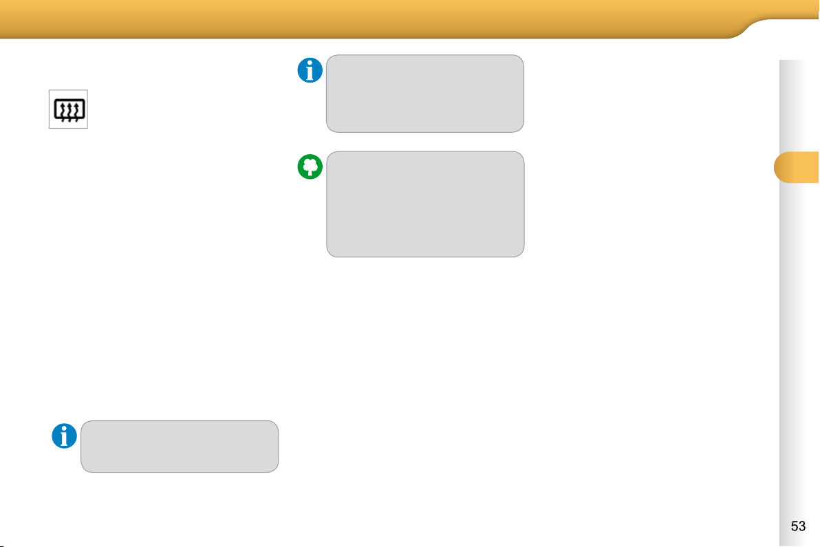
FRONT DEMIST - DEFROST
These markings on the control
panel indicate the control po-
sitions for rapid demisting or
defrosting of the windscreen
and side windows.
With the manual air
conditioning system
Put the temperature and air fl ow
controls to the dedicated marked
position.
Put the air intake control to the
"Exterior air intake" position
(manual control to the right or elec-
tric control with indicator lamp off).
Put the air distribution control to the
"Windscreen" position.
Switch on the air conditioning by
pressing the "A/C" button; the associ-
ated green warning lamp comes on.
With Stop & Start, when the
demisting, air conditioning and
air fl ow functions are activated,
STOP mode is not available.
3
COMFORT
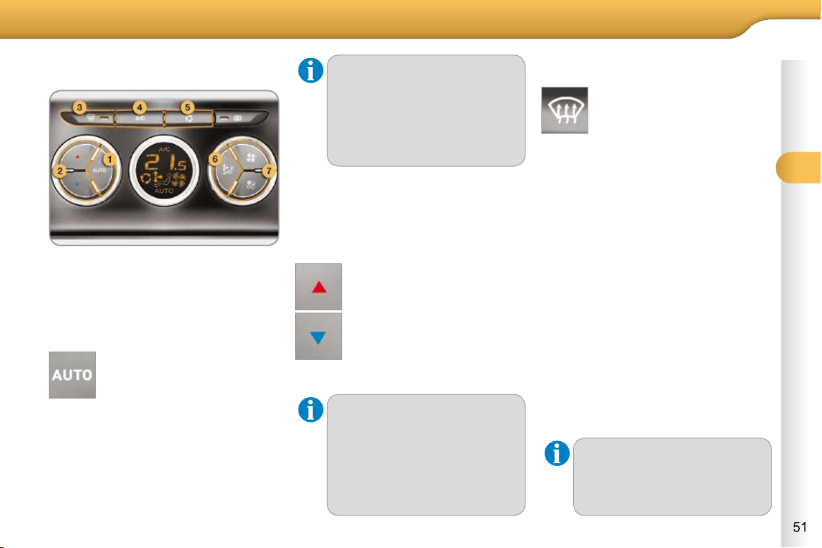
DIGITAL AIR CONDITIONING
The air conditioning operates when the
engine is running, as well as in STOP
mode with Stop & Start.
For your comfort, when the en-
gine is switched off, the settings
are retained until the engine is
switched on again.
To prevent too great a distribu-
tion of cold air when the engine
is cold, the air fl ow will only reach
its optimum level gradually.
On entering the vehicle, if the
interior is very cold or hot, there
is no need to change the value
displayed in order to reach the
required level of comfort. The
system corrects the temperature
difference automatically and as
quickly as possible.
Automatic operation
1. Automatic "comfort" programme
Press the "AUTO" button. The
"AUTO" symbol is displayed.
We recommend that you use this mode.
It provides optimised automatic control
of all of the following functions: passen-
ger compartment temperature, air fl ow,
air distribution and air intake, in accor-
dance with the comfort value that you
have chosen.
This system is designed to operate ef-
fectively in all seasons, with the windows
closed.
2. Temperature adjustment
The value indicated on the display cor-
responds to a level of comfort and not
to a temperature in degrees Celsius or
Fahrenheit.
Press the " " and " " but-
tons to change this value. A
setting around the value 21 en-
ables optimum comfort to be
obtained. However, de
pending
on your requirements,
a setting
between 18 and 24 is usual.
3. Automatic "visibility" programme
The automatic comfort pro-
gramme may not be suffi cient
for rapid demisting or defrost-
ing of the windscreen and side
windows (humidity, several
passengers, ice, etc.).
In this case, select the automatic visibility
programme. The button 3 indicator lamp
comes on.
The system automatically controls the
air conditioning and the fl ow of air and
provides optimum air distribution to the
windscreen and side windows. It deacti-
vates air recirculation 5 .
To exit this programme, press button 3
again or "AUTO" , the indicator lamp on
the button goes off and "AUTO" is dis-
played.
Manual override
It is possible to adjust one or more func-
tions manually while leaving the other
functions in automatic mode.
The "AUTO" symbol switches off.
To return to automatic mode, press the
"AUTO" button.
Switching to manual mode may
not be suitable (temperature,
humidity, odour, condensation)
and does not provide optimum
comfort.
3
COMFORT
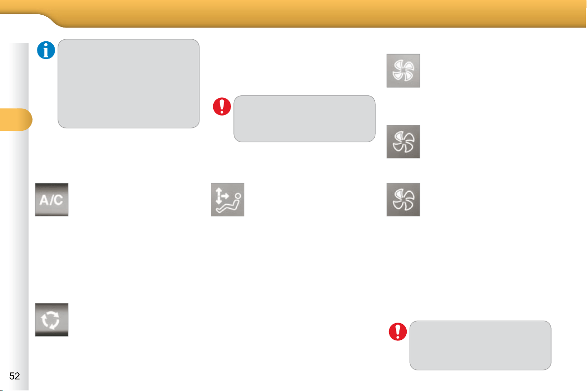
4. Air conditioning on/off
Press this button to switch off
the air conditioning.
Stopping the air conditioning may cause
some problems (humidity, misting).
Automatic operation of the air condi-
tioning is resumed when the button is
pressed again. The symbol "A/C" is
displayed.
5. Air intake/Air recirculation
Press this button for recircula-
tion of the interior air. The air
recirculation symbol 5 is dis-
played.
Air recirculation enables the passenger
compartment to be isolated from exte-
rior odours and smoke.
6. Air distribution adjustment
Avoid prolonged recirculation of
interior air (risk of condensation
or deterioration of the air quality).
Pressing this button several
times in succession enables
the air fl ow to be directed in
turn towards:
-
the windscreen and the side windows
(demisting or defrosting),
- the windscreen, side windows and
air vents,
- the windscreen, the side windows,
the air vents and the footwells,
- the windscreen, the side windows
and the footwells,
- the footwells,
- the air vents and the footwells,
- the air vents.
7. Air fl ow adjustment
Press the "full fan" button to
increase the air fl ow.
The air fl ow symbol, the fan, fi lls pro-
gressively according to the value re-
quested.
Switching the system off
Avoid driving for long periods
with the air conditioning switched
off (risk of misting and reduction
of the air quality in the cabin).
Press the air fl ow "empty fan"
button 7 until the fan symbol
disappears.
This action switches off all of the func-
tions of the air conditioning system.
Thermal comfort is no longer controlled.
A slight fl ow of air resulting from the
movement of the vehicle, remains per-
ceptible however.
Pressing the air fl ow "full fan" but-
ton 7 or on "AUTO" reactivates the
system with the values set before it was
switched off.
Press the "empty fan" button
to decrease the air fl ow.
For maximum cooling or heating
of the cabin, it is possible to go
beyond the minimum 14 or maxi-
mum 28 values.
Press the blue button 2 un-
til "LO" is displayed or the
red button 2 until "HI" is dis-
played.
Press this button again or press the
"AUTO" button to resume automatic
management of the intake of air. The air
recirculation symbol 5 goes off.
3
COMFORT
REAR SCREEN DEMIST -
DEFROST
Switching on
The rear screen demisting/defrosting
can only operate when the engine is
running.
Press this button to demist/defrost
the rear screen and (depending on
version) the door mirrors. The indi-
cator lamp associated with the but-
ton comes on.
Switching off
The demisting/defrosting switches off
automatically to prevent an excessive
consumption of current.
It is possible to stop the demisting/
defrosting operation before it is switched
off automatically by pressing the button
again. The indicator lamp associated
with the button switches off.
The control button is located on
the heating or air conditioning
system control panel.
If the engine is switched off be-
fore the demisting/defrosting is
switched off automatically, dem-
isting/defrosting will resume next
time the engine is switched on.
Switch off the demisting/de-
frosting of the rear screen
and door mirrors as soon as
appropriate as lower current
consumption results in re-
duced fuel consumption.
With Stop & Start, when dem-
isting has been activated, the
STOP mode is not available.
3
COMFORT
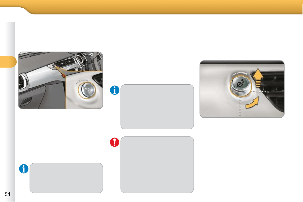
SCENTED AIR FRESHENER
System permitting the diffusion of a fra-
grance in the passenger compartment
in accordance with your requirements,
by means of the adjustment dial and the
various fragrance cartridges available.
Adjustment dial
This dial is located on the dashboard.
It allows you to adjust the intensity of
diffusion of the fragrance.
Turn the dial to the right to permit
diffusion of the fragrance.
Turn the dial to the left to stop diffu-
sion of the fragrance.
Fragrance cartridge
This cartridge can be removed easily.
The fi rst time it is used, replace the plug
with a real cartridge.
You can change it at any time and store
it in the sealed case which keeps it
closed once it has been opened.
You can obtain different fragrance car-
tridges from a CITROËN dealer or a
qualifi ed workshop.
Removing the cartridge
Press the dial and turn it a quarter of
a turn anti-clockwise.
Remove the cartridge.
Refi t its sealing case.
Fitting the cartridge
Remove the cartridge from the seal-
ing case.
Install the cartridge (fl ower at top
left).
Press the dial and turn it a quarter of
a turn clockwise.
Leave the central vents open.
The intensity of diffusion of the
fragrance may depend on the
ventilation or air conditioning
settings.
Do not discard the original car-
tridge as this serves as a plug
when no fragrance cartridge is
in use.
In order to preserve the service
life of the cartridge, turn the dial
fully to the left when you no lon-
ger wish to diffuse the fragrance
in the passenger compartment.
As a safety precaution, do not
carry out any action on the car-
tridge while driving.
Do not dismantle the cartridges.
Do not attempt to refi ll the fra-
grance diffuser or the cartridges.
Avoid all contact with the skin
and eyes.
Keep out of reach of children
and animals.
3
COMFORT
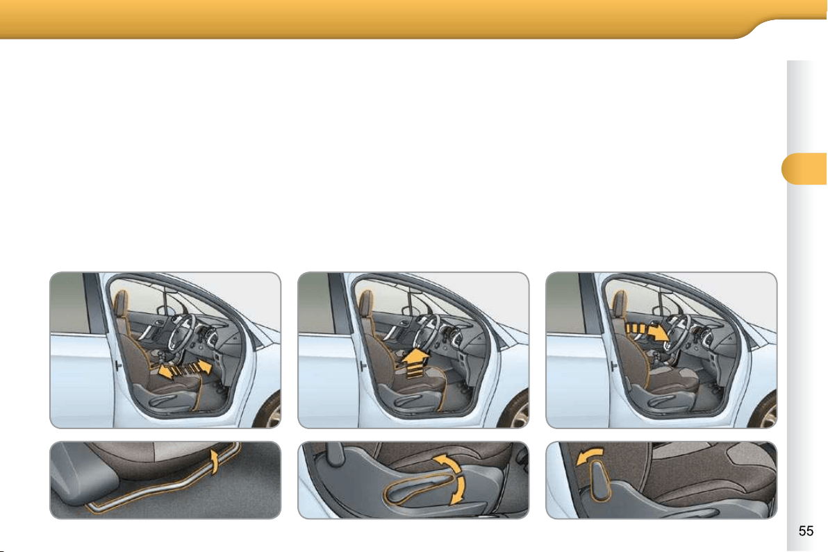
FRONT SEATS
Seat consisting of a seat cushion, a seat
back and a head restraint which can all
be adjusted to adapt your position for
ease of driving and comfort.
Manual adjustments
Forwards-backwards adjustment
Raise the control and slide the seat
forwards or backwards.
Driver's or passenger's seat height
adjustment
Pull the control upwards to raise
or push it downwards to lower, as
many times as necessary, to obtain
the position required.
Seat back angle adjustment
Push the control rearwards.
3
COMFORT
Additional adjustments
Head restraint height adjustment
To raise the head restraint, pull it for-
wards and upwards at the same time.
To remove the head restraint, press
the lug A and pull the head restraint
upwards.
To put the head restraint back in
place, engage the head restraint
stems in the openings keeping them
in line with the seat back.
To lower the head restraint, press
the lug A and the head restraint at
the same time.
The head restraint is fi tted with
a frame with notches which pre-
vents it from lowering; this is a
safety device in case of impact.
The adjustment is correct
when the upper edge of the
head restraint is level with the
top of the head.
Never drive with the head re-
straints removed; they must be
in place and adjusted correctly.
3
COMFORT
REAR SEATS
Bench seat with fi xed one-piece cush-
ion and split backrest (left hand 2/3, right
hand 1/3) which can be folded individu-
ally to adapt the load space in the boot.
Rear head restraints
These have one position for use (up)
and a stowed position (down).
Folding the backrest
Move the corresponding front seat
forward if necessary.
Check that the seat belt is posi-
tioned correctly on the side of the
seat back.
Place the head restraints in the low
position.
Repositioning the seat backrest
When repositioning the rear seat back-
rest:
Straighten the seat back 2 and
secure it.
Check that the red indicator, located
next to the control 1 , is no longer
visible.
They can also be removed.
To remove a head restraint:
release the backrest using control 1 ,
tilt the backrest 2 slightly forwards,
pull the head restraint upwards to
the stop,
then, press the lug A .
When repositioning the seat
backrest, take care not to trap
the seat belts.
Never drive with the head re-
straints removed; they must be
in place and correctly adjusted.
Pull control 1 forwards to release
the seat back 2 .
Fold the seat back 2 on to the cushion.
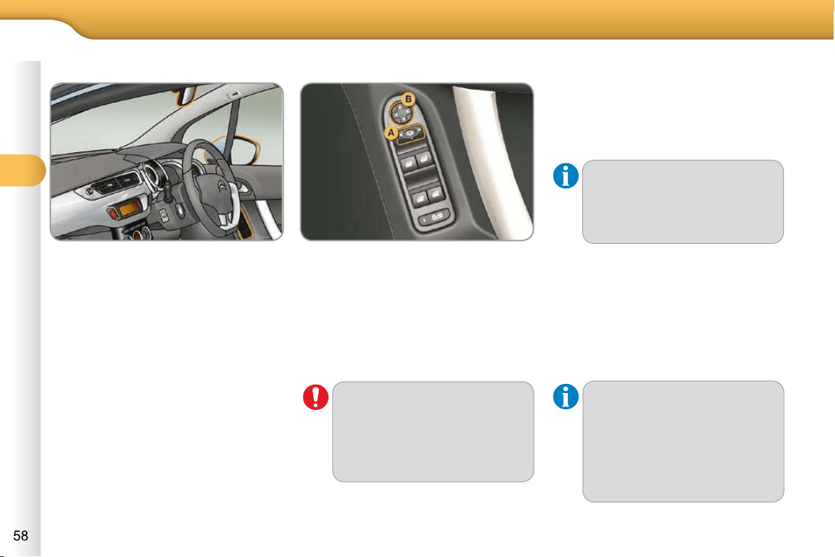
3
COMFORT
MIRRORS
Door mirrors
Each fi tted with an adjustable mirror
glass permitting the lateral rearward vi-
sion necessary for overtaking or park-
ing. They can also be folded for parking
in confi ned spaces.
Move control A to the right or to the
left to select the corresponding mirror.
Move control B in all four directions
to adjust.
Return control A to the central
position.
Adjustment Folding
From outside: lock the vehicle using
the remote control or the key.
From inside: with the ignition on, pull
control A rearwards.
Unfolding
From outside: unlock the vehicle us-
ing the remote control or the key.
From inside: with the ignition on, pull
control A rearwards.
If the mirrors are folded using
control A , they will not unfold
when the vehicle is unlocked.
Pull again on control A .
The folding and unfolding of the
door mirrors using the remote
control can be deactivated by a
CITROËN dealer.
Never fold or unfold the electric
folding mirrors manually.
The objects observed are, in re-
ality, closer than they appear.
Take this into account in order to
correctly judge the distance of ve-
hicles approaching from behind.
Demisting - Defrosting
If your vehicle is fi tted with heated mir-
rors, the demisting-defrosting operates
with the engine running, by switching
on the heated rear screen (refer to the
"Rear screen demist-defrost" page).
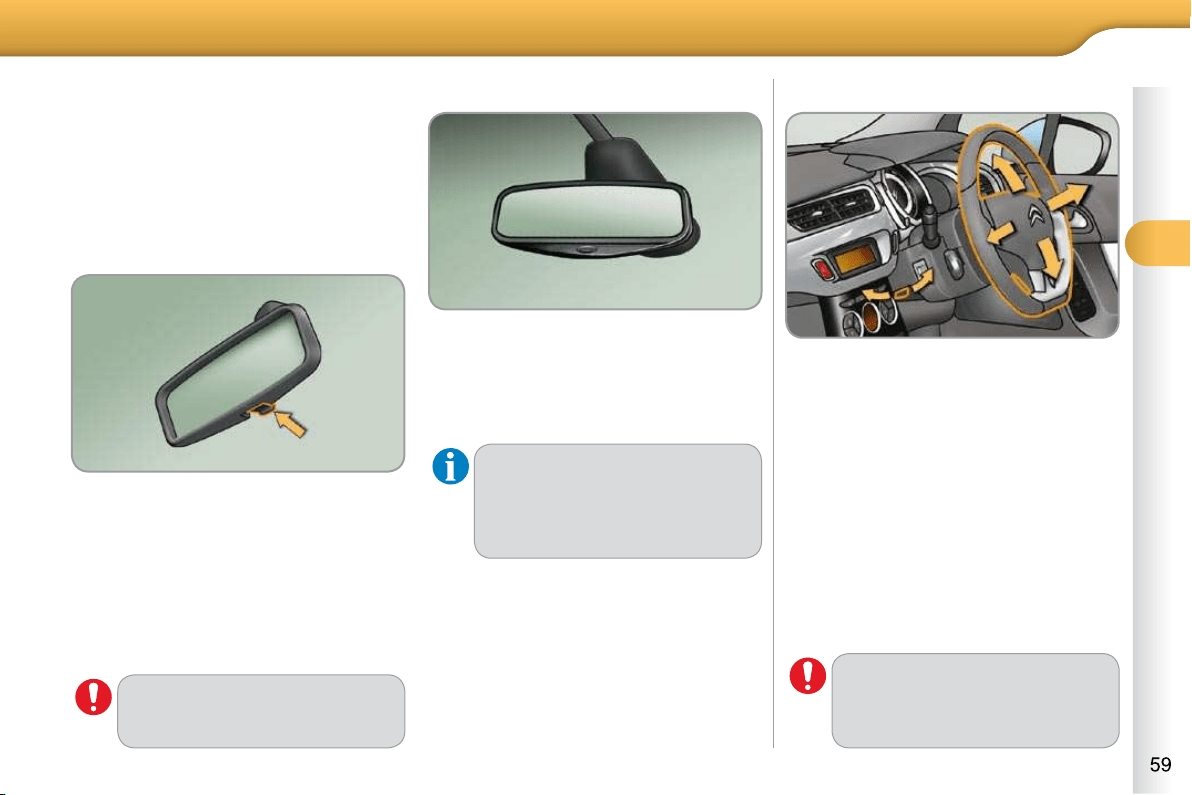
3
COMFORT
STEERING WHEEL ADJUSTMENT
When stationary , pull the control lever
to release the adjustment mechanism.
Adjust the height and reach to suit
your driving position.
Push the control lever to lock the ad-
justment mechanism.
As a safety precaution, these
operations should only be car-
ried out while the vehicle is sta-
tionary.
Rear view mirror
Adjustable mirror providing a central
rearward view.
Equipped with an anti-dazzle system,
which darkens the mirror glass: this re-
duces the nuisance to the driver caused
by the headlamps from following vehi-
cles, low sun...
Adjustment
Adjust the mirror so that the glass is di-
rected correctly in the "day" position.
Day/night position
Pull the lever to change to the "night"
anti-dazzle position.
Push the lever to change to the nor-
mal "day" position.
Automatic day/night model
By means of a sensor, which measures
the light from the rear of the vehicle, this
system automatically and progressively
changes between the day and night
uses.
In order to ensure optimum vis-
ibility during your manoeuvres,
the mirror lightens automatically
when reverse gear is engaged.
As a safety measure, the mirrors
should be adjusted to reduce the
"blind spot".
Manual day/night model
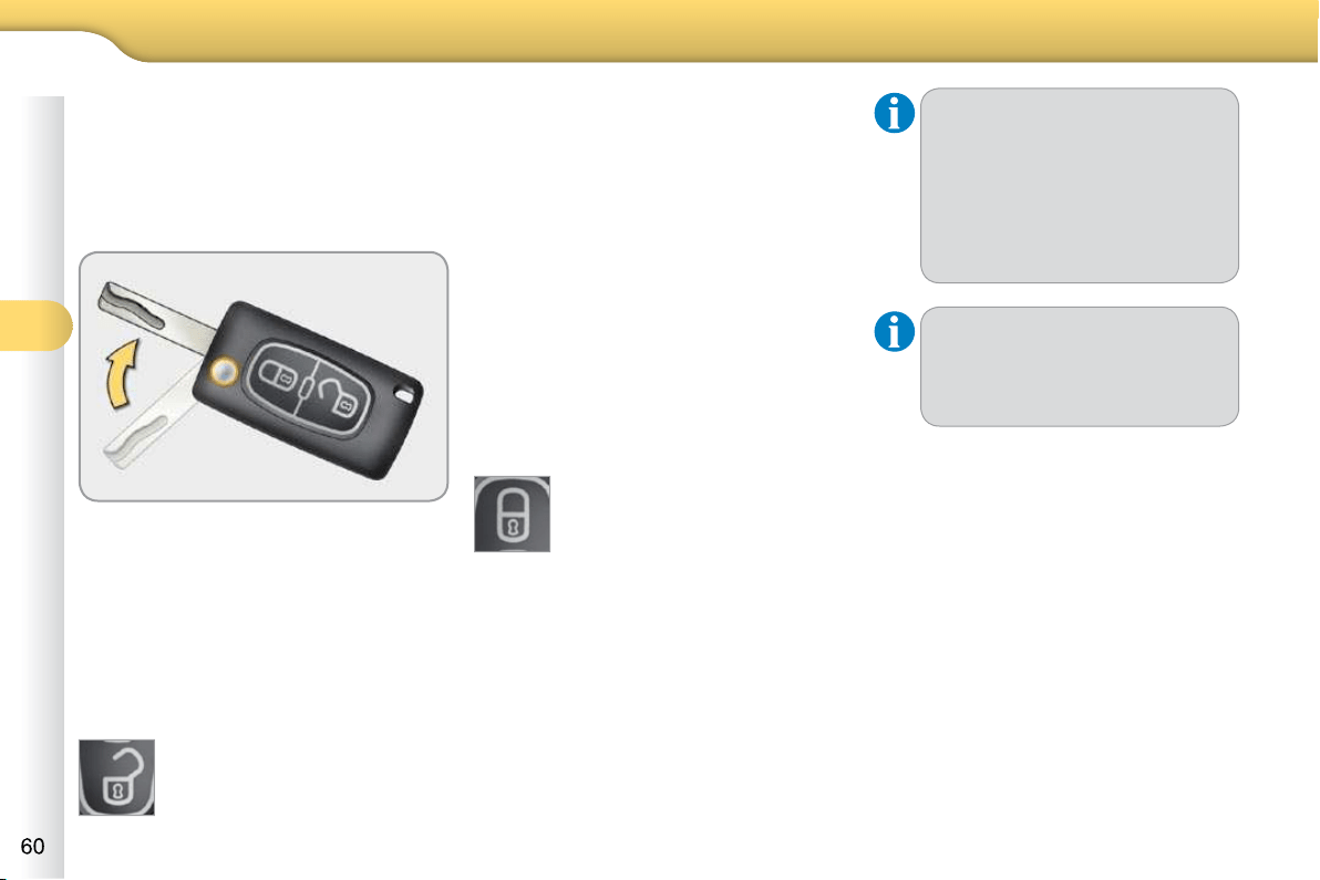
4
ACCESS
REMOTE CONTROL KEY
System which permits central unlock-
ing or locking of the vehicle using the
lock or from a distance. It is also used to
locate and start the vehicle, as well as
providing protection against theft.
Unlocking the vehicle
Unfolding the key
First press this button to unfold
the key.
Unlocking using the remote control
Press the open padlock to
unlock the vehicle.
Unlocking using the key
Turn the key to the right in the driv-
er’s door lock to unlock the vehicle.
Locking the vehicle
Locking using the remote control
Press the closed padlock
to lock the vehicle.
Locking using the key
Turn the key to the left in the driver’s
door lock to lock the vehicle com-
pletely.
If one of the doors or the boot
is still open, the central locking
does not take place.
When the vehicle is locked, if it
is unlocked inadvertently, it will
relock automatically after thirty
seconds unless a door or the
boot is open.
The folding and unfolding of the
door mirrors using the remote
control can be deactivated by a
CITROËN dealer.
Locking is confi rmed by fi xed lighting of
the direction indicators for approximately
two seconds.
According to version, the door mirrors
fold at the same time.
Unlocking is confi rmed by rapid fl ashing
of the direction indicators for approxi-
mately two seconds.
According to version, the door mirrors
unfold at the same time.

4
ACCESS
Folding the key
First press this button to fold the key.
Deadlocking using the remote
control
Press the closed padlock again
within fi ve seconds to deadlock the
vehicle.
Deadlocking using the key
Press the closed padlock
to lock the vehicle com-
pletely.
Turn the key to the left in the driver’s
door lock to lock the vehicle com-
pletely.
Turn the key to the left again within
fi ve seconds to deadlock the vehicle.
Deadlocking renders the exte-
rior and interior door controls
inoperative.
It also deactivates the manual
central control button.
Therefore, never leave anyone
inside the vehicle when it is
deadlocked.
Deadlocking is confi rmed by fi xed light-
ing of the direction indicators for ap-
proximately two seconds.
According to version, the door mirrors
fold at the same time.
Anti-theft protection
Electronic engine immobiliser
The key contains an electronic chip
which has a special code. When the
ignition is switched on, this code must
be recognised in order for starting to be
possible.
In the event of a malfunc-
tion, you are informed by
lighting of this warning lamp,
an audible signal and a message on the
multifunction screen.
In this case, your vehicle does not start;
contact a CITROËN dealer as soon as
possible.
Locating your vehicle
Press the closed pad-
lock to locate your locked
vehicle in a car park.
This is indicated by lighting of the cour-
tesy lamps and fl ashing of the direction
indicators for a few seconds.
Ignition switch
- Position 1: Stop
- Position 2: Ignition
- Position 3: Starting
This electronic engine immobiliser locks
the engine management system a few
minutes after the ignition is switched off
and prevents starting of the engine by
anyone who does not have the key.

4
ACCESS
Remote control problem
Following disconnection of the vehicle
battery, replacement of the remote con-
trol battery or in the event of a remote
control malfunction, you can no longer
unlock, lock or locate your vehicle.
First of all, use the key in the lock to
unlock or lock your vehicle.
Then, reinitialise the remote control.
If the problem persists, contact a
CITROËN dealer as soon as possible.
Reinitialisation
Switch off the ignition.
Turn the key to position 2 (Ignition
on) .
Press the closed padlock immedi-
ately for a few seconds.
Switch off the ignition and remove
the key from the ignition switch.
The remote control is fully operational
again.
Changing the battery
Battery ref.: CR1620/3 volts.
If the battery is fl at, you are
informed by illumination of
this warning lamp, an audi-
ble signal and a message in the multi-
function screen.
Unclip the casing using a coin at the
notch.
Slide the fl at battery out of its location.
Slide the new battery into its loca-
tion observing the original direction.
Clip the casing.
Reinitialise the remote control.
Starting the vehicle
Insert the key in the ignition switch.
The system recognises the starting
code.
Turn the key fully towards the dash-
board to position 3 (Starting) .
When the engine starts, release
the key.
Switching the vehicle off
Immobilise the vehicle.
Turn the key fully towards you to
position 1 (Stop) .
Remove the key from the ignition
switch.
Do not attach any heavy objects
to the key as this could weigh
down on it when in the ignition
switch and cause a fault.
Key reminder
If the key is left in the igni-
tion switch, an audible signal
sounds when the driver's door is
opened.

4
ACCESS
Lost keys
Visit a CITROËN dealer with the vehicle's V5 registration document and
your personal identifi cation documents.
The CITROËN dealer will be able to retrieve the key code and the
transponder code required to order a replacement key.
Do not throw the remote con-
trol batteries away, they contain
metals which are harmful to the
environment.
Take them to an approved col-
lection point.
Remote control
The high frequency remote control is a sensitive system; do not operate
it while it is in your pocket as there is a possibility that it may unlock the
vehicle, without you being aware of it.
Do not repeatedly press the buttons of your remote control out of range and
out of sight of your vehicle. You run the risk of stopping it from working and
the remote control would have to be reinitialised.
The remote control does not operate when the key is in the ignition, even
when the ignition is switched off, except for reinitialisation.
Locking the vehicle
Driving with the doors locked may make access to the passenger compart-
ment by the emergency services more diffi cult in an emergency.
As a safety precaution (with children on board), remove the key from the
ignition when you leave the vehicle, even for a short time.
Anti-theft protection
Do not make any modifi cations to the electronic engine immobiliser
system; this could cause malfunctions.
When purchasing a second-hand vehicle
Have the key codes memorised by a CITROËN dealer, to ensure that the
keys in your possession are the only ones which can start the vehicle.
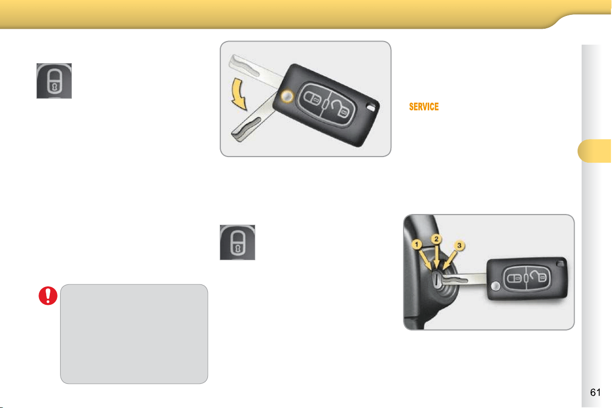
4
ACCESS
Folding the key
First press this button to fold the key.
Deadlocking using the remote
control
Press the closed padlock again
within fi ve seconds to deadlock the
vehicle.
Deadlocking using the key
Press the closed padlock
to lock the vehicle com-
pletely.
Turn the key to the left in the driver’s
door lock to lock the vehicle com-
pletely.
Turn the key to the left again within
fi ve seconds to deadlock the vehicle.
Deadlocking renders the exte-
rior and interior door controls
inoperative.
It also deactivates the manual
central control button.
Therefore, never leave anyone
inside the vehicle when it is
deadlocked.
Deadlocking is confi rmed by fi xed light-
ing of the direction indicators for ap-
proximately two seconds.
According to version, the door mirrors
fold at the same time.
Anti-theft protection
Electronic engine immobiliser
The key contains an electronic chip
which has a special code. When the
ignition is switched on, this code must
be recognised in order for starting to be
possible.
In the event of a malfunc-
tion, you are informed by
lighting of this warning lamp,
an audible signal and a message on the
multifunction screen.
In this case, your vehicle does not start;
contact a CITROËN dealer as soon as
possible.
Locating your vehicle
Press the closed pad-
lock to locate your locked
vehicle in a car park.
This is indicated by lighting of the cour-
tesy lamps and fl ashing of the direction
indicators for a few seconds.
Ignition switch
- Position 1: Stop
- Position 2: Ignition
- Position 3: Starting
This electronic engine immobiliser locks
the engine management system a few
minutes after the ignition is switched off
and prevents starting of the engine by
anyone who does not have the key.

4
ACCESS
Folding the key
First press this button to fold the key.
Deadlocking using the remote
control
Press the closed padlock again
within fi ve seconds to deadlock the
vehicle.
Deadlocking using the key
Press the closed padlock
to lock the vehicle com-
pletely.
Turn the key to the left in the driver’s
door lock to lock the vehicle com-
pletely.
Turn the key to the left again within
fi ve seconds to deadlock the vehicle.
Deadlocking renders the exte-
rior and interior door controls
inoperative.
It also deactivates the manual
central control button.
Therefore, never leave anyone
inside the vehicle when it is
deadlocked.
Deadlocking is confi rmed by fi xed light-
ing of the direction indicators for ap-
proximately two seconds.
According to version, the door mirrors
fold at the same time.
Anti-theft protection
Electronic engine immobiliser
The key contains an electronic chip
which has a special code. When the
ignition is switched on, this code must
be recognised in order for starting to be
possible.
In the event of a malfunc-
tion, you are informed by
lighting of this warning lamp,
an audible signal and a message on the
multifunction screen.
In this case, your vehicle does not start;
contact a CITROËN dealer as soon as
possible.
Locating your vehicle
Press the closed pad-
lock to locate your locked
vehicle in a car park.
This is indicated by lighting of the cour-
tesy lamps and fl ashing of the direction
indicators for a few seconds.
Ignition switch
- Position 1: Stop
- Position 2: Ignition
- Position 3: Starting
This electronic engine immobiliser locks
the engine management system a few
minutes after the ignition is switched off
and prevents starting of the engine by
anyone who does not have the key.
4
ACCESS
Lost keys
Visit a CITROËN dealer with the vehicle's V5 registration document and
your personal identifi cation documents.
The CITROËN dealer will be able to retrieve the key code and the
transponder code required to order a replacement key.
Do not throw the remote con-
trol batteries away, they contain
metals which are harmful to the
environment.
Take them to an approved col-
lection point.
Remote control
The high frequency remote control is a sensitive system; do not operate
it while it is in your pocket as there is a possibility that it may unlock the
vehicle, without you being aware of it.
Do not repeatedly press the buttons of your remote control out of range and
out of sight of your vehicle. You run the risk of stopping it from working and
the remote control would have to be reinitialised.
The remote control does not operate when the key is in the ignition, even
when the ignition is switched off, except for reinitialisation.
Locking the vehicle
Driving with the doors locked may make access to the passenger compart-
ment by the emergency services more diffi cult in an emergency.
As a safety precaution (with children on board), remove the key from the
ignition when you leave the vehicle, even for a short time.
Anti-theft protection
Do not make any modifi cations to the electronic engine immobiliser
system; this could cause malfunctions.
When purchasing a second-hand vehicle
Have the key codes memorised by a CITROËN dealer, to ensure that the
keys in your possession are the only ones which can start the vehicle.
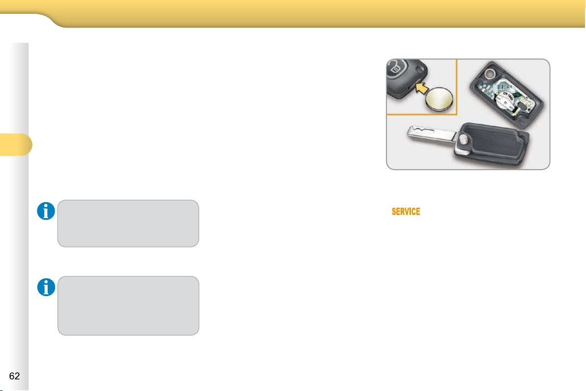
4
ACCESS
Remote control problem
Following disconnection of the vehicle
battery, replacement of the remote con-
trol battery or in the event of a remote
control malfunction, you can no longer
unlock, lock or locate your vehicle.
First of all, use the key in the lock to
unlock or lock your vehicle.
Then, reinitialise the remote control.
If the problem persists, contact a
CITROËN dealer as soon as possible.
Reinitialisation
Switch off the ignition.
Turn the key to position 2 (Ignition
on) .
Press the closed padlock immedi-
ately for a few seconds.
Switch off the ignition and remove
the key from the ignition switch.
The remote control is fully operational
again.
Changing the battery
Battery ref.: CR1620/3 volts.
If the battery is fl at, you are
informed by illumination of
this warning lamp, an audi-
ble signal and a message in the multi-
function screen.
Unclip the casing using a coin at the
notch.
Slide the fl at battery out of its location.
Slide the new battery into its loca-
tion observing the original direction.
Clip the casing.
Reinitialise the remote control.
Starting the vehicle
Insert the key in the ignition switch.
The system recognises the starting
code.
Turn the key fully towards the dash-
board to position 3 (Starting) .
When the engine starts, release
the key.
Switching the vehicle off
Immobilise the vehicle.
Turn the key fully towards you to
position 1 (Stop) .
Remove the key from the ignition
switch.
Do not attach any heavy objects
to the key as this could weigh
down on it when in the ignition
switch and cause a fault.
Key reminder
If the key is left in the igni-
tion switch, an audible signal
sounds when the driver's door is
opened.
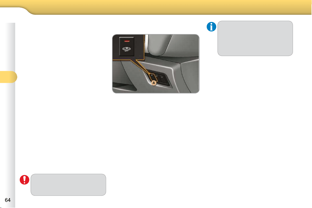
4
ACCESS
ALARM
System which protects and provides a
deterrent against the theft of your vehi-
cle. It provides two types of protection,
exterior and interior, as well as a self-
protection function.
Exterior perimeter protection
The system detects opening of the ve-
hicle.
The alarm is triggered if anyone tries to
enter the vehicle by forcing a door, the
boot or the bonnet.
Interior volumetric protection
The system detects any variation in the
volume in the passenger compartment.
The alarm is triggered if anyone breaks
a window or moves inside the vehicle.
If you wish to leave a pet in the vehicle
or a window partially open, deactivate
the interior volumetric protection.
Self-protection function
The system detects the putting out of
service of its components.
The alarm is triggered if anyone tries
to put the wires of the siren, the central
control or the battery out of service.
Do not make any modifi cations
to the alarm system, this could
cause malfunctions.
Locking the vehicle with full
alarm
Activation
Switch off the ignition and get out of
the vehicle.
Lock or deadlock the vehicle using
the locking button on the remote
control.
The alarm is activated; the indicator lamp
in button A fl ashes once per second.
The exterior perimeter protection is acti-
vated, 5 seconds after the locking button
on the remote control is pressed.
The interior volumetric protection is acti-
vated, 45 seconds after the locking button
on the remote control is pressed.
Deactivation
Unlock the vehicle using the unlock-
ing button on the remote control.
The alarm is deactivated; the indicator
lamp in button A goes off.
If an opening - door or boot -
is not closed fully, the vehicle
is not locked, but the exterior
perimeter protection will be ac-
tivated after 45 seconds at the
same time as the interior volu-
metric protection.
4
ACCESS
Locking the vehicle with exterior
perimeter protection only
Deactivation of the interior
volumetric protection
Switch off the ignition.
Within ten seconds, press button A
until the indicator lamp is on continu-
ously.
Get out of the vehicle.
Lock or deadlock the vehicle without
delay using the locking button on
the remote control.
The exterior perimeter protection alone
remains activated; the indicator lamp in
button A fl ashes once per second.
To be effective, this deactiva-
tion must be carried out each
time the ignition is switched off.
Reactivation of the interior
volumetric protection
Unlock the vehicle using the unlock-
ing button on the remote control.
Relock the vehicle using the remote
control.
The alarm is activated again with both
types of protection; the indicator lamp in
button A fl ashes once per second.
Triggering of the alarm
This is indicated by sounding of the si-
ren and fl ashing of the direction indica-
tors for approximately thirty seconds.
After it has been triggered, both types of
protection are again operational.
Failure of the remote control
Unlock the vehicle using the key in
the driver’s door lock.
Open the door; the alarm is trig-
gered.
Switch on the ignition; the alarm
stops.
If the alarm is triggered ten times
in succession, the eleventh time
will result in it becoming inactive.
If the indicator lamp in button A
fl ashes rapidly, this indicates
that the alarm was triggered
during your absence. When
the ignition is switched on, this
fl ashing stops immediately.
To avoid triggering the alarm
when washing your vehicle, lock
it using the key in the driver’s
door lock.
Locking the vehicle without
activating the alarm
Lock or deadlock the vehicle using
the key in the driver’s door lock.
Malfunction
When the ignition is switched on, illumi-
nation of the indicator lamp in button A
for ten seconds indicates malfunction
with the siren.
Have it checked by a CITROËN dealer
or a qualifi ed workshop.
* According to country.
Automatic activation *
2 minutes after the last door or the boot
is closed, the alarm is activated auto-
matically.
To avoid triggering the alarm on
entering the vehicle, fi rst press the
unlocking button on the remote
control.
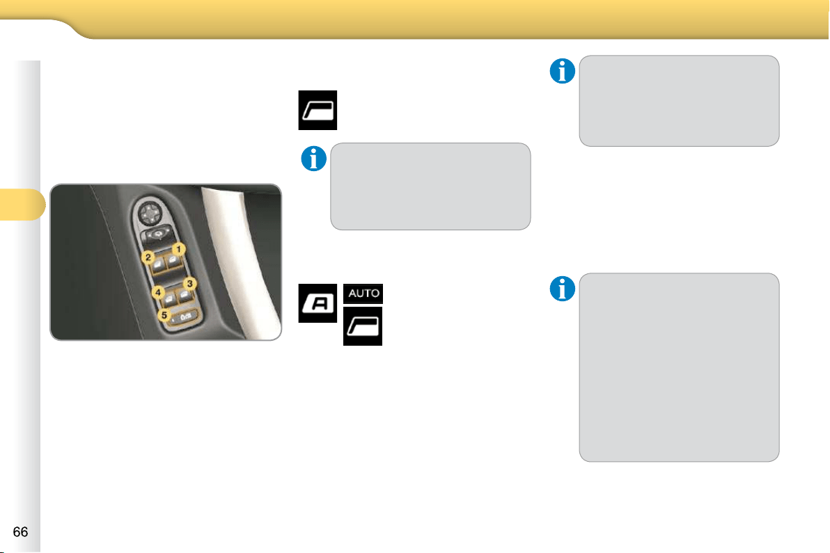
4
ACCESS
WINDOW CONTROLS
System which opens or closes a window
manually or automatically. It is fi tted with
a system which provides protection if an
obstacle is detected on the one-touch
models and a deactivation system to
prevent misuse of the rear switches on
all models.
1. Driver's electric window switch.
2.
Passenger's electric window switch.
3. Rear right electric window switch.
4. Rear left electric window switch.
5. Deactivating the rear electric win-
dow and door switches.
Electric windows
Press or pull the switch.
The window stops as soon
as the switch is released.
The electric window switches
remain operational for approxi-
mately 45 seconds after the igni-
tion is switched off or until a front
door is opened.
One-touch electric windows
There are two methods
of operation:
- manual mode
Press or pull the switch gently.
The window stops as soon as the
switch is released.
- automatic mode
Press or pull the switch fully.
The window opens or closes
completely when the switch is
released.
Pressing the switch again stops
the movement of the window.
The electric window switches
remain operational for approxi-
mately 45 seconds after the igni-
tion is switched off or until a front
door is opened.
Safety anti-pinch
The one-touch front electric windows are
fi tted with a safety anti-pinch function.
When the window rises and meets an
obstacle, it stops and partially lowers
again.
In the event of unwanted opening
of the window on closing (for ex-
ample in the presence of frost):
press the switch until it opens
completely,
then pull it immediately until
it closes,
continue to hold the switch
for approximately one second
after the window has closed.
The safety anti-pinch func-
tion is not active during these
operations.
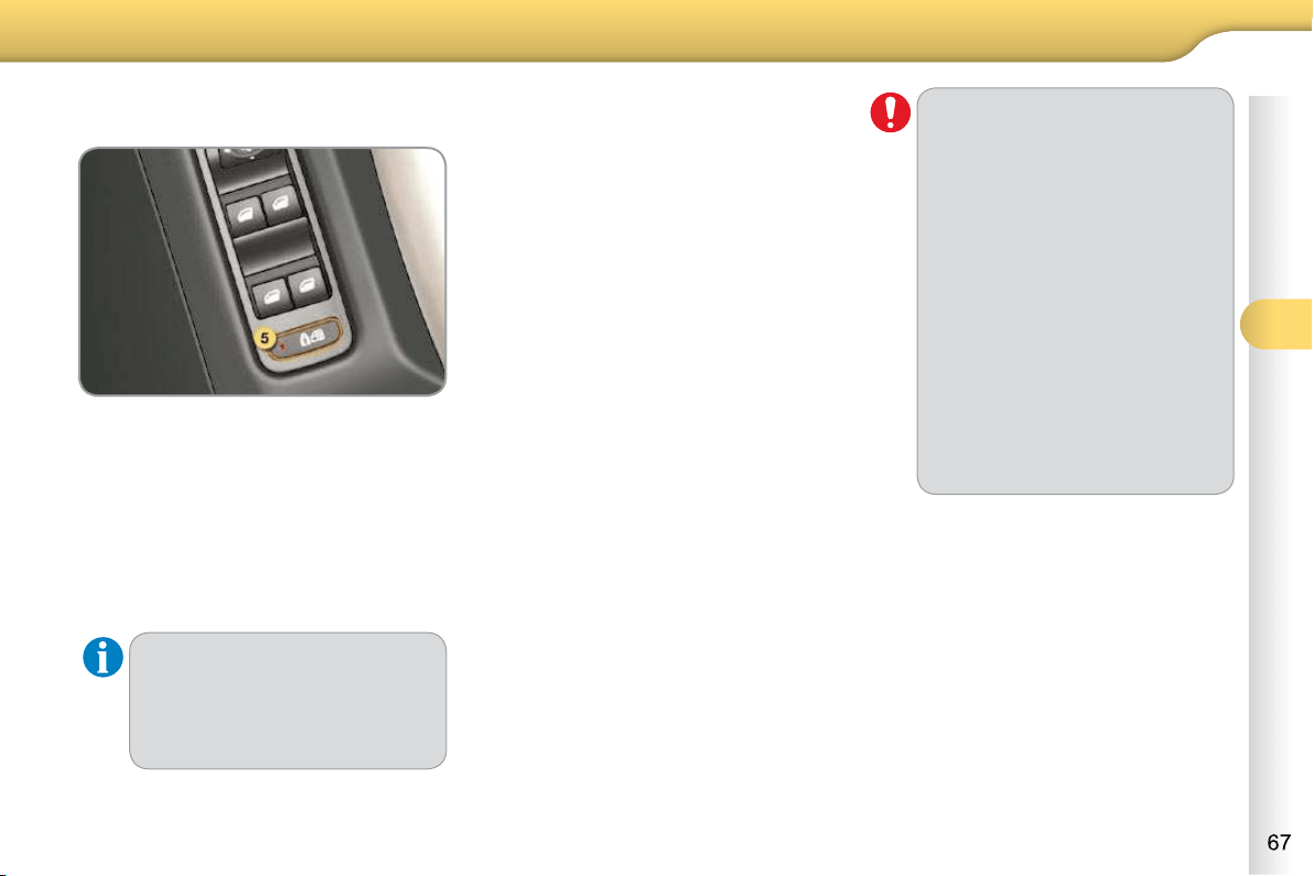
4
ACCESS
Deactivating the rear window and
door switches
For the safety of your children, press
switch 5 to prevent operation of the
rear windows irrespective of their
position.
With the lamp on, the rear controls are
deactivated.
With the lamp off, the rear controls are
activated.
This control also deactivates the
interior rear door controls (see
"Child safety - § Electric child
lock").
Reinitialisation
In the event of a malfunction you have
to reinitialise the operation of the elec-
tric windows:
release the switch and pull it again
until the window closes completely,
hold the switch for approximately
one second after closing,
press the switch to lower the window
automatically.
The safety anti-pinch function is not
active during these operations.
Always remove the key from the
ignition when leaving the vehicle,
even for a short time.
In the event of contact during
operation of the windows, re-
verse the movement of the win-
dow. To do this, press the switch
concerned.
When the driver operates the
passenger electric window
switches, they should ensure
that no one is preventing correct
closing of the windows.
The driver should ensure that
passengers use the electric win-
dows correctly.
Be aware of children when oper-
ating the windows.
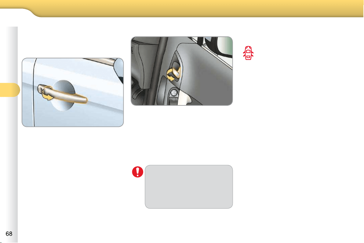
4
ACCESS
DOORS
Opening
From outside
After unlocking the vehicle using the
remote control or the key, pull the
door handle.
From inside
Pull the front door control to open
the door; this unlocks the vehicle
completely.
Pull the rear door control to open
the door; this unlocks only the door
opened.
Closing
When a door is not closed correctly:
-
when the engine is running ,
this warning lamp comes on,
accompanied by a message in
the multifunction screen for a
few seconds,
-
when the vehicle is moving (speed
higher than 6 mph (10 km/h)), this
warning lamp comes on, accom-
panied by an audible signal and a
message in the multifunction screen
for a few seconds.
Version with
deadlocking
The interior door controls do
not operate when the vehicle is
deadlocked.
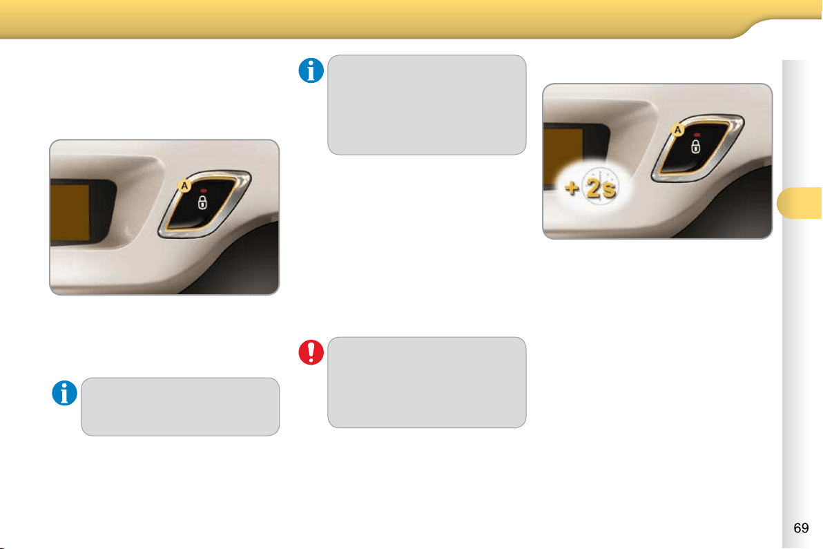
4
ACCESS
Manual centralised control
System which provides full manual
locking or unlocking of the doors from
the inside.
Locking
Press button A to lock the vehicle.
The red indicator lamp on the button
comes on.
If one of the doors is open, cen-
tral locking from the inside does
not take place.
Unlocking
Press button A again to unlock the
vehicle.
The red indicator lamp on the button
switches off.
If the vehicle is locked from the
outside, the red indicator lamp
fl ashes and button A is inactive.
In this case, use the remote
control or the key to unlock
the vehicle.
Automatic centralised control
System which provides full automatic
locking or unlocking of the doors and
the boot while driving.
You can activate or deactivate this func-
tion.
Locking
When the speed exceeds 6 mph
(10 km/h), the doors and the boot lock
automatically.
If one of the doors is open, the
automatic central locking does
not take place.
If the boot is open, the automatic
central locking of the doors is
active.
Unlocking
Above 6 mph (10 km/h), press but-
ton A to unlock the doors and the
boot temporarily.
Activation
Press button A for more than
two seconds.
A confi rmation message appears on the
multifunction screen, accompanied by
an audible signal.
Deactivation
Press button A again for more than
two seconds.
A confi rmation message appears on the
multifunction screen, accompanied by
an audible signal.
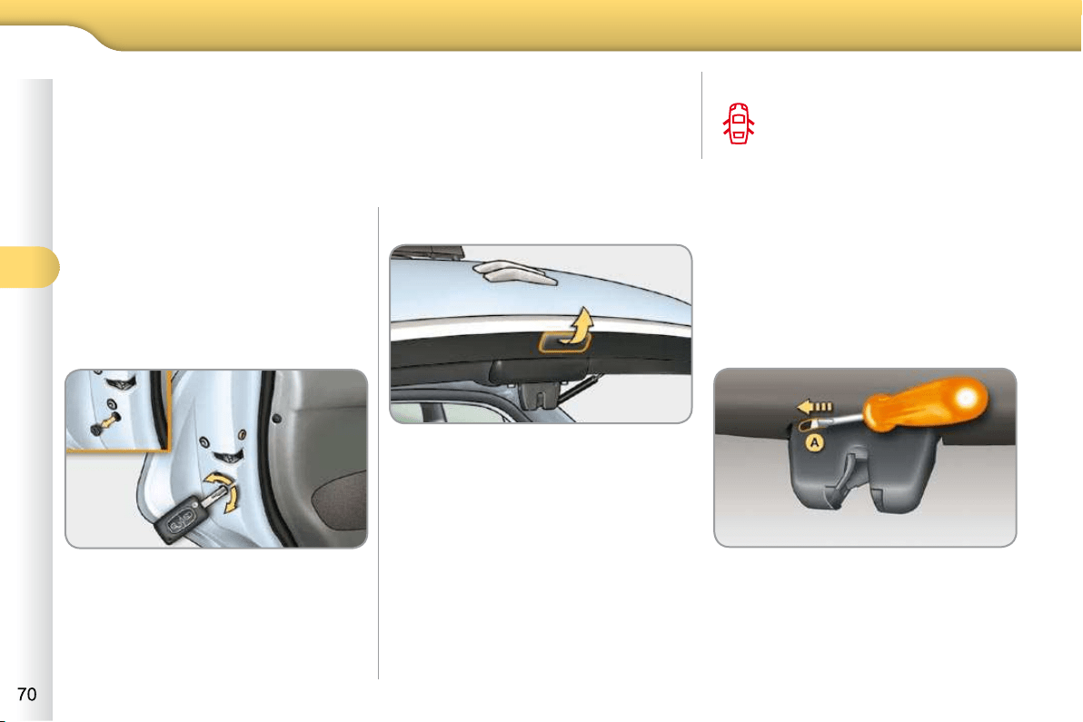
4
ACCESS
Emergency control
To lock or unlock the doors manually in
the event of a malfunction of the central
locking system or failure of the battery.
Locking the driver’s door
Insert the key in the lock, then turn it
to the left.
Unlocking the driver’s door
Insert the key in the lock, then turn it
to the right.
Locking the front and rear
passenger doors
Remove the black cap, located on
the edge of the door, using the key.
Insert the key in the recess, then
turn it as far as it will go.
Remove the key and refi t the cap.
On the rear doors, check that the
child lock is not activated.
Unlocking the front and rear
passenger doors
Pull the interior door opening con-
trol.
BOOT
Opening
After unlocking the vehicle using the
remote control or the key, pull the
handle and raise the tailgate.
Closing
Lower the tailgate using the interior
grab handle.
-
when the engine is running ,
this warning lamp comes on,
accompanied by a message
on the multifunction screen for
a few seconds,
-
when the vehicle is moving (speed
above 6 mph (10 km/h)), this warn-
ing lamp comes on, accompanied
by an audible signal and a message
on the multifunction screen for a few
seconds.
Tailgate release
System for mechanical unlocking of the
boot in the event of a battery or central
locking malfunction.
Unlocking
Fold back the rear benchseat to
gain access to the lock from inside
the boot.
Insert a small screwdriver into hole A
of the lock to unlock the tailgate.
If the tailgate is not closed correctly:
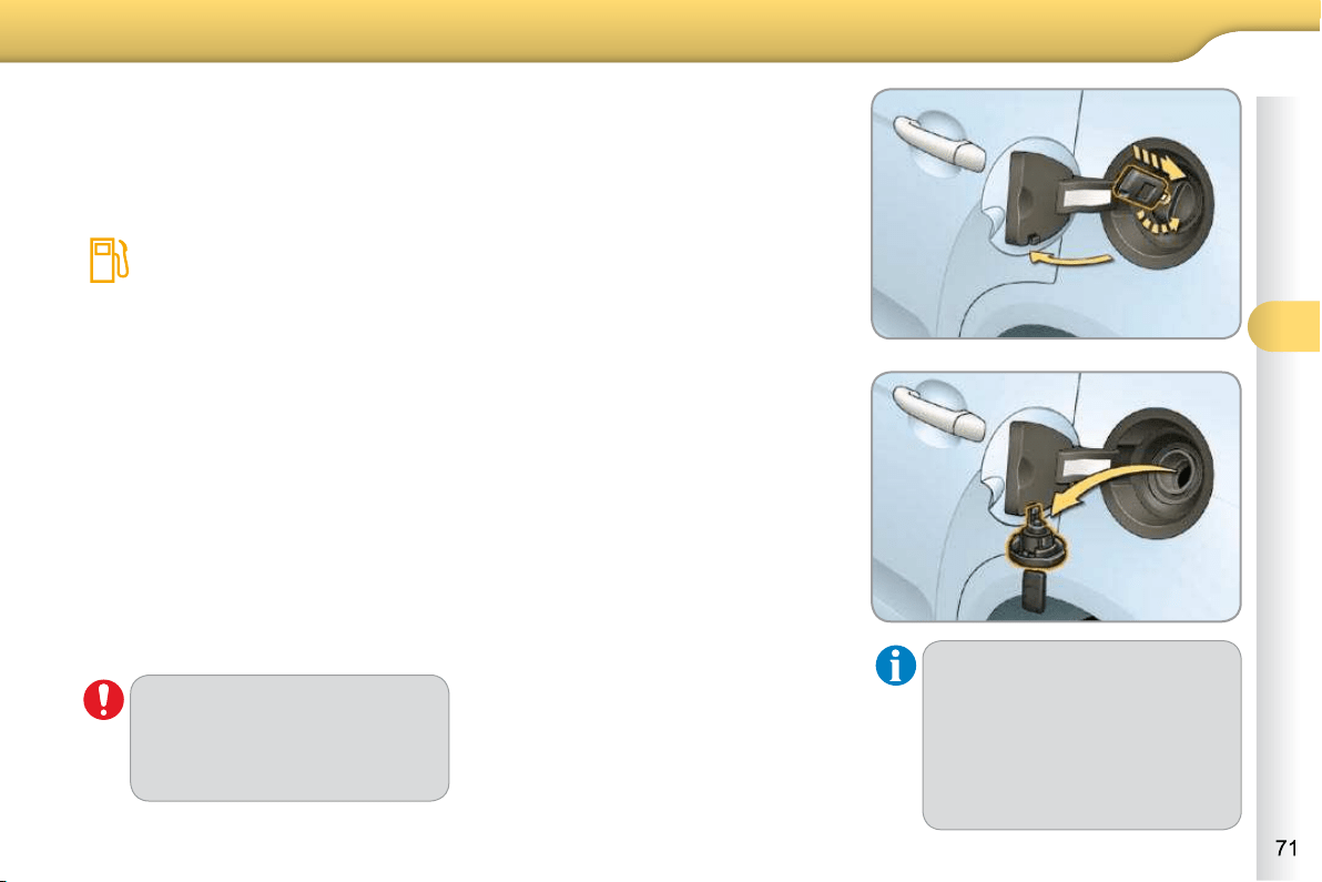
4
ACCESS
The key cannot be removed from
the lock until the cap is refi tted.
Opening the fi ller cap may cre-
ate a noise caused by an inrush
of air. This vacuum is entirely
normal, resulting from the seal-
ing of the fuel system.
FUEL TANK
Fuel tank capacity: approximately
50 litres (petrol) or 48 litres (Diesel).
Low fuel level
When the fuel tank minimum
level is reached this warning
lamp comes on on the instru-
ment panel. When it fi rst comes
on there remains approximately 5 litres
of fuel in the tank.
You must refuel as soon as possible to
avoid running out of fuel.
If you run out of fuel (Diesel), refer also
to the "Checks" section.
Filling
A label affi xed to the inside of the fl ap
reminds you of the type of fuel to be
used depending on your engine.
Additions of fuel must be of at least
5 litres, in order to be taken into account
by the fuel gauge.
To fi ll the tank safely:
the engine must be switched off,
open the fuel fi ller fl ap,
insert the key in the cap, then turn it
to the left,
remove the cap and hook it onto
the clip located on the inside of the
fl ap,
fi ll the tank, but do not continue
after the 3rd cut-off of the pump ;
this could cause malfunctions.
When you have fi lled the tank:
put the cap back in place,
turn the key to the right, then remove
it from the cap,
close the fl ap.
With Stop & Start, never refuel
with the system in STOP mode;
you must switch off the ignition
with the key.
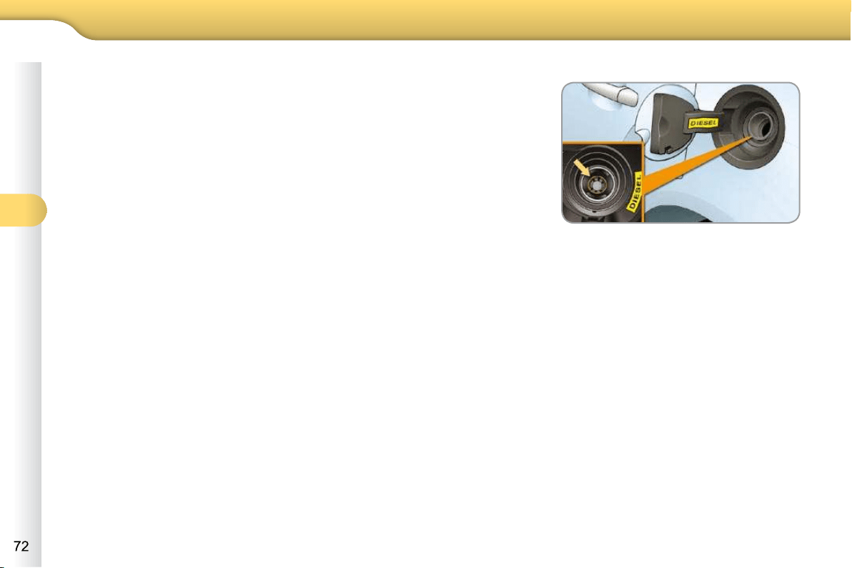
4
ACCESS
Quality of the fuel used for
petrol engines
The petrol engines are perfectly com-
patible with E10 type petrol biofuels
(containing 10 % ethanol), conforming
to European standards EN 228 and
EN 15376.
E85 type fuels (containing up to 85 %
ethanol) are reserved exclusively for
vehicles marketed for the use of this type
of fuel (BioFlex vehicles). The quality of
the ethanol must comply with European
standard EN 15293.
For Brazil only, special vehicles are
marketed to run on fuels containing up
to 100 % ethanol (E100 type).
Quality of the fuel used for
Diesel engines
The Diesel engines are perfectly com-
patible with biofuels which conform to
current and future European standards
(Diesel fuel which complies with stan-
dard EN 590 mixed with a biofuel which
complies with standard EN 14214)
available at the pumps (containing up
to 7 % Fatty Acid Methyl Ester).
The B30 biofuel can be used in
certain Diesel engines; however, this
use is subject to strict application of the
special servicing conditions. Contact a
CITROËN dealer or a qualifi ed work-
shop.
The use of any other type of (bio)fuel
(vegetable or animal oils, pure or dilut-
ed, domestic fuel...) is strictly prohibited
(risk of damage to the engine and fuel
system).
Mechanical device which prevents fi lling
the tank of a Diesel vehicle with petrol. It
avoids the risk of engine damage that can
result from fi lling with the wrong fuel.
Located in the fi ller neck, the misfuel
prevention device appears when the
fi ller cap is removed.
MISFUEL PREVENTION
Operation
When a petrol fi ller nozzle is introduced
into the fuel fi ller neck of your Diesel
vehicle, it comes into contact with the
fl ap. The system remains closed and
prevents fi lling.
Do not persist but introduce a Diesel
type fi ller nozzle.
It is still possible to use a fuel can to fi ll
the reservoir.
In order to ensure a good fl ow of fuel,
do not place the nozzle of the fuel can in
direct contact with the fl ap of the misfuel
prevention device.
This equipment will become available
during the year.
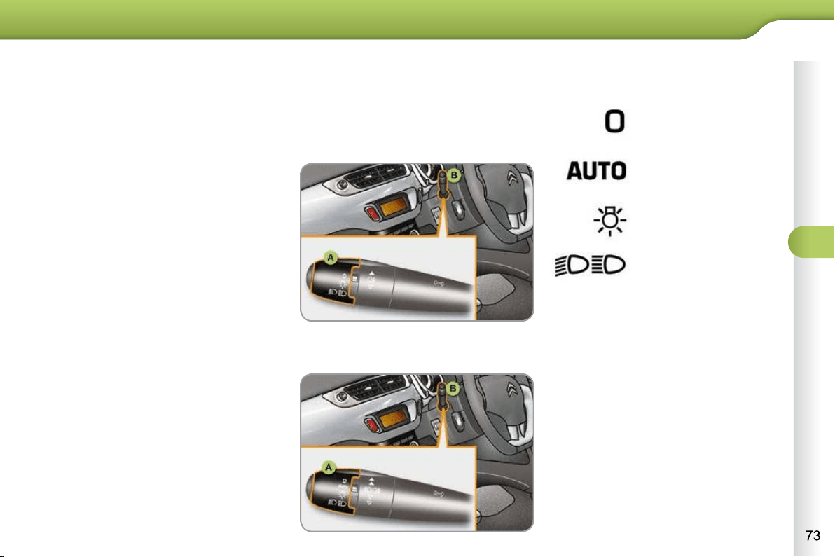
5
VISIBILITY
LIGHTING CONTROLS
System for selection and control of the
various front and rear lamps providing
the vehicle's lighting.
Main lighting
The various front and rear lamps of
the vehicle are designed to adapt the
driver's visibility progressively accord-
ing to climatic conditions:
- sidelamps, to be seen,
- dipped beam headlamps to see
without dazzling other drivers,
- main beam headlamps to see clearly
when the road is clear.
Additional lighting
Other lamps are installed to fulfi l the
requirements of particular conditions of
visibility:
- a rear foglamp to be seen from afar,
- front foglamps for even better forward
vision.
Programming
Various automatic lighting control modes
are also available according to the fol-
lowing options:
- guide-me-home lighting,
- automatic illumination of headlamps.
Model without AUTO lighting
Model with AUTO lighting
Lamps off.
Automatic illumination of
headlamps.
Sidelamps only.
Dipped or main beam
headlamps.
B. Stalk for switching the headlamp
beam: pull the stalk to switch between
dipped and main beam headlamps.
In the lamps off and sidelamps modes,
the driver can switch on the main beam
headlamps temporarily ("headlamp
fl ash") by maintaining a pull on the stalk.
Displays
Lighting of the corresponding indicator
lamp on the instrument panel confi rms the
switching on of the lighting selected.
Depending on version, the instrument
panel may have permanent back-light-
ing. Illumination of the instrument panel is
therefore not linked to the exterior lighting.
Manual controls
The lighting commands are issued
directly by the driver by means of the
ring A and the stalk B .
A. Main lighting mode selection ring:
turn it to position the symbol re-
quired facing the mark.
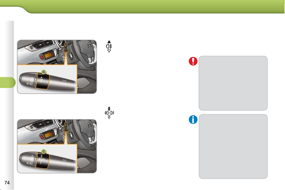
5
VISIBILITY
C. Foglamp selection ring.
The foglamps operate with the dipped
and main beam headlamps.
Rear foglamp
Rotate and release the ring C :
forwards a fi rst time to switch on the
front foglamps,
forwards a second time to switch on
the rear foglamp,
rearwards a fi rst time to switch off
the rear foglamp,
rearwards a second time to switch
of the front fog lamps.
Model with rear foglamp only
To switch on the foglamp, turn the
ring C forwards.
When the lighting is switched off auto-
matically (with AUTO model), the foglamp
and the dipped beam headlamps will
remain on.
To switch off all of the lighting, turn
the ring C rearwards.
Model with front foglamps
and a rear foglamp
Front and rear foglamps
In good or rainy weather, by both
day and night, the front foglamps
and the rear foglamp are pro-
hibited. In these situations, the
power of their beams may dazzle
other drivers.
Do not forget to switch off the front
foglamps and the rear foglamp
when they are no longer neces-
sary.
Lighting on audible warning
When the ignition is switched
off, all of the lamps switch off
automatically, unless guide-me-
home lighting is activated.
If the lighting is switched on manu-
ally after switching off the ignition,
there is an audible signal when a
front door is opened to warn the
driver that they have forgotten to
switch off the vehicle's lighting,
with the ignition off.
When the lighting is switched off auto-
matically (with AUTO model) or when
the dipped headlamps are switched off
manually, the foglamps and sidelamps
will remain on.
Turn the ring rearwards to switch
off the foglamps, the sidelamps will
then switch off.
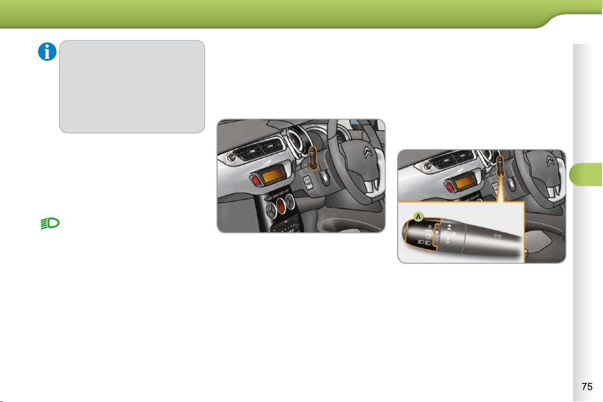
5
VISIBILITY
* According to country.
Daytime running lamps *
On vehicles fi tted with daytime run-
ning lamps, the dipped beams come on
when the vehicle is started.
Manual guide-me-home lighting
Temporarily keeping the dipped beam
headlamps on after the vehicle's ignition
has been switched off makes the driver's
exit easier when the light is poor.
Switching on
With the ignition off, "fl ash" the
headlamps using the lighting stalk.
A further "headlamp fl ash" switches
the function off.
Switching off
The manual guide-me-home lighting
switches off automatically after a set time.
Automatic illumination of
headlamps
The sidelamps and dipped beam head-
lamps are switched on automatically,
without any action on the part of the
driver, when a low level of external light
is detected or in certain cases of activa-
tion of the windscreen wipers.
As soon as the brightness returns to a
suffi cient level or after the windscreen
wipers are switched off, the lamps are
switched off automatically.
Activation
Turn ring A to the "AUTO" position.
The automatic illumination of head-
lamps is accompanied by a message
in the multifunction screen.
Deactivation
Turn ring A to a position other than
"AUTO" . Deactivation is accompa-
nied by a message in the multifunction
screen.
This warning lamp comes on in
the instrument panel.
The instruments and controls (instru-
ment panel, multifunction screen, air
conditioning control panel, etc.) are not
illuminated, except on switching to the
automatic lighting mode or when the
lighting is switched on manually.
This function can be activated/deacti-
vated by a CITROËN dealer.
In some weather conditions (e.g.
low temperature or humidity), the
presence of misting on the internal
surface of the glass of the head-
lamps and rear lamps is normal; it
disappears after the lamps have
been on for a few minutes.

5
VISIBILITY
To avoid causing a nuisance to other
road users, the height of the headlamps
should be adjusted in relation to the load
in the vehicle.
0 . Driver only or driver + front passenger.
- . Intermediate setting
1. 5 people.
- . 5 people + load in the boot.
2. Driver only + maximum authorised
load in the boot.
This position is suffi cient to avoid caus-
ing dazzle.
Higher settings may limit the spread of
light from the headlamps.
The initial setting is position "0" .
HEADLAMP ADJUSTMENT
Coupling with the automatic
"Guide-me-home" lighting
Association with the automatic illumination
of headlamps provides "guide-me-home"
lighting with the following additional op-
tions:
- selection of the lighting duration to
15, 30 or 60 seconds in the vehi-
cle parameters in the multifunction
screen confi guration menu (except
in the case of the monochrome
screen A, for which the duration is
set: 60 seconds),
- automatic activation of "guide-me-
home" lighting when automatic
illumination of headlamps is in ope-
ration.
Operating fault
In fog or snow, the sunshine sen-
sor may detect suffi cient light.
Therefore, the lighting will not
come on automatically.
Do not cover the sunshine sen-
sor, coupled with the rain sensor
and located in the centre of the
windscreen behind the rear view
mirror; the associated functions
would no longer be controlled.
In the event of a fault with
the sunshine sensor, the
lighting come on, this warn-
ing lamp is displayed in the instrument
panel and/or a message appears in the
multifunction screen, accompanied by
an audible signal.
Contact a CITROËN dealer or a quali-
fi ed workshop.

5
VISIBILITY
* According to country.
Daytime running lamps *
On vehicles fi tted with daytime run-
ning lamps, the dipped beams come on
when the vehicle is started.
Manual guide-me-home lighting
Temporarily keeping the dipped beam
headlamps on after the vehicle's ignition
has been switched off makes the driver's
exit easier when the light is poor.
Switching on
With the ignition off, "fl ash" the
headlamps using the lighting stalk.
A further "headlamp fl ash" switches
the function off.
Switching off
The manual guide-me-home lighting
switches off automatically after a set time.
Automatic illumination of
headlamps
The sidelamps and dipped beam head-
lamps are switched on automatically,
without any action on the part of the
driver, when a low level of external light
is detected or in certain cases of activa-
tion of the windscreen wipers.
As soon as the brightness returns to a
suffi cient level or after the windscreen
wipers are switched off, the lamps are
switched off automatically.
Activation
Turn ring A to the "AUTO" position.
The automatic illumination of head-
lamps is accompanied by a message
in the multifunction screen.
Deactivation
Turn ring A to a position other than
"AUTO" . Deactivation is accompa-
nied by a message in the multifunction
screen.
This warning lamp comes on in
the instrument panel.
The instruments and controls (instru-
ment panel, multifunction screen, air
conditioning control panel, etc.) are not
illuminated, except on switching to the
automatic lighting mode or when the
lighting is switched on manually.
This function can be activated/deacti-
vated by a CITROËN dealer.
In some weather conditions (e.g.
low temperature or humidity), the
presence of misting on the internal
surface of the glass of the head-
lamps and rear lamps is normal; it
disappears after the lamps have
been on for a few minutes.
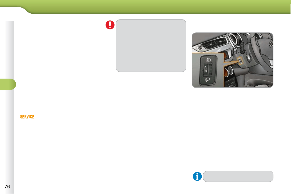
5
VISIBILITY
To avoid causing a nuisance to other
road users, the height of the headlamps
should be adjusted in relation to the load
in the vehicle.
0 . Driver only or driver + front passenger.
- . Intermediate setting
1. 5 people.
- . 5 people + load in the boot.
2. Driver only + maximum authorised
load in the boot.
This position is suffi cient to avoid caus-
ing dazzle.
Higher settings may limit the spread of
light from the headlamps.
The initial setting is position "0" .
HEADLAMP ADJUSTMENT
Coupling with the automatic
"Guide-me-home" lighting
Association with the automatic illumination
of headlamps provides "guide-me-home"
lighting with the following additional op-
tions:
- selection of the lighting duration to
15, 30 or 60 seconds in the vehi-
cle parameters in the multifunction
screen confi guration menu (except
in the case of the monochrome
screen A, for which the duration is
set: 60 seconds),
- automatic activation of "guide-me-
home" lighting when automatic
illumination of headlamps is in ope-
ration.
Operating fault
In fog or snow, the sunshine sen-
sor may detect suffi cient light.
Therefore, the lighting will not
come on automatically.
Do not cover the sunshine sen-
sor, coupled with the rain sensor
and located in the centre of the
windscreen behind the rear view
mirror; the associated functions
would no longer be controlled.
In the event of a fault with
the sunshine sensor, the
lighting come on, this warn-
ing lamp is displayed in the instrument
panel and/or a message appears in the
multifunction screen, accompanied by
an audible signal.
Contact a CITROËN dealer or a quali-
fi ed workshop.

5
VISIBILITY
To avoid causing a nuisance to other
road users, the height of the headlamps
should be adjusted in relation to the load
in the vehicle.
0 . Driver only or driver + front passenger.
- . Intermediate setting
1. 5 people.
- . 5 people + load in the boot.
2. Driver only + maximum authorised
load in the boot.
This position is suffi cient to avoid caus-
ing dazzle.
Higher settings may limit the spread of
light from the headlamps.
The initial setting is position "0" .
HEADLAMP ADJUSTMENT
Coupling with the automatic
"Guide-me-home" lighting
Association with the automatic illumination
of headlamps provides "guide-me-home"
lighting with the following additional op-
tions:
- selection of the lighting duration to
15, 30 or 60 seconds in the vehi-
cle parameters in the multifunction
screen confi guration menu (except
in the case of the monochrome
screen A, for which the duration is
set: 60 seconds),
- automatic activation of "guide-me-
home" lighting when automatic
illumination of headlamps is in ope-
ration.
Operating fault
In fog or snow, the sunshine sen-
sor may detect suffi cient light.
Therefore, the lighting will not
come on automatically.
Do not cover the sunshine sen-
sor, coupled with the rain sensor
and located in the centre of the
windscreen behind the rear view
mirror; the associated functions
would no longer be controlled.
In the event of a fault with
the sunshine sensor, the
lighting come on, this warn-
ing lamp is displayed in the instrument
panel and/or a message appears in the
multifunction screen, accompanied by
an audible signal.
Contact a CITROËN dealer or a quali-
fi ed workshop.
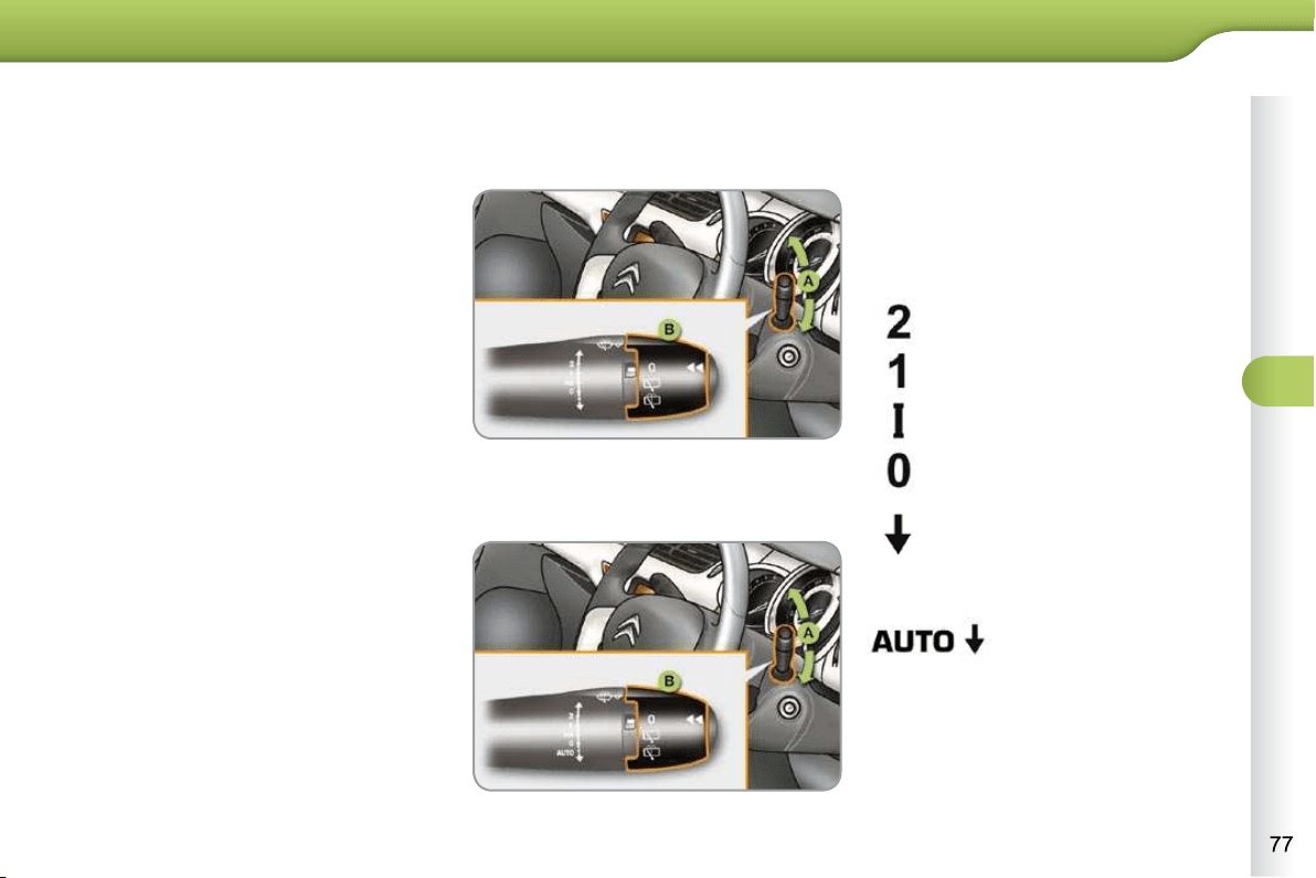
5
VISIBILITY
WIPER CONTROLS
System for selection and control of the
various front and rear wiping modes for
the elimination of rain and cleaning.
The vehicle's front and rear wipers are
designed to improve the driver's visibility
progressively according to the climatic
conditions.
Programming
Various automatic wiper control modes
are also available according to the fol-
lowing options:
- automatic rain sensitive windscreen
wipers,
- rear wiping on engaging reverse gear.
Model with intermittent wiping
Model with AUTO wiping
Manual controls
The wiper commands are issued directly
by the driver by means of the stalk A
and the ring B .
Windscreen wipers
A. Wiping speed selection stalk:
single wipe (press down and re-
lease),
or
fast (heavy rain),
normal (moderate rain),
intermittent (proportional to the
speed of the vehicle),
park,
automatic, then single
wipe (see following
page).
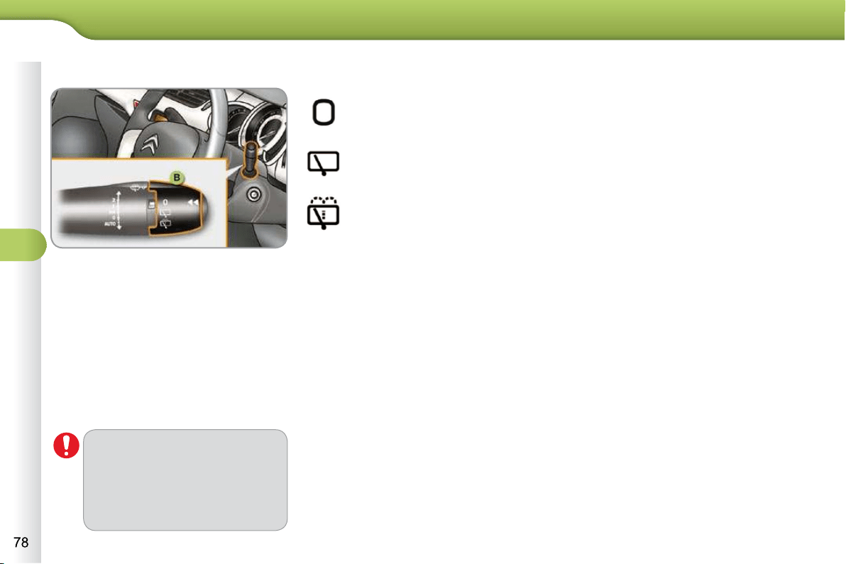
5
VISIBILITY
Rear wiper
park,
intermittent wipe,
wash-wipe (set duration).
Reverse gear
When reverse gear is engaged, the
rear wiper will come into operation if the
windscreen wipers are operating.
Programming
The function is activated or deactivated
via the multifunction screen confi gura-
tion menu.
This function is activated by default.
Windscreen wash
Pull the wiper stalk towards you. The
windscreen wash, then the windscreen
wipers, operate for a pre-determined
time.
B. Rear wiper selection ring:
If a signifi cant accumulation of
snow or ice is present, or when
using a tailgate bicycle car-
rier, deactivate the automatic
rear wiper via the multifunction
screen confi guration menu.

5
VISIBILITY
Automatic rain sensitive
windscreen wipers
The windscreen wipers operate automati-
cally, without any action on the part of the
driver, if rain is detected (sensor behind
the rear view mirror), adapting their speed
to the intensity of the rainfall.
Activation
Switching off
Operating fault
If an automatic wiping fault occurs,
the wipers will operate in intermittent
mode.
Have it checked by a CITROËN dealer
or a qualifi ed workshop.
Vertical windscreen wiper
position
To retain the effectiveness of the
"fl at-blade" wiper blades, it is ad-
visable to:
- handle them with care,
- clean them regularly using
soapy water,
- not use them to hold a sheet
of cardboard against the wind-
screen,
- replace them at the fi rst signs
of wear.
Do not cover the rain sensor,
linked with the sunshine sensor
and located in the centre of the
windscreen behind the rear view
mirror.
Switch off the automatic wiping
when using an automatic car
wash.
In winter, it is advisable to wait
until the windscreen is complete-
ly clear of ice before activating
the automatic wiping.
The automatic wiping must be re-
activated if the ignition has been
off for more than one minute, by
pushing stalk A downwards.
This position allows the wiper blades to
be lifted for winter parking, cleaning or re-
placement without damaging the bonnet.
In the minute following switching off of
the ignition, any action on the wiper
stalk positions the wipers vertically.
To park the wipers after this has been
done, switch on the ignition and operate
the wiper stalk.
This is controlled manually by the driv-
er by pushing stalk A to the "AUTO"
position.
This is controlled manually by the driver
by moving stalk A upwards, returning it
to position "0" .
It is accompanied by the indica-
tor lamp in the instrument panel
going off and a message in the
multifunction screen.
It is accompanied by the illumina-
tion of this indicator lamp in the
instrument panel and a message
in the multifunction screen.
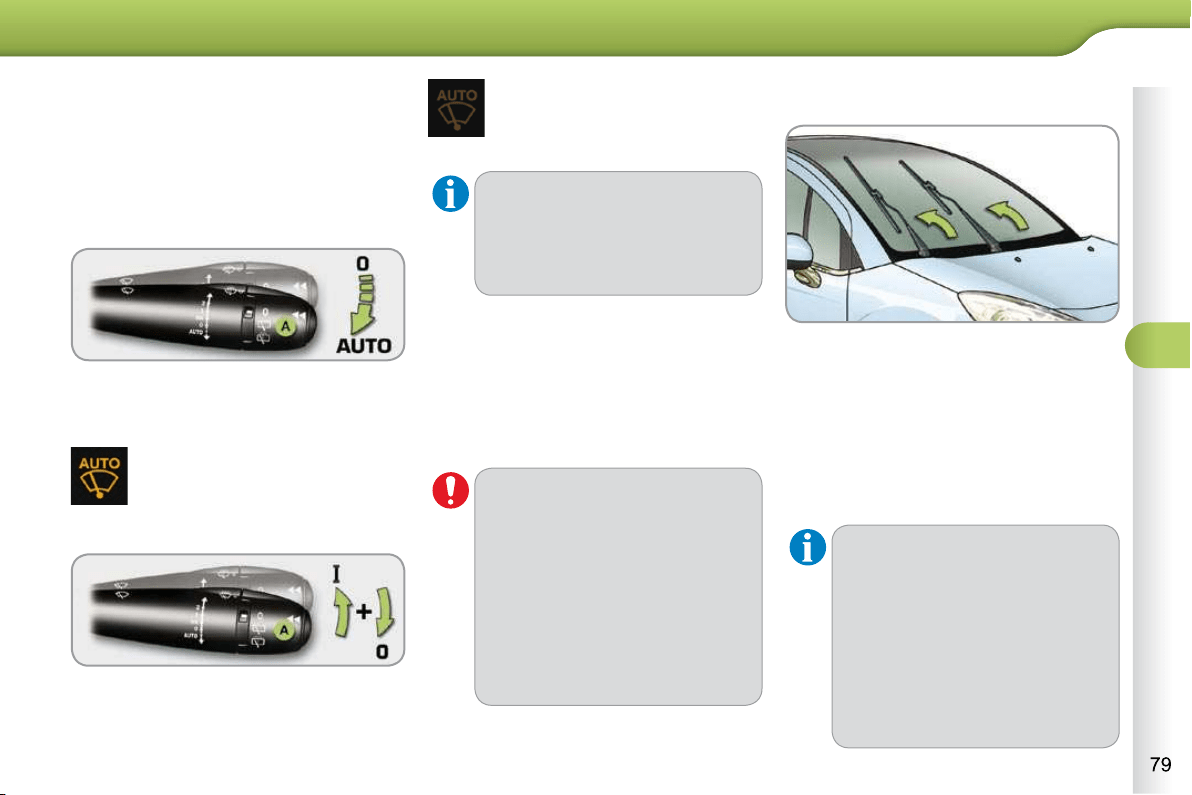
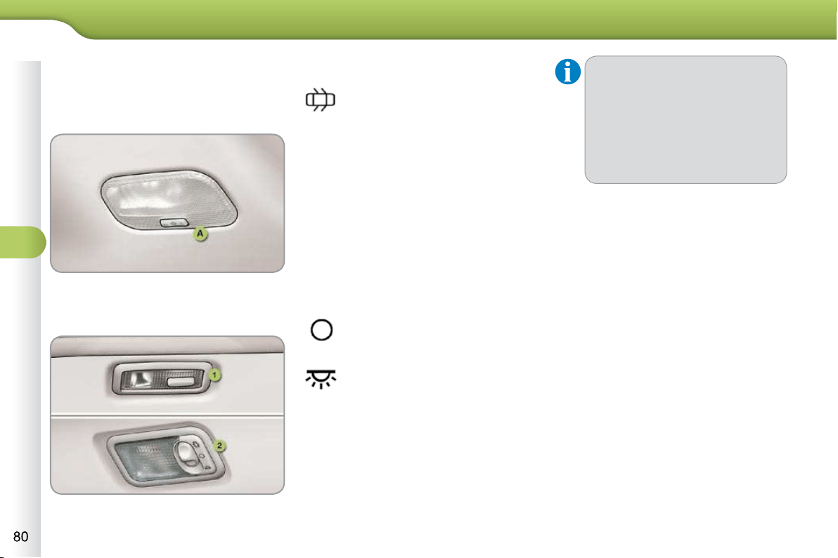
5
VISIBILITY
A. Central courtesy lamp
1. Rear side reading lamps
2. Rear courtesy lamp
Central or rear courtesy lamps
Version without Zenith windscreen
Front side reading lamps
With the ignition on, the fi rst press of
the corresponding switch switches
on the reading lamp concerned in
permanent lighting mode.
Following a second press, it comes on:
- when the vehicle is unlocked,
- when the key is removed from
the ignition,
- when a door is opened,
- when the remote control locking
button is pressed, in order to
locate your vehicle.
In permanent lighting mode, the
lighting duration varies, accord-
ing to the circumstances:
- with the ignition off, approxi-
mately ten minutes,
- in energy economy mode,
approximately thirty seconds,
- with the engine running, un-
limited.
Version with Zenith windscreen
In this position, the courtesy
lamp comes on gradually:
- when the vehicle is unlocked,
- when the key is removed from the
ignition,
- when a door is opened,
- when the remote control locking but-
ton is activated, in order to locate
your vehicle.
It switches off gradually:
- when the vehicle is locked,
- when the ignition is switched on,
- 30 seconds after the last door is
closed.
Permanently off.
Permanent lighting.
It switches off gradually:
- when the vehicle is locked,
- when the ignition is switched on,
- 30 seconds after the last door is
closed.
To switch off the rear courtesy lamp,
place it in the "permanently off" position.
COURTESY LAMPS
Selection and control of the various
passenger compartment lamps.
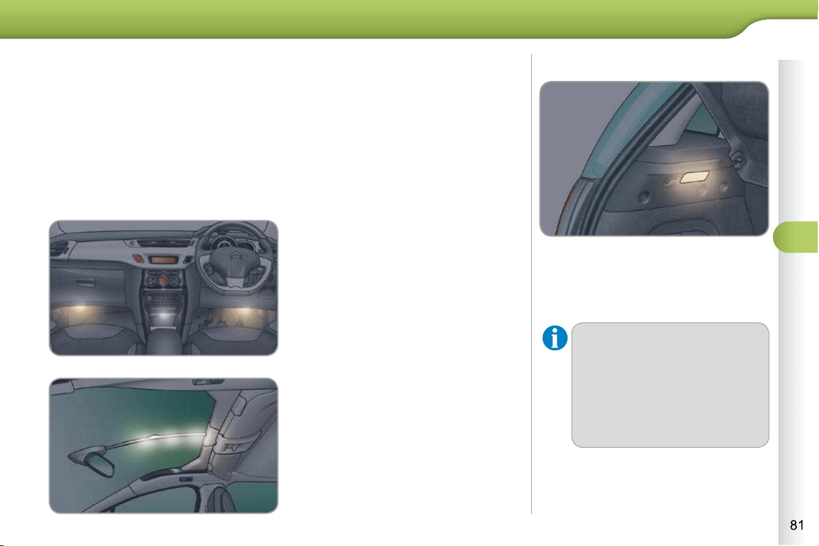
5
VISIBILITY
INTERIOR MOOD LIGHTING
The dimmed passenger compartment
lighting improves visibility in the vehicle
when the light is poor.
Switching on
At night, the illumination of footwell and
the central dashboard stoarge compart-
ment comes on automatically when the
sidelamps are switched on.
Switching off
The interior mood lighting switches off
automatically when the sidelamps are
switched off.
It can be switched off manually using
the instrument panel lighting rheostat
button.
With the lighting on, press several
times on the left hand button of the
instrument panel to progressively
reduce the dashboard lighting level.
Press again to reduce the lighting
level to the minimum and switch off
the interior mood lighting.
This comes on automatically when the
boot is opened and switches off auto-
matically when the boot is closed.
BOOT LAMP
The lighting time varies according
to the circumstances:
- when the ignition is off, ap-
proximately ten minutes,
- in energy economy mode, ap-
proximately thirty seconds,
- when the engine is running,
no limit.
On certain versions, three lamps locat-
ed in the support between the roof and
the automatic day/night interior mirror
come on as well.
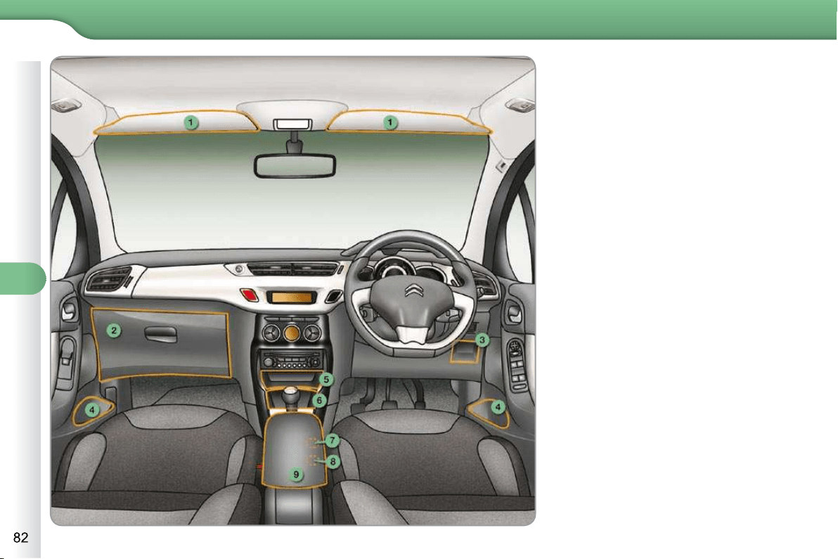
6
FITTINGS
INTERIOR FITTINGS
1. Sun visor
2. Glove box
(details on following page)
3. Storage compartments
4. Door pockets
5. Upper storage compartment
6. Lower storage compartment with
non-slip mat
7. USB port / auxiliary socket
(details on following page)
or
Coin holder
8. 12 V accessories socket
(details on following page)
9. Centre armrest with storage
(details on following page)
or
Cup/bottle holder

6
FITTINGS
SUN VISOR
Component which protects against sun-
light from the front or the side.
Version without Zenith windscreen
GLOVE BOX
To open the glove box, raise the
handle.
It houses the front passenger airbag de-
activation switch A .
It gives access to the dashboard fuse-
box (see the "Practical information - §
Changing a fuse" section).
CENTRE ARMREST
Comfort and storage system for the
driver and front passenger.
Storage
For access to the closed storage
box, lift the lever to open the lid.
For access to the open storage box
below the armrest, lift the complete
armrest towards the rear.
These can be used for portable devices
(mobile phone, MP3 player...) which can
be connected to the USB port/auxiliary
socket or charged from the 12 V socket
in the centre console.
Version with Zenith windscreen
Refer to the "Familiarisation - § Zenith
windscreen" section.
The sun visors are fi tted with a courtesy
mirror, with concealing fl ap for the driver
and a ticket/card holder.
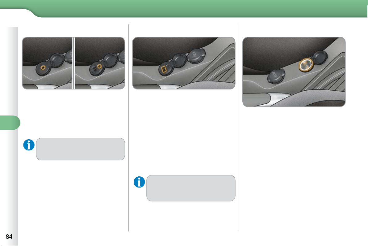
6
FITTINGS
USB PLAYER
The USB port is located in the "AUX"
box on the centre console.
It permits the connection of a portable
device, such as a digital audio player of
the iPod
®
generation 5 and later type or
USB memory stick type.
It reads the audio fi le formats (mp3,
ogg, wma, wav...) which are transmitted
to your audio equipment and played via
the vehicle's speakers.
You can manage these fi les using the
steering mounted controls or the audio
equipment control panel and display
them on the multifunction screen.
When it is in use, the portable
device charges automatically.
For more information on the use of this
equipment, refer to the Audio system part
of the "Audio and Telematics" section.
12 V ACCESSORY SOCKET
To connect a 12 V accessory (max
power: 120 W), lift the cover and
connect a suitable adaptor.
AUXILIARY SOCKET
The auxiliary socket is located in the
"AUX" box on the centre console.
It permits the connection of a portable
device, such as a digital audio player of
the iPod
®
type, to listen to your music
fi les using the vehicle's speakers.
For more information on the use of
this equipment, refer to the MyWay or
Audio system part of the "Audio and
Telematics" section.
The management of the fi les is
done using your portable device.
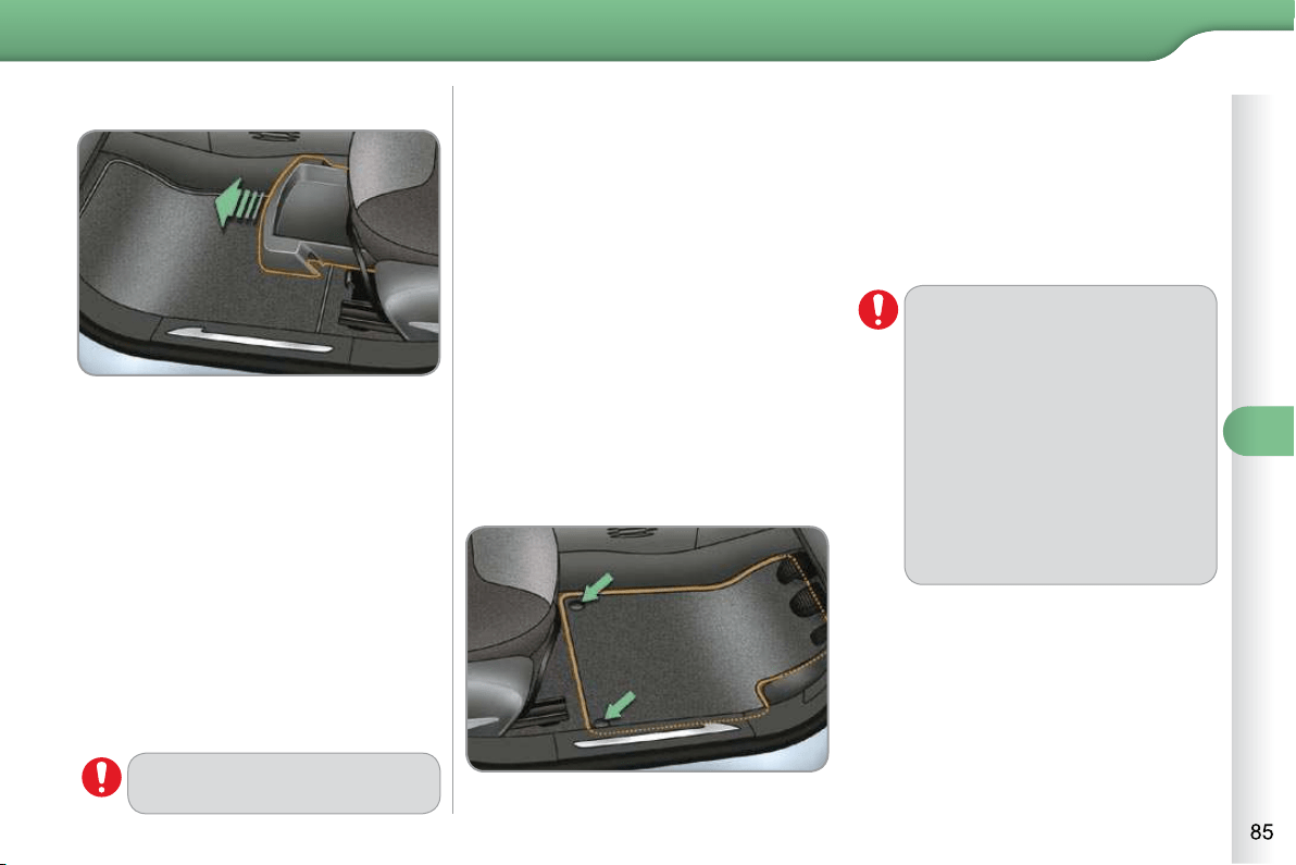
6
FITTINGS
STORAGE DRAWER
The storage drawer is located under the
front passenger's seat.
Opening
Raise the front of the drawer and pull it.
Removal
Bring the drawer to the end of its
travel.
Press the ends of the slides.
Raise the drawer and pull it fully.
Refitting
Engage the drawer in its slides.
At the end of its travel, press on the
top of the drawer to secure it.
Do not place heavy objects in
the drawer.
MATS
Removable carpet protection.
Fitting
When fi tting the mat for the fi rst time,
on the driver's side use only the fi xings
provided in the wallet attached.
The other mats are simply placed on
the carpet.
Removal
To remove the mat on the driver's side:
move the seat as far back as pos-
sible,
unclip the fi xings,
remove the mat.
Refitting
To refi t the mat on the driver's side:
position the mat correctly,
refi t the fi xings by pressing,
check that the mat is secured cor-
rectly.
To avoid any risk of jamming of
the pedals:
- only use mats which are
suited to the fi xings already
present in the vehicle; these
fi xings must be used,
- never fi t one mat on top of
another.
The use of mats not approved by
CITROËN may interfere with ac-
cess to the pedals and hinder the
operation of the cruise control/
speed limiter.
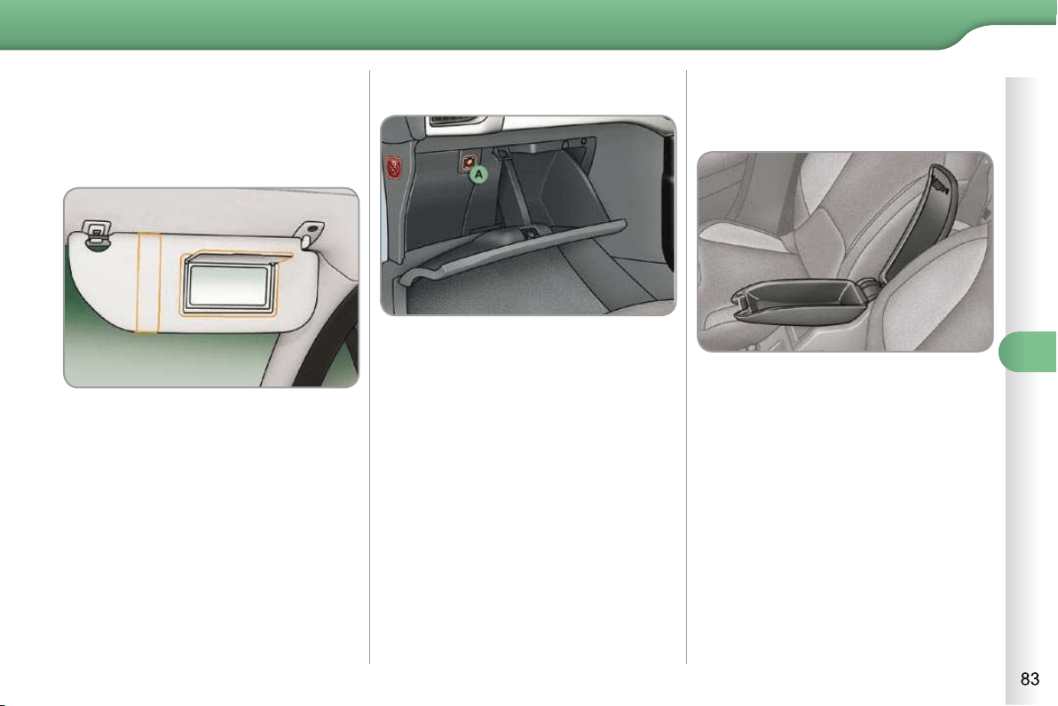
6
FITTINGS
SUN VISOR
Component which protects against sun-
light from the front or the side.
Version without Zenith windscreen
GLOVE BOX
To open the glove box, raise the
handle.
It houses the front passenger airbag de-
activation switch A .
It gives access to the dashboard fuse-
box (see the "Practical information - §
Changing a fuse" section).
CENTRE ARMREST
Comfort and storage system for the
driver and front passenger.
Storage
For access to the closed storage
box, lift the lever to open the lid.
For access to the open storage box
below the armrest, lift the complete
armrest towards the rear.
These can be used for portable devices
(mobile phone, MP3 player...) which can
be connected to the USB port/auxiliary
socket or charged from the 12 V socket
in the centre console.
Version with Zenith windscreen
Refer to the "Familiarisation - § Zenith
windscreen" section.
The sun visors are fi tted with a courtesy
mirror, with concealing fl ap for the driver
and a ticket/card holder.

6
FITTINGS
USB PLAYER
The USB port is located in the "AUX"
box on the centre console.
It permits the connection of a portable
device, such as a digital audio player of
the iPod
®
generation 5 and later type or
USB memory stick type.
It reads the audio fi le formats (mp3,
ogg, wma, wav...) which are transmitted
to your audio equipment and played via
the vehicle's speakers.
You can manage these fi les using the
steering mounted controls or the audio
equipment control panel and display
them on the multifunction screen.
When it is in use, the portable
device charges automatically.
For more information on the use of this
equipment, refer to the Audio system part
of the "Audio and Telematics" section.
12 V ACCESSORY SOCKET
To connect a 12 V accessory (max
power: 120 W), lift the cover and
connect a suitable adaptor.
AUXILIARY SOCKET
The auxiliary socket is located in the
"AUX" box on the centre console.
It permits the connection of a portable
device, such as a digital audio player of
the iPod
®
type, to listen to your music
fi les using the vehicle's speakers.
For more information on the use of
this equipment, refer to the MyWay or
Audio system part of the "Audio and
Telematics" section.
The management of the fi les is
done using your portable device.

6
FITTINGS
STORAGE DRAWER
The storage drawer is located under the
front passenger's seat.
Opening
Raise the front of the drawer and pull it.
Removal
Bring the drawer to the end of its
travel.
Press the ends of the slides.
Raise the drawer and pull it fully.
Refitting
Engage the drawer in its slides.
At the end of its travel, press on the
top of the drawer to secure it.
Do not place heavy objects in
the drawer.
MATS
Removable carpet protection.
Fitting
When fi tting the mat for the fi rst time,
on the driver's side use only the fi xings
provided in the wallet attached.
The other mats are simply placed on
the carpet.
Removal
To remove the mat on the driver's side:
move the seat as far back as pos-
sible,
unclip the fi xings,
remove the mat.
Refitting
To refi t the mat on the driver's side:
position the mat correctly,
refi t the fi xings by pressing,
check that the mat is secured cor-
rectly.
To avoid any risk of jamming of
the pedals:
- only use mats which are
suited to the fi xings already
present in the vehicle; these
fi xings must be used,
- never fi t one mat on top of
another.
The use of mats not approved by
CITROËN may interfere with ac-
cess to the pedals and hinder the
operation of the cruise control/
speed limiter.
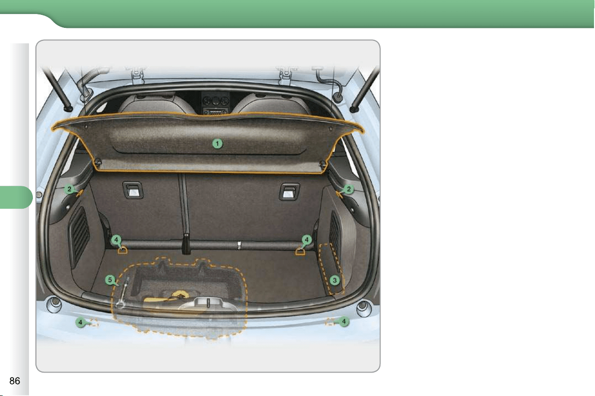
6
FITTINGS
BOOT FITTINGS
1. Rear parcel shelf
(see following page for details)
2. Hooks
(see following page for details)
3. Location for Hi-Fi amplifi er
4. Stowing rings
5. Storage box (version equipped
with a temporary puncture repair
kit)
(see following page for details)
or
Tool box (version equipped with a
spare wheel)
(refer to section "Practical Information -
§ Changing a wheel")
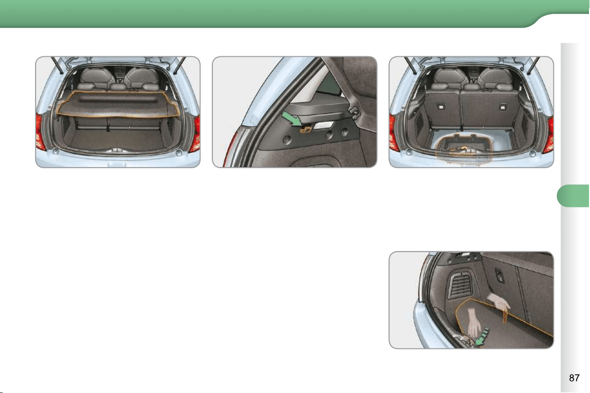
6
FITTINGS
REAR PARCEL SHELF
To remove the shelf:
unhook the two cords,
raise the shelf slightly, then unclip it
on each side.
HOOKS
The hooks can be used to hold shop-
ping bags.
STORAGE BOX
Raise the boot carpet by pulling the
strap upwards to gain access to the
storage box.
This has areas for storing a temporary
puncture repair kit, a box of spare bulbs,
a fi rst aid kit, two warning triangles, ...
refi t the boot fl oor carpet by folding it
slightly in the middle.
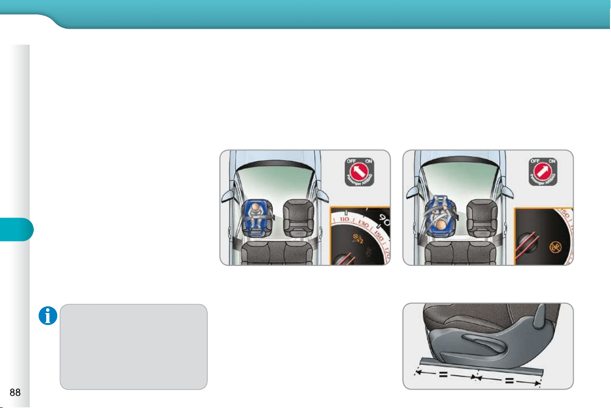
7
CHILD SAFETY
CITROËN recommends that
children should travel in the rear
seats of your vehicle:
- "rearwards-facing" up to
the age of 2,
- "forwards-facing" over the
age of 2.
* The rules for carrying children are
specifi c to each country. Refer to the
current legislation in your country.
GENERAL POINTS RELATING
TO CHILD SEATS
Although one of CITROËN's main cri-
teria when designing your vehicle, the
safety of your children also depends on
you.
For maximum safety, please observe
the following recommendations:
- in accordance with European reg-
ulations, all children under the
age of 12 or less than one and
a half metres tall must travel in
approved child seats suited to
their weight , on seats fi tted with a
seat belt or ISOFIX mountings * ,
- statistically, the safest seats in
your vehicle for carrying children
are the rear seats,
- a child weighing less than 9 kg
must travel in the "rearwards-
facing" position both in the front
and in the rear.
"Forwards-facing"
When a "forwards-facing" child seat is
installed on the front passenger seat ,
adjust the vehicle's seat to the interme-
diate longitudinal position with the seat
back upright and leave the passenger
airbag activated.
"Rearwards-facing"
When a "rearwards-facing" child seat is
installed on the front passenger seat ,
it is essential that the passenger airbag
is deactivated. Otherwise, the child
would risk being seriously injured or
killed if the airbag were to infl ate .
Intermediate longitudinal position
CHILD SEAT IN THE FRONT

7
CHILD SAFETY
Passenger airbag OFF
CHILD SEATS RECOMMENDED BY CITROËN
CITROËN offers a complete range of recommended child seats which are secured
using a three point seat belt :
Group 0+: from birth to 13 kg Groups 1, 2 and 3: from 9 to 36 kg
L1
"RÖMER Baby-Safe
Plus"
Installed in the
rearwards-facing
position.
L2
"KIDDY Life"
The use of the
restraining cushion is
compulsory for
carrying young
children
(from 9 to 18 kg).
Groups 2 and 3: from 15 to 36 kg
L3
"RECARO Start''
L4
"KLIPPAN Optima"
From the age of
6 years
(approximately
22 kg), the booster
is used on its own.
L5
"RÖMER KIDFIX"
Can be fi tted to the vehicle's ISOFIX mountings.
The child is restrained by the seat belt.
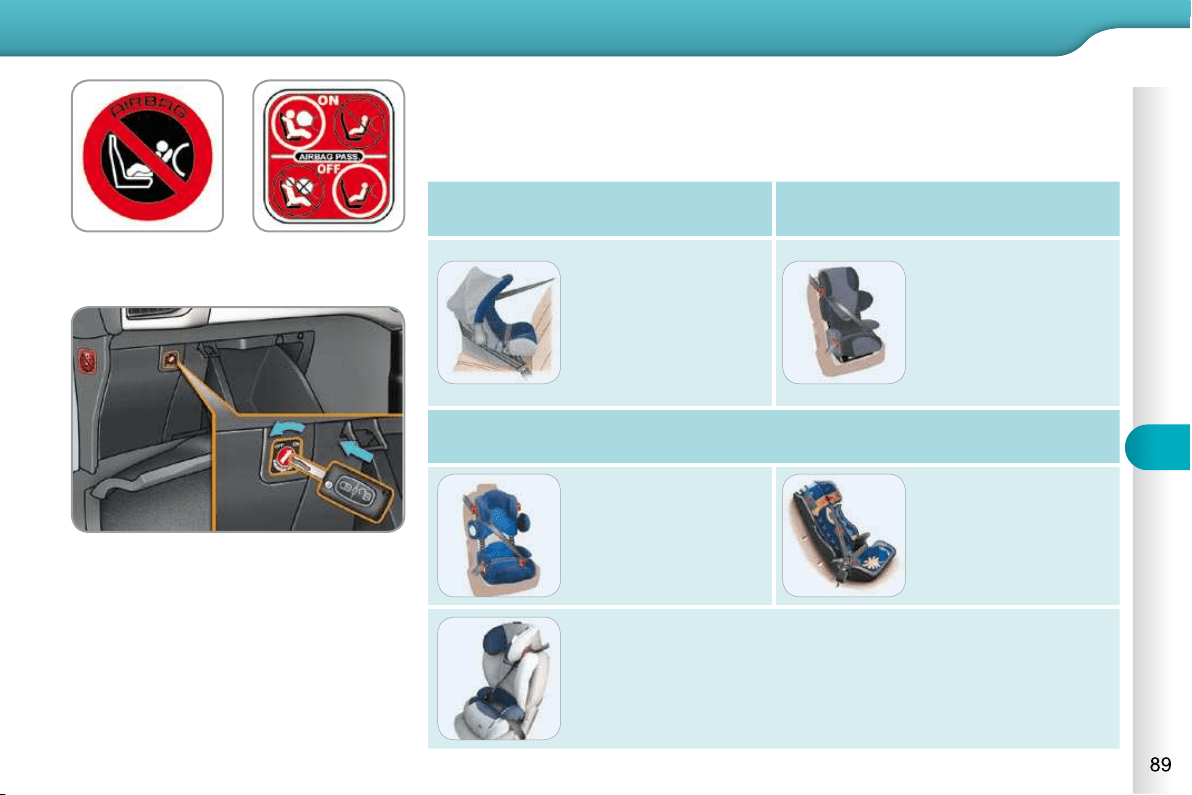
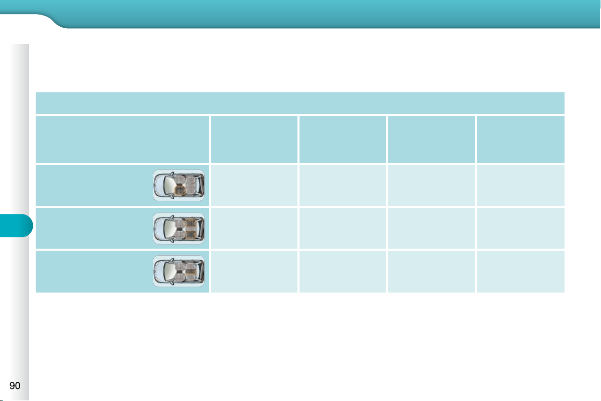
7
CHILD SAFETY
INSTALLING CHILD SEATS ATTACHED USING THE SEAT BELT
In accordance with European regulations, this table indicates the options for installing child seats secured using a seat belt
and universally approved (a) in accordance with the weight of the child and the seat in the vehicle.
Weight of the child and indicative age
Seat
Under 13 kg
(groups 0 ( b ) and
0+)
Up to approx 1 year
From 9 to 18 kg
(group 1)
1 to 3 years
approx
From 15 to 25 kg
(group 2)
3 to 6 years
approx
From 22 to 36 kg
(group 3)
6 to 10 years
approx
Front passenger seat ( c ) U U U U
Outer rear seats U U U U
Centre rear seat U U U U
(a) Universal child seat: child seat that can be installed in all vehicles using a seat belt.
(b ) Group 0: from birth to 10 kg. Shells seats and baby carriers cannot be installed in the front passenger seat.
(c ) Consult the legislation in force in your country before installing your child on this seat.
U : Seat suitable for the installation of a child seat secured using a seat belt and universally approved, "rearwards-facing"
and/or "forwards-facing".

7
CHILD SAFETY
ADVICE ON CHILD SEATS
As a safety precaution, do not leave:
- a child or children alone and un-
supervised in a vehicle,
- a child or an animal in a vehicle
which is exposed to the sun, with
the windows closed,
- the keys within reach of children
inside the vehicle.
To prevent accidental opening of the
doors and rear windows, use the
"Child lock".
Take care not to open the rear
windows by more than one third.
To protect young children from the
rays of the sun, fi t side blinds on the
rear windows.
Children under the age of 10 must
not travel in the "forwards-facing"
position on the front passenger seat,
unless the rear seats are already
occupied by other children, cannot
be used or are absent.
Deactivate the passenger airbag
when a "rearwards-facing" child seat
is installed on the front seat.
Otherwise, the child would risk being
seriously injured or killed if the airbag
were to infl ate.
Installing a booster seat
The chest part of the seat belt must
be positioned on the child's shoulder
without touching the neck.
Ensure that the lap part of the seat
belt passes correctly over the child's
thighs.
CITROËN recommends the use of
a booster seat which has a back,
fi tted with a seat belt guide at shoulder
level.
The incorrect installation of a child
seat in a vehicle compromises the
child's protection in the event of an
accident.
Remember to fasten the seat belts or
the child seat harnesses keeping the
slack relative to the child's body to a
minimum, even for short journeys.
When installing a child seat using the
seat belt, ensure that the seat belt is
tightened correctly on the child seat
and that it secures the child seat fi rmly
on the seat of your vehicle. Move the
seat forwards if necessary.
For optimum installation of the "for-
wards-facing" child seat, ensure that
the back of the child seat is in contact
with the back of the vehicle's seat
and that the head restraint does not
cause any discomfort.
If the head restraint has to be removed,
ensure that it is stored or attached se-
curely to prevent it from being thrown
around the vehicle in the event of
sharp braking.
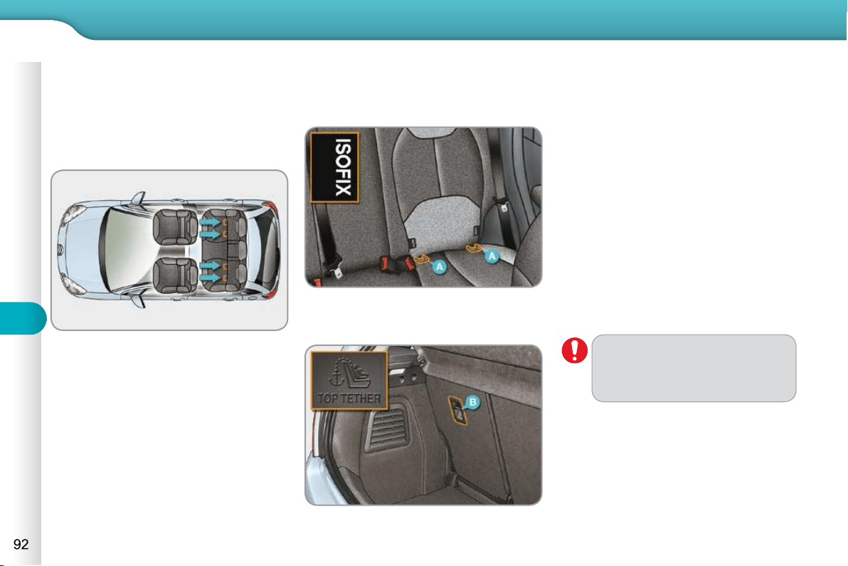
7
CHILD SAFETY
"ISOFIX" MOUNTINGS
Your vehicle has been approved in accor-
dance with the new ISOFIX regulation .
The seats, represented below, are fi tted
with regulation ISOFIX mountings:
There are three rings for each seat:
- two rings A , located between the
vehicle seat back and cushion, indi-
cated by a label,
This ISOFIX mounting system provides
fast, reliable and safe fi tting of the child
seat in your vehicle.
The ISOFIX child seats are fi tted with
two latches which are secured on the
two rings A .
When fi tting an ISOFIX child seat to the
right hand rear seat, before fi xing the
seat in place, fi rst move the centre rear
seat belt towards the middle of the ve-
hicle so as to not interfere with the op-
eration of the seat belt.
Some seats also have an upper strap
which is attached to ring B .
To attach this strap, raise the vehicle
seat's head restraint then pass the hook
between its rods. Then fi x the hook on
ring B and tighten the upper strap.
- a ring B , behind the seat, referred to
as the TOP TETHER for fi xing the
upper strap.
The incorrect installation of a
child seat in a vehicle compro-
mises the child's protection in
the event of an accident.
For information regarding the ISOFIX
child seats which can be installed in
your vehicle, refer to the table showing
the locations for installing ISOFIX child
seats.
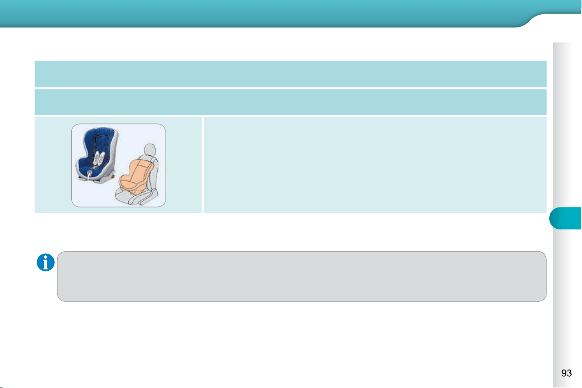
7
CHILD SAFETY
ISOFIX CHILD SEAT RECOMMENDED BY CITROËN AND APPROVED FOR YOUR VEHICLE
This child seat can also be used on seats which are not fi tted with ISOFIX mountings. In this case, it must be attached
to the vehicle seat using the three point seat belt.
Follow the instructions for fi tting the child seat given in the seat manufacturer's installation guide.
RÖMER Duo Plus ISOFIX (size category B1 )
Group 1: from 9 to 18 kg
Installed in the forwards-facing position.
Fitted with an upper strap to be secured on the upper ring B ,
referred to as the TOP TETHER.
Three seat body angles: sitting, reclining, lying.
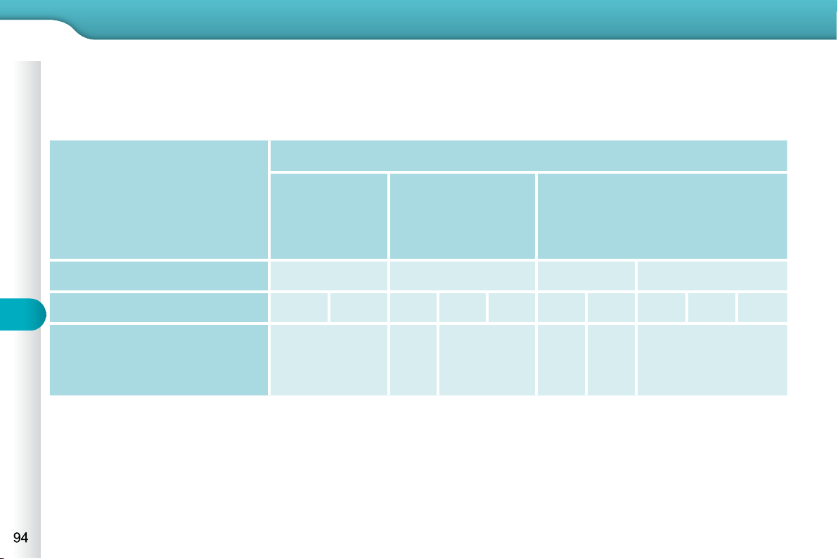
7
CHILD SAFETY
* Infant car seats and "car cots" cannot be installed on the front passenger seat.
INSTALLING ISOFIX CHILD SEATS
In accordance with European regulations, this table indicates the options for the installation of ISOFIX child seats on the
vehicle seats fi tted with ISOFIX mountings.
In the case of the universal and semi-universal ISOFIX child seats, the child seat's ISOFIX size category, determined by
a letter between A and G , is indicated on the child seat next to the ISOFIX logo.
IUF: seat suitable for the installation of an I sofi x U niversal seat, " F orward facing" and secured using the "Top Tether" upper strap.
IL-SU: seat suitable for the installation an I sofi x S emi- U niversal seat which is:
- "rear facing" fi tted with a "Top Tether" upper strap or a stay,
- "forward facing" fi tted with a stay,
For the securing of the "Top Tether" upper strap, refer to the "ISOFIX Mountings" section.
X: seat which is not suitable for the installation of an ISOFIX seat of the size category indicated.
Weight of the child /indicative age
Less than 10 kg
(group 0)
Up to 6 months
approx
Less than 10 kg
(group 0)
Less than 13 kg
(group 0+)
Up to 1 year approx
From 9 to 18 kg (group 1)
From 1 to 3 years approx
Type of ISOFIX child seat Infant car seat * "rear facing" "rear facing" "forward facing"
ISOFIX size category F G C D E C D A B B1
Universal and semi-universal
ISOFIX child seats which can be
installed on the outer rear seats
X X IL-SU X IL-SU
IUF
IL-SU
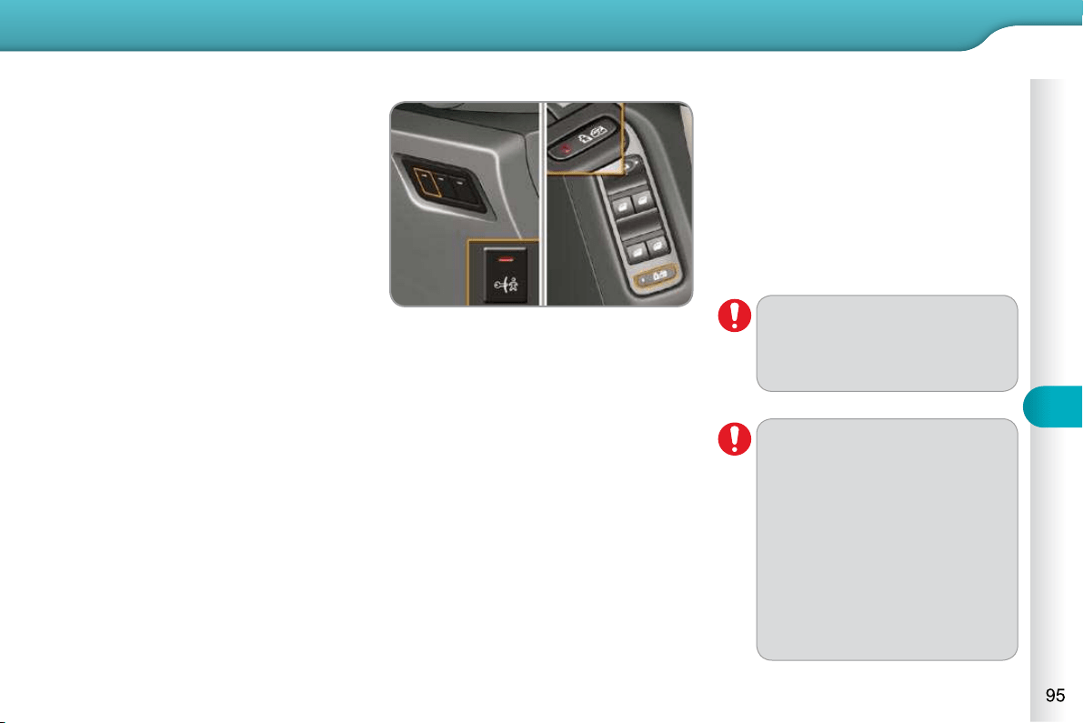
7
CHILD SAFETY
Any other status of the indica-
tor lamp indicates a fault with
the electric child lock. Have it
checked by a CITROËN dealer
or a qualifi ed workshop.
ELECTRIC CHILD LOCK
Remote control system to prevent open-
ing of the rear doors using their interior
controls and use of the rear electric
windows * .
The control is located:
- either on the dashboard, driver’s
side, for versions without rear elec-
tric windows,
- or on the driver’s door, with the elec-
tric window controls, for versions fi t-
ted with rear electric windows.
Activation
Press this button.
The indicator lamp on the button comes
on, accompanied by a message in the
multifunction screen.
This indicator lamp remains on until the
child lock is deactivated.
Deactivation
Press the button again.
The indicator lamp on the button goes
off, accompanied by a message in the
multifunction screen.
This indicator lamp remains off until the
child lock is activated.
This system is independent and
in no circumstances does it take
the place of the central locking
control.
Check the status of the child lock
each time you switch on the ignition.
Always remove the key from the
ignition when leaving the vehi-
cle, even for a short time.
In the event of a serious impact,
the electric child lock is deacti-
vated automatically to permit the
exit of the rear passengers.
* According to version.
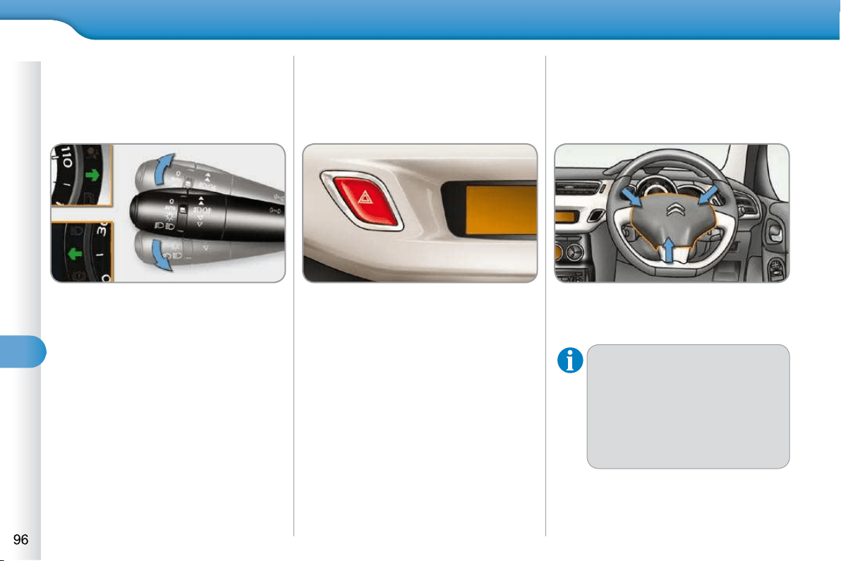
8
SAFETY
DIRECTION INDICATORS
Selection of the left or right direction in-
dicators to signal a change of direction
of the vehicle.
Left: lower the lighting stalk beyond
the point of resistance.
Right: raise the lighting stalk beyond
the point of resistance.
"Motorway" function
Press briefl y upwards or downwards,
without going beyond the point of
resistance; the direction indicators
will fl ash 3 times.
HAZARD WARNING LAMPS
A visual warning by means of the direc-
tion indicators to alert other road users
to a vehicle breakdown, towing or
accident.
Press this button, the direction indi-
cators fl ash.
They can operate with the ignition off.
Automatic operation of hazard
warning lamps
When braking in an emergency, de-
pending on the deceleration, the hazard
warning lamps come on automatically.
They switch off automatically the fi rst
time you accelerate.
You can also switch them off by
pressing the button.
HORN
Audible warning to alert other road users
to an imminent danger.
Press one of the spokes of the
steering wheel.
Use the horn moderately and
only in the following cases:
- immediate danger,
- when approaching an area
- where there is no visibility.
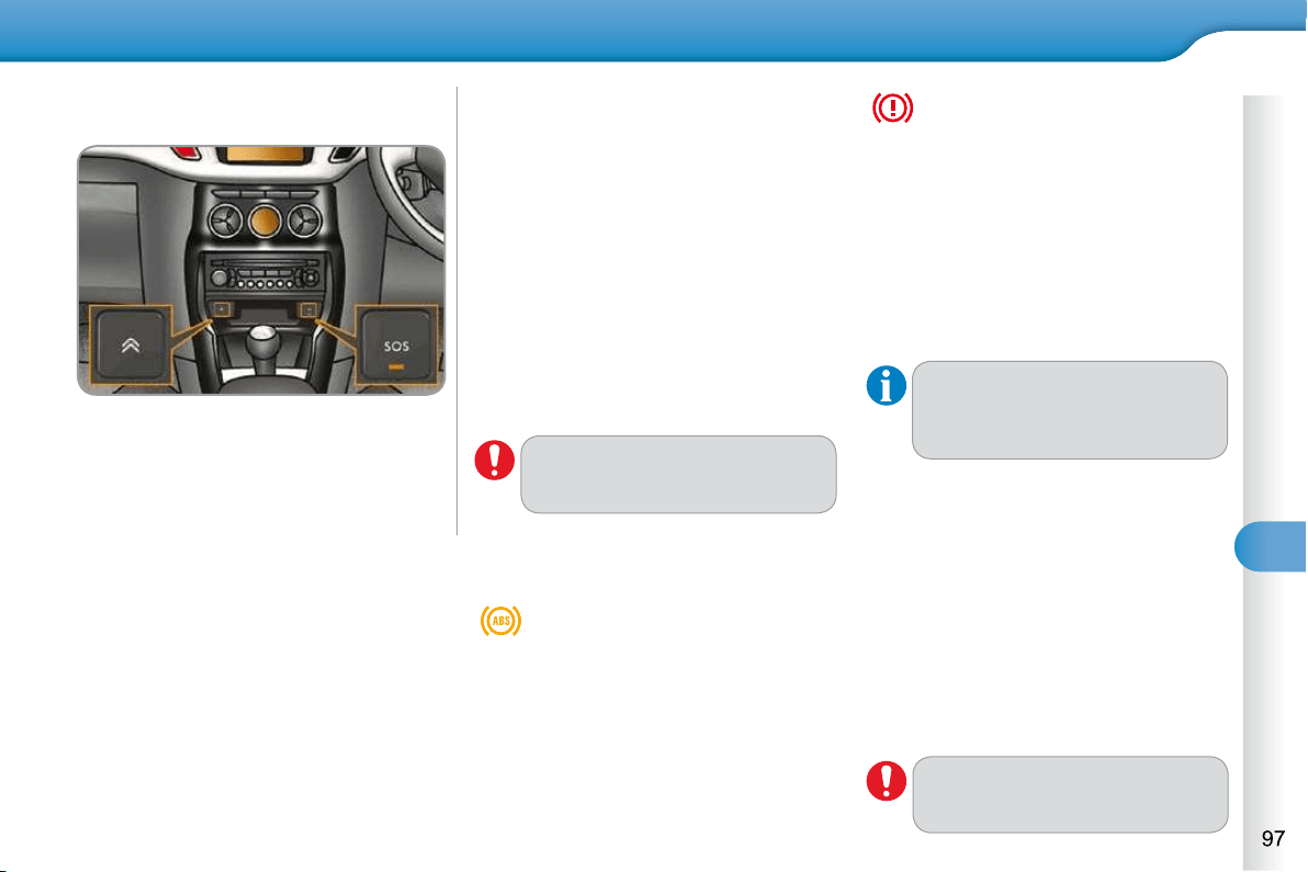
8
SAFETY
BRAKING ASSISTANCE
SYSTEMS
Group of supplementary systems which
help you to obtain optimum braking in
complete safety in emergency situa-
tions:
- anti-lock braking system (ABS),
- electronic brake force distribution
(EBFD),
- emergency braking assistance (EBA).
Anti-lock braking system
and electronic brake force
distribution
Linked systems which improve the sta-
bility and manoeuvrability of your vehicle
when braking, in particular on poor or
slippery surfaces.
Activation
The anti-lock braking system comes
into operation automatically when there
is a risk of wheel lock.
Normal operation of the ABS may make
itself felt by slight vibration of the brake
pedal.
When braking in an emergency,
press very fi rmly without releasing
the pressure.
Operating fault
In either case, contact a CITROËN
dealer or a qualifi ed workshop.
If this warning lamp comes on,
accompanied by an audible
signal and a message in the
multifunction screen, it indicates a mal-
function of the anti-lock braking system
which could result in loss of control of
the vehicle when braking.
If this warning lamp comes on,
together with the STOP and
ABS warning lamps, accompa-
nied by an audible signal and a message
in the multifunction screen, it indicates a
malfunction of the electronic brake force
distribution which could result in loss of
control of the vehicle when braking.
You must stop as soon as it is safe
to do so.
When replacing wheels (tyres
and rims), ensure that they con-
form to the manufacturer's re-
commendations.
Emergency braking assistance
System which, in an emergency, en-
ables you to obtain the optimum braking
pressure more quickly, thus reducing the
stopping distance.
Activation
It is triggered by the speed at which the
brake pedal is pressed.
The effect of this is a reduction in the
resistance of the pedal and an increase
in braking effi ciency.
When braking in an emergency,
press fi rmly without releasing
the pressure.
EMERGENCY OR ASSISTANCE
CALL
This system allows you to make an
emergency or assistance call to the
emergency services or to the dedicated
CITROËN service.
For more information on the use of this
function, refer to the "Audio and tele-
matics" section.
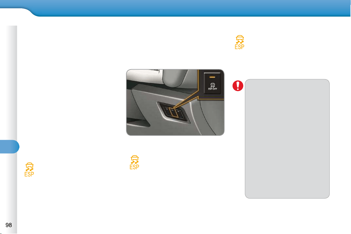
8
SAFETY
TRAJECTORY CONTROL
SYSTEMS
Anti-skid regulation (ASR) and
electronic stability programme
(ESP)
The anti-skid regulation (also known as
Traction Control) optimises traction to
prevent skidding of the wheels, by act-
ing on the brakes of the driving wheels
and on the engine.
The electronic stability programme acts
on the brake of one or more wheels and
on the engine to keep the vehicle on the
trajectory required by the driver, within
the limits of the laws of physics.
Activation
These systems are activated automati-
cally each time the vehicle is started.
They come into operation in the event
of a grip or trajectory problem.
This is indicated by fl ashing of
this warning lamp in the instru-
ment panel.
Deactivation
In exceptional conditions (starting a ve-
hicle which is bogged down, stuck in
snow, on soft ground...), it may be ad-
visable to deactivate the ASR and ESP
systems, so that the wheels can move
freely and regain grip.
Press the "ESP OFF" button, located
on the left below the steering wheel.
If this warning lamp comes on in the instru-
ment panel and the indicator lamp in the
button comes on, this indicates that the
ASR and ESP systems are deactivated.
Reactivation
These systems are reactivated automati-
cally each time the ignition is switched
back on or from 30 mph (50 km/h).
Press the "ESP OFF" button again
to reactivate them manually.
Operating fault
If this warning lamp comes on,
accompanied by an audible
signal and a message in the
screen, this indicates a fault
with these systems.
Have it checked by a CITROËN dealer
or a qualifi ed workshop.
The ESP/ASR systems offer ex-
ceptional safety in normal driving,
but this should not encourage the
driver to take extra risks or drive
at high speed.
The correct functioning of these
systems is assured provided
that manufacturer's recommen-
dations are observed on:
- wheels (tyres and rims),
- braking components,
- electronic components,
- assembly and repair proce-
dures.
After an impact, have these sys-
tems checked by a CITROËN
dealer or a qualifi ed workshop.
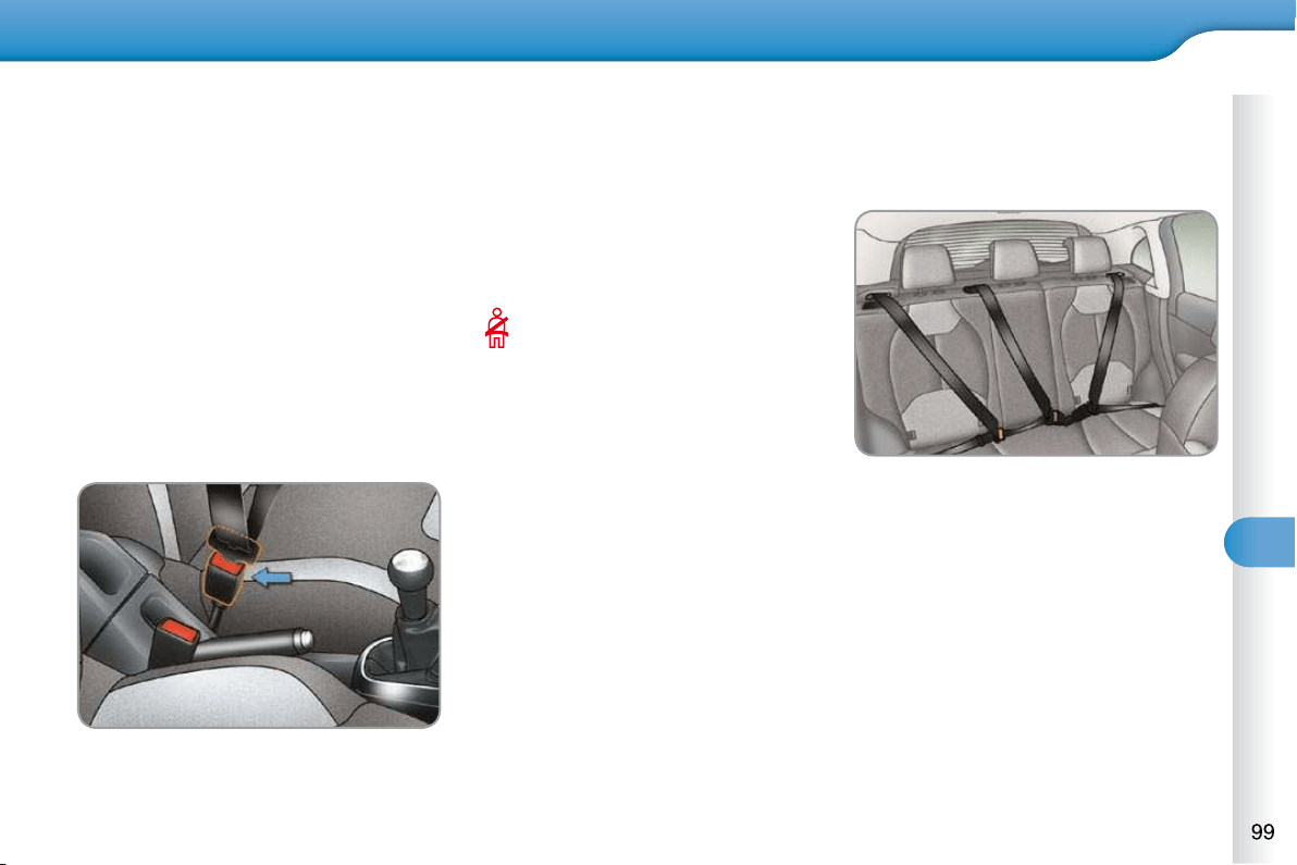
8
SAFETY
SEAT BELTS
Front seat belts
Fastening
Pull the strap, then insert the tongue
in the buckle.
Check that the seat belt is fastened
correctly by pulling the strap.
Unfastening
Press the red button on the buckle.
Guide the seat belt as it is reeled in.
Seat belt not fastened/unfastened
warning lamp
When the ignition is switched on,
this warning lamp comes on in
the instrument panel, if the driver
and/or the front passenger has
not fastened their seat belt.
From approximately 12 mph (20 km/h)
this warning lamp fl ashes for two minutes
accompanied by an audible signal of in-
creasing volume. Once these two minutes
have elapsed, this warning lamp remains
on until the driver and/or the front passen-
ger fastens their seat belt.
Rear seat belts
The rear seats are each fi tted with a
three-point inertia reel seat belt with
force limiter.
Fastening
Pull the strap, then insert the tongue
in the buckle.
Check that the seat belt is fastened
correctly by pulling the strap.
Unfastening
Press the red button on the buckle.
Guide the seat belt as it is reeled in.
The front seat belts are fi tted with a pre-
tensioning and force limiting system.
This system improves safety in the front
seats in the event of a front or side im-
pact. Depending on the severity of the
impact, the pretensioning system in-
stantly tightens the seat belts against
the body of the occupants.
The pretensioning seat belts are active
when the ignition is on.
The force limiter reduces the pressure
of the seat belt on the chest of the occu-
pant, so improving their protection.
8
SAFETY
The driver must ensure that passen-
gers use the seat belts correctly and
that they are all restrained securely
before setting off.
Wherever you are seated in the ve-
hicle, always fasten your seat belt,
even for short journeys.
Do not interchange the seat belt
buckles as they will not fulfi l their role
fully.
The seat belts are fi tted with an inertia
reel permitting automatic adjustment
of the length of the strap to your size.
The seat belt is stowed automatically
when not in use.
Before and after use, ensure that the
seat belt is reeled in correctly.
The lower part of the strap must be
positioned as low as possible on the
pelvis.
The upper part must be positioned in
the hollow of the shoulder.
The inertia reels are fi tted with an au-
tomatic locking device which comes
into operation in the event of a col-
lision, emergency braking or if the
vehicle rolls over. You can release
the device by pulling fi rmly on the
strap and releasing it so that it reels
in slightly.
Recommendations for children
Use a suitable child seat if the pas-
senger is less than 12 years old or
shorter than one and a half metres.
Never use the same seat belt to se-
cure more than one person.
Never allow a child to travel on your
lap.
In order to be effective, a seat belt
must:
- be tightened as close to the body
as possible,
- be pulled in front of you with a
smooth movement, checking that
it does not twist,
- be used to restrain only one person,
- not bear any trace of cuts or fraying,
- not be converted or modifi ed to
avoid affecting its performance.
In accordance with current safety
regulations, for all repairs on your
vehicle, go to a qualifi ed workshop
with the skills and equipment needed,
which a CITROËN dealer is able to
provide.
Have your seat belts checked regular-
ly by a CITROËN dealer or a qualifi ed
workshop, particularly if the straps
show signs of damage.
Clean the seat belt straps with soapy
water or a textile cleaning product,
sold by CITROËN dealers.
After folding or moving a seat or rear
bench seat, ensure that the seat belt
is positioned and reeled in correctly.
In the event of an impact
Depending on the nature and serious-
ness of the impact , the pretensioning
device may be deployed before and in-
dependently of the airbags. Deployment
of the pretensioners is accompanied by
a slight discharge of harmless smoke
and a noise, due to the activation of the
pyrotechnic cartridge incorporated in
the system.
In all cases, the airbag warning lamp
comes on.
Following an impact, have the seat
belts system checked, and if neces-
sary replaced, by a CITROËN dealer
or a qualifi ed workshop.
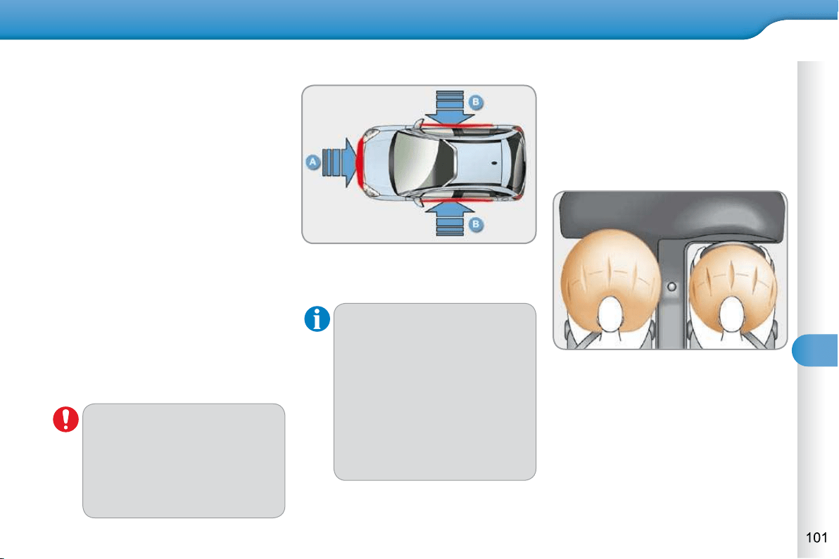
8
SAFETY
AIRBAGS
The airbags do not operate
when the ignition is switched
off.
This equipment will only deploy
once. If a second impact occurs
(during the same or a subse-
quent accident), the airbag will
not be deployed again.
Impact detection zones
A. Front impact zone.
B. Side impact zone.
Deployment of the airbag(s) is
accompanied by a slight emis-
sion of harmless smoke and a
noise, due to the activation of
the pyrotechnic cartridge incor-
porated in the system.
This smoke is not harmful, but
sensitive individuals may experi-
ence slight irritation.
The noise of the detonation may
result in a slight loss of hearing
for a short time.
Front airbags
System which protects the driver and
front passenger in the event of a seri-
ous front impact in order to limit the risk
of injury to the head and chest.
The driver's airbag is fi tted in the centre
of the steering wheel; the front passen-
ger's airbag is fi tted in the dashboard
above the glove box.
Deployment
The airbags are deployed simultane-
ously, unless the passenger's front
airbag is deactivated, in the event of
a serious front impact applied to all or
part of the front impact zone A , in the
longitudinal centreline of the vehicle on
a horizontal plane and directed from the
front to the rear of the vehicle.
The front airbag infl ates between the
head-thorax of the front occupant of the
vehicle and the dashboard to cushion
their forward movement.
System designed to maximise the safety
of the occupants (with the exception of
the rear centre passenger) in the event
of violent collisions. It supplements the
action of the force-limiting seat belts
(with the exception of the rear centre
passenger).
If a collision occurs, the electronic de-
tectors record and analyse the front and
side impacts sustained in the impact
detection zones:
- in the case of a serious impact, the
airbags are deployed instantly and
protect the occupants of the vehicle
(with the exception of the rear centre
passenger); immediately after the
impact, the airbags defl ate rapidly
so that they do not hinder visibility
or the exit of the occupants,
- in the case of a minor or rear impact
or in certain roll-over conditions, the
airbags will not be deployed; the
seat belt alone is suffi cient to pro-
vide optimum protection in these
situations.
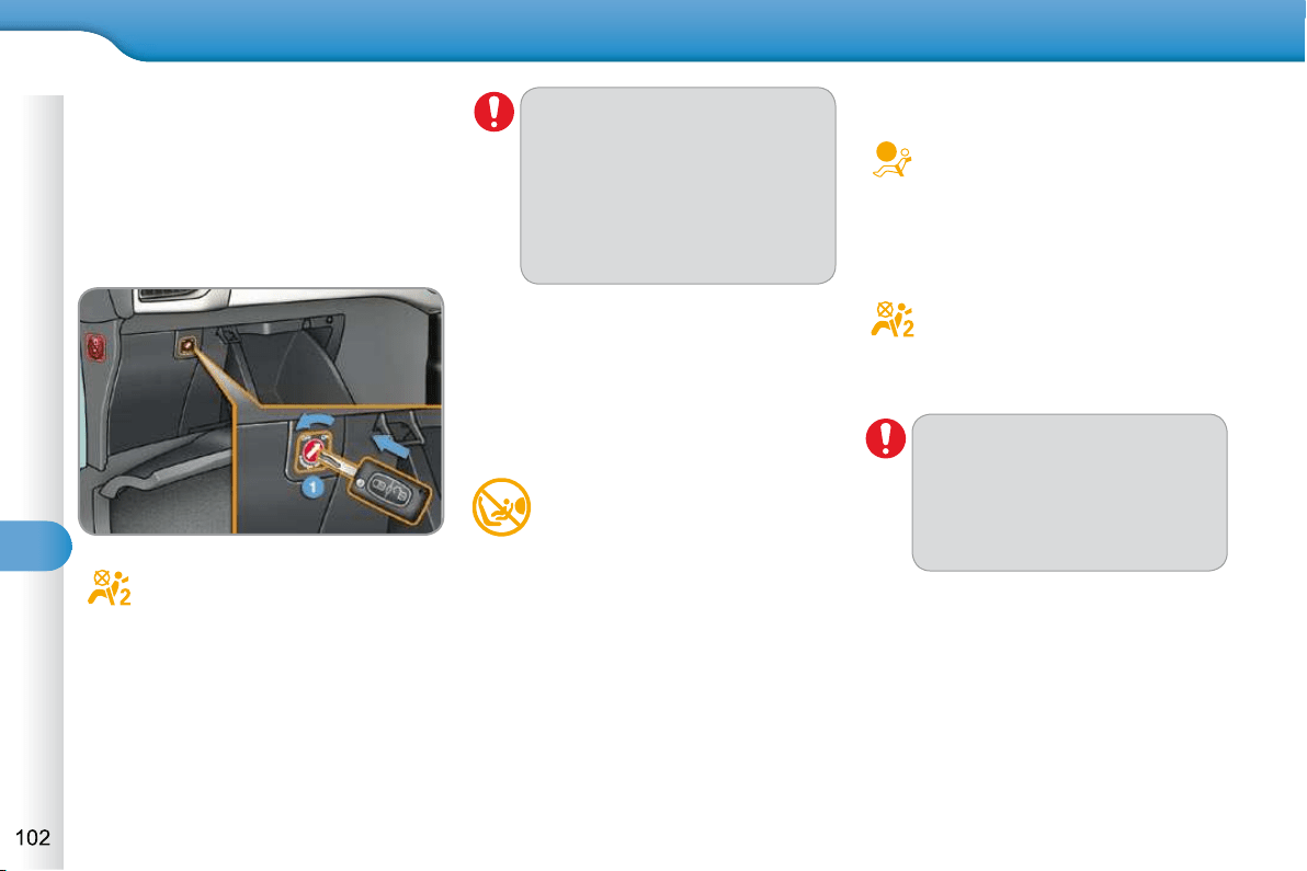
8
SAFETY
Deactivation
Only the passenger's front airbag can
be deactivated:
with the ignition off , insert the key
in the passenger airbag deactivation
switch 1 ,
turn it to the "OFF" position,
then, remove the key keeping the
switch in the new position.
This warning lamp comes on
in the instrument panel when
the ignition is on and until the
airbag is re-activated.
To assure the safety of your child,
the passenger's front airbag
must be deactivated when you
install a "rear facing" child seat
on the front passenger seat.
Otherwise, the child would risk
being seriously injured or killed if
the airbag were deployed.
Reactivation
When you remove the child seat, turn
switch 1 to the "ON" position to re-acti-
vate the airbag and so assure the safety
of your front passenger in the event of
an impact.
With the ignition on, this warn-
ing lamp comes on in the instru-
ment panel for approximately
one minute, if the passenger's
front airbag is activated.
Operating fault
If this warning lamp comes on
in the instrument panel, accom-
panied by an audible warning
and a message in the multifunc-
tion screen, contact a CITROËN dealer
or qualifi ed workshop to have the system
checked. The airbags may no longer be
deployed in the event of a serious impact.
If this warning lamp fl ashes,
contact a CITROËN dealer or
a qualifi ed workshop. The pas-
senger's front airbag may no
longer be deployed in the event
of a serious impact.
If at least one of the two airbag
warning lamps come on continu-
ously, do not install a child seat
on the front passenger seat.
Have it checked by a CITROËN
dealer or a qualifi ed workshop.

8
SAFETY
For the airbags to be fully
effective, observe the following
safety rules:
Sit in a normal upright position.
Wear a correctly adjusted seat belt.
Do not leave anything between the
occupants and the airbags (a child,
pet, object...). This could hamper the
operation of the airbags or injure the
occupants.
After an accident or if the vehicle has
been stolen or broken into, have the
airbag systems checked.
All work on the airbag system must be
carried out by a CITROËN dealer or a
qualifi ed workshop.
Even if all of the precautions men-
tioned are observed, a risk of injury
or of minor burns to the head, chest
or arms when an airbag is deployed
cannot be ruled out. The bag infl ates
almost instantly (within a few millisec-
onds) then defl ates within the same
time discharging the hot gas via open-
ings provided for this purpose.
Front airbags
Do not drive holding the steering wheel by its spokes or resting your hands on
the centre part of the wheel.
Passengers must not place their feet on the dashboard.
If possible, do not smoke as deployment of the airbags can cause burns or
the risk of injury from a cigarette or pipe.
Never remove or pierce the steering wheel or hit it violently.
Lateral airbags
Use only approved covers on the seats, compatible with the deployment the
lateral airbags. For information on the range of seat covers suitable for your
vehicle, you can contact a CITROËN dealer (see "Practical information - §
Accessories").
Do not fi x or attach anything to the seat backs (clothing...). This could cause
injury to the chest or arms if the lateral airbag is deployed.
Do not sit with the upper part of the body any nearer to the door than necessary.
Curtain airbags
Do not fi x or attach anything to the roof. This could cause injury to the head if
the curtain airbag is deployed.
Do not remove the grab handles installed on the roof, they play a part in
securing the curtain airbags.

8
SAFETY
Lateral airbags
System which protects the driver and
front passenger in the event of a seri-
ous side impact in order to limit the risk
of injury to the chest, between the hip
and the shoulder.
Each lateral airbag is fi tted in the seat
backrest frame, door side.
Deployment
The lateral airbags are deployed uni-
laterally in the event of a serious side
impact applied to all or part of the side
impact zone B , perpendicular to the
longitudinal centreline of the vehicle on
a horizontal plane and directed from
the outside towards the inside of the
vehicle.
The lateral airbag infl ates between the
hip and shoulder of the front occupant
of the vehicle and the corresponding
door trim panel.
Impact detection zones
A. Front impact zone.
B. Side impact zone.
Curtain airbags
System which protects the driver and
passengers (with the exception of the
rear centre passenger) in the event of a
serious side impact in order to limit the
risk of injury to the side of the head.
Each curtain airbag is built into the pillars
and the upper passenger compartment
area.
Deployment
The curtain airbag is deployed at the
same time as the corresponding later-
al airbag in the event of a serious side
impact applied to all or part of the side
impact zone B , perpendicular to the lon-
gitudinal centreline of the vehicle on a
horizontal plane and directed from the
outside towards the inside of the vehicle.
The curtain airbag infl ates between the
front or rear occupant of the vehicle and
the windows.
Operating fault
If this warning lamp comes on in
the instrument panel, accompa-
nied by an audible signal and a
message in the screen, contact
a CITROËN dealer or a qualifi ed work-
shop to have the system checked. The
airbags may no longer be deployed in
the event of a serious impact.
In the event of a minor impact or
bump on the side of the vehicle
or if the vehicle rolls over, the
airbag may not be deployed.
In the event of a rear or front
collision, the airbag is not de-
ployed.

8
SAFETY
For the airbags to be fully
effective, observe the following
safety rules:
Sit in a normal upright position.
Wear a correctly adjusted seat belt.
Do not leave anything between the
occupants and the airbags (a child,
pet, object...). This could hamper the
operation of the airbags or injure the
occupants.
After an accident or if the vehicle has
been stolen or broken into, have the
airbag systems checked.
All work on the airbag system must be
carried out by a CITROËN dealer or a
qualifi ed workshop.
Even if all of the precautions men-
tioned are observed, a risk of injury
or of minor burns to the head, chest
or arms when an airbag is deployed
cannot be ruled out. The bag infl ates
almost instantly (within a few millisec-
onds) then defl ates within the same
time discharging the hot gas via open-
ings provided for this purpose.
Front airbags
Do not drive holding the steering wheel by its spokes or resting your hands on
the centre part of the wheel.
Passengers must not place their feet on the dashboard.
If possible, do not smoke as deployment of the airbags can cause burns or
the risk of injury from a cigarette or pipe.
Never remove or pierce the steering wheel or hit it violently.
Lateral airbags
Use only approved covers on the seats, compatible with the deployment the
lateral airbags. For information on the range of seat covers suitable for your
vehicle, you can contact a CITROËN dealer (see "Practical information - §
Accessories").
Do not fi x or attach anything to the seat backs (clothing...). This could cause
injury to the chest or arms if the lateral airbag is deployed.
Do not sit with the upper part of the body any nearer to the door than necessary.
Curtain airbags
Do not fi x or attach anything to the roof. This could cause injury to the head if
the curtain airbag is deployed.
Do not remove the grab handles installed on the roof, they play a part in
securing the curtain airbags.
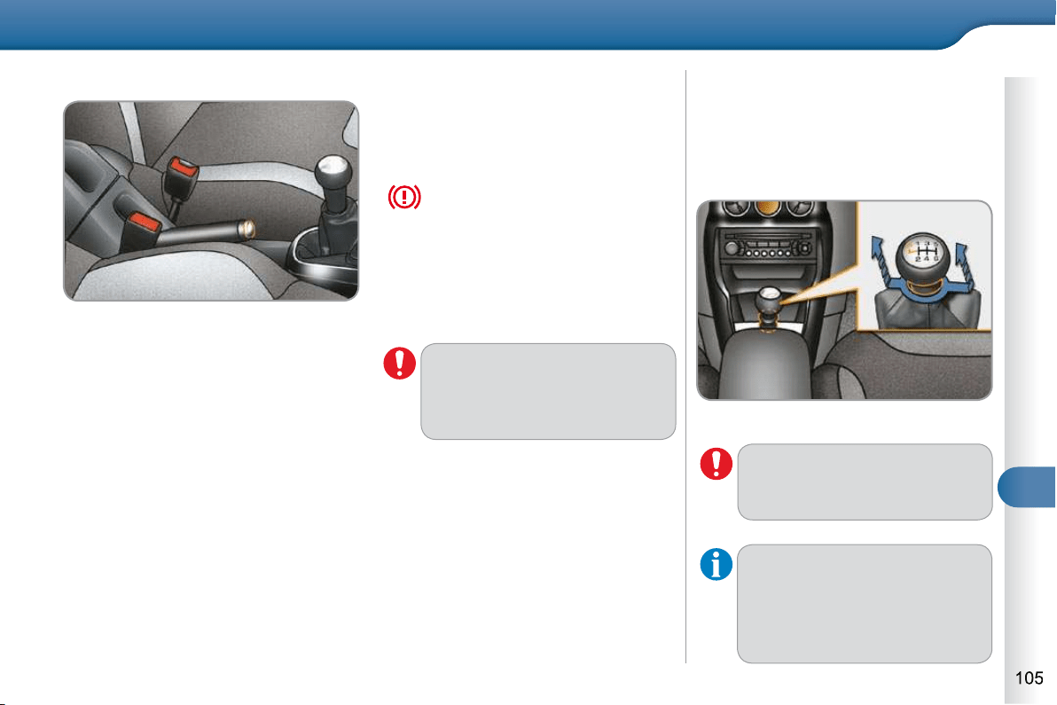
9
DRIVING
PARKING BRAKE
When parking on a slope, direct
your wheels against the pave-
ment, apply the parking brake
and engage a gear.
Applying
Pull the parking brake lever fully up
to immobilise your vehicle.
Releasing
Pull the parking brake lever gently,
press the release button then lower
the lever fully.
When the vehicle is being driven, if this
warning lamp and the STOP warning
lamp come on, accompanied by an
audible signal and a message on the
multifunction screen, this indicates that the parking
brake is still on or has not been properly released.
6-SPEED MANUAL GEARBOX
Engaging reverse gear
Raise the ring under the knob and
push the gear lever to the left then
forwards.
As a safety precaution and to fa-
cilitate starting of the engine:
- always select neutral,
- press the clutch pedal.
Only engage reverse gear when
the vehicle is stationary with the
engine at idle.
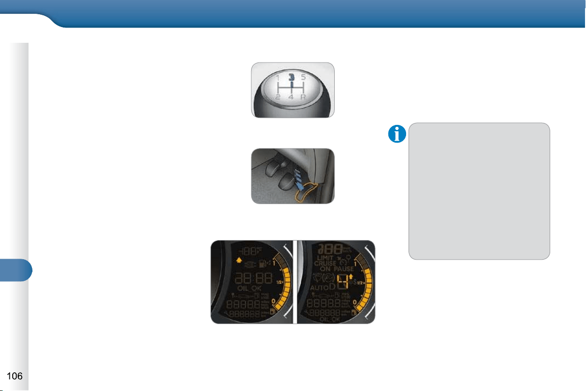
9
DRIVING
GEAR EFFICIENCY INDICATOR *
System which reduces fuel consumption
by advising the driver to change up on
vehicles fi tted with a manual gearbox.
Operation
The system intervenes only when dri-
ving economically.
Depending on the driving situation and
your vehicle's equipment, the system
may advise you to skip one or more
gears. You can follow this instruc-
tion without engaging the intermediate
gears.
The gear recommended should not
be considered compulsory. In fact, the
confi guration of the road, the amount
of traffi c and safety remain determining
factors when choosing the best gear.
Therefore, the driver remains responsi-
ble for deciding whether or not to follow
the advice given by the system.
This function cannot be deactivated.
In the case of driving which
makes particular demands on
the performance of the engine
(fi rm pressure on the accelerator
pedal, for example, when over-
taking...), the system will not rec-
ommend a gear change.
The system never suggests:
- engaging fi rst gear,
- engaging reverse gear,
- engaging a lower gear.
- You press the accelerator pedal
moderately.
Example:
- You are in third gear.
- The system may suggest that you
engage a higher gear, if appropriate.
* According to engine.
The information appears in the form
of an arrow in the instrument panel
screen.
Depending on your vehicle's equipment,
this arrow may be accompanied by the
recommended gear.
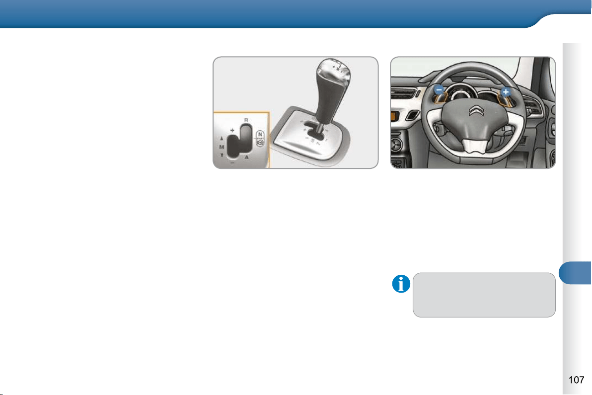
9
DRIVING
SENSODRIVE GEARBOX
Five-speed electronically controlled
gearbox which offers a choice between
the comfort of automatic operation or
the pleasure of manual gear changing.
Three driving modes are offered:
- automated mode for automatic con-
trol of the gears by the gearbox,
- sequential mode for manual chang-
ing of the gears by the driver,
- auto sequential mode for overtak-
ing, for example, remaining in the
automated mode while using the
functions of the sequential mode.
R . Reverse
With your foot on the brake, move
the lever forwards to select this po-
sition.
N . Neutral.
With your foot on the brake, select
this position to start the engine.
A . Automated mode.
Move the lever backwards to select
this mode.
M +/- . Sequential mode with manual
gear changing.
Move the lever backwards, then to
the left to select this mode, then:
- push forwards to change up a gear,
- or push backwards to change down
a gear.
Gear lever
+ . Change up paddle.
Press the back of the steering wheel
"+" paddle to change up a gear.
- . Change down paddle.
Press the back of the steering wheel
"-" paddle to change down a gear.
Steering mounted controls
The steering mounted paddles
do not permit the selection of
neutral or the engaging and disen-
gaging of reverse gear.
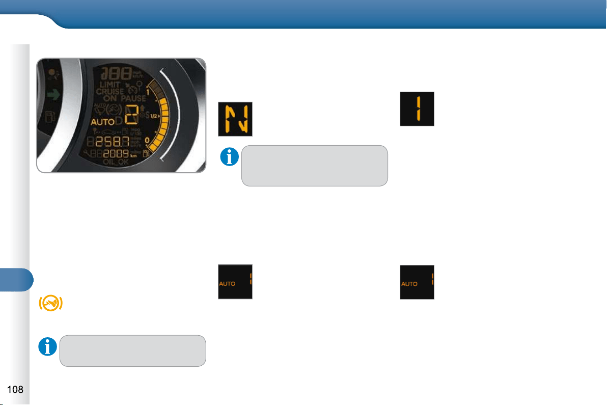
9
DRIVING
Automated mode
Following use of the sequential
mode, select position A to return to
the automated mode.
AUTO and the gear engaged
appear in the instrument panel.
The gearbox then operates in auto-
adaptive mode, without any action on
the part of the driver. It continuously se-
lects the most suitable gear in relation
to the following parameters:
- driving style,
- road conditions,
- vehicle load.
Displays in the instrument panel
Gear lever positions
N . Neutral
R . Reverse
1 2 3 4 5 . Gears engaged
AUTO. This comes on when the au-
tomated mode is selected. It
switches off on changing to se-
quential mode.
In the automated mode, if the gear-
box detects poor grip, this warning
lamp comes on.
Moving off
Select position N .
Press the brake pedal fi rmly.
Start the engine.
N appears in the instrument
panel.
N fl ashes in the instrument pa-
nel screen if the gear lever is not
in position N on starting.
Select fi rst gear (position M or A ) or
reverse (position R )
Release the parking brake.
Take your foot off the brake pedal,
then accelerate.
AUTO and 1 or R appear in
the instrument panel.
Stopping - Moving off on a slope
When stopping on a slope, do not use
the accelerator to immobilise the vehicle;
apply the parking brake.
When moving off on a slope, acceler-
ate gradually while releasing the parking
brake.
Sequential mode
After starting the vehicle, select
position M to change to sequential
mode.
AUTO disappears and the gears
engaged appear in succession
in the instrument panel.
The gear change requests are only car-
ried out if the engine speed permits.
When driving at low speed, on ap-
proaching a stop sign or traffi c lights for
example, the gearbox changes down to
fi rst gear automatically.
Place your foot on the
brake when this warning
lamp fl ashes (e.g.: starting
the engine).
There is an audible signal on
engagement of reverse.
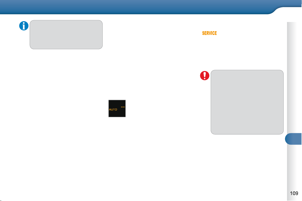
9
DRIVING
"Auto sequential" mode
In the automated mode, you can resume
control temporarily at any time using the
steering mounted control paddles.
The use of these paddles permits man-
ual selection of the gears in situations
which require a more rapid change-
down than in the automated mode (ar-
rival at a roundabout, leaving a car park
with a steep gradient, overtaking...).
The gearbox engages the required gear
if the engine speed permits. AUTO re-
mains displayed in the instrument panel.
After a few minutes, the gearbox re-
sumes automatic control of the gears.
Stopping the vehicle
Before switching off the engine, you can
change to position N to be in neutral.
In this case, you must apply the parking
brake to immobilise the vehicle.
Reinitialisation
Following disconnection of the battery,
the gearbox must be reinitialised.
Switch on the ignition.
Operating fault
With the ignition on, if this
warning lamp comes on and
AUTO fl ashes, accompa-
nied by an audible signal and a mes-
sage in the multifunction screen, this
indicates a gearbox fault.
Have it checked by a CITROËN dealer
or a qualifi ed workshop.
If you press the accelerator
pedal beyond the point of resis-
tance, the gearbox selects the
gear below to permit sharper
acceleration.
AUTO and - appear in the in-
strument panel.
Select position N .
Press the brake pedal.
Wait approximately 30 seconds
until N or a gear appears in the in-
strument panel.
Release the brake pedal.
The gearbox is operational again.
You must press the brake pedal
while starting the engine.
Never select neutral N while the
vehicle is moving.
Only engage reverse gear R
when the vehicle is immobi-
lised, with your foot on the brake
pedal.
In all cases, you must apply the
parking brake to immobilise the
vehicle.
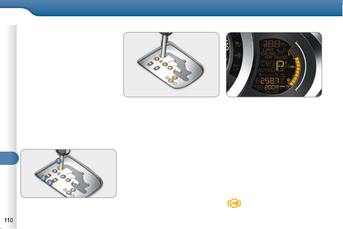
9
DRIVING
AUTOMATIC GEARBOX
Four-speed automatic gearbox which
offers a choice between the comfort of
fully automatic operation, enhanced by
sport and snow programmes, or manual
gear changing.
Therefore, four driving modes are of-
fered:
- automatic operation for electronic
management of the gears by the
gearbox,
- sport programme for a more dy-
namic style of driving,
- snow programme to improve dri-
ving when traction is poor,
- manual operation for sequential
changing of the gears by the driver.
1. Gear lever.
2. Button "S" (sport) .
3. Button " " (snow).
Gear selection gate
P. Park.
- Immobilisation of the vehicle, park-
ing brake on or off.
- Starting the engine.
R. Reverse.
- Reversing manoeuvres, vehicle sta-
tionary, engine at idle.
N. Neutral.
- Immobilisation of the vehicle, park-
ing brake on.
- Starting the engine.
D. Automatic operation.
M +/- . Manual operation with sequential
changing of the four gears.
Push forwards to change up through
the gears.
or
Pull backwards to change down
through the gears.
Gear lever
When you move the lever in the gate
to select a position, the corresponding
indicator is displayed in the instrument
panel.
P. Park
R. Reverse
N. Neutral
D. Drive (Automatic driving)
S. Sport programme
. Snow programme
1 2 3 4 . Gears engaged during manual
operation
-. Invalid value during manual operation
Displays in the instrument panel
Foot on brake
Press the brake pedal when
this indicator lamp is dis-
played in the instrument pa-
nel (e.g.: starting the engine).
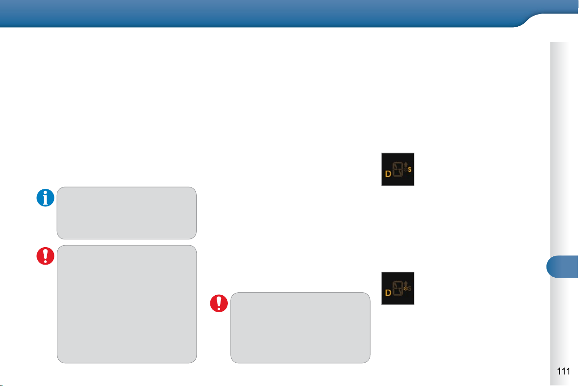
9
DRIVING
Moving off
Apply the parking brake.
Select position P or N .
Start the engine.
If this procedure is not followed, an au-
dible signal is heard, accompanied by a
message in the multifunction screen.
With the engine running, press the
brake pedal.
Release the parking brake.
Select position R , D or M .
Gradually release the brake pedal.
The vehicle moves off immediately.
Automatic operation
Select position D for automatic
changing of the four gears.
The gearbox then operates in auto-
adaptive mode, without any intervention
on the part of the driver. It continuously
selects the most suitable gear according
to the style of driving, the profi le of the
road and the load in the vehicle.
For maximum acceleration without
touching the lever, press the accelera-
tor pedal down fully (kick down). The
gearbox changes down automatically
or maintains the gear selected until the
maximum engine speed is reached.
On braking, the gearbox changes down
automatically to provide effi cient engine
braking.
If you release the accelerator sharply,
the gearbox will not change to a higher
gear for safety reasons.
Sport and snow programmes
These two special programmes supple-
ment the automatic operation in very
specifi c conditions of use.
Sport programme "S"
Press button "S" , after starting the
engine.
The gearbox automatically favours a
dynamic style of driving.
Snow programme " "
Press button " ", after starting the
engine.
The gearbox adapts to driving on slip-
pery roads.
This programme improves starting and
drive when traction is poor.
Return to automatic operation
At any time, press the button selec-
ted again to quit the programme en-
gaged and return to auto-adaptive
mode.
If position N is engaged inadver-
tently while driving, allow the en-
gine to return to idle then engage
position D to accelerate.
Never select position N while the
vehicle is moving.
Never select positions P or R
unless the vehicle is completely
stationary.
When the engine is running at
idle, with the brakes released,
if position R , D or M is selected,
the vehicle moves even without
the accelerator being pressed.
When the engine is running,
never leave children in the ve-
hicle without supervision.
When carrying out maintenance
with the engine running, apply
the parking brake and select po-
sition P .
S appears on the instrument panel.
appears on the instrument panel.

9
DRIVING
Manual operation
Select position M for sequential
changing of the four gears.
Push the lever towards the + sign to
change up a gear.
Pull the lever towards the - sign to
change down a gear.
It is only possible to change from one
gear to another if the vehicle speed and
engine speed permit; otherwise, the
gearbox will operate temporarily in auto-
matic mode.
D disappears and the gears
engaged appear in succes-
sion on the instrument panel.
If the engine speed is too low
or too high, the gear selected
fl ashes for a few seconds, then the
actual gear engaged is displayed.
It is possible to change from position D
(automatic) to position M (manual) at
any time.
When the vehicle is stationary or moving
very slowly, the gearbox selects gear M1
automatically.
The sport and snow programmes do not
operate in manual mode.
Invalid value during manual
operation
This symbol is displayed if a
gear is not engaged correctly
(selector between two posi-
tions).
Stopping the vehicle
Before switching off the engine, you
can engage position P or N to place the
gearbox in neutral.
In both cases, apply the parking brake
to immobilise the vehicle.
If the lever is not in position P ,
when the driver's door is opened
or approximately 45 seconds af-
ter the ignition is switched off, a
message appears in the multi-
function screen.
Return the lever to position P ;
the message disappears.
There is a risk of damage to the
gearbox:
- if you press the accelera-
tor and brake pedals at the
same time,
- if you force the movement
of the gear lever from the
P position to another position
when the battery is fl at.
Operating fault
When the ignition is on, the
lighting of this warning lamp,
accompanied by an audible
signal and a message in the multifunc-
tion screen, indicates a gearbox fault.
In this case, the gearbox switches to
back-up mode and is locked in 3rd gear.
You may feel a substantial knock when
changing from P to R and from N to R .
This will not cause any damage to the
gearbox.
Do not exceed 60 mph (100 km/h), local
speed restrictions permitting.
Contact a CITROËN dealer or a quali-
fi ed workshop as soon as possible.
To reduce fuel consumption when
at a prolonged standstill with the
engine running (traffi c jam...), put
the gear lever in the N position
and apply the parking brake.
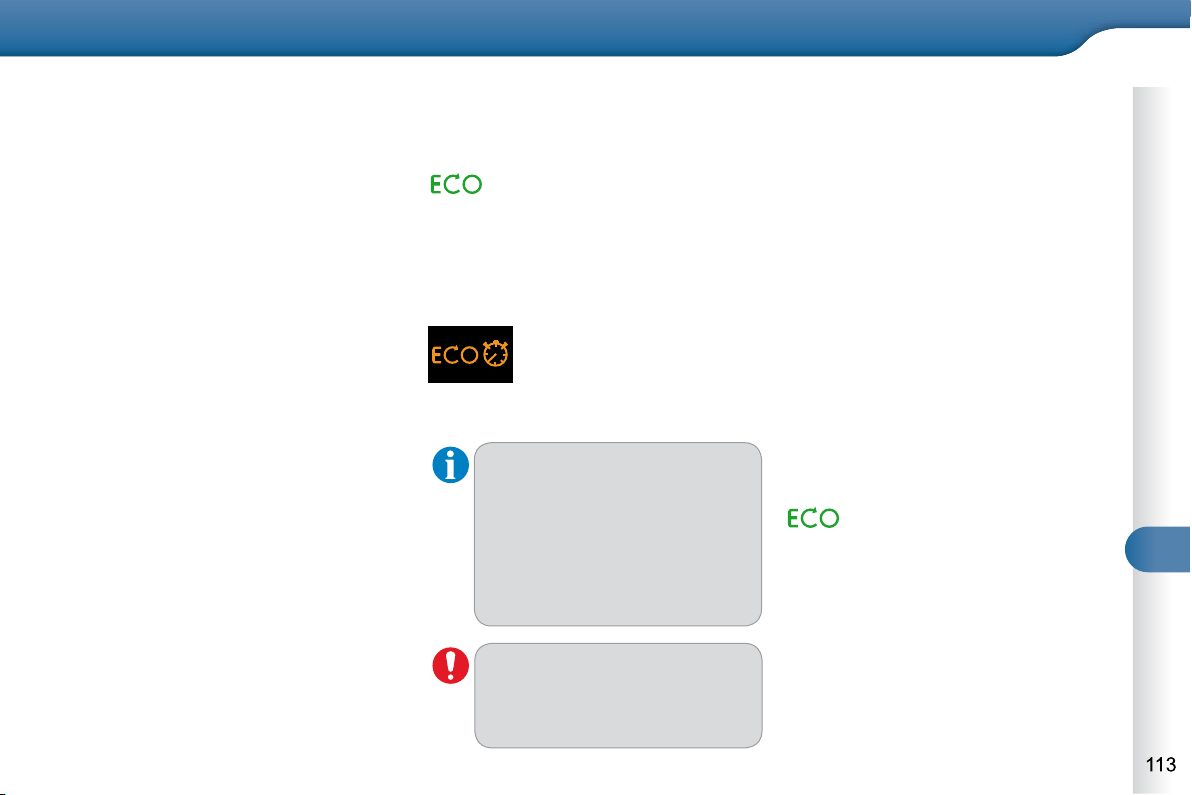
9
DRIVING
STOP & START
The Stop & Start system puts the en-
gine temporarily into standby - STOP
mode - during stops in the traffi c (red
lights, traffi c jams, etc...). The engine
restarts automatically - START mode -
as soon as you want to move off. The
restart takes place instantly, quickly and
silently.
Perfect for urban use, the Stop & Start
system reduces fuel consumption and
exhaust emissions as well as offering
the comfort of silence when stationary.
Operation
- with a manual gearbox , at speeds
below 12 mph (20 km/h), put the
gear lever into neutral, then release
the clutch pedal,
Going into engine STOP mode
The "ECO" warning lamp comes
on in the instrument panel and
the engine goes into standby:
For your comfort when parking,
STOP mode is not available for
a few seconds after coming out
of reverse gear.
STOP mode does not affect the
functionality of the vehicle, such
as braking, power steering, for
example.
Never refuel with the engine in
STOP mode; you must switch
off the ignition with the key.
A time counter calculates the
sum of the periods in STOP
mode during a journey. It
rests itself to zero every
time the ignition is switched
on with the key.
Special cases: STOP mode
unavailable
STOP mode is not invoked when:
- the driver's door is open,
- the driver's seat belt is not fastened,
- the vehicle has not exceeded 6 mph
(10 km/h) since the last engine start
using the key,
- the engine is needed to maintain a
comfortable temperature in the pas-
senger compartment,
- demisting is active,
- some special conditions (battery
charge, engine temperature, brak-
ing assistance, ambient tempera-
ture...) where the engine is needed
to assure control of a system.
The "ECO" warning lamp fl ashes
for a few seconds, then goes off.
This operation is perfectly normal.
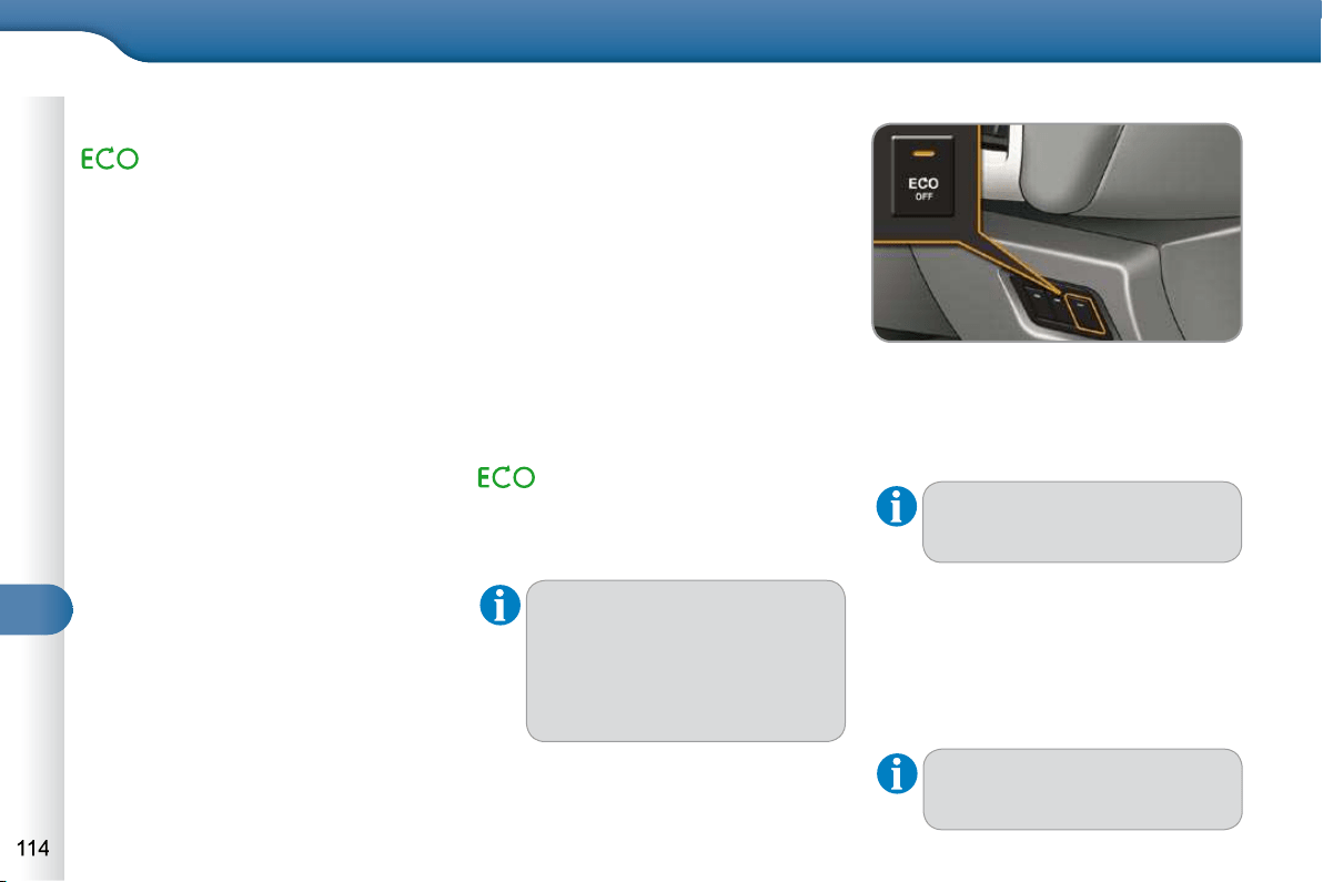
9
DRIVING
Going into engine START mode
The "ECO" warning lamp goes
off and the engine starts:
- with a manual gearbox , depress
the clutch pedal.
Special cases: START invoked
automatically
START is invoked automatically when:
- the driver's door is open,
- the driver's seat belt is not fastened,
- the speed of the vehicle exceeds
15 mph (25 km/h) with a manual
gearbox,
- some special conditions (battery
charge, engine temperature, brak-
ing assistance, ambient tempera-
ture...) where the engine is needed
to assure control of a system.
Deactivation
At any time, press the "ECO OFF" switch
to deactivate the system.
This is confi rmed by the switch warn-
ing lamp coming on accompanied by a
message in the screen.
If the system has been deacti-
vated in STOP mode, the en-
gine restarts immediately.
Reactivation
Press the "ECO OFF" switch again.
The system is active again; this is
confi rmed by the switch warning lamp
going off, accompanied by a message
in the screen.
The system is reactivated au-
tomatically at every new start
using the key.
With a manual gearbox in STOP
mode, if a gear is engaged with-
out fully depressing the clutch
pedal, a message is displayed
asking you to depress the clutch
pedal to restart the engine.
The "ECO" warning lamp fl ash-
es, then goes off.
This operation is perfectly normal.
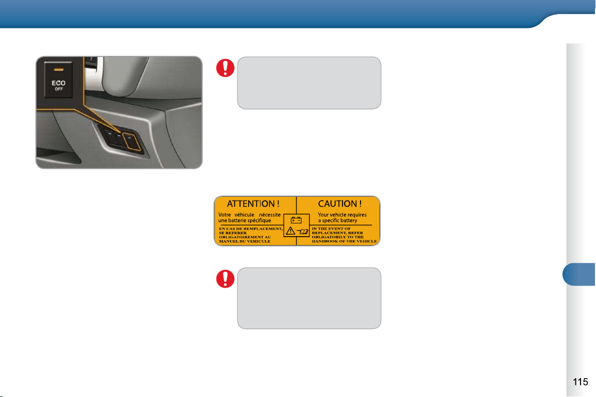
9
DRIVING
Operating fault Maintenance
In the event of a malfunction with the sys-
tem, the "ECO OFF" switch warning lamp
fl ashes, then comes on continuously.
Have it checked by a CITROËN dealer
or a qualifi ed workshop.
In the event of a fault in STOP mode,
the vehicle may stall. It is then neces-
sary to switch off the ignition and start
the engine again using the key.
Before working under the bon-
net, deactivate the Stop & Start
system to avoid any risk of injury
resulting from automatic opera-
tion of START mode.
The Stop & Start system makes
use of advanced technology.
All work on this battery must be
done by a CITROËN dealer or a
qualifi ed workshop.
This system requires a battery with a
special specifi cation and technology
(reference numbers available from a
CITROËN dealer or a qualifi ed work-
shop).
Fitting a battery not listed by CITROËN
introduces the risk of malfunction of the
system.
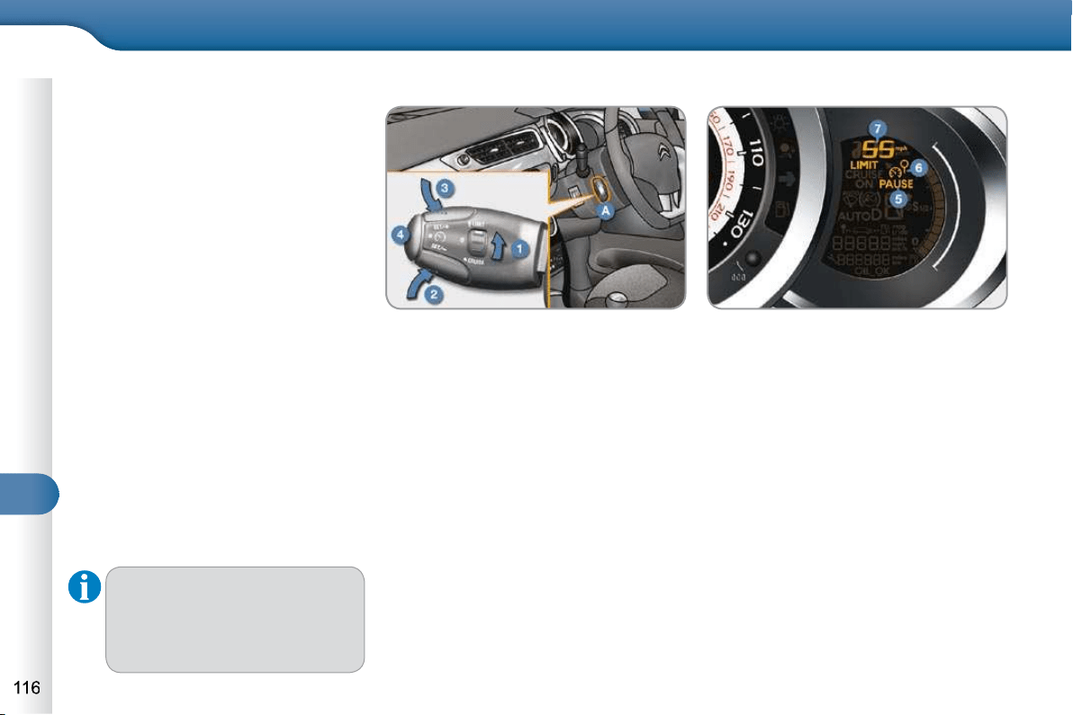
9
DRIVING
SPEED LIMITER
System which prevents the vehicle from
exceeding the speed programmed by
the driver.
When the programmed speed limit is
reached, pressing the accelerator pedal
in the normal manner no longer has any
effect.
The speed limiter is switched on ma-
nually: it requires a programmed speed
of at least 20 mph (30 km/h).
The speed limiter is switched off by
manual operation of the control.
The programmed speed can be ex-
ceeded temporarily by pressing the ac-
celerator fi rmly.
To return to the programmed speed,
simply slow down to a speed below the
programmed speed.
The programmed speed remains in the
memory when the ignition is switched off.
The speed limiter cannot, in any
circumstances, replace the need
to respect speed limits, nor can
it replace the need for vigilance
and responsibility on the part of
the driver.
Steering mounted controls
The controls of this system are grouped
together on stalk A .
1. Speed limiter mode selection thumb
wheel.
2. Value decrease button.
3. Value increase button.
4. Speed limiter on/off button.
Displays in the instrument panel
The programmed information is grouped
together in the instrument panel screen.
5. Speed limiter on/off indication.
6. Speed limiter mode selection
indication.
7. Programmed speed value.
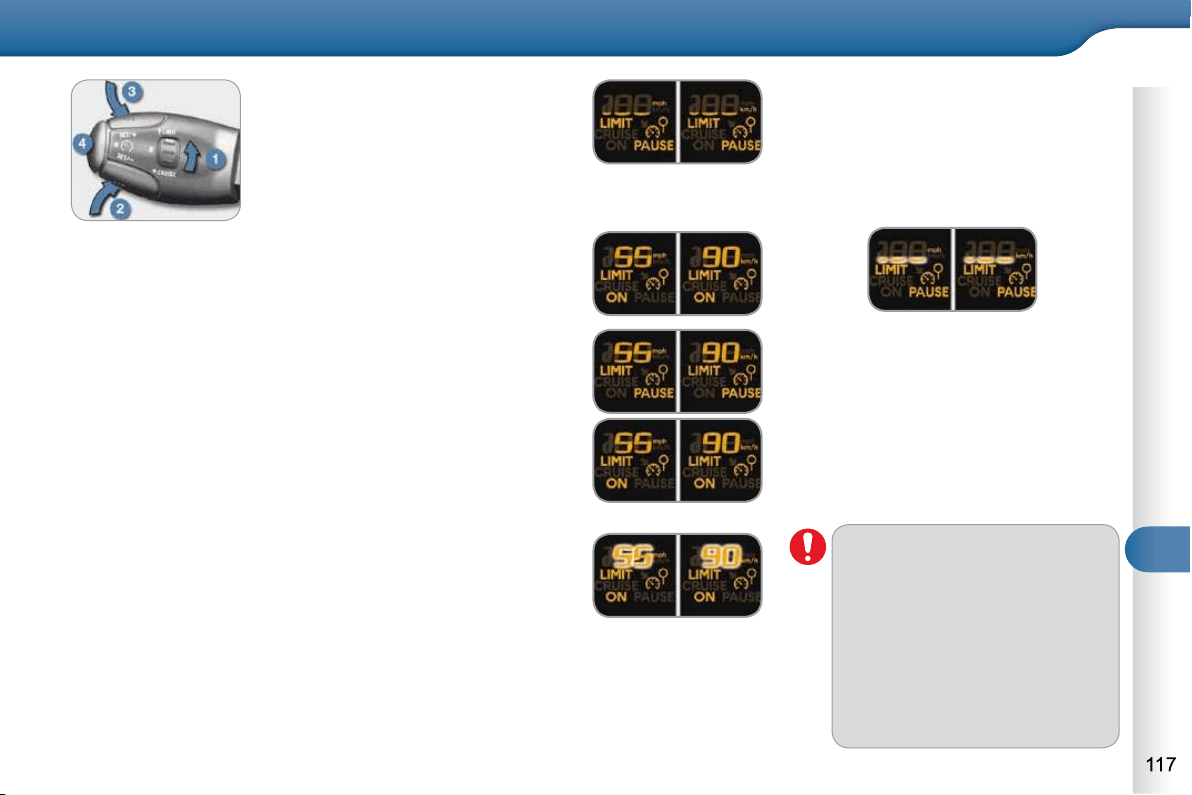
9
DRIVING
On a steep descent or in the
event of sharp acceleration, the
speed limiter will not be able to
prevent the vehicle from exceed-
ing the programmed speed.
To avoid any risk of jamming of
the pedals:
- ensure that the mat is posi-
tioned correctly,
- do not fi t one mat on top of
another.
Programming
Turn thumb wheel 1 to the "LIMIT"
position: the speed limiter mode
is selected but is not switched on
(PAUSE).
You do not have to switch the speed
limiter on in order to set the speed.
Set the speed value by pressing button 2 or 3
(e.g.: 55 mph (90 km/h)).
You can then change the programmed speed using buttons 2
and 3 :
- by + or - 1 mph (km/h) = short press,
- by + or - 5 mph (km/h) = long press,
- in steps of + or - 5 mph (km/h) = maintained press.
Switch the speed limiter on by pressing button 4 .
Switch the speed limiter off by pressing button 4 : the
display confi rms that it has been switched off (PAUSE).
Switch the speed limiter back on by pressing button 4
again.
Exceeding the programmed speed
Pressing the accelerator pedal to exceed the programmed
speed will not have any effect unless you press the pedal
fi rmly past the point of resistance .
The speed limiter is deactivated temporarily and the pro-
grammed speed, which is still displayed, fl ashes.
Returning to the programmed speed, by means of inten-
tional or unintentional deceleration of the vehicle, automati-
cally cancels the fl ashing of the programmed speed.
Leaving limiter mode
Turn thumb wheel 1 to the "0" position: the speed limiter
mode is deselected. The display returns to the distance
recorder.
Operating fault
In the event of a speed limiter fault, the
speed is cleared resulting in fl ashing of
the dashes.
Have it checked by a CITROËN dealer
or a qualifi ed workshop.
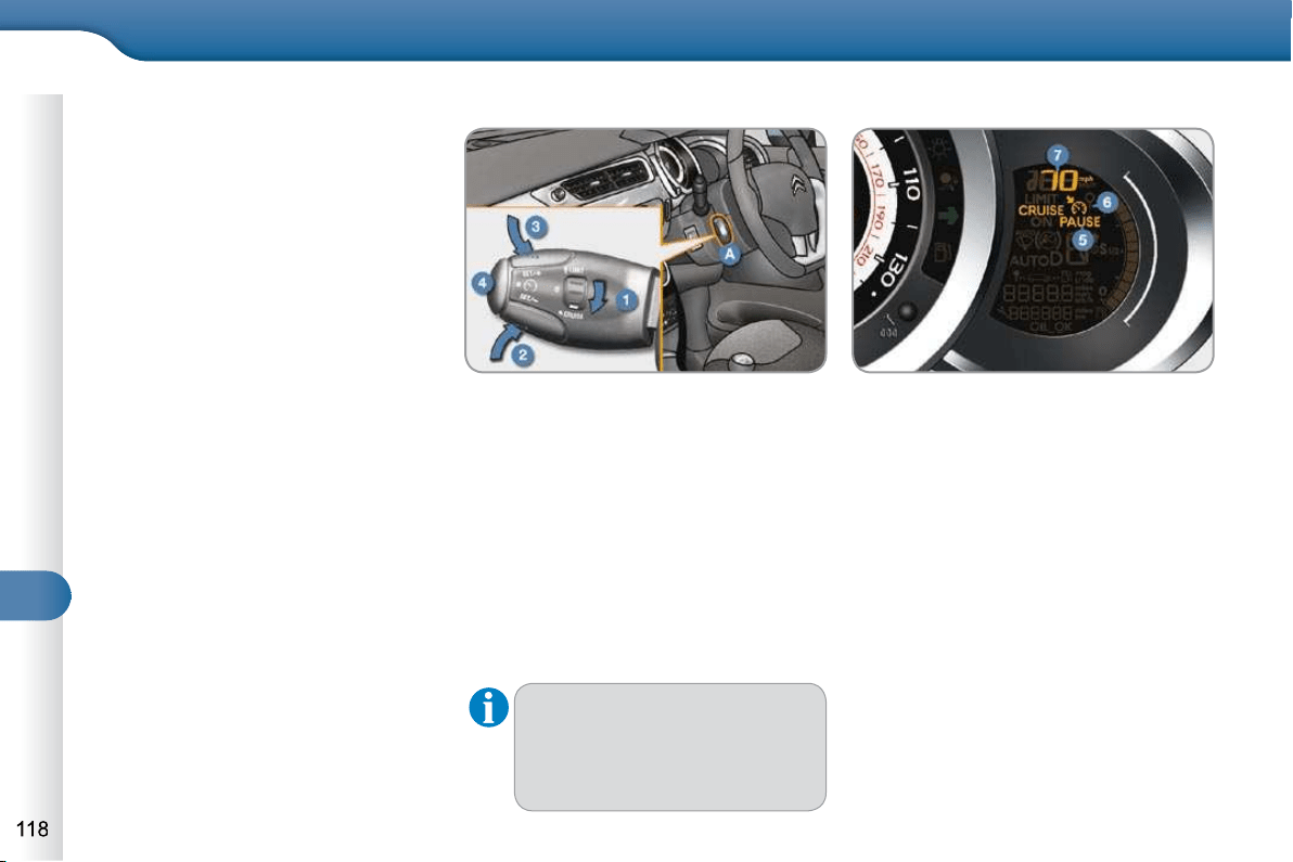
9
DRIVING
The cruise control cannot, in any
circumstances, replace the need
to respect speed limits, nor can
it replace the need for vigilance
and responsibility on the part of
the driver.
CRUISE CONTROL
System which automatically maintains
the speed of the vehicle at the value
programmed by the driver, without any
action on the accelerator pedal.
The cruise control is switched on
manually: it requires a minimum vehicle
speed of 25 mph (40 km/h), as well as
the engagement of:
- fourth gear on a manual gearbox,
- second gear on a SensoDrive or
automatic gearbox, in sequential
mode,
- position A on a SensoDrive gearbox or
position D on an automatic gearbox.
The cruise control is switched off ma-
nually or by pressing the brake or clutch
pedal or on triggering of the ESP sys-
tem for safety reasons.
It is possible to exceed the programmed
speed temporarily by pressing the ac-
celerator pedal.
To return to the programmed speed,
simply release the accelerator pedal.
Switching off the ignition cancels any
programmed speed value.
The controls of this system are grouped
together on stalk A .
1. Cruise control mode selection thumb
wheel.
2. Value decrease button.
3. Value increase button.
4. Cruise control off/resume button.
Steering mounted controls Displays in the instrument panel
The programmed information is grouped
together in the instrument panel screen.
5. Cruise control off/resume indication.
6. Cruise control mode selection indi-
cation.
7. Programmed speed value.
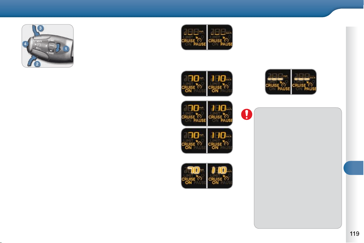
9
DRIVING
When the cruise control is
switched on, be careful if you
maintain the pressure on one of
the programmed speed chang-
ing buttons: this may result in a
very rapid change in the speed
of your vehicle.
Do not use the cruise control on
slippery roads or in heavy traffi c.
On a steep descent, the cruise
control will not be able to prevent
the vehicle from exceeding the
programmed speed.
To avoid any risk of jamming of
the pedals:
- ensure that the mat is posi-
tioned correctly,
- never fi t one mat on top of
another.
Programming
Turn thumb wheel 1 to the
"CRUISE" position: the cruise
control mode is selected but is not
switched on (PAUSE).
Set the programmed speed by
ac
celerating to the required
speed, then press button 2 or 3
(e.g.: 70 mph (110 km/h)).
You can then change the programmed speed using buttons 2
and 3 :
- by + or - 1 mph (km/h) = short press,
- by + or - 5 mph (km/h) = long press,
- in steps of + or - 5 mph (km/h) = maintained press.
Exceeding the programmed speed
Intentional or unintentional exceeding of the programmed
speed results in fl ashing of this speed in the screen.
Return to the programmed speed, by means of intentional
or unintentional deceleration of the vehicle, automatically
cancels the fl ashing of the speed.
Leaving cruise control mode
Turn thumb wheel 1 to the "0" position: the cruise control
mode is deselected. The display returns to the distance
recorder.
Switch off the cruise control by pressing button 4 : the
screen confi rms that it has been switched off (PAUSE).
Switch the cruise control back on by pressing button 4
again.
Operating fault
In the event of a cruise control malfunc-
tion, the speed is cleared resulting in
fl ashing of the dashes. Have it checked
by a CITROËN dealer or a qualifi ed
workshop.
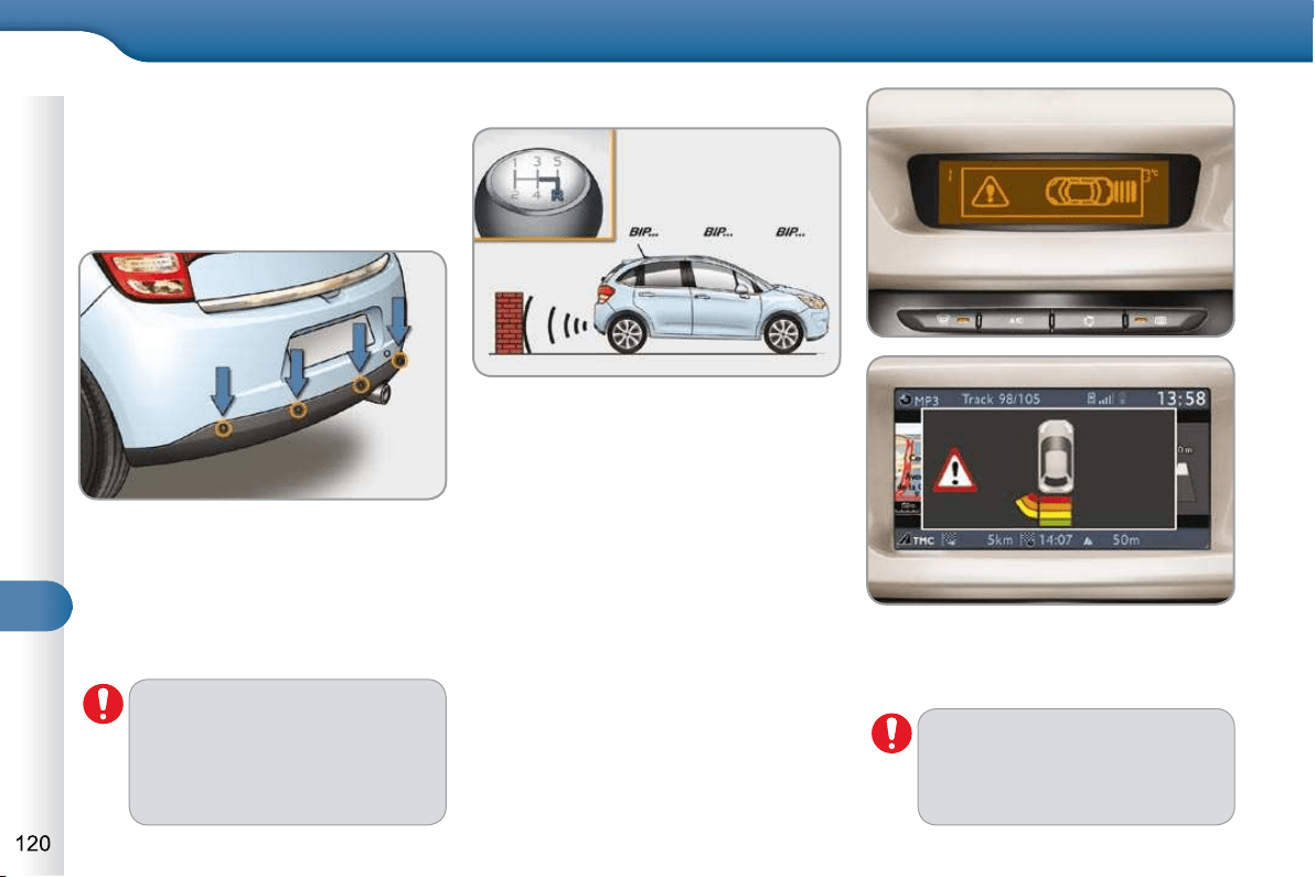
9
DRIVING
REAR PARKING SENSORS
System consisting of four proximity sen-
sors, located in the rear bumper.
Activation
This detects any obstacle (person, vehi-
cle, tree, gate, etc.) behind the vehicle,
except obstacles located just below the
bumper.
An object, such as a stake, a
roadworks cone or any other
similar object may be detected
at the beginning of the manoeu-
vre, but may no longer be de-
tected when the vehicle comes
close to it.
The parking sensor system can-
not, in any circumstances, take
the place of the vigilance and
responsibility of the driver.
The system is activated as soon as re-
verse gear is engaged, accompanied
by an audible signal.
On completion of the manoeuvre, when
you exit reverse gear, the system be-
comes inactive.
The proximity information is given by:
- an audible signal, which becomes
more rapid as the vehicle approa-
ches the obstacle.
- a graphic (according to version) in
the multifunction screen, with blocks
which become increasingly closer to
the vehicle.
When the distance between the rear of
the vehicle and the obstacle is less than
thirty centimetres, the audible signal
becomes continuous and the "Danger"
symbol appears in the multifunction
screen.
9
DRIVING
The system will be deactivated
automatically when towing a
trailer or when a bicycle carrier is
fi tted (vehicle fi tted with a towbar
or bicycle carrier recommended
by CITROËN).
In bad or wintry weather, ensure
that the sensors are not covered
with mud, frost or snow.
Programming
You can activate or deactivate the
system by means of the multifunction
screen confi guration menu. The system
state is memorised when switching off
the ignition.
For more information on access to
the parking sensors menu, refer to
"Confi guration/Vehicle parameters" in
the "Multifunction screens" section cor-
responding to your screen.
Operating faults
If there is an operating fault,
when reverse gear is engaged
this warning lamp comes on in
the instrument panel, accompanied by an
audible signal (short beep) and a message
in the multifunction screen.

10
CHECKS
BONNET
Protects the components of the engine
and provides access for checking levels.
Opening
Push the exterior safety catch B to
the left and raise the bonnet.
Unclip the bonnet stay C from its
housing, holding it by its foam pro-
tection.
Fix the stay in the notch to hold the
bonnet open.
The location of the interior re-
lease lever prevents opening of
the bonnet while the front left
door is closed.
Closing
Take the stay out of the support
notch.
Clip the stay in its housing.
Lower the bonnet and release it at
the end of its travel.
Pull on the bonnet to check that it is
fully latched.
RUNNING OUT OF FUEL
(DIESEL)
If your vehicle is fi tted with an HDI en-
gine, the fuel system must be primed if
you run out of fuel.
This system consists of a priming pump
and a transparent pipe under the bonnet.
Fill the fuel tank with at least fi ve litres
of Diesel.
Open the bonnet.
Depending on version, unclip the
cover to gain access to the priming
pump.
Squeeze and release the priming
pump until resistance is felt (could
be from the fi rst application) and fuel
appears in the transparent pipe with
the green connector.
Operate the starter until the engine
starts.
Depending on version, put the cover
back in position and clip it in place.
Close the bonnet.
If the engine does not start at the
fi rst attempt, do not try again.
Operate the priming pump again,
then the starter.
When the engine is hot, handle
the exterior safety catch and the
stay with care.
Before doing anything under the
bonnet, switch off the Stop &
Start system to avoid any risk of
injury resulting from an automatic
change to START mode.
Open the front left door.
Pull the interior release lever A ,
located at the bottom of the door
aperture.
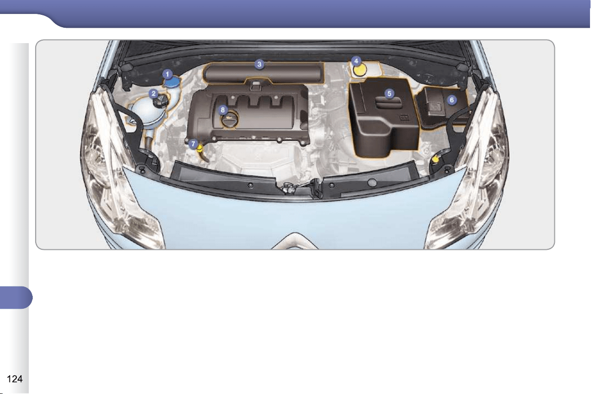
10
CHECKS
PETROL ENGINES
1. Screenwash fl uid reservoir.
2. Coolant header tank.
3. Air fi lter.
4. Brake fl uid reservoir.
5. Battery.
6. Fusebox.
7. Engine oil dipstick.
8. Engine oil fi ller cap.
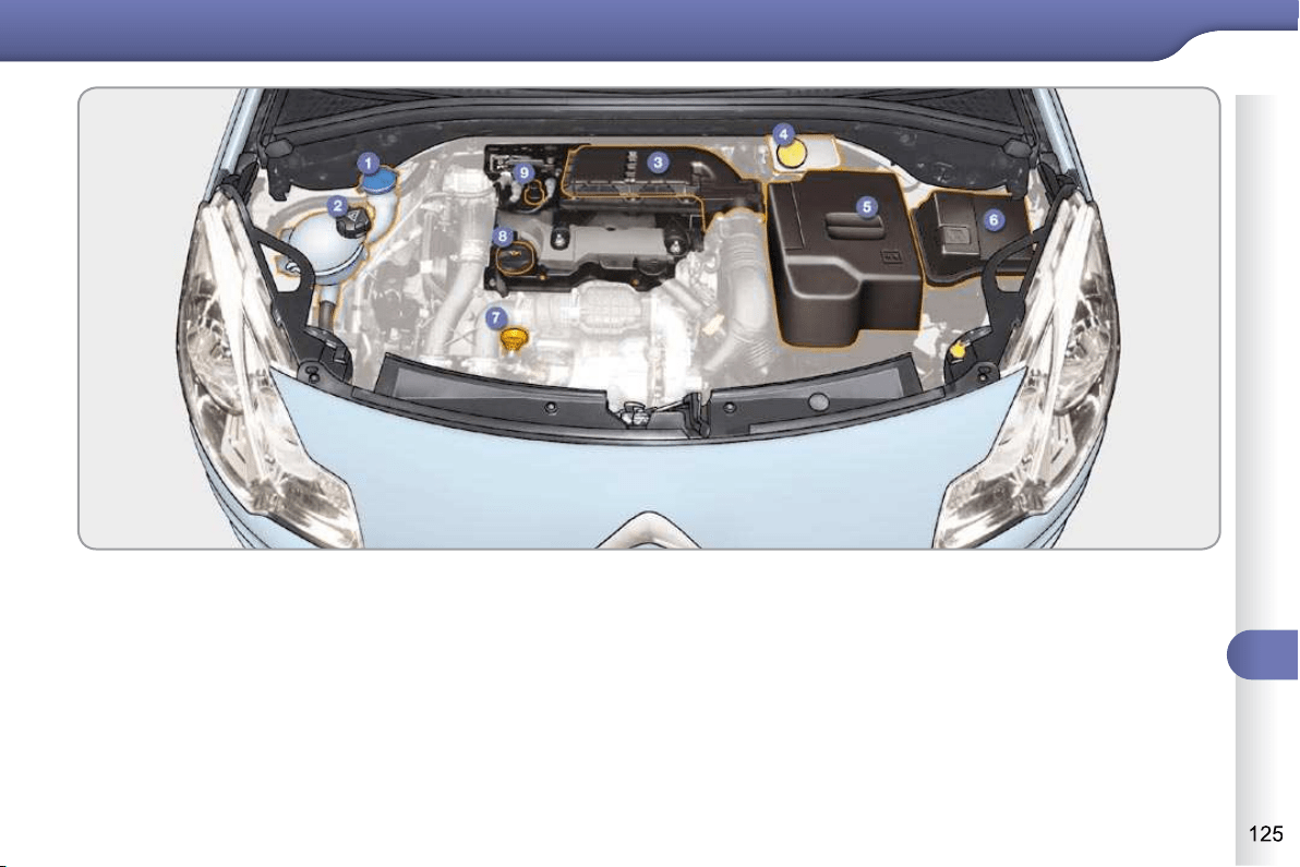
10
CHECKS
DIESEL ENGINES
1. Screenwash fl uid reservoir.
2. Coolant header tank.
3. Air fi lter.
4. Brake fl uid reservoir.
5. Battery.
6. Fusebox.
7. Engine oil dipstick.
8. Engine oil fi ller cap.
9. Priming pump (on fuel fi lter).
10
CHECKS
CHECKING LEVELS
Check all of these levels regularly and
top them up if necessary, unless other-
wise indicated.
If a level drops signifi cantly, have the
corresponding system checked by a
CITROËN dealer or a qualifi ed work-
shop.
Oil level
The reading will only be correct
if the vehicle is on level ground
and the engine has been off for
more than 30 minutes.
The check is carried out either when the
ignition is switched on using the oil level
indicator in the instrument panel, or us-
ing the dipstick.
Engine oil change
Refer to the Maintenance and Warranty
Guide for details of the interval for this
operation.
In order to maintain the reliability of the
engine and emission control system,
the use of additives in the engine oil is
prohibited.
Oil grade
The oil must be suitable for your engine
and conform to the manufacturer's rec-
ommendations.
Brake fluid level
The brake fl uid level should be
close to the "MAX" mark. If it is
not, check the brake pad wear.
Changing the fl uid
Refer to the Maintenance and Warranty
Guide for details of the interval for this
operation.
Fluid specifi cation
The brake fl uid must conform to the
manufacturer's recommendations and
meet the DOT4 standard.
Coolant level
The coolant level should be
close to the "MAX" mark but
should never exceed it.
When the engine is warm, the
temperature of the coolant is regulated
by the fan. This can operate with the ig-
nition off.
On vehicles which are fi tted with a par-
ticle emission fi lter, the fan may oper-
ate after the vehicle has been switched
off, even if the engine is cold.
In addition, as the cooling system is
pressurised, wait at least one hour after
switching off the engine before carrying
out any work.
To avoid any risk of scalding, unscrew
the cap by two turns to allow the pres-
sure to drop. When the pressure has
dropped, remove the cap and top up
the level.
Changing the coolant
The coolant does not have to be
changed.
Fluid specifi cation
The coolant must conform to the manu-
facturer's recommendations.
Screenwash fluid level
Top up the level when neces-
sary.
Fluid specifi cation
For optimum cleaning and to avoid
freezing, this fl uid must not be topped
up or replaced with water.
Take care when carrying out
checks under the bonnet as
some parts of the engine can be
very hot (risk of burns).
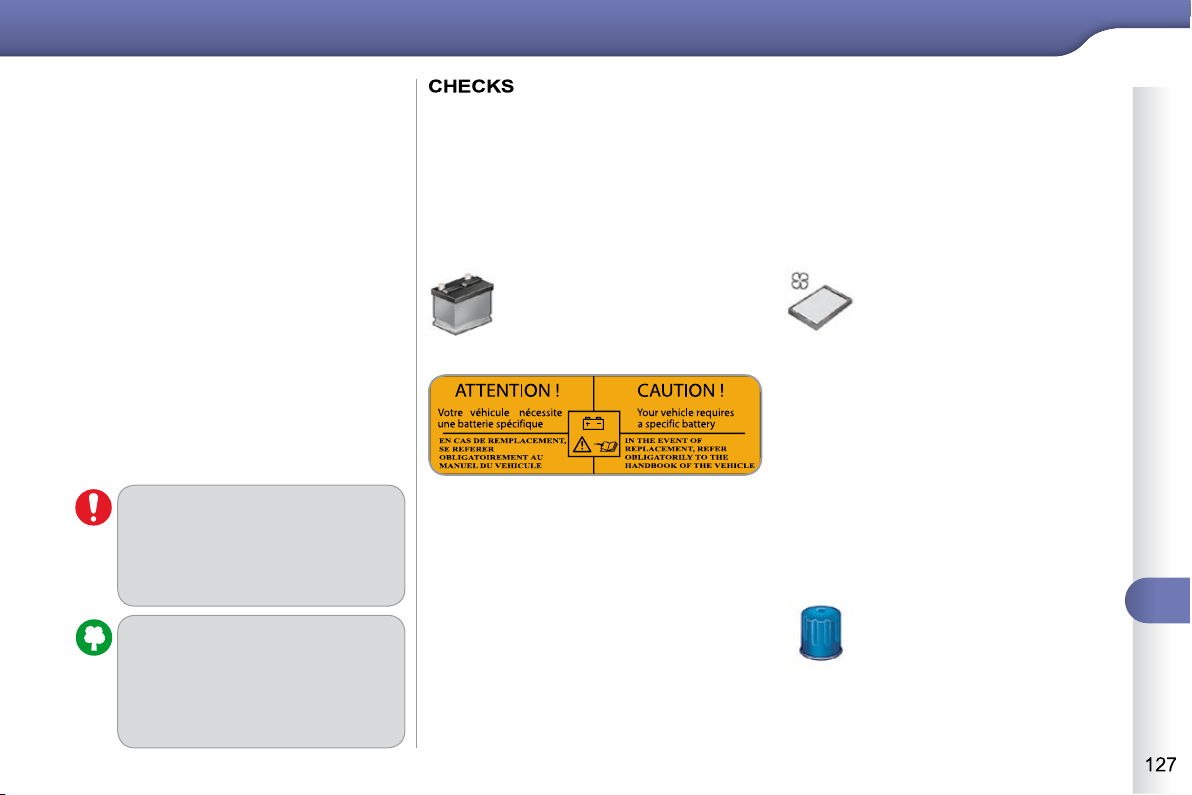
10
CHECKS
Additive level (Diesel with
particle emissions filter)
According to your version of instrument panel,
the additive reservoir low level is indicated by:
-
fi xed illumination of the particle emissions
fi lter warning lamp, accompanied by an
audible signal and a message that the
particle emissions fi lter additive level is
too low,
or
-
fi xed illumination of the service warning
lamp, accompanied by an audible signal
and a message that the particle emissions
fi lter additive level is too low.
Topping up
The reservoir must be topped up with-
out delay by a CITROËN dealer or a
qualifi ed workshop.
Used products
Avoid prolonged contact of used
oil or fl uids with the skin.
Most of these fl uids are harmful
to health or indeed very corro-
sive.
Do not discard used oil or fl uids
into sewers or onto the ground.
Take used oil to a CITROËN
dealer or a qualifi ed workshop
(France) or to an authorised
waste disposal site.
Unless otherwise indicated, check these
components in accordance with the
Maintenance and Warranty Guide and ac-
cording to your engine.
Otherwise, have them checked by a
CITROËN dealer or a qualifi ed workshop.
Battery
The battery does not require any
maintenance.
However, check that the terminals
are clean and correctly tightened,
particularly in summer and winter.
Air filter and passenger
compartment filter
Refer to the Maintenance and
Warranty Guide for details of
the replacement intervals for
these components.
Depending on the environment
(e.g. dusty atmosphere) and the use of
the vehicle (e.g. city driving), replace
them twice as often if necessary (refer
to the "Engines" section).
A clogged passenger compartment fi lter
may have an adverse effect on the per-
formance of the air conditioning system
and generate undesirable odours.
Oil filter
Replace the oil fi lter each time
the engine oil is changed.
Refer to the Maintenance and
Warranty Guide for details of
the replacement interval for
this component.
The presence of this label, in particular
with the Stop & Start system, indicates
the use of a specifi c 12 V lead-acid bat-
tery with special technology and speci-
fi cation, for which the involvement of a
CITROËN dealer or a qualifi ed work-
shop is required when replacing or dis-
connecting the battery.
Failure to observe this recommendation
may shorten the life of the battery.
When carrying out work on the battery,
refer to the "Practical information" sec-
tion for details of the precautions to be
taken before disconnecting the battery
and following its reconnection.
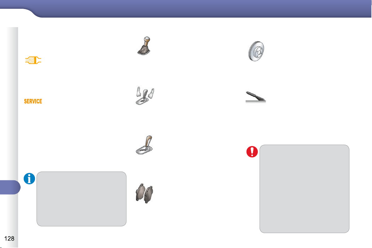
10
CHECKS
Manual gearbox
The gearbox does not re-
quire any maintenance (no oil
change).
Refer to the Maintenance and
Warranty Guide for the details
of the level checking interval
for this component.
Automatic gearbox
The gearbox does not require any
maintenance (no oil change).
Refer to the Maintenance and
Warranty Guide for details of the
level checking interval for this
component.
Brake pads
Brake wear depends on the
style of driving, particularly in
the case of vehicles used in
town, over short distances. It
may be necessary to have the
condition of the brakes checked, even
between vehicle services.
Unless there is a leak in the system, a
drop in the brake fl uid level indicates
that the brake pads are worn.
Brake disc wear
For information on checking
brake disc wear, contact a
CITROËN dealer or a quali-
fi ed workshop.
Manual parking brake
If a loss of effectiveness of this
system is noticed, the parking
brake must be checked, even
between two services.
Checking this system must be done by
a CITROËN dealer or a qualifi ed work-
shop.
Only use products recommended
by CITROËN or products of equiv-
alent quality and specifi cation.
In order to optimise the opera-
tion of units as important as the
braking system, CITROËN se-
lects and offers very specifi c
products.
To avoid damaging the electrical
units, the use of a high pressure
washer in the engine compart-
ment is strictly prohibited .
Particle emission filter (Diesel)
According to your version of instrument
panel, the start of saturation of the par-
ticle emissions fi lter is indicated by:
Following prolonged operation of
the vehicle at very low speed or
at idle, you may, in exceptional
circumstances, notice the emis-
sion of water vapour at the ex-
haust on acceleration. This does
not affect the behaviour of the
vehicle or the environment.
-
fi xed illumination of the par-
ticle emissions fi lter warning
lamp, accompanied by an
audible signal and a message
that there is a risk of blockage
of the particle emissions fi lter,
or
- temporary illumination of
the service warning lamp,
accompanied by an audible
signal and a message that
there is a risk of blockage of
the particle emissions fi lter.
As soon as the traffi c conditions per-
mit, regenerate the fi lter by driving at a
speed of at least 40 mph (60 km/h) until
the warning lamp goes off.
If the warning lamp stays on, refer to the
"Additive level" section.
SensoDrive gearbox
The gearbox does not require any
maintenance (no oil change).
Refer to the Maintenance and
Warranty Guide for details of
the checking interval for this
component.
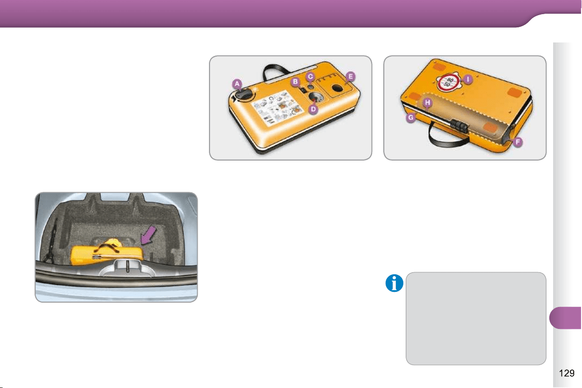
11
PRACTICAL INFORMATION
The speed limit sticker I must be
affi xed to the vehicle's steering
wheel to remind you that a wheel
is in temporary use.
Do not exceed a speed of
50 mph (80 km/h) when driving
with a tyre repaired using this
type of kit.
TEMPORARY PUNCTURE
REPAIR KIT
Complete system consisting of a com-
pressor and a sealant cartridge which
permits temporary repair of a tyre so
that you can drive to the nearest garage.
It is designed to repair most punctures
which could affect the tyre, located on
the tyre tread or shoulder.
This kit is installed in the storage box,
under the boot fl oor.
Description of the kit
A. "Sealant" or "Air" position selector.
B. On "I" /off "O" switch.
C. Defl ation button.
D. Pressure gauge (in bar or p.s.i.).
E. Compartment housing:
- a cable with adaptor for 12 V
socket,
- various infl ation adaptors for
accessories, such as balls,
bicycle tyres...
F. Sealant cartridge.
G. White pipe with cap for repair.
H. Black pipe for infl ation.
I. Speed limit sticker.
Access to the kit
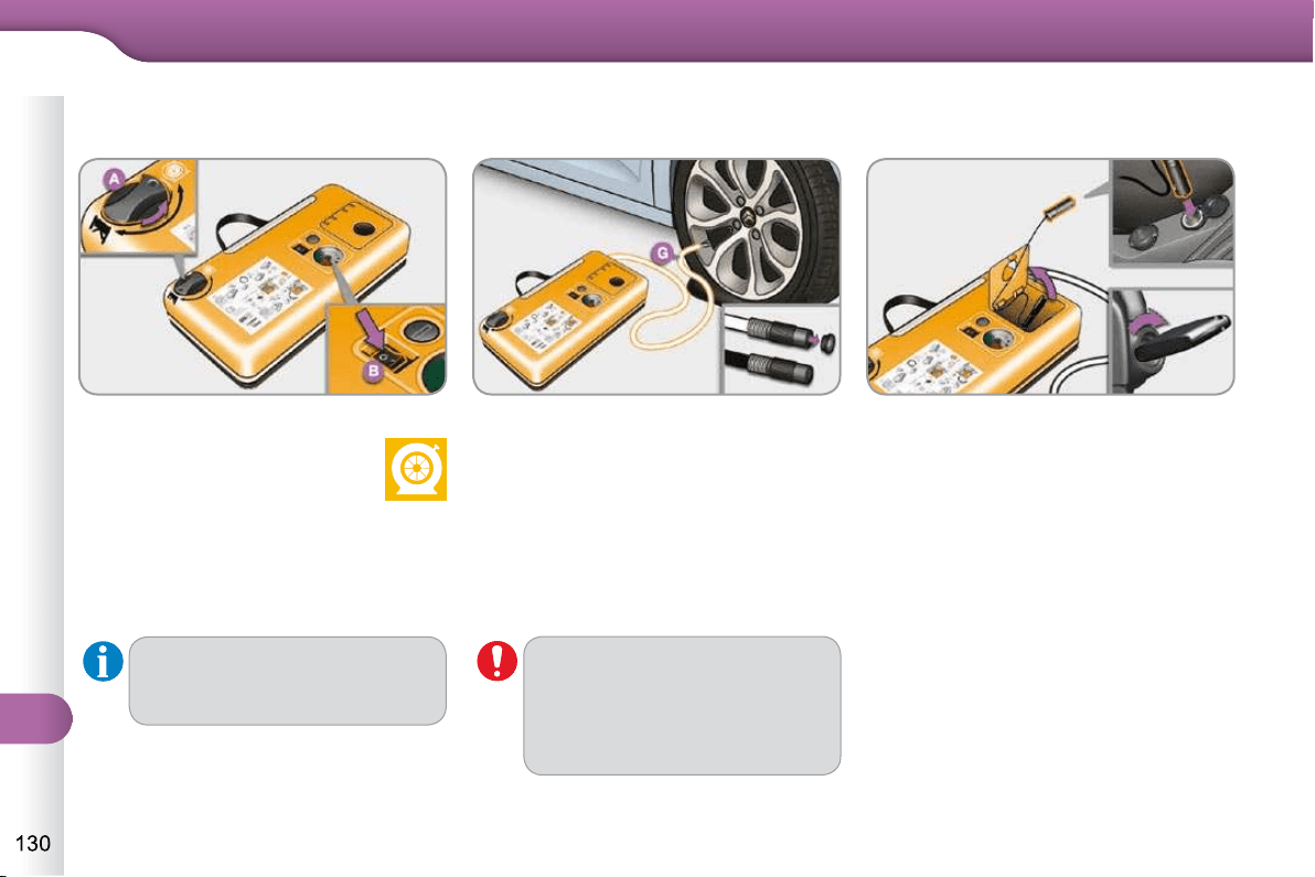
11
PRACTICAL INFORMATION
Avoid removing any foreign bo-
dies which have penetrated into
the tyre.
Repair procedure
Switch off the ignition.
Turn the selector A to
the "sealant" position.
Check that the switch B is in
position "O" .
1. Sealing
Uncoil the white pipe G fully.
Unscrew the cap from the white pipe.
Connect the white pipe to the valve
of the tyre to be repaired.
Connect the compressor's electric
plug to the vehicle's 12 V socket.
Start the vehicle and leave the en-
gine running.
Take care, this product is harmful
(e.g. ethylene-glycol, colophony...)
if swallowed and causes irritation
to the eyes.
Keep it out of reach of children.
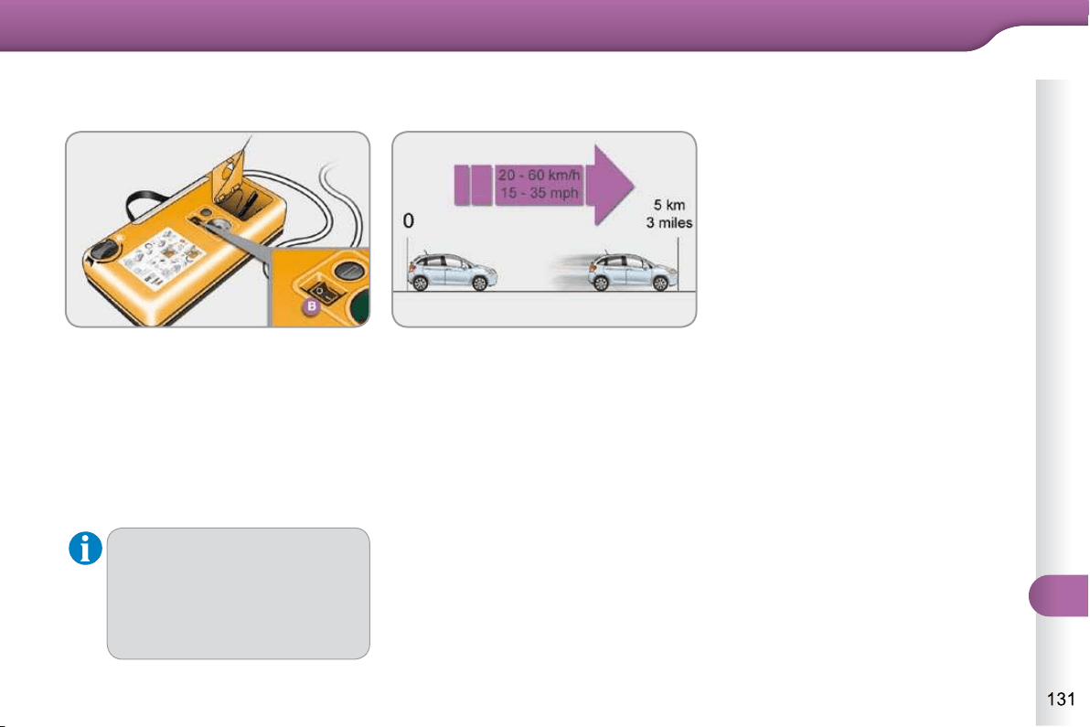
11
PRACTICAL INFORMATION
Switch on the compressor by mo-
ving the switch B to position "I" until
the tyre pressure reaches 2.0 bars.
The sealant is injected into the tyre
under pressure; do not disconnect
the pipe from the valve during this
operation (risk of splashing).
Remove the kit and screw the cap
back on the white pipe.
Take care to avoid staining your ve-
hicle with traces of fl uid. Keep the kit
to hand.
Drive immediately for approximate-
ly three miles (fi ve kilometres), at
reduced speed (between 15 and
35 mph [20 and 60 km/h]), to plug
the puncture.
Stop to check the repair and the tyre
pressure using the kit.
If after around 5 to 7 minutes
the pressure is not attained, this
indicates that the tyre is not re-
pairable; contact a CITROËN
dealer or a qualifi ed workshop
for assistance.
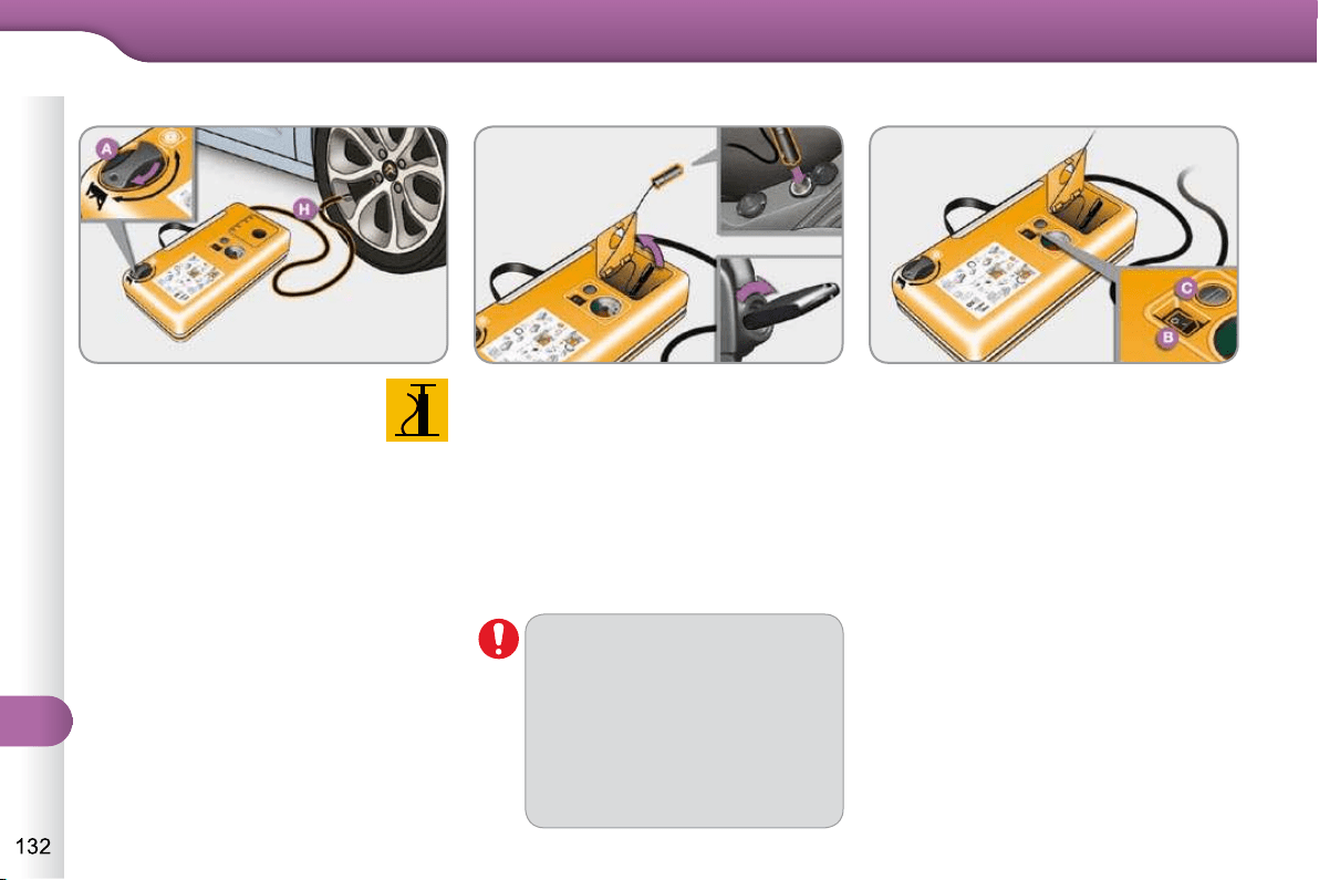
11
PRACTICAL INFORMATION
Visit a CITROËN dealer or a
qualifi ed workshop as soon
as possible.
You must inform the techni-
cian that you have used this
kit. After inspection, the tech-
nician will inform you whet-
her the tyre can be repaired
or must be replaced.
2. Infl ation
Turn the selector A to the
"air" position.
Uncoil the black pipe H fully.
Connect the black pipe to
the valve of the wheel.
Connect the compressor's electric
plug to the vehicle's 12 V socket.
Start the vehicle again and leave
the engine running.
Adjust the pressure using the
compressor (to infl ate: switch B in
position "I" ; to defl ate: switch B in
position "O" and press button C ), in
accordance with the vehicle's tyre
pressure label (located on the left
hand door aperture).
A loss of pressure indicates that the
puncture has not been fully plugged;
contact a CITROËN dealer or quali-
fi ed workshop for assistance.
Remove and stow the kit.
Drive at reduced speed (50 mph
[80 km/h] max) limiting the distance
travelled to approximately 120 miles
(200 km).
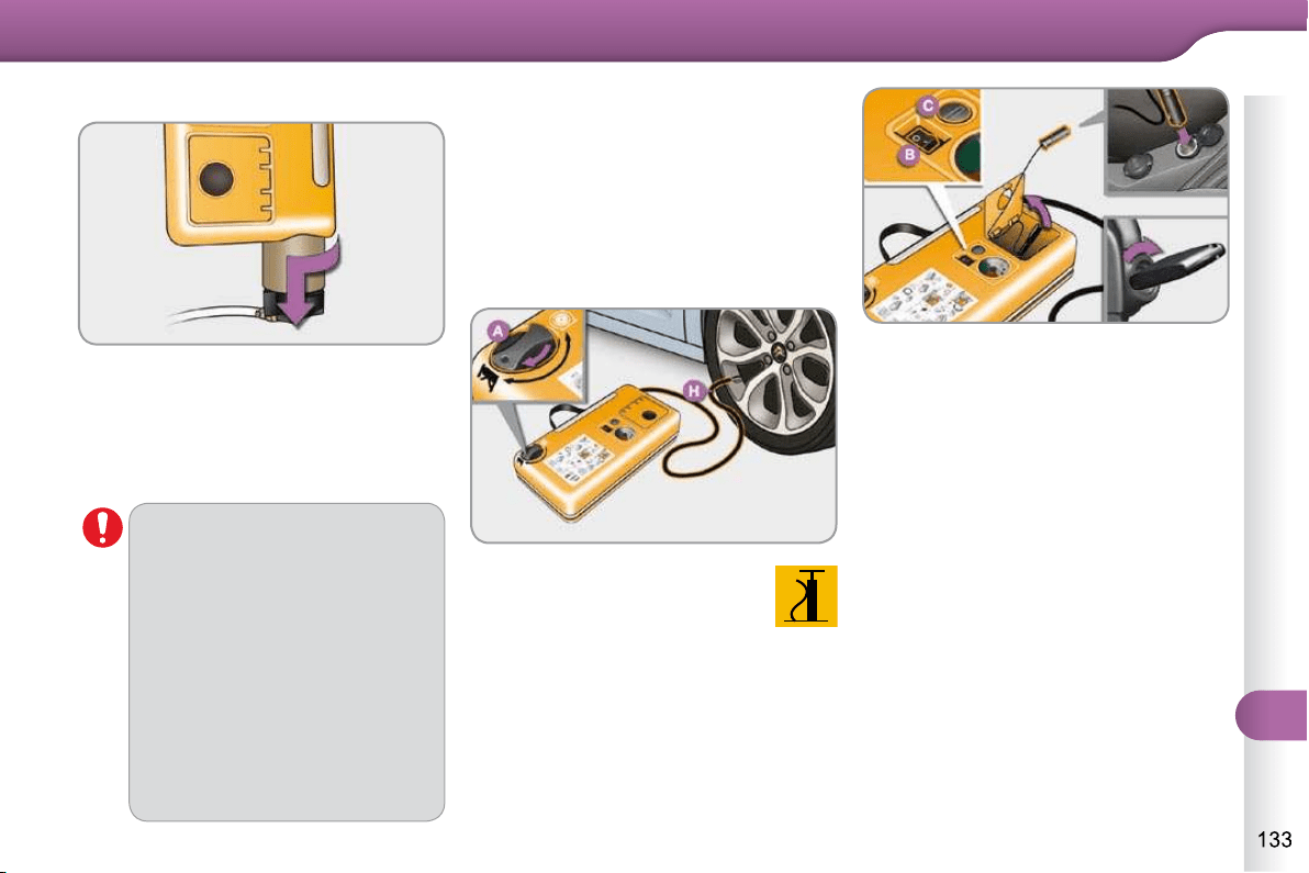
11
PRACTICAL INFORMATION
Removing the cartridge
Connect the compressor's electri-
cal connector to the vehicle's 12 V
socket.
Start the vehicle and let the engine
run.
Adjust the pressure using the com-
pressor (to infl ate: switch B in po-
sition "I" ; to defl ate: switch B in
position "O" and press button C ),
according to the vehicle's tyre pres-
sure label or the accessory's pres-
sure label.
Remove the kit then stow it.
Stow the black pipe.
Detach the angled base from the
white pipe.
Support the compressor vertically.
Unscrew the cartridge from the bottom.
Beware of discharges of fl uid.
The expiry date of the fl uid is in-
dicated on the cartridge.
The sealant cartridge is designed
for single use; even if only partly
used, it must be replaced.
After use, do not discard the car-
tridge into the environment, take
it to an authorised waste dispo-
sal site or a CITROËN dealer.
Do not forget to obtain a new
sealant cartridge, available from
CITROËN dealers or from a
qualifi ed workshop.
Checking tyre pressures/
inflating accessories
You can also use the compressor, with-
out injecting any product, to:
- check or adjust the pressure of your
tyres,
- infl ate other accessories (balls, bi-
cycle tyres...).
Turn the selector A to the
"Air" position.
Uncoil the black pipe H fully.
Connect the black pipe to
the valve of the wheel or accessory.
If necessary, fi t one of the adaptors
supplied with the kit fi rst.
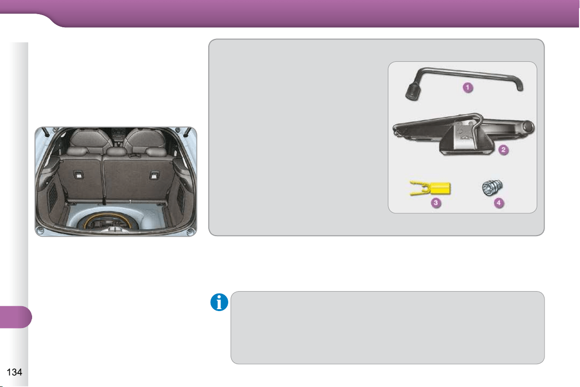
11
PRACTICAL INFORMATION
CHANGING A WHEEL
Procedure for changing a faulty wheel
for the spare wheel using the tools pro-
vided with the vehicle.
Access to the tools
The tools are installed in the boot under
the fl oor.
To gain access to them:
open the boot,
raise the fl oor,
remove the polystyrene storage box,
unclip and remove the box containing
the tools.
Wheel with trim
When removing the wheel , fi rst detach the trim using the wheelbrace 1
pulling at the valve passage hole.
When refi tting the wheel , refi t the trim starting by placing its cut-out at the
valve and press around its edge with the palm of your hand.
List of tools
All of these tools are specifi c to your
vehicle. Do not use them for other
purposes.
1. Wheelbrace.
For removing the wheel trim and
removal of the wheel fi xing bolts.
2. Jack with integral handle.
For raising of the vehicle.
3. "Bolt cover" tool.
For removing the bolt protectors
(covers) on alloy wheels (if your
vehicle has them).
4. Socket for the security wheel
bolts (located in the glove box).
For adapting the wheelbrace to
the special "security" wheel bolts.
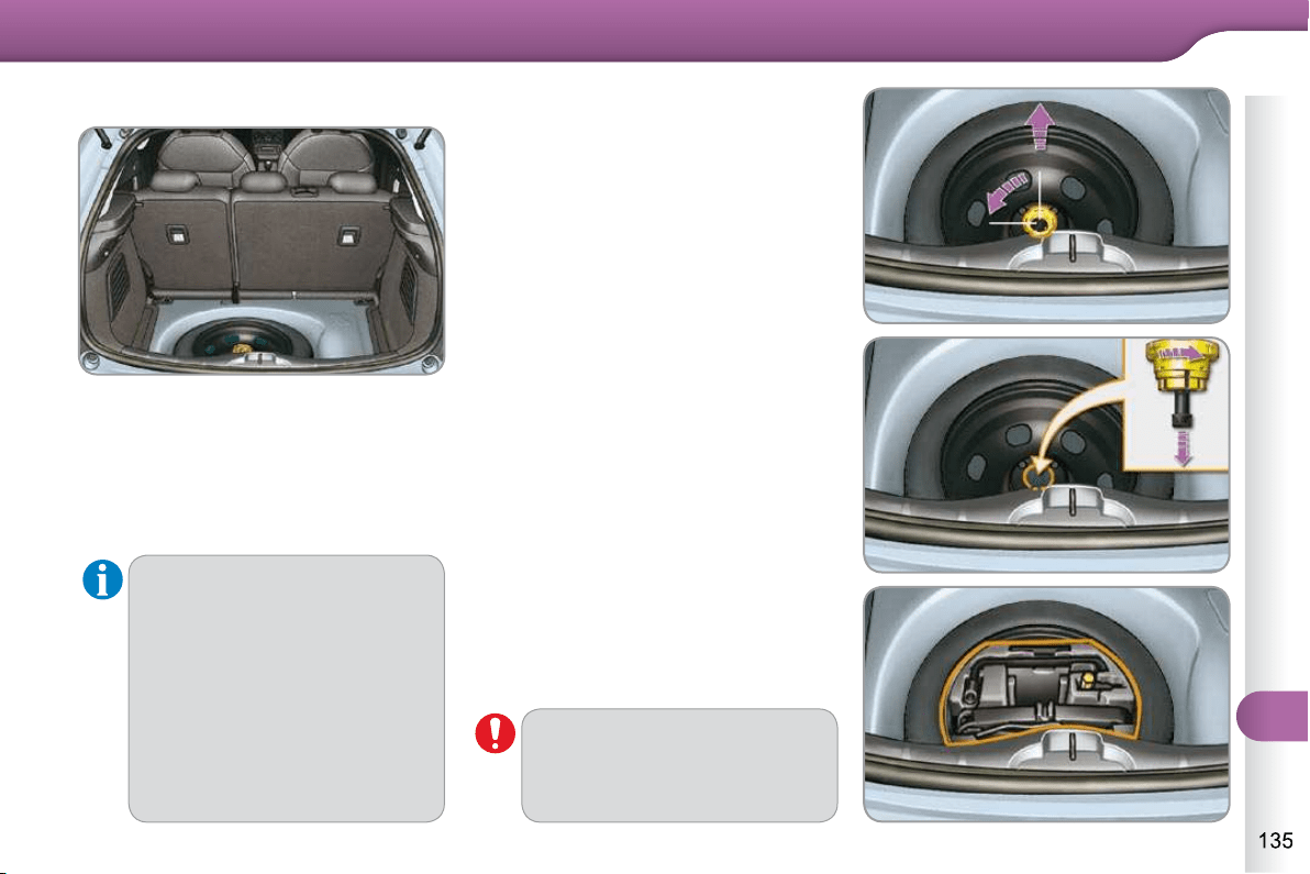
11
PRACTICAL INFORMATION
Access to the spare wheel
The spare wheel is installed in the boot
under the fl oor.
According to country, the spare wheel may
be steel or of the "space-saver" type.
To gain access to it, refer to the paragraph
"Access to the tools" on the previous
page.
Fitting the steel or
"space-saver" type spare
wheel
If your vehicle is fi tted with al-
loy wheels, it is normal to notice,
when tightening the bolts on fi t-
ting, that the washers do not
come into contact with the steel
or "space-saver" type spare
wheel. The wheel is secured by
the conical contact of each bolt.
Taking out the wheel
Unscrew the yellow central bolt.
Raise the spare wheel towards you
from the rear.
Take the wheel out of the boot.
Putting the wheel back in place
Put the wheel back in its housing.
Unscrew the yellow central bolt by a
few turns then put it in place in the
centre of the wheel.
Tighten fully until the central bolt
clicks to retain the wheel correctly.
Put the box back in place in the centre
of the wheel and clip it.
Put the polystyrene storage box
back in place.
Refi t the boot fl oor carpet by lightly
folding it in two (refer to the section
"Fittings - § Storage box").
On vehicles equipped with a
"space-saver" type spare wheel,
the punctured wheel cannot be
stowed in place of the "space-
saver" wheel.
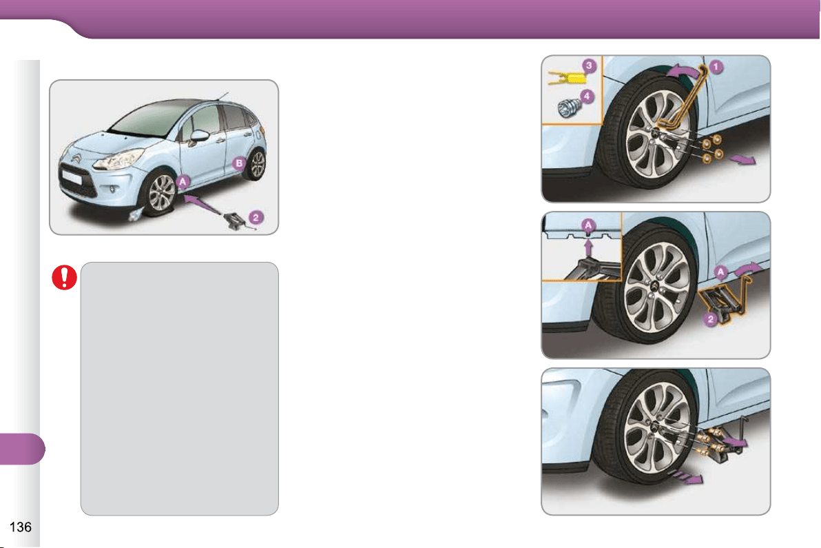
11
PRACTICAL INFORMATION
* position R for a "SensoDrive" gearbox;
position P for an automatic gearbox.
Removing the wheel
Parking the vehicle
Immobilise the vehicle where it
does not block traffi c: the ground
must be level, stable and not
slippery.
Apply the parking brake, switch
off the ignition and engage fi rst
gear * to lock the wheels.
If necessary, place a chock under
the wheel diagonally opposite the
wheel to be changed.
It is imperative that you ensure
that the occupants get out of the
vehicle and wait where they are
safe.
Never go underneath a vehicle
raised using a jack; use an axle
stand.
List of operations
Remove the chromed bolt cover from
each of the bolts using the tool 3 .
Fit the security bolt socket 4 on the
wheelbrace 1 to slacken the security
bolt.
Slacken the other bolts using the
wheelbrace 1 only.
Place the jack 2 in contact with one
of the two front A or rear B locations
provided on the underbody, which-
ever is closest to the wheel to be
changed.
Extend the jack 2 until its base plate
is in contact with the ground. Ensure
that the centreline of the jack base
plate is directly below the location A
or B used.
Raise the vehicle until there is suf-
fi cient space between the wheel and
the ground to admit the spare (not
punctured) wheel easily.
Remove the bolts and store them in
a clean place.
Remove the wheel.
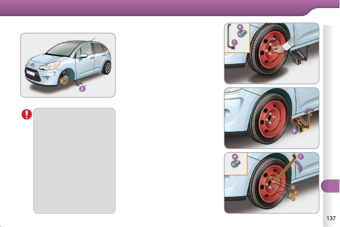
11
PRACTICAL INFORMATION
After changing a wheel
To store the punctured wheel in
the boot correctly, fi rst remove
the central cover.
When using the "space-saver"
type temporary use spare wheel,
do not exceed 50 mph (80 km/h).
Have the tightening of the bolts
and the pressure of the spare
wheel checked by a CITROËN
dealer or a qualifi ed workshop
without delay.
Have the punctured wheel re-
paired and replace it on the vehicle
as soon as possible.
Do not drive with more than one
temporary use spare wheel fi tted
to the vehicle at one time.
Fitting the wheel
List of operations
Put the wheel in place on the hub.
Screw in the bolts by hand.
Pre-tighten the security bolt using
the wheelbrace 1 fi tted with the se-
curity bolt socket 4 .
Pre-tighten the other bolts using the
wheelbrace 1 only.
Lower the vehicle fully.
Fold the jack 2 and detach it.
Tighten the security bolt using the
wheelbrace 1 fi tted with the security
bolt socket 4 .
Tighten the other bolts using the
wheelbrace 1 only.
Refi t the chromed bolt covers on
each of the bolts.
Store the tools in the box.
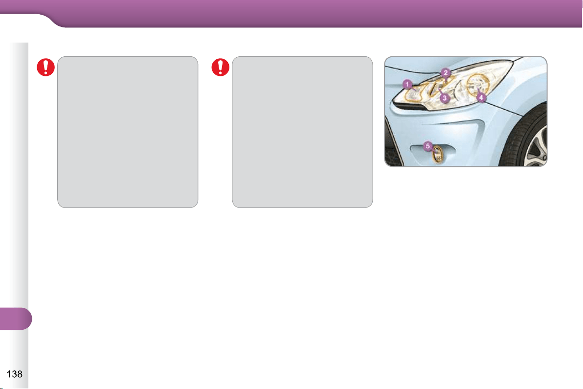
11
PRACTICAL INFORMATION
The headlamps are fi tted with
polycarbonate glass with a pro-
tective coating:
do not clean them using a
dry or abrasive cloth, nor
with a detergent or solvent
product,
use a sponge and soapy water,
when using a high pressure
washer on persistent marks,
do not direct at the lamps or
their outlines for too long, so
as not to damage their pro-
tective coating and seals.
CHANGING A BULB
Do not touch the bulb directly
with your fi ngers, use lint-
free cloths.
Changing a bulb should only be
done after the headlamp has
been switched off for a few mi-
nutes (risk of serious burns).
It is imperative to use only anti-
ultraviolet (UV) type bulbs in
order not to damage the head-
lamp.
Always replace a failed bulb with
a new bulb with the same type
and specifi cation.
Front lamps
1. Direction indicators
(PY 21 W amber).
2. Sidelamps (W 5 W).
3. Main beam headlamps (H1-55 W).
4. Dipped beam headlamps
(H7-55 W).
5. Front foglamps (PSX 24 W).
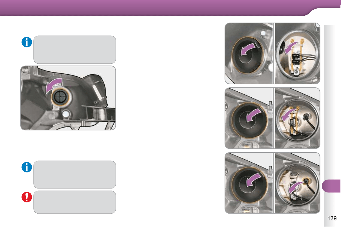
11
PRACTICAL INFORMATION
Changing direction indicator bulbs
Turn the bulb holder a quarter of a
turn and extract it.
Pull out the bulb and change it.
To refi t, carry out these operations in
reverse order.
When refi tting, close the protec-
tive cover carefully to preserve
the sealing of the headlamp.
Rapid fl ashing of the direction
indicator warning lamp (right
or left) indicates the failure of a
bulb on that side.
Amber coloured bulbs, such as
the direction indicators, must be
replaced with bulbs of identical
specifi cations and colour.
Changing dipped beam headlamp
bulbs
Remove the protective cover by
pulling on the tab.
Disconnect the bulb connector.
Spread the springs to release the
bulb.
Extract the bulb and change it.
To refi t, carry out these operations in
reverse order.
Changing main beam headlamp
bulbs
Remove the protective cover by
pulling on the tab.
Disconnect the bulb connector.
Spread the springs to release the
bulb.
Remove the bulb and change it.
To refi t, carry out these operations in
reverse order.
Changing sidelamp bulbs
Remove the protective cover by
pulling on the tab.
Pull the bulb holder pressing on the
tabs on both sides.
Pull the bulb and change it.
To refi t, carry out these operations in
reverse order.
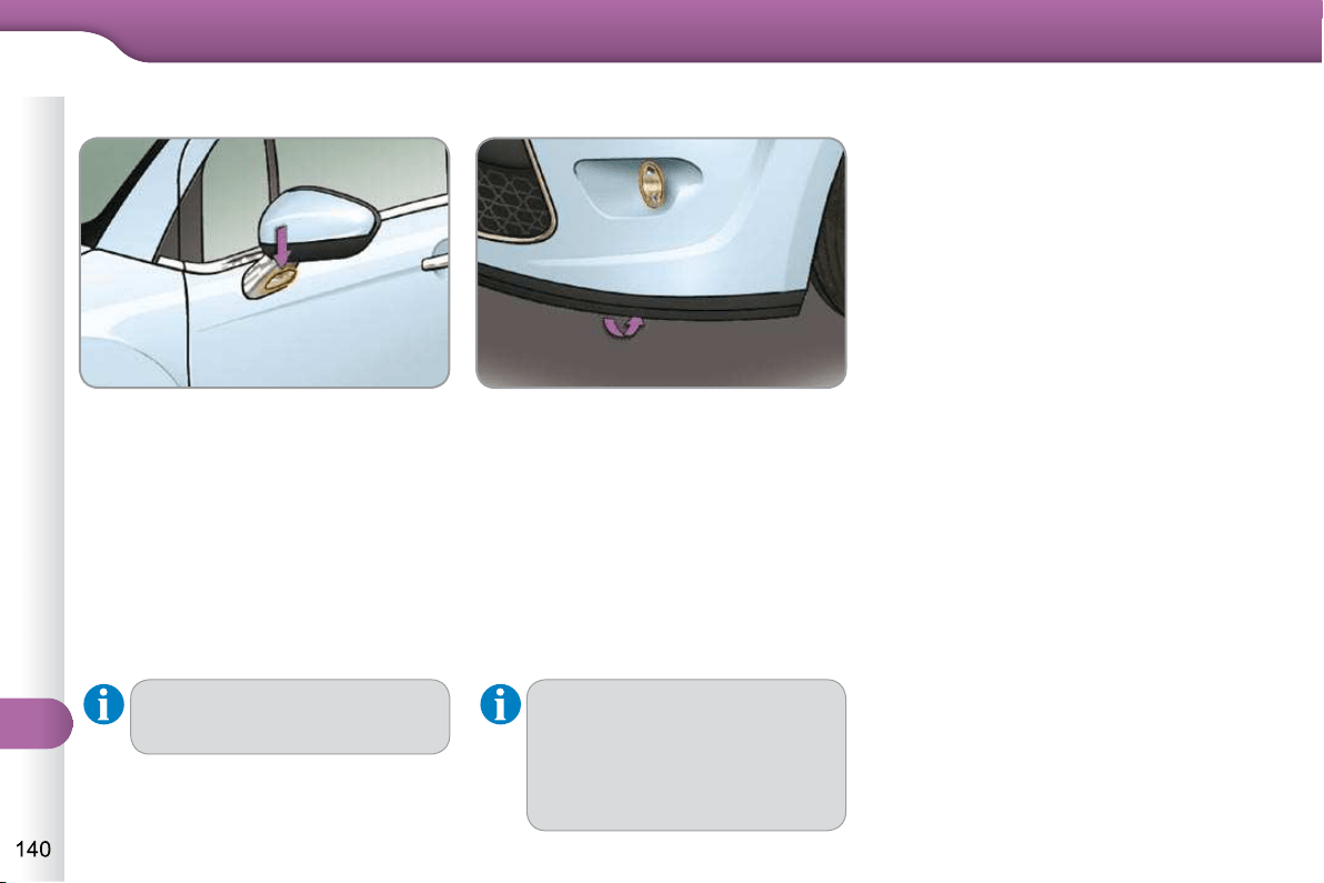
11
PRACTICAL INFORMATION
Changing front foglamp bulbs
To obtain a replacement module,
contact your CITROËN dealer or
a qualifi ed workshop.
If you experience any diffi culty
in replacing bulbs, contact your
CITROËN dealer or a qualifi ed
workshop.
Access to the front foglamp is through
the aperture below the bumper.
Disconnect the black bulb holder
connector, by pressing on the tab at
the top.
Remove the bulb-holber by press-
ing on the 2 clips (at the top and the
bottom).
Replace the module.
To refi t, carry out these operations in
reverse order.
Changing integrated direction
indicator side repeaters
Insert a screwdriver towards the
centre of the repeater between the
repeater and the base of the door
mirror.
Tilt the screwdriver to extract the re-
peater and remove it.
Disconnect the repeater connector.
Replace the module.
To refi t, carry out these operations in
reverse order.
Contact a CITROËN dealer or a
qualifi ed workshop to obtain a re-
placement side repeater module.
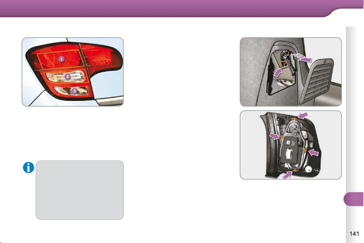
11
PRACTICAL INFORMATION
Rear lamps
1. Brake/sidelamps (P21/5W).
2. Direction indicators
(PY21W amber)
3. Foglamp, right-hand side
(PR21W red)
Reversing lamp, left-hand side
(P21W).
These four bulbs are changed from in-
side the boot:
open the boot,
remove the access fl ap from the
corresponding side trim panel,
unscrew the butterfl y nut securing
the lamp unit,
unclip the lamp unit connector,
extract the lamp unit carefully pulling
in its middle towards the outside,
spread the four tabs and remove the
bulb holder,
turn the bulb a quarter of a turn and
change it.
To refi t, carry out these operations in
reverse order.
Take care to engage the lamp unit in its
guides, while keeping it in line with the
vehicle.
Changing bulbs
Amber or red bulbs, such as
those for the direction indica-
tors and rear foglamp, must be
replaced by bulbs of the same
rating and colour.
The lamps on the tailgate are
dummy units. They are there for
aesthetic purposes only.
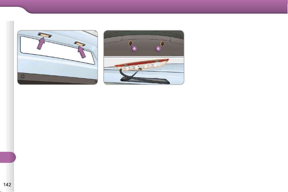
11
PRACTICAL INFORMATION
Changing the number plate lamp
bulbs (W5W)
Insert a thin screwdriver into one of
the outer holes of the lens.
Push it outwards to unclip.
Remove the lens.
Pull the bulb out and change it.
Open the boot.
Remove the plugs A on the inner
panel.
Push on the centre of the lamp
using two screwdrivers to lever it
outwards.
Disconnect the connector and if
necessary the screenwash pipe
from the lamp.
Turn the bulb holder for the faulty
bulb a quarter of a turn.
Pull out the bulb and change it.
To refi t, carry out these operations in
reverse order.
Third brake lamp (4 W5W bulbs)
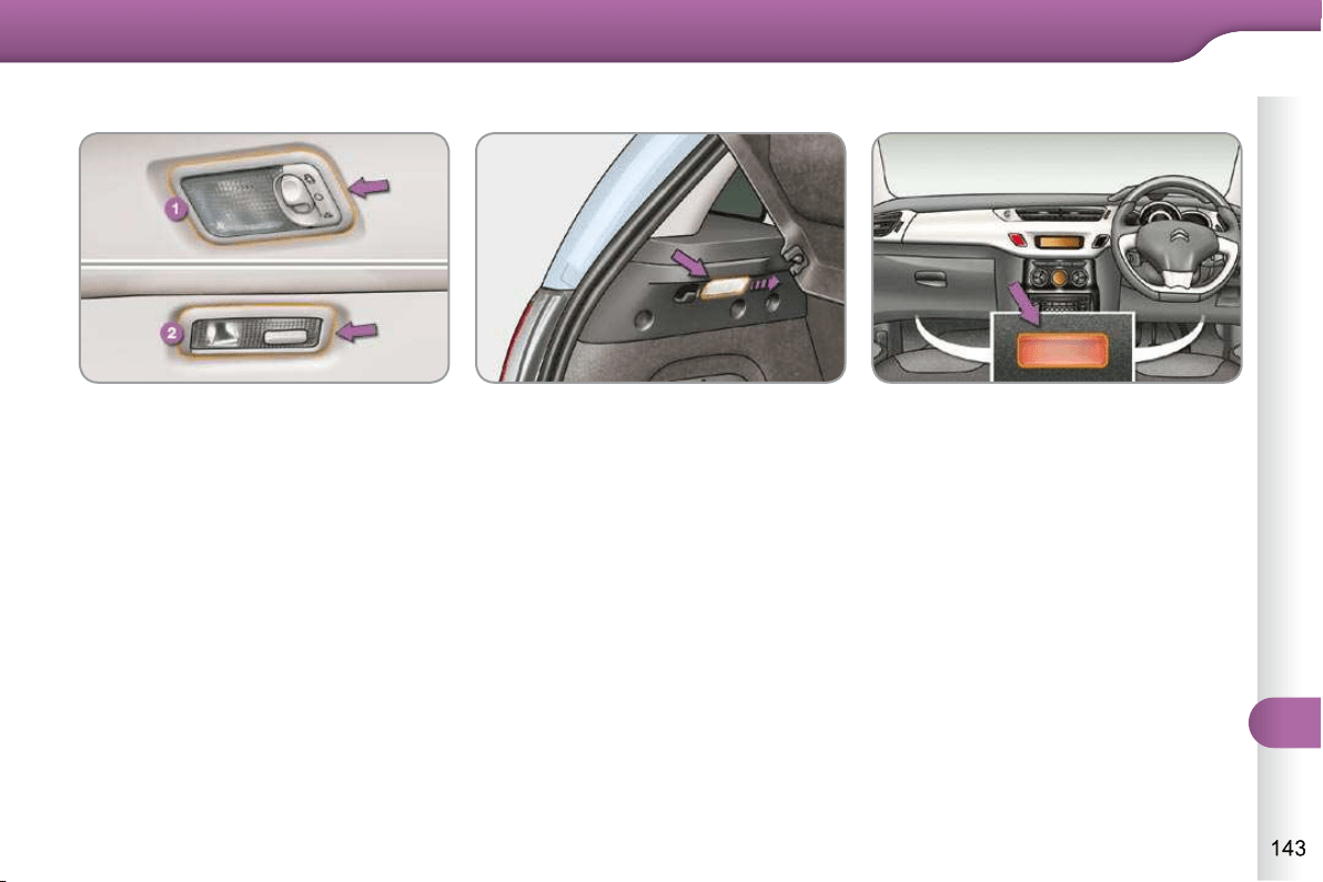
11
PRACTICAL INFORMATION
Interior lighting
Interior lamp (1/W5W)
Unclip the cover of the interior lamp with
a thin screwdriver, close to the button,
to access the faulty bulb.
Side reading lamps (2/W5W)
Unclip the cover of the reading lamp 2
with a small screwdriver at the switch
end for access to the faulty bulb.
Boot lamp (W5W)
Unclip the unit by pushing it from the
rear.
Sill lamps (W5W)
Unclip the lamp for access to the bulb.
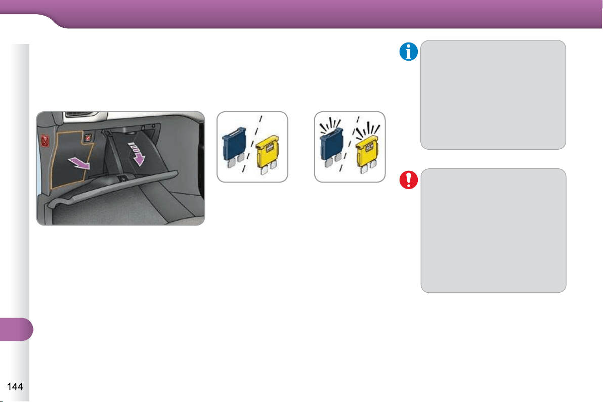
11
PRACTICAL INFORMATION
CHANGING A FUSE
Procedure for replacing a faulty fuse
with a new fuse to rectify a failure of the
corresponding function.
Access to the tools
The extraction tweezer and the spare
fuse storage locations are fi tted to the
back of the dashboard fusebox cover.
For access to them:
open the glove box lid,
unclip the fusebox cover by pulling
on the side,
remove the cover completely,
remove the tweezer.
Changing a fuse
Before changing a fuse, the cause of
the failure must be identifi ed and recti-
fi ed.
Identify the faulty fuse by checking
the condition of its fi lament.
Good
Failed
Use the special tweezer to extract
the fuse from its housing.
Always replace the faulty fuse with a
fuse of the same rating.
Check that the number marked on
the box, the rating marked on the
fuse and the tables below all agree.
Installing electrical
accessories
Your vehicle’s electrical sys-
tem is designed to operate with
standard or optional equipment.
Before installing other electrical
equipment or accessories on
your vehicle, contact a CITROËN
dealer or a qualifi ed workshop.
CITROËN will not accept respon-
sibility for the cost incurred in
repairing your vehicle or for recti-
fying malfunctions resulting from
the installation of accessories not
supplied and not recommended
by CITROËN and not installed in
accordance with its instructions,
in particular when the combined
consumption of all of the addi-
tional equipment connected ex-
ceeds 10 milliamperes.
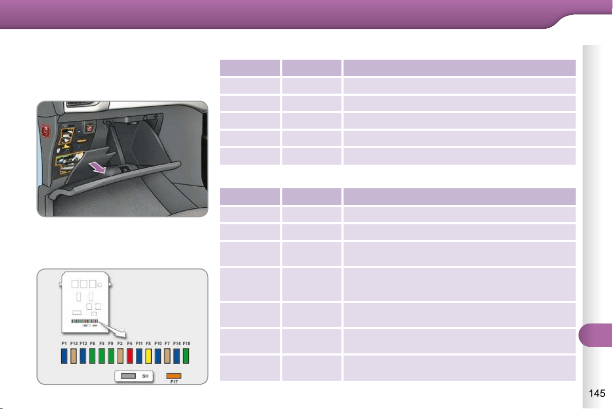
11
PRACTICAL INFORMATION
Dashboard fusebox
The fusebox is placed in the lower dash-
board (left-hand side).
Access to the fuses
Refer to the paragraph "Access to
the tools".
Fuse tables
Fuse N° Rating Functions
FH36 5 A Trailer relay unit.
FH37 - Not used.
FH38 20 A HiFi amplifi er.
FH39 - Not used.
FH40 30 A Trailer relay unit.
Fuse N° Rating Functions
F1 15 A Rear wiper.
F2 - Not used.
F3 5 A Airbags and pretensioners control unit.
F4 10 A
Air conditioning, clutch switch, electrochromatic
mirror, particle fi lter pump (Diesel), diagnostic
socket, airfl ow sensor (Diesel).
F5 30 A
Electric windows panel, passenger’s electric
window control, front electric window motor.
F6 30 A
Rear electric windows motors and driver’s electric
window motor.
F7 5 A Courtesy lamp, side reading lamps.
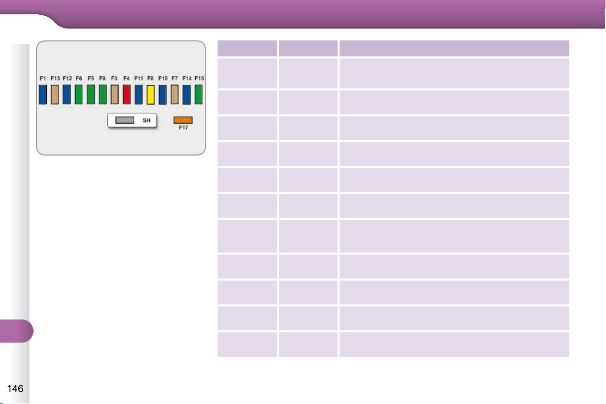
11
PRACTICAL INFORMATION
Fuse N° Rating Functions
F8 20 A
Multifunction screen, audio system, navigation
radio, instrument panel with clock, alarm control
unit, alarm siren.
F9 30 A
Audio system (after-market), 12 V socket, portable
navigation support supply.
F10 15 A Steering mounted controls.
F11 15 A
Ignition, diagnostic socket, automatic gearbox
control unit.
F12 15 A
Rain/sunshine sensor, trailer relay unit, driving
school module.
F13 5 A Main stop switch, engine relay unit.
F14 15 A
Parking sensors control unit, airbag control unit,
instrument panel, automatic air conditioning,
USB Box, HiFi amplifi er.
F15 30 A Locking.
F16 - Not used.
F17 40 A Rear screen and door mirrors demisting/defrosting.
SH - PARC shunt.
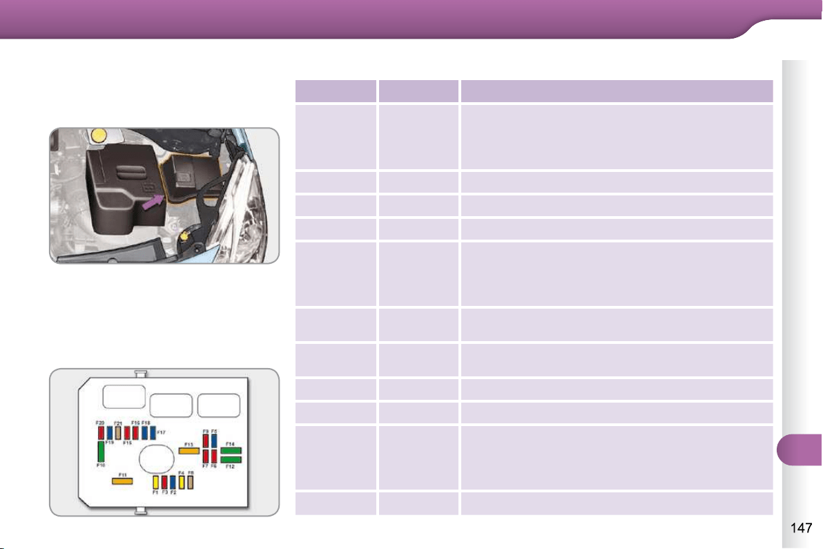
11
PRACTICAL INFORMATION
Engine compartment fusebox
The fusebox is placed in the engine
compartment near the battery (left-hand
side).
Access to the fuses
Unclip the cover.
Change the fuse (see corresponding
paragraph).
When you have fi nished, close the
cover carefully to ensure the sealing
of the fusebox.
Fuse table
Fuse N° Rating Functions
F1 20 A
Engine control unit supply, cooling fan unit control
relay, multifunction engine control main relay,
injection pump (Diesel).
F2 15 A Horn.
F3 10 A Front/rear wash-wipe.
F4 20 A Daytime running lamps.
F5 15 A
Diesel heater (Diesel), particle fi lter additive pump
(Diesel), air fl ow sensor (Diesel), fuel pump (1.1i
and 1.4i), blow-by heater and electrovalves (VTi).
F6 10 A ABS/ESP control unit, secondary stop switch.
F7 10 A Electric power steering, automatic gearbox.
F8 25 A Starter control.
F9 10 A Switching and protection unit (Diesel).
F10 30 A
Fuel heater (Diesel), blow-by heater (1.1i, 1.4i and
Diesel), fuel pump (VTi), injectors and ignition coils
(petrol), electronic thermostat and canister purge
electrovalve (1.1i and 1.4i).
F11 40 A Heater blower.

11
PRACTICAL INFORMATION
Fuse N° Rating Functions
F12 30 A Windscreen wipers slow/fast speed.
F13 40 A Built-in systems interface supply (ignition positive).
F14 30 A Valvetronic supply (VTi).
F15 10 A Right-hand main beam headlamps.
F16 10 A Left-hand main beam headlamps.
F17 15 A Left-hand dipped beam headlamps.
F18 15 A Right-hand dipped beam headlamps.
F19 15 A
Oxygen sensors and electrovalves (VTi),
electrovalves (Diesel), EGR electrovalve (Diesel).
F20 10 A
Pumps, electronic thermostat (VTi) water in fuel
sensor (Diesel).
F21 5 A Fan assembly control supply, ABS/ESP.
11
PRACTICAL INFORMATION
Table of maxi-fuses
Fuse N° Rating Functions
MF1 * 60 A Fan assembly.
MF2 * 30 A ABS/ESP pump.
MF3 * 30 A ABS/ESP electrovalves.
MF4 * 60 A Built-in Systems Interface (BSI) supply.
MF5 * 60 A Built-in Systems Interface (BSI) supply.
MF6 * - Not used.
MF7 * - Dashboard fusebox.
MF8 * - Not used.
* The maxi-fuses provide additional protection for the electrical systems. All work on the maxi-fuses must be carried out by a
CITROËN dealer or a qualifi ed workshop.
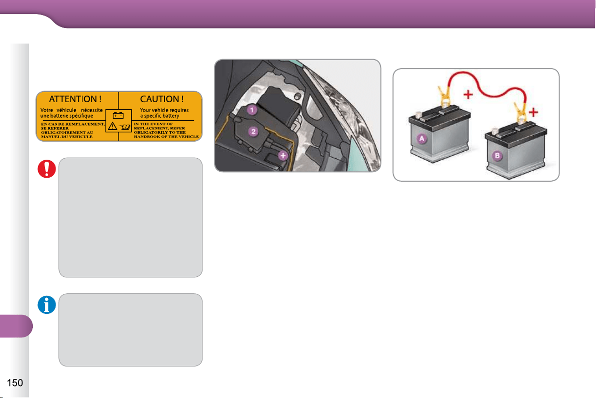
11
PRACTICAL INFORMATION
Starting using another battery
Connect the red cable to the posi-
tive terminal (+) of the fl at battery A ,
then to the positive terminal (+) of
the slave battery B .
BATTERY
Procedure for charging your battery
when it is fl at or for starting the engine
using another battery.
The battery is located under the bonnet.
To gain access to it:
open the bonnet using the interior
release lever, then the exterior safe-
ty catch,
secure the bonnet stay,
unclip the control unit housing 1 lo-
cated to the right of the battery,
unclip the fusebox 2 located on top
of the battery,
remove the cable from the (+) terminal,
remove the plastic cover.
Access to the battery
The presence of this label, in
particular with the Stop & Start
system, indicates the use of a
12 V lead-acid battery with spe-
cial technology and specifi cation;
the involvement of a CITROËN
dealer or a qualifi ed workshop is
essential when replacing or dis-
connecting the battery.
Failure to observe this recom-
mendation may cause prema-
ture wear of the battery.
After refi tting the battery, the
Stop & Start system will only be
active after a continuous period
of immobilisation of the vehicle,
a period which depends on the
climatic conditions and the state
of charge of the battery (up to
about 8 hours).
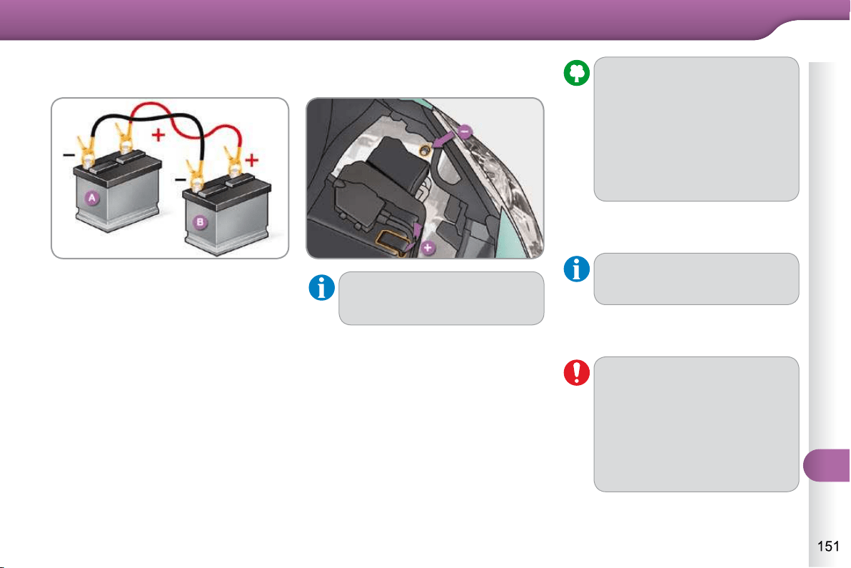
11
PRACTICAL INFORMATION
Connect one end of the green or
black cable to the negative termi-
nal (-) of the slave battery B .
Connect the other end of the green
or black cable to the negative termi-
nal (-) of the fl at battery A .
Start the slave vehicle.
Operate the starter of the broken
down vehicle and let the engine run.
Wait until the engine returns to idle
and disconnect the cables.
Charging the battery using a
battery charger
The Stop & Start battery does
not have to be disconnected for
charging.
Disconnect the battery from the
vehicle.
Follow the instructions for use pro-
vided by the manufacturer of the
charger.
Reconnect starting with the nega-
tive terminal (-).
Check that the terminals and con-
nectors are clean. If they are
covered with sulphate (whitish or
greenish deposit), remove them and
clean them.
It is advisable to disconnect the bat-
tery if the vehicle is to be left unused
for more than one month.
Batteries contain harmful sub-
stances such as sulphuric acid and
lead. They must be disposed of in
accordance with regulations and
must not, in any circumstances, be
discarded with household waste.
Take used remote control bat-
teries and vehicle batteries to a
special collection point.
Do not disconnect the terminals
while the engine is running.
Do not charge the batteries with-
out disconnecting the terminals
fi rst.
Do not push the vehicle to start
the engine if your vehicle is fi tted
with a "SensoDrive" gearbox.
11
PRACTICAL INFORMATION
If the telephone is being used at
the same time on the MyWay au-
dio navigation system, it will be
interrupted after 10 minutes.
A fl at battery prevents the engine
from starting (refer to the corre-
sponding paragraph).
ENERGY ECONOMY MODE
System which manages the period of
use of certain functions to conserve a
suffi cient level of charge in the battery.
After the engine has stopped, you can
still use functions such as the audio
equipment, windscreen wipers, dipped
beam headlamps, courtesy lamps, etc.
for a maximum combined period of
thirty minutes.
Switching to economy mode
Once this period has elapsed, a message
appears on the multifunction screen in-
dicating that the vehicle has switched to
economy mode and the active functions
are put on standby.
Exiting economy mode
These functions are reactivated auto-
matically the next time the vehicle is
driven.
In order to resume the use of these
functions immediately, start the en-
gine and let it run for a few minutes.
The time available to you will then be
double the period for which the engine is
left running. However, this period will al-
ways be between fi ve and thirty minutes.
This period may be greatly re-
duced if the battery is not fully
charged.
LOAD REDUCTION MODE
System which manages the use of cer-
tain functions according to the level of
charge remaining in the battery.
When the vehicle is being driven, the load
reduction function temporarily deactivates
certain functions, such as the air condi-
tioning, the heated rear screen...
The deactivated functions are reactiva-
ted automatically as soon as conditions
permit.
Before disconnecting
the battery
Wait 2 minutes after switching off
the ignition before disconnecting
the battery.
Close the windows and the
doors before disconnecting the
battery.
Following reconnection of
the battery
Following reconnection of the
battery, switch on the ignition
and wait 1 minute before star-
ting to permit initialisation of the
electronic systems. However,
if minor problems persist fol-
lowing this operation, contact a
CITROËN dealer or a qualifi ed
workshop.
Referring to the correspon-
ding section, you should yourself
reinitialise:
- the remote control key,
- the GPS satellite navigation
system.
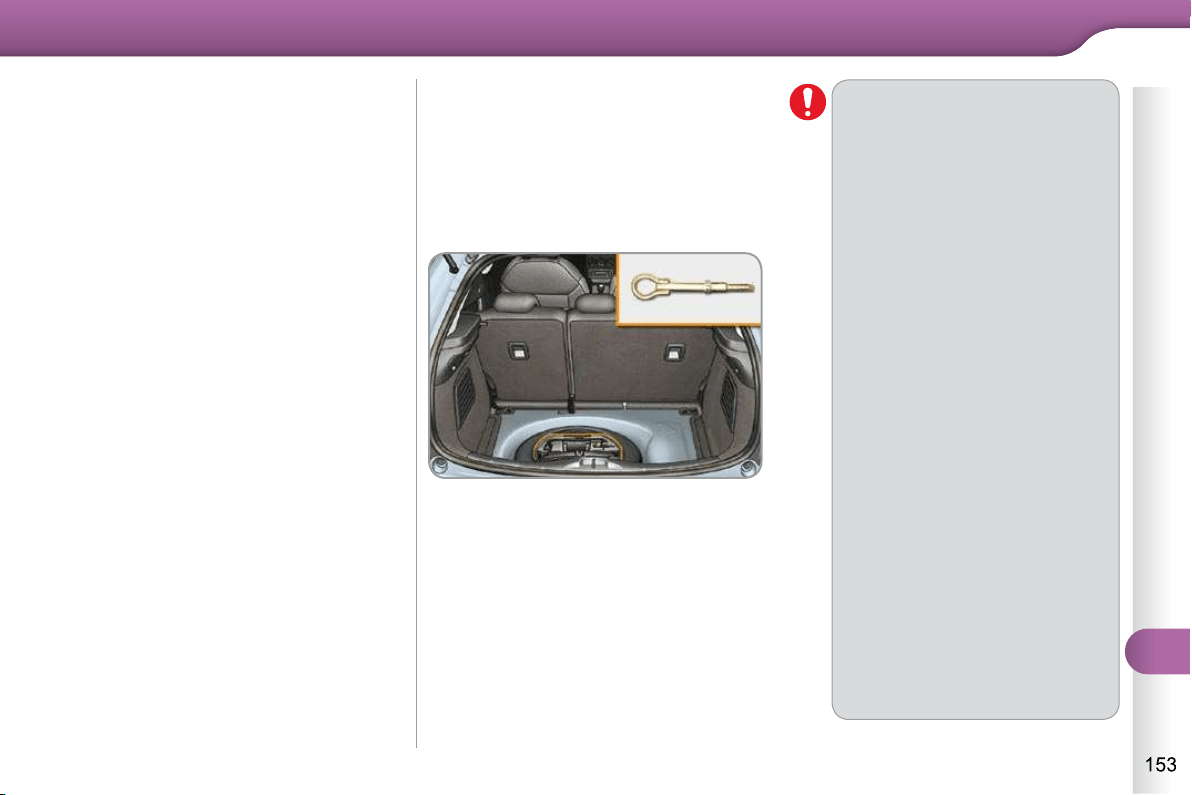
11
PRACTICAL INFORMATION
CHANGING A FRONT OR REAR
WIPER BLADE
Procedure for replacing a worn wiper
blade with a new one without the use
of tools.
Before removing a front wiper blade
Within one minute after switching off
the ignition, operate the wiper stalk
to position the wiper blades in the
vertical position.
This position must be used in order to
avoid damaging the wiper blade and the
bonnet.
Removal
Raise the corresponding wiper arm.
Unclip the wiper blade and remove it.
Fitting
At the front, check the size of the wi-
per blade as the shorter blade is fi tted
to the passenger side of the vehicle.
Put the corresponding new wiper
blade in place and clip it.
Fold down the wiper arm carefully.
After fitting a front wiper blade
Switch on the ignition.
Operate the wiper stalk again to
park the wiper blades.
TOWING THE VEHICLE
Procedure for having your vehicle towed
or for towing another vehicle using a re-
movable towing eye.
Access to the tools
The towing eye is installed in the boot
under the fl oor.
To gain access to it:
open the boot,
raise the fl oor,
remove the polystyrene storage box,
remove the towing eye from the
holder.
General
recommendations
Observe the legislation in force
in your country.
Ensure that the weight of the
towing vehicle is higher than
that of the towed vehicle.
The driver must stay at the
wheel of the towed vehicle.
Driving on motorways and fast
roads is prohibited when towing.
When towing a vehicle with all
four wheels on the ground, al-
ways use an approved towing
bar; rope and straps are pro-
hibited.
When towing a vehicle with the
engine off, there is no longer
any power assistance for bra-
king or steering.
In the following cases, you
must always call on a profes-
sional recovery service:
- vehicle broken down on a
motorway or fast road,
- when it is not possible to
put the gearbox into neu-
tral, unlock the steering, or
release the parking brake,
- towing with only two wheels
on the ground,
- where there is no approved
towing bar available...
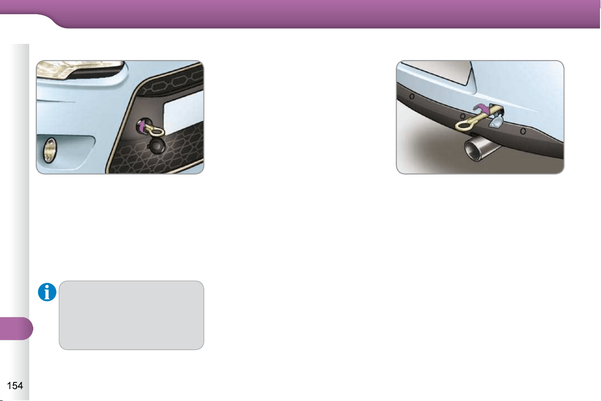
11
PRACTICAL INFORMATION
Unlock the steering by turning the
key one notch in the ignition switch
and release the parking brake.
Switch on the hazard warning lamps
on both vehicles.
Move off gently and drive for a short
distance only.
Towing another vehicle
On the rear bumper, unclip the cover
by pressing at the bottom.
Screw the towing eye in fully.
Install the towing bar.
Switch on the hazard warning lamps
on both vehicles.
Move off gently and drive for a short
distance only.
Failure to observe this special
condition could result in da-
mage to certain components
(braking, transmission...) and
the absence of braking assis-
tance the next time the engine
is started.
Towing your vehicle
On the front bumper, unclip the
cover by pressing at the bottom.
Screw the towing eye in fully.
Install the towing bar.
Place the gear lever in neutral
(position N for an SensoDrive or au-
tomatic gearbox).
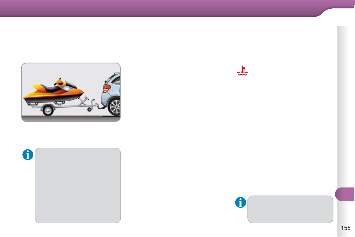
11
PRACTICAL INFORMATION
We recommend the use of genu-
ine CITROËN towbars and their
harnesses that have been tested
and approved from the design
stage of your vehicle, and that
the fi tting of the towbar is en-
trusted to a CITROËN dealer or
a qualifi ed workshop.
If the trailer is not fi tted by a
CITROËN dealer, it is impera-
tive that it is fi tted using the vehi-
cle's electrical pre-equipment, in
accordance with the manufac-
turer's instructions.
TOWING A TRAILER,
A CARAVAN, ETC.
The rear parking sensors will
be deactivated automatically if
a genuine CITROËN towbar is
used.
Towbar suitable for the attachment of a
trailer or caravan with additional lighting
and signalling.
Your vehicle is primarily designed for
transporting people and luggage, but it
may also be used for towing a trailer.
Driving with a trailer places greater de-
mands on the towing vehicle and the
driver must take particular care.
Driving advice
Distribution of loads
Distribute the load in the trailer so
that the heaviest items are as close
as possible to the axle and the nose
weight approaches the maximum
permitted without exceeding it.
Air density decreases with altitude, thus
reducing engine performance. Above
1 000 metres, the maximum towed load
must be reduced by 10 % for every
1 000 metres of altitude.
Refer to the "Technical Data" section for
details of the weights and towed loads
which apply to your vehicle.
Side wind
Take into account the increased
sensitivity to side wind.
Cooling
Towing a trailer on a slope increases
the temperature of the coolant.
As the fan is electrically controlled, its
cooling capacity is not dependent on
the engine speed.
To lower the engine speed, reduce
your speed.
The maximum towed load on a long in-
cline depends on the gradient and the
ambient temperature.
In all cases, keep a check on the coolant
temperature.
If the warning lamp and the
STOP warning lamp come
on, stop the vehicle and
switch off the engine as
soon as possible.
Braking
Towing a trailer increases the braking
distance.
Tyres
Check the tyre pressures of the towing
vehicle and of the trailer, observing the
recommended pressures.
Lighting
Check the electrical lighting and
signalling on the trailer.
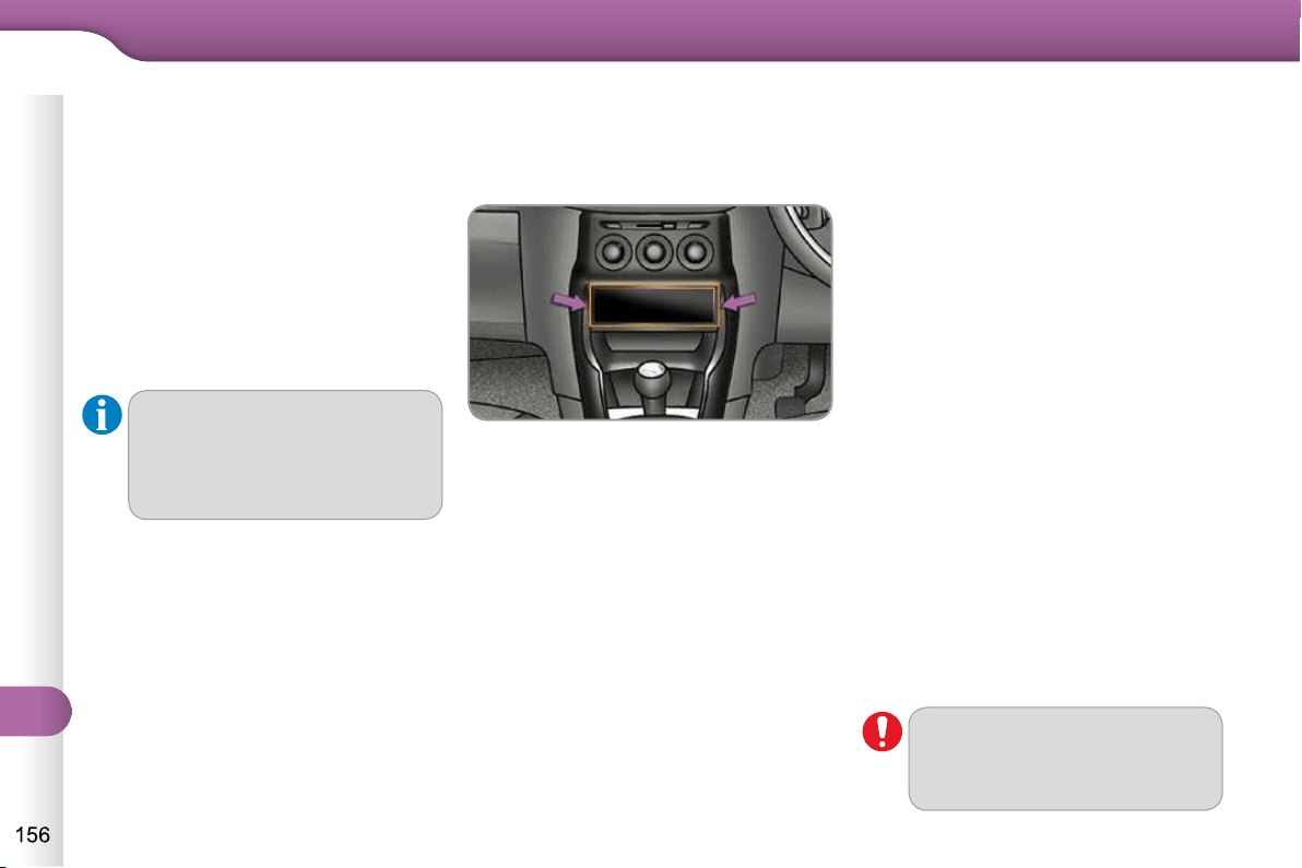
11
PRACTICAL INFORMATION
AUDIO PRE-EQUIPMENT
Your vehicle is equipped with certain
factory-fi tted audio equipment:
- a dual-function aerial at the rear of
the roof,
- a coaxial aerial cable,
- basic interference suppression,
- cabling for speakers in the front
doors and tweeters in the dash-
board,
- cabling for speakers in the rear doors
- two 8-way connectors.
Fitting an audio unit
The audio unit is fi tted in place of one
of the storage boxes located below the
heating and air conditioning control
panel.
Fitting speakers
It is possible to fi t:
- 165 mm diameter speakers in the
front doors,
- 130 mm diameter speakers in the
rear doors,
- 22.5 mm diameter tweeters in the
top of the dashboard.
Connectors
8-way connector (A)
A1: -
A2: -
A3: -
A4: -
A5: -
A6: (+) Ignition positive (in this case,
the audio equipment only oper-
ates when the ignition is on)
A7: (+) Permanent
A8: Earth
Never use a separate wire to
connect the (+) of your audio
equipment (risk of discharging of
the battery).
8-way connector (B)
B1: (+) Rear right speaker
B2: (-) Rear right speaker
B3: (+) Front right speaker and tweeter
B4: (-) Front right speaker and tweeter
B5: (+) Front left speaker and tweeter
B6: (-) Front left speaker and tweeter
B7: (+) Rear left speaker
B8: (-) Rear left speaker
Before installing a radio unit or
speakers in your vehicle, you can
contact a CITROËN dealer who
will give you the part number for
a suitable wiring harness.
Unclip the storage box on each side
using a screwdriver and pull out.
You will then have access to an aerial
coaxial cable and two 8-way connectors.
Then refer to the instructions provided
with your audio unit.
11
PRACTICAL INFORMATION
* To avoid any risk of jamming of the
pedals:
- ensure that the mat is positioned
and secured correctly,
- never fi t one mat on top of
another.
ACCESSORIES
They are all adapted to your vehicle and
benefi t from CITROËN's recommenda-
tion and warranty.
"Comfort"
sun blinds, door defl ectors, isotherm
module, smoking kit, fragrance cartridg-
es, front centre armrest, moveable mirror,
reading lamp...
"Style":
leather steering wheel, gear lever knobs,
interior styling kit, aluminium footrest, al-
loy wheels, wheel trims, chrome tailgate
fi nisher, chrome tailpipe fi nisher, chrome
mirror shells, chrome door handles...
A wide range of accessories and genu-
ine parts is available from the CITROËN
dealer network.
These accessories and parts have been
tested and approved for reliability and
safety.
Conversion kits
You can obtain an "Enterprise" kit to
convert a trade vehicle to a private car
and vice-versa.
"Transport solutions":
child seats and booster cushions, boot
tray, boot carpet, boot net, boot contain-
ers, transverse roof bars, bicycle carrier,
ski carrier, roof boxes, towbars, towbar
wiring harnesses...
"Safety":
anti-theft alarm, wheel security bolts,
stolen vehicle tracking system, breatha-
lyser, fi rst aid kit, warning triangle, high
visibility vest, dog guard, snow chains,
non-slip covers, foglamps kit, parking
sensors, bumper protection strips (trans-
lucent, gloss black, chrome fi nish)...
"Protection":
mats * , mudfl aps, seat covers, door sill
protectors...
If a towbar and wiring are fi tted
outside the CITROËN dealer
network, this must be done
making use of the vehicle's
electrical pre-equipment and
following the manufacturer's
recommendations.
11
PRACTICAL INFORMATION
Depending on the legislation in
force in the country, it may be
compulsory to have a high vis-
ibility safety vest, warning trian-
gle and spare bulbs and fuses
available in the vehicle.
The fi tting of electrical equipment
or accessories which are not rec-
ommended by CITROËN may
result in a failure of your vehicle's
electronic system and excessive
electrical consumption.
Please note this precaution.
You are advised to contact a
CITROËN representative to be
shown the range of recommend-
ed equipment and accessories.
Installation of radio
communication transmitters
Before installing any after-
market radio communication
transmitter, you can contact a
CITROËN dealer for the speci-
fi cation of transmitters which
can be fi tted (frequency, maxi-
mum power, aerial position,
specifi c installation require-
ments), in line with the Vehicle
Electromagnetic Compatibility
Directive (2004/104/EC).
"Multimedia":
Bluetooth
®
hands-free system, audio
equipment, portable satellite navigation
system, semi-integral portable navi-
gation system carrier, speed camera
warning, DVD player, auxiliary cable for
connecting a portable MP3 player, USB
Box, Hi-Fi module, speakers...
By going to a CITROËN dealer, you
can also obtain cleaning and mainte-
nance products (interior and exterior) -
including ecological products in the
"TECHNATURE" range - products for
topping up (screenwash fl uid...), touch
up pens and paint aerosols for the exact
colour of your vehicle, recharges (car-
tridge for the temporary puncture repair
kit...), ...
12
TECHNICAL DATA
MODELS: ENGINES AND GEARBOXES
Model codes:
SC...
HFV0 KFT0 8FR0 8FP0 5FS0 5FS9
PETROL ENGINES 1.1 i 1.4 i VTi 95 VTi 120
Cubic capacity (cc) 1 124 1 360 1 397 1 598
Bore x stroke (mm) 72 x 69 75 x 77 77 x 75 77 x 85.8
Max power: EU standard (kW) 44 54 70 88
Max power engine speed (rpm) 5 500 5 200 6 000 6 000
Max torque: EU standard (Nm) 94 118 136 160
Max torque engine speed (rpm) 3 300 3 300 4 000 4 250
Fuel Unleaded Unleaded Unleaded Unleaded
Catalytic converter yes yes yes yes
GEARBOX
Manual
(5-speed)
Manual
(5-speed)
Manual
(5-speed)
SensoDrive
(5-speed)
Manual
(5-speed)
Automatic
(4-speed)
OIL CAPACITIES (in litres)
Engine (with fi lter replacement) 3.0 3.0 4.25 4.25 4.25 4.25
12
TECHNICAL DATA
For more information on the operation and use of your LPG vehicle, refer to the specifi c insert attached to the other vehicle
documents.
MODELS: ENGINES AND GEARBOXES
Model codes:
SC...
HFV0/GPL KFT0/GPL
LPG ENGINES 1.1 i 1.4 i
Cubic capacity (cc) 1 124 1 360
Bore x stroke (mm) 72 x 69 75 x 77
Max. power: EU standard (kW) 44 51.5/54
Max. power speed (rpm) 5 500 5 200
Max torque: EU standard (Nm) 88/94 118
Max. torque speed (rpm) 3 500/3 300 3 300
Fuel LPG/Unleaded LPG/Unleaded
Catalytic converter Yes Yes
GEARBOXES
Manual
(5-speed)
Manual
(5-speed)
OIL CAPACITIES (in litres)
Engine (with fi lter replacement) 3.0 3.0
12
TECHNICAL DATA
MODELS: ENGINES AND GEARBOXES
Model codes:
SC...
8HZC 8HR0 9HXC 9HP4
9HP0
9HP0 /S
9HR8
DIESEL ENGINES HDi 70 HDi 70 PEF HDi 90
HDi 90 PEF
99g
HDi 90 PEF
HDi 110
PEF
Cubic capacity (cc) 1 398 1 560 1 560
Bore x stroke (mm) 73.7 x 82 75 x 88.3 75 x 88.3
Max power: EU standard (kW) 50 66 68 68 82
Max power engine speed (rpm) 4 000 4 000 3 600
Max torque: EU standard (Nm) 160 215 230 230 270
Max torque engine speed (rpm) 2 000 1 750 1 750 1 750
Fuel Diesel Diesel Diesel
Catalytic converter yes yes yes
Particle emissions fi lter (PEF) no yes no yes yes yes
GEARBOX
Manual
(5-speed)
Manual
(5-speed)
Manual
(6-speed)
OIL CAPACITIES (in litres)
Engine (with fi lter replacement) 3.75 3.75 3.75 3.75 3.75 3.75
.../S: model fi tted with Stop & Start.
12
TECHNICAL DATA
WEIGHTS AND TOWED LOADS (in kg)
Petrol engines 1.1 i 1.4 i
Gearbox Manual Manual
Model codes:
SC...
HFV0 KFT0
- Unladen weight 1 010 1 030
- Kerb weight 1 085 1 105
- Gross vehicle weight (GVW) 1 527 1 529
- Gross train weight (GTW)
on a 12 % gradient
1 977 2 329
- Braked trailer (within GTW limit)
on a 12 % gradient
450 800
- Braked trailer * (with load transfer within
the GTW limit)
775 1 105
- Unbraked trailer 450 550
- Recommended nose weight 31 44
* The weight of the braked trailer can be increased, within the GTW limit, if the GVW of the towing vehicle is reduced by an
equal amount. Warning: towing using a lightly loaded towing vehicle may have an adverse effect on its road holding.
The GTW and towed load values indicated are valid up to a maximum altitude of 1 000 metres; the towed load mentioned
must be reduced by 10 % for each additional 1 000 metres of altitude.
The speed of a towing vehicle must not exceed 60 mph (100 km/h) (comply with the legislation in force in your country).
High ambient temperatures may result in a reduction in the performance of the vehicle to protect the engine; if the ambient
temperature is above 37 °C, limit the towed load.
12
TECHNICAL DATA
* The weight of the braked trailer can be increased, within the GTW limit, if the GVW of the towing vehicle is reduced by an
equal amount. Warning: towing using a lightly loaded towing vehicle may have an adverse effect on its road holding.
The GTW and towed load values indicated are valid up to a maximum altitude of 1 000 metres; the towed load mentioned
must be reduced by 10 % for each additional 1 000 metres of altitude.
The speed of a towing vehicle must not exceed 60 mph (100 km/h) (comply with the legislation in force in your country).
High ambient temperatures may result in a reduction in the performance of the vehicle to protect the engine; if the ambient
temperature is above 37 °C, limit the towed load.
WEIGHTS AND TOWED LOADS (in kg)
Petrol engines VTi 95 VTi 120
Gearboxes Manual SensoDrive Manual Automatic
Model codes:
SC...
8FR0 8FP0 5FS0 5FS9
- Unladen weight 1 075 1 079 1 075 1 089
- Kerb weight 1 150 1 154 1 150 1 164
- Gross vehicle weight (GVW) 1 576 1 581 1 579 1 612
- Gross train weight (GTW)
on a 12 % gradient
2 476 2 481 2 479 2 512
- Braked trailer (within the GTW limit)
on a 12 % gradient
900 900 900 900
- Braked trailer * (with load transfer within
the GTW limit)
1 150 1 150 1 150 1 150
- Unbraked trailer 570 570 570 570
- Recommended nose weight 46 46 46 46
12
TECHNICAL DATA
WEIGHTS AND TOWED LOADS (in kg)
LPG engines 1.1 i 1.4 i
Gearboxes Manual Manual
Model codes:
SC...
HFV0/GPL KFT0/GPL
- Unladen weight 1 070 1 098
- Kerb weight 1 145 1 173
- Gross vehicle weight (GVW) 1 527 1 575
- Gross train weight (GTW)
on a 12 % slope
1 977 2 375
- Braked trailer (within GTW limit)
on a 12 % slope
450 800
- Braked trailer * (with load transfer within
the GTW limit)
775 1 105
- Unbraked trailer 450 550
- Recommended nose weight 31 44
* The weight of the braked trailer can be increased, within the GTW limit, if the GVW of the towing vehicle is reduced by an
equal amount; warning, towing using a lightly loaded towing vehicle may have an adverse effect on its road holding.
The GTW and towed load values indicated are valid up to a maximum altitude of 1 000 metres; the towed load mentioned
must be reduced by 10 % for each additional 1 000 metres of altitude.
The speed of a towing vehicle must not exceed 60 mph (100 km/h) (comply with the legislation in force in your country).
High ambient temperatures may result in a reduction in the performance of the vehicle to protect the engine; if the ambient
temperature is above 37 °C, limit the towed load.
12
TECHNICAL DATA
The GTW and towed load values indicated are valid up to a maximum altitude of 1 000 metres; the towed load mentioned
must be reduced by 10 % for each additional 1 000 metres of altitude.
The speed of a towing vehicle must not exceed 60 mph (100 km/h) (comply with the legislation in force in your country).
High ambient temperatures may result in a reduction in the performance of the vehicle to protect the engine; if the ambient
temperature is above 37 °C, limit the towed load.
WEIGHTS AND TOWED LOADS (in kg)
Diesel engines HDi 70
HDi 70
PEF
HDi 90
HDi 90
PEF 99g
HDi 90
PEF
HDi 90
PEF
Gearbox Manual Manual
Model codes:
SC...
8HZC 8HR0 9HXC 9HP4 9HP0 9HP0/S
- Unladen weight 1 065 1 070 1 080 1 080 1 080 1 085
- Kerb weight 1 140 1 145 1 155 1 155 1 155 1 160
- Gross vehicle weight (GVW) 1 564 1 581 1 607 1 583 1 608 1 625
- Gross train weight (GTW)
on a 12 % gradient
2 464 2 281 2 507 2 083 2 508 2 525
- Braked trailer (within GTW limit)
on 12 % gradient
900 700 900 500 900 900
- Braked trailer * (with load transfer with
the GTW limit)
1 150 950 1 150 500 1 150 1 150
- Unbraked trailer 570 570 570 500 570 570
- Recommended nose weight 46 46 46 46 46 46
* The weight of the braked trailer can be increased, within the GTW limit, if the GVW of the towing vehicle is reduced by an
equal amount. Warning: towing using a lightly loaded towing vehicle may have an adverse effect on its road holding.
12
TECHNICAL DATA
The GTW and towed load values indicated are valid up to a maximum altitude of 1 000 metres; the towed load mentioned
must be reduced by 10 % for each additional 1 000 metres of altitude.
The speed of a towing vehicle must not exceed 60 mph (100 km/h) (comply with the legislation in force in your country).
High ambient temperatures may result in a reduction in the performance of the vehicle to protect the engine; if the ambient
temperature is above 37 °C, limit the towed load.
* The weight of the braked trailer can be increased, within the GTW limit, if the GVW of the towing vehicle is reduced by an
equal amount. Warning: towing using a lightly loaded towing vehicle may have an adverse effect on its road holding.
WEIGHTS AND TOWED LOADS (in kg)
Diesel engines HDi 110 PEF
Gearboxes Manual
Model codes:
SC...
9HR8
- Unladen weight 1 090
- Kerb weight 1 165
- Gross vehicle weight (GVW) 1 632
- Gross train weight (GTW)
on a 12 % slope
2 532
- Braked trailer (within the GTW limit)
on a 12 % slope
900
- Braked trailer * (with transfer of load
within the GTW limit)
1 150
- Unbraked trailer 570
- Recommended nose weight 46
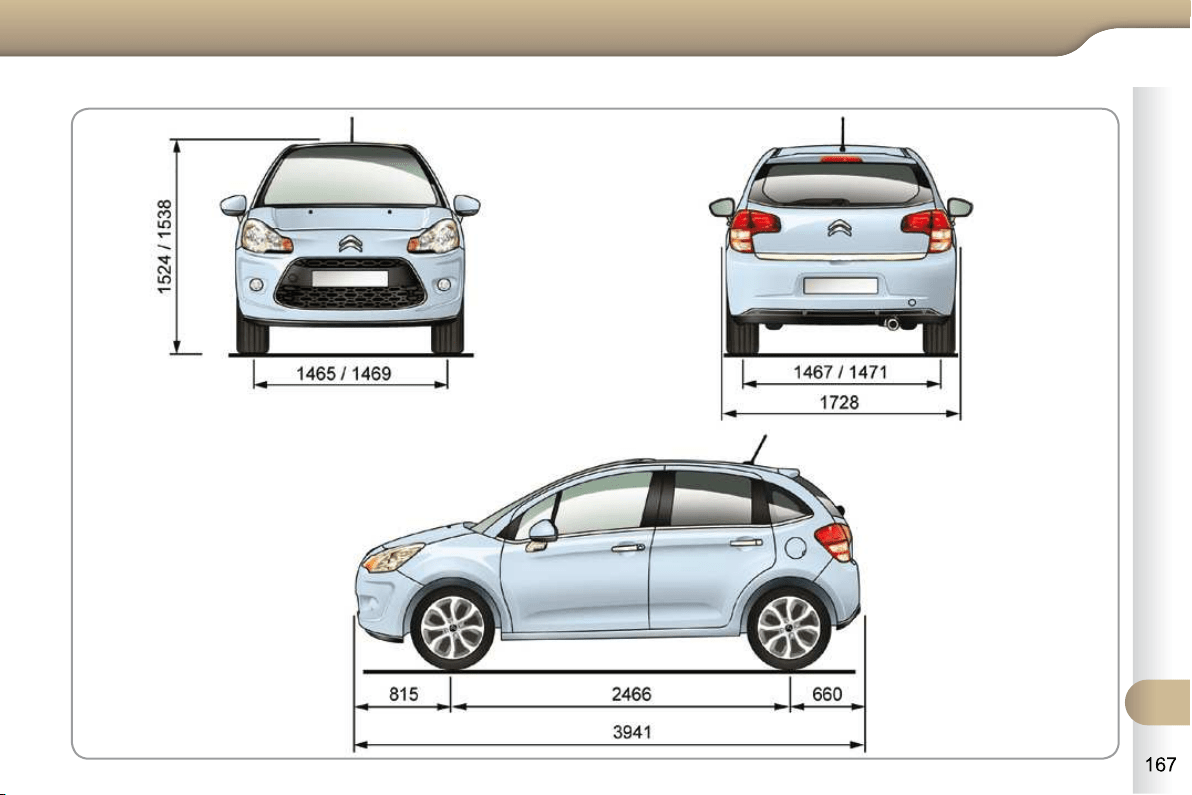
12
TECHNICAL DATA
DIMENSIONS (IN MM)
12
TECHNICAL DATA
The tyre pressures must be
checked when the tyres are cold,
at least once a month.
Low tyre pressures increase fuel
consumption.
IDENTIFICATION MARKINGS
Various visible markings for the identifi -
cation of your vehicle.
A. Vehicle identifi cation number (VIN)
under the bonnet.
This number is engraved on the body-
work near the damper mounting.
B. Vehicle identifi cation number on
the dashboard.
This number is indicated on a self-
adhesive label which is visible through
the windscreen.
C. Manufacturer's label.
The VIN is indicated on a self-destroying
label affi xed to the left hand centre pillar.
D. Tyre/paint label.
This label is affi xed to the left hand centre
pillar.
It bears the following information:
- the tyre pressures, for unladen and
laden conditions,
- the wheel rim and tyre sizes,
- the brands of tyre recommended by
the manufacturer,
- the spare tyre infl ation pressure,
- the paint colour code.
Wheels which are fi tted with
205/45 R17 tyres cannot be fi t-
ted with snow chains. For more
information, contact a CITROËN
dealer or a qualifi ed workshop.

8
SAFETY
BRAKING ASSISTANCE
SYSTEMS
Group of supplementary systems which
help you to obtain optimum braking in
complete safety in emergency situa-
tions:
- anti-lock braking system (ABS),
- electronic brake force distribution
(EBFD),
- emergency braking assistance (EBA).
Anti-lock braking system
and electronic brake force
distribution
Linked systems which improve the sta-
bility and manoeuvrability of your vehicle
when braking, in particular on poor or
slippery surfaces.
Activation
The anti-lock braking system comes
into operation automatically when there
is a risk of wheel lock.
Normal operation of the ABS may make
itself felt by slight vibration of the brake
pedal.
When braking in an emergency,
press very fi rmly without releasing
the pressure.
Operating fault
In either case, contact a CITROËN
dealer or a qualifi ed workshop.
If this warning lamp comes on,
accompanied by an audible
signal and a message in the
multifunction screen, it indicates a mal-
function of the anti-lock braking system
which could result in loss of control of
the vehicle when braking.
If this warning lamp comes on,
together with the STOP and
ABS warning lamps, accompa-
nied by an audible signal and a message
in the multifunction screen, it indicates a
malfunction of the electronic brake force
distribution which could result in loss of
control of the vehicle when braking.
You must stop as soon as it is safe
to do so.
When replacing wheels (tyres
and rims), ensure that they con-
form to the manufacturer's re-
commendations.
Emergency braking assistance
System which, in an emergency, en-
ables you to obtain the optimum braking
pressure more quickly, thus reducing the
stopping distance.
Activation
It is triggered by the speed at which the
brake pedal is pressed.
The effect of this is a reduction in the
resistance of the pedal and an increase
in braking effi ciency.
When braking in an emergency,
press fi rmly without releasing
the pressure.
EMERGENCY OR ASSISTANCE
CALL
This system allows you to make an
emergency or assistance call to the
emergency services or to the dedicated
CITROËN service.
For more information on the use of this
function, refer to the "Audio and tele-
matics" section.
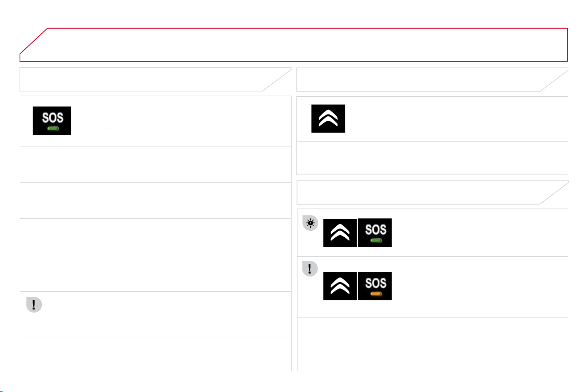
170
EMERGENCY OR ASSISTANCE CALL
EMERGENCY CALL
In an emergency, press this button for more than
2 seconds. Flashing of the green indicator lamp and a
voice message confi rm that the call has been made to the
CITROËN Emergency team * .
voice message confi rm that the call has been made to the
voice message confi rm that the call has been made to the
Pressing this button again immediately cancels the request. The green
indicator lamp goes off.
ASSISTANCE CALL
If you purchased your vehicle outside the CITROËN dealer network,
we invite you to have a dealer check the confi guration of these services
and, if desired, modifi ed to suit your wishes. In a multi-lingual country,
confi guration is possible in the offi cial national language of your choice.
When the ignition is switched on, the green
indicator lamp comes on for 3 seconds
indicating that the system is operating
correctly.
Pressing this button again immediately cancels the request.
The cancellation is confi rmed by a voice message.
Press this button for more than 2 seconds to request
assistance if the vehicle breaks down.
A voice message confi rms that the call has been made * .
OPERATION OF THE SYSTEM
The green indicator lamp remains on (without fl ashing) when
communication is established. It goes off at the end of communication.
This call is dealt with by the CITROËN Emergency team which receives
locating information from the vehicle and can send a detailed alert to the
appropriate emergency services. In countries in which the team is not
operational, or when the locating service has been expressly declined,
the call is dealt with directly by the emergency services (112) without
the vehicle location.
If an impact is detected by the airbag ECU, and independently
of the deployment of any airbags, an emergency call is made
automatically.
If the orange indicator lamp fl ashes: there is
a system fault.
If the orange indicator lamp is on continuously:
the backup battery must be replaced.
In either case, contact a CITROËN dealer or
a qualifi ed workshop.
* These services are subject to conditions and availability.
Consult a CITROËN dealer.
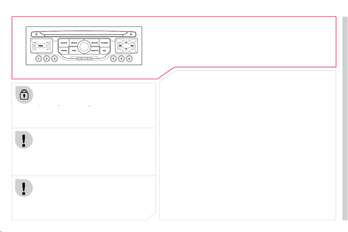
171
The MyWay is protected in such a way that it will only
operate in your vehicle. If it is to be installed in another
vehicle, contact a CITROËN dealer for confi guration of
operate in your vehicle. If it is to be installed in another
operate in your vehicle. If it is to be installed in another
the system.
Certain functions described in this handbook will
become available during the year.
MYWAY
For safety reasons, the driver must carry out operations
which require prolonged attention while the vehicle is
stationary.
When the engine is switched off and to prevent
discharging of the battery, the MyWay switches off
following the activation of the Energy Economy mode.
MULTIMEDIA AUDIO SYSTEM/BLUETOOTH TELEPHONE
SATELLITE NAVIGATION SYSTEM FOR EUROPE BY SD CARD
01 First steps
CONTENTS
02 Steering mounted controls
03 General operation
04 Navigation - Guidance
05 Traffic information
06 Radio
07 Music media players
08 Bluetooth telephone
09 Configuration
10 Trip computer
p.
p.
p.
p.
p.
p.
p.
p.
p.
p.
11 Screen menu map
Frequently asked questions
p.
p.
172
173
174
177
185
187
188
191
193
194
195
199
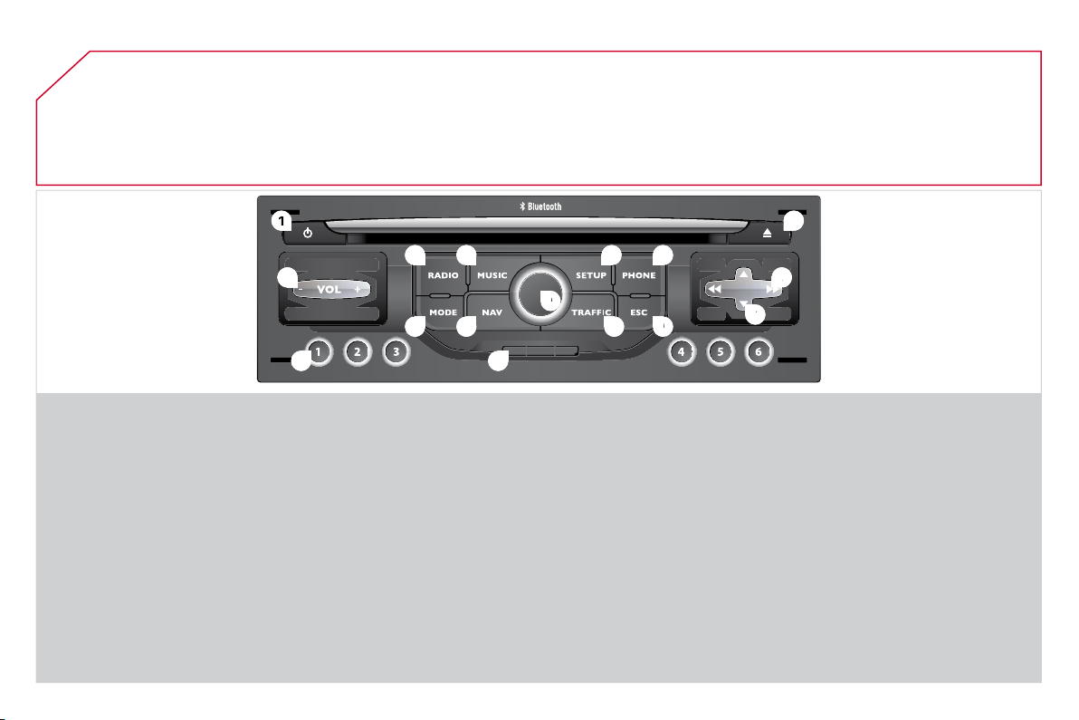
01
1
1
5
5
10
10
2
2
3
3
4
4
6
6
13
13
11
11
9
9
14
14
15
15
7
7
8
8
12
12
16
16
172
1. Engine not running:
- Short press: on/off.
- Long press: CD pause, mute for the radio.
Engine running:
- Short press: CD pause, mute for the radio.
- Long press: reinitialisation of the system.
2. Volume adjustment (each source is
independent, including also navigation
messages and alerts).
3. Access to the "Radio" Menu. Display the list of
stations.
4. Access to the "Music" Menu. Display the
tracks.
5. Access to the "SETUP" menu.
Long press: access to the GPS coverage and
the demonstration mode.
6. Access to the "Phone" Menu. Display the call list.
7. Access to the "MODE" menu.
Selection of the successive display of:
Radio, Map, NAV (if navigation is in progress),
Telephone (if a conversation is in progress), Trip
computer.
Long press: display of a black screen (DARK).
8. Access to the "Navigation" Menu. Display the
last destinations.
9. Access to the "Traffi c" Menu. Display the current
traffi c alerts.
10. ESC: abandon the operation in progress.
11. CD eject.
12. Selection of the previous/next radio station from
the list.
Selection of the previous/next MP3 folder.
Selection of the previous/next page of a list.
13. Selection of the previous/next radio station.
Selection of the previous/next CD or MP3 track.
Selection of the previous/next line of a list.
14. Buttons 1 to 6:
Selection of the stored radio station.
Long press: store the current radio station.
15. SD card reader (navigation SD card only).
16. Dial for selection of the screen display and
according to the context of the menu.
Short press: contextual menu or confi rmation.
Long press press: contextual menu specifi c to
the list displayed.
FIRST STEPS
MyWay CONTROL PANEL
3 - 4. Long press: access to the audio settings:
front/rear fader and left/right balance, bass/
treble, equaliser, loudness, automatic volume
adjustment, initialise the settings.
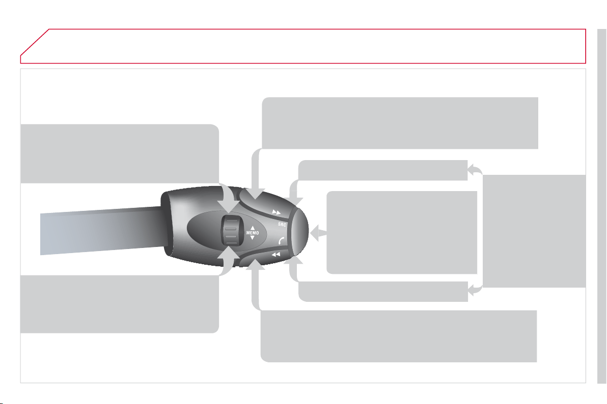
02
173
STEERING MOUNTED CONTROLS
RADIO: selection of the previous stored station.
Selection of the previous entry in the address book.
RADIO: selection of the next stored station.
Selection of the next entry in the address book.
RADIO: change to the next radio station on the list.
Long press: automatic search for a higher frequency.
CD: selection of the next track.
CD: continuous press: fast forward play.
RADIO: change to the previous radio station on the List.
Long press: automatic search for a lower frequency.
CD: selection of the previous track.
CD: continuous press: fast reverse.
- Change the sound source.
- Make a call from the address
book.
- Pick up/Hang up the telephone.
- Press for more than 2 seconds:
access to the address book.
Volume increase.
Volume decrease.
Mute: function activated
by pressing the volume
increase and decrease
buttons simultaneously.
Restore the sound by
pressing one of the
two volume buttons.
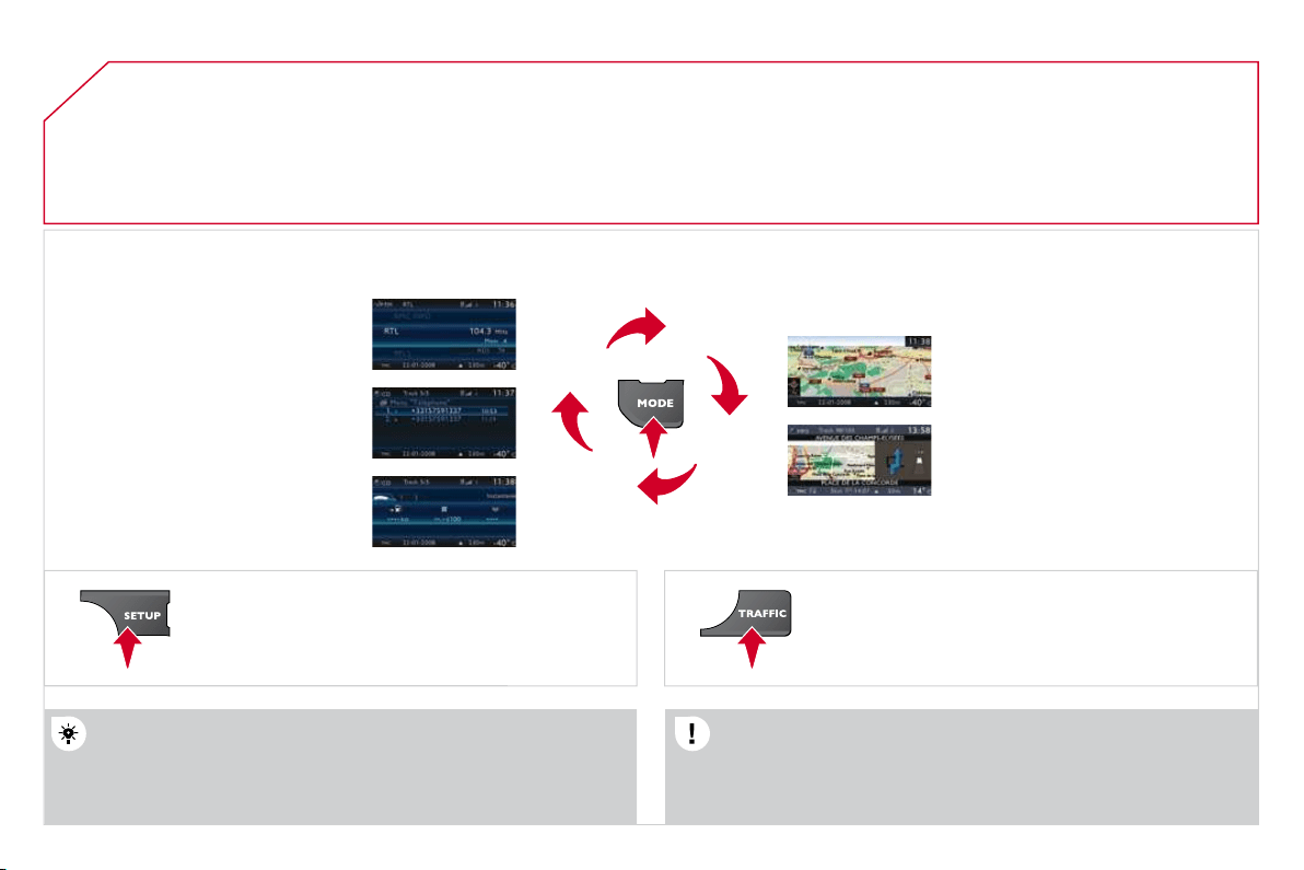
03
174
GENERAL OPERATION
For a detailed global view of the menus available, refer to
the "Screen menu map" section.
Press the MODE button several times in succession for access to the following menus:
For cleaning the screen, the use of a soft, non-abrasive cloth
(spectacles cloth) is recommended, with no additional product.
RADIO/
MUSIC MEDIA PLAYERS
TELEPHONE
(If a conversation is in progress)
FULL SCREEN MAP
NAVIGATION
(If guidance is in progress)
SETUP:
system language * , date and time * , display,
vehicle settings * , unit and system settings,
"Demo mode".
TRAFFIC:
TMC information and messages.
* Available according to model.
TRIP COMPUTER
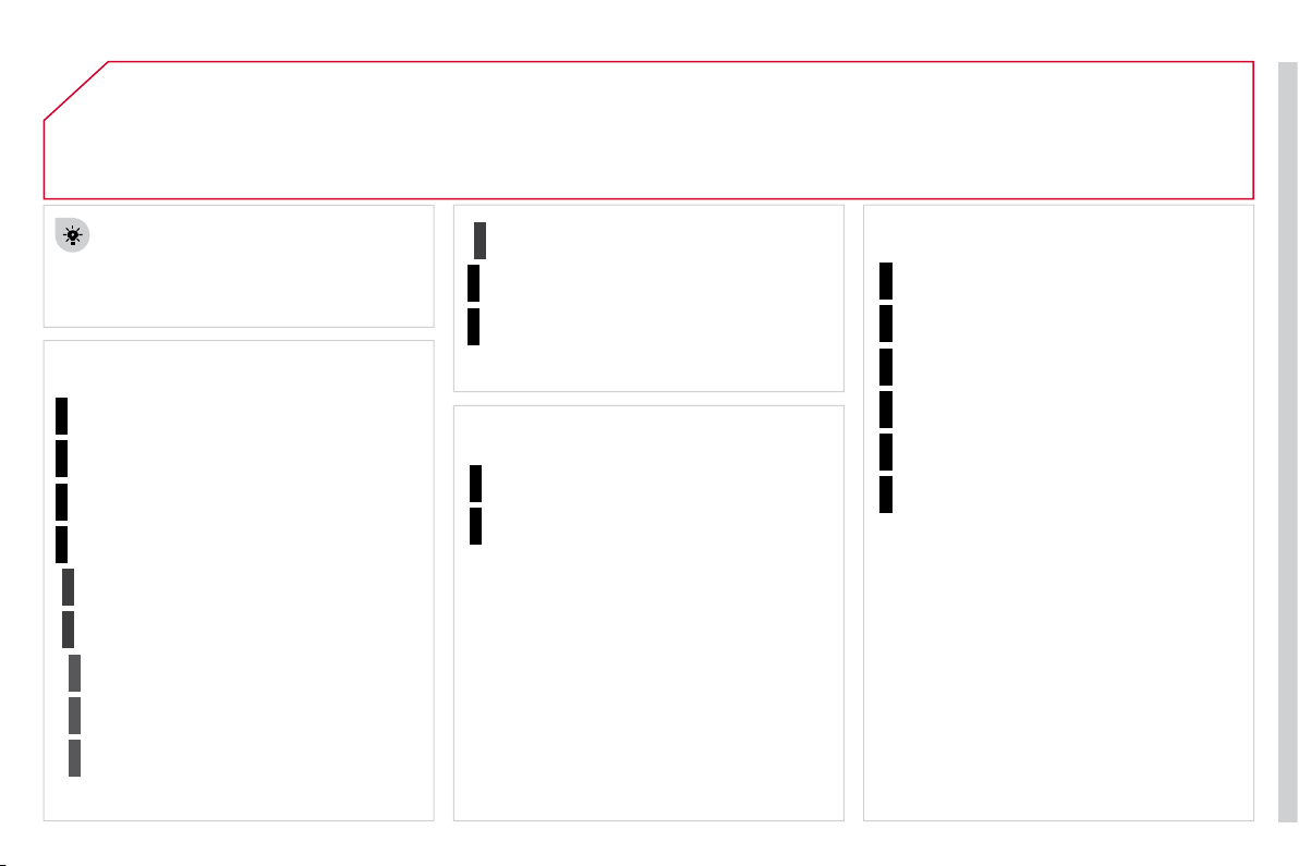
03
175
GENERAL OPERATION
A press on the OK dial gives access to
short-cut menus according to the display
on the screen.
DISPLAY ACCORDING TO THE CONTEXT
NAVIGATION (IF GUIDANCE IS IN PROGRESS):
TRIP COMPUTER:
Abort guidance
Repeat advice
Block road
Route info
Show destination
Trip info
Route type
Avoid
Satellites
Zoom/Scroll
Voice advice
Route options
Alert log
Status of functions
1
2
3
3
2
1
1
1
3
1
1
1
1
2
TELEPHONE:
End call
Hold call
Dial
DTMF-Tones
Private mode
Micro off
1
1
1
1
1
1
03
176
GENERAL OPERATION
DISPLAY ACCORDING TO THE CONTEXT
FULL SCREEN MAP:
Abort guidance
/Resume guidance
Set destination
POIs nearby
Position info
Map settings
Zoom/Scroll
1
1
1
1
1
1
RADIO:
In FM mode
Traffi c info (TA)
RDS
Radiotext
Regional prog.
In AM mode
AM
TA
Refresh AM list
FM
1
2
1
2
2
2
2
2
2
2
MUSIC MEDIA PLAYERS:
Traffi c info (TA)
Play options
Normal order
Random track
Repeat folder
Select music
Scan
1
1
2
2
2
2
1
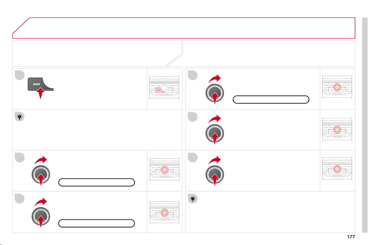
04
1
2
3
5
6
4
NAVIGATION - GUIDANCE
SELECTING A DESTINATION
Press the NAV button again or select
the Navigation Menu function and
press the dial to confi rm.
Select the "Destination input"
function and press the dial to
confi rm.
Press the NAV button.
Select the letters of the town one
by one confi rming each time by
pressing the dial.
Once the country has been selected,
turn the dial and select the town
function. Press the dial to confi rm.
Insert the SD card in the front panel reader and leave it there to use the
Navigation functions.
The navigation SD card data must not be modifi ed.
Map data updates are available from CITROËN dealers.
A pre-set list (by entering the fi rst few letters) of the towns in the
country selected can be accessed via the LIST button on the virtual
keypad.
Select the "Address input" function
and press the dial to confi rm.
The list of the last 20 destinations appears under the Navigation
Menu function.
Navigation Menu
Destination input
Address input
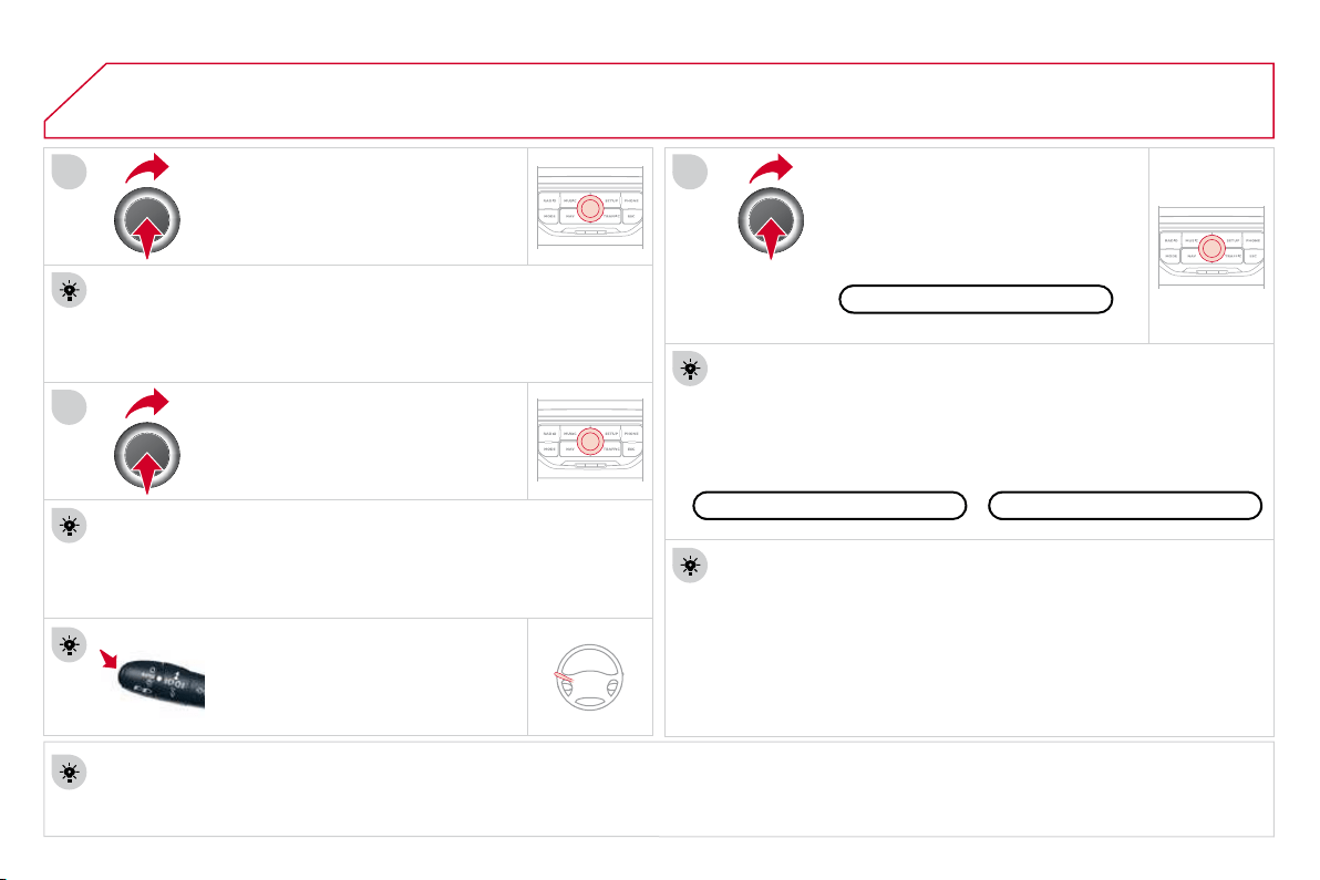
04
7
8
9
178
To clear a destination; from steps 1 to 3, select "Choose from last destinations".
A long press on one of the destinations displays a list of actions from which you can select:
Delete entry
Delete list
Repeat steps 5 to 7 for the "Street"
and "House number" functions.
Turn the dial and select OK.
Press the dial to confi rm.
Select the "Save to address book" function to record the address
entered in a directory fi le. Press the dial to confi rm the selection.
MyWay allows up to 500 contact fi les to be recorded.
To speed up the process, the post code can be entered directly
after selecting the "Postal code" function.
Use the virtual keypad to enter the letters and digits.
Then select "Start route guidance"
and the press the dial to confi rm.
During guidance, pressing the end
of the lighting stalk repeats the last
guidance instruction.
Map settings
You can zoom in/zoom out on the map using the dial.
It is possible to move the map or select its orientation via the short-
cut menu of the FULL SCREEN MAP.
Press MODE until the map is displayed full screen. Press the dial
then select "Map settings". Select "2.5D Map" or "2D Map" and in
the latter case, select "North Up" or "Heading Up".
Select the route type:
"Fast route", "Short route" or "Optimized route" and press the dial
to confi rm.
It is also possible to select a destination via "Choose from address
book" or "Choose from last destinations".
Choose from last destinations
Choose from address book
Start route guidance
NAVIGATION - GUIDANCE
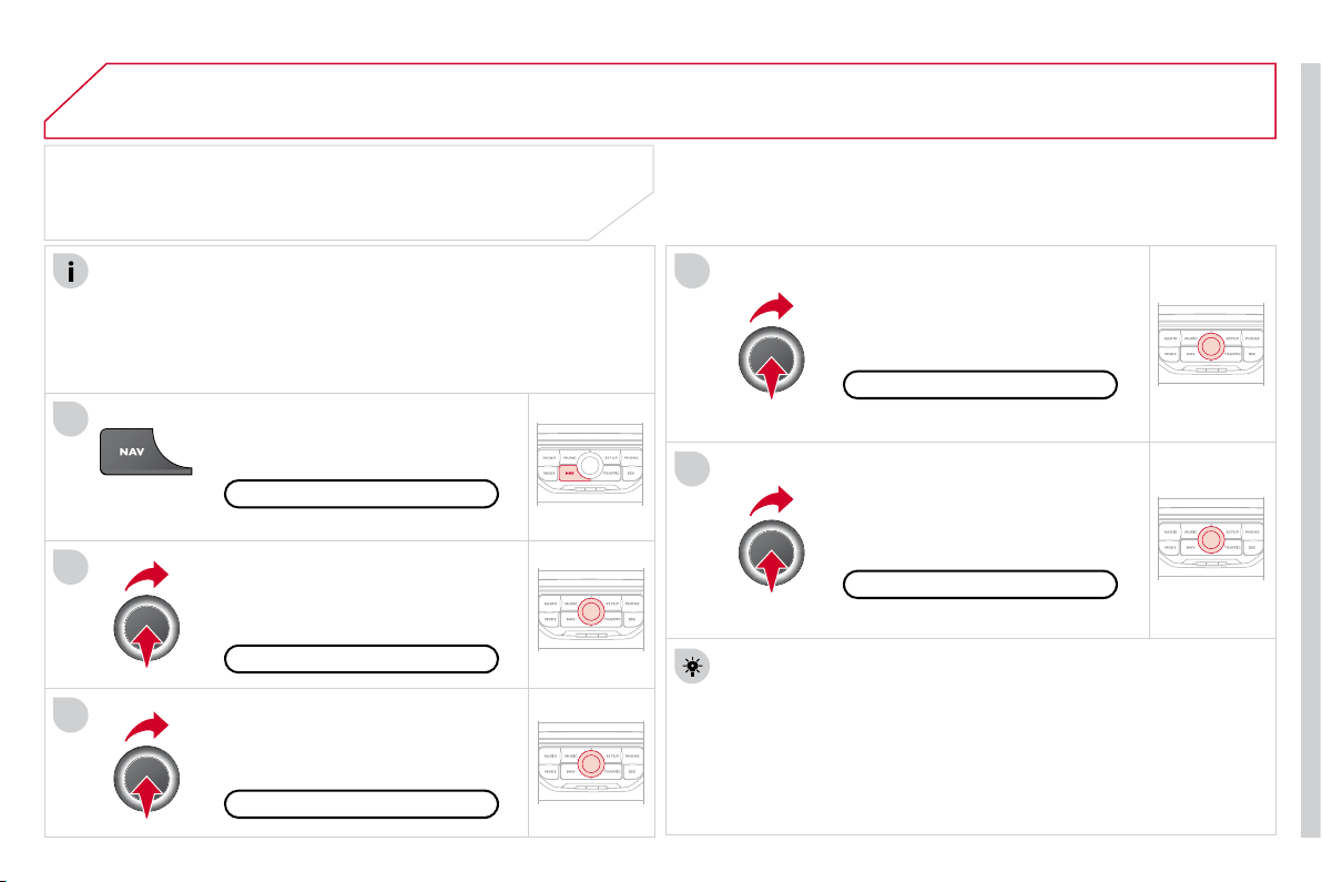
04
1
2
3
5
4
179
NAVIGATION - GUIDANCE
SETTING AND NAVIGATING TO
MY "HOME ADDRESS"
Press the NAV button twice to display
the Navigation Menu.
To be set as the "Home address", an address must fi rst be
entered in the address book, for example from "Destination
input"/"Address input" then "Save to address book".
Select "Address book" and confi rm.
Then select "Search entry (complete
address book)" and confi rm.
Select "Destination input" and confi rm.
Then select "Choose from address
book" and confi rm.
Select "Set as home address" and
confi rm to save.
Select your home address and confi rm.
Then select "Edit entry" and confi rm.
To start navigation towards "Home address", press NAV twice
to display the Navigation Menu, select "Destination input" and
confi rm.
Then select "Navigate HOME" and confi rm to start guidance.
Navigation Menu
Destination input
Address book
Edit entry
Set as "Home address"
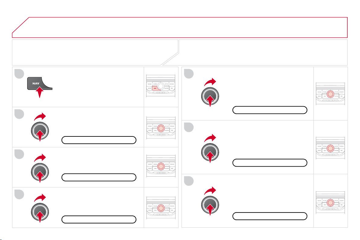
04
4
3
2
1
7
6
5
180
NAVIGATION - GUIDANCE
ROUTE OPTIONS
Select the "Route dynamics"
function.
This function gives access to the
"Traffi c independent" or "Semi-
dynamic" options.
Select the "Avoidance criteria"
function. This function provides
access to the AVOID options
(motorways, toll roads, ferries).
Turn the dial and select the
"Recalculate" function to take into
account the route options selected.
Press the dial to confi rm.
Press the NAV button.
Press the NAV button again or select
the Navigation Menu function and
press the dial to confi rm.
Select the "Route type" function
and press the dial to confi rm. This
function allows you to change the
route type.
Select the "Route options" function
and press the dial to confi rm.
Recalculate
Avoidance criteria
Route dynamics
Route type
Route options
Navigation Menu
The route selected by the MyWay system depends directly on the route
options.
Changing these options may change the route completely.
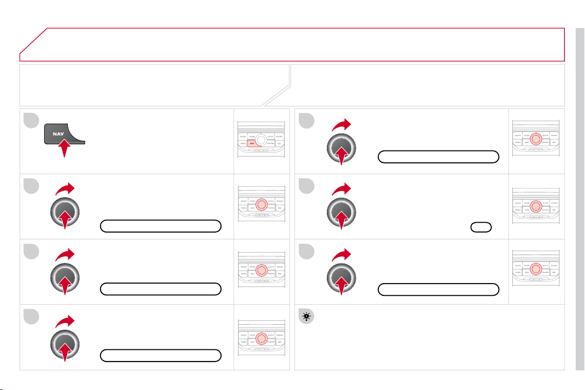
04
7
6
5
4
3
2
1
181
ADDING A STOPOVER
Enter a new address, for example.
Once the new address has been
entered, select OK and press the dial
to confi rm.
Select "Recalculate" and press the
dial to confi rm.
Press the NAV button.
Press the NAV button again or select
the Navigation Menu function and
press the dial to confi rm.
Select the "Add stopover" function
(5 stopovers maximum) and press
the dial to confi rm.
Select the "Stopovers" function and
press the dial to confi rm.
OK
Address input
Add stopover
Stopovers
Navigation Menu
Recalculate
The stopover must be completed or deleted in order for the
guidance to continue to the next destination. Otherwise, the
MyWay will always return you to the previous stopover.
Stopovers can be added to the route once the destination has been
selected.
NAVIGATION - GUIDANCE
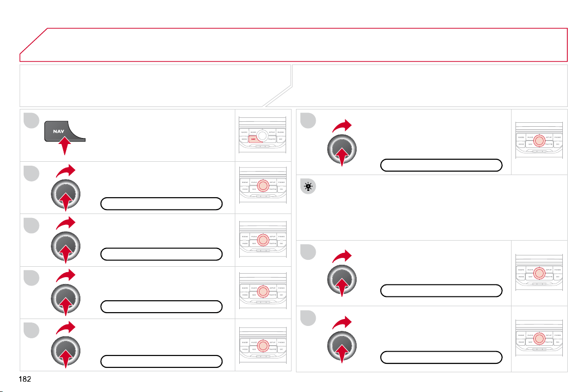
04
8
6
7
4
3
5
2
1
NAVIGATION - GUIDANCE
SEARCHING FOR POINTS OF INTEREST
(POI)
Press the NAV button.
Press the NAV button again or select
the Navigation Menu function and
press the dial to confi rm.
Select the "POI nearby" function to
search for POIs around the vehicle.
Select the "POI search" function and
press the dial to confi rm.
Navigation Menu
POI search
POI nearby
Select the "POI in city" function to
search for POIs in the city required.
Select the country then enter the
name of the city using the virtual
keypad.
Select the "POI near route" function
to search for POIs near the route.
Select the "POI in country" function
to search for POIs in the country
required.
Select the "POI near destination"
function to search for POIs near the
point of arrival of the route.
POI near destination
POI near route
POI in country
POI in city
A list of cities present in the country selected can be accessed via
the LIST button on the virtual keypad.
The points of interest (POI) indicate all of the service locations in the
vicinity (hotels, various businesses, airports...).
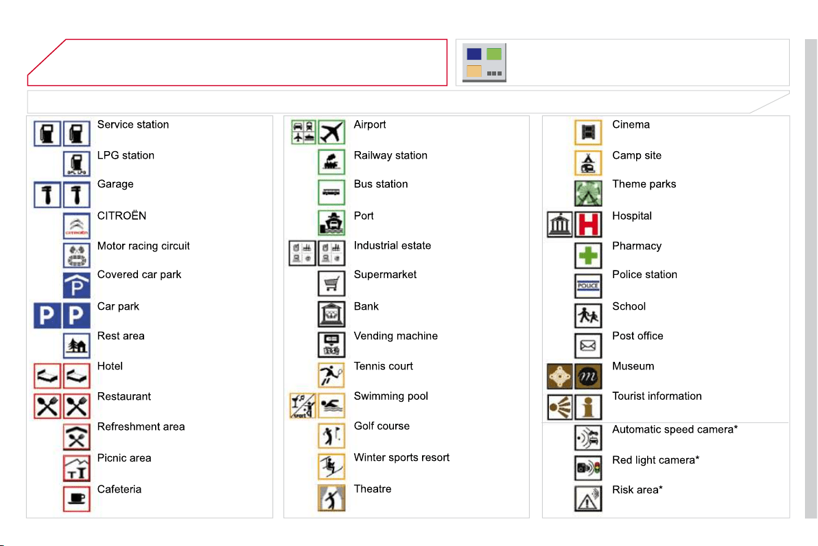
04
183
NAVIGATION - GUIDANCE
LIST OF PRINCIPAL POINTS OF INTEREST (POI)
* According to availability in the country.
This icon appears when several POIs are grouped
together in the same area. Zooming in on this icon
shows details of the POIs.
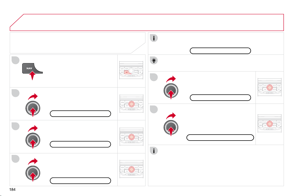
04
5
6
3
2
1
4
NAVIGATION SETTINGS
Select "Set parameters for risk
areas" for access to the "Display
on map", "Visual alert" and "Sound
alert" functions.
Select the "POI categories on Map"
function to select the POIs to be
displayed on the map by default.
Press the NAV button.
Press the NAV button again or select
the Navigation Menu function and
press the dial to confi rm.
Select the "Settings" function and
press the dial to confi rm.
POI categories on Map
Settings
Set parameters for risk areas
Navigation Menu
NAVIGATION - GUIDANCE
Select the "Navi volume" function
and turn the dial to set the volume
of each voice synthesiser (traffi c
information, alert messages…).
Navi volume
The adjustment of the volume for the Risk Areas POIs is used only
during the transmission of an alert.
UPDATING THE RISK AREAS POIs
(Speed camera information)
Contact a CITROËN dealer for the procedure to follow to obtain
the RISK AREA POIs.
This requires an SDHC (High Capacity) compatible reader.
To activate or deactivate vocal guidance, with guidance active and
the map displayed on the screen, press the dial and then select or
deselect "Voice advice".
Voice advice
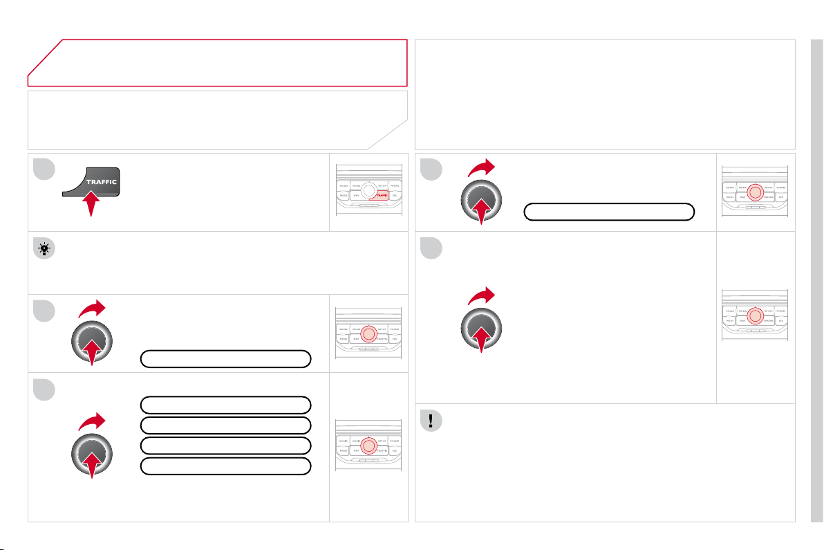
05
2
1
3
4
5
185
TRAFFIC INFORMATION
CONFIGURE THE FILTERING AND
DISPLAY OF TMC MESSAGES
Then select the radius of the fi lter
in miles (km) required in accordance
with the route, press the dial
to confi rm.
When all of the messages on the
route are selected, the addition of a
geographical fi lter is recommended
(within a radius of 3 miles (5 km) for
example) to reduce the number of
messages displayed on the map.
The geographical fi lter follows the
movement of the vehicle.
The fi lters are independent and their results are cumulative.
We recommend a fi lter on the route and a fi lter around the vehicle of:
- 2 miles (3 km) or 3 miles (5 km) for a region with heavy traffi c,
- 6 miles (10 km) for a region with normal traffi c,
- 30 miles (50 km) for long journeys (motorway).
Press the TRAFFIC button again or
select the Traffi c Menu function and
press the dial to confi rm.
Press the TRAFFIC button.
TMC (Traffi c Message Channel) messages contain information on
traffi c and weather conditions, received in real time and transmitted to
the driver in the form of audible announcements and symbols on the
navigation map.
The navigation system can then suggest an alternative route to avoid a
traffi c problem.
Select the "Geo. Filter" function and
press the dial to confi rm.
Messages on route
The list of TMC messages appears under the Traffi c Menu sorted
in order of proximity.
All warning messages
Traffi c Menu
Select the fi lter of your choice:
Only warnings on route
All messages
The messages appear on the map
and on the list.
To exit, press ESC.
Geo. Filter
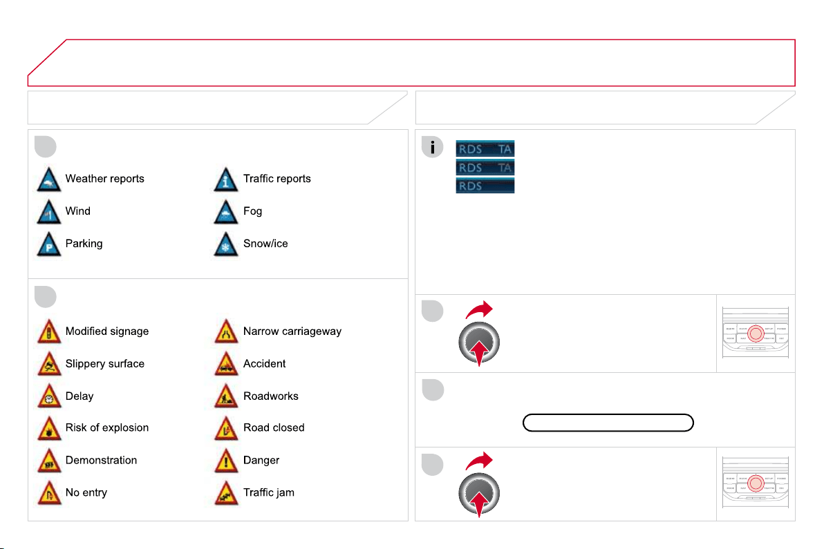
05
2
1
3
2
1
186
PRINCIPAL TMC SYMBOLS
With the current audio source
displayed on the screen, press the
dial.
The shortcut menu for the source appears and gives access to:
Select Traffi c Announcements (TA)
and press the dial to confi rm and go
to the associated settings.
TA
- the station transmits TA messages.
RECEIVING TA MESSAGES
Red and yellow triangle: traffi c information, for example:
Black and blue triangle: general information, for example:
TRAFFIC INFORMATION
The TA (Traffi c Announcement) function gives priority to TA alert
messages. To operate, this function needs good reception of a
radio station transmitting this type of message. When a traffi c
report is transmitted, the current audio source (Radio, CD, ...) is
interrupted automatically to play the TA message. Normal playback
of the audio source resumes at the end of the transmission of the
message.
- the station does not transmit TA messages.
- TA messages are not activated.
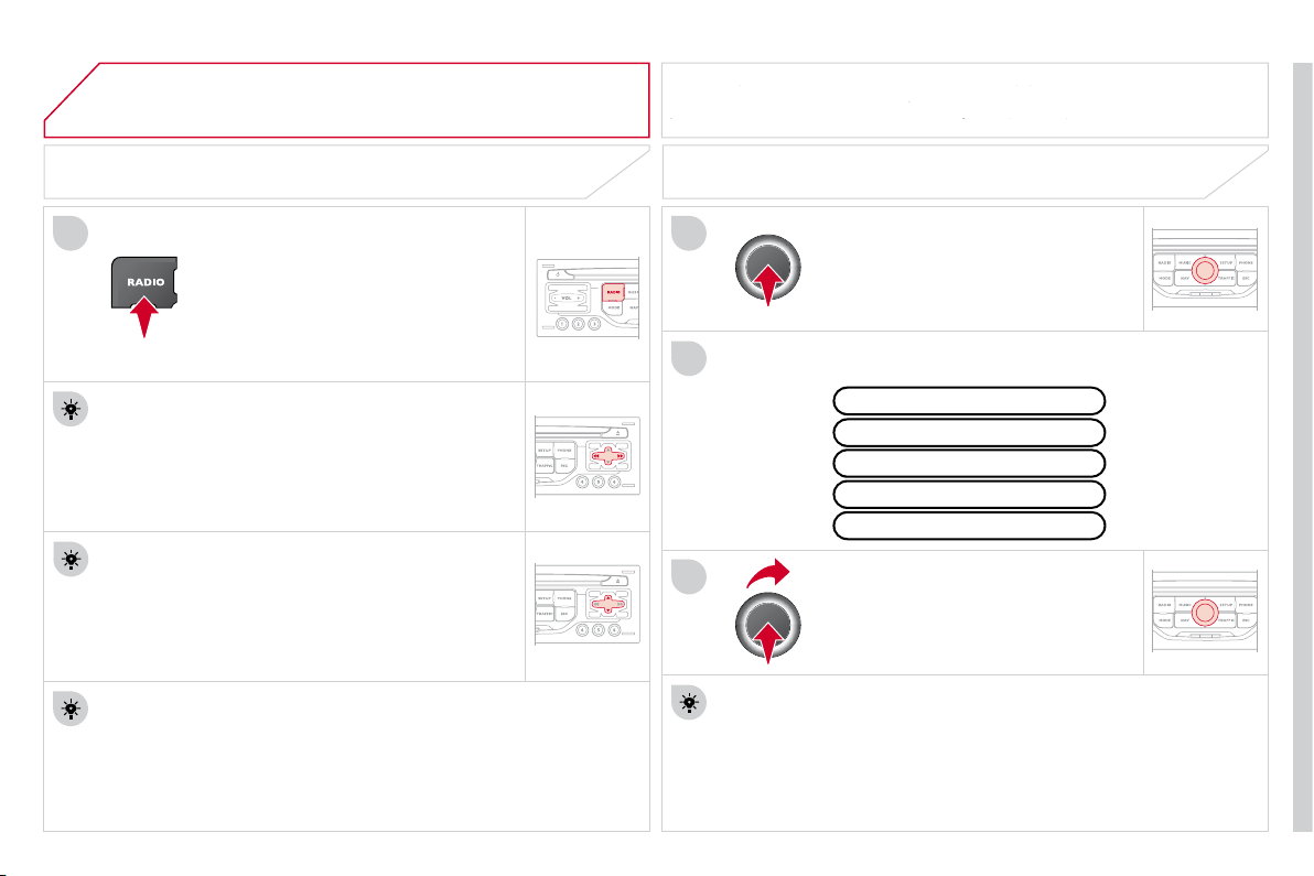
06
3
2
11
187
SELECTING A STATION
When the current radio station is
displayed on the screen, press
the dial.
The radio source short-cuts menu appears and provides access to
the following short-cuts:
Select the function required and
press the dial to confi rm to gain
access to the corresponding settings.
TA
RDS, if displayed, allows you to continue listening to the same
station by automatic retuning to alternative frequencies. However,
in certain conditions, coverage of an RDS station may not be
assured throughout the entire country as radio stations do not
cover 100 % of the territory. This explains the loss of reception of
the station during a journey.
The external environment (hill, building, tunnel, underground car park...)
may interfere with the reception, including in RDS following mode. This
The external environment (hill, building, tunnel, underground car park...)
The external environment (hill, building, tunnel, underground car park...)
phenomenon is a normal result of the way in which radio waves are
may interfere with the reception, including in RDS following mode. This
may interfere with the reception, including in RDS following mode. This
transmitted and does not in any way indicate a failure of the audio equipment.
phenomenon is a normal result of the way in which radio waves are
n which radio w
RDS - REGIONAL MODE
Press the RADIO button to display
the list of stations received locally
sorted in alphabetical order.
Select the station required by turning
the dial and press to confi rm.
Regional prog.
Radiotext
RDS
While listening to the radio, press one of the
buttons to select the previous or next station on
the list.
Press one of the buttons on the numeric keypad for more than
2 seconds to store the current station.
Press the button on the numeric keypad to recall the stored radio
station.
AM
A long press of one of the buttons starts the
automatic search for a station with a lower or
higher frequency.
RADIO
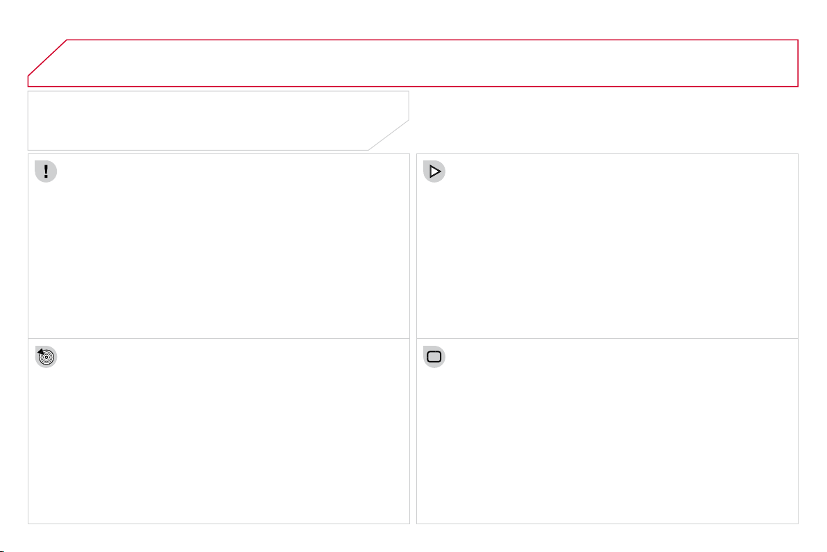
07
188
MUSIC MEDIA PLAYERS
CD, MP3/WMA CD
INFORMATION AND ADVICE
In order to be able to play a recorded CDR or CDRW, when
recording it is preferable to select the ISO 9660 level 1, 2 or Joliet
standard.
If the disc is recorded in another format it may not be played
correctly.
It is recommended that the same recording standard is always
used for an individual disc, with as low a speed as possible
(4x maximum) for optimum sound quality.
In the particular case of a multi-session CD, the Joliet standard is
recommended.
The MyWay will only play audio fi les with the extension ".mp3"
with a speed of between 8 Kbps and 320 Kbps and the extension
".wma" with a speed of between 5 Kbps and 384 Kbps.
It also supports the VBR (Variable Bit Rate) mode.
No other type of fi le (.mp4, .m3u...) can be played.
The MP3 format, an abbreviation of MPEG 1, 2 & 2.5 Audio Layer 3
and the WMA format, an abbreviation of Windows Media Audio and
the property of Microsoft, are audio compression standards which
permit the recording of several tens of music fi les on a single disc.
It is advisable to restrict fi le names to 20 characters, without using
special characters (e.g.: " " ? ; ù) to avoid any play or display
problems.
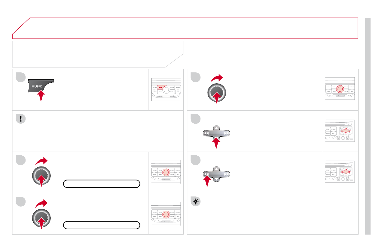
07
3
2
1
6
4
5
189
SELECTING/PLAYING MUSIC
CD, MP3/WMA CD
The playing and displaying of an MP3/WMA compilation may
depend on the recording programme and/or the settings used.
We recommend the ISO 9660 fi le standard.
Press the MUSIC button.
Select the "Select music" function
and press the dial to confi rm.
Press the up or down button to select
the next/previous folder.
Select the music source required:
CD, MP3/WMA CD. Press the dial to
confi rm. Play begins.
Select music
Press the MUSIC button again or
select the Music Menu function and
press the dial to confi rm.
Press one of the buttons to select a
music track.
Press and hold one of the buttons for
fast forward or rewind play.
Music Menu
The list of tracks or MP3/WMA fi les appears under Music Menu.
MUSIC MEDIA PLAYERS
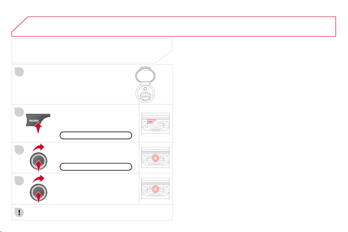
07
4
3
1
2
190
MUSIC MEDIA PLAYERS
Connect the portable device
(MP3/WMA player…) to the auxiliary
JACK socket or to the USB port,
using a suitable audio cable.
Press the MUSIC button then
press it again or select the Music
Menu function and press the dial to
confi rm.
Select the AUX music source and
press the dial to confi rm. Play begins
automatically.
Select the "External device" function
and press the dial to activate it.
External device
The display and management of the controls is via the portable
device.
USING THE EXTERNAL INPUT (AUX)
Music Menu
JACK/USB AUDIO CABLE NOT SUPPLIED
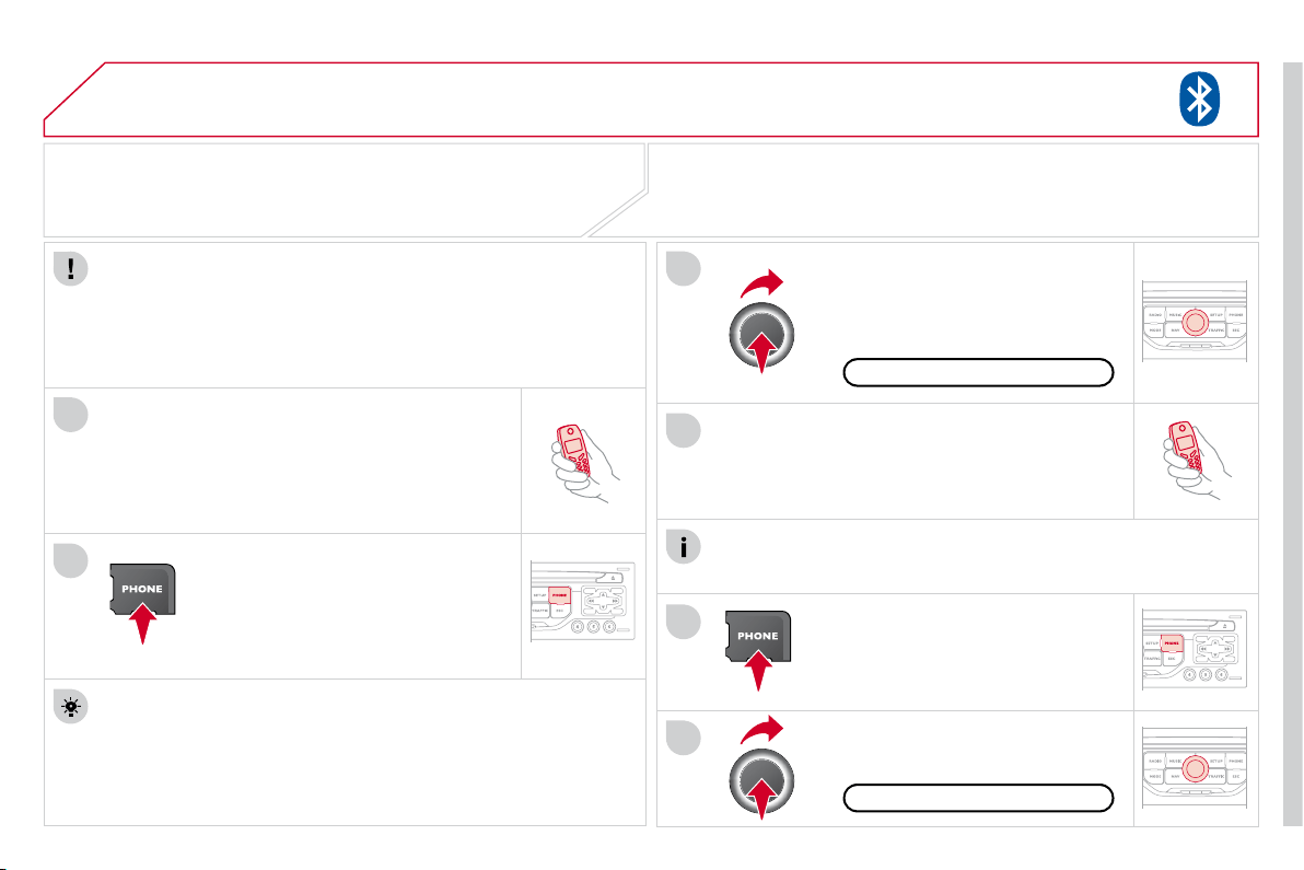
08
1
2
3
2
1
4
191
* The services available depend on the network, the SIM card and the
compatibility of the Bluetooth telephone used. Check the telephone
manual and with your network provider for details of the services
available to you. A list of mobile telephones with the best level of
compatibility is available from the dealer network.
BLUETOOTH TELEPHONE
CONNECTING A TELEPHONE
For reasons of safety and because they require prolonged attention
on the part of the driver, the operations for pairing the Bluetooth
mobile telephone to the hands-free system of the MyWay must be
carried out with the vehicle stationary. The ignition must be on.
Activate the telephone's Bluetooth function.
The last telephone connected is reconnected
automatically.
Enter the authentication code on the telephone.
The code to be entered is displayed on
the screen.
To change the telephone connected,
press the PHONE button, then select
Phone Menu and press the dial to
confi rm.
Once the telephone has been connected, MyWay can synchronise
the address book and the call list. This synchronisation may take a
few minutes * .
Select "Connect phone". Select the
telephone and press to confi rm.
The list of telephones connected previously (4 maximum) appears
on the multifunction screen. Select the telephone required for a new
connection.
Press the PHONE button.
For a fi rst connection, select
"Search phone" and press the dial to
confi rm. Then select the name of the
telephone.
Search phone
Connect phone
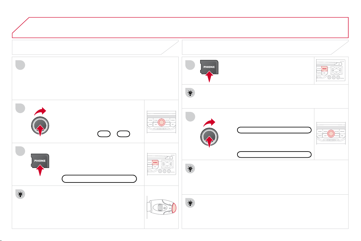
08
1
3
2
2
1
192
Select the "Yes" tab to accept or "No"
to refuse and confi rm by pressing
the dial.
RECEIVING A CALL MAKING A CALL
An incoming call is announced by a ring and a superimposed
display on the multifunction screen.
Yes
To hang up, press the PHONE button
or press the dial and select "End call"
then confi rm by pressing the dial.
End call
Press the PHONE button.
Select "Dial number", then dial the
telephone number using the virtual
keypad.
No
Select the Phone Menu function and
press the dial to confi rm.
The list of the last 20 calls made and received in the vehicle
appears under Phone Menu. You can select a number and press
the dial to make the call.
It is also possible to select a number from the address book.
You can select "Dial from address book". The MyWay can record
up to 4 000 entries.
Press the end of the steering mounted control for more than
two seconds to gain access to the address book.
Phone Menu
Dial number
To delete a number, press the PHONE button then press and hold
on a call number to display a list of actions including:
Delete entry
Delete list
BLUETOOTH TELEPHONE
Press the end of the steering mounted control to
accept the call or end the call in progress.
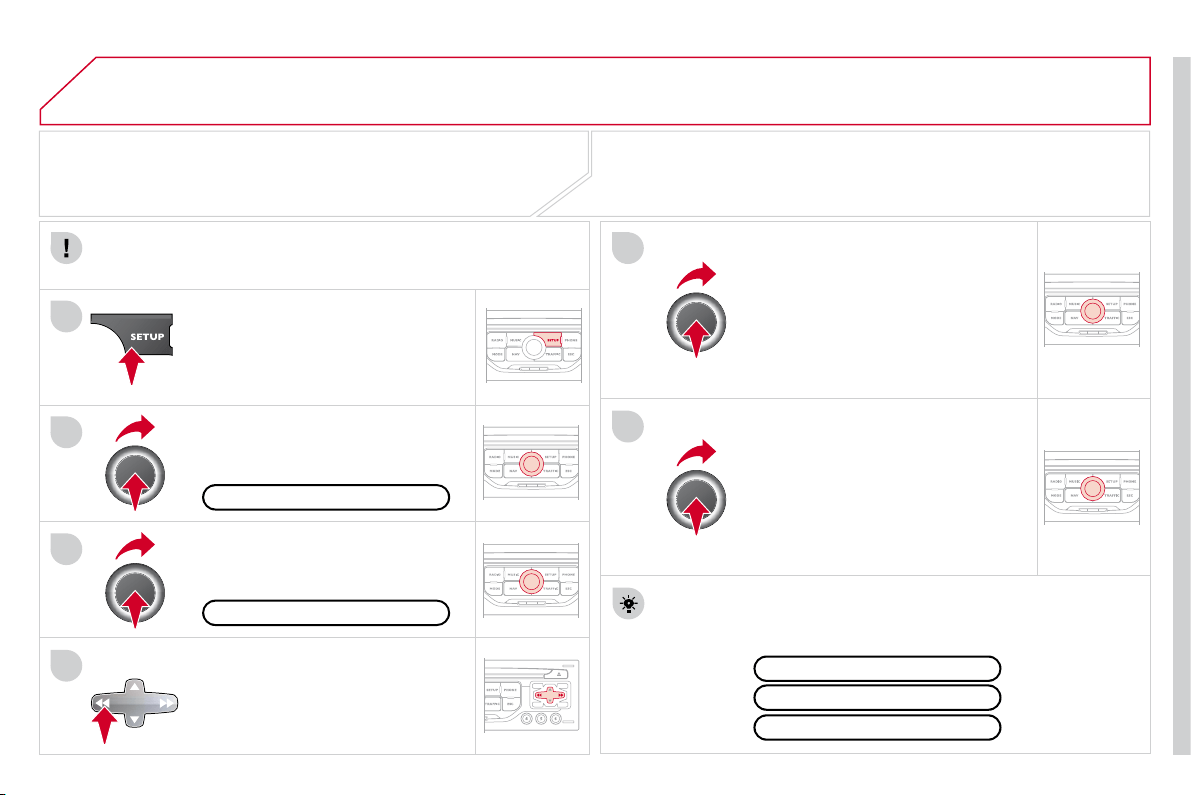
09
4
3
2
1
6
5
193
CONFIGURATION
SETTING THE DATE AND TIME
The SETUP function gives access to the following options: System
language, Date & Time, Display (Brightness, Colour, Map colour), Vehicle,
Units, System.
Adjust the settings one by one using
the direction arrows and confi rm by
means of the dial.
Select the "Date format" function and
press the dial to confi rm.
Select the "Set date & time" function
and press the dial to confi rm.
Confi rm the format required using the dial.
Pressing the SETUP button for more than 2 seconds gives
access to:
These settings must be entered again if the battery has been
disconnected.
Press the SETUP button.
Confi rm the format required using
the dial.
Select the "Time format" function and
press the dial to confi rm.
Set date & time
Select the "Date & Time" function
and press the dial to confi rm.
Demo mode
GPS coverage
Description of the unit
Date & Time
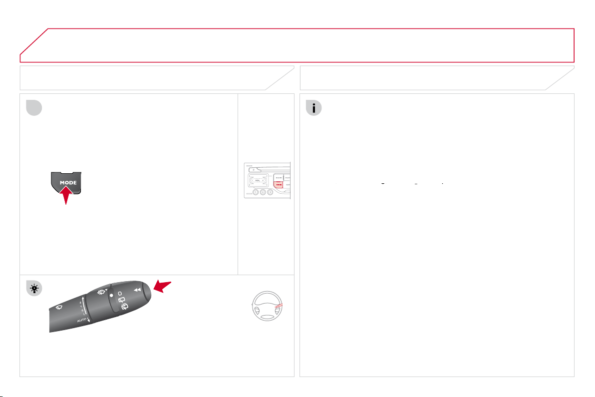
10
1
194
TRIP COMPUTER/VEHICLE PARAMETERS
TRIP COMPUTER
Press the MODE button several
times in succession until the trip
computer is displayed.
Range:
displays the distance which can travelled with the
remaining fuel detected in the tank, based on the average fuel
consumption over the last few miles (kilometres).
This displayed value may vary signifi cantly following a change in
the vehicle speed or the relief of the route.
When the range falls below 20 miles (30 km), dashes are
displayed. After fi lling with at least 5 litres of fuel, the range is
recalculated and is displayed when it exceeds 60 miles (100 km).
If, whilst driving, dashes are displayed continuously in place of the
digits, contact a CITROËN dealer.
If, whilst driving, dashes are displayed continuously in place of the
If, whilst driving, dashes are displayed continuously in place of the
Each press of the button at the end of the wiper stalk displays
the different trip computer information in succession, according to
the screen.
A FEW DEFINITIONS
- The "vehicle" tab:
The range, the current fuel
consumption and the distance
remaining or the Stop & Start
time counter.
- The "1" (trip 1) tab with:
The average speed, the average
fuel consumption and the
distance travelled calculated
over trip "1".
- The "2" (trip 2) tab with the same
functions for a second trip.
Current fuel consumption:
only calculated and displayed above
20 mph (30 km/h).
Average fuel consumption:
this is the average fuel consumption
since the last trip computer zero reset.
Distance travelled:
calculated since the last trip computer zero
reset.
Distance remaining to the destination:
calculated with reference
to the fi nal destination, entered by the user. If guidance is activated,
the navigation system calculates it as a current value.
Average speed:
this is the average speed calculated since the last
trip computer zero reset (ignition on).
Stop & Start time counter
(minutes/seconds or hours/minutes)
If your vehicle is fi tted with Stop & Start, a time counter calculates
the time spent in STOP mode during a journey.
It resets to zero every time the ignition is switched on with the key.
11
RADIO
195
SCREEN MENU MAP
"Traffic" Menu
Messages on route
Only warnings on route
All warning messages
All messages
Within
2 miles (3 km)
Geo. Filter
Within
3 miles (5 km)
Within
6 miles (10 km)
Within
30 miles (50 km)
Within 60 miles (100 km)
"Music" Menu
Select music
Sound settings
Balance/Fader
Bass/Treble
Linear
Equalizer
Classic
Jazz
Rock/Pop
Techno
Vocal
Loudness
Speed dependent volume
Reset sound settings
"Radio" Menu
Waveband
AM
Linear
FM
Manual tune
Sound settings
Balance/Fader
Bass/Treble
Equalizer
MAIN FUNCTION
OPTION A
option A1
option A2
OPTION B...
1
2
3
1
2
4
1
2
3
4
3
3
3
3
2
2
2
2
4
4
4
4
4
3
3
3
3
3
2
3
2
2
3
3
3
3
1
2
3
2
3

196
Abort guidance/Resume guidance
Destination input
Geo position
Map
Stopovers
Add stopover
Navigate HOME
Choose from address book
Rearrange route
Choose from last destinations
Replace stopover
Delete stopover
Recalculate
Fast route
Short route
Optimized route
POI search
POI nearby
Route options
Route type
Short route
Fast route
"Navigation" Menu
City
Street
Enter new address
Country
Navigate HOME
City district
House number
Start route guidance
Postal code
Save to address book
Intersection
Address input
POI near destination
POI in city
POI in country
POI near route
Choose from address book
3
3
Choose from last destinations
TMC station information
Loudness
Speed dependent volume
Reset sound settings
3
3
3
1
2
4
4
4
4
4
4
4
4
4
4
4
3
2
3
3
2
3
4
4
4
4
3
3
3
3
4
4
4
2
4
2
3
3
3
3
3
3
4
Classic
Jazz
Rock/Pop
Techno
Vocal
4
4
4
4
4
197
Avoid ferries
Recalculate
Settings
Navi volume
POI categories on Map
Set parameters for risk areas
Display on Map
Visual alert
Sound alert
3
2
4
3
3
3
4
4
4
Dial from address book
"Phone" Menu
Search phone
Call lists
Connect phone
Select ring tone
Phone/Ring tone volume
Phones connected
Enter mailbox number
Settings
Disconnect phone
Rename phone
Delete pairing
Delete all pairings
Show details
"SETUP" menu
System language *
English
Español
Deutsch
Italiano
Français
Nederlands
Polski
Portuguese
Date & Time *
Set date & time
Date format
Time format
1
2
2
2
2
3
3
4
4
4
4
4
2
3
3
3
1
2
3
3
3
3
3
3
3
3
3
3
3
2
Avoid motorways
Route dynamics
Traffi c independent
Semi-dynamic
Avoidance criteria
Avoid toll roads
Optimized route
3
3
4
4
4
4
4
* Available according to model.
198
* Available according to model.
Dark blue
Map colour
Night mode for Map
Units
Day mode for Map
Vehicle *
Vehicle information
Alert log
Status of functions
Temperature
Celsius
Fahrenheit
Metric/Imperial
Kilometres (Consumption: l/100)
Kilometres (Consumption: km/l)
Miles (Consumption: MPG)
System
Auto. Day/Night for Map
Factory reset
Software version
Automatic scrolling
3
4
4
2
4
3
4
4
2
3
4
4
3
4
4
4
2
4
3
3
3
Colour
Pop titanium
Toffee
Blue steel
Technogrey
3
4
4
4
4
Display
Brightness
2
3

FREQUENTLY ASKED QUESTIONS
QUESTION
ANSWER
SOLUTION
There is a difference in
sound quality between
the different audio
sources (radio, CD...).
For optimum sound quality, the audio settings (Volume, Bass, Treble,
Ambience, Loudness) can be adapted to the different sound sources,
which may result in audible differences when changing source
(radio, CD...).
Check that the audio settings (Volume, Bass,
Treble, Ambience, Loudness) are adapted to
the sources listened to. It is advisable to set
the AUDIO functions (Bass, Treble, Front-Rear
Balance, Left-Right Balance) to the middle position,
select the Linear musical ambience and set the
loudness correction to the "Active" position in CD
mode or to the "Inactive" position in radio mode.
The CD is ejected
automatically or is not
played by the player.
The CD is inserted upside down, is unplayable, does not contain any
audio data or contains an audio format which the player cannot play.
The CD is protected by an anti-pirating protection system which is not
recognised by the audio equipment.
- Check that the CD is inserted in the player the
right way up.
- Check the condition of the CD: the CD cannot
be played if it is too damaged.
- Check the content in the case of a recorded
CD: consult the advice in the Audio section.
- The audio equipment's CD player does not
play DVDs.
- Because of their quality level, certain writeable
CDs will not be played by the audio system.
The CD player sound is
poor.
The CD used is scratched or of poor quality.
Insert good quality CDs and store them in suitable
conditions.
The audio equipment settings (bass, treble, ambiences) are unsuitable.
Set the treble or bass level to 0, without selecting
an ambience.

200
QUESTION
ANSWER
SOLUTION
The stored stations do
not function (no sound,
87.5 Mhz is displayed...).
An incorrect waveband is selected.
Press the BAND AST button to return to the
waveband (AM, FM1, FM2, FMAST) on which the
stations are stored.
The quality of reception
of the radio station
listened to gradually
deteriorates or the stored
stations do not function
(no sound, 87.5 Mhz is
displayed...).
The vehicle is too far from the transmitter used by the station listened
to or there is no transmitter in the geographical area through which
the vehicle is travelling.
Activate the RDS function to enable the system
to check whether there is a more powerful
transmitter in the geographical area.
The environment (hills, buildings, tunnels, basement car parks...) block
reception, including in RDS mode.
This phenomenon is normal and does not indicate
a failure of the audio equipment.
The aerial is absent or has been damaged (for example when going
through a car wash or into an underground car park).
Have the aerial checked by a CITROËN dealer.
Sound cut-outs of 1 to
2 seconds in radio mode.
During this brief sound cut-out, the RDS searches for any frequency
permitting better reception of the station.
Deactivate the RDS function if the phenomenon is
too frequent and always on the same route.
With the engine off,
the audio equipment
switches off after a few
minutes of use.
When the engine is switched off, the audio equipment operating time
depends on the battery charge.
The switch-off is normal: the audio equipment switches to economy mode
and switches off to prevent discharging of the vehicle's battery.
Start the vehicle's engine to increase the battery
charge.

201
QUESTION
ANSWER
SOLUTION
TA is selected. However,
certain traffi c jams
along the route are not
indicated in real time.
On starting, it is several minutes before the system begins to receive
the traffi c information.
Wait until the traffi c information is being received
correctly (displaying of the traffi c information
symbols on the map).
In certain countries, only major routes (motorways...) are listed for
the traffi c information.
This phenomenon is normal. The system is
dependent on the traffi c information available.
I receive a speed camera
alert for a camera which
is not on my route.
The system announces all speed cameras located in a conical zone
forward of the vehicle. It may detect speed cameras on nearby or parallel
roads.
Zoom the map to view the exact position of the
speed camera.
The audible speed
camera alert is not
working.
Audible alerts are not active.
Activate audible alerts in Navigation Menu,
Settings, Set parameters for risk areas.
The alert volume level is set to minimum.
Increase the speed camera alert volume.
The altitude is not
displayed.
On starting, the initialisation of the GPS may take up to 3 minutes to
receive more than 3 satellites correctly.
Wait until the system has started up completely.
Check that there is a GPS coverage of at least
3 satellites (long press on the SETUP button, then
select GPS coverage).
Depending on the geographical environment (tunnel...) or the weather,
the conditions of reception of the GPS signal may vary.
This phenomenon is normal. The system is
dependent on the conditions of reception of
the GPS signal.
The route is not
calculated successfully.
The exclusion criteria may confl ict with the current location (exclusion of
toll roads on a motorway with tolls).
Check the exclusion criteria.

202
QUESTION
ANSWER
SOLUTION
There is a long waiting
time after inserting a CD.
When a new medium is inserted, the system reads a certain amount of
data (directory, title, artist, etc.). This may take a few seconds.
This phenomenon is normal.
I cannot connect my
Bluetooth telephone.
The telephone's Bluetooth function may be deactivated or the equipment
may not be visible.
- Check that your telephone's Bluetooth
function is activated.
- Check that your telephone is visible.
A telephone connected
by Bluetooth is inaudible.
The volume level depends on both the system and the telephone.
Increase the MyWay volume setting, possibly to
maximum, and increase the telephone volume
level if necessary.
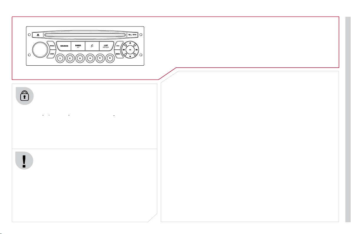
203
AUDIO SYSTEM
Your Audio system is coded in such a way that it will
only operate in your vehicle. If it is to be installed in
another vehicle, contact your CITROËN dealer for
only operate in your vehicle. If it is to be installed in
only operate in your vehicle. If it is to be installed in
confi guration of the system.
For safety reasons, the driver must carry out operations
which require prolonged attention while the vehicle is
stationary.
When the engine is switched off and to prevent
discharging of the battery, the audio equipment may
switch off after a few minutes.
AUDIO SYSTEM/BLUETOOTH
01 First steps
02 Steering mounted controls
03 Main menu
04 Audio
05 USB Box
06 Bluetooth functions
07 Configuration
08 Trip computer
09 Screen menu map
p.
p.
p.
p.
p.
p.
p.
p.
p.
204
205
206
207
210
213
215
216
217
CONTENTS
Frequently asked questions
p. 222
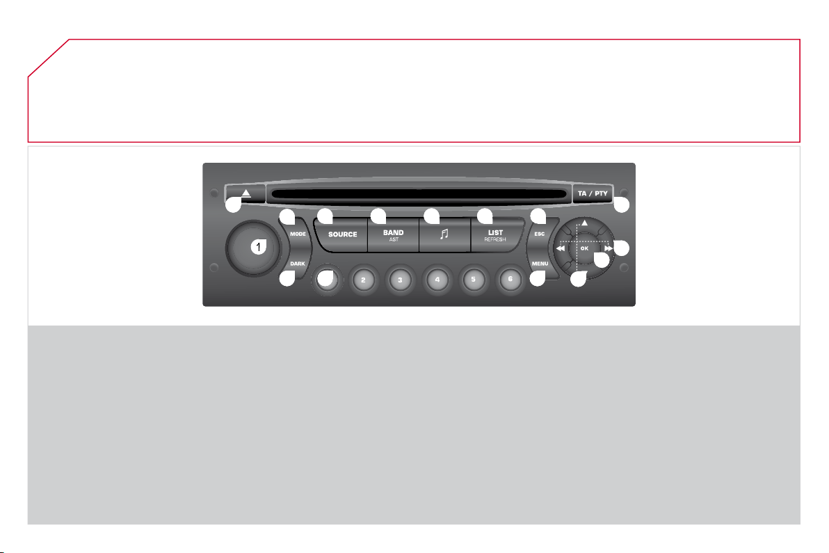
204
01
1
2
2
10
10
11
11
13
13
14
14
15
15
3
3
4
4
5
5
6
6
7
7
8
8
9
9
12
12
FIRST STEPS
1. On/Off and volume adjustment.
2. CD eject.
3. Selection of the display on the screen from
the following modes:
Audio (AUDIO), Trip Computer (TRIP) and
Telephone (TEL) functions.
4. Selection of source:
radio, audio CD/MP3 CD, USB, Jack
connection, Streaming.
5. Selection of FM1, FM2, FMast and AM
wavebands.
6. Setting audio options: front/rear fader, left/
right balance, loudness, sound ambience.
7. Display the list of local stations, of the
tracks on the CD or of the MP3 folders.
8. Abandon current operation.
9. TA (Traffi c Announcement) function on/off.
Long press: access to the PTY
(Types of radio programme) mode.
10. Confi rmation.
11. Automatic search for a lower/higher
frequency.
Selection of previous/next CD,
MP3 or USB track.
12. Selection of a lower/higher radio frequency.
Selection of the previous/next MP3 folder.
Selection of the previous/next USB device
folder/genre/artist/playlist.
13. Display the main menu.
14. Buttons 1 to 6:
Selection of a stored radio station.
Long press: store a station.
15. The DARK button changes the display
on the screen to improve driving comfort
at night.
1st press: lighting the upper band only.
2nd press: display of a black screen.
3rd press: return to the standard display.

205
02
STEERING MOUNTED CONTROLS
RADIO: selection of the next stored station.
USB: selection of the next genre/artist/folder from
the classifi cation list.
Selection of the next item on a menu.
RADIO: selection of the previous stored station.
USB: selection of the previous genre/artist/folder
from the classifi cation list.
Selection of the previous item on a menu.
RADIO: automatic search for a higher frequency.
CD/MP3/USB: selection of the next track.
CD/USB: continuous press: fast forwards play.
Selection of the previous item.
RADIO: automatic search for a lower frequency.
CD/MP3/USB: selection of the previous track.
CD/USB: continuous press: fast reverse.
Selection of the next item.
- Change of sound source.
- Confi rmation of a selection.
- Pick up/Hang up the telephone.
- Press for more than 2 seconds:
access to the telephone menu.
Volume increase.
Volume decrease.
Mute: press the volume
increase and decrease
buttons simultaneously.
The sound is restored by
pressing one of the two
volume buttons.
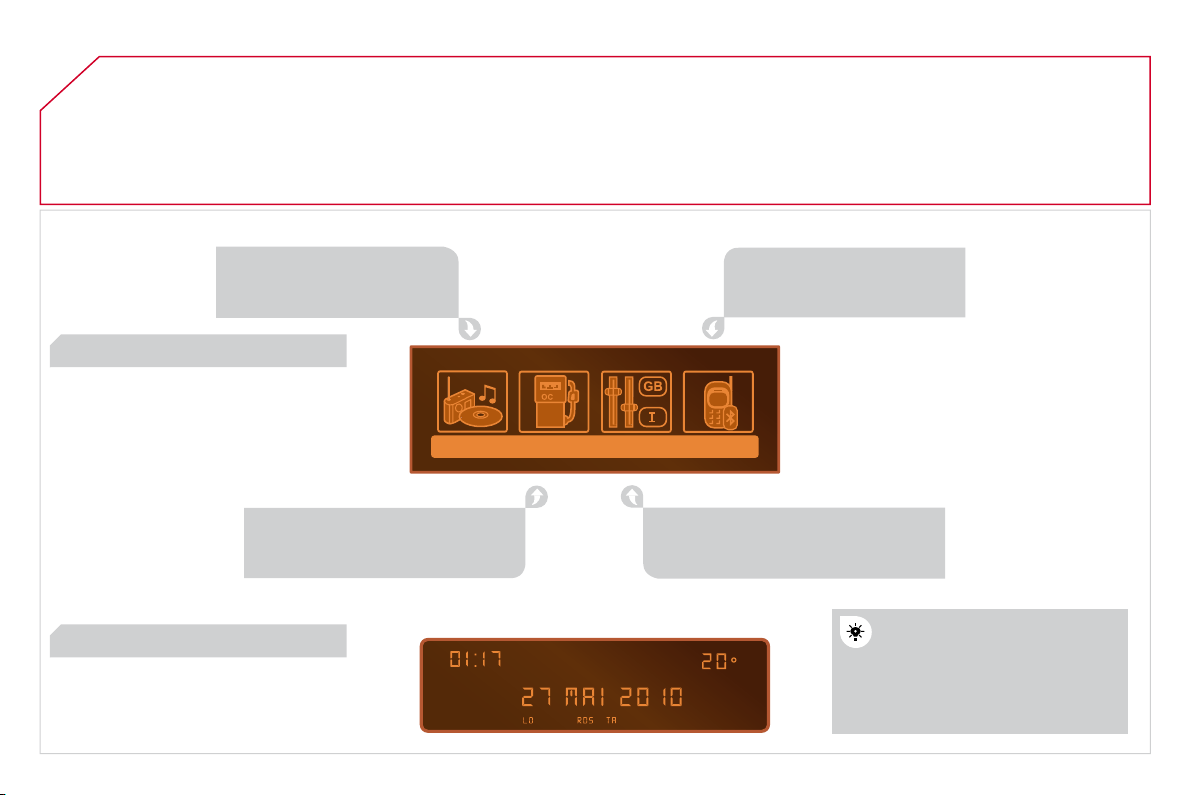
206
03
MAIN MENU
AUDIO FUNCTIONS
: radio,
CD, USB, options.
> MONOCHROME SCREEN C
For a detailed global view of the
menus available, refer to the
"Screen menu map" section.
TELEPHONE
: Bluetooth
hands-free, pairing,
management of a call.
PERSONALISATION-
CONFIGURATION
: vehicle
parameters, display, languages.
TRIP COMPUTER
: entering
of distances, alerts, status of
functions.
> MONOCHROME SCREEN A
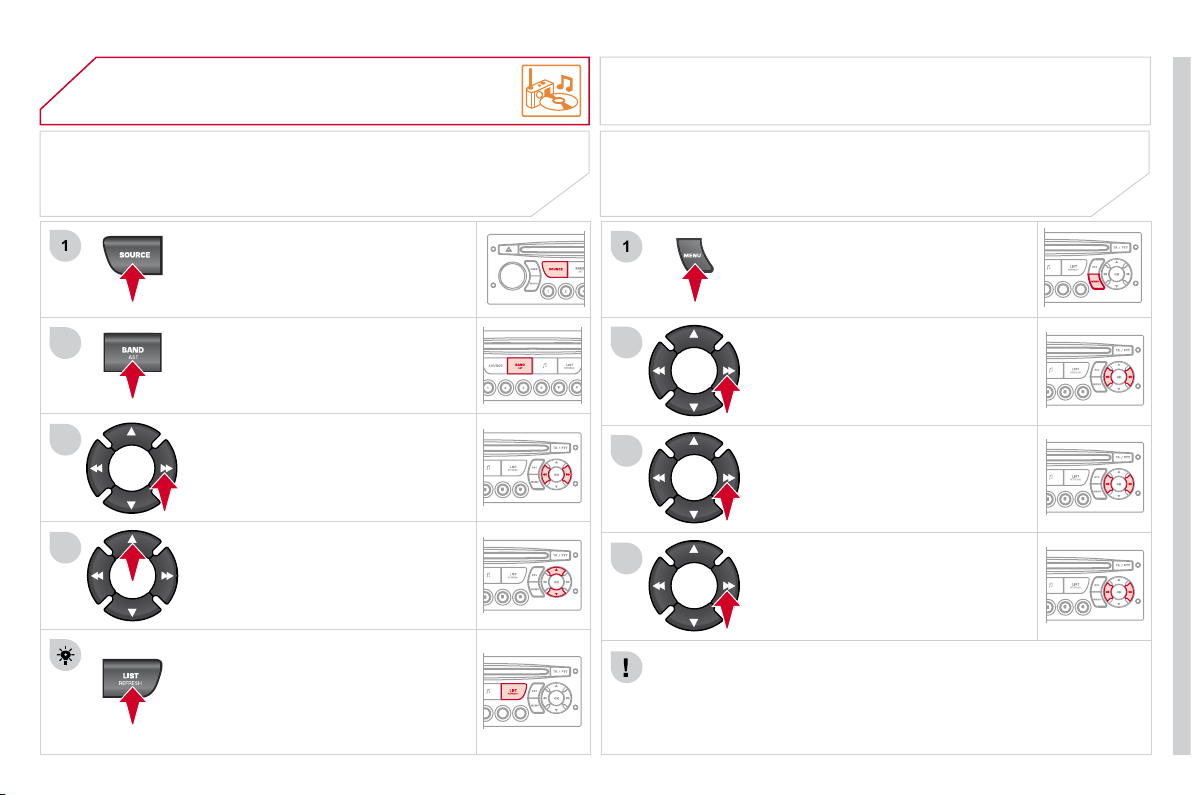
207
04
1
2
3
4
1
2
3
4
AUDIO
Press the SOURCE button several
times in succession and select
the radio.
Press the BAND AST button to select
a waveband: FM1, FM2, FMast, AM.
Briefl y press one of the buttons to
carry out an automatic search of the
radio stations.
Press one of the buttons to carry
out a manual search of the radio
stations.
Press the LIST REFRESH button to
display the list of stations received
locally (30 stations maximum).
To update this list, press for more
than two seconds.
The external environment (hills, buildings, tunnels, basement car parks, ...)
may block reception, including in RDS mode. This is a normal effect of the
way in which radio waves are transmitted and does not indicate any failure
of the Audio system.
RDS
RADIO
SELECTING A STATION
Press the MENU button.
Select AUDIO FUNCTIONS then
press OK.
Select the FM WAVEBAND
PREFERENCES function then
press OK.
Select ACTIVATE RDS then press OK.
RDS appears on the screen.
The RDS, if displayed, enables you to continue listening to the same
station by automatic retuning to alternative fequencies. However, in
certain conditions, coverage of an RDS station may not be assured
throughout the country as radio stations do not cover 100 % of the
territory. This explains the loss of reception of the station during a journey.
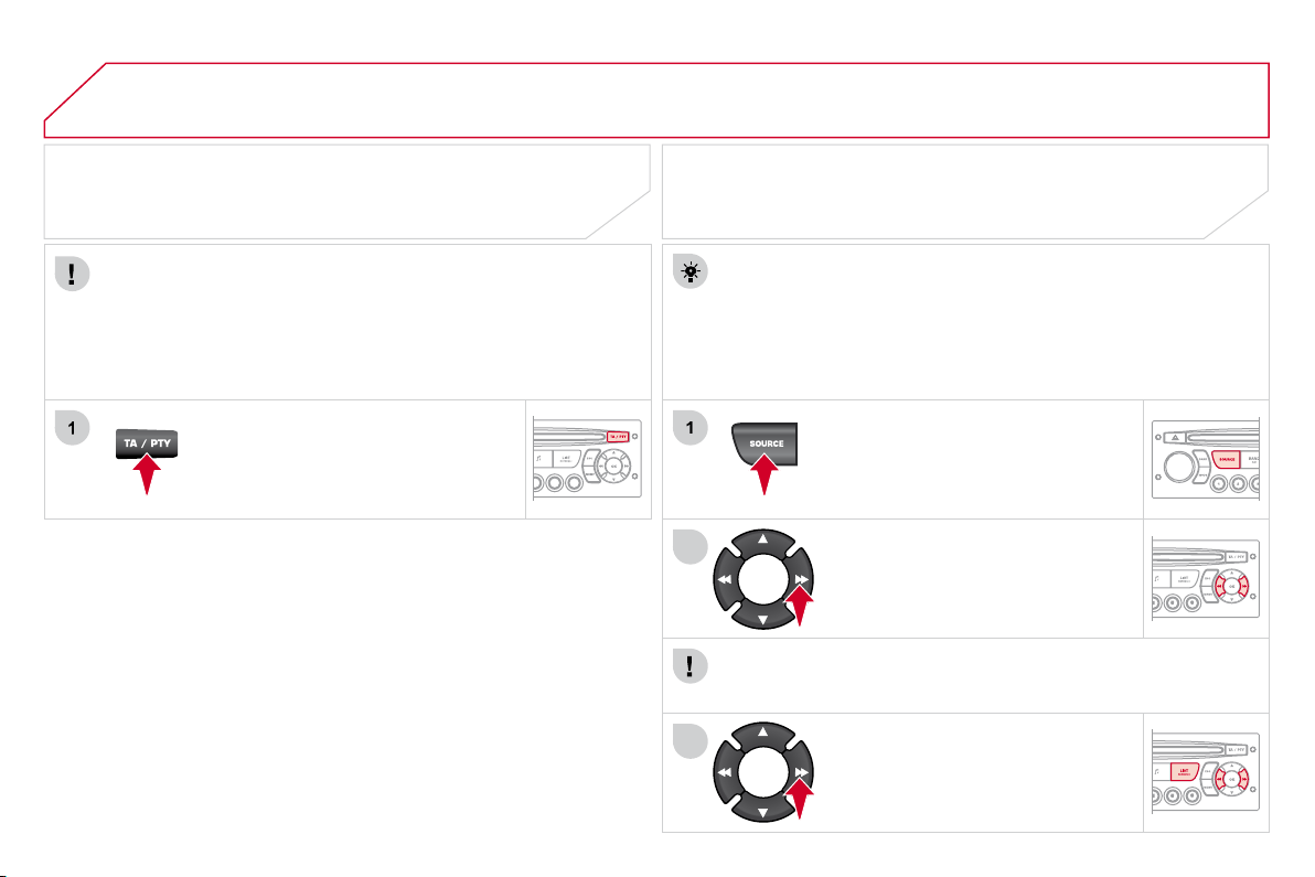
208
04
1
2
3
AUDIO
Insert circular compact discs only.
Some anti-pirating systems, on original discs or CDs copied using a
personal recorder, may cause faults which are no refl ection on the
quality of the original player.
Without pressing the EJECT button, insert a CD in the player, play
begins automatically.
CD
PLAYING A CD
To play a disc which has already been
inserted, press the SOURCE button
several times in succession and
select CD.
Press one of the buttons to select a
track on the CD.
Press the LIST REFRESH button to display the list of tracks on
the CD.
Press and hold one of the buttons for
fast forward or backward.
RECEIVING TA MESSAGES
Press the TA button to activate or
deactivate traffi c messages.
The TA (Traffi c Announcement) function gives priority to TA alert
messages. To operate, this function needs good reception of a
radio station transmitting this type of message. When a traffi c
report is transmitted, the current audio source (Radio, CD, ...) is
interrupted automatically to play the TA message. Normal playback
of the audio source resumes at the end of the transmission of
the message.
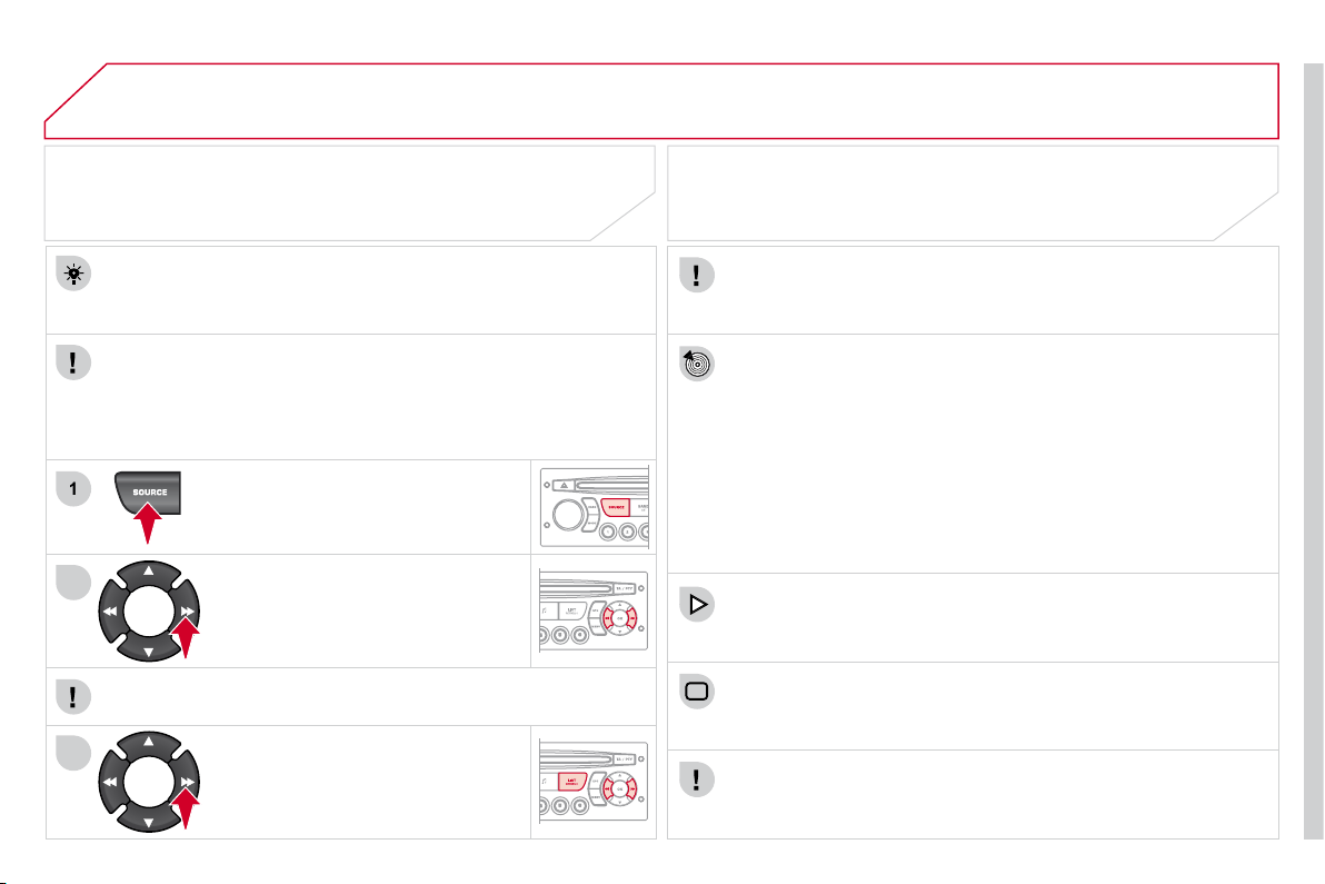
209
04
1
2
3
The MP3 format, an abbreviation of MPEG 1.2 & 2.5 Audio Layer 3,
is an audio compression standard which permits the recording of
several tens of music fi les on a single disc.
In order to be able to play a recorded CDR or CDRW, when
recording, the ISO 9660 level 1.2 or Joliet fi le format is
recommended.
If the disc is recorded in another format, it may not be played
correctly.
It is recommended that the same recording format is always
used for an individual disc, with as low a speed as possible
(4x maximum) for optimum sound quality.
In the particular case of a multi-session CD, the Joliet format is
recommended.
The Audio system will only play fi les with the extension ".mp3" with
a sampling rate of 22.05 KHz or 44.1 KHz. No other type of fi le
(.wma, .mp4, .m3u...) can be played.
It is advisable to restrict fi le names to 20 characters without using
special characters (e.g. " ? ; ù) to avoid any playing or displaying
problems.
MP3 CD
INFORMATION AND ADVICE
AUDIO
Empty CDs are not recognised and may damage the system.
Insert an MP3 compilation in the player.
The audio equipment searches for all of the music tracks, which
may take anything between a few seconds and several tens of
seconds, before play begins.
MP3 CD
PLAYING AN MP3 COMPILATION
On a single disc, the CD player can read up to 255 MP3 fi les spread
over 8 folder levels. However, it is advisable to keep to a limit of
two levels to reduce the access time before the CD is played.
While the CD is being played, the folder structure is not followed.
All of the fi les are displayed on a single level.
To play a disc which has already
been inserted, press the SOURCE
button several times in succession
and select CD.
Press one of the buttons to select a
track on the CD.
Press the LIST REFRESH button to display the list of directories
of the MP3 compilation.
Press and hold one of the buttons for
fast forward or backward play.
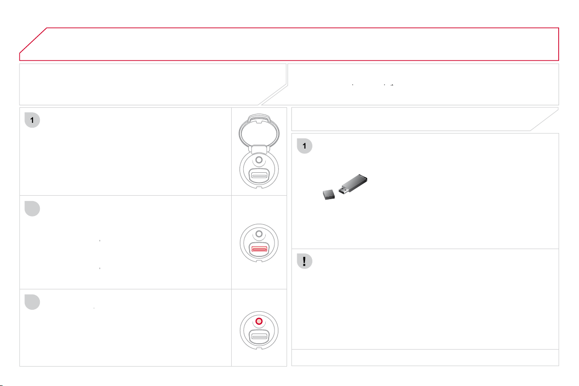
210
05
1
1
2
3
USB BOX
The system puts together playlists (temporary memory) created
over a period which depends on the capacity of the USB device.
The other sources are available during this time.
The playlists are updated each time the ignition is switched off or
each time a USB memory stick is connected.
When connecting for the fi rst time, the classifi cation suggested
is by folder. When you reconnect, the classifi cation selected
previously is retained.
Connect the memory stick to the port, directly or
using a lead. If the audio equipment is switched
on, the USB source is detected as soon as it
is connected. Play begins automatically after a
delay which depends on the capacity of the USB
memory stick.
The fi le formats recognised are .mp3 (mpeg1
layer 3 only), .wma (standard 9 only, 128 kbits/sec
compression), .wav and .ogg.
The playlists types accepted are m3u, .pls, .wpl.
This unit consists of a USB port and an auxiliary
Jack socket * . The audio fi les are transmitted
from portable equipment such as a digital player
or a USB memory stick to your Audio system to
be listened to via the vehicle's speakers.
USB memory stick (1.1, 1.2 and 2.0) or iPod
®
of
generation 5 or later:
- USB memory sticks should be formatted
FAT or FAT 32 (NTFS not supported),
- the iPod
®
lead is essential,
®
- navigation through the fi le database is by
means of the steering mounted controls,
- the iPod
®
software should be regularly
®
updated for the best connection.
The list of compatible equipment and the compression rates supported
are available from CITROËN dealers.
The list of compatible equipment and the compression rates supported
The list of compatible equipment and the compression rates supported
USING THE USB BOX
CONNECTING A USB MEMORY STICK
Other iPod
®
players of earlier generations and
®
players using the MTP protocol * :
- play via Jack-Jack lead only (not supplied),
- navigation through the fi le database is from
the portable device.
* According to vehicle.
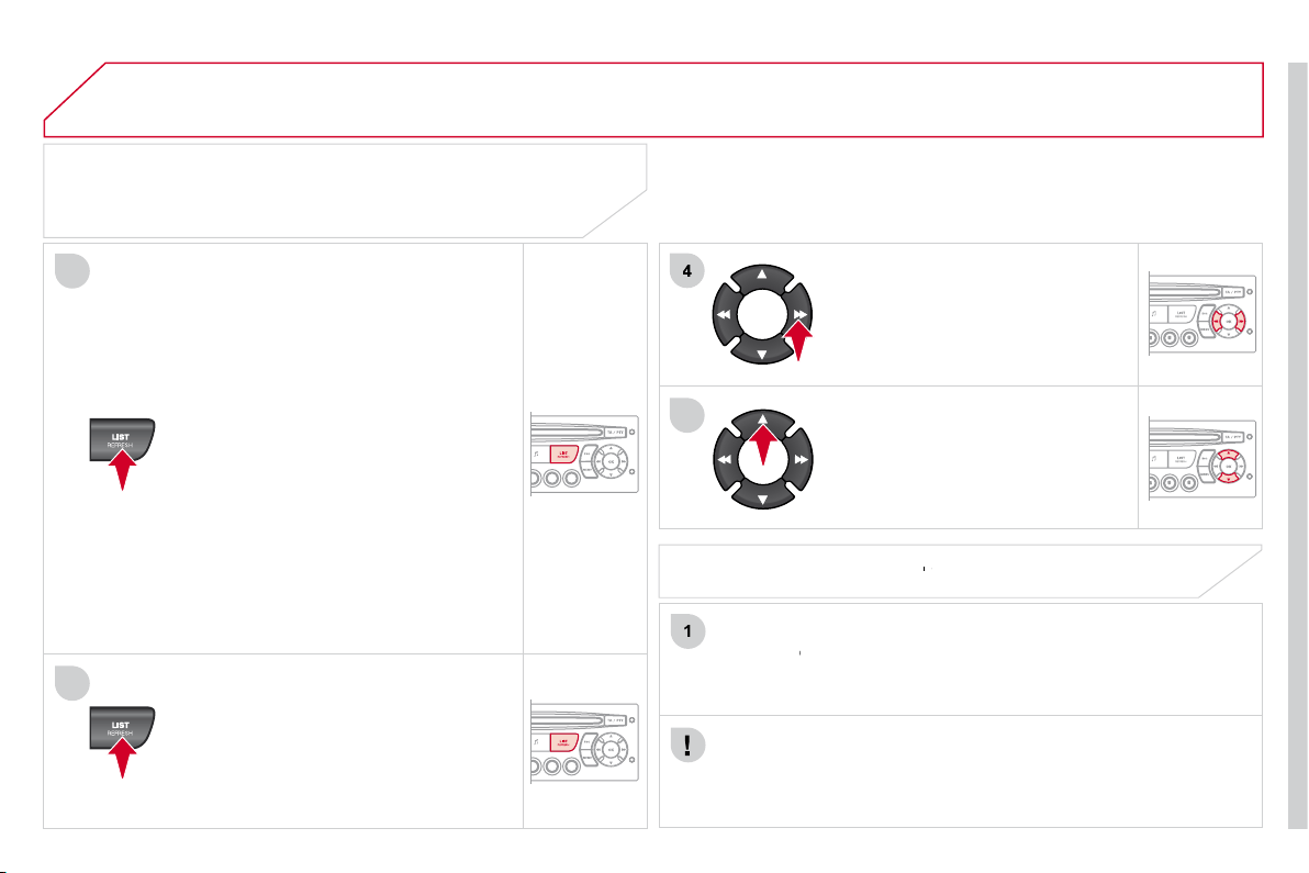
211
05
2
3
1
5
USB BOX
USING THE USB PORT
Press LIST briefl y to display the
previously selected classifi cation.
Navigate through the list using the left/
right and up/down buttons.
Confi rm the selection by pressing OK.
The lists available are Artist, Genre and Playlist (as defi ned on
the iPod
®
).
®
Selection and Navigation are described in steps 1 to 5 above.
Do not connect a hard disk or USB devices other than audio
equipment to the USB port. This could damage your installation.
CONNECTING AN iPOD
®
AN iPOD
AN iPOD
VIA THE USB PORT
®
Press one of these buttons to gain
access to the previous/next track on
the classifi cation list currently being
played.
Press and hold one of the buttons for
fast forward or backward play.
Press one of these buttons to gain
access to the previous/next Genre,
Folder, Artist or Playlist on the
classifi cation list currently being
played.
Press and hold LIST to display
the different classifi cations.
Select by Folder/Artist/Genre/Playlist,
press OK to select the classifi cation
required, then press OK again to confi rm.
- by Folder: all folders containing audio
fi les recognised on the peripheral
device, classifi ed in alphabetical
order without following the fl ow chart.
- by Artist: all of the artist names
defi ned in the ID3 Tags, classifi ed in
alphabetical order.
- by Genre: all of the genres defi ned in
the ID3 Tags.
- by Playlist: in accordance with the
playlists recorded on the USB device.
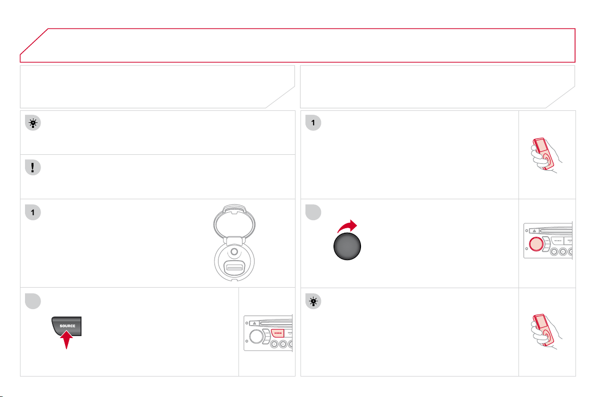
212
05
1
2
1
2
The display and control is via the portable device.
First adjust the volume of your portable device.
Then adjust the volume of your
Audio system.
USING THE AUXILIARY INPUT (AUX)
JACK SOCKET OR USB PORT
(according to vehicle)
ADJUSTING THE VOLUME OF
THE AUXILIARY SOURCE
USB BOX
The auxiliary input, JACK or USB, allows the connection of
portable equipment (MP3 player...).
Do not connect a single piece of equipment via the JACK socket
and the USB port at the same time.
Connect the portable equipment
(MP3 player…) to the JACK
socket or to the USB port, using
a suitable cable (not supplied).
Press the SOURCE button several
times in succession and select AUX.
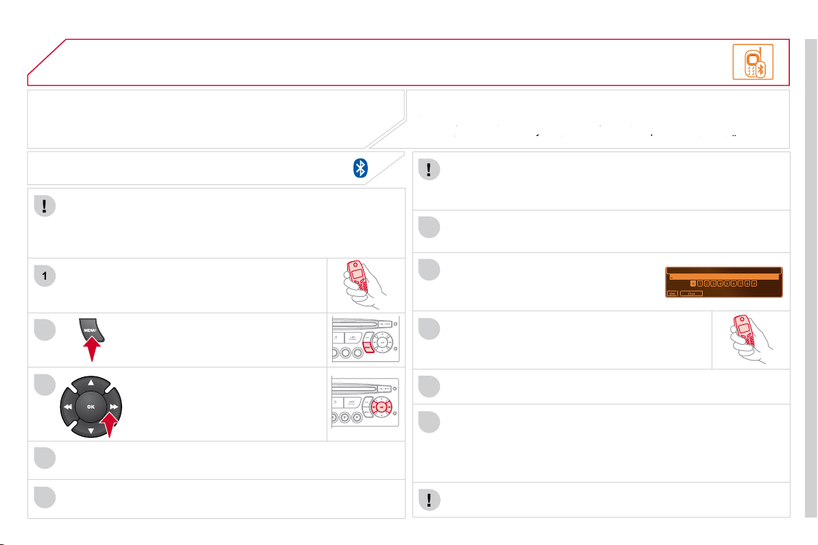
213
06
1
2
3
4
5
6
7
8
9
10
BLUETOOTH FUNCTIONS
For safety reasons and because they require prolonged attention
on the part of the driver, the operations for pairing of the Bluetooth
mobile telephone with the Bluetooth hands-free system of your
audio equipment must be carried out with the vehicle stationary
and the ignition on.
Press the MENU button.
A window is displayed with "Searching...".
Activate the telephone's Bluetooth function.
In the menu, select:
- Bluetooth telephone function -
Audio
- Bluetooth confi guration
- Perform a Bluetooth search
The services offered depend on the network, the SIM card and
the compatibility of the Bluetooth equipment used.
Consult your telephone's manual and your operator to fi nd out which
the compatibility of the Bluetooth equipment used.
the compatibility of the Bluetooth equipment used.
services are available to you. A list of mobile telephones which offer the best
Consult your telephone's manual and your operator to fi nd out which
Consult your telephone's manual and your operator to fi nd out which
range of services is available from the network. Consult a CITROËN dealer.
services are available to you. A list of mobile telephones which offer the best
services are available to you. A list of mobile telephones which offer the best
BLUETOOTH TELEPHONE
SCREEN C
The TELEPHONE menu permits access to the following functions
in particular: Directory * , Call list, Pairing management.
The fi rst 4 telephones recognised are displayed in this window.
A virtual keypad is displayed on the
screen: enter a code with at least 4 digits.
Confi rm by pressing OK.
"Pairing of Name_telephone successful" appears on the screen.
Select the telephone to be connected from the list. Only one
telephone can be connected at a time.
A message is displayed on the screen of the telephone
chosen: to accept the pairing, enter the same code on
the telephone, then confi rm by pressing OK.
The automatic connection authorised is only active after the
telephone has been confi gured.
The directory and the call list can be accessed after the
synchronisation period.
PAIRING A TELEPHONE
The pairing can also be initiated from the telephone.
(AVAILABILITY DEPENDS ON MODEL AND VERSION)
* If your telephone is fully compatible.
If pairing fails, the number of attempts is not limited.
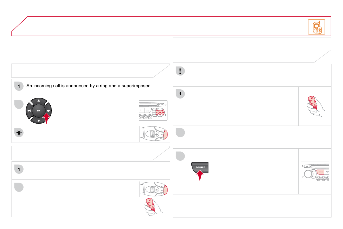
214
06
1
2
1
2
2
3
RECEIVING A CALL
display on the multifunction screen.
Initiate the pairing between the telephone and
the vehicle. This pairing can be initiated from
the vehicle's telephone function menu or via the
telephone's keypad. See steps 1 to 10 on the
previous pages. During the pairing phase, the vehicle
must be stationary with the key in the ignition.
Select the telephone to be connected from the telephone function
menu.
The Audio system connects to a newly paired telephone automatically.
Select the YES tab on the display
using the buttons and confi rm by
pressing OK.
Press the steering mounted control OK to accept
the call.
BLUETOOTH AUDIO STREAMING
Wireless transmission of the telephone's music fi les via the audio
equipment. The telephone must be able to manage the appropriate
bluetooth profi les (Profi les A2DP/AVRCP).
* In certain cases, playing of the Audio fi les must be initiated from
the keypad.
** If the telephone supports the function.
Activate the streaming source by
pressing the SOURCE button * . The
tracks to be played can be controlled
as usual via the buttons on the
Radio control panel and the steering
mounted controls ** . The contextual
information can be displayed on the
screen.
BLUETOOTH FUNCTIONS
MAKING A CALL
From the Bluetooth telephone function Audio menu, select Manage
the telephone call then Call, Call list or Directory.
Press the end of the steering mounted control for
more than two seconds to gain access to your
directory.
Or
To dial a number, use your telephone's keypad,
with the vehicle stationary.
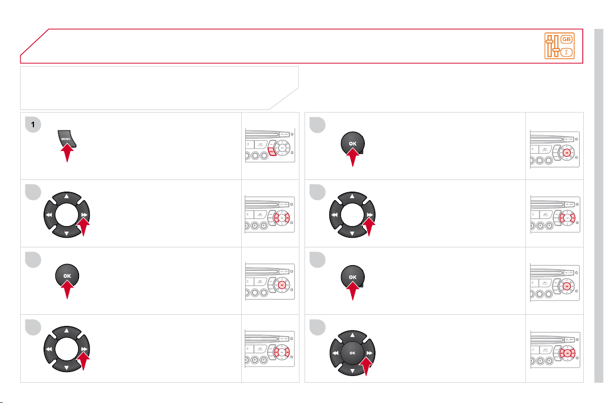
215
07
1
2
3
4
5
6
7
8
CONFIGURATION
Press the MENU button.
Using the arrows, select
PERSONALISATION
CONFIGURATION.
Press to confi rm the selection.
Using the arrows, select DISPLAY
CONFIGURATION.
Press to confi rm the selection.
Press to confi rm the selection.
Using the arrows, select ADJUST
DATE AND TIME.
Adjust the settings one by one
confi rming by pressing the OK
button. Next select the OK tab on the
screen then confi rm.
SETTING THE DATE AND TIME
SCREEN C
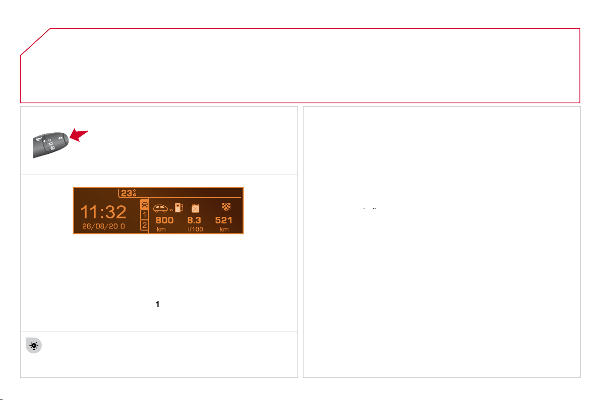
216
1
08
Each press of the button, located at the end of the
wiper stalk, displays the different trip computer
information in succession, depending on the screen.
- the "vehicle" tab with:
the range, the current fuel consumption and the distance remaining
to the destination or the Stop & Start time counter,
- the "1" tab (trip 1) with:
the average speed, the average consumption and the distance
travelled calculated over trip "
1
",
- the "2" tab (trip 2) with the same information for a second trip.
A FEW DEFINITIONS
Zero reset
When the required trip is displayed, press the control for more than
two seconds.
TRIP COMPUTER
Range:
displays the distance which can travelled with the remaining fuel
detected in the tank, based on the average fuel consumption over the last
few miles (kilometres).
This displayed value may vary signifi cantly following a change in the
vehicle speed or the relief of the route.
When the range falls below 20 miles (30 km), dashes are displayed.
After fi lling with at least 5 litres of fuel, the range is recalculated and is
displayed when it exceeds 60 miles (100 km).
If, whilst driving, dashes are displayed continuously in place of the digits,
contact a CITROËN dealer.
If, whilst driving, dashes are displayed continuously in place of the digits,
If, whilst driving, dashes are displayed continuously in place of the digits,
Current fuel consumption:
only calculated and displayed above 20 mph (30 km/h).
Average fuel consumption:
this is the average fuel consumption since
the last trip computer zero reset.
Average speed:
this is the average speed calculated since the last trip
computer zero reset (ignition on).
Distance travelled:
calculated since the last trip computer zero reset.
Distance remaining to the destination:
calculated with reference to
the fi nal destination, entered by the user. If guidance is activated, the
navigation system calculates it as a current value.
Stop & Start time counter
(minutes/seconds or hours/minutes)
If your vehicle is fi tted with Stop & Start, a time counter calculates
the time spent in STOP mode during a journey.
It resets to zero every time the ignition is switched on with the key.
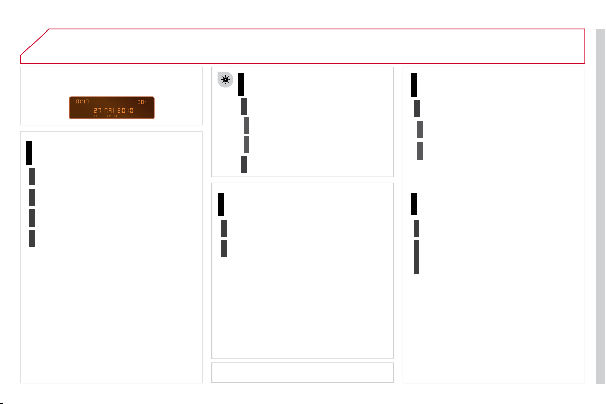
217
09
SCREEN MENU MAP
RADIO-CD
MAIN FUNCTION
* The parameters vary according to vehicle.
CHOICE A
CHOICE B...
MONOCHROME A
Choice A1
Choice A2
REG MODE
CD REPEAT
RANDOM PLAY
VEHICLE CONFIG *
REV WIPE ACT
OPTIONS
GUIDE LAMPS
DIAGNOSTICS
RDS SEARCH
CONSULT
ABANDON
UNITS
TEMPERATURE: °CELSIUS/°FAHRENHEIT
FUEL CONSUMPTION:
KM/L - L/100 - MPG
1
2
3
3
1
2
2
2
2
1
2
3
2
3
1
2
2
1
2
2
218
09
SCREEN MENU MAP
DISPLAY ADJUST
MONTH
DATE
HOUR
MINUTES
YEAR
12 H/24 H MODE
LANGUAGE
ITALIANO
NEDERLANDS
PORTUGUES
PORTUGUES-BRASIL
FRANCAIS
DEUTSCH
ENGLISH
ESPANOL
1
2
2
2
2
2
2
1
2
2
2
2
2
2
2
2
219
09
SCREEN MENU MAP
Press the OK dial for access to short-cut menus according to the display on the screen:
MONOCHROME C
activate/deactivate RDS
activate/deactivate REG mode
activate/deactivate radiotext
RADIO
activate/deactivate Intro
CD/MP3 CD
activate/deactivate track repeat
(the entire current CD for CD, the entire
current folder for MP3 CD)
activate/deactivate random play
(the entire current CD for CD, the entire
current folder for MP3 CD)
activate/deactivate track repeat (of
the current folder/artist/genre/playlist)
USB
activate/deactivate random play
(of
the current folder/artist/genre/playlist)
1
1
1
1
1
1
1
1
220
09
MONOCHROME C
M
SCREEN MENU MAP
AUDIO FUNCTIONS
alternative frequencies (RDS)
activate/deactivate
FM BAND PREFERENCES
regional mode (REG)
activate/deactivate
radio-text information (RDTXT)
activate/deactivate
1
2
3
4
3
4
3
4
PLAY MODES
album repeat (RPT)
activate/deactivate
track random play (RDM)
activate/deactivate
2
3
4
3
4
TRIP COMPUTER
Distance: x miles
ENTER DISTANCE TO DESTINATION
Diagnostic s
ALERT LOG
Functions activated or deactivated
STATUS OF THE FUNCTIONS *
1
2
3
3
2
3
2
video brightness adjustment
DISPLAY CONFIGURATION
DEFINE THE VEHICLE PARAMETERS *
PERSONALISATION-CONFIGURATION
normal video
inverse video
brightness (- +) adjustment
date and time adjustment
day/month/year adjustment
hour/minute adjustment
choice of 12 h/24 h mode
choice of units
l/100 km - mpg - km/l
°Celsius/°Fahrenheit
CHOICE OF LANGUAGE
1
2
4
3
2
4
4
3
3
4
4
2
3
4
4
Pressing the MENU button displays:
* The parameters vary according to vehicle.
221
09
SCREEN MENU MAP
BLUETOOTH TELEPHONE
Connect/Disconnect a device
Consult the paired device
Bluetooth confi guration
Telephone function
Audio Streaming function
Delete a paired device
Perform a Bluetooth search
Calls list
Call
Directory
Terminate the current call
Manage the telephone call
Activate private mode
1
2
3
3
3
4
4
4
2
3
4
2
3
3

222
FREQUENTLY ASKED QUESTIONS
QUESTION
ANSWER
SOLUTION
There is a difference in
sound quality between
the different audio
sources (radio, CD...).
For optimum sound quality, the audio settings (Volume, Bass, Treble,
Ambience, Loudness) can be adapted to the different sound sources,
which may result in audible differences when changing source
(radio, CD...).
Check that the audio settings (Volume, Bass,
Treble, Ambience, Loudness) are adapted to
the sources listened to. It is advisable to set
the AUDIO functions (Bass, Treble, Front-Rear
Balance, Left-Right Balance) to the middle
position, select the musical ambience "None" and
set the loudness correction to the "Active" position
in CD mode or to the "Inactive" position in radio
mode.
The CD is ejected
automatically or is not
played by the player.
The CD is inserted upside down, is unplayable, does not contain any
audio data or contains an audio format which the player cannot play.
The CD is protected by an anti-pirating protection system which is not
recognised by the audio equipment.
- Check that the CD is inserted in the player
the right way up.
- Check the condition of the CD: the CD cannot
be played if it is too damaged.
- Check the content in the case of a recorded
CD: consult the advice in the "Audio" section.
- The audio equipment's CD player does not
play DVDs.
- Due to their quality level, certain writeable
CDs will not be played by the Audio system.
The message "USB
peripheral error" is
displayed on the screen.
The Bluetooth connection
is cut.
The battery of the peripheral may not be suffi ciently charged.
Recharge the battery of the peripheral device.
The USB memory stick is not recognised.
The memory stick may be corrupt.
Reformat the memory stick.
The CD player sound is
poor.
The CD used is scratched or of poor quality.
Insert good quality CDs and store them in suitable
conditions.
The audio equipment settings (bass, treble, ambiences) are unsuitable.
Set the treble or bass level to 0, without selecting
an ambience.

223
QUESTION
ANSWER
SOLUTION
The stored stations do
not function (no sound,
87.5 Mhz is displayed...).
An incorrect waveband is selected.
Press the BAND AST button to return to the
waveband (AM, FM1, FM2, FMAST) on which
the stations are stored.
The traffi c announcement
(TA) is displayed. I do
not receive any traffi c
information.
The radio station is not part of the regional traffi c information network.
Tune to a radio station which broadcasts traffi c
information.
The quality of reception
of the radio station
listened to gradually
deteriorates or the stored
stations do not function
(no sound, 87.5 Mhz is
displayed...).
The vehicle is too far from the transmitter used by the station listened to
or there is no transmitter in the geographical area through which
the vehicle is travelling.
Activate the RDS function to enable the system
to check whether there is a more powerful
transmitter in the geographical area.
The environment (hills, buildings, tunnels, basement car parks...) block
reception, including in RDS mode.
This phenomenon is normal and does not indicate
a failure of the audio equipment.
The aerial is absent or has been damaged (for example when going
through a car wash or into an underground car park).
Have the aerial checked by a CITROËN dealer.
Sound cut-outs of 1 to
2 seconds in radio mode.
During this brief sound cut-out, the RDS searches for any frequency
permitting better reception of the station.
Deactivate the RDS function if the phenomenon is
too frequent and always on the same route.
With the engine off,
the audio equipment
switches off after a few
minutes of use.
When the engine is switched off, the audio equipment operating time
depends on the battery charge.
The switch-off is normal: the audio equipment switches to economy mode
and switches off to prevent discharging of the vehicle's battery.
Start the vehicle's engine to increase the battery
charge.
The message "the
Audio system is
overheated" appears on
the display.
In order to protect the installation if the surrounding temperature is too
high, the audio equipment switches to an automatic thermal protection
mode leading to a reduction of the volume or stopping of the playing of
the CD.
Switch the Audio system off for a few minutes to
allow the system to cool.