Loading ...
Loading ...
INSTALLATION
GAS CONNECTION
1. Check the “gas type” sticker attached to the hotplate. Details of the injector sizes used are recorded on the data plate
located on the base of the appliance.
2. This appliance shall be installed in accordance with installation requirements of the local gas authority of the appropriate
installation code.
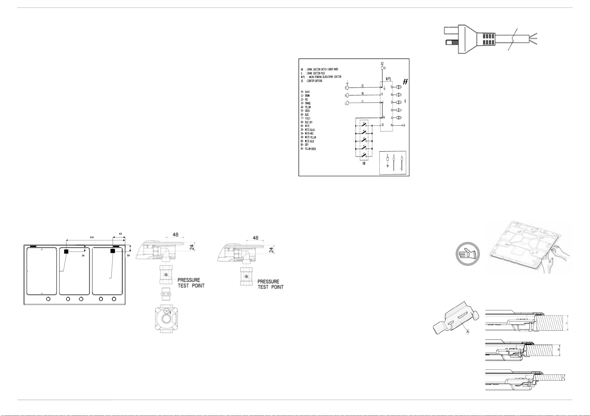
3. Before installing the hotplate consider the location of the gas supply and routing the gas line. (Refer Fig. 1).
4. For ULPG models the gas supply for the hotplate must be regulated to a pressure of 2.75kPa. The gas inlet connection
fitting is ½” B.S.P male thread.
5. For NG models the gas supply is connected to a regulator which is supplied. The inlet connection has ½” B.S.P male
thread. IT IS ESSENTIAL THAT THE ELBOW ON THE APPLIANCE BE HELD FIRMLY WITH A SPANNER. DO NOT
OVER TIGHTEN. The regulated pressure for NG is 1.00kPa.
6. A manual shut-off valve must be installed in the gas line, in an accessible position external to the hotplate, so that in the
event of an emergency or service, the gas supply can be shutoff.
7. For gas inlet position of appliance refer Fig. 2 for NG and fig.3 for ULPG. After installing the gas supply and making all
connections check thoroughly for possible leaks. Turn all control knobs on the unit to “OFF” position. Open the valve
on the gas supply. Using a soap and water solution check each gas connection one at a time, by brushing the solution
over connection. Presence of bubbles will indicate a leak. Tighten the fitting and re-check for leaks. If it is not possible to
correct the leak, replace fitting. Under no circumstance use matches or flame for checking leaks.
8. Turn on appliance gas cock and light each burner. Check for a clear blue flame without yellow tipping. If burners shows
any abnormalties check the following:
- Burner cap on correctly
- Burner positioned correctly
- Burner vertically aligned with injector nipple
9. In some cases the burners will fail to ignite immediately and will seem to 'blow's lightly when they do ignite, this is usually
due to air in the gas pipe which should clear itself within seconds of operation.
10. If after following the instructions given, satisfactory performance cannot be obtained, contact the local gas authority for
advice and assistance.
WARNING: Appliance not suitable for connection with flexible hose assembly.
ELECTRICAL
CONNECTION
POINT
GAS CONNECTION
POINT
Fig. 1
Fig. 2
Fig. 3
ELECTRICAL CONNECTION
• The electrical connections must comply with
local regulations.
• The data relevant to the voltage and power
absorption are indicated on the rating plate.
• The earthing of this appliance is compulsory by
law.
• The manufacturer cannot be held responsible for any injury to persons or animals or damage to property
arising from failure to comply with these requirements.
• When the hob is installed, provide a single-pole circuit breaker with a contact separation of at least 3 mm.
• If necessary, the electrical power cable must be replaced exclusively with a power cable having identical
characteristics to the original supplied by the manufacturer (type H05V2V2-F T90°C or H05RR-F).
This operation must be performed by a qualified electrician.
ASSEMBLY
After having cleaned the perimeter surface, apply the supplied gasket to
the hob as shown in the figure.
Position the hob in the worktop opening made respecting the dimensions indicated in the Product Description Sheet.
Note: the power supply cable must be long enough to permit its upward extraction.
To secure the hob, use the brackets (A) provided with it.
Fit the brackets into the relevant bores shown by the
arrow and fasten them by means of their screws in
accordance with the thickness of the worktop (see figures
on the right).
Earth
(yellow/green)
L
N
230 - 240 V
Top 40 mm
Top 30 mm
Top 20 mm
Loading ...