Loading ...
Loading ...
Loading ...
7
bottom baseplate, you should also see three white plastic
parts: a short azimuth bushing, a long azimuth bushing,
and a flat PTFE/UHMW bearing ring (Figure 4). The
bushings may have remained lodged in the center hole of
the baseplate(s) when you removed it. If that’s the case,
use a finger to push the bushing out of the hole. Set the
bottom baseplate and associated parts aside for now
while you install the vertical stop L-bracket on the top
baseplate.
2. Install the vertical stop L-bracket. It will be permanently
installed on the top baseplate (Figure 5). The vertical
stop L-bracket will be used before each observing
session to set the precise vertical orientation of the
optical tube, the procedure for which will be described
later. Once installed, the L-bracket will never have to be
removed because it does not interfere with the range of
motion of the optical tube between vertical and horizontal
positions.
To install the vertical stop L-bracket, insert the two 25mm
(~1") machine screws through the two holes in the
L-bracket’s foot. Then insert the screws into the holes in
the top baseplate, with the L-bracket oriented as shown
in Figure 5. On the underside of the top baseplate,
place a small lock washer on the end of each screw,
then thread on a small hex nut. While holding the hex nut
stationary with two fingers, tighten the screw with a small
Phillips screwdriver. Repeat for the other screw. Now the
L-bracket is secured in place.
Note: You may discard the two small flat washers for the
25mm machine screws that were included in the hardware kit;
they are not needed.
3. Thread the vertical stop bolt and knob into the
corresponding hole in the vertical stop bracket, in the
orientation show in Figure 5. Thread it though so that
1/2" or so of the bolt emerges on the other side of the
L-bracket, then thread on the jam nut. You will adjust the
position of the vertical stop bolt and tighten the jam nut
later, when initializing the IntelliScope system prior to
using it for the first time.
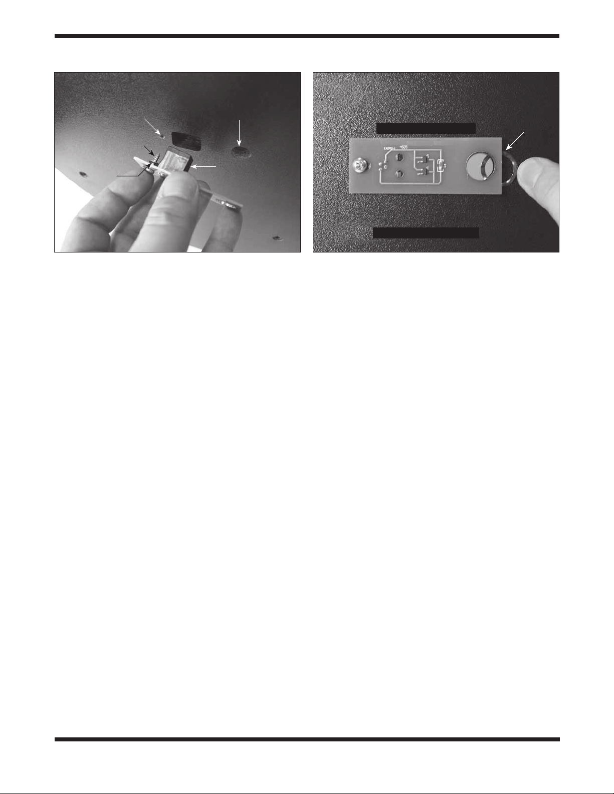
4. Attach the azimuth encoder board to the underside of the
top baseplate (Figure 6). Insert a wood screw through
the slot in the azimuth encoder board, then place a
washer over the tip of the screw. Now hold the encoder
board so that the modular jack and large hole in the
encoder board line up with their corresponding holes
in the baseplate. Insert the screw tip into the pre-drilled
starter hole and screw it in with a Phillips screwdriver
until just tight. The screw should not be fully tightened;
it should be tight, but not tight enough to prevent the
encoder board from moving in its slot.
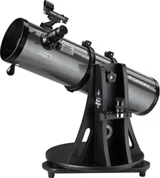
5. Place the wave spring between the azimuth encoder
board and the bottom of the top baseplate as shown
in Figure 7. Position the wave spring so that it aligns
precisely with the central hole in the baseplate.
Now that the azimuth encoder is installed on the underside of
the top baseplate, be sure not to set the baseplate down on a
flat surface, as doing so could damage the encoder. Rather,
set the baseplate with attached vertical side panel assembly
on its side for now.
6. Place one fender washer on the azimuth axis bolt,
followed by the short nylon bushing. Then insert the bolt
through the central hole from the underside of the bottom
Figure 7. Wedge the wave spring between the azimuth
encoder board and the baseplate and align the “hole” in the
wave spring with the central hole in the baseplate.
Figure 6. Install the azimuth encoder board on the under-
side of the top baseplate. Be sure to place one washer on
the screw after inserting the screw through its hole in the
azimuth board, then thread the screw into the predrilled
starter hole.
Wave
spring
Pre-drilled
starter hole
Wood screw
Washer
Center hole
Modular jack
Altazimuth encoder board
Under side of top baseplate
Under side of top baseplate
Loading ...
Loading ...
Loading ...