Loading ...
Loading ...
Loading ...
Trouble recovery
103
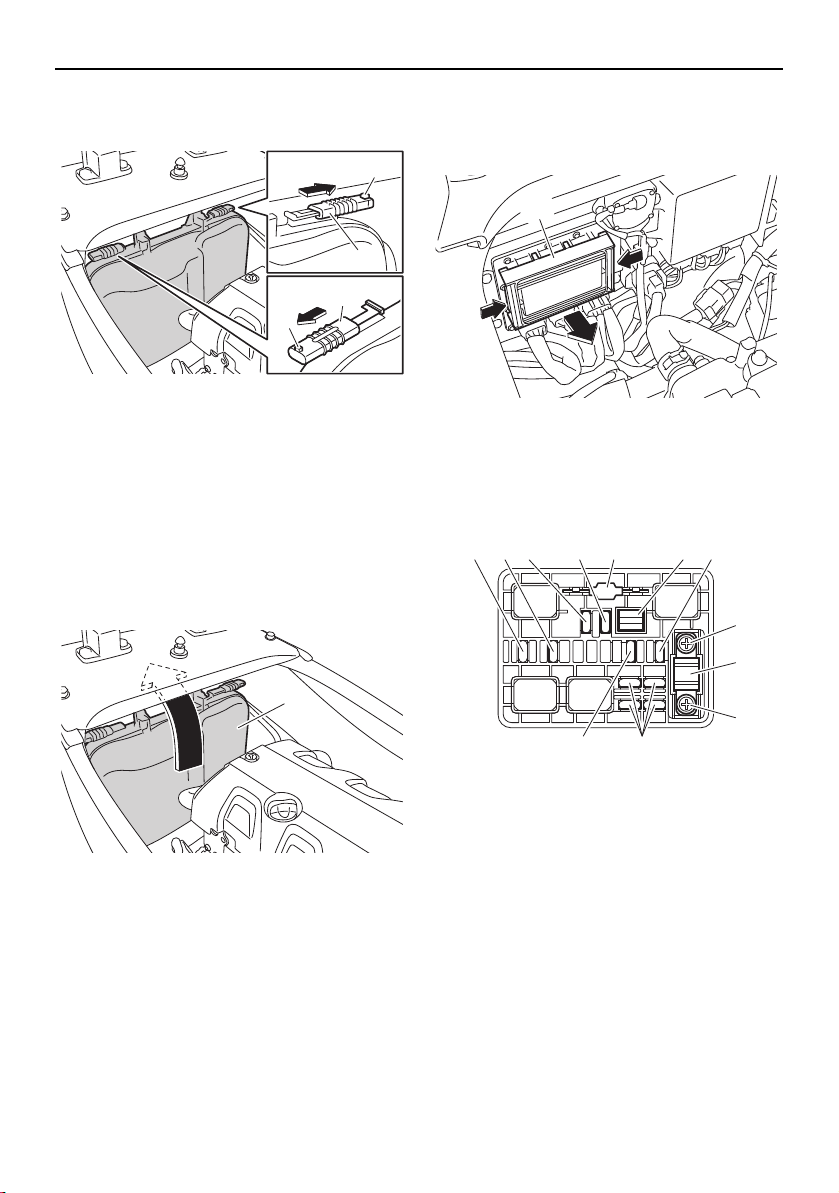
(2) While pushing the projection on each
lock, slide the locks outward.
(3) Remove the electrical box cover from the
electrical box and move it under the deck
beam toward the stern. NOTICE: Do not
attempt to forcefully remove the elec-
trical box cover from the watercraft.
Otherwise, the electrical box cover,
electrical system, and engine could be
damaged.
[ECJ02610]
(4) While pushing both sides of the fuse box
cover inward, pull the cover toward the
bow and remove it.
(5) When replacing the SCU fuse, remove
the screws, and then remove the fuse.
Install the spare fuse, and then tighten
the screws.
(6) When replacing a fuse other than the
SCU fuse, remove the fuse using the
fuse puller. Install a spare fuse of the
proper amperage. WARNING! Do not
1 Lock
2 Projection
1 Electrical box cover
1
2
1
2
1
1 Fuse box cover
1 Electronic throttle valve fuse
2 Fuel pump fuse
3 Main relay drive fuse
4 Main fuse
5 Spare fuse
6 Fuse puller
7 Battery fuse
8 Screw
9 SCU fuse (BCU fuse)
10 Security system fuse
1
1
5
23 4 5 6 7
8
9
8
10
UF2W12E0.book Page 103 Thursday, October 8, 2015 3:01 PM
Loading ...
Loading ...
Loading ...