Loading ...
Loading ...
Loading ...
8
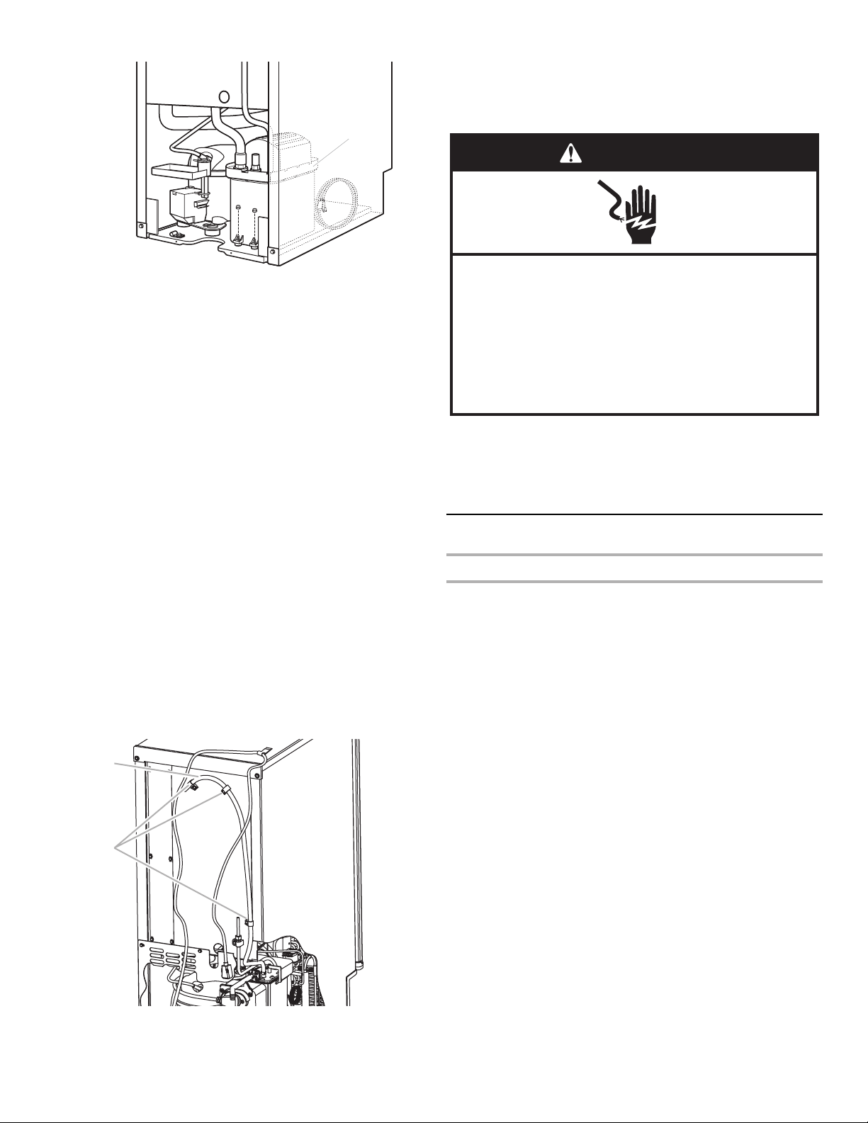
Drain Pump Installed
8. Align the 2 screw holes at the rear of the pump. Use two
#8-32 x
3
⁄
8
" screws, supplied. See “Parts Locations”
illustration.
9. Connect drain tube to ice maker bin outlet (
5
⁄
8
" ID), using
7
⁄
8
"
adjustable clamp, supplied. See “Drain Tube” illustration.
10. Coil ice maker power cord into a 4" (10.2 cm) diameter
coil. Wrap electrical tape around the power cord in several
places to keep the cord in a coil. Locate coiled power cord
between the drain pump and side of enclosure and plug into
the receptacle of the drain pump. See “Parts Locations”
illustration.
11. Attach the drain pump power cord to ice maker unit base with
clamp and screw (removed in Step 6) that was used to attach
ice maker power cord. See “Parts Locations” illustration.
12. Place new rear panel (small one for 15" ice makers, large one
for 18") against the back of the ice maker. Route the vent tube
and drain pump discharge tube through cutouts in the rear
panel.
13. Secure rear panel with original screws. See “Rear Panel”
illustration.
14. Secure vent tube to back of ice maker using 3 clamps
and three #8-32 x
3
⁄
8
" screws, supplied. See “Vent Tube”
illustration.
Vent Tube
NOTE: Do not pinch, kink or damage the vent tube. Check that it
is not damaged, or pinched or kinked between the cabinet and
the ice maker.
15. Attach ½" ID x 10 ft (3 m) drain tube to pump discharge tube.
See “Parts Locations” illustration.
16. Connect ice maker to water supply and install ice maker as
specied by the product installation instructions.
17. Check all connections for leaks.
18. Plug in ice maker or reconnect power.
19. Turn on ice maker.
20. Wait for rinsing cycle, approximately 5 minutes, to be sure the
ice maker is operating properly.
Drain Connection
Gravity Drain System
Connect the ice maker drain to your drain in accordance with all
state and local codes and ordinances. If the ice maker is provided
with a gravity drain system, follow these guidelines when
installing drain lines. This will help keep water from owing back
into the ice maker storage bin and potentially owing onto the
oor, causing water damage.
■ Drain lines must have a minimum of
5
⁄
8
" (15.88 mm) inside
diameter.
■ Drain lines must have a 1" drop per 48" (2.54 cm drop per
122 cm) of run or ¼" drop per 12" (6.35 mm per 30.48 cm) of
run and must not have low points where water can settle.
■ The oor drains must be large enough to accommodate
drainage from all drains.
■ The ideal installation has a standpipe with a 1½" (3.81 cm) to
2" (5.08 cm) PVC drain reducer installed directly below the
outlet of the drain tube as shown. You must maintain a 1"
(2.54 cm) air gap between the drain hose and the standpipe.
■ Do not connect the outlet end of the drain tube to a closed
pipe system to keep drain water from backing up into the ice
maker.
IMPORTANT: A drain pump is necessary when a oor drain is not
available. A Drain Pump kit, Part Number 1901A, is available for
purchase.
A
A. Drain pump installed
A
B
A. Vent tube
B. Clamps and screws
Electrical Shock Hazard
Plug into a grounded 3 prong outlet.
Do not remove ground prong.
Do not use an adapter.
Do not use an extension cord.
Failure to follow these instructions can result in death,
fire, or electrical shock.
WARNING
Loading ...
Loading ...
Loading ...