Foreword
Welcome to the growing family of new NISSAN
owners. This vehicle is delivered to you with
confidence. It was produced using the latest
techniques and strict quality control.
This manual was prepared to help you under-
stand the operation and maintenance of your
vehicle so that you may enjoy many miles of
driving pleasure. Please read through this
manual before operating your vehicle.
A separate Warranty Information Booklet
explains details about the warranties cov-
ering your vehicle. The NISSAN Service
and Maintenance Guide explains details
about maintaining and servicing your ve-
hicle. Additionally, a separate Customer
Care/Lemon Law Booklet (U.S. only) will
explain how to resolve any concerns you
may have with your vehicle, as well as
clarify your rights under your state’s lemon
law.
Your NISSAN dealer knows your vehicle best.
When you require any service or have any
questions, we will be glad to assist you with the
extensive resources available to us.
READ FIRST — THEN DRIVE
SAFELY
Before driving your vehicle please read
your Owner’s Manual carefully. This will
ensure familiarity with controls and main-
tenance requirements, assisting you in the
safe operation of your vehicle.
WARNING
IMPORTANT SAFETY INFORMA-
TION
REMINDERS FOR SAFETY!
Follow these important driving rules to
help ensure a safe and comfortable trip
for you and your passengers!
쐌 NEVER drive under the influence of
alcohol or drugs.
쐌 ALWAYS observe posted speed limits
and never drive too fast for condi-
tions.
쐌 ALWAYS give your full attention to
driving and avoid using vehicle fea-
tures or taking other actions that
could distract you.
쐌 ALWAYS use your seat belts. Refer to
“Child safety” and “Child restraints”
in the “Safety — Seats, seat belts and
supplemental restraint system” sec-
tion for precautions regarding chil-
dren.
쐌 ALWAYS provide information about
the proper use of vehicle safety fea-
tures to all occupants of the vehicle.
쐌 ALWAYS review this Owner’s Manual
for important safety information.
MODIFICATION OF YOUR VEHICLE
This vehicle should not be modified. Modi-
fication could affect its performance,
safety or durability, and may even violate
governmental regulations. In addition,
damage or performance problems result-
ing from modification may not be covered
under NISSAN warranties.
WHEN READING THE MANUAL
This manual includes information for all
options available on this model. There-
fore, you may find some information that
does not apply to your vehicle.
All information, specifications and illustrations in
this manual are those in effect at the time of
printing. NISSAN reserves the right to change
specifications or design at any time without
notice.
墌 08.7.24/Z33-D/V5.0 墍
IMPORTANT INFORMATION
ABOUT THIS MANUAL
You will see various symbols in this manual.
They are used in the following ways:
WARNING
This is used to indicate the presence of a
hazard that could cause death or serious
personal injury. To avoid or reduce the
risk, the procedures must be followed
precisely.
CAUTION
This is used to indicate the presence of a
hazard that could cause minor or moder-
ate personal injury or damage to your
vehicle. To avoid or reduce the risk, the
procedures must be followed carefully.
If you see this symbol, it means “Do not do
this” or “Do not let this happen”.
If you see a symbol similar to these in an
illustration, it means the arrow points to the front
of the vehicle.
Arrows in an illustration that are similar to these
indicate movement or action.
Arrows in an illustration that are similar to these
call attention to an item in the illustration.
SIC0697
墌 08.7.24/Z33-D/V5.0 墍
CALIFORNIA PROPOSITION 65
WARNING
WARNING
Engine exhaust, some of its constituents,
and certain vehicle components contain
or emit chemicals known to the State of
California to cause cancer and birth
defects or other reproductive harm. In
addition, certain fluids contained in ve-
hicles and certain products of compo-
nent wear contain or emit chemicals
known to the State of California to cause
cancer and birth defects or other repro-
ductive harm.
CALIFORNIA PERCHLORATE
ADVISORY
Some vehicle parts, such as lithium batter-
ies, may contain perchlorate material. The
following advisory is provided: “Perchlor-
ate Material — special handling may apply,
See www.dtsc.ca.gov/hazardouswaste/
perchlorate.”
BLUETOOTH is a trademark
owned by Bluetooth SIG, Inc.,
U.S.A. and licenced to Visteon
Corporation.
XM Radio requires subscrip-
tion, sold separately after first
90 days. Not available in Alaska,
Hawaii or Guam. For more infor-
mation, visit www.xmradio.com.
© 2007 NISSAN MOTOR CO., LTD.
TOKYO, JAPAN
All rights reserved. No part of this Owner’s Manual may be
reproduced or stored in a retrieval system, or transmitted
in any form, or by any means, electronic, mechanical,
photocopying, recording or otherwise, without the prior
written permission of Nissan Motor Co., Ltd.
墌 08.7.24/Z33-D/V5.0 墍

NISSAN CUSTOMER CARE
PROGRAM
NISSAN CARES ...
Both NISSAN and your NISSAN dealer are dedicated to serving all your automotive needs. Your satisfaction with your vehicle and your NISSAN dealer
are our primary concerns. Your NISSAN dealer is always available to assist you with all your automobile sales and service needs.
However, if there is something that your
NISSAN dealer cannot assist you with or you
would like to provide NISSAN directly with
comments or questions, please contact the
NISSAN Consumer Affairs Department using
our toll-free number:
For U.S. customers
1-800-NISSAN-1
(1-800-647-7261)
For Canadian customers
1-800-387-0122
The Consumer Affairs Department will ask for
the following information:
— Your name, address, and telephone
number
— Vehicle identification number (attached to the
top of the instrument panel on the driver’s
side)
— Date of purchase
— Current odometer reading
— Your NISSAN dealer’s name
— Your comments or questions
OR
You can write to NISSAN with the information
on the left at:
For U.S. customers
Nissan North America, Inc.
Consumer Affairs Department
P.O. Box 685003
Franklin, TN 37068-5003
For Canadian customers
Nissan Canada Inc.
5290 Orbitor Drive
Mississauga, Ontario L4W 4Z5
We appreciate your interest in NISSAN and thank you for buying a quality NISSAN vehicle.
墌 08.7.24/Z33-D/V5.0 墍

Table of
Contents
Illustrated table of contents
Safety — Seats, seat belts and supplemental
restraint system
Instruments and controls
Pre-driving checks and adjustments
Display screen, heater, air conditioner and audio
systems
Starting and driving
In case of emergency
Appearance and care
Maintenance and do-it-yourself
Technical and consumer information
Index
墌 08.7.24/Z33-D/V5.0 墍

0 Illustrated table of contents
Air bags, seat belts and child restraints .......................... 0-2
Exterior front ........................................................................... 0-3
Exterior rear ............................................................................ 0-4
Coupe models .................................................................. 0-4
Roadster models .............................................................. 0-5
Passenger compartment ...................................................... 0-6
Coupe models .................................................................. 0-6
Roadster models .............................................................. 0-8
Instrument panel ................................................................. 0-10
Meters and gauges ........................................................... 0-11
Engine compartment ......................................................... 0-12
墌 08.7.24/Z33-D/V5.0 墍
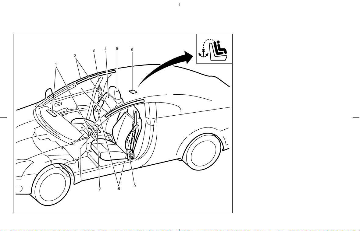
1. Supplemental front-impact air bags
(Page 1-28)
2. Roof-mounted curtain side-impact supple-
mental air bags* (P.1-28)
3. Seat belts (P.1-10)
4. Seats (P.1-2)
— Child restraints (P.1-17)
5. Head restraints (P.1-9)
— Front-seat Active Head Restraints
(P.1-10)
6. Child restraint anchor point* (for top tether
strap child restraint) (P.1-24)
7. Occupant classification sensor (pattern sen-
sor)
— Advanced air bag system (P.1-35)
8. Front seat-mounted side-impact supplemen-
tal air bags* (P.1-28)
9. Seat belt pretensioner (P.1-41)
*: if so equipped
SSI0255
AIR BAGS, SEAT BELTS AND
CHILD RESTRAINTS
0-2 Illustrated table of contents
墌 08.7.24/Z33-D/V5.0 墍
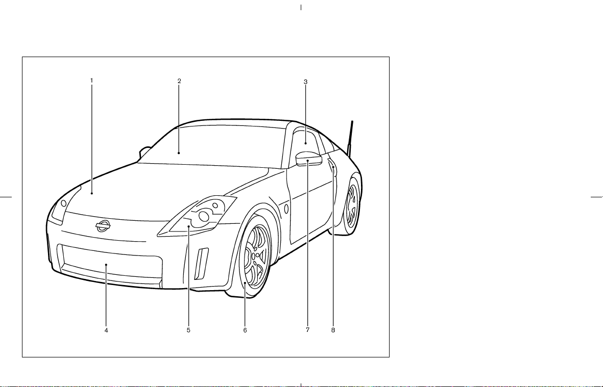
1. Hood (P.3-8)
2. Windshield wiper and washer
— Switch (P.2-21)
— Wiper replacement (P.8-19)
— Washer fluid (P.8-14)
3. Power windows (P.2-39)
— Automatic adjusting function (P.2-40,
P.8-15)
4. Recovery hook installation (P.6-12)
License plate installation (P.9-12)
5. Headlight, park and turn signal lights
— Switch (P.2-24)
— Bulb (P.8-27)
6. Tires
— Wheels and tires (P.8-30, P.9-8)
— Flat tire (P.6-2)
— Tire pressure monitoring system (TPMS)
(P.2-13, P.5-3)
7. Outside mirrors (P.3-27)
8. Doors
— Keys (P.3-2)
— Door locks (P.3-3)
— Keyfob (P.3-5)
SSI0289
EXTERIOR FRONT
Illustrated table of contents 0-3
墌 08.7.24/Z33-D/V5.0 墍
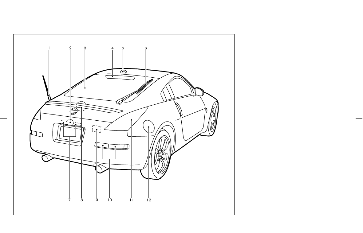
COUPE MODELS
1. Antenna (P.4-30)
2. Rear hatch release switch (P.3-9)
3. Rear window defroster (P.2-23)
4. High-mounted stop light (Bulb) (P.8-28)
5. Satellite radio antenna* (P.4-13)
6. Rear window wiper and washer
— Switch (P.2-22)
— Washer fluid (P.8-14)
7. License plate lights (Bulb) (P.8-28)
8. Rear hatch release (secondary) (P.3-12)
9. Luggage compartment light (P.2-42, P.8-28)
10. Back-up, Turn signal light (Bulb) (P.8-28)
11. Side marker, Stop/Tail light (Bulb) (P.8-28)
12. Fuel
— Fuel-filler door (P.3-23)
— Fuel recommendation (P.9-3)
*: if so equipped
SSI0152
EXTERIOR REAR
0-4 Illustrated table of contents
墌 08.7.24/Z33-D/V5.0 墍

ROADSTER MODELS
1. Antenna (P.4-30)
2. Trunk lid release switch (P.3-10)
3. Trunk light (P.2-42, P.8-28)
4. High-mounted stop light (Bulb) (P.8-28)
5. Rear window defroster (P.2-23)
6. Soft top (P.3-13)
7. Interior trunk lid release (P.3-11)
8. License plate lights (Bulb) (P.8-28)
9. Back-up, Turn signal light (Bulb) (P.8-28)
10. Side marker, Stop/Tail light (Bulb) (P.8-28)
11. Fuel
— Fuel-filler door (P.3-23)
— Fuel recommendation (P.9-3)
SSI0003
Illustrated table of contents 0-5
墌 08.7.24/Z33-D/V5.0 墍
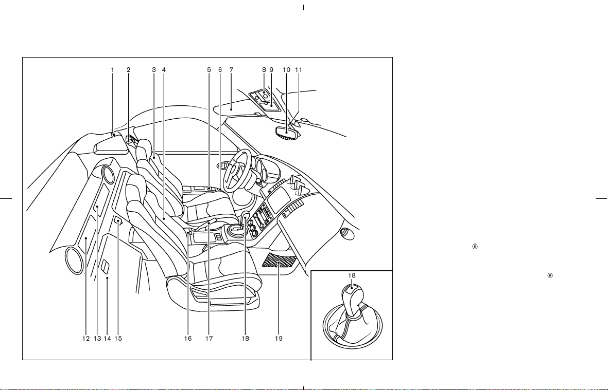
COUPE MODELS
1. Coat hook (P.2-38)
2. Seat belts (P.1-10)
3. Seats
— Manual seats adjustment (P.1-3)
— Power seats adjustment (P.1-3)
4. Passenger seat
— Tilt lever for passenger seat (seatback)
(P.1-7)
5. Power window switch (P.2-39)/Power door
lock switch (P.3-4)
6. Outside mirror remote control switch
(P.3-27)
7. Sun visor (P.3-25)
8. Interior light (P.2-41)
9. Sunglasses holder (P.2-32)
10. Inside mirror (P.3-26)
— Automatic anti-glare inside mirror*
(P.3-26)
— HomeLink
universal transceiver*
(P.2-43)
11. Front passenger air bag status light
(P.1-36)/Microphone (Bluetooth
Hands-
Free Phone System*) (P.4-31)
12. Rear parcel box (P.2-37)
13. Rear parcel box or Navigation system*1
14. Rear floor box (P.2-35)
15. Power outlet (P.2-31)
16. Console box (P.2-35)
17. Parking brake
— Operation (P.5-15)
SSI0256
PASSENGER COMPARTMENT
0-6 Illustrated table of contents
墌 08.7.24/Z33-D/V5.0 墍

— Parking/Parking on hills (P.5-19)
— Checking (P.8-21)
18. Selector lever or shift lever
— Automatic transmission (P.5-10)
— Manual transmission (P.5-13)
19. Cargo net (P.2-33)
*: if so equipped
*1: Refer to the separate Navigation System
Owner’s Manual.
Illustrated table of contents 0-7
墌 08.7.24/Z33-D/V5.0 墍
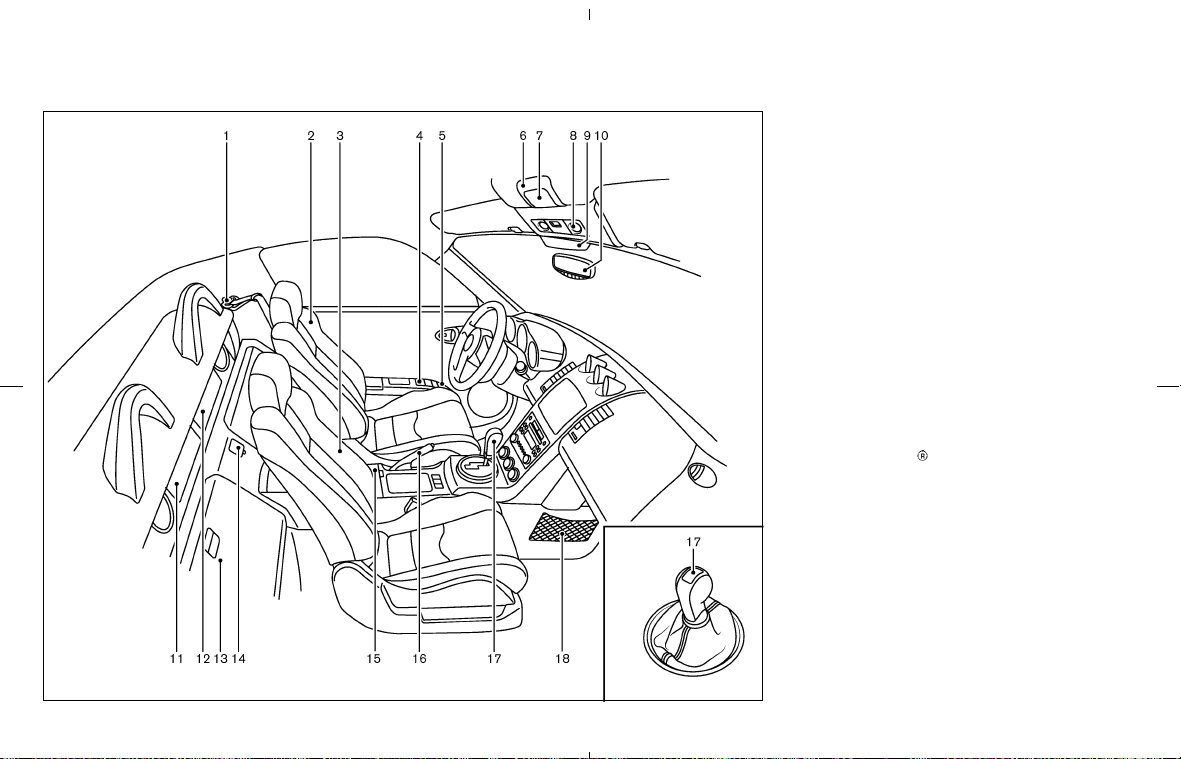
ROADSTER MODELS
1. Seat belts (P.1-10)
2. Seats
— Power seats adjustment (P.1-4)
— Ventilated net seats* (P.1-6)
3. Passenger seat
— Power seatback tilt switch (P.1-7)
— Cancel switch (P.1-8)
4. Power window switch (P.2-39)/Power door
lock switch (P.3-4)
5. Outside mirror remote control switch
(P.3-27)
6. Soft top latch lever (P.3-16)
7. Safety switch for soft top latch lever (P.3-16)
8. Interior light (P.2-41)
9. Front passenger air bag status light (P.1-36)
10. Inside mirror (P.3-26)
— Automatic anti-glare inside mirror*
(P.3-26)
— HomeLink
universal transceiver*
(P.2-43)
11. Rear parcel box (P.2-37)
12. Rear parcel box or Navigation system*1
13. Rear floor box (P.2-35)
— Trunk lid cancel switch (P.3-11)
— Secondary trunk lid release (P.3-12)
14. Power outlet (P.2-31)
15. Console box (P.2-35)
16. Parking brake
— Operation (P.5-15)
— Parking/Parking on hills (P.5-19)
— Checking (P.8-21)
SSI0257
0-8 Illustrated table of contents
墌 08.7.24/Z33-D/V5.0 墍

17. Selector lever or shift lever
— Automatic transmission (P.5-10)
— Manual transmission (P.5-13)
18. Cargo net (P.2-33)
*: if so equipped
*1: Refer to the separate Navigation System
Owner’s Manual.
Illustrated table of contents 0-9
墌 08.7.24/Z33-D/V5.0 墍

1. Headlight/turn signal switch (P.2-24)
2. Instrument brightness control switch
(P.2-26)
3. Steering wheel switch for audio control*
(P.4-29) or switch for Bluetooth
Hands-
Free Phone System* (P.4-31)
4. Driver supplemental air bag (P.1-28)/Horn
(P.2-27)
5. Meters/gauges (P.2-3)
6. Cruise control main/set switch* (P.5-16)
7. Trip computer mode/setting switch (P.2-8)
8. Wiper/washer switch (P.2-21)
9. Center ventilator (P.4-8)
10. Passenger supplemental air bag (P.1-28)
11. Side ventilators (P.4-8)
12. Soft top operating switch (for Roadster
models) (P.3-13)
13. VDC (Vehicle dynamic control) OFF switch*
(P.2-29) or TCS (Traction control system)
OFF switch* (P.2-29)
14. Fuel-filler door opener switch (P.3-23)
15. Hood lock release handle (P.3-8)
16. Fuse box (P.8-23)
17. Tilting steering wheel lock lever (P.3-25)
18. Ignition switch (P.5-6)
19. Navigation system display (P.4-2)*1 or In-
strument pocket (P.2-32)
20. Audio system (P.4-12)/Clock (P.2-30)
21. Rear window and outside mirror defroster
switch (P.2-23)
22. Hazard warning flasher switch (P.2-27)
23. Cup holder (P.2-33)
24. Heated seat switch* (P.2-28)
25. Heater/air conditioner control (P.4-9)
26. Power outlet (P.2-31)
*: if so equipped
*1: Refer to the separate Navigation System
Owner’s Manual.
SIC3266
INSTRUMENT PANEL
0-10 Illustrated table of contents
墌 08.7.24/Z33-D/V5.0 墍
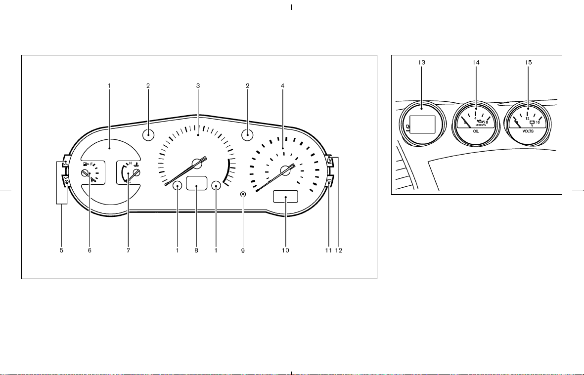
1. Warning/Indicator lights (P.2-11)
2. Turn signal/hazard indicator lights (P.2-26)
3. Tachometer (P.2-5)
4. Speedometer (P.2-4)
5. Instrument brightness control switch
(P.2-26)
6. Fuel gauge (P.2-6)
7. Engine coolant temperature gauge (P.2-5)
8. Automatic transmission position indicator
(P.2-15, P.5-10) or Manual transmission up-
shift indicator (P.2-10, P.5-14)
9. Reset knob for trip odometer (P.2-4)
10. Odometer (Total/Twin trip) (P.2-4)
11. Trip computer setting switch (P.2-8)
12. Trip computer mode switch (P.2-8)
13. Trip computer (P.2-8)
14. Engine oil pressure gauge (P.2-7)
15. Volt meter (P.2-8)
SIC3329
Combination meter
SIC1948A
Triple meter
METERS AND GAUGES
Illustrated table of contents 0-11
墌 08.7.24/Z33-D/V5.0 墍
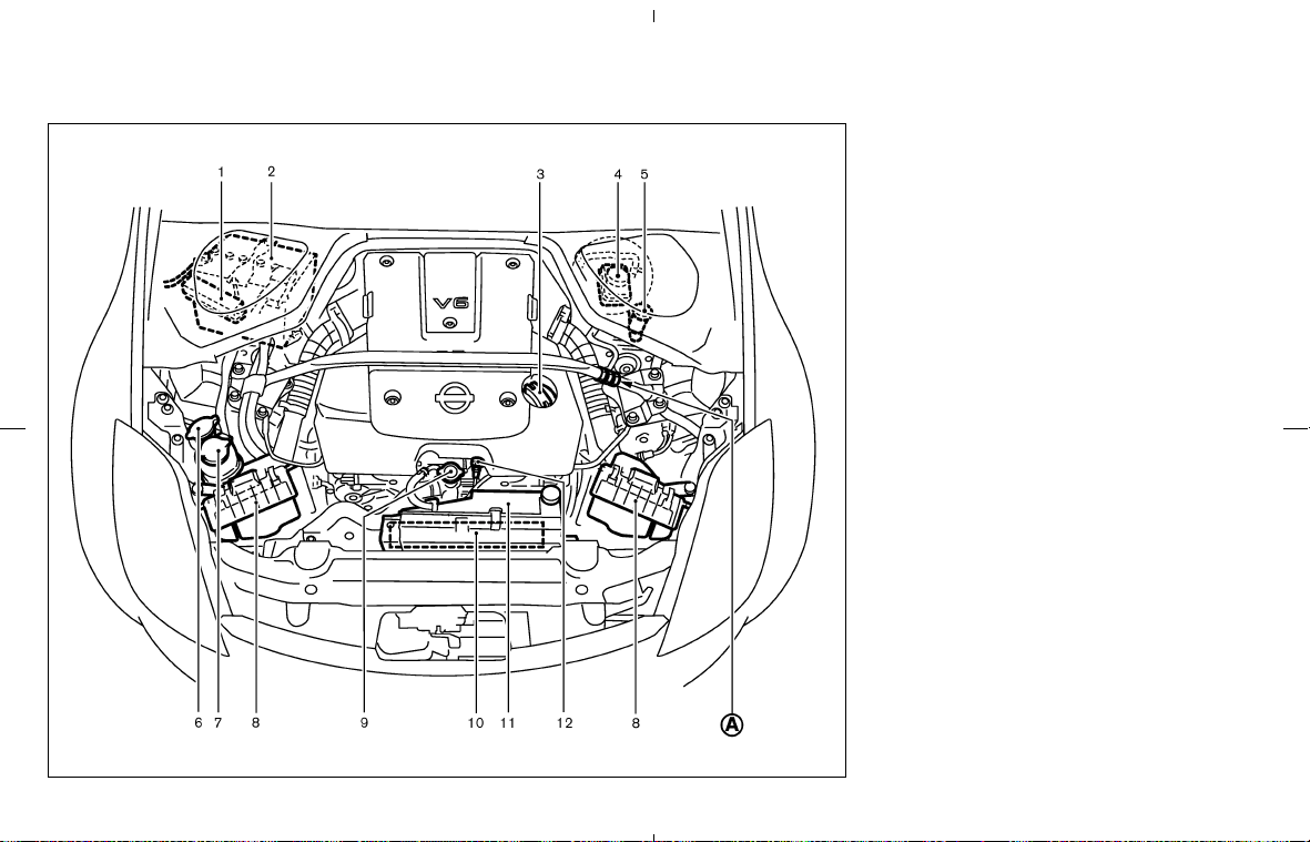
1. Fuse/fusible link holder (P.8-21)
2. Battery (P.8-15)
3. Engine oil filler cap (P.8-9)
4. Brake fluid reservoir (P.8-13)
5. Clutch fluid reservoir (M/T models) (P.8-13)
6. Window washer fluid reservoir (P.8-14)
7. Power steering fluid reservoir (P.8-12)
8. Air cleaner (P.8-18)
9. Radiator filler cap (P.8-8)
10. Engine drive belts (P.8-17)
11. Engine coolant reservoir (P.8-8)
12. Engine oil dipstick (P.8-9)
Do not tamper with the strut tower bar
adjustment
쎻
A
. The strut tower bar has
been adjusted to the most suitable posi-
tion at the factory.
SDI2050
ENGINE COMPARTMENT
0-12 Illustrated table of contents
墌 08.7.24/Z33-D/V5.0 墍

1 Safety — Seats, seat belts and supple-
mental restraint system
Seats ........................................................................................ 1-2
Front manual seat adjustment
(for Coupe models) ........................................................ 1-3
Front power seat adjustment
(for Coupe models — if so equipped) ...................... 1-3
Front power seat adjustment
(for Roadster models) .................................................... 1-4
Seat lifter (for driver’s seat) ......................................... 1-6
Tilting and reclining passenger’s seat from driver’s
seat ..................................................................................... 1-7
Head restraint adjustment ............................................ 1-9
Front-seat Active Head Restraints (except for
ventilated net seats)...................................................... 1-10
Seat belts ............................................................................. 1-10
Precautions on seat belt usage ................................ 1-10
Child safety .................................................................... 1-12
Pregnant women .......................................................... 1-13
Injured persons ............................................................. 1-14
Three-point type seat belt with retractor ............... 1-14
Seat belt extenders ...................................................... 1-16
Seat belt maintenance ................................................ 1-17
Child restraints ................................................................... 1-17
Precautions on child restraints ................................. 1-17
Child restraint installation on front passenger
seat (Coupe models only) .......................................... 1-20
Top tether strap child restraint
(Coupe models only) ................................................... 1-24
Booster seats ....................................................................... 1-25
Precautions on booster seats .................................... 1-25
Booster seat installation on front passenger
seat.................................................................................... 1-27
Supplemental restraint system ....................................... 1-28
Precautions on supplemental restraint system ..... 1-28
Supplemental air bag warning labels ...................... 1-42
Supplemental air bag warning light ......................... 1-43
墌 08.7.24/Z33-D/V5.0 墍
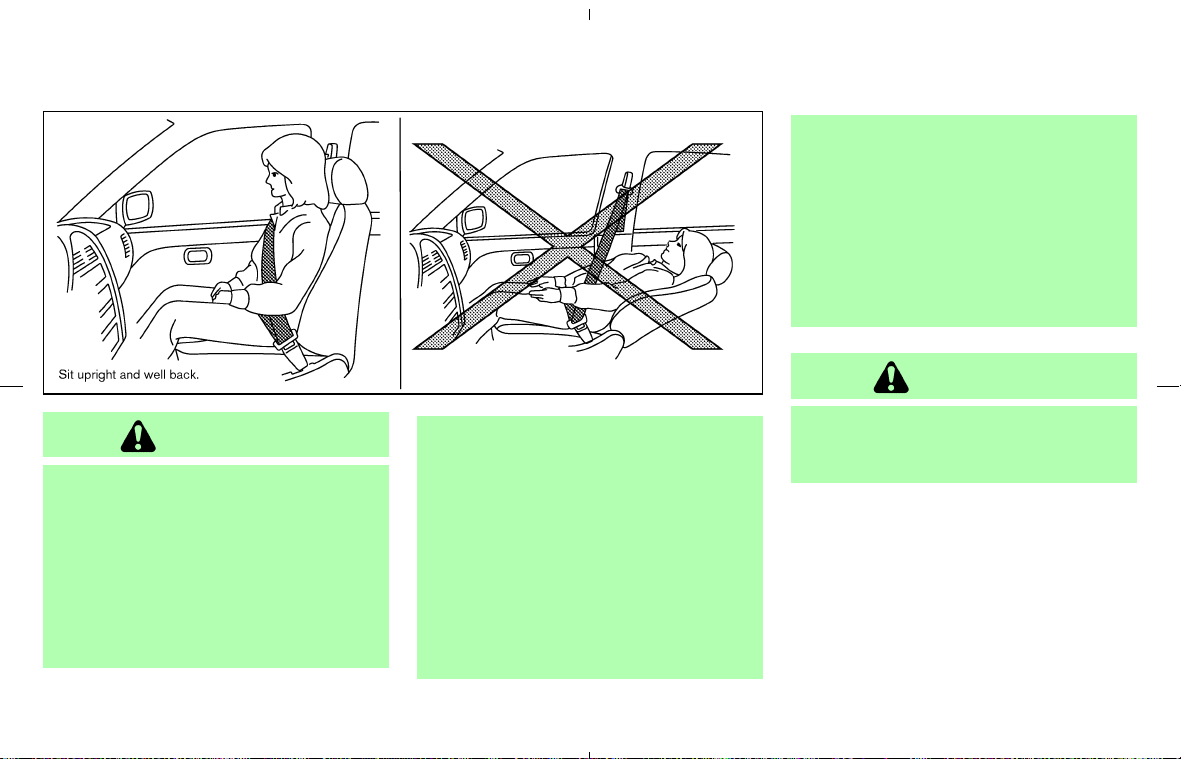
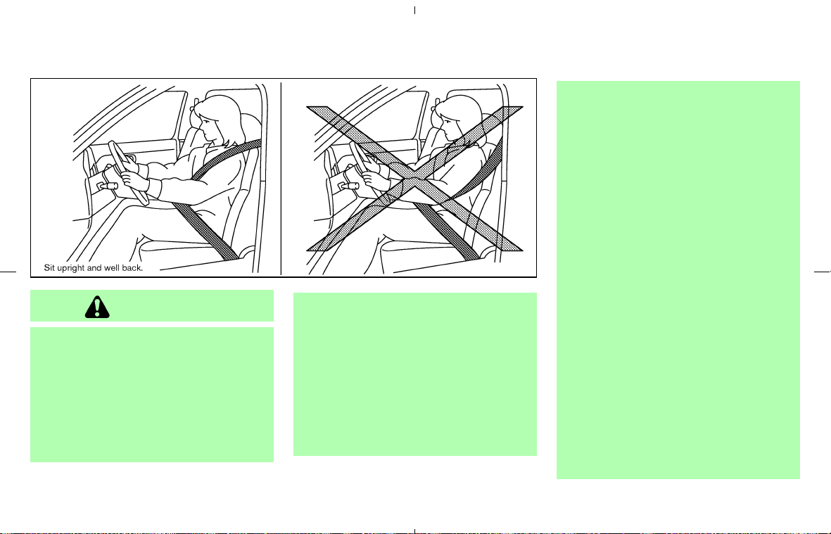
WARNING
쐌 Do not ride in a moving vehicle when
the seatback is reclined. This can be
dangerous. The shoulder belt will not
be against your body. In an accident,
you could be thrown into it and re-
ceive neck or other serious injuries.
You could also slide under the lap
belt and receive serious internal
injuries.
쐌 For the most effective protection
when the vehicle is in motion, the
seat should be upright. Always sit
well back in the seat with both feet
on the floor and adjust the seat prop-
erly. See “Precautions on seat belt
usage” later in this section.
쐌 After adjustment, gently rock in the
seat to make sure it is securely
locked.
쐌 Do not leave children unattended in-
side the vehicle. They could unknow-
ingly activate switches or controls.
Unattended children could become
involved in serious accidents.
쐌 Do not adjust the driver’s seat while
driving so full attention may be given
to vehicle operation. The seat may
move suddenly and could cause loss
of control of the vehicle.
CAUTION
When adjusting the seat positions, be
sure not to contact any moving parts to
avoid possible injuries and/or damages.
SSS0133
SEATS
1-2 Safety — Seats, seat belts and supplemental restraint system
墌 08.7.24/Z33-D/V5.0 墍
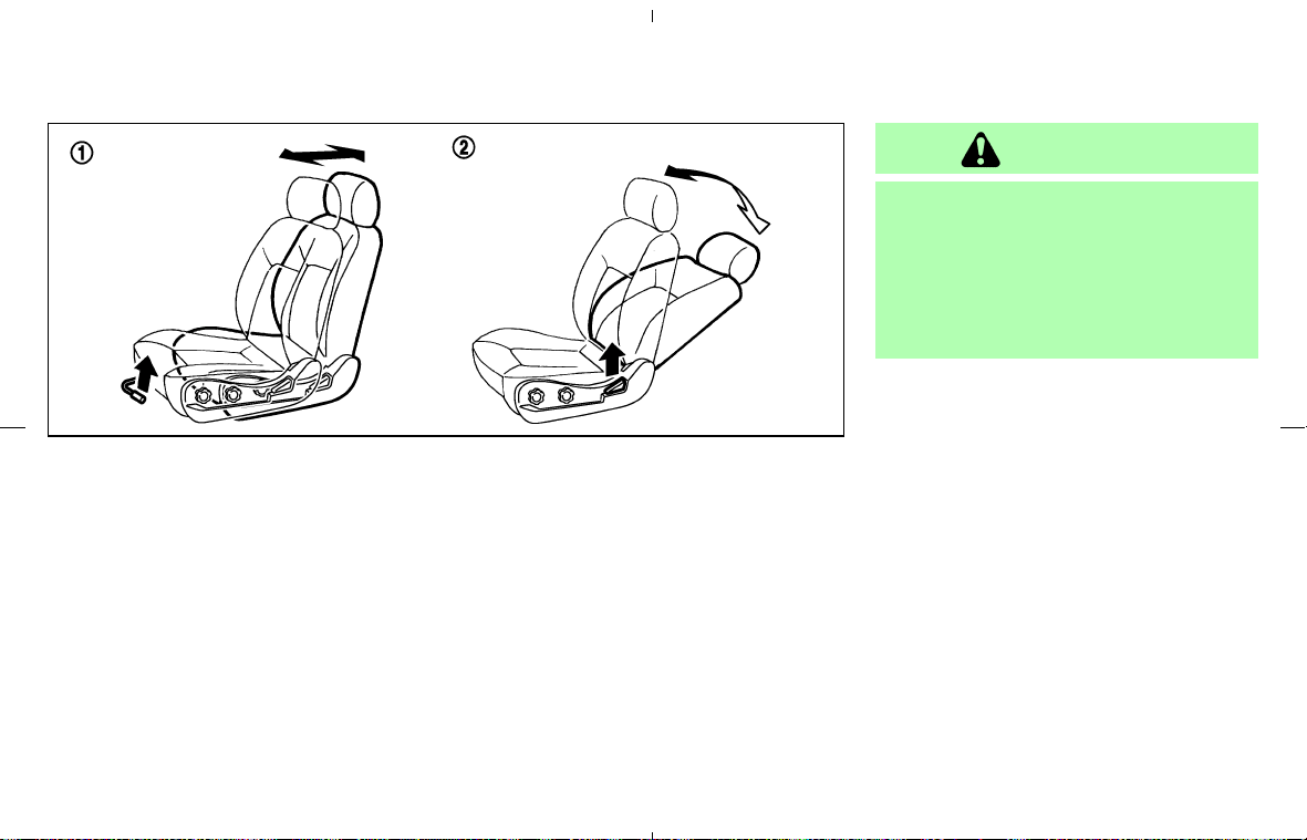
FRONT MANUAL SEAT
ADJUSTMENT (for Coupe models)
쎻
1
Forward and backward
Pull the lever up while you slide the seat forward
or backward to the desired position. Release the
lever to lock the seat in position.
When sliding the passenger’s seat backward,
be careful not to crush items in the seatback
pocket against the rear floor box.
쎻
2
Reclining
To recline the seatback, pull the lever up and
lean back. To bring the seatback forward again,
pull the lever and move your body forward. The
seatback will move forward.
The reclining feature allows adjustment of the
seatback for occupants of different sizes for
added comfort and to help obtain proper seat
belt fit. See “Precautions on seat belt usage”
later in this section. The seatback may also be
reclined to allow occupants to rest when the
vehicle is stopped and the transmission is in the
P (Park) position or N (Neutral) position with the
parking brake fully applied.
WARNING
The seatback should not be reclined any
more than needed for comfort. Seat
belts are most effective when the pas-
senger sits well back and straight up in
the seat. If the seatback is reclined, the
risk of sliding under the lap belt and
being injured is increased.
FRONT POWER SEAT
ADJUSTMENT (for Coupe models —
if so equipped)
Operating tips
쐌 The seat motor has an auto-reset overload
protection circuit. If the motor stops during
operation, wait 30 seconds, then reactivate
the switch.
쐌 Do not operate the power support seat
for a long period of time when the engine is
off. This will discharge the battery.
SSS0394
Safety — Seats, seat belts and supplemental restraint system 1-3
墌 08.7.24/Z33-D/V5.0 墍
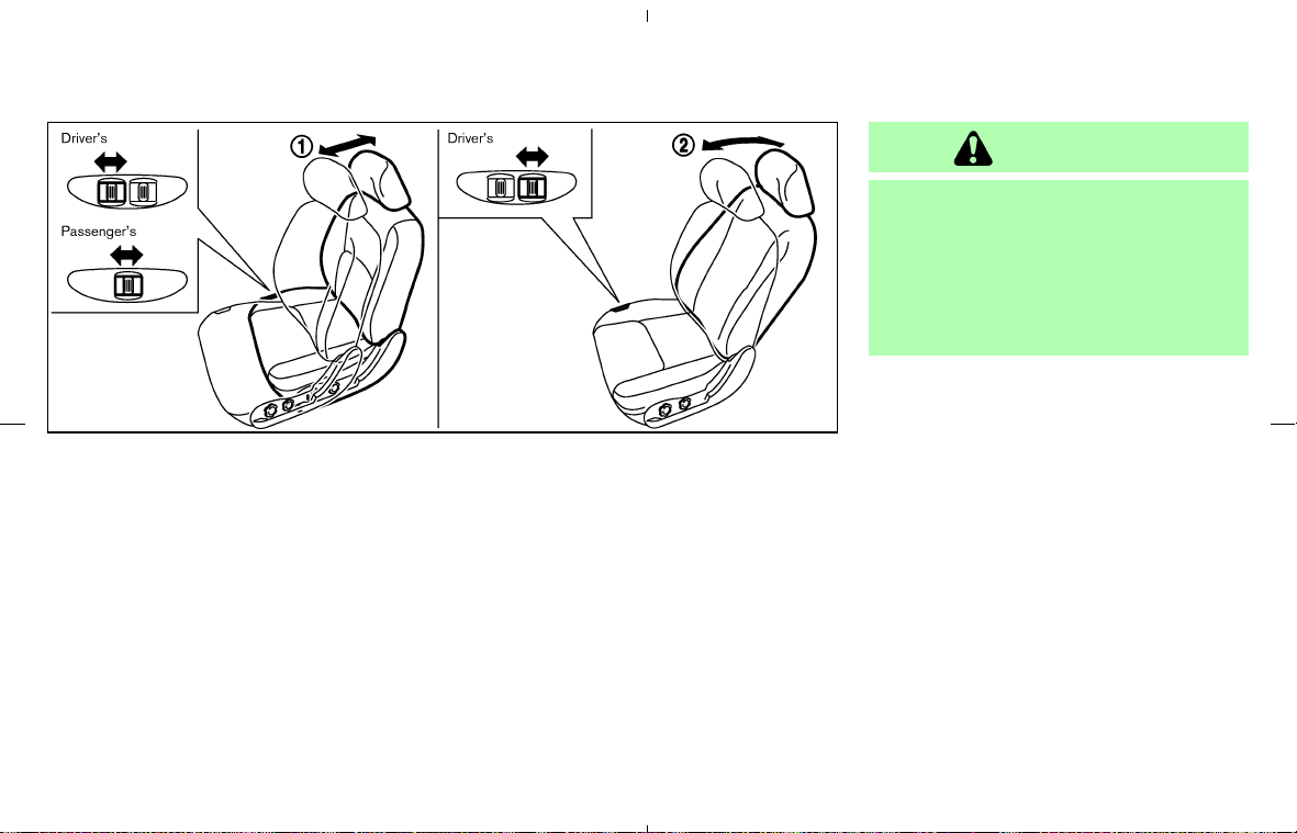
쎻
1
Forward and backward
Moving the sliding switch forward or backward
will slide the seat forward or backward to the
desired position.
When sliding the passenger’s seat backward,
be careful not to crush items in the seatback
pocket against the rear floor box.
쎻
2
Reclining (for driver’s seat)
Move the reclining switch backward until the
desired angle is obtained. To bring the seatback
forward, move the switch forward and move your
body forward. The seatback will move forward.
쎻
2
Reclining (for passenger’s seat)
The passenger’s seat is equipped with a manual
lever for reclining. See “Front manual seat ad-
justment” earlier in this section.
The reclining feature allows adjustment of the
seatback for occupants of different sizes for
added comfort and to help obtain proper seat
belt fit. See “Precautions on seat belt usage”
later in this section. The seatback may also be
reclined to allow occupants to rest when the
vehicle is stopped and the transmission is in the
P (Park) or N (Neutral) position with the parking
brake fully applied.
WARNING
The seatback should not be reclined any
more than needed for comfort. Seat
belts are most effective when the pas-
senger sits well back and straight up in
the seat. If the seatback is reclined, the
risk of sliding under the lap belt and
being injured is increased.
FRONT POWER SEAT
ADJUSTMENT (for Roadster models)
Operating tips
쐌 The seat motor has an auto-reset overload
protection circuit. If the motor stops during
operation, wait 30 seconds, then reactivate
the switch.
쐌 Do not operate the power support seat
for a long period of time when the engine is
off. This will discharge the battery.
SPA1793
1-4 Safety — Seats, seat belts and supplemental restraint system
墌 08.7.24/Z33-D/V5.0 墍

쎻
1
Forward and backward
Moving the sliding switch forward or backward
will slide the seat forward or backward to the
desired position.
When sliding the passenger’s seat backward,
be careful not to crush items in the seatback
pocket against the rear floor box.
쎻
2
Reclining
Move the reclining switch backward until the
desired angle is obtained. To bring the seatback
forward, move the switch forward and move your
body forward. The seatback will move forward.
The reclining feature allows adjustment of the
seatback for occupants of different sizes for
added comfort and to help obtain proper seat
belt fit. See “Precautions on seat belt usage”
later in this section. The seatback may also be
reclined to allow occupants to rest when the
vehicle is stopped and the transmission is in the
P (Park) or N (Neutral) position with the parking
brake fully applied.
WARNING
The seatback should not be reclined any
more than needed for comfort. Seat
belts are most effective when the pas-
senger sits well back and straight up in
the seat. If the seatback is reclined, the
risk of sliding under the lap belt and
being injured is increased.
Automatic passenger seatback tilt
function
The passenger seatback will automatically tilt
forward and backward during the soft top
open/close operation. If you need to cancel this
function or when a child restraint is installed in
the passenger’s seat, push the seatback tilt
cancel switch to the CANCEL position. For more
information about operation conditions, see
“Soft top” in the “3. Pre-driving checks and
adjustments” section. For the cancel switch, see
“Tilting and reclining passenger’s seat from driv-
er’s seat” later in this section.
SSS0472
Safety — Seats, seat belts and supplemental restraint system 1-5
墌 08.7.24/Z33-D/V5.0 墍
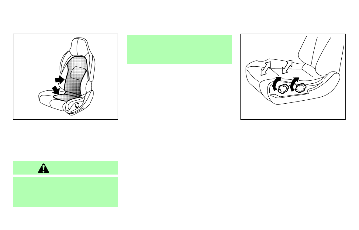
Ventilated net seats (if so equipped)
The ventilated net seats are designed for good
ventilation while driving. Net cloth is used on the
surface of the seatback and the cushion as
shown.
CAUTION
쐌 The seat is made of netted materials.
Be careful not to snag your jewelry,
such as a ring, bracelet or watch, on
the seat.
쐌 When using these seats, avoid wear-
ing clothing with soft fabrics (wool,
etc.). Clothing may be damaged as it
rubs against the netted material.
SEAT LIFTER (for driver’s seat)
Type A (except for ventilated net seat)
Turn either dial to adjust the angle and height of
the seat cushion to the desired position.
SSS0272 SPA1715
Type A
1-6 Safety — Seats, seat belts and supplemental restraint system
墌 08.7.24/Z33-D/V5.0 墍
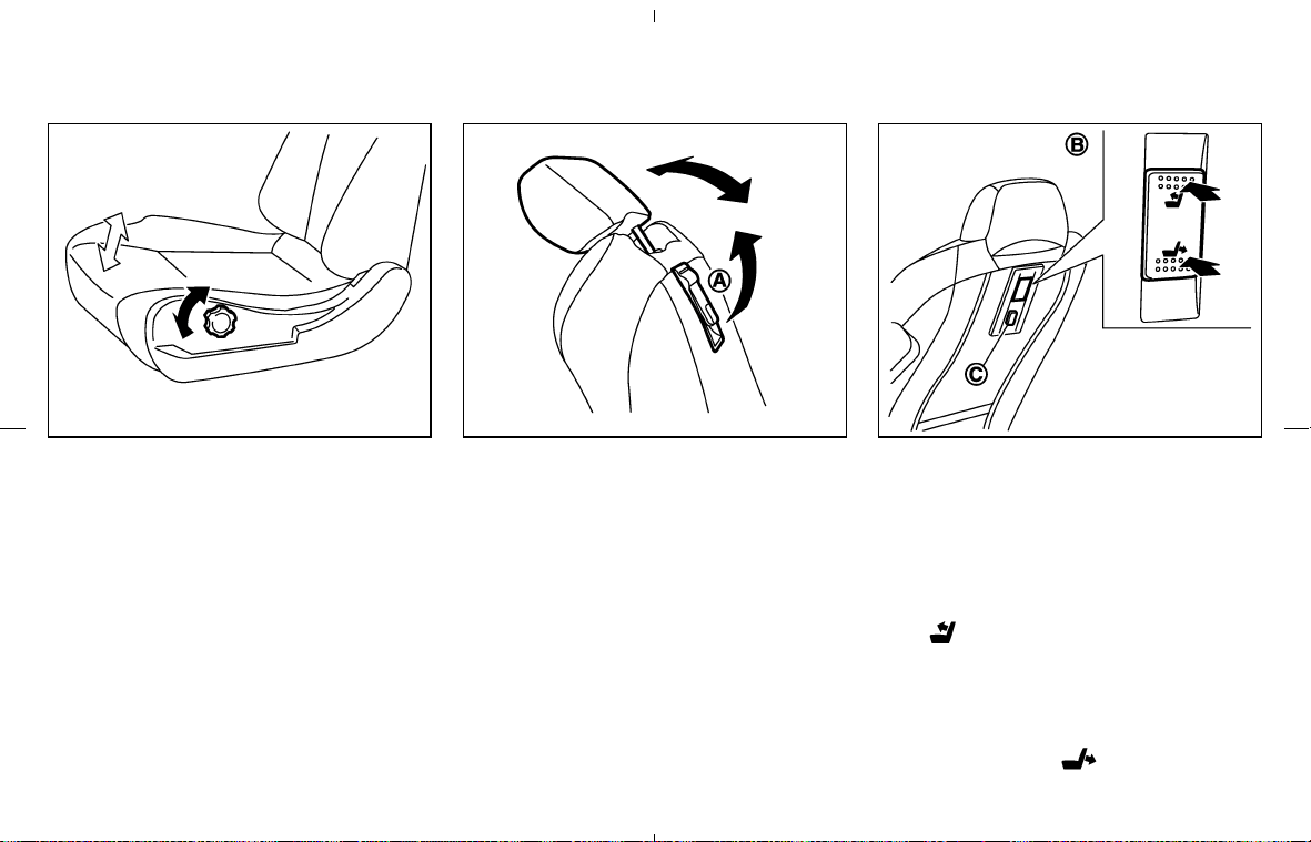
Type B (for ventilated net seat)
Turn the dial and adjust the angle of the seat
cushion to the desired position.
TILTING AND RECLINING
PASSENGER’S SEAT FROM
DRIVER’S SEAT
The passenger seatback can be adjusted from
the driver’s seat to make it easier for the driver to
use the rear parcel box or rear floor box, or to
help the passenger get in the vehicle.
Coupe models (manual type)
To tilt or recline the passenger seatback, pull up
the lever
쎻
A
located on the back side of it, and
move the seatback forward or backward.
Roadster models (power type)
The power seatback tilt switch 쎻
B
and the
seatback tilt cancel switch
쎻
C
are located on the
back side of the passenger seatback as shown.
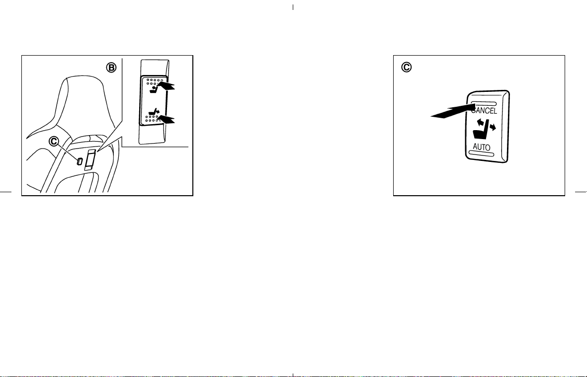
Tilting/reclining operation:
To tilt the passenger seatback forward, push the
top (
side) of the power seatback tilt
switch
쎻
B
for more than 0.5 second. The seat-
back will automatically tilt forward. To stop the
movement, push the top or bottom of the switch.
To tilt or adjust the seatback backward, push
and hold the bottom (
side) of the power
SSS0202
Type B
SSS0203
Coupe models
SSS0273
Roadster models — Type A
Safety — Seats, seat belts and supplemental restraint system 1-7
墌 08.7.24/Z33-D/V5.0 墍
seatback tilt switch. While the switch is held
down, the seatback will move backward to the
original position that was last selected using the
reclining switch (located on the seat cushion).
Release the switch to stop the movement.
Operation conditions:
The power seatback tilt switch does not activate
under the following conditions.
쐌 when the passenger seat sliding/reclining
switches on the seat cushion are being op-
erated.
쐌 when the seat tilt cancel switch is in the
CANCEL position. (See “Seatback tilt cancel
switch” later in this section.)
쐌 when the passenger seat belt is fastened.
쐌 when the vehicle speed reaches 4 MPH (7
km/h) and more.
The automatic tilting/reclining movement will be
stopped:
쐌 when any of the above 4 conditions occur.
쐌 when the power seatback tilt switch (top or
bottom) is pushed again.
쐌 when the seatback is moved with the soft top
open/close operation.
When this interruption occurs, you cannot move
the seatback backward from the stopped posi-
tion with the power seatback tilt switch. Use the
reclining switch (on the seat cushion) to select
the seatback position.
Seatback tilt cancel switch:
When the seatback tilt cancel switch
쎻
C
is
pushed to the CANCEL position, the
tilting/reclining operation using the power seat-
back tilt switch
쎻
B
will be cancelled. Only the
sliding/reclining switches (located on the seat
cushion) are operational. Push the seatback tilt
cancel switch to the AUTO position to reactivate
the power seatback tilt switch.
This cancel switch is linked with the automatic
passenger seatback tilt function of the soft top
operation. See “Soft top” in the “3. Pre-driving
checks and adjustments” section.
SSS0274
Roadster models — Type B
SSS0275
1-8 Safety — Seats, seat belts and supplemental restraint system
墌 08.7.24/Z33-D/V5.0 墍
CAUTION
When a child restraint is installed in the
passenger seat, be sure to turn the seat-
back tilt cancel switch to the CANCEL
position. Otherwise, the child restraint
may be damaged.
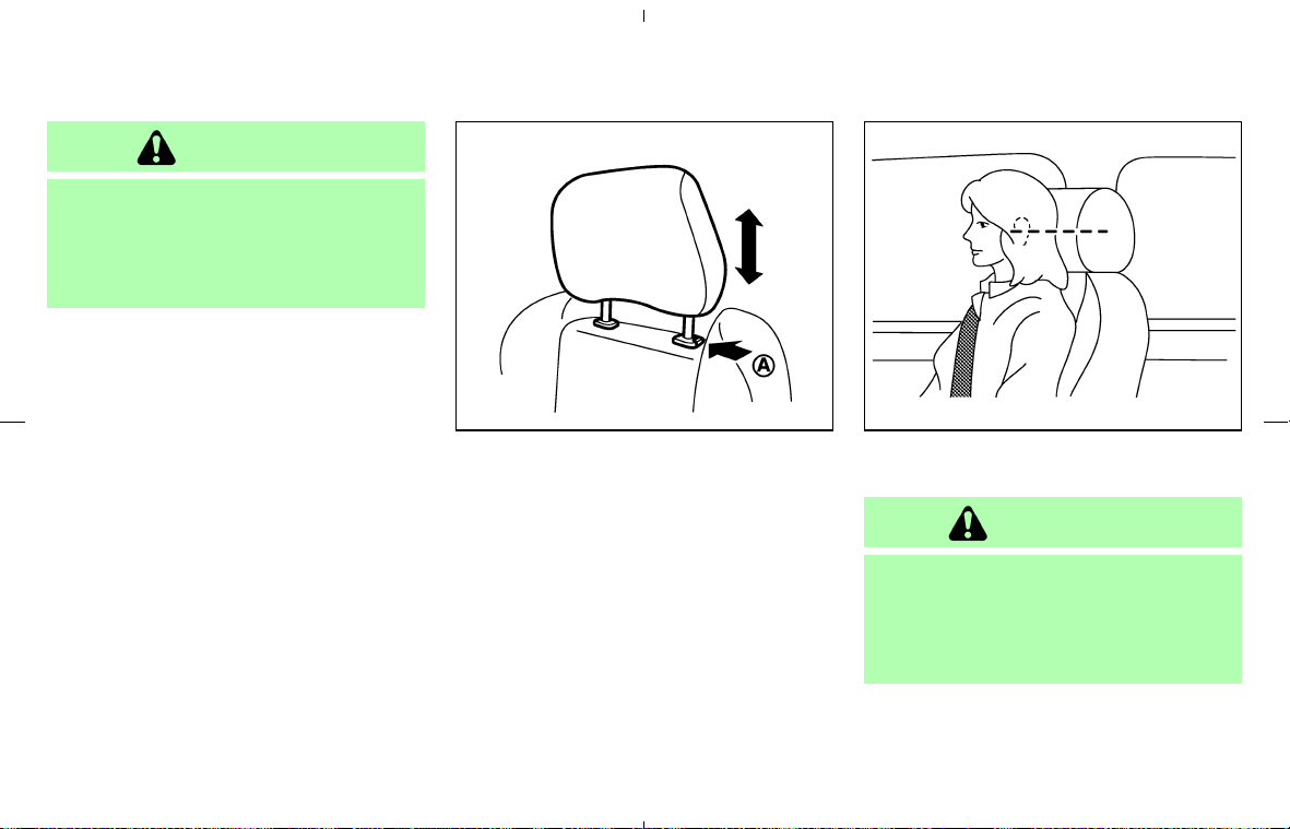
HEAD RESTRAINT ADJUSTMENT
To raise the head restraint, just pull it up. To
lower, push the lock knob
쎻
A
and push the head
restraint down.
The ventilated net seats (if so equipped for
Roadster models) have non-adjustable head
restraints.
Adjust the head restraints so the center is level
with the center of your ears.
WARNING
Head restraints should be adjusted
properly as they may provide significant
protection against injury in an accident.
Do not remove them. Check the adjust-
ment after someone else uses the seat.
SSS0204 SSS0178A
Safety — Seats, seat belts and supplemental restraint system 1-9
墌 08.7.24/Z33-D/V5.0 墍

FRONT-SEAT ACTIVE HEAD
RESTRAINTS (except for ventilated
net seats)
WARNING
쐌 Always adjust the head restraints
properly as specified in the previous
section. Failure to do so can reduce
the effectiveness of the active head
restraint.
쐌 Active Head Restraints are designed
to supplement other safety systems.
Always wear seat belts. No system
can prevent all injuries in any acci-
dent.
쐌 Do not attach anything to the head
restraint stalks. Doing so could im-
pair Active Head Restraint function.
The Active Head Restraint moves forward utiliz-
ing the force that the seatback receives from the
occupant in a rear-end collision. The movement
of the head restraint helps support the occu-
pant’s head by reducing its backward movement
and helping absorb some of the forces that may
lead to whiplash type injuries.
Active Head Restraints are effective for colli-
sions at low to medium speeds in which it is said
that whiplash injury occurs most.
Active Head Restraints operate only in certain
rear-end collisions. After the collision, the head
restraints return to their original positions.
Properly adjust the Active Head Restraints as
described in the previous section.
PRECAUTIONS ON SEAT BELT
USAGE
If you are wearing your seat belt properly ad-
justed and you are sitting upright and well back
in your seat with both feet on the floor, your
chances of being injured or killed in an accident
and/or the severity of injury may be greatly
reduced. NISSAN strongly encourages you and
all of your passengers to buckle up every time
you drive, even if your seating position includes a
supplemental air bag.
Most U.S. states and Canadian provinces
or territories require that seat belts be
worn at all times when a vehicle is being
driven.
SSS0508
SEAT BELTS
1-10 Safety — Seats, seat belts and supplemental restraint system
墌 08.7.24/Z33-D/V5.0 墍
WARNING
쐌 Every person who drives or rides in
this vehicle should use a seat belt at
all times.
쐌 The seat belt should be properly ad-
justed to a snug fit. Failure to do so
may reduce the effectiveness of the
entire restraint system and increase
the chance or severity of injury in
an accident. Serious injury or death
can occur if the seat belt is not worn
properly.
쐌 Always route the shoulder belt over
your shoulder and across your chest.
Never put the belt behind your back,
under your arm or across your neck.
The belt should be away from your
face and neck, but not falling off your
shoulder.
쐌 Position the lap belt as low and snug
as possible AROUND THE HIPS, NOT
THE WAIST. A lap belt worn too high
could increase the risk of internal
injuries in an accident.
쐌 Be sure the seat belt tongue is se-
curely fastened to the proper buckle.
쐌 Do not wear the seat belt inside out
or twisted. Doing so may reduce its
effectiveness.
쐌 Do not allow more than one person
to use the same seat belt.
쐌 Never carry more people in the ve-
hicle than there are seat belts. This
vehicle has only two seating posi-
tions. Never allow anyone to ride in
the luggage area.
쐌 If the seat belt warning light glows
continuously while the ignition is
turned ON with all doors closed and
all seat belts fastened, it may indi-
cate a malfunction in the system.
Have the system checked by a
NISSAN dealer.
SSS0136
Safety — Seats, seat belts and supplemental restraint system 1-11
墌 08.7.24/Z33-D/V5.0 墍
쐌 Once a seat belt pretensioner has
activated, it cannot be reused and
must be replaced together with the
retractor. See a NISSAN dealer.
쐌 Removal and installation of the pre-
tensioner system components
should be done by a NISSAN dealer.
쐌 All seat belt assemblies, including
retractors and attaching hardware,
should be inspected after any colli-
sion by a NISSAN dealer. NISSAN
recommends that all seat belt as-
semblies in use during a collision be
replaced unless the collision was mi-
nor and the belts show no damage
and continue to operate properly.
Seat belt assemblies not in use dur-
ing a collision should also be in-
spected and replaced if either dam-
age or improper operation is noted.
CHILD SAFETY
Children need adults to help protect them.
They need to be properly restrained.
In addition to the general information in this
manual, child safety information is available from
many other sources, including doctors, teachers,
government traffic safety offices, and community
organizations. Every child is different, so be sure
to learn the best way to transport your child.
There are three basic types of child restraint
systems:
쐌 Rear facing child restraint (should not be
installed in this vehicle)
쐌 Front facing child restraint (should not be
installed in the Roadster models)
쐌 Booster seat
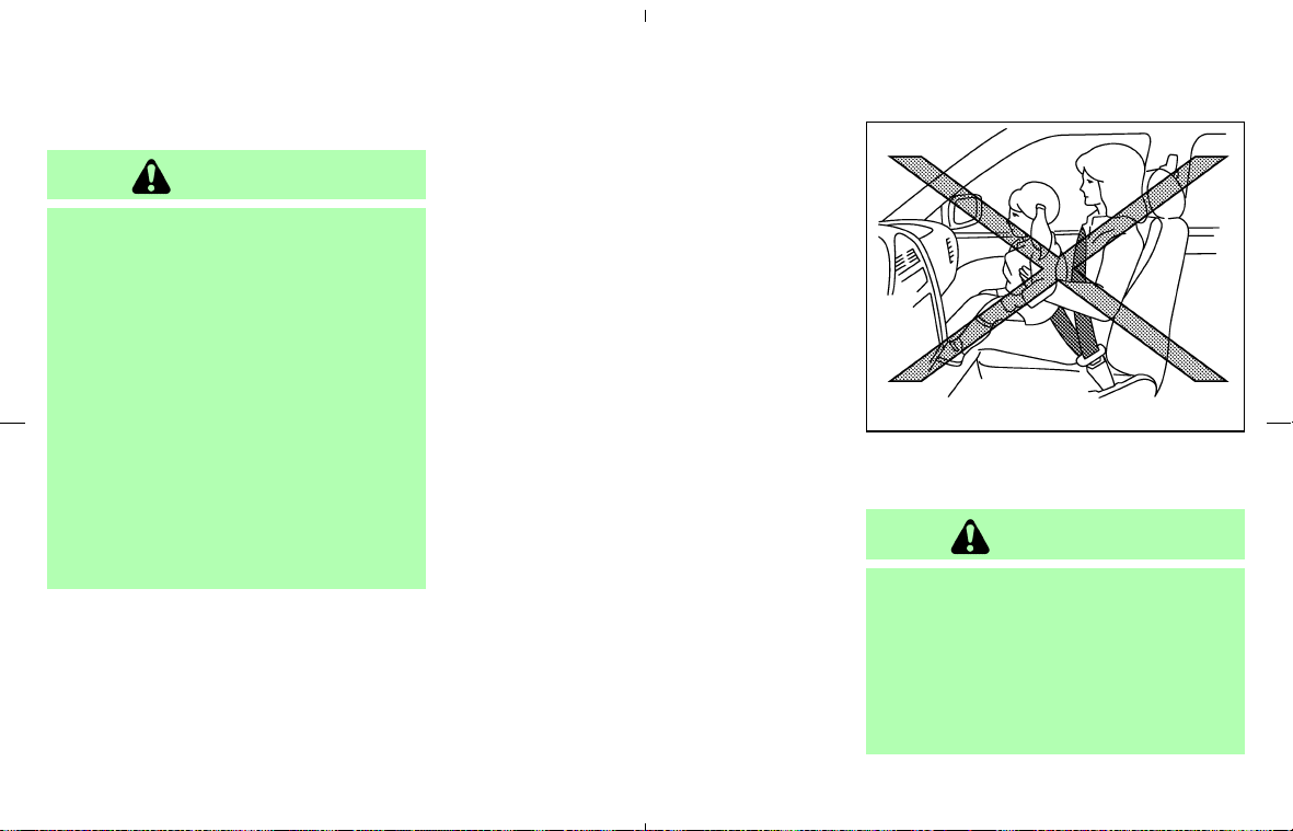
WARNING
쐌 Never let an infant who requires the
use of a rear facing child restraint
ride in this vehicle. Do not attempt to
hold a child in your lap or arms.
쐌 Roadster models do not have an an-
chor for a top tether strap required
SSS0134
1-12 Safety — Seats, seat belts and supplemental restraint system
墌 08.7.24/Z33-D/V5.0 墍

for most front facing child restraints.
Never let children who require the
use of a front facing child restraint
ride in Roadster models.
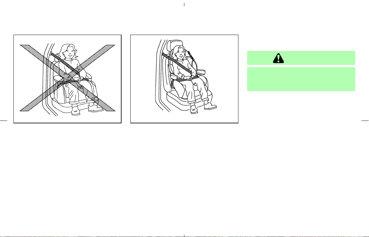
쐌 Children need special protection. The
vehicle’s seat belts may not fit them
properly. The shoulder belt may come
too close to the face or neck. The lap
belt may not fit over their small hip
bones. In an accident, an improperly
fitting seat belt could cause serious
or fatal injury. Always use appropri-
ate child restraints.
쐌 Never let a child stand or kneel on
any seat and do not allow a child in
the cargo areas while the vehicle is
moving. The child could be seriously
injured or killed in an accident or
sudden stop.
Your vehicle is equipped with a supplemental
front impact air bag system for the front passen-
ger. See “Supplemental restraint system” later in
this section. The passenger seat is not suitable
for use with a rear facing child restraint needed
for infants. Therefore, infants should not be
transported in this vehicle.
All US states and provinces of Canada require
the use of approved child restraints for infants
and small children. (See “Child restraints” later in
this section.)
Also, there are other types of child restraints
available for larger children for additional protec-
tion.
Infants
Infants up to at least 1 year old should be placed
in a rear facing child restraint. Because a rear
facing child restraint is not suitable for use in this
vehicle, infants should not be transported in it.
Small children
Children that are over 1 year old and weigh at
least 20 lbs (9 kg) can be placed in a forward
facing child restraint (except Roadster models).
Refer to the manufacturer’s instructions for mini-
mum and maximum weight and height recom-
mendations. NISSAN recommends that small
children be placed in child restraints that comply
with Federal Motor Vehicle Safety Standards or
Canadian Motor Vehicle Safety Standards. You
should choose a child restraint that fits your
vehicle and always follow the manufacturer’s
instructions for installation and use.
Larger children
Children who are too large for child restraint
systems should be seated and restrained by the
seat belts which are provided. The seat belt may
not fit properly if the child is less than 4 ft 9 in
(142.5 cm) tall and weighs between 40 lbs (18
kg) and 80 lbs (36 kg). A booster seat should be
used to obtain proper seat belt fit.
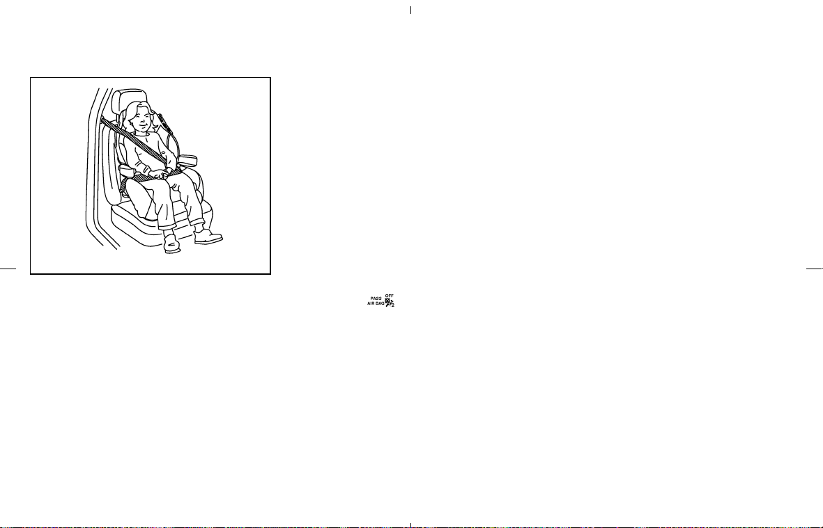
NISSAN recommends that a child be placed in a
commercially available booster seat if the shoul-
der belt in the child’s seating position fits close
to the face or neck or if the lap portion of the seat
belt goes across the abdomen. The booster seat
should raise the child so that the shoulder belt is
properly positioned across the top, middle por-
tion of the shoulder and the lap belt is low on the
hips. A booster seat can only be used in seating
positions that have a three-point type seat belt.
The booster seat should fit the vehicle seat and
have a label certifying that it complies with
Federal Motor Vehicle Safety Standards or Ca-
nadian Motor Vehicle Safety Standards. Once
the child has grown so the shoulder belt is no
longer on or near the face and neck, use the
shoulder belt without the booster seat.
PREGNANT WOMEN
NISSAN recommends that pregnant women use
seat belts. The seat belt should be worn snug,
and always position the lap belt as low as
Safety — Seats, seat belts and supplemental restraint system 1-13
墌 08.7.24/Z33-D/V5.0 墍
possible around the hips, not the waist. Place
the shoulder belt over your shoulder and across
your chest. Never run the lap/shoulder belt over
your abdominal area. Contact your doctor for
specific recommendations.
INJURED PERSONS
NISSAN recommends that injured persons use
seat belts, depending on the injury. Check with
your doctor for specific recommendations.
THREE-POINT TYPE SEAT BELT
WITH RETRACTOR
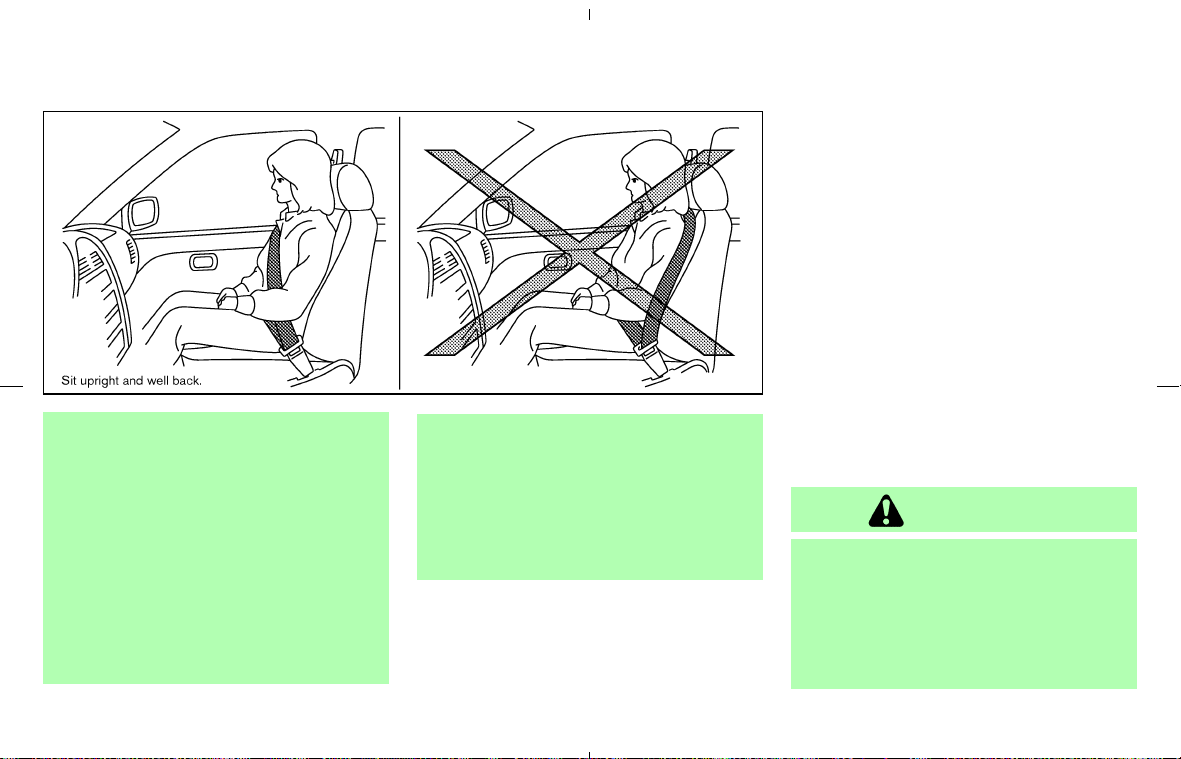
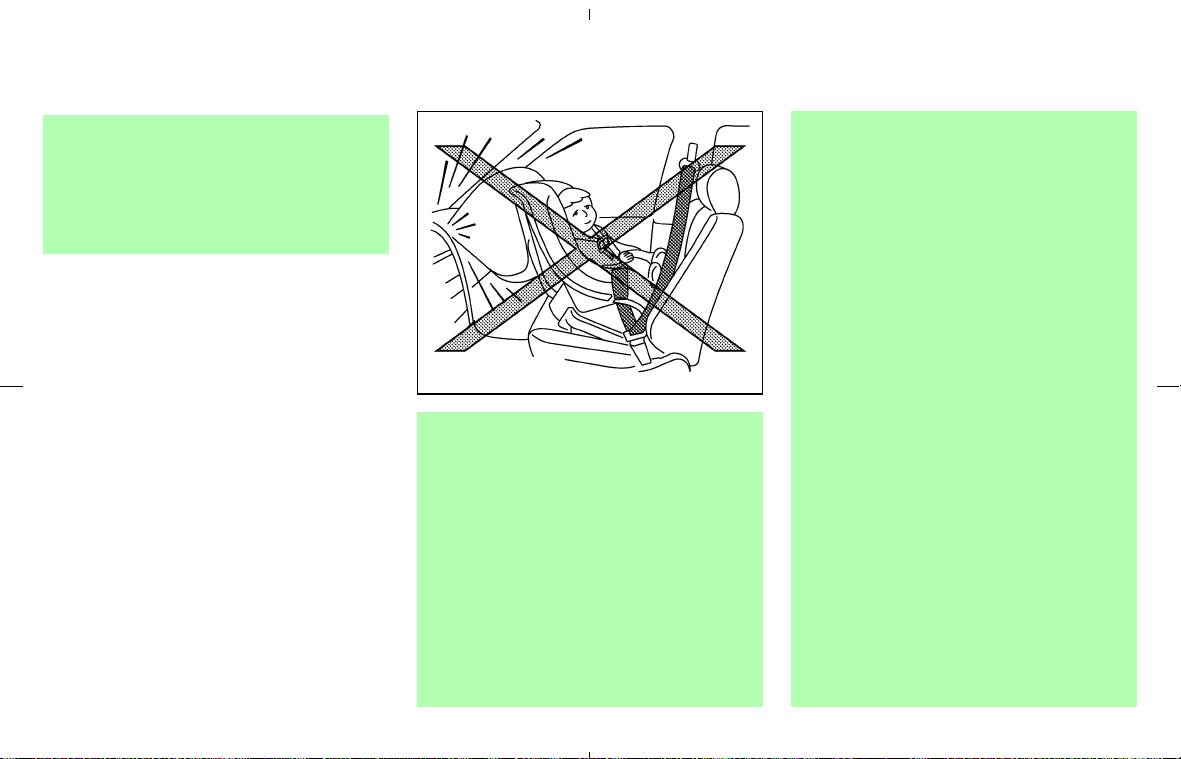
WARNING
쐌 Every person who drives or rides in
this vehicle should use a seat belt at
all times.
쐌 Do not ride in a moving vehicle when
the seatback is reclined. This can be
dangerous. The shoulder belt will not
be against your body. In an accident,
you could be thrown into it and re-
ceive neck or other serious injuries.
You could also slide under the lap
belt and receive serious internal inju-
ries.
쐌 For the most effective protection
when the vehicle is in motion, the
seat should be upright. Always sit
well back in the seat with both feet
on the floor and adjust the seat belt
properly.
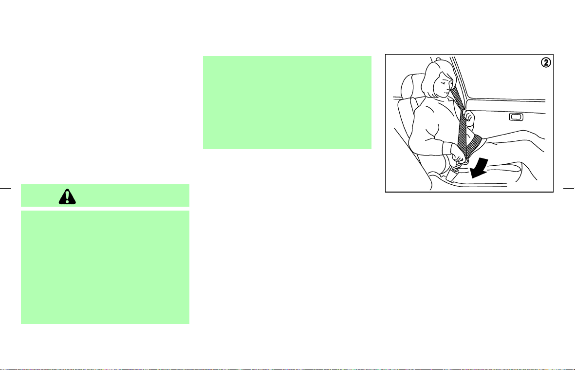
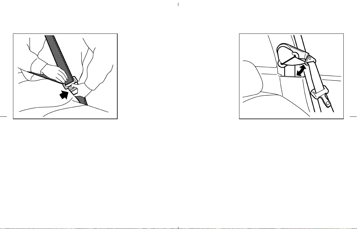
Fastening the seat belts
1. Adjust the seat. See “Seats” earlier in this
section.
2. Slowly pull the seat belt out of the retractor
and insert the tongue into the buckle until it
clicks.
쐌 The retractor is designed to lock during
a sudden stop or on impact. A slow
pulling motion will permit the belt to
move, and allow you some freedom of
movement in the seat.
쐌 If the seat belt cannot be pulled from its
fully retracted position, firmly pull the
SSS0292A
1-14 Safety — Seats, seat belts and supplemental restraint system
墌 08.7.24/Z33-D/V5.0 墍
belt and release it. Then smoothly pull
the belt out of the retractor.
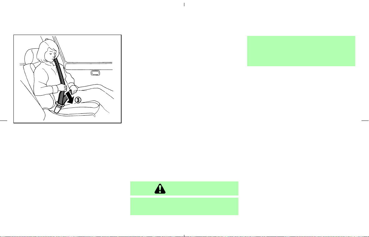
3. Position the lap belt portion low and snug
on the hips as shown.
4. Pull the shoulder belt portion toward the
retractor to take up extra slack. Be sure the
shoulder belt is routed over your shoulder
and across your chest.
The front passenger seat belt has two modes of
operation:
쐌 Emergency Locking Retractor (ELR)
쐌 Automatic Locking Retractor (ALR)
The Emergency Locking Retractor (ELR) mode
allows the seat belt to extend and retract to allow
the driver and passenger some freedom of
movement in the seat. The ELR locks the seat
belt when the vehicle slows down rapidly or
during certain impacts.
The Automatic Locking Retractor (ALR) mode
(child restraint mode) locks the seat belt for child
restraint installation.
When the ALR mode is activated the seat belt
cannot be extended again until the seat belt
tongue is detached from the buckle and fully
retracted. The seat belt returns to the ELR mode
after the seat belt fully retracts. For additional
information, see “Child restraints” later in this
section.
The ALR mode should be used only for
child restraint installation. During normal
seat belt use by a passenger, the ALR
mode should not be activated. If it is acti-
vated it may cause uncomfortable seat belt
tension.
WARNING
When fastening the seat belts, be cer-
tain that the seatbacks are completely
secured in the latched position. If they
are not completely secured, passengers
may be injured in an accident or sudden
stop.
SSS0290A
Safety — Seats, seat belts and supplemental restraint system 1-15
墌 08.7.24/Z33-D/V5.0 墍
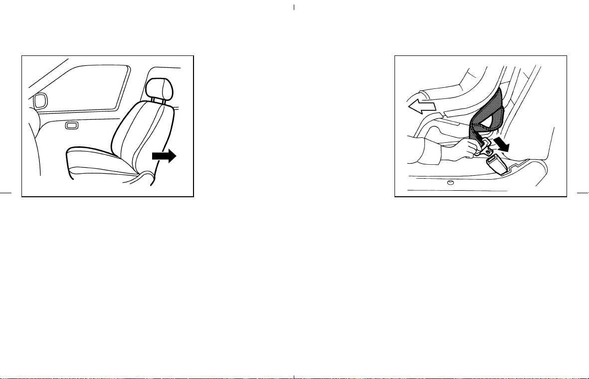
Unfastening the seat belts
To unfasten the belt, push the button on the
buckle. The seat belt will automatically retract.
Checking seat belt operation
Your seat belt retractors are designed to lock
belt movement using two separate methods:
쐌 when the belt is pulled quickly from the
retractor.
쐌 when the vehicle slows down rapidly.
You can check their operation as follows:
쐌 grasp the shoulder belt and pull quickly for-
ward. The retractor should lock and restrict
further belt movement.
If the retractor does not lock during this check or
if you have any questions about belt operation,
see a NISSAN dealer.
Shoulder belt arm
The shoulder belt arm should be adjusted to the
position best for you. (See “Precautions on seat
belt usage” earlier in this section.)
To adjust, pull the shoulder belt arm. Pulling the
arm forward will allow an easy access to the belt.
SEAT BELT EXTENDERS
If, because of body size or driving position, it is
not possible to properly fit the lap-shoulder belt
and fasten it, an extender is available. The ex-
tender adds approximately 8 in (200 mm) of
length and may be used for either the driver or
passenger seating position. See a NISSAN
SSS0326 SSS0588
1-16 Safety — Seats, seat belts and supplemental restraint system
墌 08.7.24/Z33-D/V5.0 墍
dealer for assistance if the extender is required.
WARNING
쐌 Only NISSAN seat belt extenders,
made by the same company which
made the original equipment seat
belts, should be used with NISSAN
seat belts.
쐌 Persons who can use the standard
seat belt should not use an extender.
Such unnecessary use could result in
serious personal injury in the event
of an accident.
쐌 Never use seat belt extenders to in-
stall child restraints. If the child re-
straint is not secured properly, the
child could be seriously injured in a
collision or a sudden stop.
SEAT BELT MAINTENANCE
쐌 To clean the seat belt webbings, apply a
mild soap solution or any solution recom-
mended for cleaning upholstery or carpets.
Then brush the webbing, wipe it with a cloth
and allow it to dry in the shade. Do not allow
the seat belts to retract until they are com-
pletely dry.
쐌 If dirt builds up in the shoulder belt guide of
the seat belt anchors, the seat belts may
retract slowly. Wipe the shoulder belt guide
with a clean, dry cloth.
쐌 Periodically check to see that the seat
belt and the metal components such as
buckles, tongues, retractors, flexible wires
and anchors work properly. If loose parts,
deterioration, cuts or other damage on the
webbing is found, the entire belt assembly
should be replaced.
PRECAUTIONS ON CHILD
RESTRAINTS
WARNING
쐌 Children should always be placed in
an appropriate child restraint while
riding in the vehicle. Failure to use a
child restraint can result in serious
injury or death.
쐌 Children should never be carried on
your lap. It is not possible for even
SSS0099
CHILD RESTRAINTS
Safety — Seats, seat belts and supplemental restraint system 1-17
墌 08.7.24/Z33-D/V5.0 墍
the strongest adult to resist the
forces of a severe accident. The child
could be crushed between the adult
and parts of the vehicle. Also, do not
put the same seat belt around both
your child and yourself.
쐌 Even with the NISSAN Advanced Air
Bag System, never install a rear-
facing child restraint in the front seat.
An inflating supplemental air bag
could seriously injure or kill your
child.
쐌 Never let an infant who requires the
use of a rear facing child restraint
ride in this vehicle.
쐌 Roadster models do not have an an-
chor for a top tether strap required
for most front facing child restraints.
Never let children who require the
use of a front facing child restraint
ride in Roadster models.
쐌 Improper use or improper installation
of a child restraint can increase the
risk or severity of injury for both the
child and other occupants of the ve-
hicle and can lead to serious injury or
death in an accident.
쐌 Follow all of the child restraint manu-
facturer’s instructions for installation
and use. When purchasing a child
restraint, be sure to select one which
will fit your child and vehicle. It may
not be possible to properly install
some types of child restraints in your
vehicle.
쐌 If the child restraint is not anchored
properly, the risk of a child being
injured in a collision or a sudden stop
greatly increases.
쐌 Child restraint anchor point is de-
signed to withstand only those loads
imposed by correctly fitted child re-
straint. Under no circumstances is it
SSS0100
1-18 Safety — Seats, seat belts and supplemental restraint system
墌 08.7.24/Z33-D/V5.0 墍

to be used for adult seat belts or
harnesses.
쐌 Adjustable seatbacks should be po-
sitioned to fit the child restraint, but
as upright as possible.
쐌 After attaching the child restraint,
test it before you place the child in it.
Push it from side to side while hold-
ing the seat by the seat belt path. Try
to tug it forward and check to see if
the belt holds the restraint in place.
The child restraint should not move
more than 1 in (25 mm). If the re-
straint is not secure, tighten the belt
as necessary, or put the restraint in
another seating position and test it
again. You may need to try a different
child restraint. Not all child restraints
fit in all types of vehicles.
쐌 When your child restraint is not in
use, keep it secured with a seat belt
to prevent it from being thrown
around in case of a sudden stop or
accident.
CAUTION
쐌 For Roadster models, when installing
a booster seat, be sure to turn off the
automatic passenger seatback tilt
function with the seatback tilt cancel
switch (located on the back of the
passenger seatback). Otherwise, the
booster seat may be damaged. See
“Tilting and reclining passenger’s
seat from driver’s seat” earlier in this
section for detailed information.
쐌 Remember that a child restraint left
in a closed vehicle can become very
hot. Check the seating surface and
buckles before placing your child in
the child restraint.
In general, child restraints are designed to be
installed with the lap portion of a lap/shoulder
seat belt.
Several manufacturers offer child restraints for
children of various sizes. When selecting any
child restraint, keep the following points in mind:
쐌 Choose only a restraint with a label certifying
that it complies with Federal Motor Vehicle
Safety Standard 213 or Canadian Motor
Vehicle Safety Standard 213.
쐌 Check the child restraint in your vehicle to be
sure it is compatible with the vehicle’s seat
and seat belt system.
쐌 If the child restraint is compatible with your
vehicle, place your child in the child restraint
and check the various adjustments to be sure
the child restraint is compatible with your
child. Choose a child restraint that is de-
signed for your child’s height and weight.
Always follow all recommended procedures.
The passenger seat is not suitable for use with a
rear facing child restraint for infants. Therefore,
infants should not be transported in this vehicle.
All U.S. states and Canadian provinces or
territories require that infants and small
children be restrained in approved child
restraint at all times while the vehicle is
being operated.
Safety — Seats, seat belts and supplemental restraint system 1-19
墌 08.7.24/Z33-D/V5.0 墍

CHILD RESTRAINT INSTALLATION
ON FRONT PASSENGER SEAT
(Coupe models only)
WARNING
쐌 Even with the NISSAN Advanced Air
Bag System, never install a rear-
facing child restraint in the front pas-
senger seat. Front air bags inflate
with great force. A rear-facing child
restraint could be struck by the front
air bag in a crash and could seriously
injure or kill your child.
쐌 If you must install a forward facing
child restraint in the front passenger
seat, move the passenger seat to the
rearmost position. Also, be sure the
front passenger air bag status light is
illuminated to indicate the passenger
air bag is OFF. See “Front passenger
air bag and status light” in this sec-
tion for details.
쐌 The three-point seat belt in your ve-
hicle is equipped with an Automatic
Locking Retractor (ALR) which must
be used when installing a child re-
straint.
쐌 Failure to use the ALR mode will
result in the child restraint not being
properly secured. The restraint could
tip over or otherwise be unsecured
and cause injury to the child in a
sudden stop or collision.
SSS0261
1-20 Safety — Seats, seat belts and supplemental restraint system
墌 08.7.24/Z33-D/V5.0 墍
Front facing
If you must install a child restraint in the front
seat, follow these steps:
1. Position the child restraint on the front pas-
senger seat. Move the seat to the rear-
most position. Adjust the head restraint to
its highest position (if so equipped). Always
follow the restraint manufacturer’s instruc-
tions.
The back of the child restraint should be
secured against the vehicle seatback. If nec-
essary, adjust or remove the head restraint to
obtain the correct child restraint fit. See
“Head restraint adjustment” earlier in this
section. If the head restraint is removed, store
it in a secure place. Be sure to install the
head restraint when the child restraint is
removed. If the seating position does not
have an adjustable head restraint and it is
interfering with the proper child restraint fit,
try a different child restraint.
2. Route the seat belt tongue through the child
restraint and insert it into the buckle until you
hear and feel the latch engage. Be sure to
follow the child restraint manufacturer’s in-
structions for belt routing.
SSS0640
Front facing — step 1
SSS0360B
Front facing — step 2
Safety — Seats, seat belts and supplemental restraint system 1-21
墌 08.7.24/Z33-D/V5.0 墍
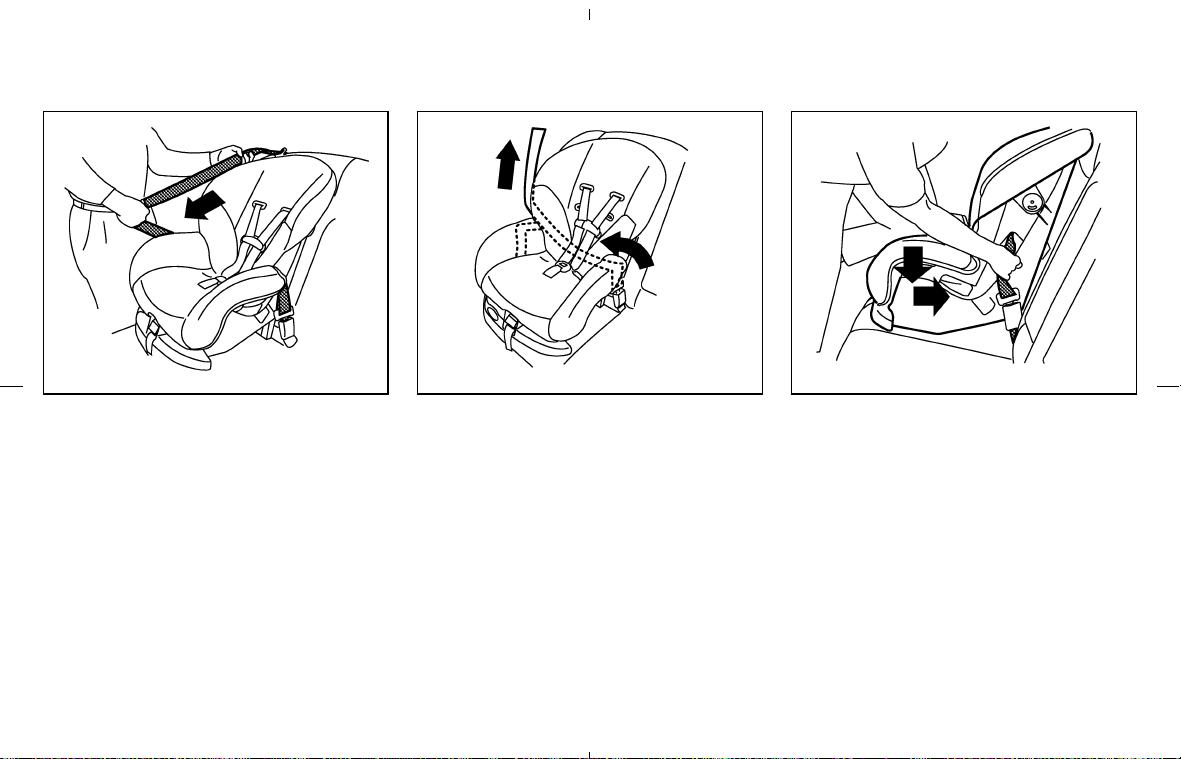
3. Pull the shoulder belt until the belt is fully
extended. At this time, the seat belt retractor
is in the Automatic Locking Retractor (ALR)
mode (child restraint mode). It reverts to
Emergency Locking Retractor (ELR) mode
when the seat belt is fully retracted.
4. Allow the seat belt to retract. Pull up on the
shoulder belt to remove any slack in the belt.
5. Remove any additional slack from the seat
belt; press downward and rearward firmly in
the center of the child restraint with your knee
to compress the vehicle seat cushion and
seatback while pulling up on the seat belt.
6. If the child restraint is equipped with a top
tether strap, route the top tether strap and
secure the tether strap to the tether anchor
point. See “Top tether strap child restraint” in
this section.
SSS0651
Front facing — step 3
SSS0652
Front facing — step 4
SSS0653
Front facing — step 5
1-22 Safety — Seats, seat belts and supplemental restraint system
墌 08.7.24/Z33-D/V5.0 墍
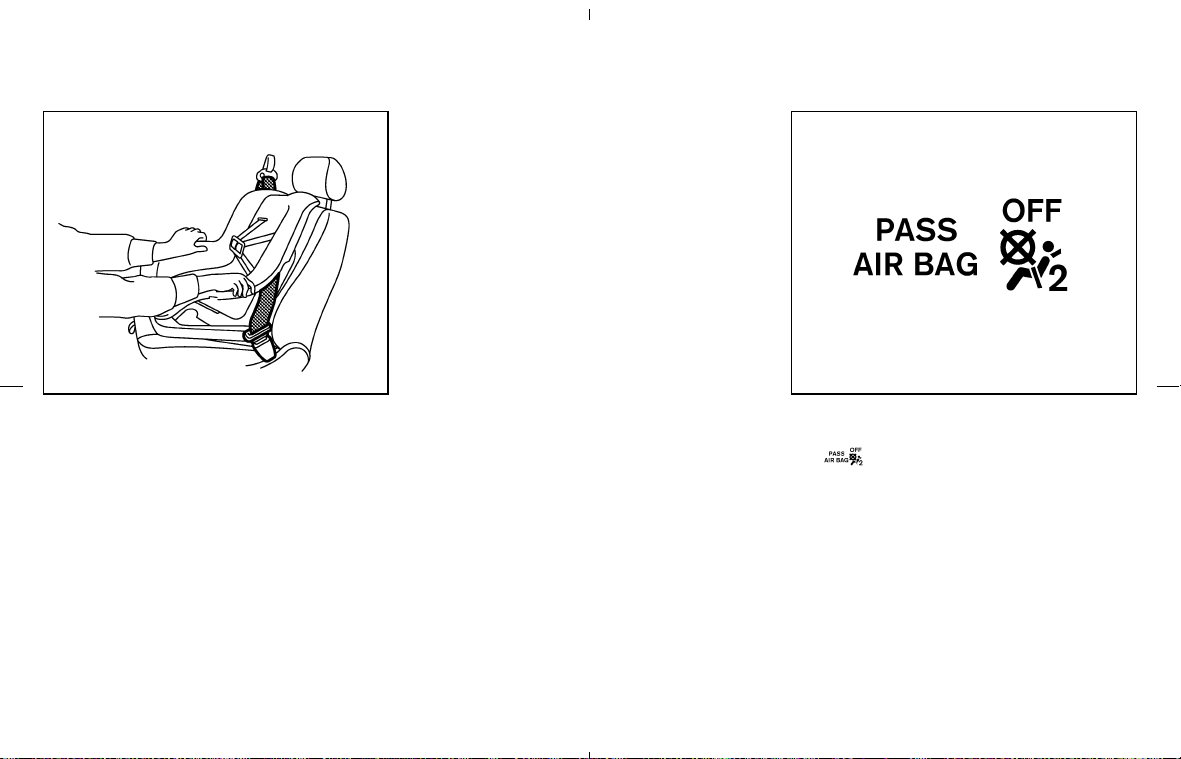
7. Before placing the child in the child restraint,
hold the child restraint near the seat belt path
and use force to push the child restraint from
side to side, and tug it forward to make sure
that it is securely held in place. It should not
move more than 1 in (25 mm). If it does move
more than 1 in (25 mm), pull again on the
shoulder belt to further tighten the child
restraint. If you are unable to properly secure
the restraint, try a different child restraint. Not
all child restraints fit in all types of vehicles.
8. Check that the retractor is in the ALR mode
by trying to pull more seat belt out of the
retractor. If you cannot pull any more belt
webbing out of the retractor, the retractor is
in the ALR mode.
9. Check to make sure the child restraint is
properly secured prior to each use. If the seat
belt is not locked, repeat steps 2 through 7.
10. Turn the ignition switch to the ON position.
The front passenger air bag status light
should illuminate. If this light is not
illuminated, see “Front passenger air bag
and status light” in this section. Try a differ-
ent child restraint. Have the system
checked by a NISSAN dealer.
After the child restraint is removed and the seat
belt is fully retracted, the ALR mode (child
restraint mode) is canceled.
SSS0641
Front facing — step 7
SSS0681
Front facing — step 10
Safety — Seats, seat belts and supplemental restraint system 1-23
墌 08.7.24/Z33-D/V5.0 墍
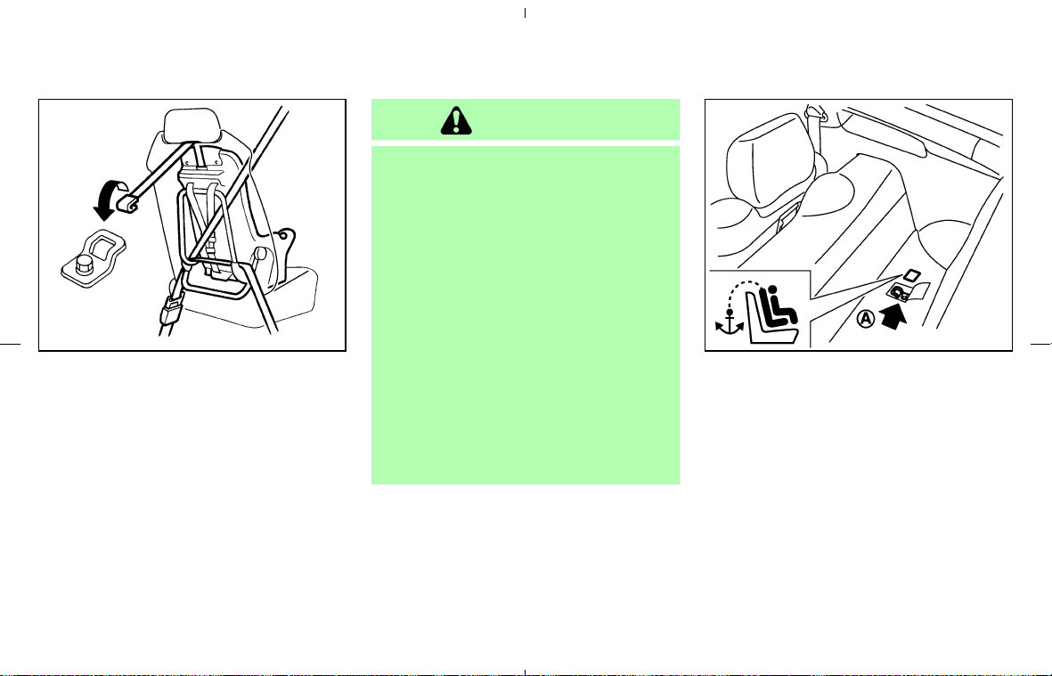
TOP TETHER STRAP CHILD
RESTRAINT (Coupe models only)
An anchor for a child restraint with a top tether is
provided in this vehicle.
If your child restraint has a top tether strap, it
must be secured to the provided anchor point.
Secure the child restraint with the seat belt.
Guide the top tether strap under the head
restraint as illustrated, and secure it to the
anchor bracket. Tighten the strap according to
manufacturer instructions to remove any slack.
WARNING
쐌 Child restraint anchor point is de-
signed to withstand only those loads
imposed by correctly fitted child re-
straints. Under no circumstance is it
to be used for adult seat belts or
harnesses.
쐌 Do not allow cargo to contact the top
tether strap when it is attached to the
top tether anchor. Properly secure
the cargo so it does not contact the
top tether strap. Cargo that is not
properly secured or that contacts the
top tether strap may damage the top
tether strap during a collision. Your
child could be seriously injured or
killed in a collision if the child re-
straint top tether strap is damaged.
Anchor point location
The anchor point 쎻
A
is located on the luggage
area floor.
A flap is provided in the carpet for easy access
and is marked with the label shown.
If you have any questions when installing a
top tether strap child restraint on the pas-
senger seat, consult a NISSAN dealer for
details.
SSS0207 SPA1644
1-24 Safety — Seats, seat belts and supplemental restraint system
墌 08.7.24/Z33-D/V5.0 墍

PRECAUTIONS ON BOOSTER
SEATS
WARNING
쐌 Children should always be placed in
an appropriate child restraint while
riding in the vehicle. Failure to use a
child restraint or booster seat can
result in serious injury or death.
쐌 Children should never be carried on
your lap. It is not possible for even
the strongest adult to resist the
forces of a severe accident. The child
could be crushed between the adult
and parts of the vehicle. Also, do not
put the same seat belt around both
your child and yourself.
쐌 A booster seat must only be installed
in a seating position that has a
lap/shoulder belt. Failure to use a
three-point type seat belt with a
booster seat can result in a serious
injury in sudden stop or collision.
쐌 Improper use or improper installation
of a booster seat can increase the
risk or severity of injury for both the
child and other occupants of the ve-
hicle and can lead to serious injury or
death in an accident.
쐌 Do not use towels, books, pillows or
other items in place of a booster
seat. Items such as these may move
during normal driving or a collision
and result in serious injury or death.
Booster seats are designed to be
used with a lap/shoulder belt.
Booster seats are designed to prop-
erly route the lap and shoulder por-
tions of the seat belt over the stron-
gest portions of a child’s body to
provide the maximum protection dur-
ing a collision.
쐌 Follow all of the booster seat manu-
facturer’s instructions for installation
and use. When purchasing a booster
seat, be sure to select one which will
fit your child and vehicle. It may not
be possible to properly install some
types of booster seats in your ve-
hicle.
쐌 If the booster seat and seat belt are
not used properly, the risk of a child
being injured in a collision or a sud-
den stop greatly increases.
쐌 Adjustable seatbacks should be po-
sitioned to fit the booster seat, but as
upright as possible.
쐌 After placing the child in the booster
seat and fastening the seat belt,
make sure the shoulder portion of
SSS0099
BOOSTER SEATS
Safety — Seats, seat belts and supplemental restraint system 1-25
墌 08.7.24/Z33-D/V5.0 墍
the belt is away from the child’s face
and neck and the lap portion of the
belt does not cross the abdomen.
쐌 Do not put the shoulder belt behind
the child or under the child’s arm. If
you must install a booster seat in the
front seat, see “Booster seat instal-
lation on front passenger seat” later
in this section.
쐌 When your booster seat is not in use,
keep it secured with a seat belt to
prevent it from being thrown around
in case of a sudden stop or accident.
CAUTION
쐌 For Roadster models, when installing
a booster seat, be sure to turn off the
automatic passenger seatback tilt
function with the seatback tilt cancel
switch (located on the back of the
passenger seatback). Otherwise, the
booster seat may be damaged. See
“Tilting and reclining passenger’s
seat from driver’s seat” earlier in this
section for detailed information.
쐌 Remember that a booster seat left in
a closed vehicle can become very hot.
Check the seating surface and buck-
les before placing your child in the
booster seat.
Booster seats of various sizes are offered by
several manufacturers. When selecting any
booster seat, keep the following points in mind:
쐌 Choose only a booster seat with a label
certifying that it complies with Federal Motor
Vehicle Safety Standard 213 or Canadian
Motor Vehicle Safety Standard 213.
LRS0455
1-26 Safety — Seats, seat belts and supplemental restraint system
墌 08.7.24/Z33-D/V5.0 墍
쐌 Check the booster seat in your vehicle to be
sure it is compatible with the vehicle’s seat
and seat belt system.
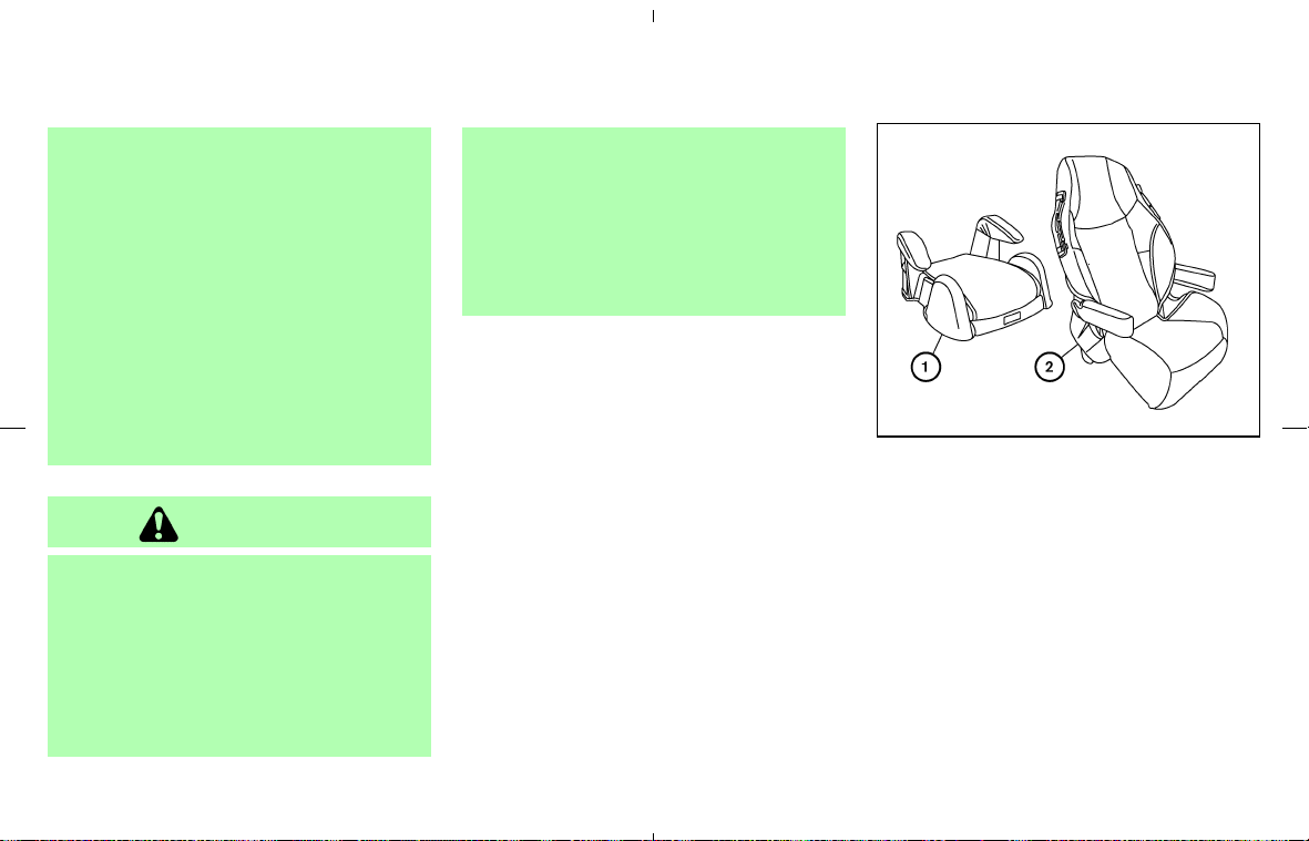
쐌 Make sure the child’s head will be properly
supported by the booster seat or vehicle
seat. The seatback must be at or above the
center of the child’s ears. For example, if a
low back booster seat
쎻
1
is chosen, the
vehicle seatback must be at or above the
center of the child’s ears. If the seatback is
lower than the center of the child’s ears, a
high back booster seat
쎻
2
should be used.
쐌 If the booster seat is compatible with your
vehicle, place your child in the booster seat
and check the various adjustments to be sure
the booster seat is compatible with your
child. Always follow all recommended proce-
dures.
All U.S. states and Canadian provinces or
territories require that infants and small
children be restrained in an approved child
restraint at all times while the vehicle is
being operated.
BOOSTER SEAT INSTALLATION
ON FRONT PASSENGER SEAT
CAUTION
Do not use the lap/shoulder belt Auto-
matic Locking Retractor mode when us-
ing a booster seat with the seat belts.
Follow these steps to install a booster seat in the
front passenger seat:
If you must install a booster seat in the
front passenger seat, move the passenger
seat to the rearmost position.
1. Turn the seatback tilt cancel switch to the
CANCEL position. (Roadster models only)
2. Position the booster seat on the seat. Only
place it in a front facing direction. Always
follow the booster seat manufacturer’s in-
structions.
SSS0363 LRS0454
Safety — Seats, seat belts and supplemental restraint system 1-27
墌 08.7.24/Z33-D/V5.0 墍
3. The booster seat should be positioned on the
vehicle seat so that it is stable. If necessary,
adjust or remove the head restraint to obtain
the correct booster seat fit. See “Head re-
straint adjustment” earlier in this section. If
the head restraint is removed, store it in a
secure place. Be sure to install the head
restraint when the booster seat is removed. If
the seating position does not have an adjust-
able head restraint and it is interfering with
the proper booster seat fit, try a different
booster seat.
4. Position the lap portion of the seat belt low
and snug on the child’s hips. Be sure to
follow the booster seat manufacturer’s in-
structions for adjusting the belt routing.
5. Pull the shoulder belt portion of the seat belt
toward the retractor to take up extra slack. Be
sure the shoulder belt is positioned across
the top, middle portion of the child’s shoul-
der. Be sure to follow the booster seat manu-
facturer’s instructions for adjusting the belt
routing.
6. Follow the warnings, cautions and instruc-
tions for properly fastening a seat belt shown
in the “Three-point type seat belt with retrac-
tor” earlier in this section.
7. If the booster seat is installed in the front
passenger seat, turn the ignition switch to the
ON position. The front passenger air bag
status light
may or may not illuminate
depending on the size of the child and the
type of booster seat used. See “Front pas-
senger air bag and status light” later in this
section.
PRECAUTIONS ON
SUPPLEMENTAL RESTRAINT
SYSTEM
This Supplemental Restraint System (SRS) sec-
tion contains important information concerning
the following systems:
쐌 Driver and passenger supplemental front-
impact air bag (NISSAN Advanced Air Bag
System)
쐌 Front seat-mounted side-impact supplemen-
tal air bag (if so equipped)
쐌 Roof-mounted curtain side-impact supple-
mental air bag (if so equipped for Coupe
models)
쐌 Seat belt pretensioner
Supplemental front-impact air bag system:
NISSAN Advanced Air Bag System can help
cushion the impact force to the head and chest
of the driver and front passenger in certain
frontal collisions.
Front seat-mounted side-impact supple-
mental air bag system (if so equipped): This
system can help cushion the impact force to the
chest area of the driver and front passenger in
certain side impact collisions. The side air bags
are designed to inflate on the side where the
vehicle is impacted.
LRS0454
SUPPLEMENTAL RESTRAINT
SYSTEM
1-28 Safety — Seats, seat belts and supplemental restraint system
墌 08.7.24/Z33-D/V5.0 墍
Roof-mounted curtain side-impact supple-
mental air bag system (if so equipped for
Coupe models): This system can help cushion
the impact force to the head of occupants in
certain side impact collisions. The curtain air
bags are designed to inflate on the side where
the vehicle is impacted.
The supplemental restraint system is designed
to supplement the crash protection provided
by the driver and passenger seat belts and is
not a substitute for them. Seat belts should
always be correctly worn and the occupant
seated a suitable distance away from the steer-
ing wheel, instrument panel, door finishers and
side roof rails. (See “Seat belts” earlier in this
section for instructions and precautions on seat
belt usage.)
The supplemental air bags operate only
when the ignition switch is in the ON or
START position.
After turning the ignition key to the ON
position, the supplemental air bag warning
light illuminates. The supplemental air bag
warning light will turn off after about 7
seconds if the systems are operational.
WARNING
쐌 The front air bags ordinarily will not
inflate in the event of a side impact,
rear impact, rollover, or lower sever-
ity frontal collision. Always wear your
seat belts to help reduce the risk or
severity of injury in various kinds of
accidents.
쐌 The front passenger air bag will not
inflate if the passenger air bag status
light is lit or if the front passenger
seat is unoccupied. See “Front pas-
senger air bag and status light” later
in this section.
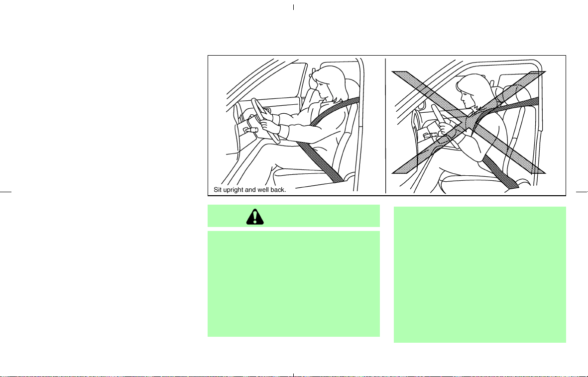
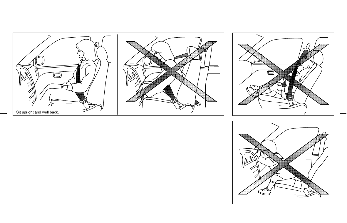
쐌 The seat belts and the front air bags
are most effective when you are sit-
ting well back and upright in the seat
with both feet on the floor. The front
air bags inflate with great force. Even
with the NISSAN Advanced Air Bag
System, if you are unrestrained, lean-
ing forward, sitting sideways or out
SSS0131
Safety — Seats, seat belts and supplemental restraint system 1-29
墌 08.7.24/Z33-D/V5.0 墍

of position in any way, you are at
greater risk of injury or death in a
crash. You may also receive serious
or fatal injuries from the front air bag
if you are up against it when it in-
flates. Always sit back against the
seatback and as far away as practical
from the steering wheel or instru-
ment panel. Always use the seat
belts.
쐌 The driver and front passenger seat
belt buckles are equipped with sen-
sors that detect if the seat belts are
fastened. The Advanced Air Bag Sys-
tem monitors the severity of a colli-
sion and seat belt usage then inflates
the air bags. Failure to properly wear
seat belts can increase the risk or
severity of injury in an accident.
쐌 The front passenger seat is equipped
with an occupant classification sen-
sor (pattern sensor) that turns the
front passenger air bag OFF under
some conditions. This sensor is only
used in this seat. Failure to be prop-
erly seated and wearing the seat belt
can increase the risk or severity of
injury in an accident. See “Front pas-
senger air bag and status light” later
in this section.
쐌 Keep hands on the outside of the
steering wheel. Placing them inside
the steering wheel rim could increase
the risk that they are injured when
the front air bag inflates.
1-30 Safety — Seats, seat belts and supplemental restraint system
墌 08.7.24/Z33-D/V5.0 墍
SSS0132 SSS0016
SSS0006
Safety — Seats, seat belts and supplemental restraint system 1-31
墌 08.7.24/Z33-D/V5.0 墍
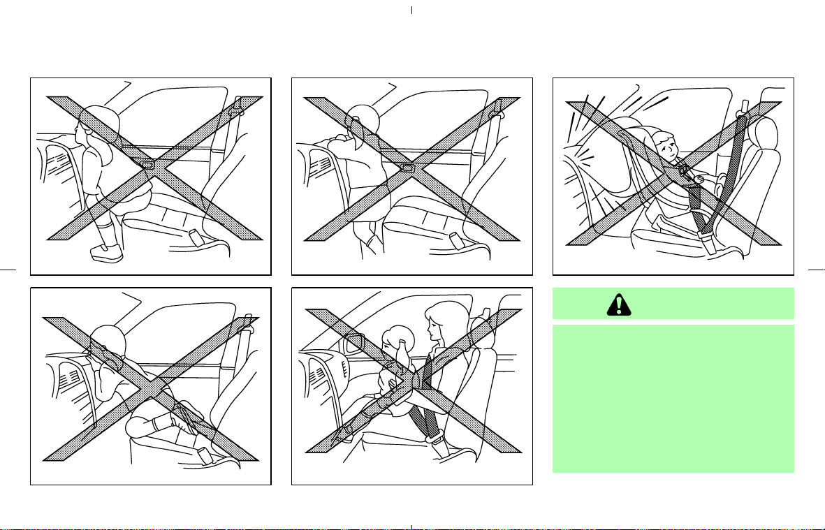
WARNING
쐌 Never let an infant who requires the
use of a rear facing child restraint
ride in this vehicle. Do not attempt to
hold a child in your lap or arms. Some
examples of dangerous riding posi-
tions are shown in the previous illus-
trations.
쐌 Roadster models do not have an an-
chor for a top tether strap required
SSS0007
SSS0008
SSS0009
SSS0099
SSS0100
1-32 Safety — Seats, seat belts and supplemental restraint system
墌 08.7.24/Z33-D/V5.0 墍
for most front facing child restraints.
Never let children who require the
use of a front facing child restraint
ride in Roadster models.
쐌 Children may be severely injured or
killed when the front air bags, side air
bags or curtain air bags inflate if they
are not properly restrained.
쐌 Even with the NISSAN Advanced Air
Bag System, never install a rear-
facing child restraint in the front seat.
An inflating front air bag could seri-
ously injure or kill your child. See
“Child restraints” earlier in this sec-
tion for details.
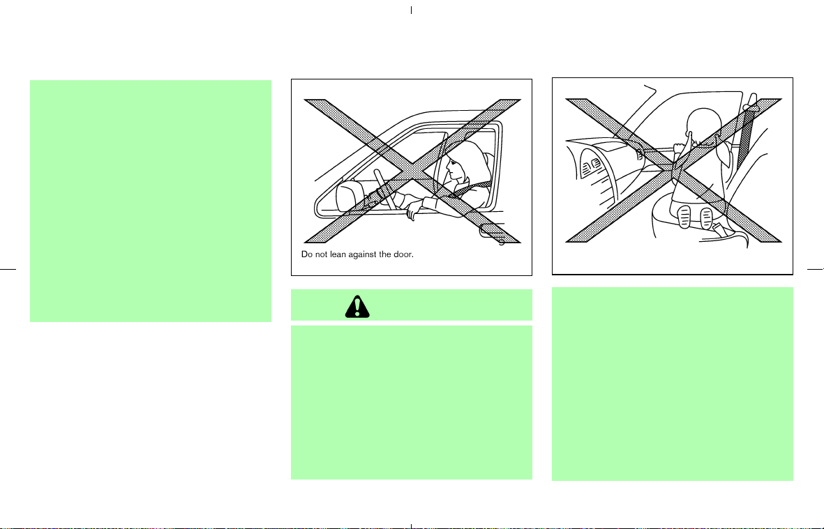
WARNING
Front seat-mounted side-impact
supplemental air bags and roof-
mounted curtain side-impact supple-
mental air bags (if so equipped):
쐌 The side air bags and curtain air bags
ordinarily will not inflate in the event
of a frontal impact, rear impact, roll-
over or lower severity side collision.
Always wear your seat belts to help
reduce the risk or severity of injury
in various kinds of accidents.
쐌 The seat belts, side air bags and
curtain air bags are most effective
when you are sitting well back and
upright in the seat. The side air bags
and curtain air bags inflate with great
force. Do not allow anyone to place
their hand, leg or face near the side
air bag on the side of the seatback of
the front seat or near the side roof
rails. Do not allow anyone sitting in
the front seat to extend their hand
out of the window or lean against the
SSS0101
SSS0159
Safety — Seats, seat belts and supplemental restraint system 1-33
墌 08.7.24/Z33-D/V5.0 墍
door. Some examples of dangerous
riding positions are shown in the pre-
vious illustrations.
쐌 Do not use seat covers on the front
seatbacks. They may interfere with
side air bag inflation.
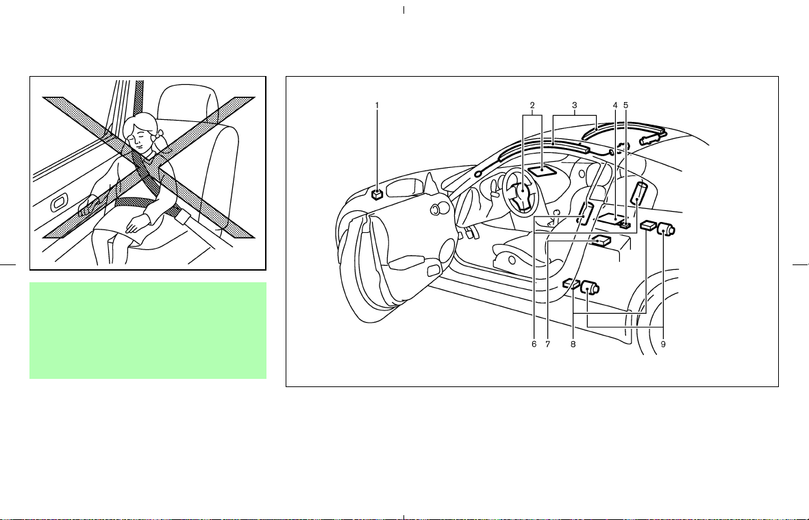
1. Crash zone sensor
2. Supplemental front-impact air bag modules
3. Roof-mounted curtain side-impact supple-
mental air bags (if so equipped for Coupe
models)
4. Occupant classification sensor (pattern sen-
sor)
5. Occupant classification system control unit
6. Front seat-mounted side-impact supplemen-
tal air bag modules (if so equipped)
SSS0162
SSS0680
1-34 Safety — Seats, seat belts and supplemental restraint system
墌 08.7.24/Z33-D/V5.0 墍

7. Air bag Control Unit (ACU)
8. Satellite sensors
9. Seat belt pretensioners
NISSAN Advanced Air Bag System
This vehicle is equipped with the NISSAN Ad-
vanced Air Bag System for the driver and front
passenger seats. This system is designed to
meet certification requirements under U.S. regu-
lations. It is also permitted in Canada. However,
all of the information, cautions and warn-
ings in this manual still apply and must be
followed.
The driver supplemental front-impact air bag is
located in the center of the steering wheel. The
passenger supplemental front-impact air bag is
mounted in the instrument panel. The front air
bags are designed to inflate in higher severity
frontal collisions, although they may inflate if the
forces in another type of collision are similar to
those of a higher severity frontal impact. They
may not inflate in certain frontal collisions. Ve-
hicle damage (or lack of it) is not always an
indication of proper air bag system operation.
The NISSAN Advanced Air Bag System has dual
stage air bag inflators. It also monitors informa-
tion from the crash zone sensor, the Air bag
Control Unit (ACU), seat belt buckle sensors
and the occupant classification sensor (pattern
sensor). Inflator operation is based on the sever-
ity of a collision and seat belt usage for the
driver. For the front passenger, the occupant
classification sensor is also monitored. Based on
information from the sensors, only one front air
bag may inflate in a crash, depending on the
crash severity and whether the front occupants
are belted or unbelted. Additionally, the front
passenger air bag may be automatically turned
OFF under some conditions, depending on the
information provided by the occupant classifica-
tion sensor. If the front passenger air bag is OFF,
the passenger air bag status light will be illumi-
nated (if the seat is unoccupied, the light will not
be illuminated, but the air bag will be off.). See
“Front passenger air bag and status light” later in
this section for further details. One front air bag
inflating does not indicate improper performance
of the system.
If you have any questions about your air bag
system, contact NISSAN or a NISSAN dealer. If
you are considering modifications of your vehicle
due to a disability, you may also contact
NISSAN. Contact information is contained in the
front of this Owner’s Manual.
When a front air bag inflates, a fairly loud noise
may be heard, followed by release of smoke.
This smoke is not harmful and does not indicate
a fire. Care should be taken not to inhale it, as it
may cause irritation and choking. Those with a
history of a breathing condition should get fresh
air promptly.
Front air bags, along with the use of seat belts,
help to cushion the impact force on the head and
chest of the front occupants. They can help save
lives and reduce serious injuries. However, an
inflating front air bag may cause facial abrasions
or other injuries. Front air bags do not provide
restraint to the lower body.
Even with NISSAN advanced air bags, seat belts
should be correctly worn and the driver and
passenger seated upright as far as practical
away from the steering wheel or instrument
panel. The front air bags inflate quickly in order
to help protect the front occupants. Because of
this, the force of the front air bag inflating can
increase the risk of injury if the occupant is too
close to, or is against, the air bag module during
inflation.
The air bag will deflate quickly after a collision.
The front air bags operate only when the
ignition switch is in the ON or START po-
sition.
After turning the ignition key to the ON
position, the supplemental air bag warning
light illuminates. The supplemental air bag
warning light will turn off after about 7
Safety — Seats, seat belts and supplemental restraint system 1-35
墌 08.7.24/Z33-D/V5.0 墍
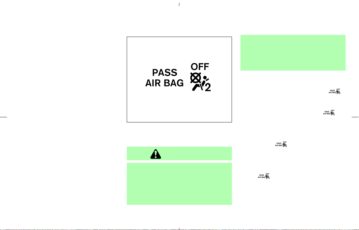
seconds if the system is operational.
Front passenger air bag and status
light
WARNING
The front passenger air bag is designed
to automatically turn OFF under some
conditions. Read this section carefully
to learn how it operates. Proper use of
the seat, seat belt and child restraints is
necessary for most effective protection.
Failure to follow all instructions in this
manual concerning the use of seats,
seat belts and child restraints can in-
crease the risk or severity of injury in an
accident.
Status light:
The front passenger air bag status light
is
located on the overhead console. The light op-
erates as follows:
쐌 Unoccupied passenger seat: The
light
is OFF and the front passenger air bag is
OFF and will not inflate in a crash.
쐌 Passenger seat occupied by a small adult,
child or child restraint as outlined in this
section: The
light illuminates to indicate
that the front passenger air bag is OFF and
will not inflate in a crash.
쐌 Occupied passenger seat and the passenger
meets the conditions outlined in this section:
The
light is OFF to indicate that the
front passenger air bag is operational.
Front passenger air bag:
The front passenger air bag is designed to
automatically turn OFF when the vehicle is op-
erated under some conditions as described
SSS0681
Front passenger air bag status light
1-36 Safety — Seats, seat belts and supplemental restraint system
墌 08.7.24/Z33-D/V5.0 墍

below in accordance with U.S. regulations. If the
front passenger air bag is OFF, it will not inflate
in a crash. The driver air bag and other air bags
in your vehicle are not part of this system.
The purpose of the regulation is to help reduce
the risk of injury or death from an inflating air bag
to certain front passenger seat occupants, such
as children, by requiring the air bag to be
automatically turned OFF.
The occupant classification sensor (pattern sen-
sor) is in the front passenger seat cushion and is
designed to detect an occupant and objects on
the seat. For example, if a child is in the front
passenger seat, the Advanced Air Bag System is
designed to turn the passenger air bag OFF in
accordance with the regulations. Also, if a child
restraint of the type specified in the regulations
is on the seat, the occupant classification sensor
can detect it and cause the air bag to turn OFF.
Front passenger seat adult occupants who are
properly seated and using the seat belt as
outlined in this manual should not cause the
passenger air bag to be automatically turned
OFF. For small adults it may be turned OFF,
however, if the occupant does not sit in the seat
properly (for example, by not sitting upright, by
sitting on an edge of the seat, or by otherwise
being out of position), this could cause the
sensor to turn the air bag OFF. Always be sure to
be seated and wearing the seat belt properly for
the most effective protection by the seat belt and
supplemental air bag.
The occupant classification sensor is designed
to operate as described above to turn the front
passenger air bag OFF for specified child re-
straints as required by the regulations. Failing to
properly secure child restrains and to use the
Automatic Locking Retractor (ALR) mode (child
restraint mode) may allow the restraint to tip or
move in an accident or sudden stop. This can
also result in the passenger air bag inflating in a
crash instead of being OFF. See “Child re-
straints” earlier in this section for proper use and
installation.
If the front passenger seat is not occupied, the
passenger air bag is designed not to inflate in a
crash. However, heavy objects placed on the
seat could result in air bag inflation, because of
the object being detected by the occupant
classification sensor. Other conditions could
also result in air bag inflation, such as if a child is
standing on the seat, or if two children are on the
seat, contrary to the instructions in this manual.
Always be sure that you and all vehicle occu-
pants are seated and restrained properly.
Using the passenger air bag status light, you can
monitor when the front passenger air bag is
automatically turned OFF with the seat occu-
pied. The light will not illuminate when the front
passenger seat is unoccupied.
If an adult occupant is in the seat but the
passenger air bag status light is illuminated
(indicating that the air bag is OFF), it could be
that the person is a small adult, or is not sitting
on the seat properly.
If a child restraint must be used in the front seat,
the passenger air bag status light may or may not
be illuminated, depending on the size of the child
and the type of child restraint being used. If the
air bag status light is not illuminated (indicating
that the air bag might inflate in a crash), it could
be that the child restraint or seat belt is not being
used properly. Make sure that the child restraint
is installed properly, the seat belt is used prop-
erly and the occupant is positioned properly. If
the air bag status light is still not illuminated, try
a different child restraint.
If the passenger air bag status light will not
illuminate even though you believe that the child
restraint, the seat belts and the occupant are
properly positioned, the system may be sensing
an unoccupied seat (in which case the air bag is
OFF). A NISSAN dealer can check that the
system is OFF by using a special tool. However,
until you have confirmed with your dealer that
your air bag is working properly, do not transport
a child in this vehicle.
Safety — Seats, seat belts and supplemental restraint system 1-37
墌 08.7.24/Z33-D/V5.0 墍

The air bag system and passenger air bag status
light will take a few seconds to register a change
in the passenger seat status. However, if the
seat becomes unoccupied, the air bag status
light will remain off.
If a malfunction occurs in the front passenger air
bag system, the supplemental air bag warning
light
, located in the meter and gauges
area, will blink. Have the system checked by a
NISSAN dealer.
Other supplemental front-impact air
bag precautions
WARNING
쐌 Do not place any objects on the
steering wheel pad or on the instru-
ment panel. Also, do not place any
objects between any occupant and
the steering wheel or instrument
panel. Such objects may become
dangerous projectiles and cause in-
jury if the front air bag inflates.
쐌 Do not place objects with sharp
edges on the seat. Also, do not place
heavy objects on the seat that will
leave permanent impressions in the
seat. Such objects can damage the
seat or occupant classification sen-
sor (pattern sensor). This can affect
the operation of the air bag system
and result in serious personal injury.
쐌 Do not use water or acidic cleaners
(hot steam cleaners) on the seat. This
can damage the seat or occupant
classification sensor. This can also
affect the operation of the air bag
system and result in serious personal
injury.
쐌 Immediately after inflation, several
front air bag system components will
be hot. Do not touch them; you may
severely burn yourself.
쐌 No unauthorized changes should be
made to any components or wiring of
the supplemental air bag system.
This is to prevent accidental inflation
of the supplemental air bag or dam-
age to the supplemental air bag
system.
쐌 Do not make unauthorized changes
to your vehicle’s electrical system,
suspension system or front end
structure. This could affect proper
operation of the front air bag system.
쐌 Tampering with the front air bag sys-
tem may result in serious personal
injury. Tampering includes changes
to the steering wheel and the instru-
ment panel assembly by placing ma-
terial over the steering wheel pad
and above the instrument panel or by
installing additional trim material
around the air bag system.
쐌 Modifying or tampering with the front
passenger seat may result in serious
personal injury. For example, do not
change the front seats by placing
material on the seat cushion or by
installing additional trim material,
such as seat covers, on the seat that
are not specifically designed to as-
sure proper air bag operation. Addi-
tionally, do not stow any objects un-
der the front passenger seat or the
1-38 Safety — Seats, seat belts and supplemental restraint system
墌 08.7.24/Z33-D/V5.0 墍
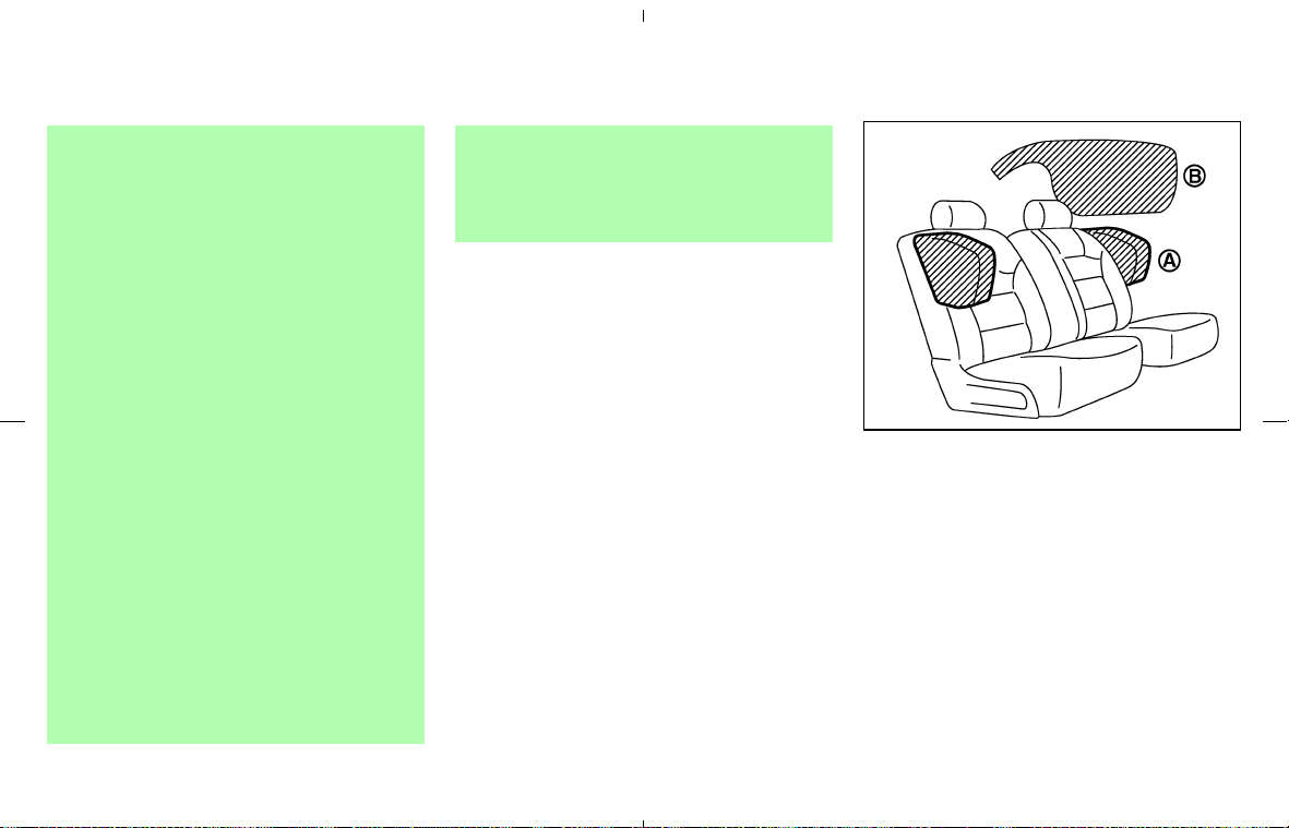
seat cushion and seatback. Such ob-
jects may interfere with the proper
operation of the occupant classifica-
tion sensor.
쐌 No unauthorized changes should be
made to any components or wiring of
the seat belt system. This may affect
the front air bag system. Tampering
with the seat belt system may result
in serious personal injury.
쐌 Work on and around the front air bag
system should be done by a NISSAN
dealer. Installation of electrical
equipment should also be done by a
NISSAN dealer. The Supplemental
Restraint System (SRS) wiring
should not be modified or discon-
nected. Unauthorized electrical test
equipment and probing devices
should not be used on the air bag
system.
쐌 A cracked windshield should be re-
placed immediately by a qualified re-
pair facility. A cracked windshield
could affect the function of the
supplemental air bag system.
쐌 The SRS wiring harness connectors
are yellow and orange for easy iden-
tification.
When selling your vehicle, we request that you
inform the buyer about the front air bag system
and guide the buyer to the appropriate sections
in this Owner’s Manual.
Front seat-mounted side-impact
supplemental air bag and
roof-mounted curtain side-impact
supplemental air bag systems (if so
equipped)
This section includes the information about both
the side air bag system
쎻
A
and the curtain air
bag system
쎻
B
. Curtain air bags are not available
on Roadster models.
The side air bags are located in the outside of
the seatback of the front seats. The curtain air
bags are located in the side roof rails. These
systems are designed to meet voluntary guide-
SSS0209A
Safety — Seats, seat belts and supplemental restraint system 1-39
墌 08.7.24/Z33-D/V5.0 墍

lines to help reduce the risk of injury to out-of-
position occupants. However, all of the infor-
mation, cautions and warnings in this
manual still apply and must be followed.
The side air bags and curtain air bags are
designed to inflate in higher severity side colli-
sions on the side that the vehicle is impacted,
although they may inflate if the forces in another
type of collision are similar to those of a higher
severity side impact. They are designed to inflate
on the side where the vehicle is impacted. They
may not inflate in certain side collisions.
Vehicle damage (or lack of it) is not always an
indication of proper side air bag and curtain air
bag operation.
When the side air bags and curtain air bags
inflate, a fairly loud noise may be heard, followed
by release of smoke. This smoke is not harmful
and does not indicate a fire. Care should be
taken not to inhale it, as it may cause irritation
and choking. Those with a history of a breathing
condition should get fresh air promptly.
Side air bags, along with the use of seat belts,
help to cushion the impact force on the chest of
the front occupants. Curtain air bags help to
cushion the impact force to the head of occu-
pants. They can help save lives and reduce
serious injuries. However, an inflating side air
bag and curtain air bag may cause abrasions or
other injuries. Side air bags and curtain air bags
do not provide restraint to the lower body.
The seat belts should be correctly worn and the
driver and passenger seated upright as far as
practical away from the side air bag, and seated
as far away as practical from the door finishers
and side roof rails. The side air bags and curtain
air bags inflate quickly in order to help protect
the front occupants. Because of this, the force of
the side air bags and curtain air bags inflating
can increase the risk of injury if the occupant is
too close to, or is against these air bag modules
during inflation. The side air bags and curtain air
bags will deflate quickly after the collision is
over.
The side air bags and curtain air bags
operate only when the ignition switch is in
the ON or START position.
After turning the ignition key to the ON
position, the supplemental air bag warning
light illuminates. The air bag warning light
will turn off after about 7 seconds if the
systems are operational.
WARNING
쐌 Do not place any objects near the
seatback of the front seats. Also, do
not place any objects (an umbrella,
bag, etc.) between the front door fin-
isher and the front seat. Such objects
may become dangerous projectiles
and cause injury if a side air bag
inflates.
쐌 Right after inflation, several side air
bag and curtain air bag system com-
ponents will be hot. Do not touch
them; you may severely burn your-
self.
쐌 No unauthorized changes should be
made to any components or wiring of
the side air bag and curtain air bag
systems. This is to prevent accidental
inflation of the side air bags and
curtain air bags or damage to the
side air bag and curtain air bag sys-
tems.
쐌 Do not make unauthorized changes
to your vehicle’s electrical system,
suspension system or side panel.
This could affect proper operation of
the side air bag and curtain air bag
systems.
1-40 Safety — Seats, seat belts and supplemental restraint system
墌 08.7.24/Z33-D/V5.0 墍

쐌 Tampering with the side air bag sys-
tem may result in serious personal
injury. For example, do not change
the front seats by placing material
near the seatback or by installing
additional trim material, such as seat
covers, around the side air bag.
쐌 Work around and on the side air bag
and curtain air bag systems should
be done by a NISSAN dealer. Instal-
lation of electrical equipment should
also be done by a NISSAN dealer.
The SRS wiring harnesses* should
not be modified or disconnected. Un-
authorized electrical test equipment
and probing devices should not be
used on the side air bag system.
* The SRS wiring harness connectors
are yellow and orange for easy iden-
tification.
When selling your vehicle, we request that you
inform the buyer about the side air bag and
curtain air bag systems and guide the buyer to
the appropriate sections in this Owner’s Manual.
Seat belts with pretensioners
WARNING
쐌 The pretensioners cannot be reused
after activation. They must be re-
placed together with the retractor
and buckle as a unit.
쐌 If the vehicle becomes involved in a
frontal collision but a pretensioner is
not activated, be sure to have the
pretensioner system checked and, if
necessary, replaced by a NISSAN
dealer.
쐌 No unauthorized changes should be
made to any components or wiring of
the pretensioner system.
This is to prevent damage to or acci-
dental activation of the pretension-
ers. Tampering with the pretensioner
system may result in serious per-
sonal injury.
쐌 Work around and on the preten-
sioner system should be done by a
NISSAN dealer. Installation of elec-
trical equipment should also be done
by a NISSAN dealer. Unauthorized
electrical test equipment and probing
devices should not be used on the
pretensioner system.
쐌 If you need to dispose of a pre-
tensioner or scrap the vehicle, con-
tact a NISSAN dealer. Correct pre-
tensioner disposal procedures are
set forth in the appropriate NISSAN
Service Manual. Incorrect disposal
procedures could cause personal
injury.
The pretensioner system activates in conjunction
with the front air bag system. Working with the
seat belt retractor, it helps tighten the seat belt
when the vehicle becomes involved in certain
types of collisions, helping to restrain front seat
occupants.
The pretensioner is encased with the seat belt
retractor. These seat belts are used the same
way as conventional seat belts.
When a pretensioner activates, smoke is re-
leased and a loud noise may be heard. The
smoke is not harmful and does not indicate a fire.
Safety — Seats, seat belts and supplemental restraint system 1-41
墌 08.7.24/Z33-D/V5.0 墍
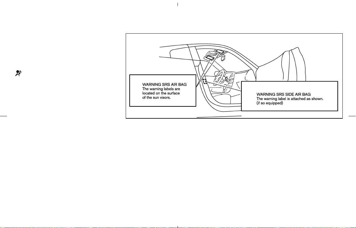
Care should be taken not to inhale it as it may
cause irritation and choking. Those with a history
of a breathing condition should get fresh air
promptly.
If any abnormality occurs in the pretensioner
system, the supplemental air bag warning light
will not come on, will flash intermittently or
will turn on for 7 seconds and remain on after the
ignition key has been turned to the ON or
START position. In this case, the pretensioner
may not function properly. They must be
checked and repaired. Take your vehicle to a
NISSAN dealer.
When selling your vehicle, we request that you
inform the buyer about the pretensioner and
guide the buyer to the appropriate sections in
this Owner’s Manual.
SUPPLEMENTAL AIR BAG
WARNING LABELS
Warning labels about the supplemental front-
impact air bag and front seat-mounted side-
impact supplemental air bag (if so equipped)
systems are placed in the vehicle as shown in
the illustration.
SSS0206
1-42 Safety — Seats, seat belts and supplemental restraint system
墌 08.7.24/Z33-D/V5.0 墍
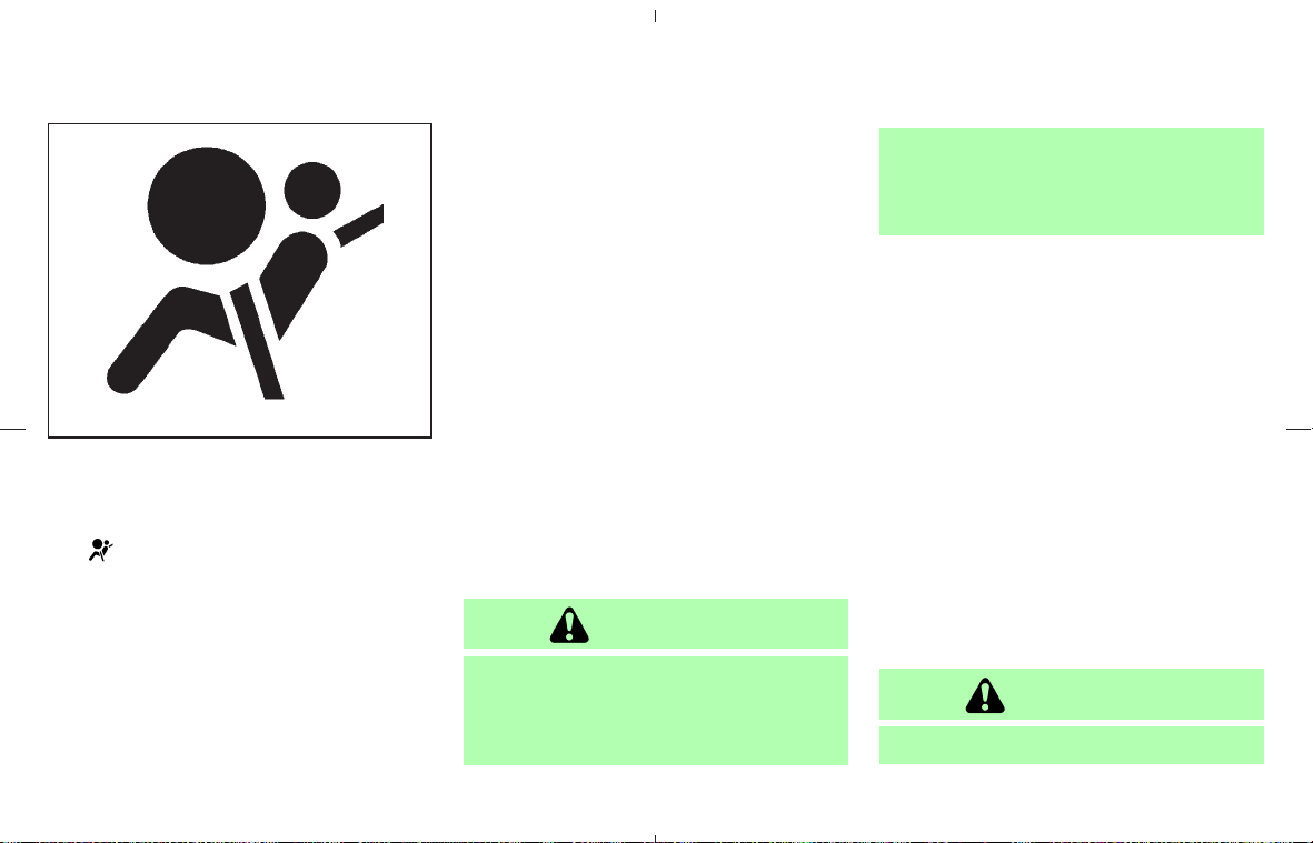
SUPPLEMENTAL AIR BAG
WARNING LIGHT
The supplemental air bag warning light, display-
ing
in the instrument panel, monitors the
circuits of the supplemental front-impact air bag,
front seat-mounted side-impact supplemental air
bag (if so equipped), roof-mounted curtain side-
impact supplemental air bag (if so equipped for
Coupe models) and seat belt pretensioner sys-
tems. The monitored circuits include the Air bag
Control Unit (ACU), crash zone sensor, satellite
sensors, front air bag modules, side air bag
modules, curtain air bag modules, pretensioners
and all related wiring.
After turning the ignition key to the ON position,
the supplemental air bag warning light illumi-
nates. The supplemental air bag warning light
will turn off after about 7 seconds if the system is
operational.
If any of the following conditions occur, the front
air bag, side air bag and curtain air bag, and
pretensioner systems need servicing:
쐌 The supplemental air bag warning light re-
mains on after approximately 7 seconds.
쐌 The supplemental air bag warning light
flashes intermittently.
쐌 The supplemental air bag warning light does
not come on at all.
Under these conditions, the front air bag, side air
bag, curtain air bag and/or pretensioner systems
may not operate properly. They must be checked
and repaired. Take your vehicle to a NISSAN
dealer.
WARNING
If the supplemental air bag warning
light is on, it could mean that the front
air bag, side air bag, curtain air bag,
and/or pretensioner systems will not
operate in an accident. To help avoid
injury to yourself or others, have your
vehicle checked by a NISSAN dealer as
soon as possible.
Repair and replacement procedure
The front air bags, side air bags (if so equipped),
curtain air bags (if so equipped for Coupe
models) and pretensioners are designed to in-
flate on a one-time-only basis. As a reminder,
unless it is damaged, the supplemental air bag
warning light will remain illuminated after inflation
has occurred. Repair and replacement of these
systems should be done only by a NISSAN
dealer.
When maintenance work is required on the
vehicle, the front air bags, side air bags, curtain
air bags, pretensioners and related parts should
be pointed out to the person conducting the
maintenance. The ignition key should always be
in the LOCK position when working under the
hood or inside the vehicle.
WARNING
쐌 Once a front air bag, side air bag or
SPA1097
Safety — Seats, seat belts and supplemental restraint system 1-43
墌 08.7.24/Z33-D/V5.0 墍

curtain air bag has inflated, the air
bag module will not function again
and must be replaced. Additionally, if
any of the front air bags inflate, the
activated pretensioners must also be
replaced. The air bag module and
pretensioner system should be re-
placed by a NISSAN dealer. The air
bag module and pretensioner system
cannot be repaired.
쐌 The front air bag, side air bag, curtain
air bag and pretensioner systems
should be inspected by a NISSAN
dealer if there is any damage to the
front end or side portion of the ve-
hicle.
쐌 If you need to dispose of these
supplemental systems or scrap the
vehicle, contact a NISSAN dealer.
Correct disposal procedures are set
forth in the appropriate NISSAN Ser-
vice Manual. Incorrect disposal pro-
cedures could cause personal injury.
1-44 Safety — Seats, seat belts and supplemental restraint system
墌 08.7.24/Z33-D/V5.0 墍

MEMO
Safety — Seats, seat belts and supplemental restraint system 1-45
墌 08.7.24/Z33-D/V5.0 墍

2 Instruments and controls
Instrument panel ................................................................... 2-2
Meters and gauges .............................................................. 2-3
Speedometer and odometer ........................................ 2-4
Tachometer ....................................................................... 2-5
Engine coolant temperature gauge ............................ 2-5
Fuel gauge ........................................................................ 2-6
Engine oil pressure gauge ........................................... 2-7
Volt meter ......................................................................... 2-8
Trip computer .................................................................. 2-8
Warning/indicator lights and audible reminders ........ 2-11
Checking bulbs ............................................................. 2-11
Warning lights ............................................................... 2-11
Indicator lights ............................................................... 2-15
Audible reminders ........................................................ 2-17
Security systems ................................................................ 2-18
Vehicle security system .............................................. 2-18
NISSAN Vehicle Immobilizer System ...................... 2-19
Windshield wiper and washer switch ........................... 2-21
Rear window wiper and washer switch
(Coupe models) .................................................................. 2-22
Rear window and outside mirror defroster switch .... 2-23
Headlight and turn signal switch ................................... 2-24
Xenon headlights .......................................................... 2-24
Headlight switch ........................................................... 2-24
Daytime running light system (Canada only) ........ 2-25
Turn signal switch ........................................................ 2-26
Instrument brightness control ................................... 2-26
Hazard warning flasher switch ....................................... 2-27
Horn ....................................................................................... 2-27
Heated seats (if so equipped) ........................................ 2-28
Vehicle Dynamic Control (VDC) off switch
(if so equipped) .................................................................. 2-29
Traction Control System (TCS) off switch
(if so equipped) .................................................................. 2-29
Clock ..................................................................................... 2-30
Adjusting the time ........................................................ 2-30
Power outlet ........................................................................ 2-31
Storage ................................................................................. 2-32
Instrument pocket (except for navigation system
equipped models) ........................................................ 2-32
Sunglasses holder (Coupe models) ........................ 2-32
Cargo net......................................................................... 2-33
Cup holders ................................................................... 2-33
Console box .................................................................. 2-35
Rear floor box ................................................................ 2-35
Rear parcel box ............................................................ 2-37
Stowing golf bags ......................................................... 2-37
Coat hook (Coupe models) ........................................ 2-38
墌 08.7.24/Z33-D/V5.0 墍

Windows .............................................................................. 2-39
Power windows ............................................................ 2-39
Automatic adjusting function ...................................... 2-40
Interior lights ........................................................................ 2-41
Room light ...................................................................... 2-41
Map lights ...................................................................... 2-41
Vanity mirror light ............................................................... 2-42
Luggage compartment light (Coupe models) ............. 2-42
Trunk light (Roadster models).......................................... 2-42
HomeLink
Universal Transceiver (if so equipped).... 2-43
Programming HomeLink
........................................... 2-43
Programming HomeLink
for Canadian
customers ....................................................................... 2-45
Operating the HomeLink
Universal
Transceiver ..................................................................... 2-45
Programming trouble-diagnosis ............................... 2-45
Clearing the programmed information .................... 2-45
Reprogramming a single HomeLink
button ........ 2-45
If your vehicle is stolen ............................................... 2-46
墌 08.7.24/Z33-D/V5.0 墍
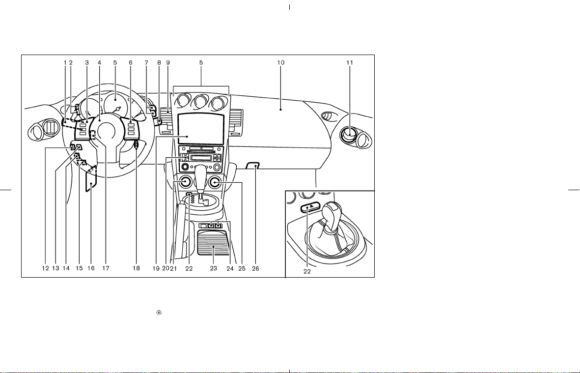
1. Headlight/turn signal switch
2. Instrument brightness control switch
3. Steering wheel switch for audio control (if so
equipped) or switch for Bluetooth
Hands-
Free Phone System (if so equipped)
4. Driver supplemental air bag/Horn
5. Meters/gauges
6. Cruise control main/set switch
(if so equipped)
7. Trip computer mode/setting switch
8. Wiper/washer switch
9. Center ventilator
10. Passenger supplemental air bag
11. Side ventilator
12. Soft top operating switch (for Roadster
models)
13. VDC (Vehicle dynamic control) OFF switch
(if so equipped) or TCS (Traction control
system) OFF switch (if so equipped)
14. Fuel-filler door opener switch
15. Hood lock release handle
16. Fuse box
17. Tilting steering wheel lock lever
18. Ignition switch/steering lock
19. Navigation system display* or Instrument
pocket
20. Audio system/Clock
21. Rear window and outside mirror defroster
switch
22. Hazard warning flasher switch
23. Cup holder
24. Heated seat switch (if so equipped)
25. Heater/air conditioner control
26. Power outlet
*: Refer to the separate Navigation System
Owner’s Manual.
SIC3266
INSTRUMENT PANEL
2-2 Instruments and controls
墌 08.7.24/Z33-D/V5.0 墍
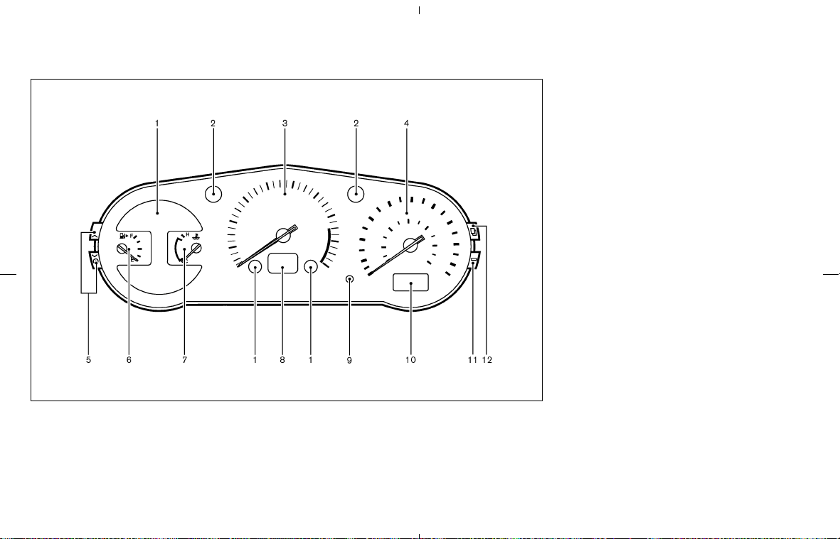
Combination meter:
1. Warning/Indicator lights
2. Turn signal/hazard indicator lights
3. Tachometer
4. Speedometer
5. Instrument brightness control switch
(See “Headlight and turn signal switch” later
in this section.)
6. Fuel gauge
7. Engine coolant temperature gauge
8. Automatic transmission position indicator or
Manual transmission shift up indicator
(See “Driving the vehicle” in the “5. Starting
and driving” section.)
9. Reset knob for trip odometer
10. Odometer (Total/Twin trip)
11. Trip computer setting switch
(See “Trip computer” later in this section.)
12. Trip computer mode switch
(See “Trip computer” later in this section.)
SIC3329
METERS AND GAUGES
Instruments and controls 2-3
墌 08.7.24/Z33-D/V5.0 墍
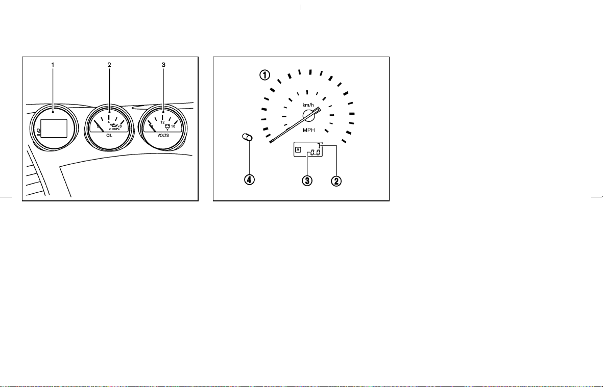
Triple meter:
1. Trip computer
2. Engine oil pressure gauge
3. Volt meter
쎻
1
Speedometer
쎻
2
Odometer
쎻
3
Twin trip odometer
쎻
4
Reset knob for trip odometer
SPEEDOMETER AND ODOMETER
Speedometer
The speedometer indicates vehicle speed in
miles per hour (MPH) and kilometers per hour
(km/h).
Odometer/Twin trip odometer
The odometer/twin trip odometer are displayed
when the ignition switch is in the ON position.
The odometer records the total distance the
vehicle has been driven.
The twin trip odometer records the distance of
individual trips.
SIC1948 SIC1949A
2-4 Instruments and controls
墌 08.7.24/Z33-D/V5.0 墍
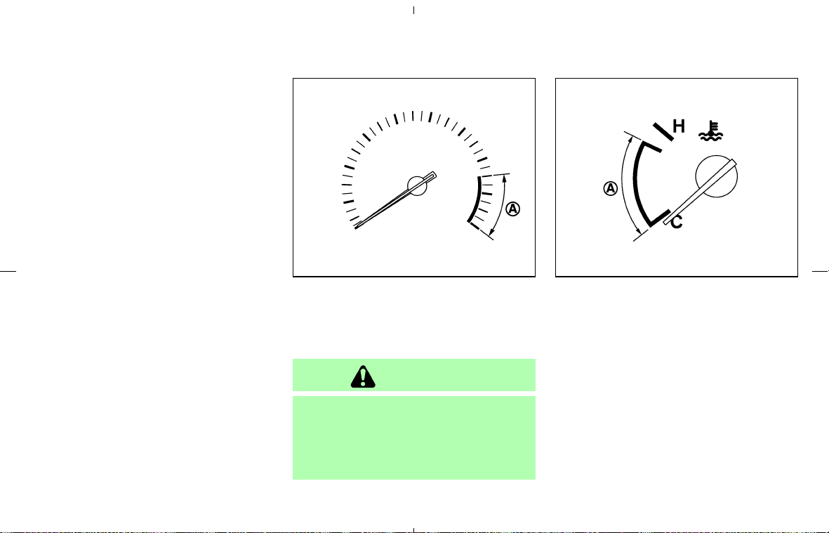
Changing the display:
Pushing the reset knob changes the display as
follows:
TRIP A → TRIP B → TRIP A
Resetting the trip odometer:
Pushing the reset knob for more than 1 second
resets the trip odometer to zero.
TACHOMETER
The tachometer indicates engine speed in revo-
lutions per minute (rpm). Do not rev engine into
the red zone
쎻
A
.
CAUTION
When engine speed approaches the red
zone, shift to a higher gear or reduce
engine speed. Operating the engine in
the red zone may cause serious engine
damage.
ENGINE COOLANT TEMPERATURE
GAUGE
The gauge indicates the engine coolant tem-
perature.
The engine coolant temperature is within the
normal range
쎻
A
when the gauge needle points
within the zone shown in the illustration.
The engine coolant temperature will vary with the
outside air temperature and driving conditions.
SIC3328 SIC2371A
Instruments and controls 2-5
墌 08.7.24/Z33-D/V5.0 墍
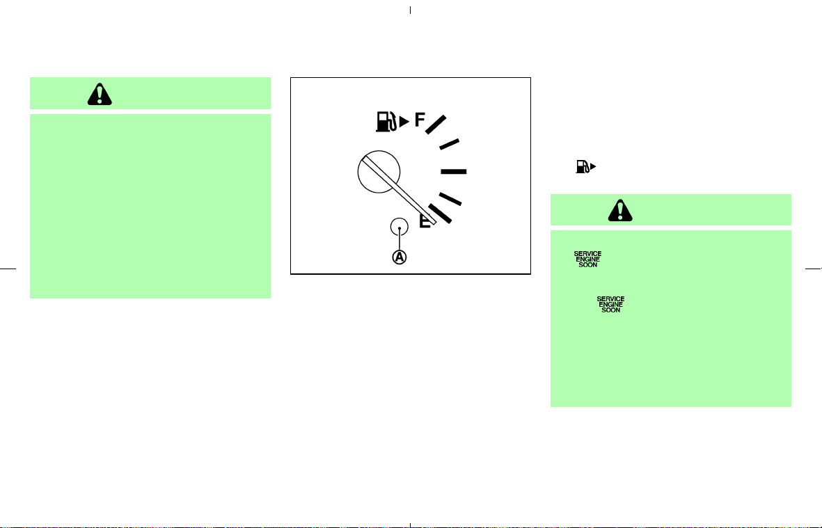
CAUTION
If the gauge indicates a coolant tem-
perature near the hot (H) end of the
normal range, reduce vehicle speed to
decrease the temperature. If the gauge
is over the normal range, stop the ve-
hicle as soon as safely possible. If the
engine is overheated, continued opera-
tion of the vehicle may seriously dam-
age the engine. See “If your vehicle
overheats” in the “6. In case of emer-
gency” section for immediate action re-
quired.
FUEL GAUGE
The gauge indicates the approximate fuel level in
the tank.
The gauge may move slightly during braking,
turning, acceleration, or going up or down hill.
The gauge needle is designed to move to the E
(Empty) position when the ignition key is turned
to the OFF position.
Refill the fuel tank before the gauge regis-
ters the E (Empty) position.
The low fuel warning light comes on when
the fuel tank is getting low. Refuel as soon
as it is convenient, preferably before the
gauge reaches the E position. There will be
a small reserve of fuel in the tank when the
fuel gauge needle reaches the E position.
The
indicates that the fuel-filler door is
located on the passenger’s side of the vehicle.
CAUTION
쐌 If the vehicle runs out of fuel, the
malfunction indicator light
(MIL) may come on. Refuel as soon
as possible. After a few driving trips,
the
light should turn off. If the
light remains on after a few driving
trips, have the vehicle inspected by a
NISSAN dealer.
쐌 For additional information, see “Mal-
function indicator light (MIL)” later in
this section.
SIC2556
2-6 Instruments and controls
墌 08.7.24/Z33-D/V5.0 墍
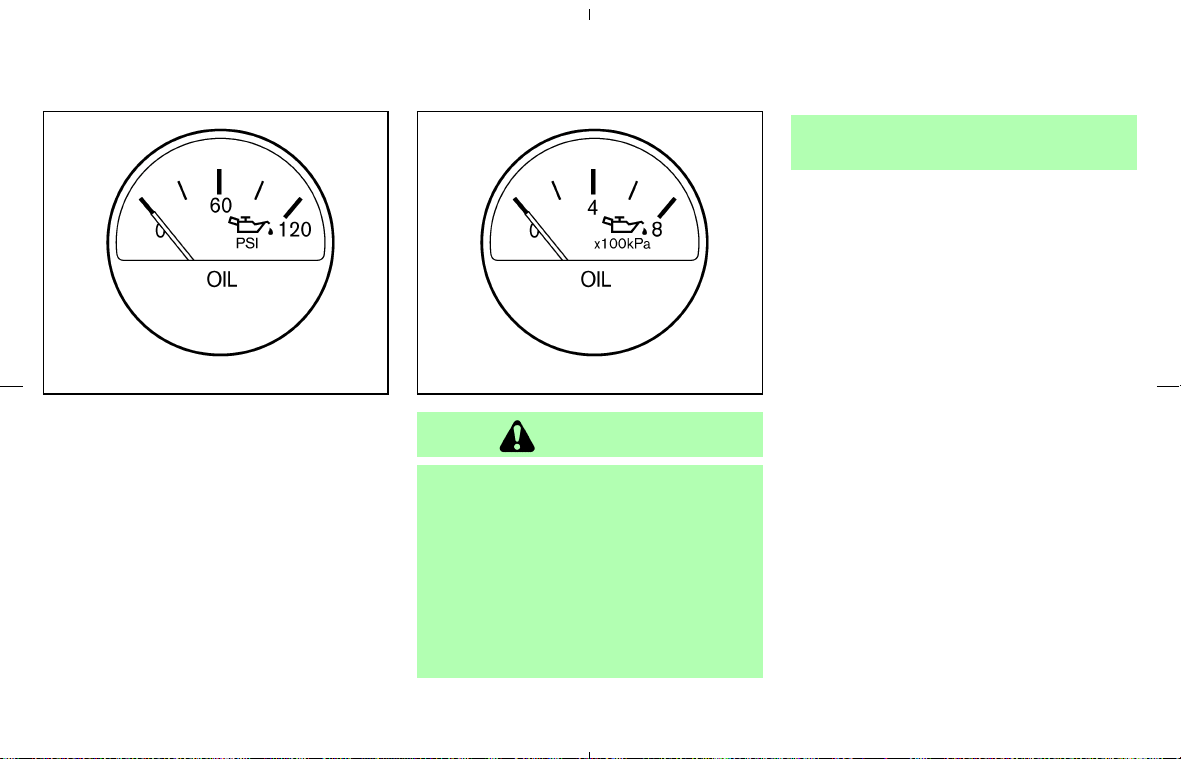
ENGINE OIL PRESSURE GAUGE
The gauge indicates the engine lubrication sys-
tem oil pressure while the engine is running.
When the engine speed is high, the engine oil
pressure is also high. When it is low, the gauge
indicates the low oil pressure.
CAUTION
쐌 This gauge is not designed to indi-
cate low engine oil level. Use the
dipstick to check the oil level. (See
“Engine oil” in the “8. Maintenance
and do-it-yourself” section.)
쐌 If the gauge needle does not move
with the proper amount of engine oil,
have the vehicle checked by a
NISSAN dealer. Continued vehicle
operation in such a condition could
cause serious damage to the engine.
SIC1954A
Type A
SIC1953A
Type B
Instruments and controls 2-7
墌 08.7.24/Z33-D/V5.0 墍
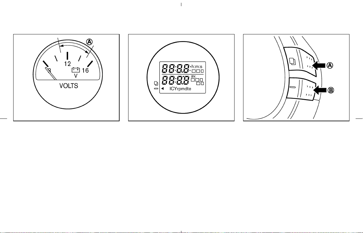
VOLT METER
When the ignition switch is turned to the ON
position, the volt meter indicates the battery
voltage; while the engine is running, it indicates
the alternator voltage of 11 - 15 volts (normal
range
쎻
A
). However, while cranking the engine,
the volts drop below the normal range.
If the needle is not in the normal range
쎻
A
while
the engine is running, it may indicate that the
charging system is not functioning properly.
Have the system checked by a NISSAN dealer.
TRIP COMPUTER
The display of the trip computer is situated in the
triple meter. When the ignition switch is turned
to ON, the display scrolls all the modes of the
trip computer and then shows the mode chosen
before the ignition switch is turned OFF.
Switches for the trip computer are located on
the side of the combination meter panel. To
operate the trip computer, push the side of the
switches as shown above.
쎻
A
: Trip computer mode switch
쎻
B
: Trip computer setting switch
When the ignition switch is turned to ON, modes
of the trip computer can be selected by pushing
the trip computer mode switch
쎻
A
.
Each time the mode switch
쎻
A
is pushed, the
display will change as follows:
Speed indicator → Outside air temperature
(ICY) → Distance to empty (dte) → Average fuel
SIC1955 SIC3357 SIC2997
2-8 Instruments and controls
墌 08.7.24/Z33-D/V5.0 墍

consumption and speed → Elapsed time and
trip odometer → Stopwatch → Up-shift indica-
tor setting (for M/T models) → Speed indicator
Speed indicator (mph or km/h)
The vehicle speed is displayed in MPH or km/h
while driving.
The speed indicator in the trip computer
indicates the reference speed. The actual
speed indicated by the speedometer (com-
bination meter) may differ from the one in
the trip computer.
Outside air temperature
(ICY—°For°C)
The outside air temperature is displayed in °F or
°C in the range of −22 to 131°F (−30 to 55°C).
The outside air temperature mode includes a low
temperature warning feature: below 37°F (3°C),
the outside air temperature mode is automati-
cally selected and the ICY indicator will illumi-
nate in order to draw the driver’s attention. Push
the mode switch
쎻
A
if you wish to return to the
mode that was selected before the warning
occurred. The ICY indicator will continue blink-
ing as long as the temperature remains below
39°F (4°C).
The ambient temperature sensor is located in
front of the radiator. The sensor may be affected
by road or engine heat, wind directions and
other driving conditions. The display may differ
from the actual ambient temperature or the
temperature displayed on various signs or bill-
boards.
Distance to empty (dte — mls or km)
The distance to empty (dte) mode provides you
with an estimation of the distance that can be
driven before refueling. The dte is constantly
being calculated, based on the amount of fuel in
the fuel tank and the actual fuel consumption.
The display is updated every 30 seconds.
The dte mode includes a low range warning
feature: when the fuel level is low, the dte mode
is automatically selected and the digits blink in
order to draw the driver’s attention. Press the
mode switch
쎻
A
if you wish to return to the mode
that was selected before the warning occurred.
The dte indicator will remain blinking until the
vehicle is refueled.
When the fuel level drops even lower, the dte
display will change to (----).
NOTE:
쐌 If the amount of fuel added while the
ignition switch is OFF is small, the dis-
play just before the ignition switch is
turned OFF may continue to be dis-
played.
쐌 When driving uphill or rounding curves,
the fuel in the tank shifts, which may
momentarily change the display.
Average fuel consumption
(mpg or l (liter)/100 km) and speed
(av. mph or av. km/h)
Fuel consumption:
The average fuel consumption mode shows the
average fuel consumption since the last reset.
Resetting is done by pushing the trip computer
setting switch
쎻
B
for more than approximately 1
second. (The average speed is also reset at the
same time.)
The display is updated every 30 seconds. At
about the first 1/3 miles (500 m) after a reset,
the display shows (----).
Speed:
The average speed mode shows the average
vehicle speed since the last reset. Resetting is
done by pushing the setting switch
쎻
B
for more
than approximately 1 second. (The average fuel
consumption is also reset at the same time.)
The display is updated every 30 seconds. The
Instruments and controls 2-9
墌 08.7.24/Z33-D/V5.0 墍

first 30 seconds after a reset, the display shows
(----).
Elapsed time (h:m:s) and trip
odometer (mls or km)
Elapsed time:
The elapsed time mode shows the time since the
last reset. The displayed time can be reset by
pushing the trip computer setting switch
쎻
B
for
more than approximately 1 second. (The trip
odometer is also reset at the same time.)
Trip odometer:
The trip odometer mode shows the total dis-
tance the vehicle has been driven since the last
reset. Resetting is done by pushing the setting
switch
쎻
B
for more than approximately 1 second.
(The elapsed time is also reset at the same time.)
Stopwatch (h:m:s)
You can use the trip computer as a stopwatch.
Each time the trip computer setting switch
쎻
B
is
pushed, the stopwatch will be operated as fol-
lows:
After 100 hours, the time will start from the reset
display again.
Even if the display is switched to the other mode
while the time is starting, the stopwatch contin-
ues to advance until you stop the time in the
stopwatch mode. When the ignition switch is
turned to the OFF position, the time is reset.
Up-shift indicator setting (rpm) (for
manual transmission models)
The up-shift indicator setting mode is used to
set the desired engine speed (rpm) for the
up-shift indicator (situated in the tachometer) to
illuminate. When the engine speed approaches
or reaches the set figure, the up-shift indicator
will flash or illuminate to show the driver the
timing for shifting into a higher gear. See “Driving
the vehicle” in the “5. Starting and driving”
section for the use of the up-shift indicator.
When the up-shift indicator setting mode is
selected, the rpm indicator blinks and the engine
speed currently set is displayed. (The initial
factory setting is 7,500 rpm.) The figure can be
changed between 2,000 and 9,000 rpm by
pushing trip computer setting switch
쎻
B
. Press-
ing the switch for less than approximately 1
second will add the figure by 100 rpm. If pushing
for more than approximately 1 second, the figure
will increase by 500 rpm.
If the battery cable is disconnected, the set
engine speed will be returned to the initial figure
(7,500 rpm).
Display priority
If a low outside air temperature warning,
low dte (distance to empty) range warning
and low tire pressure warning occur simul-
taneously, other display modes switch au-
tomatically to the outside air temperature
display.
When trip computer mode switch
쎻
A
is
pressed, the display switches to the mode
chosen before the warning display, but the
ICY indicator will continue blinking.
2-10 Instruments and controls
墌 08.7.24/Z33-D/V5.0 墍
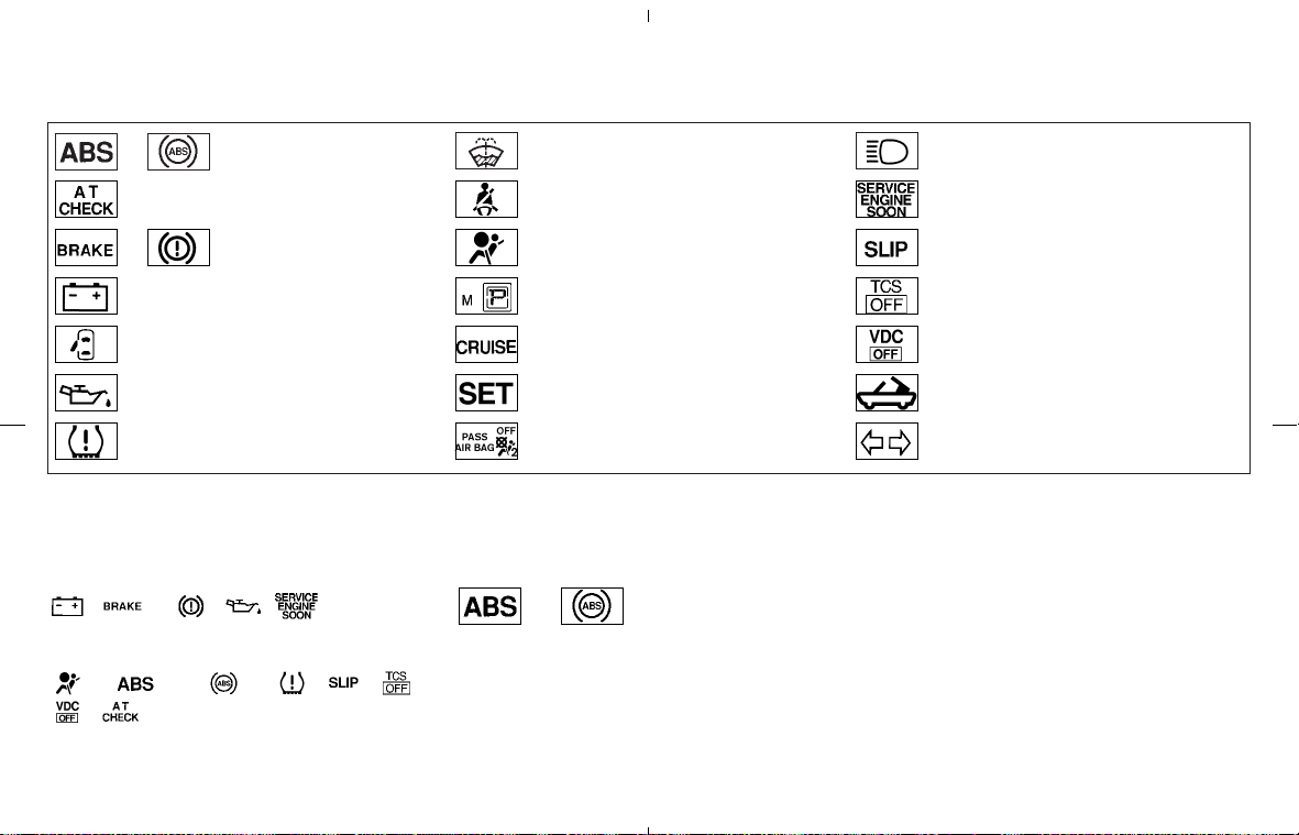
or
Anti-lock Braking System
(ABS) warning light
Low washer fluid warning light High beam indicator light (Blue)
Automatic transmission check warning
light (A/T models)
Seat belt warning light Malfunction Indicator Light (MIL)
or Brake warning light Supplemental air bag warning light Slip indicator light
Charge warning light
Automatic transmission position indicator
light (A/T models)
Traction Control System (TCS) off indica-
tor light (if so equipped)
Door open warning light
Cruise main switch indicator light
(if so equipped)
Vehicle Dynamic Control (VDC) off indi-
cator light (if so equipped)
Engine oil pressure warning light
Cruise set switch indicator light
(if so equipped)
Soft top indicator light (Roadster models)
Low tire pressure warning light Front passenger air bag status light Turn signal/hazard indicator lights
CHECKING BULBS
Apply the parking brake and turn the ignition key
to ON without starting the engine. The following
lights will come on:
, or , ,
The following lights come on briefly and then go
off:
, or , , , ,
,
If any light fails to come on, it may indicate a
burned-out bulb or an open circuit in the elec-
trical system. Have the system repaired
promptly.
WARNING LIGHTS
or Anti-lock Braking
System (ABS)
warning light
When the ignition switch is in the ON position,
the Anti-lock Braking System (ABS) warning
light illuminates and then turns off. This indicates
the ABS is operational.
If the ABS warning light illuminates while the
engine is running, or while driving, it may indicate
the ABS is not functioning properly. Have the
system checked by a NISSAN dealer.
If an ABS malfunction occurs, the anti-lock
function is turned off. The brake system then
operates normally, but without anti-lock assis-
tance. See “Brake system” in the “5. Starting
and driving” section.
WARNING/INDICATOR LIGHTS
AND AUDIBLE REMINDERS
Instruments and controls 2-11
墌 08.7.24/Z33-D/V5.0 墍
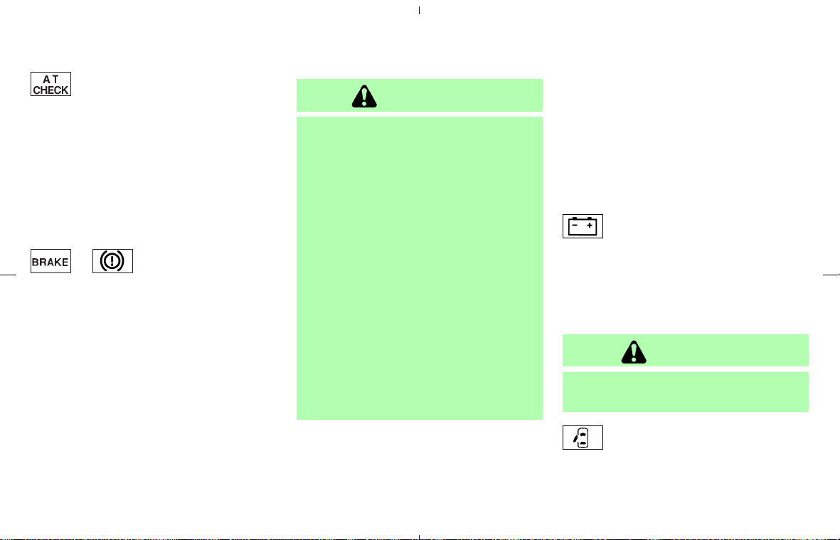
Automatic transmission check
warning light (A/T models)
When the ignition switch is turned to the ON
position, the automatic transmission check
warning light comes on and then turns off. This
indicates that the automatic transmission system
is operational.
If the light comes on while the engine is running
or while driving, it may indicate that the auto-
matic transmission system is not functioning
properly. Have a NISSAN dealer check and
repair the transmission.
or Brake warning light
This light functions for both the parking brake
and the foot brake systems.
Parking brake indicator:
When the ignition switch is in the ON position,
the light comes on when the parking brake is
applied.
Low brake fluid warning light:
The light warns of a low brake fluid level. If the
light comes on while the engine is running with
the parking brake not applied, stop the vehicle
and perform the following:
1. Check the brake fluid level. Add brake fluid as
necessary. See “Brake and clutch fluid” in the
“8. Maintenance and do-it-yourself” section.
WARNING
쐌 Your brake system may not be work-
ing properly if the warning light is on.
Driving could be dangerous. If you
judge it to be safe, drive carefully to
the nearest service station for re-
pairs. Otherwise, have your vehicle
towed because driving it could be
dangerous.
쐌 Pressing the brake pedal with the
engine stopped and/or a low brake
fluid level may increase your stop-
ping distance and braking will re-
quire greater pedal effort as well as
pedal travel.
쐌 If the brake fluid level is below the
MINIMUM or MIN mark on the brake
fluid reservoir, do not drive until the
brake system has been checked at a
NISSAN dealer.
2. If the brake fluid level is correct, have the
warning system checked by a NISSAN
dealer.
Anti-lock Braking System (ABS) warning
indicator:
When the parking brake is released and the
brake fluid level is sufficient, if both the brake
warning light and the ABS warning light illumi-
nate, it may indicate the ABS is not functioning
properly. Have the brake system checked by a
NISSAN dealer. See “Anti-lock Braking System
(ABS) warning light” earlier in this section.
Charge warning light
If the light comes on while the engine is running,
it may indicate that the charging system is not
functioning properly. Turn the engine off and
check the alternator belt. If the belt is loose,
broken, missing or if the light remains on, see a
NISSAN dealer immediately.
CAUTION
Do not continue driving if the belt is
loose, broken or missing.
Door open warning light
This light comes on when any of the doors
and/or rear hatch are not closed securely while
the ignition switch is in the ON position.
2-12 Instruments and controls
墌 08.7.24/Z33-D/V5.0 墍
Engine oil pressure warning
light
This light warns of low engine oil pressure. If the
light flickers or comes on during normal driving,
pull off the road in a safe area, stop the engine
immediately and call a NISSAN dealer or other
authorized repair shop.
The engine oil pressure warning light is not
designed to indicate a low oil level. Use the
dipstick to check the oil level. See “Engine
oil” in the “8. Maintenance and do-it-yourself”
section.
CAUTION
Running the engine with the engine oil
pressure warning light on could cause
serious damage to the engine almost
immediately. Turn off the engine as
soon as it is safe to do so.
Low tire pressure warning light
Your vehicle is equipped with a Tire Pressure
Monitoring System (TPMS) that monitors the tire
pressure of all tires except the spare.
The low tire pressure warning light warns of low
tire pressure or indicates that the TPMS is not
functioning properly.
After the ignition switch is turned ON, this light
illuminates for about 1 second and turns off.
Low tire pressure warning:
If the vehicle is being driven with low tire pres-
sure, the warning light will illuminate.
When the low tire pressure warning light illumi-
nates, you should stop and adjust the tire pres-
sure to the recommended COLD tire pressure
shown on the Tire and Loading Information label.
The low tire pressure warning light does not
automatically turn off when the tire pressure is
adjusted. After the tire is inflated to the recom-
mended pressure, the vehicle must be driven at
speeds above 16 MPH (25 km/h) to activate the
TPMS and turn off the low tire pressure warning
light. Use a tire pressure gauge to check the tire
pressure.
For additional information, see “Tire pressure
monitoring system (TPMS)” in the “5. Starting
and driving” section and in the “6. In case of
emergency” section.
TPMS malfunction:
If the TPMS is not functioning properly, the low
tire pressure warning light will flash for approxi-
mately 1 minute when the ignition switch is
turned ON. The light will remain on after the 1
minute. Have the system checked by a NISSAN
dealer.
For additional information, see “Tire pressure
monitoring system (TPMS)” in the “5. Starting
and driving” section.
WARNING
쐌 If the light does not illuminate with
the ignition switch turned ON, have
the vehicle checked by a NISSAN
dealer as soon as possible.
쐌 If the light illuminates while driving,
avoid sudden steering maneuvers or
abrupt braking, reduce vehicle speed,
pull off the road to a safe location
and stop the vehicle as soon as pos-
sible. Driving with under-inflated
tires may permanently damage the
tires and increase the likelihood of
tire failure. Serious vehicle damage
could occur and may lead to an acci-
dent and could result in serious per-
sonal injury. Check the tire pressure
for all four tires. Adjust the tire pres-
Instruments and controls 2-13
墌 08.7.24/Z33-D/V5.0 墍
sure to the recommended COLD tire
pressure shown on the Tire and
Loading Information label to turn the
low tire pressure warning light OFF.
If the light stays on after adjusting
the tire pressure and driving over 16
MPH (25 km/h), have the system
checked by a NISSAN dealer. If you
have a flat tire, replace it with a spare
tire as soon as possible.
쐌 When a spare tire is mounted or a
wheel is replaced, the TPMS will not
function and the low tire pressure
warning light will flash for approxi-
mately 1 minute. The light will remain
on after 1 minute. Contact your
NISSAN dealer as soon as possible
for tire replacement and/or system
resetting.
쐌 Replacing tires with those not origi-
nally specified by NISSAN could af-
fect the proper operation of the
TPMS.
CAUTION
쐌 The TPMS is not a substitute for the
regular tire pressure check. Be sure
to check the tire pressure regularly.
쐌 If the vehicle is being driven at
speeds of less than 16 MPH (25
km/h), the TPMS may not operate
correctly.
쐌 Be sure to install the specified size of
tires to the front and rear.
Low washer fluid warning light
This light comes on when the washer fluid is at a
low level. Add washer fluid as necessary. See
“Window washer fluid” in the “8. Maintenance
and do-it-yourself” section.
Seat belt warning light
The seat belt warning light and chime remind you
to fasten seat belts. The light illuminates when-
ever the ignition key is turned to ON, and will
remain illuminated until the driver’s seat belt is
fastened.
The seat belt warning light may also illuminate if
the front passenger’s seat belt is not fastened
when the front passenger’s seat is occupied. For
5 seconds after the ignition switch is in the ON
position, the system does not activate the warn-
ing light for the front passenger.
See “Seat belts” in the “1. Safety — Seats, seat
belts and supplemental restraint system” section
for precautions on seat belt usage.
Supplemental air bag warning
light
After turning the ignition key to the ON position,
the supplemental air bag warning light will illu-
minate. The supplemental air bag warning light
will turn off after about 7 seconds if the system is
operational.
If any of the following conditions occur, the front
air bag, side air bag (if so equipped) and curtain
air bag (if so equipped), and pretensioner sys-
tems need servicing and your vehicle must be
taken to a NISSAN dealer.
쐌 The supplemental air bag warning light re-
mains on after approximately 7 seconds.
쐌 The supplemental air bag warning light
flashes intermittently.
쐌 The supplemental air bag warning light does
not come on at all.
2-14 Instruments and controls
墌 08.7.24/Z33-D/V5.0 墍
Unless checked and repaired, the supplemental
restraint system (air bag system) and/or the
pretensioners may not function properly. For
additional information, see “Supplemental re-
straint system” in the “1. Safety — Seats, seat
belts and supplemental restraint system” sec-
tion.
WARNING
If the supplemental air bag warning
light is on, it could mean that the front
air bag, side air bag, curtain air bag
and/or pretensioner systems will not
operate in an accident. To help avoid
injury to yourself or others, have your
vehicle checked by a NISSAN dealer as
soon as possible.
INDICATOR LIGHTS
Automatic transmission
position indicator light (A/T
models)
When the ignition key is turned to the ON
position, the indicator in the tachometer shows
the automatic transmission selector lever posi-
tion. See “Driving the vehicle” (automatic trans-
mission) in the “5. Starting and driving” section.
Cruise main switch indicator
light (if so equipped)
The light comes on when the cruise control main
switch is pushed. The light goes out when the
main switch is pushed again. When the cruise
main switch indicator light comes on, the cruise
control system is operational.
Cruise set switch indicator
light (if so equipped)
The light comes on while the vehicle speed is
controlled by the cruise control system. If the
light blinks while the engine is running, it may
indicate the cruise control system is not func-
tioning properly. Have the system checked by a
NISSAN dealer.
Front passenger air bag status
light
The front passenger air bag status light
(
) will be lit and the passenger front air bag
will be OFF depending on how the front passen-
ger seat is being used.
For front passenger air bag status light opera-
tion, see “NISSAN Advanced Air Bag System” in
the “1. Safety — Seats, seat belts and supple-
mental restraint system” section of this manual.
High beam indicator light
(Blue)
This light comes on when the headlight high
beam is on and goes out when the low beam is
selected.
Malfunction Indicator Light
(MIL)
If the Malfunction Indicator Light (MIL) comes on
steady or blinks while the engine is running, it
may indicate a potential emission control mal-
function.
The malfunction indicator light may also come on
steady if the fuel-filler cap is loose or missing, or
if the vehicle runs out of fuel. Check to make sure
the fuel-filler cap is installed and closed tightly,
and that the vehicle has at least 3 US gallons (14
liters) of fuel in the fuel tank.
After a few driving trips, the
light should
turn off if no other potential emission control
system malfunction exists.
If this indicator light comes on steady for 20
seconds and then blinks for 10 seconds when
the engine is not running, it indicates that the
vehicle is not ready for an emission control
system inspection/maintenance test. See
“Readiness for inspection/maintenance (I/M)
test” in the “9. Technical and consumer informa-
Instruments and controls 2-15
墌 08.7.24/Z33-D/V5.0 墍
tion” section of this manual.
Operation
The malfunction indicator light will come on in
one of two ways:
쐌 Malfunction indicator light on steady — An
emission control system malfunction has
been detected. Check the fuel-filler cap. If the
fuel-filler cap is loose or missing, tighten or
install the cap and continue to drive the
vehicle. The
light should turn off after a
few driving trips. If the
light does not
turn off after a few driving trips, have the
vehicle inspected by a NISSAN dealer. You
do not need to have your vehicle towed to the
dealer.
쐌 Malfunction indicator light blinking — An en-
gine misfire has been detected which may
damage the emission control system. To re-
duce or avoid emission control system dam-
age:
a) Do not drive at speeds above 45 MPH
(72 km/h).
b) Avoid hard acceleration or deceleration.
c) Avoid steep uphill grades.
d) If possible, reduce the amount of cargo
being hauled or towed.
The malfunction indicator light may stop
blinking and come on steady.
Have the vehicle inspected by a NISSAN
dealer. You do not need to have your vehicle
towed to the dealer.
CAUTION
Continued vehicle operation without
having the emission control system
checked and repaired as necessary
could lead to poor driveability, reduced
fuel economy, and possible damage to
the emission control system.
Slip indicator light
The light will blink when the Vehicle Dynamic
Control (VDC) system or the Traction Control
System (TCS) is operating, thus alerting the
driver to the fact that the road surface is slippery
and the vehicle is nearing its traction limits.
This light also comes on when the ignition switch
is turned to the ON position. The light will turn off
if the VDC or TCS is operational.
Traction Control System (TCS)
off indicator light (if so
equipped)
The light comes on when the Traction Control
System (TCS) off switch is pushed to OFF. This
indicates the TCS is not operating.
This light also comes on when the ignition switch
is turned to the ON position. The light will turn off
if the TCS is operational.
When the TCS off indicator light and slip indi-
cator light come on with the TCS turned on, this
light alerts the driver to the fact that the system’s
fail-safe mode is operating, that is the TCS may
not be functioning properly. Have the system
checked by a NISSAN dealer. If a malfunction
occurs in the system, the traction control func-
tion will be canceled but the vehicle is still
driveable. For additional information, see “Trac-
tion Control System (TCS)” in the “5. Starting
and driving” section of this manual.
Vehicle Dynamic Control
(VDC) off indicator light (if so
equipped)
The light comes on when the Vehicle Dynamic
Control (VDC) off switch is pushed to OFF. This
indicates the VDC system and Traction Control
System (TCS) are not operating.
2-16 Instruments and controls
墌 08.7.24/Z33-D/V5.0 墍
This light also comes on when the ignition switch
is turned to the ON position. The light will turn off
if the VDC system is operational.
When the VDC off indicator light and slip indi-
cator light come on with the VDC system turned
on, this light alerts the driver to the fact that the
system’s fail-safe mode is operating, that is the
VDC system may not be functioning properly.
Have the system checked by a NISSAN dealer.
If a malfunction occurs in the system, the VDC
system function will be canceled but the vehicle
is still driveable. For additional information, see
“Vehicle Dynamic Control (VDC) system” in the
“5. Starting and driving” section of this manual.
Soft top indicator light
(Roadster models)
This light illuminates when the soft top is being
operated or it is stopped before reaching a full
open/close state. When the top is fully opened,
the light will turn off. When the top is fully closed,
the light will flash.
The soft top can be moved with the soft top
operating switch only under all of the following
conditions:
쐌 When the vehicle is stopped.
쐌 When the foot brake pedal is depressed.
쐌 When the ignition switch is ON.
CAUTION
Operate the soft top with the engine
running to prevent a discharged battery.
When the soft top is in motion, and any of the
above conditions are discontinued or the pas-
senger power seat switches (on the cushion or
the seatback) are operated, the top will stop
moving. Remove your hand from the operating
switch, and push it again under the above
conditions until the top is fully opened or closed.
The soft top indicator light will turn off when the
top open operation is completely finished. When
closing the top, the light, which is illuminated,
will begin to flash when the top close operation
is completely finished. Securely engage the top
to the vehicle by operating the top latch lever.
The light will turn off.
If the soft top indicator light flashes with the
ignition switch ON (whether the top is operated
or not, and when the top is engaged), it may
indicate the electric soft top control unit is not
functioning properly. Have your vehicle checked
by a NISSAN dealer as soon as possible.
For more details about the electric soft top
operation, see “Soft top” in the “3. Pre-driving
checks and adjustments” section.
Turn signal/hazard indicator
lights
The light flashes when the turn signal switch
lever or hazard switch is turned on.
AUDIBLE REMINDERS
Key reminder chime
The chime will sound if the driver’s side door is
opened while the key is left in the ignition switch
(ignition switch is turned off). Remove the key
and take it with you when leaving the vehicle.
Light reminder chime
The chime will sound when the driver’s door is
opened with the headlight switch on unless the
key is in the ignition switch. Make sure to turn the
light switch off when you leave the vehicle.
Seat belt warning chime
The chime will sound for about 6 seconds unless
the driver’s seat belt is securely fastened.
Brake pad wear warning
The disc brake pads have audible wear warn-
ings. When a brake pad requires replacement, it
will make a high pitched scraping sound when
the vehicle is in motion whether or not the brake
pedal is depressed. Have the brakes checked as
Instruments and controls 2-17
墌 08.7.24/Z33-D/V5.0 墍
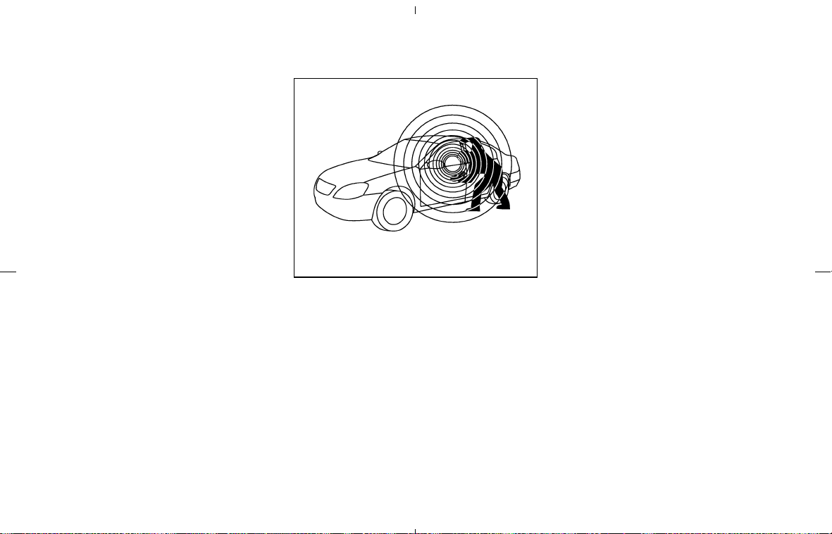
soon as possible if the warning sound is heard.
Your vehicle has two types of security systems,
as follows:
쐌 Vehicle Security System
쐌 NISSAN Vehicle Immobilizer System
The security condition will be shown by the
security indicator light.
VEHICLE SECURITY SYSTEM
The vehicle security system provides visual and
audible alarm signals if someone opens the
doors or rear hatch/trunk lid when the system is
armed. It is not, however, a motion detection
type system that activates when a vehicle is
moved or when a vibration occurs.
The system helps deter vehicle theft but cannot
prevent it, nor can it prevent the theft of interior
or exterior vehicle components in all situations.
Always secure your vehicle even if parking for a
brief period. Never leave your keys in the vehicle,
and always lock the vehicle when unattended.
Be aware of your surroundings, and park in
secure, well-lit areas whenever possible.
Many devices offering additional protection,
such as component locks, identification markers,
and tracking systems, are available at auto sup-
ply stores and specialty shops. A NISSAN dealer
may also offer such equipment. Check with your
insurance company to see if you may be eligible
for discounts for various theft protection fea-
tures.
SIC2132
SECURITY SYSTEMS
2-18 Instruments and controls
墌 08.7.24/Z33-D/V5.0 墍
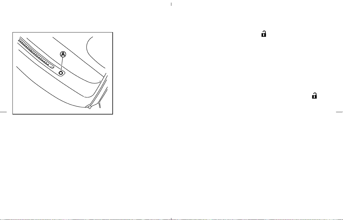
Security indicator light
This light 쎻
A
blinks whenever the ignition switch
is in the LOCK, OFF or ACC position. This is
normal.
How to arm the vehicle security
system
1. Close all windows.
The system can be activated even if the
windows are open.
2. Remove the key from the ignition switch.
3. Close and lock all doors and rear hatch/trunk
lid.
Lock all doors by using the key or the keyfob.
When using the keyfob, the hazard indicators
flash twice to indicate all doors are locked.
4. Confirm that the security indicator light
comes on. The security indicator light glows
for about 30 seconds and then blinks. The
system is now activated. If, during this 30
second time period, the door is unlocked by
the key or the keyfob, or the ignition key is
turned to ACC or ON, the system will not
activate.
Even when the driver and/or passengers
are in the vehicle, the system will activate
with all doors and rear hatch/trunk lid
locked and ignition key off. Turn the igni-
tion key to ACC to turn the system off.
Vehicle security system activation
The security system will give the following alarm:
쐌 The headlights blink and the horn sounds
intermittently.
쐌 The alarm automatically turns off after ap-
proximately 50 seconds. However, the alarm
reactivates if the vehicle is tampered with
again. The alarm can be shut off by unlocking
a door with the key, or by pushing the
UNLOCK
button on the keyfob.
The alarm is activated by:
쐌 Opening the door without using the key or
keyfob.
쐌 Opening the rear hatch or the trunk lid with-
out using the keyfob.
How to stop an activated alarm
The alarm will stop only by unlocking a door with
the key, or by pushing the UNLOCK
but-
ton on keyfob. The alarm will not stop if the
ignition key is turned to ACC or ON.
If the system does not operate as de-
scribed above, have it checked by a
NISSAN dealer.
NISSAN VEHICLE IMMOBILIZER
SYSTEM
The NISSAN Vehicle Immobilizer System will not
allow the engine to start without the use of the
registered key.
If the engine fails to start using the registered key
(for example, when interference is caused by
another registered key, an automated toll road
device or automated payment device on the key
ring), restart the engine using the following
procedures:
SIC1699A
Instruments and controls 2-19
墌 08.7.24/Z33-D/V5.0 墍
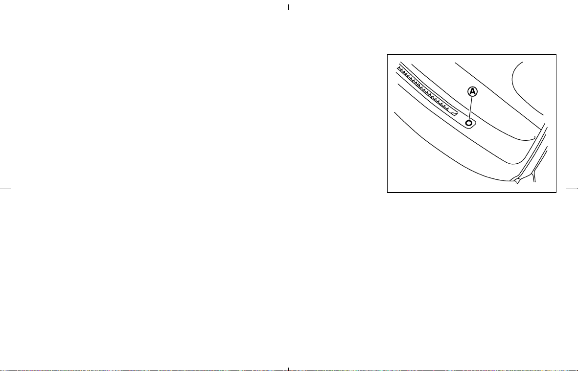
1. Leave the ignition switch in the ON position
for approximately 5 seconds.
2. Turn the ignition switch to the OFF or LOCK
position and wait approximately 10 seconds.
3. Repeat steps 1 and 2.
4. Restart the engine while holding the device
(which may have caused the interference)
separate from the registered key.
If this procedure allows the engine to start,
NISSAN recommends placing the registered
key on a separate key ring to avoid interfer-
ence from other devices.
Statement related to section 15 of FCC
rules for NISSAN Vehicle Immobilizer Sys-
tem (CONT ASSY-BCM, ANT ASSY-
IMMOBILISER)
This device complies with part 15 of the
FCC Rules and RSS-210 of Industry
Canada. Operation is subject to the follow-
ing two conditions;
(1) This device may not cause harmful in-
terference, and (2) this device must accept
any interference received, including inter-
ference that may cause undesired opera-
tion of the device.
CHANGES OR MODIFICATIONS NOT EX-
PRESSLY APPROVED BY THE PARTY RE-
SPONSIBLE FOR COMPLIANCE COULD
VOID THE USER’S AUTHORITY TO OPER-
ATE THE EQUIPMENT.
Security indicator light
This light 쎻
A
blinks whenever the ignition switch
is in the LOCK, OFF or ACC position. This
function indicates the security system equipped
on the vehicle is operational.
If the NISSAN Vehicle Immobilizer System is
malfunctioning, this light will remain on while the
ignition switch is in the ON position.
If the light still remains on and/or the
engine will not start, see a NISSAN dealer
for NISSAN Vehicle Immobilizer System
service as soon as possible. Bring all reg-
istered keys that you have when visiting a
SIC1699A
2-20 Instruments and controls
墌 08.7.24/Z33-D/V5.0 墍
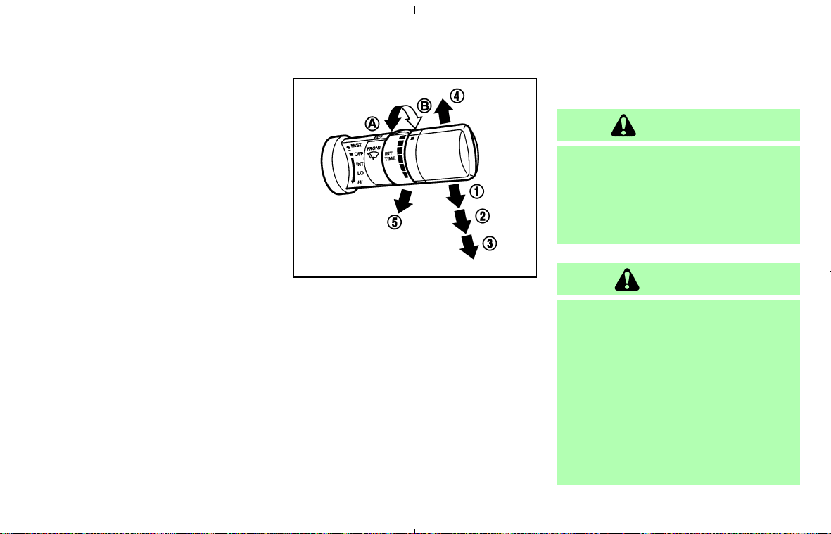
NISSAN dealer for service.
The windshield wiper and washer operates
when the ignition switch is in the ON position.
Push the lever down to operate the wiper at the
following speed:
쎻
1
Intermittent (INT) — intermittent operation
can be adjusted by turning the knob toward
쎻
A
(Slower) or 쎻
B
(Faster).
쎻
2
Low (LO) — continuous low speed operation
쎻
3
High (HI) — continuous high speed operation
Push the lever up
쎻
4
to have one sweep
operation (MIST) of the wiper.
Pull the lever toward you
쎻
5
to operate the
washer. Then the wiper will also operate several
times.
WARNING
In freezing temperatures the washer so-
lution may freeze on the windshield and
obscure your vision which may lead to
an accident. Warm the windshield with
the defroster before you wash the wind-
shield.
CAUTION
쐌 Do not operate the washer continu-
ously for more than 30 seconds.
쐌 Do not operate the washer if the
reservoir tank is empty.
쐌 Do not fill the window washer reser-
voir tank with washer fluid concen-
trates at full strength. Some methyl
alcohol based washer fluid concen-
trates may permanently stain the
grille if spilled while filling the win-
dow washer reservoir tank.
SIC2998
WINDSHIELD WIPER AND
WASHER SWITCH
Instruments and controls 2-21
墌 08.7.24/Z33-D/V5.0 墍
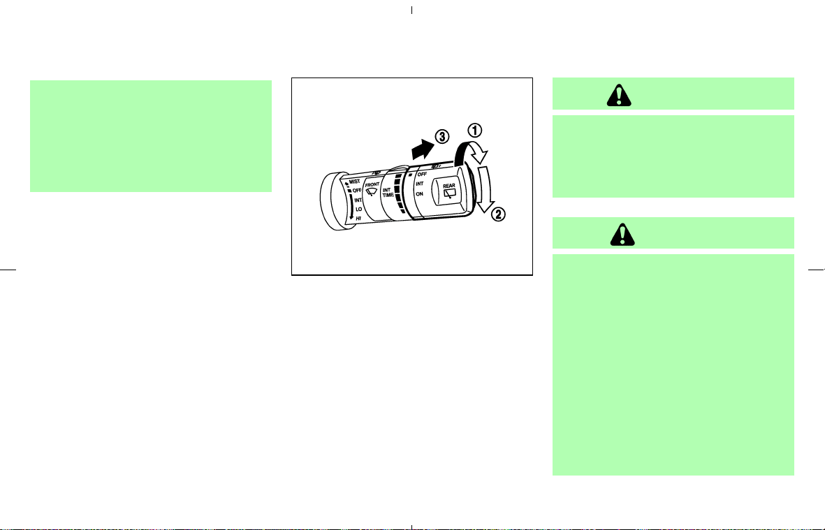
쐌 Pre-mix washer fluid concentrates
with water to the manufacturer’s rec-
ommended levels before pouring the
fluid into the window washer reser-
voir tank. Do not use the window
washer reservoir tank to mix the
washer fluid concentrate and water.
The rear window wiper and washer operate
when the ignition switch is in the ON position.
Turn the switch clockwise from the OFF position
to operate the wiper.
쎻
1
Intermittent (INT) — intermittent operation
(not adjustable)
쎻
2
Low (ON) — continuous low speed operation
Push the switch forward
쎻
3
to operate the
washer. Then the wiper will also operate several
times.
WARNING
In freezing temperatures the washer so-
lution may freeze on the rear window
and obscure your vision. Warm the rear
window with the defroster before you
wash the rear window.
CAUTION
쐌 If the rear window wiper operation is
interrupted by snow or ice, the wiper
may stop moving to protect its motor.
If this occurs, turn the wiper switch to
OFF and remove the snow or ice on
and around the wiper arms. After
about 1 minute, turn the switch ON
again to operate the wiper.
쐌 Do not operate the washer continu-
ously for more than 30 seconds.
쐌 Do not operate the washer if the
reservoir tank is empty.
쐌 Do not fill the window washer reser-
SIC3297
REAR WINDOW WIPER AND
WASHER SWITCH (Coupe
models)
2-22 Instruments and controls
墌 08.7.24/Z33-D/V5.0 墍
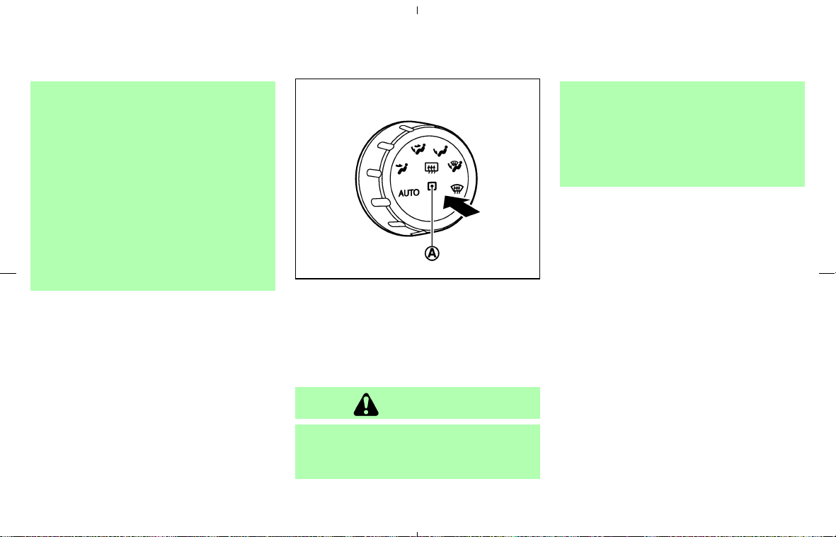
voir tank with washer fluid concen-
trates at full strength. Some methyl
alcohol based washer fluid concen-
trates may permanently stain the
grille if spilled while filling the win-
dow washer reservoir tank.
쐌 Pre-mix washer fluid concentrates
with water to the manufacturer’s rec-
ommended levels before pouring the
fluid into the window washer reser-
voir tank. Do not use the window
washer reservoir tank to mix the
washer fluid concentrate and water.
To defog/defrost the rear window glass and
outside mirrors, start the engine and push the
switch on. The indicator light
쎻
A
will come on.
Push the switch again to turn the defroster off.
It will automatically turn off in approximately 15
minutes.
CAUTION
쐌 When cleaning the inner side of the
rear window, be careful not to scratch
or damage the rear window de-
froster.
쐌 Do not use the rear window defroster
switch while the soft top is being
operated or fully opened. The heat
may damage the top material and/or
components. (for Roadster models)
SIC3000
REAR WINDOW AND OUTSIDE
MIRROR DEFROSTER SWITCH
Instruments and controls 2-23
墌 08.7.24/Z33-D/V5.0 墍
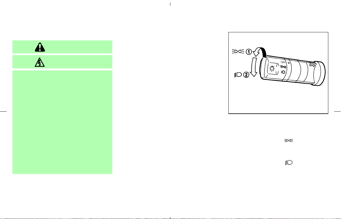
XENON HEADLIGHTS
WARNING
HIGH VOLTAGE
쐌 When xenon headlights are on, they
produce a high voltage. To prevent an
electric shock, never attempt to
modify or disassemble. Always have
your xenon headlights replaced at a
NISSAN dealer.
쐌 Xenon headlights provide consider-
ably more light than conventional
headlights. If they are not correctly
aimed, they might temporarily blind
an oncoming driver or the driver
ahead of you and cause a serious
accident. If headlights are not aimed
correctly, immediately take your ve-
hicle to a NISSAN dealer and have
the headlights adjusted correctly.
When the xenon headlight is initially turned on,
its brightness or color varies slightly. However,
the color and brightness will soon stabilize.
쐌 The life of xenon headlights will be
shortened by frequent on-off operation.
It is generally desirable not to turn off
the headlights for short intervals (for
example, when the vehicle stops at a
traffic signal). Even when the daytime
running lights are active (Canada only),
the xenon headlights do not turn on.
This way the life of the xenon headlights
is not reduced.
쐌 If the xenon headlight bulb is close to
burning out, the brightness will drasti-
cally decrease, the light will start blink-
ing, or the color of the light will become
reddish. If one or more of the above
signs appear, contact a NISSAN dealer.
HEADLIGHT SWITCH
Lighting
쎻
1
Turn the switch to the position:
The front park, side marker, tail, license plate
and instrument lights will come on.
쎻
2
Turn the switch to the position:
Headlights will come on and all the other
lights remain on.
SIC3291
HEADLIGHT AND TURN SIGNAL
SWITCH
2-24 Instruments and controls
墌 08.7.24/Z33-D/V5.0 墍
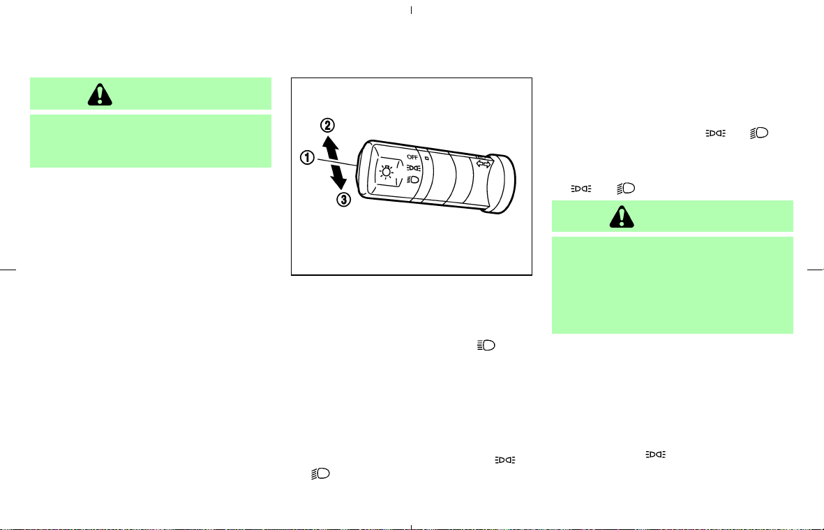
CAUTION
Use the headlights with the engine run-
ning to avoid discharging the vehicle
battery.
Headlight beam select
쎻
1
To select the high beam, push the lever
forward. The high beam lights come on and
the high beam indicator light
illumi-
nates.
쎻
2
Pull the lever back to select the low beam.
쎻
3
Pulling the lever toward you will flash the
headlight high beam.
Battery saver system
쐌 When the headlight switch is in the or
position while the ignition switch is in
the ON position, the lights will automatically
turn off 5 minutes after the ignition switch has
been turned to the OFF position.
쐌 After the headlights automatically turn off with
the headlight switch in the
or po-
sition, the headlights will illuminate again for 5
minutes if the headlight switch is turned to
the OFF position and then turned to the
or position.
CAUTION
Even though the battery saver feature
automatically turns off the headlights
after a period of time, you should turn
the headlight switch to the OFF position
when the engine is not running to avoid
discharging the vehicle battery.
DAYTIME RUNNING LIGHT SYSTEM
(Canada only)
The headlights (low beam) automatically illumi-
nate when the engine is started with the parking
brake released. The daytime running lights op-
erate with the headlight switch in the OFF
position or in the
position.
If the parking brake is applied before the engine
is started, the daytime running lights do not
SIC3315
Instruments and controls 2-25
墌 08.7.24/Z33-D/V5.0 墍
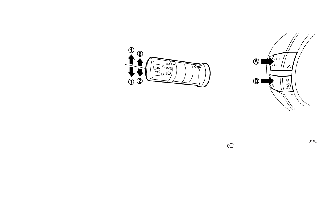
illuminate. The daytime running lights illuminate
once the parking brake is released. The daytime
running lights will remain on until the ignition
switch is turned off.
TURN SIGNAL SWITCH
쎻
1
Turn signal
Move the lever up or down to signal the turning
direction. When the turn is completed, the turn
signals cancel automatically.
쎻
2
Lane change signal
To indicate a lane change, move the lever up or
down to the point where lights begin flashing.
INSTRUMENT BRIGHTNESS
CONTROL
The instrument brightness control operates
when the light switch is in the
or
position and the ignition switch is in the
ON position.
To adjust the brightness of instrument panel
lights, press the control switches located on the
left side of the meter panel. Pressing the upper
switch
쎻
A
will brighten the lights. The lower
switch
쎻
B
will dim the lights. Repeatedly press-
ing the lower switch will turn the lights off.
SIC3316 SIC3001
2-26 Instruments and controls
墌 08.7.24/Z33-D/V5.0 墍
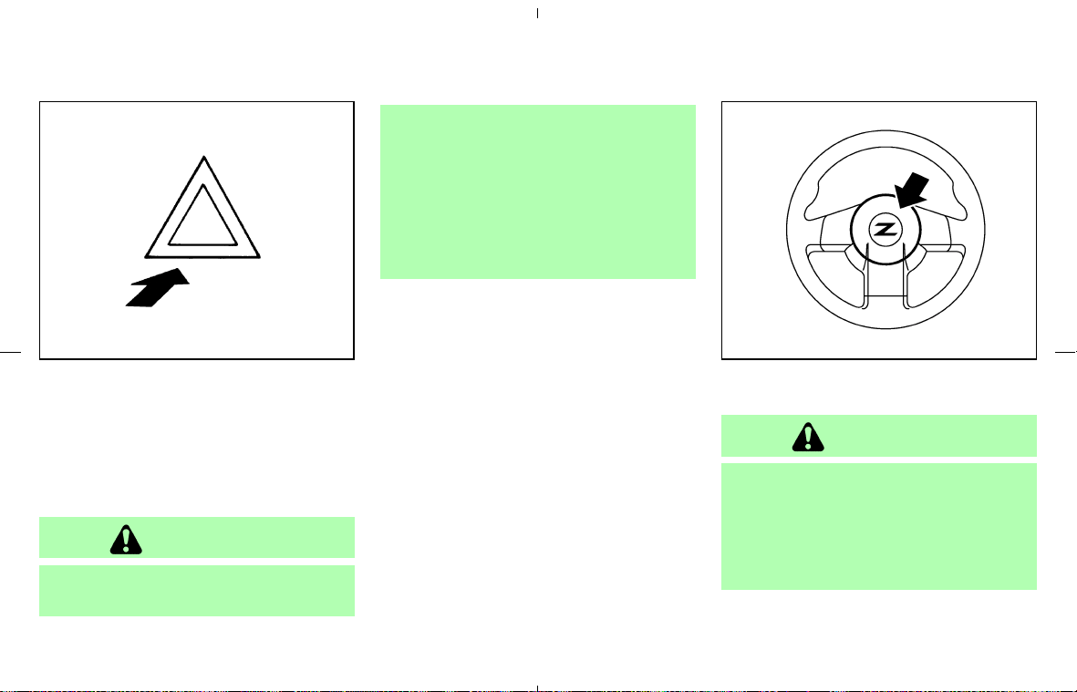
Push the switch (located on the front part of the
center console) on to warn other drivers when
you must stop or park under emergency condi-
tions. All turn signal lights will flash.
Some state or provincial laws may prohibit
the use of the hazard warning flasher
switch while driving.
WARNING
쐌 If stopping for an emergency, be sure
to move the vehicle well off the road.
쐌 Do not use the hazard warning flash-
ers while moving on the highway un-
less unusual circumstances force you
to drive so slowly that your vehicle
might become a hazard to other traf-
fic.
쐌 Turn signals do not work when the
hazard warning flasher lights are on.
The flasher will operate with the ignition switch in
any position.
To sound the horn, push the center pad area of
the steering wheel.
WARNING
Do not disassemble the horn. Doing so
could affect proper operation of the
supplemental front air bag system. Tam-
pering with the supplemental front air
bag system may result in serious per-
sonal injury.
SIC2475 SIC2195
HAZARD WARNING FLASHER
SWITCH
HORN
Instruments and controls 2-27
墌 08.7.24/Z33-D/V5.0 墍
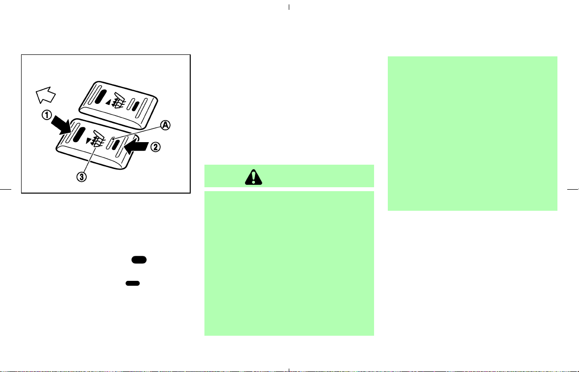
The seats are warmed by built-in heaters. The
switches are located on the center console.
1. Start the engine.
2. Select heat range.
쎻
1
For high heat, push the (High) side
of the switch.
쎻
2
For low heat, push the (Low) side of
the switch.
쎻
3
For no heat, the switch has a center OFF
position between low and high.
The indicator light
쎻
A
in the switch will
illuminate when low or high is selected.
The heater is controlled by a thermostat,
automatically turning the heater on and off.
The indicator light will remain on as long as
the switch is on.
3. When the vehicle’s interior is warmed, or
before you leave the vehicle, be sure to turn
the switch to the OFF position
쎻
3
.
An optional ventilated net seat has this built-in
heater only in the seat cushion part, not in the
seatback.
CAUTION
쐌 The battery could be discharged if
the seat heater is operated while the
engine is not running.
쐌 Do not use the seat heater for ex-
tended periods or when no one is
using the seat.
쐌 Do not put anything on the seat
which insulates heat, such as a blan-
ket, cushion, seat cover, etc. Other-
wise, the seat may become over-
heated.
쐌 Do not place anything hard or heavy
on the seat or pierce it with a pin or
similar object. This may result in
damage to the heater.
쐌 Any liquid spilled on the heated seat
should be removed immediately with
a dry cloth.
쐌 When cleaning the seat, never use
gasoline, benzine, thinner, or any
similar materials.
쐌 If any abnormalities are found or the
heated seat does not operate, turn
the switch off and have the system
checked by a NISSAN dealer.
SIC3002
HEATED SEATS (if so equipped)
2-28 Instruments and controls
墌 08.7.24/Z33-D/V5.0 墍
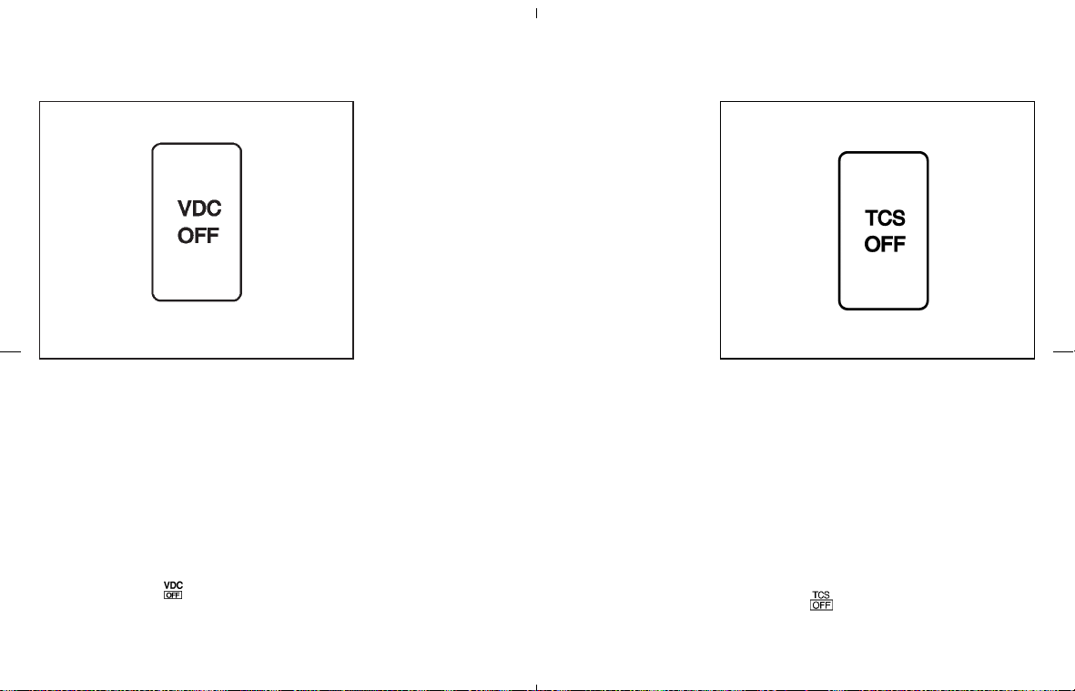
The vehicle should be driven with the Vehicle
Dynamic Control (VDC) system on for most
driving conditions.
If the vehicle is stuck in mud or snow, the VDC
system reduces the engine output to reduce
wheel spin. The engine speed will be reduced
even if the accelerator is depressed to the floor.
If maximum engine power is needed to free a
stuck vehicle, turn the VDC system off.
To turn off the VDC system, push the VDC OFF
switch (located on the lower side of the instru-
ment panel). The
indicator light will come
on.
Push the VDC OFF switch again or restart the
engine to turn on the system. See “Vehicle
Dynamic Control (VDC) system” in the “5. Start-
ing and driving” section.
The vehicle should be driven with the Traction
Control System (TCS) on for most driving con-
ditions.
If the vehicle is stuck in mud or snow, the TCS
reduces the engine output to reduce wheel spin.
The engine speed will be reduced even if the
accelerator is depressed to the floor. If maximum
engine power is needed to free a stuck vehicle,
turn the TCS off.
To turn off the TCS, push the TCS OFF switch
(located on the lower side of the instrument
panel). The
indicator light will come on.
Push it again or restart the engine to turn the
system back on.
SIC1881 SIC1967
VEHICLE DYNAMIC CONTROL
(VDC) OFF SWITCH (if so
equipped)
TRACTION CONTROL SYSTEM
(TCS) OFF SWITCH (if so
equipped)
Instruments and controls 2-29
墌 08.7.24/Z33-D/V5.0 墍
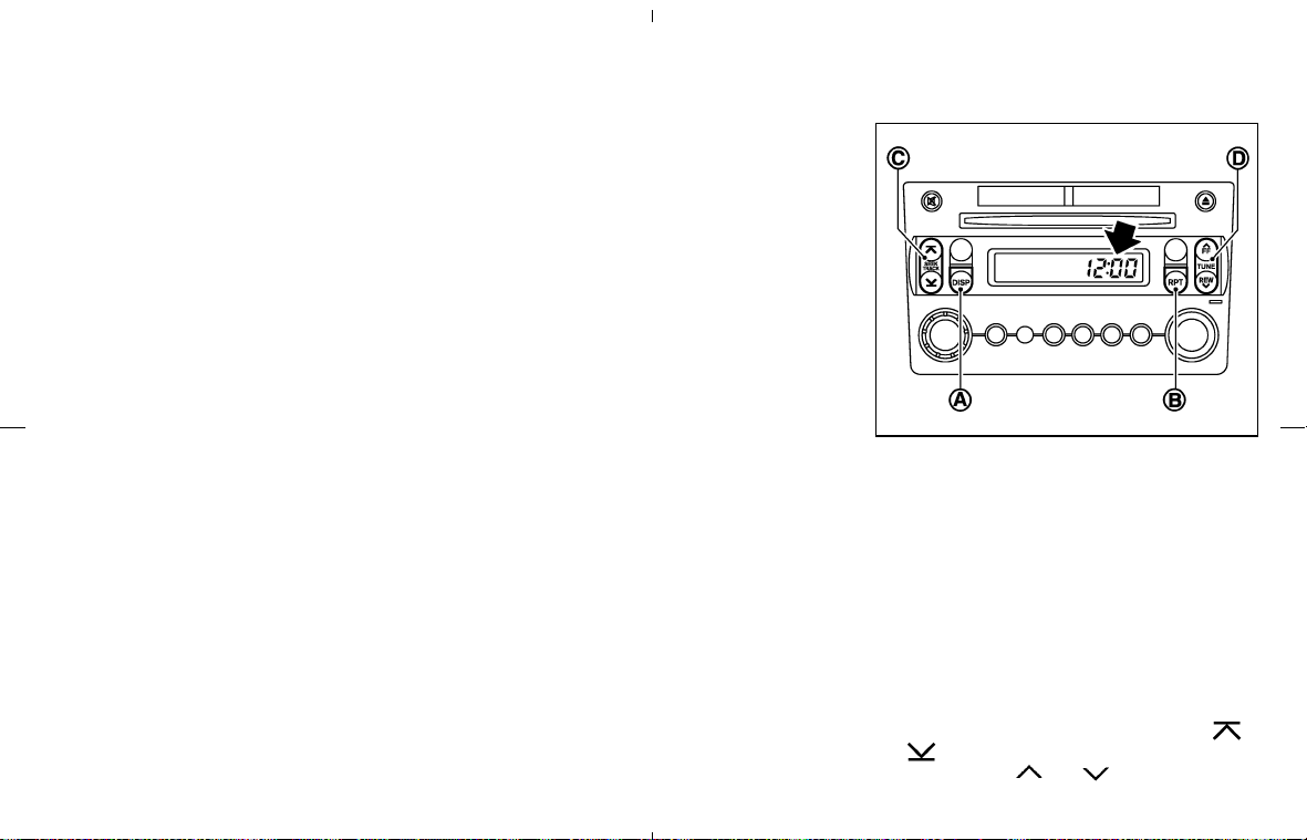
See “Traction Control System (TCS)” in the “5.
Starting and driving” section.
The digital clock (in the audio unit) displays time
when the ignition switch is in the ACC or ON
position.
If the battery cable is disconnected, the
clock will reset its time and the correct
time will not be indicated. Readjust the
time.
ADJUSTING THE TIME
Adjust the time in the following steps:
1. Switch the display to the clock adjusting
mode.
Type A (audio with 1 CD player):
Push and hold the DISP (Clock) button
쎻
A
until the clock display starts to flash.
Type B (audio with 6 CD changer):
Push and hold the RPT button
쎻
B
until the
clock display starts to flash.
2. Push the SEEK/TRACK button
쎻
C
( ,
) to adjust the hour. Push the TUNE
button
쎻
D
( , ) to adjust the
SIC3003
CLOCK
2-30 Instruments and controls
墌 08.7.24/Z33-D/V5.0 墍
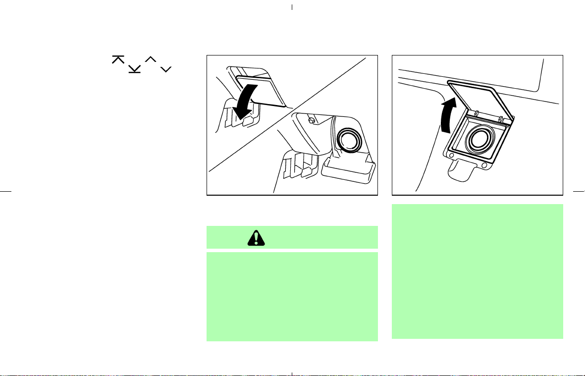
minute. Pushing the or side will
advance the time and the
or side
will turn back the time.
3. Push the DISP button
쎻
A
(Type A), or RPT
쎻
B
button (Type B) to finish the adjustment.
Resetting
Type A (audio with 1 CD player):
Push the DISP
쎻
A
and TUNE 쎻
D
buttons.
Type B (audio with 6 CD changer):
Push the RPT
쎻
B
and TUNE 쎻
D
buttons.
The time will be set to a time signal.
For example, if these buttons are pushed while
the time is between 8:00 and 8:29, the display
will be reset to 8:00. If pushed while it is
between 8:30 and 8:59, the display will be reset
to 9:00. At the same time the display will return
to the previous audio mode.
The power outlet is for powering electrical ac-
cessories such as cellular telephones.
CAUTION
쐌 The outlet and plug may be hot dur-
ing or immediately after use.
쐌 This power outlet is not designed for
use with a cigarette lighter unit.
쐌 Do not use accessories that exceed a
combined power draw of 12 volt,
120W (10A) for both the front and
rear power outlets. Do not use
double adapters or more than one
accessory with a single power outlet.
쐌 Use power outlet with the engine
running to avoid discharging the ve-
hicle battery.
쐌 Avoid using power outlets when the
air conditioner, headlights or rear
window defroster is on.
쐌 Before inserting or disconnecting a
plug, be sure to turn off the power
switch of electrical accessory being
SIC2258
Front
SIC1968
Rear
POWER OUTLET
Instruments and controls 2-31
墌 08.7.24/Z33-D/V5.0 墍
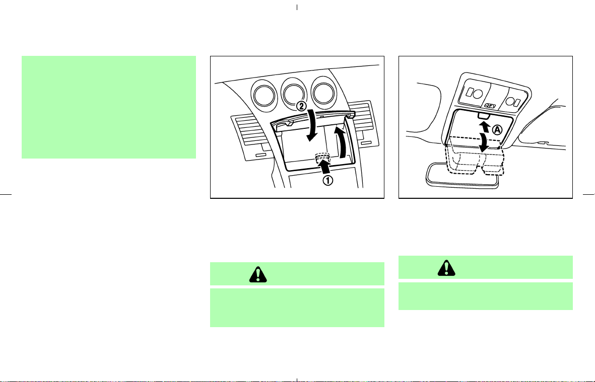
used or the ACC power of the vehicle.
쐌 Push the plug in as far as it will go. If
good contact is not made, the plug
may overheat or the internal tem-
perature fuse may open.
쐌 Do not allow water to contact the
outlet. When not in use, be sure to
close the lid.
INSTRUMENT POCKET (except for
navigation system equipped models)
To open the lid, push the knob up
쎻
1
.
To close, pull the lid down
쎻
2
.
WARNING
Keep the pocket lid closed while driving
to help prevent injury in an accident or a
sudden stop.
SUNGLASSES HOLDER (Coupe
models)
The sunglasses holder can be opened by push-
ing the button
쎻
A
.
WARNING
Keep the sunglasses holder closed
while driving to prevent an accident.
SIC3004 SIC2317
STORAGE
2-32 Instruments and controls
墌 08.7.24/Z33-D/V5.0 墍
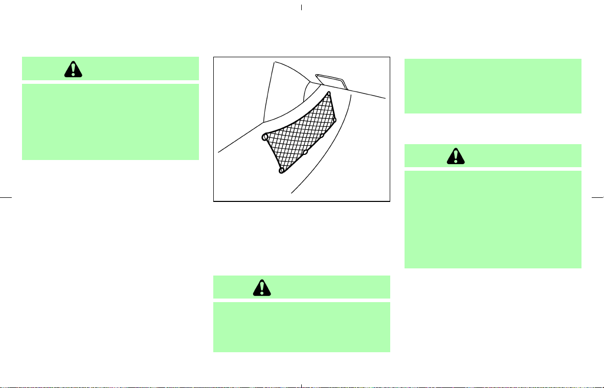
CAUTION
쐌 Do not use for anything other than
glasses.
쐌 Do not leave sunglasses in the sun-
glasses holder while parking in direct
sunlight. The heat may damage the
sunglasses.
CARGO NET
The net located under the instrument panel
(passenger’s side) can be used to hold small
objects.
The net can be removed when necessary.
WARNING
쐌 Do not place sharp objects in the net.
Such objects may become dangerous
projectiles and cause injury when the
vehicle is moving or if the vehicle is
involved in a collision.
쐌 The cargo restrained in the net must
not exceed 4 lb (2 kg) or the net may
not stay secured.
CUP HOLDERS
CAUTION
쐌 Avoid abrupt starting and braking
when the cup holder is being used to
prevent spilling the drink. If the liquid
is hot, it can scald you or your pas-
senger.
쐌 Use only soft cups in the cup holder.
Hard objects can injure you in an
accident.
SIC3006
Instruments and controls 2-33
墌 08.7.24/Z33-D/V5.0 墍
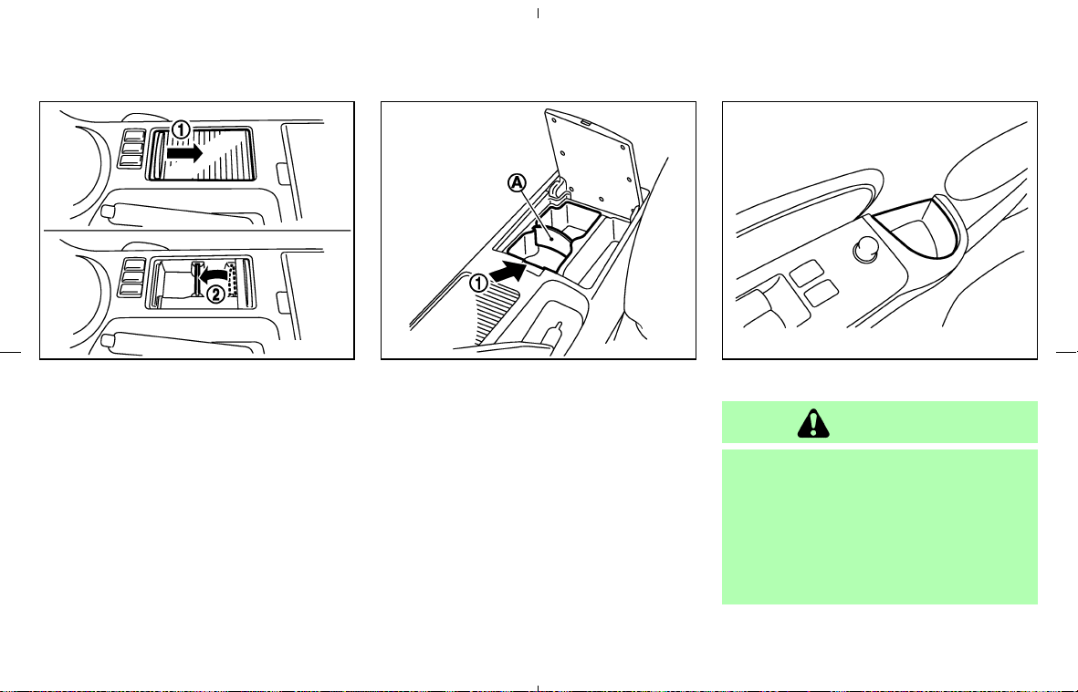
Front
Type A:
To open the cup holder, slide the lid
쎻
1
.
Install the partition plate into the slit
쎻
2
.
Type B:
Larger containers can be placed in the console
box. Push the button
쎻
1
to open the console box
lid. The partition
쎻
A
can be removed.
Soft bottle holder
CAUTION
쐌 Do not use bottle holder for any other
objects that could be thrown about in
the vehicle and possibly injure
people during sudden braking or an
accident.
쐌 Do not use bottle holder for open
liquid containers.
SIC3007 SIC3384 SIC3008
2-34 Instruments and controls
墌 08.7.24/Z33-D/V5.0 墍
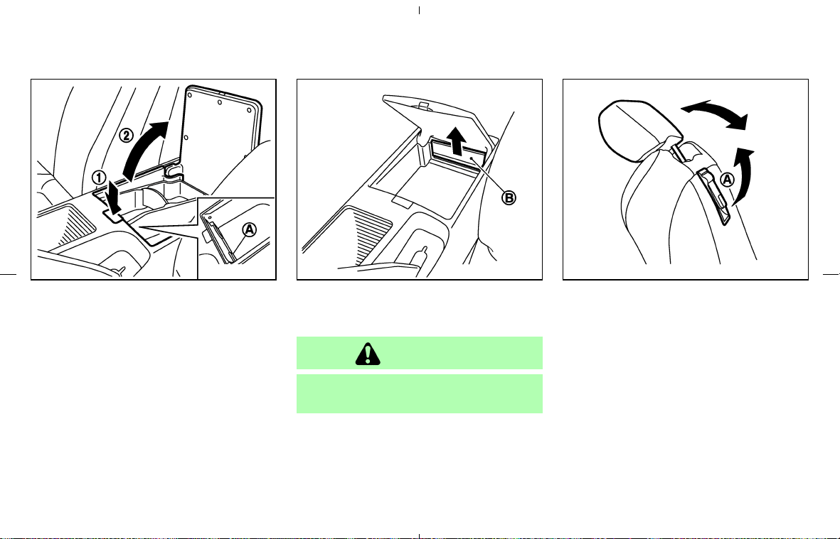
CONSOLE BOX
Pushing the button
쎻
1
will open the lid slightly,
then pull up the lid manually
쎻
2
. The center
console box is equipped with a card holder
쎻
A
.
The inside tray (cup holder and partitions) can
be removed by pulling it up.
If objects (coins, etc.) fall into the rear section of
the center console box, remove the rear wall
쎻
B
of the box as shown, and pick up the objects.
CAUTION
Be careful not to pinch your fingers
when removing the rear wall
쎻
B
.
REAR FLOOR BOX
The rear floor box is located behind the passen-
ger’s seat.
Fold the passenger’s seatback forward to ac-
cess the rear floor box.
Coupe model: Pull on the lever
쎻
A
.
Roadster model: Push the upper portion of the
power seatback tilt switch
쎻
B
.
SIC3385 SIC3010 SSS0203
Coupe model
Instruments and controls 2-35
墌 08.7.24/Z33-D/V5.0 墍
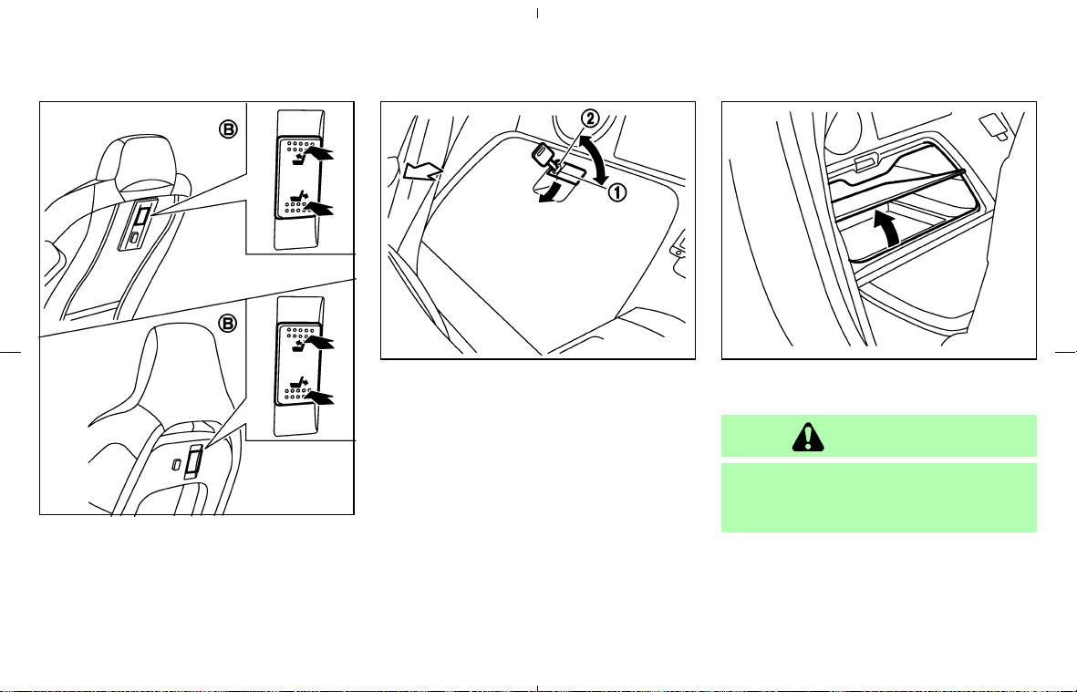
Return the passenger’s seatback to a locked
position after using the rear floor box.
Coupe model: Pull up on the lever
쎻
A
and return
the seatback.
Roadster model: Push the lower portion of the
power seatback tilt switch
쎻
B
.
The rear floor box may be opened by pulling the
handle. The rear floor box light illuminates when
the box lid is opened with the headlight switch
ON.
When locking
쎻
1
or unlocking
쎻
2
the rear floor
box, use the master key.
The rear floor box has additional space under the
bottom plate.
WARNING
Keep rear floor box lid closed while
driving to help prevent injury in an acci-
dent or a sudden stop.
SIC3348
Roadster model
SIC1975A SIC2377
2-36 Instruments and controls
墌 08.7.24/Z33-D/V5.0 墍
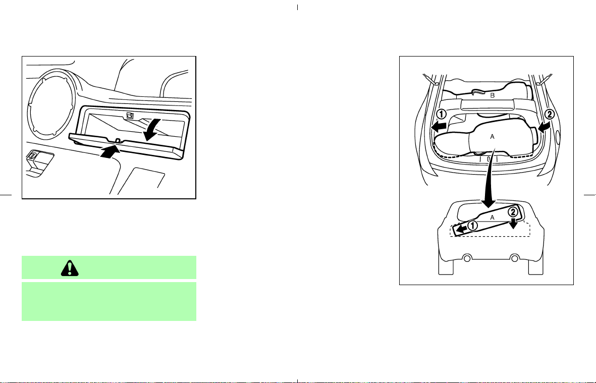
REAR PARCEL BOX
Push the upper part of the lid to open the rear
parcel box. For models without the Navigation
system, two boxes are available.
WARNING
Keep rear parcel box lid closed while
driving to help prevent injury in an acci-
dent or a sudden stop.
STOWING GOLF BAGS
Follow the instructions here to stow golf bags in
the rear cargo space of your vehicle. Normally
two bags can be stowed in the luggage area
(Coupe models) or one bag in the trunk (Road-
ster models).
However, in some cases you may not be able to
stow the above number of golf bags in your
vehicle, depending on their sizes or types.
Coupe models
Normally, two standard golf bags can be stowed
across the strut tower bar in the luggage area as
illustrated (A and B). When stowing a golf bag A
in the rear space, insert the top of the golf bag
SIC1977
SIC2196
Instruments and controls 2-37
墌 08.7.24/Z33-D/V5.0 墍
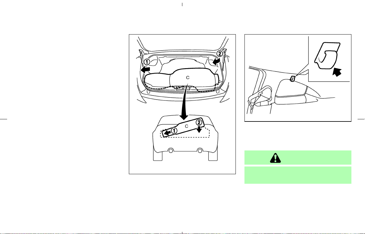
into left side of the luggage area
쎻
1
then put the
bag down
쎻
2
.
Roadster models
Normally, one standard golf bag C can be
stowed in the trunk. Insert the top of the golf bag
into left side of the trunk
쎻
1
then put the bag
down
쎻
2
.
COAT HOOK (Coupe models)
The hooks are locked above the side windows
as shown in the illustration.
CAUTION
Do not apply a total load of more than 2
lb (1 kg) to a single hook.
SIC2237
SIC2378
2-38 Instruments and controls
墌 08.7.24/Z33-D/V5.0 墍
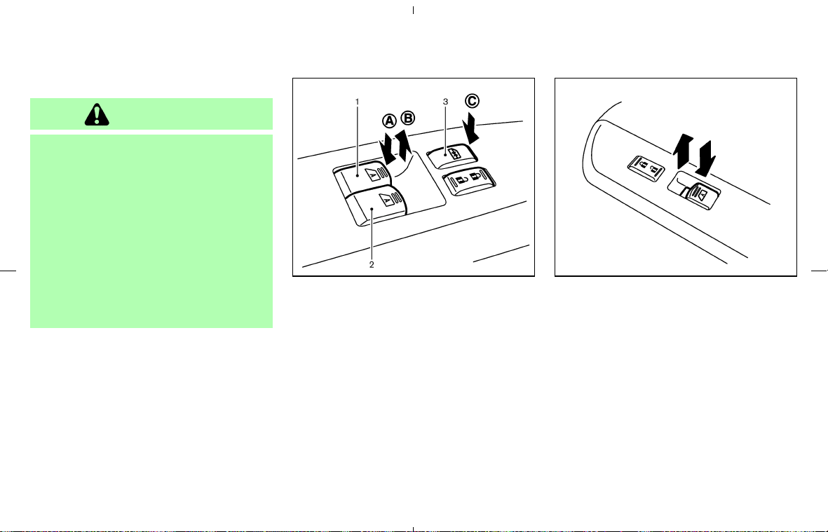
POWER WINDOWS
WARNING
쐌 Make sure that all passengers have
their hands, etc. inside the vehicle
while it is in motion and before clos-
ing the windows. Use the window
lock switch to prevent unexpected
use of the power windows.
쐌 Do not leave children unattended in-
side the vehicle. They could unknow-
ingly activate switches or controls
and become trapped in a window.
Unattended children could become
involved in serious accidents.
The power windows operate when the ignition
key is in the ON position and for about 45
seconds, after the ignition key is turned to the
OFF position. If the driver’s door or the front
passenger’s door is opened during this period of
about 45 seconds, power to the windows is
canceled.
The power window switches will be deactivated
during the soft top operation. (Roadster models)
Driver’s side power window switch
1. Driver side window
2. Passenger side window
3. Window lock button
To open or close the window, push down
쎻
A
or
pull up
쎻
B
the switch and hold it. The main
switch (driver side switches) will open or close
all the windows.
Passenger side power window switch
The passenger side switch will open or close
only the corresponding window. To open or
close the window, hold the switch down or up.
Locking passenger’s window
When the lock button 쎻
C
is pushed in, only the
driver side window can be opened or closed.
Push it in again to cancel.
SIC3286 SIC3287
WINDOWS
Instruments and controls 2-39
墌 08.7.24/Z33-D/V5.0 墍
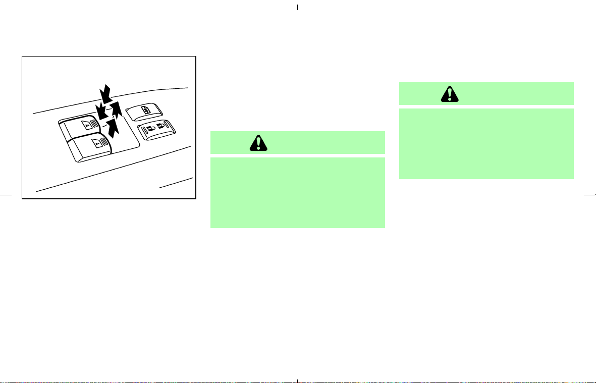
Automatic operation
To fully open or close the window, completely
press or lift the switch and release it; it need not
be held. The window will automatically open or
close all the way. To stop the window, just press
or lift the switch on the opposite side.
Auto reverse function
If the control unit detects something caught in a
window as it moves up, the window will be
immediately lowered.
The auto reverse function can be activated when
a window is closed by automatic operation when
the ignition key is in the ON position or for about
45 seconds after the ignition key is turned to the
OFF position.
Depending on the environment or driving
conditions, the auto reverse function may
be activated if an impact or load similar to
something being caught in the window
occurs.
WARNING
There are some small distances imme-
diately before the closed position which
cannot be detected. Make sure that all
passengers have their hands, etc., in-
side the vehicle before closing the win-
dow.
Automatic window lowering (Roadster
models)
When the soft top operating switch is pressed,
the power windows will automatically be low-
ered completely. The windows do not rise auto-
matically after the soft top open/close operation
is completed. Use the power window switches
to raise them.
AUTOMATIC ADJUSTING
FUNCTION
CAUTION
When the battery cable is removed from
the battery terminal, do not close either
of the front doors. The automatic win-
dow adjusting function will not work,
and the side roof panel/top side rail
may be damaged.
The power window has an automatic adjusting
function. When the door is being opened, the
window is automatically lowered slightly to avoid
contact between the window and the side roof
panel/top side rail. When the door is closed, the
window is automatically raised slightly.
SIC3288
2-40 Instruments and controls
墌 08.7.24/Z33-D/V5.0 墍
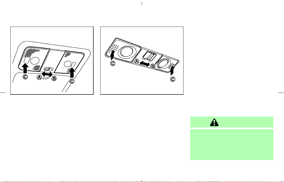
ROOM LIGHT
The interior light has a two-position switch. (쎻
A
:
DOOR,
쎻
B
: OFF)
When the switch is in the DOOR position, the
light will illuminate when a door is opened.
The light will stay on for about 30 seconds when:
쐌 The doors are unlocked by the keyfob, a key
or the power door lock switch while all doors
are closed.
쐌 The driver’s door is opened and then closed
while the key is removed from the ignition
switch.
쐌 The key is removed from the ignition switch
while all doors are closed.
The interior light will turn off while the 30 second
timer is activated, when:
쐌 The driver’s door is locked either with the
keyfob, a key or the power door lock switch.
쐌 The ignition switch is turned ON.
MAP LIGHTS
To turn on the light, push the plastic surface 쎻
C
of the light. Push it again to turn off the light.
When the map light stays on, it will auto-
matically turn off 30 minutes after the
ignition switch has been turned to the OFF
position. To turn on the light again, turn the
ignition switch to the ON position.
The map and vanity mirror lights will automati-
cally turn off 30 minutes after the latest operation
of the following with the ignition switch in the
ACC or OFF position:
쐌 Opening or closing any door
쐌 Locking or unlocking with the keyfob, a key or
the power door lock switch
쐌 Inserting or removing a key from the ignition
switch
These lights will turn on again when any of the
above operations is performed after the lights
have turned off automatically. (The lights will turn
off 30 minutes after the latest operation of the
above as well.)
CAUTION
쐌 Turn off the lights when you leave the
vehicle.
쐌 Do not use for extended periods of
time with the engine stopped. This
could result in a discharged battery.
SIC1980A
Coupe models
SIC2238
Roadster models
INTERIOR LIGHTS
Instruments and controls 2-41
墌 08.7.24/Z33-D/V5.0 墍
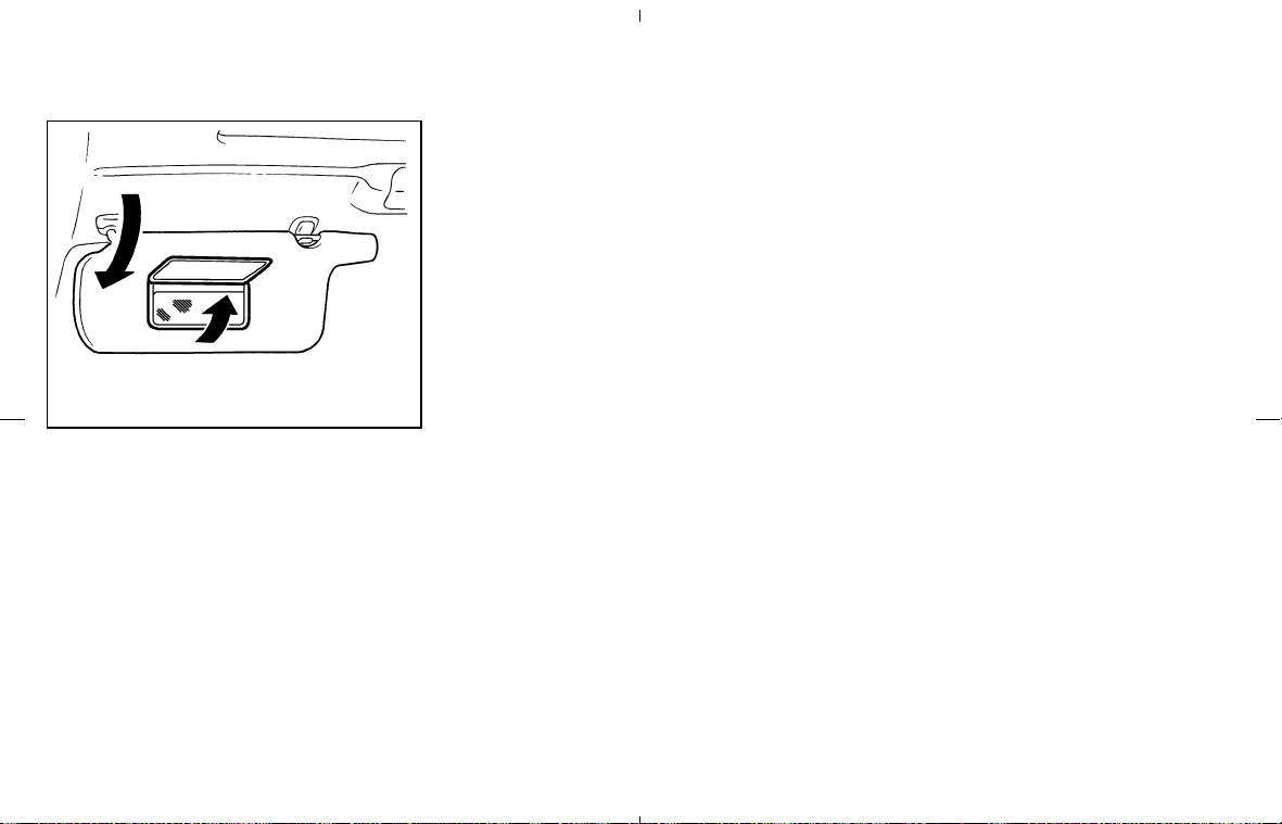
The light on the vanity mirror will turn on when
the cover on the vanity mirror is opened.
When the vanity mirror light stays on, it will
automatically turn off 30 minutes after the
ignition switch has been turned to the OFF
position. To turn on the light again, turn the
ignition switch to the ON position.
The light illuminates when the rear hatch is
opened. When the rear hatch is closed, the light
will go off.
The light illuminates when the trunk lid is
opened. When the trunk lid is closed, the light
will go off.
SIC1859
VANITY MIRROR LIGHT
LUGGAGE COMPARTMENT LIGHT
(Coupe models)
TRUNK LIGHT (Roadster models)
2-42 Instruments and controls
墌 08.7.24/Z33-D/V5.0 墍

The HomeLink
Universal Transceiver provides a
convenient way to consolidate the functions of
up to three individual hand-held transmitters into
one built-in device.
HomeLink
Universal Transceiver:
쐌 Will operate most Radio Frequency (RF)
devices such as garage doors, gates, home
and office lighting, entry door locks and se-
curity systems.
쐌 Is powered by your vehicle’s battery. No
separate batteries are required. If the vehi-
cle’s battery is discharged or is discon-
nected, HomeLink
will retain all program-
ming.
Once the HomeLink
Universal Transceiver
is programmed, retain the original trans-
mitter for future programming procedures
(for example, new vehicle purchases).
Upon sale of the vehicle, the programmed
HomeLink
Universal Transceiver buttons
should be erased for security purposes.
For additional information, refer to “Pro-
gramming HomeLink
” later in this sec-
tion.
WARNING
쐌 Do not use the HomeLink
Universal
Transceiver with any garage door
opener that lacks safety stop and
reverse features as required by fed-
eral safety standards. (These stan-
dards became effective for opener
models manufactured after April 1,
1982). A garage door opener which
cannot detect an object in the path of
a closing garage door and then auto-
matically stop and reverse, does not
meet current federal safety stan-
dards. Using a garage door opener
without these features increases the
risk of serious injury or death.
쐌 During the programming procedure,
your garage door or security gate will
open or close (if the transmitter is
within range). Make sure that people
and objects are clear of the garage
door, gate, etc. that you are
programming.
쐌 Your vehicle’s engine should be
turned off while programming the
HomeLink
Universal Transceiver.
PROGRAMMING HomeLink
To program your HomeLink Transceiver to op-
erate a garage door, gate, or entry door opener,
home or office lighting, you need to be at the
same location as the device. Note: Garage door
openers (manufactured after 1996) have “rolling
code protection”. To program a garage door
opener equipped with “rolling code protection”;
you will need to use a ladder to get up to the
garage door opener motor to be able to access
the training button.
HomeLink UNIVERSAL
TRANSCEIVER (if so equipped)
Instruments and controls 2-43
墌 08.7.24/Z33-D/V5.0 墍
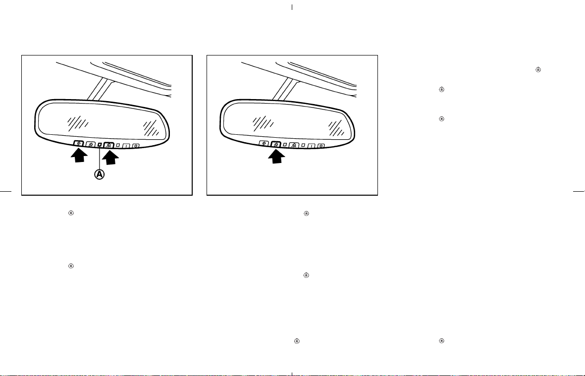
1. To begin, press and hold the 2 outer
HomeLink
buttons (to clear the memory)
until the indicator light
쎻
A
blinks (after 20
seconds). Release both buttons.
2. Position the end of the hand-held transmitter
1-3in(26-76mm)away from the
HomeLink
surface.
3. Using both hands, simultaneously press and
hold both the HomeLink
button you want to
program and the hand-held transmitter but-
ton.
DO NOT release the buttons until step 4 has
been completed.
4. Hold down both buttons until the indicator
light on the HomeLink
flashes, changing
from a “slow blink” to a “rapid blink”. When
the indicator light flashes rapidly, both but-
tons may be released. The rapidly flashing
light indicates successful programming. To
activate the garage door or other pro-
grammed device, press and hold the pro-
grammed HomeLink
button - releasing
when the device begins to activate.
5. If the indicator light on the HomeLink
blinks
rapidly for two seconds and then turns solid,
HomeLink
has picked up a “rolling code”
garage door opener signal. You will need to
proceed with the next steps to train the
HomeLink
to complete the programming
which may require a ladder and another
person for convenience.
6. Press and release the training button located
on the garage door opener’s motor to acti-
vate the “training mode”. This button is usu-
ally located near the antenna wire that hangs
down from the motor. If the wire originates
from under a light lens, you will need to
remove the lens to access the training button.
NOTE:
Once you have pressed and released the
training button on the garage door open-
er’s motor and the “training light” is lit, you
have 30 seconds in which to perform step
7. Use the help of a second person for
convenience to assist when performing
this step.
7. Quickly within 30 seconds of pressing and
releasing the garage door opener program
button, firmly press and release the
HomeLink
button you’ve just programmed.
SIC3012 SIC3011
2-44 Instruments and controls
墌 08.7.24/Z33-D/V5.0 墍

Press and release the HomeLink
button up
to three times to complete the training.
8. Your HomeLink
button should now be pro-
grammed.
To program the remaining HomeLink
buttons
for additional door or gate openers, follow steps
2-8 only.
NOTE:
Do not repeat step 1 unless you want to
“clear” all previously programmed
HomeLink
buttons.
If you have any questions or are having difficulty
programming your HomeLink
buttons, refer to
the HomeLink
web site at: www.homelink.com
or call 1-800-355-3515.
PROGRAMMING HomeLink
FOR
CANADIAN CUSTOMERS
Prior to 1992, D.O.C. regulations required hand-
held transmitters to stop transmitting after 2
seconds. To program your hand-held transmitter
to HomeLink
, continue to press and hold the
HomeLink
button (note steps 2 through 4
under “Programming HomeLink
”) while you
press and re-press (“cycle”) your hand-held
transmitter every 2 seconds until the indicator
light flashes rapidly (indicating successful pro-
gramming).
NOTE:
When programming a garage door opener,
etc., it is advised to unplug the device
during the “cycling” process to prevent
possible damage to the garage door
opener components.
OPERATING THE HomeLink
UNIVERSAL TRANSCEIVER
The HomeLink Universal Transceiver (once
programmed) may now be used to activate the
garage door, etc. To operate, simply press the
appropriate programmed HomeLink
Universal
Transceiver button. The red indicator light will
illuminate while the signal is being transmitted.
PROGRAMMING
TROUBLE-DIAGNOSIS
If the HomeLink does not quickly learn the
hand-held transmitter information:
쐌 replace the hand-held transmitter batteries
with new batteries.
쐌 position the hand-held transmitter with its
battery area facing away from the HomeLink
surface.
쐌 press and hold both the HomeLink
and
hand-held transmitter buttons without inter-
ruption.
쐌 position the hand-held transmitter 2 to 5 in
(50 to 127 mm) away from the HomeLink
surface. Hold the transmitter in that position
for up to 15 seconds. If HomeLink
is not
programmed within that time, try holding the
transmitter in another position - keeping the
indicator light in view at all times.
If you continue to have programming difficulties,
please contact the NISSAN Consumer Affairs
Department. The phone numbers are located in
the Foreword of this Owner’s Manual.
CLEARING THE PROGRAMMED
INFORMATION
Individual buttons cannot be cleared, however to
clear all programming, press and hold the two
outside buttons and release when the indicator
light begins to flash (approximately 20 seconds).
REPROGRAMMING A SINGLE
HomeLink
BUTTON
To reprogram a HomeLink
Universal Trans-
ceiver button, complete the following.
1. Press and hold the desired HomeLink
but-
ton. Do not release the button until step 4
has been completed.
2. When the indicator light begins to flash
slowly (after 20 seconds), position the hand-
held transmitter 2 to 5 in (50 to 127 mm)
Instruments and controls 2-45
墌 08.7.24/Z33-D/V5.0 墍

away from the HomeLink
surface.
3. Press and hold the hand-held transmitter
button.
4. The HomeLink
indicator light will flash, first
slowly and then rapidly. When the indicator
light begins to flash rapidly, release both
buttons.
The HomeLink
Universal Transceiver button
has now been reprogrammed. The new device
can be activated by pushing the HomeLink
button that was just programmed. This proce-
dure will not affect any other programmed
HomeLink
buttons.
IF YOUR VEHICLE IS STOLEN
If your vehicle is stolen, you should change the
codes of any non-rolling code device that has
been programmed into HomeLink
. Consult the
Owner’s Manual of each device or call the
manufacturer or dealer of those devices for
additional information.
When your vehicle is recovered, you will
need to reprogram the HomeLink
Univer-
sal Transceiver with your new transmitter
information.
FCC Notice:
This device complies with FCC rules part
15. Operation is subject to the following
two conditions: (1) This device may not
cause harmful interference and (2) This
device must accept any interference that
may be received, including interference
that may cause undesired operation.
The transmitter has been tested and com-
plies with FCC and DOC/MDC rules.
Changes or modifications not expressly
approved by the party responsible for com-
pliance could void the user’s authority to
operate the device.
DOC: ISTC 1763K1313
FCC I.D.: CB2V67690
2-46 Instruments and controls
墌 08.7.24/Z33-D/V5.0 墍

MEMO
Instruments and controls 2-47
墌 08.7.24/Z33-D/V5.0 墍

MEMO
2-48 Instruments and controls
墌 08.7.24/Z33-D/V5.0 墍

3 Pre-driving checks and adjustments
Keys ......................................................................................... 3-2
NISSAN Vehicle Immobilizer System keys................ 3-2
Doors ....................................................................................... 3-3
Locking with key ............................................................. 3-3
Locking with inside lock knob ..................................... 3-4
Locking with power door lock switch ....................... 3-4
Remote keyless entry system ............................................ 3-5
How to use remote keyless entry system ................ 3-5
Hood ........................................................................................ 3-8
Rear hatch (Coupe models) .............................................. 3-9
Opener operation ........................................................... 3-9
Secondary rear hatch release .................................... 3-10
Trunk lid (Roadster models) ............................................ 3-10
Opener operation ......................................................... 3-10
Interior trunk lid release ............................................... 3-11
Secondary trunk lid release ........................................ 3-12
Soft top (Roadster models).............................................. 3-13
Before operating the top ............................................. 3-13
When operating the top .............................................. 3-15
Opening the top ............................................................ 3-18
Closing the top .............................................................. 3-19
If the top does not open or close electrically ........ 3-19
Care of the soft top and the vehicle body.............. 3-22
Fuel-filler door ..................................................................... 3-23
Opener operation ......................................................... 3-23
Fuel-filler cap ................................................................. 3-23
Steering wheel .................................................................... 3-25
Tilt operation .................................................................. 3-25
Sun visors.............................................................................. 3-25
Mirrors ................................................................................... 3-26
Inside mirror .................................................................... 3-26
Automatic anti-glare inside mirror
(if so equipped) ............................................................ 3-26
Outside mirrors ............................................................. 3-27
墌 08.7.24/Z33-D/V5.0 墍
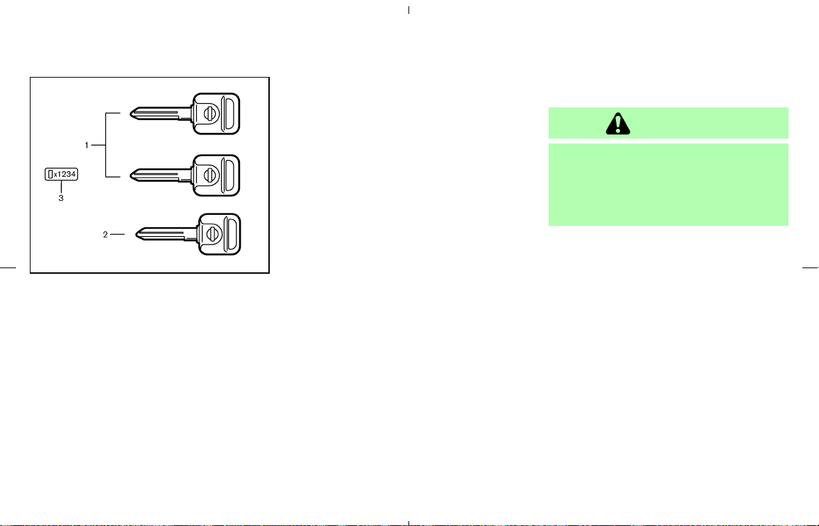
1. Master keys*
2. Valet key*
3. Key number plate
(* With built-in transponder chip)
A key number plate is supplied with your keys.
Record the key number and keep it in a safe
place (such as your wallet), not in the vehicle. If
you lose your keys, see a NISSAN dealer for
duplicates by using the key number. NISSAN
does not record any key numbers so it is very
important to keep track of your key number plate.
A key number is only necessary when you have
lost all keys and do not have one to duplicate
from. If you still have a key, this key can be
duplicated by a NISSAN dealer.
NISSAN VEHICLE IMMOBILIZER
SYSTEM KEYS
You can only drive your vehicle using the master
or valet keys which are registered to the NISSAN
Vehicle Immobilizer System components in your
vehicle. These keys have a transponder chip in
the key head.
The master key can be used for all the locks.
The valet key cannot be used for the rear floor
box lock. To protect belongings when you leave
a key with someone, give them the valet key only.
Never leave these keys in the vehicle.
Additional or replacement keys:
If you still have a key, the key number is not
necessary when you need extra NISSAN Vehicle
Immobilizer System keys. Your dealer can dupli-
cate your existing key. As many as 5 keys can be
used with one vehicle. You should bring all the
registered keys that you have to a NISSAN
dealer for registration. This is because the reg-
istration process will erase the memory of all key
codes previously registered into the NISSAN
Vehicle Immobilizer System. After the registra-
tion process, these components will only recog-
nize keys coded into the NISSAN Vehicle Immo-
bilizer System during registration. Any key that is
not given to your dealer at the time of registration
will no longer be able to start your vehicle.
CAUTION
Do not allow the NISSAN Vehicle Immo-
bilizer System key, which contains an
electrical transponder, to come in con-
tact with salt water. This could cause the
system to malfunction.
SPA1379D
KEYS
3-2 Pre-driving checks and adjustments
墌 08.7.24/Z33-D/V5.0 墍
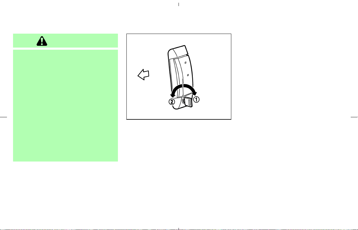
WARNING
쐌 Always have the doors locked while
driving. Along with the use of seat
belts, this provides greater safety in
the event of an accident by helping to
prevent persons from being thrown
from the vehicle. This also helps keep
children and others from uninten-
tionally opening the doors, and will
help keep out intruders.
쐌 Before opening any door, always
look for and avoid oncoming traffic.
쐌 Do not leave children unattended in-
side the vehicle. They could unknow-
ingly activate switches or controls.
Unattended children could become
involved in serious accidents.
LOCKING WITH KEY
The power door lock system allows you to lock
or unlock all doors including the rear hatch/trunk
lid simultaneously.
쐌 Turning the driver’s door key to the rear of the
vehicle
쎻
1
will lock all doors including the
rear hatch/trunk lid.
쐌 Turning the driver’s door key one time to the
front of the vehicle
쎻
2
will unlock the driver’s
door and rear hatch/trunk lid. From that po-
sition, returning the key to neutral (where the
key can only be removed and inserted) and
turning it to the front again within 5 seconds
will unlock the passenger’s door.
Opening and closing windows
Turn the driver’s door key towards the front of
the vehicle (UNLOCK position) and hold for
about 1 second, all door windows will begin to
lower.
To close all door windows, turn the key to the
LOCK position and hold for about 1 second.
To stop opening or closing, turn the key to the
neutral position.
In the event of a hand in the way, or other
obstruction, the auto reverse function will acti-
vate.
SPA1503A
DOORS
Pre-driving checks and adjustments 3-3
墌 08.7.24/Z33-D/V5.0 墍
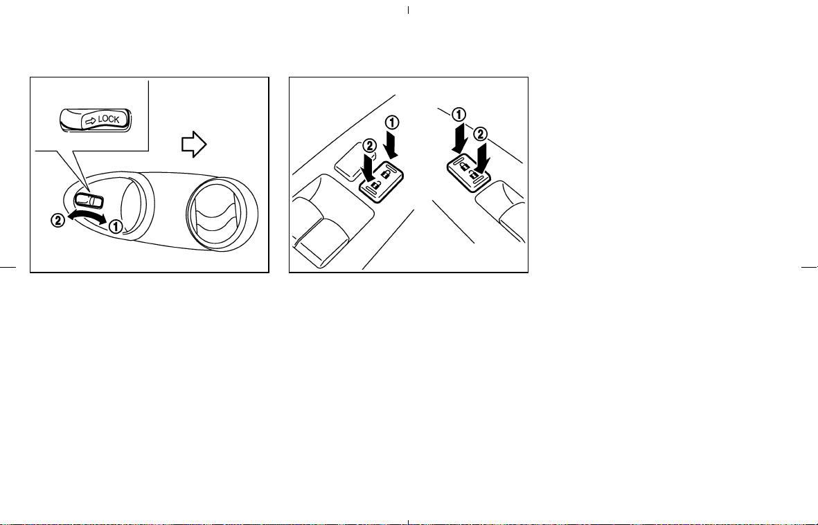
LOCKING WITH INSIDE LOCK
KNOB
Pushing the door inside lock knob to the LOCK
쎻
1
or UNLOCK
쎻
2
position will lock or unlock
the corresponding door. (The rear hatch/trunk lid
lock is linked with the driver side door lock.)
To individually lock the doors from the outside
(without a key), move the inside lock knob to the
LOCK position. Then close the door.
When locking the door without a key, be
sure not to leave the key inside the vehicle.
LOCKING WITH POWER DOOR
LOCK SWITCH
All doors will be locked when the power door
lock switch is pushed to the LOCK position
쎻
1
with the driver’s or front passenger’s door open.
Then close the door and all doors will be locked.
When locking the door this way, be certain
not to leave the key inside the vehicle.
To unlock, push the power door lock switch to
the UNLOCK position
쎻
2
.
Lockout protection
When the power door lock switch (driver or front
passenger) is moved to the LOCK position
쎻
1
with the key in the ignition and any door open, all
doors will lock and unlock automatically. This
helps to prevent the keys from being accidentally
locked inside the vehicle.
SPA2420 SPA2320
3-4 Pre-driving checks and adjustments
墌 08.7.24/Z33-D/V5.0 墍
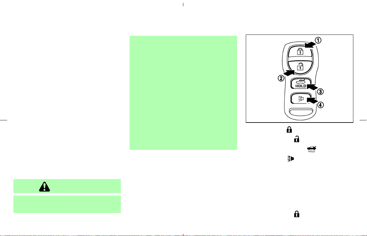
It is possible to lock/unlock all doors (including
the rear hatch/trunk lid), release the rear
hatch/trunk lid and activate the panic alarm by
using the keyfob from outside the vehicle.
Before locking the doors, make sure the
key is not left in the vehicle.
The keyfob can operate at a distance of approxi-
mately 33 ft (10 m) from the vehicle. (The
effective distance depends upon the conditions
around the vehicle.)
As many as 5 keyfobs can be used with one
vehicle. For information concerning the purchase
and use of additional keyfobs, contact a NISSAN
dealer.
The keyfob will not function when:
쐌 the battery is discharged,
쐌 the distance between the vehicle and the
keyfob is over 33 ft (10 m).
The panic alarm and the rear hatch/trunk
lid release will not activate when the key is
in the ignition switch.
CAUTION
The following conditions or occurrences
will damage the keyfob.
쐌 Do not allow the keyfob to become
wet.
쐌 Do not drop the keyfob.
쐌 Do not strike the keyfob sharply
against another object.
쐌 Do not place the keyfob for an ex-
tended period in an area where tem-
peratures exceed 140°F (60°C).
If a keyfob is lost or stolen, NISSAN
recommends erasing the ID code of that
keyfob. This will prevent the keyfob
from unauthorized use to unlock the
vehicle. For information regarding the
erasing procedure, please contact a
NISSAN dealer.
For information regarding the replacement of a
battery, see “Keyfob battery replacement” in the
“8. Maintenance and do-it-yourself” section.
쎻
1
LOCK button
쎻
2
UNLOCK button
쎻
3
HATCH/TRUNK button
쎻
4
PANIC button
HOW TO USE REMOTE KEYLESS
ENTRY SYSTEM
Locking doors
1. Remove the ignition key.*1 *2
2. Close all the doors.*3
3. Push the LOCK
button on the keyfob.
SPA1918
REMOTE KEYLESS ENTRY
SYSTEM
Pre-driving checks and adjustments 3-5
墌 08.7.24/Z33-D/V5.0 墍

4. All the doors will lock.
All of the doors will lock when the LOCK
button on the keyfob is pushed even
though a door remains open and/or the
ignition switch is in the ON position.
5. The hazard indicator flashes twice and the
horn chirps once.
쐌 When the LOCK
button is pushed with
all doors locked, the hazard indicator flashes
twice and the horn chirps once as a reminder
that the doors are already locked.
*1: Doors lock with the keyfob while a key is in
the ignition switch. However, the panic
alarm and the rear hatch/trunk lid release will
not activate when the key is in the ignition
switch.
*2: Doors lock with the keyfob while the ignition
switch is in the ON position. However, the
hazard indicator and horn will not function.
*3: Doors lock with the keyfob while any door is
open. However, the hazard indicator and
horn will not function.
Unlocking doors
1. Push the UNLOCK button on the key-
fob once.
쐌 The driver’s door and rear hatch/trunk lid
unlock.
쐌 The hazard indicator flashes once if all doors
are completely closed with the ignition switch
in any position except the ON position.
쐌 The interior light turns on and the light timer
activates for 30 seconds when the switch is
in the DOOR position with the ignition switch
in any position except the ON position.
2. Push the UNLOCK
button on the key-
fob again within 5 seconds.
쐌 Passenger’s door unlocks.
쐌 The hazard indicator flashes once if all doors
are completely closed.
All doors will be locked automatically unless one
of the following operations is performed within 1
minute of pushing the UNLOCK
button.
쐌 Any door or rear hatch/trunk lid is opened.
쐌 The ignition switch is turned to the ON
position.
The interior light can be turned off without
waiting for 30 seconds by turning the ignition
switch to the ON position or by locking the
doors with the keyfob.
Opening the windows
Push the UNLOCK button on the keyfob
and the driver’s door will unlock.
Continue to push the UNLOCK
button for
3 seconds. All the door windows will start to be
lowered. Keep pushing the UNLOCK
but-
ton until the windows are fully open.
To stop lowering the windows, release the UN-
LOCK
button. To start lowering the win-
dows again, push the UNLOCK
button
again for 3 more seconds.
Releasing the rear hatch/trunk lid
1. Push the HATCH/TRUNK button on
the keyfob for longer than 0.5 second with
the key removed from the ignition switch.
2. The rear hatch (Coupe) or trunk lid (Road-
ster) opens.
Using the panic alarm
If you are near your vehicle and feel threatened,
you may activate the alarm to call attention by
pushing and holding the PANIC
button on
the keyfob for longer than 0.5 second (with
the key removed from the ignition switch).
The theft warning alarm and headlights will stay
on for 30 seconds.
3-6 Pre-driving checks and adjustments
墌 08.7.24/Z33-D/V5.0 墍
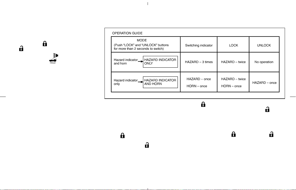
The panic alarm stops when:
쐌 It has run for 30 seconds, or
쐌 The LOCK
button or the UNLOCK
button is pushed, or
쐌 The PANIC
button or the
HATCH/TRUNK
button is pushed on
the keyfob for longer than 0.5 second.
Setting hazard indicator and horn
mode
This vehicle is set in hazard indicator and horn
mode when you first receive the vehicle.
In hazard indicator and horn mode, when the
LOCK
button is pushed, the hazard indi-
cator flashes twice and the horn chirps once.
When the UNLOCK
button is pushed, the
hazard indicator flashes once.
If hazard indicator and horn mode is not neces-
sary, you can switch to hazard indicator only
mode by following the switching procedure.
In hazard indicator only mode, when the LOCK
button is pushed, the hazard indicator
flashes twice. When the UNLOCK
button
is pushed, neither the hazard indicator nor the
horn operates.
(Switching procedure)
Push the LOCK
and UNLOCK but-
tons on the keyfob simultaneously for more than
2 seconds to switch from one mode to the other.
When pushing the buttons to set hazard indica-
tor only mode, the hazard indicator flashes 3
times.
When pushing the buttons to set hazard indica-
tor and horn mode, the hazard indicator flashes
SPA1260
Pre-driving checks and adjustments 3-7
墌 08.7.24/Z33-D/V5.0 墍
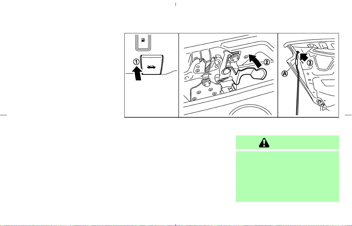
once and the horn chirps once.
1. Pull the hood lock release handle
쎻
1
located
below the instrument panel; the hood will
then spring up slightly.
2. Raise the lever
쎻
2
at the front of the hood
with your fingertips and raise the hood.
3. Insert the assist bar into the slot
쎻
3
in the
front edge of the hood.
4. When closing the hood, reset the assist bar
to its original position, then slowly close the
hood and make sure it locks into place.
Hold the coated part
쎻
A
when removing or
resetting the support rod. Avoid direct con-
tact with the metal parts, as they may be
hot immediately after the engine has been
stopped.
WARNING
쐌 Make sure the hood is completely
closed and latched before driving.
Failure to do so could cause the hood
to fly open and result in an accident.
쐌 If you see steam or smoke coming
from the engine compartment, to
avoid injury do not open the hood.
SPA2313
HOOD
3-8 Pre-driving checks and adjustments
墌 08.7.24/Z33-D/V5.0 墍
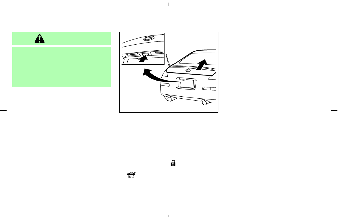
WARNING
Do not drive with the rear hatch open.
This could allow dangerous exhaust
gases to be drawn into the vehicle. See
“Precautions when starting and driving”
in the “5. Starting and driving” section
for exhaust gas.
OPENER OPERATION
The rear hatch release switch is located be-
tween the license plate lights.
To open the rear hatch, unlock it with one of the
following operations then push the release
switch:
쐌 Push the UNLOCK
button on the key-
fob once. (Pushing the HATCH/TRUNK
button on the keyfob can open the rear
hatch at once without pushing the release
switch.)
쐌 Insert the key into the door key cylinder and
turn the door key counterclockwise once.
쐌 Push the power door lock switch to the
UNLOCK side.
The rear hatch employs a spring component
which enables you to lift up the hatch by one
hand. Because of this, sometimes the rear hatch
may clatter when the lock is released, but it is not
a malfunction.
To close, push the rear hatch down securely.
The rear hatch release switch is linked with the
driver side door lock. To open the rear hatch,
unlock the driver side door.
SPA1507
REAR HATCH (Coupe models)
Pre-driving checks and adjustments 3-9
墌 08.7.24/Z33-D/V5.0 墍
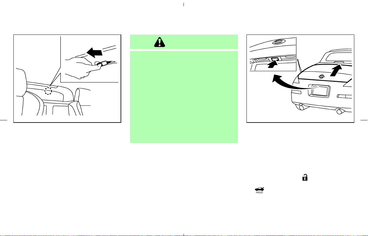
SECONDARY REAR HATCH
RELEASE
The secondary rear hatch release mechanism
allows opening the rear hatch in the event of
discharged battery or emergency.
The release (string) handle is located under the
strut tower bar inside the luggage compartment.
To open the rear hatch from the inside,
firmly pull the release handle to the direc-
tion shown above until the lock releases.
WARNING
쐌 Do not drive with the trunk lid open.
This could allow dangerous exhaust
gases to be drawn into the vehicle.
See “Precautions when starting and
driving” in the “5. Starting and driv-
ing” section for exhaust gas.
쐌 Closely supervise children when they
are around cars to prevent them from
playing and becoming locked in the
trunk where they could be seriously
injured. Keep the car locked, with the
trunk closed when not in use, and
prevent children’s access to car keys.
OPENER OPERATION
The trunk lid release switch is located between
the license plate lights.
To open the trunk lid, unlock it with one of the
following operations then push the release
switch:
쐌 Push the UNLOCK
button on the key-
fob once. (Pushing the HATCH/TRUNK
button on the keyfob can open the
trunk lid at once without pushing the release
switch.)
쐌 Insert the key into the door key cylinder and
turn it counterclockwise once.
SPA1556 SPA1685
TRUNK LID (Roadster models)
3-10 Pre-driving checks and adjustments
墌 08.7.24/Z33-D/V5.0 墍
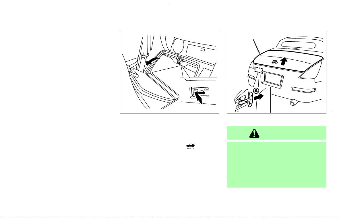
쐌 Push the power door lock switch to the
UNLOCK side. (After locking the doors with a
keyfob, this switch is not available due to the
security system.)
To close, push the trunk lid down securely.
The trunk lid release switch is linked with the
driver side door lock. To open the trunk lid,
unlock the driver side door.
Cancel switch
When the cancel switch (located inside the rear
floor box) is OFF, the trunk lid cannot be opened
with the release switch. It can be opened only by
pushing the HATCH/TRUNK
button on
the keyfob.
INTERIOR TRUNK LID RELEASE
WARNING
Closely supervise children when they
are around cars to prevent them from
playing and becoming locked in the
trunk where they could be seriously in-
jured. Keep the car locked, with the
trunk closed when not in use, and pre-
vent children’s access to car keys.
SPA1686 SPA1687
Pre-driving checks and adjustments 3-11
墌 08.7.24/Z33-D/V5.0 墍
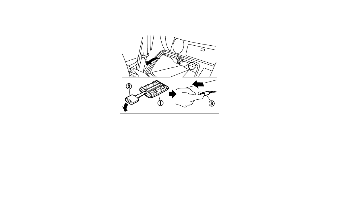
The interior trunk lid release mechanism pro-
vides a means of escape for children and adults
in the event they become locked inside the trunk.
The handle
쎻
A
is located inside the trunk com-
partment as illustrated.
To open the trunk lid from the inside, pull
the release handle towards you until the
lock releases and push up on the trunk lid.
The release lever is made of a material that
glows in the dark after a brief exposure to
ambient light.
SECONDARY TRUNK LID RELEASE
The secondary trunk lid release mechanism al-
lows opening the trunk lid in the event of dis-
charged battery or emergency.
Remove the cover
쎻
1
(located inside of the rear
floor box) using a suitable tool
쎻
2
as shown.
Access the release (string) handle
쎻
3
.
To open the trunk lid from the inside, firmly
pull the release handle to the direction
shown above until the lock releases.
SPA1688
3-12 Pre-driving checks and adjustments
墌 08.7.24/Z33-D/V5.0 墍
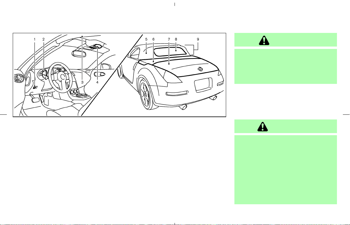
1. Soft top operating switch
2. Soft top indicator light (on the combination
meter)
3. Top side rail
4. Top latch lever
5. Soft top
6. Top storage lid
7. Trunk lid
8. Rear window
9. Rear section of the top
BEFORE OPERATING THE TOP
The soft top of your 350Z Roadster is electrically
operated. You can fully open or close the top
only by pressing the operating switch (on the
lower side of the instrument panel).
The soft top operating switch must be operated
under all of the following conditions:
쐌 When the foot brake pedal is depressed.
쐌 When the vehicle is stopped.
쐌 When the engine is running.
CAUTION
Always keep the engine running while
operating the soft top. The top will also
operate when the ignition switch is in
the ON position, but run the engine to
prevent a discharged battery.
Be sure to follow the operating instructions, and
all the warnings and cautions in this section.
Improper operation of the top could cause
a system malfunction, damage, or deterio-
ration of the top material and related parts.
WARNING
쐌 Park the vehicle in a safe and level
place and apply the parking brake.
쐌 Make sure the area is clear of ob-
stacles and there is enough clear-
ance over the top (for example, in a
garage or a covered area). More than
approximately 6.6 ft (2 m) from the
ground is required to open or close
the top safely. Otherwise, the top
may damage any objects above it
SPA2339
Interior/exterior view
SOFT TOP (Roadster models)
Pre-driving checks and adjustments 3-13
墌 08.7.24/Z33-D/V5.0 墍
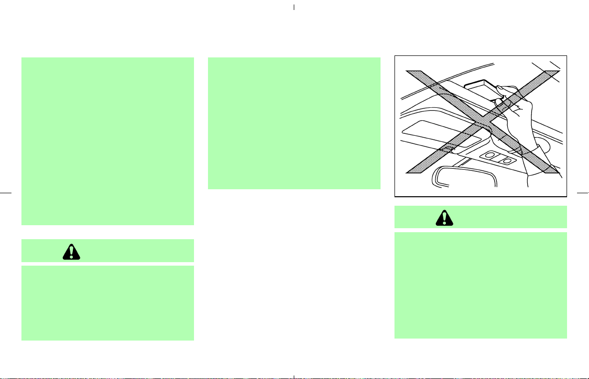
while moving. The top operating sys-
tem could also be damaged.
쐌 Do not operate the top in a strong
wind. It could be blown by the wind,
striking someone or damage the top.
쐌 Do not allow anyone to stand up or
extend any portion of their body out
of the opening while the vehicle is in
motion or while the top is being op-
erated.
쐌 In an accident you could be thrown
from the vehicle with an open top.
Always use seat belts and proper
child restraints.
CAUTION
쐌 Do not operate the top when the
temperature is below 32°F (0°C). This
may result in damage to the top ma-
terial or operating system.
쐌 Remove water drops, snow, ice or
sand from the top, and dry the sur-
face of the top completely before
opening it.
쐌 Do not open the top when it is wet or
damp. This may cause interior water
damage, stains or mildew on the top
material.
쐌 Be sure to turn off the rear window
defroster switch. Never turn it on
while the top is being operated or
fully opened. The heat may damage
the top material.
CAUTION
쐌 Do not place any objects between the
top cloth and the structure. Doing so
could interfere with top operation
and cause damage to the top operat-
ing system or the objects.
쐌 Do not place anything on the top and
the storage lid. Even small items may
interfere with the top operation and
could cause damage to the top or the
SPA1701
3-14 Pre-driving checks and adjustments
墌 08.7.24/Z33-D/V5.0 墍
vehicle body.
쐌 Do not place anything in the top stor-
age area. The top will not fit there
properly, and this could damage the
top and/or the vehicle body.
쐌 Do not sit or place excessive weight
on the top and the storage lid, espe-
cially when the top is being operated.
The top may be damaged.
쐌 Do not drive the vehicle with the top
partially opened. Always make sure
the top is either fully opened or
closed before driving.
쐌 Secure items so that they cannot be
blown from the vehicle while driving
with the top open.
쐌 When a child restraint is installed in
the passenger seat, be sure to turn
the seatback tilt cancel switch (lo-
cated on the passenger seatback) to
the CANCEL position, or the child
restraint may be damaged.
Make sure the trunk lid is securely closed before
operating the top.
WHEN OPERATING THE TOP
WARNING
Keep hands and other parts of the body
away from moving parts such as the top,
storage lid and power windows.
CAUTION
Keep all parts of the top linkage clear of
obstructions, or the top latch may not be
securely locked.
NOTE:
쐌 In case of low battery or low tempera-
ture, the top may temporarily stop mov-
ing during the operation. This functions
to protect the top control mechanism,
and it is not a malfunction.
쐌 If the top is opened and closed repeat-
edly in a short period of time, it may
stop moving to protect the top motor.
Wait for a few minutes before operating
the top again.
Pre-driving checks and adjustments 3-15
墌 08.7.24/Z33-D/V5.0 墍
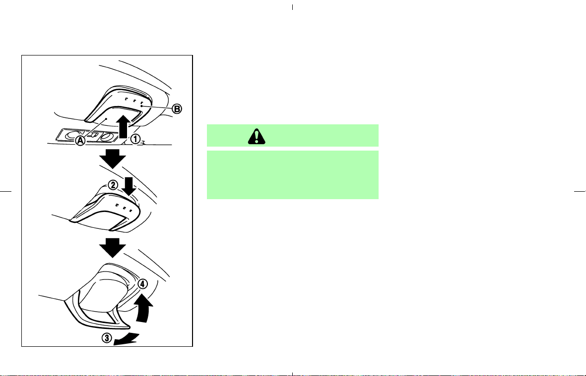
Top latch lever
The soft top has three locking points to engage
the front edge of the top to the vehicle body.
Operating the top latch lever enables you to lock
or unlock all three locking points at the same
time.
CAUTION
Before opening the top, be sure to
release the top latch. After closing,
securely engage the top to the vehicle
body.
To release the latch (before opening the
top):
쎻
1
Push the safety switch 쎻
A
.
쎻
2
The latch lever 쎻
B
is lowered.
쎻
3
Swing the lever forward until the latch is
released.
To engage the latch (after closing the top):
Check that the top is in the fully closed position.
쎻
1
Push the safety switch 쎻
A
.
쎻
2
The latch lever 쎻
B
is lowered.
쎻
3
Rotate the lever forward until the front edge
of the top is completely joined to the vehicle
body.
쎻
4
Rotate the lever toward you and push it up
into the stored position. Make sure the top is
securely engaged to the vehicle body.
The soft top indicator light will flash with the
ignition switch ON when the top is not en-
gaged. See “Soft top indicator light” later in
this section.
When releasing or engaging the top latch,
you may hear the latch operating. This is
normal and not a malfunction.
SPA1690
3-16 Pre-driving checks and adjustments
墌 08.7.24/Z33-D/V5.0 墍
Soft top indicator light
The soft top indicator light in the instrument
panel shows the conditions of top operation. The
light illuminates when the soft top is being
operated or if it is stopped before reaching the
fully opened or closed position. When the top is
fully opened, the light will turn off. When the top
is fully closed, the light will flash.
When the soft top is in motion, and any of the
following conditions occur, the top will stop
moving:
쐌 The vehicle is moved.
쐌 The ignition switch is turned to OFF.
쐌 The foot brake pedal is released.
쐌 The passenger power seat switch (on the
cushion or the seatback) is operated.
Remove your hand from the soft top operating
switch, and push the switch again to move the
top to the fully opened or closed position. The
soft top indicator light will turn off when the top
open operation is completely finished. When
closing the top, the light, which is illuminated,
will begin to flash when the top close operation
is completely finished. Securely engage the top
to the vehicle body by operating the top latch
lever. The light will turn off.
If the soft top indicator light flashes with the
ignition switch ON (whether the top is operated
or not, and when the top is engaged), it may
indicate the top operating system is not func-
tioning properly. Have your vehicle checked by a
NISSAN dealer as soon as possible.
Automatic passenger seatback tilt
function
The passenger seatback will automatically tilt
forward when the soft top is operated. This
function is designed to draw your passenger’s
attention to the rear section of the top, which will
come into the passenger compartment from
behind during the top operation. The seatback
will return to the original position when the entire
top operation is completed.
This automatic seatback movement will be
stopped:
쐌 When the passenger seat sliding or reclining
switch (on the seat cushion) is operated.
쐌 When the power seatback tilt switch (on the
seatback) is operated.
쐌 When the seatback tilt cancel switch is
turned to the CANCEL position.
Remove your hand from the soft top operating
switch, and push it again to resume operation.
The passenger seatback will start tilting forward
again from the present position, and the soft top
will start opening or closing. If the top movement
is interrupted at this time, the next time you
resume top operation, the seatback will first tilt
forward from the present position, then the top
will start moving again.
If you need to cancel this function or when a
child restraint is installed in the passenger seat,
push the seatback tilt cancel switch to the
CANCEL position. For the seatback tilt cancel
switch, see “Tilting and reclining passenger’s
seat from driver’s seat” in the “1. Safety —
Seats, seat belts and supplemental restrain sys-
tem” section.
If the seatback tilt cancel switch is in the CAN-
SPA1691
Pre-driving checks and adjustments 3-17
墌 08.7.24/Z33-D/V5.0 墍
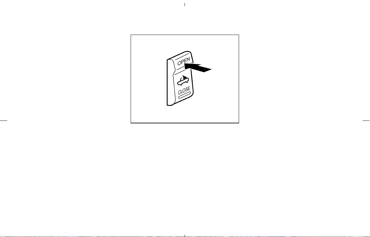
CEL position and the passenger seat is occu-
pied, ask the passenger to sit forward when the
top is being opened or closed.
Automatic window lowering
When the soft top operating switch is pressed,
the power windows will automatically be low-
ered completely. The windows do not rise auto-
matically after the top operation is completed.
Use the power window switches to raise them.
OPENING THE TOP
1. Apply the parking brake and move the selec-
tor lever to the P (Park) position (for the
automatic transmission model) or the shift
lever to the N (Neutral) position (for the
manual transmission model).
2. Start the engine.
3. Depress the foot brake pedal.
4. Release the front edge of the top from the
vehicle body with the top latch lever.
5. Push OPEN on the soft top operating switch
and hold it until the top is fully opened.
• The soft top indicator light will illuminate
while the top is in motion. (In about 20
seconds, the opening movement will finish
and the indicator light turns off.)
• Windows will automatically be fully
opened.
• The passenger seatback will automatically
move forward, unless the seatback tilt
cancel switch is in the CANCEL position.
It will return to the original position after
the top operation. (See “Automatic pas-
senger seatback tilt function” shown on
the previous page of this section.)
6. Release the switch when the top is fully
opened. (The indicator light turns off.)
NOTE:
If you release the switch and press it again
while the top is being opened, the top will
slightly move to the closing direction, then
start moving to the opening direction
again. The top is designed to move in this
way. It is not a malfunction.
SPA1692
3-18 Pre-driving checks and adjustments
墌 08.7.24/Z33-D/V5.0 墍
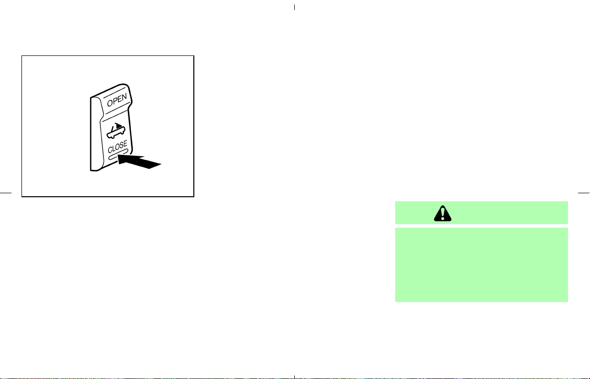
CLOSING THE TOP
1. Apply the parking brake and move the selec-
tor lever to the P (Park) position (for the
automatic transmission model) or the shift
lever to the N (Neutral) position (for the
manual transmission model).
2. Start the engine.
3. Depress the foot brake pedal.
4. Push CLOSE on the soft top operating
switch and hold it until the top is fully closed.
• The soft top indicator light will illuminate
while the top is in motion. (In about 20
seconds, the closing movement will fin-
ish.)
• Windows will automatically be fully
opened.
• The passenger seatback will automatically
move forward, unless the seatback tilt
cancel switch is in the CANCEL position.
It will return to the original position after
the top operation. (See “Automatic pas-
senger seatback tilt function” shown on
the previous page of this section.)
5. Release the switch when the top is fully
closed. (The indicator light, which is illumi-
nated, will begin to flash.)
6. Securely engage the front edge of the top to
the vehicle body with the top latch lever. (The
indicator light turns off.)
IF THE TOP DOES NOT OPEN OR
CLOSE ELECTRICALLY
If you cannot operate the soft top with the
operating switch, first check whether all the
following operating conditions are completed:
쐌 foot brake pedal is depressed
쐌 vehicle is stopped
쐌 ignition switch is ON (Run the engine when
operating the top.)
If the top still does not move under the above
conditions or has any system malfunction, see a
NISSAN dealer as soon as possible. When you
must close the top by yourself, in the event of
emergency or when an immediate dealer service
is not available, close the top manually according
to the procedures shown in this section.
When closing the soft top manually:
쐌 Move the vehicle to a safe place, away from
traffic.
쐌 Two people should perform this procedure,
as some of the top parts are extremely heavy.
The top cannot be opened manually.
WARNING
쐌 Do not drive with the top partially
opened.
쐌 If the top cannot be operated prop-
erly, see a NISSAN dealer as soon as
possible to have your vehicle
checked.
SPA1693
Pre-driving checks and adjustments 3-19
墌 08.7.24/Z33-D/V5.0 墍
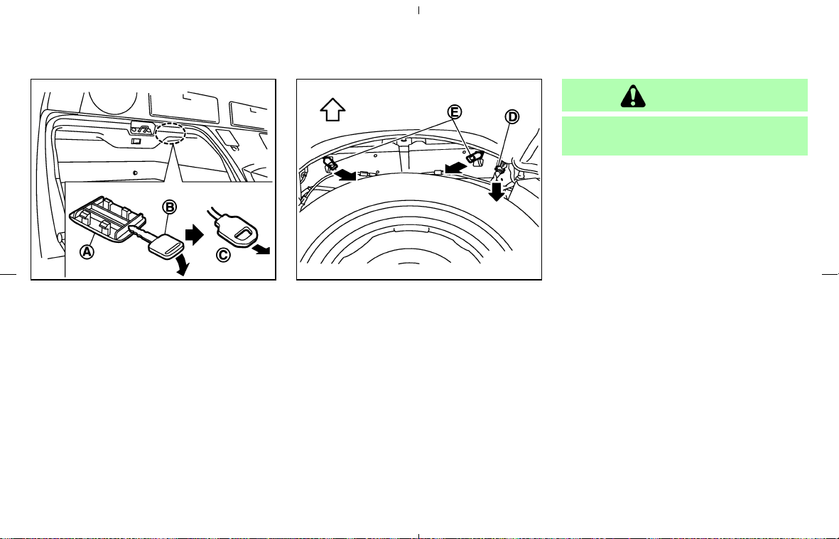
1. Open the trunk lid. In the event of discharged
battery, you need to open the trunk lid as
follows:
a. Open the rear floor box behind the passenger
seat.
b. Remove the cap
쎻
A
using a suitable tool 쎻
B
.
c. Pull the string handle (secondary trunk lid
release)
쎻
C
until the trunk lid lock is released.
d. Lift up the trunk lid.
2. Open the top storage lid
a. Remove floorboard inside of the trunk.
b. Remove the harness connector
쎻
D
of the
storage lid motor installed on the back right
side of the trunk by pulling in a downward
direction.
c. Pull down the lock release cable (right and
left)
쎻
E
.
d. Listen for a clicking sound of the lock releas-
ing.
e. Pull up the storage lid from the left and right
side of vehicle by hand.
CAUTION
The storage lid is extremely heavy. Pull-
ing it up should be done by two people.
SPA1694 SPA1695
3-20 Pre-driving checks and adjustments
墌 08.7.24/Z33-D/V5.0 墍
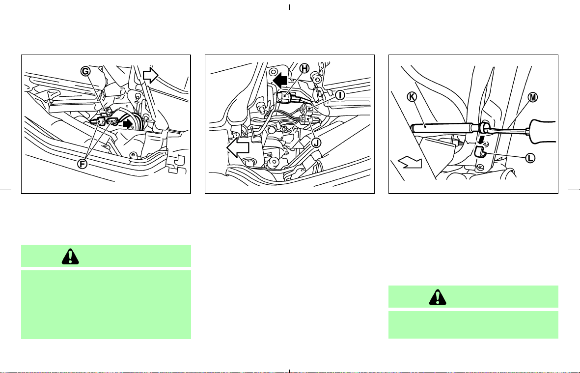
3. Close the soft top.
a. Remove the harness connectors of the top
motor,
쎻
F
(right side of the vehicle) and 쎻
H
(left side).
CAUTION
Two harness connectors are installed on
the right side and three on the left side
as shown. Only the harness connectors
쎻
F
and 쎻
H
should be removed. (Do not
remove the other harness connectors
쎻
G
, 쎻
I
and 쎻
J
.)
b. A person on each side of the vehicle should
slowly pull the top to the closed position.
c. Latch the front edge of the top to the vehicle
body with the top latch lever.
4. Push the storage lid down to the vehicle body
panel and close it. (Listen for locking sounds
from both right and left sides of the lid.)
5. Lower the rear section of the top.
a. Remove the shock absorber
쎻
K
which sup-
ports the rear section of the top from the
vehicle body. (Both the left and right side
must be removed — the figure above shows
the left side.) To remove the shock absorber,
remove the holder
쎻
L
on the terminal part
using a flat-bladed screwdriver
쎻
M
.
CAUTION
When the shock absorber is removed,
the rear section of the top loses support
SPA1734
Right side
SPA1708
Left side
SPA1697
Pre-driving checks and adjustments 3-21
墌 08.7.24/Z33-D/V5.0 墍

and falls simultaneously. Support the
top by hand so it does not strike the
body.
b. Lower the rear part of the top and push it
onto the top storage lid. The top is locked to
the storage lid, but the bottom of the rear part
is not closed tightly.
CAUTION
쐌 After closing the top manually, have
the system checked and/or repaired
by a NISSAN dealer as soon as pos-
sible.
쐌 Avoid leaving the vehicle outside for
long periods or driving at high
speeds. The rear of the top is not
locked completely, and this may al-
low wind and rain to get into your
vehicle.
CARE OF THE SOFT TOP AND THE
VEHICLE BODY
To use your Roadster safely and comfortably,
you need to observe all the warnings and cau-
tions shown in the previous pages. Also, to
maintain a good appearance of the soft top and
the vehicle body, you need to care for them by
cleaning and/or washing properly.
CAUTION
쐌 Do not use an automatic car wash or
a high-pressure car wash to clean
your vehicle. The top may be dam-
aged and water may leak into the
inside of the vehicle.
쐌 Store the vehicle with the top closed
if it is not to be used for long periods.
Keeping the top stowed for long pe-
riods may cause wrinkles on the sur-
face of the top.
See “Cleaning exterior” in the “7. Appearance
and care” section for detailed instructions.
쐌 A protective clear tape is applied to the top
storage lid painted surface where the soft top
contacts the surface. When the top is fully
closed, the tape may transmit some light,
visible from the inside of the vehicle. This
does not affect the water and air tightness of
the seal.
쐌 The inner surface of the trunk and top storage
lids may show a fibrous, or marbled pattern.
This is the normal appearance of the material
used in these parts.
3-22 Pre-driving checks and adjustments
墌 08.7.24/Z33-D/V5.0 墍
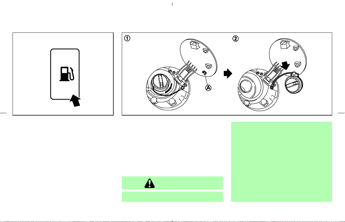
OPENER OPERATION
To open the fuel-filler door, push the opener
switch located below the instrument panel. To
lock, close the fuel-filler door securely.
FUEL-FILLER CAP
쎻
1
To remove the fuel-filler cap, turn it counter-
clockwise.
쎻
2
Hang the string of the cap on the hook 쎻
A
as
shown while refueling.
The fuel-filler cap is a ratcheting type. Tighten
the cap clockwise until ratcheting clicks are
heard.
WARNING
쐌 Gasoline is extremely flammable and
highly explosive under certain condi-
tions. You could be burned or seri-
ously injured if it is misused or mis-
handled. Always stop the engine and
do not smoke or allow open flames
or sparks near the vehicle when refu-
eling.
쐌 Do not attempt to top off the fuel
tank after the fuel pump nozzle shuts
off automatically. Continued refuel-
ing may cause fuel overflow, result-
ing in fuel spray and possibly a fire.
SPA1508 SPA2421
FUEL-FILLER DOOR
Pre-driving checks and adjustments 3-23
墌 08.7.24/Z33-D/V5.0 墍
쐌 Use only an original equipment type
fuel-filler cap as a replacement. It has
a built-in safety valve needed for
proper operation of the fuel system
and emission control system. An in-
correct cap can result in a serious
malfunction and possible injury. It
could also cause the malfunction in-
dicator light to come on.
쐌 Do not fill a portable fuel container in
the vehicle or trailer. Static electricity
can cause an explosion of flammable
liquid, vapor or gas in any vehicle or
trailer. To reduce the risk of serious
injury or death when filling portable
fuel containers:
— Always place the container on the
ground when filling.
— Do not use electronic devices
when filling.
— Keep the pump nozzle in contact
with the container while you are
filling it.
— Use only approved portable fuel
containers for flammable liquid.
쐌 Never pour fuel into the throttle body
to attempt to start your vehicle.
CAUTION
쐌 If fuel is spilled on the vehicle body,
flush it away with water to avoid
paint damage.
쐌 Tighten until the fuel-filler cap clicks.
Failure to tighten the fuel-filler cap
properly may cause the
mal-
function indicator light (MIL) to illu-
minate. If the
light illuminates
because the fuel-filler cap is loose or
missing, tighten or install the cap and
continue to drive the vehicle. The
light should turn off after a few
driving trips. If the
light does
not turn off after a few driving trips,
have the vehicle inspected by a
NISSAN dealer.
쐌 For additional information, see the
“Malfunction Indicator Light (MIL)” in
the “2. Instruments and controls”
section.
3-24 Pre-driving checks and adjustments
墌 08.7.24/Z33-D/V5.0 墍
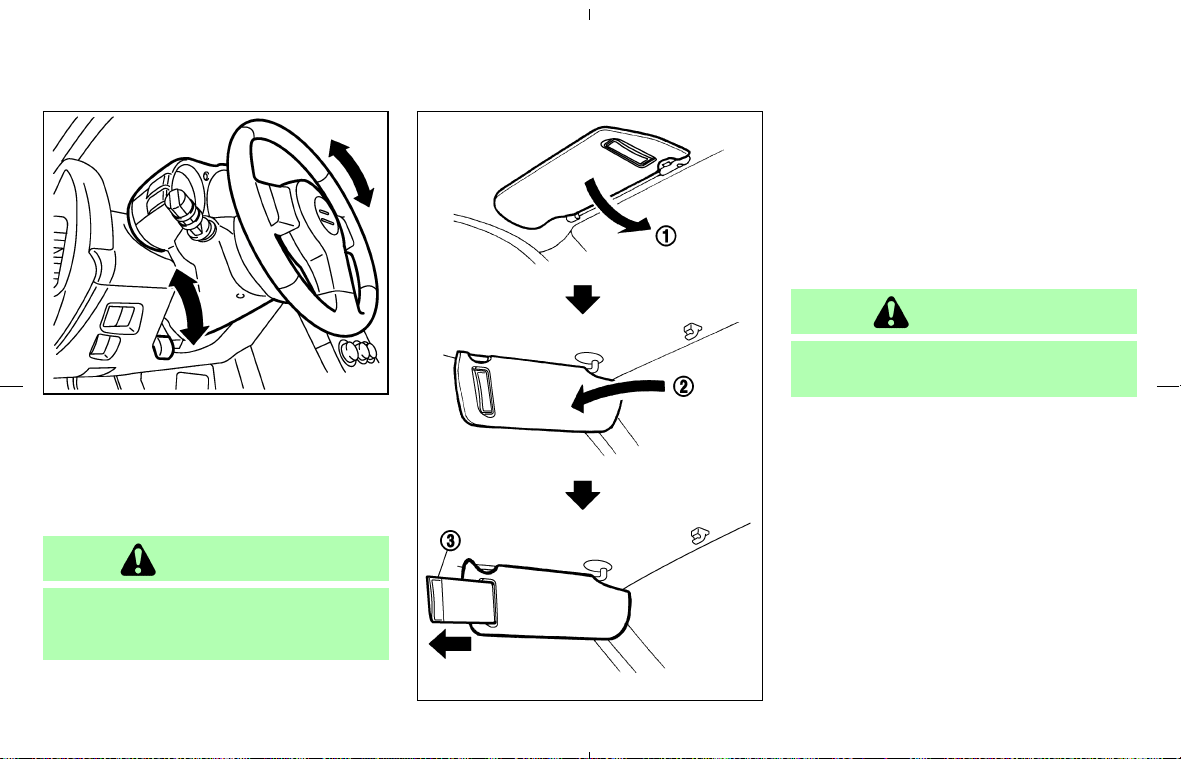
TILT OPERATION
Push the lock lever down and adjust the steering
wheel up or down to the desired position.
Push the lock lever up securely to lock the
steering wheel in place.
WARNING
Do not adjust the steering wheel while
driving. You could lose control of your
vehicle and cause an accident.
1. To block out glare from the front, swing down
the main sun visor
쎻
1
.
2. To block glare from the side, remove the main
sun visor from the center mount and swing it
to the side
쎻
2
.
3. To use the extension sun visor
쎻
3
(if so
equipped), pull it out from the main sun visor
as shown.
CAUTION
Do not store the main sun visor before
storing the extension sun visor.
SPA2314
SPA2176
STEERING WHEEL SUN VISORS
Pre-driving checks and adjustments 3-25
墌 08.7.24/Z33-D/V5.0 墍
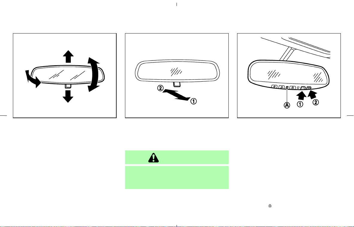
INSIDE MIRROR
Adjust the height and the angle of the inside
mirror to the desired position.
The night position
쎻
1
will reduce glare from the
headlights of vehicles behind you at night.
Use the day position
쎻
2
when driving in daylight
hours.
WARNING
Use the night position only when neces-
sary, because it reduces rear view clar-
ity.
AUTOMATIC ANTI-GLARE INSIDE
MIRROR (if so equipped)
The inside mirror is designed so that it automati-
cally changes reflection according to the inten-
sity of the headlight of the following vehicle.
When the inside mirror is in the “I” (AUTO)
position
쎻
1
, excessive glare from the headlights
of the vehicle behind you will be reduced. The
AUTO indicator light
쎻
A
(green) will be on.
When the switch of the inside mirror is in the
“쎻” (OFF) position
쎻
2
, the inside mirror will
operate normally.
For HomeLink
Universal Transceiver, see the
SPA1792 SPA2143 SPA2157
MIRRORS
3-26 Pre-driving checks and adjustments
墌 08.7.24/Z33-D/V5.0 墍

description in the “2. Instruments and controls”
section.
OUTSIDE MIRRORS
WARNING
Objects viewed in the outside mirror on
the passenger side are closer than they
appear. Be careful when moving to the
right. Using only this mirror could cause
an accident. Use the inside mirror or
glance over your shoulder to properly
judge distances to other objects.
The outside mirror will operate only when the
ignition switch is in the ACC or ON position.
Turn the control knob (located on the driver side
door armrest) to right or left to select the right or
left outside mirror, then adjust using the knob.
SPA1390
Pre-driving checks and adjustments 3-27
墌 08.7.24/Z33-D/V5.0 墍
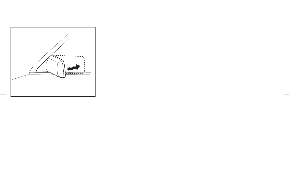
Foldable outside mirrors
Fold the outside mirror by pushing it toward the
rear of the vehicle.
IC0565
3-28 Pre-driving checks and adjustments
墌 08.7.24/Z33-D/V5.0 墍

4 Display screen, heater, air conditioner and
audio systems
Safety note .............................................................................. 4-2
Control panel buttons — with navigation system.......... 4-2
Names of the components ............................................ 4-2
How to use joystick and “ENTER” button................. 4-3
How to use “BACK” button .......................................... 4-3
Setting up the start-up screen ..................................... 4-3
How to use “INFO” button............................................ 4-3
How to use “SETTING” button .................................... 4-5
How to use the “
” button.................................... 4-8
Ventilators ............................................................................... 4-8
Center ventilators ............................................................ 4-8
Side ventilators ................................................................ 4-8
Heater and air conditioner (Automatic) .......................... 4-9
Automatic operation .................................................... 4-10
Manual operation .......................................................... 4-10
Operating tips ............................................................... 4-11
Servicing air conditioner .................................................. 4-12
Audio system ....................................................................... 4-12
Radio ............................................................................... 4-12
FM radio reception ...................................................... 4-13
AM radio reception ...................................................... 4-13
Satellite (SAT) radio reception (if so equipped) ... 4-13
Audio operation precautions ..................................... 4-14
FM-AM radio with compact disc (CD) player ...... 4-19
FM-AM-SAT radio with compact disc (CD)
changer ........................................................................... 4-23
CD care and cleaning ................................................. 4-29
Steering wheel switch for audio control (if so
equipped)......................................................................... 4-29
Antenna ........................................................................... 4-30
Car phone or CB radio .................................................... 4-31
Bluetooth
Hands-Free Phone System with
NISSAN voice recognition (if so equipped) ............... 4-31
Using the system........................................................... 4-33
Control buttons .............................................................. 4-35
Getting started ............................................................... 4-35
List of voice commands............................................... 4-37
Speaker adaptation (SA) mode ................................. 4-42
Troubleshooting guide.................................................. 4-45
墌 08.7.24/Z33-D/V5.0 墍
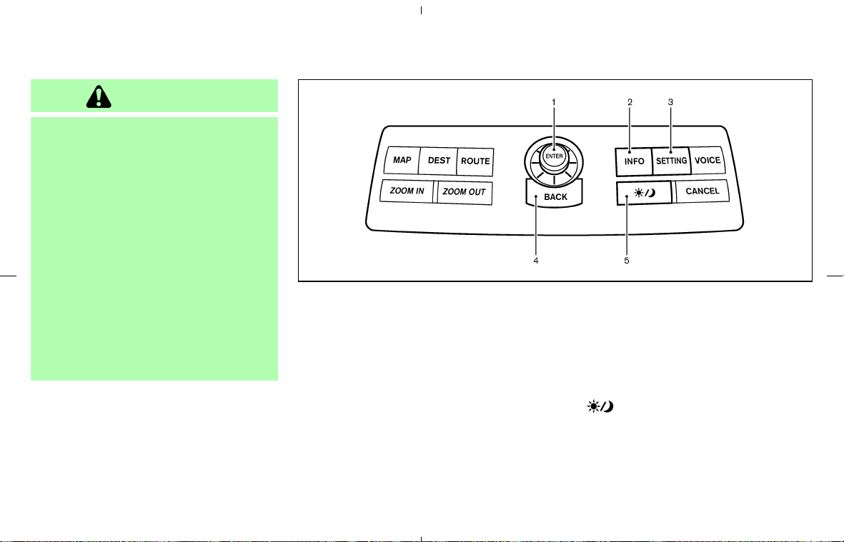
WARNING
쐌 Do not disassemble or modify this
system. If you do, it may result in
accidents, fire, or electric shock.
쐌 Do not use this system if you notice
any abnormality, such as a frozen
screen or lack of sound. Continued
use of the system may result in acci-
dent, fire or electric shock.
쐌 In case you notice any foreign object
in the system hardware, spill liquid
on it, or notice smoke or smell com-
ing from it, stop using the system
immediately and contact a NISSAN
dealer. Ignoring such conditions may
lead to accidents, fire, or electric
shock.
When you use this system, make sure the engine
is running.
If you use the system with the engine not
running (ignition ON or ACC) for a long
time, it will use up all the battery power,
and the engine will not start.
Reference symbols:
“ENTER” button
This is a button on the control panel.
“Display” key
This is a select key on the screen. By selecting
this key you can proceed to the next function.
NAMES OF THE COMPONENTS
1. JOYSTICK and “ENTER” button
2. “INFO” button
3. “SETTING” button
4. “BACK” button
5. “
” brightness control button
For Navigation System control buttons (other
than above), refer to the separate Navigation
System Owner’s Manual.
SAA1289
SAFETY NOTE
CONTROL PANEL BUTTONS —
WITH NAVIGATION SYSTEM
4-2 Display screen, heater, air conditioner and audio systems
墌 08.7.24/Z33-D/V5.0 墍
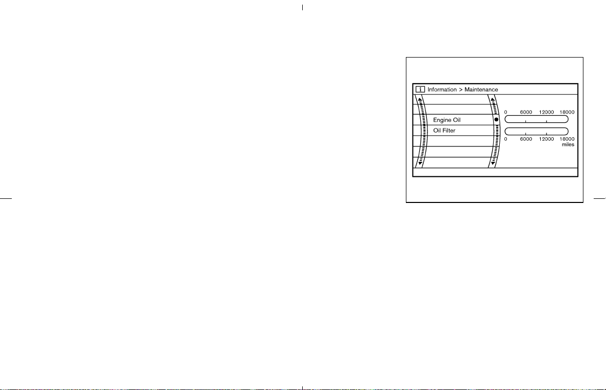
HOW TO USE JOYSTICK AND
“ENTER” BUTTON
Choose an item on the display using the joystick
and push the ENTER button for operation.
HOW TO USE “BACK” BUTTON
This button has two functions.
To return to the previous screen:
When this button is pushed during setup, setup
will be canceled, and the screen will return to the
previous screen.
To finish the set-up:
When this button is pushed after setup is com-
pleted, the settings will be renewed as directed,
and the screen will return to the map.
INFO:
When the “BACK” button must be pushed, (for
example, after the setup is finished) instructions
are given in the operation procedure of each
section in this manual. If the “BACK” button is
pushed when not finished with the setup, the
setting will be canceled, and the screen will
return to the previous screen.
SETTING UP THE START-UP
SCREEN
When you turn the ignition key to the ACC
position, the SYSTEM START-UP warning is
displayed on the screen. Read the warning and
select the “OK” key then push the “ENTER”
button.
If you do not push the ENTER button, this
system will not proceed to the next step display.
To proceed to the next step, refer to the separate
Navigation System Owner’s Manual.
HOW TO USE “INFO” BUTTON
When the “INFO” button is pushed, the “Main-
tenance” screen will be displayed.
Maintenance information
To set the maintenance interval for the Engine
Oil or Oil Filter, choose an item using the joystick
and push the “ENTER” button.
You can also set to display a message to remind
you that the maintenance needs to be per-
formed.
The following example shows how to set the
engine oil change interval. Use the same steps
SAA1290
Display screen, heater, air conditioner and audio systems 4-3
墌 08.7.24/Z33-D/V5.0 墍
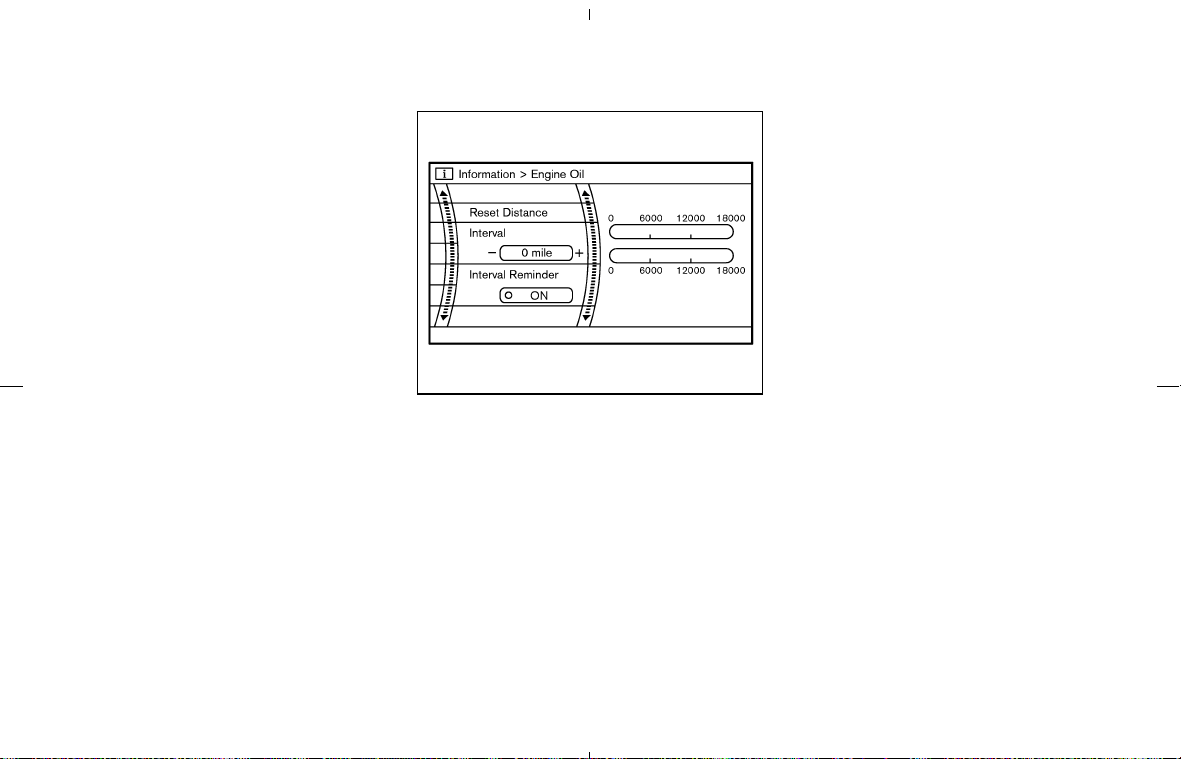
to set the other maintenance information.
1. Reset the driving distance to the new main-
tenance schedule.
2. Set the interval (mileage) of the maintenance
schedule. To determine the recommended
maintenance interval, refer to your “NISSAN
Service and Maintenance Guide”.
3. To display the MAINTENANCE INFORMA-
TION automatically when the set trip distance
is reached, highlight the “Interval Re-
minder” key with the joystick and push the
“ENTER” button.
4. To return the display to the “Maintenance”
screen, push the “BACK” button.
“Maintenance” display cannot be operated
when the vehicle is moving. Stop the vehicle in a
safe place to see the information.
SAA1291
4-4 Display screen, heater, air conditioner and audio systems
墌 08.7.24/Z33-D/V5.0 墍
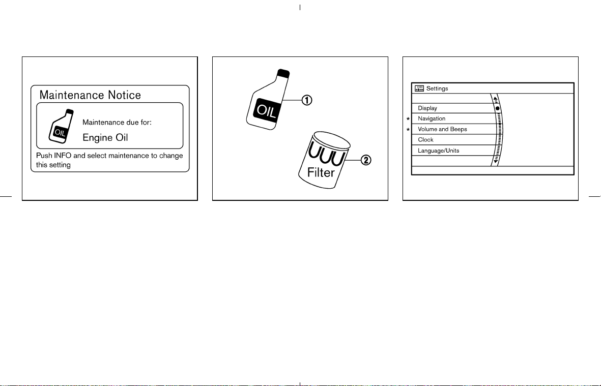
Maintenance notice
The “Maintenance Notice” screen (“ENGINE
OIL” or “OIL FILTER”) will be automatically
displayed as shown when both of the following
conditions are met:
쐌 the vehicle is driven the set distance and the
ignition switch is turned OFF.
쐌 the ignition switch is turned ON the next time
the vehicle will be driven.
To return to the previous display after the
“Maintenance Notice” screen is displayed,
push the “BACK” button.
The “Maintenance Notice” screen displays
each time the ignition switch is turned ON until
one of the following conditions are met:
쐌 “Reset Distance” is selected.
쐌 “Interval Reminder” is set OFF.
쐌 the maintenance interval is set again.
*: Refer to the separate Navigation System
Owner’s Manual.
HOW TO USE “SETTING” BUTTON
The “Settings” screen will appear when the
“SETTING” button is pushed.
SAA1332 SAA1292
Engine Oil
쎻
1
/Oil Filter
쎻
2
SAA1293
Display screen, heater, air conditioner and audio systems 4-5
墌 08.7.24/Z33-D/V5.0 墍
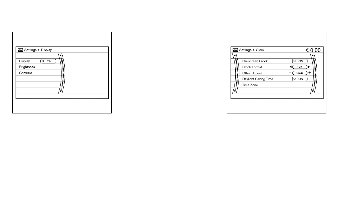
Display settings
The following menu will appear when pushing
the “SETTING” button, selecting “Display” key
and pushing the “ENTER” button.
Display:
To turn off the screen, select the “Display” key
and push the “ENTER” button to turn off the
“ON” indicator. When any mode button is
pushed with the screen off, the screen turns on
for further operation. The screen will turn off
automatically 5 seconds after the operation is
finished on the map display.
To turn on the screen, select the “Display” key
and turn on the “ON” indicator.
Brightness/Contrast:
To adjust the brightness and contrast of the
screen, select the “Brightness”or“Contrast”
key and push the “ENTER” button. Then you can
adjust the brightness to darker or brighter and
the contrast to lower or higher using the joystick.
Clock settings
The following display will appear when pushing
the “SETTING” button, selecting the “Clock”
key and pushing the “ENTER” button.
On-screen Clock:
When this item is turned to ON, a clock is always
displayed in the upper right corner of the screen.
This clock will indicate the time almost exactly
because it is always adjusted by the GPS
system.
SAA1540 SAA1091
4-6 Display screen, heater, air conditioner and audio systems
墌 08.7.24/Z33-D/V5.0 墍
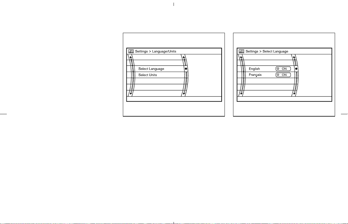
Clock Format:
Choose either the 12-hour clock display or the
24-hour clock display.
Offset Adjust:
Adjust the time by increasing or decreasing per
minute.
Daylight Saving Time:
Turn this item to ON for daylight saving time
application.
Time Zone:
Choose the time zone from the following
쐌 Pacific
쐌 Mountain
쐌 Central
쐌 Eastern
쐌 Atlantic
쐌 Newfoundland
Language/Units settings
The Language/Units settings screen will appear
when selecting the “Language/Units” key and
pushing the “ENTER” button.
Select the “Select Language”or“Select
Units” key and push the “ENTER” button.
Language: “English” or “Français”
Unit: “US” — Mile, °F, MPG
“Metric” — km, °C, L/100 km
Select the “ON” key of the desired language or
units and push the “ENTER” button.
SAA1295 SAA1296
Display of Select Language
Display screen, heater, air conditioner and audio systems 4-7
墌 08.7.24/Z33-D/V5.0 墍
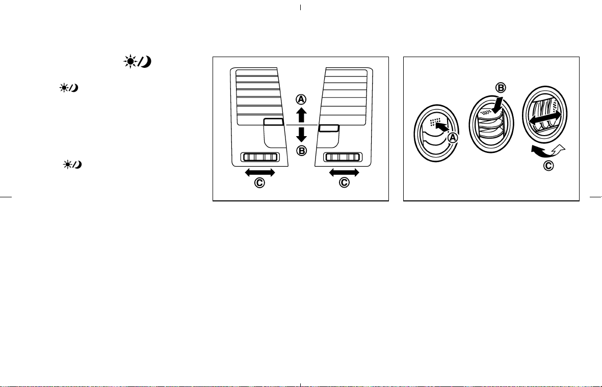
HOW TO USE THE “ ”
BUTTON
Push the “ ” (DAY/NIGHT) button to switch
the display brightness to the daytime or night-
time mode, and adjust the brightness by moving
the joystick right or left.
If no operation is done within 10 seconds, or if
the “BACK” button is pushed, the display will
return to the previous display.
Push the “
” button for more than 2 sec-
onds to turn the display off. Push the button
again for more than 2 seconds to turn the display
on.
CENTER VENTILATORS
Adjust the air flow direction of ventilators.
Moving the lever up or down will open
쎻
A
or
close
쎻
B
the vents.
To change the air flow direction, turn the dial
쎻
C
.
SIDE VENTILATORS
Adjust the air flow direction of ventilators by 쎻
A
opening, 쎻
B
closing or 쎻
C
rotating as illustrated.
SAA0600 SAA0601
VENTILATORS
4-8 Display screen, heater, air conditioner and audio systems
墌 08.7.24/Z33-D/V5.0 墍
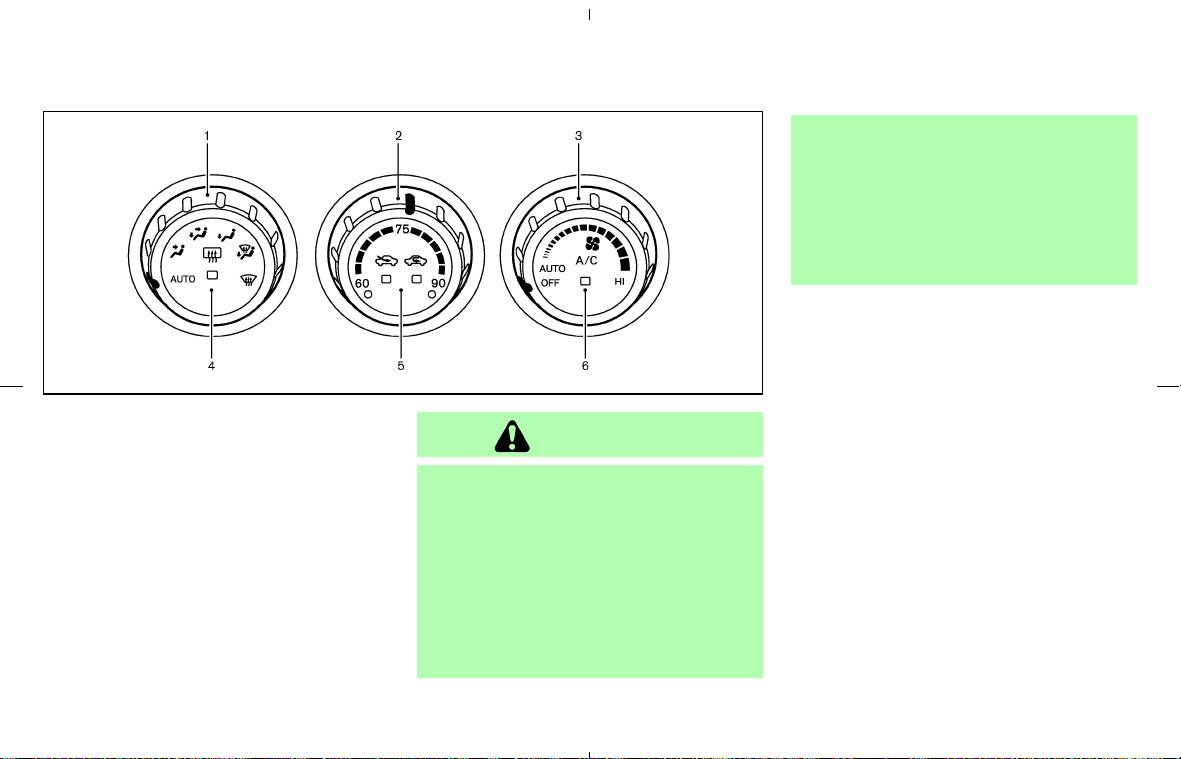
1. Air flow control dial
2. Temperature control dial*
* The display of degrees:
“60-75-90” is used for °F (US).
“18-25-32” is used for °C (Canada).
3. Fan speed control dial
4. Rear window defroster button
(See the “2. Instruments and controls” sec-
tion.)
5. Air intake button
(Air recirculation and Fresh air)
6. A/C (air conditioner) button
WARNING
쐌 The air conditioner cooling function
operates only when the engine is
running.
쐌 On hot, sunny days, temperatures in
a closed vehicle could quickly be-
come high enough to cause severe or
possibly fatal injuries to people or
animals. Do not leave children or
adults who would normally require
the assistance of others in your ve-
hicle. Unattended pets should also
not be left alone.
쐌 Do not use the recirculation mode for
long periods as it may cause the
interior air to become stale and the
windows to fog up.
Start the engine and operate the controls to
activate the air conditioner.
NOTE:
In your vehicle, the air conditioner system
is designed to automatically activate the
cooling function when operating the air
flow control dial, the fan speed control dial
or the air intake button. (The indicator light
on the A/C button will illuminate.) Push the
A/C button off when the cooling function is
not necessary.
SAA1297
HEATER AND AIR CONDITIONER
(Automatic)
Display screen, heater, air conditioner and audio systems 4-9
墌 08.7.24/Z33-D/V5.0 墍

AUTOMATIC OPERATION
Cooling and/or dehumidified heating
(AUTO)
This mode may be normally used all year round
as the system automatically works to keep a
constant temperature. Air flow distribution and
fan speed are also controlled automatically.
1. Turn the fan speed control dial and air flow
control dial to the AUTO position. The air
conditioner will automatically turn on. (The
A/C button indicator light illuminates.)
2. Turn the temperature control dial to set the
desired temperature.
쐌 Adjust the temperature to about 75°F (24°C)
for normal operation.
쐌 The temperature of the passenger compart-
ment will be maintained automatically. Air
flow distribution and fan speed are also con-
trolled automatically.
A visible mist may be seen coming from the
ventilators in hot, humid conditions as the air is
cooled rapidly. This does not indicate a malfunc-
tion.
Heating (AUTO; A/C off)
The air conditioner does not activate. When you
need to heat only, use this mode.
1. Turn the fan speed control dial and air flow
control dial to the AUTO position. (The air
conditioner will turn on.)
2. Push the A/C button to turn off the air
conditioner. (The A/C button indicator light
will turn off.)
3. Turn the temperature control dial to set the
desired temperature.
쐌 The temperature of the passenger compart-
ment will be maintained automatically. Air
flow distribution and fan speed are also con-
trolled automatically.
쐌 Do not set the temperature lower than the
outside air temperature. Otherwise the sys-
tem may not work properly.
쐌 Not recommended if windows fog up.
Dehumidified defrosting or defogging
1. Turn the fan speed control dial to the desired
position.
2. Turn the air flow control dial to the DEF
position.
3. Turn the temperature control dial to set the
desired temperature.
쐌 To quickly remove ice from the outside of the
windows, turn the fan speed control dial to
the maximum position.
쐌 As soon as possible after the windshield is
clean, turn the air flow control dial to the
AUTO position to return to the auto mode.
쐌 When the air flow control dial is turned to the
or position, the air conditioner
will automatically be turned on at outside
temperatures above 23°F (−5°C) to defog
the windshield, and the air recirculation mode
will automatically be turned off.
Outside air is drawn into the passenger
compartment to improve the defogging per-
formance.
MANUAL OPERATION
Fan speed control
Turn the fan speed control dial to manually
control the fan speed.
Turn the dial to the AUTO position to return to
automatic control of the fan speed.
Air recirculation/Fresh air
Each time the air intake button is pushed, the
indicator light on the button will alternate
(Air recirculation) and (Fresh air).
When the
indicator light is on, the interior
4-10 Display screen, heater, air conditioner and audio systems
墌 08.7.24/Z33-D/V5.0 墍
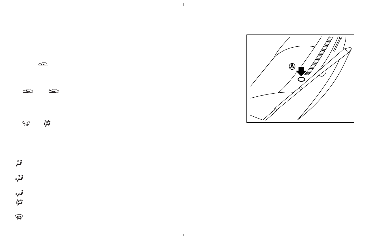
air is recirculated. (When the air recirculation
mode is selected with the A/C indicator off while
the fan speed control dial is in the AUTO
position, the air conditioner will turn on.)
When the
indicator light is on, the outside
air is drawn into the passenger compartment.
쐌 When the air intake button is pushed for
longer than 1.5 seconds, both indicator lights
(
and ) will flash twice, and then
the intake air will be controlled automatically.
During this AUTO mode, the indicator light of
the currently selected mode illuminates.
쐌 When the air flow control dial is in the
or position, the air recirculation
mode does not activate.
Air flow control
Turning the air flow control dial selects the air
outlet to:
: Air flows from center and side ventila-
tors.
: Air flows from center and side ventila-
tors and foot outlets.
: Air flows mainly from foot outlets.
: Air flows from defroster and foot out-
lets.
: Air flows mainly from defroster outlets.
To turn the system off
Turn the fan speed control dial to the OFF
position.
OPERATING TIPS
When the engine coolant temperature and out-
side air temperature are low, the air flow from the
foot outlets may not operate for a maximum of
150 seconds. However, this is not a malfunction.
After the coolant temperature warms up, the air
flow from the foot outlets will operate normally.
Sensor
쎻
A
on the instrument panel helps main-
tain a constant temperature; do not put anything
on or around this sensor.
SAA0603
Display screen, heater, air conditioner and audio systems 4-11
墌 08.7.24/Z33-D/V5.0 墍

The air conditioning system in your NISSAN
vehicle is charged with a refrigerant designed
with the environment in mind. This refrigerant
will not harm the earth’s ozone layer. How-
ever, special charging equipment and lubricant
are required when servicing your NISSAN air
conditioner. Using improper refrigerants or lubri-
cants will cause severe damage to your air
conditioning system. See “Capacities and rec-
ommended fuel/lubricants” in the “9. Technical
and consumer information” section for air con-
ditioning system refrigerant and lubricant recom-
mendations.
A NISSAN dealer will be able to service your
environmentally friendly air conditioning system.
WARNING
The air conditioner system contains re-
frigerant under high pressure. To avoid
personal injury, any air conditioner ser-
vice should be done only by an experi-
enced technician with proper equip-
ment.
RADIO
Turn the ignition key to ACC or ON and press
the POWER, FM or AM button to turn on the
radio. If you listen to the radio with the engine not
running, the key should be turned to the ACC
position.
Radio reception is affected by station signal
strength, distance from radio transmitter, build-
ings, bridges, mountains and other external in-
fluences. Intermittent changes in reception qual-
ity normally are caused by these external
influences.
Using a cellular phone in or near the ve-
hicle may influence radio reception quality.
Radio reception
Your radio system is equipped with state-of-the-
art electronic circuits to enhance radio recep-
tion. These circuits are designed to extend re-
ception range, and to enhance the quality of that
reception.
However there are some general characteristics
of FM, AM and SAT (satellite — if so equipped)
radio signals that can affect radio reception
quality in a moving vehicle, even when the finest
equipment is used. These characteristics are
completely normal in a given reception area, and
do not indicate any malfunction in your radio
system.
Remember that a moving vehicle is not the ideal
place to listen to a radio. Because of the move-
ment, reception conditions will constantly
change. Buildings, terrain, signal distance and
interference from other vehicles can work
against ideal reception. Described below are
some of the factors that can affect your radio
reception.
Some cellular phones or other devices may
cause interference or a buzzing noise to come
from the audio system speakers. Storing the
device in a different location may reduce or
eliminate the noise.
SERVICING AIR CONDITIONER AUDIO SYSTEM
4-12 Display screen, heater, air conditioner and audio systems
墌 08.7.24/Z33-D/V5.0 墍
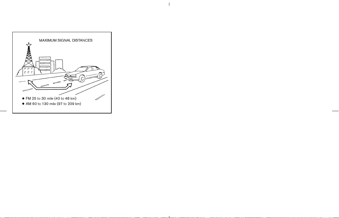
FM RADIO RECEPTION
Range: FM range is normally limited to 25 to 30
miles (40 to 48 km), with monaural (single
channel) FM having slightly more range than
stereo FM. External influences may sometimes
interfere with FM station reception even if the FM
station is within 25 miles (40 km). The strength
of the FM signal is directly related to the distance
between the transmitter and receiver. FM signals
follow a line-of-sight path, exhibiting many of the
same characteristics as light. For example they
will reflect off objects.
Fade and drift: As your vehicle moves away from
a station transmitter, the signals will tend to fade
and/or drift.
Static and flutter: During signal interference from
buildings, large hills or due to antenna position,
usually in conjunction with increased distance
from the station transmitter, static or flutter can
be heard. This can be reduced by lowering the
treble setting to reduce treble response.
Multipath reception: Because of the reflective
characteristics of FM signals, direct and re-
flected signals reach the receiver at the same
time. The signals may cancel each other, result-
ing in momentary flutter or loss of sound.
AM RADIO RECEPTION
AM signals, because of their low frequency, can
bend around objects and skip along the ground.
In addition, the signals can be bounced off the
ionosphere and bent back to earth. Because of
these characteristics. AM signals are also sub-
ject to interference as they travel from transmitter
to receiver.
Fading: Occurs while the vehicle is passing
through freeway underpasses or in areas with
many tall buildings. It can also occur for several
seconds during ionospheric turbulence even in
areas where no obstacles exist.
Static: Caused by thunderstorms, electrical
power lines, electric signs and even traffic lights.
SATELLITE (SAT) RADIO
RECEPTION (if so equipped)
When the satellite radio is first installed or the
battery has been replaced, the satellite radio
may not work properly. This is not a malfunction.
Wait more than 10 minutes with the satellite
radio ON for the satellite radio to receive all of
the necessary data.
No satellite radio reception is available when the
SAT band option is selected unless optional
satellite receiver and antenna are installed, and
an XM
®
satellite radio service subscription is
active.
Satellite radio performance may be affected if
cargo carried on the roof blocks the satellite
radio signal.
If possible, do not put cargo over the satellite
antenna.
A buildup of ice on the satellite radio antenna
can affect satellite radio performance. Remove
the ice to restore satellite radio reception.
Satellite radio is not available in Alaska and
Hawaii.
SAA0306
Display screen, heater, air conditioner and audio systems 4-13
墌 08.7.24/Z33-D/V5.0 墍
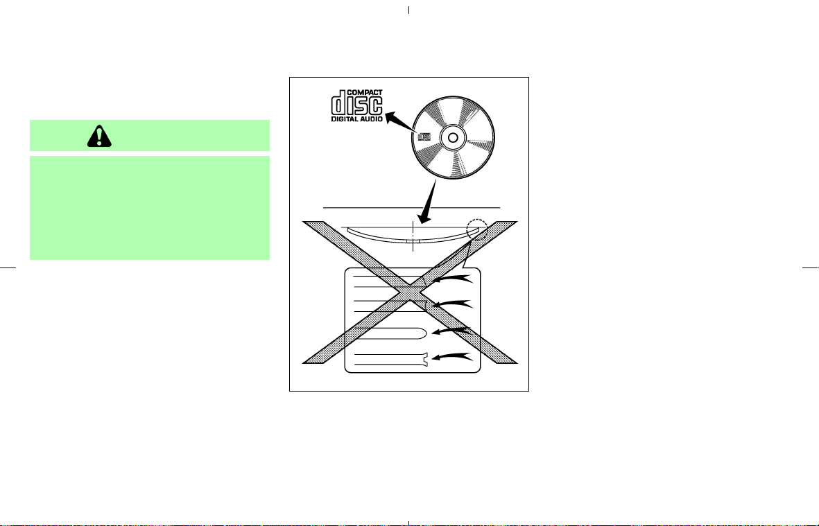
AUDIO OPERATION PRECAUTIONS
Compact Disc (CD) player
CAUTION
쐌 Do not force a compact disc into the
CD insert slot. This could damage the
CD and/or CD changer/player.
쐌 Trying to load a CD with the CD door
closed could damage the CD and/or
CD changer.
쐌 During cold weather or rainy days, the
player may malfunction due to the hu-
midity. If this occurs, remove the CD and
dehumidify or ventilate the player com-
pletely.
쐌 The player may skip while driving on
rough roads.
쐌 The CD player sometimes cannot func-
tion when the passenger compartment
temperature is extremely high. De-
crease the temperature before use.
쐌 Only use high quality 4.7 in (12 cm)
round discs that have the “COMPACT
disc DIGITAL AUDIO” logo on the disc or
packaging.
쐌 Do not expose the CD to direct sunlight.
쐌 CDs that are of poor quality, dirty,
scratched, covered with fingerprints, or
that have pin holes may not work prop-
erly.
쐌 The following CDs may not work prop-
erly:
쐌 Copy control compact discs (CCCD)
쐌 Recordable compact discs (CD-R)
쐌 Rewritable compact discs (CD-RW)
쐌 Do not use the following CDs as they
may cause the CD player to malfunction.
쐌 3.1 in (8 cm) discs
쐌 CDs that are not round
쐌 CDs with a paper label
쐌 CDs that are warped, scratched, or
have abnormal edges
쐌 This audio system can only play prere-
corded CDs. CDs with MP3 or WMA
format cannot be written in this audio
system.
쐌 If the CD cannot be played, one of the
following messages will be displayed.
SAA0480
4-14 Display screen, heater, air conditioner and audio systems
墌 08.7.24/Z33-D/V5.0 墍

CHECK DISC:
쐌 Confirm that the CD is inserted cor-
rectly (the label side is facing up,
etc.).
쐌 Confirm that the CD is not bent or
warped and it is free of scratches.
PUSH EJECT:
This is a malfunction due to excessive
temperature inside the player. Remove
the CD by pushing the EJECT button.
After a short time, reinsert the CD. The
CD can be played when the temperature
of the player returns to normal.
UNPLAYABLE:
The file is unplayable in this audio sys-
tem (only MP3 or WMA CD in the audio
system with a CD changer).
Compact Disc (CD) with MP3 or
WMA (for the audio system with a
6CD changer)
Explanation of terms:
쐌 MP3 — MP3 is short for Moving Pictures
Experts Group Audio Layer 3. MP3 is the
most well-known compressed digital audio
file format. This format allows for near “CD
quality” sound, but at a fraction of the size of
normal audio files. MP3 conversion of an
audio track from CD-ROM can reduce the file
size by approximately 10:1 ratio (Sampling:
44.1 kHz, Bit rate: 128 kbps) with virtually no
perceptible loss in quality. MP3 compression
removes the redundant and irrelevant parts of
a sound signal that the human ear doesn’t
hear.
쐌 WMA — Windows Media Audio (WMA) is a
compressed audio format created by Mi-
crosoft as an alternative to MP3. The WMA
codec offers greater file compression than
the MP3 codec, enabling storage of more
digital audio tracks in the same amount of
space when compared to MP3s at the same
level of quality.
쐌 Bit rate — Bit rate denotes the number of bits
per second used by a digital music file. The
size and quality of a compressed digital audio
file is determined by the bit rate used when
encoding the file.
쐌 Sampling frequency — Sampling frequency is
the rate at which the samples of a signal are
converted from analog to digital (A/D conver-
sion) per second.
쐌 Multisession — Multisession is one of the
methods for writing data to media. Writing
data once to the media is called a single
session, and writing more than once is called
a multisession.
쐌 ID3/WMA Tag — The ID3/WMA tag is the
part of the encoded MP3 or WMA file that
contains information about the digital music
file such as song title, artist, album title,
encoding bit rate, track time duration, etc.
ID3 tag information is displayed on the
Album/Artist/Track title line on the display.
* Windows
and Windows Media are either
registered trademarks and trademarks of Mi-
crosoft Corporation in the United States
and/or other countries.
Display screen, heater, air conditioner and audio systems 4-15
墌 08.7.24/Z33-D/V5.0 墍
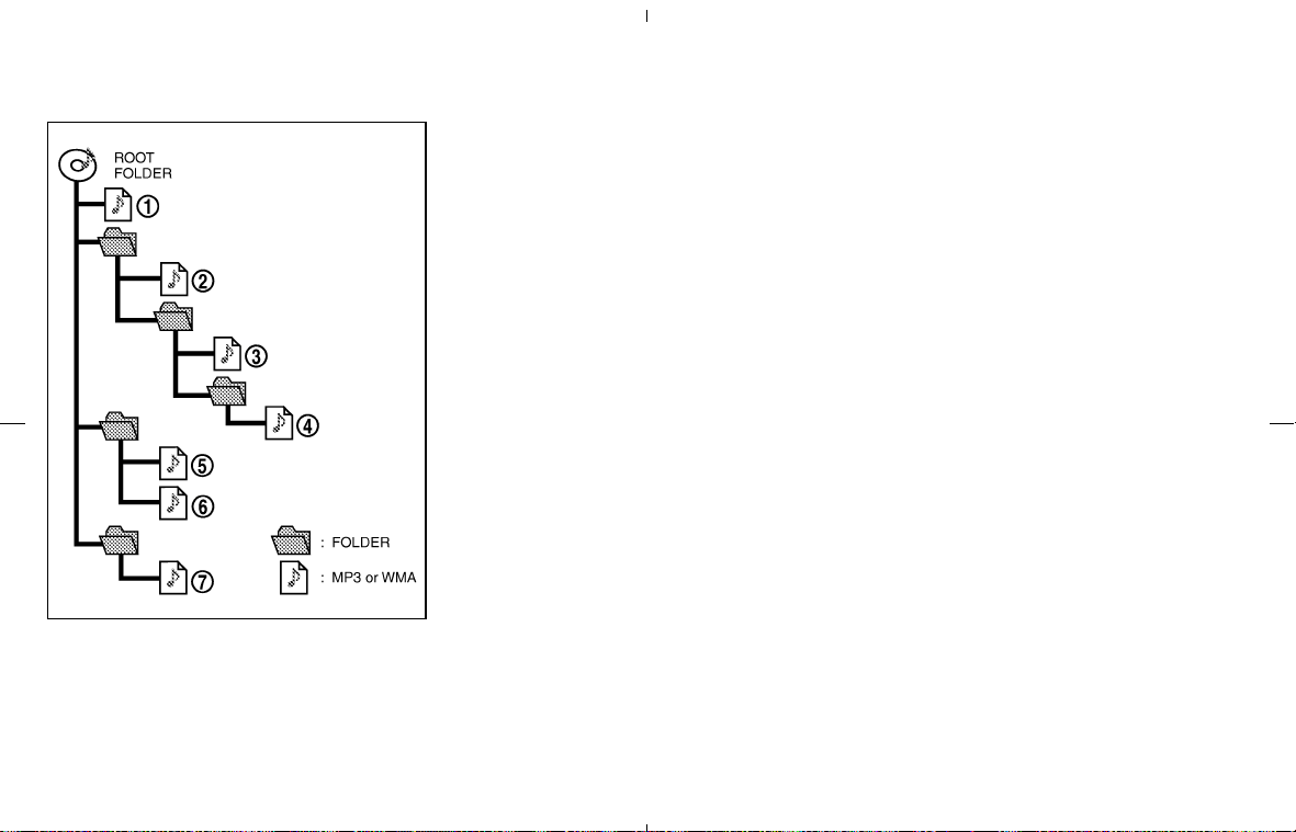
Playback order:
Playback order of the CD with compressed files
(MP3/WMA) is as illustrated above.
쐌 The names of folders not containing
MP3/WMA files are not shown in the display.
쐌 If there is a file in the top level of the disc,
“ROOT” is displayed.
쐌 The playback order is the order in which the
files were written by the writing software.
Therefore, the files might not play in the
desired order.
SAA1025
4-16 Display screen, heater, air conditioner and audio systems
墌 08.7.24/Z33-D/V5.0 墍
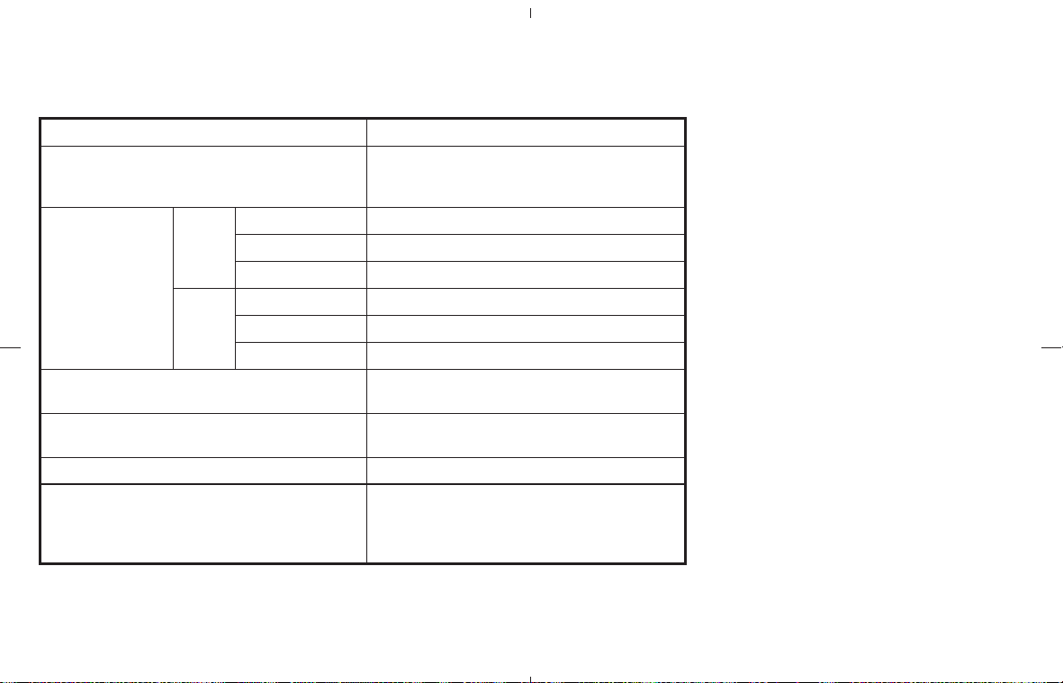
Specification chart:
Supported media CD, CD-R, CD-RW
Supported file systems
ISO9660 LEVEL1, ISO9660 LEVEL2, Romeo, Joliet
* ISO9660 Level 3 (packet writing) is not sup-
ported.
Supported ver-
sions*1
MP3
Version MPEG1, MPEG2, MPEG2.5
Sampling frequency 8 kHz - 48 kHz
Bit rate 8 kbps - 320 kbps, VBR
WMA
Version WMA7, WMA8, WMA9
Sampling frequency 32 kHz - 48 kHz
Bit rate 48 kbps - 192 kbps, VBR
Tag information (Song title and Artist name)
ID3 tag VER1.0, VER1.1, VER2.2, VER2.3 (MP3
only)
Folder levels
Folder levels: 8, Folders: 255 (including root folder),
Files: 512 (Max. 255 files for one folder)
Text character number limitation 128 characters
Displayable character codes*2
01: ASCII, 02: ISO-8859-1, 03: UNICODE
(UTF-16 BOM Big Endian), 04: UNICODE (UTF-16
Non-BOM Big Endian), 05: UNICODE (UTF-8), 06:
UNICODE (Non-UTF-16 BOM Little Endian)
*1 Files created with a combination of 48 kHz sampling frequency and 64 kbps bit rate cannot be
played.
*2 Available codes depend on what kind of media, versions and information are going to be displayed.
Display screen, heater, air conditioner and audio systems 4-17
墌 08.7.24/Z33-D/V5.0 墍

Troubleshooting guide:
Symptom Cause and Countermeasure
Cannot play
Check if the disc was inserted correctly.
Check if the disc is scratched or dirty.
Check if there is condensation inside the player. If there is, wait until the condensation is gone (about 1 hour) before using the
player.
If there is a temperature increase error, the CD player will play correctly after it returns to the normal temperature.
If there is a mixture of music CD files (CD-DA data) and MP3/WMA files on a CD, only the music CD files (CD-DA data) will be
played.
Files with extensions other than “.MP3”, “.WMA”, “.mp3” or “.wma” cannot be played. In addition, the character codes and num-
ber of characters for folder names and file names should be in compliance with the specifications.
Check if the disc or the file is generated in an irregular format. This may occur depending on the variation or the setting of
MP3/WMA writing applications or other text editing applications.
Check if the finalization process, such as session close and disc close, is done for the disc.
Check if the disc is protected by copyright.
Poor sound quality
Check if the disc is scratched or dirty.
Bit rate may be too low.
It takes a relatively long time be-
fore the music starts playing.
If there are many folder or file levels on the MP3/WMA disc, or if it is a multisession disc, some time may be required before the
music starts playing.
Music cuts off or skips
The writing software and hardware combination might not match, or the writing speed, writing depth, writing width, etc., might not
match the specifications. Try using the slowest writing speed.
Skipping with high bit rate files Skipping may occur with large quantities of data, such as for high bit rate data.
Move immediately to the next song
when playing.
When a non-MP3/WMA file has been given an extension of “.MP3”, “.WMA”, “.mp3” or “.wma”, or when play is prohibited by
copyright protection, there will be approximately 5 seconds of no sound and then the player will skip to the next song.
The songs do not play back in the
desired order.
The playback order is the order in which the files were written by the writing software. Therefore, the files might not play in the
desired order.
4-18 Display screen, heater, air conditioner and audio systems
墌 08.7.24/Z33-D/V5.0 墍
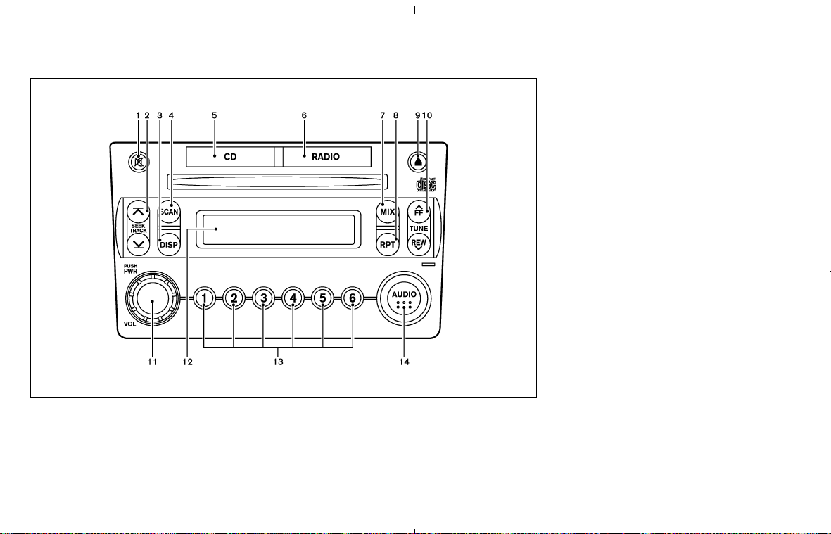
FM-AM RADIO WITH COMPACT
DISC (CD) PLAYER
1. MUTE button
2. SEEK/APS REW, APS FF/TRACK
CHANGE button
3. DISP (Display) CHANGE button
4. SCAN tuning button
5. CD play button
6. RADIO (FM/AM) band select button
7. MIX play button
8. RPT (Repeat) play button
9. CD EJECT button
10. TUNE/FF⋅REW button
11. ON⋅OFF/VOL (Volume) control knob
12. Audio/Clock display
13. Station and preset select button
14. AUDIO button
Audio main operation
For all operation precautions, see “Audio opera-
tion precautions” earlier in this section.
ON⋅OFF/Volume control:
Turn the ignition key to ACC or ON, and then
push the ON⋅OFF/VOL (Volume) control knob
while the system is off to call up the mode (radio
or CD) which was playing immediately before
the system was turned off. When no CD is
loaded, the radio will come on. While the system
is on, pushing the ON⋅OFF/VOL control knob
turns the system off.
Turn the ON⋅OFF/VOL control knob to adjust
the volume.
AUDIO button (BASS, TREBLE, FADER,
BALANCE):
Press the AUDIO button to change the selecting
mode as follows.
SAA1298
Display screen, heater, air conditioner and audio systems 4-19
墌 08.7.24/Z33-D/V5.0 墍
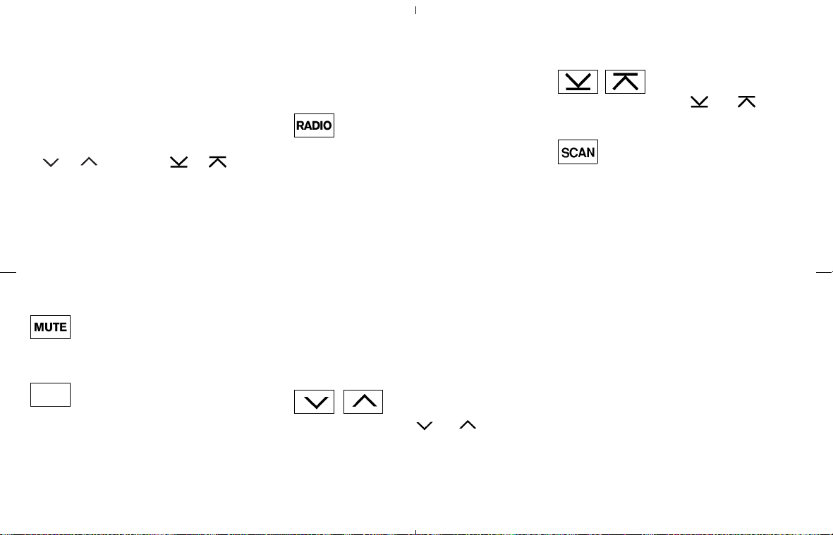
BASS → TREBLE → FADE → BALANCE
To adjust Bass, Treble, Fader and Balance, push
the AUDIO button until the desired mode
(BASS, TREBLE, FADER or BALANCE) ap-
pears in the display. Push the TUNE
(
, ) or SEEK ( , ) button
to adjust Bass and Treble to the desired level.
Use the TUNE or SEEK button also to adjust
Fader or Balance modes. Fader adjusts the
sound level between the front and rear speakers
and Balance adjusts the sound between the
right and left speakers.
After 10 seconds, the radio or CD display
reappears. Once the sound quality is set to the
desired level, push the AUDIO button repeatedly
until the radio or CD display appears.
MUTE button:
Push the MUTE button to mute the audio sound.
Push the MUTE button again to release the
mute.
DISP DISPLAY CHANGE:
Push the DISP button for more than 1.5 seconds
to adjust the digital clock display. See “Clock” in
the “2. Instruments and controls” section for the
clock adjustment operation.
When the DISP button is pushed for less than
1.5 seconds while the compact disc is being
played, the display will show the CD play time.
FM-AM radio operation
RADIO (FM/AM) band select:
Pushing the RADIO band select button will
change the band as follows:
AM → FM1 → FM2 → AM
When RADIO band select button is pushed
while the ignition switch is in the ACC or ON, the
radio will come on at the station last played.
The last station played will also come on when
the power knob is turned to ON.
If a compact disc is playing when the RADIO
band select button is pushed, the compact disc
will automatically be turned off and the last radio
station played will come on.
The FM stereo indicator ST will glow during FM
stereo reception. When the stereo broadcast
signal is weak, the radio will automatically
change from stereo to monaural reception.
TUNE (Tuning) :
Push the TUNE button
or for manual
tuning. To move quickly through the channels,
push and hold either side of the TUNE button
down for more than 0.5 second.
SEEK tuning:
Push the SEEK button
or to tune
from high to low or low to high frequencies and
stops at the next broadcasting station.
SCAN tuning:
Push the SCAN tuning button to tune from low
to high frequencies and stops at each broad-
casting station for 5 seconds. Pushing the but-
ton again during this 5 second period will stop
SCAN tuning and the radio will remain tuned to
that station.
If the SCAN tuning button is not pushed within 5
seconds, SCAN tuning moves to the next sta-
tion.
Station memory operations:
Twelve stations can be set for the FM band (six
for FM1, six for FM2) and six stations can be set
for the AM band.
1. Tune to the desired station using the SEEK,
SCAN or TUNE button.
2. Select the desired station and keep pushing
any of the desired station select buttons (1 to
6) until a beep sound is heard. (The radio
mutes when the select button is pushed.)
3. The channel indicator will then come on and
4-20 Display screen, heater, air conditioner and audio systems
墌 08.7.24/Z33-D/V5.0 墍

the sound will resume. Memorizing is now
complete.
4. Other buttons can be set in the same manner.
If the battery cable is disconnected, or if
the fuse blows, the radio memory will be
erased. In that case, reset the desired sta-
tions.
Compact disc (CD) player operation
Turn the ignition key to the ACC or ON position
and insert the compact disc into the slot with the
label side facing up. The compact disc will be
guided automatically into the slot and start play-
ing.
After loading the disc, the number of tracks on
the disc will appear on the display.
If the radio is already operating, it will automati-
cally turn off and the compact disc will play.
If the system has been turned off while the
compact disc was playing, pushing the
ON⋅OFF/VOL control knob will start the com-
pact disc.
3.1 in (8 cm) diameter compact discs can also
be used without an adapter.
CD PLAY:
When the CD (CD play) button is pushed with
the system off and the compact disc loaded, the
system will turn on and the compact disc will
start to play.
When the CD button is pushed with the com-
pact disc loaded but the radio playing, the radio
will automatically be turned off and the compact
disc will start to play.
DISP CD PLAY TIME:
Push the DISP button for less than 1.5 seconds
while the compact disc is being played to show
the play time on the display.
FF (Fast Forward), REW
(Rewind):
When the
(fast forward) or (rewind)
button is pushed while the compact disc is
being played, the compact disc will play while
fast forwarding or rewinding. When the button is
released, the compact disc will return to normal
play speed.
APS (Automatic Program
Search) FF, APS REW/
TRACK CHANGE:
When the
(APS FF) button is pushed
while the compact disc is being played, the
program next to the present one will start to play
from its beginning. Push several times to skip
through programs. The compact disc will ad-
vance the number of times the button is pushed.
(When the last program on the compact disc is
skipped through, the first program will be
played.) When the
(APS REW) button is
pushed, the program being played returns to its
beginning. Push several times to skip back
through programs. The compact disc will go
back the number of times the button is pushed.
SCAN tuning:
When the SCAN tuning button is pushed while
the CD is being played, the beginning of all the
tracks of CD will be played for 10 seconds in
sequence.
Pushing the button again during this 10 second
period will stop SCAN tuning. If the SCAN
tuning button is not pushed within 10 seconds,
SCAN tuning moves to the next CD program.
MIX MIX play:
When the MIX button is pushed while the com-
pact disc is being played, programs will be
played at random, not following the sequence on
the compact disc. The same program may be
repeated twice. Push the MIX button again to
return to the normal play mode.
REPEAT (RPT) play:
When the RPT button is pushed while the
compact disc is being played, the play pattern
can be changed as follows:
Display screen, heater, air conditioner and audio systems 4-21
墌 08.7.24/Z33-D/V5.0 墍
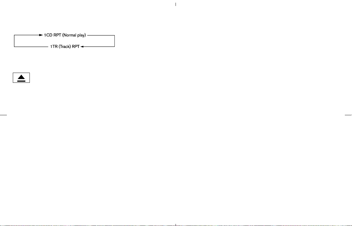
The display shows the following symbol; (no
mark): 1 CD RPT (Repeat)
1: 1 TR (Track) RPT
CD EJECT:
When the CD EJECT button is pushed with the
compact disc loaded, the compact disc will be
ejected.
When this button is pushed while the compact
disc is being played, the compact disc will come
out and the system will turn off.
If the compact disc comes out and is not
removed, it will be pulled back into the slot
to protect it. (except for 3.1 in [8 cm] diam-
eter compact discs)
If the following message appears on the display,
push the EJECT button:
쐌 CHECK DISC — Eject the disc, and check
whether it is damaged or
inserted upside-down.
쐌 CD ERR F * — Eject the disc, and check
whether it is a proper audio
CD. (* shows a different
number according to the au-
dio condition.)
CD IN indicator:
CD IN indicator appears on the display when the
CD is loaded.
4-22 Display screen, heater, air conditioner and audio systems
墌 08.7.24/Z33-D/V5.0 墍
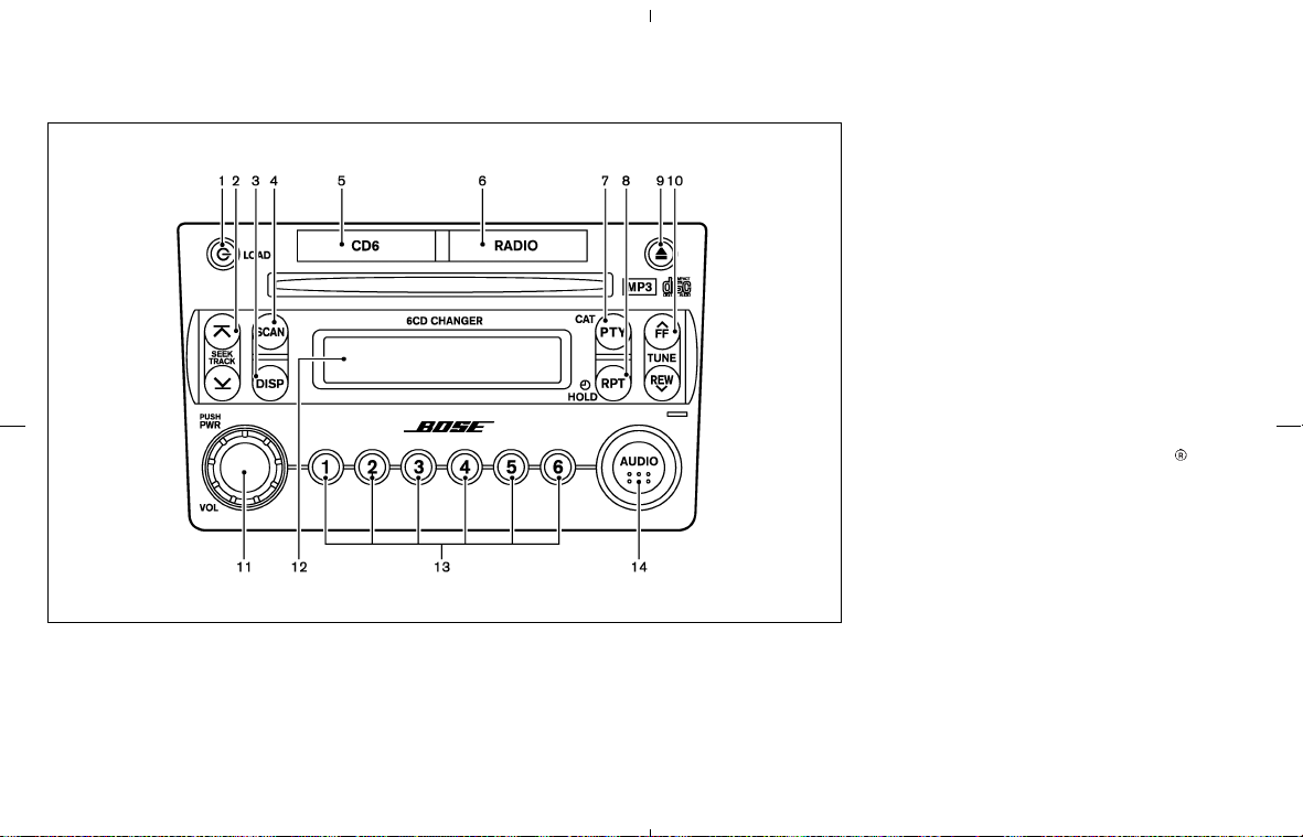
FM-AM-SAT RADIO WITH
COMPACT DISC (CD) CHANGER
1. CD LOAD button
2. SEEK/APS REW, APS FF/TRACK
CHANGE button
3. DISP (Display) CHANGE button
4. SCAN tuning button
5. CD PLAY button
6. RADIO (FM/AM/SAT*) band select button
7. PTY (Program type), CAT (Category)* select
button
8. RPT (Repeat) play/CLOCK button
9. CD EJECT button
10. TUNE/FF⋅REW button
11. ON⋅OFF/VOL (Volume) control knob
12. Audio/Clock display
13. Station and preset (FM/AM/SAT*)/CD in-
sert or CD play select button
14. AUDIO button
* No satellite radio reception is available when
the SAT band option is selected unless op-
tional satellite receiver and antenna are in-
stalled, and an XM
®
satellite radio service
subscription is active.
It may take some time to receive the activation
signal after subscribing to the XM
satellite
radio provider. After receiving the activation
signal, an available channel list will be auto-
matically updated in the radio. Turn the ignition
switch from the LOCK to ACC position to
update the channel list.
Satellite radio is not available in Alaska and
Hawaii.
Audio main operation
For all operation precautions, see “Audio opera-
tion precautions” earlier in this section.
Head unit:
The auto loudness circuit enhances the low
SAA1299
Display screen, heater, air conditioner and audio systems 4-23
墌 08.7.24/Z33-D/V5.0 墍
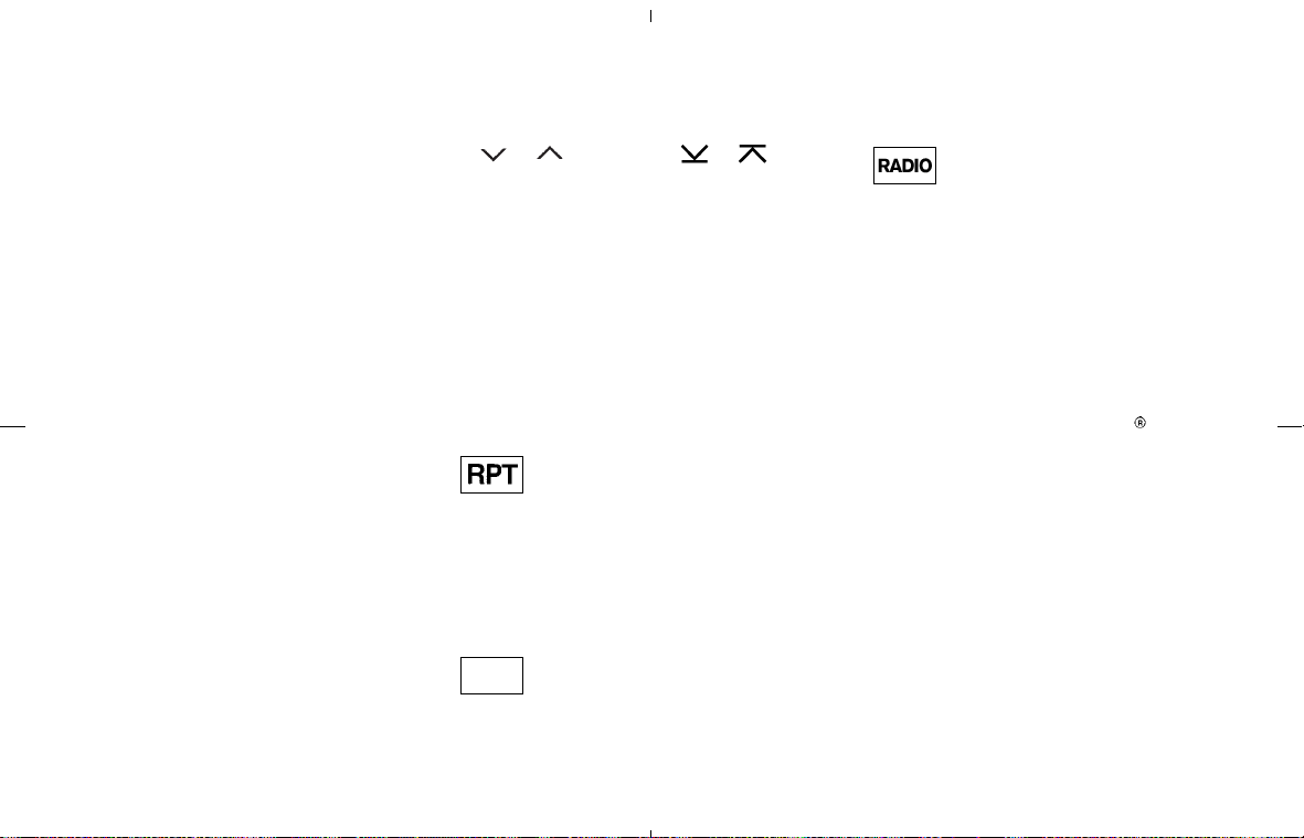
frequency range automatically in both radio re-
ception and CD playback.
This audio system has an active noise compen-
sation feature called “Audio Pilot”. The Audio
Pilot uses a microphone to detect external road
noise and automatically adjusts the amplifier to
compensate for any competing high, midrange,
or low frequency noise.
ON⋅OFF/Volume control:
Turn the ignition key to ACC or ON, and then
push the ON⋅OFF/VOL (Volume) control knob
while the system is off to call up the mode (radio
or CD) which was playing immediately before
the system was turned off. When no CD is
loaded, the radio will come on. While the system
is on, pushing the ON⋅OFF/VOL control knob
turns the system off.
Turn the ON⋅OFF/VOL control knob to adjust
the volume.
AUDIO button:
Push the AUDIO button to change the selecting
mode as follows.
BASS → TREBLE → FADE → BALANCE →
AUDIOP
To adjust Bass, Treble, Fader and Balance, push
the AUDIO button until the desired mode
(BASS, TREBLE, FADER or BALANCE) ap-
pears in the display. Push the TUNE
(
, ) or SEEK ( , ) button
to adjust Bass and Treble to the desired level.
Use the TUNE or SEEK button also to adjust
Fader or Balance modes. Fader adjusts the
sound level between the front and rear speakers
and Balance adjusts the sound between the
right and left speakers.
To change the AUDIOP (Audio Pilot) mode to
OFF or ON, push the TUNE or SEEK button.
Once you have adjusted the sound quality to the
desired level, push the AUDIO button repeatedly
until the radio or CD display reappears. Other-
wise, the radio or CD display will automatically
reappear after about 10 seconds.
CLOCK adjusting:
Push the RPT button for more than 1.5 seconds
to adjust the digital clock display.
When the clock adjusting display is selected, the
time (hour or minute) will start flashing. See
“Clock” in the “2. Instruments and controls”
section for the detailed clock adjustment opera-
tion.
DISP DISPLAY CHANGE:
This button will work during satellite radio (if so
equipped) and CD operation. Find the detailed
function in the description of each item.
FM-AM-SAT radio operation
RADIO (FM/AM/SAT) band select:
Pushing the RADIO band select button will
change the band as follows:
(Without satellite radio)
AM → FM1 → FM2 → AM
(With satellite radio)
AM → FM1 → FM2 → SAT → AM
No satellite operation is available during scrolling
of modes, unless optional satellite receiver and
antenna are installed, and an XM
satellite radio
service subscription is active.
When RADIO band select button is pushed
while the ignition switch is in the ACC or ON, the
radio will come on at the station last played.
The last station/channel played will also come on
when the ON⋅OFF/VOL control knob is pushed
to ON.
If a compact disc is playing when the RADIO
band select button is turned to ON, the compact
disc will automatically be turned off and the last
radio station/channel played will come on.
The FM stereo indicator ST will glow during FM
stereo reception. When the stereo broadcast
signal is weak, the radio will automatically
4-24 Display screen, heater, air conditioner and audio systems
墌 08.7.24/Z33-D/V5.0 墍
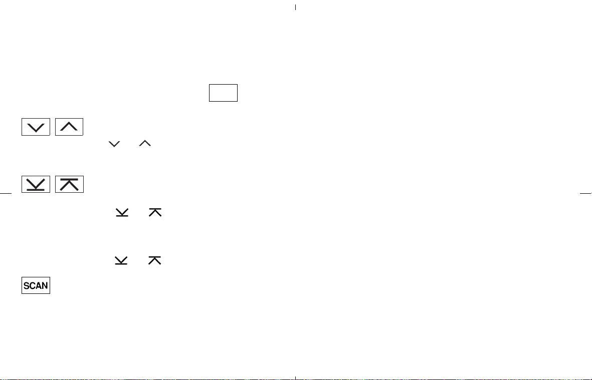
change from stereo to monaural reception.
If the satellite radio signal is lost due to interfer-
ence while driving, in a parking structure or
tunnel for example, “NO SIGNAL” will be dis-
played and no satellite radio station will be
available.
TUNE (Tuning):
Push the TUNE button
or for manual
tuning. To move quickly through the channels,
push and hold either side of the TUNE button
down for more than 0.5 second.
SEEK tuning:
(For FM and AM radio)
Push the SEEK button
or to tune
from high to low or low to high frequencies and
stops at the next broadcasting station.
(For satellite radio)
Push the SEEK button
or to seek
channels of the next or previous category.
SCAN tuning:
Push the SCAN tuning button to tune from low
to high frequencies and stops at each broad-
casting station for 5 seconds. Pushing the but-
ton again during this 5 second period will stop
SCAN tuning and the radio will remain tuned to
that station.
If the SCAN tuning button is not pushed within 5
seconds, SCAN tuning moves to the next sta-
tion.
DISP SAT radio display change (if so
equipped):
쐌 Pushing the DISP button will display addi-
tional information (for example: Title, Artist
name) about the satellite radio broadcast.
쐌 Pushing the DISP button for more than 1.5
seconds will change the display mode as
follows:
Channel number → Channel name → Artist
name → Song title → Channel number
Station memory operations:
Twelve stations/channels can be set for the FM
band (6 for FM1, 6 for FM2) and the SAT radio
(6 for SAT1, 6 for SAT2), and 6 stations can be
set for the AM band.
1. Tune to the desired station/channel using the
SEEK, SCAN or TUNE button.
2. Select the desired station/channel and keep
pushing any of the desired station/channel
and preset buttons (1 to 6) until a beep
sound is heard. (The radio mutes when the
station and preset button is pushed.)
3. The channel indicator will then come on and
the sound will resume. Memorizing is now
complete.
4. Other buttons can be set in the same manner.
If the battery cable is disconnected, or if
the fuse blows, the radio memory will be
erased. In that case, reset the desired sta-
tions.
Radio data system (RDS):
RDS stands for Radio Data System, and is a
data information service transmitted by some
radio stations on the FM band (not AM band)
and/or SAT encoded within a regular radio
broadcast. Currently, most RDS stations are in
large cities, but many stations are now consid-
ering broadcasting RDS data.
RDS can display:
쐌 Station call sign, such as “WHFR 98.3”.
쐌 Station name, such as “The Groove”.
쐌 Music or programming type such as “Classi-
cal”, “Country”, or “Rock”.
쐌 Traffic reports about delays or construction.
If the station broadcasts RDS information, the
RDS icon is displayed.
Display screen, heater, air conditioner and audio systems 4-25
墌 08.7.24/Z33-D/V5.0 墍
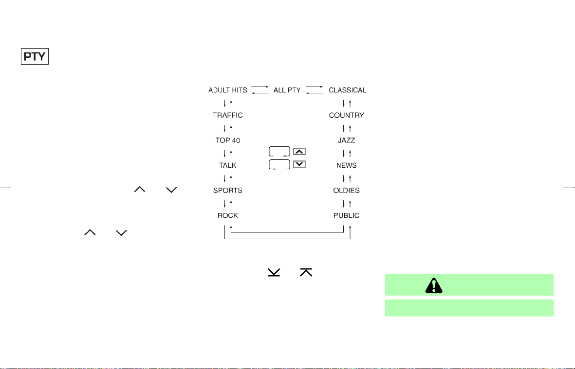
Program type (PTY)/Category
(CAT) select:
When PTY button is pushed during FM mode,
the PTY (CAT) name of the current tuned station
is displayed. When the PTY (CAT) button is
pushed during satellite radio mode (if so
equipped), the category name of the current
channel is displayed. During this time if the PTY
data code is zero, or the data is unreadable, the
display will show “NONE”.
1. PTY (CAT) selection mode
PTY (CAT) name selection can be done by
the up/down TUNE button
or in
the PTY (CAT) selection mode.
It is possible to shift the PTY (CAT) name by
one step, with one push of the up/down
TUNE button
or .
After selecting a PTY (CAT) name, push the
SEEK button or SCAN button within 10
seconds. Tuning to the PTY (CAT) station will
start. If you do not push the TUNE button
within the 10 second period, the PTY (CAT)
mode will be cancelled.
PTY (CAT) name selection can also be
achieved by pushing the preset buttons.
Initial PTY (CAT) names are stored in the
preset buttons, but these can be changed by
pushing the preset buttons for more than 1.5
seconds when the desired PTY (CAT) name
is in the display.
2. PTY (CAT) SEEK tuning mode
After selecting a PTY (CAT) name, push the
SEEK button
or within 10 sec-
onds. Tuning to the PTY (CAT) station will
start. If you do not push the SEEK button
within the 10 second period, the PTY (CAT)
mode will be cancelled.
3. PTY (CAT) SCAN tuning mode
Push the SCAN tuning button to tune the
PTY (CAT) name station, and stop at each
broadcasting station for 5 seconds. Pushing
the button again during this 5 second period
will stop SCAN tuning and the radio will
remain tuned to that station. If the SCAN
tuning button is not pushed within 5 seconds,
SCAN tuning moves to the next station.
Compact disc (CD) changer
operation
Turn the ignition key to the ACC or ON position,
push the LOAD button and insert the compact
disc into the slot with the label side facing up.
The compact disc will be guided automatically
into the slot and start playing.
After loading the disc, the number of tracks on
the disc will appear on the display.
If the radio is already operating, it will automati-
cally turn off and the compact disc will play.
CAUTION
Do not use 3.1 in (8 cm) discs.
If the system has been turned off while the
compact disc was playing, pushing the
4-26 Display screen, heater, air conditioner and audio systems
墌 08.7.24/Z33-D/V5.0 墍
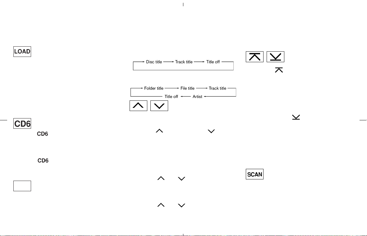
ON⋅OFF/VOL control knob will start the com-
pact disc.
CD LOAD:
To insert a CD in the CD changer, push the
LOAD button for less than 1.5 seconds. Select
the loading slot by pushing the CD insert select
button (1 to 6), then insert the CD.
To insert 6 CDs to the CD changer in succes-
sion, push the LOAD button for more than 1.5
seconds.
The inserted slot numbers will illuminate on the
display.
CD PLAY:
When the
(CD play) button is pushed with
the system off and the compact disc loaded, the
system will turn on and the compact disc will
start to play.
When the
button is pushed with the com-
pact disc loaded but the tape or the radio
playing, the tape or radio will automatically be
turned off and the compact disc will start to play.
DISP CD PLAY INFORMATION:
When the DISP button is pushed for less than
1.5 seconds while the compact disc is being
played, the play time will be displayed.
When the DISP button is pushed for more than
1.5 seconds while the CD is being played, the
disc information display will change.
CD:
CD with MP3 or WMA:
FF (Fast Forward), REW
(Rewind):
CD:
When the
(fast forward) or (rewind)
button is pushed while the compact disc is
being played, the compact disc will play while
fast forwarding or rewinding. When the button is
released, the compact disc will return to normal
play speed.
CD with MP3 or WMA:
When the
or button is pushed for
less than 1.5 seconds while the compact disc is
being played, the folders in the compact disc will
change.
When the
or button is pushed for
more than 1.5 seconds while the compact disc
is being played, the compact disc will play while
forwarding or rewinding. When the button is
released, the compact disc will return to the
normal play speed.
APS (Automatic Program
Search) FF, APS REW:
When the
(APS FF) button is pushed
while the compact disc is being played, the
program next to the present one will start to play
from its beginning. Push several times to skip
through programs. The compact disc will ad-
vance the number of times the button is pushed.
(When the last program on the compact disc is
skipped through, the first program will be
played.) When the
(APS REW) button is
pushed, the program being played returns to its
beginning. Push several times to skip back
through programs. The compact disc will go
back the number of times the button is pushed.
CD PLAY select button:
To change CD, push the CD play select button
(1 to 6).
SCAN tuning:
When the SCAN tuning button is pushed for
less than 1.5 seconds while the CD is being
played, the beginning of all the tracks of CDs will
be played for 10 seconds in sequence.
When the SCAN tuning button is pushed for
more than 1.5 seconds while the CD is being
Display screen, heater, air conditioner and audio systems 4-27
墌 08.7.24/Z33-D/V5.0 墍

played, the first program in all the CDs will be
played for 10 seconds.
Pushing the button again during this 10 second
period will stop SCAN tuning.
If the SCAN tuning button is not pushed within
10 seconds, SCAN tuning moves to the next
disc program.
REPEAT (RPT):
When the RPT play button is pushed while the
compact disc is played, the play pattern can be
changed.
CD:
CD with MP3 or WMA:
The display shows the following symbols.
(no mark): ALL CD RPT (Repeat)
1 DISC: 1 CD RPT
1: 1 TR (Track) RPT or 1 FLDR (Folder) RPT
MIX: ALL CD MIX
1 DISC MIX: 1 CD MIX
1 MIX: 1 FLDR MIX
CD EJECT:
When the CD EJECT button is pushed with the
compact disc loaded, the compact disc will be
ejected.
To eject the discs selected by the CD select
button, push the EJECT button for less than 1.5
seconds.
To eject all the discs in succession, push the
EJECT button for more than 1.5 seconds.
When this button is pushed while the compact
disc is being played, the compact disc will come
out and the system will turn off.
If the compact disc comes out and is not
removed, it will be pulled back into the slot
to protect it.
If either of the following messages appear on the
display, push the EJECT button:
쐌 PUSH EJECT — Eject the disc, and insert it
again.
쐌 CHECK DISC — Eject the disc, and check
whether it is damaged or
inserted upside-down.
쐌 CD ERR F * — Eject the disc, and check
whether it is a proper audio
CD. (* shows a different
number according to the au-
dio condition.)
CD IN indicator:
CD IN indicator (inserted slot number1-6)
appears on the display when the CD is loaded.
4-28 Display screen, heater, air conditioner and audio systems
墌 08.7.24/Z33-D/V5.0 墍
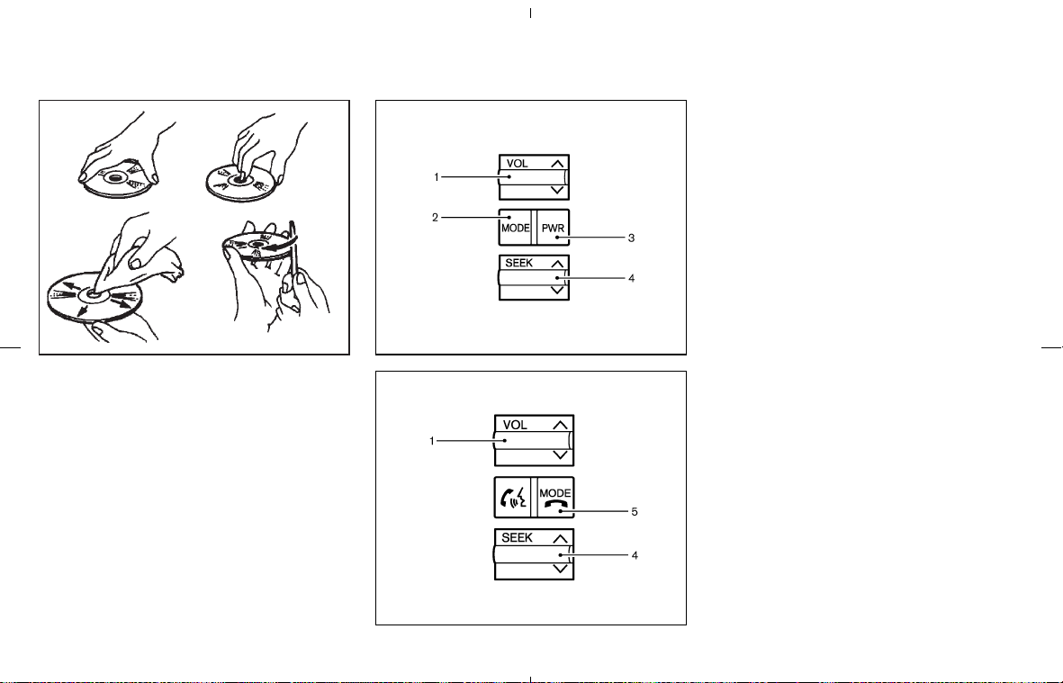
CD CARE AND CLEANING
쐌 Handle a CD by its edges. Never touch the
surface of the disc. Do not bend the disc.
쐌 Always place the discs in the storage case
when they are not being used.
쐌 To clean a disc, wipe the surface from the
center to the outer edge using a clean, soft
cloth. Do not wipe the disc using a circular
motion.
Do not use a conventional record cleaner or
alcohol intended for industrial use.
쐌 A new disc may be rough on its inner and
outer edges. Remove the rough edges using
the side of a pen or pencil as illustrated.
1. VOLUME control switch
2. MODE select switch
3. POWER on/off switch
4. Tuning switch
5. POWER on/MODE select switch
STEERING WHEEL SWITCH FOR
AUDIO CONTROL (if so equipped)
The audio system can be operated using the
controls on the steering wheel.
POWER on/off switch (for Type A)
With the ignition switch turned to the ACC or
ON position, push the POWER on/off switch to
turn the audio system on or off.
POWER on/MODE select switch
(for Type B)
With the ignition switch turned to the ACC or
ON position, push the POWER on/MODE se-
lect switch to turn the audio system on. Push the
switch to change the mode in the sequence of
AM, FM1, FM2, SAT (if so equipped) and CD.
MODE select switch (for Type A)
Push the MODE select switch to change the
mode.
SAA0451 SAA1300
Type A
SAA1698
Type B
Display screen, heater, air conditioner and audio systems 4-29
墌 08.7.24/Z33-D/V5.0 墍
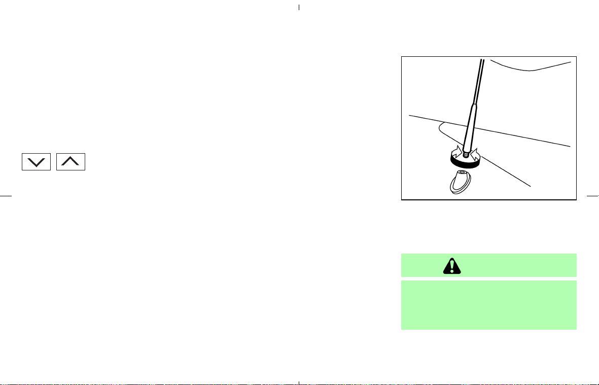
Without satellite radio:
AM, FM1, FM2 and CD or CD changer
With satellite radio:
AM, FM1, FM2, SAT and CD changer
VOLUME control switches
Push up or down the VOLUME control switch to
increase or decrease the volume.
Tuning switch
Memory change (radio):
Push up or down the tuning switch for less than
1.5 seconds to change the radio frequency.
SEEK tuning (radio):
Push up or down the tuning switch for more than
1.5 seconds to seek the next or previous radio
station.
APS (Automatic Program Search) FF,
APS REW (CD or CD changer):
Push up or down the tuning switch for less than
1.5 seconds to return to the beginning of the
present program or skip to the next program.
Push several times to skip back or skip through
programs.
This system searches for the blank intervals
between selections. If there is a blank interval
within one program or there is no interval be-
tween programs, the system may not stop in the
desired or expected location.
FOLDER change (CD changer/CD with
MP3 or WMA):
Push up or down the tuning switch for more than
1.5 seconds to change the folders (if there are
any folders).
DISC change (CD changer/CD without
MP3 or WMA):
Push up or down the tuning switch for more than
1.5 seconds to change the playing disc up or
down.
ANTENNA
The antenna is located at the rear of the vehicle.
To remove the antenna, turn it counterclockwise.
To reinstall it, screw it securely into the base.
CAUTION
Be sure to remove the antenna before
entering a low-roof garage or an auto-
matic car wash. Otherwise the antenna
may be damaged.
SAA0606
4-30 Display screen, heater, air conditioner and audio systems
墌 08.7.24/Z33-D/V5.0 墍

When installing a CB, ham radio or car phone in
your NISSAN vehicle, be sure to observe the
following cautions, otherwise the new equip-
ment may adversely affect the Engine Control
system and other electronic parts.
WARNING
쐌 A cellular telephone should not be
used while driving so full attention
may be given to vehicle operation.
Some jurisdictions prohibit the use
of cellular telephones while driving.
쐌 If you must make a call while your
vehicle is in motion, the hands free
cellular phone operational mode (if
so equipped) is highly recommended.
Exercise extreme caution at all times
so full attention may be given to
vehicle operation.
쐌 If a conversation in a moving vehicle
requires you to take notes, pull off
the road to a safe location and stop
your vehicle before doing so.
CAUTION
쐌 Keep the antenna as far away as
possible from the electronic control
modules.
쐌 Keep the antenna wire more than 8 in
(20 cm) away from the electronic con-
trol system harnesses. Do not route
the antenna wire next to any harness.
쐌 Adjust the antenna standing-wave
ratio as recommended by the manu-
facturer.
쐌 Connect the ground wire from the CB
radio chassis to the body.
쐌 For details, consult a NISSAN dealer.
WARNING
쐌 Use a phone after stopping your ve-
hicle in a safe location. If you have to
use a phone while driving, exercise
extreme caution at all times so full
attention may be given to vehicle
operation.
쐌 If you find yourself unable to devote
full attention to vehicle operation
while talking on the phone, pull off
the road to a safe location and stop
your vehicle before doing so.
CAUTION
To avoid draining the vehicle battery,
use a phone after starting the engine.
CAR PHONE OR CB RADIO
BLUETOOTH
HANDS-FREE
PHONE SYSTEM WITH NISSAN
VOICE RECOGNITION (if so
equipped)
Display screen, heater, air conditioner and audio systems 4-31
墌 08.7.24/Z33-D/V5.0 墍
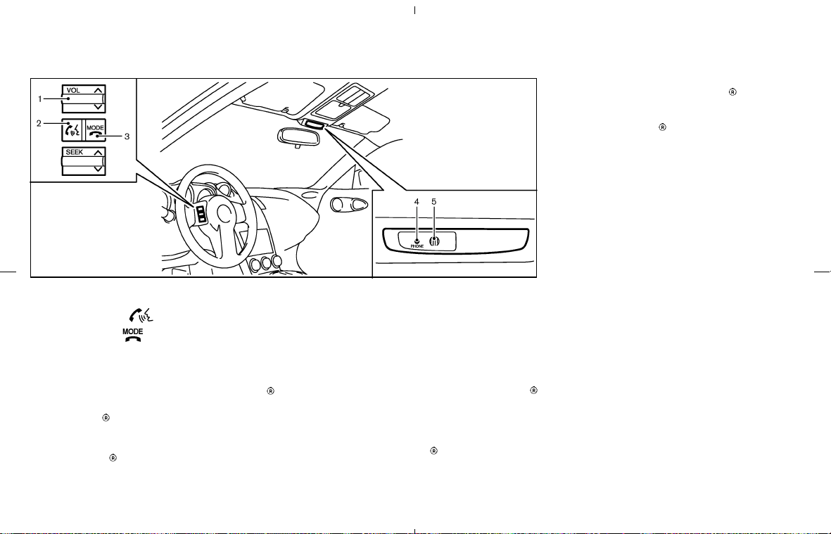
1. Volume control switch −/+
2. PHONE SEND
button
3. PHONE END
button
4. Indicator light
5. Microphone
Your vehicle is equipped with the Bluetooth
Hands-Free Phone System. If you are an owner
of a Bluetooth
enabled cellular phone, you can
set up the wireless connection between your
cellular phone and the in-vehicle phone module.
With Bluetooth
wireless technology, you can
make or receive a hands-free telephone call with
your cellular phone in the vehicle.
Once your cellular phone is paired to the in-
vehicle phone module, no other phone connect-
ing procedure is required. Your phone is auto-
matically connected with the in-vehicle phone
module when the ignition switch is turned to the
ON position with the paired cellular phone
turned on and carried in the vehicle.
You can register up to 5 different Bluetooth
cellular phones to the in-vehicle phone module.
However, you can talk on only one cellular phone
at a time.
Before using the Bluetooth
Hands-Free Phone
System, refer to the following notes.
쐌 Set up the wireless connection between a
cellular phone and the in-vehicle phone mod-
ule before using the Bluetooth
Hands-Free
Phone System.
쐌 Some Bluetooth
enabled cellular phones
may not be recognized by the in-vehicle
phone module. Please visit
www.nissanusa.com/bluetooth for a recom-
mended phone list.
쐌 You will not be able to use a hands-free
phone under the following conditions:
— Your vehicle is outside of the telephone
service area.
— Your vehicle is in an area where it is
difficult to receive radio waves; such as in
a tunnel, in an underground parking ga-
rage, near a tall building or in a mountain-
ous area.
— Your cellular phone is locked to prevent it
from being dialed.
When the radio wave condition is not ideal or
ambient sound is too loud, it may be difficult to
hear the other person’s voice during a call.
Do not place the cellular phone in an area
surrounded by metal or far away from the in-
vehicle phone module to prevent tone quality
degradation and wireless connection disruption.
While a cellular phone is connected through the
SAA1699
4-32 Display screen, heater, air conditioner and audio systems
墌 08.7.24/Z33-D/V5.0 墍

Bluetooth
wireless connection, the battery
power of the cellular phone may discharge
quicker than usual.
If the Bluetooth
Hands-Free Phone System
seems to be malfunctioning, see “Troubleshoot-
ing guide” later in this section. You can also visit
www.nissanusa.com/bluetooth for troubleshoot-
ing help.
Some cellular phones or other devices may
cause interference or a buzzing noise to come
from the audio system speakers. Storing the
device in a different location may reduce or
eliminate the noise.
Refer to the cellular phone Owner’s Manual
regarding the telephone charges, cellular phone
antenna and body, etc.
This device complies with Part 15 of the
FCC Rules. Operation is subject to the
following two conditions: (1) this device
may not cause harmful interference, and
(2) this device must accept any interference
received, including interference that may
cause undesired operation.
FCC Radiation Exposure Statement:
This equipment complies with FCC radiation
exposure limits set forth for an uncontrolled
environment. This equipment should be installed
and operated with minimum distance 8 in (20
cm) between the radiator and your body. This
Transmitter must not be co-located or operating
in conjunction with any other antenna or trans-
mitter.
USING THE SYSTEM
The NISSAN Voice Recognition system allows
hands-free operation of the Bluetooth
Hands-
Free Phone System.
If the vehicle is in motion, some commands may
not be available so full attention may be given to
vehicle operation.
Initialization
When the ignition switch is turned to the ON
position, NISSAN Voice Recognition is initial-
ized, which takes a few seconds. When com-
pleted, the amber light on the overhead console
illuminates and the system is ready to accept
voice commands. If the
button is pushed
before the initialization completes, the system
will announce “Hands-free phone system not
ready” and will not react to voice commands.
Operating tips
To get the best performance out of the NISSAN
Voice Recognition system, observe the follow-
ing:
쐌 Keep the interior of the vehicle as quiet as
possible. Close the windows to eliminate
surrounding noises (traffic noises, vibration
sounds, etc.), which may prevent the system
from recognizing voice commands correctly.
쐌
Wait until the tone sounds before speaking a
command. Otherwise, the command will not be
received properly.
쐌 Start speaking a command within 5 seconds
after the tone sounds.
쐌 Speak in a natural voice without pausing
between words.
Giving voice commands
To operate NISSAN Voice Recognition, push
and release the
button located on the
steering wheel. The light on the overhead con-
sole flashes to signal you have entered a voice
recognition (VR) session. After the tone sounds,
speak a command.
The command given is picked up by the micro-
phone, and voice feedback is given when the
command is accepted.
쐌 If you need to hear the available commands
for the current menu again, say “Help” and
the system will repeat them.
쐌 If a command is not recognized, the system
announces, “Command not recognized.
Display screen, heater, air conditioner and audio systems 4-33
墌 08.7.24/Z33-D/V5.0 墍

Please try again.” Repeat the command in a
clear voice.
쐌 If you want to go back to the previous
command, you can say “Go back” or “Cor-
rection” anytime the system is waiting for a
response.
쐌 You can cancel a command when the system
is waiting for a response by saying, “Cancel”
or “Quit.” The system announces “Cancel”
and ends the VR session. You can also push
the
button on the steering wheel at any
time. Whenever the VR session is cancelled,
a double beep is played to indicate you have
exited the system.
쐌 If you want to adjust the volume of the voice
feedback, push the volume control switch (+
or −) on the steering wheel while being
provided with feedback. You can also use the
radio volume control knob.
How to say numbers
NISSAN Voice Recognition requires a certain
way to speak numbers in voice commands. Refer
to the rules and examples below.
쐌 Either “zero” or “oh” can be used for “0”.
Example: 1-800-662-6200
— “One eight oh oh six six two six two oh
oh”, or
— “One eight zero zero six six two six two oh
oh”
쐌 Words can be used for the first 4 digits
places only.
Example: 1-800-662-6200
— “One eight hundred six six two six two oh
oh”,
— NOT “One eight hundred six six two sixty
two hundred, and
— NOT “One eight oh oh six six two sixty two
hundred.
쐌 Numbers can be spoken in small groups. The
system will prompt you to continuing entering
digits, if desired.
Example: 1-800-662-6200
— “One eight oh oh”
The system repeats the numbers and
prompts you to enter more.
— “six six two”
The system repeats the numbers and
prompts you to enter more.
— “six two oh oh”
쐌 You can say “Star” for * and “Pound” for # at
anytime in any position of the phone number.
(Available only when using the “Call Interna-
tional” command.)
Example: 1-555-1212 *123
— “One five five five one two one two star
one two three”
NOTE:
For best results, say phone numbers as
single digits.
4-34 Display screen, heater, air conditioner and audio systems
墌 08.7.24/Z33-D/V5.0 墍
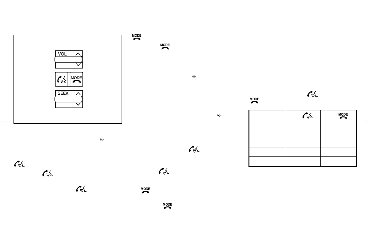
CONTROL BUTTONS
The control buttons for the Bluetooth Hands-
Free Phone System are located on the steering
wheel.
TALK/PHONE SEND
Push the
button to initiate a VR session
or answer an incoming call.
You can also use the
button to skip
through system feedback and to enter com-
mands during a call. See “List of voice com-
mands” and “During a call” later in this sec-
tion for more information.
MODE/PHONE END
Push the
button to cancel a VR session
or end a call.
GETTING STARTED
The following procedures will help you get
started using the Bluetooth
Hands-Free Phone
System with NISSAN Voice Recognition. For
additional command options, refer to “List of
voice commands” later in this section.
Choosing a language
You can interact with the Bluetooth Hands-
Free Phone System using English, Spanish or
French.
To change the language, perform the following.
1. Press and hold the
button for more
than 5 seconds.
2. The system announces: “Press the PHONE
SEND (
) button for the hands-free
phone system to enter the speaker adapta-
tion mode or press the PHONE END
(
) button to select a different lan-
guage.”
3. Press the
button.
For information on speaker adaptation, see
“Speaker adaptation (SA) mode” later in this
section.
4. The system announces the current language
and gives you the option to change the
language to Spanish (in Spanish) or French
(in French). Use the following chart to select
the language.
NOTE:
You must press the
button or the
button within 5 seconds to change
the language.
Current
language
Press
(TALK/PHONE
SEND)
to select
Press
(MODE/PHONE
END)
to select
English Spanish French
Spanish English French
French English Spanish
5. If you decide not to change the language, do
not press either button. After 5 seconds, the
VR session will end, and the language will not
be changed.
SAA1700
Display screen, heater, air conditioner and audio systems 4-35
墌 08.7.24/Z33-D/V5.0 墍
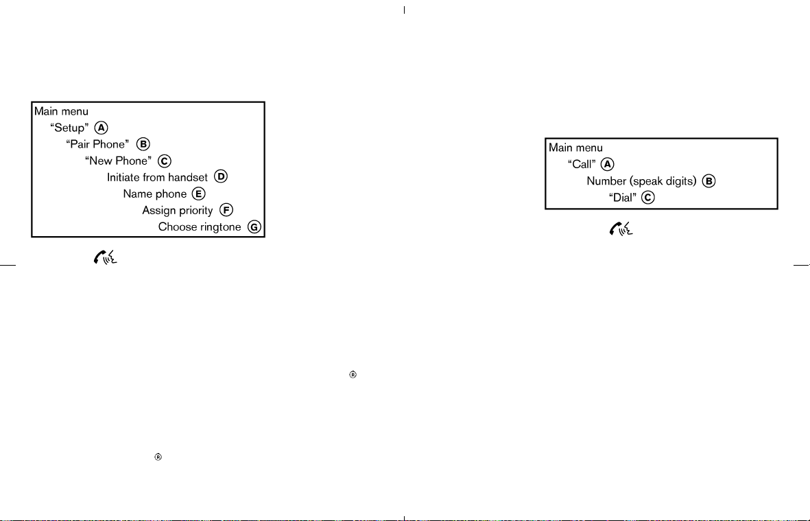
Pairing procedure
1. Push the button on the steering wheel.
The system announces the available com-
mands.
2. Say: “Setup”
쎻
A
. The system acknowledges
the command and announces the next set of
available commands.
3. Say: “Pair phone”
쎻
B
. The system acknowl-
edges the command and announces the next
set of available commands.
4. Say: “New phone”
쎻
C
. The system acknowl-
edges the command and asks you to initiate
pairing from the phone handset
쎻
D
.
When you are asked to enter a PIN code for
pairing your Bluetooth
cellular phone, oper-
ate it to enter the code “1234”.
The code is always “1234” regardless of the
number of phones paired.
The pairing procedure of the cellular phone
varies according to each cellular phone. See
the cellular phone Owner’s Manual for de-
tails. You can also visit www.nissanusa.com/
bluetooth for instructions on pairing NISSAN
recommended cellular phones.
5. The system asks you to say a name for the
phone
쎻
E
.
If the name is too long or too short, the
system tells you, then prompts you for a name
again.
Also, if more than one phone is paired and
the name sounds too much like a name
already used, the system tells you, then
prompts you for a name again.
6. The system asks you to assign a priority level
쎻
F
. The priority level determines which phone
is active when more than one paired
Bluetooth
phone is in the vehicle. Follow the
instructions provided by the system or refer
to “Setup” later in this section for more
information on changing priorities.
7. The system will ask if you would like to select
a custom ring tone
쎻
G
. Follow the instruc-
tions provided by the system or refer to
“Setup” later in this section for more informa-
tion on selecting ringtones.
Making a call by entering a phone
number
1. Push the button on steering wheel. A
tone will sound.
2. Say: “Call”
쎻
A
. The system acknowledges
the command and announces the next set of
available commands.
3. Say the number you wish to call
쎻
B
. For
example, 555-1212 can be said as “five five
five one two one two.” See “How to say
numbers” earlier in this section for more
information.
Say: “Call International” to dial more than 10
digits or any special characters.
4. When you have finished speaking the phone
number, the system repeats it back and
announces the available commands.
5. Say: “Dial”
쎻
C
. The system acknowledges the
command and makes the call.
4-36 Display screen, heater, air conditioner and audio systems
墌 08.7.24/Z33-D/V5.0 墍

For additional command options, see “List of
voice commands” later in this section.
Receiving a call
When you hear the ring tone, press the
button on the steering wheel.
Once the call has ended, press the
button
on the steering wheel.
NOTE:
If you do not wish to take the call when you
hear the ring tone, press the
button
on the steering wheel to reject the call.
For additional command options, see “List of
voice commands” later in this section.
LIST OF VOICE COMMANDS
When you push and release the button on
the steering wheel, you can choose from the
commands on the Main Menu. The following
pages describe these commands and the com-
mands in each sub-menu.
Remember to wait for the tone before
speaking.
You can say “Help” to hear the list of commands
currently available anytime the system is waiting
for a response.
If you want to end an action without completing
it, you can say “Cancel” or “Quit” at anytime the
system is waiting for a response. The system will
end the VR session. Whenever the VR session is
cancelled, a double beep is played to indicate
you have exited the system.
If you want to go back to the previous command,
you can say “Go back” or “Correction” anytime
the system is waiting for a response.
When you get used to the menus in the system,
you can talk ahead by saying more than one
command at a time. For example, say, “Call five
five five one two one two” or “Memo pad record.”
Also, when you get used to the system re-
sponses, you can skip ahead to the tone by
pressing the
button on the steering wheel.
However, if you press the
button when the
system is waiting for a response from you it will
end the VR session.
“Call”
Name (speak name) 쎻
A
If you have stored entries in the Phone Book, you
can dial a number associated with a name and
location.
See “Phone book” later in this section to learn
how to store entries.
When prompted by the system, say the name of
the phone book entry you wish to call. The
system acknowledges the name.
If there are multiple locations associated with the
name, the system asks you to choose the loca-
tion.
Once you have confirmed the name and loca-
tion, the system begins the call.
Number (speak digits)
쎻
B
When prompted by the system, say the number
Display screen, heater, air conditioner and audio systems 4-37
墌 08.7.24/Z33-D/V5.0 墍
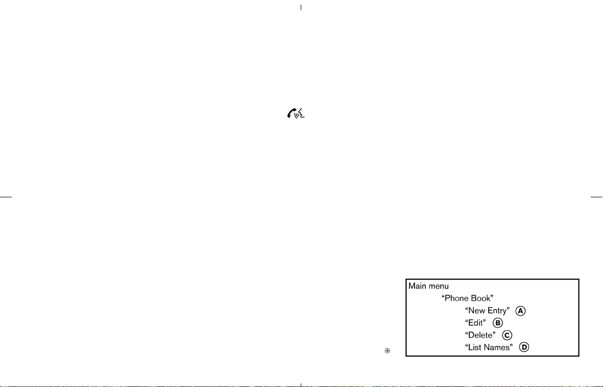
you wish to call. Refer to “How to say numbers”
and “Making a call by entering a phone number”
earlier in this section for more details.
“International”
쎻
C
For dialing more than 10 digits or any special
characters, say “International”. When the system
acknowledges the command, the system will
prompt you to speak the number.
“Redial”
쎻
D
Use the Redial command to call the last number
that was dialed within the vehicle.
NOTE:
The system will not redial the last number
dialed by the handset keypad.
The system acknowledges the command, re-
peats the number and begins dialing.
If a redial number does not exist, the system
announces, “There is no number to redial” and
ends the VR session.
“Call back”
쎻
E
Use the Call Back command to dial the number
of the last incoming call within the vehicle.
The system acknowledges the command, re-
peats the number and begins dialing. If a call
back number does not exist, the system an-
nounces, “There is no number to call back” and
ends the VR session.
During a call
During a call there are several command options
available. Press the
button on the steering
wheel to mute the receiving voice and enter
commands.
쐌 “Help” — The system announces the avail-
able commands.
쐌 “Go back/Correction” — The system an-
nounces “Go back,” ends the VR session and
returns to the call.
쐌 “Cancel/Quit” — The system announces
“Cancel,” ends the VR session and returns to
the call.
쐌 “Send/Enter/Call/Dial” — Use the Send com-
mand to enter numbers during a call. For
example, if you were directed to dial an
extension by an automated system:
Say: “Send one two three four.”
The system acknowledges the command and
sends the tones associated with the num-
bers. The system then ends the VR session
and returns to the call.
쐌 “Transfer call” — Use the Transfer Call com-
mand to transfer the call from the Bluetooth
Hands-Free Phone System to the cellular
phone when privacy is desired.
The system announces, “Transfer call. Call
transferred to privacy mode.” The system
then ends the VR session.
You can also issue the Transfer Call com-
mand again to return to a hands-free call
through the vehicle.
쐌 “Mute” — Use the Mute command to mute
your voice so the other party cannot hear it.
Use the mute command again to unmute your
voice.
NOTE:
If the other party ends the call or the
cellular phone network connection is lost
while the Mute feature is on, the Mute
feature may need to be reset to “off.”
“Phone book”
4-38 Display screen, heater, air conditioner and audio systems
墌 08.7.24/Z33-D/V5.0 墍

The Phone Book stores up to 40 names for each
phone paired with the system. Each name can
have up to 4 locations/phone numbers associated
with it.
NOTE:
Each phone has its own separate phone
book. You cannot access Phone A’s phone
book if you are currently connected with
Phone B.
“New entry”
쎻
A
Use the New Entry command to store a new
name in the system.
When prompted by the system, say the name
you would like to give the new entry.
For example, say: “Mary.”
If the name is too long or too short, the system
tells you, then prompts you for a name again.
Also, if the name sounds too much like a name
already stored, the system tells you, then
prompts you for a name again.
Once the system accepts the name and you
confirm it is correct, the system asks for a
location (Home, Office, Mobile or Other).
For example, say: “Home.”
The system acknowledges the location. The
system will ask you to say a phone number or to
transfer a phone number stored in the cellular
phone’s memory.
To enter a phone number by voice command:
For example, say: “five five five one two one
two.” See “How to say numbers” earlier in
this section for more information.
To transfer a phone number stored in the cellular
phone’s memory (if so equipped):
Say: “Transfer entry.”
The system acknowledges the command and
asks you to initiate the transfer from the phone
handset. The new contact phone number will be
transferred from the cellular phone via the
Bluetooth
communication link.
The transfer procedure varies according to each
cellular phone. See the cellular phone Owner’s
Manual for details. You can also visit
www.nissanusa.com/bluetooth for instructions
on transferring phone numbers from NISSAN
recommended cellular phones.
The system repeats the number and prompts
you for the next command. When you have
finished entering numbers, choose “Store.”
The system confirms the name, location and
number. The system then asks if you would like
to store another location for the same name. If
you do not wish to store another location, the
system ends the VR session.
“Edit”
쎻
B
Use the Edit command to alter an existing phone
book entry or to add a 2nd, 3rd or 4th phone
number to an existing entry.
When prompted by the system, say the name of
the entry you wish to edit.
The system acknowledges the name and asks
you for the location you would like to edit.
Say the name of the location. The system ac-
knowledges the location. The system will ask you
to say a phone number or to transfer a phone
number stored in the cellular phone’s memory.
To enter a phone number by voice command:
For example, say: “five five five one two one
two.” See “How to say numbers” earlier in
this section for more information.
To transfer a phone number stored in the cellular
phone’s memory (if so equipped):
Say: “Transfer entry.”
The system acknowledges the command and
asks you to initiate the transfer from the phone
handset. The new contact phone number will be
transferred from the cellular phone via the
Bluetooth
communication link.
Display screen, heater, air conditioner and audio systems 4-39
墌 08.7.24/Z33-D/V5.0 墍
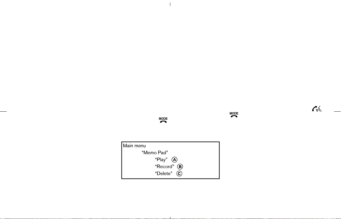
The transfer procedure varies according to each
cellular phone. See the cellular phone Owner’s
Manual for details. You can also visit
www.nissanusa.com/bluetooth for instructions
on transferring phone numbers from NISSAN
recommended cellular phones.
The system repeats the number and prompts
you for the next command. When you have
finished entering numbers, choose “Store.”
The system confirms the name, location and
number, then announces that the entry has been
stored. The system then ends the VR session.
“Delete”
쎻
C
Use the Delete command to erase one entry
from the phone book, all entries from the phone
book, the current redial number or the current
call back number.
To delete entries from the phone book, say a
name or “All entries” when prompted by the
system.
The system acknowledges the command and
asks you to confirm the deletion.
To delete the current redial number or call back
number, say “redial number” or “call back num-
ber” when prompted by the system.
If a redial number or a call back number exists,
the system deletes them without asking for
confirmation.
If there is no number for the entry you are trying
to delete, the system says so and ends the VR
session.
“List names”
쎻
D
Use the List Names command to hear all the
names and locations in the phone book.
The system recites the phone book entries but
does not include the actual phone numbers.
When the playback of the list is complete, the
system returns to the main menu.
You can stop the playback of the list at any time
by pressing the
button on the steering
wheel. The system ends the VR session.
“Memo pad”
The Memo Pad records a maximum of 6 voice
memos, each up to 20 seconds long.
“Play”
쎻
A
The system plays back all the memos in the
order of newest to oldest. The system ends the
VR session.
If there are no memos recorded, the system
announces “No messages to play.” The system
ends the VR session.
“Record”
쎻
B
The system announces “Recording” and a tone
sounds signaling you to begin.
Speak the information you wish to record clearly.
When you are done, press the
or
button on the steering wheel.
A tone sounds and the system announces
“Memo recorded.” Another tone sounds to end
the VR session.
If the memo pad is full, the system asks if you
wish to record over the oldest memo.
“Delete”
쎻
C
The Delete command erases all memos. The
system asks you to confirm this action before
deleting all memos.
4-40 Display screen, heater, air conditioner and audio systems
墌 08.7.24/Z33-D/V5.0 墍
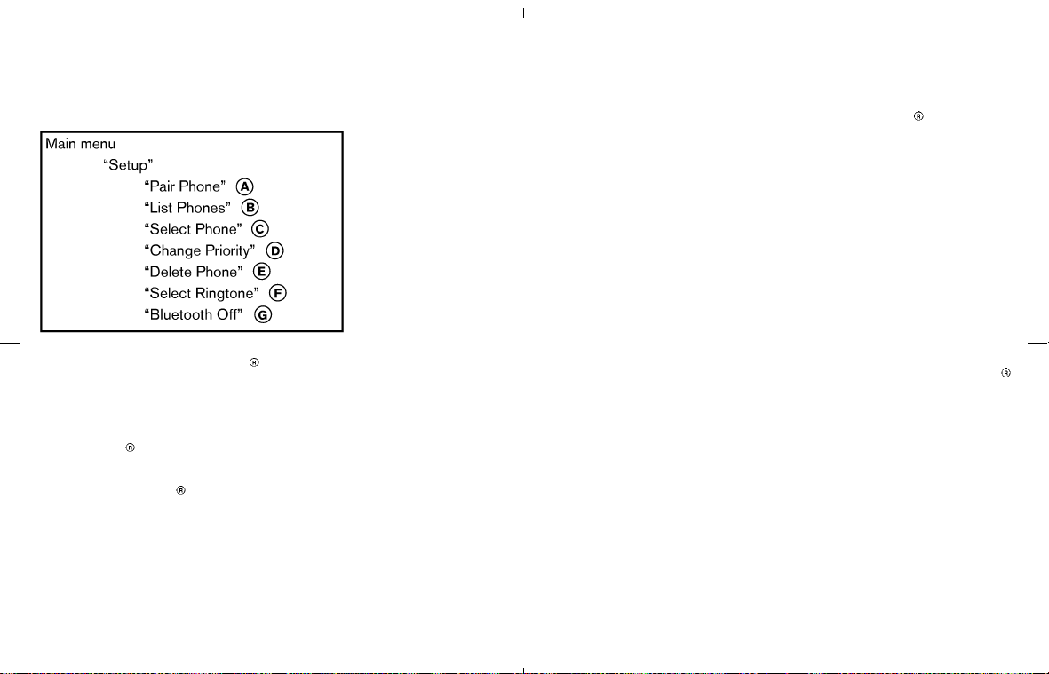
“Setup”
Use the Setup command to change options
associated with the Bluetooth
Hands-Free
Phone System.
“Pair phone”
쎻
A
Use the Pair Phone command to pair a phone to
the Bluetooth
Hands-Free Phone System.
When you are asked to enter a PIN code for
pairing your Bluetooth
cellular phone, operate it
to enter the code “1234”.
The code is always “1234” regardless of the
number of phones paired.
Up to 5 phones can be paired. If you try to pair
a sixth phone, the system announces that you
must first delete one phone or replace an exist-
ing phone.
If you try to pair a phone that has already been
paired to your vehicle’s system, the system
announces the name the phone is already using.
The pairing procedure will then be cancelled.
When prompted by the system, choose from the
following commands:
쐌 “New phone” — Refer to “Pairing a phone”
earlier in this section.
쐌 “Replace phone” — The system announces
the names of the phones already paired and
asks which you would like to replace.
Once you say the name of the phone you
wish to replace, the paring procedure will
begin. Refer to “Pairing procedure” earlier in
this section.
쐌 “List phones” — See the description below.
“List phones”
쎻
B
Use the List Phones command to hear the
names of the phones currently paired. If no
phones are paired, the system announces, “No
paired phones to list.” The system then ends the
VR session.
“Select phone”
쎻
C
Use the Select Phone command to select a
phone of lesser priority when two or more
phones paired with Bluetooth
Hands-Free
Phone System are in the vehicle at the same
time.
The system asks you to name the phone and
confirm the selection.
Once the selection is confirmed, the selected
phone remains active until the ignition switch is
turned OFF or you select a new phone.
“Change priority”
쎻
D
Use the Change Priority command to change the
priority level of the active phone.
The priority level determines which phone is
active when more than one paired Bluetooth
phone is in the vehicle.
The system states the priority level of the active
phone and asks for a new priority level (1, 2, 3,
4, 5).
If the new priority level is already being used for
another phone, the two phones will swap priority
levels.
For example, if the current priority levels are:
Priority Level 1 = Phone A
Priority Level 2 = Phone B
Priority Level 3 = Phone C
Display screen, heater, air conditioner and audio systems 4-41
墌 08.7.24/Z33-D/V5.0 墍

and you change the priority level of Phone C to
Level 1, then:
Priority Level 1 = Phone C
Priority Level 2 = Phone B
Priority Level 3 = Phone A
“Delete phone”
쎻
E
Use the Delete Phone command to delete a
specific phone or all phones from the Bluetooth
Hands-Free Phone System.
The system announces the names of the phones
already paired with the system and their priority
level. The system then gives you the option to
delete a specific phone, all phones or listen to the
list again.
Once you chose to delete a phone or all phones,
the system asks you to confirm this action.
NOTE:
When you delete a phone, the associated
phone book for that phone will also be
deleted.
“Select ringtone”
쎻
F
Use the Select Ringtone command to select the
tone heard in the vehicle when an incoming call
is received.
The system announces the name of the active
phone and asks you to choose from the follow-
ing commands:
쐌 “Ringtone” — The system plays a ringtone
and asks if you would like to select that tone.
If you say no, the system plays the next
ringtone available and continues to cycle
through the ringtones until you select one or
quit.
쐌 “Silent” — The system asks you to confirm
your wish to disable the ringtone.
“Bluetooth off”
쎻
G
Use the Bluetooth Off command to turn off the
Bluetooth
Hands-Free Phone System.
When Bluetooth
Hands-Free Phone System is
off, you will not be able to make or receive calls
using NISSAN Voice Recognition. Also, you will
not have access to the Phone Book.
You can still use the Memo Pad and access
Setup.
To turn on the system again, choose the Blue-
tooth On command from the Setup command.
SPEAKER ADAPTATION (SA) MODE
Speaker Adaptation allows up to two out-of dia-
lect users to train the system to improve recogni-
tion accuracy. By repeating a number of com-
mands, the users can create a voice model of their
own voice that is stored in the system. The system
is capable of storing a different speaker adapta-
tion model for memory A and memory B.
If memory A is available, the system will use
memory A to store the model. If memory A is in
use and memory B is available, the system will
use memory B to store the model. If both of the
memory locations are in use, the system will ask
the user to select which memory location should
be overwritten.
Training procedure
The procedure for training a voice is as follows.
1. Position the vehicle in a reasonably quiet
outdoor location.
2. Sit in the driver’s seat with the engine run-
ning, the parking brake on, and the transmis-
sion in Park.
3. Press and hold the
button for more
than 5 seconds.
4. The system announces: “Press the PHONE
SEND (
) button for the hands-free
phone system to enter the speaker adapta-
tion mode or press the PHONE END
(
) button to select a different lan-
guage.”
5. Press the
button.
4-42 Display screen, heater, air conditioner and audio systems
墌 08.7.24/Z33-D/V5.0 墍

For information on selecting a different lan-
guage, see “Choosing a language” earlier in
this section.
6. Voice memory A or memory B is selected
automatically. If both memory locations are
already in use, the system will prompt you to
overwrite one. Follow the instructions pro-
vided by the system.
7. When preparation is complete and you are
ready to begin, press the
button.
8. The SA mode will be explained. Follow the
instructions provided by the system.
9. When training is finished, the system will tell
you an adequate number of phrases have
been recorded.
10.The system will ask you to say your name.
Follow the instructions to register your name.
11.The system will announce that speaker adap-
tation has been completed and the system is
ready.
The SA mode will stop if:
쐌 The
button is pressed for more than 5
seconds in SA mode.
쐌 The vehicle is driven during SA mode.
쐌 The ignition switch is turned to the OFF or
LOCK position.
Training phrases
During the SA mode, the system instructs you to
say the following phrases.
(The system will prompt you for each phrase.)
쐌 phone book new entry
쐌 dial three oh four two nine
쐌 delete call back number
쐌 setup pair phone
쐌 memo pad play
쐌 eight pause nine three two pause seven
쐌 delete all entries
쐌 call seven two four zero nine
쐌 phone book delete entry
쐌 memo pad record
쐌 dial star two one seven oh
쐌 Yes
쐌 No
쐌 select ring tone
쐌 dial eight five six nine two
쐌 Bluetooth on
쐌 setup change priority
쐌 call three one nine oh two
쐌 nine seven pause pause three oh eight
쐌 Cancel
쐌 call back number
쐌 call star two zero nine five
쐌 delete phone
쐌 dial eight three zero five one
쐌 Home
쐌 four three pause two nine pause zero
쐌 delete redial number
쐌 phone book list names
쐌 call eight oh five four one
쐌 Correction
쐌 setup change ring tone
쐌 dial seven four oh one eight
쐌 setup main menu
쐌 Delete
쐌 dial nine seven two six six
쐌 memo pad delete
쐌 call seven six three oh one
쐌 go back
Display screen, heater, air conditioner and audio systems 4-43
墌 08.7.24/Z33-D/V5.0 墍

쐌 call five six two eight zero
쐌 dial six six four three seven
4-44 Display screen, heater, air conditioner and audio systems
墌 08.7.24/Z33-D/V5.0 墍

TROUBLESHOOTING GUIDE
The system should respond correctly to all voice commands without difficulty. If problems are encountered, try the following solutions.
Where the solutions are listed by number, try each solution in turn, starting with number 1, until the problem is resolved.
Symptom Solution
System fails to interpret the command correctly.
1. Ensure that the command is valid. See “List of voice commands” earlier in this section.
2. Ensure that the command is spoken after the tone.
3. Speak clearly without pausing between words and at a level appropriate to the ambient noise level in the vehicle.
4. Ensure that the ambient noise level is not excessive (for example, windows open or defroster on). NOTE: If it is
too noisy to use the phone, it is likely that the voice commands will not be recognized.
5. If more than one command was said at a time, try saying the commands separately.
6. If the system consistently fails to recognize commands, the voice training procedure should be carried out to im-
prove the recognition response for the speaker. See “Speaker adaptation (SA) mode” earlier in this section.
The system consistently selects the wrong entry
from the phone book.
1. Ensure that the phone book entry name requested matches what was originally stored. This can be confirmed by
using the “List Names” command. See “Phone book” earlier in this section.
2. Replace one of the names being confused with a new name.
Display screen, heater, air conditioner and audio systems 4-45
墌 08.7.24/Z33-D/V5.0 墍

MEMO
4-46 Display screen, heater, air conditioner and audio systems
墌 08.7.24/Z33-D/V5.0 墍

5 Starting and driving
Precautions when starting and driving ............................ 5-2
Exhaust gas (Carbon monoxide) ................................. 5-2
Three-way catalyst .......................................................... 5-3
Tire pressure monitoring system (TPMS) ................. 5-3
Avoiding collision and rollover ..................................... 5-5
Drinking alcohol/drugs and driving ............................ 5-6
Ignition switch ....................................................................... 5-6
Automatic transmission ................................................. 5-7
Manual transmission ....................................................... 5-7
Key positions ................................................................... 5-8
NISSAN Vehicle Immobilizer System ........................ 5-8
Before starting the engine ................................................. 5-9
Starting the engine ............................................................... 5-9
Driving the vehicle ............................................................. 5-10
Automatic transmission ............................................... 5-10
Manual transmission .................................................... 5-13
Parking brake ...................................................................... 5-15
Cruise control (if so equipped) ...................................... 5-16
Precautions on cruise control ................................... 5-16
Cruise control operations ........................................... 5-17
Break-in schedule .............................................................. 5-18
Increasing fuel economy .................................................. 5-18
Parking/parking on hills .................................................... 5-19
Power steering .................................................................... 5-20
Brake system ....................................................................... 5-21
Braking precautions ..................................................... 5-21
Anti-lock Braking System (ABS) ............................... 5-21
Traction Control System (TCS) (if so equipped) ...... 5-23
Vehicle Dynamic Control (VDC) system
(if so equipped) .................................................................. 5-23
Cold weather driving ......................................................... 5-25
Freeing a frozen door lock ......................................... 5-25
Anti-freeze ...................................................................... 5-25
Battery ............................................................................. 5-25
Draining of coolant water ........................................... 5-25
Tire equipment .............................................................. 5-25
Special winter equipment .......................................... 5-25
Driving on snow or ice ................................................ 5-25
Engine block heater (if so equipped)....................... 5-26
墌 08.7.24/Z33-D/V5.0 墍

WARNING
쐌 Do not leave children or adults who
would normally require the support
of others alone in your vehicle. Pets
should not be left alone either. They
could accidentally injure themselves
or others through inadvertent opera-
tion of the vehicle. Also, on hot,
sunny days, temperatures in a closed
vehicle could quickly become high
enough to cause severe or possibly
fatal injuries to people or animals.
쐌 Properly secure all cargo to help pre-
vent it from sliding or shifting. Do not
place cargo higher than the seat-
backs. In a sudden stop or collision,
unsecured cargo could cause per-
sonal injury. (Coupe models)
쐌 Closely supervise children when they
are around cars to prevent them from
playing and becoming locked in the
trunk where they could be seriously
injured. Keep the car locked with the
trunk closed when not in use, and
prevent children’s access to car keys.
(Roadster models)
EXHAUST GAS (Carbon monoxide)
WARNING
Do not breathe exhaust gases; they con-
tain colorless and odorless carbon mon-
oxide. Carbon monoxide is dangerous.
It can cause unconsciousness or death.
쐌 If you suspect that exhaust fumes are
entering the vehicle, drive with all
windows fully open, and have the
vehicle inspected immediately.
쐌 Do not run the engine in closed
spaces such as a garage.
쐌 Do not park the vehicle with the en-
gine running for any extended length
of time.
쐌 Keep the rear hatch/trunk lid closed
while driving, otherwise exhaust
gases could be drawn into the pas-
senger compartment. If you must
drive with the rear hatch/trunk lid
open, follow these precautions:
1. Open all the windows.
2. Set the air recirculation mode OFF
and the fan control at the maxi-
mum position to circulate the air.
쐌 If electrical wiring or other cable con-
nections must pass to a trailer
through the seal on the rear
hatch/trunk lid or the body, follow
the manufacturer’s recommendation
to prevent carbon monoxide entry
into the vehicle.
쐌 If a special body, camper, or other
equipment is added for recreational
or other usage, follow the manufac-
turer’s recommendation to prevent
carbon monoxide entry into the ve-
hicle. Some recreational vehicle ap-
pliances such as stoves, refrigera-
tors, heaters, etc. may also generate
carbon monoxide.
PRECAUTIONS WHEN STARTING
AND DRIVING
5-2 Starting and driving
墌 08.7.24/Z33-D/V5.0 墍

쐌 The exhaust system and body should
be inspected by a qualified mechanic
whenever:
• The vehicle is raised for service.
• You suspect that exhaust fumes
are entering into the passenger
compartment.
• You notice a change in the sound
of the exhaust system.
• You have had an accident involv-
ing damage to the exhaust system,
underbody, or rear of the vehicle.
THREE-WAY CATALYST
The three-way catalyst is an emission control
device installed in the exhaust system. Exhaust
gases in the converter are burned at high tem-
peratures to help reduce pollutants.
WARNING
쐌 The exhaust gas and the exhaust sys-
tem are very hot. Keep people, ani-
mals or flammable materials away
from the exhaust system compo-
nents.
쐌 Do not stop or park the vehicle over
flammable materials such as dry
grass, waste paper or rags. They may
ignite and cause a fire.
CAUTION
쐌 Do not use leaded gasoline. Deposits
from leaded gasoline will seriously
reduce the three-way catalyst’s abil-
ity to help reduce exhaust pollutants.
쐌 Keep your engine tuned up. Malfunc-
tions in the ignition, fuel injection, or
electrical systems can cause overrich
fuel flow into the three-way catalyst,
causing it to overheat. Do not keep
driving if the engine misfires, or if
noticeable loss of performance or
other unusual operating conditions
are detected. Have the vehicle in-
spected promptly by a NISSAN
dealer.
쐌 Avoid driving with an extremely low
fuel level. Running out of fuel could
cause the engine to misfire, damag-
ing the three-way catalyst.
쐌 Do not race the engine while warm-
ing it up.
쐌 Do not push or tow your vehicle to
start the engine.
TIRE PRESSURE MONITORING
SYSTEM (TPMS)
Each tire, including the spare (if provided),
should be checked monthly when cold and
inflated to the inflation pressure recommended
by the vehicle manufacturer on the vehicle plac-
ard or tire inflation pressure label. (If your vehicle
has tires of a different size than the size indicated
on the vehicle placard or tire inflation pressure
label, you should determine the proper tire infla-
tion pressure for those tires.)
As an added safety feature, your vehicle has
been equipped with a Tire Pressure Monitoring
System (TPMS) that illuminates a low tire pres-
sure telltale when one or more of your tires is
significantly under-inflated. Accordingly, when
the low tire pressure telltale illuminates, you
should stop and check your tires as soon as
Starting and driving 5-3
墌 08.7.24/Z33-D/V5.0 墍

possible, and inflate them to the proper pres-
sure. Driving on a significantly under-inflated tire
causes the tire to overheat and can lead to tire
failure. Under-inflation also reduces fuel effi-
ciency and tire tread life, and may affect the
vehicle’s handling and stopping ability.
Please note that the TPMS is not a substitute for
proper tire maintenance, and it is the driver’s
responsibility to maintain correct tire pressure,
even if under-inflation has not reached the level
to trigger illumination of the TPMS low tire
pressure telltale.
Your vehicle has also been equipped with a
TPMS malfunction indicator to indicate when the
system is not operating properly. The TPMS
malfunction indicator is combined with the low
tire pressure telltale. When the system detects a
malfunction, the telltale will flash for approxi-
mately one minute and then remain continuously
illuminated. This sequence will continue upon
subsequent vehicle start-ups as long as the
malfunction exists. When the malfunction indica-
tor is illuminated, the system may not be able to
detect or signal low tire pressure as intended.
TPMS malfunctions may occur for a variety of
reasons, including the installation of replacement
or alternate tires or wheels on the vehicle that
prevent the TPMS from functioning properly.
Always check the TPMS malfunction telltale after
replacing one or more tires or wheels on your
vehicle to ensure that the replacement or alter-
nate tires and wheels allow the TPMS to con-
tinue to function properly.
Additional information
쐌 The TPMS does not monitor the tire pressure
of the spare tire.
쐌 The TPMS will activate only when the vehicle
is driven at speeds above 16 MPH (25 km/h).
Also, this system may not detect a sudden
drop in tire pressure (for example a flat tire
while driving).
쐌 The low tire pressure warning light does not
automatically turn off when the tire pressure
is adjusted. After the tire is inflated to the
recommended pressure, the vehicle must be
driven at speeds above 16 MPH (25 km/h) to
activate the TPMS and turn off the low tire
pressure warning light. Use a tire pressure
gauge to check the tire pressure.
쐌 Tire pressure rises and falls depending on the
heat caused by the vehicle’s operation and
the outside temperature. Low outside tem-
perature can lower the temperature of the air
inside the tire which can cause a lower tire
inflation pressure. This may cause the low tire
pressure warning light to illuminate. If the
warning light illuminates in low ambient tem-
perature, check the tire pressure for all four
tires.
For additional information, see “Low tire pres-
sure warning light” in the “2. Instruments and
controls” section and “Tire pressure monitoring
system (TPMS)” in the “6. In case of emergency”
section.
WARNING
쐌 If the light illuminates while driving,
avoid sudden steering maneuvers or
abrupt braking, reduce vehicle speed,
pull off the road to a safe location
and stop the vehicle as soon as pos-
sible. Driving with under-inflated
tires may permanently damage the
tires and increase the likelihood of
tire failure. Serious vehicle damage
could occur and may lead to an acci-
dent and could result in serious per-
sonal injury. Check the tire pressure
for all four tires. Adjust the tire pres-
sure to the recommended COLD tire
pressure shown on the Tire and
Loading Information label to turn the
low tire pressure warning light OFF.
If you have a flat tire, replace it with a
5-4 Starting and driving
墌 08.7.24/Z33-D/V5.0 墍

spare tire as soon as possible. (See
“Flat tire” in the “6. In case of emer-
gency” section for changing a flat
tire.)
쐌 When a spare tire is mounted or a
wheel is replaced, the TPMS will not
function and the low tire pressure
warning light will flash for approxi-
mately 1 minute. The light will remain
on after 1 minute. Contact your
NISSAN dealer as soon as possible
for tire replacement and/or system
resetting.
쐌 Replacing tires with those not origi-
nally specified by NISSAN could af-
fect the proper operation of the
TPMS.
쐌 Do not inject any tire liquid or aerosol
tire sealant into the tires, as this may
cause a malfunction of the tire pres-
sure sensors.
CAUTION
쐌 The TPMS may not function properly
when the wheels are equipped with
tire chains or the wheels are buried in
snow.
쐌 Do not place metalized film or any
metal parts (antenna, etc.) on the
windows. This may cause poor recep-
tion of the signals from the tire pres-
sure sensors, and the TPMS will not
function properly.
Some devices and transmitters may temporarily
interfere with the operation of the TPMS and
cause the low tire pressure warning light to
illuminate. Some examples are:
쐌 Facilities or electric devices using similar
radio frequencies are near the vehicle.
쐌 If a transmitter set to similar frequencies is
being used in or near the vehicle.
쐌 If a computer (or similar equipment) or a
DC/AC converter is being used in or near the
vehicle.
FCC Notice:
Changes or modifications not expressly
approved by the party responsible for com-
pliance could void the user’s authority to
operate the equipment.
This device complies with Part 15 of the
FCC Rules and RSS-210 of Industry
Canada.
Operation is subject to the following two
conditions: (1) This device may not cause
harmful interference, and (2) this device
must accept any interference received, in-
cluding interference that may cause undes-
ired operation of the device.
AVOIDING COLLISION AND
ROLLOVER
WARNING
Failure to operate this vehicle in a safe
and prudent manner may result in loss
of control or an accident.
Be alert and drive defensively at all times. Obey
all traffic regulations. Avoid excessive speed,
high speed cornering, or sudden steering ma-
neuvers, because these driving practices could
cause you to lose control of your vehicle. As
Starting and driving 5-5
墌 08.7.24/Z33-D/V5.0 墍

with any vehicle, a loss of control could
result in a collision with other vehicles or
objects, or cause the vehicle to rollover,
particularly if the loss of control causes the
vehicle to slide sideways. Be attentive at all
times, and avoid driving when tired. Never drive
when under the influence of alcohol or drugs
(including prescription or over-the-counter
drugs which may cause drowsiness). Always
wear your seat belt as outlined in the “1. Safety
— Seats, seat belts and supplemental restraint
system” section and also instruct your passen-
gers to do so.
Seat belts help reduce the risk of injury in
collisions and rollovers. In a rollover crash, an
unbelted or improperly belted person is
significantly more likely to be injured or
killed than a person properly wearing a
seat belt.
DRINKING ALCOHOL/DRUGS AND
DRIVING
WARNING
Never drive under the influence of alco-
hol or drugs. Alcohol in the bloodstream
reduces coordination, delays reaction
time and impairs judgement. Driving af-
ter drinking alcohol increases the likeli-
hood of being involved in an accident
injuring yourself and others. Addition-
ally, if you are injured in an accident,
alcohol can increase the severity of the
injury.
NISSAN is committed to safe driving. You must
not drive under the influence of alcohol. Every
year thousands of people are injured or killed in
alcohol related accidents. Although the local
laws vary on what is considered to be legally
intoxicated, the fact is that alcohol affects all
people differently and most people underesti-
mate the effects of alcohol.
Remember, drinking and driving don’t mix! And
that is true for drugs, too (over the counter,
prescription, and illegal drugs). Don’t drive if
your ability to operate your vehicle is impaired by
alcohol, drugs, or some other physical condition.
WARNING
Never remove or turn the key to the
LOCK position while driving. The steer-
ing wheel will lock. This may cause the
driver to lose control of the vehicle and
could result in serious vehicle damage
or personal injury.
IGNITION SWITCH
5-6 Starting and driving
墌 08.7.24/Z33-D/V5.0 墍
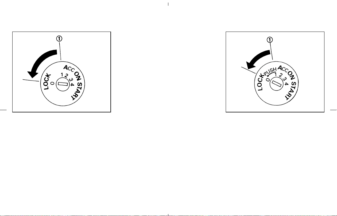
AUTOMATIC TRANSMISSION
The ignition lock is designed so the key cannot
be turned to the LOCK position and removed
until the selector lever is moved to the P (Park)
position.
When removing the key from the ignition switch,
make sure the selector lever is in the P (Park)
position.
If the selector lever is not returned to the P (Park)
position, the key cannot be moved to the LOCK
position.
When the key cannot be turned to the LOCK
position, proceed as follows to remove the key:
1. Move the selector lever into the P (Park)
position.
2. Turn the ignition key slightly toward the ON
direction.
3. Turn the key to the LOCK position.
4. Remove the key.
If the key is removed from the ignition switch, the
selector lever cannot be moved from P (Park)
position. The selector lever can be moved if
the ignition switch is in the ON position
and the foot brake pedal is depressed.
There is an OFF position
쎻
1
in between the
LOCK and ACC positions. The OFF position is
indicated by a “1” on the key cylinder. When the
ignition switch is in the OFF position, the steer-
ing wheel is not locked.
In order for the steering wheel to be locked, it
must be turned about 1/6 of a turn counterclock-
wise from the straight up position.
To lock the steering wheel, turn the key to
the LOCK position. Remove the key. To
unlock the steering wheel, insert the key
and turn it gently while rotating the steer-
ing wheel slightly right and left.
MANUAL TRANSMISSION
The ignition switch includes a device that helps
prevent accidental removal of the key while
driving.
The key can only be removed when the ignition
switch is in the LOCK position.
To turn the ignition switch to the LOCK position
from the ACC or ON position, turn the key to the
OFF position, push the key in, then turn the key
to the LOCK position.
There is an OFF position
쎻
1
in between the
LOCK and ACC positions. The OFF position is
indicated by a “1” on the key cylinder.
SSD0392 SSD0503
Starting and driving 5-7
墌 08.7.24/Z33-D/V5.0 墍

In order for the steering wheel to be locked, it
must be turned about 1/6 of a turn clockwise
from the straight up position.
To lock the steering wheel, turn the key to
the LOCK position. Remove the key. To
unlock the steering wheel, insert the key
and turn it gently while rotating the steer-
ing wheel slightly right and left.
KEY POSITIONS
The switch includes an anti-theft steering lock
device.
LOCK (Normal parking position) (0)
The ignition key can only be removed when the
switch is in this position.
OFF (1)
The engine can be turned off without locking the
steering wheel.
The ignition lock is designed so that the key
cannot be turned to LOCK and removed until the
selector lever is moved to the P (Park) position.
ACC (Accessories) (2)
This position activates electrical accessories
such as the radio when the engine is not running.
ON (Normal operating position) (3)
This position turns on the ignition system and the
electrical accessories.
START (4)
This position activates the starter motor, starting
the engine.
NISSAN VEHICLE IMMOBILIZER
SYSTEM
The NISSAN Vehicle Immobilizer System will not
allow the engine to start without the use of the
registered key.
If the engine fails to start using a registered key
(for example, when interference is caused by
another registered key, an automated toll road
device or automated payment device on the key
ring), restart the engine using the following
procedures:
1. Leave the ignition switch in the ON position
for approximately 5 seconds.
2. Turn the ignition switch to the OFF or LOCK
position and wait approximately 10 seconds.
3. Repeat steps 1 and 2.
4. Restart the engine while holding the device
(which may have caused the interference)
separate from the registered key.
If this procedure allows the engine to start,
NISSAN recommends placing the registered key
on a separate key ring to avoid interference from
other devices.
5-8 Starting and driving
墌 08.7.24/Z33-D/V5.0 墍

쐌 Make sure the area around the vehicle is
clear.
쐌 Maintenance items should be checked peri-
odically, for example, each time you check
engine oil.
쐌 Check that all windows and lights are clean.
쐌 Visually inspect tires for their appearance and
condition. Also check tires for proper infla-
tion.
쐌 Lock all doors.
쐌 Position seat and adjust head restraints.
쐌 Adjust inside and outside mirrors.
쐌 Fasten seat belts and ask all passengers to
do likewise.
쐌 Check the operation of warning lights when
the ignition key is turned to the ON position.
See “Warning/indicator lights and audible
reminders” in the “2. Instruments and con-
trols” section.
1. Apply the parking brake.
2. Automatic transmission:
Move the selector lever to P (Park) or N
(Neutral). (P preferred.)
The starter is designed not to operate if the
selector lever is in one of the driving posi-
tions.
Manual transmission:
Move the shift lever to N (Neutral) position,
and depress the clutch pedal to the floor
while cranking the engine.
The starter is designed not to operate unless
the clutch pedal is fully depressed.
3. Crank the engine with your foot off the
accelerator pedal by turning the ignition
key to START. Release the key when the
engine starts. If the engine starts, but fails to
run, repeat the above procedure.
쐌 If the engine is very hard to start in extremely
cold weather or when restarting, depress the
accelerator pedal a little (approximately 1/3
to the floor) and hold it then crank the engine.
Release the key and the accelerator pedal
when the engine starts.
쐌 If the engine is very hard to start because it is
flooded, depress the accelerator pedal all the
way to the floor and hold it. Crank the engine
for 5 to 6 seconds. After cranking the engine,
release the accelerator pedal. Crank the en-
gine with your foot off the accelerator
pedal by turning the ignition key to START.
Release the key when the engine starts. If the
engine starts, but fails to run, repeat the
above procedure.
CAUTION
Do not operate the starter for more than
15 seconds at a time. If the engine does
not start, turn the key off and wait 10
seconds before cranking again, other-
wise the starter could be damaged.
4. Warm-up
Allow the engine to idle for at least 30
seconds after starting. Do not race the en-
gine while warming it up. Drive at moderate
speed for a short distance first, especially in
cold weather.
In cold weather, keep the engine running for
a minimum of 2 to 3 minutes before shutting
it off. Starting and stopping the engine over a
short period of time may make the vehicle
more difficult to start.
BEFORE STARTING THE ENGINE STARTING THE ENGINE
Starting and driving 5-9
墌 08.7.24/Z33-D/V5.0 墍

AUTOMATIC TRANSMISSION
5-speed automatic transmission
The automatic transmission in your vehicle is
electronically controlled by a transmission con-
trol module to produce maximum power and
smooth operation.
Shown on the following pages are the recom-
mended operating procedures for this transmis-
sion. Follow these procedures for maximum ve-
hicle performance and driving enjoyment.
Starting the vehicle
After starting the engine, fully depress the foot
brake pedal and push the selector lever button
before shifting the selector lever to the R (Re-
verse), N (Neutral), D (Drive) or Manual shift
mode position. Be sure the vehicle is fully
stopped before shifting the selector lever.
This automatic transmission model is de-
signed so that the foot brake pedal must
be depressed before shifting from P (Park)
to any drive position while the ignition
switch is ON.
The selector lever cannot be moved out of
P (Park) position and into any of the other
gear positions if the ignition key is turned
to the LOCK, OFF or ACC position or if the
key is removed from the ignition switch.
1. Keep the foot brake pedal depressed and
push the selector lever button to shift into a
driving gear.
2. Release the parking brake and foot brake,
then gradually start the vehicle in motion.
WARNING
쐌 Do not depress the accelerator pedal
while shifting from P (Park) or N
(Neutral) to R (Reverse), D (Drive) or
manual shift mode. Always depress
the brake pedal until shifting is com-
pleted. Failure to do so could cause
you to lose control and have an acci-
dent.
쐌 Cold engine idle speed is high, so use
caution when shifting into a forward
or reverse gear before the engine has
warmed up.
쐌 On slippery roads, do not downshift.
This may cause a loss of control.
쐌 Never shift to P (Park) or R (Reverse)
while the vehicle is moving forward.
Never shift to P (Park) or D (Drive)
while vehicle is moving backward.
These could cause an accident.
CAUTION
When stopping the vehicle on an uphill
grade, do not hold the vehicle by de-
pressing the accelerator pedal. The foot
brake should be used for this purpose.
DRIVING THE VEHICLE
5-10 Starting and driving
墌 08.7.24/Z33-D/V5.0 墍
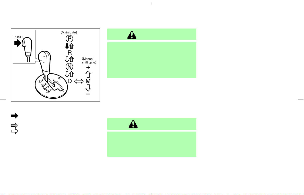
To move the selector lever,
: Push the button while depressing the
brake pedal,
: Push the button,
: Just move the selector lever.
Shifting
After starting the engine, fully depress the brake
pedal and shift the selector lever from P (Park) to
R (Reverse), N (Neutral), D (Drive), or Manual
shift mode position.
Push the button to shift into P (Park) or R
(Reverse). All other positions can be selected
without pushing the button.
WARNING
Apply the parking brake if the selector
lever is in any position while the engine
is not running. Failure to do so could
cause the vehicle to move unexpectedly
or roll away and result in serious per-
sonal injury or property damage.
If the key is turned to OFF or ACC for any reason
while the vehicle is in R (Reverse), N (Neutral), or
any D (Drive) position, the key cannot be turned
to LOCK and be removed from the ignition
switch. Move the selector lever to the P (Park)
position, then the key can be turned to LOCK.
CAUTION
To prevent automatic transmission
damage, use the P (Park) or R (Reverse)
position only when the vehicle is com-
pletely stopped.
P (Park):
Use this selector position when the vehicle is
parked or when starting the engine. Make sure
the vehicle is completely stopped. The brake
pedal must be depressed and the selector
lever button pushed in to move the selec-
tor lever from N (Neutral) or any drive
position to P (Park). Apply the parking brake.
When parking on a hill, first depress the foot
brake pedal, apply the parking brake, then shift
into the P (Park) position.
R (Reverse):
Use this position to back up. Always be sure the
vehicle is completely stopped before selecting R
(Reverse). The brake pedal must be de-
pressed and the selector lever button
pushed in to move the selector lever from
P (Park), N (Neutral) or any drive position
to R (Reverse).
N (Neutral):
Neither forward nor reverse gear is engaged.
The engine can be started in this position. You
may shift to N (Neutral) and restart a stalled
engine while the vehicle is moving.
D (Drive):
Use this position for all normal forward driving.
Manual shift mode
When the selector lever is shifted from D to the
manual shift gate with the vehicle stopped or
while driving, the transmission enters the manual
SSD0346
Starting and driving 5-11
墌 08.7.24/Z33-D/V5.0 墍

shift mode. Shift range can be selected manu-
ally.
In the manual shift mode, the shift range is
displayed on the position indicator in the meter.
Shift ranges up or down one by one as follows:
M
1
→
←
M
2
→
←
M
3
→
←
M
4
→
←
M
5
M
5 (5th):
Use this position for all normal forward driving at
highway speeds.
M
4 (4th):
Use this position when driving up long slopes, or
for engine braking when driving down long
slopes.
M
3 (3rd) and
M
2 (2nd):
Use for hill climbing or engine braking on down-
hill grades.
M
1 (1st):
Use this position when climbing steep hills
slowly or driving slowly through deep snow,
sand or mud, or for maximum engine braking on
steep downhill grades.
쐌 Remember not to drive at high speeds for
extended periods of time in lower than
M
4
range. This reduces fuel economy.
쐌 When shifting up, move the selector lever to
the + (up) side. (Shifts to higher range.)
쐌 When shifting down, move the selector lever
to the − (down) side. (Shifts to lower range.)
쐌 Moving the selector lever to the same side
twice will shift the ranges in succession.
However, if this motion is rapidly done, the
second shifting may not be completed prop-
erly.
쐌 In the manual shift mode, the transmis-
sion automatically shifts down to 1st
gear before the vehicle comes to a stop.
When accelerating again, it is necessary
to shift up to the desired range.
쐌 When canceling the manual shift mode, re-
turn the selector lever to the D position. The
transmission returns to the normal driving
mode.
쐌 In the manual shift mode, the transmis-
sion may not shift to the selected gear.
This helps maintain driving performance
and reduces the chance of vehicle dam-
age or loss of control.
Accelerator downshift
— In D position —
For passing or hill climbing, fully depress the
accelerator pedal to the floor. This shifts the
transmission down into the lower gear, depend-
ing on the vehicle speed.
Fail-safe
When fail-safe operation occurs, the automatic
transmission will be locked in 4th gear.
If the vehicle is driven under extreme con-
ditions, such as excessive wheel spinning
and subsequent hard braking, the fail-safe
system may be activated. This will occur
even if all electrical circuits are functioning
properly. In this case, turn the ignition key
OFF and wait for 3 seconds. Then turn the
key back to the ON position. The vehicle
should return to its normal operating con-
dition. If it does not return to its normal
operating condition, have a NISSAN dealer
check the transmission and repair if neces-
sary.
5-12 Starting and driving
墌 08.7.24/Z33-D/V5.0 墍
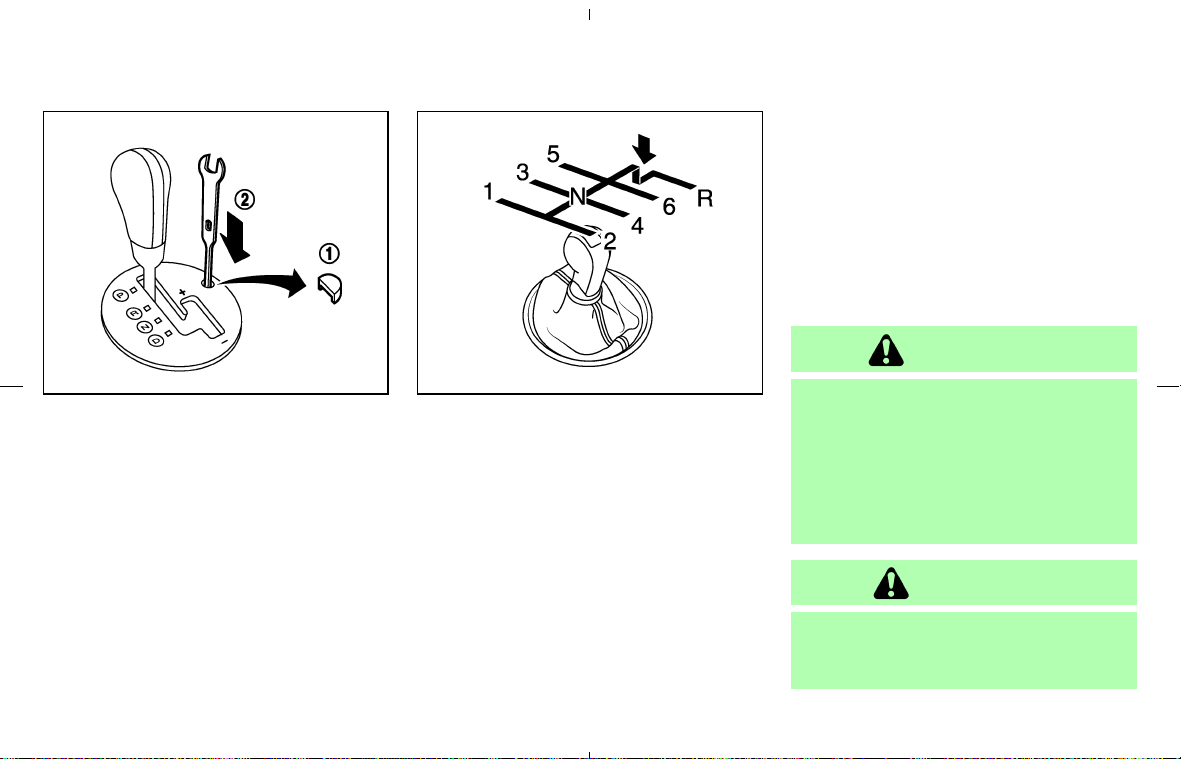
Shift lock release
If the battery charge is low or discharged, the
select lever may not be moved from the P (Park)
position even with the brake pedal depressed.
To move the selector lever, depress the brake
pedal, apply the parking brake, and push the
shift lock release button by using a suitable tool
as shown. Push the selector lever button, then
the selector lever can be moved to N (Neutral).
This allows the vehicle to be moved if the battery
is discharged.
If the lever cannot be moved out of P (Park), have
a NISSAN dealer check the automatic transmis-
sion system as soon as possible.
MANUAL TRANSMISSION
Shifting
To change gears, or when upshifting or down-
shifting, fully depress the clutch pedal, shift into
the appropriate gear then slowly and smoothly
release the clutch.
This vehicle is equipped with a short throw
shifter manual transmission. To ensure smooth
gear changes, fully depress the clutch pedal
before operating the shift lever. If the clutch
pedal is not fully depressed before the transmis-
sion is shifted, a gear noise may be heard.
Transmission damage could occur.
Start the vehicle in 1st gear and shift to 2nd, 3rd,
4th and 5th up to 6th gear in sequence accord-
ing to the vehicle speed.
To back up, depress the shift lever and then
move it to the R (Reverse) position after stop-
ping the vehicle completely.
If it is difficult to move the shift lever into R
(Reverse) or 1 (Low gear), shift to N (Neutral),
then release the clutch pedal. Fully depress the
clutch pedal again and shift into R or 1.
WARNING
쐌 Do not downshift abruptly on slip-
pery roads. This may cause a loss of
control.
쐌 Do not over-rev the engine when
shifting to a lower gear. This may
cause a loss of control or engine
damage.
CAUTION
쐌 Do not rest your foot on the clutch
pedal while driving. This may damage
the clutch.
SSD0347 SSD0536
Starting and driving 5-13
墌 08.7.24/Z33-D/V5.0 墍
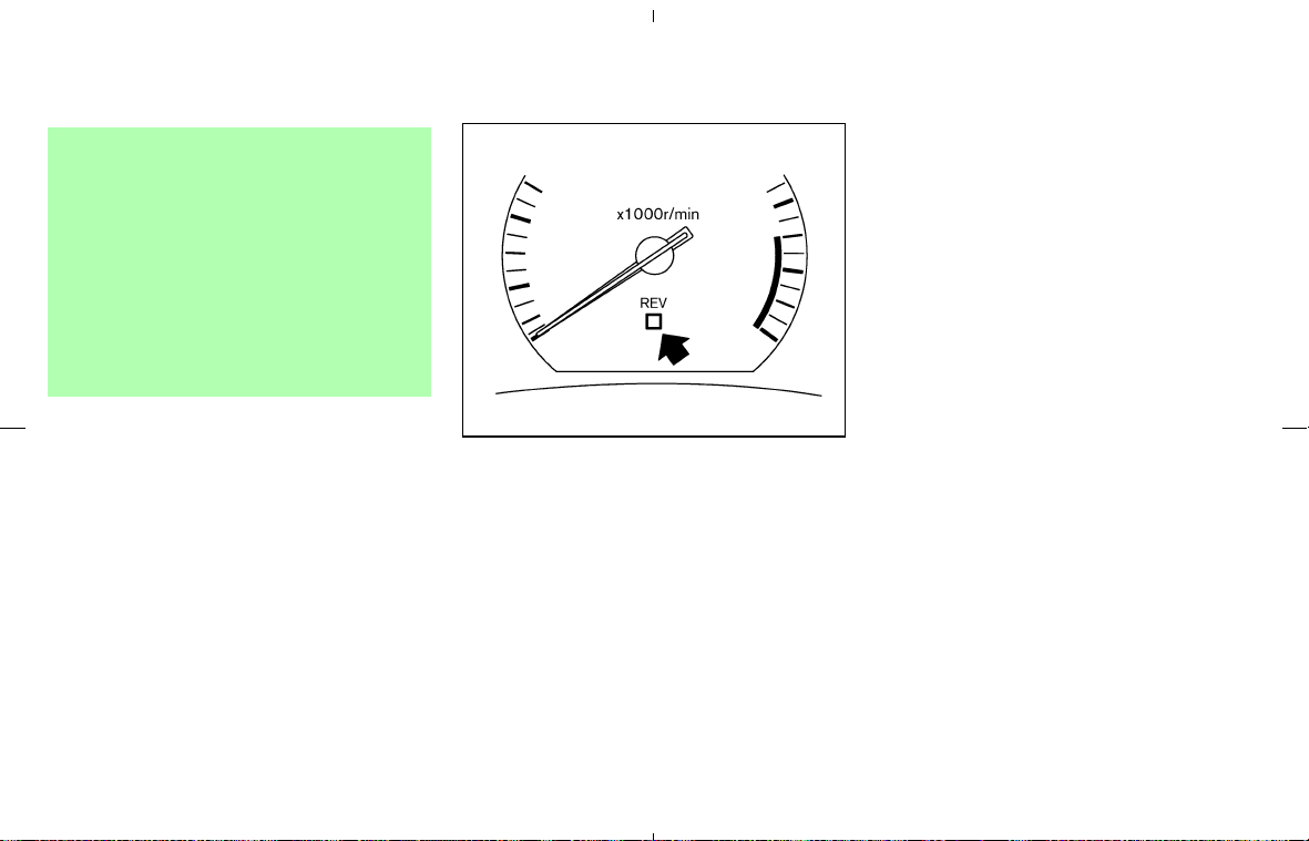
쐌 Fully depress the clutch pedal before
shifting to help prevent transmission
damage.
쐌 Stop your vehicle completely before
shifting into R (Reverse).
쐌 When the vehicle is stopped with the
engine running (for example, at a
stop light), shift to N (Neutral) and
release the clutch pedal with the foot
brake applied.
Up-shift indicator
The manual transmission up-shift indicator is
located in the tachometer and shows the driver
the timing to shift into a higher gear by illuminat-
ing. The use of the up-shift indicator will help you
to upshift at a constant engine speed (rpm) from
any gear.
The up-shift indicator will start flashing when the
engine speed is within about 500 rpm of the set
figure while driving, and then illuminate after the
engine speed reaches the set figure.
The engine speed in revolutions per minute
(rpm) for upshifting can be set on the trip
computer display. See “Trip computer” in the “2.
Instruments and controls” section for the display
setting information.
Use the up-shift indicator when driving as fol-
lows:
쐌 If the maximum engine speed is desired, set
the figure at 7,500 rpm. (The indicator starts
flashing from about 7,000 rpm and comes on
steady at 7,500 rpm.)
쐌 If the maximum engine torque is desired, set
the figure at 4,800 rpm. (The indicator starts
flashing from about 4,300 rpm and comes on
steady at 4,800 rpm.)
쐌 If you want to break in your vehicle, use of the
up-shift indicator with a rather low figure will
help you to avoid the high engine speed.
To make the up-shift indicator not come on, set
the figure at above 8,100 rpm.
There may be a slight difference between
the timing of the up-shift indicator illumi-
nation and the tachometer indication.
SSD0638
5-14 Starting and driving
墌 08.7.24/Z33-D/V5.0 墍
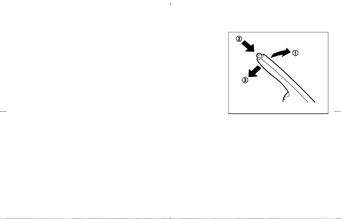
Suggested up-shift speeds
Shown below are suggested vehicle speeds for
shifting into a higher gear. These suggestions
relate to fuel economy and vehicle performance.
Actual up-shift speeds will vary according to
road conditions, the weather and individual driv-
ing habits.
For normal acceleration in low altitude areas
[less than 4,000 ft (1,219 m)]:
Gear change MPH (km/h)
1st to 2nd 8 (13)
2nd to 3rd 16 (26)
3rd to 4th 25 (40)
4th to 5th 28 (45)
5th to 6th 33 (53)
For quick acceleration in low altitude areas or in
high altitude areas [over 4,000 ft (1,219 m)]:
Gear change MPH (km/h)
1st to 2nd 15 (24)
2nd to 3rd 25 (40)
3rd to 4th 40 (64)
4th to 5th 45 (72)
5th to 6th 50 (80)
Suggested maximum speed in each
gear
Downshift to a lower gear if the engine is not
running smoothly, or if you need to accelerate.
Do not exceed the maximum suggested speed
(shown below) in any gear. For level road driving,
use the highest gear suggested for that speed.
Always observe posted speed limits, and drive
according to the road conditions, which will
ensure safe operation. Do not over-rev the en-
gine when shifting to a lower gear as it may
cause engine damage or loss of vehicle control.
Gear MPH (km/h)
1st 40 (65)
2nd 66 (106)
3rd 95 (152)
4th —
5th —
6th —
To apply: pull the parking brake lever up
쎻
1
.
To release:
1. Firmly apply the foot brake.
2. Automatic transmission models:
Move the selector lever to the P (Park) posi-
tion.
Manual transmission models:
Place the shift lever in the N (Neutral) posi-
tion.
3. While pulling up on the parking brake lever
slightly, push the button
쎻
2
and lower the
lever completely
쎻
3
.
SPA2110
PARKING BRAKE
Starting and driving 5-15
墌 08.7.24/Z33-D/V5.0 墍

4. Before driving, be sure the brake warning
light goes out.
WARNING
쐌 Be sure the parking brake is fully
released before driving. Failure to do
so can cause brake failure and lead
to an accident.
쐌 Do not release the parking brake
from outside the vehicle.
쐌 Do not use the gear shift in place of
the parking brake. When parking, be
sure the parking brake is fully en-
gaged.
쐌 Do not leave children unattended in a
vehicle. They could release the park-
ing brake and cause an accident.
WARNING
Do not use the cruise control when driv-
ing under the following conditions:
쐌 When it is not possible to keep the
vehicle at a set speed.
쐌 In heavy traffic or in traffic that varies
in speed.
쐌 On winding or hilly roads.
쐌 On slippery roads (rain, snow, ice,
etc.).
쐌 In very windy areas.
Doing so could cause a loss of vehicle
control and result in an accident.
CAUTION
On manual transmission models, do not
shift into N (Neutral) without depressing
the clutch pedal when the cruise control
is set. Should this occur, depress the
clutch pedal and turn the main switch
off immediately. Failure to do so may
cause engine damage.
PRECAUTIONS ON CRUISE
CONTROL
쐌 If the cruise control system malfunctions, it
cancels automatically. The SET indicator light
on the meter panel then blinks to warn the
driver.
쐌 If the engine coolant temperature becomes
excessively high, the cruise control system
will be canceled automatically.
쐌 If the SET indicator light blinks, turn the
cruise control MAIN (ON⋅OFF) switch off and
have the system checked by a NISSAN
dealer.
쐌 The SET indicator light may blink when the
cruise control MAIN switch is turned on while
pushing the RES/ACCEL, COAST/SET, or
CANCEL switch. To properly set the cruise
control system, perform the preceding steps
in the order indicated.
CRUISE CONTROL (if so
equipped)
5-16 Starting and driving
墌 08.7.24/Z33-D/V5.0 墍
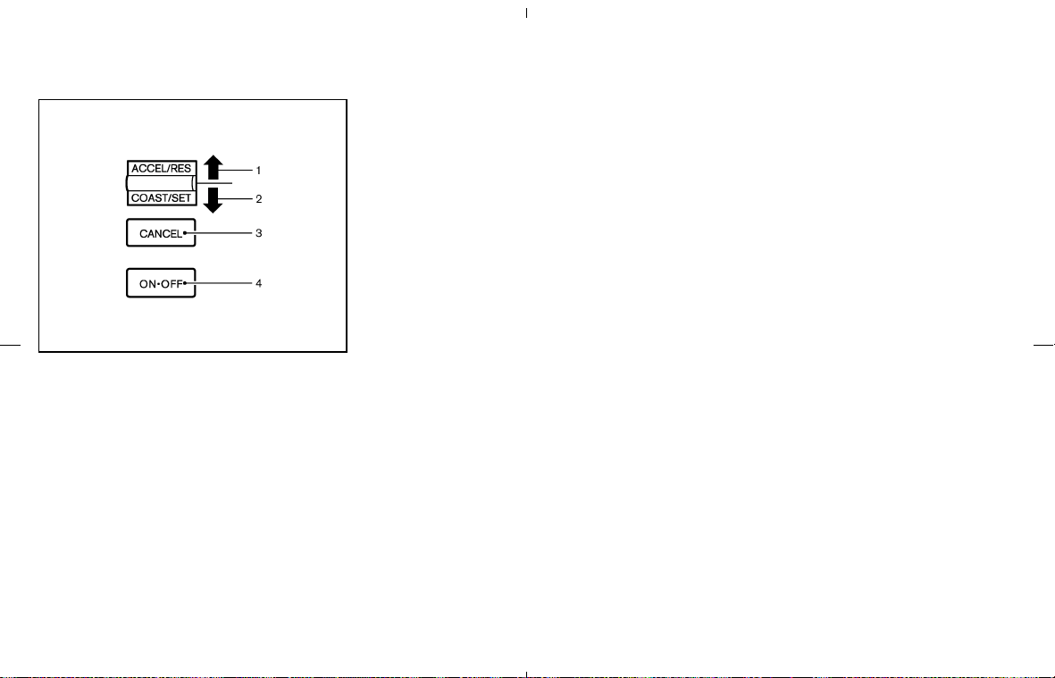
1. ACCEL or RESUME switch
2. COAST or SET switch
3. CANCEL switch
4. MAIN (ON⋅OFF) switch
CRUISE CONTROL OPERATIONS
The cruise control allows driving at a speed
between 25 to 89 MPH (40 to 144 km/h)
without keeping your foot on the accelerator
pedal.
To turn on the cruise control, push the MAIN
switch on. The CRUISE indicator light on the
meter panel will come on.
To set cruising speed, accelerate the vehicle
to the desired speed, push the COAST/SET
switch and release it. (The SET indicator light
will come on.) Take your foot off the accelerator
pedal. Your vehicle will maintain the set speed.
쐌 To pass another vehicle, depress the ac-
celerator pedal. When you release the pedal,
the vehicle will return to the previously set
speed.
쐌 The vehicle may not maintain the set speed
when going up or down steep hills. If this
happens, drive without the cruise control.
To cancel the preset speed, use one of the
following three methods:
a) Push the CANCEL switch; The SET indicator
light will go out.
b) Tap the brake pedal; The SET indicator light
will go out.
c) Turn the MAIN switch off. Both the CRUISE
indicator and SET indicator lights will go out.
쐌 If you depress the brake pedal while pushing
the ACCEL/RES set switch and reset at the
cruising speed, turn the MAIN switch off
once and then turn it on again.
쐌 The cruise control will automatically be can-
celled if the vehicle slows down more than
approximately 8 MPH (13 km/h) below the
set speed.
쐌 If you depress the clutch pedal (manual trans-
mission) or move the selector lever to N
(Neutral) position (automatic transmission),
the cruise control will be canceled.
To reset at a faster cruising speed, use one
of the following three methods:
a) Depress the accelerator pedal. When the
vehicle attains the desired speed, push and
release the COAST/SET switch.
b) Push and hold the ACCEL/RES set switch.
When the vehicle attains the speed you
desire, release the switch.
c) Push, then quickly release the ACCEL/RES
set switch. Each time you do this, the set
speed will increase by about 1 MPH (1.6
km/h).
To reset at a slower cruising speed, use one
of the following three methods:
a) Lightly tap the brake pedal. When the vehicle
attains the desired speed, push the
COAST/SET switch and release it.
b) Push and hold the COAST/SET switch. Re-
lease the switch when the vehicle slows
down to the desired speed.
SSD0528
Starting and driving 5-17
墌 08.7.24/Z33-D/V5.0 墍

c) Push, then quickly release the COAST/
SET switch. Each time you do this, the set
speed will decrease by about 1 MPH (1.6
km/h).
To resume the preset speed, push and re-
lease the ACCEL/RES set switch. The vehicle
will resume the last set cruising speed when the
vehicle speed is over 25 MPH (40 km/h).
CAUTION
During the first 1,200 miles (2,000 km),
follow these recommendations to ob-
tain maximum engine performance and
ensure the future reliability and
economy of your new vehicle. Failure to
follow these recommendations may re-
sult in shortened engine life and re-
duced engine performance.
쐌 Avoid driving for long periods at constant
speed, either fast or slow. Do not run the
engine over 4,000 rpm.
쐌 Do not accelerate at full throttle in any gear.
쐌 Avoid quick starts.
쐌 Avoid hard braking as much as possible.
쐌 Do not tow a trailer for the first 500 miles
(800 km).
쐌 Accelerate slowly and smoothly. Maintain
cruising speeds with a constant accelerator
position.
쐌 Drive at moderate speeds on the highway.
Driving at high speed will lower fuel economy.
쐌 Avoid unnecessary stopping and braking.
Maintain a safe distance behind other ve-
hicles.
쐌 Use a proper gear range which suits road
conditions. On level roads, shift into high gear
as soon as possible.
쐌 Avoid unnecessary engine idling.
쐌 Keep your engine tuned up.
쐌 Follow the recommended periodic mainte-
nance schedule.
쐌 Keep the tires inflated to the correct pres-
sure. Low tire pressure will increase tire wear
and lower fuel economy.
쐌 Keep the front wheels in correct alignment.
Improper alignment will increase tire wear
and lower fuel economy.
쐌 Air conditioner operation lowers fuel
economy. Use the air conditioner only when
necessary.
쐌 When cruising at highway speeds, it is more
economical to use the air conditioner and
BREAK-IN SCHEDULE INCREASING FUEL ECONOMY
5-18 Starting and driving
墌 08.7.24/Z33-D/V5.0 墍
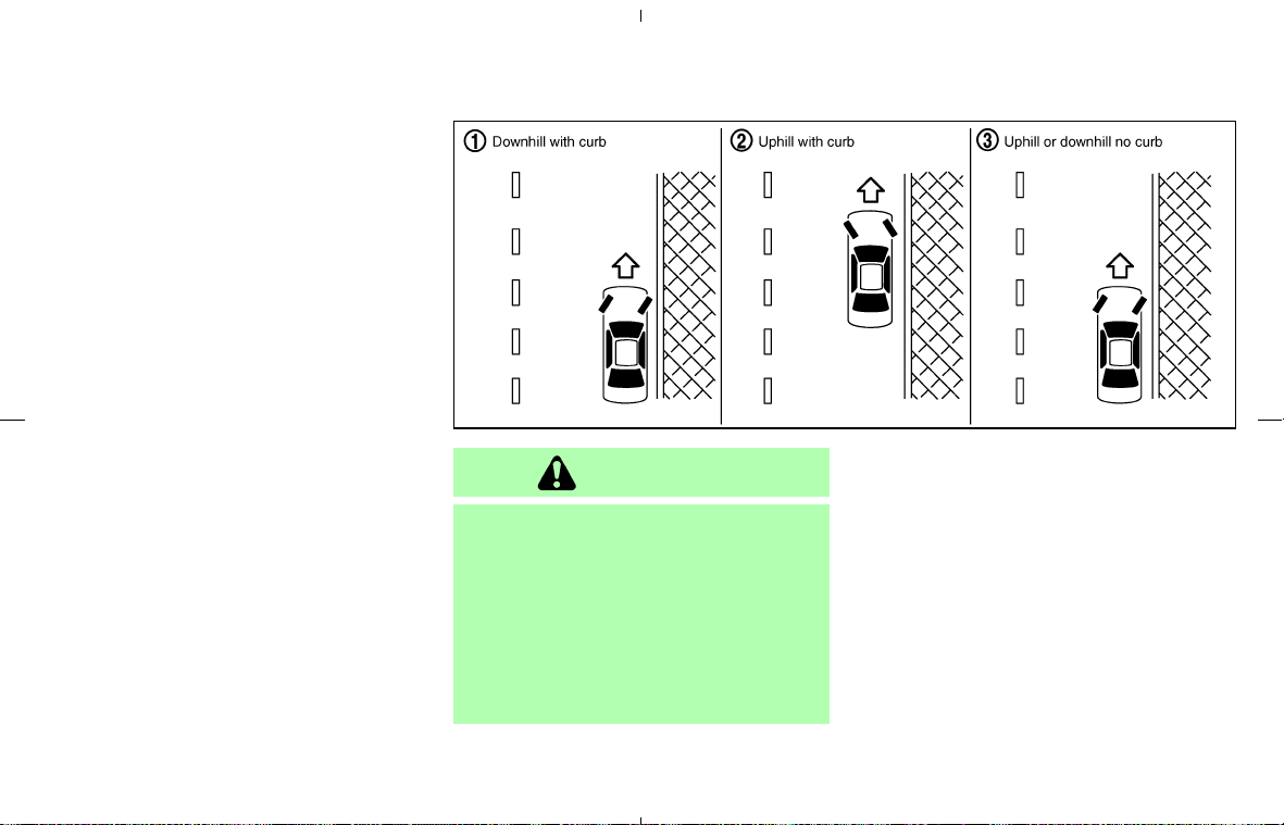
leave the windows closed to reduce drag.
쐌 Use the recommended viscosity engine oil.
See “Engine oil and oil filter recommenda-
tion” in the “9. Technical and consumer infor-
mation” section.
WARNING
쐌 Do not stop or park the vehicle over
flammable materials such as dry
grass, waste paper or rags. They may
ignite and cause a fire.
쐌 Never leave the engine running while
the vehicle is unattended.
쐌 Do not leave children unattended in-
side the vehicle.
1. Firmly apply the parking brake.
2. Automatic transmission models:
Move the selector lever to the P (Park) posi-
tion.
Manual transmission models:
Place the shift lever in the R (Reverse) posi-
tion. When parking on an uphill grade, place
the shift lever in the 1 (Low gear) position.
MSD0002
PARKING/PARKING ON HILLS
Starting and driving 5-19
墌 08.7.24/Z33-D/V5.0 墍

WARNING
쐌 Safe parking procedures require that
both the parking brake be set and the
transmission placed into P (Park) for
automatic transmission models or in
an appropriate gear for manual
transmission models. Failure to do
so could cause the vehicle to move
unexpectedly or roll away and result
in an accident.
쐌 Make sure the automatic transmis-
sion selector lever has been pushed
as far forward as it can go and cannot
be moved without depressing the
button at the end of the lever.
3. To help prevent the vehicle from rolling into
the street when parked on a sloping drive
way, it is a good practice to turn the wheels
as illustrated.
쐌 HEADED DOWNHILL WITH CURB:
쎻
1
Turn the wheels into the curb and move the
vehicle forward until the curb side wheel
gently touches the curb.
쐌 HEADED UPHILL WITH CURB:
쎻
2
Turn the wheels away from the curb and
move the vehicle back until the curb side
wheel gently touches the curb.
쐌 HEADED UPHILL OR DOWNHILL, NO
CURB:
쎻
3
Turn the wheels toward the side of the road
so the vehicle will move away from the center
of the road if it moves.
4. Turn the ignition key to the LOCK position
and remove the key.
WARNING
If the engine is not running or is turned
off while driving, the power assist for
the steering will not work. Steering will
be harder to operate.
The power assisted steering uses a hydraulic
pump, driven by the engine, to assist steering.
If the engine stops or drive belt breaks, you will
still have control of the vehicle. However, much
greater steering effort is needed, especially in
sharp turns or at low speeds.
POWER STEERING
5-20 Starting and driving
墌 08.7.24/Z33-D/V5.0 墍

BRAKING PRECAUTIONS
The brake system has two separate hydraulic
circuits. If one circuit malfunctions, you will still
have braking at two wheels.
Vacuum assisted brakes
The brake booster aids braking by using engine
vacuum. If the engine stops, you can stop the
vehicle by depressing the brake pedal. However,
greater foot pressure on the brake pedal will be
required to stop the vehicle and the stopping
distance will be longer.
Using the brakes
Avoid resting your foot on the brake pedal while
driving. This overheats the brakes, increases
wear on the brakes and pads, and reduces gas
mileage.
To help save the brakes and to prevent the
brakes from overheating, reduce speed and
downshift to a lower gear before going down a
slope or long grade. Overheated brakes may
reduce braking performance and could result in
loss of vehicle control.
WARNING
쐌 While driving on a slippery surface,
be careful when braking, accelerat-
ing or downshifting. Abrupt braking
or accelerating could cause the
wheels to skid and result in an acci-
dent.
쐌 If the engine is not running or is
turned off while driving, the power
assist for the brakes will not work.
Braking will be harder.
Wet brakes
When the vehicle is washed or driven through
water, the brakes may get wet. As a result, your
braking distance will be longer and the vehicle
may pull to one side during braking.
To dry brakes, drive the vehicle at a safe speed
while lightly pressing the brake pedal to heat-up
the brakes. Do this until the brakes return to
normal. Avoid driving the vehicle at high speeds
until the brakes function correctly.
Parking brake break-in
Break in the parking brake shoes whenever the
stopping effect of the parking brake is weakened
or whenever the parking brake shoes and/or
drums/rotors are replaced, in order to assure the
best braking performance.
This procedure is described in the vehicle ser-
vice manual and can be performed by a NISSAN
dealer.
ANTI-LOCK BRAKING SYSTEM
(ABS)
WARNING
쐌 The Anti-lock Braking System (ABS)
is a sophisticated device, but it can-
not prevent accidents resulting from
careless or dangerous driving tech-
niques. It can help maintain vehicle
control during braking on slippery
surfaces. Remember that stopping
distances on slippery surfaces will be
longer than on normal surfaces even
with ABS. Stopping distances may
also be longer on rough, gravel or
snow covered roads, or if you are
using tire chains. Always maintain a
safe distance from the vehicle in
BRAKE SYSTEM
Starting and driving 5-21
墌 08.7.24/Z33-D/V5.0 墍

front of you. Ultimately, the driver is
responsible for safety.
쐌 Tire type and condition may also af-
fect braking effectiveness.
— When replacing tires, install the
specified size of tires on all four
wheels.
— When installing a spare tire, make
sure that it is the proper size and type
as specified on the Tire and Loading
Information label. See “Tire and
Loading Information label” in the “9.
Technical and consumer informa-
tion” section of this manual.
— For detailed information, see
“Wheels and tires” in the “8. Mainte-
nance and do-it-yourself” section of
this manual.
The Anti-lock Braking System (ABS) controls
the brakes so the wheels do not lock during hard
braking or when braking on slippery surfaces.
The system detects the rotation speed at each
wheel and varies the brake fluid pressure to
prevent each wheel from locking and sliding. By
preventing each wheel from locking, the system
helps the driver maintain steering control and
helps to minimize swerving and spinning on
slippery surfaces.
Using the system
Depress the brake pedal and hold it down.
Depress the brake pedal with firm steady pres-
sure, but do not pump the brakes. The ABS will
operate to prevent the wheels from locking up.
Steer the vehicle to avoid obstacles.
WARNING
Do not pump the brake pedal. Doing so
may result in increased stopping dis-
tances.
Self-test feature
The ABS includes electronic sensors, electric
pumps, hydraulic solenoids and a computer. The
computer has a built-in diagnostic feature that
tests the system each time you start the engine
and move the vehicle at a low speed in forward
or reverse. When the self-test occurs, you may
hear a “clunk” noise and/or feel a pulsation in the
brake pedal. This is normal and does not indicate
a malfunction. If the computer senses a malfunc-
tion, it switches the ABS off and illuminates the
ABS warning light on the instrument panel. The
brake system then operates normally, but with-
out anti-lock assistance.
If the ABS warning light illuminates during the
self-test or while driving, have the vehicle
checked by a NISSAN dealer.
Normal operation
The ABS operates at speeds above 3 to 6 MPH
(5 to 10 km/h). The speed varies according to
road conditions.
When the ABS senses that one or more wheels
are close to locking up, the actuator rapidly
applies and releases hydraulic pressure. This
action is similar to pumping the brakes very
quickly. You may feel a pulsation in the brake
pedal and hear a noise from under the hood or
feel a vibration from the actuator when it is
operating. This is normal and indicates that the
ABS is operating properly. However, the pulsa-
tion may indicate that road conditions are haz-
ardous and extra care is required while driving.
5-22 Starting and driving
墌 08.7.24/Z33-D/V5.0 墍

On slippery surfaces such as wet asphalt roads,
vehicle wheels may spin when the vehicle is
accelerated. This wheel spin reduces accelera-
tion, or causes the vehicle to swerve, thus
decreasing vehicle stability.
When the vehicle drive wheels begin to spin, the
Traction Control System (TCS) controls the
engine torque using an electronic control sys-
tem, and it also controls automatic control shift-
ing if necessary (for automatic transmission
models). This reduces spinning of the drive
wheels, and result in improved vehicle accelera-
tion performance. It also improves the vehicle
stability by swerving motion.
쐌 When the TCS is operating, the “SLIP” indi-
cator light in the meter panel blinks.
쐌 If the “SLIP” indicator light blinks, the vehicle
is under slippery conditions. Be sure to drive
carefully. See “Slip indicator light” and “Trac-
tion Control System (TCS) off indicator light”
in the “2. Instruments and controls” section.
쐌 Indicator light
If a malfunction occurs in the TCS, the “SLIP”
and “TCS OFF” indicator lights come on in
the instrument panel. As long as these indi-
cator lights are illuminated, the traction con-
trol function (except the ABS) is canceled.
The vehicle will behaves like a model without
the TCS.
WARNING
The traction control system is designed
to prevent the wheels from spinning.
However, it does not prevent vehicle
slipping or spinning due to abrupt steer-
ing operation at high speeds or by care-
less or dangerous driving techniques.
Be especially careful when driving on
slippery surfaces and always drive
safely.
When accelerating or driving on slippery sur-
faces, the tires may spin or slide. With the
Vehicle Dynamic Control (VDC) system, sensors
detect these movements and control the braking
and engine output to help improve vehicle sta-
bility.
쐌 When the VDC system is operating, the
“SLIP” indicator in the instrument panel
blinks.
쐌 If the “SLIP” indicator blinks, the road condi-
tions are slippery. Be sure to adjust your
speed and driving to these conditions. Be
sure to drive carefully. See “Slip indicator
light”, and “Vehicle Dynamic Control (VDC)
OFF indicator light” in the “2. Instruments and
controls” section.
쐌 Indicator light
If a malfunction occurs in the system, the
“SLIP” and “VDC OFF” indicator lights illumi-
nate in the instrument panel. As long as these
indicators are illuminated, the VDC system
function is canceled.
The VDC system uses an Active Brake Limited
Slip (ABLS) system to improve vehicle traction.
The ABLS system works when one of the driving
wheels is spinning on a slippery surface. The
ABLS system brakes the spinning wheel, which
distributes the driving power to the other driving
wheel. If the vehicle is operated with the VDC
TRACTION CONTROL SYSTEM
(TCS) (if so equipped)
VEHICLE DYNAMIC CONTROL
(VDC) SYSTEM (if so equipped)
Starting and driving 5-23
墌 08.7.24/Z33-D/V5.0 墍

system turned off, all VDC system functions will
be turned off. The ABLS system and ABS will
still operate with the VDC system off. When the
ABLS system is activated, the “SLIP” indicator
light will blink and you may hear a clunk noise
and/or feel a pulsation in the brake pedal. This is
normal and is not an indication of a malfunction.
While the VDC system is operating, you may feel
a pulsation in the brake pedal and hear a noise or
feel a vibration from under the hood. This is
normal and indicates that the VDC system is
working properly.
The VDC system computer has a built-in diag-
nostic feature that tests the system each time
you start the engine and move the vehicle at a
low speed forward or backward. When the
self-test occurs, you may hear a clunk noise
and/or feel a pulsation in the brake pedal. This is
normal and is not an indication of a malfunction.
WARNING
쐌 The VDC system is designed to help
improve driving stability but does not
prevent accidents due to abrupt
steering operation at high speeds or
due to careless or dangerous driving
techniques. Reduce vehicle speed
and be especially careful when driv-
ing and cornering on slippery sur-
faces and always drive carefully.
쐌 Do not modify the vehicle’s suspen-
sion. If suspension parts such as
shock absorbers, struts, springs, sta-
bilizer bars and bushings and wheels
are not NISSAN-approved or are ex-
tremely deteriorated the VDC system
may not operate properly. This could
adversely affect vehicle handling per-
formance, and the “VDC OFF” indica-
tor or “SLIP” indicator or both indica-
tor lights may illuminate.
쐌 If brake related parts such as brake
pads, rotors and calipers are not
standard equipment or are extremely
deteriorated, the “VDC OFF” indica-
tor or “SLIP” indicator or both indica-
tor lights may illuminate.
쐌 If engine related parts such as a muf-
fler are not standard equipment or
are extremely deteriorated, the “VDC
OFF” indicator or “SLIP” indicator or
both indicator lights may illuminate.
쐌 When driving on extremely inclined
surfaces such as higher banked cor-
ners, the VDC system may not oper-
ate properly and the “VDC OFF” indi-
cator or “SLIP” indicator or both
indicator lights may illuminate. Do
not drive on these types of roads.
쐌 When driving on an unstable surface
such as a turntable, ferry, elevator or
ramp, the “VDC OFF” indicator or
“SLIP” indicator or both indicator
lights may illuminate. This is not a
malfunction. Restart the engine after
driving onto a stable surface.
쐌 If wheels or tires other than those
recommended are used, the VDC sys-
tem may not operate properly and the
“VDC OFF” indicator or “SLIP” indi-
cator or both indicator lights may
illuminate.
쐌 The VDC system is not a substitute
for winter tires or tire chains on a
snow-covered road.
5-24 Starting and driving
墌 08.7.24/Z33-D/V5.0 墍

FREEING A FROZEN DOOR LOCK
To prevent a door lock from freezing, apply
deicer or glycerin to it through the key hole. If the
lock becomes frozen, heat the key before insert-
ing it into the key hole.
ANTI-FREEZE
In the winter when it is anticipated that the
temperature will drop below 32°F (0°C), check
anti-freeze to assure proper winter protection.
For additional information, see “Engine Cooling
System” in the “8. Maintenance and do-it-
yourself” section.
BATTERY
If the battery is not fully charged during extremely
cold weather conditions, the battery fluid may
freeze and damage the battery. To maintain
maximum efficiency, the battery should be
checked regularly. For additional information,
see “Battery” in the “8. Maintenance and do-it-
yourself” section.
DRAINING OF COOLANT WATER
If the vehicle is to be left outside without anti-
freeze, drain the cooling system by opening the
drain plug located under the radiator. Refill
before operating the vehicle. See “Engine cool-
ing system” in the “8. Maintenance and do-it-
yourself” section for changing engine coolant.
TIRE EQUIPMENT
1. SUMMER tires are of a tread design to
provide superior performance on dry pave-
ment. However, the performance of these
tires will be substantially reduced in snowy
and icy conditions. If you operate your vehicle
on snowy or icy roads, NISSAN recommends
the use of MUD & SNOW or ALL SEASON
tires on all four wheels. Consult a NISSAN
dealer for the tire type, size, speed rating and
availability information.
2. For additional traction on icy roads, studded
tires may be used. However, some provinces
and states prohibit their use. Check local,
state and provincial laws before installing
studded tires.
Skid and traction capabilities of stud-
ded snow tires, on wet or dry surfaces,
may be poorer than that of non-studded
snow tires.
3. Tire chains may be used. For details, see
“Tire chains” in the “8. Maintenance and
do-it-yourself” section of this manual.
SPECIAL WINTER EQUIPMENT
It is recommended that the following items be
carried in the vehicle during winter:
쐌 a scraper and stiff-bristled brush to remove
ice and snow from the windows and wiper
blades.
쐌 a sturdy, flat board to be placed under the
jack to give it firm support.
쐌 a shovel to dig the vehicle out of snow-drifts.
쐌 extra window washer fluid to refill the reser-
voir tank.
DRIVING ON SNOW OR ICE
WARNING
쐌 Wet ice (32°F, 0°C and freezing rain),
very cold snow or ice can be slick and
very hard to drive on. The vehicle will
have much less traction or “grip” un-
der these conditions. Try to avoid
driving on wet ice until the road is
salted or sanded.
쐌 Whatever the condition, drive with
caution. Accelerate and slow down
COLD WEATHER DRIVING
Starting and driving 5-25
墌 08.7.24/Z33-D/V5.0 墍

with care. If accelerating or down-
shifting too fast, the drive wheels will
lose even more traction.
쐌 Allow more stopping distance under
these conditions. Braking should be
started sooner than on dry pavement.
쐌 Allow greater following distances on
slippery roads.
쐌 Watch for slippery spots (glare ice).
These may appear on an otherwise
clear road in shaded areas. If a patch
of ice is seen ahead, brake before
reaching it. Try not to brake while on
the ice, and avoid any sudden steer-
ing maneuvers.
쐌 Do not use cruise control on slippery
roads.
쐌 Snow can trap dangerous exhaust
gases under your vehicle. Keep snow
clear of the exhaust pipe and from
around your vehicle.
ENGINE BLOCK HEATER (if so
equipped)
Engine block heaters are available through
NISSAN dealers to assist in cold temperature
starting. The engine block heater should be used
when the outside temperature is 20°F (−7°C) or
lower.
To use the engine block heater:
1. Turn the engine off.
2. Open the hood and unwrap the engine block
heater cord.
3. Plug the engine block heater cord into a
grounded 3-wire, 3-pronged extension cord.
4. Plug the extension cord into a Ground Fault
Interrupt (GFI) protected, grounded 110-volt
AC (VAC) outlet.
5. The engine block heater must be plugged in
for at least2-4hours, depending on outside
temperatures, to properly warm the engine
coolant. Use an appropriate timer to turn the
engine block heater on.
6. Before starting the engine, unplug and prop-
erly store the cord to keep it away from
moving parts.
WARNING
쐌 Do not use your engine block heater
with an ungrounded electrical system
or a 2-pronged adapter. You can be
seriously injured by an electrical
shock if you use an ungrounded con-
nection.
쐌 Disconnect and properly store the
engine block heater cord before
starting the engine. Damage to the
cord could result in an electrical
shock and can cause serious injury.
쐌 Use a heavy-duty 3-wire, 3-pronged
extension cord rated for at least 10 A.
Plug the extension cord into a
Ground Fault Interrupt (GFI) pro-
tected, grounded 110-VAC outlet.
Failure to use the proper extension
cord or a grounded outlet can result
in a fire or electrical shock and cause
serious personal injury.
5-26 Starting and driving
墌 08.7.24/Z33-D/V5.0 墍

MEMO
Starting and driving 5-27
墌 08.7.24/Z33-D/V5.0 墍

MEMO
5-28 Starting and driving
墌 08.7.24/Z33-D/V5.0 墍

6 In case of emergency
Flat tire .................................................................................... 6-2
Tire pressure monitoring system (TPMS) ................. 6-2
Changing a flat tire ......................................................... 6-2
Jump starting ......................................................................... 6-7
Push starting .......................................................................... 6-9
If your vehicle overheats ..................................................... 6-9
Towing your vehicle ........................................................... 6-10
Towing recommended by NISSAN ......................... 6-11
Vehicle recovery (Freeing a stuck vehicle) ............ 6-12
墌 08.7.24/Z33-D/V5.0 墍

TIRE PRESSURE MONITORING
SYSTEM (TPMS)
This vehicle is equipped with the Tire Pressure
Monitoring System (TPMS). It monitors tire pres-
sure of all tires except the spare. When the low
tire pressure warning light is lit, one or more of
your tires is significantly under-inflated. If the
vehicle is being driven with low tire pressure, the
TPMS will activate and warn you of it by the low
tire pressure warning light (in the meter panel).
This system will activate only when the vehicle is
driven at speeds above 16 MPH (25 km/h). For
more details, refer to “Warning/indicator lights
and audible reminders” in the “2. Instruments
and controls” section and “Tire pressure moni-
toring system (TPMS)” in the “5. Starting and
driving” section.
WARNING
쐌 If the light illuminates while driving,
avoid sudden steering maneuvers or
abrupt braking, reduce vehicle speed,
pull off the road to a safe location
and stop the vehicle as soon as pos-
sible. Driving with under-inflated
tires may permanently damage the
tires and increase the likelihood of
tire failure. Serious vehicle damage
could occur and may lead to an acci-
dent and could result in serious per-
sonal injury. Check the tire pressure
for all four tires. Adjust the tire pres-
sure to the recommended COLD tire
pressure shown on the Tire and
Loading Information label to turn the
low tire pressure warning light OFF.
If you have a flat tire, replace it with a
spare tire as soon as possible.
쐌 When a spare tire is mounted or a
wheel is replaced, the TPMS will not
function and the low tire pressure
warning light will flash for approxi-
mately 1 minute. The light will remain
on after 1 minute. Contact your
NISSAN dealer as soon as possible
for tire replacement and/or system
resetting.
쐌 Replacing tires with those not origi-
nally specified by NISSAN could af-
fect the proper operation of the
TPMS.
쐌 Do not inject any tire liquid or aerosol
tire sealant into the tires, as this may
cause a malfunction of the tire pres-
sure sensors.
CHANGING A FLAT TIRE
If you have a flat tire, follow the instructions
below.
Stopping the vehicle
1. Safely move the vehicle off the road away
from traffic.
2. Turn on the hazard warning flashers.
3. Park on a level surface and apply the parking
brake. Shift the manual transmission into R
(Reverse) position (automatic transmission in
P (Park) position).
4. Turn off the engine.
5. Raise the hood to warn other traffic, and to
signal professional road assistance person-
nel that you need assistance.
6. Have all passengers get out of the vehicle
and stand in a safe place, away from traffic
and clear of the vehicle.
FLAT TIRE
6-2 In case of emergency
墌 08.7.24/Z33-D/V5.0 墍
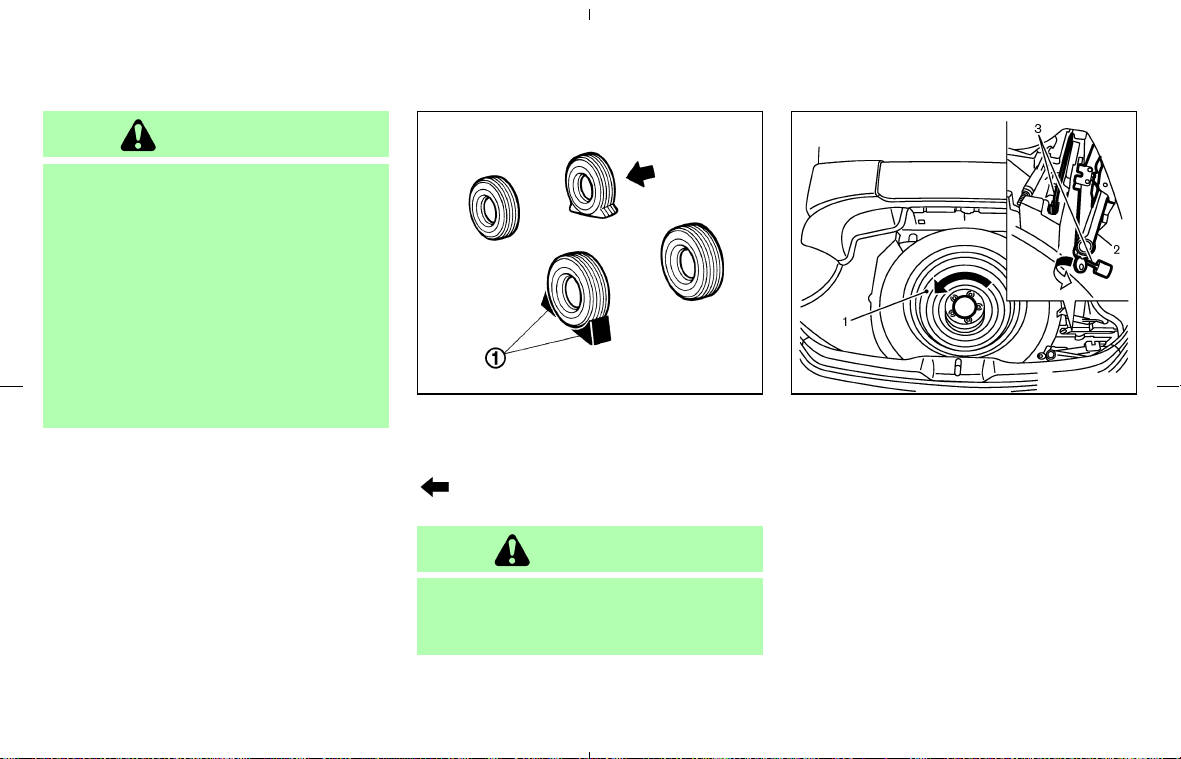
WARNING
쐌 Make sure the parking brake is se-
curely applied and the manual trans-
mission is shifted into R (Reverse), or
the automatic transmission into P
(Park).
쐌 Never change tires when the vehicle
is on a slope, ice or slippery areas.
This is hazardous.
쐌 Never change tires if oncoming traffic
is close to your vehicle. Wait for pro-
fessional road assistance.
Blocking wheels
Place suitable blocks
쎻
1
at both the front and
back of the wheel diagonally opposite the flat tire
to prevent the vehicle from moving when it
is jacked up.
WARNING
Be sure to block the wheel as the ve-
hicle may move and result in personal
injury.
Getting the spare tire and tools
Remove jacking tools and spare tire from the
storage area located in the luggage/trunk as
illustrated.
Coupe models:
1. Spare tire — Turn the retainer counterclock-
wise to remove.
2. Jack — Turn it counterclockwise to remove.
3. Jacking tools
MCE0001A SCE0409
Coupe models
In case of emergency 6-3
墌 08.7.24/Z33-D/V5.0 墍
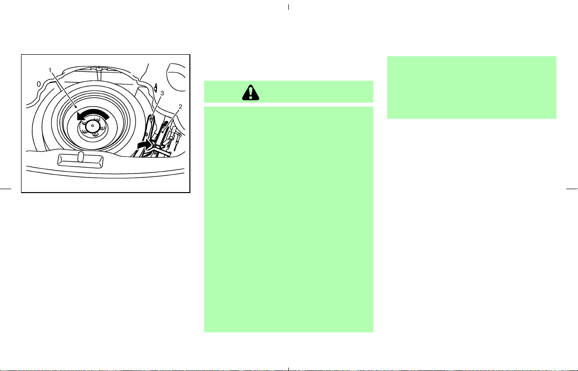
Roadster models:
1. Spare tire — Turn the retainer counterclock-
wise to remove.
2. Jack — Unfasten the belt and lift the jack up
to remove.
3. Jacking tools — They are in the tool bag.
Jacking up the vehicle and removing
the damaged tire
WARNING
쐌 Never get under the vehicle while it is
supported only by the jack. If it is
necessary to work under the vehicle,
support it with safety stands.
쐌 Use only the jack provided with your
vehicle to lift the vehicle. Do not use
the jack provided with your vehicle
on other vehicles. The jack is de-
signed for lifting only your vehicle
during a tire change.
쐌 Use the correct jack up points. Never
use any other part of the vehicle for
jack support.
쐌 Never jack up the vehicle more than
necessary.
쐌 Never use blocks on or under the
jack.
쐌 Do not start or run the engine while
vehicle is on the jack, as it may cause
the vehicle to move. This is especially
true for vehicles with limited slip dif-
ferentials.
쐌 Do not allow passengers to stay in
the vehicle while it is on the jack.
Carefully read the caution label attached to
the jack body and the following instruc-
tions.
SCE0491
Roadster models
6-4 In case of emergency
墌 08.7.24/Z33-D/V5.0 墍
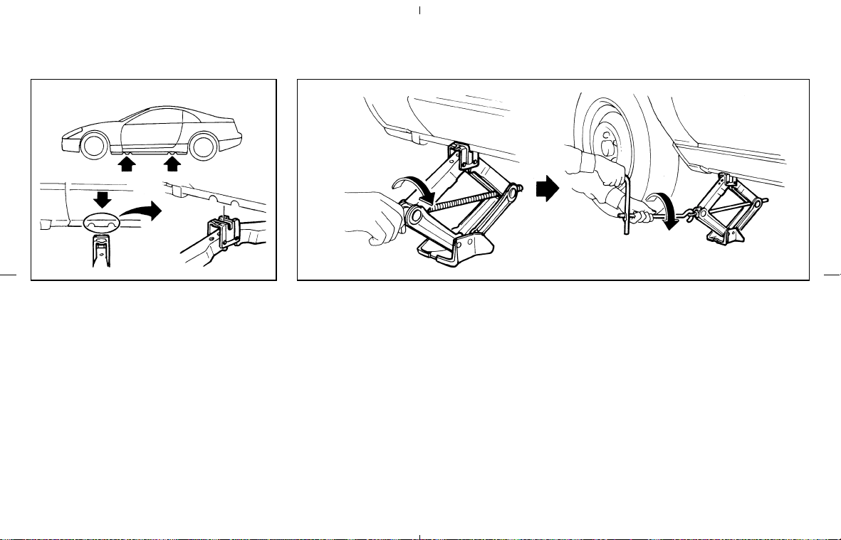
1. Place the jack directly under the jack-up point
as illustrated above so that top of the jack
contacts the vehicle at the jack up point.
Align the jack head between the two notches
in the front or the rear as shown. Also fit the
groove of the jack head between the notches
as shown.
The jack should be used on level firm
ground.
2. Loosen each wheel nut one or two turns by
turning counterclockwise with the wheel nut
wrench. Do not remove the wheel nuts
until the tire is off the ground.
3. Carefully raise the vehicle until the tire clears
the ground. To lift the vehicle, securely hold
the jack lever and rod with both hands as
shown above. Remove the wheel nuts, and
then remove the tire.
SCE0410A
Jack-up point
CE1092-A
In case of emergency 6-5
墌 08.7.24/Z33-D/V5.0 墍
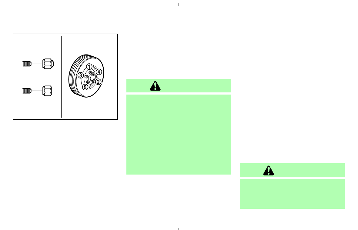
Installing the spare tire
The spare tire is designed for emergency
use. See specific instructions under the
heading “Wheels and tires” in the “8. Main-
tenance and do-it-yourself” section.
1. Clean any mud or dirt from the surface
between the wheel and hub.
2. Carefully put the wheel on and tighten the
wheel nuts finger tight. When replacing a
front tire, make sure the hole in the spare tire
wheel is aligned with the pin on the brake
rotor.
3. With the wheel nut wrench, tighten wheel
nuts alternately and evenly in the sequence
illustrated (
쎻
1
-
쎻
5
) until they are tight.
4. Lower the vehicle slowly until the tire touches
the ground. Then, with the wheel nut wrench,
tighten the wheel nuts securely in the se-
quence as illustrated. Lower the vehicle com-
pletely.
WARNING
쐌 Incorrect wheel nuts or improperly
tightened wheel nuts can cause the
wheel to become loose or come off.
This could cause an accident.
쐌 Do not use oil or grease on the wheel
studs or nuts. This could cause the
nuts to become loose.
쐌 Retighten the wheel nuts when the
vehicle has been driven for 600 miles
(1,000 km) (also in cases of a flat tire,
etc.).
As soon as possible tighten the wheel nuts
to the specified torque with a torque
wrench.
Wheel nut tightening torque:
80 ft-lb (108 N⋅m)
The wheel nuts must be kept tightened to
specification at all times. It is recom-
mended that wheel nuts be tightened to
specification at each lubrication interval.
Adjust tire pressure to the COLD pressure.
COLD pressure:
After vehicle has been parked for three
hours or more or driven less than 1 mile
(1.6 km).
COLD tire pressures are shown on the Tire
and Loading Information label affixed to
the driver’s side center pillar.
Stowing the damaged tire and tools
Securely store the spare tire and jacking equip-
ment in the vehicle.
WARNING
쐌 Always make sure that the spare tire
and jacking equipment are properly
secured after use. Such items can
become dangerous projectiles in an
SCE0039
6-6 In case of emergency
墌 08.7.24/Z33-D/V5.0 墍

accident or sudden stop.
쐌 The spare tire is designed for emer-
gency use. See specific instructions
under the heading “Wheels and tires”
in the “8. Maintenance and do-it-
yourself” section of this manual.
To start your engine with a booster battery, the
instructions and precautions below must be
followed.
WARNING
쐌 If done incorrectly, jump starting can
lead to a battery explosion, resulting
in severe injury or death. It could also
damage your vehicle.
쐌 Explosive hydrogen gas is always
present in the vicinity of the battery.
Keep all sparks and flames away
from the battery.
쐌 Do not allow battery fluid to come
into contact with eyes, skin, clothing
or painted surfaces. Battery fluid is a
corrosive sulfuric acid solution which
can cause severe burns. If the fluid
should come into contact with any-
thing, immediately flush the con-
tacted area with water.
쐌 Keep battery out of the reach of chil-
dren.
쐌 The booster battery must be rated at
12 volts. Use of an improperly rated
battery can damage your vehicle.
쐌 Whenever working on or near a bat-
tery, always wear suitable eye protec-
tors (for example, goggles or indus-
trial safety spectacles) and remove
rings, metal bands, or any other jew-
elry. Do not lean over the battery
when jump starting.
쐌 Do not attempt to jump start a frozen
battery. It could explode and cause
serious injury.
JUMP STARTING
In case of emergency 6-7
墌 08.7.24/Z33-D/V5.0 墍
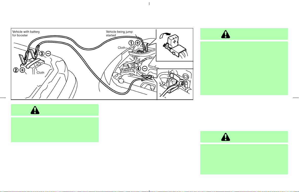
WARNING
Always follow the instructions below.
Failure to do so could result in damage
to the charging system and cause per-
sonal injury.
1. If the booster battery is in another vehicle,
position the two vehicles to bring their bat-
teries into close proximity to each other.
Do not allow the two vehicles to touch.
2. Apply parking brake. Move the selector lever
to the P (Park) position (automatic transmis-
sion models) or move the shift lever to the N
(Neutral) position (manual transmission mod-
els). Switch off all unnecessary electrical
systems (light, heater, air conditioner, etc.).
3. Remove vent caps on the battery (if so
equipped). Cover the battery with an old
cloth to reduce explosion hazard.
4. Connect jumper cables in the sequence as
illustrated. (
쎻
1
-
쎻
4
)
CAUTION
쐌 Always connect positive (+) to posi-
tive (+) and negative (−) to body
ground (for example, strut mounting
bolt, etc. — not to the battery).
쐌 Make sure that the jumper cables do
not touch moving parts in the engine
compartment and that the cable
clamps do not contact any other
metal.
5. Start the engine of the other vehicle and let it
run for a few minutes.
6. Keep the engine speed of the other vehicle at
about 2,000 rpm, and start your engine in the
normal manner.
CAUTION
Do not keep the starter motor engaged
for more than 10 seconds. If the engine
does not start right away, turn the key
off and wait 3 to 4 seconds before trying
again.
SCE0664
6-8 In case of emergency
墌 08.7.24/Z33-D/V5.0 墍

7. After starting your engine, carefully discon-
nect the negative cable and then the positive
cable.
8. Replace the vent caps (if so equipped). Be
sure to dispose of the cloth used to cover the
vent holes as it may be contaminated with
corrosive acid.
Do not attempt to start the engine by pushing.
CAUTION
쐌 Automatic transmission models can-
not be push started. Attempting to do
so may cause transmission damage.
쐌 Three-way catalyst equipped models
should not be started by pushing
since the three-way catalyst may be
damaged.
쐌 Never try to start the vehicle by tow-
ing it; when the engine starts, the
forward surge could cause the ve-
hicle to collide with the tow vehicle.
WARNING
쐌 Do not continue to drive if your ve-
hicle overheats. Doing so could
cause engine damage or a vehicle
fire.
쐌 To avoid the danger of being scalded,
never remove the radiator cap while
the engine is still hot. When the ra-
diator cap is removed, pressurized
hot water will spurt out, possibly
causing serious injury.
쐌 Do not open the hood if steam is
coming out.
If your vehicle is overheating (indicated by an
extremely high temperature gauge reading), or if
you feel a lack of engine power, detect abnormal
noise, etc., take the following steps:
1. Move the vehicle safely off the road, apply the
parking brake and move the shift lever to the
N (Neutral) position (automatic transmission
to the P (Park) position).
Do not stop the engine.
2. Turn off the air conditioner. Open all the
PUSH STARTING IF YOUR VEHICLE OVERHEATS
In case of emergency 6-9
墌 08.7.24/Z33-D/V5.0 墍

windows, and move the temperature control
to maximum hot and the fan control to high
speed.
3. If engine overheating is caused by climbing a
long hill on a hot day, run the engine at a fast
idle (approximately 1,500 rpm) until the tem-
perature gauge indication returns to normal.
4. Get out of the vehicle. Look and listen for
steam or coolant escaping from the radiator
before opening the hood. (If steam or coolant
is escaping, turn off the engine.) Do not open
the hood further until no steam or coolant can
be seen.
5. Open the engine hood.
WARNING
If steam or water is coming from the
engine, stand clear to prevent getting
burned.
6. Visually check if the cooling fan is running.
The radiator hoses and radiator should not
leak water.
If coolant is leaking or the cooling fan does
not run, stop the engine.
WARNING
쐌 Be careful not to allow your hands,
hair, jewelry or clothing to come into
contact with, or get caught in, engine
belts or the engine cooling fan.
쐌 The engine cooling fan can start at
any time when the coolant tempera-
ture is high.
7. After the engine cools down, check the cool-
ant level in the reservoir tank with the engine
running. Add coolant to the reservoir tank if
necessary. Have your vehicle repaired at a
NISSAN dealer.
When towing your vehicle, all State (Provincial in
Canada) and local regulations for towing must
be followed. Incorrect towing equipment could
damage your vehicle. Towing instructions are
available from a NISSAN dealer. Local service
operators are generally familiar with the appli-
cable laws and procedures for towing. To assure
proper towing and to prevent accidental damage
to your vehicle, NISSAN recommends having a
service operator tow your vehicle. It is advisable
to have the service operator carefully read the
following precautions.
WARNING
쐌 Never ride in a vehicle that is being
towed.
쐌 Never get under your vehicle after it
has been lifted by a tow truck.
CAUTION
쐌 When towing, make sure that the
transmission, axles, steering system
and powertrain are in working condi-
TOWING YOUR VEHICLE
6-10 In case of emergency
墌 08.7.24/Z33-D/V5.0 墍
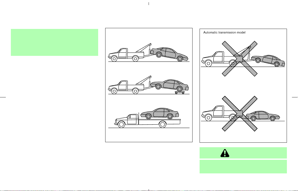
tion. If any unit is damaged, dollies
must be used.
쐌 Always attach safety chains before
towing.
For information about towing your vehicle behind
a recreational vehicle (RV), refer to “Flat towing”
in the “9. Technical and consumer information”
section of this manual.
TOWING RECOMMENDED BY
NISSAN
NISSAN recommends that your vehicle be
towed with the driving (rear) wheels off the
ground or place the vehicle on a flat bed truck as
illustrated.
CAUTION
쐌 Never tow automatic transmission
models with the rear wheels on the
SCE0342
SCE0489
In case of emergency 6-11
墌 08.7.24/Z33-D/V5.0 墍
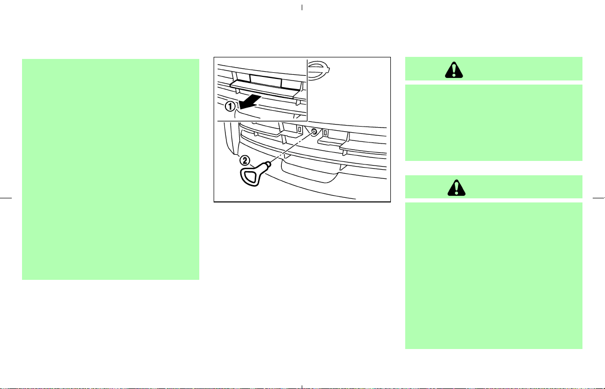
ground or four wheels on the ground
(forward or backward) as this may
cause serious and expensive damage
to the transmission.
If it is necessary to tow the vehicle
with the front wheels raised, always
use towing dollies under the rear
wheels.
쐌 When towing rear wheel drive mod-
els with the front wheels on the
ground or on towing dollies:
Turn the ignition key to the OFF po-
sition, and secure the steering wheel
in a straight ahead position with a
rope or similar device. Never secure
the steering wheel by turning the
ignition key to the LOCK position.
This may damage the steering lock
mechanism.
VEHICLE RECOVERY (Freeing a
stuck vehicle)
Use the recovery hook by installing it in the front
of the vehicle. (The rear has no towing points.)
1. Remove the front license plate (if so
equipped).
2. Remove the recovery hook cover
쎻
1
from the
bumper.
3. Securely install the recovery hook
쎻
2
stored
with jacking tools.
Make sure that the hook is properly secured in
the stored place after use.
WARNING
쐌 Stand clear of a stuck vehicle.
쐌 Do not spin your tires at high speed.
This could cause them to explode
and result in serious injury. Parts of
your vehicle could also overheat and
be damaged.
CAUTION
쐌 Tow chains or cables must be at-
tached only to the main structural
members of the vehicle or the recov-
ery hook. Otherwise, the vehicle body
will be damaged.
쐌 Do not use the vehicle tie down
hooks to free a vehicle stuck in sand,
snow, mud, etc. Never tow a vehicle
using the vehicle tie down hooks.
쐌 Always pull the cable straight out
from the front of the vehicle. Never
pull on the vehicle at an angle.
SCE0605
6-12 In case of emergency
墌 08.7.24/Z33-D/V5.0 墍

쐌 Pulling devices should be routed so
they do not touch any part of the
suspension, steering, brake or cool-
ing systems.
쐌 Pull devices such as ropes or canvas
straps are not recommended for use
in vehicle towing or recovery.
If your vehicle is stuck in sand, snow, mud, etc.,
use the following procedure:
1. Turn off the Vehicle Dynamic Control (VDC)
system or Traction Control System (TCS) (if
so equipped).
2. Make sure the area in front and behind the
vehicle is clear of obstructions.
3. Turn the steering wheel right and left to clear
an area around the front tires.
4. Slowly rock the vehicle forward and back-
ward.
쐌 Shift back and forth between R (reverse) and
D (drive) (automatic transmission models) or
1st (low) and R (reverse) (manual transmis-
sion models).
쐌 Apply the accelerator as little as possible to
maintain the rocking motion.
쐌 Release the accelerator pedal before shifting
between R and D (automatic transmission
models) or 1st and R (manual transmission
models).
쐌 Do not spin the tires above 35 MPH (55
km/h).
5. If the vehicle cannot be freed after a few tries,
contact a professional towing service to re-
move the vehicle.
In case of emergency 6-13
墌 08.7.24/Z33-D/V5.0 墍

MEMO
6-14 In case of emergency
墌 08.7.24/Z33-D/V5.0 墍

7 Appearance and care
Cleaning exterior ................................................................... 7-2
Washing ............................................................................ 7-2
Waxing ............................................................................... 7-3
Removing spots .............................................................. 7-3
Underbody ........................................................................ 7-3
Glass .................................................................................. 7-3
Aluminum alloy wheels .................................................. 7-4
Chrome parts ................................................................... 7-4
Tire dressing .................................................................... 7-4
Cleaning interior .................................................................... 7-5
Floor mats ......................................................................... 7-5
Seat belts ......................................................................... 7-6
Corrosion protection ............................................................ 7-6
Most common factors contributing to vehicle
corrosion ........................................................................... 7-6
Environmental factors influence the rate of
corrosion ........................................................................... 7-6
To protect your vehicle from corrosion ..................... 7-6
墌 08.7.24/Z33-D/V5.0 墍

In order to maintain the appearance of your
vehicle, it is important to take proper care of it.
In the following cases, please wash your vehicle
as soon as possible to protect the paint surface.
쐌 After a rainfall to prevent possible damage
from acid rain
쐌 After driving on coastal roads
쐌 When contaminants such as soot, bird drop-
pings, tree sap, metal particles or bugs get on
the paint surface
쐌 When dust or mud builds up on the surface
Whenever possible, store or park your vehicle
inside a garage or in a covered area.
When it is necessary to park outside, park in a
shady area or protect the vehicle with a body
cover.
Be careful not to scratch the paint surface
when putting on or removing the body
cover.
WASHING
Wash dirt off the vehicle with a wet sponge and
plenty of water. Clean the vehicle thoroughly
using a mild soap, a special vehicle soap or a
general purpose dish-washing liquid mixed with
clean, lukewarm (never hot) water.
CAUTION
쐌 Do not use car washes that use acid
in the detergent. Some car washes,
especially brushless ones, use some
acid for cleaning. The acid may react
with some plastic vehicle compo-
nents, causing them to crack. This
could affect their appearance, and
also could cause them not to function
properly. Always check with your car
wash to confirm that acid is not used.
쐌 Do not use strong household soap,
strong chemical detergents, gasoline
or solvents.
쐌 Do not wash the vehicle in direct
sunlight or while the vehicle body is
hot, as the surface may become
water-spotted.
쐌 Avoid using tight-napped or rough
cloths, such as washing mitts. Care
must be taken when removing
caked-on dirt or other foreign sub-
stances so the paint surface is not
scratched or damaged.
쐌 For Roadster models, observe the
following:
• Do not use an automatic car wash
or a high pressure car wash. The
soft top may be damaged.
• Avoid applying direct water pres-
sure, such as high pressured water
from household hoses, on the lin-
ing of the soft top and vehicle
body. Avoid applying continuous
water on the parts around the soft
top and the windows. These may
cause water to leak into the inside
of your vehicle.
Rinse the vehicle again with plenty of clean
water.
Inside flanges, seams and folds on the doors,
hatches and hood are particularly vulnerable to
the effects of road salt. Therefore, these areas
must be regularly cleaned. Make sure that the
drain holes in the lower edge of the door are
open. Spray water under the body and in the
wheel wells to loosen the dirt and wash away
road salt.
Avoid leaving water spots on the paint surface
by using a damp chamois to dry the vehicle.
CLEANING EXTERIOR
7-2 Appearance and care
墌 08.7.24/Z33-D/V5.0 墍

Soft top care and cleaning (Roadster
models)
Proper care and handling should be observed to
maintain a good appearance of the soft top.
Improper care may cause the top cloth’s surface
to stiffen, stain, or mat. Follow the instructions
shown in this section.
It is not necessary to wash the soft top every
time you wash the vehicle body, but clean the
top regularly before it becomes quite dirty. Leav-
ing the soft top dirty or soiled for a long period
will cause deterioration to the quality of the top
material.
Remove dust or dirt on the soft top with a soft
brush or sponge, then rinse it with plenty of
clean water. When the top is quite dirty, wash
using a mild detergent, such as a general
cleaner especially made for a cloth top or a
general purpose dish-washing liquid, mixed with
clean, lukewarm (never hot) water. Rinse the top
again with plenty of clean water to remove all
traces of soap.
CAUTION
쐌 Do not use strong household soap,
strong chemical detergents, gasoline
or solvents.
쐌 If glass cleaner gets on the soft top,
immediately wash it off with clean
water.
쐌 Do not apply direct water pressure,
such as high pressured water from
household hoses, on the lining of the
soft top and vehicle body, as this may
cause water to leak into the inside of
your vehicle.
After cleaning, always be sure the top and its
storage are completely dry before opening the
top. Opening the top while it is wet or damp may
cause interior water damage, water stains or
mildew on the top.
WAXING
Regular waxing protects the paint surface and
helps retain new vehicle appearance. Polishing
is recommended to remove built-up wax residue
and to avoid a weathered appearance before
reapplying wax.
A NISSAN dealer can assist you in choosing the
proper product.
쐌 Wax your vehicle only after a thorough wash-
ing. Follow the instructions supplied with the
wax.
쐌 Do not use a wax containing any abrasives,
cutting compounds or cleaners that may
damage the vehicle finish.
Machine compounding or aggressive polishing
on a base coat/clear coat paint finish may dull
the finish or leave swirl marks.
REMOVING SPOTS
Remove tar and oil spots, industrial dust, insects,
and tree sap as quickly as possible from the
surface of the paint to avoid lasting damage or
staining. Special cleaning products are available
at a NISSAN dealer or any automotive accessory
store.
UNDERBODY
In areas where road salt is used in winter, the
underbody must be cleaned regularly. This will
prevent dirt and salt from building up and caus-
ing underbody and suspension corrosion. Be-
fore the winter period and again in the spring, the
underseal must be checked and, if necessary,
re-treated.
GLASS
Use glass cleaner to remove smoke and dust film
from the glass surfaces. It is normal for glass to
Appearance and care 7-3
墌 08.7.24/Z33-D/V5.0 墍

become coated with a film after the vehicle is
parked in the hot sun. Glass cleaner and a soft
cloth will easily remove this film.
CAUTION
쐌 When cleaning the inside of the win-
dows, do not use sharp-edged tools,
abrasive cleaners or chlorine-based
disinfectant cleaners. They could
damage the electrical conductors or
rear window defroster elements.
쐌 If glass cleaner gets on the soft top,
immediately wash it off with clean
water. (Roadster models)
ALUMINUM ALLOY WHEELS
Wash regularly with a sponge dampened in a
mild soap solution, especially during winter
months in areas where road salt is used. Salt
could discolor the wheels if not removed.
CAUTION
Follow the directions below to avoid
staining or discoloring the wheels:
쐌 Do not use a cleaner that uses strong
acid or alkali contents to clean the
wheels.
쐌 Do not apply wheel cleaners to the
wheels when they are hot. The wheel
temperature should be the same as
ambient temperature.
쐌 Rinse the wheel to completely re-
move the cleaner within 15 minutes
after the cleaner is applied.
CHROME PARTS
Clean all chrome parts regularly with a non-
abrasive chrome polish to maintain the finish.
TIRE DRESSING
NISSAN does not recommend the use of tire
dressings. Tire manufacturers apply a coating to
the tires to help reduce discoloration of the
rubber. If a tire dressing is applied to the tires, it
may react with the coating and form a com-
pound. This compound may come off the tire
while driving and stain the vehicle paint.
If you choose to use a tire dressing, take the
following precautions:
쐌 Use a water-based tire dressing. The coating
on the tire dissolves more easily with an
oil-based tire dressing.
쐌 Apply a light coat of tire dressing to help
prevent it from entering the tire tread/grooves
(where it would be difficult to remove).
쐌 Wipe off excess tire dressing using a dry
towel. Make sure the tire dressing is com-
pletely removed from the tire tread/grooves.
쐌 Allow the tire dressing to dry as recom-
mended by tire dressing manufacturer.
7-4 Appearance and care
墌 08.7.24/Z33-D/V5.0 墍
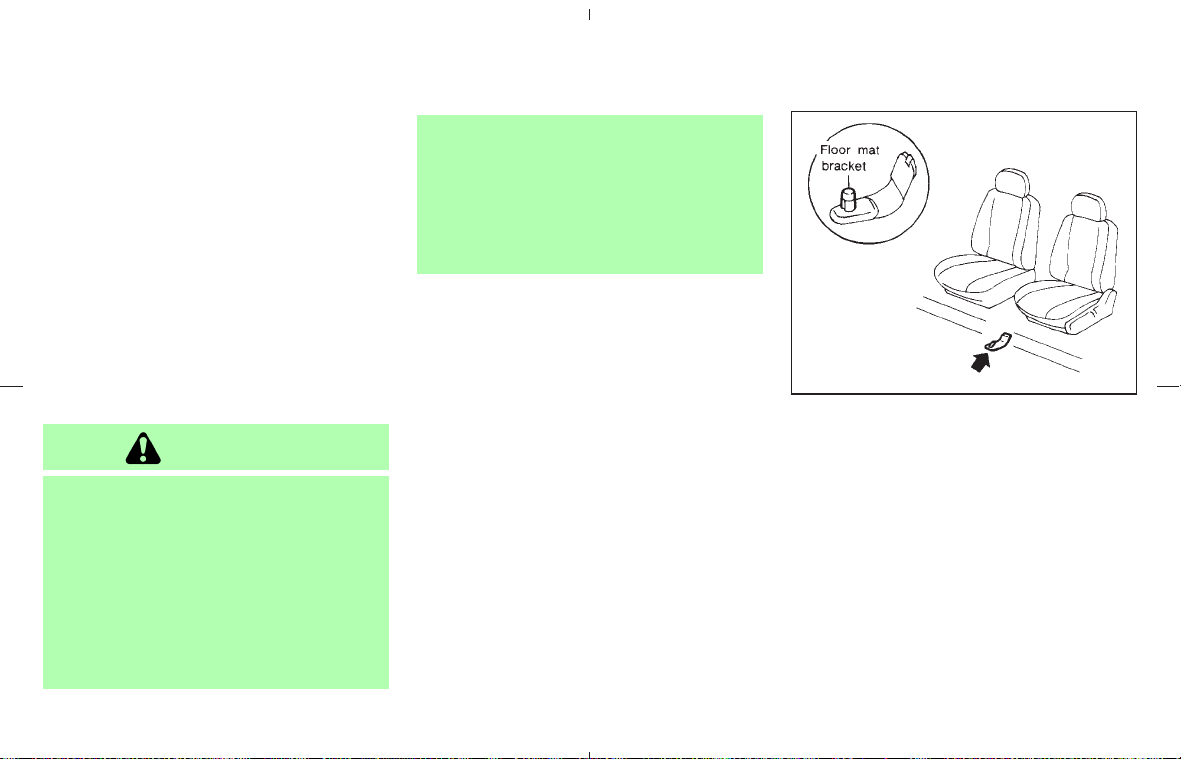
Occasionally remove loose dust from the interior
trim, plastic parts and seats using a vacuum
cleaner or soft bristled brush. Wipe the vinyl and
leather surfaces with a clean, soft cloth damp-
ened in mild soap solution, then wipe clean with
a dry soft cloth.
Regular care and cleaning is required in order to
maintain the appearance of the leather.
Before using any fabric protector, read the
manufacturer’s recommendations. Some fabric
protectors contain chemicals that may stain or
bleach the seat material.
Use a cloth dampened only with water, to clean
the meter and gauge lens.
CAUTION
쐌 Never use benzine, thinner or any
similar material.
쐌 Small dirt particles can be abrasive
and damaging to leather surfaces
and should be removed promptly. Do
not use saddle soap, car waxes, pol-
ishes, oils, cleaning fluids, solvents,
detergents or ammonia-based clean-
ers as they may damage the leather
natural finish.
쐌 Never use fabric protectors unless
recommended by the manufacturer.
쐌 Do not use glass or plastic cleaner on
meter or gauge lens covers. It may
damage the lens cover.
FLOOR MATS
The use of genuine NISSAN floor mats can
extend the life of your vehicle carpet and make it
easier to clean the interior. No matter what
mats are used, be sure they are fitted for
your vehicle and are properly positioned in
the footwell to prevent interference with
pedal operation. Mats should be maintained
with regular cleaning and replaced if they be-
come excessively worn.
Floor mat positioning aid
(driver’s side only)
This model includes a front floor mat bracket to
act as a floor mat positioning aid. NISSAN floor
mats have been specially designed for your
vehicle model. The driver’s side floor mat has a
grommet hole incorporated in it. Simply position
the mat by placing the floor mat bracket through
the floor mat grommet hole while centering the
mat in the floorpan contour.
Periodically check to make certain that the mats
are properly positioned.
SAI0012
CLEANING INTERIOR
Appearance and care 7-5
墌 08.7.24/Z33-D/V5.0 墍

SEAT BELTS
The seat belts can be cleaned by wiping them
with a sponge dampened in a mild soap solution.
Allow the belts to dry completely before using
them. See “Seat belt maintenance” in the “1.
Safety — Seats, seat belts and supplemental
restraint system” section.
WARNING
Do not allow wet seat belts to roll up in
the retractor. NEVER use bleach, dye or
chemical solvents to clean the seat
belts, since these may severely weaken
the seat belt webbing.
MOST COMMON FACTORS
CONTRIBUTING TO VEHICLE
CORROSION
쐌 The accumulation of moisture-retaining dirt
and debris in body panel sections, cavities,
and other areas.
쐌 Damage to paint and other protective coat-
ings caused by gravel and stone chips or
minor traffic accidents.
ENVIRONMENTAL FACTORS
INFLUENCE THE RATE OF
CORROSION
Moisture
Accumulation of sand, dirt and water on the
vehicle body underside can accelerate corro-
sion. Wet floor coverings will not dry completely
inside the vehicle, and should be removed for
drying to avoid floor panel corrosion.
Relative humidity
Corrosion will be accelerated in areas of high
relative humidity, especially those areas where
the temperatures stay above freezing and where
atmospheric pollution exists and road salt is
used.
Temperature
A temperature increase will accelerate the rate
of corrosion to those parts which are not well
ventilated.
Air pollution
Industrial pollution, the presence of salt in the air
in coastal areas, or heavy road salt use will
accelerate the corrosion process. Road salt will
also accelerate the disintegration of paint sur-
faces.
TO PROTECT YOUR VEHICLE
FROM CORROSION
쐌 Wash and wax your vehicle often to keep the
vehicle clean.
쐌 Always check for minor damage to the paint
and repair it as soon as possible.
쐌 Keep drain holes at the bottom of the doors
open to avoid water accumulation.
쐌 Check the underbody for accumulation of
sand, dirt or salt. If present, wash with water
as soon as possible.
CORROSION PROTECTION
7-6 Appearance and care
墌 08.7.24/Z33-D/V5.0 墍

CAUTION
쐌 Never remove dirt, sand or other de-
bris from the passenger compart-
ment by washing it out with a hose.
Remove dirt with a vacuum cleaner or
broom.
쐌 Never allow water or other liquids to
come in contact with electronic com-
ponents inside the vehicle as this
may damage them.
Chemicals used for road surface de-icing are
extremely corrosive. They accelerate corrosion
and deterioration of underbody components
such as the exhaust system, fuel and brake lines,
brake cables, floor pan and fenders.
In winter, the underbody must be cleaned
periodically.
For additional protection against rust and corro-
sion, which may be required in some areas,
consult a NISSAN dealer.
Appearance and care 7-7
墌 08.7.24/Z33-D/V5.0 墍

MEMO
7-8 Appearance and care
墌 08.7.24/Z33-D/V5.0 墍

8 Maintenance and do-it-yourself
Maintenance requirements ................................................. 8-2
General maintenance ........................................................... 8-2
Explanation of general maintenance items ............... 8-2
Maintenance precautions ................................................... 8-5
Engine compartment check locations ............................. 8-7
Engine cooling system ........................................................ 8-8
Checking engine coolant level .................................... 8-8
Changing engine coolant ............................................. 8-9
Engine oil ................................................................................ 8-9
Checking engine oil level .............................................. 8-9
Changing engine oil and filter ................................... 8-10
Automatic transmission fluid ........................................... 8-12
Power steering fluid .......................................................... 8-12
Brake and clutch fluid ....................................................... 8-13
Brake fluid ....................................................................... 8-13
Clutch fluid ..................................................................... 8-14
Window washer fluid ........................................................ 8-14
Battery ................................................................................... 8-15
Jump starting ................................................................. 8-16
Drive belts ............................................................................ 8-17
Spark plugs ......................................................................... 8-17
Replacing spark plugs ................................................ 8-17
Air cleaners .......................................................................... 8-18
Windshield wiper blades ................................................. 8-19
Cleaning ......................................................................... 8-19
Replacing ....................................................................... 8-20
Brakes ................................................................................... 8-21
Self-adjusting brakes .................................................. 8-21
Brake pad wear indicators ......................................... 8-21
Fuses ..................................................................................... 8-21
Engine compartment ................................................... 8-22
Passenger compartment ............................................ 8-23
Keyfob battery replacement.............................................. 8-24
Lights ..................................................................................... 8-26
Headlights ...................................................................... 8-27
Exterior and interior lights .......................................... 8-28
Wheels and tires ................................................................ 8-30
Tire pressure ................................................................. 8-30
Tire labeling..................................................................... 8-34
Types of tires ................................................................. 8-36
Tire chains ...................................................................... 8-37
Changing wheels and tires ........................................ 8-37
墌 08.7.24/Z33-D/V5.0 墍

Your new NISSAN has been designed to have
minimum maintenance requirements with long
service intervals to save you both time and
money. However, some day-to-day and regular
maintenance is essential to maintain your
NISSAN’s good mechanical condition, as well
as its emission and engine performance.
It is the owner’s responsibility to make sure that
scheduled maintenance, as well as general
maintenance, is performed.
As the vehicle owner, you are the only one who
can ensure that your vehicle receives the proper
maintenance care. You are a vital link in the
maintenance chain.
Scheduled maintenance:
For your convenience, both required and op-
tional scheduled maintenance items are de-
scribed and listed in your “NISSAN Service and
Maintenance Guide”. You must refer to that
guide to ensure that necessary maintenance is
performed on your NISSAN at regular intervals.
General maintenance:
General maintenance includes those items
which should be checked during normal day-to-
day operation. They are essential for proper
vehicle operation. It is your responsibility to
perform these procedures regularly as pre-
scribed.
Performing general maintenance checks re-
quires minimal mechanical skill and only a few
general automotive tools.
These checks or inspections can be done by
yourself, a qualified technician or, if you prefer, a
NISSAN dealer.
Where to go for service:
If maintenance service is required or your vehicle
appears to malfunction, have the systems
checked and tuned by a NISSAN dealer.
NISSAN technicians are well-trained specialists
and are kept up to date with the latest service
information through technical bulletins, service
tips, and in-dealership training programs. They
are completely qualified to work on NISSAN
vehicles before they work on your vehicle,
rather than after they have worked on it.
You can be confident that a NISSAN dealer’s
service department performs the best job to
meet the maintenance requirements of your ve-
hicle — in a reliable and economic way.
During the normal day-to-day operation of the
vehicle, general maintenance should be per-
formed regularly as prescribed in this section. If
you detect any unusual sounds, vibrations or
smells, be sure to check for the cause or have a
NISSAN dealer do it promptly. In addition, you
should notify a NISSAN dealer if you think that
repairs are required.
When performing any checks or maintenance
work, closely observe the “Maintenance precau-
tions” later in this section.
EXPLANATION OF GENERAL
MAINTENANCE ITEMS
Additional information on the following
items with “*” is found later in this section.
Outside the vehicle
The maintenance items listed here should be
performed from time to time, unless otherwise
specified.
Doors and engine hood: Check that all doors
and the engine hood operate smoothly as well as
the trunk lid or back hatch. Also make sure that
all latches lock securely. Lubricate if necessary.
Make sure that the secondary latch keeps the
hood from opening when the primary latch is
released.
When driving in areas using road salt or other
MAINTENANCE REQUIREMENTS GENERAL MAINTENANCE
8-2 Maintenance and do-it-yourself
墌 08.7.24/Z33-D/V5.0 墍

corrosive materials, check lubrication frequently.
Lights*: Clean the headlights on a regular basis.
Make sure that the headlights, stop lights, tail
lights, turn signal lights, and other lights are all
operating properly and installed securely. Also
check headlight aim.
Road wheel nuts (lug nuts)*: When checking
the tires, make sure no nuts are missing, and
check for any loose nuts. Tighten if necessary.
Tire rotation*: Tires cannot be rotated in this
vehicle.
Tires*: Check the pressure with a gauge often
and always prior to long distance trips. Adjust
the pressure in all tires, including the spare, to
the pressure specified. Check carefully for dam-
age, cuts or excessive wear.
Tire Pressure Monitoring System (TPMS)
transmitter components: Replace the TPMS
transmitter grommet seal, valve core and cap
when the tires are replaced due to wear or age.
Wheel alignment and balance: If the vehicle
pulls to either side while driving on a straight and
level road, or if you detect uneven or abnormal
tire wear, there may be a need for wheel align-
ment.
If the steering wheel or seat vibrates at normal
highway speeds, wheel balancing may be
needed.
For additional information regarding tires, refer to
“Important Tire Safety Information” (US) or “Tire
Safety Information” (Canada) in the Warranty
Information Booklet.
Windshield: Clean the windshield on a regular
basis. Check the windshield at least every six
months for cracks or other damage. Have a
damaged windshield repaired by a qualified re-
pair facility.
Windshield wiper blades*: Check for cracks
or wear if they do not wipe properly.
Inside the vehicle
The maintenance items listed here should be
checked on a regular basis, such as when
performing periodic maintenance, cleaning the
vehicle, etc.
Automatic transmission P (Park) position
mechanism: On a fairly steep hill check that the
vehicle is held securely with the selector lever in
the P (Park) position without applying any
brakes.
Accelerator pedal: Check the pedal for
smooth operation and make sure the pedal does
not catch or require uneven effort. Keep the floor
mat away from the pedal.
Brake pedal: Check the pedal for smooth
operation. If the brake pedal suddenly goes
down further than normal, the pedal feels spongy
or the vehicle seems to take longer to stop, see
a NISSAN dealer immediately. Keep the floor
mat away from the pedal.
Brakes: Check that the brakes do not pull the
vehicle to one side when applied. Check the
brake booster function. Be sure to keep floor mat
away from the pedal.
Parking brake: Check the parking brake op-
eration regularly. The vehicle should be securely
held on a fairly steep hill with only the parking
brake applied. If the parking brake needs to be
adjusted, see a NISSAN dealer.
Seats: Check seat position controls such as
seat adjusters, seatback recliner, etc. to ensure
they operate smoothly and that all latches lock
securely in every position. Check that the head
restraints move up and down smoothly and that
the locks (if equipped) hold securely in all
latched positions.
Seat belts: Check that all parts of the seat belt
system (for example, buckles, anchors, adjusters
and retractors) operate properly and smoothly,
and are installed securely. Check the belt web-
bing for cuts, fraying, wear or damage.
Steering wheel: Check for changes in the
Maintenance and do-it-yourself 8-3
墌 08.7.24/Z33-D/V5.0 墍

steering conditions, such as excessive free play,
hard steering or strange noises.
Warning lights and chimes: Make sure that all
warning lights and chimes are operating prop-
erly.
Windshield wiper and washer*: Check that
the wipers and washer operate properly and that
the wipers do not streak.
Windshield defroster: Check that the air
comes out of the defroster outlets properly and
in good quantity when operating the heater or air
conditioner.
Under the hood and the vehicle
The maintenance items listed here should be
checked periodically (for example, each time you
check the engine oil or refuel).
Battery*: Check the fluid level in each cell. It
should be between the MAX and MIN lines.
Vehicles operated in high temperatures or under
severe conditions require frequent checks of the
battery fluid level.
Brake and clutch fluid levels*: Make sure that
the brake and clutch fluid levels are between the
MAX and MIN lines on the reservoir.
Engine coolant level*: Check the coolant level
when the engine is cold.
Engine drive belts*: Make sure that no belt is
frayed, worn, cracked or oily.
Engine oil level*: Check the level on the
dipstick after parking the vehicle on a level spot,
turning off the engine and waiting 10 minutes.
Exhaust system: Make sure there are no loose
supports, cracks or holes. If the sound of the
exhaust seems unusual or there is a smell of
exhaust fumes, immediately locate the trouble
and correct it. (See “Precautions when starting
and driving” in the “5. Starting and driving”
section for exhaust gas (carbon monoxide).)
Fluid leaks: Check under the vehicle for fuel,
oil, water or other fluid leaks after the vehicle has
been parked for a while. Water dripping from the
air conditioner after use is normal. If you should
notice any leaks or if gasoline fumes are evident,
check for the cause and have it corrected imme-
diately.
Power steering fluid level* and lines: Check
the level in the reservoir tank with the engine off.
Check the lines for proper attachment, leaks,
cracks, etc.
Radiator and hoses: Check the front of the
radiator and clean off any dirt, insects, leaves,
etc., that may have accumulated. Make sure the
hoses have no cracks, deformation, deterioration
or loose connections.
Underbody: The underbody is frequently ex-
posed to corrosive substances such as those
used on icy roads or to control dust. It is very
important to remove these substances, other-
wise rust will form on the floor pan, frame, fuel
lines and around the exhaust system. At the end
of winter, the underbody should be thoroughly
flushed with plain water, being careful to clean
those areas where mud and dirt may accumu-
late. For additional information, see “Cleaning
exterior” in the “7. Appearance and care” sec-
tion.
Window washer fluid*: Check that there is
adequate fluid in the tank.
8-4 Maintenance and do-it-yourself
墌 08.7.24/Z33-D/V5.0 墍

When performing any inspection or maintenance
work on your vehicle, always take care to prevent
serious accidental injury to yourself or damage to
the vehicle. The following are general precau-
tions which should be closely observed.
WARNING
쐌 Park the vehicle on a level surface,
apply the parking brake securely and
block the wheels to prevent the ve-
hicle from moving. For manual trans-
mission models, move the shift lever
to N (Neutral) position. For automatic
transmission models, move the se-
lector lever to P (Park).
쐌 Be sure the ignition key is in the OFF
or LOCK position when performing
any parts replacement or repairs.
쐌 If you must work with the engine
running, keep your hands, clothing,
hair and tools away from moving
fans, belts and any other moving
parts.
쐌 It is advisable to secure or remove
any loose clothing and remove any
jewelry, such as rings, watches, etc.
before working on your vehicle.
쐌 Always wear eye protection when-
ever you work on your vehicle.
쐌 If you must run the engine in an
enclosed space such as a garage, be
sure there is proper ventilation for
exhaust gases to escape.
쐌 Never get under the vehicle while it is
supported only by a jack. If it is nec-
essary to work under the vehicle,
support it with safety stands.
쐌 Keep smoking materials, flame and
sparks away from the fuel tank and
battery.
쐌 On gasoline engine models with the
multiport fuel injection (MFI) system,
the fuel filter or fuel lines should be
serviced by a NISSAN dealer because
the fuel lines are under high pressure
even when the engine is off.
CAUTION
쐌 Do not work under the hood while
the engine is hot. Turn the engine off
and wait until it cools down.
쐌 Avoid contact with used engine oil
and coolant. Improperly disposed en-
gine oil, engine coolant and/or other
vehicle fluids can damage the envi-
ronment. Always conform to local
regulations for disposal of vehicle
fluid.
쐌 Never connect or disconnect the bat-
tery or any transistorized component
while the ignition switch is in the ON
position.
쐌 Never leave the engine or automatic
transmission related component har-
nesses disconnected while the igni-
tion switch is in the ON position.
This “8. Maintenance and do-it-yourself” section
gives instructions regarding only those items
which are relatively easy for an owner to perform.
A genuine NISSAN Service Manual is also avail-
MAINTENANCE PRECAUTIONS
Maintenance and do-it-yourself 8-5
墌 08.7.24/Z33-D/V5.0 墍

able. See “Owner’s Manual/Service Manual or-
der information” in the “9. Technical and con-
sumer information” section.
You should be aware that incomplete or im-
proper servicing may result in operating difficul-
ties or excessive emissions, and could affect
your warranty coverage. If in doubt about any
servicing, have it done by a NISSAN dealer.
8-6 Maintenance and do-it-yourself
墌 08.7.24/Z33-D/V5.0 墍
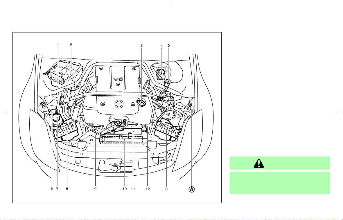
1. Fuse/fusible link holder
2. Battery
3. Engine oil filler cap
4. Brake fluid reservoir
5. Clutch fluid reservoir (M/T models)
6. Window washer fluid reservoir
7. Power steering fluid reservoir
8. Air cleaner
9. Radiator filler cap
10. Engine drive belts
11. Engine coolant reservoir
12. Engine oil dipstick
Do not tamper with the strut tower bar
adjustment
쎻
A
. The strut tower bar has
been adjusted to the most suitable posi-
tion at the factory.
CAUTION
Tampering with the strut tower bar ad-
justment may cause a noise while driv-
ing or damage to the hood or engine.
SDI2050
ENGINE COMPARTMENT CHECK
LOCATIONS
Maintenance and do-it-yourself 8-7
墌 08.7.24/Z33-D/V5.0 墍
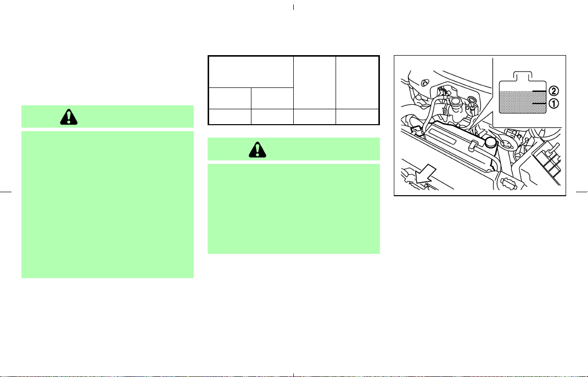
The engine cooling system is filled at the factory
with a high-quality, year-round, anti-freeze cool-
ant solution. The anti-freeze solution contains
rust and corrosion inhibitors, therefore additional
cooling system additives are not necessary.
WARNING
쐌 Never remove the radiator or coolant
reservoir cap when the engine is hot.
Wait until the engine and radiator
cool down. Serious burns could be
caused by high pressure fluid escap-
ing from the radiator. See precau-
tions in “If your vehicle overheats”
found in the “6. In case of emer-
gency” section of this manual.
쐌 The radiator is equipped with a pres-
sure type radiator cap. To prevent
engine damage, use only a genuine
NISSAN radiator cap.
Outside temperature
down to
Anti-
freeze
Deminer-
alized
water/
distilled
water
°C °F
−35 −30 50% 50%
CAUTION
When adding or replacing coolant, be
sure to use only a Genuine NISSAN
Long Life Antifreeze/Coolant (green) or
equivalent with the proper mixture ratio
of 50% anti-freeze and 50% demineral-
ized water/distilled water. The use of
other types of coolant solutions may
damage your engine cooling system.
CHECKING ENGINE COOLANT
LEVEL
Check the coolant level in the reservoir tank
when the engine is cold. If the coolant level is
below MIN
쎻
1
, add coolant up to the MAX
쎻
2
level. If the reservoir tank is empty, check the
coolant level in the radiator when the engine is
cold. If there is insufficient coolant in the radia-
tor, fill the radiator with coolant up to the filler
opening and also add it to the reservoir tank up
to the MAX
쎻
2
level.
Tighten the cap securely after adding engine
coolant.
SDI2051
ENGINE COOLING SYSTEM
8-8 Maintenance and do-it-yourself
墌 08.7.24/Z33-D/V5.0 墍
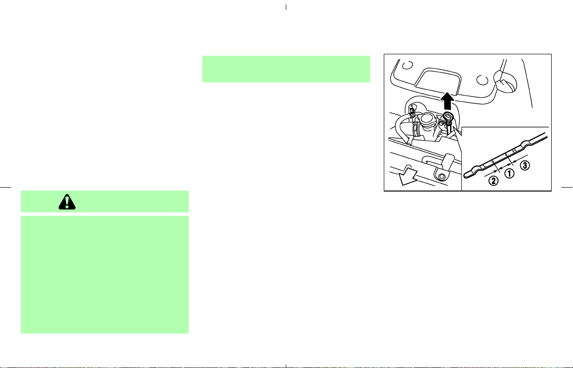
If the engine cooling system frequently
requires coolant, have it checked by a
NISSAN dealer.
CHANGING ENGINE COOLANT
Contact a NISSAN dealer if replacement is
required.
쐌 Major cooling system repairs should be per-
formed by a NISSAN dealer. The service
procedures can be found in the appropriate
NISSAN Service Manual.
쐌 Improper servicing can result in reduced
heater performance and engine overheating.
WARNING
쐌 To avoid being scalded, never change
the coolant when the engine is hot.
쐌 Never remove the radiator cap when
the engine is hot. Serious burns
could be caused by high pressure
fluid escaping from the radiator.
쐌 Avoid direct skin contact with used
coolant. If skin contact is made, wash
thoroughly with soap or hand cleaner
as soon as possible.
쐌 Keep coolant out of reach of children
and pets.
Engine coolant must be disposed of properly.
Check your local regulations.
CHECKING ENGINE OIL LEVEL
1. Park the vehicle on a level surface and apply
the parking brake.
2. Start the engine and let it idle until it reaches
the operating temperature.
3. Turn off the engine. Wait more than 10
minutes for the oil to drain back into the
oil pan.
4. Remove the dipstick and wipe it clean. Rein-
sert it all the way.
SDI2045
ENGINE OIL
Maintenance and do-it-yourself 8-9
墌 08.7.24/Z33-D/V5.0 墍
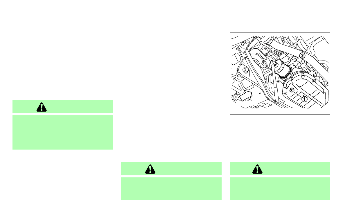
5. Remove the dipstick again and check the oil
level. It should be between the H and L marks
쎻
1
. If the oil level is below the L mark
쎻
2
,
remove the oil filler cap and pour recom-
mended oil through the opening. Do not
overfill
쎻
3
.
6. Recheck oil level with the dipstick.
It is normal to add some oil between oil
maintenance intervals or during the
break-in period, depending on the severity
of operating conditions.
CAUTION
Oil level should be checked regularly.
Operating the engine with an insuffi-
cient amount of oil can damage the
engine, and such damage is not covered
by warranty.
CHANGING ENGINE OIL AND
FILTER
Change the engine oil and filter according to the
maintenance log shown in the “NISSAN Service
and Maintenance Guide”.
Vehicle set-up
1. Park the vehicle on a level surface and apply
the parking brake.
2. Start the engine and let it idle until it reaches
the operating temperature.
3. Turn the engine off and wait more than 10
minutes.
4. Raise and support the vehicle using a suit-
able floor jack and safety jack stands.
쐌 Place the safety jack stands under the vehicle
jack-up points.
쐌 A suitable adapter should be attached to the
jack stand saddle.
5. Remove the plastic engine undercover.
a. Remove the small plastic clip at the center
point of the undercover.
b. Then remove the other bolts that hold the
undercover in place.
CAUTION
Make sure the correct lifting and sup-
port points are used to avoid vehicle
damage.
Engine oil and filter
1. Place a large drain pan under the drain plug
쎻
1
.
2. Remove the oil filler cap.
3. Remove the drain plug with a wrench and
completely drain the oil.
WARNING
쐌 Prolonged and repeated contact with
used engine oil may cause skin
cancer.
SDI2052
8-10 Maintenance and do-it-yourself
墌 08.7.24/Z33-D/V5.0 墍

쐌 Try to avoid direct skin contact with
used oil. If skin contact is made,
wash thoroughly with soap or hand
cleaner as soon as possible.
쐌 Keep used engine oil out of reach of
children.
CAUTION
Be careful not to burn yourself, as the
engine oil is hot.
쐌 Waste oil must be disposed of properly.
쐌 Check your local regulations.
Perform steps 4 to 7 when the engine oil filter
change is needed.
4. Loosen the oil filter with an oil filter wrench
쎻
2
. Remove the oil filter by turning it by hand.
5. Wipe the engine oil filter mounting surface
with a clean rag.
CAUTION
Be sure to remove any old gasket mate-
rial remaining on the mounting surface
of the engine. Failure to do so could
lead to engine damage.
6. Coat the gasket on the new filter with clean
engine oil.
7. Screw in the oil filter clockwise until a slight
resistance is felt, then tighten additionally
more than 2/3 turn.
Oil filter tightening torque:
11 to 15 ft-lb
(14.7 to 20.5 N⋅m)
8. Clean and re-install the drain plug and a new
washer. Securely tighten the drain plug with a
wrench.
Drain plug tightening torque:
22 to 29 ft-lb
(29 to 39 N⋅m)
Do not use excessive force.
9. Refill engine with recommended oil and in-
stall the cap securely.
CAUTION
The dipstick must be inserted in place to
prevent oil spillage from the dipstick
hole while filling the engine with oil.
See “Capacities and recommended fuel/
lubricants” in the “9. Technical and consumer
information” section for drain and refill capac-
ity. The drain and refill capacity depends on
the oil temperature and drain time. Use these
specifications for reference only. Always use
the dipstick to determine the proper amount
of oil in the engine.
10. Start the engine and check for leakage
around the drain plug and the oil filter.
Correct as required.
11. Turn the engine off and wait more than 10
minutes. Check the oil level with the dip-
stick. Add engine oil if necessary.
After the operation
1. Install the engine undercover into position as
outlined in the following steps.
a. Pull the center of the small plastic clip out.
b. Hold the engine undercover into position.
c. Insert the clip through the undercover into the
Maintenance and do-it-yourself 8-11
墌 08.7.24/Z33-D/V5.0 墍
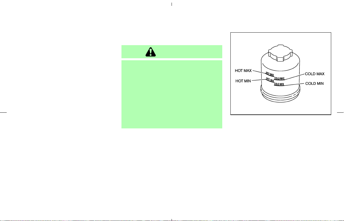
hole in the frame, then push the center of the
clip in to lock the clip in place.
d. Install the other bolts that hold the under-
cover in place. Be careful not to strip the
bolts or over-tighten them.
2. Lower the vehicle carefully to the ground.
3. Dispose of waste oil and filter properly.
When checking or replacement is required, we
recommend a NISSAN dealer for servicing.
CAUTION
쐌 Use only Genuine NISSAN Matic J
ATF. Do not mix with other fluids.
쐌 Using automatic transmission fluid
other than Genuine NISSAN Matic J
ATF will cause deterioration in drive-
ability and automatic transmission
durability, and may damage the auto-
matic transmission, which is not cov-
ered by the NISSAN new vehicle lim-
ited warranty.
Check the fluid level in the reservoir tank.
The fluid level should be checked using the HOT
range at fluid temperatures of 122 - 176°F (50 -
80°C) or using the COLD range at fluid tem-
peratures of 32 - 86°F (0 - 30°C).
If the fluid is below the MIN line, add Genuine
NISSAN PSF fluid. Remove the cap and fill
through the opening.
SDI1443
AUTOMATIC TRANSMISSION
FLUID
POWER STEERING FLUID
8-12 Maintenance and do-it-yourself
墌 08.7.24/Z33-D/V5.0 墍
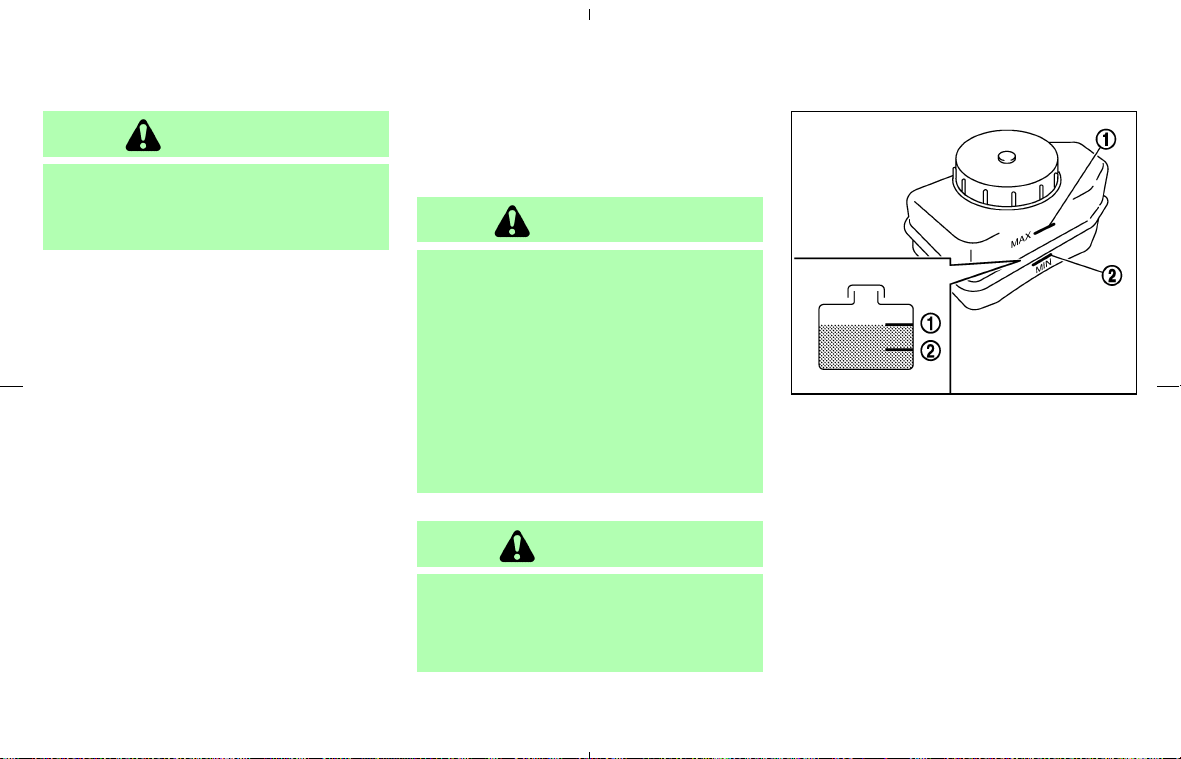
CAUTION
쐌 Do not overfill.
쐌 Recommended fluid is Genuine
NISSAN PSF or equivalent.
For more information regarding suitable equiva-
lents, see “Capacities and recommended
fuel/lubricants” in the “9. Technical and con-
sumer information” section.
For additional brake and clutch fluid information,
refer to “Capacities and recommended fuel/
lubricants” in the “9. Technical and consumer
information” section of this manual.
WARNING
쐌 Use only new fluid from a sealed
container. Old, inferior or contami-
nated fluid may damage the brake
system. The use of improper fluids
can damage the brake system and
affect the vehicle’s stopping ability.
쐌 Clean the filler cap before removing.
쐌 Brake fluid is poisonous and should
be stored carefully in marked con-
tainers out of the reach of children.
CAUTION
Do not spill the fluid on any painted
surfaces. This will damage the paint. If
fluid is spilled, immediately wash the
surface with water.
BRAKE FLUID
Check the fluid level in the reservoir. If the fluid is
below the MIN line
쎻
2
or the brake warning light
comes on, add Genuine NISSAN Super Heavy
Duty Brake Fluid or equivalent DOT 3 fluid up to
the MAX line
쎻
1
. If fluid must be added fre-
quently, the system should be thoroughly
checked by a NISSAN dealer.
SDI1923
BRAKE AND CLUTCH FLUID
Maintenance and do-it-yourself 8-13
墌 08.7.24/Z33-D/V5.0 墍
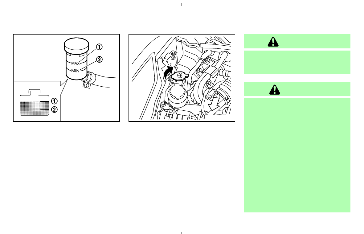
CLUTCH FLUID
Check the fluid level in the reservoir. If the fluid
level is below the MIN line
쎻
2
, add Genuine
NISSAN Super Heavy Duty Brake Fluid or
equivalent DOT 3 fluid up to the MAX line
쎻
1
.
If fluid is added frequently, the system should be
thoroughly checked by a NISSAN dealer.
Add fluid when the low washer fluid warning light
comes on.
Add a washer solvent to the washer fluid for
better cleaning. In the winter season, add a
windshield washer anti-freeze. Follow the manu-
facturer’s instructions for the mixture ratio.
Recommended fluid is Genuine NISSAN Wind-
shield Washer Concentrate Cleaner & Anti-
freeze or equivalent.
WARNING
Anti-freeze is poisonous and should be
stored carefully in marked containers
out of the reach of children.
CAUTION
쐌 Do not substitute engine anti-freeze
coolant for window washer solution.
This may result in damage to the
paint.
쐌 Do not fill the window washer reser-
voir tank with washer fluid concen-
trates at full strength. Some methyl
alcohol based washer fluid concen-
trates may permanently stain the
grille if spilled while filling the win-
dow washer reservoir tank.
쐌 Pre-mix washer fluid concentrates
with water to the manufacturer’s rec-
ommended levels before pouring the
fluid into the window washer reser-
voir tank. Do not use the window
SDI1906 SDI2053
WINDOW WASHER FLUID
8-14 Maintenance and do-it-yourself
墌 08.7.24/Z33-D/V5.0 墍

washer reservoir tank to mix the
washer fluid concentrate and water.
쐌 Keep the battery surface clean and dry. Clean
the battery with a solution of baking soda and
water.
쐌 Make certain the terminal connections are
clean and securely tightened.
쐌 If the vehicle is not to be used for 30 days or
longer, disconnect the (−) negative battery
terminal to prevent discharging it.
CAUTION
When the battery cable is removed from
the battery terminal, do not close either
of the front doors. The automatic win-
dow adjusting function will not work,
and the side roof panel/top side rail
may be damaged by doing so.
To disconnect the negative (−) battery ter-
minal, perform the procedure in the follow-
ing order. Otherwise, the window and the
side roof panel/top side rail may contact
and be damaged.
1. Close the windows.
2. Open the hood.
3. Close and lock all the doors using the
key or keyfob.
4. Disconnect the negative (−) battery ter-
minal.
5. Securely close the hood.
To connect the negative (−) battery termi-
nal, perform the procedure in the following
order. Otherwise, the window and the side
roof panel/top side rail may contact and be
damaged.
1. Unlock (using the key) and open the
driver side door. Do not close the door.
2. Open the hood.
3. Connect the negative (−) battery termi-
nal. Then close the hood.
4. Fully open the driver side door window.
5. Close the driver side door and the win-
dow.
WARNING
쐌 Do not expose the battery to flames
or electrical sparks. Hydrogen gas,
generated by battery fluid, is explo-
sive. Do not allow battery fluid to
BATTERY
Maintenance and do-it-yourself 8-15
墌 08.7.24/Z33-D/V5.0 墍
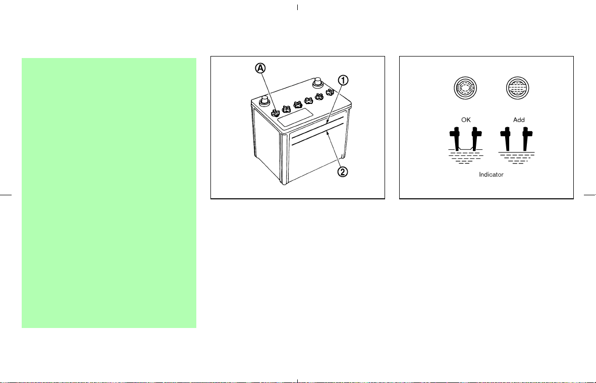
contact your skin, eyes, fabrics, or
painted surfaces. After touching a
battery or battery cap, do not touch
or rub your eyes. Thoroughly wash
your hands. If the acid contacts your
eyes, skin or clothing, immediately
flush with water for at least 15 min-
utes and seek medical attention.
쐌 Do not operate the vehicle if the fluid
in the battery is low. Low battery fluid
can cause a higher load on the bat-
tery which can generate heat, reduce
battery life, and in some cases lead
to an explosion.
쐌 When working on or near a battery,
always wear suitable eye protection
and remove all jewelry.
쐌 Battery posts, terminals and related
accessories contain lead and lead
compounds. Wash hands after han-
dling.
쐌 Keep the battery out of the reach of
children.
Check the fluid level in each cell. It should be
between the UPPER LEVEL
쎻
1
and LOWER
LEVEL
쎻
2
lines.
If it is necessary to add fluid, add only distilled
water to bring the level to the indicator in each
filler opening. Do not overfill.
Vehicles operated in high temperatures or under
severe conditions require frequent checks of the
battery fluid level.
1. Remove the cell plugs
쎻
A
.
2. Add distilled water up to the UPPER LEVEL
line
쎻
1
.
3. Tighten cell plugs.
JUMP STARTING
If jump starting is necessary, see “Jump starting”
in the “6. In case of emergency” section. If the
engine does not start by jump starting, the
battery may have to be replaced. Contact a
NISSAN dealer.
DI0137MA SDI1480
8-16 Maintenance and do-it-yourself
墌 08.7.24/Z33-D/V5.0 墍
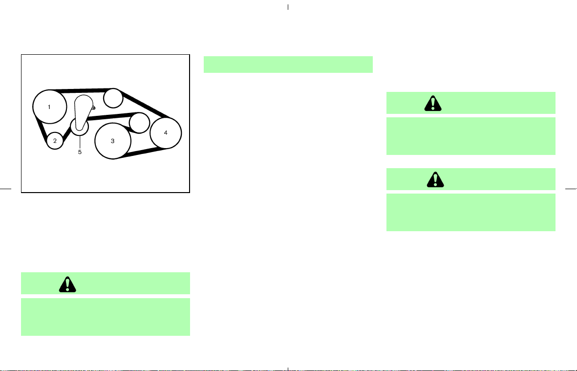
1. Power steering fluid pump
2. Alternator
3. Crankshaft pulley
4. Air conditioner compressor
5. Drive belt auto-tensioner
WARNING
Be sure the ignition key is in the OFF or
LOCK position before servicing drive
belts. The engine could rotate
unexpectedly.
1. Visually inspect each belt for signs of unusual
wear, cuts, fraying, oil adhesion or looseness.
If the belt is in poor condition or loose, have
it replaced or adjusted by a NISSAN dealer.
2. Have the belts checked regularly for condi-
tion.
REPLACING SPARK PLUGS
If replacement is required, see a NISSAN dealer
for servicing.
WARNING
Be sure the engine and ignition switch
are off and that the parking brake is
engaged securely.
CAUTION
Be sure to use the correct socket to
remove the spark plugs. An incorrect
socket can damage the spark plugs.
SDI2061
DRIVE BELTS SPARK PLUGS
Maintenance and do-it-yourself 8-17
墌 08.7.24/Z33-D/V5.0 墍
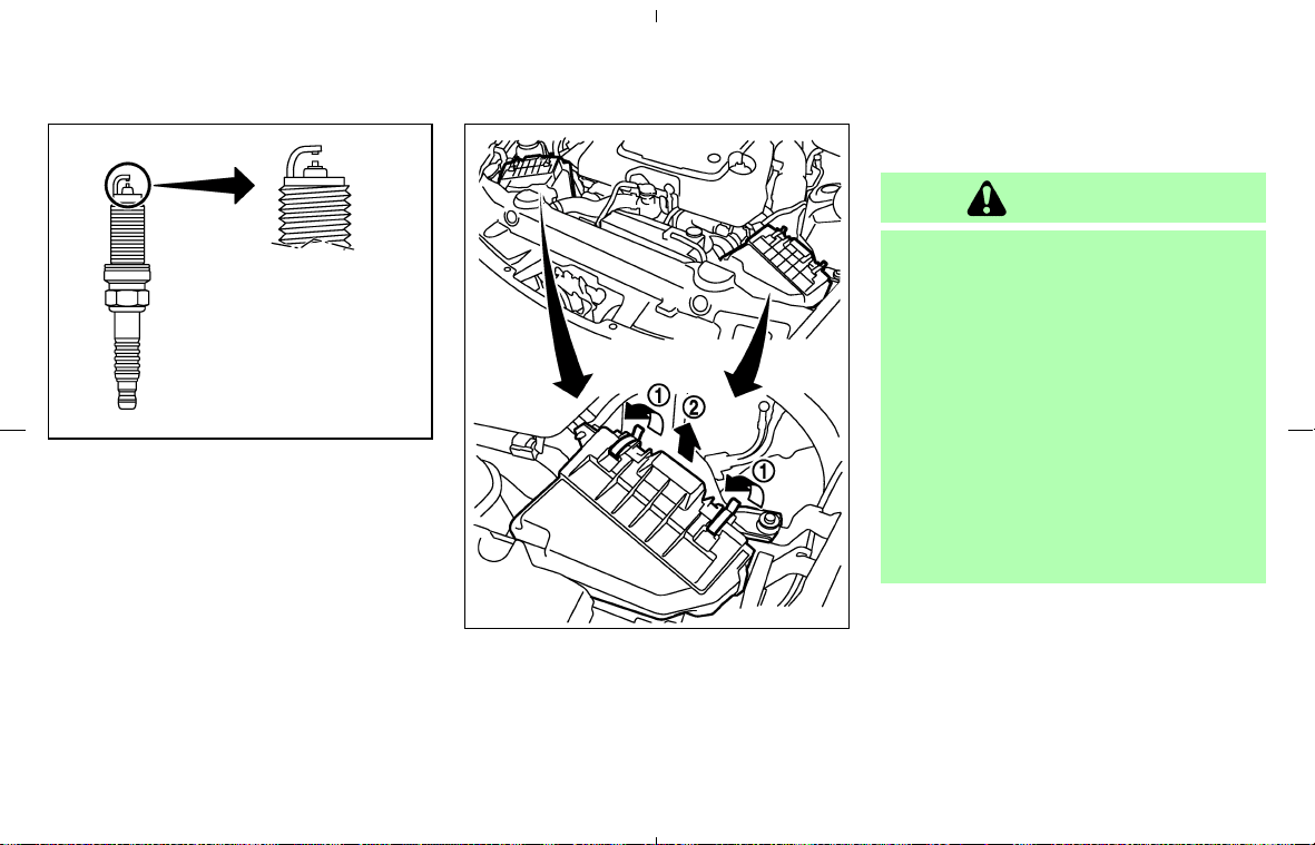
Iridium-tipped spark plugs
It is not necessary to replace the iridium-tipped
spark plugs as frequently as the conventional
type spark plugs since they will last much longer.
Follow the maintenance log shown in the
“NISSAN Service and Maintenance Guide”, but
do not service iridium-tipped spark plugs by
cleaning or regapping.
Always replace spark plugs with recom-
mended or equivalent ones.
To remove the filter from the air cleaner, pull off
the retainers
쎻
1
and pull the unit upward
쎻
2
.
The filter element should not be cleaned and
reused. Replace it according to the maintenance
log shown in the “NISSAN Service and Mainte-
nance Guide”. When replacing the filter, wipe
the inside of the air cleaner housing and the
cover with a damp cloth.
WARNING
쐌 Operating the engine with the air
cleaner removed can cause you or
others to be burned. The air cleaner
not only cleans the air, it stops the
flame if the engine backfires. If it is
not there, and the engine backfires,
you could be burned. Do not drive
with the air cleaner removed, and be
careful when working on the engine
with the air cleaner removed.
쐌 Never pour fuel into the throttle body
or attempt to start the engine with
the air cleaner removed. Doing so
could result in serious injury.
SDI2020
SDI2054
AIR CLEANERS
8-18 Maintenance and do-it-yourself
墌 08.7.24/Z33-D/V5.0 墍

CAUTION
쐌 After wiper blade replacement, return
the wiper arm to its original position.
Otherwise it may be damaged when
the engine hood is opened.
쐌 Make sure the wiper blades contact
the glass; otherwise the arms may be
damaged from wind pressure.
쐌 Worn windshield wiper blades can
damage the windshield and impair
driver vision.
CLEANING
If your windshield is not clear after using the
windshield washer or if a wiper blade chatters
when running, wax or other material may be on
the blade or windshield.
Clean the outside of the windshield with a
washer solution or a mild detergent. Your wind-
shield is clean if beads do not form when rinsing
with clear water.
Clean the blade by wiping it with a cloth soaked
in a washer solution or a mild detergent. Then
rinse the blade with clear water. If your wind-
shield is still not clear after cleaning the blades
and using the wiper, replace the blades.
WINDSHIELD WIPER BLADES
Maintenance and do-it-yourself 8-19
墌 08.7.24/Z33-D/V5.0 墍
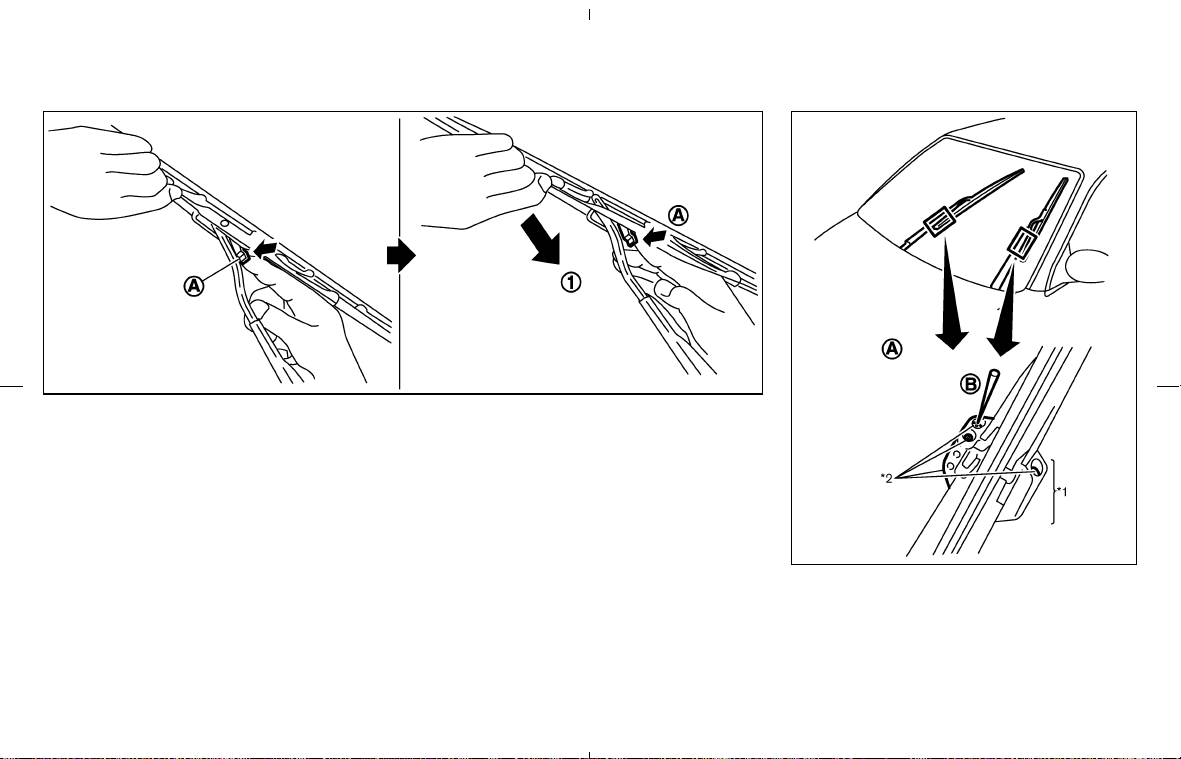
REPLACING
Replace the wiper blades if they are worn.
1. Pull the wiper arm.
2. Push the release tab
쎻
A
, then move the wiper
blade down the wiper arm to remove
쎻
1
.
3. Insert the new wiper blade onto the wiper arm
until a click sounds.
If necessary, clean the windshield washer
nozzle
쎻
A
with a needle or small pin 쎻
B
.
*1: Only for passenger’s side wiper arm
*2: Adjustable washer nozzles
SDI1649
SDI1730A
8-20 Maintenance and do-it-yourself
墌 08.7.24/Z33-D/V5.0 墍
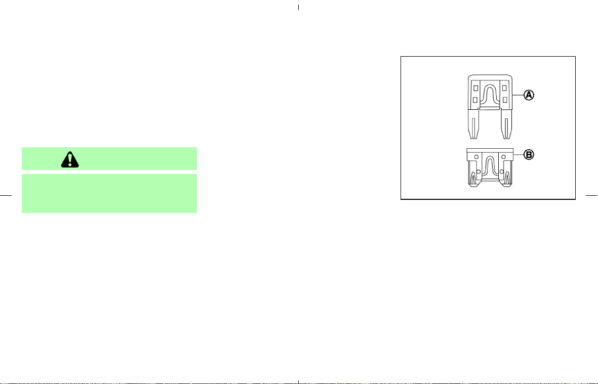
If the brakes do not operate properly, have the
brakes checked by a NISSAN dealer.
SELF-ADJUSTING BRAKES
Your vehicle is equipped with self-adjusting
brakes.
The disc-type brakes self-adjust every time the
brake pedal is applied.
WARNING
See a NISSAN dealer for a brake system
check if the brake pedal height does not
return to normal.
BRAKE PAD WEAR INDICATORS
The disc brake pads on your vehicle have au-
dible wear indicators. When a brake pad re-
quires replacement, it will make a high pitched
scraping or screeching sound when the vehicle
is in motion whether or not the brake pedal is
depressed. Have the brakes checked as soon as
possible if the wear indicator sound is heard.
Under some driving or climate conditions, occa-
sional brake squeak, squeal or other noise may
be heard. Occasional brake noise during light to
moderate stops is normal and does not affect
the function or performance of the brake system.
Proper brake inspection intervals should
be followed. For additional information, see the
appropriate maintenance log shown in the
NISSAN Service and Maintenance Guide.
Some vehicles are equipped with engine com-
partment and passenger compartment fuse
boxes that use only type
쎻
A
fuses. Other ve-
hicles are equipped with type
쎻
A
fuses in the
engine compartment fuse box and type
쎻
B
fuses
in the passenger compartment fuse box.
Type
쎻
A
fuses are provided as spare fuses. They
are stored in the passenger compartment fuse
box.
Type
쎻
A
fuses can be installed in the engine
compartment and passenger compartment fuse
boxes.
SDI1751
BRAKES FUSES
Maintenance and do-it-yourself 8-21
墌 08.7.24/Z33-D/V5.0 墍
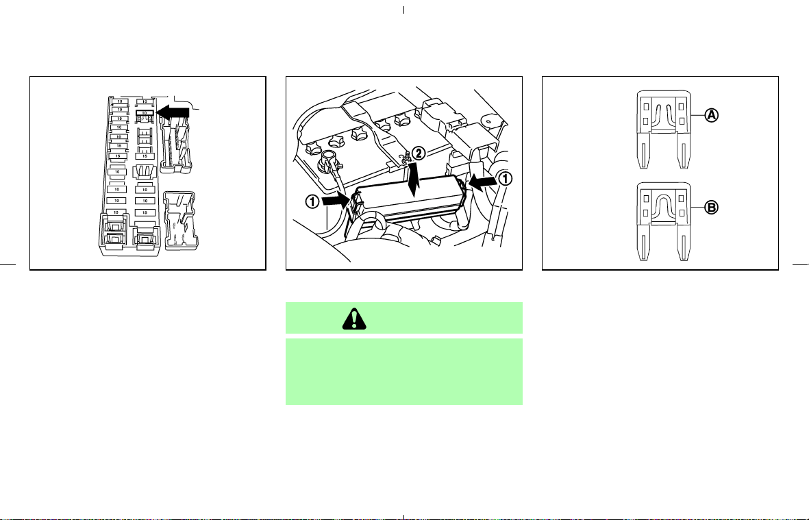
If a type 쎻
A
fuse is used to replace a type 쎻
B
fuse, the type 쎻
A
fuse will not be level with the
fuse pocket as shown in the illustration. This will
not affect the performance of the fuse. Make
sure the fuse is installed in the fuse box securely.
Type
쎻
B
fuses cannot be installed in the under-
hood fuse boxes. Only use type
쎻
A
fuses in the
underhood fuse boxes.
ENGINE COMPARTMENT
CAUTION
Never use a fuse of a higher or lower
amperage rating than that specified on
the fuse box cover. This could damage
the electrical system or cause a fire.
If any electrical equipment does not operate,
check for an open fuse.
1. Be sure the ignition switch and headlight
switch are OFF.
2. Open the engine hood and remove the cover
on the battery and the fuse/fusible link holder.
3. Remove the fuse/fusible link holder cover by
pushing the tabs
쎻
1
and lifting the cover
쎻
2
.
4. Remove the fuse with the fuse puller. The
fuse puller is located in the passenger com-
partment fuse box.
5. If the fuse is open
쎻
A
, replace it with a new
fuse
쎻
B
. Spare fuses are stored in the pas-
senger compartment fuse box.
6. If a new fuse also opens, have the electrical
system checked and repaired by a NISSAN
dealer.
SDI1752 SDI1479B SDI1753
8-22 Maintenance and do-it-yourself
墌 08.7.24/Z33-D/V5.0 墍
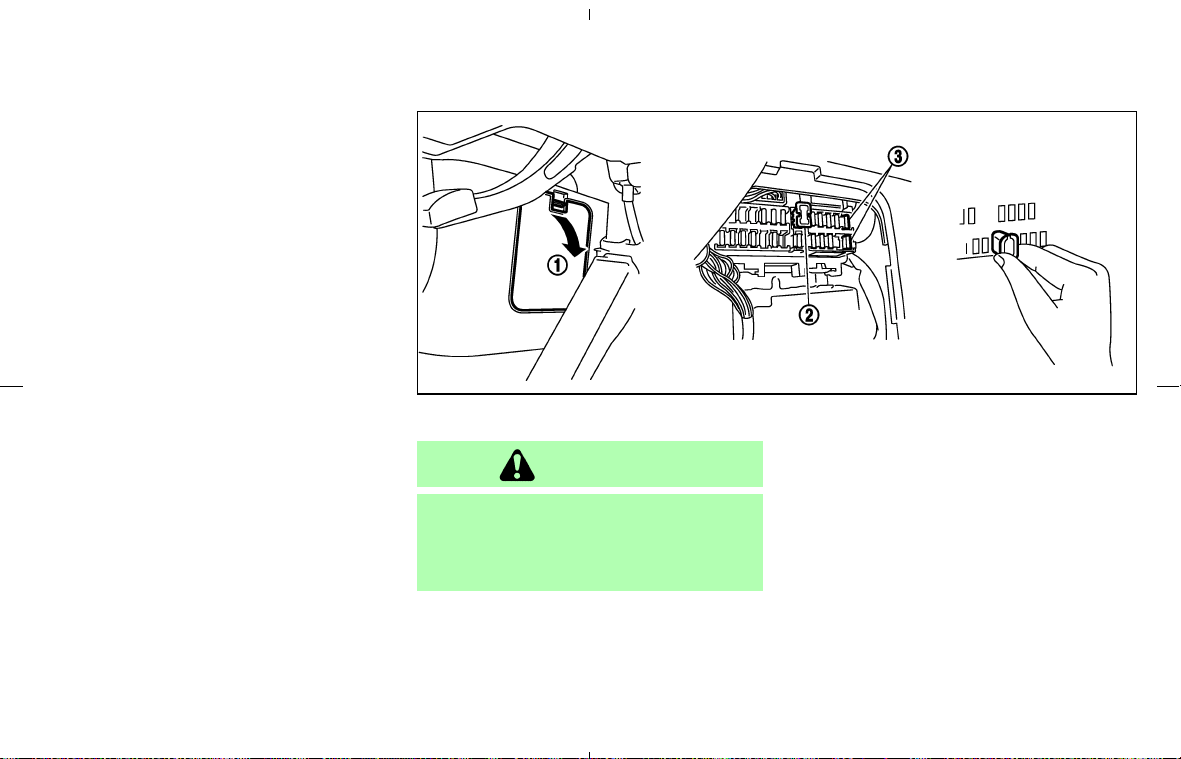
Fusible links
If any electrical equipment does not operate and
fuses are in good condition, check the fusible
links. If any of these fusible links are melted,
replace only with genuine NISSAN parts.
PASSENGER COMPARTMENT
CAUTION
Never use a fuse of a higher or lower
amperage rating than that specified on
the fuse box cover. This could damage
the electrical system or cause a fire.
If any electrical equipment does not operate,
check for an open fuse.
1. Be sure the ignition switch and the headlight
switch are OFF.
2. Open the fuse box lid
쎻
1
.
3. Pinch the fuse perpendicularly with the fuse
puller
쎻
2
and pull it out.
SDI1962
Maintenance and do-it-yourself 8-23
墌 08.7.24/Z33-D/V5.0 墍
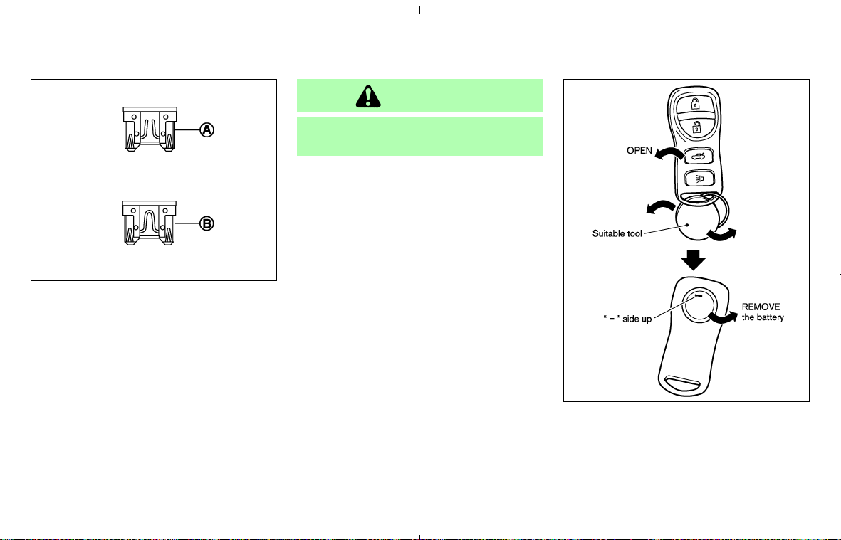
4. If the fuse is open 쎻
A
, replace it with a new
fuse
쎻
B
. Spare fuses
쎻
3
are stored in the
fuse box.
5. If a new fuse also opens, have the electrical
system checked and repaired by a NISSAN
dealer.
CAUTION
Be careful not to allow children to swal-
low the battery and removed parts.
Replace the battery as follows:
1. Open the lid using a suitable tool.
2. Replace the battery with a new one.
Recommended battery:
CR2025 or equivalent
SDI1754
SDI1608
KEYFOB BATTERY
REPLACEMENT
8-24 Maintenance and do-it-yourself
墌 08.7.24/Z33-D/V5.0 墍

Make sure that the ⊕ side faces the
bottom case.
쐌 Do not touch the internal circuit and electric
terminals as doing so could cause a malfunc-
tion.
3. Close the lid securely.
4. Push the keyfob button two or three times to
check its operation.
See a NISSAN dealer if you need any assistance
for replacement.
If the battery is removed for any reason
other than replacement, perform step 4
above.
쐌 Be careful not to touch the circuit board
and the battery terminal.
쐌 An improperly disposed battery can
harm the environment. Always confirm
local regulations for battery disposal.
쐌 The keyfob is water-resistant; however,
if it gets wet, immediately wipe it com-
pletely dry.
쐌 When changing batteries, do not let
dust or oil get on the keyfob.
FCC Notice:
Changes or modifications not expressly
approved by the party responsible for com-
pliance could void the user’s authority to
operate the equipment.
This device complies with Part 15 of the
FCC Rules and RSS-210 of Industry
Canada.
Operation is subject to the following two
conditions: (1) This device may not cause
harmful interference, and (2) this device
must accept any interference received, in-
cluding interference that may cause undes-
ired operation of the device.
Maintenance and do-it-yourself 8-25
墌 08.7.24/Z33-D/V5.0 墍
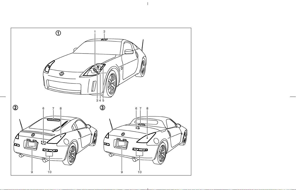
쎻
1
Front view
1. Headlight (low-beam, high-beam)
2. Spot light
3. Front park light
4. Front turn signal light
5. Front side marker light
쎻
2
Rear view (Coupe),
쎻
3
Rear view (Roadster)
6. Luggage compartment light (Coupe) or Trunk
light (Roadster)
7. High-mounted stop light
8. Rear combination light
(Side marker, Stop/Tail)
9. License plate lights
10. Rear combination light
(Back-up, Turn signal)
SDI2058
LIGHTS
8-26 Maintenance and do-it-yourself
墌 08.7.24/Z33-D/V5.0 墍

HEADLIGHTS
Replacing
If replacement is required, see a NISSAN dealer.
Xenon headlight bulb:
WARNING
HIGH VOLTAGE
When xenon headlights are on, they
produce a high voltage. To prevent an
electric shock, never attempt to modify
or disassemble. Always have your xe-
non headlights replaced at a NISSAN
dealer. For additional information, see
“Headlight and turn signal switch” in
the “2. Instruments and controls” sec-
tion.
CAUTION
Use the same number and wattage as
originally installed:
Bulb no. (Wattage)
D2S (35W) - Xenon low/high-beam
Fog may temporarily form inside the lens of the
exterior lights in the rain or in a car wash. A
temperature difference between the inside and
the outside of the lens causes the fog. This is not
a malfunction. If large drops of water collect
inside the lens, contact a NISSAN dealer.
Maintenance and do-it-yourself 8-27
墌 08.7.24/Z33-D/V5.0 墍
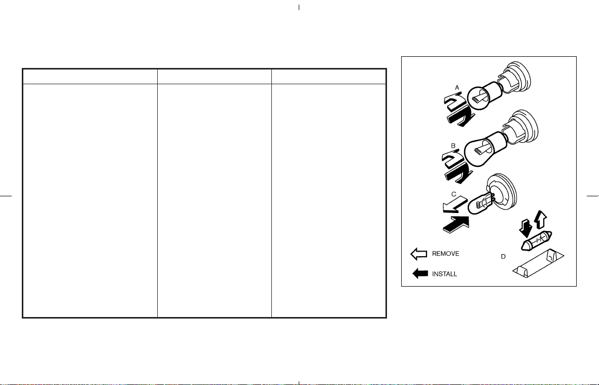
EXTERIOR AND INTERIOR LIGHTS
Item Wattage (W) Bulb No.
Front turn signal light* 28/8 3457NA
Front park light* 5 T10
Front side marker light* (LED) —
Rear combination light (Upper)
Stop/Tail* (LED) —
Side marker* (LED) —
Rear combination light (Lower)
Back-up* 21 T20
Turn signal* 21 T20
License plate light (x 2) 5 T10
High-mounted stop light* (LED) —
Spot light 8 —
Luggage compartment light (Coupe) 5 —
Trunk light (Roadster)* 3.4 —
Vanity mirror light 1.8 —
Cup holder light* 1.1 —
Rear floor box light* 1.4 —
*: See a NISSAN dealer for replacement.
NOTE: Always check with the Parts Department at a NISSAN dealer for the latest information about parts.
Replacement procedures
All other lights are either type A, B, C or D. When
replacing a bulb, first remove the lens and/or
cover.
MDI0006
8-28 Maintenance and do-it-yourself
墌 08.7.24/Z33-D/V5.0 墍
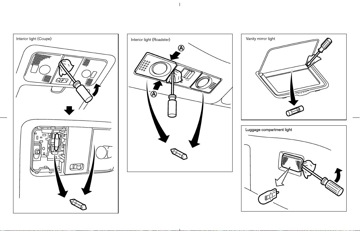
Interior light (Roadster)
Be careful not to snap the nails
쎻
A
on the plastic
cover when removing it.
SDI1450A
SDI1572
SDI1779
SDI1451
Maintenance and do-it-yourself 8-29
墌 08.7.24/Z33-D/V5.0 墍
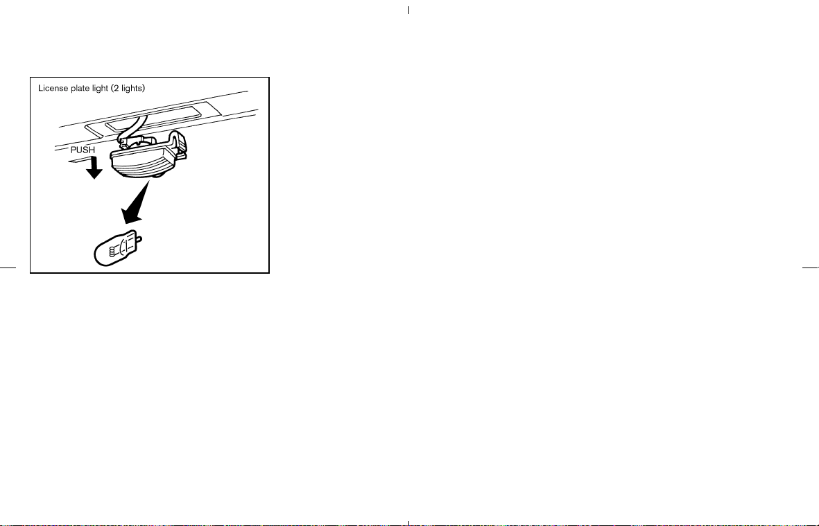
TIRE PRESSURE
Tire Pressure Monitoring System
(TPMS)
This vehicle is equipped with the Tire Pressure
Monitoring System (TPMS). It monitors tire pres-
sure of all tires except the spare. When the low
tire pressure warning light is lit, one or more of
your tires is significantly under-inflated.
The TPMS will activate only when the vehicle is
driven at speeds above 16 MPH (25 km/h). Also,
this system may not detect a sudden drop in tire
pressure (for example a flat tire while driving).
For more details, refer to “Low tire pressure
warning light” in the “2. Instruments and con-
trols” section, “Tire pressure monitoring system
(TPMS)” in the “5. Starting and driving” section,
and “Flat tire” in the “6. In case of emergency”
section.
Tire inflation pressure
Check the tire pressures (including the
spare) often and always prior to long
distance trips. The recommended tire
pressure specifications are shown on the
Tire and Loading Information label under
the “COLD TIRE PRESSURE” heading.
The Tire and Loading Information label is
affixed to the driver side center pillar. Tire
pressures should be checked regularly
because:
쐌 Most tires naturally lose air over time.
쐌 Tires can lose air suddenly when
driven over potholes or other objects
or if the vehicle strikes a curb while
parking.
The tire pressures should be checked
when the tires are cold. The tires are
considered COLD after the vehicle has
been parked for 3 or more hours, or
driven less than 1 mile (1.6 km) at mod-
erate speeds.
SDI1401A
WHEELS AND TIRES
8-30 Maintenance and do-it-yourself
墌 08.7.24/Z33-D/V5.0 墍

Incorrect tire pressure, including un-
der inflation, may adversely affect
tire life and vehicle handling.
WARNING
쐌 Improperly inflated tires can fail
suddenly and cause an acci-
dent.
쐌 The Gross Vehicle Weight Rat-
ing (GVWR) is located on the
F.M.V.S.S./C.M.V.S.S. certifica-
tion label. The vehicle weight
capacity is indicated on the Tire
and Loading Information label.
Do not load your vehicle be-
yond this capacity. Overloading
your vehicle may result in re-
duced tire life, unsafe operating
conditions due to premature
tire failure, or unfavorable han-
dling characteristics and could
also lead to a serious accident.
Loading beyond the specified
capacity may also result in fail-
ure of other vehicle compo-
nents.
쐌 Before taking a long trip, or
whenever you heavily load your
vehicle, use a tire pressure
gauge to ensure that the tire
pressures are at the specified
level.
쐌 Do not drive your vehicle over
85 MPH (137 km/h) unless it is
equipped with high speed rated
tires. Driving faster than 85
MPH (137 km/h) may result in
tire failure, loss of control and
possible injury.
쐌 For additional information re-
garding tires, refer to “Impor-
tant Tire Safety Information”
(US) or “Tire Safety Informa-
tion” (Canada) in the Warranty
Information Booklet.
Maintenance and do-it-yourself 8-31
墌 08.7.24/Z33-D/V5.0 墍
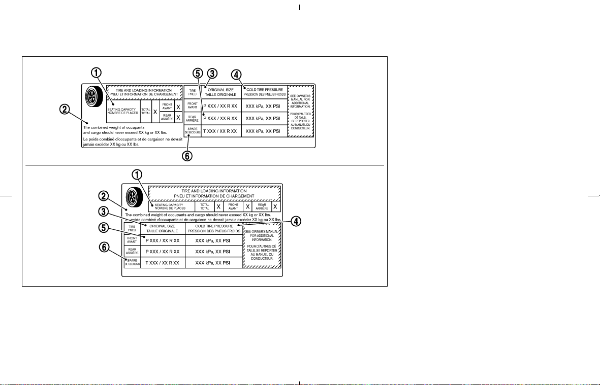
Tire and Loading Information label
쎻
1
Seating capacity: The maximum
number of occupants that can be
seated in the vehicle.
쎻
2
Vehicle load limit: See loading infor-
mation in the “Technical and con-
sumer information” section.
쎻
3
Original size: The size of the tires
originally installed on the vehicle at
the factory.
쎻
4
Cold tire pressure: Inflate the tires to
this pressure when the tires are cold.
Tires are considered COLD after the
vehicle has been parked for 3 or
more hours, or driven less than 1
mile (1.6 km) at moderate speeds.
The recommended cold tire inflation
is set by the manufacturer to provide
the best balance of tire wear, vehicle
handling, driveability, tire noise, etc.,
up to the vehicle’s GVWR.
쎻
5
Tire size — refer to “Tire labeling”
later in this section.
쎻
6
Spare tire size or compact spare tire
size (if so equipped).
SDI1948
8-32 Maintenance and do-it-yourself
墌 08.7.24/Z33-D/V5.0 墍
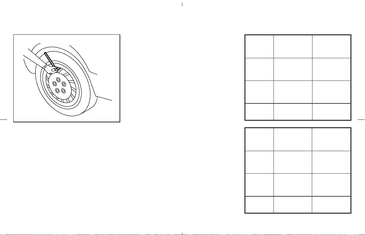
Checking the tire pressure
1. Remove the valve stem cap from the
tire.
2. Press the pressure gauge squarely
onto the valve stem. Do not press too
hard or force the valve stem sideways,
or air will escape. If the hissing sound
of air escaping from the tire is heard
while checking the pressure, reposi-
tion the gauge to eliminate this leak-
age.
3. Remove the gauge.
4. Read the tire pressure on the gauge
stem and compare it to the specifica-
tion shown on the Tire and Loading
Information label.
5. Add air to the tire as needed. If too
much air is added, press the core of
the valve stem briefly with the tip of the
gauge stem to release pressure. Re-
check the pressure and add or release
air as needed.
6. Install the valve stem cap.
7. Check the pressure of all other tires,
including the spare.
Coupe
model
Size
Cold Tire
Inflation
Pressure
Front
Original
Tire
225/45R18
245/40R18
240 kPa
(35 psi)
Rear
Original
Tire
245/45R18
265/35R19
240 kPa
(35 psi)
Spare
Tire
T145/80D17
420 kPa
(60 psi)
Roadster
model
Size
Cold Tire
Inflation
Pressure
Front
Original
Tire
225/45R18
240 kPa
(35 psi)
Rear
Original
Tire
245/45R18
240 kPa
(35 psi)
Spare
Tire
T145/80D17
420 kPa
(60 psi)
SDI1949
Maintenance and do-it-yourself 8-33
墌 08.7.24/Z33-D/V5.0 墍
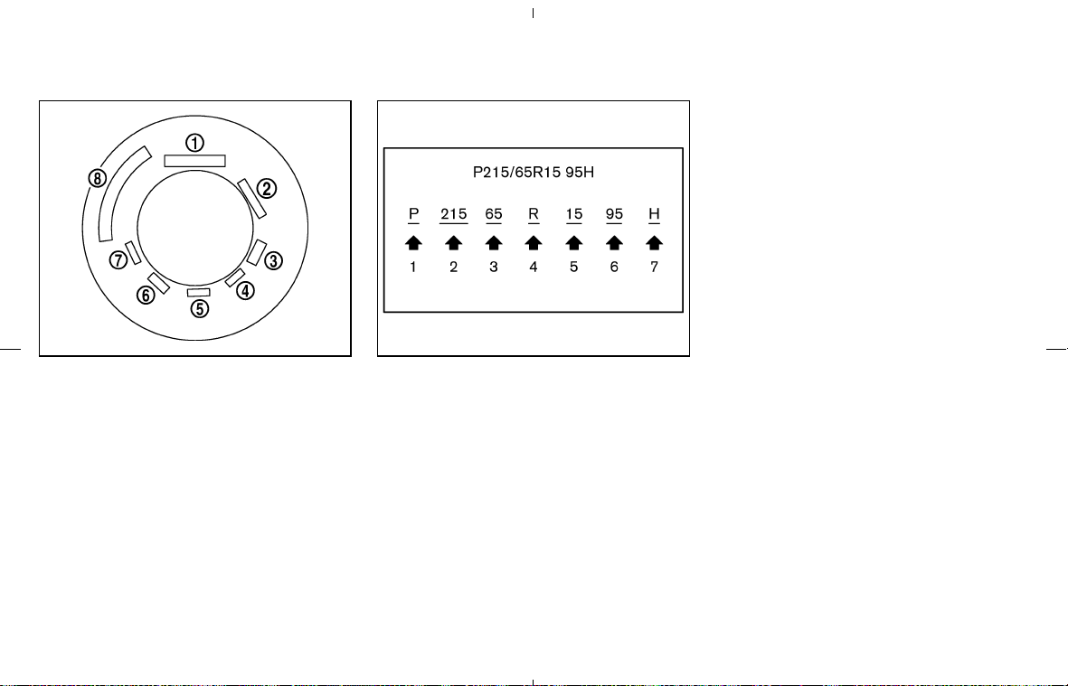
TIRE LABELING
Federal law requires tire manufacturers
to place standardized information on the
sidewall of all tires. This information iden-
tifies and describes the fundamental
characteristics of the tire and also pro-
vides the tire identification number (TIN)
for safety standard certification. The TIN
can be used to identify the tire in case of
a recall.
쎻
1
Tire size (example: P215/65R15
95H)
1. P: The “P” indicates the tire is de-
signed for passenger vehicles. (Not all
tires have this information.)
2. Three-digit number (215): This num-
ber gives the width in millimeters of the
tire from sidewall edge to sidewall
edge.
3. Two-digit number (65): This number,
known as the aspect ratio, gives the
tire’s ratio of height to width.
4. R: The “R” stands for radial.
5. Two-digit number (15): This number is
the wheel or rim diameter in inches.
6. Two- or three-digit number (95): This
number is the tire’s load index. It is a
measurement of how much weight
each tire can support. You may not
find this information on all tires be-
cause it is not required by law.
7. Tire Speed Rating. You should not
drive the vehicle faster than the tire
speed rating.
SDI1575
Example
SDI1951
Example
8-34 Maintenance and do-it-yourself
墌 08.7.24/Z33-D/V5.0 墍
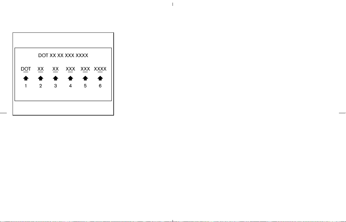
쎻
2
TIN (Tire Identification Number) for a
new tire (example: DOT XX XX XXX
XXXX)
1. DOT: Abbreviation for the “Depart-
ment of Transportation”. The
symbol can be placed above,
below or to the left or right of the
Tire Identification Number.
2. Two-digit code: Manufacturer’s identi-
fication mark
3. Two-digit code: Tire size
4. Three-digit code: Tire type code (Op-
tional)
5. Three-digit code: Date of Manufacture
6. Four numbers represent the week and
year the tire was built. For example, the
numbers 3103 means the 31st week
of 2003. If these numbers are missing,
then look on the other sidewall of the
tire.
쎻
3
Tire ply composition and material
The number of layers or plies of
rubber-coated fabric in the tire. Tire
manufacturers also must indicate the
materials in the tire, which include
steel, nylon, polyester, and others.
쎻
4
Maximum permissible inflation pres-
sure
This number is the greatest amount
of air pressure that should be put in
the tire. Do not exceed the maximum
permissible inflation pressure.
쎻
5
Maximum load rating
This number indicates the maximum
load in kilograms and pounds that
can be carried by the tire. When
replacing the tires on the vehicle,
always use a tire that has the same
load rating as the factory installed
tire.
쎻
6
Term of “tubeless” or “tube type”
Indicates whether the tire requires an
inner tube (“tube type”) or not
(“tubeless”).
쎻
7
The word “radial”
The word “radial” is shown if the tire
has radial structure.
쎻
8
Manufacturer or brand name
Manufacturer or brand name is
shown.
Other tire-related terminology:
In addition to the many terms that are
defined throughout this section, Intended
Outboard Sidewall is (1) the sidewall that
contains a whitewall, bears white letter-
ing or bears manufacturer, brand, and/or
model name molding that is higher or
deeper than the same molding on the
SDI1607
Example
Maintenance and do-it-yourself 8-35
墌 08.7.24/Z33-D/V5.0 墍

other sidewall of the tire, or (2) the
outward facing sidewall of an asymmetri-
cal tire that has a particular side that must
always face outward when mounted on a
vehicle.
TYPES OF TIRES
WARNING
쐌 When changing or replacing tires, be
sure all four tires are of the same
type (i.e., Summer, All Season or
Snow) and construction. A NISSAN
dealer may be able to help you with
information about tire type, size,
speed rating and availability.
쐌 Replacement tires may have a lower
speed rating than the factory
equipped tires, and may not match
the potential maximum vehicle
speed. Never exceed the maximum
speed rating of the tire.
쐌 Replacing tires with those not origi-
nally specified by NISSAN could af-
fect the proper operation of the tire
pressure monitoring system (TPMS).
쐌 For additional information regarding
tires, refer to “Important Tire Safety
Information” (US) or “Tire Safety In-
formation” (Canada) in the Warranty
Information Booklet.
All season tires
NISSAN specifies all season tires on some
models to provide good performance for use all
year round, including snowy and icy road condi-
tions. All season tires are identified by ALL
SEASON and/or M&S on the tire sidewall. Snow
tires have better snow traction than all season
tires and may be more appropriate in some
areas.
Summer tires
NISSAN specifies summer tires on some models
to provide superior performance on dry roads.
Summer tire performance in snow and ice will be
substantially reduced. Summer tires do not have
the tire traction rating M&S on the tire sidewall.
If you operate your vehicle in snowy or icy
conditions, NISSAN recommends the use of
snow or all season tires on all four wheels.
Snow tires
If snow tires are needed, it is necessary to select
tires equivalent in size and load rating to the
original equipment tires. If you do not, it can
adversely affect the safety and handling of your
vehicle.
Generally, snow tires will have lower speed
ratings than factory equipped tires and may not
match the potential maximum vehicle speed.
Never exceed the maximum speed rating of the
tire.
If you operate your vehicle in snowy or icy
conditions, NISSAN recommends the use of
snow or all season tires on all four wheels.
For additional traction on icy roads, studded tires
may be used. However, some provinces and
states prohibit their use. Check local, state and
provincial laws before installing studded tires.
Skid and traction capabilities of studded snow
tires, on wet or dry surfaces, may be poorer than
that of non-studded snow tires.
8-36 Maintenance and do-it-yourself
墌 08.7.24/Z33-D/V5.0 墍

TIRE CHAINS
CAUTION
Tire chains/cables should not be in-
stalled on 265/35R19 size tires. Installa-
tion of the tire chains/cables on
265/35R19 size tires will cause damage
to the vehicle. If you plan to use tire
chains/cables, you should install
245/45R18 size tires on your vehicle.
Use of tire chains may be prohibited according
to location. Check the local laws before installing
tire chains. When installing tire chains, make
sure they are of proper size for the tires on your
vehicle and are installed according to the chain
manufacturer’s suggestions. Use only SAE
class “S” chains. Class “S” chains are used on
vehicles with restricted tire to vehicle clearance.
Vehicles that can use Class “S” chains are
designed to meet the SAE standard minimum
clearances between the tire and the closest
vehicle suspension or body component required
to accommodate the use of a winter traction
device (tire chains or cables). The minimum
clearances are determined using the factory
equipped tire size. Other types may damage
your vehicle. Use chain tensioners when recom-
mended by the tire chain manufacturer to ensure
a tight fit. Loose end links of the tire chain must
be secured or removed to prevent the possibility
of whipping action damage to the fenders or
undercarriage. If possible, avoid fully loading
your vehicle when using tire chains. In addition,
drive at a reduced speed. Otherwise, your ve-
hicle may be damaged and/or vehicle handling
and performance may be adversely affected.
쐌 Never install the tire chains on a T-type
spare tire.
쐌 Do not use the tire chains on dry roads.
쐌 Tire chains must be installed only on the
rear wheels and not on the front wheels.
CHANGING WHEELS AND TIRES
Tire rotation
Tires cannot be rotated in this vehicle, as
front tires are different size from rear tires
and the direction of wheel rotation is fixed
in each tire.
A pin is on the front brake rotor to prevent
the rear wheels from being installed in
place of the front wheels. The spare tire
can be installed in place of the front and
rear wheels. When installing the spare
tire in the front wheel, the hole in the
spare tire wheel must be aligned with the
pin on the brake rotor.
WARNING
쐌 Retighten the wheel nuts when the
vehicle has been driven for 600 miles
(1,000 km) (also in cases of a flat tire,
etc.).
쐌 For additional information regarding
tires, refer to “Important Tire Safety
Maintenance and do-it-yourself 8-37
墌 08.7.24/Z33-D/V5.0 墍
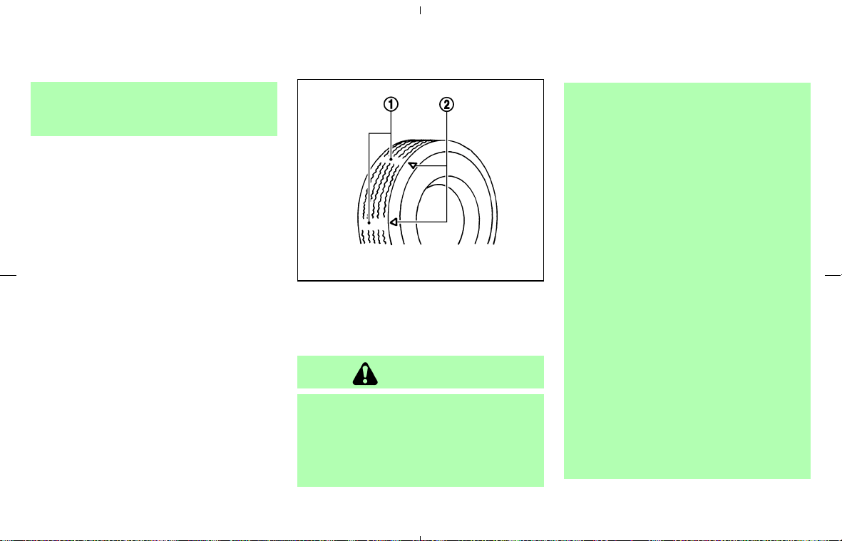
Information” (US) or “Tire Safety In-
formation” (Canada) in the Warranty
Information Booklet.
1. Wear indicator
2. Wear indicator location mark
Tire wear and damage
WARNING
쐌 Tires should be periodically in-
spected for wear, cracking,
bulging or objects caught in the
tread. If excessive wear, cracks,
bulging or deep cuts are found,
the tire(s) should be replaced.
쐌 The original tires have built-in
tread wear indicators. When the
wear indicators are visible, the
tire(s) should be replaced.
쐌 Tires degrade with age and use.
Have tires, including the spare,
over 6 years old checked by a
qualified technician because
some tire damage may not be
obvious. Replace the tires as
necessary to prevent tire failure
and possible personal injury.
쐌 Improper service of the spare
tire may result in serious per-
sonal injury. If it is necessary to
repair the spare tire, contact a
NISSAN dealer.
쐌 For additional information re-
garding tires, refer to “Impor-
tant Tire Safety Information”
(US) or “Tire Safety Informa-
SDI1663
8-38 Maintenance and do-it-yourself
墌 08.7.24/Z33-D/V5.0 墍

tion” (Canada) in the Warranty
Information Booklet.
Replacing wheels and tires
When replacing a tire, use the same size, speed
rating and load carrying capacity as originally
equipped. See “Specifications” in the “9. Tech-
nical and consumer information” section for rec-
ommended types and sizes of tires and wheels.
WARNING
쐌 The use of tires other than those
recommended or the mixed use of
tires of different brands, construction
(bias, bias-belted or radial), or tread
patterns can adversely affect the ride,
braking, handling, ground clearance,
body-to-tire clearance, tire chain
clearance, speedometer calibration,
headlight aim and bumper height.
Some of these effects may lead to
accidents and could result in serious
personal injury.
쐌 If the wheels are changed for any
reason, always replace with wheels
which have the same off-set dimen-
sion. Wheels of a different off-set
could cause premature tire wear,
possibly degraded vehicle handling
characteristics and/or interference
with the brake discs/drums. Such in-
terference can lead to decreased
braking efficiency and/or early brake
pad/shoe wear.
쐌 When a spare tire is mounted or a
wheel is replaced, the TPMS will not
function and the low tire pressure
warning light will flash for approxi-
mately 1 minute. The light will remain
on after 1 minute. Contact your
NISSAN dealer as soon as possible
for tire replacement and/or system
resetting.
쐌 Replacing tires with those not origi-
nally specified by NISSAN could af-
fect the proper operation of the
TPMS.
쐌 Do not install a damaged or de-
formed wheel or tire even if it has
been repaired. Such wheels or tires
could have structural damage and
could fail without warning.
쐌 The use of retread tire is not recom-
mended.
쐌 For additional information regarding
tires, refer to “Important Tire Safety
Information” (US) or “Tire Safety In-
formation” (Canada) in the Warranty
Information Booklet.
Wheel balance
Unbalanced wheels may affect vehicle handling
and tire life. Even with regular use, wheels can
get out of balance. Therefore, they should be
balanced as required.
Wheel balance service should be performed
with the wheels off the vehicle. Spin balancing
the front wheels on the vehicle could lead to
transmission damage.
For additional information regarding tires, refer to
“Important Tire Safety Information” (US) or “Tire
Safety Information” (Canada) in the Warranty
Information booklet.
Maintenance and do-it-yourself 8-39
墌 08.7.24/Z33-D/V5.0 墍

Care of wheels
쐌 Wash the wheels when washing the vehicle
to maintain their appearance.
쐌 Clean the inner side of the wheels when the
wheel is changed or the underside of the
vehicle is washed.
쐌 Do not use abrasive cleaners when washing
the wheels.
쐌 Inspect wheel rims regularly for dents or
corrosion. Such damage may cause loss of
pressure or poor seal at the tire bead.
쐌 NISSAN recommends that the road wheels
be waxed to protect against road salt in areas
where it is used during winter.
Spare tire (T-type spare tire)
Observe the following precautions if the T-type
spare tire must be used, otherwise your vehicle
could be damaged or involved in an accident.
CAUTION
쐌 The T-type spare tire should be used
for emergency use only. It should be
replaced by the standard tire at the
first opportunity.
쐌 Drive carefully while the T-type spare
tire is installed.
Avoid sharp turns and abrupt braking
while driving.
쐌 Periodically check the T-type spare
tire inflation pressure, and always
keep it at 60 psi (420 kPa, 4.2 bar).
쐌 Do not drive your vehicle at speeds
faster than 50 MPH (80 km/h).
쐌 Do not use tire chains on a T-type
spare tire. Tire chains will not fit
properly on the T-type spare tire and
may cause damage to the vehicle.
쐌 Tire tread of the T-type spare tire will
wear at a faster rate than the stan-
dard tire. Replace the T-type spare
tire as soon as the tread wear indica-
tors appear.
쐌 Because the T-type spare tire is
smaller than the original tire, ground
clearance is reduced. To avoid dam-
age to the vehicle, do not drive over
obstacles. Also, do not drive the ve-
hicle through an automatic car wash
since it may get caught.
쐌 Do not use the T-type spare tire on
other vehicles.
쐌 Do not use more than one T-type
spare tire at the same time.
쐌 Do not tow a trailer while the T-type
spare tire is installed.
8-40 Maintenance and do-it-yourself
墌 08.7.24/Z33-D/V5.0 墍

9 Technical and consumer information
Capacities and recommended fuel/lubricants .............. 9-2
Fuel recommendation .................................................... 9-3
Engine oil and oil filter recommendation .................. 9-5
Air conditioner system refrigerant and lubricant
recommendations ........................................................... 9-6
Specifications ........................................................................ 9-7
Engine ................................................................................. 9-7
Wheels and tires.............................................................. 9-8
Dimensions and weights ............................................... 9-8
When traveling or registering your vehicle in another
country ..................................................................................... 9-9
Vehicle identification ............................................................ 9-9
Vehicle identification number (VIN) plate ................. 9-9
Vehicle identification number (chassis number) ..... 9-9
Engine serial number ................................................... 9-10
F.M.V.S.S./C.M.V.S.S. certification label ................ 9-10
Emission control information label ........................... 9-10
Tire and loading information label ............................ 9-11
Air conditioner specification label ............................ 9-11
Installing front license plate ............................................. 9-12
Vehicle loading information ............................................. 9-13
Terms ............................................................................... 9-13
Vehicle load capacity.................................................... 9-14
Loading tips .................................................................... 9-16
Measurement of weights ............................................. 9-16
Towing a trailer ................................................................... 9-17
Maximum load limits .................................................... 9-17
Towing safety ................................................................ 9-18
Flat towing............................................................................. 9-21
Automatic transmission ................................................ 9-22
Manual transmission ..................................................... 9-22
Uniform tire quality grading ............................................. 9-22
Emission control system warranty ................................. 9-23
Reporting safety defects (US only) ............................... 9-23
Readiness for inspection/maintenance (I/M) test
(US only) .............................................................................. 9-24
Event data recorders (EDR) ............................................ 9-25
Owner’s Manual/Service Manual order information ... 9-26
In the event of a collision ........................................... 9-26
墌 08.7.24/Z33-D/V5.0 墍

The following are approximate capacities. The actual refill capacities may be a little different. When refilling, follow the procedure
instructed in the “8. Maintenance and do-it-yourself” section to determine the proper refill capacity.
Capacity (Approximate)
Recommended
specifications
US
measure
Imp
measure
Liter
Fuel 20 gal 16-5/8 gal 76 Unleaded premium gasoline with an octane rating of at least 91 AKI (RON 96)*1
Engine oil (Drain and refill)*2
With oil filter change 5-1/8 qt 4-3/8 qt 4.9
쐌 Engine oil with API Certification Mark*3
쐌 Viscosity SAE 5W-30
Without oil filter change 4-7/8 qt 4 qt 4.6
Cooling system
With reservoir 9-1/2 qt 7-7/8 qt 9.0
50% Genuine NISSAN Long Life Antifreeze/Coolant or equivalent
50% Demineralized or distilled water
Reservoir 7/8 qt 3/4 qt 0.8
Automatic transmission fluid — — — Genuine NISSAN Matic J ATF*4
Manual transmission gear oil — — —
Genuine NISSAN Manual Transmission Fluid (MTF) HQ Multi 75W-85 or API GL-4, Viscosity
SAE 75W-85 or 75W-90
Differential gear oil — — —
Genuine NISSAN Differential Oil Hypoid Super GL-5 80W-90 or API GL-5, Viscosity SAE
80W-90*5
Power steering fluid (PSF)
Refill to the proper fluid level according to the instructions in
the “8. Maintenance and do-it-yourself” section.
Genuine NISSAN PSF or equivalent*6
Brake and clutch fluid Genuine NISSAN Super Heavy Duty Brake Fluid*7 or equivalent DOT 3
Multi-purpose grease — — — NLGI No. 2 (Lithium soap base)
Air conditioning system refrigerant — — — HFC-134a (R-134a)*8
Air conditioning system lubricants — — — NISSAN A/C System Oil Type S or exact equivalent
Windshield washer fluid — — — Genuine NISSAN Windshield Washer Concentrate Cleaner & Anti-freeze or equivalent
*1: For additional information, see “Fuel recommendation” later in this section.
*2: For additional information, see “Engine oil” in the “8. Maintenance and do-it-yourself” section for changing engine oil.
*3: For additional information, see “Engine oil and oil filter recommendation” later in this section.
*4: Using automatic transmission fluid other than Genuine NISSAN Matic J ATF will cause deterioration in driveability and automatic transmission
durability, and may damage the automatic transmission, which is not covered by the NISSAN new vehicle limited warranty.
*5: For hot areas, viscosity SAE 90 is suitable for ambient temperatures above 32°F (0°C).
*6: Canada NISSAN Automatic Transmission Fluid or DEXRON
TM
VI type ATF may also be used.
*7: Available in mainland US through a NISSAN dealer.
*8: For additional information, see “Vehicle identification” in this section for air conditioner specification label.
CAPACITIES AND
RECOMMENDED FUEL/
LUBRICANTS
9-2 Technical and consumer information
墌 08.7.24/Z33-D/V5.0 墍

FUEL RECOMMENDATION
Use unleaded premium gasoline with an octane
rating of at least 91 AKI (Anti-Knock Index)
number (Research octane number 96).
If premium gasoline is not available, unleaded
regular gasoline with an octane rating of 87 AKI
number (Research octane number 91) may be
temporarily used, but only under the following
precautions:
쐌 Have the fuel tank filled only partially with
unleaded regular gasoline, and fill up with
unleaded premium gasoline as soon as pos-
sible.
쐌 Avoid full throttle driving and abrupt accelera-
tion.
However, for maximum vehicle perfor-
mance, the use of unleaded premium gaso-
line is recommended.
CAUTION
쐌 Using a fuel other than that specified
could adversely affect the emission
control system, and may also affect
the warranty coverage.
쐌 Under no circumstances should a
leaded gasoline be used, because
this will damage the three-way cata-
lyst.
쐌 Do not use E-85 fuel in your vehicle.
Your vehicle is not designed to run
on E-85 fuel. Using E-85 fuel can
damage the fuel system components
and is not covered by the NISSAN
vehicle limited warranty.
Gasoline specifications
NISSAN recommends using gasoline that meets
the World-Wide Fuel Charter (WWFC) specifi-
cations where it is available. Many of the auto-
mobile manufacturers developed this specifica-
tion to improve emission control system and
vehicle performance. Ask your service station
manager if the gasoline meets the WWFC
specifications.
Reformulated gasoline
Some fuel suppliers are now producing reformu-
lated gasolines. These gasolines are specially
designed to reduce vehicle emissions. NISSAN
supports efforts towards cleaner air and sug-
gests that you use reformulated gasoline when
available.
Gasoline containing oxygenates
Some fuel suppliers sell gasoline containing
oxygenates such as ethanol, MTBE and metha-
nol with or without advertising their presence.
NISSAN does not recommend the use of fuels of
which the oxygenate content and the fuel com-
patibility for your NISSAN cannot be readily
determined. If in doubt, ask your service station
manager.
If you use oxygenate-blend gasoline, please take
the following precautions as the usage of such
fuels may cause vehicle performance problems
and/or fuel system damage.
쐌 The fuel should be unleaded and have
an octane rating no lower than that
recommended for unleaded gasoline.
쐌 If an oxygenate-blend, excepting a
methanol blend, is used, it should con-
tain no more than 10% oxygenate.
(MTBE may, however, be added up to
15%.)
쐌 If a methanol blend is used, it should
contain no more than 5% methanol (me-
thyl alcohol, wood alcohol). It should
also contain a suitable amount of ap-
propriate cosolvents and corrosion in-
Technical and consumer information 9-3
墌 08.7.24/Z33-D/V5.0 墍

hibitors. If not properly formulated with
appropriate cosolvents and corrosion
inhibitors, such methanol blends may
cause fuel system damage and/or ve-
hicle performance problems. At this
time, sufficient data is not available to
ensure that all methanol blends are
suitable for use in NISSAN vehicles.
If any undesirable driveability problems such as
engine stalling and hard hot starting are experi-
enced after using oxygenate-blend fuels, imme-
diately change to a non-oxygenate fuel or a fuel
with a low blend of MTBE.
Take care not to spill gasoline during refu-
eling. Gasoline containing oxygenates can
cause paint damage.
E-85 fuel
E-85 fuel is a mixture of approximately 85% fuel
ethanol and 15% unleaded gasoline. E-85 can
only be used in a Flexible Fuel Vehicle (FFV). Do
not use E-85 fuel in your vehicle. U.S. govern-
ment regulations require fuel ethanol dispensing
pumps to be identified by a small, square, or-
ange and black label with the common abbre-
viation or the appropriate percentage for that
region.
Aftermarket fuel additives
NISSAN does not recommend the use of any
aftermarket fuel additives (for example, fuel in-
jector cleaner, octane booster, intake valve de-
posit removers, etc.) which are sold commer-
cially. Many of these additives intended for gum,
varnish or deposit removal may contain active
solvents or similar ingredients that can be harm-
ful to the fuel system and engine.
Octane rating tips
Using unleaded gasoline with an octane
rating lower than recommended can cause
persistent, heavy spark knock. (Spark
knock is a metallic rapping noise.) If se-
vere, this can lead to engine damage. If you
detect a persistent heavy spark knock even
when using gasoline of the above stated
octane rating, or if you hear steady spark
knock while holding a steady speed on
level roads, have your dealer correct the
condition. Failure to correct the condition
is misuse of the vehicle, for which NISSAN
is not responsible.
Incorrect ignition timing will result in knocking,
after-run or overheating. This in turn may cause
excessive fuel consumption or damage to the
engine. If any of the above symptoms are en-
countered, have your vehicle checked at a
NISSAN dealer or other competent service fa-
cility.
However, now and then you may notice
light spark knock for a short time while
accelerating or driving up hills. This is no
cause for concern, because you get the
greatest fuel benefit when there is light
spark knock for a short time under heavy
engine load.
9-4 Technical and consumer information
墌 08.7.24/Z33-D/V5.0 墍
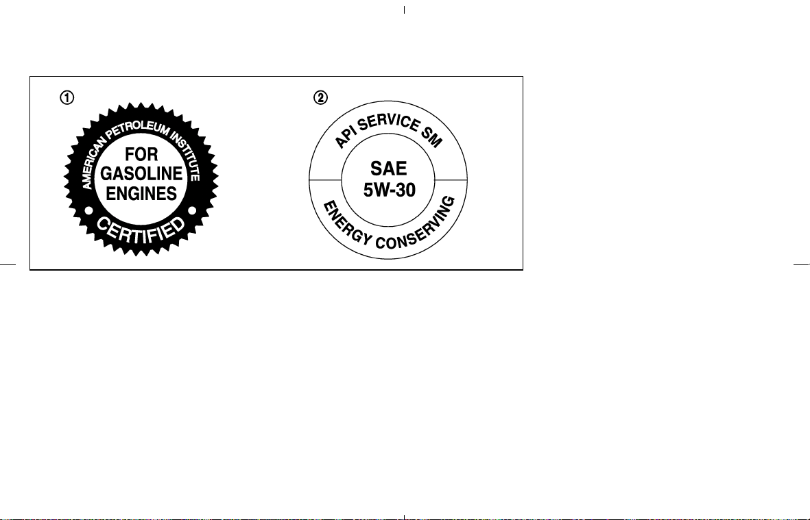
쎻
1
API certification mark
쎻
2
API service symbol
ENGINE OIL AND OIL FILTER
RECOMMENDATION
Selecting the correct oil
It is essential to choose the correct grade,
quality and viscosity engine oil to ensure satis-
factory engine life and performance. See “Ca-
pacities and recommended fuel/lubricants” ear-
lier in this section. NISSAN recommends the use
of an energy conserving oil in order to improve
fuel economy.
Select only engine oils that meet the American
Petroleum Institute (API) certification or Interna-
tional Lubricant Standardization and Approval
Committee (ILSAC) certification and SAE vis-
cosity standard. These oils have the API certifi-
cation mark on the front of the container. Oils
which do not have the specified quality label
should not be used as they could cause engine
damage.
Oil additives
NISSAN does not recommend the use of oil
additives. The use of an oil additive is not
necessary when the proper oil type is used and
maintenance intervals are followed.
Oil which may contain foreign matter or has
been previously used should not be used.
Oil viscosity
The engine oil viscosity or thickness changes
with temperature. Because of this, it is important
that the engine oil viscosity be selected based
on the temperatures at which the vehicle will be
operated before the next oil change. Choosing
an oil viscosity other than that recommended
could cause serious engine damage.
Selecting the correct oil filter
Your new NISSAN vehicle is equipped with a
high-quality genuine NISSAN oil filter. When
replacing, use a genuine NISSAN oil filter or its
equivalent for the reason described in “Change
intervals”.
Change intervals
The oil and oil filter change intervals for your
engine are based on the use of the specified
quality oils and filters. Oil and filter other than the
specified quality, or oil and filter change intervals
longer than recommended could reduce engine
life. Damage to engines caused by improper
maintenance or use of incorrect oil and filter
quality and/or viscosity is not covered by the
new NISSAN vehicle limited warranties.
Your engine was filled with a high quality engine
STI0505
Technical and consumer information 9-5
墌 08.7.24/Z33-D/V5.0 墍

oil when it was built. You do not have to change
the oil before the first recommended change
interval. Oil and filter change intervals depend
upon how you use your vehicle.
Operation under the following conditions may
require more frequent oil and filter changes:
쐌 repeated short distance driving at cold out-
side temperatures
쐌 driving in dusty conditions
쐌 extensive idling
쐌 towing a trailer
쐌 stop and go commuting
Refer to the “NISSAN Service and Maintenance
Guide” for the maintenance schedule.
AIR CONDITIONER SYSTEM
REFRIGERANT AND LUBRICANT
RECOMMENDATIONS
The air conditioner system in your NISSAN
vehicle must be charged with the refriger-
ant HFC-134a (R-134a) and the lubricant,
NISSAN A/C System Oil Type S or the
exact equivalents.
CAUTION
The use of any other refrigerant or lubri-
cant will cause severe damage to the air
conditioning system and will require the
replacement of all air conditioner sys-
tem components.
The refrigerant HFC-134a (R-134a) in your
NISSAN vehicle will not harm the earth’s ozone
layer. Although this refrigerant does not affect
the earth’s atmosphere, certain governmental
regulations require the recovery and recycling of
any refrigerant during automotive air conditioner
system service. A NISSAN dealer has the trained
technicians and equipment needed to recover
and recycle your air conditioner system refriger-
ant.
Contact a NISSAN dealer when servicing your
air conditioner system.
9-6 Technical and consumer information
墌 08.7.24/Z33-D/V5.0 墍
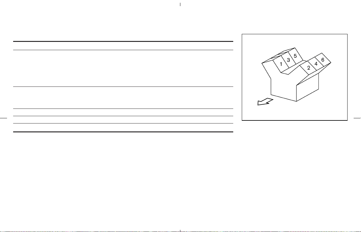
ENGINE
Model VQ35HR
Type Gasoline, 4-cycle
Cylinder arrangement 6-cylinder, V-slanted at 60°
Bore x Stroke in (mm) 3.760 x 3.205 (95.5 x 81.4)
Displacement cu in (cm
3
) 213.45 (3,498)
Firing order 1-2-3-4-5-6*1
Idle speed rpm
See the emission control label on the
underside of the hood.
Ignition timing (B.T.D.C.) degree/rpm
CO percentage at idle speed [No air] %
Spark plug Standard FXE22HR-11
Spark plug gap (Normal) in (mm) 0.043 (1.1)
Camshaft operation Timing chain
This spark ignition system complies with the Canadian standard ICES-002.
STI0425
*1: Cylinder number
SPECIFICATIONS
Technical and consumer information 9-7
墌 08.7.24/Z33-D/V5.0 墍

WHEELS AND TIRES
Road wheel
Model Type Position Size
Offset
in (mm)
Coupe Aluminum
Front 18 x 8JJ 1.18 (30)
Rear 18 x 8-1/2JJ 1.30 (33)
Front 18 x 9JJ* 1.18 (30)
Rear 19 x 10JJ* 1.18 (30)
Roadster Aluminum
Front 18 x 8JJ 1.18 (30)
Rear 18 x 8-1/2JJ 1.30 (33)
Tire
Model Type Position Size Pressure (COLD)
Coupe
Conventional
Front 225/45R18 91W 240 kPa (35 psi)
Rear 245/45R18 96W 240 kPa (35 psi)
Front 245/40R18 93W* 240 kPa (35 psi)
Rear 265/35R19 94W* 240 kPa (35 psi)
Spare — T145/80D17 107M 420 kPa (60 psi)
Road-
ster
Conventional
Front 225/45R18 91W 240 kPa (35 psi)
Rear 245/45R18 96W 240 kPa (35 psi)
Spare — T145/80D17 107M 420 kPa (60 psi)
*: For option
DIMENSIONS AND WEIGHTS
Vehicle body Coupe Roadster
Overall length in (mm) 169.8 (4,314) 169.8 (4,314)
Overall width in (mm) 71.5 (1,815) 71.5 (1,815)
Overall height in (mm) 52.1 (1,323) 52.5 (1,333)
Front tread in (mm) 60.5 (1,536) 60.5 (1,536)
Rear tread in (mm)
60.6 (1,540)*1
60.9 (1,546)*2
60.6 (1,540)
Wheelbase in (mm) 104.3 (2,650) 104.3 (2,650)
Gross vehicle weight rating
(GVWR)
lb (kg)
See the F.M.V.S.S. or C.M.V.S.S. cer-
tification label on the driver’s side
lock pillar.
Gross axle weight rating
(GAWR)
Front lb (kg)
Rear lb (kg)
*1: For model with 245/45R 18 tires
*2: For model with 265/35R 19 tires
9-8 Technical and consumer information
墌 08.7.24/Z33-D/V5.0 墍
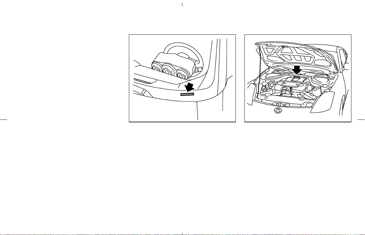
When planning to travel in another country,
you should first find out if the fuel available is
suitable for your vehicle’s engine.
Using fuel with too low an octane rating may
cause engine damage. All gasoline vehicles
must be operated with unleaded engine gaso-
line. Therefore, avoid taking your vehicle to areas
where appropriate fuel is not available.
When transferring the registration of your
vehicle to another country, state, province
or district, it may be necessary to modify the
vehicle to meet local laws and regulations.
The laws and regulations for motor vehicle emis-
sion control and safety standards vary according
to the country, state, province or district; there-
fore, vehicle specifications may differ.
When any vehicle is to be taken into an-
other country, state, province or district
and registered, its modifications, transpor-
tation, and registration are the responsibil-
ity of the user. NISSAN is not responsible
for any inconvenience that may result.
VEHICLE IDENTIFICATION NUMBER
(VIN) PLATE
The vehicle identification number plate is at-
tached as shown. This number is the identifica-
tion for your vehicle and is used in the vehicle
registration.
VEHICLE IDENTIFICATION NUMBER
(chassis number)
The number is stamped as shown.
STI0320 STI0513
WHEN TRAVELING OR
REGISTERING YOUR VEHICLE IN
ANOTHER COUNTRY
VEHICLE IDENTIFICATION
Technical and consumer information 9-9
墌 08.7.24/Z33-D/V5.0 墍
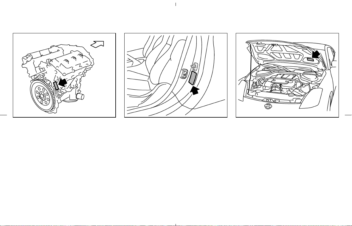
ENGINE SERIAL NUMBER
The number is stamped on the engine as shown.
F.M.V.S.S./C.M.V.S.S.
CERTIFICATION LABEL
The Federal Motor Vehicle Safety Standards
(F.M.V.S.S.) or Canadian Motor Vehicle Safety
Standards (C.M.V.S.S.) certification label is af-
fixed as shown. This label contains valuable
vehicle information, such as: Gross Vehicle
Weight Ratings (GVWR), Gross Axle Weight
Rating (GAWR), month and year of manufacture,
Vehicle Identification Number (VIN), etc. Review
it carefully.
EMISSION CONTROL
INFORMATION LABEL
The emission control information label is at-
tached as shown.
STI0516 STI0322 STI0514
9-10 Technical and consumer information
墌 08.7.24/Z33-D/V5.0 墍
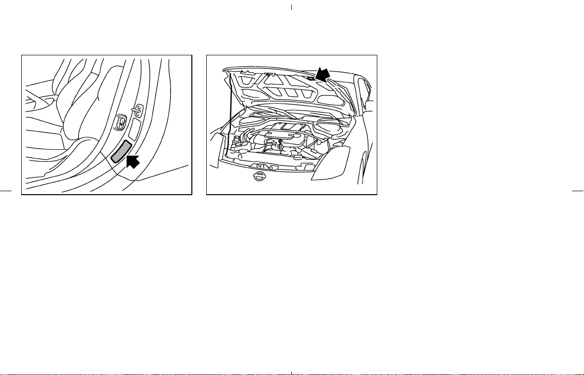
TIRE AND LOADING INFORMATION
LABEL
The cold tire inflation pressure is shown on the
Tire and Loading Information label affixed to the
driver side center pillar.
AIR CONDITIONER SPECIFICATION
LABEL
The air conditioner specification label is affixed
inside of the hood as shown.
STI0366 STI0515
Technical and consumer information 9-11
墌 08.7.24/Z33-D/V5.0 墍
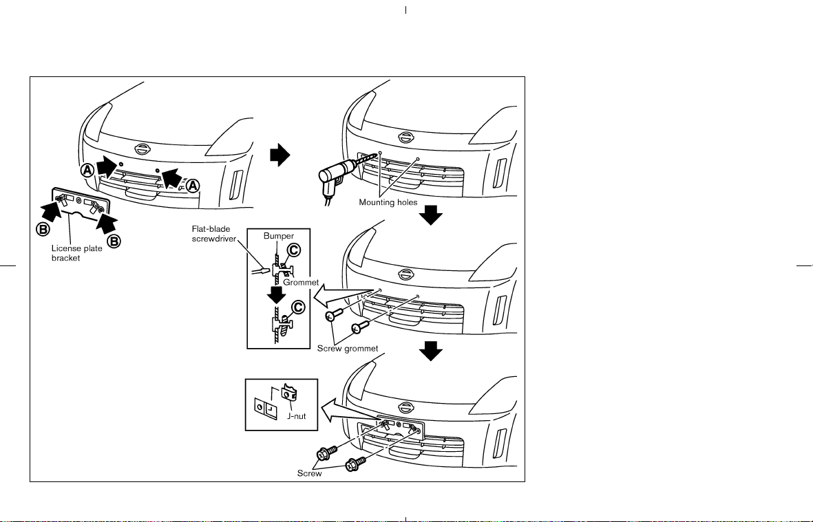
Use the following steps to mount the license
plate:
Before mounting the license plate, confirm that
the following parts are enclosed in the vinyl bag.
쐌 License plate bracket
쐌 J-nut x 2
쐌 Screw x 2
쐌 Screw grommet x 2
1. Temporarily place the license plate bracket
while aligning points
쎻
A
of the front bumper
fascia with holes
쎻
B
in the license plate
bracket.
2. Remove the license plate bracket.
3. Carefully drill two shallow pilot holes
쎻
A
using a 0.39 in (10 mm) drill bit at the marked
locations. (Be sure that the drill only goes
through the fascia, or damage to the nut
may occur.)
4. Insert grommets into the hole on the fascia.
5. Insert a flat-blade screwdriver into the grom-
met hole to add 90° turn onto the part
쎻
C
.
6. Insert a J-nut into the license plate bracket
before placing the license plate bracket on
the fascia.
7. Install the license plate bracket with screws.
STI0446
INSTALLING FRONT LICENSE
PLATE
9-12 Technical and consumer information
墌 08.7.24/Z33-D/V5.0 墍

8. Install the license plate with bolts that are no
longer than 0.55 in (14 mm).
WARNING
쐌 It is extremely dangerous to
ride in a cargo area inside a
vehicle. In a collision, people
riding in these areas are more
likely to be seriously injured or
killed.
쐌 Do not allow people to ride in
any area of your vehicle that is
not equipped with seats and
seat belts.
쐌 Be sure everyone in your ve-
hicle is in a seat and using a
seat belt properly.
TERMS
It is important to familiarize yourself with
the following terms before loading your
vehicle:
쐌 Curb Weight (actual weight of your
vehicle) - vehicle weight including:
standard and optional equipment, flu-
ids, emergency tools, and spare tire
assembly. This weight does not in-
clude passengers and cargo.
쐌 GVW (Gross Vehicle Weight) - curb
weight plus the combined weight of
passengers and cargo.
쐌 GVWR (Gross Vehicle Weight Rat-
ing) - maximum total combined weight
of the unloaded vehicle, passengers,
luggage, hitch, trailer tongue load and
any other optional equipment. This in-
formation is located on the
F.M.V.S.S./C.M.V.S.S. label.
쐌 GAWR (Gross Axle Weight Rating) -
maximum weight (load) limit specified
for the front or rear axle. This informa-
tion is located on the
F.M.V.S.S./C.M.V.S.S. label.
쐌 GCWR (Gross Combined Weight
Rating) - maximum total weight rating
of the vehicle, passengers, cargo and
trailer.
쐌 Vehicle Capacity Weight, Load limit,
VEHICLE LOADING
INFORMATION
Technical and consumer information 9-13
墌 08.7.24/Z33-D/V5.0 墍

Total load capacity - maximum total
weight limit specified of the load (pas-
sengers and cargo) for the vehicle.
This is the maximum combined weight
of occupants and cargo that can be
loaded into the vehicle. If the vehicle is
used to tow a trailer, the trailer tongue
weight must be included as part of the
cargo load. This information is located
on the Tire and Loading Information
label.
쐌 Cargo capacity - permissible weight of
cargo, the subtracted weight of occu-
pants from the load limit.
VEHICLE LOAD CAPACITY
Do not exceed the load limit of your
vehicle shown as “The combined weight
of occupants and cargo” on the Tire and
Loading Information label. Do not exceed
the number of occupants shown as
“Seating Capacity” on the Tire and Load-
ing Information label.
To get “the combined weight of occu-
pants and cargo”, add the weight of all
occupants, then add the total luggage
weight. Examples are shown in the fol-
lowing illustration.
9-14
Technical and consumer information
墌 08.7.24/Z33-D/V5.0 墍
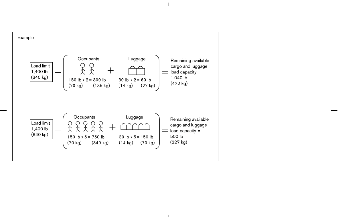
Steps for determining correct load
limit
1. Locate the statement “The combined
weight of occupants and cargo should
never exceed XXX kg or XXX lbs” on
your vehicle’s placard.
2. Determine the combined weight of the
driver and passengers that will be
riding in your vehicle.
3. Subtract the combined weight of the
driver and passengers from XXX kg or
XXX lbs.
4. The resulting figure equals the avail-
able amount of cargo and luggage
load capacity. For example, if the XXX
amount equals 1400 lbs. and there will
be five 150 lb. passengers in your
vehicle, the amount of available cargo
and luggage load capacity is 650 lbs.
(1400 − 750 (5 × 150) = 650 lbs) or
(640 − 340 (5 × 70) = 300 kg)
5. Determine the combined weight of
luggage and cargo being loaded on
the vehicle. That weight may not safely
exceed the available cargo and lug-
gage load capacity calculated in Step
4.
6. If your vehicle will be towing a trailer,
load from your trailer will be trans-
ferred to your vehicle. Consult this
manual to determine how this reduces
the available cargo and luggage load
capacity of your vehicle.
STI0447
Technical and consumer information 9-15
墌 08.7.24/Z33-D/V5.0 墍

Before driving a loaded vehicle, confirm
that you do not exceed the Gross Vehicle
Weight Rating (GVWR) or the Gross
Axle Weight Rating (GAWR) for your
vehicle. See “Measurement of Weights”
later in this section.
Also check tires for proper inflation pres-
sures. See the Tire and Loading Informa-
tion label.
LOADING TIPS
쐌 The GVW must not exceed GVWR or
GAWR as specified on the
F.M.V.S.S./C.M.V.S.S. certification la-
bel.
쐌 Do not load the front and rear axle to
the GAWR. Doing so will exceed the
GVWR.
WARNING
쐌 Properly secure all cargo with
ropes or straps to help prevent
it from sliding or shifting. Do
not place cargo higher than the
seatbacks. In a sudden stop or
collision, unsecured cargo
could cause personal injury.
쐌 Do not load your vehicle any
heavier than the GVWR or the
maximum front and rear
GAWRs. If you do, parts of your
vehicle can break, tire damage
could occur, or it can change
the way your vehicle handles.
This could result in loss of con-
trol and cause personal injury.
쐌 Overloading not only could
shorten the life of your vehicle
and the tire, but can also cause
unsafe vehicle handling and
long braking distances. This
may cause a premature tire fail-
ure, which could result in a se-
rious accident and personal in-
jury. Failures caused by over
loading are not covered by the
vehicle’s warranty.
MEASUREMENT OF WEIGHTS
Secure loose items to prevent weight
shifts that could affect the balance of
your vehicle. When the vehicle is loaded,
drive to a scale and weigh the front and
the rear wheels separately to determine
axle loads. Individual axle loads should
not exceed either of the gross axle weight
ratings (GAWR). The total of the axle
loads should not exceed the gross ve-
hicle weight rating (GVWR). These rat-
ings are given on the vehicle certification
label. If weight ratings are exceeded,
move or remove items to bring all weights
below the ratings.
9-16
Technical and consumer information
墌 08.7.24/Z33-D/V5.0 墍

Roadster model:
Do not tow a trailer with your vehicle.
Coupe model:
Your new vehicle was designed to be used
primarily to carry passengers and cargo. Re-
member that towing a trailer places additional
loads on your vehicle’s engine, drive train, steer-
ing, braking and other systems.
A NISSAN Towing Guide (U.S. only) is available
on the website at www.nissanusa.com. This
guide includes information on trailer towing ca-
pability and the special equipment required for
proper towing.
WARNING
Overloading or improper loading of a
trailer and its cargo can adversely affect
vehicle handling, braking and perfor-
mance and may lead to accidents.
CAUTION
쐌 Do not tow a trailer or haul a heavy
load for the first 500 miles (800 km).
Your engine, axle or other parts
could be damaged.
쐌 For the first 500 miles (800 km) that
you tow a trailer, do not drive over 50
mph (80 km/h) and do not make
starts at full throttle. This helps the
engine and other parts of your ve-
hicle wear in at the heavier loads.
MAXIMUM LOAD LIMITS
Maximum trailer loads
Never allow the total trailer load to exceed 1,000
lb (454 kg). The total trailer load equals trailer
weight plus its cargo weight. Towing loads
greater than 1,000 lb (454 kg) or using improper
towing equipment could adversely affect vehicle
handling, braking and performance.
The ability of a vehicle to tow a trailer is not only
related to the maximum trailer loads, but also the
places you plan to tow. Tow weights appropriate
for level highway driving may have to be reduced
on very steep grades or in low traction situations
(for example, on slippery boat ramps).
CAUTION
Vehicle damage resulting from im-
proper towing procedures are not cov-
ered by NISSAN warranties.
TOWING A TRAILER
Technical and consumer information 9-17
墌 08.7.24/Z33-D/V5.0 墍
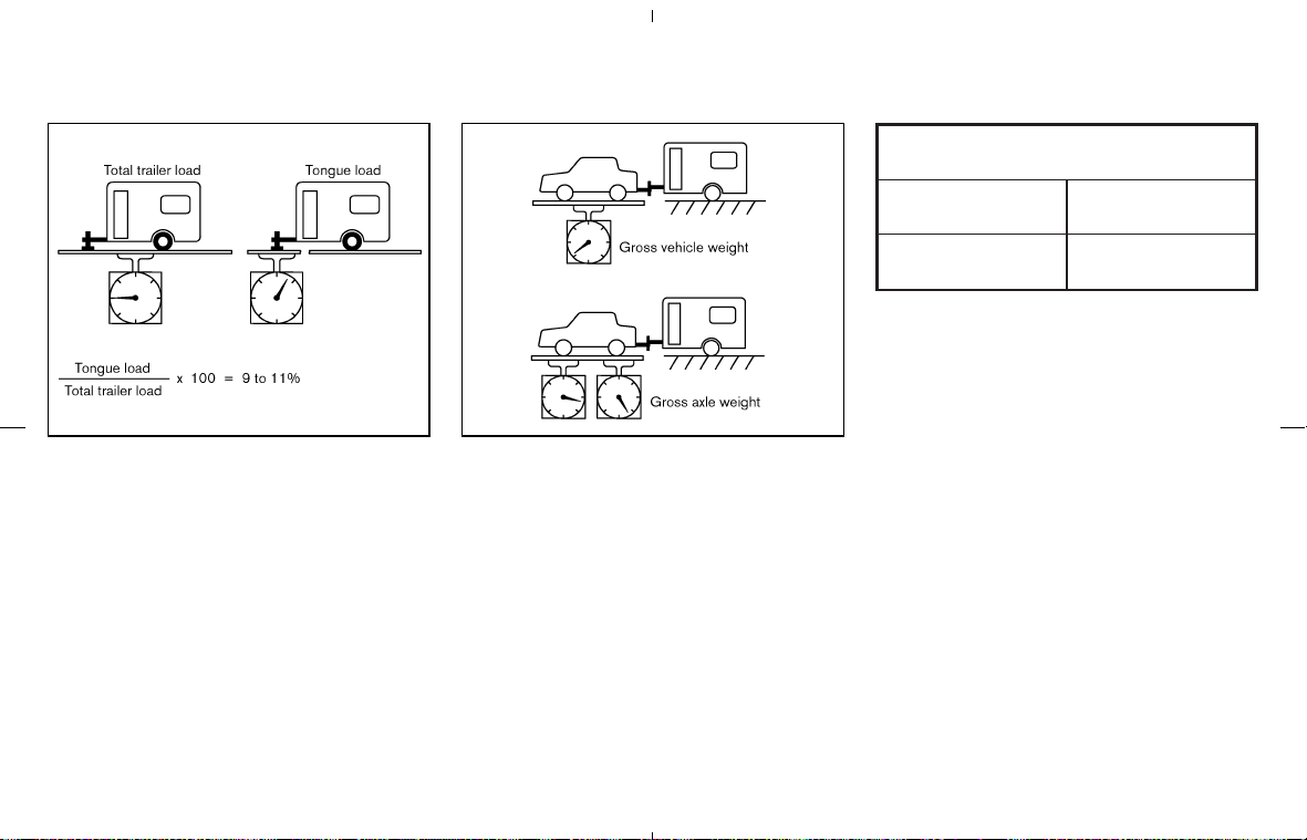
Tongue load
Keep the tongue load between 9 and 11% of the
total trailer load within the maximum tongue load
limits shown in the following Towing
Load/Specification chart. If the tongue load be-
comes excessive, rearrange cargo to allow for
proper tongue load.
Maximum gross vehicle weight/
maximum gross axle weight
The gross vehicle weight of the towing vehicle
must not exceed. GVWR shown on the
F.M.V.S.S./C.M.V.S.S. certification label. The
gross vehicle weight equals the combined
weight of the unloaded vehicle, passengers,
luggage, hitch, trailer tongue load and any other
optional equipment. In addition, front or rear
gross axle weight must not exceed GAWR
shown on the F.M.V.S.S./C.M.V.S.S. certifica-
tion label.
TOWING LOAD/SPECIFICATION CHART
Unit: lb (kg)
MAXIMUM
TOWING LOAD
1,000 (454)
MAXIMUM
TONGUE LOAD
100 (45.4)
TOWING SAFETY
Trailer hitch
Choose a proper hitch for a vehicle and trailer.
Make sure the trailer hitch is securely attached to
the vehicle, to help avoid personal injury or
property damage due to sway caused by cross-
winds, rough road surfaces or passing trucks.
Hitch ball
Choose a hitch ball of the proper size and weight
rating for your trailer:
쐌 The required hitch ball size is stamped on
most trailer couplers. Most hitch balls also
have the size printed on top of the ball.
쐌 Choose the proper class hitch ball based on
the trailer weight.
쐌 The diameter of the threaded shank of the
hitch ball must be matched to the ball mount
hole diameter. The hitch ball shank should be
TI1011M TI1012M
9-18 Technical and consumer information
墌 08.7.24/Z33-D/V5.0 墍

no more than 1/16″ smaller than the hole in
the ball mount.
쐌 The threaded shank of the hitch ball must be
long enough to be properly secured to the
ball mount. There should be at least 2 threads
showing beyond the lock washer and nut.
Class I hitch
Class I trailer hitch equipment (receiver, ball
mount and hitch ball) can be used to tow trailers
of a maximum weight of 2,000 lb (909 kg).
You may add Class I trailer hitch equipment to
the vehicle that has a 2,000 lb (909 kg) maxi-
mum weight rating, but your vehicle is only
capable of towing the maximum trailer weights
shown in the Towing Load/Specification Chart
earlier in this section.
CAUTION
쐌 Do not use axle-mounted hitches.
쐌 The hitch should not be attached to
or affect the operation of the impact-
absorbing bumper.
쐌 Do not modify the vehicle exhaust
system, brake system, etc. to install a
trailer hitch.
쐌 To reduce the possibility of addi-
tional damage if a vehicle is struck
from the rear, where practical, re-
move the hitch and/or receiver when
not in use.
쐌 After the hitch is removed, seal the
bolt holes to prevent exhaust fumes,
water or dust from entering the pas-
senger compartment.
쐌 Regularly check that all trailer hitch
mounting bolts are securely mounted.
Tire pressures
쐌 When towing a trailer, inflate the ve-
hicle tires to the recommended cold
tire pressure indicated on the Tire and
Loading Information label.
쐌 Trailer tire condition, size, load rating
and proper inflation pressure should
be in accordance with the trailer and
tire manufacturers’ specifications.
Safety chains
Always use a suitable chain between a vehicle
and the trailer. The safety chain should be
crossed and should be attached to the hitch, not
to the vehicle bumper or axle. Be sure to leave
enough slack in the chain to permit turning
corners.
Trailer lights
CAUTION
When splicing into the vehicle electrical
system, a commercially available
power-type module/converter must be
used to provide power for all trailer
lighting. This unit uses the vehicle bat-
tery as a direct power source for all
trailer lights while using the vehicle tail
light, stoplight and turn signal circuits
as a signal source. The module/
converter must draw no more than 15
milliamps from the stop and tail lamp
circuits. Using a module/converter that
exceeds these power requirements may
damage the vehicle’s electrical system.
See a reputable trailer dealer to obtain
Technical and consumer information 9-19
墌 08.7.24/Z33-D/V5.0 墍

the proper equipment and to have it
installed.
Trailer lights should comply with federal and/or
local regulations. When wiring the vehicle for
towing, connect the stop and tail light pickup
into the vehicle electrical circuit at a point be-
tween the sensor and stop light or light switch.
Trailer brakes
If your trailer is equipped with a braking system,
make sure it conforms to federal and/or local
regulations and that it is properly installed.
WARNING
Never connect a trailer brake system
directly to the vehicle brake system.
Pre-towing tips
쐌 Be certain a vehicle maintains a level position
when a loaded and/or unloaded trailer is
hitched. Do not drive the vehicle if it has an
unusual nose-up or nose-down condition;
check for improper tongue load, overload,
worn suspension or other possible causes of
these conditions.
쐌 Always secure items in the trailer to prevent
load shifts while driving.
쐌 Load the trailer so approximately 60% of the
trailer load is in the front half and 40% is in
the back half.
쐌 Check your hitch, trailer tire pressure, vehicle
tire pressure, trailer light operation, and trailer
wheel lug nuts every time you attach a trailer
to the vehicle.
쐌 Be certain your rear view mirrors conform to
all federal, state and/or local regulations. If
not, install any mirrors required for towing
before driving the vehicle.
Trailer towing tips
In order to gain skill and an understanding of the
vehicle’s behavior, you should practice turning,
stopping and backing up in an area which is free
from traffic. Steering stability, and braking per-
formance will be somewhat different than under
normal driving conditions.
쐌 Always secure items in the trailer to prevent
load shift while driving.
쐌 Avoid abrupt starts, acceleration or stops.
쐌 Avoid sharp turns or lane changes.
쐌 Always drive a vehicle at a moderate speed.
Some states or provinces have specific
speed limits for vehicles that are towing
trailers. Obey the local speed limits.
쐌 When backing up, hold the bottom of the
steering wheel with one hand. Move your
hand in the direction in which you want the
trailer to go. Make small corrections and back
up slowly. If possible, have someone guide
you when you are backing up.
쐌 Always block the wheels on both vehicle and
trailer when parking. Parking on a slope is not
recommended; however, if you must do so,
and if a vehicle is equipped with automatic
transmission, first apply the parking brake
and block the wheels, and then move the
transmission selector lever into the P (Park)
position. If you move the selector lever to the
P (Park) position before blocking the wheels
and applying the parking brake, the transmis-
sion may get damaged.
쐌 When going down a hill, shift into a lower
gear and use the engine braking effect.
When going up a long grade, downshift the
transmission to a lower gear and reduce
speed to reduce chances of engine overload-
ing and/or overheating.
쐌 If the engine coolant rises to an extremely
high temperature when the air conditioning
system is on, turn off the air conditioner.
Coolant heat can be additionally vented by
9-20 Technical and consumer information
墌 08.7.24/Z33-D/V5.0 墍

opening the windows, switching the fan con-
trol to high and setting the temperature con-
trol to the HOT position.
쐌 Trailer towing consumes more fuel than nor-
mal circumstances.
쐌 Avoid towing a trailer for the first 500 miles
(800 km).
쐌 Have a vehicle serviced more often than at
intervals specified in the recommended main-
tenance schedule.
쐌 When making a turn, your trailer wheels will
be closer to the inside of the turn than your
vehicle wheels. To compensate for this, make
a larger than normal turning radius during the
turn.
쐌 Crosswinds and rough roads will adversely
affect vehicle/trailer handling, possibly caus-
ing vehicle sway. When being passed by
larger vehicles, be prepared for possible
changes in crosswinds that could affect ve-
hicle handling. If swaying does occur, firmly
grip the steering wheel, steer straight ahead,
and immediately (but gradually) reduce ve-
hicle speed. This combination will help stabi-
lize the vehicle. Never increase speed.
쐌 Be careful when passing other vehicles.
Passing while towing a trailer requires con-
siderably more distance than normal passing.
Remember the length of the trailer must also
pass the other vehicle before you can safely
change lanes.
쐌 To maintain engine braking efficiency and
electrical charging performance, do not use
6th gear (manual transmission) or 5th posi-
tion (automatic transmission).
쐌 Avoid holding the brake pedal down too long
or too frequently. This could cause the brakes
to overheat, resulting in reduced braking ef-
ficiency.
쐌 Increase your following distance to allow for
greater stopping distances while towing a
trailer. Anticipate stops and brake gradually.
쐌 Do not use cruise control while towing a
trailer.
쐌 Check your hitch, trailer wiring harness con-
nections, and trailer wheel lug nuts after 50
miles (80 km) of travel and at every break.
쐌 When stopped in traffic for long periods of
time in hot weather, put the vehicle in the P
(Park) position.
When towing a trailer, change transmis-
sion oil more frequently. For additional
information, see the “8. Maintenance and
do-it-yourself” section.
Towing your vehicle with all four wheels on the
ground is sometimes called flat towing. This
method is sometimes used when towing a ve-
hicle behind a recreational vehicle, such as a
motor home.
CAUTION
쐌 Failure to follow these guidelines
can result in severe transmission
damage.
쐌 Whenever flat towing your vehicle,
always tow forward, never backward.
쐌 DO NOT tow any automatic transmis-
sion vehicle with all four wheels on
the ground (flat towing). Doing so
WILL DAMAGE internal transmission
parts due to lack of transmission lu-
brication.
쐌 For emergency towing procedures,
refer to “Towing recommended by
NISSAN” in the “6. In case of emer-
gency” section of this manual.
FLAT TOWING
Technical and consumer information 9-21
墌 08.7.24/Z33-D/V5.0 墍

AUTOMATIC TRANSMISSION
To tow a vehicle equipped with an automatic
transmission, an appropriate vehicle dolly MUST
be placed under the towed vehicle’s drive
wheels. Always follow the dolly manufacturer’s
recommendations when using their product.
MANUAL TRANSMISSION
쐌 Always tow with the manual transmission in
Neutral.
쐌 After towing 500 miles, start and idle the
engine with the transmission in Neutral for
two minutes. Failure to idle the engine after
every 500 miles of towing may cause damage
to internal transmission parts.
DOT (Department Of Transportation) Quality
Grades: All passenger car tires must conform to
federal safety requirements in addition to these
grades.
Quality grades can be found where applicable
on the tire sidewall between tread shoulder and
maximum section width. For example:
Treadwear 200 Traction AA Temperature A
Treadwear
The treadwear grade is a comparative rating
based on the wear rate of the tire when tested
under controlled conditions on a specified gov-
ernment test course. For example, a tire graded
150 would wear one and one-half (1 1/2) times
as well on the government course as a tire
graded 100. The relative performance of tires
depends upon the actual conditions of their use,
however, and may depart significantly from the
norm due to variations in driving habits, service
practices and differences in road characteristics
and climate.
Traction AA, A, B and C
The traction grades, from highest to lowest, are
AA, A, B, and C. Those grades represent the
tire’s ability to stop on wet pavement as mea-
sured under controlled conditions on specified
government test surfaces of asphalt and con-
crete. A tire marked C may have poor traction
performance.
WARNING
The traction grade assigned to this tire
is based on straight-ahead braking trac-
tion tests, and does not include accel-
eration, cornering, hydroplaning, or
peak traction characteristics.
Temperature A, B and C
The temperature grades are A (the highest), B,
and C, representing the tire’s resistance to the
generation of heat and its ability to dissipate heat
when tested under controlled conditions on a
specified indoor laboratory test wheel. Sus-
tained high temperature can cause the material
of the tire to degenerate and reduce tire life, and
excessive temperature can lead to sudden tire
failure. The grade C corresponds to a level of
performance which all passenger car tires must
meet under the Federal Motor Safety Standard
No. 109. Grades B and A represent higher levels
of performance on the laboratory test wheel than
the minimum required by law.
UNIFORM TIRE QUALITY
GRADING
9-22 Technical and consumer information
墌 08.7.24/Z33-D/V5.0 墍

WARNING
The temperature grade for this tire is
established for a tire that is properly
inflated and not overloaded. Excessive
speed, under-inflation, or excessive
loading, either separately or in combi-
nation, can cause heat build-up and
possible tire failure.
Your NISSAN vehicle is covered by the following
emission warranties.
For US:
쐌 Emission Defects Warranty
쐌 Emissions Performance Warranty
(See Warranty Information Booklet for de-
tails.)
For Canada:
쐌 Emission Control System Warranty
Details of these warranties may be found with
other vehicle warranties in your Warranty Infor-
mation Booklet that comes with your NISSAN
vehicle. If you did not receive a Warranty Infor-
mation Booklet, or it has become lost, you may
obtain a replacement by writing to:
쐌 Nissan North America, Inc.
Consumer Affairs Department
P.O. Box 685003
Franklin, TN 37068-5003
쐌 Nissan Canada Inc.
5290 Orbitor Drive
Mississauga, Ontario, L4W 4Z5
If you believe that your vehicle has a
defect which could cause a crash or
could cause injury or death, you should
immediately inform the National High-
way Traffic Safety Administration
(NHTSA) in addition to notifying
NISSAN.
If NHTSA receives similar complaints, it
may open an investigation, and if it
finds that a safety defect exists in a
group of vehicles, it may order a recall
and remedy campaign. However,
NHTSA cannot become involved in in-
dividual problems between you, your
dealer, or NISSAN.
To contact NHTSA, you may call the
Vehicle Safety Hotline toll-free at
1-888-327-4236 (TTY: 1-800-424-
9153); go to http://www.safercar.gov;
or write to: Administrator, NHTSA, 400
Seventh Street, SW., Washington, DC
20590. You can also obtain other in-
formation about motor vehicle safety
from http://www.safercar.gov.
You may notify NISSAN by contacting
our Consumer Affairs Department, toll-
EMISSION CONTROL SYSTEM
WARRANTY
REPORTING SAFETY DEFECTS
(US only)
Technical and consumer information 9-23
墌 08.7.24/Z33-D/V5.0 墍

free, at 1-800-NISSAN-1 (1-800-647-
7261).
Due to legal requirements in some states/
areas, your vehicle may be required to be in what
is called the “ready condition” for an Inspection/
Maintenance (I/M) test of the emission control
system.
The vehicle is set to the “ready condition” when
it is driven through certain driving patterns.
Usually, the “ready condition” can be obtained
by ordinary usage of the vehicle.
If a powertrain system component is repaired or
the battery is disconnected, the vehicle may be
reset to a not “ready condition”. Before taking
the I/M test, check the vehicle’s inspection/
maintenance test readiness condition. Turn the
ignition switch ON without starting the engine. If
the Malfunction Indicator Light (MIL) comes on
steady for 20 seconds and then blinks for 10
seconds, the I/M test condition is “not ready”. If
the MIL does not blink after 20 seconds, the I/M
test condition is “ready”.
If the MIL indicates the vehicle is in a “not ready”
condition, drive the vehicle through the following
pattern to set the vehicle to the ready condition.
If you cannot or do not want to perform the
driving pattern, a NISSAN dealer can conduct it
for you.
WARNING
Always drive the vehicle in a safe and
prudent manner according to traffic
conditions and obey all traffic laws.
1. Start the engine. Allow the engine to idle until
the engine coolant temperature gauge needle
points between the C and H (normal operat-
ing temperature).
2. Accelerate the vehicle to 55 MPH (88 km/h),
then quickly release the accelerator pedal
completely and keep it released for at least
10 seconds.
3. Quickly depress the accelerator pedal for a
moment, then drive the vehicle at a speed of
53 to 60 MPH (86 to 96 km/h) for at least 9
minutes.
4. Stop the vehicle. Leave the engine running.
5. Accelerate the vehicle to 35 MPH (55 km/h)
and maintain the speed for 20 seconds.
6. Repeat steps 4 and 5 at least 10 times.
7. Accelerate the vehicle to 55 MPH (88 km/h)
and maintain the speed for at least 3 minutes.
8. Stop the vehicle. Place the automatic trans-
READINESS FOR INSPECTION/
MAINTENANCE (I/M) TEST (US
only)
9-24 Technical and consumer information
墌 08.7.24/Z33-D/V5.0 墍

mission gear selector lever in the P (Park) or
N (Neutral) position or the manual transmis-
sion shift lever in the N position.
9. Turn the engine off.
10. Repeat steps 1 through 8 at least one more
time.
If step 1 through 7 is interrupted, repeat the
preceding step. Any safe driving mode is ac-
ceptable between steps. Do not stop the engine
until step 7 is completed.
This vehicle is equipped with an Event Data
Recorder (EDR). The main purpose of an EDR is
to record, in certain crash or near crash-like
situations, such as an air bag deployment or
hitting a road obstacle, data that will assist in
understanding how a vehicle’s systems per-
formed. The EDR is designed to record data
related to vehicle dynamics and safety systems
for a short period of time, typically 30 seconds or
less. The EDR in this vehicle is designed to
record such data as:
쐌 How various systems in your vehicle were
operating;
쐌 Whether or not the driver and passenger
safety belts were buckled/fastened;
쐌 How far (if at all) the driver was depressing
the accelerator and/or brake pedal; and,
쐌 How fast the vehicle was traveling.
쐌 Sounds are not recorded.
These data can help provide a better under-
standing of the circumstances in which crashes
and injuries occur.
NOTE: EDR data are recorded by your vehicle
only if a nontrivial crash situation occurs; no data
are recorded by the EDR under normal driving
conditions and no personal data (e.g. name,
gender, age and crash location) are recorded.
However, other parties, such as law enforce-
ment, could combine the EDR data with the type
of personally identifying data routinely acquired
during a crash investigation.
To read data recorded by an EDR, special
equipment is required and access to the vehicle
or the EDR is needed. In addition to the vehicle
manufacturer and NISSAN dealer, other parties,
such as law enforcement, that have the special
equipment, can read the information if they have
access to the vehicle or the EDR. EDR data will
only be accessed with the consent of the vehicle
owner or lessee or as otherwise required or
permitted by law.
EVENT DATA RECORDERS (EDR)
Technical and consumer information 9-25
墌 08.7.24/Z33-D/V5.0 墍

A genuine NISSAN Service Manual is the best
source of service and repair information for your
vehicle. Filled with wiring diagrams, illustrations
and step-by-step diagnostic and adjustment
procedures, this manual is the same one used by
the factory trained technicians working at
NISSAN dealerships. Also available are genuine
NISSAN Owner’s Manuals, and genuine
NISSAN Service and Owner’s Manuals for older
NISSAN models.
For USA:
For current pricing and availability of genuine
NISSAN Service Manuals for the 2000 model
year and later, contact:
1-800-450-9491
www.nissan-techinfo.com
For current pricing and availability of genuine
NISSAN Service Manuals for the 1999 model
year and prior, see a NISSAN dealer, or contact:
1-800-247-5321
For current pricing and availability of genuine
NISSAN Owner’s Manuals for this model year
and prior, see a NISSAN dealer, or contact:
1-800-247-5321
For Canada:
To purchase a copy of a genuine NISSAN
Service Manual or Owner’s Manual, please con-
tact a NISSAN dealer. For the phone number
and location of a NISSAN dealer in your area call
the NISSAN Information Center at 1-800-387-
0122 and a bilingual NISSAN representative will
assist you.
Also available are Genuine NISSAN Service and
Owner’s Manuals for older NISSAN models.
IN THE EVENT OF A COLLISION
Unfortunately, accidents do occur. In this unlikely
event, there is some important information you
should know.
Many insurance companies routinely authorize
the use of non-genuine collision parts in order to
cut costs, among other reasons.
Insist on the use of Genuine NISSAN
Collision Parts!
If you want your vehicle to be restored using
parts made to NISSAN’s original exacting speci-
fications — if you want to help it to last and hold
its resale value, the solution is simple. Tell your
insurance agent and your repair shop to
only use Genuine NISSAN Collision Parts.
NISSAN does not warrant non-NISSAN parts,
nor does NISSAN’s warranty apply to damage
caused by a non-genuine part.
Using Genuine NISSAN Parts can help protect
your personal safety, preserve your warranty
protection and maintain the resale value of your
vehicle. And if your vehicle was leased, using
Genuine NISSAN Parts may prevent or limit
unnecessary excess wear and tear expenses at
the end of your lease.
NISSAN designs its hoods with crumple zones
to minimize the risk that the hood will penetrate
the windshield of your vehicle in an accident.
Non-genuine (imitation) parts may not provide
such built-in safeguards. Also, non-genuine
parts often show premature wear, rust and cor-
rosion.
Why should you take a chance?
In over 40 states, the law says you must be
advised if non-genuine parts are used to repair
your vehicle. And some states have enacted
laws that restrict insurance companies from
authorizing the use of non-genuine collision
parts during the new vehicle warranty. These
laws help protect you, so you can take action to
protect yourself.
It’s your right!
If you should need further information visit us at:
www.nissanusa.com (for U.S. customers) or
www.nissan.ca (for Canadian customers).
OWNER’S MANUAL/SERVICE
MANUAL ORDER INFORMATION
9-26 Technical and consumer information
墌 08.7.24/Z33-D/V5.0 墍

MEMO
Technical and consumer information 9-27
墌 08.7.24/Z33-D/V5.0 墍

MEMO
9-28 Technical and consumer information
墌 08.7.24/Z33-D/V5.0 墍

10 Index
A
ABS (Anti-lock Braking System)........................... 5-21
Advanced air bag system........................................ 1-35
Air bag system
Advanced Air Bag System............................... 1-35
Front passenger air bag and status light ..... 1-36
Air bag warning labels ............................................. 1-42
Air bag warning light .................................... 1-43, 2-14
Air cleaner .................................................................. 8-18
Air conditioner
Air conditioner operation..................................... 4-9
Air conditioner service ............................. 4-9, 4-12
Air conditioner specification label .................. 9-11
Air conditioning system refrigerant and
lubricant recommendations..................... 4-12, 9-6
Heater and air conditioner (automatic)............ 4-9
Alarm, How to stop alarm (see vehicle security
system)......................................................................... 2-19
Alcohol, drugs and driving......................................... 5-6
Anchor point location, Top tether strap .............. 1-24
Antenna........................................................................ 4-30
Anti-lock Braking System (ABS)........................... 5-21
Anti-lock Braking System (ABS) warning
light ............................................................................... 2-11
Appearance care
Exterior appearance care .................................... 7-2
Interior appearance care ..................................... 7-5
Audible reminders ..................................................... 2-17
Audio operation precautions .................................. 4-14
Audio system.............................................................. 4-12
Steering wheel audio controls ........................ 4-29
Autochanger
Compact Disc (CD)........................................... 4-26
Automatic
Anti-glare inside mirror...................................... 3-26
Automatic adjusting function (front
windows)............................................................... 2-40
Automatic passenger seatback tilt
function......................................................... 1-5, 3-17
Automatic transmission fluid (ATF) ................ 8-12
Driving with automatic transmission ..... 5-7, 5-10
Avoiding collision and rollover.................................. 5-5
B
Battery.......................................................................... 8-15
Battery saver system ......................................... 2-25
Keyfob.................................................................... 8-24
Before starting the engine......................................... 5-9
Belts (See drive belts) ............................................. 8-17
Booster seats ............................................................. 1-25
Bluetooth
Hands-Free Phone System with
NISSAN Voice Recognition .................................. 4-31
Brake
Anti-lock Braking System (ABS) .................... 5-21
Brake and clutch fluid ....................................... 8-13
Brake fluid............................................................. 8-13
Brake system ....................................................... 5-21
Parking brake operation.................................... 5-15
Warning light ....................................................... 2-12
Break-in schedule ..................................................... 5-18
Brightness control, Instrument panel ................... 2-26
Bulb check/instrument panel.................................. 2-11
Bulb replacement ...................................................... 8-26
C
Capacities and recommended fuel/lubricants...... 9-2
Car phone or CB radio............................................ 4-31
Cargo (See vehicle loading information)............. 2-33
Cargo net .................................................................... 2-33
Catalytic converter, Three way catalyst ................. 5-3
CD care and cleaning.............................................. 4-29
Child restraints........................................................... 1-17
Booster seats ...................................................... 1-25
Installation on front passenger seat ............. 1-20
Precautions on child restraints........................ 1-17
Top tether strap .................................................. 1-24
Top tether strap anchor point location ......... 1-24
Child safety ................................................................. 1-12
Chimes, Audible reminders..................................... 2-17
Circuit breaker, Fusible link .................................... 8-23
Cleaning exterior and interior .......................... 7-2, 7-5
Clock ............................................................................ 2-30
Clutch fluid.................................................................. 8-13
Coat hook .................................................................. 2-38
墌 08.7.24/Z33-D/V5.0 墍

Cold weather driving ................................................ 5-25
Command (See Bluetooth
Hands-Free
Phone System)........................................................... 4-37
Compact Disc (CD) changer (See audio
system)......................................................................... 4-26
Compact Disc (CD) player (See audio
system)......................................................................... 4-21
Compact spare tire................................................... 8-40
Console box................................................................ 2-35
Control panel buttons (models with navigation
system) ........................................................................... 4-2
Controls
Control panel buttons (display with
navigation system) ................................................ 4-2
Heater and air conditioner controls
(automatic) .............................................................. 4-9
Steering wheel audio controls ........................ 4-29
Coolant
Capacities and recommended fuel/
lubricants................................................................. 9-2
Changing engine coolant.................................... 8-9
Checking engine coolant level........................... 8-8
Corrosion protection ................................................... 7-6
Cruise control............................................................. 5-16
Cup holders ................................................................ 2-33
D
Daytime running light system ................................. 2-25
Defroster switch, Rear window and outside
mirror defroster switch............................................. 2-23
Dimensions and weights............................................ 9-8
Display controls (See control panel buttons),
With navigation system .............................................. 4-2
Door open warning light.......................................... 2-12
Drive belts ................................................................... 8-17
Driving
Cold weather driving ......................................... 5-25
Driving with automatic transmission ..... 5-7, 5-10
Driving with manual transmission .......... 5-7, 5-13
Precautions when starting and driving ............ 5-2
E
Economy, Fuel............................................................ 5-18
Elapsed time............................................................... 2-10
Emission control information label ........................ 9-10
Emission control system warranty......................... 9-23
Engine
Before starting the engine .................................. 5-9
Break-in schedule............................................... 5-18
Capacities and recommended fuel/
lubricants................................................................. 9-2
Changing engine coolant.................................... 8-9
Changing engine oil and filter ......................... 8-10
Checking engine coolant level........................... 8-8
Checking engine oil level .................................... 8-9
Coolant temperature gauge ............................... 2-5
Engine block heater ........................................... 5-26
Engine compartment check locations.............. 8-7
Engine cooling system......................................... 8-8
Engine oil................................................................. 8-9
Engine oil and oil filter recommendation......... 9-5
Engine oil viscosity ............................................... 9-5
Engine serial number ......................................... 9-10
Engine specifications ........................................... 9-7
If your vehicle overheats...................................... 6-9
Oil pressure gauge ............................................... 2-7
Starting the engine ............................................... 5-9
Event data recorders................................................ 9-25
Exhaust gas (Carbon monoxide).............................. 5-2
F
F.M.V.S.S./C.M.V.S.S. certification label............. 9-10
Filter, Changing engine oil and filter .................... 8-10
Flashers (See hazard warning flasher switch)... 2-27
Flat tire............................................................................ 6-2
Flat towing .................................................................. 9-21
Floor mat cleaning ....................................................... 7-5
Fluid
Automatic transmission fluid (ATF) ................ 8-12
Brake and clutch fluid ....................................... 8-13
Brake fluid............................................................. 8-13
Capacities and recommended fuel/
lubricants................................................................. 9-2
Engine coolant ....................................................... 8-8
Engine oil................................................................. 8-9
Power steering fluid ........................................... 8-12
Window washer fluid......................................... 8-14
FM-AM radio with Compact Disc (CD)
player............................................................................ 4-19
FM-AM-SAT radio with Compact Disc (CD)
changer........................................................................ 4-23
Front manual seat adjustment ................................. 1-3
Front power seat adjustment .................................. 1-3
Front passenger air bag and status light............ 1-36
Front power seat adjustment.................................... 1-4
Front seat active head restraints ......................... 1-10
Fuel
Average fuel consumption .................................. 2-9
墌 08.7.24/Z33-D/V5.0 墍
10-2

Capacities and recommended fuel/
lubricants................................................................. 9-2
Distance to empty................................................. 2-9
Fuel economy ...................................................... 5-18
Fuel octane rating ................................................. 9-3
Fuel recommendation........................................... 9-3
Fuel-filler cap ....................................................... 3-23
Fuel-filler door...................................................... 3-23
Gauge ...................................................................... 2-6
Fuses............................................................................ 8-21
Fusible links ................................................................ 8-23
G
Garage door opener, HomeLink
Universal
Transceiver.................................................................. 2-43
Gas cap ....................................................................... 3-23
Gauge............................................................................. 2-3
Engine coolant temperature gauge .................. 2-5
Engine oil pressure gauge.................................. 2-7
Fuel gauge .............................................................. 2-6
Odometer ................................................................ 2-4
Speedometer.......................................................... 2-4
Tachometer............................................................. 2-5
Trip computer......................................................... 2-8
Volt meter................................................................ 2-8
General maintenance.................................................. 8-2
Golf bag stowing....................................................... 2-37
H
Hatch, Rear hatch........................................................ 3-9
Hazard warning flasher switch............................... 2-27
Head restraints ............................................................. 1-9
Headlights
Bulb replacement ............................................... 8-27
Headlight switch ................................................. 2-24
Xenon headlights ................................................ 2-24
Heated seats .............................................................. 2-28
Heater
Engine block heater ........................................... 5-26
Heater and air conditioner (automatic)............ 4-9
HomeLink
Universal Transceiver ......................... 2-43
Hood release ................................................................ 3-8
Hook, Coat hook ....................................................... 2-38
Horn.............................................................................. 2-27
I
Ignition switch............................................................... 5-6
Automatic transmission models ............. 5-7, 5-10
Key positions .......................................................... 5-8
Manual transmission models .................. 5-7, 5-13
Immobilizer system .................................................... 2-19
Indicator lights............................................................ 2-15
Inside
Automatic anti-glare mirror............................... 3-26
Mirror...................................................................... 3-26
Inspection/maintenance (I/M) test ........................ 9-24
Instrument brightness control ................................ 2-26
Instrument panel........................................................... 2-2
Instrument pocket...................................................... 2-32
Interior light replacement......................................... 8-28
Interior lights ............................................................... 2-41
Interior trunk lid release ........................................... 3-11
J
Jump starting................................................................. 6-7
K
Keyfob battery replacement.................................... 8-24
Keyless entry (See remote keyless entry
system) ........................................................................... 3-5
Keys................................................................................. 3-2
L
Labels
Air bag warning labels ...................................... 1-42
Air conditioner specification label .................. 9-11
Emission control information label ................. 9-10
Engine serial number ......................................... 9-10
F.M.V.S.S./C.M.V.S.S. certification label ...... 9-10
Tire and Loading Information label..... 8-32, 9-11
Vehicle identification number (VIN) .................. 9-9
License plate, Installing front license plate......... 9-12
Light
Air bag warning light ......................................... 1-43
Bulb replacement ............................................... 8-26
Headlight switch ................................................. 2-24
Headlights bulb replacement........................... 8-27
Indicator lights ..................................................... 2-15
Interior lights ........................................................ 2-41
Luggage compartment light............................. 2-42
Map lights ............................................................. 2-41
Replacement........................................................ 8-26
Room light ............................................................ 2-41
墌 08.7.24/Z33-D/V5.0 墍
10-3

Trunk light ............................................................. 2-42
Vanity mirror light................................................ 2-42
Warning/indicator lights and audible
reminders .............................................................. 2-11
Xenon headlights ................................................ 2-24
Lights, Exterior and interior light replacement ... 8-28
Loading information (See vehicle loading
information) ................................................................. 9-13
Lock
Door locks............................................................... 3-3
Power door lock .................................................... 3-3
Rear floor box ...................................................... 2-35
Rear hatch lock...................................................... 3-9
Top latch lever..................................................... 3-16
Trunk lid................................................................. 3-10
Low tire pressure warning light ............................. 2-13
Low tire pressure warning system (See tire
pressure monitoring system (TPMS))..................... 5-3
Luggage compartment light.................................... 2-42
M
Maintenance
Battery ................................................................... 8-15
General maintenance ........................................... 8-2
Inside the vehicle................................................... 8-3
Maintenance information (display) .................... 4-3
Maintenance precautions .................................... 8-5
Maintenance requirements.................................. 8-2
Outside the vehicle............................................... 8-2
Seat belt maintenance ...................................... 1-17
Under the hood and vehicle............................... 8-4
Malfunction indicator light (MIL)............................ 2-15
Map lights.................................................................... 2-41
Meter, Trip computer .................................................. 2-8
Meters and gauges ..................................................... 2-3
Meters and gauges, Instrument brightness
control .......................................................................... 2-26
Mirror
Automatic anti-glare inside mirror .................. 3-26
Inside mirror ......................................................... 3-26
Outside mirrors ................................................... 3-27
N
Net
Cargo net.............................................................. 2-33
Ventilated net seats .............................................. 1-6
New vehicle break-in................................................ 5-18
NISSAN Vehicle Immobilizer System................... 2-19
NISSAN Vehicle Immobilizer System, Engine
start.................................................................................. 5-8
O
Odometer....................................................................... 2-4
Oil
Capacities and recommended fuel/
lubricants................................................................. 9-2
Changing engine oil and filter ......................... 8-10
Checking engine oil level .................................... 8-9
Engine oil................................................................. 8-9
Engine oil pressure gauge.................................. 2-7
Engine oil viscosity ............................................... 9-5
Opening the soft top................................................ 3-13
Outside air temperature display............................... 2-9
Outside mirrors .......................................................... 3-27
Overheat, If your vehicle overheats......................... 6-9
Owner’s Manual/Service Manual order
information................................................................... 9-26
P
Parking
Brake break-in ..................................................... 5-21
Parking brake operation.................................... 5-15
Parking on hills .................................................... 5-19
Phone, Car phone or CB radio ............................. 4-31
Power
Front seat adjustment .......................................... 1-4
Power door lock .................................................... 3-3
Power outlet......................................................... 2-31
Power steering fluid ........................................... 8-12
Power steering system...................................... 5-20
Power windows................................................... 2-39
Precautions
Audio operation................................................... 4-14
Braking precautions ........................................... 5-21
Child restraints .................................................... 1-17
Cruise control ...................................................... 5-16
Maintenance ........................................................... 8-5
Seat belt usage................................................... 1-10
Supplemental restraint system ........................ 1-28
When starting and driving .................................. 5-2
Push starting ................................................................. 6-9
R
Radio ............................................................................ 4-12
Car phone or CB radio..................................... 4-31
墌 08.7.24/Z33-D/V5.0 墍
10-4

FM-AM radio with Compact Disc (CD)
changer ................................................................. 4-23
FM-AM radio with Compact Disc (CD)
player ..................................................................... 4-19
Steering wheel audio controls ........................ 4-29
Readiness for inspection/maintenance (I/M)
test (US only) ............................................................. 9-24
Rear floor box............................................................. 2-35
Rear hatch ..................................................................... 3-9
Rear hatch opener....................................................... 3-9
Rear parcel box ......................................................... 2-37
Rear power point....................................................... 2-31
Rear window and outside mirror defroster
switch ........................................................................... 2-23
Rear window wiper and washer switch .............. 2-22
Recorders, Event data ............................................. 9-25
Registering your vehicle in another country.......... 9-9
Remote keyless entry system ................................... 3-5
Reporting safety defects (US only) ...................... 9-23
Rollover........................................................................... 5-5
Roof, Soft top............................................................. 3-13
Room light................................................................... 2-41
S
Safety
Child seat belts ................................................... 1-12
Reporting safety defects (US only)................ 9-23
Towing safety....................................................... 9-18
Seat adjustment, Front power seat
adjustment ..................................................................... 1-4
Seat belt(s)
Child safety .......................................................... 1-12
Infants .................................................................... 1-13
Injured persons.................................................... 1-14
Larger children .................................................... 1-13
Precautions on seat belt usage ...................... 1-10
Pregnant women................................................. 1-13
Seat belt cleaning ................................................. 7-6
Seat belt extenders ............................................ 1-16
Seat belt maintenance ...................................... 1-17
Seat belt warning light ...................................... 2-14
Seat belts ............................................................. 1-10
Seat belts with pretensioners ........................ 1-41
Shoulder belt arm ............................................... 1-16
Small children ...................................................... 1-13
Three-point type with retractor ....................... 1-14
Seat lever, Tilting passenger’s seat ........................ 1-7
Seat(s)
Heated seats........................................................ 2-28
Seats ........................................................................ 1-2
Ventilated net seats .............................................. 1-6
Seatback tilt cancel switch ....................................... 1-8
Secondary rear hatch release................................ 3-10
Secondary trunk lid release.................................... 3-12
Security system (NISSAN Vehicle Immobilizer
System), Engine start ............................................... 2-19
Security system, Vehicle security system ........... 2-18
Selector lever, Shift lock release .......................... 5-13
Servicing air conditioner................................. 4-9, 4-12
Shift lock release, Transmission ............................ 5-13
Shifting
Automatic transmission ............................ 5-7, 5-10
Manual transmission ................................. 5-7, 5-13
Shoulder belt arm...................................................... 1-16
Soft top, Care and cleaning ..................................... 7-3
Soft top, If the top does not open or close....... 3-19
Soft top, Soft top indicator light................ 2-17, 3-17
Soft top, Soft top operation ................................... 3-13
Spare tire ....................................................................... 9-8
Spark plugs................................................................. 8-17
Speed, Speed indicator ............................................. 2-9
Speedometer ................................................................ 2-4
Starting
Before starting the engine .................................. 5-9
Jump starting .......................................................... 6-7
Precautions when starting and driving ............ 5-2
Push starting .......................................................... 6-9
Starting the engine ............................................... 5-9
Status light, Front passenger air bag .................. 1-36
Steering
Power steering fluid ........................................... 8-12
Power steering system...................................... 5-20
Steering wheel switch for audio controls..... 4-29
Tilting steering wheel......................................... 3-25
Stopwatch................................................................... 2-10
Storage ........................................................................ 2-32
Stowing golf bags..................................................... 2-37
Sun visors ................................................................... 3-25
Sunglasses holder .................................................... 2-32
Supplemental air bag warning labels................... 1-42
Supplemental air bag warning light .......... 1-43, 2-14
Supplemental restraint system............................... 1-28
Precautions on supplemental restraint
system.................................................................... 1-28
Switch
Audio control steering wheel switch ............. 4-29
Hazard warning flasher switch ........................ 2-27
Headlight switch ................................................. 2-24
Ignition switch ........................................................ 5-6
Ignition switch automatic transmission
models.......................................................... 5-7, 5-10
墌 08.7.24/Z33-D/V5.0 墍
10-5

Ignition switch manual transmission
models.......................................................... 5-7, 5-13
Power door lock switch....................................... 3-4
Rear window and outside mirror defroster
switch..................................................................... 2-23
Traction control system (TCS) off switch .... 2-29
Turn signal switch .............................................. 2-26
Vehicle dynamic control (VDC) off switch... 2-29
T
Tachometer.................................................................... 2-5
Temperature display.................................................... 2-9
Temperature gauge, Engine coolant
temperature gauge ...................................................... 2-5
Theft (NISSAN Vehicle Immobilizer System),
Engine start................................................................. 2-19
Three-way catalyst....................................................... 5-3
Tilting passenger’s seat ............................................. 1-7
Tilting steering wheel ............................................... 3-25
Tire pressure, Low tire pressure warning
light ............................................................................... 2-13
Tires
Flat tire ..................................................................... 6-2
Low tire pressure warning system.................... 5-3
Spare tire .............................................................. 8-40
Tire and Loading information label................. 8-32
Tire and Loading Information label................. 9-11
Tire chains ............................................................ 8-37
Tire dressing........................................................... 7-4
Tire pressure ........................................................ 8-30
Tire pressure monitoring system
(TPMS)............................................................ 5-3, 6-2
Tire rotation .......................................................... 8-37
Types of tires ....................................................... 8-36
Uniform tire quality grading.............................. 9-22
Wheel/tire size ....................................................... 9-8
Wheels and tires ................................................ 8-30
Top tether strap child restraints ............................ 1-24
Top, Soft top .............................................................. 3-13
Towing
Flat towing............................................................ 9-21
Tow truck towing ................................................ 6-10
Towing a trailer.................................................... 9-17
Towing load/specification chart...................... 9-17
Towing safety....................................................... 9-18
TPMS, Tire pressure monitoring system................ 5-3
TPMS, Tire pressure warning system..................... 6-2
Traction control system (TCS)............................... 5-23
Traction control system (TCS) off switch........... 2-29
Trailer towing.............................................................. 9-17
Transceiver, HomeLink
Universal
Transceiver.................................................................. 2-43
Transmission
Automatic transmission fluid (ATF) ................ 8-12
Driving with automatic transmission ..... 5-7, 5-10
Driving with manual transmission .......... 5-7, 5-13
Transmission selector lever lock release...... 5-13
Transmitter (See remote keyless entry system)... 3-5
Traveling or registering your vehicle in another
country............................................................................ 9-9
Trip computer ............................................................... 2-8
Trip odometer............................................................. 2-10
Trunk
Interior trunk lid release .................................... 3-11
Light ....................................................................... 2-42
Secondary trunk lid release ............................. 3-12
Trunk lid................................................................. 3-10
Turn signal switch ..................................................... 2-26
U
Underbody cleaning .................................................... 7-3
Uniform tire quality grading .................................... 9-22
Up-shift indicator (M/T models) ............................ 5-14
Up-shift indicator setting (rpm) (M/T models)... 2-10
V
Vanity mirror light ...................................................... 2-42
Vehicle
Dimensions and weights ..................................... 9-8
Identification number (VIN) ................................. 9-9
Loading information............................................ 9-13
Recovery (freeing a stuck vehicle) ................. 6-12
Security system................................................... 2-18
Vehicle dynamic control (VDC) off switch... 2-29
Vehicle dynamic control (VDC) system ........ 5-23
Ventilated net seats..................................................... 1-6
Ventilators ...................................................................... 4-8
Voice command (See Bluetooth
Hands-Free
Phone System)........................................................... 4-37
Volt meter ...................................................................... 2-8
W
Warning labels, Air bag warning labels .............. 1-42
Warning light
Air bag warning light.............................. 1-43, 2-14
Anti-lock braking system (ABS) warning
light......................................................................... 2-11
墌 08.7.24/Z33-D/V5.0 墍
10-6

Brake warning light ............................................ 2-12
Door open warning light ................................... 2-12
Low tire pressure warning light ...................... 2-13
Seat belt warning light ...................................... 2-14
Warning lights............................................................ 2-11
Warning, Hazard warning flasher switch ............ 2-27
Warning, Tire pressure monitoring system
(TPMS) .................................................................. 5-3, 6-2
Warning, Warning/indicator lights and audible
reminders..................................................................... 2-11
Warranty, Emission control system warranty ..... 9-23
Washer switch
Rear window wiper and washer switch........ 2-22
Windshield wiper and washer switch ........... 2-21
Washing......................................................................... 7-2
Waxing............................................................................ 7-3
Weights (See dimensions and weights) ............... 9-8
Wheel/tire size.............................................................. 9-8
Wheels and tires ....................................................... 8-30
Cleaning aluminum alloy wheels ....................... 7-4
Window washer fluid ............................................... 8-14
Window(s)
Automatic adjusting function ........................... 2-40
Cleaning................................................................... 7-3
Power windows................................................... 2-39
Windshield wiper and washer switch.................. 2-21
Wiper
Rear window wiper and washer switch........ 2-22
Windshield wiper and washer switch ........... 2-21
Wiper blades ....................................................... 8-19
X
Xenon headlights....................................................... 2-24
墌 08.7.24/Z33-D/V5.0 墍
10-7

MEMO
10-8
墌 08.7.24/Z33-D/V5.0 墍

FUEL RECOMMENDATION:
Use unleaded premium gasoline with an octane
rating of at least 91 AKI (Anti-Knock Index)
number (Research octane number 96).
If premium gasoline is not available, unleaded
regular gasoline with an octane rating of 87 AKI
number (Research octane number 91) may be
temporarily used, but only under the following
precautions:
쐌 Have the fuel tank filled only partially with
unleaded regular gasoline, and fill up with
unleaded premium gasoline as soon as pos-
sible.
쐌 Avoid full throttle driving and abrupt accelera-
tion.
However, for maximum vehicle perfor-
mance, the use of unleaded premium gaso-
line is recommended.
CAUTION
쐌 Using a fuel other than that specified
could adversely affect the emission
control system, and may also affect
the warranty coverage.
쐌 Under no circumstances should a
leaded gasoline be used, because
this will damage the three-way cata-
lyst.
쐌 Do not use E-85 fuel in your vehicle.
Your vehicle is not designed to run
on E-85 fuel. Using E-85 fuel can
damage the fuel system components
and is not covered by the NISSAN
vehicle limited warranty.
For additional information, see “Capacities and
recommended fuel/lubricants” in the “9. Techni-
cal and consumer information” section.
ENGINE OIL RECOMMENDATION:
쐌 Engine oil with API Certification Mark
쐌 Viscosity SAE 5W-30
See “Capacities and recommended fuel/
lubricants” in the “9. Technical and consumer
information” section for engine oil and oil filter
recommendation.
COLD TIRE INFLATION
PRESSURES:
The label is typically located on the driver side
center pillar or on the driver’s door. For addi-
tional information, see “Wheels and tires” in the
“8. Maintenance and do-it-yourself” section.
NEW VEHICLE BREAK-IN
PROCEDURES
RECOMMENDATION:
During the first 1,200 miles (2,000 km) of ve-
hicle use, follow the recommendations outlined
in the “Break-in schedule” information found in
the “5. Starting and driving” section of this
Owner’s Manual. Follow these recommenda-
tions for the future reliability and economy of
your new vehicle.
GAS STATION INFORMATION
墌 08.7.24/Z33-D/V5.0 墍
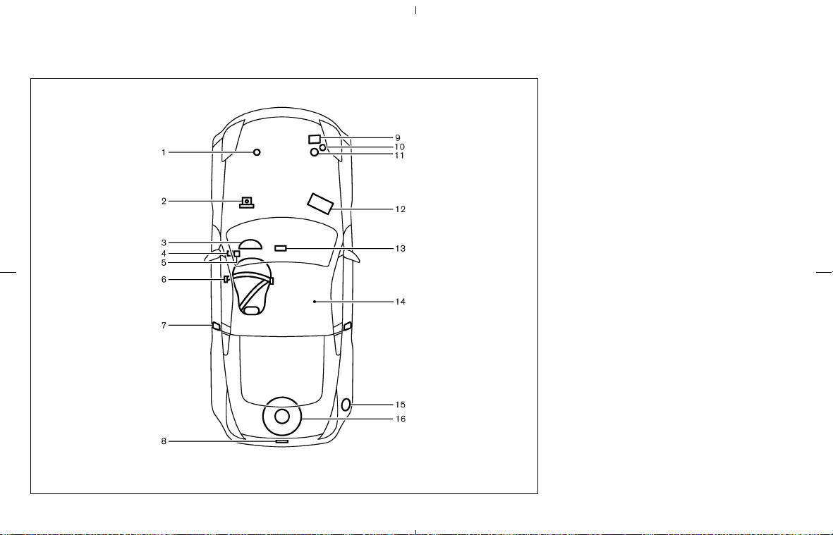
1. Engine oil (P.8-9)
2. Brake fluid (P.8-13)
3. Meters and gauges (P.2-3)
4. Fuel-filler door release (P.3-23)
5. Hood release (P.3-8)
6. Seat belt (P.1-10)
7. Door lock/key (P.3-2)
8. Rear hatch release (Coupe) (P.3-9) or Trunk
lid release (Roadster) (P.3-10)
9. Engine coolant (P.8-8)
10. Window washer fluid (P.8-14)
11. Power steering fluid (P.8-12)
12. Battery (P.8-15)
13. Audio system (P.4-12)/
Heater and air conditioner (P.4-9)
14. Soft top (Roadster models) (P.3-13)
15. Fuel (P.3-23, P.9-3)
16. Spare tire (P.6-3, P.8-38)
STI0364
QUICK REFERENCE
墌 08.7.24/Z33-D/V5.0 墍