MULTIMEDIA PROJECTOR
LV-7245/LV-7240/LV-X5
User’s Manual
E
English

i
Important Information
Safety Cautions
Precautions
Please read this manual carefully before using your Canon LV-7245/LV-7240/LV-X5 projector and keep the manual
handy for future reference. Your serial number is located on the bottom of your projector. Record it here:
CAUTION
To turn off main power, be sure to remove the plug from power outlet.
The power outlet socket should be installed as near to the equipment as possible, and should be easily
accessible.
CAUTION
TO PREVENT SHOCK, DO NOT OPEN THE CABINET.
NO USER-SERVICEABLE PARTS INSIDE.
REFER SERVICING TO QUALIFIED SERVICE PERSONNEL.
This symbol warns the user that uninsulated voltage within the unit may be sufficient to cause electrical
shock. Therefore, it is dangerous to make any kind of contact with any part inside of the unit.
This symbol alerts the user that important information concerning the operation and maintenance of this
unit has been provided.
The information should be read carefully to avoid problems.
WARNING: TO PREVENT FIRE OR SHOCK, DO NOT EXPOSE THIS UNIT TO RAIN OR MOISTURE.
DO NOT USE THIS UNIT’S PLUG WITH AN EXTENSION CORD OR IN AN OUTLET UNLESS ALL THE PRONGS
CAN BE FULLY INSERTED.
DO NOT OPEN THE CABINET. THERE ARE HIGH-VOLTAGE COMPONENTS INSIDE. ALL SERVICING MUST
BE DONE BY QUALIFIED SERVICE PERSONNEL.
Acoustic Noise Information Ordinance-3. GSGV (for Germany only):
The sound pressure level is less than 70 dB (A) according to ISO 3744 or ISO 7779.
CAUTION
Avoid displaying stationary images for a prolonged period of time.
Doing so can result in these images being temporarily sustained on the surface of the LCD panel.
If this should happen, continue to use your projector. The static background from previous images will
disappear.
CAUTION
Do not put the projector on its side when the lamp is turned on.
Doing so may cause damage to the projector.
WARNING TO CALIFORNIA RESIDENTS:
Handling the cables supplied with this product, will expose you to lead, a chemical known to the State of California
to cause birth defects or other reproductive harm. Wash hands after handling.

ii
Important Information
NOTE FOR CUSTOMERS IN THE US
Hg
LAMP(S) INSIDE THIS PRODUCT CONTAIN MERCURY AND MUST BE RE-
CYCLED OR DISPOSED OF ACCORDING TO LOCAL, STATE OR FEDERAL LAWS.
Federal Communication Commission Notice
Multimedia Projector, Model : LV-7245E,LV-7245U,LV-7240E,LV-7240U,LV-X5E and LV-X5U
This device complies with Part 15 of the FCC Rules. Operation is subject to the following two conditions:
(1) This device may not cause harmful interference, and (2) this device must accept any interference received,
including interference that may cause undesired operation.
Note : This equipment has been tested and found to comply with the limits for a Class B digital device, pursuant to
part 15 of the FCC Rules. These limits are designed to provide reasonable protection against harmful interference
in a residential installation. This equipment generates, uses and can radiate radio frequency energy and, if not
installed and used in accordance with the instructions, may cause harmful interference to radio communications.
However, there is no guarantee that interference will not occur in a particular installation. If this equipment does
cause harmful interference to radio or television reception, which can be determined by turning the equipment off
and on, the user is encouraged to try to correct the interference by one or more of the following measures :
– Reorient or relocate the receiving antenna.
– Increase the separation between the equipment and receiver.
– Connect the equipment into an outlet on a circuit different from that to which the receiver is connected.
– Consult the dealer or an experienced radio/TV technician for help.
The cable with the ferrite core provided with the projector must be used with this equipment in order to comply with
Class B limits in Subpart B of Part 15 of the FCC rules.
Use of shielded cable is required to comply with class B limits in Subpart B of Part 15 of FCC Rules.
Do not make any changes or modifications to the equipment unless otherwise specified in the instructions. If such
changes or modifications should be made, you could be required to stop operation of the equipment.
Canon U.S.A., Inc.
One Canon Plaza, Lake Success, NY 11042, U.S.A.
Tel No. (516)328-5600
Canadian Radio Interference Regulations
This Class B digital apparatus complies with Canadian ICES-003.
Réglementation canadienne sur les intérferences radio
Cet appareil numérique de la classe B est conforme à la norme NMB-003 du Canada.
iii
Important Information
LAMP HANDLING
PRECAUTIONS
This projector uses a high-pressure mercury lamp which must be handled carefully and properly as mentioned below.
•A lamp may explode with a loud sound or burn out due to a shock, scratch, or expiration of lifetime.
• The lamp life may differ from lamp to lamp and according to the environment of use. There is not guarantee of the
same lifetime for each lamp. Some lamps may fail or terminate their life in a shorter period of time than other
similar lamps.
•A lamp gradually becomes darker with time of use.
• If the projector indicates that the lamp should be replaced (i.e., the LAMP REPLACE indicator blinks red rapidly),
chances of explosion become higher. Replace the lamp with a new one immediately.
• Always keep your face away from the exhaust vent so that you do not suffer from the gas and broken shards of the
lamp.
IF A LAMP EXPLODES
If a lamp explodes, the gas and broken shards may scatter inside the projector and they may come out
of the exhaust vent. The gas contains toxic mercury.
Open windows and doors for ventilation.
If you inhale the gas or the shards of the broken lamp enter your eyes or mouth, consult the doctor
immediately.
If a lamp explodes, its shards may scatter inside the projector. Ask the Canon service representative to
clean and check the inside of the projector and replace the lamp.
DISPOSAL OF WASTE LAMP
Dispose of the mercury lamp of the projector according to the local regulation just like the fluorescent
lamp.
iv
Important Information
10˚
For UK only: In UK, a BS approved power cord with moulded plug has a Black (five Amps) fuse installed for use with
this equipment. If a power cord is not supplied with this equipment please contact your supplier.
Important Safeguards
These safety instructions are to ensure the long life of your projector and to prevent fire and shock. Please read them
carefully and heed all warnings.
Installation
1. For best results, use your projector in a darkened room.
2. Place the projector on a flat, level surface in a dry area away from dust and moisture.
3. Do not place your projector in direct sunlight, near heaters or heat radiating appliances.
4. Exposure to direct sunlight, smoke or steam can harm internal components.
5. Handle your projector carefully. Dropping or jarring can damage internal components.
6. Do not place heavy objects on top of the projector.
7. If you wish to have the projector installed on the ceiling:
a. Do not attempt to install the projector yourself.
b. The projector must be installed by qualified technicians in order to ensure proper operation and reduce the
risk of bodily injury.
c. In addition, the ceiling must be strong enough to support the projector and the installation must be in accor-
dance with any local building codes.
d. Please consult your dealer for more information.
Do Not Use in the Following Environments
Do not install the projector in a humid or dusty place or a place where there is much oily
smoke or cigarette smoke. Optical parts such as a lens and mirror are stained, resulting in
poor picture.
Do not use the projector in a place where the temperature becomes very high or low.
Operating temperature: +5°C to +35°C Storage temperature: -10°C to +50°C
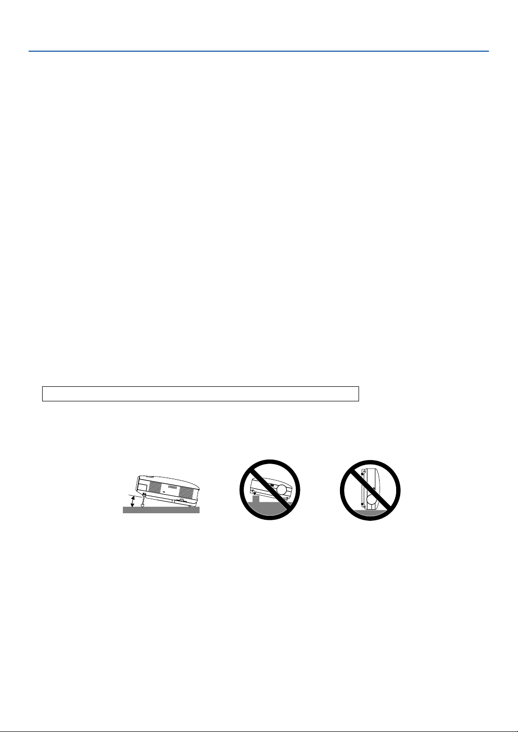
Place the projector in a horizontal position
The tilt angle of the projector should not exceed 10 degrees, nor should the projector be installed in any way other than
the desktop and ceiling mount, otherwise lamp life could decrease dramatically.
Fire and Shock Precautions
1. Ensure that there is sufficient ventilation and that vents are unobstructed to prevent the build-up of heat inside
your projector. Allow at least 1 m (3.3') of space between your projector and a wall.
2. Prevent foreign objects such as paper clips and bits of paper from falling into your projector.
Do not attempt to retrieve any objects that might fall into your projector. Do not insert any metal objects such as
a wire or screwdriver into your projector. If something should fall into your projector, disconnect it immediately
and have the object removed by a qualified service personnel.
3. Do not place any liquids on top of your projector.
4. Do not look into the lens while the projector is on. Serious damage to your eyes could result.
5. Keep any items such as magnifying glass out of the light path of the projector. The light being projected from the
lens is extensive, therefore any kind of abnormal objects that can redirect light coming out of the lens, can
cause unpredictable outcome such as fire or injury to the eyes.

v
Important Information
6. Do not cover the lens with the supplied lens cap or equivalent while the projector is on. Doing so can lead to
melting of the cap and possibly burning your hands due to the heat emitted from the light output.
7. Do not place any objects, which are easily affected by heat, in front of the projector lens or a projector exhaust
vent.
Doing so could lead to the object melting or getting your hands burned from the heat that is emitted from the
light output and exhaust.
8. The projector is designed to operate on a power supply of 100-240V AC 50/60 Hz. Ensure that your power
supply fits this requirement before attempting to use your projector.
9. Handle the power cord carefully and avoid excessive bending.
A damaged cord can cause electric shock or fire.
10. If the projector is not to be used for an extended period of time, disconnect the plug from the power outlet.
11. Do not touch the power plug during a thunderstorm. Doing so can cause electrical shock or fire.
12. Do not handle the power plug with wet hands.
13. Remote Control Precautions
• Handle the remote control carefully.
• If the remote control gets wet, wipe it dry immediately.
•Avoid excessive heat and humidity.
• If you will not be using the remote control for a long time, remove the batteries.
• Do not place the batteries upside down.
• Do not use new and old batteries together, or use different types of batteries together.
• Dispose of used batteries according to your local regulations.
CAUTION
• Do not try to touch the ventilation outlet on the left side (when seen from the front) as it can become heated
while the projector is turned on.
• Do no use the tilt-foot for purposes other than originally intended. Misuses such as gripping the tilt-foot or
hanging on the wall can cause damage to the projector.
• When carrying the projector by the carrying handle, make sure the two screws that attach the carrying handle
to the projector cabinet are tight. (LV-7245/LV-7240 only)
Insufficient tightening of the two screws could result in the projector falling and causing injury.
• Do not send the projector in the soft carrying case by parcel delivery service or cargo shipment. The projector
inside the soft carrying case could be damaged.
• Select [High] in Fan mode if you continue to use the projector for consecutive days. (From the menu, select
[Advanced settings] → [Fan mode] → [High].) Fan noise increases noticeably in High mode.
• Do not unplug the power cord from the wall outlet under any one of the following circumstances.
Doing so can cause damage to the projector:
* While the Hour Glass icon appears.
* While the cooling fans are running. (The cooling fans continue to work for 30 seconds after the projector is
turned off).
* While the lamp is lighted.
Lamp Replacement
•To replace the lamp, follow all instructions provided on page 49.
• Be sure to replace the lamp when the message “Replace with the new lamp.” appears. If you continue to use
the lamp after the lamp has reached the end of its usable life, the lamp bulb may shatter, and pieces of glass
may be scattered in the lamp case. Do not touch them as the pieces of glass may cause injury.
If this happens, contact your dealer for lamp replacement.
• Allow a minimum of 30 seconds to elapse after turning off the projector. Then turn off the main power switch,
disconnect the power cord and allow 60 minutes to cool the projector before replacing the lamp.

vi
Table of Contents
Important Information ........................................................................... i
1. Introduction ......................................................................................1
What's in the Box? ........................................................................................................ 1
Introduction to the Projector ......................................................................................... 2
Part Names of the Projector ......................................................................................... 4
Attaching the Supplied Carrying Handle (LV-7245/LV-7240 only) ........................... 5
Top Features ........................................................................................................... 6
Te r minal Panel Features ......................................................................................... 7
Part Names of the Remote Control .............................................................................. 8
Battery Installation ........................................................................................... 10
Remote Control Precautions ............................................................................ 10
Operating Range for Wireless Remote Control................................................ 10
2. Installation and Connections ....................................................... 11
Setting Up the Screen and the Projector .................................................................... 11
Selecting a Location.............................................................................................. 11
Throw Distance and Screen Size .......................................................................... 12
Making Connections ................................................................................................... 14
Enabling the computer’s external display .............................................................. 14
Connecting Your PC or Macintosh Computer ........................................................ 14
To connect Scart output (RGB) ............................................................................. 15
Connecting an External Monitor ........................................................................... 16
Connecting Your DVD Player with Component Output .......................................... 17
Connecting Your VCR or Laser Disc Player .......................................................... 18
Connecting the Supplied Power Cord ................................................................... 19
3. Projecting an Image (Basic Operation)...................................... 20
Tur ning on the Projector ............................................................................................. 20
Note on Startup Screen (Menu Language Select screen) .................................... 21
Selecting a Source ..................................................................................................... 22
Adjusting the Picture Size and Position ...................................................................... 23
Correcting Keystone Distortion ................................................................................... 25
Automatically Optimizing on RGB Image ................................................................... 27
Tu rning Up or Down Volume ....................................................................................... 27
Tu rning off the Projector ............................................................................................. 28
After Use..................................................................................................................... 28

vii
Table of Contents
4. Convenient Features ...................................................................... 29
Tu rning Off the Image and Sound ............................................................................... 29
Freezing a Picture....................................................................................................... 29
Enlarging and Moving a Picture.................................................................................. 29
Using the Remote Mouse Receiver (LV-7245/LV-7240 only) ...................................... 30
5. Using On-Screen Menu ................................................................. 31
Using the Menus......................................................................................................... 31
Menu Elements........................................................................................................... 33
List of Menu Items ...................................................................................................... 34
Menu Descriptions & Functions [Image adjustment] .................................................. 36
Menu Descriptions & Functions [Display settings]...................................................... 38
Menu Descriptions & Functions [Setup] ..................................................................... 39
Menu Descriptions & Functions [Advanced settings] ................................................. 41
Menu Descriptions & Functions [Information] ............................................................. 45
Menu Descriptions & Functions [Factory default] ....................................................... 46
6. Maintenance .................................................................................... 47
Cleaning or Replacing the Filter ................................................................................ 47
Cleaning the Cabinet and the Lens ........................................................................... 48
Replacing the Lamp................................................................................................... 49
7. Appendix ........................................................................................... 52
Troubleshooting ......................................................................................................... 52
Specifications ............................................................................................................ 55
Cabinet Dimensions .................................................................................................. 57
Pin Assignments of D-Sub ANALOG Input Connector .............................................. 58
Compatible Input Signal List ...................................................................................... 59
PC Control Codes and Cable Connection ................................................................. 60
Troubleshooting Check List ........................................................................................ 61
1
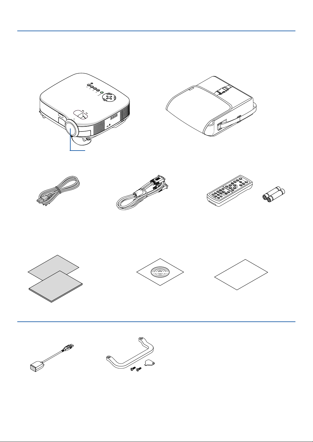
What's in the Box?
Make sure your box contains everything listed. If any pieces are missing, contact your dealer.
Please save the original box and packing materials if you ever need to ship your projector.
ZOOM
P
O
W
E
R
V
ID
E
O
S
-
V
ID
EO
COMPUTER-1 COMPUTER-2
W
A
R
N
I
N
G
L
A
M
P
R
E
P
L
A
C
E
A
U
TO
PC
V
O
L
-
V
O
L
+
Z
O
O
M
F
O
C
U
S
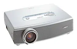
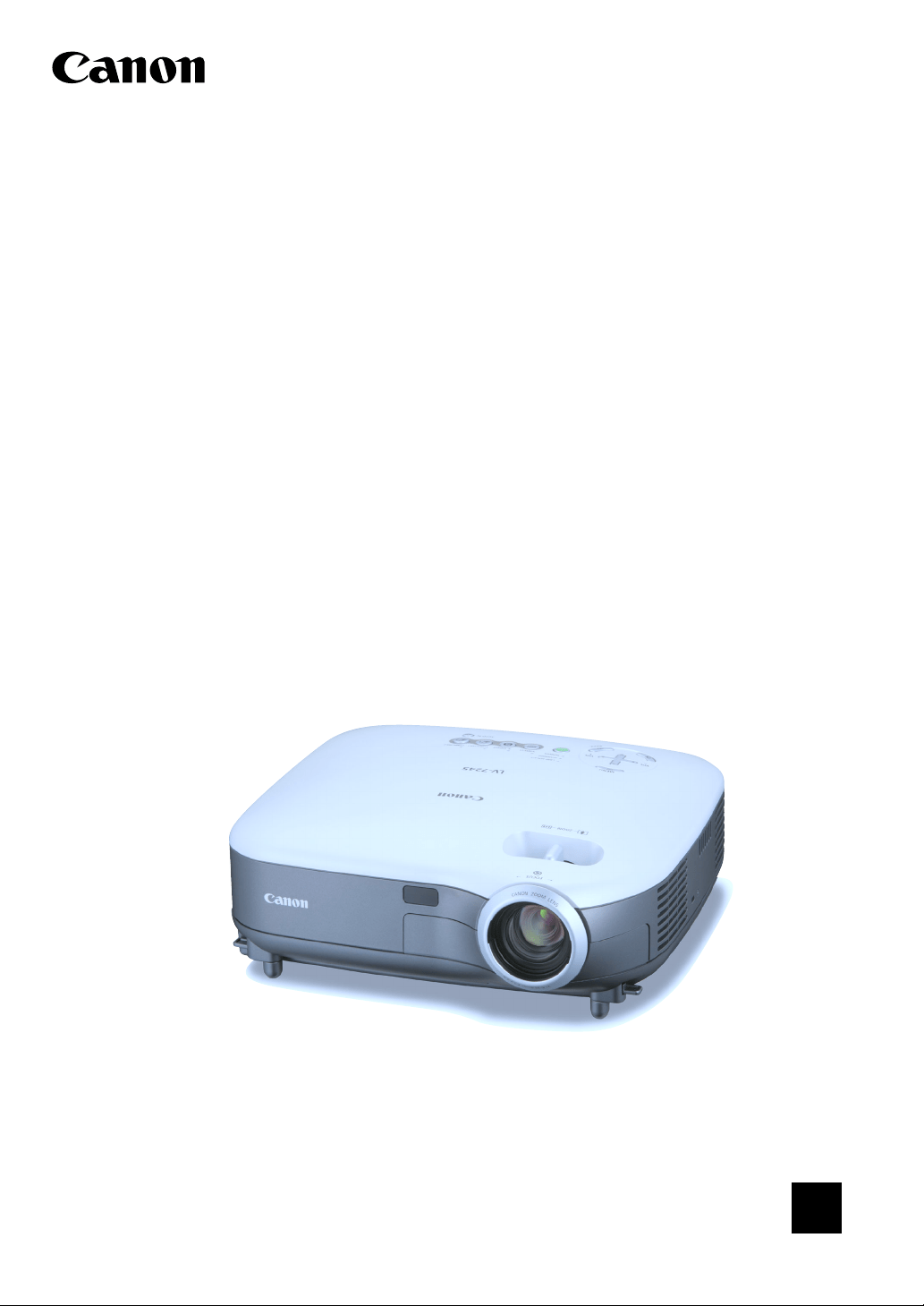
Projector
Lens cap
AC power cord VGA cable
Soft case
Quick
Start
Guide
Important
Information
CD-ROM
User’s manual
Quick Start Guide
Important Information
1. Introduction
For LV-7245/LV-7240 only
POWER
O
F
F
NO SHOW
D
.Z
O
O
M
P
A
G
E
M
E
N
U
B
A
C
K
RD-426E
R-CLICK
L-CLICK
V
ID
EO
C
O
M
P
U
T
E
R
-1
A
U
T
O
P
C
VOL
FREEZE
IN
FO
.
IMAGE
ASPECT
1
2
C
O
M
P
U
T
E
R
-
2
S-VIDEO
Remote control Batteries (AAA
⳯
2)
Remote mouse receiver
Carrying handle
Screw (M4
⳯
2)
Flathead screwdriver
Warranty

2
1. Introduction
Introduction to the Projector
This section introduces you to your new projector and describes the features and controls.
Congratulations on Your Purchase of The Projector
The LV-7245/LV-7240/LV-X5 is one of the very best projectors available today. The projector enables you to project
precise images up to 300 inches across (measured diagonally) from your PC or Macintosh computer (desktop or
notebook), VCR, DVD player, document camera, or a laser disc player.
You can use the projector on a tabletop or cart, from behind a screen, or permanently mounted on a ceiling*
1
. The
remote control can be used wirelessly.
*
1
Do not attempt to mount the projector on a ceiling yourself.
The projector must be installed by qualified technicians in order to ensure proper operation and reduce the
risk of bodily injury.
In addition, the ceiling must be strong enough to support the projector and the installation must be in accor-
dance with any local building codes. Please consult your dealer for more information.
Features you'll enjoy:
•Auto vertical keystone correction up to +/– 30 degrees
• Built-in Screen color presets provide for adaptive color correction when projecting onto non-white screen
material
• Quick Start & Quick Shutoff
The quick start & quick shutoff function means you can set up or put away the projector without delay.
Nine seconds after turning on the power, the projector is ready to display PC or video images.
When you're finished, the fans stop in 30 seconds after turning off the power, so you can put away the projector
quickly after the conference or class.
•Low level operation noise
• Short focal length lens
• 130W lamp (110W Quiet mode) : LV-X5
180W lamp (150W Quiet mode) : LV-7240
190W lamp (150W Quiet mode) : LV-7245
• Direct keys for source selection
•New Color Management system
•New menu design improves operation
• Safety protect by Password function
Password feature prevents the projector from being used by unauthorized individuals.
Password prevents unauthorized individuals from changing projector settings or adjustments.
• Intelligent pixel blending technology - an extremely accurate image compression technology - offers a crisp
image with UXGA (1600⳯1200) resolution*
2
• Supports most IBM VGA, SVGA, XGA , SXGA/UXGA (with scaling technology)*
2
, Macintosh, component signal
(YCbCr/ YPbPr) or any other RGB signals within a horizontal frequency range of 24 to 100 kHz and a vertical
frequency range of 50 to 120 Hz. This includes NTSC, PAL, PAL-N, PAL-M, PAL60, SECAM and NTSC4.43
standard video signals.
*
2
A UXGA (1600⳯1200) and SXGA image (1280⳯1024) are displayed with scaling technology.

3
NOTE: Composite video standards are as follows:
NTSC: U.S. TV standard for video in U.S. and Canada.
PAL: TV standard used in Western Europe.
PAL-N: TV standard used in Argentine, Paraguay and Uruguay.
PAL-M: TV standard used in Brazil.
PAL60: TV standard used for NTSC playback on PAL TVs.
SECAM: TV standard used in France and Eastern Europe.
NTSC4.43: TV standard used in Middle East countries.
•You can use the supplied wireless remote control and remote mouse receiver to operate your PC mouse
wireless from across the room. The remote mouse receiver supports almost any PC using a USB connection
(LV-7245/LV-7240).
•You can control the projector with a PC or control system using the PC Control port.
• The contemporary cabinet design is light, compact, easy to carry, and complements any office, boardroom or
auditorium.
About this user's manual
The fastest way to get started is to take your time and do everything right the first time. Take a few minutes now to
review the user's manual. This may save you time later on. At the beginning of each section of the manual you'll find an
overview. If the section doesn't apply, you can skip it.
• IBM is a trademark or registered trademark of International Business Machines Corporation.
• Mac and PowerBook are trademarks of Apple Computer, Inc., registered in the U.S. and other countries.
• Windows, Windows 98, Windows Me, Windows XP or Windows 2000 are trademarks or registered trademarks
of Microsoft Corporation.
• Other product and company names mentioned in this user’s manual may be the trademarks or registered
trademarks of their respective holders.
1. Introduction
4
1. Introduction
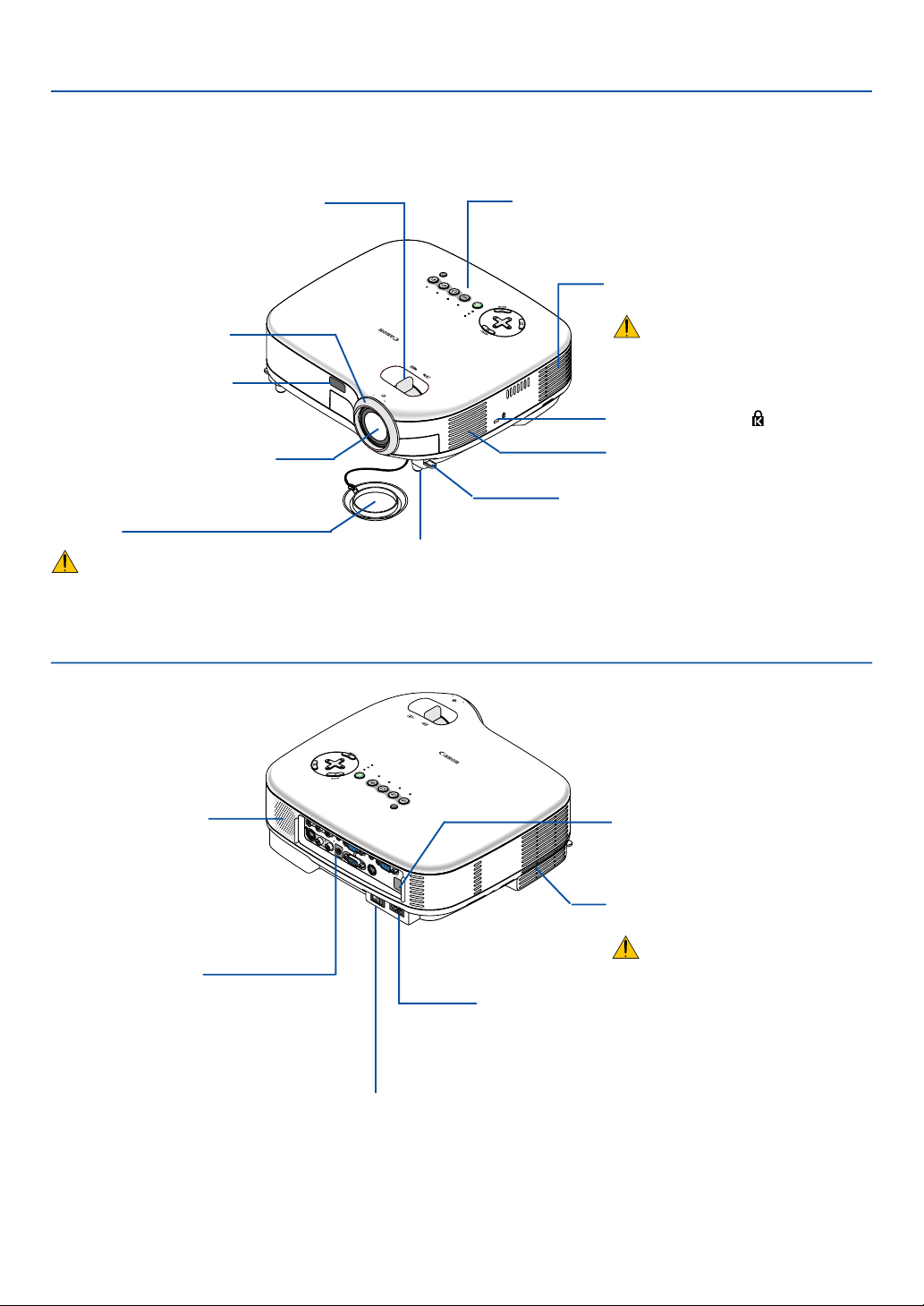
Part Names of the Projector
POWE
R
V
ID
E
O
S-
VIDEO
CO
MPUTER-1 CO
M
PU
TER-2
WARN
ING
L
A
M
P
R
E
P
L
A
C
E
AUTO PC
V
O
L
-
V
O
L
+
Z
O
O
M
FO
CUS
AC IN
V
O
L
-
V
O
L
+
ZOOM
F
O
CU
S
S-VIDEO IN
M
O
N
O
M
O
N
O
VID
EO
IN
L
A
U
D
IO
IN
R
A
NA
LO
G
IN-1 A
NA
LO
G IN
-2
A
U
D
IO
O
U
T
L
A
U
D
IO
IN
R
SERVICE PO
RT
A
U
D
IO IN
PO
W
ER
V
ID
EO
S-
VIDEO
C
O
M
P
U
T
E
R
-1
C
O
M
P
U
T
E
R
-
2
W
A
R
NING
LAM
P REPLACE
AUTO PC
AC IN
Zoom Lever
(See page 24)
Controls
(See page 6)
Lens
Lens Cap
Be sure to remove the lens cap
during projection. The cap can
deform or fire can occur.
Built-in Security Slot ( )*
Focus Ring
(See page 24)
Adjustable Tilt Foot Lever
(See page 23)
Adjustable Tilt Foot
(See page 23)
Remote sensor
(See page 10)
Ventilation (inlet) / Filter Cover
(See page 47)
Do not block this vent.
Troubles or fire can result.
Ventilation (inlet)
Front/Top
AC Input
Connect the supplied power cord’s two-pin plug here, and
plug the other end into an active wall outlet. (See page 19)
Main Power Switch
When you plug the supplied power cord into an active wall outlet
and turn on the Main Power, the POWER indicator turns orange
and the projector is in standby mode.
(See page 20)
Remote sensor
(See page 10)
Ter minal Panel
(See page 7)
Monaural Speaker
(1W)
Rear
* This security slot supports the MicroSaver ® Security System. MicroSaver ® is a registered trademark of
Kensington Microware Inc. The logo is trademarked and owned by Kensington Microware Inc.
Ventilation (outlet)
Heated air is exhausted from here.
Do not block this vent. Troubles or
fire can result.
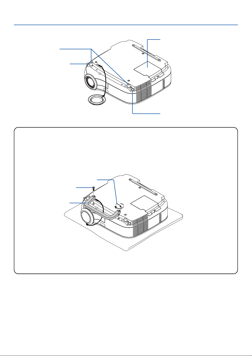
5
1. Introduction
For LV-7245/LV-7240 only
Attaching the supplied carrying handle
You can carry the projector by attaching the supplied carrying handle securely to the projector.
To attach the supplied carrying handle, use the supplied flathead screwdriver and two screws.
Place a soft cloth on the working surface before turning the projector over to prevent scratching the top cover.
Make sure that the carrying handle is attached with correct orientation as shown below.
Bottom
Adjustable Tilt Foot
(See page 23)
Adjustable Tilt Foot Lever
(See page 23)
Adjustable Tilt Foot Lever
(See page 23)
Lamp Cover
(See page 49)
CAUTION
When carrying the projector by the carrying handle, make sure the two screws that attach the carrying handle
to the projector cabinet are tight.
Carrying handle
Screw
Flathead screwdriver

6
1. Introduction
Top Features
POWER
VIDEO S-
VIDEO
COMPUTER-1 COMPUTER-2
WARNING
LAMP REPLACE
AUTO PC
VOL
-
VOL
+
12 13
10 2 3 411
1567 8
9
1. POWER Button ( )
Use this button to turn the power on and off when the
main power is supplied and the projector is in standby
mode.
To turn on the projector, press and hold this button for
a minimum of two seconds. To turn off the projector,
press this button twice.
2. POWER Indicator
When this indicator is green, the projector is on; when
this indicator is orange, it is in standby mode. See the
Power Indicator section on page 52 for more details.
3. WARNING Indicator
If this light blinks red rapidly, it indicates that an error
has occurred, the lamp cover is not attached properly
or the projector has overheated. If this light remains
orange, it indicates that you have pressed a cabinet
key while the Key lock is enabled. See the WARNING
Indicator section on page 52 for more details.
4. LAMP REPLACE Indicator
If this light blinks red rapidly, it's warning you that the
lamp has reached the end of its usable life. After this
light appears, replace the lamp as soon as possible
(See page 49). If this is lit green continually, it indi-
cates that the lamp mode is set to Quiet. See the Lamp
Indicator section on page 52 for more details.
5. VIDEO Button
Press this button to select a video source from a VCR,
DVD player, laser disc player or document camera.
6. S-VIDEO Button
Press this button to select an S-Video source from a
VCR, DVD player, laser disc player or document cam-
era.
7. COMPUTER-1 and -2 Buttons
Press this button to select an RGB source from com-
puter or component equipment connected to your
ANALOG IN-1 or -2 port.
8. AUTO PC Button
Use this button to adjust an RGB source for an opti-
mal picture (See page 27).
9. Source Indicators
When one of the ANALOG IN-1/-2, VIDEO or S-VIDEO
input is selected, the corresponding source indicator
lights.
10. MENU Button
Displays the menu.
11. SELECT
/ VOL (+/–) Buttons
: Use these buttons to select the menu of the
item you wish to adjust.
: Use these buttons to change the level of a se-
lected menu item. A press of the
button ex-
ecutes the selection. When no menus appear,
these buttons work as a volume control.
12. OK Button
Executes your menu selection and activates items
selected from the menu.
13. BACK Button
Pressing this button will return to the previous menu.
While you are in the main menu, pressing this button
will close the menu.
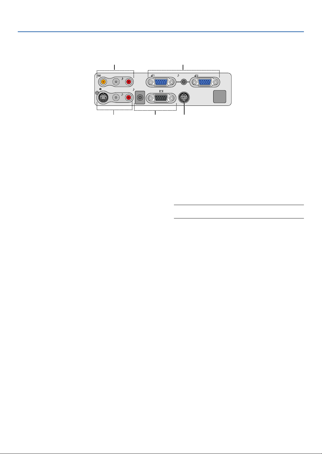
7
1. Introduction
VIDEO IN
L
AUDIO
IN
R
S-VIDEO IN
ANALOG IN-1
ANALOG IN-2
AUDIO OUT
L
AUDIO
IN
R
SERVICE PORT
AUDIO IN
MONO
MONO
4 1
325
Te r minal Panel Features
1. ANALOG IN-1 and -2 / Component Input Connec-
tor (Mini D-Sub 15 Pin)
Connect your computer or other analog RGB equip-
ment such as IBM compatible or Macintosh comput-
ers. Use the supplied RGB cable to connect to your
computer. This also serves as a component input con-
nector that allows you to connect a component video
output of component equipment such as a DVD player.
This connector also supports Scart output signal. See
page 15 for more details.
AUDIO IN Mini Jack (Stereo Mini)
This is where you connect the audio output from your
computer or DVD player when connected to the COM-
PUTER input. A commercially available audio cable is
required.
2.
MONITOR OUT Connector (Mini D-Sub 15 Pin)
You can use this connector to loop your computer
image to an external monitor from the RGB input
source.
This connector outputs RGB signal in standby mode.
AUDIO OUT Mini Jack (Stereo Mini)
You can use this jack to output sound from the cur-
rently selected source (COMPUTER, VIDEO or S-
VIDEO). Output sound level can be adjusted in accor-
dance with the sound level of the internal speaker.
Note that this cannot be used as a headphone jack.
(When audio equipment is connected, the projector
speaker is disabled.)
When a cable mini-plug is inserted into this jack, both
the right and left audio signals are not mixed, but sepa-
rate.
For example, when a cable mini-plug is inserted into
the left AUDIO IN jack only, only left sound is output.
3. S-VIDEO IN Connector (Mini DIN 4 Pin)
Here is where you connect the S-Video input from an
external source like a VCR.
NOTE: S-Video provides more vivid color and higher
resolution than the traditional composite video format.
S-VIDEO AUDIO Input Jacks L/R (RCA)
These are your left and right channel audio inputs for
stereo sound from an S-Video source.
4. VIDEO IN Connector (RCA)
Connect a VCR, DVD player, laser disc player, or docu-
ment camera here to project video.
VIDEO AUDIO Input Jacks L/R (RCA)
These are your left and right channel audio inputs for
stereo sound from a Video source.
5. SERVICE PORT (DIN 8 Pin)
Use this port to connect a PC or control system to
control the projector via an optional RS-232C serial
cable (LV-CA34). If you are writing your own program,
typical PC control codes are on page 60.
8
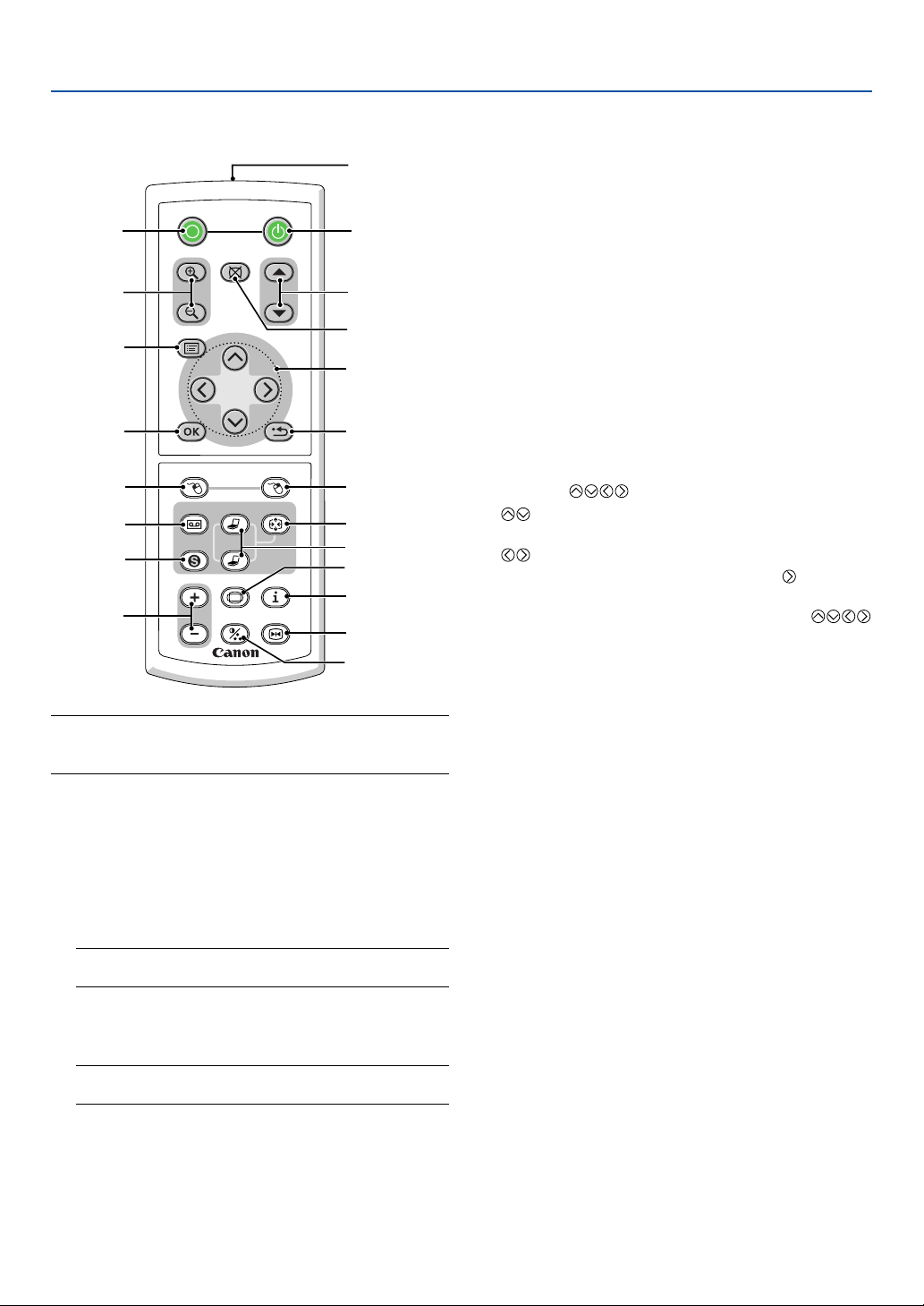
1. Introduction
Part Names of the Remote Control
NOTE: If you are using a Macintosh computer, you can click
either the MOUSE R-CLICK or MOUSE L-CLICK button to
activate the mouse.
1. Infrared Transmitter
Direct the remote control toward the remote sensor
on the projector cabinet.
2. POWER Button
When the main power is on, you can use this button
to turn your projector on.
NOTE: To turn on the projector, press and hold the POWER
button for a minimum of two seconds.
3. OFF Button
You can use this button to turn your projector off.
NOTE: To turn off the projector, press the OFF button
twice.
4. D. ZOOM (+) (–) Button
Use this button to adjust the image size up to 400%.
The image is magnified about the center of the screen.
See page 29.
POWER
OFF
NO SHOW
D.ZOOM
PAGE
MENU
BACK
RD-426E
R-CLICKL-CLICK
VIDEO
COMPUTER-1
AUTO PC
VOL
FREEZE
INFO.
IMAGE
ASPECT
1
2
COMPUTER-2
S-VIDEO
1
3
4
7
6
9
2
8
10
11
13
14
12
20
21
19
16
15
18
5
17
5. NO SHOW Button
This button turns off the image and sound for a short
period of time. Press again to restore the image and
sound.
6. PAGE / Button
(Not available on LV-X5)
Use these buttons to operate your computer with the
supplied remote mouse receiver. See page 30. You
can use these buttons to scroll the viewing area of the
window or to move to the previous or next slide in
PowerPoint on your computer.
7. MENU Button
Displays the menu for various settings and adjust-
ments.
8. SELECT
(Mouse) Button
: Use these buttons to select the menu of the
item you wish to adjust.
: Use these buttons to change the level of a se-
lected menu item. A press of the button ex-
ecutes the selection.
When an image is magnified, the SELECT
button moves the image. See page 29.
9. OK Button
Use this button to enter your menu selection. It works
the same way as the OK button on the cabinet. See
page 6.
10. BACK Button
It works the same way as the BACK button on the
cabinet. See page 6.
11. MOUSE L-CLICK Button
(Not available on LV-X5)
This button works as the mouse left button when the
supplied remote mouse receiver is connected with your
computer. See page 30.
12. MOUSE R-CLICK Button
(Not available on LV-X5)
This button works as the mouse right button when the
supplied remote mouse receiver is connected with your
computer. See page 30.
13. VIDEO Button
Press this button to select a video source from a VCR,
DVD player, laser disc player or document camera.
14. S-VIDEO Button
Press this button to select an S-Video source from a
VCR or DVD player.
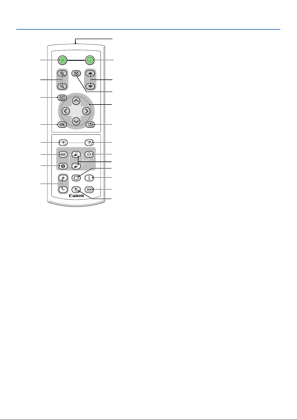
9
15. COMPUTER-1/-2 Button
Press this button to select COMPUTER-1 or -2 (or
Component) input.
16. AUTO PC Button
Use this button to adjust an RGB source for an opti-
mal picture.
See page 27.
17. VOL (+) (–) Button
Press (+) to increase the volume and (–) to decrease
it.
18. ASPECT Button
Press this button once to display the Aspect select
menu. Keep pressing will change aspect ratios. See
page 38.
19. IMAGE Button
Press this button to display the Image adjustment
menu to adjust Screen color, Image mode, Brightness,
Contrast, Sharpness, Color and Color balance. See
pages 36 to 37.
POWER
OFF
NO SHOW
D.ZOOM
PAGE
MENU
BACK
RD-426E
R-CLICKL-CLICK
VIDEO
COMPUTER-1
AUTO PC
VOL
FREEZE
INFO.
IMAGE
ASPECT
1
2
COMPUTER-2
S-VIDEO
1
3
4
7
6
9
2
8
10
11
13
14
12
20
21
19
16
15
18
5
17
1. Introduction
20. INFO. Button
Provides the information on the current signal and pro-
jector settings. See page 45.
21. FREEZE Button
This button will freeze a picture. Press again to re-
sume motion.
10
1. Introduction
30°
30°
30°
30°
Remote Control Precautions
• Handle the remote control carefully.
• If the remote control gets wet, wipe it dry immediately.
•Avoid excessive heat and humidity.
• If you will not be using the remote control for a long time, remove the batteries.
• Do not place the batteries upside down.
• Do not use new and old batteries together, or use different types of batteries together.
• Dispose of used batteries according to your local regulations.
Operating Range for Wireless Remote Control
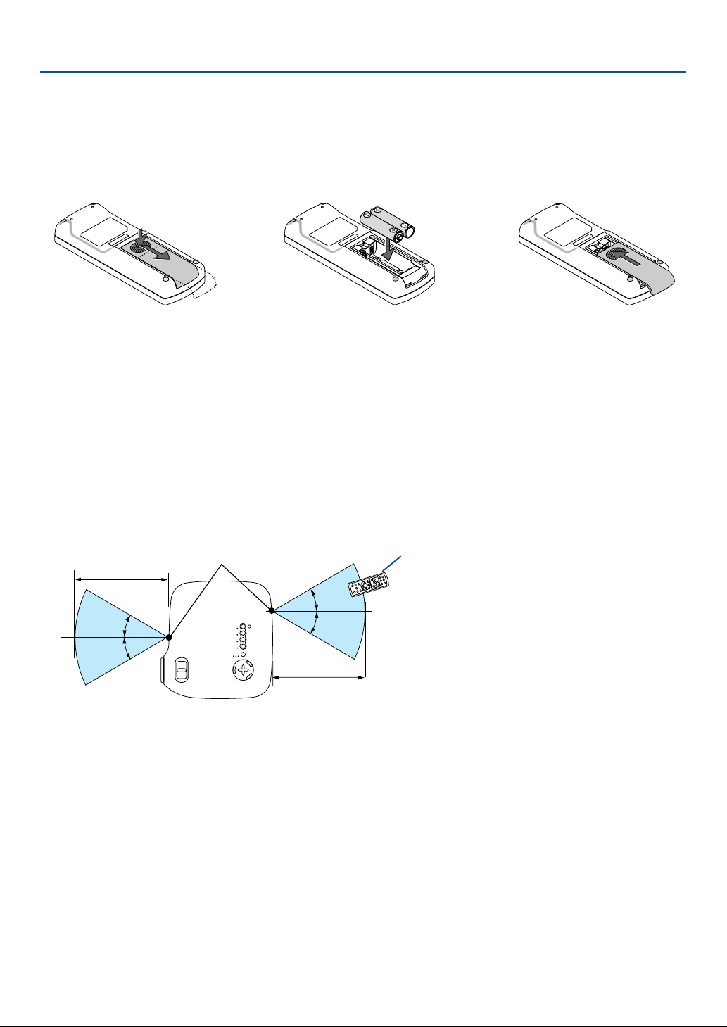
Battery Installation
1
Press firmly and slide the
battery cover off.
2
Remove both old batteries and
install new ones (AAA). Ensure
that you have the batteries' po-
larity (+/–) aligned correctly.
3
Slip the cover back over the bat-
teries until it snaps into place. Do
not mix different types of batter-
ies or new and old batteries.
Remote sensor on projector cabinet
Remote control
7m/22 feet
7m/22 feet
• The infrared signal operates by line-of-sight up to a distance of about 7 m (22 feet) and within a 60-degree angle of
the remote sensor on the projector cabinet.
• The projector will not respond if there are objects between the remote control and the sensor, or if strong light falls
on the sensor. Weak batteries will also prevent the remote control from properly operating the projector.
11
This section describes how to set up your projector and how to connect video and audio sources.
2. Installation and Connections
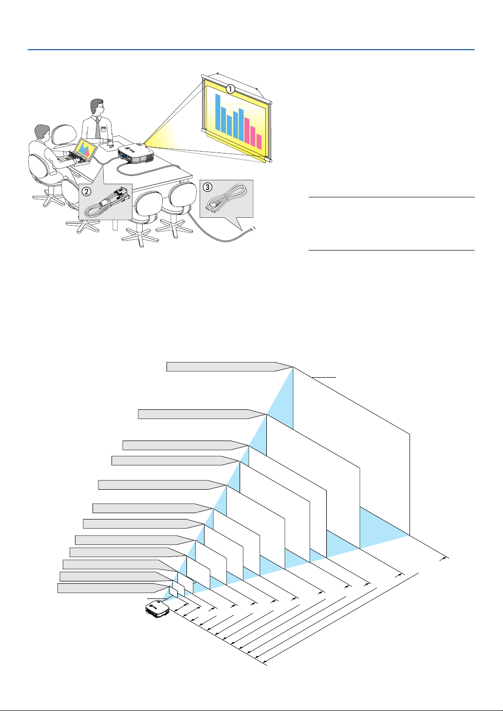
Setting Up the Screen and the Projector
Selecting a Location
The further your projector is from the screen or wall, the larger the image. The minimum size the image can be is
approximately 21" measured diagonally when the projector is roughly 0.73 m (29 inches) from the wall or screen. The
largest the image can be is 300" when the projector is about 10 m (393 inches) from the wall or screen. Use the
drawing below as a guide.
Your projector is simple to set up and use.
But before you get started, you must first:
z Set up a screen and the projector.
x Connect your computer or video equip-
ment to the projector. See pages 14 to
18.
c Connect the supplied power cord. See
page 19.
NOTE: Ensure that the power cord and any
other cables are disconnected before moving
the projector. When moving the projector or
when it is not in use, cover the lens with the
lens cap.
To the wall outlet.
300"
240
"
200
"
180"
150"
120"
100"
60"
40"
30"
21"
80"
Distance (Unit: m/inch)
Screen Size (Unit: cm/inch)
Screen Size
Lens center
609.6(W)⳯457.2(H) / 240(W)⳯180(H)
487.7(W)⳯365.8(H) / 192(W)⳯144(H)
406.4(W)⳯304.8(H) / 160(W)⳯120(H)
365.8(W)⳯274.3(H) / 144(W)⳯108(H)
304.8(W)⳯228.6(H) / 120(W)⳯90(H)
243.8(W)⳯182.9(H) / 96(W)⳯72(H)
203.2(W)⳯152.4(H) / 80(W)⳯60(H)
162.6(W)⳯121.9(H) / 64(W)⳯48(H)
121.9(W)⳯91.4(H) / 48(W)⳯36(H)
81.3(W)⳯61.0(H) / 32(W)⳯24(H)
61.0(W)⳯45.7(H) / 24(W)⳯18(H)
42.7(W)⳯32(H) / 17(W)⳯13(H)
1.0/38
0.73/
29
2.0/78
2.6/104
3.3/130
4.0/157
5.0/196
6.0/236
6.6/262
8.0/314
10.0/393
1.3/
51
A
C
I
N
12
2. Installation and Connections
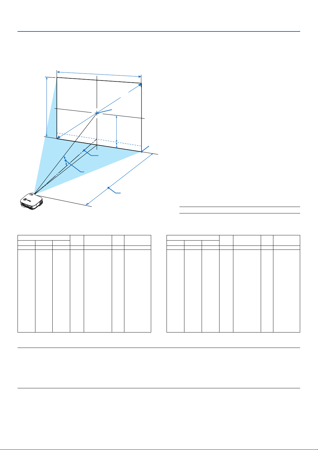
Lens Center
Throw Angle (움)
Throw Distance (C)
Screen center
Screen Diagonal
Screen Width
Screen Height
Screen Bottom
(B)
(D)
A
C
I
N
Throw Distance and Screen Size
The following shows the proper relative positions of the projector and screen. Refer to the table to determine the
position of installation.
Distance Chart
B =Vertical distance between lens center and
screen center
C = Throw distance
D =Vertical distance between lens center and
bottom of screen (top of screen for ceiling
application)
α = Throw angle
NOTE: Distances may vary +/-5%.
α
Wide – Tele
degree
–– – 9.9
12.0 – 9.8
11.9 – 9.8
11.7 – 9.7
11.6 – 9.6
11.6 – 9.6
11.6 – 9.6
11.6 – 9.6
11.5 – 9.6
11.5 – 9.6
11.5 – 9.5
11.5 – 9.5
11.5 – 9.5
11.5 – 9.5
11.5 – 9.5
11.5 – 9.5
11.4 – 9.5
11.4 – 9.5
inch
13
15
18
24
36
43
48
50
54
60
72
90
108
120
126
144
162
180
Screen Size B C
Wide – Tele
D
Diagonal Width Height
inch
–– – 29
28 – 34
34 – 42
46 – 56
70 – 85
84 – 102
93 – 113
98 – 119
105 – 128
117 – 142
141 – 171
176 – 214
212 – 257
236 – 285
247 – 300
283 – 343
319 – 386
354 – 429
inch
-1
-2
-2
-2
-4
-4
-5
-5
-6
-6
-7
-9
-11
-12
-13
-15
-17
-18
inch
5
6
7
10
14
17
19
20
22
24
29
36
43
48
50
57
65
72
inch
21
25
30
40
60
72
80
84
90
100
120
150
180
200
210
240
270
300
inch
17
20
24
32
48
58
64
67
72
80
96
120
144
160
168
192
216
240
α
Wide – Tele
degree
–– – 9.9
12.0 – 9.8
11.9 – 9.8
11.7 – 9.7
11.6 – 9.6
11.6 – 9.6
11.6 – 9.6
11.6 – 9.6
11.5 – 9.6
11.5 – 9.6
11.5 – 9.5
11.5 – 9.5
11.5 – 9.5
11.5 – 9.5
11.5 – 9.5
11.5 – 9.5
11.4 – 9.5
11.4 – 9.5
mm
320
381
457
610
914
1097
1219
1280
1372
1524
1829
2286
2743
3048
3200
3658
4115
4572
Screen Size B C
Wide – Tele
D
Diagonal Width Height
mm
––– – 730
720 – 870
870 – 1060
1170 – 1420
1770 – 2150
2130 – 2590
2370 – 2880
2490 – 3020
2670 – 3240
2970 – 3600
3580 – 4330
4480 – 5420
5380 – 6520
5980 – 7240
6280 – 7610
7190 – 8700
8090 – 9790
8990 – 10880
mm
-30
-40
-50
-60
-90
-110
-120
-130
-140
-160
-190
-230
-280
-310
-330
-370
-420
-470
mm
130
150
180
240
360
440
490
510
550
610
730
910
1090
1210
1270
1460
1640
1820
mm
533
635
762
1016
1524
1829
2032
2134
2286
2540
3048
3810
4572
5080
5334
6096
6858
7620
mm
427
508
610
813
1219
1463
1626
1707
1829
2032
2438
3048
3658
4064
4267
4877
5486
6096
NOTE:
This projector can be hung from the ceiling (Ceiling mounted) with it turned up side down.
When a translucent screen is used, the projector can project an image from behind the screen (Rear).
When the projector is hung from the ceiling or projector projects an image from behind the screen, the image must be inverted
vertically or horizontally. See page 40.
• When hanging the projector from the ceiling, optional brackets (part No. LV-CL10) are required.

13
2. Installation and Connections
WARNING
* Installing your projector on the ceiling must be done
by a qualified technician. Contact your dealer for more
information.
* Do not attempt to install the projector yourself.
• Only use your projector on a solid, level surface. If the
projector falls to the ground, you can be injured and
the projector severely damaged.
• Do not use the projector where temperatures vary
greatly. The projector must be used at temperatures
between 41˚F (5˚C) and 95˚F (35˚C).
• Do not expose the projector to moisture, dust, or
smoke. This will harm the screen image.
• Ensure that you have adequate ventilation around your
projector so heat can dissipate. Do not cover the vents
on the side or the front of the projector.
Reflecting the Image
Using a mirror to reflect your projector's image enables
you to enjoy a much larger image. Contact your dealer if
you need a mirror system. If you're using a mirror sys-
tem and your image is inverted, use the MENU and
SELECT
buttons on your projector cabinet or
your remote control to correct the orientation. See page
40.
14
2. Installation and Connections
Making Connections
NOTE: When using with a notebook PC, be sure to connect between the projector and the notebook PC before turning on the
power to the notebook PC. In most cases signal cannot be output from RGB output unless the notebook PC is turned on after
connecting with the projector.
* If the screen goes blank while using your remote control, it may be the result of the computer's screen-saver or power
management software.
AC IN
ANALOG IN-1
ANALOG IN-2
VIDEO IN
L
AUDIO
IN
R
S-VIDEO IN
ANALOG IN-1
ANALOG IN-2
AUDIO OUT
L
AUDIO
IN
R
MONO
MONO
SERVICE PORT
AUDIO IN
AUDIO IN
PHONE
PHONE
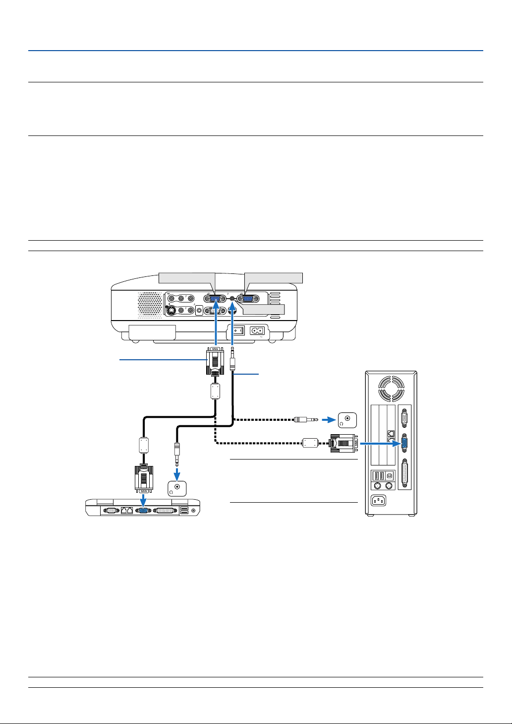
Connecting Your PC or Macintosh Computer
NOTE: The COMPUTER 1 connector supports Plug & Play (DDC2).
VGA cable (supplied)
To mini D-Sub 15-pin connector on the projector. It
is recommended that you use a commercially
available distribution amplifier if connecting a
signal cable longer than the supplied one.
Audio cable
(not supplied)
IBM PC or Compatibles (Desktop type)
or Macintosh (Desktop type)
NOTE: For older Macintosh, use a
commercially available pin adapter
(not supplied) to connect to your
Mac's video port.
IBM VGA or Compatibles (Notebook
type) or Macintosh (Notebook type)
Connecting your PC or Macintosh computer to your projector will enable you to project your computer's screen image
for an impressive presentation.
To connect to a PC or Macintosh, simply:
1. Turn off the power to your projector and computer.
2. Use the supplied VGA cable to connect your PC or Macintosh to the projector.
3. Connect the supplied power cord. See page 19.
4. Turn on the projector and the computer.
5. If the projector goes blank after a period of inactivity, it may be caused by a screen saver installed on the computer
you've connected to the projector.
NOTE: Use an audio cable without a built-in resistor. Using an audio cable with a built-in resistor turns down the sound.
Enabling the computer’s external display
Displaying an image on the notebook PC’s screen does not necessarily mean it outputs a signal to the projector.
When using a PC compatible laptop, a combination of function keys will enable/disable the external display.
Usually, the combination of the ‘Fn” key along with one of the 12 function keys gets the external display to come on
or off. For more details, refer to your computer’s owner’s manual.
15
NOTE: An image may not be displayed correctly when a Video or S-Video source is played back via a commercially available scan
converter.
This is because the projector will process a video signal as a computer signal at the default setting. In that case, do the following.
* When an image is displayed with the lower and upper black portion of the screen or a dark image is not displayed correctly:
Project an image to fill the screen and then press the AUTO PC button on the remote control or the projector cabinet.
2. Installation and Connections
AC IN
VIDEO IN
L
AUDIO
IN
R
S-VIDEO IN
ANALOG IN-1
ANALOG IN-2
AUDIO OUT
L
AUDIO
IN
R
MONO
MONO
SERVICE PORT
AUDIO IN
ANALOG IN-1
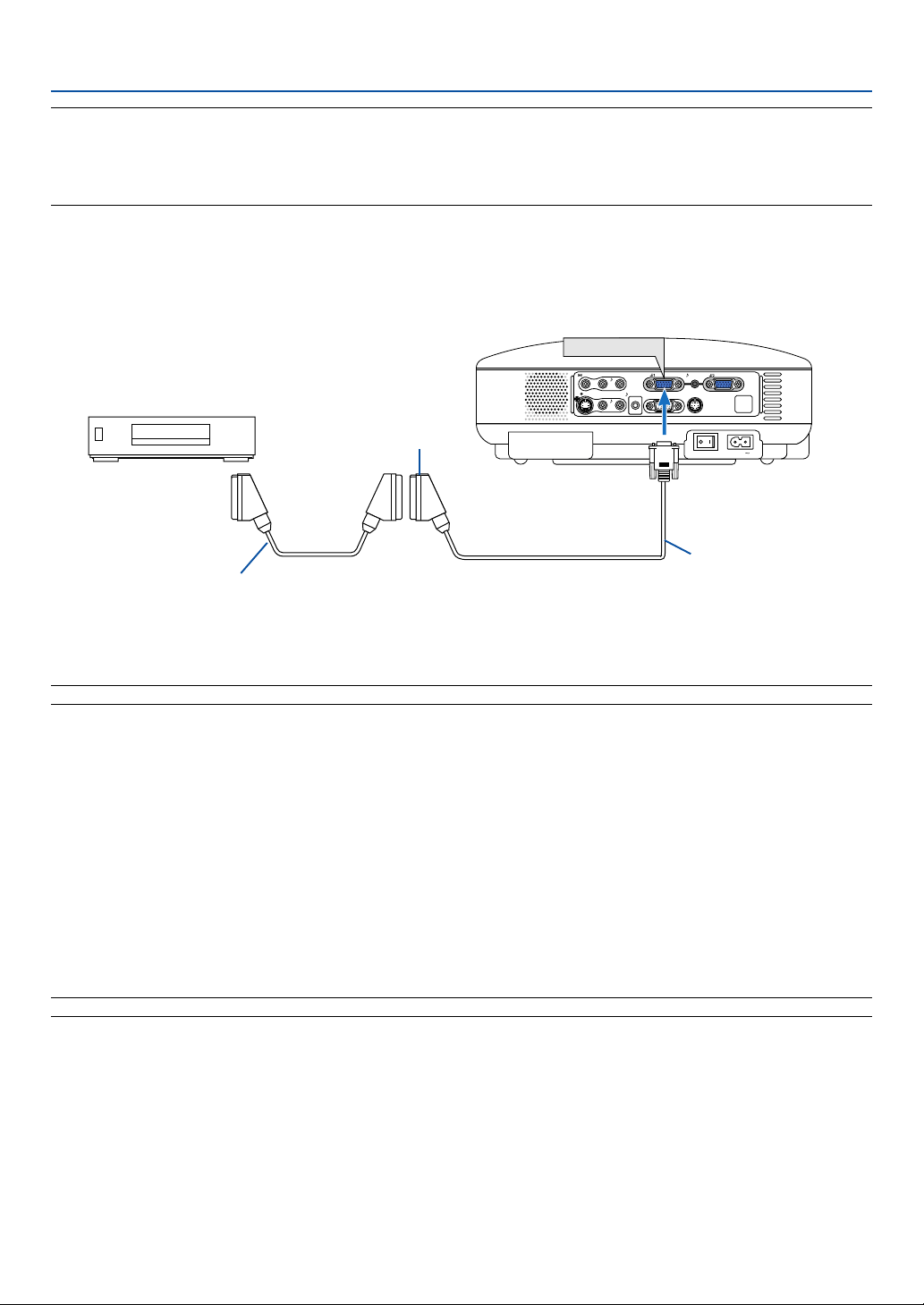
Before connections: An exclusive Scart adapter (LV-CA35) and a commercially available Scart cable are required for
this connection.
NOTE: Audio signal is not available for this connection.
1. Turn off the power to the projector and your video equipment.
2. Use the LV-CA35 Scart adapter and a commercially available Scart cable to connect the RGB input of your projec-
tor and a Scart output (RGB) of your video equipment.
3. Connect the supplied power cord. See page 19.
4. Turn on the power to the projector and your video equipment.
5. Use the COMPUTER-1 button on the projector cabinet to select the ANALOG IN-1 input.
6. Press the MENU button on the projector cabinet to display the menu.
7. From the menu, select [Advanced settings] → [Signal select] → [Computer-1] → [Scart].
Scart is a standard European audio-visual connector for TVs, VCRs and DVD players. It is also referred to as Euro-
connector.
NOTE: The LV-CA35 Scart adapter is obtainable from your dealer in Europe. Contact your dealer in Europe for more information.
To connect Scart output (RGB)
Video equipment such as DVD player
Commercially available Scart cable
Female
LV-CA35
Projector
To ANALOG 1 input
16
2. Installation and Connections
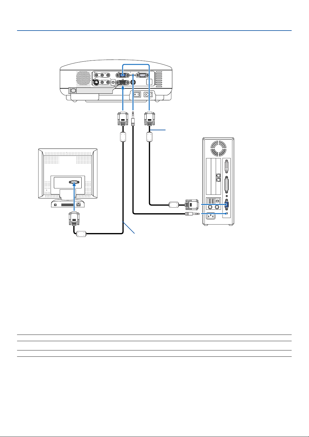
Connecting an External Monitor
MONITOR OUT
AUDIO
AC IN
VIDEO IN
L
AUDIO
IN
R
S-VIDEO IN
ANALOG IN-1
ANALOG IN-2
AUDIO OUT
L
AUDIO
IN
R
MONO
MONO
SERVICE PORT
AUDIO IN
(MONITOR OUT)
You can connect a separate, external monitor to your projector to simultaneously view on a monitor the RGB analog
image you're projecting.
To do so:
1. Turn off the power to your projector, monitor and computer.
2.
Use an VGA cable to connect your monitor to the MONITOR OUT (Mini D-Sub 15 pin) connector on your projector.
3. Connect the supplied power cord. See page 19.
4. Turn on the projector, monitor and the computer.
NOTE: Daisy chain connection is not possible.
NOTE: Use an audio cable without a built-in resistor. Using an audio cable with a built-in resistor turns down the sound.
VGA cable (supplied)
VGA cable (not supplied)
17
AUDIO IN
LR
AUDIO OUT
L R
Component
YCbCr
AC IN
ANALOG IN-1
AUDIO IN
VIDEO IN
L
AUDIO
IN
R
S-VIDEO IN
ANALOG IN-1
ANALOG IN-2
AUDIO OUT
L
AUDIO
IN
R
MONO
MONO
SERVICE PORT
AUDIO IN
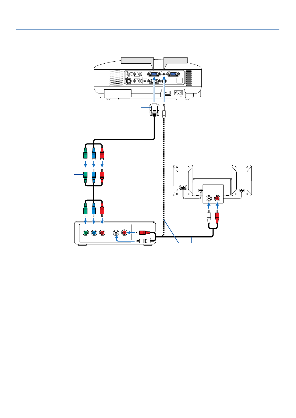
2. Installation and Connections
You can connect your projector to a DVD player with component or composite video output. To do so, simply:
1. Turn off the power to your projector and DVD player.
2. If your DVD player has the component video (Y,Cb,Cr) output, use a commercially available component video cable
(RCA⳯3) and the optional 15-pin-to-RCA (female)⳯3 cable to connect your DVD player to the ANALOG IN con-
nector on the projector.
For a DVD player without component video (Y,Cb,Cr) output, use common RCA cables (not provided) to connect a
composite VIDEO output of the DVD player to the Video Input of the projector.
3. Connect the supplied power cord. See page 19.
4. Turn on the projector and DVD player.
A component signal will be automatically displayed. If not, from the menu, select [Advanced settings] → [Input
signal select] → [Computer], and then place a check mark in the COMPONENT radio button.
NOTE: Refer to your DVD player's owner's manual for more information about your DVD player's video output requirements.
Connecting Your DVD Player with Component Output
DVD player
Audio Equipment
Audio cable (not supplied)
Optional 15-pin - to - RCA (female)
⳯
3 cable (LV-CA32)
Component video RCA
⳯
3
cable (not supplied)
18
2. Installation and Connections
AUDIO IN
LR
AUDIO OUT
L R
VIDEO OUT
S-VIDEOVIDEO
AC IN
VIDEO IN
L
AUDIO
IN
R
S-VIDEO IN
ANALOG IN-1
ANALOG IN-2
AUDIO OUT
L
AUDIO
IN
R
MONO
MONO
SERVICE PORT
AUDIO IN
S-VIDEO IN
VIDEO IN
AUDIO IN
AUDIO IN
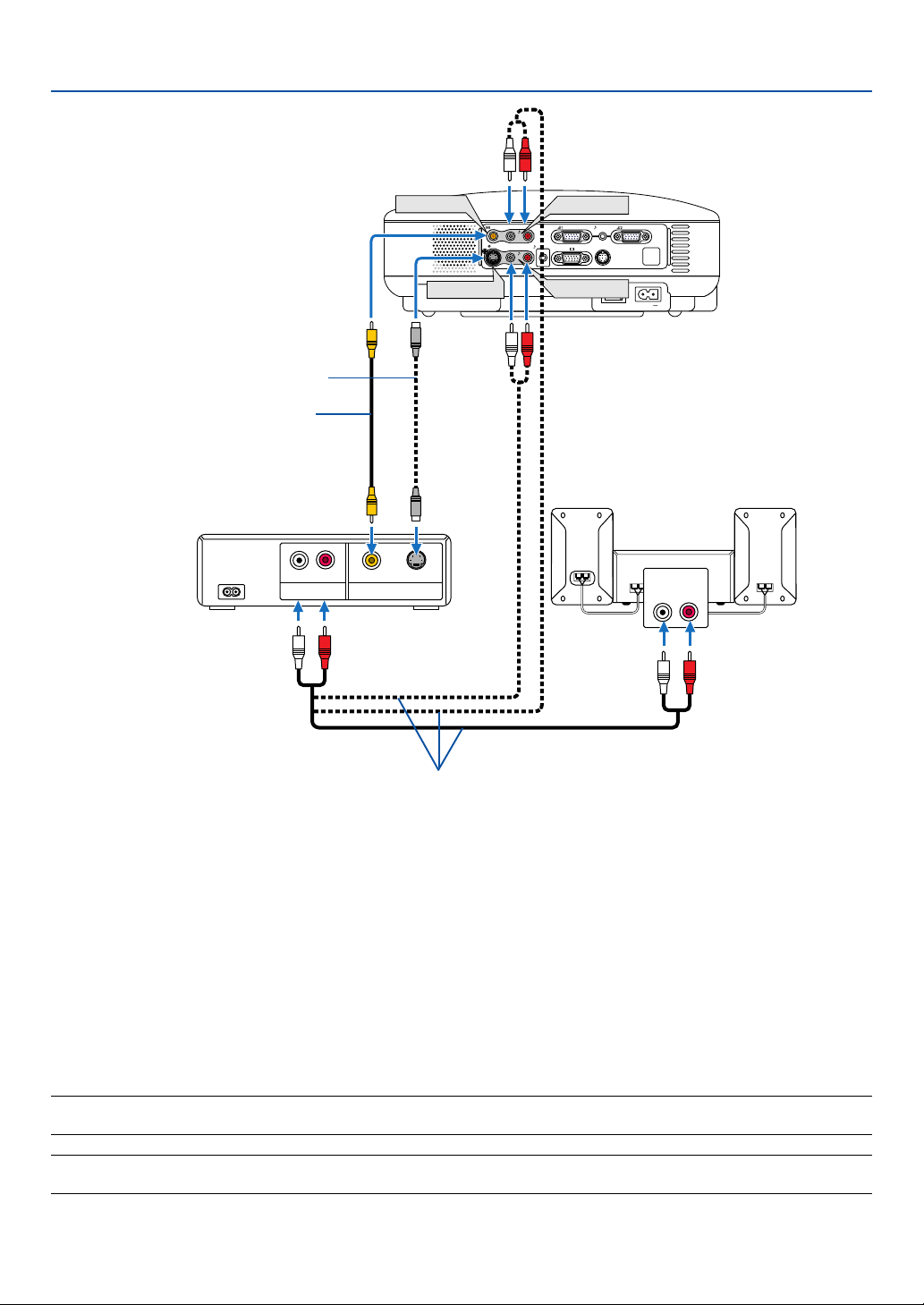
Connecting Your VCR or Laser Disc Player
S-Video cable (not supplied)
Video cable (not supplied)
VCR/ Laser disc player
Audio equipment
Audio cable (not supplied)
Use an RCA or S-Video cable (not provided) to connect the video and use RCA cables (not provided) to connect the
audio from your VCR, laser disc player or document camera to your projector.
To make these connections, simply:
1. Turn off the power to the projector and VCR, laser disc player or document camera.
2. Connect one end of an RCA cable to the video output (or one end of an S-Video cable to the S-Video output
connector) on the back of your VCR or laser disc player, connect the other end to the appropriate video input
on your projector. Connect one end of a pair RCA cables (not supplied) to the audio output on the back of your
VCR or laser disc player, connect the other end to your audio equipment or to the appropriate audio input on
the projector.
Be careful to keep the right and left channel connections correct for stereo sound.
3. Connect the supplied power cord. See page 19.
4. Turn on the projector and the VCR or laser disc player.
NOTE: Refer to your VCR or laser disc player owner's manual for more information about your equipment's video output
requirements.
NOTE: An image may not be displayed correctly when a Video or S-Video source is played back in fast-forward or fast-rewind via
a scan converter.
19
2. Installation and Connections
AC IN
VOL
-
VO
L
+
ZOOM
FOCUS
S
-V
ID
E
O
IN
M
O
N
O
M
O
N
O
V
ID
E
O
IN
L
A
UD
IO
IN
R
ANALOG IN-1
ANALOG IN-2
A
U
D
IO
O
U
T
L
A
UD
IO
IN
R
S
E
R
V
IC
E
P
O
R
T
A
U
D
IO
IN
POWER
V
ID
E
O
S
-
V
IDEO
COMPUTER-1 COMPUTER-2
W
A
R
N
I
N
G
LA
M
P
R
EP
LA
C
E
A
UTO
PC
AC IN
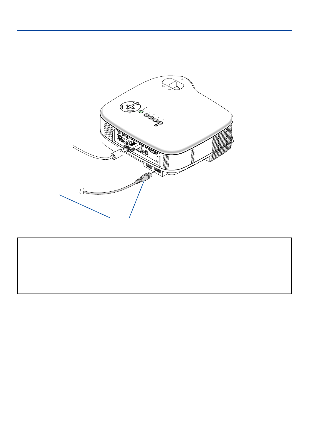
Connecting the Supplied Power Cord
Connect the supplied power cord to the projector.
First connect the supplied power cord's two-pin plug to the AC IN of the projector, and then connect the other plug of
the supplied power cord in the wall outlet.
Make sure that the prongs are fully inserted into
both the AC IN and the wall outlet.
To wall outlet
←
CAUTION:
Do not unplug the power cord from the wall outlet under any one of the following circumstances.
Doing so can cause damage to the projector:
• While the Hour Glass icon appears.
• While the cooling fans are running. The cooling fans continue to work for 30 seconds after the projector is
turned off.
• While the lamp is lighted.
20
3.
Projecting an Image (Basic Operation)
This section describes how to turn on the projector and to project a picture onto the screen.
Turning on the Projector
NOTE:
• The projector has two power switches: a main power switch and a POWER button.
• When plugging in or unplugging the supplied power cord, make sure that the main power switch is pushed to the off (
䡬
)
position. Failure to do so may cause damage to the projector.
A
C
IN
Z
O
O
M
F
O
C
U
S
WARNING
LAMP REPLACE
POWER
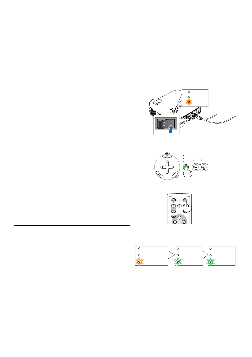
1. To turn on the main power to the projector, press the
Main Power switch to the on position ( I ).
• The POWER indicator will light orange.
See the Power Indicator section on page 52 for more
details.
2. Press the POWER button on the projector cabinet or
the POWER button on the remote control for a
minimum of 2 seconds. The POWER indicator will
turn to green and the projector will become ready to
use.
After you turn on your projector, ensure that the
computer or video source is turned on and that your
lens cap is removed.
NOTE: When no signal is available, a blue, black or logo screen is
displayed.
When the projector displays a blue or a black screen (not logo),
the Quiet mode will be automatically selected in "Lamp Mode."
NOTE: If you turn on the projector immediately after the lamp is
turned off or when the temperature is high, the fans runs without
displaying an image for some time and then the projector will
display the image.
POWER
VIDEO S-
VIDEO
WARNING
LAMP REPLACE
VOL
-
VOL
+
POWER
OFF
NO SHOW
D.ZOOM
PAGE
MENU
POWER
POWER
WARNING
LAMP REPLACE
WARNING
LAMP REPLACE
POWER
WARNING
LAMP REPLACE
Standby Blinking Power On
Steady orange light Blinking green
light
Steady green
light
See page 52 for more details.
21
POWER
VIDEO S-
VIDEO
COMPUTER-1 COMPUTER-2
WARNING
LAMP REPLACE
AUTO PC
VOL
-
VOL
+
3. Projecting an Image (Basic Operation)
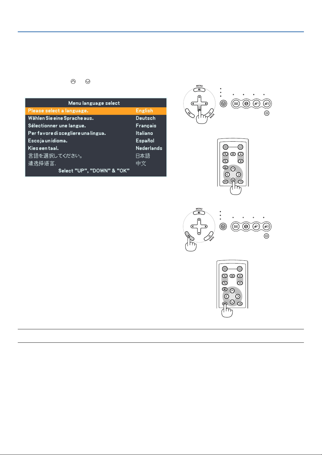
Note on Startup screen (Menu Language Select screen)
When you first turn on the projector, you will get the Startup menu. This menu gives you the opportunity to select one
of the 8 menu languages.
To select a menu language, follow these steps:
1. Use the SELECT or button to select one of the
8 languages for the menu.
POWER
OFF
NO SHOW
D.ZOOM
PAGE
MENU
BACK
2. Press the OK button to execute the selection.
After this has been done, you can proceed to the menu opera-
tion.
If you want, you can select the menu language later. See "Lan-
guage" on pages 34 and 40.
POWER
VIDEO S-
VIDEO
COMPUTER-1 COMPUTER-2
WARNING
LAMP REPLACE
AUTO PC
VOL
-
VOL
+
POWER
OFF
NO SHOW
D.ZOOM
PAGE
MENU
BACK
NOTE: Immediately after turning on the projector, screen flicker may occur. This is normal. Wait 3 to 5 minutes until the lamp
lighting is stabilized.
When the Lamp mode is set to Quiet, the LAMP REPLACE indicator will light green.
If one of the following things happens, the projector will not turn on.
• If the internal temperature of the projector is too high, the projector will not turn on to protect the internal system.
Please wait for the projector's internal components to cool down.
• When the lamp reaches its end of usable life, the projector will not turn on. If this happens, replace the lamp.
• If the lamp fails to light, and if the WARNING indicator flashes on and off in a cycle of six times, wait a full minute and
then turn on the power.
22
3. Projecting an Image (Basic Operation)
Selecting a Source
Selecting the computer or video source
VIDEO S-
VIDEO
COMPUTER-1 COMPUTER-2
POWER
WARNING
LAMP REPLACE
AUTO PC
VOL
-
VOL
+
RD-426E
1
2
R-CLICKL-CLICK
VIDEO
COMPUTER-1
AUTO PC
VOL
FREEZE
INFO.
IMAGE
ASPECT
COMPUTER-2
S-VIDEO
NOTE: Turn on the computer or VCR connected to the projector.
Using the cabinet buttons
Press any one of the COMPUTER-1/-2, VIDEO and S-VIDEO buttons.
The corresponding indicator will light green.
Using the Remote Control
Press any one of the COMPUTER-1/-2, VIDEO or S-VIDEO buttons.
23
3. Projecting an Image (Basic Operation)
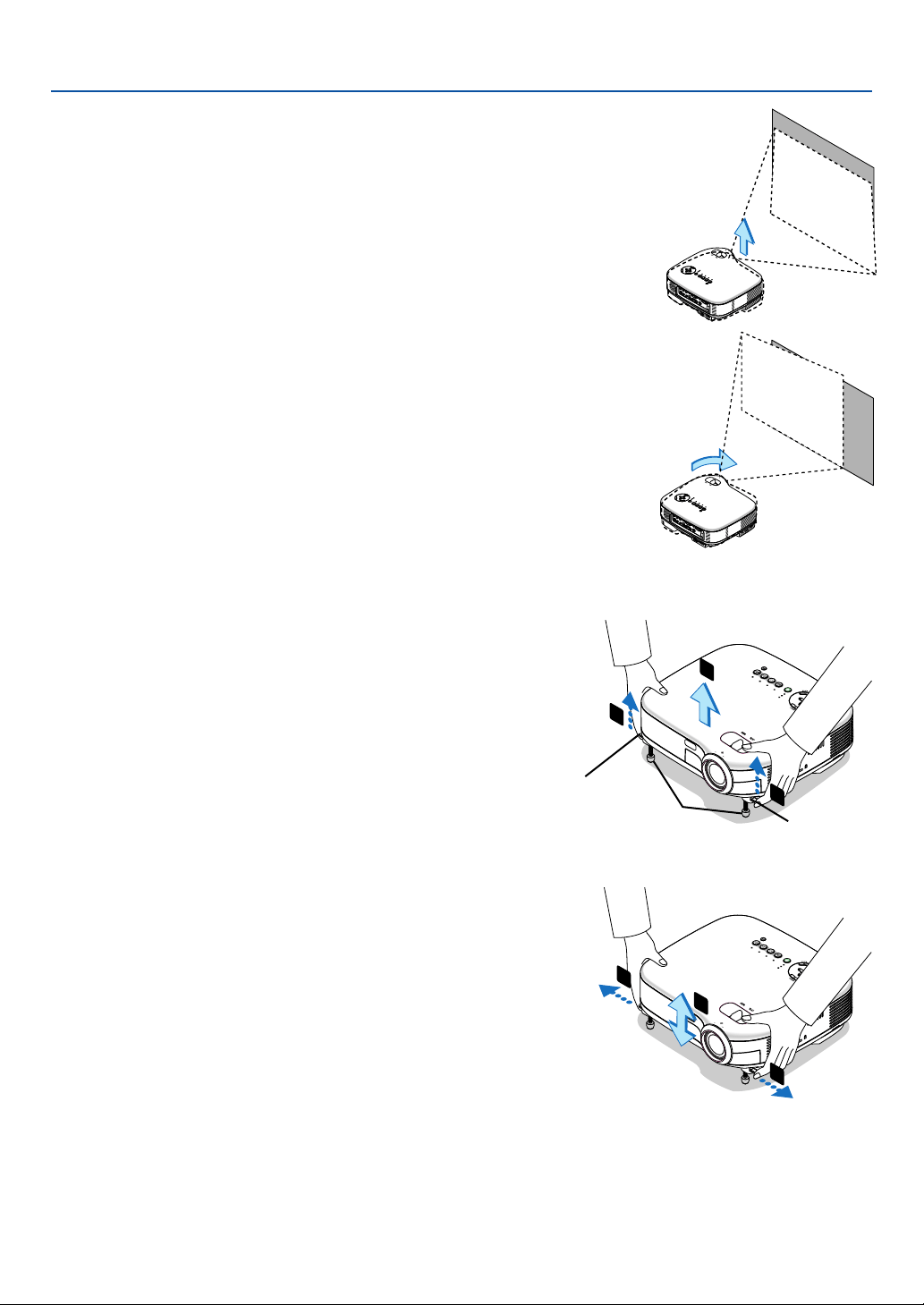
Place your projector on a flat level surface and ensure that the projector is
square to the screen.
Lift the front edge of the projector to center the image vertically.
* If the projected image does not appear square to the screen then use the
Keystone feature for proper adjustment. See page 25 to 26.
Adjusting the Picture Size and Position
AC
IN
ZO
OM
F
O
C
U
S
A
C
I
N
Z
O
O
M
F
O
C
U
S
Adjust the Tilt Foot
1. Lift the front edge of the projector.
2. Push up the Adjustable Tilt Foot Levers on the right and left sides
of the projector to extend the adjustable tilt feet (maximum height).
3. Push down the Adjustable Tilt Foot Levers.
4. Lower the front of the projector to the desired height and release
the Adjustable Tilt Foot Lever to lock the Adjustable tilt foot. There
is approximately 10 degrees of up and down adjustment for the
front of the projector.
CAUTION
Do not use the tilt-foot for purposes other than originally intended. Misuses
such as gripping the tilt-foot or hanging on the wall can cause damage to the
projector.
P
O
W
E
R
VIDEO
S-
V
I
D
E
O
C
O
M
P
U
T
E
R
-
1
C
O
M
P
U
T
E
R
-
2
W
A
R
N
IN
G
L
A
M
P
R
E
P
L
A
C
E
A
U
T
O
P
C
V
O
L
-
V
O
L
+
ZOOM
F
O
C
U
S
2
1
2
PO
W
E
R
V
I
D
E
O
S
-
V
I
D
E
O
COM
PUTER-1
COM
PUTER-2
WARNING
LA
MP
REPLACE
A
U
T
O
P
C
V
O
L
-
V
O
L
+
Z
O
O
M
F
O
CU
S
4
3
4
Adjustable Tilt Foot
Move the projector left to center the image horizontally on the screen.
Adjustable Tilt
Foot Lever
Adjustable Tilt
Foot Lever
24
3. Projecting an Image (Basic Operation)
A
C
I
N
Z
O
O
M
F
O
C
U
S
Z
O
O
M
FO
C
US
A
C
I
N
Z
O
O
M
F
O
C
U
S
Z
O
O
M
FO
CUS
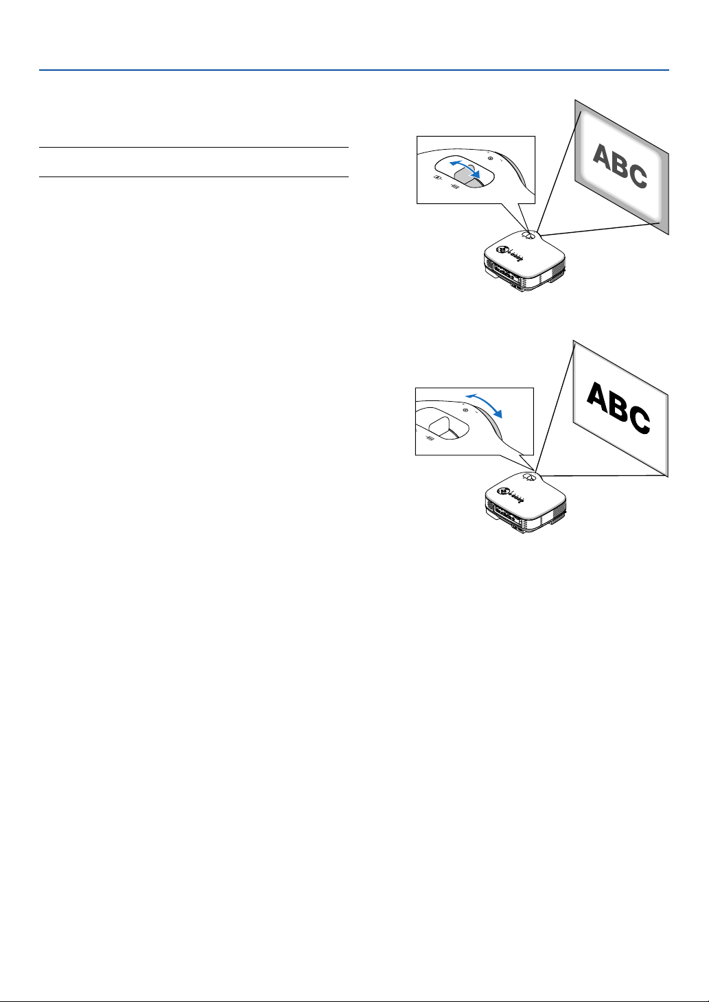
Focus
Use the FOCUS ring to obtain the best focus.
Zoom
Use the ZOOM lever to finely adjust the image size on the
screen.
NOTE: Digital Zoom can cause result in a blurry image because
zooming is made electronically.
25
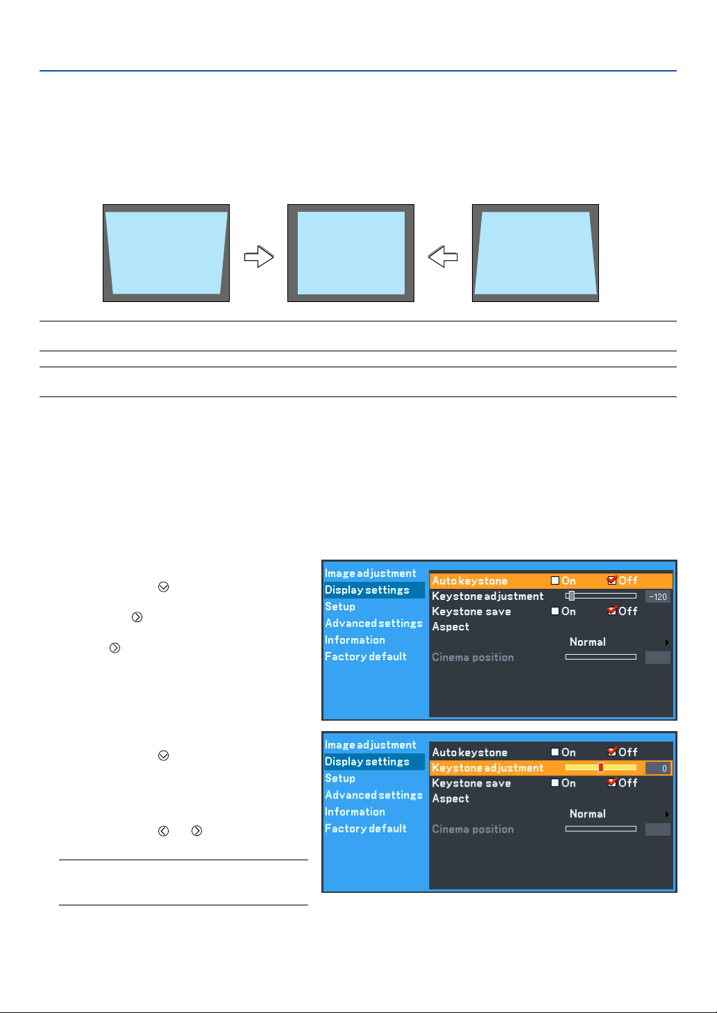
Correcting Keystone Distortion
Auto Keystone Correction
The Auto keystone correction feature will correct the vertical distortion of a projected image on the screen. No special
operation required. Just put the projector on a flat surface.
Note that the vertical keystone angle can be corrected between 30 degrees upward and 30 degrees downward of
projector tilt from level.
3. Projecting an Image (Basic Operation)
NOTE: Auto and Manual keystone correction angle could be less than 30 degrees depending on some kinds of signal and aspect
ratios.
NOTE: The Auto keystone correction feature can cause an image to be slightly blurred because the correction is made electroni-
cally.
Manual Keystone Correction
You can also correct the vertical keystone distor-
tion manually.
To do so:
1. Press the MENU button.
The menu will be displayed.
2. Turn off the Auto keystone function.
Use the SELECT
button to select
“Display settings” and then press OK or
the SELECT button. The “Auto key-
stone” will be displayed. Press the
SELECT to select “Off”.
3. Select the Keystone function.
Use the SELECT
button to select
“Keystone adjustment”.
4. Correct the vertical distortion.
Use the SELECT
or button to correct
the vertical keystone distortion.
NOTE: The Keystone correction feature can cause
an image to be slightly blurred because the
correction is made electronically.

27
3. Projecting an Image (Basic Operation)
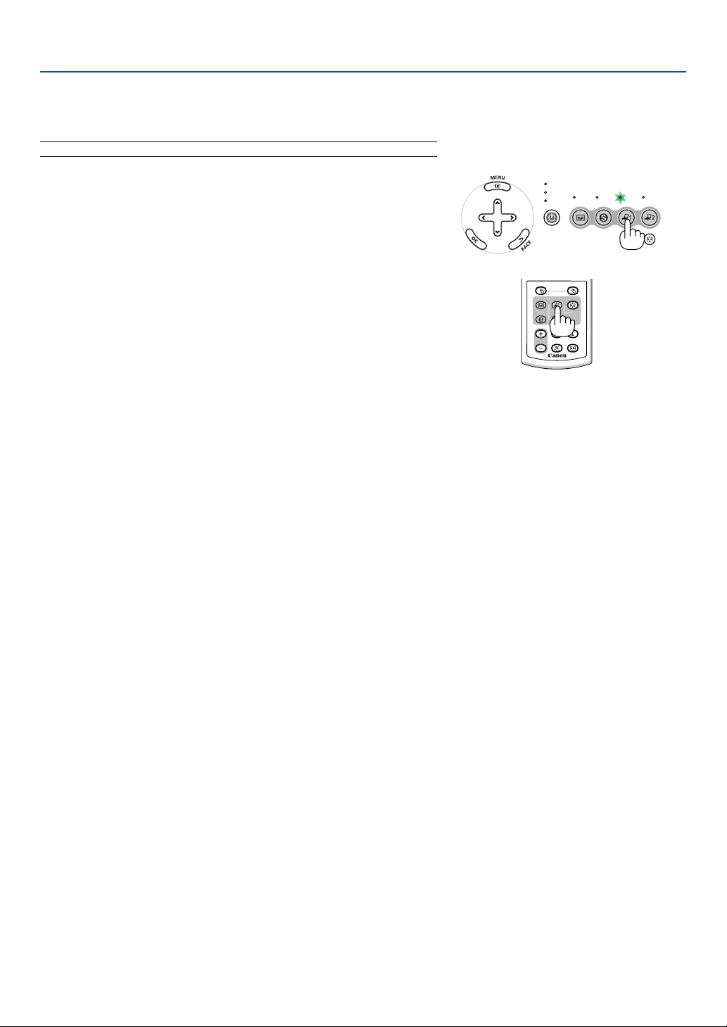
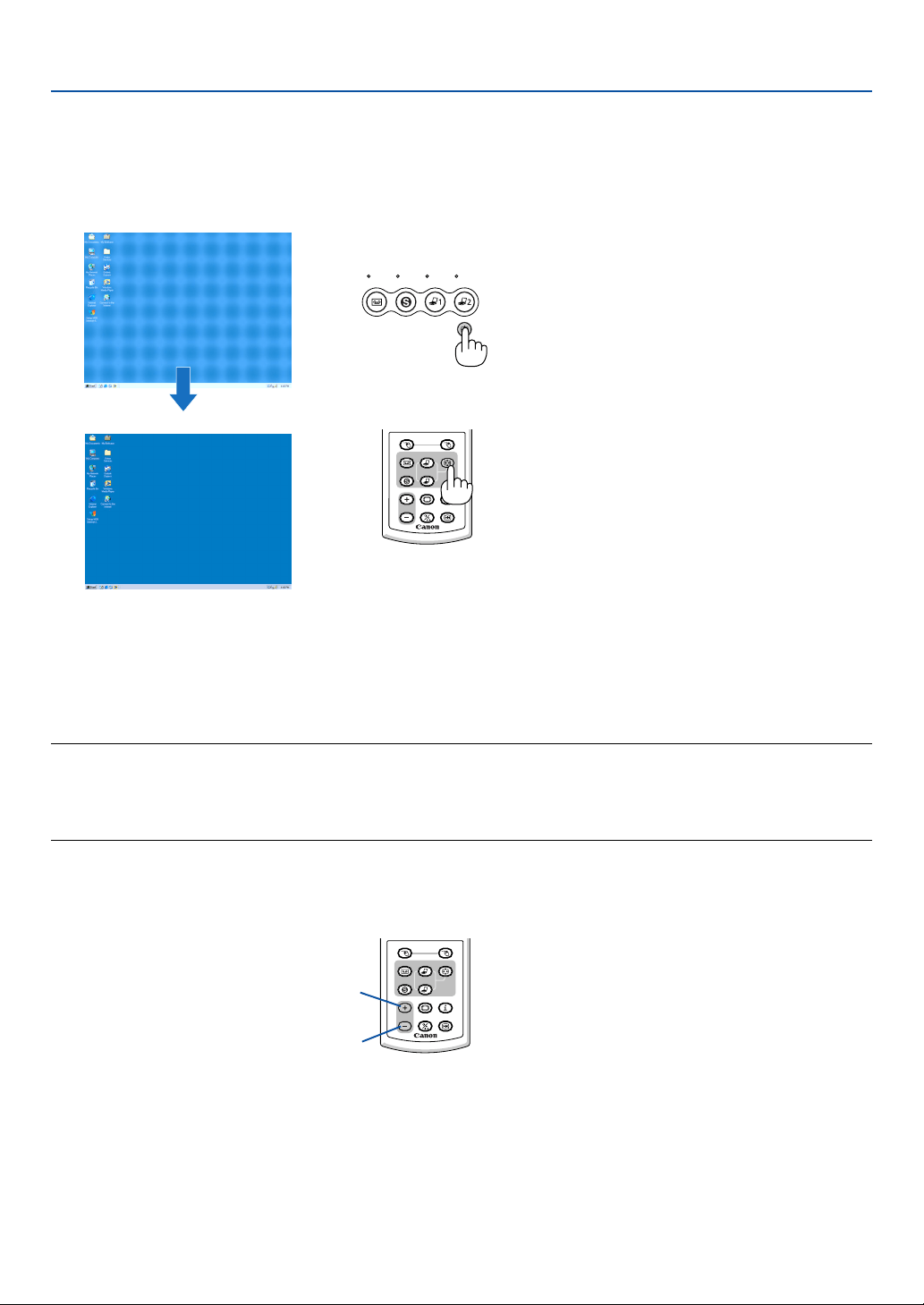
Automatically Optimizing on RGB Image
Adjusting the Image Using Auto PC adjustment
Optimizing an RGB image automatically.
Press the AUTO PC button to optimize an RGB image automatically.
[Poor picture]
[Normal picture]
VIDEO S-
VIDEO
COMPUTER-1 COMPUTER-2
C
E
AUTO PC
RD-426E
R-CLICKL-CLICK
VIDEO
COMPUTER-1
AUTO PC
VOL
FREEZE
INFO.
IMAGE
ASPECT
1
2
COMPUTER-2
S-VIDEO
Press the AUTO PC button to fine-tune the computer image or to remove any vertical banding that might appear and
to reduce video noise, dot interference or cross talk (this is evident when part of your image appears to be shimmer-
ing). This function adjusts the clock frequencies that eliminate the horizontal banding in the image. This function also
adjusts the clock phase to reduce video noise, dot interference or cross talk. (This is evident when part of your image
appears to be shimmering.)
This adjustment may be necessary when you connect your computer for the first time.
NOTE:
Some signals may not be displayed correctly or take time.
• The Auto PC adjustment function does not work for component, composite and S-video signals.
• If the Auto PC adjustment operation cannot optimize the RGB signal, try to adjust Horizontal/Vertical Position Clock and
Tracking manually. See pages 44 and 45.
Turning Up or Down Volume
Increase volume
Decrease volume
RD-426E
R-CLICKL-CLICK
VIDEO
COMPUTER-1
AUTO PC
VOL
FREEZE
INFO.
IMAGE
ASPECT
1
2
COMPUTER-2
S-VIDEO
Sound level from the speaker and the AU-
DIO OUT jack (Stereo mini) on the projec-
tor can be adjusted.
28
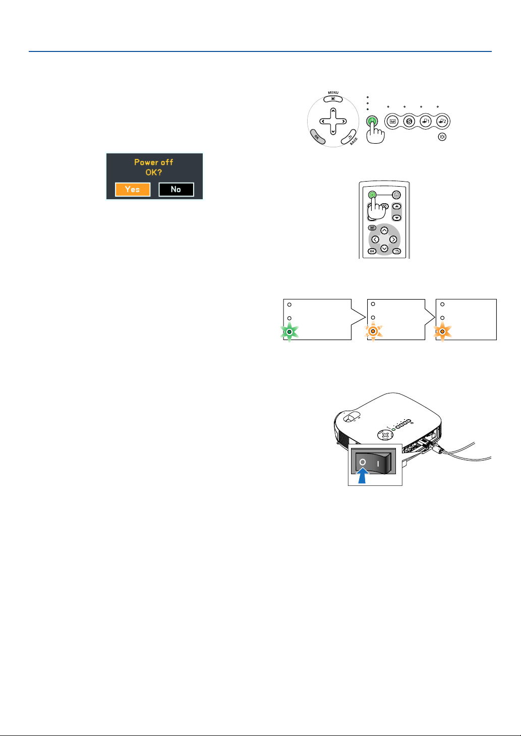
Turning off the Projector
To turn off the projector:
3. Projecting an Image (Basic Operation)
POWER
VIDEO S-
VIDEO
COMPUTER-1 COMPUTER-2
WARNING
LAMP REPLACE
AUTO PC
VOL
-
VOL
+
POWER
OFF
NO SHOW
D.ZOOM
PAGE
MENU
BACK
First, press the POWER button on the projector cabinet
or the OFF button on the remote control. The “Power Off /
OK?” message will appear.
CAUTION
Do not unplug the power cord from the wall outlet or do not turn off
the main power under any one of the following circumstances. Doing
so can cause damage to the projector:
• While the Hour Glass icon appears.
• While the cooling fans are running. (The cooling fans continue to
work for 30 seconds after the projector is turned off)
• While the lamp is lighted.
A
C IN
F
O
C
U
S
V
O
L
-
V
O
L
+
Z
O
O
M
After Use
Preparation: Make sure that the projector is turned off.
1. Unplug the power cord.
2. Disconnect any other cables.
3. Retract adjustable tilt feet if extended.
4. Cover the lens with the lens cap.
5. Put the projector and its accessories in the supplied soft case.
Secondly, press the OK button or press the POWER or
the OFF button again.
The POWER indicator will glow orange. After the projec-
tor turns off, the cooling fans keep operating for 30 sec-
onds (Cooling-off time).
Immediately after turning on the projector and displaying
an image, you cannot turn off the projector for 60 sec-
onds.
Finally, turn off the Main Power switch. The power indica-
tor will go out.
POWER
WARNING
LAMP REPLACE
POWER
WARNING
LAMP REPLACE
POWER
WARNING
LAMP REPLACE
Power On Fan running Standby
Steady green light Blinking
orange light
Steady orange
light
29
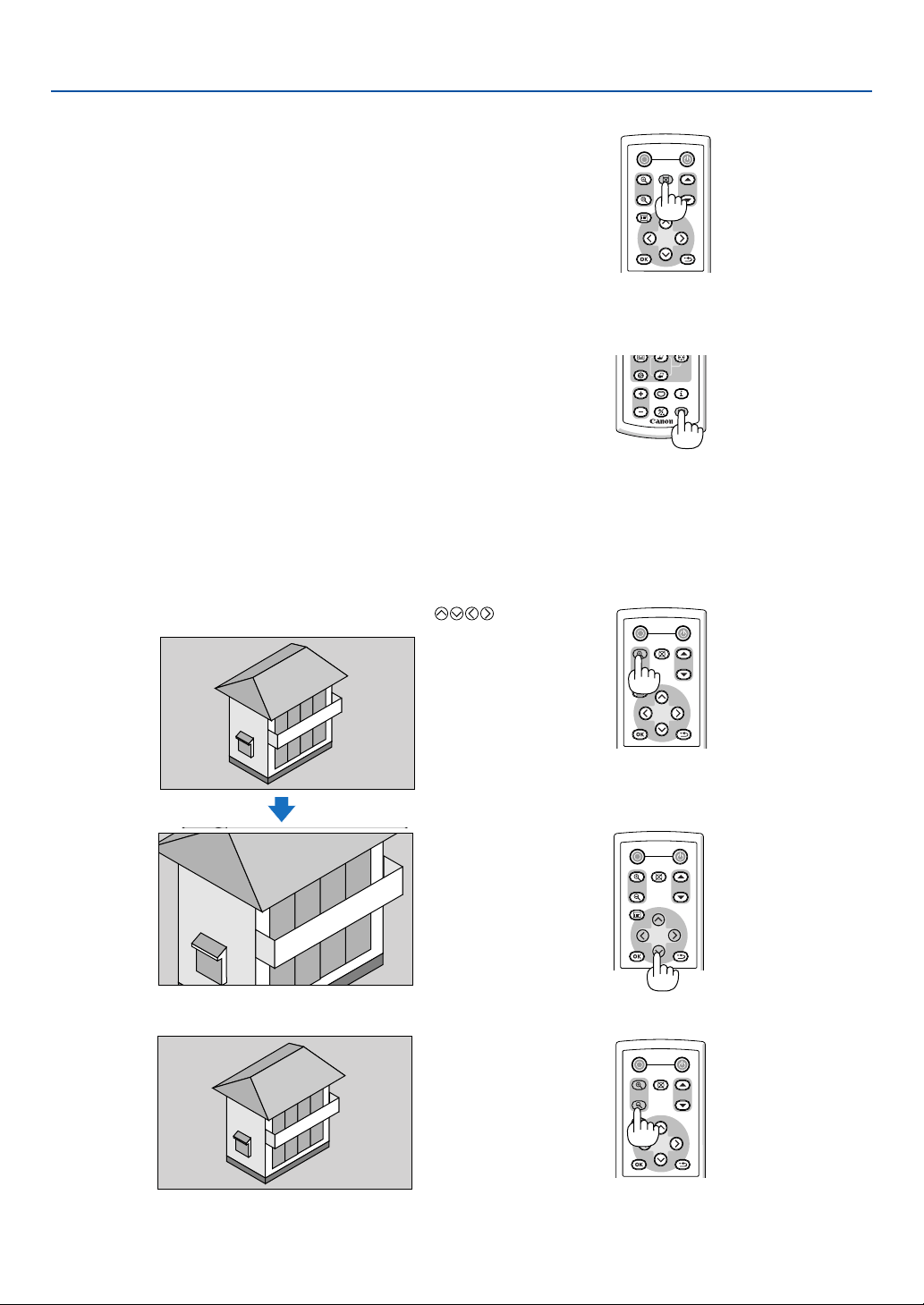
4. Convenient Features
쐃 Turning off the Image and Sound
Press the NO SHOW button to turn off the image and sound for a short
period of time. Press again to restore the image and sound.
POWER
OFF
NO SHOW
D.ZOOM
PAGE
MENU
BACK
쐇 Freezing a Picture
Press the FREEZE button to freeze a picture. Press again to resume
motion.
Enlarging and Moving a Picture
POWER
OFF
D.ZOOM
NO SHOW
PAGE
MENU
BACK
You can enlarge the picture up to 400 percent.
To do so:
1. Press the D. ZOOM (+) button to magnify the picture.
To move the magnified image, use the SELECT
button.
2. Return the image to the original size.
POWER
OFF
D.ZOOM
NO SHOW
PAGE
MENU
BACK
POWER
OFF
NO SHOW
D.ZOOM
PAGE
MENU
BACK
RD-426E
VOL
FREEZE
INFO.
IMAGE
ASPECT
1
2
COMPUTER-2
S-VIDEO

30
4. Convenient Features
Using the Remote Mouse Receiver (LV-7245/LV-7240 only)
The remote mouse receiver enables you to operate your computer’s mouse functions from the remote control. It is a
great convenience for clicking through your computer-generated presentations.
Connecting the remote mouse receiver to your computer
If you wish to use the remote mouse function, connect the mouse receiver and computer.
The mouse receiver can be connected directly to the computer’s USB port (type A).
NOTE: Depending on the type of connection or OS installed on your computer, you may have to restart your computer or change
your computer settings.
30˚
30˚
Remote mouse receiver
Computer
To USB port of PC or Macintosh
When operating a computer via the remote mouse receiver
Remote sensor on the
remote mouse receiver
7m/22 feet
When connecting using the USB terminal
For PC, the mouse receiver can only be used with a Windows 98/Me/XP*, Windows 2000 or Mac OS X 10.0.0 or later
operating system.
* NOTE: In Windows XP, if the mouse cursor will not move correctly, do the following:
Clear the Enhance pointer precision check box underneath the mouse speed slider in the Mouse Properties dialog box [Pointer
Options tab].
NOTE: Wait at least 5 seconds after disconnecting the mouse receiver before reconnecting it and vice versa. The computer may
not identify the mouse receiver if it is repeatedly connected and disconnected in rapid intervals.
Operating your computer’s mouse from the remote control
You can operate your computer's mouse from the remote control.
PAGE / Button: scrolls the viewing area of the window or to move to the previous or next slide in PowerPoint
on your computer.
/ Mouse Buttons
:moves the mouse cursor on your computer.
MOUSE L-CLICK Button: works as the mouse left button.
MOUSE R-CLICK Button: works as the mouse right button.
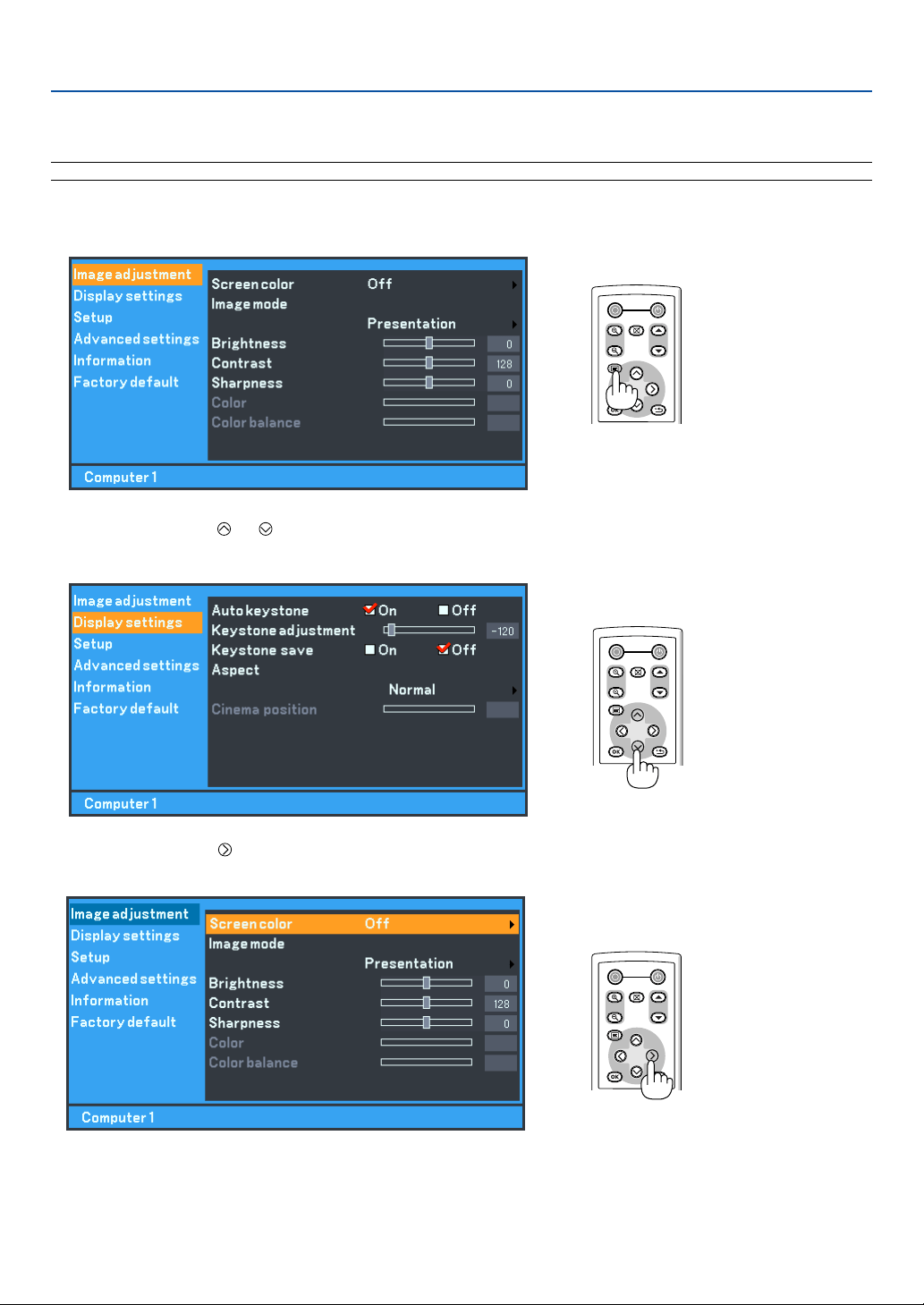
31
Using the Menus
NOTE: The on-screen menu may not be displayed correctly while interlaced motion video image is projected.
1. Press the MENU button on the remote control or projector cabinet to display the Menu.
5. Using On-Screen Menu
POWER
OFF
NO SHOW
D.ZOOM
PAGE
MENU
BACK
2. Press the SELECT or
button on the remote control or the projector cabinet to highlight the menu
for the item you want to adjust or set.
POWER
OFF
NO SHOW
D.ZOOM
PAGE
MENU
BACK
POWER
OFF
NO SHOW
D.ZOOM
PAGE
MENU
BACK
3. Press the SELECT button or the OK button on the remote control or the projector cabinet to select a
submenu or item.
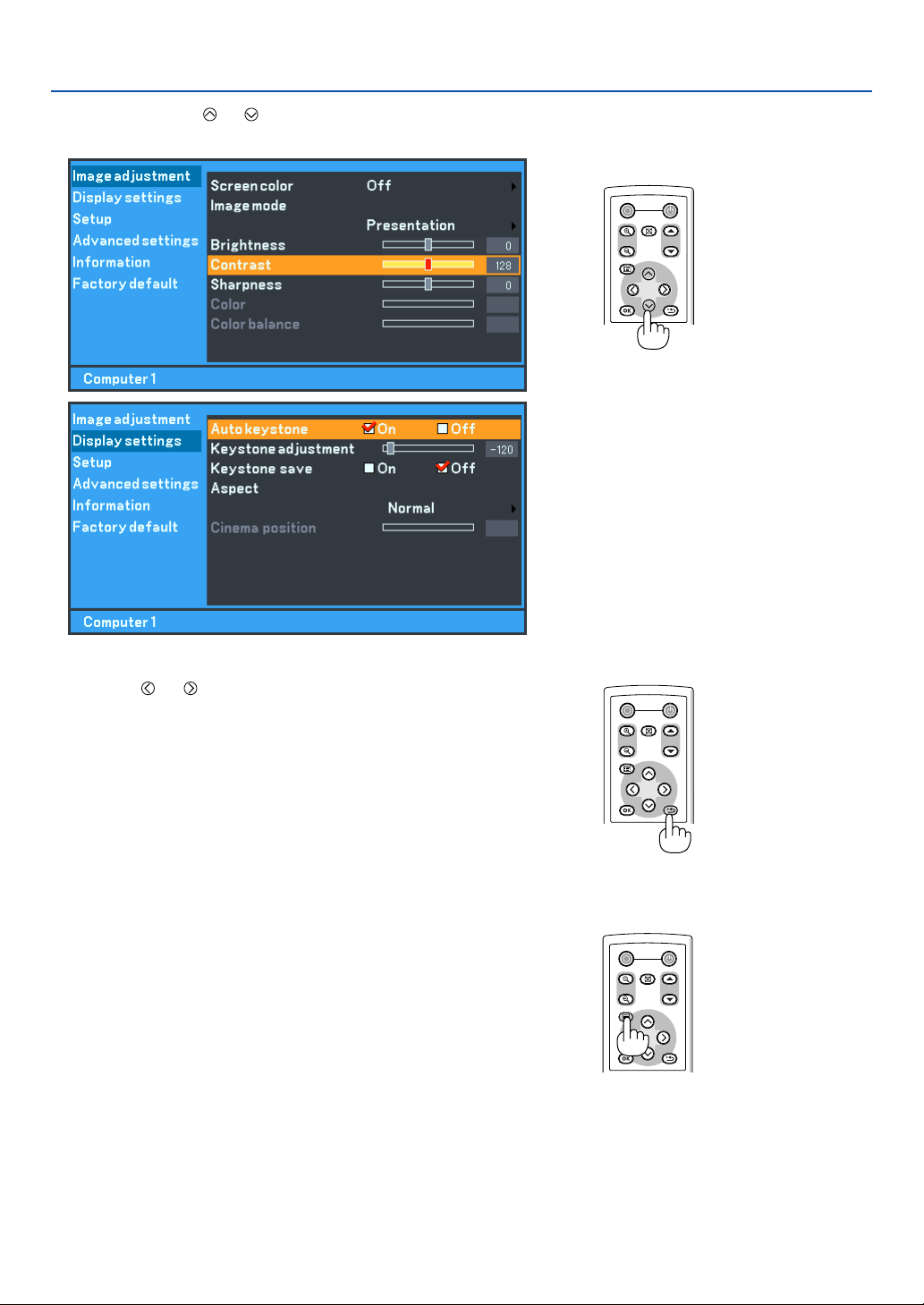
32
5. Using On-Screen Menu
4. Use the SELECT or
button on the remote control or the projector cabinet to select the item you
want to adjust or set.
POWER
OFF
NO SHOW
D.ZOOM
PAGE
MENU
BACK
5. Adjust the level or turn the selected item on or off by using
SELECT
or
button on the remote control or the projector
cabinet.
The on-screen slide bar will show you the amount of increase
or decrease.
Changes are stored until you adjust it again.
BACK ..................... Return to the previous menu.
6. Repeat steps 2-5 to adjust an additional item, or press the
MENU button to close the menu.
POWER
OFF
NO SHOW
D.ZOOM
PAGE
MENU
BACK
POWER
OFF
NO SHOW
D.ZOOM
PAGE
MENU
BACK
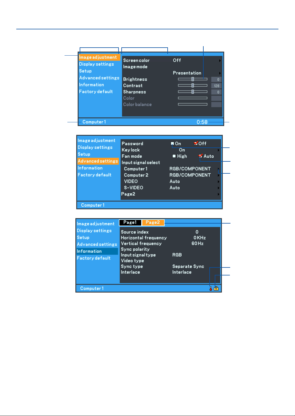
33
5. Using On-Screen Menu
쐇 Menu Elements
Highlight
Title
Slide bar
Off Timer remaining
time
Source
Solid triangle
Check mark
Ta b
Thermometer symbol
Key symbol
Menu windows or dialog boxes typically have the following elements:
Title .......................................... Indicates the menu title.
Highlight................................... Indicates the selected menu or item.
Source ...................................... Indicates the currently selected source.
Remaining countdown time ..... Indicates the remaining countdown time when the Off Timer is preset.
Solid triangle ............................ Indicates further choices are available. A highlighted triangle indicates the item is active.
Tab ........................................... Indicates a group of features in a dialog box. Selecting on any tab brings its page to the front.
Check box ................................ Place a checkmark in the square box to turn the option On.
Check mark .............................. Indicates the item is selected.
Slide bar ................................... Indicates settings or the direction of adjustment.
Key symbol .............................. Indicates the Key Lock is enabled.
Thermometer symbol ............... Indicates the lamp is forcibly being cooled down because the internal temperature is too high.
Check box
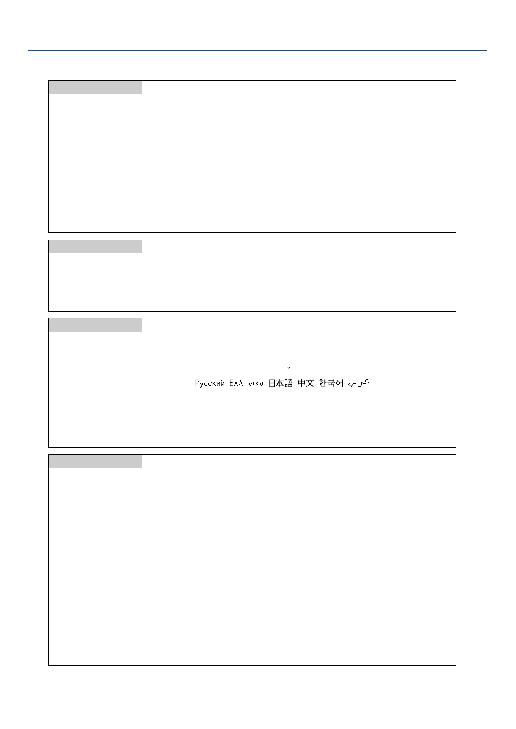
34
쐋 List of Menu Items
5. Using On-Screen Menu
Image adjustment
Screen color Off, Greenboard, Light yellow, Light green, Light blue, Sky blue, Light rose, Pink
Image mode
Standard, Presentation, Cinema, Video, sRGB
User
Base setting Standard, Presentation, Cinema, Video, sRGB
Gamma Black detail, Dynamic, Natural
Brightness R,G,B
Contrast R,G,B
Brightness
Contrast
Sharpness
Color
Color balance
Display settings
Auto keystone On, Off
Keystone adjustment
Keystone save On, Off
Aspect Normal, Wide zoom, Cinema, True size
Cinema position
Setup
Off timer Off, 0:30, 1:00, 2:00, 3:00, 4:00, 6:00, 8:00
Lamp mode Normal, Quiet
Language Language-1 English, Deutsch, Français, Italiano, Español, Português, Nederlands
Language-2 Svenska, Norsk, Suomi,
C
esk
y
, Magyar, Polski, Türkçe
Language-3 , , , , , , Dansk
Menu color select Color, Monochrome
Menu display time Manual, 5 sec, 15sec, 45 sec
No signal screen Blue, Black, Canon logo
Image flip H/V None / Rear, Ceiling mounted / Rear / Ceiling mounted
Beep On, Off
Advanced settings
Password On, Off
Key lock On, Off
Fan mode High, Auto
Input signal select
Computer 1 RGB/COMPONENT, RGB, COMPONENT, Scart
Computer 2 RGB/COMPONENT, RGB, COMPONENT
VIDEO Auto, NTSC3.58, NTSC4.43, PAL, PAL-M, PAL-N, PAL60, SECAM
S-VIDEO Auto, NTSC3.58, NTSC4.43, PAL, PAL-M, PAL-N, PAL60, SECAM
Page2 Power management On, Off
Noise reduction On, Off
Flicker reduction On, Off
Auto PC adjustment Off, Normal, Fine
Horizontal position
Ver tical position
Clock
Tracking
Communication speed 4800, 9600, 19200

35
5. Using On-Screen Menu
NOTE: Some menu items are not available depending on the input source.
Factory default
Factory default Current signal
All data
Clear filter usage
Lamp counter
Information
Page1 Remaining lamp time, Lamp counter, Filter usage, Projector usage,
BIOS version, Firmware version, Data version
Page2 Source index, Horizontal frequency, Vertical frequency, Sync polarity
Input signal type, Video type, Sync type, Interlace
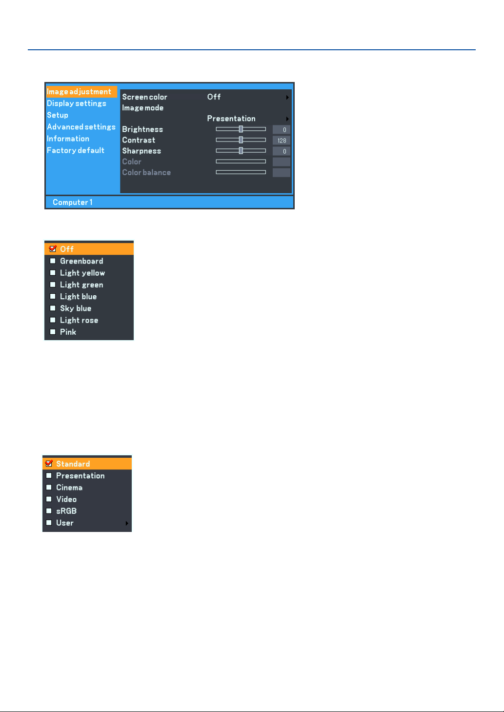
36
5. Using On-Screen Menu
쐏 Menu Descriptions & Functions [Image adjustment]
Using the Screen color correction [Screen color]
This function allows for quick adaptive color correction in applications where the screen material is not white.
The following eight options are available.
• OFF • Greenboard
• Light yellow • Light green
• Light blue • Sky blue
• Light rose • Pink
Using Image mode [Image mode]
This option allows you to adjust neutral tint for yellow, cyan or magenta.
There are 5 factory presets optimized for various types of images, or you can set user adjustable settings.
Standard................ Select this to project an image with a similar quality to that of the original image. An image is projected with
a high regard for reproduction of white.
Presentation .......... Select this to project an image with a similar quality to that of the original image. A bright and high-contract
image is projected.
Cinema .................. Select this to project a moving picture. A picture is projected with a high regard for color tone reproduction.
Video ..................... Select this to project a regular picture such as TV program
sRGB ..................... Select this when you want to project an image from a sRGBcompatible digital camera. An image is projected
in the display mode conforming to the sRGB Standard.
User ...................... User adjustable

37
5. Using On-Screen Menu
NOTE: When “sRGB”, “Standard”, “Video” or “Cinema” is selected, the brightness decreases slightly when compared to “Presen-
tation”. This is not a malfunction.
User Adjust (when using User)
When selecting user adjustable presetting (User), the submenu will be displayed.
You can customize each gamma or color. To do so, first select “User” and press the OK button, and then proceed the
following steps.
Selecting Base Setting [Base setting]
This feature allows you to use white balance or gamma values as reference data to optimize for various types of
images. You can select one of the following five settings.
• Standard • Video
• Presentation • sRGB
• Cinema
Selecting Gamma Mode [Gamma]
Each mode is recommended for :
Black detail ............ Emphasizes detail in dark areas of the picture
Dynamic ................ Creates a high-contrast picture
Natural .................. Natural reproduction of the picture
Adjusting White Balance [Brightness RGB/Contrast RGB]
This allows you to adjust the white balance. Brightness for each color (RGB) is used to adjust the black level of the
screen; Contrast for each color (RGB) to adjust the white level of the screen.
Adjusting Brightness, Contrast, Sharpness, Color and Color balance
Brightness ............. Adjusts the brightness level.
Contrast ................ Adjusts the intensity of the image according to the incoming signal.
Sharpness ............. Controls the detail of the image for Video.
Color ..................... Increases or decreases the color saturation level (not valid for RGB).
Color balance ........ Varies the color level from +/– green to +/– blue. The red level is used as reference. This adjustment is only
valid for Video and Component inputs (not valid for RGB).
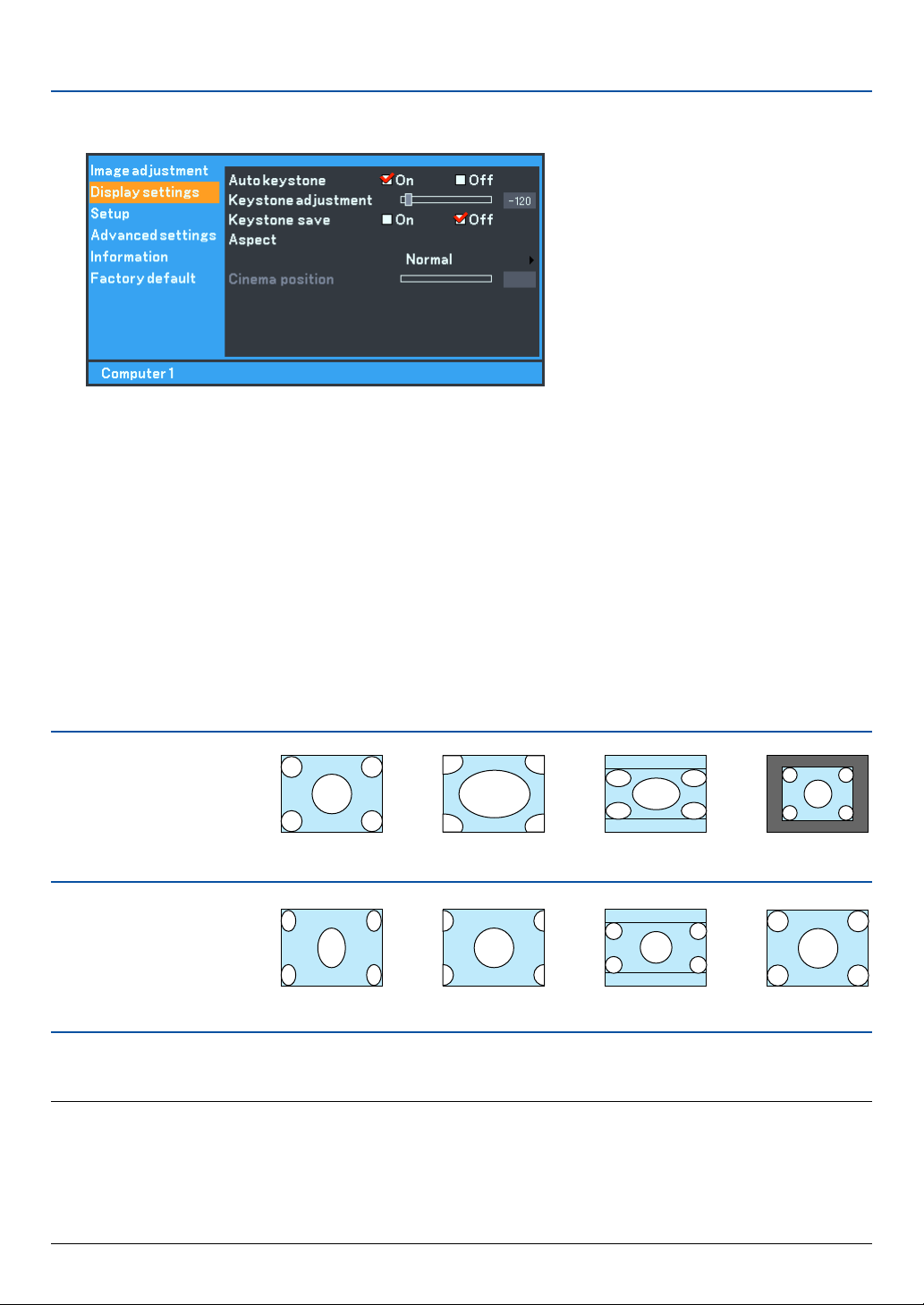
38
5. Using On-Screen Menu
쐄 Menu Descriptions & Functions [Display settings]
Enabling Auto Keystone [Auto keystone]
This feature allows the projector to detect its tilt and correct vertical distortion automatically.
To turn on the Auto keystone feature, select “On”.
Correcting Vertical Keystone Distortion Manually [Keystone adjustment]
You can correct vertical distortion manually from the menu when “Auto keystone” is turned off.
You can save the changes using the Keystone save feature when you turn off the projector.
Saving Vertical Keystone Correction [Keystone save]
This option enables you to save your current keystone settings.
Saving your change once affects all sources. The changes are saved when the projector is off.
Selecting Aspect Ratio [Aspect]
Aspect allows you to select the best Aspect mode to display your source image. You can also display the Aspect menu
by pressing the “ASPECT” button on the remote control.
Normal
Standard
4:3 Aspect
When 16:9 is selected from
the source (i.e. DVD player),
the following selections will
display:
Normal
16:9 image displayed
in 4:3 mode
Wide Zoom Cinema True size
Left and right
stretched
Left and right
stretched
Wide Zoom Cinema True size
Left and right
stretched
Left and right stretched to
display the true aspect
Tr ue size (RGB only): Turns off the scaling technology feature. The projector displays the current image in its true
resolution.
NOTE:
• While you are displaying an image at the projector’s native resolution or higher, “True size” is not available.
•You can adjust the image position for Cinema aspect. See “Cinema position” for setting the image position.
Copyright
Please note that using this projector for the purpose of commercial gain or the attraction of public attention in a venue such as a
coffee shop or hotel and employing compression or expansion of the screen image with a "Aspect" setting may raise concern
about the infringement of copyrights which are protected by copyright law.
When 4:3 is selected from
the source (i.e. DVD player),
the following selections will
display:
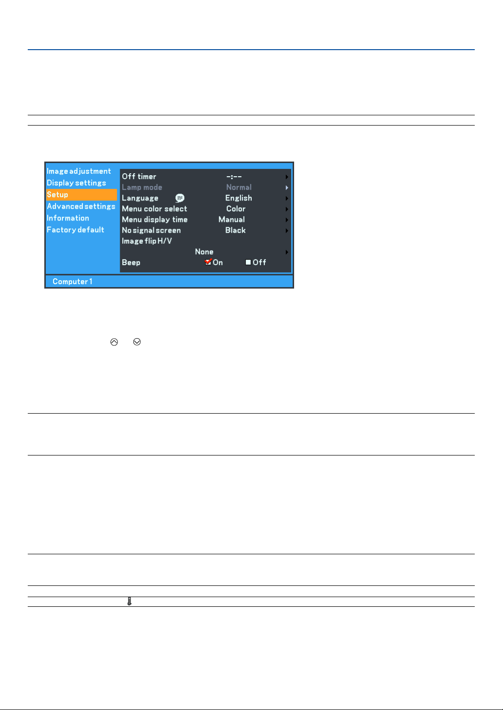
39
5. Using On-Screen Menu
Adjusting the Vertical Position of Image [Cinema position] (for Cinema only)
This feature adjusts the vertical position of the image when viewing video with Cinema aspect selected.
When “Cinema” is selected in “Aspect”, the image is displayed with black borders on the top and bottom.
You can adjust the vertical position between top and bottom.
NOTE: This option is available only when “Cinema” is selected in Aspect.
쐂 Menu Descriptions & Functions [Setup]
Using Off Timer [Off timer]
You can set the timer so that the projector turns itself off at the preset time.
1. Use the SELECT or button to select your desired time between 30 minutes and 8 hours: Off, 0:30,
1:00, 2:00, 3:00, 4:00, 6:00 and 8:00.
2. Press the OK button.
3. The Off Timer starts counting down the remaining time.
4. The projector turns off after the countdown is complete.
NOTE:
•To cancel the preset time, select “Off” for the preset time or turn off the power.
• When the remaining time reaches 3 minutes before the projector is turned off, the “Power off within 3 minutes.” message will
be displayed on the bottom of the screen.
Selecting Lamp Mode [Lamp mode]
This feature enables you to select two brightness modes of the lamp:
Normal and Quiet modes. The lamp life can be extended by using the Quiet mode.
Normal mode ........ This is the default setting (100% Brightness).
Quiet mode ............ Select this mode to increase the lamp life (80% Brightness).
NOTE: If the projector is overheated in Normal mode, there may be a case where the Lamp mode automatically changes to Quiet
mode to protect the projector. When the projector is in Quiet mode, the picture brightness decreases. When the projector comes
back to normal temperature, the Lamp mode returns to Normal mode.
NOTE: Thermometer symbol indicates the lamp is forcibly being cooled down because the internal temperature is too high.

40
5. Using On-Screen Menu
Selecting Menu Language [Language]
You can choose one of 21 languages for on-screen instructions.
Selecting Menu Color [Menu color select]
You can choose between two color modes for menu color: color and monochrome.
Selecting Menu Display Time [Menu display time]
This option allows you to select how long the projector waits after the last touch of a button to turn off the menu.
The preset choices are “Manual”, “5 sec”, “15 sec”, and “45 sec”. The “45 sec” is the factory preset.
Selecting a Color or Logo for No signal screen [No signal screen]
Use this feature to display a black/ blue screen or logo when no signal is available.
Selecting Projector Orientation [Image flip H/V]
This sets your image for your type of projection. The options are:
Front projection, Rear projection, and Ceiling mounted projection.
Enabling Key Sound and Error Sound [Beep]
This feature turns on or off the keypad sound or alarm when a button on the cabinet and the remote control is pressed
or an error occurs.
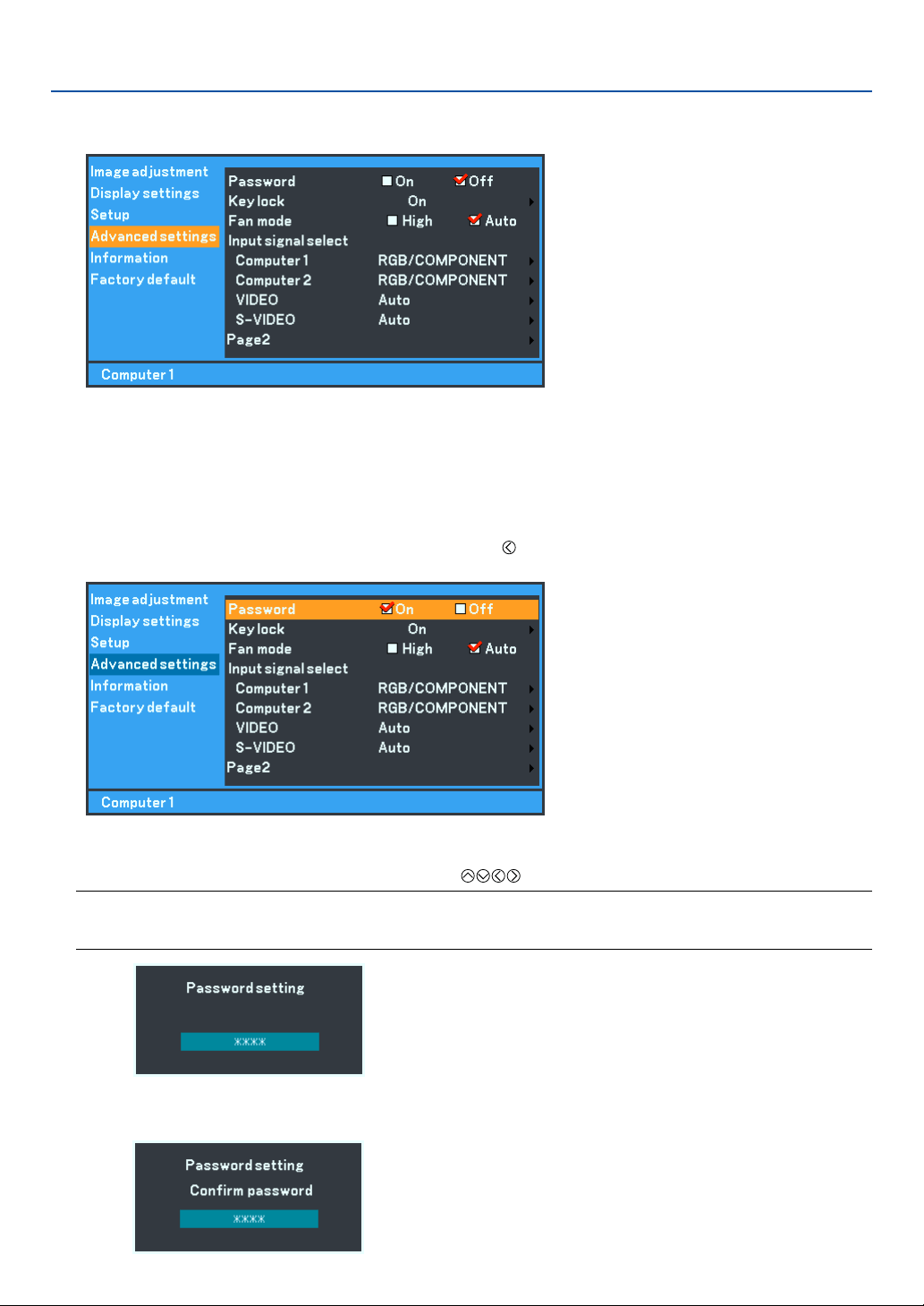
41
5. Using On-Screen Menu
쐆 Menu Descriptions & Functions [Advanced settings]
Password
A password can be set for your projector to avoid operation by an unauthorized user using the Menu. When a pass-
word is set, turning on the projector will display the password input screen. Unless the correct password is entered, the
projector cannot project an image.
To enable the Password function:
1. Select [Advanced settings]
→
[Password] and press the button to select “On”.
The [Password] screen will be displayed.
The [Confirm password] screen will be displayed.
2. Type in a combination of the four SELECT buttons and press the OK button.
NOTE:
• A password must be four to 10 digits in length.
• When you want to cancel registering the password, press the MENU button without entering the password.
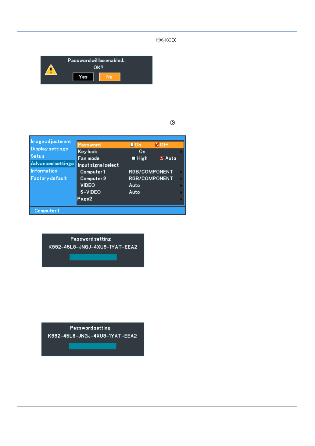
42
5. Using On-Screen Menu
3. Type in the same combination of SELECT buttons and press the OK button.
The confirmation screen will be displayed.
4. Select “Yes” and press the OK button.
The Password function has been enabled.
To disable the Password function:
1. Select [Advanced settings]
→
[Password] and press the button to select “Off”.
2. Type in your password and press the OK button.
When the correct password is entered, the Password function will be disabled.
When the Password function is enabled and the projector is turned on, the projector will display a blue
background.
To display an image at this time, press the MENU button to display the Password input screen.
The Password confirmation screen will be displayed.
Type in the correct password and press the OK button. The projector will display an image.
NOTE:
• The password disable mode is maintained until the main power is turned off (by setting the main power switch to “O” or
unplugging the power cord).
• If you forget your password, contact your dealer.

43
5. Using On-Screen Menu
Disabling the Key lock [Key lock]
This option turns on or off the Key lock function.
NOTE:
• This Key lock does not affect the remote control and the PC Control functions.
• When the Key Lock is Off, pressing and holding the BACK button for about 10 seconds will change the setting to enable.
• Key symbol indicates the Key lock is On.
Enabling High Speed Fan Mode [Fan mode]
This option allows you to select two modes for fan speed: High speed mode and Auto mode.
High ...................... The built-in fans run at a fixed high speed.
Auto ...................... The built-in fans automatically run at a variable speed according to the internal temperature.
When you wish to cool down the temperature inside the projector quickly, select “High”.
NOTE: Select “High” if you continue to use the projector for consecutive days.
Selecting Signal Format [Input signal select]
[Computer]
Allows you to choose “Computer” for an RGB source such as a computer, or “COMPONENT” for a component
video source such as a DVD player. Normally select “RGB/COMPONENT” and the projector automatically detects
a component signal. However there may be some component signals that the projector is unable to detect. If this
is the case, select “COMPONENT”. Select “Scart” in Computer 1 for the European Scart signal.
[VIDEO & S-VIDEO system select]
This feature enables you to select composite video standards manually. Normally select “Auto”.
When you select the video standard for VIDEO and S-VIDEO, select the video standard from the pull-down menu.
This must be done for VIDEO and S-VIDEO respectively.
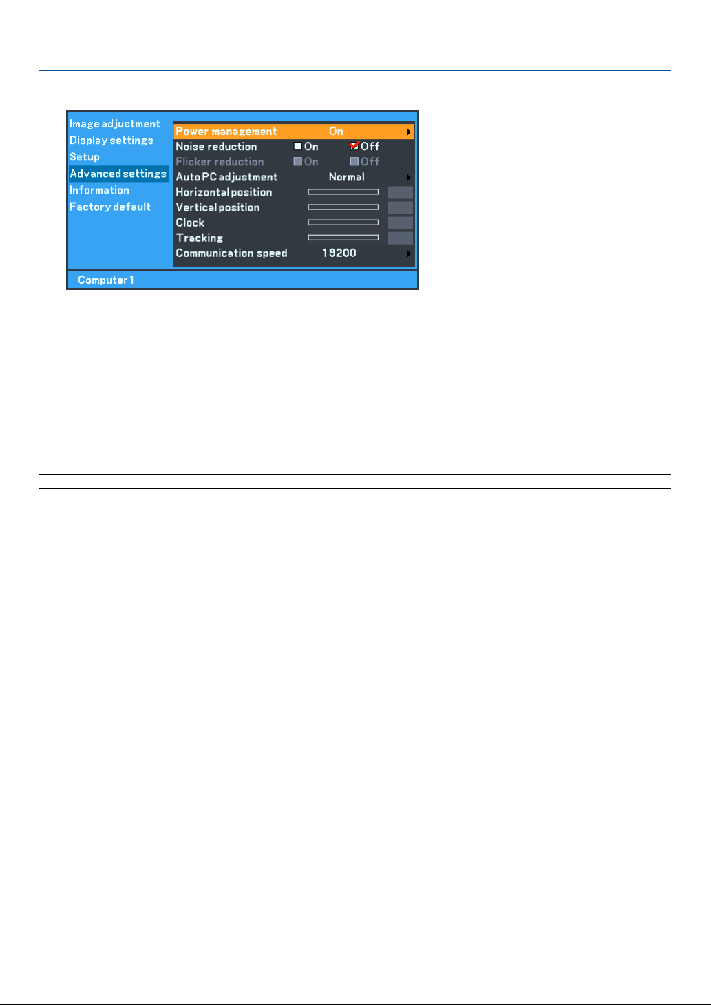
44
5. Using On-Screen Menu
(Advanced settings Page 2)
Enabling Power Management [Power management]
When this option is on and there is no signal or no menu operation for five minutes or more, the projector will automati-
cally turn itself off.
Turning On Noise Reduction [Noise reduction] (not available for Video and S-Video signals)
Reduces video noise. Select “On” to enable the Noise Reduction feature.
Turning On Flicker Reduction [Flicker reduction]
Reduces flicker which can occur in an interlaced signal. This feature is not available for RGB and HDTV signals.
NOTE: When the Flicker reduction is ON, jagged lines can be visible depending on the signal. In that case, select OFF.
NOTE: This feature may not be available depending on your video equipment connected to the projector.
Setting Auto PC adjustment [Auto PC adjustment]
This feature sets the Auto PC adjustment mode so that the RGB image can be automatically or manually adjusted for
noise and stability. You can automatically make adjustment in two ways: Normal and Fine
Off ......................... The RGB image will not be automatically adjusted.
You can manually optimize the RGB image.
Normal .................. Default setting. The RGB image will be automatically adjusted. Normally select this option.
Fine ....................... Select this option if fine adjustment is needed. It takes more time to switch to the source than when “Nor-
mal” is selected.
Adjusting Position/Clock (when Auto PC adjustment is off)
This allows you to manually adjust the image horizontally and vertically, and adjust Clock and Tracking.
[Horizontal/Vertical position]
Adjusts the image location horizontally and vertically.
This adjustment is made automatically when the Auto PC adjustment is turned on.
[Clock] (available for RGB and HDTV signals only)
Use this item with the “Auto PC adjustment off” to fine tune the computer image or to remove any vertical banding
that might appear. This function adjusts the clock frequencies that eliminate the horizontal banding in the image.
This adjustment may be necessary when you connect your computer for the first time. This adjustment is made
automatically when the Auto PC adjustment is turned on.
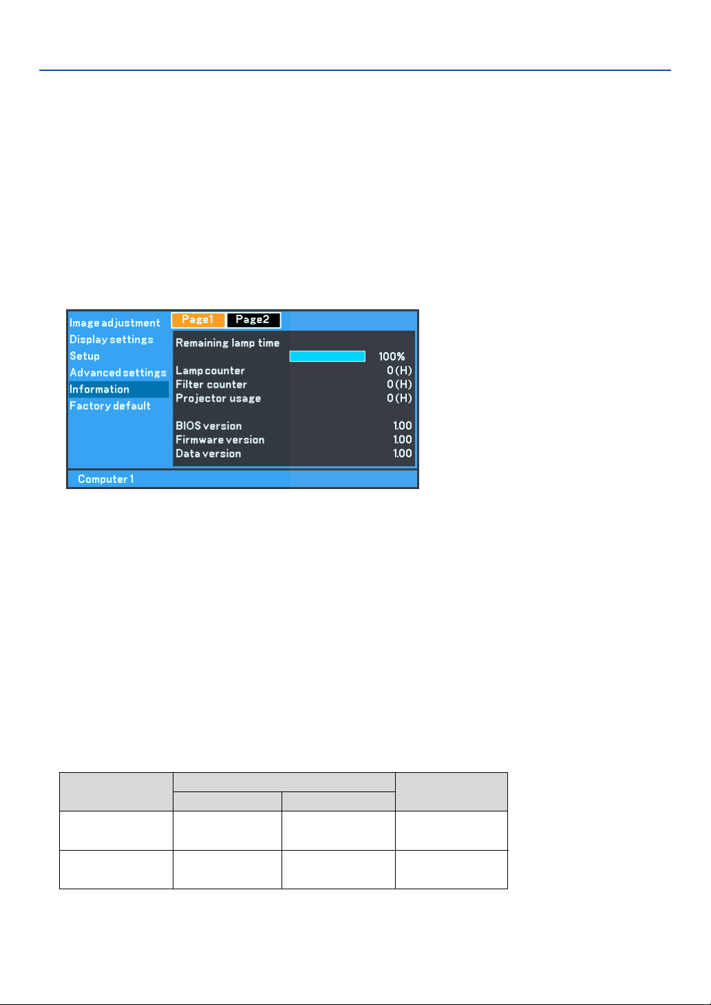
45
5. Using On-Screen Menu
[Tracking] (available for RGB and HDTV signals only)
Use this item to adjust the clock phase or to reduce video noise, dot interference or cross talk. (This is evident
when part of your image appears to be shimmering.)
Use “Tracking” only after the “Clock” is complete.
This adjustment is made automatically when the Auto PC adjustment is turned on.
Selecting Communication Speed [Communication speed]
This feature sets the baud rate of the SERVICE PORT (DIN 8 Pin). It supports data rates from 4800 to 19200 bps.
The default is 19200 bps.
Select the appropriate baud rate for your equipment to be connected (depending on the equipment, a lower baud rate
may be recommended for long cable runs).
쐊 Menu Descriptions & Functions [Information]
Displays the status of the current signal, Remaining lamp time (%), Lamp/Filter/Projector usage time (hours) and
version information. The Information has two pages. The Information included is as follows:
[Page 1]
Remaining lamp time (%)*
Lamp counter (H)
Filter counter
Projector usage
* The progress indicator shows the percentage of remaining bulb life. The value informs you of the amount of
lamp usage. When the remaining lamp time reaches 0, the Remaining lamp time bar indicator changes from
0% to 100 Hours and starts counting down.
If the Remaining lamp time reaches 0 hours, the projector will not turn on regardless of whether the lamp
mode is set to Normal or Quiet.
BIOS version
Firmware version
Data version
Model
Lamp life(H)
Normal Quiet
2000 3000
3000 4000
Replacement lamp
LV-LP24
LV-LP25
LV-7245/LV-7240
LV- X5
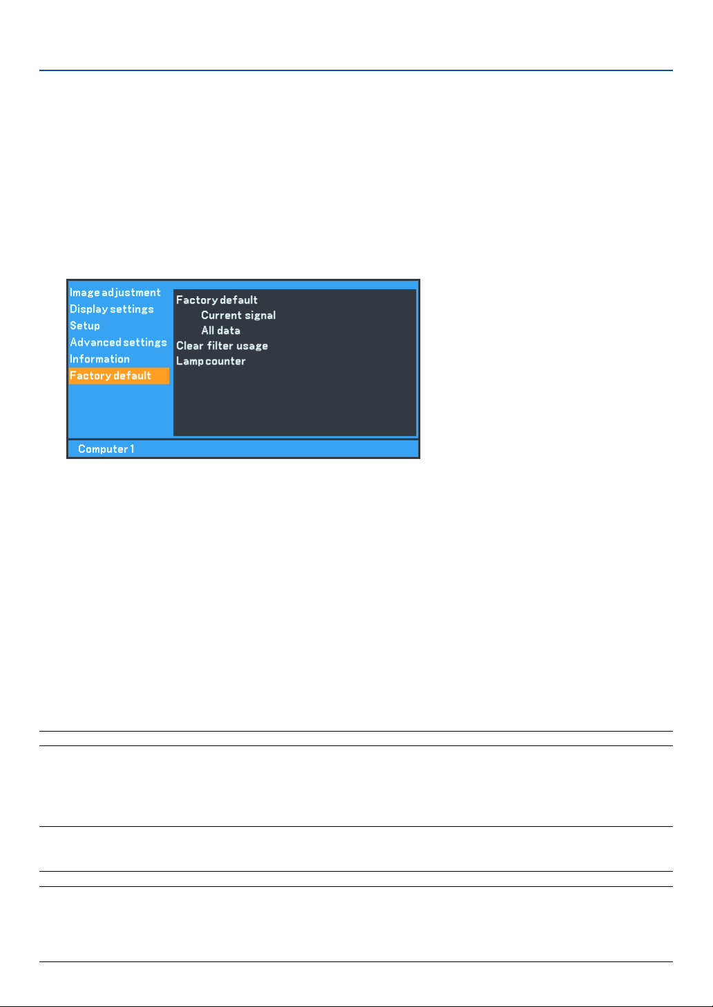
46
5. Using On-Screen Menu
쐎 Menu Descriptions & Functions [Factory default]
Returning to Factory Default [Factory default]
The Factory default feature allows you to change adjustments and settings to the factory presets.
[Current signal]
Resets the adjustments for the current signal to the factory preset levels.
The items that can be reset are: Brightness, Contrast, Color, Color balance, Sharpness, Noise reduction, Aspect,
Horizontal position, Vertical position, Clock, Tracking and Image mode.
[All data]
Resets all the adjustments and settings for all the signals to the factory preset for source except the following:
Language, Password, Communication speed, Remaining lamp time, Lamp counter, Filter usage and Projector
usage. To reset the lamp and filter usage time, see “Lamp counter” and “Clear filter usage”.
Resetting the Filter Usage Hours [Clear filter usage]
Resets the filter usage back to zero. Selecting this option displays submenu for a confirmation. Select “Yes” and press
the OK button.
NOTE: Reset the Filter usage after cleaning or replacing the filter.
Clearing Lamp counter [Lamp counter]
Resets the lamp clock back to zero. Selecting this option displays a submenu for a confirmation. Select “Yes” and press
the OK button.
NOTE: Do not reset the lamp counter except when you have replaced the lamp. If reset, the lamp counter cannot indicate the
correct timing of lamp replacement.
For the lamp replacement method, see page 49.
NOTE: The projector will turn off and go into standby mode after 2100* hours (up to 3100* hours in Quiet mode) of service.
If this happens, press the INFO. button on the remote control for ten seconds to reset the lamp clock back to zero.
When the lamp time clock is reset to zero, the LAMP REPLACE indicator goes out.
Do this only after replacing the lamp.
* LV-X5: 3100 hours (up to 4100 hours in Quiet mode).
[Page 2]
Source index
Horizontal frequency
Ver tical frequency
Sync polarity
Input signal type
Video type
Sync type
Interlace
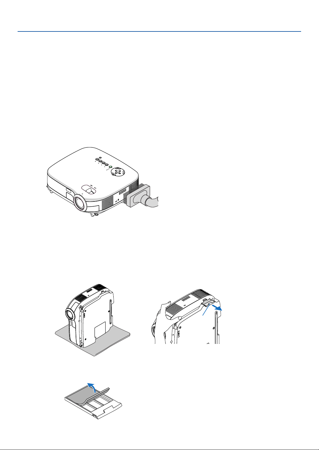
47
6. Maintenance
ZOOM
P
O
W
E
R
V
ID
E
O
S-
VIDEO
COM
PUTER-1
CO
MPUTER-2
WARNING
L
A
M
P
R
E
P
L
A
C
E
AUTO PC
VOL
-
VOL
+
ZO
O
M
F
O
C
U
S
This section describes the simple maintenance procedures you should follow to clean the filter and replace the lamp.
Cleaning or Replacing the Filter
The air-filter sponge keeps dust and dirt from getting inside the projector and should be cleaned after every 100 hours
of operation (more often in dusty conditions). If the filter is dirty or clogged, your projector may overheat.
CAUTION
•Turn off the projector, turn off the main power switch and unplug the projector before replacing the filter.
• Only clean the outside of the filter cover with a vacuum cleaner.
• Do not attempt to operate the projector without the filter cover.
To clean the air-filter:
Vacuum the filter through the filter cover.
To replace the filter (sponge):
1. Remove the filter cover by pushing down on the catch of the cover until you feel it detach.
Catch
2. Gently peel off the filter (sponge) and replace it with the new one.
To reset the filter usage time, from the menu, select [Factory default] → [Clear filter usage].
See also page 46 for resetting the filter usage time.
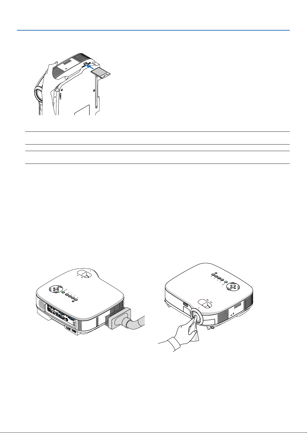
48
6. Maintenance
3. Reinstall the new filter cover.
NOTE: Do not wash the filter with soap and water. Soap and water will damage the filter membrane. Before replacing the filter,
remove dust and dirt from the projector cabinet. Keep out dust and dirt during filter replacement.
NOTE: When you replace the lamp, it is also wise to replace the filter. The filter comes in the same package with your
replacement lamp.
4. Turn on the projector.
5. Reset the Filter counter. See page 46.
쐇 Cleaning the Cabinet and the Lens
1. Turn off the projector before cleaning.
2. Clean the cabinet periodically with a damp cloth. If heavily soiled, use a mild detergent. Never use strong
detergents or solvents such as alcohol or thinner.
3. Use a blower or lens paper to clean the lens, and be careful not to scratch or mar the lens.
A
C
IN
VOL
-
VOL
+
ZOOM
F
O
C
U
S
S
-V
ID
E
O
IN
M
O
N
O
M
O
N
O
V
ID
E
O
IN
L
A
U
D
IO
IN
R
A
N
A
L
O
G
I
N
-
1
A
N
A
L
O
G
I
N
-
2
A
U
D
IO
O
U
T
L
A
U
D
IO
IN
R
S
E
R
V
IC
E
P
O
R
T
A
U
D
IO
I
N
P
O
W
E
R
VIDEO S-
V
I
D
E
O
C
O
M
P
U
T
E
R
-1
C
O
M
P
U
T
E
R
-2
W
A
R
N
I
N
G
L
A
M
P
R
EP
LA
C
E
A
U
T
O
P
C
A
C
IN
P
O
W
E
R
V
ID
EO
S
-
V
I
D
E
O
C
O
M
P
U
T
E
R
-
1
C
O
M
P
U
T
E
R
-
2
W
A
R
N
I
N
G
LAMP REPLACE
A
U
T
O
P
C
V
O
L
-
V
O
L
+
Z
O
O
M
FOCUS
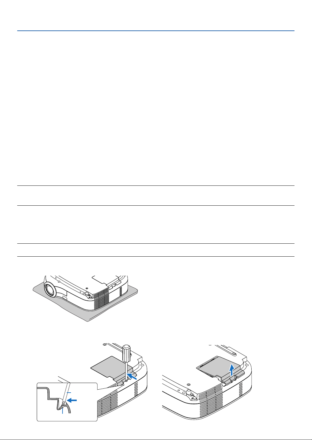
49
쐋 Replacing the Lamp
After your lamp has been operating for 2000* hours (up to 3000* hours in Quiet mode) or longer, the LAMP REPLACE
indicator in the cabinet will blink red and the message “Replace with the new lamp.” will appear. Even though the
lamp may still be working, replace it at 2000* (up to 3000* hours in Quiet mode) hours to maintain optimal projector
performance. After replacing the lamp, be sure to clear the lamp counter. See page 46.
CAUTION
• DO NOT TOUCH THE LAMP immediately after it has been used. It will be extremely hot. Turn the projector off,
wait 30 seconds, turn off the main power switch and then disconnect the power cord. Allow at least one hour for
the lamp to cool before handling.
• DO NOT REMOVE ANY SCREWS except two lamp case screws. You could receive an electric shock.
• Do not break the glass on the lamp housing.
Keep finger prints off the glass surface on the lamp housing. Leaving finger prints in the glass surface might
cause an unwanted shadow and poor picture quality.
• The projector will turn off and go into standby mode after 2100* (up to 3100* hours in Quiet mode) hours of
service. If this happens, be sure to replace the lamp. If you continue to use the lamp after 2000* hours (up to
3000* hours in Quiet mode) of use, the lamp bulb may shatter, and pieces of glass may be scattered in the lamp
case. Do not touch them as the pieces of glass may cause injury. If this happens, contact your dealer for lamp
replacement.
*NOTE: Lamp life for LV-X5 is 3000 hours in Normal mode and 4000 hours in Quiet mode.
The projector will turn off and go into standby mode after 3100 (up to 4100 hours in Quiet mode) hours of service.
A lamp may burn out before the LAMP REPLACE indicator blinks.
To replace the lamp:
Optional lamp and tools needed for replacement:
• Replacement lamp LV-LP24 (LV-7245/LV-7240) or LV-LP25 (LV-X5)
• Phillips screwdriver or equivalent
NOTE: The two lamp houses are slightly different in appearance.
The following explanation uses drawings for the lamp LV-LP24.
1. Place the projector on a soft cloth and turn it over to access the lamp cover on the bottom.
6. Maintenance
2. Use a Philips screwdriver to push and release the tab.
Push up and remove the lamp cover.
Catch
Philips
screwdriver
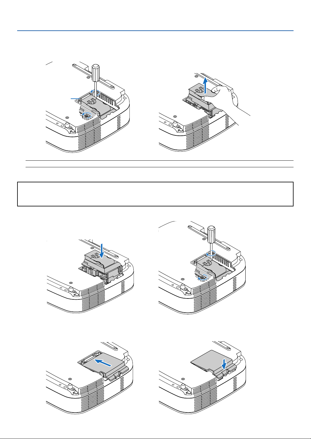
50
3. Loosen the two screws securing the lamp until the phillips screwdriver goes into a freewheeling condi-
tion. The two screws are not removable.
Remove the lamp by holding it.
6. Maintenance
NOTE: There is an interlock on this case to prevent the risk of electrical shock. Do not attempt to circumvent this interlock.
4. Insert a new lamp until the lamp is plugged into the socket.
CAUTION
Do not use a lamp other than the replacement lamp LV-LP24 (LV-7245/LV-7240) or LV-LP25 (LV-X5).
This may be ordered from your dealer.
Secure it in place with the two screws.
Be sure to tighten the screws.
5. Reattach the lamp cover.
Slip the lamp cover back until it snaps into place.
Interlock

51
6. Maintenance
6. Connect the supplied power cord, turn on the Main Power switch and turn on the projector.
7. Finally, select the menu
→
[Factory default]
→
[Lamp counter] to reset the lamp usage hours.
NOTE: When the lamp exceeds 2100* hours (up to 3100* hours in Quiet mode) of service, the projector cannot turn on and the
menu is not displayed.
If this happens, press the INFO. button on the remote control for ten seconds to reset the lamp clock back to zero.
When the lamp time clock is reset to zero, the LAMP REPLACE indicator goes out.
* LV-X5: 3100 hours (up to 4100 hours in Quiet mode).
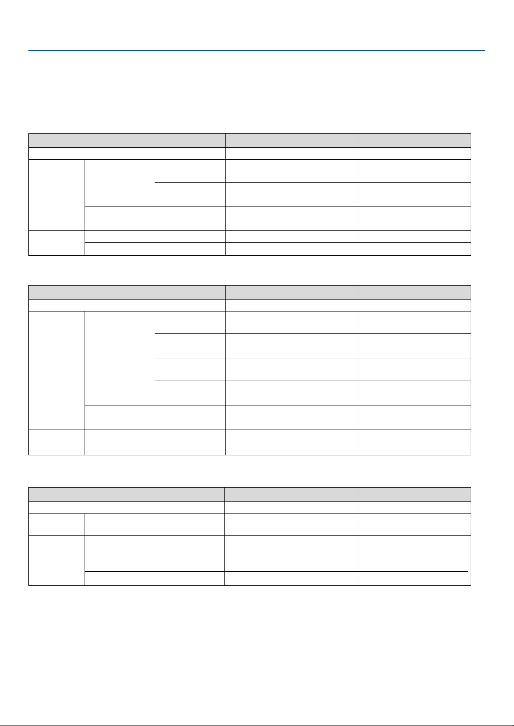
52
7. Appendix
Troubleshooting
This section helps you resolve problems you may encounter while setting up or using the projector.
Indicator Messages
POWER Indicator
Indicator Condition
Projector Condition Note
Off
Blinking light
Steady light
Green
Orange
Green
Orange
0.5 sec On,
0.5 sec Off
2.5 sec On,
0.5 sec Off
0.5 sec On,
0.5 sec Off
The main power is off
The projector is getting ready to turn on.
Off Timer is enabled.
The projector is cooling down.
The projector is turned on.
The projector is in Standby.
–
Wait for a moment.
–
Wait for a moment.
–
–
WARNING Indicator
Indicator Condition
Projector Condition Note
Off
Blinking light
Steady light
Red
Green
Orange
1 cycle (0.5 sec On,
2.5 sec Off)
2 cycle (0.5 sec On,
0.5 sec Off)
4 cycle (0.5 sec On,
0.5 sec Off)
6 cycle (0.5 sec On,
0.5 sec Off)
Normal
Lamp cover error or lamp housing error
Temperature error
Fan error
Lamp error
Re-firing the lamp (The projector is cool-
ing down.)
Key lock is On.
–
Replace the lamp cover or lamp
housing correctly.
The projector is overheated. Move
the projector to a cooler location.
Fans will not work correctly.
Lamp fails to light. Wait a full
minute and then turn on again.
The projector is re-firing.
Wait for a moment.
You have pressed cabinet button
when Key lock is On.
LAMP REPLACE Indicator
Indicator Condition
Projector Condition Note
Off
Blinking light
Steady light
Normal
Lamp has reached its end of life. Lamp
replacement message will be displayed.
Lamp has been used beyond its limit. The
projector will not turn on until the lamp is
replaced.
Lamp mode is set to Quiet mode
Red
Red
Green
–
Replace the lamp.
Replace the lamp.
–
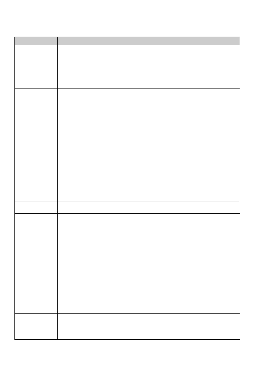
53
7. Appendix
Common Problems & Solutions (See also "POWER/WARNING/LAMP REPLACE Indicator" on page 52.)
Does not turn on
Will turn off
No picture
Picture suddenly
becomes dark
Color tone or Color
balance is unusual
Image isn’t square to
the screen
Picture is blurred
Image is scrolling
vertically, horizontally
or both
Remote control does
not work
Indicator is lit or
blinking
Cross color in RGB
mode
Whenever the projector
is turned on, a message
prompting you to clean
the filter will be dis-
played
• Check that the power cord is plugged in and that the power button on the projector cabinet or the remote
control is on. See pages 19 and 20.
• Ensure that the lamp cover is installed correctly. See page 50.
• Check to see if the projector has overheated or the lamp usage exceeds 2100* hours (up to 3100* hours :
Quiet mode). If there is insufficient ventilation around the projector or if the room where you’re presenting is
particularly warm, move the projector to a cooler location.
*LV-X5: 3100 hours (up to 4100 hours in Quiet mode).
• The lamp may fail to light. Wait a full minute and then turn on the power again.
• The lamp has reached the end of its usable life. Replace the lamp.
• Ensure that the Power Management is off. See page 44.
• Use the VIDEO, the S-VIDEO or the COMPUTER button on the remote control to select your source (Computer,
Video or S-Video). See page 22. If there is still no picture, press the button again.
• Ensure your cables are connected properly.
• Use menus to adjust the brightness and contrast. See page 37.
• Remove the lens cap.
•
Reset the settings or adjustments to factory preset levels using the “Factory default” in the Menu. See page 46.
• Enter your registered Password if the Password function is enabled. See page 41.
• When using with a notebook PC, be sure to connect between the projector and the notebook PC before turning
on the power to the notebook PC. In most cases signal cannot be output from RGB output unless the notebook
PC is turned on after connecting with the projector.
* If the screen goes blank while using your remote control, it may be the result of the computer's screen-
saver or power management software.
• See also the next page.
• When one of the following happens, the Lamp mode automatically changes from Normal to Quiet.
* When there are no signals (blue or black screen) → To return to the Normal mode, select another available
source.
* When the image is muted using the NO SHOW button on the remote control → Press the NO SHOW button
again to return to the Normal mode.
* When the room where you' re presenting is particularly warm → Move the projector to a cooler location.
• Check if an appropriate color is selected in "Screen color". If so, select an appropriate option. See page 36.
• Adjust "Color balance" in "Image adjustment". See page 37.
• Reposition the projector to improve its angle to the screen. See page 23.
• Use the Keystone correction function to correct the trapezoid distortion. See page 25.
• Adjust the focus. See page 24.
• Reposition the projector to improve its angle to the screen. See page 23.
• Ensure that the distance between the projector and screen is within the adjustment range of the lens. See page
11.
• Condensation may form on the lens if the projector is cold, brought into a warm place and is then turned on.
Should this happen, let the projector stand until there is no condensation on the lens.
• Use the VIDEO, the S-VIDEO or the COMPUTER button on the remote control to select your source (Video, S-
Video or Computer). See page 22.
• Adjust the computer image manually with the Horizontal/Vertical position in the “Advanced settings → Page
2”. See page 44.
• Install new batteries.See page 10.
• Make sure there are no obstacles between you and the projector.
• Stand within 7 m (22 feet) of the projector. See page 10.
• See the POWER/WARNING/LAMP REPLACE Indicator on page 52.
• Press the AUTO PC button on the projector cabinet or the remote control. See page 27.
• When “Off” is selected in Auto PC adjustment, adjust the computer image manually with Clock/Tracking in
“Advanced settings → Page 2” in the menu. See pages 44 and 45.
• Clean or replace the filter and then reset the Filter counter. See page 46.
Problem Check These Items
For more information contact your dealer.

54
7. Appendix
If there is no picture, or the picture is not displayed correctly.
• Power on process for the projector and the PC.
Be sure to connect the RGB cable between the projector and the computer before turning on the computer.
There are some notebook PCs, which do not output signal unless there is a projector or monitor connected first.
NOTE: You can check the horizontal frequency of the current signal in the projector’s menu under Information. If it reads
“0kHz”, this means there is no signal being output from the computer. See page 45 or go to next step.
• Enabling the computer’s external display.
Displaying an image on the notebook PC’s screen does not necessarily mean it outputs a signal to the projec-
tor. When using a PC compatible laptop, a combination of function keys will enable/disable the external display.
Usually, the combination of the ‘Fn” key along with one of the 12 function keys gets the external display to come
on or off. For more details, refer to your computer’s owner’s manual.
• Non-standard signal output from the computer
If the output signal from a notebook PC is not an industry standard, the projected image may not be displayed
correctly. Should this happen, deactivate the notebook PC’s LCD screen when the projector display is in use.
Each notebook PC has a different way of deactivate/reactivate the local LCD screens as described in the
previous step. Refer to your computer’s documentation for detailed information.
• Image displayed is incorrect when using a Macintosh
When using a Macintosh with the projector, set the DIPswitch of the Mac adapter (not supplied with the projec-
tor) according to your resolution. After setting, restart your Macintosh for the changes to take affect.
For setting display modes other than those supported by your Macintosh and the projector, changing the DIP
switch on a Mac adapter may bounce an image slightly or may display nothing. Should this happen, set the DIP
switch to the 13” fixed mode and then restart your Macintosh. After that, restore the DIP switches to a
displayable mode and then restart the Macintosh again.
NOTE: A Video Adapter cable manufactured by Apple Computer is needed for a PowerBook which does not have a mini D-Sub
15-pin connector.
• Mirroring on a PowerBook
* When using the projector with a Macintosh PowerBook, output may not be set to 1024 x 768 unless “mirror-
ing” is off on your PowerBook. Refer to owner’s manual supplied with your Macintosh computer for mirroring.
• Folders or icons are hidden on the Macintosh screen
Folders or icons may not be seen on the screen. Should this happen, select [View] → [Arrange] from the Apple
menu and arrange icons.

55
7. Appendix
Specifications
This section provides technical information about the projector's performance.
Model Number LV-7245/LV-7240/LV-X5
Optical
LCD Panel 0.7" p-Si TFT active-matrix with Micro Lens Array
Resolution 1024 ⳯ 768 pixels* native, up to UXGA with scaling technology
Lens Manual zoom and manual focus
F1.7 - 2.0 f=21.6 - 25.9 mm
Lamp LV-7245 : 190W DC lamp (150W Quiet mode)
LV-7240: 180W DC lamp (150W Quiet mode)
LV-X5: 130W DC lamp (110W Quiet mode)
Brightness LV-7245: 2500 lm
LV-7240: 2100 lm
LV-X5: 1500 lm
Uniformity 85%
Image Size (Diagonal) 21" to 300"
Projection Distance 0.7 m to 10.9 m / 2.4' to 35.8'
Projection Angle Tele: 9.5° - 9.9°/ Wide: 11.5° - 12.0°
Keystone Correction +/- 30° Vertical (auto)
Electrical
Inputs 2 RGB/Component (D-Sub 15 Pin),
1 S-Video (DIN 4 Pin), 1 Video (RCA), 2 (L/R) RCA Audio,
1 Stereo Mini Audio, 1 Service Port (DIN 8 Pin)
Outputs 1 RGB (D-Sub 15 Pin), 1 Stereo Mini Audio
Video Compatibility NTSC, NTSC4.43, PAL, PAL-60, PAL-N, PAL-M, SECAM,
1080p, 1080i, 720p, 480p, 480i / 60Hz
1080i, 576p, 576i / 50Hz
Scan Rate Horizontal: 15 kHz to 100 kHz (RGB: 24 kHz or over)
Ver tical: 50 Hz to 120 Hz
Video Bandwidth RGB: 80 MHz (-3dB)
Color Reproduction 16.7 million colors simultaneously, Full color
Horizontal Resolution NTSC / NTSC4.43/PAL/PAL-M/PAL-N/PAL60/YCbCr: 540 TV lines
SECAM: 300 TV lines
RGB: 1024 dots (H)⳯768 dots (V)
External Control RS232, IR
Sync Compatibility Separate Sync / Composite Sync / Sync on G
Built-in Speaker 1W (monaural)
Power Requirement 100 - 240V AC, 50 / 60 Hz
Input Current LV-7245/LV-7240: 2.7 - 1.4A
LV-X5: 2.1 - 1.2A
Power Consumption LV-7245/LV-7240: 8W in Standby mode /
250W in Lamp Normal mode / 200W in Lamp Quiet mode
LV-X5: 8W in Standby mode /
190W in Lamp Normal mode / 155W in Lamp Quiet mode
* Effective pixels are more than 99.99%.

56
7. Appendix
Mechanical
Installation Orientation Front / Rear / Ceiling mounted / Rear, Ceiling mounted
Dimensions 11.6" (W)⳯3.7" (H)⳯10.2" (D)
294mm (W)⳯93mm (H)⳯260mm (D)
(not including protrusions)
Weight approx. 7 lbs / 3 kg
Fan Noise LV-7245/LV-7240: 35 dB (Normal mode), 30dB (Quiet mode)
LV-X5: 33 dB (Normal mode), 28dB (Quiet mode)
Environmental Considerations Operational Temperatures : 41° to 95°F (5° to 35°C),
20% to 80% humidity (non-condensing)
Storage Temperatures : 14° to 122°F (-10° to 50°C),
20% to 80% humidity (non-condensing)
Regulations
For United States:
UL Approved (UL 60950)
Meets FCC Class B requirements
For Canada:
UL Approved (CSA 60950)
Meets DOC Canada Class B requirements
For Australia/New Zealand:
Meets AS/NZS CISPR.22 Class B
For Europe:
Meets EMC Directive (EN55022, EN55024, EN61000-3-2, EN61000-3-3)
Meets Low Voltage Directive (EN60950)
The specifications are subject to change without notice.
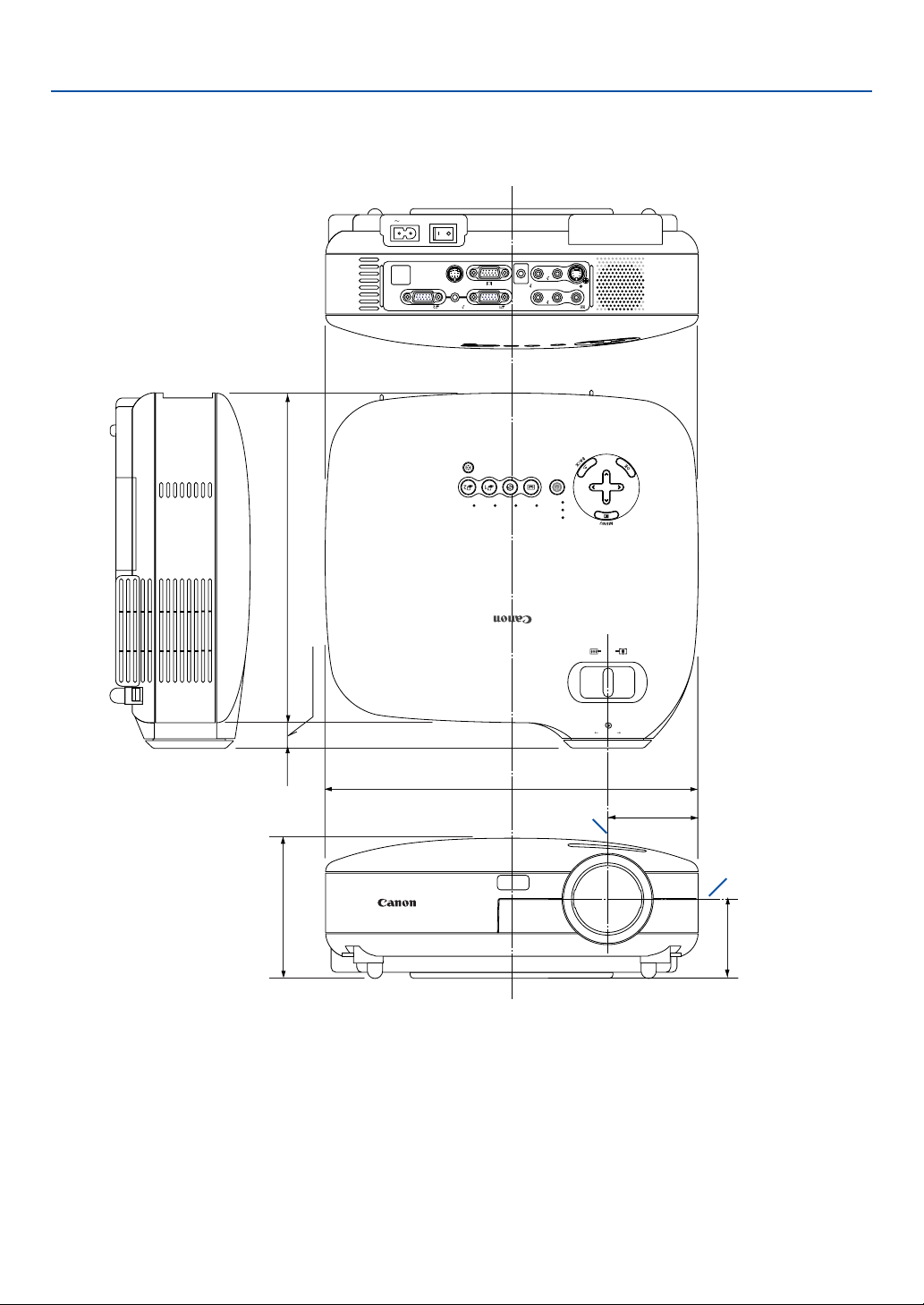
57
7. Appendix
Cabinet Dimensions
112.5 (4.4)
260 (10.2)
20.3 (0.8)
64.6 (2.5)
294 (11.6)
71.5 (2.8)
AC IN
VIDEO IN
L
AUDIO
IN
R
S-VIDEO IN
ANALOG IN-1
ANALOG IN-2
AUDIO OUT
L
AUDIO
IN
R
MONO
MONO
SERVICE PORT
AUDIO IN
POWER
VIDEO S-
VIDEO
COMPUTER-1 COMPUTER-2
WARNING
LAMP REPLACE
AUTO PC
VOL
-
VOL
+
ZOOM
FOCUS
Lens center
Lens center
Unit: mm (inch)
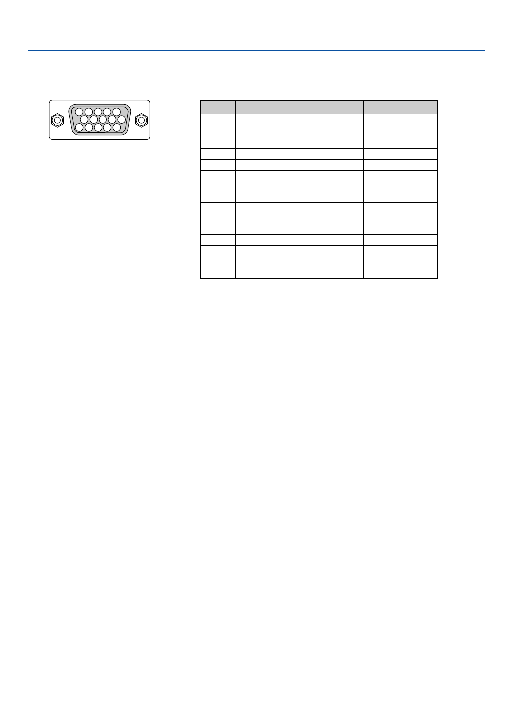
58
Mini D-Sub 15 Pin Connector
Pin Assignments of D-Sub ANALOG Input Connector
Signal Level
Video signal : 0.7Vp-p (Analog)
Sync signal : TTL level
51423
10
1112131415
6978
7. Appendix
* Only ANALOG-1 input connector supported.
Pin No. RGB Signal (Analog) YCbCr Signal
1 Red Cr
2 Green or Sync on Green Y
3 Blue Cb
4 Ground
5 Ground
6 Red Ground Cr Ground
7 Green Ground Y Ground
8 Blue Ground Cb Ground
9 No Connection
10 Sync Signal Ground
11 Scart Sync
12 Bi-directional DATA (SDA)*
13
Horizontal Sync or Composite Sync
14 Vertical Sync
15 Data Clock*

59
7. Appendix
Compatible Input Signal List
Signal Resolution Frequency H. Refresh Rate
( Dots ) ( kHz ) ( Hz )
NTSC – 15.73 60
PAL–15.63 50
PAL60 – 15.73 60
SECAM – 15.63 50
VESA 640 ⳯ 480 31.47 59.94
IBM 640 ⳯ 480 31.47 60
MAC 640 ⳯ 480 34.97 66.67
MAC 640 ⳯ 480 35 66.67
VESA 640 ⳯ 480 37.86 72.81
VESA 640 ⳯ 480 37.5 75
IBM 640 ⳯ 480 39.38 75
VESA 640 ⳯ 480 43.27 85.01
IBM 720 ⳯ 350 31.47 70.09
IBM 720 ⳯ 350 39.44 87.85
IBM 720 ⳯ 400 39.44 87.85
VESA 800 ⳯ 600 35.16 56.25
VESA 800 ⳯ 600 37.88 60.32
VESA 800 ⳯ 600 48.08 72.19
VESA 800 ⳯ 600 46.88 75
VESA 800 ⳯ 600 53.67 85.06
MAC 832 ⳯ 624 49.73 74.55
VESA 1024 ⳯ 768 35.5 43 Interlaced
VESA 1024 ⳯ 768 48.36 60
VESA 1024 ⳯ 768 56.47 70.07
MAC 1024 ⳯ 768 60.24 74.93
VESA 1024 ⳯ 768 60.02 75.03
VESA 1024 ⳯ 768 68.68 85
# VESA 1152 ⳯ 864 67.5 75
#MAC 1152 ⳯ 870 68.68 75.06
# SGI 1152 ⳯ 900 71.74 76.05
# VESA 1280 ⳯ 960 60 60
# VESA 1280 ⳯ 1024 63.98 60.02
#MAC 1280 ⳯ 1024 69.89 65.18
# VESA 1280 ⳯ 1024 79.98 75.03
# VESA 1280 ⳯ 1024 91.15 85.02
# SXGA+ 1400 ⳯ 1050 65.32 59.98
#
HDTV
(1080p)
1920 ⳯ 1080 67.5 60 Progressive
#
SDTV(576i)(625i)
– 15.6 50
#
SDTV(576p)(625p)
– 31.5 50
#
HDTV
(1080i)(1125i)
1920 ⳯ 1080 33.75 60 Interlace
#
HDTV
(1080i)(1125i)
1920 ⳯ 1080 28.13 50 Interlace
#
HDTV (720p)(750p)
1280 ⳯ 720 45 60 Progressive
#
SDTV (480p)(525p)
– 31.47 59.94 Progressive
# VESA 1600 ⳯ 1200 75.0 60
# VESA 1600 ⳯ 1200 81.25 65
# VESA 1600 ⳯ 1200 87.5 70
# VESA 1600 ⳯ 1200 93.75 75
DVD YCbCr – 15.73 59.94 Interlaced
DVD YCbCr – 15.63 50 Interlaced
# : Images in above flagged with # are compressed with scaling technology.
NOTE: Some composite sync signals may not be displayed correctly.
Signals other than those specified in the table above may not be displayed correctly. If this should happen, change the refresh
rate or resolution on your PC. Refer to Display Properties help section of your PC for procedures.
UXGA (1600 x 1200) is supported for separate sync signal only.
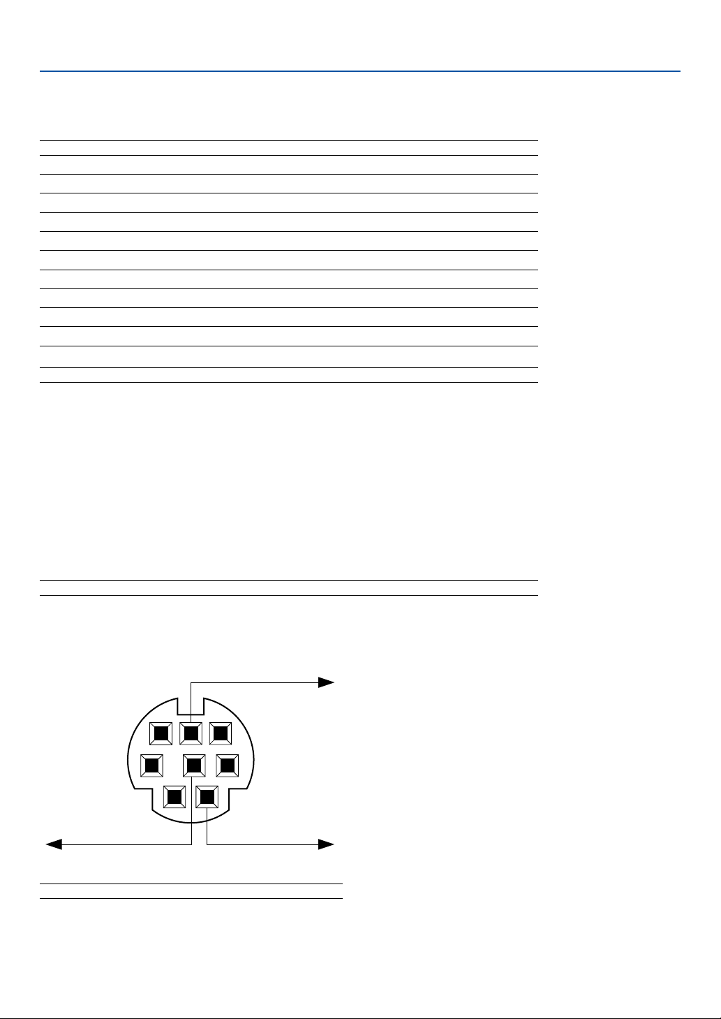
60
7. Appendix
PC Control Codes and Cable Connection
PC Control Codes
Function Code Data
POWER ON 02H 00H 00H 00H 00H 02H
POWER OFF 02H 01H 00H 00H 00H 03H
INPUT SELECT COMPUTER-1 02H 03H 00H 00H 02H 01H 01H 09H
INPUT SELECT COMPUTER-2 02H 03H 00H 00H 02H 01H 02H 0AH
INPUT SELECT VIDEO 02H 03H 00H 00H 02H 01H 06H 0EH
INPUT SELECT S-VIDEO 02H 03H 00H 00H 02H 01H 0BH 13H
NO SHOW ON 02H 10H 00H 00H 00H 12H
NO SHOW OFF 02H 11H 00H 00H 00H 13H
SOUND MUTE ON 02H 12H 00H 00H 00H 14H
SOUND MUTE OFF 02H 13H 00H 00H 00H 15H
Cable Connection
Communication Protocol
Baud rate ........................................ 19200 bps
Data length ..................................... 8 bits
Parity .............................................. No parity
Stop bit .......................................... One bit
X on/off .......................................... None
Communications procedure ........... Full duplex
NOTE: Depending on the equipment, a lower baud rate may be recommended for long cable runs.
NOTE: Contact your local dealer for a full list of the PC Control Codes if needed.
12
54 3
6
7
8
To RxD of PC
PC Control Connector (DIN-8P)
To TxD of PC
To GND of PC
NOTE: Pins 2, 3, 5, 6 and 8 are used inside the projector.
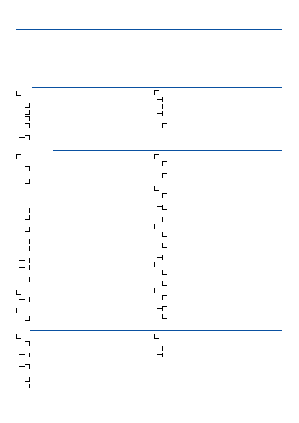
61
7. Appendix
Troubleshooting Check List
Before contacting your dealer or service personnel, check the following list to be sure repairs are needed, you may
also refer to the “Troubleshooting” section in your user’s manual. This checklist below will help us solve your problem
more efficiently.
* Print the following pages.
No image is displayed from your PC or video equipment to the
projector.
Still no image even though you connect the projector to the PC
first, then start the PC.
Enabling your notebook PC’s signal output to the projector.
•A combination of function keys will enable/disable the ex-
ternal display. Usually, the combination of the “Fn” key along
with one of the 12 function keys turns the external display
on or off.
No image (blue background, logo, no display).
Still no image even though you press the AUTO PC button.
Still no image even though you carry out “Factory default” in
the projector’s menu.
Signal cable's plug is fully inserted into the input connector
A message appears on the screen.
( _____________________________________________ )
The source connected to the projector is active and available.
Still no image even though you adjust the brightness and/or
the contrast.
Input source's resolution and frequency are supported by the
projector.
Frequency of occurrence 䡺 always 䡺 sometimes (How often?_____________________) 䡺 other (__________________)
Power
No power (POWER indicator does not light green) See also “WARN-
ING Indicator (WARNING)”.
Power cord's plug is fully inserted into the wall outlet.
Main power switch is pressed to the ON position.
Lamp cover is installed correctly .
Lamp counter (lamp operation hours) was cleared after lamp
replacement.
No power even though you press and hold the POWER button
for a minimum of 2 seconds.
Shut down during operation.
Power cord's plug is fully inserted into the wall outlet.
Lamp cover is installed correctly .
Power Management is turned off (only models with the Power
Management function).
Sleep Timer is turned off (only models with the Sleep Timer
function ).
Video and Audio
Image is too dark.
Remains unchanged even though you adjust the brightness
and/or the contrast.
Image is distorted.
Image appears to be trapezoidal (unchanged even though you
carry out the “Keystone adjustment”).
Parts of the image are lost.
Still unchanged even though you press the AUTO PC button.
Still unchanged even though you carry out “Factory default” in
the projector’s menu.
Image is shifted in the vertical or horizontal direction.
Horizontal and vertical positions are correctly adjusted on a
computer signal.
Input source's resolution and frequency are supported by the
projector.
Some pixels are lost.
Image is flickering.
Still unchanged even though you press the AUTO PC button.
Still unchanged even though you carry out “Factory default” in
the projector’s menu.
Image shows flickering or color drift on a computer signal.
Image appears blurry or out of focus.
Still unchanged even though you checked the signal’s resolu-
tion on PC and changed it to projector’s native resolution.
Still unchanged even though you adjusted the focus.
No sound.
Audio cable is correctly connected to the audio input of the
projector.
Still unchanged even though you adjusted the volume level.
AUDIO OUT is connected to your audio equipment (only mod-
els with the AUDIO OUT connector).
Other
Remote control does not work.
No obstacles between the sensor of the projector and the re-
mote control.
Projector is placed near a fluorescent light that can disturb the
infrared remote controls.
One or more remote sensors are enabled (only models with
the Remote Sensor Selection function).
Batteries are new and are not reversed in installation.
If present on the remote control, projector selector switch is
not used.
Buttons on the projector cabinet do not work ( only models with
the Key lock function).
Key lock is not turned on or is disabled in the menu.
Still unchanged even though you press and hold the BACK but-
ton for a minimum of 10 seconds.
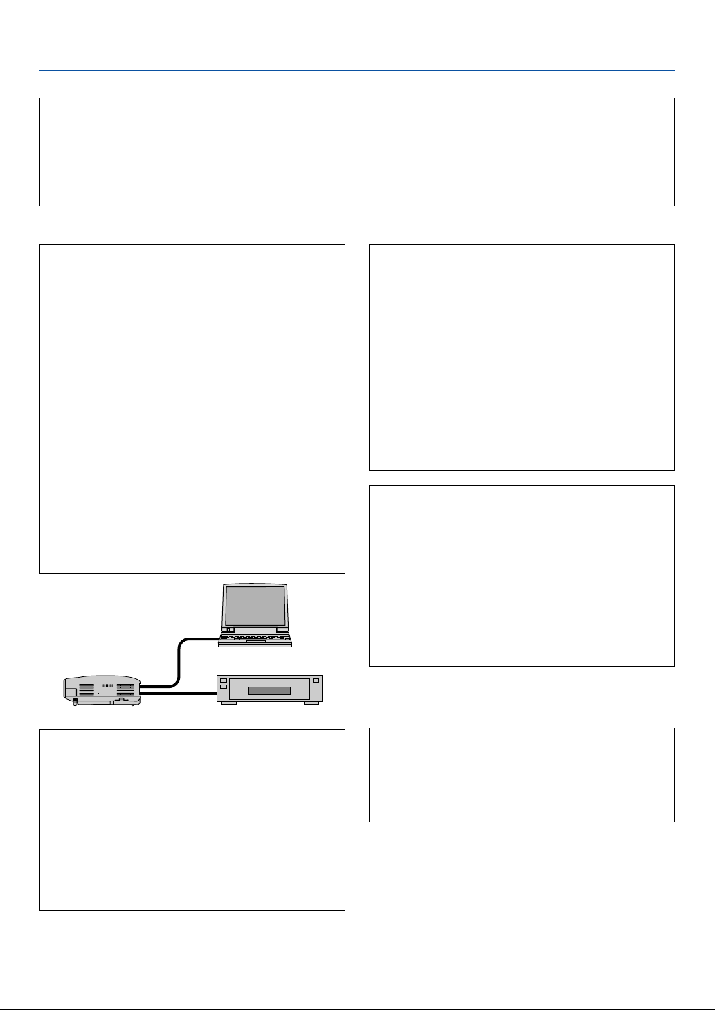
62
7. Appendix
In the space below please describe your problem in detail.
Information on application and environment where your projector is used
Projector
Model number:
Serial No.:
Date of purchase:
Lamp operating time (hours):
Lamp Mode: 䡺 Normal 䡺 Quiet
Information on input signal:
Horizontal sync frequency [ ] kHz
Vertical sync frequency [ ] Hz
Sync polarity H 䡺 (+) 䡺 (–)
V 䡺 (+) 䡺 (–)
Sync type 䡺 Separate 䡺 Composite
䡺 Sync on Green
WARNING Indicator:
Steady light 䡺 Orange 䡺 Green
Flashing light [ ] cycles
Remote control model number:
Signal cable
Canon standard or other manufacturer’s cable?
Model number: Length: inch/m
Distribution amplifier
Model number:
Switcher
Model number:
Adapter
Model number:
Projector
PC
DVD player
Installation environment
Screen size: inch
Screen type: 䡺 White matte 䡺 Beads 䡺 Polarization
䡺 Wide angle 䡺 High contrast
Throw distance: feet/inch/m
Orientation: 䡺 Ceiling mount 䡺 Desktop
Power outlet connection:
䡺 Connected directly to wall outlet
䡺 Connected to power cord extender or other (the num-
ber of connected equipment______________)
䡺 Connected to a power cord reel or other (the number
of connected equipment______________)
Computer
Manufacturer:
Model number:
Notebook PC 䡺 / Desktop 䡺
Native resolution:
Refresh rate:
Video adapter:
Other:
Video equipment
VCR, DVD player, Video camera, Video game or other
Manufacturer:
Model number:

CANON INC. 30- 2, Shimomaruko 3- chome, Ohta- ku, Tokyo 146- 8501, Japan
CANON U. S. A., INC.
One Canon Plaza, Lake Success, NY 11042, U. S. A.
CANON CANADA, INC.
6390 Dixie Road Mississauga, Ontario L5T 1P7 Canada
CANON LATIN AMERICA, INC.
703 Waterford Way Suite 400 Miami, Florida 33126 U. S. A.
CANON MEXICANA, S. de R. L. de C. V.
Boulevard Manuel Avila Camacho, No. 138 PB, Pisos 15, 16 y 17Col. Lomas de
Chapultepec, CP 11000, Mexico D. F., Mexico
CANON EUROPA N. V.
P. O. Box 2262, 1180 EG Amstelveen, The Netherlands
CANON COMMUNICATION & IMAGE FRANCE S. A.
102, Avenue du General de Gaulle, 92250 La Garenne Colombes, France
CANON (UK) LTD.
Woodhatch, Reigate, Surrey RH2 8BF, United Kingdom
CANON DEUTSCHLAND GmbH
Europark Fichtenhain A 10, 47807 Krefeld, Germany
CANON ITALIA S. p. A.
Via Milano, 8 San Donato M. se-20097 (MI), Italy
CANON (Schweiz) A. G.
Industriestrasse 12, 8305 Dietlikon, Switzerland
CANON BELGIUM N. V./ S. A
Bessenveldstraat 7, 1831 Diegem, Belgium
CANON GmbH
Zetschegasse 11, A- 1232 Wien, Austria
CANON ESPANA S. A.
C/ Joaquin Costa 41, 28002 Madrid, Spain
CANON SVENSKA AB
Stensätravägen 13, S- 127 88 Skarholmen 2, Sweden
CANON NORGE A/ S
Hallagerbakken 110, P. O. Box 2- 33, Holmlia 1201 Oslo 12, Norway
CANON OY
Huopalahdentie 24, P. O. Box 1, FIN- 00351 Helsinki, Finland
CANON HONGKONG CO., LTD.
19/F., The Metropolis Tower, 10 Metropolis Drive, Hunghom, Kln., H. K.
CANON SINGPORE PTE. LTD.
1 HarbourFront Avenue #04-01, Keppel Bay Tower Singapore 098632
CANON AUSTRALIA PTY. LTD.
1 Thomas Holt Drive, North Ryde, Sydney, N. S. W. 2113, Australia
CANON NEW ZEALAND LTD.
Akoranga Business Park, Akoranga Drive, Northcote, Auckland, New Zealand
CANON DENMARK A/ S
Knud Hoejgaards Vej, DK- 2860 Soeborg, Denmark
YT1-7322-000 © CANON INC. 2005
7N950731