Installation Manual AV Receiver
Connection
Precautions
Your new product and this manual
- Do not operate this product, any applications, or the rear view camera option (if purchased) if doing so will divert your attention in any way from the safe operation of your vehicle. Always observe safe driving rules and follow all existing traffic regulations. If you experience difficulty in operating this product, pull over, park your vehicle in a safe location and apply the parking brake before making the necessary adjustments.
- Do not install this product where it may (i) obstruct the driver’s vision, (ii) impair the performance of any of the vehicle’s operating systems of safety features, including airbags, hazard lamp buttons, or (iii) impair the driver’s ability to safely operate the vehicle. In some cases, it may not be possible to install this product because of the vehicle type or the shape of the vehicle interior
Important safeguards
- WARNING: Pioneer does not recommend that you install this product yourself. This product is designed for professional installation only. We recommend that only authorized Pioneer service personnel, who have special training and experience in mobile electronics, set up and install this product. NEVER SERVICE THIS PRODUCT YOURSELF. Installing or servicing this product and its connecting cables may expose you to the risk of electric shock or other hazards, and can cause damage to this product that is not covered by warranty.
Precautions before connecting the system
WARNING: Do not take any steps to tamper with or disable the parking brake interlock system which is in place for your protection. Tampering with or disabling the parking brake interlock system could result in serious injury or death.
CAUTION
- Secure all wiring with cable clamps or electrical tape. Do not allow any bare wiring to remain exposed.
- Do not directly connect the yellow lead of this product to the vehicle battery. If the lead is directly connected to the battery, engine vibration may eventually cause the insulation to fail at the point where the wire passes from the passenger compartment into the engine compartment. If the yellow lead’s insulation tears as a result of contact with metal parts, short-circuiting can occur, resulting in considerable danger.
- It is extremely dangerous to allow cables to become wound around the steering column or shift lever. Be sure to install this product, its cables, and wiring away in such so that they will not obstruct or hinder driving.
- Make sure that the cables and wires will not interfere with or become caught in any of the vehicle’s moving parts, especially the steering wheel, shift lever, parking brake, sliding seat tracks, doors, or any of the vehicle’s controls.
- Do not route wires where they will be exposed to high temperatures. If the insulation heats up, wires may become damaged, resulting in a short circuit or malfunction and permanent damage to the product.
- Do not shorten any leads. If you do, the protection circuit (fuse holder, fuse resistor or filter, etc.) may fail to work properly.
- Never feed power to other electronic products by cutting the insulation of the power supply lead of this product and tapping into the lead. The current capacity of the lead will be exceeded, causing overheating.
Before installing this product
- Use this unit with a 12-volt battery and negative grounding only. Failure to do so may result in a fire or malfunction.
- To avoid shorts in the electrical system, be sure to disconnect the (–) battery cable before installation.
To prevent damage
- When speaker output is used by 4 channels , use speakers over 50 W (Maximum input power) and between 4 Ω to 8 Ω (impedance value). Do not use 1 Ω to 3 Ω speakers for this unit.
- When rear speaker output is used by 2 Ω of subwoofer, use speakers over 70 W (Maximum input power). *Please refer to connection for a connection method.
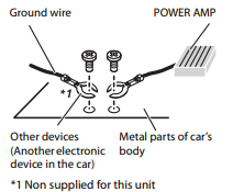
- The black cable is ground. When installing this unit or power amp (sold separately), make sure to connect the ground wire first. Ensure that the ground wire is properly connected to metal parts of the car’s body. The ground wire of the power amp and the one of this unit or any other device must be connected to the car separately with different screws. If the screw for the ground wire loosens or falls out, it could result in fire generation of smoke or malfunction
- When replacing the fuse, be sure to only use a fuse of the rating prescribed on this product.
- This product cannot be installed in a vehicle without ACC (accessory) position on the ignition switch.

- To avoid short-circuiting, cover the disconnected lead with insulating tape. It is especially important to insulate all unused speaker leads, which if left uncovered may cause a short circuit.
- For connecting a power amp or other devices to this product, refer to the manual for the product to be connected.
- The graphical symbol
 placed on the product means direct current.
Notice for the blue/ white lead
- When the ignition switch is turned on (ACC ON), a control signal is output through the blue/white lead. Connect to an external power amp’s system remote control terminal, the auto-antenna relay control terminal, or the antenna booster power control terminal (max. 300 mA 12 V DC). The control signal is output through the blue/white lead, even if the audio source is switched off.
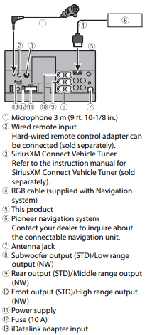
This product
Power cord
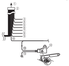
- To power supply
- Power cord
- Yellow: To terminal supplied with power regardless of ignition switch position.
- Red: To electric terminal controlled by ignition switch (12 V DC) ON/OFF
- Orange/white: To lighting switch terminal.
- Black (ground): To vehicle (metal) body.
- Violet/white: Of the two lead wires connected to the back lamp, connect the one in which the voltage changes when the gear shift is in the REVERSE (R) position. This connection enables the unit to sense whether the car is moving forward or backward.
- Yellow/black: If you use an equipment with Mute function, wire this lead to the Audio Mute lead on that equipment. If not, keep the Audio Mute lead free of any connections.
- Blue/white: Connect to system control terminal of the power amp (max. 300 mA 12 V DC).
- Light green: Used to detect the ON/OFF status of the parking brake. This lead must be connected to the power supply side of the parking brake switch.
- Power supply side
- Parking brake switch
- Ground side
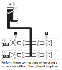
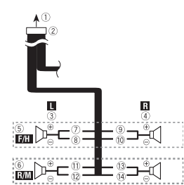
Speaker leads
- To power supply
- Power cord
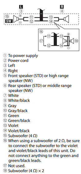
- Left
- Right
- Front speaker (STD) or high range speaker (NW)
- Rear speaker (STD) or middle range speaker (NW)
- White
- White/black
- Gray
- Gray/black
- Green
- Green/black
- Violet
- Violet/black
- Subwoofer (4 Ω)
- When using a subwoofer of 2 Ω, be sure to connect the subwoofer to the violet and violet/black leads of this unit. Do not connect anything to the green and green/black leads.
- Not used.
- Subwoofer (4 Ω) × 2
NOTES
- When a subwoofer is connected to this product instead of a rear speaker, change the rear output setting in the initial setting. The subwoofer output of this product is monaural. For details, refer to the Operation Manual.
- With a two-speaker system, do not connect anything to the speaker leads that are not connected to speakers.
Power amp (sold separately)
Without internal amp
 Important: The speaker leads are not used when this connection is in use.
With internal amp
Important: Front speaker and Rear speaker signals (STD) or middle range speaker and high range speaker signals (NW) are output from the speaker leads when this connection is in use.
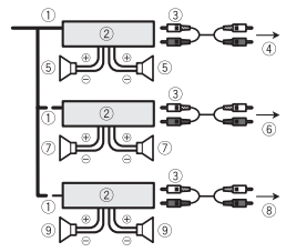
- System remote control: Connect to Blue/white cable.
- Power amp (sold separately)
- Connect with RCA cable (sold separately)
- To Rear output (STD): To middle range output (NW)
- Rear speaker (STD): Middle range speaker (NW)
- To Front output (STD): To high range output (NW)
- Front speaker (STD): High range speaker (NW)
- To subwoofer output (STD): To low range output (NW)
- Subwoofer (STD): Low range speaker (NW)
Select the appropriate speaker mode between standard mode (STD) and network mode (NW). For details, refer to the Operation Manual.
iPod®/iPhone® and smartphone
NOTES
- For details on how to connect an external device using a separately sold cable, refer to the manual for the cable.
- For details concerning the connection, operations and compatibility of iPhone, refer to the Operation Manual.
- For details concerning the connection and operations of smartphone, refer to the Operation Manual.
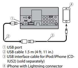
iPod/iPhone with Lightning connector
Connecting via the USB port
iPhone with 30-pin connector
Connecting via the USB port

4. iPhone with 30-pin connector
Smartphone (Android™ device)
Connecting via the USB port

NOTE: The length of Type USB A - micro USB B cable cannot exceed 2 m (6 ft. 6 in.) and Type USB A - USB C cannot exceed 4 m (13 ft. 1 in.) according to the USB cable standard. When using a cable other than the above conditions, the main unit function may not operate properly.
Camera
- About rear view camera: When you use the rear view camera, the rear view image is automatically switched from the video by moving the shift lever to REVERSE (R). Camera View mode also allows you to check what is behind you while driving.
- WARNING USE INPUT ONLY FOR REVERSE OR MIRROR IMAGE REAR VIEW CAMERA. OTHER USE MAY RESULT IN INJURY OR DAMAGE.
- CAUTION
- The screen image may appear reversed.
- With the rear view camera you can keep an eye on trailers, or back into a tight parking spot. Do not use for entertainment purposes.
- Objects in rear view may appear closer or more distant than in reality.
- The image area of full-screen images displayed while backing or checking the rear of the vehicle may differ slightly
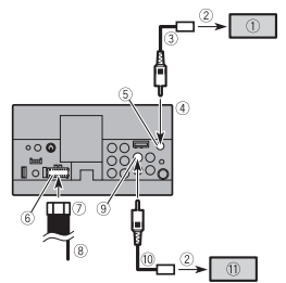
- Rear view camera (ND-BC8) (sold separately)
- To video output
- RCA cable (supplied with ND-BC8)
- This product
- Brown (R.C IN)
- Power supply
- Power cord
- Violet/white (REVERSE-GEAR SIGNAL INPUT) Refer to Power cord on page 3.
- Yellow (F.C IN) (AVH-2440NEX/AVH-1440NEX)
- RCA cable (sold separately)
- View camera (sold separately)
NOTES
- Connect only the rear view camera to R.C IN. Do not connect any other equipment.
- Some appropriate settings are required to use rear view cameras. For details, refer to the Operation Manual.
External video component and the display
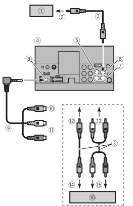
- Rear display with RCA input jacks
- To video input
- RCA cables (sold separately)
- This product Yellow (V IN )
- Yellow (V OUT )
- Red, white (R IN, L IN )
- AUX input
- Mini-jack AV cable (CD-RM10) (sold separately)
- Yellow Red, white
- To Yellow
- To Red, white
- To video output
- To audio outputs
- External video component (sold separately)
Installation
Precautions before installation
CAUTION: Never install this product in places where, or in a manner that:
- Could injure the driver or passengers if the vehicle stops suddenly.
- May interfere with the driver’s operation of the vehicle, such as on the floor in front of the driver’s seat, or close to the steering wheel or shift lever.
- To ensure proper installation, be sure to use the supplied parts in the manner specified. If any parts are not supplied with this product, use compatible parts in the manner specified after you have the part compatibility checked by your dealer. If parts other than supplied or compatible ones are used, they may damage internal parts of this product or they may work loose and the product may become detached.
- Do not install this product where it may (i) obstruct the driver’s vision, (ii) impair the performance of any of the vehicle’s operating systems or safety features, including airbags, hazard lamp buttons or (iii) impair the driver’s ability to safely operate the vehicle.
- Never install this product in front of or next to the place in the dashboard, door, or pillar from which one of your vehicle’s airbags would deploy. Please refer to your vehicle’s owner’s manual for reference to the deployment area of the frontal airbags.
Before installing
- Consult with your nearest dealer if installation requires drilling holes or other modifications of the vehicle.
- Before making a final installation of this product, temporarily connect the wiring to confirm that the connections are correct and the system works properly
Installation notes
- Do not install this product in places subject to high temperatures or humidity, such as:
- Places close to a heater, vent or air conditioner.
- Places exposed to direct sunlight, such as on top of the dashboard.
- Places that may be exposed to rain, such as close to the door or on the vehicle’s floor.
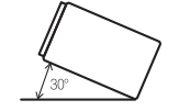
- Install this product horizontally on a surface within 0 to 30 degrees tolerance (within 5 degrees to the left or right). Improper installation of the unit with the surface tilted more than these tolerances increases the potential for errors in the vehicle’s location display, and might otherwise cause reduced display performance.
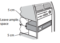
- When installing, to ensure proper heat dispersal when using this product, make sure you leave ample space behind the rear panel and wrap any loose cables so they are not blocking the vents.
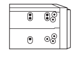
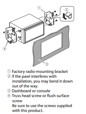
Installation using the screw holes on the side of this product
- Fastening this product to the factory radio-mounting bracket. Position this product so that its screw holes are aligned with the screw holes of the bracket, and tighten the screws at three locations on each side. Use either the truss head screws (5 mm × 9 mm) or flush surface screws (5 mm × 9 mm), depending on the shape of the bracket’s screw holes.
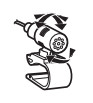
Installing the microphone
- Install the microphone in a place where its direction and distance from the driver make it easiest to pick up the driver’s voice.
- Be sure to turn off (ACC OFF) the product before connecting the microphone.
- Depending on the vehicle model, the microphone cable length may be too short when you mount the microphone on the sun visor. In such cases, install the microphone on the steering column.
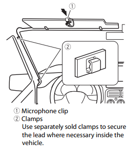
Mounting on the sun visor
1. Fit the microphone lead into the groove.
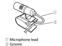
2. Attach the microphone clip to the sun visor.
Install the microphone on the sun visor when it is in the up position. It cannot recognise the driver’s voice if the sun visor is in the down position
Installation on the steering column
1. Detach the microphone base from the microphone clip by sliding the microphone base while pressing the tab.
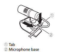
2. Mount the microphone on the steering column.
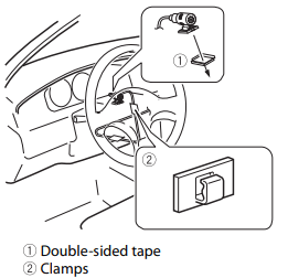
NOTE: Keeping it away from the steering wheel.
Adjusting the microphone angle