User Manual
Benützersanleitung
Manuel de l’utilisateur
Philips
Business
Solutions
G
I
S
F
E
BDS4621_EN.qxd 13-12-2004 10:38 Pagina 1
TYPE NR. BDS4621

TABLE OF CONTENTS
1. Important Safety Instructions . . . . . . . . . . . . . . . . . . . . . . . . . . . . . . . . . . . . . . . . 3
2. Before Use . . . . . . . . . . . . . . . . . . . . . . . . . . . . . . . . . . . . . . . . . . . . . . . . . . . . . . 7
2.1 Unpacking . . . . . . . . . . . . . . . . . . . . . . . . . . . . . . . . . . . . . . . . . . . . . . . . . . 7
2.2 Installation . . . . . . . . . . . . . . . . . . . . . . . . . . . . . . . . . . . . . . . . . . . . . . . . . . 7
3. Product features . . . . . . . . . . . . . . . . . . . . . . . . . . . . . . . . . . . . . . . . . . . . . . . . . . 8
4. Package Contents . . . . . . . . . . . . . . . . . . . . . . . . . . . . . . . . . . . . . . . . . . . . . . . . . 9
5. Names and functions of parts . . . . . . . . . . . . . . . . . . . . . . . . . . . . . . . . . . . . . . . 10
5.1 Sideview . . . . . . . . . . . . . . . . . . . . . . . . . . . . . . . . . . . . . . . . . . . . . . . . . . . 10
5.2 Front View . . . . . . . . . . . . . . . . . . . . . . . . . . . . . . . . . . . . . . . . . . . . . . . . . 11
5.3 Rear View . . . . . . . . . . . . . . . . . . . . . . . . . . . . . . . . . . . . . . . . . . . . . . . . . . 13
5.4 Remote Control . . . . . . . . . . . . . . . . . . . . . . . . . . . . . . . . . . . . . . . . . . . . . 15
6. Connection to External Equipment . . . . . . . . . . . . . . . . . . . . . . . . . . . . . . . . . . . 18
6.1 PC Module . . . . . . . . . . . . . . . . . . . . . . . . . . . . . . . . . . . . . . . . . . . . . . . . . 18
6.2 PC Module + Video Module . . . . . . . . . . . . . . . . . . . . . . . . . . . . . . . . . . . . 19
6.3 Connection to External Speakers: . . . . . . . . . . . . . . . . . . . . . . . . . . . . . . . . 20
7. Basic Operation . . . . . . . . . . . . . . . . . . . . . . . . . . . . . . . . . . . . . . . . . . . . . . . . . 21
7.1 Power ON/OFF . . . . . . . . . . . . . . . . . . . . . . . . . . . . . . . . . . . . . . . . . . . . . 21
7.2 Selection of Input Mode . . . . . . . . . . . . . . . . . . . . . . . . . . . . . . . . . . . . . . . 21
7.3 Selection of VIDEO Input Mode . . . . . . . . . . . . . . . . . . . . . . . . . . . . . . . . 22
7.4 Selection of PC Input Mode . . . . . . . . . . . . . . . . . . . . . . . . . . . . . . . . . . . . 22
7.5 OSD Option Adjustment . . . . . . . . . . . . . . . . . . . . . . . . . . . . . . . . . . . . . . 23
7.6 Sound Adjustment . . . . . . . . . . . . . . . . . . . . . . . . . . . . . . . . . . . . . . . . . . . 24
7.7 Zoom Functions . . . . . . . . . . . . . . . . . . . . . . . . . . . . . . . . . . . . . . . . . . . . . 24
7.8 Other Functions . . . . . . . . . . . . . . . . . . . . . . . . . . . . . . . . . . . . . . . . . . . . . 25
7.9 OSD Functions . . . . . . . . . . . . . . . . . . . . . . . . . . . . . . . . . . . . . . . . . . . . . . 26
8 OSD Pages and Functions . . . . . . . . . . . . . . . . . . . . . . . . . . . . . . . . . . . . . . . . . . 27
8.1 Display Pages . . . . . . . . . . . . . . . . . . . . . . . . . . . . . . . . . . . . . . . . . . . . . . . 27
8.2 Image and AV System Page . . . . . . . . . . . . . . . . . . . . . . . . . . . . . . . . . . . . . 28
8.3 Audio Page . . . . . . . . . . . . . . . . . . . . . . . . . . . . . . . . . . . . . . . . . . . . . . . . . 28
8.4 Language and Screen Saver Page . . . . . . . . . . . . . . . . . . . . . . . . . . . . . . . . . 29
8.5 Misc. Page . . . . . . . . . . . . . . . . . . . . . . . . . . . . . . . . . . . . . . . . . . . . . . . . . . 30
8.6 PIP Settings (PC only) . . . . . . . . . . . . . . . . . . . . . . . . . . . . . . . . . . . . . . . . . 31
8.7 User Color Temp (AV only) . . . . . . . . . . . . . . . . . . . . . . . . . . . . . . . . . . . . 31
8.8 Status . . . . . . . . . . . . . . . . . . . . . . . . . . . . . . . . . . . . . . . . . . . . . . . . . . . . . 32
9. Optional Accessories . . . . . . . . . . . . . . . . . . . . . . . . . . . . . . . . . . . . . . . . . . . . . 33
10. Technical Specifications . . . . . . . . . . . . . . . . . . . . . . . . . . . . . . . . . . . . . . . . . . . . 35
11. Factory Settings . . . . . . . . . . . . . . . . . . . . . . . . . . . . . . . . . . . . . . . . . . . . . . . . . 36
12. Cleaning and troubleshooting . . . . . . . . . . . . . . . . . . . . . . . . . . . . . . . . . . . . . . . 37
13. Limited Warranty (EUR) . . . . . . . . . . . . . . . . . . . . . . . . . . . . . . . . . . . . . . . . . . . 40
14. Limited Warranty (USA) . . . . . . . . . . . . . . . . . . . . . . . . . . . . . . . . . . . . . . . . . . . 43
APPENDIX
Serial Communication Protocol (RS-232) . . . . . . . . . . . . . . . . . . . . . . . . . . . . . . . 47
2
User Manual BDS4621
BDS4621_EN.qxd 13-12-2004 10:38 Pagina 2

1. IMPORTANT SAFETY INSTRUCTIONS
Read before operating equipment
1. Read these instructions.
2. Keep these instructions.
3. Heed all warnings.
4. Follow all instructions.
5. Do not use this apparatus near water.
6. Clean only with a dry cloth.
7. Do not block any of the ventilation openings.
Install in accordance with the manufacturers
instructions.
8. Do not install near any heat sources such as
radiators, heat registers, stoves, or other
apparatus (including amplifiers) that produce
heat.
9. Do not defeat the safety purpose of the
polarized or grounding type plug.A polarized
plug has two blades with one wider than the
other.
A grounding type plug has two blades and
third grounding prong.The wide blade or
third prong are provided for your safety.
When the provided plug does not fit into
your outlet, consult an electrician for
replacement of the obsolete outlet.
10. Protect the power cord from being walked
on or pinched particularly at plugs,
convenience receptacles, and the point
where they exit from the apparatus.
11. Only use attachments/accessories specified
by the manufacturer.
12 Use only with a cart, stand, tripod, bracket,
or table specified by the manufacturer, or
sold with the apparatus.When a cart is used,
use caution when moving the cart/apparatus
combination to avoid injury from tip-over.
13. Unplug this apparatus during lightning storms
or when unused for long periods of time.
14. Refer all servicing to qualified service
personnel. Servicing is required when the
apparatus has been damaged in any way, such
as power-supply cord or plug is damaged,
liquid has been spilled or objects have fallen
into apparatus, the apparatus has been
exposed to rain or moisture, does not
operate normally, or has been dropped.
15. This product may contain lead and mercury.
Disposal of these materials may be regulated
due to environmental considerations. For
disposal or recycling information, please
contact your local authorities or the
Electronic Industries Alliance: www.eiae.org
3
User Manual BDS4621
BDS4621_EN.qxd 13-12-2004 10:38 Pagina 3

16. Damage Requiring Service - The appliance
should be serviced by qualified service
personnel when:
A.The power supply cord or the plug has
been damaged;
B. Objects have fallen, or liquid has been
spilled into the appliance;
C.The appliance has been exposed to rain;
D.The appliance does not appear to operate
normally or exhibits a marked change in
performance;
E. The appliance has been dropped, or the
enclosure damaged.
17. Tilt/Stability:
All displays must comply with recommended
international global safety standards for tilt
and stability properties of its cabinet design.
• Do not compromise these design
standards by applying excessive pull force
to the front, or top, of the cabinet which
could ultimately overturn the product.
• Do not endanger yourself, or children, by
placing electronic equipment/toys on the top
of the cabinet. Such items could unsuspec-
tingly fall from the top of the set and cause
product damage and/or personal injury.
18. Wall or Ceiling Mounting - The appliance
should be mounted to a wall or ceiling only
as recommended by the manufacturer.
19. Power Lines - An outdoor antenna should be
located away from power lines.
20. Outdoor Antenna Grounding - If an outside
antenna is connected to the receiver, be sure
the antenna system is grounded so as to
provide some protection against voltage
surges and built up static charges.
Section 810 of the National Electric Code,
ANSI/NFPA No. 70-1984, provides information
with respect to proper grounding of the mast
and supporting structure, grounding of the
lead-in wire to an antenna discharge unit, size
of grounding connectors, location of antenna-
discharge unit, connection to grounding
electrodes, and requirements for the
grounding electrode.
21. Object and Liquid Entry - Care should be taken
so that objects do not fall and liquids are not
spilled into the enclosure through openings.
22. Battery Usage CAUTION - To prevent battery
leakage that may result in bodily injury,
property damage, or damage to the unit:
• Install all batteries correctly, with + and -
aligned as marked on the unit
• Do not mix batteries (old and new or
carbon and alkaline, etc.)
• Remove batteries when the unit is not
used for a long time.
4
User Manual BDS4621
BDS4621_EN.qxd 13-12-2004 10:38 Pagina 4
Note to the CATV system installer:
This reminder is provided to call the CATV
system installer's attention to Article 820-40 of
the NEC that provides guidelines for proper
grounding and, in particular, specifies that the
cable ground shall be connected to the
grounding system of the building, as close to the
point of cable entry as practical.
KNOW THESE SAFETY SYMBOLS
This "bolt of lightning" indicates uninsulated
material within your unit, which may cause an
electrical shock. For the safety of everyone in
your household, please do not remove product
covering.
For the safety of everyone in your household,
please do not remove product covering.
The "exclamation point" calls attention to
features for which you should read the enclosed
literature closely to prevent operating and
maintenance problems.
WARNING:
To reduce the risk of fire or electric shock, this
appliance should not be exposed to rain or
moisture and objects filled with liquids, such as
vases, should not be placed on this apparatus.
CAUTION:
To prevent electric shock, match wide blade of
plug to wide slot, and fully insert.
ATTENTION:
Pour éviter les chocs électriques, introduire la
lame la plus large de la fiche dans la bome corres-
pondante de la prise et pousser jusqu’au fond.
5
User Manual BDS4621
CAUTION
RISK OF ELECTRIC SHOCK
DO NOT OPEN
CAUTION: TO REDUCE THE RISK OF ELECTRIC
SHOCK, DO NOT REMOVE COVER (OR BACK). NO
USER SERVICEABLE PARTS INSIDE. REFER SER-
VICING TO QUALIFIED SERVICE PERSONEL. a
BDS4621_EN.qxd 13-12-2004 10:38 Pagina 5

CLEANING & CARE
• To avoid possible shock hazard, please be
sure that the television is unplugged from the
electrical outlet before cleaning.
• When cleaning the television screen, take
care not to scratch or damage the screen
surface (avoid wearing jewelry or using
anything abrasive).
• Wipe the front of the screen with a clean
cloth dampened with water. Use even, easy,
vertical strokes when cleaning.
• Gently wipe the cabinet surfaces with a clean
cloth or sponge dampened in a solution of
cool clear water. Use a clean dry cloth to
dry the wiped surfaces.
• Occasionally vacuum the ventilation holes or
slots in the cabinet back.
• Never use thinners, insecticide sprays, or
other chemicals on or near the cabinet, as
they might cause permanent marring of the
cabinet finish.
END-OF-LIFE DISPOSAL
• This Philips product and its packaging contain
materials that can be recycled and re-used.
Specialized companies can recycle your
product to increase the amount of reusable
materials and minimize the amounts which
need to be properly disposed.
• This product might also use batteries, which
should not be thrown away when depleted,
but should be handed in and disposed of as
small chemical waste.
• Please find out about the local regulations
regarding the disposal of the television,
batteries, and packaging materials whenever
you replace existing equipment.
6
User Manual BDS4621
BDS4621_EN.qxd 13-12-2004 10:38 Pagina 6

2. BEFORE USE
The 46” WVGA (wide-screen with VGA
resolution) Plasma Display is an ideal product for
individual users and commercial exhibitioners.
The product is a precise electronic product.
Users should read the following instructions
carefully to maximize the performance of the
product:
2.1 Unpacking
• The product is packaged in a carton
together with the standard accessories.Any
optional accessories will be packed
separately in another carton.
• The weight of the Plasma Display is approx.
37 kg. Due to the size and weight of the
product, it is recommended that the unit be
moved by a minimum of 2 people.
• The protective glass and the glass substrate
are installed on the front of the product.
Since both glasses can be broken and
scraped easily, move the product gently.
Never place the unit with the glass facing
down unless it is protected with pads.
• When opening the carton, check that the
product is in good condition and that all
standard accessories and items are included.
• Whenever possible, use the handles on the
back of the Display for transport.
2.2 Installation
• Due to the high power consumption, always
use the plug exclusively designed for this
product. If an extended line is required,
please consult your service agent.
• The product should be installed on a flat
surface to avoid tipping.The distance
between the back of the product and the
wall should be maintained for proper
ventilation.
Avoid installing the product in the kitchen,
bathroom or any other places with high
humidity so as not to shorten the service life
of the electronic components.
• Please ensure the product is installed
horizontally.Any 90 degrees clockwise or
counter-clockwise installation may induce
poor ventilation and subsequent component
damage.
• To protect the screen and avoid screen
damage, do not display a still picture for a
long time.
7
User Manual BDS4621
BDS4621_EN.qxd 13-12-2004 10:38 Pagina 7

3. PRODUCT FEATURES
• The 46” PDP provides quality image displays
and is suitable for a variety of multimedia
applications.
• Available input signals:
- The standard PC module provides RGB
(D-SUB, 15 Pin) and digital DVI input
connectors, and a RS-232 communication
connector (D-SUB, 9 Pin Male).
- The Video module provides composite
video (RCA), S-Video (DIN 4P) and
component video (RCA) input connectors,
and a composite video (RCA) output
connector. It supports the quality input
images of DVD and HDTV
(480P/720P/1080i), as well as the images of
TV systems such as NTSC, PAL and
SECAM.The Video module also provides
two sets of stereo audio input connectors
(RCA).
- The product supports PC image
resolutions up to XGA (1024x768) with a
vertical frequency of 85Hz.
• Power Management Function:The machine
provides an automatic power control
function.
• Fan-free Design:The unit does not require
any fans for ventilation, eliminating any
bothersome noise that may be generated. It
also lowers the power consumption of the
unit.
• Others:
- PIP Function:The user may watch video
while working with his or her PC.
- The product includes a set of built-in
2.0W speakers or can be connected to
external 10W+10W speakers. (BAL 4611)
- The Plasma unit provides high, medium
and low color temperature options.
The user may customize their favorite
color temperature.
- The user may work with the video module
or enhanced PC module to expand the
applications of the product to meet any
special requirements.
8
User Manual BDS4621
BDS4621_EN.qxd 13-12-2004 10:38 Pagina 8
9
User Manual BDS4621
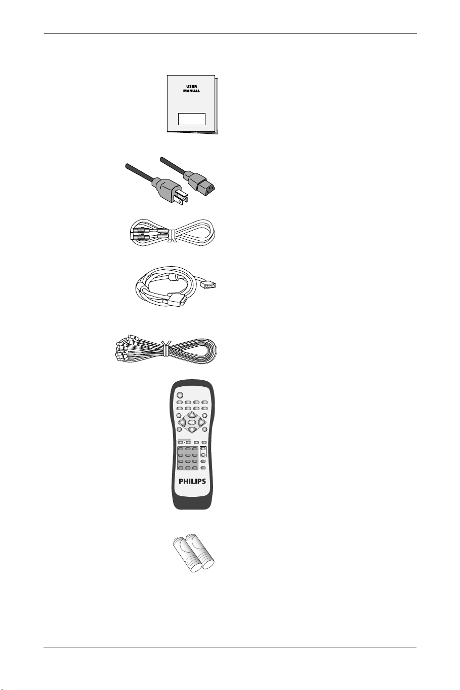
4. PACKAGE CONTENTS
User Manual (1x)
Power cable (1x)
Note: Power cable will vary depending on
shipping area.
S- Video cable (1x).
SUB-D, 15 PIN cable (1x).
AV- cable (1x).
Remote control (1x)
Including batteries UM-4 (2x).
POWER
MENU
INPUTMTS
PC
WIDE PIP FREEZE AUTO
CH
VOL
VIDEO
EXIT
12
+
-
3
456
789
0
100
ZOOM
RETURN
FULL
WHITE
WOW MUTE DISPLAY
MENU
BDS4621_EN.qxd 13-12-2004 10:38 Pagina 9
5. NAMES AND FUNCTIONS OF PARTS
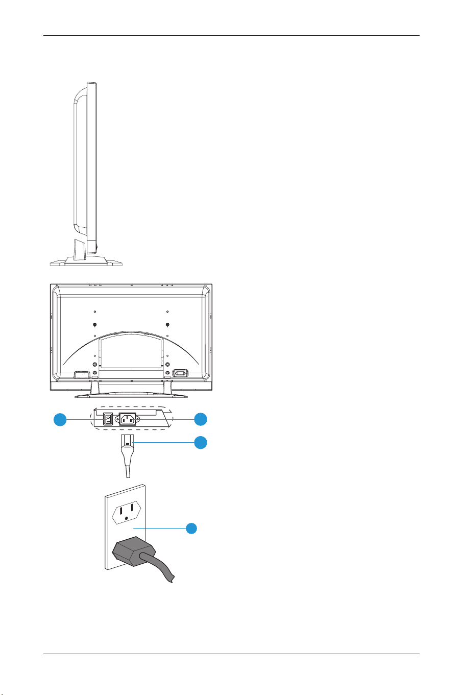
5.1 Sideview
1 Power switch.
2 Power cable.
3 Power jack.
4 Power outlet on the wall.
• Connect the power cable to the product,
then connect the main plug into the wall
outlet.
Note: Power plug types vary between
countries.The power plug shown
may not be the type supplied with
your set.
• Push the power switch (0 =
OFF / 1 = ON).
The power indicator on the front of the
panel should now display red, indicating that
the Plasma Display is in standby mode.
10
User Manual BDS4621
1
2
3
4
BDS4621_EN.qxd 13-12-2004 10:38 Pagina 10
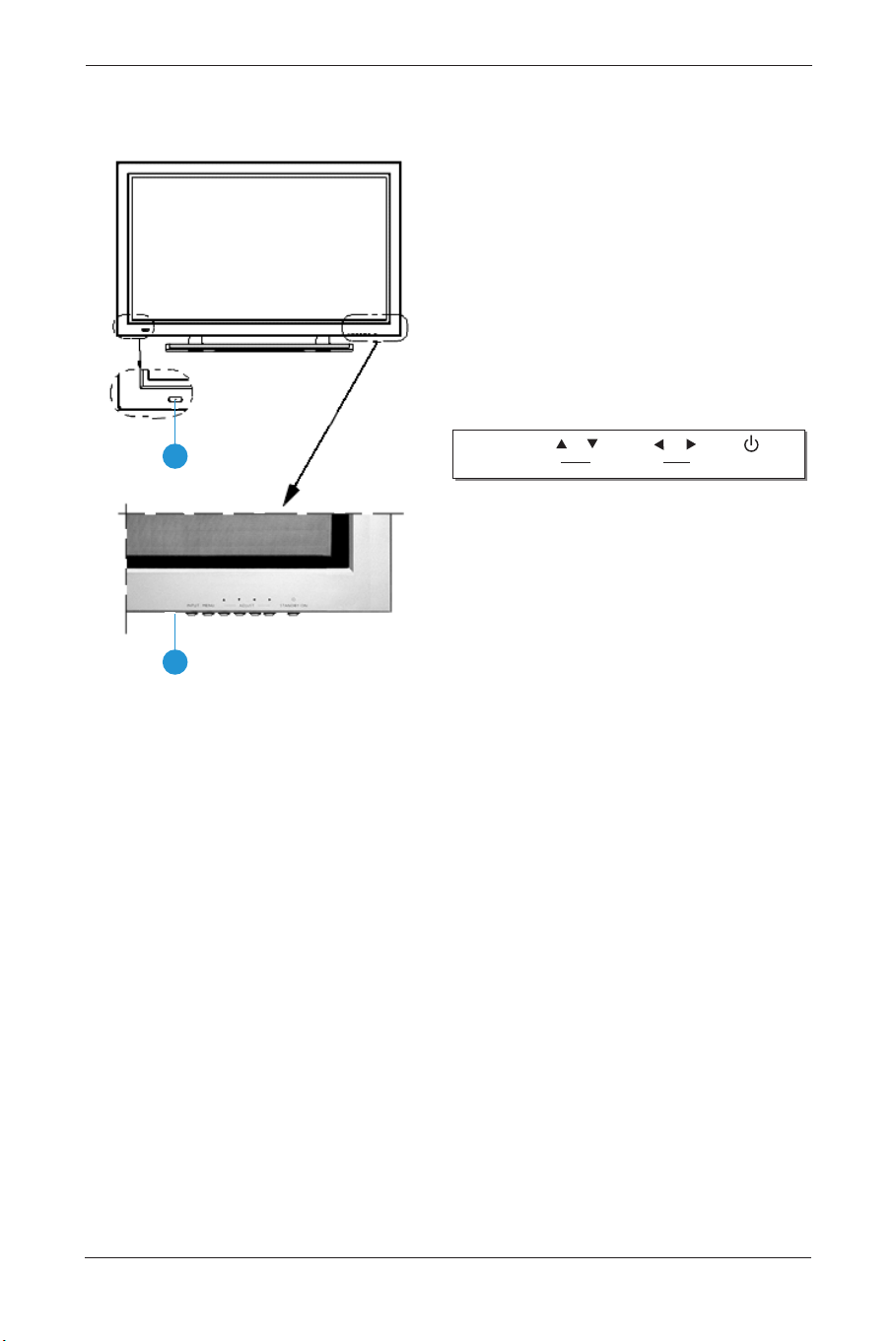
5.2 Front View
1 Remote control window
The window includes the power indicator
and the IR remote control sensor. LEDs are
used to indicate the power status.
• Indicator ON (red) means:‘Standby’ mode.
• Indicator ON (green) means:‘Power ON’
mode.
• Indicator flashing (red/green) alternately
means:‘Power Saving’ mode or switching
from Standby to Power On.
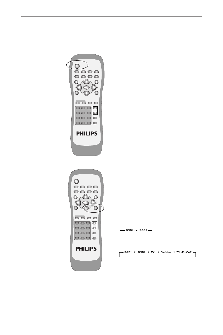
2 Buttons: The functions of the buttons
are described as follows:
INPUT
Select appropriate signal source directly.
(Depending on the module, the available signal
source options may vary).
A. PC Module: RGB 1 → RGB 2 (Circular dis-
play).
B. PC Module + Video Module:
RGB 1 → RGB 2 → AV1 → S-Video → Y
Cb/Pb Cr/Pr (circular display).
Note: When pressing this button to display
‘OSD Menu’, the signal sources can be
selected by using the ▲ ▼ arrow
buttons.
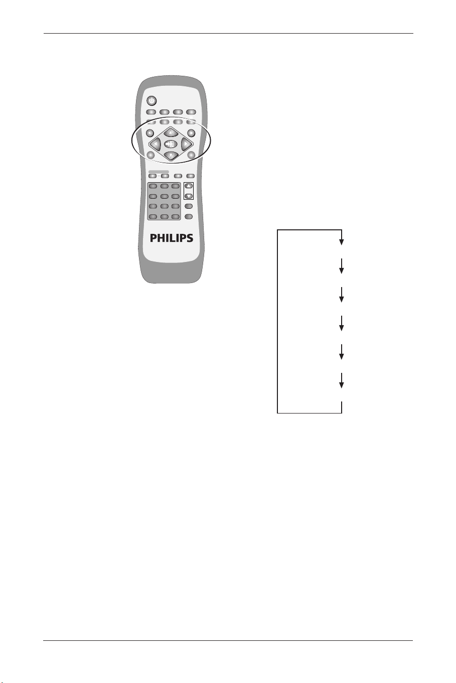
MENU
Enter ‘OSD Menu’ and select ‘OSD Menu’ page,
the pages appear in the following sequence:
Display → Image (for PC input) or AV System
(for Video input) → Audio → Language and
Screen Saver → Misc. → Status (circular display).
▲ ▼ UP/Down buttons
A. They are used as Up/Down buttons in the
‘OSD Menu’ screens.
B. They are used for quick adjustment when
the ‘OSD Menu’ is not displayed on the
screen.The screen displays in the following
sequence: Balance→Bass→Treble→Volume→
PIP Source*→Contrast* →Brightness*
(circular display).The adjustment is made in
conjunction with the
p π arrow buttons.
Note: ‘PIP Source’ is only for PC input.
‘Contrast’ and ‘Brightness’ is only for
Video input.
11
User Manual BDS4621
1
2
INPUT MENU STANDBY/ONADJUST
BDS4621_EN.qxd 13-12-2004 10:38 Pagina 11

p π Left/right arrow buttons
A. These buttons are used in the ‘OSD Menu’
screen.
The right button
π has the function of
Enter.
B. These buttons can be used for the
adjustment of the volume when the ‘OSD
Menu’ is not shown on the screen. Press the
left button
p to reduce the volume. Press
the right button
π to increase the volume.
STANDBY/ON
Is used to activate the Display or return it to
standby mode.
12
User Manual BDS4621
BDS4621_EN.qxd 13-12-2004 10:38 Pagina 12
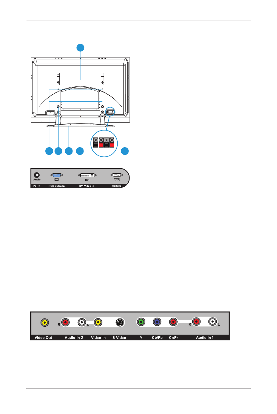
5.3 Rear View
1 Speaker Terminals: Can be used to connect
external speakers (optional accessories) to
the product.
Maximum power output: 10W + 10W.
2 Stand.
3 Stand mounting holes: use the standard
screws to mount the stand.
4 Wall Mount holes: use the standard screws
to attach the wall mount (optional
accessory).
5 Transport handles: use the handles to help
transport the product.The transport handles
must be removed in order to mount the
product to the wall.
6 Signal input terminals.
PC Module
PC In (Audio)
For PC Audio input purposes. Connects to
the PC Phone jack Audio output of the PC.
RGB Video In
For PC display purposes. Connects to the
SUB-D 15 PIN analog output connector of
the PC display card.
DVI Video In
For high quality PC display purposes.
Connects to the DVI-I digital output
connector of the PC display card.
RS-232C
Is a SUB-D, 9 Pin male terminal, used as a
control port for serial communication
between PC and Panel.
Video Module
Video Out
is a composite video output terminal
(RCA connector) for connecting to other
displays.
13
User Manual BDS4621
4
5
6 123
BDS4621_EN.qxd 13-12-2004 10:38 Pagina 13

Audio In 2
Is an audio input terminal
(RCA connector)
connecting to the audio output terminal of
the video output device.‘CVBS In’ and
‘S-Video’ share this audio terminal.
Video In
Is a Composite video input terminal (RCA
connector) connecting to the video output
terminal of the video output device.
S-Video
Is a Y/C S-Video input terminal (DIN 4
PIN) connecting to the S-Video output
terminal of the video output device.
Y/CbPb/CrPr
Is a Component video input terminal
(RCA connector) connecting to the
Component output terminal of the video
output device.
Audio 1
Is an audio input terminal connecting to
the audio output terminal of the video
output device.The component video and
PC input signals share this terminal.
14
User Manual BDS4621
BDS4621_EN.qxd 13-12-2004 10:38 Pagina 14
15
User Manual BDS4621
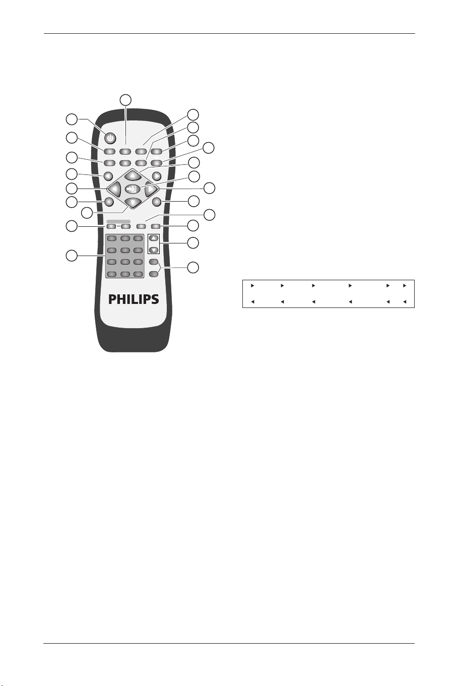
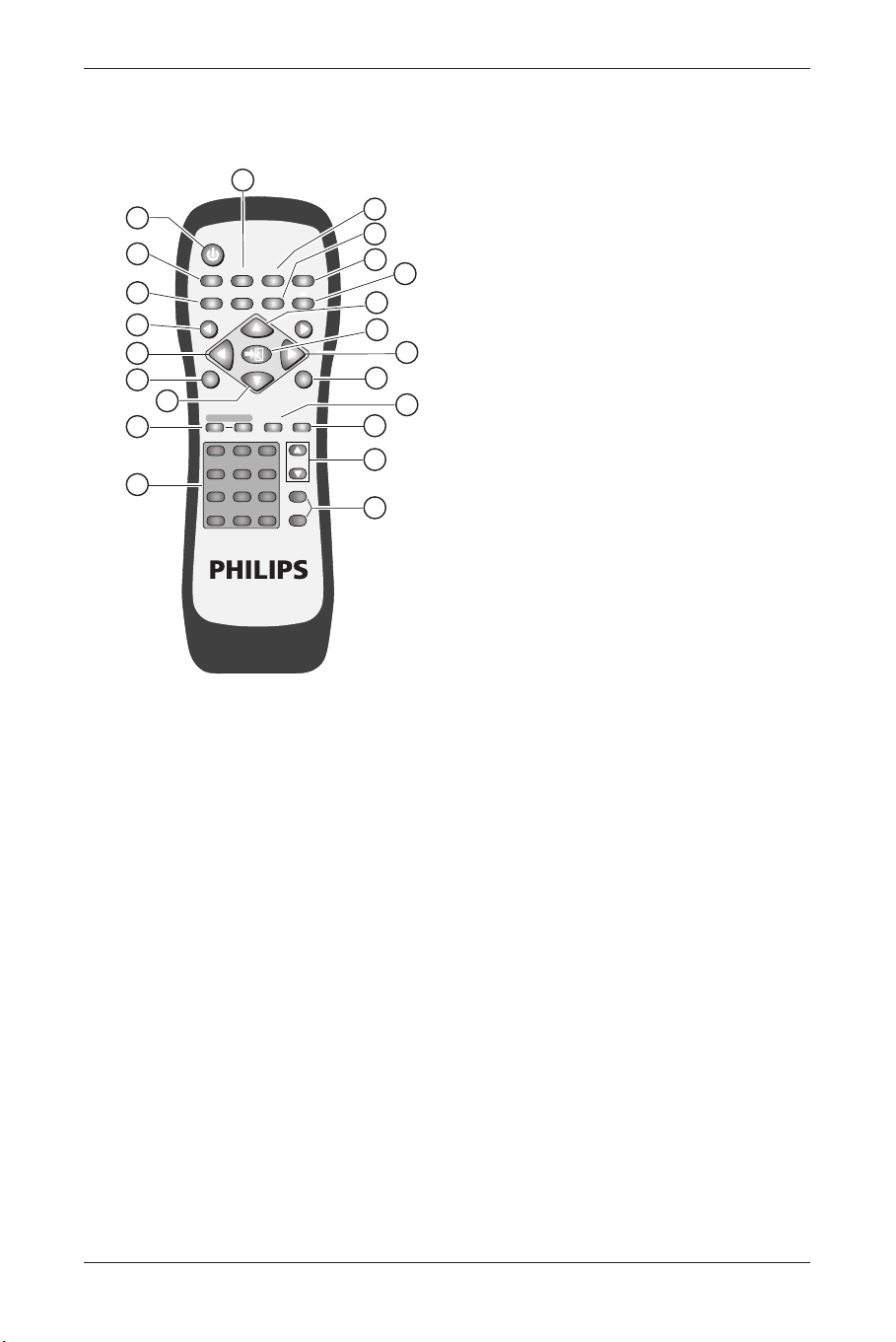
5.4 Remote Control
Function of buttons:
1. POWER
Press this button to turn the power On or
Off.
2. WIDE
Press this button to select wide screen.
Pressing this button again will restore the
original size of the screen.
3. FULL WHITE
Displays a full white screen.This can be used
to reduce image retention after a long
period of time displaying a still picture.
Press again to return to picture.
4. MENU
p and MENU π
Switch OSD pages in the following sequence
(circular display).
5. MTS
TV bi-language selection.
6. ZOOM + AND ZOOM -
Use these buttons to zoom in or zoom out
on the displayed image.
7. NUMBER BUTTONS
8. PIP
Use this button to open and adjust the size
of the picture-in-picture in the following
sequence:
Picture-in-picture open (small) → Screen
(medium) → Screen(large) → Picture-in-
picture closed (circular display).
9. FREEZE
Press this button to “freeze-frame” the
current screen.You may press this button
again to continue playing or play shall resume
automatically after 100 seconds.
10. MUTE
Press this button to mute the sound. Press
again to reactivate the sound. Sound is also
reactivated if the power is turned Off and
then On or if the volume level is changed.
POWER
MENU
INPUTMTS
PC
WIDE PIP FREEZE AUTO
CH
VOL
VIDEO
EXIT
1
13
17
16
15
14
19
18
20
11
12
7
6
15
5
4
13
2
3
8
9
10
12
+
-
3
456
789
0
100
ZOOM
RETURN
FULL
WHITE
WOW MUTE DISPLAY
MENU
Display
_
Image or AV System
_
Audio
_
Language and Screen Saver
_
Misc.
_
Status
BDS4621_EN.qxd 13-12-2004 10:38 Pagina 15
11. AUTO
• The Display automatically adjusts the
phase, vertical/horizontal position when
pressing this button in PC mode.
• The Display chooses the appropriate video
format automatically when pressing this
button in Video mode.
12 DISPLAY
Image and system information display
ON/OFF.
13. Up/Down arrows
▲ ▼
Use these buttons to adjust the ‘OSD Menu’
up and down or to select ‘Quick Menu’.
14. EXIT
Press this button to exit the ‘OSD Menu’.
15. Left/Right arrows
p π
Use these buttons to adjust the’OSD Menu’
left and right.
16. INPUT
Press this button to select the signal sources
directly. (Depending on the module, the
available signal source options may be
different).
PC Module
RGB 1→RGB 2 (circular display).
PC Module + Video Module
RGB1→RGB 2→AV1→S-Video→Y Cb/Pb
Cr/Pr (circular display).
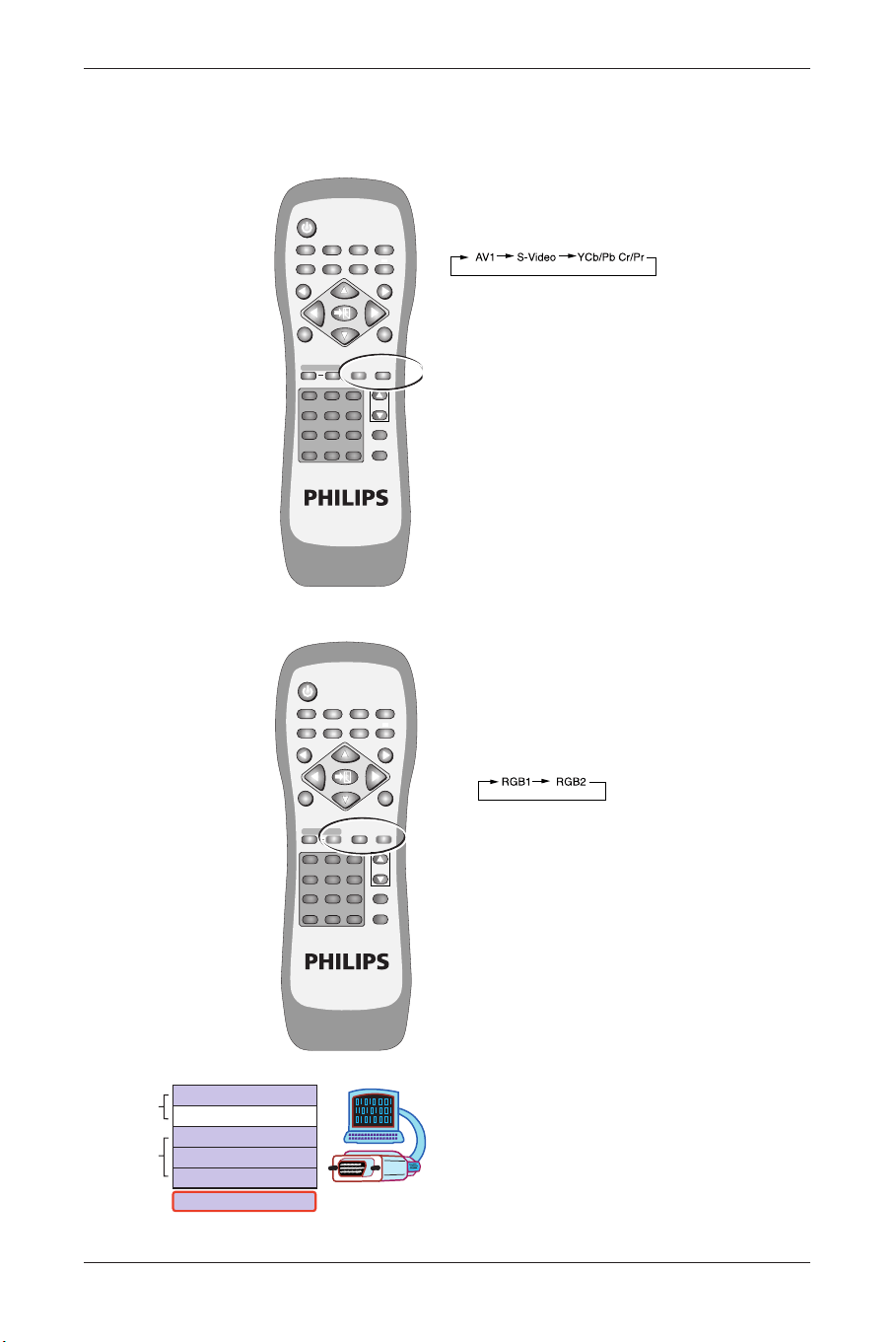
17. PC
Press this button to select the PC signal
source.The signal sources appear in the
following sequence:
RGB 1 (PC Module SUB-D Terminal), RGB 2
(PC Module DVI Terminal).
18. VIDEO
Press this button to select the video input
signal source. The signal sources appear in
the following sequence:
AV1, S-Video,YCb/PbCr/Pr.
19. TV CHANNEL SELECTION
20. VOL + and VOL -
Press the volume buttons to increase or
decrease the sound volume level.
Note: 5, 7 and 19 require TV Module installed.
16
User Manual BDS4621
POWER
MENU
INPUTMTS
PC
WIDE PIP FREEZE AUTO
CH
VOL
VIDEO
EXIT
1
13
17
16
15
14
19
18
20
11
12
7
6
15
5
4
13
2
3
8
9
10
12
+
-
3
456
789
0
100
ZOOM
RETURN
FULL
WHITE
WOW MUTE DISPLAY
MENU
BDS4621_EN.qxd 13-12-2004 10:38 Pagina 16
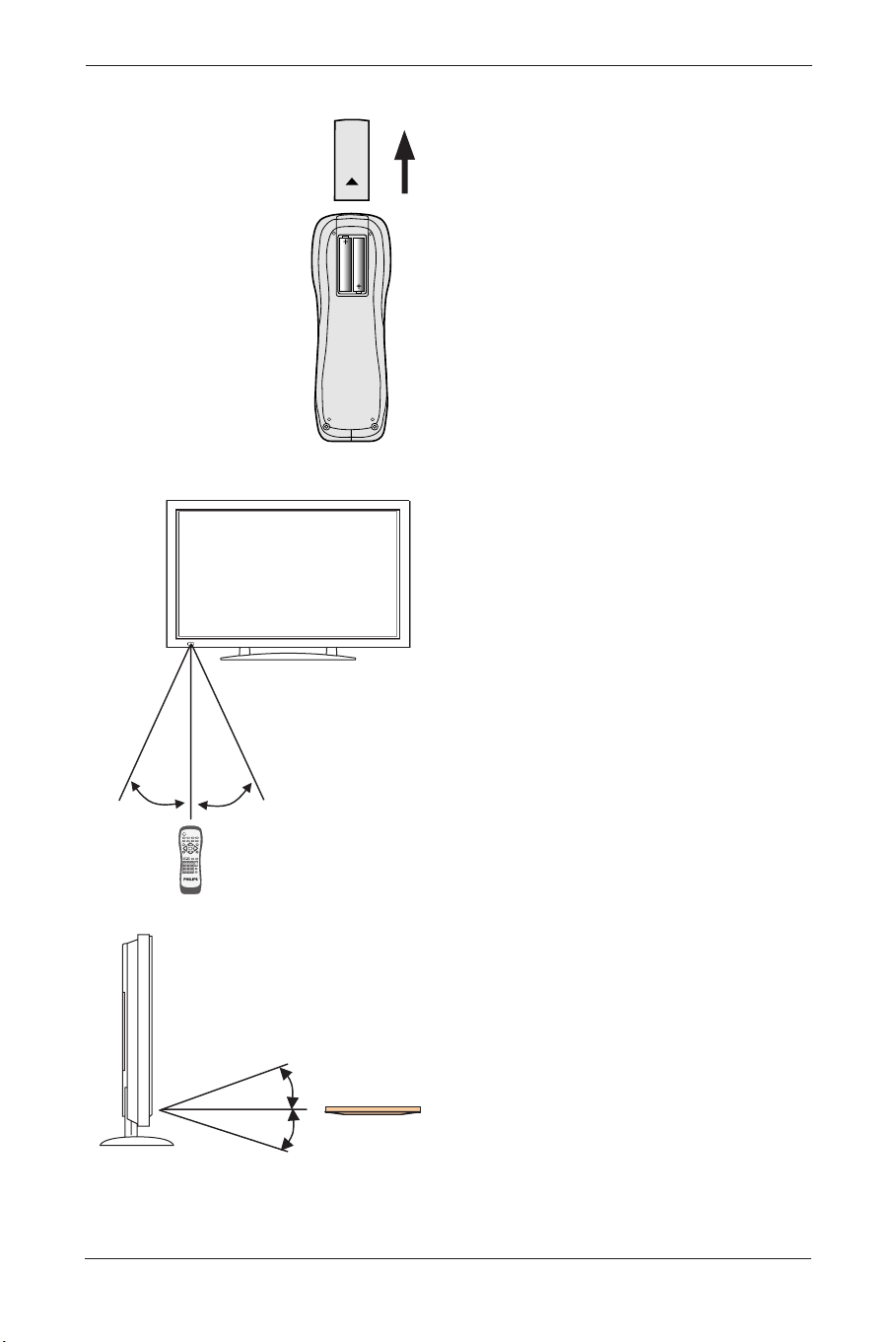
Inserting of Remote Control Batteries
• Turn the remote control upside down, press
and slide off the battery cover.
• Insert two AA batteries in the remote
control as shown in the diagram. (Positive +
and negative polarities - must match the
markings in the compartment).
• Place the cover in reverse order until the
lock snaps.
Scope of Remote Control
• Be sure the remote control is pointed
towards the remote control window on the
display.
• No obstacles should be placed between the
remote control and the remote control
window.
• The effective receiving scope for the signal is
10 meters to the front of the remote
control window, and 30 degrees to the left
or right side and 20 degrees above or below
the control window.
Use of Remote Control
• To ensure a normal operation, the remote
control should not be dropped or damaged
in any way. It should also be kept dry and
away from all heat sources.
• Battery replacement is necessary when the
remote control acts inconsistently or stops
operating the Plasma Display.
17
User Manual BDS4621
10m Front
RightLeft
30°
30°
POWE
R
MENU
I
N
P
U
TMTS
PC
WIDE PIP FREEZE AUTO
CH
VOL
VI
D
EO
EXIT
12
+
-
3
456
789
0
100
ZOOM
RETURN
F
U
LL
W
H
ITE
WOW MUTE DISPLAY
MENU
Upper
20°
Lower
20°
BDS4621_EN.qxd 13-12-2004 10:38 Pagina 17
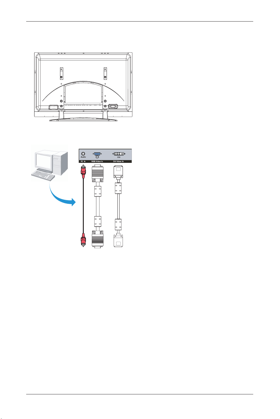
6. CONNECTION TO EXTERNAL EQUIPMENT
Rear view
6.1 PC Module
For operating the Plasma monitor as a PC
monitor.
SUB-D, (15 PIN) connects to analog RGB output
interface (Input option RGB 1).
DVI connects to digital RGB output interface
(Input option RGB 2).
Note:
• The DVI connector type of the Display is
DVI-I, which does not support analog signal
input.
• The RS-232 connector of the Display
provides a transmission interface for
professional technicians to update firmware,
without providing additional communication
functions.
18
User Manual BDS4621
BDS4621_EN.qxd 13-12-2004 10:38 Pagina 18
19
User Manual BDS4621
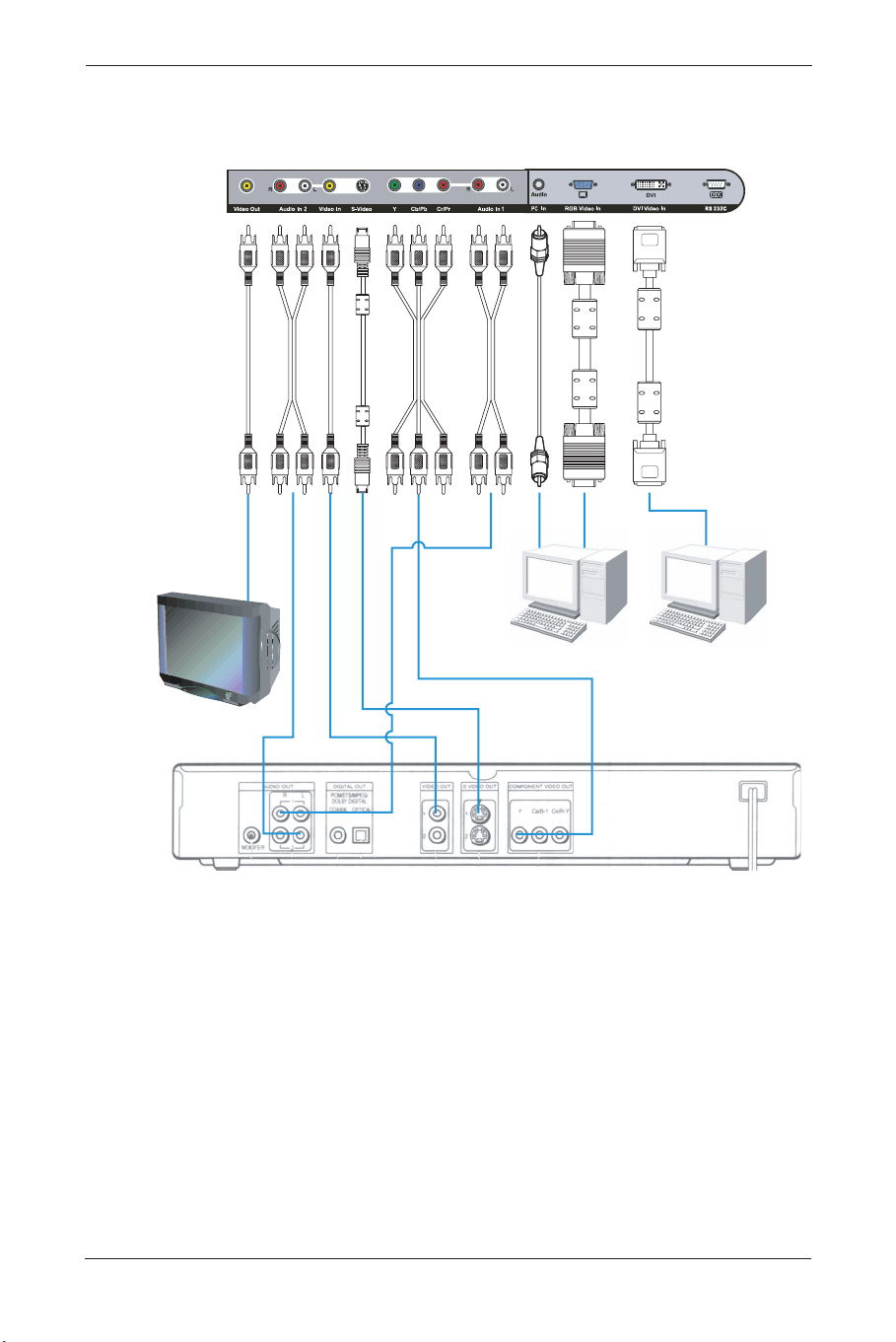
6.2 PC Module + Video Module
• The functions of SUB-D, DVI and RS-232
terminals are the same as for the PC module.
• The component terminal (Y/PbCb/PrCr)
connects to the component output of a
video output device (such as DVD or HDTV
TUNER).The audio should input via Audio 1
(INPUT Option:Y Cb/Pb Cr/Pr).
• The S-Video terminal connects to the
Y/C S-Video output of a video output device
(such as S-VHS or DVD).The audio should
input via Audio 2 (INPUT Option S-Video).
• CVBS In terminal connects to the CVBS
(Video) output of a video output device (such
as VHS, S-VHS or DVD).The audio should
input via Audio 2 (INPUT Option AV1).
BDS4621_EN.qxd 13-12-2004 10:38 Pagina 19
• The S-Video and CVBS inputs share the
Audio 2 input.
• The CVBS Out terminal can be used to
connect the unit to another TV or display
and transmits the signal input via CVBS to
the other display.
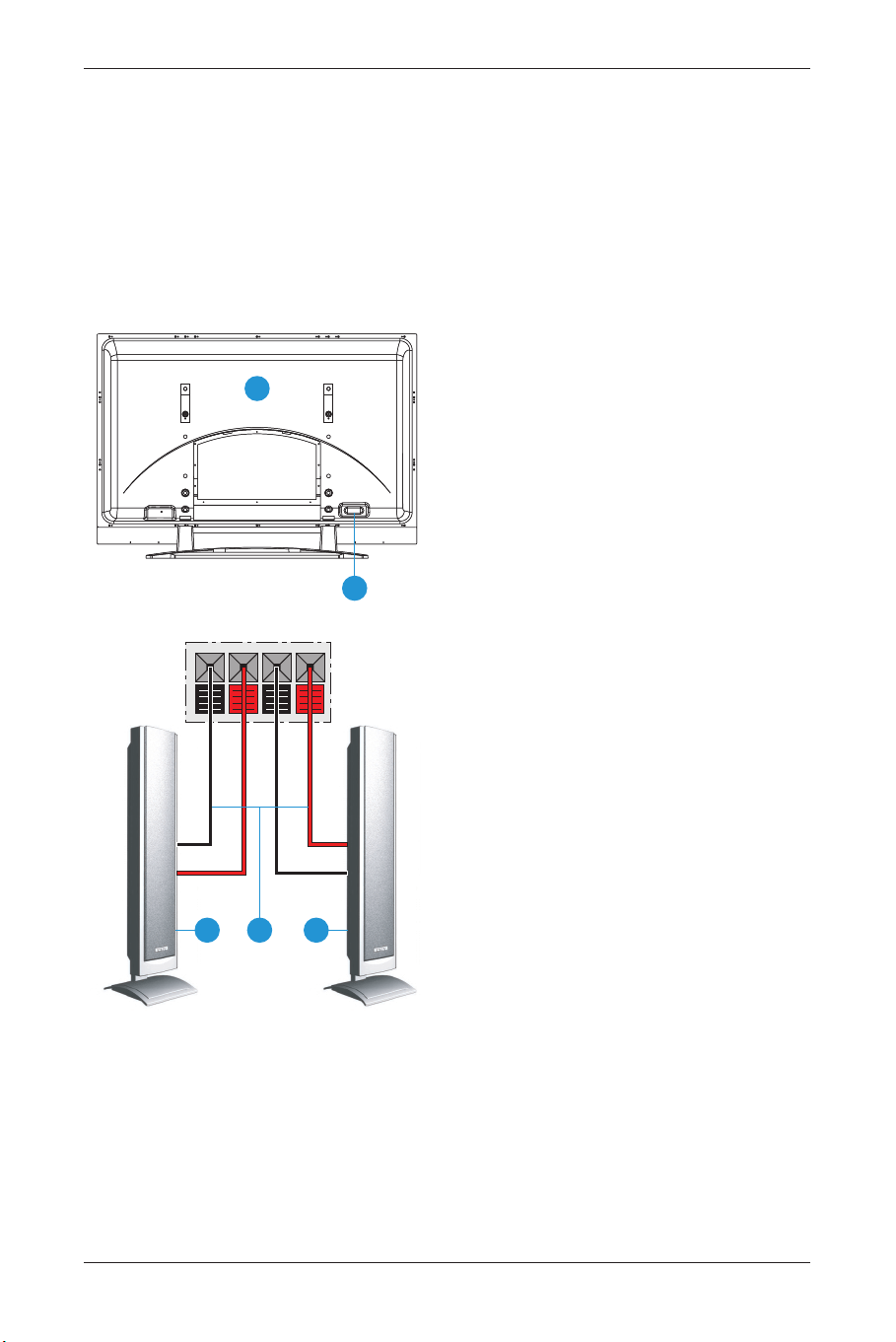
6.3 Connection to External
Speakers:
1 PDP Rear View
2 Speakers (Optional)
3 Speaker Wire
4 Speaker Terminal
• Open the terminals and insert the speaker
wire, making sure that the copper is making
good contact with the metal terminal and
the colors on the wire match those on the
terminal (red to red and black to black).
• Close the terminals to clamp the speaker
wire in place.
Note 1: When connecting the external
speakers, remember to set the
speaker to External mode in the
‘Audio’ page of the ‘OSD Menu’.
(Refer to Chapter ‘Basic
Operation’).
Note 2: Please use the speaker wire
enclosed with the external
speakers, otherwise we cannot
guarantee that our product can fit
the standard of electro magnetic
interference.
20
User Manual BDS4621
1
4
2 3 2
BDS4621_EN.qxd 13-12-2004 10:38 Pagina 20
21
User Manual BDS4621
7. BASIC OPERATION
7.1 Power ON/OFF
Display standby mode
• Press the ‘POWER’ button to turn on the
Display.The power indicator changes from
red to green.
• Press the ‘POWER’ button again to return
the Display to standby mode.The power
indicator changes from green to red.
Note: The power indicator will flash for a
few seconds before changing color.
7.2 Selection of Input Mode
• Press the INPUT button. A menu of input
signal sources shall appear. Use the
▲ ▼
buttons to select the signal source you want
and press the
π button to confirm the
selection.
• You may also press the INPUT button
repeatedly until the signal source you want is
highlighted.The signal sources are displayed
in the following sequence (depending on the
module, the sequence might be different):
A. PC Module
B. PC Module + Video Module
POWER
MENU
INPUTMTS
PC
WIDE PIP FREEZE AUTO
CH
VOL
VIDEO
EXIT
12
+
-
3
456
789
0
100
ZOOM
RETURN
FULL
WHITE
WOW MUTE DISPLAY
MENU
POWER
MENU
INPUTMTS
PC
WIDE PIP FREEZE AUTO
CH
VOL
VIDEO
EXIT
12
+
-
3
456
789
0
100
ZOOM
RETURN
FULL
WHITE
WOW MUTE DISPLAY
MENU
BDS4621_EN.qxd 13-12-2004 10:38 Pagina 21
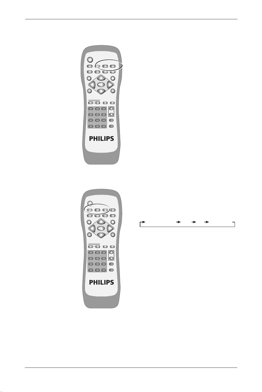
7.3 Selection of VIDEO Input
Mode
Press the ‘Video’ button repeatedly to select a
signal source from the Video module. The signal
sources are displayed in the following sequence:
7.4 Selection of PC Input Mode
Press the ‘PC’ button repeatedly to select a
signal source from the PC or enhanced PC
modules. The signal sources are displayed in the
following sequence:
• PC Module
Input Menu with modes
22
User Manual BDS4621
POWER
MENU
INPUTMTS
PC
WIDE PIP FREEZE AUTO
CH
VOL
VIDEO
EXIT
12
+
-
3
456
789
0
100
ZOOM
RETURN
FULL
WHITE
WOW MUTE DISPLAY
MENU
POWER
MENU
INPUTMTS
PC
WIDE PIP FREEZE AUTO
CH
VOL
VIDEO
EXIT
12
+
-
3
456
789
0
100
ZOOM
RETURN
FULL
WHITE
WOW MUTE DISPLAY
MENU
S-Video
Y Cb/Pb Cr/Pr
S-Video
AV 1
RGB 2 (DVI)
RGB 1 (D-sub)
V
ideo Mode
PC Mode
BDS4621_EN.qxd 13-12-2004 10:38 Pagina 22
7.5 OSD Option Adjustment
• The buttons for OSD option adjustment are:
- MENU
p, MENU π
- Button ▲, Button ▼
- Button p, Button π
- EXIT button
• Press the MENU
p, MENU π to open the
last used ‘OSD Menu’.
• Press again MENU
p or MENU π to select
the desired menu page.
Note: The menu pages are displayed in
the following sequence (circular
display):
• Use the
▼ ▲ buttons to adjust the ‘OSD
Menu’ up and down or to select item from
Quick Menu.
23
User Manual BDS4621
POWER
MENU
INPUTMTS
PC
WIDE PIP FREEZE AUTO
CH
VOL
VIDEO
EXIT
12
+
-
3
456
789
0
100
ZOOM
RETURN
FULL
WHITE
WOW MUTE DISPLAY
MENU
Display
Image or AV System
Audio
Language and Screen Saver
Misc.
Status
MENU
BDS4621_EN.qxd 13-12-2004 10:38 Pagina 23

7.6 Sound Adjustment
• Press and hold the VOL + button to
increase the sound volume level and press
and hold the VOL - button to decrease the
sound volume level.
• Press the MUTE button to mute the
internal or external speakers. Press the
MUTE button again to resume the sound at
the previous volume.
• Other audio adjustments (such as treble,
bass and balance) can be adjusted on the
OSD Menu.
7.7 Zoom Functions
• The Zoom buttons include: WIDE, ZOOM +
and ZOOM -.
• By pressing the
WIDE button, you can zoom
in on the image to fill the screen.You can
then restore the image to its original size by
pressing the
WIDE button again.
Note: When a PC signal is selected, you
can switch between the full screen
size and the original signal size.
Note: When a video signal is selected, you
can switch among six screen sizes,
including Full, Fill Aspect Ratio, 4:3
to 16:9, LB to 16:9, LB Subtitles to
16:9 and Anamorphic.
• By pressing and holding the
ZOOM + button
you can zoom in on the image gradually. By
pressing and holding the
ZOOM - button,
you can zoom out of the image gradually.
Note: You can only zoom out of the
image to its original size by pressing
the
ZOOM - button.The image
cannot be made any smaller with
this function.
Note: When the image is zoomed in by
using the
ZOOM + key, you can use
▼ ▲ p π arrow buttons to adjust
the viewing area.
24
User Manual BDS4621
POWER
MENU
INPUTMTS
PC
WIDE PIP FREEZE AUTO
CH
VOL
VIDEO
EXIT
12
+
-
3
456
789
0
100
ZOOM
RETURN
FULL
WHITE
WOW MUTE DISPLAY
MENU
POWER
MENU
INPUTMTS
PC
WIDE PIP FREEZE AUTO
CH
VOL
VIDEO
EXIT
12
+
-
3
456
789
0
100
ZOOM
RETURN
FULL
WHITE
WOW
MUTE DISPLAY
MENU
BDS4621_EN.qxd 13-12-2004 10:38 Pagina 24
25
User Manual BDS4621
7.8 Other Functions
• If an image cannot be displayed after
changing the timing in PC mode, press the
AUTO button.
• The unit will automatically adjust the phase,
horizontal/vertical position to optimize the
display.
• Also, if the image cannot be shown after
changing the playback system in “Video Input
mode”, press the
AUTO button.The unit will
select the appropriate format for the image
system.
Note: For information about the timing
capabilities of the unit, refer to
Chapter ‘Factory Settings’.
• Press the
FREEZE button to freeze (or
suspend) the current screen.You may press
the Freeze button again to continue the
playing.
Note: You can only freeze the screen by
pressing the
FREEZE button.The
play back system keeps playing
when the screen is frozen.
• You can press the PIP button to show the
picture-in-picture screen.The screen will
change as follows when you press the
PIP
key consecutively:
Note: The “Picture-in-picture screen” can
receive video images while the PC
outputs the display to the Main
Screen, so the prerequisites for the
display of the sub-picture include:
1.A video module.
2.The Main Screen (must be a PC
display).
3.The video image source must also
be connected.
• The location of the sub-picture on the
screen and the video image source can be
set from the OSD menu.
POWER
MENU
INPUTMTS
PC
WIDE PIP FREEZE AUTO
CH
VOL
VIDEO
EXIT
12
+
-
3
456
789
0
100
ZOOM
RETURN
FULL
WHITE
WOW MUTE DISPLAY
MENU
POWER
MENU
INPUTMTS
PC
WIDE PIP FREEZE AUTO
CH
VOL
VIDEO
EXIT
12
+
-
3
456
789
0
100
ZOOM
RETURN
FULL
WHITE
WOW MUTE DISPLAY
MENU
Sub-picture open (small) Medium Large Sub-picture closed
BDS4621_EN.qxd 13-12-2004 10:38 Pagina 25

7.9 OSD Functions
General Description of OSD Function Pages:
PC Table
PIP Setting Table
AV Table
User Colour Temp Table
Note: The adjustable items vary depending on
the input source.
26
User Manual BDS4621
Display
Brightness
Contrast
Red
Green
Blue
Reset
Image
H. Position
V. Position
Phase adj.
Sync adj.
Aspect Ratio
DPMS
Audio
Volume
Treble
Bass
Balance
Mute
Speaker
Language and
Screen saver
Language
Image Reverse
Image Move
Move Time
WOW
Advanced Mode
Gamma
Colour Space
PC User
Misc
OSD Position
OSD Timeout
OSD Rotation
Colour Temp
Reset to default
PIP Settings
Resolution
V Frequency
H Frequency
PIP Input
PIP System
Display
Brightness
Contrast
Saturation
Hue
Sharpness
Reset
Misc
PIP Size
PIP Source
PIP Position
Display
Brightness
Contrast
Saturation
Hue
Sharpness
Reset
AV System
Aspect Ratio
Video Format
Audio
Volume
Treble
Bass
Balance
Mute
Speaker
Language and
Screen saver
Language
Image Reverse
Image Move
Move Time
Advanced Mode
Gamma
Color Space
PC User
Misc
OSD Position
OSD Timeout
OSD Rotation
Color Temp
Reset to default
User Color Temp
Status
Input Source
System
Display
Red
Green
Blue
BDS4621_EN.qxd 13-12-2004 10:38 Pagina 26
8. OSD PAGES AND FUNCTIONS
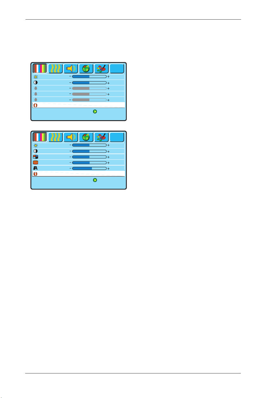
8.1 Display Pages
PC Display page Screen
• Only the Brightness, Contrast and Reset
functions can be adjusted when using a PC
input signal.
Note: To adjust the Brightness of the Red,
Green and Blue, select at first User
in the ‘Color Temp’ function of the
’Misc’. OSD page. Next, return to
the Display page again.
VIDEO Display page Screen
• The Brightness, Contrast, Saturation, Hue,
Sharpness and Reset can all be adjusted
when using Video input signals.
27
User Manual BDS4621
Press [Menu] to Next Page
to Select
Brightness
Contrast
Red
Green
Blue
Reset
50
50
50
50
50
?
Press [Menu] to Next Page
to Select
Brightness
Contrast
Saturation
Hue
Sharpness
Reset
50
50
51
51
58
?
BDS4621_EN.qxd 13-12-2004 10:38 Pagina 27
8.2 Image and AV System Page
PC Image and System page.
• From PC input signal, the Horizontal
position,Vertical position, and Phase sync
can be adjusted.
The Aspect Ratio can be selected to your
liking.
The DPMS can be set On or Off.
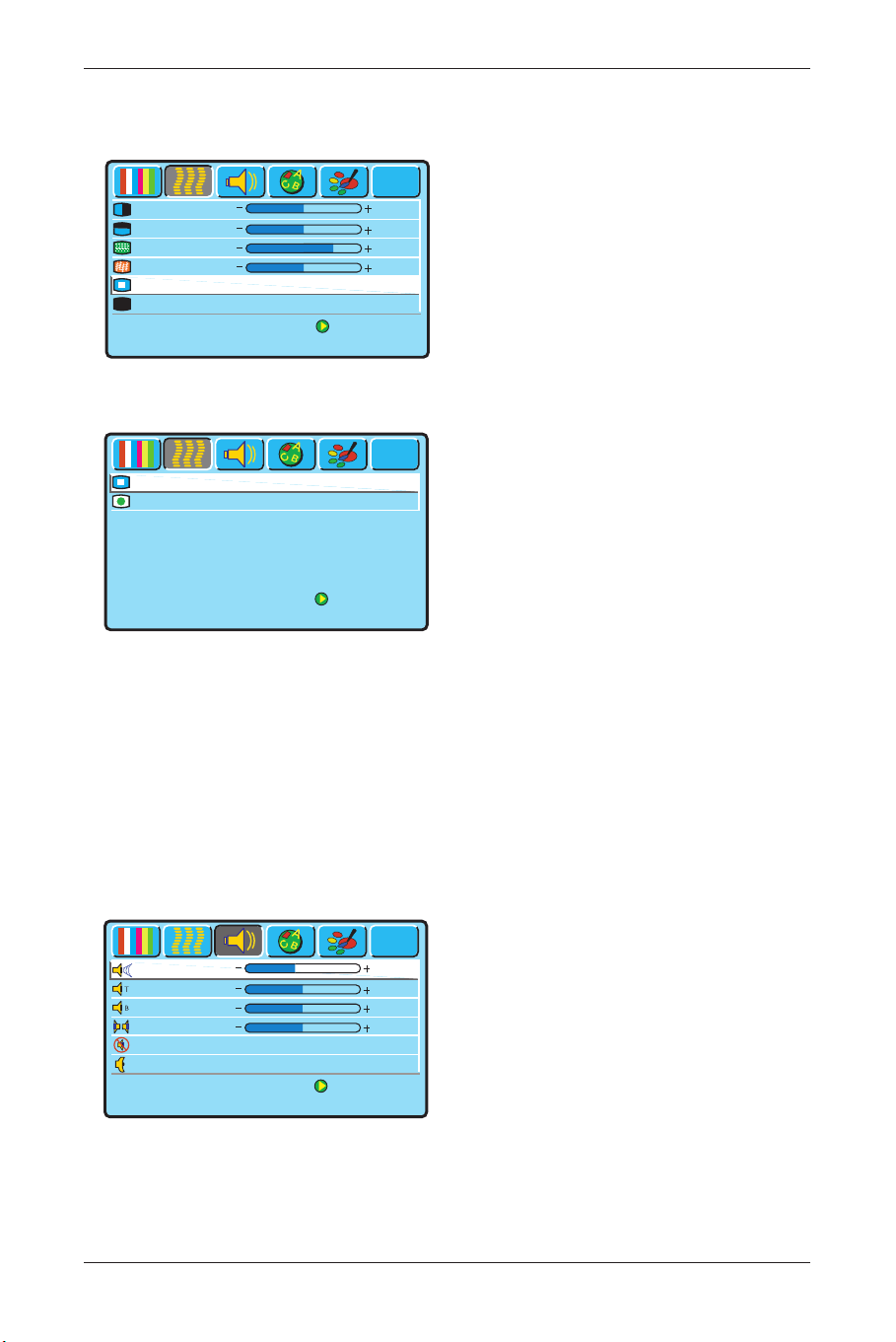
VIDEO Image and System page
• From a video signal you can adjust the
Aspect Ratio and you can select the Video
Format.
• Aspect Ratio
The Display provides six Aspect Ratio
formats.You can select the most suitable
format for the selected signal source.
Press the p π arrow buttons on the
remote control or the display to select:
Full, Fill Aspect Ratio, 4:3 to 16:9, LB to
16:9, LB Subtitles to 16:9 or Anamorphic
aspect ratio.
• Video Format
Select ‘Auto’ If you do not know which
Video Format to select.The display will
select the correct signal automatically.
Other options are: NTSC-M, PAL-N, PAL-
M, PAL-DK/1, SECAM and NTSC-J.
8.3 Audio Page
• The adjustable items on the Audio page
Volume,Treble, Bass, and Balance.
Mute can be switched On or Off.
The Speaker option allows you to switch
between Internal or External.
Note: These Audio options are the same for
both PC and Video modes.
28
User Manual BDS4621
Press [Menu] to Next Page
to Select
H. Position
V. Position
Phase Adj.
Sync Adj
Aspect Ratio
Fill Screen One to One
On Off
DPMS
50
50
24
48
?
z
z
Press [Menu] to Next Page
to Select
Video Format
Auto
?
Aspect Ratio
Anamorphic
Press [Menu] to Next Page
to Select
?
Tre ble
Bass
Balance
Mute
On
Off
Internal
External
Speaker
50
24
0
Volu m e
44
BDS4621_EN.qxd 13-12-2004 10:38 Pagina 28
29
User Manual BDS4621
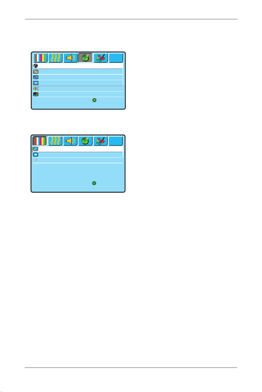
8.4 Language and Screen Saver
Page
PC and Video Language and Screen
Saver Page
• Language
You can select the languages provided by
OSD from this option.
• Image Reverse or Image Move
When a still image is being displayed on
the screen for a long period of time, use
this features to prevent screen burn in and
protect your screen.
• Move Time
The ‘Move Time’ function allows you to
adjust the length of time between the
stages of the ‘Image Move’ feature.
• Advanced Mode
When the Advanced mode is selected,
press the π button, a new page will appear.
In this page the Gamma value can be
selected, as well as the Color Space.
Note: The function PC User will only be
active if the display is switched in
‘PC Mode’.
Press [Menu] to Next Page
to Select
Language English
Image reverse Enable Disable
Image Move Off Mode1 Mode2
Move Time 1 Sec.
?
WOW Enable Disable
Advanced Mode
Press [Menu] to Next Page
to Select
Color space NTSC PDP EBU
PC User Data Movie
?
Gamma 2.2 2.4 2.6 2.8
BDS4621_EN.qxd 13-12-2004 10:38 Pagina 29
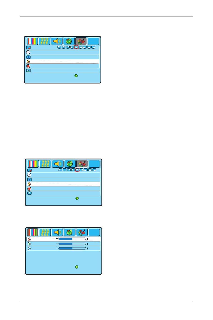
8.5 Misc. Page
PC Misc page
• OSD Position
By means of this option you can select the
location of the OSD menu on the screen.
• OSD Timeout
By means of this option you can adjust
length of time that the OSD shall remain
on screen.
• OSD Rotation
Use this option to rotate the OSD
through 90 degrees.
• Color Temp
This allows you to select the Color
Temperature you like.
Select User if you want to adjust the RGB
colors by yourself in the ‘Display’ OSD
page. (Switch to the ‘Display’ OSD page
for this action).
• Reset to Default
Use this option to return to the factory
settings for the ‘Misc’ OSD page.
• PIP Settings
This option can be accessed when the
display is switched in PC Mode.
(For PIP settings see next page).
VIDEO Misc page
• The OSD Position, OSD Timeout and
OSD rotation options are the same as
described above for the ‘PC Misc’ OSD
page.
• Your preferred screen color temperature
can be selected from the ‘Color Temp.’
option.You can choose from Warm,
Standard, Cool or User.
• By selecting ‘User’, you can adjust the
brightness of Red, Green and Blue
individually to suit your taste. (See next
piture.
RGB adjustment OSD page.
30
User Manual BDS4621
Press [Menu] to Next Page
to Select
OSD Position
OSD Timeout 15 Sec.
OSD Rotation
Standard Rotated
Color Temp.
Warm Standard Cool User
Reset to default 1 Sec.
Pip Settings
?
Press [Menu] to Next Page
to Select
OSD Timeout 15 Sec.
OSD Rotation
Standard Rotated
Reset to default 1 Sec.
?
OSD Position
User Color Temp
Color Temp. Warm Standard Cool User
Press [Menu] to Next Page
to Select
Green
Blue
50
50
?
Red
50
BDS4621_EN.qxd 13-12-2004 10:38 Pagina 30
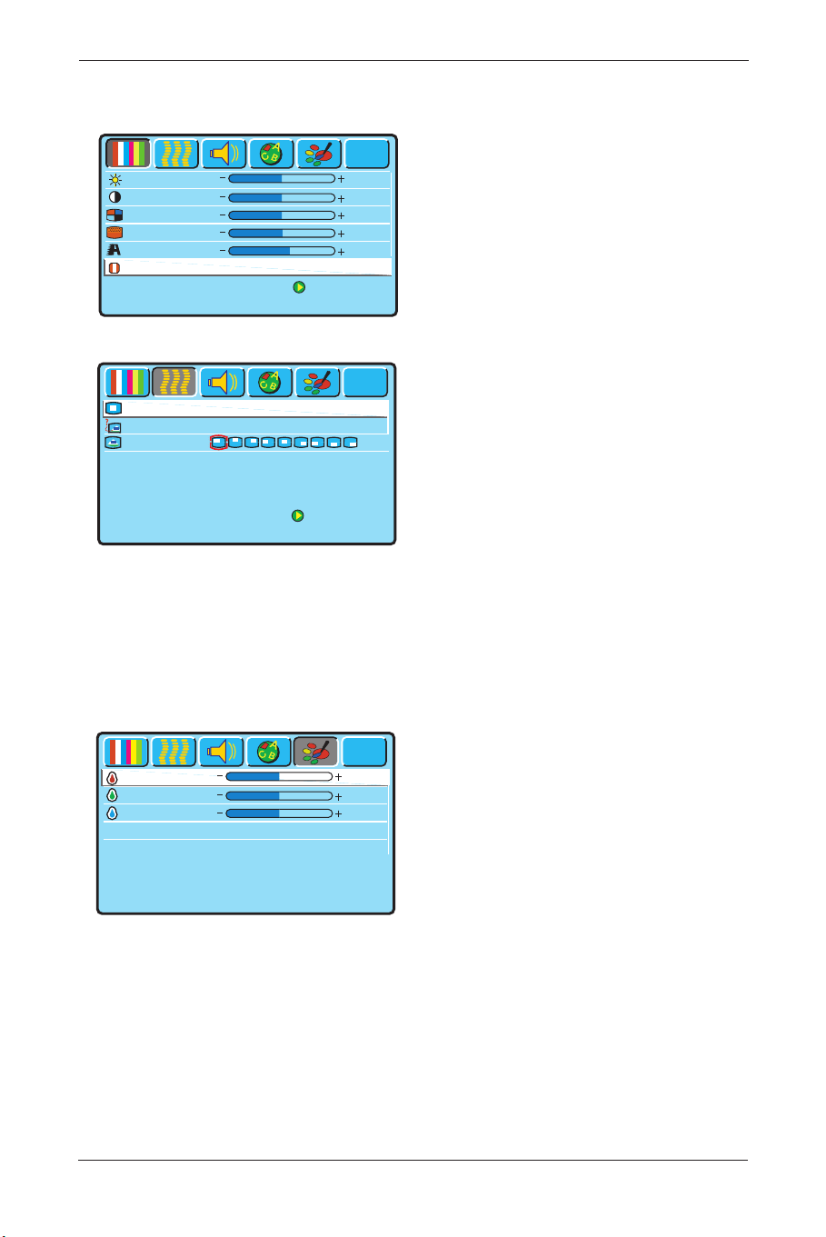
8.6 PIP Settings (PC only)
• If PIP is activated by pressing the π button
when the PIP Settings rule is selected in
the ‘PC Misc’ OSD page, next ‘Video
Display’ OSD appears, so you can adjust
the colors for the small Picture which will
be shown on the screen.
• After color adjustment in this Display
menu, press the MENU
π button on the
Remote control, so the ‘PIP Settings’ OSD
page will appear, see next picture.
• PIP Size
You can choose between three PIP sizes:
Small, Medium and Large.
Also the PIP function can be disabled by
selecting ‘Off’.
• PIP Source
Select the desired PIP input source.
• PIP Position
Select the desired picture position on the
screen.
Note:
The Video, S-Video or Composite
terminals must have an input signal
for this option).
8.7 User Color Temp (AV only)
• To access these options, select the option
‘User’ in the Color Temp function in the
Misc. page.You can adjust the brightness of
the Red, Green and Blue to suit your
personal preference.
31
User Manual BDS4621
Press [Menu] to Next Page
to Select
Brightness
Contrast
Saturation
Hue
Sharpness
Reset
50
50
51
51
58
?
Press [Menu] to Next Page
to Select
PIP Source
AV1 S-Video YCbCr
?
PIP Size
Off Small Medium Large
PIP Position
Press [Menu] to Next Page
Green
Blue
50
50
?
Red
50
BDS4621_EN.qxd 13-12-2004 10:38 Pagina 31
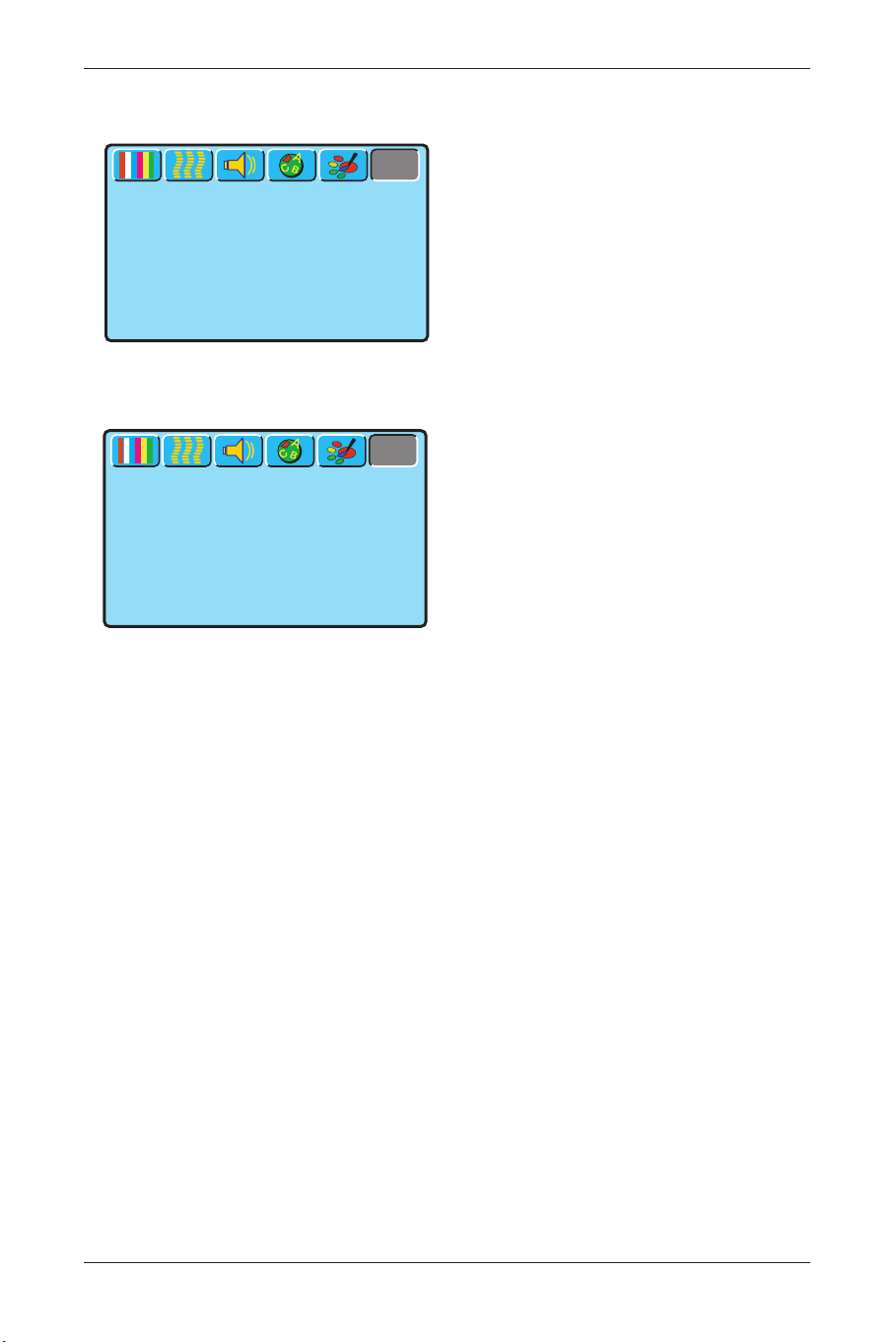
8.8 Status
PC Status Page
• This OSD page displays the Resolution and
Vertical/Horizontal Frequency when a PC
input is operating.
If PIP is in use, the sub-picture source and
system are also displayed.
VIDEO Status page
• The Input source and System are displayed
when using video signals.
32
User Manual BDS4621
Press [Menu] to Next Page
Signal Information
Resolution
1024 x 768
V Frequency 60 Hz
H Frequency 48.33 kHz
?
Press [Menu] to Next Page
Signal Information
Input Source
AV1
System PAL 50 Hz / 4.43 MHz
?
BDS4621_EN.qxd 13-12-2004 10:38 Pagina 32
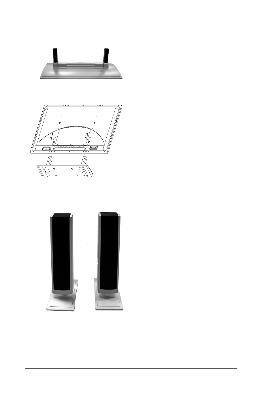
9. OPTIONAL ACCESSORIES
Stand (BM05111)
Attach the Stand to the PDP set.
Speaker Set
33
User Manual BDS4621
BDS4621_EN.qxd 13-12-2004 10:38 Pagina 33
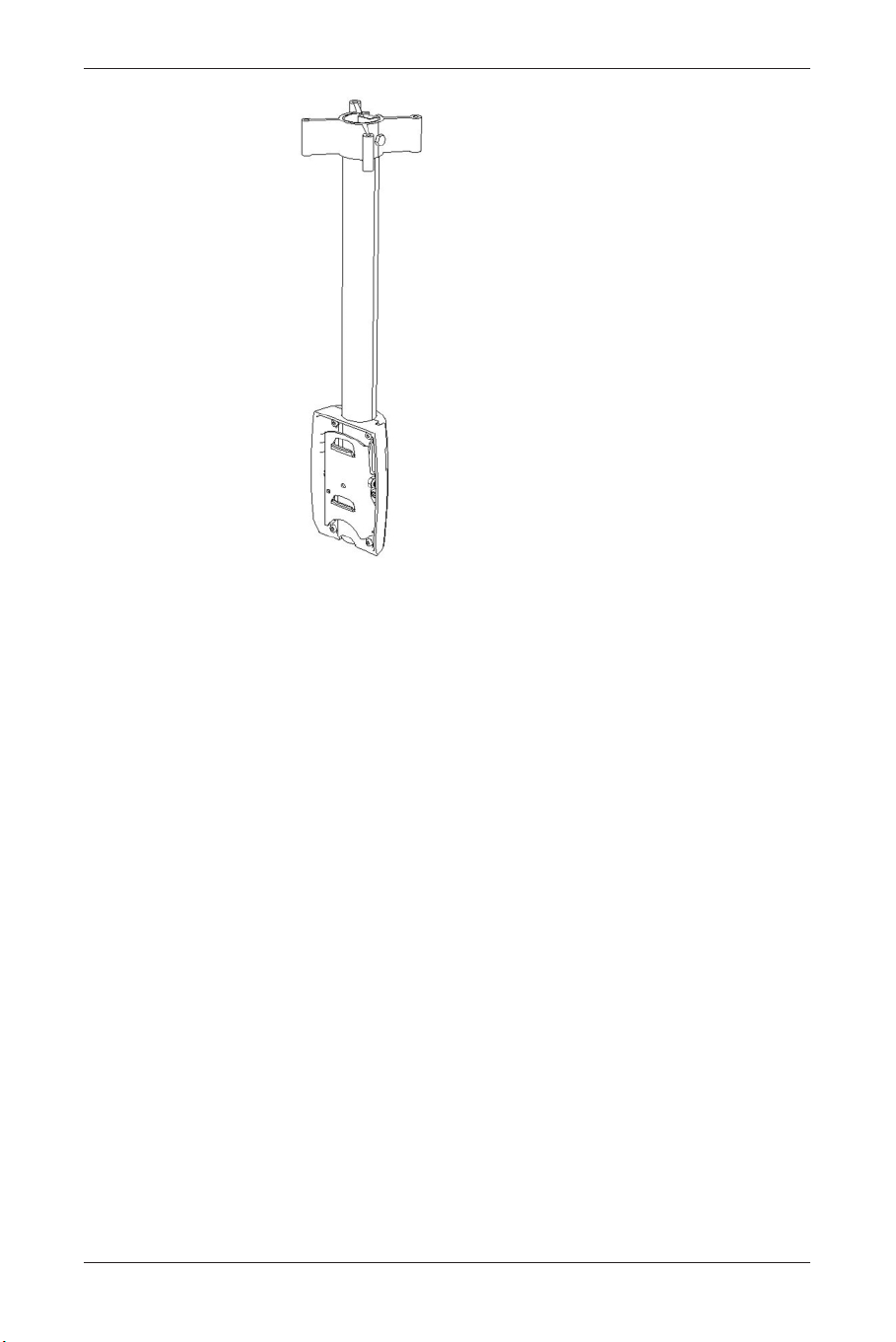
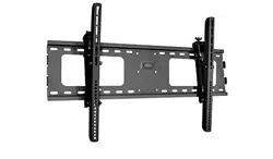
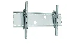
Ceiling Mount Kit (BM01111)
34
User Manual BDS4621
BDS4621_EN.qxd 13-12-2004 10:38 Pagina 34

10. TECHNICAL SPECIFICATIONS
Screen Size: 46” Wide screen
Screen Area: 1007mm(W) x 567.4mm(H)
Aspect Ratio: 16 : 9
External Size: 1138mm(W) x 691mm(H) x 98mm(D)
(w/o Stand and handles)
Weight 37kg (w/o Stand)
Resolution: 852 (H) x 480 (V) pixels
(Each pixel has R/G/B 3-color cels)
Pixel Dot Pitch: 1.182mm(H) x 1.182mm(V)
Color: 16.7 millions colors (R/G/B each 256 scales)
Gray Scale: 256 (R/G/B each 8-bit)
Brightness (Peak Value): 1000 Cd /m
2
(Typical)
Contrast (Dark Room): 1500 : 1 (Typical)
Viewing Angle: Hor.: More than 160 degrees
Vert.: More than 160 degrees
Sound: SRS Surround
Power Supply: AC 100V~120V/220V~240V , 50Hz ~ 60Hz
Power Consumption: 330W (Average)
Input Terminals: PC Module
- SUB-D, 15 Pin (Analog RGB Input)
- DVI Connector (Digital TMDS Input)
- SUB-D, 9 Pin (RS-232 Terminal)
Video Module
- S-Video Input Mini Din 4 Pin Terminal
- CVBS Input RCA Terminal
- Comp. Input Y / Pb(Cb) / Pr(Cr) RCA Terminal
- 2 sets of Left and Right Stereo RCA Terminals
- CVBS Output RCA Terminal
Agent Approval: CE, FCC, UL, C-UL,TUV
Standard Accessories: 1 x Remote Control
2 x AA Batteries
1 x Power Cable
1 x SUB-D Cable
1 x S-Video Cable; 1 x AV Cable
1 x User Manual
35
User Manual BDS4621
BDS4621_EN.qxd 13-12-2004 10:38 Pagina 35

11. FACTORY SETTINGS
The manufacturer has setup 17 signal modes as
shown in the following table:
Factory Signal Settings (for RGB mode)
• When the signal received by the Display
exceeds the allowed range, a warning
message ‘Signal Out of Range’ will appear on
the screen.
• You can confirm the input signal format by
selecting the ‘Status page’ from the OSD
Menu.
36
User Manual BDS4621
No
1
2
3
4
5
6
7
8
9
10
11
12
13
14
15
16
17
Resolution
Horizontal
720 x 400
640 x 400
640 x 480
640 x 480
640 x 480
640 x 480
640 x 480
800 x 600
800 x 600
800 x 600
800 x 600
800 x 600
832 x 624
1024 x 768
1024 x 768
1024 x 768
1024 x 768
Horizontal
Frequency
(KHz)
31.47
37.90
31.50
35.00
37.50
37.86
43.30
35.16
37.90
46.90
48.08
53.70
49.00
48.40
56.50
60.00
68.70
Vertical
Frequency
(Hz)
70.08
85.00
60.00
67.00
75.00
72.81
85.00
56.25
60.32
75.00
72.19
85.00
74.00
60.00
70.00
75.00
85.00
Dot Clock
Frequency
(MHz)
25.17
31.50
25.18
30.24
31.50
31.50
36.00
36.00
40.00
49.50
50.00
56.25
57.27
65.00
75.00
78.75
94.50
Remark
DOS
VESA
DOS
MAC. (SOG)
VESA
VESA
VESA
VESA
VESA
VESA
VESA
VESA
MAC. (H+V)
VESA
VESA
VESA
VESA
BDS4621_EN.qxd 13-12-2004 10:38 Pagina 36

12. CLEANING AND TROUBLESHOOTING
Important
• Make sure that the power cable is unplugged
from the socket before cleaning the product.
• Never use solvent, thinner, benzene or
alcohol to clean the Display. Such chemicals
may damage the cabinet, screen glass and
remote control, and cause the paint to peel.
Cleaning the cabinet and Remote Control
• Use a soft cotton cloth for cleaning.
• If the cabinet or remote control are dirty,
use a soft cloth dampened with water to
clean the Display.Wring water out of the
cloth before cleaning, to prevent water from
penetrating into the cabinet.Wipe the
Display with a dry cloth after cleaning.
Cleaning of Screen
• Use a soft cotton cloth to clean the screen
gently.
• The screen glass is very fragile.When
cleaning, take care not to scratch or damage
the screen surface. Don’t press or tap the
screen to avoid cracking.When the screen is
dirty, use a soft cloth moistened with water
to clean the Display.Wring water out of the
cloth before cleaning, to prevent water from
penetrating into the cabinet.Wipe the
Display with a dry cloth after cleaning.
Simple Troubleshooting
If the Display fails or the performance changes
dramatically, check the Display in accordance
with the following instructions. Remember to
check the peripherals to pinpoint the source of
failure. If the Display still fails to perform as
expected, contact the dealer for assistance.
37
User Manual BDS4621
BDS4621_EN.qxd 13-12-2004 10:38 Pagina 37

Problem: Measures:
No Power
(Power indicator does not light)
• Remove the power cable from the power
outlet for 10 seconds, then re-insert the plug
into the outlet.
‘No Input Signal’ message
appears.
• Check that the signal line is connected
properly.
• Check that the power of the relevant
peripherals is turned on.
• Check that the Input option that has been
selected matches the input signal.
The remote control does not
work.
• Check the batteries for correct placement.
• Replace with new batteries.
• Check to make sure the Remote Control is
within operating range.
• Check to make sure the Remote Control is
pointed to the Remote Control Window on
the Display.
• Check that there are no obstacles between
the Remote Control and the Remote
Control Window.
• For more information about the Remote
Control, refer to Chapter Basic Operation.
Flashing spots or stripes appear
on the screen.
• Check that there is no emitter sources (Car,
HV cable or Neon lamp) or other possible
interference sources.
Image color or quality
deteriorates.
• Check that all the video settings are adjusted
appropriately, such as brightness, contrast,
color etc.
• For more information about video settings,
refer to ‘OSD Functions’ in the chapter ‘Basic
Operation’.
Screen position and size are
incorrect.
• Check that the screen position and size is
adjusted appropriately.
Image or color is incorrect.
• Check that the signal line is connected
properly.
• When connecting to a PC, you can change
the resolution of PC to acquire correct
image.The discrepancy of the PC output
signal may affect the display of the image.
38
User Manual BDS4621
BDS4621_EN.qxd 13-12-2004 10:38 Pagina 38

Problem: Measures:
The external speaker has no sound. • Check that the speaker cables are
connected appropriately.
• Check that the Display is not in ‘Mute’
mode.
• Check that the audio signal lines from the
peripherals are connected properly.
The power indicator flashes. • Check that the input signal line is properly
connected.
• Check that the screen is not in ‘Power
Save’ mode.
The input image and signal is not
received appropriately.‘Signal
‘Out of Range’ message appears.
• Select the correct input signal.
• For more information, refer to chapter
‘Factory Settings’.
39
User Manual BDS4621
BDS4621_EN.qxd 13-12-2004 10:38 Pagina 39

40
User Manual BDS4621
13. LIMITED WARRANTY (EUR)
Two Year Free Labor
Two Year Free Parts
WHO IS COVERED?
You must have proof of the date purchased to
receive warranty service.A sales receipt or other
document showing the date that you purchased
the product is considered proof of purchase.
WHAT IS COVERED?
Warranty coverage begins the day you buy your
product. For two years thereafter, all defective
parts will be repaired or replaced and labor is
free.After two years from the day of purchase,
you pay for the replacement or repair of all parts,
and for all labor charges.All parts, including
repaired and replaced parts, are covered only for
the original warranty period.When the warranty
on the product expires, the warranty on all
replaced and repaired parts also expires.
WHAT IS EXCLUDED?
Your warranty does not cover:
• labor charges for removal, installation or
setup of the product, adjustment of
customer controls on the product, and
installation or repair of antenna systems
outside of the product.
• product repair and/or part replacement
because of misuse, accident, unauthorized
repair or other cause not within the control
of Philips Consumer Electronics Europe.
• reception problems caused by signal conditions
or cable or antenna systems outside the unit.
• a product that requires modification or
adaptation to enable it to operate in any
country other than the country for which it
was designed, manufactured, approved and/or
authorized, or repair of products damaged by
these modifications.
• incidental or consequential damages resulting
from the product. (Some states do not allow
the exclusion of incidental or consequential
damages, so the above exclusion may not
apply to you.This includes, but is not limited
to, prerecorded material, whether
copyrighted or not copyrighted.)
• modifications or adaptations to enable the
product to operate in any country other
than the country for which it was designed,
manufactured, approved and/or authorized,
or the repair of products damaged by these
modifications.
BDS4621_EN.qxd 13-12-2004 10:38 Pagina 40

• normal wear and tear (decreased light output
of PDP module) over the product's lifetime.
• phosphor burn. Do not display static images
for prolonged periods, otherwise phosphor
burn might appear on part of the panel.
• limited quantity of cells (fine pixel elements)
that do not produce light, or that remain lit
after they should have turned off.
WHERE IS SERVICE AVAILABLE?
Warranty service is available in all countries
where the product is officially distributed by
Philips Consumers Electronics Europe.
In countries where Philips Consumers Electronics
Europe does not distribute the product, the local
Philips service organization will attempt to
provide service (although there may be a delay if
the appropriate spare parts and technical
manual(s) are not readily available).
MAKE SURE YOU KEEP ...
Please keep your sales receipt or other
document showing proof of purchase. Attach it
to this owner’s manual and keep both nearby.
Also keep the original box and packing material
in case you need to return your product.
BEFORE REQUESTING SERVICE ...
Please check your owner’s manual before
requesting service.Adjustments of the controls
discussed there may save you a service call.
TO GET WARRANTY SERVICE OR IF
YOU HAVE QUESTIONS …
Please contact Philips at one of the telephone
numbers below:
Austria . . . . . . . . . . . . . . . . . . . 01 5465 75603
Belgium . . . . . . . . . . . . . . . . . . . . 02 275 0701
Cyprus . . . . . . . . . . . . . . . . . . . . . . 800 92256
Denmark . . . . . . . . . . . . . . . . . . . 35 25 87 61
Finland . . . . . . . . . . . . . . . . . . . . 09 2290 1908
France . . . . . . . . . . . . . . . . . . . . 03 8717 0033
Germany . . . . . . . . . . . . . . . . . 0696 698 4712
Greece . . . . . . . . . . . . . . . . . 00800 3122 1223
Ireland . . . . . . . . . . . . . . . . . . . . . 01 601 1161
Italy . . . . . . . . . . . . . . . . . . . . . . 02 4827 1153
Luxembourg. . . . . . . . . . . . . . . . . . 26 84 3000
Netherlands . . . . . . . . . . . . . . . . 053 482 9800
Norway . . . . . . . . . . . . . . . . . . . . 22 70 82 50
Poland . . . . . . . . . . . . . . . . . . 00800 311 1338
Portugal . . . . . . . . . . . . . . . . . . . . 800 831 363
Spain . . . . . . . . . . . . . . . . . . . . . . 917 456 246
Sweden . . . . . . . . . . . . . . . . . . . . 08 632 0016
Switzerland . . . . . . . . . . . . . . . . 02 2310 2116
United Kingdom. . . . . . . . . . . . 0207 949 0069
41
User Manual BDS4621
BDS4621_EN.qxd 13-12-2004 10:38 Pagina 41

Repair must be performed by an authorized
service center or a factory service center.
If you do not live near a factory service center,
contact your dealer. If your dealer is an
authorized service center, he will arrange repair.
REMEMBER ...
Please record the model and serial numbers found
on the product below. .Also, please fill out and
mail your warranty registration card promptly.
It will be easier for us to notify you if necessary.
MODEL # _ _ _ _ _ _ _ _ _ _ _ _ _ _ _ _ _ _ _
SERIAL # _ _ _ _ _ _ _ _ _ _ _ _ _ _ _wo_ _ _
42
User Manual BDS4621
BDS4621_EN.qxd 13-12-2004 10:38 Pagina 42

14. LIMITED WARRANTY (USA)
One Year Free Labor
One Year Free Parts
WHO IS COVERED?
You must have proof of the date purchased to
receive warranty service.A sales receipt or other
document showing the date that you purchased
the product is considered proof of purchase.
WHAT IS COVERED?
Warranty coverage begins the day you buy your
product. For one year thereafter, all defective
parts will be repaired or replaced and labor is
free.After one year from the day of purchase,
you pay for the replacement or repair of all parts,
and for all labor charges.All parts, including
repaired and replaced parts, are covered only for
the original warranty period.When the warranty
on the product expires, the warranty on all
replaced and repaired parts also expires.
WHAT IS EXCLUDED?
Your warranty does not cover:
• labor charges for removal, installation or
setup of the product, adjustment of
customer controls on the product, and
installation or repair of antenna systems
outside of the product.
• product repair and/or part replacement
because of misuse, accident, unauthorized
repair or other cause not within the control of
Philips Consumer Electronics North America.
• reception problems caused by signal conditions
or cable or antenna systems outside the unit.
• a product that requires modification or
adaptation to enable it to operate in any
country other than the country for which it
was designed, manufactured, approved and/or
authorized, or repair of products damaged by
these modifications.
• incidental or consequential damages resulting
from the product. (Some states do not allow
the exclusion of incidental or consequential
damages, so the above exclusion may not
apply to you.This includes, but is not limited
to, prerecorded material, whether
copyrighted or not copyrighted.)
• modifications or adaptations to enable the
product to operate in any country other than
the country for which it was designed,
manufactured, approved and/or authorized, or
the repair of products damaged by these
modifications.
43
User Manual BDS4621
BDS4621_EN.qxd 13-12-2004 10:38 Pagina 43

• normal wear and tear (decreased light output
of PDP module) over the product's lifetime.
• phosphor burn. Do not display static images
for prolonged periods, otherwise phosphor
burn might appear on part of the panel.
• limited quantity of cells (fine pixel elements)
that do not produce light, or that remain lit
after they should have turned off.
WHERE IS SERVICE AVAILABLE?
Warranty service is available in all countries
where the product is officially distributed by
Philips Consumers Electronics North America.
In countries where Philips Consumers Electronics
North America doos not distribute the product,
the local Philips service organization will attempt
to provide service (although there may be a delay
if the appropriate spare parts and technical
manual(s) are not readily available).
MAKE SURE YOU KEEP ...
Please keep your sales receipt or other
document showing proof of purchase. Attach it to
this owner’s manual and keep both nearby.Also
keep the original box and packing material in case
you need to return your product.
BEFORE REQUESTING SERVICE ...
Please check your owner’s manual before
requesting service.Adjustments of the controls
discussed there may save you a service call.
TO GET WARRANTY SERVICE U.S.A.,
PUERTO RICO OR US VIRGIN ISLANDS ...
Please contact Philips at:
1-877-835-1838
or an authorized service center to arrange repair.
(In U.S.A., Puerto Rico and U.S.Virgin Islands, all
implied warranties, including implied warranties of
merchantability and fitness for a particular purpose,
are limited in duration to the duration of this
express warranty. But, because some states do not
allow limitations on how long an implied warranty
may last, this limitation may not apply to you.)
TO GET WARRANTY SERVICE IN
CANADA ...
Please contact Philips at:
800-661-6162 (French Speaking) (within Canada
only)
800-531-0039 (English Speaking)
44
User Manual BDS4621
BDS4621_EN.qxd 13-12-2004 10:38 Pagina 44

(In Canada, this warranty is given in lieu of all
other warranties. No other warranties are
expressed or implied, including any implied
warranties of merchantability or fitness for a
particular purpose. Philips is not liable under any
circumstances for any direct, indirect, special,
incidental or consequential damages, howsoever
incurred, even if notified of the possibility of
such damages.)
REMEMBER ...
Please record the model and serial numbers found
on the product below. .Also, please fill out and
mail your warranty registration card promptly.
It will be easier for us to notify you if necessary.
MODEL # _ _ _ _ _ _ _ _ _ _ _ _ _ _ _ _ _ _ _
SERIAL # _ _ _ _ _ _ _ _ _ _ _ _ _ _ _wo_ _ _
45
User Manual BDS4621
BDS4621_EN.qxd 13-12-2004 10:38 Pagina 45

46
User Manual BDS4621
BDS4621_EN.qxd 13-12-2004 10:38 Pagina 46

APPENDIX
47
User Manual BDS4621
BDS4621_EN.qxd 13-12-2004 10:38 Pagina 47
1. SERIAL COMMUNICATION PROTOCOL (RS-232)
This serial communication protocol can be used
to control the BDS4621 plasma display remotely
through the serial RS232C port.This information
is provided as is.
Philips cannot accept any liability for damages
or malfunctioning of the display caused by
operation through the serial port.
The external communication protocol include
two parts:
• setup connecting,
• send command.
Default Serial Port:
Baud Rate: 19200
Parity: none
Data bits: 8
Stop bits: 1
Flow Control: none
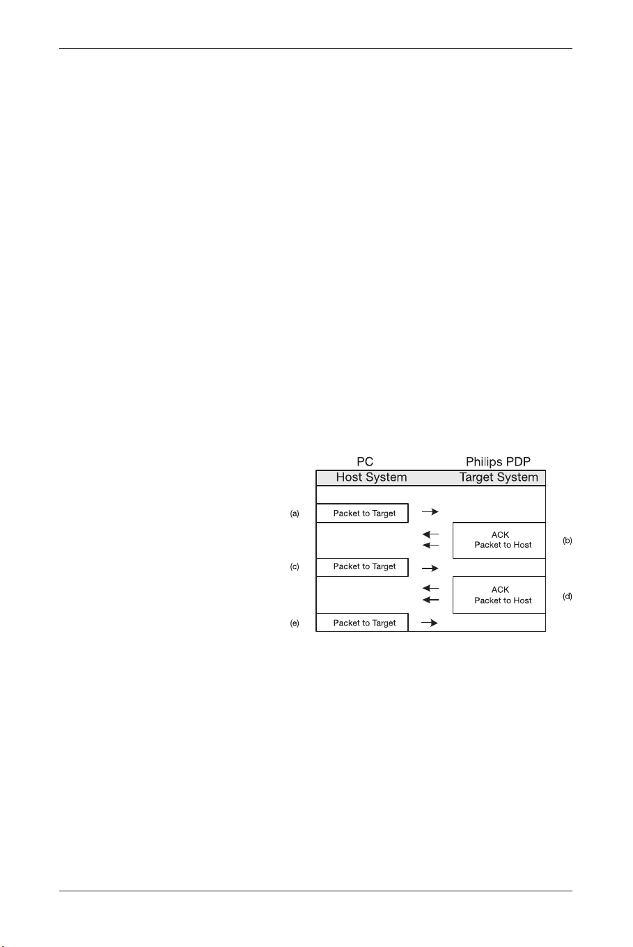
1.1. Setup Connecting
A typical Packet transaction session is shown in
Figure 1
Figure 1
48
User Manual BDS4621
BDS4621_EN.qxd 13-12-2004 10:38 Pagina 48

a). 1st Packet to Target (Philips PDP) structure
like as below (Table 1)
Byte0 0xBE Magic
Byte1 0xEF Number
Byte2 0x01 Packet Type
Packet Header Byte3 0x05 Packet size (Low)
Byte4 0x00 Packet size (High)
Byte5 0xD1 CRC (Low)
Byte6 0xFA CRC (High)
Byte7 0x01 System Info Type
Byte8 0x02 Version
Packet Payload Byte9 0x00 Number
Byte10 0x00 Object ID
Byte11 0x00 Level
Tabl e 1
b). The Ack of Packet to Host (PC) (Table 2)
Ack Byte0 0x1E PAK
Byte1 0xBE Magic
Byte2 0xEF Number
Byte3 0x01 Packet Type
Packet Header Byte4 0x05 Packet size (Low)
Byte5 0x00 Packet size (High)
Byte6 0xD1 CRC (Low)
Byte7 0xFA CRC (High)
Byte8 0x01 System Info Type
Byte9 0x02 Version
Packet Payload Byte10 0x00 Number
Byte11 0x00 Object ID
Byte12 0x00 Leve
Tabl e 2
PAK means that PC will follow the received
Packet data
c). Packet same as 1st Packet (Table 1)
d). Same as Ack (Table 2)
e). Packet to Target (Philips PDP) structure (Table 3)
Byte0 0xBE Magic
Byte1 0xEF Number
Byte2 0x01 Packet Type
Packet Header Byte3 0x05 Packet size (Low)
Byte4 0x00 Packet size (High)
Byte5 0xA9 CRC (Low)
Byte6 0xC6 CRC (High)
Byte7 0x00 System Info Type
Byte8 0x00 Version
Packet Payload Byte 9 0x00 Number
Byte10 0x00 Object ID
Byte11 0x00 Level
Tabl e 3
49
User Manual BDS4621
BDS4621_EN.qxd 13-12-2004 10:38 Pagina 49

1.2. Send Command
1.1.2. Introduction
Command packets consist of "Header" and
"Payload".The Packet Header is consistent for all
packets.The Packet Payload type and content
varies based on the type of packet sent.The
entire packet size is variable, being the sum of
the fixed-size Packet Header and variable-sized
Packet Payload.
Packet Header (fixed size) Packet Payload (variable size)
Tabl e 4
Packet Header Format
Introduction
All Packets use the same Packet Header format
illustrated in Table 5.
Byte 0 1 2 3 4 5 6
Magic Number Type Packet Payload Size CRC
0xBE 0xEF type size_lo size_hi crc_lo crc_hi
Tabl e 5
The Packet Header size is fixed at seven bytes
(Intel byte ordering is used).The following code
fragments are taken from these source files
The Packet Header definition is shown below:
typedef struct
{
BYTE ePacketType;//type of the
payload
WORD nPacketSize;//size of the
payload
WORD nCRCPacket;//CRC for the
entire packet
} PACKET_HEADER;
Magic Number
The Magic Number is a fixed value that is used
to insure packet alignment if there are partial
packets received or bytes lost.
The Magic Number is a WORD in length (2
bytes).The Magic Number value is 0xEFBE.
Because Intel byte ordering is used, the ls-byte
of the word is sent first (byte0 = 0xBE), then the
ms-byte (byte1 = 0xEF).
50
User Manual BDS4621
BDS4621_EN.qxd 13-12-2004 10:38 Pagina 50

Packet Type
The Packet Type (ePacketType) is a BYTE in length
number that defines the type of data in the packet.
The following entries are valid packet typess:
Packet Type Name Packet Type Number Description
pt_INVALID 0 Invalid Packet Type
RESERVED 1 RESERVED
pt_EVENT 2 Host can send any event defined in
Philips PDP software.
pt_OPERATION 3 Host can send any operation defined in
Philips PDP software.
Table 6: Packet Types
Packet Payload Size
The Packet Payload Size (nPacketSize) is a BYTE
that defines the size of the Payload portion of
the packet. If the packet contains only header
information, this is zero.Therefore, the total byte
count of any packet = nPacketSize plus 7 (since
the Packet Header is seven bytes long).
Packet Checksum (CRC)
Each packet is CRC’ed using the tables later in
this document.This number is the CRC value for
the complete packet including the Packet Header
and Packet Payload.The CRC is calculated with
the nCRCPacket value initialized to zero.
1.1.3. Packet Payload Definition
Event Packet Type
The Event packet is used by the host system to
send virtual events (such as Zoom, Source,Auto
Adjust, etc.) to the target system. Packet payload
size is 6 bytes.
Byte Field Name Field Value Description
0-1 Virtual Event Virtual Event ID as defined through Configurator
2-5 Parameter Parameter that can be associated with the event.
Table 7: Event Packet Type Format
The source code definition of the Message
packet data structure is:
typedef struct
{
WORD eEvent;
DWORD dwParam;
} EVENT_MESSAGE;
This lets you send any event defined in
Configurator to the system including all remote,
IR, or special events.
51
User Manual BDS4621
BDS4621_EN.qxd 13-12-2004 10:38 Pagina 51

Operation Packet Type
The Operation packet is used by the host system
to execute operations (such as Brightness,
Contrast, Image Position, etc) in the target system.
The Operation packet payload size is 25 bytes.
Byte Field Name Field Value Description
0 Operation Type 1 OPERATION_SET
2 OPERATION_GET
3 OPERATION_INCREMENT
4 OPERATION_DECREMENT
5 OPERATION_EXECUTE
1-2 Operation Operation ID as defined in Configurator
3-4 Is Avail Operation is available
5-8 Operation Target Used for Operation with Targets.
These Targets are defined in configurator.
For instance, op_BRIGHTNESS has a
Target of either MAIN or PIP window.
9-12 Operation Value Value of the Set on a set or the Value of the
Get on a Return.
13-16 Operation Value The Minimum Value of the set
of minimum for operation command.
17-20 Operation Value The Maximum Value of the set
of maximum for operation command.
21-24 Operation Value The Increment Value of the set
of Increment for operation command.
Table 8: Operation Packet Payload Format
The source code definition of the Operation
packet data structure is:
typedef struct
{
eOPERATION_TYPE eOpType;
WORD eOperation;
WORD bisAvail;
DWORD dwTarget;
DWORD dwValue;
DWORD lmMin;
DWORD lmMax;
DWORD lmInc;
} OPERATION_MESSAGE;
This lets the user directly perform logical
operations such as "Set Contrast = 80".
52
User Manual BDS4621
BDS4621_EN.qxd 13-12-2004 10:38 Pagina 52
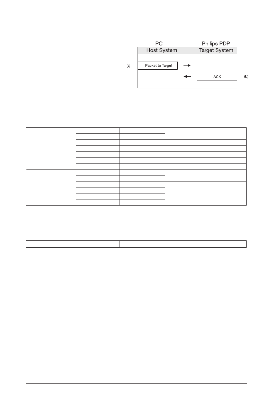
1.1.4. Send Command
a. The structure of Command (EX. input
select) send to Target (Philips PDP) like as
below (Table 9)
Byte0 0xBE Magic
Byte1 0xEF Number
Byte2 0x02 Packet Type
Packet Header
Byte3 0x06 Packet size (Low)
Byte4 0x00 Packet size (High)
Byte5 0x80 CRC (Low)
Byte6 0xC7 CRC (High)
Byte7 0xC9 Virtual
Byte8 0x00 Event ID
Packet Payload
Byte9 0x00
Byte10 0x00
Parameter
Byte11 0x00
Byte12 0x00
Tabl e 9
b. Target return to Host (PC) Ack like as below
Table 10
Ack Byte0 0x06 ACK
Table 10
53
User Manual BDS4621
BDS4621_EN.qxd 13-12-2004 10:38 Pagina 53
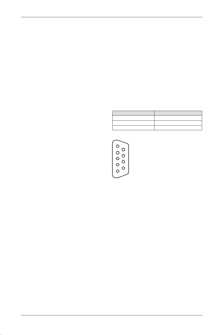
1.3. Serial Communication Cable and
Parameters
For external serial communication from a
computer to Philips plasma, Philips recommends
manfactures use RS-232 communations over a
straight through serial cable a 9 pin female D-sub9
connector.
The standard D-sub9 connector on the computer
is a male connector, and Philips Plasma, too.The
wiring between the computer and Philips plasma is
a straight through cable.A 9 pin female to 9 pin
female stright through cable is a very standard
part and readily available in many lengths.
Female D-sub9 pinout numbering and definitions
on both terminal :
Pin number Name
2 Transmit
3 Receive
5 Ground
PW Serial uses the following default serial port
settings:
• Baud Rate: 19200
• Parity: none
• Data bits: 8
• Stop bits: 1
• Flow Control: none
54
User Manual BDS4621
1
2
3
4
5
6
7
8
9
BDS4621_EN.qxd 13-12-2004 10:38 Pagina 54
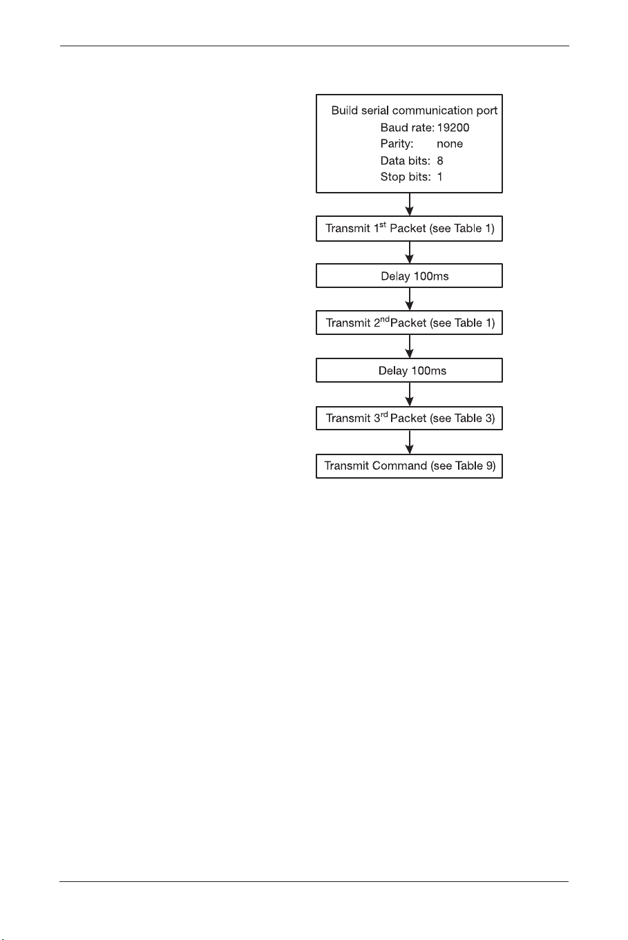
1.4. Software Flow Chart
55
User Manual BDS4621
BDS4621_EN.qxd 13-12-2004 10:38 Pagina 55

1.5. Command List
a. Event Packet Type command:
command Packet Header (7 bytes) Packet Payload (6 bytes)
Power BE EF 02 06 00 1F C0 E6 00 00 00 00 00
Input select BE EF 02 06 00 80 C7 C9 00 00 00 00 00
Menu < BE EF 02 06 00 58 C4 D1 00 00 00 00 00
Menu > BE EF 02 06 00 89 C5 D0 00 00 00 00 00
BE EF 02 06 00 E6 C7 CF 00 00 00 00 00
BE EF 02 06 00 37 C6 CE 00 00 00 00 00
BE EF 02 06 00 D5 C7 CC 00 00 00 00 00
BE EF 02 06 00 04 C6 CD 00 00 00 00 00
Exit BE EF 02 06 00 BA C5 D3 00 00 00 00 00
b. Operation Packet Type command:
command Packet Header (7 bytes) Packet Payload (25 bytes)
PC Mode
Brightness 0 (0) BE EF 03 19 00 78 50 01 35 02 00 00 00 00 00 00 00 00 00 00 00
00 00 00 00 00 00 00 00 00 00 00
50 (64) BE EF 03 19 00 88 61 01 35 02 00 00 00 00 00 00 40 00 00 00 00
00 00 00 00 00 00 00 00 00 00 00
100 (127) BE EF 03 19 00 68 30 01 35 02 00 00 00 00 00 00 7F 00 00 00 00
00 00 00 00 00 00 00 00 00 00 00
Contrast 0 (0) BE EF 03 19 00 87 B4 01 36 02 00 00 00 00 00 00 00 00 00 00 00
00 00 00 00 00 00 00 00 00 00 00
50 (128) BE EF 03 19 00 27 D5 01 36 02 00 00 00 00 00 00 80 00 00 00 00
00 00 00 00 00 00 00 00 00 00 00
100 (255) BE EF 03 19 00 37 B5 01 36 02 00 00 00 00 00 00 FF 00 00 00 00
00 00 00 00 00 00 00 00 00 00 00
Red (0) BE EF 03 19 00 AA C2 01 DF 02 00 00 00 00 00 00 00 00 00 00 00
00 00 00 00 00 00 00 00 00 00 00
Red (255) BE EF 03 19 00 1A C3 01 DF 02 00 00 00 00 00 00 FF 00 00 00 00
00 00 00 00 00 00 00 00 00 00 00
Green (0) BE EF 03 19 00 01 BA 01 E1 02 00 00 00 00 00 00 00 00 00 00 00
00 00 00 00 00 00 00 00 00 00 00
Green (255) BE EF 03 19 00 B1 BB 01 E1 02 00 00 00 00 00 00 FF 00 00 00 00
00 00 00 00 00 00 00 00 00 00 00
Blue (0) BE EF 03 19 00 FE 5E 01 E2 02 00 00 00 00 00 00 00 00 00 00 00
00 00 00 00 00 00 00 00 00 00 00
Blue (255) BE EF 03 19 00 4E 5F 01 E2 02 00 00 00 00 00 00 FF 00 00 00 00
00 00 00 00 00 00 00 00 00 00 00
Reset BE EF 03 19 00 7F 29 05 CB 02 00 00 00 00 00 00 FF 00 00 00 00
00 00 00 00 00 00 00 00 00 00 00
H. Position (Inc) BE EF 03 19 00 8A 2A 03 40 02 00 00 00 00 00 00 23 01 00 00 00
00 00 00 00 00 00 00 00 00 00 00
H.Position (Dec) BE EF 03 19 00 E4 80 04 40 02 00 00 00 00 00 00 23 01 00 00 00
00 00 00 00 00 00 00 00 00 00 00
V. Position (Inc) BE EF 03 19 00 1F 77 03 41 02 00 00 00 00 00 00 23 01 00 00 00
00 00 00 00 00 00 00 00 00 00 00
V. Position (Dec) BE EF 03 19 00 71 DD 04 41 02 00 00 00 00 00 00 23 01 00 00 00
00 00 00 00 00 00 00 00 00 00 00
Phase 0 BE EF 03 19 00 7B A0 01 42 02 00 00 00 00 00 00 00 00 00 00 00
00 00 00 00 00 00 00 00 00 00 00
56
User Manual BDS4621
BDS4621_EN.qxd 13-12-2004 10:38 Pagina 56

command Packet Header (7 bytes) Packet Payload (25 bytes)
Phase 31 BE EF 03 19 00 43 E8 01 42 02 00 00 00 00 00 00 1F 00 00 00 00
00 00 00 00 00 00 00 00 00 00 00
Sync Adj. (Inc) BE EF 03 19 00 1C 79 03 46 02 00 00 00 00 00 00 00 00 00 00 00
00 00 00 00 00 00 00 00 00 00 00
Sync Adj. (Dec) BE EF 03 19 00 72 D3 04 46 02 00 00 00 00 00 00 00 00 00 00 00
00 00 00 00 00 00 00 00 00 00 00
Aspect Ratio BE EF 03 19 00 40 89 01 6D 02 00 00 00 00 00 00 01 00 00 00 00
(Fill Screen) 00 00 00 00 00 00 00 00 00 00 00
Aspect Ratio BE EF 03 19 00 D0 48 01 6D 02 00 00 00 00 00 00 00 00 00 00 00
00 00 00 00 00 00 00 00 00 00 00
DPMS ON BE EF 03 19 00 3C 53 01 01 02 00 00 00 00 00 00 01 00 00 00 00
00 00 00 00 00 00 00 00 00 00 00
DPNS OFF BE EF 03 19 00 AC 92 01 02 02 00 00 00 00 00 00 00 00 00 00 00
00 00 00 00 00 00 00 00 00 00 00
Gamma (2.2) BE EF 03 19 00 04 26 01 E0 02 00 00 00 00 00 00 01 00 00 00 00
00 00 00 00 00 00 00 00 00 00 00
Gamma (2.4) BE EF 03 19 00 F5 66 01 E0 02 00 00 00 00 00 00 02 00 00 00 00
00 00 00 00 00 00 00 00 00 00 00
Gamma (2.6) BE EF 03 19 00 65 A7 01 E0 02 00 00 00 00 00 00 03 00 00 00 00
00 00 00 00 00 00 00 00 00 00 00
Gamma (2.8) BE EF 03 19 00 57 E5 01 E0 02 00 00 00 00 00 00 04 00 00 00 00
00 00 00 00 00 00 00 00 00 00 00
ColorSpace (NTSC) BE EF 03 19 00 AC 3E 01 B8 02 00 00 00 00 00 00 01 00 00 00 00
00 00 00 00 00 00 00 00 00 00 00
ColorSpace (PDP) BE EF 03 19 00 3C FF 01 B8 02 00 00 00 00 00 00 00 00 00 00 00
00 00 00 00 00 00 00 00 00 00 00
ColorSpace (EBU) BE EF 03 19 00 5D 7E 01 B8 02 00 00 00 00 00 00 02 00 00 00 00
00 00 00 00 00 00 00 00 00 00 00
Language BE EF 03 19 00 D3 28 01 0B 02 00 00 00 00 00 00 00 00 00 00 00
(English) 00 00 00 00 00 00 00 00 00 00 00
Language BE EF 03 19 00 43 E9 01 0B 02 00 00 00 00 00 00 01 00 00 00 00
(French) 00 00 00 00 00 00 00 00 00 00 00
Language BE EF 03 19 00 B2 A9 01 0B 02 00 00 00 00 00 00 02 00 00 00 00
(German) 00 00 00 00 00 00 00 00 00 00 00
Language BE EF 03 19 00 22 68 01 0B 02 00 00 00 00 00 00 03 00 00 00 00
(Italian) 00 00 00 00 00 00 00 00 00 00 00
Language BE EF 03 19 00 10 2A 01 0B 02 00 00 00 00 00 00 04 00 00 00 00
(Spanish) 00 00 00 00 00 00 00 00 00 00 00
Language BE EF 03 19 00 80 EB 01 0B 02 00 00 00 00 00 00 05 00 00 00 00
(S. Chinese) 00 00 00 00 00 00 00 00 00 00 00
Language BE EF 03 19 00 71 AB 01 0B 02 00 00 00 00 00 00 06 00 00 00 00
(T. Chinese) 00 00 00 00 00 00 00 00 00 00 00
Image Reverse BE EF 03 19 00 7B 0C 01 F8 02 00 00 00 00 00 00 01 00 00 00 00
(Enable) 00 00 00 00 00 00 00 00 00 00 00
Image Reverse BE EF 03 19 00 EB CD 01 F8 02 00 00 00 00 00 00 00 00 00 00 00
(Disable) 00 00 00 00 00 00 00 00 00 00 00
Image move BE EF 03 19 00 7E 90 01 F9 02 00 00 00 00 00 00 00 00 00 00 00
(Off) 00 00 00 00 00 00 00 00 00 00 00
Image move BE EF 03 19 00 EE 51 01 F9 02 00 00 00 00 00 00 01 00 00 00 00
(mode1) 00 00 00 00 00 00 00 00 00 00 00
Image move BE EF 03 19 00 1F 11 01 F9 02 00 00 00 00 00 00 02 00 00 00 00
(mode2) 00 00 00 00 00 00 00 00 00 00 00
57
User Manual BDS4621
BDS4621_EN.qxd 13-12-2004 10:38 Pagina 57

command Packet Header (7 bytes) Packet Payload (25 bytes)
Move Time (0) BE EF 03 19 00 81 74 01 FA 02 00 00 00 00 00 00 00 00 00 00 00
00 00 00 00 00 00 00 00 00 00 00
Move Time (100) BE EF 03 19 00 6A 5E 01 FA 02 00 00 00 00 00 00 64 00 00 00 00
00 00 00 00 00 00 00 00 00 00 00
OSD Position
Upper Left BE EF 03 19 00 C7 0B 01 22 02 00 00 00 00 00 00 00 00 00 00 00
00 00 00 00 00 00 00 00 00 00 00
Upper Center BE EF 03 19 00 57 CA 01 22 02 00 00 00 00 00 00 01 00 00 00 00
00 00 00 00 00 00 00 00 00 00 00
Upper Right BE EF 03 19 00 A6 8A 01 22 02 00 00 00 00 00 00 02 00 00 00 00
00 00 00 00 00 00 00 00 00 00 00
Mid Left BE EF 03 19 00 36 4B 01 22 02 00 00 00 00 00 00 03 00 00 00 00
00 00 00 00 00 00 00 00 00 00 00
Mid Center BE EF 03 19 00 04 09 01 22 02 00 00 00 00 00 00 04 00 00 00 00
00 00 00 00 00 00 00 00 00 00 00
Mid Right BE EF 03 19 00 94 C8 01 22 02 00 00 00 00 00 00 05 00 00 00 00
00 00 00 00 00 00 00 00 00 00 00
Lower Left BE EF 03 19 00 65 88 01 22 02 00 00 00 00 00 00 06 00 00 00 00
00 00 00 00 00 00 00 00 00 00 00
Lower Center BE EF 03 19 00 F5 49 01 22 02 00 00 00 00 00 00 07 00 00 00 00
00 00 00 00 00 00 00 00 00 00 00
Lower Right BE EF 03 19 00 01 0C 01 22 02 00 00 00 00 00 00 08 00 00 00 00
00 00 00 00 00 00 00 00 00 00 00
OSD Timeout (sec)
5 (5) BE EF 03 19 00 00 25 01 10 02 00 00 00 00 00 00 05 00 00 00 00
00 00 00 00 00 00 00 00 00 00 00
10 (10) BE EF 03 19 00 F4 60 01 10 02 00 00 00 00 00 00 0A 00 00 00 00
00 00 00 00 00 00 00 00 00 00 00
255 (255) BE EF 03 19 00 E3 E7 01 10 02 00 00 00 00 00 00 FF 00 00 00 00
00 00 00 00 00 00 00 00 00 00 00
Color Temp.
PC Warm BE EF 03 19 00 9F 4F 01 F3 02 00 00 00 00 00 00 02 00 00 00 00
00 00 00 00 00 00 00 00 00 00 00
PC Standard BE EF 03 19 00 6E 0F 01 F3 02 00 00 00 00 00 00 01 00 00 00 00
00 00 00 00 00 00 00 00 00 00 00
PC Cool BE EF 03 19 00 FE CE 01 F3 02 00 00 00 00 00 00 00 00 00 00 00
00 00 00 00 00 00 00 00 00 00 00
PC User BE EF 03 19 00 0F 8E 01 F3 02 00 00 00 00 00 00 03 00 00 00 00
00 00 00 00 00 00 00 00 00 00 00
Reset to Default BE EF 03 19 00 FD F3 05 CA 02 00 00 00 00 00 00 0A 00 00 00 00
00 00 00 00 00 00 00 00 00 00 00
Input Select
RGB1 (D-Sub) BE EF 03 19 00 15 09 01 D9 02 00 00 00 00 00 00 00 00 00 00 00
00 00 00 00 00 00 00 00 00 00 00
RGB2 (DVI) BE EF 03 19 00 E4 49 01 D9 02 00 00 00 00 00 00 03 00 00 00 00
00 00 00 00 00 00 00 00 00 00 00
58
User Manual BDS4621
BDS4621_EN.qxd 13-12-2004 10:38 Pagina 58

59
User Manual BDS4621
BDS4621_EN.qxd 13-12-2004 10:38 Pagina 59

60
User Manual BDS4621
BDS4621_EN.qxd 13-12-2004 10:38 Pagina 60