ELECTRICAL SYSTEM
SECTION
EL
CONTENTS
PRECAUTIONS ...............................................................4
Supplemental Restraint System (SRS) ″AIR
BAG″ and ″SEAT BELT PRE-TENSIONER″...............4
Wiring Diagrams and Trouble Diagnosis.....................4
HARNESS CONNECTOR................................................5
Description...................................................................5
STANDARDIZED RELAY................................................7
Description...................................................................7
POWER SUPPLY ROUTING...........................................9
Schematic....................................................................9
Wiring Diagram - POWER - ......................................10
Inspection...................................................................16
GROUND........................................................................17
Ground Distribution....................................................17
COMBINATION SWITCH ..............................................28
Check.........................................................................28
Replacement..............................................................29
STEERING SWITCH......................................................30
Check.........................................................................30
HEADLAMP (FOR USA)...............................................31
Component Parts and Harness Connector
Location .....................................................................31
System Description....................................................31
Schematic..................................................................34
Wiring Diagram - H/LAMP -.......................................35
CONSULT-II Inspection Procedure............................39
CONSULT-II Application Items ..................................40
Trouble Diagnoses.....................................................40
Bulb Replacement .....................................................43
Aiming Adjustment.....................................................43
HEADLAMP (FOR CANADA) - DAYTIME LIGHT
SYSTEM - ......................................................................45
Component Parts and Harness Connector
Location .....................................................................45
System Description....................................................45
Schematic..................................................................49
Wiring Diagram - DTRL -...........................................50
CONSULT-II Inspection Procedure............................55
CONSULT-II Application Items ..................................55
Trouble Diagnoses.....................................................55
Bulb Replacement .....................................................60
Aiming Adjustment.....................................................60
PARKING, LICENSE AND TAIL LAMPS .....................61
System Description....................................................61
Schematic..................................................................63
Wiring Diagram - TAIL/L -..........................................64
CONSULT-II Inspection Procedure............................68
CONSULT-II Application Items ..................................69
Trouble Diagnoses.....................................................69
STOP LAMP ..................................................................71
Wiring Diagram - STOP/L - .......................................71
BACK-UP LAMP............................................................73
Wiring Diagram - BACK/L - .......................................73
FRONT FOG LAMP.......................................................74
System Description....................................................74
Wiring Diagram - F/FOG -.........................................75
Aiming Adjustment.....................................................77
TURN SIGNAL AND HAZARD WARNING LAMPS.....78
System Description....................................................78
Wiring Diagram - TURN -..........................................80
Trouble Diagnoses.....................................................82
Electrical Components Inspection.............................82
ILLUMINATION..............................................................83
System Description....................................................83
Schematic..................................................................85
Wiring Diagram - ILL -...............................................86
INTERIOR, SPOT, VANITY MIRROR AND
LUGGAGE ROOM LAMPS...........................................92
System Description....................................................92
Schematic..................................................................94
Wiring Diagram - INT/L - ...........................................95
CONSULT-II Inspection Procedure..........................100
CONSULT-II Application Items ................................101
Trouble Diagnoses for Interior Lamp Timer.............103
METERS AND GAUGES.............................................118
Component Parts and Harness Connector
Location ...................................................................118
System Description..................................................118
GI
MA
EM
LC
EC
FE
CL
MT
AT
TF
PD
AX
SU
BR
ST
RS
BT
HA
SC
IDX

Combination Meter ..................................................120
Schematic................................................................122
Wiring Diagram - METER - .....................................123
Meter/Gauge Operation and Odo/Trip Meter
Segment Check in Diagnosis Mode........................124
Trouble Diagnoses...................................................125
Electrical Components Inspection...........................131
COMPASS AND THERMOMETER.............................132
System Description..................................................132
Wiring Diagram - COMPAS -...................................133
Trouble Diagnoses...................................................134
Calibration Procedure for Compass........................135
WARNING LAMPS ......................................................136
Schematic................................................................136
Wiring Diagram - WARN -.......................................137
Fuel Warning Lamp Sensor Check .........................145
Electrical Components Inspection...........................145
WARNING CHIME .......................................................146
Component Parts and Harness Connector
Location ...................................................................146
System Description..................................................146
Wiring Diagram - CHIME - ......................................148
CONSULT-II Inspection Procedure..........................150
CONSULT-II Application Items ................................151
Trouble Diagnoses...................................................152
FRONT WIPER AND WASHER..................................160
System Description..................................................160
Wiring Diagram - WIPER -......................................162
Removal and Installation.........................................163
Washer Nozzle Adjustment .....................................164
Washer Tube Layout ...............................................164
REAR WIPER AND WASHER ....................................165
System Description..................................................165
Wiring Diagram - WIP/R -........................................167
Trouble Diagnoses...................................................169
Removal and Installation.........................................169
Washer Nozzle Adjustment .....................................170
Washer Tube Layout ...............................................170
Check Valve.............................................................170
HORN...........................................................................171
Wiring Diagram - HORN - .......................................171
CIGARETTE LIGHTER................................................172
Wiring Diagram - CIGAR -.......................................172
CLOCK.........................................................................173
Wiring Diagram - CLOCK -......................................173
REAR WINDOW DEFOGGER.....................................174
Component Parts and Harness Connector
Location ...................................................................174
System Description..................................................174
Wiring Diagram - DEF -...........................................176
CONSULT-II Inspection Procedure..........................178
CONSULT-II Application Items ................................179
Trouble Diagnoses...................................................180
Electrical Components Inspection...........................183
Filament Check........................................................183
Filament Repair .......................................................184
AUDIO..........................................................................186
System Description..................................................186
Wiring Diagram - AUDIO -/Base System ................187
Schematic/BOSE System........................................189
Wiring Diagram - AUDIO -/BOSE System...............190
Trouble Diagnoses...................................................195
Inspection.................................................................196
Audio Unit Removal and Installation.......................196
Wiring Diagram - REMOTE -...................................197
AUDIO ANTENNA .......................................................198
System Description..................................................198
Wiring Diagram - P/ANT - .......................................199
Trouble Diagnoses...................................................200
Location of Antenna.................................................200
Antenna Rod Replacement .....................................200
POWER SUNROOF.....................................................202
System Description..................................................202
Wiring Diagram - SROOF -.....................................203
CONSULT-II Inspection Procedure..........................205
CONSULT-II Application Items ................................206
Trouble Diagnoses...................................................206
DOOR MIRROR...........................................................208
Wiring Diagram - MIRROR - ...................................208
POWER SEAT.............................................................209
Wiring Diagram - SEAT -.........................................209
HEATED SEAT............................................................211
Wiring Diagram - HSEAT -......................................211
Seatback Heating Unit.............................................212
AUTOMATIC DRIVE POSITIONER ............................213
Component Parts and Harness Connector
Location ...................................................................213
System Description..................................................214
Schematic................................................................217
Wiring Diagram - AUT/DP -.....................................218
On Board Diagnosis ................................................223
Trouble Diagnoses...................................................225
AUTOMATIC SPEED CONTROL DEVICE (ASCD)...248
Component Parts and Harness Connector
Location ...................................................................248
System Description..................................................249
Schematic................................................................251
Wiring Diagram - ASCD -........................................252
Fail-safe System......................................................256
Trouble Diagnoses...................................................257
Electrical Component Inspection.............................266
ASCD Wire Adjustment ...........................................267
POWER WINDOW.......................................................268
System Description..................................................268
CONTENTS (Cont’d)
EL-2

Schematic................................................................271
Wiring Diagram - WINDOW -..................................272
CONSULT-II Inspection Procedure..........................277
CONSULT-II Application Items ................................278
Trouble Diagnoses...................................................278
POWER DOOR LOCK.................................................287
Component Parts and Harness Connector
Location ...................................................................287
System Description..................................................287
Schematic................................................................288
Wiring Diagram - D/LOCK -.....................................289
CONSULT-II Inspection Procedure..........................295
CONSULT-II Application Items ................................296
Trouble Diagnoses...................................................297
REMOTE KEYLESS ENTRY SYSTEM.......................310
Component Parts and Harness Connector
Location ...................................................................310
System Description..................................................310
Schematic................................................................314
Wiring Diagram - KEYLESS -..................................315
CONSULT-II Inspection Procedure..........................319
CONSULT-II Application Items ................................320
Trouble Diagnoses...................................................321
ID Code Entry Procedure........................................334
Keyfob Battery Replacement...................................338
VEHICLE SECURITY (THEFT WARNING)
SYSTEM.......................................................................339
Component Parts and Harness Connector
Location ...................................................................339
System Description..................................................340
Schematic................................................................344
Wiring Diagram - VEHSEC -...................................346
CONSULT-II Inspection Procedure..........................352
CONSULT-II Application Item ..................................353
Trouble Diagnoses...................................................354
SMART ENTRANCE CONTROL UNIT.......................372
Description...............................................................372
CONSULT-II.............................................................374
Schematic................................................................376
Smart Entrance Control Unit Inspection Table........378
HOMELINK UNIVERSAL TRANSCEIVER..................381
Wiring Diagram - TRNSCV -...................................381
Trouble Diagnoses...................................................382
NVIS (NISSAN VEHICLE IMMOBILIZER SYSTEM
- NATS) ........................................................................385
Component Parts and Harness Connetor
Location ...................................................................385
System Description..................................................386
System Composition................................................386
Wiring Diagram - NATS -.........................................387
CONSULT-II.............................................................388
Trouble Diagnoses...................................................391
How to Replace NVIS (NATS) IMMU......................404
NAVIGATION SYSTEM...............................................405
Component Parts Location......................................405
System Description..................................................406
Schematic................................................................413
Wiring Diagram - NAVI -..........................................414
Self-diagnosis Mode................................................417
Confirmation/Adjustment Mode ...............................420
Setting Mode............................................................430
Trouble diagnoses ...................................................438
This Condition is Not Abnormal...............................444
Program Loading.....................................................453
Initialization..............................................................454
ELECTRICAL UNITS LOCATION...............................457
Engine Compartment...............................................457
Passenger Compartment.........................................458
HARNESS LAYOUT....................................................460
How to Read Harness Layout.................................460
Outline......................................................................461
Main Harness...........................................................462
Engine Room Harness ............................................464
Engine Control Harness ..........................................466
Body Harness LH ....................................................468
Body Harness RH....................................................469
Back Door Harness .................................................470
Engine and Transmission Harness..........................471
Room Lamp Harness...............................................472
Air Bag Harness ......................................................473
Front Door Harness.................................................474
Rear Door Harness..................................................475
BULB SPECIFICATIONS............................................476
Headlamp.................................................................476
Exterior Lamp ..........................................................476
Interior Lamp............................................................476
WIRING DIAGRAM CODES (CELL CODES).............477
GI
MA
EM
LC
EC
FE
CL
MT
AT
TF
PD
AX
SU
BR
ST
RS
BT
HA
SC
IDX
CONTENTS (Cont’d)
EL-3

Supplemental Restraint System (SRS) “AIR
BAG” and “SEAT BELT PRE-TENSIONER”
NAEL0001
The Supplemental Restraint System such as “AIR BAG” and “SEAT BELT PRE-TENSIONER” used along with
a seat belt, helps to reduce the risk or severity of injury to the driver and front passenger for certain types of
collision. The SRS system composition which is available to NISSAN MODEL R50 is as follows:
I For a frontal collision
The Supplemental Restraint System consists of driver air bag module (located in the center of the steer-
ing wheel), front passenger air bag module (located on the instrument panel on passenger side), seat belt
pre-tensioners, a diagnosis sensor unit, warning lamp, wiring harness and spiral cable.
I For a side collision
The Supplemental Restraint System consists of side air bag module (located in the outer side of front seat),
satellite sensor, diagnosis sensor unit (one of components of air bags for a frontal collision), wiring harness,
warning lamp (one of components of air bags for a frontal collision).
Information necessary to service the system safely is included in the RS section of this Service Manual.
WARNING:
I To avoid rendering the SRS inoperative, which could increase the risk of personal injury or death
in the event of a collision which would result in air bag inflation, all maintenance must be performed
by an authorized NISSAN dealer.
I Improper maintenance, including incorrect removal and installation of the SRS, can lead to per-
sonal injury caused by unintentional activation of the system. For removal of Spiral Cable and Air
Bag Module, see the RS section.
I Do not use electrical test equipment on any circuit related to the SRS unless instructed to in this
Service Manual. SRS wiring harnesses can be identified by yellow harness connector (and by yel-
low harness protector or yellow insulation tape before the harness connectors).
Wiring Diagrams and Trouble Diagnosis
NAEL0002
When you read wiring diagrams, refer to the following:
I GI-11, “HOW TO READ WIRING DIAGRAMS”
I EL-9, “POWER SUPPLY ROUTING” for power distribution circuit
When you perform trouble diagnosis, refer to the following:
I GI-35, “HOW TO FOLLOW TEST GROUPS IN TROUBLE DIAGNOSES”
I GI-24, “HOW TO PERFORM EFFICIENT DIAGNOSIS FOR AN ELECTRICAL INCIDENT”
Check for any Service bulletins before servicing the vehicle.
PRECAUTIONS
Supplemental Restraint System (SRS) “AIR BAG” and “SEAT BELT PRE-TENSIONER”
EL-4
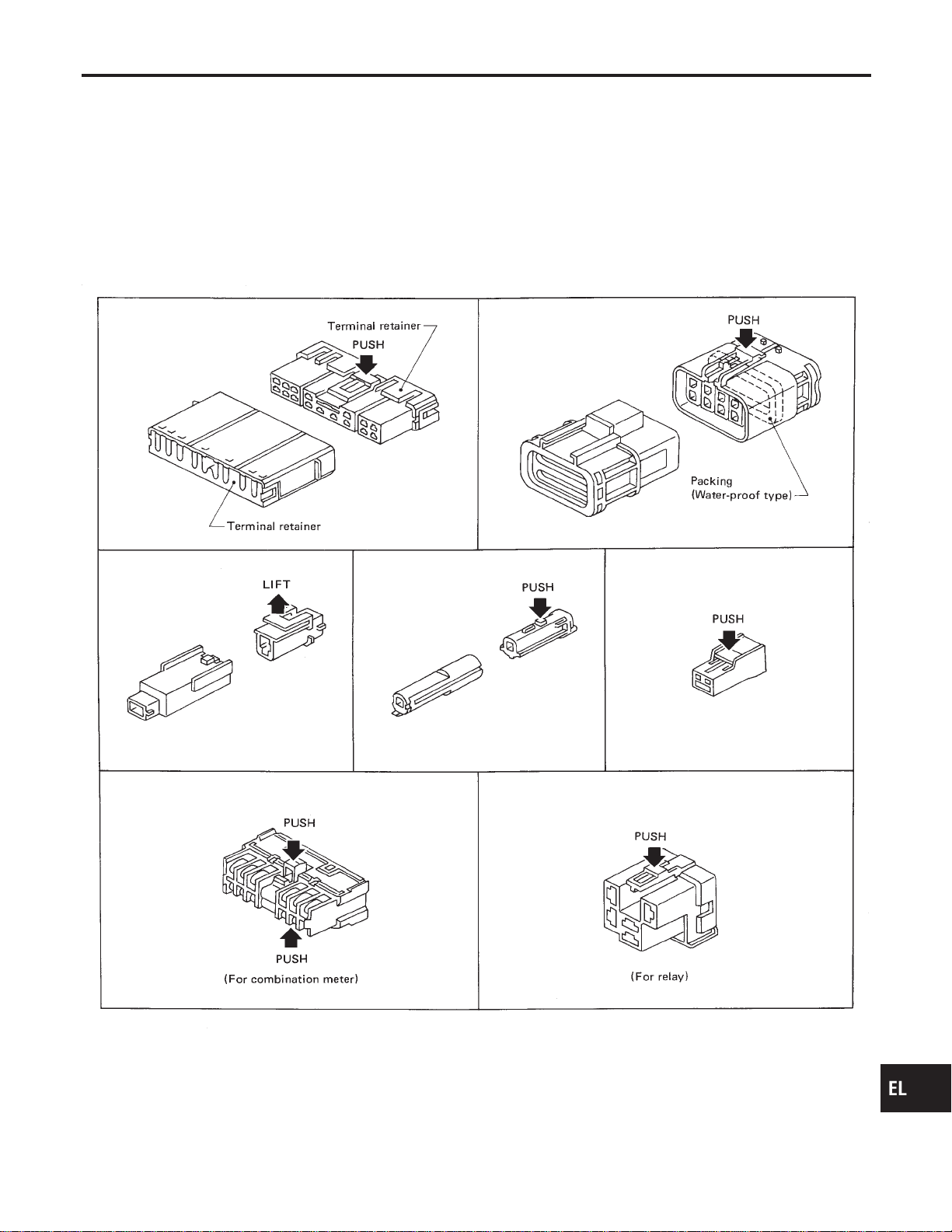
Description
NAEL0003
HARNESS CONNECTOR (TAB-LOCKING TYPE)
NAEL0003S01
I The tab-locking type connectors help prevent accidental looseness or disconnection.
I The tab-locking type connectors are disconnected by pushing or lifting the locking tab(s). Refer to the
illustration below.
Refer to the next page for description of the slide-locking type connector.
CAUTION:
Do not pull the harness when disconnecting the connector.
[Example]
SEL769D
GI
MA
EM
LC
EC
FE
CL
MT
AT
TF
PD
AX
SU
BR
ST
RS
BT
HA
SC
IDX
HARNESS CONNECTOR
Description
EL-5
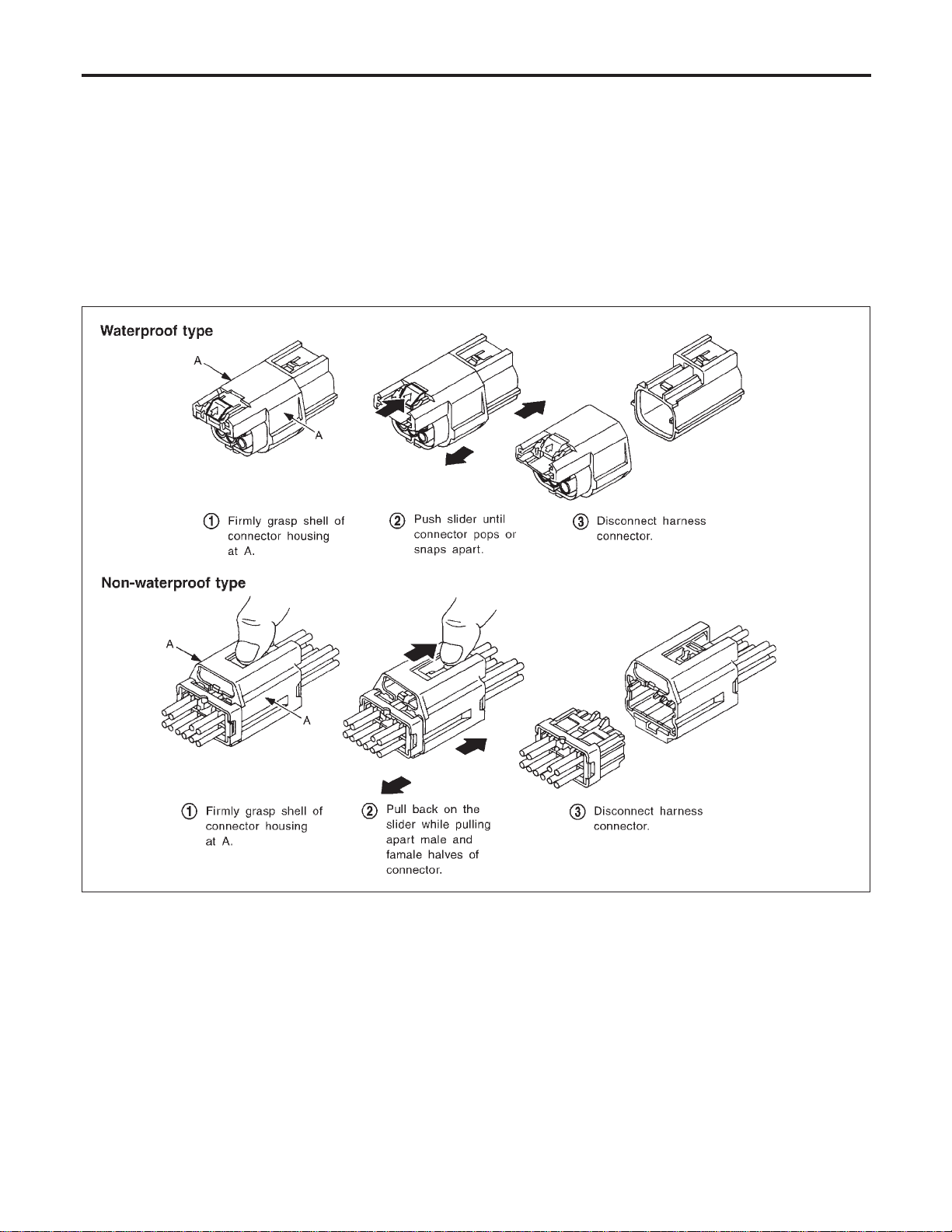
HARNESS CONNECTOR (SLIDE-LOCKING TYPE)
=NAEL0003S02
I A new style slide-locking type connector is used on certain systems and components, especially those
related to OBD.
I The slide-locking type connectors help prevent incomplete locking and accidental looseness or disconnec-
tion.
I The slide-locking type connectors are disconnected by pushing or pulling the slider. Refer to the illustra-
tion below.
CAUTION:
I Do not pull the harness or wires when disconnecting the connector.
I Be careful not to damage the connector support bracket when disconnecting the connector.
[Example]
SEL769V
HARNESS CONNECTOR
Description (Cont’d)
EL-6
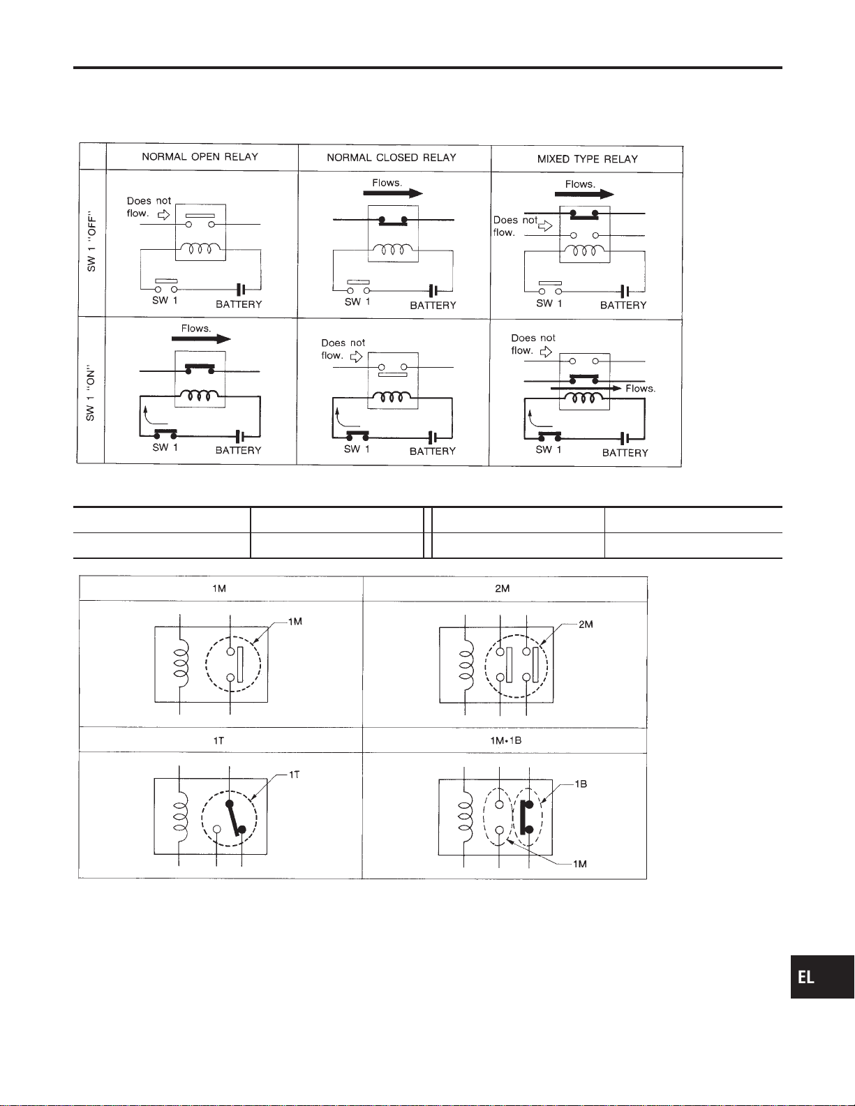
Description
NAEL0004
NORMAL OPEN, NORMAL CLOSED AND MIXED TYPE RELAYS
NAEL0004S01
Relays can mainly be divided into three types: normal open, normal closed and mixed type relays.
SEL881H
TYPE OF STANDARDIZED RELAYS
NAEL0004S02
1M 1 Make 2M 2 Make
1T 1 Transfer 1M·1B 1 Make 1 Break
SEL882H
GI
MA
EM
LC
EC
FE
CL
MT
AT
TF
PD
AX
SU
BR
ST
RS
BT
HA
SC
IDX
STANDARDIZED RELAY
Description
EL-7
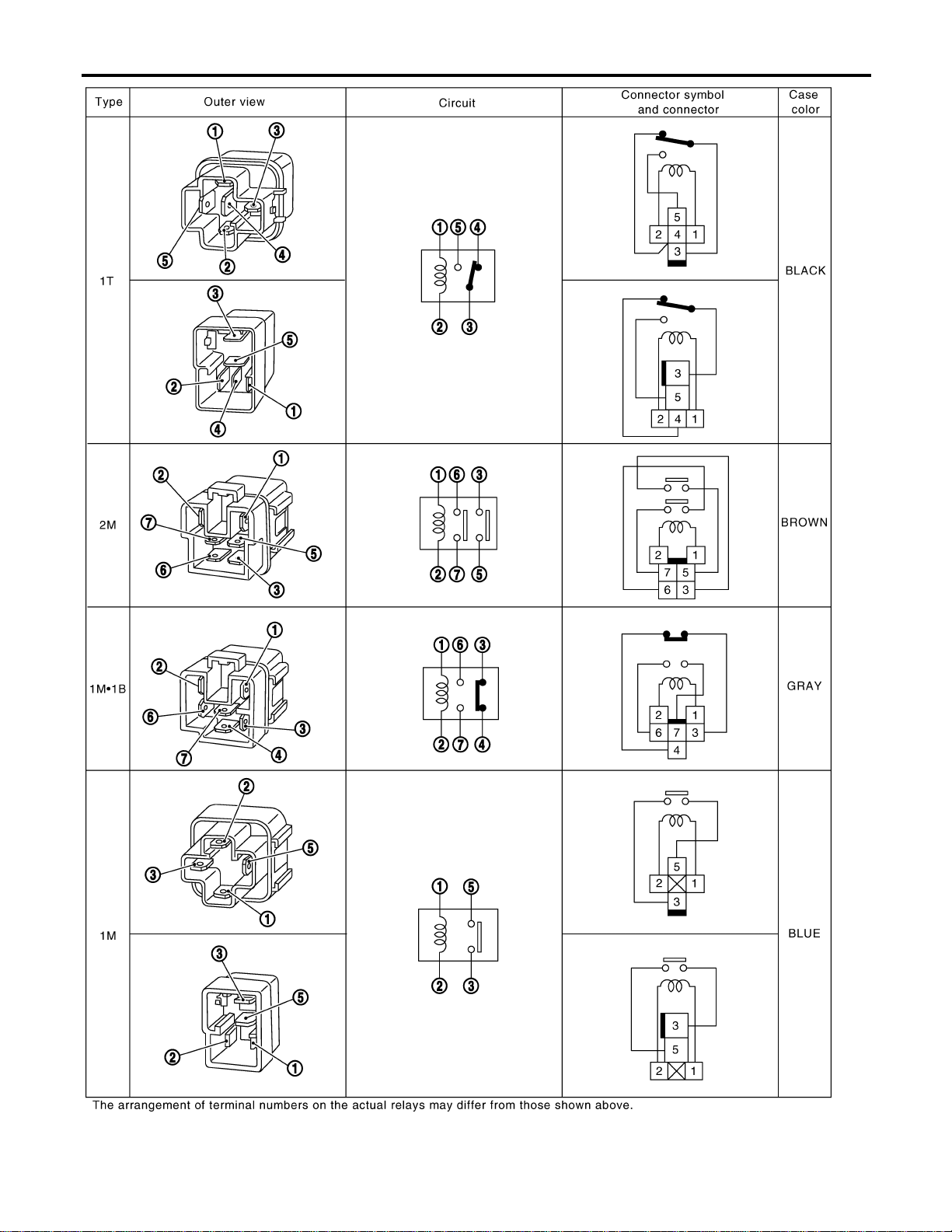
GEL264
STANDARDIZED RELAY
Description (Cont’d)
EL-8

Schematic
NAEL0247
MEL400O
GI
MA
EM
LC
EC
FE
CL
MT
AT
TF
PD
AX
SU
BR
ST
RS
BT
HA
SC
IDX
POWER SUPPLY ROUTING
Schematic
EL-9
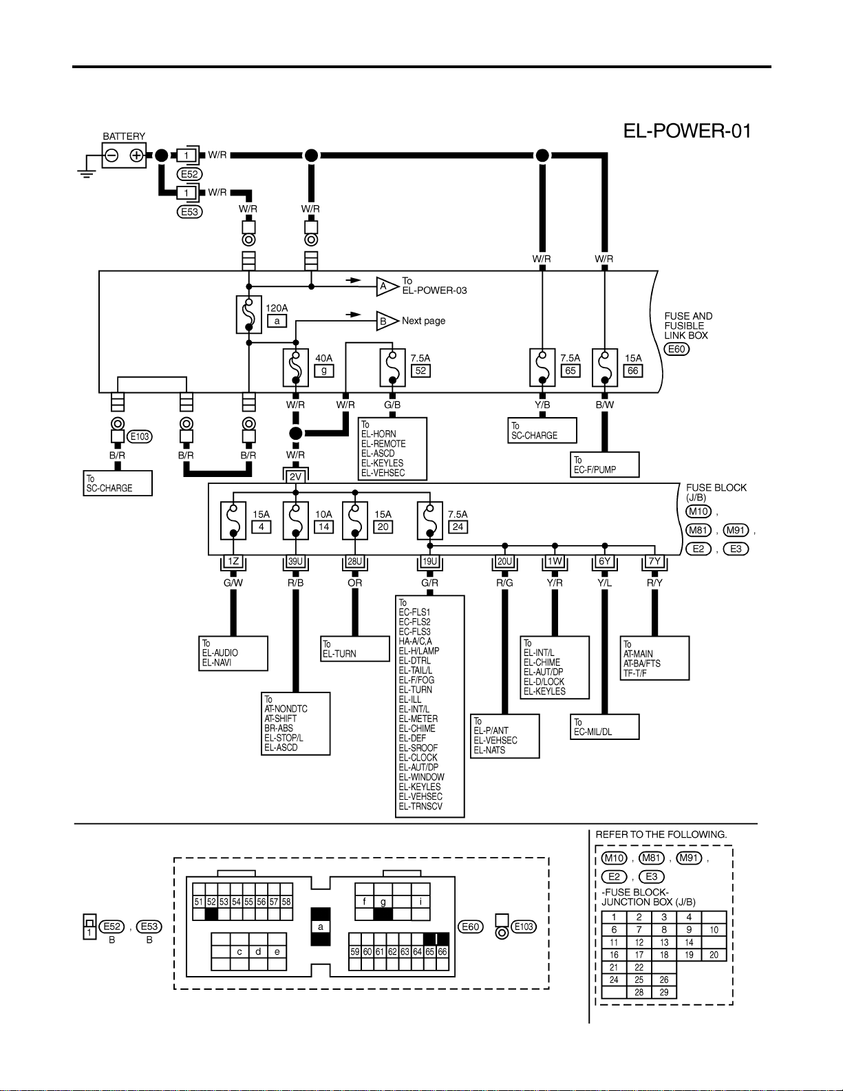
Wiring Diagram — POWER —
NAEL0248
BATTERY POWER SUPPLY — IGNITION SW. IN ANY POSITION
NAEL0248S01
MEL401O
POWER SUPPLY ROUTING
Wiring Diagram — POWER —
EL-10
MEL402O
GI
MA
EM
LC
EC
FE
CL
MT
AT
TF
PD
AX
SU
BR
ST
RS
BT
HA
SC
IDX
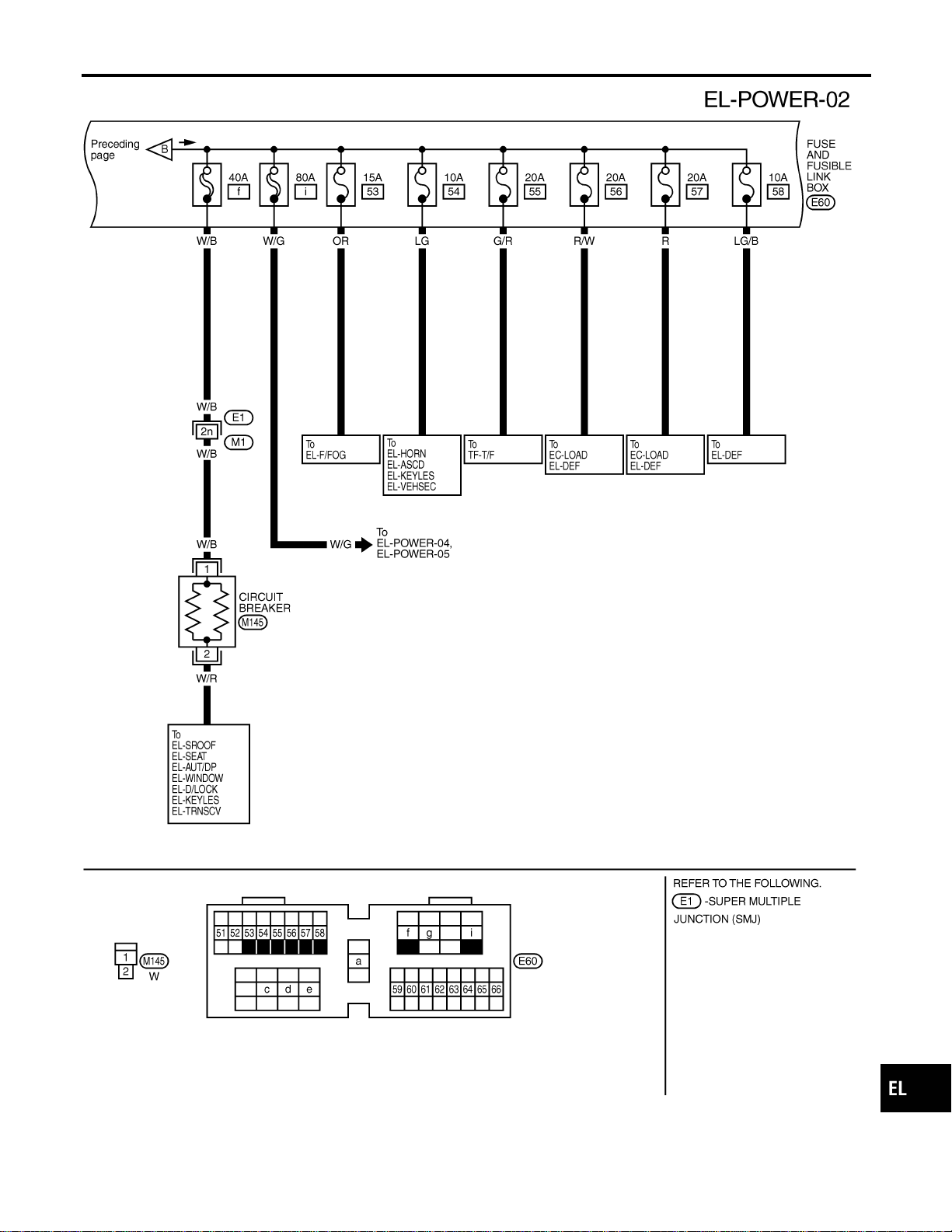
POWER SUPPLY ROUTING
Wiring Diagram — POWER — (Cont’d)
EL-11
MEL551P
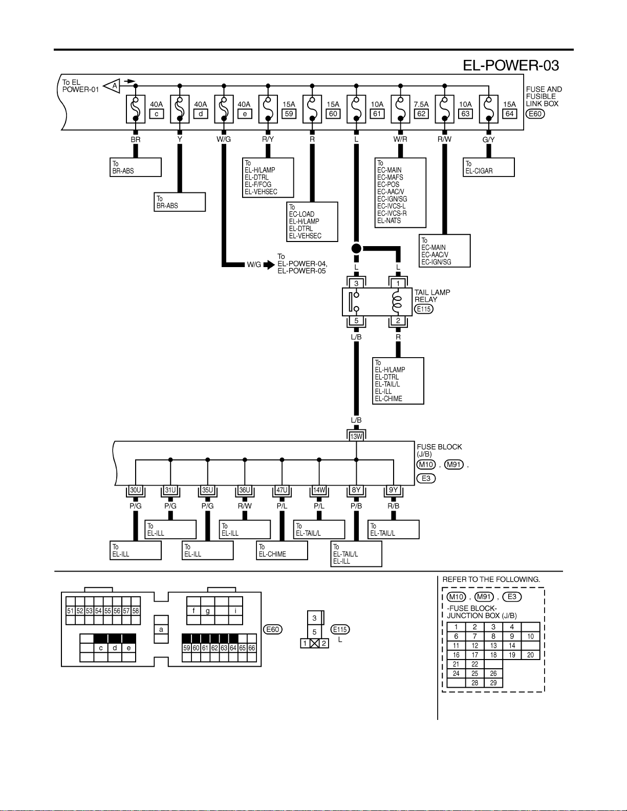
POWER SUPPLY ROUTING
Wiring Diagram — POWER — (Cont’d)
EL-12
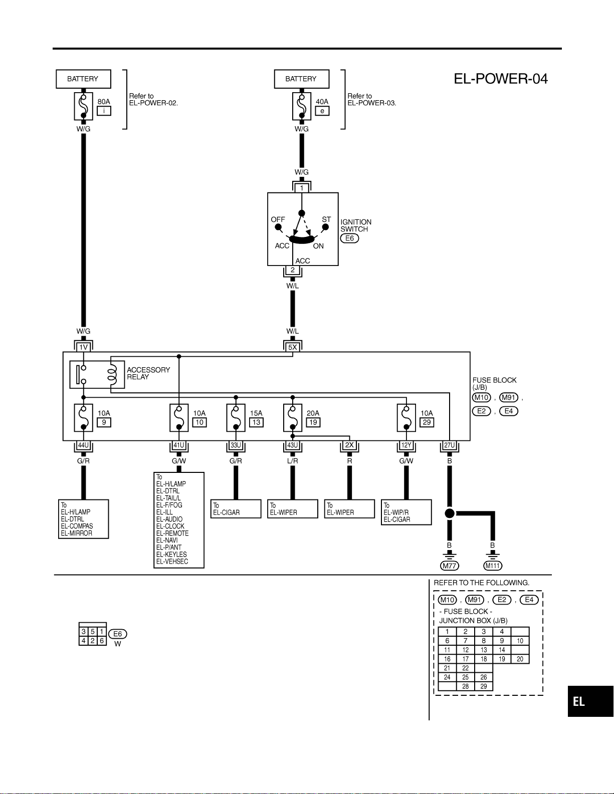
ACCESSORY POWER SUPPLY — IGNITION SW. IN “ACC” OR “ON”
NAEL0248S02
MEL403O
GI
MA
EM
LC
EC
FE
CL
MT
AT
TF
PD
AX
SU
BR
ST
RS
BT
HA
SC
IDX
POWER SUPPLY ROUTING
Wiring Diagram — POWER — (Cont’d)
EL-13
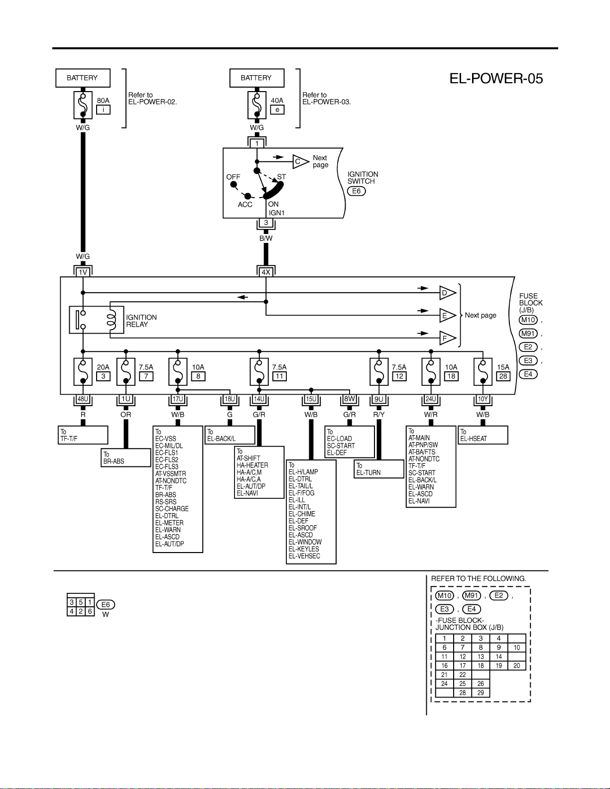
IGNITION POWER SUPPLY — IGNITION SW. IN “ON” AND/OR “START”
NAEL0248S03
MEL404O
POWER SUPPLY ROUTING
Wiring Diagram — POWER — (Cont’d)
EL-14

MEL552P
GI
MA
EM
LC
EC
FE
CL
MT
AT
TF
PD
AX
SU
BR
ST
RS
BT
HA
SC
IDX
POWER SUPPLY ROUTING
Wiring Diagram — POWER — (Cont’d)
EL-15
CEL083
Inspection
NAEL0249
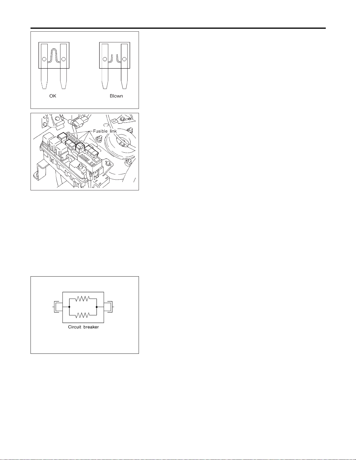
FUSE
NAEL0249S01
I If fuse is blown, be sure to eliminate cause of problem
before installing new fuse.
I Use fuse of specified rating. Never use fuse of more than
specified rating.
I Do not partially install fuse; always insert it into fuse
holder properly.
I Remove fuse for “ELECTRICAL PARTS (BAT)” if vehicle is
not used for a long period of time.
MEL944F
FUSIBLE LINK
NAEL0249S02
A melted fusible link can be detected either by visual inspection or
by feeling with finger tip. If its condition is questionable, use circuit
tester or test lamp.
CAUTION:
I If fusible link should melt, it is possible that critical circuit
(power supply or large current carrying circuit) is shorted.
In such a case, carefully check and eliminate cause of
problem.
I Never wrap outside of fusible link with vinyl tape. Impor-
tant: Never let fusible link touch any other wiring harness,
vinyl or rubber parts.
SEL109W
CIRCUIT BREAKER (PTC THERMISTOR TYPE)
NAEL0249S03
The PTC thermister generates heat in response to current flow.
The temperature (and resistance) of the thermister element varies
with current flow. Excessive current flow will cause the element’s
temperature to rise. When the temperature reaches a specified
level, the electrical resistance will rise sharply to control the circuit
current.
Reduced current flow will cause the element to cool. Resistance
falls accordingly and normal circuit current flow is allowed to
resume.
POWER SUPPLY ROUTING
Inspection
EL-16

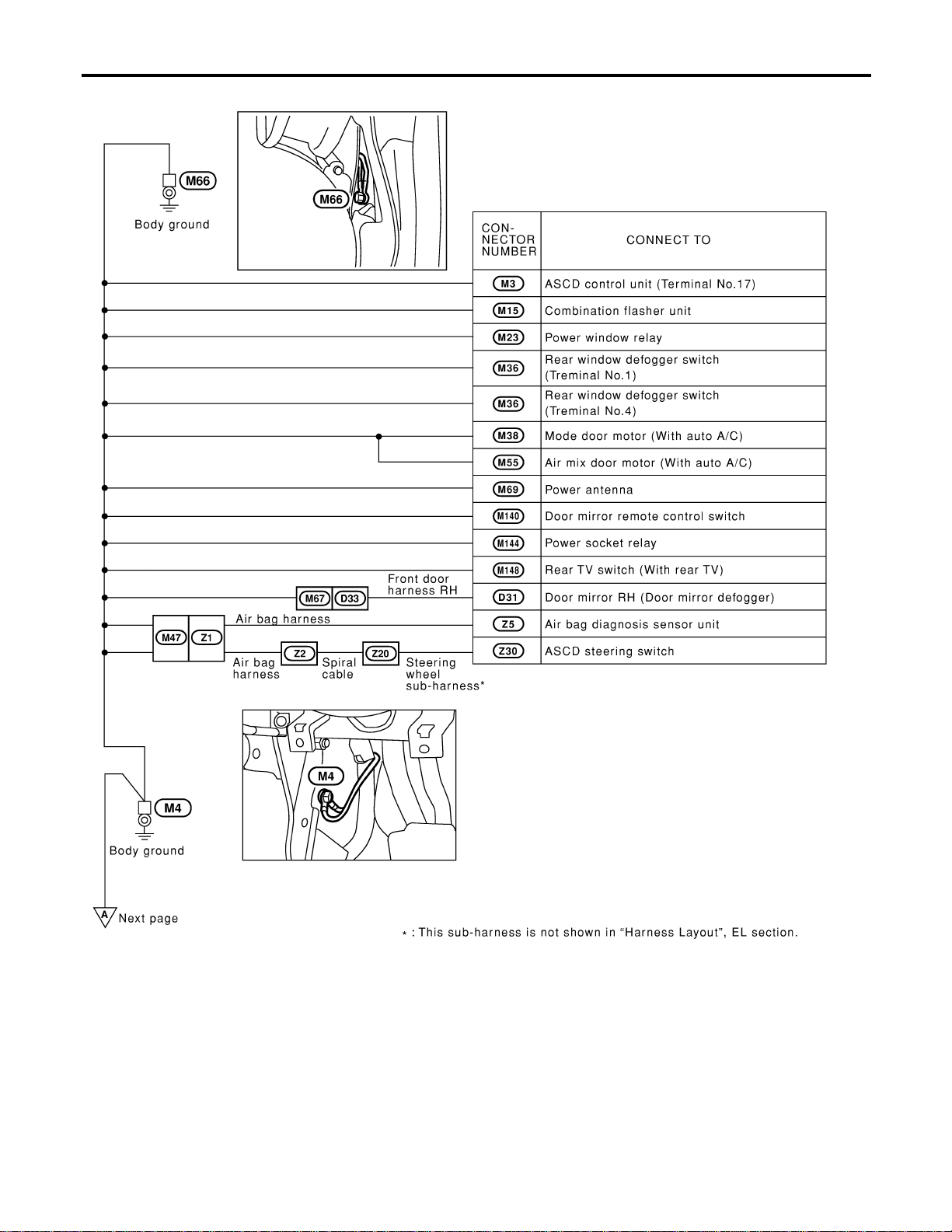
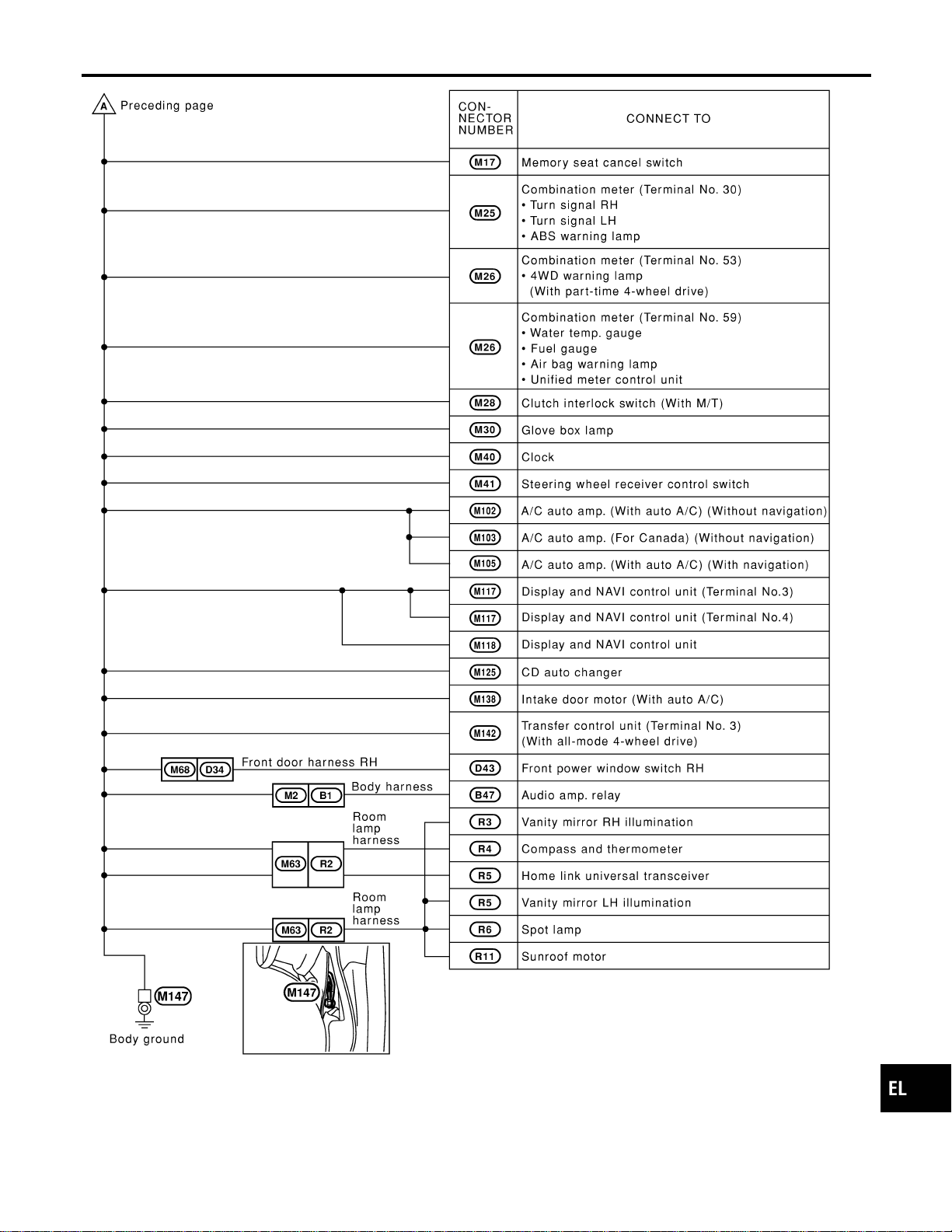
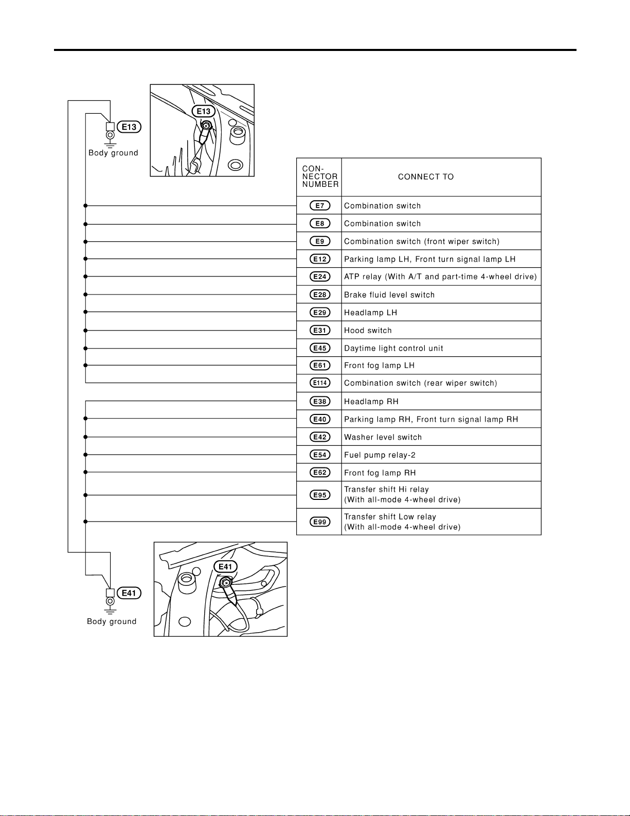
Ground Distribution
NAEL0250
MAIN HARNESS
NAEL0250S01
MEL489P
GI
MA
EM
LC
EC
FE
CL
MT
AT
TF
PD
AX
SU
BR
ST
RS
BT
HA
SC
IDX
GROUND
Ground Distribution
EL-17
MEL490P
GROUND
Ground Distribution (Cont’d)
EL-18
MEL478O
GI
MA
EM
LC
EC
FE
CL
MT
AT
TF
PD
AX
SU
BR
ST
RS
BT
HA
SC
IDX
GROUND
Ground Distribution (Cont’d)
EL-19
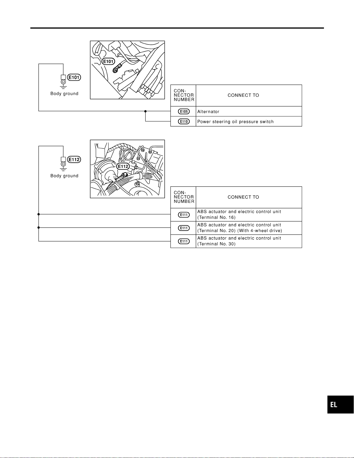
ENGINE ROOM HARNESS
NAEL0250S02
MEL415O
GROUND
Ground Distribution (Cont’d)
EL-20
MEL908N
GI
MA
EM
LC
EC
FE
CL
MT
AT
TF
PD
AX
SU
BR
ST
RS
BT
HA
SC
IDX
GROUND
Ground Distribution (Cont’d)
EL-21
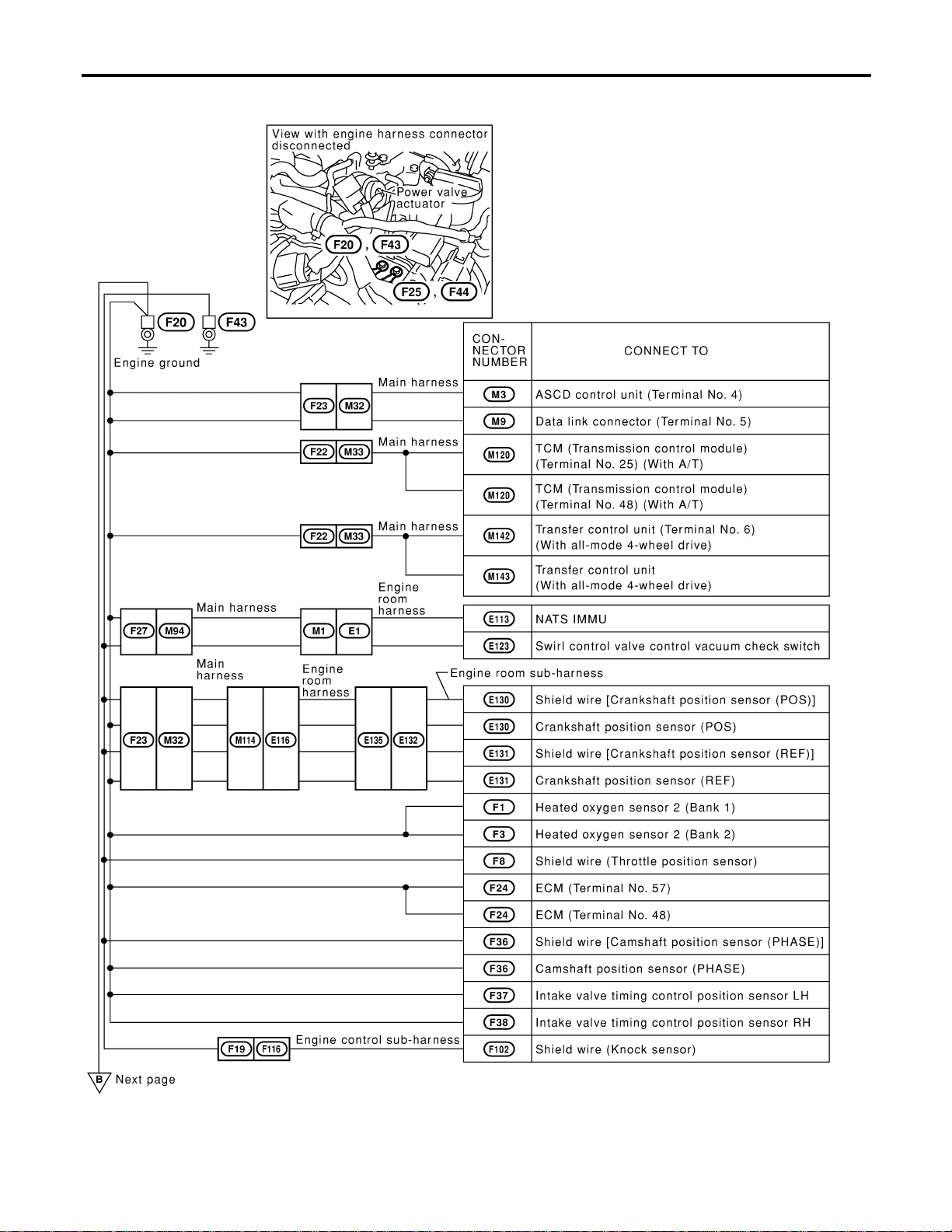
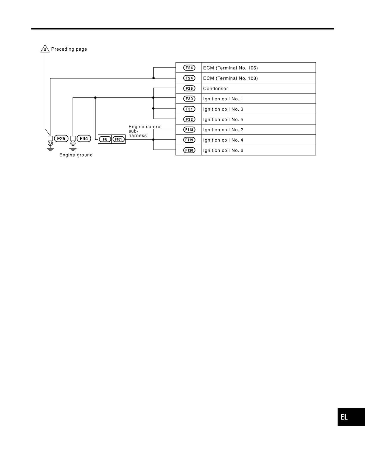
ENGINE CONTROL HARNESS
NAEL0250S03
MEL704O
GROUND
Ground Distribution (Cont’d)
EL-22
MEL233M
GI
MA
EM
LC
EC
FE
CL
MT
AT
TF
PD
AX
SU
BR
ST
RS
BT
HA
SC
IDX
GROUND
Ground Distribution (Cont’d)
EL-23
BODY HARNESS RH
NAEL0250S04
MEL909N
GROUND
Ground Distribution (Cont’d)
EL-24

BODY HARNESS LH
NAEL0250S05
MEL416O
GI
MA
EM
LC
EC
FE
CL
MT
AT
TF
PD
AX
SU
BR
ST
RS
BT
HA
SC
IDX
GROUND
Ground Distribution (Cont’d)
EL-25
MEL911N
GROUND
Ground Distribution (Cont’d)
EL-26
BODY HARNESS
NAEL0250S06
MEL152M
GI
MA
EM
LC
EC
FE
CL
MT
AT
TF
PD
AX
SU
BR
ST
RS
BT
HA
SC
IDX
GROUND
Ground Distribution (Cont’d)
EL-27
Check
NAEL0251
MEL911O
COMBINATION SWITCH
Check
EL-28
MEL912O
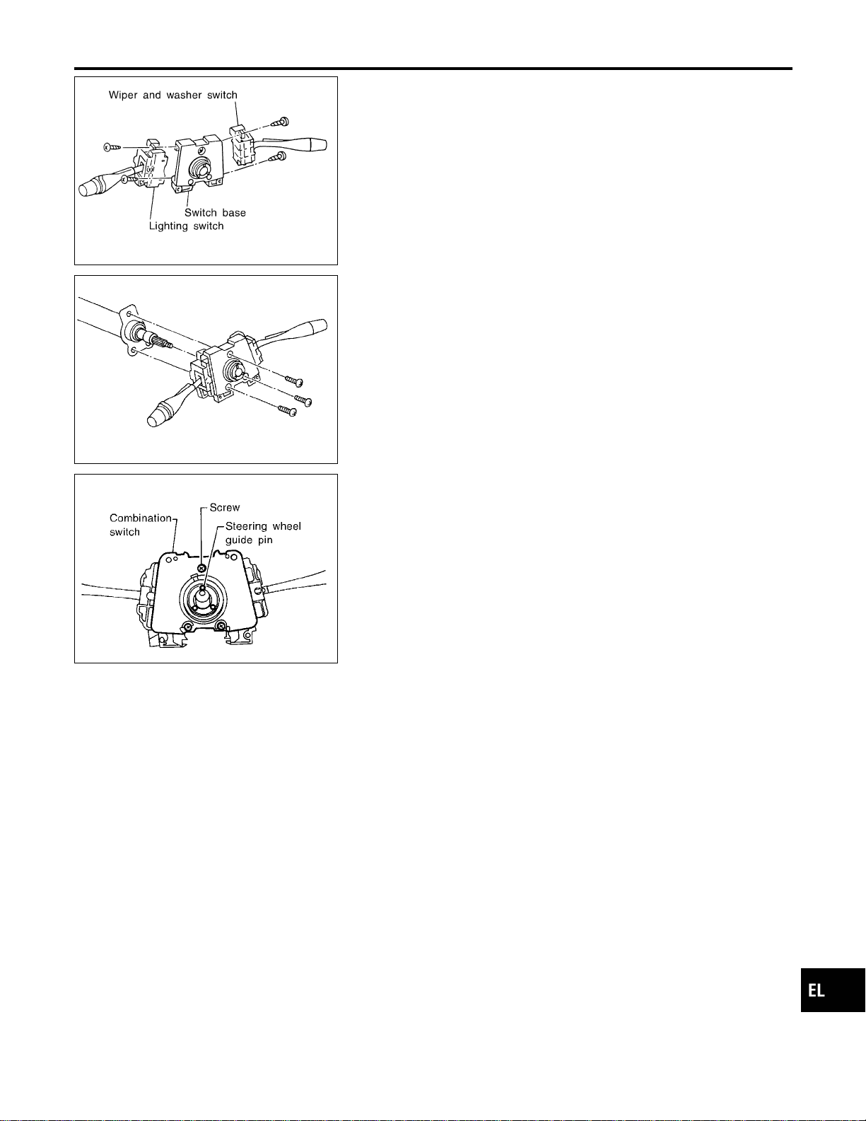
Replacement
NAEL0252
For removal and installation of spiral cable, refer to RS-18,
“Installation — Air Bag Module and Spiral Cable”.
I Each switch can be replaced without removing combination
switch base.
MEL326G
I To remove combination switch base, remove base attaching
screw.
SEL151V
I Before installing the steering wheel, align the steering wheel
guide pins with the screws which secure the combination
switch as shown in the left figure.
GI
MA
EM
LC
EC
FE
CL
MT
AT
TF
PD
AX
SU
BR
ST
RS
BT
HA
SC
IDX
COMBINATION SWITCH
Replacement
EL-29
Check
NAEL0253
MEL447P
STEERING SWITCH
Check
EL-30
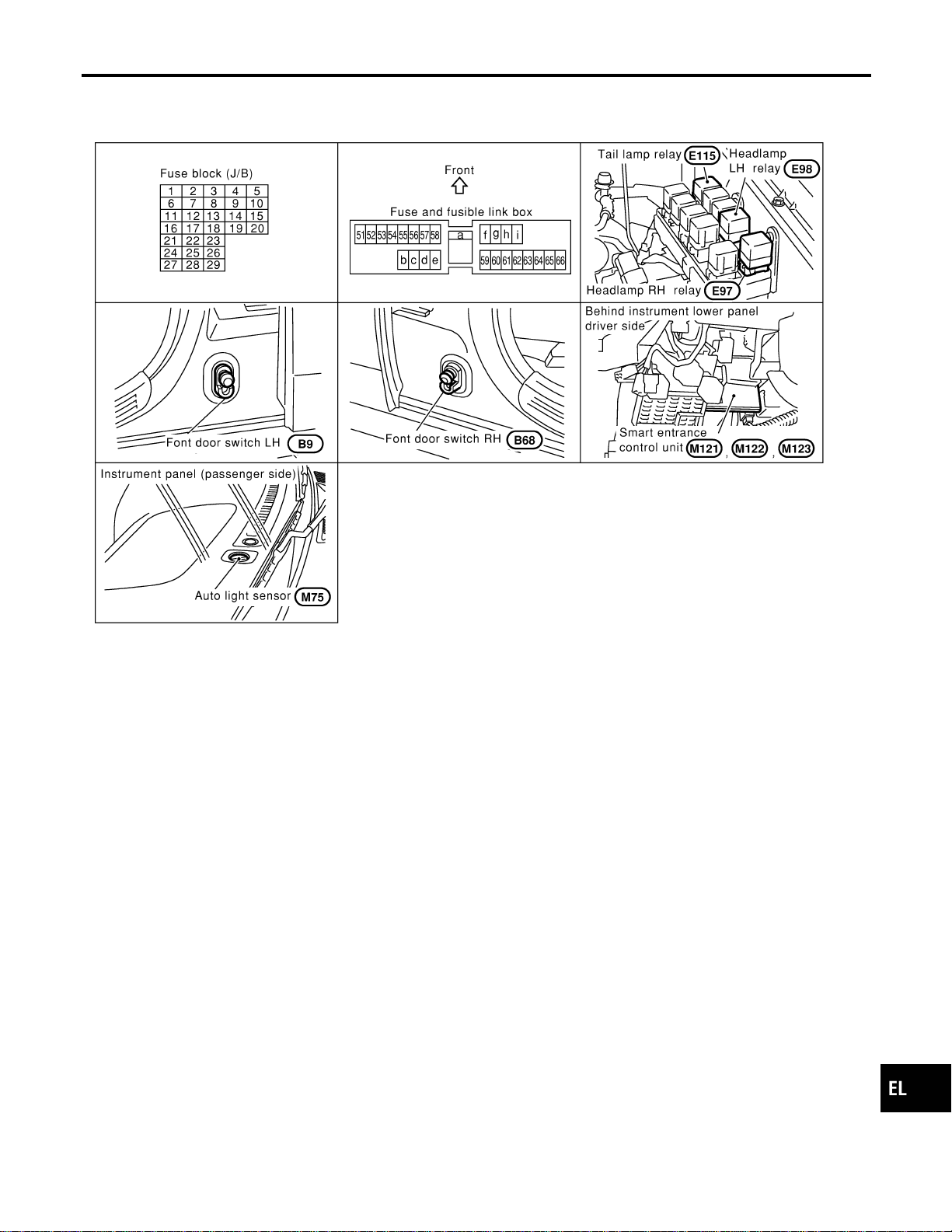
Component Parts and Harness Connector
Location
NAEL0254
SEL288Y
System Description
NAEL0255
The headlamp operation is controlled by the lighting switch which is built into the combination switch and smart
entrance control unit. And the headlamp battery saver system is controlled by the smart entrance control unit.
OUTLINE
NAEL0255S01
Power is supplied at all times
I to headlamp LH relay terminals 1 and 3
I through 15A fuse (No. 60, located in the fuse and fusible link box), and
I to headlamp RH relay terminals 1 and 3
I through 15A fuse (No. 59, located in the fuse and fusible link box), and
I to smart entrance control unit terminal 49
I through 7.5A fuse [No. 24, located in the fuse block (J/B)].
When the ignition switch is in the ON or START position, power is supplied
I to smart entrance control unit terminal 27
I through 7.5A fuse [No. 11, located in the fuse block (J/B)].
When the ignition switch is in the ACC or ON position, power is supplied
I to smart entrance control unit terminal 26
I through 10A fuse [No. 10, located in the fuse block (J/B)]
Ground is supplied
I to smart entrance control unit terminals 43 and 64
I through body grounds M77 and M111.
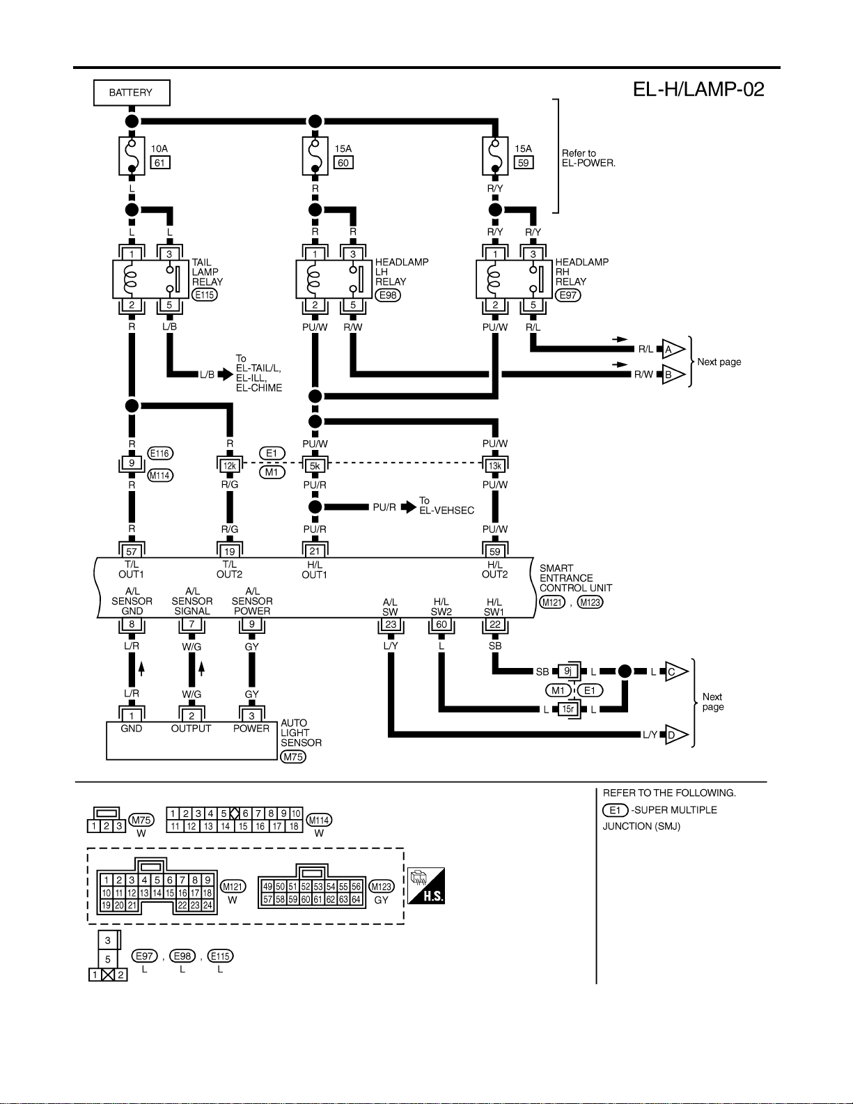
POWER SUPPLY TO LOW BEAM AND HIGH BEAM
NAEL0255S02
When lighting switch is in 2ND or PASS position, ground is supplied
I to headlamp relay (LH and RH) terminal 2 from smart entrance control unit terminals 21 and 59
GI
MA
EM
LC
EC
FE
CL
MT
AT
TF
PD
AX
SU
BR
ST
RS
BT
HA
SC
IDX
HEADLAMP (FOR USA)
Component Parts and Harness Connector Location
EL-31

I through smart entrance control unit terminals 22 and 60,
I from lighting switch terminal 12
Headlamp relays (LH and RH) are energized and then power is supplied to headlamps (LH and RH).
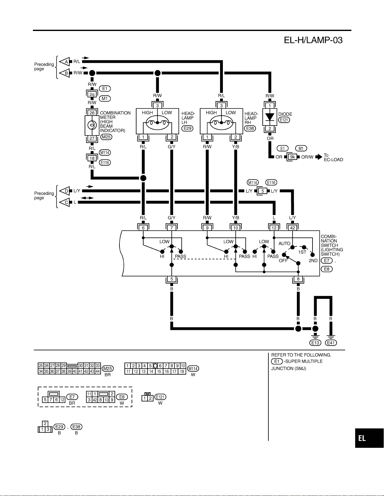
LOW BEAM OPERATION
NAEL0255S03
When the lighting switch is turned to the 2ND position and placed in LOW (“B”) position, power is supplied
I from terminal 5 of each headlamp relay
I to terminal 3 of each headlamp
Ground is supplied
I to headlamp LH terminal 2
I through lighting switch terminals 7 and 5
I through body grounds E13 and E41, and
I to headlamp RH terminal 2
I through lighting switch terminal 10 and 8
I through body grounds E13 and E41.
With power and ground supplied, the headlamp(s) will illuminate.
HIGH BEAM OPERATION/FLASH-TO-PASS OPERATION
NAEL0255S04
When the lighting switch is turned to the 2ND position and placed in HIGH (“A”) position or PASS (“C”) position,
power is supplied
I from terminal 5 of each headlamp relay
I to terminal 3 of each headlamp, and
I to combination meter terminal 26 for the HIGH BEAM indicator.
Ground is supplied
I to headlamp LH terminal 1, and
I to combination meter terminal 27 for the HIGH BEAM indicator
I through lighting switch terminals 6 and 5
I through body grounds E13 and E41, and
I to headlamp RH terminal 1
I through lighting switch terminals 9 and 8
I through body grounds E13 and E41.
With power and ground supplied, the high beams and the high beam indicator illuminate.
EXTERIOR LAMP BATTERY SAVER CONTROL
NAEL0255S05
Except for Auto Light Control Operation
NAEL0255S0501
Headlamps will remain on for a short while after the ignition switch is turned from ON (or ACC) to OFF.
Continuity between terminals 21 and 22, and between terminals 59 and 60 of smart entrance control unit will
be disturbed after 5 minutes, then the headlamps will be turned off.
When the lighting switch is turned from OFF to 2ND after headlamps are turned to off by the exterior lamp
battery saver control, ground is supplied
I to smart entrance control unit terminals 20 and 58 from lighting switch terminal 11, and then,
I to headlamp LH and RH relays terminal 2 from smart entrance control unit terminals 21 and 59,
I through smart entrance control unit terminals 22 and 60 and
I through lighting switch terminal 12.
Then headlamps illuminate again.
Auto light control operation
NAEL0255S0502
While the headlamps are turned ON by “AUTO” operation, the exterior lamp battery saver is activated for 5
minutes when the ignition switch is turned from ON (or ACC) to OFF, and either LH or RH front door switch
is opened.
The smart entrance control unit controls exterior lamp battery saver activation as follows:
I When the door switch signal changes from ON to OFF while the exterior lamp battery saver is activated,
the operation is discontinued, and restarts and lasts for 45 seconds, then the headlamps will be turned
off.
I When the door switch signal changes from OFF to ON while the exterior lamp battery saver is activated,
the operation discontinued, restarts and lasts for 45 seconds, then the headlamps will be turned off.
HEADLAMP (FOR USA)
System Description (Cont’d)
EL-32

I When the one of four door switch signals changes from OFF to ON while the exterior lamp battery saver
is activated, the operation is discontinued, restarts and lasts for 5 minutes, then the headlamps will be
turned off.
I When all the door switch ON signals are input while the exterior lamp battery saver is activated, the saver
is discontinued and restarts and lasts for 45 seconds, then the headlamps will be turned off.
I Exterior battery saver control time can be changed using “WORK SUPPORT” mode in “HEADLAMP”.
When the lighting switch is turned from OFF to 2ND after headlamps are turned to off by the exterior lamp
battery saver control, ground is supplied
I to smart entrance control unit terminals 20 and 58 from lighting switch terminal 11, and then,
I to headlamp LH and RH relays terminal 2 from smart entrance control unit terminals 21 and 59,
I through smart entrance control unit terminals 22 and 60 and
I through lighting switch terminal 12.
Then headlamps illuminate again.
AUTO LIGHT OPERATION
NAEL0255S06
The auto light control system has an auto light sensor inside instrument mask that detects outside brightness.
I to smart entrance control unit terminal 23
I from lighting switch terminal 42.
When ignition switch is turned to ″ON″ or “START” position and
I Outside brightness is darker than prescribed level.
After 3 seconds delay, outside brightness becomes darker than prescribed level.
Ground is supplied
I to headlamp relay LH and RH terminals 2
I through smart entrance control unit terminals 21, 59 and 43, 64.
Then both headlamp relays and tail lamp relay are energized, headlamps (low or high) and tail lamps are illu-
minated according to switch position.
Auto light operation allows headlamps and tail lamps to go off when
I Outside brightness is brighter than prescribed level, or
I After 5 seconds delay, outside brightness is brighter than prescribed level.
I Ignition switch is turned to “OFF” position. (Headlamp will be turned OFF by exterior lamp battery saver
control system. Refer to EL-32.)
NOTE:
The delay time changes (maximum of 20 seconds) as the outside brightness changes.
For parking license and tail lamp auto operation, refer to “PARKING, LICENSE AND TAIL LAMPS”.
VEHICLE SECURITY SYSTEM
NAEL0255S07
The vehicle security system will flash the high beams if the system is triggered. Refer to “VEHICLE SECU-
RITY (THEFT WARNING) SYSTEM” (EL-342).
GI
MA
EM
LC
EC
FE
CL
MT
AT
TF
PD
AX
SU
BR
ST
RS
BT
HA
SC
IDX
HEADLAMP (FOR USA)
System Description (Cont’d)
EL-33
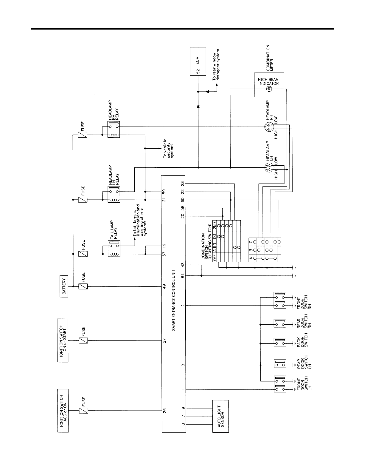
Schematic
NAEL0256
MEL390P
HEADLAMP (FOR USA)
Schematic
EL-34
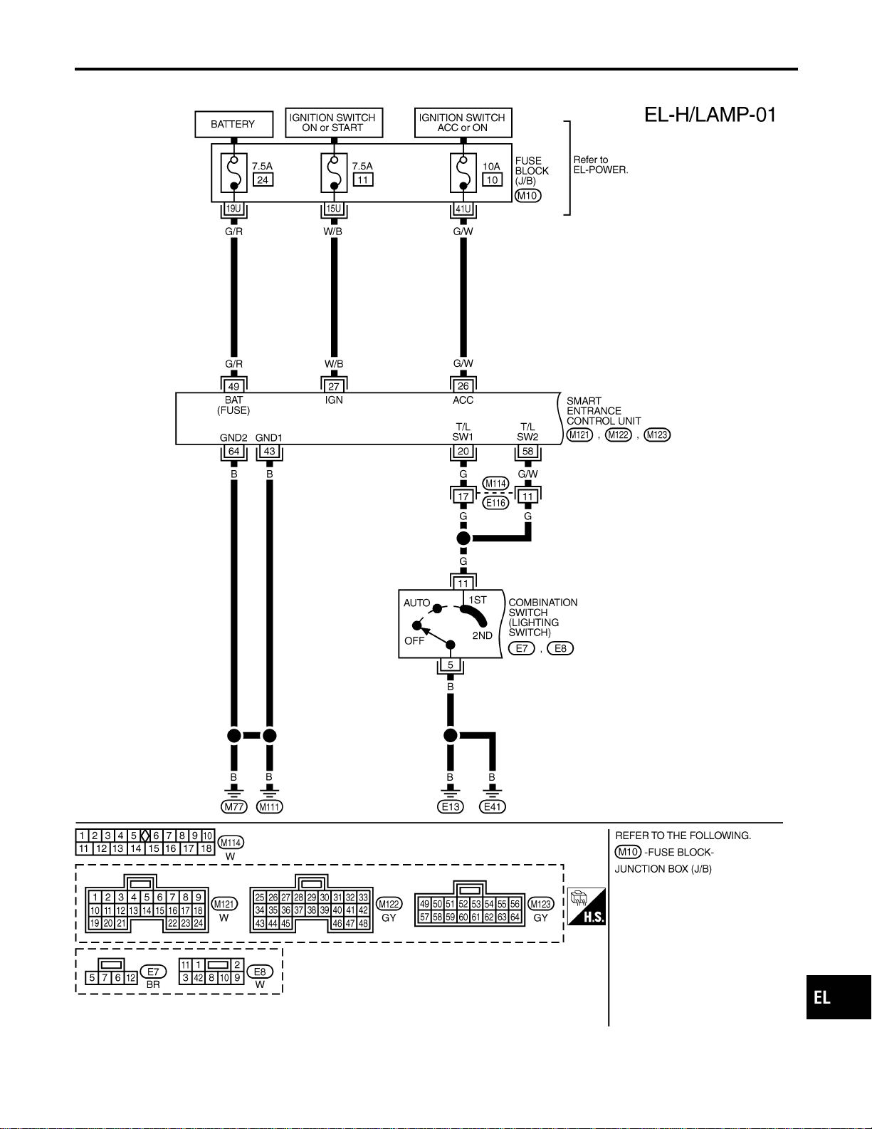
Wiring Diagram — H/LAMP —
NAEL0257
MEL389P
GI
MA
EM
LC
EC
FE
CL
MT
AT
TF
PD
AX
SU
BR
ST
RS
BT
HA
SC
IDX
HEADLAMP (FOR USA)
Wiring Diagram — H/LAMP —
EL-35
MEL391P
HEADLAMP (FOR USA)
Wiring Diagram — H/LAMP — (Cont’d)
EL-36
MEL853N
GI
MA
EM
LC
EC
FE
CL
MT
AT
TF
PD
AX
SU
BR
ST
RS
BT
HA
SC
IDX
HEADLAMP (FOR USA)
Wiring Diagram — H/LAMP — (Cont’d)
EL-37

MEL392P
HEADLAMP (FOR USA)
Wiring Diagram — H/LAMP — (Cont’d)
EL-38
SEL331X
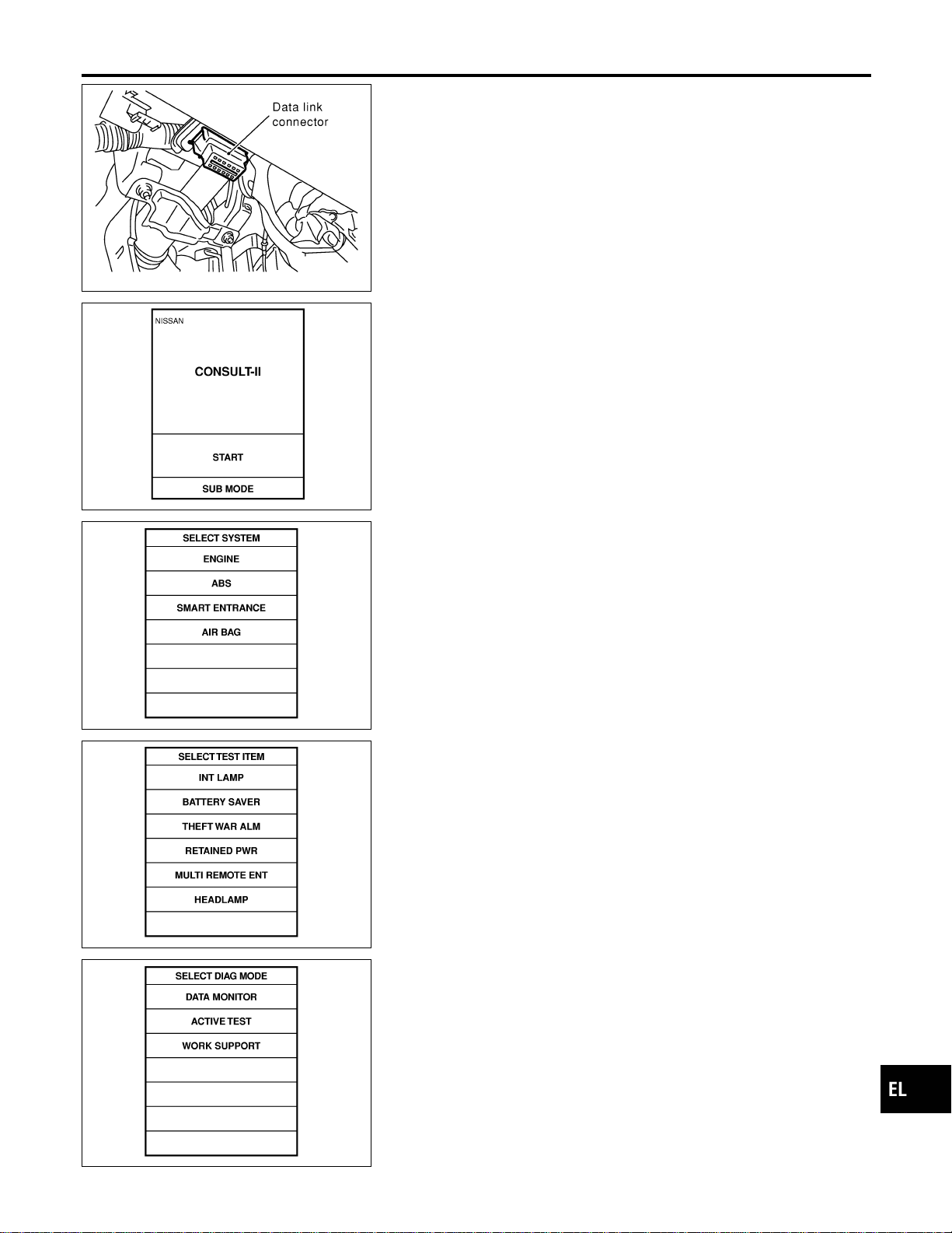
CONSULT-II Inspection Procedure
NAEL0258
“HEADLAMP”
NAEL0258S01
1. Turn ignition switch “OFF”.
2. Connect “CONSULT-II” to the data link connector.
PBR455D
3. Turn ignition switch “ON”.
4. Touch “START”.
SEL398Y
5. Touch “SMART ENTRANCE”.
SEL401Y
6. Touch “HEADLAMP”.
SEL400Y
7. Select diagnosis mode.
“DATA MONITOR”, “ACTIVE TEST” and “WORK SUPPORT”
are available.
GI
MA
EM
LC
EC
FE
CL
MT
AT
TF
PD
AX
SU
BR
ST
RS
BT
HA
SC
IDX
HEADLAMP (FOR USA)
CONSULT-II Inspection Procedure
EL-39

CONSULT-II Application Items
NAEL0453
“HEAD LAMP”
NAEL0453S01
Data Monitor
NAEL0453S0101
Monitored Item Description
IGN ON SW Indicates [ON/OFF] condition of ignition switch in ON position.
ACC ON SW Indicates [ON/OFF] condition of ignition switch in ACC position.
AUTO LIGT SW
Displays status of the lighting switch as judged from the lighting switch signal.
(AUTO position: ON/Other than AUTO position: OFF)
AUTO LIGT SENS
Displays “Illumination outside of the vehicle (close to 5V when light/close to 0V when dark)” as
judged from the optical sensor signal.
LIGHT SW 1ST
Displays status of the lighting switch as judged from the lighting switch signal.
(1ST or 2ND position: ON/Other than 1ST and 2ND position: OFF)
LIGHT SW 2ND
Displays status of the lighting switch as judged from the lighting switch signal.
(2ND position: ON/Other than 2ND position: OFF)
DOOR SW-DR Indicates [ON/OFF] condition of front door switch LH.
DOOR SW-AS Indicates [ON/OFF] condition of door switch RH.
DOOR SW-RR Indicates [ON/OFF] condition of rear door switch.
Active Test
NAEL0453S0102
Test Item Description
TAIL LAMP Tail lamp relay can be operated by on-off operation of the tail lamp.
HEAD LAMP Headlamp relay can be operated by on-off operation of the headlamp.
AUTO LIGHT Night time dimming signal can be operated by on-off operation.
Work Support
NAEL0453S0103
Work Item Description
AUTO LIGHT SET
Auto light sensitivity can be changed in this mode. Sensitivity can be adjusted in four modes.
I MODE 1 (Normal)/MODE 2 (Sensitive)/MODE 3 (Desensitized)/MODE 4 (Insensitive)
BATTERY SAVER SET
Exterior lamp battery saver control mode can be changed in this mode. Selects exterior lamp
battery saver control mode between two modes.
I MODE 1 (ON)/MODE 2 (OFF)
ILL DELAY SET
Exterior lamp battery saver control time can be changed in this mode. Selects exterior lamp bat-
tery saver control time among eight modes.
I MODE 1 (45 sec.)/MODE 2 (OFF)/MODE 3 (30 sec.)/MODE 4 (60 sec.)/ MODE 5 (90 sec.)/
MODE 6 (120 sec.)/MODE 7 (150 sec.)/MODE 8 (180 sec.)
Trouble Diagnoses
NAEL0260
Symptom Possible cause Repair order
Neither headlamp operates. 1. 7.5A fuse
2. Headlamp relay circuit
3. Lighting switch
4. Smart entrance control unit
1. Check 7.5A fuse [No. 24, located in fuse block
(J/B)].
Verify battery positive voltage is present at terminal
49 of smart entrance control unit.
2. Check between smart entrance control unit and
headlamp relays (LH and RH).
3. Check Lighting switch.
4. Check smart entrance control unit. (EL-378)
HEADLAMP (FOR USA)
CONSULT-II Application Items
EL-40

Symptom Possible cause Repair order
Headlamp LH (low and high beam)
does not operate, but headlamp
RH (low and high beam) does
operate.
1. 15A fuse
2. Headlamp LH relay
3. Headlamp LH relay circuit
1. Check 15A fuse (No. 60, located in fusible link and
fuse box). Verify battery positive voltage is present
at terminals 1 and 3 of headlamp LH relay.
2. Check headlamp LH relay.
3. Check harness between headlamp LH relay and
smart entrance control unit.
Headlamp RH (low and high beam)
does not operate, but headlamp LH
(low and high beam) does operate.
1. 15A fuse
2. Headlamp RH relay
3. Headlamp RH relay circuit
1. Check 15A fuse (No. 59, located in fusible link and
fuse box). Verify battery positive voltage is present
at terminals 1 and 3 of headlamp RH relay.
2. Check headlamp RH relay.
3. Check harness between headlamp RH relay and
smart entrance control unit.
LH high beam does not operate,
but LH low beam operates.
1. Bulb
2. Open in the LH high beam cir-
cuit
3. Lighting switch
1. Check bulb.
2. Check harness between headlamp LH and lighting
switch for open circuit.
3. Check lighting switch.
LH low beam does not operate, but
LH high beam operates.
1. Bulb
2. Open in LH low beam circuit
3. Lighting switch
1. Check bulb.
2. Check harness between headlamp LH and lighting
switch for open circuit.
3. Check lighting switch.
RH high beam does not operate,
but RH low beam operates.
1. Bulb
2. Open in the RH high beam cir-
cuit
3. Lighting switch
1. Check bulb.
2. Check harness between headlamp RH and lighting
switch for open circuit.
3. Check lighting switch.
RH low beam does not operate,
but RH high beam operates.
1. Bulb
2. Open in RH low beam circuit
3. Lighting switch
1. Check bulb.
2. Check harness between headlamp RH and lighting
switch for open circuit.
3. Check lighting switch.
High beam indicator does not work. 1. Bulb
2. Open in high beam circuit
1. Check bulb in combination meter.
2. Check the following.
a. Harness between headlamp LH relay and combina-
tion meter for an open circuit
b. Harness between high beam indicator and lighting
switch
Battery saver control does not
operate properly.
1. Door switch LH or RH circuit
2. Lighting switch circuit
3. Smart entrance control unit
1. Check the following.
a. Harness between smart entrance control unit and
LH or RH door switch for open or short circuit.
b. LH or RH door switch ground circuit.
c. LH or RH door switch.
2. Check the following.
a. Harness between smart entrance control unit termi-
nals 20 or 58 and lighting switch terminal 11 for
open or short circuit.
b. Harness between lighting switch terminal 5 and
ground.
c. Lighting switch.
3. Check smart entrance control unit. (EL-378)
GI
MA
EM
LC
EC
FE
CL
MT
AT
TF
PD
AX
SU
BR
ST
RS
BT
HA
SC
IDX
HEADLAMP (FOR USA)
Trouble Diagnoses (Cont’d)
EL-41

Symptom Possible cause Repair order
When outside is dark, neither tail
lamp nor headlamp turn on by auto
light operation.
1. 7.5A fuse
2. Lighting switch “AUTO” check
3. Lighting switch circuit check
4. Lighting switch ground circuit
check
5. Auto light sensor check
6. Auto light sensor circuit check
1. Check 7.5A fuse [NO. 11 located in fuse block (J/B)].
Verify battery positive voltage is present at terminal
27 of smart entrance control unit.
2. Check lighting switch (AUTO) input signal with
“CONSULT-II” in “DATA MONITOR” mode.
When lighting switch is in AUTO:
AUTO LIGHT SWITCH ON
When lighting switch is in OFF:
AUTO LIGHT SWITCH OFF
3. Check harness for open or short between smart
entrance control unit and lighting switch.
4. Check harness for lighting switch and ground.
5. Check auto light sensor input signal.
(With CONSULT-II)
See “AUTO LIGHT SENSOR” in DATA MONITOR
mode. When auto light sensor in stuck by light:
More than 3V
When auto light sensor is not stuck by light:
Approx. 0.5V
(Without CONSULT-II)
Check voltage between smart entrance control unit
terminal 7 and ground. Refer to smart entrance con-
trol unit. (EL-378)
6. Check the following.
a. Harness for open or short between smart entrance
control unit terminal 8 and auto light sensor terminal
1
b. Harness for open or short between smart entrance
control unit terminal 7 and auto light sensor terminal
2
c. Harness for open or short between smart entrance
control unit terminals 9 and 3
When outside is dark, tail lamp
turns on but headlamp does not
turn on by auto light operation.
Auto light output check Check auto light output.
(With CONSULT-II)
See “HEADLAMP” and “TAIL LAMP” in ACTIVE TEST
mode, and headlamp switch to AUTO position.
Headlamp and tail lamp should turn on.
(Without CONSULT-II)
Check voltage between smart entrance control unit ter-
minals 19, 21, 57, 59 and ground. Refer to smart
entrance control unit. (EL-378)
When outside is dark, headlamp
turns on but tail lamp does not turn
on by auto light operation.
Auto light output check Check auto light output.
(With CONSULT-II)
See “HEADLAMP” and “TAIL LAMP” in ACTIVE TEST
mode, and headlamp switch to AUTO position.
Headlamp and tail lamp should turn on.
(Without CONSULT-II)
Check voltage between smart entrance control unit ter-
minals 19, 21, 57, 59 and ground. Refer to smart
entrance control unit. (EL-378)
Light does not turn off when igni-
tion key switch is turned to “OFF”
(exterior battery saver control is
canceled).
1. 7.5A fuse
2. IGN switch circuit
1. Check 7.5A fuse [NO. 11 located in fuse block (J/B)].
Verify battery positive voltage is present at terminal
27 of smart entrance control unit.
2. Check harness for open or short between smart
entrance control unit and fuse.
HEADLAMP (FOR USA)
Trouble Diagnoses (Cont’d)
EL-42
Symptom Possible cause Repair order
When outside is bright, neither tail
lamps nor headlamps turn off by
auto light operation.
Auto light sensor check Check auto light sensor input signal.
(With CONSULT-II)
See “AUTO LIGHT SENSOR” in DATA MONITOR
mode. When auto light sensor in stuck by light:
More than 3V
When auto light sensor is not stuck by light:
Approx. 0.5V
(Without CONSULT-II)
Check voltage between smart entrance control unit ter-
minal 7 (W/G) and ground. Refer to smart entrance
control unit. (EL-378)
SEL107X
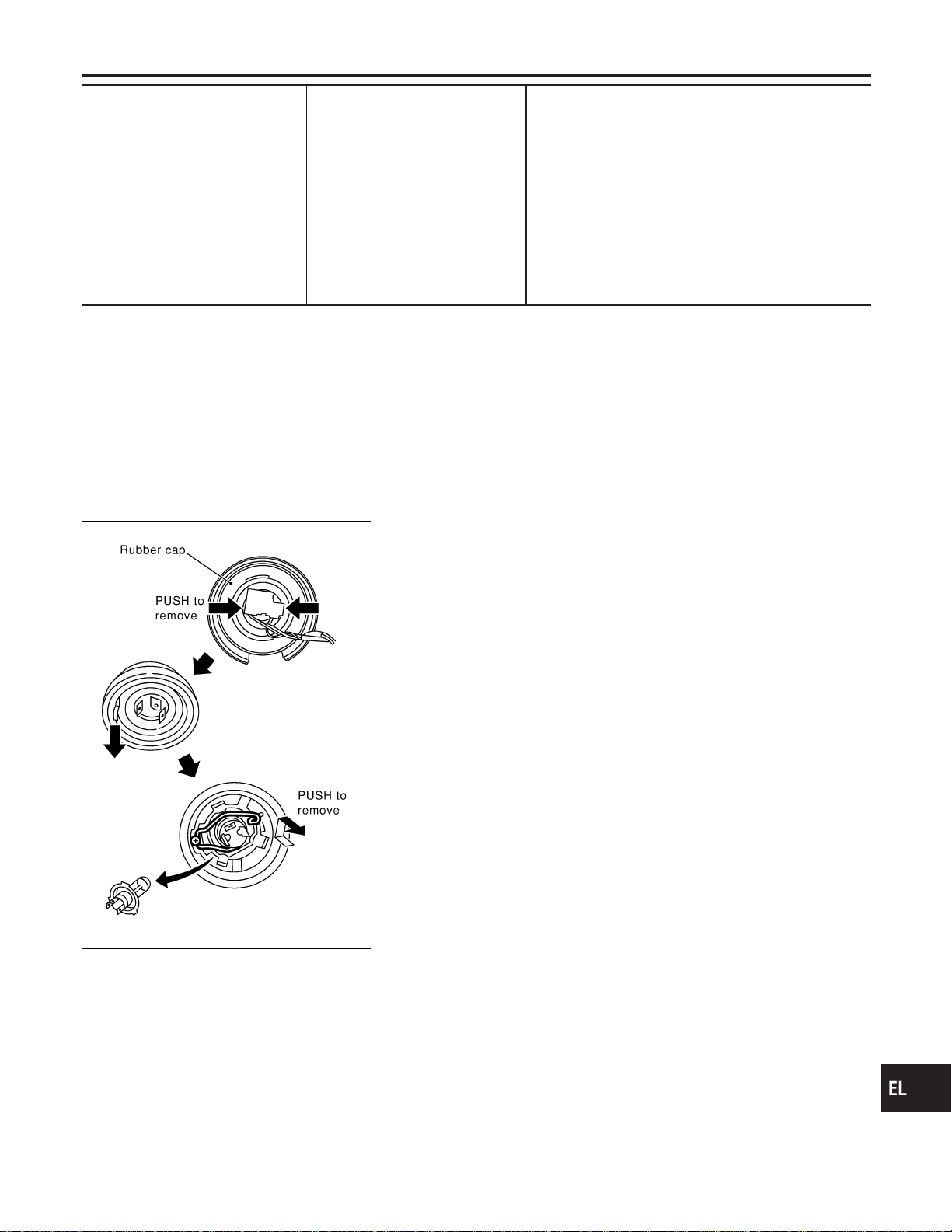
Bulb Replacement
NAEL0261
The headlamp is a semi-sealed beam type which uses a replace-
able halogen bulb. The bulb can be replaced from the engine com-
partment side without removing the headlamp body.
I Grasp only the plastic base when handling the bulb. Never
touch the glass envelope.
1. Disconnect the battery cable.
2. Disconnect the harness connector from the back side of the
bulb.
3. Pull off the rubber cap.
4. Remove the headlamp bulb carefully. Do not shake or rotate
the bulb when removing it.
5. Install in the reverse order of removal.
CAUTION:
Do not leave headlamp reflector without bulb for a long period
of time. Dust, moisture, smoke, etc. entering headlamp body
may affect the performance of the headlamp. Remove head-
lamp bulb from the headlamp reflector just before a replace-
ment bulb is installed.
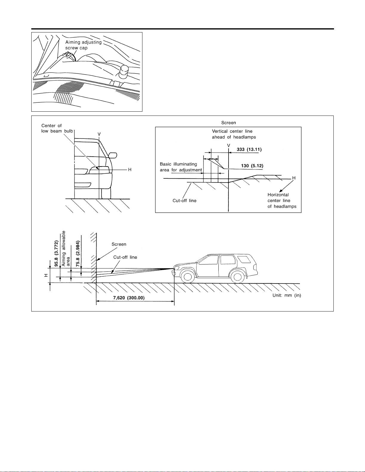
Aiming Adjustment
NAEL0262
Before performing aiming adjustment, check the following.
For details, refer to the regulations in your own country.
1) Keep all tires inflated to correct pressures.
2) Place vehicle flat surface.
3) See that there is no-load in vehicle (coolant, engine oil filled up
to correct level and full fuel tank) other than the driver (or
equivalent weight placed in driver’s position).
GI
MA
EM
LC
EC
FE
CL
MT
AT
TF
PD
AX
SU
BR
ST
RS
BT
HA
SC
IDX
HEADLAMP (FOR USA)
Trouble Diagnoses (Cont’d)
EL-43
MEL222P
LOW BEAM
NAEL0262S01
1. Remove aiming adjusting screw cap.
2. Turn headlamp low beam on.
3. Use adjusting screws to perform aiming adjustment.
I First tighten the adjusting screw all the way and then
make adjustment by loosening the screw.
SEL376X
If the vehicle front body has been repaired and/or the headlamp
assembly has been replaced, check aiming. Use the aiming chart
shown in the figure.
I Basic illuminating area for adjustment should be within
the range shown on the aiming chart. Adjust headlamps
accordingly.
HEADLAMP (FOR USA)
Aiming Adjustment (Cont’d)
EL-44

Component Parts and Harness Connector
Location
NAEL0263
SEL288Y
System Description
NAEL0264
The headlamp system for Canada vehicles contains a daytime light control unit that activates the high beam
headlamps at approximately half illumination whenever the engine is running. If the parking brake is applied
before the engine is started the daytime lights will not be illuminated. The daytime lights will illuminate once
the parking brake is released. Thereafter, the daytime lights will continue to operate when the parking brake
is applied.
And battery saver system is controlled by the smart entrance control unit.
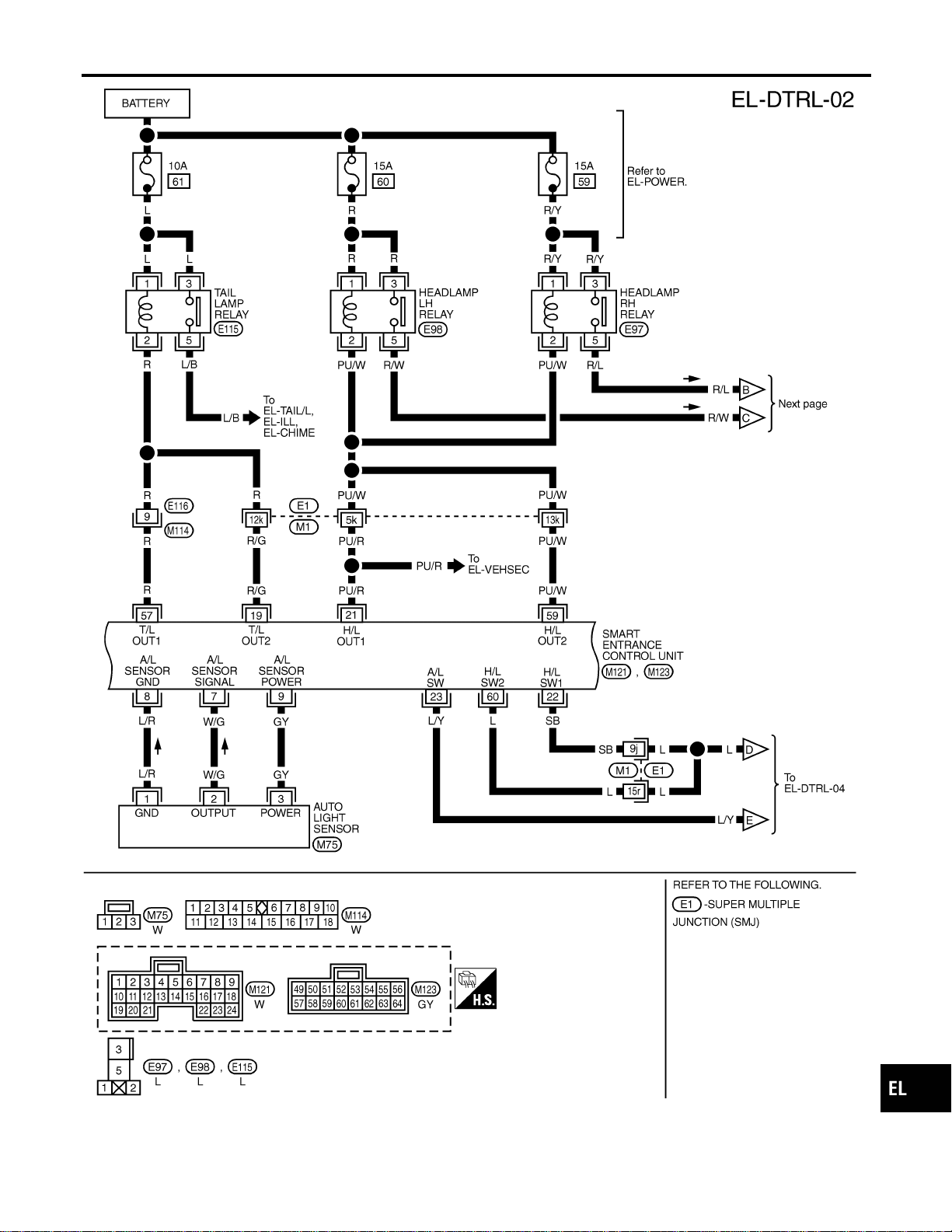
Power is supplied at all times
I to headlamp LH relay terminals 1 and 3
I through 15A fuse (No. 60, located in the fuse and fusible link box), and
I to headlamp RH relay terminals 1 and 3
I through 15A fuse (No. 59, located in the fuse and fusible link box), and
I to smart entrance control unit terminal 49
I through 7.5A fuse [No. 24, located in the fuse block (J/B)].
Ground is supplied
I to daytime light control unit terminal 16 and
I to smart entrance control unit terminals 43 and 64
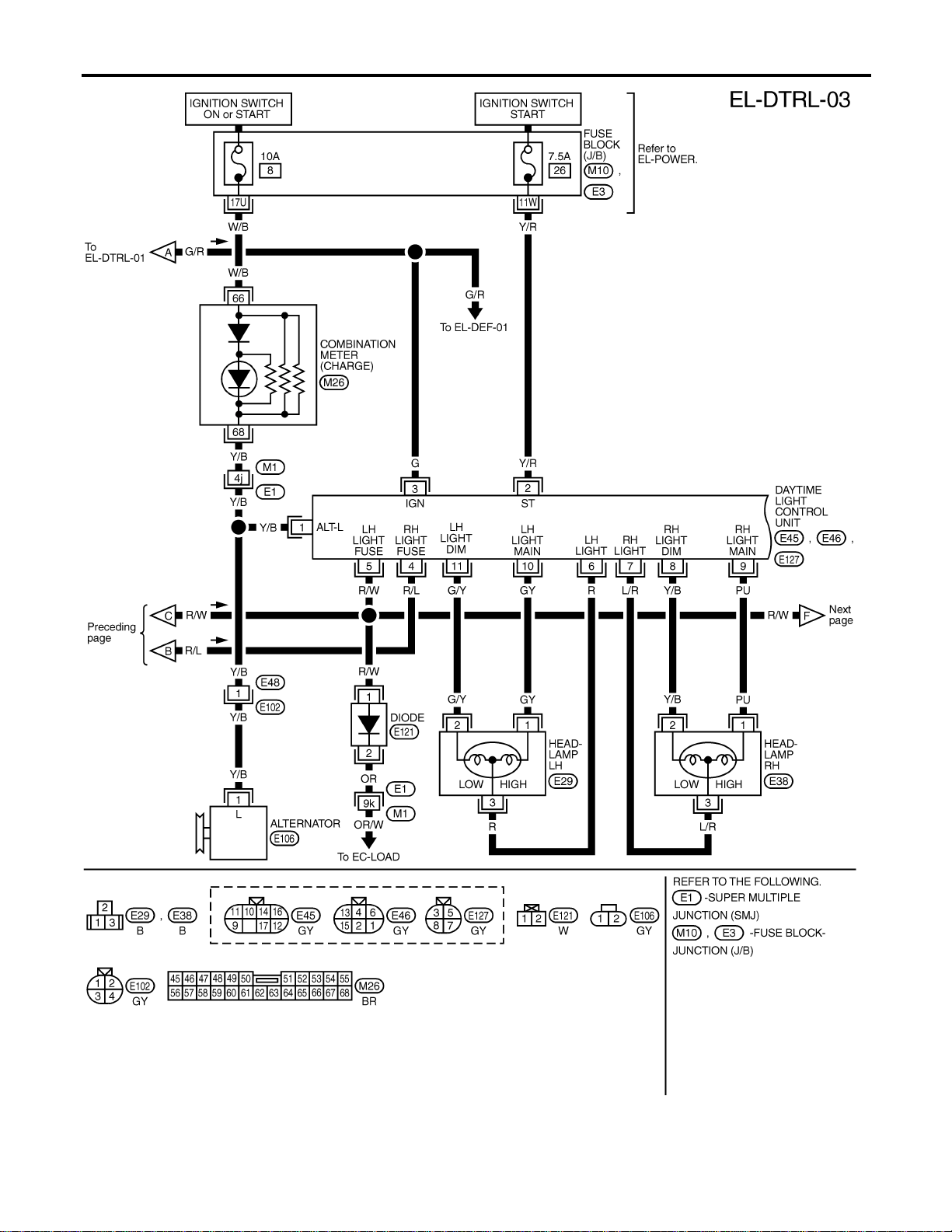
When the ignition switch is in the ON or START position, power is also supplied
I to daytime light control unit terminal 3, and
I to smart entrance control unit terminal 27
I through 7.5A fuse [No. 11, located in the fuse block (J/B)].
When the ignition switch is in the ACC or ON position, power is supplied
I to smart entrance control unit terminal 26
I through 10A fuse [No. 10, located in the fuse block (J/B)].
When the ignition switch is in the START position, power is supplied
GI
MA
EM
LC
EC
FE
CL
MT
AT
TF
PD
AX
SU
BR
ST
RS
BT
HA
SC
IDX
HEADLAMP (FOR CANADA) — DAYTIME LIGHT SYSTEM —
Component Parts and Harness Connector Location
EL-45

I to daytime light control unit terminal 2
I through 7.5A fuse [No. 26, located in the fuse block (J/B)].
HEADLAMP OPERATION
NAEL0264S01
Power Supply to Low Beam and High Beam
NAEL0264S0101
When lighting switch is in 2ND or PASS position, ground is supplied
I to headlamp relay (LH and RH) terminal 2 from smart entrance control unit terminals 21 and 59
I through smart entrance control unit terminals 22 and 60
I from lighting switch terminal 12.
Headlamp relays (LH and RH) are energized and then power is supplied to headlamps (LH and RH).
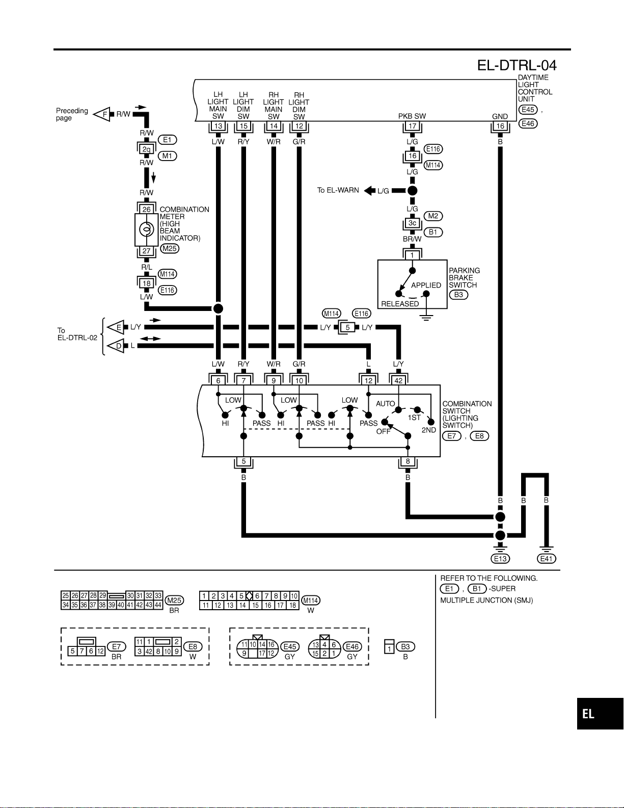
Low Beam Operation
NAEL0264S0102
When the lighting switch is turned to 2ND and LOW (“B”) positions, ground is supplied
I to terminal 2 of the headlamp LH
I through daytime light control unit terminals 11 and 15
I through lighting switch terminals 7 and 5
I through body grounds E13 and E41.
Ground is also supplied
I to terminal 2 of the headlamp RH
I through daytime light control unit terminals 8 and 12
I through lighting switch terminals 10 and 8
I through body grounds E13 and E41.
With power and ground supplied, the low beam headlamps illuminate.
High Beam Operation/Flash-to-pass Operation
NAEL0264S0103
When the lighting switch is turned to 2ND and HIGH (“A”) or PASS (“C”) positions, ground is supplied
I to terminal 1 of headlamp LH
I through daytime light control unit terminals 10 and 13, and
I to combination meter terminal 27 for the HIGH BEAM indicator
I through lighting switch terminals 6 and 5
I through body grounds E13 and E41.
Ground is also supplied
I to terminal 1 of headlamp RH
I through daytime light control unit terminals 9 and 14
I through lighting switch terminals 9 and 8
I through body grounds E13 and E41.
With power and ground supplied, the high beam headlamps and HIGH BEAM indicator illuminate.
EXTERIOR LAMP BATTERY SAVER CONTROL
NAEL0264S02
Except for Auto Light Control Operation
NAEL0264S0201
Headlamps will remain on for a short while after the ignition switch is turned from ON (or ACC) to OFF.
Continuity between terminals 21 and 22, and between terminals 59 and 60 of smart entrance control unit will
be disturbed after 5 minutes, then the headlamps will be turned off.
When the lighting switch is turned from OFF to 2ND after headlamps are turned to off by the exterior lamp
battery saver control, ground is supplied
I to smart entrance control unit terminals 20 and 58 from lighting switch terminal 11, and then,
I to headlamp LH and RH relays terminal 2 from smart entrance control unit terminals 21 and 59,
I through smart entrance control unit terminals 22 and 60 and
I through lighting switch terminal 12.
Then headlamps illuminate again.
Auto light control operation
NAEL0264S0202
While the headlamps are turned ON by “AUTO” operation, the exterior lamp battery saver is activated for 5
minutes when the ignition switch is turned from ON (or ACC) to OFF, and either LH or RH front door switch
is opened.
The smart entrance control unit controls exterior lamp battery saver activation as follows:
HEADLAMP (FOR CANADA) — DAYTIME LIGHT SYSTEM —
System Description (Cont’d)
EL-46
I When the door switch signal changes from ON to OFF while the exterior lamp battery saver is activated,
the operation is discontinued, restarts and lasts for 45 seconds, then the headlamps will be turned off.
I When the door switch signal changes from OFF to ON while the exterior lamp battery saver is activated,
the operation is discontinued, restarts and lasts for 45 seconds, then the headlamps will be turned off.
I When the one of four door switch signals changes from OFF to ON while the exterior lamp battery saver
is activated, the operation is discontinued, restarts and lasts for 5 minutes, then the headlamps will be
turned off.
I When all the door switch ON signals are input while the exterior lamp battery saver is activated, the saver
is discontinued and restarts and lasts for 45 seconds, then the headlamps will be turned off.
I Exterior battery saver control time can be changed using “WORK SUPPORT” mode in “HEADLAMP”.
When the lighting switch is turned from OFF to 2ND after headlamps are turned to off by the exterior lamp
battery saver control, ground is supplied
I to smart entrance control unit terminals 20 and 58 from lighting switch terminal 11, and then,
I to headlamp LH and RH relays terminal 2 from smart entrance control unit terminals 21 and 59,
I through smart entrance control unit terminals 22 and 60 and
I through lighting switch terminal 12.
Then headlamps illuminate again.
AUTO LIGHT OPERATION
NAEL0264S03
For auto light operation, refer to “HEADLAMP” (EL-33).
DAYTIME LIGHT OPERATION
NAEL0264S04
With the engine running, the lighting switch in the OFF or 1ST position and parking brake released, power is
supplied
I through daytime light control unit terminal 7
I to terminal 3 of headlamp RH
I through terminal 1 of headlamp RH
I to daytime light control unit terminal 9
I through daytime light control unit terminal 6
I to terminal 3 of headlamp LH.
Ground is supplied to terminal 1 of headlamp LH.
I through daytime light control unit terminals 10 and 16
I through body grounds E13 and E41.
Because the high beam headlamps are now wired in series, they operate at half illumination.
OPERATION
NAEL0264S05
After starting the engine with the lighting switch in the “OFF” or “1ST” position, the headlamp high beam auto-
matically turns on. Lighting switch operations other than the above are the same as conventional light sys-
tems.
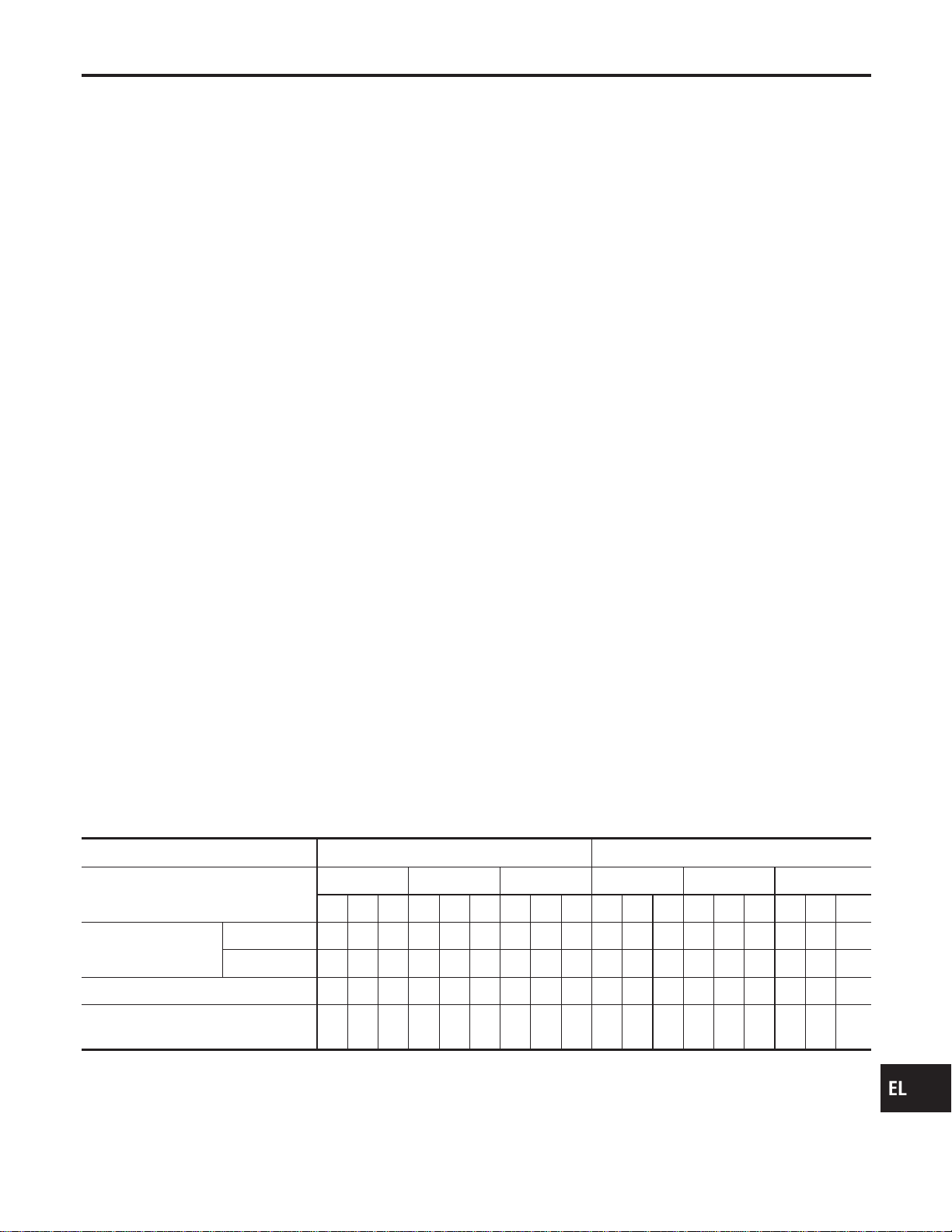
Engine With engine stopped With engine running
Lighting switch
OFF 1ST 2ND OFF 1ST 2ND
ABCABCABCABCABCABC
Headlamp
High beam X X O X X O O X O g* g*Og* g*OOXO
Low beam XXXXXXXOXXXXXXXXOX
Clearance and tail lamp X X X OOOOOOXXXOOOOOO
License and instrument illumination
lamp
XXXOOOOOOXXXOOOOOO
A: “HIGH BEAM” position
B: “LOW BEAM” position
C: “FLASH TO PASS” position
O : Lamp “ON”
X : Lamp “OFF”
g : Lamp dims. (Added functions)
GI
MA
EM
LC
EC
FE
CL
MT
AT
TF
PD
AX
SU
BR
ST
RS
BT
HA
SC
IDX
HEADLAMP (FOR CANADA) — DAYTIME LIGHT SYSTEM —
System Description (Cont’d)
EL-47

*: When starting the engine with the parking brake released, the daytime light will come ON.
When starting the engine with the parking brake pulled, the daytime light won’t come ON.
HEADLAMP (FOR CANADA) — DAYTIME LIGHT SYSTEM —
System Description (Cont’d)
EL-48
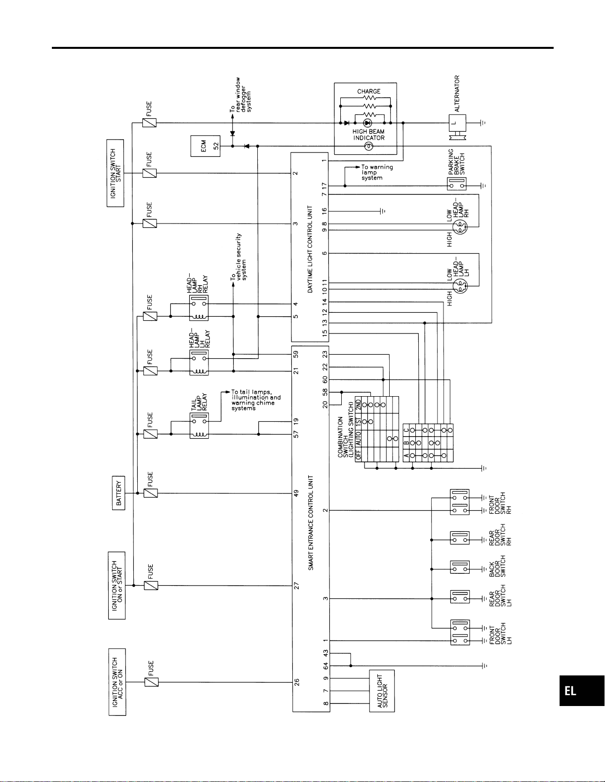
Schematic
NAEL0265
MEL393P
GI
MA
EM
LC
EC
FE
CL
MT
AT
TF
PD
AX
SU
BR
ST
RS
BT
HA
SC
IDX
HEADLAMP (FOR CANADA) — DAYTIME LIGHT SYSTEM —
Schematic
EL-49
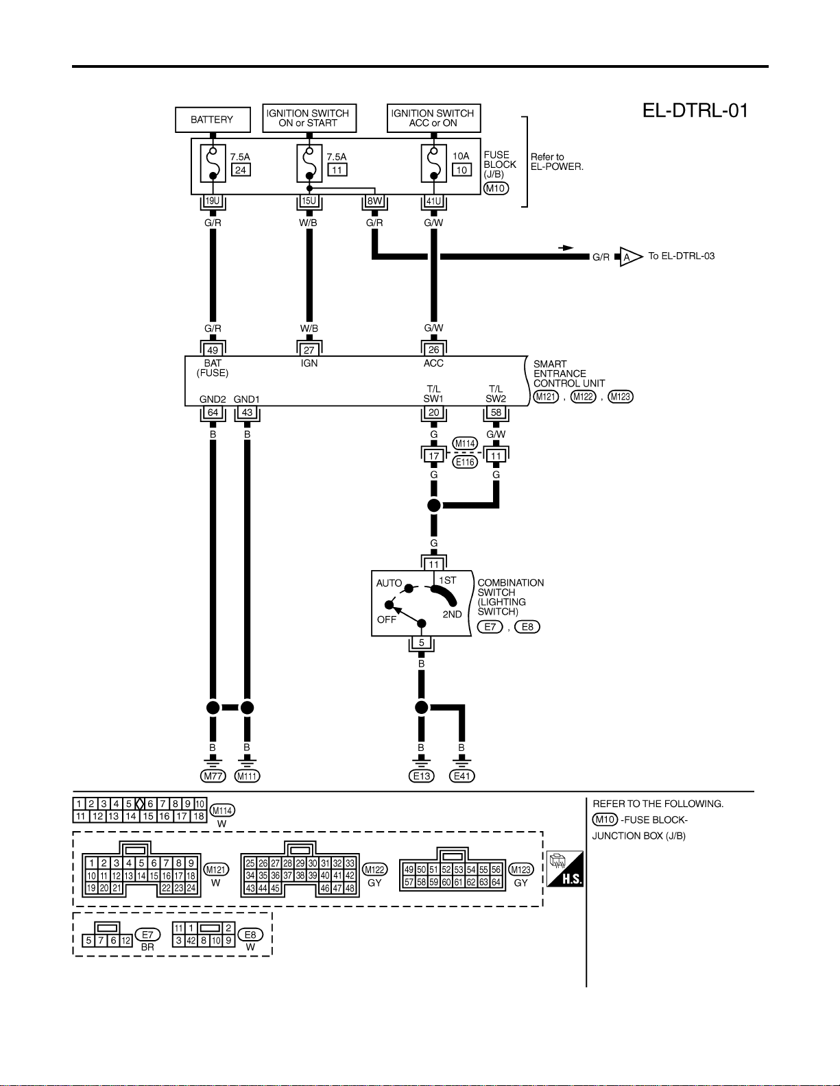
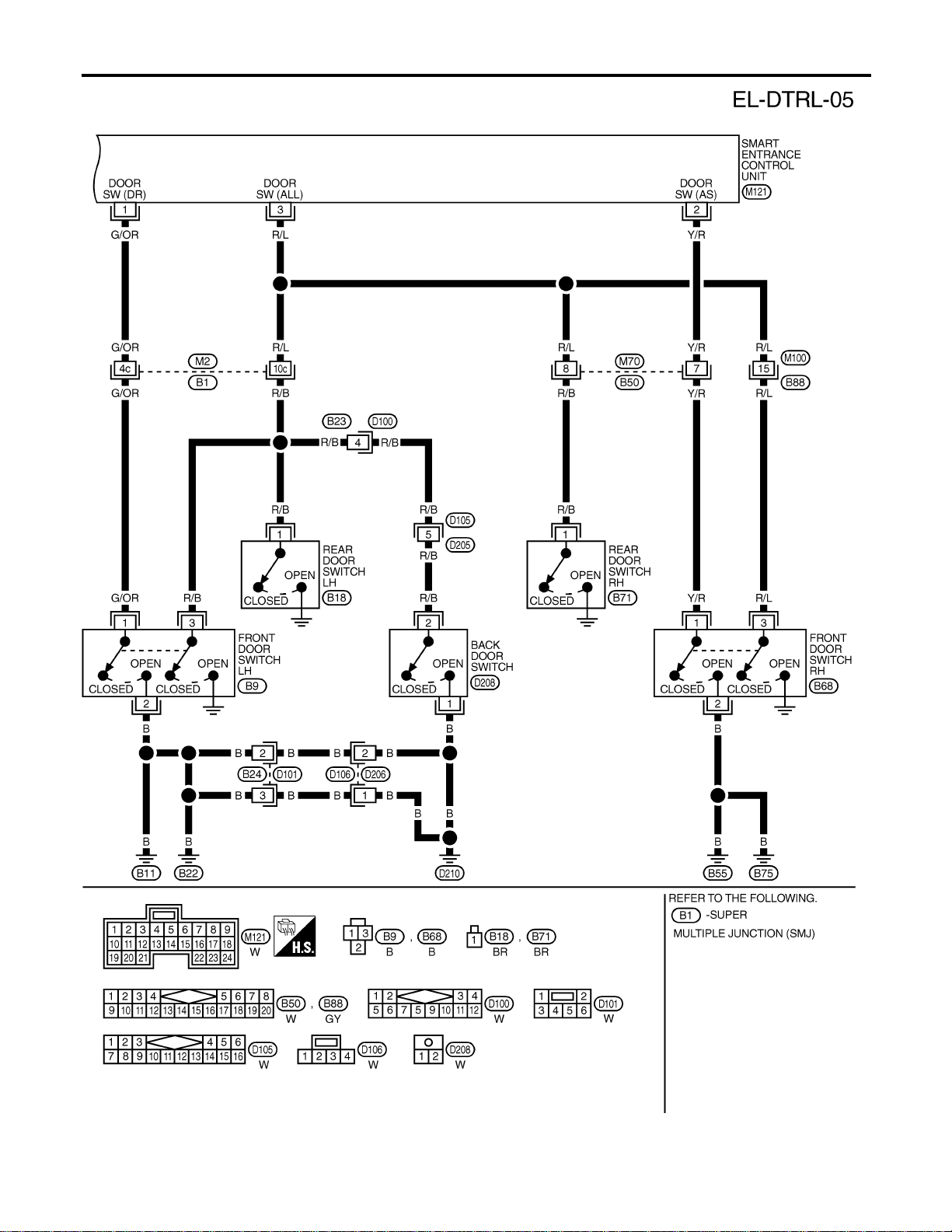
Wiring Diagram — DTRL —
NAEL0266
MEL394P
HEADLAMP (FOR CANADA) — DAYTIME LIGHT SYSTEM —
Wiring Diagram — DTRL —
EL-50
MEL395P
GI
MA
EM
LC
EC
FE
CL
MT
AT
TF
PD
AX
SU
BR
ST
RS
BT
HA
SC
IDX
HEADLAMP (FOR CANADA) — DAYTIME LIGHT SYSTEM —
Wiring Diagram — DTRL — (Cont’d)
EL-51
MEL396P
HEADLAMP (FOR CANADA) — DAYTIME LIGHT SYSTEM —
Wiring Diagram — DTRL — (Cont’d)
EL-52
MEL857N
GI
MA
EM
LC
EC
FE
CL
MT
AT
TF
PD
AX
SU
BR
ST
RS
BT
HA
SC
IDX
HEADLAMP (FOR CANADA) — DAYTIME LIGHT SYSTEM —
Wiring Diagram — DTRL — (Cont’d)
EL-53
MEL397P
HEADLAMP (FOR CANADA) — DAYTIME LIGHT SYSTEM —
Wiring Diagram — DTRL — (Cont’d)
EL-54

CONSULT-II Inspection Procedure
NAEL0267
“HEADLAMP”
NAEL0267S01
Refer to “HEADLAMP (FOR USA)” (EL-39).
CONSULT-II Application Items
NAEL0268
“HEADLAMP”
NAEL0268S01
Refer to “HEADLAMP (FOR USA)” (EL-40).
Trouble Diagnoses
NAEL0269
Symptom Possible cause Repair order
Neither headlamp operates. 1. 7.5A fuse
2. Lighting switch
3. Smart entrance control unit
1. Check 7.5A fuse [No. 24, located in fuse block
(J/B)].
Verify battery positive voltage is present at terminal
49 of smart entrance control unit.
2. Check Lighting switch.
3. Check smart entrance control unit. (EL-378)
LH headlamp (low and high beam)
does not operate, but RH head-
lamp (low and high beam) does
operate.
1. 15A fuse
2. Headlamp LH relay
3. Headlamp LH relay circuit
4. Headlamp LH ground circuit
5. Lighting switch circuit
6. Daytime light control unit
7. Smart entrance control unit
1. Check 15A fuse (No. 60, located in fusible link and
fuse box). Verify battery positive voltage is present
at terminal 1 and 3 of headlamp LH relay.
2. Check headlamp LH relay.
3. Check the following.
a. Harness between headlamp LH relay and daytime
light control unit.
b. Harness between headlamp LH relay and smart
entrance control unit.
4. Harness between headlamp LH and daytime light
control unit.
5. Check harness between smart entrance control unit
and lighting switch.
6. Check daytime light control unit. (EL-58)
7. Check smart entrance control unit. (EL-378)
GI
MA
EM
LC
EC
FE
CL
MT
AT
TF
PD
AX
SU
BR
ST
RS
BT
HA
SC
IDX
HEADLAMP (FOR CANADA) — DAYTIME LIGHT SYSTEM —
CONSULT-II Inspection Procedure
EL-55

Symptom Possible cause Repair order
RH headlamp (low and high beam)
does not operate, but LH headlamp
(low and high beam) does operate.
1. 15A fuse
2. Headlamp RH relay
3. Headlamp RH relay circuit
4. Headlamp RH ground circuit
5. Lighting switch circuit
6. Daytime light control unit
7. Smart entrance control unit
1. Check 15A fuse (No. 59, located in fusible link and
fuse box). Verify battery positive voltage is present
at terminals 1 and 3 of headlamp RH relay.
2. Check headlamp RH relay.
3. Check the following.
a. Harness between headlamp RH relay and daytime
light control unit.
b. Harness between headlamp RH relay and smart
entrance control unit.
4. Harness between headlamp RH and daytime light
control unit.
5. Check harness between smart entrance control unit
and lighting switch.
6. Check daytime light control unit. (EL-58)
7. Check smart entrance control unit. (EL-378)
LH high beam does not operate,
but LH low beam operates.
1. Bulb
2. Headlamp LH high beams cir-
cuit
3. Lighting switch
4. Lighting switch circuit
5. Daytime light control unit
1. Check bulb.
2. Check harness between LH headlamp and daytime
light control unit.
3. Check lighting switch.
4. Check harness between daytime light control unit
and lighting switch.
5. Check daytime light control unit. (EL-58)
LH low beam does not operate, but
LH high beam operates.
1. Bulb
2. Headlamp LH high beams cir-
cuit
3. Lighting switch
4. Lighting switch circuit
5. Daytime light control unit
1. Check bulb.
2. Check harness between LH headlamp and daytime
light control unit.
3. Check lighting switch.
4. Check harness between daytime light control unit
and lighting switch.
5. Check daytime light control unit. (EL-58)
RH high beam does not operate,
but RH low beam operates.
1. Bulb
2. Open in the RH high beams
circuit
3. Lighting switch
4. Lighting switch circuit
5. Daytime light control unit
1. Check bulb.
2. Check harness between RH headlamp and daytime
light control unit.
3. Check lighting switch.
4. Check harness between daytime light control unit
and lighting switch.
5. Check daytime light control unit. (EL-58)
RH low beam does not operate,
but RH high beam operates.
1. Bulb
2. Open in the RH high beams
circuit
3. Lighting switch
4. Lighting switch circuit
5. Daytime light control unit
1. Check bulb.
2. Check harness between RH headlamp and daytime
light control unit.
3. Check lighting switch.
4. Check harness between daytime light control unit
and lighting switch.
5. Check daytime light control unit. (EL-58)
High beam indicator does not work. 1. Bulb
2. Open in high beam circuit
1. Check bulb in combination meter.
2. Check the following.
a. Harness between headlamp LH relay and combina-
tion meter for an open circuit.
b. Harness between high beam indicator and lighting
switch.
Battery saver control does not
operate properly.
1. Door switch LH or RH circuit
2. Smart entrance control unit
1. Check the following.
a. Harness between smart entrance control unit and
LH or RH door switch for open or short circuit.
b. LH or RH door switch ground circuit.
c. LH or RH door switch.
2. Check smart entrance control unit. (EL-378)
HEADLAMP (FOR CANADA) — DAYTIME LIGHT SYSTEM —
Trouble Diagnoses (Cont’d)
EL-56

Symptom Possible cause Repair order
Daytime light control does not
operate properly.
1. Fuse check
2. Parking brake switch
3. Parking brake switch circuit
4. Alternator circuit
5. Daytime light control unit
1. Check the following.
a. 7.5A fuse [No. 11, located in fuse block (J/B)]. Verify
battery positive voltage is present at terminal 3 of
daytime light control unit.
b. 7.5A fuse [No. 26, located in fuse block (J/B)]. Verify
battery positive voltage is present at terminal 2 of
daytime light control unit.
2. Check parking brake switch.
3. Check harness between parking brake switch and
daytime light control unit.
4. Check harness between alternator and daytime light
control unit.
5. Check daytime light control unit. (EL-58)
When outside is dark, neither tail
lamp nor headlamp turn on by auto
light operation.
1. 7.5A fuse
2. Lighting switch “AUTO” check
3. Lighting switch circuit check
4. Lighting switch ground circuit
check
5. Auto light sensor check
6. Auto light sensor circuit check
1. Check 7.5A fuse [NO. 11 located in fuse block (J/B)].
Verify battery positive voltage is present at terminal
27 of smart entrance control unit.
2. Check lighting switch (AUTO) input signal with
“CONSULT-II” in “DATA MONITOR” mode.
When lighting switch is in AUTO:
AUTO LIGHT SWITCH ON
When lighting switch is in OFF:
AUTO LIGHT SWITCH OFF
3. Check harness for open or short between smart
entrance control unit and lighting switch.
4. Check harness for lighting switch and ground.
5. Check auto light sensor input signal.
(With CONSULT-II)
See “AUTO LIGHT SENSOR” in DATA MONITOR
mode. When auto light sensor in stuck by light:
More than 3V
When auto light sensor is not stuck by light:
Approx. 0.5V
(Without CONSULT-II)
Check voltage between smart entrance control unit
terminal 7 and ground. Refer to smart entrance con-
trol unit. (EL-378)
6. Check the following.
a. Harness for open or short between smart entrance
control unit terminal 8 and auto light sensor terminal
1
b. Harness for open or short between smart entrance
control unit terminal 7 and auto light sensor terminal
2
c. Harness for open or short between smart entrance
control unit terminal 9 and 3
When outside is dark, tail lamp
turns on but headlamp does not
turn on by auto light operation.
Auto light output check Check auto light output.
(With CONSULT-II)
See “HEADLAMP” and “TAIL LAMP” in ACTIVE TEST
mode, and headlamp switch to AUTO position.
Headlamp and tail lamp should turn on.
(Without CONSULT-II)
Check voltage between smart entrance control unit ter-
minals 19, 21, 57, 59 and ground. Refer to smart
entrance control unit. (EL-378)
GI
MA
EM
LC
EC
FE
CL
MT
AT
TF
PD
AX
SU
BR
ST
RS
BT
HA
SC
IDX
HEADLAMP (FOR CANADA) — DAYTIME LIGHT SYSTEM —
Trouble Diagnoses (Cont’d)
EL-57
Symptom Possible cause Repair order
When outside is dark, headlamp
turns on but tail lamp does not turn
on by auto light operation.
Auto light output check Check auto light output.
(With CONSULT-II)
See “HEADLAMP” and “TAIL LAMP” in ACTIVE TEST
mode, and headlamp switch to AUTO position.
Headlamp and tail lamp should turn on.
(Without CONSULT-II)
Check voltage between smart entrance control unit ter-
minals 19, 21, 57, 59 and ground. Refer to smart
entrance control unit. (EL-378)
Light does not turn off when igni-
tion key switch is turned to “OFF”
(exterior battery saver control is
canceled).
1. 7.5A fuse
2. IGN switch circuit
1. Check 7.5A fuse [NO. 11 located in fuse block (J/B)].
Verify battery positive voltage is present at terminal
27 of smart entrance control unit.
2. Check harness for open or short between smart
entrance control unit and fuse.
When outside is bright, neither tail
lamps nor headlamps turn off by
auto light operation.
Auto light sensor check Check auto light sensor input signal.
(With CONSULT-II)
See “AUTO LIGHT SENSOR” in DATA MONITOR
mode. When auto light sensor in stuck by light:
More than 3V
When auto light sensor is not stuck by light:
Approx. 0.5V
(Without CONSULT-II)
Check voltage between smart entrance control unit ter-
minal 7 (W/G) and ground. Refer to smart entrance
control unit. (EL-378)
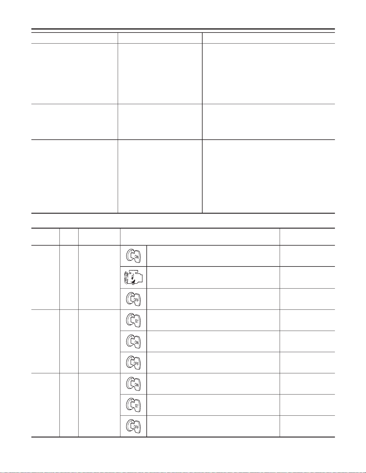
DAYTIME LIGHT CONTROL UNIT INSPECTION TABLE
NAEL0269S01
Terminal
No.
Wire
color
Item Condition
Voltage
(Approximate values)
1 Y/B Alternator
When turning ignition switch to “ON” Less than 1V
When engine is running Battery voltage
When turning ignition switch to “OFF” Less than 1V
2 Y/R Start signal
When turning ignition switch to “ST” Battery voltage
When turning ignition switch to “ON” from “ST” Less than 1V
When turning ignition switch to “OFF” Less than 1V
3 G Power source
When turning ignition switch to “ON” Battery voltage
When turning ignition switch to “ST” Battery voltage
When turning ignition switch to “OFF” Less than 1V
HEADLAMP (FOR CANADA) — DAYTIME LIGHT SYSTEM —
Trouble Diagnoses (Cont’d)
EL-58
Terminal
No.
Wire
color
Item Condition
Voltage
(Approximate values)
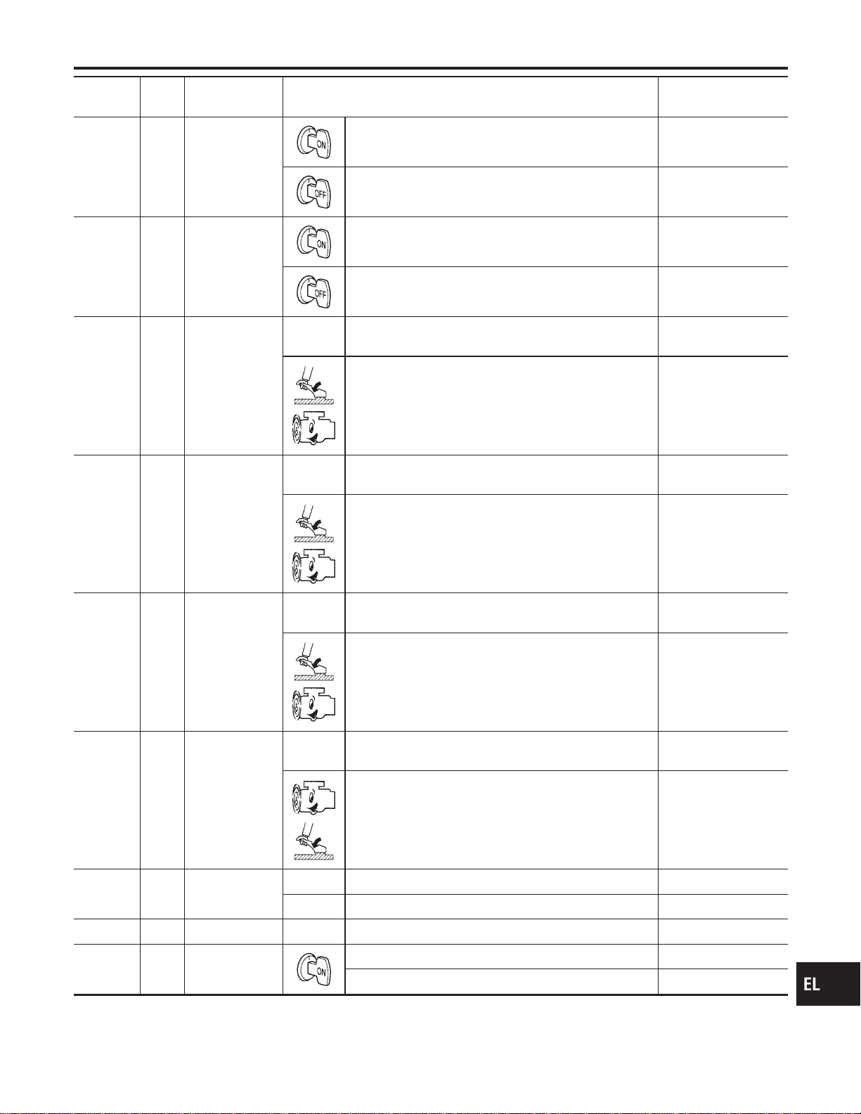
4 R/L Power source
When turning ignition switch to “ON” Battery voltage
When turning ignition switch to “OFF” Battery voltage
5 R/W Power source
When turning ignition switch to “ON” Battery voltage
When turning ignition switch to “OFF” Battery voltage
6 R LH hi beam When lighting switch is turned to the 2ND position with
“HI BEAM” position
Battery voltage
When releasing parking brake with engine running and
turning lighting switch to “OFF” (daytime light operation)
CAUTION:
Block wheels and ensure selector lever is in N or P
position.
Approx. half battery
voltage
7 L/R RH hi beam When lighting switch is turned to the 2ND position with
“HI BEAM” position
Battery voltage
When releasing parking brake with engine running and
turning lighting switch to “OFF” (daytime light operation)
CAUTION:
Block wheels and ensure selector lever is in N or P
position.
Battery voltage
9 PU RH hi beam
(ground)
When lighting switch is turned to the 2ND position with
“HI BEAM” position
Less than 1V
When releasing parking brake with engine running and
turning lighting switch to “OFF” (daytime light operation)
CAUTION:
Block wheels and ensure selector lever is in N or P
position.
Approx. half battery
voltage
10 GY LH hi beam
(ground)
When lighting switch is turned to the 2ND position with
“HI BEAM” position
Less than 1V
When releasing parking brake with engine running and
turning lighting switch to “OFF” (daytime light operation)
CAUTION:
Block wheels and ensure selector lever is in N or P
position.
Less than 1V
13
14
L/W
W/R
Lighting switch
(Hi beam)
When turning lighting switch to “HI BEAM” Less than 1V
When turning lighting switch to “FLASH TO PASS” Less than 1V
16 B Ground — —
17 L/G Parking brake
switch
When parking brake is released Battery voltage
When parking brake is set Less than 1.5V
GI
MA
EM
LC
EC
FE
CL
MT
AT
TF
PD
AX
SU
BR
ST
RS
BT
HA
SC
IDX
HEADLAMP (FOR CANADA) — DAYTIME LIGHT SYSTEM —
Trouble Diagnoses (Cont’d)
EL-59


System Description
NAEL0272
The parking, license and tail lamp operation is controlled by the lighting switch which is built into the combi-
nation switch and smart entrance control unit. The battery saver system is controlled by the smart entrance
control unit.
Power is supplied at all times
I to tail lamp relay terminals 1 and 3
I through 10A fuse (No. 61, located in the fuse and fusible link box), and
I to smart entrance control unit terminal 49
I through 7.5A fuse [No. 24, located in the fuse block (J/B)].
When ignition switch is in ON or START position, power is supplied
I to smart entrance control unit terminal 27
I through 7.5A fuse [No. 11, located in the fuse block (J/B)].
When the ignition switch is in the ACC or ON position, power is supplied
I to smart entrance control unit terminal 26
I through 10A fuse [No. 10, located in the fuse block (J/B)].
Ground is supplied
I to smart entrance control unit terminals 43 and 64
I through body grounds M77 and M111.
LIGHTING OPERATION BY LIGHTING SWITCH
NAEL0272S01
When lighting switch is in 1ST (or 2ND) position, ground is supplied
I to tail lamp relay terminal 2 from smart entrance control unit terminals 19 and 57
I through smart entrance control unit terminals 20 and 58, and
I through lighting switch and body grounds E13 and E41.
Tail lamp relay is then energized and the parking, license and tail lamps illuminate.
LIGHTING OPERATION BY AUTO LIGHT CONTROL SYSTEM
NAEL0272S02
When lighting switch is in AUTO position, ground is supplied
I to tail lamp relay terminal 2 from smart entrance control unit terminals 19 and 57
I through smart entrance control unit terminals 43 and 64, and
I to body grounds M77 and M111.
Tail lamp relay is then energized and the parking, license and tail lamps illuminate.
EXTERIOR LAMP BATTERY SAVER CONTROL
NAEL0272S03
Except for Auto Light Control Operation
NAEL0272S0301
Parking, license and tail lamps will remain on for a short while after the ignition switch is turned from ON (or
ACC) to OFF.
Continuity between terminals 21 and 22, and between terminals 59 and 60 of smart entrance control unit will
be disturbed after 5 minutes, then the headlamps will be turned off.
When the lighting switch is turned from OFF to 2ND after parking, license and tail lamps headlamps are turned
to off by the exterior lamp battery saver control, ground is supplied
I to smart entrance control unit terminals 20 and 58 from lighting switch terminal 11, and then,
I to headlamp LH and RH relays terminal 2 from smart entrance control unit terminals 21 and 59,
I through smart entrance control unit terminals 22 and 60 and
I through lighting switch terminal 12.
Then parking, license and tail lamps illuminate again.
Auto light control operation
NAEL0272S0302
While the parking, license and tail lamps are turned ON by “AUTO” operation, the exterior lamp battery saver
is activated for 5 minutes when the ignition switch is turned from ON (or ACC) to OFF, and either LH or RH
front door switch is opened.
The smart entrance control unit controls exterior lamp battery saver activation as follows:
I When the door switch signal changes from ON to OFF while the exterior lamp battery saver is activated,
the operation is discontinued, restarts and lasts for 45 seconds, then the parking, license and tail lamps
will be turned off.
I When the door switch signal changes from OFF to ON while the exterior lamp battery saver is activated,
GI
MA
EM
LC
EC
FE
CL
MT
AT
TF
PD
AX
SU
BR
ST
RS
BT
HA
SC
IDX
PARKING, LICENSE AND TAIL LAMPS
System Description
EL-61

the operation is discontinued, restarts and lasts for 45 seconds, then the parking, license and tail lamps
will be turned off.
I When the one of four door switch signals changes from OFF to ON while the exterior lamp battery saver
is activated, the operation is discontinued, restarts and lasts for 5 minutes seconds, then the parking,
license and tail lamps will be turned off.
I When all the door switch ON signals are input while the exterior lamp battery saver is activated, the
operation is discontinued, restarts and lasts for 45 seconds, then the parking, license and tail lamps will
be turned off.
I Exterior battery saver control time can be changed using “WORK SUPPORT” mode in “HEADLAMP”.
When the lighting switch is turned from OFF to 2ND after parking, license and tail lamps are turned to off by
the exterior lamp battery saver control, ground is supplied
I to smart entrance control unit terminals 20 and 58 from lighting switch terminal 11, and then,
I to tail lamp relays terminal 2 from smart entrance control unit terminals 21 and 59,
I through smart entrance control unit terminals 22 and 60 and
I through lighting switch terminal 12.
Then parking, license and tail lamps illuminate again.
PARKING, LICENSE AND TAIL LAMPS
System Description (Cont’d)
EL-62
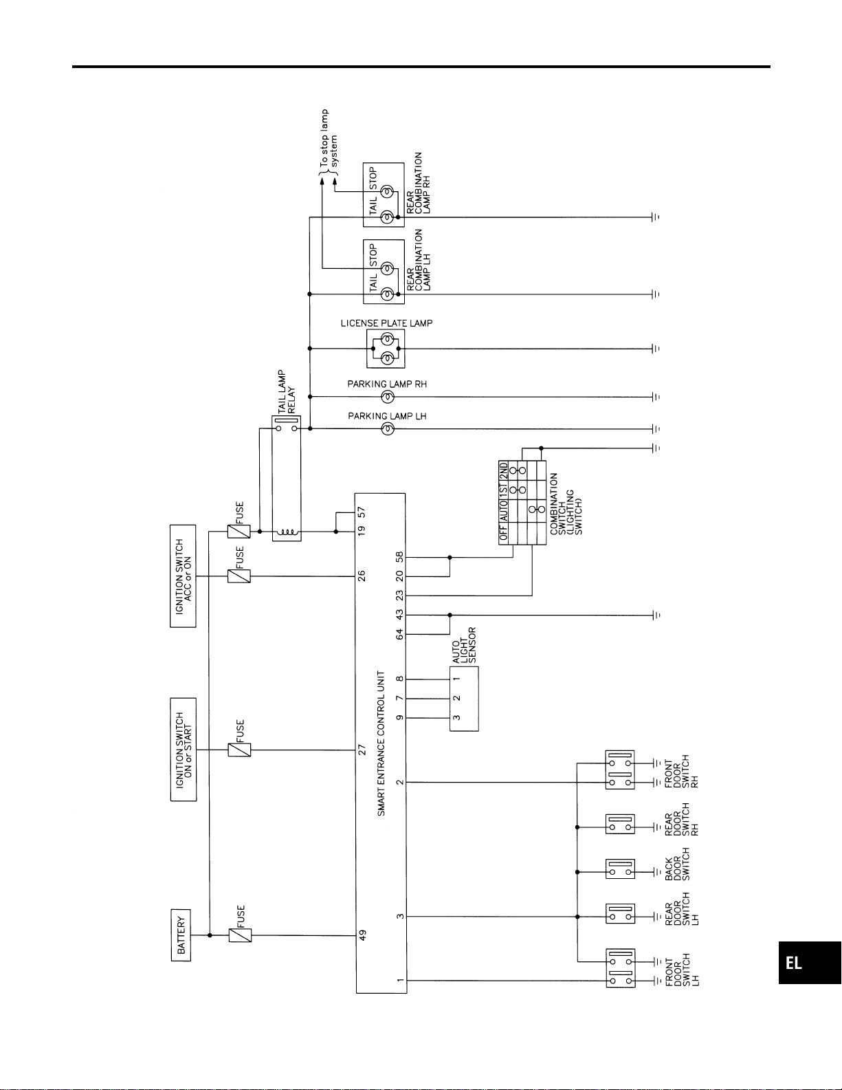
Schematic
NAEL0273
MEL515P
GI
MA
EM
LC
EC
FE
CL
MT
AT
TF
PD
AX
SU
BR
ST
RS
BT
HA
SC
IDX
PARKING, LICENSE AND TAIL LAMPS
Schematic
EL-63
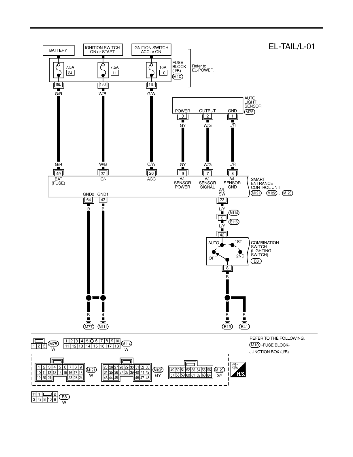
Wiring Diagram — TAIL/L —
NAEL0274
MEL398P
PARKING, LICENSE AND TAIL LAMPS
Wiring Diagram — TAIL/L —
EL-64
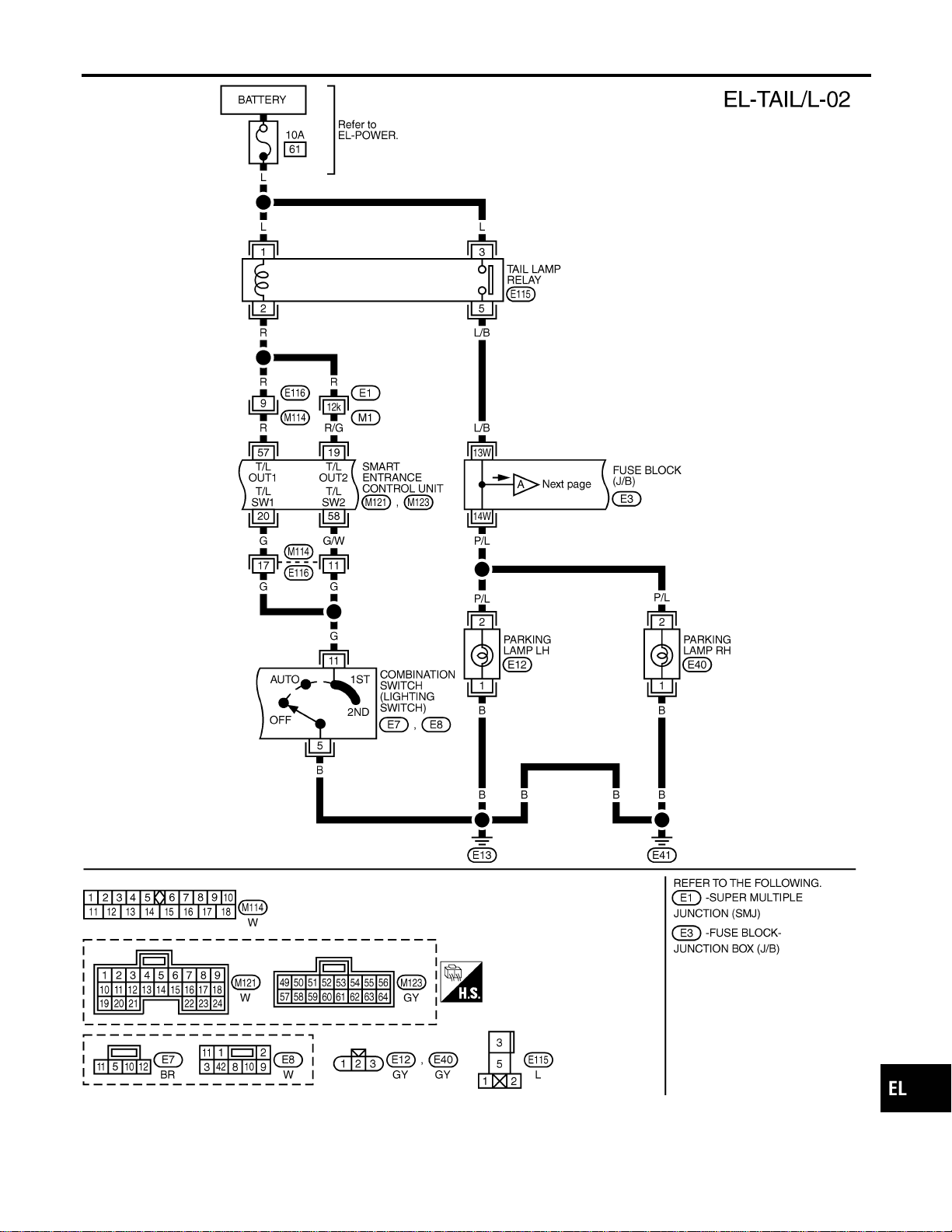
MEL403P
GI
MA
EM
LC
EC
FE
CL
MT
AT
TF
PD
AX
SU
BR
ST
RS
BT
HA
SC
IDX
PARKING, LICENSE AND TAIL LAMPS
Wiring Diagram — TAIL/L — (Cont’d)
EL-65
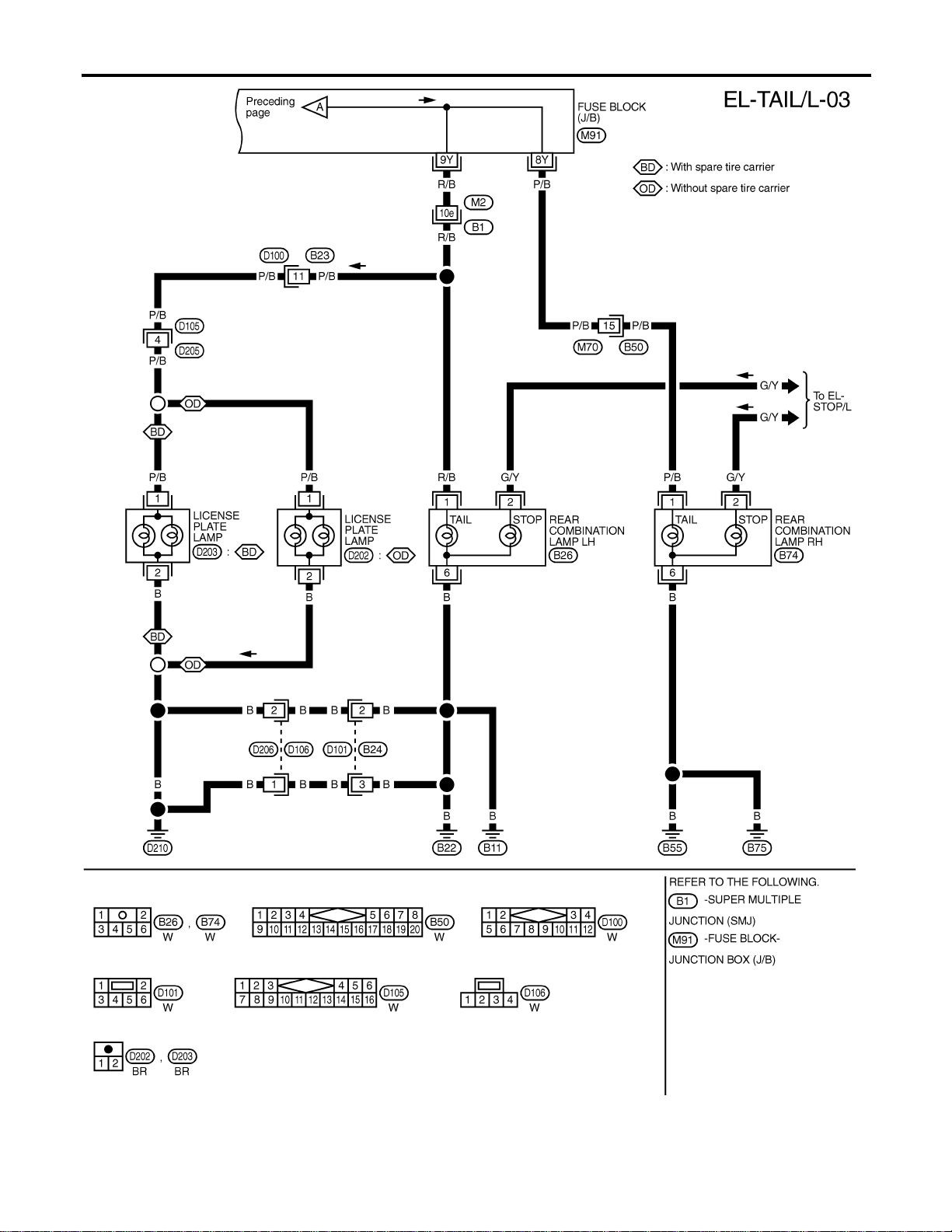
MEL553P
PARKING, LICENSE AND TAIL LAMPS
Wiring Diagram — TAIL/L — (Cont’d)
EL-66
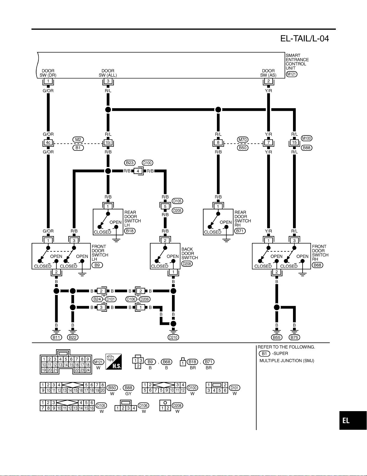
MEL404P
GI
MA
EM
LC
EC
FE
CL
MT
AT
TF
PD
AX
SU
BR
ST
RS
BT
HA
SC
IDX
PARKING, LICENSE AND TAIL LAMPS
Wiring Diagram — TAIL/L — (Cont’d)
EL-67
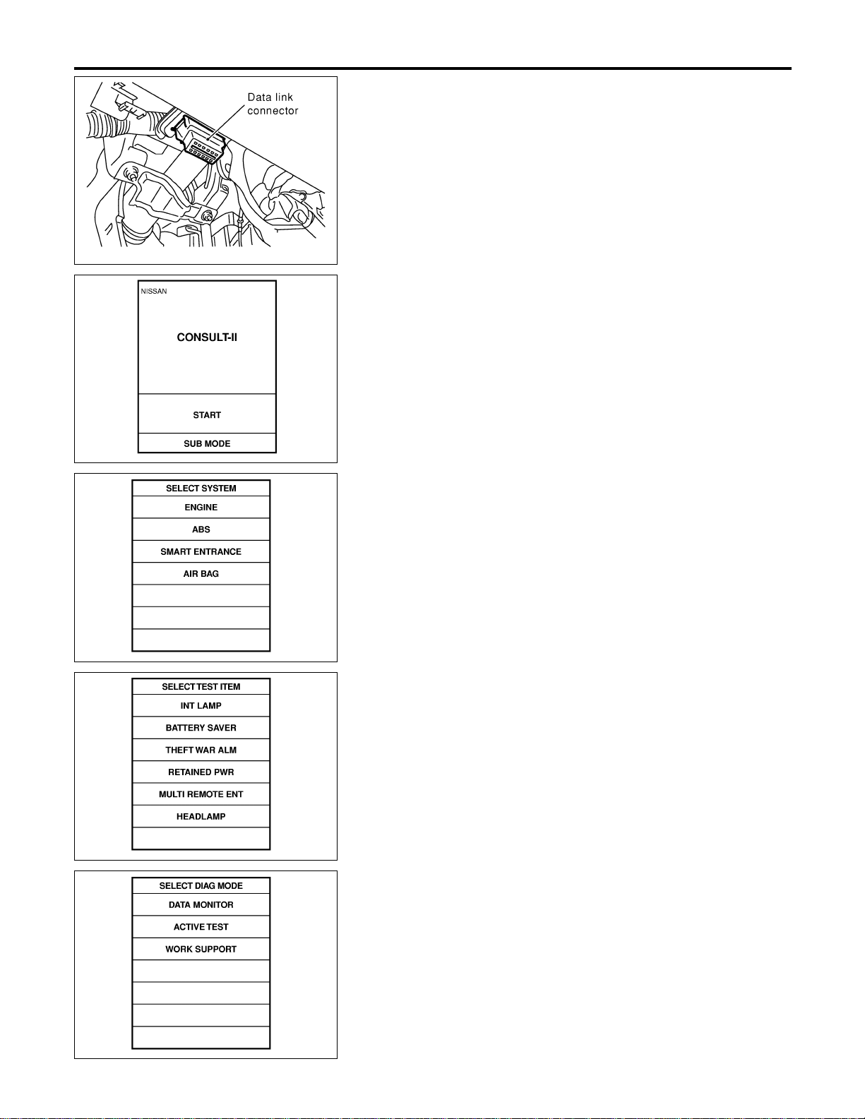
SEL331X
CONSULT-II Inspection Procedure
NAEL0275
“HEADLAMP”
NAEL0275S01
1. Turn ignition switch “OFF”.
2. Connect “CONSULT-II” to the data link connector.
PBR455D
3. Turn ignition switch “ON”.
4. Touch “START”.
SEL398Y
5. Touch “SMART ENTRANCE”.
SEL401Y
6. Touch “HEADLAMP”.
SEL400Y
7. Select diagnosis mode.
“DATA MONITOR” and “ACTIVE TEST” are available.
PARKING, LICENSE AND TAIL LAMPS
CONSULT-II Inspection Procedure
EL-68

CONSULT-II Application Items
NAEL0454
“HEADLAMP”
NAEL0454S01
Data Monitor
NAEL0454S0101
Monitored Item Description
IGN ON SW Indicates [ON/OFF] condition of ignition switch in ON position.
ACC ON SW Indicates [ON/OFF] condition of ignition switch in ACC position.
AUTO LIGT SW
Displays status of the lighting switch as judged from the lighting switch signal.
(AUTO position: ON/Other than AUTO position: OFF)
AUTO LIGT SENS
Displays “Illumination outside of the vehicle (close to 5V when light/close to 0V when dark)” as
judged from the optical sensor signal.
LIGHT SW 1ST
Displays status of the lighting switch as judged from the lighting switch signal.
(1ST or 2ND position: ON/Other than 1ST and 2ND position: OFF)
LIGHT SW 2ND
Displays status of the lighting switch as judged from the lighting switch signal.
(2ND position: ON/Other than 2ND position: OFF)
DOOR SW-DR Indicates [ON/OFF] condition of front door switch LH.
DOOR SW-AS Indicates [ON/OFF] condition of door switch RH.
DOOR SW-RR Indicates [ON/OFF] condition of rear door switch.
Active Test
NAEL0454S0102
Test Item Description
TAIL LAMP Tail lamp relay can be operated by on-off operation of the tail lamp.
HEAD LAMP Headlamp relay can be operated by on-off operation of the headlamp.
AUTO LIGHT Night time dimming signal can be operated by on-off operation.
Work Support
NAEL0454S0103
Work Item Description
AUTO LIGHT SET
Auto light sensitivity can be changed in this mode. Sensitivity can be adjusted in four modes.
I MODE 1 (Normal)/MODE 2 (Sensitive)/MODE 3 (Desensitized)/MODE 4 (Insensitive)
BATTERY SAVER SET
Exterior lamp battery saver control mode can be changed in this mode. Selects exterior lamp
battery saver control mode between two modes.
I MODE 1 (ON)/MODE 2 (OFF)
ILL DELAY SET
Auto light delay off timer period can be changed in this mode. Selects auto light delay off timer
period among eight modes.
I MODE 1 (45 sec.)/MODE 2 (OFF)/MODE 3 (30 sec.)/MODE 4 (60 sec.)/ MODE 5 (90 sec.)/
MODE 6 (120 sec.)/MODE 7 (150 sec.)/MODE 8 (180 sec.)
Trouble Diagnoses
NAEL0277
Symptom Possible cause Repair order
No lamps operate (including head-
lamps).
1. 7.5A fuse
2. Lighting switch
3. Smart entrance control unit
1. Check 7.5A fuse [No. 24, lacated in fuse block
(J/B)]. Verify battery positive voltage is present at
terminal 49 of smart entrance control unit.
2. Check lighting switch.
3. Check smart entrance control unit. (EL-378)
GI
MA
EM
LC
EC
FE
CL
MT
AT
TF
PD
AX
SU
BR
ST
RS
BT
HA
SC
IDX
PARKING, LICENSE AND TAIL LAMPS
CONSULT-II Application Items
EL-69

Symptom Possible cause Repair order
No parking, license and tail lamps
operate, but headlamps do oper-
ate.
1. 10A fuse
2. Tail lamp relay
3. Tail lamp relay circuit
4. Lighting switch
5. Lighting switch circuit
6. Smart entrance control unit
1. Check 10A fuse (No. 61, located in fusible and fuse
block). Verify battery positive voltage is present at
terminals 1 and 3 of tail lamp relay.
2. Check tail lamp relay.
3. Check the following.
a. Harness between smart entrance control unit termi-
nals 19 and 57 and tail lamp relay terminal 2
b. Harness between tail lamp relay terminal 5 and fuse
block.
4. Check lighting switch.
5. Check the following.
a. Harness between lighting switch terminal 11 and
smart entrance control unit terminals 20 and 58.
b. Harness between lighting switch terminal 5 and
ground.
6. Check smart entrance control unit. (EL-378)
Exterior lamp battery saver control
does not operate properly.
1. Driver, passenger or rear door
switch circuit
2. Smart entrance control unit
1. Check the following.
a. Harness between smart entrance control unit and
driver, passenger or rear door switch for open or
short circuit.
b. Driver passenger or rear door switch ground circuit.
c. Driver, passenger or rear door switch.
2. Check smart entrance control unit. (EL-378)
Auto light malfunctioning — Refer to trouble diagnosis in “HEADLAMP”. (EL-40)
PARKING, LICENSE AND TAIL LAMPS
Trouble Diagnoses (Cont’d)
EL-70
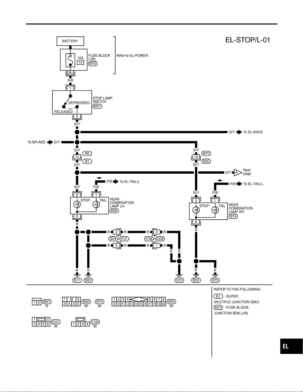
Wiring Diagram — STOP/L —
NAEL0278
MEL777L
GI
MA
EM
LC
EC
FE
CL
MT
AT
TF
PD
AX
SU
BR
ST
RS
BT
HA
SC
IDX
STOP LAMP
Wiring Diagram — STOP/L —
EL-71

MEL262M
STOP LAMP
Wiring Diagram — STOP/L — (Cont’d)
EL-72
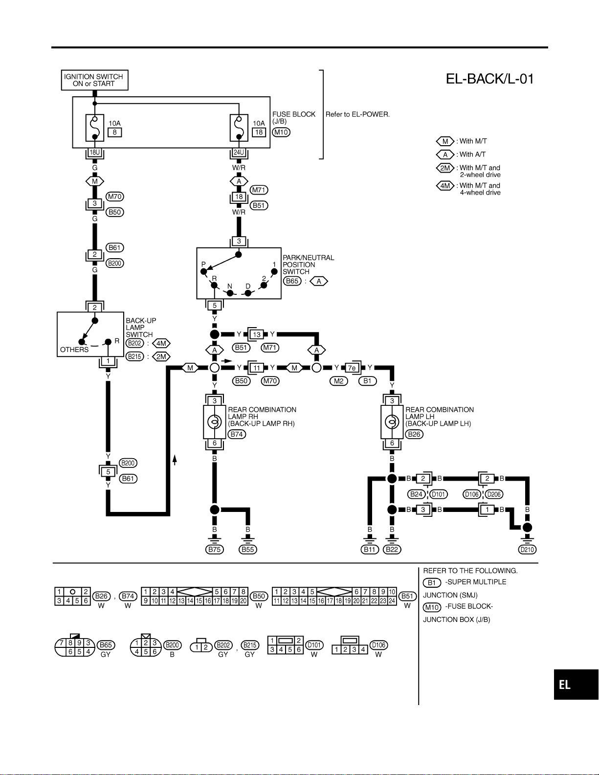
Wiring Diagram — BACK/L —
NAEL0279
MEL006M
GI
MA
EM
LC
EC
FE
CL
MT
AT
TF
PD
AX
SU
BR
ST
RS
BT
HA
SC
IDX
BACK-UP LAMP
Wiring Diagram — BACK/L —
EL-73

System Description
NAEL0280
OUTLINE
NAEL0280S01
Power is supplied at all times
I to headlamp RH relay terminals 1 and 3
I through 15A fuse (No. 59, located in the fuse and fusible link box), and
I to smart entrance control unit terminal 49
I through 7.5A fuse [No. 24, located in the fuse block (J/B)], and
I to front fog lamp relay terminal 3
I through 15A fuse (No. 53, located in the fuse and fusible link box).
When ignition switch is in ON or START position, power is supplied
I to smart entrance control unit terminal 27
I through 7.5A fuse [No. 11, located in the fuse block (J/B)].
When the ignition switch is in the ACC or ON position, power is supplied
I to smart entrance control unit terminal 26
I through 10A fuse [No. 10, located in the fuse block (J/B)].
Ground is supplied to smart entrance control unit terminals 43 and 64.
When lighting switch is in 2ND position, ground is supplied
I to headlamp RH relay terminal 2 from smart entrance control unit terminals 21 and 59.
I through smart entrance control unit terminals 22 and 60,
I through lighting switch terminal 12, and
I through body grounds E13 and E41.
Headlamp RH relay is then energized.
FOG LAMP OPERATION
NAEL0280S02
The front fog lamp switch is built into the combination switch. The lighting switch must be in the 2ND position
and LOW (“B”) position for front fog lamp operation.
With the front fog lamp switch in the ON position, ground is supplied
I to front fog lamp relay terminal 1
I through the front fog lamp switch, lighting switch and body grounds E13 and E41.
The front fog lamp relay is energized and power is supplied
I from front fog lamp relay terminal 5
I to terminal 1 of each front fog lamp.
Ground is supplied to terminal 2 of each front fog lamp through body grounds E13 and E41.
With power and ground supplied, the front fog lamps illuminate.
EXTERIOR LAMP BATTERY SAVER CONTROL
NAEL0280S03
Front fog lamps will remain on for a short while after the ignition switch is turned from ON (or ACC) to OFF.
Continuity between terminals 21 and 22, and between terminals 59 and 60 of smart entrance control unit will
be disturbed after 5 minutes, then the front fog lamps will be turned off.
When the lighting switch is turned from OFF to 2ND after front fog lamps are turned off by the battery saver
control, ground is supplied
I to smart entrance control unit terminals 20 and 58 from lighting switch terminal 11, and then
I to headlamp RH relay terminal 2 from smart entrance control unit terminal 21
I through smart entrance control unit terminal 22 from lighting switch terminal 12.
Then the front fog lamps illuminate again.
NOTE:
For Trouble Diagnoses for battery saver control, refer to “HEADLAMP (FOR USA)”, EL-40.
FRONT FOG LAMP
System Description
EL-74
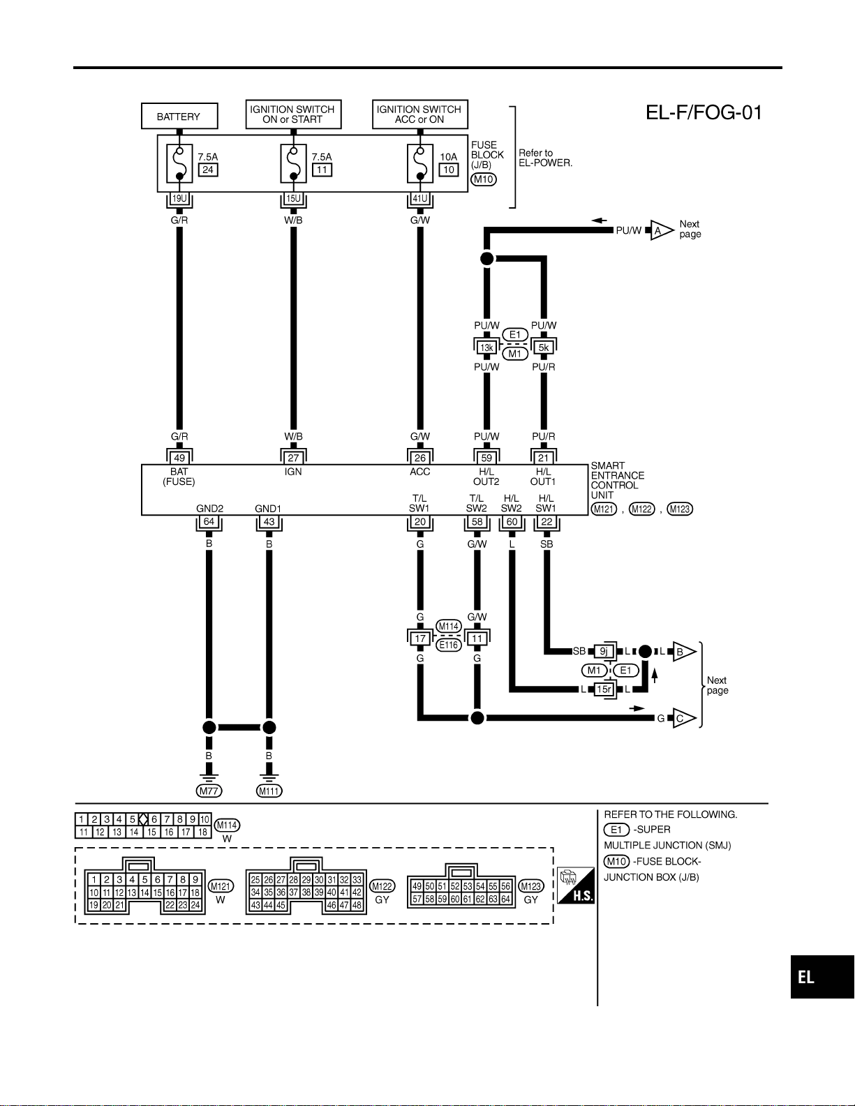
Wiring Diagram — F/FOG —
NAEL0281
MEL523P
GI
MA
EM
LC
EC
FE
CL
MT
AT
TF
PD
AX
SU
BR
ST
RS
BT
HA
SC
IDX
FRONT FOG LAMP
Wiring Diagram — F/FOG —
EL-75

MEL584P
FRONT FOG LAMP
Wiring Diagram — F/FOG — (Cont’d)
EL-76
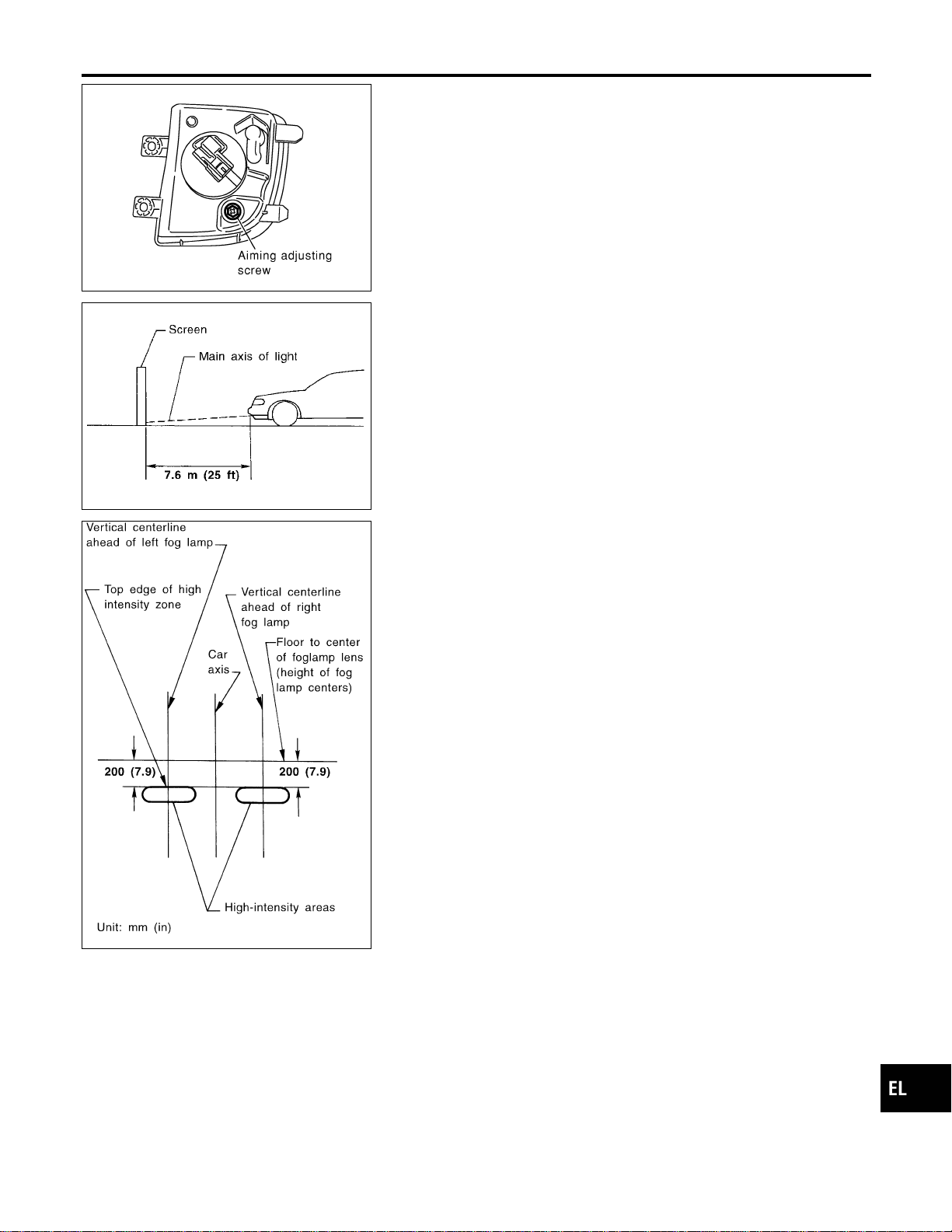
MEL917O
Aiming Adjustment
NAEL0282
Before performing aiming adjustment, make sure of the following.
1) Keep all tires inflated to correct pressure.
2) Place vehicle on level ground.
3) See that vehicle is unloaded (except for full levels of coolant,
engine oil and fuel, and spare tire, jack, and tools). Have the
driver or equivalent weight placed in driver’s seat.
Adjust aiming in the vertical direction by turning the adjusting
screw.
MEL327G
1. Set the distance between the screen and the center of the fog
lamp lens as shown at left.
2. Turn front fog lamps ON.
MEL328GA
3. Adjust front fog lamps so that the top edge of the high inten-
sity zone is 200 mm (7.9 in) below the height of the fog lamp
centers as shown at left.
I When performing adjustment, if necessary, cover the head-
lamps and opposite fog lamp.
GI
MA
EM
LC
EC
FE
CL
MT
AT
TF
PD
AX
SU
BR
ST
RS
BT
HA
SC
IDX
FRONT FOG LAMP
Aiming Adjustment
EL-77

System Description
NAEL0283
TURN SIGNAL OPERATION
NAEL0283S01
With the hazard switch in the OFF position and the ignition switch in the ON or START position, power is sup-
plied
I through 7.5A fuse [No. 12, located in the fuse block (J/B)]
I to hazard switch terminal 2
I through terminal 1 of the hazard switch
I to combination flasher unit terminal 1
I through terminal 3 of the combination flasher unit
I to turn signal switch terminal 1.
Ground is supplied to combination flasher unit terminal 2 through body grounds M4, M66 and M147.
LH Turn
NAEL0283S0101
When the turn signal switch is moved to the LH position, power is supplied from turn signal switch terminal 3
to
I front turn signal lamp LH terminal 2
I combination meter terminal 25
I rear combination lamp LH terminal 5.
Ground is supplied to the front turn signal lamp LH terminal 1 through body grounds E13 and E41.
Ground is supplied to the rear combination lamp LH terminal 6 through body grounds B11, B22 and D210.
Ground is supplied to combination meter terminal 30 through body grounds M4, M66 and M147.
With power and ground supplied, the combination flasher unit controls the flashing of the LH turn signal lamps.
RH Turn
NAEL0283S0102
When the turn signal switch is moved to the RH position, power is supplied from turn signal switch terminal
2to
I front turn signal lamp RH terminal 3
I combination meter terminal 29
I rear combination lamp RH terminal 5.
Ground is supplied to the front turn signal lamp RH terminal 1 through body grounds E13 and E41.
Ground is supplied to the rear combination lamp RH terminal 6 through body grounds B55 and B75.
Ground is supplied to combination meter terminal 30 through body grounds M4, M66 and M147.
With power and ground supplied, the combination flasher unit controls the flashing of the RH turn signal lamps.
HAZARD LAMP OPERATION
NAEL0283S02
Power is supplied at all times to hazard switch terminal 3 through:
I 15A fuse [No. 20, located in the fuse block (J/B)].
With the hazard switch in the ON position, power is supplied
I through terminal 1 of the hazard switch
I to combination flasher unit terminal 1
I through terminal 3 of the combination flasher unit
I to hazard switch terminal 4.
Ground is supplied to combination flasher unit terminal 2 through body grounds M4, M66 and M147.
Power is supplied through terminal 5 of the hazard switch to
I front turn signal lamp LH terminal 3
I combination meter terminal 25
I rear combination lamp LH terminal 5.
Power is supplied through terminal 6 of the hazard switch to
I front turn signal lamp RH terminal 3
I combination meter terminal 29
I rear combination lamp RH terminal 5.
TURN SIGNAL AND HAZARD WARNING LAMPS
System Description
EL-78

Ground is supplied to terminal 1 of each front turn signal lamp through body grounds E13 and E41.
Ground is supplied to terminal 6 of the rear combination lamp LH through body grounds B11, B22 and D210.
Ground is supplied to terminal 6 of the rear combination lamp RH through body grounds B55 and B75.
Ground is supplied to combination meter terminal 30 through body grounds M4, M66 and M147.
With power and ground supplied, the combination flasher unit controls the flashing of the hazard warning
lamps.
REMOTE KEYLESS ENTRY SYSTEM OPERATION
NAEL0283S03
Power is supplied at all times
I to smart entrance control unit terminal 49
I through 7.5A fuse [No. 24, located in the fuse block (J/B)].
Ground is supplied to smart entrance control unit terminal 43 and 64.
Refer to “REMOTE KEYLESS ENTRY SYSTEM”, EL-310.
When smart entrance control unit receives LOCK or UNLOCK signal from keyfob with all doors closed, power
is supplied
I through terminal 47 of smart entrance control unit
I to front turn signal lamp LH terminal 3
I to combination meter terminal 25
I to rear combination lamp LH terminal 5, and
I through terminal 48 of smart entrance control unit
I to front turn signal lamp RH terminal 3
I to combination meter terminal 29
I to rear combination lamp RH terminal 5.
Ground is supplied to terminal 1 of each front turn signal lamp through body grounds E13 and E41.
Ground is supplied to terminal 6 of the rear combination lamp LH through body grounds B11, B22 and D210.
Ground is supplied to terminal 6 of the rear combination lamp RH through body grounds B55 and B75.
Ground is supplied to combination meter terminal 30 through body grounds M4, M66 and M147.
With power and ground supplied, the smart entrance control unit controls the flashing of the hazard warning
lamps.
GI
MA
EM
LC
EC
FE
CL
MT
AT
TF
PD
AX
SU
BR
ST
RS
BT
HA
SC
IDX
TURN SIGNAL AND HAZARD WARNING LAMPS
System Description (Cont’d)
EL-79
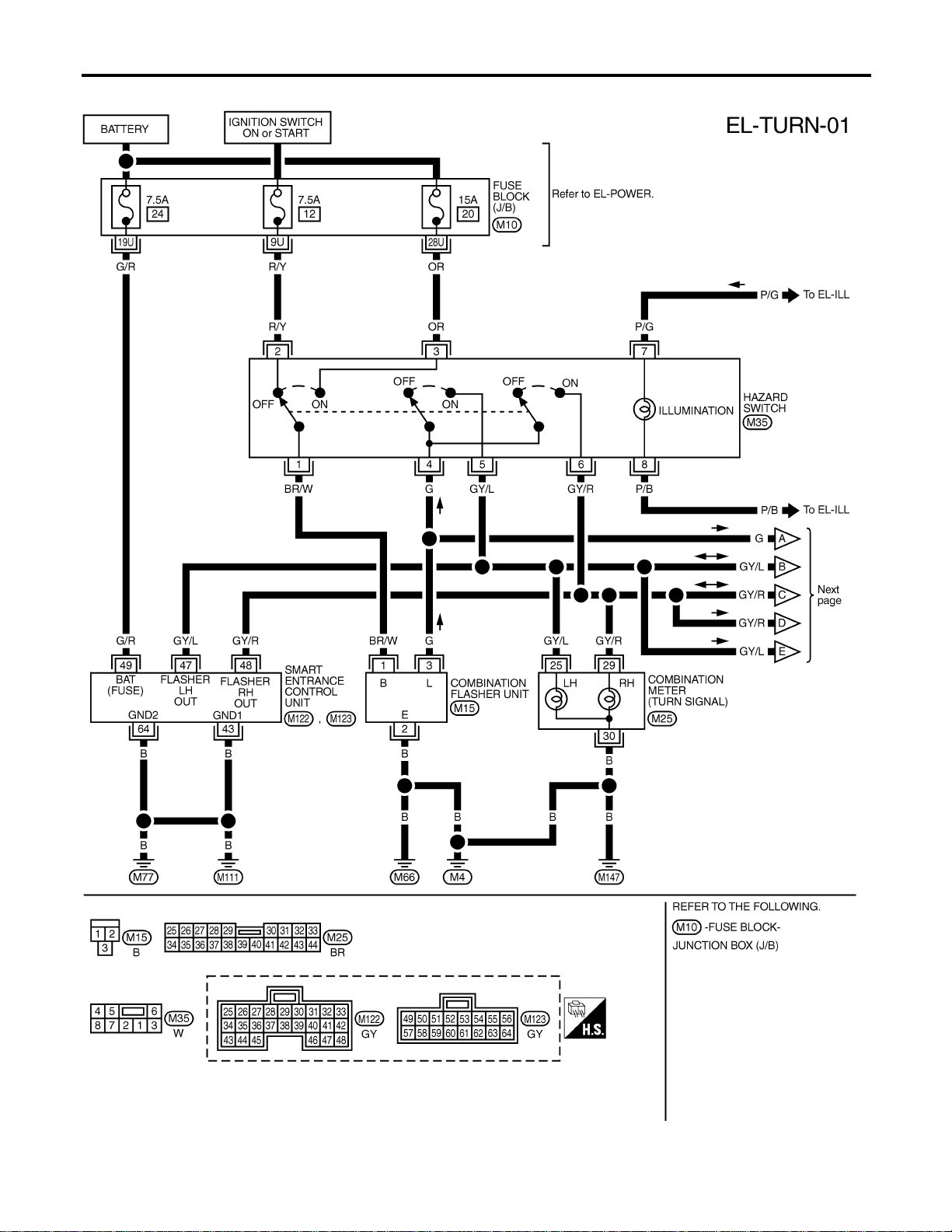
Wiring Diagram — TURN —
NAEL0284
MEL861N
TURN SIGNAL AND HAZARD WARNING LAMPS
Wiring Diagram — TURN —
EL-80
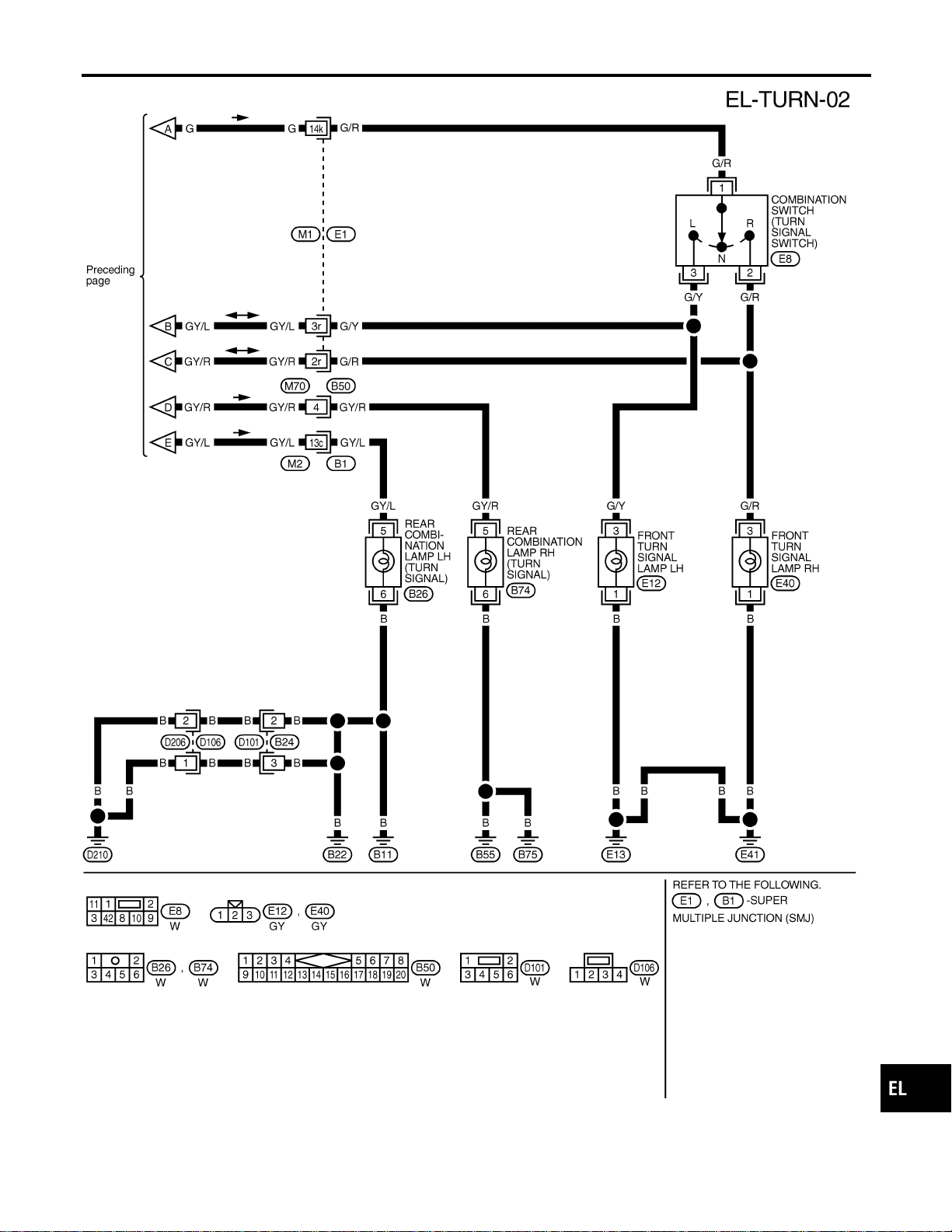
MEL862N
GI
MA
EM
LC
EC
FE
CL
MT
AT
TF
PD
AX
SU
BR
ST
RS
BT
HA
SC
IDX
TURN SIGNAL AND HAZARD WARNING LAMPS
Wiring Diagram — TURN — (Cont’d)
EL-81

Trouble Diagnoses
NAEL0285
Symptom Possible cause Repair order
Turn signal and hazard warning
lamps do not operate.
1. Hazard switch
2. Combination flasher unit
3. Open in combination flasher
unit circuit
1. Check hazard switch.
2. Refer to combination flasher unit check.
3. Check wiring to combination flasher unit for open
circuit.
Turn signal lamps do not operate
but hazard warning lamps operate.
1. 7.5A fuse
2. Hazard switch
3. Combination switch (turn signal)
4. Open in combination switch
(turn signal) circuit
1. Check 7.5A fuse [No. 12, located in fuse block
(J/B)]. Turn ignition switch ON and verify battery
positive voltage is present at terminal 2 of hazard
switch.
2. Check hazard switch.
3. Check combination switch (turn signal).
4. Check the wire between combination flasher unit
terminal 3 and combination switch (turn signal) ter-
minal 1 for open circuit.
Hazard warning lamps do not oper-
ate but turn signal lamps operate.
1. 15A fuse
2. Hazard switch
3. Open in hazard switch circuit
1. Check 15A fuse [No. 20, located in fuse block (J/B)].
Verify battery positive voltage is present at terminal
3 of hazard switch.
2. Check hazard switch.
3. Check the wire between combination flasher unit
terminal 3 and hazard switch terminal 4 for open cir-
cuit.
Front turn signal lamp LH or RH
does not operate.
1. Bulb
2. Grounds E13 and E41
3. Open in front turn signal lamp
circuit
1. Check bulb.
2. Check grounds E13 and E41.
3. Check harness between front turn signal lamp and
combination switch.
Rear combination lamp LH does
not operate.
1. Bulb
2. Grounds B11, B22 and D210
3. Open in rear combination lamp
LH circuit
1. Check bulb.
2. Check grounds B11, B22 and D210.
3. Check harness between rear combination lamp LH
and hazard switch.
Rear combination lamp RH does
not operate.
1. Bulb
2. Grounds B55 and B75
3. Open in rear combination lamp
RH circuit
1. Check bulb.
2. Check grounds B55 and B75.
3. Check harness between rear combination lamp RH
and hazard switch.
LH and RH turn indicators do not
operate.
1. Ground 1. Check grounds M4, M66 and M147.
LH or RH turn indicator does not
operate.
1. Bulb
2. Open in turn indicator circuit
1. Check bulb in combination meter.
2. Check harness between combination meter and haz-
ard switch.
SEL122E
Electrical Components Inspection
NAEL0286
COMBINATION FLASHER UNIT CHECK
NAEL0286S01
I Before checking, ensure that bulbs meet specifications.
I Connect a battery and test lamp to the combination flasher
unit, as shown. Combination flasher unit is properly function-
ing if it blinks when power is supplied to the circuit.
TURN SIGNAL AND HAZARD WARNING LAMPS
Trouble Diagnoses
EL-82
System Description
NAEL0287
The illumination lamp operation is controlled by the lighting switch which is built into the combination switch
and smart entrance control unit. The battery saver system is controlled by smart entrance control unit.
Power is supplied at all times
I to tail lamp relay terminals 1 and 3
I through 10A fuse (No. 61, located in the fuse and fusible link box), and
I to smart entrance control unit terminal 49
I through 7.5A fuse [No. 24, located in the fuse block (J/B)].
When ignition switch is in ON or START position, power is supplied
I to smart entrance control unit terminal 27
I through 7.5A fuse [No. 11, located in the fuse block (J/B)], and
When the ignition switch is in ACC or ON position, power is supplied
I to smart entrance control unit terminal 26
I through 10A fuse [No. 10, located in the fuse block (J/B)].
Ground is supplied
I to smart entrance control unit terminals 43 and 64
I through body grounds M77 and M111.
LIGHTING OPERATION BY LIGHTING SWITCH
NAEL0287S01
When lighting switch is 1ST (or 2ND) position, ground is supplied
I to tail lamp relay terminal 2 from smart entrance control unit terminals 19 and 57
I through smart entrance control unit terminals 20 and 58, and
I through lighting switch and body grounds E13 and E41.
Tail lamp relay is then energized and illumination lamps illuminate.
The lighting switch must be in the 1ST or 2ND position for illumination.
The illumination control switch that controls the amount of current to the illumination system. As the amount
of current increases, the illumination becomes brighter.
The ground for all of the components except for grove box lamp, ashtray and compass and thermometer are
controlled through terminals 2 and 3 of the illumination control switch and body grounds M77 and M111.
LIGHTING OPERATION BY AUTO LIGHT CONTROL SYSTEM
NAEL0287S02
When auto light operation is operated, ground is supplied
I to tail lamp relay terminal 2 from smart entrance control unit terminals 19 and 57
I through smart entrance control unit terminals 43 and 64, and
I to body grounds M77 and M111.
Tail lamp relay is then energized and the illumination lamps illuminate.
The illumination control switch that controls the amount of current to the illumination system. As the amount
of current increases, the illumination becomes brighter.
The following chart shows the power and ground connector terminals for the components included in the illu-
mination system.
Component Connector No. Power terminal Ground terminal
Illumination control switch M19 1 3
4WD shift switch M141 7 8
Ashtray B76 1 2
A/T indicator B59 3 4
Cigarette lighter M57 3 4
Audio unit M48 8 7
Compass and thermometer R4 5 2
Hazard switch M35 7 8
Rear window defogger switch M36 5 6
GI
MA
EM
LC
EC
FE
CL
MT
AT
TF
PD
AX
SU
BR
ST
RS
BT
HA
SC
IDX
ILLUMINATION
System Description
EL-83

Component Connector No. Power terminal Ground terminal
CD player M92, M93 3 5
CD auto changer M125 2 9
A/C switch illumination M45 2 1
Power window main switch D6 16 18
Front power window switch RH D36 10 17
Display & NAVI control unit M117, M118 8 24
A/C auto amp. M102 24 25
Clock M40 3 4
Globe box lamp M30 1 2
The ground for all of the components except for compass and thermometer, glove box lamp and ashtray are
controlled through terminals 2 and 3 of the illumination control switch and body grounds M77 and M111.
EXTERIOR LAMP BATTERY SAVER CONTROL
NAEL0287S03
Except for Auto Light Control Operation
NAEL0287S0301
Illumination lamps will remain on for a short while after the ignition switch is turned from ON (or ACC) to OFF.
Continuity between terminals 19 and 20, and between terminals 57 and 58 of smart entrance control unit will
be disturbed after 5 minutes, then the illumination lamp will be turned off.
When the lighting switch is turned from OFF to 1ST (or 2ND) after illumination lamps are turned off by the
battery saver control, ground is supplied
I to smart entrance control unit terminals 20 and 58 from lighting switch terminal 11, and
I to tail lamp relay terminal 2 from smart entrance control unit terminals 19 and 57.
Then illumination lamps illuminate again.
Auto light control operation
NAEL0287S0302
While the illumination lamps are turned ON by “AUTO” operation, the exterior lamp battery saver is activated
for 5 minutes when the ignition switch is turned from ON (or ACC) to OFF, and either LH or RH front door
switch is opened.
The smart entrance control unit controls exterior lamp battery saver activation as follows:
I When the door switch signal changes from ON to OFF while the exterior lamp battery saver is activated,
the operation is discontinued, restarts and lasts for 45 seconds, then the illumination lamps will be turned
off.
I When the door switch signal changes from OFF to ON while the exterior lamp battery saver is activated,
the operation is discontinued, restarts and lasts for 45 seconds, then the illumination lamps will be turned
off.
I When the one of four door switch signals changes from OFF to ON while the exterior lamp battery saver
is activated, the operation is discontinued, restarts and lasts for 5 minutes seconds, then the illumination
lamps will be turned off.
I When all the door switch ON signals are input while the exterior lamp battery saver is activated, the
operation is discontinued, restarts and lasts for 45 seconds, then the illumination lamps will be turned off.
I Exterior battery saver control time can be changed using “WORK SUPPORT” mode in “HEADLAMP”.
When the lighting switch is turned from OFF to 2ND after illumination lamps are turned to off by the exterior
lamp battery saver control, ground is supplied
I to smart entrance control unit terminals 20 and 58 from lighting switch terminal 11, and then,
I to tail lamp relays terminal 2 from smart entrance control unit terminals 21 and 59,
I through smart entrance control unit terminals 22 and 60 and
I through lighting switch terminal 12.
Then illumination lamps illuminate again.
NOTE:
For Trouble Diagnoses for battery saver control, refer to “PARKING, LICENSE AND TAIL LAMPS”
(EL-69).
ILLUMINATION
System Description (Cont’d)
EL-84
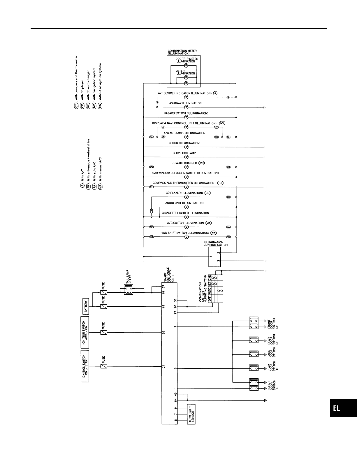
Schematic
NAEL0288
MEL399P
GI
MA
EM
LC
EC
FE
CL
MT
AT
TF
PD
AX
SU
BR
ST
RS
BT
HA
SC
IDX
ILLUMINATION
Schematic
EL-85
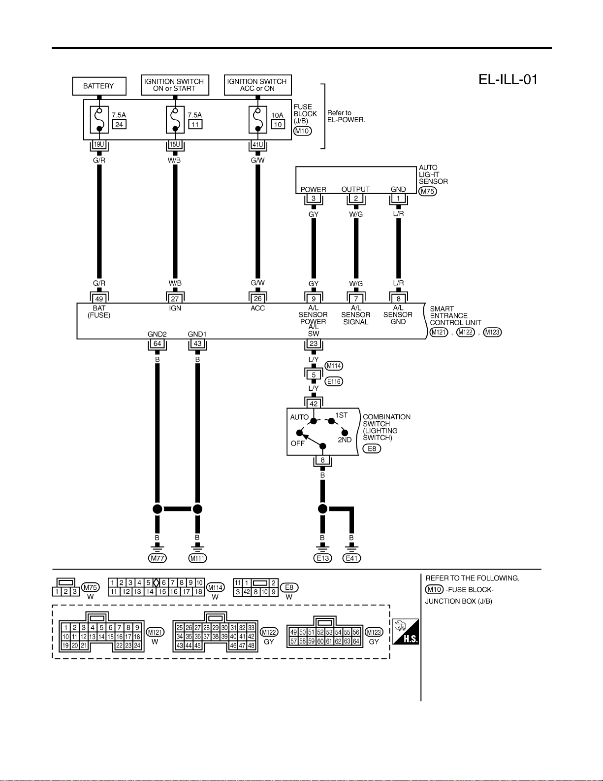
Wiring Diagram — ILL —
NAEL0289
MEL400P
ILLUMINATION
Wiring Diagram — ILL —
EL-86
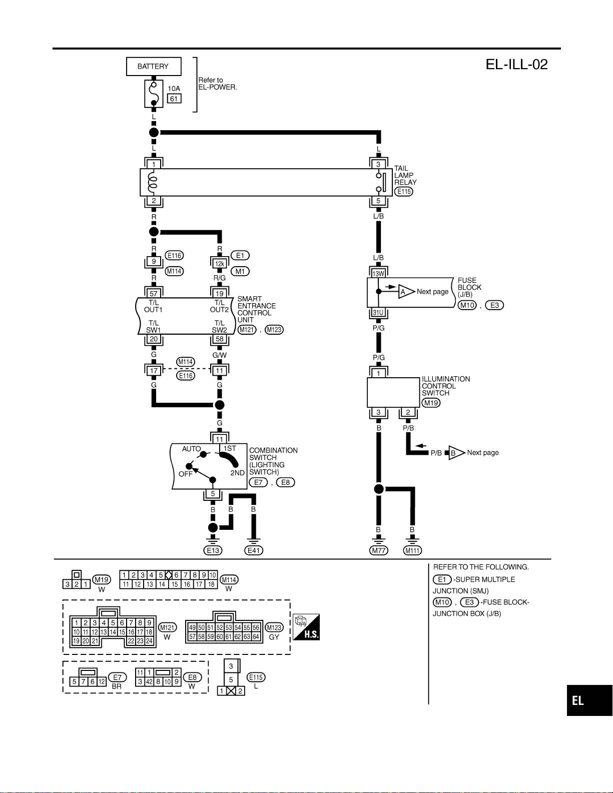
MEL405P
GI
MA
EM
LC
EC
FE
CL
MT
AT
TF
PD
AX
SU
BR
ST
RS
BT
HA
SC
IDX
ILLUMINATION
Wiring Diagram — ILL — (Cont’d)
EL-87

MEL427O
ILLUMINATION
Wiring Diagram — ILL — (Cont’d)
EL-88
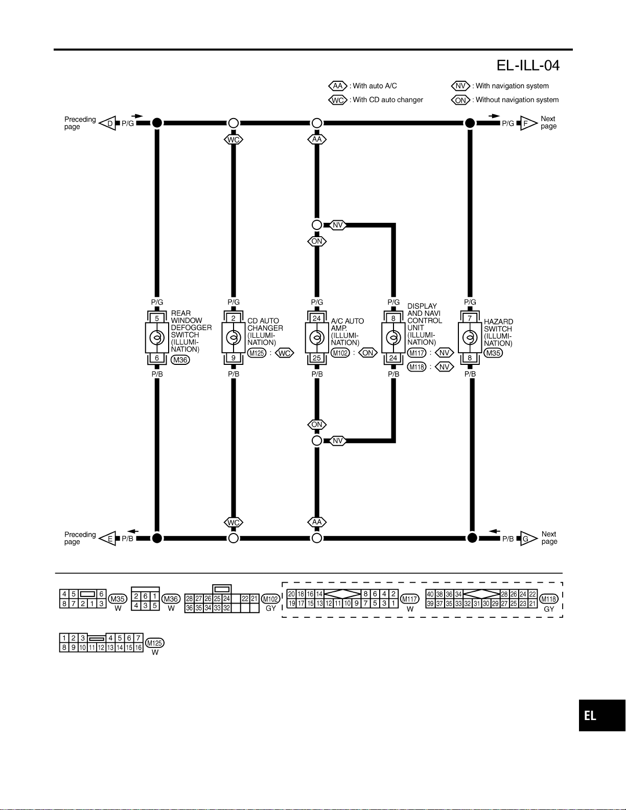
MEL401P
GI
MA
EM
LC
EC
FE
CL
MT
AT
TF
PD
AX
SU
BR
ST
RS
BT
HA
SC
IDX
ILLUMINATION
Wiring Diagram — ILL — (Cont’d)
EL-89
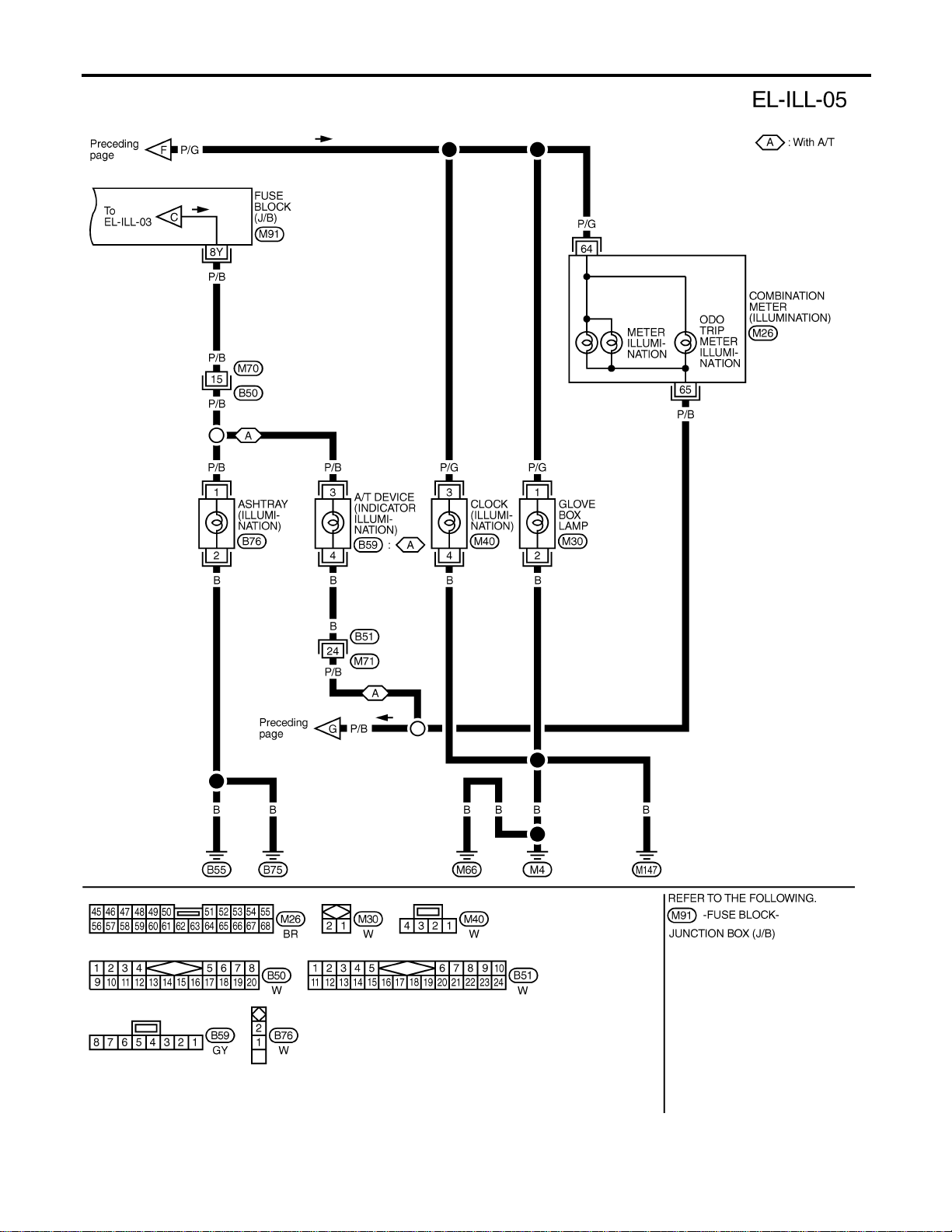
MEL402P
ILLUMINATION
Wiring Diagram — ILL — (Cont’d)
EL-90

MEL406P
GI
MA
EM
LC
EC
FE
CL
MT
AT
TF
PD
AX
SU
BR
ST
RS
BT
HA
SC
IDX
ILLUMINATION
Wiring Diagram — ILL — (Cont’d)
EL-91

System Description
NAEL0290
POWER SUPPLY AND GROUND
NAEL0290S01
Power is supplied at all times:
I through 7.5A fuse [No. 24, located in the fuse block (J/B)]
I to key switch terminal 2 and
I to smart entrance control unit terminal 49.
When the key is removed from ignition key cylinder, power is interrupted:
I through key switch terminal 1
I to smart entrance control unit terminal 25.
With the ignition key switch in the ON or START position, power is supplied:
I through 7.5A fuse [No. 11, located in the fuse block (J/B)]
I to smart entrance control unit terminal 27.
Ground is supplied:
I to smart entrance control unit terminals 43 and 64
I through body grounds terminals M77 and M111.
When the front driver side door is opened, ground is supplied:
I through body grounds B11, B22 and D210
I to front door switch (LH) terminal 2
I from front door switch (LH) terminal 1
I to smart entrance control unit terminal 1.
When the front passenger side door is opened, ground is supplied:
I through body grounds terminals B55 and B75
I to front door switch (RH) terminal 2
I from front door switch (RH) terminal 1
I to smart entrance control unit terminal 2.
When any other door (except front door) is opened, ground is supplied to smart entrance control unit termi-
nal 3 in the same manner as the front door switch.
When the front driver side door is unlocked by the central switch, the smart entrance control unit receives a
ground signal:
I through body grounds terminals M77 and M111 (LH) or M4, M66 and M147 (RH)
I to door lock and unlock switch terminal 5 (LH) or 7 (RH)
I from door lock and unlock switch terminal 19 (LH) or 18 (RH)
I to smart entrance control unit terminal 4.
When the front LH door is unlocked by the front door key cylinder switch and back door key cylinder switch,
the smart entrance control unit receives a ground signal:
I through body grounds terminals M77 and M111
I to front door key cylinder switch LH terminal 2
I from front door key cylinder switch LH terminal 1
I to smart entrance control unit terminal 10, and
I through body grounds terminals B11, B22 and D210
I to back door key cylinder switch terminal 4
I from back door key cylinder switch terminal 2
I to smart entrance control unit terminal 10.
When a signal, or combination of signals is received by the smart entrance control unit, ground is supplied:
I through smart entrance control unit terminal 31
I to interior lamp terminal 2.
With power and ground supplied, the interior lamp illuminates.
SWITCH OPERATION
NAEL0290S02
When interior lamp switch is ON, ground is supplied:
I through case grounds of interior lamp
I to interior lamp.
INTERIOR, SPOT, VANITY MIRROR AND LUGGAGE ROOM LAMPS
System Description
EL-92

And power is supplied:
I to interior lamp terminal 1
I from smart entrance control unit terminal 50.
When spot lamp (LH and/or RH) is ON, ground is supplied:
I through body grounds M4, M66 and M147
I to spot lamp terminal 2.
And power is supplied:
I to spot lamp terminal 1
I from smart entrance control unit terminal 50.
When vanity mirror illumination (LH and/or RH) is ON, ground is supplied:
I through body grounds M4, M66 and M147
I to vanity mirror illuminations (LH and RH) terminals 2.
And power is supplied:
I to vanity mirror illuminations (LH and RH) terminals 1
I from smart entrance control unit terminal 50.
With power and ground supplied, interior lamps turn ON.
INTERIOR LAMP TIMER OPERATION
NAEL0290S03
When interior lamp switch is in the “DOOR” position, the smart entrance control unit keeps the interior lamp
illuminated for about 30 seconds when:
I unlock signal is supplied from door lock and unlock switch while all doors are closed and key is out of
ignition key cylinder
I unlock signal is supplied from keyfob or door key cylinder while driver’s door is locked and all doors are
closed
I key is removed from ignition key cylinder while all doors are closed
I driver’s door is opened and then closed while key is out of the iginition key cylinder. (However, if the driv-
er’s door is closed with the key inserted in the ignition key cylinder after the driver’s door is opened with
the key removed, the timer is operated.)
The timer is canceled when:
I driver’s door is locked,
I driver’s door is opened, or
I ignition switch is turned ON.
When driver’s door is locked, interior room lamp timer is canceled as described before.
ON-OFF CONTROL
NAEL0290S04
When the driver side door, front passenger door, rear LH or RH door is opened, the interior room lamp turns
on while the interior room lamp switch is in the “DOOR” position.
INTERIOR LAMP BATTERY SAVER
NAEL0290S05
The lamp turns off automatically when interior lamp, luggage room lamp, spot lamp and/or vanity mirror illu-
mination is illuminated with the ignition key is in OFF position, if the lamp remains lit by the door switch open
signal or if the lamp switch is in ON position for more than 30 minutes.
After lamps turn OFF by the battery saver system, the lamps illuminate again when:
I driver’s door is locked or unlocked,
I door is opened or closed,
I key is removed from ignition key cylinder or inserted in ignition key cylinder
GI
MA
EM
LC
EC
FE
CL
MT
AT
TF
PD
AX
SU
BR
ST
RS
BT
HA
SC
IDX
INTERIOR, SPOT, VANITY MIRROR AND LUGGAGE ROOM LAMPS
System Description (Cont’d)
EL-93
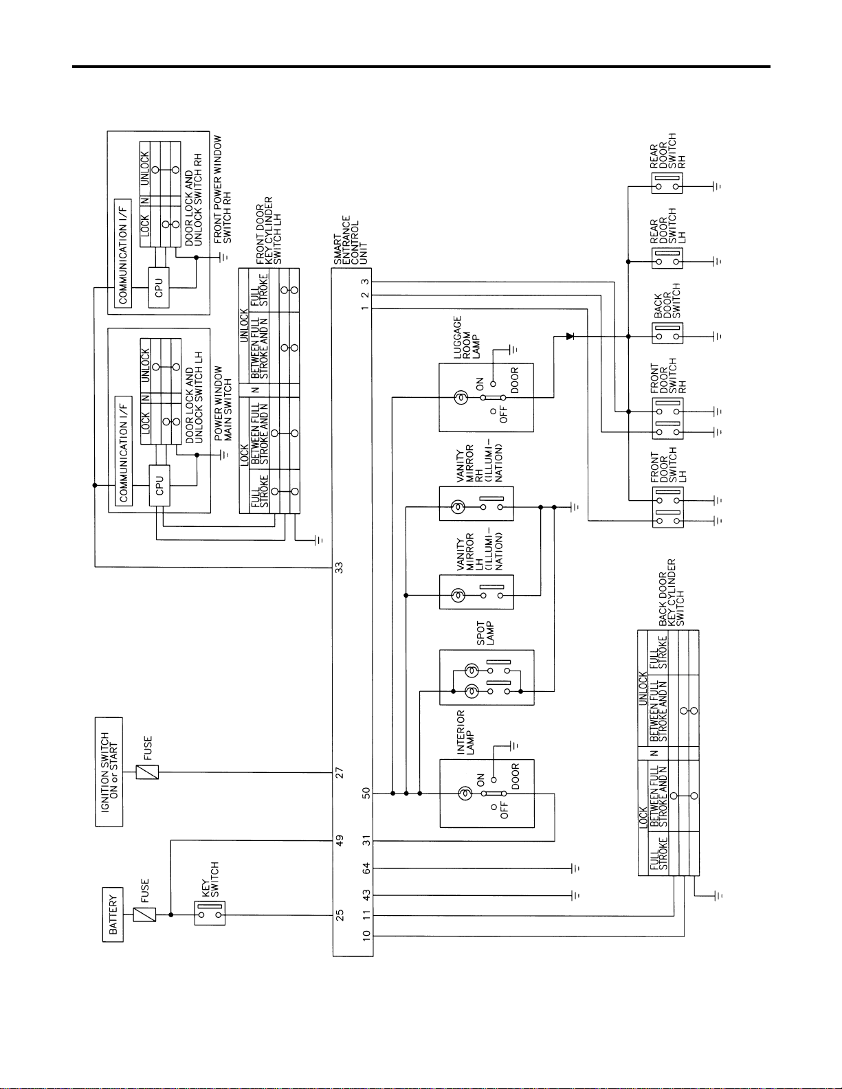
Schematic
NAEL0291
MEL407P
INTERIOR, SPOT, VANITY MIRROR AND LUGGAGE ROOM LAMPS
Schematic
EL-94
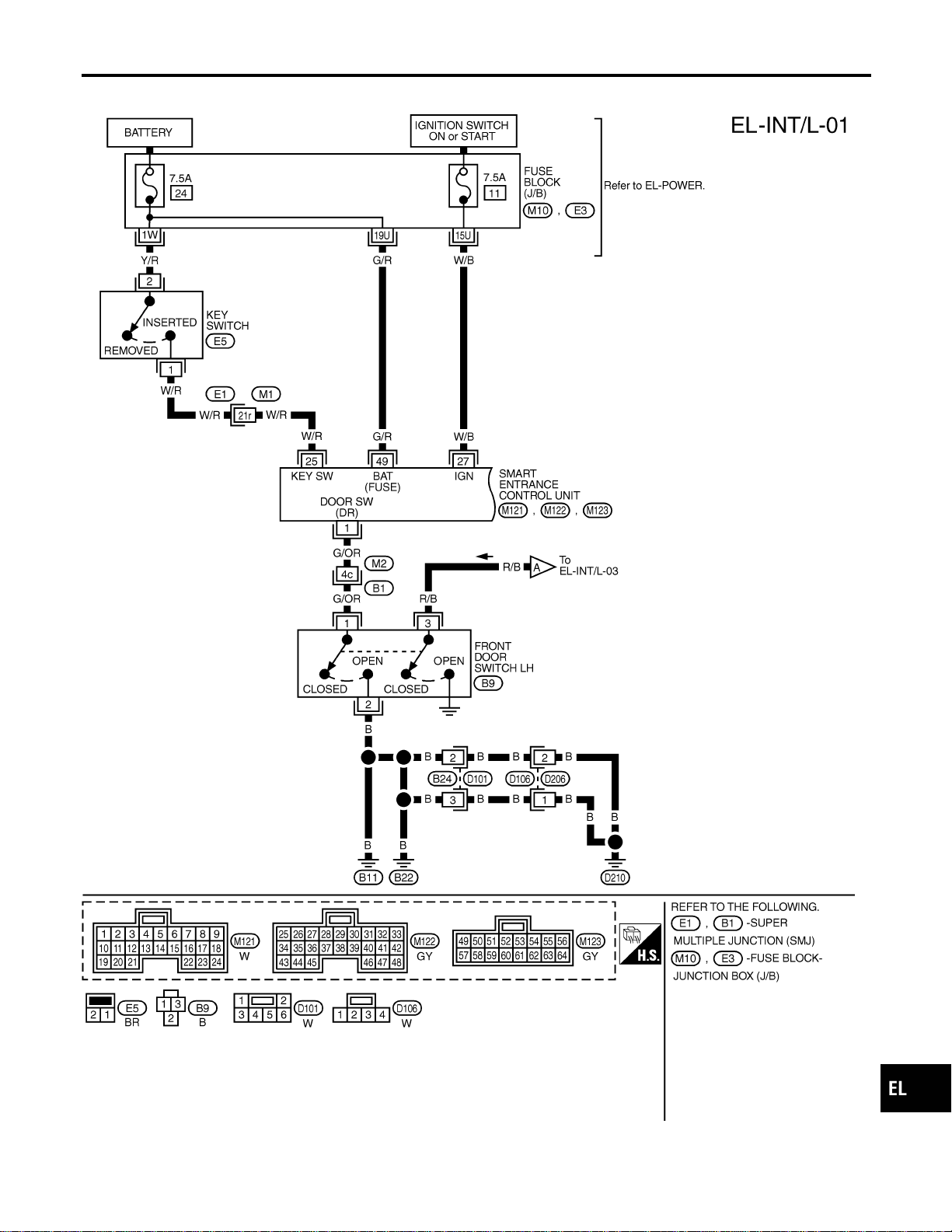
Wiring Diagram — INT/L —
NAEL0292
MEL408P
GI
MA
EM
LC
EC
FE
CL
MT
AT
TF
PD
AX
SU
BR
ST
RS
BT
HA
SC
IDX
INTERIOR, SPOT, VANITY MIRROR AND LUGGAGE ROOM LAMPS
Wiring Diagram — INT/L —
EL-95
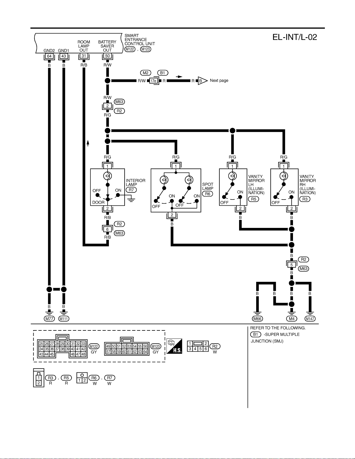
MEL713N
INTERIOR, SPOT, VANITY MIRROR AND LUGGAGE ROOM LAMPS
Wiring Diagram — INT/L — (Cont’d)
EL-96
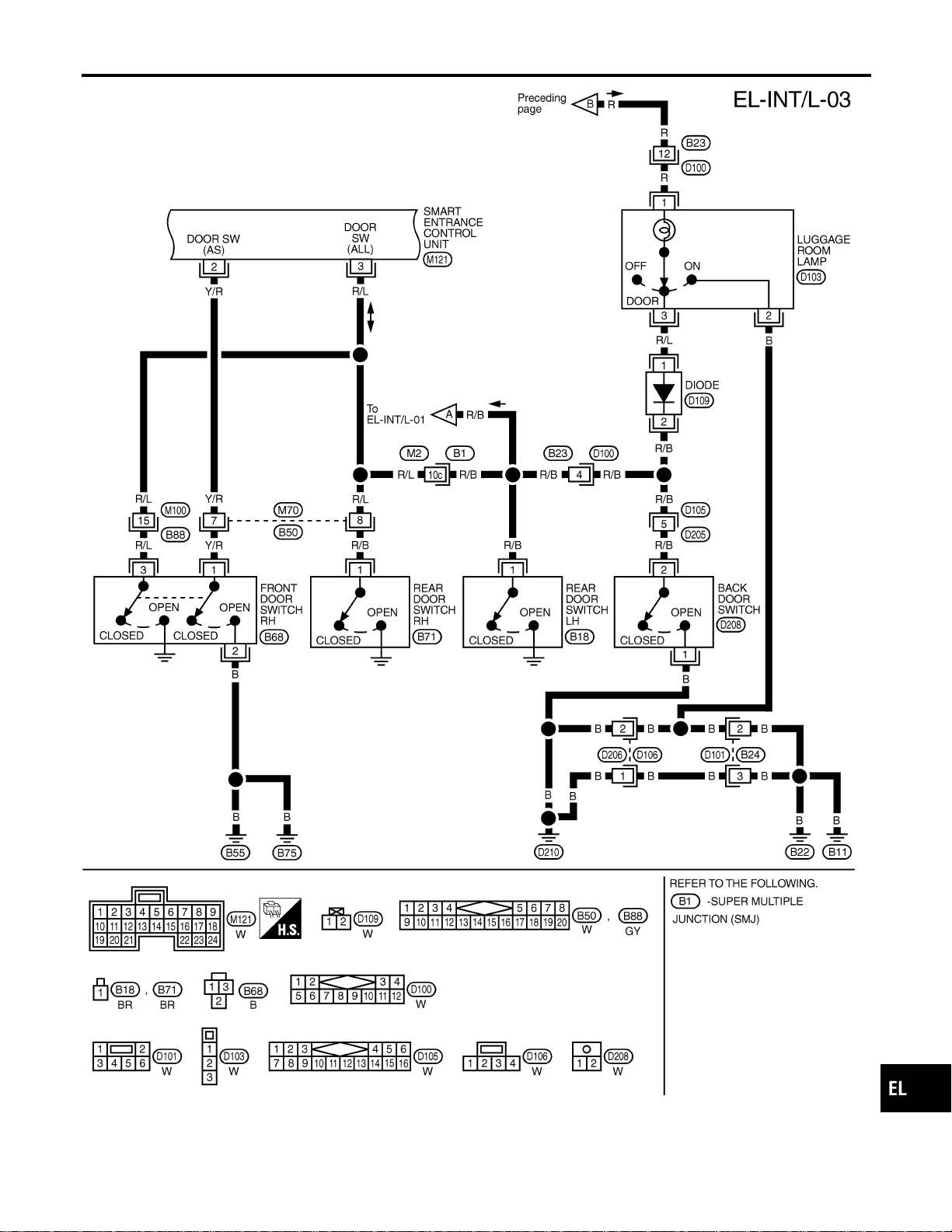
MEL476O
GI
MA
EM
LC
EC
FE
CL
MT
AT
TF
PD
AX
SU
BR
ST
RS
BT
HA
SC
IDX
INTERIOR, SPOT, VANITY MIRROR AND LUGGAGE ROOM LAMPS
Wiring Diagram — INT/L — (Cont’d)
EL-97
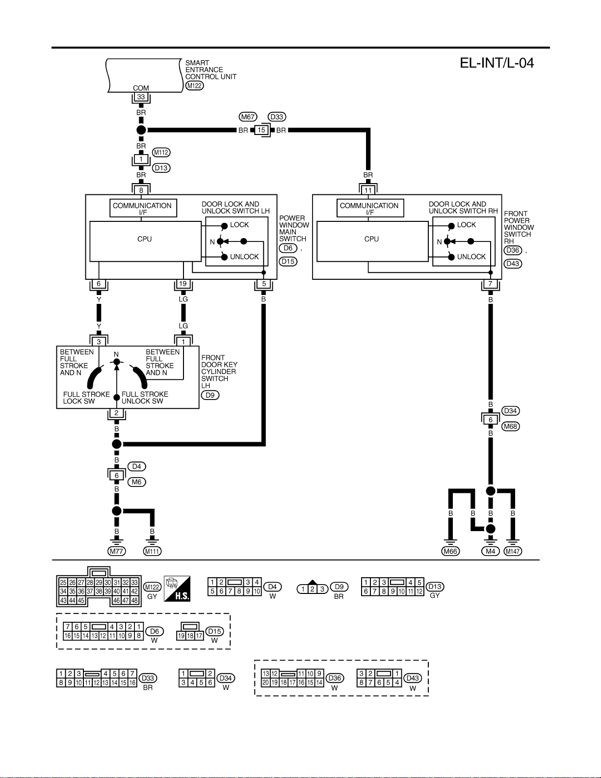
MEL409P
INTERIOR, SPOT, VANITY MIRROR AND LUGGAGE ROOM LAMPS
Wiring Diagram — INT/L — (Cont’d)
EL-98
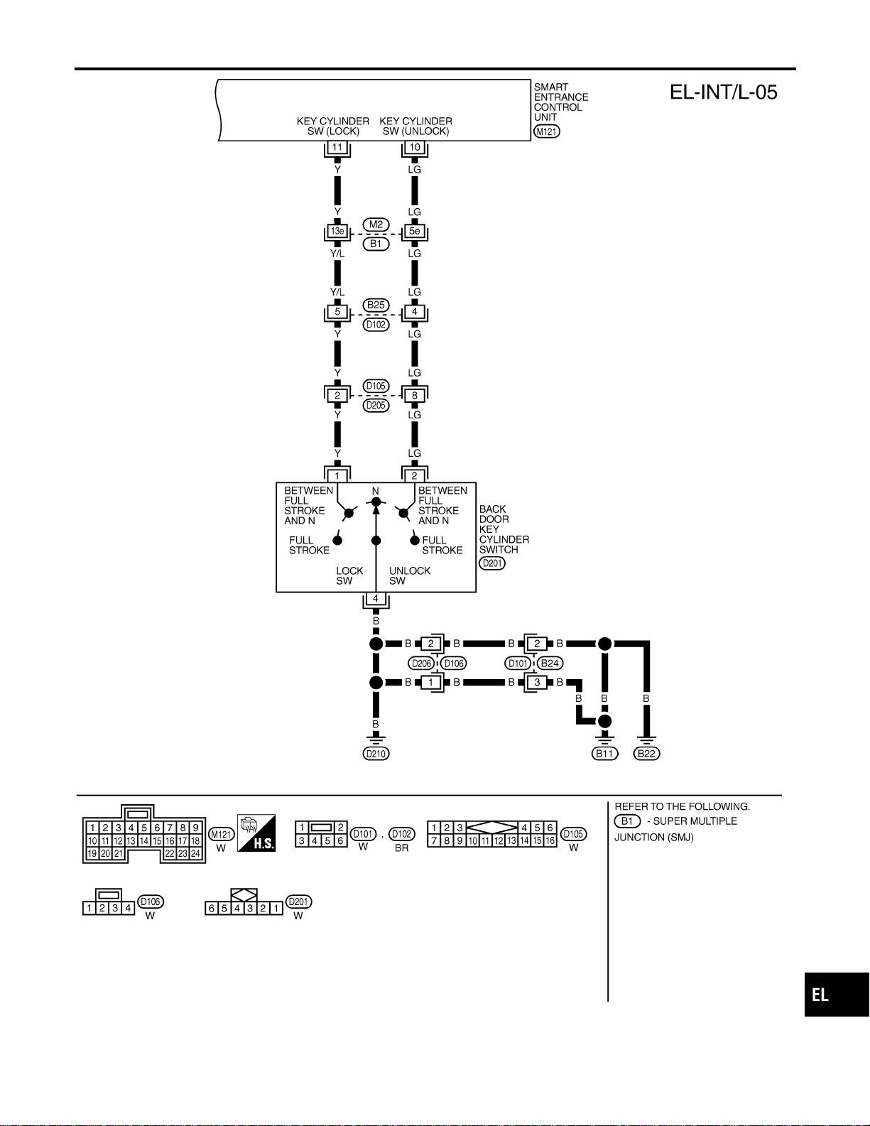
MEL410P
GI
MA
EM
LC
EC
FE
CL
MT
AT
TF
PD
AX
SU
BR
ST
RS
BT
HA
SC
IDX
INTERIOR, SPOT, VANITY MIRROR AND LUGGAGE ROOM LAMPS
Wiring Diagram — INT/L — (Cont’d)
EL-99
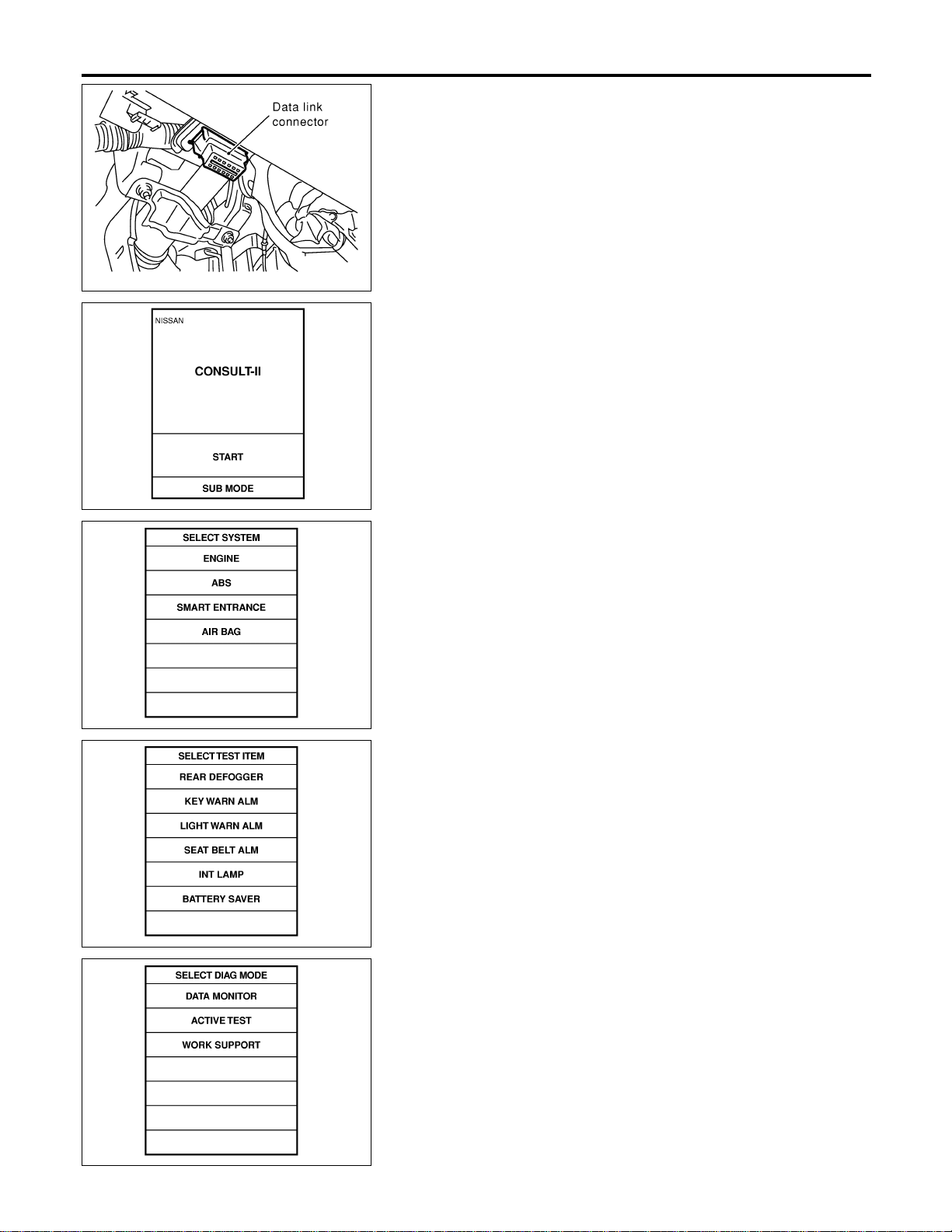
SEL331X
CONSULT-II Inspection Procedure
=NAEL0293
“INT LAMP”/“BATTERY SAVER”
NAEL0293S01
1. Turn ignition switch “OFF”.
2. Connect “CONSULT-II” to the data link connector.
PBR455D
3. Turn ignition switch “ON”.
4. Touch “START”.
SEL398Y
5. Touch “SMART ENTRANCE”.
SEL399Y
6. Touch “INT LAMP” or “BATTERY SAVER”.
SEL400Y
7. Select diagnosis mode.
“DATA MONITOR” and “ACTIVE TEST” are available for “INT
LAMP” and “BATTERY SAVER”.
INTERIOR, SPOT, VANITY MIRROR AND LUGGAGE ROOM LAMPS
CONSULT-II Inspection Procedure
EL-100

CONSULT-II Application Items
NAEL0294
“INT LAMP”
NAEL0294S01
Data Monitor
NAEL0294S0101
Monitored Item Description
IGN ON SW Indicates [ON/OFF] condition of ignition switch.
DOOR SW-RR Indicates [ON/OFF] condition of ignition switch.
KEY ON SW Indicates [ON/OFF] condition of key switch.
DOOR SW-DR Indicates [ON/OFF] condition of front door switch LH.
DOOR SW-AS Indicates [ON/OFF] condition of front door switch RH.
LOCK SW DR/AS Indicates [ON/OFF] condition of front door lock switch.
UNLK SW DR/AS Indicates [ON/OFF] condition of front door lock switch.
KEY CYL LK-SW Indicates [ON/OFF] condition of front door key cylinder switch.
KEY CYL UN-SW Indicates [ON/OFF] condition of front door key cylinder switch.
LK BUTTON/SIG Indicates [ON/OFF] condition of unlock signal from keyfob.
UN BUTTON/SIG Indicates [ON/OFF] condition of unlock signal from keyfob.
Active Test
NAEL0294S0102
Test Item Description
INT LAMP This test enables to check interior lamp operation.
When “ON” on CONSULT-II screen is touched:
I Interior lamp turns on when the switch is at DOOR.
(Smart entrance control unit supplies power and ground to interior lamp.)
IGN ILLUM This test enables to check ignition key hole illumination operation. The illumination turns on when
“ON” on CONSULT-II screen is touched.
STEP LAMP This test enables to check step lamp operation.
The illumination turns on when “ON” on CONSULT-II screen is touched.
NOTE:
Even though ignition key hole illumination and step lamp are actually displayed on the CONSULT-II screen,
those are not equipped, therefore, they cannot be activated.
Work Support
NAEL0294S0103
Work Item Description
ROOM LAMP TIMER SET
Interior lamp timer mode can be changed by mode setting. Selects ON-OFF of the room lamp
illumination at the time the driver door is unlocked.
NOTE:
Even though ignition keyhole illumination and step lamp are actually displayed on the CON-
SULT-II screen, those are not equipped, therefore, they cannot be activated.
“BATTERY SAVER”
NAEL0294S02
Data Monitor
NAEL0294S0201
Monitored Item Description
IGN ON SW Indicates [ON/OFF] condition of ignition switch.
DOOR SW-RR Indicates [ON/OFF] condition of ignition switch.
KEY ON SW Indicates [ON/OFF] condition of key switch.
DOOR SW-DR Indicates [ON/OFF] condition of front door switch LH.
GI
MA
EM
LC
EC
FE
CL
MT
AT
TF
PD
AX
SU
BR
ST
RS
BT
HA
SC
IDX
INTERIOR, SPOT, VANITY MIRROR AND LUGGAGE ROOM LAMPS
CONSULT-II Application Items
EL-101

Monitored Item Description
DOOR SW-AS Indicates [ON/OFF] condition of front door switch RH.
LOCK SW DR/AS Indicates [ON/OFF] condition of front door lock switch.
UNLK SW DR/AS Indicates [ON/OFF] condition of front door lock switch.
KEY CYL LK-SW Indicates [ON/OFF] condition of front door key cylinder switch.
KEY CYL UN-SW Indicates [ON/OFF] condition of front door key cylinder switch.
LK BUTTON/SIG Indicates [ON/OFF] condition of unlock signal from keyfob.
UN BUTTON/SIG Indicates [ON/OFF] condition of unlock signal from keyfob.
Active Test
NAEL0294S0202
Test Item Description
BATTERY SAVER This test enables to check interior lamp and spot lamp and vanity mirror illuminations opera-
tions.
When touch “ON” on CONSULT-II screen.
I Interior lamp turns on when the switch is in ON.
(Smart entrance control unit supplies power to interior lamp.)
I Spot lamp and vanity mirror illuminations turn on when the switch is in ON.
(Smart entrance control unit supplies power to spot lamp, and vanity mirror illuminations.)
Work Support
NAEL0294S0203
Work Item Description
ROOM LAMP BAT SAV SET
Interior lamp battery saver control period can be changed by mode setting. Selects interior lamp
battery saver control period between two modes.
I MODE 1 (30 minutes)/MODE 2 (60 minutes)
INTERIOR, SPOT, VANITY MIRROR AND LUGGAGE ROOM LAMPS
CONSULT-II Application Items (Cont’d)
EL-102

Trouble Diagnoses for Interior Lamp Timer
=NAEL0295
DIAGNOSTIC PROCEDURE 1
NAEL0295S01
SYMPTOM: Interior lamp timer does not operate.
1 CHECK IGNITION ON SIGNAL
With CONSULT-II
Check ignition switch ON signal (“IGN ON SW”) in “DATA MONITOR” mode with CONSULT-II.
SEL318W
Without CONSULT-II
Check voltage between smart entrance control unit harness connector M122 terminal 27 (W/G) and ground.
SEL003Y
OK or NG
OK © GO TO 2.
NG © Check the following.
I 7.5A fuse [No. 11, located in fuse block (J/B)]
I Harness for open or short between smart entrance control unit and fuse
GI
MA
EM
LC
EC
FE
CL
MT
AT
TF
PD
AX
SU
BR
ST
RS
BT
HA
SC
IDX
INTERIOR, SPOT, VANITY MIRROR AND LUGGAGE ROOM LAMPS
Trouble Diagnoses for Interior Lamp Timer
EL-103
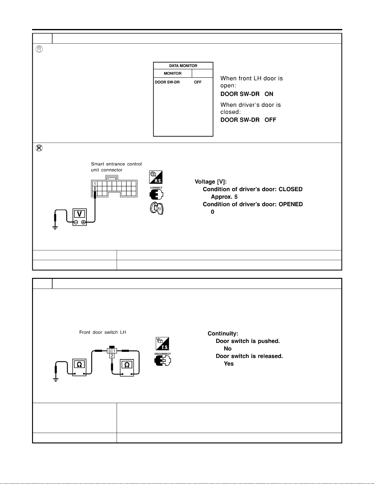
2 CHECK FRONT LH DOOR SWITCH INPUT SIGNAL
With CONSULT-II
Check driver door switch signal (“DOOR SW-DR”) in “DATA MONITOR” mode with CONSULT-II.
SEL319WA
Without CONSULT-II
Check voltage between smart entrance control unit harness connector M121 terminal 1 (G/R) and ground.
SEL004Y
OK or NG
OK © GO TO 4.
NG © GO TO 3.
3 CHECK FRONT LH DOOR SWITCH
Check the following.
I Continuity between front LH door switch connector B9 terminals 1 and 2
I Continuity between front LH door switch B9 terminal 3 and ground
SEL277Y
OK or NG
OK © Check the following.
I Front LH door switch ground circuit and condition
I Harness for open or short between smart entrance control unit and front LH door
switch
NG © Replace front LH door switch.
INTERIOR, SPOT, VANITY MIRROR AND LUGGAGE ROOM LAMPS
Trouble Diagnoses for Interior Lamp Timer (Cont’d)
EL-104
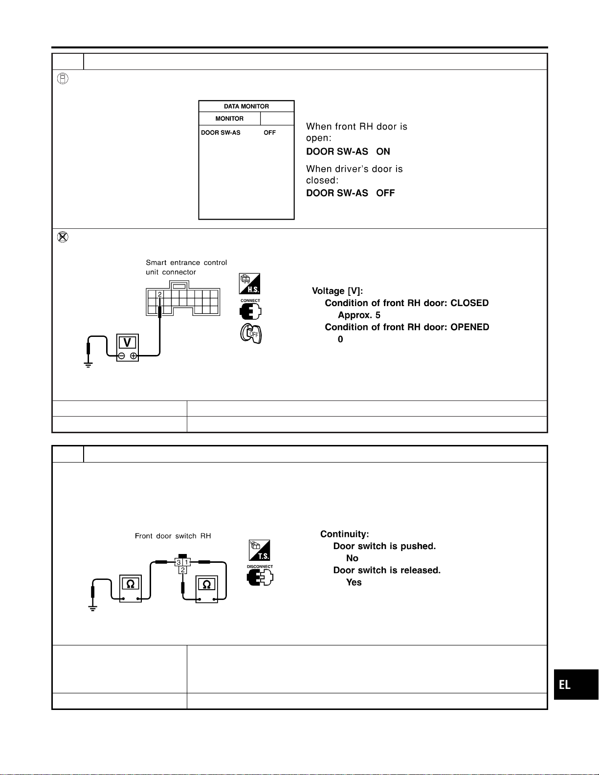
4 CHECK FRONT RH DOOR SWITCH INPUT SIGNAL
With CONSULT-II
Check driver door switch signal (“DOOR SW-AS”) in “DATA MONITOR” mode with CONSULT-II.
SEL153Y
Without CONSULT-II
Check voltage between smart entrance control unit harness connector M121 terminal 2 (Y) and ground.
SEL152Y
OK or NG
OK © GO TO 6.
NG © GO TO 5.
5 CHECK FRONT RH DOOR SWITCH
Check the following.
I Continuity between front RH door switch connector B68 terminals 1 and 2
I Continuity between front RH door switch connector B68 terminal 3 and ground
SEL278Y
OK or NG
OK © Check the following.
I Front RH door switch ground circuit and condition
I Harness for open or short between smart entrance control unit and front RH door
switch
NG © Replace front RH door switch.
GI
MA
EM
LC
EC
FE
CL
MT
AT
TF
PD
AX
SU
BR
ST
RS
BT
HA
SC
IDX
INTERIOR, SPOT, VANITY MIRROR AND LUGGAGE ROOM LAMPS
Trouble Diagnoses for Interior Lamp Timer (Cont’d)
EL-105
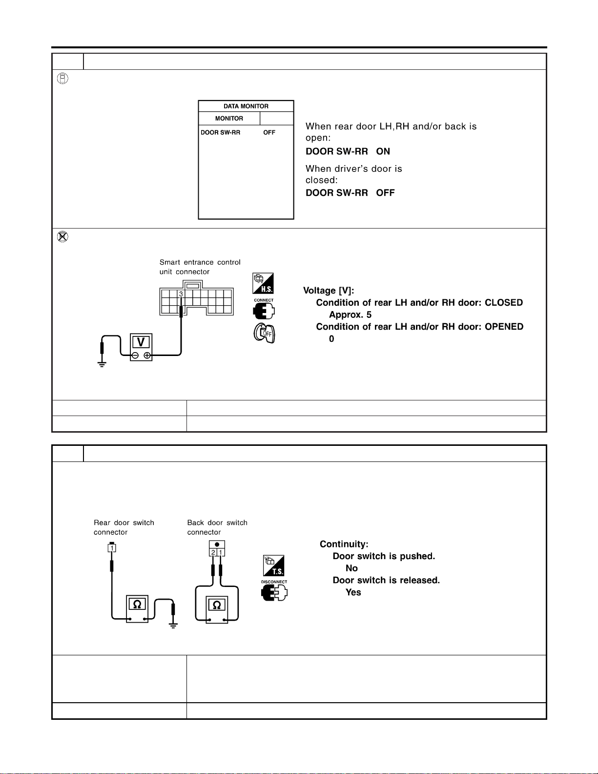
6 CHECK REAR AND BACK DOOR SWITCHES INPUT SIGNAL
With CONSULT-II
Check door switches (“DOOR SW-RR”) in “DATA MONITOR” mode with CONSULT-II.
SEL154YA
Without CONSULT-II
Check voltage between smart entrance control unit harness connector M121 terminal 3 (R/L) and ground.
SEL155Y
OK or NG
OK © GO TO 8.
NG © GO TO 7.
7 CHECK REAR AND BACK DOOR SWITCHES
1. Disconnect door switch harness connector.
2. Check the following.
I Continuity between rear door switches connector B18 and B71 terminal 1 and ground
I Continuity between back door switch connector D208 terminals 1 and 2
SEL279Y
OK or NG
OK © Check the following.
I Rear LH, RH and/or back door switch ground circuit or door switch ground condition
I Harness for open or short between smart entrance control unit and rear LH, RH and/or
back door switch
NG © Replace rear LH, RH and/or back door switch.
INTERIOR, SPOT, VANITY MIRROR AND LUGGAGE ROOM LAMPS
Trouble Diagnoses for Interior Lamp Timer (Cont’d)
EL-106
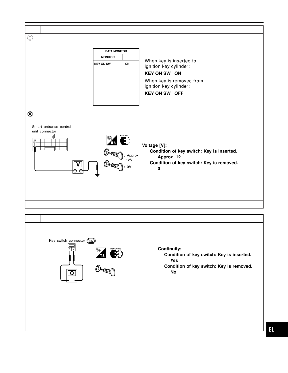
8 CHECK KEY SWITCH INPUT SIGNAL
With CONSULT-II
Check key switch (“KEY ON SW”) in “DATA MONITOR” mode with CONSULT-II.
SEL315W
Without CONSULT-II
Check voltage between smart entrance control unit harness connector M122 terminal 25 (W/R) and ground.
SEL011Y
OK or NG
OK © GO TO 10.
NG © GO TO 9.
9 CHECK KEY SWITCH (INSERT)
Check continuity between terminals 1 and 2.
SEL308X
OK or NG
OK © Check the following.
I 7.5A fuse [No. 24, located in fuse block (J/B)]
I Harness for open or short between key switch and fuse
I Harness for open or short between smart entrance control unit and key switch
NG © Replace key switch.
GI
MA
EM
LC
EC
FE
CL
MT
AT
TF
PD
AX
SU
BR
ST
RS
BT
HA
SC
IDX
INTERIOR, SPOT, VANITY MIRROR AND LUGGAGE ROOM LAMPS
Trouble Diagnoses for Interior Lamp Timer (Cont’d)
EL-107

10 CHECK DOOR LOCK/UNLOCK SWITCH INPUT SIGNAL
With CONSULT-II
Check door lock/unlock switch (“LOCK SW DR/AS”/“UNLK SW DR/AS”) in “DATA MONITOR” mode with CONSULT-II.
SEL341W
Without CONSULT-II
1. Disconnect smart entrance control unit harness connector .
2. Check continuity between smart entrance control unit harness connector M121 terminal 4 (LG/R) or 5 (BR) and ground.
SEL157Y
OK or NG
OK © GO TO 12.
NG © GO TO 11.
INTERIOR, SPOT, VANITY MIRROR AND LUGGAGE ROOM LAMPS
Trouble Diagnoses for Interior Lamp Timer (Cont’d)
EL-108
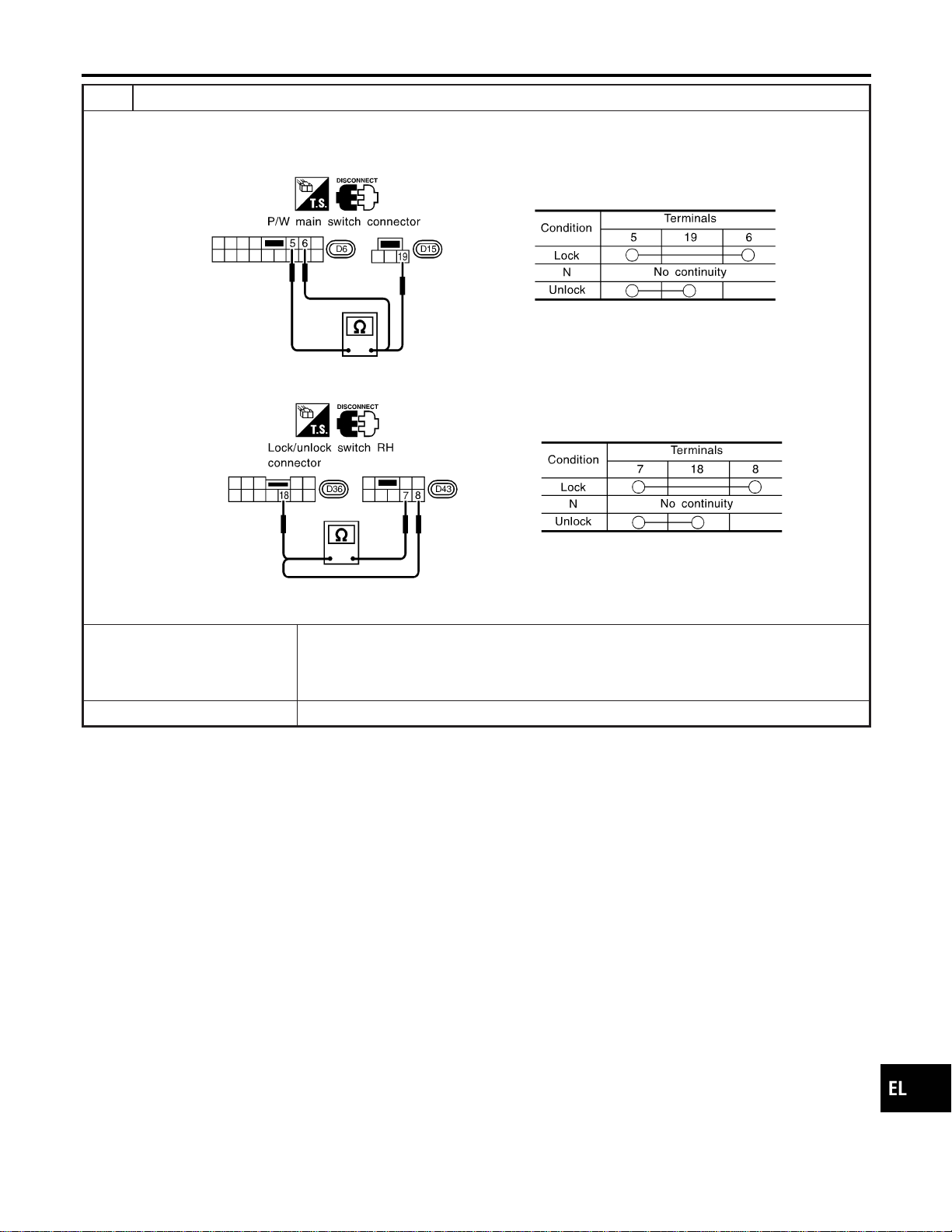
11 CHECK DOOR LOCK/UNLOCK SWITCH
1. Disconnect door lock/unlock switch harness connector.
2. Check continuity between each door lock/unlock switch terminals.
I Power window main switch (Door lock/unlock switch connector)
SEL310X
I Door lock/unlock switch RH connector
SEL311X
OK or NG
OK © Check the following.
I Ground circuit for door lock/unlock switch
I Harness for open or short between door lock/unlock switch and smart entrance control
unit connector
NG © Replace door lock/unlock switch.
GI
MA
EM
LC
EC
FE
CL
MT
AT
TF
PD
AX
SU
BR
ST
RS
BT
HA
SC
IDX
INTERIOR, SPOT, VANITY MIRROR AND LUGGAGE ROOM LAMPS
Trouble Diagnoses for Interior Lamp Timer (Cont’d)
EL-109

12 CHECK DOOR KEY CYLINDER SWITCH INPUT SIGNAL (LOCK/UNLOCK SIGNAL)
With CONSULT-II
Check front door key cylinder switch (“KEY CYL LK-SW”/“KEY CYL UN-SW”) in “DATA MONITOR” mode with CONSULT-
II.
SEL342W
Without CONSULT-II
Check voltage between smart entrance control unit harness connector M121 terminals 10 (LG) or 11 (Y) and ground.
SEL280Y
OK or NG
OK © Replace smart entrance control unit.
NG © GO TO 13.
INTERIOR, SPOT, VANITY MIRROR AND LUGGAGE ROOM LAMPS
Trouble Diagnoses for Interior Lamp Timer (Cont’d)
EL-110
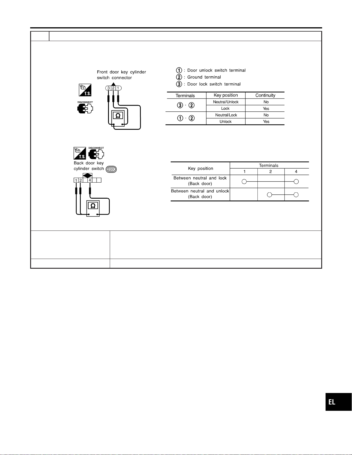
13 CHECK DOOR KEY CYLINDER SWITCH
1. Disconnect door key cylinder switch harness connector.
2. Check continuity between each key cylinder switch terminals.
I Front door key cylinder switch harness connector D9
SEL187YA
I Back door key cylinder switch harness connector D201
SEL315X
OK or NG
OK © Check the following.
I Front or back door key cylinder switch ground circuit
I Harness for open or short between front or back door key cylinder switch and smart
entrance control unit connector
NG © Replace front or back door key cylinder switch.
GI
MA
EM
LC
EC
FE
CL
MT
AT
TF
PD
AX
SU
BR
ST
RS
BT
HA
SC
IDX
INTERIOR, SPOT, VANITY MIRROR AND LUGGAGE ROOM LAMPS
Trouble Diagnoses for Interior Lamp Timer (Cont’d)
EL-111
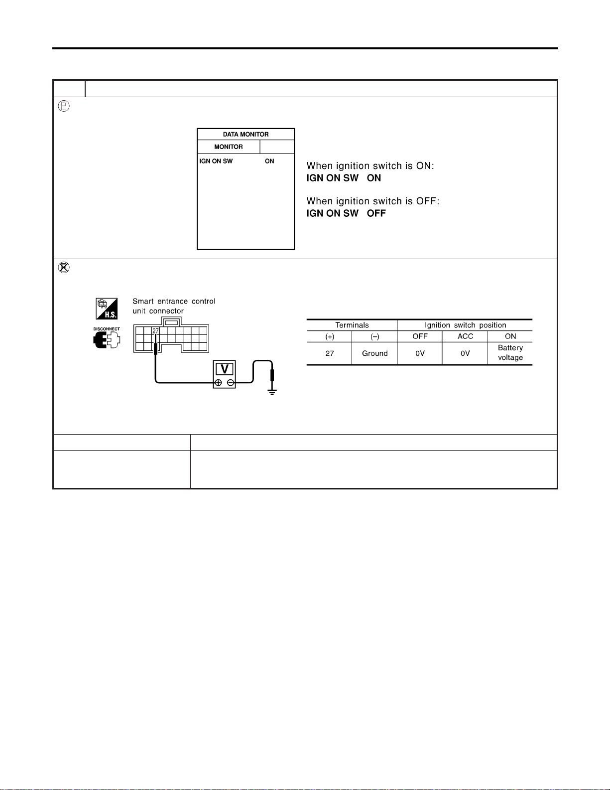
DIAGNOSTIC PROCEDURE 2
NAEL0295S02
SYMPTOM: Interior lamp timer does not cancel properly.
1 CHECK IGNITION ON SIGNAL
With CONSULT-II
Check ignition switch ON signal (“IGN ON SW”) in “DATA MONITOR” mode with CONSULT-II.
SEL318W
Without CONSULT-II
Check voltage between smart entrance control unit harness connector M122 terminal 27 (W/B) and ground.
SEL995X
OK or NG
OK © GO TO 2.
NG © Check the following.
I 7.5A fuse [No. 11, located in fuse block (J/B)]
I Harness for open or short between smart entrance control unit and fuse
INTERIOR, SPOT, VANITY MIRROR AND LUGGAGE ROOM LAMPS
Trouble Diagnoses for Interior Lamp Timer (Cont’d)
EL-112
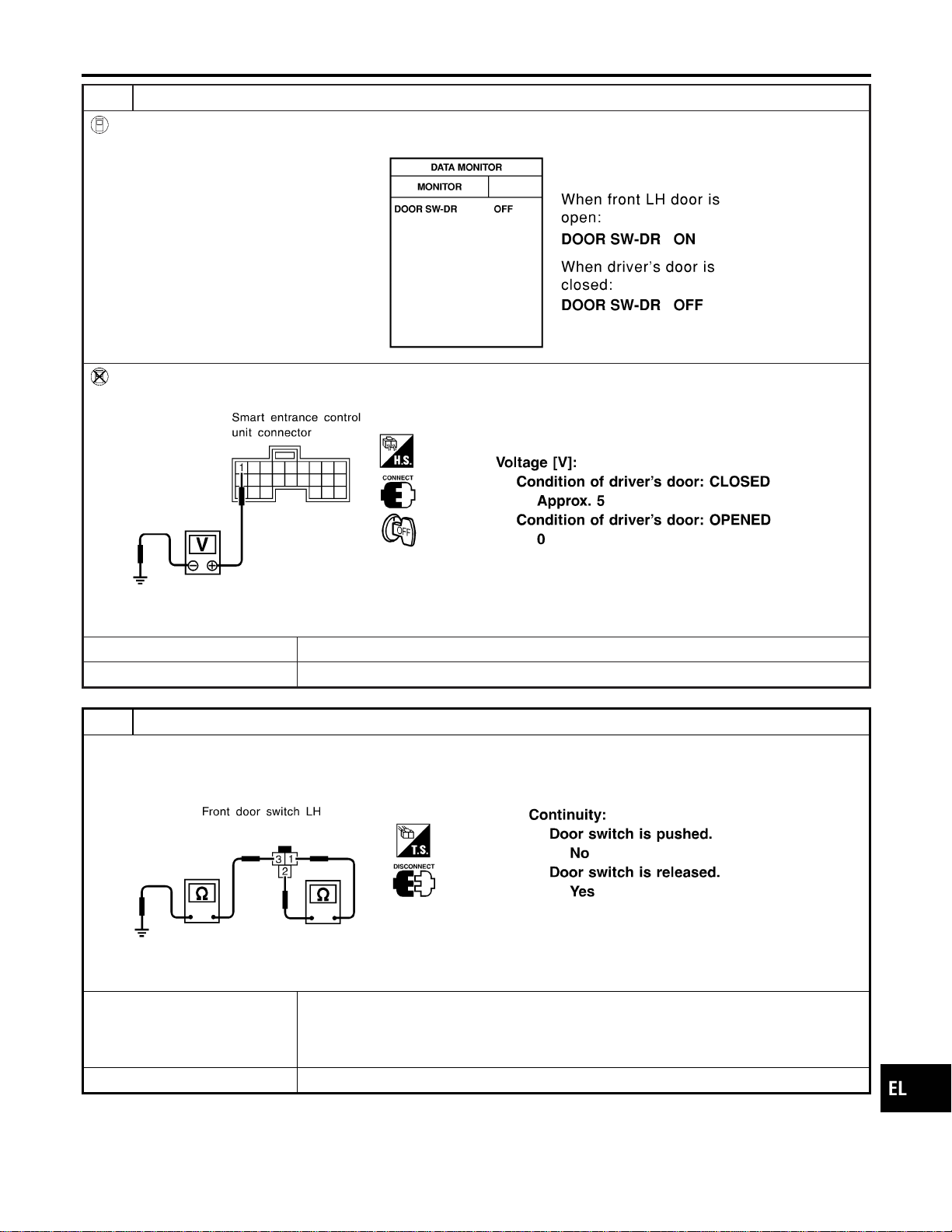
2 CHECK FRONT LH DOOR SWITCH INPUT SIGNAL
With CONSULT-II
Check driver door switch signal (“DOOR SW-DR”) in “DATA MONITOR” mode with CONSULT-II.
SEL319WA
Without CONSULT-II
Check voltage between smart entrance control unit harness connector M121 terminal 1 (G/R) and ground.
SEL004Y
OK or NG
OK © GO TO 4.
NG © GO TO 3.
3 CHECK FRONT LH DOOR SWITCH
Check continuity between door switch connector B9 terminals 1 and 2.
SEL277Y
OK or NG
OK © Check the following.
I Front LH door switch ground circuit and condition
I Harness for open or short between smart entrance control unit and front LH door
switch
NG © Replace front LH door switch.
GI
MA
EM
LC
EC
FE
CL
MT
AT
TF
PD
AX
SU
BR
ST
RS
BT
HA
SC
IDX
INTERIOR, SPOT, VANITY MIRROR AND LUGGAGE ROOM LAMPS
Trouble Diagnoses for Interior Lamp Timer (Cont’d)
EL-113

4 CHECK DOOR LOCK/UNLOCK SWITCH INPUT SIGNAL
With CONSULT-II
Check door lock/unlock switch (“LOCK SW DR/AS”/“UNLK SW DR/AS”) in “DATA MONITOR” mode with CONSULT-II.
SEL341W
Without CONSULT-II
1. Disconnect smart entrance control unit harness connector .
2. Check continuity between smart entrance control unit harness connector M121 terminal 4 (LG/R) or 5 (BR) and ground.
SEL157Y
OK or NG
OK © GO TO 6.
NG © GO TO 5.
INTERIOR, SPOT, VANITY MIRROR AND LUGGAGE ROOM LAMPS
Trouble Diagnoses for Interior Lamp Timer (Cont’d)
EL-114

5 CHECK DOOR LOCK/UNLOCK SWITCH
1. Disconnect door lock/unlock switch harness connector.
2. Check continuity between each door lock/unlock switch terminals.
I Power window main switch (Door lock/unlock switch connector)
SEL310X
I Door lock/unlock switch RH connector
SEL311X
OK or NG
OK © Check the following.
I Ground circuit for door lock/unlock switch
I Harness for open or short between door lock/unlock switch and smart entrance control
unit connector
NG © Replace door lock/unlock switch.
GI
MA
EM
LC
EC
FE
CL
MT
AT
TF
PD
AX
SU
BR
ST
RS
BT
HA
SC
IDX
INTERIOR, SPOT, VANITY MIRROR AND LUGGAGE ROOM LAMPS
Trouble Diagnoses for Interior Lamp Timer (Cont’d)
EL-115
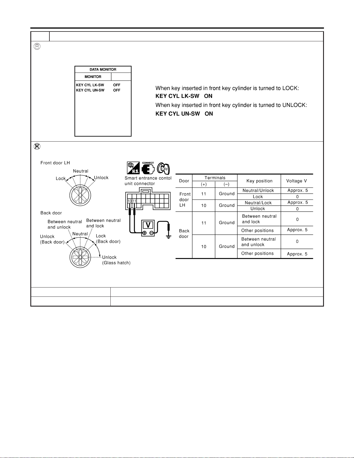
6 CHECK DOOR KEY CYLINDER SWITCH INPUT SIGNAL (LOCK/UNLOCK SIGNAL)
With CONSULT-II
Check front door key cylinder switch (“KEY CYL LK-SW”/“KEY CYL UN-SW”) in “DATA MONITOR” mode with CONSULT-
II.
SEL342W
Without CONSULT-II
Check voltage between smart entrance control unit harness connector M121 terminals 10 (LG) or 11 (Y) and ground.
SEL280Y
OK or NG
OK © Replace smart entrance control unit.
NG © GO TO 7.
INTERIOR, SPOT, VANITY MIRROR AND LUGGAGE ROOM LAMPS
Trouble Diagnoses for Interior Lamp Timer (Cont’d)
EL-116

7 CHECK DOOR KEY CYLINDER SWITCH
1. Disconnect door key cylinder switch harness connector.
2. Check continuity between each key cylinder switch terminals.
I Front door key cylinder switch harness connector D9
SEL187YA
I Back door key cylinder switch harness connector D201
SEL315X
OK or NG
OK © Check the following.
I Front or back door key cylinder switch ground circuit
I Harness for open or short between front or back door key cylinder switch and smart
entrance control unit connector
NG © Replace front or back door key cylinder switch.
GI
MA
EM
LC
EC
FE
CL
MT
AT
TF
PD
AX
SU
BR
ST
RS
BT
HA
SC
IDX
INTERIOR, SPOT, VANITY MIRROR AND LUGGAGE ROOM LAMPS
Trouble Diagnoses for Interior Lamp Timer (Cont’d)
EL-117
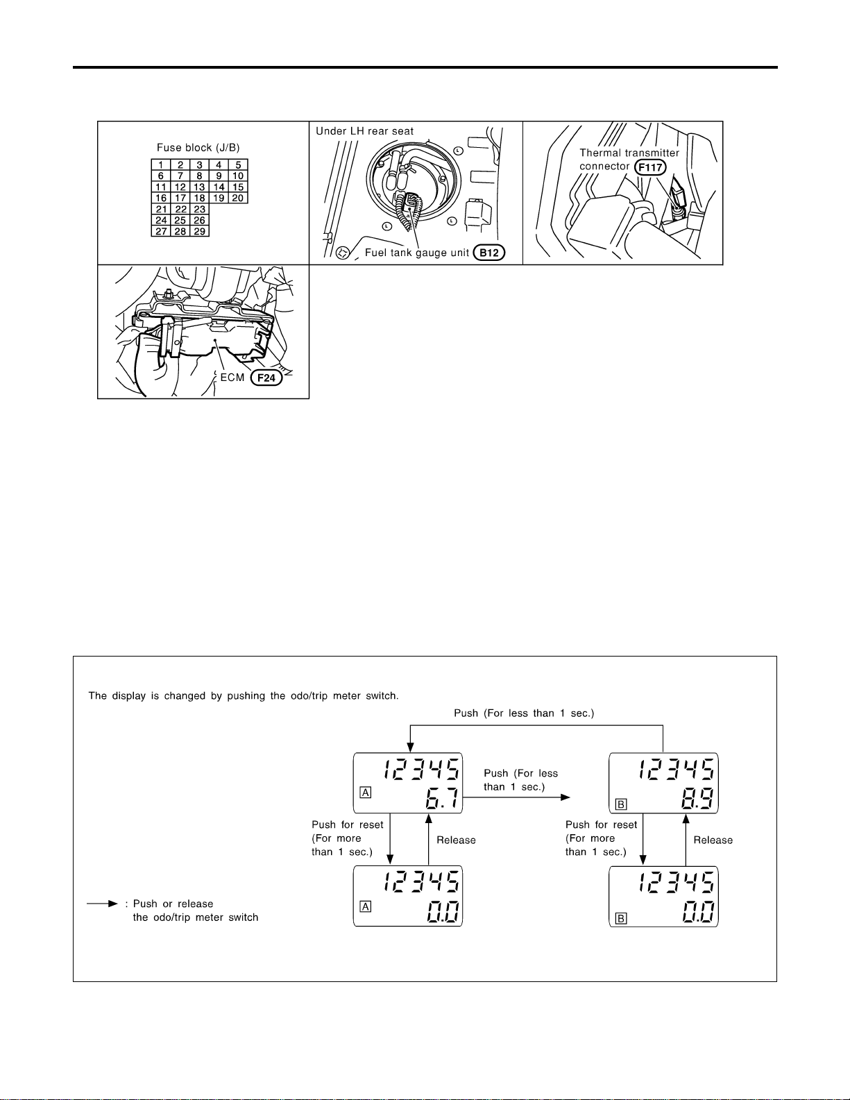
Component Parts and Harness Connector
Location
NAEL0296
SEL486Y
System Description
NAEL0297
UNIFIED CONTROL METER
NAEL0297S01
I Speedometer, odo/trip meter, tachometer, fuel gauge and water temperature gauge are controlled totally
by control unit.
I Digital meter is adopted for odo/trip meter.*
*The record of the odo meter is kept even if the battery cable is disconnected. The record of the trip meter
is erased when the battery cable is disconnected.
I Odo/trip meter segment can be checked in diagnosis mode.
I Meter/gauge can be checked in diagnosis mode.
HOW TO CHANGE THE DISPLAY FOR ODO/TRIP METER
NAEL0297S02
SEL175W
NOTE:
Turn ignition switch to the “ON” position to operate odo/trip meter.
METERS AND GAUGES
Component Parts and Harness Connector Location
EL-118

POWER SUPPLY AND GROUND CIRCUIT
NAEL0297S03
Power is supplied at all times
I through 7.5A fuse [No. 24, located in the fuse block (J/B)]
I to combination meter terminal 62.
With the ignition switch in the ON or START position, power is supplied
I through 10A fuse [No. 8, located in the fuse block (J/B)]
I to combination meter terminal 66.
Ground is supplied
I to combination meter terminal 59
I through body grounds M4, M66 and M147.
WATER TEMPERATURE GAUGE
NAEL0297S04
The water temperature gauge indicates the engine coolant temperature. The reading on the gauge is based
on the resistance of the thermal transmitter.
As the temperature of the coolant increases, the resistance of the thermal transmitter decreases. A variable
ground is supplied to terminal 18 of the combination meter for the water temperature gauge. The needle on
the gauge moves from “C” to “H”.
TACHOMETER
NAEL0297S05
The tachometer indicates engine speed in revolutions per minute (rpm).
The tachometer is regulated by a signal
I from terminal 25 of the ECM
I to combination meter terminal 16 for the tachometer.
FUEL GAUGE
NAEL0297S06
The fuel gauge indicates the approximate fuel level in the fuel tank.
The fuel gauge is regulated by a variable ground signal supplied
I to combination meter terminal 17 for the fuel gauge
I from terminal 3 of the fuel level sensor unit
I through terminal 2 of the fuel level sensor unit and
I through body grounds B11, B22 and D210.
SPEEDOMETER
NAEL0297S07
The ABS actuator and electric unit provides a voltage signal to the combination meter for the speedometer.
The voltage is supplied
I from combination meter terminal 15 for the speedometer
I to terminal 19 of the ABS actuator and electric unit.
The speedometer converts the voltage into the vehicle speed displayed.
GI
MA
EM
LC
EC
FE
CL
MT
AT
TF
PD
AX
SU
BR
ST
RS
BT
HA
SC
IDX
METERS AND GAUGES
System Description (Cont’d)
EL-119
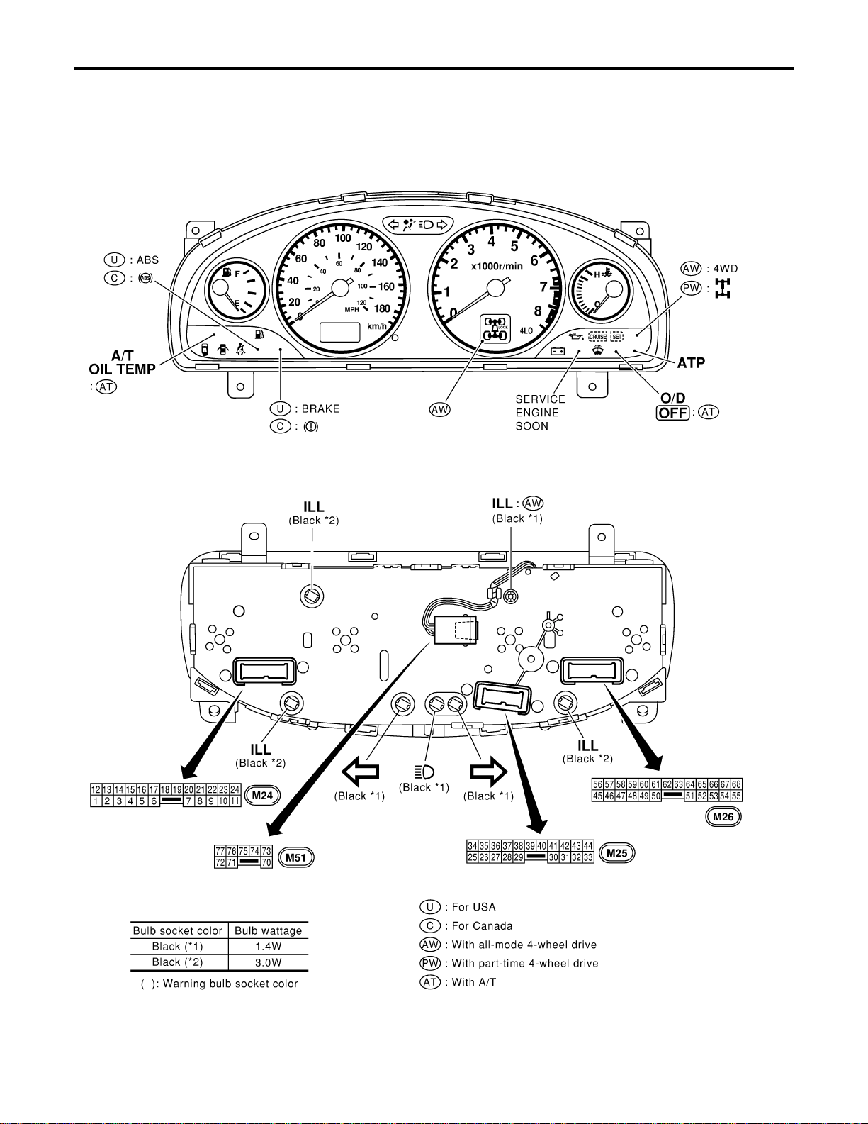
Combination Meter
NAEL0298
CHECK
NAEL0298S01
MEL915O
METERS AND GAUGES
Combination Meter
EL-120
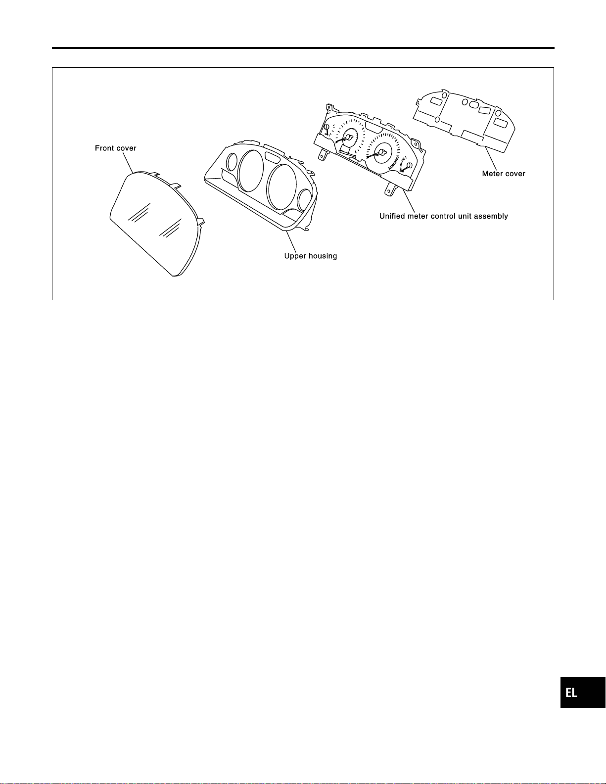
CONSTRUCTION
NAEL0298S02
SEL482Y
GI
MA
EM
LC
EC
FE
CL
MT
AT
TF
PD
AX
SU
BR
ST
RS
BT
HA
SC
IDX
METERS AND GAUGES
Combination Meter (Cont’d)
EL-121
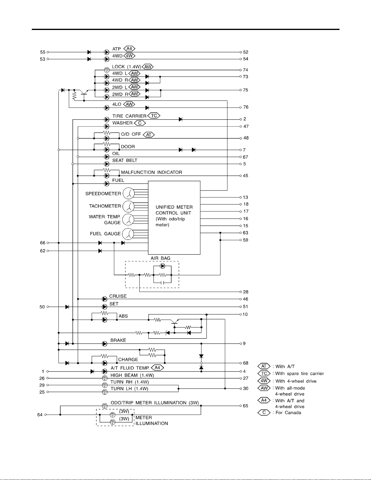
Schematic
NAEL0299
MEL411P
METERS AND GAUGES
Schematic
EL-122
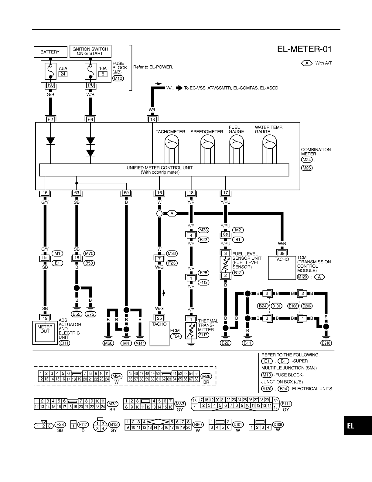
Wiring Diagram — METER —
NAEL0300
MEL412P
GI
MA
EM
LC
EC
FE
CL
MT
AT
TF
PD
AX
SU
BR
ST
RS
BT
HA
SC
IDX
METERS AND GAUGES
Wiring Diagram — METER —
EL-123
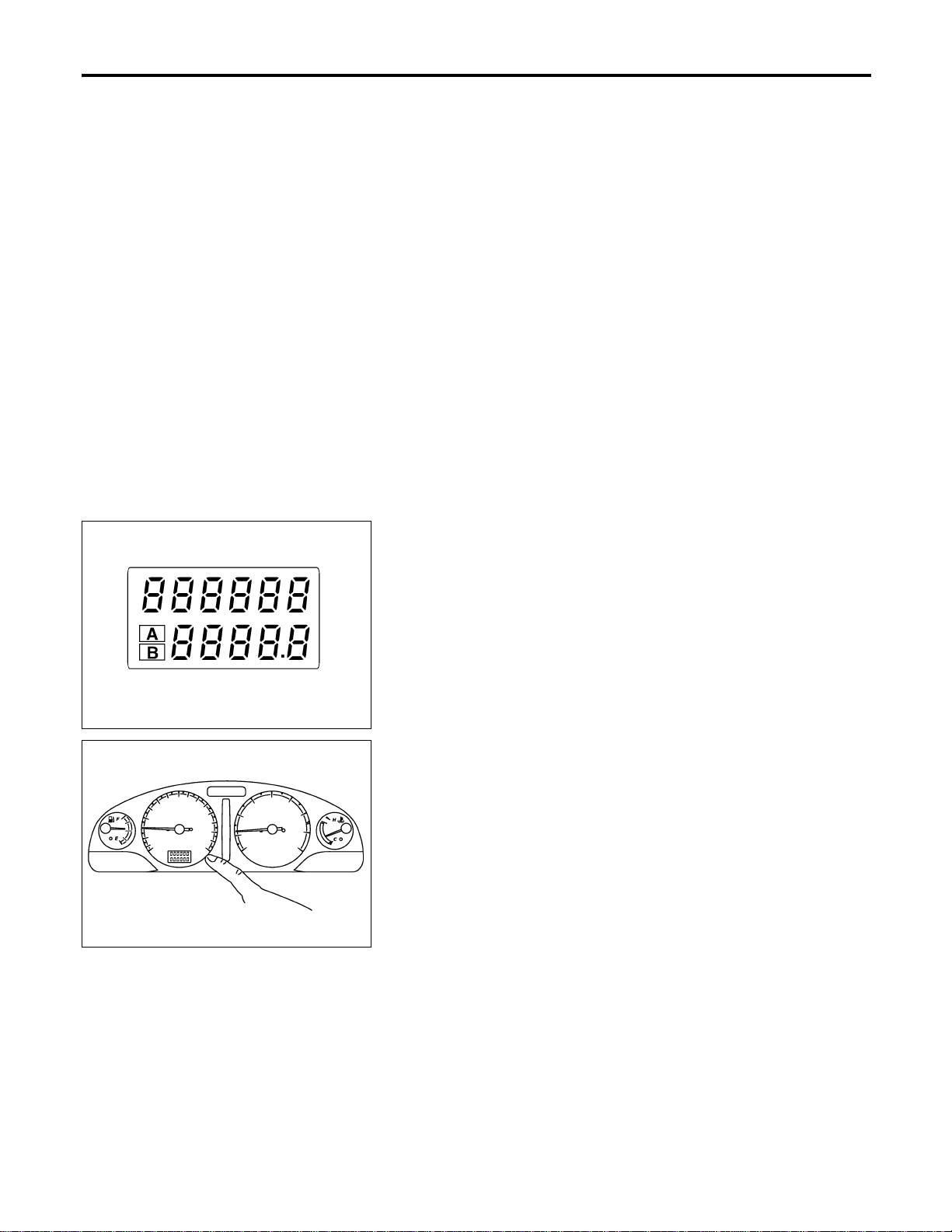
Meter/Gauge Operation and Odo/Trip Meter
Segment Check in Diagnosis Mode
NAEL0301
DIAGNOSIS FUNCTION
NAEL0301S01
I Odo/trip meter segment can be checked in diagnosis mode.
I Meters/gauges can be checked in diagnosis mode.
HOW TO ALTERNATE DIAGNOSIS MODE
NAEL0301S02
1. Turn ignition switch to ON and change odo/trip meter to “TRIP
A” or “TRIP B”.
2. Turn ignition switch to OFF.
3. Turn ignition switch to ON when pushing odo/trip meter switch.
4. Push odo/trip meter switch 1 second.
5. Release odo/trip meter switch.
6. Push odo/trip meter switch more than three times within 7
seconds.
SEL176W
7. All odo/trip meter segments should be turned on.
NOTE:
If some segments are not turned on, unified meter control unit with
odo/trip meter should be replaced.
At this point, the unified control meter is turned to diagnosis
mode.
SEL177W
8. Push odo/trip meter switch. Indication of each meter/gauge
should be as shown left during pushing odo/trip meter switch
if it is no malfunctioning.
NOTE:
It takes about a few seconds for indication of fuel gauge and water
temperature gauge to become stable.
METERS AND GAUGES
Meter/Gauge Operation and Odo/Trip Meter Segment Check in Diagnosis Mode
EL-124
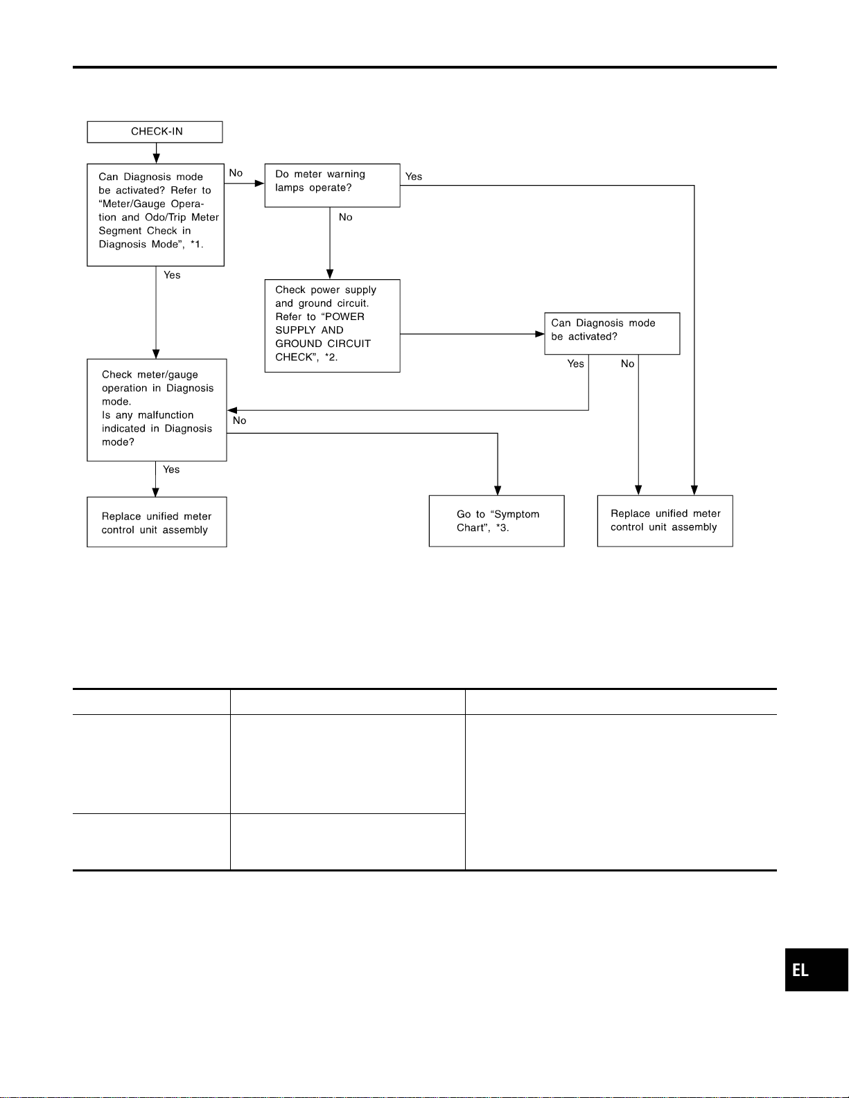
Trouble Diagnoses
NAEL0302
PRELIMINARY CHECK
NAEL0302S01
SEL494Y
*1: Meter/Gauge Operation and Odo/
Trip Meter Segment Check in
Diagnosis Mode (EL-124)
*2: POWER SUPPLY AND GROUND
CIRCUIT CHECK (EL-126)
*3: Symptom Chart 1 (EL-125)
SYMPTOM CHART
NAEL0302S02
Symptom Possible causes Repair order
One of speedometer/
tachometer/fuel gauge/
water temp. gauge is mal-
functioning.
1. Sensor signal
- Vehicle speed signal
- Engine revolution signal
- Fuel gauge
- Water temp. gauge
2. Unified meter control unit
1. Check the sensor for malfunctioning meter/gauge.
INSPECTION/VEHICLE SPEED SIGNAL (Refer to
EL-127.)
INSPECTION/ENGINE REVOLUTION SIGNAL
(Refer to EL-128.)
INSPECTION/FUEL LEVEL SENSOR UNIT (Refer to
EL-129.)
INSPECTION/THERMAL TRANSMITTER (Refer to
EL-130.)
2. Replace unified meter control unit assembly.
Multiple meter/gauge are
malfunctioning. (except
odo/trip meter)
Unified meter control unit
Before starting trouble diagnoses below, perform PRELIMINARY
CHECK, EL-125.
GI
MA
EM
LC
EC
FE
CL
MT
AT
TF
PD
AX
SU
BR
ST
RS
BT
HA
SC
IDX
METERS AND GAUGES
Trouble Diagnoses
EL-125
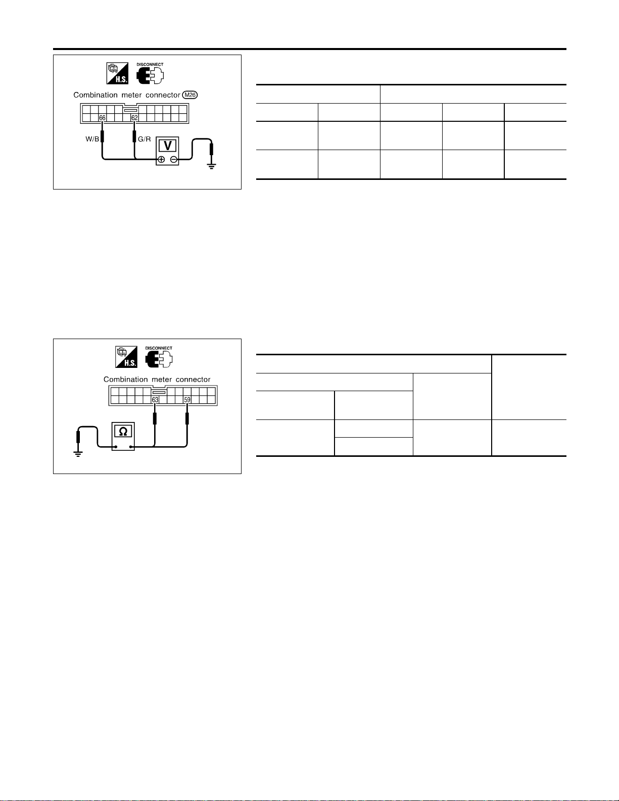
SEL179WB
POWER SUPPLY AND GROUND CIRCUIT CHECK
=NAEL0302S03
Power Supply Circuit Check
NAEL0302S0301
Terminals Ignition switch position
(+) (−) OFF ACC ON
62 Ground
Battery
voltage
Battery
voltage
Battery
voltage
66 Ground 0V 0V
Battery
voltage
If NG, check the following.
I 7.5A fuse [No. 24, located in fuse block (J/B)]
I 10A fuse [No. 8, located in fuse block (J/B)]
I Harness for open or short between fuse and combination
meter
SEL057Y
Ground Circuit Check
NAEL0302S0302
Terminals
Continuity
(+)
(−)
Connector
Terminal
(wire color)
M26
59 (B)
Ground Yes
63 (SB)
METERS AND GAUGES
Trouble Diagnoses (Cont’d)
EL-126

INSPECTION/VEHICLE SPEED SIGNAL
=NAEL0302S04
1 CHECK ABS CONTROL UNIT OUTPUT SIGNAL
With CONSULT-II
1. Lift up drive wheels.
2. Start engine and drive vehicle at more than 20 km/h (12 MPH).
3. Check signal between combination meter harness connector M24 terminal 15 (G/Y) and ground when rotating wheels
with engine at idle. (Use “SIMPLE OSCILLOSCOPE” in “SUB MODE” with CONSULT-II.)
SEL938W
Without CONSULT-II
1. Lift up drive wheels.
2. Start engine and drive vehicle at more than 20 km/h (12 MPH).
3. Check voltage between combination meter harness connector M24 terminal 15 (G/Y) and ground when rotating wheels
with engine at idle.
SEL939WA
OK or NG
OK © ABS control unit is OK.
NG © Check the following.
I Harness for open or short between ABS actuator and electric unit and combination
meter.
I ABS actuator and electric unit. Refer to BR-59, “Wheel Sensor or Rotor”.
GI
MA
EM
LC
EC
FE
CL
MT
AT
TF
PD
AX
SU
BR
ST
RS
BT
HA
SC
IDX
METERS AND GAUGES
Trouble Diagnoses (Cont’d)
EL-127
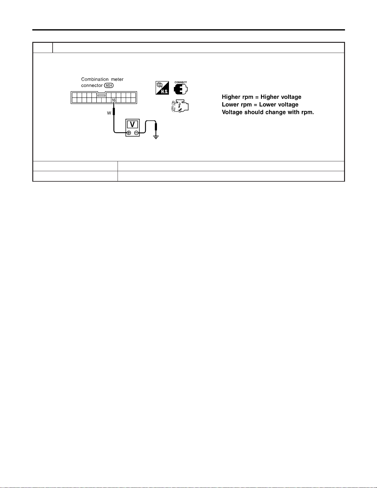
INSPECTION/ENGINE REVOLUTION SIGNAL
NAEL0302S05
1 CHECK ECM OUTPUT
1. Start engine.
2. Check voltage between combination meter terminals 16 and ground at idle and 2,000 rpm.
SEL364WB
OK or NG
OK © Engine revolution signal is OK.
NG © Harness for open or short between ECM and combination meter
METERS AND GAUGES
Trouble Diagnoses (Cont’d)
EL-128
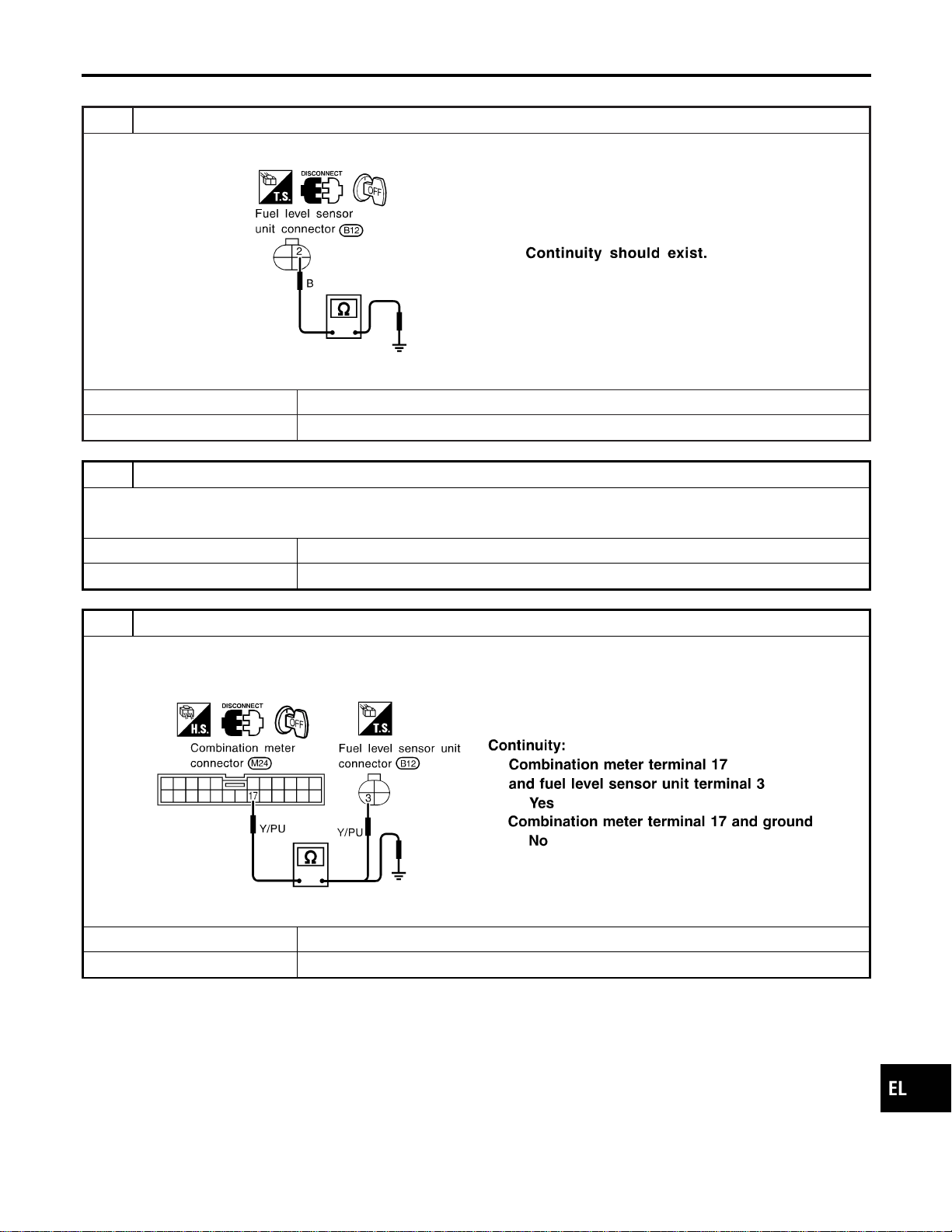
INSPECTION/FUEL LEVEL SENSOR UNIT
=NAEL0302S06
1 CHECK GROUND CIRCUIT FOR FUEL LEVEL SENSOR UNIT
Check harness continuity between fuel level sensor unit terminal 2 and ground.
SEL299X
OK or NG
OK © GO TO 2.
NG © Repair harness or connector.
2 CHECK FUEL LEVEL SENSOR UNIT
Refer to “FUEL LEVEL SENSOR UNIT CHECK” (EL-131).
OK or NG
OK © GO TO 3.
NG © Replace fuel level sensor unit.
3 CHECK HARNESS FOR OPEN OR SHORT
1. Disconnect combination meter connector and fuel level sensor unit connector.
2. Check continuity between combination meter terminal 17 and fuel level sensor unit terminal 3.
3. Check continuity between combination meter terminal 17 and ground.
SEL300X
OK or NG
OK © Fuel level sensor unit is OK.
NG © Repair harness or connector.
GI
MA
EM
LC
EC
FE
CL
MT
AT
TF
PD
AX
SU
BR
ST
RS
BT
HA
SC
IDX
METERS AND GAUGES
Trouble Diagnoses (Cont’d)
EL-129
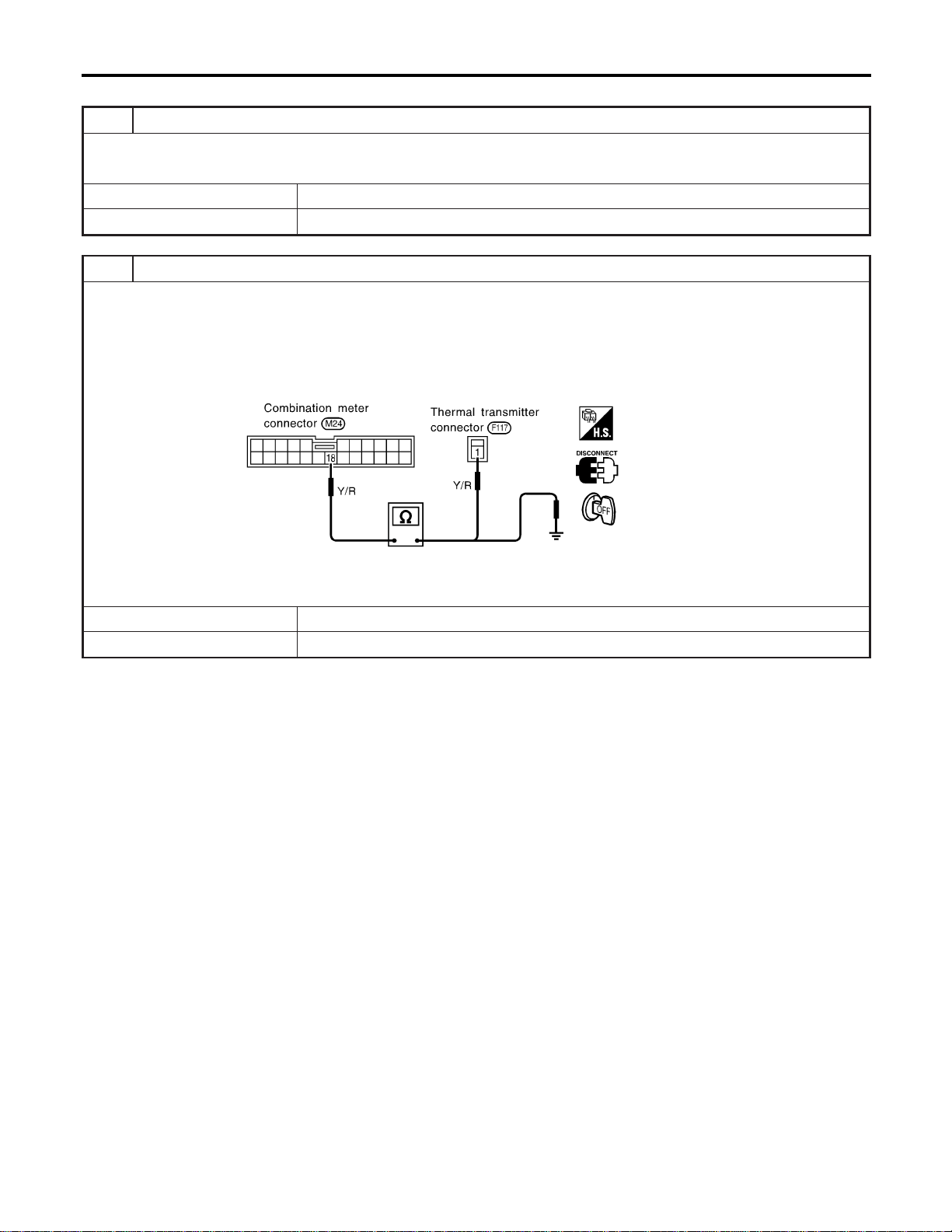
INSPECTION/THERMAL TRANSMITTER
=NAEL0302S07
1 CHECK THERMAL TRANSMITTER
Refer to “THERMAL TRANSMITTER CHECK” (EL-131).
OK or NG
OK © GO TO 2.
NG © Replace.
2 CHECK HARNESS FOR OPEN OR SHORT
1. Disconnect combination meter connector and thermal transmitter connector.
2. Check continuity between combination meter terminal 18 and thermal transmitter terminal 1.
Continuity should exist.
3. Check continuity between combination meter terminal 18 and ground.
Continuity should not exist.
SEL184WA
OK or NG
OK © Thermal transmitter is OK.
NG © Repair harness or connector.
METERS AND GAUGES
Trouble Diagnoses (Cont’d)
EL-130
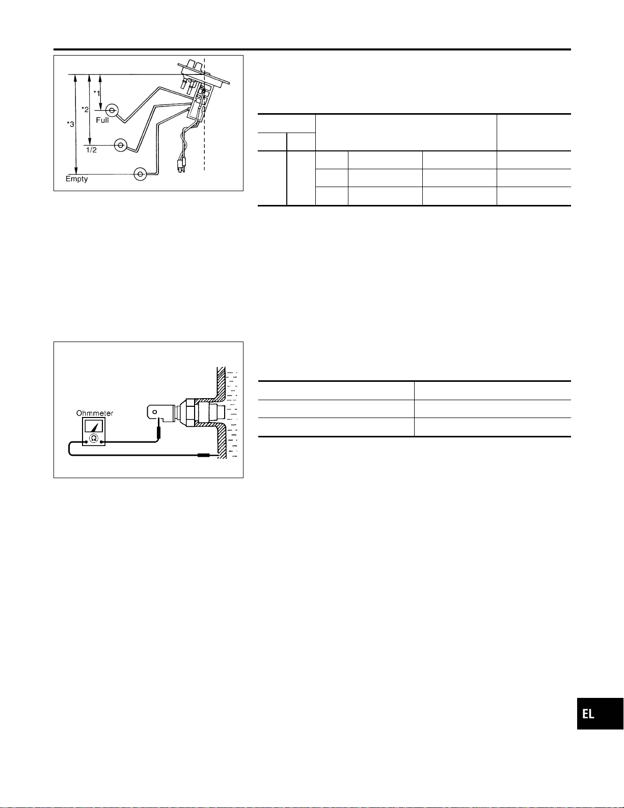
YEL066K
Electrical Components Inspection
=NAEL0303
FUEL LEVEL SENSOR UNIT CHECK
NAEL0303S02
I For removal, refer to FE-4, “FUEL SYSTEM”.
Check the resistance between terminals 3 and 2.
Ohmmeter
Float position mm (in)
Resistance
value Ω
(+) (−)
32
*1 Full 95 (3.74) Approx.4-6
*2 1/2 184 (7.24) 31 - 34
*3 Empty 265 (10.43) 80 - 83
*1 and *3: When float rod is in contact with stopper.
MEL424F
THERMAL TRANSMITTER CHECK
NAEL0303S03
Check the resistance between the terminals of thermal transmitter
and body ground.
Water temperature Resistance
60°C (140°F) Approx. 170 - 210Ω
100°C (212°F) Approx. 47 - 53Ω
GI
MA
EM
LC
EC
FE
CL
MT
AT
TF
PD
AX
SU
BR
ST
RS
BT
HA
SC
IDX
METERS AND GAUGES
Electrical Components Inspection
EL-131
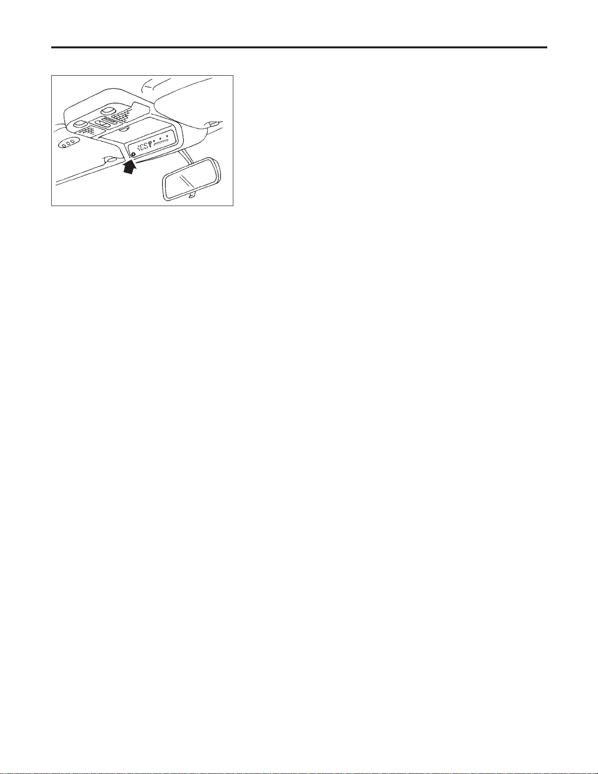
System Description
NAEL0304
SEL713U
This unit displays following items:
I Earth magnetism and heading direction of vehicle.
I Outside air temperature.
I Caution for frozen road surfaces.
OUTSIDE TEMPERATURE DISPLAY
NAEL0304S01
Push the switch when the ignition key is in the “ACC” or “ON” position. The outside temperature will be dis-
played in “°F”.
I Selecting the indication range
Push the switch to change from “°F” to “°C”.
I When the outside temperature drops below freezing point, ICE is displayed on the unit.
I When the outside temperature is between 55°C (130°F) and 70°C (158°F), the display shows 55°C
(130°F).
I When the outside temperature is lower than −30°C (−20°F) or higher than 70°C (158°F), the display shows
only “---” though it is operating. This is not a problem.
I The indicated temperature on the thermometer is not readily affected by engine heat. It changes only when
one of the following conditions is present.
a) The temperature detected by the ambient air temperature sensor is lower than the indicated temperature
on the thermometer.
b) The difference in temperature detected during a period of 40 seconds is less than 1°C (1.8°F) when vehicle
speed has been greater than 24 km/h (15 MPH) for more than 100 seconds.
(This is to prevent the indicated temperature from being affected by engine heat or cooling fan operation
during low-speed driving.)
c) The ignition key has been turned to the “OFF” position for more than 4 hours. (The engine is cold.)
DIRECTION DISPLAY
NAEL0304S02
Push the switch when the ignition key is in the “ACC” or “ON” position. The direction will be displayed.
COMPASS AND THERMOMETER
System Description
EL-132
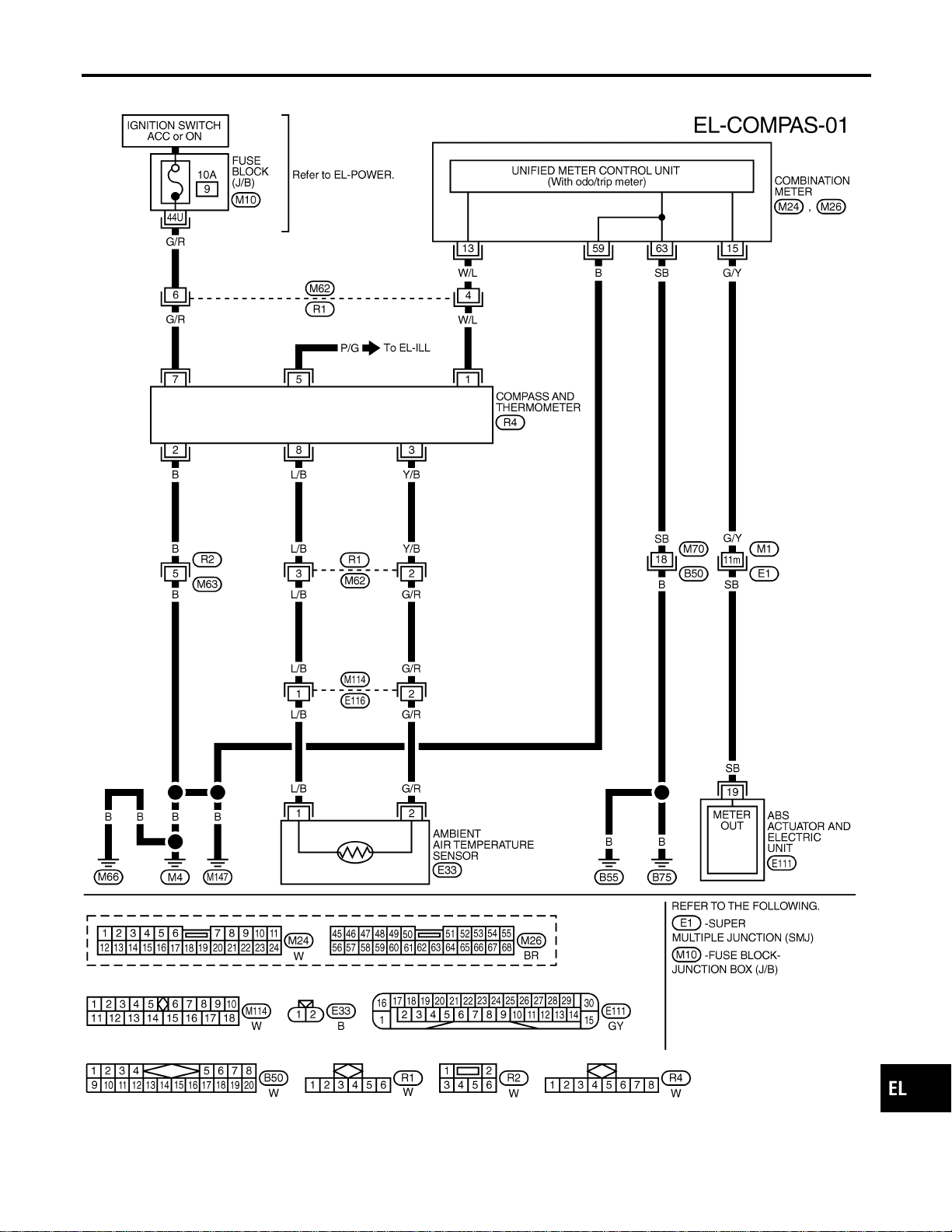
Wiring Diagram — COMPAS —
NAEL0305
MEL346N
GI
MA
EM
LC
EC
FE
CL
MT
AT
TF
PD
AX
SU
BR
ST
RS
BT
HA
SC
IDX
COMPASS AND THERMOMETER
Wiring Diagram — COMPAS —
EL-133
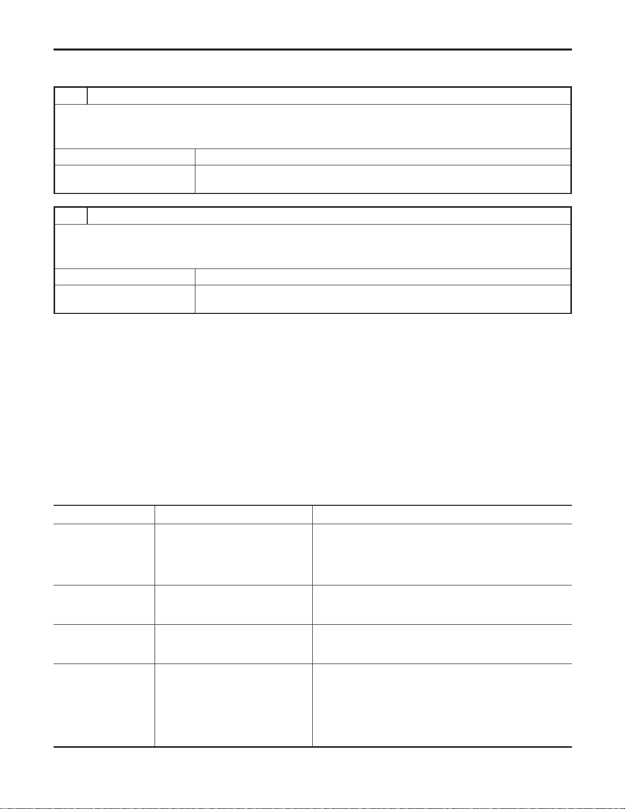
Trouble Diagnoses
NAEL0306
PRELIMINARY CHECK FOR THERMOMETER
NAEL0306S01
1 COOL DOWN CHECK
1. Turn the ignition key switch to the “ACC” position.
2. Cool down the ambient air temperature sensor with water or ice, so that the indicated temperature falls.
Does the indicated temperature fall?
Yes © GO TO 2.
No © The system is malfunctioning. Check the system following “INSPECTION/COMPASS
AND THERMOMETER”.
2 WARM UP CHECK
1. Leave the vehicle for 10 minutes, so that the indicated temperature rises.
2. With the ignition key in the “ACC” position, disconnect and reconnect the ambient air temperature sensor connector.
Does the indicated temperature rise?
Yes © The system is OK.
No © The system is malfunctioning. Check the system following “INSPECTION/COMPASS
AND THERMOMETER”.
NOTE:
I When the outside temperature is between 55°C (130°F) and 70°C (158°F), the display shows 55°C
(130°F). When the outside temperature is lower than −30°C (−20°F) or higher than 70°C (158°F), the dis-
play shows only “---”.
I The indicated temperature on the thermometer is not readily affected by engine heat. It changes only when
one of the following conditions is present.
a) The temperature detected by the ambient air temperature sensor is lower than the indicated temperature
on the thermometer.
b) The difference in temperature detected during a period of 40 seconds is less than 1°C (1.8°F) when vehicle
speed has been greater than 24 km/h (15 MPH) for more than 100 seconds.
(This is to prevent the indicated temperature from being affected by engine heat or cooling fan operation
during low-speed driving.)
c) The ignition key has been turned to the “OFF” position for more than 4 hours. (The engine is cold.)
INSPECTION/COMPASS AND THERMOMETER
NAEL0306S02
Symptom Possible causes Repair order
No display at all 1. 10A fuse
2. Ground circuit
3. Compass and thermometer
1. Check 10A fuse [No. 9, located in fuse block (J/B)].
Turn the ignition switch ON and verify that battery positive
voltage is at terminal 7 of compass and thermometer.
2. Check ground circuit for compass and thermometer.
3. Replace compass and thermometer.
Forward direction indi-
cation slips off the
mark or incorrect.
1. In manual correction mode (Bar
and display vanish.)
2. Zone variation change is not done.
1. Drive the vehicle and turn at an angle of 90°.
2. Perform the zone variation change.
Compass reading
remains unchanged.
1. Vehicle speed signal is not entered.
2. Compass and thermometer
1. Check harness for open or short between combination meter
terminal 13 and compass and thermometer terminal 1.
2. Replace compass and thermometer.
Displays wrong tem-
perature when ambient
temperature is between
−30°C (−20°F) and
55°C (130°F). (See
NOTE above.)
1. Check operation
2. Ambient air temperature sensor
circuit
3. Vehicle speed signal is not entered.
4. Ambient air temperature sensor
5. Compass and thermometer
1. Perform preliminary check shown above.
2. Check harness for open or short between ambient air tem-
perature sensor and compass and thermometer.
3. Check harness for open or short between combination meter
terminal 13 and compass and thermometer terminal 1.
4. Replace ambient air temperature sensor.
5. Replace compass and thermometer.
COMPASS AND THERMOMETER
Trouble Diagnoses
EL-134
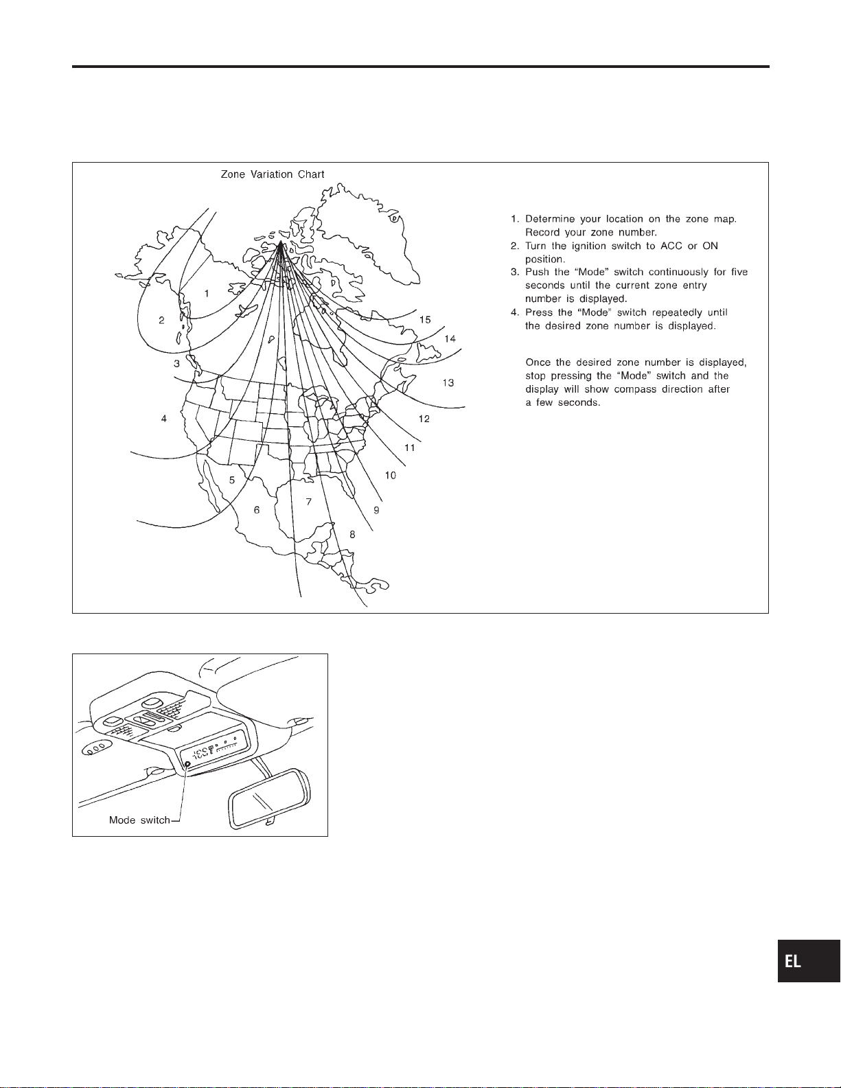
Calibration Procedure for Compass
=NAEL0307
The difference between magnetic North and geographical North
can sometimes be great enough to cause false compass readings.
In order for the compass to operate accurately in a particular zone,
it must be calibrated using the following procedure.
SEL738UA
SEL065V
CORRECTION FUNCTIONS OF COMPASS
NAEL0307S01
The direction display is equipped with automatic correction func-
tion. If the direction is not shown correctly, carry out initial correc-
tion.
INITIAL CORRECTION PROCEDURE FOR COMPASS
NAEL0307S02
1. Pushing the “Mode” switch for about 10 seconds will enter the
initial correction mode. The direction bar starts blinking.
2. Turn the vehicle slowly in an open, safe place. The initial cor-
rection is completed in one or two turns.
NOTE:
In places where the terrestrial magnetism is extremely disturbed,
the initial correction may start automatically.
GI
MA
EM
LC
EC
FE
CL
MT
AT
TF
PD
AX
SU
BR
ST
RS
BT
HA
SC
IDX
COMPASS AND THERMOMETER
Calibration Procedure for Compass
EL-135
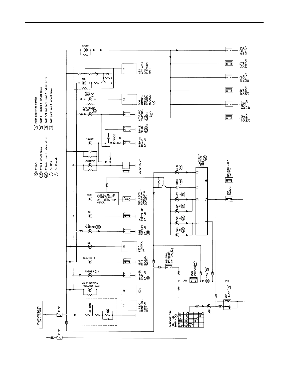
Schematic
NAEL0308
MEL431O
WARNING LAMPS
Schematic
EL-136
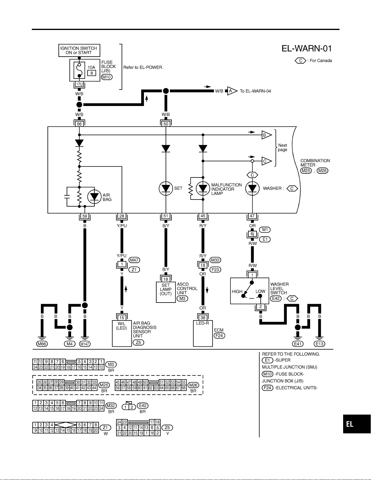
Wiring Diagram — WARN —
NAEL0309
MEL413P
GI
MA
EM
LC
EC
FE
CL
MT
AT
TF
PD
AX
SU
BR
ST
RS
BT
HA
SC
IDX
WARNING LAMPS
Wiring Diagram — WARN —
EL-137
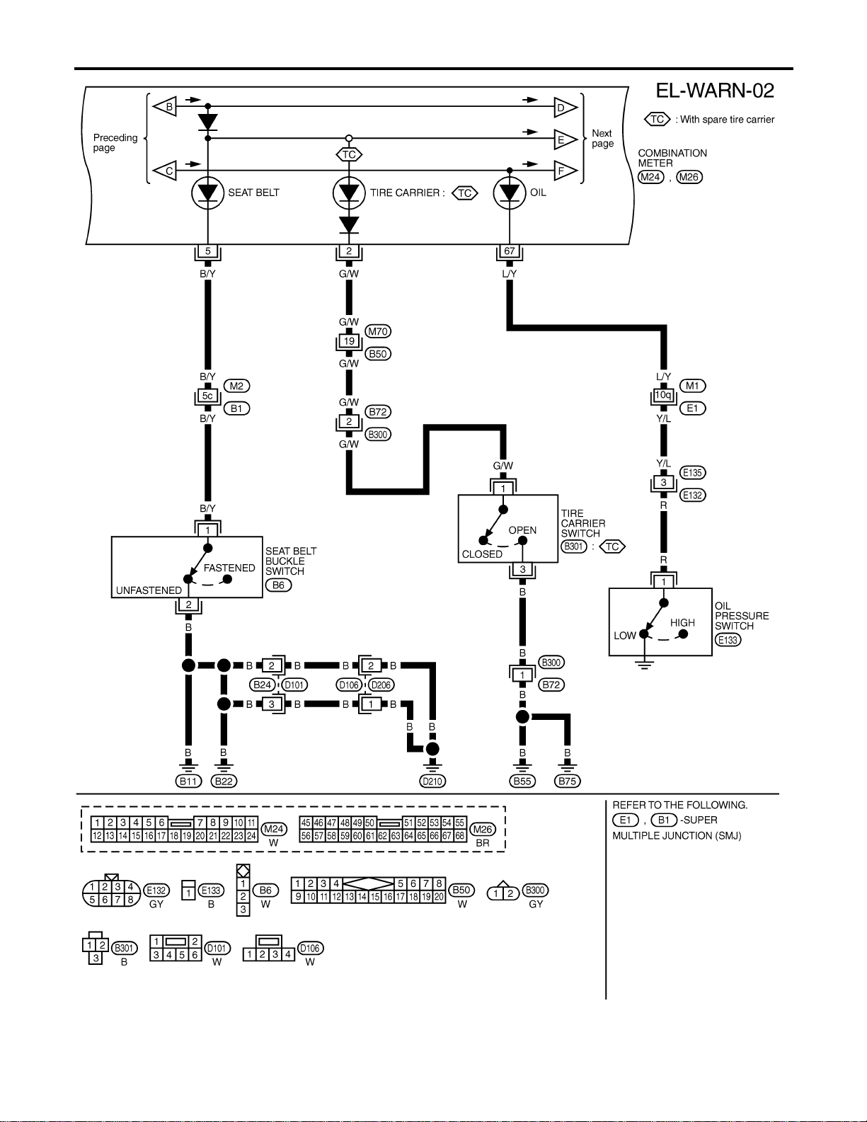
MEL414P
WARNING LAMPS
Wiring Diagram — WARN — (Cont’d)
EL-138
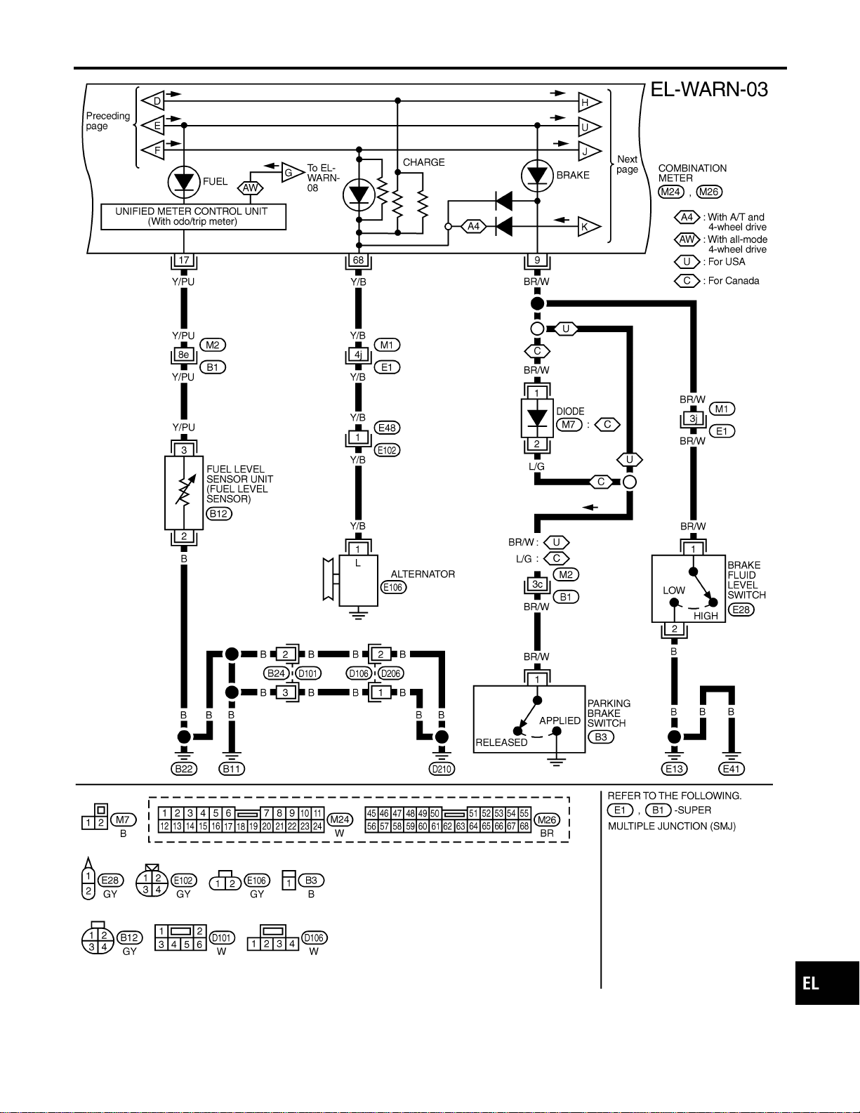
MEL405O
GI
MA
EM
LC
EC
FE
CL
MT
AT
TF
PD
AX
SU
BR
ST
RS
BT
HA
SC
IDX
WARNING LAMPS
Wiring Diagram — WARN — (Cont’d)
EL-139
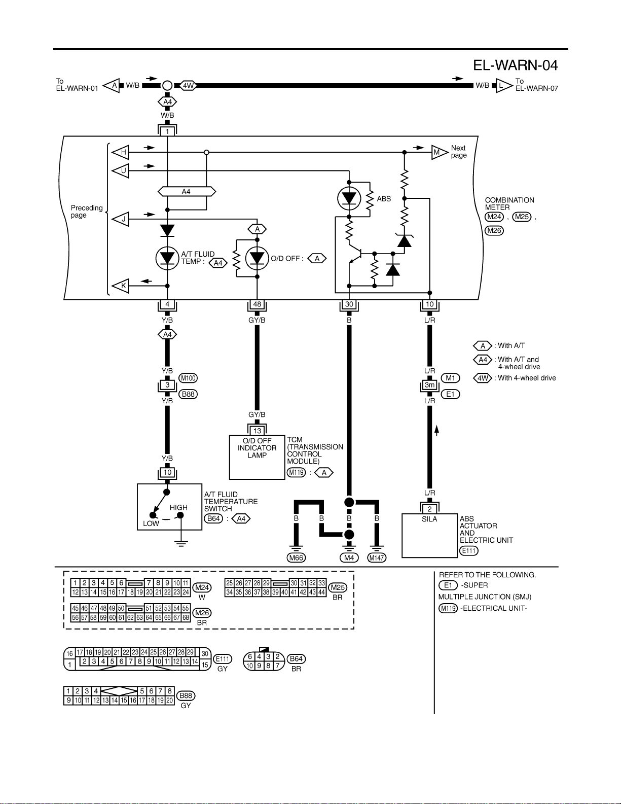
MEL432O
WARNING LAMPS
Wiring Diagram — WARN — (Cont’d)
EL-140

MEL406O
GI
MA
EM
LC
EC
FE
CL
MT
AT
TF
PD
AX
SU
BR
ST
RS
BT
HA
SC
IDX
WARNING LAMPS
Wiring Diagram — WARN — (Cont’d)
EL-141
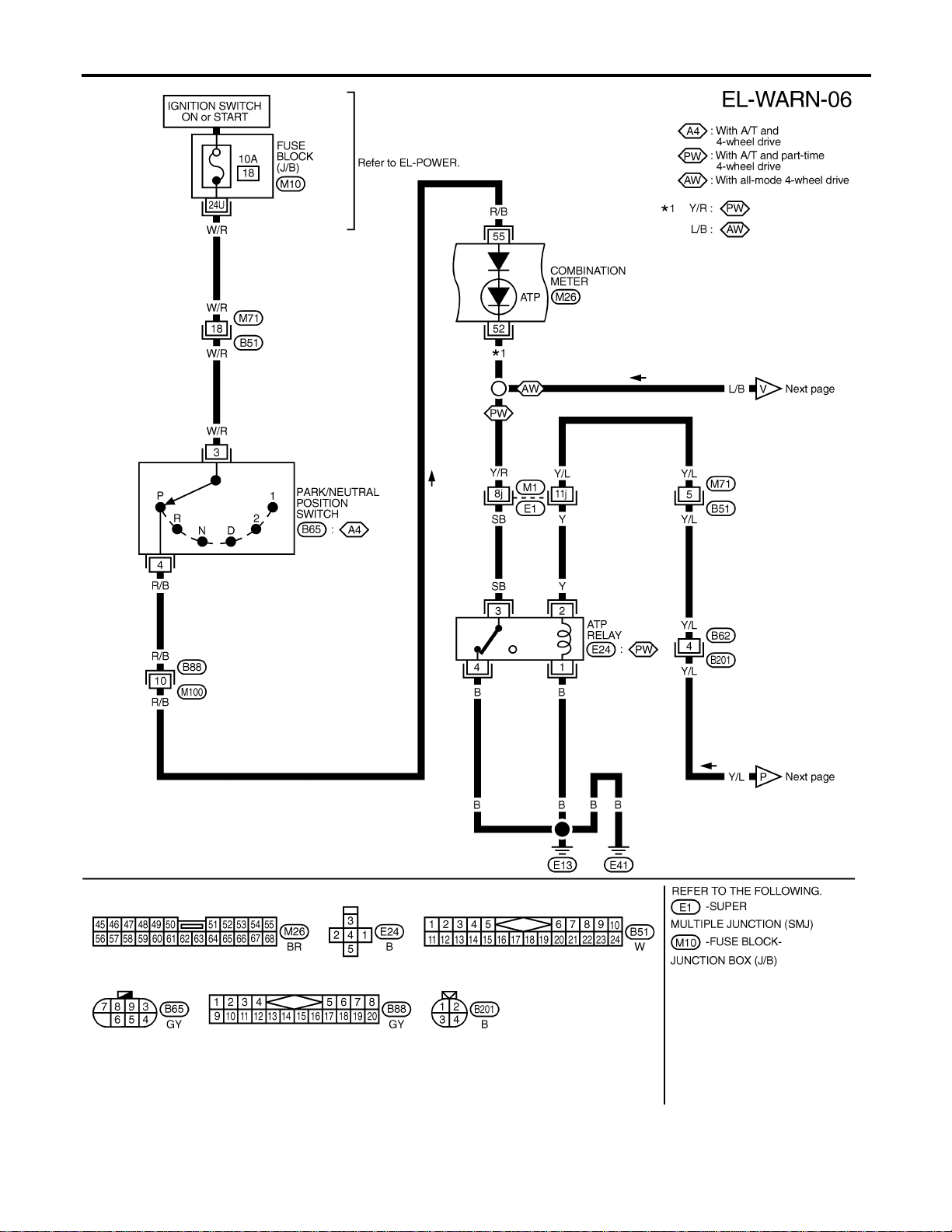
MEL415P
WARNING LAMPS
Wiring Diagram — WARN — (Cont’d)
EL-142
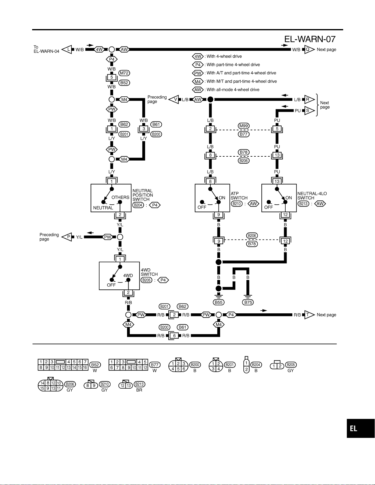
MEL416P
GI
MA
EM
LC
EC
FE
CL
MT
AT
TF
PD
AX
SU
BR
ST
RS
BT
HA
SC
IDX
WARNING LAMPS
Wiring Diagram — WARN — (Cont’d)
EL-143
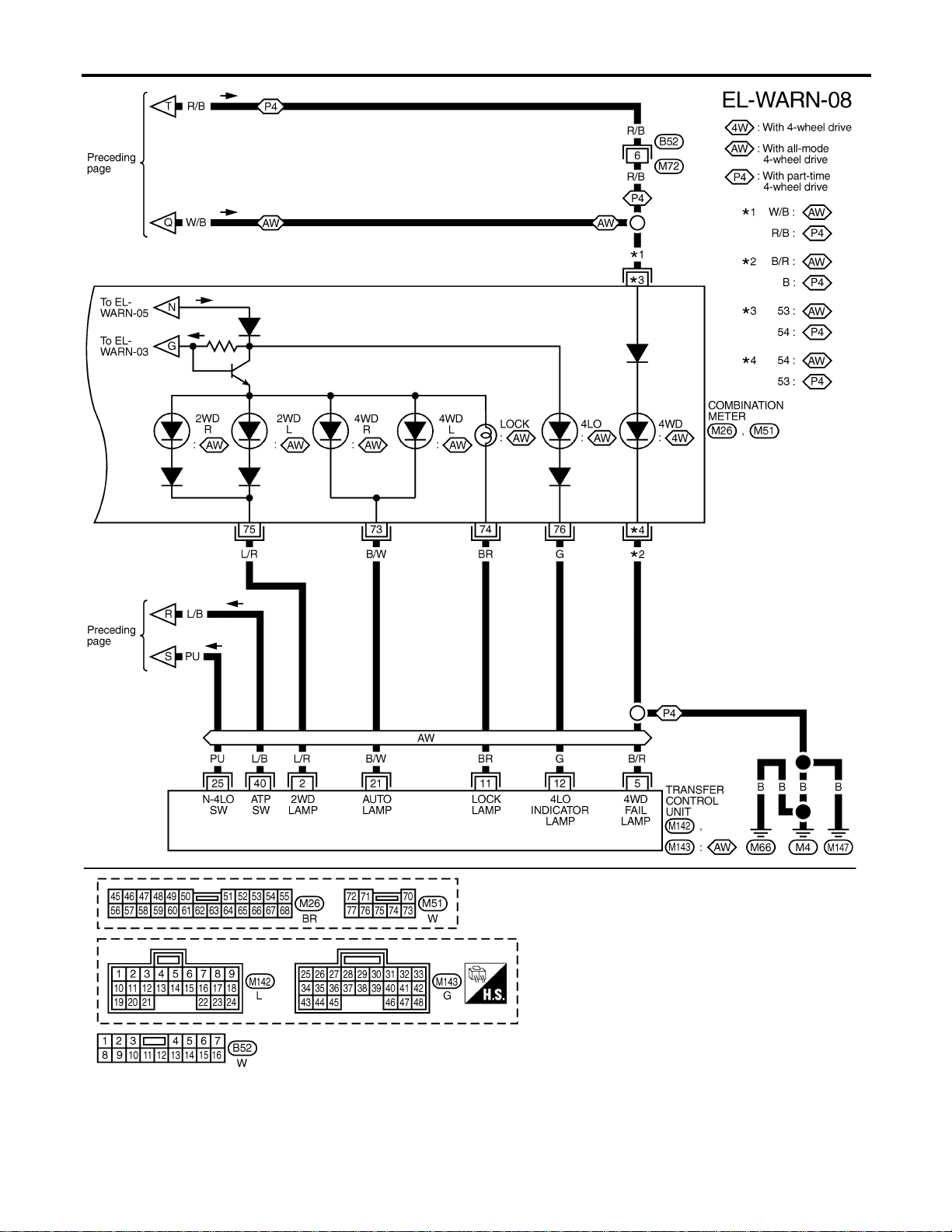
MEL417P
WARNING LAMPS
Wiring Diagram — WARN — (Cont’d)
EL-144
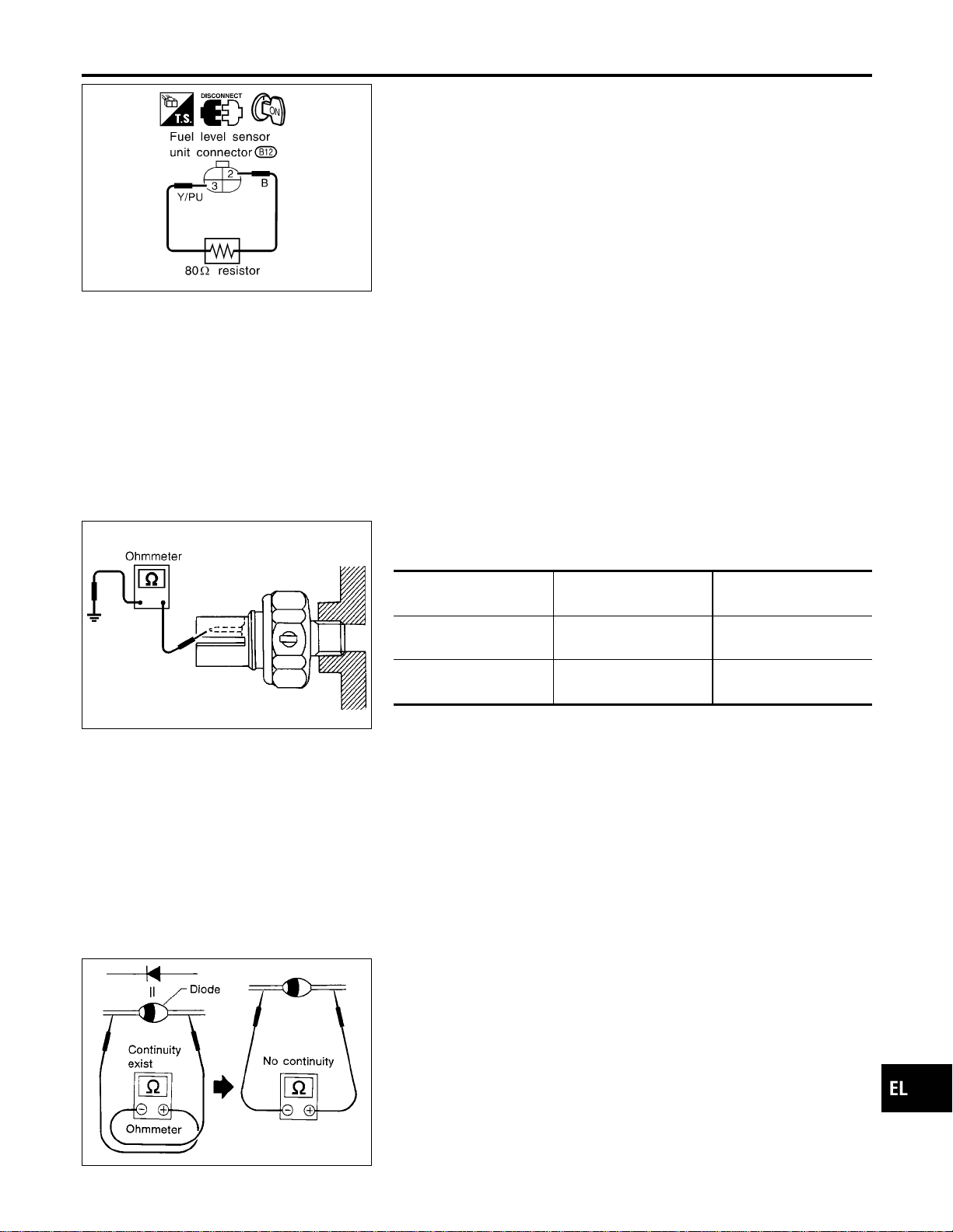
SEL062WA
Fuel Warning Lamp Sensor Check
NAEL0310
1. Turn ignition switch “OFF”.
2. Disconnect fuel level sensor unit harness connector B12.
3. Connect a resistor (80Ω) between fuel tank gauge unit harness
connector terminals 2 and 3.
4. Turn ignition switch “ON”.
The fuel warning lamp should come on.
NOTE:
ECM might store the 1st trip DTC P0180 during this inspection.
If the DTC is stored in ECM memory, erase the DTC after recon-
necting fuel tank gauge unit harness connector.
Refer to EC-73, “HOW TO ERASE EMISSION-RELATED DIAG-
NOSTIC INFORMATION”.
MEL425F
Electrical Components Inspection
NAEL0311
OIL PRESSURE SWITCH CHECK
NAEL0311S01
Oil pressure
kPa (kg/cm
2
, psi)
Continuity
Engine start
More than 10 - 20
(0.1-0.2,1-3)
NO
Engine stop
Less than 10 - 20
(0.1-0.2,1-3)
YES
Check the continuity between the terminals of oil pressure switch
and body ground.
SEL901F
DIODE CHECK
NAEL0311S02
I Check continuity using an ohmmeter.
I Diode is functioning properly if test results are as shown in the
figure at left.
I Check diodes at the combination meter harness connector
instead of checking them on the combination meter assembly.
Refer to EL-137, “WARNING LAMP” wiring diagrams.
NOTE:
Specification may vary depending on the type of tester. Before
performing this inspection, be sure to refer to the instruction
manual for the tester to be used.
GI
MA
EM
LC
EC
FE
CL
MT
AT
TF
PD
AX
SU
BR
ST
RS
BT
HA
SC
IDX
WARNING LAMPS
Fuel Warning Lamp Sensor Check
EL-145
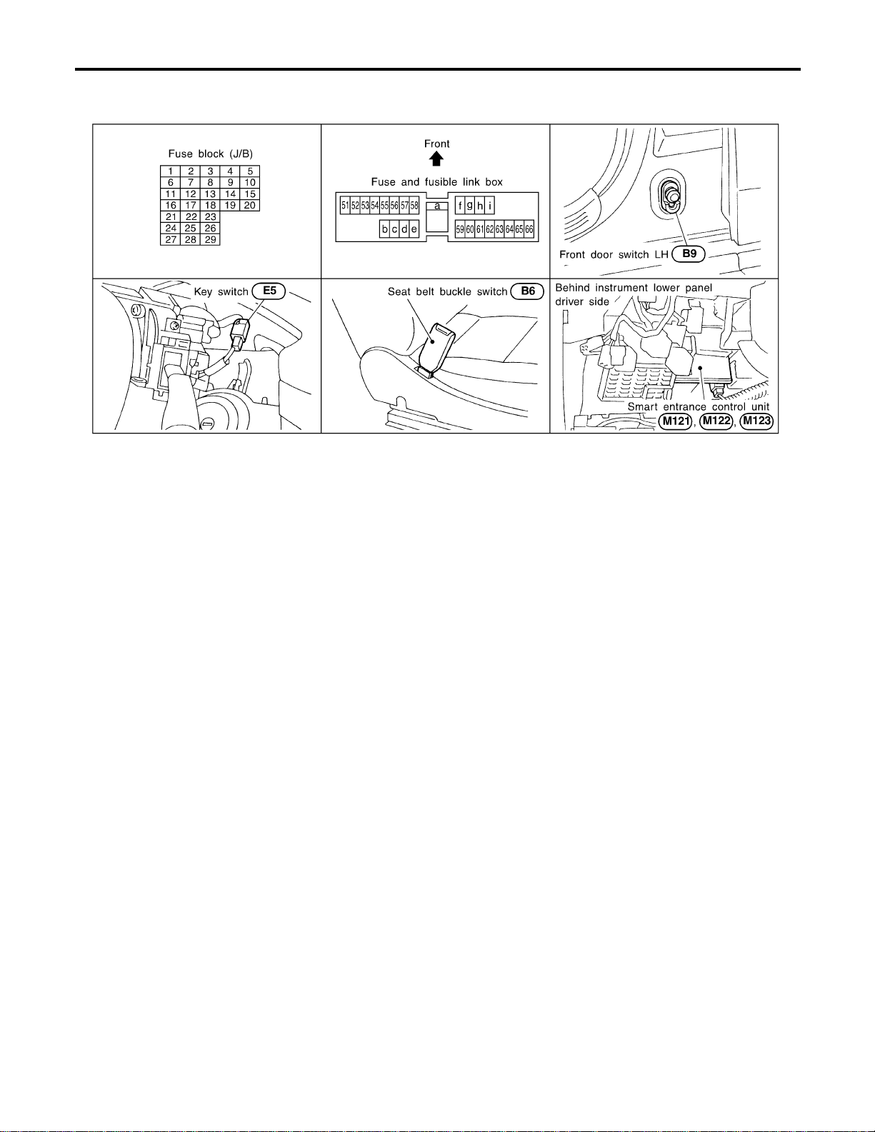
Component Parts and Harness Connector
Location
NAEL0312
SEL046WA
System Description
NAEL0313
The warning chime is controlled by the smart entrance control unit.
The warning chime is located in the smart entrance control unit.
Power is supplied at all times
I through 7.5A fuse [No. 24, located in fuse block (J/B)]
I to smart entrance control unit terminal 49 and
I to key switch terminal 2,
I through 10A fuse (No. 61, located in the fuse and fusible link box
I to tail lamp relay terminals 1 and 3.
When the ignition switch in the ON or START position, power is supplied
I through 7.5A fuse [No. 11, located in the fuse block (J/B)]
I to smart entrance control unit terminal 27.
Ground is supplied
I to smart entrance control unit terminals 43 and 64
I through body grounds M77 and M111.
When a signal, or combination of signals, is received by the smart entrance control unit, the warning chime
will sound.
IGNITION KEY WARNING CHIME
NAEL0313S01
When the key in the ignition switch in the OFF position, and the driver’s door open, the warning chime will
sound. Power is supplied
I from key switch terminal 1
I to smart entrance control unit terminal 25.
Ground is supplied
I from front door switch (driver side) terminal 1
I to smart entrance control unit terminal 1.
Front door switch (driver side) terminal 2 is grounded through body grounds B11, B22 and D210.
LIGHT WARNING CHIME
NAEL0313S02
When ignition switch OFF, driver’s door open, and lighting switch in 1ST or 2ND position, warning chime will
sound. Power is supplied.
I from tail lamp relay terminal 2
WARNING CHIME
Component Parts and Harness Connector Location
EL-146

I to smart entrance control unit terminal 19 and 57.
Ground is supplied
I from front door switch (driver side) terminal 1
I to smart entrance control unit terminal 1.
Front door switch (driver side) terminal 2 is grounded through body grounds B11, B22 and D210.
SEAT BELT WARNING CHIME
NAEL0313S03
With ignition switch turned ON and seat belt unfastened (seat belt switch ON), warning chime will sound for
approximately 6 seconds.
Ground is supplied
I from seat belt switch terminal 1
I to smart entrance control unit terminal 28.
Seat belt switch terminal 2 is grounded through body grounds B11, B22 and D210.
GI
MA
EM
LC
EC
FE
CL
MT
AT
TF
PD
AX
SU
BR
ST
RS
BT
HA
SC
IDX
WARNING CHIME
System Description (Cont’d)
EL-147
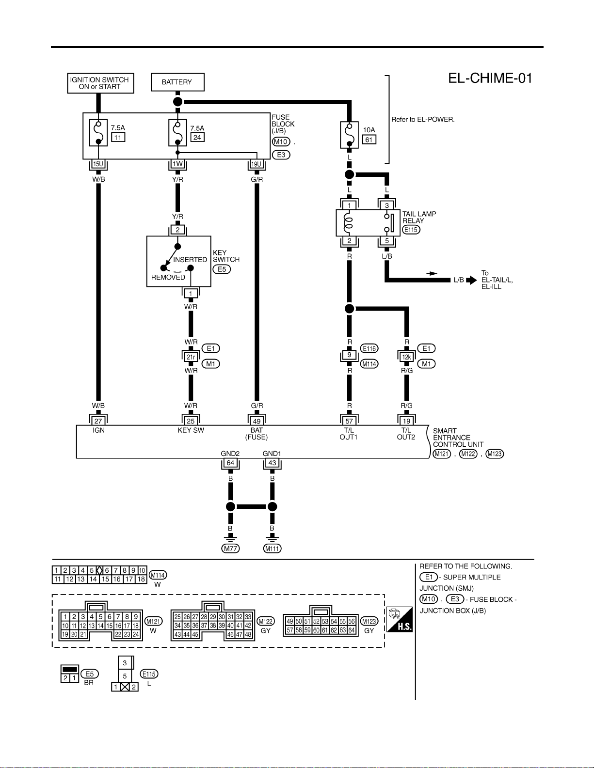
Wiring Diagram — CHIME —
NAEL0314
MEL554P
WARNING CHIME
Wiring Diagram — CHIME —
EL-148
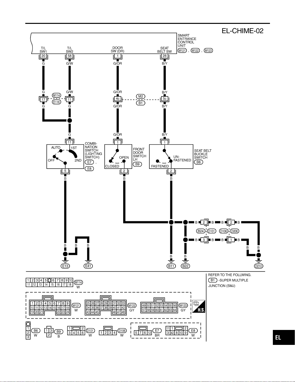
MEL555P
GI
MA
EM
LC
EC
FE
CL
MT
AT
TF
PD
AX
SU
BR
ST
RS
BT
HA
SC
IDX
WARNING CHIME
Wiring Diagram — CHIME — (Cont’d)
EL-149

SEL331X
CONSULT-II Inspection Procedure
=NAEL0315
“KEY WARN ALM”/“LIGHT WARN ALM”/“SEAT BELT
ALM”
NAEL0315S01
1. Turn ignition switch “OFF”.
2. Connect “CONSULT-II” to the data link connector.
PBR455D
3. Turn ignition switch “ON”.
4. Touch “START”.
SEL398Y
5. Touch “SMART ENTRANCE”.
SEL023X
6. Touch “KEY WARNALM”, “LIGHTWARNALM” or “SEAT BELT
ALM”.
SEL322W
I DATAMONITOR andACTIVE TEST are available for the warn-
ing chime.
WARNING CHIME
CONSULT-II Inspection Procedure
EL-150
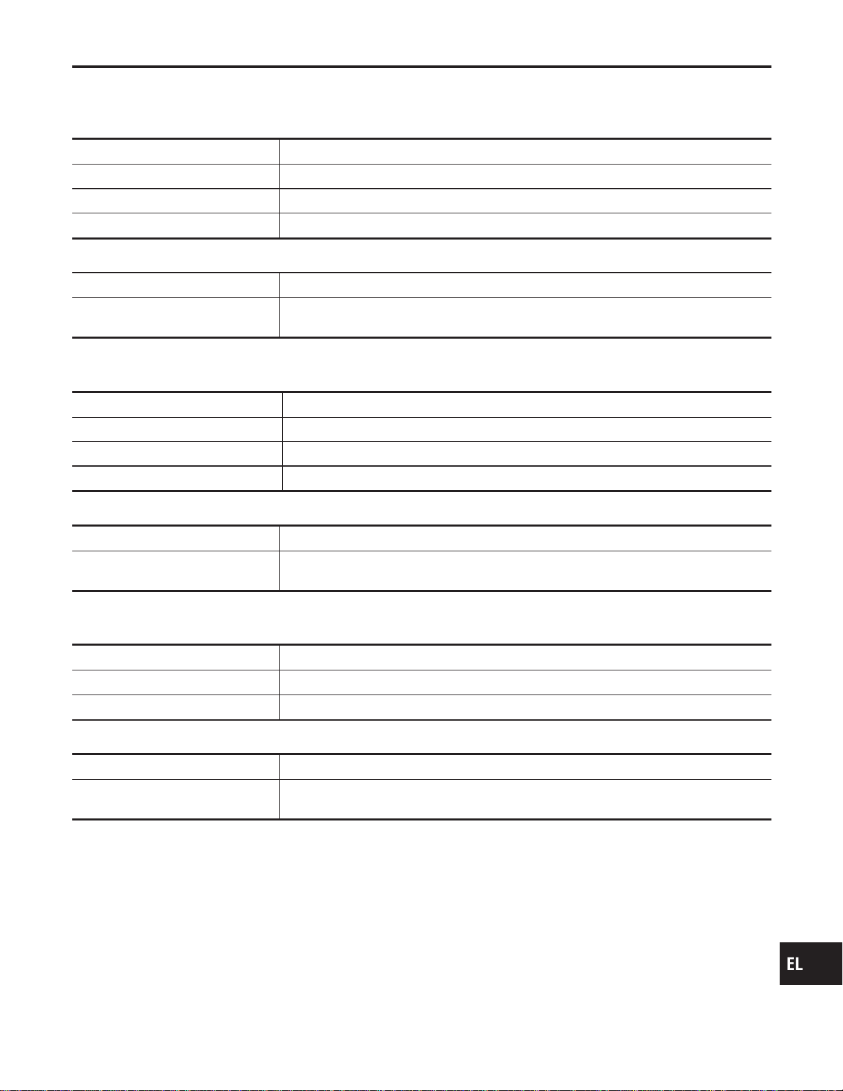
CONSULT-II Application Items
NAEL0316
“KEY WARNING ALARM”
NAEL0316S01
Data Monitor
NAEL0316S0101
Monitored Item Description
IGN ON SW Indicates [ON/OFF] condition of ignition switch.
KEY ON SW Indicates [ON/OFF] condition of key switch.
DOOR SW DR Indicates [ON/OFF] condition of front door switch LH.
Active Test
NAEL0316S0102
Test Item Description
CHIME
This test is able to check key warning chime operation. Key warning chime sounds for 2
seconds after touching “ON” on CONSULT-II screen.
“LIGHT WARN ALM”
NAEL0316S02
Data Monitor
NAEL0316S0201
Monitored Item Description
LIGHT SW 1ST Indicates [ON/OFF] condition of lighting switch.
IGN ON SW Indicates [ON/OFF] condition of ignition switch.
DOOR SW-DR Indicates [ON/OFF] condition of front door switch LH.
Active Test
NAEL0316S0202
Test Item Description
CHIME
This test is able to check light warning chime operation. Light warning chime sounds for 2
seconds after touching “ON” on CONSULT-II screen.
“SEAT BELT WARM ALM”
NAEL0316S03
Data Monitor
NAEL0316S0301
Monitored Item Description
IGN ON SW Indicates [ON/OFF] condition of ignition switch.
SEAT BELT SW Indicates [ON/OFF] condition of seat belt switch.
Active Test
NAEL0316S0302
Test Item Description
CHIME
This test is able to check seat belt warning chime operation. Seat belt warning chime
sounds for 2 seconds after touching “ON” on CONSULT-II screen.
GI
MA
EM
LC
EC
FE
CL
MT
AT
TF
PD
AX
SU
BR
ST
RS
BT
HA
SC
IDX
WARNING CHIME
CONSULT-II Application Items
EL-151
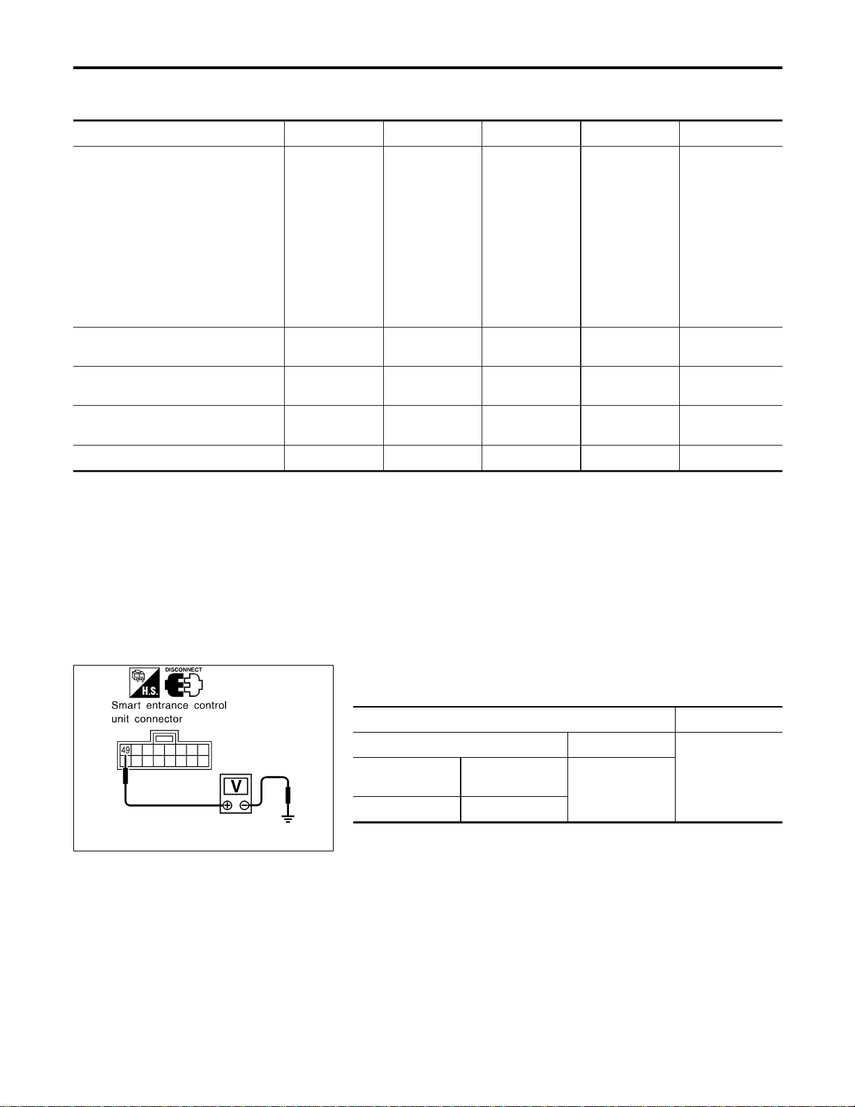
Trouble Diagnoses
NAEL0317
SYMPTOM CHART
NAEL0317S01
REFERENCE PAGE (EL- ) 152 154 155 156 157
SYMPTOM
POWER SUPPLY AND
GROUND CIRCUIT CHECK
DIAGNOSTIC PROCEDURE 1
(LIGHTING SWITCH INPUT
SIGNAL CHECK)
DIAGNOSTIC PROCEDURE 2
(KEY SWITCH INSERT
SIGNAL CHECK)
DIAGNOSTIC PROCEDURE 3
(SEAT BELT BUCKLE
SWITCH CHECK)
DIAGNOSTIC PROCEDURE 4
Light warning chime does not acti-
vate.
XX X
Ignition key warning chime does not
activate.
XXX
Seat belt warning chime does not
activate.
XXX
All warning chimes do not activate. X X
SEL989XA
POWER SUPPLY AND GROUND CIRCUIT CHECK
NAEL0317S02
Power Supply Circuit Check
NAEL0317S0201
Terminals Voltage
(+) (–)
Battery voltageConnector
Terminal
(Wire color)
Ground
M122 49 (G/R)
If NG, check the following.
I 7.5A fuse [No. 24, located in fuse block (J/B)]
I Harness for open or short between smart entrance control unit
and fuse
WARNING CHIME
Trouble Diagnoses
EL-152
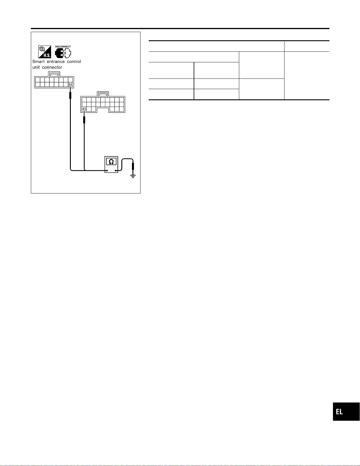
SEL990XA
Ground Circuit Check
NAEL0317S0202
Terminals Continuity
(+)
(–)
Yes
Connector
Terminal
(Wire color)
M122 43 (B)
Ground
M123 64 (B)
GI
MA
EM
LC
EC
FE
CL
MT
AT
TF
PD
AX
SU
BR
ST
RS
BT
HA
SC
IDX
WARNING CHIME
Trouble Diagnoses (Cont’d)
EL-153
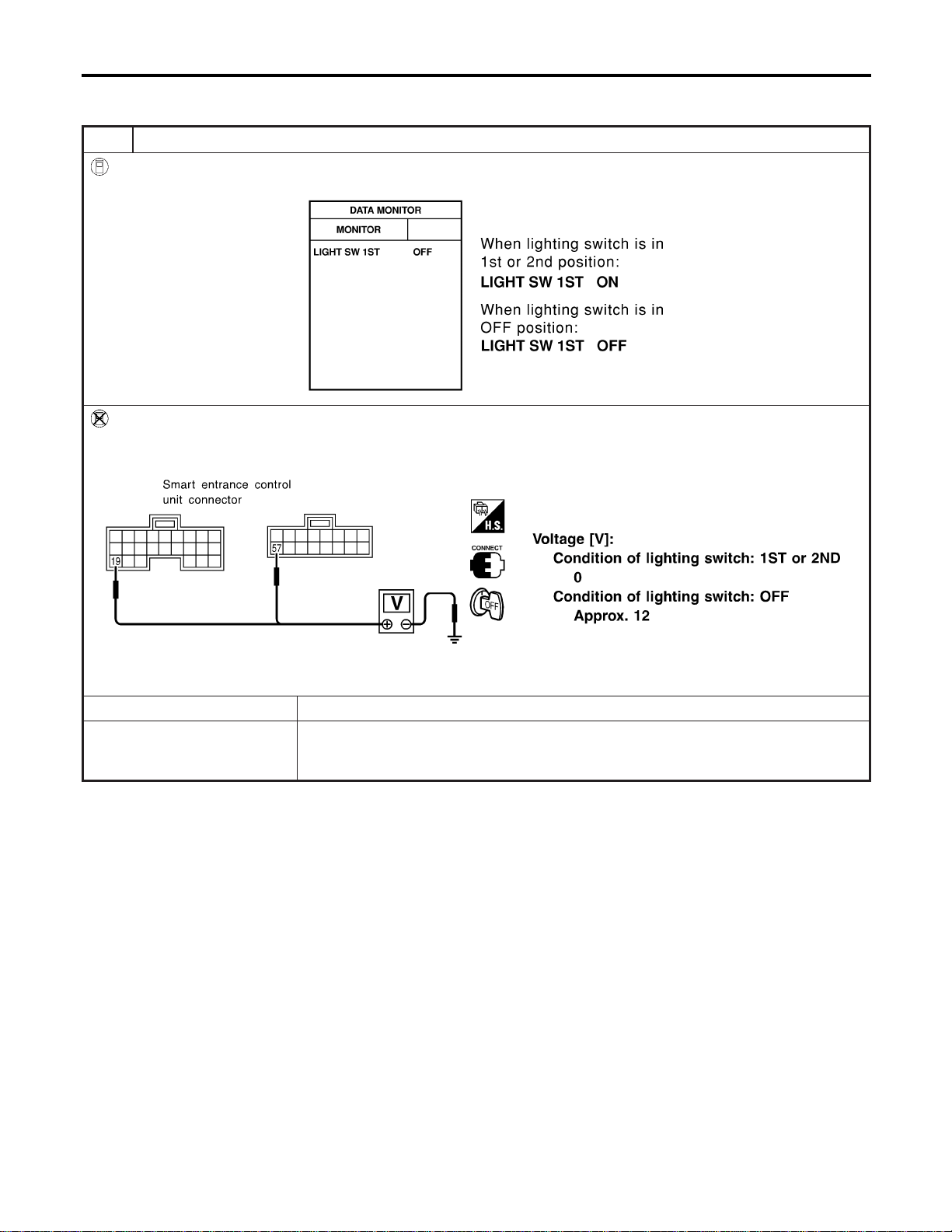
DIAGNOSTIC PROCEDURE 1 (LIGHTING SWITCH
INPUT SIGNAL CHECK)
=NAEL0317S03
1 CHECK LIGHTING SWITCH INPUT SIGNAL
With CONSULT-II
Check lighting switch (“LIGHT SW 1ST”) in “DATA MONITOR” mode with CONSULT-II.
SEL991X
Without CONSULT-II
Check voltage between smart entrance control unit harness connector M121 terminal 19 (R), connector M123 terminal 57
(R) and ground.
SEL992XA
OK or NG
OK © Replace smart entrance control unit.
NG © Check the following.
I 10A fuse (No. 61, located in the fuse and fusible link box)
I Harness for open or short between smart entrance control unit and tail lamp relay
WARNING CHIME
Trouble Diagnoses (Cont’d)
EL-154
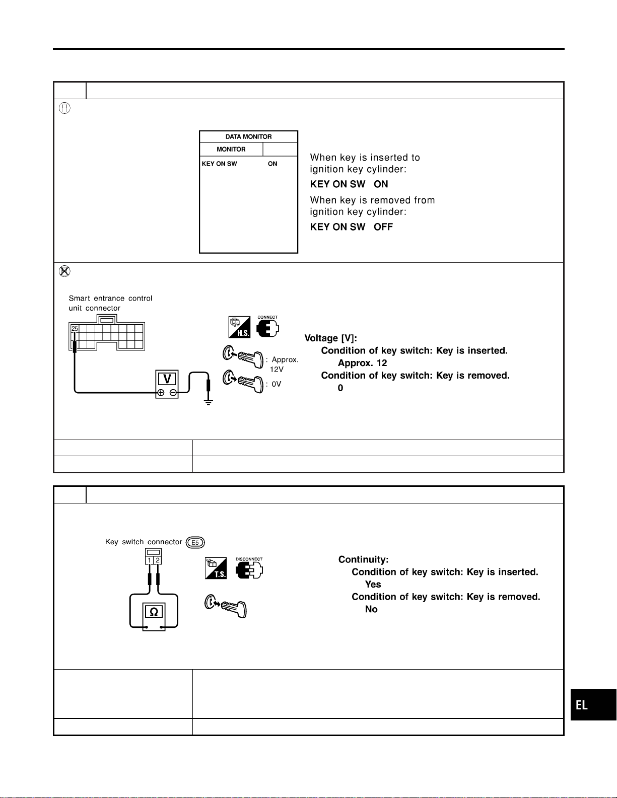
DIAGNOSTIC PROCEDURE 2 (KEY SWITCH INSERT
SIGNAL CHECK)
=NAEL0317S04
1 CHECK KEY SWITCH INPUT SIGNAL
With CONSULT-II
Check key switch (“KEY ON SW”) in “DATA MONITOR” mode with CONSULT-II.
SEL315W
Without CONSULT-II
Check voltage between smart entrance control unit harness connector M122 terminal 25 (W/R) and ground.
SEL011Y
OK or NG
OK © Replace smart entrance control unit.
NG © GO TO 2.
2 CHECK KEY SWITCH (INSERT)
Check continuity between terminals 1 and 2.
SEL308X
OK or NG
OK © Check the following.
I 10A fuse [No. 13, located in fuse block (J/B)]
I Harness for open or short between key switch and fuse
I Harness for open or short between smart entrance control unit and key switch
NG © Replace key switch.
GI
MA
EM
LC
EC
FE
CL
MT
AT
TF
PD
AX
SU
BR
ST
RS
BT
HA
SC
IDX
WARNING CHIME
Trouble Diagnoses (Cont’d)
EL-155
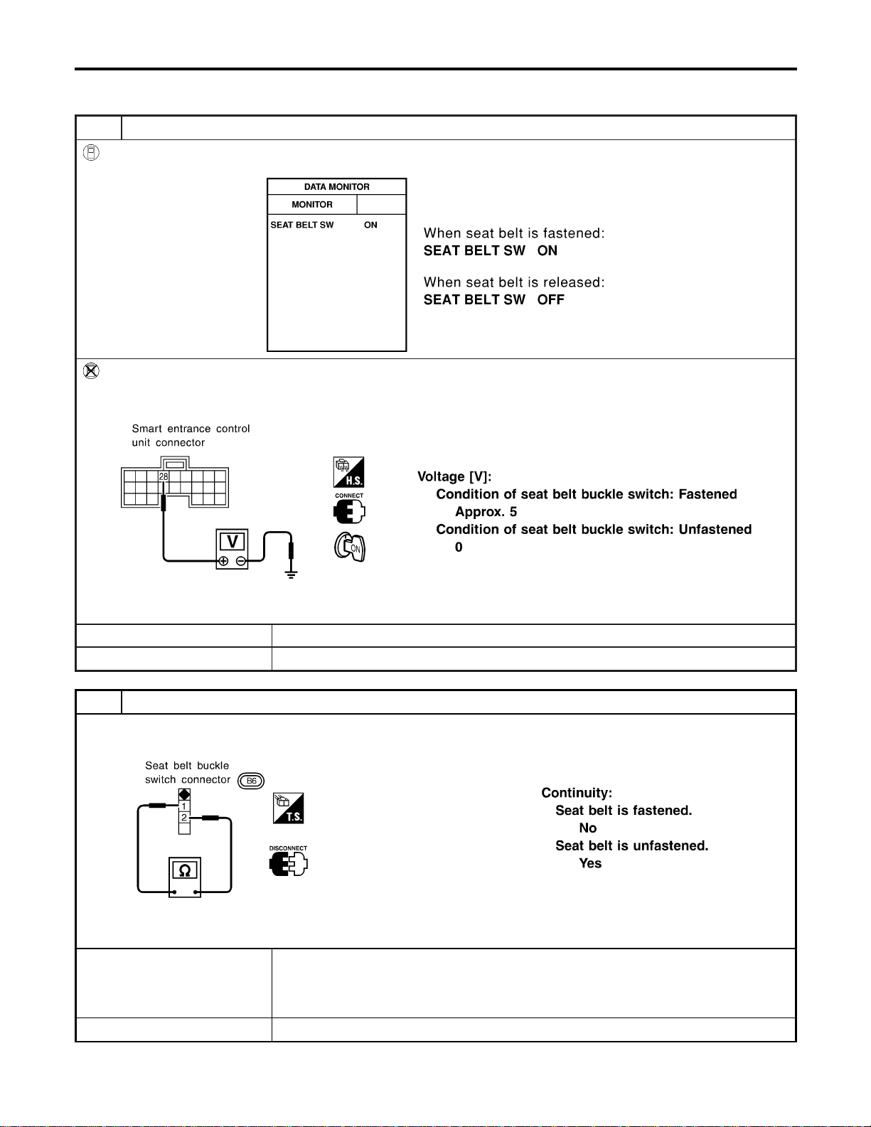
DIAGNOSTIC PROCEDURE 3 (SEAT BELT BUCKLE
SWITCH CHECK)
=NAEL0317S05
1 CHECK SEAT BELT BUCKLE SWITCH INPUT SIGNAL
With CONSULT-II
Check seat belt buckle switch (“SEAT BELT SW”) in “DATA MONITOR” mode with CONSULT-II.
SEL317W
Without CONSULT-II
1. Turn ignition switch “ON”.
2. Check voltage between smart entrance control unit harness connector M122 terminal 28 (B/Y) and ground.
SEL994X
OK or NG
OK © Replace smart entrance control unit.
NG © GO TO 2.
2 CHECK SEAT BELT BUCKLE SWITCH
Check continuity between terminals 1 and 2 when seat belt is fastened and unfastened.
SEL381X
OK or NG
OK © Check the following.
I Seat belt buckle switch ground circuit
I Harness for open or short between smart entrance control unit and seat belt buckle
switch
NG © Replace seat belt buckle switch.
WARNING CHIME
Trouble Diagnoses (Cont’d)
EL-156
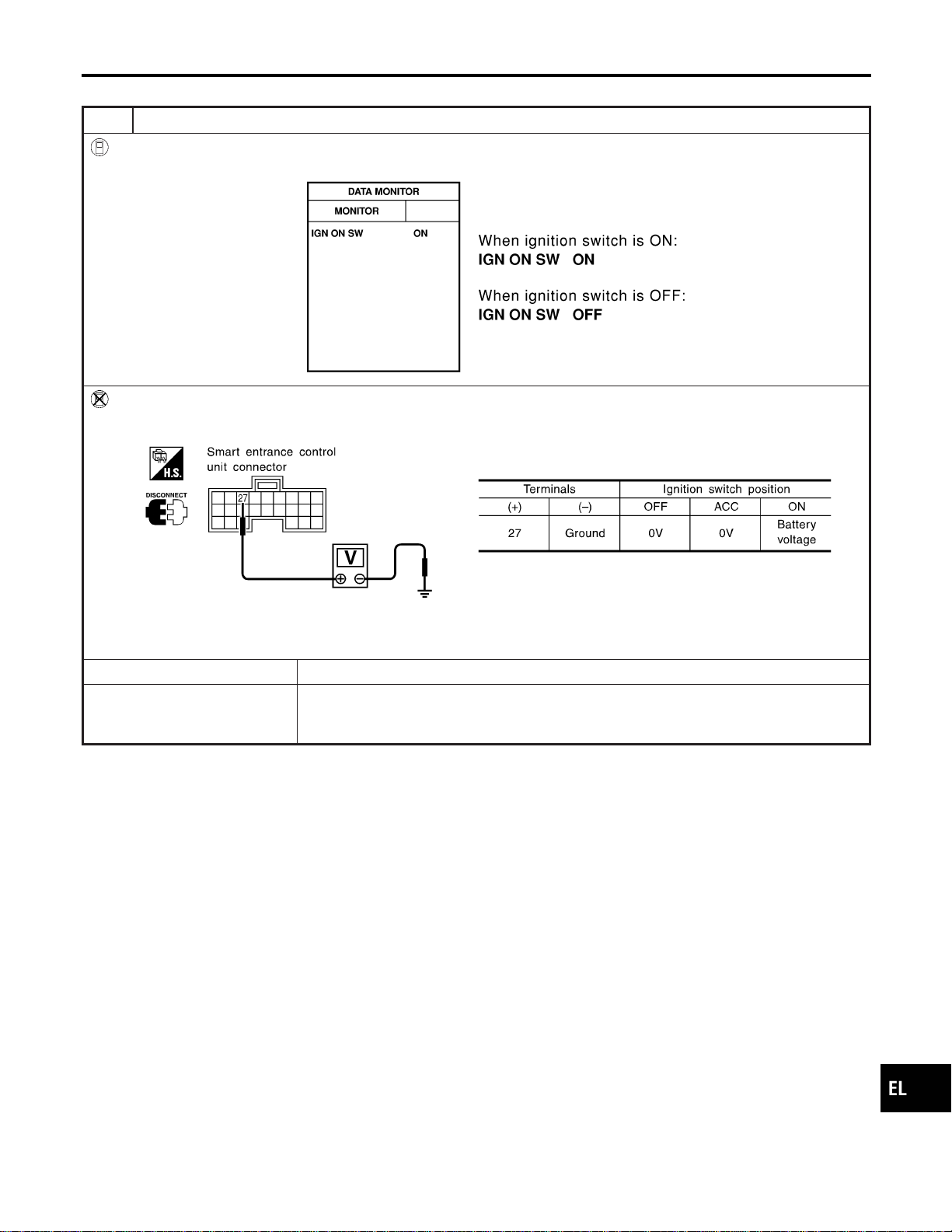
DIAGNOSTIC PROCEDURE 4
NAEL0317S06
1 CHECK IGNITION ON SIGNAL
With CONSULT-II
Check ignition switch ON signal (“IGN ON SW”) in “DATA MONITOR” mode with CONSULT-II.
SEL318W
Without CONSULT-II
Check voltage between smart entrance control unit harness connector M122 terminal 27 (W/B) and ground.
SEL995X
OK or NG
OK © GO TO 2.
NG © Check the following.
I 7.5A fuse [No. 11, located in fuse block (J/B)]
I Harness for open or short between smart entrance control unit and fuse
GI
MA
EM
LC
EC
FE
CL
MT
AT
TF
PD
AX
SU
BR
ST
RS
BT
HA
SC
IDX
WARNING CHIME
Trouble Diagnoses (Cont’d)
EL-157
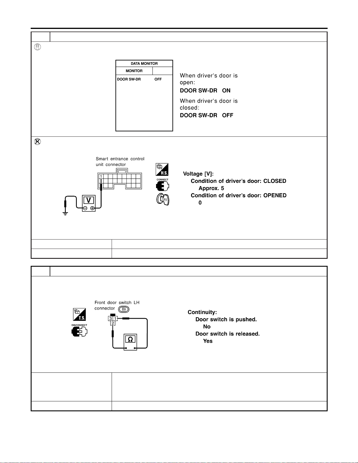
2 CHECK DOOR SWITCH INPUT SIGNAL
With CONSULT-II
Check driver door switch signal (“DOOR SW-DR”) in “DATA MONITOR” mode with CONSULT-II.
SEL319W
Without CONSULT-II
Check voltage between smart entrance control unit harness connector M121 terminal 1 (G/R) and ground.
SEL996X
OK or NG
OK © GO TO 4.
NG © GO TO 3.
3 CHECK DRIVER SIDE DOOR SWITCH
Check continuity between terminals 2 and 3.
SEL383X
OK or NG
OK © Check the following.
I Driver side door switch ground circuit and condition
I Harness for open or short between smart entrance control unit and driver side door
switch
NG © Replace driver side door switch.
WARNING CHIME
Trouble Diagnoses (Cont’d)
EL-158
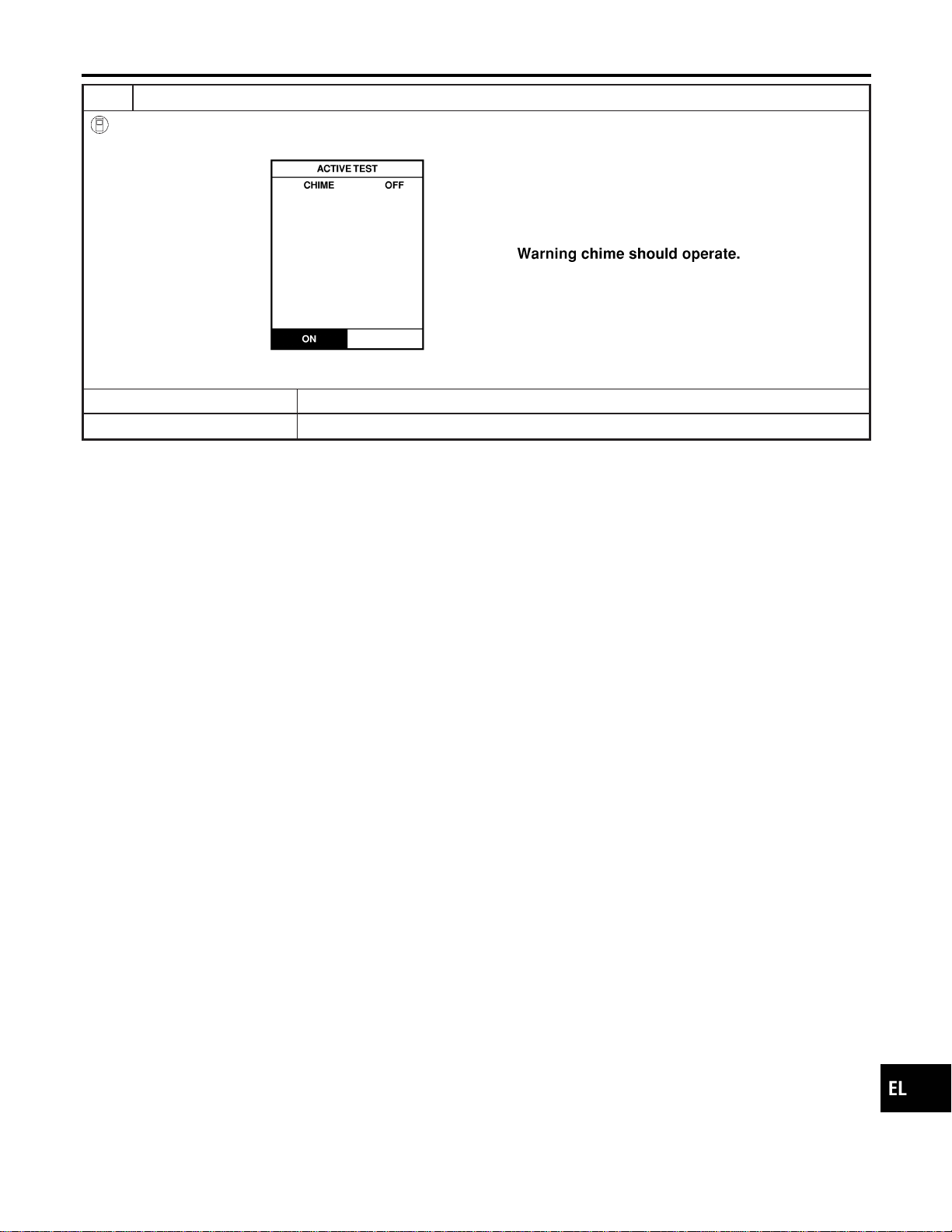
4 CHECK WARNING CHIME
With CONSULT-II
Perform “CHIME” in “ACTIVE TEST” mode with CONSULT-II.
SEL320W
OK or NG
OK © System is OK.
NG © Replace smart entrance control unit.
GI
MA
EM
LC
EC
FE
CL
MT
AT
TF
PD
AX
SU
BR
ST
RS
BT
HA
SC
IDX
WARNING CHIME
Trouble Diagnoses (Cont’d)
EL-159

System Description
NAEL0318
WIPER OPERATION
NAEL0318S01
The front wiper switch is controlled by a lever built into the combination switch.
There are three wiper switch positions:
I LO speed
I HI speed
I INT (Intermittent)
With the ignition switch in the ACC or ON position, power is supplied
I through 20A fuse [No. 19, located in the fuse block (J/B)]
I to front wiper motor terminal 1, and
I to front wiper switch terminal 15.
Low and High Speed Wiper Operation
NAEL0318S0101
Ground is supplied to front wiper switch terminal 17 through body grounds E13 and E41.
When the wiper switch is placed in the LO position, ground is supplied
I through terminal 14 of the front wiper switch
I to front wiper motor terminal 5.
With power and ground supplied, the front wiper motor operates at low speed.
When the front wiper switch is placed in the HI position, ground is supplied
I through terminal 16 of the front wiper switch
I to front wiper motor terminal 3.
With power and ground supplied, the front wiper motor operates at high speed.
Auto Stop Operation
NAEL0318S0102
With front wiper switch turned OFF, front wiper motor will continue to operate until wiper arms reach windshield
base.
When wiper arms are not located at base of windshield with front wiper switch OFF, ground is provided
I from terminal 14 of the front wiper switch
I to front wiper motor terminal 5, in order to continue front wiper motor operation at low speed.
Ground is also supplied
I to terminal 13 of the front wiper switch
I through front wiper motor terminal 4
I through terminal 6 of the front wiper motor, and
I through body grounds M77 and M111.
When wiper arms reach base of windshield, front wiper motor terminals 1 and 4 are connected instead of ter-
minals 4 and 6. Wiper motor will then stop wiper arms at the PARK position.
Intermittent Operation
NAEL0318S0103
The front wiper motor operates the wiper arms one time at low speed at a set interval of approximately 2 to
13 seconds. This feature is controlled by the wiper amplifier built in the front wiper switch.
When the front wiper switch is placed in the INT position, ground is supplied
I to wiper amplifier (INT SW)
I from front wiper switch terminal 17
I through body grounds E13 and E41, and
I to front wiper motor terminal 5
I through the front wiper switch terminal 14
I through wiper amplifier (OUTPUT)
WASHER OPERATION
NAEL0318S02
With the ignition switch in the ACC or ON position, power is supplied
I through 20A fuse [No. 19, located in the fuse block (J/B)]
I to front washer motor terminal 1.
When the lever is pulled to the WASH position, ground is supplied
I to front washer motor terminal 2
I through terminal 18 of the front wiper switch
FRONT WIPER AND WASHER
System Description
EL-160

I through terminal 17 of the front wiper switch, and
I through body grounds E13 and E41.
With power and ground supplied, the front washer motor operates.
When the lever is pulled to the WASH position for one second or more, the front wiper motor operates at low
speed for approximately 3 seconds to clean windshield. This feature is controlled by the wiper amplifier in the
same manner as the intermittent operation.
GI
MA
EM
LC
EC
FE
CL
MT
AT
TF
PD
AX
SU
BR
ST
RS
BT
HA
SC
IDX
FRONT WIPER AND WASHER
System Description (Cont’d)
EL-161

Wiring Diagram — WIPER —
NAEL0319
MEL349N
FRONT WIPER AND WASHER
Wiring Diagram — WIPER —
EL-162
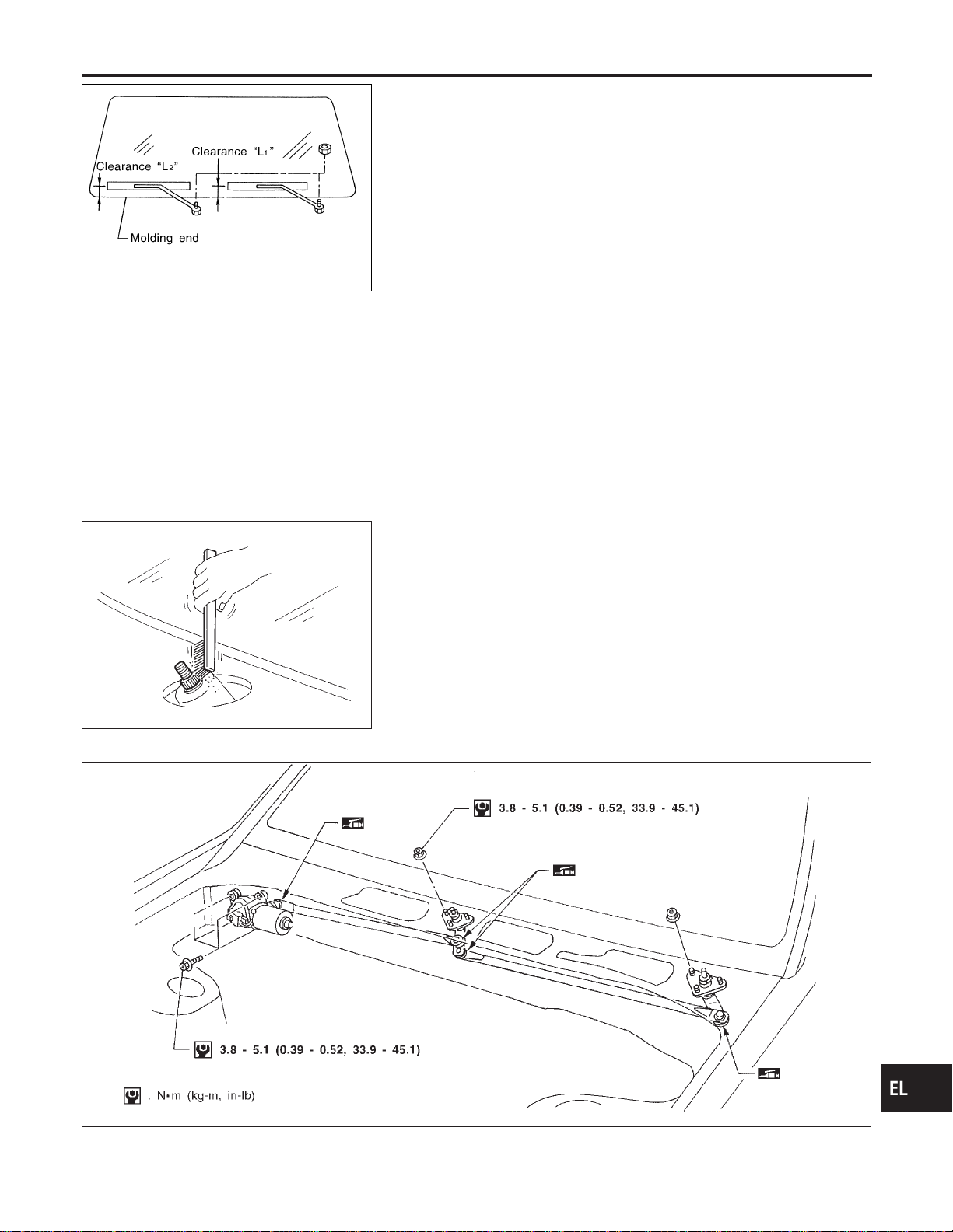
SEL543TA
Removal and Installation
NAEL0320
WIPER ARMS
NAEL0320S01
1. Prior to wiper arm installation, turn on wiper switch to operate
wiper motor and then turn it “OFF” (Auto Stop).
2. Lift the blade up and then set it down onto glass surface to set
the blade center to clearance “L
1
”&“L
2
” immediately before
tightening nut.
3. Eject washer fluid. Turn on wiper switch to operate wiper motor
and then turn it “OFF”.
4. Ensure that wiper blades stop within clearance “L
1
”&“L
2
”.
Clearance “L
1
”: 29 - 39 mm (1.14 - 1.54 in)
Clearance “L
2
”: 32 - 42 mm (1.26 - 1.65 in)
I Tighten wiper arm nuts to specified torque.
Front wiper: 21 - 26 N·m (2.1 - 2.7 kg-m, 15 - 20 ft-lb)
SEL024J
I Before reinstalling wiper arm, clean up the pivot area as
illustrated. This will reduce possibility of wiper arm loose-
ness.
WIPER LINKAGE
NAEL0320S02
MEL840F
GI
MA
EM
LC
EC
FE
CL
MT
AT
TF
PD
AX
SU
BR
ST
RS
BT
HA
SC
IDX
FRONT WIPER AND WASHER
Removal and Installation
EL-163

Removal
NAEL0320S0201
1. Remove 4 bolts that secure wiper motor.
2. Detach wiper motor from wiper linkage at ball joint.
3. Remove wiper linkage.
Be careful not to break ball joint rubber boot.
Installation
NAEL0320S0202
I Grease ball joint portion before installation.
1. Installation is the reverse order of removal.
MEL137M
Washer Nozzle Adjustment
NAEL0321
I Adjust washer nozzle with suitable tool as shown in the figure
at left.
Adjustable range: ±10°
MEL540M
Unit: mm (in)
*1 251 (9.88) *6 459 (18.07)
*2 315 (12.40) *7 256 (10.08)
*3 165 (6.50) *8 67 (2.64)
*4 269 (10.59) *9 40 (1.57)
*5 167 (6.57)
*A: The diameters of these circles are less than 80 mm (3.15 in).
*B: The diameters of these circles are less than 138 × 80 mm (5.43 × 3.15 in).
*C: The diameters of these circles are less than 96 × 80 mm (3.78 × 3.15 in).
MEL074H
Washer Tube Layout
NAEL0322
FRONT WIPER AND WASHER
Removal and Installation (Cont’d)
EL-164

System Description
NAEL0323
WIPER OPERATION
NAEL0323S01
Power Supply and Ground
NAEL0323S0101
With ignition switch in the ACC or ON position, power is supplied
I through 10A fuse [No. 29, located in the fuse block (J/B)]
I to rear wiper motor terminal 4.
When the glass hatch switch is OPEN, ground is supplied
I to rear wiper motor terminal 6
I through glass hatch switch terminal 1 and 2
I through body grounds B11, B22 and D210.
Ground is supplied
I to rear wiper motor terminal 8
I through body grounds B11, B22 and D210.
Wiper Operation
NAEL0323S0102
When the rear wiper switch is turned ON, ground is supplied
I to rear wiper motor terminal 2
I through combination switch terminals 22 and 24
I through body grounds E13 and E41.
Then, power is supplied
I to rear wiper motor terminal 4.
Ground is supplied
I to rear wiper motor terminal 8
I through body grounds B11, B22 and D210.
With power and ground supplied, the wiper motor operates.
Auto Stop Operation
NAEL0323S0103
With rear wiper switch turned OFF, rear wiper motor will continue to operate until wiper arm reaches rear wiper
stopper.
Then wiper motor turns the other way and wiper arm moves once until wiper arm reaches stopper.
Intermittent Operation
NAEL0323S0104
The rear wiper motor operates the wiper arms at low speed approximately every 7 seconds.
When the wiper switch is placed in the INT position, ground is supplied
I to wiper motor terminal 3
I through rear wiper switch terminal 21 and 24
I through body grounds E13 and E41.
Then, power is supplied
I to rear wiper motor terminal 4.
Ground is supplied
I to rear wiper motor terminal 8
I through body grounds B11, B22 and D210.
With power and ground supplied, rear wiper operates at intermittent.
WIPER OPERATION PROHIBIT CONTROL
NAEL0323S02
When glass hatch is open with back door key cylinder while rear wiper is operated, wiper operation is stopped.
(Wiper operation prohibit control)
When glass hatch is closed and rear wiper switch turns from OFF and then rear wiper switch is turned to ON,
wiper operation prohibit control is canceled.
WASHER OPERATION
NAEL0323S03
When the rear wiper switch is turned to WASH position, ground is supplied
I to rear wiper motor terminal 5
I through terminals 23 and 24
I through body grounds E13 and E41.
GI
MA
EM
LC
EC
FE
CL
MT
AT
TF
PD
AX
SU
BR
ST
RS
BT
HA
SC
IDX
REAR WIPER AND WASHER
System Description
EL-165

Then, power is supplied
I to rear washer motor terminal 2
I through 10 A fuse [No. 29, located in the fuse block (J/B)].
Ground is supplied
I to rear washer motor terminal 1
I through rear wiper switch terminals 23 and 24
I through body grounds E13 and E41.
With power and ground supplied, the rear washer motor operates.
When the rear wiper switch is turned to WASH position for 0.4 seconds or more, the rear wiper motor oper-
ates approximately 3 times after the rear wiper switch is released.
REAR WIPER AND WASHER
System Description (Cont’d)
EL-166
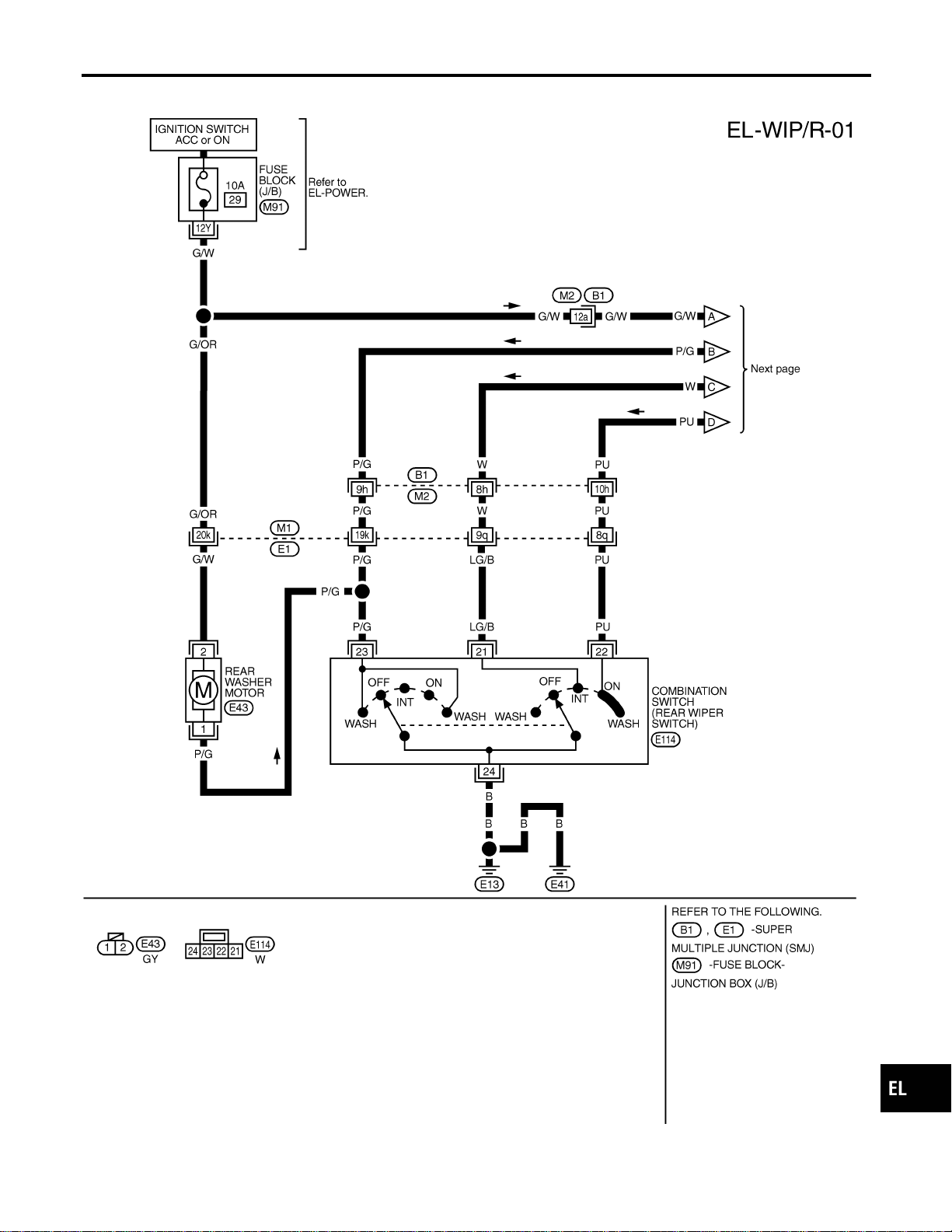
Wiring Diagram — WIP/R —
NAEL0324
MEL407O
GI
MA
EM
LC
EC
FE
CL
MT
AT
TF
PD
AX
SU
BR
ST
RS
BT
HA
SC
IDX
REAR WIPER AND WASHER
Wiring Diagram — WIP/R —
EL-167
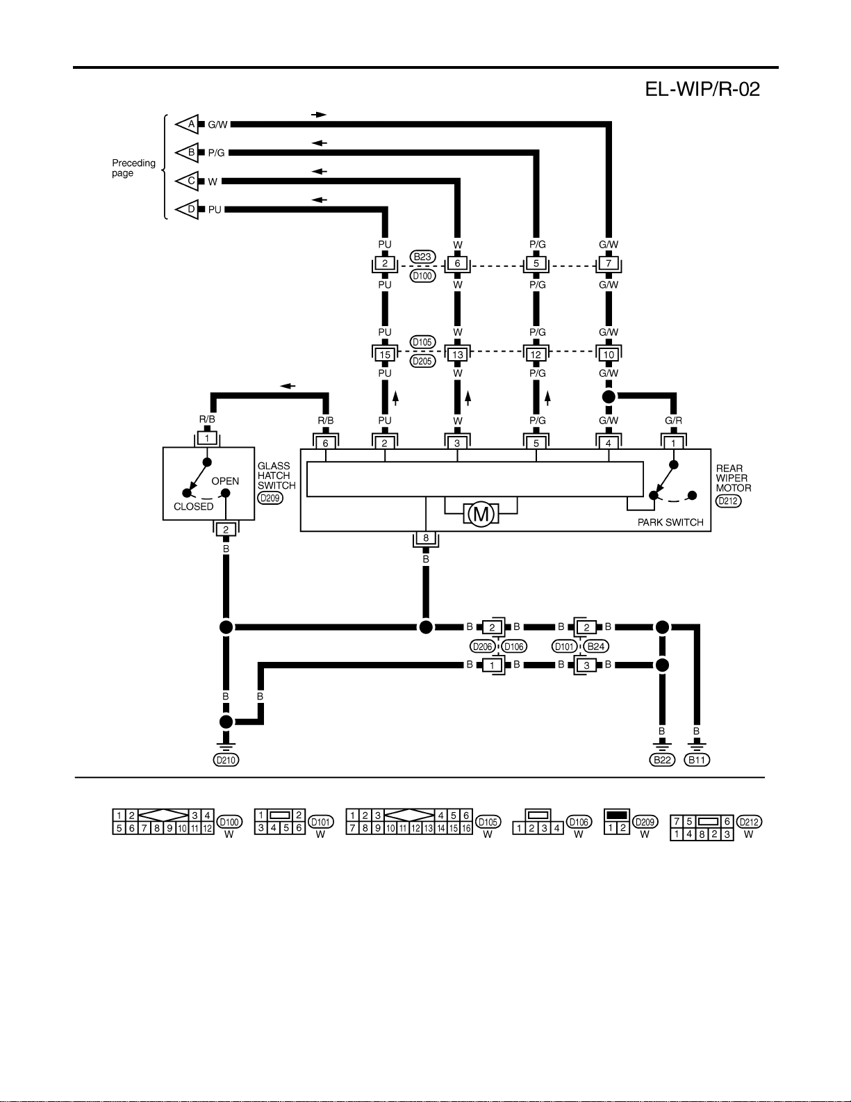
MEL408O
REAR WIPER AND WASHER
Wiring Diagram — WIP/R — (Cont’d)
EL-168
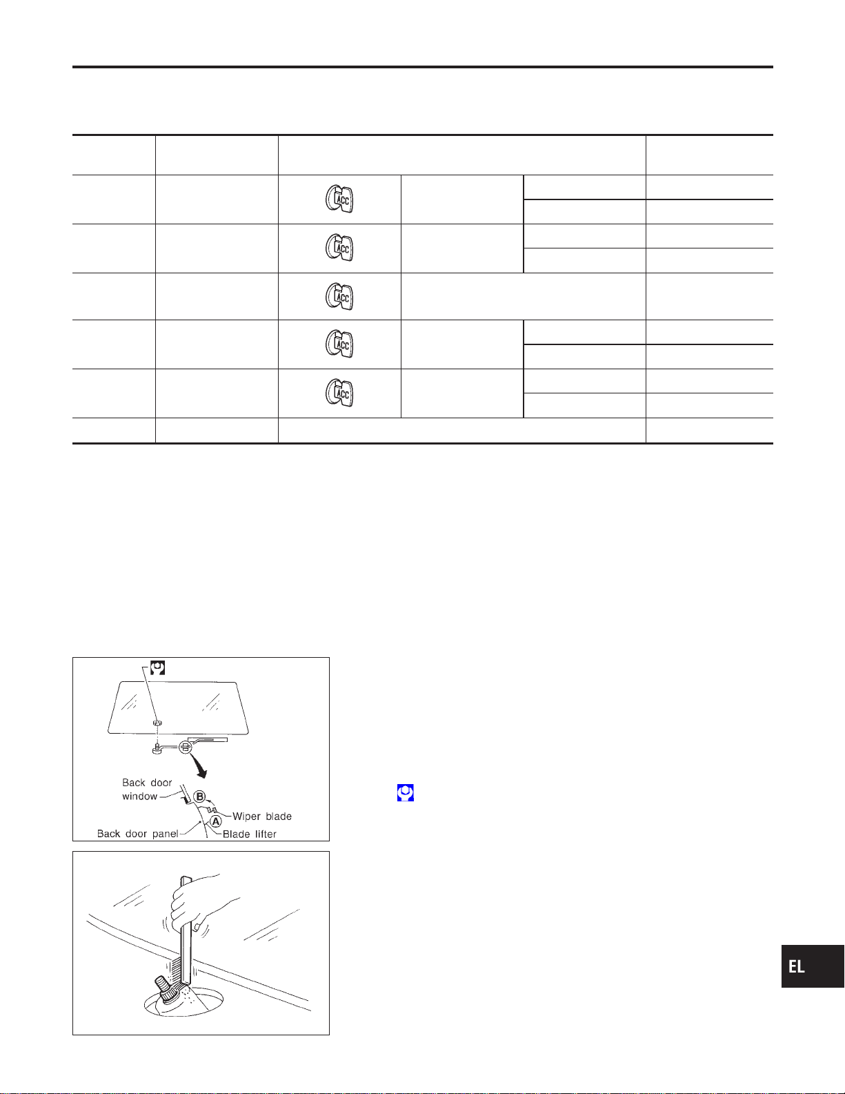
Trouble Diagnoses
NAEL0325
REAR WIPER MOTOR INSPECTION TABLE
NAEL0325S01
(Data are reference values.)
Terminal No. Item Condition Voltage
(Approximate value)
2 ON switch
Rear wiper switch ON Less than 1V
OFF or INT Battery voltage
3 Intermittent switch
Rear wiper switch INT Less than 1V
OFF, ON or WASH Battery voltage
4 Power supply (ACC)
— Battery voltage
5 Washer switch
Rear wiper switch WASH Less than 1V
OFF, ON or INT Battery voltage
6 Glass hatch switch
Glass hatch Open Less than 1V
Closed Battery voltage
8 Ground — —
NOTE:
Power to the rear wiper motor will be interrupted when the rear glass hatch is opened. In that case, conduct
the inspection of the rear wiper motor with the rear glass hatch closed, unless otherwise indicated.
MEL066G
Removal and Installation
NAEL0326
WIPER ARMS
NAEL0326S01
1. Prior to wiper arm installation, turn on wiper switch to operate
wiper motor and then turn it “OFF” (Auto Stop).
2. Install wiper arm to portion A as in figure below and tighten
wiper arm nut to specification.
3. Then, set wiper arm to portion B.
: 13 - 18 N·m (1.3 - 1.8 kg-m,9-13ft-lb)
SEL024J
I Before reinstalling wiper arm, clean up the pivot area as
illustrated. This will reduce possibility of wiper arm loose-
ness.
GI
MA
EM
LC
EC
FE
CL
MT
AT
TF
PD
AX
SU
BR
ST
RS
BT
HA
SC
IDX
REAR WIPER AND WASHER
Trouble Diagnoses
EL-169
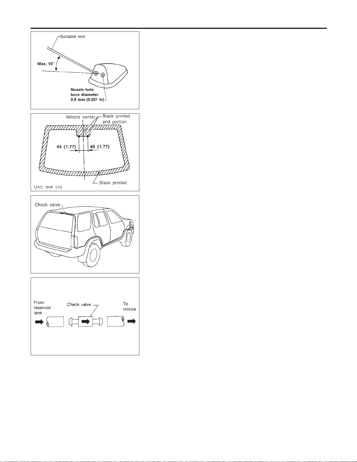
SEL241P
MEL034G
Washer Nozzle Adjustment
NAEL0327
I Adjust washer nozzle with suitable tool as shown in the figure
at left.
Adjustable range: ±10° (In any direction)
MEL067G
Washer Tube Layout
NAEL0328
SEL411H
Check Valve
NAEL0329
I A check valve is provided in the washer fluid line. Be careful
not to connect check valve to washer tube in the wrong direc-
tion.
REAR WIPER AND WASHER
Washer Nozzle Adjustment
EL-170
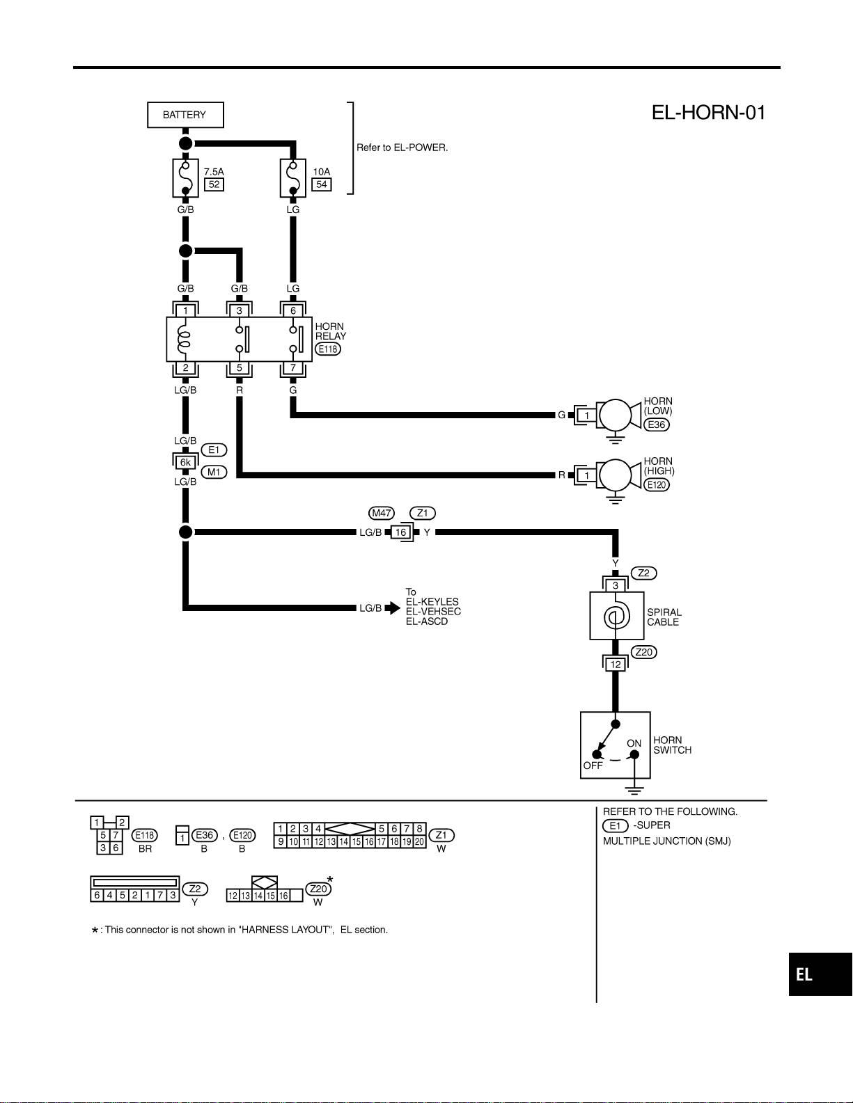
Wiring Diagram — HORN —
NAEL0330
MEL428O
GI
MA
EM
LC
EC
FE
CL
MT
AT
TF
PD
AX
SU
BR
ST
RS
BT
HA
SC
IDX
HORN
Wiring Diagram — HORN —
EL-171
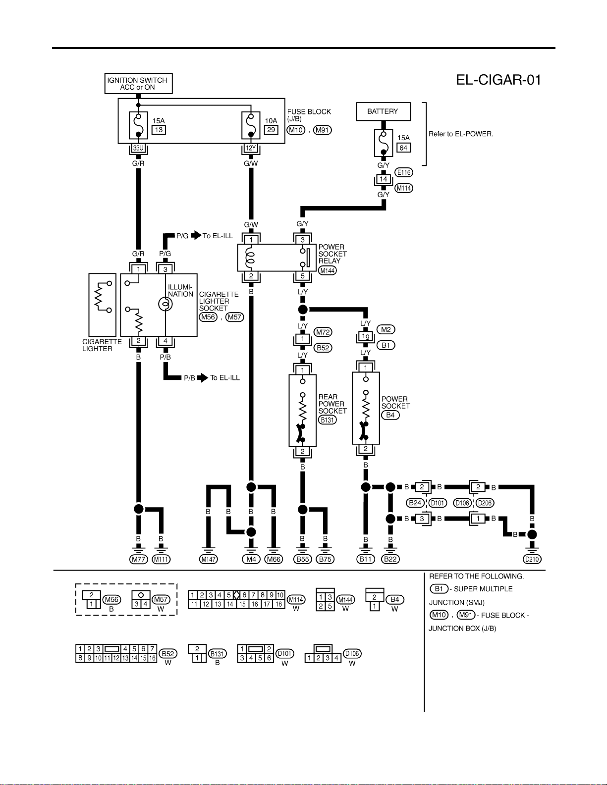
Wiring Diagram — CIGAR —
NAEL0331
MEL353N
CIGARETTE LIGHTER
Wiring Diagram — CIGAR —
EL-172

Wiring Diagram — CLOCK —
NAEL0332
MEL035M
GI
MA
EM
LC
EC
FE
CL
MT
AT
TF
PD
AX
SU
BR
ST
RS
BT
HA
SC
IDX
CLOCK
Wiring Diagram — CLOCK —
EL-173

Component Parts and Harness Connector
Location
NAEL0333
SEL483Y
System Description
NAEL0334
The rear window defogger system is controlled by the smart entrance control unit. The rear window defogger
operates only for approximately 15 minutes.
Power is supplied at all times
I to rear window defogger relay terminal 3
I through 20A fuse (No. 56, located in the fuse and fusible link box) and
I to rear window defogger relay terminal 6
I through 20A fuse (No. 57, located in the fuse and fusible link box)
I to smart entrance control unit terminal 49
I through 7.5A [No. 24, located in fuse block (J/B)]
With the ignition switch in the ON or START position, power is supplied
I through 7.5A fuse [No. 11, located in the fuse block (J/B)]
I to the rear window defogger relay terminal 1, and
I to smart entrance control unit terminal 27.
Ground is supplied
I to terminal 1 of the rear window defogger switch
I through body grounds M4, M66 and M147,
I to smart entrance control unit terminals 43 and 64
I through body grounds M77 and M111.
When the rear window defogger switch is turned ON, ground is supplied
REAR WINDOW DEFOGGER
Component Parts and Harness Connector Location
EL-174

I through terminal 2 of the rear window defogger switch
I to smart entrance control unit terminal 14.
Terminal 37 of the smart entrance control unit then supplies ground to the rear window defogger relay termi-
nal 2.
With power and ground supplied, the rear window defogger relay is energized.
Power is supplied
I through terminals 5 and 7 of the rear window defogger relay
I to the rear window defogger.
The rear window defogger has an independent ground.
With power and ground supplied, the rear window defogger filaments heat and defog the rear window.
When the system is activated, the rear window defogger indicator illuminates in the rear window defogger
switch.
Power is supplied
I to terminal 3 of the rear window defogger switch
I from terminal 7 of the rear window defogger relay.
Terminal 4 of the rear window defogger switch is grounded through body grounds M4, M66 and M147.
GI
MA
EM
LC
EC
FE
CL
MT
AT
TF
PD
AX
SU
BR
ST
RS
BT
HA
SC
IDX
REAR WINDOW DEFOGGER
System Description (Cont’d)
EL-175

Wiring Diagram — DEF —
NAEL0335
MEL867N
REAR WINDOW DEFOGGER
Wiring Diagram — DEF —
EL-176
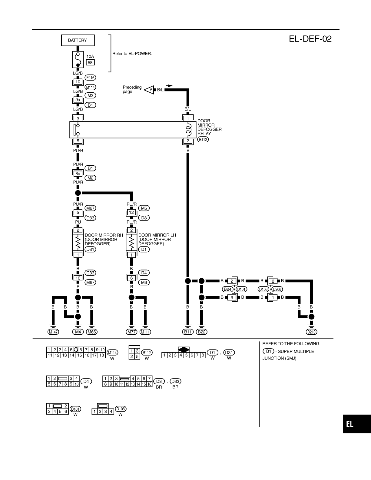
MEL418P
GI
MA
EM
LC
EC
FE
CL
MT
AT
TF
PD
AX
SU
BR
ST
RS
BT
HA
SC
IDX
REAR WINDOW DEFOGGER
Wiring Diagram — DEF — (Cont’d)
EL-177
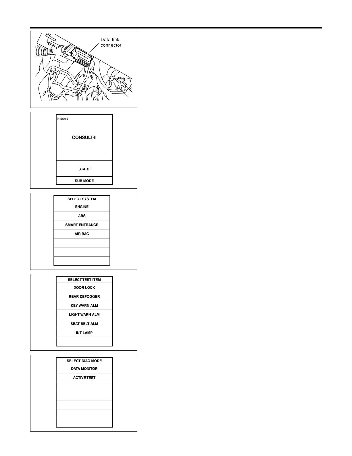
SEL331X
CONSULT-II Inspection Procedure
NAEL0336
“REAR DEFOGGER”
NAEL0336S01
1. Turn ignition switch “OFF”.
2. Connect “CONSULT-II” to the data link connector.
PBR455D
3. Turn ignition switch “ON”.
4. Touch “START”.
SEL398Y
5. Touch “SMART ENTRANCE”.
SEL023X
6. Touch “REAR DEFOGGER”.
SEL322W
7. Select diagnosis mode.
“DATA MONITOR” and “ACTIVE TEST” are available.
REAR WINDOW DEFOGGER
CONSULT-II Inspection Procedure
EL-178
CONSULT-II Application Items
NAEL0337
“REAR DEFOGGER”
NAEL0337S01
Data Monitor
NAEL0337S0101
Monitored Item Description
IGN ON SW Indicates [ON/OFF] condition of ignition switch.
REAR DEF SW Indicates [ON/OFF] condition of rear window defogger switch.
Active Test
NAEL0337S0102
Test Item Description
REAR DEFOGGER
This test is able to check rear window defogger operation. Rear window defogger activates
when “ON” on CONSULT-II screen is touched.
GI
MA
EM
LC
EC
FE
CL
MT
AT
TF
PD
AX
SU
BR
ST
RS
BT
HA
SC
IDX
REAR WINDOW DEFOGGER
CONSULT-II Application Items
EL-179
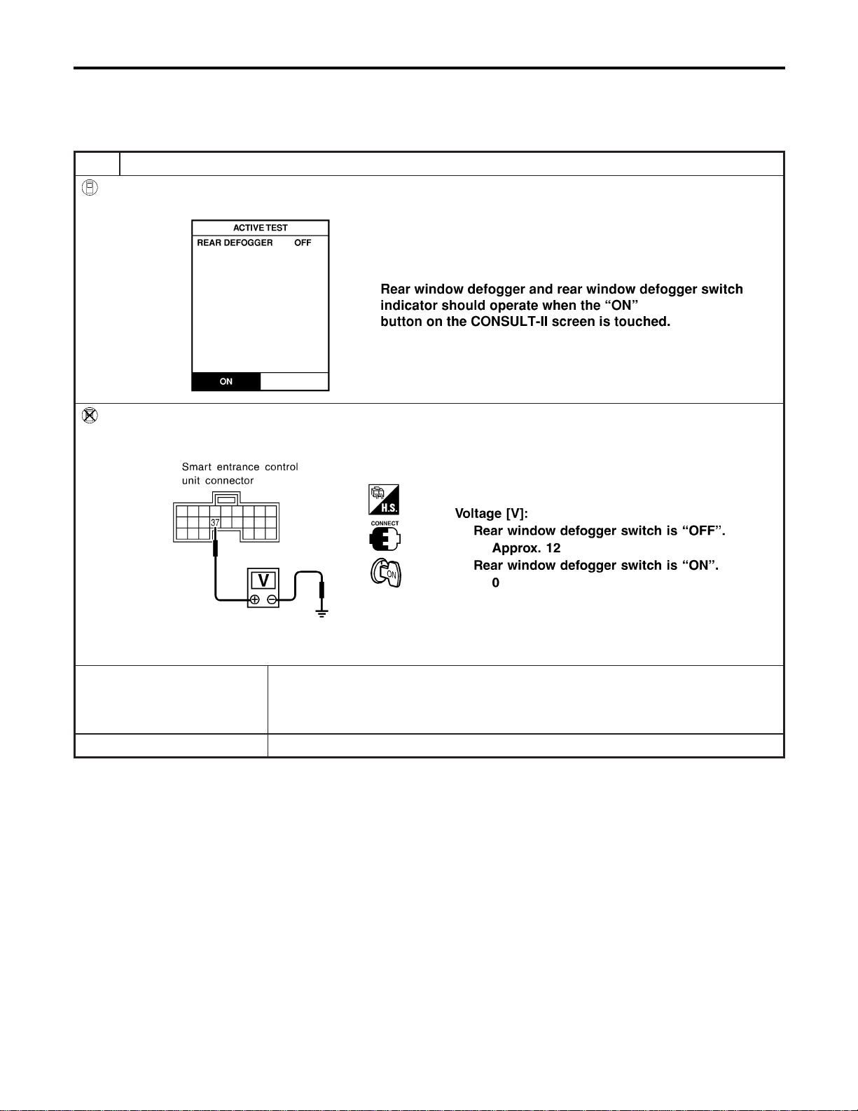
Trouble Diagnoses
NAEL0338
DIAGNOSTIC PROCEDURE
NAEL0338S01
SYMPTOM: Rear window defogger does not activate, or does
not go off after activating.
1 CHECK REAR WINDOW DEFOGGER OUTPUT SIGNAL
With CONSULT-II
Select “ACTIVE TEST” in “REAR DEFOGGER” with CONSULT-II.
SEL353W
Without CONSULT-II
1. Turn ignition switch to ON position.
2. Check voltage between smart entrance control unit harness connector M122 terminal 37 (G/B) and ground.
SEL997X
OK or NG
OK © Check the following.
I Rear window defogger relay (Refer to EL-183.)
I Rear window defogger circuit
I Rear window defogger filament (Refer to EL-183.)
NG © GO TO 2.
REAR WINDOW DEFOGGER
Trouble Diagnoses
EL-180
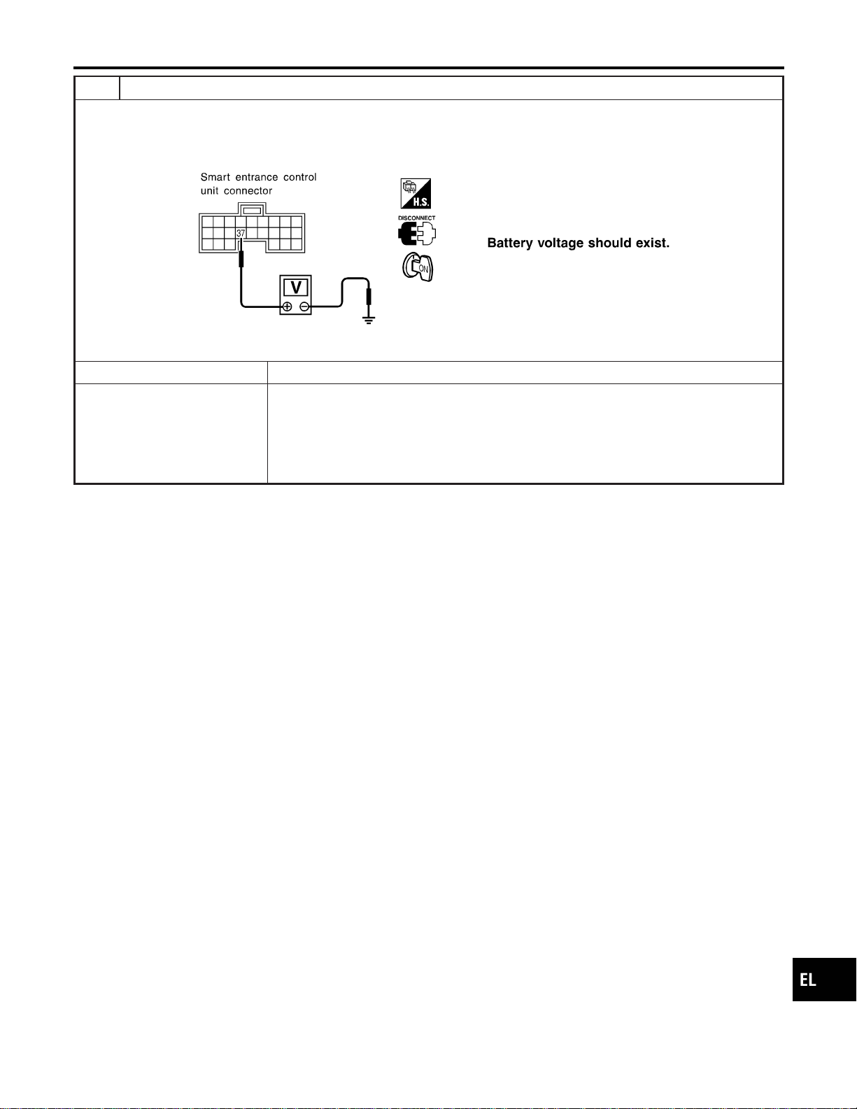
2 CHECK DEFOGGER RELAY COIL SIDE CIRCUIT
1. Disconnect control unit connector.
2. Turn ignition switch to ON position.
3. Check voltage between smart entrance control unit harness connector M122 terminal 37 (G/B) and ground.
SEL998X
OK or NG
OK © GO TO 3.
NG © Check the following.
I 7.5A fuse [No. 11, located in the fuse block (J/B)]
I Rear window defogger relay
I Harness for open or short between fuse and rear window defogger relay
I Harness for open or short between rear window defogger relay and smart entrance
control unit
GI
MA
EM
LC
EC
FE
CL
MT
AT
TF
PD
AX
SU
BR
ST
RS
BT
HA
SC
IDX
REAR WINDOW DEFOGGER
Trouble Diagnoses (Cont’d)
EL-181
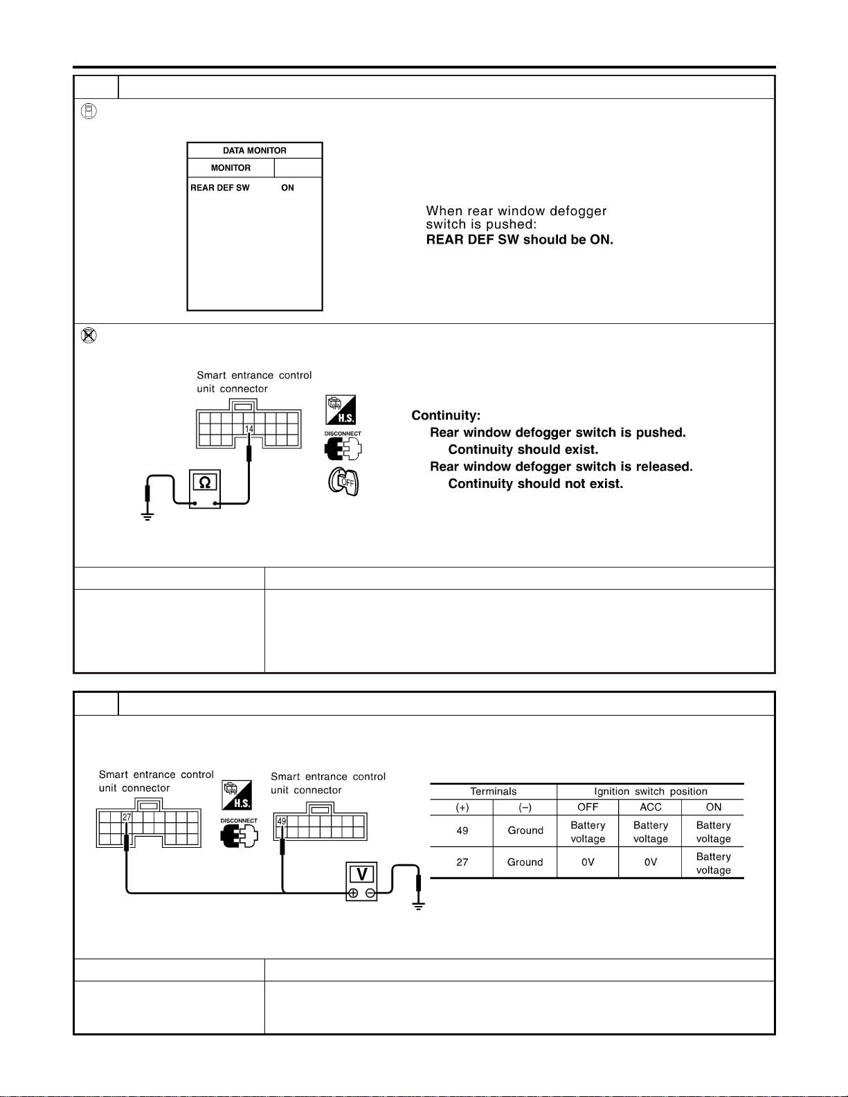
3 CHECK REAR WINDOW DEFOGGER SWITCH INPUT SIGNAL
With CONSULT-II
Select “REAR DEF SW” in “DATA MONITOR” mode with CONSULT-II.
SEL352W
Without CONSULT-II
Check continuity between smart entrance control unit harness connector M121 terminal 14 (OR) and ground.
SEL999X
OK or NG
OK © GO TO 4.
NG © Check the following.
I Rear window defogger switch (Refer to EL-183.)
I Harness for open or short between smart entrance control unit and rear window defog-
ger switch
I Rear window defogger switch ground circuit
4 CHECK POWER SUPPLY AND IGNITION INPUT SIGNAL
Check voltage between smart entrance control unit harness connector M122 terminal 27 (W/B), M123 terminal 49 (G/R)
and ground.
SEL001Y
OK or NG
OK © GO TO 5.
NG © Check the following.
I 7.5A fuse [No. 11 or No. 24, located in the fuse block (J/B)]
I Harness for open or short between smart entrance control unit and fuse
REAR WINDOW DEFOGGER
Trouble Diagnoses (Cont’d)
EL-182
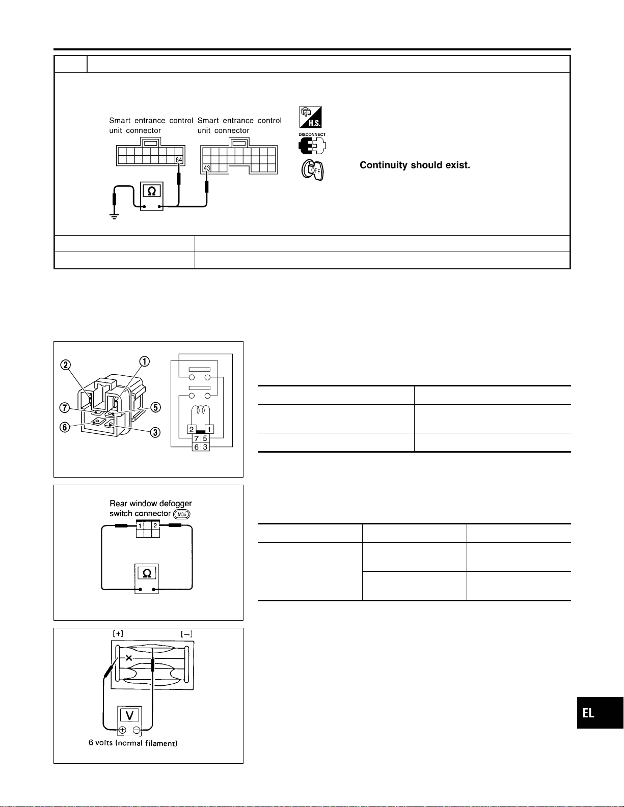
5 CHECK CONTROL UNIT GROUND CIRCUIT
Check continuity between smart entrance control unit harness connector M122 terminal 43 (B), M123 terminal 64 (B) and
ground.
SEL002Y
Yes © Replace smart entrance control unit.
No © Repair harness or connectors.
SEC202B
Electrical Components Inspection
NAEL0339
REAR WINDOW DEFOGGER RELAY
NAEL0339S01
Check continuity between terminals 3 and 5, 6 and 7.
Condition Continuity
12V direct current supply between ter-
minals 1 and 2
Yes
No current supply No
SEL430TB
REAR WINDOW DEFOGGER SWITCH
NAEL0339S02
Check continuity between terminals when rear window defogger
switch is pushed and released.
Terminals Condition Continuity
1-2
Rear window defogger
switch is pushed
Yes
Rear window defogger
switch is released
No
SEL263
Filament Check
NAEL0340
1. Attach probe circuit tester (in volt range) to middle portion of
each filament.
GI
MA
EM
LC
EC
FE
CL
MT
AT
TF
PD
AX
SU
BR
ST
RS
BT
HA
SC
IDX
REAR WINDOW DEFOGGER
Trouble Diagnoses (Cont’d)
EL-183
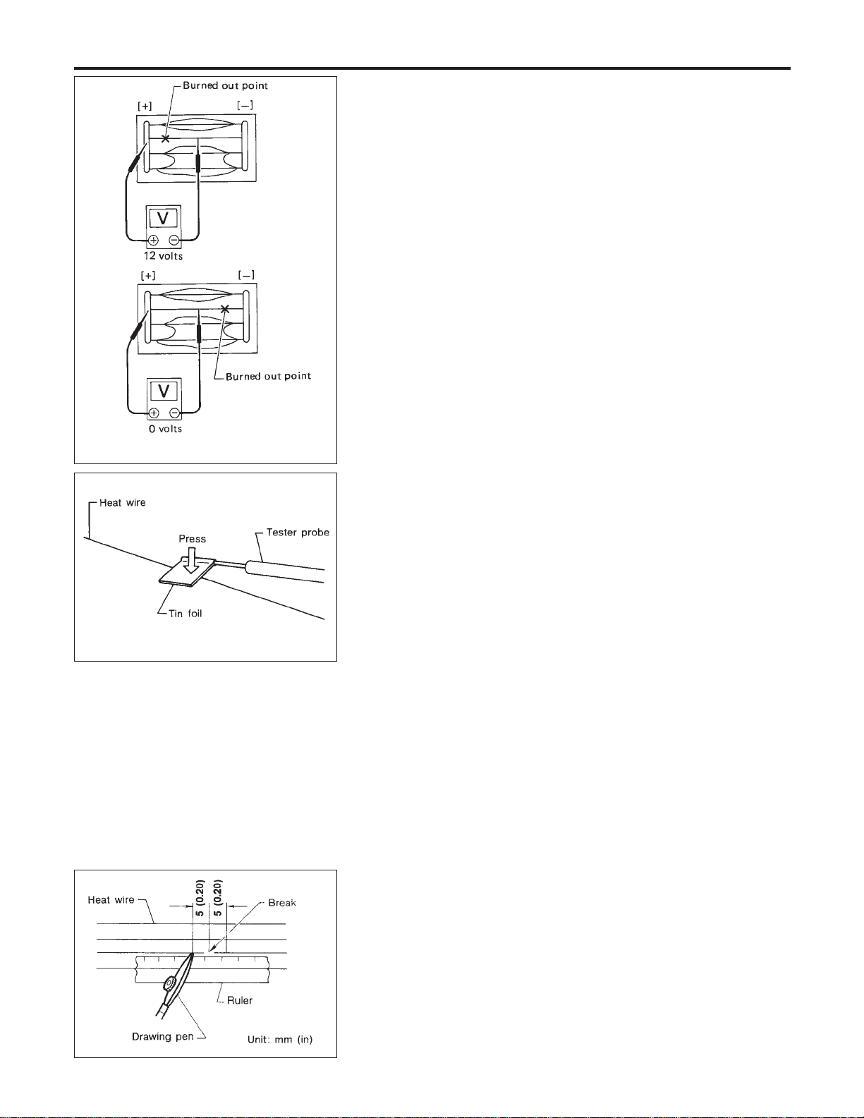
SEL265
2. If a filament is burned out, circuit tester registers 0 or 12 volts.
3. To locate burned out point, move probe to left and right along
filament. Test needle will swing abruptly when probe passes
the point.
SEL122R
I When measuring voltage, wrap tin foil around the top of
the negative probe. Then press the foil against the wire
with your finger.
Filament Repair
NAEL0341
REPAIR EQUIPMENT
NAEL0341S01
1) Conductive silver composition (Dupont No. 4817 or equivalent)
2) Ruler 30 cm (11.8 in) long
3) Drawing pen
4) Heat gun
5) Alcohol
6) Cloth
BE540
REPAIRING PROCEDURE
NAEL0341S02
1. Wipe broken heat wire and its surrounding area clean with a
cloth dampened in alcohol.
2. Apply a small amount of conductive silver composition to tip of
drawing pen.
Shake silver composition container before use.
3. Place ruler on glass along broken line. Deposit conductive sil-
ver composition on break with drawing pen. Slightly overlap
existing heat wire on both sides [preferably 5 mm (0.20 in)] of
the break.
REAR WINDOW DEFOGGER
Filament Check (Cont’d)
EL-184

SEL012D
4. After repair has been completed, check repaired wire for con-
tinuity. This check should be conducted 10 minutes after silver
composition is deposited.
Do not touch repaired area while test is being conducted.
SEL013D
5. Apply a constant stream of hot air directly to the repaired area
for approximately 20 minutes with a heat gun. A minimum dis-
tance of 3 cm (1.2 in) should be kept between repaired area
and hot air outlet. If a heat gun is not available, let the repaired
area dry for 24 hours.
GI
MA
EM
LC
EC
FE
CL
MT
AT
TF
PD
AX
SU
BR
ST
RS
BT
HA
SC
IDX
REAR WINDOW DEFOGGER
Filament Repair (Cont’d)
EL-185

System Description
NAEL0342
Refer to Owner’s Manual for audio system operating instructions.
BASE SYSTEM
NAEL0342S01
Power is supplied at all times
I through 15A fuse [No. 4, located in the fuse block (J/B)]
I to audio unit terminal 6, and
I to CD player terminal 4 (with CD player).
With the ignition switch in the ACC or ON position, power is supplied
I through 10A fuse [No. 10, located in the fuse block (J/B)]
I to audio unit terminal 10, and
I to CD player terminal 1 (with CD player).
Ground is supplied through the case of the audio unit.
When the audio unit power knob is pushed to the ON position, audio signals are supplied
I through audio unit terminals 1, 2, 3, 4, 13, 14, 15 and 16
I to the front and rear speakers.
BOSE SYSTEM
NAEL0342S02
Power is supplied at all times
I through 15A fuse [No. 4, located in the fuse block (J/B)]
I to audio unit terminal 6,
I to audio amp. relay terminal 3,
I to rear speaker amp. terminal 11,
I to CD auto changer terminal 12 (with CD auto changer) and
I to AUX box terminal 7 (with rear TV).
With the ignition switch in the ACC or ON position, power is supplied
I through 10A fuse [No. 10, located in the fuse block (J/B)]
I to audio unit terminal 10,
I to CD auto changer terminal 16 (with CD auto changer) and
I to AUX box terminal 6 (with rear TV).
Ground is supplied through the case of the audio unit.
Ground is supplied
I to audio amp. relay terminal 2,
I through body grounds M4, M66 and M147
I to front door speaker LH terminal 5 and
I to front door speaker RH terminal 5
I through body grounds M77 and M111
I to rear speaker amp. terminal 24 and
I to AUX box terminal 8 (with rear TV)
I through body grounds B11, B22 and D210
I to CD auto changer terminal 15 and
I to rear TV switch terminal 3
I through body grounds M4, M66 and M147.
When the audio unit POWER button is pressed, power is supplied to rear speaker amp. terminal 9 and audio
amp. relay terminal 1 from audio unit terminal 12. Then audio amp. relay is energized and power is supplied
I to front door speaker LH terminal 4 and
I to front door speaker RH terminal 4.
Audio signals are supplied
I through audio unit terminals 1, 2, 3, 4, 13, 14, 15 and 16
I to terminals 2 and 6 of the LH and RH front speakers and terminals 5, 7, 18 and 20 of the rear speaker
amp.
I to LH and RH tweeters through terminals 1 and 3 of the front speakers
I to rear LH and RH speakers through terminals 1, 2, 25 and 26 of the rear speaker amp.
AUDIO
System Description
EL-186
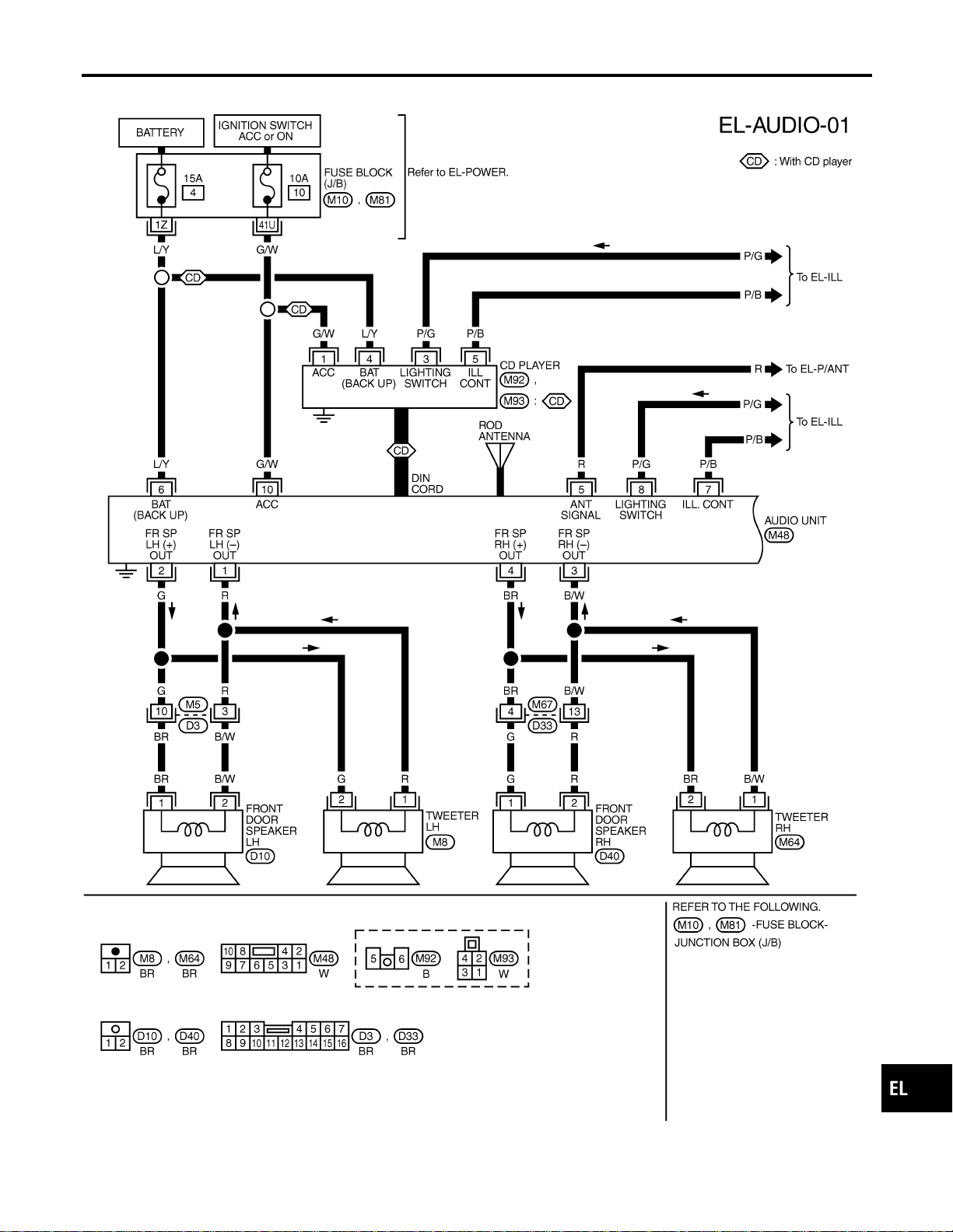
Wiring Diagram — AUDIO —/Base System
NAEL0343
MEL355N
GI
MA
EM
LC
EC
FE
CL
MT
AT
TF
PD
AX
SU
BR
ST
RS
BT
HA
SC
IDX
AUDIO
Wiring Diagram — AUDIO —/Base System
EL-187
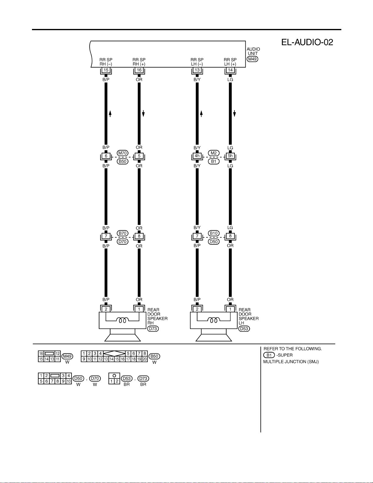
MEL038M
AUDIO
Wiring Diagram — AUDIO —/Base System (Cont’d)
EL-188
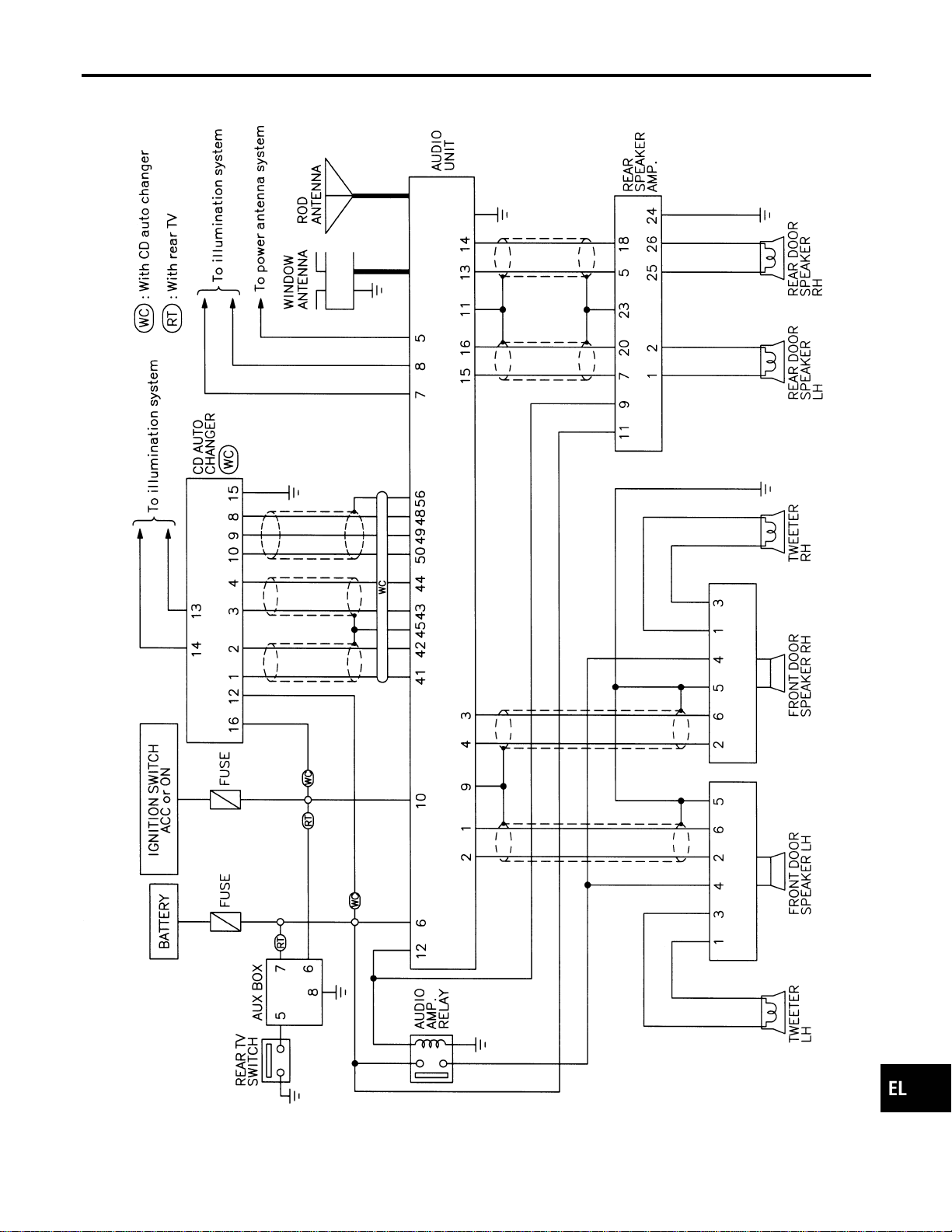
Schematic/BOSE System
NAEL0344
MEL356N
GI
MA
EM
LC
EC
FE
CL
MT
AT
TF
PD
AX
SU
BR
ST
RS
BT
HA
SC
IDX
AUDIO
Schematic/BOSE System
EL-189
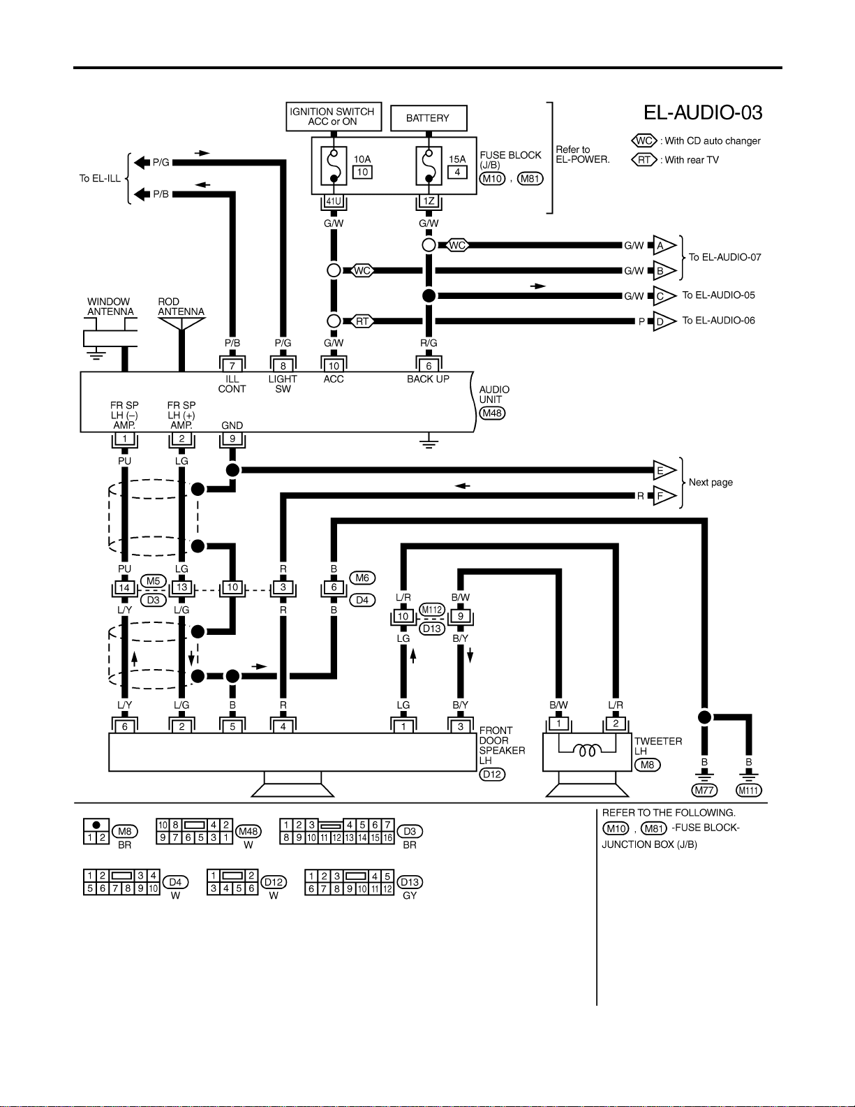
Wiring Diagram — AUDIO —/BOSE System
NAEL0345
MEL357N
AUDIO
Wiring Diagram — AUDIO —/BOSE System
EL-190
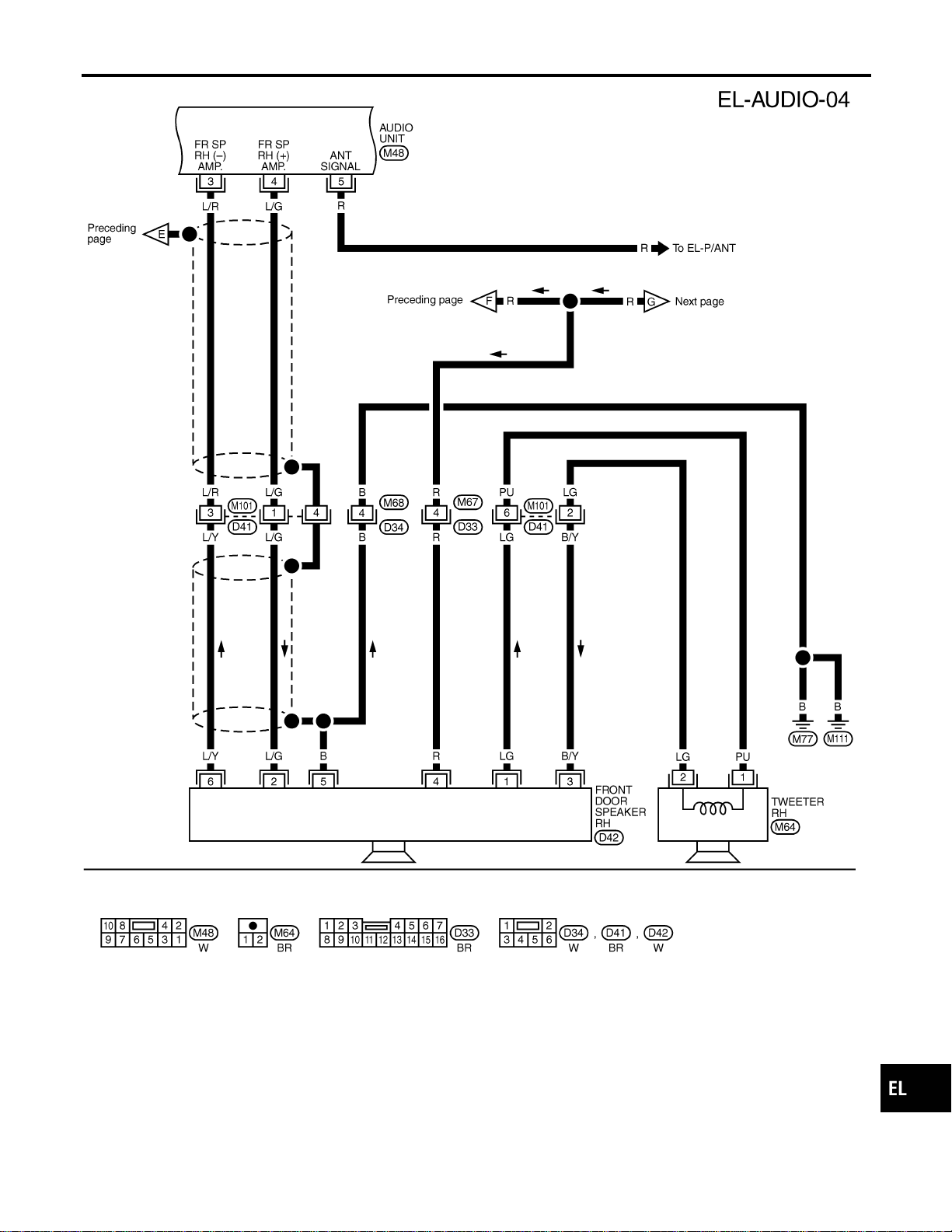
MEL419P
GI
MA
EM
LC
EC
FE
CL
MT
AT
TF
PD
AX
SU
BR
ST
RS
BT
HA
SC
IDX
AUDIO
Wiring Diagram — AUDIO —/BOSE System (Cont’d)
EL-191
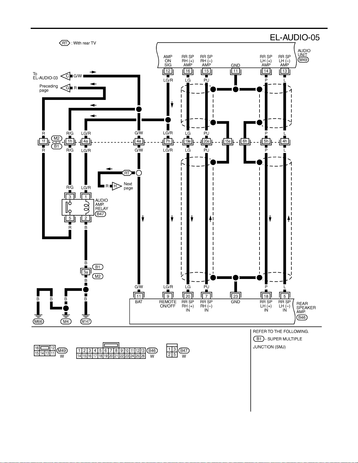
MEL359N
AUDIO
Wiring Diagram — AUDIO —/BOSE System (Cont’d)
EL-192
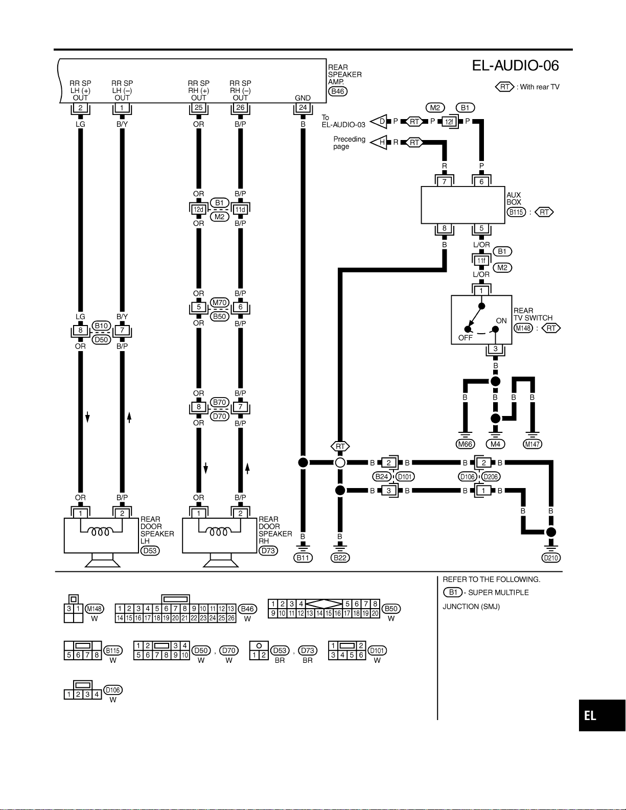
MEL556P
GI
MA
EM
LC
EC
FE
CL
MT
AT
TF
PD
AX
SU
BR
ST
RS
BT
HA
SC
IDX
AUDIO
Wiring Diagram — AUDIO —/BOSE System (Cont’d)
EL-193
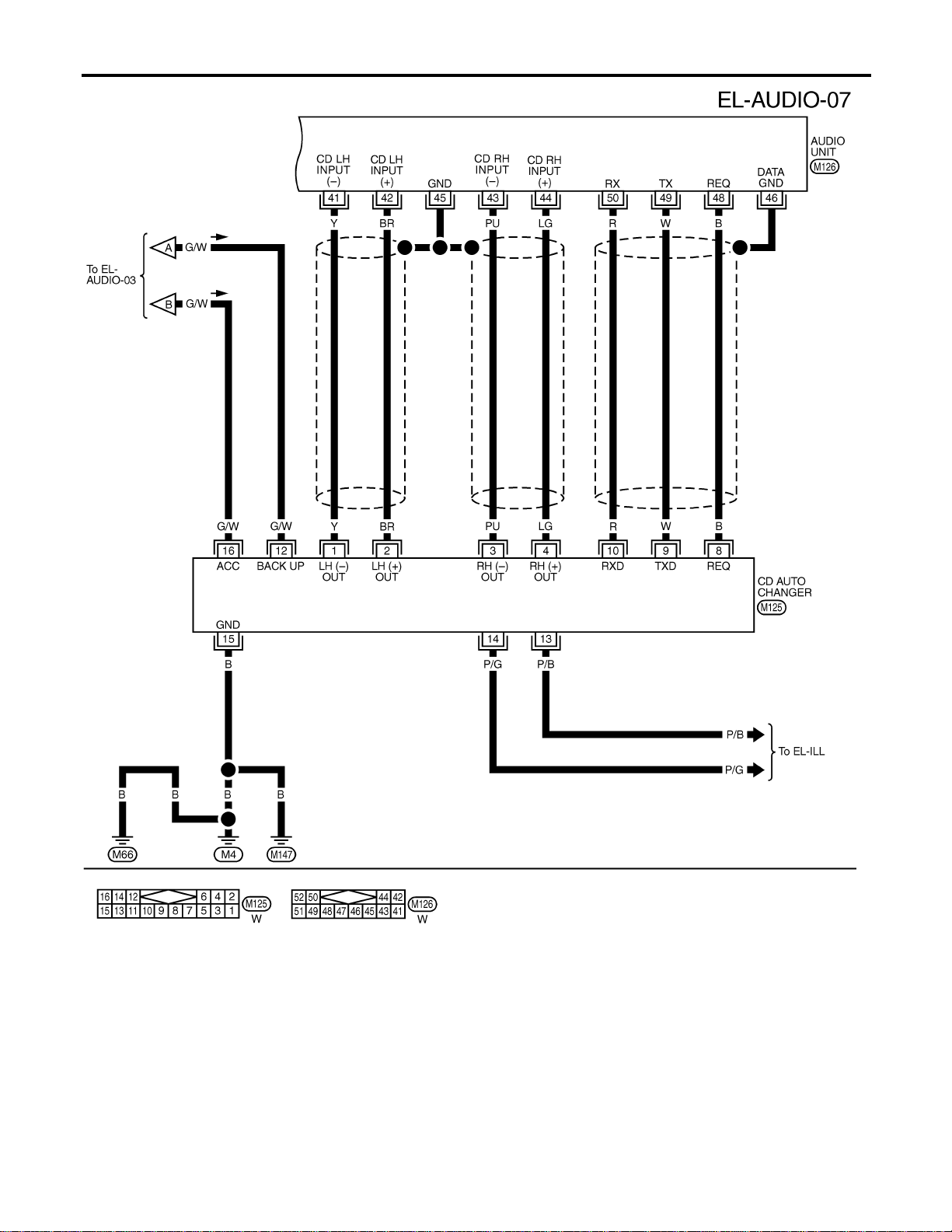
MEL044M
AUDIO
Wiring Diagram — AUDIO —/BOSE System (Cont’d)
EL-194

Trouble Diagnoses
NAEL0346
AUDIO UNIT
NAEL0346S01
Symptom Possible causes Repair order
Audio unit inoperative (no
digital display and no
sound from speakers).
1. 10A fuse
2. Poor audio unit case ground
3. Audio unit
1. Check 10A fuse [No. 10, located in fuse block (J/B)].
Turn ignition switch ON and verify that battery posi-
tive voltage is present at terminal 10 of audio unit.
2. Check audio unit case ground.
3. Remove audio unit for repair.
Audio unit presets are lost
when ignition switch is
turned OFF.
1. 15A fuse
2. Audio unit
1. Check 15A fuse [No. 4, located in fuse block (J/B)]
and verify that battery positive voltage is present at
terminal 6 of audio unit.
2. Remove audio unit for repair.
AM stations are weak or
noisy (FM stations OK).
1. Antenna
2. Poor audio unit ground
3. Audio unit
1. Check antenna.
2. Check audio unit ground.
3. Remove audio unit for repair.
FM stations are weak or
noisy (AM stations OK).
1. Window antenna
2. Audio unit
1. Check window antenna.
2. Remove audio unit for repair.
Audio unit generates noise
in AM and FM modes with
engine running.
1. Poor audio unit ground
2. Loose or missing ground bonding
straps
3. Ignition condenser or rear window
defogger noise suppressor condenser
4. Alternator
5. Ignition coil or secondary wiring
6. Audio unit
1. Check audio unit ground.
2. Check ground bonding straps.
3. Replace ignition condenser or rear window defogger
noise suppressor condenser.
4. Check alternator.
5. Check ignition coil and secondary wiring.
6. Remove audio unit for repair.
Audio unit generates noise
in AM and FM modes with
accessories on (switch
pops and motor noise).
1. Poor audio unit ground
2. Antenna
3. Accessory ground
4. Faulty accessory
1. Check audio unit ground.
2. Check antenna.
3. Check accessory ground.
4. Replace accessory.
BASE SYSTEM
NAEL0346S02
Symptom Possible causes Repair order
Individual speaker is noisy
or inoperative.
1. Speaker
2. Audio unit output
3. Speaker circuit
4. Audio unit
1. Check speaker.
2. Check audio unit output voltages.
3. Check wires for open or short between audio unit
and speaker.
4. Remove audio unit for repair.
BOSE SYSTEM
NAEL0346S03
Symptom Possible causes Repair order
Audio unit controls are
operational, but no sound
is heard from any speaker.
1. 15A fuse
2. Audio unit output
3. Audio unit
1. Check 15A fuse [No. 4, located in fuse block (J/B)].
Verify battery positive voltage is present at terminal 2
of audio amp. relay.
2. Check audio unit output voltage (Terminal 12).
3. Remove audio unit for repair.
All front speakers are inop-
erative.
1. Audio amp. relay
2. Audio amp. relay ground
3. Amp. ON signal
1. Check audio amp. relay.
2. Check audio amp. relay ground (Terminal 3).
3. Turn ignition switch ACC and audio unit ON. Verify
battery positive voltage is present at terminal 1 of
audio amp. relay.
Individual front speaker is
noisy or inoperative.
1. Speaker ground
2. Power supply
3. Audio unit output
4. Speaker
1. Check speaker ground (Terminal 5).
2. Check power supply for speaker (Terminal 4).
3. Check audio unit output voltage for speaker.
4. Replace speaker.
GI
MA
EM
LC
EC
FE
CL
MT
AT
TF
PD
AX
SU
BR
ST
RS
BT
HA
SC
IDX
AUDIO
Trouble Diagnoses
EL-195

Symptom Possible causes Repair order
Both rear speakers are
inoperative.
1. Poor rear speaker amp. ground
2. Power supply
3. Amp. ON signal
4. Rear speaker amp.
1. Check rear speaker amp. ground circuit.
2. Check power supply for rear speaker amp. (Terminal
11).
3. Turn ignition switch ACC and audio unit ON. Verify
battery positive voltage is present at terminal 9 of
rear speaker amp.
4. Remove rear speaker amp. for repair.
Individual rear speaker is
noisy or inoperative.
1. Speaker
2. Audio unit/amp. output
3. Speaker circuit
4. Audio unit
1. Check speaker.
2. Check audio unit/amp. output.
3. Check wires for open or short between audio unit/
amp. and speakers.
4. Remove audio unit for repair.
Inspection
NAEL0347
AUDIO UNIT AND AMP.
NAEL0347S01
All voltage inspections are made with:
I Ignition switch ON or ACC
I Audio unit ON
I Audio unit and amps. connected (If audio unit or amp. is removed for inspection, supply a ground to the
case using a jumper wire.)
ANTENNA
NAEL0347S02
1. Using a jumper wire, clip an auxiliary ground between antenna and body.
I If reception improves, check antenna ground (at body surface).
I If reception does not improve, check main feeder cable for short circuit or open circuit.
Audio Unit Removal and Installation
NAEL0348
1. Lock the CD changer unit mechanism (if so equipped) prior to removing a malfunctioning CD changer unit.
Refer to “LOCKING CD CHANGER UNIT MECHANISM”, EL-196.
2. Remove CD changer unit. Refer to BT-22, “INSTRUMENT PANEL ASSEMBLY”.
LOCKING CD CHANGER UNIT MECHANISM
NAEL0348S01
CAUTION:
I Prior to removing a malfunctioning CD changer unit that will be shipped for repair, the changer
mechanism MUST BE LOCKED to prevent the mechanism from being damaged during shipping.
I If a CD is jammed or unable to be removed from the unit, do NOT lock the changer mechanism. If
the unit is to be shipped for repair, carefully package the unit to prevent vibration and shock.
1. Eject and remove any CDs from the CD changer unit.
2. Turn ignition switch OFF. Wait until CD changer unit display is off and mechanism stops moving (mecha-
nism sound stops).
3. Press any one of the disc selection buttons once. When a display shows on the CD changer unit, press
the same disc selection button again within 5 seconds.
I The changer mechanism will lock itself within 10 seconds.
4. After mechanism stops moving (mechanism sound stops), disconnect the CD changer unit connectors.
NOTE:
After installing a new or remanufactured CD changer unit, switching the CD changer unit ON will automati-
cally unlock the mechanism. A special unlocking procedure is not required.
AUDIO
Trouble Diagnoses (Cont’d)
EL-196
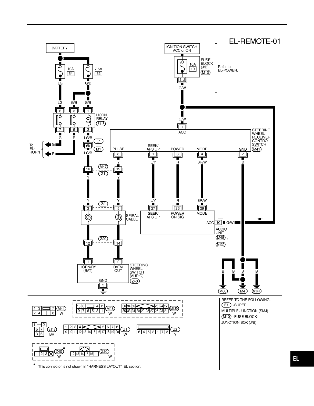
Wiring Diagram — REMOTE —
NAEL0349
MEL409O
GI
MA
EM
LC
EC
FE
CL
MT
AT
TF
PD
AX
SU
BR
ST
RS
BT
HA
SC
IDX
AUDIO
Wiring Diagram — REMOTE —
EL-197

System Description
NAEL0350
Power is supplied at all times
I through 7.5A fuse [No. 24, located in the fuse block (J/B)]
I to power antenna terminal 6.
Ground is supplied to the power antenna terminal 2 through body grounds M4, M66 and M147.
When the audio unit is turned to the ON position, battery positive voltage is supplied
I through audio unit terminal 5
I to power antenna terminal 4.
The antenna raises and is held in the extended position.
When the audio unit is turned to the OFF position, battery positive voltage is interrupted
I from audio unit terminal 5
I to power antenna terminal 4.
The antenna retracts.
AUDIO ANTENNA
System Description
EL-198
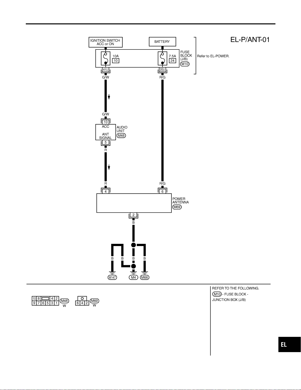
Wiring Diagram — P/ANT —
NAEL0351
MEL824L
GI
MA
EM
LC
EC
FE
CL
MT
AT
TF
PD
AX
SU
BR
ST
RS
BT
HA
SC
IDX
AUDIO ANTENNA
Wiring Diagram — P/ANT —
EL-199
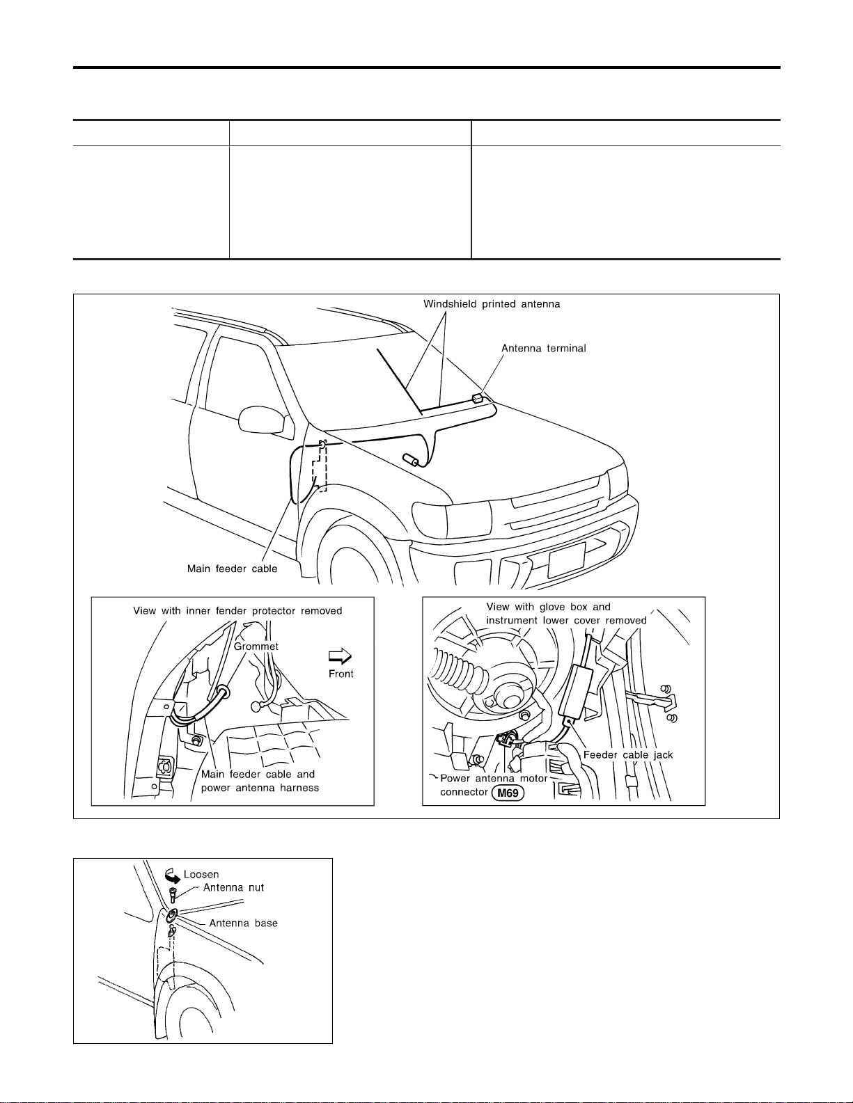
Trouble Diagnoses
NAEL0352
POWER ANTENNA
NAEL0352S01
Symptom Possible causes Repair order
Power antenna does not
operate.
1. 7.5A fuse
2. Audio unit signal
3. Grounds M4, M66 and M147
1. Check 7.5A fuse [No. 24, located in fuse block
(J/B)]. Verify that battery positive voltage is present
at terminal 6 of power antenna.
2. Turn ignition switch and audio unit ON. Verify that
battery positive voltage is present at terminal 4 of
power antenna.
3. Check grounds M4, M66 and M147.
Location of Antenna
NAEL0353
YEL067K
MEL036G
Antenna Rod Replacement
NAEL0354
REMOVAL
NAEL0354S01
1. Remove antenna nut and antenna base.
AUDIO ANTENNA
Trouble Diagnoses
EL-200

MEL037G
2. Withdraw antenna rod while raising it by operating antenna
motor.
MEL038G
INSTALLATION
NAEL0354S02
1. Lower antenna rod by operating antenna motor.
2. Insert gear section of antenna rope into place with it facing
toward antenna motor.
3. As soon as antenna rope is wound on antenna motor, stop
antenna motor. Insert antenna rod lower end into antenna
motor pipe.
4. Retract antenna rod completely by operating antenna motor.
5. Install antenna nut and base.
GI
MA
EM
LC
EC
FE
CL
MT
AT
TF
PD
AX
SU
BR
ST
RS
BT
HA
SC
IDX
AUDIO ANTENNA
Antenna Rod Replacement (Cont’d)
EL-201

System Description
NAEL0355
OUTLINE
NAEL0355S01
Electric sunroof system consists of
I Sunroof switch
I Sunroof motor
I Smart entrance control unit
Smart entrance control unit controls retained power operation.
OPERATION
NAEL0355S02
The sunroof can be tilted up or down with the tilt switch.
The sunroof can be opened or closed automatically with the sunroof switch.
RETAINED POWER OPERATION
NAEL0355S04
When the ignition switch is turned to OFF position from ON or START position, power is supplied for 45 sec-
onds
I to power window relay terminal 2
I from smart entrance control unit terminal 46.
Ground is always supplied
I to power window relay terminal 1
I through body grounds.
When power and ground are supplied, power window relay continues to be energized, and the electrical sun-
roof can be operated.
When power is supplied, the electrical sunroof can be operated.
The retained power operation is canceled when the driver or passenger side door is opened.
RAP signal period can be changed by CONSULT-II. (EL-206)
INTERRUPTION DETECTION FUNCTION
NAEL0355S05
The CPU of sunroof motor monitors the sunroof motor operation and the sunroof position (full closed or other)
for sunroof by the signals from encoder and limit switch in sunroof motor.
When sunroof motor detects interruption during the following close operation,
I automatic close operation when ignition switch is in the “ON” position
I automatic close operation during retained power operation
sunroof switch controls the motor for open and the sunroof will operate about 150 mm (5.91 in).
POWER SUNROOF
System Description
EL-202
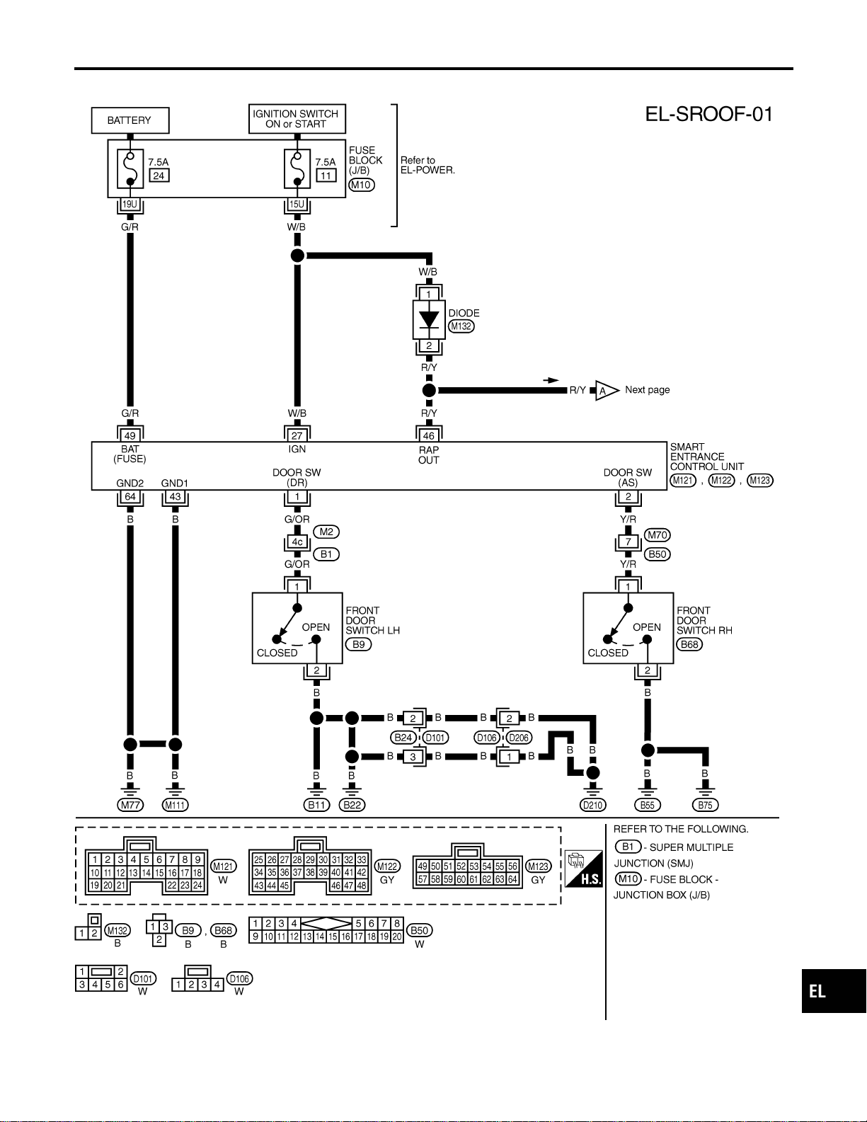
Wiring Diagram — SROOF —
NAEL0356
MEL429O
GI
MA
EM
LC
EC
FE
CL
MT
AT
TF
PD
AX
SU
BR
ST
RS
BT
HA
SC
IDX
POWER SUNROOF
Wiring Diagram — SROOF —
EL-203
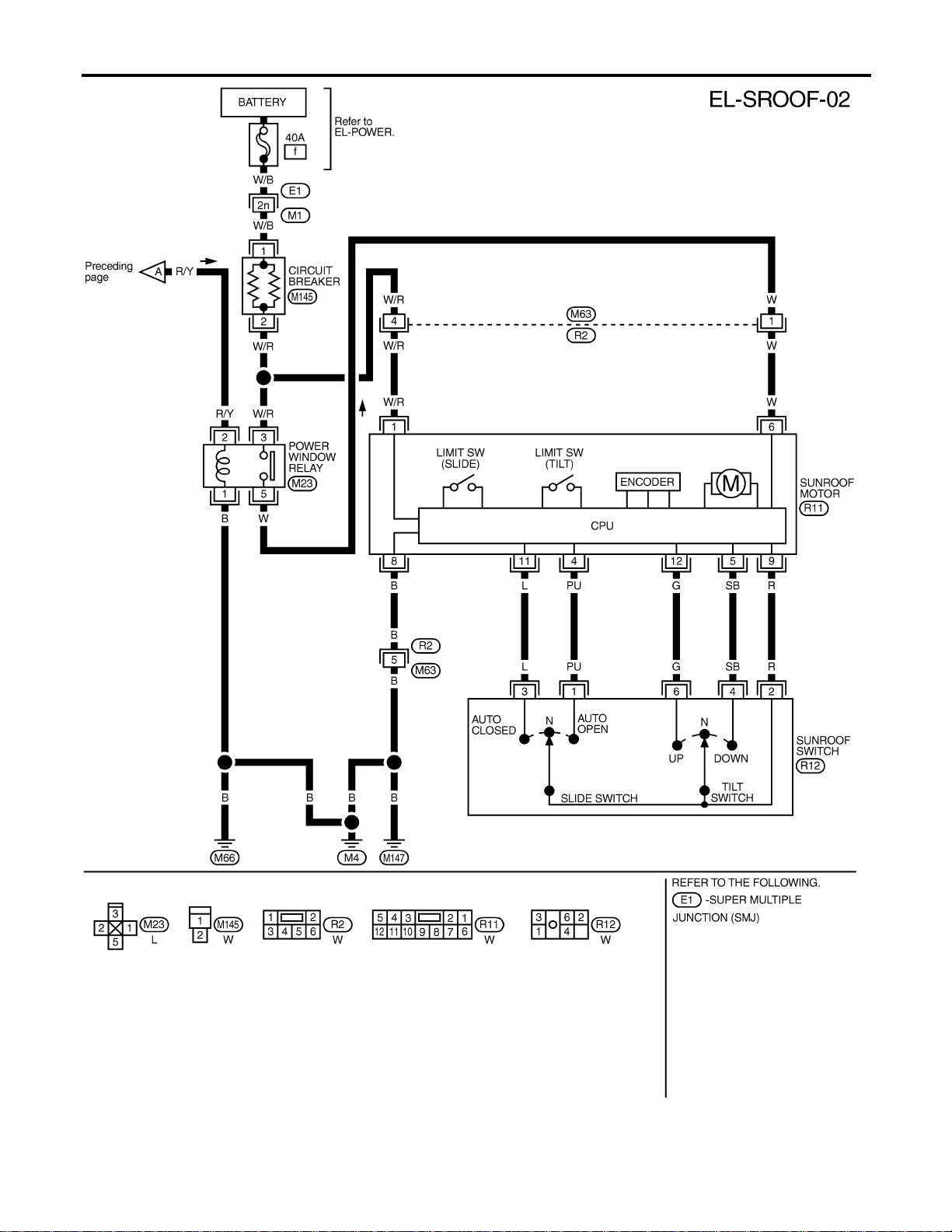
MEL420P
POWER SUNROOF
Wiring Diagram — SROOF — (Cont’d)
EL-204
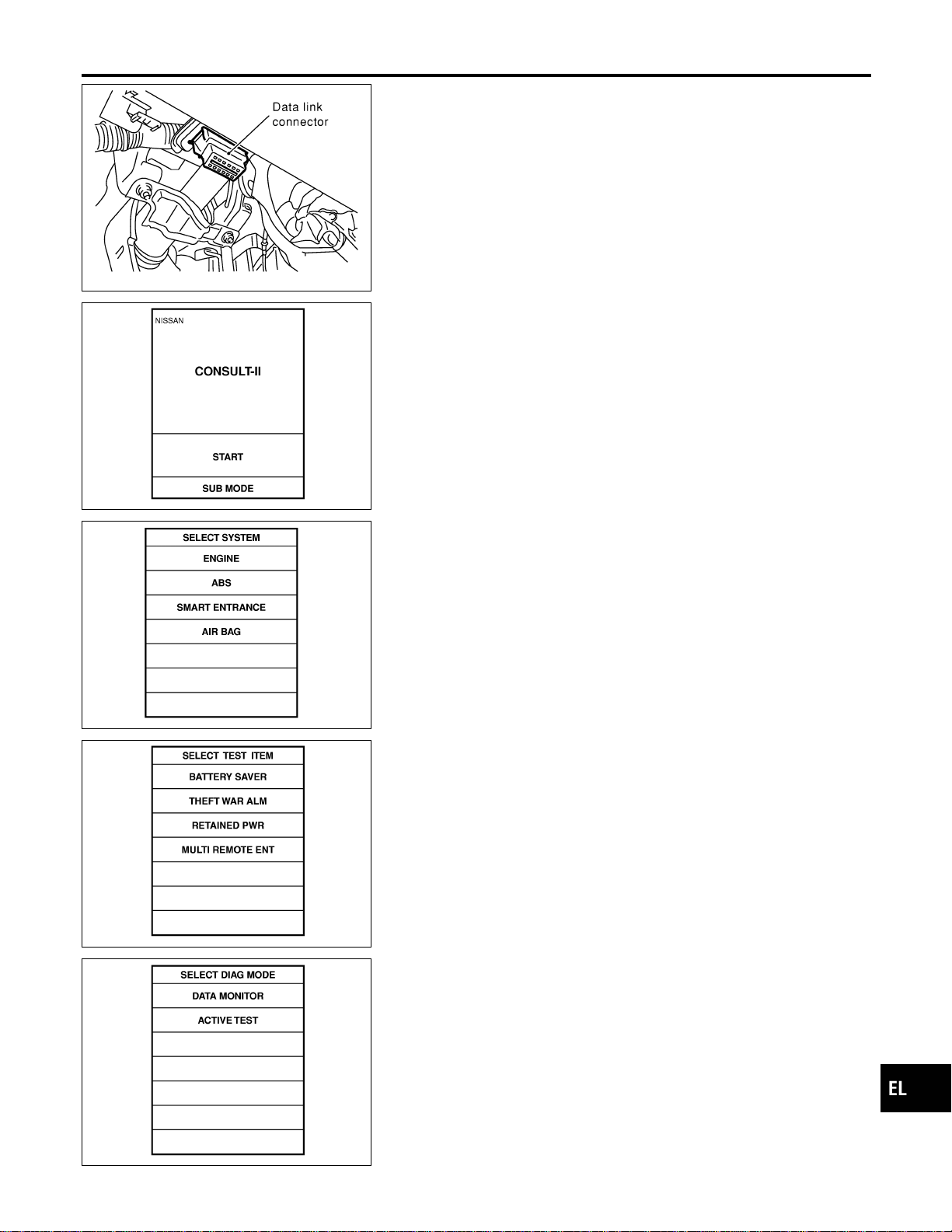
SEL331X
CONSULT-II Inspection Procedure
=NAEL0357
“RETAINED PWR”
NAEL0357S01
1. Turn ignition switch “OFF”.
2. Connect “CONSULT-II” to the data link connector.
PBR455D
3. Turn ignition switch “ON”.
4. Touch “START”.
SEL398Y
5. Touch “SMART ENTRANCE”.
SEL273W
6. Touch “RETAINED PWR”.
SEL322W
7. Select diagnosis mode.
“DATA MONITOR” and “ACTIVE TEST” are available.
GI
MA
EM
LC
EC
FE
CL
MT
AT
TF
PD
AX
SU
BR
ST
RS
BT
HA
SC
IDX
POWER SUNROOF
CONSULT-II Inspection Procedure
EL-205

CONSULT-II Application Items
NAEL0455
“RETAINED PWR”
NAEL0455S01
Data Monitor
NAEL0455S0101
Monitored Item Description
IGN ON SW Indicates [ON/OFF] condition of ignition switch.
DOOR SW-DR Indicates [ON/OFF] condition of front door switch LH.
DOOR SW-AS Indicates [ON/OFF] condition of front door switch RH.
Active Test
NAEL0455S0102
Test Item Description
RETAINED PWR
This test is able to supply RAP signal (power) from smart entrance control unit to power
window system, power sunroof system. Those systems can be operated when turning on
“RETAINED PWR” on CONSULT-II screen even if the ignition switch is tuned OFF.
NOTE:
During this test, CONSULT-II can be operated with ignition switch “OFF” position.
“RETAINED PWR” should be turned “ON” or “OFF” on CONSULT-II screen when
ignition switch is ON. Then turn ignition switch OFF for checking retained power
operation. CONSULT-II might be stuck if “RETAINED PWR” is turned “ON” or “OFF”
on CONSULT-II screen when ignition switch is OFF.
Work Support
NAEL0455S0103
Work Item Description
RETAINED PWR SET
RAP signal’s power supply period can be changed by mode setting. Selects RAP signal’s
power supply period between three steps.
I MODE 1 (45 sec.)/MODE 2 (OFF)/MODE 3 (2 min.)
Trouble Diagnoses
NAEL0456
Symptom Possible cause Repair order
Power sunroof cannot be operated
using any switch.
1. 7.5A fuse, 40A fusible link and
M145 circuit breaker
2. Power window relay ground cir-
cuit
3. Sunroof motor ground circuit
4. Power window relay
5. Sunroof motor circuit
6. Sunroof switch
7. Sunroof switch circuit
8. Sunroof motor
1. Check 7.5A fuse [No. 11, located in fuse block
(J/B)], 40A fusible link (letter f, located in fuse and
fusible link box) and M145 circuit breaker. Turn igni-
tion switch “ON” and verify battery positive voltage is
present at terminals 2 and 3 of power window relay
and terminal 1 of sunroof motor.
2. Check power window relay ground circuit.
3. Check sunroof motor ground circuit.
4. Check power window relay.
5. Check the wire between power window relay and
sunroof motor.
6. Check sunroof switch.
7. Check harness between sunroof switch and sunroof
motor.
8. Check sunroof motor.
Power sunroof cannot be operated
using one of the sunroof switches.
1. Sunroof switch
2. Sunroof switch circuit
1. Check sunroof switch.
2. Check the harness between sunroof motor and sun-
roof switch.
POWER SUNROOF
CONSULT-II Application Items
EL-206

Symptom Possible cause Repair order
Power sunroof cannot be opened
or closed fully.
1. Full closed position not initial-
ized
2. Sunroof slide mechanism
3. Sunroof switch
4. Sunroof switch circuit
5. Sunroof motor
1. Initialize full closed position.
2. Check the following.
a. Check obstacles in sunroof, etc.
b. Check worn or deformed sunroof.
c. Check sunroof sash tilted too far inward or outward.
3. Check sunroof switch.
4. Check harness between sunroof motor and sunroof
switch.
5. Replace sunroof motor.
Retained power operation does not
operate properly.
1. RAP signal circuit
2. Driver or passenger side door
switch circuit
3. Smart entrance control unit
1. Check RAP signal.
a. (With CONSULT-II)
Check RAP signal with CONSULT-II. Use “ACTIVE
TEST” mode, “RETAINED PWR” in “SMART
ENTRANCE”. (Refer to EL-206.)
If NG, go to the step b. below.
b. Verify 12 positive voltage from smart entrance con-
trol unit is present at terminal 2 of power window
relay:
I Within 45 seconds after ignition switch turns off.
I When front door LH and RH is closed.
2. Check harness between smart entrance control unit
and driver or passenger side door switch.
Check driver or passenger side door switch.
Check driver or passenger side door switch.
3. Check smart entrance control unit. (EL-378)
GI
MA
EM
LC
EC
FE
CL
MT
AT
TF
PD
AX
SU
BR
ST
RS
BT
HA
SC
IDX
POWER SUNROOF
Trouble Diagnoses (Cont’d)
EL-207
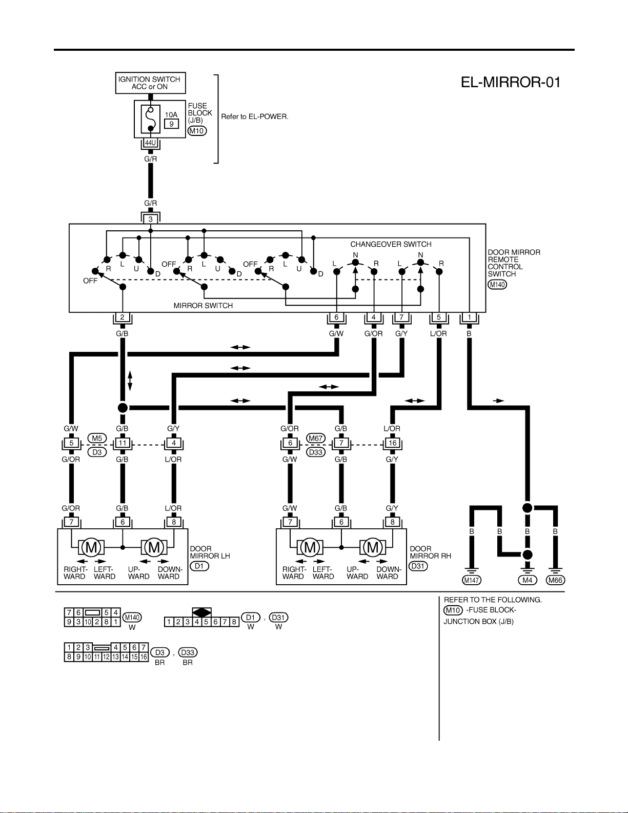
Wiring Diagram — MIRROR —
NAEL0360
MEL421P
DOOR MIRROR
Wiring Diagram — MIRROR —
EL-208
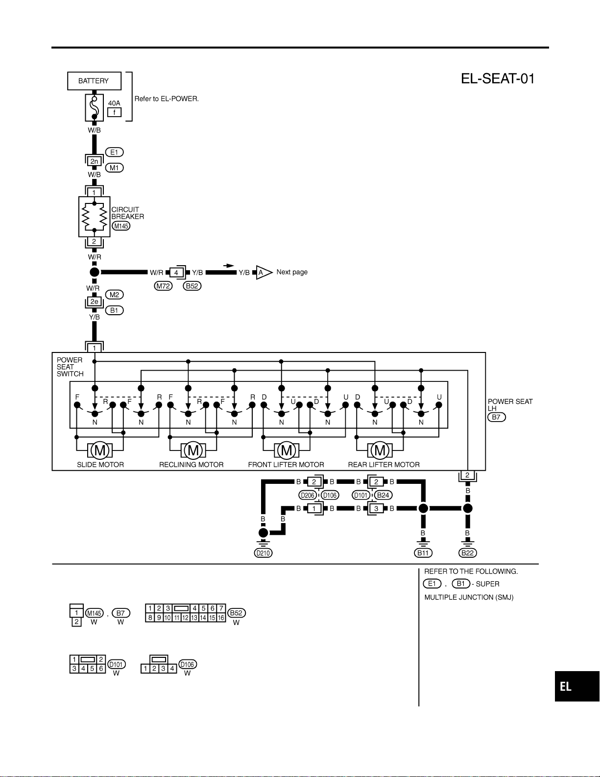
Wiring Diagram — SEAT —
NAEL0361
MEL830L
GI
MA
EM
LC
EC
FE
CL
MT
AT
TF
PD
AX
SU
BR
ST
RS
BT
HA
SC
IDX
POWER SEAT
Wiring Diagram — SEAT —
EL-209
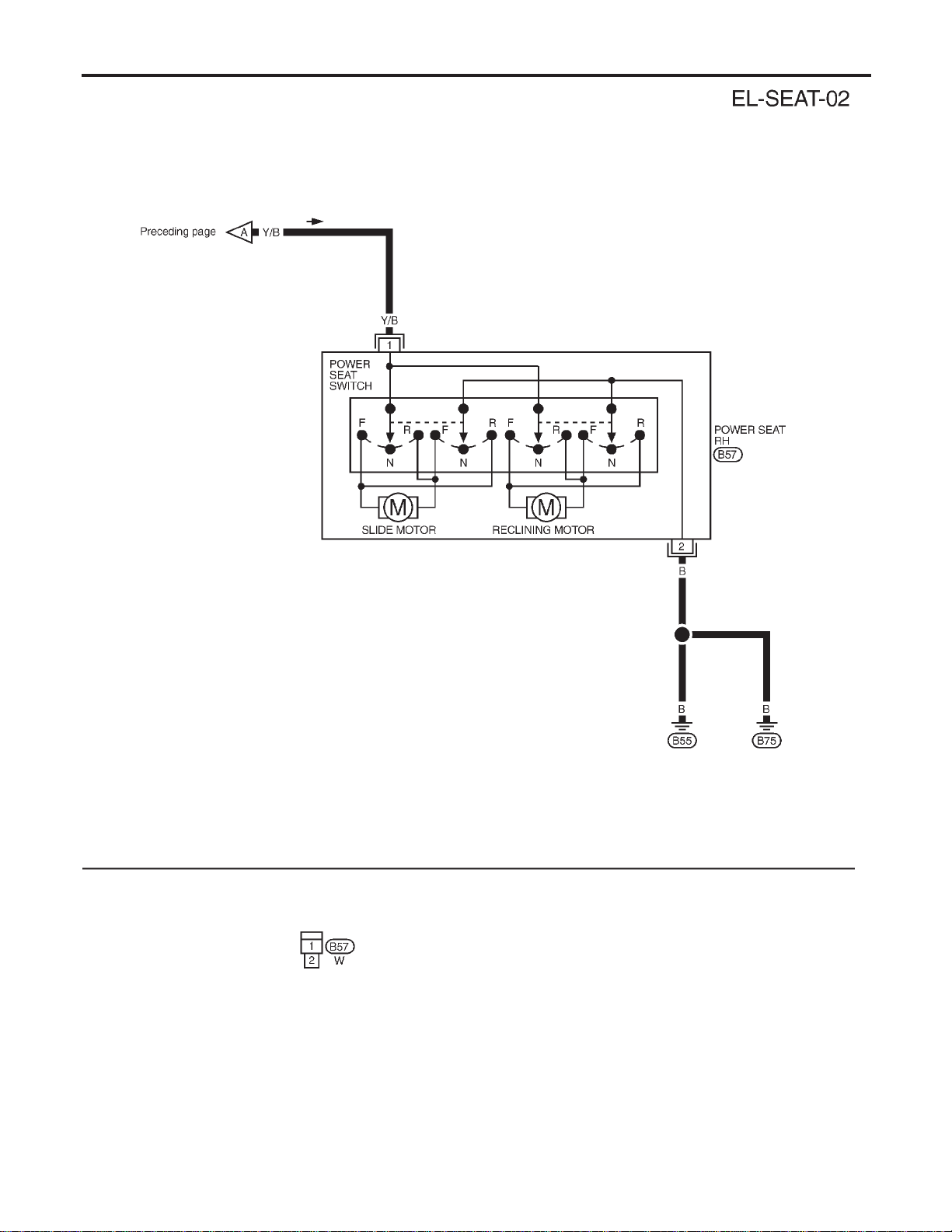
MEL601F
POWER SEAT
Wiring Diagram — SEAT — (Cont’d)
EL-210
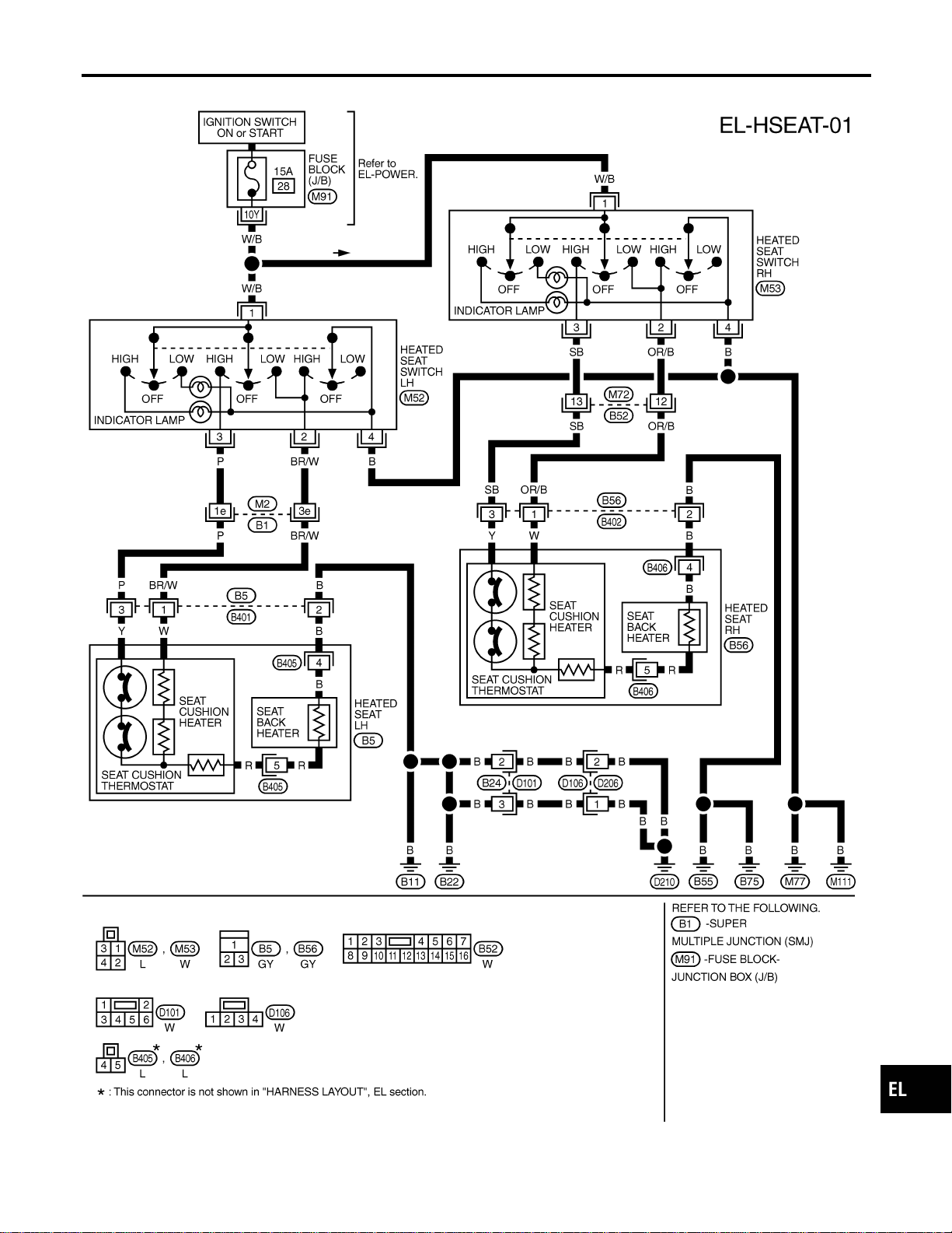
Wiring Diagram — HSEAT —
NAEL0362
MEL046M
GI
MA
EM
LC
EC
FE
CL
MT
AT
TF
PD
AX
SU
BR
ST
RS
BT
HA
SC
IDX
HEATED SEAT
Wiring Diagram — HSEAT —
EL-211
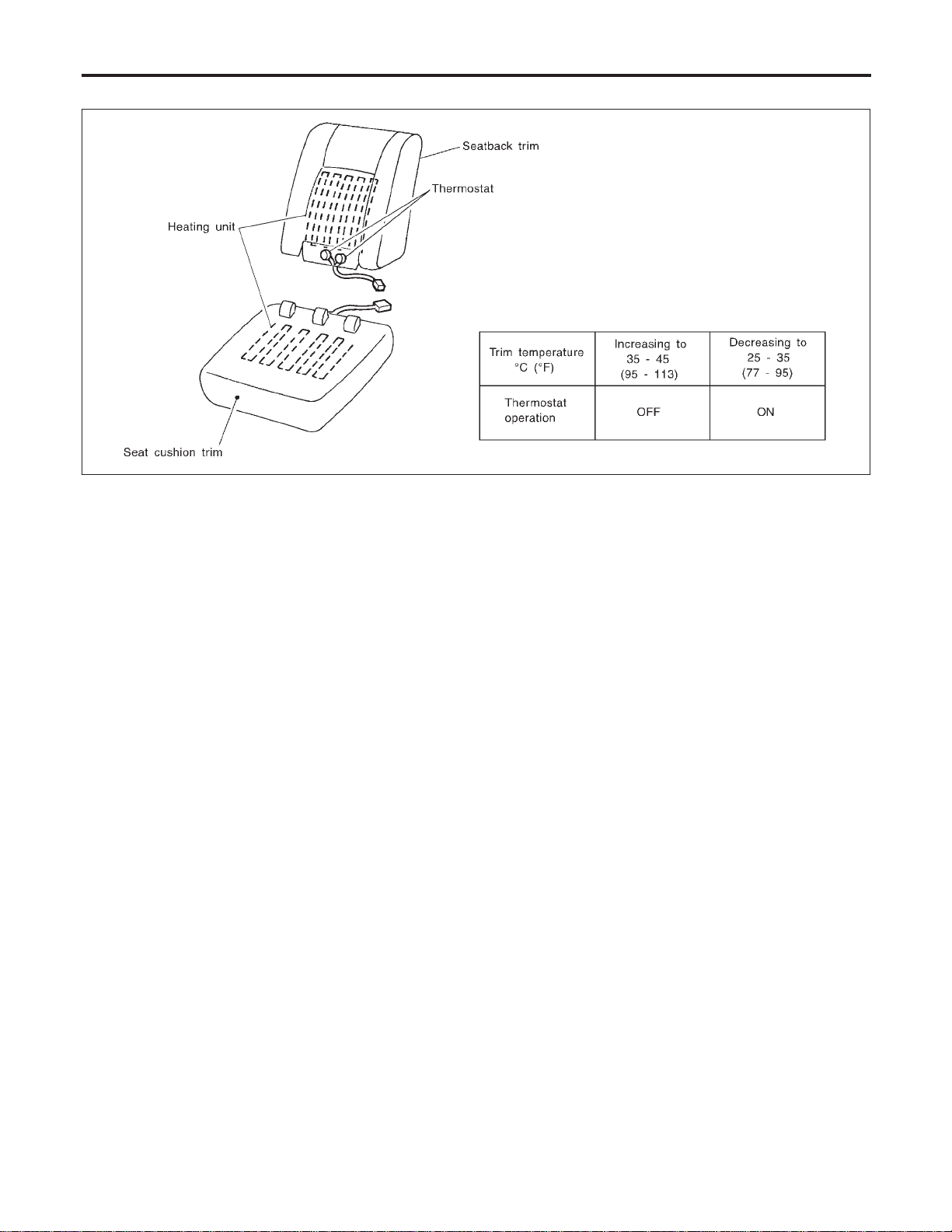
Seatback Heating Unit
NAEL0363
SBT314
HEATED SEAT
Seatback Heating Unit
EL-212
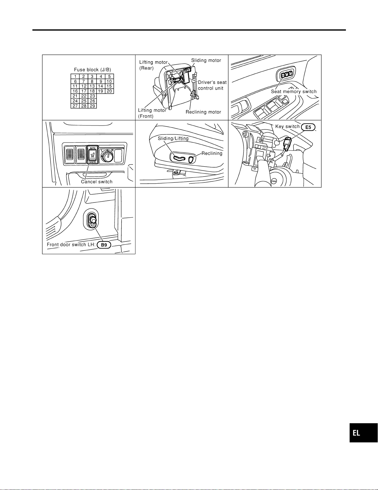
Component Parts and Harness Connector
Location
NAEL0364
SEL190Y
GI
MA
EM
LC
EC
FE
CL
MT
AT
TF
PD
AX
SU
BR
ST
RS
BT
HA
SC
IDX
AUTOMATIC DRIVE POSITIONER
Component Parts and Harness Connector Location
EL-213

System Description
=NAEL0365
OPERATIVE CONDITION
NAEL0365S01
The drive position can be set in 2 ways, manually and automatically.
Manual Operation
NAEL0365S0101
The driver’s seat can be adjusted for sliding, reclining, front cushion height and rear cushion height with the
LH power seat switches. The manual operation can be adjusted with the IGN key in any position.
Automatic Operation
NAEL0365S0102
The driver’s seat is adjusted to the proper positions for the driver automatically, in 3 different ways: MEMORY
AUTOMATIC SET, AUTOMATIC EXITING SETTING and AUTOMATIC SET RETURN. (Automatic Drive Posi-
tioner = ADP)
CONDITIONS INHIBITING AUTOMATIC OPERATION
NAEL0365S02
Automatic memory setting procedures are suspended under any of the following conditions:
1) When vehicle speed is more than 7 km/h (4 MPH).
2) When driver’s side power seat switch is turned on.
3) When any two of the switches (set switch and memory switches 1 and 2) are turned ON.
4) When cancel switch is turned on.
5) When selector lever is in any position other than “P”.
6) When ignition switch is turned to “START” position.
(Operation resumes when ignition switch is returned to “ON”.)
7) When detention switch malfunction is detected:
I Detention switch failure is sensed when detention switch remains off for at least 2 seconds at a vehicle
speed of greater than 7 km/h (4 MPH).
FAIL-SAFE SYSTEM
NAEL0365S03
Output Failure
NAEL0365S0301
When the ignition switch is in the ON position, if any of the parts (indicated in the following chart) move more
than the specified amount within a period “T2” when no “ON” input is sent from any of the switches (indicated
in the following chart), or an output from the automatic drive positioner is not produced, an output failure is
sensed. Motor operation will be suspended automatically, and all automatic operations will be ineffective. (In
this case, the motor will not operate manually.)
OPERATED PORTION T2 Allowable measurement
Seat sliding Approx. 2.5 sec. Within 6 mm (0.24 in)
Seat reclining Same as above Change angle within 1°
Absolving
NAEL0365S0302
When moving selector lever back to “P” position after having moved it to any position except “P”, fail-safe
operation will be canceled.
INITIALIZATION
NAEL0365S04
After reconnecting battery cable, perform initialization procedureAor B. If initialization has not been performed,
automatic drive positioner will not operate.
PROCEDURE A
1) Insert key in the ignition key cylinder. (Ignition switch is in “OFF” position.)
2) Open , close , open driver side door. (Do not perform with the door switch operation.)
3) End
PROCEDURE B
1) Drive the vehicle at more than 25 km/h (16 MPH).
2) End
AUTOMATIC DRIVE POSITIONER
System Description
EL-214
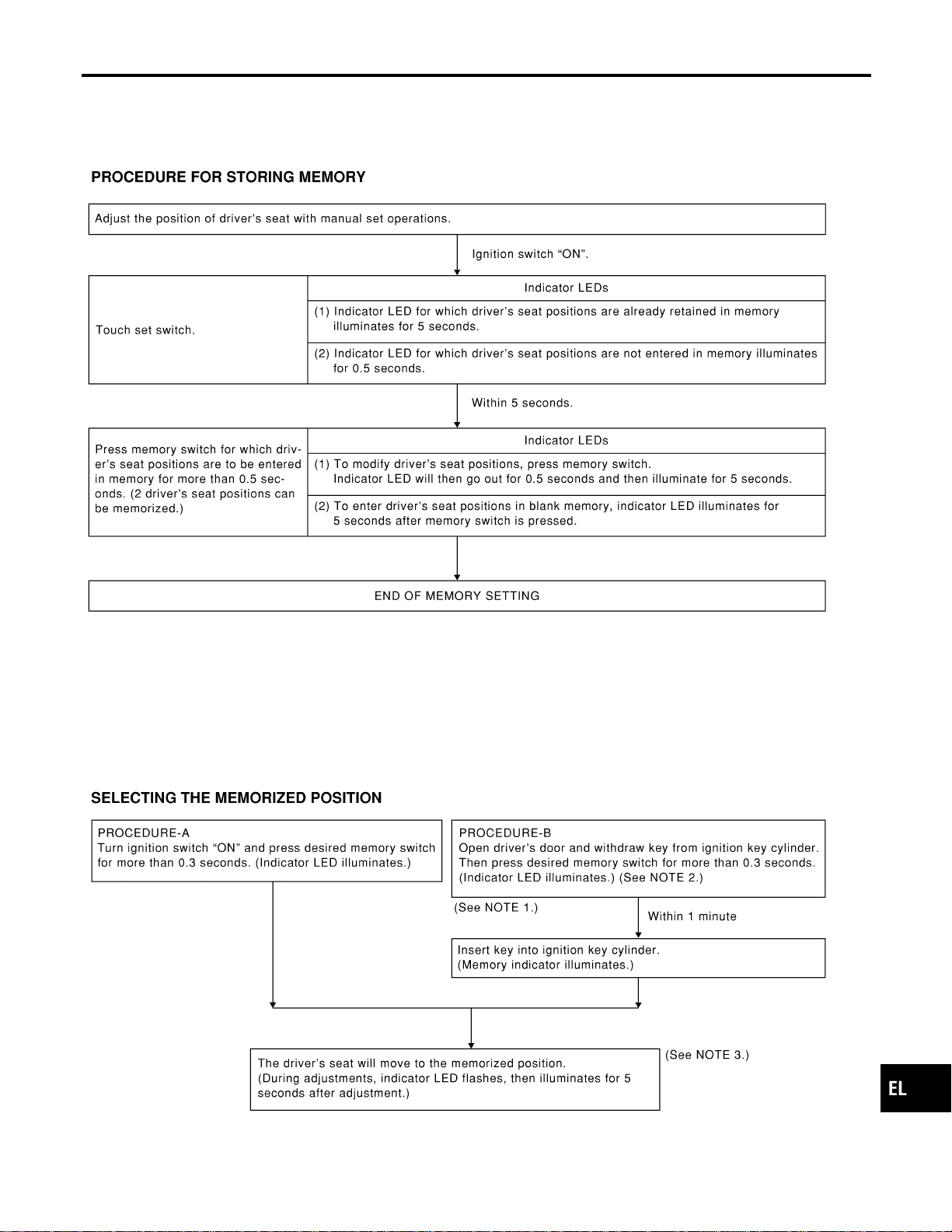
MEMORY AUTOMATIC SET
=NAEL0365S05
Two drive positions can be retained in the memory. Press memory switch to set driver’s seat to preset posi-
tion.
SEL592W
NOTE:
I When memory switch for which driver’s seat positions are already retained in memory is pressed, new seat
positions will be retained in memory in place of the previously set positions.
I Drive position is erased from the memory when battery cable is disconnected more than 30 seconds. After
connecting battery cable, perform initialization procedures.
SEL593W
GI
MA
EM
LC
EC
FE
CL
MT
AT
TF
PD
AX
SU
BR
ST
RS
BT
HA
SC
IDX
AUTOMATIC DRIVE POSITIONER
System Description (Cont’d)
EL-215
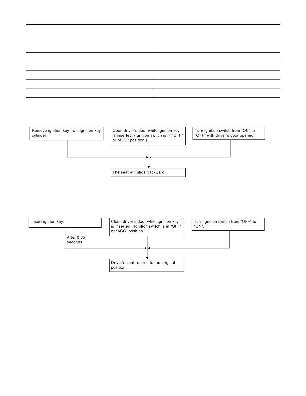
NOTE:
1) Do not keep cancel switch pressed as it will not operate.
2) Automatic exiting setting will be performed.
3) The driver’s seat position (see the following Table) operates in the order of priority.
The order of priority Operated portion
1 Seat sliding
2 Seat reclining
3 Seat front lifting
4 Seat rear lifting
AUTOMATIC EXITING SETTING
NAEL0365S06
“Exiting” positions:
Driver’s seat ... Slides about 40 mm (1.57 in) rear from normal sitting position.
SEL594W
AUTOMATIC SET RETURN
NAEL0365S07
With driver’s seat set to the “exiting” position, operating one of the following procedures moves it to the posi-
tion previously retained in memory.
SEL595W
AUTOMATIC DRIVE POSITIONER
System Description (Cont’d)
EL-216
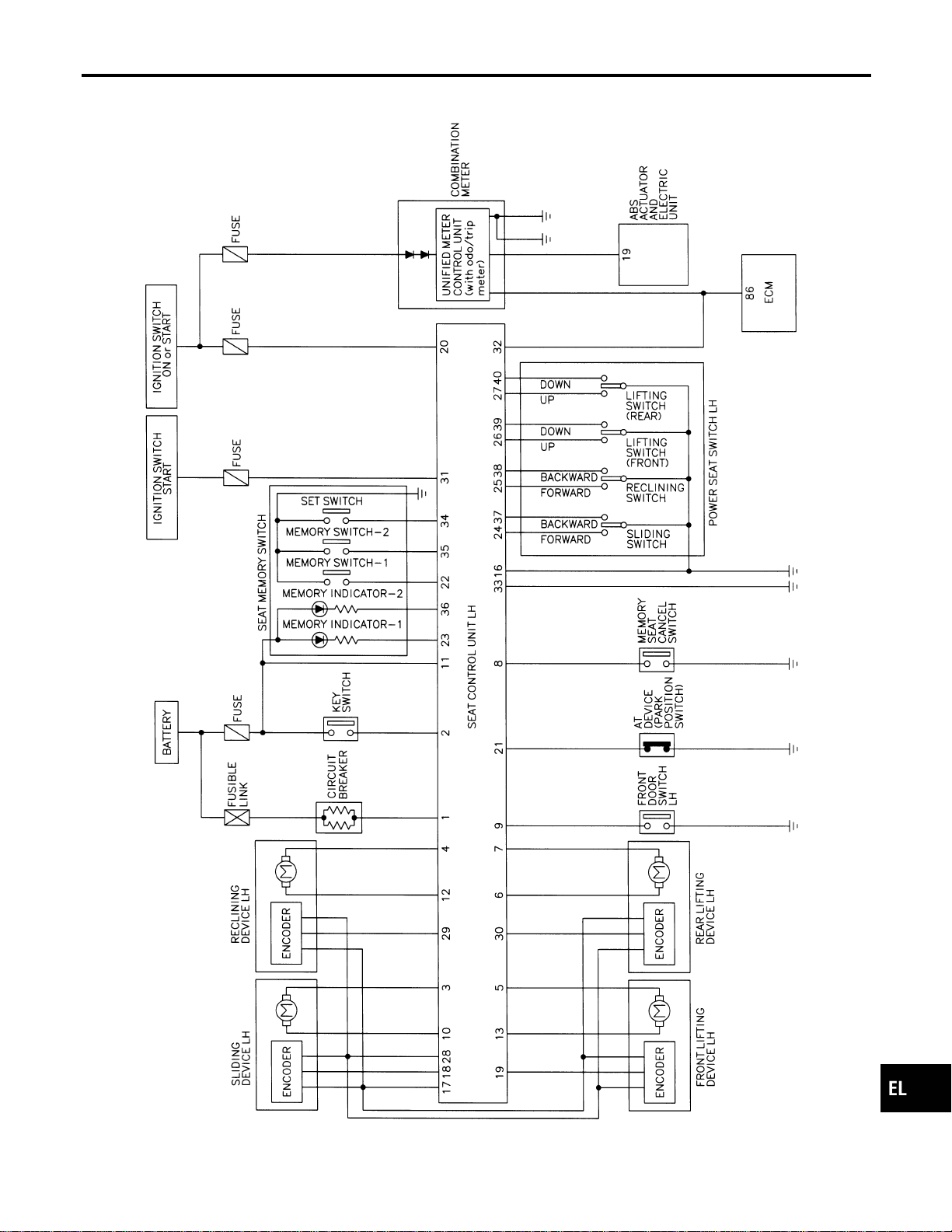
Schematic
NAEL0366
MEL422P
GI
MA
EM
LC
EC
FE
CL
MT
AT
TF
PD
AX
SU
BR
ST
RS
BT
HA
SC
IDX
AUTOMATIC DRIVE POSITIONER
Schematic
EL-217
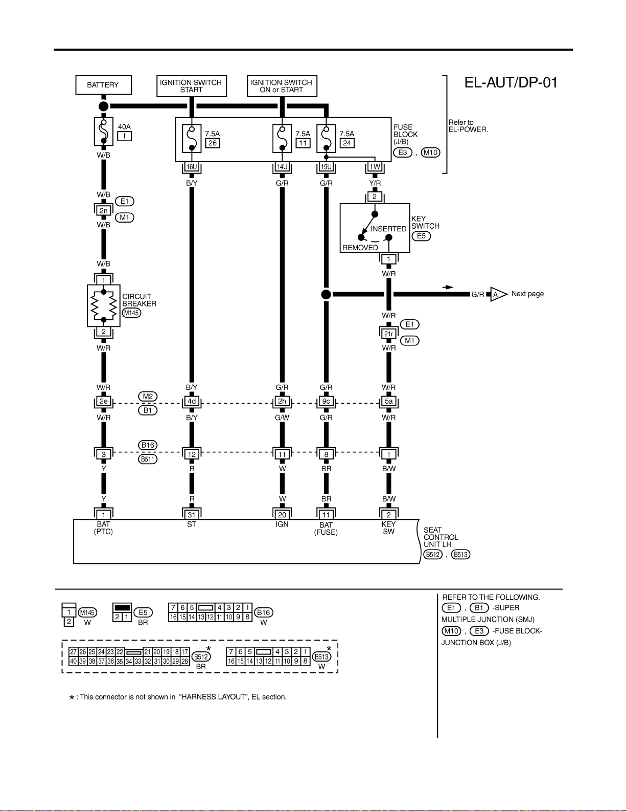
Wiring Diagram — AUT/DP —
NAEL0367
MEL557P
AUTOMATIC DRIVE POSITIONER
Wiring Diagram — AUT/DP —
EL-218
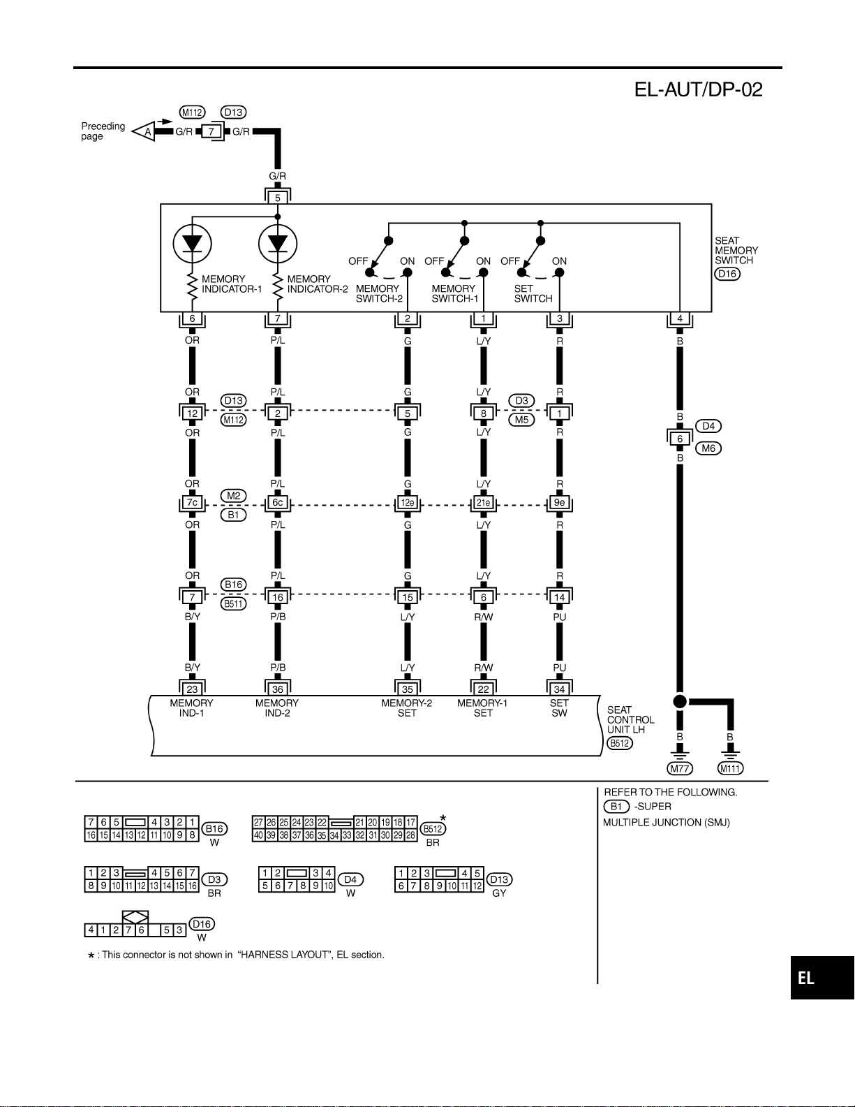
MEL558P
GI
MA
EM
LC
EC
FE
CL
MT
AT
TF
PD
AX
SU
BR
ST
RS
BT
HA
SC
IDX
AUTOMATIC DRIVE POSITIONER
Wiring Diagram — AUT/DP — (Cont’d)
EL-219
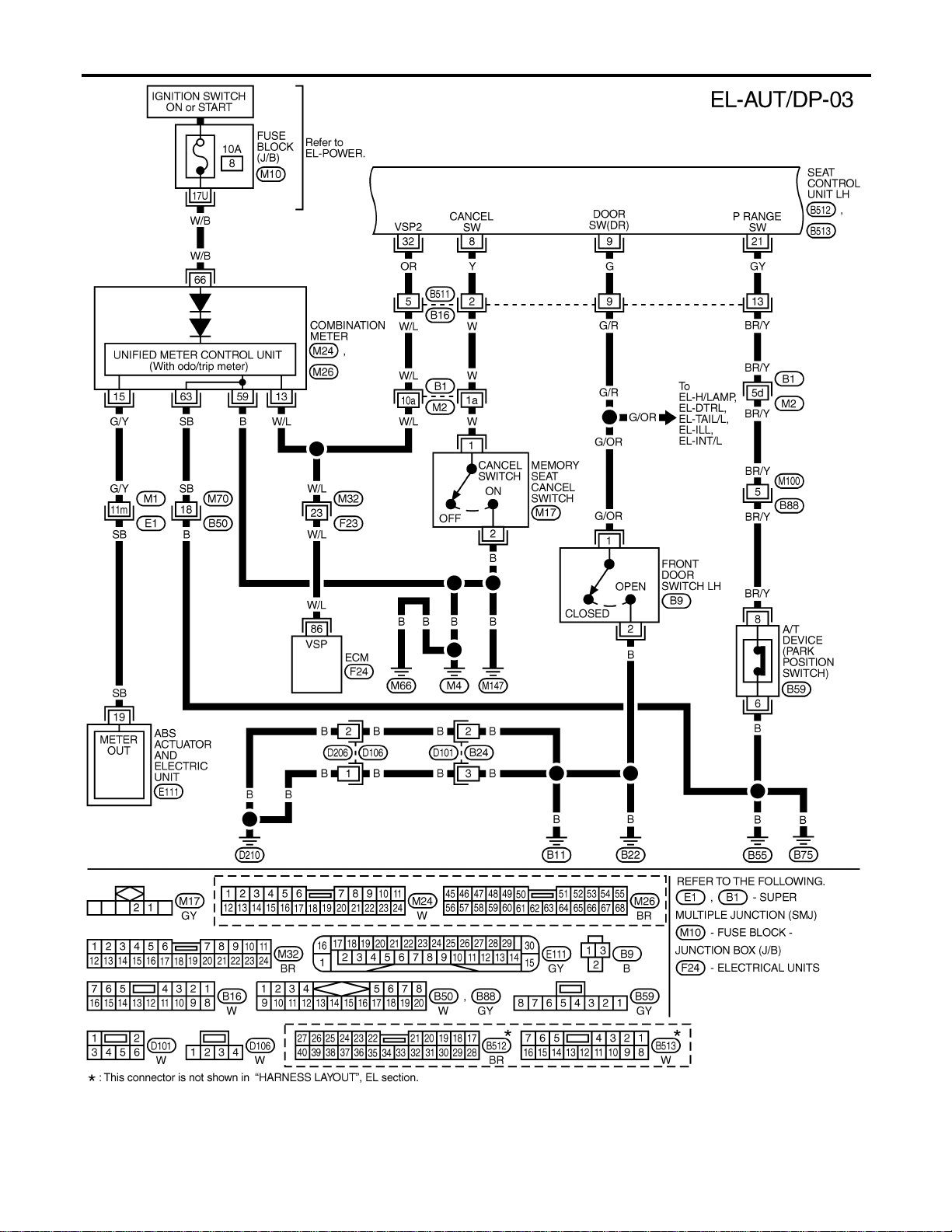
MEL423P
AUTOMATIC DRIVE POSITIONER
Wiring Diagram — AUT/DP — (Cont’d)
EL-220
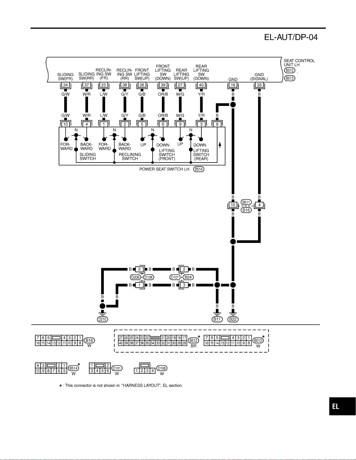
MEL186M
GI
MA
EM
LC
EC
FE
CL
MT
AT
TF
PD
AX
SU
BR
ST
RS
BT
HA
SC
IDX
AUTOMATIC DRIVE POSITIONER
Wiring Diagram — AUT/DP — (Cont’d)
EL-221
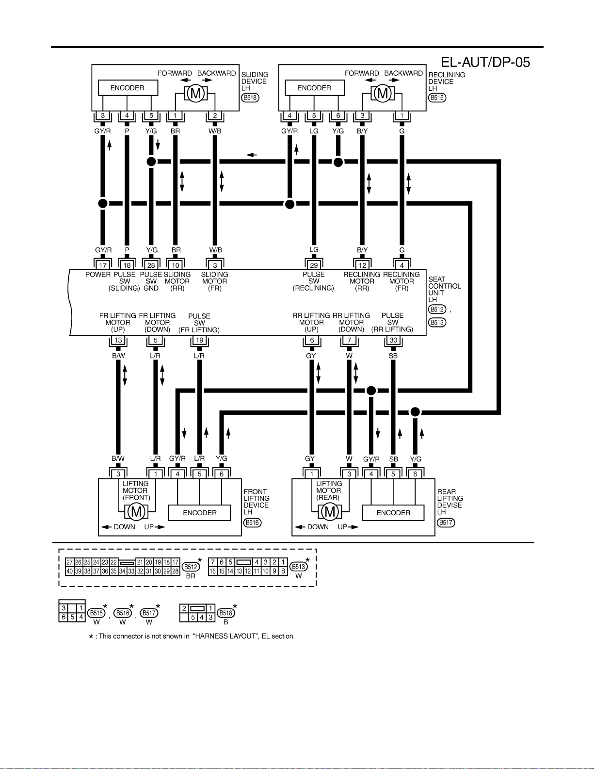
MEL187M
AUTOMATIC DRIVE POSITIONER
Wiring Diagram — AUT/DP — (Cont’d)
EL-222
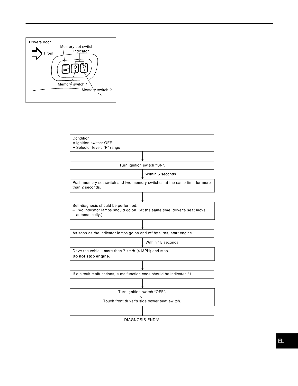
On Board Diagnosis
NAEL0368
SEL354X
HOW TO PERFORM SELF-DIAGNOSIS
NAEL0368S01
SEL596W
*1: If no malfunction is indicated, self-diagnosis will end after the vehicle speed sensor diagnosis is performed.
*2: Diagnosis ends after self-diagnostic results have been indicated for 10 minutes if left unattended.
GI
MA
EM
LC
EC
FE
CL
MT
AT
TF
PD
AX
SU
BR
ST
RS
BT
HA
SC
IDX
AUTOMATIC DRIVE POSITIONER
On Board Diagnosis
EL-223
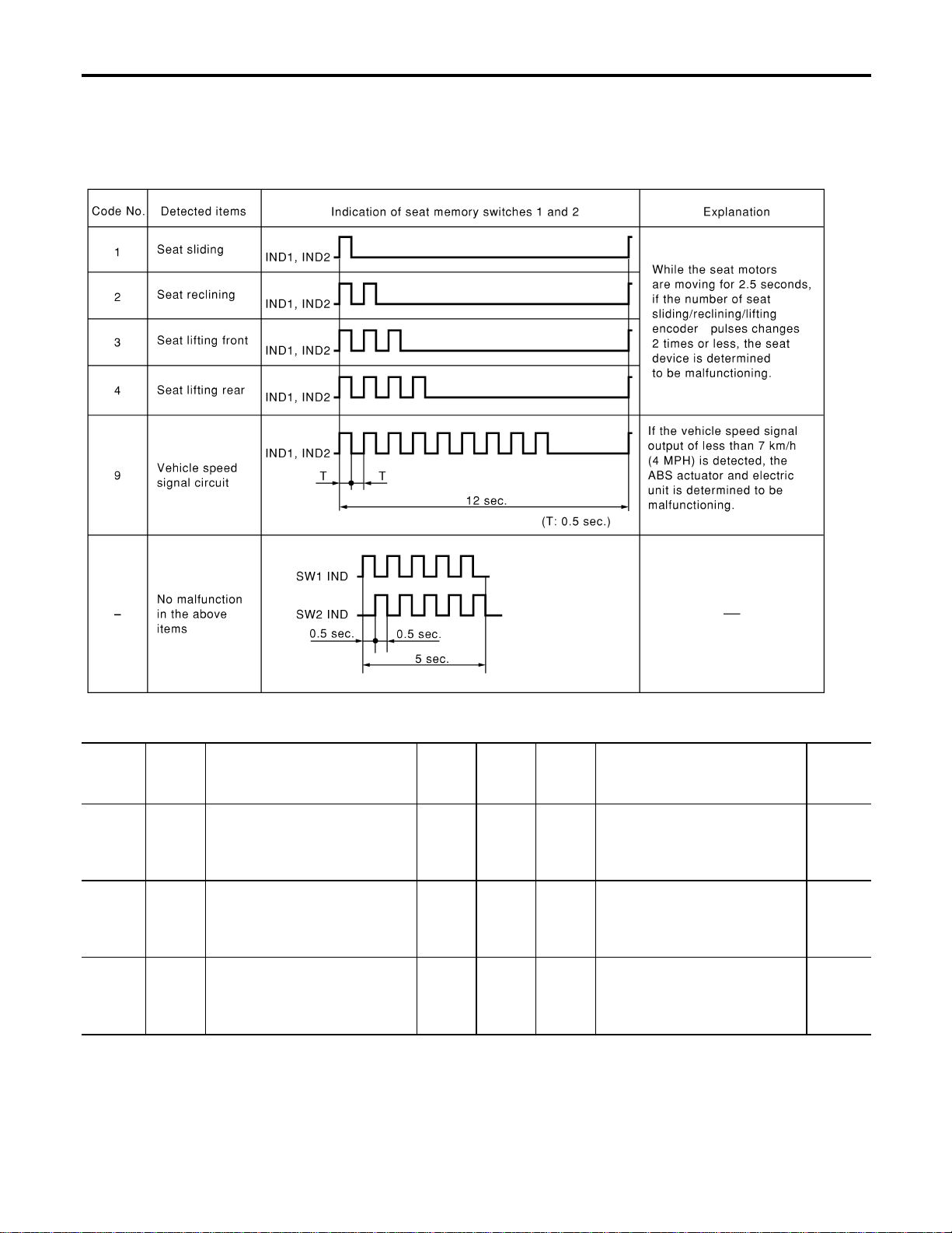
MALFUNCTION CODE TABLE
=NAEL0368S02
In this mode, a malfunction code is indicated by the number of flashes from the automatic drive positioner
indicator lamps (indicator lamp 1, indicator lamp 2) as shown below.
SEL597WA
Code
No.
Detected
items
Diagnostic procedure
Refer-
ence
page
Code
No.
Detected
items
Diagnostic procedure
Refer-
ence
page
1
Seat
sliding
PROCEDURE 2
(Sliding encoder check)
PROCEDURE 6
(Sliding motor check)
EL-230
EL-238
4
Seat
lifting
rear
PROCEDURE 5
[Lifting encoder (rear) check]
PROCEDURE 9
[Lifting motor (rear) check]
EL-236
EL-241
2
Seat
reclining
PROCEDURE 3
(Reclining encoder check)
PROCEDURE 7
(Reclining motor check)
EL-232
EL-239
9
Vehicle
speed
sensor
PROCEDURE 12
(Vehicle speed sensor check)
EL-244
3
Seat
lifting
front
PROCEDURE 4
[Lifting encoder (front) check]
PROCEDURE 8
[Lifting motor (front) check]
EL-234
EL-240
AUTOMATIC DRIVE POSITIONER
On Board Diagnosis (Cont’d)
EL-224
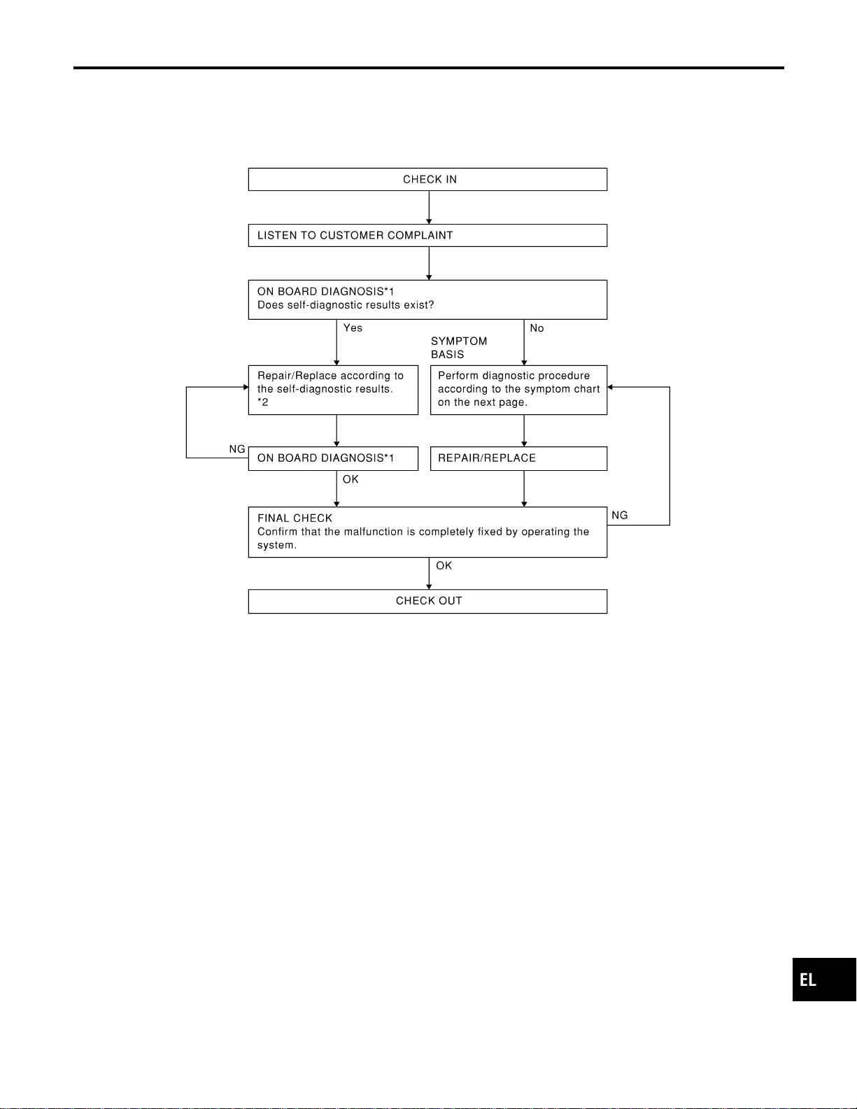

PRELIMINARY CHECK
NAEL0369S02
SEL600W
*1: After reconnecting battery cable, perform initialization proce-
dure A or B.
If initialization has not been performed, automatic drive positioner
will not operate.
PROCEDURE A
1) Insert key in the ignition key cylinder. (Ignition switch is in
“OFF” position.)
2) Open , close , open driver side door. (Do not perform with
the door switch operation.)
3) End
PROCEDURE B
1) Drive the vehicle at more than 30 km/h (19 MPH).
AUTOMATIC DRIVE POSITIONER
Trouble Diagnoses (Cont’d)
EL-226
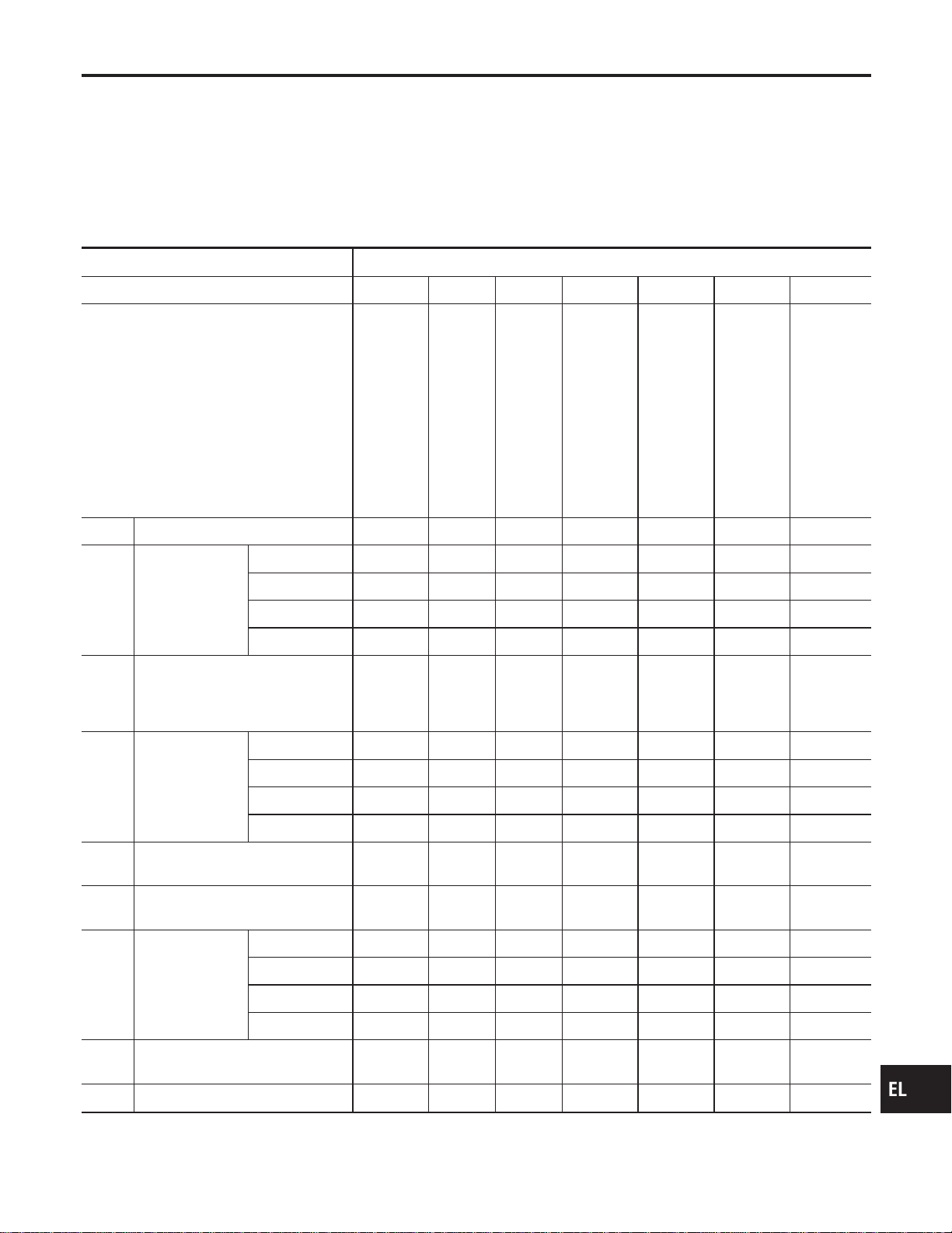
2) End
After performing preliminary check, go to symptom chart
below.
Before starting trouble diagnoses below, perform preliminary
check, EL-226. Symptom numbers in the symptom chart cor-
respond with those of preliminary check.
SYMPTOM CHART
NAEL0369S03
PROCEDURE Diagnostic procedure
REFERENCE PAGE (EL- ) 229 230 232 234 236 238 239
SYMPTOM
DIAGNOSTIC PROCEDURE 1
(Power supply and ground circuit
for Driver’s seat control unit)
DIAGNOSTIC PROCEDURE 2
(Sliding encoder check)
DIAGNOSTIC PROCEDURE 3
(Reclining encoder check)
DIAGNOSTIC PROCEDURE 4
[Lifting encoder (front) check]
DIAGNOSTIC PROCEDURE 5
[Lifting encoder (rear) check]
DIAGNOSTIC PROCEDURE 6
(Sliding motor check)
DIAGNOSTIC PROCEDURE 7
(Reclining motor check)
1 No seat system functions operate. X
2
Some of the seat
system functions
do not operate
during automatic/
manual opera-
tion.
Sliding X
Reclining X
Lifting (Front)
Lifting (Rear)
3
No functions operate during auto-
matic operation, and some/all func-
tions do not during manual opera-
tion.
4
Some of the seat
system functions
do not operate
during automatic
operation.
Sliding X
Reclining X
Lifting (Front) X
Lifting (Rear) X
5
No automatic operation functions
operate.
6
Drive position cannot be retained
in the memory.
7
Does not operate
during manual
operation. (Oper-
ates during auto-
matic operation.)
Sliding
Reclining
Lifting (Front)
Lifting (Rear)
8
Automatic operation cannot be
canceled.
9 Memory indicator does not light up.
X : Applicable
GI
MA
EM
LC
EC
FE
CL
MT
AT
TF
PD
AX
SU
BR
ST
RS
BT
HA
SC
IDX
AUTOMATIC DRIVE POSITIONER
Trouble Diagnoses (Cont’d)
EL-227

PROCEDURE Diagnostic procedure
REFERENCE PAGE (EL- ) 240 241 242 243 244 247 247
SYMPTOM
DIAGNOSTIC PROCEDURE 8
[Lifting motor (front) check]
DIAGNOSTIC PROCEDURE 9
[Lifting motor (rear) check]
DIAGNOSTIC PROCEDURE 10
(Power seat switch check)
DIAGNOSTIC PROCEDURE 11
(Cancel switch check)
DIAGNOSTIC PROCEDURE 12
(Key, park position, door switch
and vehicle speed sensor check)
DIAGNOSTIC PROCEDURE 13
(Seat memory switch check)
DIAGNOSTIC PROCEDURE 14
(Memory indicator check)
1 No seat system functions operate.
2
Some of the seat
system functions
do not operate
during automatic/
manual opera-
tion.
Sliding
Reclining
Lifting (Front) X
Lifting (Rear) X
3
No functions operate during auto-
matic operation, and some/all func-
tions do not during manual opera-
tion.
X
X
(ACC, ON
START
signal)
4
Some of the seat
system functions
do not operate
during automatic
operation.
Sliding
Reclining
Lifting (Front)
Lifting (Rear)
5
No automatic operation functions
operate.
XX
6
Drive position cannot be retained
in the memory.
X
(IGN ON
signal)
X
7
Does not operate
during manual
operation. (Oper-
ates during auto-
matic operation.)
Sliding X
Reclining X
Lifting (Front) X
Lifting (Rear) X
8
Automatic operation cannot be
canceled.
X
9 Memory indicator does not light up. X
X : Applicable
AUTOMATIC DRIVE POSITIONER
Trouble Diagnoses (Cont’d)
EL-228
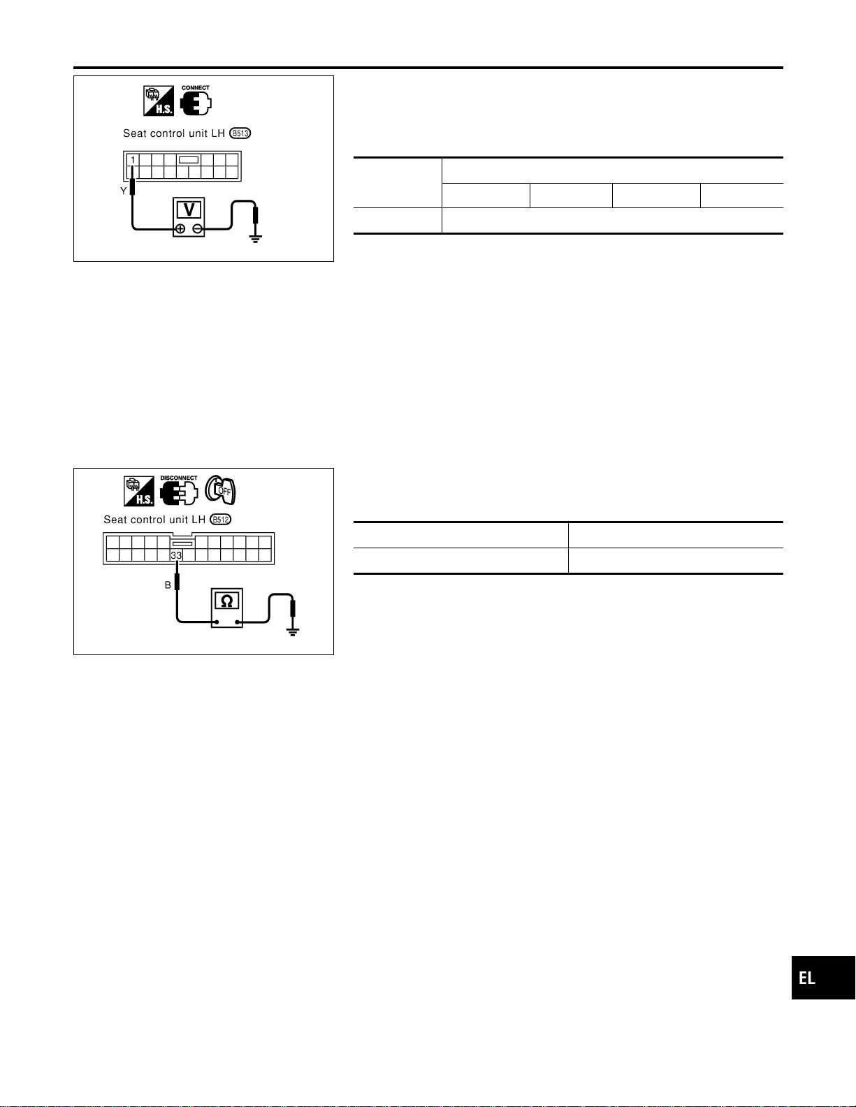
SEL601W
DIAGNOSTIC PROCEDURE 1
=NAEL0369S04
(Power supply and ground circuit for driver’s seat control unit)
Power Supply Circuit Check
NAEL0369S0401
Check voltage between seat control unit LH terminal 1 and ground.
Terminals
Ignition switch position
OFF ACC ON START
1 - Ground Battery voltage
If NG, check the following.
I 40Afusible link (letter f, located in the fuse and fusible link box)
I Circuit breaker
I Harness for open or short between circuit breaker and seat
control unit LH
SEL602W
Ground Circuit Check
NAEL0369S0402
Check continuity between seat control unit LH terminal 33 and
ground.
Terminals Continuity
33 - Ground Yes
GI
MA
EM
LC
EC
FE
CL
MT
AT
TF
PD
AX
SU
BR
ST
RS
BT
HA
SC
IDX
AUTOMATIC DRIVE POSITIONER
Trouble Diagnoses (Cont’d)
EL-229
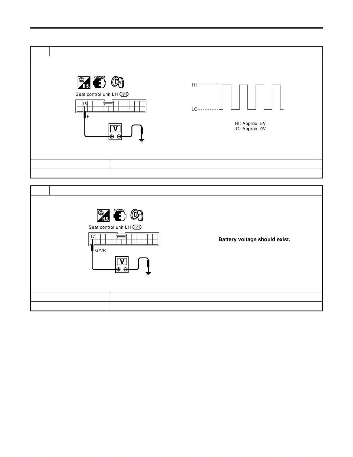
DIAGNOSTIC PROCEDURE 2
=NAEL0369S05
(Sliding encoder check)
1 CHECK SLIDING ENCODER OUTPUT SIGNAL
Measure voltage between seat control unit LH terminal 18 and ground with CONSULT-II or oscilloscope when power seat
slide is operated.
SEL603W
OK or NG
OK © Sliding encoder is OK.
NG © GO TO 2.
2 CHECK SLIDING ENCODER INPUT SIGNAL
Check voltage between seat control unit LH terminal 17 and ground.
SEL604W
OK or NG
OK © GO TO 3.
NG © Replace seat control unit LH.
AUTOMATIC DRIVE POSITIONER
Trouble Diagnoses (Cont’d)
EL-230

3 CHECK SLIDING ENCODER OPEN CIRCUIT
1. Disconnect seat control unit LH connector and sliding device LH connector.
2. Check harness continuity between seat control unit LH connector and sliding device LH connector.
SEL605WA
OK or NG
OK © GO TO 4.
NG © Repair harness.
4 CHECK SLIDING ENCODER SHORT CIRCUIT
Check harness continuity between seat control unit LH connector and ground.
SEL606W
OK or NG
OK © Replace sliding encoder.
NG © Repair harness.
GI
MA
EM
LC
EC
FE
CL
MT
AT
TF
PD
AX
SU
BR
ST
RS
BT
HA
SC
IDX
AUTOMATIC DRIVE POSITIONER
Trouble Diagnoses (Cont’d)
EL-231
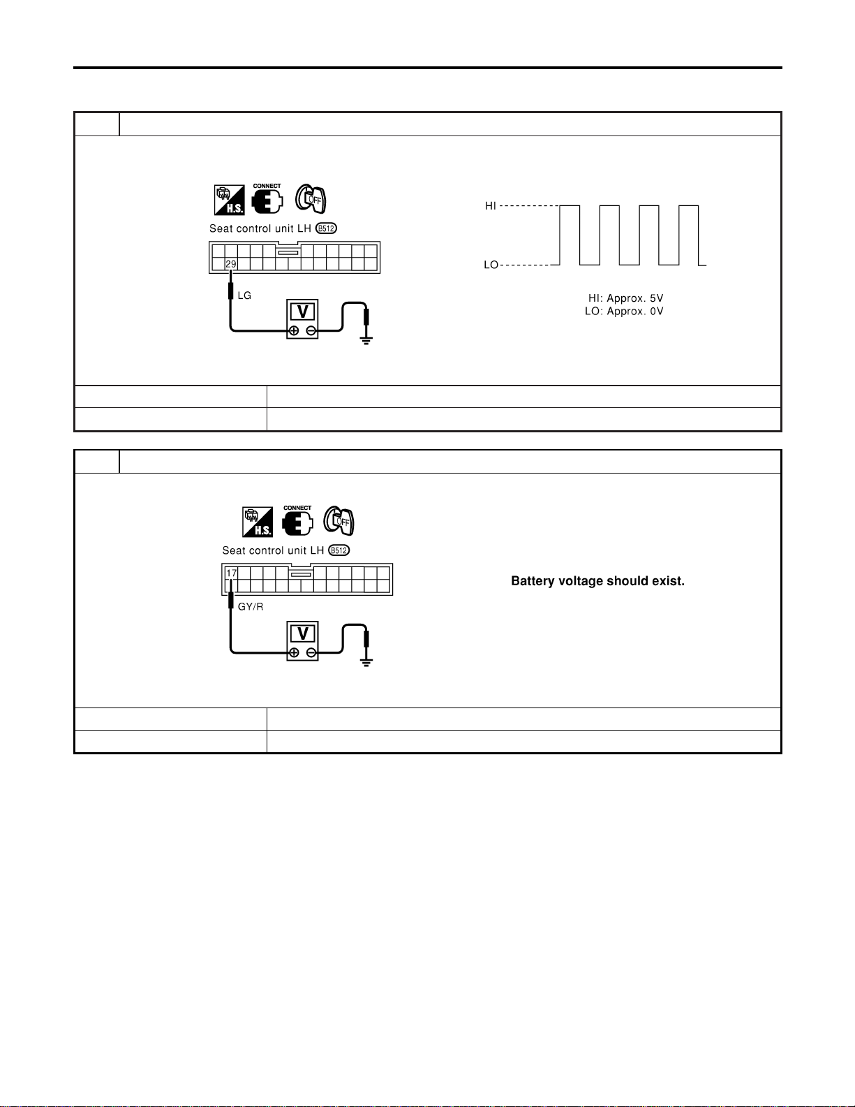
DIAGNOSTIC PROCEDURE 3
=NAEL0369S06
(Reclining encoder check)
1 CHECK RECLINING ENCODER OUTPUT SIGNAL
Measure voltage between seat control unit LH terminal 29 and ground with CONSULT-II or oscilloscope when power seat
reclining is operated.
SEL607W
OK or NG
OK © Reclining encoder is OK.
NG © GO TO 2.
2 CHECK RECLINING ENCODER INPUT SIGNAL
Check voltage between seat control unit LH terminal 17 and ground.
SEL608W
OK or NG
OK © GO TO 3.
NG © Replace seat control unit LH.
AUTOMATIC DRIVE POSITIONER
Trouble Diagnoses (Cont’d)
EL-232
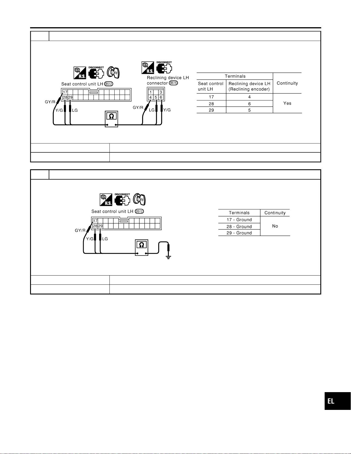
3 CHECK RECLINING ENCODER OPEN CIRCUIT
1. Disconnect seat control unit LH connector and reclining device LH connector.
2. Check harness continuity between seat control unit LH connector and reclining LH connector.
SEL609WA
OK or NG
OK © GO TO 4.
NG © Repair harness.
4 CHECK RECLINING ENCODER SHORT CIRCUIT
Check harness continuity between seat control unit LH connector and ground.
SEL610W
OK or NG
OK © Replace reclining encoder.
NG © Repair harness.
GI
MA
EM
LC
EC
FE
CL
MT
AT
TF
PD
AX
SU
BR
ST
RS
BT
HA
SC
IDX
AUTOMATIC DRIVE POSITIONER
Trouble Diagnoses (Cont’d)
EL-233
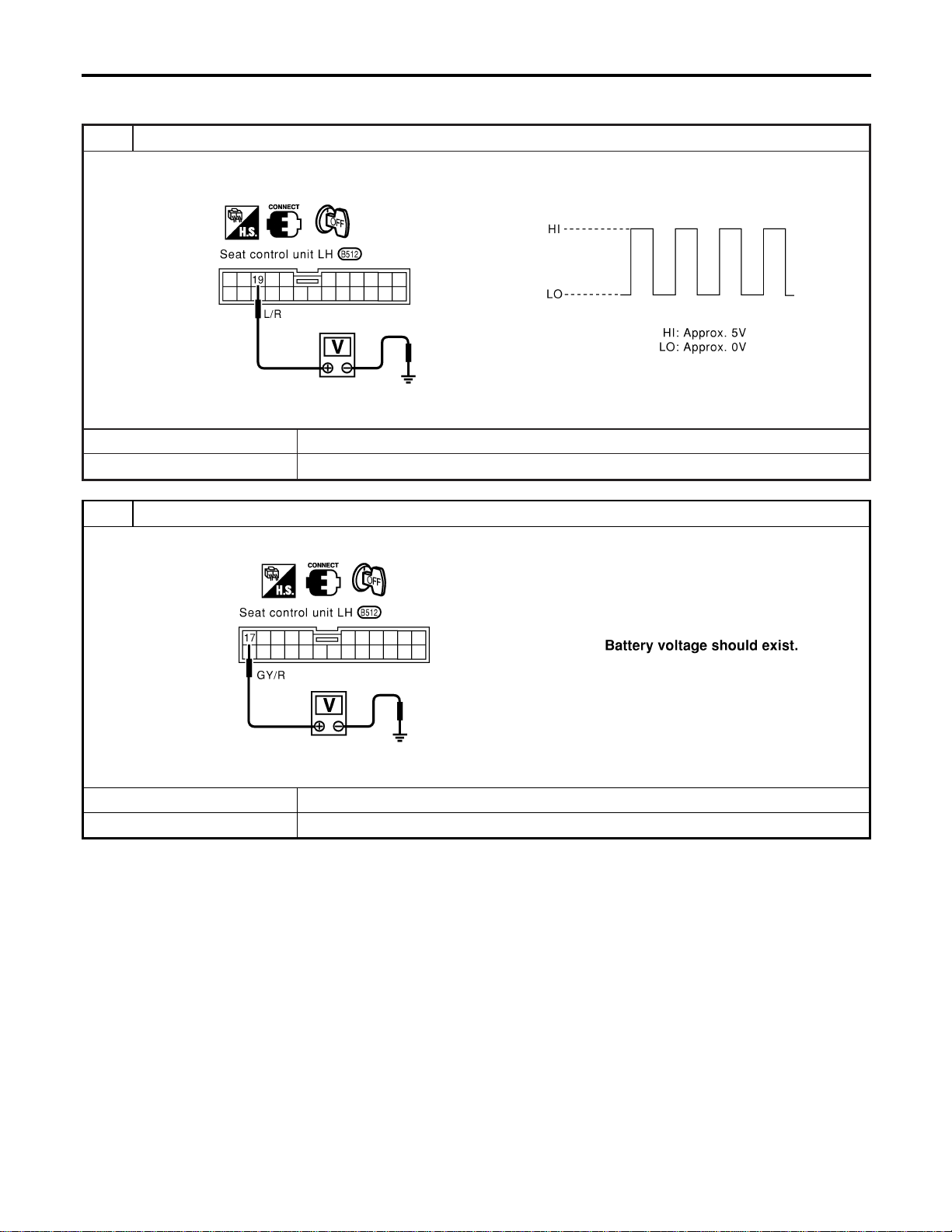
DIAGNOSTIC PROCEDURE 4
=NAEL0369S07
[Lifting encoder (front) check]
1 CHECK LIFTING ENCODER (FRONT) OUTPUT SIGNAL
Measure voltage between seat control unit LH terminal 19 and ground with CONSULT-II or oscilloscope when power seat
lifting (front) is operated.
SEL611W
OK or NG
OK © Lifting encoder (front) is OK.
NG © GO TO 2.
2 CHECK LIFTING ENCODER (FRONT) INPUT SIGNAL
Check voltage between seat control unit LH terminal 17 and ground.
SEL612W
OK or NG
OK © GO TO 3.
NG © Replace seat control unit LH.
AUTOMATIC DRIVE POSITIONER
Trouble Diagnoses (Cont’d)
EL-234
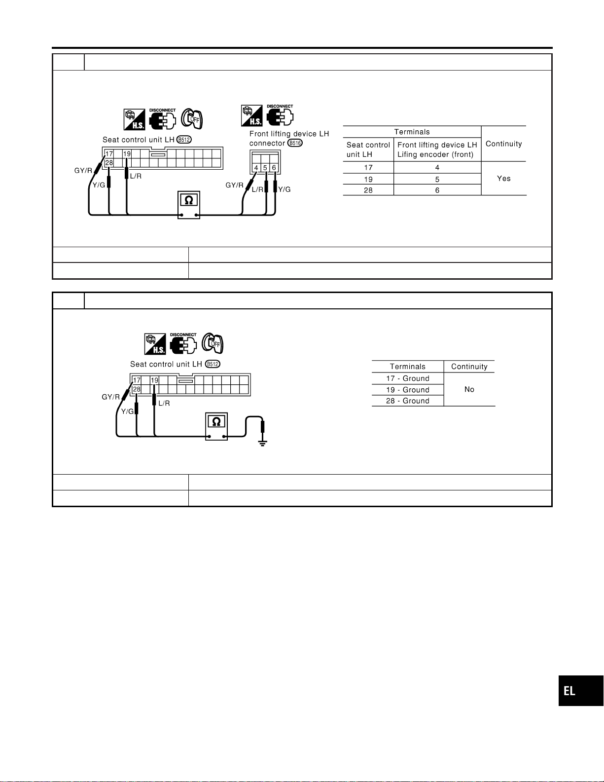
3 CHECK LIFTING ENCODER (FRONT) OPEN CIRCUIT
1. Disconnect seat control unit LH connector and front lifting device LH connector.
2. Check harness continuity between seat control unit LH connector and front lifting device LH connector.
SEL613WA
OK or NG
OK © GO TO 4.
NG © Repair harness.
4 CHECK LIFTING ENCODER (FRONT) SHORT CIRCUIT
Check harness continuity between seat control unit LH connector and ground.
SEL614W
OK or NG
OK © Replace lifting encoder (front).
NG © Repair harness.
GI
MA
EM
LC
EC
FE
CL
MT
AT
TF
PD
AX
SU
BR
ST
RS
BT
HA
SC
IDX
AUTOMATIC DRIVE POSITIONER
Trouble Diagnoses (Cont’d)
EL-235

DIAGNOSTIC PROCEDURE 5
=NAEL0369S08
[Lifting encoder (rear) check]
1 CHECK LIFTING ENCODER (REAR) OUTPUT SIGNAL
Measure voltage between seat control unit LH terminal 30 and ground with CONSULT-II or oscilloscope when power seat
lifting (rear) is operated.
SEL615W
OK or NG
OK © Lifting encoder (rear) is OK.
NG © GO TO 2.
2 CHECK LIFTING ENCODER (REAR) INPUT SIGNAL
Check voltage between seat control unit LH terminal 17 and ground.
SEL616W
OK or NG
OK © GO TO 3.
NG © Replace seat control unit LH.
AUTOMATIC DRIVE POSITIONER
Trouble Diagnoses (Cont’d)
EL-236
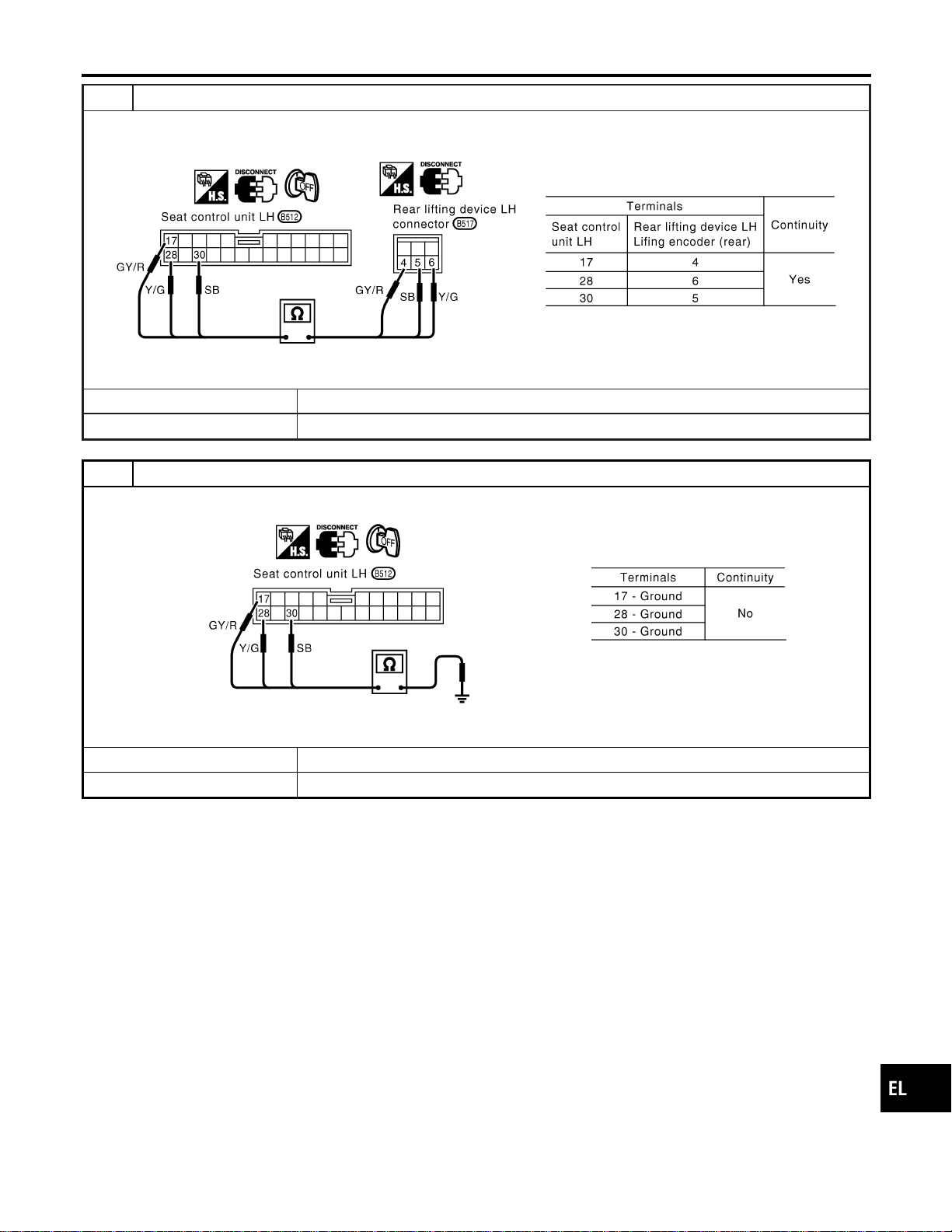
3 CHECK LIFTING ENCODER (REAR) OPEN CIRCUIT
1. Disconnect seat control unit LH connector and rear lifting device LH connector.
2. Check harness continuity between seat control unit LH connector and rear lifting device LH connector.
SEL617WA
OK or NG
OK © GO TO 4.
NG © Repair harness.
4 CHECK LIFTING ENCODER (REAR) SHORT CIRCUIT
Check harness continuity between seat control unit LH connector and ground.
SEL618W
OK or NG
OK © Replace lifting encoder (rear).
NG © Repair harness.
GI
MA
EM
LC
EC
FE
CL
MT
AT
TF
PD
AX
SU
BR
ST
RS
BT
HA
SC
IDX
AUTOMATIC DRIVE POSITIONER
Trouble Diagnoses (Cont’d)
EL-237
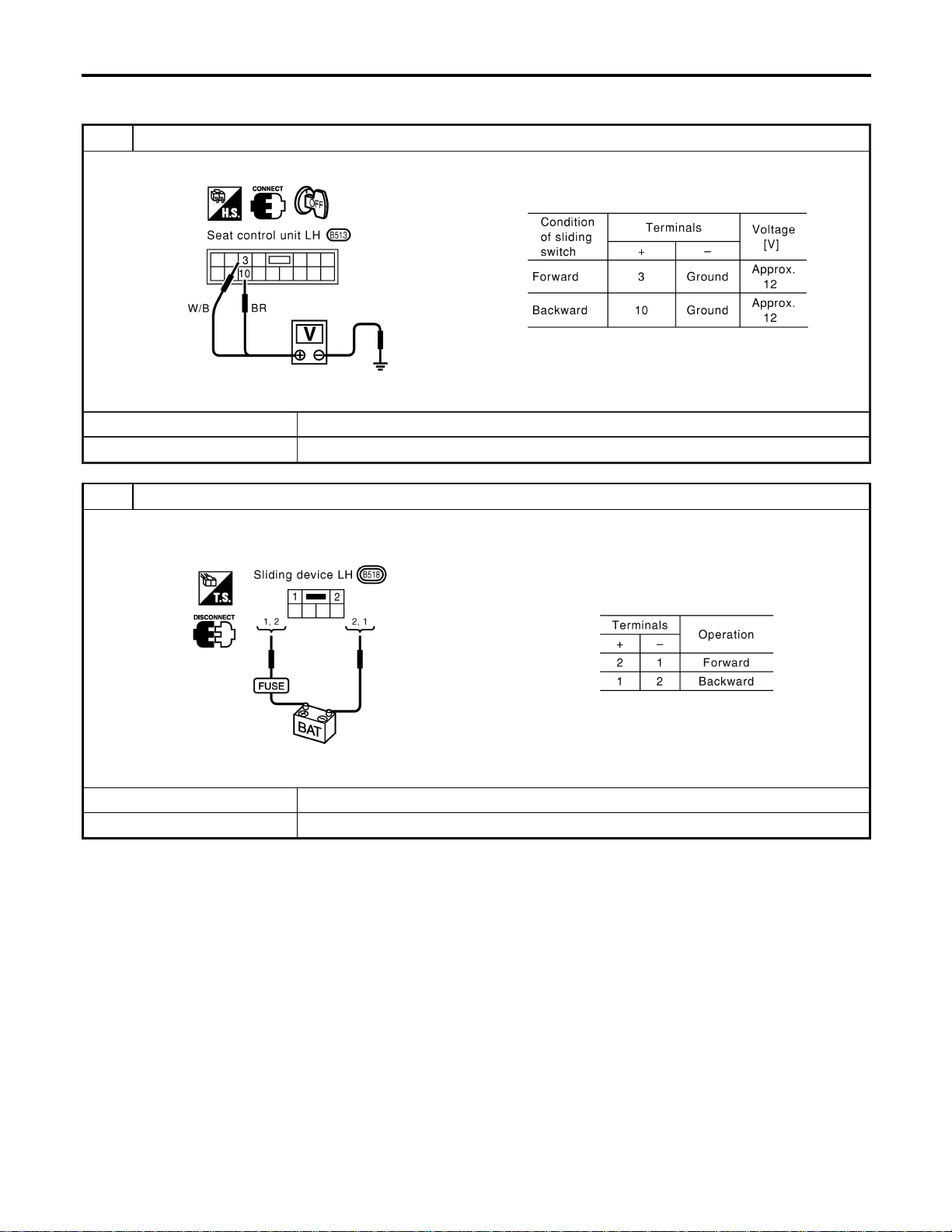
DIAGNOSTIC PROCEDURE 6
=NAEL0369S09
(Sliding motor check)
1 CHECK OUTPUT SIGNAL TO SLIDING MOTOR
Check voltage between seat control unit LH terminals 3 or 10 and ground.
SEL619W
OK or NG
OK © GO TO 2.
NG © Replace seat control unit LH.
2 CHECK SLIDING MOTOR
1. Disconnect sliding device LH connector.
2. Apply 12V DC direct current to motor and check operation.
SEL620WA
OK or NG
OK © Check harness for operation between seat control unit LH and sliding motor.
NG © Replace sliding motor.
AUTOMATIC DRIVE POSITIONER
Trouble Diagnoses (Cont’d)
EL-238
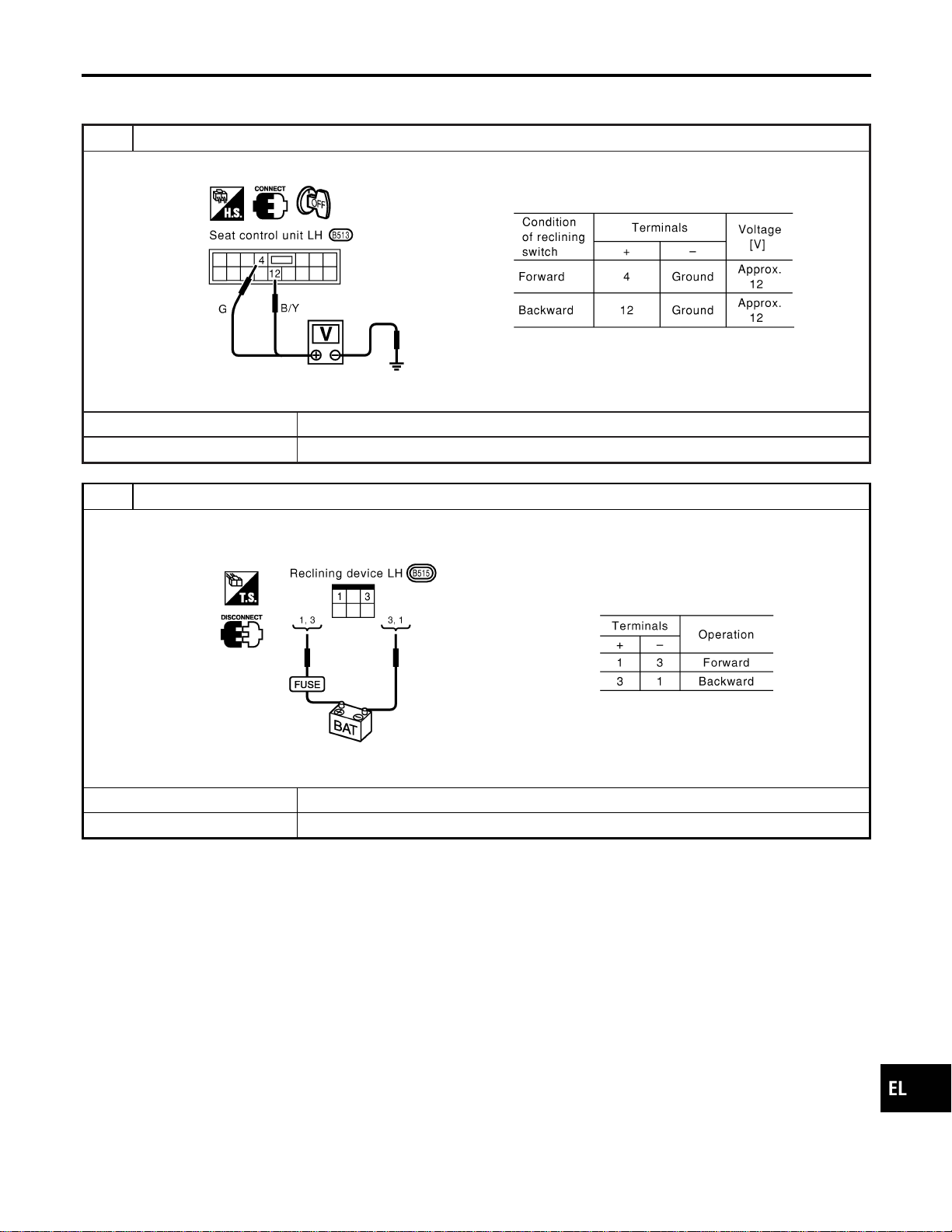
DIAGNOSTIC PROCEDURE 7
=NAEL0369S10
(Reclining motor check)
1 CHECK OUTPUT SIGNAL TO RECLINING MOTOR
Check voltage between seat control unit LH terminals 4 or 12 and ground.
SEL621W
OK or NG
OK © GO TO 2.
NG © Replace seat control unit LH.
2 CHECK RECLINING MOTOR
1. Disconnect reclining device LH connector.
2. Apply 12V DC direct current to motor and check operation.
SEL622WA
OK or NG
OK © Check harness for operation between seat control unit LH and reclining motor.
NG © Replace reclining motor.
GI
MA
EM
LC
EC
FE
CL
MT
AT
TF
PD
AX
SU
BR
ST
RS
BT
HA
SC
IDX
AUTOMATIC DRIVE POSITIONER
Trouble Diagnoses (Cont’d)
EL-239
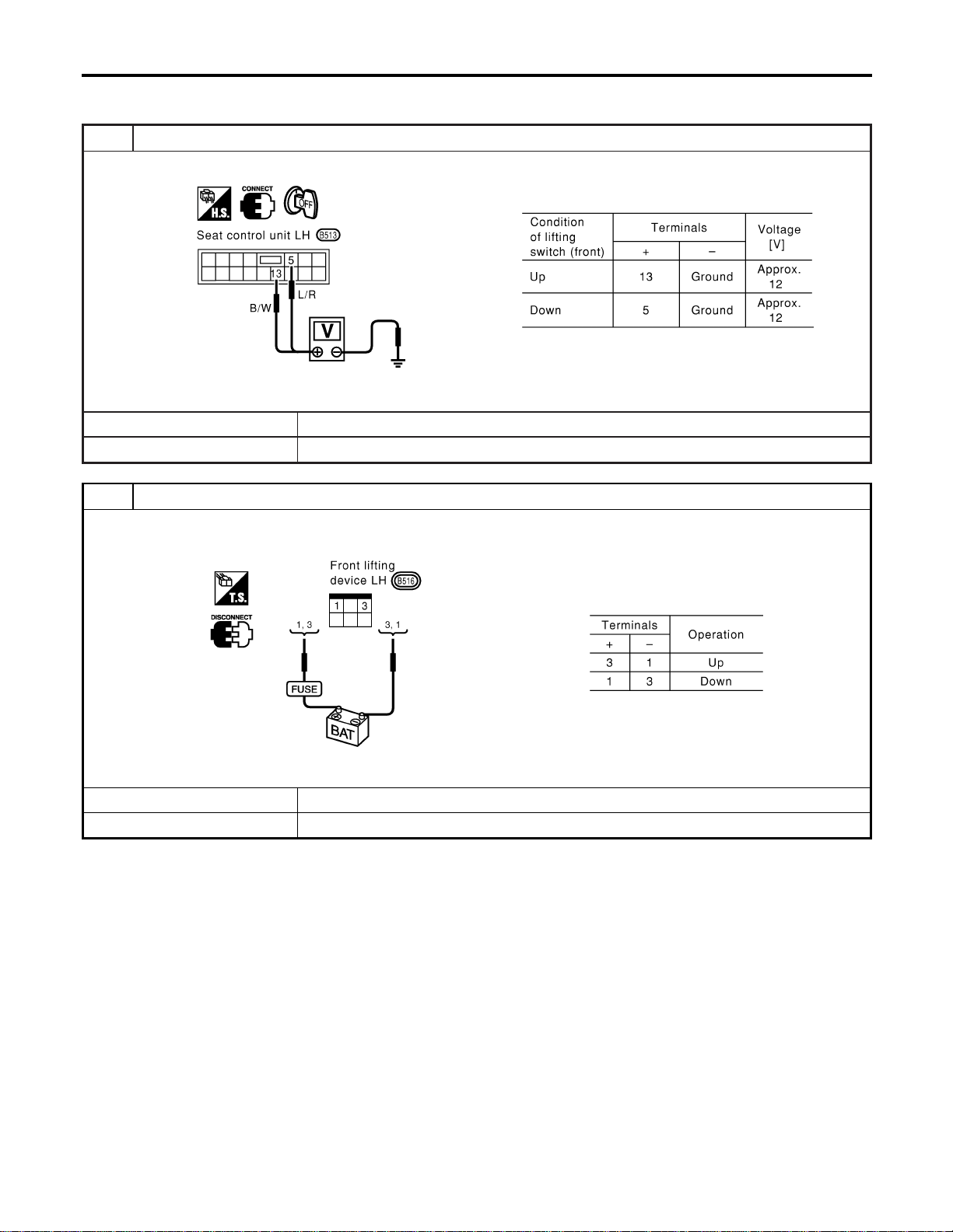
DIAGNOSTIC PROCEDURE 8
=NAEL0369S11
[Lifting motor (front) check]
1 CHECK OUTPUT SIGNAL TO LIFTING MOTOR (FRONT)
Check voltage between seat control unit LH terminals 5 or 13 and ground.
SEL623W
OK or NG
OK © GO TO 2.
NG © Replace seat control unit LH.
2 CHECK LIFTING MOTOR (FRONT)
1. Disconnect front lifting device LH connector.
2. Apply 12V DC direct current to motor and check operation.
SEL624WA
OK or NG
OK © Check harness for operation between seat control unit LH and lifting motor (front).
NG © Replace lifting motor (front).
AUTOMATIC DRIVE POSITIONER
Trouble Diagnoses (Cont’d)
EL-240
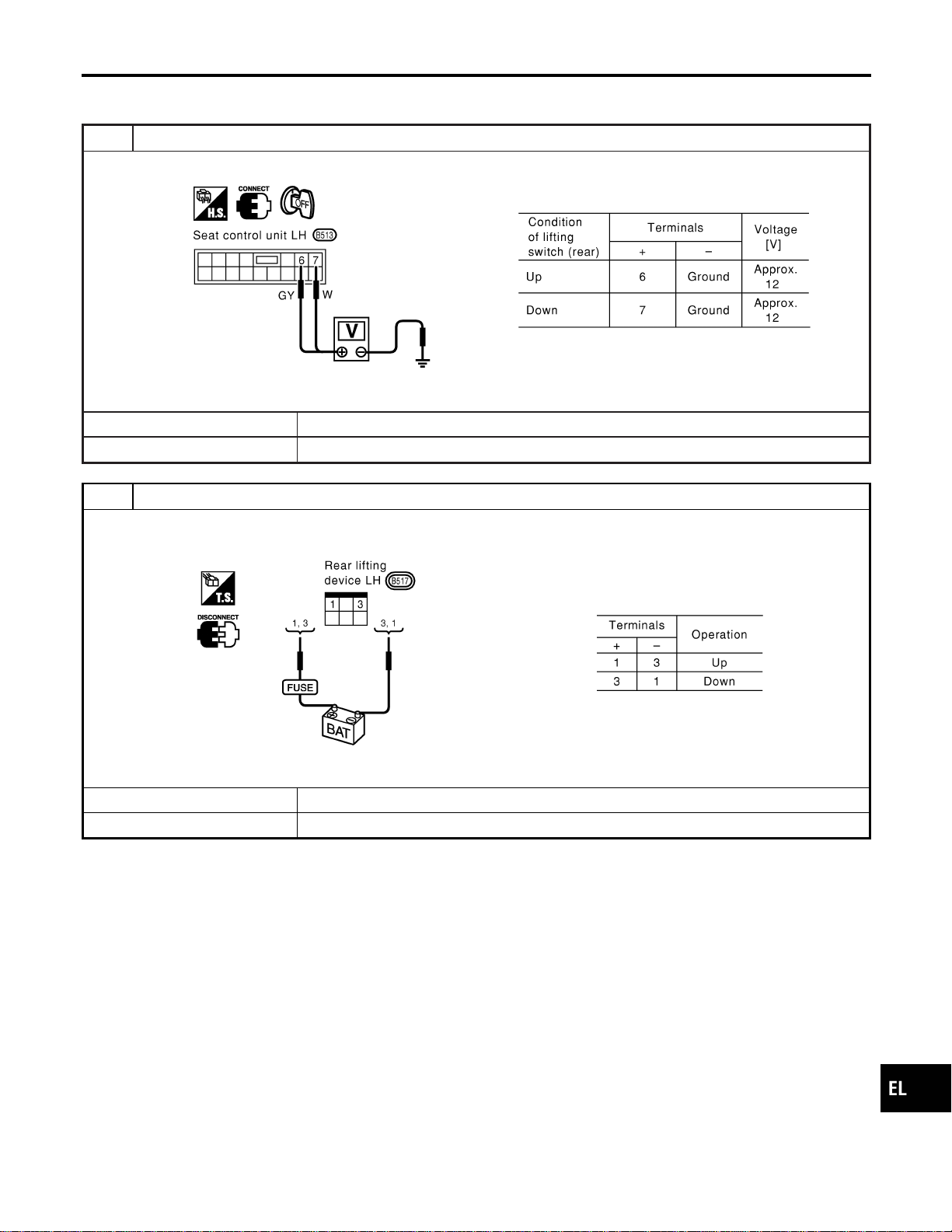
DIAGNOSTIC PROCEDURE 9
=NAEL0369S12
[Lifting motor (rear) check]
1 CHECK OUTPUT SIGNAL TO LIFTING MOTOR (REAR)
Check voltage between seat control unit LH terminals 6 or 7 and ground.
SEL625W
OK or NG
OK © GO TO 2.
NG © Replace seat control unit LH.
2 CHECK LIFTING MOTOR (REAR)
1. Disconnect rear lifting device LH connector.
2. Apply 12V DC direct current to motor and check operation.
SEL626WA
OK or NG
OK © Check harness for operation between seat control unit LH and lifting motor (rear).
NG © Replace lifting motor (rear).
GI
MA
EM
LC
EC
FE
CL
MT
AT
TF
PD
AX
SU
BR
ST
RS
BT
HA
SC
IDX
AUTOMATIC DRIVE POSITIONER
Trouble Diagnoses (Cont’d)
EL-241

DIAGNOSTIC PROCEDURE 10
=NAEL0369S13
(Power seat switch check)
1 CHECK POWER SEAT SWITCH
1. Disconnect power seat switch LH connector.
2. Check continuity between power seat switch terminals.
SEL569X
OK or NG
OK © Check the following.
I Ground circuit for power seat switch
I Harness for open or short between seat control unit LH and power seat switch
NG © Replace power seat switch.
AUTOMATIC DRIVE POSITIONER
Trouble Diagnoses (Cont’d)
EL-242

DIAGNOSTIC PROCEDURE 11
=NAEL0369S14
(Cancel switch check)
1 CHECK CANCEL SWITCH
1. Disconnect cancel switch connector.
2. Check continuity between cancel switch terminals.
SEL628WA
OK or NG
OK © Check the following.
I Ground circuit for cancel switch
I Harness for open or short between seat control unit LH and cancel switch
NG © Replace cancel switch.
GI
MA
EM
LC
EC
FE
CL
MT
AT
TF
PD
AX
SU
BR
ST
RS
BT
HA
SC
IDX
AUTOMATIC DRIVE POSITIONER
Trouble Diagnoses (Cont’d)
EL-243
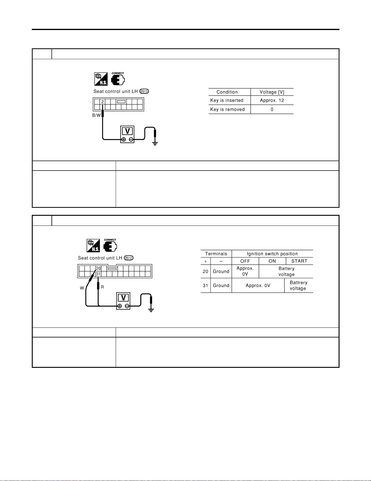
DIAGNOSTIC PROCEDURE 12
=NAEL0369S15
(Key, detention, door switch and vehicle speed signal check)
1 CHECK KEY SWITCH INPUT SIGNAL
Check voltage between seat control unit LH terminal 2 and ground.
SEL629W
OK or NG
OK © GO TO 2.
NG © Check the following.
I 7.5A fuse [No. 24, located in fuse block (J/B)]
I Key switch
I Harness for open or short between key switch and fuse
I Harness for open or short between seat control unit LH and key switch
2 CHECK IGNITION SWITCH INPUT SIGNAL (ON AND START)
Check voltage between seat control unit LH terminals and ground.
SEL630W
OK or NG
OK © GO TO 3.
NG © Check the following.
I 7.5A fuse [No. 11, located in fuse block (J/B)]
I 7.5A fuse [No. 26, located in fuse block (J/B)]
I Harness for open or short between seat control unit LH and fuse
AUTOMATIC DRIVE POSITIONER
Trouble Diagnoses (Cont’d)
EL-244
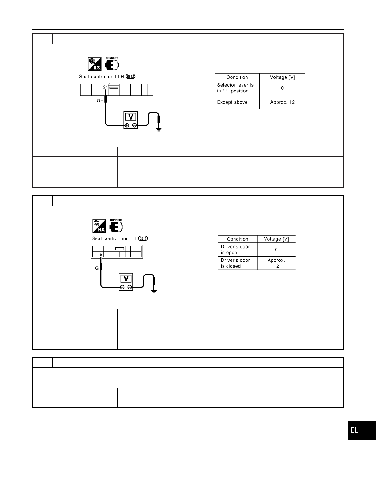
3 CHECK PARK POSITION SWITCH INPUT SIGNAL
Check voltage between seat control unit LH terminal 21 and ground.
SEL631W
OK or NG
OK © GO TO 4.
NG © Check the following.
I Park position switch
I Park position switch ground circuit
I Harness for open or short between seat control unit LH and park position switch
4 CHECK DRIVER DOOR SWITCH INPUT SIGNAL
Check voltage between seat control unit LH terminal 9 and ground.
SEL632W
OK or NG
OK © GO TO 5.
NG © Check the following.
I Driver door switch
I Driver door switch ground circuit
I Harness for open or short between seat control unit LH and driver door switch
5 CHECK VEHICLE SPEED SIGNAL
Does speedometer operate normally?
YesorNo
OK © GO TO 6.
NG © Check speedometer and ABS actuator and electric unit circuit. Refer to EL-127.
GI
MA
EM
LC
EC
FE
CL
MT
AT
TF
PD
AX
SU
BR
ST
RS
BT
HA
SC
IDX
AUTOMATIC DRIVE POSITIONER
Trouble Diagnoses (Cont’d)
EL-245
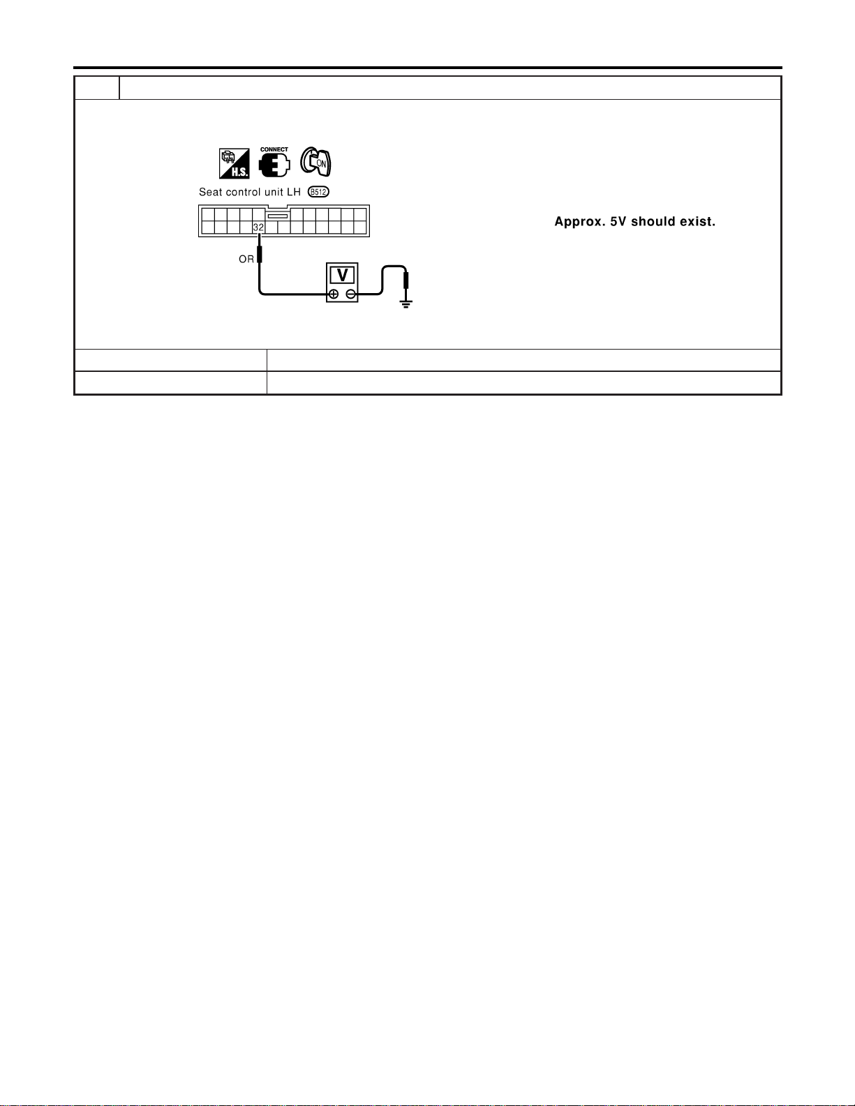
6 CHECK VEHICLE SPEED SIGNAL PULL UP VOLTAGE
1. Turn ignition switch “ON”.
2. Check voltage between seat control unit LH terminal 32 and ground.
SEL633W
OK or NG
OK © Harness for open or short between seat control unit LH and combination meter.
NG © Repair harness.
AUTOMATIC DRIVE POSITIONER
Trouble Diagnoses (Cont’d)
EL-246
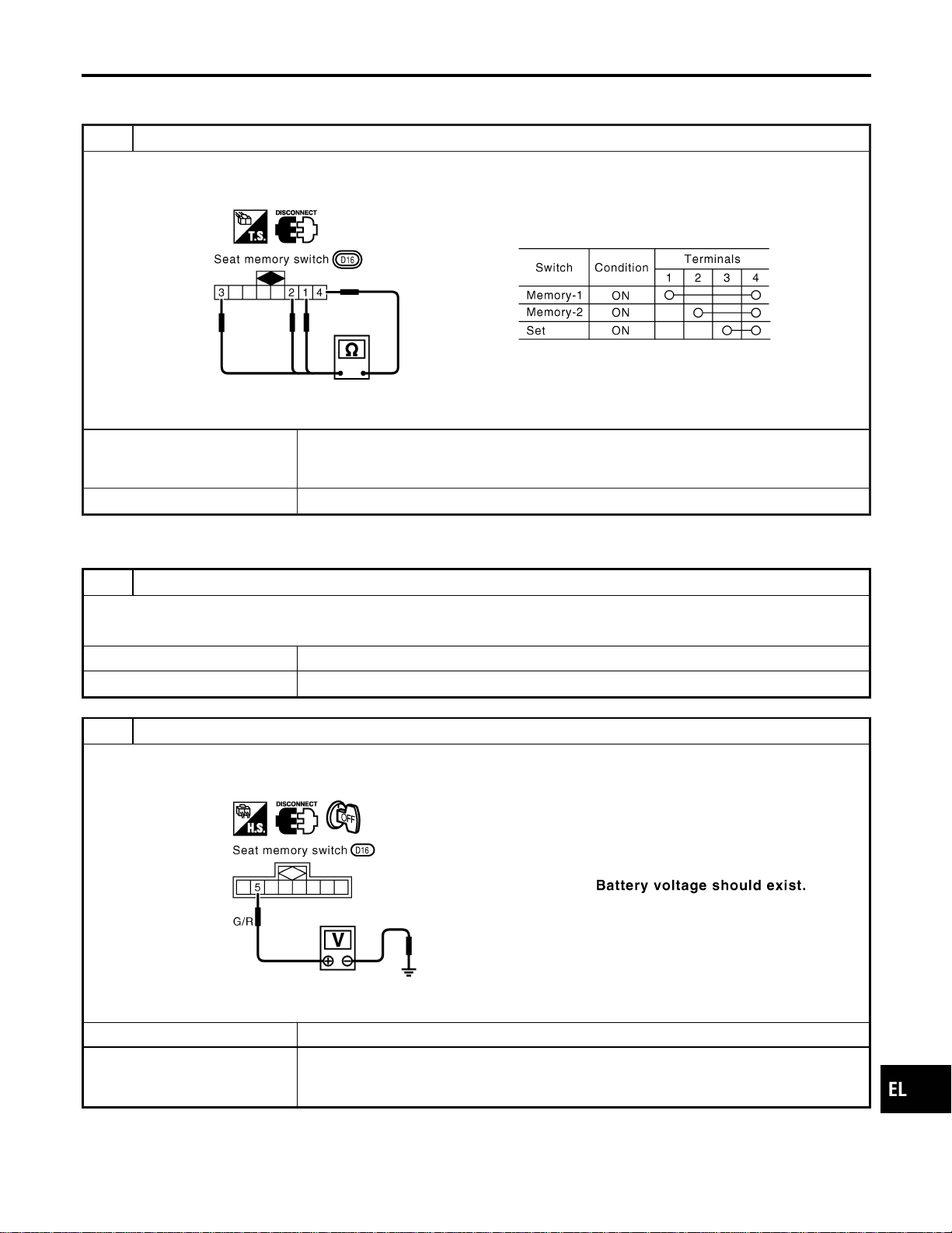
DIAGNOSTIC PROCEDURE 13
=NAEL0369S16
(Seat memory switch check)
1 CHECK SEAT MEMORY SWITCH
1. Disconnect seat memory switch connector.
2. Check continuity between seat memory switch terminals.
SEL634WA
OK or NG
OK © Check the following.
I Ground circuit for seat memory switch
I Harness for open or short between seat control unit LH and seat memory switch
NG © Replace seat memory switch.
DIAGNOSTIC PROCEDURE 14
NAEL0369S17
(Memory indicator check)
1 CHECK INDICATOR LAMP
Check indicator lamp illumination.
OK or NG
OK © GO TO 2.
NG © Replace seat memory switch (indicator lamp).
2 CHECK POWER SUPPLY CIRCUIT FOR INDICATOR LAMP
1. Disconnect seat memory switch connector.
2. Check voltage between seat memory switch terminal and ground.
SEL635WA
OK or NG
OK © Check harness for open or short between seat control unit LH and seat memory switch
NG © Check the following.
I 7.5A fuse [No. 24 located in the fuse block (J/B)]
I Harness for open or short between fuse and indicator lamp
GI
MA
EM
LC
EC
FE
CL
MT
AT
TF
PD
AX
SU
BR
ST
RS
BT
HA
SC
IDX
AUTOMATIC DRIVE POSITIONER
Trouble Diagnoses (Cont’d)
EL-247
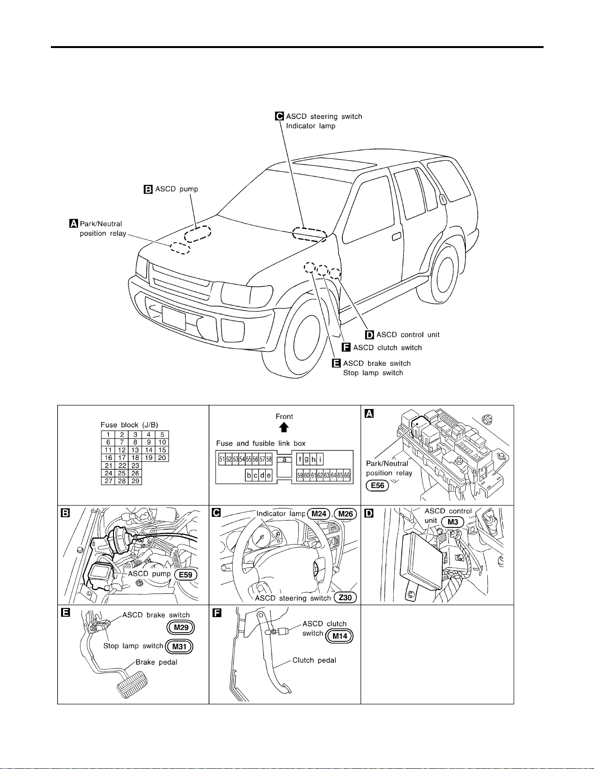
Component Parts and Harness Connector
Location
NAEL0370
SEL256Y
AUTOMATIC SPEED CONTROL DEVICE (ASCD)
Component Parts and Harness Connector Location
EL-248

System Description
NAEL0371
Refer to Owner’s Manual for ASCD operating instructions.
POWER SUPPLY AND GROUND
NAEL0371S01
Power is supplied at all times:
I through 10A fuse [No. 14, located in the fuse block (J/B)]
I to the stop lamp switch terminal 1, and
I through 7.5A fuse (No. 52, located in fuse and fusible link box)
I to the horn relay terminals 1 and 3.
When ignition switch is in the ON or START position, power is supplied:
I through 7.5A fuse [No. 11, located in the fuse block (J/B)]
I to ASCD brake switch terminal 1 and
I to ASCD control unit terminal 5,
I through 10A fuse [No. 18, located in the fuse block (J/B)]
I to park/neutral position relay terminal 1,
I through 10A fuse [No. 8, located in the fuse block (J/B)]
I to combination meter terminal 66, and
When park/neutral position switch is in the P or N position (A/T models), ground is supplied:
I to park/neutral position relay terminal 2
I through park/neutral position switch and body grounds B55 and B75.
When ASCD main switch is depressed (ON), ground is supplied:
I to ASCD control unit terminal 9
I from ASCD steering switch terminal 4
I to ASCD steering switch terminal 5
I through body grounds M4, M66 and M147
then ASCD control unit holds CRUISE condition and illuminates CRUISE indicator.
Ground is supplied:
I from ASCD control unit terminal 15
I to combination meter terminal 46.
OPERATION
NAEL0371S02
Set Operation
NAEL0371S0201
To activate the ASCD, all following conditions must exist.
I Ground is supplied to ASCD control unit terminal 9 (Main switch is in ON position.)
I Power is supplied to ASCD control unit terminal 8 [Brake pedal and clutch pedal are released (M/T mod-
els) and brake pedal is released and A/T selector lever is in other than P and N position (A/T models)].
I Vehicle speed is between 40 km/h (25 MPH) and 144 km/h (89 MPH). (Signal from combination meter)
When the SET/COAST switch is depressed, power is supplied:
I from ASCD steering switch terminal 2
I to ASCD control unit terminal 11.
And then ASCD pump is activated to control throttle wire and ASCD control unit supply ground
I to combination meter terminals 51 to illuminate SET indicator.
A/T Overdrive Control during Cruise Control Driving (A/T models)
NAEL0371S0202
When the vehicle speed is approximately 3 km/h (2 MPH) below set speed, a signal is sent
I from ASCD control unit terminal 10
I to TCM (transmission control module) terminal 24.
When this occurs, the TCM (transmission control module) cancels overdrive.
After vehicle speed is approximately 1 km/h (1 MPH) below set speed, overdrive is reactivated.
ASCD Shifting Control (A/T models)
NAEL0371S0203
During ASCD cruise, ASCD control unit controls A/T shifting to avoid uncomfortable shifting.
This is used to control the signals below.
I Throttle position sensor from ECM
GI
MA
EM
LC
EC
FE
CL
MT
AT
TF
PD
AX
SU
BR
ST
RS
BT
HA
SC
IDX
AUTOMATIC SPEED CONTROL DEVICE (ASCD)
System Description
EL-249

I A/T shift solenoid valve A
Coast Operation
NAEL0371S0204
When the SET/COAST switch is depressed during cruise control driving, ASCD actuator returns the throttle
cable to decrease vehicle set speed until the switch is released. And then ASCD will keep the new set speed.
Accel Operation
NAEL0371S0205
When the RESUME/ACCEL switch is depressed, power is supplied
I from ASCD steering switch terminal 3
I to ASCD control unit terminal 24.
If the RESUME/ACCELswitch is depressed during cruise control driving,ASCD actuator pulls the throttle cable
to increase the vehicle speed until the switch is released or vehicle speed is reached to maximum controlled
speed by the system. And then ASCD will keep the new set speed.
Cancel Operation
NAEL0371S0206
When any of following condition exists, cruise operation will be canceled.
I CANCEL switch is depressed. (Power supply to ASCD control unit terminals 11 and 24)
I Brake pedal is depressed. (Power supply to ASCD control unit terminal 23 from stop lamp switch)
I Brake pedal or clutch pedal is depressed (M/T models)/brake pedal is depressed or A/T selector lever is
shifted to P or N position (A/T models). (Power supply to ASCD control unit terminal 8 is interrupted.)
If MAIN switch is turned to OFF during ASCD is activated, all of ASCD operation will be canceled and vehicle
speed memory will be erased.
Resume Operation
NAEL0371S0207
When the RESUME/ACCEL switch is depressed after cancel operation other than depressing MAIN switch is
performed, vehicle speed will return to last set speed. To resume vehicle set speed, vehicle condition must
meet following conditions.
I Brake pedal is released.
I Clutch pedal is released (M/T models).
I A/T selector lever is in other than P and N position (A/T models).
I Vehicle speed is between 40 km/h (25 MPH) and 144 km/h (89 MPH).
ASCD PUMP OPERATION
NAEL0371S03
The ASCD pump consists of a vacuum motor, an air valve and a release valve. When the ASCD activates,
power is supplied
I from terminal 12 of ASCD control unit
I to ASCD pump terminal 1.
Ground is supplied to vacuum motor, air valve and release valve from ASCD control unit depending on the
operated condition as shown in the below table.
The pump is connected to ASCD actuator by vacuum hose. When the ASCD pump is activated, the ASCD
pump vacuum the diaphragm of ASCD actuator to control throttle cable.
Air valve (*1) Release valve (*1) Vacuum motor
Actuator inner pres-
sure
ASCD not operating Open Open Stopped Atmosphere
ASCD operating
Releasing throttle
cable
Open Closed Stopped Vacuum
Holding throttle
position
Closed Closed Stopped Vacuum (*2)
Pulling throttle cable Closed Closed Operated Vacuum
*1: When power and ground is supplied, valve is closed.
*2: Set position held.
AUTOMATIC SPEED CONTROL DEVICE (ASCD)
System Description (Cont’d)
EL-250
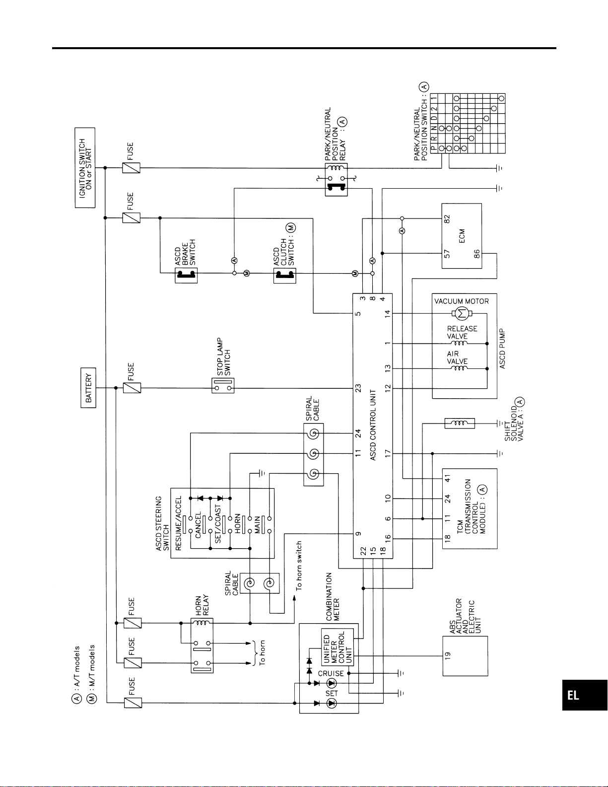
Schematic
NAEL0372
MEL424P
GI
MA
EM
LC
EC
FE
CL
MT
AT
TF
PD
AX
SU
BR
ST
RS
BT
HA
SC
IDX
AUTOMATIC SPEED CONTROL DEVICE (ASCD)
Schematic
EL-251
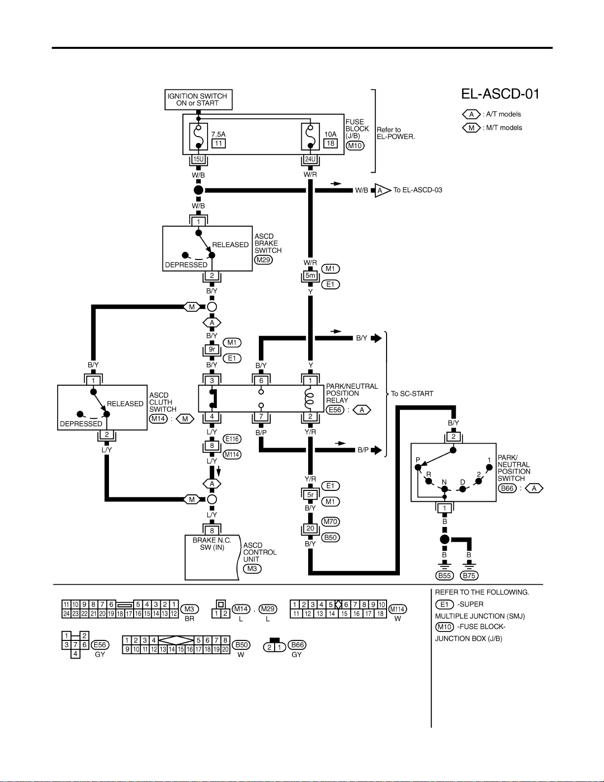
Wiring Diagram — ASCD —
NAEL0373
FIG. 1
NAEL0373S01
MEL048M
AUTOMATIC SPEED CONTROL DEVICE (ASCD)
Wiring Diagram — ASCD —
EL-252
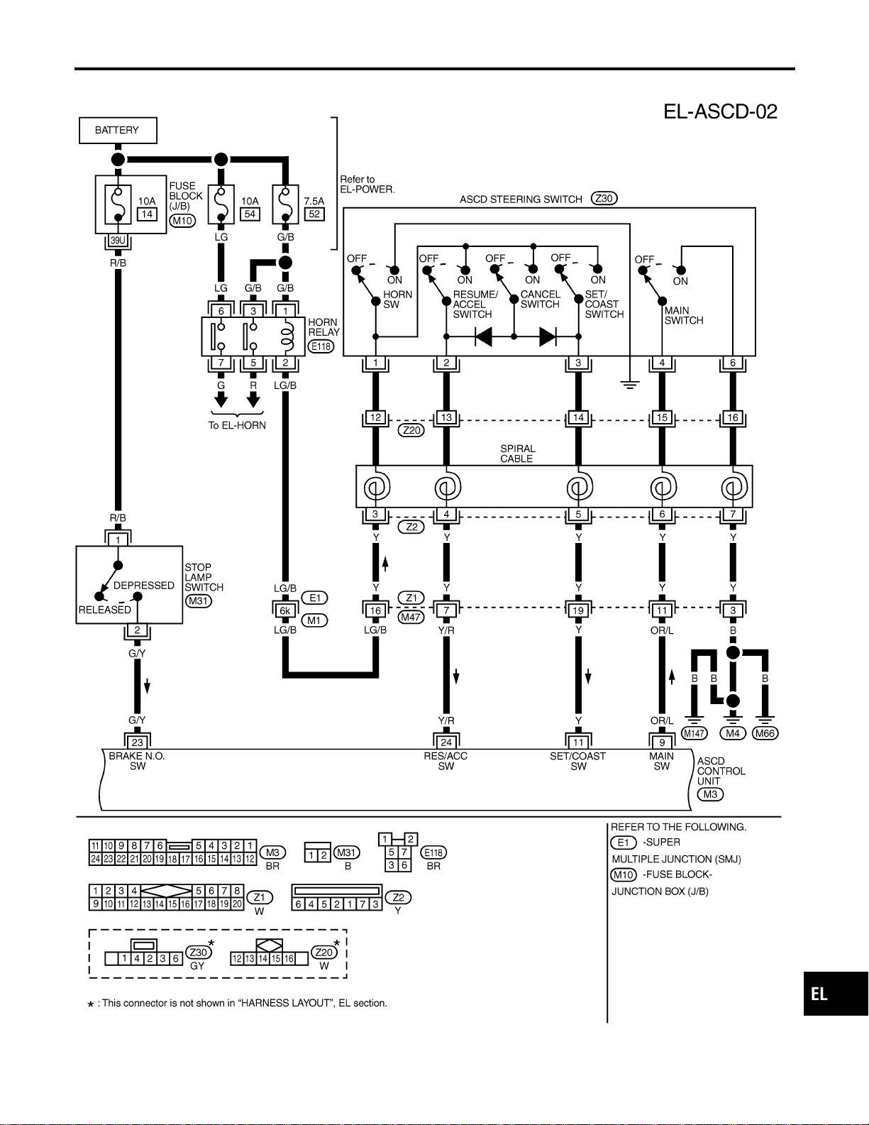
FIG. 2
NAEL0373S02
MEL916O
GI
MA
EM
LC
EC
FE
CL
MT
AT
TF
PD
AX
SU
BR
ST
RS
BT
HA
SC
IDX
AUTOMATIC SPEED CONTROL DEVICE (ASCD)
Wiring Diagram — ASCD — (Cont’d)
EL-253
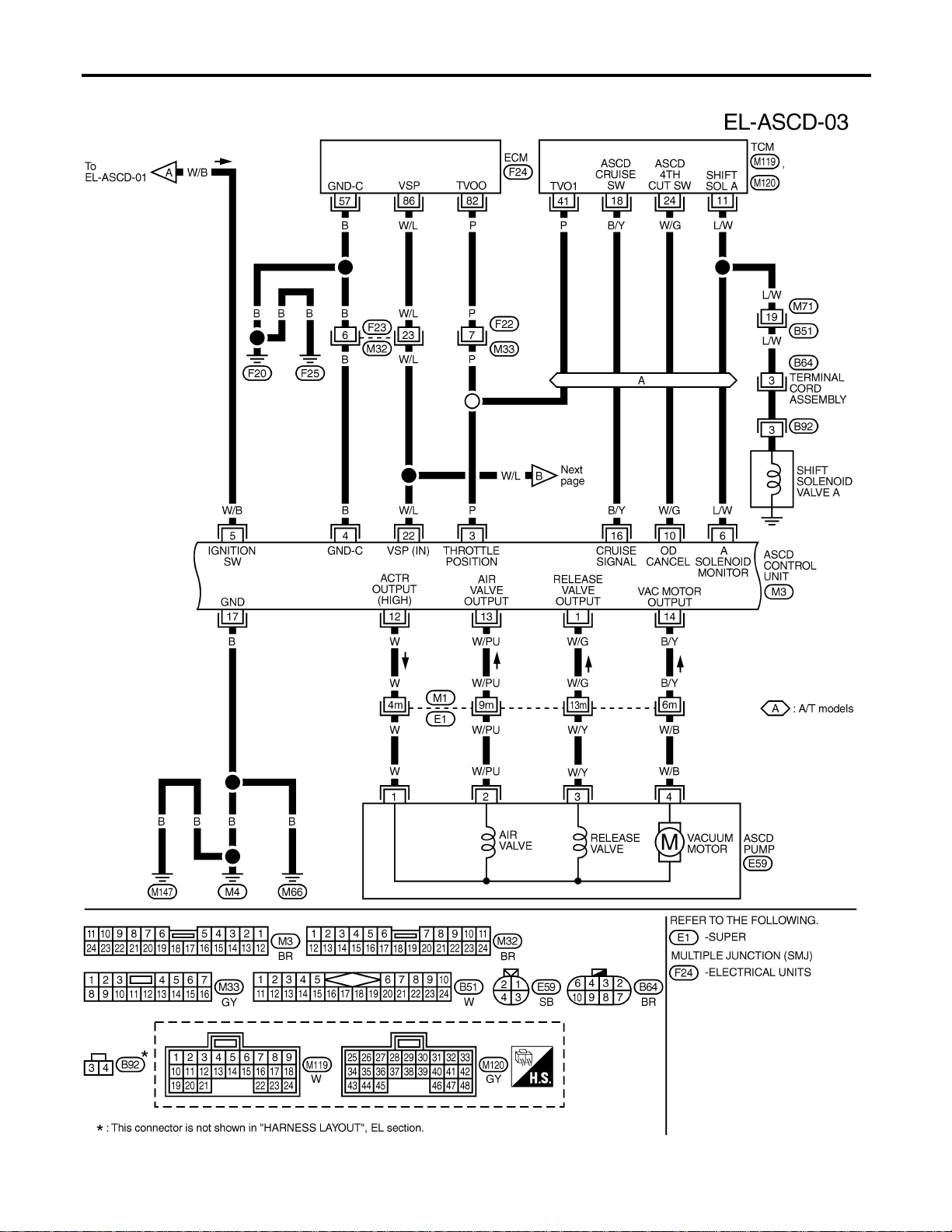
FIG. 3
NAEL0373S03
MEL425P
AUTOMATIC SPEED CONTROL DEVICE (ASCD)
Wiring Diagram — ASCD — (Cont’d)
EL-254
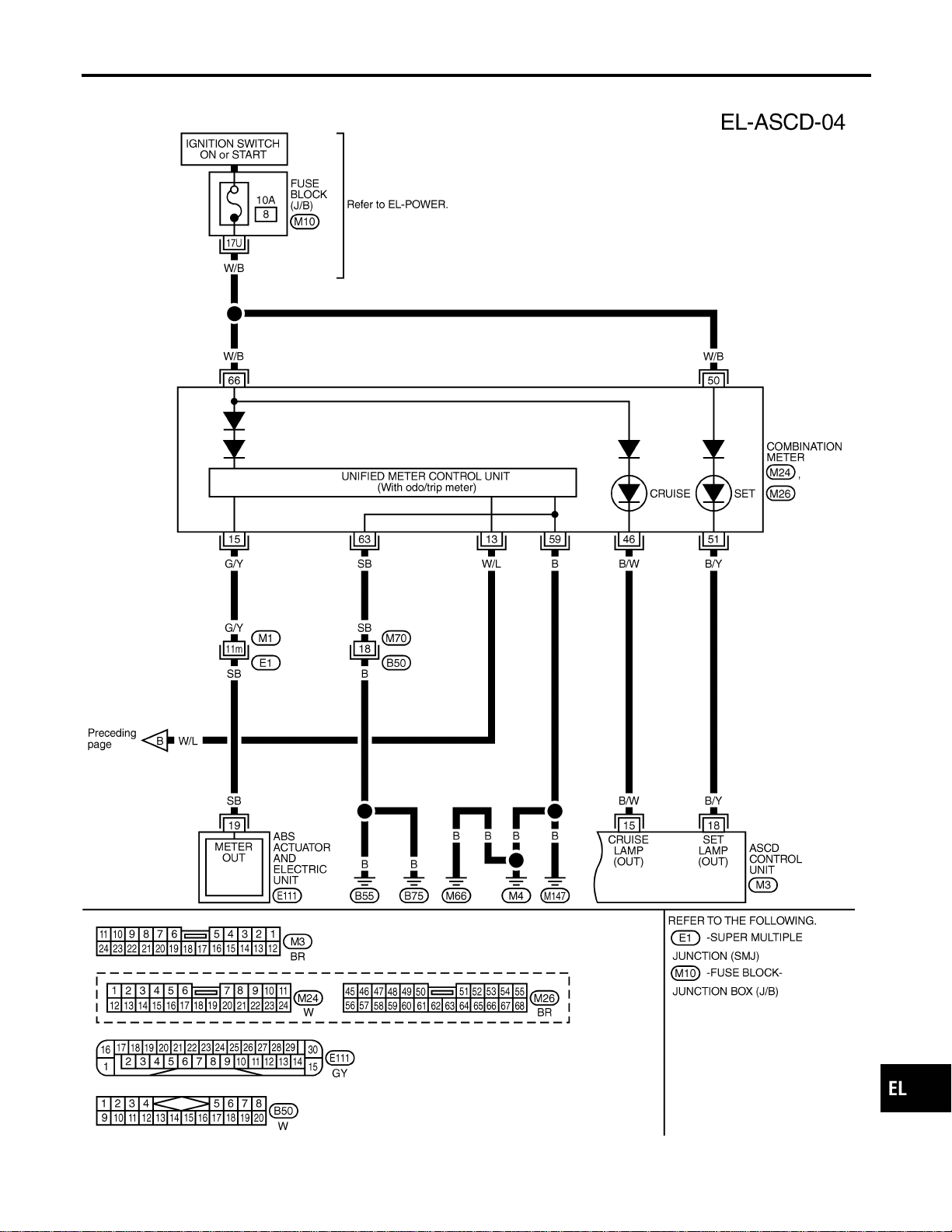
FIG. 4
NAEL0373S04
MEL426P
GI
MA
EM
LC
EC
FE
CL
MT
AT
TF
PD
AX
SU
BR
ST
RS
BT
HA
SC
IDX
AUTOMATIC SPEED CONTROL DEVICE (ASCD)
Wiring Diagram — ASCD — (Cont’d)
EL-255
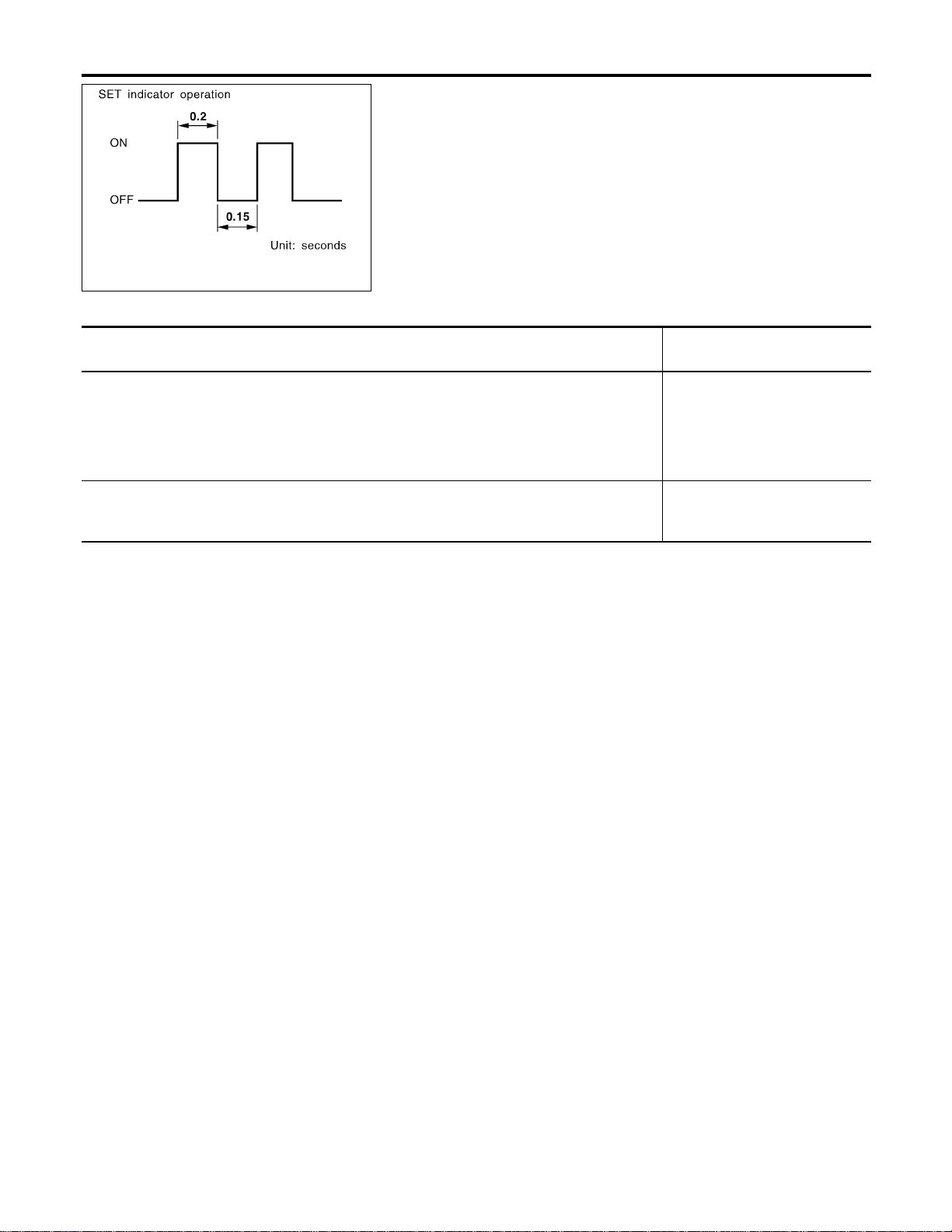
SEL255W
Fail-safe System
NAEL0374
DESCRIPTION
NAEL0374S01
When the fail-safe system senses a malfunction, it deactivates
ASCD operation. The SET indicator in the combination meter will
then flash.
MALFUNCTION DETECTION CONDITIONS
NAEL0374S02
Detection conditions
ASCD operation during malfunc-
tion detection
I ASCD steering (RESUME/ACCEL, CANCEL, SET/COAST) switch is stuck.
I Vacuum motor ground circuit or power circuit is open or shorted.
I Air valve ground circuit or power circuit is open or shorted.
I Release valve ground circuit or power circuit is open or shorted.
I Vehicle speed sensor is faulty.
I ASCD control unit internal circuit is malfunctioning.
I ASCD is deactivated.
I Vehicle speed memory is can-
celed.
I ASCD brake switch or stop lamp switch is faulty. I ASCD is deactivated.
I Vehicle speed memory is not
canceled.
AUTOMATIC SPEED CONTROL DEVICE (ASCD)
Fail-safe System
EL-256

Trouble Diagnoses
NAEL0375
SYMPTOM CHART
NAEL0375S01
PROCEDURE Diagnostic procedure
REFERENCE PAGE (EL- ) 258 259 260 261 262 262 264
SYMPTOM
FAIL-SAFE SYSTEM CHECK
POWER SUPPLY AND GROUND CIRCUIT CHECK
ASCD BRAKE/STOP LAMP SWITCH CHECK
ASCD STEERING SWITCH CHECK
VEHICLE SPEED SENSOR CHECK
ASCD PUMP CIRCUIT CHECK
ASCD ACTUATOR/PUMP CHECK
ASCD cannot be set. (“CRUISE” indica-
tor lamp does not ON.)
XX★3
ASCD cannot be set. (“SET” indicator
lamp does not blink.)
XXX
ASCD cannot be set. (“SET” indicator
lamp blinks.★1)
X XXXX
Vehicle speed does not decrease after
SET/COAST switch has been pressed.
XX
Vehicle speed does not return to the set
speed after RESUME/ACCEL switch has
been pressed.★2
XX
Vehicle speed does not increase after
RESUME/ACCEL switch has been
pressed.
XX
System is not released after CANCEL
switch (steering) has been pressed.
XX
Large difference between set speed and
actual vehicle speed.
XXX
Deceleration is greatest immediately
after ASCD has been set.
XXX
★1: It indicates that system is in fail-safe. After completing diagnostic procedures, perform “FAIL-SAFE SYSTEM CHECK” (EL-258) to
verify repairs.
★2: If vehicle speed is greater than 40 km/h (25 MPH) after system has been released, pressing RESUME/ACCELswitch returns vehicle
speed to the set speed previously achieved. However, doing so when the ASCD main switch is turned to “OFF”, vehicle speed will not
return to the set speed since the memory is canceled.
★3: Check only main switch built-in steering switch.
GI
MA
EM
LC
EC
FE
CL
MT
AT
TF
PD
AX
SU
BR
ST
RS
BT
HA
SC
IDX
AUTOMATIC SPEED CONTROL DEVICE (ASCD)
Trouble Diagnoses
EL-257
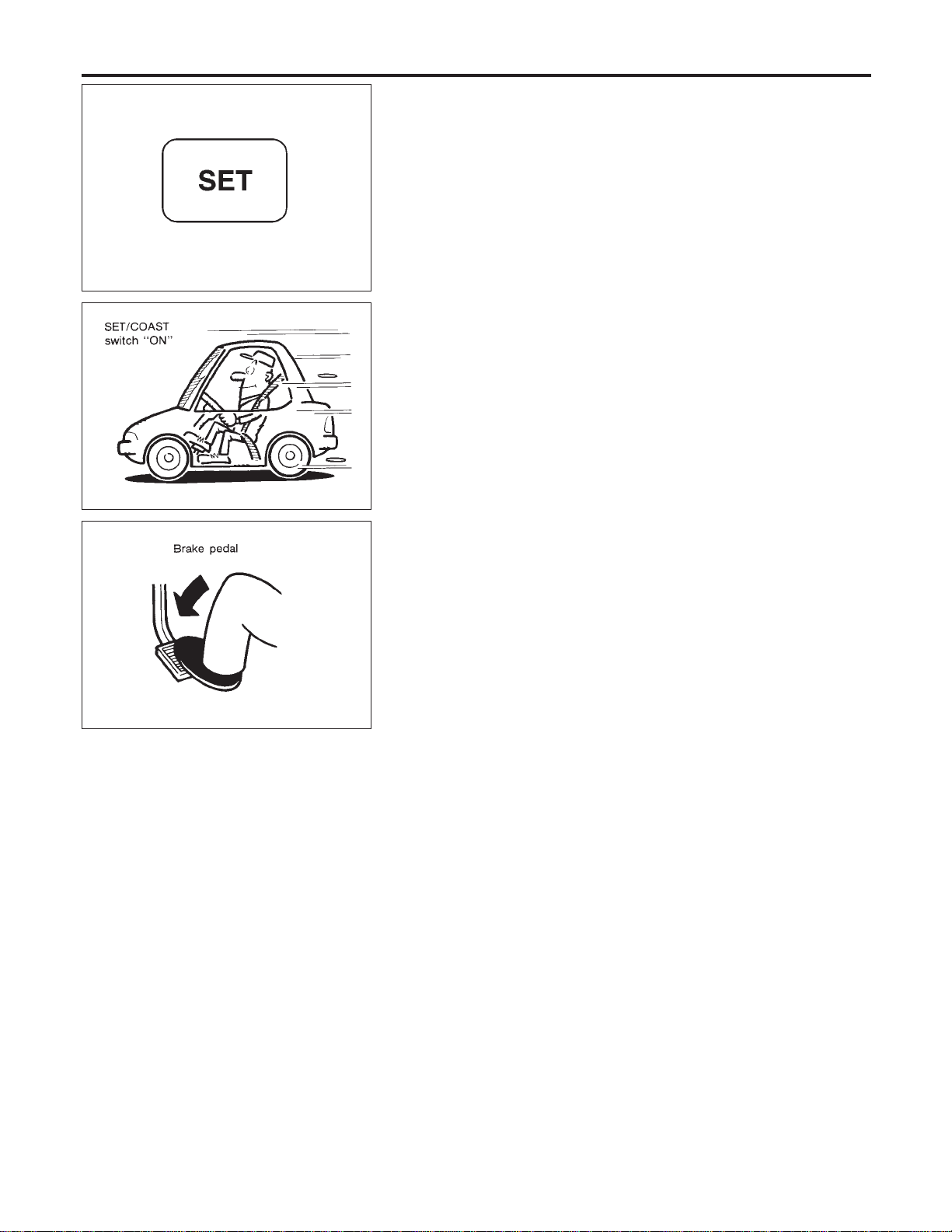
SEL417V
FAIL-SAFE SYSTEM CHECK
=NAEL0375S02
1. Turn ignition switch to ON position.
2. Turn ASCD main switch to ON and check if the SET indicator
blinks.
If the indicator lamp blinks, check the following.
I ASCD steering switch. Refer to EL-261.
SEL767P
3. Drive the vehicle at more than 40 km/h (25 MPH) and push
SET/COAST switch.
If the indicator lamp blinks, check the following.
I Vehicle speed signal. Refer to EL-262.
I ASCD pump circuit. Refer to EL-262.
I Replace control unit.
SAT797A
4. Depress brake pedal slowly (brake pedal should be depressed
more than 5 seconds).
If the indicator lamp blinks, check the following.
I ASCD brake/stop lamp switch. Refer to EL-260.
5. END. (System is OK.)
AUTOMATIC SPEED CONTROL DEVICE (ASCD)
Trouble Diagnoses (Cont’d)
EL-258
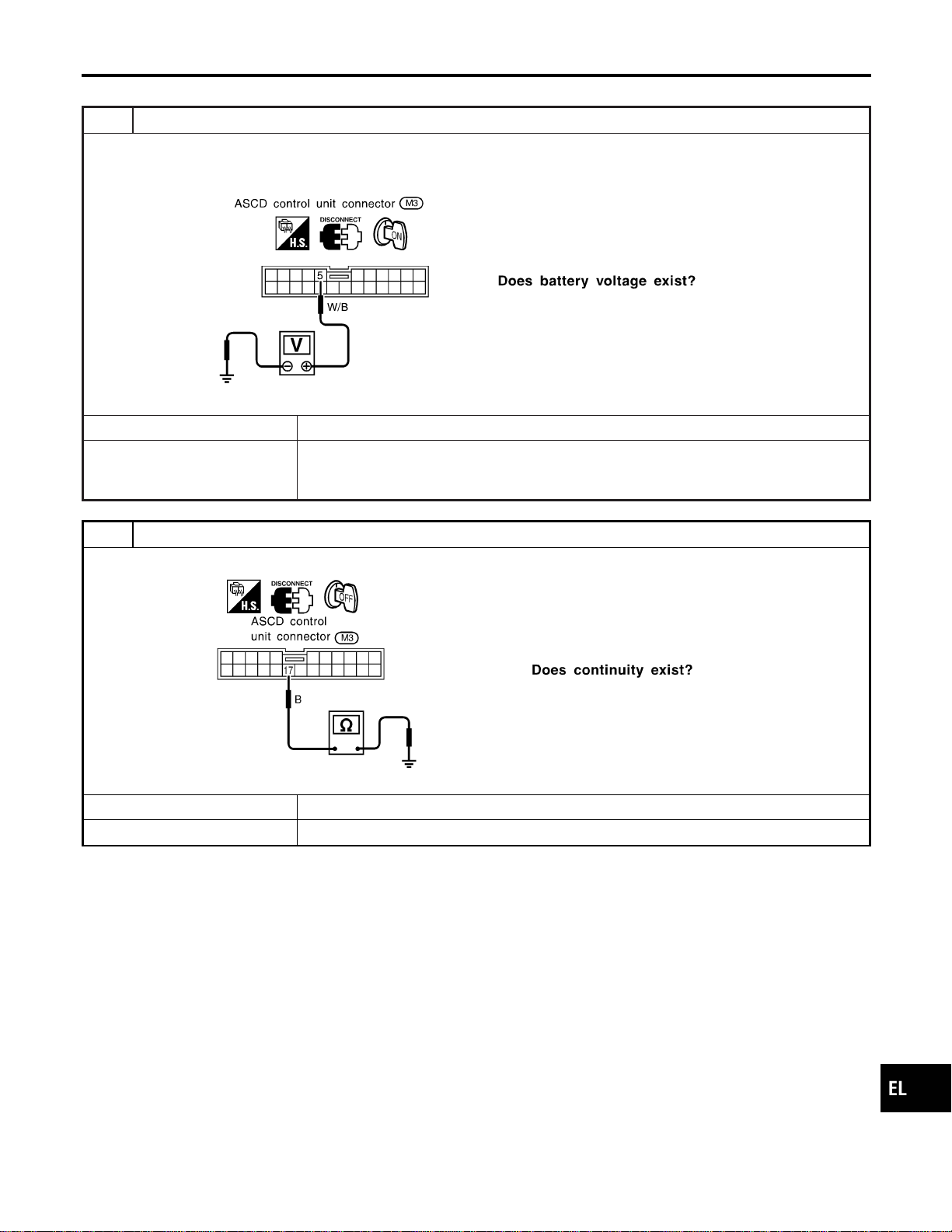
POWER SUPPLY AND GROUND CIRCUIT CHECK
=NAEL0375S03
1 CHECK POWER SUPPLY CIRCUIT FOR ASCD CONTROL UNIT
1. Disconnect ASCD control unit harness connector.
2. Turn ignition switch ON.
3. Check voltage between ASCD control unit harness connector terminal 5 and ground.
SEL256WB
Refer to wiring diagram in EL-254.
Yes © GO TO 2.
No © Check the following.
I 7.5A fuse [No. 11, located in the fuse block (J/B)]
I Harness for open or short between ASCD control unit and fuse
2 CHECK GROUND CIRCUIT FOR ASCD CONTROL UNIT
Check continuity between ASCD control unit harness connector terminal 17 and body ground.
SEL257WB
Refer to wiring diagram in EL-254.
Yes © Power supply and ground circuit is OK.
No © Repair harness.
GI
MA
EM
LC
EC
FE
CL
MT
AT
TF
PD
AX
SU
BR
ST
RS
BT
HA
SC
IDX
AUTOMATIC SPEED CONTROL DEVICE (ASCD)
Trouble Diagnoses (Cont’d)
EL-259
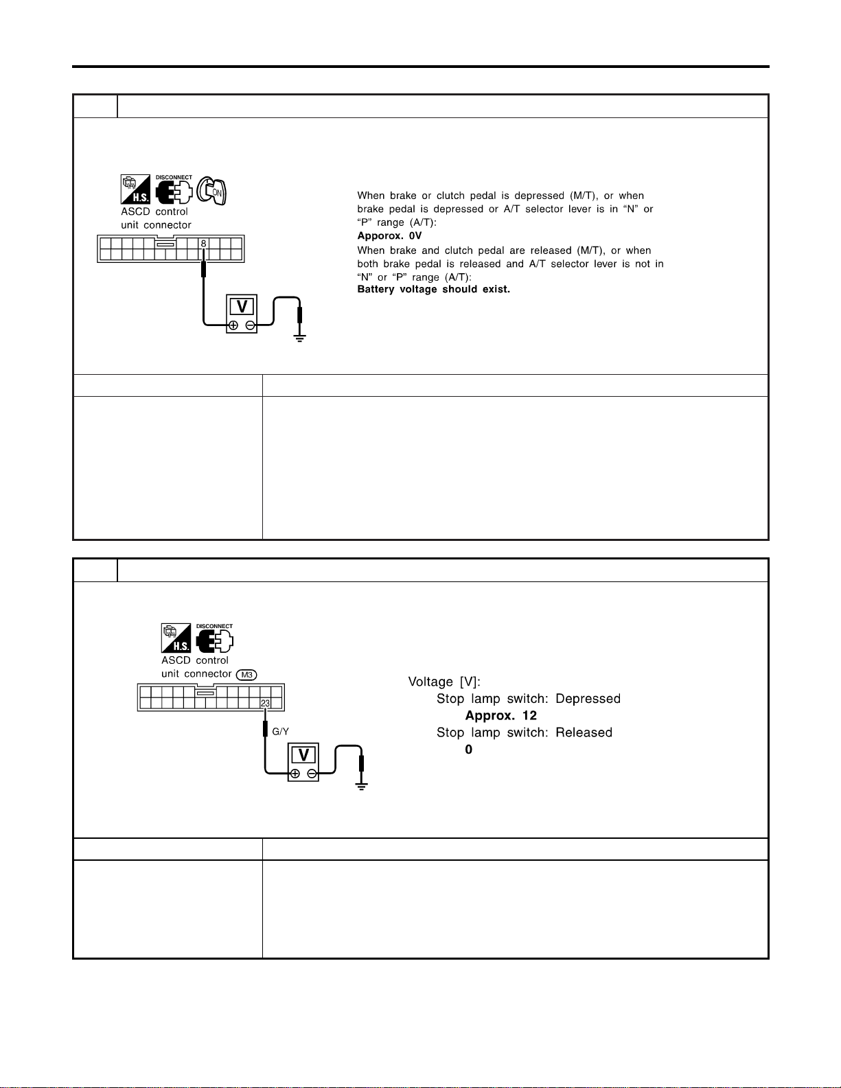
ASCD BRAKE/STOP LAMP SWITCH CHECK
=NAEL0375S04
1 CHECK ASCD BRAKE SWITCH CIRCUIT
1. Disconnect ASCD control unit harness connector.
2. Turn ignition switch ON.
3. Check voltage between ASCD control unit harness connector M3 terminal 8 and ground.
SEL258WF
OK or NG
OK © GO TO 2.
NG © Check the following.
I ASCD brake switch
Refer to “Electrical Component Inspection” (EL-266).
I ASCD clutch switch (M/T models)
Refer to “Electrical Component Inspection” (EL-266).
I Park/neutral position switch (A/T models)
Refer to “Electrical Component Inspection” (EL-266).
I Park/neutral position relay (A/T models)
I Harness for open or short
2 CHECK STOP LAMP SWITCH CIRCUIT
1. Disconnect ASCD control unit harness connector.
2. Check voltage between ASCD control unit harness connector terminal 23 and ground.
SEL259WB
Refer to wiring diagram in EL-253.
OK or NG
OK © ASCD brake/stop lamp switch is OK.
NG © Check the following.
I 10A fuse [No. 14, located in the fuse block (J/B)]
I Harness for open or short between ASCD control unit and stop lamp switch
I Harness for open or short between fuse and stop lamp switch
I Stop lamp switch
Refer to “Electrical Component Inspection” (EL-266).
AUTOMATIC SPEED CONTROL DEVICE (ASCD)
Trouble Diagnoses (Cont’d)
EL-260
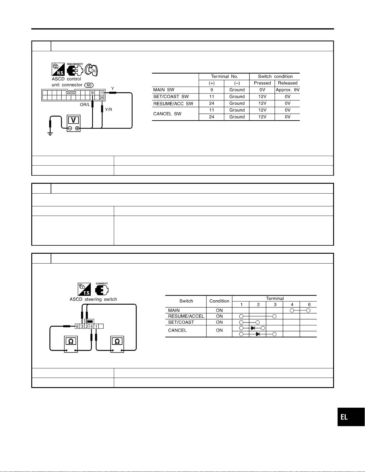
ASCD STEERING SWITCH CHECK
=NAEL0375S05
1 CHECK ASCD STEERING SWITCH CIRCUIT FOR ASCD CONTROL UNIT
Check voltage between ASCD control unit harness connector terminals and ground.
SEL260WC
Refer to wiring diagram in EL-253.
OK or NG
OK © ASCD steering switch is OK.
NG © GO TO 2.
2 CHECK POWER SUPPLY FOR ASCD STEERING SWITCH
Does horn work?
Yes © GO TO 3.
No © Check the following.
I 7.5A fuse (No. 52, located in the relay box)
I Horn relay
I Horn circuit
3 CHECK ASCD STEERING SWITCH
1. Disconnect ASCD steering switch.
2. Check continuity between ASCD steering switch harness connector Z30 terminals by pushing each switch.
SEL495Y
OK or NG
OK © Check harness for open or short between ASCD steering switch and ASCD control unit.
NG © Replace ASCD steering switch.
GI
MA
EM
LC
EC
FE
CL
MT
AT
TF
PD
AX
SU
BR
ST
RS
BT
HA
SC
IDX
AUTOMATIC SPEED CONTROL DEVICE (ASCD)
Trouble Diagnoses (Cont’d)
EL-261
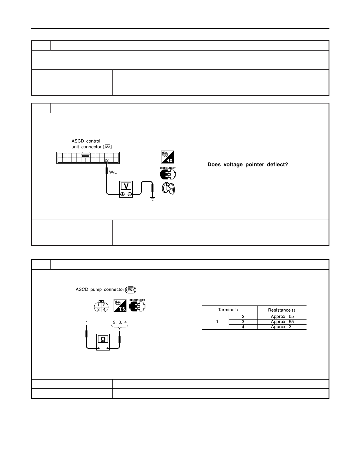
VEHICLE SPEED SIGNAL CHECK
=NAEL0375S06
1 CHECK SPEEDOMETER OPERATION
Does speedometer operate normally?
Yes © GO TO 2.
No © Check speedometer and ABS actuator and electric unit circuit. Refer to wiring diagram in
EL-255.
2 CHECK VEHICLE SPEED INPUT
1. Apply wheel chocks and jack up drive wheel.
2. Disconnect ASCD control unit harness connector.
3. Check voltage between control unit terminal 22 and ground with turning drive wheel slowly by hand.
SEL263WB
Refer to wiring diagram in EL-254.
Yes © Vehicle speed signal is OK.
No © Check harness for open or short between ASCD control unit terminal 22 and combination
meter terminal 13.
ASCD PUMP CIRCUIT CHECK
NAEL0375S07
1 CHECK ASCD PUMP
1. Disconnect ASCD pump connector.
2. Measure resistance between ASCD pump terminals 1 and 2, 3, 4.
SEL262WB
Refer to wiring diagram in EL-254.
OK or NG
OK © GO TO 2.
NG © Replace ASCD pump.
AUTOMATIC SPEED CONTROL DEVICE (ASCD)
Trouble Diagnoses (Cont’d)
EL-262
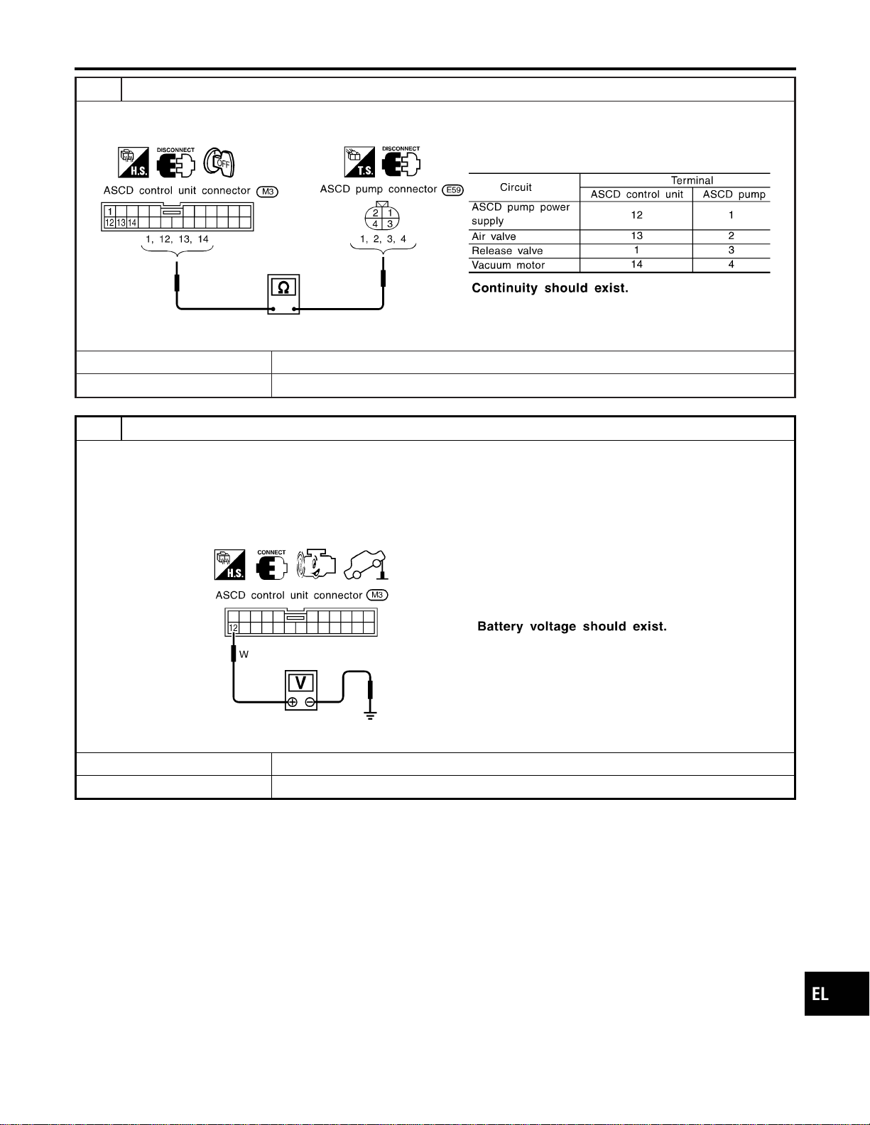
2 CHECK ASCD PUMP CIRCUIT
1. Disconnect ASCD control unit harness connector.
2. Check harness for open or short between ASCD control unit and ASCD pump.
SEL269WB
OK or NG
OK © GO TO 3.
NG © Repair harness.
3 CHECK ASCD PUMP POWER SUPPLY
1. Jack-up the drive wheels.
2. Maintain the conditions below.
I Vehicle speed is more than 40 km/h (25 MPH).
I Main switch (CRUISE lamp) is ON.
I Set/coast switch (SET lamp) is ON.
Check voltage between ASCD control unit harness connector terminal 12 and ground.
SEL381WB
OK or NG
OK © ASCD pump power supply is OK.
NG © Replace ASCD control unit.
GI
MA
EM
LC
EC
FE
CL
MT
AT
TF
PD
AX
SU
BR
ST
RS
BT
HA
SC
IDX
AUTOMATIC SPEED CONTROL DEVICE (ASCD)
Trouble Diagnoses (Cont’d)
EL-263
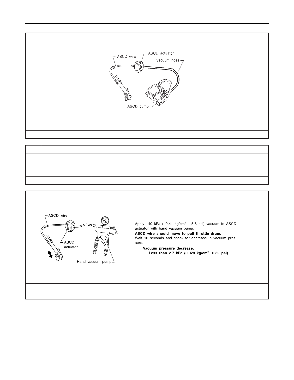
ASCD ACTUATOR/PUMP CHECK
=NAEL0375S08
1 CHECK VACUUM HOSE
Check vacuum hose (between ASCD actuator and ASCD pump) for breakage, cracks or fracture.
MEL402G
OK or NG
OK © GO TO 2.
NG © Repair or replace hose.
2 CHECK ASCD WIRE
Check wire for improper installation, rust formation or breaks.
OK or NG
OK © GO TO 3.
NG © Repair or replace wire. Refer to “ASCD Wire Adjustment” (EL-267).
3 CHECK ASCD ACTUATOR
1. Disconnect vacuum hose from ASCD actuator.
2. Connect the hose of hand vacuum pump to ASCD actuator.
SEL264W
OK or NG
OK © GO TO 4.
NG © Replace ASCD actuator.
AUTOMATIC SPEED CONTROL DEVICE (ASCD)
Trouble Diagnoses (Cont’d)
EL-264
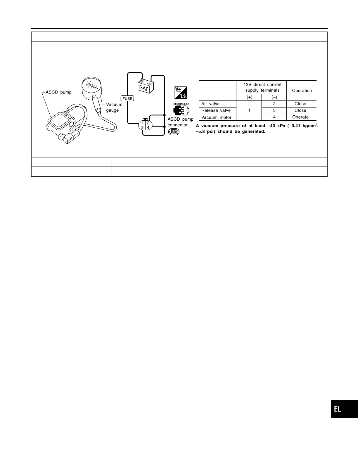
4 CHECK ASCD PUMP
1. Disconnect vacuum hose from ASCD pump and ASCD pump connector.
2. If necessary remove ASCD pump.
3. Connect vacuum gauge to ASCD pump.
4. Apply 12V direct current to ASCD pump and check operation.
SEL265WB
OK or NG
OK © INSPECTION END
NG © Replace ASCD pump.
GI
MA
EM
LC
EC
FE
CL
MT
AT
TF
PD
AX
SU
BR
ST
RS
BT
HA
SC
IDX
AUTOMATIC SPEED CONTROL DEVICE (ASCD)
Trouble Diagnoses (Cont’d)
EL-265
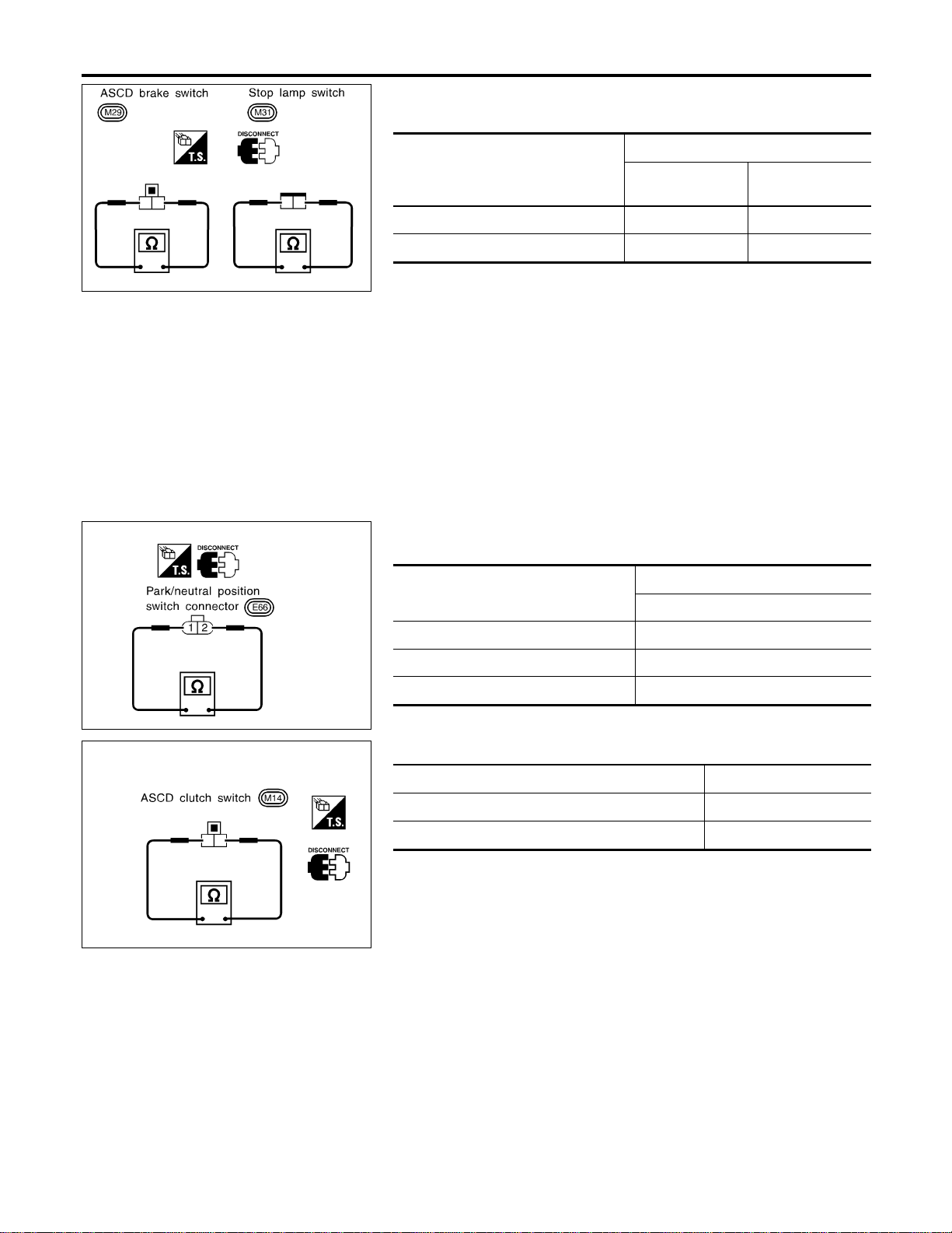
SEL302X
Electrical Component Inspection
=NAEL0376
ASCD BRAKE SWITCH AND STOP LAMP SWITCH
NAEL0376S01
Condition
Continuity
ASCD brake
switch
Stop lamp switch
When brake pedal is depressed No Yes
When brake pedal is released Yes No
Checkeach switchafter adjustingbrakepedal—refertoBR-14,
“BRAKE PEDAL AND BRACKET”.
SEL303X
PARK/NEUTRAL POSITION SWITCH (FOR A/T
MODELS)
NAEL0376S02
A/T selector lever position
Continuity
Between terminals 1 and 2
“P” Yes
“N” Yes
Except “P” and “N” No
SEL635X
ASCD CLUTCH SWITCH (FOR M/T MODELS)
NAEL0376S03
Condition Continuity
When clutch pedal is depressed No
When clutch pedal is released Yes
AUTOMATIC SPEED CONTROL DEVICE (ASCD)
Electrical Component Inspection
EL-266
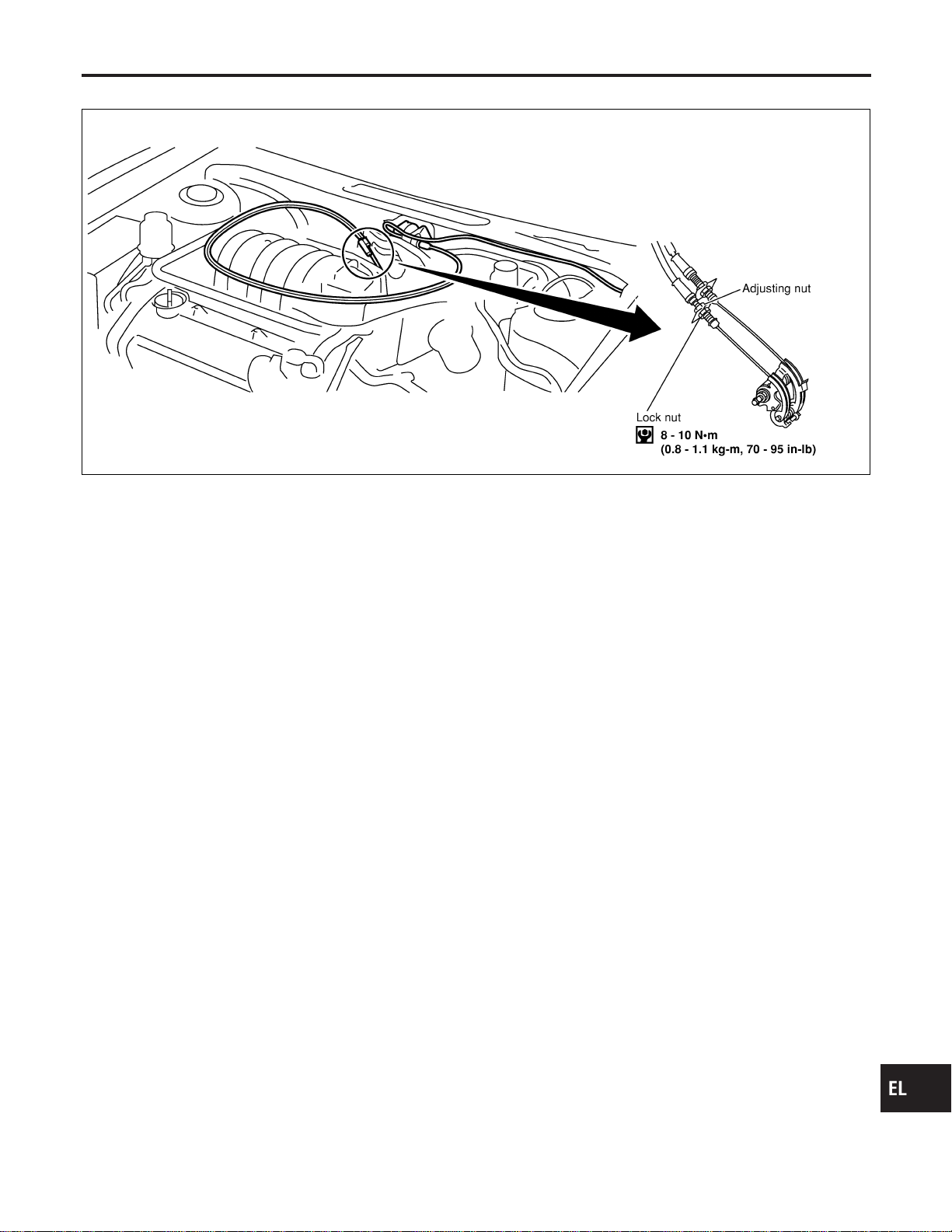
ASCD Wire Adjustment
=NAEL0377
MEL383K
CAUTION:
I Be careful not to twist ASCD wire when removing it.
I Do not tense ASCD wire excessively during adjustment.
Adjust the tension of ASCD wire in the following manner.
1. Loosen lock nut and adjusting nut.
2. Make sure that accelerator wire is properly adjusted. Refer to
FE-3, “ACCELERATOR CONTROL SYSTEM”.
3. Tighten adjusting nut just until throttle drum starts to move.
4. Loosen adjusting nut again 1/2 to 1 turn.
5. Tighten lock nut.
GI
MA
EM
LC
EC
FE
CL
MT
AT
TF
PD
AX
SU
BR
ST
RS
BT
HA
SC
IDX
AUTOMATIC SPEED CONTROL DEVICE (ASCD)
ASCD Wire Adjustment
EL-267

System Description
NAEL0378
Power is supplied at all times
I from 40A fusible link (letter f, located in the fuse and fusible link box)
I to circuit breaker terminal 1
I through circuit breaker terminal 2
I to power window relay terminal 3,
I to front power window main switch terminal 4, and
I to front power window switch RH terminal 6.
With ignition switch in ON or START position, power is supplied
I through 7.5A fuse [No. 11, located in the fuse block (J/B)]
I to smart entrance control unit terminal 27
I to smart entrance control unit terminal 46 and
I to power window relay terminal 2.
Ground is supplied to power window relay terminal 1
I through body grounds M4, M66 and M147.
The power window relay is energized and power is supplied
I through power window relay terminal 5
I to front power window main switch terminal 11,
I to front power window switch RH terminal 13 and
I to rear power window switch LH and RH terminals 5.
MANUAL OPERATION
NAEL0378S01
Front Door LH
NAEL0378S0101
Ground is supplied
I to front power window main switch terminal 5
I through body grounds M77 and M111.
WINDOW UP
When the front LH switch in the front power window main switch is pressed in the up position, power is sup-
plied
I to front power window regulator LH terminal 1
I through front power window main switch terminal 2.
Ground is supplied
I to front power window regulator LH terminal 3
I through front power window main switch terminal 3.
Then, the motor raises the window until the switch is released.
WINDOW DOWN
When the LH switch in the front power window main switch is pressed in the down position, power is supplied
I to front power window regulator LH terminal 3
I through front power window main switch terminal 3.
Ground is supplied
I to front power window regulator LH terminal 1
I through front power window main switch terminal 2.
Then, the motor lowers the window until the switch is released.
Front Door RH
NAEL0378S0102
Ground is supplied
I to front power window main switch terminal 5
I through body grounds M77 and M111.
NOTE:
Numbers in parentheses are terminal numbers, when power window switch is pressed in the UP and DOWN
positions respectively.
FRONT POWER WINDOW MAIN SWITCH OPERATION
When front RH switch in the front power window main switch is pressed UP or DOWN, a signal is supplied
POWER WINDOW
System Description
EL-268

I through front power window main switch terminal 8
I to front power window switch RH terminal 11.
The subsequent operation is the same as the front power window switch RH operation.
FRONT POWER WINDOW SWITCH RH OPERATION
Power is supplied
I through front power window switch RH (5, 4)
I to front power window regulator RH (1, 3).
Ground is supplied
I to front power window regulator RH (3, 1)
I through front power window switch RH (4, 5)
I to front power window switch RH terminal 12
I through front power window main switch terminal 1.
Then, the motor raises or lowers the window until the switch is released.
Rear Door LH
NAEL0378S0103
Ground is supplied
I to front power window main switch terminal 5
I through body grounds the M77 and M111.
NOTE:
Numbers in parentheses are terminal numbers, when the power window switch is pressed in the UP and
DOWN positions.
FRONT POWER WINDOW MAIN SWITCH OPERATION
Power is supplied
I through front power window main switch terminal (13, 12)
I to rear power window switch LH terminal (3, 4)
The subsequent operation is the same as the rear power window switch LH operation.
REAR POWER WINDOW SWITCH LH
Power is supplied
I through rear power window switch LH (1, 2)
I to rear power window regulator LH (1, 2)
Ground is supplied
I to rear power window regulator LH (2, 1)
I through rear power window switch LH (2, 1)
I to rear power window switch LH terminal (4, 3)
I through front power window main switch terminal (12, 13)
Then, the motor raises or lowers the window until the switch is released.
Rear Door RH
NAEL0378S0104
Rear door RH windows will rise and lower in the same manner as the rear door LH window.
AUTO OPERATION
NAEL0378S02
The power window AUTO feature enables the driver or front passenger to open or close the driver’s and front
passenger’s window without holding the window switch in the up or down position.
The AUTO feature only operates on the driver’s and front passenger’s window upward and downward move-
ment.
POWER WINDOW LOCK
NAEL0378S03
The power window lock is designed to lock operation of all windows except for driver’s door window.
When the lock switch is pressed to lock position, the ground of the front and rear power window switches, in
the power window main switch, is disconnected. This prevents the power window motors from operating.
RETAINED POWER OPERATION
NAEL0378S04
When the ignition switch is turned to OFF position from ON or START position, power is supplied for 45 sec-
onds
I to power window relay terminal 2
I from smart entrance control unit terminal 46.
GI
MA
EM
LC
EC
FE
CL
MT
AT
TF
PD
AX
SU
BR
ST
RS
BT
HA
SC
IDX
POWER WINDOW
System Description (Cont’d)
EL-269

Ground is always supplied
I to power window relay terminal 1
I through body grounds M4, M66 and M147.
When power and ground are supplied, the power window relay continues to be energized, and the power win-
dow can be operated.
The retained power operation is canceled when the driver or passenger side door is opened.
RAP signal’s period can be changed by CONSULT-II. (EL-278)
INTERRUPTION DETECTION FUNCTION
NAEL0378S05
Front power window main switch and front power window switch RH monitor the power window regulator motor
operation and the power window position (full closed or other) for driver’s and passenger’s power window by
the signals from encoder and limit switch in front power window regulator LH or RH.
When front power window main switch or front power window switch RH detects interruption during the fol-
lowing close operation in the driver’s or front passenger’s side door,
I automatic close operation when ignition switch is in the “ON” position
I automatic close operation during retained power operation
front power window main switch or front power window switch RH controls driver’s or front passenger’s power
window regulator motor for open and the power window will be lowered about 150 mm (5.91 in).
POWER WINDOW OPENED/CLOSED OPERATION WITH KEY CYLINDER
NAEL0378S06
When ignition key switch is OFF, front power window can be opened or closed by turning the front door key
cylinder LH to UNLOCK/LOCK position.
I Power window can be opened as the door key cylinder is kept fully turning to the UNLOCK position.
I Power window can be closed as the door key cylinder is kept fully turning to the LOCK position.
The power window opening stops when the following operations are carried out:
I While performing open/close the window, power window is stopped at the position as the door key cylin-
der is placed on Neutral.
I When the ignition switch is turned ON while the power window opening is operated.
POWER WINDOW
System Description (Cont’d)
EL-270
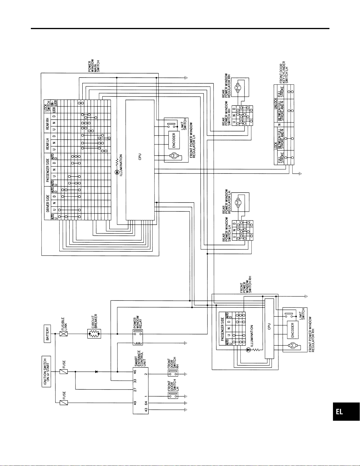
Schematic
NAEL0379
MEL427P
GI
MA
EM
LC
EC
FE
CL
MT
AT
TF
PD
AX
SU
BR
ST
RS
BT
HA
SC
IDX
POWER WINDOW
Schematic
EL-271
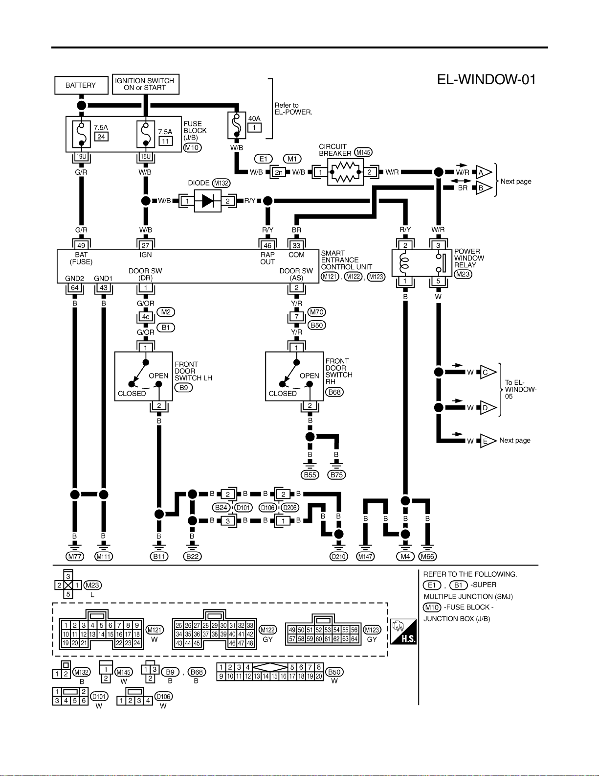
Wiring Diagram — WINDOW —
NAEL0380
MEL410O
POWER WINDOW
Wiring Diagram — WINDOW —
EL-272
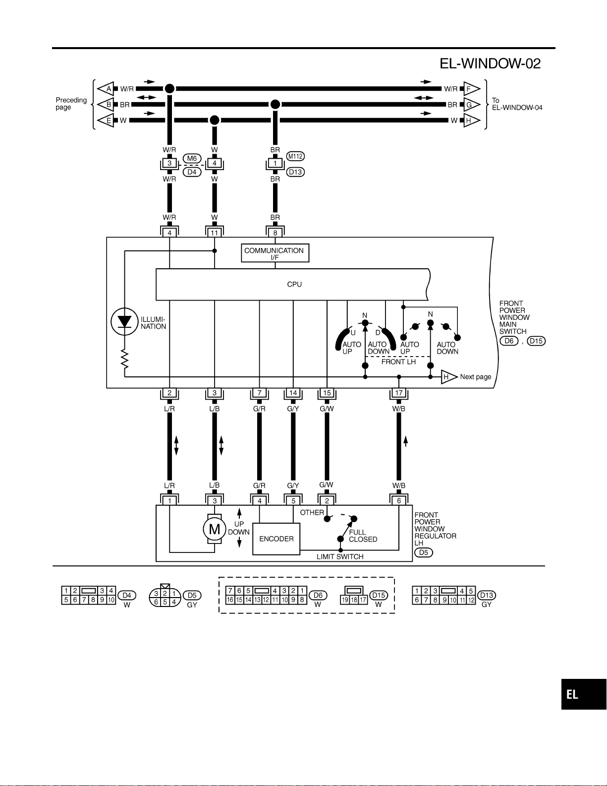
MEL428P
GI
MA
EM
LC
EC
FE
CL
MT
AT
TF
PD
AX
SU
BR
ST
RS
BT
HA
SC
IDX
POWER WINDOW
Wiring Diagram — WINDOW — (Cont’d)
EL-273
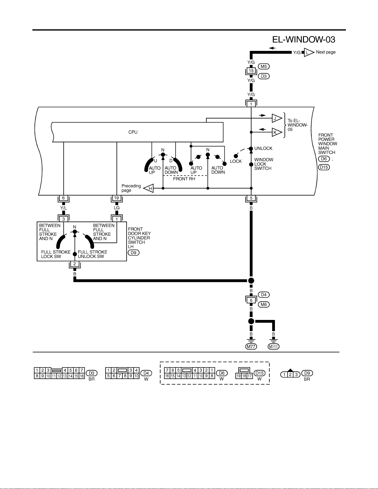
MEL516P
POWER WINDOW
Wiring Diagram — WINDOW — (Cont’d)
EL-274

MEL429P
GI
MA
EM
LC
EC
FE
CL
MT
AT
TF
PD
AX
SU
BR
ST
RS
BT
HA
SC
IDX
POWER WINDOW
Wiring Diagram — WINDOW — (Cont’d)
EL-275
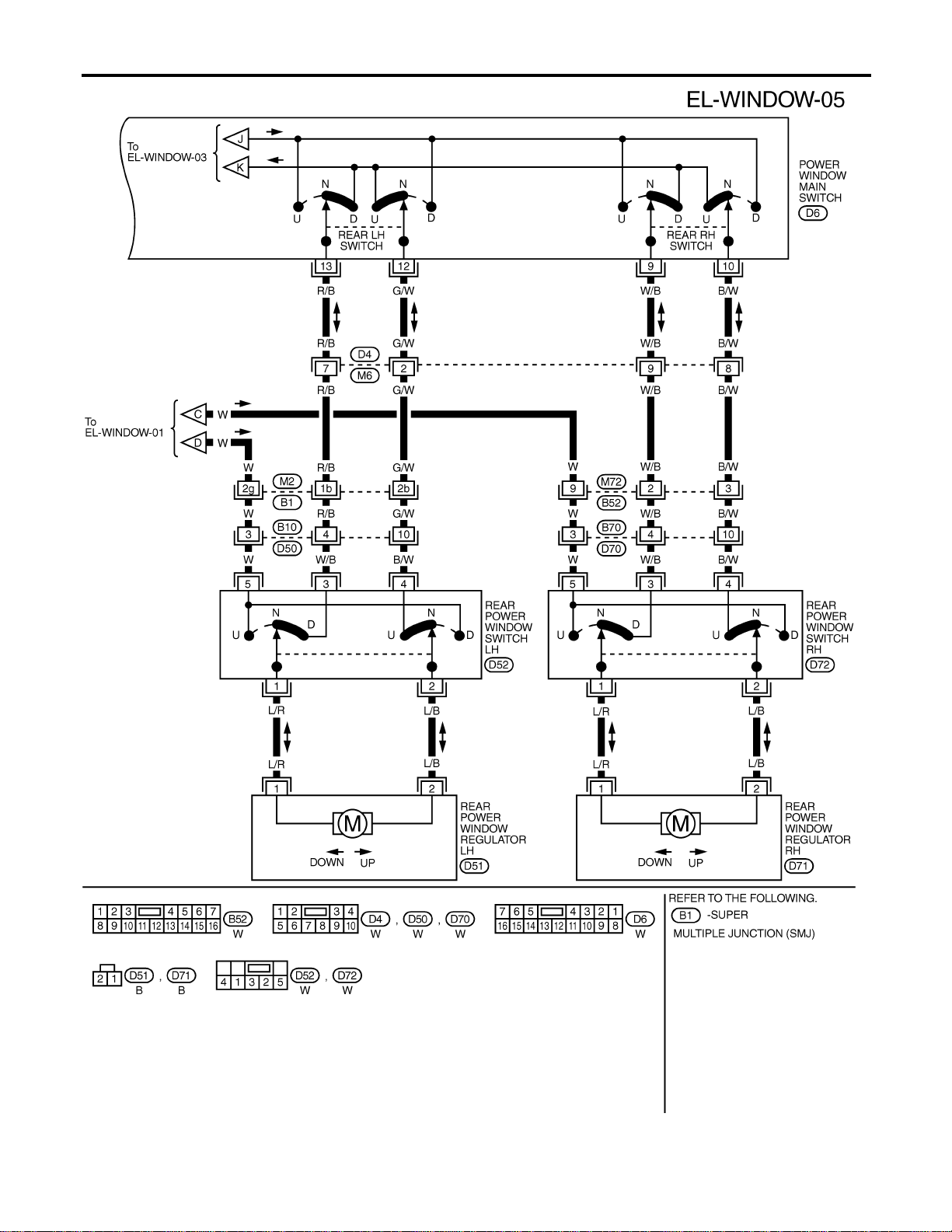
MEL517P
POWER WINDOW
Wiring Diagram — WINDOW — (Cont’d)
EL-276

SEL331X
CONSULT-II Inspection Procedure
NAEL0381
“RETAINED PWR”
NAEL0381S01
1. Turn ignition switch “OFF”.
2. Connect “CONSULT-II” to the data link connector.
PBR455D
3. Turn ignition switch “ON”.
4. Touch “START”.
SEL398Y
5. Touch “SMART ENTRANCE”.
SEL401Y
6. Touch “RETAINED PWR”.
SEL400Y
7. Select diagnosis mode.
“DATA MONITOR”, “ACTIVE TEST” and “WORK SUPPORT”
are available.
GI
MA
EM
LC
EC
FE
CL
MT
AT
TF
PD
AX
SU
BR
ST
RS
BT
HA
SC
IDX
POWER WINDOW
CONSULT-II Inspection Procedure
EL-277

CONSULT-II Application Items
NAEL0382
“RETAINED PWR”
NAEL0382S01
Data Monitor
NAEL0382S0101
Monitored Item Description
IGN ON SW Indicates [ON/OFF] condition of ignition switch.
DOOR SW-DR Indicates [ON/OFF] condition of front door switch LH.
DOOR SW-AS Indicates [ON/OFF] condition of front door switch RH.
Active Test
NAEL0382S0102
Test Item Description
RETAINED PWR This test is able to supply RAP signal (power) from smart entrance control unit to power window
system, power sunroof system and headlamp battery saver control unit. Those systems can be
operated when turning on “RETAINED PWR” on CONSULT-II screen even if the ignition switch is
tuned OFF.
NOTE:
During this test, CONSULT-II can be operated with ignition switch in “OFF” position.
“RETAINED PWR” should be turned “ON” or “OFF” on CONSULT-II screen when ignition
switch is ON. Then turn ignition switch OFF to check retained power operation. CON-
SULT-II might be stuck if “RETAINED PWR” is turned “ON” or “OFF” on CONSULT-II screen
when ignition switch is OFF.
Work Support
NAEL0382S0103
Work Item Description
RETAINED PWR SET Rap signal’s power supply period can be changed by mode setting. Selects rap signal’s power
supply period between three steps.
I MODE 1 (45 sec.)/MODE 2 (OFF)/MODE 3 (2 min.)
Trouble Diagnoses
NAEL0383
Symptom Possible cause Repair order
None of the power windows can be
operated using any switch.
1. 7.5A fuse, 40A fusible link
2. M145 circuit breaker
3. Power window relay
4. M145 circuit breaker circuit
5. Power window relay circuit
6. Ground circuit
7. Power window main switch
1. Check 7.5A fuse [No. 11, located in fuse block
(J/B)], 40A fusible link (letter f, located in fuse and
fusible link box).
2. Check M145 circuit breaker.
3. Check power window relay.
4. Check the following.
a. Harness between M145 circuit breaker and 40A fus-
ible link
b. Harness between M145 circuit breaker and front
power window main switch
5. Check the following.
a. Harness between 7.5A fuse and power window relay
b. Harness between M145 circuit breaker and power
window relay
6. Check the following.
a. Ground circuit of power window main switch terminal
5
b. Power window relay ground circuit
7. Check power window main switch.
POWER WINDOW
CONSULT-II Application Items
EL-278

Symptom Possible cause Repair order
Driver side power window cannot
be operated but other windows can
be operated.
1. Driver side power window regu-
lator circuit
2. Driver side power window regu-
lator
3. Power window main switch
1. Check harness between power window main switch
and driver side power window regulator for open or
short circuit.
2. Check driver side power window regulator.
3. Check power window main switch.
Passenger side power window can-
not be operated but other window
can be operated.
1. Power supply for front power
window switch RH
2. Front power window switch RH
ground circuit
3. Front power window switch RH
circuit
4. Front power window regulator
RH circuit
5. Front power window regulator
RH
6. Front power window main
switch
7. Front power window switch RH
1. Check power supply for front power window switch
RH terminals 6 and 13.
2. Check front power window switch RH ground circuit.
3. Check harness between front power window switch
RH and power window main switch.
4. Check harness between front power window switch
RH and front power window regulator RH for open
or short circuit.
5. Check front power window regulator RH.
6. Check front power window main switch.
7. Check front power window switch RH.
One or more rear power windows
except front window cannot be
operated.
1. Rear power window switches
2. Rear power window regulators
3. Power window main switch
4. Rear power window circuit
1. Check rear power window switches.
2. Check rear power window regulator.
3. Check power window main switch.
4. Check the following.
a. Harness between the rear power window switches
(LH and RH) terminal 5 and power window relay
terminal 5
b. Harnesses between power window main switch and
rear power window switches for open/short circuit
c. Harnesses between rear power window switches
and rear power window regulator for open/short cir-
cuit
Power windows except driver’s
side window cannot be operated
using power window main switch
but can be operated by power win-
dow switches.
1. Power window main switch 1. Check power window main switch.
Driver side power window auto-
matic operation does not function
properly.
1. Power window main switch
2. Encoder and limit switch
1. Check power window main switch.
2. Check encoder and limit switch. (EL-281)
Front passenger side power win-
dow automatic operation does not
function properly.
1. Front power window switch RH
2. Encoder and limit switch
1. Check front power window switch RH.
2. Check encoder and limit switch. (EL-281)
GI
MA
EM
LC
EC
FE
CL
MT
AT
TF
PD
AX
SU
BR
ST
RS
BT
HA
SC
IDX
POWER WINDOW
Trouble Diagnoses (Cont’d)
EL-279

Symptom Possible cause Repair order
Retained power operation does not
operate properly.
1. RAP signal circuit
2. Driver or passenger side door
switch circuit
3. Smart entrance control unit
1. Check RAP signal.
a. (With CONSULT-II)
I Check RAP signal with CONSULT-II.
Use “WORK SUPPORT” mode, “RETAINED PWR” in
“SMART ENTRANCE”. (Refer to EL-278.)
I Check RAP signal with CONSULT-II.
Use “ACTIVE TEST” mode, “RETAINED PWR” in
“SMART ENTRANCE”.
(Refer to EL-277.)
If NG, go to the step b. below.
b. Verify 12 positive voltage from smart entrance con-
trol unit terminal 46 is present at terminal 2 of power
window relay:
I Within 45 seconds after ignition switch turns off.*1
I When front door LH and RH is closed.
2. Check the following.
a. Harness between smart entrance control unit and
driver or passenger side door switch for short circuit
b. Driver or passenger side door switch ground circuit
c. Driver or passenger side door switch
3. Check smart entrance control unit. (EL-378)
Passenger side power window can-
not be operated using power win-
dow main switch but can be oper-
ated by passenger side power win-
dow switch.
1. Front power window main
switch
1. Check power window main switch. (EL-283)
Rear LH power window cannot be
operated using power window main
switch but can be operated by rear
LH power window switch.
1. Front power window main
switch
1. Check power window main switch. (EL-283)
Rear RH power window cannot be
operated using power window main
switch but can be operated by rear
RH power window switch.
1. Front power window main
switch
1. Check power window main switch. (EL-283)
*1: RAP signal’s period can be changed by CONSULT-II. (EL-278)
POWER WINDOW
Trouble Diagnoses (Cont’d)
EL-280
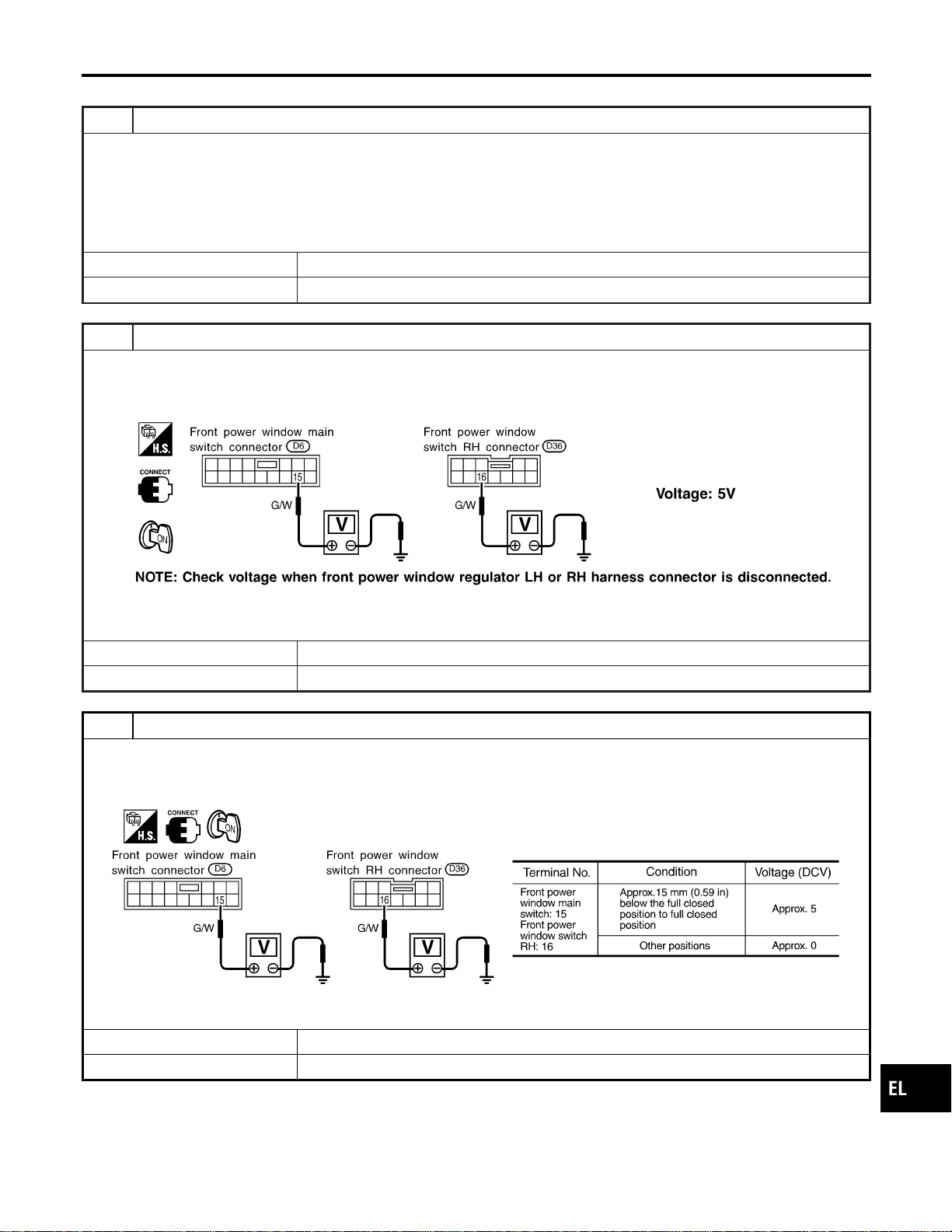
ENCODER AND LIMIT SWITCH CHECK
=NAEL0383S01
1 CHECK DOOR WINDOW SLIDE MECHANISM
Check the following.
I Obstacles in window, glass molding, etc.
I Worn or deformed glass molding
I Door sash tilted too far inward or outward
I Door window regulator
OK or NG
OK © GO TO 2.
NG © Remove obstacles or repair door window slide mechanism.
2 CHECK POWER SUPPLY TO LIMIT SWITCH
1. Disconnect front power window regulator LH or RH harness connector.
2. Check voltage between front power window main switch terminal 15 or front power window switch RH terminal 16 and
ground.
SEL725WA
OK or NG
OK © GO TO 3.
NG © Replace power window main switch or front power window switch RH.
3 CHECK LIMIT SWITCH OPERATION
1. Connect front power window regulator LH or RH harness connector.
2. Check voltage between front power window main switch terminal 15 or front power window switch RH terminal 16 and
ground during power window closing operation.
SEL726WA
OK or NG
OK © GO TO 5.
NG © GO TO 4.
GI
MA
EM
LC
EC
FE
CL
MT
AT
TF
PD
AX
SU
BR
ST
RS
BT
HA
SC
IDX
POWER WINDOW
Trouble Diagnoses (Cont’d)
EL-281

4 RESET LIMIT SWITCH
Reset limit switch. Refer to BT-20, “Front Door Glass Limit Switch Reset”. Then check voltage between front power win-
dow main switch terminal 15 or front power window switch RH terminal 16 and ground during power window closing
operation at least ten times.
SEL726WA
OK or NG
OK © GO TO 5.
NG © Replace power window regulator motor.
5 CHECK ENCODER
Measure voltage between front power window main switch terminal 14 or front power window switch RH terminal 19 and
ground with oscilloscope when power window is in automatic closing operation.
SEL727WA
OK or NG
OK © Replace power window main switch.
NG © Replace power window regulator motor.
POWER WINDOW
Trouble Diagnoses (Cont’d)
EL-282
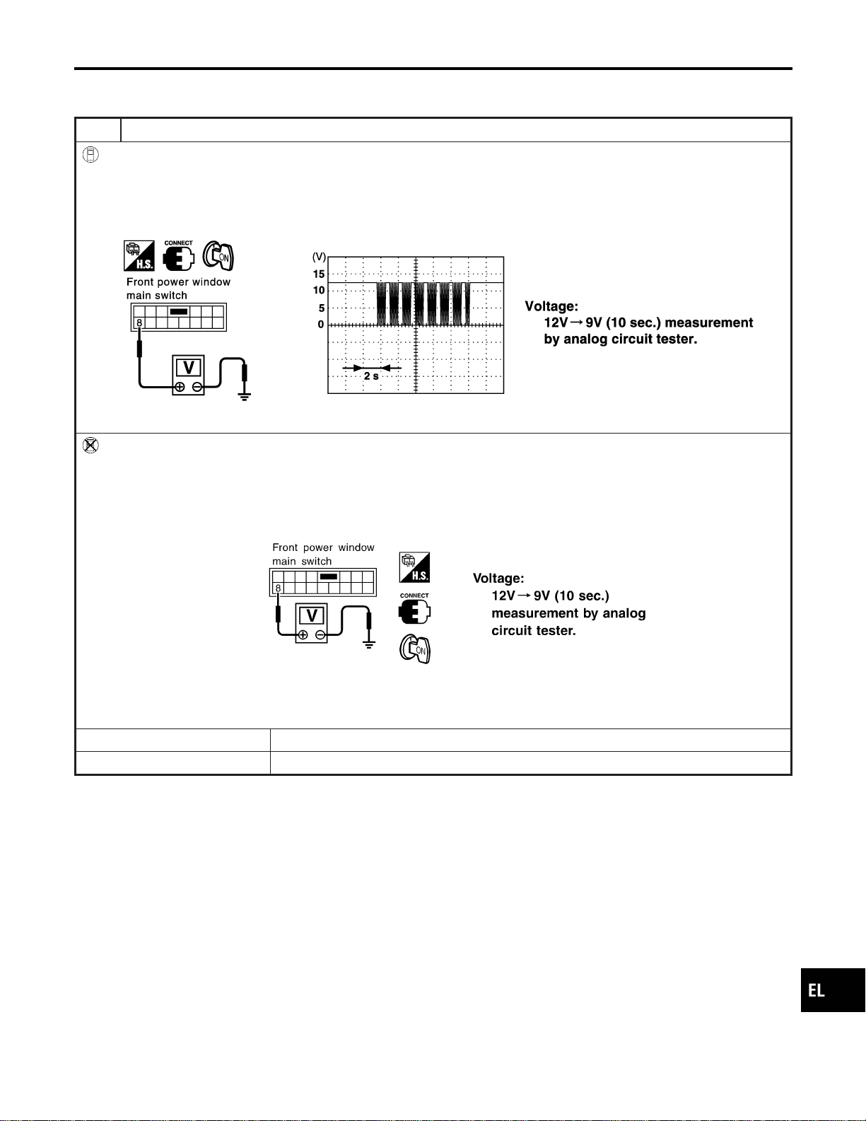
MAIN SWITCH OPERATION CHECK
NAEL0383S02
Passenger Side Operation
NAEL0383S0201
1 CHECK POWER WINDOW MAIN SWITCH OUTPUT SIGNAL
With CONSULT-II
1. Turn ignition switch to ON position.
2. Turn front power window main switch to ON (UP or DOWN).
3. Check signal between front power window main switch harness connector D6 terminal 8 (Y) and ground when power
window is in open or close operation. (Use “SIMPLE OSCILLOSCOPE” in “SUB MODE” with CONSULT-II.)
SEL496Y
Without CONSULT-II
1. Turn ignition switch to ON position.
2. Turn front power window main switch to ON (UP or DOWN).
3. Check signal between front power window main switch harness connector D6 terminal 8 (Y) and ground when power
window is in open or close operation.
SEL497Y
OK or NG
OK © GO TO 2.
NG © Replace front power window main switch.
GI
MA
EM
LC
EC
FE
CL
MT
AT
TF
PD
AX
SU
BR
ST
RS
BT
HA
SC
IDX
POWER WINDOW
Trouble Diagnoses (Cont’d)
EL-283
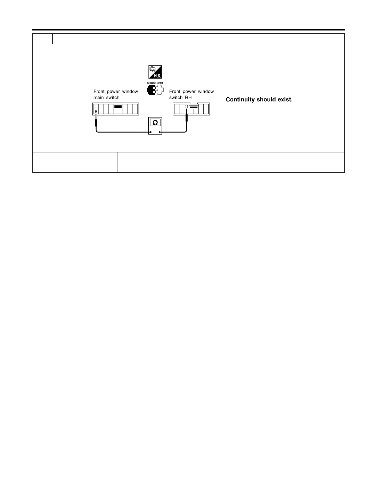
2 CHECK SIGNAL CIRCUIT
1. Check continuity between front power window switch harness connector D6 terminal 8 (Y) and front power window
switch harness connector D36 RH terminal 11 (Y).
SEL163Y
YesorNo
Yes © INSPECTION END
No © Repair harness or connectors.
POWER WINDOW
Trouble Diagnoses (Cont’d)
EL-284
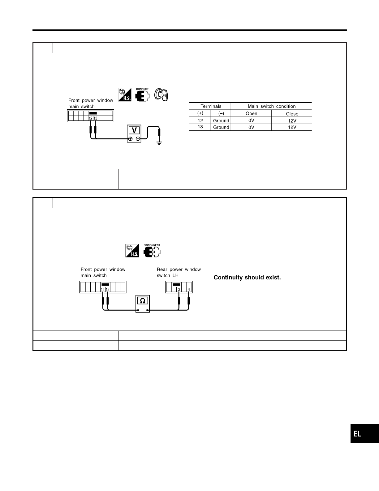
Rear LH Side Window Operation
=NAEL0383S0202
1 CHECK POWER WINDOW MAIN SWITCH OUTPUT SIGNAL
1. Turn ignition switch to ON position.
2. Check voltage between front power window main switch harness connector D6 terminal 12 or 13 and ground when rear
power window LH side is in open or close operation.
SEL164Y
OK or NG
OK © GO TO 2.
NG © Replace front power window main switch.
2 CHECK SIGNAL CIRCUIT
1. Check continuity between front power window main switch harness connector D6 terminal 12 and rear power window
switch LH harness connector D52 terminal 4.
2. Check continuity between front power window main switch harness connector D6 terminal 13 and rear power window
switch LH harness connector D52 terminal 3.
SEL165Y
YesorNo
Yes © INSPECTION END
No © Repair harness or connectors.
GI
MA
EM
LC
EC
FE
CL
MT
AT
TF
PD
AX
SU
BR
ST
RS
BT
HA
SC
IDX
POWER WINDOW
Trouble Diagnoses (Cont’d)
EL-285
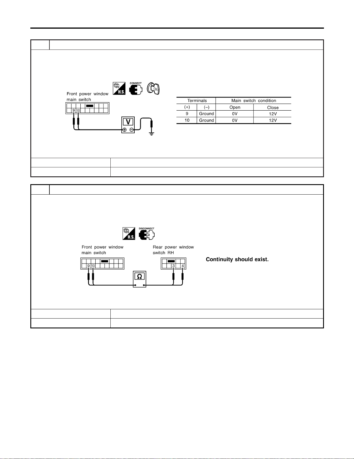
Rear RH Side Window Operation
=NAEL0383S0203
1 CHECK POWER WINDOW MAIN SWITCH OUTPUT
1. Turn ignition switch to ON position.
2. Check voltage between front power window main switch harness connector D6 terminal 9 or 10 and ground when rear
power window RH side is in open or close operation.
SEL166Y
OK or NG
OK © GO TO 2.
NG © Replace front power window main switch.
2 CHECK SIGNAL CIRCUIT
1. Check continuity between front power window main switch harness connector D6 terminal 9 and rear power window
switch RH harness connector D72 terminal 3.
2. Check continuity between front power window main switch harness connector D6 terminal 10 and rear power window
switch RH harness connector D72 terminal 4.
SEL167Y
YesorNo
Yes © INSPECTION END
No © Repair harness or connectors.
POWER WINDOW
Trouble Diagnoses (Cont’d)
EL-286
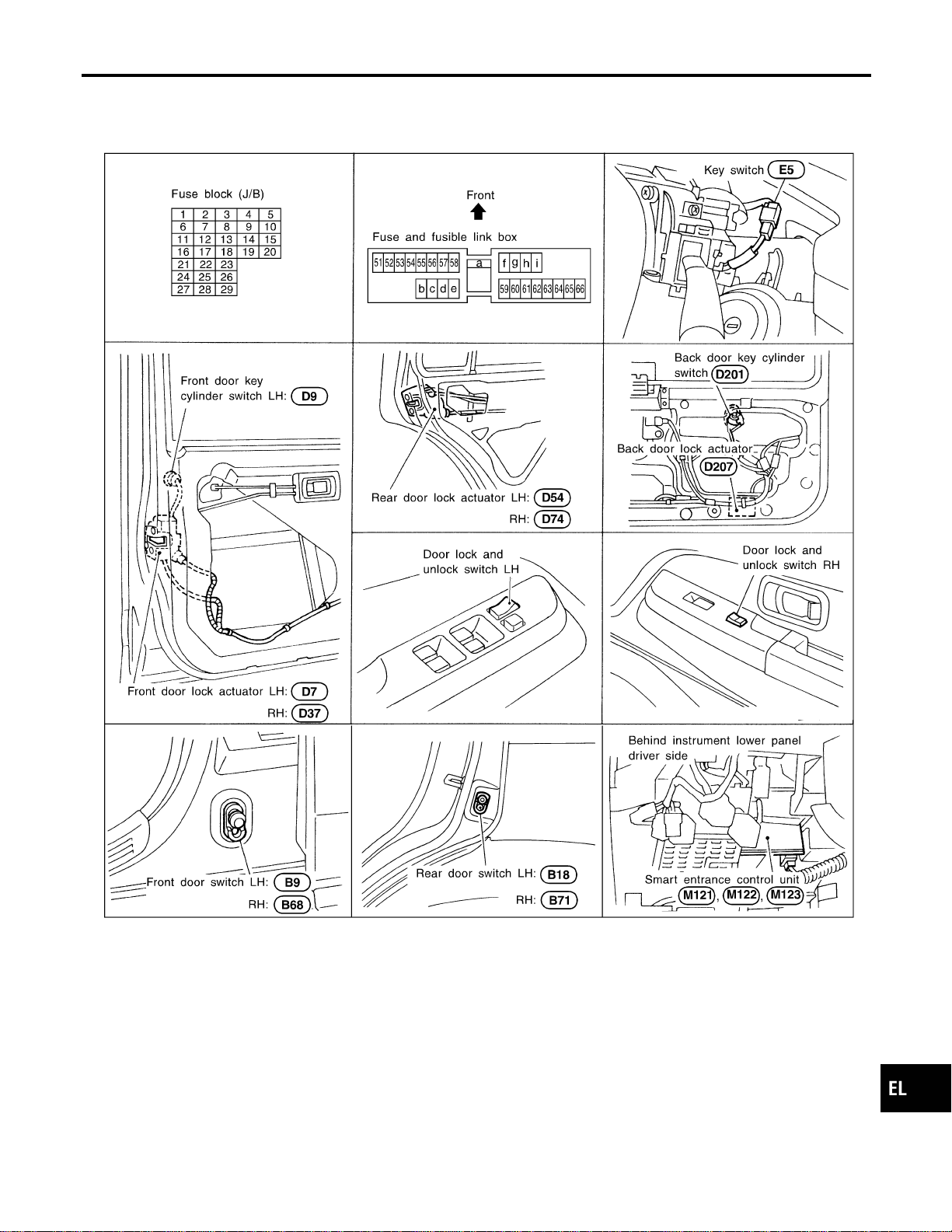
Component Parts and Harness Connector
Location
NAEL0384
SEL065WB
System Description
NAEL0385
OPERATION
NAEL0385S01
I The lock/unlock switch (LH and RH) on door trim can lock and unlock all doors.
I With the door key inserted in the key cylinder on front LH or back door, turning it to “LOCK”, will lock all
doors; turning it to “UNLOCK” once unlocks the corresponding door; turning it to “UNLOCK” again within
5 seconds after the first unlock operation unlocks all of the other doors. (Signals from door key cylinder
switch)
I If the ignition key is in the ignition key cylinder and one or more of doors are open, setting the lock/unlock
switch to “LOCK” locks the doors once but then immediately unlock them. (Combination signals from key
switch and door switches) - (KEY REMINDER DOOR SYSTEM)
GI
MA
EM
LC
EC
FE
CL
MT
AT
TF
PD
AX
SU
BR
ST
RS
BT
HA
SC
IDX
POWER DOOR LOCK
Component Parts and Harness Connector Location
EL-287
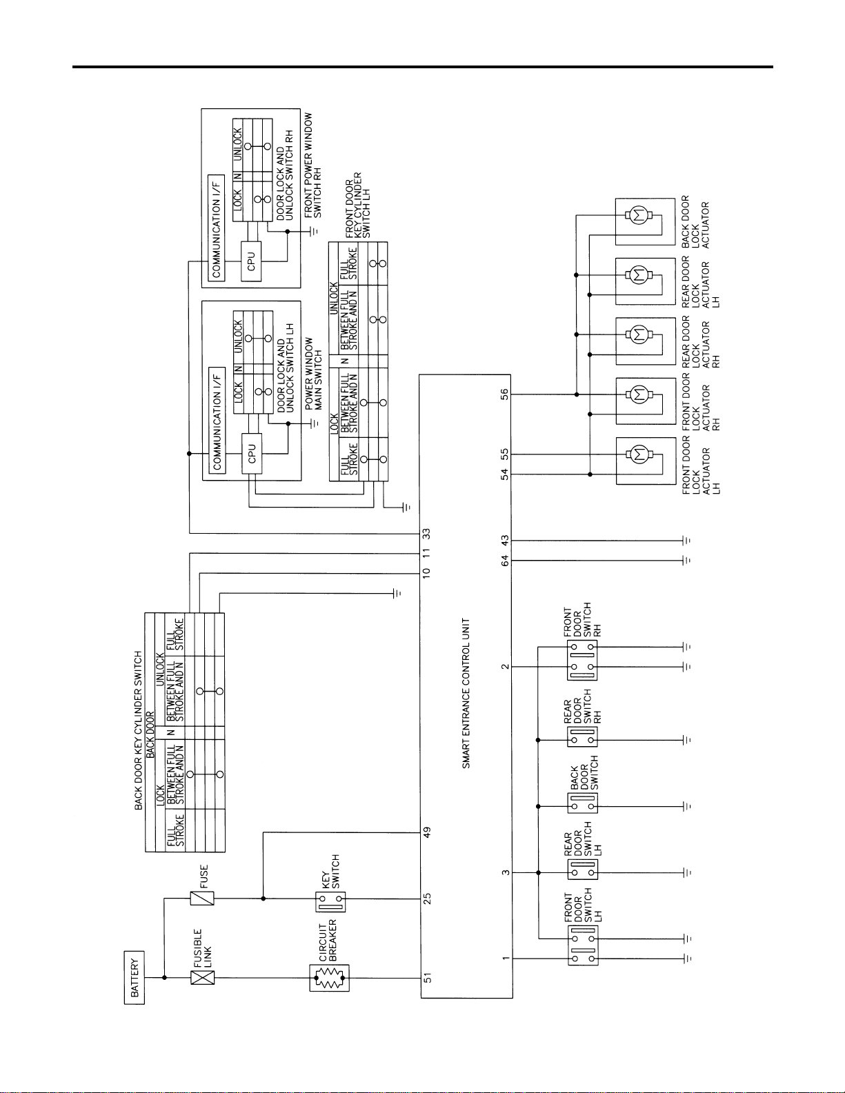
Schematic
NAEL0386
MEL431P
POWER DOOR LOCK
Schematic
EL-288
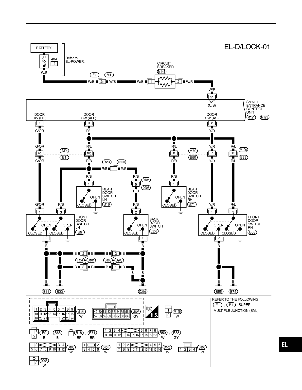
Wiring Diagram — D/LOCK —
NAEL0387
FIG. 1
NAEL0387S01
MEL388P
GI
MA
EM
LC
EC
FE
CL
MT
AT
TF
PD
AX
SU
BR
ST
RS
BT
HA
SC
IDX
POWER DOOR LOCK
Wiring Diagram — D/LOCK —
EL-289
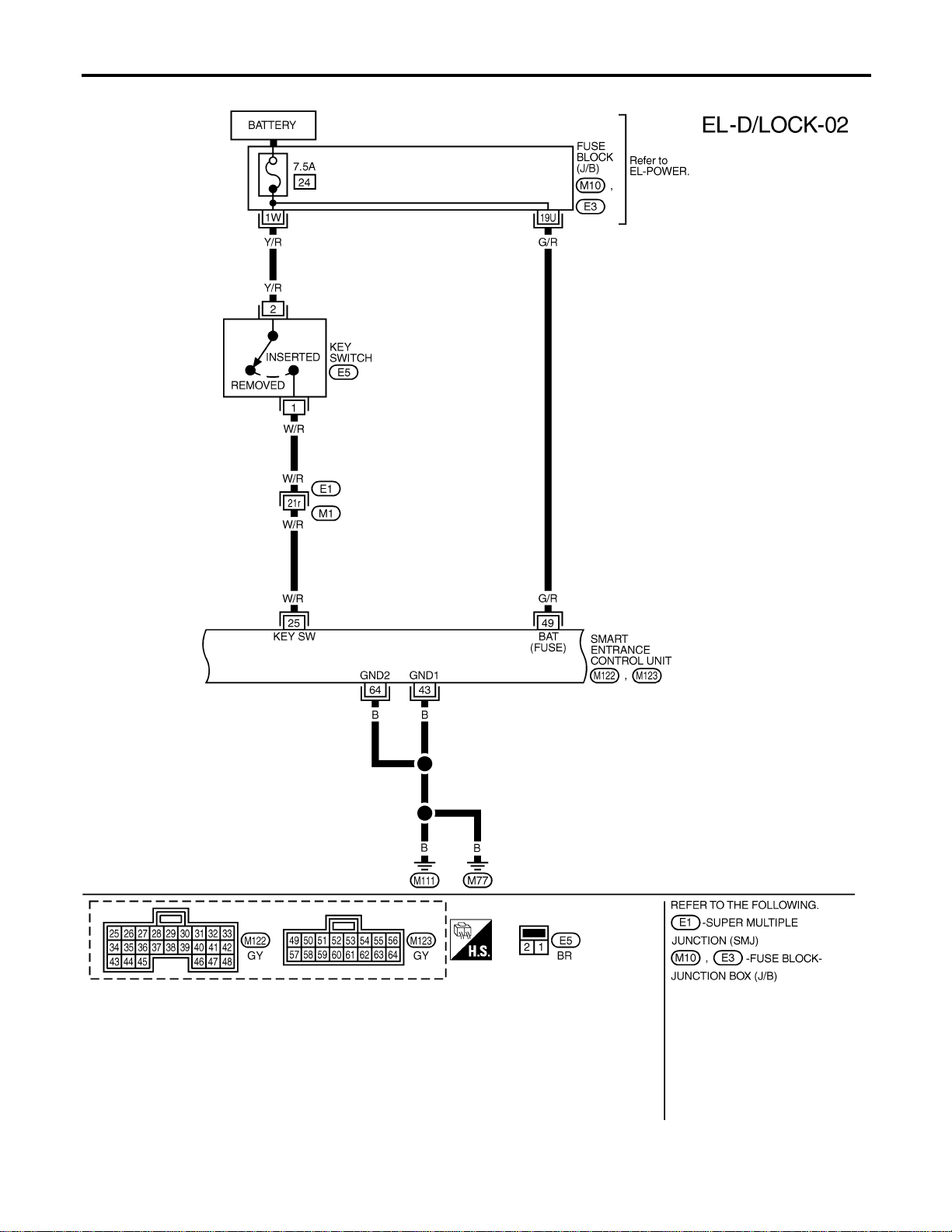
FIG. 2
NAEL0387S02
MEL432P
POWER DOOR LOCK
Wiring Diagram — D/LOCK — (Cont’d)
EL-290
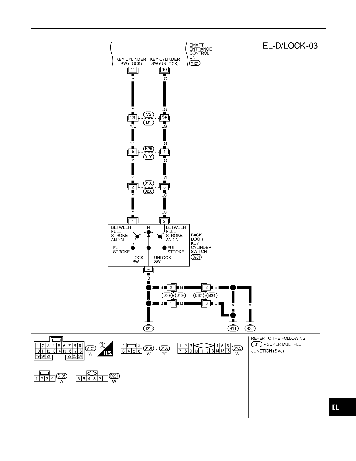
FIG. 3
NAEL0387S03
MEL433P
GI
MA
EM
LC
EC
FE
CL
MT
AT
TF
PD
AX
SU
BR
ST
RS
BT
HA
SC
IDX
POWER DOOR LOCK
Wiring Diagram — D/LOCK — (Cont’d)
EL-291
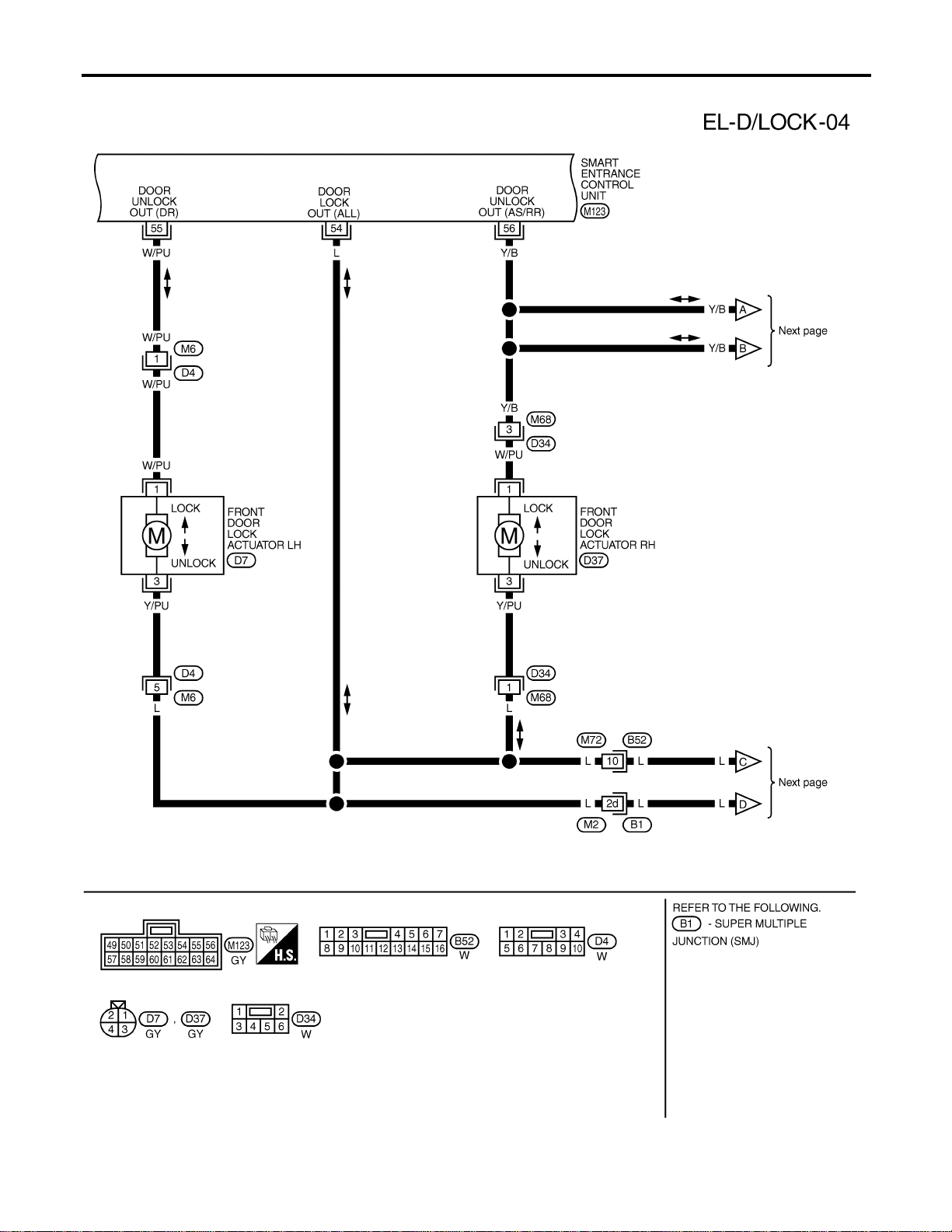
FIG. 4
NAEL0387S04
MEL434P
POWER DOOR LOCK
Wiring Diagram — D/LOCK — (Cont’d)
EL-292
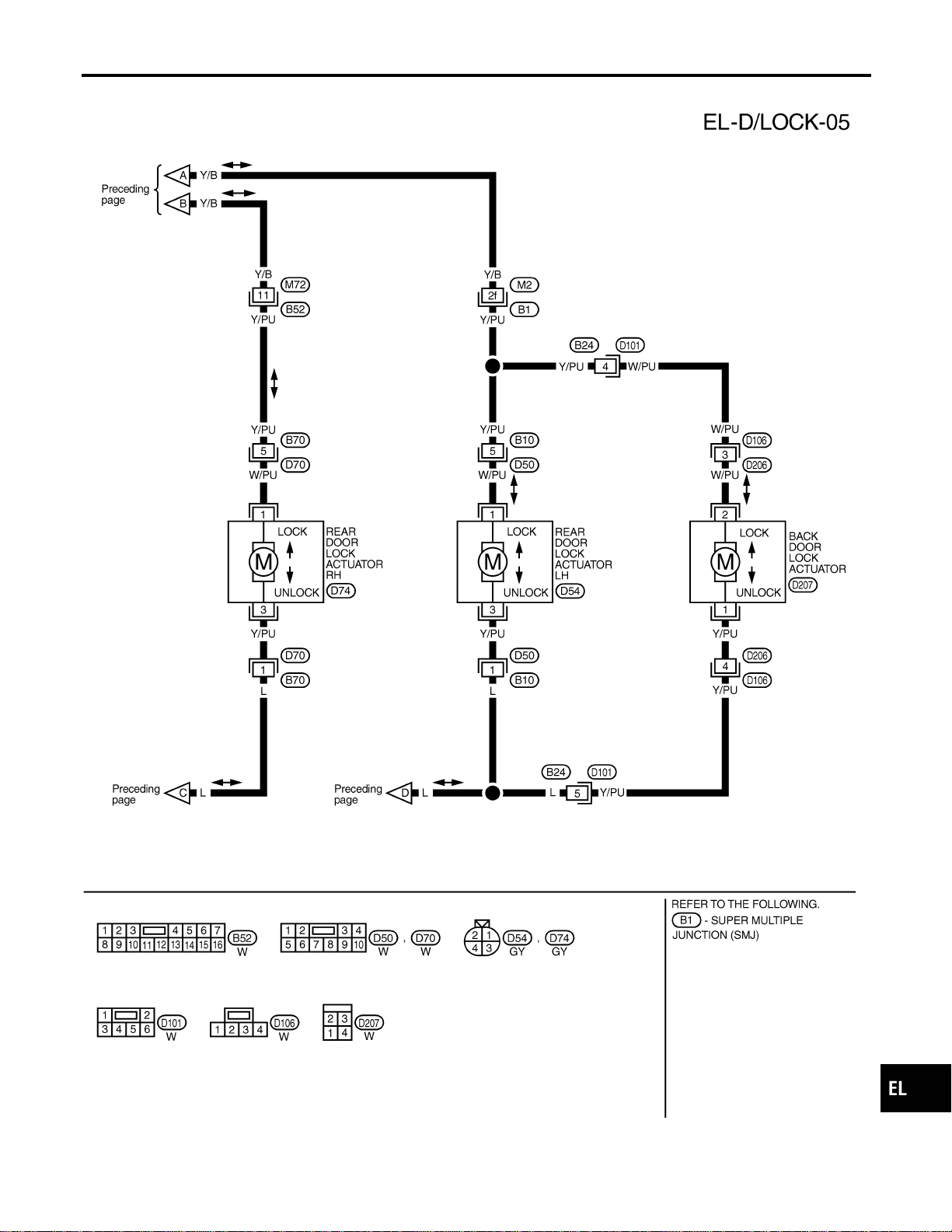
FIG. 5
NAEL0387S05
MEL852L
GI
MA
EM
LC
EC
FE
CL
MT
AT
TF
PD
AX
SU
BR
ST
RS
BT
HA
SC
IDX
POWER DOOR LOCK
Wiring Diagram — D/LOCK — (Cont’d)
EL-293
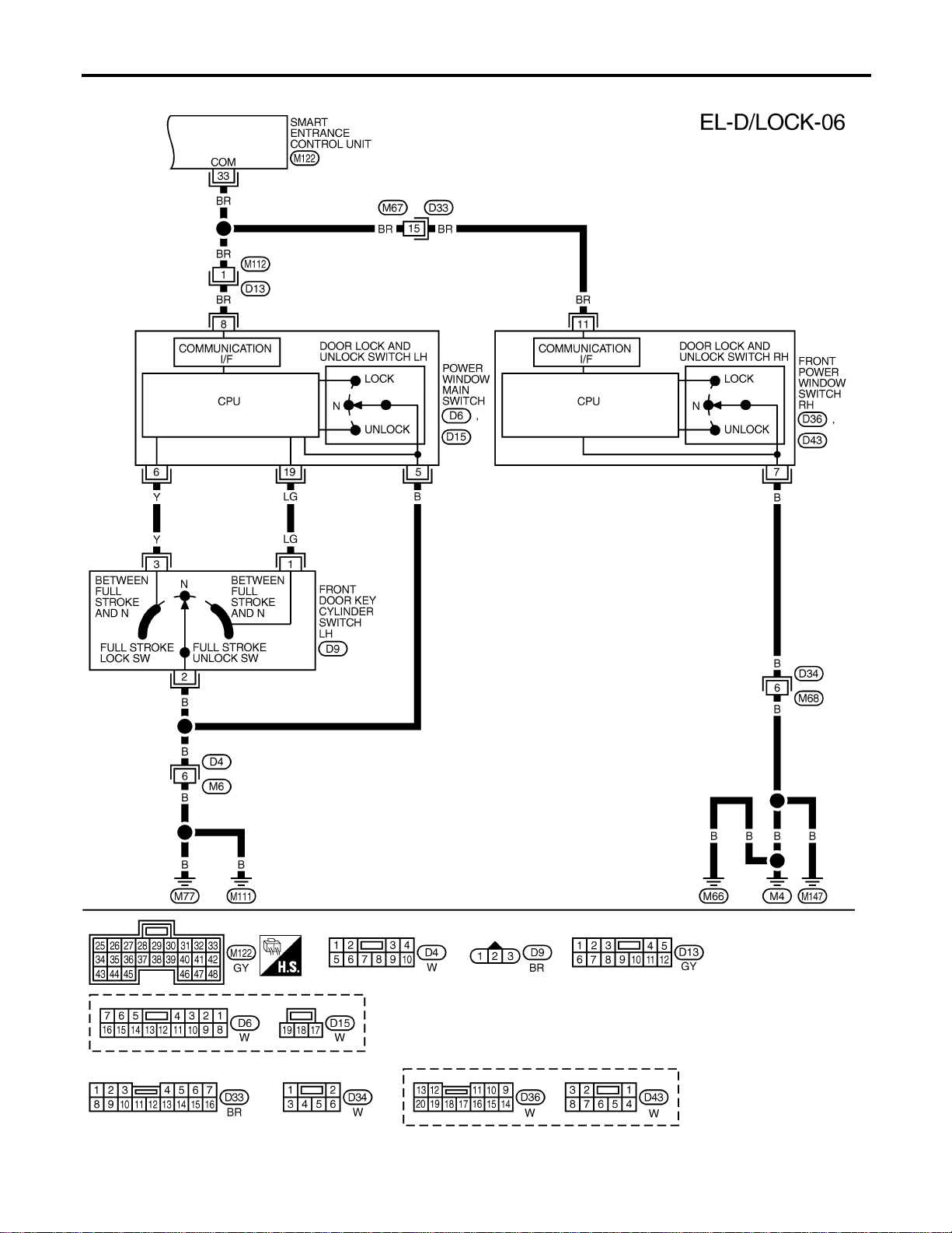
FIG. 6
NAEL0387S06
MEL435P
POWER DOOR LOCK
Wiring Diagram — D/LOCK — (Cont’d)
EL-294
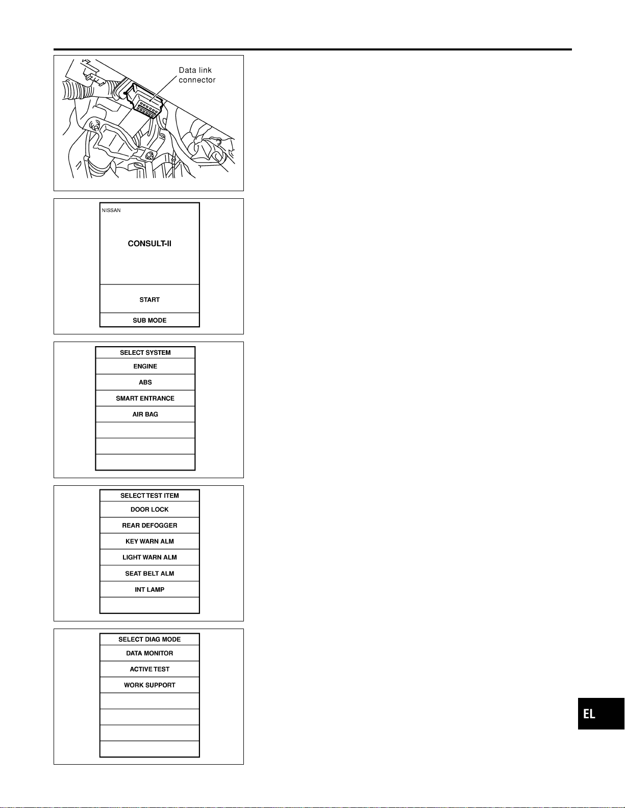
SEL331X
CONSULT-II Inspection Procedure
=NAEL0388
“DOOR LOCK”
NAEL0388S01
1. Turn ignition switch “OFF”.
2. Connect “CONSULT-II” to the data link connector.
PBR455D
3. Turn ignition switch “ON”.
4. Turn “START”.
SEL398Y
5. Touch “SMART ENTRANCE”.
SEL023X
6. Touch “DOOR LOCK”.
SEL274W
7. Select diagnosis mode.
“DATA MONITOR”, “ACTIVE TEST” and “WORK SUPPORT”
are available.
GI
MA
EM
LC
EC
FE
CL
MT
AT
TF
PD
AX
SU
BR
ST
RS
BT
HA
SC
IDX
POWER DOOR LOCK
CONSULT-II Inspection Procedure
EL-295

CONSULT-II Application Items
NAEL0389
“DOOR LOCK”
NAEL0389S01
Data Monitor
NAEL0389S0101
Monitored Item Description
KEY ON SW Indicates [ON/OFF] condition of key switch.
LOCK SW DR/AS Indicates [ON/OFF] condition of lock signal from lock/unlock switch LH and RH.
DOOR SW-RR Indicates [ON/OFF] condition of door switch (Rear).
UNLK SW DR/AS Indicates [ON/OFF] condition of unlock signal from lock/unlock switch LH and RH.
KEY CYL LK-SW Indicates [ON/OFF] condition of lock signal from key cylinder.
KEY CYL UN-SW Indicates [ON/OFF] condition of unlock signal from key cylinder.
LK BUTTON/SIG Indicates [ON/OFF] condition of lock signal from keyfob.
UN BUTTON/SIG Indicates [ON/OFF] condition of unlock signal from keyfob.
IGN ON SW Indicates [ON/OFF] condition of ignition switch.
DOOR SW-DR Indicates [ON/OFF] condition of front door switch LH.
DOOR SW-AS Indicates [ON/OFF] condition of front door switch RH.
Active Test
NAEL0389S0102
Test Item Description
ALL D/LK MTR
This test is able to check all door lock actuators lock operation. These actuators lock when
“ON” on CONSULT-II screen is touched.
DR D/UN MTR
This test is able to check front door lock actuator LH unlock operation. The actuator unlocks
when “ON” on CONSULT-II screen is touched.
NON DR D/UN
This test is able to check door lock actuators (except front door lock actuator LH) unlock opera-
tion. These actuators unlock when “ON” on CONSULT-II screen is touched.
Work Support
NAEL0389S0103
Work Item Description
DOOR LOCK-UNLOCK SET Select unlock mode can be changed in this mode. Selects ON-OFF of select unlock mode.
ANTI-LOCK OUT SET
Key reminder door mode can be changed in this mode. Selects ON-OFF of key reminder door
mode.
POWER DOOR LOCK
CONSULT-II Application Items
EL-296

Trouble Diagnoses
NAEL0390
SYMPTOM CHART
NAEL0390S01
REFERENCE PAGE (EL- ) 298 299 301 302 303 305 307
SYMPTOM
MAIN POWER SUPPLY AND GROUND CIRCUIT CHECK
DOOR SWITCH CHECK
KEY SWITCH (INSERT) CHECK
DOOR LOCK/UNLOCK SWITCH CHECK
FRONT DOOR KEY CYLINDER SWITCH CHECK
BACK DOOR KEY CYLINDER SWITCH CHECK
DOOR LOCK ACTUATOR CHECK
Key reminder door system does not operate
properly.
XXX X
Specific door lock actuator does not operate. X X
Power door lock does not operate with door
lock and unlock switch (LH and RH) on door
trim.
XX
Power door lock does not operate with front
door key cylinder operation.
XX
Power door lock does not operate with back
door key cylinder operation.
XX
GI
MA
EM
LC
EC
FE
CL
MT
AT
TF
PD
AX
SU
BR
ST
RS
BT
HA
SC
IDX
POWER DOOR LOCK
Trouble Diagnoses
EL-297
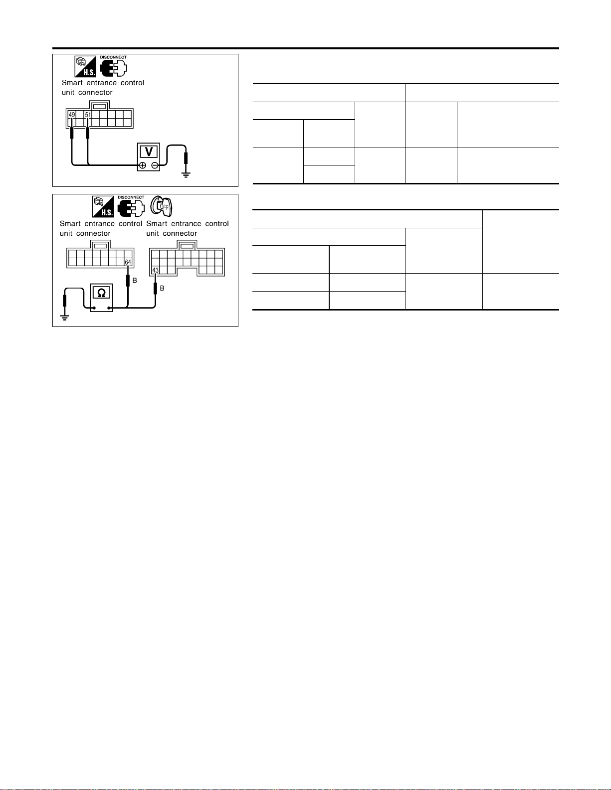
SEL007YA
MAIN POWER SUPPLY AND GROUND CIRCUIT CHECK
=NAEL0390S02
Main Power Supply Circuit Check
NAEL0390S0201
Terminals Ignition switch
(+)
(–) OFF ACC ON
Connector
Terminal
(Wire color)
M123
49 (G/R)
Ground
Battery
voltage
Battery
voltage
Battery
voltage
51 (W/R)
SEL008Y
Ground Circuit Check
NAEL0390S0202
Terminals
Continuity
(+)
(–)
Connector
Terminal
(Wire color)
M122 43 (B)
Ground Yes
M123 64 (B)
POWER DOOR LOCK
Trouble Diagnoses (Cont’d)
EL-298
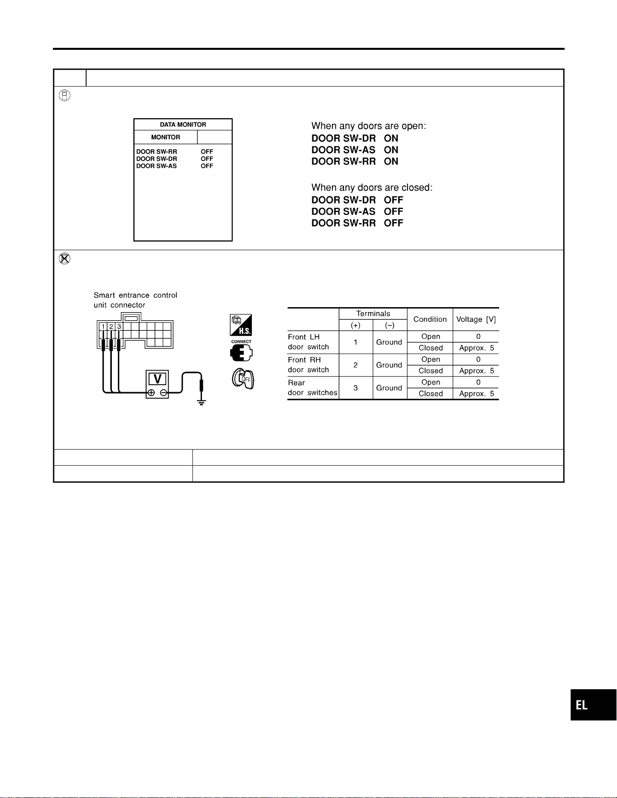
DOOR SWITCH CHECK
=NAEL0390S03
1 CHECK DOOR SWITCH INPUT SIGNAL
With CONSULT-II
Check door switches (“DOOR SW-DR”, “DOOR SW-AS”, “DOOR SW-RR”) in “DATA MONITOR” mode with CONSULT-II.
SEL009Y
Without CONSULT-II
Check voltage between smart entrance control unit harness connector M121 terminals 1 (G/OR), 2 (Y) or 3 (R/L) and
ground.
SEL010Y
Refer to wiring diagram in EL-289.
OK or NG
OK © Door switch is OK.
NG © GO TO 2.
GI
MA
EM
LC
EC
FE
CL
MT
AT
TF
PD
AX
SU
BR
ST
RS
BT
HA
SC
IDX
POWER DOOR LOCK
Trouble Diagnoses (Cont’d)
EL-299
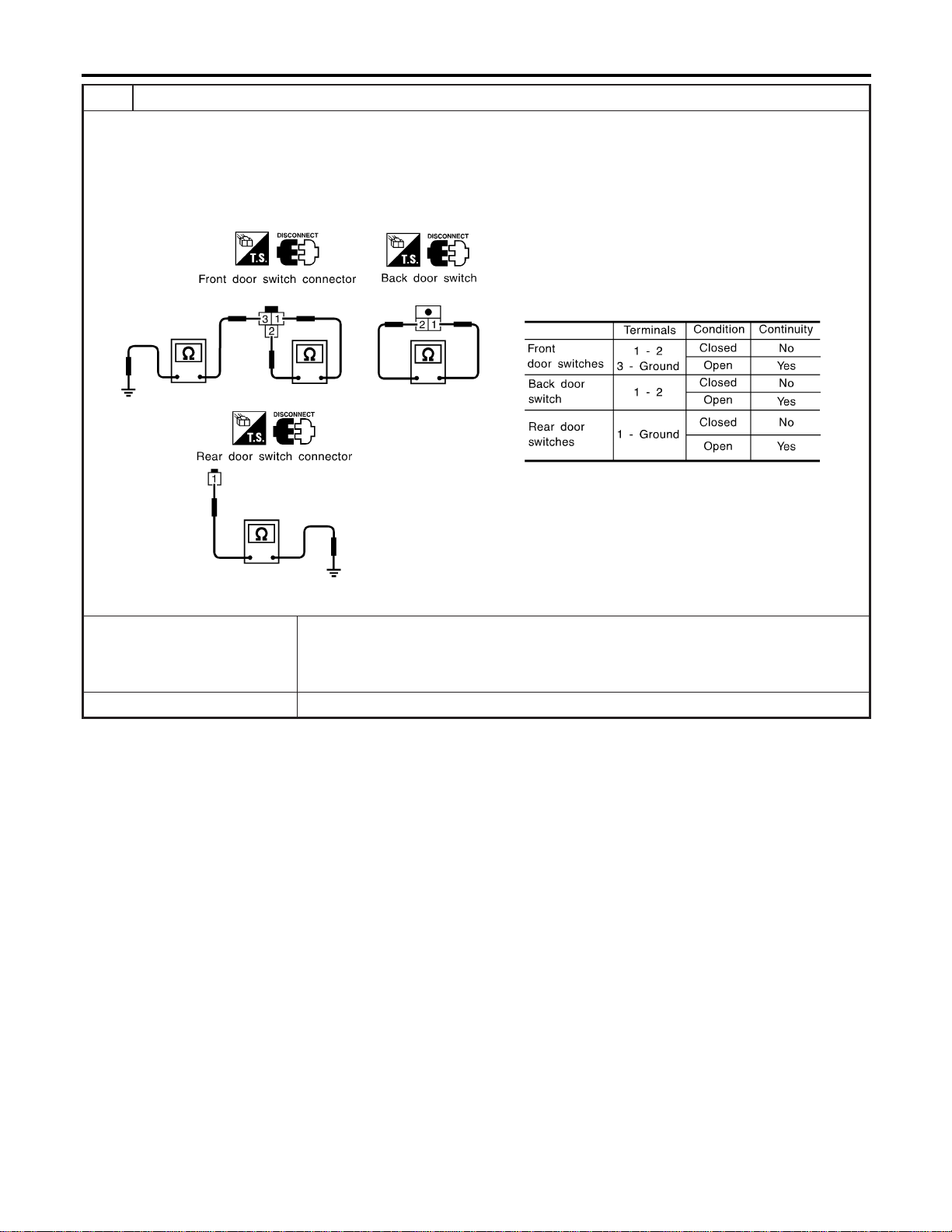
2 CHECK DOOR SWITCH
1. Disconnect door switch connector.
2. Check the following.
I Continuity between front door switch harness connector B9 (LH) or B68 (RH) terminals 1 and 2
I Continuity between front door switch harness connector B9 (LH) or B68 (RH) terminal and ground
I Continuity between back door switch harness connector D208 terminals 1 and 2
I Continuity between rear door switch harness connector B18 (LH) or B71 (RH) terminal 1 and ground
SEL287Y
OK or NG
OK © Check the following.
I Door switches ground circuit (Front or back door) or rear door switches ground condi-
tion
I Harness for open or short between smart entrance control unit and door switch
NG © Replace door switch.
POWER DOOR LOCK
Trouble Diagnoses (Cont’d)
EL-300
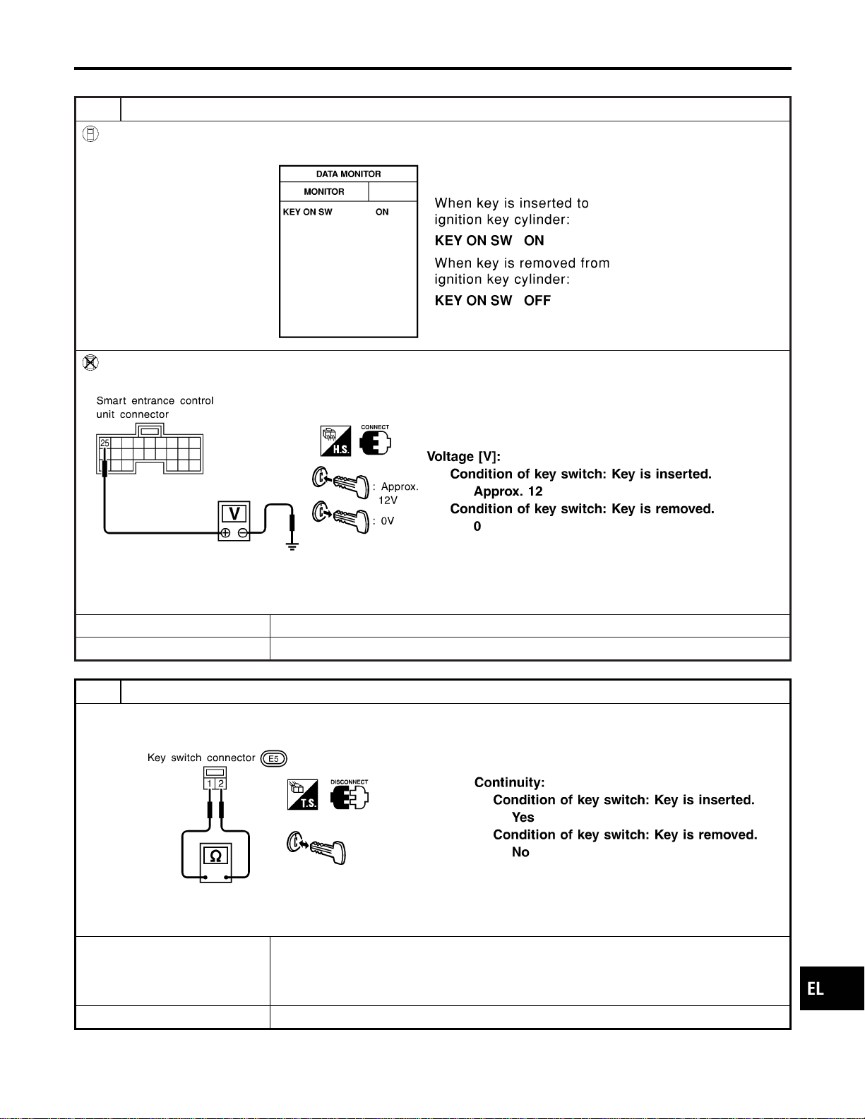
KEY SWITCH (INSERT) CHECK
=NAEL0390S04
1 CHECK KEY SWITCH INPUT SIGNAL
With CONSULT-II
Check key switch (“KEY ON SW”) in “DATA MONITOR” mode with CONSULT-II.
SEL315W
Without CONSULT-II
Check voltage between smart entrance control unit harness connector M122 terminal 25 (W/R) and ground.
SEL011Y
Refer to wiring diagram in EL-290.
OK or NG
OK © Key switch is OK.
NG © GO TO 2.
2 CHECK KEY SWITCH (INSERT)
Check continuity between terminals 1 and 2.
SEL308X
OK or NG
OK © Check the following.
I 7.5A fuse [No. 24, located in fuse block (J/B)]
I Harness for open or short between key switch and fuse
I Harness for open or short between smart entrance control unit and key switch
NG © Replace key switch.
GI
MA
EM
LC
EC
FE
CL
MT
AT
TF
PD
AX
SU
BR
ST
RS
BT
HA
SC
IDX
POWER DOOR LOCK
Trouble Diagnoses (Cont’d)
EL-301
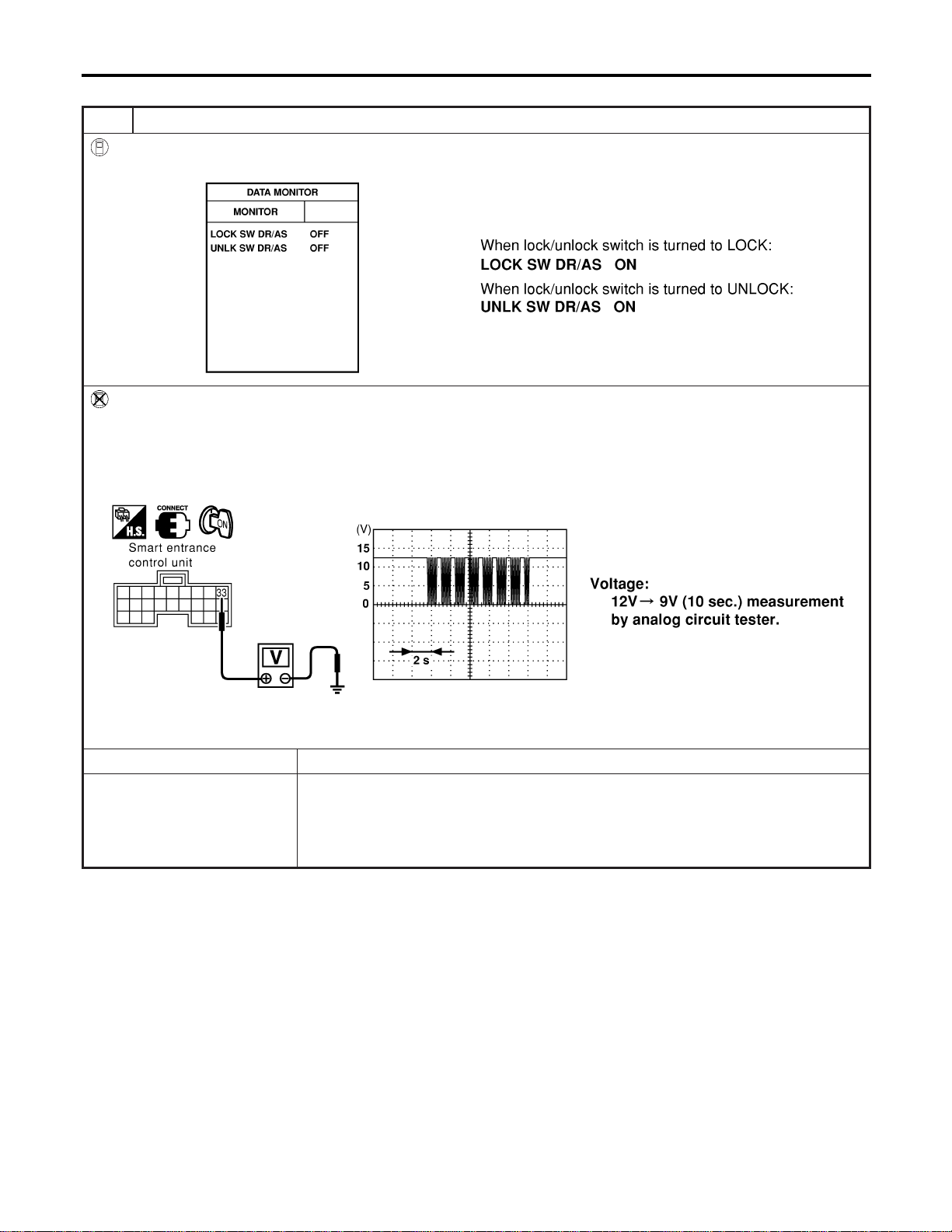
DOOR LOCK/UNLOCK SWITCH CHECK
=NAEL0390S05
1 CHECK DOOR LOCK/UNLOCK SWITCH INPUT SIGNAL
With CONSULT-II
Check door lock/unlock switch (“LOCK SW DR/AS”/“UNLK SW DR/AS”) in “DATA MONITOR” mode with CONSULT-II.
SEL341W
Without CONSULT-II
1. Remove key from ignition switch.
2. Check the signal between smart entrance control unit harness connector M144 terminal 33 (L) and ground with oscillo-
scope when door lock/unlock switch is turned “LOCK” or “UNLOCK”.
3. Make sure signals which are shown in the figure below can be detected during 10 sec. just after door lock/unlock
switch is turned “LOCK” or “UNLOCK”.
SEL487Y
Refer to wiring diagram in EL-294.
OK or NG
OK © Door lock/unlock switch is OK.
NG © Check the following.
I Ground circuit for each front power window switch
I Harness for open or short between each front power window switch and smart
entrance control unit connector
If above systems are normal, replace the front power window switch.
POWER DOOR LOCK
Trouble Diagnoses (Cont’d)
EL-302
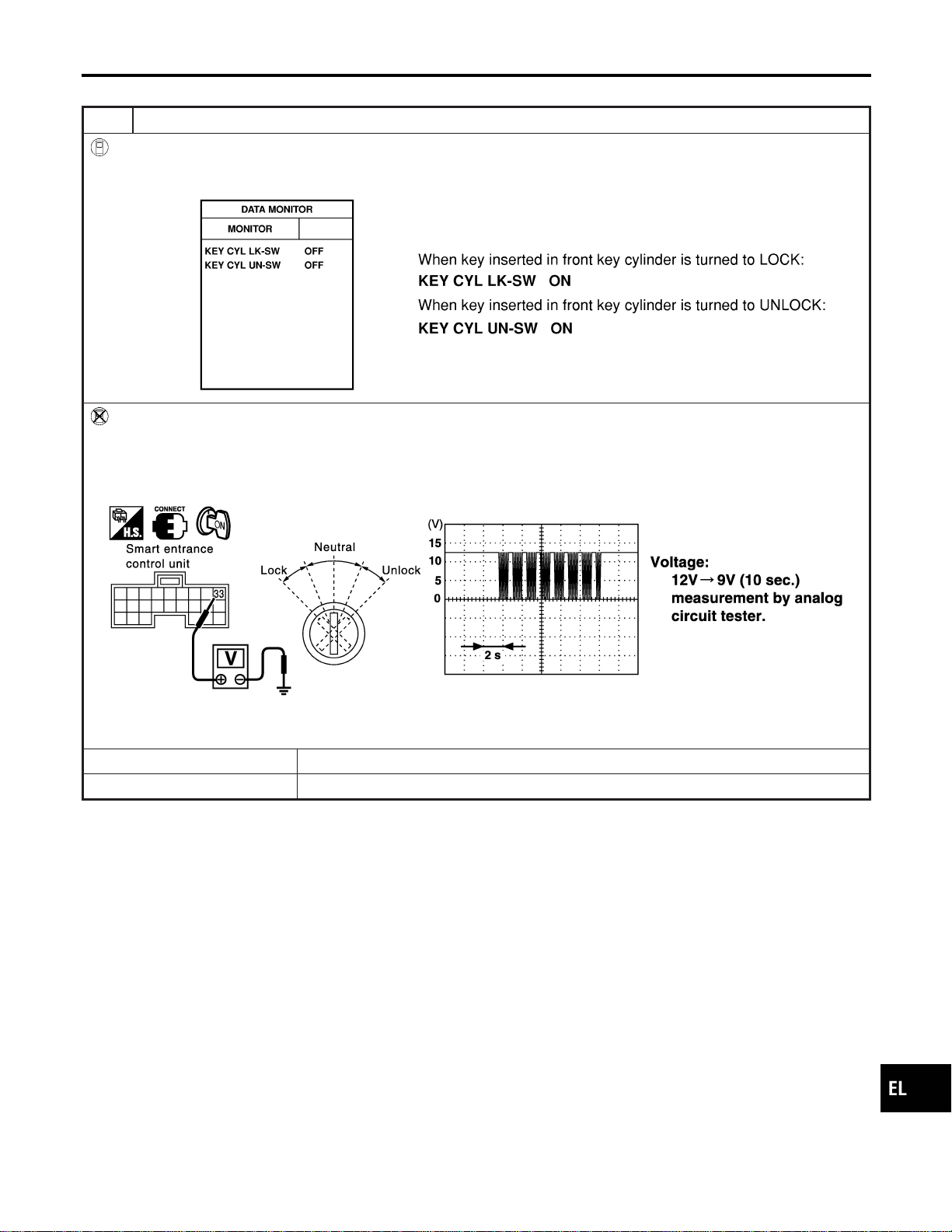
FRONT DOOR KEY CYLINDER SWITCH CHECK
=NAEL0390S06
1 CHECK DOOR KEY CYLINDER SWITCH INPUT SIGNAL (LOCK/UNLOCK SIGNAL)
With CONSULT-II
Check front door key cylinder switch (“KEY CYL LK-SW”/“KEY CYL UN-SW”) in “DATA MONITOR” mode with CONSULT-
II.
SEL342W
Without CONSULT-II
1. Check the signal between smart entrance control unit harness connector M144 terminal 33 (L) and ground with oscillo-
scope when key inserted in front key cylinder is turned “LOCK” or “UNLOCK”.
2. Make sure signals which are shown in the figure below can be detected during 10 sec. just after key is turned “LOCK”
or “UNLOCK”.
SEL488Y
Refer to wiring diagram in EL-294.
OK or NG
OK © Door key cylinder switch LH is OK.
NG © GO TO 2.
GI
MA
EM
LC
EC
FE
CL
MT
AT
TF
PD
AX
SU
BR
ST
RS
BT
HA
SC
IDX
POWER DOOR LOCK
Trouble Diagnoses (Cont’d)
EL-303
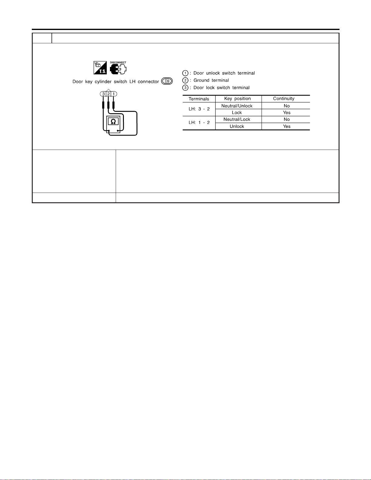
2 CHECK DOOR KEY CYLINDER SWITCH
1. Disconnect door key cylinder switch connector.
2. Check continuity between door key cylinder switch terminals.
SEL313X
OK or NG
OK © Check the following.
I Door key cylinder switch LH ground circuit
I Harness for open or short between smart entrance control unit and front power win-
dow main switch
I Harness for open or short between front power window main switch and door key cyl-
inder switch LH
NG © Replace door key cylinder switch LH.
POWER DOOR LOCK
Trouble Diagnoses (Cont’d)
EL-304
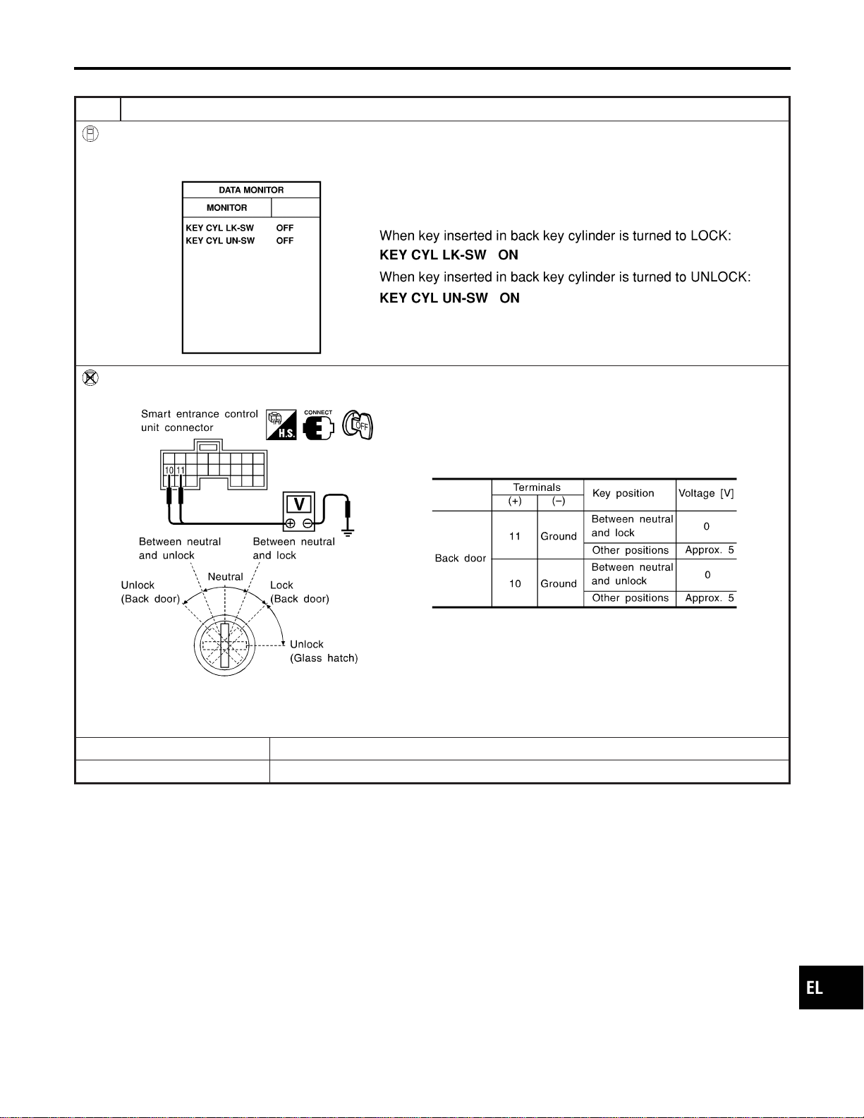
BACK DOOR KEY CYLINDER SWITCH CHECK
=NAEL0390S07
1 CHECK BACK DOOR KEY CYLINDER SWITCH INPUT SIGNAL (LOCK/UNLOCK SIGNAL)
With CONSULT-II
Check back door key cylinder switch (“KEY CYL LK-SW”/“KEY CYL UN-SW”) in “DATA MONITOR” mode with CONSULT-
II.
SEL342WB
Without CONSULT-II
Check voltage between smart entrance control unit harness connector M121 terminals 10 (LG) or 11 (Y) and ground.
SEL286Y
Refer to wiring diagram in EL-291.
OK or NG
OK © Back door key cylinder switch is OK.
NG © GO TO 2.
GI
MA
EM
LC
EC
FE
CL
MT
AT
TF
PD
AX
SU
BR
ST
RS
BT
HA
SC
IDX
POWER DOOR LOCK
Trouble Diagnoses (Cont’d)
EL-305
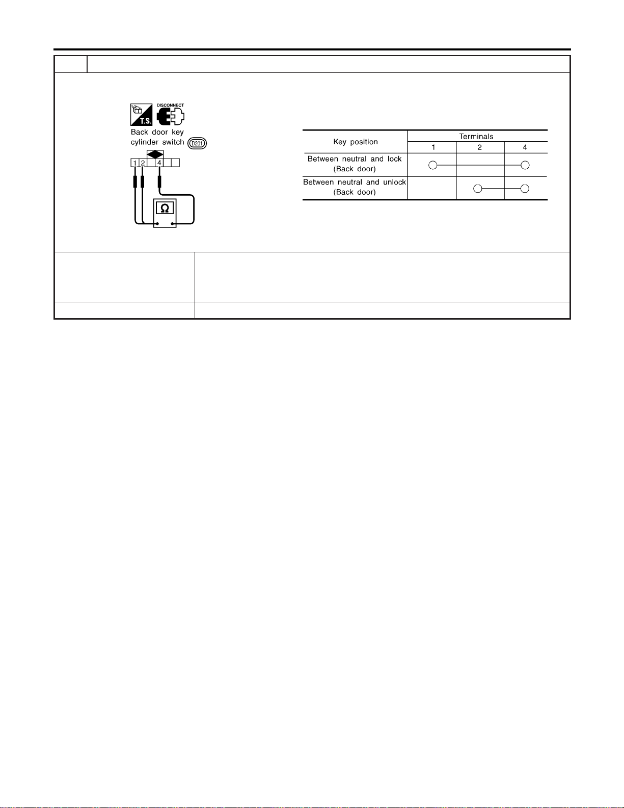
2 CHECK BACK DOOR KEY CYLINDER SWITCH
1. Disconnect back door key cylinder switch connector.
2. Check continuity between back door key cylinder switch terminals.
SEL315X
OK or NG
OK © Check the following.
I Back door key cylinder switch ground circuit
I Harness for open or short between smart entrance control unit and back door key cyl-
inder switch
NG © Replace back door key cylinder switch.
POWER DOOR LOCK
Trouble Diagnoses (Cont’d)
EL-306
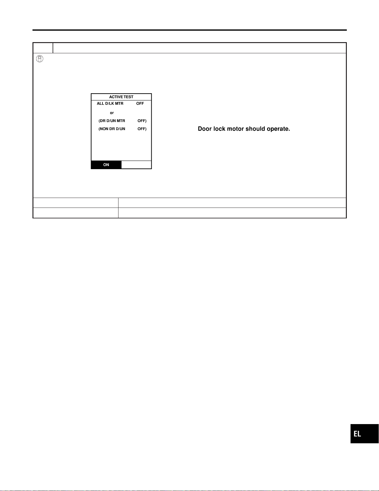
DOOR LOCK ACTUATOR CHECK
=NAEL0390S08
1 CHECK DOOR LOCK ACTUATOR OPERATION
With CONSULT-II
1. Select “ACTIVE TEST” in “DOOR LOCK” with CONSULT-II.
2. Select “ALL D/LK MTR” and touch “ON”.
3. Then, select “DR D/UN MTR” and touch “ON”.
4. Select “NON DR D/UN” and touch “ON”.
SEL343W
NOTE:
If CONSULT-II is not available, skip this procedure and go to the next step.
OK or NG
OK © Door lock actuator is OK.
NG © GO TO 2.
GI
MA
EM
LC
EC
FE
CL
MT
AT
TF
PD
AX
SU
BR
ST
RS
BT
HA
SC
IDX
POWER DOOR LOCK
Trouble Diagnoses (Cont’d)
EL-307
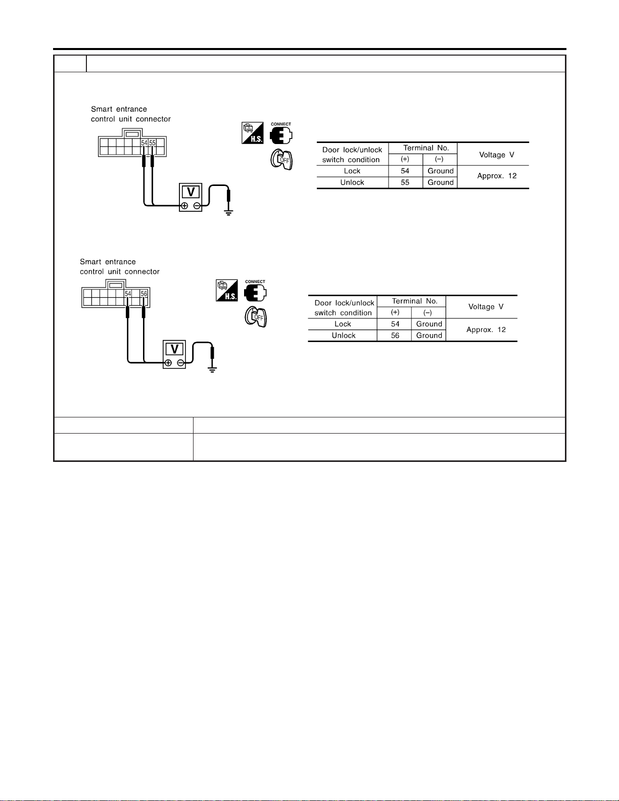
2 CHECK DOOR LOCK ACTUATOR CIRCUIT
I Door lock actuator front LH
Check voltage between smart entrance control unit harness connector M145 terminal 54 (GY), 55 (W/B) and ground.
SEL014Y
I Door lock actuator front RH and rear
Chcek voltage between smart entrance control unit harness connector M145 terminal 54 (GY), 56 (G/Y) and ground.
SEL015Y
Refer to wiring diagram in EL-292.
OK or NG
OK © GO TO 2.
NG © Replace smart entrance control unit. (Before replacing smart entrance control unit, per-
form “DOOR LOCK/UNLOCK SWITCH CHECK”.)
POWER DOOR LOCK
Trouble Diagnoses (Cont’d)
EL-308
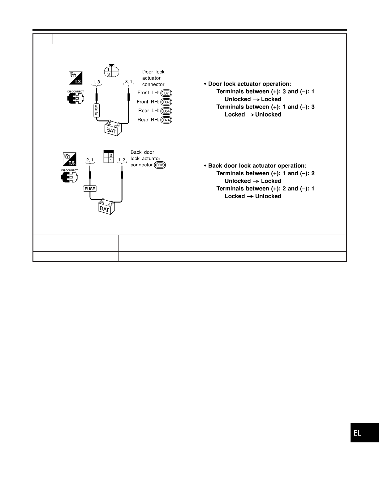
3 CHECK DOOR LOCK ACTUATOR
1. Disconnect door lock actuator connector.
2. Apply 12V direct current to door lock actuator and check operation.
SEL318X
SEL319X
OK or NG
OK © Check harness for open or short between smart entrance control unit connector and door
lock actuator.
NG © Replace door lock actuator.
GI
MA
EM
LC
EC
FE
CL
MT
AT
TF
PD
AX
SU
BR
ST
RS
BT
HA
SC
IDX
POWER DOOR LOCK
Trouble Diagnoses (Cont’d)
EL-309
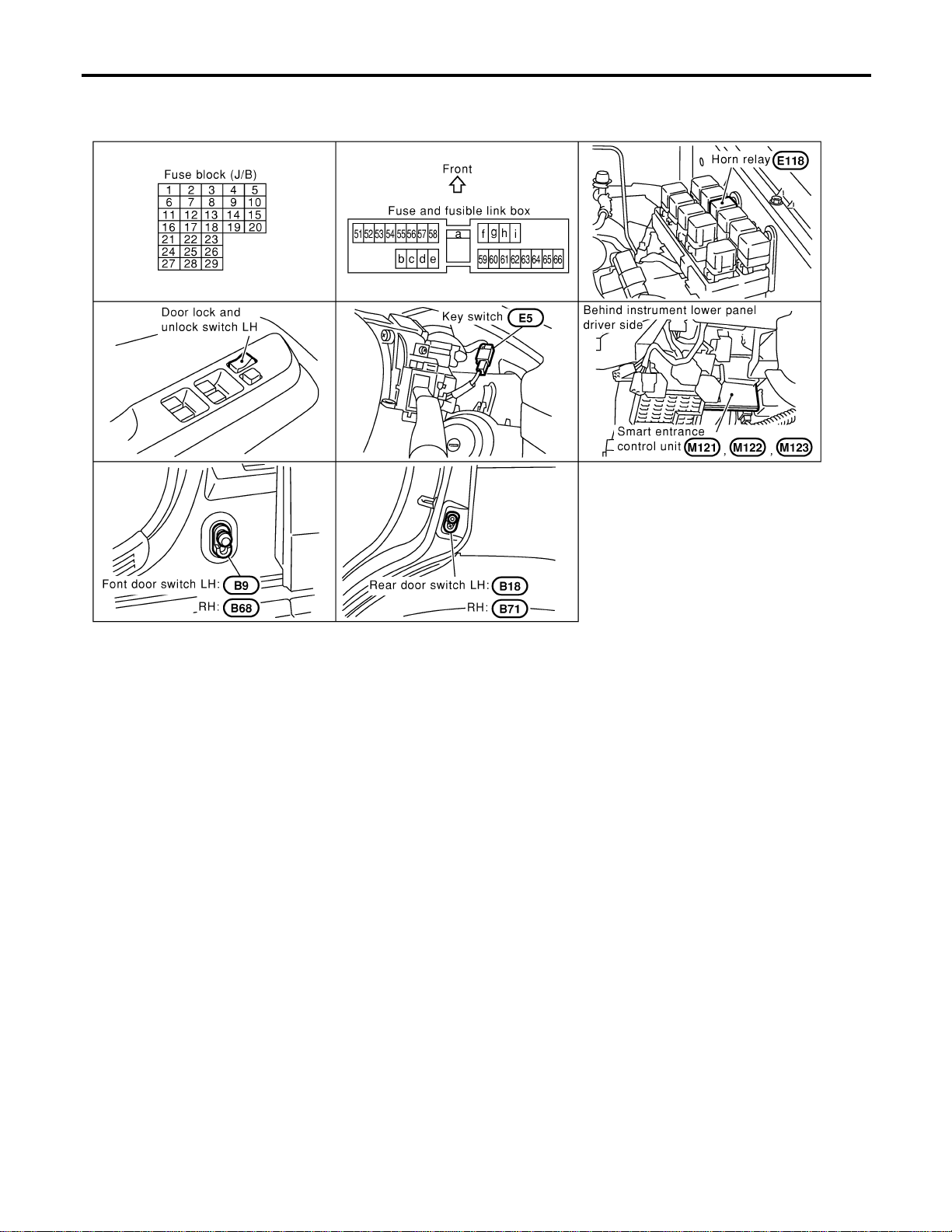
Component Parts and Harness Connector
Location
NAEL0391
SEL290Y
System Description
NAEL0392
INPUTS
NAEL0392S01
Power is supplied at all times
I to smart entrance control unit terminal 49 and
I to key switch terminal 2
I through 7.5A fuse [No. 24, located in the fuse block (J/B)].
When the key switch is ON (ignition key is inserted in key cylinder), power is supplied
I through key switch terminal 1
I to smart entrance control unit terminal 25.
When the front door switch LH is ON (door is OPEN), ground is supplied
I to smart entrance control unit terminal 1
I through front door switch LH terminal 1
I to front door switch LH terminal 2
I through body grounds B11, B22 and D210.
When the front door switch RH is ON (door is OPEN), ground is supplied
I to smart entrance control unit terminal 2
I through front door switch RH terminal 1
I to front door switch RH terminal 2
I through body grounds B55 and B75.
When the all doors switches are ON (door is OPEN), ground is supplied
REMOTE KEYLESS ENTRY SYSTEM
Component Parts and Harness Connector Location
EL-310

I to smart entrance control unit terminal 3
I through front door switches terminal 3
I to front door switches case grounds, and
I through rear door switches terminal 1
I to rear door switchs case grounds, and
I through back door switch terminal 2
I to back door switch terminal 1
I through body grounds B11, B22 and D210.
When lock/unlock switch LH is LOCK, ground is supplied
I to smart entrance control unit terminal 5
I through lock/unlock switch LH terminal 6, and
I through body grounds M77 and M111.
When lock/unlock switch LH is UNLOCK, ground is supplied
I to smart entrance control unit terminal 4
I through lock/unlock switch LH terminal 19, and
I through body grounds M77 and M111.
Remote controller signal is inputted to smart entrance control unit (The antenna of the system is combined
with smart entrance control unit).
OPERATION
NAEL0392S02
The remote keyless entry system controls operation of the
I power door lock
I auto door lock
I interior lamp
I panic alarm
I hazard and horn reminder
I power window opener
OPERATED PROCEDURE
NAEL0392S03
Power Door Lock Operation
NAEL0392S0301
Smart entrance control unit receives a LOCK signal from keyfob. Smart entrance control unit locks all doors
with input of LOCK signal from keyfob.
When an UNLOCK signal is sent from keyfob once, driver’s door will be unlocked.
Then, if an UNLOCK signal is sent from keyfob again within 5 seconds, all other door will be unlocked.
Select unlock mode can be changed by CONSULT-II (EL-320).
Auto Door Lock Operation
NAEL0392S0308
Auto lock function signal is sent for operation when any of the following signals are not sent within 5 minutes
after the unlock signal is sent from the keyfob:
I when door switch is turned ON for open.
I when the ignition switch is turned ON.
I when the lock signal is sent from the keyfob.
Auto door lock mode can be changed by CONSULT-II (EL-320).
Hazard and Horn Reminder
NAEL0392S0302
Power is supplied at all times
I to horn relay terminals 1 and 3
I through 7.5A fuse (No. 52, located in the fusible link and fuse box), and
I to horn relay terminal 6
I through 10A fuse (No. 54, located in the fusible link and fuse box)
When smart entrance control unit receives LOCK or UNLOCK signal from remote controller with all doors
closed, ground is supplied
I to horn relay terminal 2
I through smart entrance control unit terminal 42, and
I to smart entrance control unit terminals 47 and 48 from hazard warning lamp system.
GI
MA
EM
LC
EC
FE
CL
MT
AT
TF
PD
AX
SU
BR
ST
RS
BT
HA
SC
IDX
REMOTE KEYLESS ENTRY SYSTEM
System Description (Cont’d)
EL-311
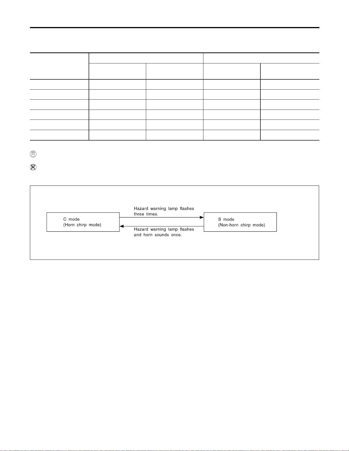
Horn relay are now energized, and hazard warning lamp flashes and horn sounds as a reminder.
The hazard and horn reminder has C mode (horn chirp mode) and S mode (non-horn chirp mode).
Operating function of hazard and horn reminder
Lock Unlock
Hazard warning lamp
flash
Horn sound
Hazard warning lamp
flash
Horn sound
C MODE Twice Once Once —
S MODE Twice — — —
MODE 3 ————
MODE 4 Twice — Once —
MODE 5 Twice Once — —
MODE 6 — Once Once —
How to change hazard and horn reminder mode
With CONSULT-II
Hazard and horn reminder can be changed by CONSULT-II (EL-320).
Without CONSULT-II
When LOCK and UNLOCK signals are sent from the keyfob for more than 2 seconds at the same time, the
hazard and horn reminder mode is changed and hazard warning lamp flashes and horn sounds as follows:
SEL153WA
NOTE:
Reminder mode setting cannot be changed without CONSULT-II for MODES 3,4, 5, and 6. However, C and
S MODES can be changed without CONSULT-II.
Interior Lamp Operation
NAEL0392S0303
When the following input signals are both supplied:
I door switch CLOSED (when all the doors are closed);
I driver’s door LOCKED;
remote keyless entry system turns on interior lamp and keyhole illumination (for 30 seconds) with input of
UNLOCK signal from keyfob.
For detailed description, refer to “INTERIOR, STEP, SPOT, VANITY MIRROR AND TRUNK ROOM LAMPS”
(EL-92).
Panic Alarm Operation
NAEL0392S0304
When key switch is OFF (when ignition key is not inserted in key cylinder), remote keyless entry system turns
horn and headlamp on and off intermittently with input of PANIC ALARM signal from keyfob.
The alarm automatically turns off after 25 seconds or when smart entrance control unit receives any signal
from keyfob.
For detailed description, refer to “VEHICLE SECURITY SYSTEM” (EL-343).
The panic alarm button’s pressing time on keyfob can be changed with CONSULT-II (EL-320).
Power Window Opener Operation
NAEL0392S0307
The front power windows open when the unlock button on keyfob is activated and kept pressed for more than
3 seconds with the ignition key OFF. The windows keep opening if the unlock button is continuously pressed.
The power window opening stops when the following operations are carried out:
REMOTE KEYLESS ENTRY SYSTEM
System Description (Cont’d)
EL-312

I When the unlock button is kept pressed more than 15 seconds.
I When the ignition switch is turned ON while the power window opening is operated.
I When the unlock button is released.
The unlock button’s pressing time can be changed with CONSULT-II (EL-320).
Door Lock/Unlock and front power window down signal is supplied
I through smart entrance control unit terminal 33
I to front power window main switch terminal 8 and
I to front power window switch RH terminal 11.
GI
MA
EM
LC
EC
FE
CL
MT
AT
TF
PD
AX
SU
BR
ST
RS
BT
HA
SC
IDX
REMOTE KEYLESS ENTRY SYSTEM
System Description (Cont’d)
EL-313
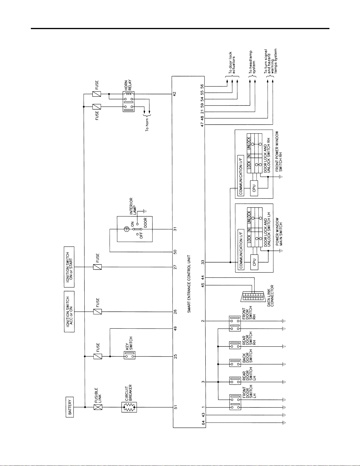
Schematic
NAEL0393
MEL433O
REMOTE KEYLESS ENTRY SYSTEM
Schematic
EL-314
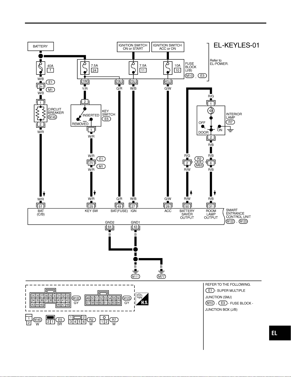
Wiring Diagram — KEYLESS —
NAEL0394
FIG. 1
NAEL0394S01
MEL411O
GI
MA
EM
LC
EC
FE
CL
MT
AT
TF
PD
AX
SU
BR
ST
RS
BT
HA
SC
IDX
REMOTE KEYLESS ENTRY SYSTEM
Wiring Diagram — KEYLESS —
EL-315
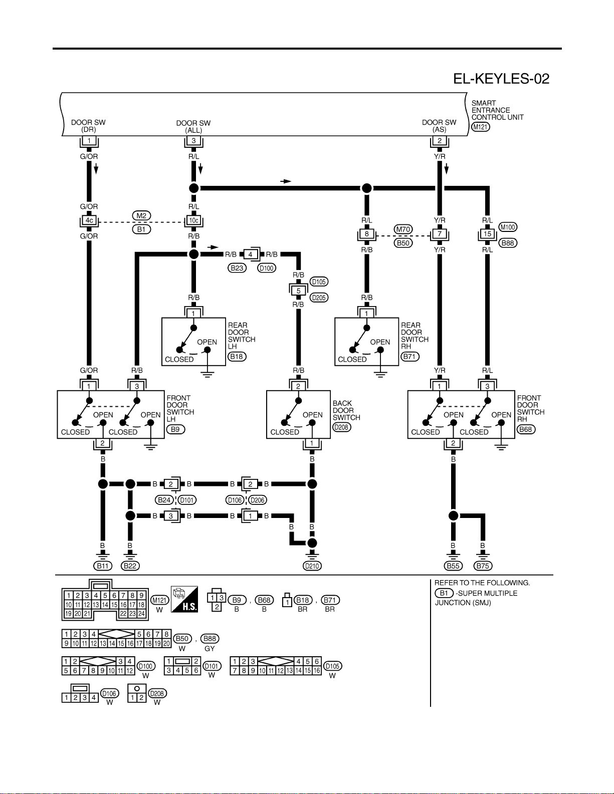
FIG. 2
NAEL0394S02
MEL412O
REMOTE KEYLESS ENTRY SYSTEM
Wiring Diagram — KEYLESS — (Cont’d)
EL-316
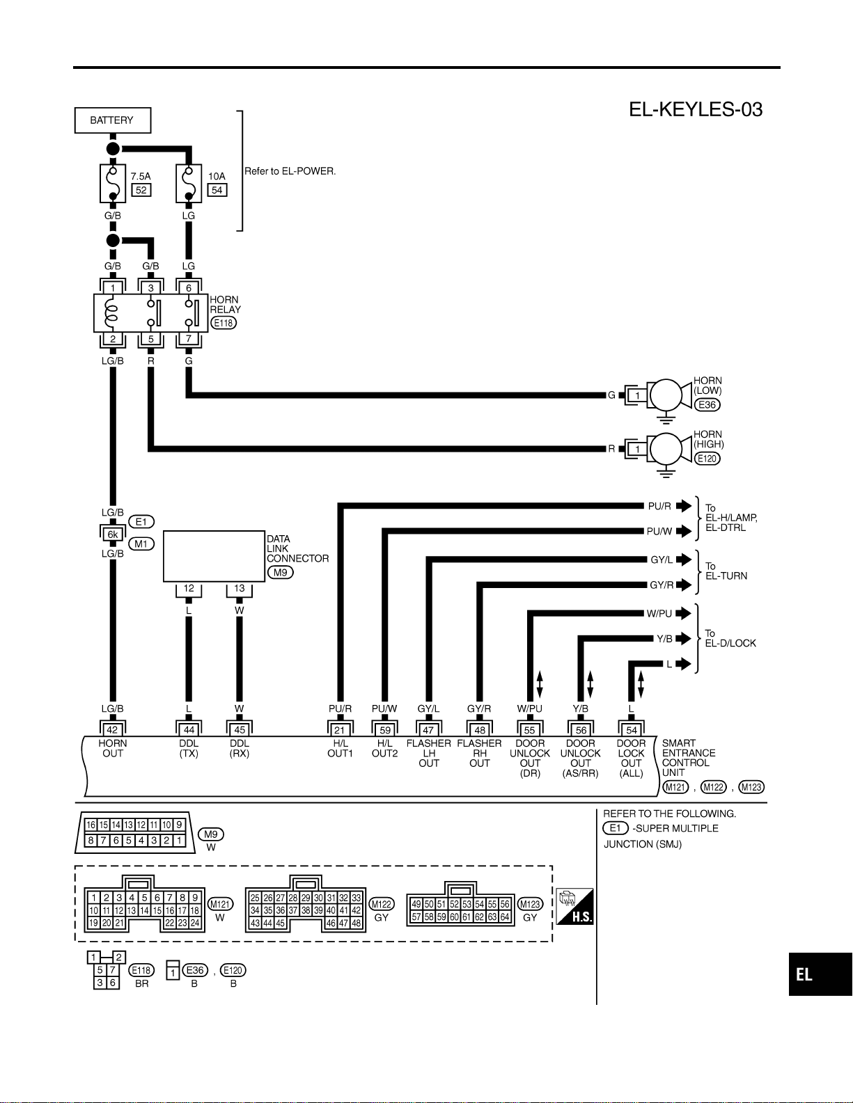
FIG. 3
NAEL0394S03
MEL413O
GI
MA
EM
LC
EC
FE
CL
MT
AT
TF
PD
AX
SU
BR
ST
RS
BT
HA
SC
IDX
REMOTE KEYLESS ENTRY SYSTEM
Wiring Diagram — KEYLESS — (Cont’d)
EL-317
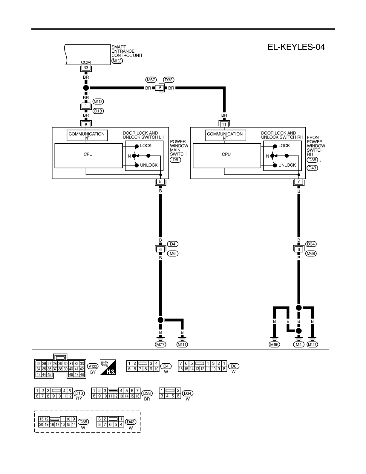
FIG. 4
NAEL0394S05
MEL436P
REMOTE KEYLESS ENTRY SYSTEM
Wiring Diagram — KEYLESS — (Cont’d)
EL-318
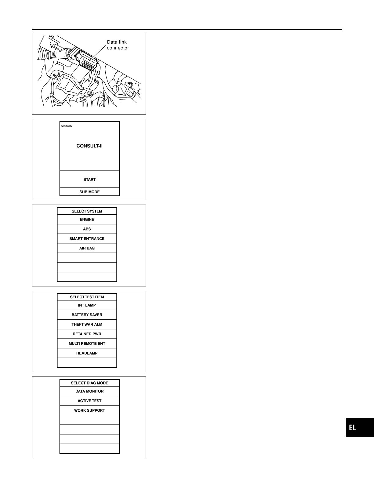
SEL331X
CONSULT-II Inspection Procedure
NAEL0395
“MULTI REMOTE ENT”
NAEL0395S01
1. Turn ignition switch “OFF”.
2. Connect “CONSULT-II” to the data link connector.
PBR455D
3. Turn ignition switch “ON”.
4. Touch “START”.
SEL398Y
5. Touch “SMART ENTRANCE”.
SEL401Y
6. Touch “MULTI REMOTE ENT”.
SEL274W
7. Select diagnosis mode.
“DATA MONITOR”, “ACTIVE TEST” and “WORK SUPPORT”
are available.
GI
MA
EM
LC
EC
FE
CL
MT
AT
TF
PD
AX
SU
BR
ST
RS
BT
HA
SC
IDX
REMOTE KEYLESS ENTRY SYSTEM
CONSULT-II Inspection Procedure
EL-319

CONSULT-II Application Items
NAEL0457
“MULTI REMOTE ENT”
NAEL0457S01
Data Monitor
NAEL0457S0101
Monitored Item Description
IGN ON SW Indicates [ON/OFF] condition of ignition switch in ON position.
ACC ON SW Indicates [ON/OFF] condition of ignition switch in ACC position.
DOOR SW-RR Indicates [ON/OFF] condition of rear door switch.
KEY ON SW Indicates [ON/OFF] condition of key switch.
DOOR SW-DR Indicates [ON/OFF] condition of front door switch LH.
DOOR SW-AS Indicates [ON/OFF] condition of door switch RH.
LOCK SW DR/AS Indicates [ON/OFF] condition of lock signal from lock/unlock switch LH and RH.
UNLK SW DR/AS Indicates [ON/OFF] condition of unlock signal from lock/unlock switch LH and RH.
KEY CYL LK-SW Indicates [ON/OFF] condition of lock signal from key cylinder switch.
LK BUTTON/SIG Indicates [ON/OFF] condition of lock signal from keyfob.
UN BUTTON/SIG Indicates [ON/OFF] condition of unlock signal from keyfob.
TRUNK BTN/SIG Indicates [ON/OFF] condition of trunk open signal from keyfob.
PANIC BTN Indicates [ON/OFF] condition of panic signal from keyfob.
UN BUTTON ON Indicates [ON/OFF] condition of unlock switch form keyfob.
LK/UN BTN ON Indicates [ON/OFF] condition of lock/unlock signal at the same time from keyfob.
NOTE:
Even though TRUNK BTN/SIG is actually displayed on the CONSULT-II screen, it is not equipped, therefore, they cannot be activated.
Active Test
NAEL0457S0102
Test Item Description
INT/IGN ILLUM This test is able to check interior lamp and ignition key hole illumination operation. The interior
lamp and ignition key hole illumination are turned on when “ON” on CONSULT-II screen is
touched.
HAZARD This test is able to check hazard reminder operation. The hazard lamp turns on when “ON” on
CONSULT-II screen is touched.
TRUNK OUTPUT This test is able to check trunk lid opener actuator operation. The trunk is unlocked when “ON”
on CONSULT-II screen is touched.
HORN This test is able to check panic alarm and horn reminder operations. The alarm activate for 0.5
seconds after “ON” on CONSULT-II screen is touched.
HEAD LAMP This test is able to check headlamps panic alarm operation. The headlamp illuminates for 0.5
seconds after “ON” on CONSULT-II screen is touched.
PW REMOTE DOWN SET This test is able to check power window open operation. The front power windows activate for
10 seconds after “ON” on CONSULT-II screen is touched.
NOTE:
Even though TRUNK OUTPUT is actually displayed on the CONSULT-II screen, it is not equipped, therefore, they cannot be activated.
Work Support
NAEL0457S0103
Test Item Description
REMO CONT ID CONFIR It can be checked whether keyfob ID code is registered or not in this mode.
REMO CONT ID REGIST Keyfob ID code can be registered.
REMO CONT ID ERASUR Keyfob ID code can be erased.
REMOTE KEYLESS ENTRY SYSTEM
CONSULT-II Application Items
EL-320
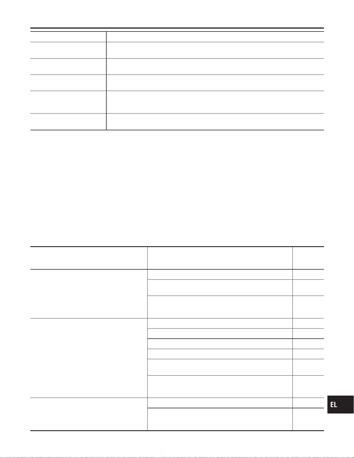
Test Item Description
MULTI ANSWER BACK SET Hazard and horn reminder mode can be changed with this mode. Selects hazard and horn
reminder mode among six steps (EL-311).
AUTO LOCK SET Auto door lock mode can be selected among the following periods:
I MODE 1 (5 min.)/MODE 2 (OFF-Mode)/MODE 3 (1 min.)
PANIC ALARM SET The panic alarm button’s pressing time on keyfob can be selected among the following periods:
I MODE 1 (0.5 sec.)/MODE 2 (OFF-Mode)/MODE 3 (1.5 sec.)
TRUNK OPENER The trunk lid opener button’s pressing time on keyfob can be selected among the following peri-
ods:
I MODE 1 (0.5 sec.)/MODE 2 (OFF-Mode)/MODE 3 (1.5 sec.)
PW DOWN SET The unlock button’s pressing time on keyfob can be selected among the following periods:
I MODE 1 (3 sec.)/MODE 2 (OFF-Mode)/MODE 3 (5 sec.)
NOTE:
Even though TRUNK OPENER is actually displayed on the CONSULT-II screen, it is not equipped, therefore, they cannot be activated.
Trouble Diagnoses
NAEL0397
SYMPTOM CHART
NAEL0397S01
NOTE:
I Always check keyfob battery before replacing keyfob.
I The panic alarm operation of remote keyless entry system
does not activate with the ignition key inserted in the ignition
key cylinder.
Symptom Diagnoses/service procedure
Reference
page
(EL- )
All functions of remote keyless entry system do
not operate.
1. Keyfob battery and function check 323
2. Power supply and ground circuit for smart entrance control
unit check
324
3. Replace keyfob. Refer to ID Code Entry Procedure.
NOTE: If the result of keyfob function check with CONSULT-II is
OK, keyfob is not malfunctioning.
336
The new ID of keyfob cannot be entered. 1. Keyfob battery and function check 323
2. Key switch (insert) check 328
3. Door switch check 326
4. Door lock/unlock switch LH check 329
5. Power supply and ground circuit for smart entrance control
unit check
324
6. Replace keyfob. Refer to ID Code Entry Procedure.
NOTE: If the result of keyfob function check with CONSULT-II is
OK, keyfob is not malfunctioning.
336
Door lock or unlock does not function.
(If the power door lock system does not operate
manually, check power door lock system. Refer to
EL-297)
1. Keyfob battery and function check 323
2. Replace keyfob. Refer to ID Code Entry Procedure.
NOTE: If the result of keyfob function check with CONSULT-II is
OK, keyfob is not malfunctioning.
336
GI
MA
EM
LC
EC
FE
CL
MT
AT
TF
PD
AX
SU
BR
ST
RS
BT
HA
SC
IDX
REMOTE KEYLESS ENTRY SYSTEM
CONSULT-II Application Items (Cont’d)
EL-321

Symptom Diagnoses/service procedure
Reference
page
(EL- )
Hazard and horn reminder does not activate prop-
erly when pressing lock or unlock button of key-
fob.
1. Keyfob battery and function check 323
2. Hazard reminder check 330
3. Horn reminder check*
*: Horn chirp can be activated or deactivated.
First check the horn chirp setting. Refer to “System Description”,
EL-311.
331
4. Door switch check 326
5. Replace keyfob. Refer to ID Code Entry Procedure.
NOTE: If the result of keyfob function check with CONSULT-II is
OK, keyfob is not malfunctioning.
336
Interior room lamp operation do not activate prop-
erly.
1. Interior room lamp operation check 333
2. Door switch check 326
Panic alarm (horn and headlamp) does not acti-
vate when panic alarm button is continuously
pressed.
1. Keyfob battery and function check 323
2. Theft warning operation check. Refer to “PRELIMINARY
CHECK” in “VEHICLE SECURITY SYSTEM”.
354
3. Key switch (insert) check 328
4. Replace keyfob. Refer to ID Code Entry Procedure.
NOTE: If the result of keyfob function check with CONSULT-II is
OK, keyfob is not malfunctioning.
336
REMOTE KEYLESS ENTRY SYSTEM
Trouble Diagnoses (Cont’d)
EL-322

REMOTE CONTROLLER BATTERY AND FUNCTION
CHECK
=NAEL0397S02
1 CHECK REMOTE CONTROLLER BATTERY
Remove battery (refer to EL-338) and measure voltage across battery positive and negative terminals, (+) and (−).
Voltage [V]:
2.5 - 3.0
NOTE:
Keyfob does not function if battery is not set correctly.
SEL237W
OK or NG
OK © GO TO 2.
NG © Replace battery.
2 CHECK REMOTE CONTROLLER FUNCTION
With CONSULT-II
Check keyfob function (“LK BUTTON/SIG”, “UN BUTTON/SIG”, “PANIC BTN”, “UN BUTTON ON” and “LK/UN BTN ON”)
in “DATA MONITOR” mode with CONSULT-II.
SEL423Y
NOTE:
Even though TRUNK BTN/SIG is actually displayed on the CONSULT-II screen, it is not equipped, therefore, they cannot
be activated.
OK or NG
OK © Keyfob is OK. Further inspection is necessary. Refer to “SYMPTOM CHART”, EL-321.
NG © Replace keyfob. Refer to ID Code Entry Procedure.
GI
MA
EM
LC
EC
FE
CL
MT
AT
TF
PD
AX
SU
BR
ST
RS
BT
HA
SC
IDX
REMOTE KEYLESS ENTRY SYSTEM
Trouble Diagnoses (Cont’d)
EL-323
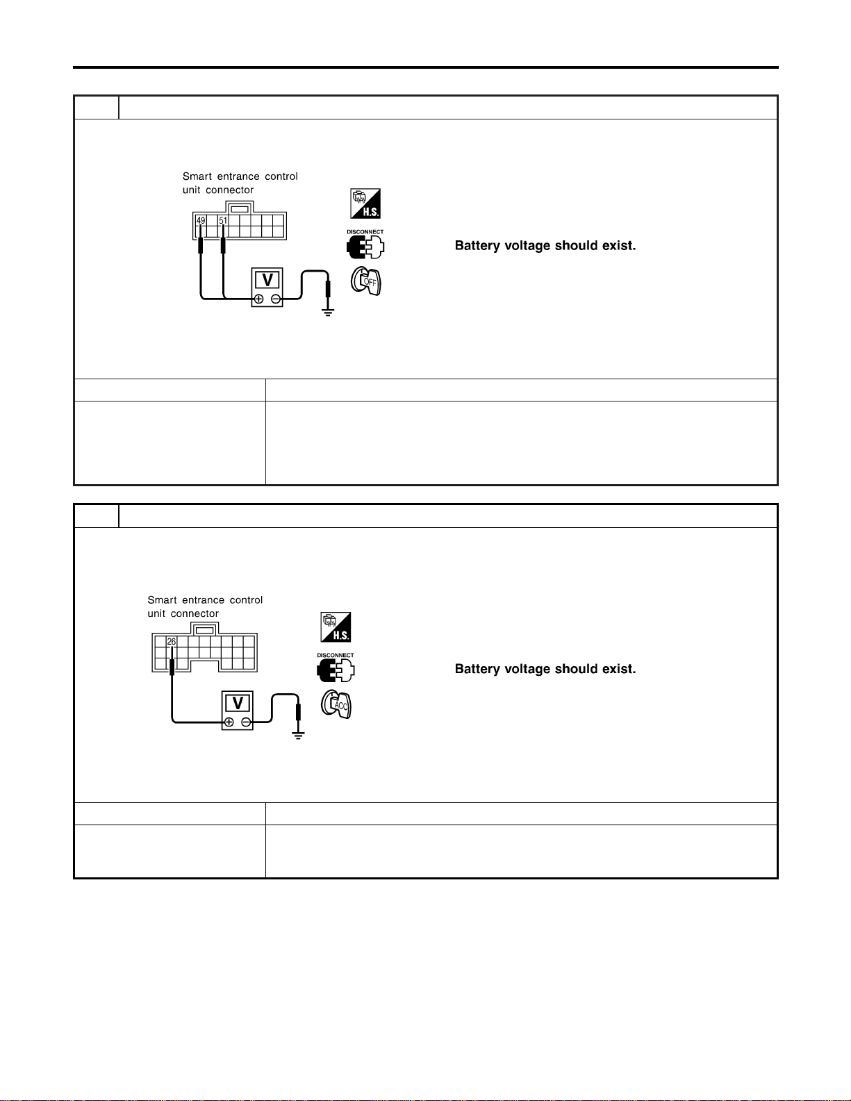
POWER SUPPLY AND GROUND CIRCUIT CHECK
=NAEL0397S03
1 CHECK MAIN POWER SUPPLY CIRCUIT FOR SMART ENTRANCE CONTROL UNIT
1. Disconnect smart entrance control unit harness connector.
2. Check voltage between smart entrance control unit harness connector M123 terminal 49 (G/R) or 51 (W/R) and ground.
SEL018Y
Refer to wiring diagram in EL-315.
OK or NG
OK © GO TO 2.
NG © Check the following.
I 40A fusible link (letter f, located in fuse and fusible link box)
I 7.5A fuse [No. 24, located in fuse block (J/B)]
I M145 circuit breaker
I Harness for open or short between smart entrance control unit and fuse
2 CHECK IGNITION SWITCH “ACC” CIRCUIT
1. Disconnect smart entrance control unit harness connector.
2. Check voltage between smart entrance control unit harness connector M122 terminal 26 (G/W) and ground while igni-
tion switch is “ACC”.
SEL019Y
Refer to wiring diagram in EL-315.
OK or NG
OK © GO TO 3.
NG © Check the following.
I 10A fuse [No. 10, located in fuse block (J/B)]
I Harness for open or short between smart entrance control unit and fuse
REMOTE KEYLESS ENTRY SYSTEM
Trouble Diagnoses (Cont’d)
EL-324
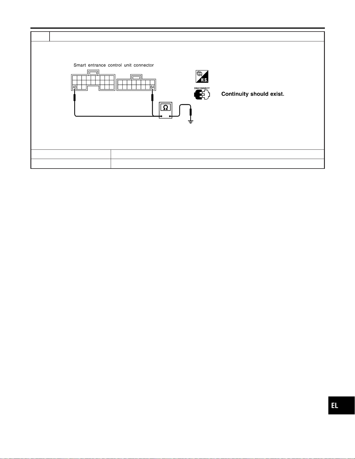
3 CHECK GROUND CIRCUIT FOR SMART ENTRANCE CONTROL UNIT
Check continuity between smart entrance control unit harness connector M122 terminal 43 (B) or M123 terminal 64 (B)
and ground.
SEL020Y
Refer to wiring diagram in EL-315.
OK or NG
OK © Power supply and ground circuits are OK.
NG © Check ground harness.
GI
MA
EM
LC
EC
FE
CL
MT
AT
TF
PD
AX
SU
BR
ST
RS
BT
HA
SC
IDX
REMOTE KEYLESS ENTRY SYSTEM
Trouble Diagnoses (Cont’d)
EL-325
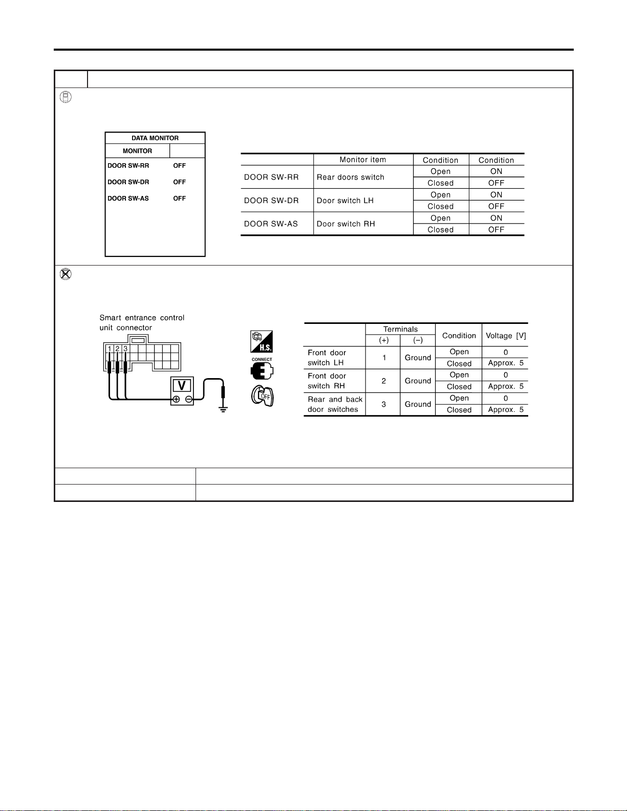
DOOR SWITCH CHECK
=NAEL0397S04
1 CHECK DOOR SWITCH INPUT SIGNAL
With CONSULT-II
Check door switches (“DOOR SW-RR”, “DOOR SW-DR” and “DOOR SW-AS”) in “DATA MONITOR” mode with CON-
SULT-II.
SEL024Y
Without CONSULT-II
Check voltage between smart entrance control unit harness connector M121 terminals 1 (G/OR), 2 (Y) or 3 (R/L) and
ground.
SEL021YA
Refer to wiring diagram in EL-316.
OK or NG
OK © Door switch is OK.
NG © GO TO 2.
REMOTE KEYLESS ENTRY SYSTEM
Trouble Diagnoses (Cont’d)
EL-326
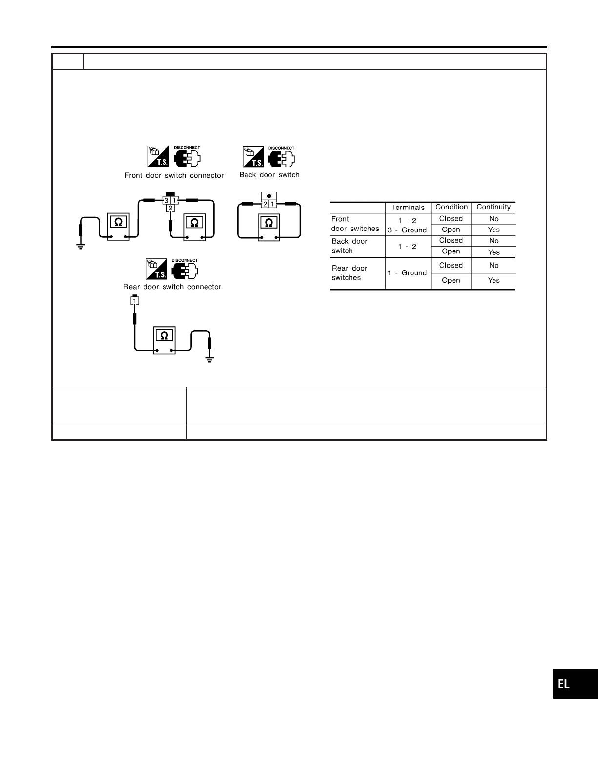
2 CHECK DOOR SWITCH
1. Disconnect door switch harness connector.
2. Check the following.
I Continuity between front door switch harness connector B9 (LH) or B68 (RH) terminals 1 and 2
I Continuity between front door switch harness connector B9 (LH) or B68 (RH) terminal 3 and ground
I Continuity between back door switch harness connector D208 terminals 1 and 2
I Continuity between rear door switch harness connector B18 (LH) or B71 (RH) terminal 1 and ground
SEL287Y
OK or NG
OK © Check the following.
I Door switch ground circuit (Front or back door) or door switch ground condition
I Harness for open or short between smart entrance control unit and door switch
NG © Replace door switch.
GI
MA
EM
LC
EC
FE
CL
MT
AT
TF
PD
AX
SU
BR
ST
RS
BT
HA
SC
IDX
REMOTE KEYLESS ENTRY SYSTEM
Trouble Diagnoses (Cont’d)
EL-327
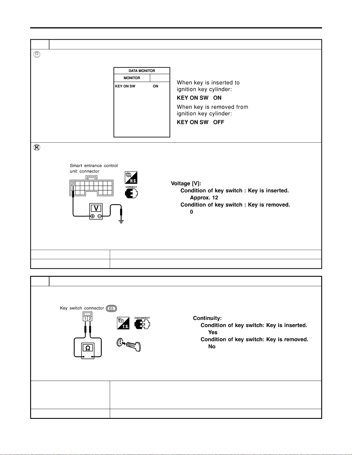
KEY SWITCH (INSERT) CHECK
=NAEL0397S05
1 CHECK KEY SWITCH INPUT SIGNAL
With CONSULT-II
Check key switch (“KEY ON SW”) in “DATA MONITOR” mode with CONSULT-II.
SEL315W
Without CONSULT-II
Check voltage between control unit harness connector M122 terminal 25 (W/R) and ground.
SEL022Y
Refer to wiring diagram in EL-315.
OK or NG
OK © Key switch is OK.
NG © GO TO 2.
2 CHECK KEY SWITCH (INSERT)
Check continuity between key switch terminals 1 and 2.
SEL308X
OK or NG
OK © Check the following.
I 7.5A fuse [No. 24, located in fuse block (J/B)]
I Harness for open or short between key switch and fuse
I Harness for open or short between smart entrance control unit and key switch
NG © Replace key switch.
REMOTE KEYLESS ENTRY SYSTEM
Trouble Diagnoses (Cont’d)
EL-328
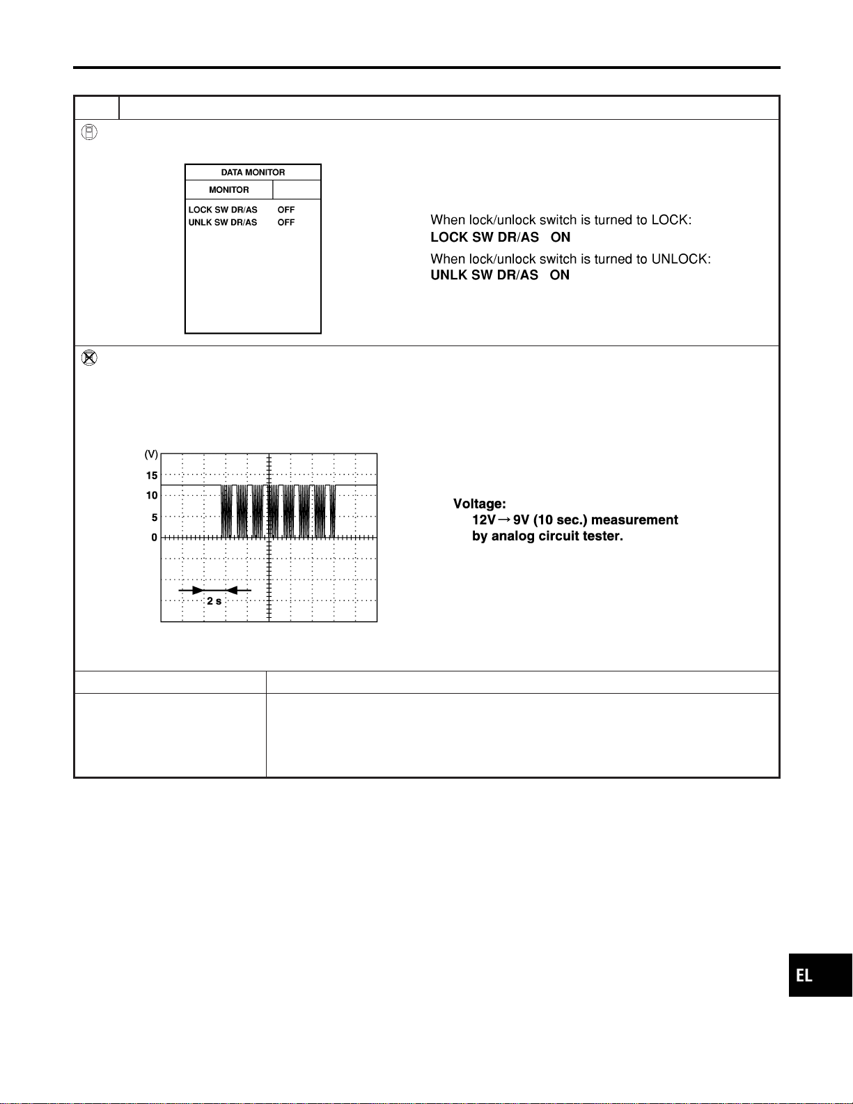
DOOR LOCK/UNLOCK SWITCH LH CHECK
=NAEL0397S06
1 CHECK DOOR LOCK/UNLOCK SWITCH INPUT SIGNAL
With CONSULT-II
Check door lock/unlock switch (“LOCK SW DR/AS”/“UNLK SW DR/AS”) in “DATA MONITOR” mode with CONSULT-II.
SEL341W
Without CONSULT-II
1. Remove key from ignition switch.
2. Check the signal between smart entrance control unit harness connector M122 terminal 33 (BR) and ground with an
oscilloscope when door lock/unlock switch is turned “LOCK” or “UNLOCK”.
3. Make sure signals shown in the figure below can be detected during the first 10 sec. just after door lock/unlock switch
is turned to “LOCK” or “UNLOCK”.
SEL396Y
Refer to wiring diagram in EL-315.
OK or NG
OK © Door lock/unlock switch is OK.
NG © Check the following.
I Ground circuit for each front power window switch
I Harness for open or short between each front power window switch and smart
entrance control unit connector
If above systems are normal, replace the front power window switch.
GI
MA
EM
LC
EC
FE
CL
MT
AT
TF
PD
AX
SU
BR
ST
RS
BT
HA
SC
IDX
REMOTE KEYLESS ENTRY SYSTEM
Trouble Diagnoses (Cont’d)
EL-329

HAZARD REMINDER CHECK
=NAEL0397S07
1 CHECK HAZARD INDICATOR
Check if hazard indicator flashes with hazard switch.
Does hazard indicator operate?
Yes © GO TO 2.
No © Check “hazard indicator” circuit.
2 CHECK HAZARD REMINDER OPERATION WITH CONSULT-II
With CONSULT-II
1. Select “ACTIVE TEST” in “MULTI REMOTE ENT” with CONSULT-II.
2. Select “HAZARD” and touch “ON”.
SEL347W
NOTE: If CONSULT-II is not available, skip this procedure and go to the next step.
OK or NG
OK © Hazard reminder operation is OK.
NG © Replace smart entrance control unit.
3 CHECK HAZARD REMINDER OPERATION WITHOUT CONSULT-II
Without CONSULT-II
Apply ground to smart entrance control unit harness connector M122 terminal 47 (GY/L) and 48 (GY/R).
SEL027Y
Refer to wiring diagram in EL-317.
OK or NG
OK © System is OK.
NG © Replace smart entrance control unit.
REMOTE KEYLESS ENTRY SYSTEM
Trouble Diagnoses (Cont’d)
EL-330
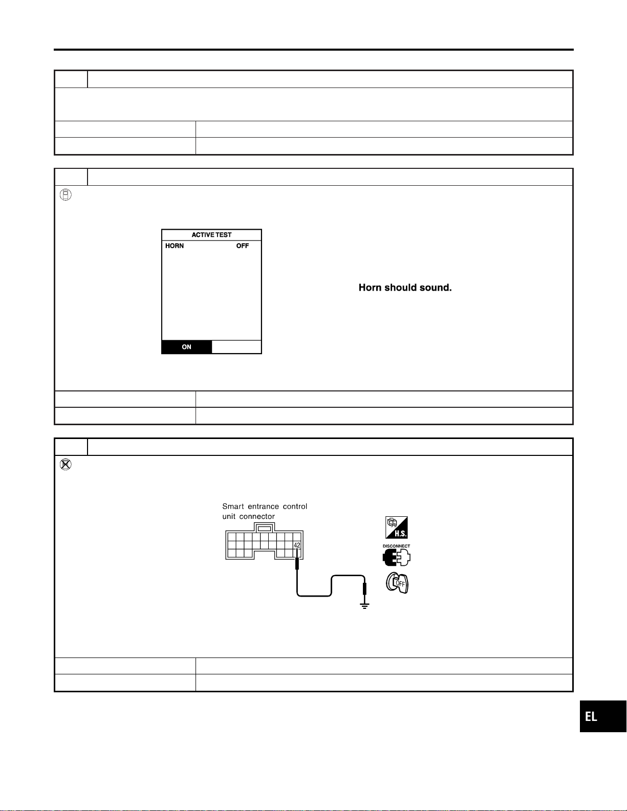
HORN REMINDER CHECK
=NAEL0397S08
1 CHECK HORN
Check if horn sounds with horn switch.
Does horn operate?
Yes © GO TO 2.
No © Check horn circuit.
2 CHECK HORN REMINDER OPERATION WITH CONSULT-II
With CONSULT-II
1. Select “ACTIVE TEST” in “MULTI REMOTE ENT” with CONSULT-II.
2. Select “HORN” and touch “ON”.
SEL451Y
NOTE: If CONSULT-II is not available, skip this procedure and go to the next step.
OK or NG
OK © Horn reminder operation is OK.
NG © GO TO 4.
3 CHECK HORN REMINDER OPERATION WITHOUT CONSULT-II
Without CONSULT-II
1. Disconnect smart entrance control unit harness connector.
2. Apply ground to smart entrance control unit harness connector M122 terminal 42 (LG/B).
SEL028Y
Refer to wiring diagram in EL-317.
Does horn sound?
Yes © Replace smart entrance control unit.
No © GO TO 4.
GI
MA
EM
LC
EC
FE
CL
MT
AT
TF
PD
AX
SU
BR
ST
RS
BT
HA
SC
IDX
REMOTE KEYLESS ENTRY SYSTEM
Trouble Diagnoses (Cont’d)
EL-331
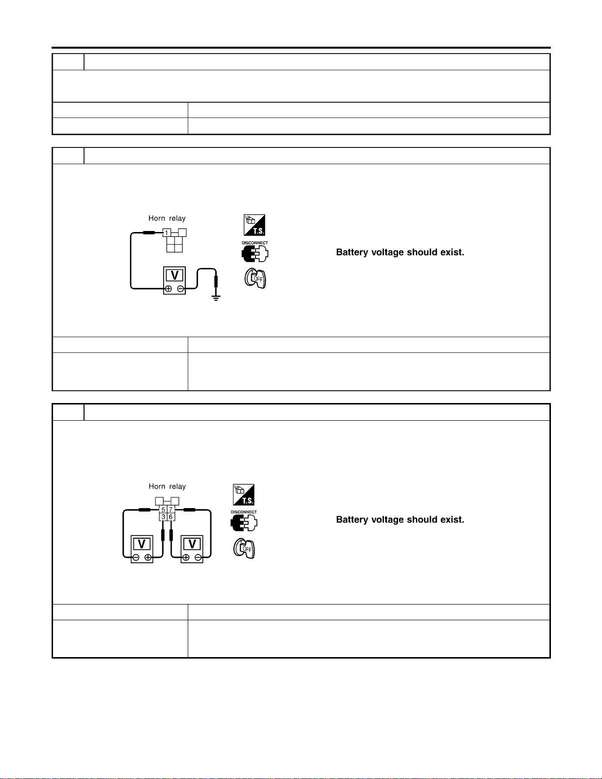
4 CHECK HORN RELAY
Check horn relay.
OK or NG
OK © GO TO 5.
NG © Replace horn relay.
5 CHECK POWER SUPPLY FOR HORN RELAY
1. Disconnect horn relay harness connector.
2. Check voltage between horn relay harness connector E118 terminal 1 (G/B) and ground.
SEL326XA
OK or NG
OK © GO TO 6.
NG © Check the following.
I 7.5A fuse [No. 52, located in fuse block (J/B)]
I Harness for open or short between horn relay and fuse
6 CHECK HORN RELAY CIRCUIT
1. Disconnect horn relay harness connector.
2. Check voltage between horn relay harness connector E118 terminals 3 (G/B) and 5 (R).
3. Check voltage between horn relay harness connector E118 terminals 6 (LG) and 7 (G).
SEL327XA
OK or NG
OK © Check harness for open or short between smart entrance control unit and horn relay.
NG © Check the following.
I Harness for open or short between horn relay and fuse
I Harness for open or short between horn relay and horns
REMOTE KEYLESS ENTRY SYSTEM
Trouble Diagnoses (Cont’d)
EL-332
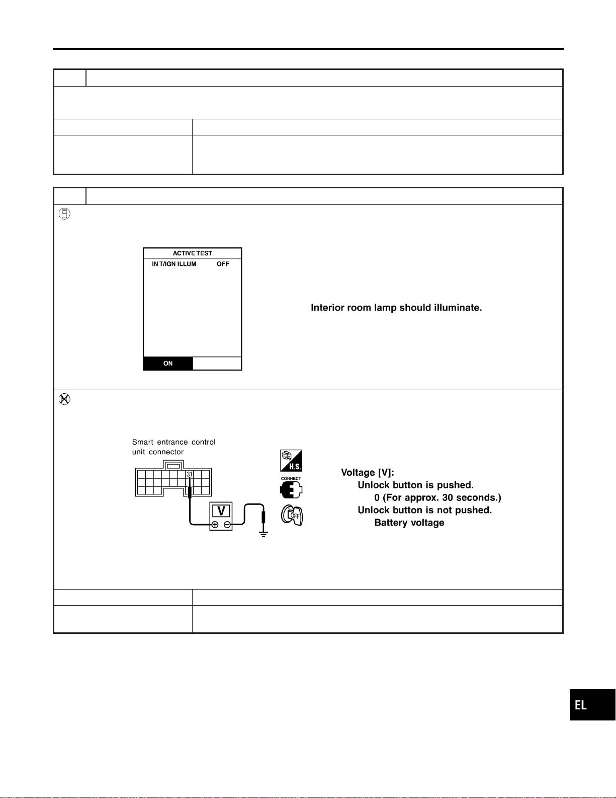
INTERIOR ROOM LAMP OPERATION CHECK
=NAEL0397S09
1 CHECK ROOM INTERIOR LAMP
Check if the interior room lamp switch is in the “ON” position and the lamp illuminates.
Does interior room lamp illuminate?
Yes © GO TO 2.
No © Check the following.
I Harness for open or short between smart entrance control unit and interior room lamp
I Interior room lamp
2 CHECK INTERIOR ROOM LAMP OPERATION
With CONSULT-II
1. Select “ACTIVE TEST” in “MULTI REMOTE ENT” with CONSULT-II.
2. Select “INT/IGN ILLUM” and touch “ON”.
SEL312Y
Without CONSULT-II
Push unlock button of keyfob with all doors closed and driver’s door locked, and check voltage between smart entrance
control unit harness connector M122 terminal 31 (R/B) and ground.
SEL029Y
Refer to wiring diagram in EL-315.
OK or NG
OK © System is OK.
NG © Check harness open or short between smart entrance control unit and interior room
lamp.
GI
MA
EM
LC
EC
FE
CL
MT
AT
TF
PD
AX
SU
BR
ST
RS
BT
HA
SC
IDX
REMOTE KEYLESS ENTRY SYSTEM
Trouble Diagnoses (Cont’d)
EL-333

ID Code Entry Procedure
=NAEL0398
KEYFOB ID SET UP WITH CONSULT-II
NAEL0398S01
NOTE:
If a keyfob is lost, the ID code of the lost keyfob must be
erased to prevent unauthorized use. When the ID code of a
lost keyfob is not known, all keyfob ID codes should be
erased. After all ID codes are erased, the ID codes of all
remaining and/or new keyfob must be re-registered.
SEL331X
1. Turn ignition switch “OFF”.
2. Connect CONSULT-II to the data link connector.
PBR455D
3. Turn ignition switch “ON”.
4. Touch “START”.
SEL398Y
5. Touch “SMART ENTRANCE”.
SEL401Y
6. Touch “MULTI REMOTE ENT”.
REMOTE KEYLESS ENTRY SYSTEM
ID Code Entry Procedure
EL-334
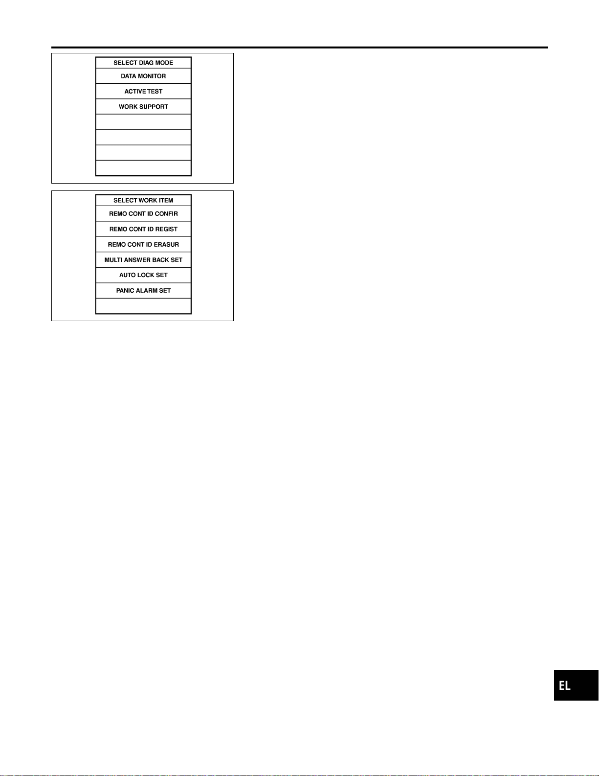
SEL274W
7. Touch “WORK SUPPORT”.
SEL424Y
8. The items are shown on the figure at left can be set up.
I “REMO CONT ID CONFIR”
Use this mode to confirm if a keyfob ID code is registered or
not.
I “REMO CONT ID REGIST”
Use this mode to register a keyfob ID code.
NOTE:
Register the ID code when keyfob or smart entrance control
unit is replaced, or when additional keyfob is required.
I “REMO CONT ID ERASUR”
Use this mode to erase a keyfob ID code.
Refer to the EL-320, “WORK SUPPORT” in “CONSULT-II Applica-
tion Items” for the following items.
I “MULTI ANSWER BACK SET”
I “AUTO LOCK SET”
I “PANIC ALARM SET”
I “TRUNK OPENER”
I “PW DOWN SET”
NOTE:
Even though TRUNK OPENER is actually displayed on the CON-
SULT-II screen, it is not equipped, therefore, they cannot be acti-
vated.
GI
MA
EM
LC
EC
FE
CL
MT
AT
TF
PD
AX
SU
BR
ST
RS
BT
HA
SC
IDX
REMOTE KEYLESS ENTRY SYSTEM
ID Code Entry Procedure (Cont’d)
EL-335
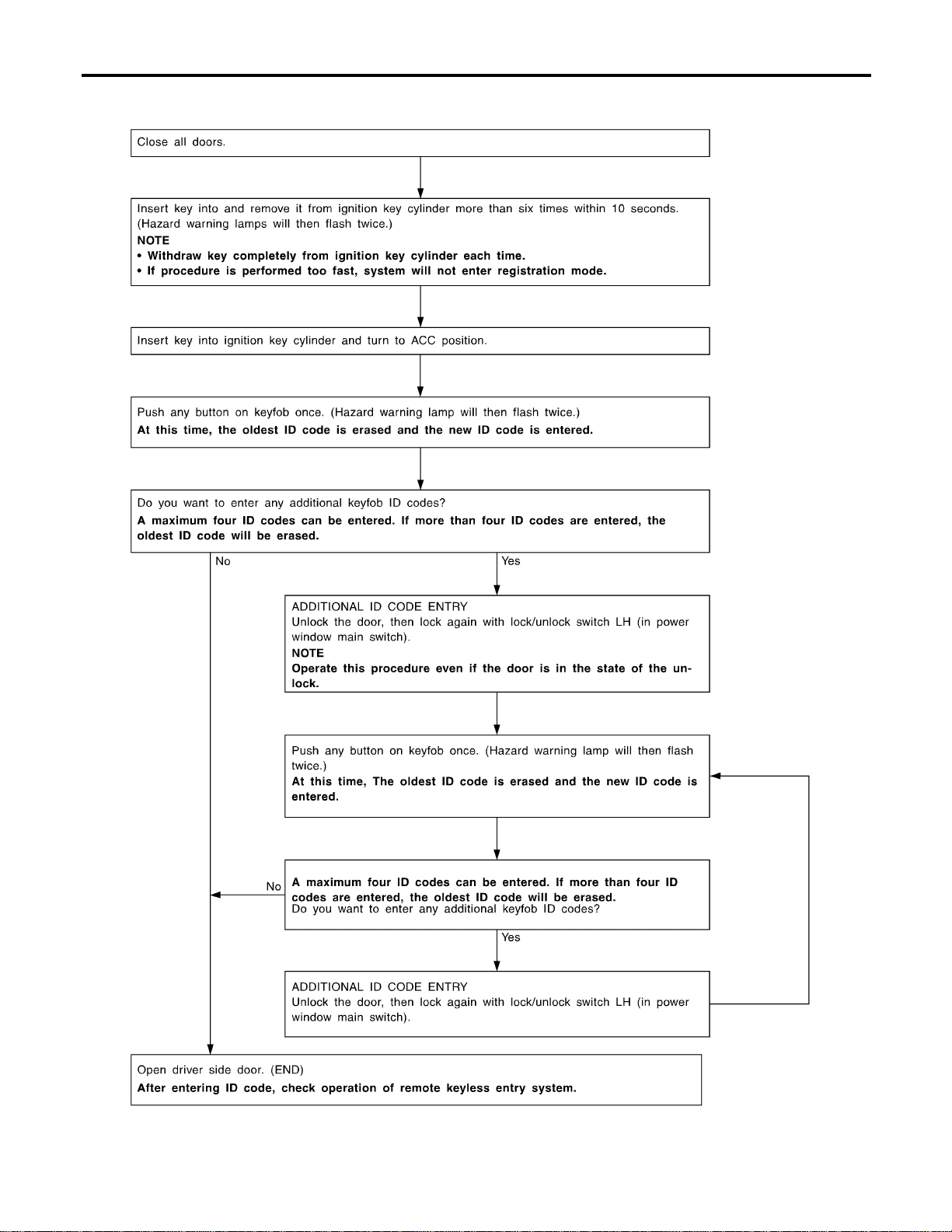
KEYFOB ID SET UP WITHOUT CONSULT-II
NAEL0398S02
SEL170YA
REMOTE KEYLESS ENTRY SYSTEM
ID Code Entry Procedure (Cont’d)
EL-336

NOTE:
I If a keyfob is lost, the ID code of the lost keyfob must be erased
to prevent unauthorized use. A specific ID code can be erased
with CONSULT-II. However, when the ID code of a lost keyfob
is not known, all keyfob ID codes should be erased. After all
ID codes are erased, the ID codes of all remaining and/or new
keyfob must be re-registered.
To erase all ID codes in memory, register one ID code (keyfob)
four times. After all ID codes are erased, the ID codes of all
remaining and/or new keyfob must be re-registered.
I When registering an additional keyfob, the existing ID codes in
memory may or may not be erased. If four ID codes are stored
in memory, when an additional code is registered, only the
oldest code is erased. If less than four ID codes are stored in
memory, when an additional ID code is registered, the new ID
code is added and no ID codes are erased.
I If you need to activate more than two additional new keyfob,
repeat the procedure “Additional ID code entry” for each new
keyfob.
I Entry of maximum four ID codes is allowed. When more than
four ID codes are entered, the oldest ID code will be erased.
I Even if the same ID code that is already in the memory is input,
the same ID code can be entered. The code is counted as an
additional code.
GI
MA
EM
LC
EC
FE
CL
MT
AT
TF
PD
AX
SU
BR
ST
RS
BT
HA
SC
IDX
REMOTE KEYLESS ENTRY SYSTEM
ID Code Entry Procedure (Cont’d)
EL-337
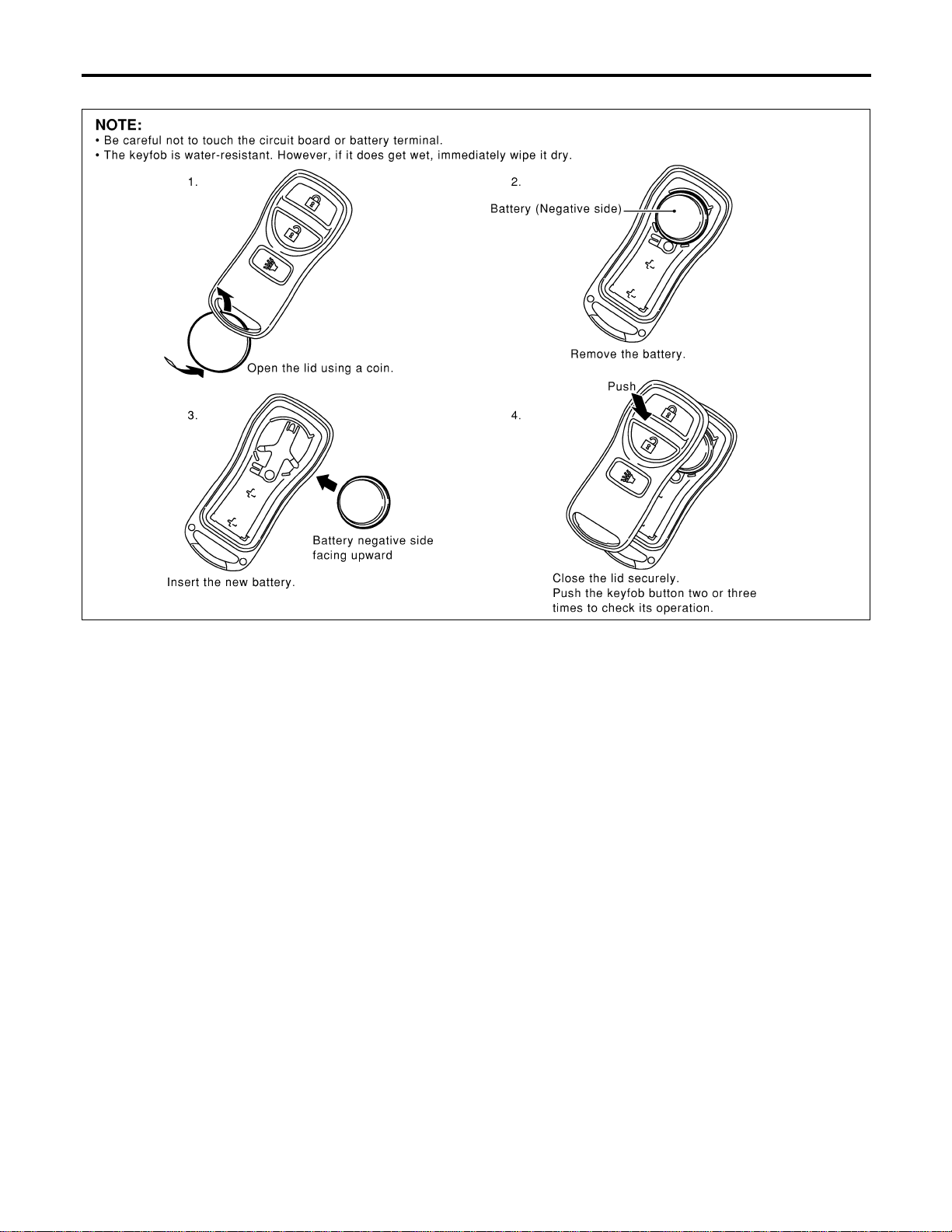
Keyfob Battery Replacement
NAEL0399
SEL485Y
REMOTE KEYLESS ENTRY SYSTEM
Keyfob Battery Replacement
EL-338
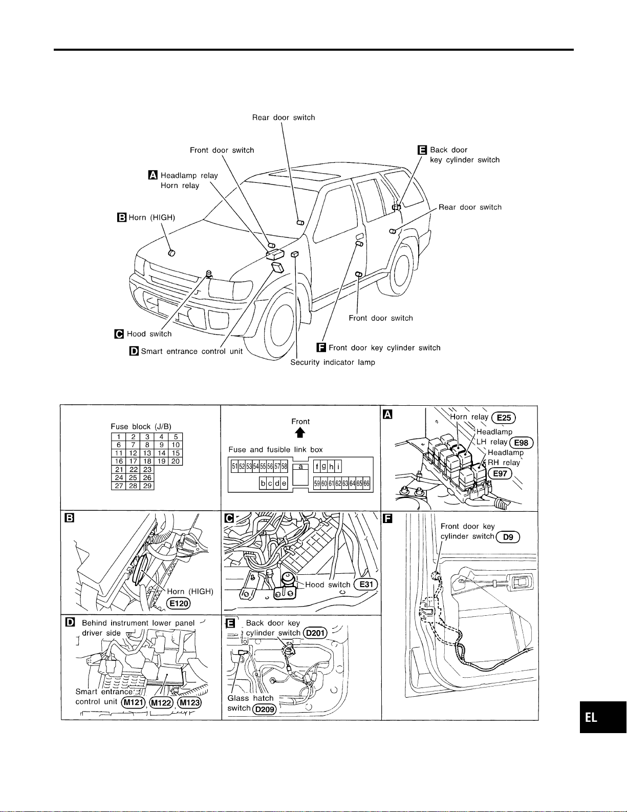
Component Parts and Harness Connector
Location
NAEL0400
SEL484Y
GI
MA
EM
LC
EC
FE
CL
MT
AT
TF
PD
AX
SU
BR
ST
RS
BT
HA
SC
IDX
VEHICLE SECURITY (THEFT WARNING) SYSTEM
Component Parts and Harness Connector Location
EL-339
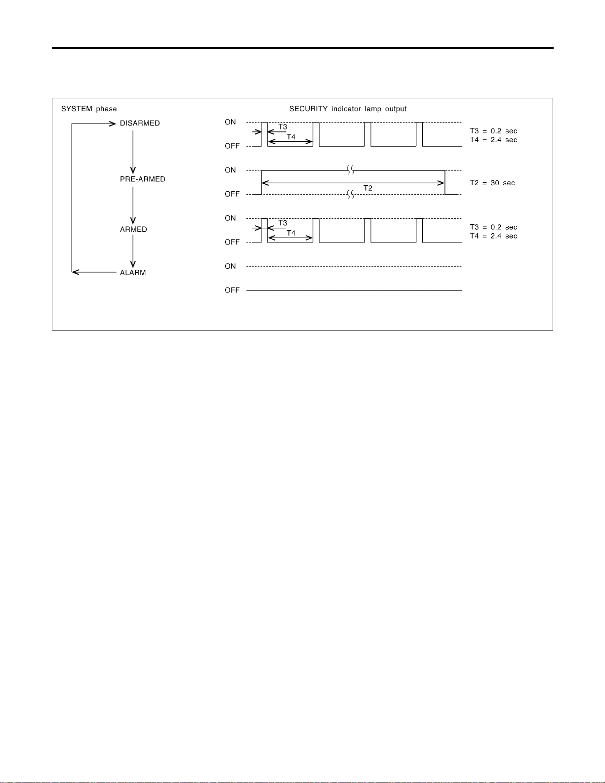
System Description
NAEL0401
DESCRIPTION
NAEL0401S01
1. Operation Flow
NAEL0401S0101
SEL334W
2. Setting The Vehicle Security System
NAEL0401S0102
Initial condition
1) Ignition switch is in OFF position.
Disarmed phase
When the vehicle security system is in the disarmed phase, the security indicator lamp blinks every 2.6 sec-
onds.
Pre-armed phase and armed phase
When the following operation 1) or 2) is performed, the vehicle security system turns into the “pre-armed”
phase. (The security indicator lamp illuminates.)
1) Smart entrance control unit receives LOCK signal from key cylinder switch or keyfob after hood, glass
hatch and all doors are closed.
2) Hood, glass hatch and all doors are closed after front doors are locked by key, lock/unlock switch or multi-
remote controller.
After about 30 seconds, the system automatically shifts into the “armed” phase (the system is set). (The
security indicator lamp blinks every 2.6 seconds.)
3. Canceling The Set Vehicle Security System
NAEL0401S0103
When the following 1) or 2) operation is performed, the armed phase is canceled.
1) Unlock the doors with the key or keyfob.
2) Open the glass hatch with the key or keyfob.
4. Activating The Alarm Operation of The Vehicle Security System
NAEL0401S0104
Make sure the system is in the armed phase. (The security indicator lamp blinks every 2.6 seconds.)
When the following operation 1) or 2) is performed, the system sounds the horns and flashes the headlamps
for about 50 seconds.
1) Engine hood, glass hatch or any door is opened during armed phase.
2) Disconnecting and connecting the battery connector before canceling armed phase.
POWER SUPPLY AND GROUND
NAEL0401S02
Power is supplied at all times
I through 7.5A fuse [No. 24, located in the fuse block (J/B)]
I to security indicator lamp terminal 1, and
I to smart entrance control unit terminal 49.
VEHICLE SECURITY (THEFT WARNING) SYSTEM
System Description
EL-340

With the ignition switch in the ON or START position, power is supplied
I through 7.5A fuse [No. 11, located in the fuse block (J/B)]
I to smart entrance control unit terminal 27.
With the ignition switch in the ACC or ON position, power is supplied
I through 10A fuse [No. 10, located in the fuse block (J/B)]
I to smart entrance control unit terminal 26.
Ground is supplied
I to smart entrance control unit terminals 43 and 64
I through body grounds M77 and M111.
INITIAL CONDITION TO ACTIVATE THE SYSTEM
NAEL0401S03
The operation of the vehicle security system is controlled by the doors, hood and glass hatch.
Pattern A
NAEL0401S0301
To activate the vehicle security system, the smart entrance control unit must receive signals indicating the
doors, hood and glass hatch are closed.
When a door is open, smart entrance control unit terminal 1, 2 or 3 receives a ground signal from each door
switch.
When the hood is open, smart entrance control unit terminal 6 receives a ground signal
I from terminal 1 of the hood switch
I through body grounds E13 and E41.
When the glass hatch is open, smart entrance control unit terminal 13 receives a ground signal
I from terminal 1 of the glass hatch switch
I through body grounds B11, B22 and D210.
When smart entrance control unit receives LOCK signal from key cylinder switch or keyfob and none of the
described conditions exist, the vehicle security system will automatically shift to armed mode.
Pattern B
NAEL0401S0302
To activate the vehicle security system, the smart entrance control unit must receive signal indicating any door
(including hood and glass hatch) is opened.
When the front doors are locked with key, lock/unlock switch or keyfob and then all doors are closed, the
vehicle security system will automatically shift to armed mode.
VEHICLE SECURITY SYSTEM ACTIVATION
NAEL0401S04
Pattern A
NAEL0401S0401
With all doors (including hood and glass hatch) closed, if the key is used to lock doors, smart entrance con-
trol unit terminal 33 receives a signal from power window main switch terminal 8.
When key cylinder switch is in LOCK position, ground is supplied
I to power window main switch terminal 6
I from terminal 3 of the front key cylinder switch LH
I through terminal 2 of front key cylinder switch LH
I through body grounds M77 and M111, or
smart entrance control unit terminal 11 receives a ground signal
I from terminal 1 of the back door key cylinder switch
I through body grounds B11, B22 and D210.
If this signal, or lock signal from keyfob is received by the smart entrance control unit, the vehicle security
system will activate automatically.
NOTE:
Vehicle security system can be set even though all doors are not locked.
Pattern B
NAEL0401S0402
With any door (including hood and glass hatch) open, if lock/unlock switch is used to lock doors, smart entrance
control unit terminal 33 receives a LOCK signal
I from terminal 8 of lock/unlock switch LH
I through body grounds M77 and M111, or
I from terminal 11 of lock/unlock switch RH
GI
MA
EM
LC
EC
FE
CL
MT
AT
TF
PD
AX
SU
BR
ST
RS
BT
HA
SC
IDX
VEHICLE SECURITY (THEFT WARNING) SYSTEM
System Description (Cont’d)
EL-341

I through body grounds M4, M66 and M147, or
With any door (including hood and glass hatch) open if the key is used to lock doors, smart entrance control
unit terminal 33 receives a LOCK signal from power window main front switch terminal 8.
When key cylinder switch LOCK signal ground is supplied
I to power window main switch terminal 6
I from terminal 3 of the front key cylinder switch LH
I through terminal 2 of front key cylinder switch LH
I through body grounds M9, M25 and M87, or
smart entrance control unit terminal 11 receives a ground signal
I from terminal 1 of the back door key cylinder switch
I through body grounds B11, B22 and D210.
If these signals and lock signal from keyfob are received by the smart entrance control unit, ground signals
of terminals 1, 2 and 3 are interrupted and all doors are closed, the vehicle security system will activate auto-
matically.
NOTE:
Vehicle security system can be set even though the rear door is not locked.
Once the vehicle security system has been activated, smart entrance control unit terminal 38 supplies ground
to terminal 2 of the security indicator lamp.
The security lamp will illuminate for approximately 30 seconds and then blinks every 2.6 seconds.
Now the vehicle security system is in armed phase.
VEHICLE SECURITY SYSTEM ALARM OPERATION
NAEL0401S05
The vehicle security system is triggered by
I opening a door
I opening the hood or the glass hatch
I detection of battery disconnect and connect.
Once the vehicle security system is in armed phase, if the smart entrance control unit receives a ground sig-
nal at terminal 1, 2, 3 (door switch), 13 (glass hatch switch) or 6 (hood switch), the vehicle security system
will be triggered. The headlamps flash and the horn sounds intermittently.
Power is supplied at all times
I through 7.5A fuse (No. 52, located in fuse and fusible link box)
I to horn relay terminals 1 and 3.
I through 10A fuse (No. 54, located in fuse and fusible link box)
I to horn relay terminal 6.
I through 15A fuse (No. 60, located in fuse and fusible link box)
I to headlamp LH relay terminals 1 and 3,
I through 15A fuse (No. 59, located in fuse and fusible link box)
I to headlamp RH relay terminals 1 and 3.
When the vehicle security system is triggered, ground is supplied intermittently
I to headlamp (LH and RH) relay terminal 2 from smart entrance control unit terminals 21 and 59
I through smart entrance control unit terminals 43 and 64.
When headlamp relays (LH and RH) are energized and then power is supplied to headlamps (LH and RH).
The headlamps flash intermittently.
When the vehicle security system is triggered, ground is supplied intermittently
I from smart entrance control unit terminal 42
I to horn relay terminal 2.
When horn relay are energized, then power is supplied to horn.
The horn sounds intermittently.
The alarm automatically turns off after 50 seconds but will reactivate if the vehicle is tampered with again.
VEHICLE SECURITY SYSTEM DEACTIVATION
NAEL0401S06
To deactivate the vehicle security system, a door or glass hatch must be unlocked with the key or keyfob.
When the key is used to unlock the door, smart entrance control unit terminal 33 receives an UNLOCK sig-
nal from power window main switch terminal 18.
When key cylinder switch is in UNLOCK position, the ground is supplied
VEHICLE SECURITY (THEFT WARNING) SYSTEM
System Description (Cont’d)
EL-342

I to power window main switch terminal 19
I from the front door key cylinder switch LH terminal 1
I through front door key cylinder switch terminal 2,
I through body grounds M77 and M111.
When the key is used to open the glass hatch, smart entrance control unit terminal 12 receives a ground sig-
nal from terminal 3 of the back door key cylinder switch.
When the smart entrance control unit receives either one of these signals or unlock signal from keyfob, the
vehicle security system is deactivated. (Disarmed phase)
PANIC ALARM OPERATION
NAEL0401S07
Remote keyless entry system may or may not operate vehicle security system (horn and headlamps) as
required.
When the remote keyless entry system (panic alarm) is triggered, ground is supplied intermittently
I from smart entrance control unit terminals 21 and 59
I to headlamp (LH and RH) relay terminal 2
I from smart entrance control unit terminal 42
I to horn relay terminal 2.
The headlamp flashes and the horn sounds intermittently.
The alarm automatically turns off after 25 seconds or when smart entrance control unit receives any signal
from keyfob.
GI
MA
EM
LC
EC
FE
CL
MT
AT
TF
PD
AX
SU
BR
ST
RS
BT
HA
SC
IDX
VEHICLE SECURITY (THEFT WARNING) SYSTEM
System Description (Cont’d)
EL-343
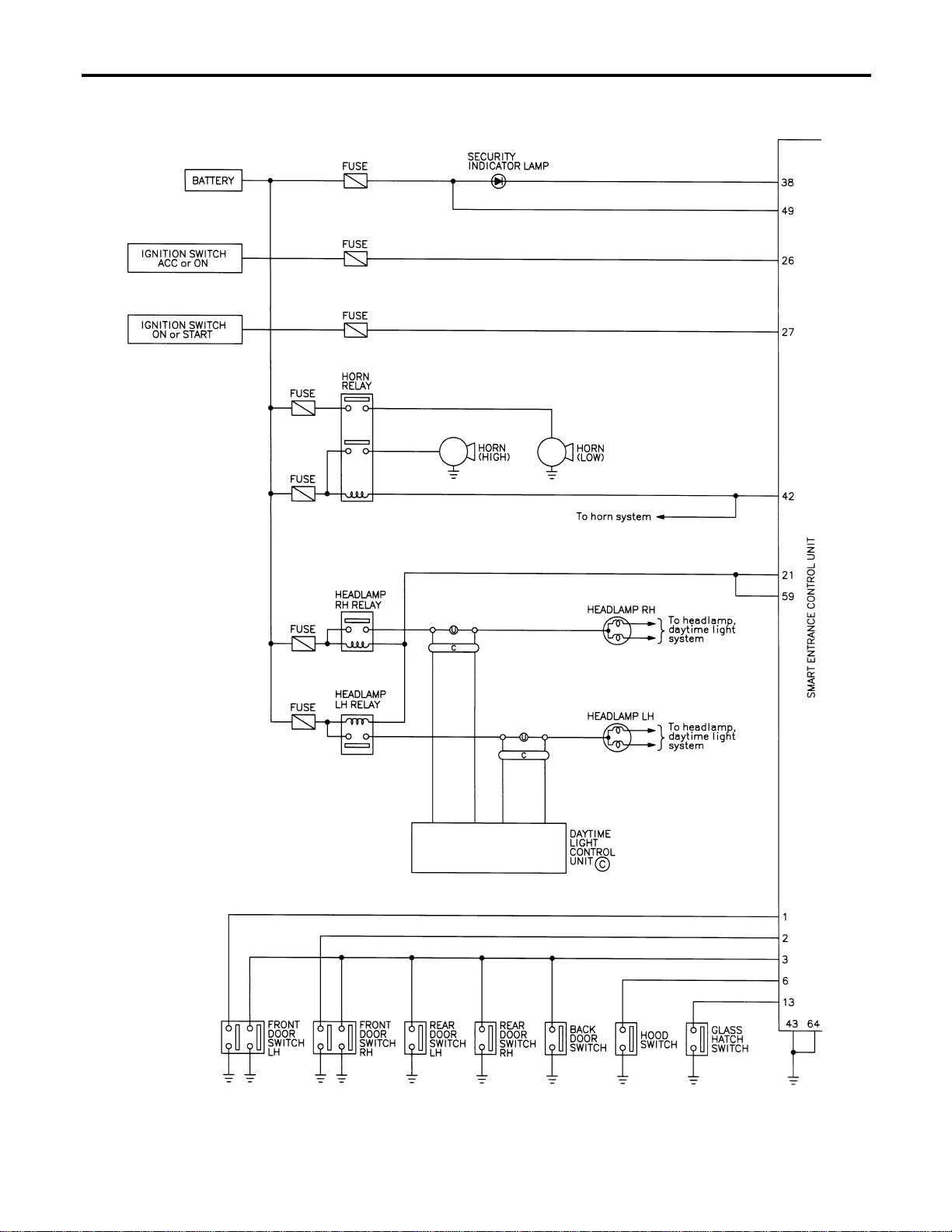
Schematic
NAEL0402
MEL873N
VEHICLE SECURITY (THEFT WARNING) SYSTEM
Schematic
EL-344
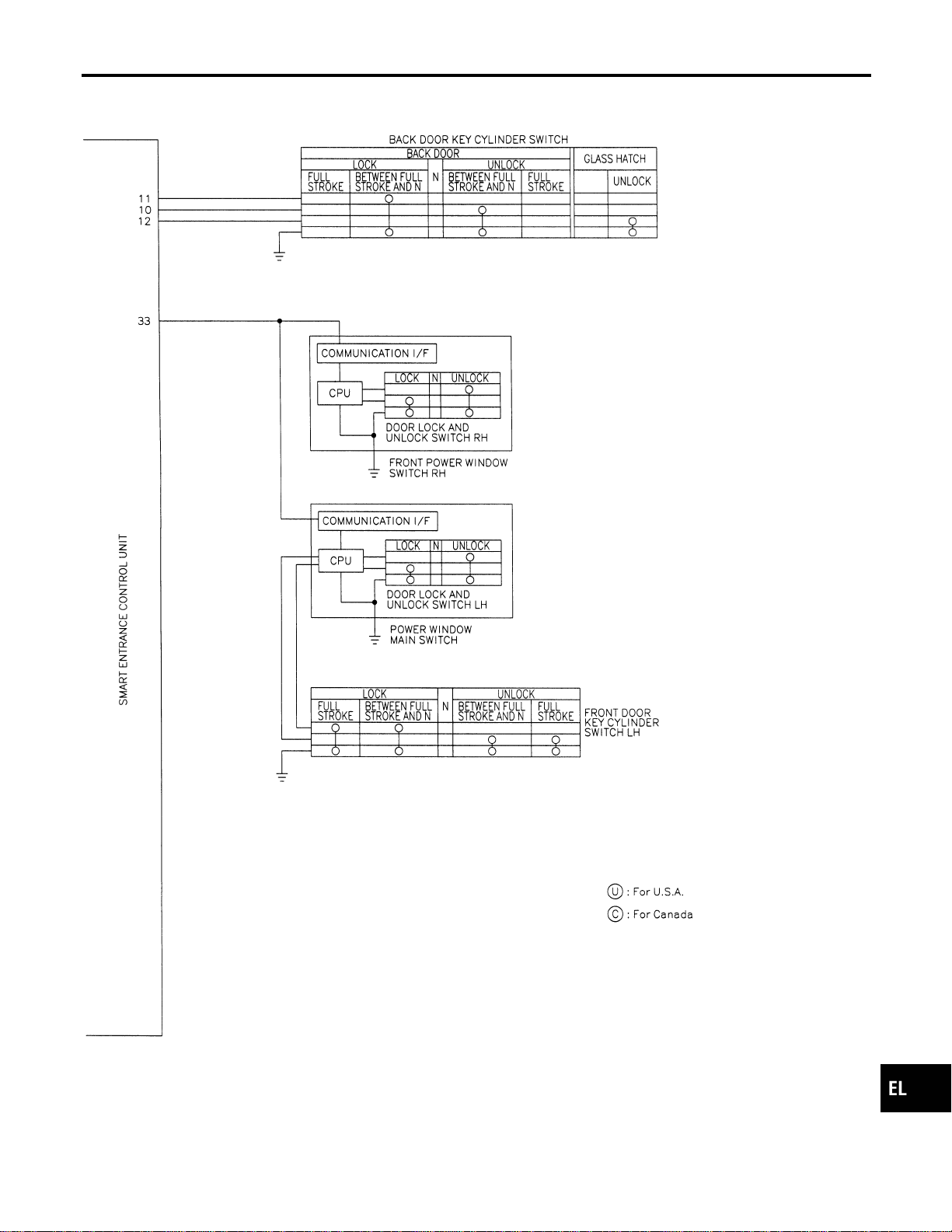
MEL437P
GI
MA
EM
LC
EC
FE
CL
MT
AT
TF
PD
AX
SU
BR
ST
RS
BT
HA
SC
IDX
VEHICLE SECURITY (THEFT WARNING) SYSTEM
Schematic (Cont’d)
EL-345
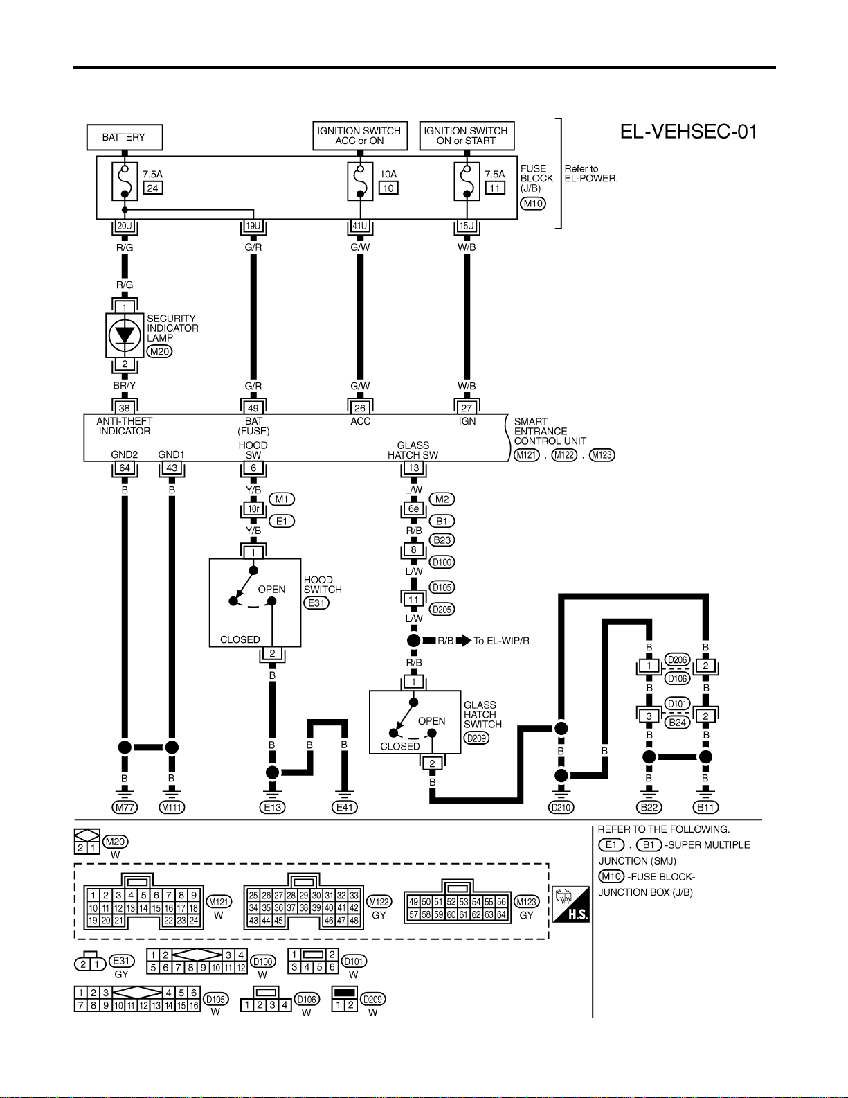
Wiring Diagram — VEHSEC —
NAEL0403
FIG. 1
NAEL0403S01
MEL414O
VEHICLE SECURITY (THEFT WARNING) SYSTEM
Wiring Diagram — VEHSEC —
EL-346
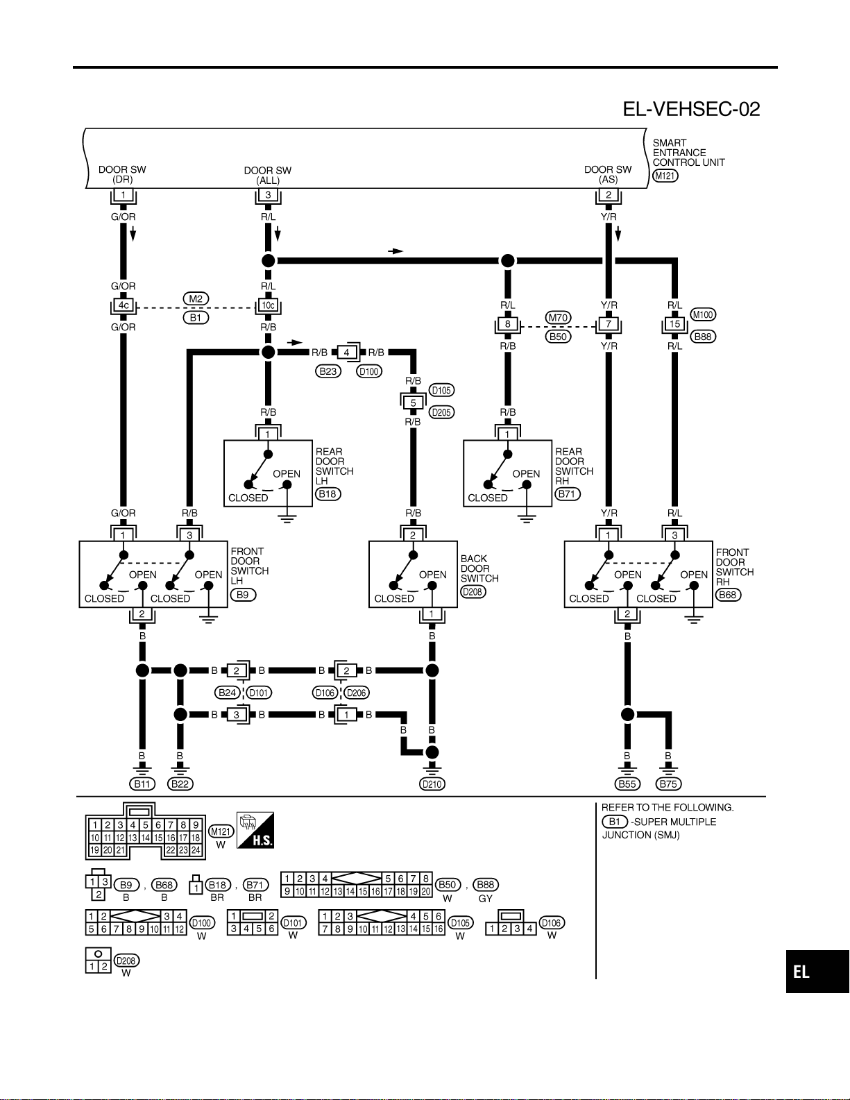
FIG. 2
NAEL0403S02
MEL438P
GI
MA
EM
LC
EC
FE
CL
MT
AT
TF
PD
AX
SU
BR
ST
RS
BT
HA
SC
IDX
VEHICLE SECURITY (THEFT WARNING) SYSTEM
Wiring Diagram — VEHSEC — (Cont’d)
EL-347

FIG. 3
NAEL0403S03
MEL439P
VEHICLE SECURITY (THEFT WARNING) SYSTEM
Wiring Diagram — VEHSEC — (Cont’d)
EL-348
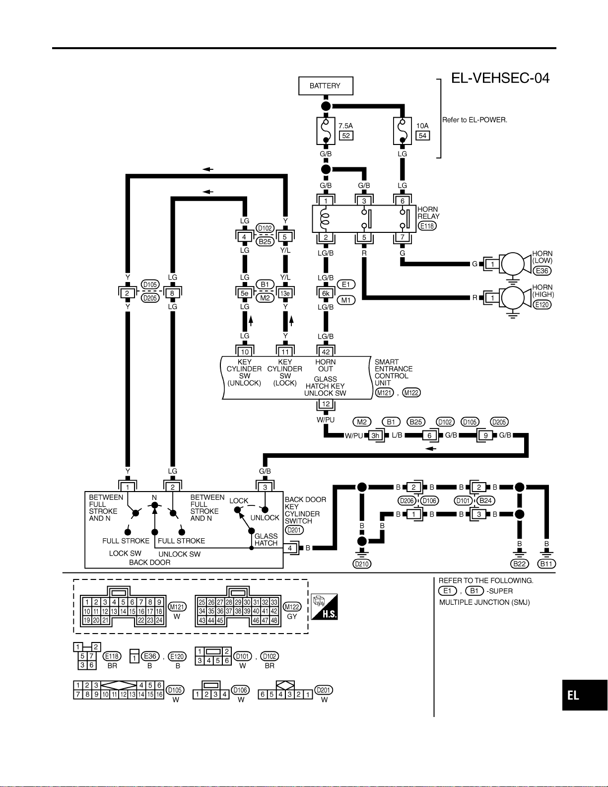
FIG. 4
NAEL0403S04
MEL477O
GI
MA
EM
LC
EC
FE
CL
MT
AT
TF
PD
AX
SU
BR
ST
RS
BT
HA
SC
IDX
VEHICLE SECURITY (THEFT WARNING) SYSTEM
Wiring Diagram — VEHSEC — (Cont’d)
EL-349
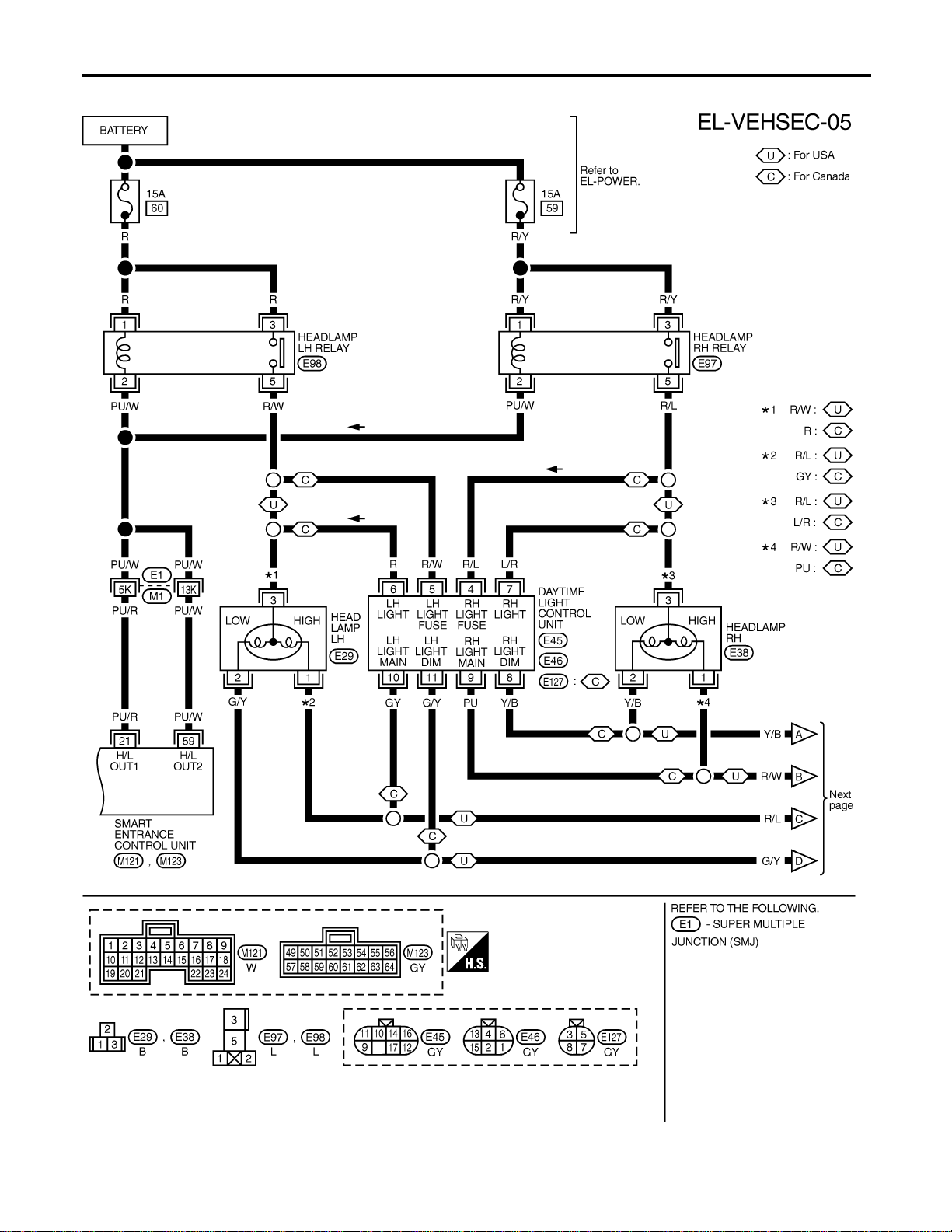
FIG. 5
NAEL0403S05
MEL440P
VEHICLE SECURITY (THEFT WARNING) SYSTEM
Wiring Diagram — VEHSEC — (Cont’d)
EL-350
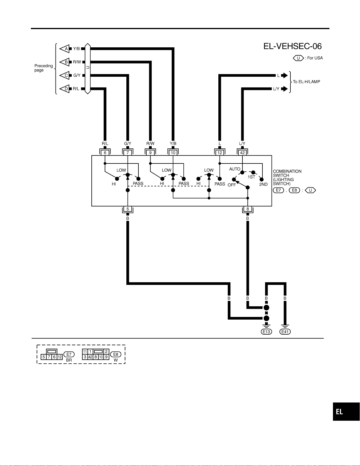
FIG. 6
NAEL0403S06
MEL441P
GI
MA
EM
LC
EC
FE
CL
MT
AT
TF
PD
AX
SU
BR
ST
RS
BT
HA
SC
IDX
VEHICLE SECURITY (THEFT WARNING) SYSTEM
Wiring Diagram — VEHSEC — (Cont’d)
EL-351
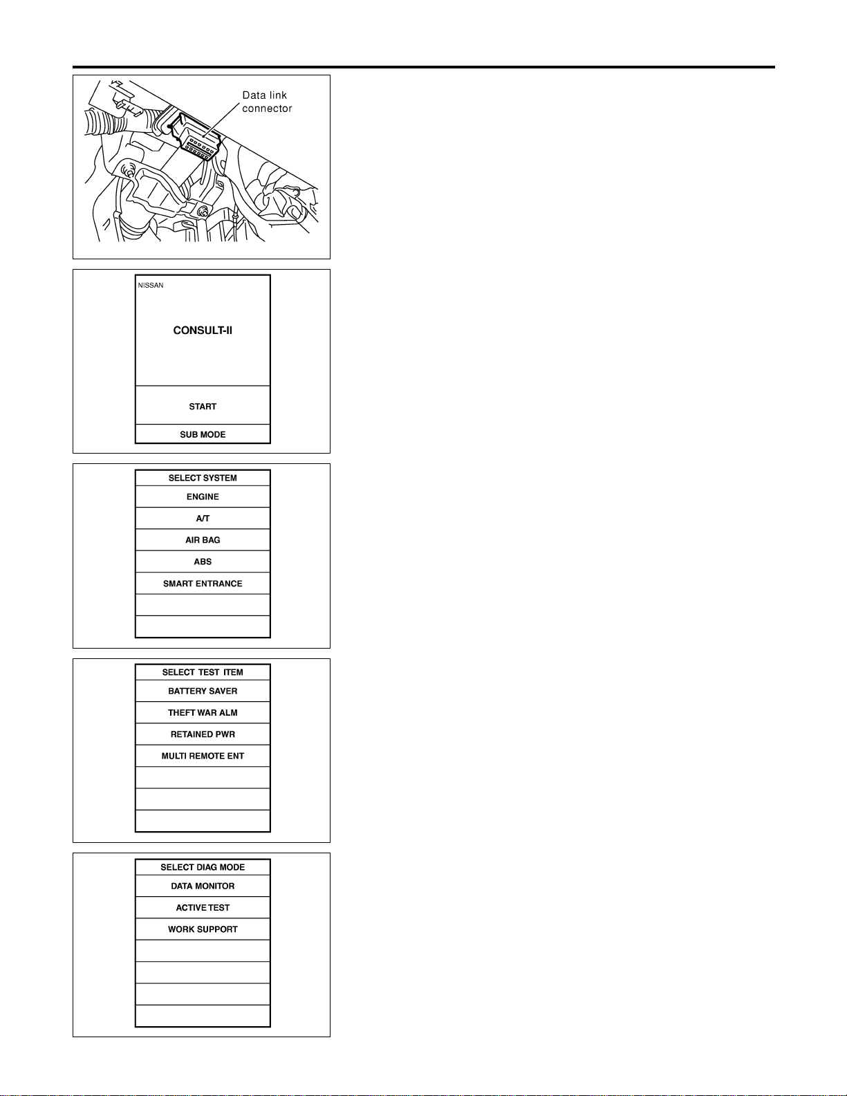
SEL331X
CONSULT-II Inspection Procedure
=NAEL0404
“THEFT WAR ALM”
NAEL0404S01
1. Turn ignition switch “OFF”.
2. Connect “CONSULT-II” to the data link connector.
PBR455D
3. Turn ignition switch “ON”.
4. Touch “START”.
SEL941W
5. Touch “SMART ENTRANCE”.
SEL273W
6. Touch “THEFT WAR ALM”.
SEL274W
7. Select diagnosis mode.
“DATA MONITOR”, “ACTIVE TEST” and “WORK SUPPORT”
are available.
VEHICLE SECURITY (THEFT WARNING) SYSTEM
CONSULT-II Inspection Procedure
EL-352
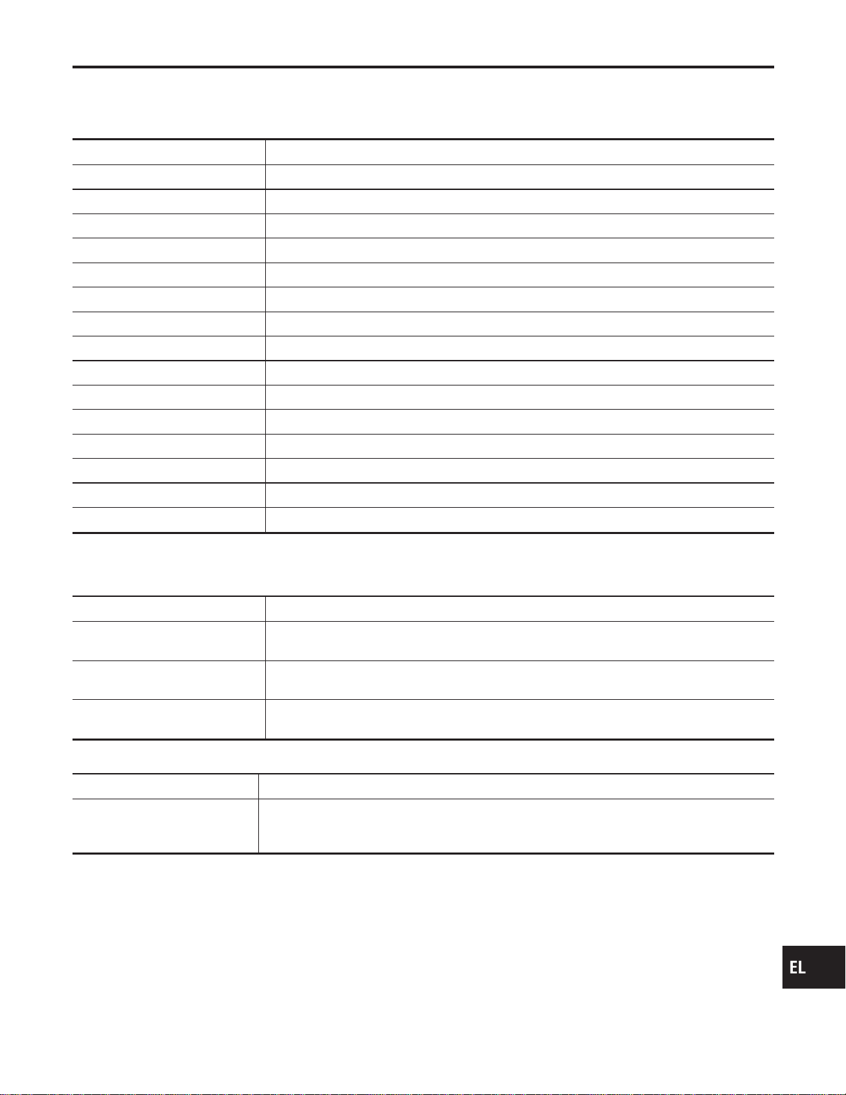
CONSULT-II Application Item
NAEL0405
“THEFT WAR ALM”
NAEL0405S01
Data Monitor
NAEL0405S0101
Monitored Item Description
IGN ON SW Indicates [ON/OFF] condition of ignition switch.
ACC ON SW Indicates [ON/OFF] condition of ignition switch in ACC position.
KEY CYL LK SW Indicates [ON/OFF] condition of lock signal from key cylinder switch.
KEY CYL UN SW Indicates [ON/OFF] condition of unlock signal from key cylinder switch.
DOOR SW-RR Indicates [ON/OFF] condition of rear door switch.
DOOR SW-DR Indicates [ON/OFF] condition of front door switch LH.
DOOR SW-AS Indicates [ON/OFF] condition of front door switch RH.
TRUNK SW Indicates [ON/OFF] condition of back door switch.
TRUNK KEY SW Indicates [ON/OFF] condition of back door key cylinder switch.
HOOD SWITCH Indicates [ON/OFF] condition of hood switch.
LOCK SW DR/AS Indicates [ON/OFF] condition of lock signal from door lock/unlock switch LH and RH.
UNLK SW DR/AS Indicates [ON/OFF] condition of unlock signal from door lock/unlock LH and RH.
LK BUTTON/SIG Indicates [ON/OFF] condition of lock signal from keyfob.
UN BUTTON/SIG Indicates [ON/OFF] condition of unlock signal from keyfob.
TRUNK BTN/SIG Indicates [ON/OFF] condition of trunk open signal from keyfob.
NOTE:
Even though TRUNK BTN/SIG is actually displayed on the CONSULT-II screen, it is not equipped, therefore, they cannot be activated.
Active Test
NAEL0405S0102
Test Item Description
THEFT IND
This test is able to check security indicator lamp operation. The lamp will be turned on when
“ON” on CONSULT-II screen is touched.
HORN
This test is able to check vehicle security alarm operation. The alarm will be activated for 0.5
seconds after “ON” on CONSULT-II screen is touched.
HEADLAMP
This test is able to check vehicle security alarm headlamp operation. The headlamp illumi-
nates for 0.5 seconds after “ON” on CONSULT-II screen is touched.
Work Support
NAEL0405S0103
Test Item Description
THEFT ALM TRG
The switch which triggered theft warning alarm is recorded. This mode is able to confirm and
erase the record of theft waning alarm. The trigger data can be erased by touching “CLEAR”
on CONSULT-II screen.
GI
MA
EM
LC
EC
FE
CL
MT
AT
TF
PD
AX
SU
BR
ST
RS
BT
HA
SC
IDX
VEHICLE SECURITY (THEFT WARNING) SYSTEM
CONSULT-II Application Item
EL-353
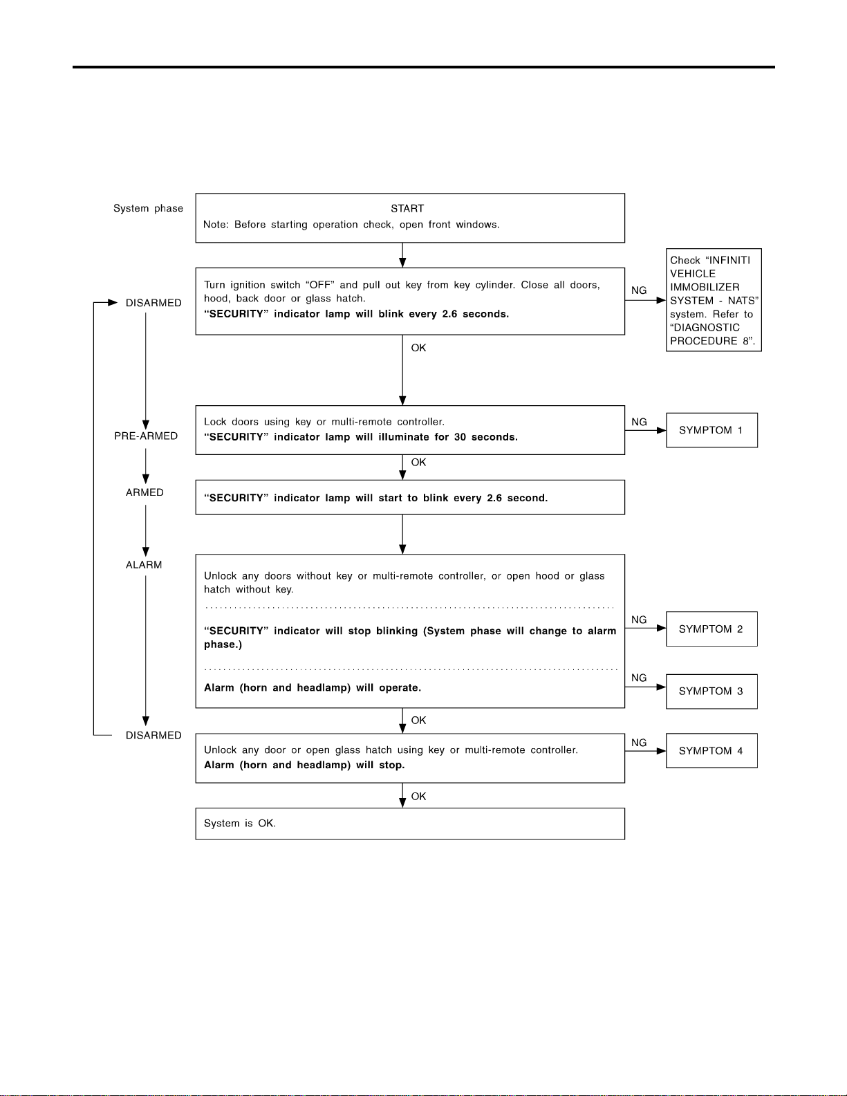
Trouble Diagnoses
=NAEL0406
PRELIMINARY CHECK
NAEL0406S01
The system operation is canceled by turning ignition switch to
“ACC” at any step between START and ARMED in the following
flow chart.
SEL733W
After performing preliminary check, go to symptom chart
below.
VEHICLE SECURITY (THEFT WARNING) SYSTEM
Trouble Diagnoses
EL-354

SYMPTOM CHART
NAEL0406S02
REFERENCE PAGE (EL- ) 354 356 357 362 364 366 369 371 321
SYMPTOM
PRELIMINARY CHECK
POWER SUPPLY AND GROUND CIRCUIT CHECK
DOOR, HOOD AND GLASS HATCH SWITCH CHECK
SECURITY INDICATOR LAMP CHECK
DOOR KEY CYLINDER SWITCH CHECK
BACK DOOR KEY CYLINDER SWITCH CHECK
VEHICLE SECURITY HORN ALARM CHECK
VEHICLE SECURITY HEADLAMP ALARM CHECK
Check “MULTI-REMOTE CONTROL” system.
1
Vehicle security indicator does not
illuminate for 30 seconds.
XXXX
Vehicle security
system cannot
be set by ....
All items X X X
Door outside key X X
Back door key X X
Multi-remote control X X
2
*1 Vehicle security
system does not
alarm when ...
Any door is opened. X X
Any door is unlocked
without using key or
multi-remote controller
X
3
Vehicle security
alarm does not
activate.
All function X X
Horn alarm X X
Headlamp alarm X X
4
Vehicle security
system cannot be
canceled by ....
Door outside key X X
Back door key X X
Multi-remote control X X
X : Applicable
*1: Make sure the system is in the armed phase.
Before starting trouble diagnoses above, perform preliminary
check, EL-354.
Symptom numbers in the symptom chart correspond with those of
preliminary check.
GI
MA
EM
LC
EC
FE
CL
MT
AT
TF
PD
AX
SU
BR
ST
RS
BT
HA
SC
IDX
VEHICLE SECURITY (THEFT WARNING) SYSTEM
Trouble Diagnoses (Cont’d)
EL-355
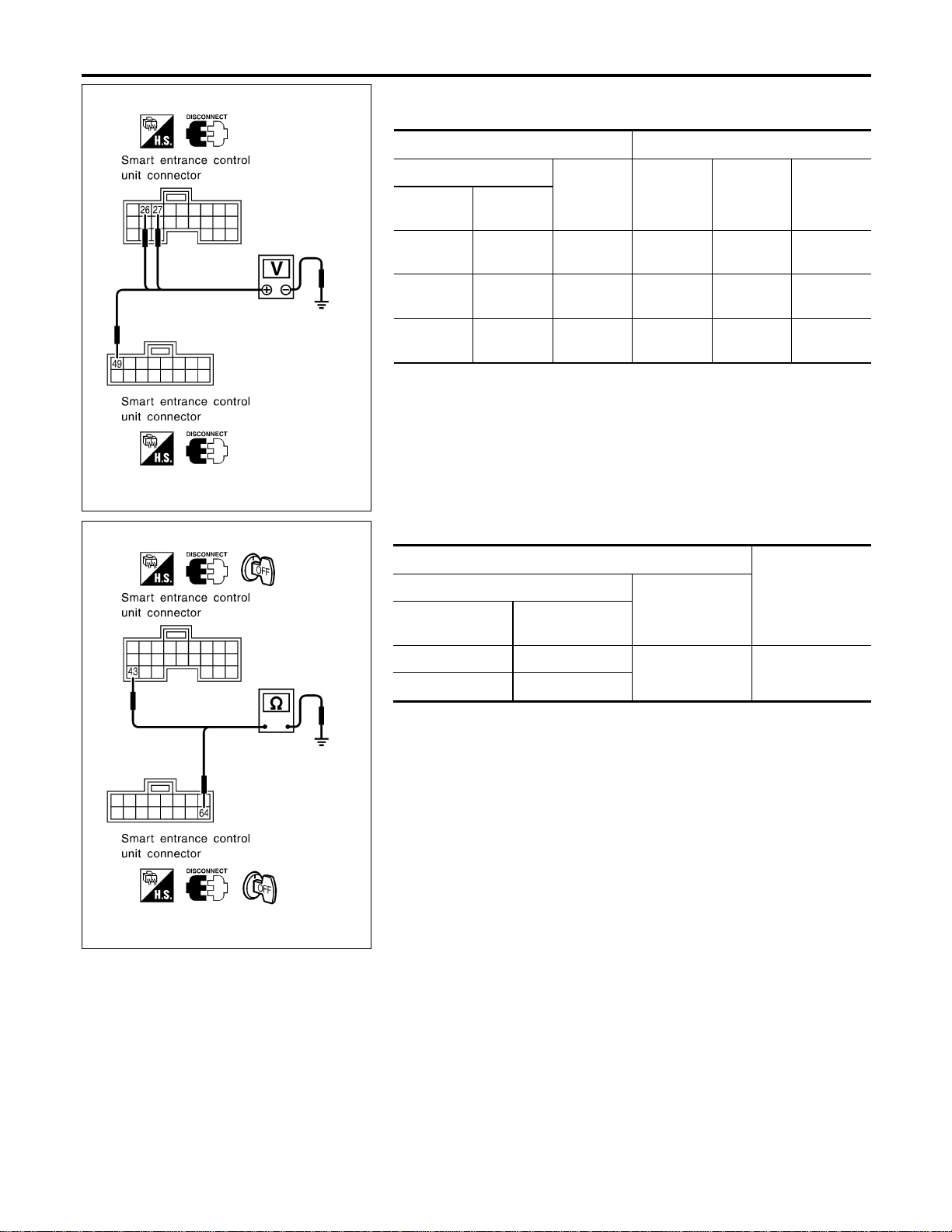
SEL281Y
POWER SUPPLY AND GROUND CIRCUIT CHECK
NAEL0406S03
Power Supply Circuit Check
NAEL0406S0301
Terminals Ignition switch position
(+)
(−) OFF ACC ON
Connector
Terminal
(Wire color)
M123 49 (G/R) Ground
Battery
voltage
Battery
voltage
Battery
voltage
M122 26 (G/W) Ground 0V
Battery
voltage
Battery
voltage
M122 27 (W/B) Ground 0V 0V
Battery
voltage
If NG, check the following.
I 7.5A fuse [No. 24, located in fuse block (J/B)]
I 7.5A fuse [No. 11, located in fuse block (J/B)]
I 10A fuse [No. 10, located in fuse block (J/B)]
I Harness for open or short between smart entrance control unit
and fuse.
SEL282Y
Ground Circuit Check
NAEL0406S0302
Terminals
Continuity
(+)
(−)
Connector
Terminal
(Wire color)
M122 43 (B)
Ground Yes
M123 64 (B)
VEHICLE SECURITY (THEFT WARNING) SYSTEM
Trouble Diagnoses (Cont’d)
EL-356
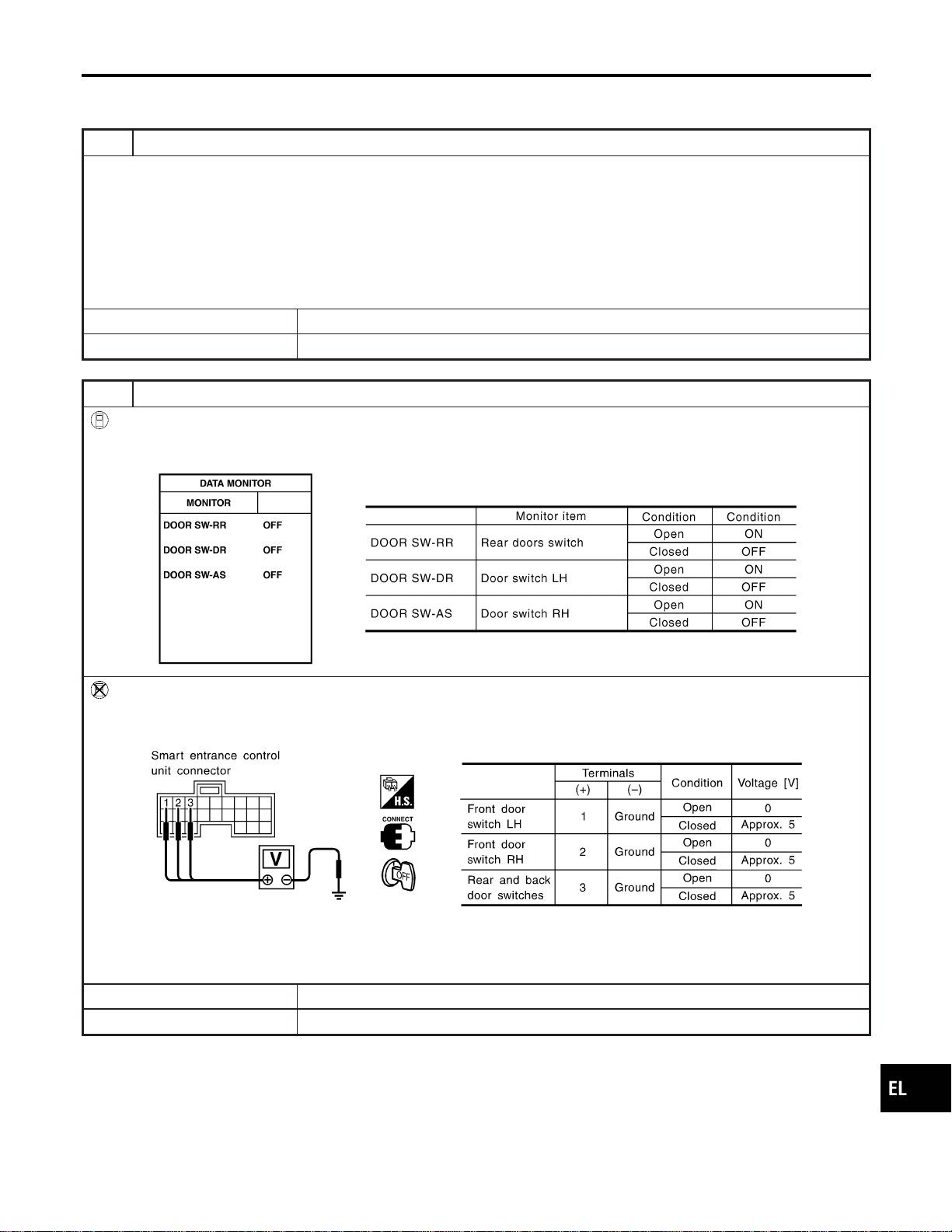
DOOR, HOOD AND GLASS HATCH SWITCH CHECK
=NAEL0406S04
Door Switch Check
NAEL0406S0401
1 PRELIMINARY CHECK
1. Turn ignition switch OFF and remove key from ignition key cylinder.
“SECURITY” indicator lamp should blink every 2.6 seconds.
2. Close all doors, hood and glass hatch.
3. Lock doors with multi-remote controller from inside the vehicle.
“SECURITY” indicator lamp should turn on for 30 seconds.
4. Unlock any door with the door lock knob and open the door within 30 seconds after door is locked.
“SECURITY” indicator lamp should turn off.
OK or NG
OK © Door switch is OK, and go to hood switch check.
NG © GO TO 2.
2 CHECK DOOR SWITCH INPUT SIGNAL
With CONSULT-II
Check door switches (“DOOR SW-RR”, “DOOR SW-DR” and “DOOR SW-AS”) in “DATA MONITOR” mode with CON-
SULT-II.
SEL024Y
Without CONSULT-II
Check voltage between smart entrance control unit harness connector M121 terminals 1 (G/OR), 2 (Y) or 3 (R/L) and
ground.
SEL021YA
Refer to wiring diagram in EL-347.
OK or NG
OK © Door switch is OK, and go to hood switch check.
NG © GO TO 3.
GI
MA
EM
LC
EC
FE
CL
MT
AT
TF
PD
AX
SU
BR
ST
RS
BT
HA
SC
IDX
VEHICLE SECURITY (THEFT WARNING) SYSTEM
Trouble Diagnoses (Cont’d)
EL-357
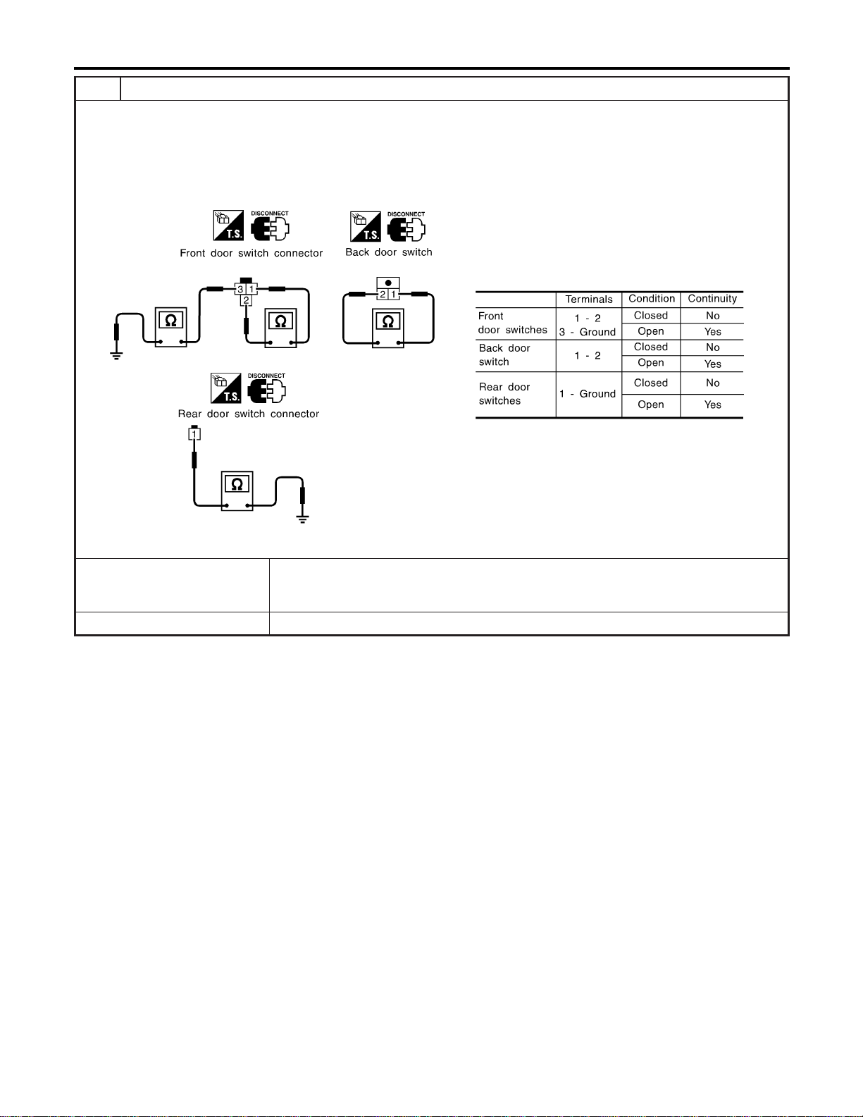
3 CHECK DOOR SWITCH
1. Disconnect door switch connector.
2. Check the following.
I Continuity between front door switch harness connector B9 (LH) or B68 (RH) terminals 1 and 2
I Continuity between front door switch harness connector B9 (LH) or B68 (RH) terminals 3 and ground
I Continuity between back door switch harness connector D208 terminals 1 and 2
I Continuity between rear door switch harness connector B18 (LH) or B71 (RH) terminal 1 and ground
SEL287Y
OK or NG
OK © Check the following.
I Door switch ground circuit (Front or back) or door switch ground condition
I Harness for open or short between smart entrance control unit and door switch
NG © Replace door switch.
VEHICLE SECURITY (THEFT WARNING) SYSTEM
Trouble Diagnoses (Cont’d)
EL-358
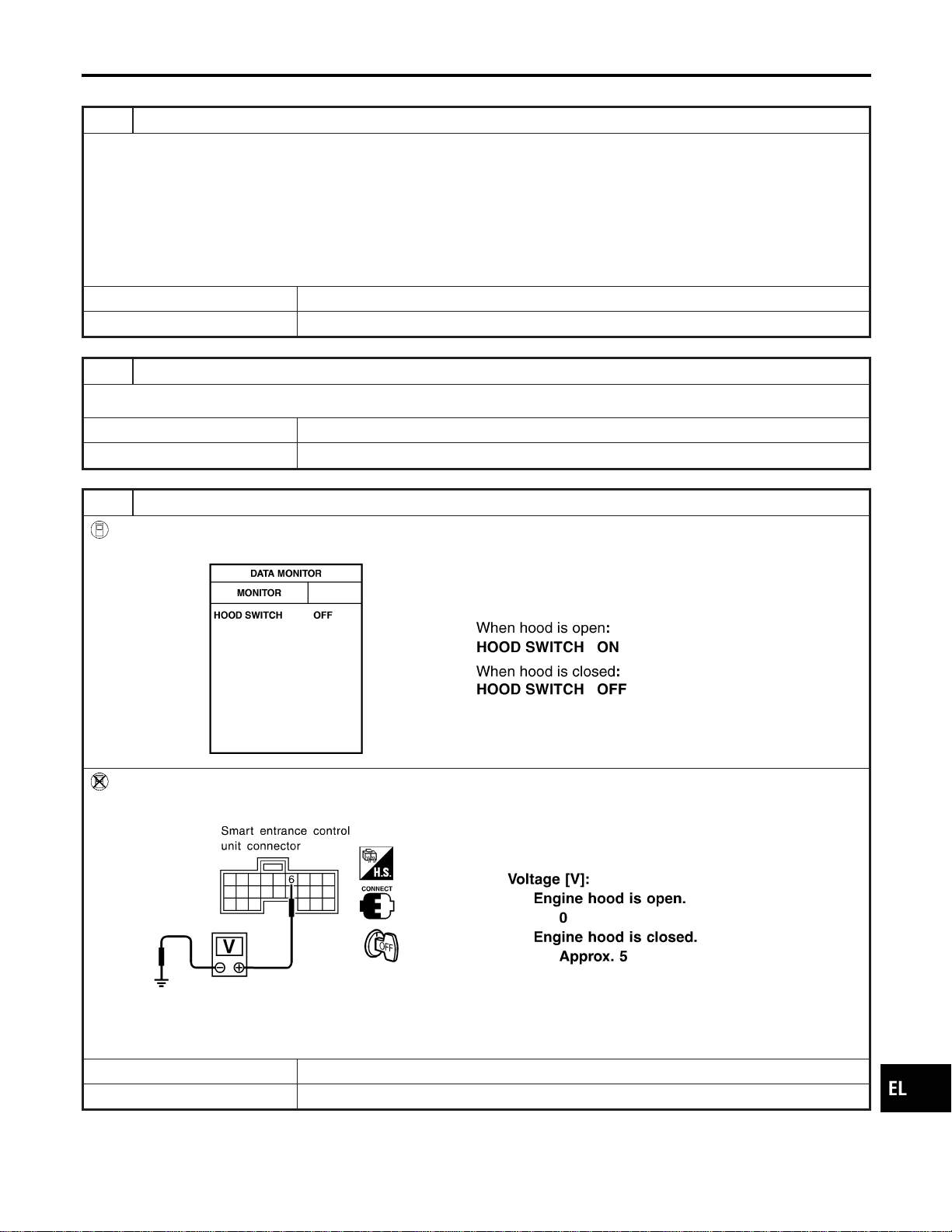
Hood Switch Check
=NAEL0406S0402
1 PRELIMINARY CHECK
1. Turn ignition switch OFF and remove key from ignition key cylinder.
“SECURITY” indicator lamp should blink every 2.6 seconds.
2. Close all doors, hood and trunk lid.
3. Lock doors with multi-remote controller from inside the vehicle.
“SECURITY” indicator lamp should turn on for 30 seconds.
4. Unlock hood with hood opener within 30 seconds after door is locked.
“SECURITY” indicator lamp should turn off.
OK or NG
OK © Hood switch is OK, and go to trunk room lamp switch check.
NG © GO TO 2.
2 CHECK HOOD SWITCH FITTING CONDITION
OK or NG
OK © GO TO 3.
NG © Adjust installation of hood switch or hood.
3 CHECK HOOD SWITCH INPUT SIGNAL
With CONSULT-II
Check hood switch (“HOOD SWITCH”) in “DATA MONITOR” mode with CONSULT-II.
SEL354W
Without CONSULT-II
Check voltage between smart entrance control unit harness connector M121 terminal 6 (Y/B) and ground.
SEL035Y
Refer to wiring diagram in EL-346.
OK or NG
OK © Hood switch is OK, and go to glass hatch switch check.
NG © GO TO 4.
GI
MA
EM
LC
EC
FE
CL
MT
AT
TF
PD
AX
SU
BR
ST
RS
BT
HA
SC
IDX
VEHICLE SECURITY (THEFT WARNING) SYSTEM
Trouble Diagnoses (Cont’d)
EL-359
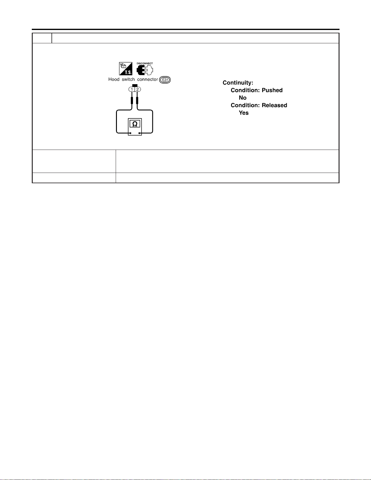
4 CHECK HOOD SWITCH
1. Disconnect hood switch connector.
2. Check continuity between hood switch terminals 1 and 2.
SEL338X
OK or NG
OK © Check the following.
I Hood switch ground circuit
I Harness for open or short between smart entrance control unit and hood switch
NG © Replace hood switch.
VEHICLE SECURITY (THEFT WARNING) SYSTEM
Trouble Diagnoses (Cont’d)
EL-360
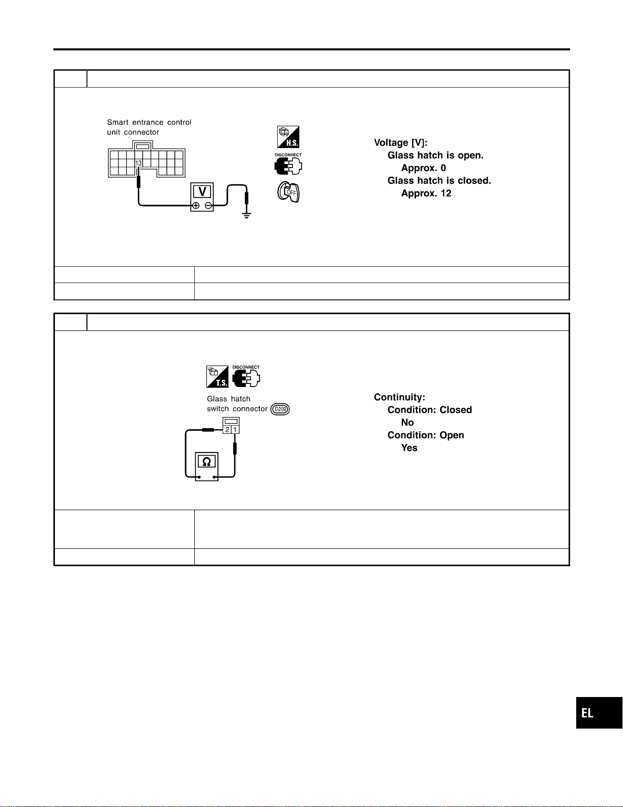
Glass Hatch Switch Check
=NAEL0406S0403
1 CHECK GLASS HATCH SWITCH INPUT SIGNAL
Check voltage between smart entrance control unit harness connector M121 terminal 13 (L/W) and ground.
SEL326Y
Refer to wiring diagram in EL-346.
OK or NG
OK © Glass hatch switch is OK.
NG © GO TO 2.
2 CHECK GLASS HATCH SWITCH
1. Disconnect glass hatch switch connector.
2. Check continuity between glass hatch switch terminals 1 and 2.
SEL340X
OK or NG
OK © Check the following.
I Glass hatch switch ground circuit
I Harness for open or short between smart entrance control unit and glass hatch switch
NG © Replace glass hatch switch.
GI
MA
EM
LC
EC
FE
CL
MT
AT
TF
PD
AX
SU
BR
ST
RS
BT
HA
SC
IDX
VEHICLE SECURITY (THEFT WARNING) SYSTEM
Trouble Diagnoses (Cont’d)
EL-361
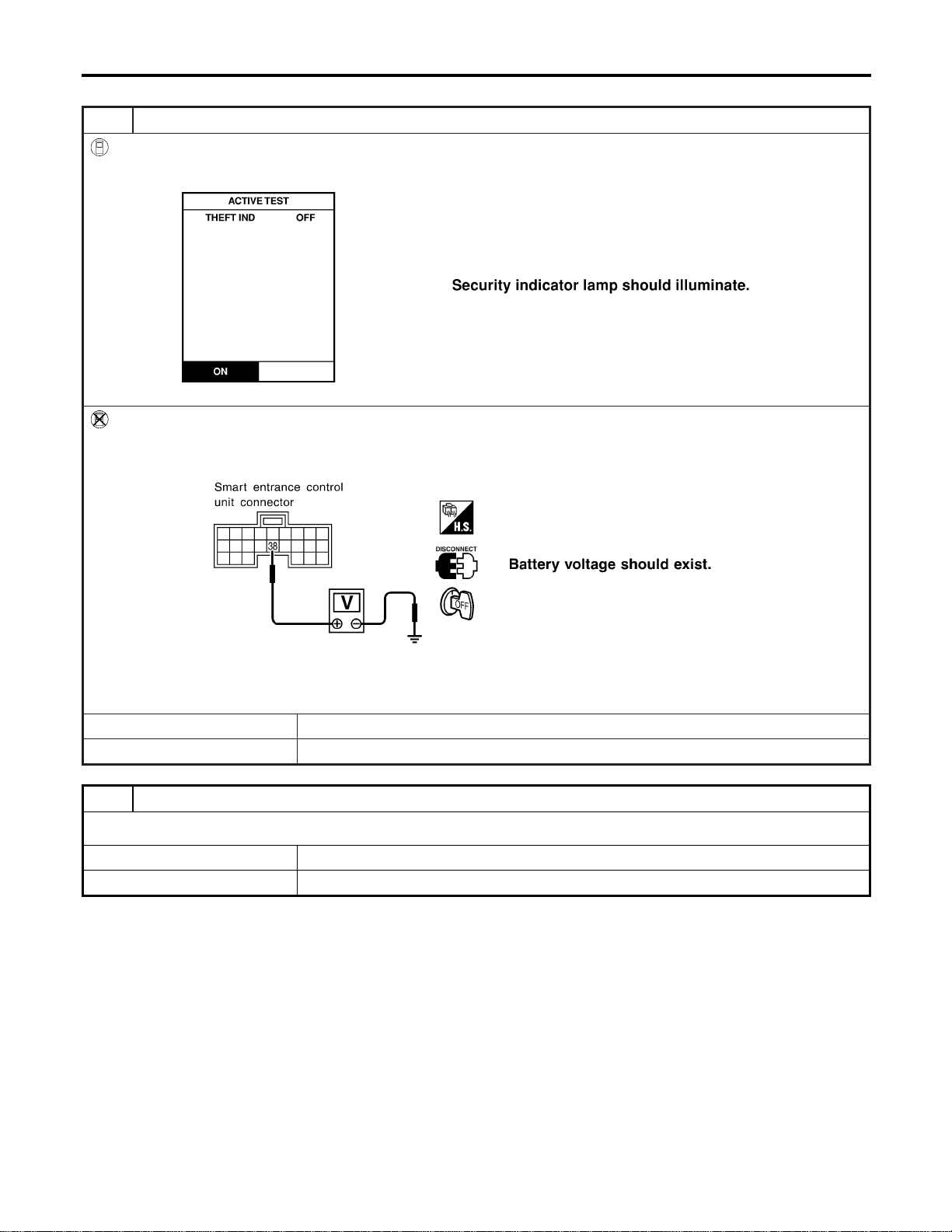
SECURITY INDICATOR LAMP CHECK
=NAEL0406S05
1 CHECK INDICATOR LAMP OPERATION
With CONSULT-II
1. Select “ACTIVE TEST” in “THEFT WAR ALM” with CONSULT-II.
2. Select “THEFT IND” and touch “ON”.
SEL356W
Without CONSULT-II
1. Disconnect smart entrance control unit harness connector.
2. Check voltage between smart entrance control unit harness connector M122 terminal 38 (BR/Y) and ground.
SEL037Y
Refer to wiring diagram in EL-346.
OK or NG
OK © Security indicator lamp is OK.
NG © GO TO 2.
2 CHECK INDICATOR LAMP
OK or NG
OK © GO TO 3.
NG © Replace indicator lamp.
VEHICLE SECURITY (THEFT WARNING) SYSTEM
Trouble Diagnoses (Cont’d)
EL-362
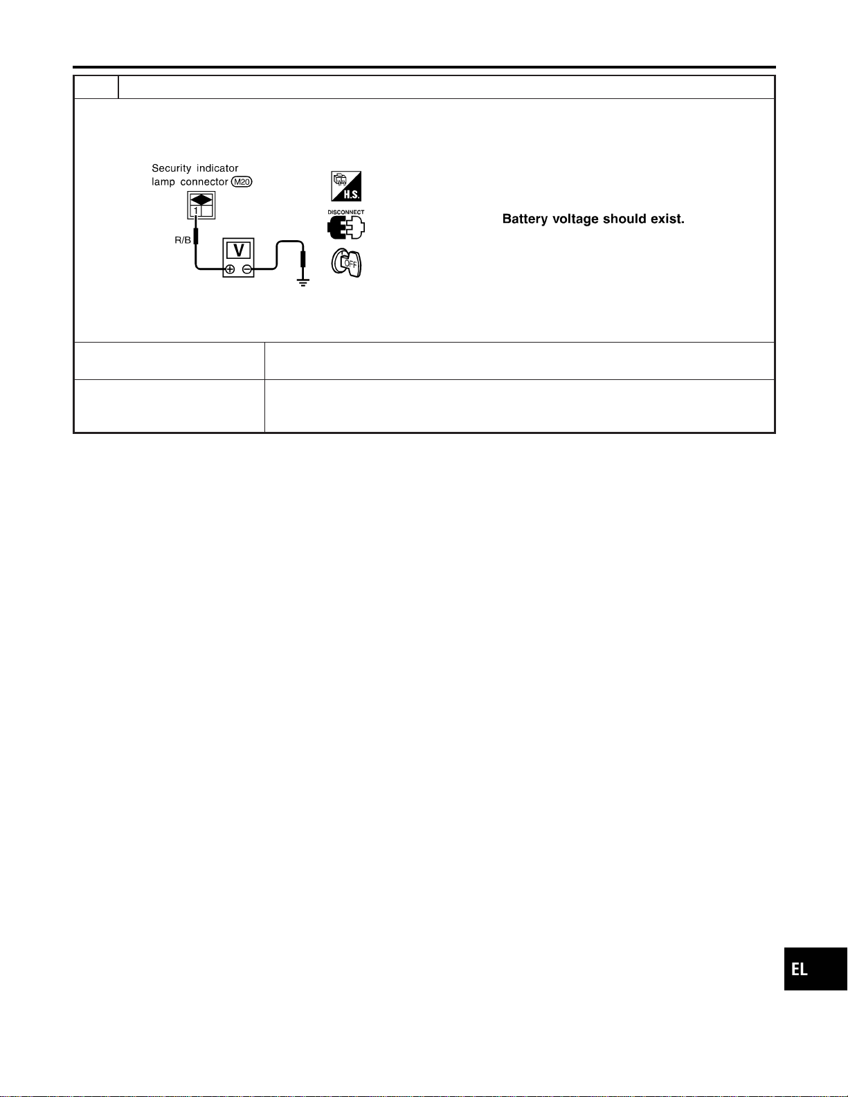
3 CHECK POWER SUPPLY CIRCUIT FOR INDICATOR LAMP
1. Disconnect security lamp connector.
2. Check voltage between indicator lamp terminal 1 and ground.
SEL342X
Does battery voltage exist?
Yes © Check harness for open or short between security indicator lamp and smart entrance
control unit.
No © Check the following.
I 7.5A fuse [No. 24, located in fuse block (J/B)]
I Harness for open or short between security indicator lamp and fuse
GI
MA
EM
LC
EC
FE
CL
MT
AT
TF
PD
AX
SU
BR
ST
RS
BT
HA
SC
IDX
VEHICLE SECURITY (THEFT WARNING) SYSTEM
Trouble Diagnoses (Cont’d)
EL-363
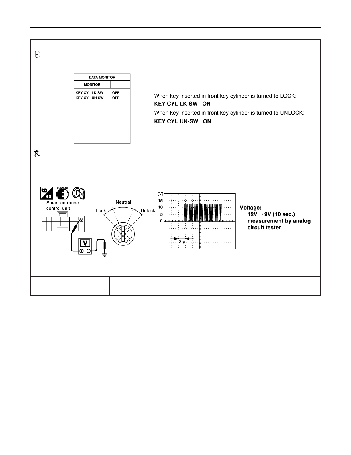
FRONT DOOR KEY CYLINDER SWITCH CHECK
=NAEL0406S06
1 CHECK DOOR KEY CYLINDER SWITCH INPUT SIGNAL (LOCK/UNLOCK SIGNAL)
With CONSULT-II
Check front door key cylinder switch (“KEY CYL LK-SW”/“KEY CYL UN-SW”) in “DATA MONITOR” mode with CONSULT-
II.
SEL342W
Without CONSULT-II
1. Check the signal between smart entrance control unit harness connector M144 terminal 33 (BR) and ground with oscil-
loscope when key inserted in front key cylinder is turned “LOCK” or “UNLOCK”.
2. Make sure signals which are shown in the figure below can be detected during 10 sec. just after key is turned “LOCK”
or “UNLOCK”.
SEL488Y
Refer to wiring diagram in EL-348.
OK or NG
OK © Door key cylinder switch LH is OK.
NG © GO TO 2.
VEHICLE SECURITY (THEFT WARNING) SYSTEM
Trouble Diagnoses (Cont’d)
EL-364
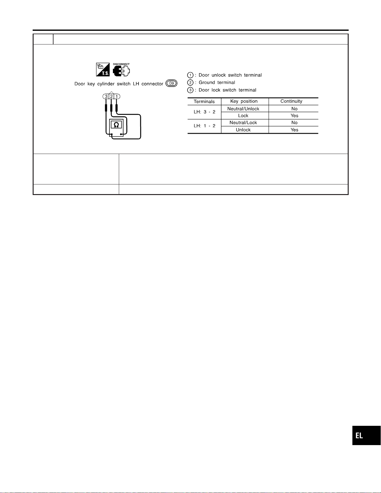
2 CHECK DOOR KEY CYLINDER SWITCH
1. Disconnect door key cylinder switch LH connector.
2. Check continuity between door key cylinder switch LH terminals.
SEL313X
OK or NG
OK © Check the following.
I Door key cylinder switch LH ground circuit
I Harness for open or short between smart entrance control unit and door key cylinder
switch LH
NG © Replace door key cylinder switch LH.
GI
MA
EM
LC
EC
FE
CL
MT
AT
TF
PD
AX
SU
BR
ST
RS
BT
HA
SC
IDX
VEHICLE SECURITY (THEFT WARNING) SYSTEM
Trouble Diagnoses (Cont’d)
EL-365

BACK DOOR KEY CYLINDER SWITCH CHECK
=NAEL0406S07
1 CHECK BACK DOOR KEY CYLINDER SWITCH INPUT SIGNAL (LOCK/UNLOCK SIGNAL)
With CONSULT-II
Check back door key cylinder switch (“KEY CYL LK-SW”/“KEY CYL UN-SW”) in “DATA MONITOR” mode with CONSULT-
II.
SEL342WB
Without CONSULT-II
Check voltage between smart entrance control unit terminals 10 (LG), 11 (Y) or 12 (G/B) and ground.
SEL325Y
Refer to wiring diagram in EL-349.
OK or NG
OK © Back door key cylinder switch is OK.
NG © GO TO 2.
VEHICLE SECURITY (THEFT WARNING) SYSTEM
Trouble Diagnoses (Cont’d)
EL-366
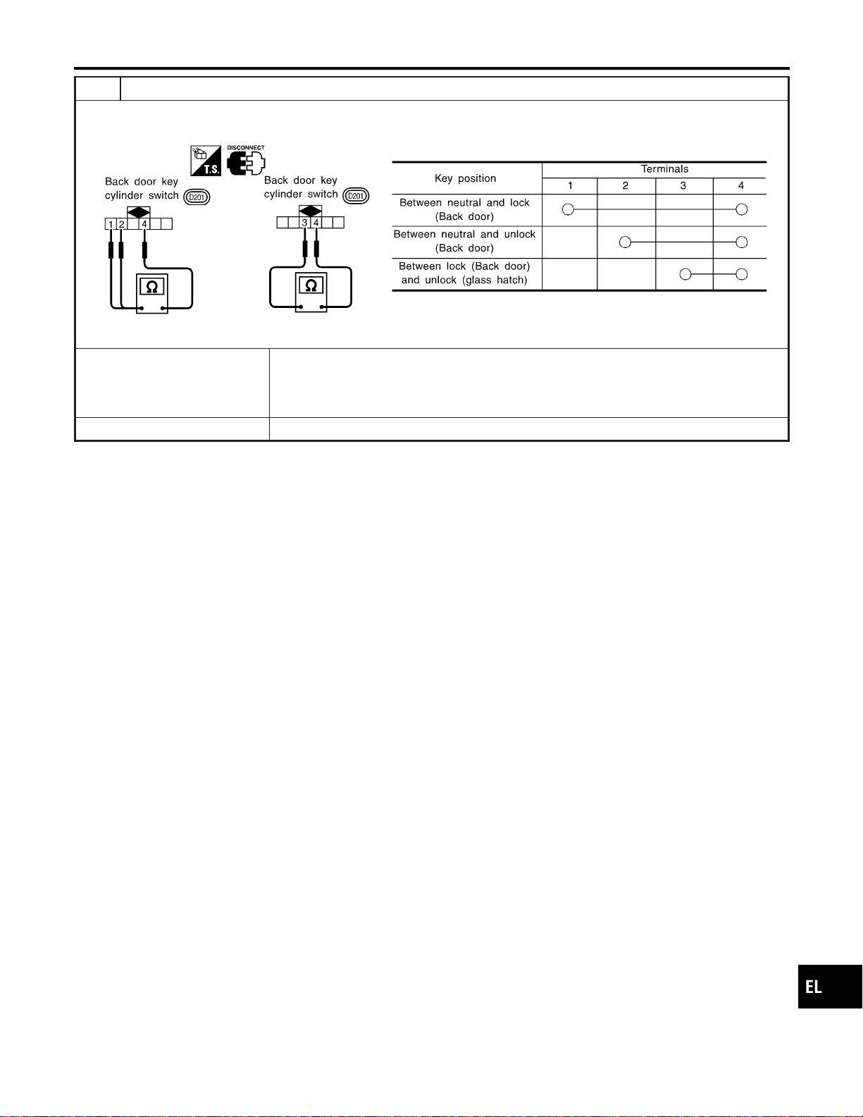
2 CHECK BACK DOOR KEY CYLINDER SWITCH
1. Disconnect back door key cylinder switch connector.
2. Check continuity between back door key cylinder switch terminals.
SEL345X
OK or NG
OK © Check the following.
I Back door key cylinder switch ground circuit
I Harness for open or short between smart entrance control unit and back door key cyl-
inder switch
NG © Replace back door key cylinder switch.
GI
MA
EM
LC
EC
FE
CL
MT
AT
TF
PD
AX
SU
BR
ST
RS
BT
HA
SC
IDX
VEHICLE SECURITY (THEFT WARNING) SYSTEM
Trouble Diagnoses (Cont’d)
EL-367

DOOR LOCK/UNLOCK SWITCH CHECK
=NAEL0406S08
1 CHECK DOOR LOCK/UNLOCK SWITCH INPUT SIGNAL
With CONSULT-II
Check door lock/unlock switch (“LOCK SW DR/AS”/“UNLK SW DR/AS”) in “DATA MONITOR” mode with CONSULT-II.
SEL341W
Without CONSULT-II
1. Remove key from ignition switch.
2. Check the signal between smart entrance control unit harness connector M144 terminal 33 (BR) and ground with oscil-
loscope when door lock/unlock switch is turned “LOCK” or “UNLOCK”.
3. Make sure signals which are shown in the figure below can be detected during 10 sec. just after door lock/unlock
switch is turned “LOCK” or “UNLOCK”.
SEL487Y
Refer to wiring diagram in EL-348.
OK or NG
OK © Door lock/unlock switch is OK.
NG © Check the following.
I Ground circuit for each front power window switch
I Harness for open or short between each front power window switch and smart
entrance control unit connector
If above systems are normal, replace the front power window switch.
VEHICLE SECURITY (THEFT WARNING) SYSTEM
Trouble Diagnoses (Cont’d)
EL-368
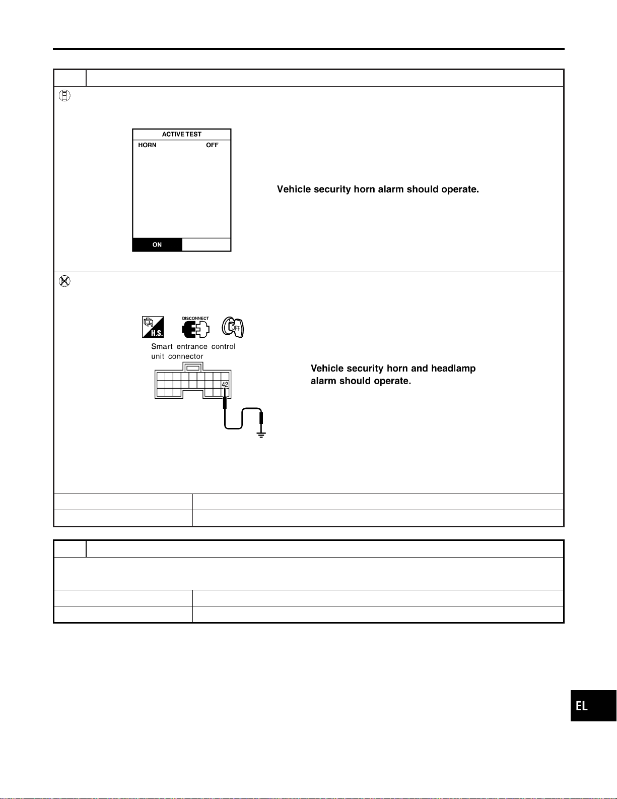
VEHICLE SECURITY HORN ALARM CHECK
=NAEL0406S09
1 CHECK VEHICLE SECURITY HORN
With CONSULT-II
1. Select “ACTIVE TEST” in “THEFT WAR ALM” with CONSULT-II.
2. Select “HORN” and touch “ON”.
SEL041Y
Without CONSULT-II
1. Disconnect smart entrance control unit harness connector.
2. Apply ground to smart entrance control unit harness connector M121 terminal 42 (LG/B).
SEL043Y
Refer to wiring diagram in EL-349.
NOTE:
If CONSULT-II is not available, skip this procedure and go to the next step.
OK or NG
OK © Horn alarm is OK.
NG © GO TO 2.
2 CHECK HORN RELAY
Check horn relay.
OK or NG
OK © GO TO 3.
NG © Replace horn relay.
GI
MA
EM
LC
EC
FE
CL
MT
AT
TF
PD
AX
SU
BR
ST
RS
BT
HA
SC
IDX
VEHICLE SECURITY (THEFT WARNING) SYSTEM
Trouble Diagnoses (Cont’d)
EL-369
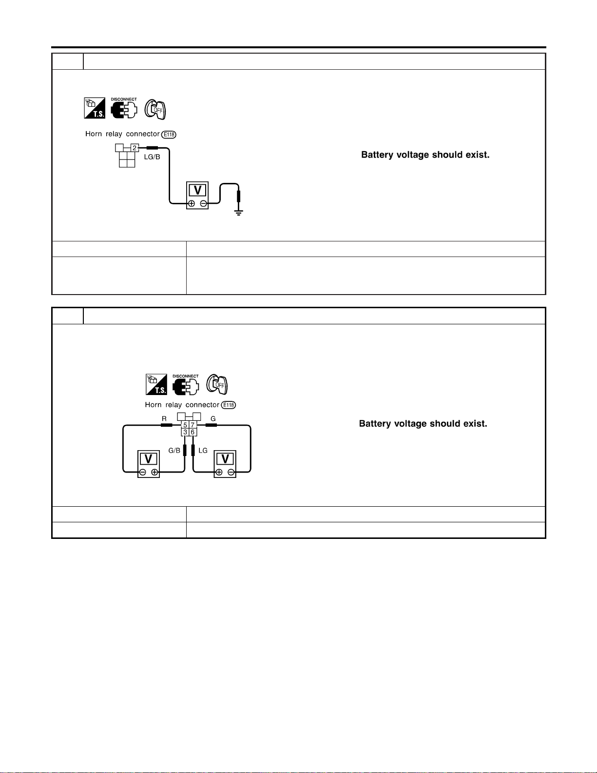
3 CHECK POWER SUPPLY FOR HORN RELAY
1. Disconnect horn relay connector.
2. Check voltage between terminal 2 and ground.
SEL347X
OK or NG
OK © GO TO 4.
NG © Check the following.
I 7.5A fuse (No. 52, located in the fuse and fusible link box)
I Harness for open or short between horn relay and fuse
4 CHECK HORN RELAY CIRCUIT
1. Disconnect horn relay connector.
2. Check voltage between terminals 3 and 5.
3. Check voltage between terminals 6 and 7.
SEL348X
OK or NG
OK © Check harness for open or short between horn relay and smart entrance control unit.
NG © Check harness for open or short.
VEHICLE SECURITY (THEFT WARNING) SYSTEM
Trouble Diagnoses (Cont’d)
EL-370
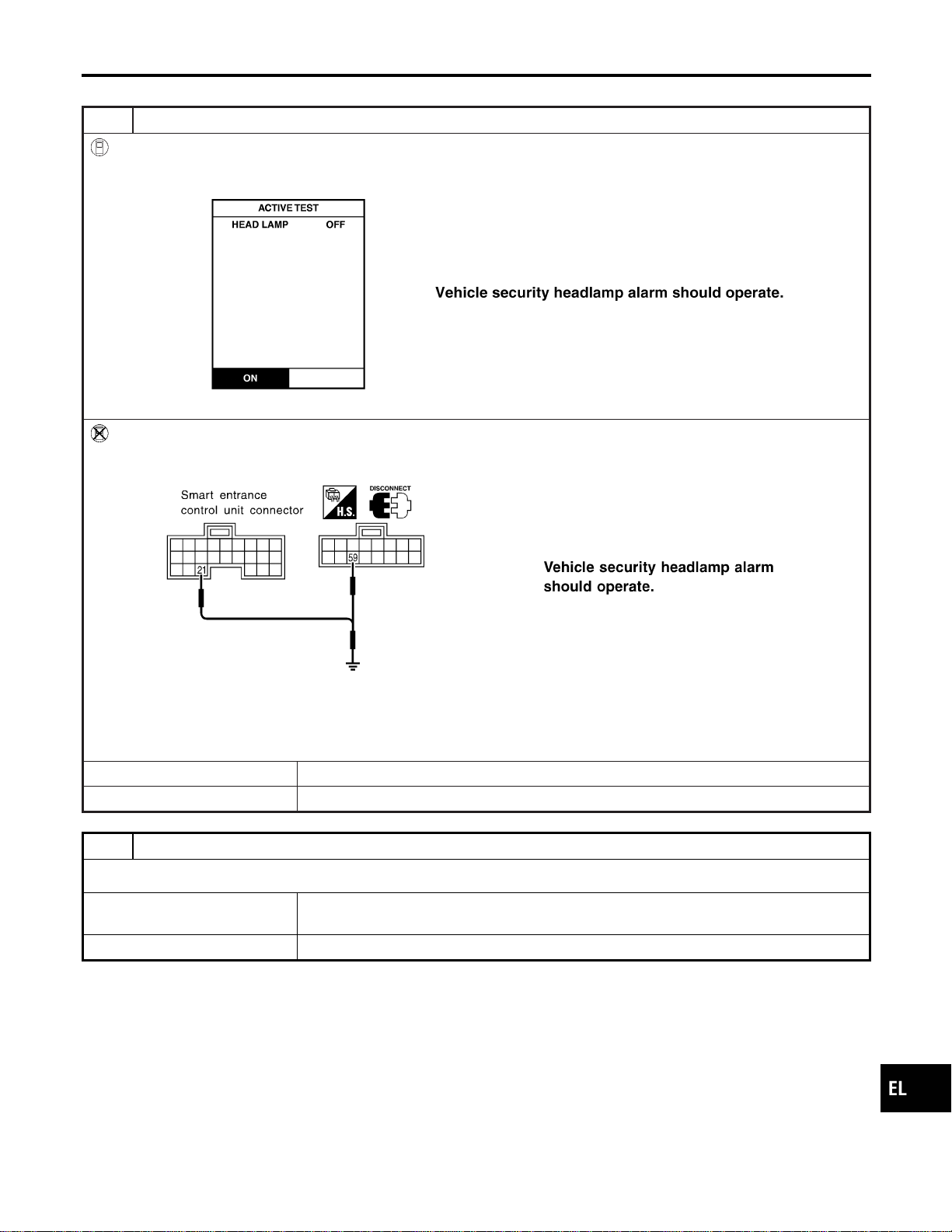
VEHICLE SECURITY HEADLAMP ALARM CHECK
=NAEL0406S10
1 CHECK VEHICLE SECURITY HEADLAMP ALARM OPERATION
With CONSULT-II
1. Select “ACTIVE TEST” in “THEFT WAR ALM” with CONSULT-II.
2. Select “HEADLAMP” and touch “ON”.
SEL042Y
Without CONSULT-II
1. Disconnect smart entrance control unit connector.
2. Apply ground to smart entrance control unit terminal 4.
SEL198Y
Refer to wiring diagram in EL-350.
NOTE:
If CONSULT-II is not available, skip this procedure and go to the next step.
OK or NG
OK © Headlamp is OK.
NG © GO TO 2.
2 CHECK HEADLAMP OPERATION
Does headlamp come on when turning lighting switch “ON”?
Yes © Check harness for open or short between headlamp relay and smart entrance control
unit.
No © Check headlamp system. Refer to “HEADLAMP”.
GI
MA
EM
LC
EC
FE
CL
MT
AT
TF
PD
AX
SU
BR
ST
RS
BT
HA
SC
IDX
VEHICLE SECURITY (THEFT WARNING) SYSTEM
Trouble Diagnoses (Cont’d)
EL-371

Description
NAEL0407
OUTLINE
NAEL0407S01
The smart entrance control unit totally controls the following body electrical system operations.
I Headlamp auto light control system
I Warning chime
I Rear defogger and door mirror defogger timer
I Power door lock
I Remote keyless entry system
I Vehicle security system
I Interior lamp
In addition, the following timer operations are controlled by the smart entrance control unit.
I Battery saver control
I Retained power control
BATTERY SAVER CONTROL
NAEL0407S02
Headlamps/Parking Lamps/License Lamps/Tail Lamps/Fog Lamps/Illumination Lamps
NAEL0407S0201
While the headlamps (including parking, license, tail, fog and illumination lamps) are turned ON by “1ST” or
“2ND” of lighting switch, the exterior lamp battery saver control is activated when the ignition switch signal
changes from ON (or ACC) to OFF, and either one of LH or RH front door switch ON signal is received. The
headlamps (including parking, license, tail, fog and illumination lamps) are turned off after 5 minutes.
While the headlamps are turned ON by “AUTO” operation, the exterior lamp battery saver control is activated
when the ignition switch is turned from ON (or ACC) to OFF, and either LH or RH front door switch ON sig-
nal is input.
The smart entrance control unit controls timer activation as follows:
I When the door switch signal changes from ON to OFF while the exterior lamp battery saver is activated,
the operation is discontinued, restarts and lasts for 45 seconds, then the headlamps (including parking,
license, tail, fog and illumination lamps) will be turned off.
I When the door switch signal changes from OFF to ON while the exterior lamp battery saver is activated,
the operation is discontinued, restarts and lasts for 45 seconds, then the headlamps will be turned off.
I When the one of four door switch signals changes from OFF to ON while the exterior lamp battery saver
is activated, the operation is discontinued, restarts and lasts for 5 minutes, then the headlamps (including
parking, license, tail, fog and illumination lamps) will be turned off.
I When all the door switch ON signals are input while the exterior lamp battery saver is activated, the
operation is discontinued, restarts and lasts for 45 seconds, then the headlamps (including parking,
license, tail, fog and illumination lamps) will be turned off.
The “45” second timer’s duration can be changed with the function setting mode of CONSULT-II.
Interior Lamp/Luggage Room Lamp/Spot Lamp/Vanity Mirror Illumination
NAEL0407S0202
The lamps turn off automatically when the interior lamp, spot lamp or/and vanity mirror illumination are illumi-
nated with the ignition key in the OFF position, if the lamp remains lit by the door switch open signal or if the
lamp switch is in the ON position for more than 30 minutes.
After lamps are turned off by the battery saver system, the lamps illuminate again when:
I Door is locked or unlocked with keyfob or door lock/unlock switch or door key cylinder.
I Ignition switch ON.
I Door is opened or closed,
I Key is inserted or removed into ignition key cylinder.
Rear Window Defogger/Door Mirror Defogger
NAEL0407S0203
Rear window defogger and door mirror defogger are turned off in approximately 15 minutes after the rear win-
dow defogger switch is turned on.
RETAINED POWER CONTROL
NAEL0407S03
When the ignition switch is turned to OFF (or ACC) position from ON or START position, the following sys-
tems can be operated for 45 seconds by the RAP signal from the smart entrance control unit terminal 46.
I Electric sunroof
I Power window
The retained power operation is canceled when the driver or passenger side door is opened.
SMART ENTRANCE CONTROL UNIT
Description
EL-372

INPUT/OUTPUT
NAEL0407S04
System Input Output
Power door lock
Door lock and unlock switch LH and RH
Key switch (Insert)
Door switches
Door key cylinder switches
Door lock actuator
Multi-remote control
Key switch (Insert)
Ignition switch (ACC)
Door switches
Remote controller signal
Door lock/unlock switch LH
Horn relay
Headlamp relay (LH and RH)
Hazard warning lamp
Interior lamp
Door lock actuator
Remote keyless entry
Key switch (Insert)
Ignition switch (ACC)
Door switches
Keyfob signal
Door lock/unlock switch LH
Horn relay
Vehicle security horn relay-1
Vehicle security horn relay-2
Hazard warning lamp
Interior lamp
Ignition key hole illumination
Door lock actuator
Opener actuator
Warning chime
Key switch (Insert)
Ignition switch (ON)
Lighting switch (1st)
Seat belt switch (driver’s seat)
Front door switch LH
Warning chime (located in smart entrance
control unit)
Rear window defogger and
door mirror defogger
Ignition switch (ON)
Rear window defogger switch
Rear window defogger relay
Vehicle security
Ignition switch (ACC, ON)
Door switches
Hood switch
Trunk room lamp switch
Door lock/unlock switches
Door key cylinder switches (lock/unlock)
Key cylinder switch (unlock)
Vehicle security horn relay-2
Headlamp relay
Security indicator
Interior lamp
Door switches
Keyfob signal (lock/unlock)
Door lock/unlock switches (lock/unlock)
Door key cylinder switch (lock/unlock)
Ignition switch (ON)
Key switch (Insert)
Interior lamp
Key hole illumination
Step lamp
Door indicator
Battery saver control for
headlamps/parking lamps/
licence lamps/tail lamps/fog
lamps/illumination lamps
Ignition switch (ON)
Front door switches
Lighting switches
Headlamps
Parking lamps
Licence lamps
Tail lamps
Fog lamps
Illumination lamps
Battery saver control for inte-
rior lamp/spot lamp/vanity mir-
ror illumination
Ignition switch (ON)
Front door switches
Lamp switches
Interior lamp
Step lamp
Spot lamp
Vanity mirror illumination
Battery saver control for rear
window defogger and door
mirror defogger
Ignition switch (ON)
Rear window defogger switch
Rear window defogger relay
Retained power control for
electric sunroof
Ignition switch (ON)
Front door switches
Sunroof motor
Retained power control for
power window
Ignition switch (ON)
Front door switches
Power window relay
GI
MA
EM
LC
EC
FE
CL
MT
AT
TF
PD
AX
SU
BR
ST
RS
BT
HA
SC
IDX
SMART ENTRANCE CONTROL UNIT
Description (Cont’d)
EL-373

CONSULT-II
NAEL0408
DIAGNOSTIC ITEMS APPLICATION
NAEL0408S01
Item (CONSULT-II
screen terms)
Diagnosed system DATA MONITOR ACTIVE TEST WORK SUPPORT
DOOR LOCK Power door lock X X X
REAR DEFOGGER Rear window defogger X X
KEY WARN ALM Warning chime X X
LIGHT WARN ALM Warning chime X X
SEAT BELT ALM Warning chime X X
INT LAMP Interior lamps X X X
BATTERY SAVER Battery saver control for
interior lamp
XXX
THEFT WAR ALM Vehicle security system X X X
RETAINED PWR Retained power control X X X
MULTI REMOTE ENT Remote keyless entry
system
XXX
HEAD LAMP Headlamp X X X
X: Applicable
For diagnostic item in each control system, refer to the relevant pages for each system.
DIAGNOSTIC ITEM DESCRIPTION
NAEL0408S02
MODE Description
DATA MONITOR Input/output data in the smart entrance control unit can be
read.
ACTIVE TEST Diagnostic Test Mode in which CONSULT-II drives some sys-
tems apart from the smart entrance control unit.
WORK SUPPORT for DOOR LOCK I Select unlock mode ON-OFF setting can be changed.
I Key reminder door mode ON-OFF setting can be changed.
WORK SUPPORT for INT LAMP Interior lamp timer mode ON-OFF setting can be changed.
WORK SUPPORT for BATTERY SAVER Interior lamp battery saver period can be changed.
WORK SUPPORT for THEFT WAR ALM I The recorded trigger signal when vehicle security system
was activated can be checked.
I Security alarm ON-OFF setting can be changed.
WORK SUPPORT for RETAINED PWR SET RAP signal’s power supply period can be changed.
WORK SUPPORT for MULTI REMOTE ENT I ID code of keyfob can be registered and erased.
I Keyless answer back mode can be changed.
I Pressing time of panic alarm, trunk lid opener and door
unlock (for power window down operation) buttons on keyfob
can be changed.
I Auto lock operation starting time can be changed.
WORK SUPPORT for HEADLAMP I Auto light sensitivity can be changed.
I Exterior lamp battery saver control ON-OFF setting can be
changed.
I Auto light delay off time can be changed.
SMART ENTRANCE CONTROL UNIT
CONSULT-II
EL-374
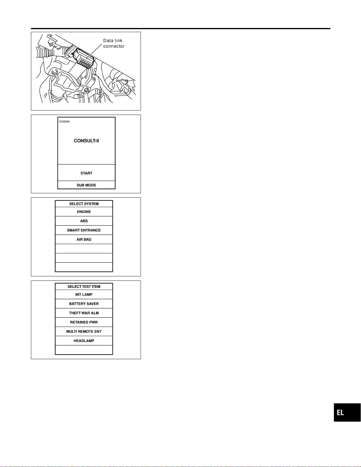
SEL331X
CONSULT-II INSPECTION PROCEDURE
NAEL0408S03
1. Turn the ignition switch “OFF”.
2. Connect “CONSULT-II” to the data link connector.
PBR455D
3. Turn ignition switch “ON”.
4. Touch “START”.
SEL398Y
5. Touch “SMART ENTRANCE”.
SEL401Y
6. Perform each diagnostic item according to “DIAGNOSTIC
ITEMS APPLICATION”. Refer to EL-374.
GI
MA
EM
LC
EC
FE
CL
MT
AT
TF
PD
AX
SU
BR
ST
RS
BT
HA
SC
IDX
SMART ENTRANCE CONTROL UNIT
CONSULT-II (Cont’d)
EL-375
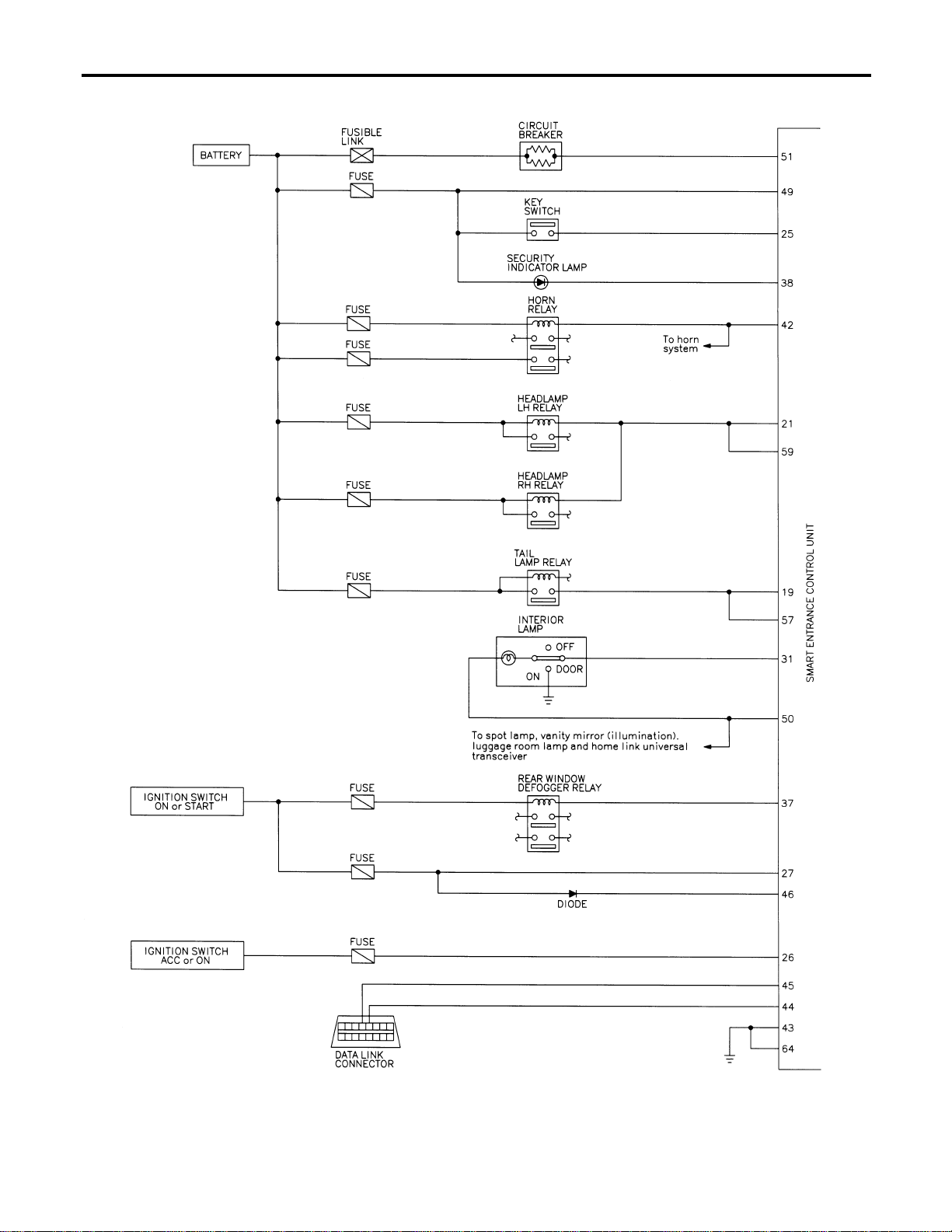
Schematic
NAEL0409
MEL442P
SMART ENTRANCE CONTROL UNIT
Schematic
EL-376
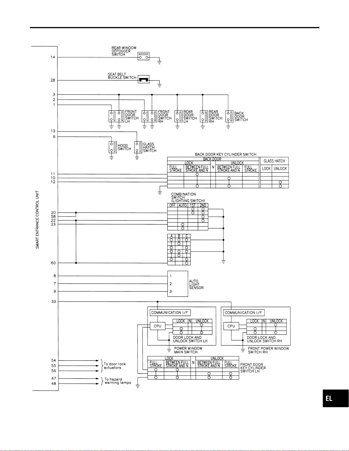
MEL443P
GI
MA
EM
LC
EC
FE
CL
MT
AT
TF
PD
AX
SU
BR
ST
RS
BT
HA
SC
IDX
SMART ENTRANCE CONTROL UNIT
Schematic (Cont’d)
EL-377

Smart Entrance Control Unit Inspection Table
NAEL0410
Terminal
No.
Wire
color
Connections Operated condition
Voltage
(Approximate val-
ues)
1 G/OR Driver door switch OFF (Closed) , ON (Open) 12V , 0V
2 Y Passenger door switch OFF (Closed) , ON (Open) 5V , 0V
3 R/L Rear door switch OFF (Closed) , ON (Open) 5V , 0V
4 LG/R Door lock & unlock switches Neutral , Unlocks 5V , 0V
5 BR Door lock & unlock switches Neutral , Locks 5V , 0V
6 Y/B Hood switch ON (Open) , OFF (Closed) 0V , 12V
7 W/G Auto light sensor (Signal)
Ignition switch ON
position
Light is applied to auto light sen-
sor.
1to5V
Light is not applied to auto light
sensor.
Less than 1V
8 L/R Auto light sensor (GND) — —
9 GY Auto light sensor (Power) Ignition switch (OFF , ON) 0V , 5V
10 LG
Door key cylinder unlock
switch
OFF (Neutral) , ON (Locked) 5V , 0V
11 Y Door key cylinder lock switch OFF (Neutral) , ON (Locked) 5V , 0V
12 W/PU Back door key cylinder switch OFF (Neutral) , ON (Unlock) 5V , 0V
13 L/W Glass hatch switch ON (Open) , OFF (Closed) 0V , 12V
14 OR Rear window defogger switch OFF , ON (Only when pushed) 5V , 0V
19 R/G Tail lamp relay (Output)
Ignition switch
(with lighting
switch 1ST or
2ND)
ON or START
, OFF position
More than 5
minutes after
ignition switch is
turned to OFF
position
12V
Within 5 min-
utes after igni-
tion switch is
turned to OFF
position
0V
ON or START position 0V
Headlamps illuminate by auto light control. (Operate
, Not operate)
Less than 1V ,
12V
20 G Tail lamp switch Light switch (OFF or AUTO , 1ST or 2ND position) 12V , 0V
21 PU/R Headlamp LH relay
Ignition switch
(with lighting
switch 2ND)
ON or START
, OFF position
More than 5
minutes after
ignition switch is
turned to OFF
position
12V
Within 5 min-
utes after igni-
tion switch is
turned to OFF
position
0V
ON or START position 0V
Headlamps illuminate by auto light control. 0V
SMART ENTRANCE CONTROL UNIT
Smart Entrance Control Unit Inspection Table
EL-378
Terminal
No.
Wire
color
Connections Operated condition
Voltage
(Approximate val-
ues)
22 SB Headlamp switch
Lighting switch
Except PASS or 2ND position 12V
PASS or 2ND position 0V
Headlamps illuminate by auto light control. (Operate
, Not operate)
10V , 12V
23 L/Y Headlamp switch
Ignition switch
“ON” position
Lighting switch (Except AUTO ,
AUTO position)
12V , 0V
25 W/R Ignition key switch (Insert) Key inserted , Key removed from IGN key cylinder 12V , 0V
26 G/W Ignition switch (ACC) “ACC” position 12V
27 W/B Ignition switch (ON) Ignition key is in “ON” position 12V
28 B/Y Seat belt buckle switch
Unfastened , Fastened (Ignition key is in “ON” posi-
tion)
0V , 12V
31 R/B Interior lamp
When doors are locked using keyfob (Lamp switch in
“DOOR” position)
0V , 12V
37 G/B Rear window defogger relay OFF , ON (Ignition key is in “ON” position) 12V , 0V
38 BR/Y Security indicator Goes off , Illuminates 12V , 0V
42 LG/B Horn relay
When panic alarm is operated using keyfob (ON ,
OFF)
12V , 0V
43 B Ground — —
46 R/Y Power window relay Retained power operation is operated (ON , OFF) 12V , 0V
47 GY/L LH turn signal lamp
When door lock or unlock is operated using keyfob
(ON , OFF)
12V , 0V
48 GY/R RH turn signal lamp
When door lock or unlock is operated using keyfob
(ON , OFF)
12V , 0V
49 G/R Power source (Fuse) — 12V
50 R/W Battery saver (Interior lamp)
Battery saver operates , Does not operate (ON
,OFF)
12V , 0V
51 W/R Power source (PTC) — 12V
54 L Door lock actuators Door lock & unlock switch (Free , Lock) 0V , 12V
55 W/PU Driver door lock actuator Door lock & unlock switch (Free , Unlock) 0V , 12V
56 Y/B
Passenger, rear and back
doors lock actuator
Door lock & unlock switch (Free , Unlock) 0V , 12V
57 R Tail lamp relay
Ignition switch
(with lighting
switch 1ST or
2ND)
ON or START
, OFF position
More than 5
minutes after
ignition switch is
turned to OFF
position
12V
Within 5 min-
utes after igni-
tion switch is
turned to OFF
position
0V
ON or START position 0V
Headlamps illuminate by auto light control. (Operate
, Not operate)
Less than 1V,
12V
GI
MA
EM
LC
EC
FE
CL
MT
AT
TF
PD
AX
SU
BR
ST
RS
BT
HA
SC
IDX
SMART ENTRANCE CONTROL UNIT
Smart Entrance Control Unit Inspection Table (Cont’d)
EL-379
Terminal
No.
Wire
color
Connections Operated condition
Voltage
(Approximate val-
ues)
58 G/W Tail lamp switch Lighting switch OFF or AUTO , 1ST or 2ND 12V , 0V
59 PU/W Headlamp RH relay
Ignition switch
(with lighting
switch OFF or
1ST)
ON or START
, OFF position
More than 5
minutes after
ignition switch is
turned to OFF
position
12V
Within 5 min-
utes after igni-
tion switch is
turned to OFF
position
0V
ON or START position 0V
Headlamps illuminate by auto light control.
(Operate , Not operate)
Less than 1V ,
12V
60 L Headlamp switch
Lighting switch
Except PASS or 2ND position 12V
PASS or 2ND position 0V
Headlamps illuminate by auto light control. (Operate
, Not operate)
10V , 12V
64 B Ground — —
SMART ENTRANCE CONTROL UNIT
Smart Entrance Control Unit Inspection Table (Cont’d)
EL-380
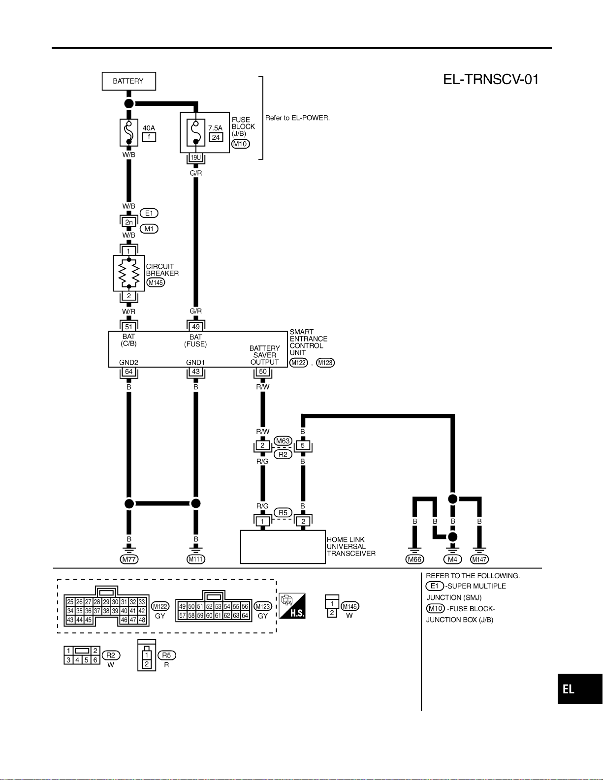
Wiring Diagram — TRNSCV —
NAEL0411
MEL444P
GI
MA
EM
LC
EC
FE
CL
MT
AT
TF
PD
AX
SU
BR
ST
RS
BT
HA
SC
IDX
HOMELINK UNIVERSAL TRANSCEIVER
Wiring Diagram — TRNSCV —
EL-381
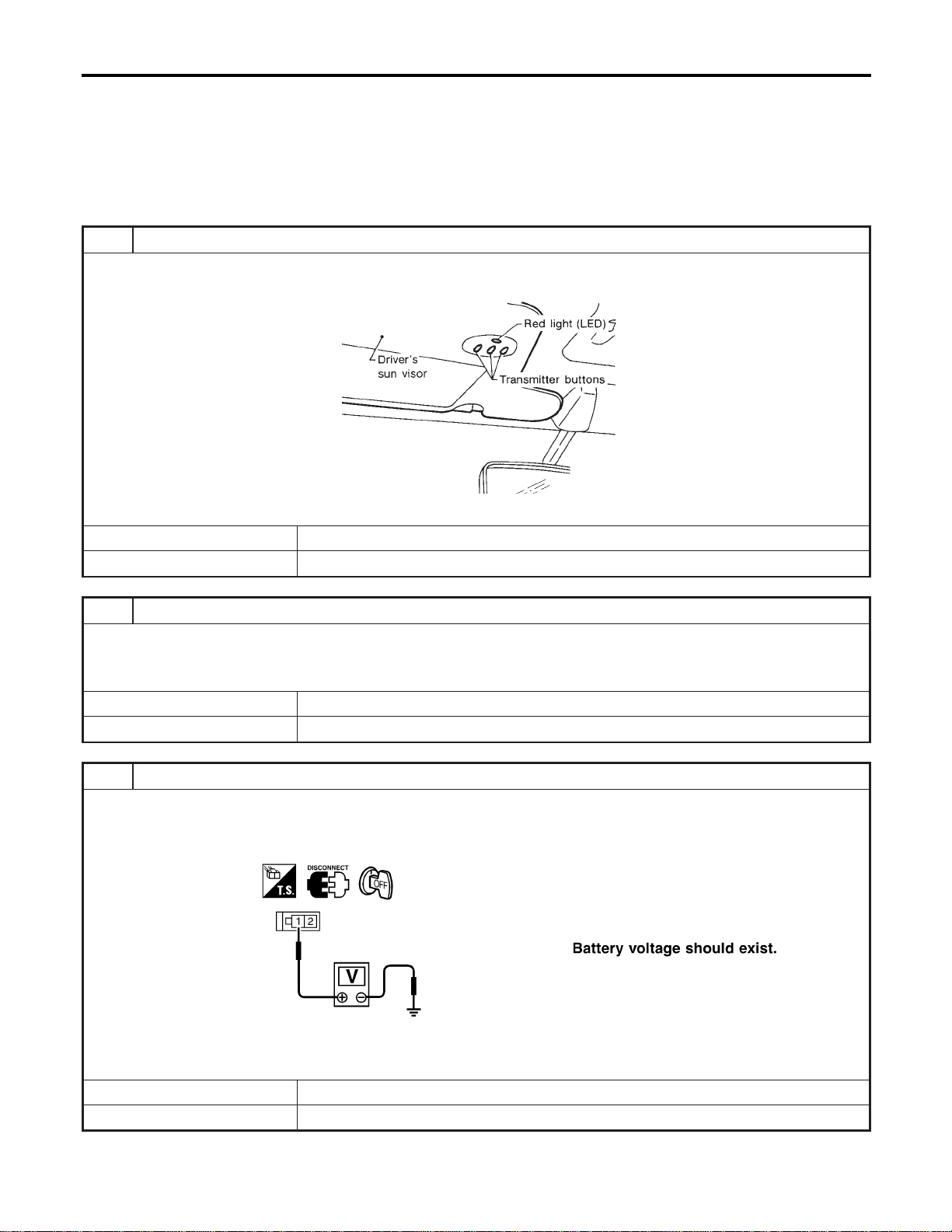
Trouble Diagnoses
NAEL0412
DIAGNOSTIC PROCEDURE
NAEL0412S01
SYMPTOM: Transmitter does not activate receiver.
Before conducting the procedure given below, make sure that sys-
tem receiver (garage door opener, etc.) operates with original,
hand-held transmitter. If NG, receiver or hand-held transmitter is at
fault, not vehicle related.
1 PRELIMINARY CHECK
1. Turn ignition switch “OFF”.
2. Does red light (LED) of transmitter illuminate when any button is pressed?
SEL442U
YesorNo
Yes © GO TO 2.
No © GO TO 3.
2 CHECK TRANSMITTER FUNCTION
Check transmitter with Tool.
For details, refer to Technical Service Bulletin.
OK or NG
OK © Receiver or handheld transmitter fault, not vehicle related.
NG © Replace transmitter with sun visor assembly.
3 CHECK POWER SUPPLY
1. Disconnect transmitter connector.
2. Turn ignition switch “OFF”.
3. Check voltage between terminal 1 and body ground.
SEL358X
OK or NG
OK © GO TO 4.
NG © GO TO 5.
HOMELINK UNIVERSAL TRANSCEIVER
Trouble Diagnoses
EL-382
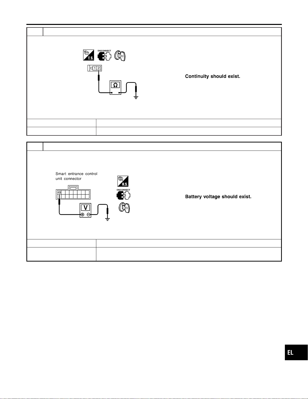
4 CHECK GROUND CIRCUIT
Check continuity between terminal 2 and ground.
SEL359X
OK or NG
OK © Replace transmitter with sun visor assembly.
NG © Repair harness.
5 CHECK MAIN POWER SUPPLY FOR SMART ENTRANCE CONTROL UNIT
1. Disconnect smart entrance control unit.
2. Check voltage between smart entrance control unit harness connector M123 terminal 49 (G/R) and ground.
SEL284Y
OK or NG
OK © GO TO 6.
NG © Check the following.
I 7.5A fuse No. 24, located in fuse block (J/B)
GI
MA
EM
LC
EC
FE
CL
MT
AT
TF
PD
AX
SU
BR
ST
RS
BT
HA
SC
IDX
HOMELINK UNIVERSAL TRANSCEIVER
Trouble Diagnoses (Cont’d)
EL-383
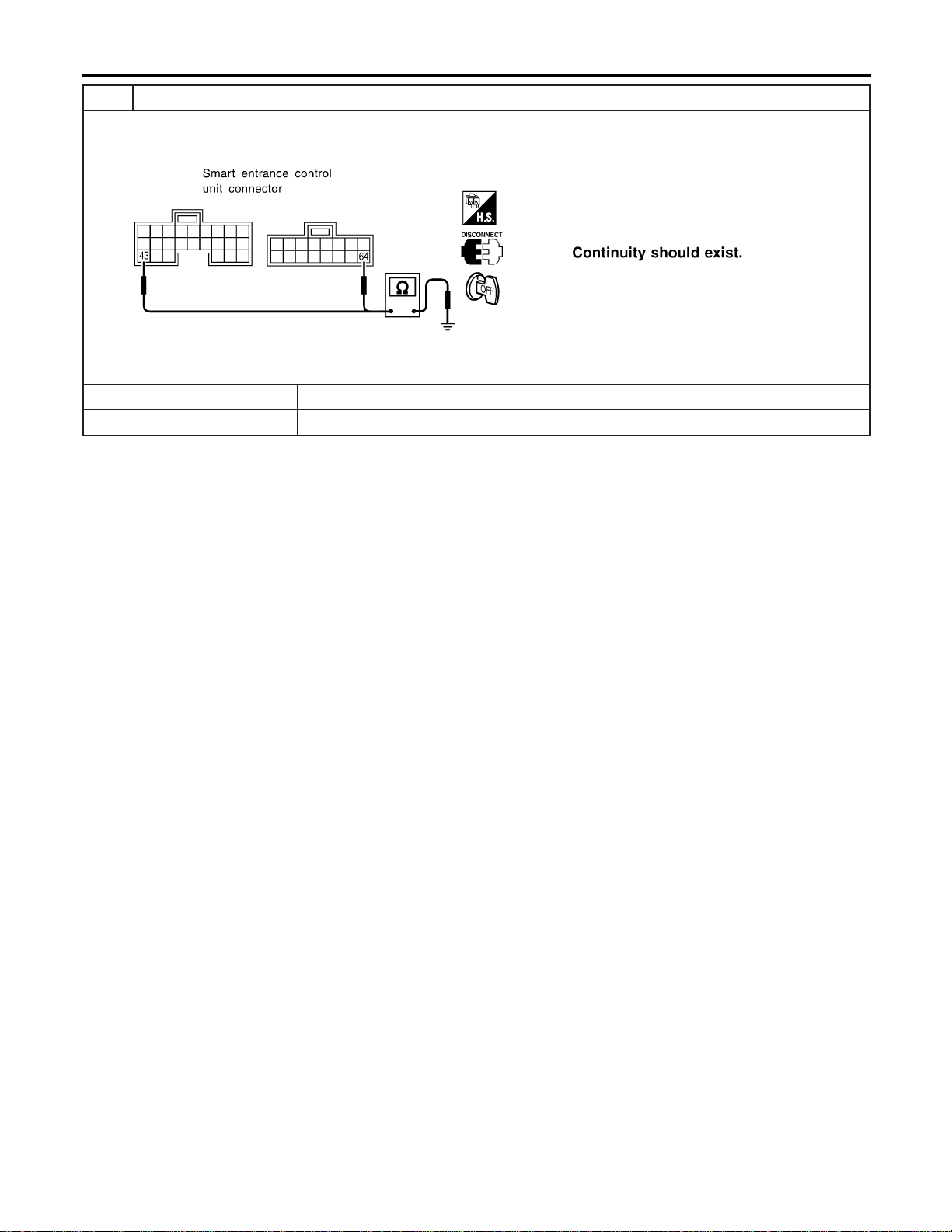
6 CHECK GROUND CIRCUIT FOR SMART ENTRANCE CONTROL UNIT
Check continuity between smart entrance control unit harness connector M122 terminal 43 (B) or M123 terminal 64 (B)
and ground.
SEL285Y
OK or NG
OK © Power supply and ground circuits are OK.
NG © Check ground harness.
HOMELINK UNIVERSAL TRANSCEIVER
Trouble Diagnoses (Cont’d)
EL-384
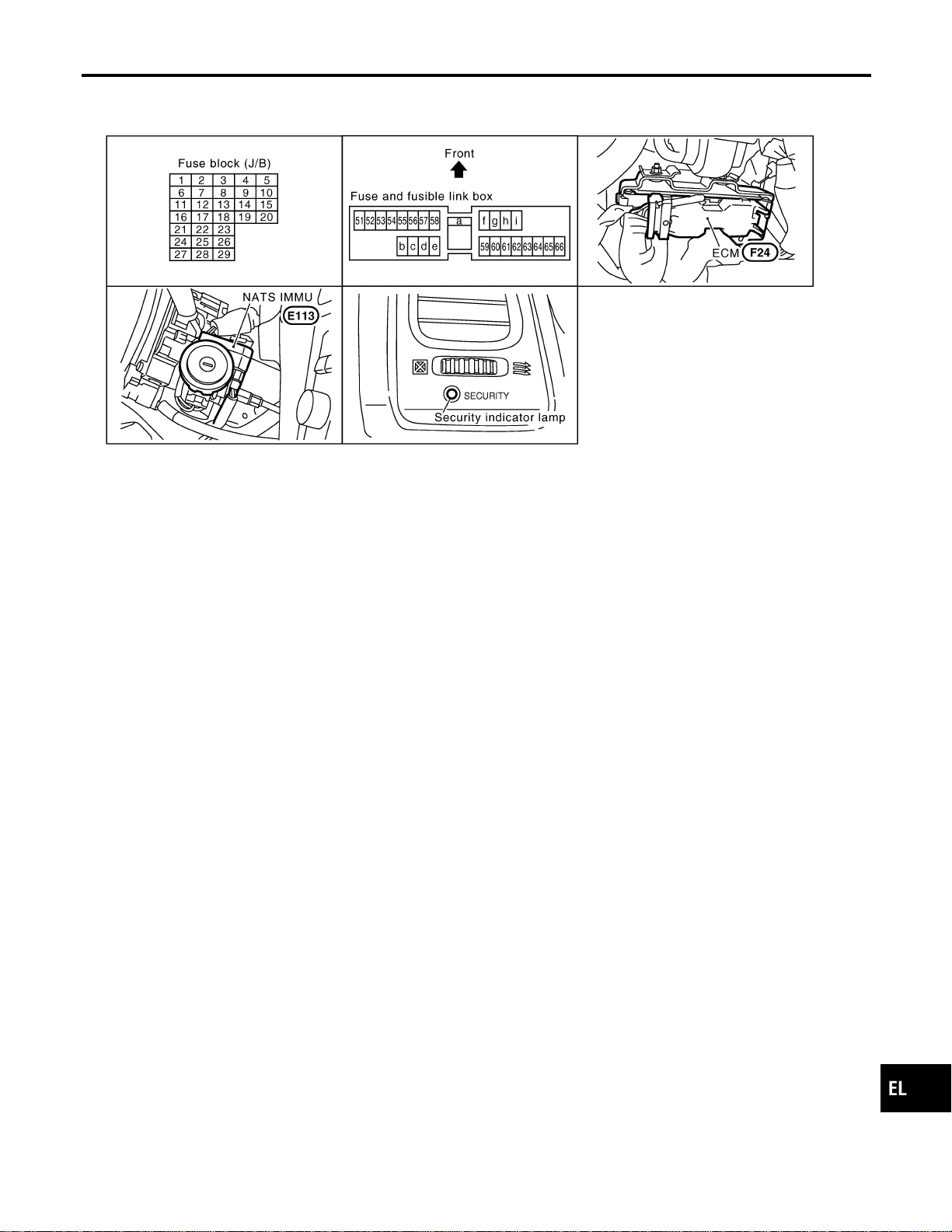
Component Parts and Harness Connetor
Location
NAEL0413
SEL357X
NOTE:
If customer reports a “No Start” condition, request ALL KEYS
to be brought to the Dealer in case of an NVIS (NATS) malfunc-
tion.
GI
MA
EM
LC
EC
FE
CL
MT
AT
TF
PD
AX
SU
BR
ST
RS
BT
HA
SC
IDX
NVIS (NISSAN VEHICLE IMMOBILIZER SYSTEM — NATS)
Component Parts and Harness Connetor Location
EL-385
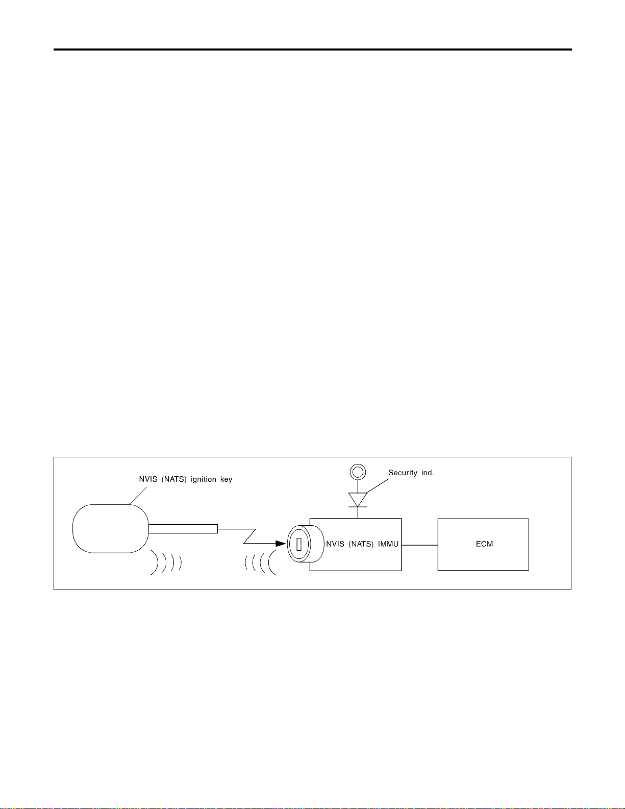
System Description
=NAEL0414
NATS (Nissan Anti-Theft System) has the following immobilizer functions:
I Since only NVIS (NATS) ignition keys, whose ID nos. have been registered into the ECM and IMMU of
NVIS (NATS), allow the engine to run, operation of a stolen vehicle without an NVIS (NATS) registered
key is prevented by NVIS (NATS).
That is to say, NVIS (NATS) will immobilise the engine if someone tries to start it without the registered
key of NVIS (NATS).
I All of the originally supplied ignition key IDs (except for card plate key) have been NVIS (NATS) regis-
tered.
If requested by the vehicle owner, a maximum of five key IDs can be registered into the NVIS (NATS)
components.
I The security indicator blinks when the ignition switch is in “OFF” or “ACC” position.Therefore, NVIS (NATS)
warns outsiders that the vehicle is equipped with the anti-theft system.
I When NVIS (NATS) detects trouble, the security indicator lamp lights up while ignition key is in the “ON”
position.
I NVIS (NATS) trouble diagnoses, system initialization and additional registration of other NVIS (NATS)
ignition key IDs must be carried out using CONSULT-II hardware and CONSULT-II NVIS (NATS) software.
When NVIS (NATS) initialization has been completed, the ID of the inserted ignition key is automatically
NVIS (NATS) registered. Then, if necessary, additional registration of other NVIS (NATS) ignition key IDs
can be carried out.
Regarding the procedures of NVIS (NATS) initialization and NVIS (NATS) ignition key ID registration, refer
to CONSULT-II operation manual, IVIS/NVIS.
I When servicing a malfunction of the NVIS (NATS) (indicated by lighting up of Security Indicator
Lamp) or registering another NVIS (NATS) ignition key ID no., it is necessary to re-register original
key identification. Therefore, be sure to receive ALL KEYS from vehicle owner.
System Composition
NAEL0415
The immobiliser function of the NVIS (NATS) consists of the following:
I NVIS (NATS) ignition key
I NVIS (NATS) immobilizer control unit (IMMU) located in the ignition key cylinder
I Engine control module (ECM)
I Security indicator
SEL085WF
NVIS (NISSAN VEHICLE IMMOBILIZER SYSTEM — NATS)
System Description
EL-386
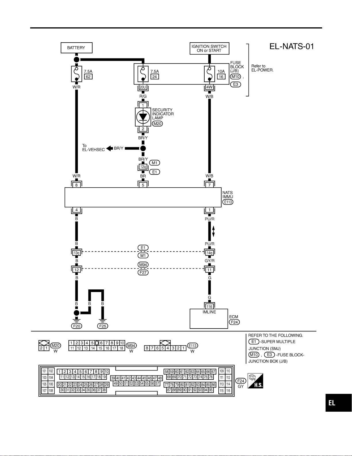
Wiring Diagram — NATS —
NAEL0416
MEL559P
GI
MA
EM
LC
EC
FE
CL
MT
AT
TF
PD
AX
SU
BR
ST
RS
BT
HA
SC
IDX
NVIS (NISSAN VEHICLE IMMOBILIZER SYSTEM — NATS)
Wiring Diagram — NATS —
EL-387
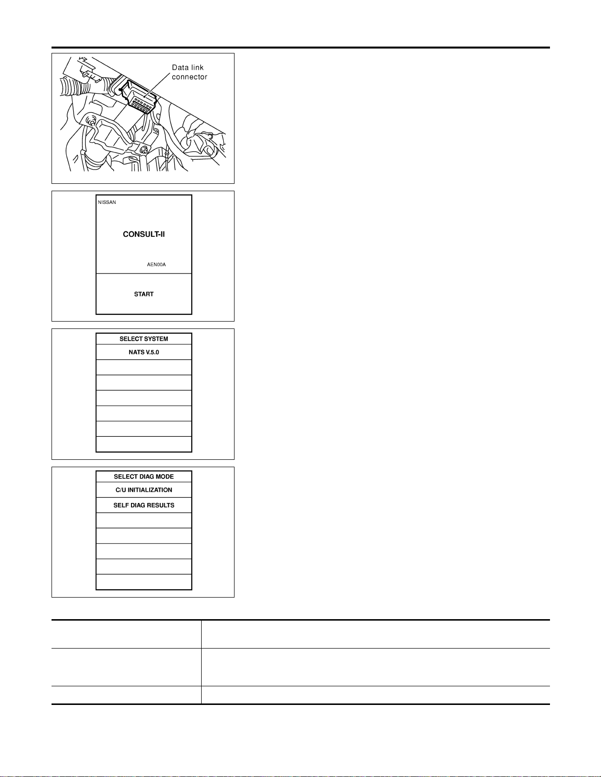
SEL331X
CONSULT-II
NAEL0417
CONSULT-II INSPECTION PROCEDURE
NAEL0417S01
1. Turn ignition switch OFF.
2. Insert NVIS (NATS) program card into CONSULT-II.
Program card
NATS (AEN00A)
3. Connect CONSULT-II to data link connector.
SEL943X
4. Turn ignition switch ON.
5. Touch “START”.
SEL851W
6. Select “NATS V.5.0”.
SEL363X
7. Perform each diagnostic test mode according to each service
procedure.
For further information, see the CONSULT-II Operation
Manual, IVIS/NVIS.
CONSULT-II DIAGNOSTIC TEST MODE FUNCTION
NAEL0417S02
CONSULT-II DIAGNOSTIC TEST
MODE
Description
C/U INITIALIZATION When replacing any of the following three components, C/U initialization and re-registration
of all NVIS (NATS) ignition keys are necessary.
[NVIS (NATS) ignition key/IMMU/ECM]
SELF-DIAG RESULTS Detected items (screen terms) are as shown in the chart EL-389.
NVIS (NISSAN VEHICLE IMMOBILIZER SYSTEM — NATS)
CONSULT-II
EL-388
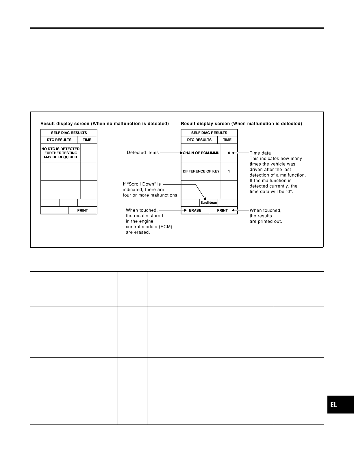
NOTE:
I When any initialization is performed, all ID previously reg-
istered will be erased and all NVIS (NATS) ignition keys
must be registered again.
I The engine cannot be started with an unregistered key. In this
case, the system will show “DIFFERENCE OF KEY” or “LOCK
MODE” as a self-diagnostic result on the CONSULT-II screen.
I In rare case, “CHAIN OF ECM-IMMU” might be stored as a
self-diagnostic result during key registration procedure, even if
the system is not malfunctioning.
HOW TO READ SELF-DIAGNOSTIC RESULTS
NAEL0417S03
SEL364X
NVIS (NATS) SELF-DIAGNOSTIC RESULTS ITEM
CHART
NAEL0417S04
Detected items (NATS program card
screen terms)
P No. Code
(Self-diag-
nostic
result of
“ENGINE”
Malfunction is detected when .....
Reference page
ECM INT CIRC-IMMU
NATS MAL-
FUNCTION
P1613
The malfunction of ECM internal circuit of IMMU com-
munication line is detected. EL-393
CHAIN OF ECM-IMMU
NATS MAL-
FUNCTION
P1612
Communication impossible between ECM and IMMU
(In rare case, “CHAIN OF ECM-IMMU” might be stored
during key registration procedure, even if the system is
not malfunctioning.)
EL-394
DIFFERENCE OF KEY
NATS MAL-
FUNCTION
P1615
IMMU can receive the key ID signal but the result of ID
verification between key ID and IMMU is NG. EL-398
CHAIN OF IMMU-KEY
NATS MAL-
FUNCTION
P1614
IMMU cannot receive the key ID signal.
EL-399
ID DISCORD, IMM-ECM
NATS MAL-
FUNCTION
P1611
The result of ID verification between IMMU and ECM is
NG. System initialization is required. EL-400
GI
MA
EM
LC
EC
FE
CL
MT
AT
TF
PD
AX
SU
BR
ST
RS
BT
HA
SC
IDX
NVIS (NISSAN VEHICLE IMMOBILIZER SYSTEM — NATS)
CONSULT-II (Cont’d)
EL-389

Detected items (NATS program card
screen terms)
P No. Code
(Self-diag-
nostic
result of
“ENGINE”
Malfunction is detected when .....
Reference page
LOCK MODE
NATS MAL-
FUNCTION
P1610
When the starting operation is carried out five or more
times consecutively under the following conditions,
NVIS (NATS) will shift the mode to one which prevents
the engine from being started.
I Unregistered ignition key is used.
I IMMU or ECM’s malfunctioning.
EL-403
DON’T ERASE BEFORE
CHECKING ENG DIAG
—
All engine trouble codes except NVIS (NATS) trouble
code has been detected in ECM.
EL-391
NVIS (NISSAN VEHICLE IMMOBILIZER SYSTEM — NATS)
CONSULT-II (Cont’d)
EL-390
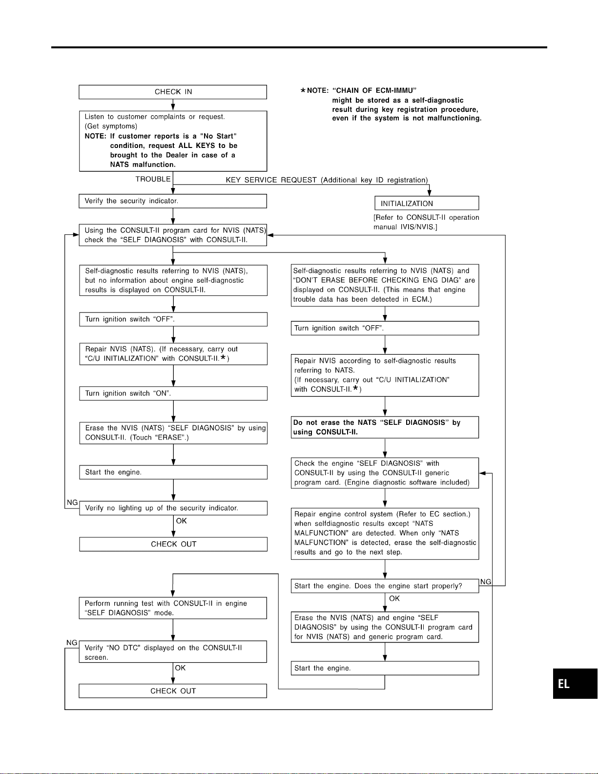
Trouble Diagnoses
NAEL0418
WORK FLOW
NAEL0418S01
SEL004XA
GI
MA
EM
LC
EC
FE
CL
MT
AT
TF
PD
AX
SU
BR
ST
RS
BT
HA
SC
IDX
NVIS (NISSAN VEHICLE IMMOBILIZER SYSTEM — NATS)
Trouble Diagnoses
EL-391

SYMPTOM MATRIX CHART 1
NAEL0418S02
(Self-diagnosis related item)
SYMPTOM
Displayed “SELF-DIAG
RESULTS” on CON-
SULT-II screen.
DIAGNOSTIC PROCE-
DURE
(Reference page)
SYSTEM
(Malfunctioning part or
mode)
REFERENCE PART NO.
OF ILLUSTRATION ON
NEXT PAGE
I Security indicator
lighting up*
I Engine cannot be
started.
ECM INT CIRC-IMMU
PROCEDURE 1
(EL-393)
ECM B
CHAIN OF ECM-IMMU
PROCEDURE 2
(EL-394)
In rare case, “CHAIN
OF ECM-IMMU” might
be stored during key
registration procedure,
even if the system is
not malfunctioning.
—
Open circuit in battery
voltage line of IMMU
circuit
C1
Open circuit in ignition
line of IMMU circuit
C2
Open circuit in ground
line of IMMU circuit
C3
Open circuit in commu-
nication line between
IMMU and ECM
C4
Short circuit between
IMMU and ECM com-
munication line and bat-
tery voltage line
C4
Short circuit between
IMMU and ECM com-
munication line and
ground line
C4
ECM B
IMMU A
DIFFERENCE OF KEY
PROCEDURE 3
(EL-398)
Unregistered key D
IMMU A
CHAIN OF IMMU-KEY
PROCEDURE 4
(EL-399)
Malfunction of key ID
chip
E
IMMU A
ID DISCORD, IMM-
ECM
PROCEDURE 5
(EL-400)
System initialization has
not yet been com-
pleted.
F
ECM F
LOCK MODE
PROCEDURE 7
(EL-403)
LOCK MODE D
I MIL staying ON
I Security indicator
lighting up*
DON’T ERASE
BEFORE CHECKING
ENG DIAG
WORK FLOW
(EL-391)
Engine trouble data and
NVIS (NATS) trouble
data have been
detected in ECM
—
*: When NVIS (NATS) detects trouble, the security indicator lights up while ignition key is in the “ON” position.
NVIS (NISSAN VEHICLE IMMOBILIZER SYSTEM — NATS)
Trouble Diagnoses (Cont’d)
EL-392
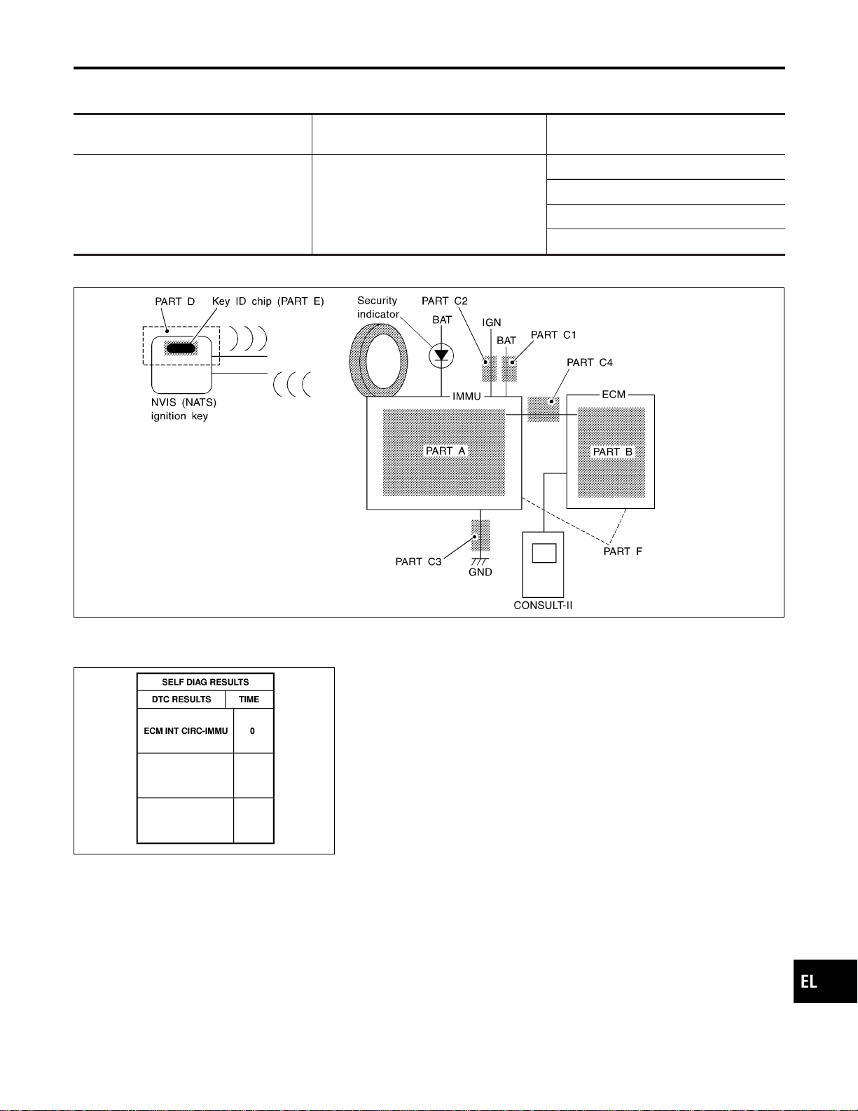
SYMPTOM MATRIX CHART 2
NAEL0418S03
(Non self-diagnosis related item)
SYMPTOM
DIAGNOSTIC PROCEDURE
(Reference page)
SYSTEM
(Malfunctioning part or mode)
Security ind. does not light up.
PROCEDURE 6
(EL-401)
Security ind.
Open circuit between Fuse and IMMU
Continuation of initialization mode
IMMU
DIAGNOSTIC SYSTEM DIAGRAM
NAEL0418S04
SEL087WF
SEL365X
DIAGNOSTIC PROCEDURE 1
NAEL0418S05
Self-diagnostic results:
“ECM INT CIRC-IMMU” displayed on CONSULT-II screen
1. Confirm SELF-DIAGNOSTIC RESULTS “ECM INT CIRC-
IMMU” displayed on CONSULT-II screen. Ref. part No. B.
2. Replace ECM.
3. Perform initialization with CONSULT-II.
For initialization, refer to “CONSULT-II operation manual
IVIS/NVIS”.
GI
MA
EM
LC
EC
FE
CL
MT
AT
TF
PD
AX
SU
BR
ST
RS
BT
HA
SC
IDX
NVIS (NISSAN VEHICLE IMMOBILIZER SYSTEM — NATS)
Trouble Diagnoses (Cont’d)
EL-393

DIAGNOSTIC PROCEDURE 2
=NAEL0418S06
Self-diagnostic results:
“CHAIN OF ECM-IMMU” displayed on CONSULT-II screen
1 CONFIRM SELF-DIAGNOSTIC RESULTS
Confirm SELF-DIAGNOSTIC RESULTS “CHAIN OF ECM-IMMU” displayed on CONSULT-II screen.
NOTE:
In rare case, “CHAIN OF ECM-IMMU” might be stored during key registration procedure, even if the system is not mal-
functioning.
SEL366X
Is CONSULT-II screen displayed as above?
Yes © GO TO 2.
No © GO TO SYMPTOM MATRIX CHART 1.
2 CHECK POWER SUPPLY CIRCUIT FOR IMMU
1. Disconnect IMMU connector.
2. Check voltage between terminal 8 of IMMU and ground with CONSULT-II or tester.
SEL302WD
OK or NG
OK © GO TO 3.
NG © Check the following
I 7.5A fuse (No. 62, located in the fuse and fusible link box)
I Harness for open or short between fuse and IMMU connector
Ref. Part No. C1
NVIS (NISSAN VEHICLE IMMOBILIZER SYSTEM — NATS)
Trouble Diagnoses (Cont’d)
EL-394
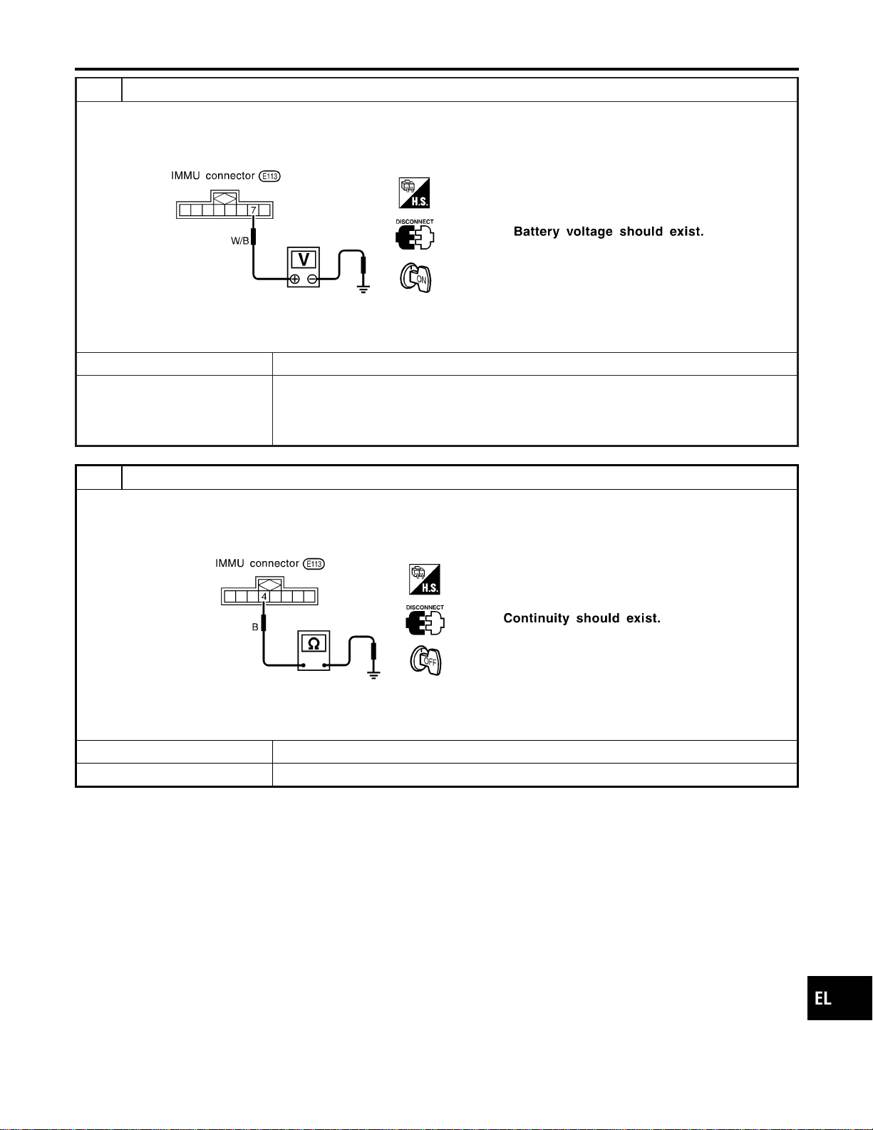
3 CHECK IGN SW. ON SIGNAL
1. Turn ignition switch ON.
2. Check voltage between terminal 7 of IMMU and ground with CONSULT-II or tester.
SEL303WF
OK or NG
OK © GO TO 4.
NG © Check the following
I 10A fuse [No. 16, located in the fuse block (J/B)]
I Harness for open or short between fuse and IMMU connector
Ref. part No. C2
4 CHECK GROUND CIRCUIT FOR IMMU
1. Turn ignition OFF.
2. Check harness continuity between IMMU terminal 4 and ground.
SEL304WD
OK or NG
OK © GO TO 5.
NG © Repair harness. Ref. part No. C3
GI
MA
EM
LC
EC
FE
CL
MT
AT
TF
PD
AX
SU
BR
ST
RS
BT
HA
SC
IDX
NVIS (NISSAN VEHICLE IMMOBILIZER SYSTEM — NATS)
Trouble Diagnoses (Cont’d)
EL-395
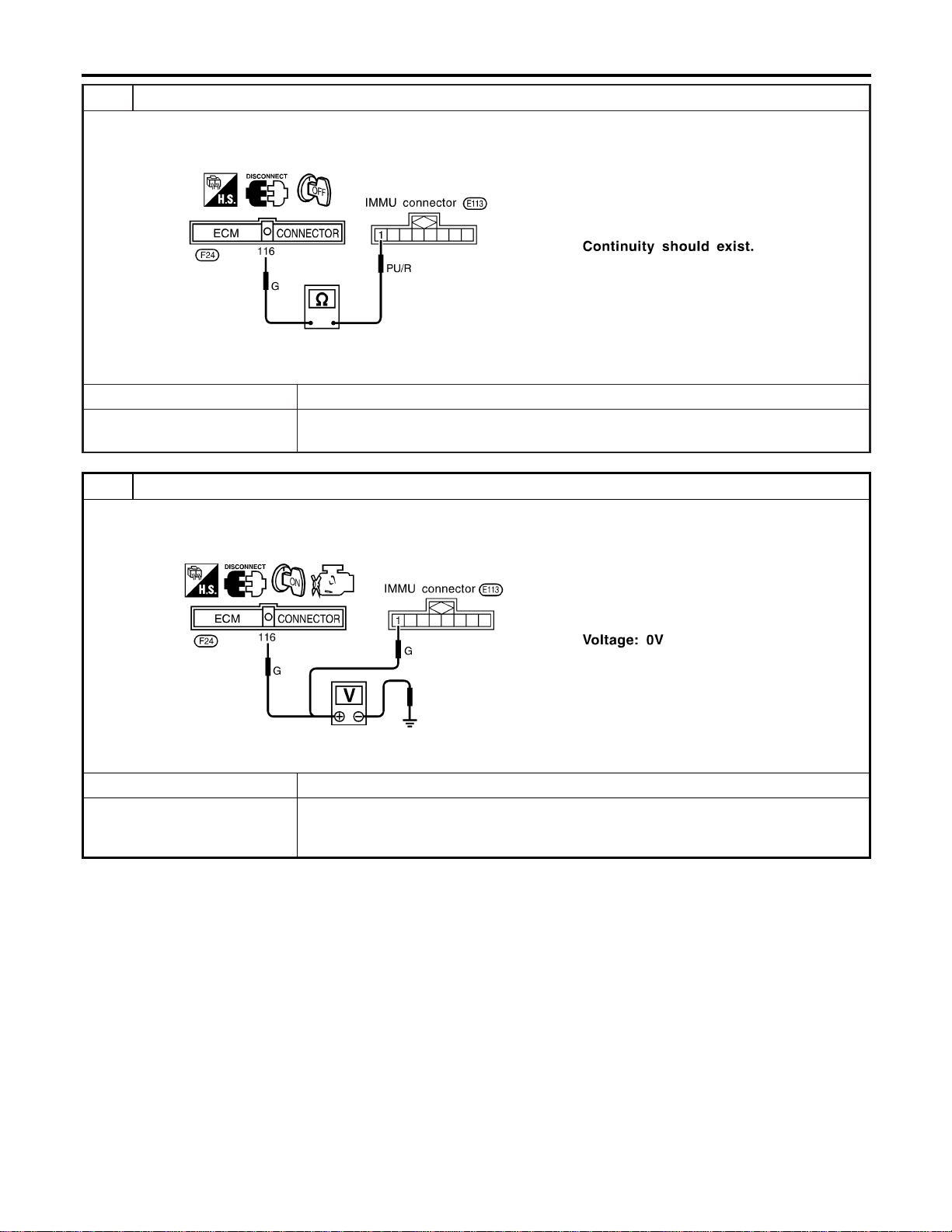
5 CHECK COMMUNICATION LINE OPEN CIRCUIT
1. Disconnect ECM connector.
2. Check harness continuity between ECM terminal 116 and IMMU terminal 1.
SEL305WD
OK or NG
OK © GO TO 6.
NG © Repair harness or connector.
Ref. part No. C4
6 CHECK COMMUNICATION LINE BATTERY SHORT CIRCUIT
1. Turn ignition ON.
2. Check voltage between ECM terminal 116 or IMMU terminal 1 and ground.
SEL306WD
OK or NG
OK © GO TO 7.
NG © Communication line is short-circuited with battery voltage line or ignition switch ON line.
Repair harness or connectors.
Ref. part No. C4
NVIS (NISSAN VEHICLE IMMOBILIZER SYSTEM — NATS)
Trouble Diagnoses (Cont’d)
EL-396
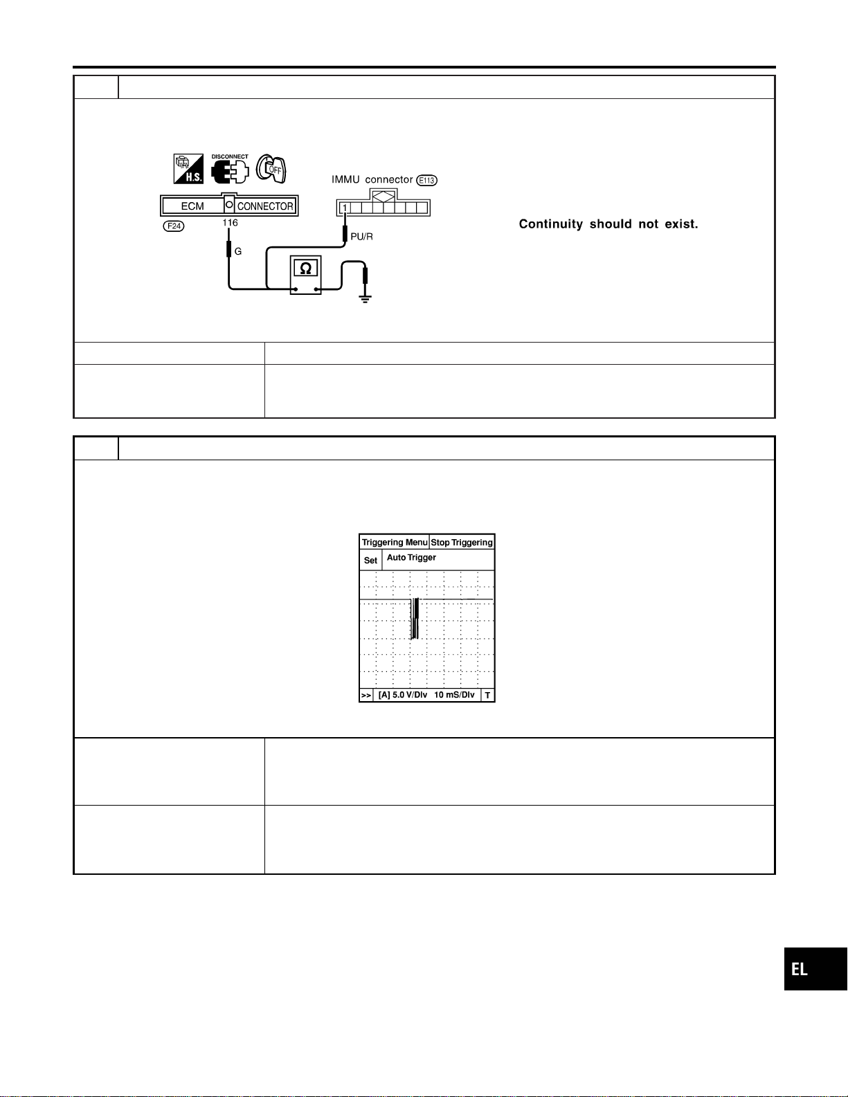
7 CHECK COMMUNICATION LINE GROUND SHORT CIRCUIT
1. Turn ignition switch OFF.
2. Check continuity between ECM terminal 116 or IMMU terminal 1 and ground.
SEL307WD
OK or NG
OK © GO TO 8.
NG © Communication line is short-circuited with ground line.
Repair harness or connectors.
Ref. part No. C4
8 SIGNAL FROM ECM TO IMMU CHECK
1. Check the signal between ECM terminal 116 and ground with CONSULT-II or oscilloscope when ignition switch is
turned “ON”.
2. Make sure signals which are shown in the figure below can be detected during 750 msec. just after ignition switch is
turned “ON”.
SEL730W
OK or NG
OK © IMMU is malfunctioning.
Replace IMMU. Ref. part No. A
Perform initialization with CONSULT-II.
For the operation of initialization, refer to “CONSULT-II Operation Manual IVIS/NVIS”.
NG © ECM is malfunctioning.
Replace ECM. Ref. part No. B
Perform initialization with CONSULT-II.
For the operation of initialization, refer to “CONSULT-II Operation Manual IVIS/NVIS”.
GI
MA
EM
LC
EC
FE
CL
MT
AT
TF
PD
AX
SU
BR
ST
RS
BT
HA
SC
IDX
NVIS (NISSAN VEHICLE IMMOBILIZER SYSTEM — NATS)
Trouble Diagnoses (Cont’d)
EL-397
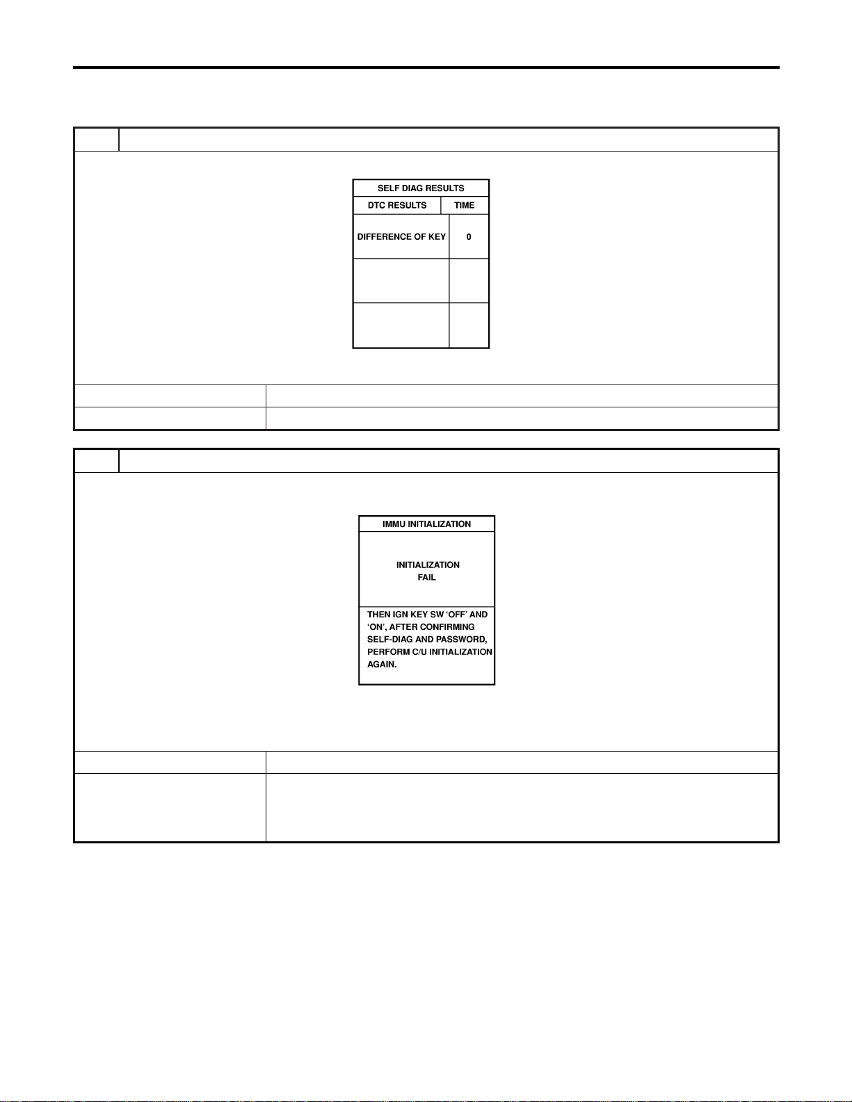
DIAGNOSTIC PROCEDURE 3
=NAEL0418S07
Self-diagnostic results:
“DIFFERENCE OF KEY” displayed on CONSULT-II screen
1 CONFIRM SELF-DIAGNOSTIC RESULTS
Confirm SELF-DIAGNOSTIC RESULTS “DIFFERENCE OF KEY” displayed on CONSULT-II screen.
SEL367X
Is CONSULT-II screen displayed as above?
Yes © GO TO 2.
No © GO TO SYMPTOM MATRIX CHART 1.
2 PERFORM INITIALIZATION WITH CONSULT-II
Perform initialization with CONSULT-II. Re-register all NVIS (NATS) ignition key IDs.
For initialization and registration of NVIS (NATS) ignition key IDs, refer to “CONSULT-II operation manual NVIS/NVIS”.
SEL297W
NOTE:
If the initialization is not completed or fails, CONSULT-II shows above message on the screen.
Can the system be initialized and can the engine be started with re-registered NVIS (NATS) ignition key?
Yes © Ignition key ID was unregistered. Ref. part No. D
No © IMMU is malfunctioning.
Replace IMMU. Ref. part No. A
Perform initialization with CONSULT-II.
For initialization, refer to “CONSULT-II operation manual IVIS/NVIS”.
NVIS (NISSAN VEHICLE IMMOBILIZER SYSTEM — NATS)
Trouble Diagnoses (Cont’d)
EL-398
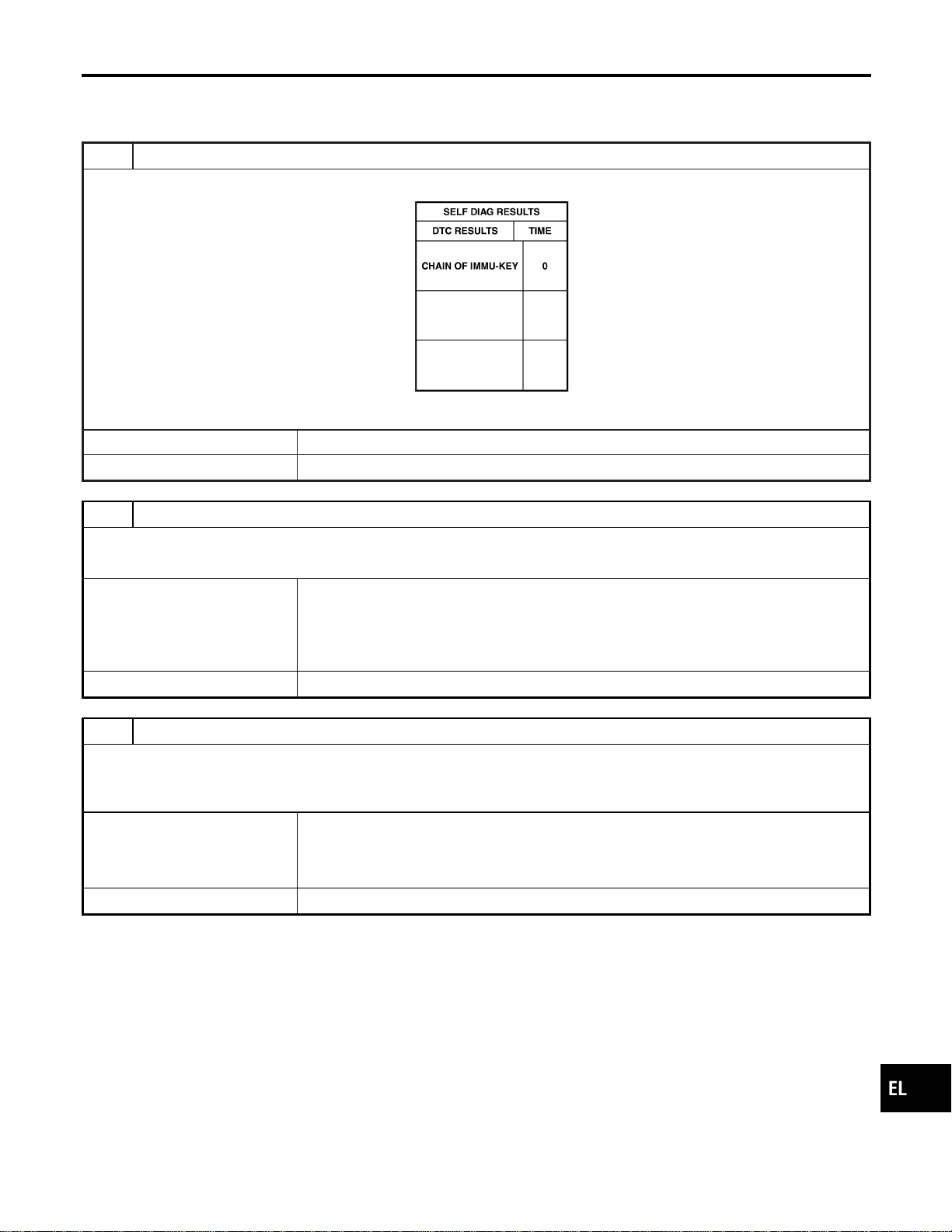
DIAGNOSTIC PROCEDURE 4
=NAEL0418S08
Self-diagnostic results:
“CHAIN OF IMMU-KEY” displayed on CONSULT-II screen
1 CONFIRM SELF-DIAGNOSTIC RESULTS
Confirm SELF-DIAGNOSTIC RESULTS “CHAIN OF IMMU-KEY” displayed on CONSULT-II screen.
SEL368X
Is CONSULT-II screen displayed as above?
Yes © GO TO 2.
No © GO TO SYMPTOM MATRIX CHART 1.
2 CHECK NVIS (NATS) IGNITION KEY ID CHIP
Start engine with another registered NVIS (NATS) ignition key.
Does the engine start?
Yes © Ignition key ID chip is malfunctioning.
Replace the ignition key.
Ref. part No. E
Perform initialization with CONSULT-II.
For initialization, refer to “CONSULT-II Operation Manual IVIS/NVIS”.
No © GO TO 3.
3 CHECK IMMU INSTALLATION
Check IMMU installation.
Refer to “How to Replace IMMU” in EL-404.
OK or NG
OK © IMMU is malfunctioning.
Replace IMMU. Ref. part No. A
Perform initialization with CONSULT-II.
For initialization, refer to “CONSULT-II Operation Manual IVIS/NVIS”.
NG © Reinstall IMMU correctly.
GI
MA
EM
LC
EC
FE
CL
MT
AT
TF
PD
AX
SU
BR
ST
RS
BT
HA
SC
IDX
NVIS (NISSAN VEHICLE IMMOBILIZER SYSTEM — NATS)
Trouble Diagnoses (Cont’d)
EL-399
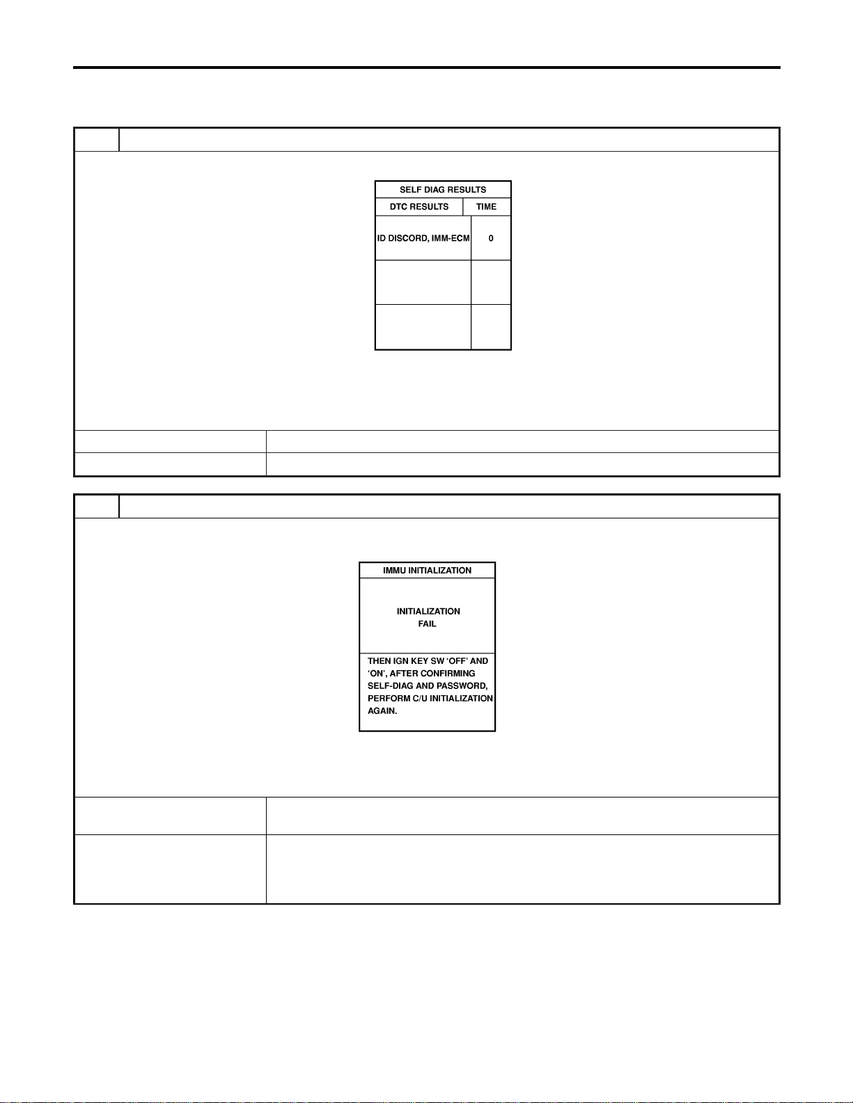
DIAGNOSTIC PROCEDURE 5
=NAEL0418S09
Self-diagnostic results:
“ID DISCORD, IMM-ECM” displayed on CONSULT-II screen
1 CONFIRM SELF-DIAGNOSTIC RESULTS
Confirm SELF-DIAGNOSTIC RESULTS “ID DISCORD, IMM-ECM” displayed on CONSULT-II screen.
SEL369X
NOTE:
“ID DISCORD IMMU-ECM”:
Registered ID of IMMU is in discord with that of ECM.
Is CONSULT-II screen displayed as above?
Yes © GO TO 2.
No © GO TO SYMPTOM MATRIX CHART 1.
2 PERFORM INITIALIZATION WITH CONSULT-II
Perform initialization with CONSULT-II. Re-register all NVIS (NATS) ignition key IDs.
For initialization, refer to “CONSULT-II operation manual IVIS/NVIS”.
SEL297W
NOTE:
If the initialization is not completed or fails, CONSULT-II shows above message on the screen.
Can the system be initialized?
Yes © Start engine. (END)
(System initialization had not been completed. Ref. part No. F)
No © ECM is malfunctioning.
Replace ECM. Ref. part No. F
Perform initialization with CONSULT-II.
For initialization, refer to “CONSULT-II operation manual IVIS/NVIS”.
NVIS (NISSAN VEHICLE IMMOBILIZER SYSTEM — NATS)
Trouble Diagnoses (Cont’d)
EL-400
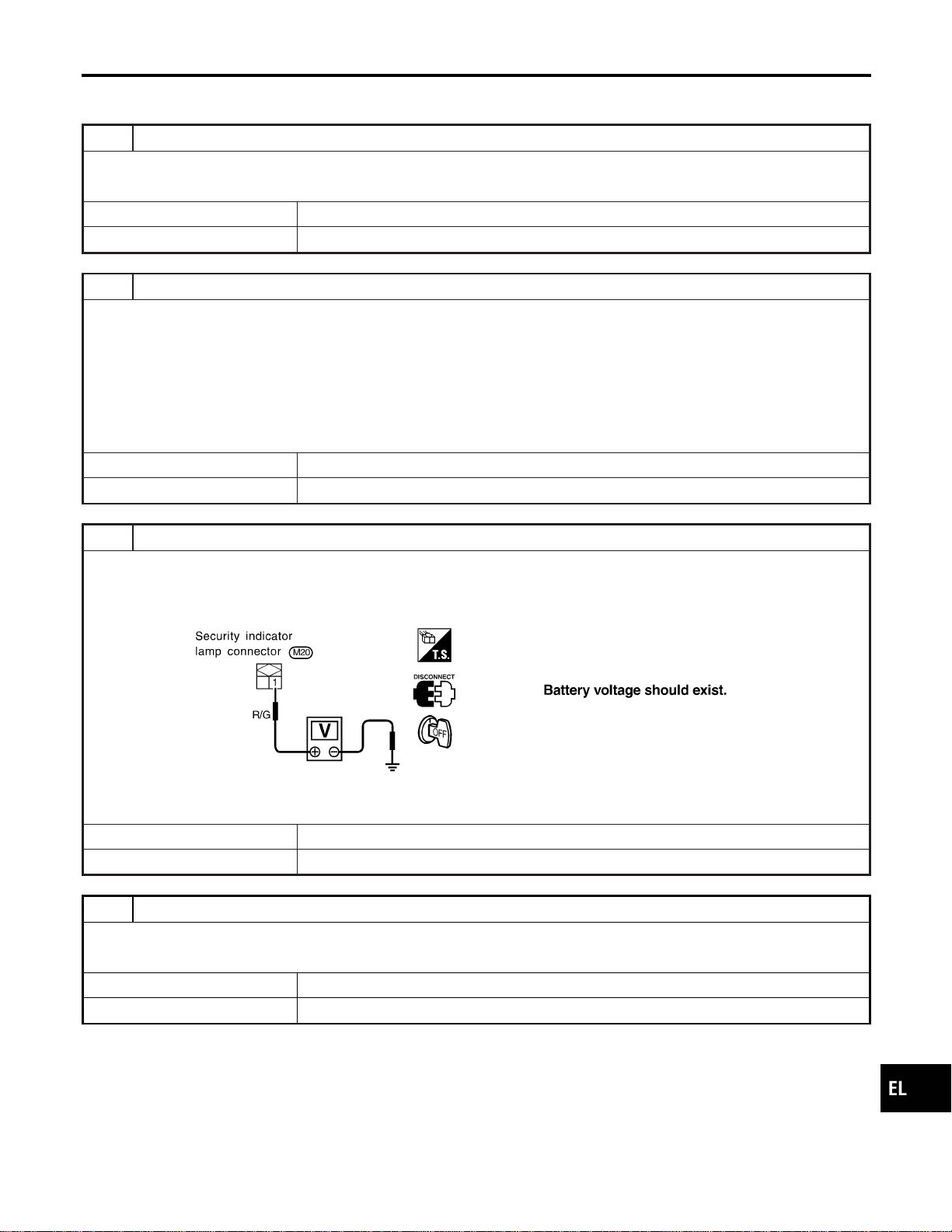
DIAGNOSTIC PROCEDURE 6
=NAEL0418S10
“SECURITY INDICATOR LAMP DOES NOT LIGHT UP”
1 CHECK FUSE
Check 10A fuse [No. 12, located in the fuse block (J/B)].
Is 10A fuse OK?
Yes © GO TO 2.
No © Replace fuse.
2 CHECK SECURITY INDICATOR LAMP
1. Install 10A fuse.
2. Perform initialization with CONSULT-II.
For initialization, refer to “CONSULT-II Operation Manual IVIS/NVIS”.
3. Turn ignition switch OFF.
4. Start engine and turn ignition switch OFF.
5. Check the security indicator lamp lighting.
Security indicator lamp should be blinking.
OK or NG
OK © INSPECTION END
NG © GO TO 3.
3 CHECK SECURITY INDICATOR LAMP POWER SUPPLY CIRCUIT
1. Disconnect security indicator lamp connector.
2. Check voltage between security indicator lamp connector terminal 1 and ground.
SEL370XA
OK or NG
OK © GO TO 4.
NG © Check harness for open or short between fuse and security indicator lamp.
4 CHECK SECURITY INDICATOR LAMP
Check security Indicator Lamp.
Is security indicator lamp OK?
Yes © GO TO 5.
No © Replace security indicator lamp.
GI
MA
EM
LC
EC
FE
CL
MT
AT
TF
PD
AX
SU
BR
ST
RS
BT
HA
SC
IDX
NVIS (NISSAN VEHICLE IMMOBILIZER SYSTEM — NATS)
Trouble Diagnoses (Cont’d)
EL-401
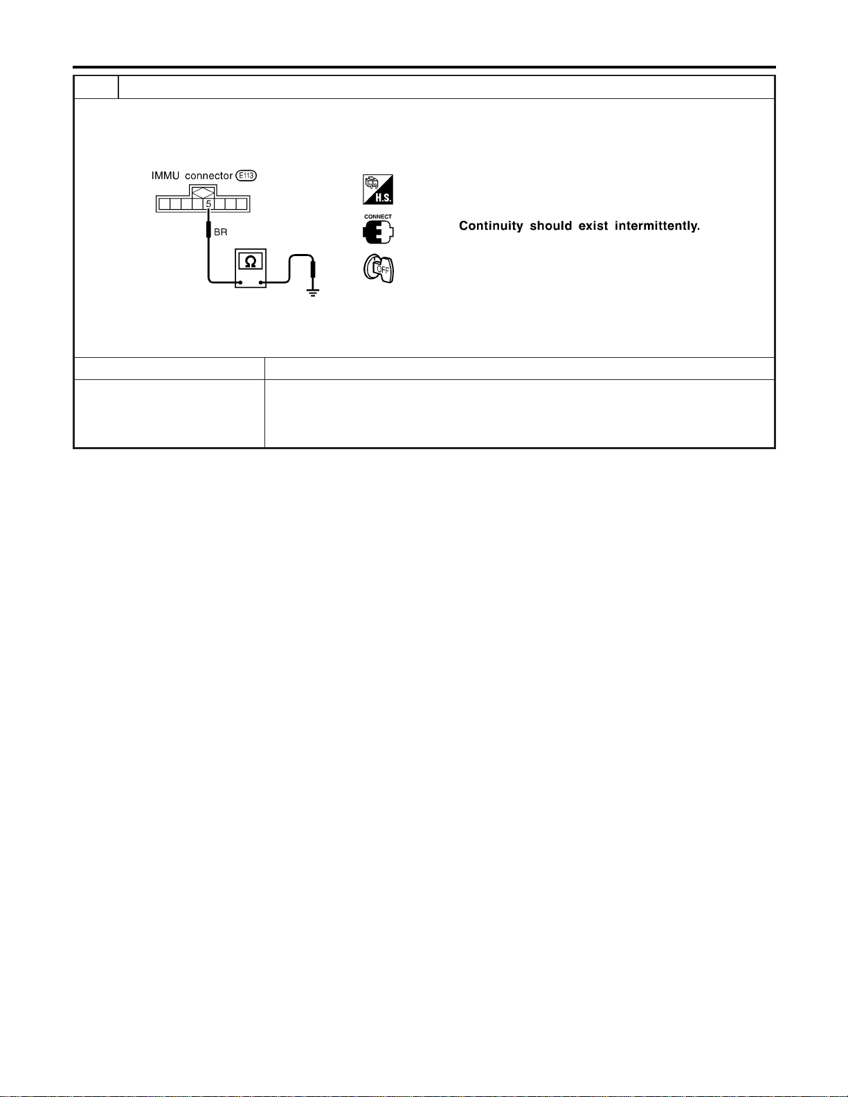
5 CHECK IMMU FUNCTION
1. Connect IMMU connector.
2. Disconnect security indicator lamp connector.
3. Check continuity between IMMU terminal 5 and ground.
SEL300WC
OK or NG
OK © Check harness for open or short between security indicator lamp and IMMU.
NG © IMMU is malfunctioning.
Replace IMMU.
Perform initialization with CONSULT-II.
For initialization, refer to “CONSULT-II operation manual IVIS/NVIS”.
NVIS (NISSAN VEHICLE IMMOBILIZER SYSTEM — NATS)
Trouble Diagnoses (Cont’d)
EL-402
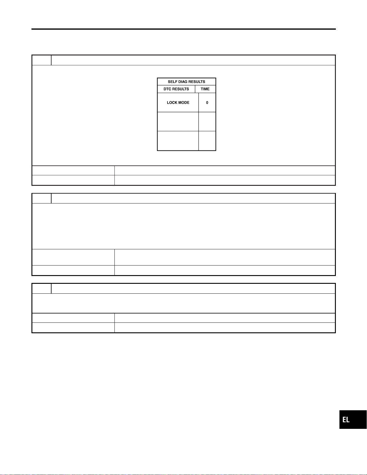
DIAGNOSTIC PROCEDURE 7
=NAEL0418S11
Self-diagnostic results:
“LOCK MODE” displayed on CONSULT-II screen
1 CONFIRM SELF-DIAGNOSTIC RESULTS
Confirm SELF-DIAGNOSTIC RESULTS “LOCK MODE” is displayed on CONSULT-II screen.
SEL371X
Is CONSULT-II screen displayed as above?
Yes © GO TO 2.
No © GO TO SYMPTOM MATRIX CHART 1.
2 ESCAPE FROM LOCK MODE
1. Turn ignition switch OFF.
2. Turn ignition switch ON with registered key. (Do not start engine.) Wait 5 seconds.
3. Return the key to OFF position.
4. Repeat steps 2 and 3 twice (total of three cycles).
5. Start the engine.
Does engine start?
Yes © System is OK.
(Now system is escaped from “LOCK MODE”.)
No © GO TO 3.
3 CHECK IMMU ILLUSTRATION
Check IMMU installation. Refer to “How to Replace IMMU” in EL-404.
OK or NG
OK © GO TO 4.
NG © Reinstall IMMU correctly.
GI
MA
EM
LC
EC
FE
CL
MT
AT
TF
PD
AX
SU
BR
ST
RS
BT
HA
SC
IDX
NVIS (NISSAN VEHICLE IMMOBILIZER SYSTEM — NATS)
Trouble Diagnoses (Cont’d)
EL-403
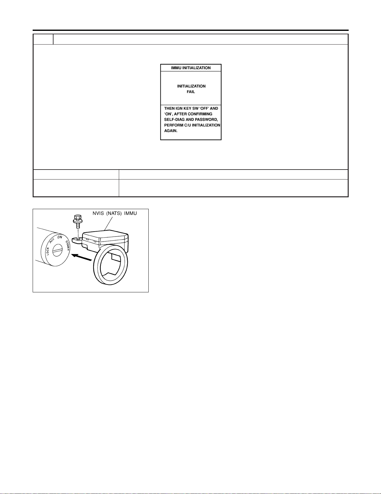
4 PERFORM INITIALIZATION WITH CONSULT-II
Perform initialization with CONSULT-II.
For initialization, refer to “CONSULT-II operation manual IVIS/NVIS”.
SEL297W
NOTE:
If the initialization is not completed or fails, CONSULT-II shows the above message on the screen.
Can the system be initialized?
Yes © System is OK.
No © GO TO DIAGNOSTIC PROCEDURE 4 to check “CHAIN OF IMMU-KEY”, refer to
EL-399.
SEL096WA
How to Replace NVIS (NATS) IMMU
NAEL0419
NOTE:
I If NVIS (NATS) IMMU is not installed correctly, NVIS
(NATS) system will not operate properly and SELF-DIAG
RESULTS on CONSULT-II screen will show “LOCK
MODE”.
NVIS (NISSAN VEHICLE IMMOBILIZER SYSTEM — NATS)
Trouble Diagnoses (Cont’d)
EL-404
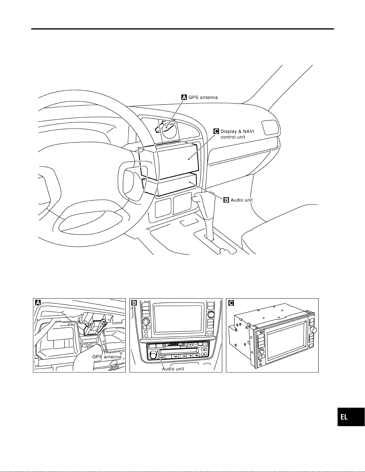
Component Parts Location
NAEL0420
SEL508X
GI
MA
EM
LC
EC
FE
CL
MT
AT
TF
PD
AX
SU
BR
ST
RS
BT
HA
SC
IDX
NAVIGATION SYSTEM
Component Parts Location
EL-405
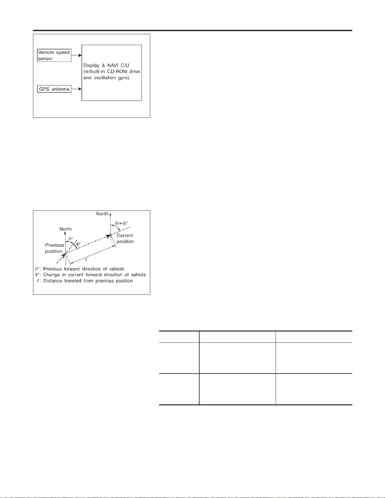
SEL683V
System Description
=NAEL0421
OUTLINE
NAEL0421S01
The Navigation System (Multi-AV System) relies upon three sens-
ing devices in order to determine vehicle location at regular time
intervals.
1. Vehicle speed sensor: Determines the distance the vehicle has
traveled.
2. Gyro (Angular velocity sensor): Determines vehicle steering
angle and directional change.
3. GPS antenna (GPS data): Determines vehicle forward move-
ment and direction.
The data provided by the three sensing functions together with a
comparison of the mapping information read from the CD-ROM
drive permit accurate determination of the vehicle’s current location
and subsequent course (map matching). The information appears
on a liquid crystal display.
This comparison of GPS data (vehicle position sensing) and map
matching permits precise determination of vehicle location.
SEL684V
Position Sensor Operating Principles
NAEL0421S0101
The sensor determines current vehicle location by calculating the
previously sensed position, the distance traveled from this position,
and the directional changes occurring during this travel.
1. Distance traveled
The distance traveled is calculated using signals received from
the vehicle speed sensor. The sensor automatically compen-
sates for the slightly reduced wheel and tire diameter resulting
from tire wear.
2. Forward movement (Direction)
Changes in the direction of forward movement are calculated
by the gyro (angular velocity sensor) and the GPS antenna
(GPS data). Each of these functions has its advantage and
disadvantages. Depending upon conditions, one function takes
precedence over the other to accurately determine the direc-
tion of forward movement.
Function type Advantage Disadvantage
Gyro (Angular
velocity sen-
sor)
I Able to accurately detect
minute changes in steering
angle and direction.
I Calculation errors may
accumulate over a long
period of continuous
vehicle travel.
GPS antenna
(GPS data)
I Able to sense vehicle travel
in four general directions
(North, South, East, and
West)
I Unable to detect direction
of vehicle travel at low
vehicle speeds.
NAVIGATION SYSTEM
System Description
EL-406
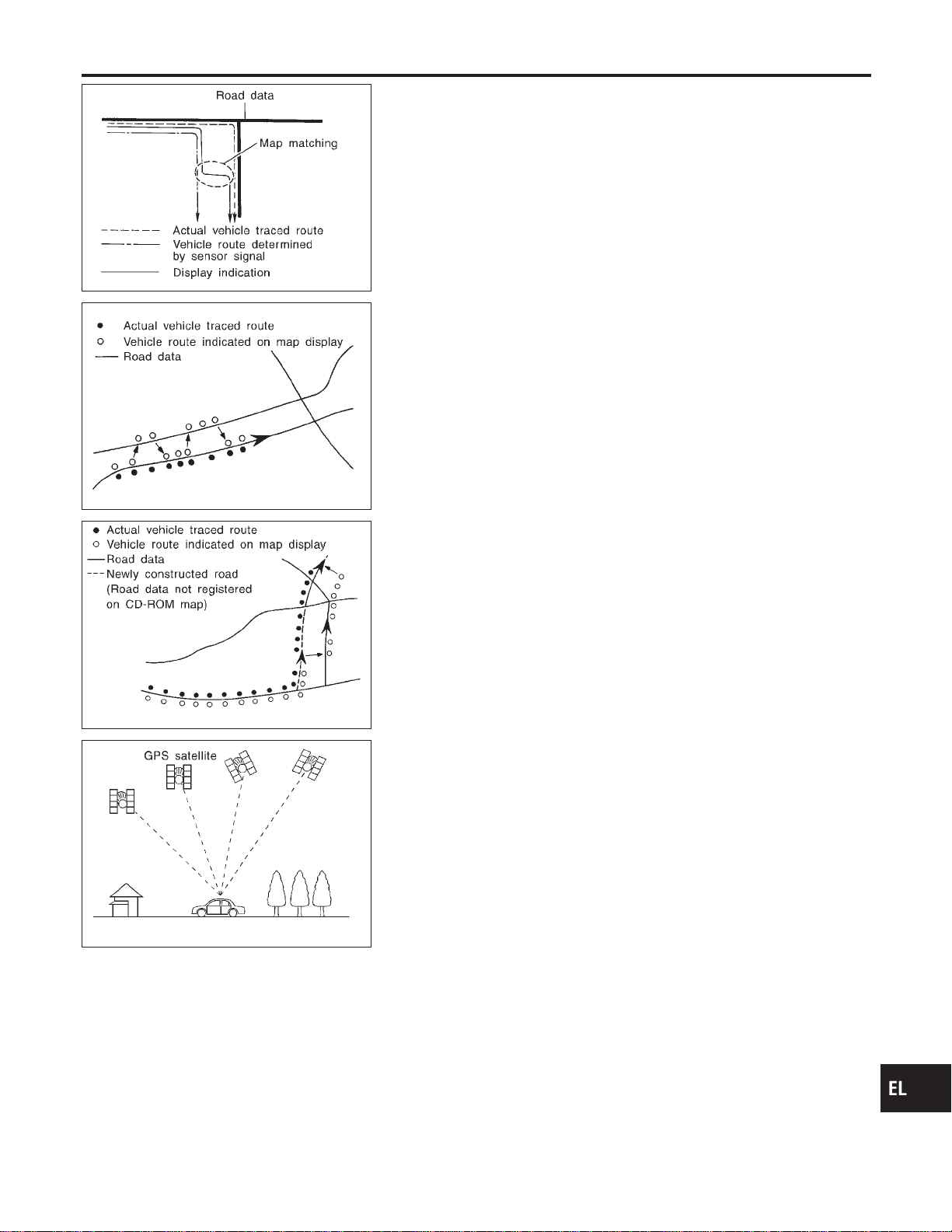
SEL685V
Map Matching
NAEL0421S0102
Map matching allows the driver to compare the sensed vehicle
location data with the road map contained in the CD-ROM drive.
Vehicle position is marked on the CD-ROM map. This permits the
driver to accurately determine his/her present position on the high-
way and to make appropriate course decisions.
When GPS data reception is poor during travel, the vehicle posi-
tion is not amended. At this time, manual manipulation of the CD-
ROM map position marker is required.
SEL686V
Map matching permits the driver to make priority judgments about
possible appropriate roads other than the one currently being trav-
eled.
If there is an error in the distance or direction of travel, there will
also be an error in the relative position of other routes. When two
routes are closely parallel to one another, the indicated position for
both routes will be nearly the same priority. This is so that, slight
changes in the steering direction may cause the marker to indicate
both routes alternately.
SEL687V
Newly constructed roads may not appear on the CD-ROM map. In
this case, map matching is not possible. Changes in the course of
a road will also prevent accurate map matching.
When driving on a road not shown on the CD-ROM map, the posi-
tion marker used for map matching may indicate a different route.
Even after returning to a route shown on the map, the position
marker may jump to the position currently detected.
SEL526V
GPS (Global Positioning System)
NAEL0421S0103
GPS is the global positioning system developed and operated by
the US Department of Defense. GPS satellites (NAVSTAR) trans-
mit radio waves and orbit around the earth at an altitude of approxi-
mately 21,000 km (13,000 miles).
GPS receiver calculates the three-dimensional position of the
vehicle (latitude, longitude, and altitude from the sea level) by the
time difference of the radio wave arriving from more than four GPS
satellites (three-dimensional positioning).
When the radio wave is received from only three GPS satellites, the
two-dimensional position (latitude and longitude) is calculated,
using the altitude from the sea level data calculated by using four
GPS satellites (two-dimensional positioning).
Positioning capability is degraded in the following cases.
I In two-dimensional positioning, when the vehicle’s altitude
from the sea level changes, the precision becomes lower.
I The location detection performance can have an error of about
100 m (300 ft) even in three-dimensional positioning with high
precision. Because the precision is influenced by the location
of GPS satellites used for positioning, the location detection
performance may drop depending on the location of GPS sat-
ellites.
I When the radio wave from GPS satellites cannot be received,
GI
MA
EM
LC
EC
FE
CL
MT
AT
TF
PD
AX
SU
BR
ST
RS
BT
HA
SC
IDX
NAVIGATION SYSTEM
System Description (Cont’d)
EL-407
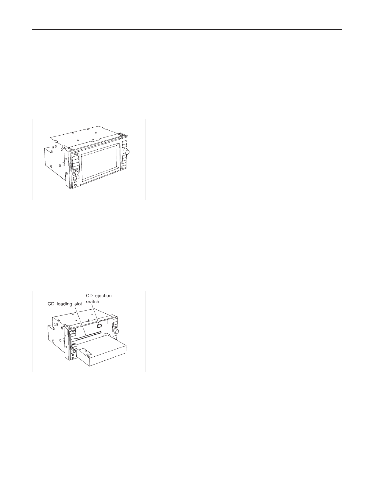
for example, when the vehicle is in a tunnel, in a parking lot
inside building, under an elevated superhighway or near strong
power lines, the location may not be detected. Turbulent/
electric weather conditions may also affect positioning perfor-
mance. If something is placed on the antenna, the radio wave
from GPS satellites may not be received.
SEL688V
COMPONENT DESCRIPTION
NAEL0421S02
Display & NAVI Control Unit
NAEL0421S0201
I The gyro (angular speed sensor) and the CD-ROM drive are
built-in units that control the navigation functions.
I Signals are received from the gyro, the vehicle speed sensor,
and the GPS antenna. Vehicle location is determined by com-
bining this data with the data contained in the CD-ROM map.
Locational information is shown on liquid crystal display panel.
I Finger-operated touch switches are positioned on the liquid
crystal display panel for easy operation.
I The touch switches used to control the equipment are beneath
a glass sheet and two resistance membranes at the top of the
liquid crystal display panel. The switches are sensitive to resis-
tance value where touched with your finger to detect operat-
ing status.
SEL689V
CD-ROM Driver
NAEL0421S0202
Maps, traffic control regulations, and other pertinent information
can be easily red from the CD-ROM disc.
NOTE:
I When removing the CD-ROM, allow it to remain open until the
liquid crystal display locks.
I The liquid crystal display must be closed when the vehicle is
running.
I Do not place cups, cans or other containers containing liquids
on top of the liquid crystal display.
Map CD-ROM
NAEL0421S0203
I The map CD-ROM has maps, traffic control regulations, and
other pertinent information.
I To improve CD-ROM map matching and route determination
functions, the CD-ROM uses an exclusive Nissan format.
Therefore, the use of a CD-ROM provided by other manufac-
turers cannot be used.
NAVIGATION SYSTEM
System Description (Cont’d)
EL-408
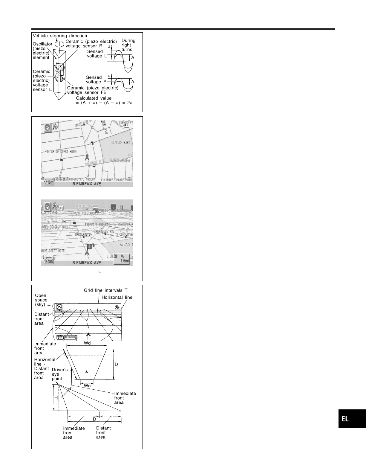
SEL690V
Gyro (Angular Speed Sensor)
NAEL0421S0204
I The oscillator gyro sensor is used to detect changes in vehicle
steering angle.
I The oscillator gyro periodically senses oscillatory variation at
the oscillation terminals. This variation is caused by changes
in the vehicle angular velocity. Voltage variations are sensed
by ceramic voltage sensors at the left and right sides of the
terminals. Vehicle angular velocity corresponds directly with
these changes in voltage.
I The gyro is built into the display & navigation (NAVI) control
unit.
MAP DISPLAY
BIRDVIEW
R
SEL636X
BIRDVIEW
T
NAEL0421S0205
The BIRDVIEW
T
provides a detailed and easily seen display of
road conditions covering the vehicle’s immediate to distant area.
SEL691V
Description
NAEL0421S0206
I Display area: Trapezoidal representation showing approximate
distances (Wn, D, and Wd).
I Ten horizontal grid lines indicate display width while six verti-
cal grid lines indicate display depth and direction.
I Drawing line area shows open space, depth, and immediate
front area. Each area is to a scale of approximately 5:6:25.
I When the “ZM−” button is pushed, the view point height is
increased. Pushing the “ZM+” button decreases the height.
Pushing the “ZM−” button or the “ZM+” button during operation
indicates the scale change and the view point height at the
left-hand side of the screen.
GI
MA
EM
LC
EC
FE
CL
MT
AT
TF
PD
AX
SU
BR
ST
RS
BT
HA
SC
IDX
NAVIGATION SYSTEM
System Description (Cont’d)
EL-409
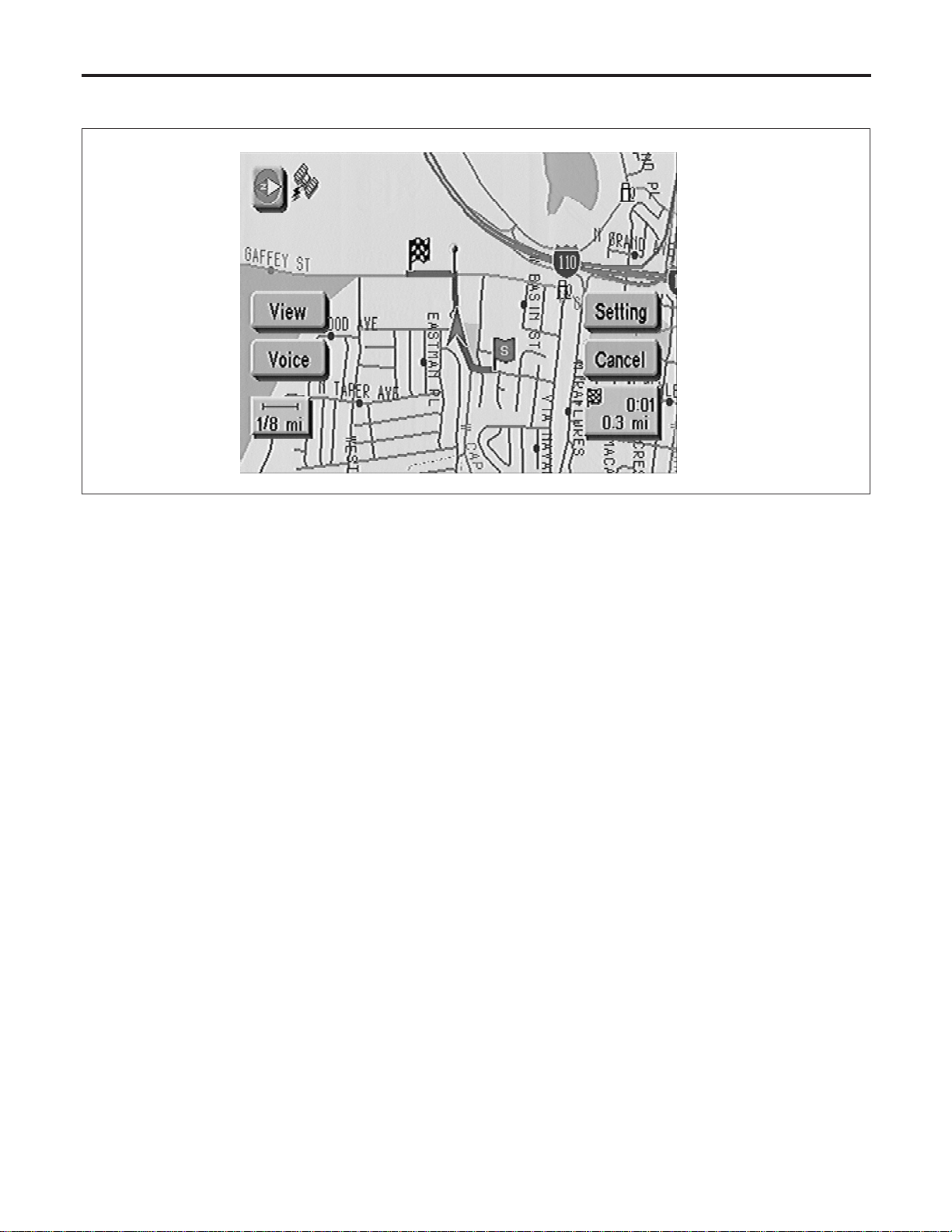
FUNCTION OF TOUCH SWITCH (SUMMARY)
=NAEL0421S03
Display with Pushed “MAP” Switch
NAEL0421S0301
SEL475Y
The function of each touch switch is as follows:
1) Azimuth indication
2) Position marker
The tip of the arrow shows the current position. The shaft of
the arrow indicates the direction in which the vehicle is travel-
ing.
3) GPS reception signal (indicates current reception conditions)
4) Distance display (shows the distance in a reduced scale)
5) Current location voice information
(this information is available when the route guide is being
activated and the designated route is being traveled.)
6) Switch display from map screen to BIRDVIEW
T
screen
(change to map screen on display when the BIRDVIEW
T
is
being used.)
7) The following items can be set.
I Save Current Location
I Edit Address Book
I Guide Volume
I System Setting
8) The route guide operation can be canceled.
NAVIGATION SYSTEM
System Description (Cont’d)
EL-410
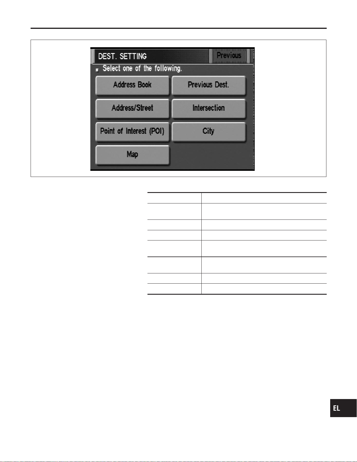
Display with Pushed “DEST” Switch
=NAEL0421S0302
SEL581X
The function of each touch switch is as follows:
Icon Description
Address Book Favorite place can be saved to memory.
The destination can be selected from the memory.
Address/Street The destination can be searched from the address.
Point of Interest (POI) The destination of favorite facility can be searched.
Previous Dest. The previous ten destinations stored in memory are
displayed.
Intersection The destination from the intersection name can be
retrieved.
City The destination can be searched from city name.
Map The destination can be searched from the map.
GI
MA
EM
LC
EC
FE
CL
MT
AT
TF
PD
AX
SU
BR
ST
RS
BT
HA
SC
IDX
NAVIGATION SYSTEM
System Description (Cont’d)
EL-411
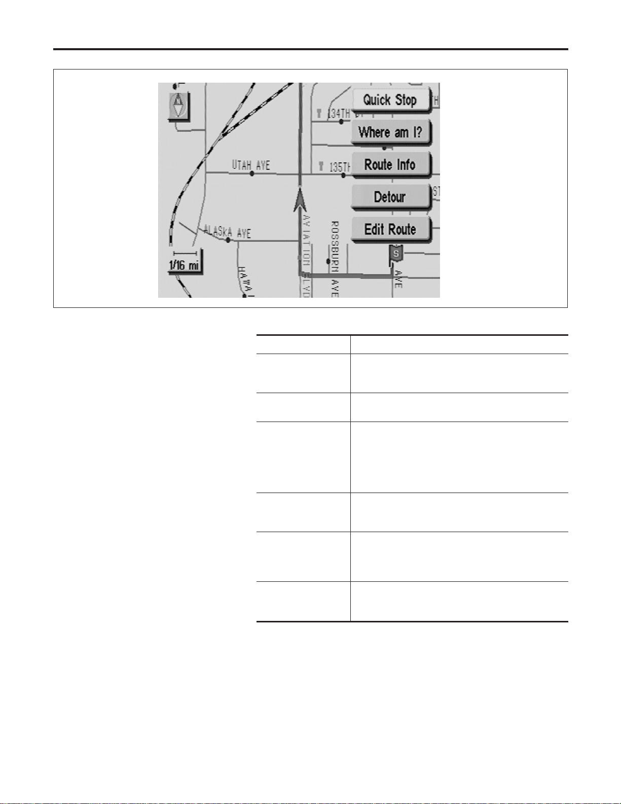
Display with Toutch Screen
NAEL0421S0303
SEL476Y
The function of each touch switch is as follows:
Icon Description
Quick Stop The selected facility is set as the destination or way-
point. (Route guidance has been turned OFF or the
destination has been reached.)
Where am I? Next, current and previous street names can be dis-
played.
Route Info.* The following items can be set.
I Complete Route
I Turn List
I Route Simulation
(Displayed only when the destination area has been
set.)
Detour* Based on the selected distance, an alternative route is
searched. [Displayed only when the recommended
route (not its reverse) is followed.]
Edit Route* Change the destination or add the transit points of the
route set in the route guide. (Displayed only when the
automatic reroute function has been turned OFF and
the recommended route is not followed.)
Route Calc. Search for a recommended route between the vehi-
cle’s current location and the destination area. (Dis-
played only when the destination area has been set.)
*: When destinations have been entered, route guidance has been turned OFF or
destination has been reached, “Route Info.”, “Detour” and “Edit Route” are not
displayed.
NAVIGATION SYSTEM
System Description (Cont’d)
EL-412
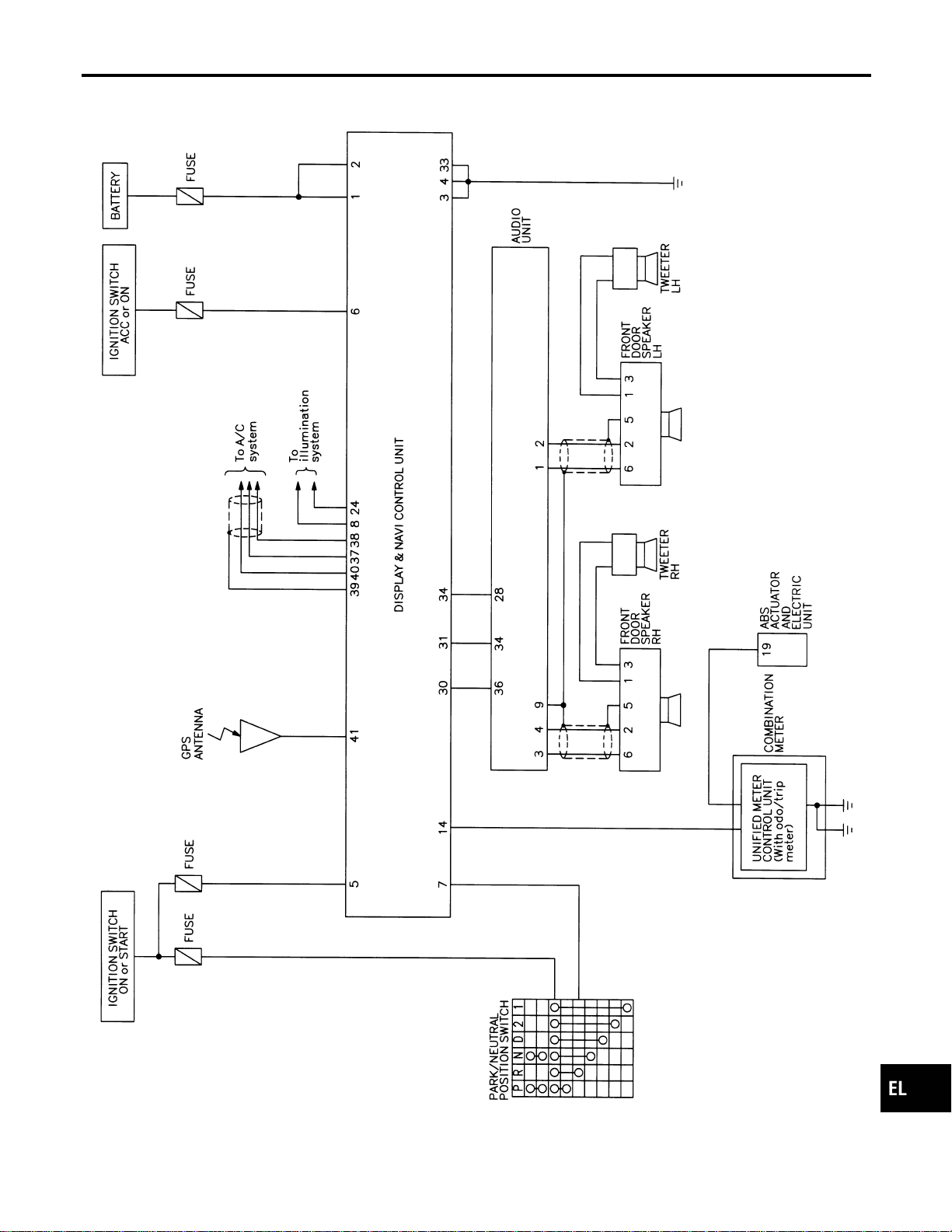
Schematic
NAEL0422
MEL270N
GI
MA
EM
LC
EC
FE
CL
MT
AT
TF
PD
AX
SU
BR
ST
RS
BT
HA
SC
IDX
NAVIGATION SYSTEM
Schematic
EL-413
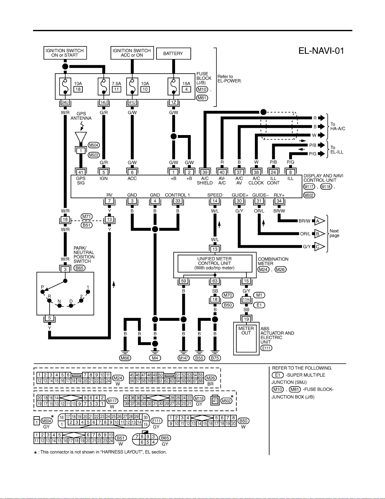
Wiring Diagram — NAVI —
NAEL0423
MEL878N
NAVIGATION SYSTEM
Wiring Diagram — NAVI —
EL-414
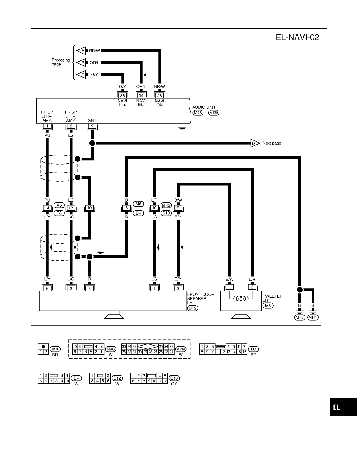
MEL272N
GI
MA
EM
LC
EC
FE
CL
MT
AT
TF
PD
AX
SU
BR
ST
RS
BT
HA
SC
IDX
NAVIGATION SYSTEM
Wiring Diagram — NAVI — (Cont’d)
EL-415
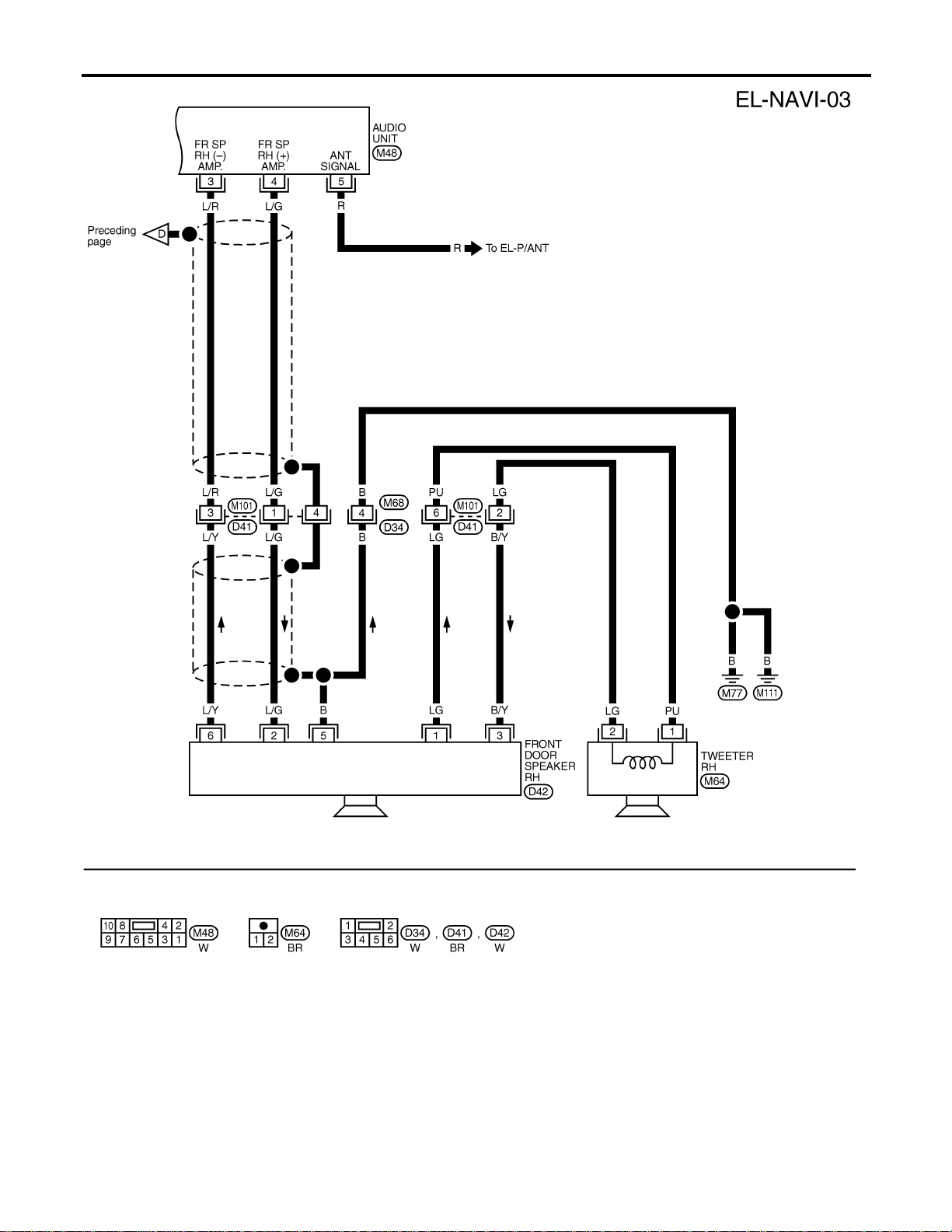
MEL270M
NAVIGATION SYSTEM
Wiring Diagram — NAVI — (Cont’d)
EL-416
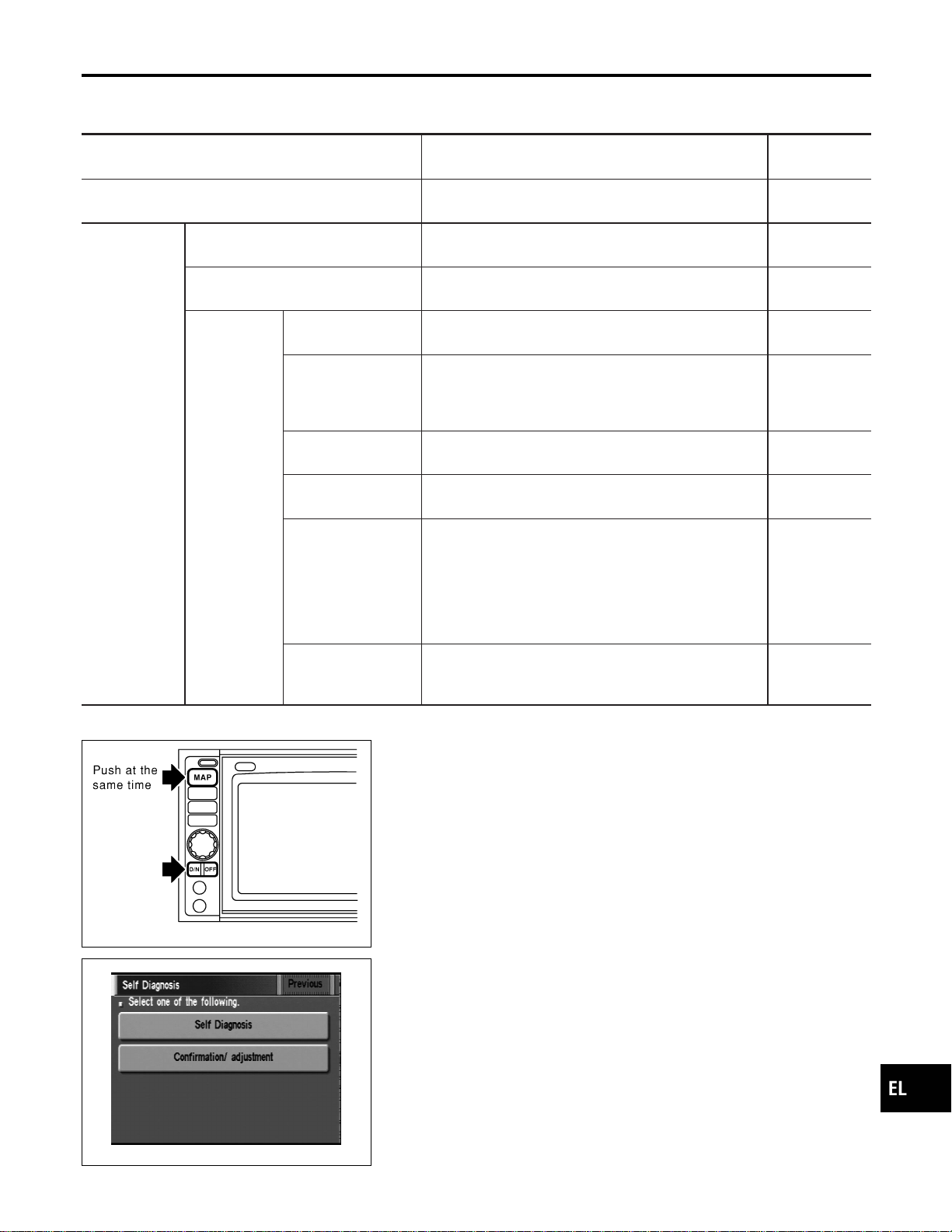
Self-diagnosis Mode
NAEL0424
APPLICATION ITEMS
NAEL0424S01
Mode Description
Reference
page
Self Diagnosis
Self-diagnosis for display & NAVI control unit, CD-ROM
and GPS antenna connection.
EL-418
Confirmation/
adjustment
Display Diagnosis Color and gray gradation of display can be checked in
this mode.
EL-426
Diagnostic Signals from the Car Several input signals to display & NAVI control unit, can
be monitored in this mode.
EL-424
Navigation
Check the map CD-
ROM version
The version (parts number) of inserted CD-ROM can be
checked in this mode.
EL-425
History of errors Diagnosis results previously stored in the memory
(before turning ignition switch ON) are displayed in this
mode. Time and location when/where the errors
occurred are also displayed.
EL-420
Longitude & Latitude Display the map. Use the joystick to adjust position. Lon-
gitude and latitude will be displayed.
EL-427
Adjust the angle Turning angle of the vehicle on the display can be
adjusted in this mode.
EL-428
Speed Calibration
Under ordinary conditions, the navigation system dis-
tance measuring function will automatically compensate
for minute decreases in wheel and tire diameter caused
by tire wear or low pressure. Speed calibration immedi-
ately restores system accuracy in cases such as when
distance calibration is needed because of the use of tire
chains in inclement weather.
EL-429
Initialize Location This mode is for initializing the current location. Use
when the vehicle is transported a long distance on a
trailer, etc.
EL-454
SEL583X
HOW TO PERFORM SELF-DIAGNOSIS MODE
NAEL0424S02
1. Start the engine.
2. Push both of “MAP” and “D/N” switches at the same time for
more than 5 seconds.
SEL584X
3. Touch “Self Diagnosis” or “Confirmation/ adjustment”.
I For further procedure, refer to the following pages which
describe each application item of the self-diagnosis mode.
GI
MA
EM
LC
EC
FE
CL
MT
AT
TF
PD
AX
SU
BR
ST
RS
BT
HA
SC
IDX
NAVIGATION SYSTEM
Self-diagnosis Mode
EL-417
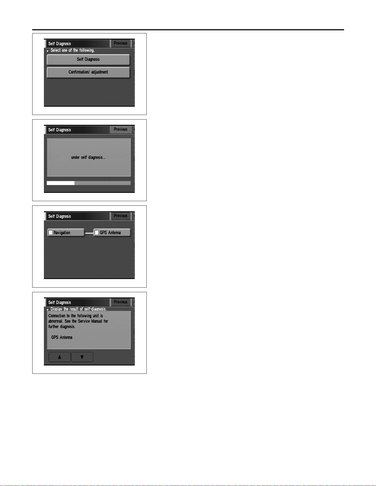
SEL584X
“Self Diagnosis”
NAEL0424S0201
1. Start the engine.
2. Push both “MAP” and “D/N” switches at the same time for more
than 5 seconds.
3. Touch “Self Diagnosis”.
SEL585X
4. Self-diagnosis will be performed.
SEL586X
5. Diagnosis results will be displayed. Diagnosis results are indi-
cated by display color. For details refer to “SELF-DIAGNOSIS
RESULTS”.
SEL587X
To obtain detailed diagnosis results on the screen, touch “Naviga-
tion” or “GPS Antenna”.
NAVIGATION SYSTEM
Self-diagnosis Mode (Cont’d)
EL-418

SELF-DIAGNOSIS RESULTS
=NAEL0424S03
Diagnosed
item
Displayed
color
Detailed result Description
Diagnoses/service procedure
Recheck system at each check or
replacement (When malfunction is
eliminated, further repair work is
not required.)
“GPS
Antenna”
(GPS
antenna con-
nection)
Green —
GPS antenna is connected to dis-
play & NAVI control unit correctly.
—
Yellow
Connection to the follow-
ing unit is abnormal. See
the Service Manual for
further diagnosis.
GPS antenna connection error is
detected.
1. Check GPS antenna feeder cable
connection at display & NAVI
control unit.
2. Visually check GPS antenna
feeder cable. If NG, replace GPS
antenna assembly.
3. Replace GPS antenna.
“Navigation”
(Display &
NAVI control
unit)
Green — No failure is detected. —
Red [*** is abnormal.]
Display & NAVI control unit is mal-
functioning.
Replace display & NAVI control unit.
Gray
Self-diagnosis for CD-
ROM DRIVER of DISP &
NAVI was not conducted
due to no insertion of
CD-ROM.
Any CD-ROM is not inserted or dis-
play & NAVI control unit is malfunc-
tioning.
1. Confirm that map CD-ROM is not
inserted into display & NAVI con-
trol unit.
2. Replace display & NAVI control
unit.
Yellow
CD-ROM or CD-ROM
DRIVER of DISP & NAVI
is abnormal. See the
Service Manual for fur-
ther diagnosis.
Display & NAVI control unit judges
that inserted CD-ROM is malfunc-
tioning.
Map CD-ROM or CD-ROM driver of
the unit is malfunctioning.
1. Confirm the disk is installed cor-
rectly (not up side down.)
2. Perform “CHECK THE MAP CD-
ROM VERSION” in EL-425 to
confirm whether correct CD-ROM
is inserted or not.
3. Check the disk surface. Are there
any scratches, abrasions or pits
on the surface?
4. Replace the CD-ROM.
5. Replace display & NAVI control
unit.
CD-ROM is abnormal.
Please check the disc.
Inserted map CD-ROM can not be
read.
Map CD-ROM or CD-ROM driver of
the unit is malfunctioning.
Connection to the follow-
ing unit is abnormal. See
the Service Manual for
further diagnosis.
GPS antenna connection error is
detected.
1. Check GPS antenna feeder cable
connection at display & NAVI
control unit.
2. Visually check GPS antenna
feeder cable. If NG, replace GPS
antenna assembly.
3. Replace GPS antenna.
GI
MA
EM
LC
EC
FE
CL
MT
AT
TF
PD
AX
SU
BR
ST
RS
BT
HA
SC
IDX
NAVIGATION SYSTEM
Self-diagnosis Mode (Cont’d)
EL-419
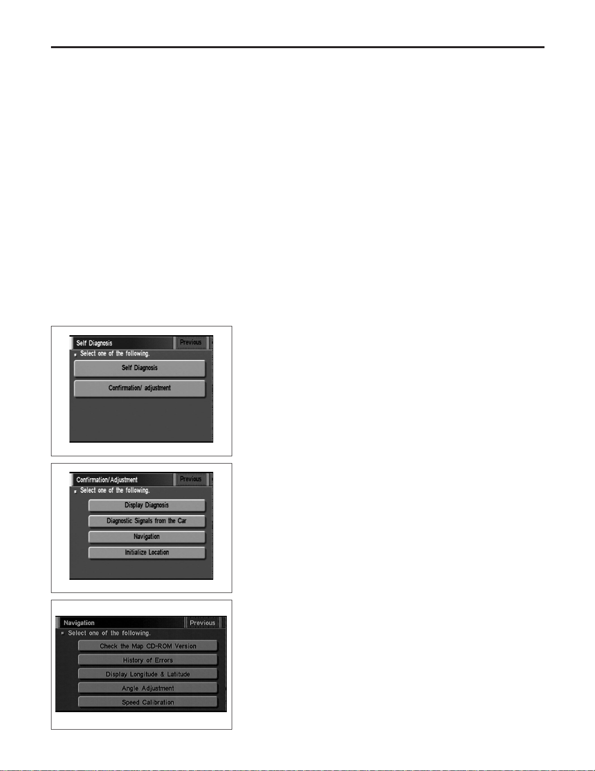
Confirmation/Adjustment Mode
=NAEL0425
“HISTORY OF ERRORS” MODE
NAEL0425S01
Description
NAEL0425S0101
In this mode, historical errors of the system are displayed with the
following data.
I How many times the error was detected
I The last time data when the error was detected
I The last place where the error was detected
NOTE:
I The number of errors can be counted up to 50 times. More
than 51 times will be indicated as 50 times.
I Malfunction of the GPS board (inside the display & NAVI
control unit) will result in the display of incorrect time
data.
I When an error occurs, an incorrect position marker
appears on the display. The accuracy of the display data
(position marker) will be affected.
SEL584X
How to Perform
NAEL0425S0102
1. Start the engine.
2. Push both “MAP” and “D/N” switch at the same time for more
than 5 seconds.
3. Touch “Confirmation/ adjustment”.
SEL588X
4. Touch “Navigation”.
SEL453Y
5. Touch “Error history”.
NAVIGATION SYSTEM
Confirmation/Adjustment Mode
EL-420
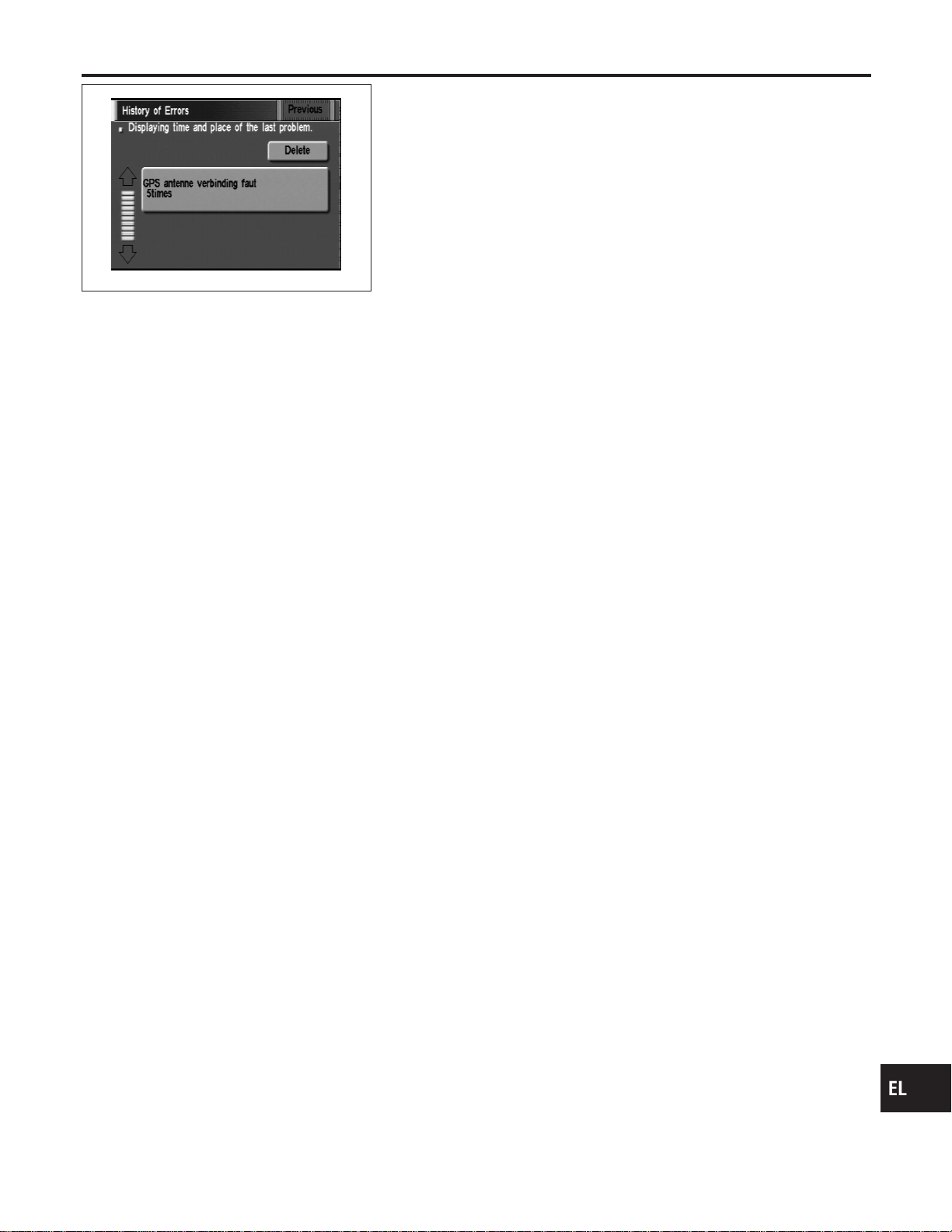
SEL590X
6. If trouble items are displayed with time count, repair/replace
the system according to “HISTORY OF ERRORS” TABLE,
EL-422.
7. If necessary, touch error item to display the time when the error
was detected and the place where the error was detected.
8. After repairing the system, erase the diagnosis memory.
NOTE:
When the display & NAVI control unit must be replaced, do not
erase the diagnosis memory for further inspection of malfunc-
tions.
a. Start the engine.
b. Push both “Map” and “D/N” switches at the same time for more
than 5 seconds.
c. Touch “Confirmation/ adjustment”.
d. Touch “Navigation”.
e. Touch “Error history”.
f. Touch “Delete”.
g. Touch “Yes”.
GI
MA
EM
LC
EC
FE
CL
MT
AT
TF
PD
AX
SU
BR
ST
RS
BT
HA
SC
IDX
NAVIGATION SYSTEM
Confirmation/Adjustment Mode (Cont’d)
EL-421

“HISTORY OF ERRORS” TABLE
=NAEL0425S02
Detected items Description Diagnosis/service procedure
Refer-
ence
page
Gyro sensor disconnected
Communications malfunction between
display & NAVI control unit and internal
gyro
Perform self-diagnosis to confirm
whether the display & NAVI control unit
is malfunctioning or not. If no failure is
detected, a momentary and/or tempo-
rary malfunction may have been caused
by strong electromagnetic wave interfer-
ence.
EL-417
Connection problem of speed
sensor
Input malfunction of display & NAVI con-
trol unit and speed sensor
Check vehicle speed sensor signal in
“DIAGNOSTIC SIGNALS FROM THE
CAR” mode. If the input signal is not
detected correctly, check harness for
open or short between combination
meter and display & NAVI control unit.
EL-424
GPS disconnected
Communications malfunction between
display & NAVI control unit and GPS
board
Perform self-diagnosis to confirm
whether the display & NAVI control unit
is malfunctioning or not. If no failure is
detected, a momentary and/or tempo-
rary malfunction may have been caused
by strong electromagnetic wave interfer-
ence.
EL-417
GPS transmission cable malfunc-
tion
GPS input line connection error
GPS TCXO over
The transmission circuit of the GPS
board frequency synchronization oscilla-
tor (inside the display & NAVI control
unit) is sending an oscillation frequency
that is greater or less than the set value.
A location error occurs. Strong electro-
magnetic wave interference may have
occurred. The GPS antenna may be in a
very hot or very cold environment. This
is usually a temporary malfunction.
—
GPS TCXO under
GPS ROM malfunction
Internal malfunction of GPS board RAM
or ROM inside the display & NAVI con-
trol unit.
Perform self-diagnosis to confirm
whether the display & NAVI control unit
is malfunctioning or not. If no failure is
detected, a momentary and/or tempo-
rary malfunction may have been caused
by strong electromagnetic wave interfer-
ence.
EL-417
GPS RAM malfunction
GPS RTC malfunction
Malfunction of GPS board clock IC
inside the display & NAVI control unit.
GPS antenna disconnected —
Perform self-diagnosis to confirm GPS
antenna connection. If no failure is
detected, a momentary and/or tempo-
rary malfunction may have been caused
by a strong impact.
EL-425
Low voltage of GPS
Power supply voltage for GPS board
inside the display & NAVI control unit is
low.
1. Check power supply circuits for dis-
play & NAVI control unit.
EL-438
2. Perform self-diagnosis to confirm
GPS antenna connection.
EL-417
3. If above diagnosis results are OK, a
momentary and/or temporary malfunc-
tion may have been caused by a strong
impact.
—
CD-ROM communication error
CD-ROM driver malfunction (inside the
display & NAVI control unit)
Perform self-diagnosis to confirm
whether the display & NAVI control unit
is malfunctioning or not. If no failure is
detected, a momentary and/or tempo-
rary malfunction may have been caused
by strong electromagnetic wave interfer-
ence.
EL-417
NAVIGATION SYSTEM
Confirmation/Adjustment Mode (Cont’d)
EL-422

Detected items Description Diagnosis/service procedure
Refer-
ence
page
Loading mechanism malfunction —
Check that whether the disc can be
inserted and ejected correctly. If the
loading function does not operate
correctly, replace NAVI & display control
unit.
—
CD-ROM reading error
It is confirmed that the appropriate CD-
ROM disc is positioned in the CD-ROM
loader. However, no data can be read.
Perform self-diagnosis to confirm
whether the inserted disc is malfunction-
ing or not.
EL-417
Malfunctioning of error correction
for CD-ROM
Erroneous data is read from the CD-
ROM. The errors cannot be corrected.
CD-ROM focus error
CD-ROM data reading beam is out of
focus.
Rough road driving might create CD
skipping like music CD audio unit.
—
CD-ROM malfunction —
Perform self-diagnosis to confirm
whether the inserted disc is malfunction-
ing or not.
EL-417
GI
MA
EM
LC
EC
FE
CL
MT
AT
TF
PD
AX
SU
BR
ST
RS
BT
HA
SC
IDX
NAVIGATION SYSTEM
Confirmation/Adjustment Mode (Cont’d)
EL-423
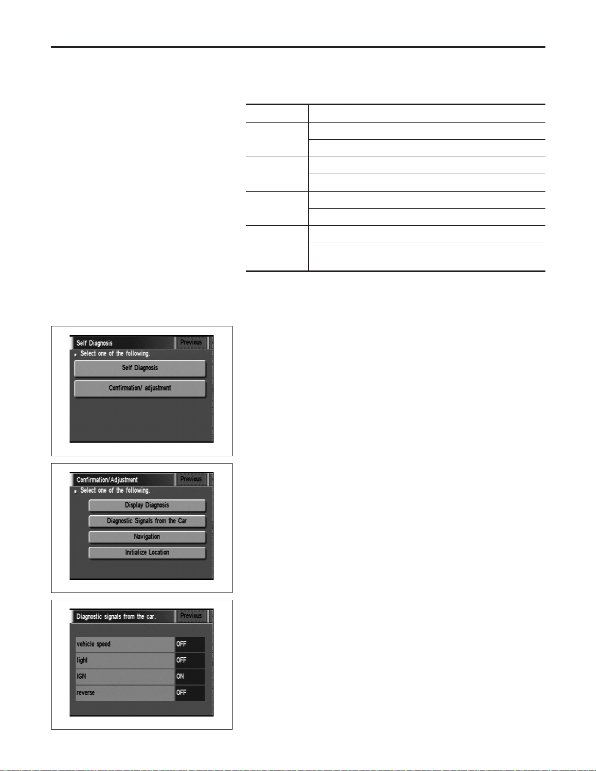
“DIAGNOSTIC SIGNALS FROM THE CAR” MODE
=NAEL0425S03
Description
NAEL0425S0301
In “Diagnostic Signals From the Car” mode, following input signals
to the display & NAVI control unit can be checked on the display.
Item Indication Vehicle condition
Vehicle
Speed*
ON Vehicle speed is greater than 0 km/h (0 MPH).
OFF Vehicle speed is 0 km/h (0 MPH).
Light
ON Lighting switch is in 1st or 2nd position.
OFF Lighting switch is in “OFF” position.
IGN
ON Ignition switch is in “ON” position.
OFF Ignition switch is in “ACC” position.
REVERSE*
ON Selector/shift lever is in “Reverse” position.
OFF
Selector/shift lever is in other than “Reverse” posi-
tion.
*: When ignition switch is in “ACC” position, indication will be changed to “-”.
SEL584X
How to Perform
NAEL0425S0302
1. Start the engine.
2. Push both “MAP” and “D/N” switches at the same time for more
than 5 seconds.
3. Touch “Confirmation/ adjustment”.
SEL588X
4. Touch “Diagnostic Signals from the Car”.
SEL591X
5. Then “Diagnostic Signals from the Car” mode is performed.
NAVIGATION SYSTEM
Confirmation/Adjustment Mode (Cont’d)
EL-424
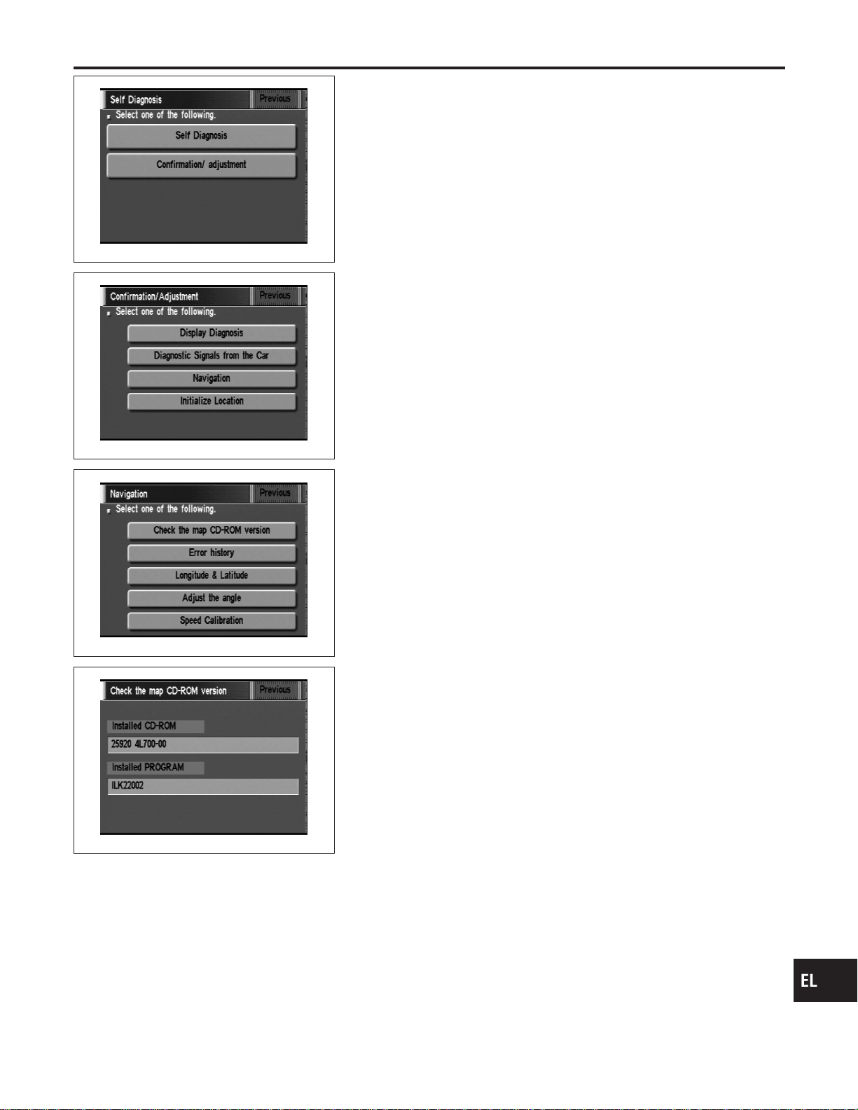
SEL584X
“CHECK THE MAP CD-ROM VERSION” MODE
=NAEL0425S04
How to Perform
NAEL0425S0401
1. Start the engine.
2. Push both “MAP” and “D/N” switches at the same time for more
than 5 seconds.
3. Touch “Confirmation/ adjustment”.
SEL588X
4. Touch “Navigation”.
SEL589X
5. Touch “Check the map CD-ROM version”.
SEL592X
6. The version (parts number) of CD-ROM loaded to the display
and NAVI control unit will be displayed.
GI
MA
EM
LC
EC
FE
CL
MT
AT
TF
PD
AX
SU
BR
ST
RS
BT
HA
SC
IDX
NAVIGATION SYSTEM
Confirmation/Adjustment Mode (Cont’d)
EL-425
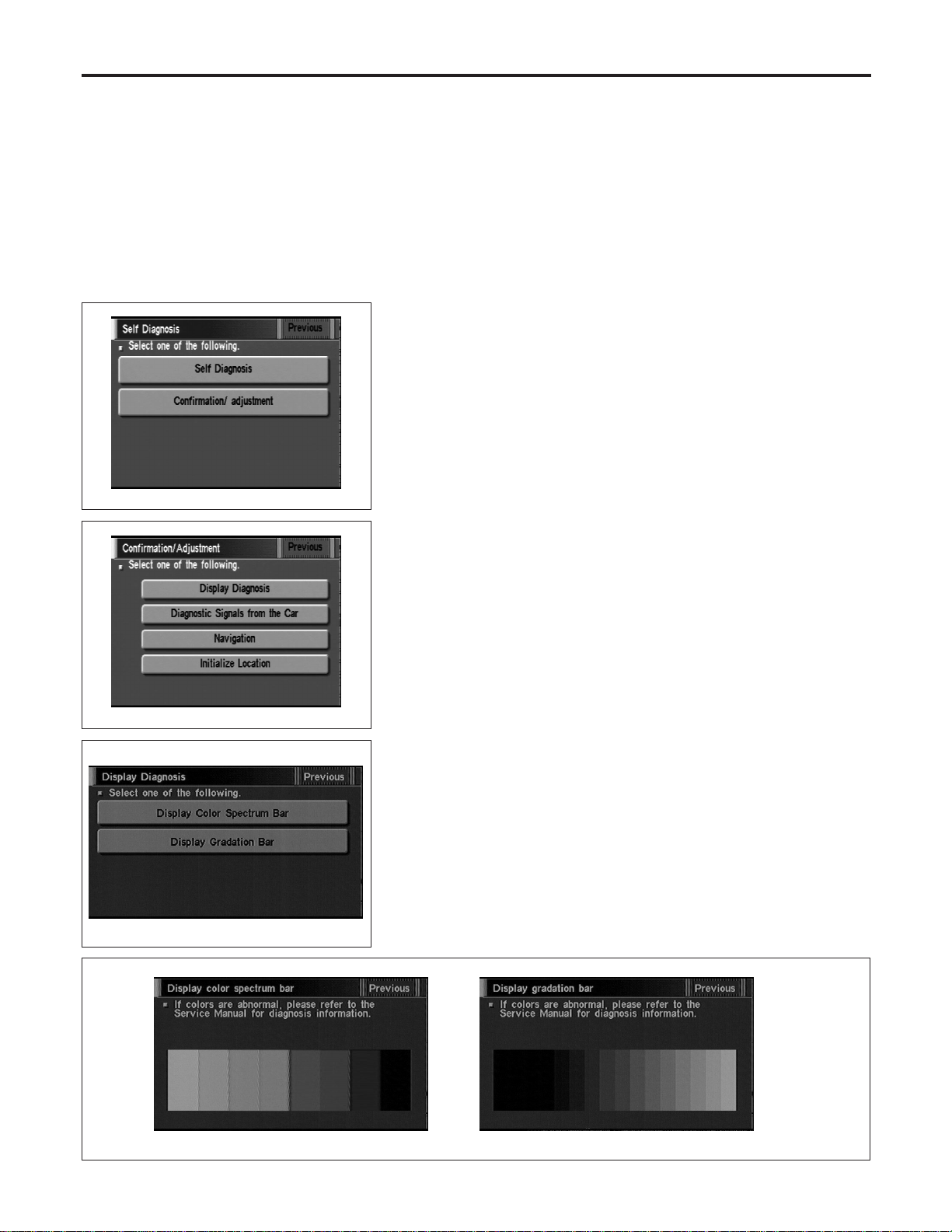
“DISPLAY DIAGNOSIS” MODE
=NAEL0425S05
Description
NAEL0425S0501
Use the “Diagnosis Display” mode to check the display color bright-
ness and shading. The display & NAVI control unit must be
replaced if the color brightness and shading are abnormal.
SEL584X
How to Perform
NAEL0425S0502
1. Start the engine.
2. Push both “MAP” and “D/N” switches at the same time for more
than 5 seconds.
3. Touch “Confirmation/ adjustment”.
SEL588X
4. Touch “Display Diagnosis”.
SEL454Y
5. Touch “Display color spectrum bar” or “Display gradation bar”.
6. Then color bar/gray scale will be displayed.
SEL455Y
NAVIGATION SYSTEM
Confirmation/Adjustment Mode (Cont’d)
EL-426
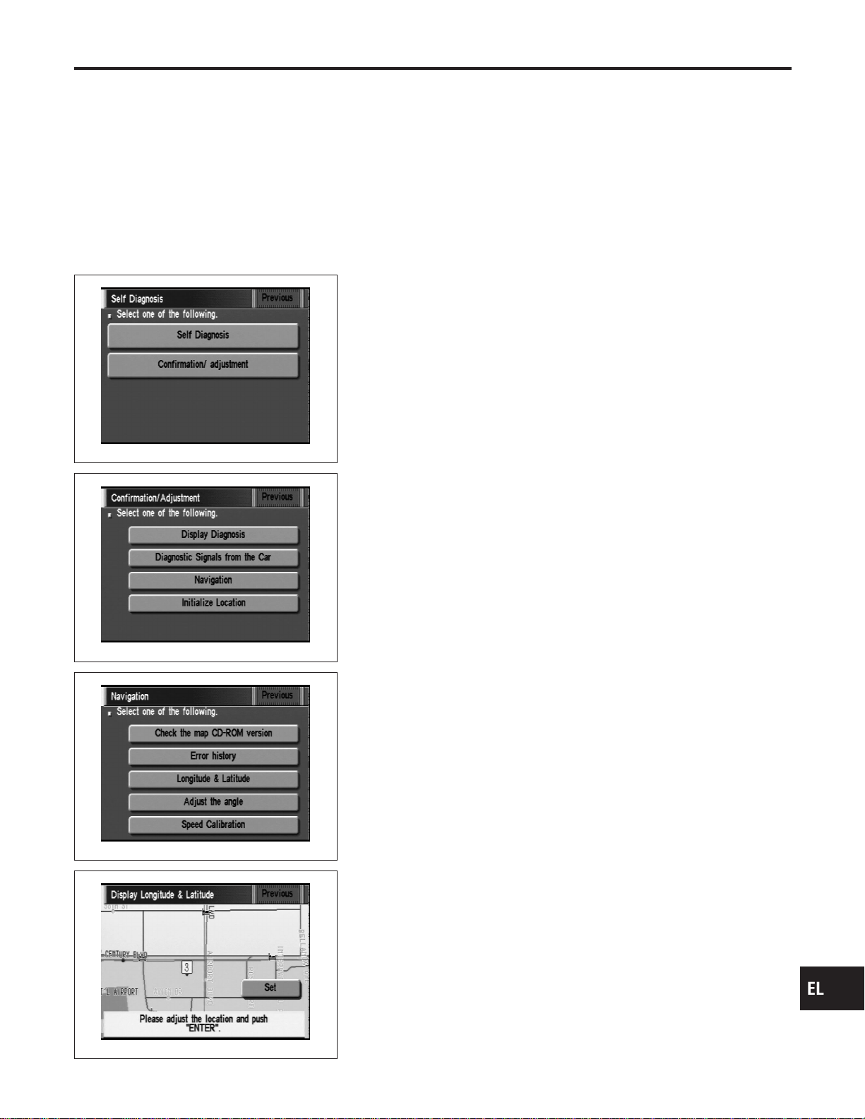
“LONGITUDE & LATITUDE” MODE
NAEL0425S06
Description
NAEL0425S0601
The “Longitude & Latitude” is used to confirm the longitude and
latitude of some optional area point.
SEL584X
How to Perform
NAEL0425S0602
1. Start the engine.
2. Push both “MAP” and “D/N” switches at the same time for more
than 5 seconds.
3. Touch “Confirmation/ adjustment”.
SEL588X
4. Touch “Navigation”.
SEL589X
5. Touch “Longitude & Latitude”.
SEL595X
6. Adjust the pointer with using the joystick and touch “Set”.
7. The longitude and latitude are displayed.
GI
MA
EM
LC
EC
FE
CL
MT
AT
TF
PD
AX
SU
BR
ST
RS
BT
HA
SC
IDX
NAVIGATION SYSTEM
Confirmation/Adjustment Mode (Cont’d)
EL-427
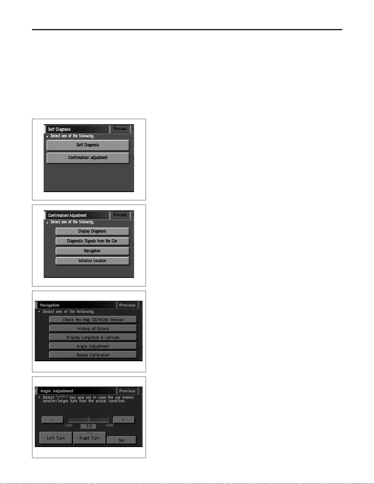
“ADJUST THE ANGLE” MODE
=NAEL0425S07
Description
NAEL0425S0701
If the display indicates a larger or smaller turning angle than the
actual turning angle, the gyro (angular speed sensor) sensing val-
ues must be checked.
In case that the vehicle on the display makes larger angle turn than
reality, touch “−”. In case that the vehicle on the display makes
smaller angle turn than reality, touch “+”.
SEL584X
How to Perform
NAEL0425S0702
1. Start the engine.
2. Push both “MAP” and “D/N” switches at the same time for more
than 5 seconds.
3. Touch “Confirmation/ adjustment”.
SEL588X
4. Touch “Navigation”.
SEL453Y
5. Touch “Adjust the angle”.
SEL456Y
6. Touch “Left Turn” to adjust the angle to the left. Touch “Right
Turn” to adjust the angle to the right.
7. Touch “+” to increase the angle change coefficient or “−” to
reduce the angle change coefficient.
8. Touch “Set” to save the changed values in memory.
9. Then the vehicle turning angle on the display has adjusted.
NAVIGATION SYSTEM
Confirmation/Adjustment Mode (Cont’d)
EL-428

SEL584X
SPEED CALIBRATION
=NAEL0425S08
1. Start the engine.
2. Push both “MAP” and “D/N” switches at the same time for more
than 5 seconds.
3. Touch “Confirmation/ adjustment”.
4. Touch “Navigation”.
SEL453Y
5. Touch “Speed Calibration”.
SEL457Y
6. Touch “+” or “−” to adjust the distance change coefficient.
I To make the distance change coefficient smaller, touch “−”.
I To make the distance change coefficient larger, touch “+”.
7. Touch “Set”.
GI
MA
EM
LC
EC
FE
CL
MT
AT
TF
PD
AX
SU
BR
ST
RS
BT
HA
SC
IDX
NAVIGATION SYSTEM
Confirmation/Adjustment Mode (Cont’d)
EL-429
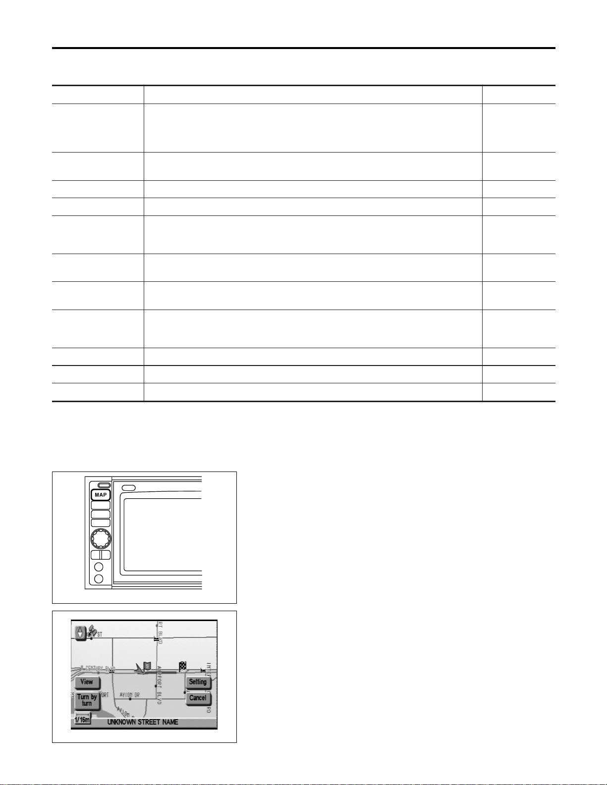
Setting Mode
=NAEL0426
APPLICATION ITEMS
NAEL0426S01
Mode Description Reference page
GPS Information The GPS includes longtitude, latitude and altitude (distance above sea level) of the
present vehicle position, and current date and time for the area in which the vehicle is
being driven.
Also indicated are the GPS reception conditions and the GPS satellite position.
EL-430
Quick Stop Customer
Setting
One facility of your selection can be added to your Quick Stop.
EL-433
Route Priorities Priorities of search request and automatic re-searching can be set for route search. EL-434
Tracking Tracking to the present vehicle position can be displayed. EL-435
Display Setting The following display settings can be customized.
I Display color (Day mode or Night mode)
I Brightness of display
EL-432
Heading Heading of the map display can be customized for either north heading or the actual
driving direction of the vehicle.
EL-435
Nearby Display Icons Icons of facilities can be displayed.
Facilities to be displayed can be selected from the variety of selections.
EL-436
Adjust Current Loca-
tion
Current location of position marker can be adjusted. Direction of position marker also
can be calibrated when heading direction of the vehicle on the display is not matched
with the actual direction.
EL-431
Avoid Area Setting Particular area can be avoided when routing. —
Beep On/Off Beep sounds which correspond to the system operation can be activated/deactivated. EL-432
Clear Memory Address book, Previous destination or Avoid area can be deleted. EL-436
SEL597X
HOW TO PERFORM CONTROL PANEL MODE
NAEL0426S02
1. Start the engine.
2. Push “MAP” switch.
I For further procedures, refer to the following pages which
describe each application item of the control panel mode.
SEL598X
“GPS INFORMATION” SETTING
NAEL0426S03
1. Start the engine.
2. Push “MAP” switch.
3. Touch “Setting”.
NAVIGATION SYSTEM
Setting Mode
EL-430
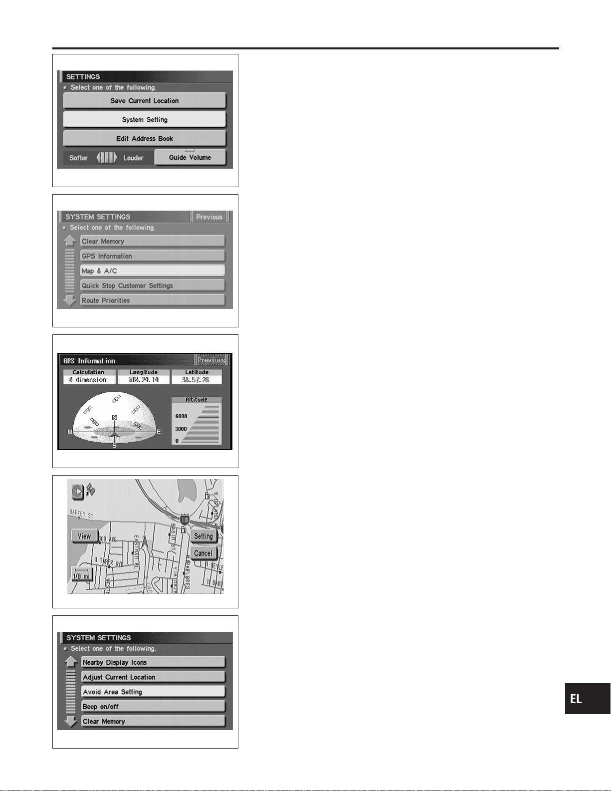
SEL461Y
4. Touch “System Setting”.
SEL462Y
5. Touch “GPS Information”.
SEL146W
6. Then GPS information will be displayed.
SEL460Y
“ADJUST CURRENT LOCATION” SETTING
NAEL0426S04
1. Start the engine.
2. Push “MAP” switch.
3. Touch “Setting”.
4. Touch “System Setting”.
SEL463Y
5. Touch “Adjust Current Location”.
GI
MA
EM
LC
EC
FE
CL
MT
AT
TF
PD
AX
SU
BR
ST
RS
BT
HA
SC
IDX
NAVIGATION SYSTEM
Setting Mode (Cont’d)
EL-431

SEL602X
6. Touch “ ”or“ ” to calibrate the heading direction. (Arrow
marks will rotate corresponding to the calibration key.)
7. Touch “Set”. Then the vehicle mark will be matched to the
arrow mark.
8. Display will show “Heading direction has been calibrated” and
then go back to the current location map.
SEL460Y
BEEP ON/OFF SETTING
NAEL0426S05
1. Start the engine.
2. Push “MAP” switch.
3. Touch “Setting”.
4. Touch “System Setting”.
SEL463Y
5. Touch “Beep on/off”.
SEL464Y
6. Touch “On” or “Off” icon.
I If you want the beep sound, select “ON”.
I If you do not want the beep sound, select “OFF”.
7. Push “MAP” switch, then the display will go back to the current
location map.
DISPLAY SETTING
NAEL0426S06
Description
NAEL0426S0601
The following display setting can be changed in this mode.
I Dimmer operation (when lighting switch is turned on.)
I Display color (Day mode or Night mode)
I Brightness of display
NAVIGATION SYSTEM
Setting Mode (Cont’d)
EL-432
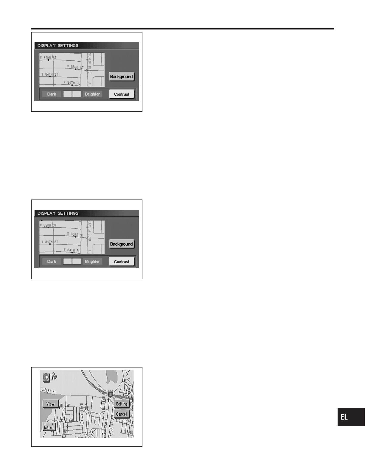
SEL465Y
DISPLAY COLOR SETTING
NAEL0426S07
1. Start the engine.
2. Push “MAP” switch.
3. Touch “Setting”.
4. Touch “System Setting”.
5. Touch “Color”. Display color will change to Day mode/Night
mode.
6. Touch “Previous”.
NOTE:
I Display color can be changed independently when light-
ing switch is turned on and off.
I Initial setting of the color is as follows:
When lighting switch is turned off: Day mode
When lighting switch is turned on: Night mode
Day mode: White background
Night mode: Black background
SEL465Y
BRIGHTNESS SETTING
NAEL0426S08
1. Start the engine.
2. Push “MAP” switch.
3. Touch “Setting”.
4. Touch “System Setting”.
5. Touch “Display Setting”.
6. Touch “Bright” or “Dark” to adjust the brightness of display.
7. Touch “Previous”.
NOTE:
Display brightness can be adjusted independently when light-
ing switch is turned on and off.
SEL460Y
“QUICK STOP CUSTOMER SETTING” MODE
NAEL0426S09
1. Start the engine.
2. Push the “MAP” switch.
3. Touch “Setting”.
4. Touch “System Setting”.
GI
MA
EM
LC
EC
FE
CL
MT
AT
TF
PD
AX
SU
BR
ST
RS
BT
HA
SC
IDX
NAVIGATION SYSTEM
Setting Mode (Cont’d)
EL-433
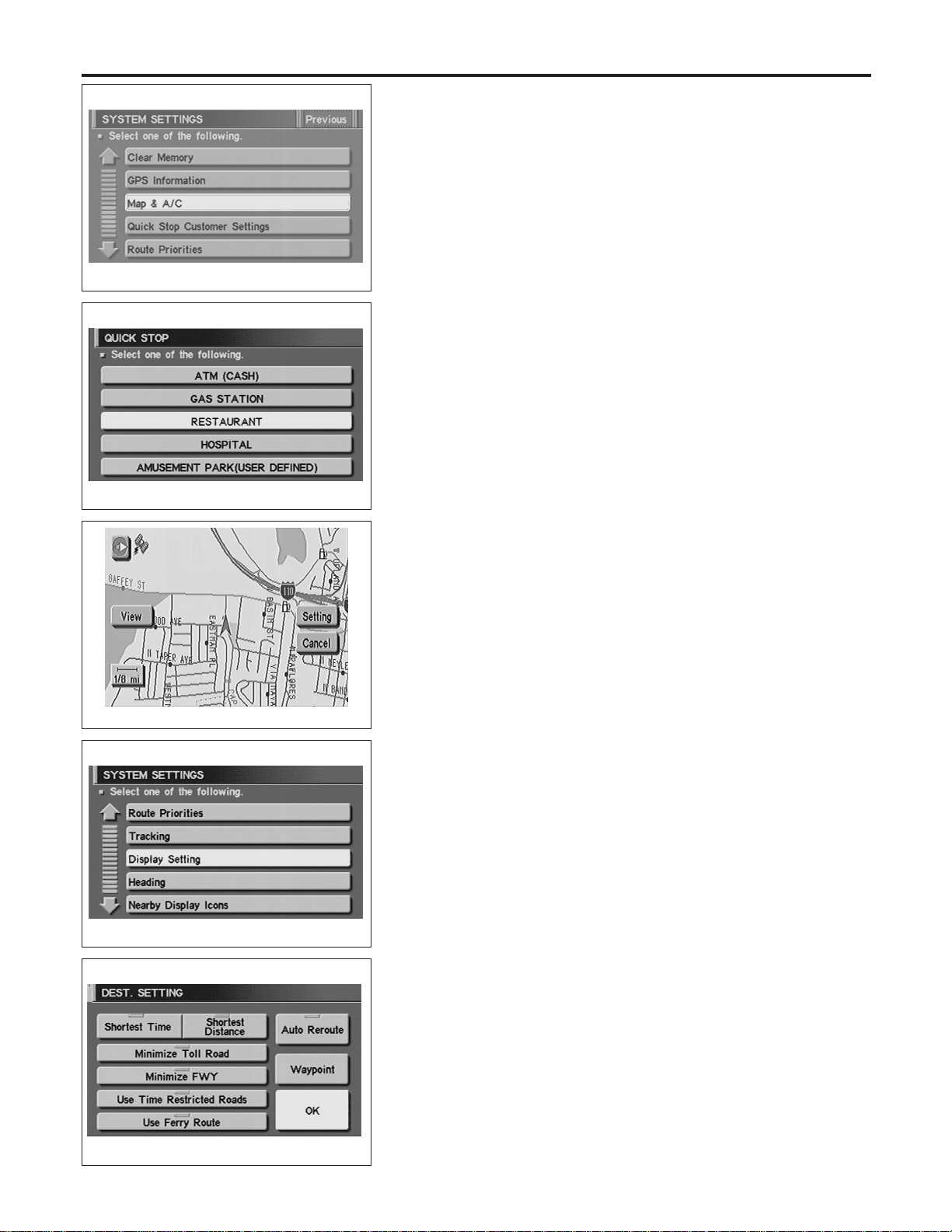
SEL462Y
5. Touch “Quick Stop Customer Setting”.
SEL466Y
6. Select from the itemized list.
SEL460Y
“ROUTE PRIORITIES” MODE
NAEL0426S10
1. Start the engine.
2. Push the “MAP” switch.
3. Touch “Setting”.
4. Touch “System Setting”.
SEL467Y
5. Touch “Route Priorities”.
SEL468Y
6. Select from the itemized list.
NAVIGATION SYSTEM
Setting Mode (Cont’d)
EL-434
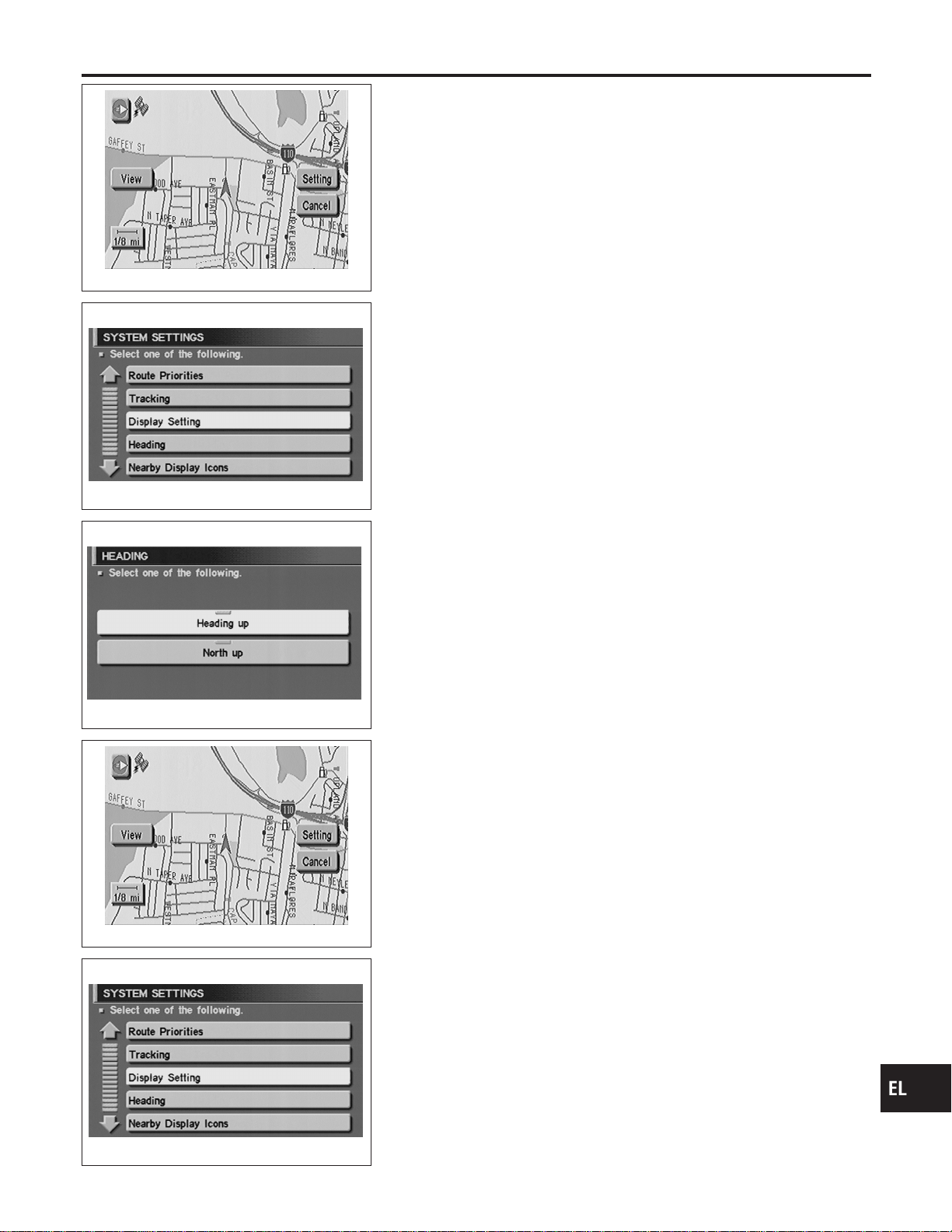
SEL460Y
“TRACKING” MODE
NAEL0426S11
1. Start the engine.
2. Push the “MAP” switch.
3. Touch “Setting”.
4. Touch “System Setting”.
SEL467Y
5. Touch “Tracking”.
SEL470Y
6. Touch the “On” or “Off” icon.
I If you don’t need a trail on the map, select “Off”.
I If you need a trail on the map, select “On”.
7. Push the “MAP” switch to return the display to the current
location map.
NOTE:
When a trail display is turned OFF, trail data is erased from the
memory.
SEL460Y
“HEADING” MODE
NAEL0426S12
1. Start the engine.
2. Push the “MAP” switch.
3. Touch “Setting”.
4. Touch “System Setting”.
SEL467Y
5. Touch “Heading”.
GI
MA
EM
LC
EC
FE
CL
MT
AT
TF
PD
AX
SU
BR
ST
RS
BT
HA
SC
IDX
NAVIGATION SYSTEM
Setting Mode (Cont’d)
EL-435
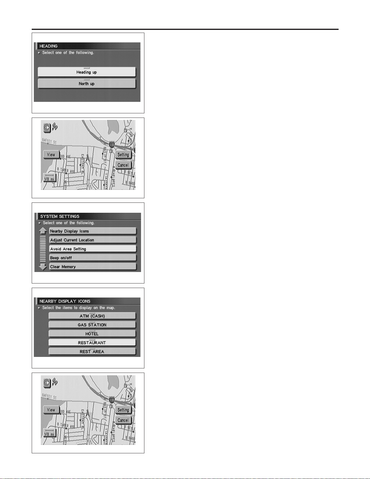
SEL470Y
6. Touch the “Heading up” or “North up” icon.
I To display North up, select “North up”.
I To display the car heading up, select “Heading up”.
7. Push the “MAP” switch, then the display will go back to the
current location map.
SEL460Y
“NEARBY DISPLAY ICONS” MODE
NAEL0426S13
1. Start the engine.
2. Push the “MAP” switch.
3. Touch “Setting”.
4. Touch “System Setting”.
SEL463Y
5. Touch “Nearby Display Icons”.
SEL471Y
6. Select and touch the itemized list.
7. Push the “MAP” switch to return the display to the current
location map.
SEL460Y
“CLEAR MEMORY” MODE
NAEL0426S14
1. Start the engine.
2. Push the “MAP” switch.
3. Touch “Setting”.
4. Touch “System Setting”.
NAVIGATION SYSTEM
Setting Mode (Cont’d)
EL-436
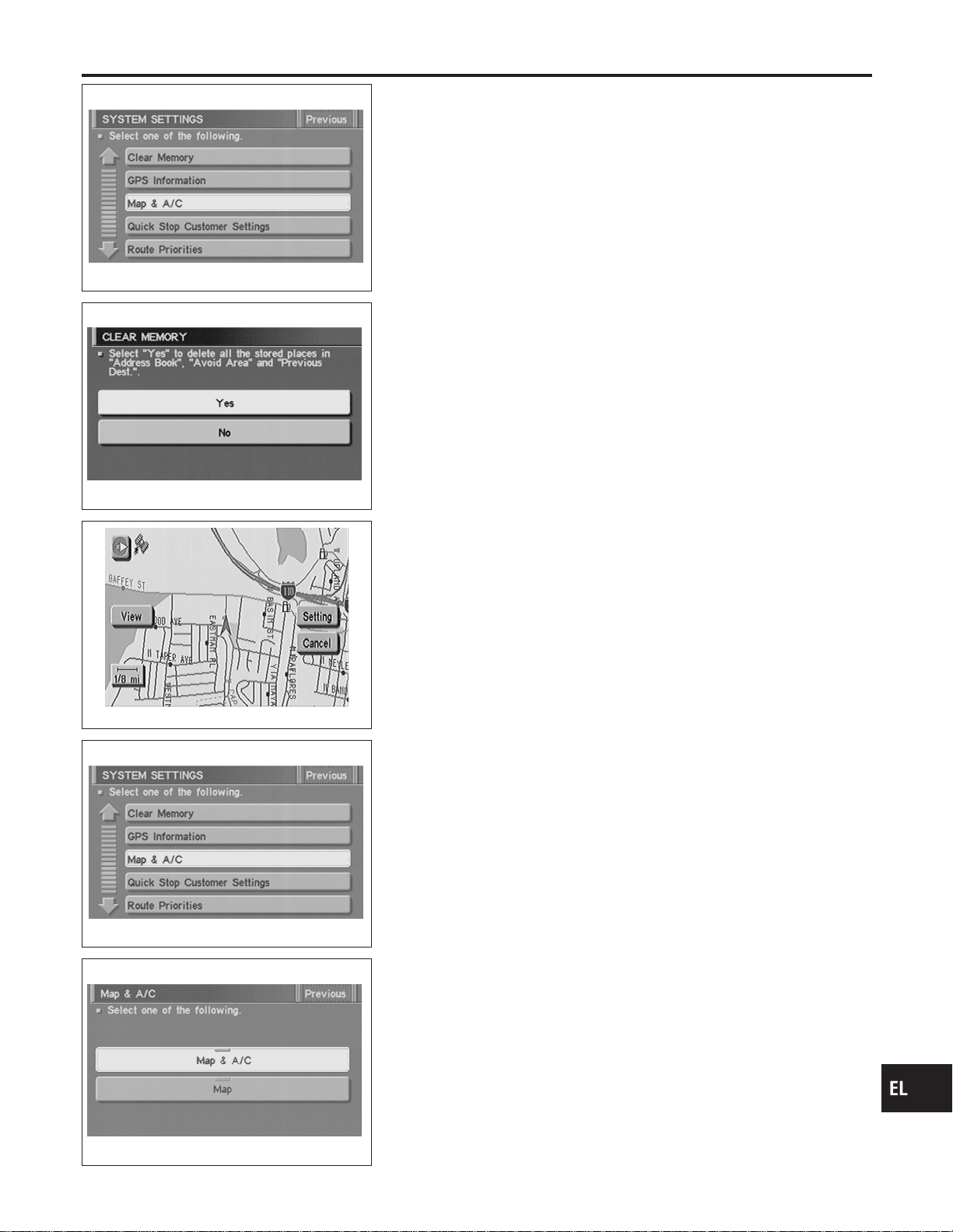
SEL462Y
5. Touch “Clear Memory”.
SEL472Y
6. To delete all the stored places in the “Address Book”, “Avoid
Area” and “Previous Dest.”, select “Yes”.
SEL460Y
“MAP & A/C” MODE
NAEL0426S15
1. Start the engine.
2. Push “MAP” switch.
3. Touch “Setting”.
4. Touch “System Setting”.
SEL462Y
5. Touch “MAP & A/C”.
SEL474Y
6. Touch “Map & A/C” or “Map” icon.
I To set the split display with both the map and the air condi-
tioner information as the initial setting of the NAVI system,
select “MAP & A/C”.
I To set the map only display as the initial setting of the NAVI
system, select “MAP”.
7. Push “MAP” switch, then the display will go back to the current
location map.
NOTE:
When the enlarged view is displayed, the air conditioner control
screen will not be displayed.
GI
MA
EM
LC
EC
FE
CL
MT
AT
TF
PD
AX
SU
BR
ST
RS
BT
HA
SC
IDX
NAVIGATION SYSTEM
Setting Mode (Cont’d)
EL-437

Trouble diagnoses
NAEL0427
SYMPTOM CHART
NAEL0427S01
Symptom Diagnoses/service procedure
Reference
page
Any function of the system
does not operate.
Check power supply and ground circuit for display & NAVI control unit. EL-441
Strange screen color or
unusual screen brightness.
1. Check “DISPLAY SETTING”. EL-432
2. Check display in “Diagnosis of Display” MODE. —
The display is not dimmed
when turning lighting switch
to ON.
1. Check “DISPLAY SETTING”. EL-432
2. Check lighting switch signal input to display & NAVI control unit correctly in
“DIAGNOSTIC SIGNAL FROM THE CAR” MODE.
EL-424
No navigation guide voice
are heard from both front
speakers.
1. Check “Voice Guidance Setting”. —
2. Check voice guide operation. EL-442
Beep does not sound when
the system guides route.
Check “BEEP ON/OFF SETTING”. EL-432
Position marker does not
trace along the route being
traveled.
Go to “WORK FLOW FOR NAVIGATION INSPECTION”. EL-439
Position marker does not
indicate forward or backward
movement.
Check reverse signal input to display & NAVI control unit correctly by “DIAGNOS-
TIC SIGNAL FROM THE CAR” MODE.
EL-424
Radio wave of GPS cannot
be received. (GPS marker
on the display does not
become green color.)
1. Is there anything obstructing the GPS antenna on the rear parcel finisher?
(GPS antenna located under the rear parcel finisher.)
—
2. Check GPS radio wave receive condition in “GPS INFORMATION SETTING”. EL-430
3. Check GPS antenna in “Self Diagnosis”. EL-417
Heading direction of position
marker does not match
vehicle direction.
1. Perform “ADJUST CURRENT LOCATION” SETTING. EL-431
2. Go to “WORK FLOW FOR NAVIGATION INSPECTION”. EL-439
Stored location in the
address book and other
memory functions are lost
when battery is disconnected
or becomes discharged.
Stored location in the address book and other memory functions may be lost if the
battery is disconnected or becomes discharged. If this should occur, charge or
replace the battery as necessary and re-enter the information.
—
Map appears grey and can-
not be scrolled.
The current location in the memory is out of the map data area.
Perform “Initialize Location”.
EL-454
NAVIGATION SYSTEM
Trouble diagnoses
EL-438
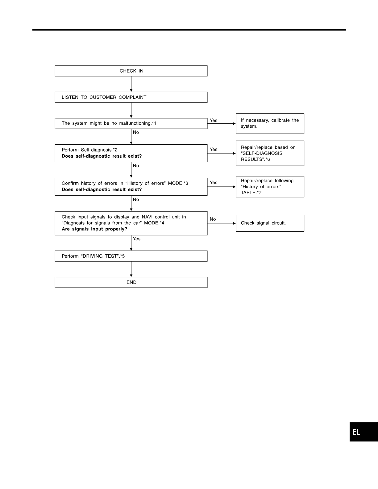

DRIVING TEST
=NAEL0427S03
During the driving test, diagnose the system by checking the dif-
ference of symptoms with each sensor ON or OFF.
Test pattern 1
Test method in which current position adjustment is not made
according to GPS data.
I Remove the GPS antenna connector from the display & NAVI
control unit. Drive the vehicle.
Before driving the vehicle, perform “ADJUST CURRENT
LOCATION” (EL-431).
Test pattern 2
Test procedure in which map matching is not used.
I Before driving the vehicle, perform “ADJUST CURRENT
LOCATION” (EL-431). With the ignition switch OFF and the
map CD-ROM removed from the display & NAVI control unit,
drive the vehicle. After driving the vehicle, reinstall the map
CD-ROM. Compare the saved driving tracks for the vehicle’s
current location with roads on the map.
Example
<The position marker consistently indicates the wrong position
when driving in the same area. Determine if this is the result of the
map matching function or the GPS function.>
, Perform test pattern 1.
<To verify the accuracy of the road configuration shown on the
display>
, Perform test patterns 1 and 2.
I Compare the map and the saved driving tracks. The precision
of the saved driving tracks is within several hundred meters.
<To make distance calibration and adjustments>
, Perform test patterns 1 and 2.
I Make adjustments by driving the vehicle over a known course
(highway or other road where distances are clearly marked).
Calibrate the distance against the known distance. Use the
formula below.
Calibration value = Screen display distance/Actual distance
NAVIGATION SYSTEM
Trouble diagnoses (Cont’d)
EL-440

SEL693VD
POWER SUPPLY AND GROUND CIRCUIT CHECK FOR
DISPLAY & NAVI CONTROL UNIT
=NAEL0427S04
Power Supply Circuit Check
NAEL0427S0401
Terminal Ignition switch
(+) (−) OFF ACC ON
1 Ground Battery voltage Battery voltage Battery voltage
2 Ground Battery voltage Battery voltage Battery voltage
5 Ground 0V 0V Battery voltage
6 Ground 0V Battery voltage Battery voltage
If NG, check the following.
I 7.5A fuse [No. 11, located in the fuse block (J/B)]
I 10A fuse [No. 10, located in the fuse block (J/B)]
I 15A fuse [No. 4, located in the fuse block (J/B)]
I Harness for open or short between fuse and display & NAVI
control unit
SEL694VD
Ground Circuit Check
NAEL0427S0402
Terminals Continuity
3 - Ground Yes
4 - Ground Yes
GI
MA
EM
LC
EC
FE
CL
MT
AT
TF
PD
AX
SU
BR
ST
RS
BT
HA
SC
IDX
NAVIGATION SYSTEM
Trouble diagnoses (Cont’d)
EL-441
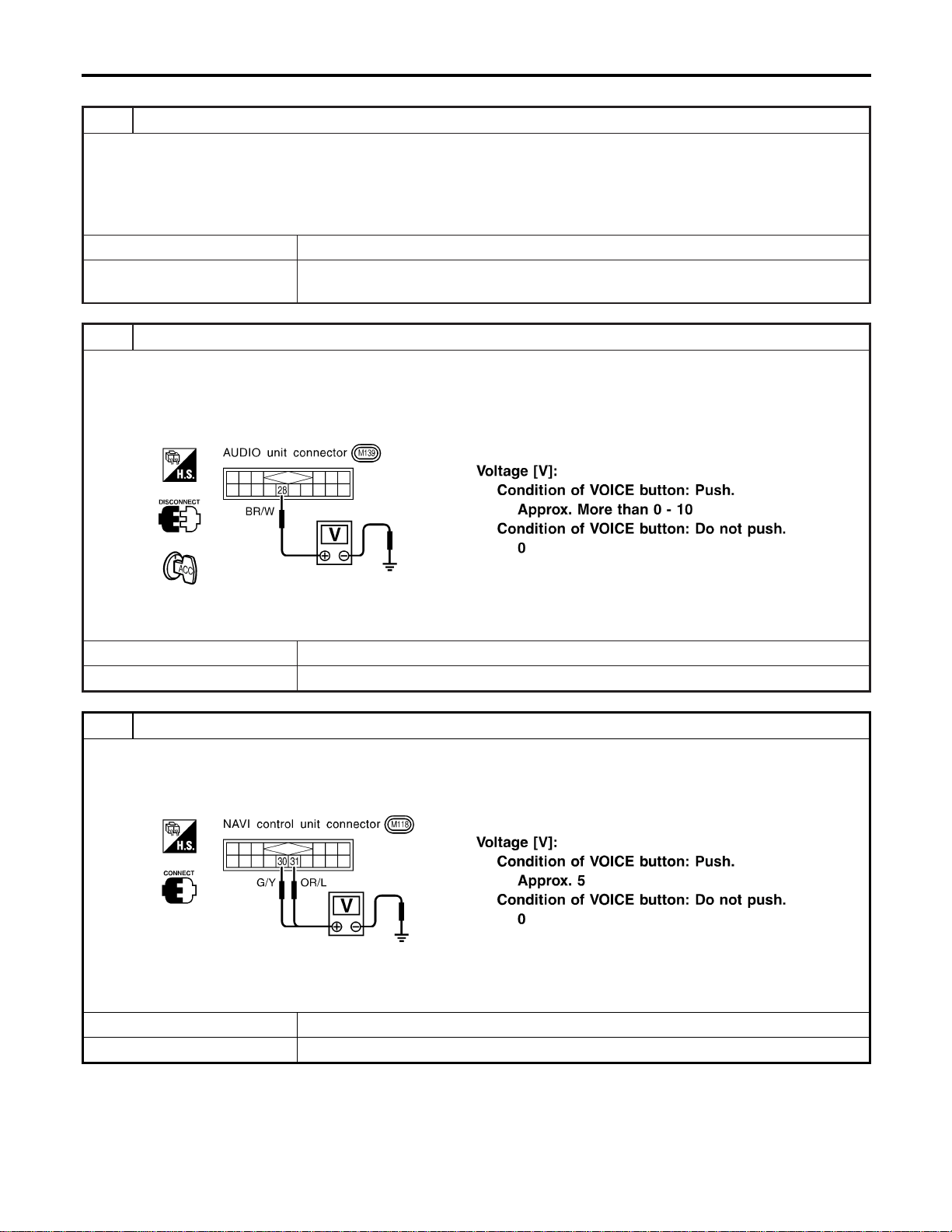
VOICE GUIDE OPERATION CHECK
=NAEL0427S05
1 PRELIMINARY CHECK
1. Turn ignition switch to ACC position.
2. Insert the music CD into the radio and CD player.
3. Try to play the music CD.
Is the sound emitted from all speakers?
YesorNo
Yes © GO TO 2.
No © Repair or replace audio system.
Refer to “AUDIO”, EL-170.
2 CHECK NAVI OPERATION ON SIGNAL
1. Disconnect audio unit connector.
2. Push “VOICE” button.
3. Check voltage between terminal 28 and ground.
SEL645XA
OK or NG
OK © GO TO 3.
NG © Repair or replace harness or NAVI control unit.
3 CHECK VOICE SIGNAL CIRCUIT
1. Push “VOICE” button.
2. Check voltage between NAVI control unit terminal 30 or 31 and ground.
SEL648X
OK or NG
OK © GO TO 4.
NG © Repair or replace NAVI control unit.
NAVIGATION SYSTEM
Trouble diagnoses (Cont’d)
EL-442
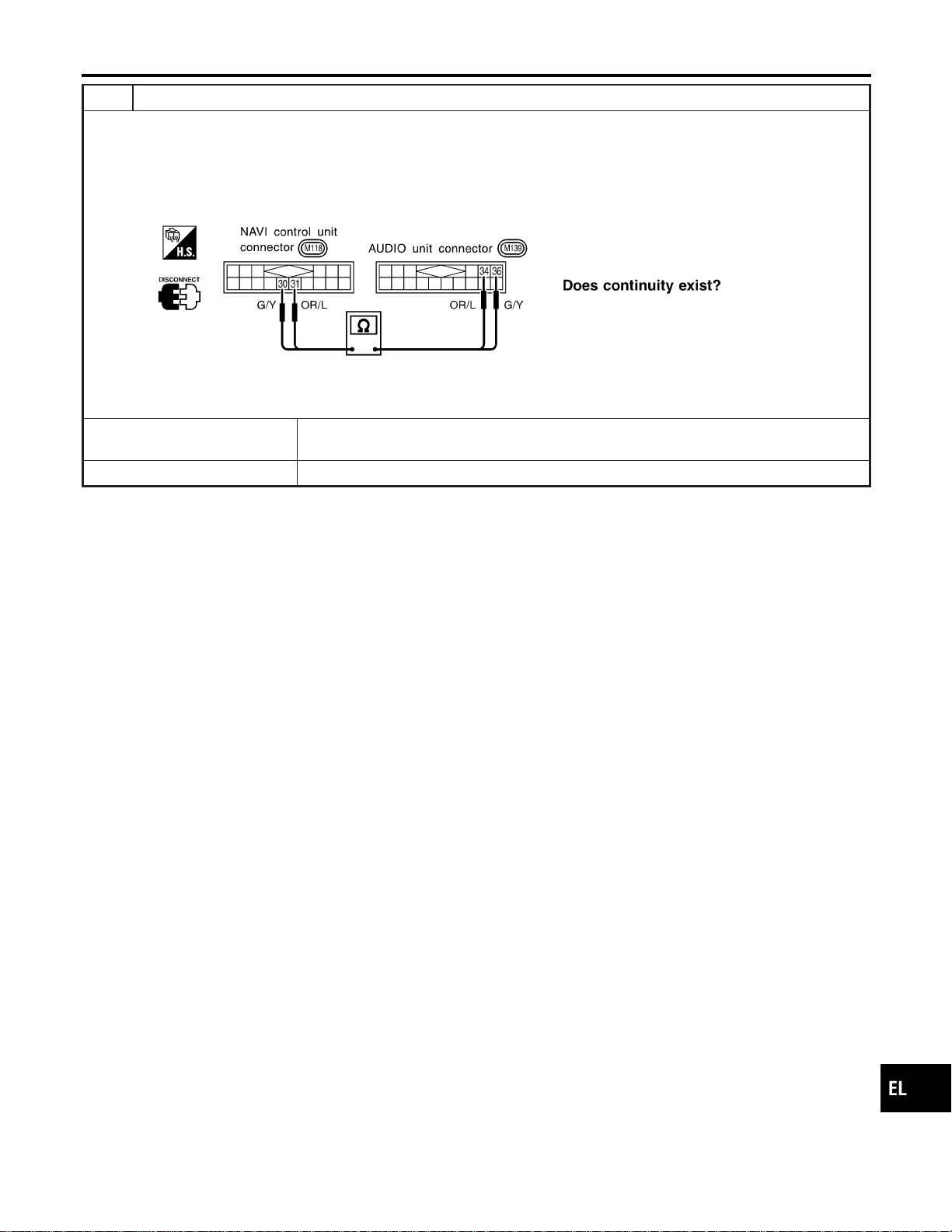
4 CHECK VOICE SIGNAL CIRCUIT
1. Turn ignition switch OFF.
2. Disconnect NAVI control unit connector and AUDIO unit connector.
3. Check continuity between NAVI control unit terminal 30 and AUDIO unit terminal 36.
4. Check continuity between NAVI control unit terminal 31 and AUDIO unit terminal 34.
SEL649X
YesorNo
Yes © Repair or replace audio system.
Refer to “AUDIO”, EL-170.
No © Repair or replace harness or connector.
GI
MA
EM
LC
EC
FE
CL
MT
AT
TF
PD
AX
SU
BR
ST
RS
BT
HA
SC
IDX
NAVIGATION SYSTEM
Trouble diagnoses (Cont’d)
EL-443

This Condition is Not Abnormal
=NAEL0428
EXAMPLE OF BASIC OPERATIONAL ERRORS
NAEL0428S01
Symptom Possible cause Repair order
No image is dis-
played.
Monitor brightness control is set to full dark. Readjust monitor brightness.
Map does not appear
on display.
Map CD is not inserted or inserted upside down. Insert the map CD with the label facing up.
Map mode is turned OFF. Press the “MAP” button.
No guide tone is
heard.
Voice guide adjustment OFF/Volume is set to the
lowest or highest level.
Adjust the voice guide level.
Voice guide volume
is too high or too low.
Dark display/Slow
image movement
Low vehicle interior temperature
Wait until vehicle interior temperature rises to appro-
priate level.
Small black or white
dots appear on the
screen.
Unique liquid crystal display phenomena No problem
“Unable to read CD”
message appears
only during specified
operation.
Map CD surface is tainted/CD surface is partially
scratched.
Check map CD surface. If dirty, wipe clean with a
soft cloth.
If map CD surface is damaged, replace the CD.
Area place names are not displayed.
If area place names do not appear on the map display, these names may not be available. Use the BIRD-
VIEW
T
flat surface map display function. Display output may differ. Note the items related to BIRDVIEW
T
below.
I Priority is given to the display of place names in the direction of vehicle travel.
I Extended display of vehicle travel distance for both surfaces and steering angle (flat directional changes).
This phenomenon disappears after the display image has been replaced by another one.
I The names of route and area might vary between the immediate front area and distance front area.
I Alphanumeric display characters are limited to maintain display simplicity and clarity. Display details may
differ with time and place.
I Identical place and road names may appear on the display at more than one location.
NAVIGATION SYSTEM
This Condition is Not Abnormal
EL-444
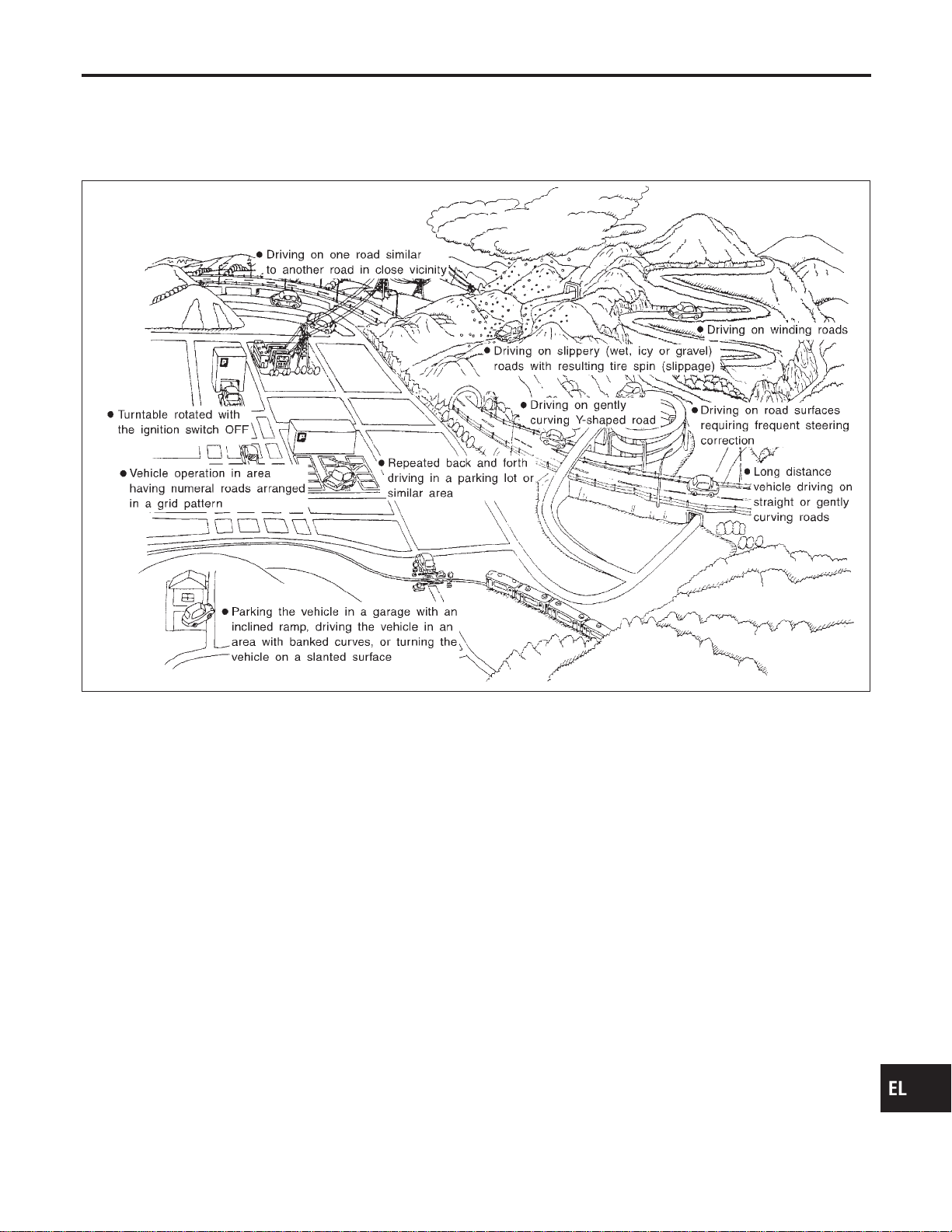
EXAMPLE OF CURRENT VEHICLE POSITION MARKER ERROR
=NAEL0428S02
The navigation system reads the vehicle distance and steering angle data. Because the vehicle is moving,
there will be an error in the current position indication. After the error appears, drive the vehicle for a short
distance. Stop the vehicle. If the position marker does not return to its original position, perform “ADJUST
CURRENT LOCATION” (EL-431).
SEL698V
GI
MA
EM
LC
EC
FE
CL
MT
AT
TF
PD
AX
SU
BR
ST
RS
BT
HA
SC
IDX
NAVIGATION SYSTEM
This Condition is Not Abnormal (Cont’d)
EL-445
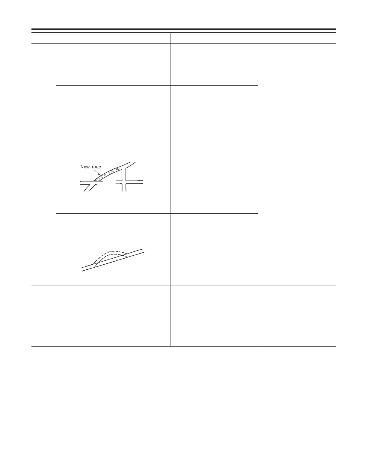
Possible cause Drive condition Service procedure
Area
Slippery road surface
On wet, icy, or gravel road where
frequent wheel slippage occurs, dis-
tance calculations may be errone-
ous. The position marker may show
the vehicle to be in inaccurate posi-
tion.
If the position marker does not
move to the correct position
even after the vehicle has been
driven approximately 10 km (6
miles), perform “ADJUST CUR-
RENT LOCATION” (EL-431). If
necessary, perform “SPEED
CALIBRATION” (EL-429).
Slanted area
Hilly areas where the road has
banked curves. When the vehicle
enters these banked curves, there
may be an error in steering angle
measurement. The position marker
may show the vehicle to be in inac-
curate position.
Map
data
Map display for a given road does not appear.
SEL699V
When the vehicle is driven on a
newly constructed road that does
not appear on the existing map.
Map marking and calibration are not
possible. The position marker may
indicate inaccurate position in close
proximity to the actual position.
Subsequently, when the vehicle is
driven on a road which is available
as map data, the position marker
may still indicate an inaccurate posi-
tion.
The vehicle is driven on a road whose course
has been altered (usually to improve the road or
to eliminate some hazard).
SEL700V
When the map data shown on the
display and the actual conditions are
different. Map matching will not be
possible. The position marker may
indicate inaccurate position in close
proximity to the actual position. If
the vehicle is driven on the indicated
road, further errors may occur.
Vehicle Use of tire chains (Stormy weather)
Tire chains will affect distance sens-
ing. The position marker may indi-
cate inaccurate position.
If the position marker does not
move to the correct position
even after the vehicle has been
driven approximately 10 km (6
miles), perform “SPEED CALI-
BRATION” (EL-429). After
removing the tire chains, sens-
ing accuracy may recover by
itself.
NAVIGATION SYSTEM
This Condition is Not Abnormal (Cont’d)
EL-446
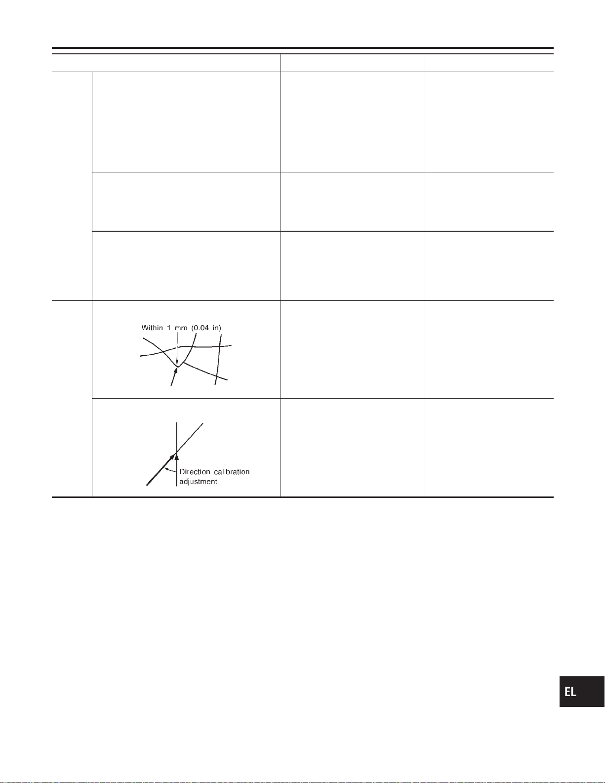
Possible cause Drive condition Service procedure
Opera-
tion
Driving immediately after starting engine.
The gyro (angular velocity sensor)
needs about 15 seconds after the
engine is started to precisely sense
the angular velocity. Directional
sensing errors will occur if the
vehicle is moved immediately after
starting the engine. The position
marker may indicate inaccurate
position.
Wait a few moments between
starting the engine and actually
driving the vehicle.
Continuous driving for long distances (non-stop)
When the vehicle is driven continu-
ously without stopping over a long
distance, errors in directional sens-
ing may occur. The position marker
may indicate inaccurate position.
Stop the vehicle. Perform
“SPEED CALIBRATION” (EL-
429).
Rough or violent driving
Wheel spinning (peeling out) or simi-
lar rough driving techniques can
adversely affect sensing accuracy.
The position marker may indicate
inaccurate position.
If the position marker does not
move to the correct position
even after the vehicle has been
driven approximately 10 km (6
miles), perform “ADJUST CUR-
RENT LOCATION” (EL-431).
Posi-
tional
calibra-
tion pro-
cedures
Positional calibration precision
SEL701V
If current vehicle location is roughly
set, the system may be unable to
locate the road that the vehicle is
traveling on. (This is especially true
in an area where there are many
roads.)
Perform “ADJUST CURRENT
LOCATION” (EL-431) within a
precision standard of 1 mm
(0.04 in) on the display.
Note: During calibration, use
the most detailed map pos-
sible.
Position calibration direction
SEL702V
When calibrating the position, check
the vehicle direction. If the vehicle
direction is not correct, subsequent
precision of current location will be
affected.
Perform “ADJUST CURRENT
LOCATION”, refer to EL-431.
GI
MA
EM
LC
EC
FE
CL
MT
AT
TF
PD
AX
SU
BR
ST
RS
BT
HA
SC
IDX
NAVIGATION SYSTEM
This Condition is Not Abnormal (Cont’d)
EL-447
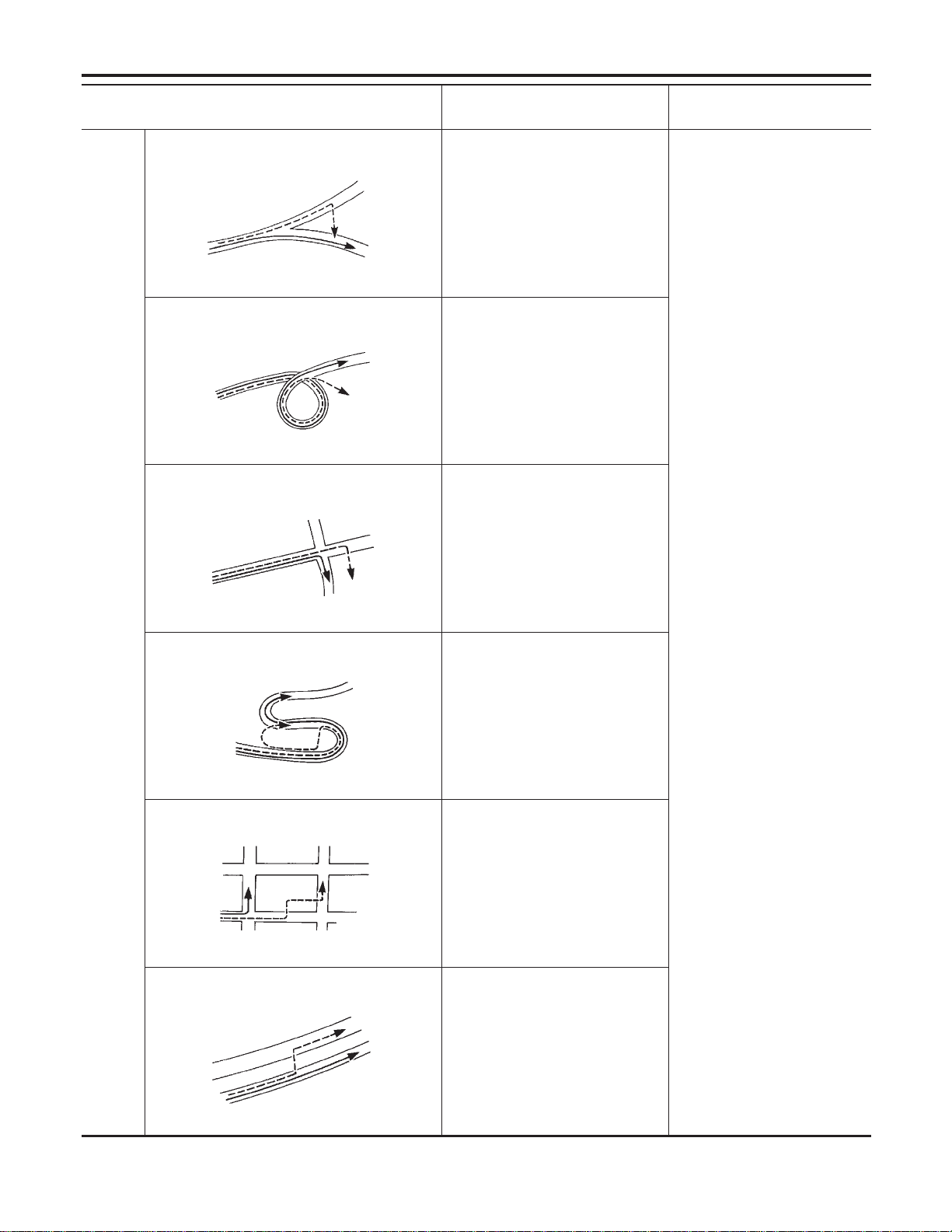
Possible cause:
—: Vehicle running ---: Indication
Drive condition Service procedure
Road
shapes
Y-intersection
SEL703V
In Y-intersections with a very
gradual change in course, a direc-
tional sensing may be inaccurate.
This may result in the position
marker giving the wrong road indica-
tion.
If the position marker does not
move to the correct position
even after the vehicle has been
driven approximately 10 km (6
miles), perform “Store place”. If
required, also perform
“ADJUST CURRENT LOCA-
TION” (EL-431).
Spiral road
SEL704V
On loop bridges and similar struc-
tures which result in a large and
continuous turn, turning angle may
be sensed inaccurately. As a result,
the position marker may separate
from the route on the map.
Straight road
SEL705V
In long distance driving on a straight
road or road with very gradual
curves, map marking inaccuracies
may occur. In such cases, the posi-
tion marker may stray from the route
being traveled during subsequent
turns due to inaccurate distance cal-
culation.
Winding road
SEL706V
Directional sensing precision errors
may occur when traveling on wind-
ing roads. During map matching, the
position marker may stray to an
adjacent road having a similar
shape. Subsequent position marker
error may occur.
Grid-like road shape
SEL707V
Directional sensing and distance
sensing, precision errors may occur
because of many roads having a
similar shape in the immediate area.
During map matching, the position
marker may stray to an adjacent
road having a similar shape. Subse-
quent position marker error may
occur.
Parallel roads
SEL708V
When driving on a parallel road,
map matching errors may occur.
Subsequent position marker error
may also occur.
NAVIGATION SYSTEM
This Condition is Not Abnormal (Cont’d)
EL-448
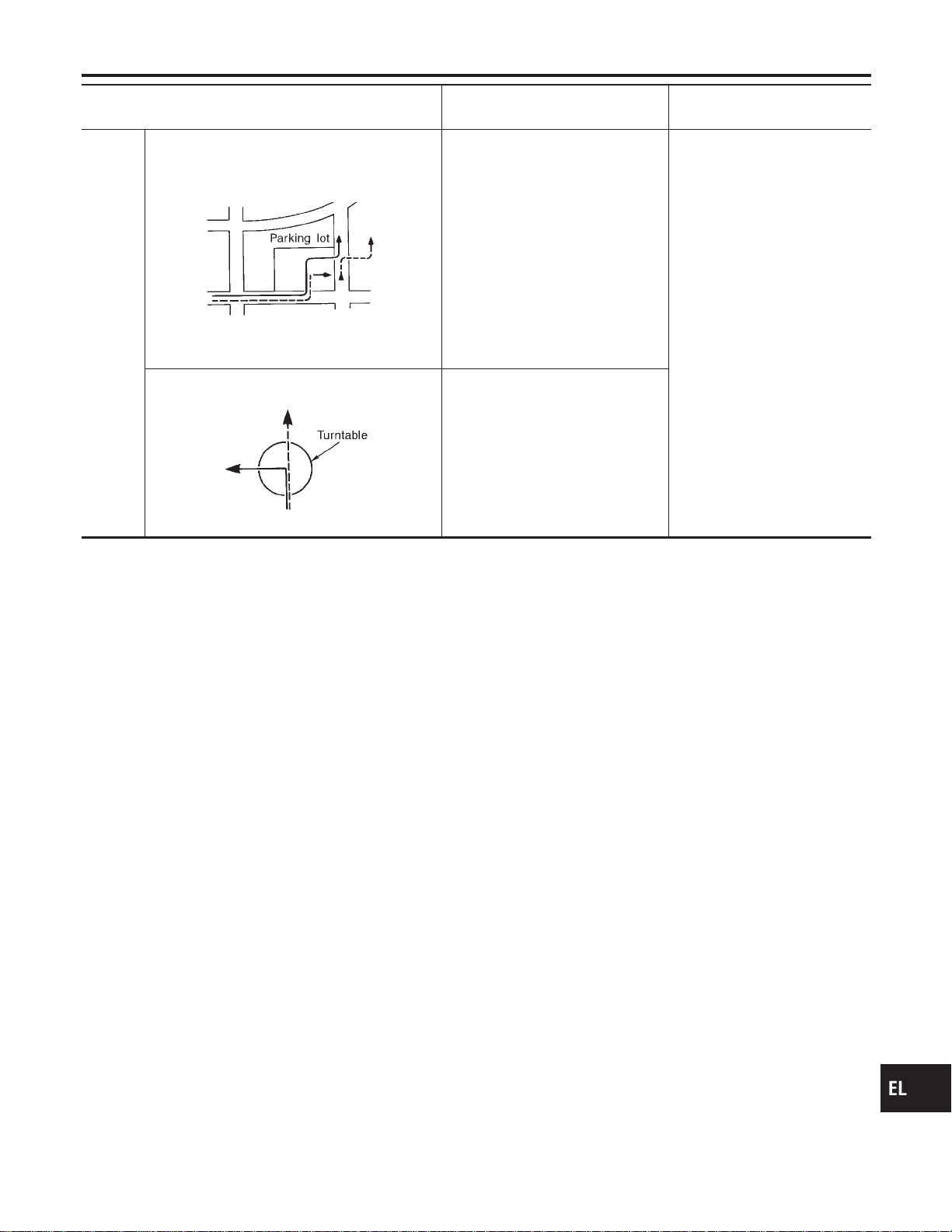
Possible cause:
—: Vehicle running ---: Indication
Drive condition Service procedure
Loca-
tion
Parking lot or similar area
SEL709V
When the vehicle is driven in a park-
ing lot or similar area, such as in an
area not normally marked as a road
on map, during map matching, the
system may select nearby roads.
This error may continue after the
vehicle exits the parking area and
begins to run on ordinary roads.
Vehicle operation in a parking area
may involve frequent turns and up
and/or down operation. Directional
sensing errors may occur leading to
subsequent route and position mis-
takes.
Turntable
SEL710V
When the ignition switch is OFF (the
usual situation when the vehicle is
on a turntable), the navigation sys-
tem receives no data from the gyro
(angular velocity sensor). When the
turntable rotates, no directional
change is sensed. During subse-
quent vehicle operation, directional
and route errors may occur.
Position marker displays a completely different location
In circumstances such as those described below, GPS signal reception conditions may result in an erroneous
position of the position marker. Perform “ADJUST CURRENT LOCATION” (EL-431).
NOTE:
I When GPS satellite signal reception conditions are poor, the position of position marker may be errone-
ous. If correction is not made immediately, the position marker error will be compounded and a completely
different location will be indicated. In an area where GPS satellite signal reception conditions are good,
the system can be returned to normal operation.
I The vehicle is driven aboard a car ferry or is towed for some distance with the ignition switch OFF. Vehicle
movement is not sensed. Current location calculations do not occur and current location data does not
appear on the display screen. Use GPS to accurately determine actual vehicle position. The system can
be returned to normal operation when the GPS satellite signal reception conditions are good.
Position marker jumps
In circumstances such as those described below, the position marker may jump as a result of automatic cur-
rent location corrections made by the system.
During map matching
I During map matching, the position marker may jump from one spot to another. In this case, it may be cor-
rected to a wrong road or to an area where no road exist.
GPS location correcting
I Vehicle current location is sensed using the GPS data. Positional calibration is performed. The position
marker continues to be in the wrong position. It may jump about from one area of the screen to another.
In this case, it may be corrected to a wrong road or to an area where no road exist.
Position marker indicates that the vehicle is in the middle of an ocean or large river
The navigation system does not distinguish between land and water surfaces. In some cases, a position
marker error may cause the display to show the vehicle above a water surface.
Position of position marker varies when the vehicle is repeatedly operated on the same road
Driving lane and steering wheel movement results in a variety of different positions of the position mark when
traveling on the same road based on sensing results by the GPS antenna and gyro (angular velocity sensor).
Slow locational correction using map matching
I The map matching function requires verification of local data. To make the map matching function, some
distance needs to be driven.
I The map matching function may not provide accurate performance in an area where there are numerous
parallel roads. Until the system judges the road characteristics, an incorrect position may be shown.
GI
MA
EM
LC
EC
FE
CL
MT
AT
TF
PD
AX
SU
BR
ST
RS
BT
HA
SC
IDX
NAVIGATION SYSTEM
This Condition is Not Abnormal (Cont’d)
EL-449

GPS signal reception conditions are good. However, the position mark does not return to its proper
position.
I he system senses the vehicle location with an error of approximately 100 m (328 ft). Due to the limitation
of precision, the position marker may be inaccurate even if the GPS signal reception condition is good.
I The navigation system uses GPS data to determine vehicle location. GPS data is compared with other
locational sensing data during the map matching process. The system decides which data is more pre-
cise and uses that data.
I When the vehicle is stationary, GPS data cannot be used to make system corrections.
Area designations on the map display and the BIRDVIEWT display differ.
To prevent the display from becoming congested, alphanumeric information is abridged.
[No problem]
Correct position of your vehicle is not displayed.
Vehicle position changed after ignition key was turned to the OFF position (Vehicle is transported on car ferry,
car train, or by some other means).
[Operate vehicle for short time under GPS receiving conditions.]
The display does not change to night-time mode even though the light switch has been turned ON.
Lights have been turned on. In “DISPLAY CHANGE” mode, night-time mode on display has been switched to
day-time mode and still is.
[Turn lights on again. Set the display to night-time mode. Refer to EL-432.]
Map does not scroll even though the position of your vehicle is changed.
Present area does not appear on the display.
[Press the “MAP” switch.]
Vehicle position marker does not appear.
Present area does not appear on the display.
[Press the “MAP” switch.]
The map surface precision display (GPS satellite marker) still remains gray.
Vehicle is parked inside a building or in the shadow of a large building. This intercepts the GPS signal.
[Move the vehicle to a more open position.]
GPS signal is not received because objects are placed on the rear parcel shelf.
[Remove objects from the rear parcel shelf.]
GPS satellite position is bad.
[Wait until GPS satellite position improves.]
Vehicle position precision is bad.
The map surface precision display (GPS satellite marker) still remains gray.
[Refer to “The map surface precision display (GPS satellite marker) still remains gray” item (Symptoms)]
Vehicle speed and elapsed distance is calculated from the vehicle speed pulse. This pulse is dependent upon
tire size. If tire chains are used on the vehicle, accuracy will be affected (pulse rate will be too fast or too slow).
The same is true if the system installed to your vehicle is removed and installed on another vehicle.
[Drive the vehicle at a speed higher than 30 km/h (19 MPH) for approximately 30 minutes. Automatic read-
justment should occur. If it does not (remains too fast or too slow), distance calibration is required. Or, drive
the vehicle for a short distance. Perform “SPEED CALIBRATION” (EL-429). After removing the tire chains,
sensing accuracy may recover by itself.]
Bad map data or system defect (same error consistently occurs in the same area)
ROUTE SEARCH/ROUTE GUIDE
NAEL0428S03
I If the present location or the destination location is displayed in the avoid area, it is not possible to search
routes.
I If the avoid area is set to wide range area, it may not be possible to find appropriate routes or search for
alternate routes.
I The automatic re-route calculates a return to the original route. Because of this, it may not be possible to
search appropriate new routes. If you deviate from the original route and wish to select an appropriate new
route, touch “Route Calculation”.
I The automatic re-route function may sometimes require considerable time.
I Displayed route number and directional information at a highway junction may differ from the information
posted on the actual road signs.
I Displayed street name information at a highway exit may differ from the information posted on the actual
road signs.
I Street name information displayed on the enlarged intersection map may differ from the information posted
on the actual road signs.
NAVIGATION SYSTEM
This Condition is Not Abnormal (Cont’d)
EL-450
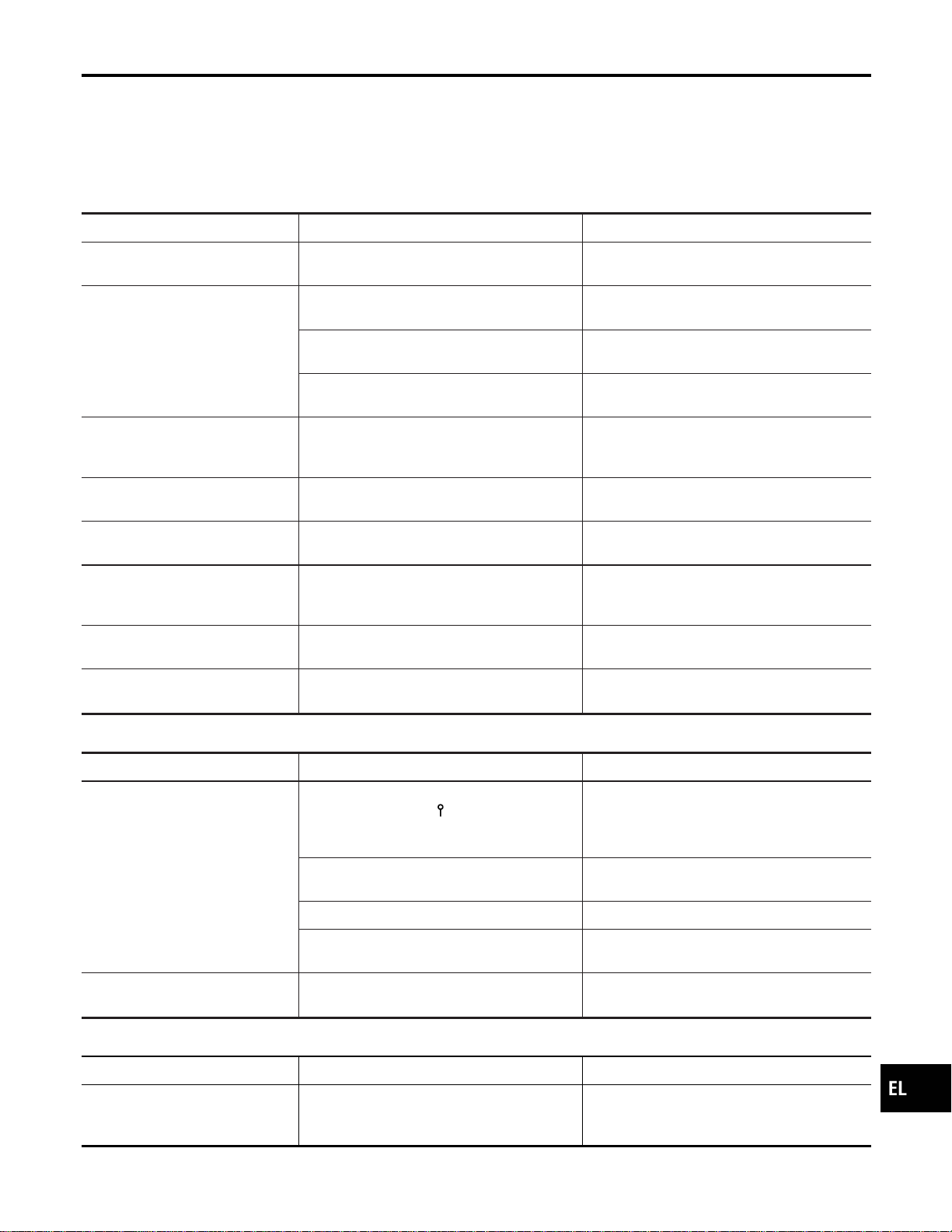
I The enlarged intersection map may display an “Unknown Street” message at some street intersections.
I Because of road configuration, etc. the guide may finish early. If this occurs, follow the marker to reach
your destination.
I Destination area side information (left side and right side) may differ from actual conditions because of
data error.
Unable to Set Destination, Way Point, and/or Menu Items
NAEL0428S0301
Symptom Possible cause Repair order
Unable to search way points in
re-search mode
A way point already crossed or determined to
have been crossed.
If you desire to pass through a way point for a
second time, reperform route edit.
Turn list is not displayed.
Route search does not occur.
Set designation areas and perform route
search.
Car marker does not appear on recom-
mended route.
Drive on the recommended route.
Route guide is canceled.
Turn the route guide ON. (Push “VOICE”
switch.)
Automatic search does not func-
tion.
Vehicle is not running on search object route
(road indicated by orange, brown or red line).
Drive the vehicle on the search object route
or perform a manual route search. Note that
all routes will be re-searched at this time.
Unable to select detour route. Vehicle is not running on recommended route.
Use the “RE-ROUTE” mode to search again
or return to the recommended route.
Detour route search results are
identical to previous search.
All possible conditions were considered, but
results are the same.
This is not abnormal.
Unable to set a way point.
More than five way points have been previ-
ously set (and not cleared).
More than five way points cannot be specified
at the same time. Break down into smaller
segments and perform search.
Unable to select starting point
during route edit.
Starting point will normally be your present
location during route edit.
This is not abnormal.
Cannot select certain menu items. While vehicle is running.
Park the vehicle in a safe area and perform
operation.
Voice Guide Information
NAEL0428S0302
Symptom Possible cause Repair order
Voice guide does not function. Voice guide is only available at certain inter-
sections (marked with
). In some cases, the
guide is not available even when the vehicle
makes a turn.
This is not abnormal.
Vehicle is not running on recommended route.
Return to recommended route or reperform
route search.
Voice guide is OFF. Set voice guide to the ON position.
Route guide is canceled.
Turn the route guide ON. (Push “VOICE”
switch.)
The guide content does not corre-
spond to actual conditions.
The content of the voice guide may vary
depending on the type of junction.
Operate vehicle following the traffic rules and
regulation.
Route Search Information
NAEL0428S0303
Symptom Possible cause Repair order
Proceeding in desired direction.
However, route search in desired
direction does not function.
Unable to find appropriate route in the desired
direction.
This is not abnormal.
GI
MA
EM
LC
EC
FE
CL
MT
AT
TF
PD
AX
SU
BR
ST
RS
BT
HA
SC
IDX
NAVIGATION SYSTEM
This Condition is Not Abnormal (Cont’d)
EL-451

Symptom Possible cause Repair order
No route is displayed.
No object route is searched near destination
area.
Adjust position to wide road (brown) near des-
tination area. In an area where traffic direction
is displayed separately, pay close attention to
the direction of travel. Set the destination area
and the way point over the road.
Starting point and destination areas are very
near.
Move destination areas away from starting
point on the screen.
Recommended route which has
been passed disappears from the
display.
The recommended route is divided into indi-
vidual control segments. When way point 1 is
passed, the data from the starting point to the
way point 1 is erased.
This is not abnormal.
Search recommends roundabout
route.
There may be special conditions for roads
near the starting point and destination area
(one-way traffic, etc.). A roundabout route may
be displayed.
Slightly change starting point and destination
area settings.
Landmark display does not show
actual conditions.
Mistaken or missing map data may result in
erroneous display.
Change map CD.
Recommended route drawn
slightly away from starting point,
way points, and destination area.
Course search data may not exist for closely
positioned starting point, way points, and des-
tination area shown on the map. Route guide
starting point, way point, and destination point
may be separated.
Set the destination area to the general route
(indicated by a thick brown line). However,
even if the selected route is a major one,
appropriate route search data may not be
available.
LOCATION OF CAR MARKER
NAEL0428S04
I If the vehicle has been parked in a multi-level parking facility or underground parking facility, the car marker
position may be inaccurate immediately after exiting the parking facility.
I The GPS accuracy is within ±100 m (300 ft). Even when receiving conditions are excellent, further posi-
tional correction may not occur.
STREET INDICATION
NAEL0428S05
I Street names displayed on the map may differ from the actual street names.
I An “Unknown Street” message may appear on the map in place of street name information.
RESEARCH
NAEL0428S06
I Position may be searched by house number. However, the displayed position and street may differ from
the actual position and street.
I When position is searched using POI, the displayed position may differ from the actual position.
I Some data may not be available for new buildings and other structures in a map.
GPS ANTENNA
NAEL0428S07
I Do not place metal objects above the GPS antenna mounted on the rear parcel shelf. This will cause
interference with signal reception.
I Do not place mobile telephones or vehicle radio transceivers in close proximity to the GPS antenna
mounted on the rear parcel shelf. This may cause interference with signal reception.
NAVIGATION SYSTEM
This Condition is Not Abnormal (Cont’d)
EL-452
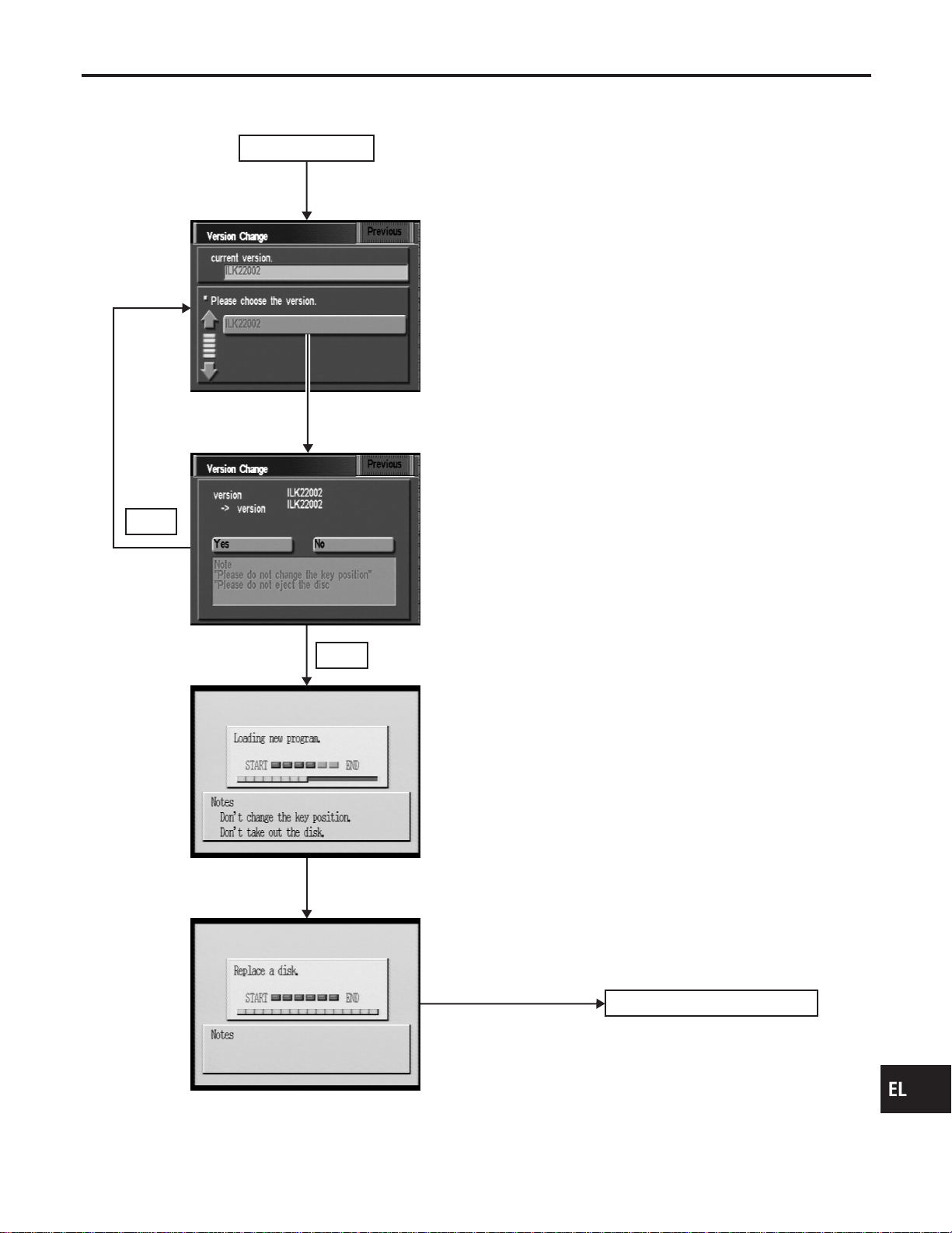
Program Loading
NAEL0429
Insert CD-ROM
with designated program.
Position marker screen display
No
* Program loading progress is shown on the bar graph
at the center of the screen.
Note: Load the program only after the engine has been started.
Map CD-ROM insertion
Power supply ON
Push for changing version.
Yes
SEL612X
GI
MA
EM
LC
EC
FE
CL
MT
AT
TF
PD
AX
SU
BR
ST
RS
BT
HA
SC
IDX
NAVIGATION SYSTEM
Program Loading
EL-453
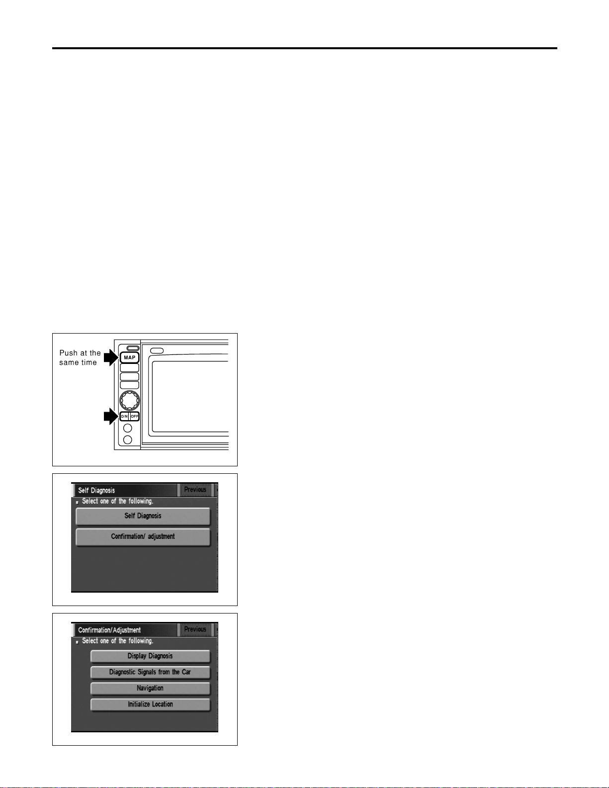
Initialization
NAEL0430
This procedure is for initializing the current location. Perform “Ini-
tialize Location” when the vehicle is transported a long distance by
trailer, etc.
Map with grey background appears and the vehicle location can-
not be adjusted by scrolling the display when the vehicle location
in the memory is out of the area of the inserted map data.
Perform “Initialize Location” when this occurs.
NOTE:
I Only initialize the system when the display & NAVI control
unit is replaced. If the system is initialized in other cases,
it may cause inaccurate positioning of the position marker
for a while.
I Initialize the system outside for receiving the radio wave
from the GPS satellite.
SEL583X
HOW TO PERFORM
NAEL0430S01
1. Switch the navigation system mode to self-diagnosis by push-
ing both “MAP” and “D/N” switches at the same time for more
than 5 seconds.
SEL584X
2. Touch “Confirmation/ adjustment”.
SEL588X
3. Touch “Initialize Location”. Then the previous screen is dis-
played.
NAVIGATION SYSTEM
Initialization
EL-454
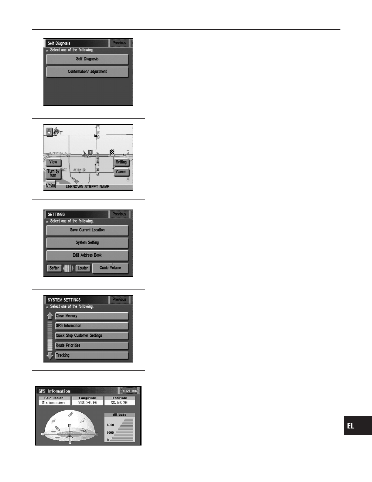
SEL584X
4. Push “Previous” switch.
SEL598X
5. Push the “MAP” switch.
6. Touch “Setting”.
SEL599X
7. Touch “System Setting”.
SEL600X
8. Touch “GPS Information”.
SEL146W
9. More than one GPS satellite icon turns green. (It may take 1
to 15 minutes.)
NOTE:
Drive the vehicle for a while* in order to change the receiving
condition of the radio wave from the GPS satellite if the GPS
icon does not turn green.
* The driving distance which is necessary depends on the
receiving condition of the radio wave from the GPS satellite.
GI
MA
EM
LC
EC
FE
CL
MT
AT
TF
PD
AX
SU
BR
ST
RS
BT
HA
SC
IDX
NAVIGATION SYSTEM
Initialization (Cont’d)
EL-455
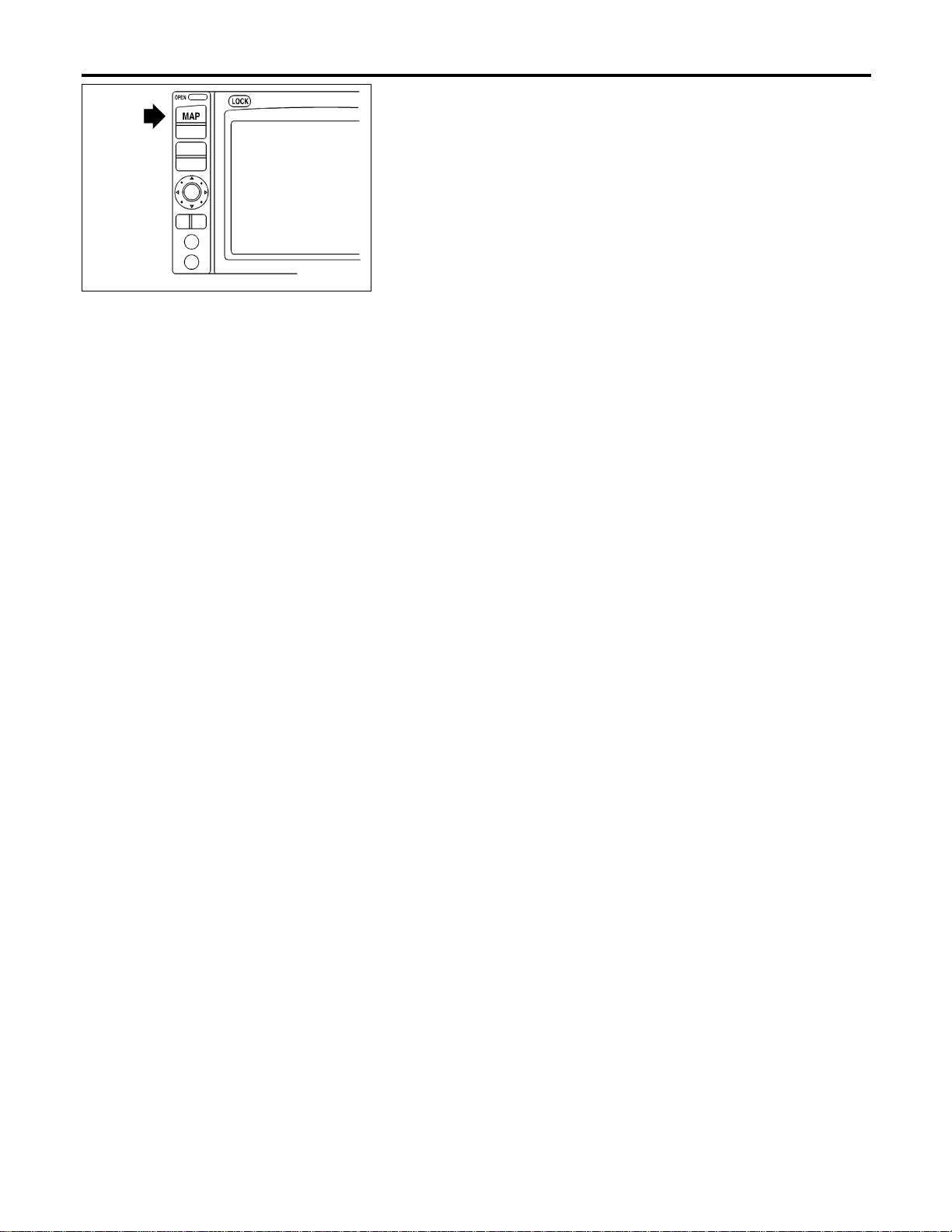
SEL613X
10. Push “MAP” switch and check the following.
I Confirm that the GPS icon on the map turns green.
I Then the position marker should show the current location.
I Position marker rotates corresponding to the movement of the
vehicle.
11. Initialization is completed.
NAVIGATION SYSTEM
Initialization (Cont’d)
EL-456
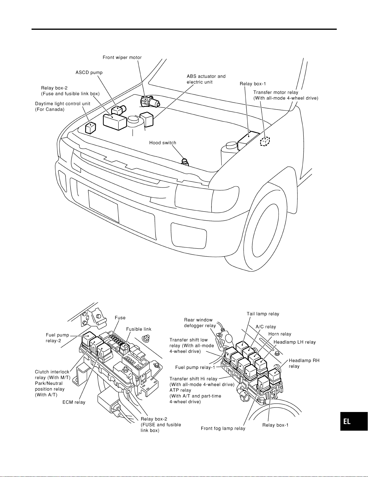
Engine Compartment
NAEL0431
MEL912N
GI
MA
EM
LC
EC
FE
CL
MT
AT
TF
PD
AX
SU
BR
ST
RS
BT
HA
SC
IDX
ELECTRICAL UNITS LOCATION
Engine Compartment
EL-457
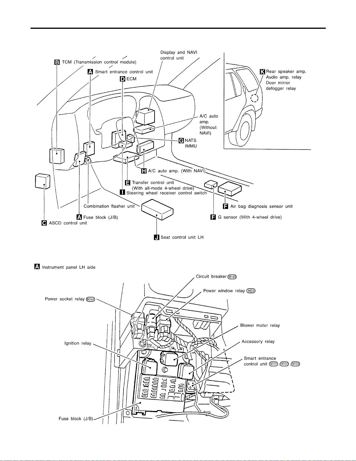
Passenger Compartment
NAEL0432
MEL918O
ELECTRICAL UNITS LOCATION
Passenger Compartment
EL-458
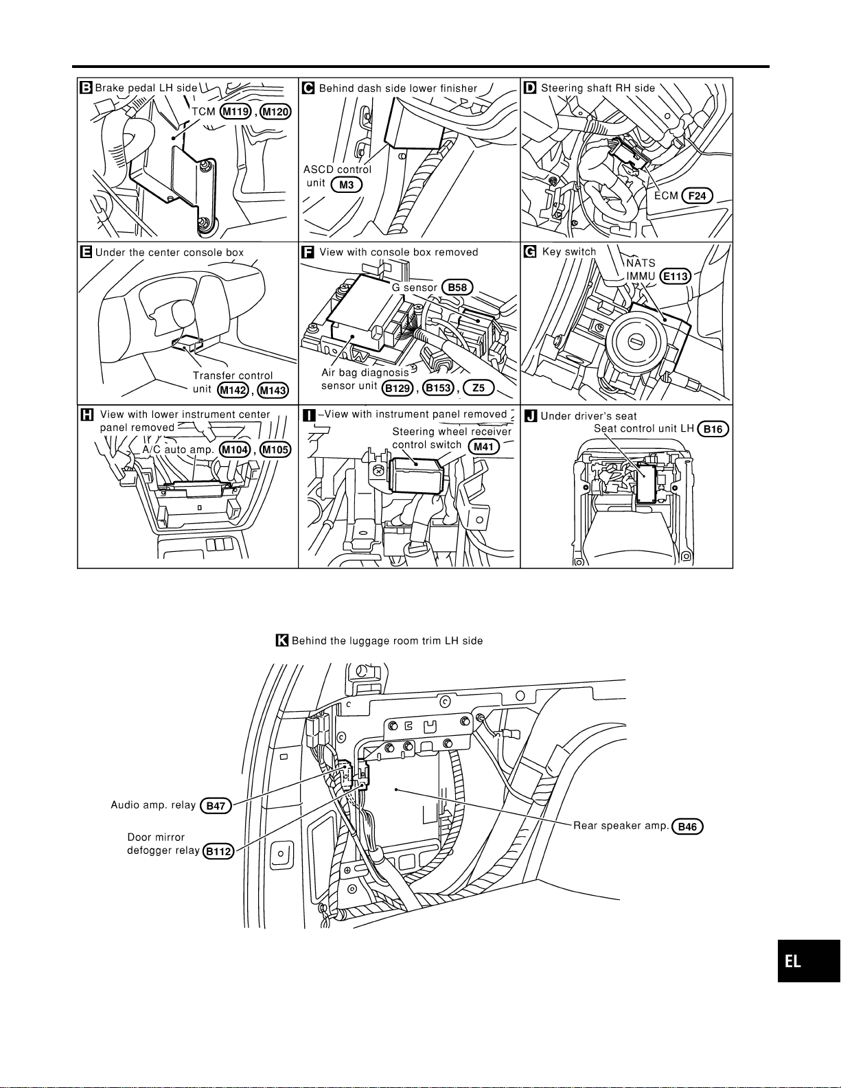
MEL417O
GI
MA
EM
LC
EC
FE
CL
MT
AT
TF
PD
AX
SU
BR
ST
RS
BT
HA
SC
IDX
ELECTRICAL UNITS LOCATION
Passenger Compartment (Cont’d)
EL-459
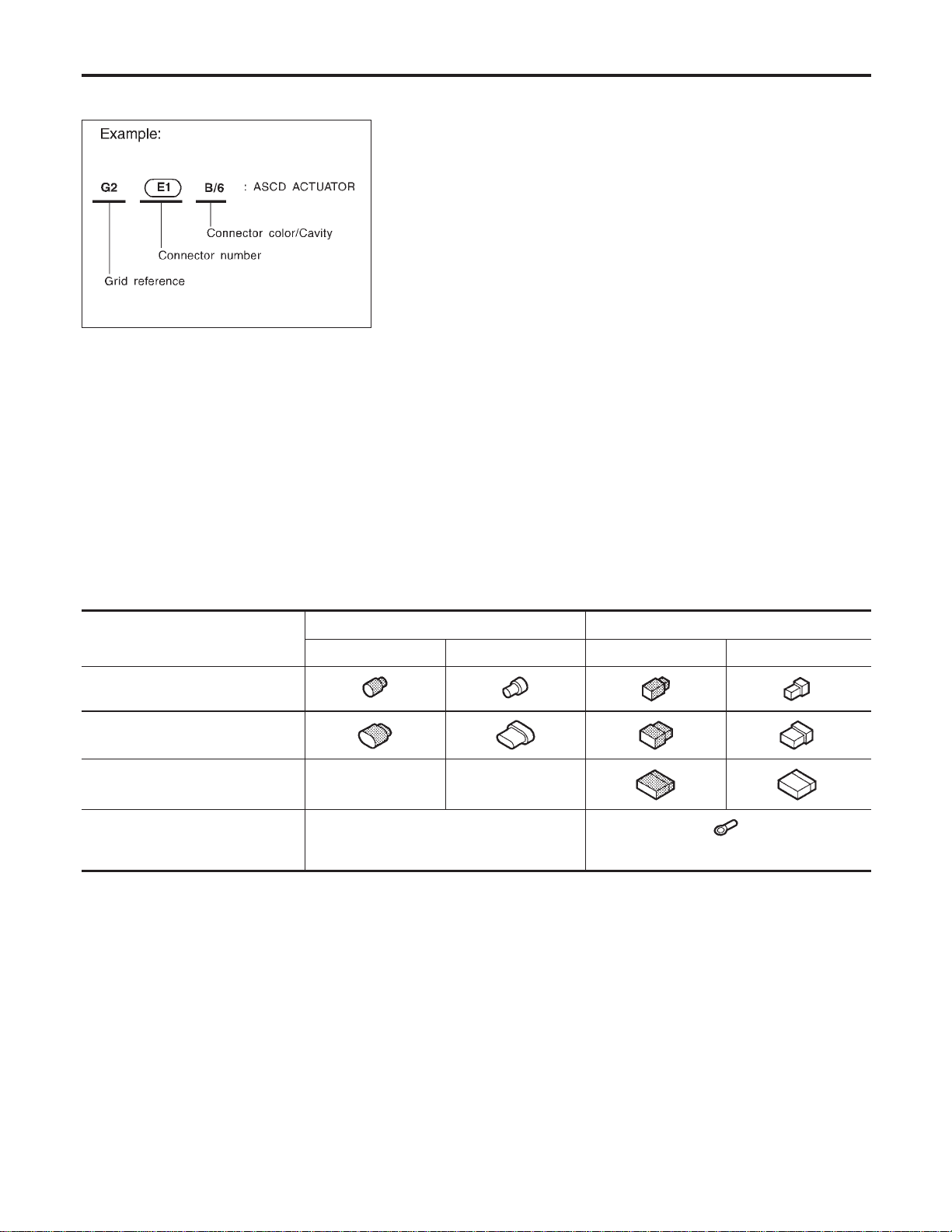
How to Read Harness Layout
NAEL0433
SEL252V
The following Harness Layouts use a map style grid to help locate connectors on the drawings:
I Main Harness
I Engine Room Harness (Engine Compartment)
I Engine Control Harness
TO USE THE GRID REFERENCE
NAEL0433S01
1. Find the desired connector number on the connector list.
2. Find the grid reference.
3. On the drawing, find the crossing of the grid reference letter column and number row.
4. Find the connector number in the crossing zone.
5. Follow the line (if used) to the connector.
CONNECTOR SYMBOL
NAEL0433S02
Main symbols of connector (in Harness Layout) are indicated in the below.
Connector type
Water proof type Standard type
Male Female Male Female
I Cavity: Less than 4
I Relay connector
I Cavity: From 5 to 8
I Cavity: More than 9
——
I Ground terminal etc.
—
HARNESS LAYOUT
How to Read Harness Layout
EL-460
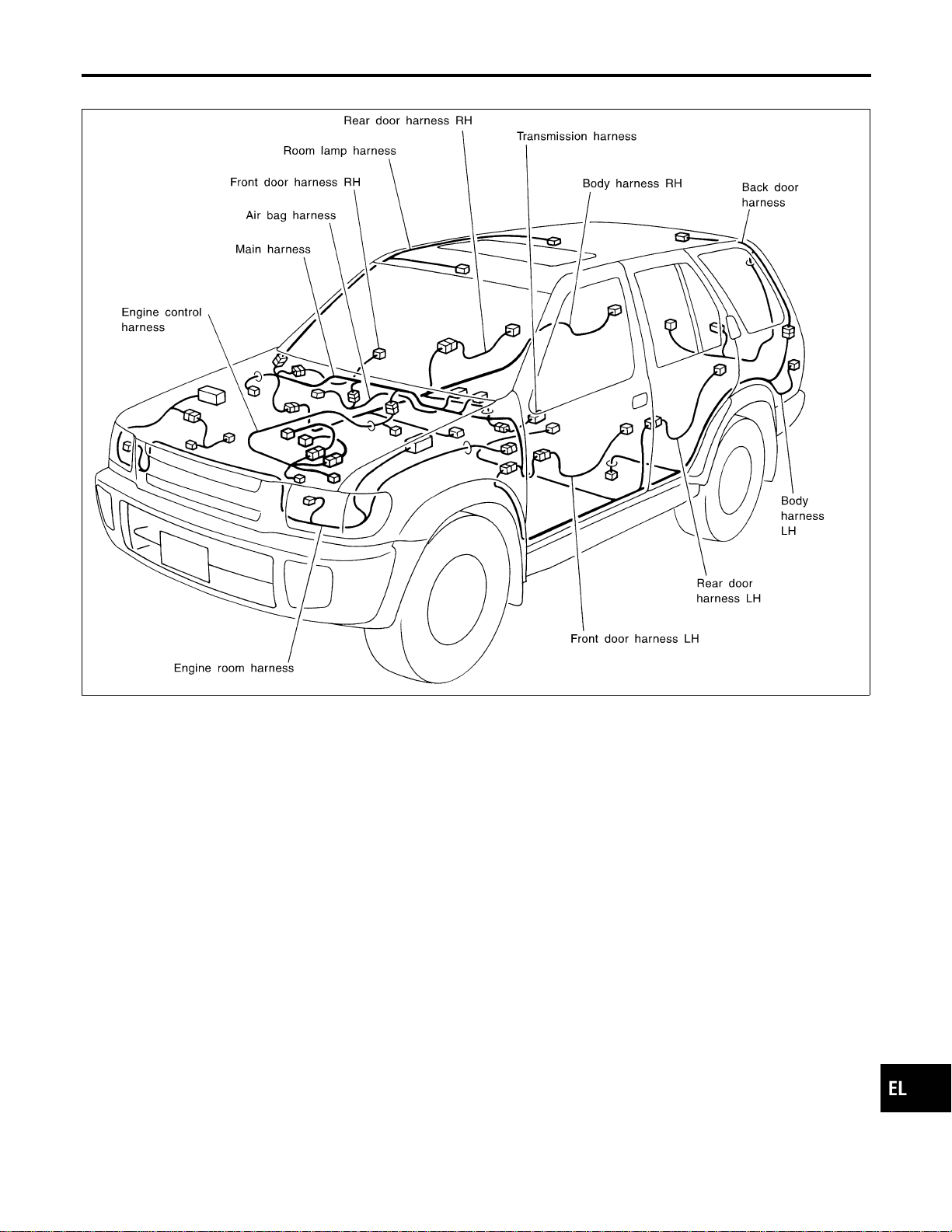
Outline
NAEL0434
MEL072M
GI
MA
EM
LC
EC
FE
CL
MT
AT
TF
PD
AX
SU
BR
ST
RS
BT
HA
SC
IDX
HARNESS LAYOUT
Outline
EL-461
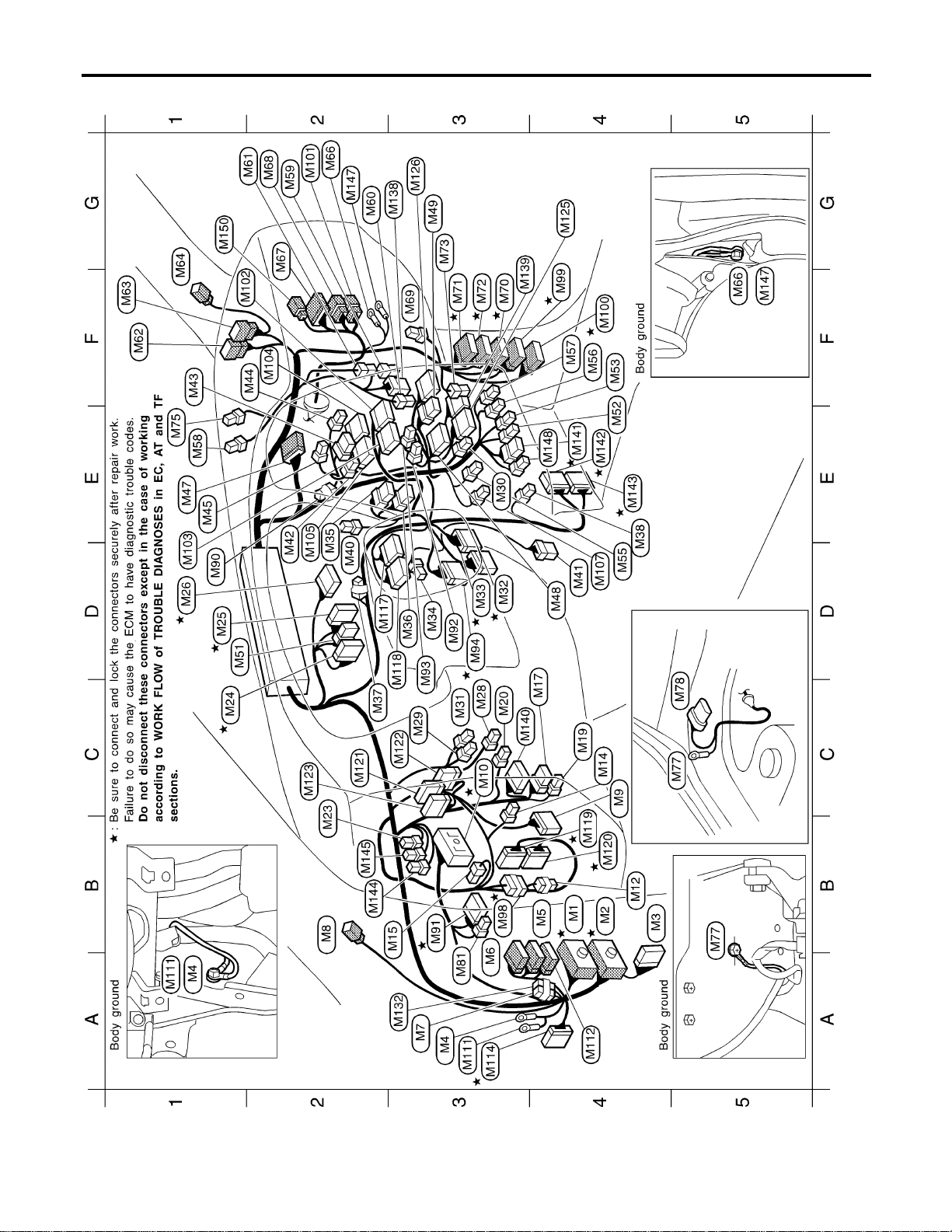
Main Harness
NAEL0435
MEL418O
HARNESS LAYOUT
Main Harness
EL-462

MEL419O
GI
MA
EM
LC
EC
FE
CL
MT
AT
TF
PD
AX
SU
BR
ST
RS
BT
HA
SC
IDX
HARNESS LAYOUT
Main Harness (Cont’d)
EL-463
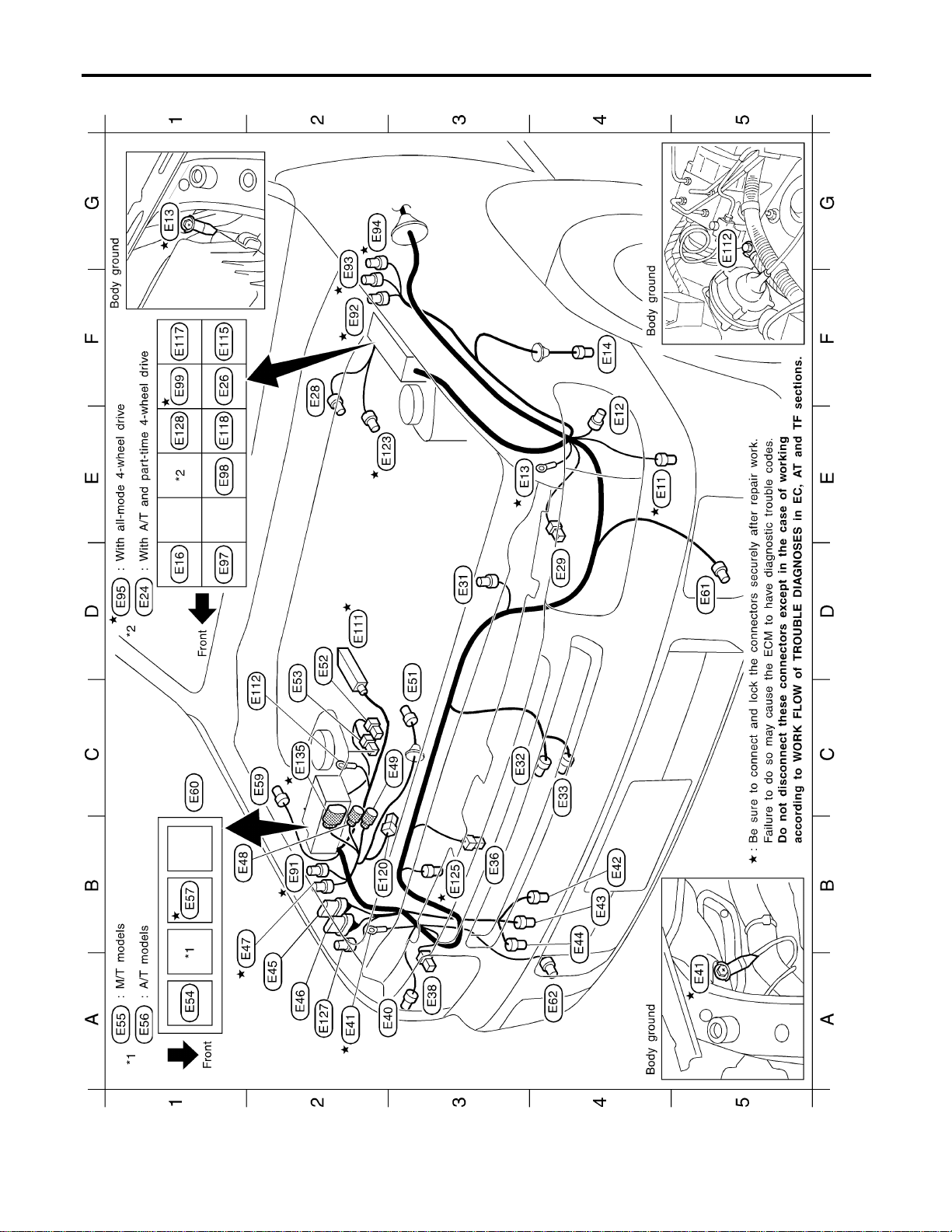
Engine Room Harness
NAEL0436
MEL917N
HARNESS LAYOUT
Engine Room Harness
EL-464

MEL481O
GI
MA
EM
LC
EC
FE
CL
MT
AT
TF
PD
AX
SU
BR
ST
RS
BT
HA
SC
IDX
HARNESS LAYOUT
Engine Room Harness (Cont’d)
EL-465

Engine Control Harness
NAEL0437
MEL317N
HARNESS LAYOUT
Engine Control Harness
EL-466

MEL705O
GI
MA
EM
LC
EC
FE
CL
MT
AT
TF
PD
AX
SU
BR
ST
RS
BT
HA
SC
IDX
HARNESS LAYOUT
Engine Control Harness (Cont’d)
EL-467
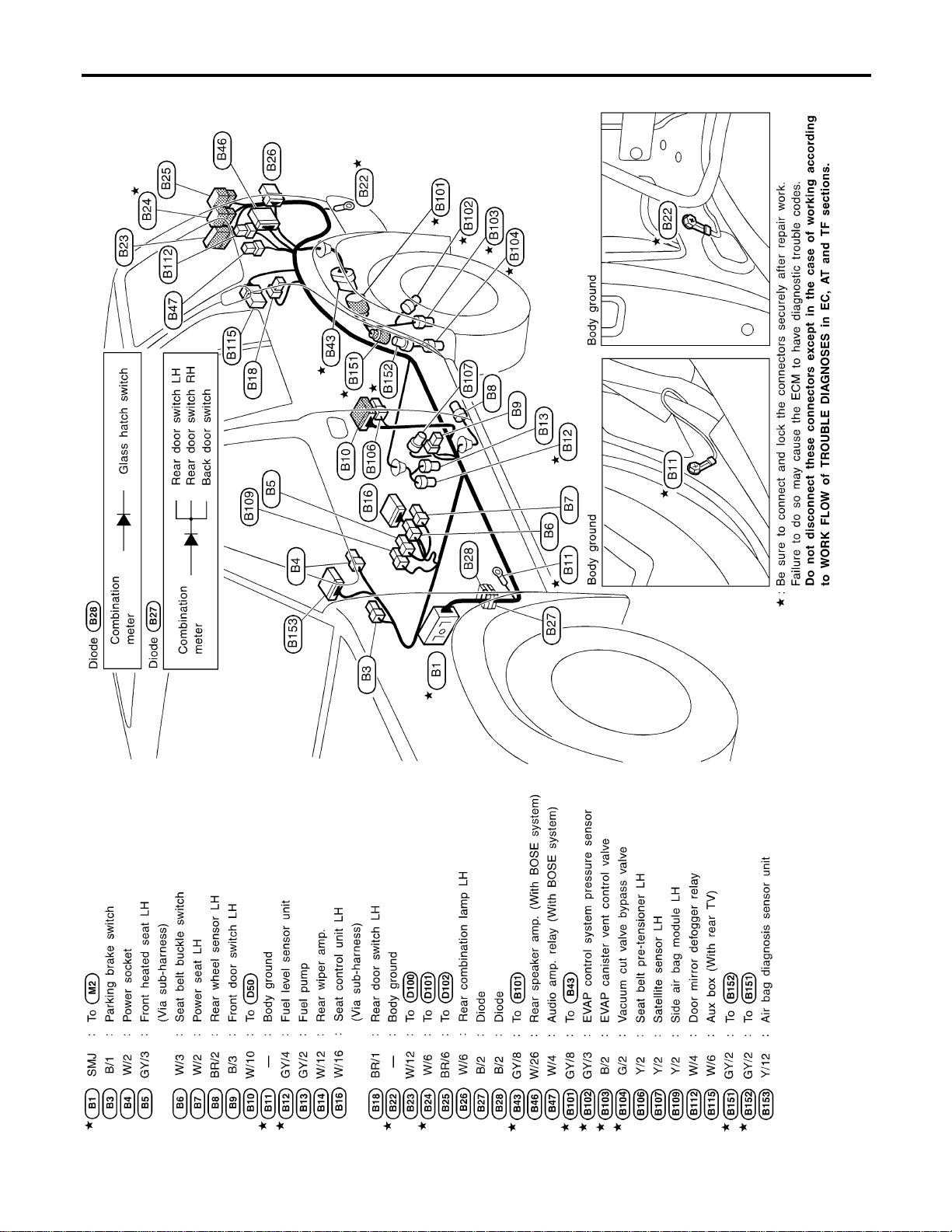
Body Harness LH
NAEL0438
MEL420O
HARNESS LAYOUT
Body Harness LH
EL-468
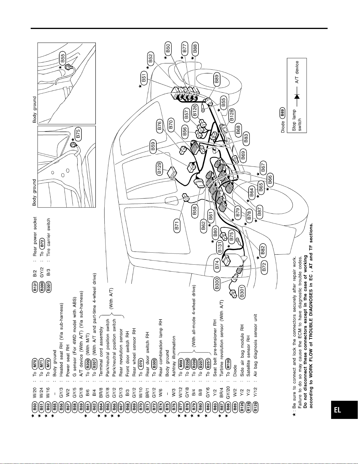
Body Harness RH
NAEL0439
MEL445P
GI
MA
EM
LC
EC
FE
CL
MT
AT
TF
PD
AX
SU
BR
ST
RS
BT
HA
SC
IDX
HARNESS LAYOUT
Body Harness RH
EL-469
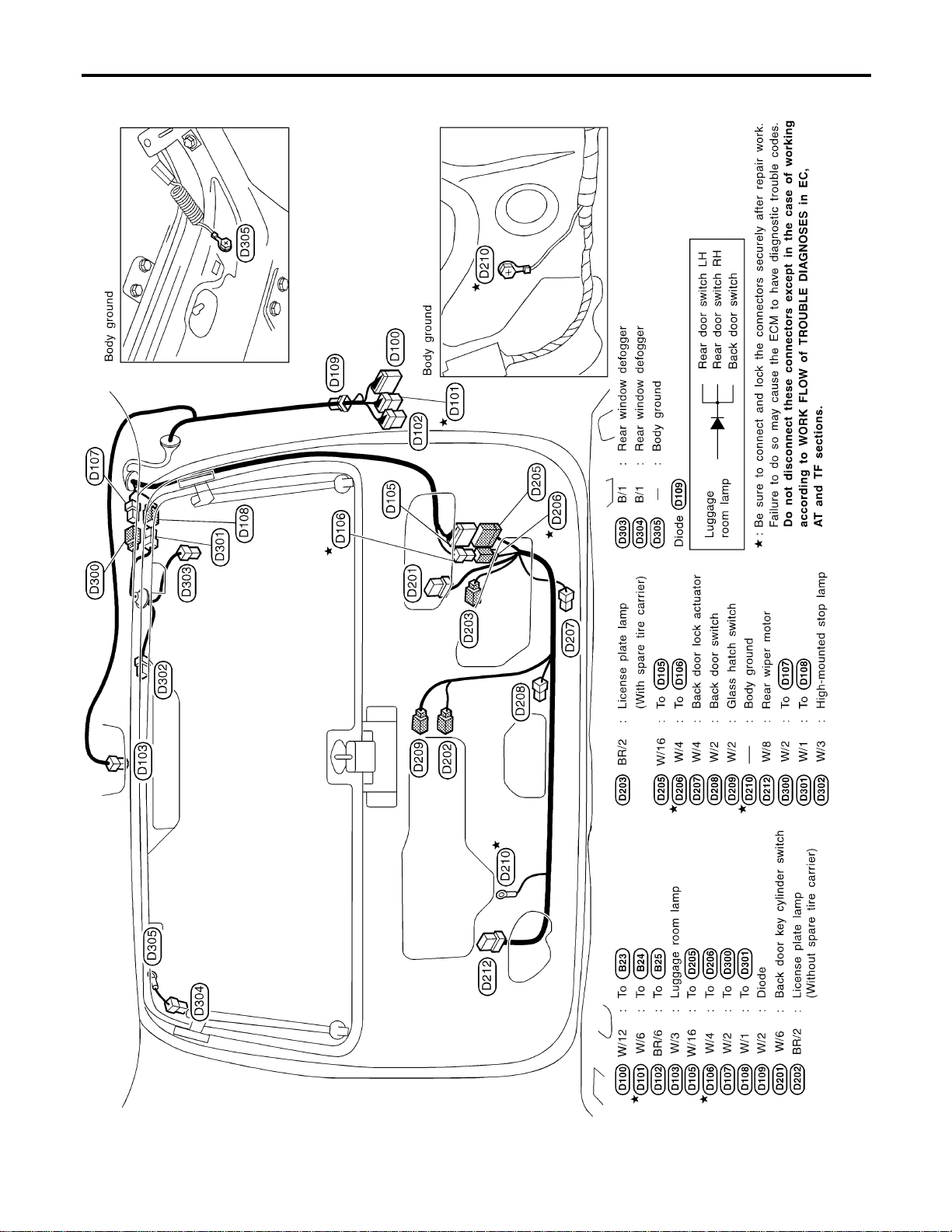
Back Door Harness
NAEL0440
MEL241M
HARNESS LAYOUT
Back Door Harness
EL-470
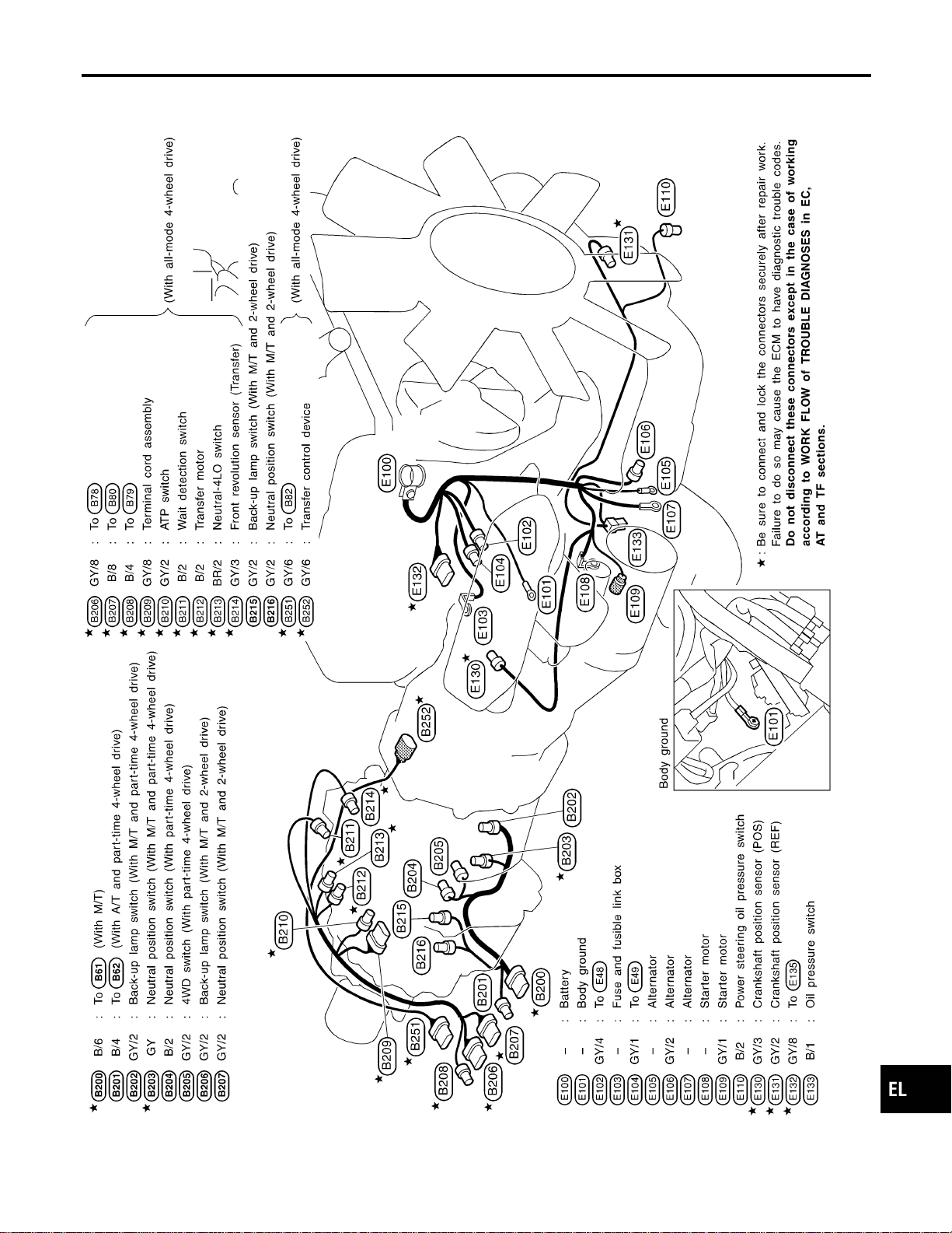
Engine and Transmission Harness
NAEL0441
MEL479O
GI
MA
EM
LC
EC
FE
CL
MT
AT
TF
PD
AX
SU
BR
ST
RS
BT
HA
SC
IDX
HARNESS LAYOUT
Engine and Transmission Harness
EL-471
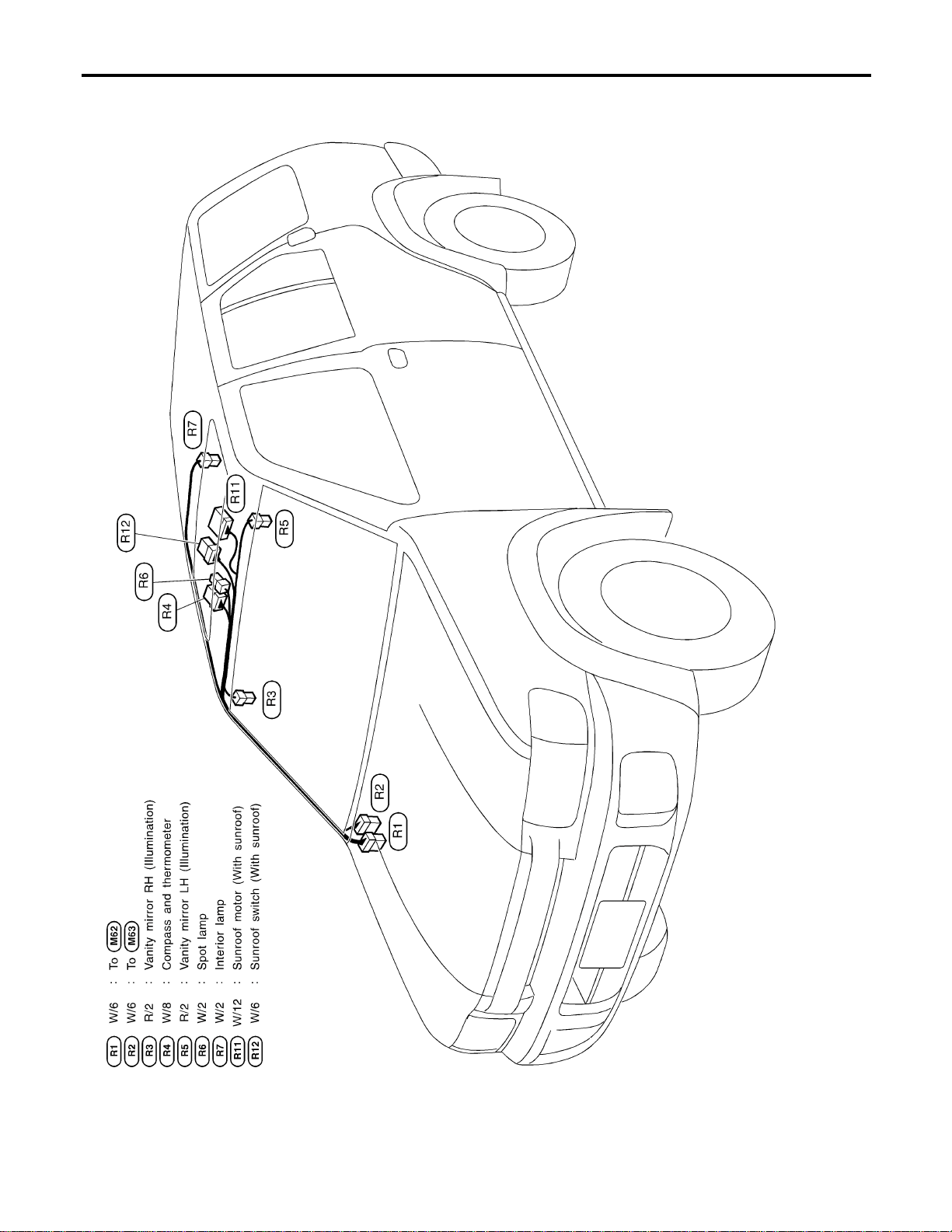
Room Lamp Harness
NAEL0442
MEL446P
HARNESS LAYOUT
Room Lamp Harness
EL-472
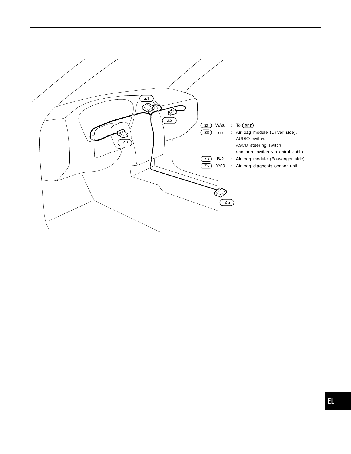
Air Bag Harness
NAEL0443
MEL244M
GI
MA
EM
LC
EC
FE
CL
MT
AT
TF
PD
AX
SU
BR
ST
RS
BT
HA
SC
IDX
HARNESS LAYOUT
Air Bag Harness
EL-473
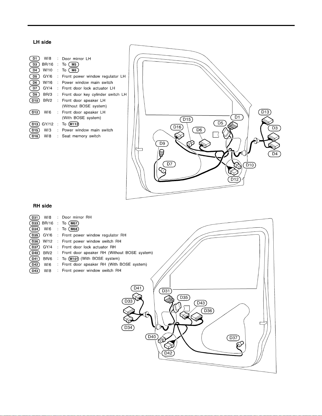
Front Door Harness
NAEL0444
MEL482O
HARNESS LAYOUT
Front Door Harness
EL-474
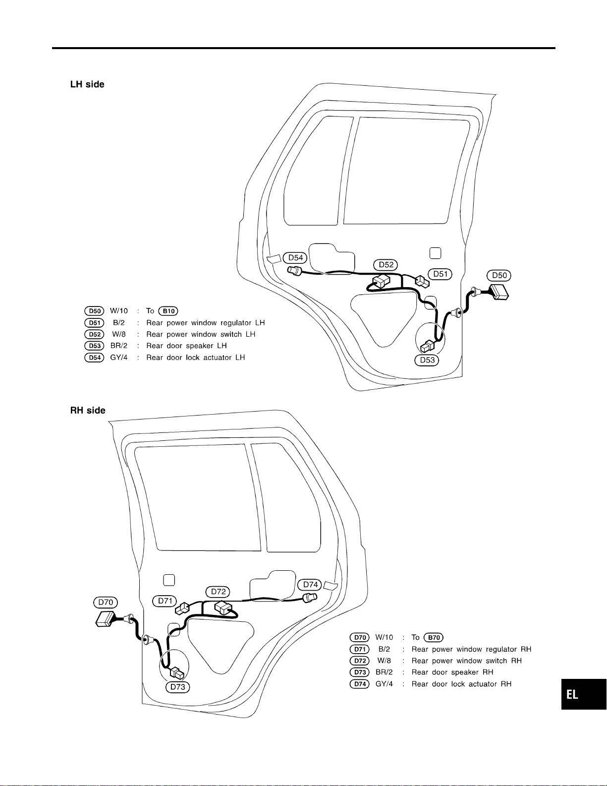
Rear Door Harness
NAEL0445
MEL261M
GI
MA
EM
LC
EC
FE
CL
MT
AT
TF
PD
AX
SU
BR
ST
RS
BT
HA
SC
IDX
HARNESS LAYOUT
Rear Door Harness
EL-475

NAEL0446
Headlamp
NAEL0446S01
Item Wattage W
High/Low (Semi-sealed beam) 60/55 (HB2)
Exterior Lamp
NAEL0446S02
Item Wattage W
Front fog lamp 55
Front turn signal lamp 21
Parking lamp 5
Rear combination lamp
Turn signal lamp 27
Stop/Tail lamp 21/5
Back-up lamp 18
License plate lamp 5
High-mounted stop lamp 5
Interior Lamp
NAEL0446S03
Item Wattage W
Interior lamp 10
Spot lamp 8
Luggage room lamp 10
BULB SPECIFICATIONS
Headlamp
EL-476

NAEL0447
Use the chart below to find out what each wiring
diagram code stands for.
Refer to the wiring diagram code in the alphabetical
index to find the location (page number) of each
wiring diagram.
Code Section Wiring Diagram Name
1STSIG AT A/T 1ST Signal
2NDSIG AT A/T 2ND Signal
3RDSIG AT A/T 3RD Signal
4THSIG AT A/T 4TH Signal
A/C, A HA Auto Air Conditioner
AAC/V EC IACV-AAC Valve
ABS BR Anti-lock Brake System
AP/SEN EC Absolute Pressure Sensor
ASCD EL Automatic Speed Control Device
AT/C EC A/T Control
ATDIAG EC A/T Diagnosis Communication
Line
AUDIO EL Audio
AUT/DP EL Automatic Drive Positioner
BA/FTS AT A/T Fluid Temperature Sensor
and TCM Power Supply
BACK/L EL Back-up Lamp
BYPS/V EC Vacuum Cut Valve Bypass Valve
CHARGE SC Charging System
CHIME EL Warning Chime
CIGAR EL Cigarette Lighter
CLOCK EL Clock
COMPAS EL Compass and Thermometer
D/LOCK EL Power Door Lock
DEF EL Rear Window Defogger
DTRL EL Headlamp — With Daytime Light
System —
ECTS EC Engine Coolant Temperature
Sensor
ENGSS AT Engine Speed Signal
F/FOG EL Front Fog Lamp
F/PUMP EC Fuel Pump Control
FICD EC IACV-FICD Solenoid Valve
FLS1 EC Fuel Gauge
FLS2 EC Fuel Gauge
FLS3 EC Fuel Gauge
Code Section Wiring Diagram Name
FTS AT A/T Fluid Temperature Sensor
FUELLH EC Fuel Injection System Function
(Left Bank)
FUELRH EC Fuel Injection System Function
(Right Bank)
H/LAMP EL Headlamp
HORN EL Horn
HSEAT EL Heated Seat
IATS EC Intake Air Temperature Sensor
IGN/SG EC Ignition Signal
ILL EL Illumination
INJECT EC Injector
INT/L EL Interior, Spot, Vanity Mirror, and
Luggage Room Lamps
IVC-L EC Intake Valve Timing Control Sole-
noid Valve LH
IVC-R EC Intake Valve Timing Control Sole-
noid Valve RH
IVCS-L EC Intake Valve Timing Control Posi-
tion Sensor LH
IVCS-R EC Intake Valve Timing Control Posi-
tion Sensor RH
KS EC Knock Sensor
LAN AT A/T Communication Line
LOAD EC Electrical Load Signal
LPSV AT Line Pressure Solenoid Valve
MAFS EC Mass Air Flow Sensor
MAIN AT Main Power Supply and Ground
Circuit
MAIN EC Main Power Supply and Ground
Circuit
METER EL Speedometer, Tachometer,
Temp., Oil, and Fuel Gauges
MIL/DL EC MIL and Data Link Connectors
MIRROR EL Door Mirror
KEYLES EL Remote Keyless Entry System
NATS EL NVIS (NISSAN Vehicle Immobi-
lizer System)
NAVI EL Navigation System
NONDTC AT Non-detectable Items
O2H1B1 EC Heated Oxygen Sensor 1 Heater
(Bank 1)
GI
MA
EM
LC
EC
FE
CL
MT
AT
TF
PD
AX
SU
BR
ST
RS
BT
HA
SC
IDX
WIRING DIAGRAM CODES (CELL CODES)
EL-477

Code Section Wiring Diagram Name
O2H1B2 EC Heated Oxygen Sensor 1 Heater
(Bank 2)
O2H2B1 EC Heated Oxygen Sensor 2 Heater
(Bank 1)
O2H2B2 EC Heated Oxygen Sensor 2 Heater
(Bank 2)
O2S1B1 EC Heated Oxygen Sensor 1 (Bank
1)
O2S1B2 EC Heated Oxygen Sensor 1 (Bank
2)
O2S2B1 EC Heated Oxygen Sensor 2 (Bank
1)
O2S2B2 EC Heated Oxygen Sensor 2 (Bank
2)
OVRCSV AT Overrun Clutch Solenoid Valve
P/ANT EL Power Antenna
PGC/V EC EVAP Canister Purge Volume
Control Solenoid Valve
PHASE EC Camshaft Position Sensor
(PHASE)
PNP/SW EC Park/Neutral Position Switch
PNP/SW AT Park/Neutral Position Switch
POS EC Crankshaft Position Sensor
(CKPS) (POS)
POWER EL Power Supply Routing
PRE/SE EC EVAP Control System Pressure
Sensor
PST/SW EC Power Steering Oil Pressure
Switch
REF EC Crankshaft Position Sensor
(CKPS) (REF)
REMOTE EL Audio (Remote Control Switch)
RP/SEN EC Refrigerant Pressure
S/SIG EC Start Signal
S/VCSW EC Swirl Control Valve Control
Vacuum Check Switch
SEAT EL Power Seat
SHIFT AT A/T Shift Lock System
SROOF EL Sunroof
SRS RS Supplemental Restraint System
SSV/A AT Shift Solenoid Valve A
SSV/B AT Shift Solenoid Valve B
START SC Starting System
STOP/L EL Stop lamp
Code Section Wiring Diagram Name
SWL/V EC Swirl Control Valve Control Sole-
noid Valve
TAIL/L EL Parking, License and Tail Lamps
TCCSIG AT A/T TCC Signal (Lock up)
TCV AT Torque Converter Clutch Solenoid
Valve
T/F TF Transfer
FTTS EC Fuel Tank Temperature Sensor
TP/SW EC Throttle Position Switch
TPS AT Throttle Position Sensor
TPS EC Throttle Position Sensor
TRNSCV EL Homelink Universal Transceiver
TRSA/T AT Turbine Revolution Sensor
TURN EL Turn Signal and Hazard Warning
Lamps
VEHSEC EL Vehicle Security System
VIAS/V EC Variable Induction Air Control
System
VSS EC Vehicle Speed Sensor
VSSA/T AT Vehicle Speed Sensor A/T (Revo-
lution Sensor)
VSSMTR AT Vehicle Speed Sensor MTR
WARN EL Warning Lamps
WINDOW EL Power Window
WIP/R EL Rear Wiper and Washer
WIPER EL Front Wiper and Washer
WIRING DIAGRAM CODES (CELL CODES)
EL-478