Loading ...
Loading ...
Loading ...
9
Drill Holes in Rear Wall
In addition to being installed on at least 1 wall stud, the
mounting plate must attach to the wall at both end holes. If the
end holes are not over wall studs, use two 3/16-24 x 3"
round-head bolts with toggle nuts; if 1 end hole is over a wall
stud, use 1 lag screw and one 3/16-24 x 3" round-head bolt with
toggle nut; or if both end holes are over wall studs, use 2 lag
screws. Following are 3 installation congurations.
Installation for No Wall Studs at End Holes
(Figures 1 and 2)
1. Drill 5/8" (1.6 cm) holes through the wall at both end holes
marked in Step 3 of the “Mark Rear Wall.”
2. Drill 3/16" (5 mm) hole(s) into the wall stud(s) at the hole(s)
marked in Step 6 of the “Mark Rear Wall.” Refer to gures 1
and 2 in “Possible Wall Stud Congurations” in the “Locate
Wall Stud(s)” section.
Installation for Wall Stud at One End Hole (Figure 3)
1. Drill a 3/16" (5 mm) hole into the wall stud at the end hole
marked in Step 3 of the “Mark Rear Wall.”
2. If installing on a second wall stud, drill a 3/16" (5 mm) hole
into the wall stud at the other hole marked in Step 6 of the
“Mark Rear Wall.” Refer to Figure 3 in “Possible Wall Stud
Congurations” in the “Locate all Stud(s)” section.
3. Drill a 5/8" (1.6 cm) hole through the wall at the other end
hole.
Installation for Wall Studs at Both End Holes
(Figure 4)
1. Drill 3/16" (5 mm) holes into the studs at the end holes
marked in Step 3 of the “Mark Rear Wall.”
Attach Mounting Plate to Wall
NOTE: Secure the mounting plate to the wall at both end holes
drilled into the wall studs and/or drywall using either 3/16-24 x
3" (7.6 cm) round-head bolts and toggle nuts or 1/4 x 2" (5.1 cm)
lag screws.
Refer to illustrations in “Possible Wall Stud Congurations” in the
“Locate Wall Stud(s)” section.
No Wall Studs at End Holes (Figures 1 and 2)
NOTE: The mounting plate must be secured to the wall on at
least 1 wall stud as well as at both ends.
1. With the support tabs of the mounting plate facing forward,
insert 3/16-24 x 3" round-head bolts through both end holes
of mounting plate.
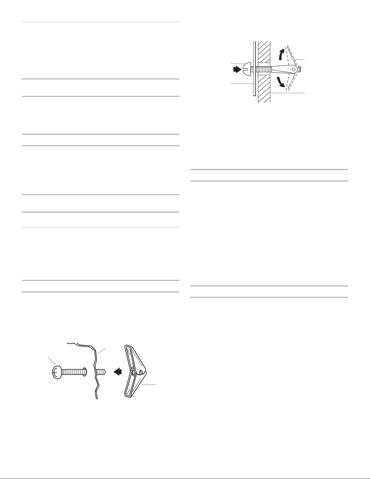
2. Start toggle nuts on bolts from the back of the mounting
plate. Leave enough space for the toggle nuts to go through
the wall and to open.
3. Position mounting plate on the wall.
4. Push the 2 bolts with toggle nuts through the drywall, and
nger tighten the bolts to make sure toggle nuts have
opened against drywall.
5. Insert lag screw(s) into the hole(s) drilled into wall stud(s) in
Step 2 of “Installation for No Wall Studs at End Holes” in the
“Drill Holes in Rear Wall” section.
6. Check alignment of mounting plate, making sure it is level.
7. Securely tighten all lag screws and bolts.
Wall Stud at One End Hole (Figure 3)
1. With the support tabs of the mounting plate facing forward,
insert a 3/16-24 x 3" round-head bolt through the end
hole that ts over the 5/8" (16 mm) hole drilled in Step 3 of
“Installation for Wall Stud at One End Hole” in the “Drill Holes
in Rear Wall” section.
2. Start a toggle nut on the bolt from the back of the mounting
plate. Leave enough space for the toggle nut to go through
the wall and to open.
3. Position mounting plate on the wall.
4. Push the bolt with toggle nut through the drywall, and nger
tighten the bolt to make sure toggle nut has opened against
drywall.
5. Insert a lag screw into the remaining end hole.
6. If installing on a second wall stud, insert a lag screw into the
other hole drilled in Step 2 of “Installation for Wall Stud at
One End Hole” in the “Drill Holes in Rear Wall” section.
7. Check alignment of mounting plate, making sure it is level.
8. Securely tighten the lag screw(s) and bolt.
Wall Studs at Both End Holes (Figure 4)
1. Position mounting plate on the wall.
2. Insert lag screws into both end holes.
3. Check alignment of mounting plate, making sure it is level.
4. Securely tighten the lag screws.
C
A
B
A. 3/16-24 x 3" round-head bolt
B. Mounting plate
C. Spring toggle nut
A. 3/16-24 x 3" round-head bolt
B. Mounting plate
C. Spring toggle nut
D. Drywall
A
B
C
D
Loading ...
Loading ...
Loading ...