Loading ...
Loading ...
Loading ...
15
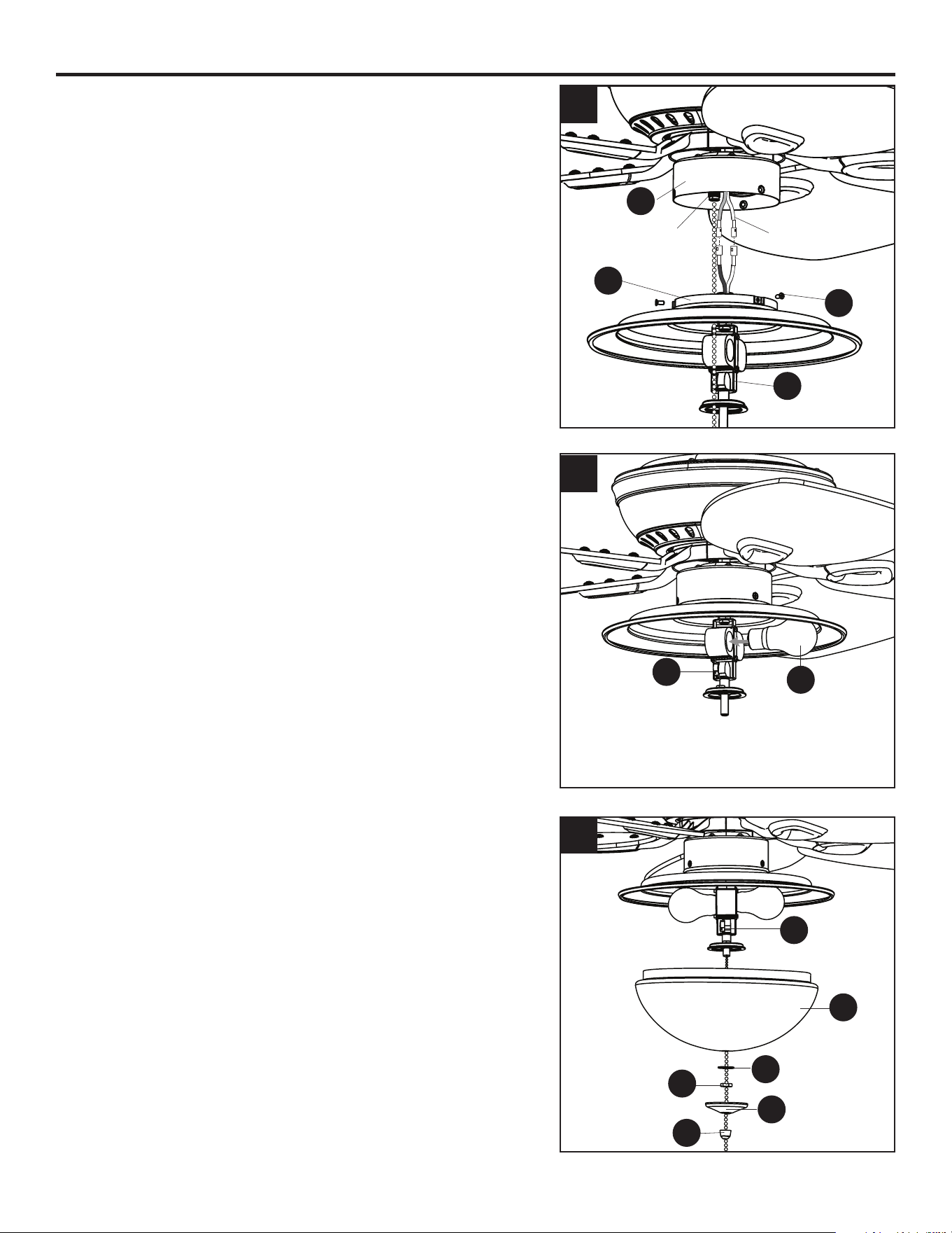
FINAL INSTALLATION
7. Remove the three switch housing screws (Z) from the
switch housing cap (I). Then connect the single-pin
connector from the switch housing (H) to the single-
pin connector from the light kit (K) -- Blue to Black and
White to White. Feed the pull chain from the switch
housing (H) through the hole in the switch housing cap
(I) and down through the preassembled grommet on the
lower part of the light kit (K).
Then, secure the switch housing cap (I) with light kit (K)
to the switch housing (H) using the previously removed
switch housing screws (Z).
IMPORTANT: Ensure the hole for the pull chain, located
in the switch housing cap (I), is aligned with the pull
chain shooter when installing the light kit (K) to the switch
housing (H).
8. Install the bulbs (O) into the sockets on the light kit (K).
IMPORTANT: Make sure you allow the bulbs (O) and
light kit (K) to cool before you replace the bulbs.
9. Feed pull chain coming from the center of the light
kit (K) through the center hole in the glass bowl (P).
Feed the pull chain coming from the switch housing
(H) through the o-center hole in the glass bowl (P).
Re-install hex nut (V) and rubber washer (W). Feed the
pull chains through the appropriate holes in the nial
cap (L) and the hole in the nial (M), then lift the nial
cap (L) up until it is ush with the glass bowl (P). Screw
the nial (M) onto the threaded rod of the light kit (K) to
secure.
W
P
K
V
L
M
9
7
H
K
I
Z
8
O
K
Single-pin
Connector
Pull Chain
Shooter
Loading ...
Loading ...
Loading ...