MULTIMEDIA PROJECTOR
User’s Manual
]
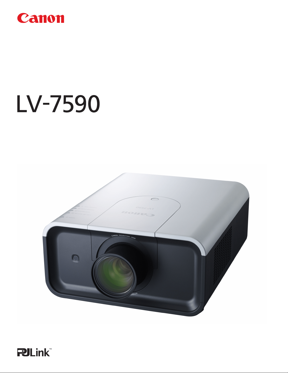
Projection lens not included.

2
This Multimedia Projector is designed with most advanced technology for portability, durability, and ease of use. This
projector utilizes built-in multimedia features, a palette of 1.07 billion colors, and matrix liquid crystal display (LCD)
technology.
◆ Functionally Rich
◆ Multi-use Remote Control Unit
Use a remote control unit as wired and wireless,
or as a PC wireless mouse. Eight remote control
codes and selectable pointer shapes are also
available.
◆ Multilanguage Menu Display
Operation menu is available in 12 languages;
English, German, French, Italian, Spanish,
Portuguese, Dutch, Swedish, Russian, Chinese,
Korean, and Japanese (p.54).
◆ Network-capable
Through an optional Network Imager, you can
operate and control the projector.
◆ Logo Function
This projector has many useful functions such
as lens shifting, ceiling and rear projection,
perpendicular omnidirectional projection, variety of
lens options, etc.
✔Note:
•TheOn-ScreenMenuandfiguresinthismanualmaydifferslightlyfromtheproduct.
•Thecontentsofthismanualaresubjecttochangewithoutnotice.
Features and Design
◆ Simple Computer System Setting
The projector has the Multi-scan system to
conform to almost all computer output signals
quickly (p.40). Supported resolution up to WUXGA.
◆ Useful Functions for Presentation
Digital zoom function allows you to focus on the
crucial information during a presentation (pp.17,
46).
◆ Security Function
The Security function helps you to ensure security
of the projector. With the Key lock function, you can
lock the operation on the side control or remote
control unit (p.59). PIN code lock functions prevents
unauthorized use of the projector (pp.59–60).
◆ Automatic Filter Replacement Function
The projector monitors the condition of the filter
and replaces a filter automatically when it detects
the clogging.
◆ Powered Lens Shift
Projection lens can be moved up, down, right
and left with the powered lens shift function. This
function makes it easy to provide projected image
where you want. Zoom and focus can also be
adjusted with a motor-driven operation. (p.32)
◆ Power Management
The Power management function reduces power
consumption and maintains lamp life (p.58).
◆ Multiple Interface Terminals
The projector has several interface terminals that
can support various types of equipment and signals
(pp.13-14).
The Logo function allows you to customize the
screen logo (pp.55–56). You can capture an image
for the screen logo and use it for the starting-up
display or between presentations.
◆ Pointer Function
Remote control pointer function. This function
helps you to make a smart presentation on a
projected screen.
◆ Shutter Function
The projector is equipped with the shutter that
provides complete blackness when the projected
image is not needed with keeping the projector
on. The shutter management function allows you
to set the timer. It prevents from keeping the
projector on when the shutter is closed for a long
time. (p.61)
◆ New Optical Technology
This projector is equipped with a new optical
engine. The new optical engine controls the
amount of yellow light in the image, producing
higher brightness with improved color accuracy
and clarity. (p.52)

3
Table of Contents
Features and Design................ 2
Table of Contents .................. 3
To The Owner ..................... 4
Safety Instructions ................. 5
Air Circulation 8
Installing the Projector in Proper Directions 9
Moving the Projector 10
Cautions in Handling the Projector 10
Compliance .......................11
Part Names and Functions.......... 12
Front 12
Back 12
Bottom 12
Rear Terminal 13
Side Control and Indicators 15
Remote Control Unit 16
Remote Control Battery Installation 18
Remote Control Receivers and Operating Range 18
Wired Remote Control Transmitter 18
Remote Control Unit Code 19
Installation ...................... 20
Adjustable Feet 20
Lens Installation and Replacement 21
Connecting to a Computer (Digital and Analog RGB) 24
Connecting to Video Equipment (Video, S-Video) 25
Connecting for Audio Signal 26
Connecting the AC Power Cord 27
Basic Operation .................. 28
Turning On the Projector 28
Turning Off the Projector 29
How to Operate the On-Screen Menu 30
Menu Bar 31
Operating with Projector Control 32
Sound Adjustment 33
Operating with Remote Control Unit 34
Pointer Function 36
Wireless Mouse Operation 36
Input Selection ................... 37
Input 37
Computer Input Source Selection 38
Video Input Source Selection 39
Computer Input .................. 40
Computer System Selection 40
Auto PC Adjustment 41
Manual PC Adjustment 42
Image Level Selection 44
Screen Size Adjustment 45
Video Input ...................... 47
Video System Selection 47
Image Level Selection 48
Screen Size Adjustment 49
Picture Image .................... 51
Image Adjustment 51
Setting .......................... 54
Setting 54
Maintenance and Care ............. 63
Filter Instructions 63
Replacing the Filter Cartridge 64
Resetting the Filter Counter 65
Resetting the Scroll Counter 65
Lamp Replacement 66
Resetting the Lamp Counter 67
Cleaning the Projection Lens 69
Cleaning the Projector Cabinet 69
Warning Indicators 70
Appendix ........................ 71
Troubleshooting 71
Menu Tree 74
Indicators and Projector Condition 77
Compatible Computer Specifications 80
Technical Specifications 82
Optional Parts 83
Lens Replacement 83
PJ Link Notice 83
Configurations of Terminals 84
Dimensions 86
Serial Control Interface 87
Trademarks
Each name of corporations or products in this book is either
a registered trademark or a trademark of its respective
corporation.

4
Safety Precaution
WARNING: ● THIS APPARATUS MUST BE EARTHED.
● TO REDUCE THE RISK OF FIRE OR
ELECTRIC SHOCK, DO NOT EXPOSE THIS
APPLIANCE TO RAIN OR MOISTURE.
– This projector produces intense light from the projection
lens. Do not stare directly into the lens, otherwise eye
damage could result. Be especially careful that children do
not stare directly into the beam.
– Install the projector in a proper position. Otherwise it may
result in a fire hazard.
– Allowing the proper amount of space on the top, sides,
and rear of the projector cabinet is critical for proper air
circulation and cooling of the unit. The diagrams shown
here indicates the minimum space required. If the projector
is to be built into a compartment or similarly enclosed,
these minimum distances must be maintained.
1.5' (50 cm)
1.5' (50 cm) 1.5' (50 cm)
3' (1 m)
SIDE and TOP REAR
– Do not cover the ventilation slots on the projector. Heat
build-up can reduce the service life of your projector, and
can also be dangerous.
– If the projector is unused for an extended time, unplug the
projector from the power outlet.
– Do not project the same image for a long time.
The afterimage may remain on the LCD panels by the
characteristic of panel.
CAUTION ON HANGING FROM THE CEILING
When hanging the projector from the
ceiling, clean the air intake vents and top
of the projector periodically with a vacuum
cleaner. If you leave the projector unclean
for a long time, the cooling fans can be
clogged with dust, and it may cause a
breakdown or a disaster.
DO NOT SET THE PROJECTOR IN GREASY, WET,
OR SMOKY CONDITIONS SUCH AS IN A KITCHEN
TO PREVENT A BREAKDOWN OR A DISASTER. IF
THE PROJECTOR COMES IN CONTACT WITH OIL OR
CHEMICALS, IT MAY BECOME DETERIORATED.
To The Owner
CAUTION:TO REDUCE THE RISK OF ELECTRIC
SHOCK, DO NOT REMOVE COVER
(OR BACK). NO USER-SERVICEABLE
PARTS INSIDE EXCEPT LAMP
REPLACEMENT. REFER SERVICING TO
QUALIFIED SERVICE PERSONNEL.
THIS SYMBOL INDICATES THAT DANGEROUS
VOLTAGE CONSTITUTING A RISK OF
ELECTRIC SHOCK IS PRESENT WITHIN THIS
UNIT.
THIS SYMBOL INDICATES THAT THERE
ARE IMPORTANT OPERATING AND
MAINTENANCE INSTRUCTIONS IN THE
USER’S MANUAL WITH THIS UNIT.
CAUTION
RISK OF ELECTRIC SHOCK
DO NOT OPEN
Before installing and operating the projector, read this
manual thoroughly.
The projector provides many convenient features and
functions. Operating the projector properly enables
you to manage those features and maintains it in good
condition for many years to come.
Improper operation may result in not only shortening the
product life, but also malfunctions, fire hazard, or other
accidents.
If your projector seems to operate improperly, read this
manual again, check operations and cable connections
and try the solutions in the “Troubleshooting” section
in the back of this manual. If the problem still persists,
contact the dealer where you purchased the projector or
the service center.
READ AND KEEP THIS USER’S MANUAL FOR LATER USE.
CAUTION
Not for use in a computer room as defined in the
Standard for the Protection of Electronic Computer/
Data Processing Equipment, ANSI/NFPA 75.
NOTE FOR CUSTOMERS IN THE US
Hg LAMP(S) INSIDE THIS PRODUCT CONTAIN MERCURY
AND MUST BE RECYCLED OR DISPOSED OF ACCORDING TO
LOCAL, STATE OR FEDERAL LAWS.

5
All the safety and operating instructions should be read before
the product is operated.
Read all of the instructions given here and retain them for
later use. Unplug this projector from AC power supply before
cleaning. Do not use liquid or aerosol cleaners. Use a damp
cloth for cleaning.
Follow all warnings and instructions marked on the projector.
For added protection to the projector during a lightning storm,
or when it is left unattended and unused for long periods of
time, unplug it from the wall outlet. This will prevent damage
due to lightning and power line surges.
Do not expose this unit to rain or use near water... for
example, in a wet basement, near a swimming pool, etc...
D o n o t u se a tt a ch men t s n o t r e co m m e n ded by t h e
manufacturer as they may cause hazards.
Do not place this projector on an unstable cart, stand, or
table. The projector may fall, causing serious injury to a child
or adult, and serious damage to the projector. Use only with
a cart or stand recommended by the manufacturer, or sold
with the projector. Wall or shelf mounting should follow the
manufacturer's instructions, and should use a mounting kit
approved by the manufacturers.
An a ppliance a nd car t combi nati on
should be moved with care. Quick stops,
excessive force, and uneven surfaces
may cause t h e a p p l i ance a n d c a r t
combination to overturn.
Slots and openings in the back and sides of the cabinet are
provided for ventilation, to ensure reliable operation of the
equipment and to protect it from overheating.
The openings should never be covered with cloth or other
materials, and the bottom opening should not be blocked
by placing the projector on a bed, sofa, rug, or other similar
surface. This projector should never be placed near or over a
radiator or heat register.
This projector should not be placed in a built-in installation
such as a book case unless proper ventilation is provided.
Never push objects of any kind into this projector through
cabinet slots as they may touch dangerous voltage points
or short out parts that could result in a fire or electric shock.
Never spill liquid of any kind on the projector.
Do not install the projector near the ventilation duct of air-
conditioning equipment.
This projector should be operated only from the type of power
source indicated on the marking label. If you are not sure of
the type of power supplied, consult your authorized dealer or
local power company.
Do not overload wall outlets and extension cords as this can
result in fire or electric shock. Do not allow anything to rest on
the power cord. Do not locate this projector where the cord
may be damaged by persons walking on it.
Do not attempt to service this projector yourself as opening
or removing covers may expose you to dangerous voltage
or other hazards. Refer all servicing to qualified service
personnel.
Unplug this projector from wall outlet and refer servicing to
qualified service personnel under the following conditions:
a. When the power cord or plug is damaged or frayed.
b. If liquid has been spilled into the projector.
c. If the projector has been exposed to rain or water.
d. If the projector does not operate normally by following
the operating instructions. Adjust only those controls that
are covered by the operating instructions as improper
adjustment of other controls may result in damage and will
often require extensive work by a qualified technician to
restore the projector to normal operation.
e. If the projector has been dropped or the cabinet has been
damaged.
f. W h e n the proj e c tor exhi b i ts a disti n c t ch a nge i n
performance-this indicates a need for service.
When replacement parts are required, be sure the service
technician has used replacement parts specified by the
manufacturer that have the same characteristics as the original
part. Unauthorized substitutions may result in fire, electric
shock, or injury to persons.
Upon completion of any service or repairs to this projector,
ask the service technician to perform routine safety checks to
determine that the projector is in safe operating condition.
Safety Instructions
6
Immediately turn the power off, unplug the projector,
and contact your dealer under the following conditions,
otherwise a fire or an electric shock may result.
– If smoke comes out from it.
– If it emits a strange odor, or makes a strange noise.
– If lamp goes out with a loud bang.
– If water or any other liquid gets into it.
– If metal or foreign objects get inside it.
– If it is knocked down or dropped and the cabinet is
broken.
WARNING
Follow the instructions below when using the power
cable, otherwise a fire, an electric shock, or injury may
result.
– Do not place heavy objects on the power cord or
position the power cord under the projector. Doing so
may damage the power cord.
– Do not run the power cord under a carpet. As it goes
unnoticed, excessive load may be applied on the cord
unintentionally.
– Do not modify, bend forcibly, twist, or pull the power
cord.
– Do not place the power cord near heat generating
equipment or heat it.
– Do not bend, wind, or bind excessively the power cord
when using it.
– Be sure to connect the projector to a grounded outlet.
Failure to do so may result in an electric shock.
– Do not continue to use a damaged power cord. If the
power cord is damaged, take it to your dealer and
have it replace.
– Use only the supplied power cord.
Follow the instructions below when handling the power
plug or connector, otherwise a fire, an electric shock, or
injury may result.
– Use the projector within the voltage range specified
on the projector (AC 100 V– 240 V).
– Insert the power plug or connector into the power
outlet firmly. Do not use a damaged or loosen power
plug or connector.
– Be sure to hold the power cord plug or connector
when disconnecting it from the power outlet. If the
power cord itself is pulled, it may be damaged.
– Do not plug or unplug the power cord with wet hands.
– Disconnect the power cord from the power outlet
before cleaning the projector.
– Do not stick metal objects into the electrical contacts
of the power plug or connector.
WARNING
WARNING
WARNING
Follow the instructions below to install or handle the
projector. Otherwise, a fire, an electric shock, or injury
may result.
– Do not touch the projector, power cord, or cables
when lighting begins.
– Do not use the projector in a bathroom or shower
room.
– Do not expose the projector to rain, snow, or use near
water.
– Do not insert metal objects into the projector through
the air vents.
– Do not place the containers with water on the
projector.
– Do not install in the locations exposed to oily vapors
or smoke (e.g., near a cooking table or humidifier).
– Before moving the projector, turn the power off and
disconnect the power cord and all cables.
– Do not put spray cans in front of the exhaust vent.
When spray cans are exposed to heat, the pressure in
them will increase and explode.
– Do not open nor remove the cabinet. There are high
voltage components inside the projector. Contact your
dealer for inspection, adjustment, and service.
– Do not attempt to disassemble the projector (including
expendable parts) or remote control unit.
– Do not look into the lens while the projector is used.
Strong light may hurt your eyes. Be especially careful
that small children do not look into the lens.
WARNING
– When an extension cord is necessary, be sure that the
total current load of all equipment connected to the
extension cord does not exceed the specified rating of
the extension cord.
– Periodically unplug the power cord and remove the
dust that builds up on the power cord or connector.
Follow the instructions below when handling the
batteries. Failure to do so may cause explosion, heat
generation, a fire, or leakage of the battery fluid.
– Do not heat or disassemble the batteries, or throw
them into fire.
– Do not attempt to recharge the batteries.
Safety Instructions
Follow the instructions below when the lamp is
replaced or breaks.
– Always unplug the power cord before replacing the
lamp.
– When the lamp breaks, shards of glass may scatter in
the lamp housing. Contact your dealer for cleaning or
inspecting the projector, or replacing the lamp.
WARNING
7
– Remove the batteries when they have been exhausted
or not in use for an extended period of time.
– Be sure to replace both batteries at the same time. Do
not mix batteries of different types.
– Insert batteries correctly according to the “+” and “-“
markings.
– If a fluid from a battery leaks and comes in contact
with your skin, rinse the affected skin thoroughly as
soon as possible.
CAUTION
– Do not place heavy objects or step on the projector.
Be especially careful that small children do not step on
the projector. If not, the projector may drop or break,
causing injury.
– Disconnect the power cord from the power outlet if
the projector is left unused for a long period of time.
Failure to do so may result in a fire.
– Do not bring your hands to the peripheral part of the
exhaust vent on the cabinet. This area becomes hot
during use. Be especially careful that small children do
not touch the area. Failure to do so may result in burn.
– Do not put metal objects in front of or near the
exhaust vent. They will become hot while projector is
being used.
– Do not place the projector on top of unstable or
slanted surfaces. The projector may fall down and
cause injury.
– Do not attach the lens cover while the projector is
being used or place any objects in front of the lens.
Failure to do so may result in a fire.
– A buildup of dust inside the projector can cause a fire
or damage. Consult your dealer for cleaning.
– When installing the projector to a ceiling, consult
your electrician or dealer. If the projector is not fixed
securely, accidents may result.
CAUTION
– Never take out the lamp soon after the projector is
used. Let the projector cool for at least 1 hour before
taking out the lamp, as burns may result.
– If the lamp replacement icon appears or the LAMP
REPLACE indicator lights orange, immediately replace
the lamp with a new one. Otherwise, the lamp may
burst.
– If the lamp burns out, the gas or dust (containing
mercury) inside the lamp may escape from the air
vents. Immediately open the windows and ventilate
the room. If you inhale the gas or the gas gets into
your eyes or mouth, see a doctor at once.
– Dispose of a lamp containing mercury in the same
manner as fluorescent lamps according to local
regulations.
– This projector is a precision machine. Do not subject
the projector to strong shocks or vibrations or knock it
down. Remove the lens, close the lens mounting hole
with the front cover, and retract the adjustable feet
before placing the projector into the carrying case. The
projector may be damaged if you place it in the case
without retracting the adjustable feet.
– Place the projector into the specified case when
transporting it by courier or any other transportation
service. Consult your dealer for the case.
– Keep space of 1 m or more at the sides of the
projector between the intake/exhaust vents and walls.
Poor ventilation may cause malfunction.
– Do not install the projector in the locations with heavy
dust, high humidity, oily vapors, or cigarette smoke.
A buildup of dust on the optical elements such as lens
or mirror may degrade image quality.
– Directly touching the lens may cause poor image
quality.
–If the projector is carried from a cold place to a warm
place or the room temperature is raised rapidly,
condensation may form on the lens and mirror due to
the moisture in the atmosphere, resulting in a blurred
picture. Wait until condensation evaporates and
normal picture is shown.
– Do not install the projector in the locations with great
difference in temperature. Doing so may cause
malfunction. The ranges of the operating and storage
temperatures are as shown below:
Operating temperature: 41˚F–104˚F (5˚C–40˚C)
Storage temperature: 10˚F–140˚F (-10˚C–60˚C)
– Do not install the projector near high-voltage electric
power lines or power sources.
– Do not place the projector on a carpet or bed. The
internal temperature will rise, causing malfunction.
– To avoid increase in the internal temperature, do not
block the intake/exhaust vents.
– Position the projector at a proper angle. Incorrect
positioning may cause troubles and accidents. Do
not roll the projector more than 10 degrees from the
horizontal.
– Do not place any heat-sensitive objects on the
projector.
Precaution During Use
Safety Instructions
8
Openings in the cabinet are provided for ventilation.
To ensure reliable operation of the product and to
protect it from overheating, these openings must not
be blocked or covered.
CAUTION
Hot air is exhausted from the exhaust vent. When
using or installing the projector, the following
precautions should be taken.
– Do not put any flammable object or spray can near
the projector, hot air is exhausted from the air
vents.
– Keep the exhaust vent at least 3’ (1 m) away from
any objects.
– Do not touch peripheral parts of the exhaust vent,
especially screws and metallic parts. These areas
will become hot while the projector is being used.
– Do not put anything on the cabinet. Objects put on
the cabinet will not only get damaged but also may
cause fire hazard by heat.
Cooling fans are provided to cool down the projector.
The fans’ running speed is changed according to the
temperature inside the projector.
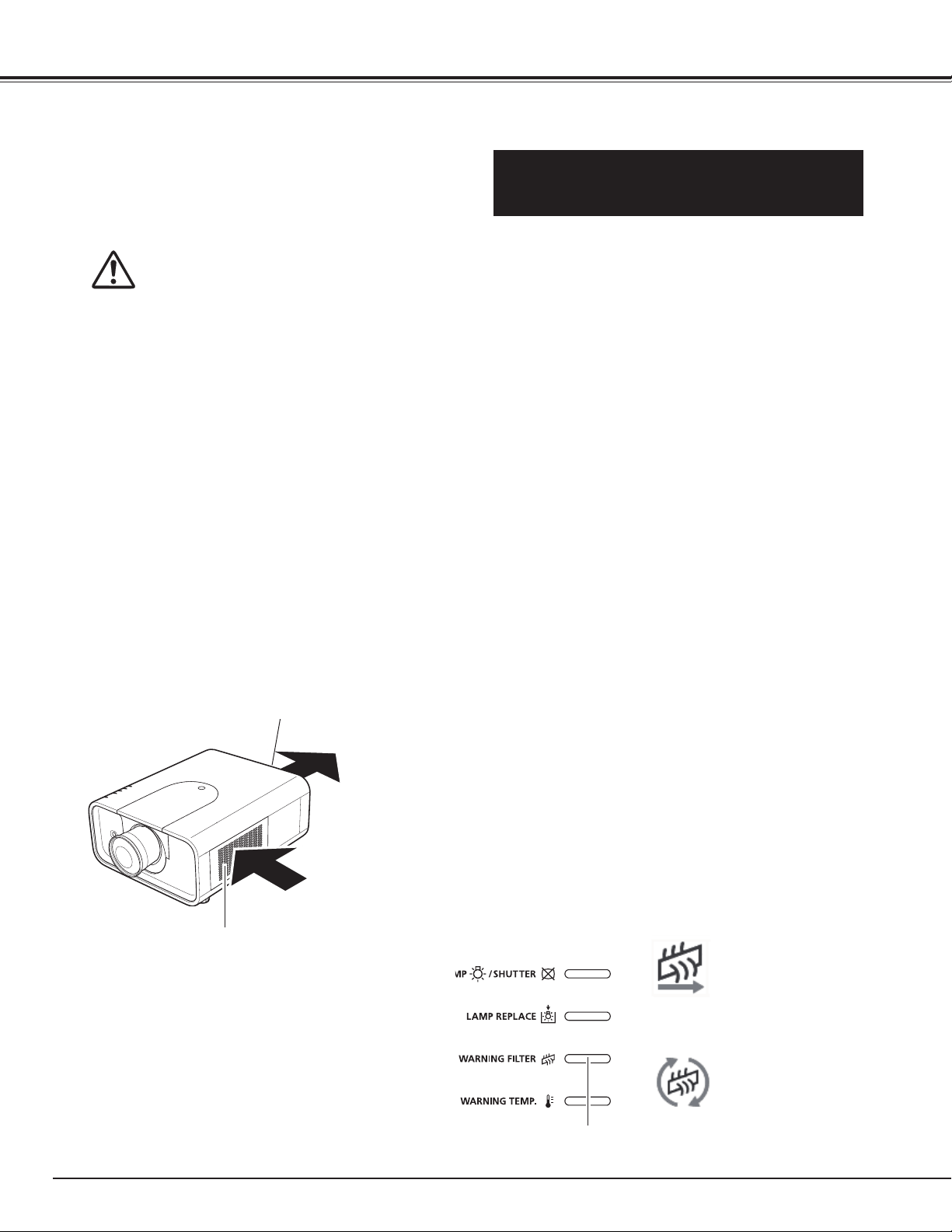
Air Circulation
Exhaust Vent
(Hot air exhaust)
Air Intake Vent
Air flow
The projector uses a lamp which generates
significant heat. The cooling fans and air vents are
provided to dissipate the heat by drawing air into the
housing and the filter is located in the intake vents to
prevent dust from getting inside of the projector.
In order to care for the projector appropriately,
regular cleaning is required. Remove any dirt or dust
that has accumulated on the projector.
If the projector reaches a time set in the timer
setting, a Filter replacement icon (Fig. 1) appears on
the screen and WARNING FILTER indicator on the
top panel lights up (see below), indicating that the
filter replacement is necessary.
If the projector detects that the filter is clogged and
no scroll is left in the filter cartridge, a Filter cartridge
replacement icon (Fig. 2) appears on the screen and
WARNING FILTER indicator on the top panel lights
up (see below). Stop using the projector immediately
and replace the filter cartridge.
Blocking the air vents and leaving the projector
uncleaned for a long time may not only damage the
projector and may require costly repairs but may also
cause accidents or fire.
For maintenance of the filter, refer to “Filter counter”
on page 62 and “Maintenance and Care” on pages
63–65.
Damages to the projector caused by using an
uncleaned filter or improper maintenance will
void the warranty on the projector.
IMPORTANT!
Filter Maintenance!!
Top Panel
WARNING FILTER
indicator
Fig.1 Filter replacement icon
Fig.2 Filter cartridge replacement
icon
Safety Instructions
9
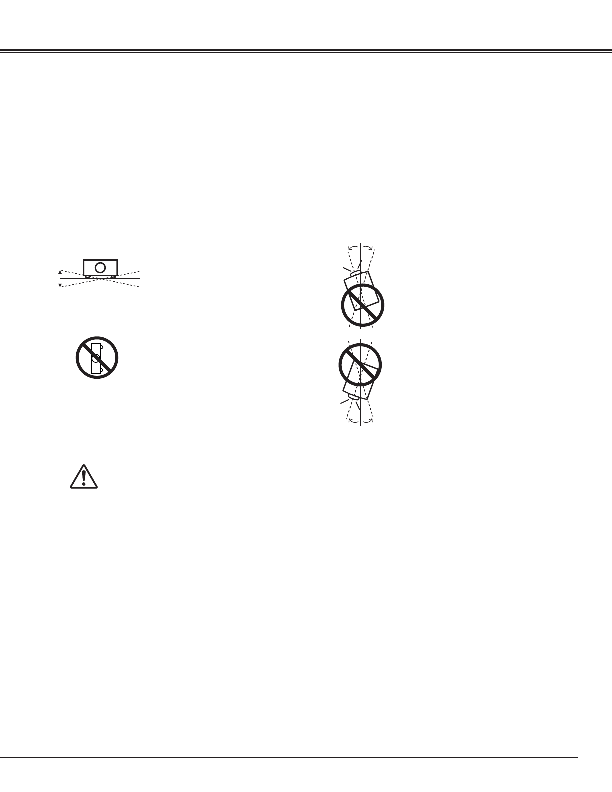
Use the projector properly in specified positions. Improper positioning may reduce the lamp life and result in
severe accident or fire hazard.
This projector can project the picture in upward, downward, or inclined position in perpendicular direction to the
horizontal plane. When installing the projector in downwardly inclined position, install the projector bottom side
up.
Installing the Projector in Proper Directions
Avoid positioning the projector as described below when installing.
Positioning Precautions
Do not tilt the projector more than
10 degrees from side to side.
Do not put the projector on either
side to project an image.
10˚
10˚
10˚10˚
10˚
10˚
In upward projection, do
not tilt the projector over 10
degrees right and left.
In downward projection, do
not tilt the projector over 10
degrees right and left.
For ceiling mounting, you need the ceiling mount kit designed for this
projector. When not mounted properly, the projector may fall, causing
hazards or injury. For details, consult your dealer. The warranty on
this projector does not cover any damage caused by use of any non-
recommended ceiling mount kit or installation of the ceiling mount kit in an
improper location.
CAUTION ON CEILING MOUNTING
Safety Instructions
✔Note:
•Toinverseorreversetheimage,settheceilingfunctionto“On.”(pp.46,50)
10
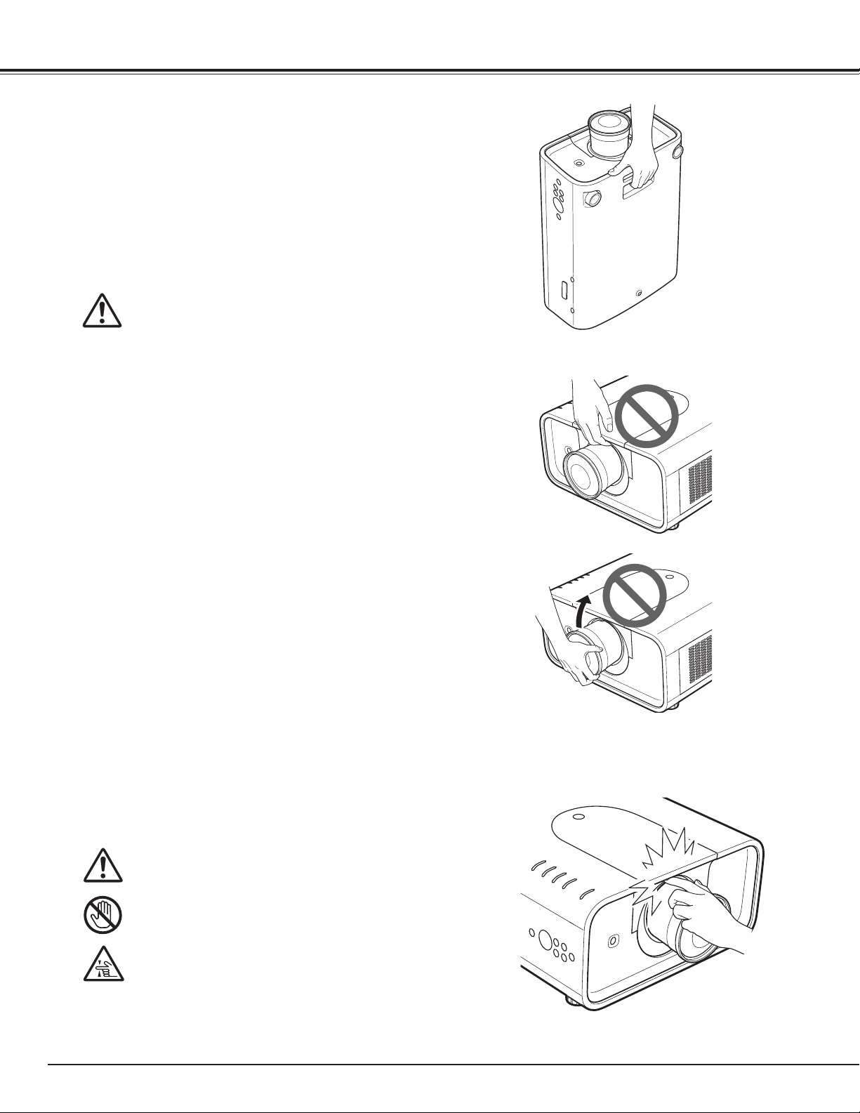
Moving the Projector
Use the handle grip when moving the projector.
Retract the adjustable feet to prevent damage to the lens
and cabinet when carrying.
When this projector is not in use for an extended period, put
it into a suitable case to protect the projector.
CAUTION IN CARRYING OR
TRANSPORTING THE PROJECTOR
– Do not drop or bump the projector, otherwise damages
or malfunctions may result.
– When carrying the projector, use a suitable carrying
case.
– Do not transport the projector by courier or any other
transport service in an unsuitable transport case. This
may cause damage to the projector. For information
about transporting the projector by courier or any other
transport service, consult your dealer.
– Do not put the projector in a case before it is cooled
enough.
– Remove the lens, close the lens mounting hole with
the lens mounting cover, and retract the adjustable feet
before placing the projector into the carrying case.
Cautions in Handling the Projector
Do not hold the lens or the top cover when lifting or moving
the projector. Doing so may cause damage to the lens and
the projector.
Care must be taken when handling the projector; do not
drop, bump, subject it to strong forces, or put other things
on the cabinet.
Do not hold the lens and the peripheral part.
CAUTION
Projection lens is a motorized lens. Please note the
followings when using the projector.
● Do not touch the lens while it is moving as this
could cause injury to the fingers.
● Never allow children to touch the lens.
Safety Instructions
11
The AC Power Cord supplied with this projector meets the requirement for use in the country you purchased it.
AC Power Cord for the United States and Canada:
AC Power Cord used in the United States and Canada is listed by the Underwriters Laboratories
(UL) and certified by the Canadian Standard Association (CSA).
AC Power Cord has a grounding-type AC line plug. This is a safety feature to be sure that the
plug will fit into the power outlet. Do not try to defeat this safety feature. Should you be unable
to insert the plug into the outlet, contact your electrician.
GROUND
AC POWER CORD REQUIREMENT
Federal Communications Commission Notice
Multimedia Projector, Model: LV-7590
This device complies with Part 15 of the FCC Rules. Operation is subject to the following two conditions:
(1) This device may not cause harmful interference, and
(2) this device must accept any interference received, including interference that may cause undesired operation.
Note: This equipment has been tested and found to comply with the limits for a Class B digital device, pursuant to
Part 15 of the FCC Rules. These limits are designed to provide reasonable protection against harmful interference in a
residential installation. This equipment generates, uses and can radiate radio frequency energy and, if not installed and
used in accordance with the instructions, may cause harmful interference to radio communications. However, there is no
guarantee that interference will not occur in a particular installation. If this equipment does cause harmful interference to
radio or television reception, which can be determined by turning the equipment off and on, the user is encouraged to try
to correct the interference by one or more of the following measures:
– Reorient or relocate the receiving antenna.
– Increase the separation between the equipment and receiver.
– Connect the equipment into an outlet on a circuit different from that to which the receiver is connected.
– Consult the dealer or an experienced radio/TV technician for help.
Use of shielded cable is required to comply with class B limits in Subpart B of Part 15 of FCC Rules.
Do not make any changes or modifications to the equipment unless otherwise specified in the instructions. If such
changes or modifications should be made, you could be required to stop operation of the equipment.
Canon U.S.A., Inc.
One Canon Plaza, Lake Success, NY 11042-1198, U.S.A.
Tel No. (516)328-5000
Compliance
European Union (and EEA) only.
These symbols indicate that this product is not to be disposed of with your household waste, according to the WEEE
Directive (2002/96/EC), the Battery Directive (2006/66/EC) and/or your national laws implementing those Directives.
If a chemical symbol is printed beneath the symbol shown above, in accordance with the Battery Directive, this
indicates that a heavy metal (Hg = Mercury, Cd = Cadmium, Pb = Lead) is present in this battery or accumulator at a
concentration above an applicable threshold specified in the Battery Directive.
This product should be handed over to a designated collection point, e.g., on an authorized one-for-one basis when you
buy a new similar product or to an authorized collection site for recycling waste electrical and electronic equipment
(EEE) and batteries and accumulators. Improper handling of this type of waste could have a possible impact on the
environment and human health due to potentially hazardous substances that are generally associated with EEE.
Your cooperation in the correct disposal of this product will contribute to the effective usage of natural resources.
For more information about the recycling of this product, please contact your local city office, waste authority,
approved scheme or your household waste disposal service or visit www.canon-europe.com/environment.
(EEA: Norway, Iceland and Liechtenstein)
Canadian Radio Interference Regulations
This Class B digital apparatus complies with Canadian ICES-003.
THE SOCKET-OUTLET SHOULD BE INSTALLED NEAR THE EQUIPMENT AND EASILY ACCESSIBLE.
12
Part Names and Functions
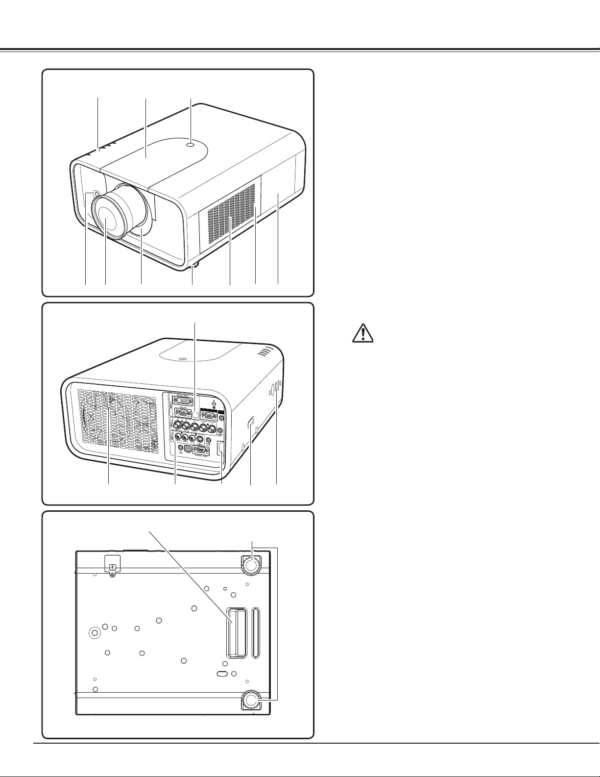
Bottom
Back
e
Front
q
w
qIndicators
wTop Cover
e Top Cover Release Button
rInfrared Remote Receiver (Front)
tProjection Lens (not supplied)
y Light-Block Sheet
uAdjustable Feet
i Air Intake Vent
o Filter Cover
!0 Lamp Cover
!1Exhaust Vent
CAUTION
Hot air is exhausted from the exhaust
vent. Do not put heat-sensitive objects
near this side.
!2Terminals and Connectors
!3 Power Cord Connector
✔Note:
•Replceonlywiththesametypesofthe
suppliedcordsorcables.Usingimproper
cordsorcablesmaycauseanelectricshock
orafire.ACPowercord:1AV4W11B20500
(forUS)/1AV4W11B17000(forEU),VGA
Cable:1AV4W20B29700,USBCable
1AV4W20B20201
!4 Optional Parts Attachment
!5 Side Controls
!6 Infrared Remote Receiver (Back)
!7Hand Grip
i
t
y
!1
!0
u
o
r
!7
!6
!5!3!2
!4
u
13
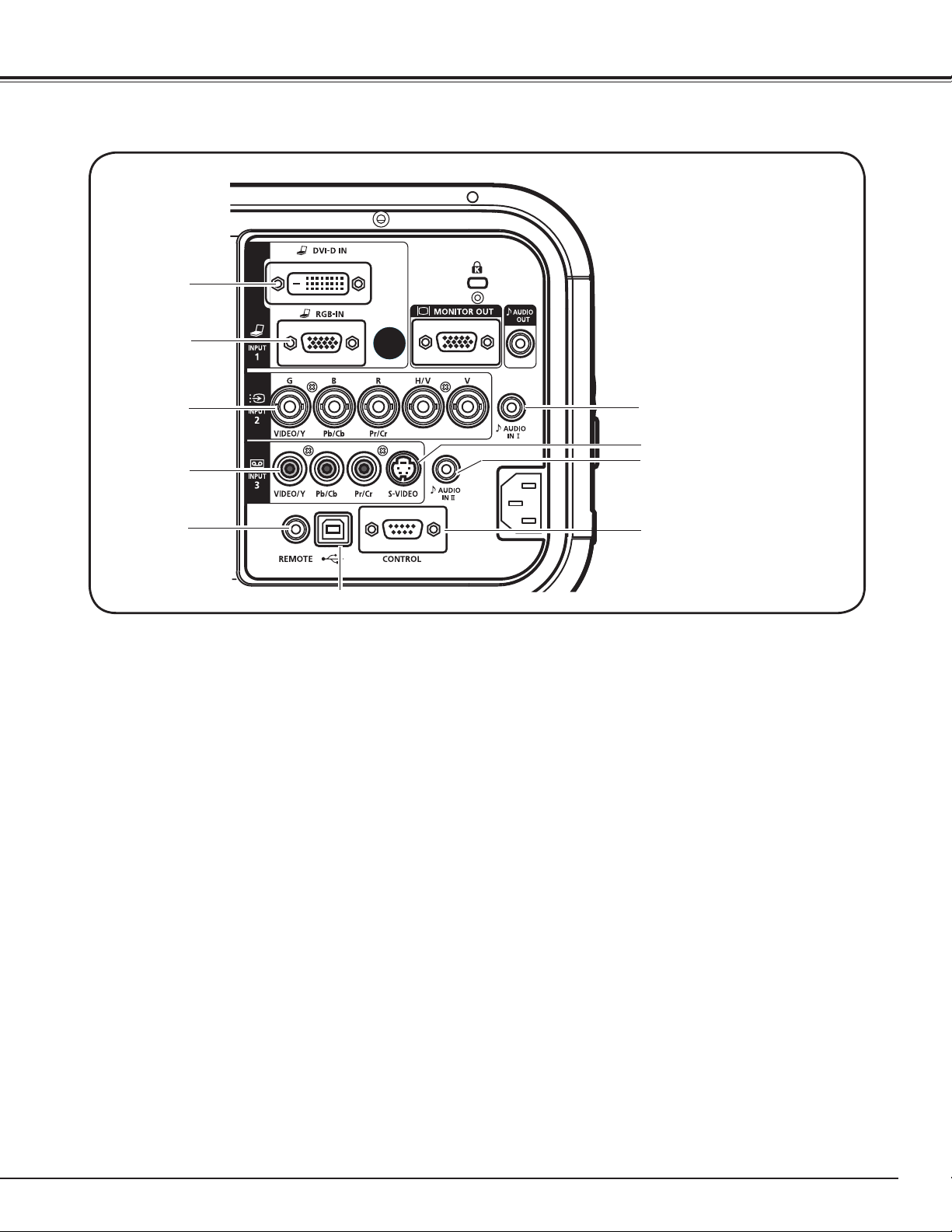
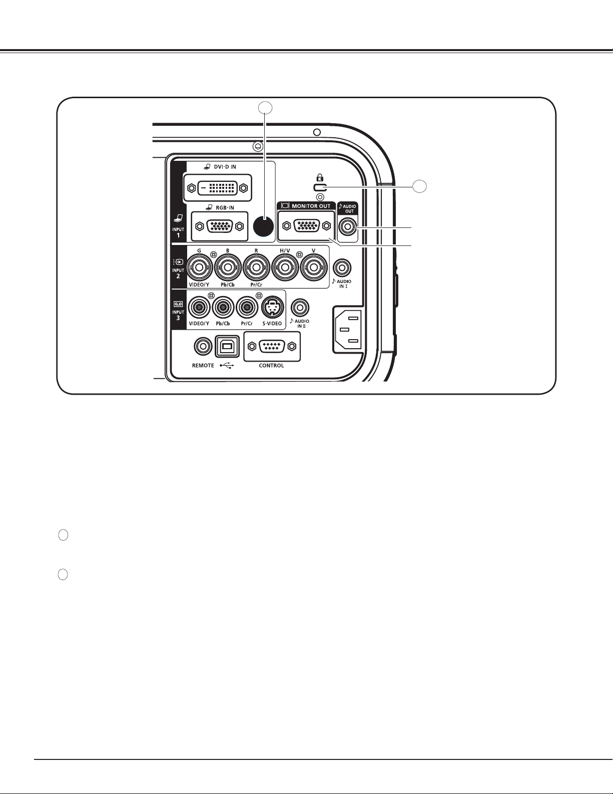
Rear Terminal
tREMOTE TERMINAL
When using the wired remote control unit, connect
the wired remote control unit to this terminal with
a remote control unit cable (not supplied).
yUSB TERMINAL (Series B)
Use this connector when controlling a computer
with the remote control unit of the projector.
Connect the USB terminal of your computer to this
connector with the supplied USB cable (p.24).
iAUDIO IN II TERMINAL
Connect the audio output (stereo) signal from a
computer or video equipment (p.26).
rINPUT 3 TERMINAL (VIDEO)
Connect the component or the composite video
output signal from video equipment to this terminal
(p.25).
uCONTROL TERMINAL
When controlling the projector from a computer,
connect the computer to this connector with a
control cable (p.24).
qINPUT 1 TERMINAL (DIGITAL)
Connect the computer output digital signal to this
terminal. The HDTV (HDCP compatible) signal can
also be connected (pp.24-25).
wINPUT 1 TERMINAL (ANALOG)
Connect the computer (or RGB scart) output signal
to this terminal (pp.24-25).
eINPUT 2 TERMINAL
Connect the component or composite video output
signal from video equipment to VIDEO/Y, Pb/Cb,
and Pr/Cr jacks or connect the computer output
signal (5 BNC Type [Green, Blue, Red, Horiz. Sync,
and Vert. Sync.]) to G, B, R, H/V, and V terminals
(pp.24-25).
q
w
e
r
t
y
o
u
Part Names and Functions
i
!0
oINPUT 3 TERMINAL (S-VIDEO)
Connect the S-VIDEO output signal from video
equipment to this terminal (p.25).
!0AUDIO IN I TERMINAL
Connect the audio output (stereo) signal from a
computer or video equipment (p.26).
✔Note:
•UseaDVI-Digitalcablewhichfitsthewidthoftherear
terminal.
14
A
Rear Terminal
Part Names and Functions
!2AUDIO MONITOR OUTPUT TERMINAL
This terminal outputs the audio signal from
computer or video equipment to external audio
equipment (p.26).
!2
!1
!1MONITOR OUT TERMINAL
This terminal can be used to output the incoming
analog RGB signal from INPUT 1-3 terminal to the
other monitor (pp.24-25).
B
A
B Kensington Security Slot
This slot is for a Kensington lock used to deter theft
of the projector.
*Kensington is a registered trademark of ACCO Brands
Corporation.
A INFRARED REMOTE RECEIVER (Back)
The infrared remote receiver is also located in the
front (pp.12, 18).
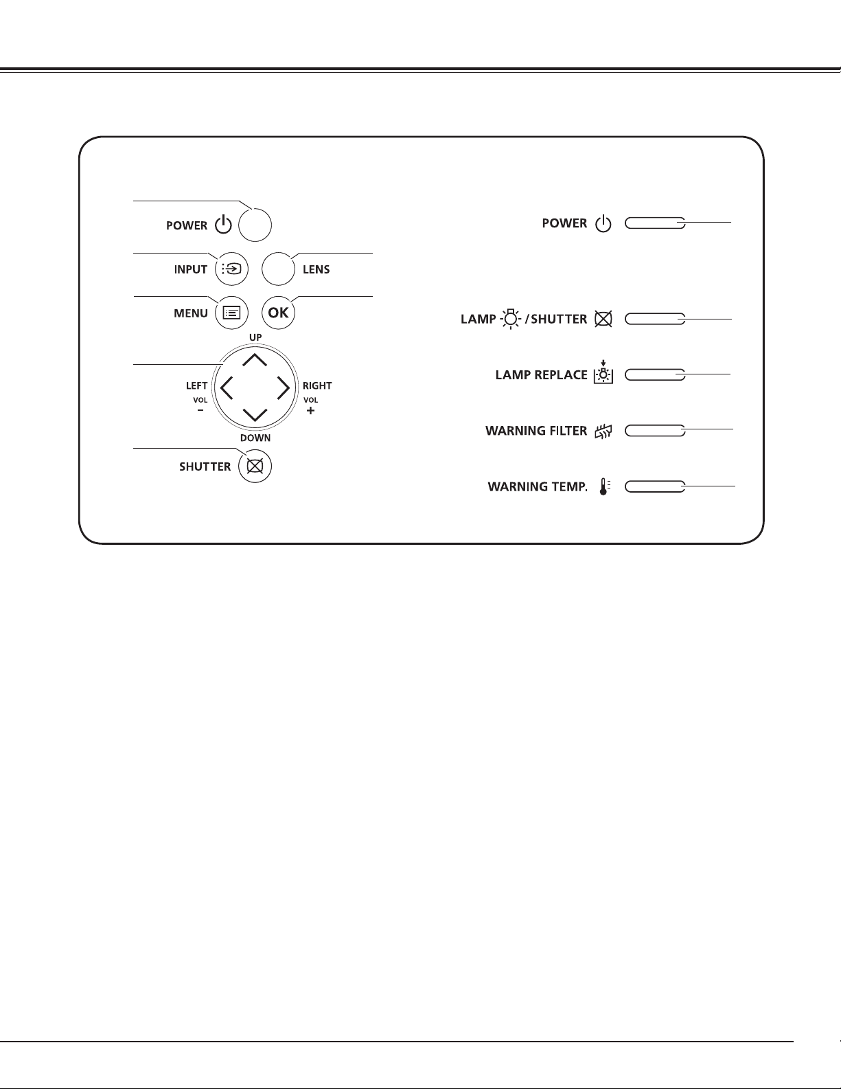
15
qPOWER button
Turn the projector on or off (pp.28–29).
eMENU button
Open or close the On-Screen Menu (p.30).
rPoint ed7 8 ( VOLUME + / – ) buttons
– Select an item or adjust the value in the On-
Screen Menu (p.30).
– Pan the image in Digital zoom + mode (p.46).
– Adjust the volume level (with Point
7 8 buttons)
(p.33).
!2WARNING TEMP. indicator
Blink red when the internal temperature of the
projector exceeds the operating range (pp.70, 77-
79 ).
t
SHUTTER button
Close and open up the built-in shutter. (p.32)
iPOWER indicator
– Light when in stand-by mode and during
operations.
– Blink in the Power management mode (p.58).
Side Control and Indicators
yOK button
– Execute the selected item (p.30).
– Zoom in or out the image in the Digital zoom
mode (p.46).
oLAMP/
SHUTTER
indicator
Light red during operations.
Light blue when the shutter is closed (p.77).
!0LAMP REPLACE indicator
Light orange when the projection lamp reaches its
end of life (pp.66, 78).
!1WARNING FILTER indicator
– Blink slow when the filter is being scrolled (pp.
63, 77).
– Blink fast when the filter scroll is not working
properly or the filter cartridge is not installed
(pp.63, 79).
– Light orange when the clogging of the filter is
detected or the filter counter reaches a time set
in the timer setting, urging immediate filter/ filter
cartridge replacement (pp.62, 63, 79).
q
w
e
t
y
r
Side Control Indicators (on the top panel)
u
i
o
!0
!2
Part Names and Functions
!1
wINPUT button
Select an input source (pp.37–39).
uLENS button
Enter the focus, zoom, and lens shift adjustment
mode (p.32).
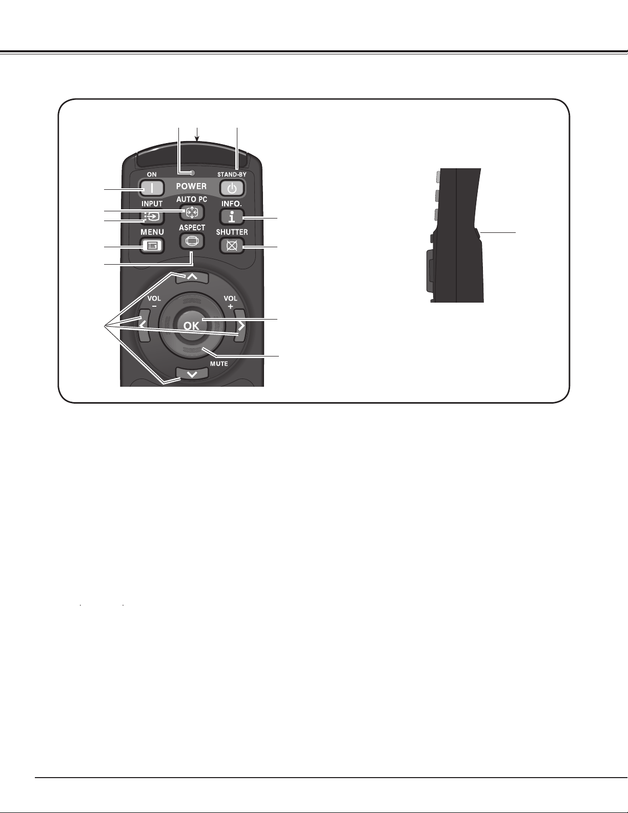
16
q STAND-BY button
Turn the projector off (p.29).
r ON button
Turn the projector on (p.28).
yINPUT button
Select a signal (pp.37–39).
iASPECT button
Select the screen size (p.34).
r
Remote Control Unit
!0
!4
q
!4 L- CLICK button
Act as the left mouse button for wireless mouse
operation (p.34).
e SIGNAL EMISSION indicator
Light red while a signal is being sent from the
remote control unit to the projector.
o POINT ed 7 8 ( VOLUME + / – , MUTE) buttons
– Select an item or adjust the value in the On-
Screen Menu (p.30).
– Pan the image in Digital zoom + mode (p.46).
– Adjust the volume level (with Point 7 8 buttons)
or mute the sound (with Point d button.) (p.33).
✔Note:
To ensure safe operation, observe the following
precautions:
– Do not bend, drop, or expose the remote control unit
to moisture or heat.
– For cleaning, use a soft dry cloth. Do not apply
benzene, thinner, spray, or any other chemical
materials.
e
w WIRED REMOTE jack
Connect the remote control unit cable (not
supplied) to this jack when using as a wired remote
control unit.
!1 OK button
– Execute the selected item (p.30).
– Zoom in or out the image in the Digital zoom
mode (p.46).
w
u MENU button
Open or close the On-Screen Menu (p.30).
!2
!0 MOUSE POINTER button
Move a pointer of the projector or a pointer for
wireless mouse operation (p.36).
Part Names and Functions
tAUTO PC button
Automatically adjust the computer image to its
optimum setting (pp.34, 41).
t
!3
y
u
i
o
!1
!3INFO. button
Display the input source information (p.34).
!2
SHUTTER button
Close and open up the built-in shutter (p.32).
!4 L- CLICK button
Act as the left mouse button for wireless mouse
operation (p.36).
17
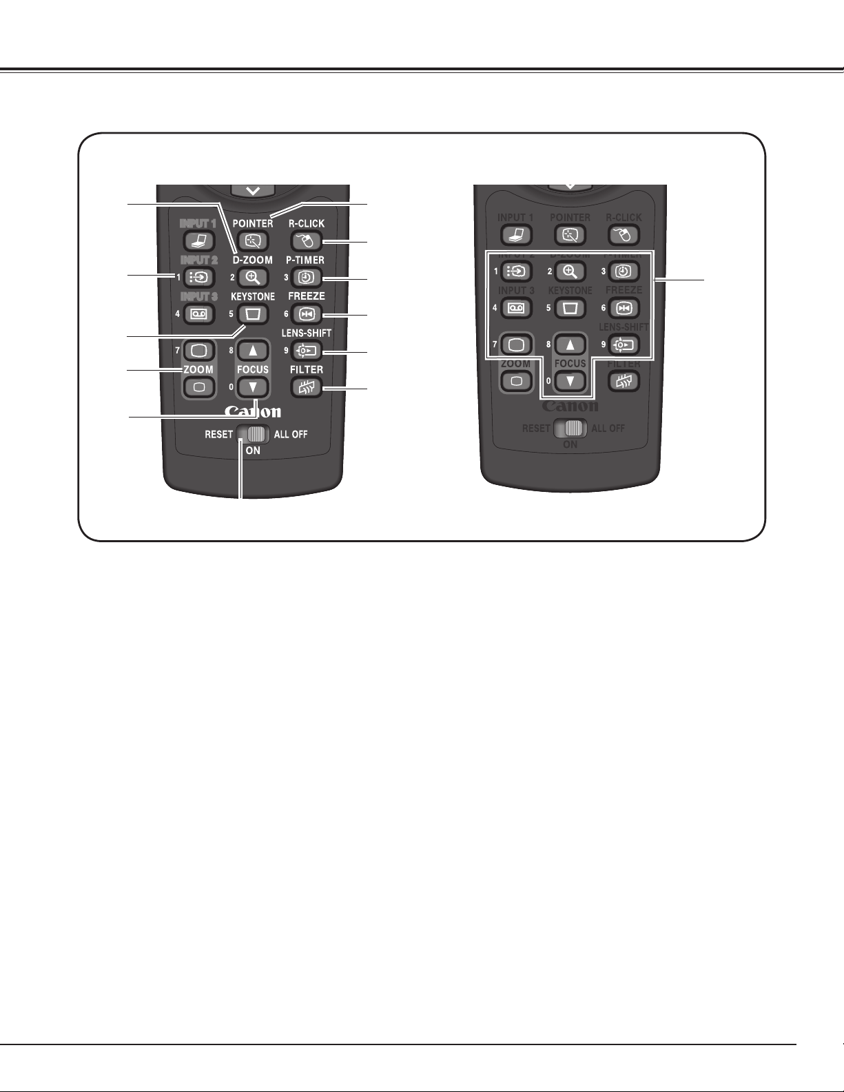
Remote Control Unit
!6
!5
!9
!7
!8
!8ZOOM ed buttons
Zoom in and out the images (p.34).
!5D-ZOOM button
Select the Digital zoom +/- mode and resize the
image (p.46).
!9FOCUS buttons
Adjust the focus (p.34).
@1FILTER button
Scroll the filter (p.35).
@3FREEZE button
Freeze the picture on the screen (p.35).
!7KEYSTONE button
Correct keystone distortion (p.35).
@0 RESET/ON/ALL OFF switch
When using the remote control unit, set this
switch to “ON.” Set it to “ALL OFF” for power
saving when it is not in use. Slide this switch to
“RESET” to initialize the remote control unit code.
@5 R-CLICK button
Act as the right mouse button for wireless mouse
operation (p.36).
@2 LENS-SHIFT button
Select the Lens Shift function (p.34).
@4 P-TIMER button
Operate the P-timer function (p.35).
@6
@7 NUMBER buttons
Act as number buttons. Use these buttons when
setting the remote control unit codes (pp.19, 57) or
when entering the PIN code numbers (pp. 28, 56,
60).
@2
@1
@0
@3
@4
@6 POINTER button
Act as the On-Off switch for the Pointer (p.35, 36).
@7
For PIN code
and remote
control unit
code.
Part Names and Functions
@5
!6 INPUT 1 – 3 buttons
Select an input source (INPUT 1 – INPUT 3)
(pp.37–39).
18
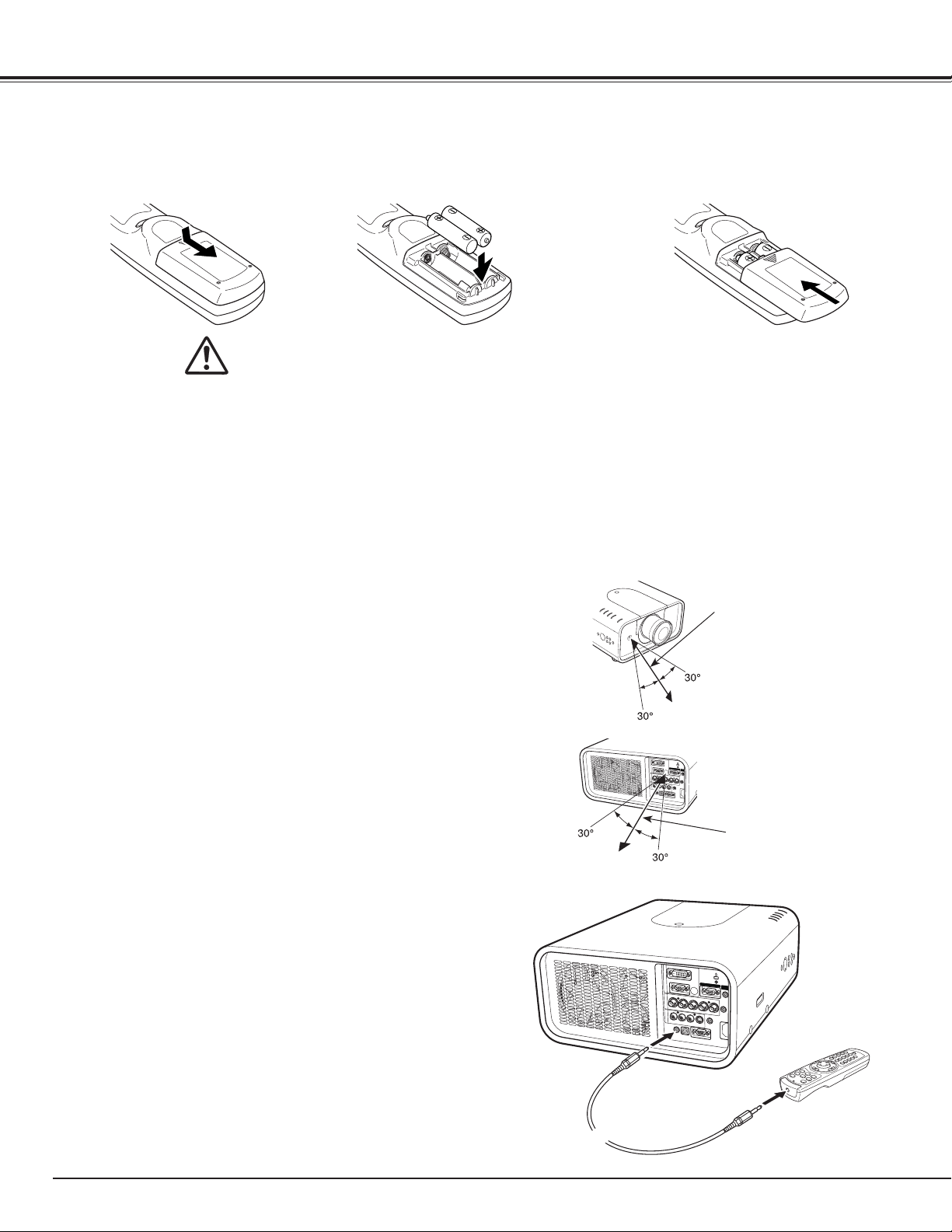
Remote Control Battery Installation
1 2 3
Open the battery
compartment lid.
Install new batteries into
the compartment.
Replace the
compartment lid.
Press the lid downward and
slide it.
Two AAA size batteries
For correct polarity (+ and –),
be sure battery terminals are
in contact with pins in the
compartment.
To ensure safe operation, please observe the following precautions :
● Use two (2) AAA or LR03 type alkaline batteries.
● Always replace batteries in sets.
● Do not use a new battery with a used battery.
● Avoid contact with water or liquid.
● Do not expose the remote control unit to moisture or heat.
● Do not drop the remote control unit.
● If the battery has leaked on the remote control unit, carefully wipe the case clean and install
new batteries.
● There is a risk of an explosion if battery is replaced by an incorrect type.
● Dispose of used batteries according to the instructions or your local disposal rules or guidelines.
Point the remote control unit toward the projector (to
Infrared Remote Receivers) when pressing the buttons.
Maximum operating range for the remote control unit is
about 16.4’ (5 m) and 60 degrees in front and rear of the
projector.
Infrared Remote Receivers are provided both in front and
back of the projector. You can conveniently use both of
the receivers (pp. 12, 58).
16.4’
(5 m)
Remote Control Receivers and Operating Range
The remote control unit can be used as a wired remote control unit
Wired remote control unit helps you use the remote control unit
outside of the operating range (16.4’/ 5 m). Connect the remote
control unit and the projector with the remote control cable (sold
separately). Connected with the remote control cable, the remote
control unit does not emit wireless signal.
Wired Remote Control Transmitter
Part Names and Functions
16.4’
(5 m)
WARNING

19
The eight different remote control unit codes (Code 1–Code 8) are assigned to this projector. Switching the
remote control unit codes prevents interference from other remote control units when several projectors or
video equipment next to each other are operated at the same time. Change the remote control unit code for the
projector first before changing that for the remote control unit. See “Remote control” in the Setting Menu on
page 57.
Press and hold the MENU and a number button (1–8)
for more than 5 seconds to switch between the codes.
1
To initialize the remote control code, slide the RESET/
ON/ALL OFF switch to “RESET,” and then to “ON.” The
initial code is set to Code 1.
2
MENU button
Remote Control Unit Code
Number buttons
RESET/ON/ALL
OFF Switch
Press and hold the MENU and a number button
(1–8) that corresponds to the remote control unit
code for more than 5 seconds to switch between
the codes.
Part Names and Functions
20
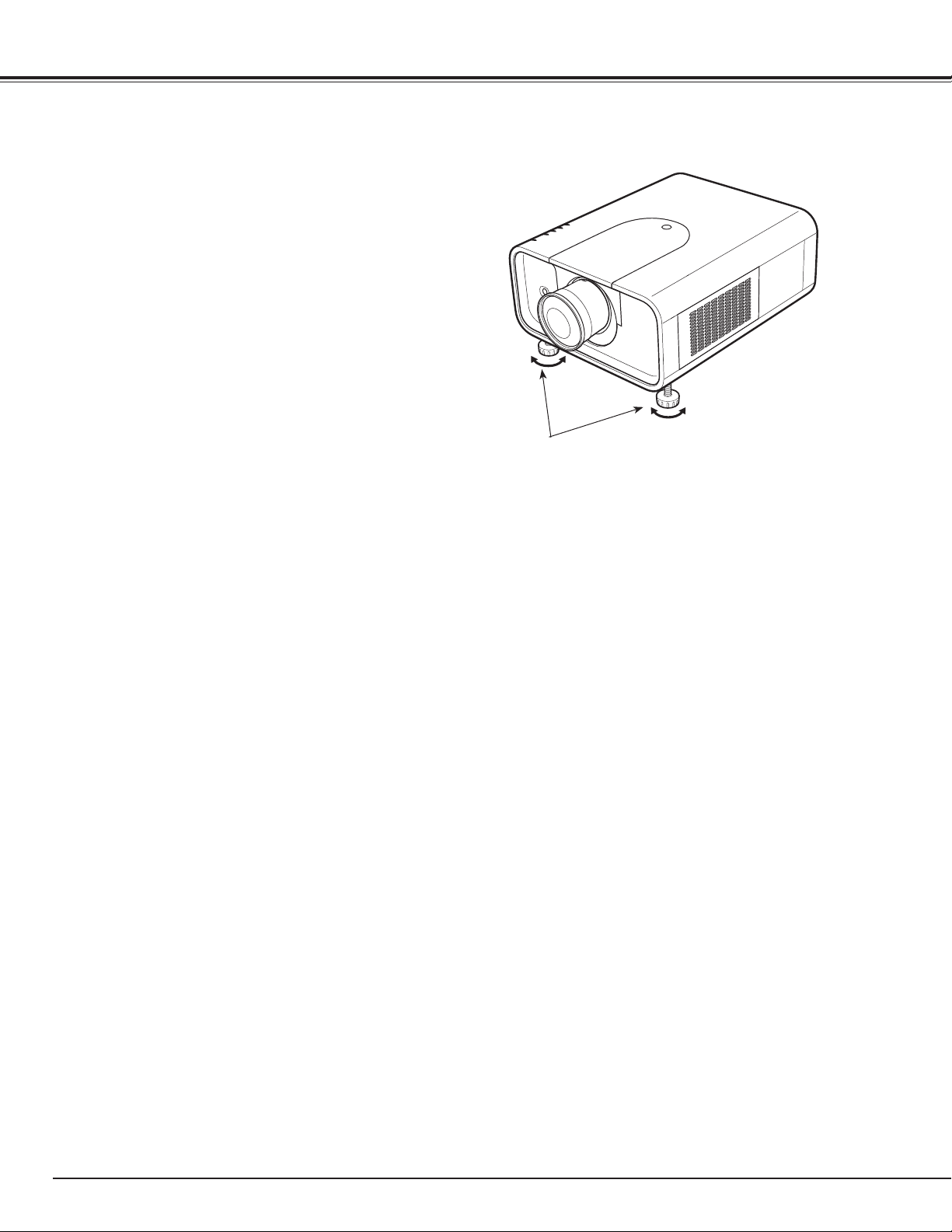
ADJUSTABLE FEET
Projection angle can be adjusted up to 6.5 degrees with the
adjustable feet.
Rotate the adjustable feet and adjust the projector to the proper
height; to raise the projector, rotate the both feet clockwise.
To lower the projector or to retract the adjustable feet, rotate the
both feet counterclockwise.
To correct keystone distortion, press the KEYSTONE button on the
remote control unit or select Keystone from the menu (see pages
17, 35, 46, 50).
Adjustable Feet
Installation
21
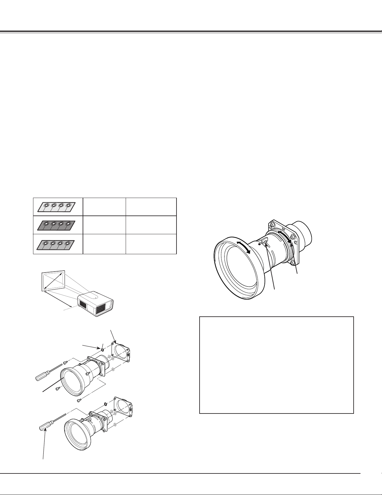
When replacing the lens or using an optional lens, install the lens by following the instructions below. Ask the
sales dealer for detailed information of the optional lens specifications.
✔Note:
Be careful when handling the lens. Do not drop.
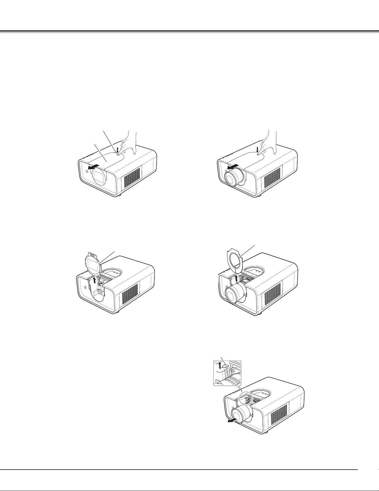
Front cover
Slide the front cover upword and remove it as shown in the left figure below. (Follow this procedure for
installing the lens for the first time.)
Installation
Lens Lock Lever
Top cover release button
Top cover
Lens Installation and Replacement
2
1
While pressing the top cover release button on the top cover, slide the top cover toward front to remove it.
Turn off the projector and unplug the AC power cord.
5
Hold the mounted lens with one hand and pull the lens lock lever upwarad with the other hand. Remove
the lens from the projector as shown in the figure below. (Follow this procedure for replacing the lens.)
] Do not touch the glass part of the lens with your hands.
3
Shift the lens to the center position by using Lens shift function (p. 32).(Follow this procedure for replacing
the lens.)
4
Slide the light-block sheet upward (if attached) and remove it as shown in the right figure below. (Follow this
procedure for replacing the lens.)
Light-block sheet
22
NOTES ON LENS INSTALLATION AND REPLACEMENT
● Do not touch or remove any parts except the lens and related parts. It may result in malfunctions, electrical shock, fire hazard
or other accidents.
● Before installing or replacing the lens, check that the Model No. of the Projection Lens matches to the projector.
● For details of the lens and installation, contact the sales dealer where you purchased the projector.
● The mounting clamps that are shipped with the standard zoom lens LV-IL05 (not supplied with the projector) are designed for
use with the standard zoom lens. Do not use the mounting clamps with any other lens. After replacing the standard zoom lens
with an optional lens (not supplied), save the mounting clamps in the event that you should reinstall the standard zoom lens.
● This projector is a precision machine. Do not subject the projector to strong shocks or vibrations when transporting the device.
Failure to do so may cause malfunction or damage to the lens or projector.
Installation
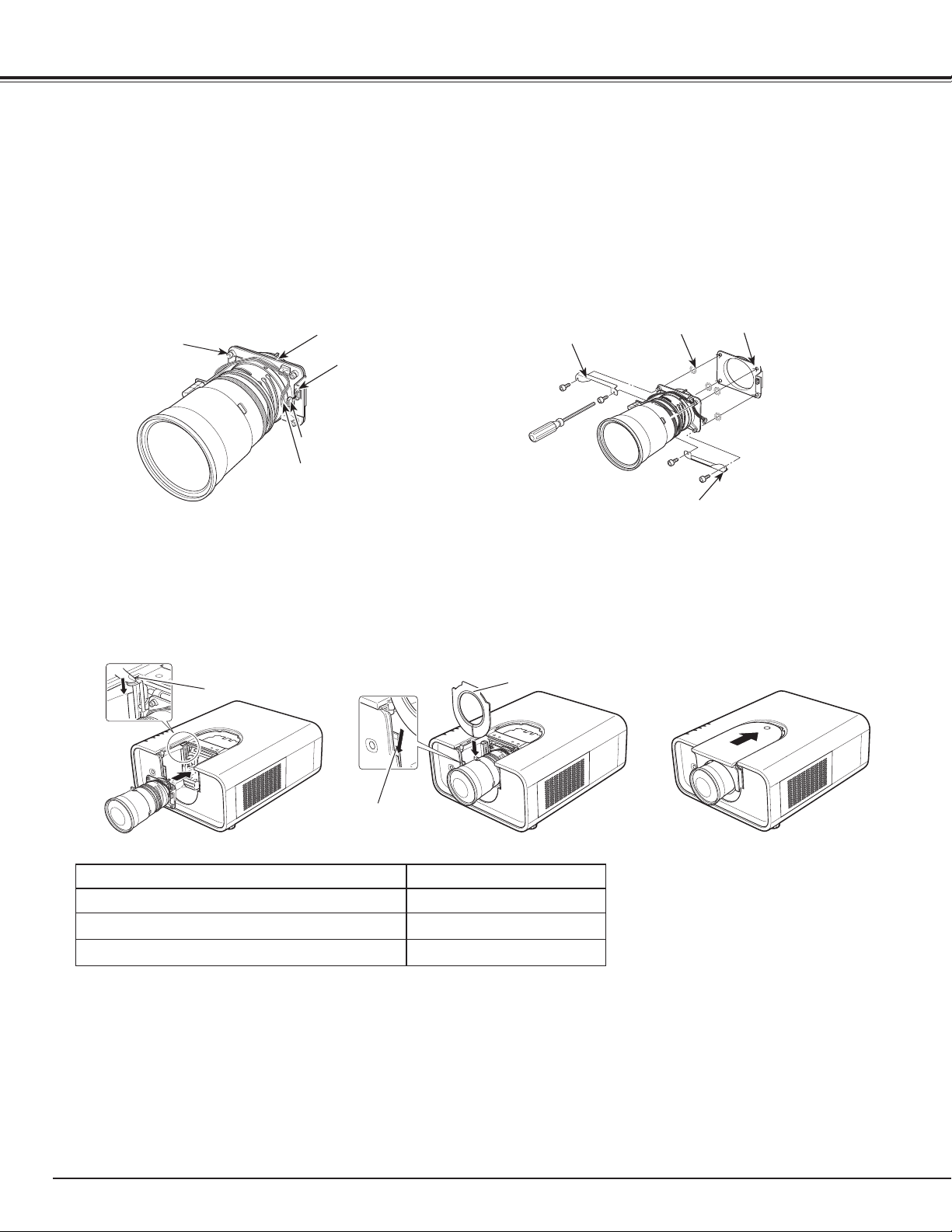
Lens Lock Lever
Groove
Light-block sheet
Unplug the Lens Motor Lead connector from the socket on the Lens Attachment (follow this procedure for
replacing with the Powered lens)
, remove the 4 screws fixing the lens attachment to detach it (follow this
procedure for replacing the lens)
, remove the safety lens caps on the optional or standard lens, attach the Lens
Attachment (supplied with the projector) to the back end of the lens by using the removed screws or supplied
screws, and then reconnect the Lens Motor Lead connector to the socket (follow this procedure for replacing
with the Powered lens)
. If you install the standard lens, you also need to attach the mounting clamps to the lens.
The mounting clamps that are shipped with the standard zoom lens LV-IL05 (not supplied with the projector) are
designed for use with the standard zoom lens. Do not use the mounting clamps with any other lens.
Fit the lens to the projector. Make sure that the lens is fully inserted to the projector.
While pressing the top cover release button on the top cover, slide the top cover back to the projector.
Slide the light-block sheet in the groove to mount if necessary. (Follow this procedure for replacing the lens.)
Push the Lens Lock Lever downward. Make sure that the lens is properly locked.
Light-Block Sheet for each Lens
Light-Block Sheet Type No. (Part No.) Lens Part No.
Type PG1(610 339 2967) LV-IL05
Type PH1(610 339 2974) LV-IL03, LV-IL02, LV-IL04
No need to attach LV-IL01
6
7
8
9
10
Lens Motor Lead
Connector
Socket
Lens Attachment
Screw
Lens Attachment
Spacer
*Mounting clamp
*Mounting clamp
* Attach when mounting the standard lens.
23
Installation
Installation
Some parts are not used for installation or replacement.
Keep these parts for later use.
Focus Lock Screw
Focus Lock Ring
Focus adjustment
Set up the projector and project image on the screen.
1. Loosen the Focus Lock Screw on the lens.
2. Rotate the lens to obtain proper focus on center
area of the screen.
3. Lock the Focus Lock Screw securely.
When proper focus is not observed at outer area of the
screen, proceed the following adjustments.
4. Loosen the Focus Lock Ring on the lens. (Turn the
Lock Ring counter-clockwise.)
5. Rotate the lens to obtain proper focus on outer area
of the screen.
6. Lock the Focus Lock Ring securely. (Turn the Lock
Ring clockwise.)
If proper focus is not observed over the entire screen,
repeat above adjustments 1~ 6.
Focus correction
LV-IL01
BE SURE TO CHECK FOR SAFETY
After installing or replacing the lens, be
sure to check the following for safety.
1. Check the lens is securely fixed with the
screws.
2. Check no wiring is damaged or tangled
on the gear of the lens motor or the
other mechanical parts.
3. Check no part is missing, and no
mounting part is loose.
When the lens is attached to the projector and images
are being projected onto the screen, the peripheral
focus may be out of focus in some localized areas. If
this happens, insert the one, of three sizes of spacers,
in between the Lens Attachment and the lens to adjust
the focus.
Inserting the Spacer corrects the distance on the Lens
Adjustment and improves the diagonal focus.
The corrected distance is determined by the thickness
of the used spacers. As a guide, the distance is
adjusted by approximately 30 mm for each 0.1-mm
thickness of the spacers.
There are three types of spacers provided, and there
are four of each spacer type. Use these spacers to
correct the distance as required.
Spacer "1"
Color; Clear
Thickness; 0.1 mm
Spacer "2"
Color; Black
Thickness; 0.2 mm
Spacer "3"
Color; Cream
Thickness; 0.3 mm
Correction distance
30 m m/ for 4 0- in ch
projection
Correction distance
55 m m/ for 4 0- in ch
projection
Correction distance
80 m m/ for 4 0- in ch
projection
B
C
D
A
B
C
D
A
Spacer
Lens
Lens Attachment
Screw driver supplied with the lens
✔Note:
•Theillustrationsshownonthispagemaydifferfromyour
product.
D
B
C
A
Distance
Screen
40-inch projection
24
Monitor Output
BNC
cable
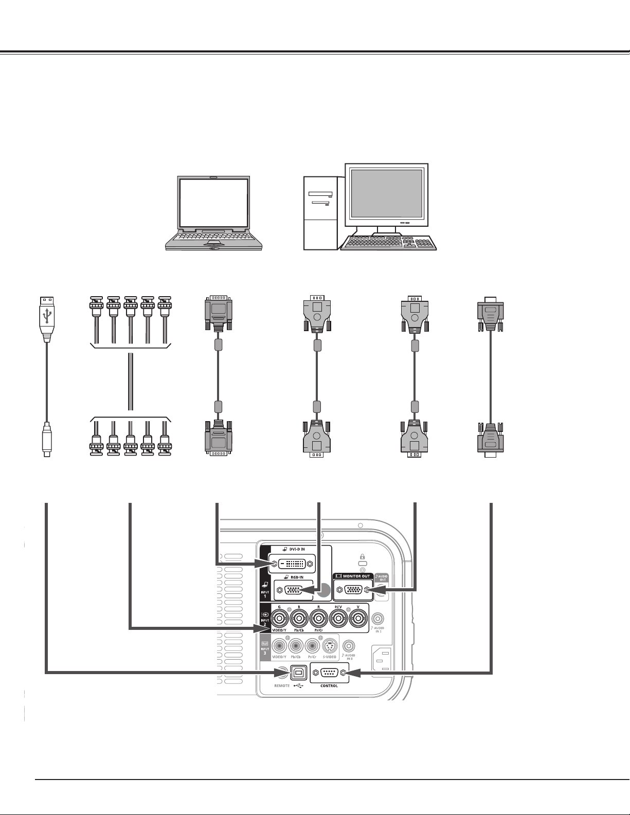
Connecting to a Computer (Digital and Analog RGB)
Monitor Output
G B R H/V V
DVI-Digital
cable
VGA
cable
VGA
cable
USB cable
(Supplied)
USB port
✔Note:
Unplug the power cords of both the
projector and external equipment from
the AC outlet before connecting cables.
Cables used for connection (] = Cables not supplied with this projector.)
• VGA Cable (One cable is supplied.)
• DVI-Digital Cable
• BNC Cable
]
• Serial Cross Cable
]
• USB Cable
Monitor Output
INPUT 1
(DIGITAL)
INPUT 1
(ANALOG)
MONITOR OUTUSB
Serial Cross
cable
Serial out
CONTROL PORT
Installation
See the next page for the signals that can output to the
MONITOR OUT terminal.
v
Monitor Input
v
25
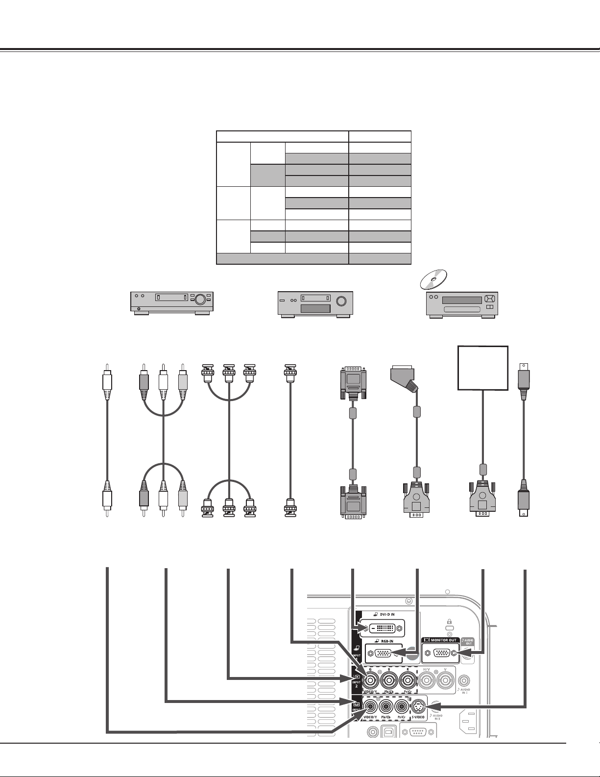
Connecting to Video Equipment (Video, S-Video)
S-video
cable
S-video
Output
Composite Video
INPUT 3
(Y - Pb/Cb - Pr/Cr)
BNC
cable
✔Note:
Unplug the power cords
of both the projector
and external equipment
from the AC outlet before
connecting cables.
Cables used for connection (] = Cables not supplied with this projector.)
• Video Cable (RCA x 1 or RCA x 3) ]
• BNC Cable ]
• S-VIDEO Cable ]
• Scart-VGA Cable ]
• DVI-Digital Cable ]
Component Video
Output
Composite Video
Component Video
Output
(Y, Pb/Cb, Cr/Pr)
Digital Output
(HDCP
compatible)
RCA
cable
DVI-Digital
cable
INPUT 3
(VIDEO)
Video
INPUT 2
(Y - Pb/Cb - Pr/Cr)
INPUT 1
(DIGITAL)
MONITOR OUT
INPUT 3
(S-VIDEO)
Installation
Input Terminal Monitor Out
Input 1
D-sub15
RGB (PC analog) YES
RGB (SCART) NO
DVI-D
RGB (PC digital) NO
RGB (AV HDCP) NO
Input 2 5BNC
RGB YES
Video YES
Y, Cb/Cr YES
Input 3
RCA
Y, Cb/Cr YES
S-Video
S-video NO
Video
Video YES
Network
NO
Monitor Out Signal Table
Refer to the
Monitor Out
Signal Table
(above).
INPUT 1
(ANALOG)
RGB Scart
21-pin Output
Scart-VGA
cable
26
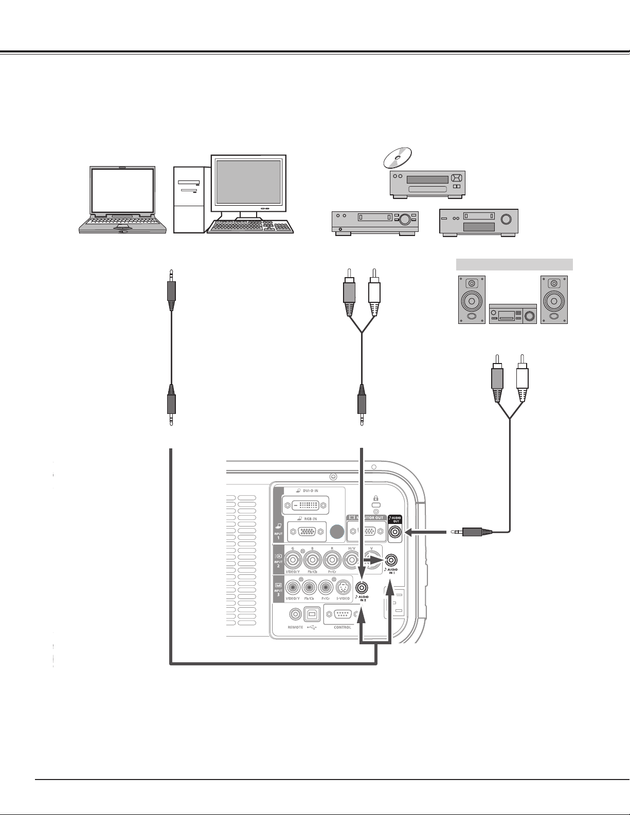
Audio Output
Audio
cable
(stereo)
Connecting for Audio Signal
AUDIO IN I/II
✔Note:
Unplug the power cords of both the
projector and external equipment from
the AC outlet before connecting cables.
Cables used for connection (] = Cables not supplied with this projector.)
Audio Output
Installation
Audio
cable
(stereo)
(R) (L)
AUDIO IN I/II
External Audio Equipment
Audio
cable
(stereo)
Audio Input
AUDIO OUT
(stereo)
• Audio Cable ]
✔Note:
•See the Soundmenutosetthe Input
patternforAUDIOINI/II. (p.33)
27
This projector uses nominal input voltages of 100–120 V or 200–
240 V AC and it automatically selects the correct input voltage. It
is designed to work with single-phase power systems having a
grounded neutral conductor. To reduce the risk of electrical shock,
do not plug into any other type of power system.
If you are not sure of the type of power being supplied, consult
your authorized dealer or service station.
Connect the projector with all peripheral equipment before turning
on the projector.
Connecting the AC Power Cord
Installation
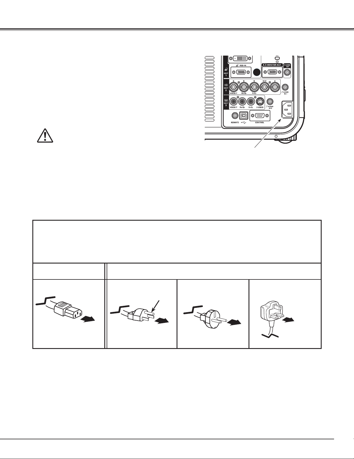
NOTE ON THE POWER CORD
AC power cord must meet the requirements of the country where you use the projector.
Confirm the AC plug type with the chart below and proper AC power cord must be used.
If the supplied AC power cord does not match your AC outlet, contact your sales dealer.
Projector side AC Outlet side
To POWER CORD
CONNECTOR on your
projector.
Ground
To the AC Outlet.
(120 V AC)
For Continental Europe
For the U.S.A. and Canada
For the U.K.
To the AC Outlet.
(200–240 V AC)
To the AC Outlet.
(200–240 V AC)
Connect the AC power cord (supplied) to the
projector.
✔Note:
•Unplug the AC power cord when the projector is not in use.
When the projector is connected to an outlet withAC power
cord,itisinstand-bymodeandconsumesalittleelectricpower.
CAUTION
The AC outlet must be near this equipment and must be easily
accessible.
28
Turning On the Projector
Connect the projector’s AC power cord into an AC
outlet. The LAMP/SHUTTER indicator lights red and the
POWER indicator lights green.
Press the POWER button on the side control or the ON
button on the remote control unit. The LAMP/SHUTTER
indicator dims and the cooling fans start to operate.
The preparation display appears on the screen and the
countdown starts.
2
3
1
16
The preparation display will disappear after 30
seconds.
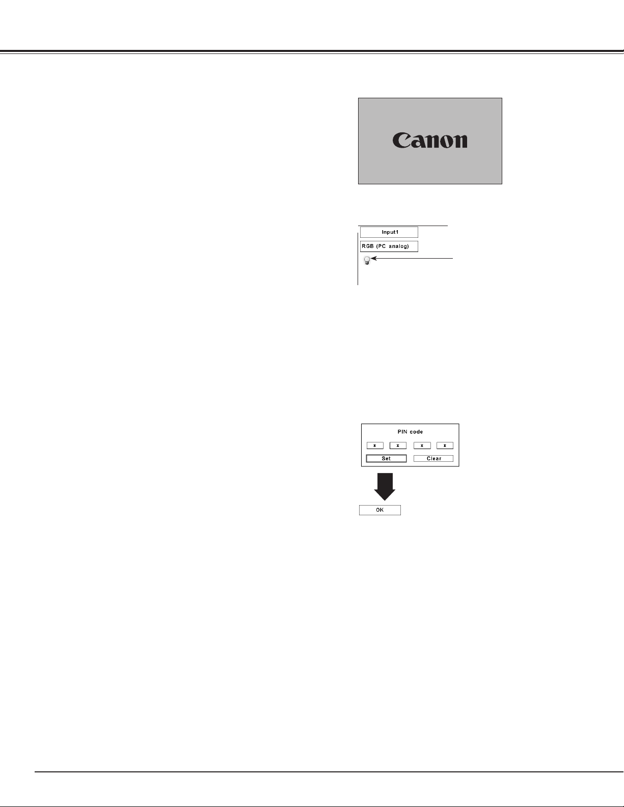
4
After the countdown, the input source that was
selected the last time and the Lamp mode status icon
(see page 57) appear on the screen.
If the projector is locked with a PIN code, PIN code
Input Dialog Box will appear. Enter the PIN code as
instructed below.
Selected Input Source and Lamp mode
Complete peripheral connections (with a computer,
VCR, etc.) before turning on the projector.
What is PIN code?
PIN (Personal Identification Number) code is a security
code that allows the person who knows it to operate the
projector. Setting a PIN code prevents unauthorized use of
the projector.
A PIN code consists of a four-digit number. Refer to the PIN
code lock function in the Setting Menu on page 59-60 for
locking operation of the projector with your PIN code.
PIN code Input Dialog Box
Enter a PIN code
After the OK icon
disappears, you can
operate the projector.
Lamp mode status
See page 57 for the Lamp mode status
✔Note:
•TheLampreplacementiconandtheFilter
replacementortheFiltercartridgereplacement
iconmayappearonthescreendependingonthe
usagestateoftheprojector.
•Whenthefiltercartridgereplacementicon
keepsappearingonthescreenatturningonthe
projectorforsometimeandnoactionistakento
replacethefiltercartridge,theprojectorwillbe
automaticallyshutdownin3minutesafterturning
ontoprotecttheprojector.(pp.63-65,79)
Use the Point ed buttons on the side control or Number
buttons on the remote control unit to enter a number.
When using side control
Use the Point ed buttons on the side control to select a
number. Press the Point 8 button to fix the number and
move the red frame pointer to the next box. The number
changes to “✳.” Repeat this step to complete entering a
four-digit number. After entering the four-digit number, move
the pointer to “Set.” Press the OK button so that you can
start to operate the projector.
When using remote control unit
Press the Number buttons on the remote control unit to
enter a number (p.17). When you complete entering a four-
digit number, the pointer moves to “Set.” Press the OK
button so that you can start to operate the projector.
If you fixed an incorrect number, use the Point 7 button to
move the pointer to the number you want to correct, and
then enter the correct number.
If you entered an incorrect PIN code, “PIN code” and the
number (✳✳✳✳) will turn red for a moment. Enter the
correct PIN code all over again.
✔Note:
•WhentheLogoselectfunctionissetto“Off,”the
logowillnotbeshownonthescreen(p.55).
•Whenthe“Countdownoff”or“Off”isselectedin
theDisplayfunction,thecountdownwillnotbe
shownonthescreen(p.54).
•Duringthecountdownperiod,alloperationsare
invalid.
•IfthePINcodenumberisnotenteredwithin3
minutesafterthePINcodedialogboxappeared,
theprojectorwillbeturnedoffautomatically.
•The“1234”issetastheinitialPINcodeatthe
factory.
Basic Operation
CAUTION ON HANDLING PIN CODE
If you forget your PIN code, the projector
can no longer be started. Take special care
in setting a new PIN code. Write down the
number as a reminder. Should the PIN code
be missing or forgotten, consult your dealer
or service center.
29
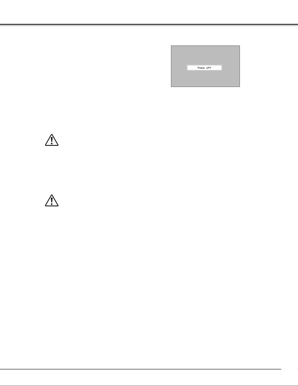
Press the POWER button on the side control or the
STAND-BY button on the remote control unit, and
“Power off?” appears on the screen.
Press the POWER button on the side control or the
STAND-BY button on the remote control unit again to
turn off the projector. The LAMP/SHUTTER indicator
lights bright and the POWER indicator turns off. After
the projector is turned off, the cooling fans operate for
90 seconds. You cannot turn on the projector during this
cooling down period.
1
2
TO MAINTAIN THE LIFE OF THE LAMP, ONCE YOU
TURN THE PROJECTOR ON, WAIT AT LEAST FIVE
MINUTES BEFORE TURNING IT OFF.
DO NOT UNPLUG THE AC POWER CORD WHILE
COOLING FANS ARE RUNNING OR BEFORE THE
POWER INDICATOR LIGHTS GREEN AGAIN.
OTHERWISE IT WILL RESULT IN SHORTENING OF
THE LAMP LIFE.
3
When the projector has cooled down enough, the
POWER indicator lights green and then you can turn on
the projector. To unplug the AC power cord, wait until
the projector is completely cooled down.
“Power off?” disappears after 4 seconds.
✔Note:
•WhentheOnstartfunctionissetto“On,”theprojectorwillbe
turnedonautomaticallybyconnectingtheACpowercordtoanAC
outlet(p.58).
•Therunningspeedofcoolingfansischangedaccordingtothe
temperatureinsidetheprojector.
•Donotputtheprojectorinacasebeforetheprojectoriscooled
enough.
•IftheWARNINGTEMP.indicatorblinksred,see“Warning
Indicators”onpage70.
•Theprojectorcannotbeturnedonduringthecoolingperiodwith
thePOWERindicatorturnedoff.Youcanturnitonagainafterthe
POWERindicatorbecomesgreenagain.
Turning Off the Projector
DO NOT OPERATE THE PROJECTOR CONTINUOUSLY
WITHOUT REST. CONTINUOUS USE MAY RESULT
IN SHORTENING THE LAMP LIFE. TURN OFF THE
PROJECTOR AND LET STAND FOR ABOUT 1 HOUR IN
EVERY 24 HOURS.
Basic Operation
CAUTION
CAUTION
30
Side Control
OK
button
How to Operate the On-Screen Menu
MENU button
POINT buttons
On-Screen Menu
The projector can be adjusted or set via the On-Screen
Menu. For each adjustment and setting procedure, refer to
the respective sections in this manual.
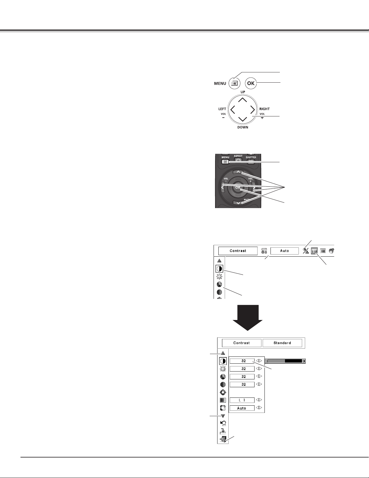
Use the Point
7 8 buttons to select a Menu icon. Use
the Point ed buttons to select an item in the selected
menu.
Press the OK button to show the item data. Use the
Point
7 8 buttons to adjust the values.
To close the On-Screen Menu, press the MENU button
again.
Press the MENU button on the side control or the
remote control unit to display the On-Screen Menu.
✔Note:
•TheselecteditemisnotactiveuntiltheOKbuttonispressed.
1
2
3
Remote Control Unit
POINT buttons
OK button
MENU button
Basic Operation
Pointer
(red frame )
Pointer (red frame )
Press the Point
ed buttons
to move the pointer.
Items
Menu icon
Menu bar
Item data
Press the Point
7 8
buttons to adjust the
value.
Press the OK button here to
display next items.
Press the OK button here to
display previous items.
Quit
Exit this menu.
OK button
31
Basic Operation
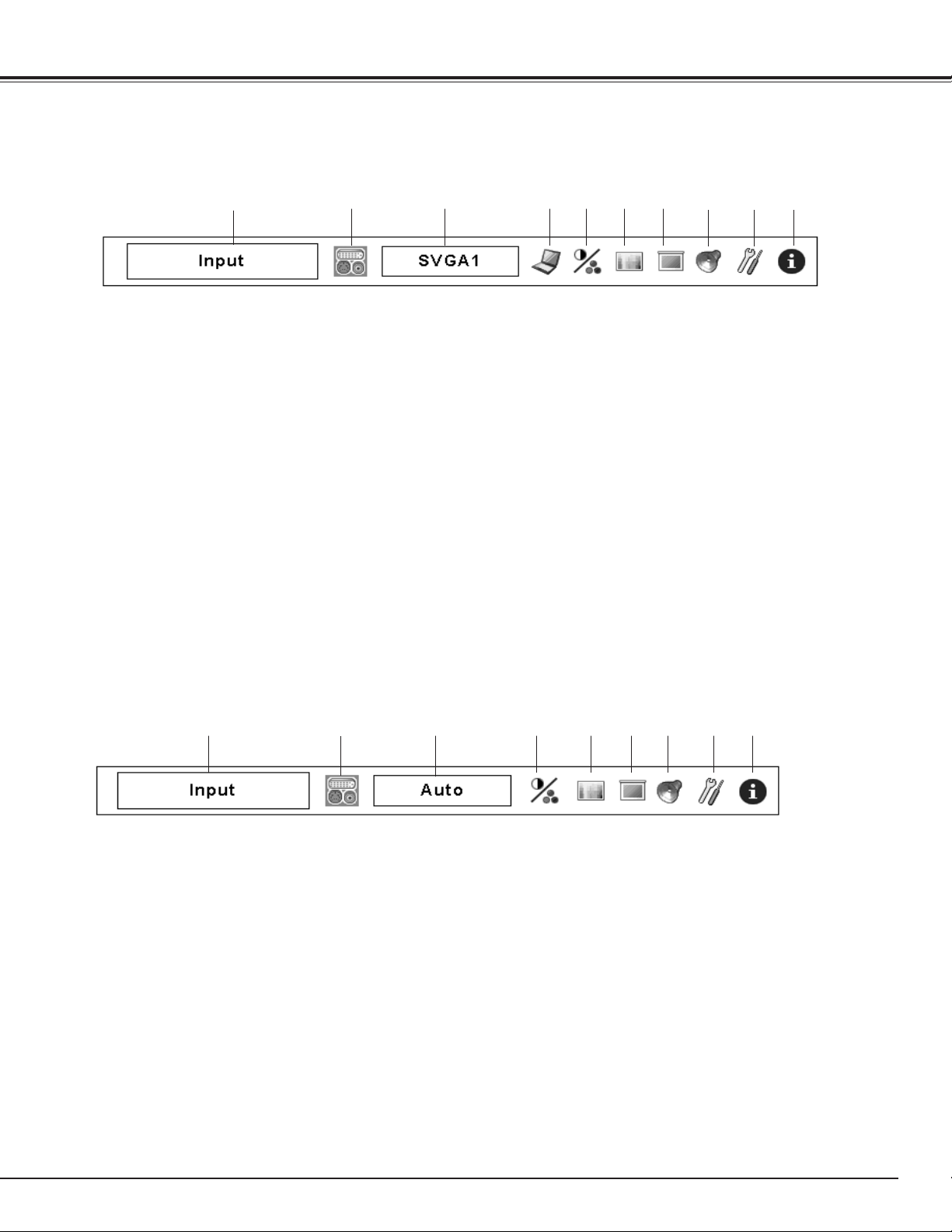
Menu Bar
For Computer Source
For Video Source
For detailed functions of each menu, see “Menu Tree” on pages 74-76.
q w oiuytre
!0
Show the selected of the On-Screen Menu.
Used to select computer system (p. 40).
Used to select an image level among Standard, High
contrast, and Custom 1–10 (p. 44).
Used to adjust the size of the image. [Normal/True/Wide/
Full screen/Custom/Keystone/Ceiling/Rear/Reset/Digital
zoom +/–] (pp.45-46).
Used to adjust the computer image. [Contrast/ Brightness/
Color management/Auto picture control/Advanced
color/Color temp./White balance (R/G/B)/Offset (R/G/B)/
Sharpness/ Gamma/Reset/Store/Quit] (pp.51–53).
Used to adjust the parameters to match with the input signal
format (pp. 41-43).
Used to select an input source (Input 1, Input 2, or Input 3)
(pp. 37, 38).
Used to adjust the volume, mute the sound, or switch the
Input pattern (p. 33).
qGuide Window
w
Input Menu
e
PC System Window
r
PC Adjust Menu
tImage Select Menu
yImage Adjust Menu
uAspect Menu
iSound Menu
Display the input source information (p. 34).
Used to set the projector’s operating configurations
(pp. 54-62).
oSetting Menu
!0Information Menu
q w oiuytre
Show the selected Menu of the On-Screen Menu.
Used to select the system of selected video source (p. 47).
Used to select an image level among Standard, Cinema, and
Custom 1–10 (p. 48).
Used to adjust the size of the image. [Normal/Wide/
Custom/Keystone/Ceiling/Rear/Reset] (pp. 49-50).
Used to select an input source (Input 1, Input 2, or Input 3)
(pp. 37, 38).
Used to adjust the volume, mute the sound, or switch the
Input pattern (p. 33).
qGuide Window
w
Input Menu
e
AV System Window
rImage Select Menu
yAspect Menu
uSound Menu
Display the input source information (p.34).
Used to set the projector’s operating configurations
(pp. 54-62).
iSetting Menu
oInformation Menu
Used to adjust the picture image. [Contrast/Brightness/
Color/Tint/Color management/ Auto picture control/
tImage Adjust Menu
Advanced color/Color temp./White balance (R/G/B)/ Offset
(R/G/B)/Sharpness/Gamma/Noise reduction/Progressive/
Reset/Store/Quit) (pp. 51–53.)
✔Note:
•Itemswillbesameastheitemsinvideosourcewhen480i,
575i,480p,575p,720p,1035ior1080iisselected.
32
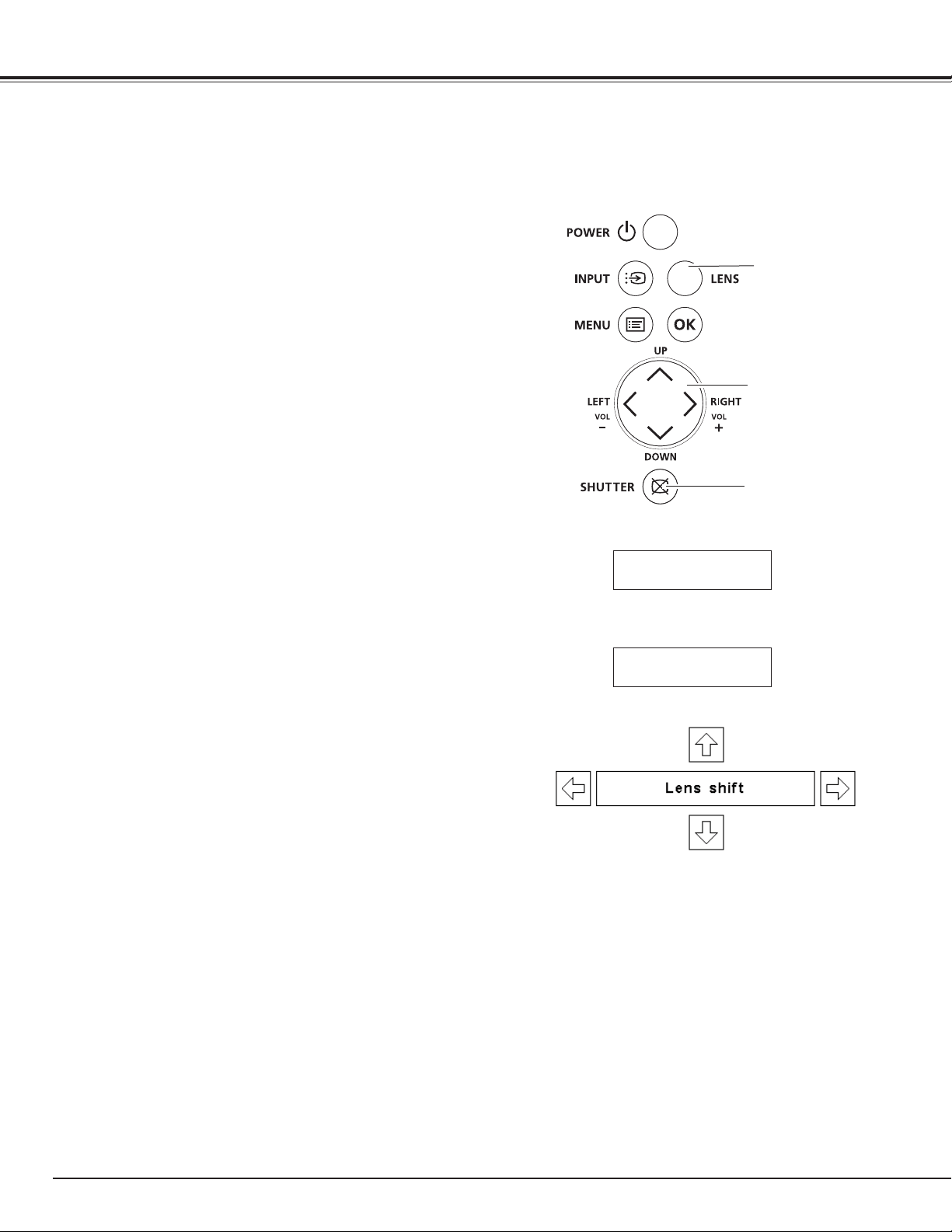
Operating with Projector Control
The following lens operation can be made with the Lens
button on the side control.
Press the LENS button to enter each lens operation mode.
The selected adjustment display appears on the screen.
Display “Lens shift” on the screen. Use the Point ed7 8
buttons to position the screen to the desired point without
having picture distortion.
The screen can be moved up or down to 50 percent, or
sideways up to 10 percent from the central axis of the
lens shift.
Lens Shift Adjustment
✔Note:
•Thearrowdisappearsatthemaximum
lensshiftineachdirection.
•The arrow turns red when the lens
shift comes to the center position of
thescreen.
Display “ZOOM” on the screen. Use the Point ed
buttons to zoom in and out the image.
Zoom Adjustment
Display “FOCUS” on the screen. Use the Point ed
buttons to adjust focus of the image.
Focus Adjustment
Side Control
Lens Operation
ZOOM
FOCUS
POINT buttons
ZOOM ➜ FOCUS ➜ Lens shift ➜
• • • • •
Basic Operation
Shutter Function
Shutter function allows you to completely block out light
to the screen. Press the SHUTTER button to close the
shutter inside the projector. To open up the shutter, press
the SHUTTER button again. Refer to p.61 for detail of
setting for the Shutter function.
✔Note:
•The SHUTTER button on the side control and the
remote control unit cannot be effective when
Shutter Protection is "On" in the Setting menu.
(p.61)
•TheLAMP/SHUTTERindicatorontheprojector'stop
lightsbluewhentheshutterisclosed.(p.15)
•The projector will shut down automatically when
the set time on shutter management has passed.
(p.61)
•The Power management function does not work
whentheshutterisclosed.(p.58)
SHUTTER button
LENS button
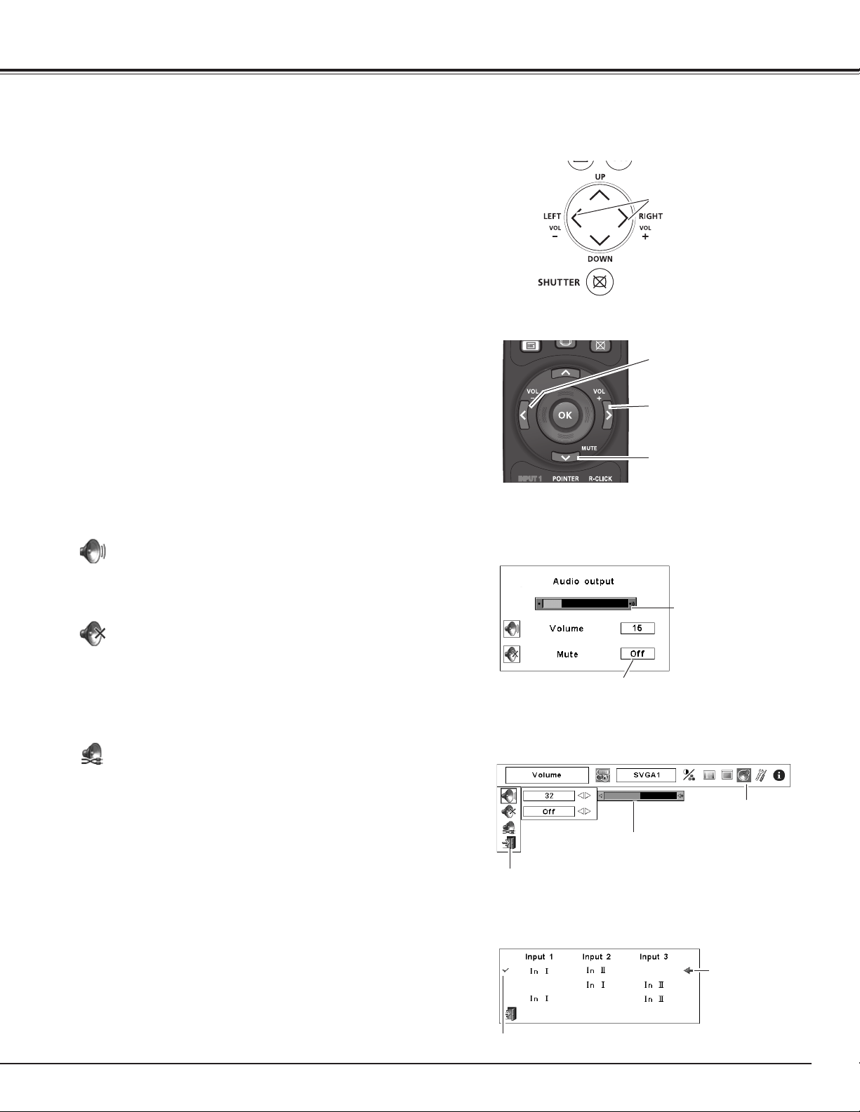
33
1
2
Press the MENU button to display the On-Screen
Menu. Use the Point 7 8 buttons to move the red
frame pointer to the Sound Menu icon.
Press the VOLUME+/– buttons on the side control or on the
remote control unit to adjust the volume of Audio Output.
The volume dialog box appears on the screen for a few
seconds.
Press the MUTE button on the remote control unit to
temporarily turn off the AUDIO OUT. To turn the AUDIO OUT
back on, press the MUTE button again or press the VOLUME
+/– buttons.
Press the Point 7 8 buttons to switch the mute function
On/Off. When the sound is turned off, “On” is displayed.
Press the Point 7 8 buttons again to turn the sound back
on.
Use the Point ed buttons to move the red frame
pointer to the desired item, and then press the OK
button.
Approximate level of
the volume.
Exit the Sound Menu.
Approximate
level of the
volume.
Press the MUTE button to set the Mute function
On or Off. The dialog box disappears after 4
seconds.
Sound Menu
Sound Menu icon
Volume
Remote Control Unit
VOL + button
VOL – button
MUTE button
Volume (Audio output)
Mute (Audio output)
Press the Point 8 button to turn up the volume; press the
Point 7 button to turn down the volume.
Mute
Direct Operation
Menu Operation
Sound Adjustment
Side Control
Volume Dialog Box
Input pattern
This projector has two INPUT terminals [AUDIO IN I/
AUDIO IN II]. Input pattern allows you to set up INPUT 1,
INPUT 2, and INPUT 3 to each INPUT for sound function.
(pp. 13, 37-39)
Press the OK button to display the input pattern dialog box.
Use the Point ed buttons to move the pointer (red arrow)
to the desired pattern and press the OK button to set the
input pattern for sound function. Check mark appears next
to the selected Input pattern.
Basic Operation
VOLUME +/– buttons
Input Pattern Dialog Box
Move the pointer
(red arrow) to the
desired pattern
and press the OK
button.
Selected Input Pattern

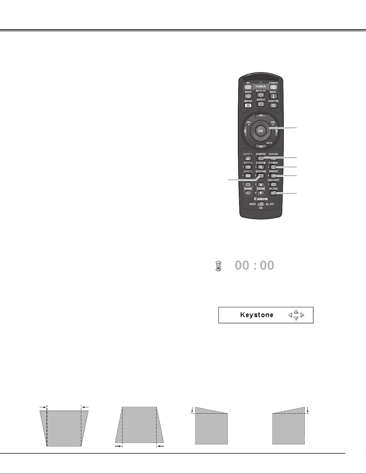
34
Operating with Remote Control Unit
Using the remote control unit for some frequently used operations is advisable. Just pressing one of the
buttons enables you to make the desired operation quickly without calling up the On-Screen Menu.
Remote Control Unit
D-ZOOM
button
AUTO PC
button
ZOOM
buttons
FOCUS
buttons
LENS-SHIFT
button
✔Note:
•See the next page for the description
ofotherbuttons.
Information Menu
Basic Operation
ASPECT
button
INFO. button
POINT ed7 8
buttons
Information Menu
Press the ZOOM buttons on the remote control unit to zoom
in and out the image.
ZOOM buttons
Press the FOCUS buttons on the remote control unit to
adjust focus of the image.
FOCUS buttons
Information display can be used to confirm the current
operating condition of the projector and the signal being
projected through the projector.
Press the INFO. button on the remote control unit to
display the information window on the screen. To hide the
information window, press the INFO. button again or Point
7 8 buttons.
The information window can also be selected from the
menu.
INFO. button
Press the AUTO PC button on the remote control unit to
operate the Auto PC Adj. function. The computer screen
adjustment can be done easily by pressing this button. See
page 41 for details.
AUTO PC button
Press the D-ZOOM button on the remote control unit to
enter to the Digital zoom +/– mode. See page 46 for details.
D-ZOOM button
✔Note:
•TheH-andV-syncfreq.valuesdescribedinthefiguremaybe
differentfromtheactualvalues.
•SERIALNO.isusedtoservicetheprojector.
Press the ASPECT button on the remote control unit to
select the desired screen size. The selected screen size
symbol appears on the screen for 4 seconds. See pages 45,
46, 49, 50 and for details.
Press and hold the ASPECT button for more than 5 seconds
to return all the screen size adjustment setting to the factory
default setting.
ASPECT button
See page 32 for details.
LENS-SHIFT button
SHUTTER button
SHUTTER button
See page 32 for details.
35
FILTER button
Press and hold the FILTER button for more than 5 seconds
to operate electrically operated filter to replace the filter.
KEYSTONE button
Reduce the upper width with
Point e button.
Reduce the lower width
with Point d button.
Reduce the left part with
Point 7 button.
Reduce the right part with
Point 8 button.
• The white arrows indicate that there is no correction.
• A red arrow indicates the direction of correction.
• An arrow disappears at the maximum correction.
• If you press the KEYSTONE button on the remote
control unit again while the Keystone dialog box is
being displayed, the keystone adjustment will be
canceled.
• The adjustable range can be limited depending on
the input signal.
• “Keystone” disappears after 10 seconds.
Remote Control Unit
POINTER button
FILTER button
✔Note:
•See the previous page for the
descriptionofotherbuttons.
MOUSE
POINTER
button
Press the KEYSTONE button on the remote control unit. The
“Keystone” appears on the screen.
Use the Point ed7 8 buttons to correct keystone
distortion. The keystone adjustment can be stored (pp.46,
50).
Basic Operation
✔Note:
•Whenthefilterisreplaced,thetotalaccumulatedtimeofthefilter
useisautomaticallysetto0.
KEYSTONE
button
FREEZE button
P-TIMER button
Move the pointer on the screen with this button.
MOUSE POINTER button
POINTER button
Press POINTER button on the remote control unit to display
the Pointer on the screen.
P-Timer display
Press the P-TIMER button on the remote control unit. The
Timer display “00 : 00” appears on the screen and starts to
count time (00 : 00–59 : 59).
To stop the P-TIMER, press the P-TIMER button.
To cancel the P-TIMER, press the P-TIMER button again.
P-TIMER button
Press the FREEZE button on the remote control unit to
freeze the picture on the screen. To cancel the FREEZE
function, press the FREEZE button again or press any other
button.
FREEZE button
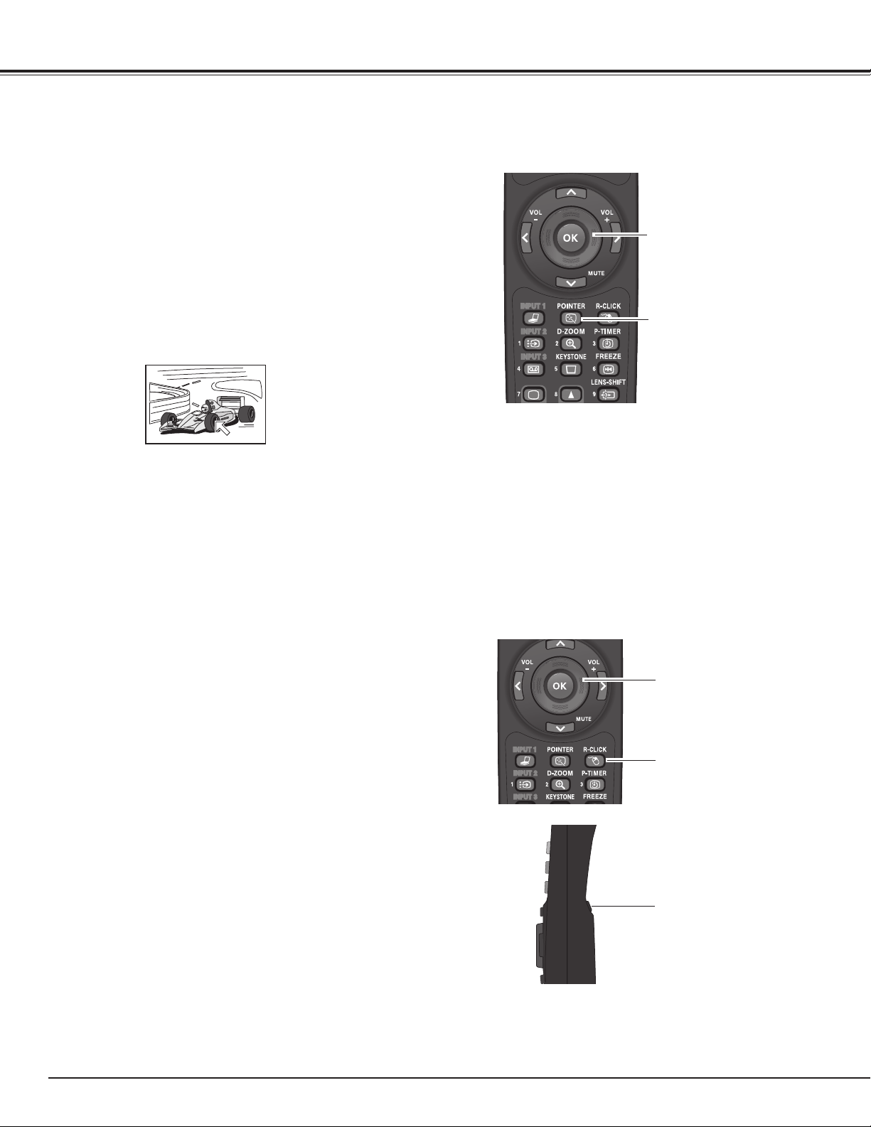
36
Pointer Function
Pointer
✔Note:
•YoucanchoosethepatternofPointer(Cross/Arrow/Dot)inthe
SettingMenu(p.58)
You can move the Pointer of the projector with the remote control unit to emphasize a part of the projected
image.
Press the POINTER button to activate the Pointer
function.
1
2
3
MOUSE POINTER button
POINTER button
To cancel the Pointer function, press the POINTER
button again or press any other button.
Use the MOUSE POINTER button to move the Pointer.
Wireless Mouse Operation
The remote control unit can be used as a wireless mouse for your computer.
Move the pointer on
the screen with this
button.
MOUSE POINTER
button
R-CLICK button
L-CLICK button
Acts as right (click)
mouse button while
the projector and
a computer are
connected with a USB
cable.
Acts as left (click)
mouse button while
the projector and
a computer are
connected with a USB
cable.
Before operating the wireless mouse, connect your
computer and the projector with the supplied USB
cable (p. 24).
When the Pointer function is used, the wireless mouse
is not available.
When a USB cable is connected to the computer
and the projector, turn on the projector first, then
the computer. If you turn on the computer first, the
wireless mouse function may not operate properly.
1
2
Basic Operation
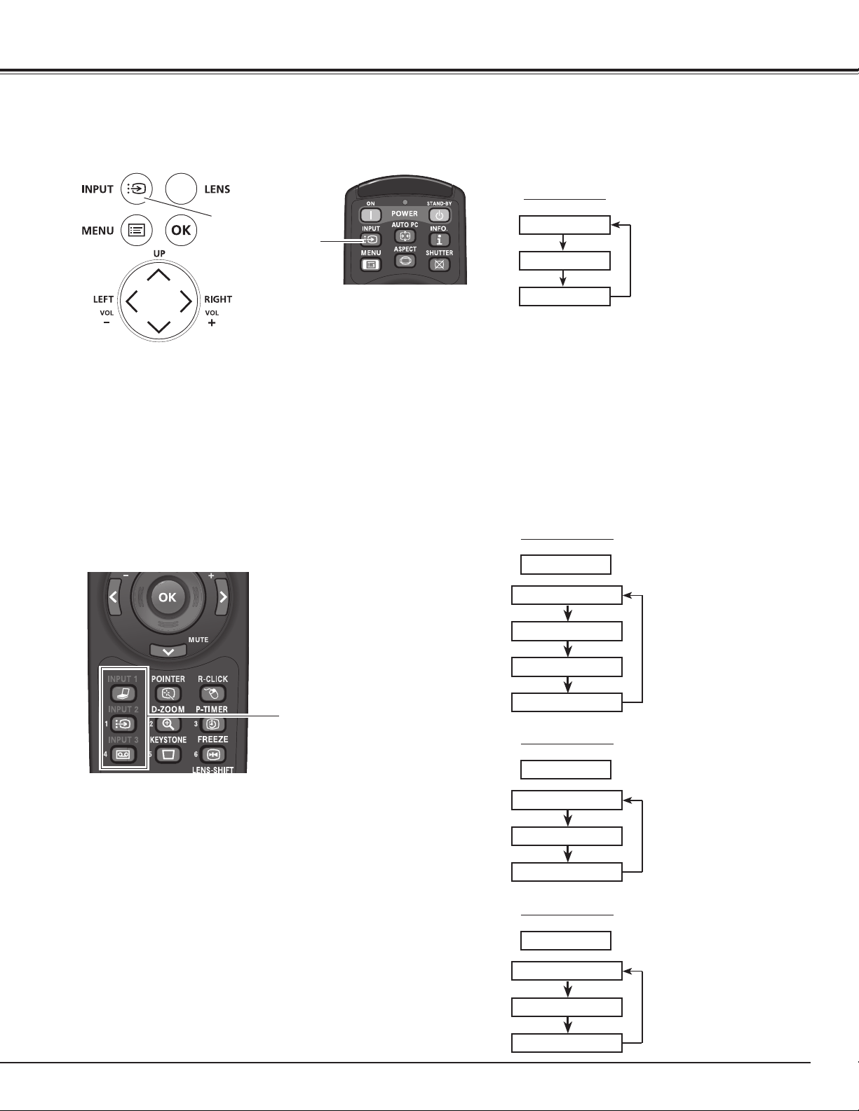
37
Input
Remote control unit button operation
INPUT button
Press the INPUT button on the side control or the remote
control unit. It switches to INPUT 1, INPUT 2, and INPUT 3
as you press the INPUT button.
Before using the INPUT button on the side control or the
remote control unit, you must select a correct input source
by On-Screen Menu and the latest input source will be
displayed.
INPUT button
Input 1
Input 2
Input 3
Side Control/Remote control unit
button operation
Input Selection
Press the INPUT 1, INPUT 2, or INPUT 3 buttons on the
remote control unit. The input source appears on the screen
as you press each button. Select the connected input
source.
INPUT buttons
INPUT 1 button
Input 1
RGB (PC analog)
RGB (Scart)
RGB (PC digital)
RGB (AV HDCP)
INPUT 2 button
Input 2
Video
Y,Pb/Cb,Pr/Cr
RGB
INPUT 3 button
Input 3
Video
Y,Pb/Cb,Pr/Cr
S-video
Remote Control Unit Operation
Side Control/Remote Control Unit Operation
Remote Control Unit
Side Control
Remote Control Unit
INPUT button
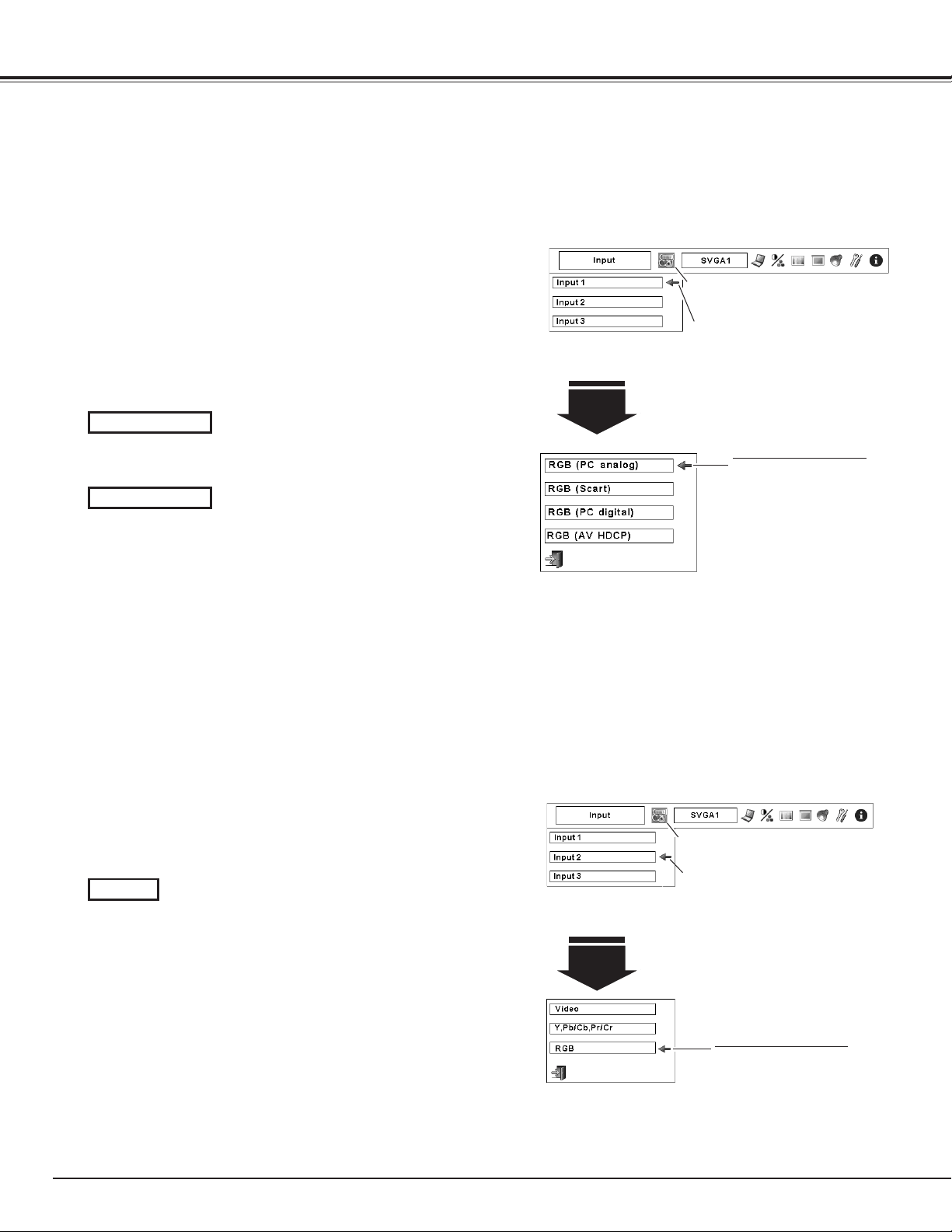
38
Computer Input Source Selection
WHEN SELECTING INPUT 1 (COMPUTER INPUT TERMINALS )
Press the MENU button to display the On-Screen Menu. Use
the Point 7 8 buttons to move the red frame pointer to the
INPUT Menu icon.
Use the Point ed buttons to move the red arrow pointer to
the desired input and then press the OK button. The Source
Select Menu appears.
1
2
Input 1
Use the Point ed buttons to select the desired source and
then press the OK button.
3
When your computer is connected to INPUT 1 (DIGITAL)
terminal, select RGB (PC digital).
When your computer is connected to the INPUT 1 (ANALOG)
terminal, select RGB (PC analog).
Move the pointer (red
arrow) to the desired source
and press the OK button.
Source Select Menu
RGB (PC digital)
RGB (PC analog)
✔Note:
•INPUTSOURCEchangesiftheINPUT1buttonontheremote
controlunitispressed.
•HDCP(High-bandwidthDigitalContentProtection)isasystem
forprotectingdigitalentertainmentcontentwhichisdeliveredby
DVI(DigitalVisualInterface)frombeingcopied.Thespecification
ofHDCPisdecidedandcontrolledbyDigitalContentProtection,
LLC.Shouldthespecificationbechanged,thisprojectormaynot
displaythedigitalcontentprotectedbyHDCP.
Menu Operation
Input Menu icon
Move the pointer (red arrow) to Input
1 and press the OK button.
When connecting the computer output [5 BNC Type (Green,
Blue, Red, Horiz. Sync, and Vert. Sync.)] from the computer
to G, B, R, H/HV, and V jacks:
WHEN SELECTING INPUT 2 (5 BNC INPUT JACKS )
INPUT MENU
INPUT Menu icon
Move the pointer (red arrow) to Input
2 and press the OK button.
Input 2
Move the pointer (red
arrow) to RGB and press the
OK button.
Source Select Menu
Input Selection
When your computer is connected to the INPUT 2 (5 BNC
INPUT JACKS) terminal, select RGB.
RGB
INPUT MENU
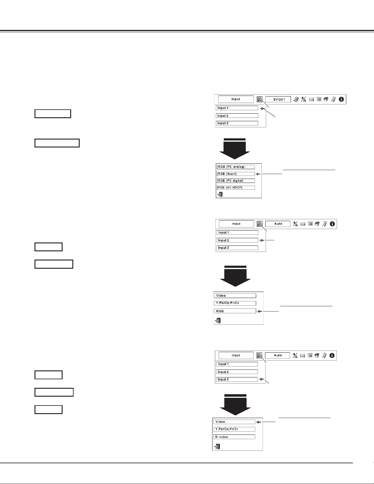
39
When the video input signal is connected to the Y-
Pb/Cb-Pr/Cr jacks, select Y, Pb/Cb, Pr/Cr.
When the video input signal is connected to the
VIDEO jack, select Video.
When the video input signal is connected to the S-
VIDEO jack, select S-Video.
When connecting to video equipment, select the type of
Video source in the Source Select Menu.
WHEN SELECTING INPUT 3 (AV TERMINALS )
When the video input signal is connected to the Y-
Pb/Cb-Pr/Cr jacks, select Y, Pb/Cb, Pr/Cr.
When the video input signal is connected to the
VIDEO jack, select Video.
When connecting to video equipment, select the type of
Video source in the Source Select Menu.
Video
Y, Pb/Cb, Pr/Cr
Video
Y, Pb/Cb, Pr/Cr
S-Video
Menu Operation
Input Menu icon
Move the pointer (red arrow) to
Input 2 and press the OK button.
Input 2
Move the pointer (red
arrow) to Video or Y, Pb/Cb,
Pr/Cr and press the OK
button.
Source Select Menu
INPUT MENU
Input Menu icon
Move the pointer (red arrow) to Input
3 and press the OK button.
Input 3
Move the pointer (red
arrow) to the desired source
and press the OK button.
Source Select Menu
Video Input Source Selection
Input Selection
WHEN SELECTING INPUT 1 (COMPUTER INPUT TERMINALS )
When connecting to video equipment, select the type of
Video source in the Source Select Menu.
Input 1
INPUT MENU
Move the pointer (red
arrow) to RGB (Scart) or
RGB (AV HDCP) and press
the OK button.
Source Select Menu
Input Menu icon
Move the pointer (red arrow) to Input
1 and press the OK button.
RGB (AV HDCP)
RGB (Scart)
When scart video equipment is connected to the INPUT 1
(ANALOG) terminal, select RGB (Scart).
If the HDCP-compatible signal source is connected to the
INPUT 1 (DIGITAL) terminal, select RGB (AV HDCP).
INPUT MENU
WHEN SELECTING INPUT 2 (5 BNC INPUT JACKS )
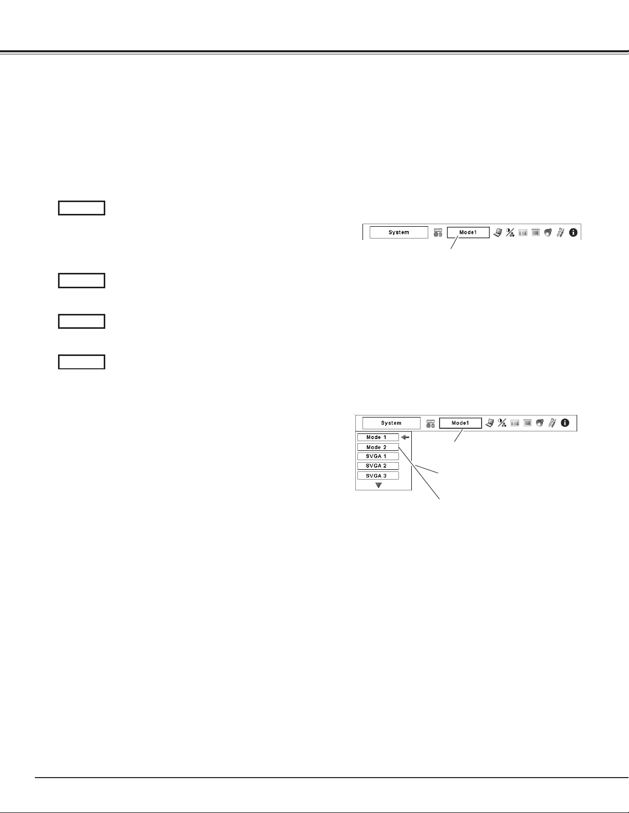
40
Computer System Selection
This projector automatically tunes to various types of computers based on VGA, SVGA, XGA, SXGA, SXGA+,
WXGA, UXGA or WUXGA (refer to “Compatible Computer Specifications” on pages 80–81). If a computer is
selected as a signal source, this projector automatically detects the signal format and tunes to project a proper
image without any additional settings. (Some computers need to be set manually.)
One of the following messages may appear when:
The projector cannot recognize the connected signal
conforming to the provided PC Systems. The “Auto” is
displayed on the System Menu box and the Auto PC
Adjustment function works to display proper images.
If the image is not projected properly, a manual
adjustment is required. (pp. 42–43.)
There is no signal input from the computer. Check the
connection between your computer and the projector.
(See “Troubleshooting” on page 71.)
Auto
-----
PC System Menu icon
Selected system is displayed.
PC SYSTEM MENU
Selecting Computer System Manually
Press the MENU button to display the On-Screen Menu. Use
the Point 7 8 buttons to move the red frame pointer to the
PC System Menu icon.
Use the Point ed buttons to move the red arrow pointer to
the desired system, and then press OK button.
1
2
PC SYSTEM MENU
PC system can also be selected manually.
Automatic Multi-Scan System
The preset system is manually adjusted in the PC
Adjust Menu. The adjusted data can be stored in the
Mode 1–10. (pp. 42-43)
Mode 1
PC systems provided in this projector is chosen. The
projector chooses a proper system provided in the
projector and displays it.
SVGA 1
] Mode 1 and SVGA 1 are examples.
PC System Menu icon
Selected system is displayed
Systems in this dialog box can be
selected.
Custom Mode (1–10) set in PC Adjust
Menu. (pp.42–43)
Computer Input
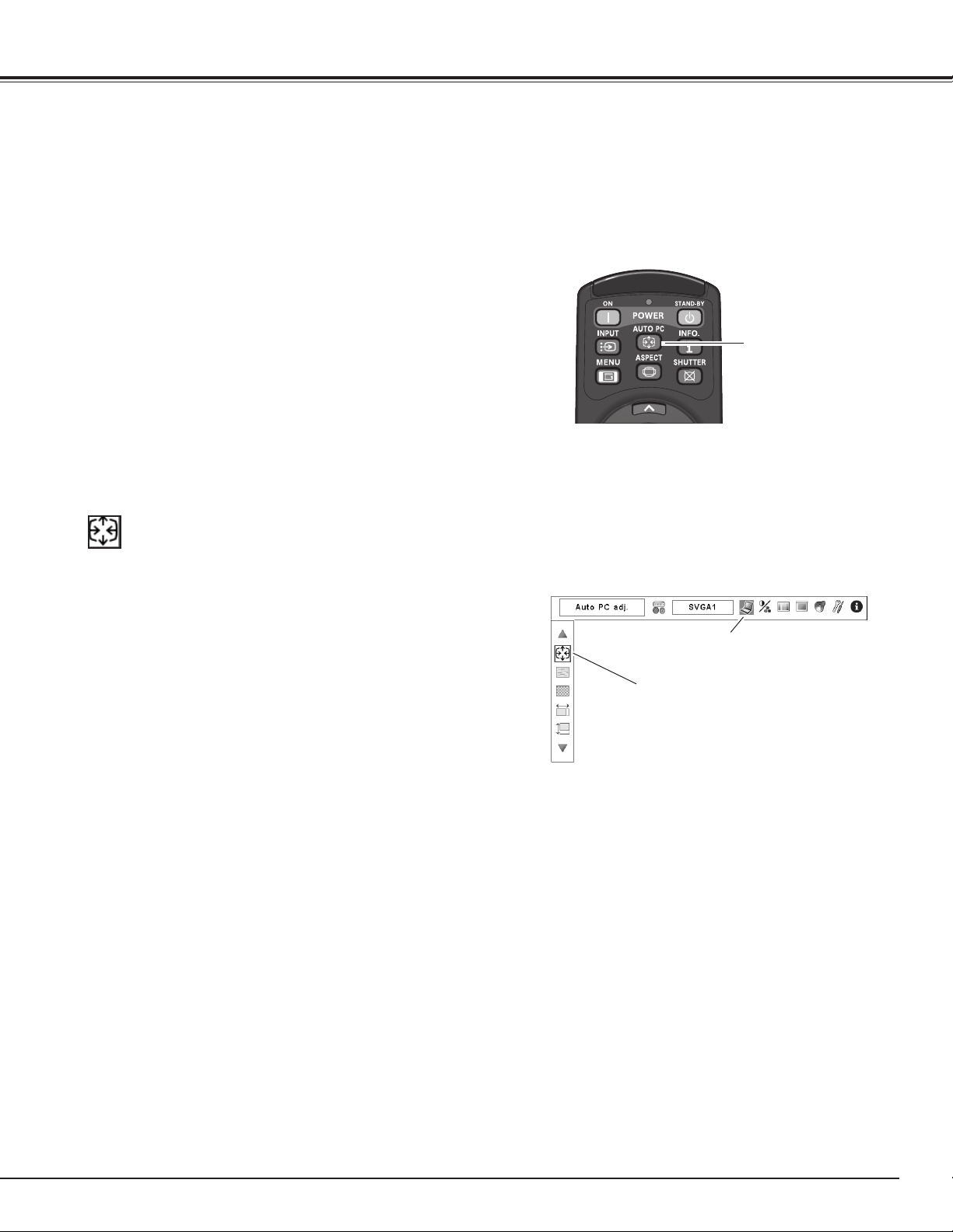
41
Auto PC Adjustment
Auto PC Adjustment function is provided to automatically adjust Fine sync, Total dots, Horizontal and Vertical
positions to conform to your computer.
Press the MENU button to display the On-Screen Menu. Use
the Point 7 8 buttons to move the red frame pointer to the
PC Adjust Menu icon.
1
2
Use the Point ed buttons to move the red frame pointer to
the AUTO PC adj. icon and then press the OK button twice.
PC ADJUST MENU
Auto PC adj.
To store the adjusted parameters.
The adjusted parameters from the Auto PC Adjustment can be stored in
the projector. Once the parameters are stored, the setting can be done
just by selecting Mode in PC SYSTEM Menu (p.40). See MANUAL PC
ADJUSTMENT on pages 42–43.
✔Note:
•Fine sync,Total dots, Horizontal andVertical position of certain
computers cannot be fully adjusted with theAutoPCAdjustment
function.When the image is not provided properly with this
operation,manualadjustmentsarerequired.(pp.42–43.)
•AutoPCAdjustmentcannotbeoperatedinDigitalSignal Inputon
theDVIterminaland“480p,”“575p,”“480i,”“575i,”“720p,”“1035i,”
or“1080i”isselectedonthePCSYSTEMMenu.
•Dependingontheconditionofsignalsandthetypeandlengthof
cables,thesignalsmaynotbeproperlyviewed.
PC Adjust Menu icon
Move the red frame pointer to the Auto PC
adj. and press the OK button twice.
“Please wait...” appears while the Auto PC
adjustment is in process.
The Auto PC adjustment function can be operated directly
by pressing the AUTO PC button on the remote control unit.
AUTO PC button
Direct Operation
Remote Control Unit
Menu Operation
Computer Input
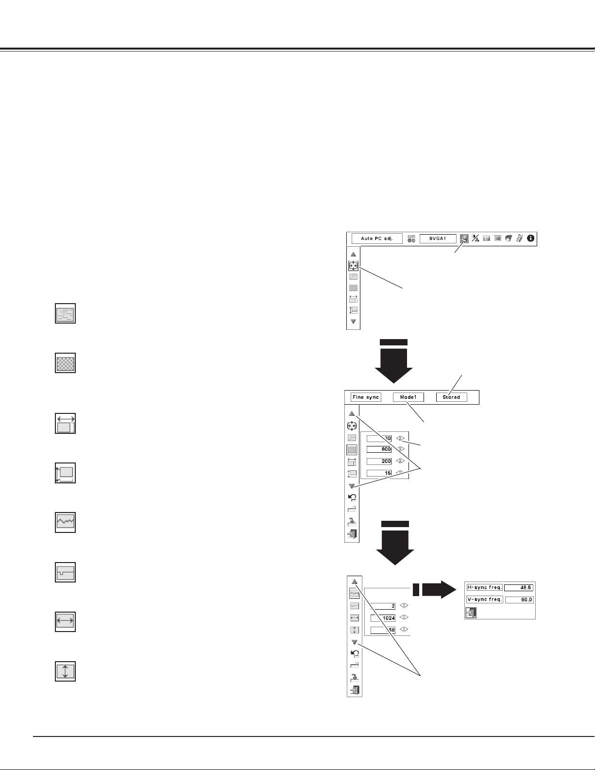
42
Manual PC Adjustment
Some computers employ special signal formats which may not be tuned by Multi-Scan system of this projector.
Manual PC Adjustment enables you to precisely adjust several parameters to match those special signal formats.
The projector has 10 independent memory areas to store those parameters manually adjusted. It allows you to
recall the setting for a specific computer.
✔Note: The PC Adjust Menu cannot be operated when the digital signal input on the DVI terminal is selected on
PC System Menu.
Press the MENU button to display the On-Screen Menu. Use
the Point 7 8 buttons to move the red frame pointer to the
PC Adjust Menu icon.
1
2
Use the Point ed buttons to move the red frame pointer to
the desired item and then press the OK button to display the
adjustment dialog box. Use the Point 7 8 buttons to adjust
the setting value.
Use the Point 7 8 buttons to adjust the value, eliminating a flicker
from the image displayed (from 0 to 31).
Fine sync
Use the Point 7 8 buttons to adjust the number of total dots in one
horizontal period to match your PC image.
Total dots
Use the Point 7 8 buttons to adjust the horizontal picture position.
Position H
Use the Point 7 8 buttons to adjust the vertical picture position.
Position V
Press the OK button to show H-sync freq. and V-sync freq. of the
connected computer.
Current mode
Use the Point 7 8 buttons to adjust the clamp level. When the
image has dark bars, try this adjustment.
Clamp
Press the OK button at
Current mode icon to
show the information
of the connected
computer.
Current mode
Use the Point 7 8 buttons to adjust the horizontal area displayed
by this projector.
Display area H
Use the Point 7 8 buttons to adjusts the vertical area displayed by
this projector.
Display area V
Move the red frame pointer to the
desired item and press the OK button.
Press the Point 7 8 buttons to adjust
the value.
Press the OK button at this icon to
adjust “Clamp,” “Display area H,” or
“Display area V.”
Selected Mode
Status (Stored/Free) of the
Selected Mode.
Press the OK button at this icon to
display the previous items.
PC ADJUST MENU
PC Adjust Menu icon
Computer Input
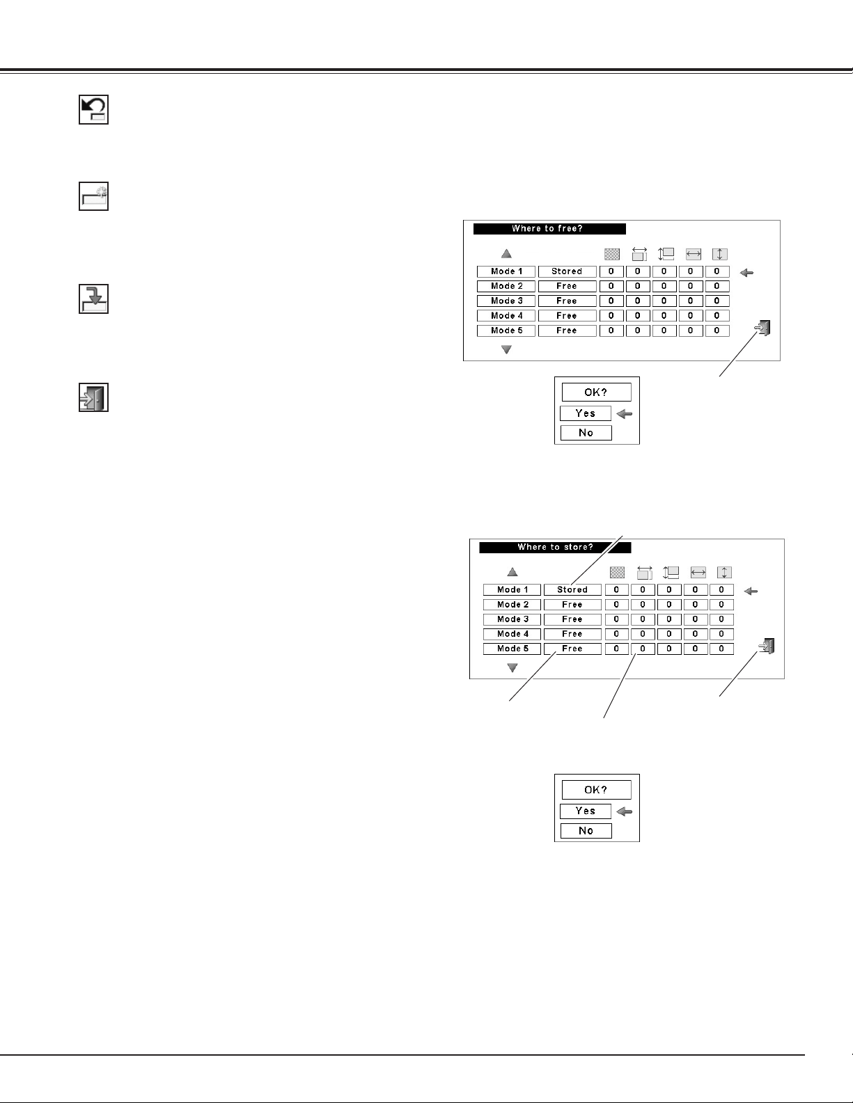
43
Exit the PC Adjust Menu.
To store the adjusted data, select Store and then press the OK
button. Move the red arrow pointer to one of the Mode 1 to 10 in
which you want to store, and then press the OK button.
To reset the adjusted data, select Reset and press the OK button. A
confirmation box appears and then select [Yes]. All adjustments will
return to their previous figures.
To store the adjusted data.
To clear the adjusted data.
To clear the adjusted data, select Mode free and then press the OK
button. Move the red arrow pointer to the Mode that you want to
clear and then press the OK button.
Reset
Mode free
Store
Quit
This Mode has stored parameters.
Vacant
Values of “Total dots,” “Position
H,” “Position V,” “Display area
H,” and “Display area V.”
Close this dialog box.
Close this dialog box.
Confirmation box appears
and then select [Yes].
Confirmation box appears
and then select [Yes].
Computer Input
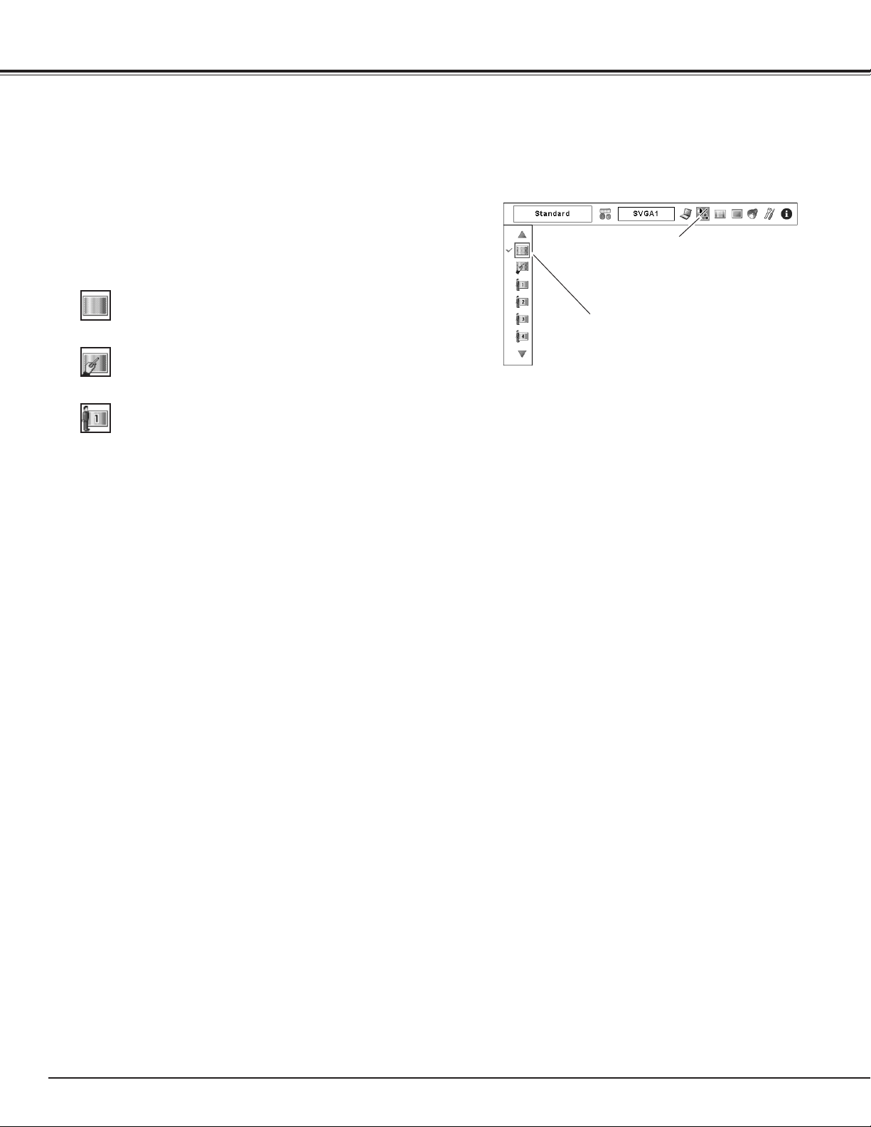
44
Press the MENU button to display the On-Screen Menu. Use
the Point 7 8 buttons to move the red frame pointer to the
Image Select Menu icon.
1
2
Use the Point ed buttons to move the red frame pointer to
the desired image level and then press the OK button.
IMAGE SELECT MENU
Normal picture level preset on the projector.
Standard
Picture level with improved halftone for graphics.
High contrast
User preset picture adjustment in the Image Adjust Menu. (p. 53)
Custom 1–10
Image Level Selection
Menu Operation
Image Select Menu icon
Move the red frame pointer to the desired
level and press the OK button.
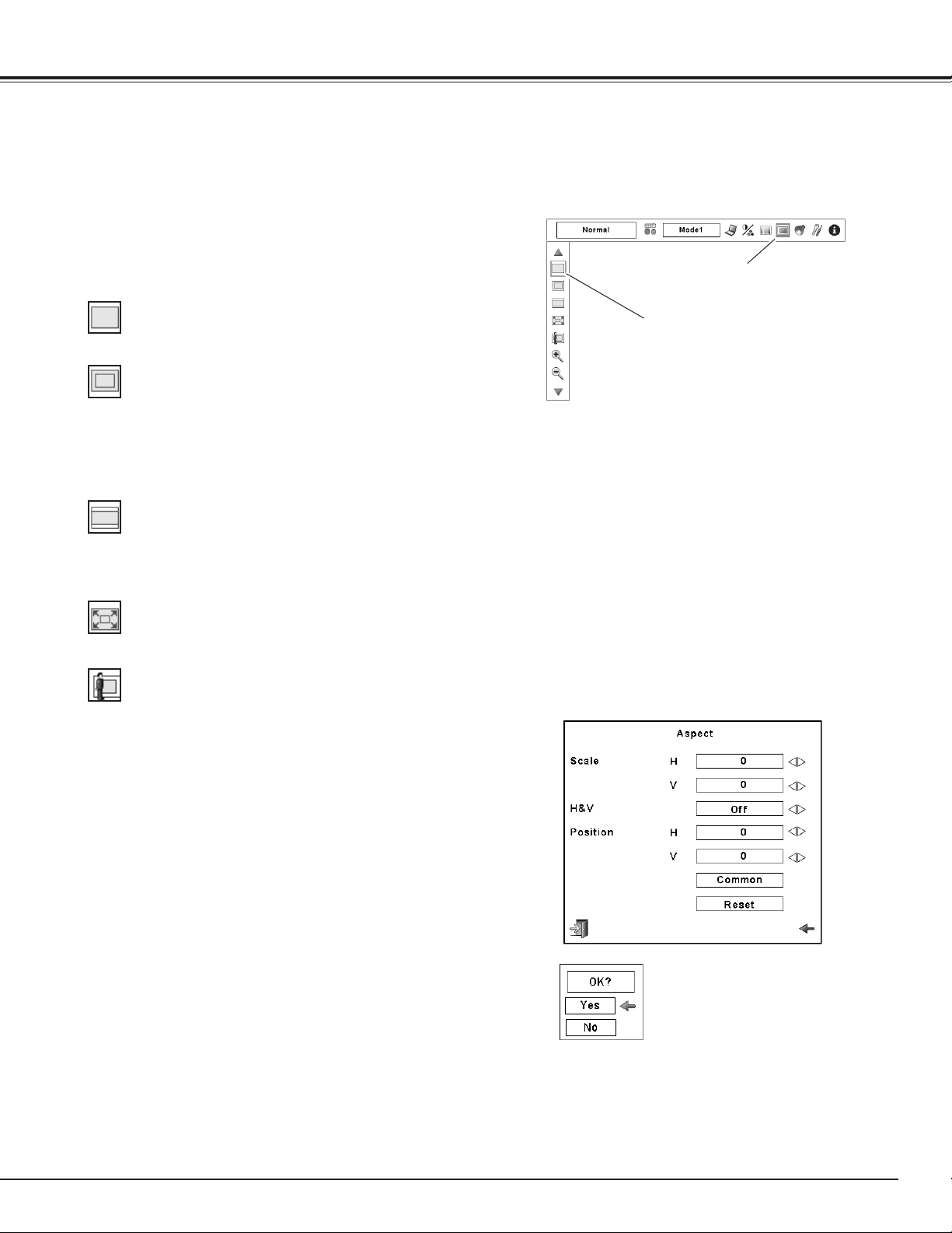
45
Screen Size Adjustment
Select the desired screen size that conforms to the input signal source.
Press the MENU button to display the On-Screen Menu. Use
the Point 7 8 buttons to move the red frame pointer to the
Aspect Menu icon.
1
Use the Point ed buttons to move the red frame pointer to
the desired function and then press the OK button.
2
Normal
ASPECT MENU
Provide the image at the normal computer aspect ratio of 4:3.
Wide
True
Provide the image in its original size. When the original image size
is larger than the screen size (1024 x 768), the projector enters to
the panning mode automatically. Use the Point ed7 8 buttons
to pan the image. When adjusted, the arrows will turn red. When
reached to the correction limits, the arrows will disappear.
Provide the image to fit the wide video aspect ratio (16:9) by
expanding the image width uniformly. This function can be used to
provide the squeezed video signal at 16:9.
Full screen
Provides the full screen image.
Aspect Menu icon
Move the red frame pointer to the desired
function and press the OK button.
Scale H/V .............. Adjust the Horizontal/Vertical screen scale.
H&V ...................... When set to “On,” the aspect ratio is fixed.
The “Scale V” appears dimmed and becomes
unavailable. Adjust “Scale H,” then the screen
scale is automatically modified based on the
aspect ratio.
Position H/V .......... Adjust the Horizontal/Vertical screen position.
Common .............. Save the adjusted scale to all the inputs.
Press the OK button at Common to display a
confirmation box. To save the scale, press the
OK button at “Yes.” When Custom is selected,
the saved scale is used.
Reset .................... Reset the all adjusted values. Press the OK
button at Reset to display a confirmation box.
To reset, press the OK button at “Yes.”
Custom
✔Note:
•Whennosignalisdetected,“Normal”is
setautomaticallyandtheAspectdialogbox
disappears.
•TheadjustablerangeforScaleH/VandPosition
H/Vislimiteddependingontheinputsignal.
Press the OK button at Common or Reset,
to display a confirmation box.
Computer Input
Adjust the screen scale and position manually with this function.
Press the OK button at Custom and the “Custom” is displayed on
the screen for a few seconds. To display the Aspect dialog box,
press the OK button at Custom again and then the Aspect dialog
box appears.
✔Note:
•Theprojectorcannotdisplayanyresolution
higherthan1920x1200.Ifyourcomputer’s
screenresolutionishigherthan1920x1200,
lowertheresolutionbeforeconnectingthe
projector.
•TheimagedataotherthanXGA(1024x768)is
modifiedtofitthescreensizeininitialmode.
•True,Fullscreen,andDigitalzoom+/–cannot
beselectedwhennosignalisdetectedinthePC
SystemMenu.(p.40)
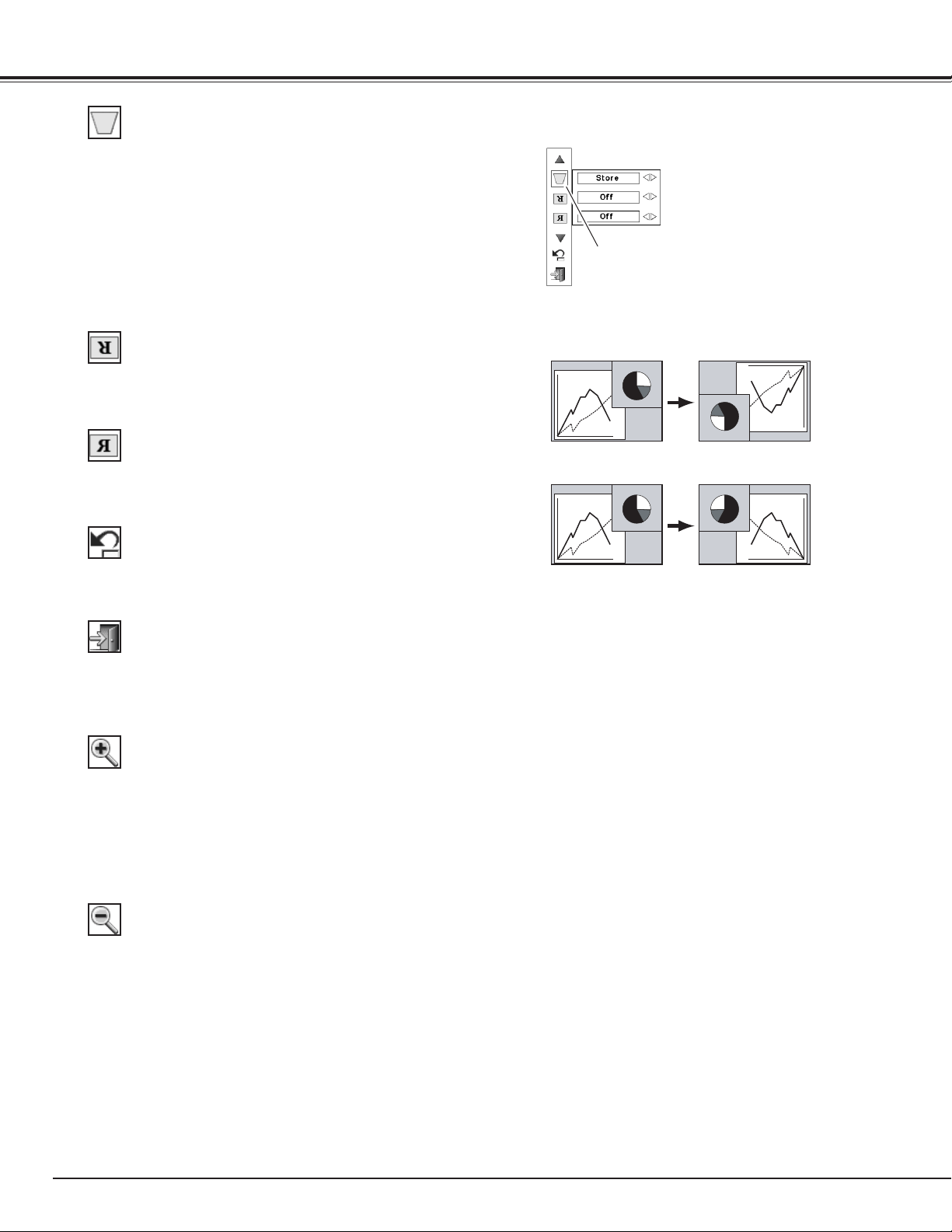
46
Select Digital zoom +. The On-Screen Menu disappears and “D.
zoom +” appears. Press the OK button to expand the image size.
Use the Point ed7 8 buttons to pan the image. The Panning
function can work only when the image is larger than the screen
size.
You can also enter the Digital zoom + mode by pressing the D-
ZOOM button on the remote control unit.
Digital zoom +
Select Digital zoom –. The On-Screen Menu disappears and “D.
Zoom –” appears. Press the OK button to compress the image size.
You can also enter the Digital zoom – mode by pressing the D-
ZOOM button on the remote control unit.
To exit the Digital Zoom +/– mode, press any button except the D-
ZOOM , OK, and Point buttons.
Digital zoom –
For zooming in and out the images
Keystone
This function is used to store or reset the keystone correction
when the AC power cord is unplugged. Use the Point 7 8 buttons
to switch between each option.
Store. . . Keep the keystone correction even when the AC power
cord is unplugged.
Reset . . Release the keystone correction when the AC power
cord is unplugged.
To correct keystone distortion, press the OK button. The Keystone
dialog box appears. Use the Point ed7 8 buttons to correct
keystone distortion. (p.35)
Ceiling
Rear
Ceiling
When this function is set to “On,” the picture is top/bottom and
left/right reversed. This function is used to project the image from a
ceiling-mounted projector.
Rear
When this function is set to “On,” the picture is left/right reversed.
This function is used to project the image from the rear of the
screen.
Reset
This function returns all adjusted values to the factory default
settings. Press the OK button at Reset to display a confirmation
box. To reset, press the OK button at “Yes.”
ASPECT MENU
Move the red frame pointer to the desired
function and press the OK button.
Computer Input
Exit the Screen Size Adjustment Menu.
Quit
✔Note:
•Thepanningfunctionmaynotoperateproperlyif
thestoredModeinthePCAdjustMenuisused.
(p.43)
•Theminimumcompressionratiocanbelimited
dependingontheinputsignalorwhenthe
Keystonefunctionisworking.
•Digitalzoom+/–cannotbeselectedwhenFull
screenorTrueisselected.
•Digitalzoom–cannotbeoperatedwhenCustom
isselected.
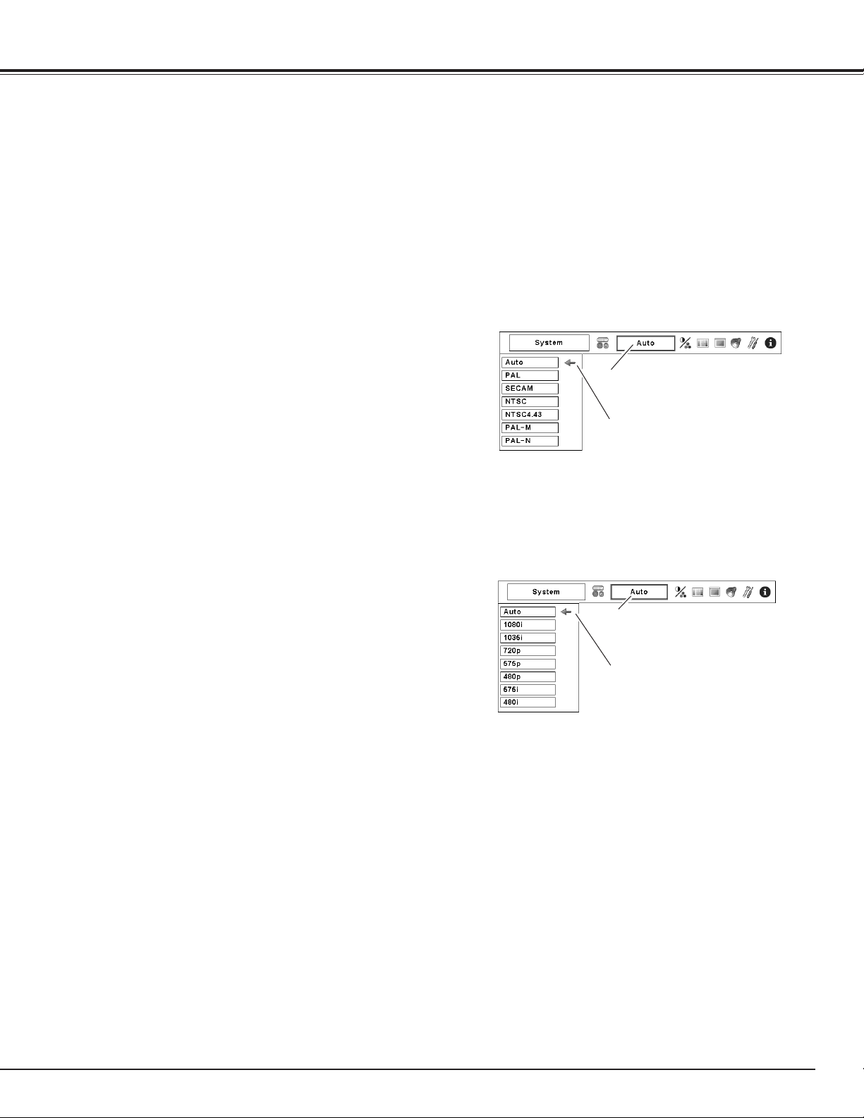
47
AV SYSTEM MENU (VIDEO OR S-VIDEO)
AV SYSTEM MENU (COMPONENT VIDEO)
Video System Selection
Press the MENU button to display the On-Screen Menu. Use
the Point 7 8 buttons to move the red frame pointer to the
AV System Menu icon.
Use the Point ed buttons to move the red arrow pointer to
the desired system and then press the OK button.
1
2
If the projector cannot reproduce proper video image, select a
specific broadcast signal format from among PAL, SECAM, NTSC,
NTSC 4.43, PAL-M, and PAL-N.
PAL/SECAM/NTSC/NTSC4.43/PAL-M/PAL-N
The projector automatically detects an incoming video signal, and
adjusts itself to optimize its performance.
When the Video System is 1035i or 1080i, select the system
manually.
If the projector cannot reproduce proper video image, select a
specific component video signal format from among 480i, 575i,
480p, 575p, 720p, 1035i, and 1080i.
Auto
COMPONENT VIDEO SIGNAL FORMAT
INPUT 3 TERMINAL (VIDEO) or INPUT 3 TERMINAL (S-VIDEO)
INPUT 2 TERMINAL
The projector automatically detects an incoming video system, and
adjusts itself to optimize its performance.
When Video System is PAL-M or PAL-N, select the system manually.
Auto
AV System Menu icon
The selected system is displayed
Move the pointer to the desired
system and press the OK button.
AV System Menu icon
The selected system is displayed.
Move the pointer to the desired
system and press the OK button.
Video Input
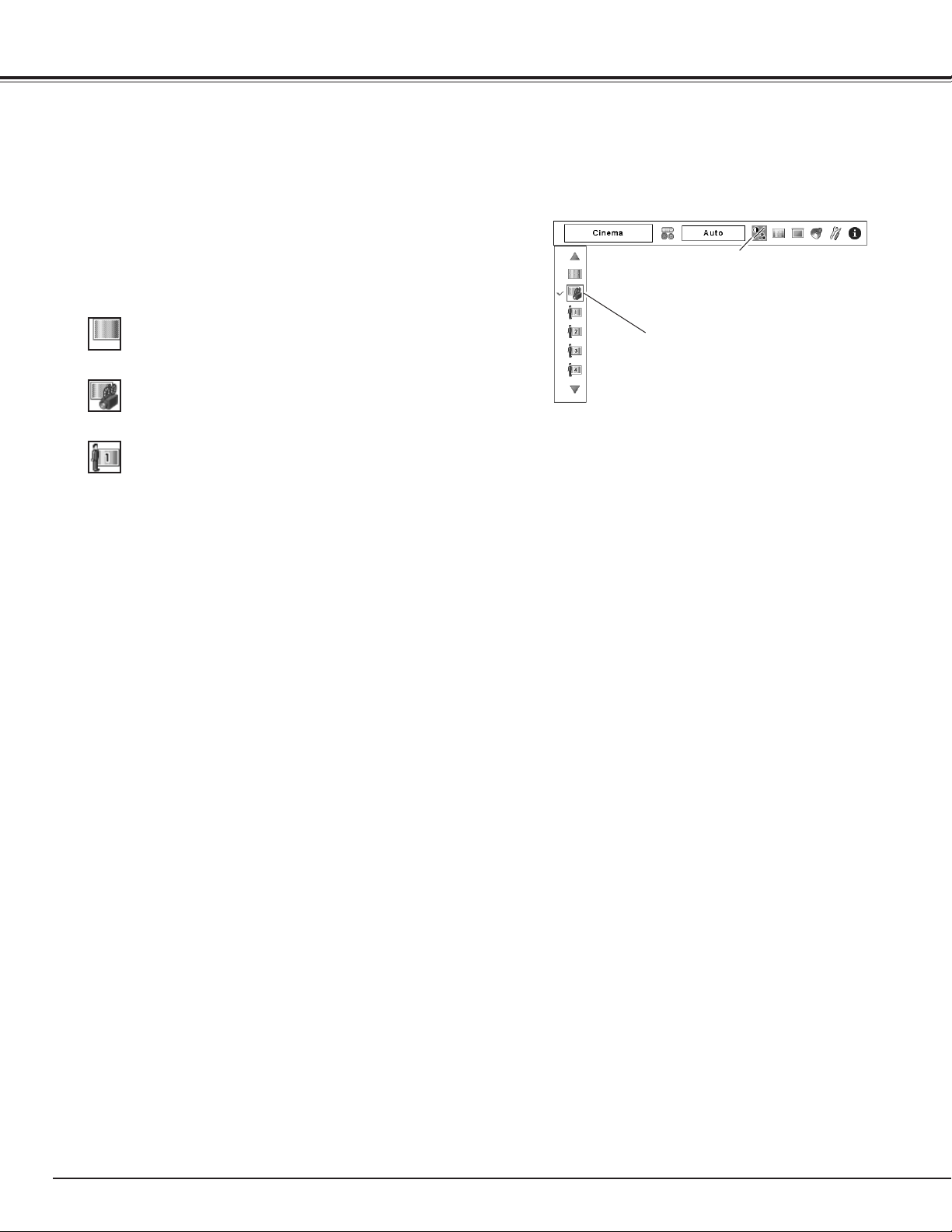
48
Press the MENU button to display the On-Screen Menu. Use
the Point 7 8 buttons to move the red frame pointer to the
Image Select Menu icon.
1
2
Use the Point ed buttons to move the red frame pointer to
the desired image level and then press the OK button.
IMAGE SELECT MENU
Image Level Selection
Move the red frame pointer to the desired
level and press the OK button.
Image Select Menu icon
Normal picture level preset on the projector.
Standard
Picture level adjusted with fine tone.
Cinema
User preset picture adjustment in the Image Adjust Menu. (p. 53)
Custom 1–10
Menu Operation
Video Input
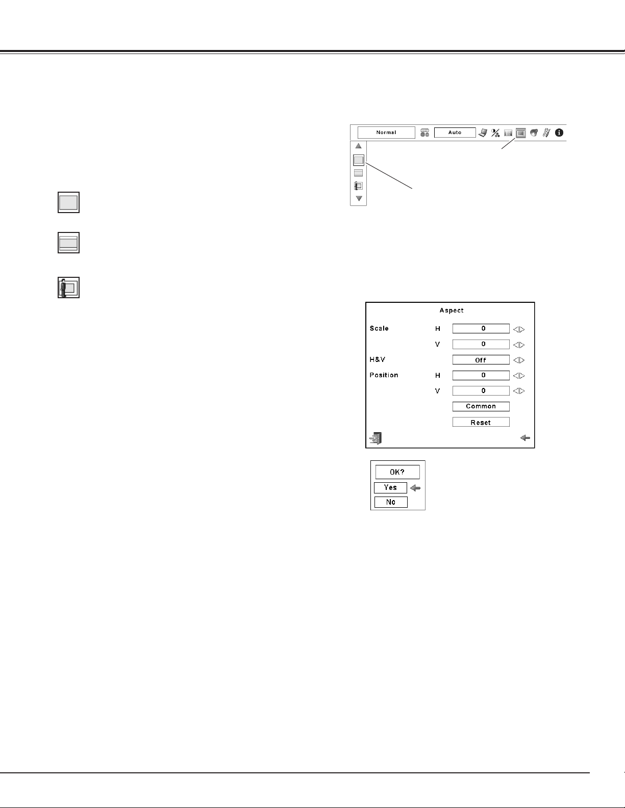
49
Screen Size Adjustment
Press the MENU button to display the On-Screen Menu. Use
the Point 7 8 buttons to move the red frame pointer to the
Aspect Menu icon.
Use the Point ed buttons to move the red frame pointer to
the desired function and then press the OK button.
1
2
✔Note:
•Widecannotbeoperatedwhen“720p,”“1035i,”
or“1080i”isselectedonAVSystemMenu(p.47).
ASPECT MENU
Provide the image at the wide screen ratio of 16:9.
Wide
Provide the image at the normal video aspect ratio of 4:3.
Normal
Move the red frame pointer to the desired
function and press the OK button.
Aspect Menu icon
Scale H/V .............. Adjust the Horizontal/Vertical screen scale.
H&V ...................... When set to “On,” the aspect ratio is fixed.
The “Scale V” appears dimmed and becomes
unavailable. Adjust “Scale H,” then the screen
scale is automatically modified based on the
aspect ratio.
Position H/V .......... Adjust the Horizontal/Vertical screen position.
Common .............. Save the adjusted scale to all the inputs.
Press the OK button at Common to display a
confirmation box. To save the scale, press the
OK button at “Yes.” When Custom is selected,
the saved scale is used.
Reset .................... Reset the all adjusted values. Press the OK
button at Reset to display a confirmation box.
To reset, press the OK button at “Yes.”
Custom
✔Note:
•Whennosignalisdetected,“Normal”is
setautomaticallyandtheAspectdialogbox
disappears.
•TheadjustablerangeforScaleH/VandPosition
H/Vislimiteddependingontheinputsignal.
Press the OK button at Common or Reset,
to display a confirmation box.
Video Input
Adjust the screen scale and position manually with this function.
Press the OK button at Custom and the “Custom” is displayed on
the screen for a few seconds. To display the Aspect dialog box,
press the OK button at Custom again and then the Aspect dialog
box appears.
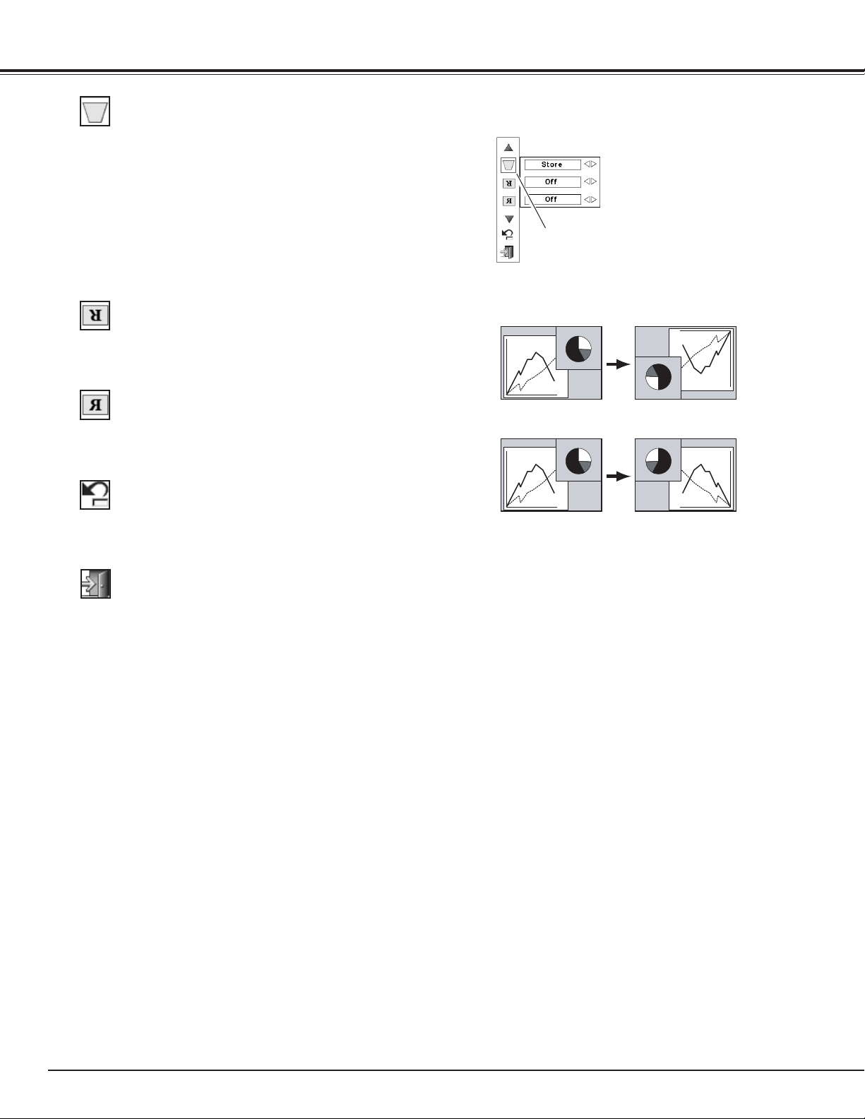
50
Keystone
This function is used to store or reset the keystone correction
when the AC power cord is unplugged. Use the Point 7 8 buttons
to switch between each option.
Store. . . Keep the keystone correction even when the AC power
cord is unplugged.
Reset . . Release the keystone correction when the AC power
cord is unplugged.
To correct keystone distortion, press the OK button. The Keystone
dialog box appears. Use the Point ed7 8 buttons to correct
keystone distortion. (p.35)
Ceiling
Rear
Ceiling
When this function is set to “On,” the picture is top/bottom and
left/right reversed. This function is used to project the image from a
ceiling-mounted projector.
Rear
When this function is set to “On,” the picture is left/right reversed.
This function is used to project the image from the rear of the
screen.
Reset
This function returns all adjusted values to the factory default
settings. Press the OK button at Reset to display a confirmation
box. To reset, press the OK button at “Yes.”
ASPECT MENU
Move the red frame pointer to a function and
press the OK button.
Video Input
Exit the Screen Size Adjustment Menu.
Quit
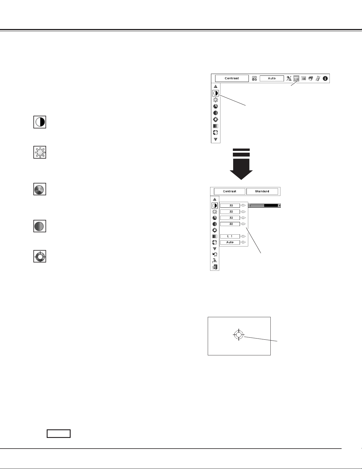
51
Press the MENU button to display the On-Screen Menu. Use
the Point 7 8 buttons to move the red frame pointer to the
Image Adjust Menu icon.
1
2
Use the Point ed buttons to move the red frame pointer to
the desired item and then press the OK button to display the
adjustment dialog box. Use the Point 7 8 buttons to adjust
the setting value.
IMAGE ADJUST MENU
Press the Point 7 button to decrease contrast; press the Point 8
button to increase the contrast (from 0 to 63).
Press the Point 7 button to decrease the brightness; press the
Point 8 button to increase the brightness (from 0 to 63).
Contrast
Brightness
Press the Point 7 button to decrease the intensity of the color;
press the Point 8 button to increase the intensity of the color (from
0 to 63).
Press the Point 7 8 buttons to adjust the tint value to obtain
proper color balance (from 0 to 63).
Color
]
Tint
]
Color Management
The Color Management function can be used to adjust the LEVEL,
PHASE, and GAMMA of the selected display colors (except for
black, white, and gray) on the screen and replace these colors with
other colors if required.
You can store up to eight (8) color management data.
1
Use the Point ed buttons to move the red frame pointer
to Color Management, and then press the OK button. The
projected image freezes, and the COLOR MANAGEMENT
POINTER appears.
Use the Point ed7 8 buttons to move the pointer to the
spot where you want to adjust the color and then press the
OK button. The COLOR SELECTION window appears, and
the color in the center of the pointer is selected and you can
adjust the color.
2
Use the Point ed7 8 buttons to adjust the LEVEL and
PHASE of the color, and then press the OK button to confirm
the setting. Then use the Point ed buttons to adjust the
GAMMA for the color and press the OK button to accept
the setting. After adjusting, press the OK button to go to the
COLOR MANAGEMENT LIST.
3
COLOR MANAGEMENT
POINTER
POINTER MODE
Image Adjustment
Move the red frame pointer to the desired
item and then press OK button.
Image Adjust Menu icon
Use the Point 7 8 buttons to adjust the
setting value.
COLOR SELECTION MODE
Go to the COLOR MANAGEMENT LIST.
LIST
Picture Image
✔Note:
•DisplayedonlyinVideoInput.
•Tintcannotbeselectedwhenthevideosystem
isPAL,SECAM,PAL-M,orPAL-N(p.47).
]
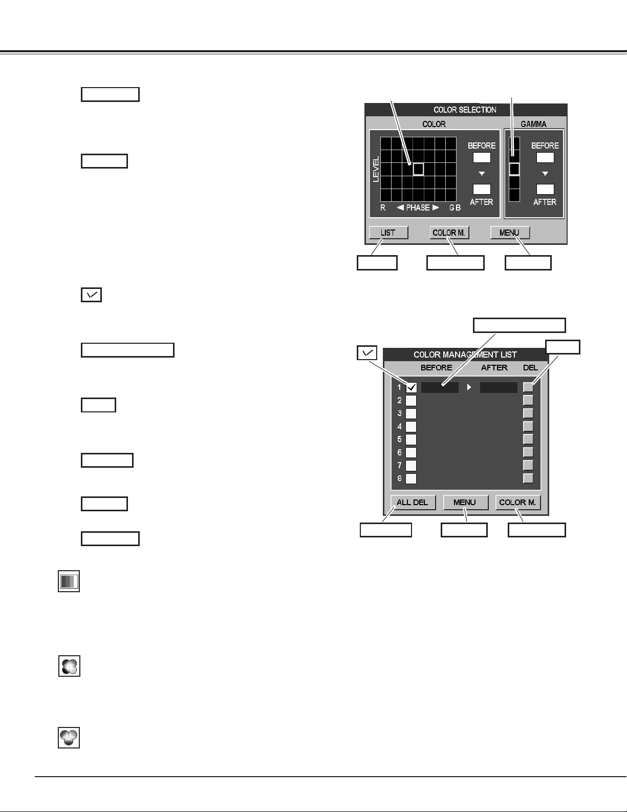
52
Auto picture control
Use the Point 7 8 buttons to select the desired Auto picture
control position (Off, L1 or L2).
Off . . . . Auto picture control OFF position.
L1 . . . . . Auto picture control LEVEL 1 position.
L2 . . . . . Auto picture control LEVEL 2 position.
Clear the check mark if you do not want to apply the adjusted
color data; select the check mark and then press the OK
button. The check mark disappears.
Return to the COLOR MANAGEMENT POINTER. (If you press
the MENU button on the side control or the remote control
unit, it returns to the COLOR MANAGEMENT POINTER and
you will need to reselect and readjust the color.)
Return to the IMAGE ADJUST Menu. Any settings that
have been changed will not be stored. To store the changed
settings, be sure to select “LIST” and go to the COLOR
MANAGEMENT LIST.
LIST MODE
Return to the COLOR SELECTION mode so that you can
readjust the setting for the color in that line. (This option is
not available if the check mark is cleared.)
Select the DEL box if you want to delete the adjusted data.
Press the OK button and a confirmation box appears and then
select [Yes].
Delete all the data in the list. Press the OK button and a
confirmation box appears and then select [Yes].
The same function as stated above.
Level and phase
adjustment palette.
Gamma
adjustment palette.
Color temp.
Use the Point 7 8 buttons to select the desired Color temp. level
(High, Mid, Low, or XLow).
COLOR M.
MENU
COLOR PALETTE
DEL
ALL DEL
COLOR M.
LIST COLOR M. MENU
COLOR PALETTE
DEL
ALL DEL MENU COLOR M.
COLOR SELECTION MODE
LIST MODE
COLOR SELECTION MODE (continued)
In the COLOR MANAGEMENT LIST, the adjusted color data
are checkmarked. You can decide whether or not to apply the
adjusted color data in the list to the projected image (see
below).
4
MENU
The same function as stated above.
Picture Image
Advanced color*
Use the Point 7 8 buttons to select the advanced color mode.
Off . . . . Advanced color mode is “Off”.
Auto . . .
Advanced color according to the type of image
.
*This function controls the operation of the Color
Control Device, which independently and automatically
regulates the amount of yellow light passing through
the LCD panel, to accurately reproduce both image
color and image brightness. Normally leave Auto
(default setting).
✔Note:
•White balance may change depending on the image.
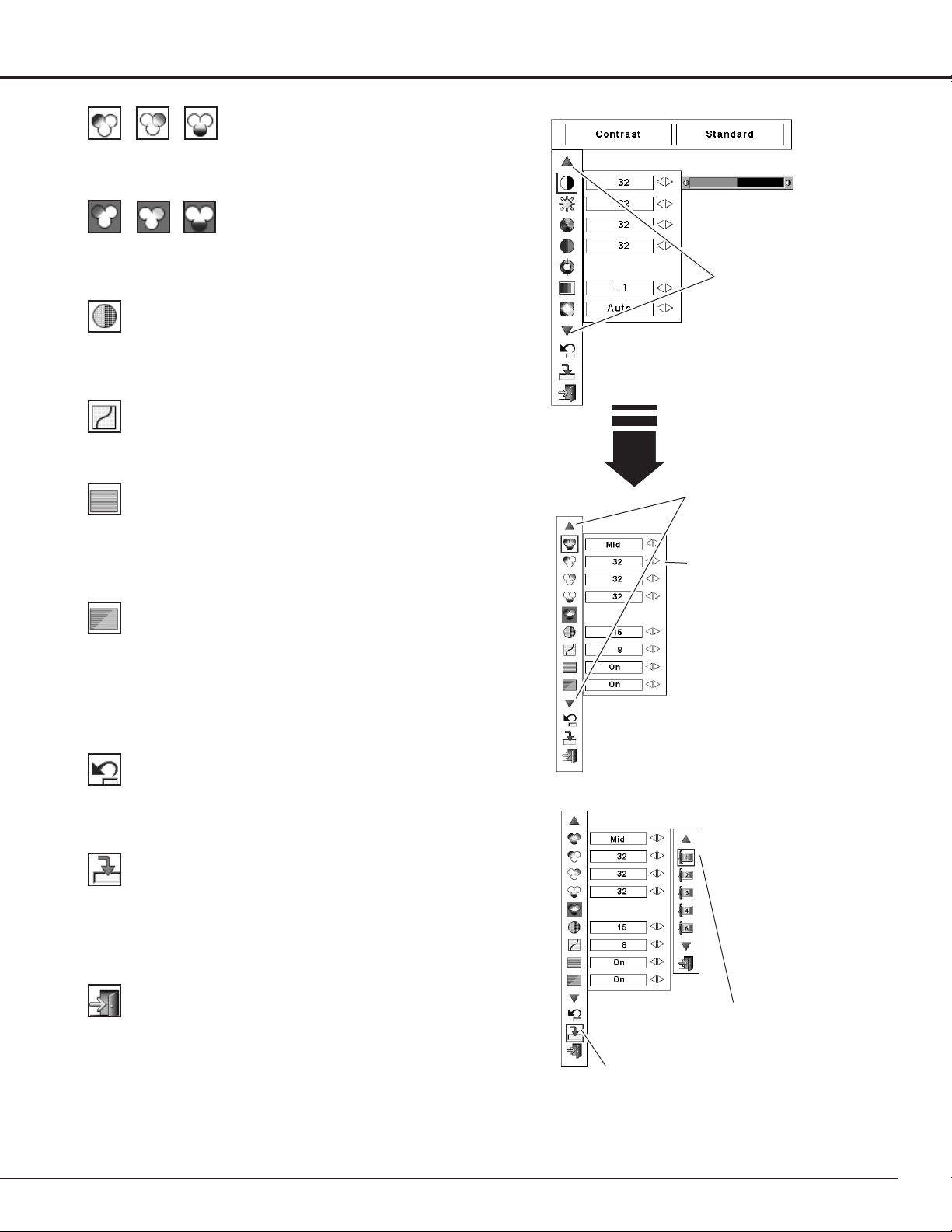
53
Use the Point 7 8 buttons to adjust the gamma value to obtain a
better balance of contrast (from 0 to 15).
Gamma
Press the Point 7 button to decrease the sharpness of the image;
press the Point 8 button to increase the sharpness of the image
(from 0 to 31).
Sharpness
An interlaced video signal can be displayed in progressive mode.
Press the Point 7 8 buttons to change the progressive scan mode.
Off . . . . Progressive scan mode is “Off.”
On . . . . Progressive scan mode is “On.”
Film . . . For watching a film. With this function, the projector
reproduces pictures faithful to the original film quality.
Noise interference on the screen can be reduced. Press the Point
7 8 buttons to change the noise reduction mode.
Off . . . . Noise reduction mode is “Off”
On . . . . Noise reduction mode is “On”
Noise reduction
]
Progressive
]
Store icon
Press the OK button at this icon
to store the adjustment.
Press the Point 7 button to lighten red/green/blue tone; press the
Point 8 button to deepen red/green/blue tone (from 0 to 63).
White balance (Red/Green/Blue)
Press the Point 7 button to lighten red/green/blue tone of the black
level of an image; press the Point 8 button to deepen red/green/
blue tone of the black level of an image (from 0 to 63).
Offset (Red/Green/Blue)
Exit the Image Adjust Menu.
To store the adjusted data, move the red frame pointer to the Store
icon and press the OK button. The Image Level Menu appears.
Move the red arrow pointer to any of the Custom 1 to 10 in which
you want to set and press the OK button. A confirmation box
appears and then select [Yes].
To reset the adjusted data, select Reset and press the OK button. A
confirmation box appears and then select [Yes]. All adjustments will
return to their previous figures.
Reset
Store
Quit
Press the OK button at this icon to display
other items.
Press the OK button at this icon to
display the previous items.
Press the Point
7 8 buttons to
adjust the setting value.
Picture Image
Image Level Menu
Move the red frame pointer to an
image item to be set and then press
the OK button.
✔Note:
•DisplayedonlyinVideoInput.
•WhentheWhitebalanceRed,Green,orBlueisadjusted,theColor
temp.levelwillchangeto“Adj.”
•Progressivecannotbeselectedwhen“480p,”“575p,”or“720p”is
selected(p.47).
]
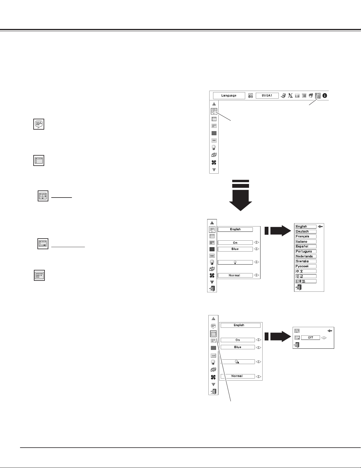
54
Press the MENU button to display the On-Screen Menu. Use
the Point 7 8 buttons to move the red frame pointer to the
Setting Menu icon.
1
2
Language
The language used in the On-Screen Menu is available in English,
German, French, Italian, Spanish, Portuguese, Dutch, Swedish,
Russian, Chinese, Korean, or Japanese.
Use the Point ed buttons to move the red frame pointer to
the desired item and then press the
OK button. The Setting
dialog box appears.
Press the OK button at
Language, then the Language
Menu appears.
SETTING MENU (Language)
This projector has a Setting menu that allows you to set up other various functions.
Setting
Set the red frame pointer
to the item and press the
OK button.
Setting Menu icon
When this function is set to “On,” the value adjustment bar in the
Picture Image Adjustment Menu appears on the screen.
Simple menu
Menu
This function is used to adjust the On-Screen Menu display
position. Press the OK button and the adjustment screen appears
(arrows appear). Use the Point ed7 8 buttons to adjust the
position. After making the adjustment, press the OK button to
return to the Menu screen.
Position
This function allows you to adjust the position of the On-Screen
Display and the value adjustment bar in the Picture Image
Adjustment Menu.
Display
This function decides whether to display On-Screen Displays.
On . . . . . . . . . . . . Shows all the On-Screen Displays. Use this
function when you want to project images
after the lamp becomes bright enough. The
factory default setting is in this option.
Countdown Off. . . Shows the input image instead of the
countdown when turning on the projector.
Use this function when you want to project
the image as early as possible even when the
lamp is not bright enough.
Off . . . . . . . . . . . . Hides the On-Screen Displays except:
● On-Screen Menu
● “Power off?” (p.29)
● Color management operation screen
(pp.51-52)
● “No signal” for Power management (p.58)
● P-TIMER (p.35)
● ”Please wait....” for Auto PC adjustment
(p.41)
●
Arrows for the True function in the ASPECT
Menu (p.45)
●
Exclamation mark when non-simple mode
buttons are pressed while the simple mode
is set to “On.” (p.57)
Menu
Set the red frame pointer
to the item and press the
OK button.
Setting
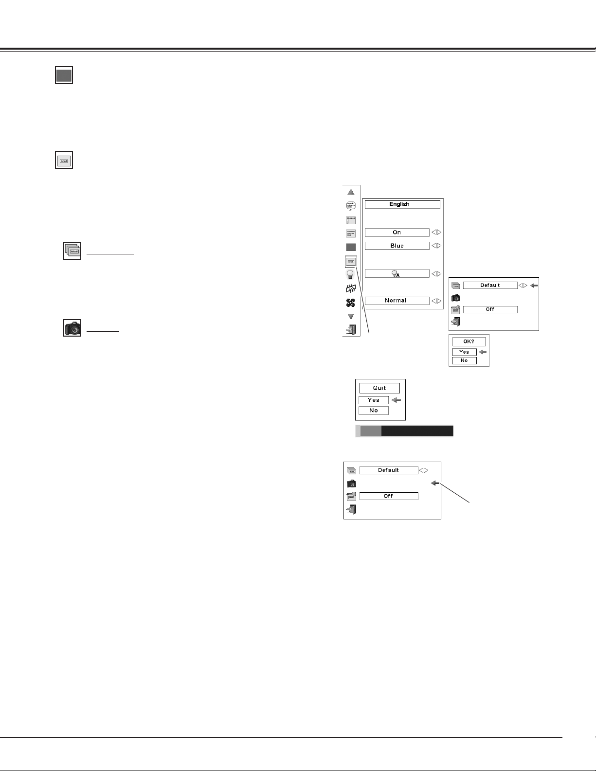
55
This function allows you to customize the screen logo with Logo
select, Capture, and Logo PIN code lock functions.
Logo
✔Note:
•Beforecapturinganimage,select“Standard”intheImage
SelectMenutocaptureaproperimage(pp.44,48).Adjusted
imageonthescreencannotbecaptured.
•AsignalfromacomputercanbecaptureduptoXGA(1024X
768).
•Certainsignalsmaynotbecapturedproperly.
•Whencapturingtheimagethathasbeenadjustedbythe
Keystonefunction,theadjusteddataisautomaticallyresetand
theprojectorcapturesanimagewithoutkeystonecorrection.
•Whenstartingtocaptureanewimage,thepreviouslystored
imageisclearedevenifyoucancelthecapturing.
•OnceyouexittheLogoMenuaftersettingtheLogolockto
"On,"youarerequiredtoenterthePINcodeeveryattemptingto
changetheLogosetting.
•“User”cannotbeselectedwhentheimageisnotcaptured.
Select [Yes]
to capture
the projected
image.
This function decides on the starting-up display from among the
following options.
User . . . Show the image you captured.
Default . Show the factory-set logo.
Off . . . . Show the countdown display only.
Capture
Select [Yes] to stop
capturing.
Logo select
Logo
✔Note:
•When“On”isselectedintheLogoPINcodelockfunction,Logo
selectandCapturefunctionscannotbeselected.
This function enables you to capture an image being projected to
use it for a starting-up display or interval of presentations.
Select Capture and press the OK button.
A confirmation box appears and select [Yes] to capture the
projected image.
After capturing the projected image, go to the Logo select
function and set it to “User”. Then the captured image will be
displayed the next time you turn on the projector.
To cancel the Capture function, select [No].
Set the red frame pointer
to the item and press the
OK button.
Capture
Setting
Background
The selected background screen will be displayed when no input
signal is detected.
Blue . . . Blue colored background.
User . . . The image you captured.
Black . . . Black colored background.
✔Note:
•“User”cannotbeselectedwhentheimageis
notcaptured.
Set the pointer (red
arrow) to the item and
press the OK button.
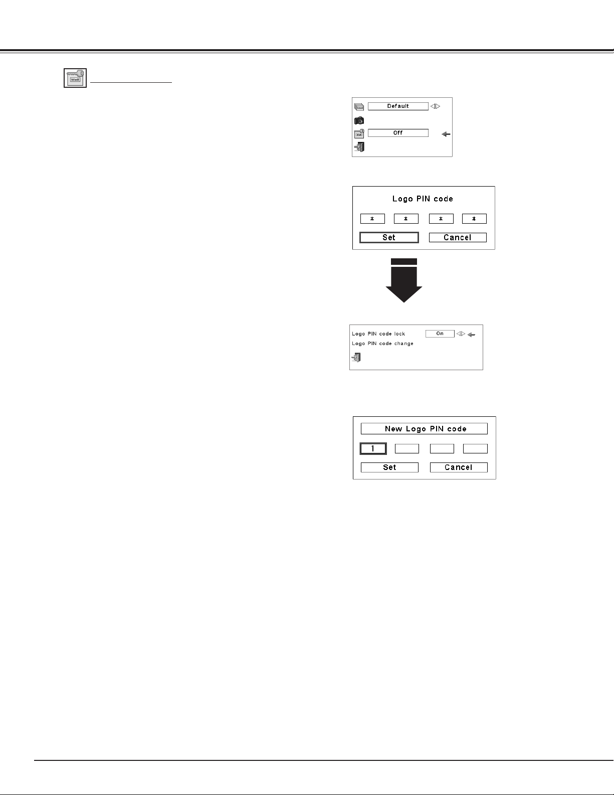
56
Change the Logo PIN code lock setting
After a correct Logo PIN code is
entered, the following dialog box
appears.
Use the Point 7 8 buttons to switch On/Off,
This function prevents an unauthorized person from changing the
screen logo.
Off . . . . The screen logo can be changed freely from the Logo
Menu.
On . . . . The screen logo cannot be changed without a Logo
PIN code.
If you want to change the Logo PIN code lock setting, press the
OK button and the Logo PIN code dialog box appears. Enter a
Logo PIN code by following the steps below. The initial Logo PIN
code is set to “4321” at the factory.
Logo PIN code lock
Enter a Logo PIN code
Change the Logo PIN code
Logo PIN code can be changed to your desired four-digit number.
Press the Point d button to select “Logo PIN code change” and
then press the OK button. The New Logo PIN code input dialog
box appears. Set a new Logo PIN code.
Be sure to note the new Logo PIN code and keep it at hand. If you
lost the number, you could no longer change the Logo PIN code
setting. For details on PIN code setting, refer to “PIN code lock”
on pages 59–60.
Logo PIN Code Lock
Enter a Logo PIN code
Use the Point 7 8 buttons to switch On/Off, and then press the
Point d button to move the pointer to “Quit.” Press the OK button
to close the dialog box.
Change the Logo PIN code lock setting
CAUTION:
WHEN YOU HAVE CHANGED THE LOGO PIN
CODE, WRITE DOWN THE NEW PIN CODE AS A
REMINDER. SHOULD THE LOGO PIN CODE BE
LOST OR FORGOTTEN, THE LOGO PIN CODE
SETTING CAN NO LONGER BE CHANGED.
Change the Logo PIN code
Use the Point ed buttons on the side control or Number buttons
on the remote control unit to enter a number.
When using side control
Use the Point ed buttons on the side control to select a number.
Press the Point 8 button to fix the number and move the red
frame pointer to the next box. The number changes to “✳.”
Repeat this step to complete entering a four-digit number. After
entering the four-digit number, move the pointer to “Set.” Press
the OK button so that you can change the Logo PIN code lock
setting.
When using remote control unit
Press the Number buttons on the remote control unit to enter a
number (p.17). When you complete entering a four-digit number,
the pointer moves to “Set.” Press the OK button so that you can
change the Logo PIN code lock setting.
If you fixed an incorrect number, use the Point 7 button to move
the pointer to the number you want to correct, and then enter the
correct number.
If you entered an incorrect PIN code, “Logo PIN code” and the
number (✳✳✳✳) will turn red for a moment. Enter the correct PIN
code all over again.
Setting
NOTE:
If you forget your Logo PIN code and unable to change
it, the Logo PIN code can be reset to the factory default
setting (4321) according to the following procedures.
When you reset the Logo PIN code, the PIN code and
Key lock will be reset, as well.
1. Unplug the AC Power Cord from the AC outlet.
2. Hold down the OK button on the projector and
connect the AC Power Cord into the outlet again.
Keep holding down the OK button until the POWER
indicator lights. The Logo PIN code returns to the
factory default setting while the Logo PIN code lock
state will remain the same as the previous set state.
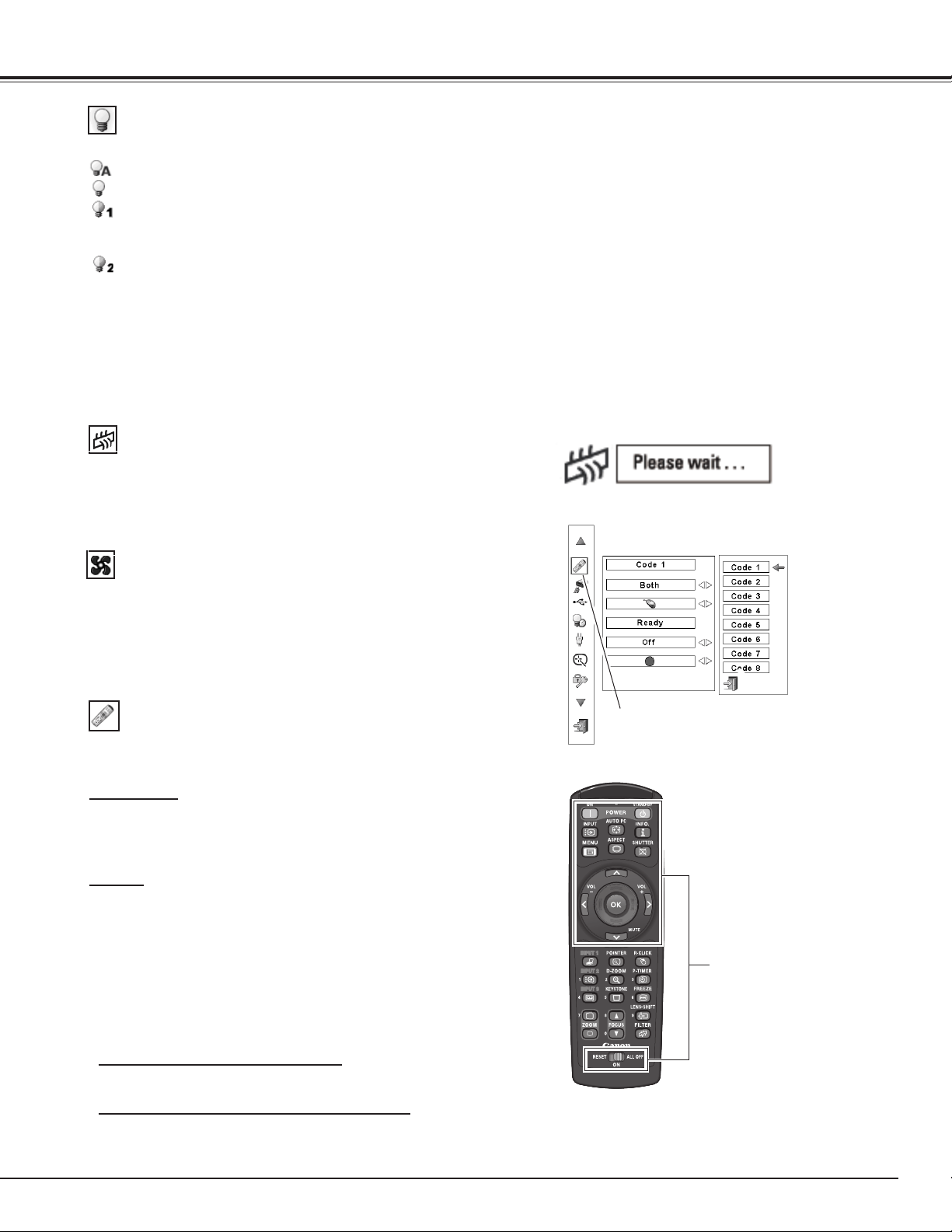
57
Lamp mode
Filter control
Choose the running speed of cooling fans from the following
options.
Normal ....... Operate in this mode under normal conditions.
Max ........... Use this mode when you want to increase the
cooling effect when operating the projector in high
ambient temperature environment. Fan noise is
louder than “Normal”.
Fan control
This function allows you to change the brightness of the screen.
Auto . . . . . Brightness according to the input signal.
Normal . . . Normal brightness.
Eco 1. . . . . Lower brightness and Fan control set to Normal.
Lower brightness reduces the lamp power
consumption and extends the lamp life.
Eco 2. . . . . Lower brightness and Fan control set to Max.
Lower brightness reduces the lamp power
consumption and extends the lamp life. It is
recommended to use Eco 2 when using the
projector continuously over a long period of time.
The fan noise becomes louder in Eco 2 than in
Eco 1. Select the suitable mode for the used
environment.
Setting
Remote control
When pressing the OK button on
Remote control unit, the Remote
control menu appears.
This function allows you to change the Simple mode and RC code
setting on the remote control unit.
Simple mode
This function decides whether to activate the simple mode.
Off . . . . Simple mode function is off.
On . . . . Only the simple mode buttons are active.
RC code
The eight different remote control codes (Code 1–Code 8) are
assigned to the projector; the factory-set, initial code (Code 1) and
the other seven codes (Code 2 to Code 8). After selecting the RC
code, move the red arrow pointer to the Quit icon and press the OK
button to set the RC code.
The same code should set on both the projector and the remote
control unit. For example, operating the projector in “Code 7”, the
remote control unit code also must be switched to “Code 7”.
To change the code for the projector:
Select a remote control unit code in this Setting Menu.
To change the code for the remote control unit:
Press and hold the MENU button and a number button (1–8) on
the remote control unit for more than 5 seconds to switch between
the codes (p. 19).
Simple mode buttons
Only these buttons are active
when the simple mode is set to
“On.“ [ON, STAND-BY, INPUT,
AUTO PC, INFO., MENU, ASPECT,
SHUTTER, ed7 8, OK, VOL.+,
VOL.-, MUTE, RESET/ON/ALL OFF
switch]
Number buttons (p.17) also
become active only when setting
the remote control codes numbers
or entering the PIN code numbers
(pp. 56, 60).
Remote control
✔Note:
•IfyoudonotselecttheQuiticonandexit
theRemotecontrolmenu,theRCcodewill
notbeset.
You can replace the filter with this function. Press the OK button at
Filter control to display a confirmation box. To replace, press the OK
button at “YES” and the electrically operated filter starts to scroll.
You can also replace the filter by using the remote control unit (p.
35).
✔Note:
•Filterreplacementiconand“Pleasewait...”
messageappearonthescreenwhenthe
filterisbeingscrolled.
•Whenthefilterisreplaced,thetotal
accumulatedtimeofthefilteruseis
automaticallysetto0
.
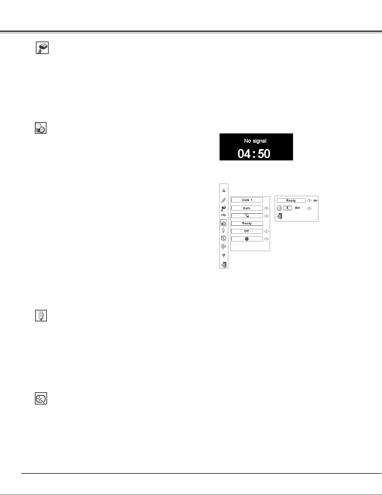
58
On start
When this function is set to “On,” the projector will be
automatically turned on just by connecting the AC power cord to
the wall outlet.
✔Note:
•Besuretoturnofftheprojectorproperly(see“TurningOffthe
Projector”onpage29).Iftheprojectoristurnedoffintheincorrect
sequence,theOnstartfunctiondoesnotworkproperly.
Power management
Time left before the lamp is off
For reducing power consumption as well as maintaining the lamp
life, the Power management function turns off the projection lamp
when the projector is not used for a certain period.
If the input signal is interrupted and no button is pressed for more
than 30 seconds, the timer display with “No signal” appears. It
starts the countdown until the lamp is turned off. The countdown
time can be set between 1 and 30 minutes.
Use the Point 7 8 buttons to set the countdown timer.
Select one of the following options:
Ready . . . . When the lamp has been fully cooled down, the
POWER indicator starts blinking. In this condition,
the projection lamp is turned on if the input signal
is reconnected or any button on the side control or
remote control unit is pressed .
Shutdown. . When the lamp has been fully cooled down, the
power is turned off.
Off . . . . . . . Power Management function is off.
Power management
Pointer
You can emphasize a part of the projected image with this function.
Use the Point 7 8 buttons to select a pattern of the Pointer (Cross,
Arrow, or Dot) (P. 36)
✔Note:
•Factorydefaultis“Ready:5min.”
•WhentheshutterisclosedwhilethePowermanagementfunction
isworking,thePowermanagementfunctionisreleased.
Setting
✔Note:
•ThePointed7 8 buttonsandOKbuttonareinvalidwhenthe
Pointerfunctionisoperating.
RC sensor
Select a location of the infrared remote receiver of the remote
control unit. See “Remote Control Receivers and Operating Range”
on page 18 for details.
Both ......... Activate both the front and back receiver.
Front ........ Activate only the front receiver.
Back ......... Activate only the back receiver.
Press the OK button at Power
management and the dialog box
appears. Use the Point 7 8
buttons to choose one of the three
options.
Press the Point d button to select
the timer, and then use the Point
7 8 buttons to set the timer
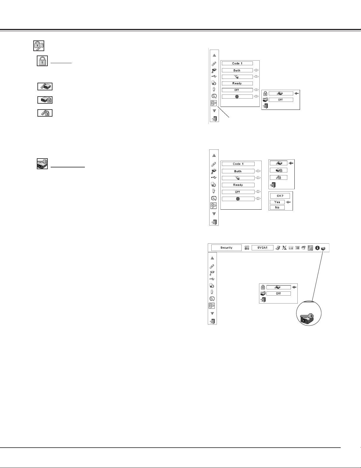
59
Security
Key lock
Security
Select Key lock and
this box appears.
Choose one of the
alternatives with the
Point ed buttons
and select [Yes] to
activate it.
This function locks the side control and remote control unit
buttons to prevent operation by unauthorized persons.
. . . . . Unlocked.
. . . . . Lock the side control buttons.
To unlock, use the remote control unit.
. . . . . Lock the remote control unit buttons.
To unlock, use the side control.
If the side control accidentally becomes locked and you
do not have the remote control unit nearby and unable to
operate the projector, contact the service station.
PIN code lock
This function prevents the projector from being operated by
unauthorized persons and provides the following setting options
for security.
Off . . . . Unlocked.
On1 . . . Enter the PIN code every time turning on the projector.
On2 . . . Enter the PIN code to operate the projector once the
power cord is disconnected; as long as the AC power
cord is connected, the projector can be operated
without a PIN code.
Whenever you change the PIN code lock setting or the PIN code
(the four-digit number), you are required to enter the PIN code.
“1234” is set as the initial PIN code at the factory.
If you want to change the PIN code lock setting, press the OK
button and the PIN code dialog box appears. Enter a PIN code by
following the steps on the next page.
PIN code lock
When the projector
is locked with a PIN
code, the PIN code
lock symbol appears
on the menu bar.
Setting
Set the red frame pointer to the item
and press the OK button.
Key lock
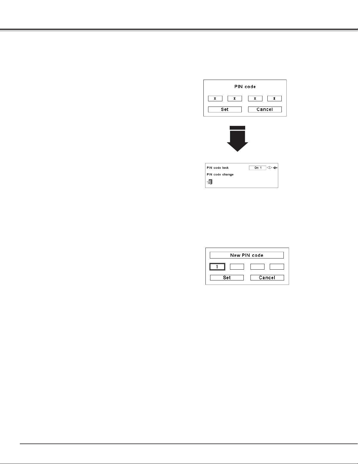
60
Change the PIN Code
Change the PIN code
The PIN code can be changed to your desired four-digit number.
Press the Point d buttons to select “PIN code change” and press
the OK button. The New PIN code input dialog box appears. Set a
new PIN code.
Change the PIN Code Lock setting
Change the PIN code lock setting
Use the Point 7 8
buttons to switch
between the options.
Enter a PIN code
Use the Point 7 8 button to select Off, On1, or On2 and then
move the pointer to “Quit” with the Point d button. Press the OK
button to close the dialog box.
After a correct Logo PIN code is
entered, the following dialog box
appears.
Enter a PIN code
Use the Point ed buttons on the side control or Number buttons
on the remote control unit to enter a number.
When using side control
Use the Point ed buttons on the side control to select a number.
Press the Point 8 button to fix the number and move the red
frame pointer to the next box. The number changes to “✳.”
Repeat this step to complete entering a four-digit number. After
entering the four-digit number, move the pointer to “Set.” Press
the OK button so that you can change the PIN code lock setting.
When using remote control unit
Press the Number buttons on the remote control unit to enter a
number (p.17). When you complete entering a four-digit number,
the pointer moves to “Set.” Press the OK button so that you can
change the PIN code lock setting.
If you fixed an incorrect number, use the Point 7 button to move
the pointer to the number you want to correct, and then enter the
correct number.
If you entered an incorrect PIN code, “PIN code” and the number
(✳✳✳✳) will turn red for a moment. Enter the correct PIN code all
over again.
Setting
CAUTION:
WHEN YOU HAVE CHANGED THE LOGO PIN CODE, WRITE
DOWN THE NEW PIN CODE AS A REMINDER. IF YOU FORGET
YOUR PIN CODE, THE PROJECTOR CAN NO LONGER BE
STARTED.
NOTE:
If you forget your PIN code and unable to change it, the PIN code can
be reset to the factory default setting (1234) according to the following
procedures.
When you reset the PIN code, the Logo PIN code and Key lock will be
reset, as well.
1. Unplug the AC Power Cord from the AC outlet.
2. Hold down the OK button on the projector and connect the AC Power
Cord into the outlet again. Keep holding down the OK button until the
POWER indicator lights. The PIN code returns to the factory default
setting while the PIN code lock state will remain the same as the
previous set state.
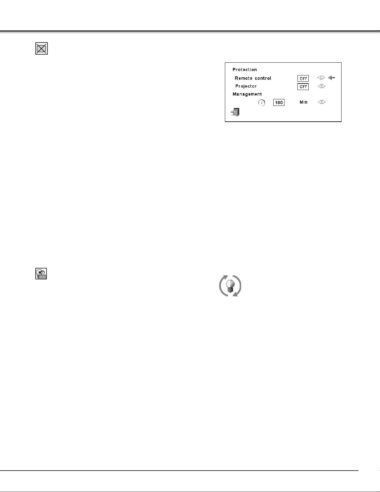
61
Lamp counter
This function is used to reset the lamp counter.
When the lamp life reaches a recommended lamp replacement
time, the time shown in the dialog box turns red and the Lamp
replacement icon appears on the screen, indicating that the end of
lamp life is approaching.
When replacing the projection lamp, reset the lamp counter. See
“Resetting the Lamp Counter” on page 67.
This icon appears on the screen when the end of lamp life is
approaching.
✔Note:
•Thisiconalsoappearsatturningonand
selectinginputsource.
✔Note:
•TheLampreplacementiconwillnotappearwhentheDisplay
functionissetto“Off”(p.54)orduring“Freeze”(p.35).
Shutter
Shutter function is available to block out light to the screen, so
that the screen can be used for the other presenters.
Prohibit the shutter operation from the remote control unit
and the projector's side control.
Remote control Selecting "On" prohibits the shutter
operation from the remote control unit.
Projector . . . Selecting "On" prohibits the shutter
operation from the side control unit.
It is possible to prohibit the shutter operation from both of the
remote control and the side control.
Protection
Management
The Shutter Management function turns off the projection
lamp when the projector is left with the shutter closed and
the set time has passed away. The count-down time can be
set between 5 and 180 minutes. When the count-down time
has elapsed, the shutter will be opened up automatically
and the lamp will be turned off to cool itself down. The
LAMP/SHUTTER indicator is blinking blue and red during
this cooling-off period. When the lamp has been fully cooled
down, the POWER indicator turns green lighting and the
LAMP/SHUTTER indicator keeps blinking. Should the ON /
STAND-BY button be pressed in this condition, the projection
lamp will be turned on and the LAMP/SHUTTER indicator
lights dim red.
✔Note:
•TheFactorydefault valueisset to180 minutes
forthecountdowntime.
•The Shutter Management function cannot be
halted.
Setting
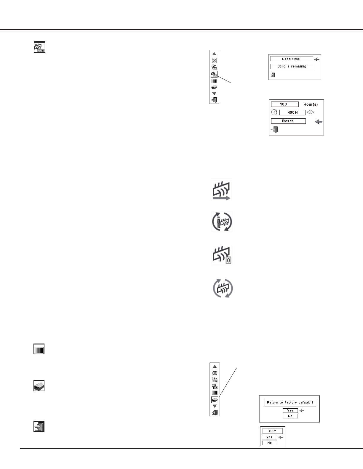
62
Factory default
This function returns all setting values except for the user logo, PIN
code lock, Logo PIN code lock, lamp counter, and filter counter to
the factory default settings.
Factory default
Quit
Exit the Setting Menu.
Select Factory default and this box
appears. Select [Yes], and the next
box appears.
Test pattern
Various test pattern are available for use when setting up the
projector.
Filter counter
Filter counter
Filter replacement icon appears on the screen
at a set time.
✔Note:
•Donotresetthecounter(s)whenthefilterorthefiltercartridgeare
notreplaced.
•Timersettingnotifiesthatthefilterneedsreplacement.Toreplace
thefilter,usethefiltercontrolfunction(p.57).
Fig.1 Filter replacement icon
Filter cartridge replacement icon appears on
the screen when the filter scroll is counted
down to 0 scroll.
Fig.4 Filter cartridge replacement icon
✔Note:
•Fig.1,Fig.2,Fig.3andFig.4appearatturning
onandselectinginputsource.
•Fig.1,Fig.2,Fig.3andFig.4willnotappear
whentheDisplayfunctionissetto“Off”(p.54)
orduring“Freeze”(p.35).
Set the red frame pointer
to the item and press the
OK button.
Set the red frame pointer
to the item and press the
OK button.
Last scroll icon appears on the screen when
the filter is down to the last scroll.
Fig.3 Last scroll icon
Use the Point 7 8 buttons
to set the timer. Select from
(Off/ 400H/700H/1000H)
depending on the use
environment
Setting
This function is used to set a frequency for the filter replacement.
Use the Point ed buttons to move the red frame pointer to
Filter counter and then press the OK button. A dialog box appears
showing the Used time option and the Scrolls remaining option.
Used Time . . . . . . Show the total accumulated time of the
filter use, timer setting option and the Reset
options. When the projector reaches a time
set in the timer setting, the Filter replacement
icon (Fig. 1) appears on the screen and the
total accumulated time turns red, indicating
that the filter replacement is necessary. If
the filter is out of scroll and the projector
reaches a time set in the timer setting, Fig.
2 appears on the screen, indicating that the
filter cartridge replacement is necessary.
Scrolls remaining
. . Show the scroll counter and the Reset
options. When the filter scroll is counted
down to 1 (Scroll counter on the screen is
showing “0 scroll(s)” , the last scroll icon
(Fig. 3) appears on the screen. When the
filter scroll is counted down to 0, the Filter
cartridge replacement icon (Fig. 4) appears
on the screen and the WARNING FILTER
indicator lights orange, indicating that the
filter cartridge replacement is necessary.
To set a timer, press the OK button on Used time option. Move the
red arrow pointer to the timer setting option and use the Point 7 8
buttons to select from (Off/ 400H/700H/1000H) depending on the
use environment.
When replacing the Filter cartridge, reset the Filter counter and the
Scroll counter (p.65).
Select [Yes] to
activate it.
Fig.2
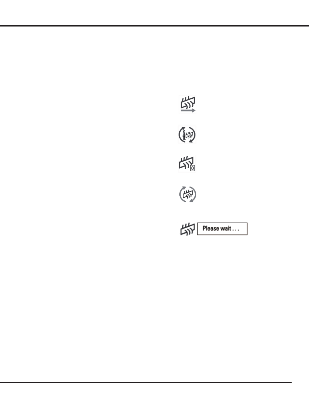
63
Filter Instructions
Filter prevents dust from accumulating on the optical elements inside the projector. Should the filter becomes
clogged with dust particles, it will reduce cooling fans’ effectiveness and may result in internal heat buildup
and adversely affect the life of the projector. This projector has an electrically operated filter which helps you to
replace the filter easily. The projector monitors the condition of the filter at all time and replaces a filter with a
new one automatically when it detects the clogging.
If the projector reaches a time set in the timer setting (p.
62), a Filter replacement icon (Fig.1) appears on the screen
and the WARNING FILTER indicator on the top panel lights
up (p.79). When you see this icon, replace the filter as soon
as possible (pp.35, 57). If the filter is out of scroll and the
projector reaches a time set in the timer setting, Fig. 2
appears on the screen, indicating that the filter cartridge
replacement is necessary.
When the filter scroll is counted down to 1, the Last scroll
icon (Fig.3) appears on the screen, indicating that there is
one scroll left in the filter cartridge (p.62).
If the projector detects that the filter is clogged and no scroll
is left in the filter cartridge, a Filter cartridge replacement
icon (Fig. 4) appears on the screen and the WARNING
FILTER indicator on the top panel lights up (p.79). When you
see this icon, replace the filter cartridge (p.64) and reset the
Filter counter (p.65) and the Scroll counter (p.65).
When the filter is being scrolled using the remote control
unit (p.35) or the Filter control function in the setting
menu (p.57), a Filter replacement icon and “Please wait...”
message (Fig.5) appear on the screen and the WARNING
FILTER indicator blinks slow (approx. 2 seconds ON, 2
seconds OFF) (p.77).
The WARNING FILTER indicator blinks fast when the
projector detects an abnormal condition, the filter cartridge
is not installed properly, or the filter scroll is not working
properly (p.79).
Fig.1 Filter replacement icon
Fig.4 Filter cartridge replacement icon
Fig.3 Last scroll icon
Maintenance and Care
✔Note:
•Fig.1,Fig.2,Fig.3,Fig.4andFig.5willnotappearwhenthe
Displayfunctionissetto“Off”(p.54)orduring“Freeze”
(p.35).
•Thefiltercannotberewound.
•Thefiltercanbescrolled9timessincethefiltercartridge
has10scrolls.
•Thefiltercartridgeisdisposable.Donotcleanandreusethe
filtercartridge.
•Donotexposethefiltercartridgetowaterorliquid,orit
maycauseabreakdown.
•Replacethefiltercartridgeafterallthescrollisusedup.If
youreplacethefiltercartridgewhentherearesomescrolls
leftinthefiltercartridge,thefiltercounterandthescroll
counterdonotrecognizethecorrectnumberofremaining
scrollsandtheresetfunctioncannotworkproperly.Itmay
causeabreakdown.
Fig.5 Filter replacement icon and
“Please wait...” message.
•Donotusethefiltercartridgewithotherprojector.Thefilter
counterandthescrollcounterdonotrecognizethecorrect
numberofremainingscrollsoftheusedfiltercartridgeand
theresetfunctioncannotworkproperly.Itmaycausea
breakdown.
•Makesurethattheprojectionlampisturnoffwhenyou
arereplacingthefiltercartridge.Ifyoureplacethefilter
cartridgewhentheprojectionlampisturnon,theprojector
willbeshutdownautomaticallyforsafetypurpose
•Whenyouforgettoresetthefiltercounter,theprojector
cannotrecognizethecorrectnumberofremainingscrolls
andmaycauseabreakdown.
•Donotforgettoresetthefiltercounterandthescroll
counterinthesettingmenuafterreplacingthefilter
cartridge.Ifyouforgettoresetthefiltercounterandthe
scrollcounter,theprojectorcannotrecognizethecorrect
numberofremainingscrollsandmaycauseabreakdown.
Fig.2
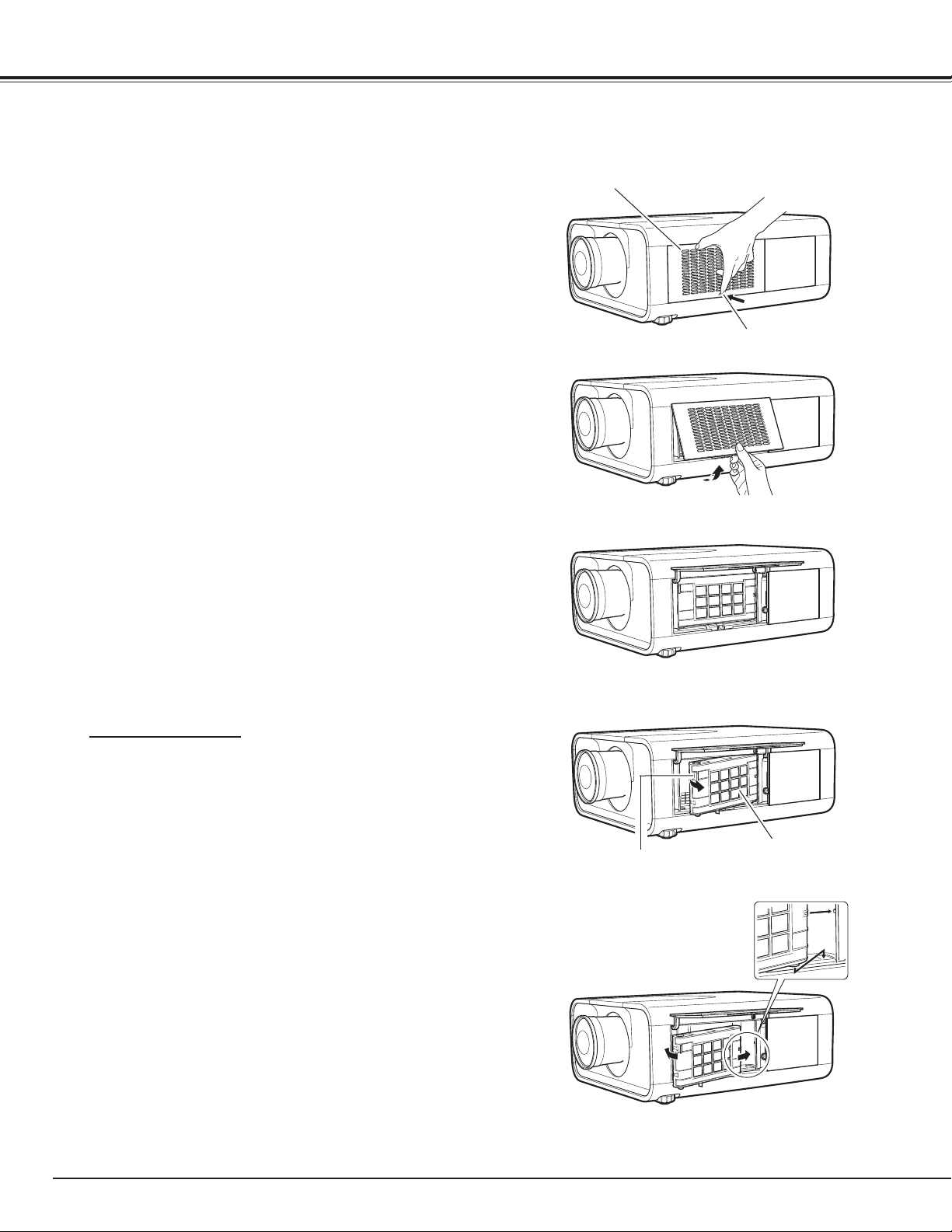
64
Turn off the projector, and unplug the AC power cord
from the AC outlet.
First, clean up the dust on the projector and around the
air vents.
1
2
Press s on the filter cover to release the latch and open
the filter cover.
3
Put the new one back into the position and close
the filter cover. Make sure that the filter cartridge is
properly and fully inserted.
5
✔Note:
Make sure the filter cartridge is inserted in the
projector. If the filter cartridge is not inserted, the
projector cannot be turned on.
Do not put anything into the air vents. Doing so
may result in malfunction of the projector.
4
Reset the filter counter and the scroll counter (p.65).
6
Filter cover
Replacing the Filter Cartridge
Pull out the filter cartridge. When taking out the filter
cartridge, put your finger on the filter cartridge’s tab
and then pull.
Latch
Filter cartridge
Tab
RECOMMENDATION
We recommend avoiding dusty/smoky environments when
operating the projector. Usage in these environments may
cause a poor image quality.
When using the projector under dusty or smoky conditions,
dust may accumulate on a lens, liquid crystal panels, or optical
elements inside the projector. Such condition may degrade the
quality of the projected image.
When the symptoms above are noticed, contact your authorized
dealer or service station for proper cleaning.
Connect the AC power cord to the projector and turn
on the projector.
7
Maintenance and Care
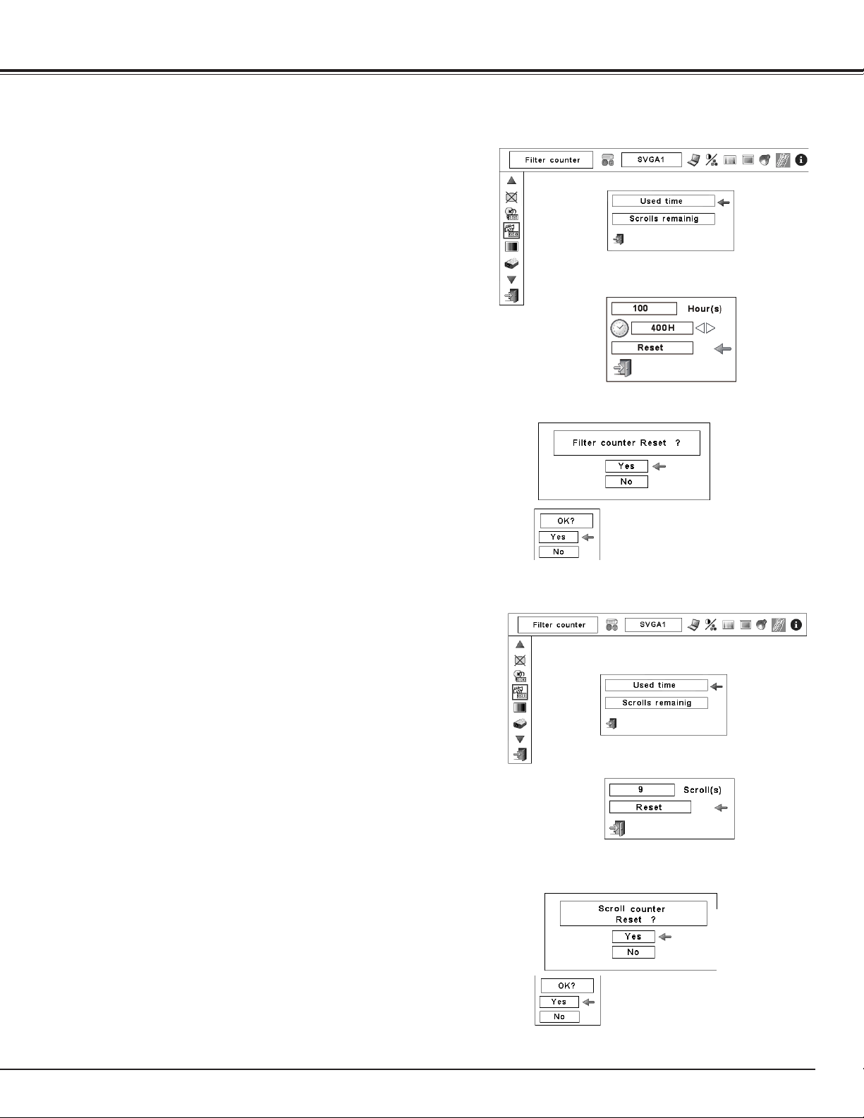
65
Be sure to reset the Scroll counter after replacing the filter
cartridge.
Press the MENU button to display the On-Screen Menu. Use
the Point 7 8 buttons to move the red frame pointer to the
Setting Menu icon.
Use the Point ed buttons to move the red frame pointer
to Filter counter and then press the OK button. A dialog
box appears showing the Used time option and the Scrolls
remaining option. Use the Point ed buttons to select
Scroll(s) remaining.
1
2
Resetting the Scroll Counter
Scroll counter
Another confirmation dialog box appears, select [Yes] to
reset the Scroll counter.
3
Scroll(s) remaining shows the number of the remaining
scrolls and the Reset option. Select Reset and the “Scroll
counter Reset?” appears. Select [Yes] to continue.
4
Be sure to reset the Filter counter after replacing the filter
cartridge.
Press the MENU button to display the On-Screen Menu. Use
the Point 7 8 buttons to move the red frame pointer to the
Setting Menu icon.
Use the Point ed buttons to move the red frame pointer
to Filter counter and then press the OK button. A dialog
box appears showing the Used time option and the Scrolls
remaining option. Use the Point ed buttons to select Used
time.
1
2
Resetting the Filter Counter
Filter counter
Select Reset and the “Filter
counter Reset?” appears.
Select [Yes],
then another
confirmation
box appears.
Select [Yes] again to reset
the Filter counter.
Another confirmation dialog box appears, select [Yes] to
reset the Filter counter.
3
Used time shows the total accumulated time of the filter
use, a timer setting option, and the Reset option. Select
Reset and the “Filter counter Reset?” appears. Select [Yes]
to continue.
4
Select “Used time” and the
dialogue box below appears.
Select “Scrolls remaining” and
the dialogue box below appears.
Select Reset and the “Scroll
counter Reset?” appears.
Select [Yes],
then another
confirmation
box appears.
Select [Yes] again to reset
the Scroll counter.
Maintenance and Care
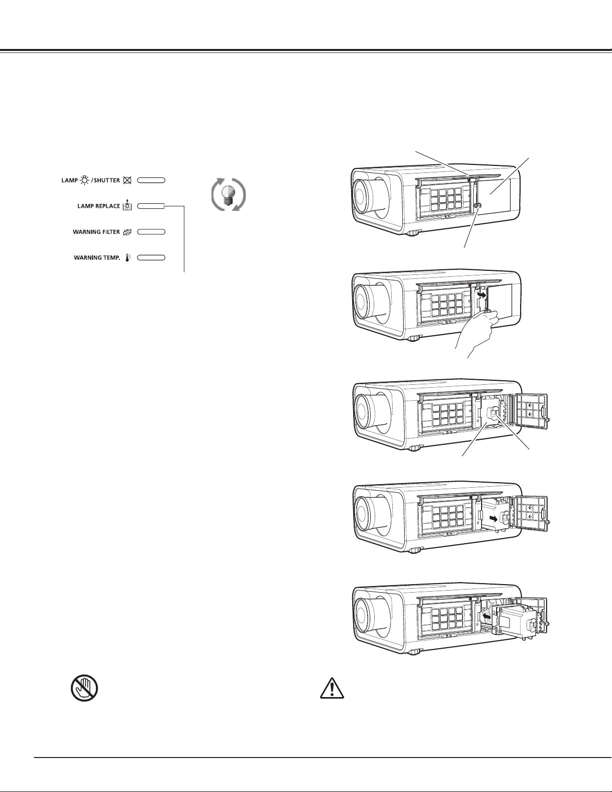
66
Turn off the projector and unplug the AC power cord. Let
the projector cool for at least 1 hour.
Loosen the screw and open the lamp cover. Pull out the
lamp by using the built in handle.
1
3
Replace the lamp with a new one. Make sure that the
lamp is properly and fully inserted.
4
Open the filter cover (p.64).
2
Connect the AC power cord to the projector and turn on
the projector.
6
Follow these steps to replace the lamp.
Reset the Lamp counter (p.67).
5
✔Note:
•Besuretoinsertthelampinthecorrectdirection.
•DonotresettheLampcounterwhentheprojectionlampis
notreplaced.
Lamp Replacement
For continued safety, replace with a lamp of the
same type. Do not drop the lamp or touch the
glass bulb! The glass can shatter and may cause
injury.
Allow a projector to cool for at least one hour
before you open the lamp cover. The inside of the
projector can become very hot.
CAUTION
CAUTION
When the projection lamp of the projector reaches its end of life, the Lamp replacement icon appears on the
screen and LAMP REPLACE indicator lights orange. Replace the lamp with a new one promptly. The timing
when the LAMP REPLACE indicator should light is depending on the lamp mode.
Top Panel
LAMP REPLACE indicator
Lamp replacement icon
✔Note:
•TheLampreplacementiconwillnotappearwhen
theDisplayfunctionissetto“Off”(p.54)orduring
“Freeze”(p.35)
7
Close the lamp cover and secure the screw.
Lamp
Handle
Lamp cover
Filter cover
Screw
Maintenance and Care
8
Close the filter cover.
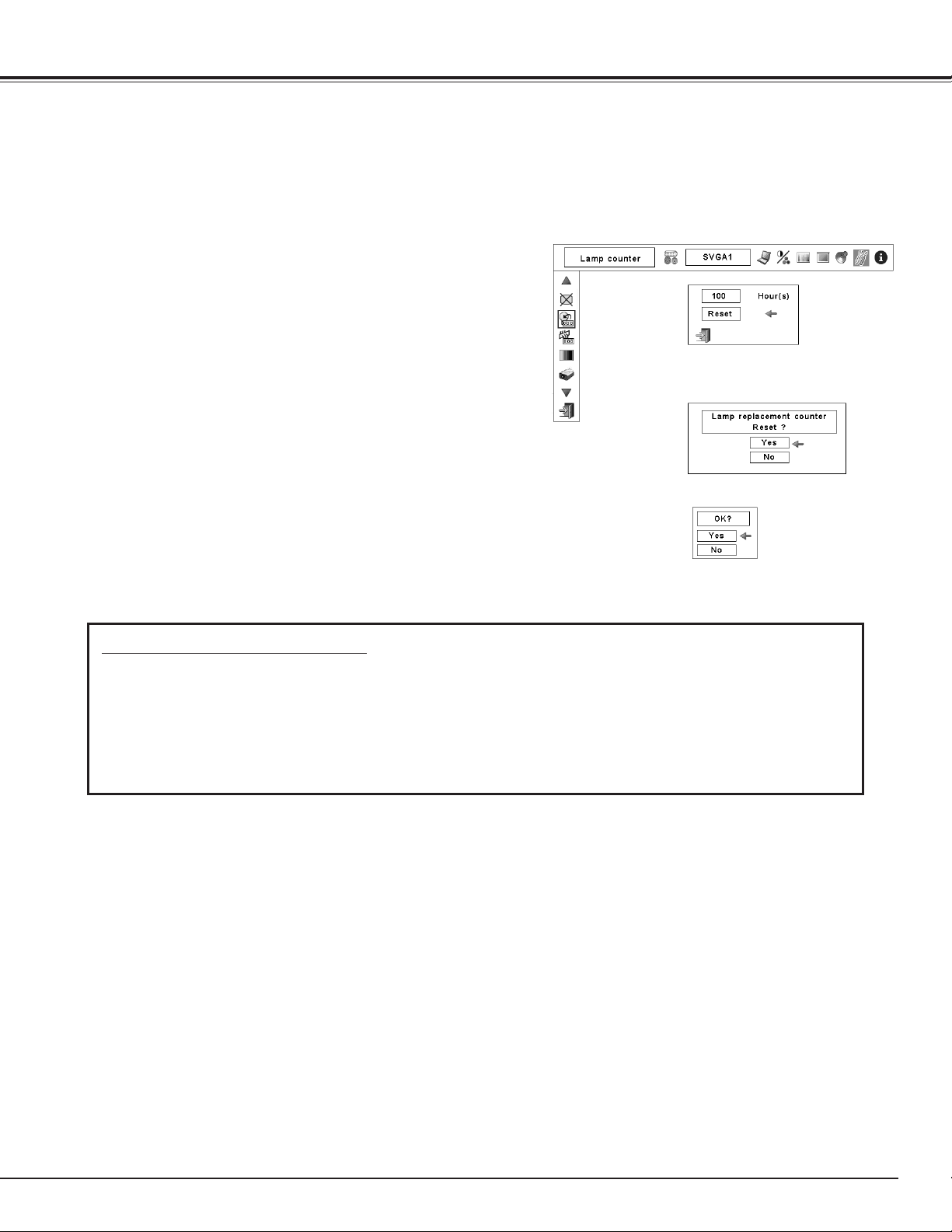
67
ORDER REPLACEMENT LAMP
Replacement lamp can be ordered through your dealer. When ordering, give the following information to the
dealer.
● Model No. of your projector : LV-7590
● Replacement Lamp Type No. : LV-LP33
Resetting the Lamp Counter
Be sure to reset the Lamp counter after the lamp is replaced. When the Lamp counter is reset, the LAMP
REPLACE indicator stops lighting and the Lamp replacement icon disappears.
✔Note:
•DonotresettheLampcounterwithoutreplacingthelamp.Besure
toresettheLampcounteronlyafterreplacingthelamp.
Press the MENU button to display the On-Screen Menu. Use
the Point 7 8 buttons to move the red frame pointer to the
Setting Menu icon
Use the Point ed buttons to move the red frame pointer to
Lamp counter and then press the OK button.
A dialog box appears showing the total accumulated time of
the lamp usage and the reset option. Select Reset and the
“Lamp replacement counter Reset?” appears. Select [Yes] to
continue.
1
2
Lamp counter
Select Reset and the “Lamp
replacement counter Reset?”
appears.
Select [Yes] again
to reset the lamp
counter.
Select [Yes], then another
confirmation box appears.
Another confirmation dialog box appears and select [Yes] to
reset the Lamp counter.
3
Maintenance and Care

68
This projector uses a high-pressure lamp which must be handled carefully and properly.
Improper handling may result in accidents, injury, or create a fire hazard.
● Lamp lifetime may differ from lamp to lamp and according to the environment of use. There is no
guarantee of the same lifetime for each lamp. Some lamps may fail or terminate their lifetime in a
shorter period of time than other similar lamps.
● If the projector indicates that the lamp should be replaced, i.e., if the LAMP REPLACE indicator lights
up, replace the lamp with a new one IMMEDIATELY after the projector has cooled down. (Follow
carefully the instructions in the Lamp Replacement section of this manual.) Continuous use of the lamp
with the LAMP REPLACE indicator lighted may increase the risk of lamp explosion.
● Lamp may explode as a result of vibration, shock or degradation as a result of hours of use as its
lifetime draws to an end. Risk of explosion may differ according to the environment or conditions in
which the projector and lamp are being used.
IF A LAMP EXPLODES, THE FOLLOWING SAFETY PRECAUTIONS SHOULD BE TAKEN.
If a lamp explodes, disconnect the projector’s AC plug from the AC outlet immediately. Contact an
authorized service station for a checkup of the unit and replacement of the lamp. Additionally, check
carefully to ensure that there are no broken shards or pieces of glass around the projector or coming out
from the cooling air circulation holes. Any broken shards found should be cleaned up carefully. No one
should check the inside of the projector except those who are authorized trained technicians and who
are familiar with projector service. Inappropriate attempts to service the unit by anyone, especially those
who are not appropriately trained to do so, may result in an accident or injury caused by pieces of broken
glass.
LAMP HANDLING PRECAUTIONS
Maintenance and Care
CAUTION
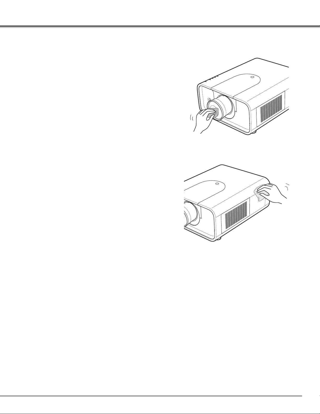
69
Unplug the AC power cord before cleaning.
Gently wipe the projection lens with a cleaning cloth that
contains a small amount of non-abrasive camera lens
cleaner, or use a lens cleaning paper or commercially
available air blower to clean the lens.
Avoid using an excessive amount of cleaner. Abrasive
cleaners, solvents, or other harsh chemicals might scratch
the surface of the lens.
Cleaning the Projector Cabinet
Unplug the AC power cord before cleaning.
Gently wipe the projector body with a soft dry cleaning
cloth. When the cabinet is heavily soiled, use a small amount
of mild detergent and finish with a soft dry cleaning cloth.
Avoid using an excessive amount of cleaner. Abrasive
cleaners, solvents, or other harsh chemicals might scratch
the surface of the cabinet.
When the projector is not in use, put the projector in
an appropriate carrying case to protect it from dust and
scratches.
Cleaning the Projection Lens
Maintenance and Care
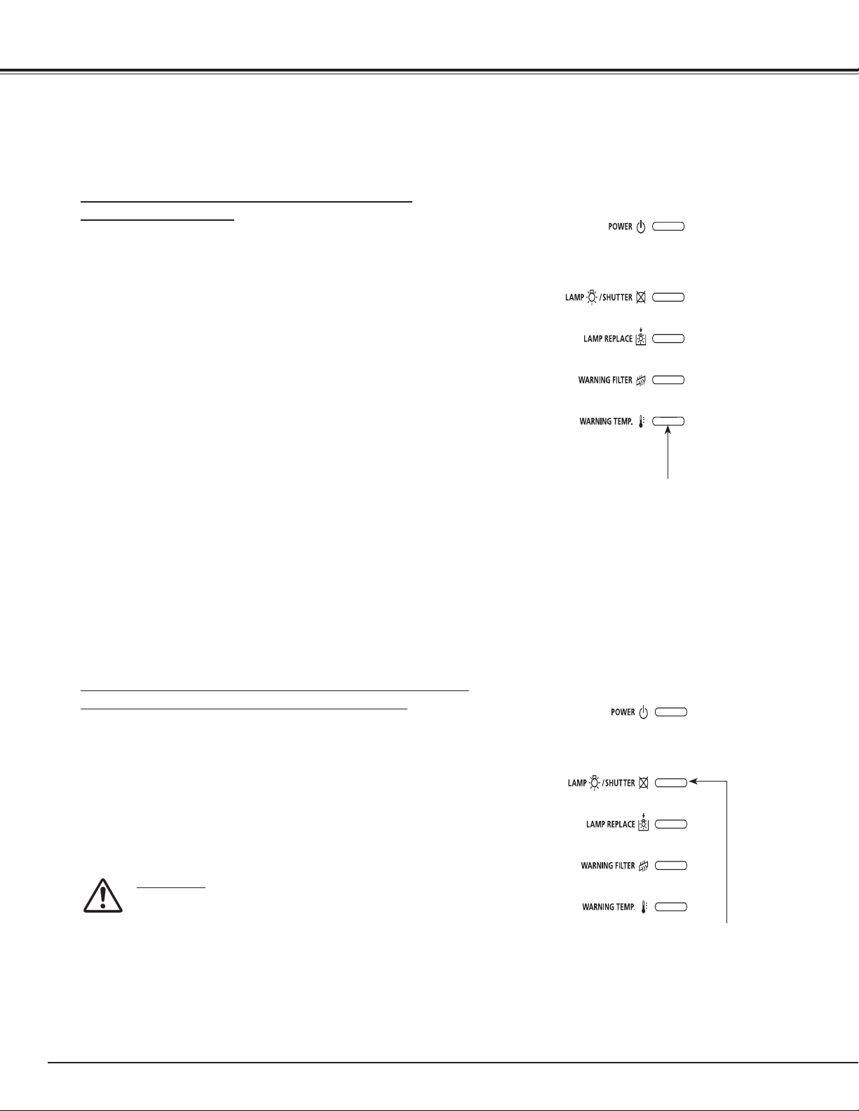
70
The WARNING indicators show the state of the function which protects the projector. Check the state of the
WARNING indicators and the POWER indicator to take proper maintenance.
Warning Indicators
The projector is shut down and the WARNING TEMP.
indicator is blinking red.
When the temperature inside the projector reaches a
certain level, the projector will be automatically shut down
to protect the inside of the projector. The LAMP/SHUTTER
indicator turns red and the WARNING TEMP indicator
blinks while the projector is being cooled down. When the
projector has cooled down enough (to its normal operating
temperature), it can be turned on again by pressing the
POWER button.
✔Note:
•TheWARNINGTEMP.indicatorcontinuestoblinkevenafterthe
temperatureinsidetheprojectorreturnstonormal.Whenthe
projectoristurnedonagain,theWARNINGTEMP.indicatorstops
blinking.
Then check the matters below:
– Did you provide appropriate space for the projector to be
ventilated? Check the installing condition to see if the air
vents of the projector are not blocked.
– Has the projector been installed near an Air-Conditioning/
Heating Duct or Vent? Move the installation of the
projector away from the duct or vent.
– Is the filter clean? Replace the filter with a new one.
The projector is shut down; and the LAMP/SHUTTER indicator
is lighting red and other four indicators are blinking.
When the projector detects an abnormal condition, it will
be automatically shut down to protect the inside of the
projector and the LAMP/SHUTTER indicator lights red and
other four indicators blink. In this case, unplug the AC power
cord and plug it, and then turn on the projector once again
to verify operation. If the projector cannot be turned on and
these indicators are still lighting and blinking, unplug the AC
power cord and contact the service station.
WARNING
DO NOT LEAVE THE PROJECTOR WITH THE
AC POWER CORD CONNECTED UNDER AN
ABNORMAL CONDITION. IT MAY RESULT IN FIRE
OR ELECTRIC SHOCK.
Top Panel
LAMP/SHUTTER indicator
lights red and other four
indicators blink
Top Panel
WARNING TEMP.
blinking red
Maintenance and Care
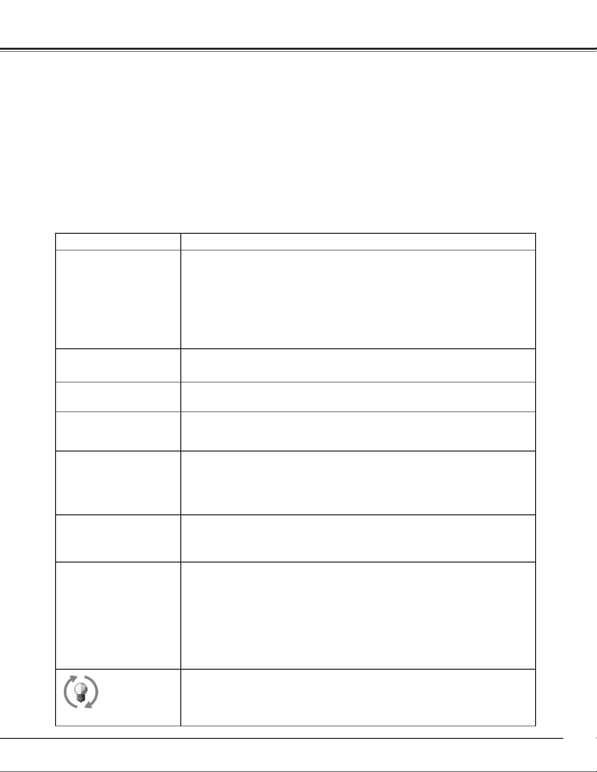
71
Troubleshooting
Before calling your dealer or service center for assistance, check the items below once again.
1. Make sure you have properly connected the projector to peripheral equipment as described on pages 24–26.
2. Check the cable connection. Make sure that all computers, video equipment, and power cords are properly
connected.
3. Make sure that all power is switched on.
4. If the projector still does not produce an image, restart your computer.
5. If an image still does not appear, disconnect the projector from your computer and check your computer
monitor’s display. A problem may be noticed with your graphics controller rather than with the projector.
(When you reconnect the projector, be sure to turn the computer and monitor off before you turn on the
projector. Turn on equipment in the order of the projector and computer.)
6. If a problem still persists, check the following solutions.
Appendix
Problem: Solutions
No power.
– Plug the power cord of the projector into the AC outlet.
–
Wait until the POWER indicator stops blinking to turn on the projector again. (See
page 28)
–
Check the WARNING TEMP. indicator. If the WARNING TEMP. indicator is blinking, the
projector cannot be turned on. (See page 70.)
–
Unlock the Key lock function for the projector. (See page 59)
–
See if the filter cartridge is inserted. (See page 64)
– Check the projection lamp. (See page 66.)
PIN code dialog box
appears at start-up.
– PIN code lock is being set. Enter a PIN code; the “1234” or numbers you have set
(See pages 28, 59-60)
The initial display is not
shown.
– Make sure “Off ” or “Countdown Off” are not chosen at Display function.
(See “SETTING” section on page 54)
The initial display is not
same with the default
one.
– Make sure “User” or “Off” are not chosen at Logo select function.
(See “SETTING” section on page 55)
When the projector is on
and you press the input
button, an icon other
than the Lamp mode icon
appears.
– That is the Filter warning icon. (See page 63.)
An icon other than Input
mode or Lamp mode icon
appears.
– That is the Lamp replacement icon or the Filter warning icon. (See pages 62-63.)
No image.
– Check the connection between your computer or video equipment and the projector.
– See if the input signal is correctly output from your computer. Some laptop
computers may need to be changed the setting for monitor output when connected
to the projector. See your computer’s instruction manual for the setting.
– It takes about 30 seconds to display an image after turning on the projector.
– See if the selected system is corresponding with your computer or video equipment.
– Select correct input source once again through menu operation (See pages 37-39).
– Make sure the temperature is not out of Operating Temperature
(41˚F–104˚F [5˚C–
40˚C]).
appears on the screen
–
End of lamp life is approaching. Replace the lamp with a new one promptly. (See
pages 61, 66-67)
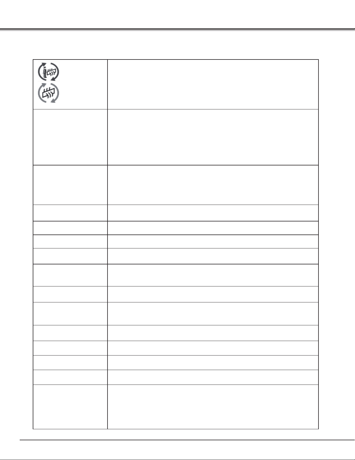
72
appears on the screen
–
Filter is out of scroll. Replace the filter cartridge with a new one promptly. (See pages
64 -65)
The image is out of focus.
– Adjust the focus of the projector.
– Check Projection Lens to see if it needs cleaning.
✔Note: Moving the projector from a cool temperature location to a warm temperature
location may result in moisture condensation on Projection Lens. In such cases,
leave the projector OFF and wait until condensation evaporates.
– Projecting from excessive slant angle to the screen may cause keystone distortion
and partial imperfect focus.
– Make sure the projection screen is at least 4.6’ (1.4 m) away from the projector.
The image is not bright
enough.
– Check if “Contrast” or “Brightness” are adjusted properly. (See page 51)
– Check if “Image level” is selected properly. (See pages 44, 48)
– Check the Lamp mode function. ( See “SETTING” section on page 57)
– Check the LAMP REPLACE indicator. If it lights, the end of lamp life is approaching.
Replace the lamp with a new one promptly. (See page 66)
The color is strange.
– Check the Input signal, color system, video system, or computer system mode.
– Adjust the Image Level properly. (See pages 44, 48)
The image is Left/Right
reversed.
– Check the Ceiling / Rear function. (See pages 46, 50.)
The image is Top/Bottom
reversed.
– Check the Ceiling function. (See pages 46, 50.)
The image is distorted or
runs off.
– Check “PC Adjust” menu or “ Aspect” menu and adjust them.
Auto PC adjustment
function does not work.
– Check the Input signal. Auto PC Adjustment function cannot work when 480p, 575p,
720p, 480i, 575i, 1035i, or 1080i is selected or when the digital signal is input into DVI
terminal. (See page 41)
Some displays are not
seen during the operation.
– Check the Display function (see page 54).
The setting does not
remain after turning off
power.
– Make sure you selected “Store” after adjusting settings. Some settings cannot be
stored if not registered with “Store”.
Power management
function does not work.
– Power management function cannot work while “Freeze” function is running or the
shutter is closed.
Image disappears
automatically.
– Check the power management function in the Setting. The power management is set
to "On" at the factory.
Capture function does not
work.
– Check the connection to see if there is signal.
Some menus cannot be
selected.
– Each of the Video Input and Computer Input has a limit on selectable menus.
No sound
– Check the audio cable connection from audio input source.
– Adjust the audio source.
– Press the Volume + button. ( See page 33)
– Press the Mute button. (See page 33)
– Is the image projected? You will hear the sound only when the image is projected.
– Make sure you selected correct Input pattern. (See page 33)
Appendix
73
WARNING:
High voltages are used to operate this projector. Do not attempt to open the cabinet.
If problems still persist after following all operating instructions, contact the dealer where you purchased the projector
or the service center. Specify the model number and explain about the problem. We will advise you how to obtain
service.
Appendix
The power is turned off
automatically.
– Power management function runs by initial setting. Check “SETTING” section on page
58.
– When the filter cartridge replacement icon keeps appearing on the screen at turning
on the projector for some time and no action is taken to replace the filter cartridge, the
projector will be automatically shut down in 3 minutes after turning on to protect the
projector. (See pages 63-65, 79)
– Do not cover the ventilation slots on the projector. (See pages 4, 8)
– Projector may be used in high ambient temperature environment. Make sure the
temperature is not out of Operating Temperature
(41˚F–104˚F [5˚C–40˚C]). (See page 71)
You cannot operate with
the side control.
– The side control is not available. If the side control is locked at “Key lock” under
“Security” of SETTING section. Please check “SETTING” section on page 59.
The remote control unit
does not work.
– Check the batteries.
– Check if the RC sensor is set properly. (See page 58)
– Make sure no obstruction is between the projector and remote control unit.
– Make sure you are not too far from the projector when using the remote control unit.
Maximum operating range is 16.4’ (5m).
– Make sure that the remote control unit code conforms to the projector’s code. (See
“SETTING” section on page 57.)
– Unlock the Key lock function for the remote control unit. (See page 59)
– Wireless remote control unit does not work when the remote control cable is
connected to the projector. (See page 18)
–
Check if the ALL OFF switch on the remote control unit is set to “ON.”
– Make sure that the simple mode in the remote control function is set to “Off“ (See
page 57).
Wireless mouse function
does not work.
– Check the cable connection between the projector and your computer. (See page 36)
– Check the mouse setting on your computer.
– Turn on the projector before you turn on the computer.
Indicators blink or light.
– Check the status of the projector with referring to “ INDICATORS AND PROJECTOR
CONDITION” on pages 77-79
appears on the screen
– Your operation is invalid. Operate correctly.
Unable to unlock the Logo
PIN code lock, Security
key lock or Security PIN
code lock.
– Contact the dealer where you purchased the projector or the service center.
Forget the Logo PIN code
or Security PIN code.
– Contact the dealer where you purchased the projector or the service center.
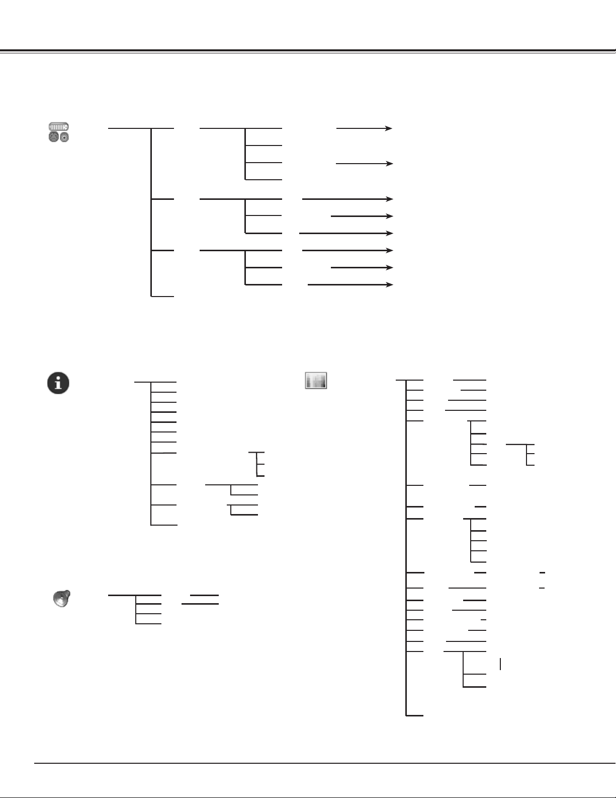
74
Menu Tree
Input
RGB (PC analog)
Go to System
(1)
Input 1
Y, Pb/Cb,Pr/Cr
Computer Input/Video Input
RGB (Scart)
RGB (PC digital)
RGB (AV HDCP)
Network
Video
RGB
Go to System
(2)
Go to System
(3)
Go to System
(1)
Go to System
(2)
Video
Y, Pb/Cb,Pr/Cr
S-video
Go to System
(3)
Go to System
(2)
Input 2
Input 3
Go to System
(1)
Input
H-sync freq.
V-sync freq.
Information
Aspect
Language
Lamp status
Power management
Security
Remote control
0–63
0–63
Image Adjust
Contrast
Brightness
Color ]
Tint ]
0–63
0–63
✔Note:
•TheMenudisplayvariesdependingontheinputsignal.
Information Image Adjust
High
Color temp.
Appendix
Color
management
Auto picture
control
Off/L1/L2
Off/Auto
Advanced color
COLOR
GAMMA
LIST
COLOR M.
MENU
Mid
Low
COLOR M.
ALL DEL
MENU
Projector
Shutter management
Remote Control
5 - 180 Min
PIN code lock
Key lock
RC code
Simple mode
Network will be displayed only when an
optional Network Imager is attached.
]
]
Quit
Off/On/Film
White Balance
Sharpness
Reset
Store
Gamma
Progressive ]
Red/Green/Blue
0–31
0–15
Custom 1
Yes/No
Quit
Off/OnNoise reduction ]
]
DisplayedonlyinVideoInput
High
Mid
Low
XLow
Adj.
Color temp. High
Mid
Low
Color temp.
Offset Red/Green/Blue
Custom 10
Volume
Mute On/Off
Sound
0–63
Input pattern
Quit
Sound
SERIAL NO.
0-63
0-63
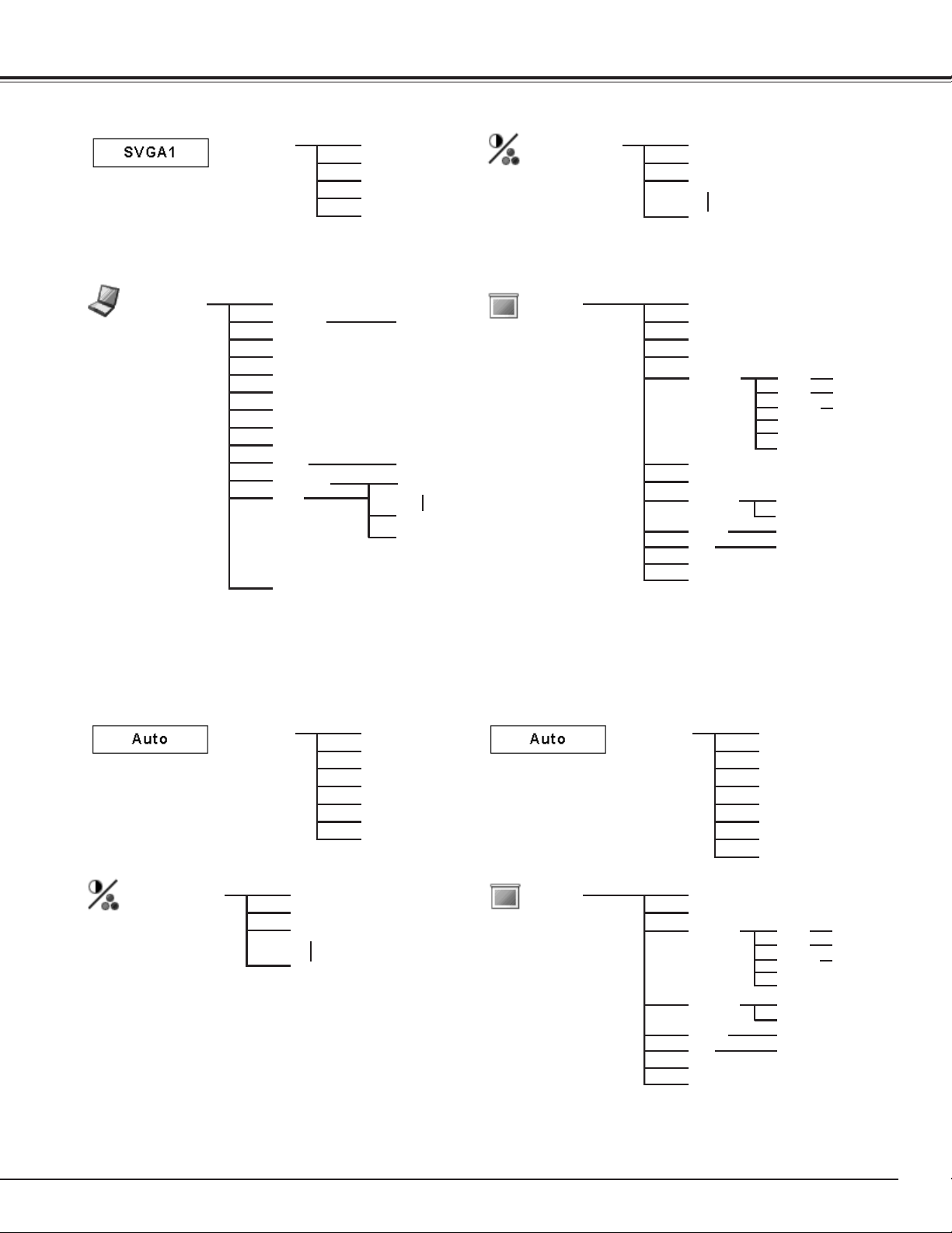
75
Computer Input
System
(1)
Mode 1
Mode 2
Image Select
Standard
High contrast
Custom 1
Custom 10
Aspect
Normal
True
Wide
Full screen
Digital zoom +
Digital zoom -
PC Adjust
Auto PC adj.
Fine sync.
Total dots
Position H
Position V
Current mode
Clamp
Display area - H
Display area - V
Reset
Mode free
Store
Quit
0–31
Yes/No
Mode 1
Mode 10
Quit
] System displayed in the System Menu varies depending on the input signal.
✔Note:
•TheMenudisplayvariesdependingontheinputsignal.
SVGA 1
SVGA 2
SVGA 3
Rear
Keystone
Ceiling
Reset
Store
On/Off
On/Off
Custom
H & V
Scale
Position
H / V
On/Off
H / V
Common
Reset
Video Input
System
(2)
Auto
PAL
SECAM
NTSC
NTSC 4.43
PAL-M
PAL-N
System
(3)
Auto
1080i
1035i
720p
575p
480p
575i
480i
Image Select
Standard
Cinema
Custom 1
Custom 10
Aspect
Normal
Wide
Rear
Keystone
Ceiling
Reset
Store
On/Off
On/Off
Custom
H & V
Scale
Position
H / V
On/Off
H / V
Common
Reset
Reset
Reset
Appendix
Quit
Quit
Quit
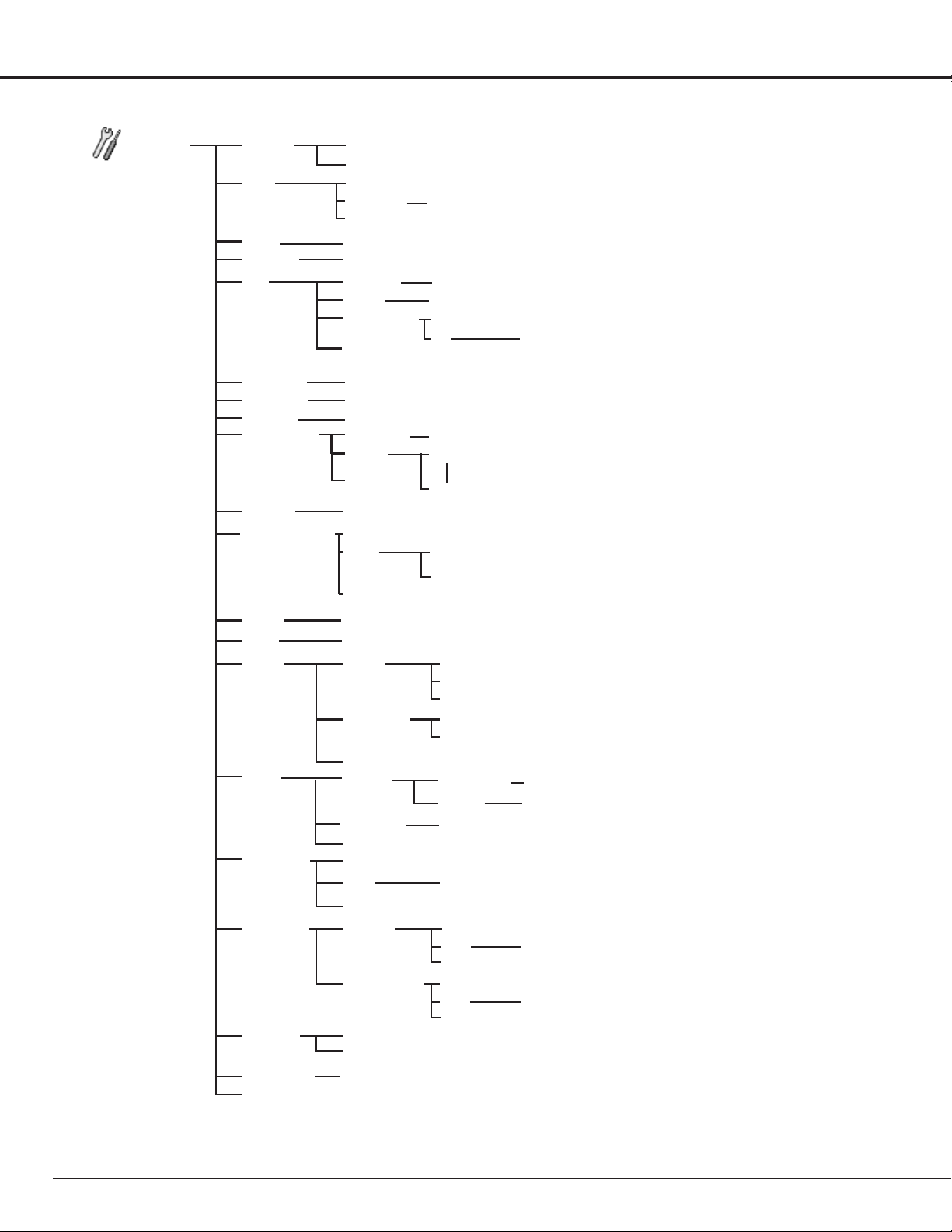
76
Computer Input/Video Input
Setting
Language
Fan control
Quit
Position
Blue/User/Black
Logo select
Capture
Logo PIN code lock
Quit
Auto/Normal/Eco1/Eco2
Yes/No
12 languages provided.
Menu
Logo
Lamp mode
Filter control
Both/Front/Back
Normal/Max
Power management
Background
On
RC sensor
Ready
Off
Shut down
1–30 Min.
Quit
On/OffOn start
Pointer
Key lock
Security Off
Projector
Remote control
PIN code lock Off/On1/On2
PIN code change
On/Countdown Off/Off
Display
User/Default/Off
Yes/No
Simple modeRemote control
RC code
Cross/Arrow/Dot
Appendix
Quit
Used timeFilter counter
Yes/No
Factory default
Quit
Off/400H/700H/1000H
Reset
Yes/No
Quit
Scrolls remaining Scroll(s)
Reset
Yes/No
Quit
8 test patterns provided
Test pattern
Quit
Lamp counter
Hour(s)
Quit
Reset
Yes/No
Shutter
Management
Remote control
On/Off
Projector
On/Off
5 - 180 Min.
Quit
Code 1
Code 8
Quit
On/Off
Simple Menu
Quit
On/Off
Off
Protection
Logo PIN code change
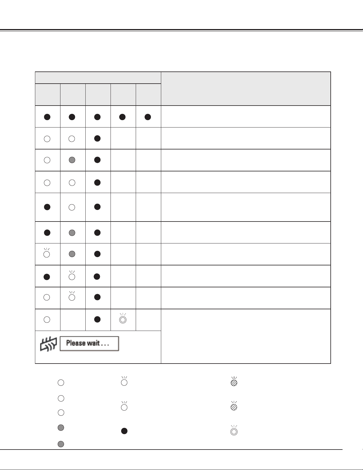
77
Indicators and Projector Condition
Check the indicators for the projector condition.
Appendix
The projector is operating normally.
Indicators
Projector Condition
POWER
green
LAMP/
SHUTTER
red/blue
WARNING
TEMP.
red
WARNING
FILTER
orange
LAMP
REPLACE
orange
The projector is off. (The AC power cord is unplugged.)
The projector is in stand-by mode. Press the POWER button
to turn on the projector.
The projector is operating normally.
(The shutter is open)
The projector is operating normally.
(The shutter is closed)
The projector is preparing for stand-by or the projection lamp
is being cooled down. The projector cannot be turned on until
cooling is completed and the POWER indicator lights green.
The projection lamp is being cooled down in the Power
management mode.
The projector is in the Power management mode.
The projection lamp is being cooled down in the Shutter
management mode.
The projector is in the Shutter management mode. Press the
POWER button to turn on the projector.
The filter is scrolled using the FILTER button on the remote
control unit or the Filter control function in the setting menu.
When the filter is being scrolled, the Filter replacement icon
and “Please wait...” message (Fig. 1) appear on the screen for
about 30 seconds.
• • • on
• • • off
• • • blinking at the normal rate
(approx. 1 second ON,
1 second OFF)
• • • dim
• • • blinking slow
(approx. 2 seconds ON,
2 seconds OFF)
]
]
]
]
Fig.1 Filter replacement icon and “Please wait...”
• • • on (blue)
❊
❊
• • • blinking at the normal rate (blue
and dim red) (approx. 1 second
ON, 1 second OFF)
❊
• • • blinking fast (blue and dim red)
(approx. 0.5 seconds ON, 0.5
seconds OFF)
• • • blinking fast
(approx. 0.5 seconds ON,
0.5 seconds OFF)
• • • on (red)
❖
❖
• • • dim (red)
❖
❖
]
❊
❖
]
❖
❖
❊
❊
]
]
]
]
]
]
]
]
]
]
]
• • • Differ according to conditions.
]
]
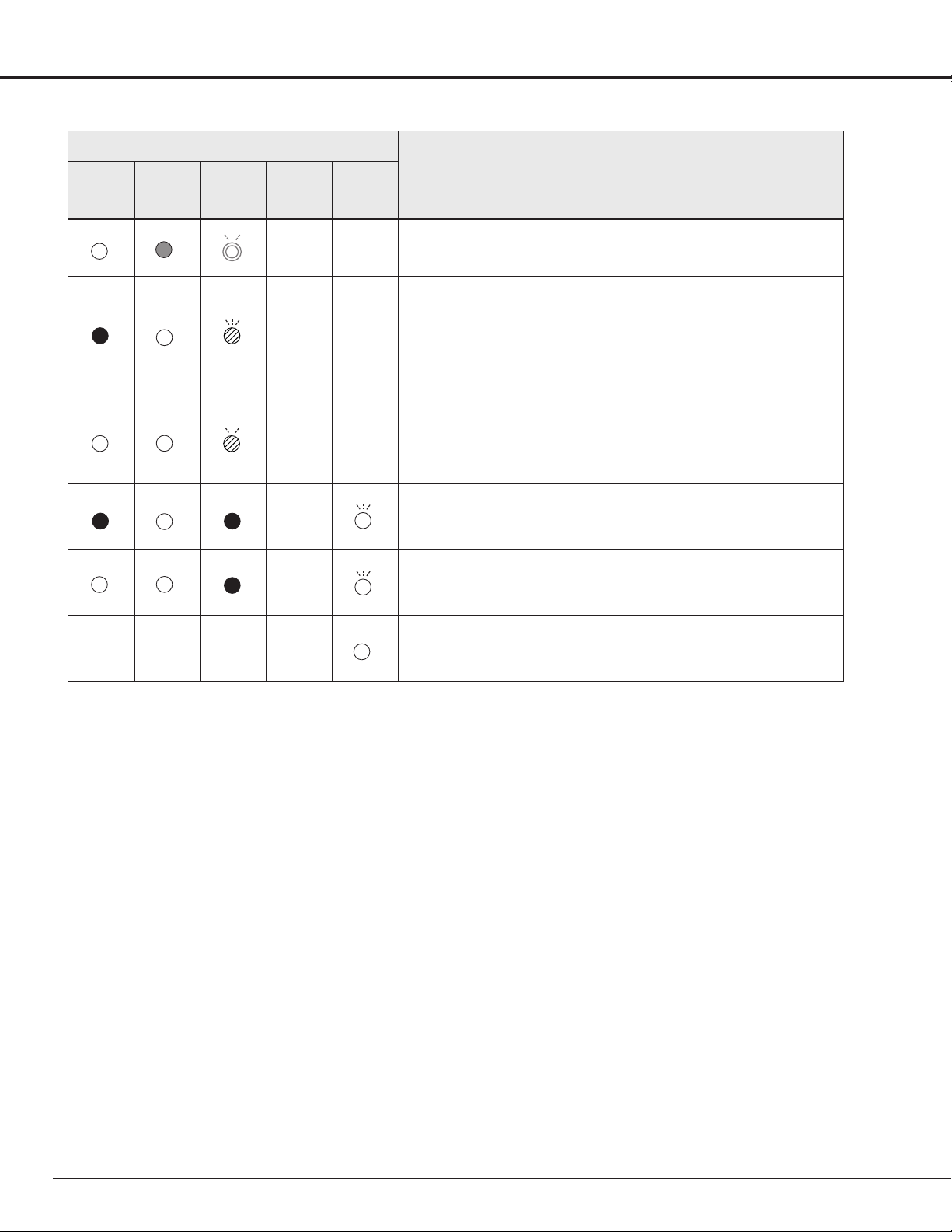
78
Appendix
The projector is detecting abnormal condition.
Indicators
Projector Condition
POWER
green
LAMP/
SHUTTER
red/blue
WARNING
TEMP.
red
WARNING
FILTER
orange
LAMP
REPLACE
orange
The temperature inside the projector is elevated close to the
abnormally high level.
The temperature inside the projector is abnormally high. The
projector cannot be turned on. When the projector is cooled
down enough and the temperature returns to normal, the
POWER indicator lights green and the projector can be turned
on. (The WARNING TEMP. indicator keeps blinking.) Check and
replace the filter.
The projector has been cooled down enough and the
temperature returns to normal. When turning on the projector,
the WARNING TEMP. indicator stops blinking. Check and
replace the filter.
The lamp cannot light up. (The projector is preparing for stand-
by or the projection lamp is being cooled down. The projector
cannot be turned on until cooling is completed.)
The lamp cannot light up. (The lamp has been cooled down
enough and the projector is in stand-by mode and ready to be
turned on with the POWER button.)
The lamp has been used overtime. Replace the lamp
immediately and then reset the lamp counter. The indicator
will be turned off after resetting the counter.
When the filter detects clogging, reaches a time set in the timer setting or runs out of the filter scroll, the WARNING
FILTER indicator lights orange. When this indicator lights orange, replace the filter or the filter cartridge with a new one
promptly. Reset the Filter counter and Scroll counter after replacing the filter cartridge (p.65).
]
]
]
]
]
When the projection lamp reaches its end of life, the LAMP REPLACE indicator lights orange. When this indicator lights
orange, replace the projection lamp with a new one promptly. Reset the lamp counter after replacing the lamp (p.67).
WARNING FILTER
LAMP REPLACE
]
]
]
]
❖
❖
❖
❖
❖
]]]
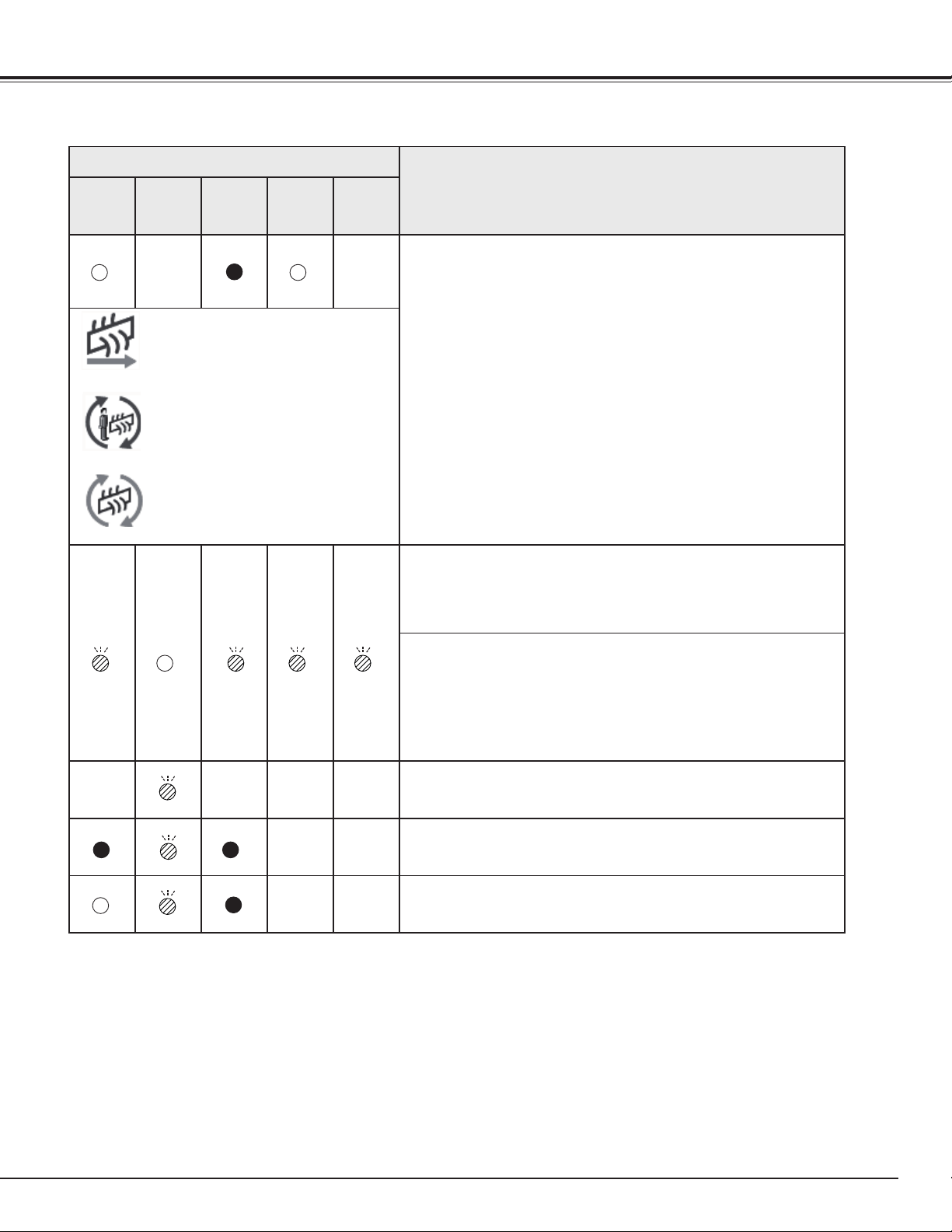
79
The projector is detecting abnormal condition.
Indicators
Projector Condition
POWER
green
LAMP/
SHUTTER
red/blue
WARNING
TEMP.
red
WARNING
FILTER
orange
LAMP
REPLACE
orange
If the Filter counter reached a time set in the timer setting,
a Filter replacement icon (Fig.2) appears on the screen and
the WARNING FILTER indicator on the top panel lights up.
Replace the filter as soon as possible. If the filter is out of
scroll and the projector reaches a time set in the timer setting,
Fig. 3 appears on the screen and the WARNING FILTER
indicator lights up. Replace the filter cartridge as soon as
possible.
If the filter is clogged and no scroll is left in the filter cartridge,
a Filter cartridge replacement icon (Fig.4) appears on the
screen and the WARNING FILTER indicator lights up. Replace
the filter cartridge as soon as possible.
✔Note:
•Fig.2,Fig.3andFig.4iconwillnotappearwhentheDisplayfunction
issetto“Off”(p.54)orduring“Freeze”(p.35).
The filter cartridge is not installed in the projector. Check the
filter compartment to see if the filter cartridge is installed in
the projector. When the filter cartridge is installed and the
indicators continue to light and blink, read the column below.
The projector detects an abnormal condition and cannot be
turned on. Unplug the AC power cord and plug it again to turn
on the projector. If the projector is turned off again, unplug the
AC power cord and contact the dealer or the service center.
Do not leave the projector on. It may cause an electric shock
or a fire hazard.
The shutter is out of control.
The shutter is out of control. (The projector is in the cooling
mode.)
The shutter is out of control. (The projector is in the stand-by
mode.) In that case, contact the service station immediately.
Fig.2 Filter replacement icon
Fig.4 Filter cartridge replacement icon
Fig.3
]
]
]
]]] ]
]
]
Appendix
]
❖
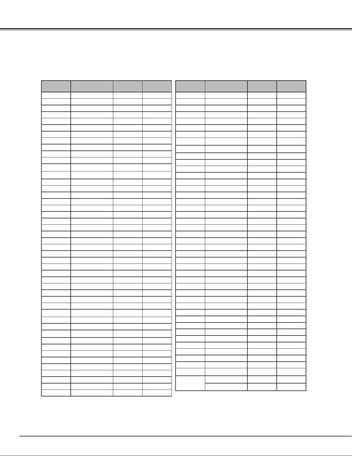
80
ON-SCREEN
DISPLAY
RESOLUTION
H-Freq.
(kHz)
V-Freq.(Hz)
VGA 1 640x480 31.470 59.880
VGA 2 720x400 31.470 70.090
VGA 3 640x400 31.470 70.090
VGA 4 640x480 37.860 74.380
VGA 5 640x480 37.860 72.810
VGA 6 640x480 37.500 75.000
VGA 7 640x480 43.269 85.000
MAC LC13 640x480 34.970 66.600
MAC 13 640x480 35.000 66.670
480p 640x480 31.470 59.880
575p 768x575 31.250 50.000
575i
768x576
(Interlace)
15.625 50.000
480i
640x480
(Interlace)
15.734 60.000
SVGA 1 800x600 35.156 56.250
SVGA 2 800x600 37.880 60.320
SVGA 3 800x600 46.875 75.000
SVGA 4 800x600 53.674 85.060
SVGA 5 800x600 48.080 72.190
SVGA 6 800x600 37.900 61.030
SVGA 7 800x600 34.500 55.380
SVGA 8 800x600 38.000 60.510
SVGA 9 800x600 38.600 60.310
SVGA 10 800x600 32.700 51.090
SVGA 11 800x600 38.000 60.510
MAC 16 832x624 49.720 74.550
XGA 1 1024x768 48.360 60.000
XGA 2 1024x768 68.677 84.997
XGA 3 1024x768 60.023 75.030
XGA 4 1024x768 56.476 70.070
XGA 5 1024x768 60.310 74.920
XGA 6 1024x768 48.500 60.020
XGA 7 1024x768 44.000 54.580
XGA 8 1024x768 63.480 79.350
XGA 9
1024x768
(Interlace)
36.000 87.170
XGA 10 1024x768 62.040 77.070
XGA 11 1024x768 61.000 75.700
XGA 12
1024x768
(Interlace)
35.522 86.960
XGA 13 1024x768 46.900 58.200
XGA 14 1024x768 47.000 58.300
XGA 15 1024x768 58.030 72.000
MAC 19 1024x768 60.240 75.080
SXGA 1 1152x864 64.200 70.400
SXGA 2 1280x1024 62.500 58.600
SXGA 3 1280x1024 63.900 60.000
SXGA 4 1280x1024 63.340 59.980
SXGA 5 1280x1024 63.740 60.010
ON-SCREEN
DISPLAY
RESOLUTION
H-Freq.
(kHz)
V-Freq.(Hz)
SXGA 6 1280x1024 71.690 67.190
SXGA 7 1280x1024 81.130 76.107
SXGA 8 1280x1024 63.980 60.020
SXGA 9 1280x1024 79.976 75.025
SXGA 10 1280x960 60.000 60.000
SXGA 11 1152x900 61.200 65.200
SXGA 12 1152x900 71.400 75.600
SXGA 13
1280x1024
(Interlace)
50.000 86.000
SXGA 14
1280x1024
(Interlace)
50.000 94.000
SXGA 15 1280x1024 63.370 60.010
SXGA 16 1280x1024 76.970 72.000
SXGA 17 1152x900 61.850 66.000
SXGA 18
1280x1024
(Interlace)
46.430 86.700
SXGA 19 1280x1024 63.790 60.180
SXGA 20 1280x1024 91.146 85.024
SXGA+ 1 1400x1050 63.970 60.190
SXGA+ 2 1400x1050 65.350 60.120
SXGA+ 3 1400x1050 65.120 59.900
SXGA+ 4 1400x1050 64.030 60.010
SXGA+ 5 1400x1050 62.500 58.600
MAC 21 1152x870 68.680 75.060
MAC 1280x960 75.000 75.080
MAC 1280x1024 80.000 75.080
WXGA 1 1366x768 48.360 60.000
WXGA 2 1360x768 47.700 60.000
WXGA 3 1376x768 48.360 60.000
WXGA 4 1360x768 56.160 72.000
WXGA 6 1280x768 47.776 59.870
WXGA 7 1280x768 60.289 74.893
WXGA 8 1280x768 68.633 84.837
WXGA 9 1280x800 49.600 60.050
WXGA 10 1280x800 41.200 50.000
WXGA 11 1280x800 49.702 59.810
WUXGA 1 1920x1200 74.556 59.885
WSXGA+ 1 1680x1050 65.290 59.954
WXGA+ 1 1440x900 55.935 59.887
UXGA 1 1600x1200 75.000 60.000
UXGA 2 1600x1200 81.250 65.000
UXGA 3 1600x1200 87.500 70.000
UXGA 4 1600x1200 93.750 75.000
720p 1280x720 45.000 60.000
720p 1280x720 37.500 50.000
1035i
1920x1035
(Interlace)
33.750 60.000
1080i
1920x1080
(Interlace)
33.750 60.000
1920x1080
(Interlace)
28.125 50.000
Compatible Computer Specifications
Basically this projector can accept the signal from all computers with the V- and H-Frequency mentioned below
and less than 180 MHz of Dot Clock.
Appendix
]
]
]
]
]
]
]
✔Note:
•True cannot be selected when isselected.(p.45)
]
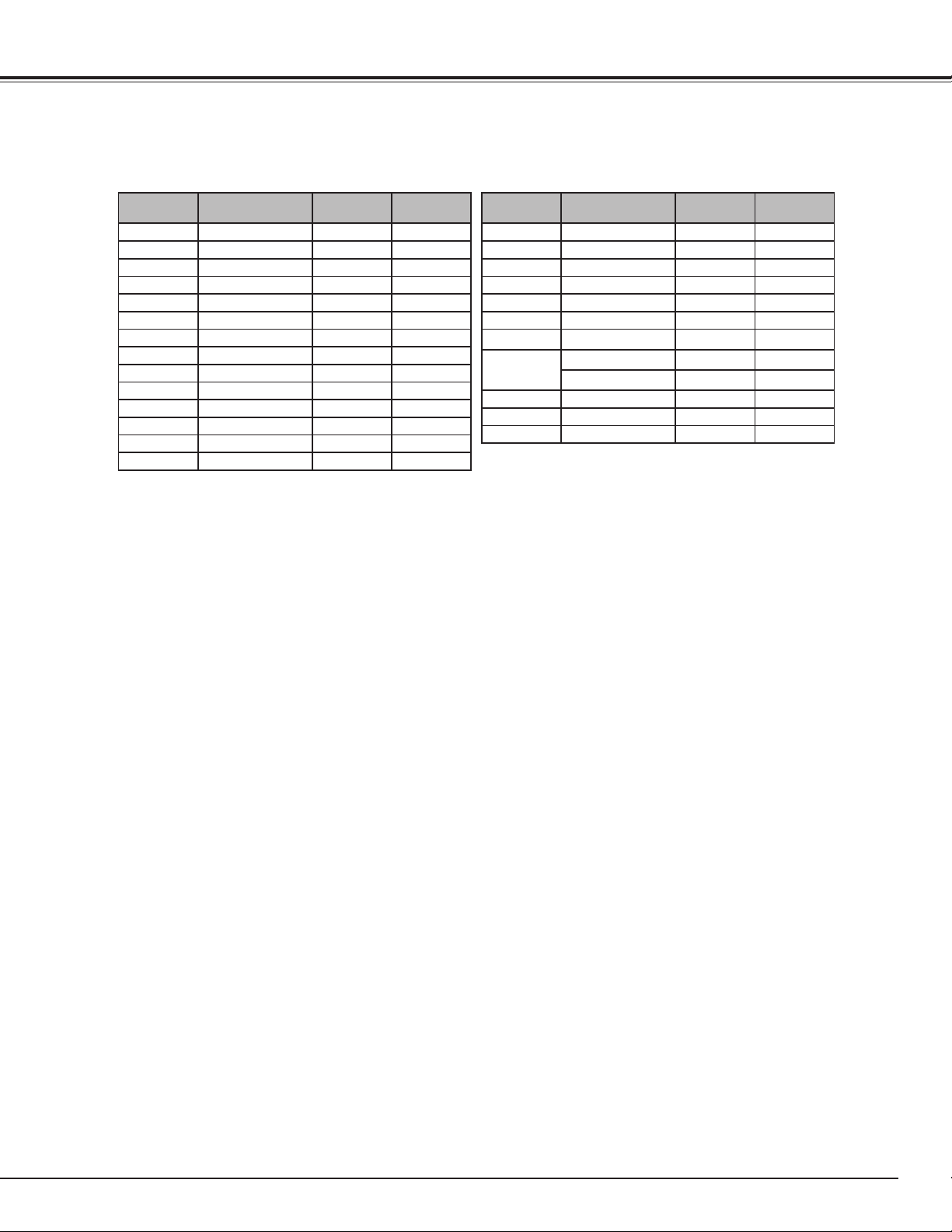
81
ON-SCREEN
DISPLAY
RESOLUTION
H-Freq.
(kHz)
V-Freq.(Hz)
D-VGA 640x480 31.470 59.940
D-480p 720x480 31.470 59.880
D-575p 720x575 31.250 50.000
D-SVGA 800x600 37.879 60.320
D-XGA 1024x768 43.363 60.000
D-WXGA 1 1366x768 48.360 60.000
D-WXGA 2 1360x768 47.700 60.000
D-WXGA 3 1376x768 48.360 60.000
D-WXGA 4 1360x768 56.160 72.000
D-WXGA 5 1366x768 46.500 50.000
D-WXGA 6 1280x768 47.776 59.870
D-WXGA 7 1280x768 60.289 74.893
D-WXGA 9 1280x800 49.600 60.050
D-WXGA 10 1280x800 41.200 50.000
ON-SCREEN
DISPLAY
RESOLUTION
H-Freq.
(kHz)
V-Freq.(Hz)
D-WXGA 11 1280x800 49.702 59.810
D-SXGA 2 1280x1024 60.276 58.069
D-SXGA 3 1280x1024 31.650 29.800
D-WXGA+ 1 1440x900 55.935 59.887
D-720p 1280x720 45.000 60.000
D-720p 1280x720 37.500 50.000
D-1035i
1920x1035
(Interlace)
33.750 60.000
D-1080i
1920x1080
(Interlace)
33.750 60.000
1920x1080
(Interlace)
28.125 50.000
D-1080psf/30 1920x1080 33.750 60.000
D-1080psf/25 1920x1080 28.125 50.000
D-1080psf/24 1920x1080 27.000 48.000
Appendix
✔Note:
•Dependingontheconditionofsignalsandthetypeandlengthofcables,thesesignalsmaynotbeproperly
viewed.
•Specificationsaresubjecttochangewithoutnotice.
When an input signal is digital from the DVI terminal, refer to the chart below.

82
Technical Specifications
Mechanical Information
Projector Type Multi-media Projector
Dimensions (W x H x D) 14.56” x 7.36” x 17.32” (370.0 mm x 187.0 mm x 439.9 mm)
Net Weight 25.1 lbs (11.4 kg)
Feet Adjustment 0˚ to 6.5˚
Panel Resolution
LCD Panel System 1.3” TFT Active Matrix type, 3 panels
Panel Resolution 1,024 x 768 dots
Number of Pixels 2,359,296 (1,024 x 768 x 3 panels)
Signal Compatibility
Color System
PAL, SECAM, NTSC, NTSC4.43, PAL-M, and PAL-N
High Definition TV Signal 480i, 480p, 575i, 575p, 720p, 1035i, and 1080i
Input Scanning Frequency H-sync. 15 kHz–100 kHz, V-sync. 48 Hz–100 Hz
Optical Information
Projection Lens Optional
Projection Lamp 330 W NSHA lamp
Interface
Input 1 Digital (DVI-D) x 1, Analog (Mini D-sub 15 pin) x 1
Input 2 BNC Type x 5 (G or Video/Y, B or Cb-Pb, R or Cr-Pr, HV and V)
Input 3 RCA Type x 3 (Video/Component), Mini DIN 4 pin x 1 (S-video)
Monitor Out
Analog RGB (Mini D-sub 15 pin) Terminal x 1
Audio Out
Audio (Mini Type stereo) x 1
Audio In I/ II
Audio (Mini Type stereo) x 2
R/C Jack Mini jack (Wired Remote) x 1
Control Port D-sub 9 pin x 1
USB Connector USB Series B x 1
Option Network Imager Terminal x 1
Power
Voltage and Power Consumption AC 100–120 V (5.5 A Max. Ampere), 50/60 Hz (The U.S.A and Canada)
AC 200–240 V (2.6 A Max. Ampere), 50/60 Hz (Continental Europe and The U.K.)
Operating Environment
Operating Temperature 41˚F–104˚F (5˚C–40˚C)
Storage Temperature 14˚F–140˚F (-10˚C–60˚C)
Remote Control Unit
Battery AAA or LR03 Type x 2
Operating Range 16.4’ (5 m/±30˚)
Dimensions 1.8” (W) x 1.0” (H) x 5.7” (D) (45 mm x 25 mm x 145 mm)
Net Weight 3.5 oz (99 g) (including batteries)
Accessories
User’s Manual (CD-ROM) Lens Attachment, Screws (W3), (W4)
Quick Start Guide Light-block sheet (G), (H)
AC Power Cord Spacers (For optional lens)
Remote Control Unit and Batteries Warranty card
VGA Cable (1AV4W20B29700)
USB Cable (1AV4W20B20201)
PIN Code Label
Appendix
● The specifications are subject to change without notice.
● LCD panels are manufactured to the highest possible standards. Even though
99.99% of the pixels are effective, a tiny fraction of the pixels (0.01% or less)
may be ineffective by the characteristics of the LCD panels.

83
Optional Parts
Lens Replacement
The lens of this projector can be replaced with other optional lens. This feature enables you to use the projector
for wide variety of uses.
For installation and replacement of the lens, always contact the sales dealer. The projector lens must be
installed or replaced by well-trained sales or service engineers. Do not attempt to install and replace the lens by
yourself as it may cause injury.
Do not hold the lens when carrying or lifting the projector. It may cause serious damage to the projector.
This projector is compliant with PJLink Standard Class 1 of JBMIA (Japan Business Machine and Information
System Industries Association). The projector supports all commands defined by PJLink Class 1 and is verified
conformance with PJLink Standard Class 1.
PJLink is a registered trademark of JBMIA and pending trademark in some countries.
PJ Link Notice
To the sales and service engineers:
For the lens replacement and lens installation, refer to the installation manual of the optional lens. Before replacing and
installing the lens, make sure that you are using the lens with the correct Type No.
Projector Input PJLink Input Parameter
Input 1 RGB (PC analog) RGB 1 11
RGB (Scart) RGB 2 12
RGB (PC digital) DIGITAL 1 31
RGB (AV HDCP) DIGITAL 2 32
Input 2 Video VIDEO 1 21
Y, Pb/Cb,Pr/Cr VIDEO 2 22
RGB RGB 3 13
Input 3 Video VIDEO 3 23
Y, Pb/Cb,Pr/Cr VIDEO 4 24
S-video VIDEO 5 25
Input 4 Network NETWORK 1 51
Model No.
Ultra Wide Angle Lens Type No. : LV-IL01
Wide Angle Zoom Lens Type No. : LV-IL02
Long Focus Zoom Lens Type No. : LV-IL03
Ultra Long Focus Zoom Lens Type No. : LV-IL04
Standard Zoom Lens Type No. : LV-IL05
Ceiling Attachment Type No. : LV-CL13
High Ceiling Attachment Type No. : LV-CL14
Network Imager Type No. : LV-NI03
The parts listed below are optionally available. When ordering those parts, specify the item name and Model No.
to the sales dealer.
Appendix
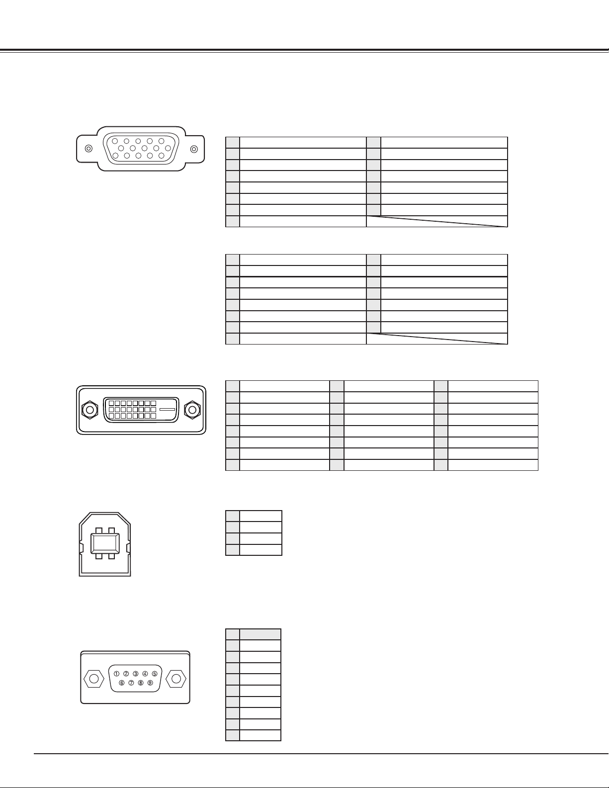
84
Configurations of Terminals
INPUT 1 (ANALOG)/ MONITOR OUT (Mini D-sub 15 pin)
5
1
2
34
10
9 678
15
14
13
11
12
CONTROL TERMINAL (D-sub 9 pin)
-----
R X D
T X D
-----
SG
-----
RTS
CTS
Serial
1
2
3
4
5
6
7
8
INPUT 1 (DIGITAL) (DVI 24 PIN)
1
9
17
2
10
18
3
11
19
4
12
20
5
13
21
6
14
22
7
15
23
8
16
24
T.M.D.S. Data2–
No Connect
T.M.D.S. Data2+
No Connect
T.M.D.S. Data2 Shield
DDC Clock
DDC Data
No Connect
1
5
2
4
3
6
7
8
T.M.D.S. Data1–
No Connect
T.M.D.S. Data1+
No Connect
T.M.D.S. Data1 Shield
+5V Power
Ground (for +5V)
Hot Plug Detect
9
13
10
12
11
14
15
16
T.M.D.S. Data0–
No Connect
T.M.D.S. Data0+
No Connect
T.M.D.S. Data0 Shield
T.M.D.S. Clock Shield
T.M.D.S. Clock+
T.M.D.S. Clock–
17
21
18
20
19
22
23
24
Vcc
- Data
+ Data
Ground
1
2
3
4
USB TERMINAL (Series B)
2
34
1
Appendix
-----
9
Red Input
Ground (Horiz.sync.)
Green Input
No Connect
Blue Input
Ground (Red)
Ground (Green)
Ground (Blue)
1
5
2
4
3
6
7
8
Horiz. sync. Input (Composite H/V sync.)
Ground (Vert.sync.)
DDC Data
Ground
Vert. sync. Input
DDC Clock
9
13
10
12
11
14
15
+5V Power
Red Output
Ground (Horiz.sync.)
Green Output
No Connect
Blue Output
Ground (Red)
Ground (Green)
Ground (Blue)
1
5
2
4
3
6
7
8
Horiz. sync. Output
Ground (Vert.sync.)
No Connect
No Connect
Vert. sync. Output
No Connect
9
13
10
12
11
14
15
No Connect
Input
Output

85
Put the label below (supplied) on in a prominent place of
the projector’s body while it is locked with a PIN code.
While the projector is locked with the PIN code...
Appendix
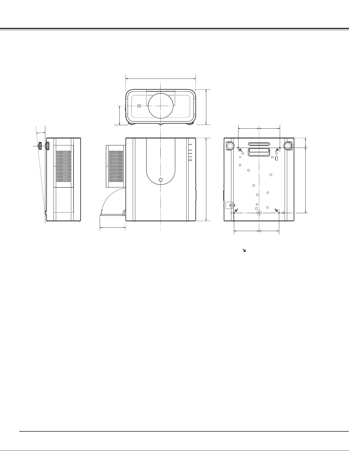
86
Dimensions
3.94 (100)
14.57 (370)
5.75 (146)
17.32 (439.9)
13.58 (345)
4.13 (105)5.20 (132)
4.33 (110)4.33 (110)
7.36 (187)
6.5º MAX
Screw Holes for Ceiling Mount
Screw: M6
Depth: 0.393 (10.0)
2.05 (52)
Unit: inch (mm)
Appendix

87
Serial Control Interface
Appendix
This projector provides a function to control and monitor the projector's operations by using the RS-232C serial
port.
Connect a RS-232C serial cross cable to CONTROL
PORT on the projector and serial port on the PC.
(See p.24)
Launch a communication software provided with PC
and setup the communication condition as follows:
1
2
3
Baud rate : 9600 / 19200 bps
Parity check : none
Stop bit : 1
Flow control : none
Data bit : 8
Type the command for controlling the projector and
then enter the "Enter" key.
Example
When you want to change the input to INPUT 2, Type
'C' '0' '6' 'Enter'.
✔Note:
•EnterwithASCII64-bytecapitalcharactersandone-
bytecharacters.
✔Note:
•Thedefaultofthebaudrateissetto19200bps.Ifan
erroroccursinthecommunication,changetheserial
portandthecommunicationspeed(baudrate).
Operation
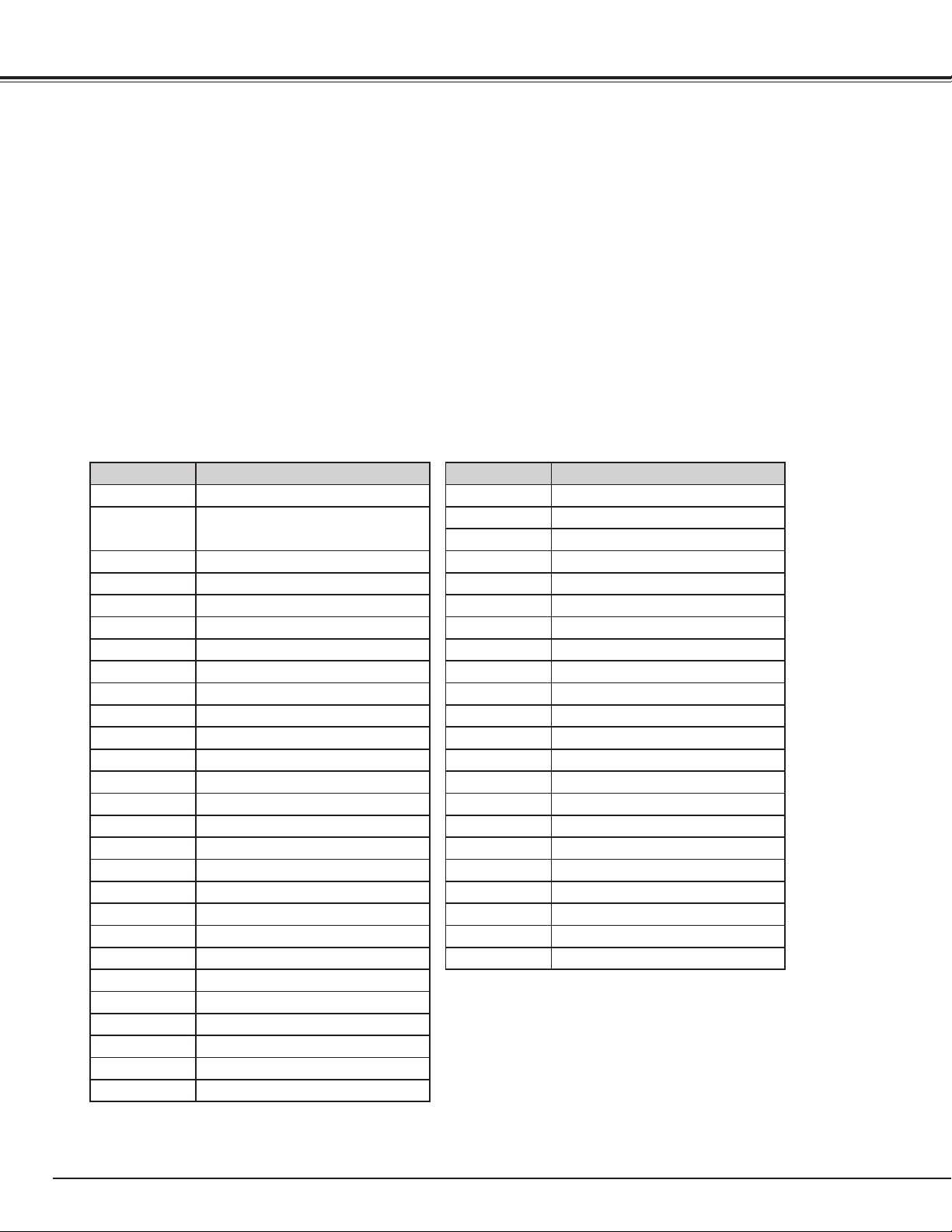
88
The command is sent from PC to the projector with
the format below;
'C' [Command] 'CR'
Command: two characters (refer to the
command table below.
-The projector decodes the command and returns the
'ACK' with the format below;
'ACK' 'CR'
-When the projector can not decode the command, it
returns with format below.
‘?’ ‘CR’
Format
Appendix
Functional Execution Command
Command Function
C00 Turn the projector ON
C01
Turn the projector OFF
(immediately OFF)
C02 Turn the projector OFF
C05 Select Input 1
C06 Select Input 2
C07 Select Input 3
C08 Select Network
C09 Volume +
C0A Volume -
C0B Sound mute ON
C0C Sound mute OFF
C0D Video mute ON
C0E Video mute OFF
C0F Aspect 4:3
C10 Aspect 16:9
C1C Menu ON
C1D Menu OFF
C20 Brightness UP
C21 Brightness DOWN
C23 Select Input 2 Video
C24 Select Input 2 Y, Pb/Cb,Pr/Cr
C25 Select Input 2 RGB
C28 ON Start ON
C29 ON Start OFF
C33 Select Input 3 Video
C34 Select Input 3 S-video
C35 Select Input 3 Y, Pb/Cb,Pr/Cr
Command Function
C3A Pointer RIGHT
C3B Pointer LEFT
C3C Pointer UP
C3D Pointer DOWN
C3F Enter
C46 Zoom DOWN
C47 Zoom UP
C4A Focus DOWN
C4B Focus UP
C50 Select Input 1 Analog RGB
C51 Select Input 1 SCART
C52 Select Input 1 DVI (PC Digital)
C53 Select Input 1 DVI (AV HDCP)
C5D Lens shift UP
C5E Lens shift DOWN
C5F Lens shift LEFT
C60 Lens shift RIGHT
C89 Auto PC Adj.
C8E Keystone UP
C8F Keystone DOWN
C90 Keystone RIGHT
C91 Keystone LEFT
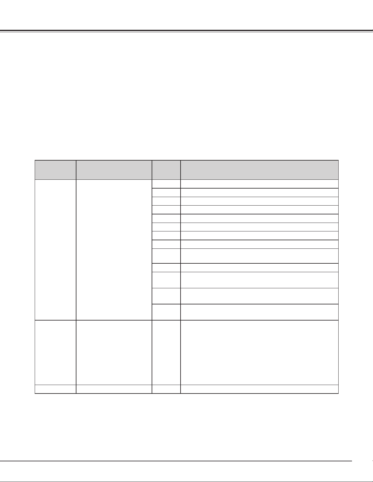
89
Status Read Command
Appendix
The command is sent from PC to the projector with
the format below;
'CR' [Command] 'CR'
Command: one character (refer to the command
table below.
The projector decodes the command and returns the
'Character string' with the format below;
Format
The tables on page 88 and 89 show the typical command lists for controlling the projector. Please consult your
local dealer for further information of other commands.
Command Function
Projector
Return
Projector status
CR0 Status Read
00
Power On
80
Stand-by mode
40
Countdown
20
Cooling down
10
Power Malfunction
28
Cooling down at the temperature abnormally
24
Cooling down at Power Management mode
04
Power Management mode after Cooling down
21
Cooling down after the projector is turned off when the lamps
are out.
81
Stand-by mode after Cooling down when the lamps are out.
88
Stand-by mode after Cooling down at the temperature
abnormally.
2C
Cooling down when the projector is turned off by the shutter
management function.
8C
Stand-by mode after cooling down by the shutter management
function.
CR6 Temperature Read S1 S2 S3
S1 = Temperature at Sensor 1 (˚C)
S2 = Temperature at Sensor 2 (˚C)
S3 = Temperature at Sensor 3 (˚C)
(ex.) S1 = 12.3˚C, S2 = 23.4˚C, S3 = 34.5˚C
--> The projector displays “12.3 23.4 34.5”
( For each sensor, two digit and the tenth place numbers are
displayed with a space between each temperature.)
?
Communication failure

© CANON INC. 2010
CANON INC.
30-2, Shimomaruko 3-chome, Ohta-ku, Tokyo 146-8501,
Japan
CANON U.S.A. INC.
One Canon Plaza, Lake Success, NY 11042-1198,
U.S.A.
CANON CANADA INC. HEADQUARTERS
6390 Dixie Road, Mississauga, Ontario L5T 1P7,
Canada
CANON CANADA INC. MONTREAL BRANCH
5990, Côte-de-Liesse, Montréal Québec H4T 1V7,
Canada
CANON CANADA INC. CALGARY OFFICE
2828, 16th Street, N.E. Calgary, Alberta T2E 7K7,
Canada
CANON EUROPE LTD.
3 The Square, Stockley Park, Uxbridge, Middlesex, UB11
1ET United Kingdom
CANON EUROPA N.V.
Bovenkerkerweg 59-61, 1185 XB Amstelveen,
The Netherlands
CANON FRANCE S.A.S
17, quai du President Paul Doumer, 92414 Courbevoie
Cedex, France
CANON UK LTD.
Woodhatch Reigate Surrey RH2 8BF, United Kingdom
CANON DEUTSCHLAND GmbH
Europark Fichtenhain A10, 47807 Krefeld, Germany
CANON ITALIA S.p.A.
Via Milano 8 I-20097 San Donato Milanese, Milano,
Italy
CANON Schweiz AG
Geschäftsbereich Wiederverkauf, Industriestrasse 12,
CH-8305 Dietlikon, Switzerland
CANON GMBH
Zetschegasse 11, A-1230 Wien, Austria
CANON España, S.A.
C/Joaquín Costa, 41, 28002 Madrid, Spain
CANON PORTUGAL S.A.
Rua Alfredo da Silva, 14 Alfragide 2610-016 Amadora,
Portugal
CANON Belgium N.V./S.A.
Berkenlaan 3, 1831 Diegem (Mechelen), Belgium
CANON Netherland NV
Neptunusstraat 1, 2132 JA Hoofddorp,
The Netherlands
CANON LUXEMBOURG S.A.
Rue des Joncs 21, L1-818 Howald, Luxembourg
CANON DANMARK A/S
Knud Hoejgaards Vej 1 DK-2860 Soeborg,
Danmark
CANON OY
Huopalahdentie 24 PL 1 00351 Helsinki, Finland
CANON SVENSKA AB
Gustav III:s Boulevard 26 169 88 Solna, Sweden
CANON NORGE as
Hallagerbakken 110, Postboks 33, Holmlia, 1201
Oslo, Norway
CANON LATIN AMERICA, INC.
703 Waterford Way, Ste. 400 Miami, FL 33126,
U.S.A.
CANON (China) Co., Ltd.
15F Jinbao Building No.89 Jinbao Street,
Dongcheng District, Beijing 100005, China
CANON HONGKONG CO., LTD.
19/F., The Metropolis Tower, 10 Metropolis Drive,
Hunghom, Kowloon, Hong Kong
CANON SINGAPORE PTE. LTD.
1 HarbourFront Avenue, #04-01 Keppel Bay
Tower, Singapore 098632
CANON KOREA CONSUMER IMAGING INC.
Gangnam Finance Center 17F, 737, Yeoksam-
Dong, Gangnam-gu, Seoul, 135-984, Korea
CANON AUSTRALIA PTY. LTD.
1 Thomas Holt Drive, North Ryde, N.S.W. 2113,
Australia
CANON NEW ZEALAND LTD.
Akoranga Business Park, Akoranga Drive, Northcote,
Auckland, New Zealand
KR7PL