A
C
B
A
A
B
I
N
B
RIEF
4
I
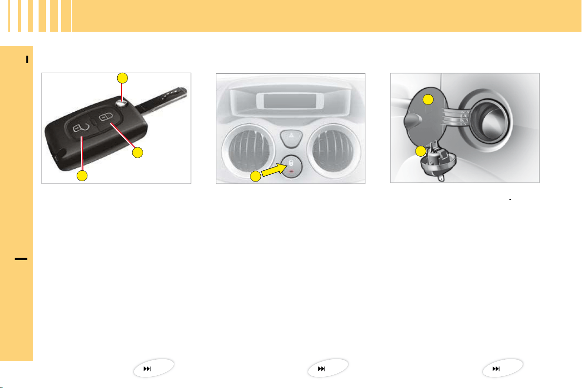
Fuel tank
A.
Opening of the fuel fl ap
.
B.
Opening of the fuel cap.
Tank capacity: approximately 47 litres.
A.
Locking/unlocking of the
vehicle from the interior.
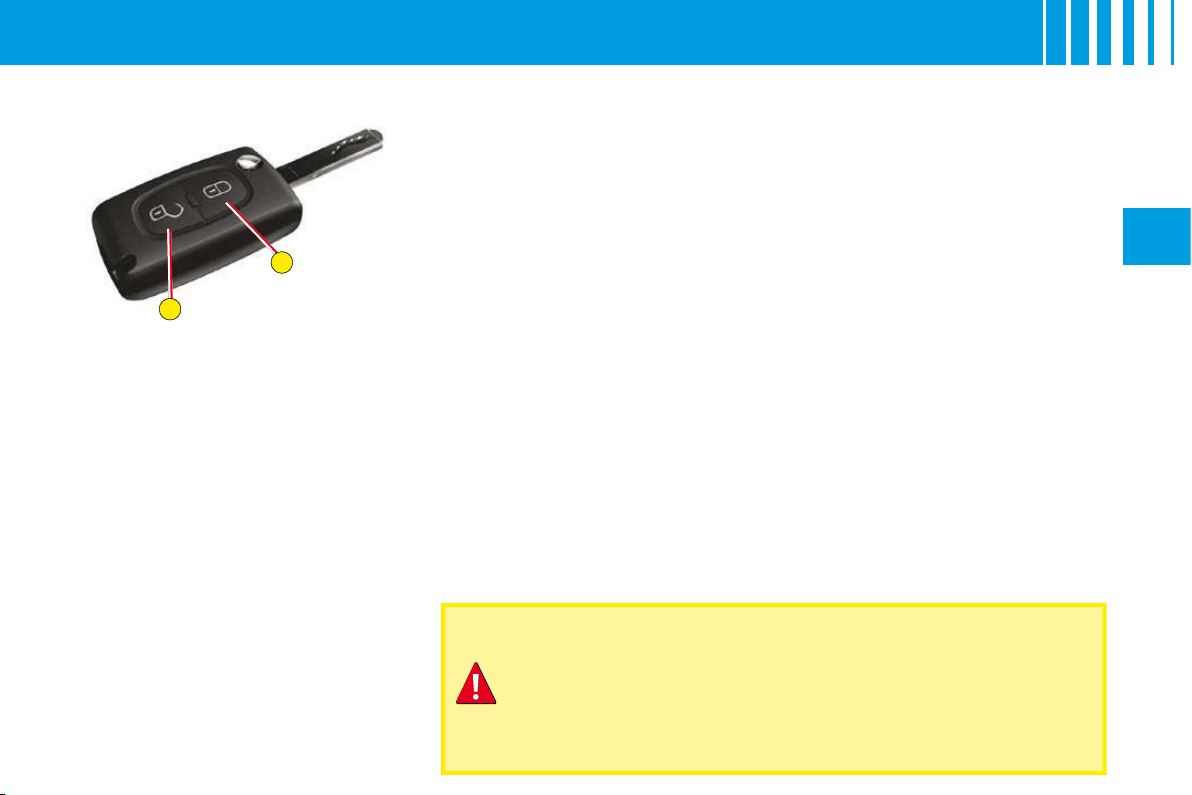
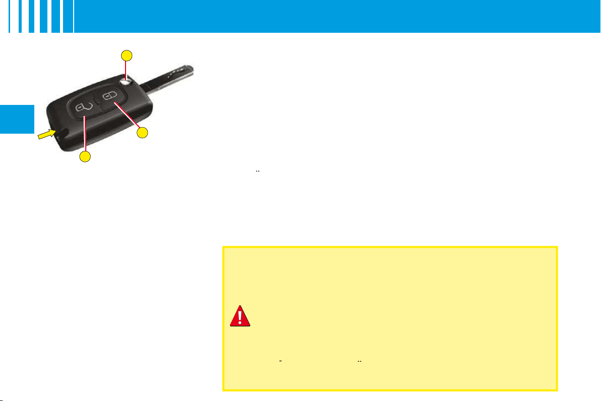
Remote control key
A.
Locking of the vehicle.
B.
Unlocking of the vehicle.
C.
Key release/storage.
Manual central locking
O P E N I N G
15
77
45
B
A
I
N
B
RIEF
5
I
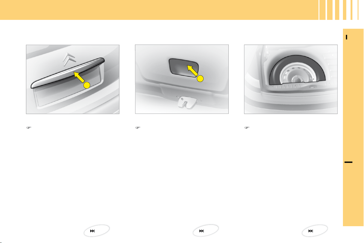
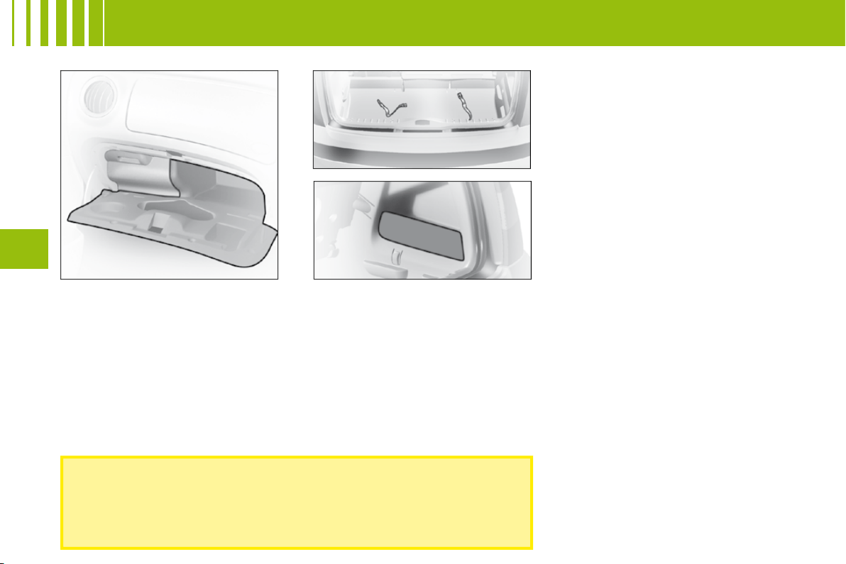
Tailgate
Spare wheel and tools
O P E N I N G
Closing
Lower the tailgate, using the
grip
B
, located in the interior
tailgate trim. Press fi rmly to
shut.
Access to the spare wheel
Lift up the carpet, then remove
the toolbox to access the
wheel.
Access to the tools
The tools are located in the toolbox
in the spare wheel. Pull the strap
to access.
Opening
After unlocking the vehicle with
the remote control or they key,
press upwards on handle
A
located between the number
plate lights.
47
84
47
1
2
3 4 5 6 7 8 9 10 11 12 13 14
24
25
26272829
18 16 1517
20
19
21
23
22
I
N
B
RIEF
6
I
D A S H B O A R D

N
B
RIEF
7
I
D A S H B O A R D
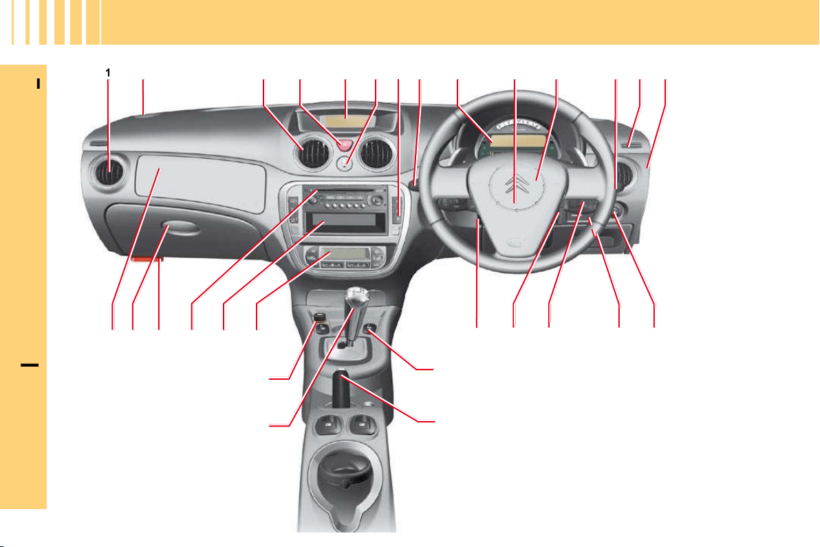
21 Parking brake.
22 Gear lever.
23 12 V accessories socket
(functions with ignition
switched on) (Maximum
power 120 W).
24 Air conditioning or
heating/ventilation.
25 Storage/CD changer.
26 Radio.
27 Bonnet release.
28 Lower glovebox:
• Vehicle document storage.
• Access to fusebox.
29 Passenger’s airbag.
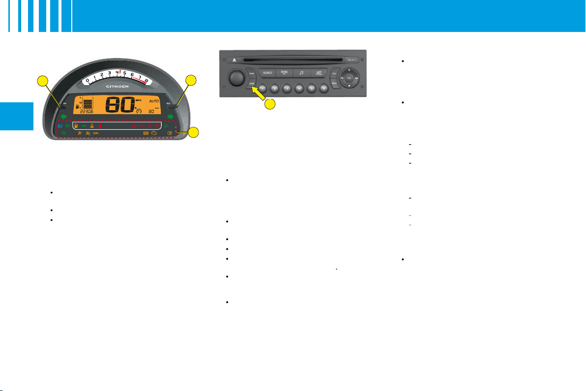
Horn
.
12
Controls
:
•
Windscreen wipe
.
•
Screen wash
.
•
Rear screen wipe
.
•
Trip computer
.
13
Window deicing and demisting
vent
.
14
Key switch
:
•
Activation/Deactivation of
•
•
passenger’s airbag
.
15
Electric door mirrors
adjustment
.
16
Headlamps adjustment
.
17 Radio control under steering
wheel.
18 Steering lock - Ignition.
19 Steering column adjustment
control.
20 Front electric window controls.
Lateral air vent
.
2
Loudspeaker (Tweeter).
3
Central air vents
.
4
Hazard warning lamps
.
5
Display
.
6
Doors and boot central locking
control
.
7
Control
:
•
Overspeed alert
.
8
Controls
:
•
Lighting
.
•
Direction indicators
.
•
Rear foglamp
.
9
Instrument panel
.
10
Driver’s airbag
.
5
4
2
1
3
I
N
B
RIEF
8
I
G E T T I N G S TA R T E D
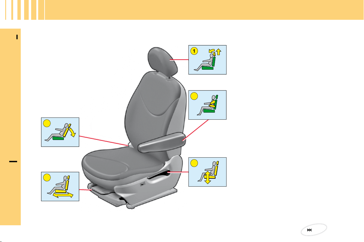
Front seats
1.
Head restraint adjustment.
2.
Armrest.
3.
Seat height and angle.
4.
Longitudinal adjustment.
5.
Backrest angle adjustment.
52
1
2
1
1
2
1
I
N
B
RIEF
9
I
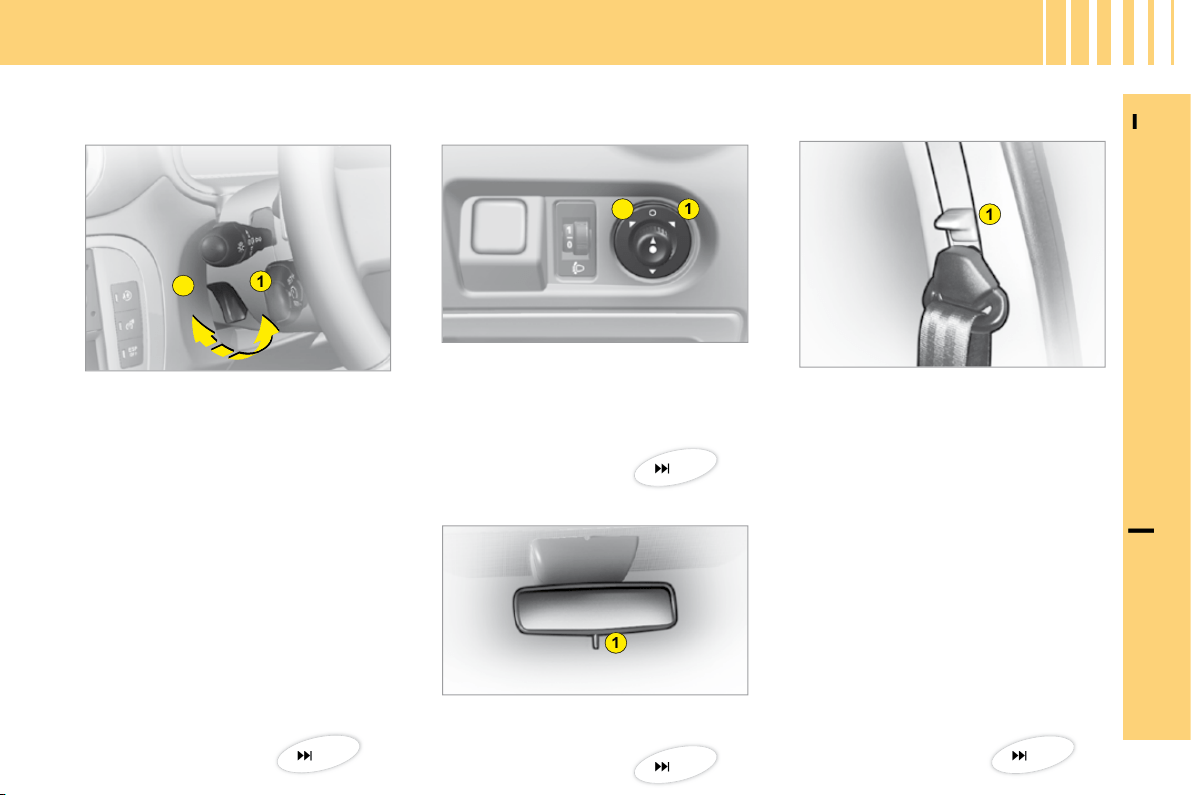
1.
Releasing by pulling lever.
2.
Locking by pushing lever.
Manual adjustment of
steering wheel height
Adjustment of exterior rear
view mirrors
1.
Selection of driver’s side
mirror.
2.
Selection of passenger’s side
mirror.
Adjustment of interior rear view mirror
1.
"Day/Night" mirror position
control.
G E T T I N G S TA R T E D
Front seat belt
1.
Height adjustment.
38
38
39
39
1
2
I
N
B
RIEF
10
I
G E T T I N G S TA R T E D
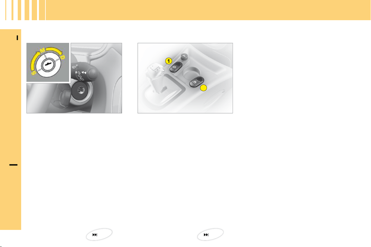
Electric window controls
1.
Driver’s electric window
control.
2.
Passenger’s electric window
control.
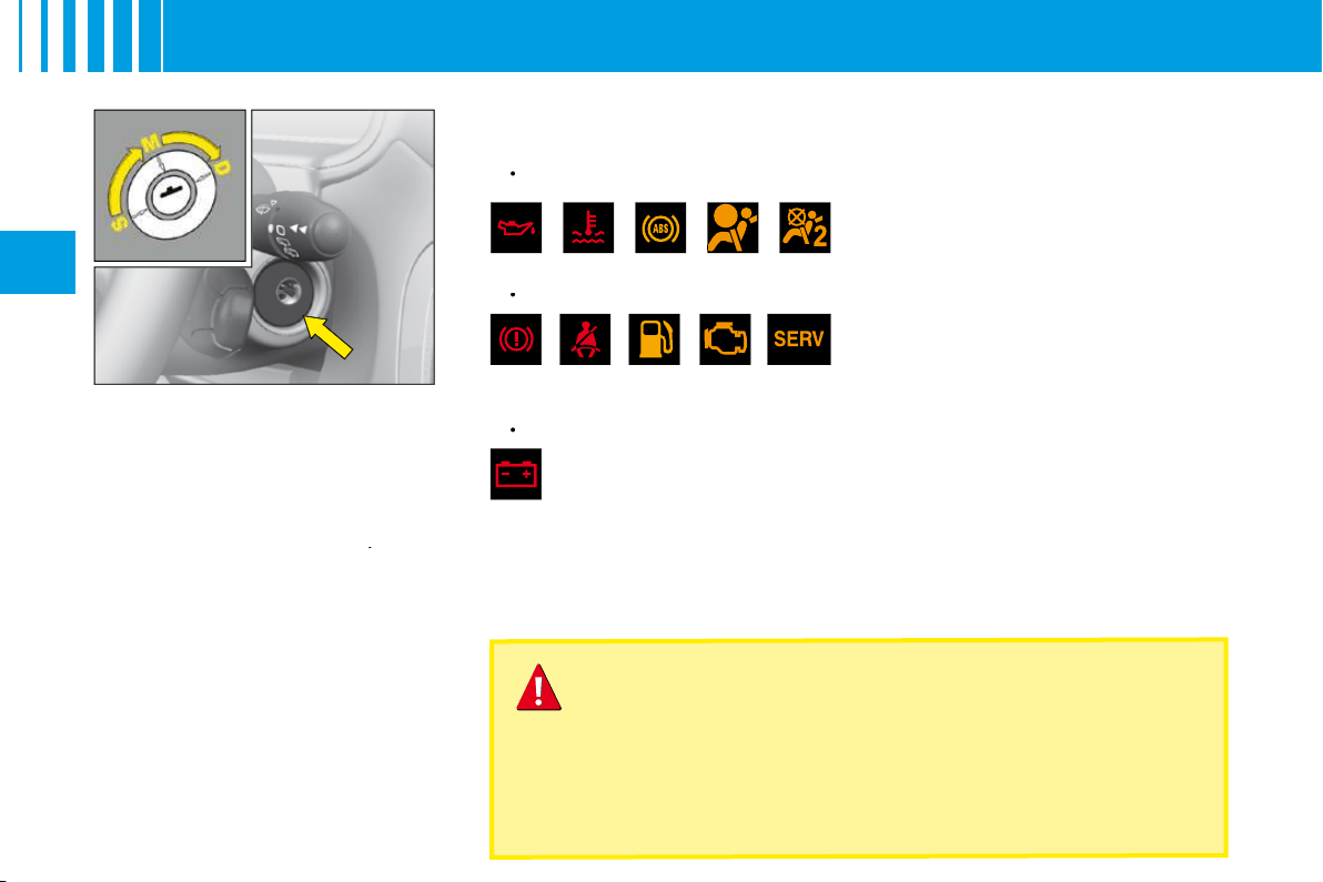
Ignition switch
S.
Steering lock
position.
M.
Drive
position.
D.
Starting
position.
18
40
A
B
I
N
B
RIEF
11
I
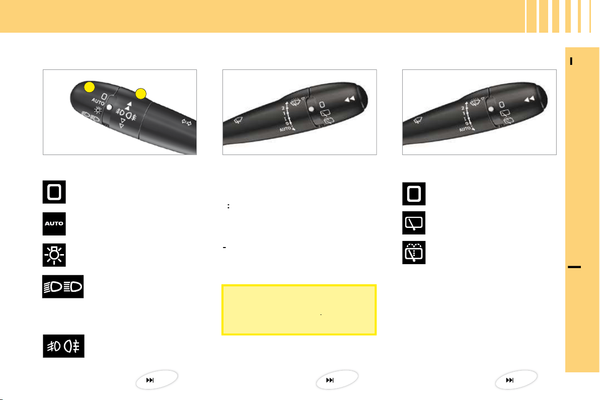
Lighting
Ring A
Ring B
Rear foglamps.
Headlamps off.
Automatic lighting of
headlamps.
Sidelamps.
Dipped or main beams.
Front screen wipe
Screen wipe
Rear screen wipe
2:
Fast wipe.
1:
Normal wipe.
I
:
Intermittent wipe.
0:
Off.
Pressing downwards:
- AUTO:
Automatic wipe.
-
Single wipe.
Off.
V I S I B I L I T Y
Intermittent rear screen
wipe.
Timed rear screen wash
and wipe.
34
37
36
To deactivate automatic wipe,
put the control to position
I
, then
return it to position
0
.
I
N
B
RIEF
12
I
V E N T I L AT I O N
Manual air conditioning
49
D
B
A
C
A
I
N
B
RIEF
13
I
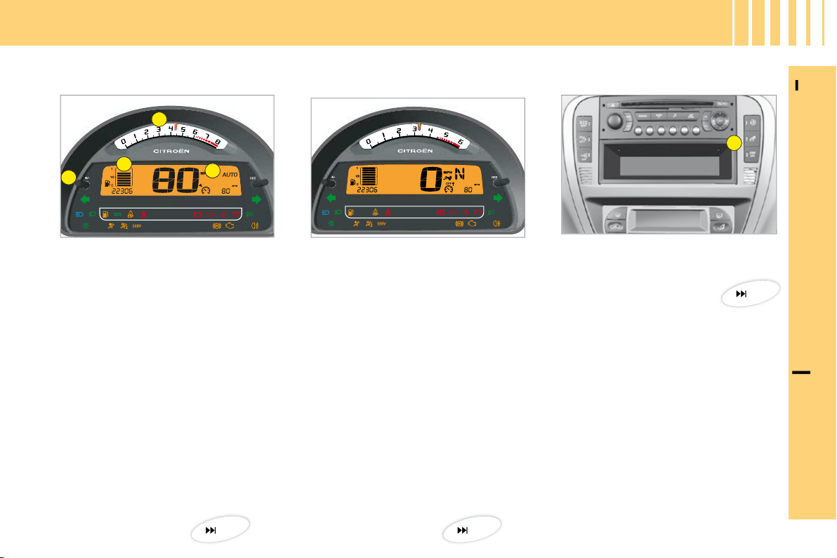
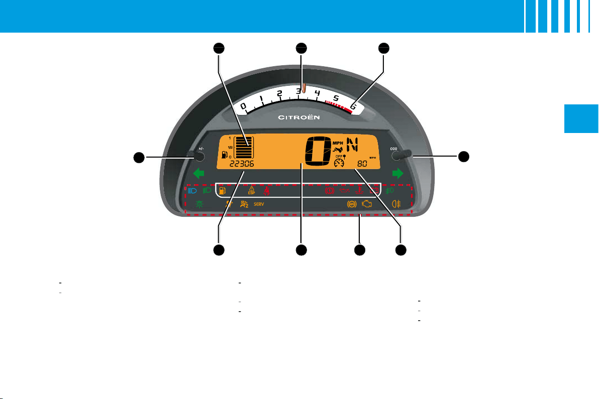
M O N I TO R I N G
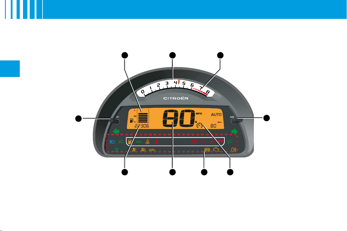
Instrument panel
Controls panel
A.
Rev counter.
B.
Instrument panel screen.
C.
Fuel gauge.
D.
Dashboard lighting rheostat.
When the ignition is switched on,
the orange and red warning lamps
light up.
With the engine running, these
warning lamps should go out.
If the warning lamps remain lit,
refer to the appropriate page.
Warning lamps
The lighting of the warning lamp indicates
the status of the corresponding function.
A.
Activation of
overspeed alert.
20
44
23

A
B
I
N
B
RIEF
14
I
Driver’s seat belt fastening
detection
Deactivation of front
passenger’s airbag
The warning lamp lights up
if the driver’s seat belt has
not been fastened when the
ignition is switched on and
between 0 and 20 km/h.
Over 20 km/h, the warning lamp
fl ashes accompanied by a sound
signal for approximately 2 minutes.
After this it remains lit up.
1.
With the ignition off, insert the
key in switch
A
.
2.
Turn the key to the
"OFF"
position, the passenger’s
airbag is deactivated.
3.
The front passenger’s airbag
deactivation warning lamp, on
the instrument panel, lights up
when the ignition is switched on.
Isofi x fastening system
Two rings
B
, located between the
backrest and the seat cushion,
allow a child seat to be fi tted.
PA S S E N G E R S A F E T Y
23
56
55
B
A
15
II
R E M O T E C O N T R O L
Note:
The simultaneous use of
other high frequency equipment
(mobile telephones, domestic
alarms, etc.) may momentarily
hinder the operation of the remote
control.
If there is a permanent fault, the
remote control has to be reini-
tialised. See "Changing remote
control batteries".
Central unlocking
A short press on control
B
unlocks your vehicle.
This operation is confi rmed by the rapid fl ashing of the direction indicators
and the lighting of the interior lamp (if the function is activated). It can also
deploy the exterior rear view mirrors.
Central locking – Deadlocking
A
short press
on button
A
locks your vehicle.
This is confi rmed by the lighting for around 2 seconds of the direction
indicators and by the interior lamp going out. It may cause the exterior rear
view mirrors to fold back.
If any of the doors, or the boot, is open or not properly closed, the central
locking does not operate.
For vehicles equipped with deadlocking, two successive presses on control
A
will operate deadlocking. It is then impossible to open the doors, either
from the inside or from the outside.
It is dangerous to operate the deadlocking when a person
is in the vehicle as unlocking is impossible from the inside
(without the remote control).
A
C
B
16
II
R E M O T E C O N T R O L
Changing the remote control battery
First, retract the key-carrier if necessary.
Unclip the housing by lifting at the rear (see diagram).
Battery:
CR 0523 of 3 V.
Re-initialisation of the remote control
After a change of battery, it may be necessary to re-initialise the remote
control. To do that, switch on the ignition and immediately action button
A
on your remote control to trigger the action desired. This may take some ten
seconds.
Note:
Make a careful note of the numbers for the keys and for the remote
control on the ASSISTANCE card. Keep this in a safe place.
Do not throw away the old batteries. They should be returned to a
CITROËN
Do not throw
Do not throw
dealer or deposited at a recognised collection point (a camera
shop, for example).
Except when reinitialising, the remote control cannot function
while the key is in the ignition, even when switched off.
Warning: by inadvertently actioning the remote control, when
for example it is in your pocket, you can unlock the vehicle
without your realising it.
However, if none of the doors is opened within thirty seconds
following an unlocking, the doors will automatically relock.
Warning: there is a risk of damage if the replacement battery
is not the correct one.
Only use batteries that are identical or equivalent to those
approved by CITROËN.
Only use batteries that
ies tha
Locating of the vehicle
To locate the vehicle on a carpark,
press button
A
, the interior lamps
come on and the direction indica-
tors fl ash for a few seconds. The
vehicle remains locked.
Folding and ejecting the key
Button
C
is for folding and ejec-
ting the key from its housing in the
remote control.
If you do not press on button
C
,
you could damage the key mecha-
nism.
II
K E Y S
It is dangerous to operate the deadlocking when a person
is in the vehicle as unlocking is impossible from the inside
(without the remote control).
The key number is on the label attached to the key.
Should you lose your key or remote control, a CITROËN dealer
can supply replacements.
Should any keys be lost
Visit your CITROËN dealer with your car registration document
and proof of identity.
Your CITROËN dealer can recover your key code and
transponder code to be able to replace your key
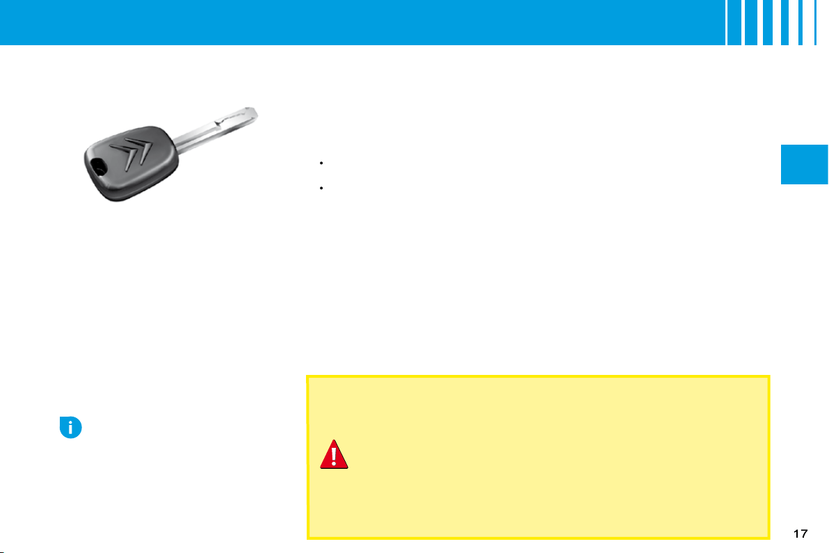
Electronic immobiliser key
The key operates all the vehicle’s
locks as well as the ignition.
Note:
For safety reasons, a buz-
zer will sound if you have switched
off the ignition and opened the dri-
ver’s door without having removed
the ignition key.
The key can be used to deactivate
the front passenger’s airbag. See
"Airbags".
Central locking using the key
A brief action with the key locks the vehicle.
Deadlocking: Central locking using the key
A second action straightaway with the key deadlocks the vehicle. It is then
impossible to open the doors from either inside or outside the vehicle.
Note:
With the vehicle stationary and the engine switched off, locking is
signalled by the fl ashing of the interior locking control warning lamp.
If any of the doors, or the boot, is open or not properly closed, the central
locking does not operate.
Electronic immobiliser
The ELECTRONIC IMMOBILISER device locks the engine supply system.
The system activates automatically as the key is removed from the ignition.
All the vehicle’s keys contain an electronic immobiliser device.
After you switch on the ignition, a dialogue starts between the key and the
electronic immobiliser device.
If the key is not recognised, you cannot start the vehicle.
If this occurs, leave your vehicle immobilised and contact a CITROËN dealer.
•
•
Advice
If any key modifi cations become
necessary (addition, cancellation
or replacement), it is essential to
contact your CITROËN dealer, and
to take with you all of the vehicle
keys and the code card.
18
II
S: Steering lock
To unlock the steering, gently move
the steering wheel while turning the
key, without exerting undue force.
When you remove the key, turn
your steering wheel to lock the
steering. The key can only be
removed when in position
S
.
M: Drive position
The steering is unlocked (by turning
the key in position
M
, if necessary
move the steering wheel).
Depending on your vehicle ver-
sion, the following warning lamps
are tested:
Briefl y:
•
Up to starting:
•
Flashes until the engine starts:
•
If one of these warning lamps does
not light up, this indicates a mal-
function.
NEVER REMOVE THE IGNITION KEY BEFORE THE ENGINE
HAS COME TO A COMPLETE STOP.
IT IS ESSENTIAL ALWAYS TO DRIVE WITH THE ENGINE
RUNNING, SO AS TO RETAIN STEERING AND BRAKING
ASSISTANCE (risk of the steering lock engaging and loss of
safety features).
When stationary, having removed the key, carefully turn the steering
wheel if you wish to lock the steering.
D: Starting
Release the key as soon as the
engine starts. Never turn it while
the engine is running.
Starting and stopping the
engine:
See "Driving".
Economy mode
In order not to discharge the bat-
tery while the engine is stopped,
your vehicle goes automatically
into economy mode after a maxi-
mum of 30
minutes. Economy
mode is indicated by a message
on the screen.
The electrical components relating
to comfort and also the headlamps
(not sidelamps or hazard warning
lamps) cut out automatically. To
reactivate them, it is necessary to
start the engine.
S T E E R I N G L O C K - I G N I T I O N - S TA R T E R

19
II
Manual gearbox
Ensure that the gear lever is
in the neutral position.
Do not touch the accelerator.
For Diesel engines: Turn the
key to the drive position. Wait
for the preheater warning lamp
to go off, if this has come on.
Turn the key to action the
starter (not for more than
ten seconds), until the engine
starts.
In ambient temperatures lower
than 0°C, depress the clutch
while actioning the starter to
facilitate starting. Then release
the clutch pedal slowly.
•
•
•
•
•
Advice
Vehicles equipped with a
Turbo
Never stop the engine without fi rst
having allowed it to idle for a few
seconds, this being the time requi-
red for the turbochargers to return
to a normal speed.
Do not "fl ick" the accelerator at the
moment you switch off the ignition
as this could seriously damage the
turbochargers.
Note:
If it does not work at fi rst, switch off the ignition. Wait for ten seconds, then operate the starter again as
described above.
WARNING
DO NOT RUN THE ENGINE IN A CLOSED SPACE OR IN ONE THAT
IS INSUFFICIENTLY VENTILATED.
D R I V I N G
B C D
A
E
HI FG
20
II
I N S T R U M E N T PA N E L
P E T R O L V E R S I O N

B
22
II
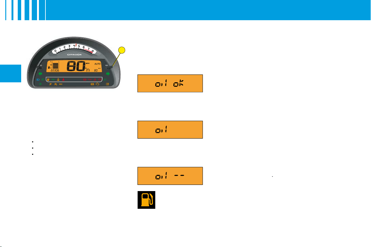
I N S T R U M E N T PA N E L
Display
As soon as you open the driver's
door, the instrument panel displays
the total mileage and trip mileage.
When you switch on the ignition, it
scrolls through the following infor-
mation:
Maintenance indicator.
The engine oil level indicator.
Total mileage.
It also displays the trip mileage or
trip computer information (depen-
ding on the memory status since
the vehicle was last stopped).
Trip mileage recorder reset
This can operate when the ignition
is switched on.
Press
B
to show the trip mileage,
then give a long press on
B
to reset
the counter to zero.
•
•
•
Engine oil level indicator
When the ignition is switched on, the maintenance indicator is displayed
for a few seconds, followed by the engine oil level for a few seconds. See
"Maintenance indicator".
An incorrect engine oil level can seriously damage your engine.
Fuel low/Fuel gauge
When the tank is full, all 8 bars are lit up. They go out one by one.
If the fuel low warning lamp comes on accompanied by a beep,
there remain around 4 to 6 litres of fuel in the tank.
If "black panel" mode is active and there are only around 4 to 6 litres of fuel
in the tank, that will make the fuel low warning lamp come on.
Flashing of
"OIL"
indicates an oil level that is
below the minimum.
Check using the manual dipstick. See "Levels".
Check the engine oil level on horizontal ground
with the engine having been switched off for at
least 15 minutes.
Contact a CITROËN dealer.
A fl ashing of
"OIL – –"
indicates a
malfunctio-
ning of the indicator
.
Contact a CITROËN dealer.
Display of
"OIL OK"
indicates normal functioning.
B C D
A
E
HI G F
21
II
I N S T R U M E N T PA N E L
D I E S E L V E R S I O N
A.
Control:
Lighting rheostat
Night driving (Black panel)
B.
Fuel gauge
C.
Rev counter
During the running-in period,
see "Running-in".
D.
Red zone of rev counter telling
you of the need to change to a
higher gear.
-
-
E.
Control:
Trip mileage recorder reset
F.
Display:
Trip mileage recorder
Trip computer
-
-
-
G.
Display of warning lamps
H.
Speed indicator
I.
Display:
Maintenance indicator
Engine oil level indicator
Total mileage recorder
-
-
-
B
22
II
I N S T R U M E N T PA N E L
Display
As soon as you open the driver's
door, the instrument panel displays
the total mileage and trip mileage.
When you switch on the ignition, it
scrolls through the following infor-
mation:
Maintenance indicator.
The engine oil level indicator.
Total mileage.
It also displays the trip mileage or
trip computer information (depen-
ding on the memory status since
the vehicle was last stopped).
Trip mileage recorder reset
This can operate when the ignition
is switched on.
Press
B
to show the trip mileage,
then give a long press on
B
to reset
the counter to zero.
•
•
•
Engine oil level indicator
When the ignition is switched on, the maintenance indicator is displayed
for a few seconds, followed by the engine oil level for a few seconds. See
"Maintenance indicator".
An incorrect engine oil level can seriously damage your engine.
Fuel low/Fuel gauge
When the tank is full, all 8 bars are lit up. They go out one by one.
If the fuel low warning lamp comes on accompanied by a beep,
there remain around 4 to 6 litres of fuel in the tank.
If "black panel" mode is active and there are only around 4 to 6 litres of fuel
in the tank, that will make the fuel low warning lamp come on.
Flashing of
"OIL"
indicates an oil level that is
below the minimum.
Check using the manual dipstick. See "Levels".
Check the engine oil level on horizontal ground
with the engine having been switched off for at
least 15 minutes.
Contact a CITROËN dealer.
A fl ashing of
"OIL – –"
indicates a
malfunctio-
ning of the indicator
.
Contact a CITROËN dealer.
Display of
"OIL OK"
indicates normal functioning.

B
22
II
I N S T R U M E N T PA N E L
Display
As soon as you open the driver's
door, the instrument panel displays
the total mileage and trip mileage.
When you switch on the ignition, it
scrolls through the following infor-
mation:
Maintenance indicator.
The engine oil level indicator.
Total mileage.
It also displays the trip mileage or
trip computer information (depen-
ding on the memory status since
the vehicle was last stopped).
Trip mileage recorder reset
This can operate when the ignition
is switched on.
Press
B
to show the trip mileage,
then give a long press on
B
to reset
the counter to zero.
•
•
•
Engine oil level indicator
When the ignition is switched on, the maintenance indicator is displayed
for a few seconds, followed by the engine oil level for a few seconds. See
"Maintenance indicator".
An incorrect engine oil level can seriously damage your engine.
Fuel low/Fuel gauge
When the tank is full, all 8 bars are lit up. They go out one by one.
If the fuel low warning lamp comes on accompanied by a beep,
there remain around 4 to 6 litres of fuel in the tank.
If "black panel" mode is active and there are only around 4 to 6 litres of fuel
in the tank, that will make the fuel low warning lamp come on.
Flashing of
"OIL"
indicates an oil level that is
below the minimum.
Check using the manual dipstick. See "Levels".
Check the engine oil level on horizontal ground
with the engine having been switched off for at
least 15 minutes.
Contact a CITROËN dealer.
A fl ashing of
"OIL – –"
indicates a
malfunctio-
ning of the indicator
.
Contact a CITROËN dealer.
Display of
"OIL OK"
indicates normal functioning.
23
II
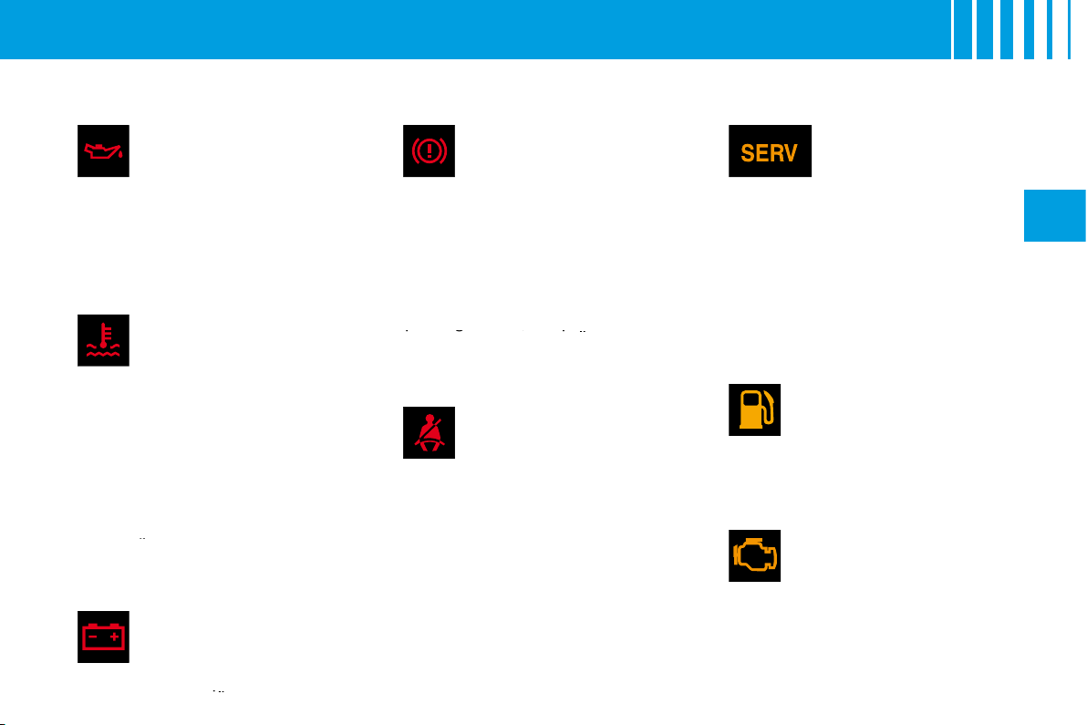
WA R N I N G L A M P S
These warning lamps may be accompanied by a message and/or a sound signal
Engine oil pressure
It comes on for a few
seconds each time you
switch on the ignition.
If this warning lamp comes on,
engine running, it tells you that the
oil pressure is low.
It is essential to stop the vehicle.
Contact a CITROËN dealer.
Coolant temperature
warning lamp
It comes on for a few
seconds each time you
switch on the ignition.
If this warning lamp comes on,
engine running, it tells you that
the coolant temperature is rising
abnormally.
It is essential to stop the vehicle.
Check the coolant level.
See "Levels".
If the level is satisfactory, consult a
CITROËN dealer.
If the level is satisfactory
the level
Battery charge
This warning lamp should
go out when the engine is
running.
If it remains permanently on,
contact a CITROËN dealer.
If it remains permanently
remains permanently
Warning lamp for
parking brake, brake
fl uid level and braking
distribution malfunction
With the engine running, the
lighting of this warning lamp indi-
cates that the parking brake is on
or not properly released, that the
brake fl uid level is low or that the
braking system is malfunctioning.
If the warning lamp remains on
even after you have released the
parking brake, stop immediately
and contact a CITROËN dealer.
parking brake, stop immediately
stop immediately
Driver's seat belt not
fastened
This lamp comes on if the
LH seat belt is not fastened
when the ignition is switched on
and while the vehicle is moving at
up to approx. 20 km/h (12 mph).
Above this speed, the warning lamp
fl ashes, accompanied by a sound
signal for around 120 seconds.
Then it remains on.
SERVICE
This warning lamp
remains on for a
serious fault. Consult
a CITROËN dealer as soon as
possible.
This warning lamp remains on only
for a short time for faults that are
minor. Contact a CITROËN dealer
if necessary.
To fi nd out the nature of the corres-
ponding warning, consult the Log
of Alerts (See section "Displays
A
and
C
" in "Multifunction display").
Fuel low
It comes on for a few
seconds each time you
switch on the ignition.
If the fuel low warning lamp comes
on, there remain approx.
4
to
6
litres
of fuel in the tank.
Depollution system
It remains on until you start
the engine.
If this warning lamp fl ashes
or lights up while you are driving,
this indicates a problem with the
depollution system.
Consult a CITROËN dealer as
soon as possible.
24
II
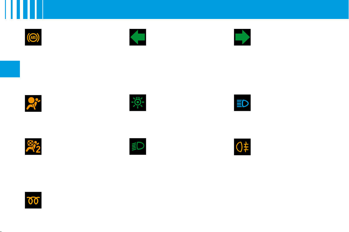
WA R N I N G L A M P S
Front passenger's
airbag deactivation
See "Airbags".
It is tested briefl y on starting.
Airbag fault
See "Airbags".
It is tested briefl y on starting.
ABS system
The
ABS
warning lamp
lights up when you switch
on the ignition: it should go
out after a few seconds.
If it does not go out, there could be
a system malfunction.
See "Brakes".
Diesel engine
preheating
See method for starting
the engine.
See "Driving".
Left hand direction
indicator
See "Signalling".
Right hand direction
indicator
See "Signalling".
Sidelamps
See "Signalling".
Dipped beams
See "Signalling".
Foglamps (rear)
See "Signalling".
Main beams
See "Signalling".
If the hazard lamps are activated, this means that the direction
indicators fl ash on both sides at the same time.
25
II
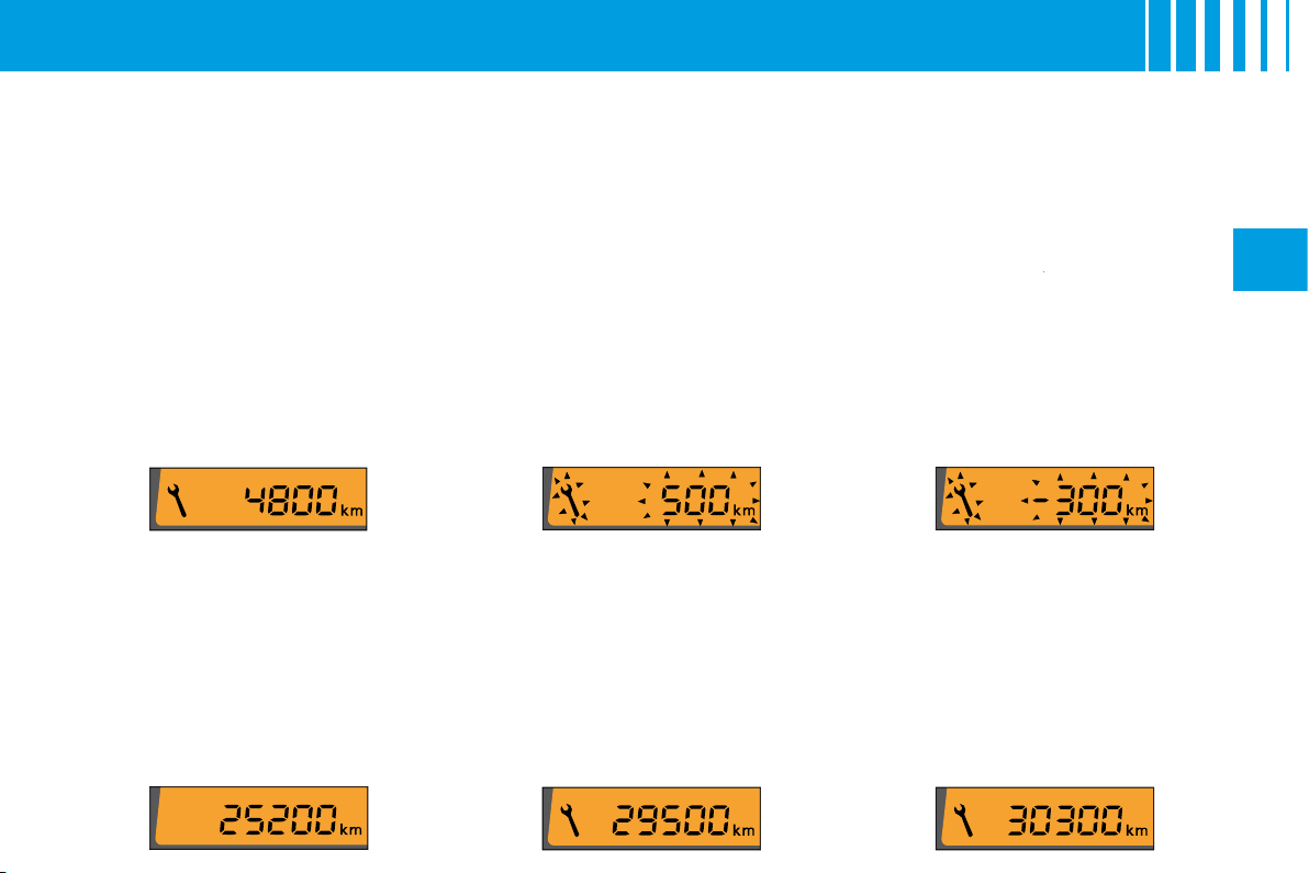
M A I N T E N A N C E I N D I C ATO R
It informs you when the next routine service is due in accordance with the vehicle servicing schedule in the
Maintenance Guide. This information is dependent on two parameters: the mileage covered, and the time
elapsed since the last visit.
Operation
When the ignition is switched on,
the maintenance indicator spanner
is displayed for a few seconds. The
mileage recorder display indicates
how many miles remain to be tra-
velled before the next service is
due (in thousands and hundreds of
miles).
Example:
there remain up to the
next service:
A few seconds after this, the engine
oil level indicator is displayed, then
the total mileage recorder resumes
its normal role.
Operation if the distance to
the next service is less than
1 000 km (600 miles)
Each time you switch on the ignition
and for 5 seconds, the spanner and
the distance fl ash.
Example:
there remain up to the
next service: 500 km (300 miles).
On switching on the ignition and for
5 seconds, the instrument panel
indicates:
A few seconds after this, the engine
oil level indicator is displayed, then
the total mileage recorder resumes
its normal role and the spanner
remains lit up. This is a warning to
you that a service must be carried
out at the earliest opportunity.
Operation if the service
interval has been passed
Each time you switch on the igni-
tion, the
spanner
and the distance
spanner
covered (preceded by a minus)
beyond the recommended interval
fl ash.
Example:
You have exceeded
the service interval by 300 km
(300 miles).
The routine service on your vehicle
needs to be carried as soon as
possible.
A few seconds after this, the engine
oil level indicator is displayed, then
the total mileage recorder resumes
its normal role and the spanner
remains lit up.
A
B
D
C
26
II
I N S T R U M E N T PA N E L L I G H T I N G –
B L A C K PA N E L
Lighting rheostat
The dimmer is active when the
lamps are on and affects:
The instrument panel: Rev
counter, fuel level display.
The display screen.
The air conditioning control
panel.
Selection of mode and brightness
is done by pressing the dimmer
button
A
on the instrument panel.
Night driving (headlamps on)
4 levels of brightness + 1 level for
Black panel.
Adjustment is by successive presses
on button A in the following cycle:
level 4
level 3
level 2
level 1
Black panel.
•
•
•
This function is to give you the best
possible visual conditions for dri-
ving at night.
In black panel mode, the following
information only will be displayed
temporarily, should you request it
or in the event of an alert:
The warning lamps in zone
C
(bottom area of the instrument
panel) will come on in the
event of an alert: e.g. fuel low,
coolant temperature.
The direction indicator warning
lamps.
The speed indicator.
The gear engaged.
The mileage recorder each
time you press button
B
.
The automatic air conditioning
display each time you press
one of the buttons.
The trip computer information.
•
•
•
•
•
•
•
Night driving
The fi rst press
on button
D
"DARK"
places the display on
standby. Only the time and the
temperature remain visible at
the top of the screen.
A second press
on
D
switches
the screen and the instrument
panel off (black panel) with
the exception of information
concerning for example:
The speed indicator.
The gearbox.
Cruise control/Speed limiter if
this has been activated.
Note:
Timed lighting of functions
if you:
Press any of the display
controls.
Select Radio-CD.
Operate any of the air
conditioning controls.
Note:
All the displays come on
if there is an alert.
A third press
on
D
returns you
to normal lighting.
•
•
-
-
-
-
-
-
•

2
1
27
II
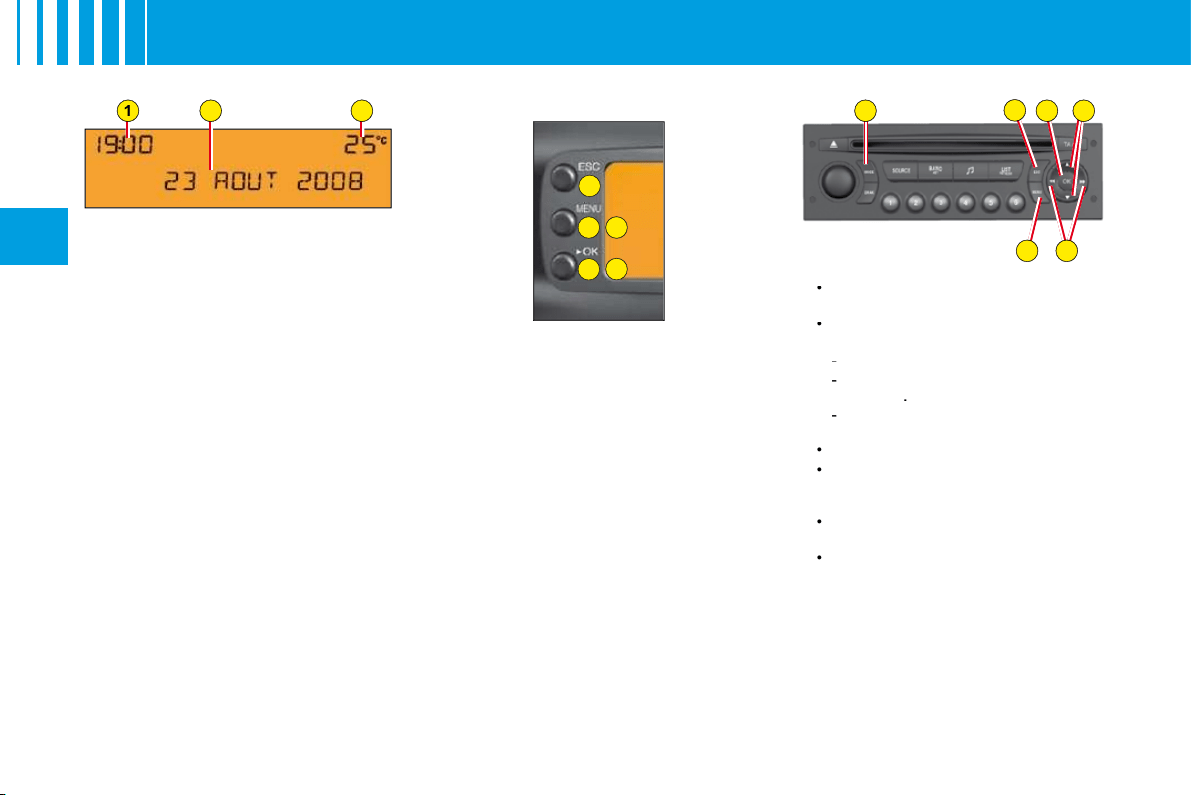
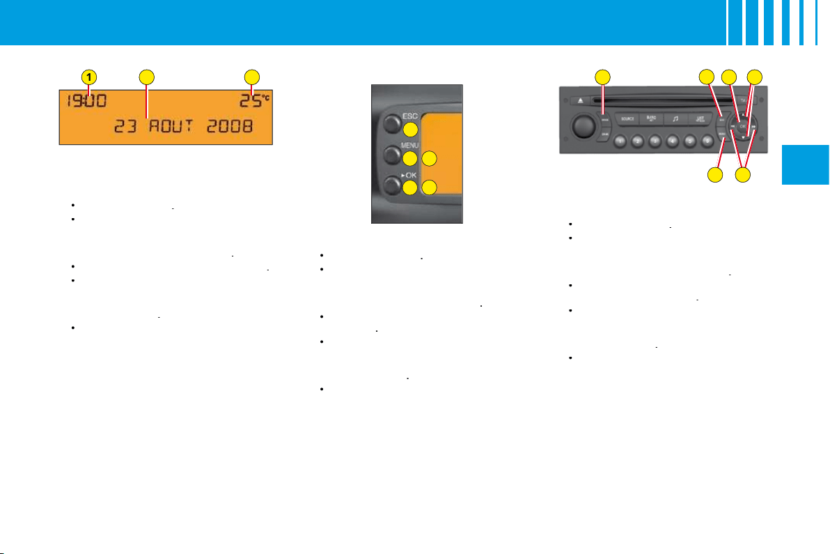
D I S P L AY S
Digital clock
To adjust the display, press on
button
1
to alter the hours and on
button
2
to alter the minutes.
Display A
D
2
3
A
C
B
E
E
D
C
B
A
E
1
28
II
M U LT I F U N C T I O N D I S P L AY
D I S P L AY A
The driver is recommended not to
concern himself with the display
controls while driving.
1.
Time.
2.
Date - Display zone.
3.
Outside temperature.
When the outside temperature
is between +3 °C and –3 °C, the
temperature display fl ashes (risk
of ice).
Note:
The outside temperature
displayed may be higher than the
actual temperature if the vehicle is
stationary in bright sunlight.
Remark:
The display of certain
types of information is sometimes
scrolled and sometimes alternated.
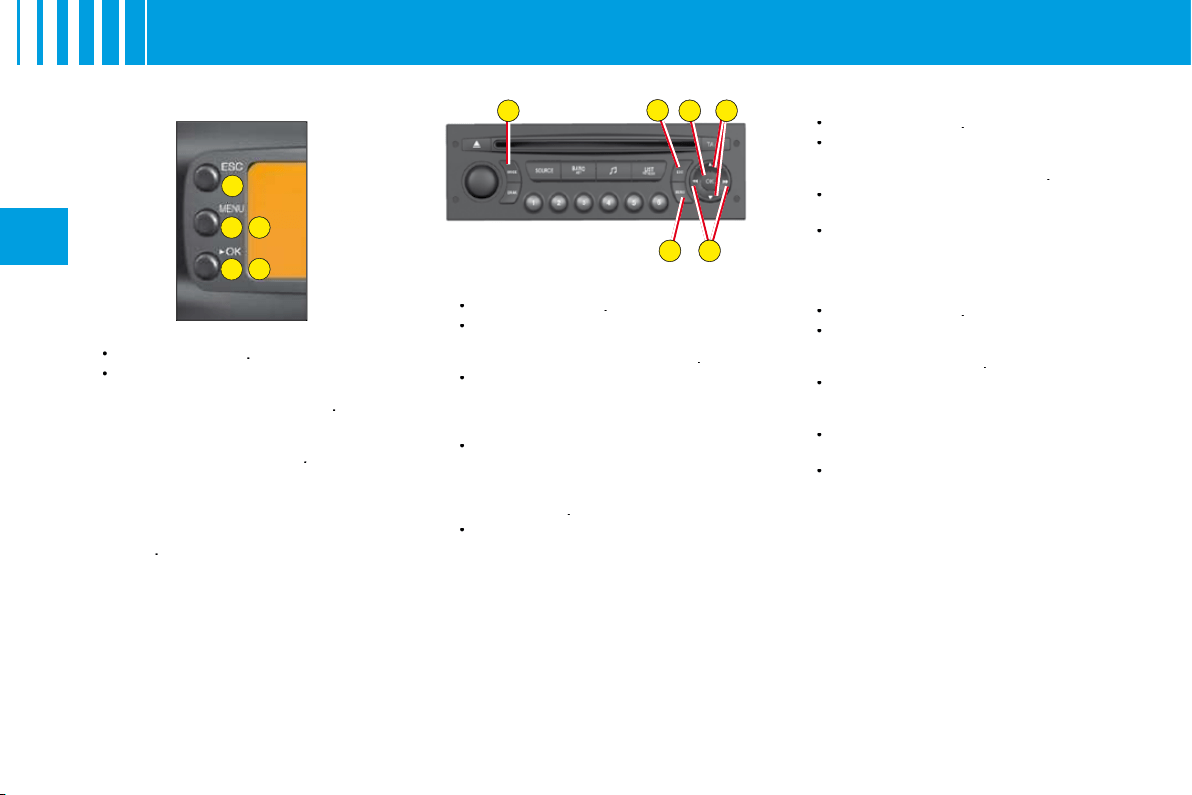
Controls
A.
Access to the "Main menu" of
the display.
B.
Scroll through display menus.
C.
Validation and Selection in the
menus, of the function chosen
or value modifi ed.
D.
Cancellation of the operation or
return to the previous display.
E.
Selection of the type of
information displayed in
zone
2
(date, radio/CD and trip
computer).
In the Menus, choice of
activation/deactivation of your
functions and choice of your
adjustments.
Main Menu
By pressing control
A
then
B
, you
have access to the following func-
tions:
Radio-CD
(See radio-CD
handbook).
Vehicle confi guration,
to
activate/deactivate:
Triggering of rear screen wipe.
The automatic guide-me-home
lighting
.
Automatic lighting of
headlamps.
Options,
to display the alerts.
Display adjustments,
to
adjust the date and time on the
display.
Languages,
to select the
display language.
Units,
to access the choices of
units of Temperature and Fuel
Consumption.
•
•
-
-
-
•
•
•
•
D
2
3
A
C
B
E
E
D
C
B
A
E
1
29
II
M U LT I F U N C T I O N D I S P L AY
D I S P L AY A
Personalisation/Confi guration
To activate/deactivate rear screen
wipe on engaging reverse gear:
Press button
A
.
Select, using
B
, the sub-menu
to personalise-confi gure your
vehicle, then confi rm your
choice with a press on
C
.
Select rear screen wipe, using
B
.
The system tells you the status
(active or inactive) of the
function. Modify this status with
a press on
E
.
Then please wait for the
display to disappear.
Note:
The activation/deactivation
registers immediately.
•
•
•
•
•
To activate/deactivate the auto-
matic guide-me-home lighting:
Press button
A
.
Select, using
B
, the sub-menu
to personalise-confi gure your
vehicle, then confi rm your
choice with a press on
C
.
Select guide-me-home lighting,
using
B
.
The system tells you the status
(active or inactive) of the
function. Modify this status with
a press on
E
.
Then please wait for the
display to disappear.
•
•
•
•
•
To activate/deactivate the auto-
matic lighting of headlamps:
Press button
A
.
Select, using
B
, the sub-menu
to personalise-confi gure your
vehicle, then confi rm your
choice with a press on
C
.
Select automatic lighting of
headlamps using
B
.
The system tells you the status
(active or inactive) of the
function. Modify this status with
a press on
E
.
Then please wait for the
display to disappear.
Note:
Activation of this function is
immediate while deactivation requires
the ignition to be switched off.
•
•
•
•
•
D
A
C
B
E
E
D
C
B
A
E
30
II
M U LT I F U N C T I O N D I S P L AY
D I S P L AY A
To choose the language:
Press button
A
.
Using
B
, select the sub-menu
for Languages. Confi rm your
choice with a press on
C
.
By presses on
E
, select the
language of your choice.
Then please wait for the
display to disappear.
To choose units:
Press button
A
.
Using
B
, select the sub-menu
for Units. Confi rm your choice
with a press on
C
.
Using
B
, select the unit you
wish to modify (Temperature or
Consumption).
Via presses on
E
, select the
unit of your choice.
Then please wait for the
display to disappear.
Note:
This choice concerns all the
types of information (fuel consump-
tion, speed, etc.) that appear on
the displays.
•
•
•
•
•
•
•
•
•
To display the Log of Alerts:
Press button
A
.
Using
B
, select the sub-menu
for options. Confi rm your
choice with a press on
C
.
Note:
You can cancel the start of the
display by selecting
E
to abandon,
validate with a press on
C
.
The alerts that have previously
been signalled to you but not resol-
ved, are recalled to you in a scroll.
To delete the display of an alert,
press
D
.
•
•
To adjust the date and the time:
Press button
A
.
Using
B
, select the sub-menu
for Display Adjustments, then
confi rm with a press on
C
.
Using
B
, select what you wish
to modify: Day, month, year,
hour, minutes and display
mode.
Make your adjustment by
presses on
E
. You can
continue your adjustments,
selecting further parameters by
pressing
B
.
When you have fi nished your
adjustments, simply wait for
the display to disappear.
•
•
•
•
•
31
II
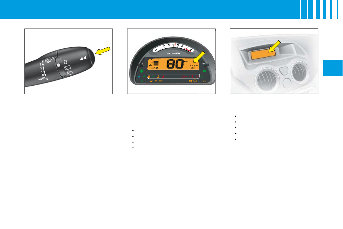
T R I P C O M P U T E R
For selection and display of the
various types of information, give
short presses on the end of the
windcsreen wiper stalk.
Instrument panel (For a
version with digital clock)
The trip computer provides 4 types
of information on the instrument
panel, following the display of trip
mileage:
Range.
Instantaneous consumption.
Average consumption.
Average speed.
•
•
•
•
Display A
The trip computer provides 5 types
of information:
Range.
Average consumption.
Instantaneous consumption.
Distance travelled.
Average speed.
To cancel the display of the trip
computer information, press a
sixth time.
•
•
•
•
•
To reset the trip computer infor-
mation to zero,
keep the end of
the control stalk pressed for a few
seconds when you see the rele-
vant information displayed.
32
II
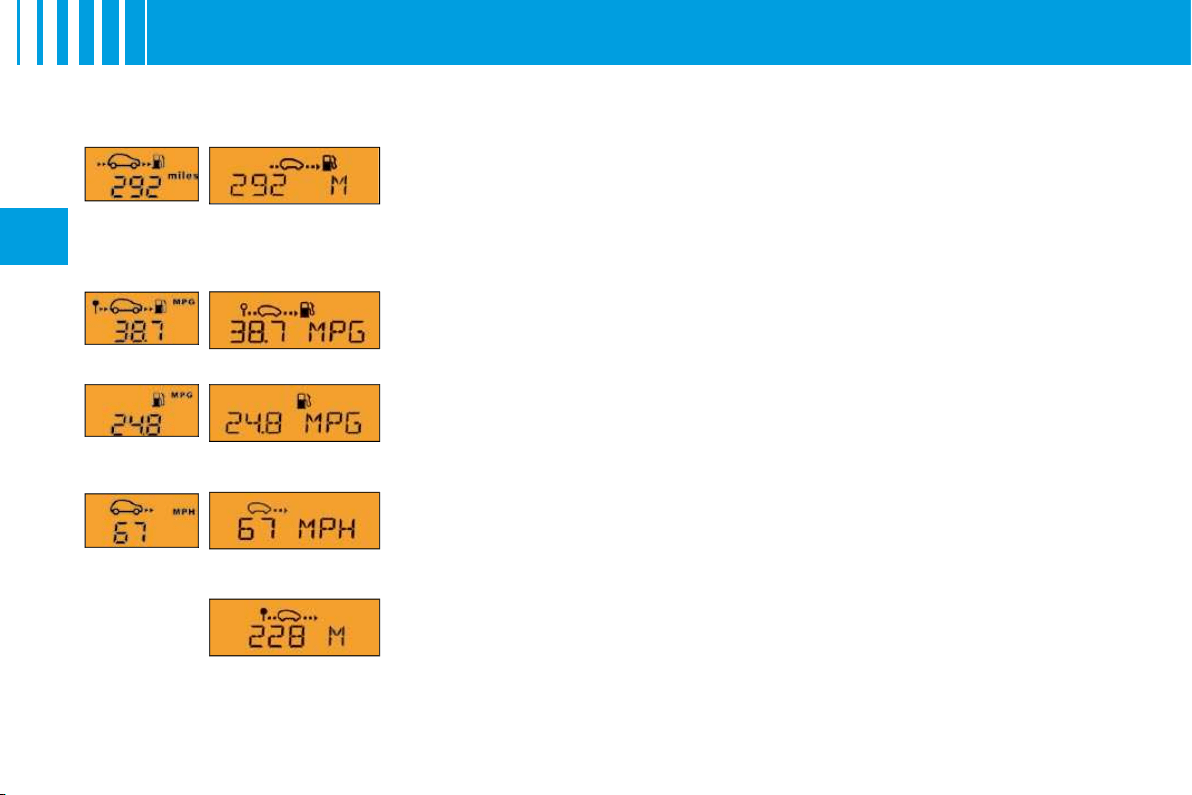
Range
This is the distance that can still be travelled on the amount of fuel remaining in
the tank.
When the distance that can still be travelled is less than approx. 25 km (around
15 miles), only three dashes are shown.
Average consumption
This is the ratio between the fuel consumed and the distance travelled since the
last reset to zero for the Journey selected.
Instantaneous consumption
This is the result from the consumption recorded within the last 2 seconds. This
function is only available when travelling at over 30 km/h (approx. 20 mph).
Average speed
This is obtained, from the last reset to zero of the trip computer, by dividing the dis-
tance travelled by the time taken (with ignition switched on).
Distance travelled
This is the distance that has been travelled since the last reset to zero of the Jour-
ney selected.
Distance to be travelled
To enter it, see "Multifunction display".
Instrument
panel
Display
version A
T R I P C O M P U T E R

33
II
S I G N A L L I N G
Direction indicators
Left
, downwards.
Right
, upwards.
For a change of direction, move
the control stalk beyond the tight
spot. Stops automatically with the
return of the steering wheel.
Visible alert/headlamp fl ash
Pull the control towards you.
The headlamp fl ash can be made
even with the ignition switched off.
Horn
Press at the centre of the steering
wheel.
Hazard warning lamps
This operates all the direction
indicators simultaneously.
Only use them to indicate danger,
for an emergency stop or for driving
in abnormal conditions.
The hazard lamps can also be
used with the ignition switched off.
Sound signal for headlamps
left on
This operates when the driver's door
is opened, ignition off, to indicate
that the vehicle lamps are still on.
It stops when you close the door,
switch off the lamps or switch on
the ignition.
This signal does not operate if the
automatic lighting of headlamps
or the guide-me-home lighting are
active.
Emergency operation of
hazard warning lamps
A sudden deceleration of the vehicle
causes the hazard lamps to come
on automatically.
They will cease to operate automa-
tically, or manually if you press the
hazard lamps button on the dash-
board.
The direction indicators cannot operate if the hazard warning
lamps are on.
A
34
II
S I G N A L L I N G
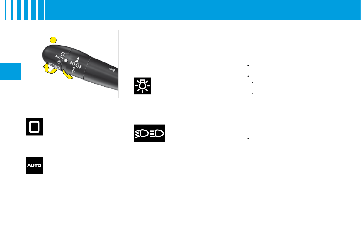
Lighting control stalk
All vehicle lamps off
Sidelamps on
The instrument panel lights
up.
Dipped beams/
main beams on
Rotate the ring
A
forwards.
Rotate the ring
A
forwards.
Sidelamps and dipped beams
come on automatically in poor
ambient light, or if the wipers are
in continuous operation. They go
out as soon as the ambient light
again become suffi cient or when
the wipers cease to operate.
Guide-me-home lighting
This function switches on your
headlamps, to light your way when
you wish to walk from a carpark,
for example.
This function is activated:
Manually by pulling the lighting
stalk towards you, ignition off.
Automatically, provided:
The automatic lighting of
headlamps is activated.
To activate the guide-me-home
lighting function, select in the
"Main menu", then in
"Personalisation/Confi guration",
the sub-menu for lighting and
signalling, then activate the
function.
See "Multifunction display".
Note:
On screen
A
, the length is
fi xed.
Note:
On vehicles equipped with
daytime running lamps, automatic
headlamp lighting and guide-me-
home lighting are not available.
•
•
-
-
•
Rotate the ring
A
forwards.
Pull the control stalk
towards you
to change between dipped beam
and main beam.
Rotate the ring
A
forwards.
Take care not to cover the brightness
sensor, which is visible from outside
the windscreen, behind the interior
rear view mirror.
Automatic lighting of
headlamps
B
35
II
S I G N A L L I N G
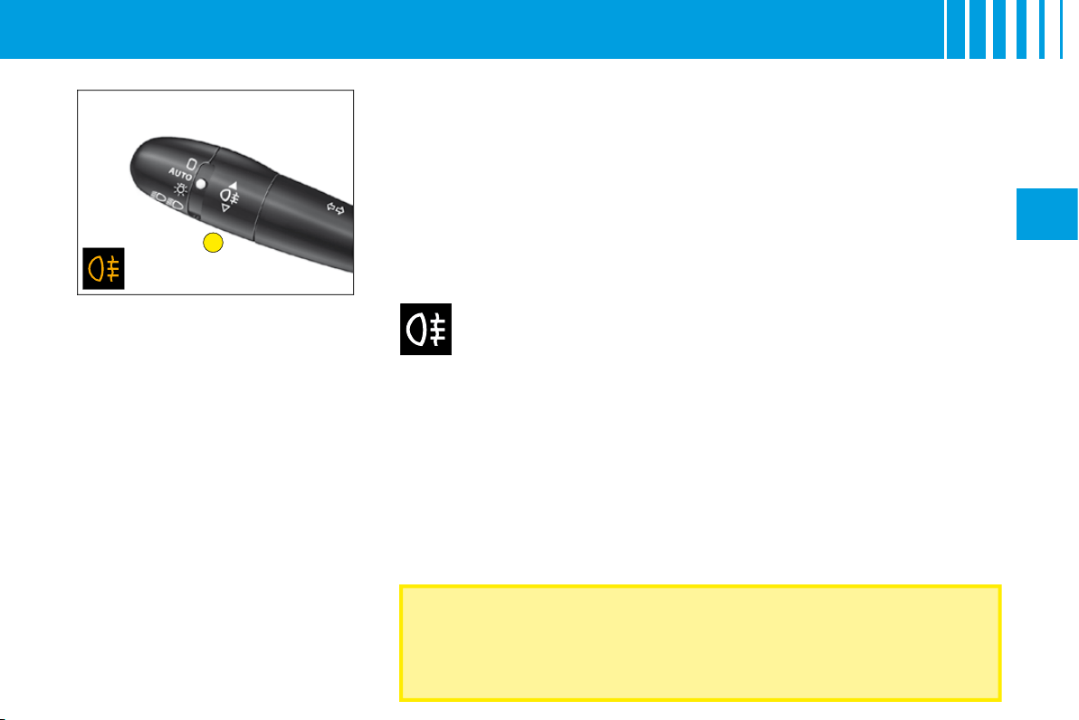
Rear foglamps on
The warning lamp lights up.
The foglamps operate only with
either headlamp dipped beam or
headlamp main beam switched on.
In foggy conditions, if the ambient light is not such that the
headlamps come on automatically, it is up to the driver to switch
on dipped beams, and/or foglamps, manually
Rear foglamps (Ring B)
Switch on your dipped/main beams.
Rotate the ring
B
forwards.
36
II
W I P E R S
For safety, the wiper system is
deactivated when the ignition
is switched off.
If the ignition has been switched
off for more than 1 minute, you
will need to reactivate auto-
matic wipe, by pressing the
control stalk downwards.
Position
I
:
The wipe speed adjusts automatically to the speed of the
vehicle.
Positions 1 and 2:
When the vehicle is stationary, the speed of the wipers
will reduce automatically.
For safety, the wiper system is deactivated when the ignition is
switched off.
When you switch the ignition on again, to reactivate the function:
Return to
position
0
.
Or go to the
desired position
.
Activation of the function is confi rmed by one sweep of the wipers.
Vehicle with rain sensor
Activation of automatic wipe:
One touch downwards:
"AUTO"
. The wipe speed will adjust according to
the intensity of the rain.
Note:
If automatic wipe is active, a touch downwards triggers a single wipe,
without deactivating automatic wipe.
Deactivation of automatic wipe:
Go to position
I
, then return to position
0
.
Or
stop
the engine.
WARNING
Do not cover the rain detector
which is located behind the interior rear
detector
view mirror and visible from outside the windscreen.
For washing the vehicle, switch off the ignition or deactivate the automatic
wipe.
•
•
•
•
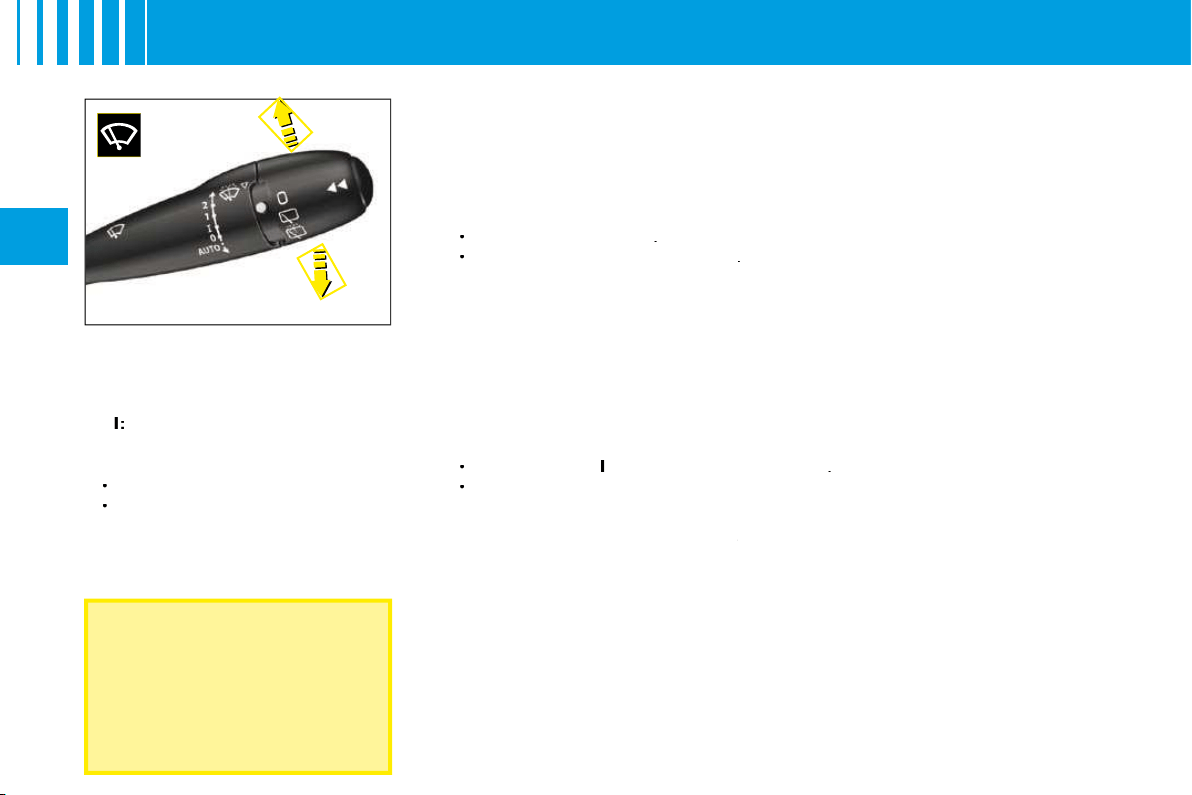
Windscreen wiper
Control positions
2:
Rapid wipe.
1:
Normal wipe.
I
:
Intermittent wipe.
0:
Off.
One press downwards:
AUTO:
Automatic wipe activated.
Single wipe.
•
•

B
A
37
II
W I P E R S
Check that the windscreen and rear wipers can operate freely when
for example a bicycle-carrier is fi tted, or in freezing conditions.
Remove any accumulation of snow at the base of the windscreen.
Changing the wiper blades
If you have to
replace
them, the
wiper blades have to be parked in
the
maintenance position
. For
this, switch off the ignition and then
within one minute move the wiper
control stalk. The wipers stand up
in a vertical position.
After replacement,
switch on the
ignition
and
move the wiper
control stalk
so that the wipers
resume their normal position.
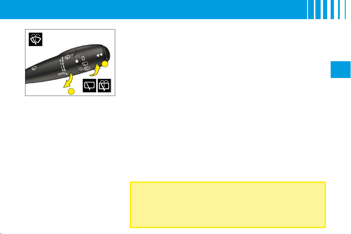
A. Windscreen wash
To operate the windscreen wash,
pull the wiper stalk towards you.
The screen wash is accompanied
by a timed wipe of the windscreen,
the headlamp wash also activates
if the dipped beams are on.
B. Rear screen wipe
First notch
Off.
Second notch
Intermittent rear wipe.
Third notch
Timed rear wash/wipe.
Automatic wipe
When the windscreen wipers are
operational and reverse gear is
engaged.
Activation/deactivation of this
function is possible in the menu
"Personalisation/Confi guration" in
the "Main menu".
Deactivation may be necessary
when a bicycle-carrier is installed
on the tailgate.
B
A
37
II
W I P E R S
Check that the windscreen and rear wipers can operate freely when
for example a bicycle-carrier is fi tted, or in freezing conditions.
Remove any accumulation of snow at the base of the windscreen.
Changing the wiper blades
If you have to
replace
them, the
wiper blades have to be parked in
the
maintenance position
. For
this, switch off the ignition and then
within one minute move the wiper
control stalk. The wipers stand up
in a vertical position.
After replacement,
switch on the
ignition
and
move the wiper
control stalk
so that the wipers
resume their normal position.
A. Windscreen wash
To operate the windscreen wash,
pull the wiper stalk towards you.
The screen wash is accompanied
by a timed wipe of the windscreen,
the headlamp wash also activates
if the dipped beams are on.
B. Rear screen wipe
First notch
Off.
Second notch
Intermittent rear wipe.
Third notch
Timed rear wash/wipe.
Automatic wipe
When the windscreen wipers are
operational and reverse gear is
engaged.
Activation/deactivation of this
function is possible in the menu
"Personalisation/Confi guration" in
the "Main menu".
Deactivation may be necessary
when a bicycle-carrier is installed
on the tailgate.
II
D A S H B O A R D A D J U S T M E N T S
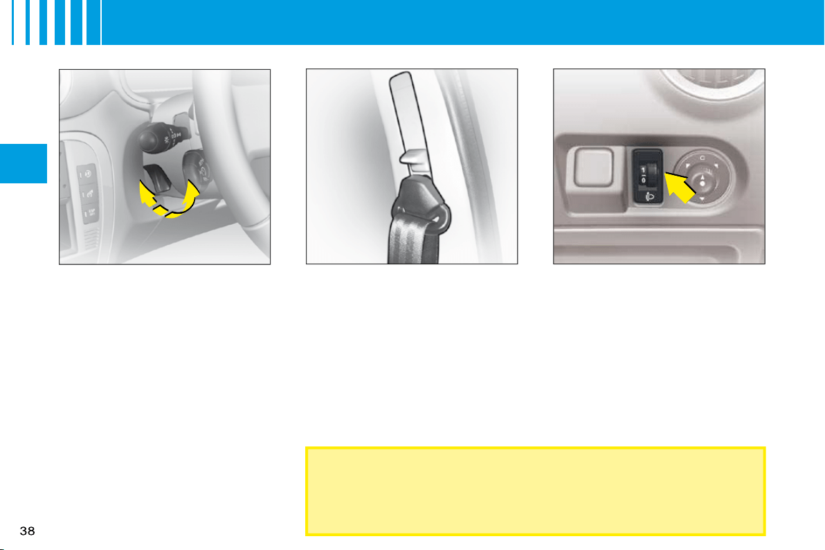
Seat belt height adjustment
The correct positioning of the seat
belt is across the middle of the
shoulder. See User Precautions.
Adjust the height of the seat belt
anchorage by holding down the
button and the lever.
Headlamps adjustment
You are advised to adjust the aim
of the headlamps in accordance
with vehicle load.
In the dashboard on the right hand
side of the steering column.
0:
Unladen weight.
1:
Lightly laden.
2:
Half laden.
3:
Fully laden.
As a metter of safety, these manœuvres should not be performed
while the vehicle is moving.
Steering column adjustment
The steering can be adjusted for
both height and reach.
With the vehicle stationary,
fi rst adjust your seat to the most
suitable position, then adjust the
position of the steering wheel. See
"Driving position".
Unlock the steering wheel by
pulling the control upwards.
Adjust the position of the steering
wheel then lock by pushing the
control fully downwards.
Make sure that you have a good view
of the instrument panel displays.
1
2
39
II
R E A R V I E W M I R R O R S
Electric exterior rear view
mirrors
Your vehicle is equipped with
electric door mirrors.
Set the position of the selected
door mirror:
1.
Left hand door mirror.
2.
Right hand door mirror.
Move the control in the four direc-
tions to set the position.
The defrosting of the exterior rear
view mirrors is linked to the electri-
cal demisting of the rear window.
Fold-back of door mirrors
When the vehicle is parked, the
door mirrors can be folded back
either manually.
The end of the glass in the exte-
rior rear view mirrors is aspherical,
so as to enlarge the lateral fi eld of
vision.
Objects observed in the aspherical
part of the rear view mirrors are in
reality closer than they appear.
You must take this into account in
order to be properly aware of the
distances involved.
Interior rear view mirror
The lever on the lower edge
enables you to place the rear view
mirror in either of two positions:
Day position:
the lever is not
visible.
Night position (anti-dazzle):
the
lever is visible.
40
II
W I N D O W S
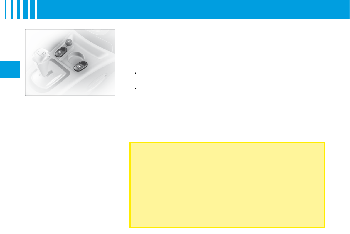
Electric operation
The switches on the console allow
the vehicle’s electric windows to
be controlled from the driver’s
position.
Sequential control on
driver's side
An action on the control to the fi rst
notch causes a window movement
which stops as soon as the control
is released.
An action on the control to the
second notch causes the window
to close or open completely, a fur-
ther press on the control stops the
movement.
Note:
The window controls also
operate for a limited time after you
have switched off the ignition.
ALWAYS PAY ATTENTION TO WHERE CHILDREN ARE WHEN
OPENING OR CLOSING THE WINDOWS
Always remove the ignition key when leaving the vehicle, even if for a
short time.
If there is an obstruction when operating a window, you must immediately
reverse the window movement. To do that, reverse the position of the
control concerned.
If the driver is operating the electric window controls for passengers, he
or she should ensure that no passenger is obstructing the window from
closing.
The driver must ensure that the electric windows are used properly by
passengers.
Anti-pinch on driver's window
An anti-pinch device stops the
window from rising. If it meets an
obstacle, it goes back down.
After a battery disconnection or
if there has been a malfunction
,
you have to
re-initialise
the anti-
pinch function:
Use the control to fully open
the window, then reclose. It will
rise only a few centimetres.
Press again on the control until
the window closes fully.
During this operation, the anti-
pinch protection does not work.
•
•
41
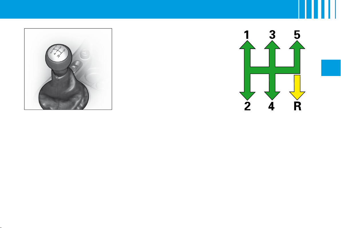
II
Reverse gear
Do not select reverse gear until the
vehicle is completely stationary.
Depress the clutch pedal and wait
a few moments before gently enga-
ging reverse gear.
Manual gearbox gear lever.
M A N U A L G E A R B O X
42
II
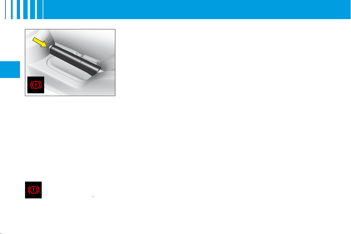
B R A K E S
Parking brake
The parking brake is actioned by pulling on the lever with a force appropriate to
any slope.
To facilitate the action on the lever, you are recommended to press the brake
pedal at the same time.
In all circumstances, as a precautionary measure, engage fi rst gear.
On steep gradients, turn the steering towards the pavement.
To release the brake, pull the lever lightly up, press the button on the end of the
lever and return the lever to the fully down position.
Parking brake released
The lighting of this warning lamp indicates that the brake fl uid level is insuffi cient or that the braking distributor
is malfunctionning
.
It is essential to stop the vehicle.
Consult a CITROËN dealer as soon as possible.
Note:
The warning lamp comes on if the parking brake is on or not fully released when you switch the ignition on.
Note:
The lighting of this warning lamp indicates that the parking brake is on or not fully released while the engine is
running (at a speed above approximately 5 km/h).

43
II
ABS system
The ABS system enhances your safety by preventing the wheels from locking in the event of sudden braking
or in conditions of poor road adherence. It enables you to retain control of the steering.
The functioning capability of all the electrical components essential to the ABS is monitored electronically
before and during your journey. The ABS warning lamp lights up when you switch on the ignition: it should go out
after a few seconds.
If the monitoring warning lamp does not go out, that means that the ABS has disconnected because there is a fault.
Also, the fact that the monitoring warning lamp comes on during the journey shows that the ABS system is inactive.
In both cases, the normal braking system remains effi cient, exactly as on a vehicle without ABS. However, in order
for the security associated with the correct functioning of the ABS to be restored, the vehicle should be examined as
soon as possible by a CITROËN dealer.
for the security associated with the correct
associated with the
On roads with poor adherence (chippings, snow, ice etc.), it is always imperative to drive with prudence.
System of emergency braking assistance
(For vehicles with the ABS system)
The emergency braking assistance system helps you to attain the required braking pressure more rapidly, thus to
reduce the stopping distance. It operates as a function of the speed of action on the brake pedal, decreasing the
resistance to this action. To prolong this action of the emergency braking assistance system, simply keep your foot
on the brake pedal.
Emergency braking or sudden deceleration automatically operates the hazard warning lamps. They will cease to
operate automatically, or manually if you press the hazard lamps button on the dashboard.
When braking in an emergency, press down fi rmly on the brake pedal and do not release any force.
B R A K E S
E
44
II
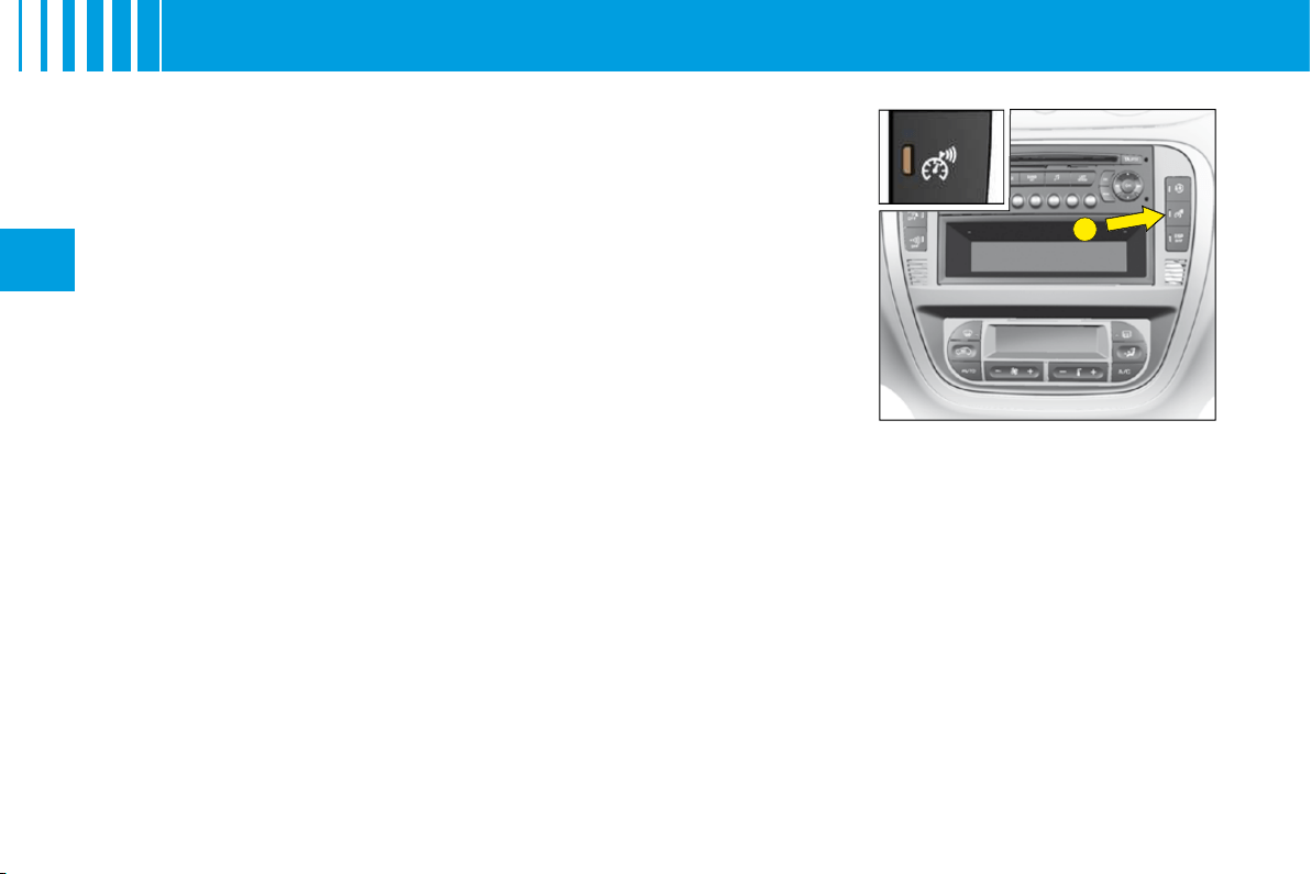
O V E R S P E E D A L E R T
Overspeed alert
Function for keeping to a desired maximum speed.
A short press on control
E
activates this function (the warning lamp lights up).
To pre-set or modify the desired alert speed, when you have reached this
speed, give a long press on control
E
(located on the dashboard central
panel) until you hear a confi rmation gong.
An audible signal indicates that the programmed speed is being exceeded.
To cancel
Give another short press on control
E
to deactivate this function (the warning
lamp goes out).
Note:
The overspeed alert only functions for speeds above around 30 km/h
(around 18 mph).
A
B
45
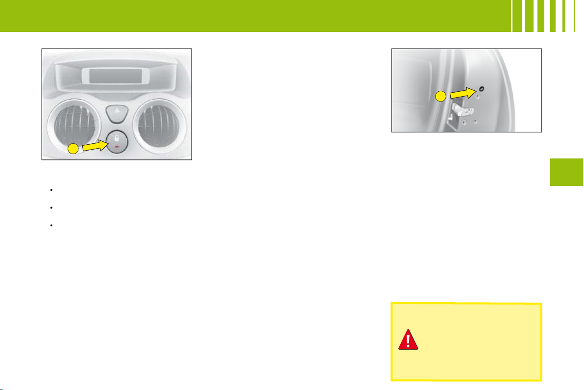
III
Locking from the inside
A press on the control
A
operates
the electric central locking and
unlocking, provided all the doors
are closed.
It is still possible to open the doors
from the inside.
If one of the doors or the tailgate
is open or not properly closed, the
central locking does not operate.
The warning lamp associated with the control
A
signals 3 statuses:
lt fl ashes when the ignition key is in the stop position or when the key is
not detected and the doors are locked.
It lights up when the ignition key is in the "accessories" position or
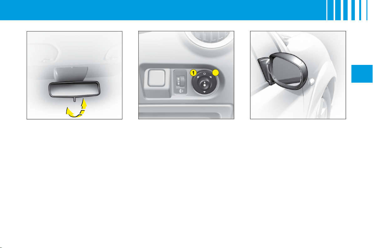
"ignition + engine running" or starter position and if the doors are locked.
It goes out when the doors are not locked.
Note:
Control
A
is inactive if the vehicle has been locked using the remote
control or the key.
Anti-theft
In all cases, as soon as the vehicle is moving (above a speed of 10 km/h),
the tailgate locks automatically. The tailgate unlocks when a door is opened
or when the interior locking/unlocking control is actioned.
Anti-theft protection
On starting the vehicle, the system automatically locks the doors as soon as
you reach approximately 10 km/h.
Note:
If a door has been opened, this will lock again automatically when the
vehicle reaches approx. 10.
Activation/Deactivation of the function
After switching on the ignition, give a long press on the central unlocking
button until a message is displayed.
•
•
•
Manual operation
It is possible to lock the vehicle’s
doors, in the event of an electrical
malfunction, by actioning control
B
on each door.
With the door open, peel back the
black sticker (on rear doors only).
Insert an object, such as the end of
a key, into the cavity and turn.
Then close the door.
After a repair, normal functioning
resumes by means of the unlocking
control
A
, the remote control or the
key used in the driver’s door.
Note:
In order to unlock the rear
doors from the inside, you must fi rst
deactivate the child locks.
If you decide to drive
with the doors locked,
remember that in the
event of an accident
this renders access
more difficult for the
emergency services.
ACCESS
ANTI-THEFT AND ANTI-INTRUSION PROTECTION

46
III
Child safety manual control
This prohibits the opening of both
the rear doors from the inside.
This device is independent of the
central locking system.
The rear doors are locked by
operating the lever.
A C C E S S
A
B
47
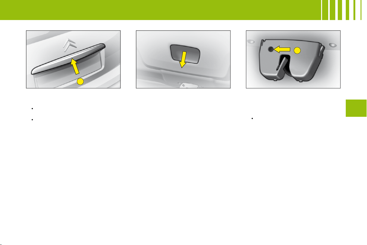
III
Tailgate
When stationary, this unlocks:
when you use the remote
control,
or open any of the doors.
Note:
In all cases, as soon as the
vehicle is moving (above a speed
of 10 km/h), the tailgate locks auto-
matically.
Opening from the outside
Press upwards on lever
A
which is
located between the number plate
lamps.
•
•
Closing the tailgate
Lower the tailgate using the grip
located in the tailgate interior trim
moulding.
Press fi rmly shut.
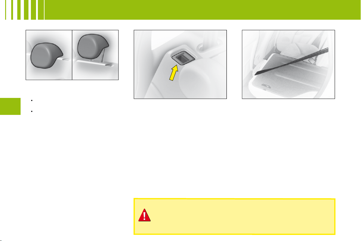
Unlocking in emergency
If there is a problem with unlock-
ing the tailgate, it can be unlocked
from inside the boot:
Insert a screwdriver into the
aperture
B
in the lock. Turn it in
order to unlock the tailgate.
•
A C C E S S
48
III
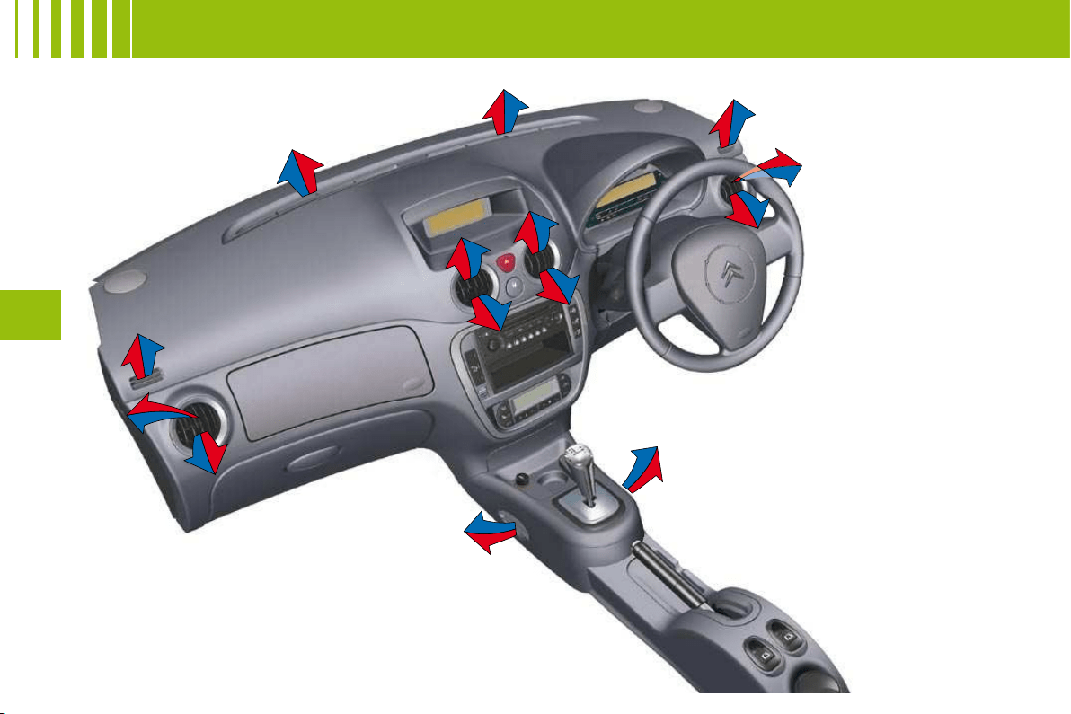
V E N T I L AT I O N - H E AT I N G
1
2
3
4
5
6
1
1
1
2
2
2
3
3
3
4
4
4
5
6
6
6
50
III
V E N T I L AT I O N - H E AT I N G -
M A N U A L A I R C O N D I T I O N I N G
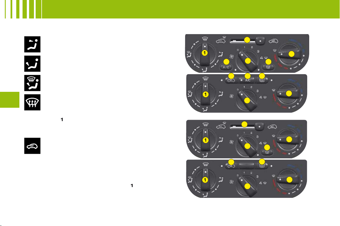
Air fl ow to the face level vents
(Air vents open)
1. Air distribution
Air fl ow to the front and rear footwells
(Air vents closed)
Air fl ow to the footwells and windscreen and side
windows
Air fl ow to the windscreen and side windows
Demisting - Defrosting
Distribution from the air blower can be altered at will by placing
the distributor
1
in an intermediate position.
Air recirculation
This position is useful for excluding undesirable
odours or fumes coming from outside. It should be
cancelled as soon as possible in order to permit
renewal of air in the cabin and to prevent misting.
2. Cabin air
3. Heater blower control
The air blower operates only when the engine is running. For
optimum comfort in the passenger compartment, the control
should not remain in position
0
(position
1
minimum).
4. Temperature control
5. Air conditioning
6. Demisting - deicing of the rear screen.
MANUAL AIR CONDITIONING
VENTILATION - HEATING

49
III
V E N T I L AT I O N - A I R C O N D I T I O N I N G
Air inlet
Check that the exterior grille for the air inlet, at the
bottom of the windscreen, is clean and free of dead
leaves, snow, etc.
If washing the vehicle with a high pressure jet, avoid
targeting the air inlet zone.
Air vents
The air vents to the face (except the central air vent)
have grilles for orienting the fl ow of air (up-down, right-
left).
Air circulation
For your comfort we advise you to maintain a proper
distribution of air within the cabin, both at the front and
at the rear.
Air outlets are also located on the central console
close to the gear lever, to enhance comfort for the rear
passengers.
Pollen fi lter – Odour fi lter
Your installation has a fi lter for keeping out dust.
This fi lter has to be changed according to the vehicle
maintenance schedule. See "Maintenance Guide".
Air conditioning
Whatever the time of year, even in cool weather the
air conditioning is useful in removing humidity and
misting.
To keep the air conditioning compressor well sealed, it
is essential to operate the air conditioning at least once
in every month.
To be effective, the air conditioning should only be used
with the windows closed.
If you are towing a heavy trailer and outside tempera-
tures are high, the air conditioning may be temporarily
paused if the engine cooling requires this.
Water arising from condensation in the air conditioning
system is evacuated through a hole provided for this
purpose ; a pool of water may thus form underneath the
vehicle when stationary.
You are advised to have the air conditioning system
checked on a regular basis. See "Maintenance Guide".
The air conditioning operates by using power from the engine.
This results in a slight increase in fuel consumption.
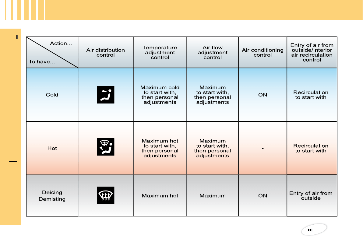
Demisting - deicing of the
windscreen and front side
windows
Place the controls for temperature and
air fl ow on maximum.
Close the central air vents.
Operate the air conditioning.
Note:
You should not be in air recirculation.
•
•
•

1
2
3
4
5
6
1
1
1
2
2
2
3
3
3
4
4
4
5
6
6
6
50
III
V E N T I L AT I O N - H E AT I N G -
M A N U A L A I R C O N D I T I O N I N G
Air fl ow to the face level vents
(Air vents open)
1. Air distribution
Air fl ow to the front and rear footwells
(Air vents closed)
Air fl ow to the footwells and windscreen and side
windows
Air fl ow to the windscreen and side windows
Demisting - Defrosting
Distribution from the air blower can be altered at will by placing
the distributor
1
in an intermediate position.
Air recirculation
This position is useful for excluding undesirable
odours or fumes coming from outside. It should be
cancelled as soon as possible in order to permit
renewal of air in the cabin and to prevent misting.
2. Cabin air
3. Heater blower control
The air blower operates only when the engine is running. For
optimum comfort in the passenger compartment, the control
should not remain in position
0
(position
1
minimum).
4. Temperature control
5. Air conditioning
6. Demisting - deicing of the rear screen.
MANUAL AIR CONDITIONING
VENTILATION - HEATING
5
3
4
B
A
5
3
4
51
III
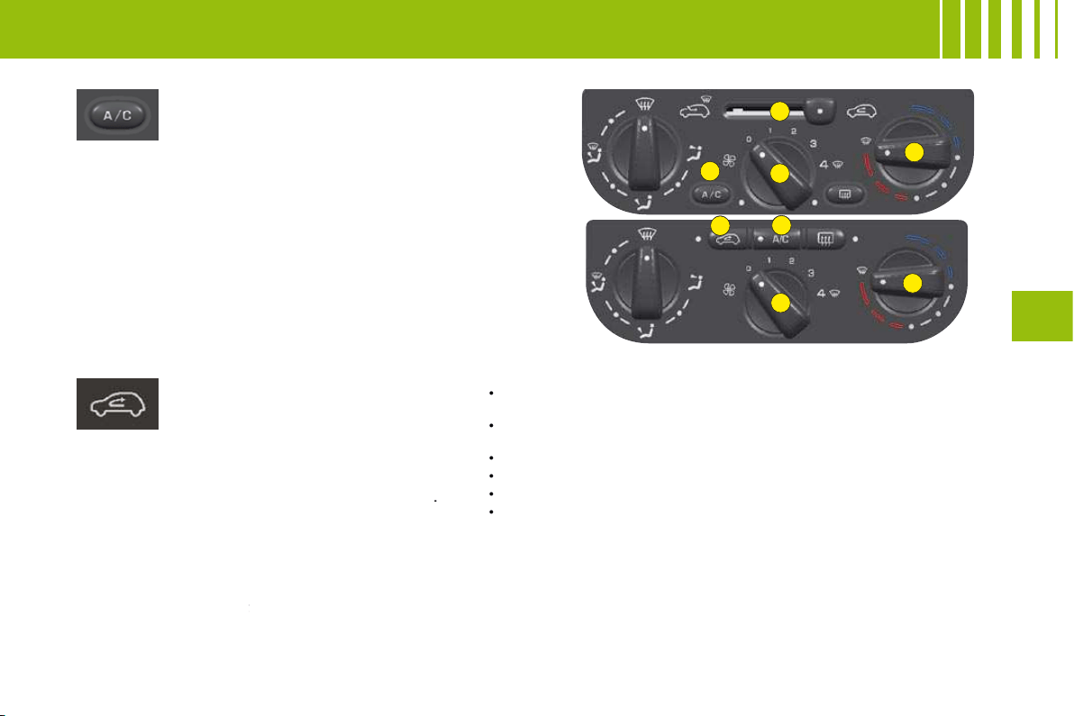
Air conditioning
The air conditioning only operates
when the engine is running.
Press the control located on the
control panel.
Warning lamp on = in operation
Air conditioning is obtained by the mixing of
hot air and cold air. Control
4
allows you to
adjust the air conditioning while control
5
is in
operation.
To obtain refrigerated air, you should check that
the air blower control
3
is not on position "
0
".
Air recirculation
This function isolates the passenger
compartment from disagreeable
odours or smoke coming from
outside and increases the effi ciency and
rapidity of the air conditioning.
According to version, press on control
A
(warning lamp comes on), or move control
B
.
The entry of air from outside is blocked.
This function should be cancelled when no
longer needed in order to permit a renewal of
cabin air and to prevent misting.
Note:
To obtain a rapid rise in cabin temperature,
place control
A
or
B
in the air recirculation
position and control
4
on maximum in the red
4
zone.
If after a prolonged stop in bright sunlight, the cabin temperature
is very high:
Open the windows for a few moments to let in air, then close
the windows again.
Adjust the temperature on control
4
to the maximum cold
position.
Open the air vents.
Use the recycled cabin air position.
Place the air blower control
3
to the position close to maximum.
With comfort restored, action the air blower
3
and the
temperature control
4
to adjust comfort.
•
•
•
•
•
•
M A N U A L A I R C O N D I T I O N I N G
2
5
4
1
3
52
III
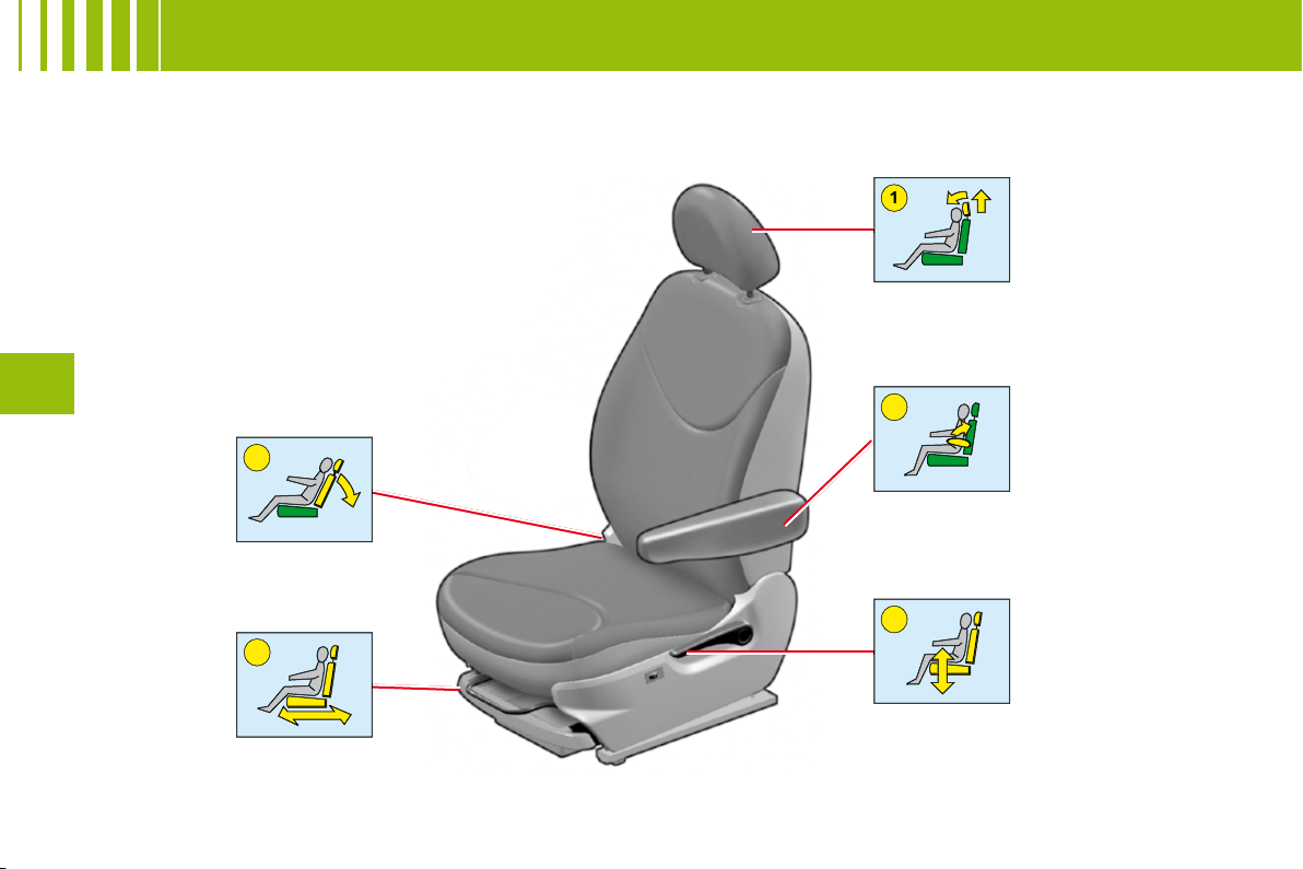
F R O N T S E AT S
1
2
4
3
5
53
III
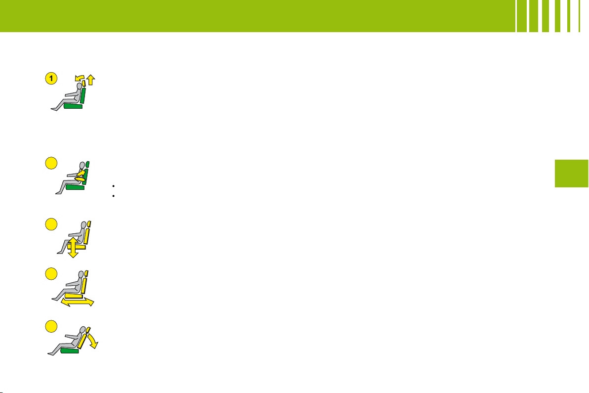
F R O N T S E AT S
Manual adjustments
Head restraint
To fi t it, slide it in.
To lower it, press on the tab.
Adjustment is correct when the top of the head restraint is level with the top of the head.
It is also tilt-adjustable.
To remove it, bring it to the high position. Lift the tab with the aid of a coin and pull.
Backrest angle
Use the control to adjust the backrest angle.
It is possible to recline the backrest to an angle of 45° by tilting it until it locks. Press the control to
unlock.
Seat height and rake adjustment
Raise the control and place the seat in the desired position.
Reach
Lift the control bar and adjust to the desired position.
Armrest
To place it in the vertical position: Lift it from its position of use until it locks.
Note:
To remove the armrest:
Press the control located on its axis of rotation.
Pull the armrest to remove.
•
•
54
III
Rear head restraints
The rear head restraints have
two positions:
A stowed position for when the
seat is not occupied.
A deployed position to provide
passenger safety, by raising
them to their locking point.
To raise them, pull them upwards
to their maximum height, pressing
the unlocking button.
•
•
Foldable backrest
It can be folded either totally or
partially.
Stow the head restraints.
Make sure that all the seat belts
are fastened in their buckles.
Press on the control placed at the
extremity of the backrest and tilt
fully forward.
When you reposition the backrest,
make sure that it locks in place.
It is essential to secure the seat belt fastenings in their
respective buckles whenever you have repositioned the
backrest. This ensures that all the seat belts with their buckles
are available for use by your rear passengers.
3 - S E AT E R R E A R B E N C H S E AT
A
55
III
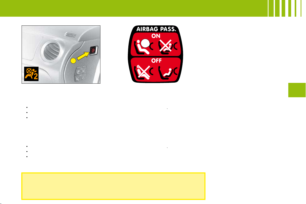
A I R B A G S
In the front passenger's seat position, it is imperative to deactivate the
front passenger's airbag if you are installing a "rear-facing" child seat
there. Otherwise the child risks being killed or seriously injured should
the airbag deploy.
Front passenger's airbag deactivation
In order to be able to use a rear-facing child seat in the front passenger's seat position, it is imperative to deactivate
the passenger's airbag.
For that:
With the ignition switched off, insert the key into the switch
A
.
Turn the key to the
"OFF"
position, the passenger's airbag is deactivated.
The front passenger's airbag deactivation warning lamp, in the instrument panel, lights up when you switch on
the ignition.
Reactivating the front passenger's airbag
Do not forget to reactivate the function.
For that:
With the ignition switched off, insert the key into the switch
A
.
Turn the key to the
"ON"
position, the airbag is activated.
The warning lamp in the instrument panel lights up for a few seconds when you switch on the ignition.
The airbags only function with the ignition switched on. A slight noise is emitted when they are triggered.
Note : the gas released from the airbags may be a mild irritant.
•
•
•
•
•
•
56
III
C H I L D R E S T R A I N T S
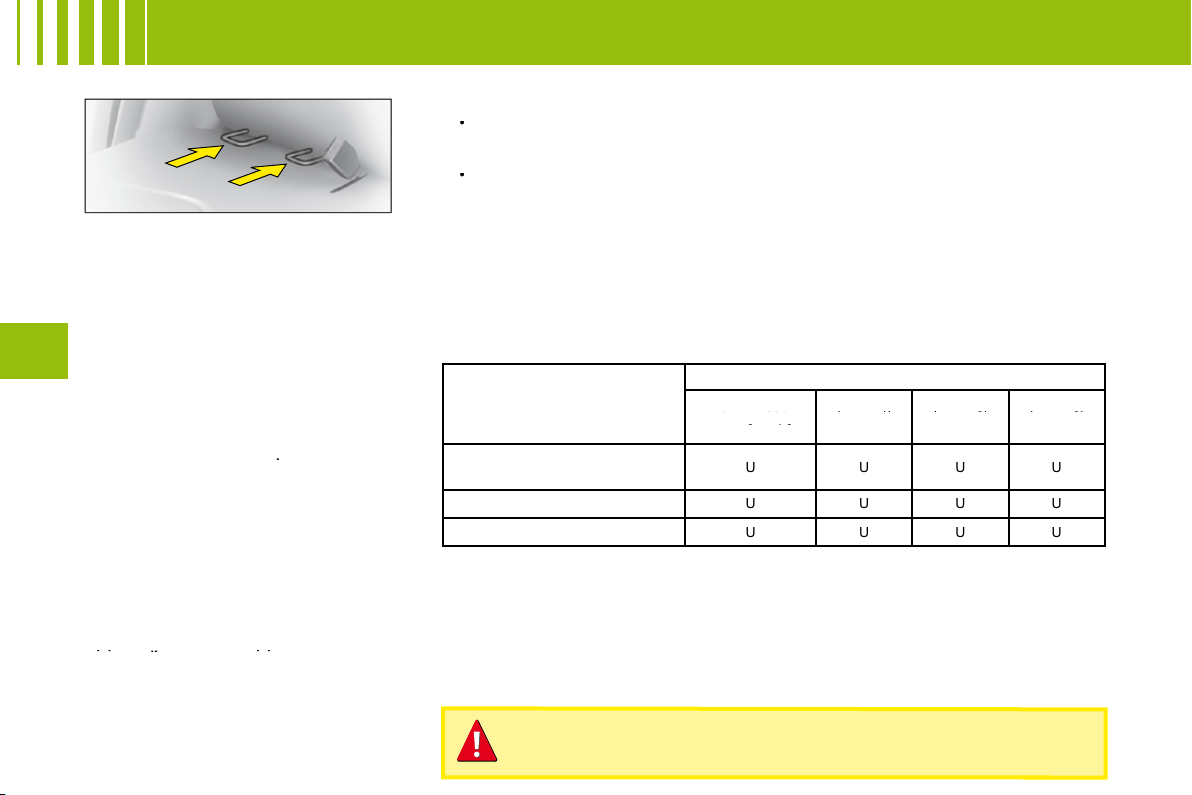
ISOFIX anchoring points
and the ISOFIX fastening
system
The lateral rear seats of your vehicle
are each equipped with regulation
ISOFIX anchoring points. These
consist of 2 rings located between
the backrest and the vehicle seat,
approx. 28 cm apart.
ISOFIX child seats are equipped
with 2 latches which are eay to
attach to these rings. This fi xing
system is intended for children
weighing
up to 18 kg
.
Incorrect installation of a child seat
in a vehicle compromises protection
of the child in the event of a collision.
The ISOFIX system enables you to
minimise the risks posed by incorrect
fi tting. The ISOFIX fastening system
gives you a convenient, strong and
reliable fi tting for a child seat in your
vehicle.
The ISOFIX child seat that is
approved and supplied by the
CITROËN network is the
approved and supplied by
approved
KIDDY
Isofi x
child seat (1).
It can be installed "rear-facing"
from birth to 13 kg and "forward-
facing" from 9 to 18 kg.
Advice on installing your KIDDY Isofi x child seat:
In the "forward facing" position, the vehicle’s corresponding front
seat should be adjusted between the furthest forward and the
medium fore/aft position, with the backrest upright.
If "rear-facing", the shell of the child seat should be in contact
with the backrest of the vehicle front seat.
Child seats secured by means of the vehicle seat belt
In conformance with the European Directive, the table tells you to what
extent each of the seat positions in your vehicle may take a child seat that
is secured by means of the vehicle seat belt and approved as "Universal"
according to the weight of the child.
•
•
Seat position(s)
Weight of child
Up to 10 kg
and up to 13 kg
Up to 10 kg
Up to 10 kg
(groups 0 and 0+)
and up to 13 kg
and up to 13 kg
9 - 18 kg
(group 1)
9 - 18 kg
9 - 18 kg
15 - 25 kg
(group 2)
15 - 25 kg
15 - 25 kg
22 - 36 kg
(group 3)
22 - 36 kg
22 - 36 kg
Front passenger’s (a)
Fixed seat - Height-adjustable seat
U
U
U
U
Lateral rear
U
U
U
U
Central rear
U
U
U
U
KEY TO THE TABLE
U: Seat position suitable for the installation of a universal rear-facing child seat and a universal forward-
facing child seat position.
(a): In the front passenger's seat position, it is imperative to deactivate the front passenger's airbag if you
are installing a "rear-facing" child seat there. Otherwise the child risks being killed or seriously injured
should the airbag deploy. Before placing your child in the front passenger’s seat position, consult the
legislation currently in force in your country on the carrying of children in this position.
(1): On ISOFIX anchorages, you may fi x only the ISOFIX child seats that are approved for your vehicle.
Take care to comply with the fi tting instructions given in the
child seat manufacturer’s installation guide.
1
2
2
57
III
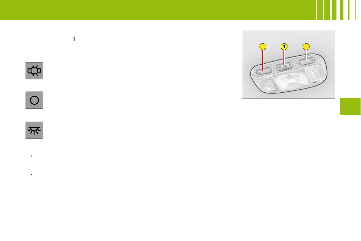
I N T E R I O R L I G H T I N G
1. Interior lamps
Move the control
1
to the 3 following positions.
Automatic lighting of the interior lamps
On entering the vehicle:
They come on as soon as the vehicle is unlocked or a door is opened.
They go out 30 seconds after the doors are closed or when ignition is switched on.
On vacating the vehicle:
They come on as soon as the ignition key is removed (timed for 30 seconds), or when a door is opened.
They go out 30 seconds after all the doors have been closed or immediately after the vehicle has been locked.
2. Spotlamps
A press on one of the buttons
2
switches the corresponding spotlamp on or off.
These do not work if the ignition is off or in economy mode.
•
•
In this position, the interior lamp comes on when you open a door
or the boot.
In this position, it is deactivated and remains permanently off. The
spotlamps are deactivated.
In this position, lighting is permanent.
58
III
I N T E R I O R C O M F O R T
Lower glovebox
To open, pull the handle and lower
the lid.
It comprises a storage area for
vehicle documents.
Boot storage
Straps anchored to the boot aper-
ture are provided for the securing
of a wide variety of objects (e.g.
doctor’s bag, warning triangle, oil
container etc).
Further items can be stowed in the
storage area fi tted into the right
hand side of the load area.
WARNING
As a safety measure, the glovebox must remain shut when
the vehicle is in motion.
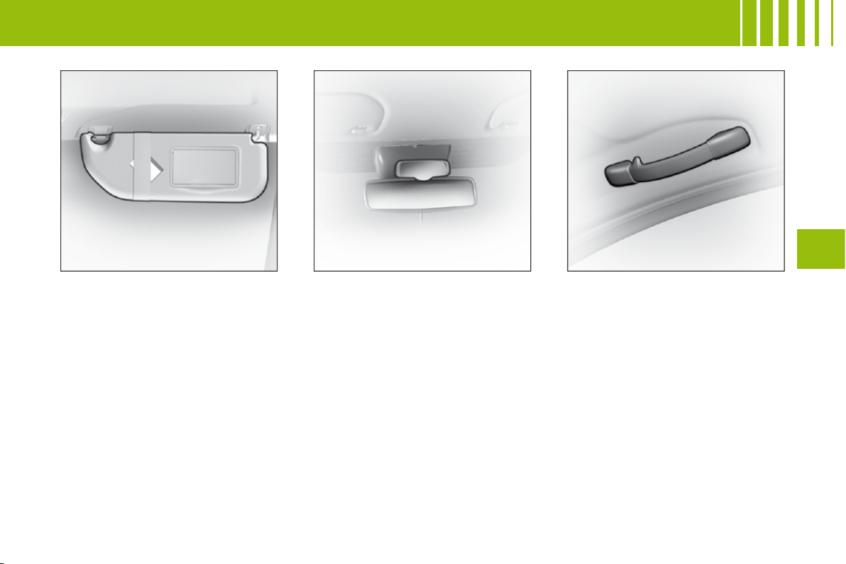
59
III
I N T E R I O R C O M F O R T
Sun visor
To prevent dazzle from ahead, fold
the visor downwards. They can be
disengaged from their central fi x-
ing and pivoted over to the side
windows if required.
The passenger’s and driver’s sun
visors each have a mirror that can
be covered.
Child surveillance mirror
This mirror allows the driver or the
front passenger to observe the rear
seat positions.
Grab handles - coat hooks
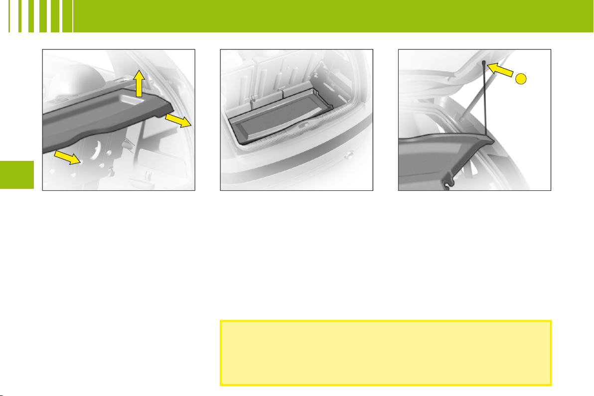
B
60
III
R E A R PA R C E L S H E L F
Removal
To remove it, detach the cords.
Push up vertically, then lift on each
side.
Storage areas
Tilt the shelf to stow it against the
rear seats.
Refi tting
Present the shelf to its fi xing points
and push vertically until it is fully
engaged.
To attach the shelf and tailgate,
take the cords and fi x them at
B
Do not place any hard or heavy item on the rear shelf.
These could be dangerous if thrown around during harsh
braking or, if they touch the rear screen, could damage
the heating elements.
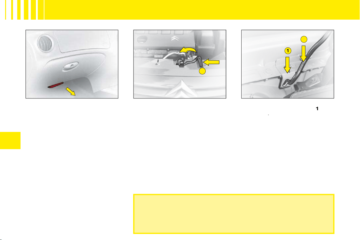
A
1
2
IV
62
B O N N E T R E L E A S E
Check that the bonnet is properly secured.
Avoid opening the bonnet in high winds.
Bonnet
This operation should only be
performed while the vehicle is
stationary.
To release the bonnet, pull the
control located under the dash-
board towards you.
Operate the lever
A
, located
above the grille, to the right of the
chevrons, then lift.
Note:
The panel may be hot after
the vehicle has been in use.
Bonnet stay:
Unclip and swivel
the strut, to insert it in notch
1
, then
in notch
2
.
Warning:
Do not pull the strut
towards the front.
To close
Lower the bonnet carefully, then let
it drop shut.
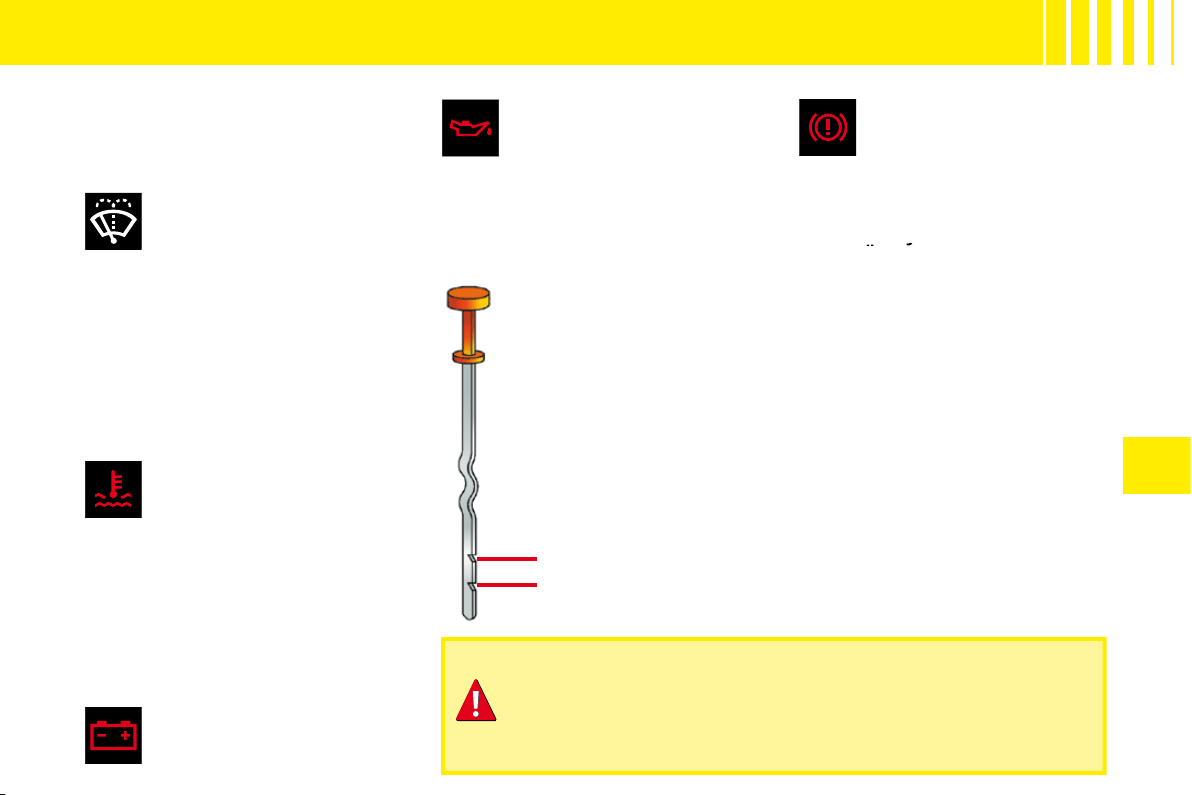
A
B
IV
63
L E V E L S
REFER TO THE CHAPTER: USER PRECAUTIONS
Air fi lter
Follow the requirements
set out in the Maintenance
Guide.
Windscreen/rear
screen wash and
headlamp wash fl uid
Use CITROËN-approved
products wherever possible.
Capacity:
See "Capacities".
Characteristics of fl uid
In order to ensure optimum clea-
ning and to avoid freezing, you
must never top up or replace this
fl uid with water.
Engine coolant
The fl uid level should be
between the marks
MIN.
and
MAX.
on the header tank.
Engine hot, wait at least 15 minutes.
Quality:
See "Maintenance Guide".
Never do anything relating to
the cooling system of an engine
that is hot.
12 V battery
See "Starting with a slave
battery".
Engine oil
Check the engine oil level
on horizontal ground with
the engine having been
switched off for at least 10 minutes.
Quality:
See "Maintenance Guide".
Pull out the manual dipstick.
The level should be
between the marks
MIN.
and
MAX.
on the gauge.
It must never exceed the
maximum.
MAX.
MIN.
Brake fl uid
The level of fl uid should be
between the marks
MIN.
and
MAX.
on the reservoir.
Quality:
See "Maintenance Guide".
If the warning lamp comes on
while you are driving, stop
immediately and contact a
CITROËN dealer.
immediately and
immediately
Cabin particle fi lter/
Odour fi lter
See "Maintenance Guide".
If opening the bonnet when the engine is hot, even if it is
stopped and the ignition is switched off, remember that the
cooling fan may operate at any moment.
Consult "User Precautions" at the end of this handbook.
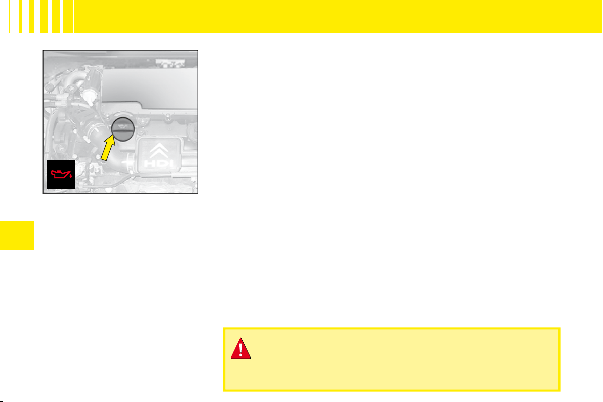
IV
66
Engine oil
Check the engine oil level on hori-
zontal ground with the engine
having been switched off for at
least 10 minutes.
Pull out the manual dipstick.
The level should be between the
marks
MIN.
and
MAX.
on the
gauge.
Topping up engine oil
Before fi lling, pull out the dipstick.
Check the dipstick after fi lling.
It must never exceed the maximum.
Screw the cap back on and close the bonnet.
Quality:
See "Maintenance Guide".
If opening the bonnet when the engine is hot, even if it is
stopped and the ignition is switched off, remember that the
cooling fan may operate at any moment.
L E V E L S
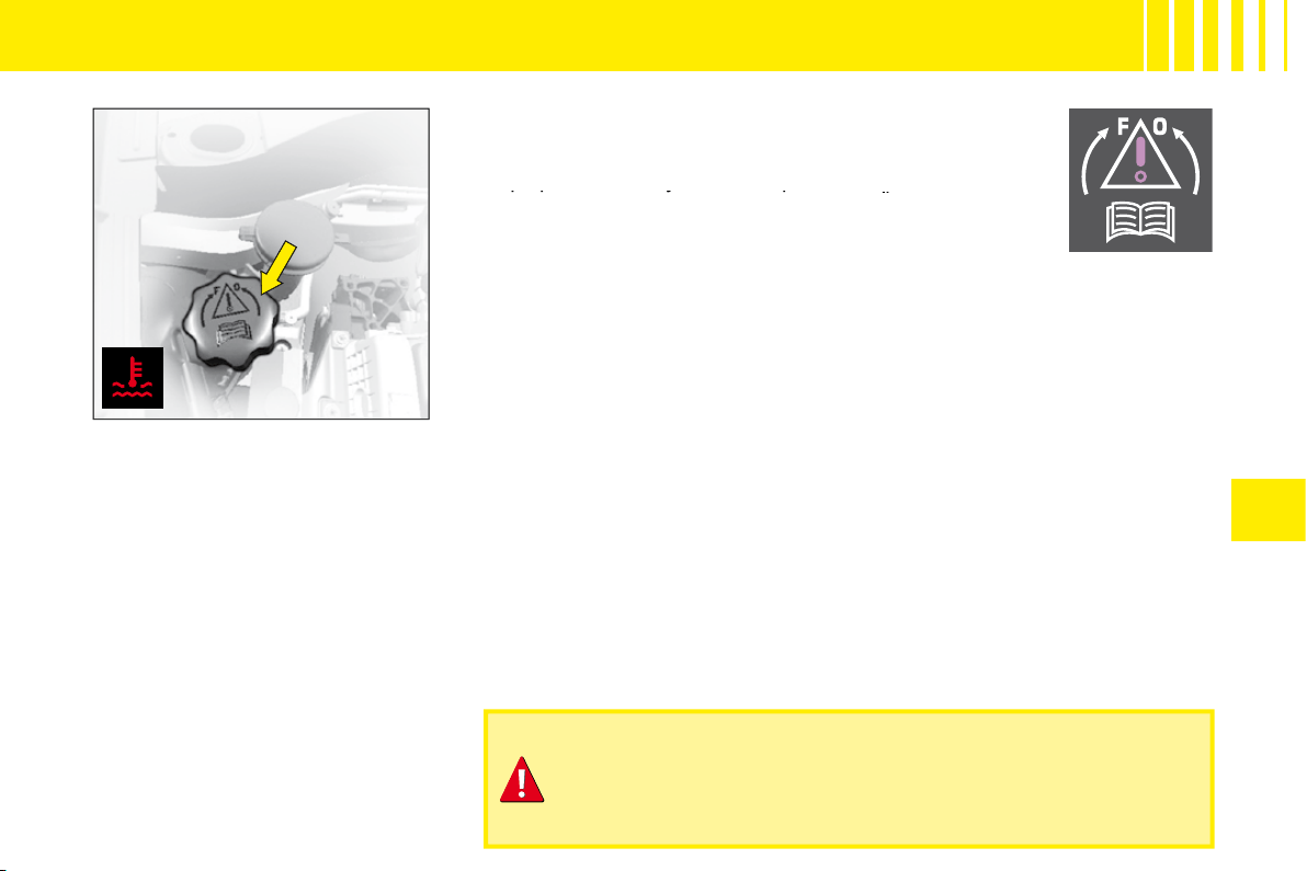
IV
67
L E V E L S
Radiator – coolant fl uid
Checking the level and topping up
with fl uid must always be done with
the engine cold.
Engine hot
Release the protection cover.
Wait 15 minutes or for the tempe-
rature to be lower than 100 °C and
then carefully unscrew the cap so
as to allow the pressure to drop,
protecting yourself with, say, a
cloth.
Topping up the coolant
The fl uid level should be between the marks
MIN.
and
MAX.
on the header tank.
Top up the level. If you have to put in more than 1 litre, have
the cooling system checked by a CITROËN dealer.
Top up the level. If you have to put in more than 1 litre,
more than
Make sure that the cap is back on properly.
Note:
If you need to top up the fl uid frequently, this indicates
a malfunction which you should get checked at the earliest
opportunity.
Quality:
See "Maintenance Guide".
Remark:
The cooling fan may operate for around 10 minutes after the
engine has stopped.
If opening the bonnet when the engine is hot, even if it is
stopped and the ignition is switched off, remember that the
cooling fan may operate at any moment.
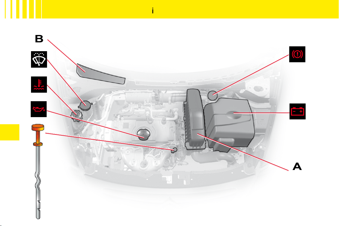
IV
64
1 . 1
i
E N G I N E
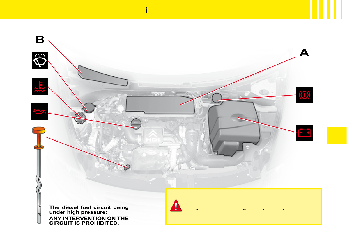
IV
65
H D
i
7 0 E N G I N E
HDi engines are the result of advanced technology.
Any intervention requires special qualifi cations
which only a CITROËN dealer can guarantee.
Any intervention requires special qualifi cations
Any intervention requires special qualifi cations
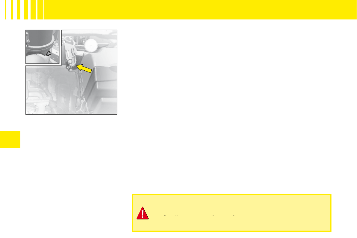
IV
68
HDi 70 engine
HDi engines are the result of advanced technology.
Any intervention requires special qualifi cations which only a
CITROËN dealer can guarantee.
Any intervention requires special qualifi cations which only a
Any intervention requires special qualifi cations which only a
D I E S E L I N J E C T I O N E Q U I P M E N T
Draining water from the fuel
fi lter
Purge regularly (at each oil change).
To drain the water, slacken the
bleed screw or the water-in-diesel-
fuel sensor located at the base of
the fi lter.
Operate until the water has com-
pletely drained away.
Then retighten the bleed screw or
the water in diesel fuel sensor.
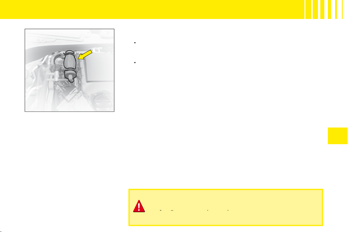
IV
69
HDi 70 engine
HDi engines are the result of advanced technology.
Any intervention requires special qualifi cations which only a
CITROËN dealer can guarantee.
Any intervention requires special qualifi cations which only a
Any intervention requires special qualifi cations which only a
D I E S E L I N J E C T I O N E Q U I P M E N T
Priming the fuel system
In the event of running out of fuel:
After fi lling (5 litres minimum),
operate the manual priming
pump until some resistance is
felt.
Operate the starter motor while
depressing the accelerator
pedal slightly until the engine
starts.
If the engine fails to start at the fi rst
attempt, wait 15 seconds before
trying again.
If the engine fails to start after seve-
ral attempts, repeat the procedure
from the beginning.
When the engine is idling, accelerate
slightly to complete the bleeding of
the circuit.
•
•

IV
70
C A PA C I T I E S
Engine type
Engine oil capacities (in litres)
(1)
1.1i engine
3,2
HDi 70 engine
3,8
(1)
After draining with change of oil fi lter.
Screen wash fl uid (in litres)
3,5
Screen and headlamp wash fl uid (in litres)
6
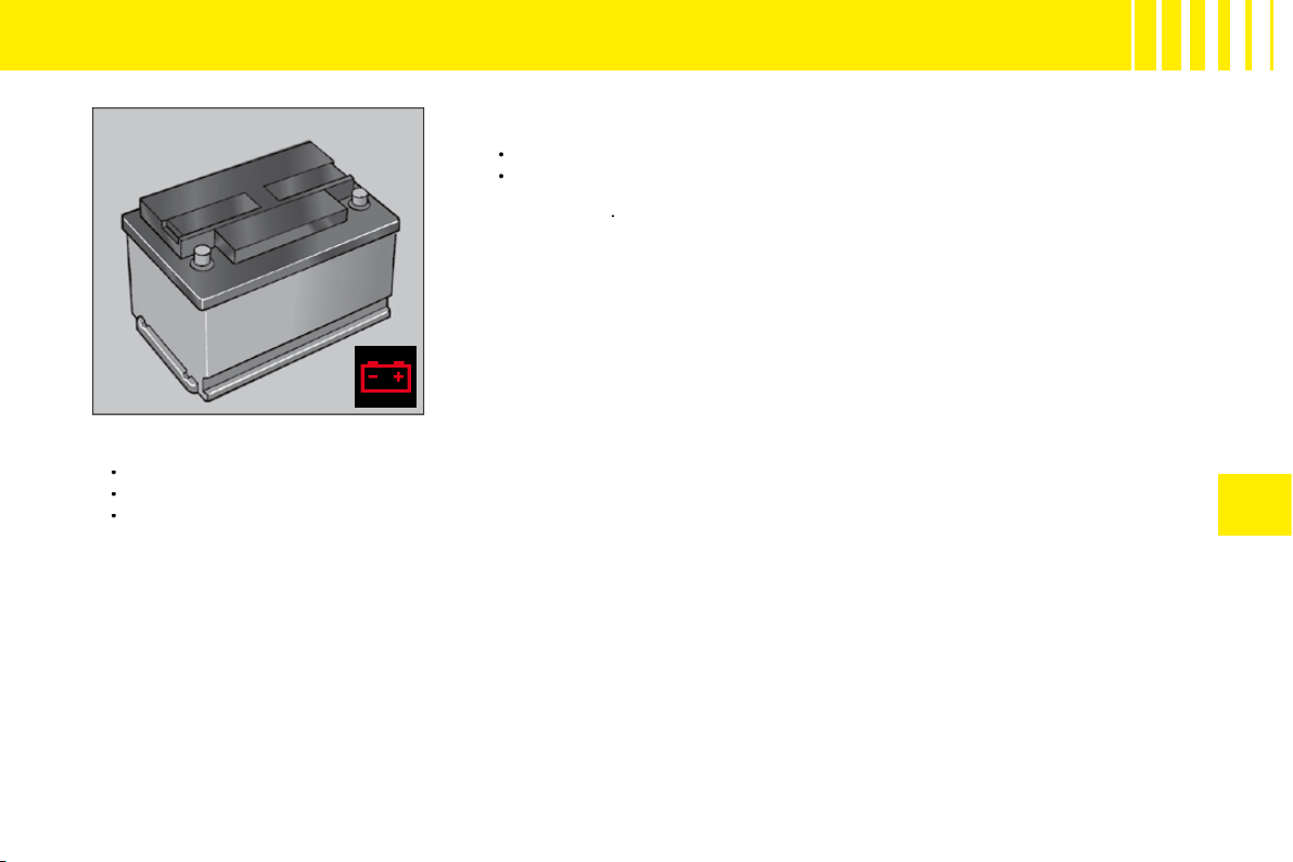
IV
71
Starting the engine after disconnecting and reconnecting the
battery
Turn the ignition key.
Wait approximately 1 minute before operating the starter in order to allow
the electronic systems to re-initialise. It may be necessary to enter the
radio code
.
•
•
After the battery has been disconnected for a lengthy period of time, it may be necessary to re-initialise the following
functions:
Anti-pinch and sequential operation on the electric windows.
The multifunction display parameters (date, time, language, units of distance and of temperature).
The Radio stations.
•
•
•
1 2 V B AT T E R Y
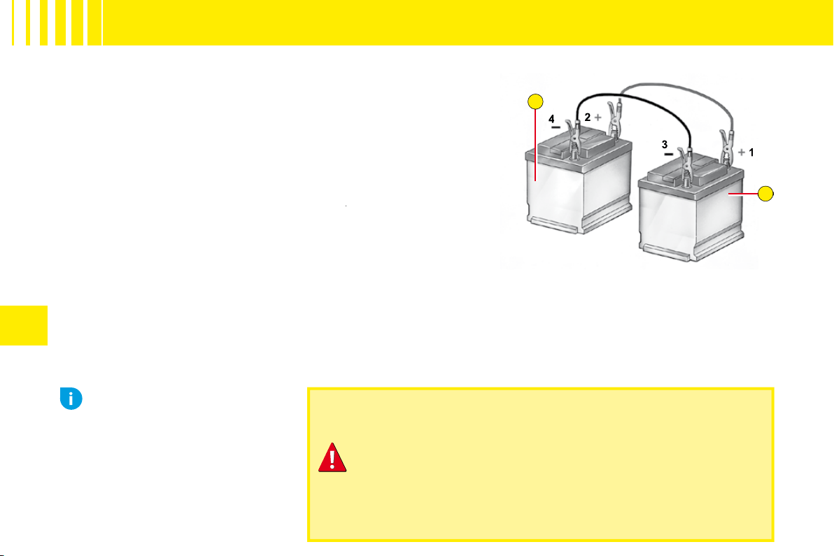
A
B
IV
72
Starting the engine with an assisting battery
If the battery is discharged, it is possible to use either a separate
emergency battery or a battery on another vehicle.
A.
Dischargedbattery (Under the bonnet).
B.
Assisting battery.
Check that the assisting battery has suffi cient voltage (12 V).
If you use the battery on another vehicle, stop the engine on the
latter. The two vehicles must not come into direct contact with
each other.
Connect the cables according to the
order
indicated in the
order
diagram. Check that the leads are well secured (risk of sparks).
Start the engine of the assisting vehicle. Let the engine run for
around 1 minute at a slightly accelerated idle.
Operate the starter on the vehicle being assisted.
It is essential to follow the indicated sequence correctly.
Never approach with a fl ame or create sparks in the vicinity
of the battery (explosive gas).
The battery contains dilute sulphuric acid which is highly
corrosive.
When handling batteries, always protect your face and
especially your eyes.
In the event of any contact with the skin, rinse immediately
with copious amounts of fresh water.
Advice
Do not touch the leads during
the operation.
Do not lean over the batteries.
Disconnect the cables in reverse
order, making sure they do not
touch together.
1 2 V B AT T E R Y
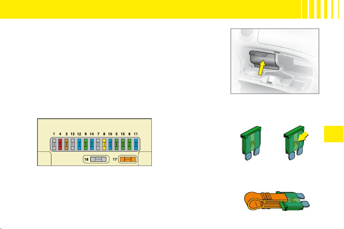
IV
73
F U S E S
Fuseboxes
There are two fuse boxes, one below the dashboard and one under the
bonnet.
Dashboard fuses
The fuse box is located in the lower glovebox compartment. To access the
fuses, open the glove box, pull the handle on the fuse box cover.
Replacing a fuse
Before replacing a fuse, you should ascertain the cause of the fault and
have it remedied. The numbers of the fuses are indicated on the fusebox.
Good
Bad
Pliers A
Replace the fuse that has blown with one of the same rating (same colour).
Use the special pliers
A
stowed on the cover close to the fuseboxes, this
includes a compartment for replacement fuses.

IV
74
TA B L E O F F U S E S
D A S H B O A R D F U S E S
Ref.
Rating
Function
3
5 A
Airbags
4
10 A
Diagnostic socket – Clutch switch – Steering angle sensor
6
30 A
Screen wash
8
20 A
Digital clock – Controls at the steering wheel – Radio – Display
9
30 A
Digital clock – Interior lamps
11
15 A
Ignition switch – Diagnostic socket
12
15 A
Airbag ECU – Rain and brightness sensor
14
15 A
Instrument panel – Air conditioning
15
30 A
Central locking – Deadlocking
17
40 A
Heated rear screen
18
SHUNT
CUSTOMER PARK SHUNT
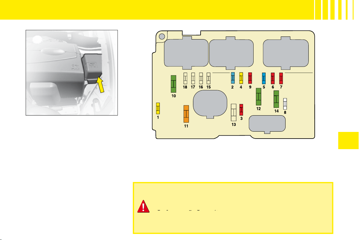
IV
75
F U S E S
Fusebox
To access the fusebox located in
the engine compartment, remove
the battery cover and detach the
lid.
After a repair, take care to
reclose the cover.
Any action on the MAXI fuses (that give extra protection) (in
grey in the diagrams), located in the fuseboxes, should be left
to a CITROËN dealer.
grey in the diagrams), l
the dia
Fuses under the bonnet

IV
76
TA B L E O F F U S E S
F U S E S U N D E R T H E B O N N E T
Ref.
Rating
Function
1
20 A
Water-in-diesel-fuel sensor
2
15 A
Horn
3
10 A
Screen wash
4
20 A
Headlamp wash
5
15 A
Fuel pump
6
10 A
Power steering
7
10 A
Coolant level sensor
8
25 A
Starter
9
10 A
ECUs (ABS)
10
30 A
Engine control actuators (Ignition coil, Electrovalve, Oxygen sensor, Injection) – Canister purge
11
40 A
Air blower
12
30 A
Windscreen wiper
14
30 A
Air pump (petrol version) – Diesel fuel heater
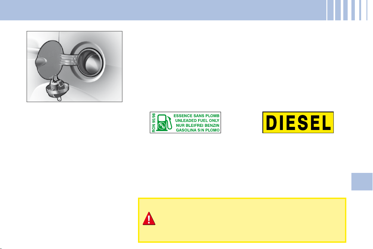
77
V
R E F U E L L I N G
To open the fl ap, pull at the edge.
Locking fi ller cap
Turn the key a quarter turn to lock
and unlock the fi ller cap.
When refuelling, place the cap in
the support provided on the inside
of the fi ller fl ap.
For a petrol engine with a cata-
lytic converter, unleaded fuel is
compulsory.
The fi ller neck is narrower to
ensure that only unleaded petrol
can be put in.
When you are seeking to fi ll your tank, do not persist after the third
cut-off; that could cause your vehicle to malfunction.
Fuel tank capacity (in litres):
Approx. 47.
If you should put in fuel that is not suitable for your vehicle's
engine type, it is imperative to have the tank drained before
you start the engine again.
FUEL QUALITY
A label inside the fi ller fl ap tells you which type of fuel to use.
UNLEADED PETROL
DIESEL FUEL
The petrol engines are designed to run on RON 95.
However, for better performance (petrol engine), we recommend RON 98.
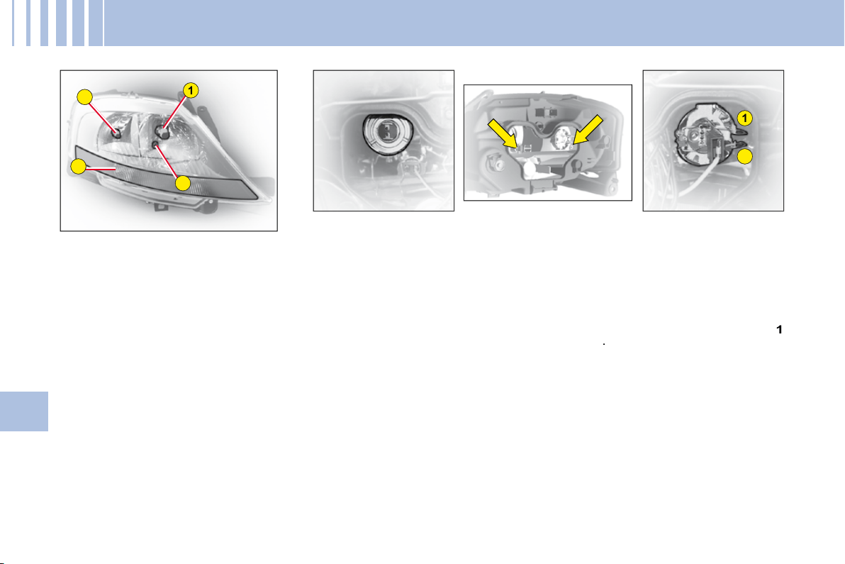
1
3
4
2
2
1
78
V
C H A N G I N G B U L B S
HEADLAMP UNIT
1: Dipped beam
2: Main beam
3: Sidelamp
4: Direction indicator
Note:
A light misting may appear
on the headlamp surface in certain
conditions of use.
Dipped beam
Tilt the metallic spring holding the
fl ap giving access to the lamp
bulbs.
Open the access fl ap.
Disconnect the connector.
Disengage the retaining spring.
Take out the bulb.
Bulb: H7
Main beam
Tilt the metallic spring holding the
fl ap giving access to the lamp
bulbs.
Open the access fl ap.
Disconnect the connector.
Press and disengage the bars
1
and
2
.
Take out the bulb.
Bulb: H1
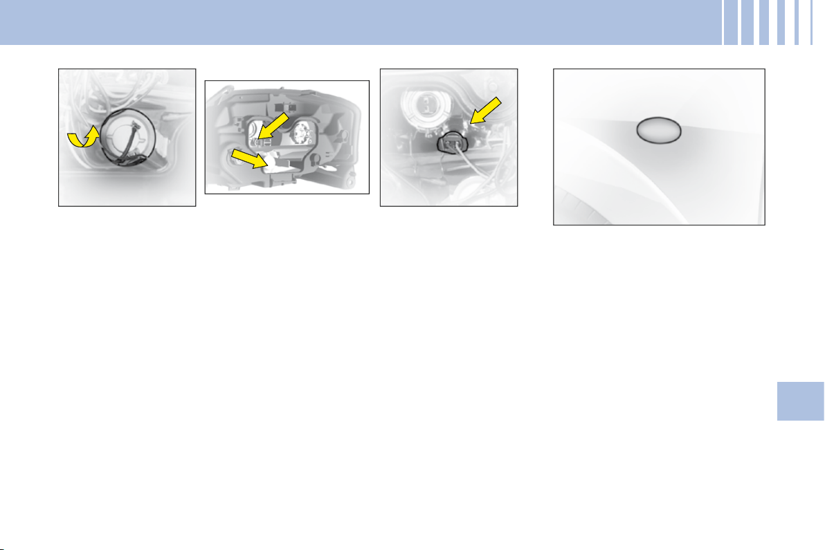
79
V
C H A N G I N G B U L B S
Front direction indicator
Tilt the metallic spring holding the
fl ap giving access to the lamp
bulbs.
Open the access fl ap.
Rotate the bulb- holder a quarter
turn and pull.
Take out the bulb.
Bulb: PY 21 W (yellow)
Sidelamp
Tilt the metallic spring holding the
fl ap giving access to the lamp
bulbs.
Open the access fl ap.
Rotate the bulb- holder a quarter
turn and pull.
Bulb: W 5
Side repeater direction
indicator
To change the direction indicator
side repeater, push it forwards or
rearwards to detach it, then pull it
towards you.
Hold the cable and disconnect it.
Contact a CITROËN dealer.
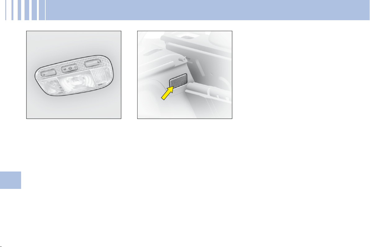
80
V
C H A N G I N G B U L B S
Interior lamp
Unclip the transparent cover of the
interior lamp to reach the bulb.
Bulb: W 5 W
Spotlamps
Unclip the transparent cover of the
interior lamp to reach the bulb.
Bulb: W 5 W
Boot lamp
Unclip the lens unit to access the
bulb.
Bulb: W 5 W
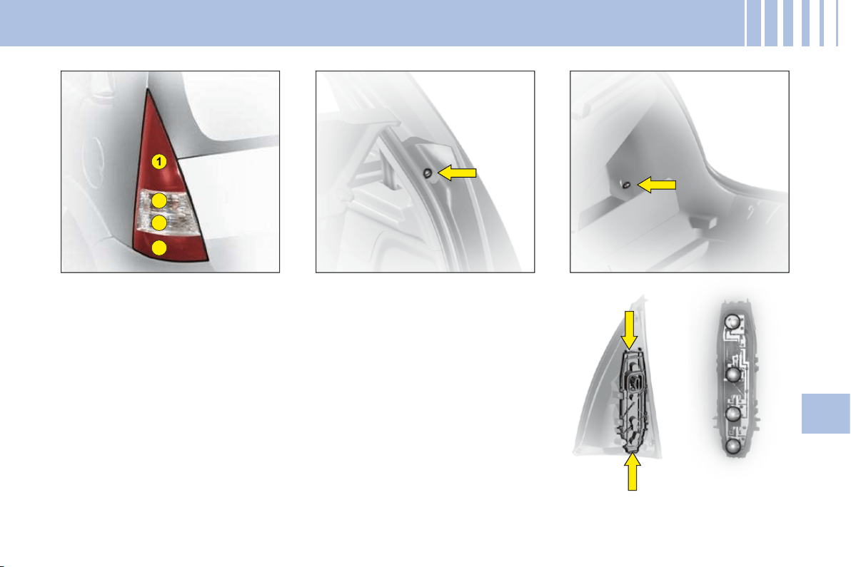
4
3
1
2
81
V
Rear lamp unit
Identify the failed bulb.
Bulbs:
1: Stop-lamps and sidelamps:
P21 W/5 W
2: Direction indicator: PY 21 W
3: Reversing lamp: P21 W
4: Foglamp: P21 W
Removal
Unclip the nut cover on the exterior
fi xing.
Undo the 2 nuts (1 outer and 1 inner).
In the side storage compartment,
unclip the lamp holder and discon-
nect the connector to access the
bulb.
Refi t the assembly after replacing
the bulb.
C H A N G I N G B U L B S
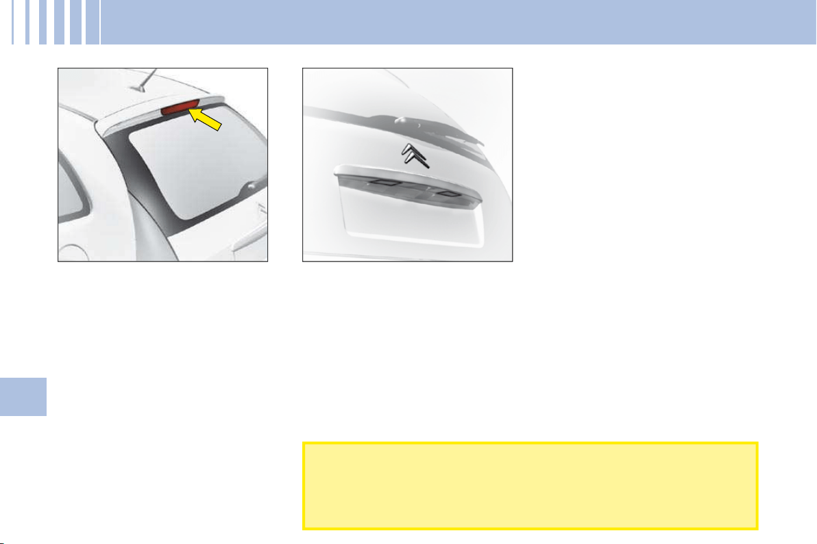
82
V
C H A N G I N G B U L B S
Third stoplamp
To access the bulb, open the tail-
gate and press on the two metallic
springs through the two holes that
are provided for this purpose in the
tailgate inner panel.
When refi tting, ensure that the bulb
is fi rmly secured in place.
Bulb: W 16 W
Number plate
Unclip the lens then pull the bulb-
holder.
Bulb: W 5 W
After each operation, check that the lamps work.
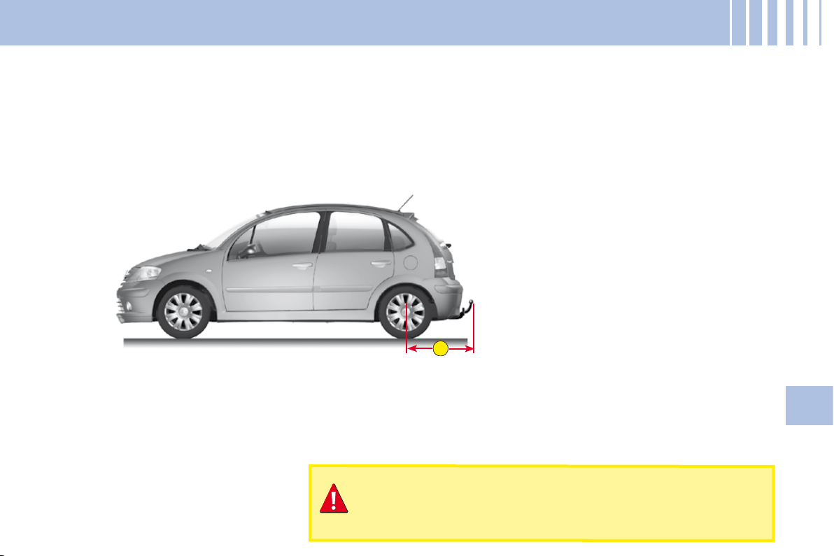
A
83
V
S A F E T Y R E C O M M E N D AT I O N S
Towbar
We recommend you to have this device fi tted by a CITROËN Dealer, who will be acquainted with your vehicle’s
towing capability and with the procedures necessary for installing a safety item of this kind.
Dimensions (in metres)
A:
0.75
Do not exceed the maximum permitted load.
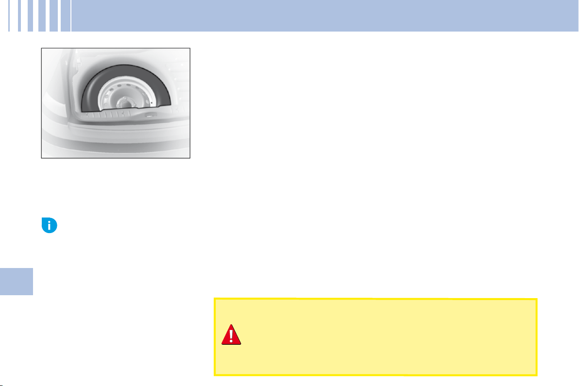
84
V
C H A N G I N G A W H E E L
Access to the spare wheel
To access the spare wheel
Lift the boot carpet.
Remove the jack- holder to access the wheel.
Tools
The tools are located in a protective holder in the spare wheel. Pull back the
retaining strap to have access.
To reposition the spare wheel
Return the wheel to the boot, place the toolbox inside the wheel, then secure
using the strap.
Advice
The wheel bolts are specifi c to the type of wheel.
If the type of wheel is changed, check with your CITROËN dealer that the wheel bolts are compatible with the new
wheels.
The jack and all the tools are designed specifi cally for use on
your particular vehicle.
Do not use them for any other applications.
With a spare wheel, drive cautiously.
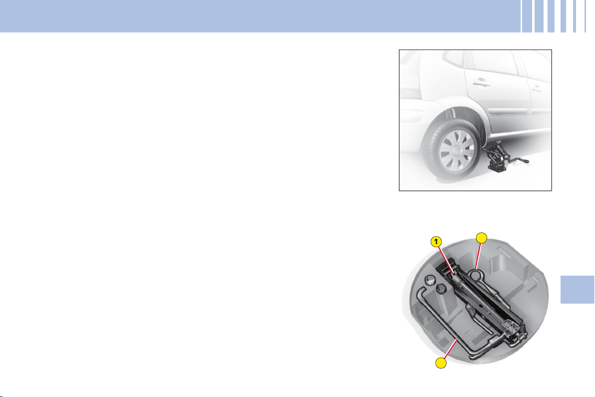
2
1
3
85
V
C H A N G I N G A W H E E L
Removal
1.
Park the vehicle on stable, fi rm ground that is not slippery. Apply the
parking brake.
Switch off the ignition and engage fi rst gear or reverse gear, depending
on any slope.
Ensure that all vehicle occupants have left the vehicle and are
positioned in a safe place.
2.
Position the jack at one of the four jacking-points provided on the
subframe close to the wheels. Using the handle, unwind the jack until it
reaches the ground.
3.
To unclip the wheel embellisher, pull using the end of the wheelbrace as
a lever in one of the apertures.
4.
Continue to extend the jack until the wheel is a few centimetres off the
ground.
5.
Undo the other bolts, remove the wheel.
Tools
1.
Jack
2.
Wheelbrace
3.
Movable towing eye.
86
V
C H A N G I N G A W H E E L
Refi tting
1.
Engage the wheel on the hub.
2.
Screw in the bolts but do not
fully tighten them.
3.
Lower the jack and remove it.
4.
Tighten the wheel bolts, using
the wheelbrace.
5.
Refi t the embellisher, taking
care to accommodate the tyre
valve. Then pressing all round
its circumference.
6.
Have the original wheel
repaired and refi tted as soon
as possible.
7.
Make sure that the tyre is
at the correct pressure (see
"Vehicle Identifi cation" and
"User Precautions") and have
the wheel balancing checked.
Dimension of the spare
wheel
If your spare wheel has dimen-
sions different from those of the
normal vehicle wheels (identifi ed
by a label), it is imperative to use
the spare wheel only temporarily,
to drive with caution, not to exceed
80 km/h (50 mph) and to have the
tyre repaired and the normal wheel
refi tted as soon as possible.
Tyre pressures
This is indicated on the label on the
front door pillar. See "Vehicle iden-
tifi cation" and "User Precautions".
Never get underneath the vehicle if it is supported only by
the jack.
When changing a wheel, it is essential to park the vehicle
safely on level and stable ground.
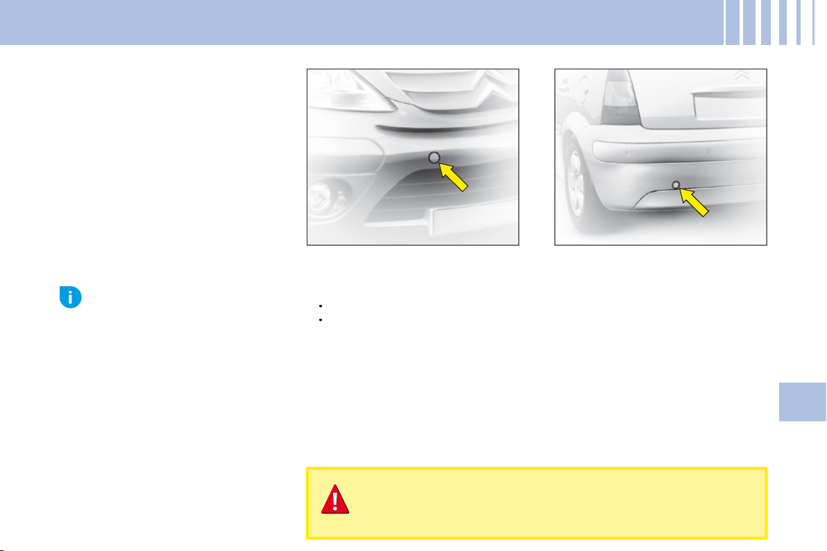
87
V
TO W I N G – L I F T I N G
Towing with wheels on the ground
Towing eye fi xings are located at the front and at the rear of the vehicle.
To access them:
Carefully lift the access cover.
Release it by pressing on the lower part.
A lug keeps the cover attached to the bumper, so that it does not become
lost.
The ignition key must be in position M to retain steering.
Use a bar with attachments to the towing eyes as above.
Vehicles with manual gearbox (diesel models)
For vehicles with a manual gearbox, the gear lever must be in "neutral",
otherwise some components in the braking system could become
damaged and impair braking assistance the next time the engine is
started.
•
•
Movable towing eye
The towing ring is detachable and
can be fi tted either at the front or at
the rear of the vehicle. It is stowed
in the jack's protective holder in the
spare wheel.
When the engine is not running, the steering and the braking
are no longer assisted.
If you are towing another vehicle, the latter must be free-
wheeling (gearbox in neutral).
Towing
at low speed over a
very short distance
is authorised
in exceptional cases depending
on the regulations in force.
Otherwise, it is necessary to
have your vehicle transported
on a recovery truck.
Advice
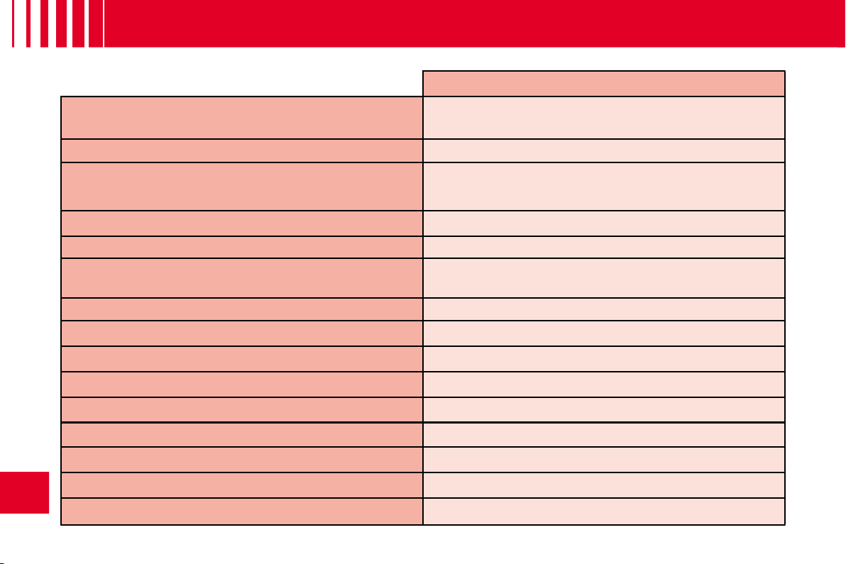
88
VI
G E N E R A L
Saloon
Engine type
1.1i
BVM
Fuel tank capacity
Approximately 47 litres
Fuels to be used
Unleaded petrol RON 95 - RON 98
Turning circle between walls (in metres)
10.45
French fi scal rating
4
Calculated maximum speed in km/h (mph)
(In the highest gear)
157
(98)
Weights (kg)
Unladen weight (MAV)
1 010
Gross vehicle weight (MTAC)
1 483
Maximum weight on rear axle (CMAE AR)
820
Gross train weight (MTRA)
2 133
Gross trailer weight (with brakes) (Within the Gross Train Weight limit)
920
Gross trailer weight (without brakes)
540
Trailer nose weight
37
Dimensions of chainable tyres
175/65 R14 - 185/60 R15 - 195/50 R16
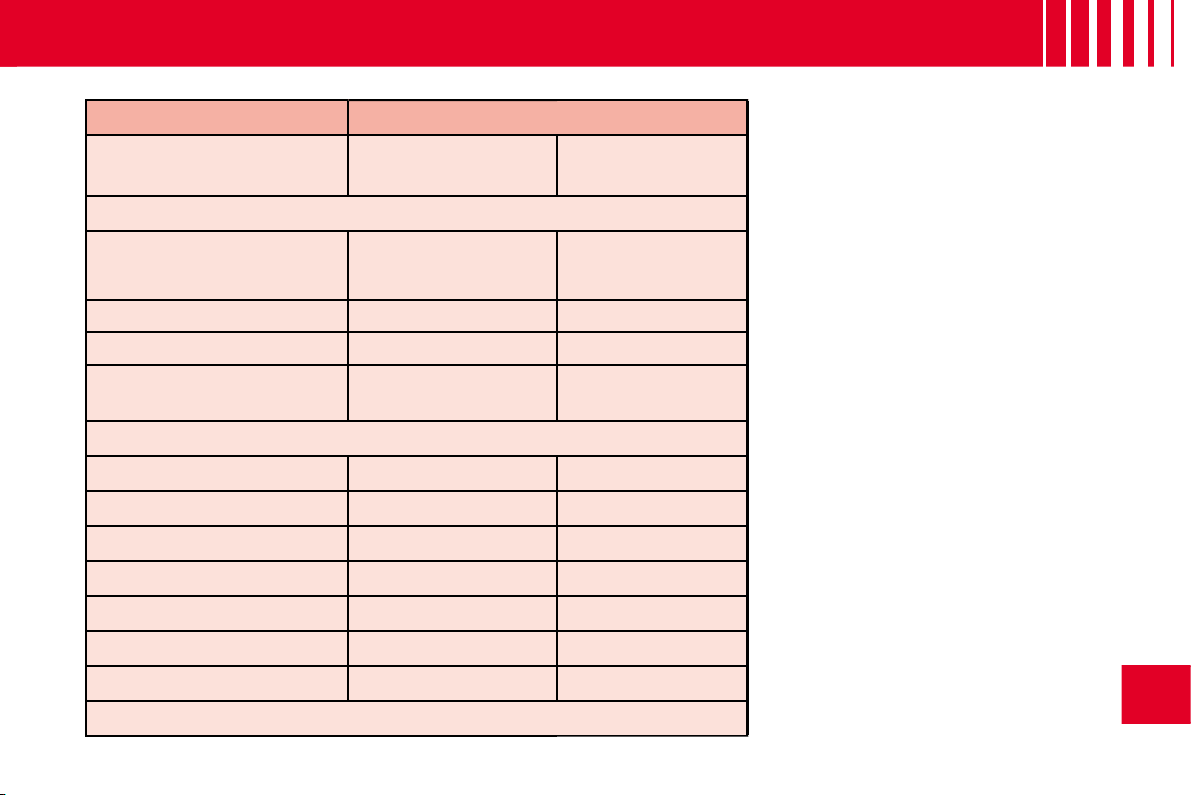
89
VI
G E N E R A L
Saloon
Entreprise
HDi 70
BVM
1.1i
BVM
HDi 70
BVM
Approximately 47 litres
Diesel fuel
Unleaded petrol
RON 95 - RON 98
Diesel fuel
10.45
10.45
10.45
4
6
6
165
(103)
157
(98)
165
(103)
1 022
1 012
1 049
1 539
1 487
1 530
820
820
820
2 439
2 137
2 430
1 160
650
900
560
520
560
47
26
36
175/65 R14 - 185/60 R15 - 195/50 R16
MAV:
Unladen weight.
MTAC:
Gross vehicle weight.
CMAE AR:
Maximum weight on
rear axle.
MTRA:
Gross train weight.
Weights:
Refer to the manufacturer's
plate.
BVM:
Manual gearbox.
Observe your vehicle's towing
limits.
It is essential to comply with the
max. Gross Trailer Weights and
speed limits as specifi ed by legis-
lation in each country.
For further information about the
towing capacity of your vehicle and
its max. authorised Gross Train
Weight, contact a CITROËN dealer.
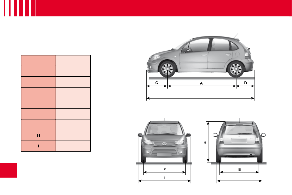
B
I
G
H
90
VI
D I M E N S I O N S
( I N M E T R E S )
A
2.460
B
3.860
C
0.760
D
0.640
E
1.435/1.440
F
1.436/1.439
G
1.667
H
1.510/1.612
I
1.912
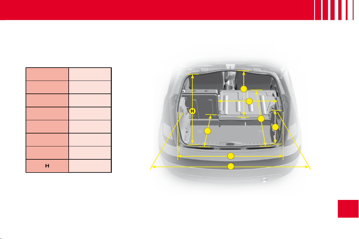
A
B
C
D
E
F
G
H
91
VI
D I M E N S I O N S
( I N M E T R E S )
A
1.070
B
0.585
C
0.600
D
1.040
E
0.700
F
1.160
G
0.660
H
0.624

A
A’
A’
A
C
B
A’
4
5
6
92
VI
V E H I C L E I D E N T I F I C AT I O N
A. Chassis number plate
On the left hand door centre
pillar
Or,
A’.
In the boot close to the catch.
1.
EU type approval number.
2.
Vehicle identifi cation No. (VIN).
3.
Gross vehicle weight.
4.
Gross train weight.
5.
Maximum weight on front axle.
6.
Maximum weight on rear axle.
B. Body serial number
C. Paint colour code
Tyre reference
Tyre pressures
All CITROËN original replacement parts are available exclusively within the
dealer network.
For your safety and in order to remain within the terms of the guarantee, you
are advised to use only CITROËN replacement parts.
For your safety and in order to remain within the terms of
order to remain
Fitting parts or units not supplied by CITROËN may even result in violation
of the law, if it involves non-compliance with regulations concerning safety,
pollution control, interference suppression and the noise level of the vehicle.
Fitting such parts or units could also deprive the user of any recourse against
the maker.
This applies in particular to: parts of the braking equipment, lighting and
signalling equipment, engine equipment, the exhaust system, steering
system, structural and suspension parts.
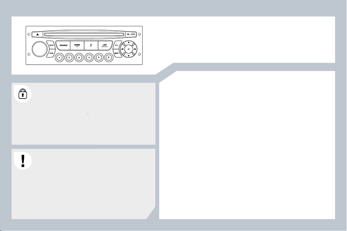
95
Audio system
CONTENTS
01 First steps p
02 Steering mounted controls p
03 Audio p
04 Confi guration p
05 Screen menu map p
Frequently asked questions p
Your Audio system is coded in such a way that it will only
operate in your vehicle. If it is to be installed in another
vehicle, contact a CITROËN dealer for confi guration of
operate in your vehicle. If it is to be installed in another
le. If it i
the system.
For safety reasons, the driver must carry out operations
which require prolonged attention while the vehicle is
stationary.
When the engine is switched off and to prevent
discharging of the battery, your Audio system may switch
off after a few minutes.
96
97
98
101
102
103
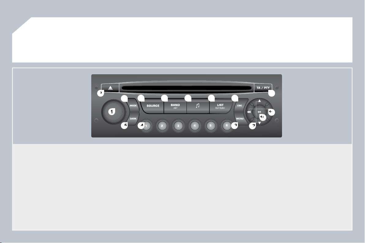
96
1
1
2
2
10
10
11
11
13
13
14
14
15
15
3
3
4
4
5
5
6
6
7
7
8
8
9
9
12
12
01
FIRST STEPS
1. On / Off and volume adjustment.
2. CD eject.
3. Selection of the display on the screen from the modes:
Audio (AUDIO), Trip Computer (TRIP) and Telephone (TEL)
functions.
4. Selection of the source:
radio, audio CD / MP3 CD.
5. Selection of the FM1, FM2, FMast and AM wavebands.
6. Setting the audio options: front / rear balance, left / right
balance, loudness, sound ambiences.
7. Displaying of the list of local stations, of the tracks on the CD
or of the MP3 directories.
8. Abandon current operation.
9. TA (Traffi c Announcement) function on / off.
Long press: access to the PTY (TYpes of radio Programme)
mode.
10. Confi rmation.
11. Automatic search for a lower / higher frequency.
Selection of previous / next CD, MP3 track.
12. Selection of a lower / higher radio frequency.
Selection of the previous / next MP3 directory.
13. Displaying of the general menu.
14. Buttons 1 to 6:
Selection of a stored radio station.
Long press: storing of a station.
15. The DARK button changes the display on the screen to
improve driving comfort at night.
1st press: lighting of the top banner only.
2nd press: displaying of a black screen.
3rd press: return to the standard display.
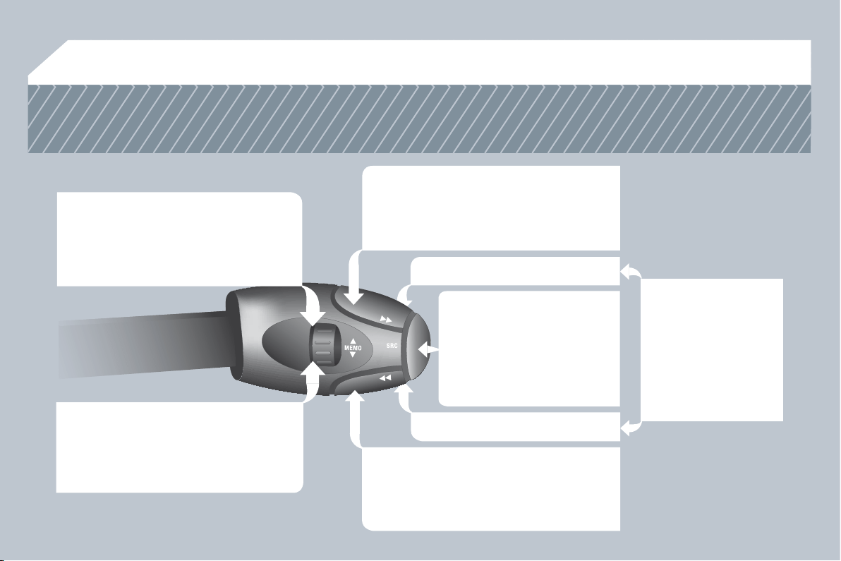
97
02
STEERING MOUNTED CONTROLS
RADIO: selection of the next
stored station.
Selection of the next item on a menu.
RADIO: selection of the previous stored
station.
Selection of the previous item on a menu.
RADIO: automatic search for a higher
frequency.
CD / MP3: selection of the next track.
CD : continuous press: fast forward play.
Selection of the previous item.
RADIO: automatic search for a lower
frequency.
CD / MP3: selection of the previous track.
CD : continuous press: backward play.
Selection of the next item.
Volume increase.
Volume decrease.
Mute: by pressing
the volume increase
and decrease buttons
simultaneously.
Restore the sound by
pressing one of the
two volume buttons.
- Change of sound source.
- Confi rmation of a selection.
- Pick up/Hang up the
telephone.
- Press for more than
2 seconds: access to the
telephone menu.
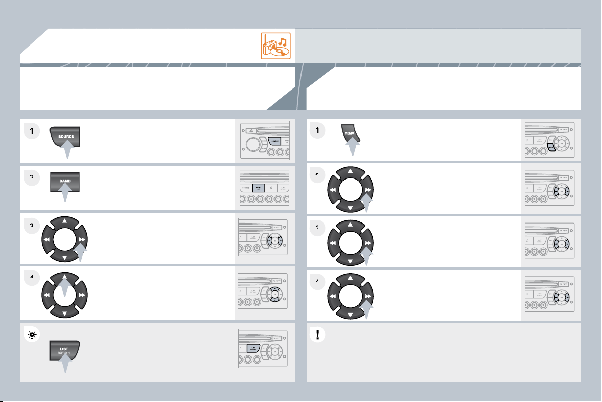
98
2
2
3
3
4
4
1
2
2
4
4
3
3
1
1
03
AUDIO
Press the SOURCE button several
times in succession and select the
radio.
Press the BAND AST button to select
a waveband: FM1, FM2, FMast, AM.
Briefl y press one of the buttons to
carry out an automatic search of the
radio stations.
Press one of the buttons to carry out a
manual search of the radio stations.
Press the LIST REFRESH button to
display the list of stations received
locally (30 stations maximum).
To update this list, press for more than
two seconds.
Select ACTIVATE FREQUENCY
FOLLOWING (RDS) then press OK.
RDS appears on the display.
Select the FM WAVEBAND
PREFERENCES function then press
OK.
Select AUDIO FUNCTIONS then
press OK.
Press the MENU button.
The external environment (hills, buildings, tunnels, basement car parks) may block reception, including
in RDS mode. This is a normal effect of the way in which radio waves are transmitted and does not
indicate any failure of the audio equipment.
RDS
The RDS, if displayed, enables you to continue listening to the same
station by automatic retuning to alternative frequencies. However, in
certain conditions, coverage of an RDS station may not be assured
throughout the country as radio stations do not cover 100 % of the
territory. This explains the loss of reception of the station during a
journey.
RADIO
SELECTING A STATION
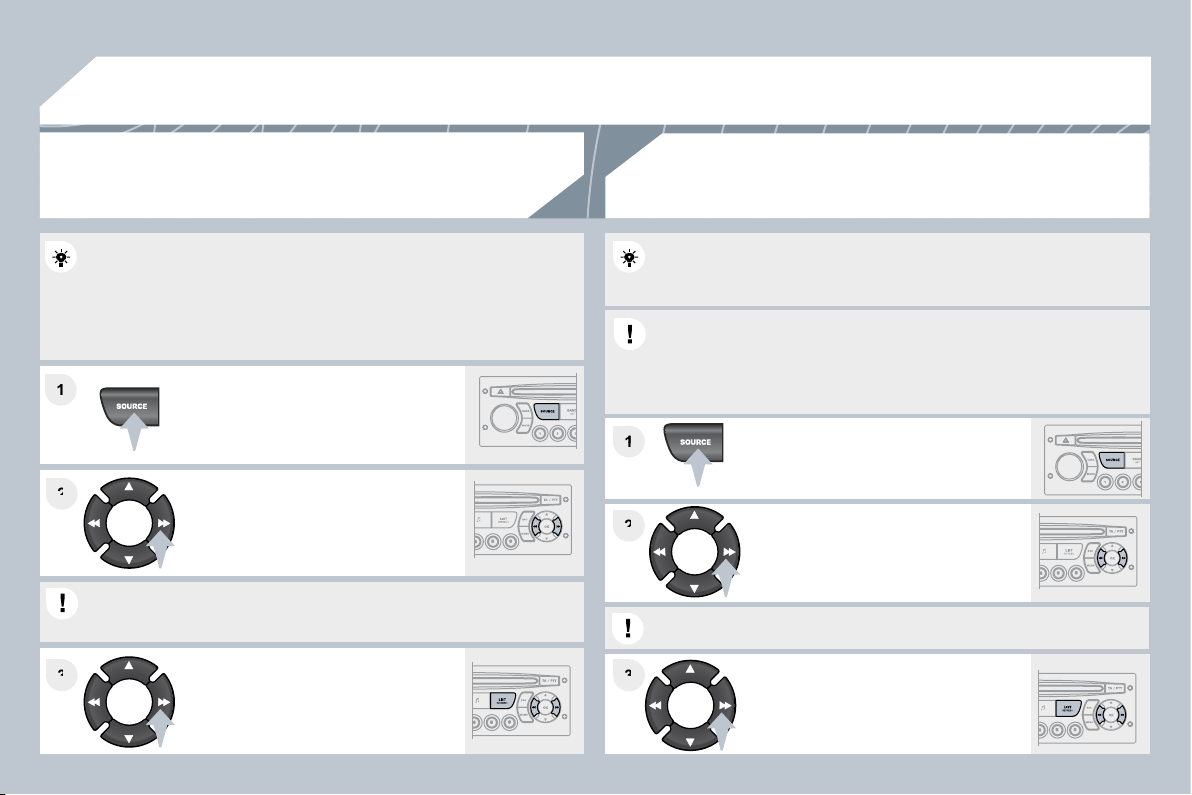
99
03
1
1
1
1
2
2
3
3
3
3
2
2
AUDIO
Insert circular compact discs only.
Some anti-pirating systems, on original discs or CDs copied using a
personal recorder, may cause faults which are no refl ection on the
quality of the original player.
Without pressing the EJECT button, insert a CD in the player, play
begins automatically.
To play a disc which has already been
inserted, press the SOURCE button
several times in succession and select
CD.
Press and hold one of the buttons for
fast forward or backward.
Insert an MP3 compilation in the player.
The audio equipment searches for all of the music tracks, which may
take anything between a few seconds and several tens of seconds,
before play begins.
On a single disc, the CD player can read up to 255 MP3 fi les spread
over 8 directory levels. However, it is advisable to keep to a limit of
two levels to reduce the access time before the CD is played.
While the CD is being played, the directory fl ow chart is not followed.
All of the fi les are displayed on a single level.
To play a disc which has already been
inserted, press the SOURCE button
several times in succession and
select CD.
Press and hold one of the buttons for
fast forward or backward play.
CD
PLAYING A CD
MP3 CD
PLAYING AN MP3 COMPILATION
Press one of the buttons to select a
track on the CD.
Press the LIST REFRESH button to display the list of tracks
on the CD.
Press one of the buttons to select a
track on the CD.
Press the LIST REFRESH button to display the list of directories of
the MP3 compilation.
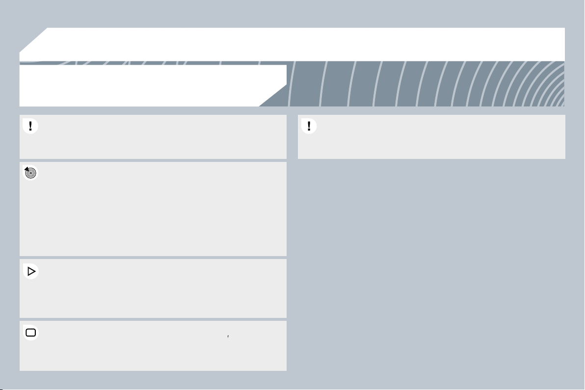
100
03
The MP3 format, an abbreviation of MPEG 1.2 & 2.5 Au
2.5 Audio
Layer 3, is an audio compression standard which permi
permits the
recording of several tens of music fi les on a single disc.
recording of several tens of music fi les on a single disc.
In order to be able to play a recorded CDR or CDRW, when recording
In order to be able to play a recorded CDR or CDRW, when recording
it is preferable to select standards ISO 9660 level 1.2 or Joliet.
it is preferable to select standards ISO 9660 level 1.2 or Joliet.
If the disc is recorded in another format, it may not be p
t be played
correctly.
It is recommended that the same recording standard is always used
It is recommended that the same recording standard is always used
for an individual disc, with as low a speed as possible (4
ible (4x maximum)
for optimum sound quality.
In the particular case of a multi-session CD, the Joliet standard is
In the particular case of a multi-session CD, the Joliet standard is
recommended.
The audio equipment will only play fi les with the extension ".mp3"
The audio equipment will only play fi les with the extension ".mp3"
with a sampling rate of 22.05 KHz or 44.1 KHz. No other type of fi le
with a sampling rate of 22.05 KHz or 44.1 KHz. No other type of fi le
(.wma, .mp4, .m3u...) can be played.
It is advisable to restrict fi le names to 20 characters without using
It is advisable to restrict fi le names to 20 characters without using
special characters (e.g. " ? ; ù) to avoid any playing or displaying
special characters (e.g. " ? ; ù) to avoid any playing or displaying
problems.
MP3 CD
INFORMATION AND ADVICE
AUDIO
Empty CDs are not recognised and may damage the system.
Empty CDs are not recognised and may damage the system.
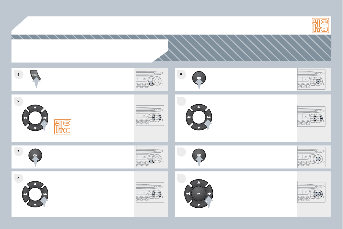
101
1
1
2
2
3
3
4
4
5
5
6
6
7
7
8
8
04
CONFIGURATION
Press the MENU button.
Using the arrows, select
PERSONALISATION
CONFIGURATION.
Press to confi rm the selection.
Using the arrows, select DISPLAY
CONFIGURATION.
Press to confi rm the selection.
Press to confi rm the selection.
Using the arrows, select ADJUST
DATE AND TIME.
Adjust the settings one by one
confi rming by pressing the OK button.
Next select the OK tab on the screen
then confi rm.
SETTING THE DATE AND TIME
SCREEN C
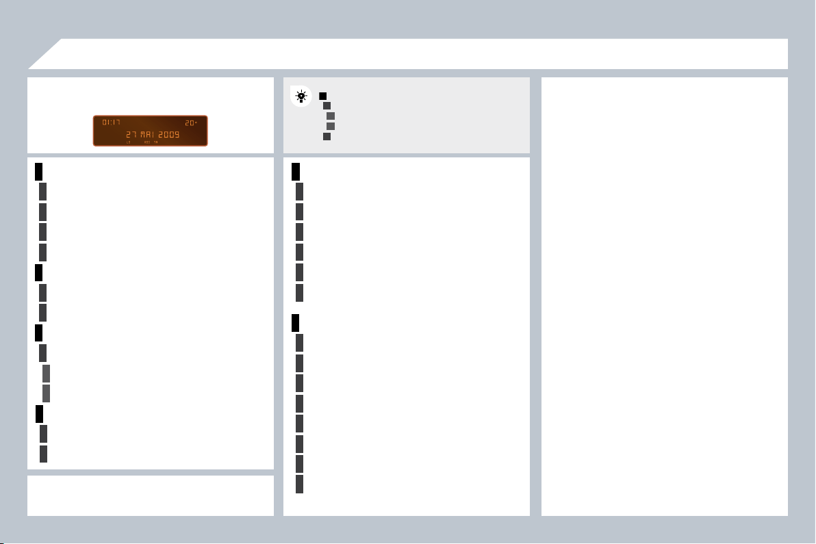
102
1
2
2
2
2
1
2
2
1
2
3
3
1
2
2
2
2
2
2
1
2
2
2
2
2
2
2
2
1
2
2
1
2
3
2
3
05
RADIO-CD
DISPLAY ADJUST
YEAR
MONTH
DAY
HOUR
MINUTES
12 H/24 H MODE
SCREEN MENU MAP
MAIN FUNCTION
* The parameters vary according to vehicle.
CHOICE A
Choice A1
Choice A2
CHOICE B...
LANGUAGE
FRANCAIS
ITALIANO
NEDERLANDS
PORTUGUES
PORTUGUES-BRASIL
DEUTSCH
ENGLISH
ESPANOL
monochrome A
RANDOM PLAY
RDS SEARCH
REG MODE
CD REPEAT
VEHICLE CONFIG *
REV WIPE ACT
GUIDE LAMPS
OPTIONS
DIAGNOSTICS
consult
abandon
UNITS
TEMPERATURE: °CELSIUS / °FAHRENHEIT
FUEL CONSUMPTION: KM/L - L/100 - MPG
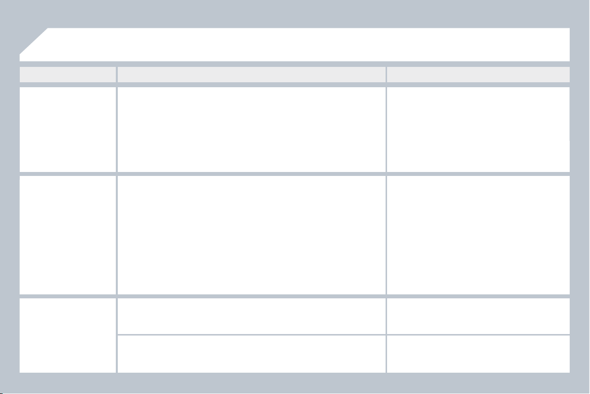
103
There is a difference in
sound quality between
the different audio
sources (radio, CD...).
Check that the audio settings (Volume, Bass,
Treble, Ambience, Loudness) are adapted to
the sources listened to. It is advisable to set
the AUDIO functions (Bass, Treble, Front-Rear
Balance, Left-Right Balance) to the middle
position, select the musical ambience "None"
and set the loudness correction to the "Active"
position in CD mode or to the "Inactive" position
in radio mode.
For optimum sound quality, the audio settings (Volume, Bass, Treble,
Ambience, Loudness) can be adapted to the different sound sources,
which may result in audible differences when changing source (radio,
CD...).
The CD is ejected
automatically or is not
played by the player.
- Check that the CD is inserted in the player the
right way up.
- Check the condition of the CD: the CD cannot
be played if it is too damaged.
- Check the content in the case of a recorded
CD: consult the advice in the "Audio" section.
- The audio equipment's CD player does not
play DVDs.
- Due to their quality level, certain writeable CDs
will not be played by the audio system.
The CD is inserted upside down, is unplayable, does not contain any audio
data or contains an audio format which the player cannot play.
The CD is protected by an anti-pirating protection system which is not
recognised by the audio equipment.
QUESTION
SOLUTION
ANSWER
FREQUENTLY ASKED QUESTIONS
The CD player sound
is poor.
The CD used is scratched or of poor quality.
Insert good quality CDs and store them in
suitable conditions.
The audio equipment settings (bass, treble, ambiences) are unsuitable.
Set the treble or bass level to 0, without selecting
an ambience.

104
The traffi c announcement
(TA) is displayed. I do
not receive any traffi c
information.
Tune to a radio station which broadcasts traffi c
information.
The radio station is not part of the regional traffi c information network.
QUESTION
SOLUTION
ANSWER
The quality of reception
of the radio station
listened to gradually
deteriorates or the
stored stations do
not function (no
sound, 87.5 Mhz is
displayed...).
The vehicle is too far from the transmitter used by the station listened to or
there is no transmitter in the geographical area through which the vehicle
is travelling.
The environment (hills, buildings, tunnels, basement car parks...) block
reception, including in RDS mode.
The aerial is absent or has been damaged (for example when going
through a car wash or into an underground car park).
Activate the RDS function to enable the system
to check whether there is a more powerful
transmitter in the geographical area.
This phenomenon is normal and does not
indicate a failure of the audio equipment.
Have the aerial checked by a CITROËN dealer.
Sound cut-outs of
1 to 2 seconds in radio
mode.
During this brief sound cut-out, the RDS searches for any frequency
permitting better reception of the station.
Deactivate the RDS function if the phenomenon
is too frequent and always on the same route.
With the engine off,
the audio equipment
switches off after a few
minutes of use.
When the engine is switched off, the audio equipment operating time
depends on the battery charge.
The switch-off is normal: the audio equipment switches to economy mode
and switches off to prevent discharging of the vehicle's battery.
Start the vehicle's engine to increase the battery
charge.
The stored stations do
not function (no sound,
87.5 Mhz is displayed...).
An incorrect waveband is selected.
Press the BAND AST button to return to the
waveband (AM, FM1, FM2, FMAST) on which the
stations are stored.
The message "the audio
system is overheated"
appears on the display.
Switch the audio system off for a few minutes to
allow the system to cool.
In order to protect the installation if the surrounding temperature is too
high, the audio equipment switches to an automatic thermal protection
mode leading to a reduction of the volume or stopping of the playing of the
CD.