Loading ...
Loading ...
Loading ...
ENG - 6 ENG - 7
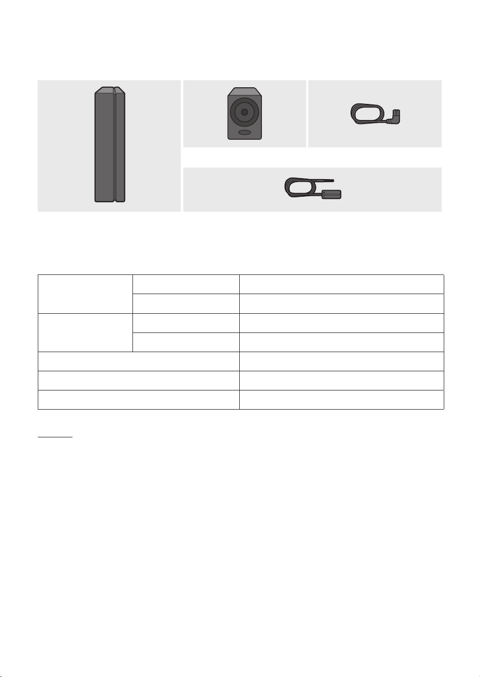
Accessories
STANDBY
LINK
Surround Speaker (2EA) Power Cord (3903-001117)
Wireless Receiver Module Speaker Cable (2EA) (AH81-02137A)
Specications
Weight
Wireless Receiver Module 1.5 lbs (0.7 kg)
Surround Speaker 1.1 lbs (0.5 kg)
Dimensions (W x H x D)
Wireless Receiver Module 2.0 x 7.9 x 5.2 inches (50.0 X 201.3 X 132.0 mm)
Surround Speaker 3.0 x 5.0 x 3.0 inches (76.2 X 126.9 X 76.2 mm)
Operating Temperature Range +41°F to +95°F (+5°C to +35°C)
Operating Humidity Range 10% ~ 75%
Frequency range 20Hz~20KHz
NOTES
–
Samsung Electronics Co., Ltd reserves the right to change the specications without notice.
– Weight and dimensions are approximate.
– For more information about the power supply and power consumption, refer to the label attached
to the product.
– Design and specications are subject to change without prior notice.
Open Source License Notice
• To send inquiries and requests regarding open sources, contact Samsung via Email
(oss.request@samsung.com).
Connecting the SWA-8500S to a Soundbar
1. Connect the Wireless Receiver Module to 2 Surround Speakers
Use the speaker cables to connect the two surround sound speakers to the Wireless Receiver Module.
• The speaker cables are color coded.
SURROUND-LEFT
ID SET
L
R
SURROUND SPEAKERS OUT
SPEAKER IMPEDANCE : 3Ω
POWER
ID SET
L
R
SURROUND SPEAKERS OUT
SPEAKER IMPEDANCE : 3Ω
SURROUND-RIGHT
SURROUND-LEFT SURROUND-RIGHT
• When connecting the speaker cables to the Wireless Receiver Module, follow these steps:
1. Insert the grey plug into the grey jack on the Wireless Receiver.
2. Insert the blue plug into the blue jack on the Wireless Receiver.
• When connecting the speaker cables to the surround speakers, follow these steps:
1. Match the speaker cable connected to the grey jack to the speaker with the grey label.
2. Match the speaker cable connected to the blue jack to the speaker with the blue label.
3. Insert the red and black colored ends of each speaker cable into the red and black jacks of
the appropriate speakers.
• The labels are on the backs of the speaker.
2. Check the standby status after plugging into an electrical outlet
Plug the Wireless Receiver Module power cord into an electrical outlet and into the Wireless
Receiver Module to turn on the Wireless Receiver Module. The LINK LED indicator (blue LED) on the
Wireless Receiver Module blinks. If the LED does not blink, refer to step 7 on page 9.
ID SET
L
R
SURROUND SPEAKERS OUT
SPEAKER IMPEDANCE : 3Ω
POWER
POWER
STANDBY
LINK
STANDBY
LINK
Blue blinking
Loading ...
Loading ...
Loading ...