
2018 LEAF
®
OWNER’S MANUAL
For your safety, read carefully and keep in this vehicle.
2018 NISSAN LEAF
®
ZE1-D
ZE1-D
Printing : November 2017
Publication No.:
Printed in U.S.A.
OM18EA 0ZE1U0
‘18

This manual was prepared to help you un-
derstand the operation and maintenance
of your vehicle so that you may enjoy many
miles of driving pleasure. Please read
through this manual before operating your
vehicle.
A separate Warranty Information Book-
let explains details about the warranties
covering your vehicle. The NISSAN Ser-
vice and Maintenance Guide explains de-
tails about maintaining and servicing
your vehicle. Additionally, a separate
Customer Care/Lemon Law Booklet (U.S.
only) will explain how to resolve any con-
cerns you may have with your vehicle, as
well as clarify your rights under your
state’s lemon law.
In addition to factory installed options, your
vehicle may also be equipped with addi-
tional accessories installed prior to deliv-
ery. It is recommended that you visit a
NISSAN certified LEAF dealer for details
concerning the particular accessories with
which your vehicle is equipped. It is impor-
tant that you familiarize yourself with all
disclosures, warnings, cautions and in-
structions concerning proper use of such
accessories prior to operating the vehicle
and/or accessory. It is recommended that
you visit a NISSAN certified LEAF dealer for
details concerning the particular accesso-
ries with which your vehicle is equipped.
A NISSAN certified LEAF dealer knows your
vehicle best. When you require any service
or have any questions, we will be glad to
assist you with the extensive resources
available to us.
Before driving your vehicle, read your Own-
er’s Manual carefully. This will ensure famil-
iarity with controls and maintenance re-
quirements, assisting you in the safe
operation of your vehicle.
WARNING
IMPORTANT SAFETY INFORMATION RE-
MINDERS!
Follow these important driving rules to
help ensure a safe and comfortable
trip for you and your passengers!
• NEVER drive under the influence of
alcohol or drugs.
• ALWAYS observe posted speed limits
and never drive too fast for condi-
tions.
• ALWAYS give your full attention to
driving and avoid using vehicle fea-
tures or taking other actions that
could distract you.
• ALWAYS use your seat belts and ap-
propriate child restraint systems.
Pre-teen children should be seated
in the rear seat.
FOREWORD READ FIRST — THEN DRIVE SAFELY
• ALWAYS provide information about
the proper use of vehicle safety fea-
tures to all occupants of the vehicle.
• ALWAYS review this Owner’s Manual
for important safety information.
MODIFICATION OF YOUR VEHICLE
This vehicle should not be modified.
Modification could affect its perfor-
mance, safety or durability, and may
even violate governmental regula-
tions. In addition, damage or perfor-
mance problems resulting from modi-
fication may not be covered under
NISSAN warranties.
WARNING
Installing an aftermarket On-Board Di-
agnostic (OBD) plug-in device that
uses the port during normal driving,
for example remote insurance com-
pany monitoring, remote vehicle diag-
nostics, telematics or engine repro-
gramming, may cause interference or
damage to vehicle systems. We do not
recommend or endorse the use of any
aftermarket OBD plug-in devices, un-
less specifically approved by NISSAN.
The vehicle warranty may not cover
damage caused by any aftermarket
plug-in device.
This manual includes information for all
features and equipment available on this
model. Features and equipment in your ve-
hicle may var y depending on model, trim
level, options selected, order, date of pro-
duction, region or availability. Therefore,
you may find information about features or
equipment that are not included or in-
stalled on your vehicle.
All information, specifications and illustra-
tions in this manual are those in effect at
the time of printing. NISSAN reserves the
right to change specifications, perfor-
mance, design or component suppliers
without notice and without obligation.
From time to time, NISSAN may update or
revise this manual to provide Owners with
the most accurate information currently
available. Please carefully read and retain
with this manual all revision updates sent
to you by NISSAN to ensure you have ac-
cess to accurate and up-to-date informa-
tion regarding your vehicle. Current ver-
sions of vehicle Owner's Manuals and any
updates can also be found in the Owner
section of the NISSAN website at
https://owners.nissanusa.com/nowners/
navigation/manualsGuide
. If you have
WHEN READING THE MANUAL
questions concerning any information in
your Owner's Manual, contact NISSAN Con-
sumer Affairs. For contact information, re-
fer to the NISSAN CUSTOMER CARE PRO-
GRAM page in this Owner’s Manual.
IMPORTANT INFORMATION ABOUT
THIS MANUAL
You will see various symbols in this manual.
They are used in the following ways:
WARNING
This is used to indicate the presence of
a hazard that could cause death or se-
rious personal injury. To avoid or re-
duce the risk, the procedures must be
followed precisely.
CAUTION
This is used to indicate the presence of
a hazard that could cause minor or
moderate personal injury or damage
to your vehicle. To avoid or reduce the
risk, the procedures must be followed
carefully.
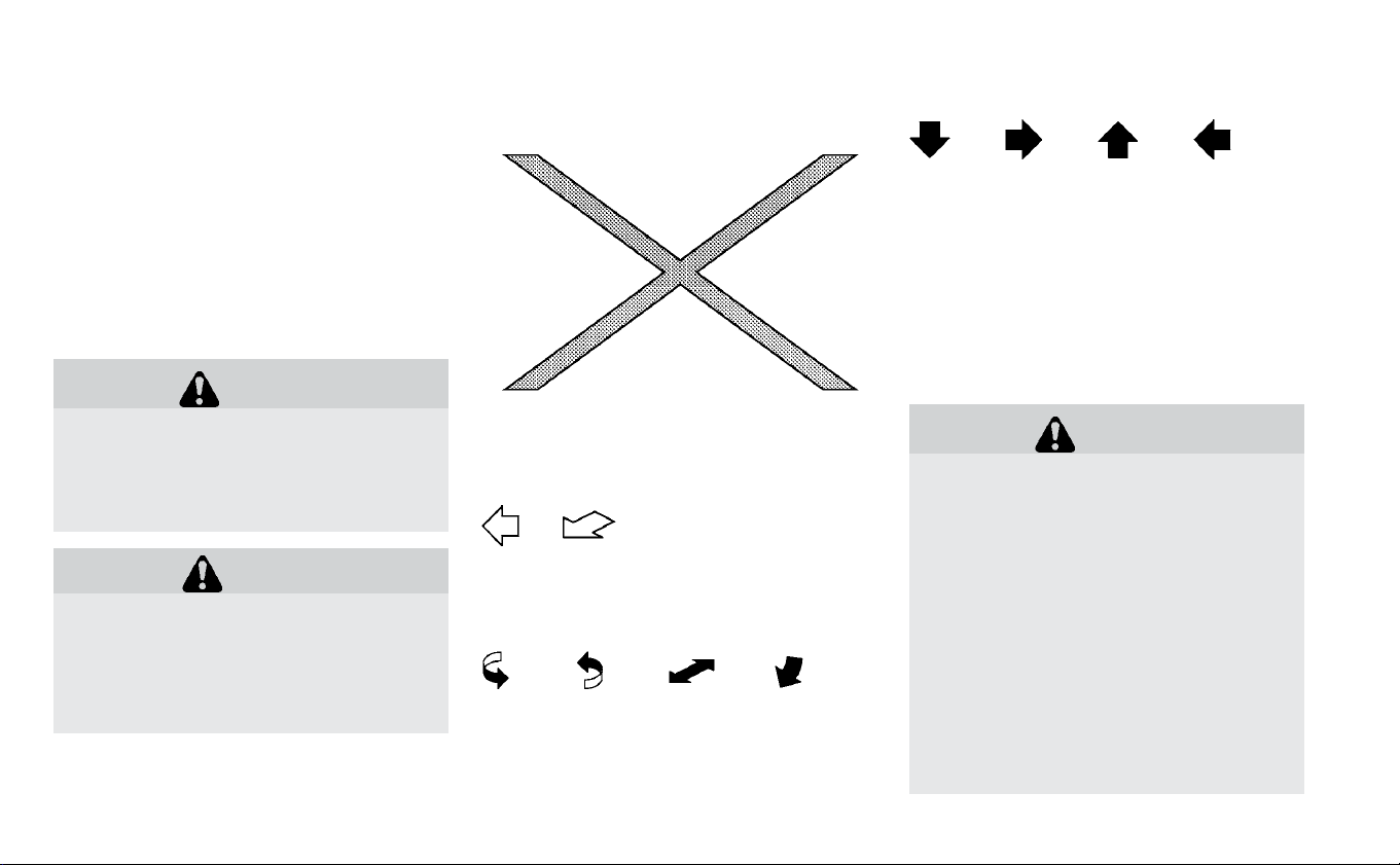
If you see the symbol above, it means “Do
not do this” or “Do not let this happen”.
If you see a symbol similar to those above
in an illustration, it means the arrow points
to the front of the vehicle.
Arrows in an illustration that are similar to
those above indicate movement or action.
Arrows in an illustration that are similar to
those above call attention to an item in the
illustration.
[ ]: Indicates a key/item displayed on the
screen.
CALIFORNIA PROPOSITION
65 WARNING
WARNING
Certain vehicle components contain or
emit chemicals known to the State of
California to cause cancer and birth
defects or other reproductive harm. In
addition, certain fluids contained in ve-
hicles and certain products of compo-
nent wear contain or emit chemicals
known to the State of California to
cause cancer and birth defects or
other reproductive harm.
Operating,servicing and maintaining a
passenger vehicle or off-road vehicle
can expose you to chemicals including
engine exhaust, carbon monoxide,
phthalates, and lead, which are known

to the State of California to cause can-
cer and birth defects or other repro-
ductive harm. To minimize exposure,
avoid breathing exhaust, do not idle
the engine except as necessary, ser-
vice your vehicle in a well-ventilated
area and where gloves or wash your
hands frequently when servicing your
vehicle. For more information go to
www.P65Warnings.ca.gov.
CALIFORNIA PERCHLORATE
ADVISORY
Some vehicle parts, such as lithium bat-
teries, may contain perchlorate material.
The following advisory is provided: “Per-
chlorate Material - special handling may
apply. For additional information, refer
to www.dtsc.ca.gov/hazardouswaste/
perchlorate.”
Bluetooth® is a trademark
owned by Bluetooth SIG,
Inc. and licensed to Vis-
teon.
SiriusXM® services require
a subscription after trial
period and are sold sepa-
rately or as a package.
The satellite service is
available only in the
48 contiguous USA and
DC. SiriusXM® satellite ser-
vice is also available in
Canada; see
www.siriusxm.ca.
© 2017 NISSAN NORTH AMERICA, INC.
All rights reserved. No part of this Owner’s
Manual may be reproduced or stored in a
retrieval system, or transmitted in any
form, or by any means, electronic, me-
chanical, photocopying, recording or oth-
erwise, without the prior written permis-
sion of Nissan North America, Inc.

NISSAN CARES ...
Both NISSAN and your NISSAN certified LEAF dealer are dedicated to serving all your automotive needs. Your satisfaction with your vehicle
and your NISSAN certified LEAF dealer are our primary concerns. Your NISSAN certified LEAF dealer is always available to assist you with
all your automobile sales and service needs.
However, if there is something that your
NISSAN certified LEAF dealer cannot assist
you with or you would like to provide
NISSAN directly with comments or ques-
tions, please contact the NISSAN Con-
sumer Affairs Department using our toll-
free number:
For U.S. customers
1-877-NOGASEV
(1-877-664-2738)
For Canadian customers
1-800-387-0122
The Consumer Affairs Department will ask
for the following information:
• Your name, address, and telephone
number
• Vehicle identification number (attached
to the top of the instrument panel on the
driver’s side)
• Date of purchase
• Current odometer reading
• Your NISSAN certified LEAF dealer’s name
• Your comments or questions
OR
You can write to NISSAN with the informa-
tion at:
For U.S. customers
Nissan North America, Inc.
Consumer Affairs Department
P.O. Box 685003
Franklin, TN 37068-5003
or via e-mail at:
nnaconsumer[email protected]om
For Canadian customers
Nissan Canada Inc.
5290 Orbitor Drive
Mississauga, Ontario L4W 4Z5
or via e-mail at:
information.centre@nissancanada.
com
If you prefer, visit us at:
www.nissanusa.com (for U.S. customer) or
www.nissan.ca (for Canadian customers)
We appreciate your interest in NISSAN and thank you for buying a quality NISSAN vehicle.
NISSAN CUSTOMER CARE PROGRAM

NOTES

Table of
contents
Illustrated table of contents
EV Overview
Charging
Safety–Seats, seat belts and supplemental restraint system
Instruments and controls
Pre-driving checks and adjustments
Monitor, climate, audio, phone and voice recognition systems
Starting and driving
In case of emergency
Appearance and care
Maintenance and do-it yourself
Technical and consumer information
Index
0
EV
CH
1
2
3
4
5
6
7
8
9
10


0 Illustrated table of contents
Seats, seat belts and Supplemental Restraint
System (SRS).........................0-2
Ex terior front.........................0-3
Ex terior rear .........................0-4
Passenger compartment ................0-5
Cockpit ............................0-3
Instrument panel ......................0-5
Meters and gauges ....................0-6
Motor compartment ...................0-10
Warning and indicator lights ..............0-11

1. Rear head restraints/headrests (P. 1-7)
2. Child restraint anchor points (for top
tether strap child restraint) (P. 1-22)
3. Roof-mounted curtain side-impact and
rollover air bags (P. 1-43)
4. Front head restraints/headrests (P. 1-7)
5. Front seat belt with pretensioner(s) and
shoulder height adjuster (P. 1-11, 1-43)
6. Front seats (P. 1-2)
7. Supplemental front-impact air bags
(P. 1-43)
8. Occupant classification sensor (weight
sensor) (P. 1-43)
9. Front seat-mounted side-impact
supplemental air bags (P. 1-43)
10. LATCH (Lower Anchors and Tethers for
CHildren) system (P. 1-22)
SEATS, SEAT BELTS AND
SUPPLEMENTAL RESTRAINT SYSTEM
(SRS)
0-2 Illustrated table of contents

1. Charge port lid
—Charging lid switch (P. 3-19)
2. Hood (P. 3-16)
3. Wiper and washer switch
— Switch operation (P. 2-49)
— Blade replacement (P. 8-14)
— Windshield-washer fluid (P. 8-11)
4. Outside mirrors
— Switch operation (P. 3-23)
— Side camera (if so equipped) (P. 4-13)
5. Power windows (P. 2-68)
6. Child safety rear door lock (P. 3-4)
7. Doors
— Keys (P. 3-2)
— Door locks (P. 3-4)
— NISSAN Intelligent Key® system (P. 3-6)
— Security system (P. 2-46)
8. Tires
— Wheels and tires (P. 8-28, 9-5)
— Flat tire (P. 6-3)
— Tire Pressure Monitoring System
(TPMS) (P. 2-20, 5-4)
9. Headlight and turn signal lights
— Switch operation (P. 2-52)
— Bulb replacement (P. 8-24)
— LED Daytime Running Lights (DRL) (if
so equipped) (P. 2-52)
10. Fog lights (if so equipped)
— Switch operation (P. 2-52)
— Bulb replacement (P. 8-24)
11. License plate installation (P. 9-8)
12. Front view camera (if so equipped)
(P. 4-13)
EXTERIOR FRONT
Illustrated table of contents 0-3

1. Rear wiper and washer switch
— Switch operation (P. 2-49)
— Windshield-washer fluid (P. 8-11)
2. High-mounted stop light
— Bulb replacement (P. 8-24)
3. Rear window defroster (P. 2-51)
4. Rear combination lights
— Bulb replacement (P. 8-24)
5. Rear hatch (P. 3-17)
— Rear view camera (P. 4-4, 4-13)
EXTERIOR REAR
0-4 Illustrated table of contents

1. Emergency tire puncture repair kit
(P. 6-3)
2. Map lights
— Switch operation (P. 2-70)
— Bluetooth® Hands-Free Phone System
(without Navigation) microphone (P. 4-67)
— Bluetooth® Hands-Free Phone System
(with Navigation) microphone (Refer to
NissanConnect® Manual (for Leaf))
— Sunglasses holder (P. 2-63)
3. Sun visors (P. 3-22)
4. Mirror
— Inside rearview mirror (P. 3-23)
— HomeLink® (if so equipped) (P. 2-72)
5. Front cup holders (P. 2-63)
6. Console box (P. 2-63)
7. C a r g o a r e a
— Tonneau cover (if so equipped) (P. 2-63)
— EVSE (Electric Vehicle Supply Equip-
ment) (P. CH-42)
PASSENGER COMPARTMENT
Illustrated table of contents 0-5

1. TRIP RESET switch for twin trip odom-
eter (P. 2-6)
— Instrument brightness control switch
(P. 2-57)
2. Headlight, fog light (if so equipped) and
turn signal switch
— Headlight (P. 2-52)
— Turn signal light (P. 2-52)
— Fog light (if so equipped) (P. 2-52)
3. Steering-wheel-mounted controls (left
side)
— Audio control (P. 4-45)
— Bluetooth® Hands-Free Phone System
control (without navigation) (P. 4-45)
— Bluetooth® Hands-Free Phone System
control (with navigation) (Refer to
NissanConnect® Manual (for Leaf))
4. Steering wheel
— Power steering system (P. 5-133)
— Horn (P. 2-58)
— Driver's supplemental air bag (P. 1-43)
5. Wiper and washer switch (P. 2-49)
6. Steering-wheel-mounted controls
(right side)
— Cruise control switches (if so
equipped) (P. 5-54)
— Intelligent Cruise Control (ICC)
switches (if so equipped) (P. 5-56)
— ProPILOT
TM
Assist switch (if so
equipped) (P. 5-79)
COCKPIT
0-6 Illustrated table of contents

7. Shift lever (P. 5-15)
— ECO switch (P. 2-58)
— e-Pedal switch (P. 5-22)
8. Console box (P. 2-63)
9. Parking brake (switch type) (if so
equipped) (P. 5-19)
10. Tilting steering wheel lever (P. 3-21)
11. Charge port lid switch (P. 3-19)
— Charge timer OFF switch (P. 2-61)
— Heated steering wheel switch (if so
equipped) (P. 2-60)
— Steering Assist switch (if so equipped)
(P. 5-79)
12. Fuse box cover (P. 8-17)
Illustrated table of contents 0-7

1. Vents (P. 4-29)
2. Meters and gauges (P. 2-6)
3. Center multi-function control panel
— Navigation system (Refer to
NissanConnect® Manual (for Leaf))
— Without Navigation System (P. 4-45)
4. Hazard warning flasher switch (P. 6-2)
5. Rear window defroster switch (P. 2-51)
6. Front passenger supplemental air bag
(P. 1-43)
7. Glove box (P. 2-63)
8. Heater and air conditioner control
(P. 4-30)
9. Power outlet (P. 2-62)
10. Front heated seat switches (if so
equipped) (P. 2-59)
11. Auxiliary input jack (P. 4-64)
— iPod® connector/USB connector
(P. 4-45)
12. Push-button power switch (P. 5-10)
13. Front passenger air bag status light
(P. 1-43)
14. Hood release handle (P. 3-16)
INSTRUMENT PANEL
0-8 Illustrated table of contents

1. Vehicle information display (P. 2-27)
— Clock (P. 2-12)
— Outside air temperature (P. 2-11)
— Li-ion battery available charge gauge
(P. 2-10)
— Driving range (P. EV-19)
— Odometer/twin trip odometer (P. 2-7)
— Indicator for timer (P. CH-35)
— Power meter (P. 2-9)
2. Warning and indicator lights (P. 2-14)
— Turn signal/Hazard indicator light
(P. 2-52)
— READY to drive indicator light (P. 2-25)
— ECO mode indicator (P. 2-12
3. Speedometer (P. 2-6)
METERS AND GAUGES
Illustrated table of contents 0-9

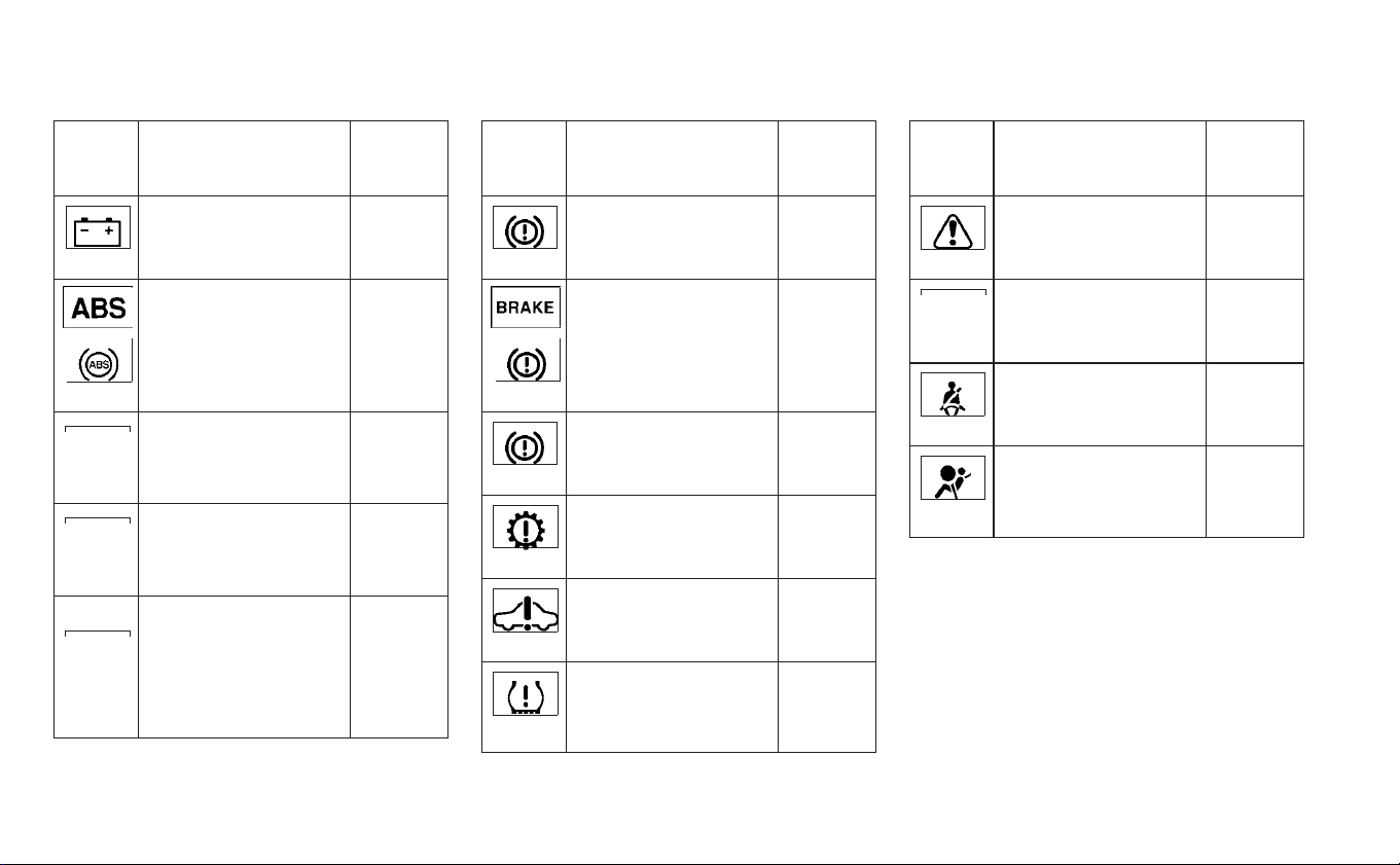
Warn-
ing
light
Name Page
12-volt battery
charge warning light
2-16
Anti-lock Braking
System (ABS) warn-
ing light
2-17
Approaching Vehicle
Sound for Pedestri-
ans (VSP) OFF system
warning light
2-17
Automatic Emer-
gency Braking (AEB)
system warning light
(if so equipped)
2-17
Automatic Emer-
gency Braking (AEB)
with Pedestrian De-
tection system warn-
ing light (if so
equipped)
2-18
Warn-
ing
light
Name Page
Brake system warn-
ing light (yellow)
2-18
Brake warning light
(red)
2-19
Electronic parking
brake system warn-
ing light (yellow)
2-19
Electric shift control
system warning light
2-20
Electric Vehicle (EV)
system warning light
2-20
Low tire pressure
warning light
2-20
Warn-
ing
light
Name Page
Master warning light
(red/yellow)
2-22
Power steering warn-
ing light
2-22
Seat belt warning
light
2-22
Supplemental air bag
warning light
2-22
WARNING AND INDICATOR LIGHTS
Illustrated table of contents 0-11
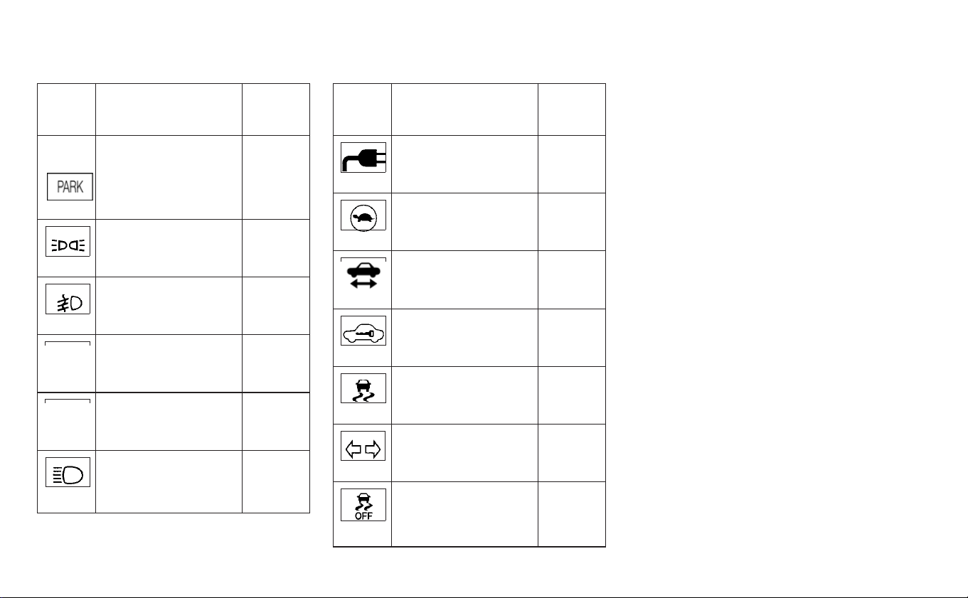
Indica-
tor
light
Name Page
Electronic parking
brake indicator light
2-23
Ex terior light indica-
tor light
2-23
Front fog light indica-
tor light (if so
equipped)
2-23
Front passenger air
bag status light
2-23
High Beam Assist in-
dicator light (if so
equipped)
2-23
High beam indicator
light (blue)
2-24
Indica-
tor
light
Name Page
Plug-in indicator light 2-24
Power limitation indi-
cator light
2-24
READY to drive indi-
cator light
2-25
Security indicator
light
2-25
Slip indicator light 2-25
Turn signal/hazard
indicator lights
2-25
Vehicle Dynamic
Control (VDC) OFF
indicator light
2-25
0-12 Illustrated table of contents

EV Overview
The EV (Electric Vehicle) system ...........EV-2
Li-ion battery .......................EV-2
Driving with a discharged Li-ion battery . . . .EV-3
Charging the 12-volt battery............EV-5
Li-ion battery warmer (if so equipped) .....EV-5
High voltage precautions................EV-7
High-voltage components .............EV-7
Road accident precautions ..............EV-8
Emergency shut-off system............EV-8
EV characteristics ....................EV-9
Noise and vibration .................EV-10
Life with an EV (scene guide) .............EV-10
Charging the Li-ion battery............EV-10
Before driving your vehicle (models with
Navigation System) .................EV-12
Checking Li-ion battery charging status . . .EV-12
Operating the climate control system before
driving .........................EV-13
Starting your vehicle ................EV-14
Driving the vehicle..................EV-15
Charging after driving ...............EV-18
Efficient use of your vehicle..............EV-19
Range..........................EV-19
Improve driving range ...............EV-19
Li-ion battery life ..................EV-20
Li-ion battery maintenance ...........EV-21
EV unique information .................EV-21
Meters and indicators ...............EV-21
Approaching Vehicle Sound for
Pedestrians (VSP) system.............EV-24
Electric shift control system ...........EV-25
LED headlight (low beam) (if so equipped) . .EV-25
Driving range (if so equipped) ..........EV-25

The LEAF is an electric vehicle. Some of the
vehicle’s systems operate differently and
have different operating characteristics
than vehicles equipped with an internal
combustion engine. It is important to care-
fully review the entire Owner's Manual for
this reason. The main difference is the LEAF
is powered by electricity. The LEAF does not
require and it is not capable of using gaso-
line like a vehicle powered by a traditional
internal combustion engine. The LEAF uses
electricity stored in the lithium ion (Li-ion)
battery. The vehicle’s Li-ion battery must
be charged with electricity before the ve-
hicle can be driven. As the vehicle operates,
the Li-ion battery gradually discharges. If
the Li-ion battery becomes completely dis-
charged, the vehicle will not operate until it
is re-charged.
This vehicle uses two types of batteries.
One is the 12-volt battery that is the same
as the battery in vehicles powered by
gasoline engines, the other is the Li-ion
battery (high voltage).
The 12-volt batter y provides power to the
vehicle systems and features such as the
audio system, supplemental restraint sys-
tems, headlights and windshield wipers.
The Li-ion battery provides power to the
electric motor (traction motor) that moves
the vehicle.
The Li-ion battery also charges the 12-volt
battery.
The vehicle must be plugged in for the Li-
ion battery to be charged. Additionally, the
vehicle system can extend the vehicle
range by converting driving force into elec-
tricity that is stored in the Li-ion battery
while the vehicle is decelerating or being
driven downhill. This is called regenerative
braking. This vehicle is considered to be an
environmentally friendly vehicle because it
does not emit exhaust gases, such as car-
bon dioxide and nitrogen oxide.
WARNING
Your vehicle contains a sealed Li-ion
high voltage battery. If the Li-ion bat-
tery is disposed of improperly, there is
a risk of severe burns and electrical
shock that may result in serious injury
or death and there is also a risk of en-
vironmental damage.
CAUTION
To prevent damage to the Li-ion bat-
tery:
• Do not expose the vehicle to ex-
treme ambient temperatures for ex-
tended periods.
• Do not store the vehicle in tempera-
tures below −13°F (−25°C) for more
than seven days.
• Do not leave the vehicle for more
than 14 days where the Li-ion bat-
tery available charge gauge reaches
azeroornearzero.
• Do not use the Li-ion battery for any
other purpose.
THE EV (ELECTRIC VEHICLE) SYSTEM LI-ION BATTERY
EV-2 EV Overview

NOTE:
• If the outside temperature is −13°F
(−25°C) or less, the Li-ion battery may
freeze and it cannot be charged or pro-
vide power to run the vehicle. Move the
vehicle to a warm location.
• The capacity of the Li-ion battery in
your vehicle to hold a charge will, like all
such batteries, decrease with time and
usage. As the battery ages and capacity
decreases, this will result in a decrease
from the vehicle’s initial mileage range.
This is normal, expected, and not in-
dicative of any defect in your Li-ion bat-
tery.
• The Li-ion battery has limited service
life, and when its charging capacity falls
below a specific level, the EV system
warning light will illuminate. Owners
should bring their vehicle in for inspec-
tion and possible battery replacement.
• It is recommended that you visit a
NISSAN certified LEAF dealer for infor-
mation about recycling or disposal of
the Li-ion battery. Do not attempt to re-
cycle or dispose of the Li-ion battery
yourself.
DRIVING WITH A DISCHARGED
LI-ION BATTERY
When a destination is set in the navigation
system (if so equipped) that exceeds the
available vehicle range, the navigation sys-
tem automatically searches the location of
nearby charging stations. When the nearby
charging station locations are displayed,
charge the Li-ion battery as soon as pos-
sible.
Warning lights illuminate on the instru-
ment panel and messages are displayed
on the vehicle information display to in-
form you that the Li-ion battery charge is
low. Instructions are also displayed on the
navigation system screen (if so equipped)
to direct you to nearby charging stations.
The vehicle's range is very limited when
these warning lights illuminate and mes-
sages are displayed. Follow the instruc-
tions on the navigation system screen (if so
equipped) and immediately charge the ve-
hicle at the nearest charging station.
There are three levels of information that
will be displayed as the Li-ion battery be-
comes discharged:
1. The following warning lights illuminate
on the instrument panel and messages
are displayed on the vehicle information
display at the same time to indicate low
Li-ion battery charge:
EV Overview EV-3

• The low battery charge indicator light
• The master warning light
• The “Battery charge is low, Charge now”
warning message is displayed on the
vehicle information display.
• Messages are displayed on the naviga-
tion system screen (if so equipped).
• For additional information, refer to “Low
battery charge indicator” in the “Instru-
ments and controls” section of this
manual.
• The driving range flashes
䊊
1
.
NOTE:
Due to traffic conditions, it may be dif-
ficult to get to the charging station
suggested by the navigation system
(if so equipped). If the Li-ion battery is
almost completely discharged, drive
directly to the nearest charging sta-
tion.
2. If the vehicle is driven and the Li-ion bat-
tery continues to discharge, the driving
range on the instrument panel changes
to “— — —”
䊊
2
.
Messages are displayed on the naviga-
tion system screen (if so equipped). For
additional information, refer to “Li-ion
battery available charge gauge” in the
“Instruments and controls” section of
this manual.
3. When the power limitation indicator
light
illuminates, traction motor
output is limited resulting in reduced ve-
hicle speed. Stop the vehicle in a safe
EV-4 EV Overview

location before the Li-ion battery be-
comes completely discharged and
there is no power available to drive the
vehicle. Contact Roadside Assistance
Service shown in your NISSAN Warranty
Information Booklet. For additional in-
formation, refer to “If the Li-ion battery
becomes completely discharged” in the
“In case of emergency” section of this
manual.
CHARGING THE 12-VOLT BATTERY
The 12-volt battery is charged automati-
cally using electricity stored in the Li-ion
battery.
When the 12-volt battery is being charged,
the charge status indicator light on the in-
strument panel flashes (except when
charging the Li-ion battery or the power
switch is in the Ready to Drive position). For
additional information, refer to “Charging
status indicator lights” in the “Charging”
section of this manual.
While vehicle is driven
The Li-ion battery charges the 12-volt bat-
tery as necessary when the power switch
is in the Ready to Drive position or ON posi-
tion.
The 12-volt battery is not charged in the
following conditions.
• When the power switch is in the ACC
position.
• When the power switch is in the ON posi-
tion and the shift position is in the N (Neu-
tral) position.
While the vehicle is not in use
When the EV system is off for an extended
time, the 12-volt battery may be automati-
cally charged for a short period of time on a
regular basis.
LI-ION BATTERY WARMER (IF SO
EQUIPPED)
CAUTION
The Li-ion battery warmer does not
operate if the available Li-ion battery
charge is less than approximately 15%
and the charger is not connected to
the vehicle. To help prevent the Li-ion
battery from freezing, do not leave the
vehicle in an environment if tempera-
tures may go below -1°F (-17°C) unless
the vehicle is connected to a charger.
The Li-ion battery warmer helps to prevent
the Li-ion battery from freezing and helps
to prevent significant reductions in the Li-
ion battery output when the temperature
is cold. The Li-ion battery warmer auto-
matically turns on when the Li-ion battery
temperature is approximately -1°F (-17°C) or
colder. The Li-ion battery warmer auto-
matically turns off when the Li-ion battery
temperature is approximately 14°F (-10°C)
or higher.
The Li-ion batter y warmer uses electrical
power from an external source when a
charger is connected to the vehicle. The
Li-ion battery warmer uses electrical
power from the Li-ion battery when the
charger is not connected to the vehicle.
EV Overview EV-5

NOTE:
• Connect the charger to the vehicle and
place the power switch in the OFF posi-
tion when parking the vehicle if tem-
peratures may go below -1°F (-17°C). This
provides external power to the Li-ion
battery warmer when it operates and
does not discharge the Li-ion battery.
• The charging status indicator lights illu-
minate in a specific pattern when the
Li-ion battery warmer operates. The
charging status indicator lights use the
same pattern to indicate 12-volt battery
charging, Climate Ctrl. Timer operation
or Remote Climate Control operation
(models with Navigation System). The
charging status indicator lights do not
change if the Li-ion battery warmer op-
erates at the same time as the above
features. For additional information, re-
fer to “Charging status indicator lights”
in the “Charging” section of this manual.
• The Li-ion battery warmer uses Li-ion
battery power to operate, even if the
vehicle is connected to a charger when:
– The vehicle's power switch is in the
ON position.
– There is no electrical power being
supplied to the charging equipment.
• When the Li-ion battery warmer is al-
ready in operation using an external
power source, it will continue to use the
external power even if the power switch
is placed in the ON position.
• Vehicle driving range is reduced if the
Li-ion battery warmer operates (Li-ion
battery temperature approximately
-1°F (-17°C) or colder) while driving the
vehicle. You may need to charge the Li-
ion battery sooner than in warmer tem-
peratures.
• The Li-ion battery requires more time to
charge when the Li-ion battery warmer
operates.
• The predicted charging time displayed
on the meter and navigation system (if
so equipped) increases when the Li-ion
battery warmer operates.
• Climate control performance is reduced
when using the Climate Ctrl. Timer or
Remote Climate Control (models with
Navigation System) while the Li-ion bat-
tery warmer operates.
• The Li-ion battery may not charge to
the expected level using the charging
timer while the Li-ion battery warmer
operates.
EV-6 EV Overview

HIGH-VOLTAGE COMPONENTS
WARNING
• The EV system uses high voltage up
to approximately DC 400 volt. The
system can be hot during and after
starting and when the vehicle is shut
off. Be careful of both the high volt-
age and the high temperature. Fol-
low the warning labels that are at-
tached to the vehicle.
• Never disassemble, remove or re-
place high-voltage parts and cables
as well as their connectors because
they can cause severe burns or elec-
tric shock that may result in serious
injury or death. High-voltage cables
are colored orange. The vehicle high
voltage system has no user service-
able parts. It is recommended that
you take your vehicle to a NISSAN
certified LEAF dealer for any neces-
sary maintenance.
1. Traction motor and reduction gear
2. Traction motor inverter
3. Power delivery module (PDM) (Charger,
DC/DC converter, junction box)
4. High-voltage wire harnesses (colored
orange)
5. Li-ion battery
6. Service plug
HIGH VOLTAGE PRECAUTIONS
EV Overview EV-7

WARNING
In case of a collision:
• If your vehicle is drivable, pull your
vehicle off the road, push the P
(Park) position switch on the shift
lever, apply the parking brake and
turn the EV system off.
• Check your vehicle to see if there are
exposed high-voltage parts or
cables. For their locations, refer to
“High voltage components” in this
section. To avoid personal injury,
never touch high-voltage wiring,
connectors, and other high-voltage
parts, such as inverter unit and Li-
ion battery. An electric shock may
occur if exposed electric wires are
visible when viewed from inside or
outside of your vehicle. Therefore,
never touch exposed electric wires.
• If the vehicle receives a strong im-
pact to the floor while driving, stop
the vehicle in a safe location and
check the floor.
• Leaks or damage to the Li-ion bat-
tery may result in a fire. If you dis-
cover them, contact emergency ser-
vices immediately. Since the fluid
leak may be lithium manganate
from the Li-ion battery, never touch
the fluid leak inside or outside the
vehicle. If the fluid contacts your
skin or eyes, wash it off immediately
with a large amount of water and
receive immediate medical atten-
tion to help avoid serious injury.
• If a fire occurs in the EV, leave the
vehicle as soon as possible. Only use
a type ABC, BC or C fire extinguisher
that is meant for use on electrical
fires. Using a small amount of water
or the incorrect fire extinguisher can
result in serious injury or death from
electrical shock.
• If your vehicle needs to be towed, do
it with the front wheels raised. If the
front wheels are on the ground
when towing, the traction motor
may generate electricity. This may
damage the components of the EV
system and cause a fire.
• If you are not able to safely assess
the vehicle due to vehicle damage,
do not touch the vehicle. Leave the
vehicle and contact emergency ser-
vices. Advise first responders that
this is an electric vehicle.
• In the event of an accident that re-
quires body repair and painting, the
Li-ion battery pack and high voltage
parts such as the inverter, including
the wire harness, should be re-
moved prior to painting. It is recom-
mended that you visit a NISSAN cer-
tified LEAF dealer for this service. Li-
ion battery packs exposed to heat in
the paint booth will experience ca-
pacity loss. Damaged Li-ion battery
packs may also pose safety risks to
untrained mechanics and repair
personnel.
EMERGENCY SHUT-OFF SYSTEM
The emergency shut-off system is acti-
vated and the high-voltage system auto-
matically turns off in the following condi-
tions:
- Front and side collisions in which the air
bags are deployed.
- Certain rear collisions.
- Certain EV system malfunctions.
For the above collisions and certain other
EV system malfunctions, the Ready to Drive
indicator light will turn off. For additional
ROAD ACCIDENT PRECAUTIONS
EV-8 EV Overview

information, refer to “Warning lights, indica-
tor lights and audible reminders” in the “In-
struments and controls” section of this
manual.
The emergency shut-off activates for the
above collisions to minimize risk of an
event that could cause injury or an acci-
dent. If the emergency shut-off system ac-
tivates, the EV system may not be switched
to the Ready to Drive position; it is recom-
mended that you visit a NISSAN certified
LEAF dealer. Even if the power switch is
switched to the Ready to Drive position, the
system may shut-off suddenly. Therefore,
drive cautiously to the nearest certified re-
pair facility; it is recommended that you
visit a NISSAN certified LEAF dealer for ser-
vice.
WARNING
• Pay special attention to pedestrians.
Because there is no engine noise,
pedestrians may not know the ve-
hicle is approaching, moving or
about to move, and may step into
the path of vehicle travel.
• When leaving the vehicle, be sure to
turn off the EV system.
• Be sure to push the P (Park) position
switch on the shift lever and apply
the parking brake when parking be-
cause the vehicle can move when
the Ready to Drive indicator light is
ON. When the Ready to Drive indica-
tor light is ON, do not leave your ve-
hicle in a shift position other than
the P (Park) position.
• Keep the brake pedal depressed un-
til you are ready to drive. When the
vehicle is in the D (Drive) position, B
or R (Reverse) position, if you release
the brake pedal and do not depress
the accelerator, the vehicle will creep
and may start abruptly. This may
cause serious injury or death.
NOTE:
• The vehicle cannot run with a dis-
charged Li-ion battery. Repeated accel-
eration consumes more power from the
Li-ion battery than driving at a steady
speed.
• This vehicle is equipped with a regen-
erative brake system. The primary pur-
pose of the regenerative brake system
is to provide some power to recharge
the Li-ion battery and extend driving
range. A secondary benefit is “engine
braking” that operates based on Li-ion
battery conditions.
• In the D (Drive) position, when the accel-
erator pedal is released, the regenera-
tive brake system provides some decel-
eration.
• When you put the shift lever in the B
mode and take your foot off the accel-
erator pedal, more regenerative brake is
applied than in the D (Drive) position.
• Less deceleration is provided by the re-
generative brake system when the Li-
ion battery is fully charged. The regen-
erative brake is automatically reduced
when the Li-ion battery is fully charged
EV CHARACTERISTICS
EV Overview EV-9

to prevent the Li-ion battery from be-
coming overcharged. The regenerative
brake is also automatically reduced
when the battery temperature is high/
low (indicated by the red/blue zones on
the Li-ion battery temperature gauge)
to prevent Li-ion battery damage.
• The brake pedal should be used to slow
or stop the vehicle depending on traffic
or road conditions. The vehicle brakes
are not affected by the regenerative
brake system operation.
NOISE AND VIBRATION
You might experience the following noise
or vibration as a normal characteristic of
this vehicle:
• Traction motor noise from the motor
compartment.
• Water pump and radiator fan noise while
charging.
• Compressor and radiator fan noise when
the Climate Ctrl. Timer or remote climate
control (models with Navigation System)
is used.
• Relay operation noise and vibration at
start-up and shut-down of the EV system
(power switch placed in the ON and OFF
position).
• Approaching Vehicle Sound for Pedestri-
ans (VSP).
This section provides a brief explanation
for the most important LEAF functions. For
additional information, refer to the specific
sections of this manual for detailed expla-
nations of the vehicle features and
operation.
CHARGING THE LI-ION BATTERY
WARNING
The EV system uses a high voltage cur-
rent. Failure to follow the proper han-
dling instructions may cause serious
injury or death. Be sure to read the
“Charging” section and follow the pro-
cedures and guidelines described.
LIFE WITH AN EV (SCENE GUIDE)
EV-10 EV Overview

EV Overview EV-11

BEFORE DRIVING YOUR VEHICLE
(MODELS WITH NAVIGATION
SYSTEM)
The Li-ion battery charging status and the
Li-ion battery warmer (if so equipped) op-
eration can be checked using an internet
enabled smart phone or personal com-
puter at home. You may also choose to
have SMS messages (text messages) sent
to a cellular phone. Additionally, the vehi-
cle’s heater and air conditioner can be set
to operate using the Climate Ctrl. Timer
function or A/C-heater remote function, if
necessary. For additional information, refer
to “Remote climate control” in the “Monitor,
climate, audio, phone and voice recogni-
tion systems” section of this manual.
NOTE:
• To check the Li-ion battery charging
status or to use the remote heater and
air conditioner using an internet en-
abled smart phone or personal com-
puter, the following conditions must be
met:
– The vehicle must be located in a cel-
lular phone or smart phone cover-
age area.
– The internet enabled cellular phone
or smart phone must be located in a
cellular phone or smart phone cov-
erage area.
– The computer must be connected to
the internet.
– A cellular phone must be used to
communicate with the vehicle.
– A cellular phone capable of text mes-
saging must be used to receive text
message regarding vehicle charge
status.
• The remote heater and cooler can ad-
just the in-cabin temperature.
• When the charge connector is discon-
nected from the vehicle, the heater and
air conditioner operates using vehicle
Li-ion battery electric power.
• If the remote heater and air conditioner
function and Li-ion battery charging are
performed at the same time, Li-ion bat-
tery charging will take longer than
usual due to the power used to heat or
cool the vehicle.
CHECKING LI-ION BATTERY
CHARGING STATUS
The Li-ion battery charge status can be
checked on the NISSAN Data Center web-
site via an internet enabled smart phone or
personal computer.
If the Li-ion battery is not sufficiently
charged, you can start charging the Li-ion
battery via the remote charge function. For
additional information, refer to “Charging
related remote function” in the “Charging”
section of this manual.
EV-12 EV Overview

OPERATING THE CLIMATE
CONTROL SYSTEM BEFORE
DRIVING
The vehicle’s heating and air conditioning
system can be turned on via remote con-
trol with an internet enabled smart phone
or personal computer.
This allows the interior of the vehicle to be
heated or cooled while the vehicle is charg-
ing. This reduces the load on the Li-ion bat-
tery while the vehicle is being driven and
can help increase the vehicle driving range.
For additional information, refer to “Remote
climate control” in the “Monitor, climate, au-
dio, phone and voice recognition systems”
section of this manual.
EV Overview EV-13

STARTING YOUR VEHICLE
1. Depress the brake pedal.
2. Push the power switch.
3. Check that the Ready to Drive indicator
light illuminates. For additional informa-
tion, refer to “Ready to drive indicator
light” in the “Instruments and controls”
section of this manual.
4. For models with Navigation System: If
route guidance is necessary, enter the
destination in the navigation system.
For additional information, refer to the
LEAF Navigation System Owner's
Manual.
5. Check the Li-ion battery level and the
estimated driving range shown on the
meter. For additional information, refer
to “Driving range” in the “Instruments
and controls” section of this manual.
NOTE:
• Before driving, compare the driving dis-
tance to the destination displayed on
the navigation system screen (if so
equipped) with the estimated driving
range shown on the meter. Determine if
it will be necessary to charge the Li-ion
battery before or while driving to your
planned destination.
• If it is necessary to charge the Li-ion
battery, use the navigation system (if so
equipped) to search for available charg-
ing stations on your planned driving
route.
EV-14 EV Overview

DRIVING THE VEHICLE
1. Depress the brake pedal.
2. Release the parking brake.
3. Move the shift lever into the D (Drive)
position. When released, the shift lever
returns to its original center position.
4. Confirm that the vehicle is in the D (Drive)
position. The indicator next to the “D” by
the shift lever illuminates and “D” is dis-
played on the meter.
5. Release the brake pedal.
6. Depress the accelerator pedal and start
driving.
EV Overview EV-15

These are the following gear positions for
driving the vehicle forward:
• Use the D (Drive) position for optimum
driving performance.
• Use the B mode for downhill driving. When
the B mode is used, more regenerative
brake is applied when the accelerator
pedal is released in comparison to the D
(Drive) position.
For additional information, refer to “Driving
the vehicle” in the “Starting and driving” sec-
tion of this manual.
NOTE:
The regenerative brake converts the ve-
hicle's forward motion to electric power
to help slow the vehicle.
Use the ECO mode for maximum vehicle
range and for city driving. The ECO mode
helps reduce power consumption by re-
ducing acceleration when compared to
the same accelerator pedal position in the
D (Drive) position.
EV-16 EV Overview

If the low battery charge indicator
illuminates yellow, the Li-ion battery charge
is too low for travel. For additional informa-
tion, refer to "Li-ion battery available
charge gauge" in the “Instruments and
controls” section of this manual. Charge
the Li-ion battery as soon as possible.
EV Overview EV-17

CHARGING AFTER DRIVING
Charging the Li-ion batter y
When you return home, connect the ve-
hicle to the charging device installed at
your home or the EVSE plugged to outlet
using the normal charge connector.
Charge the vehicle or set the charging
timer function to have the vehicle charge
at a specific time. For additional informa-
tion, refer to “Charging timer” in the “Charg-
ing” section of this manual.
1. When the power switch is turned off, the
settings of the charging timer, and the
Climate Ctrl. Timer and the charge con-
nector lock functions are displayed on
the vehicle information display. For addi-
tional information, refer to “Vehicle infor-
mation display” in the “Instruments and
controls” section of this manual.
2. Open the charge port lid and charge
port cap. For additional information, re-
fer to “Charge port lid” in the “Pre-driving
checks and adjustments” section of this
manual.
3. Connect the charge connector to the
vehicle.
4. When the charging timer is turned on,
charging starts at the set time. When the
charging timer is not turned on, charg-
ing starts immediately.
NOTE:
• Charging can be started remotely, even
if the charging timer is set up.
• When you have forgotten to connect
the charge connector at home, there is a
function that can notify you via a text
message capable cellular phone, inter-
net enabled smart phone or personal
computer. For additional information,
refer to “Charging related remote func-
tion” in the “Charging” section of this
manual (models with Navigation Sys-
tem).
• NISSAN recommends that you connect
the normal charge cable when getting
out of the vehicle, even if it is not going
to be used. By doing this, you can get
the most out of the remote climate con-
trol (models with Navigation System)
and Climate Ctrl. Timer functions the
next time you use the vehicle.
EV-18 EV Overview

RANGE
The distance you can drive the vehicle
(range) varies considerably depending
upon available charge, weather, tempera-
ture, usage, battery age, topography, and
driving style.
Refer to the Monroney label (window
sticker) for the official EPA range. Your ac-
tual range can vary, either initially or as the
battery ages and with use over time. For
additional information, refer to “Improve
driving range” in this section for informa-
tion on the factors that affect vehicle range
and how to use the vehicle to maximize
vehicle range.
IMPROVE DRIVING RANGE
Vehicle range depends on a number of fac-
tors.
Actual vehicle range will vary depending
upon:
• Speed,
• Vehicle load,
• Electrical load from vehicle accessories,
• Traffic and road conditions.
NISSAN recommends the following driv-
ing habits to help maximize vehicle
range:
Before driving:
• Follow recommended periodic
maintenance.
• Keep tires inflated to correct pressure.
• Keep wheels in correct alignment.
• Pre-heat or pre-cool the interior cabin
while the vehicle is charging.
• Remove unnecessary cargo from the
vehicle.
While driving:
• Drive in ECO mode
– The ECO mode helps reduce power
consumption by reducing acceleration
when compared to the same accelera-
tor pedal position in the D (Drive) posi-
tion.
• Drive at a constant speed. Maintain cruis-
ing speeds with constant accelerator po-
sitions or by using cruise control when
appropriate.
• Accelerate slowly and smoothly. Gently
press and release the accelerator pedal
for acceleration and deceleration.
• Drive at moderate speeds on the highway.
• Avoid frequent stopping and braking.
Maintain a safe distance behind other
vehicles.
• Turn off the air conditioner/heater when it
is not necessary.
• Select a moderate temperature setting
for heating or cooling to help reduce
power consumption.
• Use the air conditioner/heater and close
windows to reduce drag when cruising at
highway speed.
• Vehicle range may be substantially re-
duced in extremely cold conditions (for ex-
ample, -4°F (-20°C)).
• Using the climate control system to heat
the cabin when the outside temperature
is below 32°F (0°C) uses more electricity
and affects vehicle range more than when
using the heater when the temperature is
above 32°F (0°C).
EFFICIENT USE OF YOUR VEHICLE
EV Overview EV-19

• When it is cold, use the steering wheel
heater in substitution for the heater/air
conditioner. The steering wheel heater
consumes less power than the heater/air
conditioner.
• Release the accelerator pedal to slow
down and do not apply the brakes when
traffic and road conditions allow.
– This vehicle is equipped with a regen-
erative brake system. The primary pur-
pose of the regenerative brake system
is to provide some power to recharge
the Li-ion battery and extend driving
range. A secondary benefit is “engine
braking” that operates based on Li-ion
battery conditions. In the D (Drive) posi-
tion, when the accelerator is released,
the regenerative brake system pro-
vides some deceleration and some
power to the Li-ion battery.
LI-ION BATTERY LIFE
The Li-ion battery's ability to hold a charge,
like all batteries, decreases with battery
age and usage which results in decreased
vehicle range when compared to the ve-
hicle range when the vehicle was new. This
is normal and expected, and does not indi-
cate a malfunction of the vehicle or Li-ion
battery.
The Li-ion battery's ability to hold a charge
can be affected by how you drive the ve-
hicle, store the vehicle, how you charge the
Li-ion battery and Li-ion battery tempera-
ture during vehicle operation and charging.
To maximize the battery's useful life, use
the following driving and charging habits
where possible:
• Avoid exposing a vehicle to extreme am-
bient temperatures for extended periods.
• Avoid storing a vehicle in temperatures
below −13°F (−25°C) for more than seven
days.
• Avoid leaving your vehicle for more than
14 days where the Li-ion battery available
charge gauge reaches a zero or near zero
(state of charge).
• Allow the vehicle and Li-ion battery to cool
down after use before charging.
• Park/store your vehicle in cool locations
out of direct sunlight and away from heat
sources.
• Avoid sustained high battery tempera-
tures (caused, for example, by exposure to
very high ambient temperatures or ex-
tending highway driving with multiple
quick charges [if so equipped]) .
• Use the normal charging or trickle charg-
ing methods to charge the Li-ion battery
and minimize the use of public Fast
Charge or Quick Charger.
• Moderate driving.
• Use of ECO mode.
• Do not operate the charging timer repeat-
edly while the charge connector is con-
nected to the vehicle after the Li-ion bat-
tery charging is completed. Doing so may
discharge the 12-volt battery.
• The power of the Li-ion battery can be
checked on the Li-ion battery available
charge gauge. For additional information,
refer to “Li-ion battery available charge
gauge” in the “Instruments and controls”
section of this manual.
EV-20 EV Overview

LI-ION BATTERY MAINTENANCE
In addition to the regular maintenance rec-
ommended by NISSAN, the LEAF requires
some special Li-ion battery inspections.
• For additional information, refer to the
NISSAN Warranty Information Booklet for
significant limitations, exclusions and pos-
sible voiding of your warranty resulting
from failure to have these necessary in-
spections, repairs and/or adjustments
performed.
• For additional information, refer to the
NISSAN Service and Maintenance Guide
for a detailed explanation of the Li-ion bat-
tery inspection and intervals.
METERS AND INDICATORS
Various meters and gauges related to the
EV functions are displayed in the vehicle
information display.
Meter
Master warning light:
The master warning light (red or yellow)
illuminates when any warning lights or in-
dicators illuminate in the display or when
messages are displayed on the vehicle in-
formation display.
For additional information, refer to “Master
warning light (red/yellow)” in the “Instru-
ments and controls” section of this manual.
EV UNIQUE INFORMATION
EV Overview EV-21

Li-ion battery temperature gauge:
This gauge displays the temperature of the
Li-ion battery.
For additional information, refer to “Li-ion
battery temperature gauge” in the “Instru-
ments and controls” section of this manual.
Power meter:
This meter displays the actual traction mo-
tor power consumption and the regenera-
tive brake power provided to the Li-ion bat-
tery.
For additional information, refer to “Power
meter” in the “Instruments and controls”
section of this manual.
Driving range:
This indicator displays the estimated driv-
ing range (calculated based on a program
that accounts for current driving style and
operational conditions) that can be driven
before recharging is necessary.
For additional information, refer to “Driving
range” in the “Instruments and controls”
section of this manual.
EV-22 EV Overview

Li-ion battery available charge gauge:
This indicator displays the available Li-ion
battery capacity remaining to drive the ve-
hicle.
For additional information, refer to “Li-ion
battery available charge gauge” in the “In-
struments and controls” section of this
manual.
The EV unique information is displayed on
the vehicle information display as well. For
additional information, refer to “Vehicle in-
formation display” in the “Instruments and
controls” section of this manual.
Warning and indicator lights
The EV system uses the following EV spe-
cific warning and indicator lights:
1. Master warning light (red)
2. Master warning light (yellow)
3. 12-volt battery charge warning light
4. Plug-in indicator light
5. Ready to Drive indicator light
6. Power limitation indicator light
7. EV system warning light
8. Electric shift control system warning
light
9. Regenerative brake system warning
light (yellow)
10. Approaching Vehicle Sound for Pedes-
trians (VSP) system OFF warning light
For additional information, refer to “Warn-
ing lights, indicator lights and audible re-
minders” in the “Instruments and controls”
section of this manual.
EV Overview EV-23

APPROACHING VEHICLE SOUND
FOR PEDESTRIANS (VSP) SYSTEM
The Approaching Vehicle Sound for Pedes-
trians (VSP) system is a function that uses
sound to alert pedestrians of the presence
of the vehicle when it is being driven at a
low speed.
When the vehicle starts to move, it pro-
duces a sound.
The sound stops when the vehicle speed is
more than 19 mph (30 km/h) while
accelerating.
The sound starts when the vehicle speed is
less than 16 mph (25 km/h) while deceler-
ating.
The sound stops when the vehicle stops.
The sound does not stop with the vehicle in
the R (Reverse) position even if the vehicle
stops.
WARNING
• If the sound cannot be heard, pedes-
trians may not notice the oncoming
vehicle, which may cause an acci-
dent resulting in serious injury or
death. It is recommended that you
immediately visit a NISSAN certified
LEAF dealer for VSP system inspec-
tion.
• If the VSP system OFF warning light
illuminates while the power switch
is in the ON position, or in the Ready
to Drive position, it may indicate the
VSP system is not functioning prop-
erly. Have the VSP system checked. It
is recommended that you visit a
NISSAN certified LEAF dealer for this
service. For additional information,
refer to “Approaching Vehicle Sound
for Pedestrians (VSP) system OFF
warning light” in the “Instruments
and controls” section of this manual.
If you wish to make the sound of the VSP
system louder, it is recommended that you
visit a NISSAN certified LEAF dealer for this
service. It is not possible to make the sound
lower.
EV-24 EV Overview

ELECTRIC SHIFT CONTROL
SYSTEM
This vehicle is equipped with an electric
shift control system. This control system
has three features:
• Smooth and easy shift lever operation.
• To place the vehicle in the P (Park) position,
push the P (Park) position switch on the
shift lever.
• The vehicle automatically applies the P
(Park) position when the power switch is
placed in the OFF position.
For additional information, refer to “Driving
the vehicle” in the “Starting and driving” sec-
tion of this manual.
LED HEADLIGHT (LOW BEAM) (IF SO
EQUIPPED)
This vehicle uses an LED headlight for the
headlight low beam. The LED headlight has
the following features:
• Low power consumption
• The shape is very compact.
It is recommended that you visit a NISSAN
certified LEAF dealer to replace the head-
light.
DRIVING RANGE (IF SO EQUIPPED)
On the navigation system screen, you can
check the estimated distance the vehicle
may be driven with the available Li-ion bat-
tery charge. For additional information, re-
fer to the LEAF Navigation System Owner's
Manual.
EV Overview EV-25

NOTES
EV-26 EV Overview

Charging
Precautions on charging................CH-2
Types of charge and how to charge the Li-ion
battery...........................CH-5
How to normal charge (AC 220–240 volt)
by charging device .................CH-8
How to trickle charge (AC 110–120 volt)
byL1EVSE.......................CH-9
How to trickle charge (AC 110–120 volt)
byL1&L2EVSE ...................CH-15
How to normal charge (AC 220–240 volt)
byL1&L2EVSE...................CH-22
How to quick charge (if so equipped) .....CH-29
Charge connector lock system.........CH-32
Charging methods...................CH-35
Charging timer ...................CH-35
Timer Display ....................CH-38
Immediate charge .................CH-40
Charging related remote function
(models with Navigation System) .......CH-41
Charging related indicator lights..........CH-42
Charging status indicator lights ........CH-42
EVSE (Electric Vehicle Supply Equipment)
control box indicator light ............CH-45
Charging troubleshooting guide ..........CH-47

WARNING
• If you use any medical electric de-
vices, such as an implantable car-
diac pacemaker or an implantable
cardiovascular defibrillator, check
with the electric medical device
manufacturer concerning the ef-
fects that charging may have on im-
planted devices before starting the
charge operation. Charging may af-
fect the operation.
• Make sure there is no water or for-
eign materials in the charge port,
charge connector or electrical plug,
and that they are not damaged or
affected by rust or corrosion. If any
of these conditions are noticeable,
do not charge the Li-ion battery. This
may result in a short circuit or elec-
tric shock and could cause a fire
which may result in serious personal
injury or death.
• To avoid serious personal injury or
death when the Li-ion battery is
charging, be aware of the following
precautions.
– Do not touch the metal contacts
of the charge port, charge con-
nector, electrical plug or Genuine
NISSAN Adapter.
– Do not touch the vehicle and EVSE
when there is lightning.
– Do not pull, twist, bend, step on, or
drag the cable.
• Make sure the charge connector is
removed from the charge port be-
fore starting your vehicle. If the
charge connector is only partially
engaged and the connector latch is
unlocked, it is possible to place the
EV in the Ready to Drive position.
• Do not touch the plug or the Genuine
NISSAN Adapter if they are wet or
with wet hands. Do not put the plug
or the Genuine NISSAN Adapter in
water, liquid or snow. This may cause
an electric shock which may result in
serious personal injury or death.
• Do not disassemble or modify the
charge port, the EVSE or the Genuine
NISSAN Adapter. This may cause a
fire or an electric shock which may
result in serious personal injury or
death.
• If you notice an unusual odor, smoke
or abnormal noises coming from the
vehicle, stop charging immediately.
• Be careful not to allow your hands,
hair, jewelry or clothing to come into
contact with, or get caught in, the
traction motor cooling fan. The cool-
ing fan can start at any time during
charging.
• Do not use extension cords or
adapters unless they are Genuine
NISSAN parts.
• Do not use the Genuine NISSAN
Adapter with any devices except the
Genuine NISSAN EVSE.
• Do not allow an unattended child to
handle or use this product.
• Use the EVSE with outlet and wiring
installed according to the
regulations/standards.
• Pass the lower side belt of the EVSE
case securely through the fastener
on the bottom of the luggage board.
If the case suddenly becomes loose,
it may cause serious injury or death.
PRECAUTIONS ON CHARGING
CH-2 Charging

CAUTION
•
To prevent damage to the charging
equipment:
– Do not close the charge port lid
without closing the charge port
cap.
– Do not subject the charging
equipment to impact.
– Do not store and use charging
equipment in locations where the
temperature is over 185°F (85°C).
• Make sure the charge port cap is
closed on the charge port when
charging is finished. If the charge
port lid is closed when the charge
port cap is open, water or foreign
materials may enter the charge
port.
• Do not charge when a vehicle body
cover is in use. This may cause dam-
age to the charge connector.
• Do not attempt to perform a jump
start on the 12-volt battery at the
same time that the Li-ion battery is
being charged. Doing so may dam-
age the vehicle or charging equip-
ment and could cause an injury. For
additional information, refer to
“Jump starting” in the “In case of
emergency” section of this manual.
• In normal charging (AC 220 -
240 volt) and trickle charging (AC 110
- 120 volt) using the EVSE (Electric
Vehicle Supply Equipment) provided
with the vehicle, NISSAN recom-
mends using an AC 220 - 240 volt,
50A and an AC 110- 120 volt, 15A dedi-
cated electrical circuit and outlet.
The dedicated circuit is used to help
prevent circuit damage or the circuit
breaker from tripping due to the
high draw of charging the Li-ion bat-
tery. If the dedicated circuit is not
used, the circuit may cause adverse
interference on MCB (Moulded Cir-
cuit Board) and household electrical
appliances such as televisions and
audio systems. If the circuit is
shared, and another electrical de-
vice is being used at the same time
the vehicle is charging, the breaker
may trip. A qualified electrician
should install a dedicated circuit if
one is not already available.
NOTE:
• When charging the Li-ion battery, place
the power switch in the OFF position.
When the power switch is in the ON po-
sition, the Li-ion battery will not start
charging.
• For your safety, if the charge connector
r is connected to the vehicle while the
power switch is in the Ready to Drive,
the vehicle will automatically switch to
the ON position. Because charging will
not be started while the power switch is
in this position, be sure to place the
power switch in the OFF position.
• When the ambient temperature is 32°F
(0°C) or less, charging time may be lon-
ger than normal and the level to which
Charging CH-3

the Li-ion battery can be charged may
be less than at higher temperatures.
• Do not operate the charging timer re-
peatedly while the charge connector is
connected to the vehicle after the Li-ion
battery charging is completed. Doing so
may discharge the 12-volt battery. For
additional information, refer to “Charg-
ing timer” in this section. If the Li-ion
battery becomes discharged, charge it
immediately.
• The power switch can be set to the ON
position and the climate control and
navigation system (if so equipped) can
be used while the Li-ion battery is
charging. However, because these op-
erations consume Li-ion battery power,
it will take longer for the Li-ion battery
to become fully charged. Place the
power switch in the OFF position to help
reduce Li-ion battery charge time.
• If electrical power is interrupted while
charging, charging restarts automati-
cally when the electrical power is re-
stored.
• It is recommended to keep the charge
cable connected to save Li-ion battery
power, when the heater and air condi-
tioner are operating with remote opera-
tion (models with Navigation System).
• If the charge port is frozen, melt the ice
using a hair dryer. After the ice has
melted, charge the Li-ion battery. Forc-
ing the charge connector to connect
may cause a malfunction.
• If foreign materials have entered the
charge connector and charge port and
it is not possible to connect it, do not
attempt to force the connection. It is
recommended that you visit a NISSAN
certified LEAF dealer. Forcing the
charge connector to connect may
cause damage to the charging equip-
ment and vehicle.
• There is a hole on the charge port for
water drainage. If the water drainage
hole becomes blocked, or if water gets
trapped inside the charge port, do not
charge. It is recommended that you visit
a NISSAN certified LEAF dealer.
CH-4 Charging

TYPES OF CHARGE AND HOW TO
CHARGE THE LI-ION BATTERY
Charging CH-5

This vehicle is an electric vehicle and it re-
quires electricity to operate. The Li-ion bat-
tery is the only source of power to operate
the vehicle. It is important to conserve
power and plan your charging needs when
you drive to avoid completely discharging
the Li-ion battery and being unable to
drive.
There are three methods available to
charge the Li-ion battery:
• Normal charge
• Trickle charge
• Quick charge (if so equipped)
The time to completely charge the vehicle
Li-ion battery varies based on the state of
charge of the Li-ion battery, condition and
age of the Li-ion battery, ambient tempera-
ture and condition of the power source
connected to the vehicle, and whether the
electric equipment (such as the air condi-
tioner, which consumes electric power) is
used.
Normal charge
NISSAN recommends using normal charg-
ing for usual charging of the vehicle. Use of
quick charge should be minimized in order
to help prolong Li-ion battery life.
Normal charging uses L1 & L2 EVSE(Electric
Vehicle Supply Equipment) or SAE
J1772 compliant the charging device con-
nected to dedicated AC 220 - 240 volt cir-
cuit. L1 & L2 EVSE is provided with the ve-
hicle (if so equipped). The charging device is
a home charging dock installed in your
home by a qualified electrician. Contact
your NISSAN certified LEAF dealer. For addi-
tional information, refer to “How to normal
charge” in this section.
Trickle Charge
Trickle charging is not recommended for
regular use because it takes more time
than normal charging. Trickle charge can
be used when it is necessary to perform an
emergency charge at a destination such
as a friend’s house.
Trickle charge uses the EVSE (Electric Vehicle
Supply Equipment) provided with the vehicle
or an SAE J1772 compliant cord set to connect
the vehicle to an AC 110–120 volt, 15A dedicated
outlet. The outlet should be protected by a
circuit breaker to avoid overloading the circuit
or other electrical hazard.
For additional information, refer to “How to
trickle charge” in this section.
Quick charge (if so equipped)
Quick charge capability is only available on
vehicles manufactured with the quick
charge option, which includes the quick
charge port. If your vehicle does not have
such a port, quick charging cannot be
used.
A vehicle equipped with a quick charge
port is compatible with most CHAdeMO
(Japanese industry standard) connectors
on charging stations. Charging stations
using this standard are UL certified and
safe to use in the US. While supported by
NISSAN, this connector may not become
the US SAE standard.
Quick charging is possible (even several
times a day). If the battery temperature is
near the red zone, in order to protect the
battery, power of the quick charging will be
limited.
CH-6 Charging

Public charging:
This vehicle is compatible with any public
charging station that is SAE J1772 compli-
ant. If you attempt to charge from a non-
compliant charging station, you may not
receive a complete charge, or you may not
be able to charge at all due to hardware
and software differences. NISSAN is work-
ing with states, municipalities, utility com-
panies and others to assist in the prepara-
tion of markets and infrastructure.
However, NISSAN makes no representa-
tions that public charging stations will be
available in locations where you wish to
operate the vehicle, nor can NISSAN predict
the period of time it may take for public
charging infrastructure to be developed in
your area. Depending on where you live or
drive, there may not be sufficient public
charging stations available to meet your
particular needs for driving range and
charging away from your home. Trip plan-
ning is therefore important, and you should
plan trips with these facts in mind.
Quick charge uses public charging sta-
tions (up to 50 kW of power).
The time needed to charge the Li-ion bat-
tery from discharged (low battery charge
indicator light illuminated) to 80% charged
using the quick charger depends on many
factors including the Li-ion battery tem-
perature and the type of quick charger
used.
It may take more time to charge the Li-ion
battery using the quick charger if the ve-
hicle is parked in a cold location for a long
time.
It may take more time to charge the Li-ion
battery using the quick charger if the tem-
perature of the Li-ion battery is high or low.
For additional information, refer to “Li-ion
battery temperature gauge” in the “Instru-
ments and controls” section of this manual.
For additional information, refer to “How to
quick charge” in this section.
Power Limitation Mode
This mode protects the health and opera-
tion of the vehicle's Li-ion battery. This
mode operates in certain extreme condi-
tions (heat, cold, low state of charge). Power
available to vehicle systems, including its
traction motor, is limited resulting in limited
performance, acceleration and top speed.
Charging may be automatically termi-
nated, especially with repeated quick
charging in extreme hot weather.
Checking Li-ion battery charge
The three methods for checking the
amount of charge are as follows:
• Check by using the Li-ion battery available
charge gauge on the vehicle information
display when the power switch is placed in
the ON position. For additional informa-
tion, refer to “Li-ion battery available
charge gauge” and “Li-ion battery low
charge warning” in the “Instruments and
controls” section of this manual.
• Check by using an internet enabled smart
phone or personal computer. For addi-
tional information, refer to the LEAF Navi-
gation System Owner’s Manual.
• Check by using the charging status indi-
cator light. For additional information, re-
fer to “Charging status indicator lights” in
this section.
Charging CH-7

NOTE:
• During the charge operation, charge
continues when the power switch is
placed in the ON position.
• The Li-ion battery cannot be charged if
the quick charge connector and the
normal charge connector are con-
nected at the same time. If another
charge connector is connected mid-
charge, charging will stop.
• For safety reasons, it is not possible to
switch to the Ready to Drive position
while a charge connector is connected.
• During charging, it is possible that the
radio may be inaudible due to noise by
the electromagnetic wave.
HOW TO NORMAL CHARGE (AC
220–240 VOLT) BY CHARGING
DEVICE
WARNING
• If you use any medical electric de-
vices, such as an implantable car-
diac pacemaker or an implantable
cardiovascular defibrillator, check
with the electric medical device
manufacturer concerning the ef-
fects that charging may have on im-
planted devices before starting the
charge operation. Charging may af-
fect the operation.
• Be sure to follow the precautions for
using the charging device that can
be installed in your home. Failing to
do so could result in serious injury or
death.
CAUTION
• Do not use any charging equipment
that is not compatible with the LEAF.
Doing so could prevent the Li-ion
battery from charging properly or
could result in damage to the vehicle
or Li-ion battery.
• Normal charge uses the charging device
(AC 220 - 240 volt, 16A or 32A) that can be
installed in your home to charge the Li-ion
battery.
•
Immediate charge, charging timer and re-
mote charge (models with Navigation Sys-
tem) can be performed in the normal
charge mode. For additional information,
refer to “Charging methods” in this section.
• The charging equipment communicates
with the vehicle before Li-ion battery
charging starts. If this communication
does not occur because other equipment
is used, the Li-ion battery will not charge.
• NISSAN recommends that you connect
the charging device when getting out of
the vehicle, even if it is not going to be
used. By doing this, you can get the most
out of the remote climate control (models
with Navigation System) and Climate Ctrl.
Timer functions the next time you use the
vehicle.
To start normal charge:
1. Push the P (Park) position switch to place
the vehicle in the P (Park) position and
apply the parking brake.
2. When charging the Li-ion battery, place
the power switch in the OFF position.
When the power switch is in the ON po-
sition, the Li-ion battery will not start
charging.
3. Open the charge port lid and charge
port cap. For additional information, re-
fer to “Charge port lid” and “Charge port
cap” in the “Pre-driving checks and ad-
justments” section of this manual.
CH-8 Charging

4. Connect the charge connector to the
charge port. If it is connected normally, a
beep will sound once.
5. If charging has started or if the battery is
waiting for the charging timer, a beep
will sound twice and the charging status
indicator light display will change. For
additional information, refer to “Charg-
ing status indicator lights” in this section.
To stop normal charge:
1. Ensure that the charge connector lock is
not engaged. For additional information,
refer to “Charge connector lock system”
in this section.
2. Press the button on the charge connec-
tor, release the lock and remove the
charge connector from the charge port
and properly store it.
3. Close the charge port cap.
4. After closing the charge port cap on the
charge port, close the charge port lid.
NOTE:
To stop charging mid-charge, remove
the charge connector. Charging auto-
matically stops.
HOW TO TRICKLE CHARGE (AC
110–120 VOLT) BY L1 EVSE
WARNING
• If you wear a pacemaker or an im-
plantable cardiovascular defibrilla-
tor (ICD), stay at least 6 in (15 cm)
away from the EVSE.
• If you wear a pacemaker or an im-
plantable cardiovascular defibrilla-
tor (ICD), check with the electric
medical device manufacturer con-
cerning the effects that charging
may have on implanted devices be-
fore starting the charge operation.
Charging may affect the operation.
• In order to avoid an electric shock or
fire due to a short circuit, connect to
a GFI (Ground Fault Interrupter) cir-
cuit breaker and use a waterproof
electrical ground socket.
Charging CH-9

• Discontinue charger use immedi-
ately if plug or outlet becomes hot to
the touch or if you notice any un-
usual odors.
• Never use extension cords or plug
adapters with charger.
• Always unplug the charger when not
in use.
• The NISSAN Genuine L1 EVSE charg-
ing device draws 12 amps continu-
ously while charging the Li-ion bat-
tery with AC 110–120 volt outlet. Do
not plug in to any electrical circuit
unless it is inspected by a qualified
electrician to confirm that the elec-
trical circuit can accept a 12 amp
draw. Any electrical circuit has a
much higher likelihood of being
compromised in the following con-
ditions listed below.
– Improper use of the EVSE may re-
sult in a fire and serious injury or
death.
– Do not use the EVSE in structures
more than 40 years old.
– Do not use the EVSE in structures
using fuse-based circuit protec-
tion. Use only with electrical cir-
cuits protected by circuit
breakers.
– Do not use the EVSE on electrical
circuits with two-prong outlets.
– Do not use the EVSE if other de-
vices are plugged into the same
circuit.
– When unplugging, be sure to pull
by the plug or the EVSE, not the
cord.
– Do not pull, twist, bend, step on or
drag the cable.
– Do not attach or detach the Genu-
ine NISSAN Adapter while the
Genuine NISSAN Adapter is in-
serted into an outlet.
– Do not use the Genuine NISSAN
Adapter if the plug is not fully in-
serted and not locked.
– If you use the EVSE holder, handle
it with care to avoid injuries due to
contact with its edges or other
parts.
– Do not use the EVSE if the cable or
cord is frayed, has broken insula-
tion, or shows any other indica-
tions of damage.
– Stop using the EVSE immediately
if charging stops before comple-
tion when you move the plug or
cord.
– Do not use the EVSE if the control
box, plug, the EVSE or charge con-
nector is broken, cracked, open,
corroded or shows any other indi-
cations of damage.
– Do not use the EVSE if the plug has
a loose connection with the outlet
or if the outlet is damaged or
rusted.
– Before you connect the EVSE, be
sure to check the rated current
shown on the EVSE to ensure that
the outlet and circuit have enough
current capacity to charge your
vehicle safely. If the capacity of
the outlet and circuit is not
enough, wiring may cause over-
heating or a fire.
– If in any doubt about the outlet
and circuit, consult a qualified
electrician.
– The EVSE has parts that may
spark inside. Do not use it where
gasoline, paint, or flammable liq-
uids are used or stored.
– Do not use if a malfunction occurs
or if the EVSE has been damaged
in any manner. It is recommended
that you visit a NISSAN certified
LEAF dealer for replacement.
CH-10 Charging

– The EVSE contains no user ser-
viceable parts. Do not attempt to
repair the EVSE, doing so will void
your warranty.
• Pass the lower side belt of the EVSE
case securely through the fastener
on the bottom of the luggage board.
If the case suddenly becomes loose,
it may cause serious injury or death.
CAUTION
• Only charge using a standard AC 110
- 120 volt, 15A dedicated electrical
outlet (for example, do not use an
electric generator). Failure to do so
may cause charging to fail and could
cause damage to the vehicle or the
EVSE equipment due to power
surges.
• NISSAN recommends using Genuine
NISSAN charging equipment to
charge the vehicle. Using non-
NISSAN equipment could cause the
Li-ion battery to not charge cor-
rectly and may damage the vehicle.
Precautions on storage
• Do not store the EVSE and Genuine
NISSAN Adapter in a place exposed to di-
rect sunlight.
• Do not store the EVSE and Genuine
NISSAN Adapter in a place exposed to
wind or rain.
• Be sure to store the EVSE with the protec-
tive cap on to keep the terminal of the
charge connector away from dirt and
dust.
• Do not store the EVSE with the cable
and/or cord wound around the control
box.
• Do not store the EVSE in a condition in
which the cable and/or cord are twisted.
• The control box will become hot while the
EVSE is charging. This is not a malfunction.
Charging CH-11

To start trickle charging:
NOTE:
Charging timer, remote charge (models
with navigation system) and immediate
charge can be performed in the trickle
charge mode. For additional informa-
tion, refer to “Charging methods” in this
section.
1. Push the P (Park) position switch to place
the vehicle in the P (Park) position and
apply the parking brake.
2. When charging the Li-ion battery, place
the power switch in the OFF position.
When the power switch is in the ON po-
sition, the Li-ion battery will not start
charging.
3. Open the charge port lid. For additional
information, refer to “Charge port lid” in
the “Pre-driving checks and adjust-
ments” section of this manual.
4. Take out the EVSE from the rear hatch.
5. Connect the electrical plug to the AC 110
- 120 volt, 15A dedicated electrical outlet.
If it is connected normally, the green light
on the EVSE control box indicator light
illuminates.
NOTE:
You can pass a rope through the
holes
䊊
A
in the control box in order
to hang it up while the Li-ion bat-
tery is charging. Use the EVSE with
the plug in an upright position (the
cord should extend down from the
outlet).
6. Open the charge port cap. For additional
information, refer to “Charge port cap” in
the “Pre-driving checks and adjust-
ments” section of this manual.
CH-12 Charging

7. Remove the safety cap from the charge
connector.
8. Connect the charge connector to the
charge port. If it is connected normally, a
beep will sound once.
9. If charging has started, or if the Li-ion
battery is waiting for the charging timer,
a beep will sound twice and the charg-
ing status indicator light display will
change. For additional information, refer
to “Charging status indicator lights” in
this section.
10. When recharging outside, such as in
your driveway, use a commercially
available padlock attached in position
䊊
A
to prevent theft.
Charging CH-13

To stop trickle charge:
1. Ensure that the charge connector lock is
not engaged. For additional information,
refer to “Charge connector lock system”
in this section.
2. Press the button on the charge connec-
tor, release the lock and remove the
charge connector from the charge port.
3. Close the charge port cap.
4. Attach the safety cap to the EVSE.
5. Remove the electrical plug from the AC
110 - 120 volt, 15A dedicated electrical
outlet.
6. Store in its case.
NOTE:
Perform the following procedure to
store the EVSE in the case:
a. Wind the charge cable into a size that
will allow it to be stored in the case
(approximately 14 in (36 cm) in
diameter).
b. Place the EVSE into the case.
CH-14 Charging

c. Pass the lower side belt from the case
through the fastener on the bottom of
the luggage board.
d. Hang the hook from the case to the
ring from the trim.
e. Fix the belt with the hook-and-loop
fastener on the side of the case by
pulling the end of the belt.
WARNING
Pass the lower side belt of the EVSE
case securely through the fastener on
the bottom of the luggage board. If the
case suddenly becomes loose, it may
cause serious injury or death.
7. After closing the cap on the charge port,
close the charge port lid.
NOTE:
To stop charging mid-charge, remove
the charge connector. Charging auto-
matically stops.
HOW TO TRICKLE CHARGE (AC
110–120 VOLT) BY L1 & L2 EVSE
WARNING
• If you wear a pacemaker or an im-
plantable cardiovascular defibrilla-
tor (ICD), stay at least 6 in (15 cm)
away from the EVSE.
• If you use any medical electric de-
vices, such as an implantable car-
diac pacemaker or an Implantable
Cardiovascular Defibrillator (ICD),
check with the electric medical de-
vice manufacturer concerning the
effects that charging may have on
implanted devices before starting
the charge operation. Charging may
affect the operation.
• In order to avoid an electric shock or
fire due to a short circuit, connect to
a GFI (Ground Fault Interrupter) cir-
cuit breaker and use a waterproof
electrical ground socket.
• Discontinue charger use immedi-
ately if plug or outlet becomes hot to
the touch or if you notice any un-
usual odors.
Charging CH-15

• Never use extension cords or plug
adapters with charger.
• Always unplug the charger when not
in use.
• The NISSAN Genuine L1 & L2 EVSE
draws 12 amps continuously while
charging the Li-ion battery with AC
110–120 volt outlet. Do not plug in to
any electrical circuit unless it is in-
spected by a qualified electrician to
confirm that the electrical circuit can
accept a 12 amp draw. Any electrical
circuit has a much higher likelihood
of being compromised in the follow-
ing conditions listed below.
– Improper use of the EVSE may re-
sult in a fire and serious injury or
death.
– Do not use the EVSE in structures
more than 40 years old.
– Do not use the EVSE in structures
using fuse-based circuit protec-
tion. Use only with electrical cir-
cuits protected by circuit break-
ers.
– Do not use the EVSE on electrical
circuits with two-prong outlets.
– Do not use the EVSE if other de-
vices are plugged into the same
circuit.
– When unplugging, be sure to pull
by the plug or the Genuine NISSAN
Adapter, not the cord.
– Do not pull, twist, bend, step on or
drag the cable.
– Do not attach or detach the Genu-
ine NISSAN Adapter while the
Genuine NISSAN Adapter is in-
serted into an outlet.
– Do not use the Genuine NISSAN
Adapter if the plug is not fully in-
serted and not locked.
– If you use the EVSE holder, handle
it with care to avoid injuries due to
contact with its edges or other
parts.
– Do not use the EVSE or Genuine
NISSAN Adapter if the cable or
cord is frayed, has broken insula-
tion, or shows any other indica-
tions of damage.
– Stop using the EVSE or Genuine
NISSAN Adapter immediately if
charging stops before completion
when you move the Genuine
NISSAN Adapter, the plug or the
cord.
– Do not use the EVSE or Genuine
NISSAN Adapter if the control box,
plug, Genuine NISSAN Adapter or
charge connector is broken,
cracked, open, corroded or shows
any other indications of damage.
– Do not use the EVSE or Genuine
NISSAN Adapter if the plug or
Genuine NISSAN Adapter has a
loose connection with the outlet
or if the outlet is damaged or
rusted.
– Before connecting the EVSE, be
sure to check the rated current
shown on the EVSE to ensure that
the outlet and circuit have enough
current capacity to charge your
vehicle safely. If the capacity of
the outlet and circuit is not
enough, wiring may cause over-
heating or a fire.
– If in any doubt about the outlet
and circuit, consult a qualified
electrician.
– The device has parts that may
spark inside. Do not use it where
gasoline, paint, or flammable liq-
uids are used or stored.
CH-16 Charging

– Do not use if a malfunction occurs
or if the EVSE or Genuine NISSAN
Adapter has been damaged in any
manner. It is recommended that
you visit a NISSAN certified LEAF
dealer for replacement.
– The EVSE or Genuine NISSAN
Adapter contains no user service-
able parts. Do not attempt to re-
pair the EVSE or Genuine NISSAN
Adapter, doing so will void your
warranty.
• Pass the lower side belt of the EVSE
case securely through the fastener
on the bottom of the luggage board.
If the case suddenly becomes loose,
it may cause serious injury or death.
CAUTION
• Only charge using a standard AC 110
- 120 volt, 15A dedicated electrical
outlet (for example, do not use an
electric generator). Failure to do so
may cause charging to fail and could
cause damage to the vehicle or the
EVSE due to power surges.
• NISSAN recommends using Genuine
NISSAN charging equipment to
charge the vehicle. Using non-
NISSAN equipment could cause the
Li-ion battery to not charge cor-
rectly and may damage the vehicle.
Precautions on storage
• Do not store the EVSE and Genuine
NISSAN Adapter in a place exposed to di-
rect sunlight.
• Do not store the EVSE and Genuine
NISSAN Adapter in a place exposed to
wind or rain.
• Be sure to store the EVSE with the protec-
tive cap on to keep the terminal of the
charge connector away from dirt and
dust.
Charging CH-17

• Do not store the EVSE with the cable
and/or cord wound around the control
box.
• Do not store the EVSE in a condition in
which the cable and/or cord are twisted.
• The control box will become hot while the
EVSE is charging. This is not a malfunction.
To start trickle charging:
NOTE:
Charging timer, remote charge (models
with navigation system) and immediate
charge can be performed in the trickle
charge mode. For additional informa-
tion, refer to “Charging methods” in this
section.
CH-18 Charging

1. Push the P (Park) position switch to place
the vehicle in the P (Park) position and
apply the parking brake.
2. When charging the Li-ion battery, place
the power switch in the OFF position.
When the power switch is in the ON po-
sition, the Li-ion battery will not start
charging.
3. Open the charge port lid. For additional
information, refer to “Charge port lid” in
the “Pre-driving checks and adjust-
ments” section of this manual.
4. Take out the EVSE from the rear hatch.
5. Connect the electrical plug to the AC 110
- 120 volt, 15A dedicated electrical outlet
using a NISSAN Genuine Adapter. . If it is
connected normally, the green light on
the EVSE control box indicator light
illuminates.
NOTE:
You can pass a rope through the
holes
䊊
A
on the control box to the
holder in order to hang it up while the
Li-ion battery is charging.
Use the EVSE with the plug in the up-
right position. (The cord should ex-
tend down from the outlet.)
6. Open the charge port cap. For additional
information, refer to “Charge port cap” in
the “Pre-driving checks and adjust-
ments” section of this manual.
Charging CH-19

7. Remove the safety cap from the charge
connector.
8. Connect the charge connector to the
charge port. If it is connected normally, a
beep will sound once.
9. If charging has started, or if the Li-ion
battery is waiting for the charging timer,
a beep will sound twice and the charg-
ing status indicator light display will
change. For additional information, refer
to “Charging status indicator lights” in
this section.
10. When recharging outside, such as in
your driveway, use a commercially
available padlock attached in position
䊊
A
to prevent theft.
To stop trickle charge:
1. Ensure that the charge connector lock is
not engaged. For additional information,
refer to “Charge connector lock system”
in this section.
2. Press the button on the charge connec-
tor, release the lock and remove the
charge connector from the charge port.
3. Attach the safety cap to the EVSE.
4. Remove the electrical plug from the AC
110 - 120 volt, 15A dedicated electrical
outlet.
CH-20 Charging

5. Store in its case.
NOTE:
Perform the following procedure to
store the EVSE in the case.
a. Wind the charge cable into a size
that will allow it to be stored in the
case (approximately 14 in (36 cm)
in diameter). Winding the charge
cable in the direction shown below
avoids shortening of cable life.
b. Place the EVSE into the case.
c. Pass the lower side belt from the
case through the fastener on the
bottom of the luggage board.
d. Hang the hook from the case to the
ring from the trim.
e. Fix the belt with the hook-and-
loop fastener on the case, pulling
the belt from the case.
WARNING
Pass the lower side belt of the EVSE
case securely through the fastener
on the bottom of the luggage
board. If the case suddenly be-
comes loose, it may cause serious
injury or death.
Charging CH-21

6. After closing the cap on the charge port,
close the charge port lid.
NOTE:
To stop charging mid-charge, remove
the charge connector. Charging auto-
matically stops.
HOW TO NORMAL CHARGE (AC
220–240 VOLT) BY L1 & L2 EVSE
WARNING
• If you wear a pacemaker or an im-
plantable cardiovascular defibrilla-
tor (ICD), stay at least 6 in (15 cm)
away from the EVSE.
• If you wear a pacemaker or an im-
plantable cardiovascular defibrila-
tor (ICD), check with the electric
medical device manufacturer con-
cerning the effects that charging
may have on implanted devices be-
fore starting the charge operation.
Charging may affect the operation.
• In order to avoid an electric shock or
fire due to a short circuit, connect to
a GFI (Ground Fault Interrupter) cir-
cuit breaker and use a waterproof
electrical ground socket.
• Discontinue charger use immedi-
ately if plug or outlet becomes hot to
the touch or if you notice any un-
usual odors.
• Never use extension cords or plug
adapters with charger.
CH-22 Charging

• Always unplug the charger when not
in use.
• The NISSAN Genuine L1 &L2 EVSE
draws 30 amps continuously while
charging the Li-ion battery with AC
220–240 volt outlet. Do not plug in to
any electrical circuit unless it is in-
spected by a qualified electrician to
confirm that the electrical circuit can
accept a 30 amp draw. Any electrical
circuit has a much higher likelihood
of being compromised in the follow-
ing conditions listed below.
– Improper use of the EVSE may re-
sult in a fire and serious injury or
death.
– Do not use the EVSE in structures
more than 40 years old.
– Do not use the EVSE in structures
using fuse-based circuit protec-
tion. Use only with electrical cir-
cuits protected by circuit break-
ers.
– Do not use the EVSE on electrical
circuits with two-prong outlets.
– Do not use the EVSE if other de-
vices are plugged into the same
circuit.
– When unplugging, be sure to pull
by the plug and not the cord.
– Do not pull, twist, bend, step on or
drag the cable.
– If you use the EVSE holder, handle
it with care to avoid injuries due to
contact with its edges or other
parts.
– Do not use the EVSE if the cable or
cord is frayed, has broken insula-
tion, or shows any other indica-
tions of damage.
– Stop using the EVSE immediately
if charging stops before comple-
tion when you move the plug or
cord.
– Do not use the EVSE if the control
box, plug, the EVSE or charge con-
nector is broken, cracked, open,
corroded or shows any other indi-
cations of damage.
– Do not use the EVSE if the plug has
a loose connection with the outlet
or if the outlet is damaged or
rusted.
– Before you connect the EVSE, be
sure to check the rated current
shown on the EVSE to ensure that
the outlet and circuit have enough
current capacity to charge your
vehicle safely. If the capacity of
the outlet and circuit is not
enough, wiring may cause over-
heating or a fire.
– If in any doubt about the outlet
and circuit, consult a qualified
electrician.
– The EVSE has parts that may
spark inside. Do not use it where
gasoline, paint, or flammable liq-
uids are used or stored.
– Do not use if a malfunction occurs
or if the EVSE has been damaged
in any manner. It is recommended
that you visit a NISSAN certified
LEAF dealer for replacement.
– The EVSE contains no user ser-
viceable parts. Do not attempt to
repair the EVSE, doing so will void
your warranty.
• Pass the lower side belt of the EVSE
case securely through the fastener
on the bottom of the luggage board.
If the case suddenly becomes loose,
it may cause serious injury or death.
Charging CH-23

CAUTION
• Only charge using a standard AC 220
- 240 volt, 50A dedicated electrical
outlet (for example, do not use an
electric generator). Failure to do so
may cause charging to fail and could
cause damage to the vehicle or the
EVSE due to power surges.
• NISSAN recommends using Genuine
NISSAN charging equipment to
charge the vehicle. Using non-
NISSAN equipment could cause the
Li-ion battery to not charge cor-
rectly and may damage the vehicle
or the EVSE.
Precautions on storage
• Do not store the EVSE in a place exposed
to direct sunlight.
• Do not store the EVSE in a place exposed
to wind or rain.
• Be sure to store the EVSE with the protec-
tive cap on to keep the terminal of the
charge connector away from dirt and
dust.
• Do not store the EVSE with the cable
and/or cord wound around the control
box.
• Do not store the EVSE in a condition in
which the cable and/or cord are twisted.
• The control box will become hot while the
EVSE is charging. This is not a malfunction.
• Normal charge (AC 220-240 volt) by L1 &
L2 EVSE is performed using an AC 220 -
240 volt, 50A dedicated electrical outlet
using the L1 & L2 EVSE provided with the
vehicle.
CH-24 Charging

To start normal charging:
NOTE:
Charging timer, remote charge (models
with navigation system) and immediate
charge can be performed in the trickle
charge mode. For additional informa-
tion, refer to “Charging methods” in this
section.
1. Push the P (Park) position switch to place
the vehicle in the P (Park) position and
apply the parking brake.
2. When charging the Li-ion battery, place
the power switch in the OFF position.
When the power switch is in the ON po-
sition, the Li-ion battery will not start
charging.
3. Open the charge port lid. For additional
information, refer to “Charge port lid” in
the “Pre-driving checks and adjust-
ments” section of this manual.
4. Take out the EVSE from the rear hatch.
Charging CH-25

5. Connect the electrical plug to the AC 220
- 240 volt, 50A dedicated electrical outlet.
If it is connected normally, the green light
on the EVSE control box indicator light
illuminates.
NOTE:
You can pass a rope through the
holes
䊊
A
on the control box or place
the control box to the holder in order
to hang it up while the Li-ion battery
is charging.
Use the EVSE with the plug in an up-
right position. (The cord should ex-
tend down from the outlet.)
6. Open the charge port cap. For additional
information, refer to “Charge port cap” in
the “Pre-driving checks and adjust-
ments” section of this manual.
CH-26 Charging

7. Remove the safety cap from the charge
connector.
8. Connect the charge connector to the
charge port. If it is connected normally, a
beep will sound once.
9. If charging has started, or if the Li-ion
battery is waiting for the charging timer,
a beep will sound twice and the charg-
ing status indicator light display will
change. For additional information, refer
to “Charging status indicator lights” in
this section.
10. When recharging outside, such as in
your driveway, use a commercially
available padlock attached in position
䊊
A
to prevent theft.
To stop normal charging:
1. Ensure that the charge connector lock is
not engaged. For additional information,
refer to “Charge connector lock system”
in this section.
2. Press the button on the charge connec-
tor, release the lock and remove the
charge connector from the charge port.
3. Attach the safety cap to the EVSE.
4. Remove the electrical plug from the AC
220 - 240 volt, 50A dedicated electrical
outlet.
Charging CH-27

5. Store in its case.
NOTE:
Perform the following procedure to
store the EVSE in the case:
a. Wind the charge cable into a size
that will allow it to be stored in the
case (approximately 14 in (36 cm)
in diameter). Winding the charge
cable in the direction shown below
avoids shortening the cable life.
b. Place the EVSE into the case.
c. Pass the ring of the lower side belt
from the case through the fastener
on the bottom of the luggage
board.
d. Hang the hook from the case to the
ring from the trim.
e. Fix the belt with the hook-and-
loop fastener on the case, pulling
the belt from the case.
WARNING
Pass the lower side belt of the EVSE
case securely through the fastener on
the bottom of the luggage board. If the
case suddenly becomes loose, it may
cause serious injury or death.
CH-28 Charging

6. After closing the cap on the charge port,
close the charge port lid.
NOTE:
To stop charging mid-charge, remove
the charge connector. Charging auto-
matically stops.
HOW TO QUICK CHARGE (IF SO
EQUIPPED)
Quick charge uses public charging sta-
tions (up to 50 kW of power) to charge the
battery in a short period of time.
WARNING
• Always use a quick charger that is
compatible with the LEAF. Using an
incompatible quick charger may
cause a fire or malfunction resulting
in serious personal injury or death.
• Before starting the quick charge,
carefully read the instructions pro-
vided on the quick charger and
make sure the quick charge connec-
tor is properly connected and
locked. Failure to connect or operate
the quick charger correctly could
cause damage to the vehicle or the
charging equipment.
NOTE:
• Quick charging is possible (even several
times a day) if the battery temperature
is not near the red zone. If the battery
temperature reaches the red zone, in
order to protect the battery, quick
charging is not allowed and the power
limitation mode will be triggered. For
additional information, refer to “Li-ion
battery temperature gauge” in the “EV
Overview” and “Instruments and con-
trols” section of this manual.
• When the Li-ion battery available
charge and the Li-ion battery capacity
are shown on the quick charger unit, the
readings may differ from the Li-ion bat-
tery available charge/capacity reading
shown on the vehicle’s display.
Charging CH-29

To start charging:
1. Push the P (Park) position switch to place
the vehicle in the P (Park) position and
apply the parking brake.
2. When charging the Li-ion battery, place
the power switch in the OFF position.
When the power switch is in the ON po-
sition, the Li-ion battery will not start
charging.
3. Open the charge port lid and charge
port cap. For additional information, re-
fer to “Charge port lid” and “Charge port
cap” in the “Pre-driving checks and ad-
justments” section of this manual.
4. Align
䊊
1
with the groove of the charge
port and insert the charge connector.
CAUTION
•
Be sure to insert the charge connec-
tor straight into the quick charge port
right up to the base. Failure to do so
may result in the Li-ion battery not
charging or could cause damage to
the charging equipment.
CH-30 Charging

5. Grasp the lock lever and lock the charge
connector.
6. Follow the instructions on the quick
charge equipment to start charging.
When the equipment is properly in-
stalled and ready to charge a beep
sounds twice and the charging status
indicator light will change. For additional
information, refer to “Charge status indi-
cator lights” in this section.
Charging ends in the following situations:
• When charging is complete
• When the possible charge time set for the
quick charger is exceeded
NOTE:
• Charging may automatically stop even
if it is not completed.
• If charging stops mid-charge, you can
restart charging by pressing the start
button on the quick charger again.
• The charge connector is locked to the
charge port during charging and can-
not be disconnected. Follow the in-
structions on the quick charge equip-
ment to stop charging. Confirm
charging is stopped by looking at the
indicators on the instrument panel. The
charge connector can be disconnected
from the vehicle when charging is
stopped.
• When quick charging, the Li-ion battery
charging rate is slower as the percent-
age of available battery charge in-
creases.
To finish charging:
1. Confirm charging is stopped by looking
at the indicators on the instrument
panel. The charge connector can be dis-
connected from the vehicle when charg-
ing is stopped.
2. Unlock the charge connector, remove
from the vehicle and properly store it.
3. Close the quick charge port cap.
4. Shut the charge port lid.
Charging CH-31

CAUTION
• As the quick charge connector is
heavier in comparison to the other
charge connectors, allowing it to
drop could cause damage to the ve-
hicle or charge connector or per-
sonal injury. When removing the
connector, be sure to pull it out
straight and as carefully as possible.
CHARGE CONNECTOR LOCK
SYSTEM
The normal or trickle charge connector
can be locked to the normal charge port.
Perform the following steps and the
charge connector lock mode can be se-
lected:
1. Push the
button to select “EV
settings” and then push the OK button.
2. Push the
button until “Chg.
Connector Lock” is selected and then
push the OK button.
3. Push the
button until the
preferred mode of AUTO, LOCK or UN-
LOCK, is selected and then push the OK
button.
NOTE:
The charge connector lock can be acti-
vated when the shift lever is in the P
(Park) position and the charge connector
is connected. The charge connector lock
will not be activated if the charge con-
nector is not properly connected.
AUTO mode
To select AUTO mode, push the up and
down switch until "AUTO" is selected and
then push the OK button. The indicator
light for "AUTO" will illuminate.
When AUTO mode is selected, the charge
connector is locked while charging is in
process. The charge connector will be un-
locked automatically when charging is
complete.
CH-32 Charging

LOCK mode
To select the LOCK mode, push the up and
down switch until "LOCK" is selected and
then push the OK button. The indicator
light for "LOCK" will illuminate.
When LOCK mode is selected, the charge
connector will remain locked. The charge
connector will be unlocked when UNLOCK
mode is selected or temporary unlock op-
eration is performed.
UNLOCK mode
To select UNLOCK mode, push the up and
down switch until "UNLOCK" is selected
and then push the OK button. The indicator
light for "UNLOCK" will illuminate.
When UNLOCK mode is selected, the
charge connector will remain unlocked.
Temporary unlock mode:
When the charge connector lock system is
in the AUTO or LOCK mode, the charge
connector lock can be unlocked temporar-
ily by using the NISSAN Intelligent Key® or
the charge port lid opener switch.
Unlock operation using Intelligent
Key
1. Press the charge port lid opener button
on the Intelligent Key for more than
1 second.
2. The charging status indicator light
flashes three times and a beep sounds
three times. The charge connector lock
is unlocked for 30 seconds.
3. After 30 seconds, the charge connector
lock is locked.
The charge connector lock can also be un-
locked for 30 seconds when unlocking a
door or the rear hatch (in this case, the
charging status indicator light does not
operate). If the lock is operated again within
30 seconds after unlocking the door/rear
hatch, the charge connector lock is locked
again.
Charging CH-33

Unlock operation using charge
port lid opener switch
1. Push the charge port lid opener switch.
2. The charging status indicator light
flashes three times and a beep sounds
three times. The charge connector lock
is unlocked for 30 seconds.
3. After 30 seconds, the charge connector
lock is locked.
NOTE:
• Depending on the charging station, the
lock mechanism established by local
standards may not be compatible with
your vehicle. It may not be possible for
the charge connector to lock to your ve-
hicle.
• When the power source is cut off while
charging in AUTO mode, the connector
will be continuously locked for 5 min-
utes, then it will be released.
• When timer charging is set with AUTO
mode, the connector will not lock until
charging is started.
• When the following system(s) are oper-
ated individually or the 12-volt battery
is being charged, the charging connec-
tor lock will not lock:
– Climate Ctrl. Timer
– Remote climate control (if so
equipped)
– Li-ion battery warmer (if so
equipped)
If the charge connector cannot be
unlocked
1. Place power switch in the OFF position.
2. Open the hood.
3. Insert a flat head screwdriver or suitable
tool into the screw that is located on the
front of the hood lock.
4. Turn it clockwise to release the charge
connector lock.
5. Remove the charge connector.
CH-34 Charging

CHARGING TIMER
Use charging timer to schedule when the
Li-ion battery charges. The vehicle auto-
matically begins charging at the scheduled
times when the charge connector is con-
nected to the vehicle. The timers do not
need to be reset each time the Li-ion bat-
tery needs charging.
The charging timer can save two timer set-
tings that include the charging start time
and end time. The charging timer can be
applied to the timer settings for each day
of the week (models with Navigation Sys-
tem).
The vehicle automatically begins charging
at the scheduled times when the charge
connector is connected to the vehicle. The
timers do not need to be reset each time
the Li-ion battery needs to be charged.
1. Push the
button to select “EV
settings” and then push the OK button.
2. Push the
button to select
“Charge Timer1” or “Charge Timer2” and
then push the OK button.
3. Push the
button to select
“Timer” and then push the OK button.
The indicator light will turn on when the
timer setting is turned on.
4. Push the
button until to select
“Start time” and then push the OK
button.
5. Push the
button to set “Hour”
and then push the OK button.
6. Push the
button to set “Min-
ute” and then push the OK button.
7. Push the
button to select “End
time” and then push the OK button.
8. Push the
button to set “Hour”
and then push the OK button.
9. Push the
button to set “Min-
ute” and then push the OK button.
10. Models with Navigation System: Push
the
button to select the days
of the week you wish to activate the
Charging Timer and then push the OK
button. Push the Back button to return
to the previous display.
11. After the setting is complete, place the
power switch in the OFF position, and
then connect the charge connector to
the vehicle.
NOTE:
• Always place the power switch in the
OFF position after setting the charging
timers. When the power switch in the
ON position, the Li-ion battery will not
start charging.
CHARGING METHODS
Charging CH-35

• Some charging stations used to per-
form normal charge are equipped with
timer functions. If the charger timer
function and the vehicle timer are both
set, and the two timers are not set to
operate at the same time, it is possible
that the charger will not start or the bat-
tery will not be charged to the level ex-
pected.
• The Li-ion battery may not charge to
the expected level using the Charging
Timer while the Li-ion battery warmer
(if so equipped) operates.
• Charging timer is performed according
to the current time setting of the clock
on the vehicle information display.
When setting the charging timer func-
tion, be sure to check that the current
time displayed is correct.
• To turn off the charging timer function,
select "Timer" on the Charge Timer dis-
play (vehicle information display) using
the
button and push the OK
button to turn off the indicator light.
The start and end time settings are not
deleted, even if the charging timer func-
tion is turned off.
• If the day of the week is not selected on
the timer charge setting screen, the
charging timer will not operate on that
day. The system will wait until the next
set charging time to perform charging
(models with Navigation System).
• When either the charge start time or
charge end time is set, the charging
timer function is activated.
• When only the charging timer end time
is set, the system automatically deter-
mines when to begin charging. The Li-
ion battery may not be charged to the
expected level in the following condi-
tions:
• The Li-ion battery is charged in cold
weather.
• The charge connector is connected to the
vehicle too close to the scheduled charg-
ing end time. When only the charging
timer end time is set, the system auto-
matically stops charging when the Li-ion
battery charges to a full charge. Charging
may stop before the scheduled end time.
• If the charging timer and the Climate
Ctrl. Timer are operating at the same
time due to an overlap of the timer set-
tings, you can prioritize which function
receives electrical power first. For addi-
tional information, refer to the LEAF
Navigation System Owner's Manual.
• When charging is set as the first priority,
the Climate Ctrl. Timer does not start
until 10 segments (80%) of the Li-ion
battery available charge gauge are illu-
minated.
• Even when the climate control is set as
the first priority, the climate control sys-
tem will be turned off when the electric
demands of the climate control system
are more than can be provided to the
Li-ion battery for charging.
• Set only the Charging Timer End time
when charging in cold weather. The ve-
hicle automatically determines when to
start charging to fully charge the Li-ion
battery, even if the Li-ion battery
warmer (if so equipped) operates.
Charging ends before the set End time if
the Li-ion battery is fully charged.
CH-36 Charging

Timer Charge setting screen
Chg. Timer Only at HOME (models
with Navigation System):
If you register your home in the navigation
system and turn on “Chg. Timer Only at
HOME,” the timer charging is applied only
when the normal or trickle charge is per-
formed at home. For additional informa-
tion, refer to LEAF Navigation System Own-
er’s Manual for the registration. When the
charging is performed at a place other
than home, the charging automatically
starts when a normal or trickle charge con-
nector is connected to the vehicle.
Full charge has priority:
If “Full charge has priority” is turned on, the
charge start timer will be advanced if the
fully charged condition of the Li-ion battery
cannot be achieved during the start time
to end time interval. If the fully charged
battery condition cannot be achieved, the
charge continues until the battery is fully
charged.
Charging CH-37

NOTE:
If “Full charge has priority” is turned
on, it is possible that the battery is
not charged fully by the charge end
time due to the operating condition
of Climate Ctrl. Timer and the toler-
ance of charging time, etc. In that
case, the charging continues until the
Li-ion battery is fully charged.
TIMER DISPLAY
The timer display appears for approxi-
mately 30 seconds when the power switch
is placed in the OFF position.
䊊
1
Charging time
The estimated time of charging the Li-ion
battery (start time and end time) is dis-
played.
• When the charging timer is set, the charg-
ing system calculates the estimated time
to charge the Li-ion battery based on the
electrical power supplied in the last
charging using the timer, and the start
time and end time are displayed.
• When the charging timer is set to OFF, the
estimated end time to charge the Li-ion
battery to a full level in the case of per-
forming the immediate charge. The end
time is calculated based on the electrical
power selected in the “Charge Time
Screen”.
• When the Li-ion battery was fully charged,
the charging time will be displayed as
“--:--”.
䊊
2
Charging timer setting status
When the charging timer is set, the start
time and end time of the charging using
the timer are displayed
䊊
3
Climate Ctrl. timer setting status
When the Climate Ctrl. timer is set, the de-
parture time (end time) set for the Climate
Ctrl. Timer is displayed.
䊊
4
Charge connector lock setting status
The current mode of the charge connector
lock (AUTO, LOCK or UNLOCK) is displayed.
For the charge connector lock operation,
see “Charge connector lock system” in the
“Charging” section of this manual.
When the OK button on the steering wheel
is pushed, the display will be switched to
the “EV Settings” menu. In the EV Settings,
the setting of the charging timer, Climate
Ctrl. timer and charge connector lock
CH-38 Charging

mode can be changed. (See “Vehicle infor-
mation display” in the “2. Instruments and
controls” section of this manual for the set-
tings menu of the vehicle information dis-
play.)
When the
button on the steering
wheel is pushed while the timer display is
shown, the display is switched to the ECO
Drive Report (if the vehicle was driven).
Either display will continue to be displayed
for another 30 seconds when the button is
operated. If the doors are locked after the
power switch was placed in the OFF posi-
tion, the display will turn off before the pre-
set time.
For models with Navigation System, the
day of the week is displayed with the time
(hour and minute) in each information
䊊
1
–
䊊
3
.
In addition to the above, note the following
conditions for the charging time
䊊
1
infor-
mation:
• The charging time is displayed by the
10 minutes. If the estimated charging time
is longer than 24 hours, “Over 24h” is
displayed.
• When the charging is set to start immedi-
ately after connecting the charge con-
nector to the vehicle, the start time is dis-
played as “Charge Now”.
• While being charged, the time when the
charging has actually started is displayed
as the start time. The end time is dis-
played according to the estimated charg-
ing time that was calculated based on the
electrical power being supplied.
• For models with Li-ion battery warmer,
the charging system calculates the elec-
trical power used by the battery warmer
when the Li-ion battery temperature is
low, and longer charging time will be
displayed.
• When “Chg. Timer Only at HOME” is set to
ON (models with Navigation System) in
the EV Settings, the start time is displayed
only when the power switch is placed in
the OFF position at home. If the power
switch is placed in the OFF position other
than at home, the immediate charge
mode is selected and “Charge Now” will
appear as the start time.
• When “Full charge has priority” is set to ON
in the EV Settings and the Li-ion battery
cannot be charged to a full level within the
hours between the scheduled star t time
and end time of the charging timer, the
charging time shows the time that ex-
ceeds the scheduled hours in the charg-
ing timer.
• If you need to confirm the estimated
charging time depending on the available
electrical power (supplied to the charger),
see the Estimated Charge Time display.
(See “Trip computer” in the “Instruments
and controls” section of this manual.)
NOTE:
• The displayed end time of charging is
an estimation. The Li-ion battery may
not be charged to a full level by the es-
timated end time.
• If the charging timer and the Climate
Ctrl. timer are set to operate at the same
time, longer charging time will be dis-
played or the Li-ion battery may not be
charged to a full level at the scheduled
end time.
Charging CH-39

IMMEDIATE CHARGE
When a charging timer is not turned on,
charging automatically starts when a nor-
mal or trickle charge connector is con-
nected to the vehicle.
Use the immediate charge mode anytime
you want to start charging when a charg-
ing timer is turned on by performing the
following:
1. Place the power switch in the OFF
position.
2. Push the immediate charge switch.
3. Connect the normal or trickle charge
cable when the charging status indica-
tor light changes to display immediate
charge mode. For additional informa-
tion, refer to “Charging status indicator
lights” in this section.
NOTE:
• You have 15 minutes to connect a nor-
mal or trickle charge connector to the
vehicle after the immediate charge
switch is pushed. If a charge connector
is not connected to the vehicle within
15 minutes, the vehicle automatically
returns to the previous setting.
• To cancel immediate charge mode push
the immediate charge switch again.
• If the charge cable is disconnected, the
Li-ion battery automatically switches to
charging timer. To perform an immedi-
ate charge again, push the immediate
charge switch and connect the charge
cable.
• If the charge cable is already connected,
push the immediate charge switch to
start performing an immediate charge.
CH-40 Charging

CHARGING RELATED REMOTE
FUNCTION (MODELS WITH
NAVIGATION SYSTEM)
This vehicle incorporates a communica-
tion device that is called a TCU (Telematics
Communication Unit). The communication
connection between this unit and NISSAN
Data Center allows for various remote
function services.
• Remote Battery status check:
The charging status of the Li-ion battery
is available using the NissanConnect®
EV & Services app or Owners Portal even
if you are not in the vehicle.
• Remote charge and remote climate
control:
The function of starting the Li-ion bat-
tery charge or starting the heater and air
conditioner is available using your per-
sonal computer or internet enabled
smart phone.
• Plug-in reminder:
A notification e-mail will be sent to your
personal computer or internet enabled
smart phone if the plug is not connected
at the specific time you selected, after
turning off the power switch.
NOTE:
• Establishing the NissanConnect® EV &
Services is necessary before using this
service. For additional information, re-
fer to the LEAF Navigation System Own-
er's Manual.
• To check the Li-ion battery charging
status using an internet enabled smart
phone or personal computer, the fol-
lowing conditions must be met:
– The vehicle must be located in a cel-
lular phone coverage area.
– The cellular phone must be located
in an area with cellular phone cover-
age.
– If using a computer, the computer
must be connected to the internet.
– Some cellular phones are not com-
patible and cannot be used to check
the Li-ion battery charging status.
Please confirm beforehand.
• Certain remote functions require a
compatible smart phone, which is not
included with the vehicle.
• NissanConnect® EV & Services informa-
tion system features are included
through a subscription service which
requires owner consent to activate. The
subscription must be active to use
these features.
• NissanConnect® EV & Services commu-
nications may be received at a verified
e-mail address or by SMS/text
messaging-enabled mobile phone.
• Standard text rates and/or data usage
may apply depending on your carrier.
Charging CH-41

CHARGING STATUS INDICATOR
LIGHTS
The charging status indicator lights
䊊
1
to
䊊
3
display the charging status, and are vis-
ible from both inside and outside the
vehicle.
When the normal charge connector lock
is unlocked
All of the indicator lights,
䊊
1
to
䊊
3
, will flash
and a beep will sound three times when
the normal charge connector lock switch
on the Intelligent Key or the charge port lid
opener switch is pushed.
When the normal charge connector is
connected incorrectly
All of the indicator lights,
䊊
1
to
䊊
3
, will flash
and a beep will sound three times within
30 seconds when the charge connector is
connected incorrectly to the normal
charge port.
Ready for charging timer
If the charging timer is set, the indicator
lights illuminate in order from
䊊
1
to
䊊
3
. The
indicator lights turn off after approximately
5 minutes.
CHARGING RELATED INDICATOR
LIGHTS
CH-42 Charging

Ready for immediate charge
When the power switch is off and if the
immediate charge switch is pushed while
the charge cable is not connected, the in-
dicator light
䊊
2
illuminates.
This indicator light
䊊
2
illuminates when the
vehicle is ready for immediate charge. You
have 15 minutes to connect the charge
connector to the vehicle. If the charge con-
nector is not connected within 15 minutes,
the indicator light
䊊
2
turns off and you
must start the immediate charge mode
again to charge the Li-ion battery.
When charging
When the Li-ion battery is being charged,
the charging status indicator lights will
change depending on the amount the Li-
ion battery is charged.
*: This value is also displayed by the battery
available charge gauge on the vehicle in-
formation display..
When fully charged
All of the indicator lights
䊊
1
to
䊊
3
illuminate
when the Li-ion battery is fully charged to
the selected charging mode level.
The indicator lights turn off after approxi-
mately 5 minutes or when the charge con-
nector is removed.
Charging CH-43

When the indicator light
䊊
3
flashes
The indicator light
䊊
3
flashes when the 12-
volt battery is being charged. For additional
information, refer to “Charging the 12-volt
battery” in the “EV overview” section of this
manual.
The indicator light will also flash for up to
5 minutes if the electrical power from the
EVSE or charging device is interrupted dur-
ing charging. Charging will restart auto-
matically when the electrical power from
the EVSE or charging device is restored if
the normal charge connector is con-
nected. The charge start beep will not
sound when charging restarts.
The indicator will also flash when the fol-
lowing systems are operating:
• Climate Ctrl. Timer
• Remote climate control (if so equipped)
• Li-ion battery warmer (if so equipped)
When not charging
None of the lights are illuminated when the
Li-ion battery and 12-volt battery are not
charging.
CH-44 Charging

EVSE (ELECTRIC VEHICLE SUPPLY
EQUIPMENT) CONTROL BOX
INDICATOR LIGHT
When a charge is being performed, the
charging status is shown by the indicator
light that is on the EVSE control box.
An indicator light also indicates if there is
an EVSE malfunction.
Meaning Light ON Blinking
Light
OFF
Symbol 䡩嘷
䡩
쏹
Charging CH-45

READY
CHARGE
or POWER
FAULT
Status and action to be taken
䡩䡩䡩All LED lamps will light for a 1/2 second check when EVSE is first connected to an outlet.
䡩 쏹쏹
After initial processing is completed, when the EVSE is not connected to the vehicle, or the EVSE is connected to the vehicle
but charging is not being performed. For additional information, refer to “Charging troubleshooting guide” in this section.
䡩䡩쏹 While the Li-ion battery is being charged
쏹쏹쏹
If the EVSE control box indicator light does not illuminate after connecting the plug to the outlet, check the GFCI and circuit
breaker for the outlet. If either the GFCI or breaker has tripped, the circuit may not be suitable for use with EVSE. You should
have a qualified electrician inspect and repair the electrical circuit. If the GFCI breaker is not tripped, stop using the EVSE. It is
recommended that you visit a NISSAN certified LEAF dealer.
嘷
䡩
쏹쏹
The EVSE could not detect sufficient grounding at outlet for reliable EV charging. Consult a qualified electrician to have the out-
let checked.
嘷
䡩
䡩
嘷
䡩
When the temperature of the electrical plug is too hot or the EVSE is unable to detect the temperature of the electrical plug.
The EVSE is restricting the charging current for safety according to the temperature of the electrical plug.
POWER or CHARGE Lamp status:
䡩 = No charging current restricted.
嘷
䡩
= Charge current restricted
쏹 = Charge stopped
This problem may be caused by a failure in the outlet.
Stop using the outlet and consult a qualified electrician.
If the same indication continues after checking an outlet, it is recommended that you visit a NISSAN certified LEAF dealer.
嘷
䡩
嘷
䡩
嘷
䡩
嘷
䡩
쏹
嘷
䡩
嘷
䡩
嘷
䡩
䡩
L1&L2EVSEonly
The temperature detection circuit in the plug of the EVSE is malfunctioning.
Power Lamp status:
嘷
䡩
= Charge current reduced
쏹 = Charge stopped
Since the EVSE is restricting the charging current, it is recommended that you visit a NISSAN certified LEAF dealer.
嘷
䡩
쏹 䡩
䡩
쏹
or
嘷
䡩
䡩
This trouble is caused by a malfunction of the EVSE internal circuits.
Stop using the EVSE immediately. It is recommended that you visit a NISSAN certified LEAF dealer.
䡩 쏹
嘷
䡩
The EVSE detected leakage current or PWM signal error
Stop using the EVSE immediately. It is recommended that you visit a NISSAN certified LEAF dealer.
CH-46 Charging

Symptom Possible cause Possible solution
Charging cannot be per-
formed.
The vehicle power switch is in the ON posi-
tion.
Before charging, place the vehicle power switch in the OFF position.
Both the normal charge connector and the
quick charge connector (if so equipped) are
connected at the same time.
The normal charge connector and the quick charge connector cannot be connected at
the same time.
The Li-ion battery is already fully charged.
Confirm the available Li-ion battery capacity remaining by checking the Li-ion battery
available charge gauge. If the Li-ion battery charge gauge reaches 100%, the Li-ion battery
is already fully charged and cannot be charged. Charging automatically turns off if the
Li-ion battery is fully charged.
The temperature of the Li-ion battery is too
hot or cold to charge.
Confirm the Li-ion battery temperature by checking the Li-ion battery temperature gauge.
If the gauge indicates the Li-ion battery is too hot (red zone) or too cold (blue zone),
charging is not possible. Allow the Li-ion battery to cool or warm up before charging. For
additional information, refer to “Li-ion battery temperature gauge” in the “Instruments and
controls” section of this manual.
The 12-volt battery is discharged.
If the vehicle electrical systems cannot be turned on even when the power switch is turned
on, the 12V battery may be discharged. Charge or replace the 12V battery.
The vehicle has a malfunction. The vehicle may have a malfunction. Confirm if the warning light on the meter is illumi-
nated. If a warning is displayed, stop charging. It is recommended that you visit a NISSAN
certified LEAF dealer.
Normal charge or trickle
charge cannot be per-
formed.
There is no electrical power coming from
the outlet.
Confirm that there has not been a power failure. Make sure the breaker is on. If an outlet
with a timer device installed is used, power will only be available at the time set by the
timer.
The EVSE or charging device may have a
malfunction.
If Genuine NISSAN EVSE is used, refer to “Charging Troubleshooting.”
The charge connector is not connected
correctly.
Confirm the charge connector is connected correctly.
Plug might not be connected correctly. Confirm if the plug is connected correctly.
Immediate charge cannot
be performed.
Charging timer has been set.
Turn off the charging timer. For additional information, refer to “Charging timer ” in this
section.
CHARGING TROUBLESHOOTING
GUIDE
Charging CH-47

Symptom Possible cause Possible solution
Charging timer cannot be
performed.
The charge cable is not connected. Connect the charge cable.
The time on the clock is wrong. The charging timer function does not start charging based on the clock located on the
vehicle information display. Adjust the clock. For additional information, refer to “Clock” in
the “Instruments and controls” section of this manual. If the 12-volt battery is discharged
or if the Li-ion battery is disconnected, the time setting must be updated. For models
with Navigation System, there must be a GPS signal to adjust the timer setting clock.
The immediate charge switch has been
pushed.
Charging timer does not operate when immediate charge is selected.
Charging timer has not been set. Set the charging timer schedule. For additional information, refer to “Charging timer” in
this section.
Charging does not start because the
charging timer start time and end time are
set and the current time is before the set
start time.
Confirm when the charging timer time is set to start charging. Change the charging timer
setting to the desired charge time or push the immediate charge switch. For additional
information, refer to “Charging timer” in this section.
The charge cable is not connected. Connect the charge cable beforehand.
Normal charge stops in
the middle of charging.
There is no power coming from the outlet. There may have been an electrical power failure, or the breaker may have failed. Charg-
ing will resume when the power source is reset.
The charge cable has been disconnected. Check that the charge cable has not been disconnected.
Both the normal charge connector and the
quick charge connector were connected at
the same time.
If the normal charge connector and the quick charge connector are connected at the
same time, charging will be stopped.
Charging timer end time has been
reached.
When the charging timer is set and the charge end time is reached, charging will be
stopped, even if the Li-ion battery is not fully charged.
The temperature of the Li-ion battery is
too hot or too cold to charge.
Confirm the Li-ion battery temperature by checking the Li-ion battery temperature
gauge. If the gauge indicates the Li-ion battery is too hot (red zone) or too cold (blue
zone), charging is not possible. Allow the Li-ion battery to cool or warm up before charg-
ing. For additional information, refer to “Li-ion battery temperature gauge” in the “Instru-
ments and controls” section of this manual.
CH-48 Charging

Symptom Possible cause Possible solution
Quick charge cannot be
performed.
Incorrect charge connector connection, not
fully inserted or may not be locked.
Check that the charge connector is connected correctly and that it is locked.
The self-diagnostic function of the quick
charge device returns a negative result.
There is a possibility that the vehicle has a malfunction. Stop charging. It is recommended
that you visit a NISSAN certified LEAF dealer.
The power switch of the quick charger is off.
Check the power switch of the quick charger.
Quick charge stops in the
middle of charging.
Charging is stopped by the quick charge
timer.
Charging will stop depending on the timer function setting of the quick charge device. If
you need to charge the Li-ion battery more, start the charging procedure again.
The power supply for the quick charger is
off.
Check whether the power supply for the quick charger is off.
Charging CH-49

NOTES
CH-50 Charging

1 Safety–Seats, seat belts and
supplemental restraint system
Seats..............................1-2
Front manual seat adjustment
(for passenger’s seat and if so equipped for
driver’s seat) .......................1-3
Front power seat adjustment
(if so equipped for driver’s seat)...........1-4
Rearseats ........................1-6
Head restraints/headrests ................1-7
Adjustable head restraint/headrest
components .......................1-8
Non-adjustable head restraint/headrest
components .......................1-8
Remove..........................1-9
Install ............................1-9
Adjust ...........................1-10
Seatbelts...........................1-11
Precautions on seat belt usage ..........1-11
Seat belt warning light ................1-14
Pregnant women ...................1-14
Injured persons.....................1-14
Three-point type seat belt with retractor . . . .1-14
Seat belt extenders ..................1-18
Seat belt maintenance................1-19
Child safety .........................1-19
Infants ..........................1-20
Small children .....................1-20
Larger children .....................1-20
Child restraints .......................1-22
Precautions on child restraints ..........1-22
LATCH (Lower Anchors and Tethers for
CHildren) system ...................1-24
Rear-facing child restraint installation
using LATCH.......................1-27
Rear-facing child restraint installation
using the seat belts..................1-29
Forward-facing child restraint installation
using LATCH.......................1-32
Forward-facing child restraint installation
using the seat belts..................1-35
Booster seats .....................1-40
Supplemental Restraint System (SRS) ........1-43
Precautions on SRS ..................1-43
Supplemental air bag warning labels ......1-61
Supplemental air bag warning light .......1-61
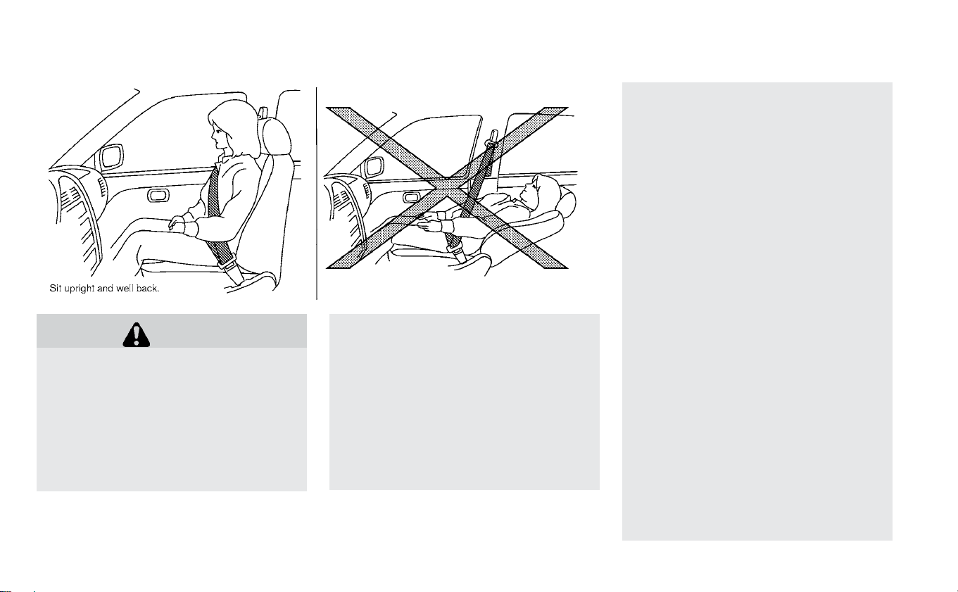
WARNING
• Do not ride in a moving vehicle when
the seatback is reclined. This can be
dangerous. The shoulder belt will
not be against your body. In an acci-
dent, you could be thrown into it and
receive neck or other serious inju-
ries. You could also slide under the
lap belt and receive serious internal
injuries.
• For the most effective protection
when the vehicle is in motion, the
seat should be upright. Always sit
well back and upright in the seat
with both feet on the floor and ad-
just the seat properly. For additional
information, refer to “Precautions on
seat belt usage” in this section.
• After adjustment, gently rock in the
seat to make sure it is securely
locked.
• Do not leave children unattended in-
side the vehicle. They could un-
knowingly activate switches or con-
trols or make the vehicle move.
Unattended children could become
involved in serious accidents.
• To help avoid risk of injury or death
through unintended operation of
the vehicle and/or its systems, do
not leave children, people who re-
quire the assistance of others or
pets unattended in your vehicle. Ad-
ditionally, the temperature inside a
closed vehicle on a warm day can
quickly become high enough to
cause a significant risk of injury or
death to people and pets.
• Do not adjust the driver’s seat while
driving so full attention may be
given to vehicle operation. The seat
may move suddenly and could
cause loss of control of the vehicle.
• The seatback should not be reclined
any more than needed for comfort.
Seat belts are most effective when
the passenger sits well back and
straight up in the seat. If the seat-
back is reclined, the risk of sliding
under the lap belt and being injured
is increased.
SEATS
1-2 Safety–Seats, seat belts and supplemental restraint system

CAUTION
When adjusting the seat positions, be
sure not to contact any moving parts
to avoid possible injuries and/or dam-
age.
FRONT MANUAL SEAT
ADJUSTMENT (FOR PASSENGER’S
SEAT AND IF SO EQUIPPED FOR
DRIVER’S SEAT)
Your vehicle seats can be adjusted manu-
ally. For additional information about ad-
justing the seats, refer to the steps outlined
in this section.
Forward and backward
Pull the bar up and hold it while sliding the
seat forward or backward to the preferred
position. Release the bar to lock the seat in
position.
Reclining
To recline the seatback, pull the lever up
and lean back. To bring the seatback for-
ward, pull the lever up and lean your body
forward. Release the lever to lock the seat-
back in position.
The reclining feature allows adjustment of
the seatback for occupants of different
sizes for added comfort and to help obtain
proper seat belt fit. For additional informa-
tion, refer to “Precautions on seat belt us-
age” in this section. Also, the seatback can
be reclined to allow occupants to rest
when the vehicle is stopped and the ve-
hicle is in the P (Park) position.
Safety–Seats, seat belts and supplemental restraint system 1-3

Seat lifter (driver’s seat)
Pull up or push down the adjusting lever to
adjust the seat height to the preferred po-
sition.
FRONT POWER SEAT ADJUSTMENT
(IF SO EQUIPPED FOR DRIVER’S
SEAT)
Operating tips
• The power seat motor has an auto-reset
overload protection circuit. If the motor
stops during operation, wait 30 seconds
then reactivate the switch.
• Do not operate the power seat switch for
a long period of time when the system is
not in the READY mode. This will discharge
the battery.
Forward and backward
Moving the switch as shown will slide the
seat forward or backward to the desired
position.
Reclining
Move the recline switch as shown until the
desired angle is obtained.
The reclining feature allows adjustment of
the seatback for occupants of different
sizes for added comfort and to help obtain
proper seat belt fit. For additional informa-
tion, refer to “Precautions on seat belt us-
age” in this section. Also, the seatback can
1-4 Safety–Seats, seat belts and supplemental restraint system

be reclined to allow occupants to rest
when the vehicle is stopped and the shift
lever is in P (Park).
Seat lifter
Move the switch as shown to adjust the
angle (if so equipped) and height of the
seat cushion.
Type A (if so equipped) Type B (if so equipped)
Safety–Seats, seat belts and supplemental restraint system 1-5
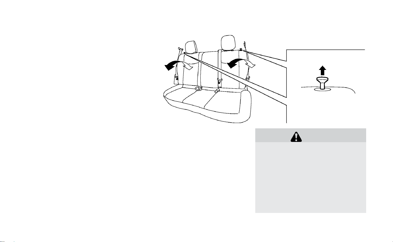
Lumbar support
The lumbar support feature provides ad-
justable lower back support to the driver.
Move the switch as shown to adjust the
seat lumbar area.
REAR SEATS
Folding
Before folding the rear seats:
• Secure the seat belts on the seat belt
hooks located on the side wall. For addi-
tional information, refer to “Seat belt hook”
in this section.
To fold down the seatback, pull the release
knob.
To return the seatback to the seating posi-
tion, lift up each seatback and push it to the
upright position until it is latched.
WARNING
• Do not fold down the rear seats
when occupants are in the rear seat
area or any objects are on the rear
seats.
• Never allow anyone to ride in the
cargo area or on the rear seats when
they are in the folded-down posi-
tion. Use of these areas by passen-
gers without proper restraints could
result in serious injury or death in an
accident or sudden stop.
1-6 Safety–Seats, seat belts and supplemental restraint system

• Properly secure all cargo with ropes
or straps to help prevent it from slid-
ing or shifting. Do not place cargo
higher than the seatbacks. In a sud-
den stop or collision, unsecured
cargo could cause personal injury.
• When returning the seatbacks to the
upright position, be certain they are
completely secured in the latched
position. If they are not completely
secured, passengers may be injured
in an accident or sudden stop.
WARNING
Head restraints/headrests supple-
ment the other vehicle safety systems.
They may provide additional protec-
tion against injury in certain rear end
collisions. Adjustable head restraints/
headrests must be adjusted properly,
as specified in this section. Check the
adjustment after someone else uses
the seat. Do not attach anything to the
head restraint/headrest stalks or re-
move the head restraints/headrests.
Do not use the seat if the head
restraint/headrest has been removed.
If the head restraint/headrest was re-
moved, reinstall and properly adjust
the head restraint/headrest before an
occupant uses the seating position.
Failure to follow these instructions can
reduce the effectiveness of the head
restraint/headrest. This may increase
the risk of serious injury or death in a
collision.
The illustration shows the seating posi-
tions equipped with a head restraint/
headrest.
Indicates the seating position is
equipped with a head restraint.
+ Indicates the seating position is not
equipped with a head restraint or headrest
(if applicable).
• Your vehicle is equipped with a head
restraint/headrest that may be inte-
grated, adjustable or non-adjustable.
HEAD RESTRAINTS/HEADRESTS
Safety–Seats, seat belts and supplemental restraint system 1-7

• Adjustable head restraints/headrests
have multiple notches along the stalks to
lock them in a desired adjustment
position.
• The non-adjustable head restraints/
headrests have a single locking notch to
secure them to the seat frame.
• Proper Adjustment:
– For the adjustable type, align the head
restraint/headrest so the center of
your ear is approximately level with the
center of the head restraint/headrest.
– If your ear position is still higher than
the recommended alignment, place
the head restraint/headrest at the
highest position.
• If the head restraint/headrest has been
removed, ensure that it is reinstalled and
locked in place before riding in that desig-
nated seating position.
ADJUSTABLE HEAD RESTRAINT/
HEADREST COMPONENTS
1. Removable head restraint/headrest
2. Multiple notches
3. Lock knob
4. Stalks
NON-ADJUSTABLE HEAD
RESTRAINT/HEADREST
COMPONENTS
1. Removable head restraint/headrest
2. Single notch
3. Lock knob
4. Stalks
1-8 Safety–Seats, seat belts and supplemental restraint system

REMOVE
Use the following procedure to remove the
head restraint/headrest.
1. Pull the head restraint/headrest up to
the highest position.
2. Push and hold the lock knob.
3. Remove the head restraint/headrest
from the seat.
4. Store the head restraint/headrest prop-
erly in a secure place so it is not loose in
the vehicle.
5. Reinstall and properly adjust the head
restraint/headrest before an occupant
uses the seating position.
INSTALL
1. Align the head restraint/headrest stalks
with the holes in the seat. Make sure the
head restraint/headrest is facing the
correct direction. The stalk with the
notch (notches)
䊊
1
must be installed in
the hole with the lock knob
䊊
2
.
2. Push and hold the lock knob and push
the head restraint/headrest down.
3. Properly adjust the head restraint/
headrest before an occupant uses the
seating position.
Safety–Seats, seat belts and supplemental restraint system 1-9

ADJUST
For adjustable head restraint/headrest
Adjust the head restraint/headrest so the
center is level with the center of your ears. If
your ear position is still higher than the
recommended alignment, place the head
restraint/headrest at the highest position.
For non-adjustable head restraint/
headrest
Make sure the head restraint/headrest is
positioned so the lock knob is engaged in
the notch before riding in that designated
seating position.
Raise
To raise the head restraint/headrest, pull it
up.
Make sure the head restraint/headrest is
positioned so the lock knob is engaged in
the notch before riding in that designated
seating position.
1-10 Safety–Seats, seat belts and supplemental restraint system

Lower
To lower, push and hold the lock knob and
push the head restraint/headrest down
Make sure the head restraint/headrest is
positioned so the lock knob is engaged in
the notch before riding in that designated
seating position.
PRECAUTIONS ON SEAT BELT
USAGE
If you are wearing your seat belt properly
adjusted, and you are sitting upright and
well back in your seat with both feet on the
floor, your chances of being injured or killed
in an accident and/or the severity of injury
may be greatly reduced. NISSAN strongly
encourages you and all of your passengers
to buckle up every time you drive, even if
your seating position includes a supple-
mental air bag.
Most U.S. states and Canadian provinces
or territories specify that seat belts be
worn at all times when a vehicle is being
driven.
SEAT BELTS
Safety–Seats, seat belts and supplemental restraint system 1-11
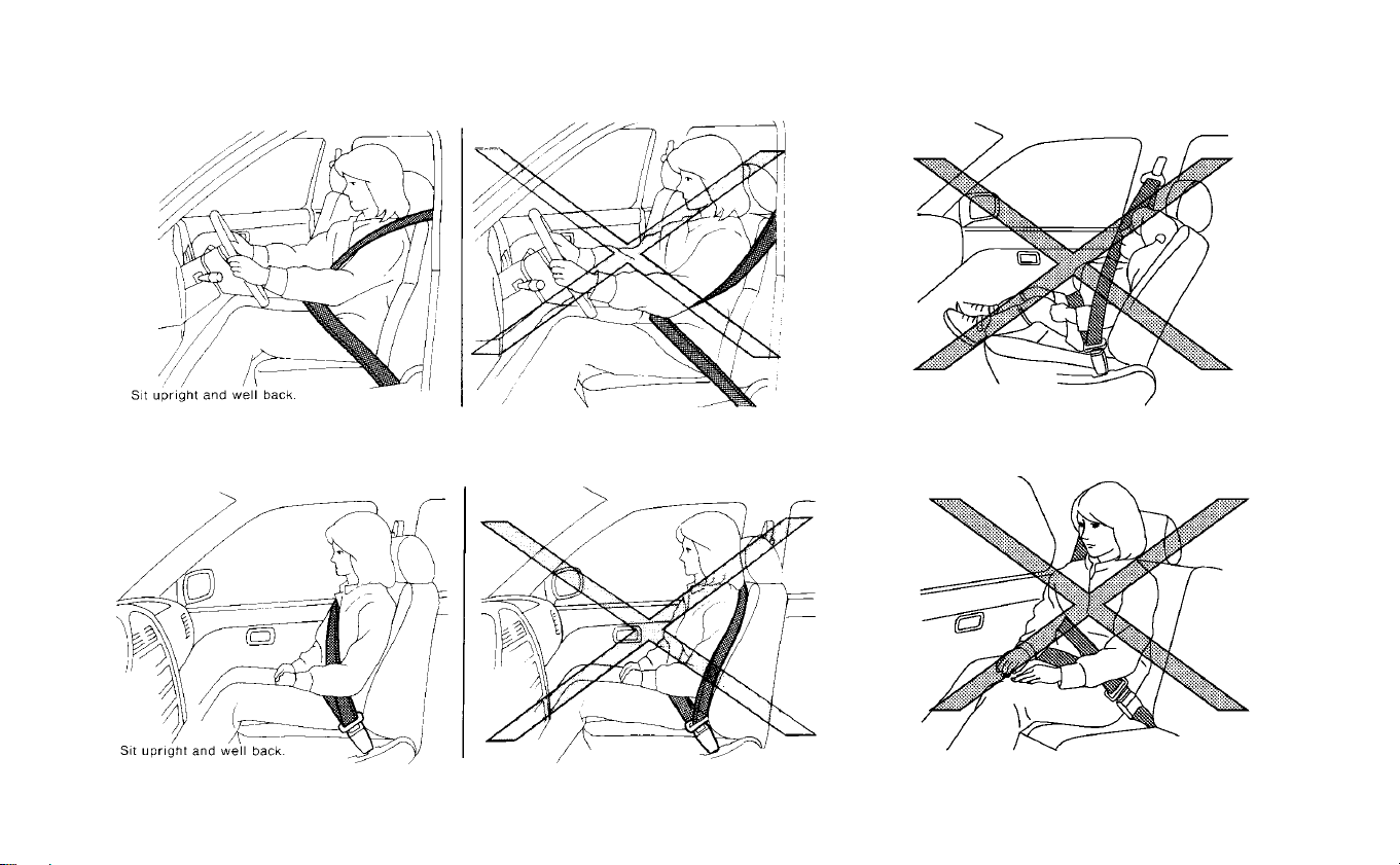
1-12 Safety–Seats, seat belts and supplemental restraint system

WARNING
• Every person who drives or rides in
this vehicle should use a seat belt at
all times. Children should be in the
rear seats and in an appropriate re-
straint.
• The seat belt should be properly ad-
justed to a snug fit. Failure to do so
may reduce the effectiveness of the
entire restraint system and increase
the chance or severity of injury in an
accident. Serious injury or death can
occur if the seat belt is not worn
properly.
• Always route the shoulder belt over
your shoulder and across your
chest. Never put the belt behind your
back, under your arm or across your
neck. The belt should be away from
your face and neck, but not falling
off your shoulder.
• Position the lap belt as low and snug
as possible AROUND THE HIPS, NOT
THE WAIST. A lap belt worn too high
could increase the risk of internal in-
juries in an accident.
• Be sure the seat belt tongue is se-
curely fastened to the proper buckle.
• Do not wear the seat belt inside out
or twisted. Doing so may reduce its
effectiveness.
• Do not allow more than one person
to use the same seat belt.
• Never carry more people in the ve-
hicle than there are seat belts.
• If the seat belt warning light glows
continuously while the power switch
is turned ON with all doors closed
and all seat belts fastened, it may
indicate a malfunction in the sys-
tem. Have the system checked. It is
recommended that you visit a
NISSAN certified LEAF dealer for this
service.
• No changes should be made to the
seat belt system. For example, do
not modify the seat belt, add mate-
rial, or install devices that may
change the seat belt routing or ten-
sion. Doing so may affect the opera-
tion of the seat belt system. Modify-
ing or tampering with the seat belt
system may result in serious per-
sonal injury.
• Once seat belt pretensioner(s) have
activated, they cannot be reused
and must be replaced together with
the retractor. It is recommended
that you visit a NISSAN certified LEAF
dealer for this service.
• All seat belt assemblies, including
retractors and attaching hardware,
should be inspected after any colli-
sion. It is recommended that you
visit a NISSAN certified LEAF dealer
for this service. NISSAN recom-
mends that all seat belt assemblies
in use during a collision be replaced
unless the collision was minor and
the belts show no damage and con-
tinue to operate properly. Seat belt
assemblies not in use during a colli-
sion should also be inspected and
replaced if either damage or im-
proper operation is noted.
• All child restraints and attaching
hardware should be inspected after
any collision. Always follow the re-
straint manufacturer’s inspection
instructions and replacement rec-
ommendations. The child restraints
should be replaced if they are dam-
aged.
Safety–Seats, seat belts and supplemental restraint system 1-13

SEAT BELT WARNING LIGHT
Both the driver’s and passenger’s front
seats are equipped with a seat belt warn-
ing light. The warning light, located on the
instrument panel, will show the status of
the driver and passenger seat belt.
NOTE:
The front passenger seat belt warn-
ing light will not light up if the seat is
not occupied.
For additional information, refer to “Warn-
ing lights, indicator lights and audible re-
minders” in the “Instruments and controls”
section of this manual.
PREGNANT WOMEN
NISSAN recommends that pregnant
women use seat belts. The seat belt should
be worn snug, and always position the lap
belt as low as possible around the hips, not
the waist. Place the shoulder belt over your
shoulder and across your chest. Never put
the lap/shoulder belt over your abdominal
area. Contact your doctor for specific rec-
ommendations.
INJURED PERSONS
NISSAN recommends that injured persons
use seat belts, depending on the injury.
Check with your doctor for specific recom-
mendations.
THREE-POINT TYPE SEAT BELT
WITH RETRACTOR
WARNING
• Every person who drives or rides in
this vehicle should use a seat belt at
all times.
• Do not ride in a moving vehicle when
the seatback is reclined. This can be
dangerous. The shoulder belt will
not be against your body. In an acci-
dent, you could be thrown into it and
receive neck or other serious inju-
ries. You could also slide under the
lap belt and receive serious internal
injuries.
• For the most effective protection
when the vehicle is in motion, the
seat should be upright. Always sit
well back and upright in the seat
with both feet on the floor and ad-
just the seat belt properly.
• Do not allow children to play with the
seat belts. Most seating positions
are equipped with Automatic Lock-
ing Retractor (ALR) mode seat belts.
If the seat belt becomes wrapped
around a child’s neck with the ALR
mode activated, the child can be se-
riously injured or killed if the seat
belt retracts and becomes tight. This
can occur even if the vehicle is
parked. Unbuckle the seat belt to re-
lease the child. If the seat belt can-
not be unbuckled or is already un-
buckled, release the child by cutting
the seat belt with a suitable tool
1-14 Safety–Seats, seat belts and supplemental restraint system

(such as a knife or scissors) to re-
lease the seat belt.
Fastening the seat belts
1. Adjust the seat. For additional informa-
tion, refer to “Seats” in this section.
2. Slowly pull the seat belt out of the retrac-
tor and insert the tongue into the buckle
until you hear and feel the latch engage.
• The retractor is designed to lock dur-
ing a sudden stop or on impact. A
slow pulling motion permits the belt
to move and allows you some free-
dom of movement in the seat.
• If the seat belt cannot be pulled from
its fully retracted position, firmly pull
the belt and release it. Then smoothly
pull the belt out of the retractor.
3. Position the lap belt portion low and
snug on the hips as shown.
4. Pull the shoulder belt portion toward the
retractor to take up extra slack. Be sure
the shoulder belt is routed over your
shoulder and across your chest.
The front passenger seat and the rear
seating positions three-point seat belts
have two modes of operation:
• Emergency Locking Retractor (ELR)
• Automatic Locking Retractor (ALR)
Safety–Seats, seat belts and supplemental restraint system 1-15
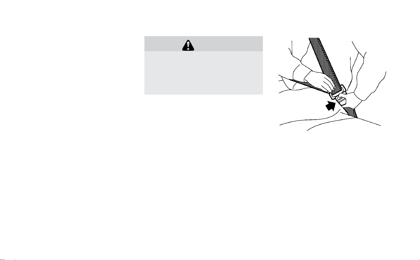
The ELR mode allows the seat belt to ex-
tend and retract to allow the driver and
passengers some freedom of movement
in the seat. The ELR locks the seat belt
when the vehicle slows down rapidly or
during certain impacts.
The ALR mode (child restraint mode) locks
the seat belt for child restraint installation.
When ALR mode is activated the seat belt
cannot be extended again until the seat
belt tongue is detached from the buckle
and fully retracted. The seat belt returns to
the ELR mode after the seat belt fully re-
tracts. For additional information, refer to
“Child restraints” in this section.
The ALR mode should be used only for
child restraint installation. During nor-
mal seat belt use by an occupant, the ALR
mode should not be activated. If it is ac-
tivated, it may cause uncomfortable seat
belt tension. It can also change the op-
eration of the front passenger air bag.
For additional information, refer to
“Front passenger air bag and status
light” in this section.
WARNING
When fastening the seat belts, be cer-
tain that seatbacks are completely se-
cured in the latched position. If they
are not completely secured, passen-
gers may be injured in an accident or
sudden stop.
Unfastening the seat belts
To unfasten the seat belt, push the button
on the buckle. The seat belt automatically
retracts.
Checking seat belt operation
Seat belt retractors are designed to lock
seat belt movement by two separate
methods:
• When the belt is pulled quickly from the
retractor
• When the vehicle slows down rapidly
1-16 Safety–Seats, seat belts and supplemental restraint system
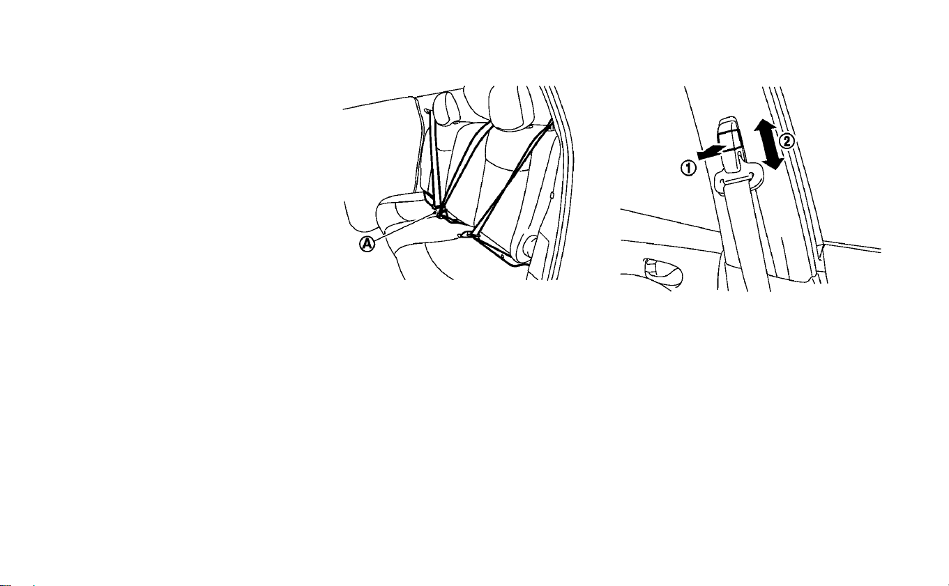
To increase your confidence in the seat
belts, check the operation as follows:
• Grasp the shoulder belt and pull forward
quickly. The retractor should lock and re-
strict further belt movement.
If the retractor does not lock during this
check, get the system checked. It is recom-
mended that you visit a NISSAN certified
LEAF dealer for this service, or to learn
more about seat belt operation.
Center of rear seat
Selecting correct set of seat belts:
The center seat belt buckle is identified by
the CENTER mark
䊊
A
. The center seat belt
tongue can be fastened only into the cen-
ter seat belt buckle.
Shoulder belt height adjustment
(front seats)
The shoulder belt anchor height should be
adjusted to the position that is best for you.
For additional information, refer to “Precau-
tions on seat belt usage” in this section.
To adjust, pull the adjustment button
䊊
1
,
and then move the shoulder belt anchor to
the preferred position
䊊
2
so that the belt
passes over the center of the shoulder. The
belt should be away from your face and
neck, but not falling off of your shoulder.
Release the adjustment button to lock the
shoulder belt anchor into position.
Safety–Seats, seat belts and supplemental restraint system 1-17
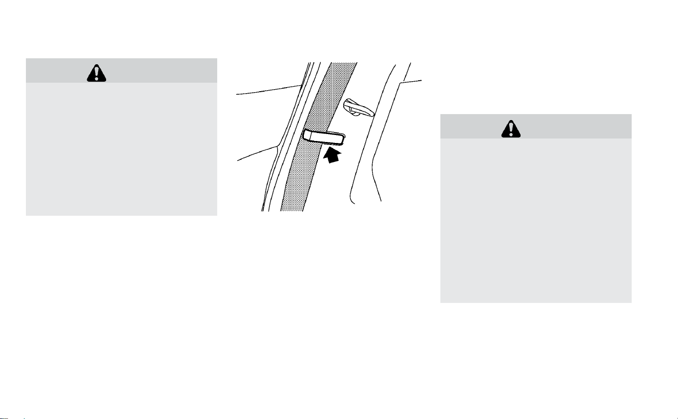
WARNING
• After adjustment, release the ad-
justment button and then try to
move the shoulder belt anchor up
and down to make sure that it is se-
curely fixed in position.
• The shoulder belt anchor height
should be adjusted to the position
that is best for you. Failure to do so
may reduce the effectiveness of the
entire restraint system and increase
the chance or severity of injury in an
accident.
Seat belt hook
When the rear seat belts are not in use and
when folding down the rear seats, hook the
rear outer seat belts on the seat belt hooks.
SEAT BELT EXTENDERS
If, because of body size or driving position, it
is not possible to properly fit the lap/
shoulder belt and fasten it, an extender
that is compatible with the installed seat
belts is available for purchase. The ex-
tender adds approximately 8 in (200 mm)
of length and may be used for either the
driver or front passenger seating position.
It is recommended that you visit a NISSAN
certified LEAF dealer for assistance with
purchasing an extender if an extender is
required.
WARNING
• Only NISSAN seat belt extenders,
made by the same company which
made the original equipment seat
belts, should be used with NISSAN
seat belts.
• Adults and children who can use the
standard seat belt should not use an
extender. Such unnecessary use
could result in serious personal in-
jury in the event of an accident.
• Never use seat belt extenders to in-
stall child restraints. If the child re-
straint is not secured properly, the
child could be seriously injured or
killed in a collision or a sudden stop.
1-18 Safety–Seats, seat belts and supplemental restraint system

SEAT BELT MAINTENANCE
• To clean the seat belt webbing, apply a
mild soap solution or any solution recom-
mended for cleaning upholstery or car-
pets. Then wipe with a cloth and allow the
seat belts to dry in the shade. Do not allow
the seat belts to retract until they are
completely dry.
• If dirt builds up in the shoulder belt
guide of the seat belt anchors, the seat
belts may retract slowly. Wipe the shoul-
der belt guide with a clean, dry cloth.
• Periodically check to see that the seat
belt and the metal components, such as
buckles, tongues, retractors, flexible wires
and anchors, work properly. If loose parts,
deterioration, cuts or other damage on
the webbing is found, the entire seat belt
assembly should be replaced.
WARNING
Do not allow children to play with the
seat belts. Most seating positions are
equipped with Automatic Locking Re-
tractor (ALR) mode seat belts. If the
seat belt becomes wrapped around a
child’s neck with the ALR mode acti-
vated, the child can be seriously in-
jured or killed if the seat belt retracts
and becomes tight. This can occur
even if the vehicle is parked. Unbuckle
the seat belt to release the child. If the
seat belt cannot be unbuckled or is al-
ready unbuckled, release the child by
cutting the seat belt with a suitable
tool (such as a knife or scissors) to re-
lease the seat belt.
Children need adults to help protect
them. They need to be properly re-
strained.
In addition to the general information in
this manual, child safety information is
available from many other sources, includ-
ing doctors, teachers, government traffic
safety offices, and community organiza-
tions. Every child is different, so be sure to
learn the best way to transport your child.
There are three basic types of child re-
straint systems:
• Rear-facing child restraint
• Forward-facing child restraint
• Booster seat
The proper restraint depends on the child’s
size. Generally, infants up to about 1 year
and less than 20 lbs. (9 kg) should be placed
in rear-facing child restraints. Forward-
facing child restraints are available for chil-
dren who outgrow rear-facing child re-
straints and are at least 1 year old. Booster
seats are used to help position a vehicle
lap/shoulder belt on a child who can no
longer use a forward-facing child restraint.
WARNING
Infants and children need special pro-
tection. The vehicle’s seat belts may
not fit them properly. The shoulder belt
may come too close to the face or neck.
The lap belt may not fit over their small
hip bones. In an accident, an improp-
erly fitting seat belt could cause seri-
ous or fatal injury. Always use appro-
priate child restraints.
CHILD SAFETY
Safety–Seats, seat belts and supplemental restraint system 1-19

All U.S. states and Canadian provinces or
territories require the use of approved child
restraints for infants and small children. For
additional information, refer to “Child re-
straints” in this section.
A child restraint may be secured in the ve-
hicle by using either the LATCH (Lower An-
chor and Tethers for CHildren) system or
with the vehicle seat belt. For additional
information, refer to “Child restraints” in this
section.
NISSAN recommends that all pre-teens
and children be restrained in the rear
seat. According to accident statistics,
children are safer when properly re-
strained in the rear seat than in the front
seat.
This is especially important because
your vehicle has a supplemental re-
straint system (air bag system) for the
front passenger. For additional informa-
tion, refer to “Supplemental Restraint
System (SRS)” in this section.
INFANTS
Infants up to at least 1 year old should be
placed in a rear-facing child restraint. NISSAN
recommends that infants be placed in child
restraints that comply with Federal Motor
Vehicle Safety Standards or Canadian Motor
Vehicle Safety Standards.You should choose
a child restraint that fits your vehicle and
always follow the manufacturer’s instruc-
tions for installation and use.
SMALL CHILDREN
Children that are over 1 year old and weigh
at least 20 lbs. (9 kg) should remain in a
rear-facing child restraint as long as pos-
sible up to the height or weight limit of the
child restraint. Children who outgrow the
height or weight limit of the rear-facing
child restraint and are at least 1 year old
should be secured in a forward-facing child
restraint with a harness. Refer to the manu-
facturer’s instructions for minimum and
maximum weight and height recommen-
dations. NISSAN recommends that small
children be placed in child restraints that
comply with Federal Motor Vehicle Safety
Standards or Canadian Motor Vehicle
Safety Standards. You should choose a
child restraint that fits your vehicle and al-
ways follow the manufacturer’s instruc-
tions for installation and use.
LARGER CHILDREN
Children should remain in a forward-facing
child restraint with a harness until they
reach the maximum height or weight limit
allowed by the child restraint manufac-
turer.
Once a child outgrows the height or weight
limit of the harness-equipped forward-
facing child restraint, NISSAN recommends
that the child be placed in a commercially
available booster seat to obtain proper
seat belt fit. For a seat belt to fit properly, the
booster seat should raise the child so that
the shoulder belt is properly positioned
across the chest and the top, middle por-
tion of the shoulder. The shoulder belt
should not cross the neck or face and
should not fall off the shoulder. The lap belt
should lie snugly across the lower hips or
upper thighs, not the abdomen. A booster
seat can only be used in seating positions
that have a three-point type seat belt. The
booster seat should fit the vehicle seat and
have a label certifying that it complies with
Federal Motor Vehicle Safety Standards or
Canadian Motor Vehicle Safety Standards.
1-20 Safety–Seats, seat belts and supplemental restraint system

A booster seat should be used until the
child can pass the seat belt fit test below:
• Are the child’s back and hips against the
vehicle seatback?
• Is the child able to sit without slouching?
• Do the child’s knees bend easily over the
front edge of the seat with feet flat on the
floor?
• Can the child safely wear the seat belt (lap
belt low and snug across the hips and
shoulder belt across mid-chest and
shoulder)?
• Is the child able to use the properly ad-
justed head restraint/headrest?
• Will the child be able to stay in position for
the entire ride?
If you answered no to any of these ques-
tions, the child should remain in a booster
seat using a three-point type seat belt.
NOTE:
Laws in some communities may follow
different guidelines. Check local and
state regulations to confirm your child is
using the correct restraint system before
traveling.
WARNING
Never let a child stand or kneel on any
seat and do not allow a child in the
cargo areas. The child could be seri-
ously injured or killed in an accident or
sudden stop.
Safety–Seats, seat belts and supplemental restraint system 1-21
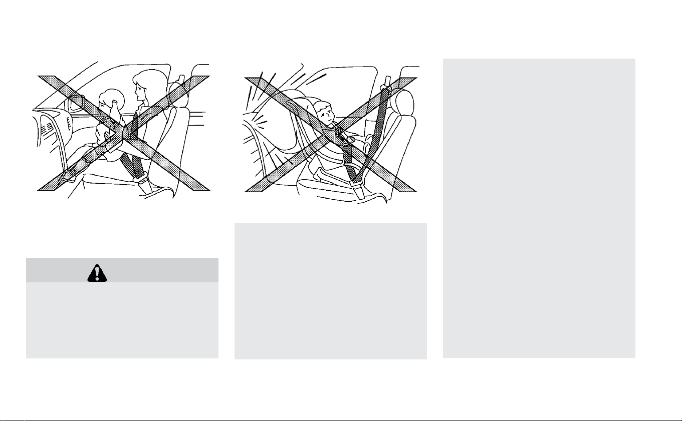
PRECAUTIONS ON CHILD
RESTRAINTS
WARNING
•
Failure to follow the warnings and
instructions for proper use and in-
stallation of child restraints could
result in serious injury or death of a
child or other passengers in a sud-
den stop or collision:
–
The child restraint must be used
and installed properly. Always fol-
low all of the child restraint manu-
facturer’s instructions for instal-
lation and use.
–
Infants and children should never
be held on anyone’s lap. Even the
strongest adult cannot resist the
forces of a collision.
–
Do not put a seat belt around both
a child and another passenger.
–
NISSAN recommends that all child
restraints be installed in the rear
seat. Studies show that children
are safer when properly re-
strained in the rear seat than in
the front seat. If you must install a
forward-facing child restraint in
the front seat, refer to “Forward-
facing child restraint installation
using the seat belts” in this
section.
–
Even with the NISSAN Advanced
Air Bag System, never install a
rear-facing child restraint in the
front seat. An inflating air bag
could seriously injure or kill a
child. A rear-facing child restraint
must only be used in the rear seat.
–
Be sure to purchase a child re-
straint that will fit the child and
vehicle. Some child restraints may
not fit properly in your vehicle.
–
Child restraint anchorages are de-
signed to withstand only those
loads imposed by correctly fitted
CHILD RESTRAINTS
1-22 Safety–Seats, seat belts and supplemental restraint system

child restraints. Under no circum-
stances are they to be used to at-
tach adult seat belts, or other items
or equipment to the vehicle. Doing
so could damage the child restraint
anchorages. The child restraint will
not be properly installed using the
damaged anchorage, and a child
could be seriously injured or killed in
a collision.
–
Never use the anchor points for
adult seat belts or other items.
–
A child restraint with a top tether
strap should not be used in the
front passenger seat.
–
Keep seatbacks as upright as pos-
sible after fitting the child
restraint.
–
Infants and children should al-
ways be placed in an appropriate
child restraint while in the vehicle.
•
When the child restraint is not in use,
keep it secured with the LATCH system
or a seat belt. In a sudden stop or colli-
sion, loose objects can injure occu-
pants or damage the vehicle.
CAUTION
A child restraint in a closed vehicle can
become very hot. Check the seating
surface and buckles before placing a
child in the child restraint.
This vehicle is equipped with a universal
child restraint anchor system, referred to
as the LATCH (Lower Anchors and Tethers
for CHildren) system. Some child restraints
include rigid or webbing-mounted attach-
ments that can be connected to these an-
chors.
For additional information, refer to “LATCH
(Lower Anchors and Tethers for CHildren)
system” in this section.
If you do not have a LATCH compatible child
restraint, the vehicle seat belts can be used.
Several manufacturers offer child re-
straints for infants and small children of
various sizes. When selecting any child re-
straint, keep the following points in mind:
• Choose only a restraint with a label certi-
fying that it complies with Federal Motor
Vehicle Safety Standard 213 or Canadian
Motor Vehicle Safety Standard 213.
• Check the child restraint in your vehicle to
be sure it is compatible with the vehicle’s
seat and seat belt system.
• If the child restraint is compatible with
your vehicle, place your child in the child
restraint and check the various adjust-
ments to be sure the child restraint is
compatible with your child. Choose a child
restraint that is designed for your child’s
height and weight. Always follow all rec-
ommended procedures.
• If the combined weight of the child and
child restraint is less than 65 lbs. (29.5 kg),
you may use either the LATCH anchors or
the seat belt to install the child restraint
(not both at the same time).
• If the combined weight of the child and
child restraint is greater than 65 lbs.
(29.5 kg), use the vehicle's seat belt (not the
lower anchors) to install the child restraint.
• Be sure to follow the child restraint manu-
facturer's instructions for installation.
Safety–Seats, seat belts and supplemental restraint system 1-23

All U.S. states and Canadian provinces or
territories require that infants and small
children be restrained in an approved
child restraint at all times while the ve-
hicle is being operated. Canadian law re-
quires the top tether strap on forward-
facing child restraints be secured to the
designated anchor point on the vehicle.
LATCH (LOWER ANCHORS AND
TETHERS FOR CHILDREN) SYSTEM
Your vehicle is equipped with special an-
chor points that are used with LATCH sys-
tem compatible child restraints. This sys-
tem may also be referred to as the ISOFIX
or ISOFIX compatible system. With this sys-
tem, you do not have to use a vehicle seat
belt to secure the child restraint unless the
combined weight of the child and child re-
straint exceeds 65 lbs. (29.5 kg). If the com-
bined weight of the child and child restraint
is greater than 65 lbs. (29.5 kg), use the ve-
hicle's seat belt (not the lower anchors) to
install the child restraint. Be sure to follow
the child restraint manufacturer's instruc-
tions for installation.
The LATCH lower anchor points are pro-
vided to install child restraints in the rear
outboard seating positions only. Do not at-
tempt to install a child restraint in the cen-
ter position using the LATCH lower an-
chors.
LATCH lower anchor
WARNING
Failure to follow the warnings and in-
structions for proper use and installa-
tion of child restraints could result in
serious injury or death of a child or
other passengers in a sudden stop or
collision:
• Attach LATCH system compatible
child restraints only at the locations
shown in the illustration.
• Do not secure a child restraint in the
center rear seating position using
the LATCH lower anchors. The child
restraint will not be secured
properly.
1-24 Safety–Seats, seat belts and supplemental restraint system
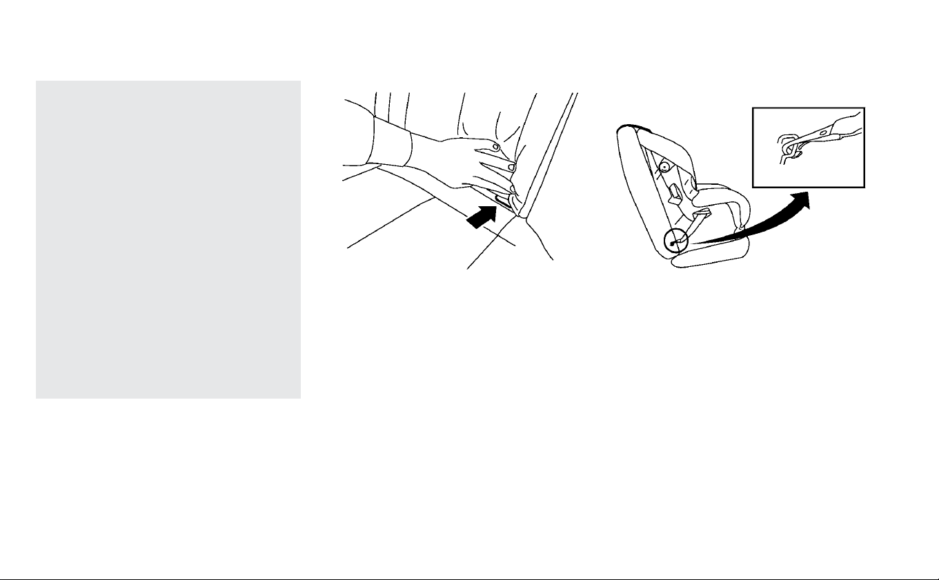
• Inspect the lower anchors by insert-
ing your fingers into the lower an-
chor area. Feel to make sure there
are no obstructions over the an-
chors such as seat belt webbing or
seat cushion material. The child re-
straint will not be secured properly if
the lower anchors are obstructed.
• Child restraint anchorages are de-
signed to withstand only those
loads imposed by correctly fitted
child restraints. Under no circum-
stances are they to be used to attach
adult seat belts, or other items or
equipment to the vehicle. Doing so
could damage the child restraint an-
chorages. The child restraint will not
be properly installed using the dam-
aged anchorage, and a child could
be seriously injured or killed in a
collision.
LATCH lower anchor location
The LATCH lower anchors are located at
the rear of the seat cushion near the seat-
back. A label is attached to the seatback to
help you locate the LATCH lower anchors.
Installing child restraint LATCH
lower anchor attachments
LATCH compatible child restraints include
two rigid or webbing-mounted attach-
ments that can be connected to two an-
chors located at certain seating positions
in your vehicle. With this system, you do not
have to use a vehicle seat belt to secure the
child restraint. Check your child restraint for
a label stating that it is compatible with the
LATCH system. This information may also
be in the instructions provided by the child
restraint manufacturer.
LATCH lower anchor location LATCH webbing-mounted attachment
Safety–Seats, seat belts and supplemental restraint system 1-25
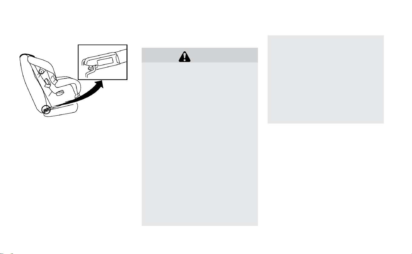
When installing a child restraint, carefully
read and follow the instructions in this
manual and those supplied with the child
restraint.
Top tether anchor
WARNING
• If the tonneau cover (if so equipped)
contacts the top tether strap when it
is attached to the top tether anchor,
remove the tonneau cover (if so
equipped) from the vehicle or secure
it on the cargo floor below its attach-
ment location. If the tonneau cover
(if so equipped) is not removed, it
may damage the top tether strap
during a collision.Your child could be
seriously injured or killed in a colli-
sion if the child restraint top tether
strap is damaged.
• Do not allow cargo to contact the top
tether strap when it is attached to
the top tether anchor. Properly se-
cure the cargo so it does not contact
the top tether strap.Cargo that is not
properly secured or that contacts
the top tether strap may damage
the top tether strap during a colli-
sion. Your child could be seriously in-
jured or killed in a collision if the
child restraint top tether strap is
damaged.
• Child restraint anchorages are de-
signed to withstand only those
loads imposed by correctly fitted
child restraints. Under no circum-
stances are they to be used to attach
adult seat belts, or other items or
equipment to the vehicle. Doing so
could damage the child restraint an-
chorages. The child restraint will not
be properly installed using the dam-
aged anchorage, and a child could
be seriously injured or killed in a col-
lision.
LATCH rigid-mounted attachment
1-26 Safety–Seats, seat belts and supplemental restraint system

Top tether anchor point locations:
Anchor points are located on the back side
of the seatbacks.
The child restraint top tether strap must be
used when installing child restraints with
the LATCH lower anchor attachments or
seat belts. For additional information, refer
to “Installing top tether strap” in this sec-
tion.
If you have any questions when install-
ing a top tether strap, it is recommended
that you visit a NISSAN certified LEAF
dealer for details.
REAR-FACING CHILD RESTRAINT
INSTALLATION USING LATCH
For additional information, refer to all Warn-
ings and Cautions in “Child safety” and
“Child restraints” in this section before in-
stalling a child restraint.
Do not use the lower anchors if the com-
bined weight of the child and the child re-
straint exceeds 65 lbs. (29.5 kg). If the com-
bined weight of the child and the child
restraint is greater than 65 lbs. (29.5 kg), use
the vehicle's seat belt (not the lower an-
chors) to install the child restraint. Be sure
to follow the child restraint manufacturer's
instructions for installation.
Follow these steps to install a rear-facing
child restraint using the LATCH system:
1. Position the child restraint on the seat.
Always follow the child restraint manu-
facturer’s instructions.
Safety–Seats, seat belts and supplemental restraint system 1-27
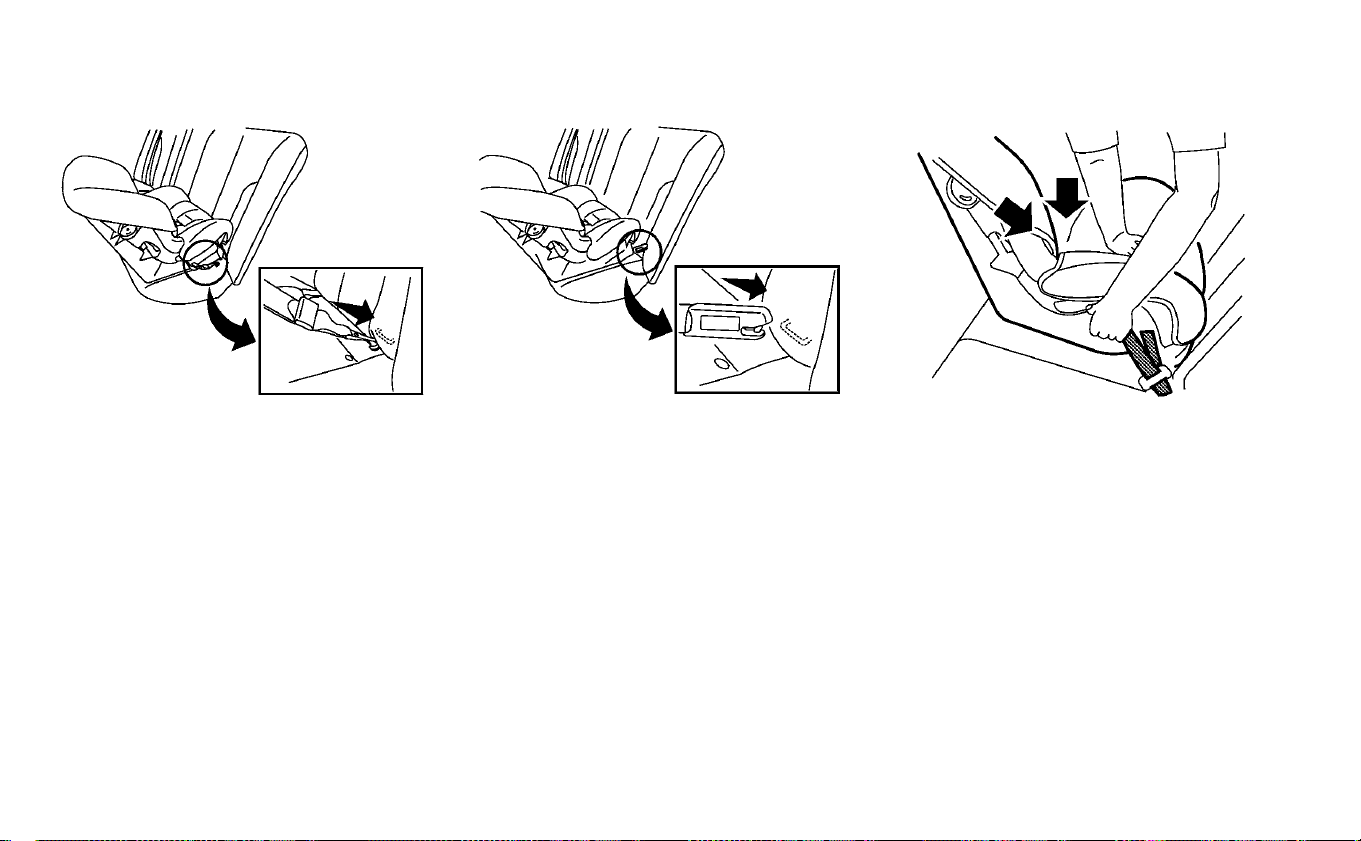
2. Secure the child restraint anchor at-
tachments to the LATCH lower anchors.
Check to make sure that the LATCH at-
tachment is properly attached to the
lower anchors.
3. For child restraints that are equipped
with webbing-mounted attachments,
remove any additional slack from the
anchor attachments. Press downward
and rearward firmly in the center of the
child restraint with your hand to com-
press the vehicle seat cushion and seat-
back while tightening the webbing of
the anchor attachments.
Rear-facing webbing-mounted — step 2 Rear-facing rigid-mounted — step 2 Rear-facing — step 3
1-28 Safety–Seats, seat belts and supplemental restraint system
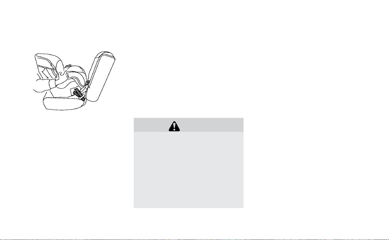
4. After attaching the child restraint, test it
before you place the child in it. Push it
from side to side while holding the seat
near the LATCH attachment path. The
child restraint should not move more
than 1 inch (25 mm), from side to side. Try
to tug it forward and check to see if the
LATCH attachment holds the restraint in
place. If the restraint is not secure,
tighten the LATCH attachment as nec-
essary, or put the restraint in another
seat and test it again. You may need to
try a different child restraint or try install-
ing by using the vehicle seat belt (if ap-
plicable). Not all child restraints fit in all
types of vehicles.
5. Check to make sure that the child re-
straint is properly secured prior to each
use. If the child restraint is loose, repeat
steps 2 through 4.
REAR-FACING CHILD RESTRAINT
INSTALLATION USING THE SEAT
BELTS
WARNING
The three-point seat belt with Auto-
matic Locking Retractor (ALR) must be
used when installing a child restraint.
Failure to use the ALR mode will result
in the child restraint not being properly
secured. The restraint could tip over or
be loose and cause injury to a child in a
sudden stop or collision. Also, it can
change the operation of the front pas-
senger air bag. For additional informa-
tion, refer to “Front passenger air bag
and status light” in this section.
For additional information, refer to all Warn-
ings and Cautions in the “Child safety” and
“Child restraints” sections of this manual
before installing a child restraint.
Do not use the lower anchors if the com-
bined weight of the child and child restraint
exceeds 65 lbs. (29.5 kg). If the combined
weight of the child and child restraint is
greater than 65 lbs. (29.5 kg), use the vehi-
cle’s seat belt (not the lower anchors) to
install the child restraint. Be sure to follow
the child restraint manufacturer’s instruc-
tions for installation.
Follow these steps to install a rear-facing
child restraint using the vehicle seat belt in
the rear seats:
Rear-facing — step 4
Safety–Seats, seat belts and supplemental restraint system 1-29
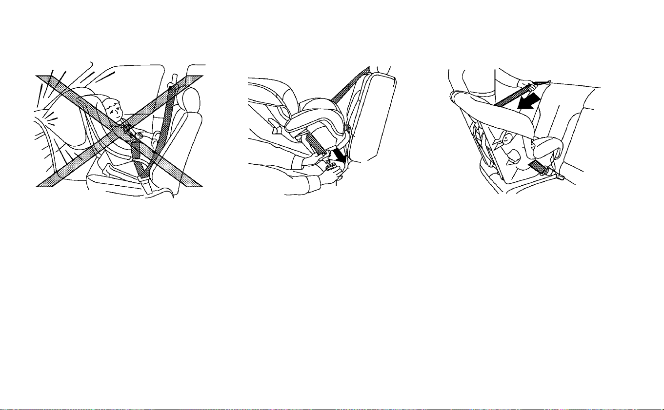
1. Child restraints for infants must be
used in the rear-facing direction and
therefore must not be used in the front
seat. Position the child restraint on the
seat. Always follow the child restraint
manufacturer’s instructions.
2. Route the seat belt tongue through the
child restraint and insert it into the
buckle until you hear and feel the latch
engage. Be sure to follow the child re-
straint manufacturer’s instructions for
belt routing.
3. Pull the shoulder belt until the belt is fully
extended. At this time, the seat belt re-
tractor is in the ALR mode (child restraint
mode). It reverts to the ELR mode when
the seat belt is fully retracted.
Rear-facing — step 1 Rear-facing — step 2 Rear-facing — step 3
1-30 Safety–Seats, seat belts and supplemental restraint system
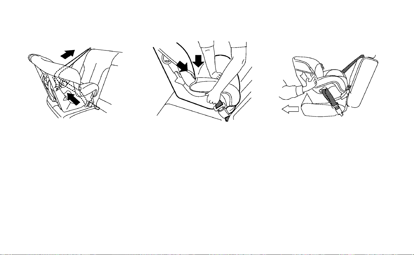
4. Allow the seat belt to retract. Pull up on
the shoulder belt to remove any slack in
the belt.
5. Remove any additional slack from the
child restraint. Press downward and
rearward firmly in the center of the child
restraint with your hand to compress
the vehicle seat cushion and seatback
while pulling up on the seat belt.
6. After attaching the child restraint, test it
before you place the child in it. Push it
from side to side while holding the child
restraint near the seat belt path. The
child restraint should not move more
than 1 inch (25 mm), from side to side. Try
to tug it forward and check to see if the
belt holds the restraint in place. If the
restraint is not secure, tighten the seat
belt as necessary, or put the restraint in
another seat and test it again. You may
need to try a different child restraint. Not
Rear-facing — step 4 Rear-facing — step 5 Rear-facing — step 6
Safety–Seats, seat belts and supplemental restraint system 1-31
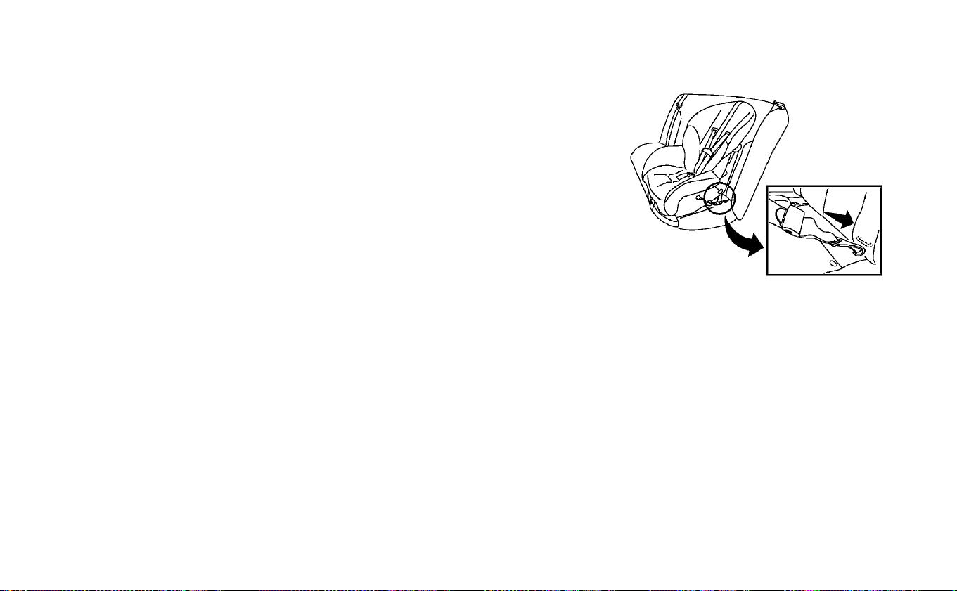
all child restraints fit in all types of
vehicles.
7. Check to make sure that the child re-
straint is properly secured prior to each
use. If the seat belt is not locked, repeat
steps 1 through 6.
After the child restraint is removed and the
seat belt fully retracted, the ALR mode
(child restraint mode) is canceled.
FORWARD-FACING CHILD
RESTRAINT INSTALLATION USING
LATCH
For additional information, refer to all Warn-
ings and Cautions in “Child safety” and
“Child restraints” sections of this manual
before installing a child restraint.
Do not use the lower anchors if the com-
bined weight of the child and the child re-
straint exceeds 65 lbs. (29.5 kg). If the com-
bined weight of the child and the child
restraint is greater than 65 lbs. (29.5 kg), use
the vehicle's seat belt (not the lower an-
chors) to install the child restraint. Be sure
to follow the child restraint manufacturer's
instructions for installation.
Follow these steps to install a forward-
facing child restraint using the LATCH sys-
tem:
1. Position the child restraint on the seat.
Always follow the child restraint manu-
facturer’s instructions.
2. Secure the child restraint anchor at-
tachments to the LATCH lower anchors.
Check to make sure that the LATCH at-
tachment is properly attached to the
lower anchors.
Forward-facing webbing-mounted —
step 2
1-32 Safety–Seats, seat belts and supplemental restraint system
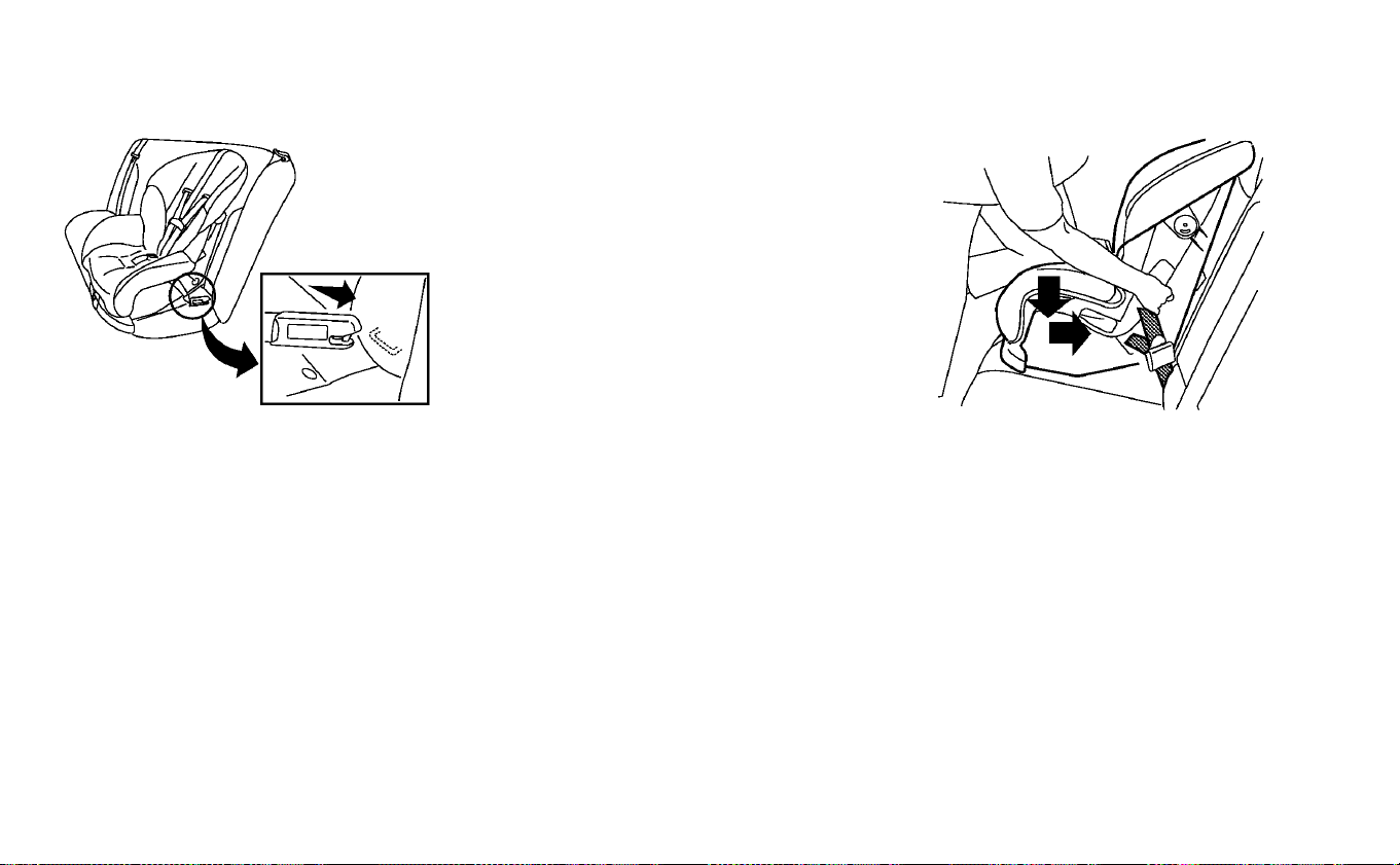
If the child restraint is equipped with a
top tether strap, route the top tether
strap and secure the tether strap to the
tether anchor point. For additional infor-
mation, refer to “Installing top tether
strap” in this section.
Do not install child restraints that re-
quire the use of a top tether strap in
seating positions that do not have a top
tether anchor.
3. The back of the child restraint should be
secured against the vehicle seatback.
If necessary, remove the head restraint/
headrest to obtain the correct child re-
straint fit. If the head restraint/headrest
is removed, store it in a secure place. Be
sure to reinstall the head restraint/
headrest when the child restraint is
removed. For additional information, re-
fer to “Head restraints/headrests” in this
section.
If the seating position does not have an
adjustable head restraint/headrest and
it is interfering with the proper child re-
straint fit, try another seating position or
a different child restraint.
4. For child restraints that are equipped
with webbing-mounted attachments,
remove any additional slack from the
anchor attachments. Press downward
and rearward firmly in the center of the
child restraint with your knee to com-
press the vehicle seat cushion and seat-
back while tightening the webbing of
the anchor attachments.
5. Tighten the tether strap according to
the manufacturer’s instructions to re-
move any slack.
Forward-facing rigid-mounted — step 2 Forward-facing — step 4
Safety–Seats, seat belts and supplemental restraint system 1-33

6. After attaching the child restraint, test it
before you place the child in it. Push it
from side to side while holding the child
restraint near the LATCH attachment
path. The child restraint should not
move more than 1 inch (25 mm), from
side to side. Try to tug it forward and
check to see if the LATCH attachment
holds the restraint in place. If the re-
straint is not secure, tighten the LATCH
attachment as necessary, or put the re-
straint in another seat and test it again.
You may need to try a different child
restraint. Not all child restraints fit in all
types of vehicles.
7. Check to make sure the child restraint is
properly secured prior to each use. If the
child restraint is loose, repeat steps
1 through 6.
Installing top tether strap
䊊
1
Top tether strap
䊊
2
Tether anchor point
The child restraint top tether strap must be
used when installing the child restraint with
the LATCH lower anchor attachments.
First, secure the child restraint with the
LATCH lower anchors (rear bench out-
board seating positions only).
Forward-facing — step 6
1-34 Safety–Seats, seat belts and supplemental restraint system
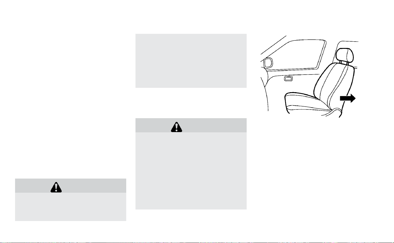
Rear bench seat
OUTBOARD SEATING POSITIONS
1. Remove the head restraint/headrest
and store it in a secure place. Be sure to
reinstall the head restraint/headrest
when the child restraint is removed. For
additional information, refer to “Head
restraints/headrests" in this section.
2. Position the top tether strap
䊊
1
over the
seatback.
3. Secure the tether strap to the tether an-
chor point
䊊
2
on the bottom of the seat-
back behind the child restraint.
4. Tighten the tether strap according to
the manufacturer’s instructions to re-
move any slack.
If you have any questions when install-
ing a top tether strap, it is recommended
that you visit a NISSAN certified LEAF
dealer for details.
WARNING
Child restraint anchorages are de-
signed to withstand only those loads
imposed by correctly fitted child re-
straints. Under no circumstances are
they to be used to attach adult seat
belts, or other items or equipment to
the vehicle. Doing so could damage the
child restraint anchorages. The child
restraint will not be properly installed
using the damaged anchorage, and a
child could be seriously injured or
killed in a collision.
FORWARD-FACING CHILD
RESTRAINT INSTALLATION USING
THE SEAT BELTS
WARNING
The three-point seat belt with Auto-
matic Locking Retractor (ALR) must be
used when installing a child restraint.
Failure to use the ALR mode will result
in the child restraint not being properly
secured. The restraint could tip over or
be loose and cause injury to a child in a
sudden stop or collision. Also, it can
change the operation of the front pas-
senger air bag. For additional informa-
tion, refer to “Front passenger air bag
and status light” in this section.
For additional information, refer to all Warn-
ings and Cautions in “Child safety” and
“Child restraints” sections of this manual
before installing a child restraint.
Do not use the lower anchors if the com-
bined weight of the child and the child re-
straint exceeds 65 lbs. (29.5 kg). If the com-
bined weight of the child and the child
restraint is greater than 65 lbs. (29.5 kg), use
the vehicle's seat belt (not the lower an-
chors) to install the child restraint. Be sure
Forward-facing (front passenger seat)
— step 1
Safety–Seats, seat belts and supplemental restraint system 1-35
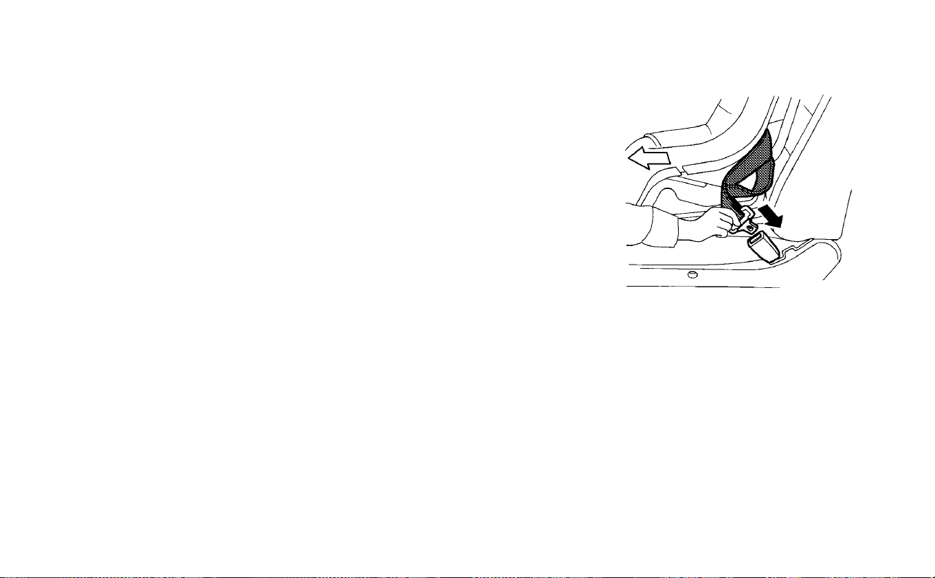
to follow the child restraint manufacturer's
instructions for installation.
Follow these steps to install a forward-
facing child restraint using the vehicle seat
belt in the rear seat or in the front passen-
ger seat:
1. If you must install a child restraint in
the front seat, it should be placed in
the forward-facing direction only.
Move the seat to the rearmost posi-
tion. Child restraints for infants must
be used in the rear-facing direction
and therefore must not be used in the
front seat.
2. Position the child restraint on the seat.
Always follow the child restraint manu-
facturer’s instructions.
The back of the child restraint should be
secured against the seatback.
If necessary, adjust the head restraint/
headrest to obtain the correct child re-
straint fit. If the head restraint/headrest
is removed, store it in a secure place. Be
sure to reinstall the head restraint/
headrest when the child restraint is
removed. For additional information,
refer to “Head restraints/headrests” in
this section.
If the seating position does not have an
adjustable head restraint/headrest and
it is interfering with the proper child re-
straint fit, try another seating position or
a different child restraint.
3. Route the seat belt tongue through the
child restraint and insert it into the
buckle until you hear and feel the latch
engage. Be sure to follow the child re-
straint manufacturer’s instructions for
belt routing.
If the child restraint is equipped with a
top tether strap, route the top tether
strap and secure the tether strap to the
Forward-facing — step 3
1-36 Safety–Seats, seat belts and supplemental restraint system
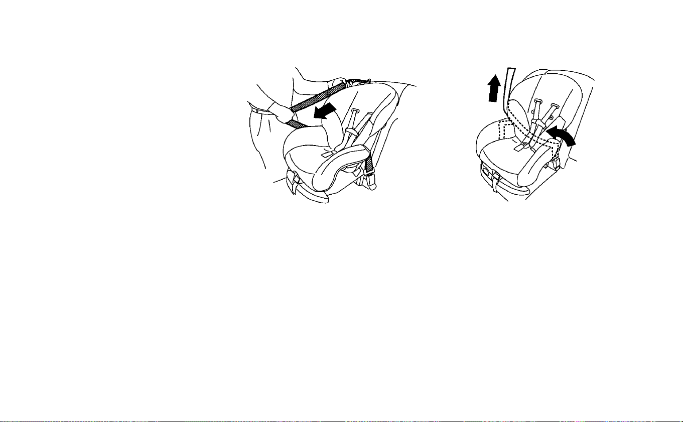
tether anchor point (rear seat installa-
tion only). For additional information, re-
fer to “Installing top tether strap” in this
section.
Do not install child restraints that re-
quire the use of a top tether strap in
seating positions that do not have a top
tether anchor.
4. Pull the shoulder belt until the belt is fully
extended. At this time, the seat belt re-
tractor is in the ALR mode (child restraint
mode). It reverts to the ELR mode when
the seat belt is fully retracted.
5. Allow the seat belt to retract. Pull up on
the shoulder belt to remove any slack in
the belt.
Forward-facing — step 4 Forward-facing — step 5
Safety–Seats, seat belts and supplemental restraint system 1-37
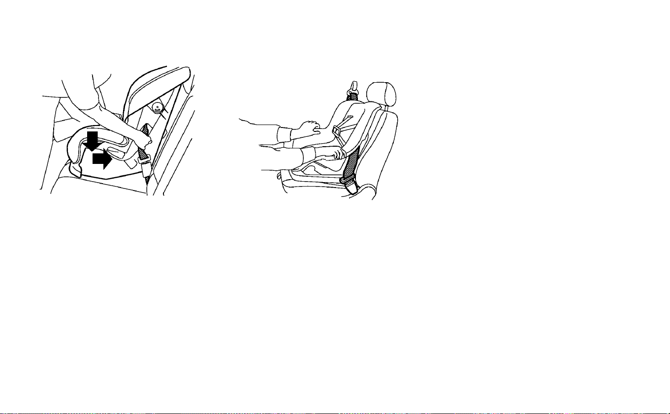
6. Remove any additional slack from the
seat belt. Press downward and rearward
firmly in the center of the child restraint
with your knee to compress the vehicle
seat cushion and seatback while pulling
up on the seat belt.
7. Tighten the tether strap according to the
manufacturer’s instructions to remove
any slack.
8. After attaching the child restraint, test it
before you place the child in it. Push it
from side to side while holding the child
restraint near the seat belt path. The
child restraint should not move more
than 1 inch (25 mm), from side to side. Try
to tug it forward and check to see if the
belt holds the restraint in place. If the
restraint is not secure, tighten the seat
belt as necessary, or put the restraint in
another seat and test it again. You may
need to try a different child restraint. Not
all child restraints fit in all types of
vehicles.
9. Check to make sure the child restraint is
properly secured prior to each use. If the
seat belt is not locked, repeat steps
2 through 8.
Forward-facing — step 6 Forward-facing — step 8
1-38 Safety–Seats, seat belts and supplemental restraint system

10. If the child restraint is installed on the
front passenger seat, push the power
switch to the ON position. The front
passenger air bag status light
should illuminate. If this light does not
illuminate, refer to “Front passenger air
bag and status light” in this section.
Move the child restraint to another
seating position. Have the system
checked. It is recommended that you
visit a NISSAN certified LEAF dealer for
this service.
After the child restraint is removed and the
seat belt is fully retracted, the ALR mode
(child restraint mode) is canceled.
Installing top tether strap
䊊
1
Top tether strap
䊊
2
Tether anchor point
The child restraint top tether strap must be
used when installing the child restraint with
the seat belts.
First, secure the child restraint with the seat
belt.
Safety–Seats, seat belts and supplemental restraint system 1-39

Rear bench seat
OUTBOARD SEATING POSITIONS
1. Remove the head restraint/headrest
and store it in a secure place. Be sure to
reinstall the head restraint/headrest
when the child restraint is removed. For
additional information, refer to “Head
restraints/headrests" in this section.
2. Position the top tether strap
䊊
1
over the
seatback.
3. Secure the tether strap to the tether an-
chor point
䊊
2
on the bottom of the seat-
back behind the child restraint.
4. Tighten the tether strap according to
the manufacturer’s instructions to re-
move any slack.
CENTER SEATING POSITION
1. Position the top tether strap
䊊
1
over the
seatback.
2. Secure the tether strap to the tether an-
chor point
䊊
2
on the bottom of the seat-
back behind the child restraint.
3. Tighten the tether strap according to
the manufacturer’s instructions to re-
move any slack.
If you have any questions when install-
ing a top tether strap, it is recommended
that you visit a NISSAN certified LEAF
dealer for this service.
WARNING
Child restraint anchorages are de-
signed to withstand only those loads
imposed by correctly fitted child re-
straints. Under no circumstances are
they to be used to attach adult seat
belts, or other items or equipment to
the vehicle. Doing so could damage the
child restraint anchorages. The child
restraint will not be properly installed
using the damaged anchorage, and a
child could be seriously injured or
killed in a collision.
BOOSTER SEATS
For additional information on installing a
booster seat in your vehicle, follow the in-
structions outlined in this section.
Precautions on booster seats
WARNING
If a booster seat and seat belt are not
used properly, the risk of a child being
injured or killed in a sudden stop or
collision greatly increases:
•
Make sure the shoulder portion of
the belt is away from the child’s face
and neck and the lap portion of the
belt does not cross the stomach.
•
Make sure the shoulder belt is not
behind the child or under the child’s
arm.
• A booster seat must only be in-
stalled in a seating position that has
a lap/shoulder belt.
1-40 Safety–Seats, seat belts and supplemental restraint system
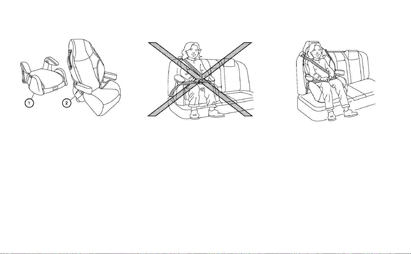
Booster seats of various sizes are offered
by several manufacturers. When selecting
any booster seat, keep the following points
in mind:
• Choose only a booster seat with a label
certifying that it complies with Federal
Motor Vehicle Safety Standard 213 or Ca-
nadian Motor Vehicle Safety Standard 213.
• Check the booster seat in your vehicle to
be sure it is compatible with the vehicle’s
seat and seat belt system.
• Make sure the child’s head will be properly
supported by the booster seat or vehicle
seat. The seatback must be at or above
the center of the child’s ears. For example,
if a low back booster seat
䊊
1
is chosen, the
vehicle seatback must be at or above the
center of the child’s ears. If the seatback is
lower than the center of the child’s ears, a
high back booster seat
䊊
2
should be used.
• If the booster seat is compatible with your
vehicle, place your child in the booster
seat and check the various adjustments
to be sure the booster seat is compatible
with your child. Always follow all recom-
mended procedures.
All U.S. states and Canadian provinces or
territories require that infants and small
children be restrained in an approved
child restraint at all times while the ve-
hicle is being operated.
Safety–Seats, seat belts and supplemental restraint system 1-41
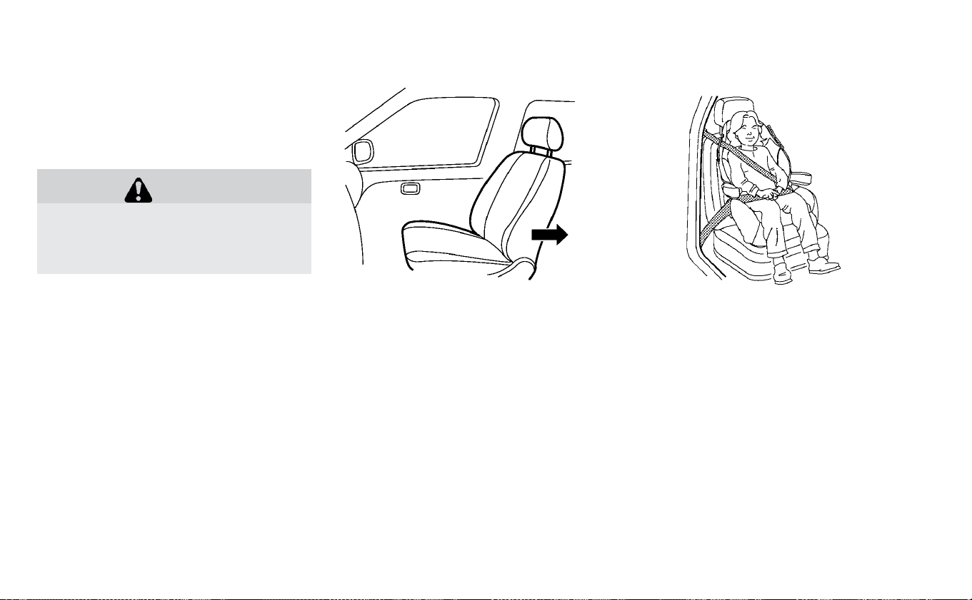
The instructions in this section apply to
booster seat installation in the rear seats
or the front passenger seat.
Booster seat installation
WARNING
To avoid injury to child, do not use the
lap/shoulder belt Automatic Locking
Retractor (ALR) mode when using a
booster seat with the seat belts.
For additional information, refer to all Warn-
ings and Cautions in “Child safety”, “Child
restraints” and “Booster seats” sections of
this manual before installing a child re-
straint.
Follow these steps to install a booster seat
on the rear seat or in the front passenger
seat:
1. If you must install a booster seat in the
front seat, move the seat to the rear-
most position.
2. Position the booster seat on the seat.
Only place it in the forward-facing direc-
tion. Always follow the booster seat
manufacturer’s instructions.
3. The booster seat should be positioned
on the vehicle seat so that it is stable.
If necessary, adjust or remove the head
restraint/headrest to obtain the correct
booster seat fit. If the head restraint/
headrest is removed, store it in a secure
place. Be sure to reinstall the head
restraint/headrest when the booster
seat is removed. For additional infor-
mation, refer to “Head restraints/
headrests” in this section.
Front passenger seat
Front passenger seat
1-42 Safety–Seats, seat belts and supplemental restraint system

If the seating position does not have an
adjustable head restraint/headrest and
it is interfering with the proper booster
seat fit, try another seating position or a
different booster seat.
4. Position the lap portion of the seat belt
low and snug on the child’s hips. Be sure
to follow the booster seat manufactur-
er’s instructions for adjusting the seat
belt routing.
5. Pull the shoulder belt portion of the seat
belt toward the retractor to take up ex-
tra slack. Be sure the shoulder belt is
positioned across the top, middle por-
tion of the child’s shoulder. Be sure to
follow the booster seat manufacturer’s
instructions for adjusting the seat belt
routing.
6. Follow the warnings, cautions and in-
structions for properly fastening a seat
belt. For additional information, refer to
“Three-point type seat belt with retrac-
tor” in this section.
7. If the booster seat is installed in the front
passenger seat, push the power switch
to the ON position. The front passenger
air bag status light
may or may not
illuminate, depending on the size of the
child and the type of booster seat used.
For additional information, refer to “Front
passenger air bag and status light” in this
section.
PRECAUTIONS ON SRS
This SRS section contains important infor-
mation concerning the following systems.
• Driver and front passenger supplemental
front-impact air bag (NISSAN Advanced
Air Bag System)
• Front seat-mounted side-impact supple-
mental air bag
• Roof-mounted curtain side-impact and
rollover supplemental air bag
• Seat belt with pretensioner(s) (front seats)
Supplemental front-impact air bag sys-
tem
The NISSAN Advanced Air Bag System can
help cushion the impact force to the head
and chest of the driver and front passenger
in certain frontal collisions.
Front seat-mounted side-impact
supplemental air bag system
This system can help cushion the impact
force to the chest and pelvic area of the
driver and front passenger in certain side
impact collisions. The side air bags are de-
signed to inflate on the side where the ve-
hicle is impacted.
SUPPLEMENTAL RESTRAINT SYSTEM
(SRS)
Safety–Seats, seat belts and supplemental restraint system 1-43
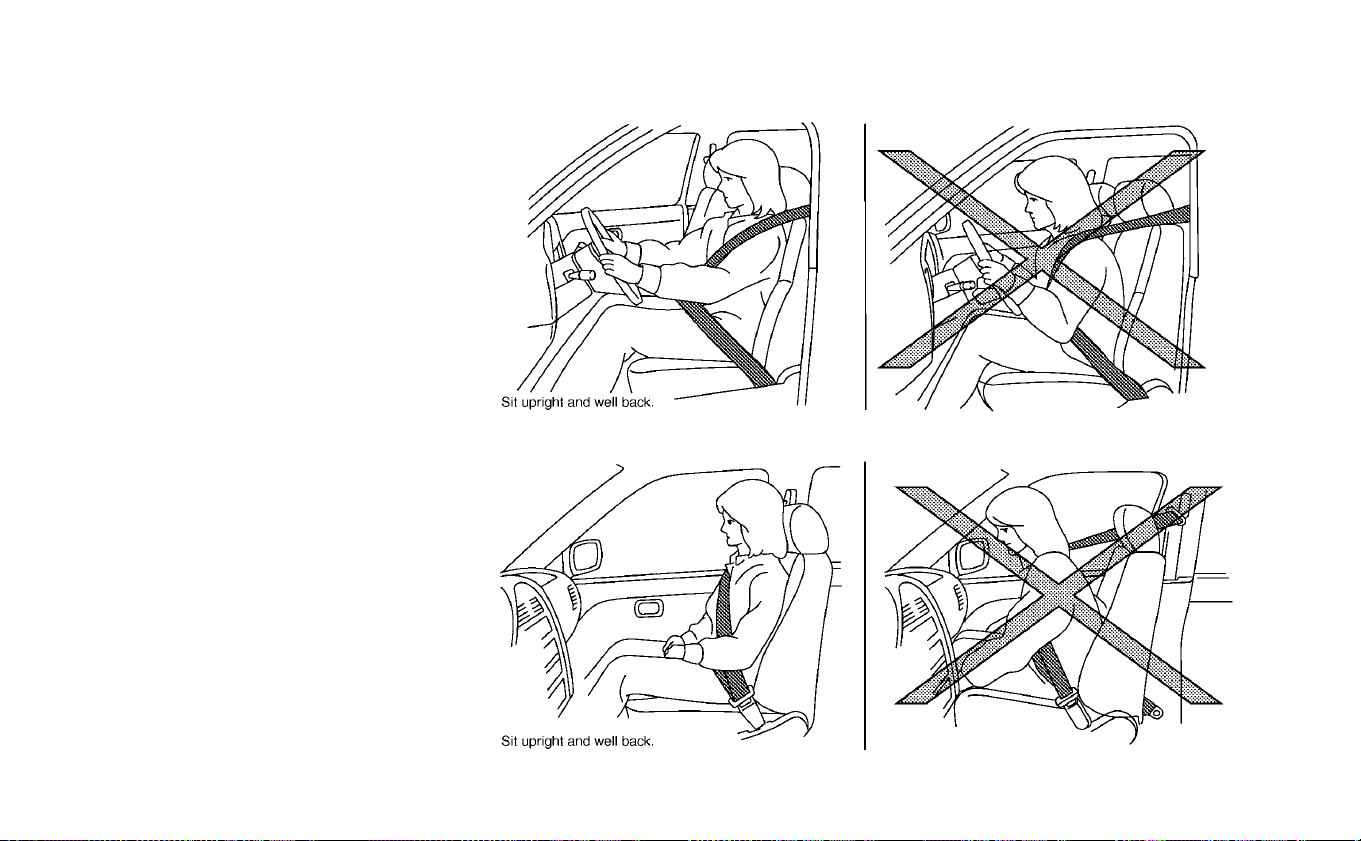
Roof-mounted curtain side-impact and
rollover supplemental air bag system
This system can help cushion the impact
force to the head of occupants in front and
rear outboard seating positions in certain
side impact collisions. In a side impact, the
curtain air bags are designed to inflate on the
side where the vehicle is impacted. In a roll-
over, the curtain air bags are designed to in-
flate and remain inflated for a short time.
The SRS is designed to supplement the
crash protection provided by the driver and
passenger seat belts and is not a substi-
tute for them. Seat belts should always be
correctly worn, and the occupant should
be seated a suitable distance away from
the steering wheel, instrument panel and
door finishers. For additional information,
refer to “Seat belts” in this section.
The supplemental air bags operate only
when the power switch is in the ON position.
After the power switch is placed in the
ON position, the supplemental air bag
warning light illuminates. The supple-
mental air bag warning light will turn off
after about 7 seconds if the system is
operational.
1-44 Safety–Seats, seat belts and supplemental restraint system
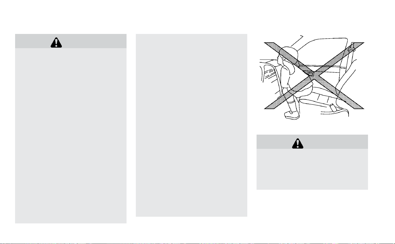
WARNING
• The front air bags ordinarily will not
inflate in the event of a side impact,
rear impact, rollover or lower sever-
ity frontal collision. Always wear
your seat belts to help reduce the
risk or severity of injury in various
kinds of accidents.
• The front passenger air bag will not
inflate if the passenger air bag sta-
tus light is lit. For additional infor-
mation, refer to “Front passenger air
bag and status light” in this section.
• The seat belts and the front air bags
are most effective when you are sit-
ting well back and upright in the seat
with both feet on the floor. The front
air bags inflate with great force.
Even with the NISSAN Advanced Air
Bag System, if you are unrestrained,
leaning forward, sitting sideways or
out of position in any way, you are at
greater risk of injury or death in a
crash. You may also receive serious
or fatal injuries from the front air
bag if you are up against it when it
inflates. Always sit back against the
seatback and as far away as practi-
cal from the steering wheel or in-
strument panel. Always properly use
the seat belts.
• The driver and front passenger seat
belt buckles are equipped with sen-
sors that detect if the seat belts are
fastened. The NISSAN Advanced Air
Bag System monitors the severity of
a collision and seat belt usage then
inflates the air bags as needed. Fail-
ure to properly wear seat belts can
increase the risk or severity of injury
in an accident.
• The front passenger seat is
equipped with occupant classifica-
tion sensor (weight sensor) that
turns the front passenger air bag
OFF under some conditions. This
sensor is only used in this seat. Fail-
ure to be properly seated and wear-
ing the seat belt can increase the
risk or severity of injury in an acci-
dent. For additional information, re-
fer to “Front passenger air bag and
status light” in this section.
• Keep hands on the outside of the
steering wheel. Placing them inside
the steering wheel rim could in-
crease the risk that they are injured
if the front air bag inflates.
WARNING
• Never let children ride unrestrained
or extend their hands or face out of
the window. Do not attempt to hold
them in your lap or arms. Some ex-
amples of dangerous riding posi-
tions are shown in the illustrations.
Safety–Seats, seat belts and supplemental restraint system 1-45
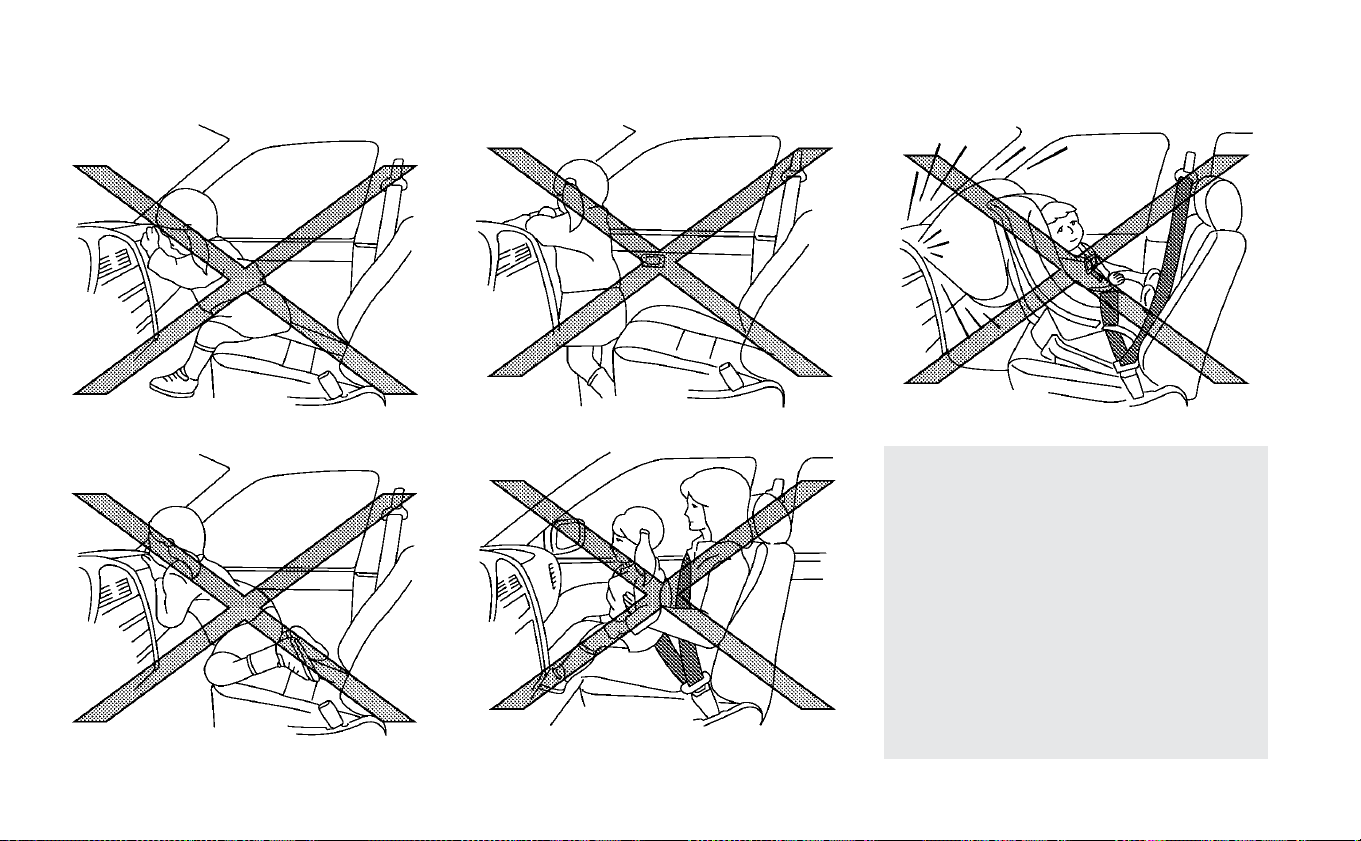
• Children may be severely injured or
killed when the front air bags, side
air bags or curtain air bags inflate if
they are not properly restrained.
Pre-teens and children should be
properly restrained in the rear seat,
if possible.
• Even with the NISSAN Advanced Air
Bag System, never install a rear-
facing child restraint on the front
seat. An inflating front air bag could
seriously injure or kill your child. For
additional information, refer to
“Child restraints” in this section.
1-46 Safety–Seats, seat belts and supplemental restraint system
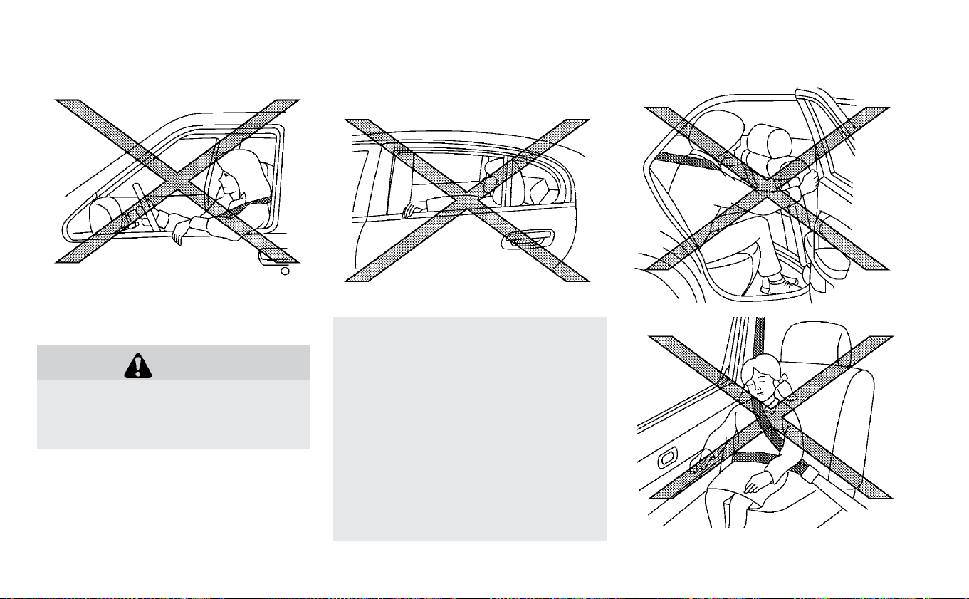
WARNING
Front seat-mounted side-impact
supplemental air bags and roof-
mounted curtain side-impact and roll-
over supplemental air bags:
• The side air bags and curtain air
bags ordinarily will not inflate in the
event of a frontal impact, rear im-
pact, or lower severity side collision.
Always wear your seat belts to help
reduce the risk or severity of injury in
various kinds of accidents.
• The seat belts, the side air bags and
curtain air bags are most effective
when you are sitting well back and
upright in the seat. The side air bag
and curtain air bag inflate with great
force. Do not allow anyone to place
their hand, leg or face near the side
Do not lean against doors or windows.
Safety–Seats, seat belts and supplemental restraint system 1-47
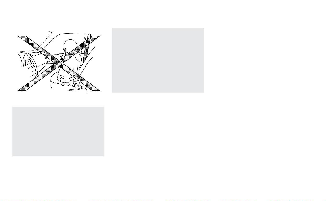
air bag on the side of the seatback of
the front seat or near the side roof
rails. Do not allow anyone sitting in
the front seats or rear outboard
seats to extend their hand out of the
window or lean against the door.
Some examples of dangerous riding
positions are shown in the previous
illustrations.
• When sitting in the rear seat, do not
hold onto the seatback of the front
seat. If the side air bag inflates, you
may be seriously injured. Be espe-
cially careful with children, who
should always be properly re-
strained. Some examples of danger-
ous riding positions are shown in the
illustrations.
• Do not use seat covers on the front
seatbacks. They may interfere with
side air bag inflation.
1-48 Safety–Seats, seat belts and supplemental restraint system

1. Crash zone sensor
2. Supplemental front-impact air bag
modules
3. Front seat-mounted side-impact
supplemental air bag modules
4. Occupant classification sensor (weight
sensor)
5. Occupant classification system control
unit
6. Roof-mounted curtain side-impact and
rollover supplemental air bag inflators
7. Roof-mounted curtain side-impact and
rollover supplemental air bag modules
8. Satellite sensors
9. Seat belt with pretensioner(s) (front
seats)
10. Air bag Control Unit (ACU)
11. Door sensors
Safety–Seats, seat belts and supplemental restraint system 1-49

NISSAN Advanced Air Bag System
(front seats)
WARNING
To ensure proper operation of the front
passenger’s NISSAN Advanced Air Bag
System, please observe the following
items.
• Do not allow a passenger in the rear
seat to push or pull on the seatback
pocket.
• Do not place heavy loads heavier
than 9.1 lbs. (4 kg) on the seatback,
head restraint/headrest or in the
seatback pocket.
• Make sure that there is nothing
pressing against the rear of the
seatback, such as a child restraint
installed in the rear seat or an object
stored on the floor.
• Make sure that there is no object
placed under the front passenger
seat.
• Make sure that there is no object
placed between the seat cushion
and center console or between the
seat cushion and the door.
• If a forward-facing child restraint is
installed in the front passenger seat,
do not position the front passenger
seat so the child restraint contacts
the instrument panel. If the child re-
straint does contact the instrument
panel, the system may determine
the seat is occupied and the passen-
ger air bag may deploy in a collision.
Also the front passenger air bag sta-
tus light may not illuminate. For ad-
ditional information, refer to “Child
restraints” in this section.
• Confirm the operating condition
with the front passenger air bag sta-
tus light.
• If you notice that the front passen-
ger air bag status light is not operat-
ing as described in this section, get
the occupant classification system
checked. It is recommended that
you visit a NISSAN certified LEAF
dealer for this service.
• Until you have confirmed with a
dealer that your passenger seat oc-
cupant classification system is
working properly, position the occu-
pants in the rear seating positions.
• Do not position the front passenger
seat so it contacts the rear seat. If
the front seat does contact the rear
seat, the air bag system may deter-
mine a sensor malfunction has oc-
curred and the front passenger air
bag status light may illuminate and
the supplemental air bag warning
light may flash.
This vehicle is equipped with the NISSAN
Advanced Air Bag System for the driver and
front passenger seats. This system is de-
signed to meet certification requirements
under U.S. regulations. It is also permitted in
Canada. All of the information, cautions
and warnings in this manual apply and
must be followed.
The driver supplemental front-impact air
bag is located in the center of the steering
wheel. The front passenger supplemental
front-impact air bag is mounted in the in-
strument panel above the glove box. The
front air bags are designed to inflate in
higher severity frontal collisions, although
they may inflate if the forces in another
type of collision are similar to those of a
higher severity frontal impact. They may
1-50 Safety–Seats, seat belts and supplemental restraint system

not inflate in certain frontal collisions. Ve-
hicle damage (or lack of it) is not always an
indication of proper front air bag operation.
The NISSAN Advanced Air Bag System
monitors information from the crash zone
sensor and the Air bag Control Unit (ACU).
Inflator operation is based on the severity
of a collision and seat belt usage for the
driver. For the front passenger, the occu-
pant classification sensor is also moni-
tored. Based on information from the sen-
sor, only one front air bag may inflate in a
crash, depending on the crash severity. Ad-
ditionally, the front passenger air bag may
be automatically turned OFF under some
conditions, depending on the weight de-
tected on the passenger seat and how the
seat belt is used. If the front passenger air
bag is OFF, the passenger air bag status
light will be illuminated. For additional infor-
mation, refer to “Front passenger air bag
and status light” in this section. One front
air bag inflating does not indicate improper
performance of the system.
If you have any questions about your air
bag system, it is recommended that you
visit a NISSAN certified LEAF dealer to ob-
tain information about the system. If you
are considering modification of your ve-
hicle due to a disability, you may also con-
tact NISSAN. Contact information is con-
tained in the front of this Owner’s Manual.
When a front air bag inflates, a fairly loud
noise may be heard, followed by release of
smoke. This smoke is not harmful and
does not indicate a fire. Care should be
taken not to inhale it, as it may cause irrita-
tion and choking. Those with a history of a
breathing condition should get fresh air
promptly.
Front air bags, along with the use of seat
belts, help to cushion the impact force on
the head and chest of the front occupants.
They can help save lives and reduce seri-
ous injuries. However, an inflating front air
bag may cause facial abrasions or other
injuries. Front air bags do not provide re-
straint to the lower body.
Even with NISSAN Advanced Air Bags, seat
belts should be correctly worn and the
driver and front passenger seated upright
as far as practical away from the steering
wheel or instrument panel. The front air
bags inflate quickly in order to help protect
the front occupants. Because of this, the
force of the front air bag inflating can in-
crease the risk of injury if the occupant is
too close to, or is against, the air bag mod-
ule during inflation.
The front air bags deflate quickly after a
collision.
The front air bags operate only when the
power switch is in the ON position.
After the power switch is placed in the
ON position, the supplemental air bag
warning light illuminates. The supple-
mental air bag warning light will turn off
after about 7 seconds if the system is
operational.
Safety–Seats, seat belts and supplemental restraint system 1-51
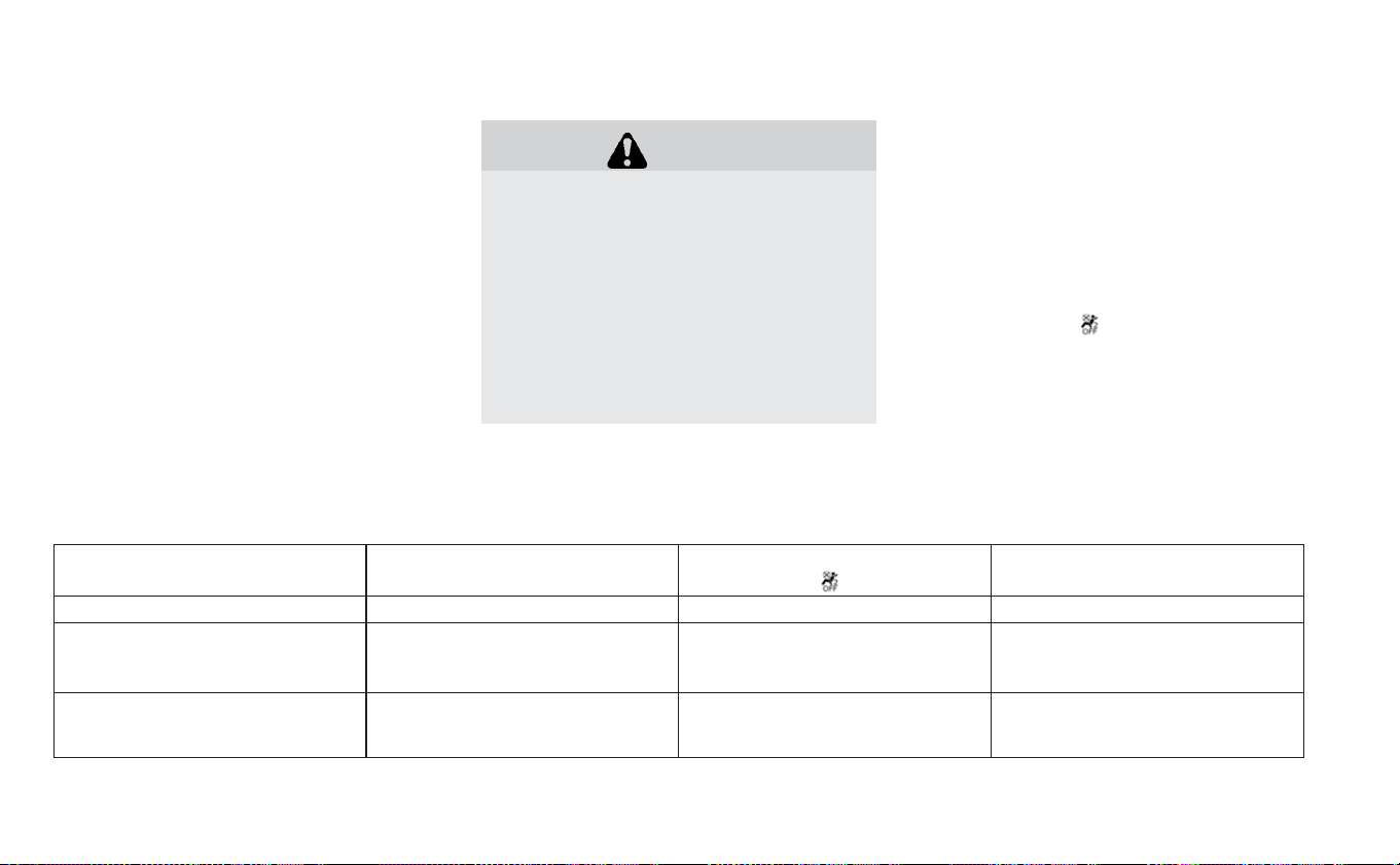
Front passenger air bag and status
light:
WARNING
The front passenger air bag is de-
signed to automatically turn OFF un-
der some conditions. Read this section
carefully to learn how it operates.
Proper use of the seat, seat belt and
child restraints is necessary for most
effective protection. Failure to follow
all instructions in this manual concern-
ing the use of seats, seat belts and
child restraints can increase the risk or
severity of injury in an accident.
Status light:
The front passenger seat is equipped with
an occupant classification sensor (weight
sensor) that turns the front passenger air
bag on or off depending on the weight ap-
plied to the front passenger seat. The sta-
tus of the front passenger air bag (ON or
OFF) is indicated by the front passenger air
bag status light
which is located on
the instrument panel.
After the power switch is placed in the “ON”
position, the front passenger air bag status
light on the instrument panel illuminates
for about 7 seconds and then turns off or
remains illuminated depending on the
front passenger seat occupied status. The
light operates as follows:
CONDITION DESCRIPTION
PASSENGER AIR BAG INDICA-
TOR LIGHT (
) RESULT
FRONT PASSENGER AIR BAG
STATUS
Empty Empty front passenger seat ON (illuminated) INHIBITED
Nobody/Somebody
Bag or Child or Child Restraint or
Small Adult in front passenger
seat
ON (illuminated) INHIBITED
Adult
Adult in the front passenger
seat
OFF (dark) ACTIVATED
1-52 Safety–Seats, seat belts and supplemental restraint system

In addition to the above, certain objects
placed on the front passenger seat may
also cause the light to operate as de-
scribed above depending on their weight.
For additional information, refer to “Normal
operation” and “Troubleshooting” in this
section.
Front passenger air bag:
The front passenger air bag is designed to
automatically turn OFF when the vehicle is
operated under some conditions as de-
scribed below in accordance with U.S. regu-
lations. If the front passenger air bag is OFF,
it will not inflate in a crash. The driver air bag
and other air bags in your vehicle are not
part of this system.
The purpose of the regulation is to help
reduce the risk of injury or death from an
inflating air bag to certain front passenger
seat occupants, such as children, by requir-
ing the air bag to be automatically turned
OFF. Certain sensors are used to meet the
requirements.
The occupant classification sensor in this
vehicle is a weight sensor. It is designed to
detect an occupant and objects on the
seat by weight. For example, if a child is in
the front passenger seat, the NISSAN Ad-
vanced Air Bag System is designed to turn
the front passenger air bag OFF in accor-
dance with the regulations. Also, if a child
restraint of the type specified in the regula-
tions is on the seat, its weight and the
child’s weight can be detected and cause
the air bag to turn OFF.
Front passenger seat adult occupants who
are properly seated and using the seat belt
as outlined in this manual should not
cause the front passenger air bag to be
automatically turned OFF. For small adults
it may be turned OFF, however if the occu-
pant takes his/her weight off the seat
cushion (for example, by not sitting upright,
by sitting on an edge of the seat, or by
otherwise being out of position), this could
cause the sensors to turn the air bag OFF.
Always be sure to be seated and wearing
the seat belt properly for the most effective
protection by the seat belt and supple-
mental air bag.
NISSAN recommends that pre-teens and
children be properly restrained in a rear
seat. NISSAN also recommends that ap-
propriate child restraints and booster
seats be properly installed in a rear seat. If
this is not possible, the occupant classifica-
tion sensor is designed to operate as de-
scribed above to turn the front passenger
air bag OFF for specified child restraints as
required by regulations. Failing to properly
secure child restraints and to use the ALR
mode may allow the restraint to tip or
move in a collision or sudden stop. This can
also result in the front passenger air bag
inflating in a crash instead of being OFF. For
additional information, refer to “Child re-
straints” in this section.
If the front passenger seat is not occupied,
the front passenger air bag is designed not
to inflate in a crash. However, heavy objects
placed on the seat could result in air bag
inflation, because of the object’s weight be-
ing detected by the occupant classification
sensor. Other conditions could also result
in air bag inflation, such as if a child is
standing on the seat, or if two children are
on the seat, contrary to the instructions in
this manual. Always be sure that you and all
vehicle occupants are seated and re-
strained properly.
Safety–Seats, seat belts and supplemental restraint system 1-53

Using the front passenger air bag status
light, you can monitor when the front pas-
senger air bag is automatically turned OFF.
If an adult occupant is in the seat but the
front passenger air bag status light is illu-
minated (indicating that the air bag is OFF),
it could be that the person is a small adult,
or is not sitting on the seat properly or not
using the seat belt properly.
If a child restraint must be used in the front
seat, the front passenger air bag status
light may or may not be illuminated, de-
pending on the size of the child and the
type of child restraint being used. If the
front passenger air bag status light is not
illuminated (indicating that the air bag
might inflate in a crash), it could be that the
child restraint or seat belt is not being used
properly. Make sure that the child restraint
is installed properly, the seat belt is used
properly and the occupant is positioned
properly. If the front passenger air bag sta-
tus light is still not illuminated, reposition
the occupant or child restraint in a rear
seat.
If the front passenger air bag status light
will not illuminate even though you believe
that the child restraint, the seat belts and
the occupant are properly positioned, it is
recommended that you take your vehicle
to a NISSAN certified LEAF dealer. A NISSAN
certified LEAF dealer can check system
status by using a special tool. However, un-
til you have confirmed with a dealer that
your air bag is working properly, reposition
the occupant or child restraint in a rear
seat.
The NISSAN Advanced Air Bag System and
front passenger air bag status light will
take a few seconds to register a change in
the front passenger seat status. This is nor-
mal system operation and does not indi-
cate a malfunction.
If a malfunction occurs in the front passen-
ger air bag system, the supplemental air
bag warning light
, located in the me-
ter and gauges area of the instrument
panel, will be illuminated (blinking or
steadily lit). Have the system checked. It is
recommended that you visit a NISSAN cer-
tified LEAF dealer for this service.
Normal operation:
In order for the occupant classification
sensor system to classify the front passen-
ger based on weight, please follow the pre-
cautions and steps outlined below:
Precautions:
• Make sure that there are no objects
weighing over 9.1 lbs. (4 kg) hanging on the
seat or placed in the seatback pocket.
• Make sure that a child restraint or other
object is not pressing against the rear of
the seatback.
• Make sure that the rear passenger is not
pushing or pulling on the back of the front
passenger seat.
• Make sure that the front passenger seat
or seatback is not forced back against an
object on the seat or floor behind it.
• Make sure that there is no object placed
under the front passenger seat.
Steps:
1. Adjust the seat as outlined in the “Seats”
section of this manual. Sit upright, lean-
ing against the seatback, and centered
on the seat cushion with your feet com-
fortably ex tended to the floor.
1-54 Safety–Seats, seat belts and supplemental restraint system

2. Make sure there are no objects on your
lap.
3. Fasten the seat belt as outlined in the
“Seat belts” section of this manual. Front
passenger seat belt buckle status is
monitored by the occupant classifica-
tion system, and is used as an input to
determine occupancy status. So, it is
highly recommended that the front pas-
senger fasten their seat belt.
4. Remain in this position for 30 seconds
allowing the system to classify the front
passenger before the vehicle is put into
motion.
5. Ensure proper classification by checking
the front passenger air bag status light.
NOTE:
This vehicle’s occupant classification
sensor system generally keeps the clas-
sification locked during driving, so it is
important that you confirm that the
front passenger is properly classified
prior to driving. However, the occupant
classification sensor may recalculate the
weight of the occupant under some con-
ditions (both while driving and when
stopped), so front passenger seat occu-
pants should continue to remain seated
as outlined above.
Troubleshooting:
If you think the front passenger air bag
status light is incorrect:
1. If the light is ON with an adult occupying
the front passenger seat:
• Occupant is a small adult — the air bag
light is functioning as intended. The
front passenger air bag is suppressed.
However, if the occupant is not a small
adult, then this may be due to the fol-
lowing conditions that may be interfer-
ing with the weight sensors:
• Occupant is not sitting upright, leaning
against the seatback, and centered on
the seat cushion with his/her feet com-
fortably ex tended to the floor.
• A child restraint or other object press-
ing against the rear of the seatback.
• A rear passenger pushing or pulling on
the back of the front passenger seat.
• Forcing the front seat or seatback
against an object on the seat or floor
behind it.
• An object placed under the front pas-
senger seat.
• An object placed between the seat
cushion and center console or between
the seat cushion and the door.
If the vehicle is moving, please come to a
stop when it is safe to do so. Check and
correct any of the above conditions. Re-
start the vehicle and wait 1 minute.
NOTE:
A system check will be performed dur-
ing which the front passenger air bag
status light will remain lit for about
7 seconds initially.
If the light is still ON after this, the person
should be advised not to ride in the front
passenger seat and the vehicle should
be checked as soon as possible. It is
recommended that you visit a NISSAN
certified LEAF dealer for this service.
2. If the light is OFF with a small adult, child
or child restraint occupying the front
passenger seat.
This may be due to the following condi-
tions that may be interfering with the
weight sensors:
Safety–Seats, seat belts and supplemental restraint system 1-55

• Small adult or child is not sitting upright,
leaning against the seatback, and cen-
tered on the seat cushion with his/her
feet comfortably extended to the floor.
• The child restraint is not properly in-
stalled, as outlined in the “Child re-
straints” section of this manual.
• An object weighting over 9.1 lbs. (4 kg)
hanging on the seat or placed in the
seatback pocket.
• A child restraint or other object press-
ing against the rear or the seatback.
• A rear passenger pushing or pulling on
the back of the front passenger seat.
pushing or pulling on the seatback of
the front passenger seat.
• Forcing the front seat or seatback
against an object on the seat or floor
behind it.
• An object placed under the front pas-
senger seat.
• An object placed between the seat
cushion and center console.
If the vehicle is moving, please come to a
stop when it is safe to do so. Check and
correct any of the above conditions. Re-
start the vehicle and wait 1 minute.
NOTE:
A system check will be performed dur-
ing which the front passenger air bag
status light will remain lit for about
7 seconds initially.
If the light is still OFF after this, the small
adult, child or child restraint should be
repositioned in the rear seat and the
vehicle should be checked as soon as
possible. It is recommended that you
visit a NISSAN certified LEAF dealer for
this service.
3. If the light is OFF with no front passenger
and no objects on the front passenger
seat the vehicle should be checked as
soon as possible. It is recommended
that you visit a NISSAN certified LEAF
dealer for this service.
Other supplemental front-impact air
bag precautions:
WARNING
• Do not place any objects on the
steering wheel pad or on the instru-
ment panel. Also, do not place any
objects between any occupant and
the steering wheel or instrument
panel. Such objects may become
dangerous projectiles and cause in-
jury if the front air bags inflate.
• Do not place objects with sharp
edges on the seat. Also, do not place
heavy objects on the seat that will
leave permanent impressions in the
seat. Such objects can damage the
seat or occupant classification sen-
sor (weight sensor). This can affect
the operation of the air bag system
and result in serious personal injury.
• Do not use water or acidic cleaners
(hot steam cleaners) on the seat.
This can damage the seat or occu-
pant classification sensor. This can
also affect the operation of the air
bag system and result in serious
personal injury.
1-56 Safety–Seats, seat belts and supplemental restraint system

• Immediately after inflation, several
front air bag system components
will be hot. Do not touch them; you
may severely burn yourself.
• No unauthorized changes should be
made to any components or wiring
of the supplemental air bag system.
This is to prevent accidental infla-
tion of the supplemental air bag or
damage to the supplemental air bag
system.
• Do not make unauthorized changes
to your vehicle’s electrical system,
suspension system or front end
structure. This could affect proper
operation of the front air bag sys-
tem.
• Tampering with the front air bag
system may result in serious per-
sonal injury. Tampering includes
changes to the steering wheel and
the instrument panel assembly by
placing material over the steering
wheel pad and above the instru-
ment panel or by installing addi-
tional trim material around the air
bag system.
• Removing or modifying the front
passenger seat may affect the func-
tion of the air bag system and result
in serious personal injury.
• Modifying or tampering with the
front passenger seat may result in
serious personal injury. For ex-
ample, do not change the front seats
by placing material on the seat
cushion or by installing additional
trim material, such as seat covers,
on the seat that is not specifically
designed to assure proper air bag
operation. Additionally, do not stow
any objects under the front passen-
ger seat or the seat cushion and
seatback. Such objects may inter-
fere with the proper operation of the
occupant classification sensor
(weight sensor).
• No unauthorized changes should be
made to any components or wiring
of the seat belt system. This may af-
fect the front air bag system. Tam-
pering with the seat belt system
may result in serious personal injury.
• It is recommended that you visit a
NISSAN certified LEAF dealer for
work on and around the front air bag
system. It is also recommended that
you visit a NISSAN certified LEAF
dealer for installation of electrical
equipment. The Supplemental Re-
straint System (SRS) wiring har-
nesses* should not be modified or
disconnected. Unauthorized electri-
cal test equipment and probing de-
vices should not be used on the air
bag system.
• A cracked windshield should be re-
placed immediately by a qualified
repair facility. A cracked windshield
could affect the function of the
supplemental air bag system.
*The SRS wiring harness connectors are
yellow and orange for easy identifica-
tion.
When selling your vehicle, we request that
you inform the buyer about the front air
bag system and guide the buyer to the
appropriate sections in this Owner’s
Manual.
Safety–Seats, seat belts and supplemental restraint system 1-57

Front seat-mounted side-impact
supplemental air bag and
roof-mounted curtain
side-impact and rollover
supplemental air bag systems
The side air bags are located in the outside
of the seatback of the front seats. The cur-
tain air bags are located in the side roof
rails. All of the information, cautions, and
warnings in this manual apply and must
be followed. The side air bags and curtain
air bags are designed to inflate in higher
severity side collisions, although they may
inflate if the forces in another type of colli-
sion are similar to those of a higher severity
side impact. They are designed to inflate on
the side where the vehicle is impacted.
They may not inflate in certain side colli-
sions on the side where the vehicle is im-
pacted.
If so equipped, the curtain air bags are also
designed to inflate in certain types of roll-
over collisions or near rollovers. As a result,
certain vehicle movements (for example,
during severe off-roading) may cause the
curtain air bags to inflate.
Vehicle damage (or lack of it) is not always
an indication of proper side air bag and
curtain air bag operation.
When the side air bags and curtain air bags
inflate, a fairly loud noise may be heard,
followed by release of smoke. This smoke is
not harmful and does not indicate a fire.
Care should be taken not to inhale it, as it
may cause irritation and choking. Those
with a history of a breathing condition
should get fresh air promptly.
Side air bags, along with the use of seat
belts, help to cushion the impact force on
the chest and pelvic area of the front occu-
pants. Curtain air bags help to cushion the
impact force to the head of occupants in
the front and rear outboard seating posi-
tions. They can help save lives and reduce
serious injuries. However, side air bags and
curtain air bags may cause abrasions or
other injuries. Side air bags and curtain air
bags do not provide restraint to the lower
body.
The seat belts should be correctly worn
and the driver and passenger seated up-
right as far as practical away from the side
air bags. Rear seat passengers should be
seated as far away as practical from the
door finishers and side roof rails. The side
air bags and curtain air bags inflate quickly
in order to help protect the occupants in
the outboard seating positions. Because of
this, the force of the side air bags and cur-
tain air bags inflating can increase the risk
of injury if the occupant is too close to, or is
against, these air bag modules during in-
flation. The side air bags and curtain air
bags will deflate quickly after the collision is
over.
1-58 Safety–Seats, seat belts and supplemental restraint system

The side air bags and curtain air bags
operate only when the power switch is in
the ON position.
After turning the power switch to the ON
position, the supplemental air bag warn-
ing light illuminates. The supplemental
air bag warning light will turn off after
about 7 seconds if the systems are op-
erational.
WARNING
• Do not place any objects near the
seatback of the front seats. Also, do
not place any objects (an umbrella,
bag, etc.) between the front door fin-
isher and the front seat. Such ob-
jects may become dangerous pro-
jectiles and cause injury if a side air
bag inflates.
• Right after inflation, several side air
bag and curtain air bag system com-
ponents will be hot. Do not touch
them; you may severely burn your-
self.
• No unauthorized changes should be
made to any components or wiring
of the side air bag and curtain air
bag systems. This is to prevent dam-
age to or accidental inflation of the
side air bag and curtain air bag sys-
tems.
• Do not make unauthorized changes
to your vehicle’s electrical system,
suspension system or side panel.
This could affect proper operation of
the side air bag and curtain air bag
systems.
• Tampering with the side air bag sys-
tem may result in serious personal
injury. For example, do not change
the front seats by placing material
near the seatbacks or by installing
additional trim material, such as
seat covers, around the side air bag.
• It is recommended that you visit a
NISSAN certified LEAF dealer for
work around and on the side air bag
and curtain air bag systems. It is also
recommended that you visit a
NISSAN certified LEAF dealer for in-
stallation of electrical equipment.
The Supplemental Restraint System
(SRS) wiring harnesses* should not
be modified or disconnected. Unau-
thorized electrical test equipment
and probing devices should not be
used on the side air bag and curtain
supplemental air bag systems.
*The SRS wiring harness connectors are
yellow and orange for easy identifica-
tion.
When selling your vehicle, we request that
you inform the buyer about the side air bag
and curtain air bag systems and guide the
buyer to the appropriate sections in this
Owner’s Manual.
Seat belt with pretensioner(s)
(front seats)
WARNING
• The pretensioner(s) cannot be re-
used after activation. They must be
replaced together with the retractor
and buckle as a unit.
• If the vehicle becomes involved in a
collision but pretensioner(s) are not
activated, be sure to have the pre-
tensioner system checked and, if
necessary, replaced. It is recom-
mended that you visit a NISSAN cer-
tified LEAF dealer for this service.
Safety–Seats, seat belts and supplemental restraint system 1-59

• No unauthorized changes should be
made to any components or wiring
of the pretensioner system. This is to
prevent damage to or accidental ac-
tivation of the pretensioner(s). Tam-
pering with the pretensioner system
may result in serious personal injury.
• It is recommended that you visit a
NISSAN certified LEAF dealer for
work around and on the preten-
sioner system. It is also recom-
mended that you visit a NISSAN cer-
tified LEAF dealer for installation of
electrical equipment. Unauthorized
electrical test equipment and prob-
ing devices should not be used on
the pretensioner system.
• If you need to dispose of the preten-
sioner(s) or scrap the vehicle, it is
recommended that you visit a
NISSAN certified LEAF dealer for this
service. Incorrect disposal proce-
dures could cause personal injury.
The pretensioner system may activate
with the supplemental air bag system in
certain types of collisions. Working with the
seat belt retractor, the pretensioner(s) help
tighten the seat belt when the vehicle be-
comes involved in certain types of colli-
sions, helping to restrain front seat occu-
pants.
The pretensioner(s) are encased with the
seat belt retractor and to the seat belt an-
chor affixed to the floor of the vehicle.
These seat belts are used the same way as
conventional seat belts.
When pretensioner(s) activate, smoke is re-
leased and a loud noise may be heard. This
smoke is not harmful and does not indi-
cate a fire. Care should be taken not to
inhale it, as it may cause irritation and
choking. Those with a history of a breath-
ing condition should get fresh air promptly.
After the pretensioner(s’) activation, load
limiters allow the seat belt to release web-
bing (if necessary) to reduce forces against
the chest.
The supplemental air bag warning light
is used to indicate malfunctions in the
pretensioner system. For additional infor-
mation, refer to “Supplemental air bag
warning light” in this section. If the opera-
tion of the supplemental air bag warning
light indicates there is a malfunction, have
the system checked. It is recommended
that you visit a NISSAN certified LEAF dealer
for this service.
When selling your vehicle, we request that
you inform the buyer about the preten-
sioner system and guide the buyer to the
appropriate sections in this Owner’s
Manual.
1-60 Safety–Seats, seat belts and supplemental restraint system

SUPPLEMENTAL AIR BAG WARNING
LABELS
A. Supplemental front-impact air bag sys-
tem warning labels
The warning labels are located on the sur-
face of the sun visors.
SUPPLEMENTAL AIR BAG WARNING
LIGHT
The supplemental air bag warning light,
displaying
in the instrument panel,
monitors the circuits of the Air bag Control
Unit (ACU), satellite sensors, crash zone
sensor, occupant classification sensor, the
supplemental front-impact air bag, front
seat-mounted side-impact supplemental
air bag, roof-mounted curtain side-impact
supplemental air bag and seat belt preten-
sioner systems. The monitored circuits in-
clude air bag systems, pretensioner(s) and
all related wiring.
When the power switch is in the ON posi-
tion, the supplemental air bag warning
light illuminates for about 7 seconds and
then turns off. This means the system is
operational.
If any of the following conditions occur, the
front air bag, side air bag, curtain air bag
and pretensioner systems need servicing:
• The supplemental air bag warning light
remains on after approximately
7 seconds.
• The supplemental air bag warning light
flashes intermittently.
• The supplemental air bag warning light
does not come on at all.
Under these conditions, the front air bag,
side air bag, curtain air bag and preten-
sioner systems may not operate properly.
They must be checked and repaired. It is
recommended that you visit the nearest
NISSAN certified LEAF dealer for this
service.
Safety–Seats, seat belts and supplemental restraint system 1-61

WARNING
If the supplemental air bag warning
light is on, it could mean that the front
air bag, side air bag, curtain air bag
and/or pretensioner systems will not
operate in an accident. To help avoid
injury to yourself or others, have your
vehicle checked as soon as possible. It
is recommended that you visit a
NISSAN certified LEAF dealer for this
service.
Repair and replacement
procedure
The front air bags, side air bags, curtain air
bags and pretensioner(s) are designed to
activate on a one-time-only basis. As a re-
minder, unless it is damaged, the supple-
mental air bag warning light will remain
illuminated after inflation has occurred.
These systems should be repaired and/or
replaced as soon as possible. It is recom-
mended that you visit a NISSAN certified
LEAF dealer for this service.
When maintenance work is required on the
vehicle, the front air bags, side air bags,
curtain air bags and pretensioner(s) and
related parts should be pointed out to the
person performing the maintenance. The
power switch should always be in the LOCK
position when working under the hood or
inside the vehicle.
WARNING
• Once a front air bag, side air bag or
curtain air bag has inflated, the air
bag module will not function again
and must be replaced. Additionally,
the activated pretensioner(s) must
also be replaced. The air bag module
and pretensioner(s) should be re-
placed. It is recommended that you
visit a NISSAN certified LEAF dealer
for this service. The air bag modules
and pretensioner system cannot be
repaired.
• The front air bag, side air bag and
curtain air bag systems, and preten-
sioner system should be inspected if
there is any damage to the front end
or side portion of the vehicle. It is
recommended that you visit a
NISSAN certified LEAF dealer for this
service.
• If you need to dispose of a supple-
mental air bag or pretensioner sys-
tem or scrap the vehicle, it is recom-
mended that you visit a NISSAN
certified LEAF dealer for this service.
Correct supplemental air bag and
pretensioner system disposal pro-
cedures are set forth in the appro-
priate NISSAN Service Manual. Incor-
rect disposal procedures could
cause personal injury.
• If there is an impact to your vehicle
from any direction, your Occupant
Classification Sensor (OCS) should
be checked. It is recommended that
you visit a NISSAN certified LEAF
dealer to verify it is still functioning
correctly. The OCS should be
checked even if no air bags deploy
as a result of the impact. Failure to
verify proper OCS function may re-
sult in an improper air bag deploy-
ment resulting in injury or death.
1-62 Safety–Seats, seat belts and supplemental restraint system

2 Instruments and controls
Cockpit ............................2-3
Instrument panel ......................2-5
Meters and gauges ....................2-6
Speedometer and odometer ............2-7
Li-ion battery temperature gauge.........2-8
Power meter.......................2-9
Driving range ......................2-10
Li-ion battery available charge gauge......2-10
Outside air temperature ...............2-11
Clock ...........................2-12
ECO mode indicator .................2-12
e-Pedal system indicator ..............2-13
Warning lights, indicator lights and audible
reminders ..........................2-14
Checking lights ....................2-16
Warning lights .....................2-16
Indicator lights.....................2-23
Audible reminders ..................2-25
Vehicle information display ..............2-27
How to use the vehicle information display . .2-27
Startup display.....................2-27
Settings .........................2-28
Vehicle information display warnings and
indicators ........................2-36
Warning information displays (models with a
Navigation System) .................2-44
Security systems .....................2-46
Vehicle security system ...............2-46
NISSAN Vehicle Immobilizer System .......2-47
Wiper and washer switch................2-49
Washer operation...................2-50
Rear wiper operation ................2-50
Rear window and outside mirror (if so equipped)
defroster switch ......................2-51
Headlight and turn signal switch ...........2-52
Headlight switch ...................2-52
Instrument brightness control ..........2-57
Turn signal switch...................2-57
F
og
light switch (if so equipped) ...........2-58
Horn .............................2-58
ECO switch .........................2-58
Heated seat switches (if so equipped) .......2-59
Heated steering wheel switch (if so equipped) . .2-60
E-call (SOS) switch (if so equipped) ..........2-61
Charge port lid switch ..................2-61
Charge timer OFF switch ................2-61
Steering Assist switch (if so equipped) .......2-62
Power outlet ........................2-62

Storage...........................2-63
Seatback Pocket (if so equipped).........2-63
Storagetray......................2-64
Glovebox........................2-64
Console box ......................2-64
Overhead sunglasses storage ..........2-65
Cup holders ......................2-65
Tonneau cover (if so equipped) ..........2-66
Stowing golf bags ..................2-68
Windows ..........................2-68
Power windows ....................2-68
Interior lights .......................2-70
Console light (if so equipped) ...........2-71
Map lights ........................2-71
Room light........................2-71
Cargo light .......................2-72
HomeLink® universal transceiver (if so
equipped) ..........................2-72
Programming HomeLink® .............2-73
Programming HomeLink® for Canadian
customers and gate openers ...........2-75
Operating the HomeLink® universal
transceiver .......................2-75
Programming trouble-diagnosis .........2-75
Clearing the programmed information.....2-76
Reprogramming a single HomeLink®
button..........................2-76
If your vehicle is stolen................2-76

1. TRIP RESET switch for twin trip odom-
eter (P. 2-6)
— Instrument brightness control switch
(P. 2-57)
2. Headlight, fog light (if so equipped) and
turn signal switch
— Headlight (P. 2-52)
— Turn signal light (P. 2-52)
— Fog light (if so equipped) (P. 2-52)
3. Steering-wheel-mounted controls (left
side)
— Audio control (P. 4-45)
— Bluetooth® Hands-Free Phone System
control (without navigation) (P. 4-45)
— Bluetooth® Hands-Free Phone System
control (with navigation) (Refer to
NissanConnect® Manual (for Leaf))
4. Steering wheel
— Power steering system (P. 5-133)
— Horn (P. 2-58)
— Driver's supplemental air bag (P. 1-43)
5. Wiper and washer switch (P. 2-49)
6. Steering-wheel-mounted controls
(right side)
— Cruise control switches (if so
equipped) (P. 5-54)
— Intelligent Cruise Control (ICC)
switches (if so equipped) (P. 5-56)
— ProPILOT
TM
Assist switch (if so
equipped) (P. 5-79)
COCKPIT
Instruments and controls 2-3

7. Shift lever (P. 5-15)
— ECO switch (P. 2-58)
— e-Pedal switch (P. 5-22)
8. Console box (P. 2-63)
9. Parking brake (switch type) (if so
equipped) (P. 5-19)
10. Tilting steering wheel lever (P. 3-21)
11. Charge port lid switch (P. 3-19)
— Charge timer OFF switch (P. 2-61)
— Heated steering wheel switch (if so
equipped) (P. 2-60)
— Steering Assist switch (if so equipped)
(P. 5-79)
12. Fuse box cover (P. 8-17)
2-4 Instruments and controls

1. Vents (P. 4-29)
2. Meters and gauges (P. 2-6)
3. Center multi-function control panel
— Navigation system (Refer to
NissanConnect® Manual (for Leaf))
— Without Navigation System (P. 4-45)
4. Hazard warning flasher switch (P. 6-2)
5. Rear window defroster switch (P. 2-51)
6. Front passenger supplemental air bag
(P. 1-43)
7. Glove box (P. 2-63)
8. Heater and air conditioner control
(P. 4-30)
9. Power outlet (P. 2-62)
10. Front heated seat switches (if so
equipped) (P. 2-59)
11. Auxiliary input jack (P. 4-64)
— iPod® connector/USB connector
(P. 4-45)
12. Push-button power switch (P. 5-10)
13. Front passenger air bag status light
(P. 1-43)
14. Hood release handle (P. 3-16)
INSTRUMENT PANEL
Instruments and controls 2-5

1. Vehicle information display (P. 2-27)
— Clock (P. 2-12)
— Outside air temperature (P. 2-11)
— Li-ion battery available charge gauge
(P. 2-10)
— Driving range (P. EV-19)
— Odometer/twin trip odometer (P. 2-7)
— Indicator for timer (P. CH-35)
— Power meter (P. 2-9)
2. Warning and indicator lights (P. 2-14)
— Turn signal/Hazard indicator light
(P. 2-52)
— READY to drive indicator light (P. 2-25)
— ECO mode indicator (P. 2-12
3. Speedometer (P. 2-6)
METERS AND GAUGES
2-6 Instruments and controls

SPEEDOMETER AND ODOMETER
The vehicle is equipped with a speedom-
eter and odometer. The speedometer is
located on the right side of the vehicle in-
formation display. The odometer is located
within the vehicle information display.
Speedometer
The speedometer indicates the vehicle
speed.
Odometer/twin trip odometer
The odometer and twin trip odometer
䊊
2
are displayed on the vehicle information
display when the power switch is in the ON
or READY to drive position.
The odometer records the total distance
the vehicle has been driven.
The twin trip odometer records the dis-
tance of individual trips.
Instruments and controls 2-7

Changing the display:
Pushing the TRIP RESET switch
䊊
1
located
on the left side of the combination meter
panel changes the display as follows:
Odometer → TRIP A → TRIP B → Odometer
For additional information about the ve-
hicle information display, refer to “Vehicle
information display” in this section.
Resetting the trip odometer:
Pushing the TRIP RESET switch
䊊
1
for ap-
proximately 1 second resets the currently
displayed trip odometer to zero.
LI-ION BATTERY TEMPERATURE
GAUGE
The gauge indicates the temperature of
the Li-ion battery.
The temperature of the Li-ion battery is
within the normal range when the display
is within the zone
䊊
1
shown in the illustra-
tion.
The temperature of the Li-ion battery var-
ies according to the outside air tempera-
ture and driving conditions.
NOTE:
• If the display indicates that the tem-
perature of the Li-ion battery is near the
red zone end of the normal range, re-
duce vehicle speed to decrease the
temperature. If the indicator is over the
normal range, the power provided to
the traction motor is reduced when the
power limitation indicator light is illumi-
nated. Therefore, the vehicle is not as
responsive when the accelerator is de-
pressed while the power limitation light
is illuminated. For additional informa-
tion, refer to “Power limitation indicator
light” in this section.
• If the outside temperature is extremely
low, the Li-ion temperature gauge may
not display a temperature reading. The
vehicle may not be able to be put in the
READY to drive mode. Have the system
checked. It is recommended that you
visit a NISSAN certified LEAF dealer for
this service.
2-8 Instruments and controls

POWER METER
This meter displays the actual traction mo-
tor power consumption
䊊
A
and the regen-
erative brake power provided to the Li-ion
battery
䊊
B
.
The power meter is in a neutral state
䊊
3
.
The white illuminated portion
䊊
1
in the dis-
play moves right or left depending on de-
mand.
The white illuminated portion
䊊
1
moves to
the right when power is provided to the
traction motor (Li-ion battery discharges).
The white illuminated portion
䊊
1
moves to
the left when power is generated and pro-
vided to the Li-ion battery by the regenera-
tive brake system (Li-ion battery charging).
The power meter also indicates if the
power provided to the motor is limited or if
regenerative braking is limited. When
power or regenerative braking is limited,
the illuminated segments on the display
are narrowed
䊊
2
.
Regenerative braking is automatically re-
duced when the Li-ion battery is fully
charged to prevent the Li-ion battery from
becoming overcharged. Regenerative
braking is also automatically reduced
when the Li-ion battery temperature is
high/low (indicated by the red/blue zones
on the Li-ion battery temperature gauge)
to prevent Li-ion battery damage.
The more regenerative braking is reduced,
the more illuminated segments on the dis-
play are narrowed
䊊
2
.
If the Li-ion battery charge is low, power
provided to the traction motor is reduced.
Motor output is also limited if the Li-ion
battery temperature is high/low (indicated
by the red/blue zones on the Li-ion battery
temperature gauge) or the Li-ion battery
charge level is low.
The more power provided to the traction
motor is reduced, the more illuminated
segments on the display are narrowed
䊊
2
.
NOTE:
If the power meter is selected on the
trip computer, the meter is not dis-
played.
Instruments and controls 2-9

DRIVING RANGE
The driving range
䊊
1
provides an esti-
mated distance that the vehicle can be
driven before recharging is necessary. The
driving range is constantly being calcu-
lated, based on the amount of available
Li-ion battery charge and the actual power
consumption average.
NOTE:
• The driving range display will flash
when the low battery charge indicator
illuminates. Additionally, if you continue
to drive the vehicle in this state and the
Li-ion battery is close to being com-
pletely discharged, “---” will be dis-
played. Charge the Li-ion battery as
soon as possible. When the Li-ion bat-
tery is charged, the original display will
be restored.
• After the vehicle is charged, the dis-
played driving range is calculated
based on the actual average energy
consumption of the previous driving.
The displayed driving range will vary ev-
ery time the vehicle is fully charged.
• The driving range increases or de-
creases when the air conditioner, heater
or Li-ion battery warmer (if so
equipped) is turned on or off, or when
the ECO mode is selected, or when any
other accessory is turned on or off
based on driving.
LI-ION BATTERY AVAILABLE
CHARGE GAUGE
䊊
1
This gauge indicates the approximate
available Li-ion battery charge to run the
vehicle.
䊊
2
This figure shows the current state of
charge (%) of the vehicle.
䊊
3
Low battery charge indicator
: This
indicator illuminates yellow when the avail-
able Li-ion battery charge is getting low.
Charge the Li-ion battery before the blue
bar of the gauge
䊊
1
disappears.
2-10 Instruments and controls

The low battery charge indicator
䊊
3
illuminates yellow when the available Li-ion
battery charge is getting low. Charge as
soon as it is convenient, preferably before
the blue bar of the gauge
䊊
1
disappears.
When the blue bar of the gauge
䊊
1
disap-
pears and the charge indicator
䊊
3
illuminates, there is a very small reserve of
Li-ion battery charge remaining.
NOTE:
• The length of the blue bar of the gauge
䊊
1
is determined by the available
charge and the amount of charge the
Li-ion battery is capable of storing at
the current temperature.
• Temperature affects the amount of
charge the Li-ion battery is capable of
storing. The Li-ion battery is capable of
storing less power when the Li-ion bat-
tery temperature is cold. The Li-ion bat-
tery is capable of storing more power
when the Li-ion battery temperature is
warm. The length of the blue bar of the
gauge
䊊
1
can change based on the
amount of power the Li-ion battery is
capable of storing. For example, when
the Li-ion battery becomes colder, a
longer blue bar of the gauge
䊊
1
illumi-
nates because the available charge is a
greater percentage of the Li-ion bat-
tery's capability of storing power. When
the Li-ion battery becomes warmer, a
shorter blue bar of the gauge
䊊
1
illumi-
nates because the remaining energy is
a lower percentage of the Li-ion bat-
tery's capability of storing power.
OUTSIDE AIR TEMPERATURE
The outside air temperature is displayed in
°F or °C.
The display may differ from the actual out-
side temperature displayed on various
signs or billboards.
Instruments and controls 2-11

CLOCK
For models without a Navigation Sys-
tem:
Adjust the clock on the setting screen of
the vehicle information display. For addi-
tional information, refer to “Settings” in this
section. If the power supply (12-volt batter y)
is disconnected, the clock will not indicate
the correct time. Readjust the time.
For models with a Navigation System:
This clock is synchronized with the clock
displayed on the navigation system
screen. For additional information, refer to
the separate NissanConnect® Manual (for
Leaf).
ECO MODE INDICATOR
This indicator in the vehicle information
display shows the status of the e-Pedal
system. When the e-Pedal system is turned
off, the indicator changes to "e-Pedal OFF".
For additional information, refer to "e-Pedal
system" in the "Starting and driving" sec-
tion of this manual.
2-12 Instruments and controls

E-PEDAL SYSTEM INDICATOR
This indicator "e-Pedal" illuminates within
the vehicle information display when the
e-Pedal system has been activated. The
"e-Pedal OFF" illuminates when the system
deactivated.
Instruments and controls 2-13
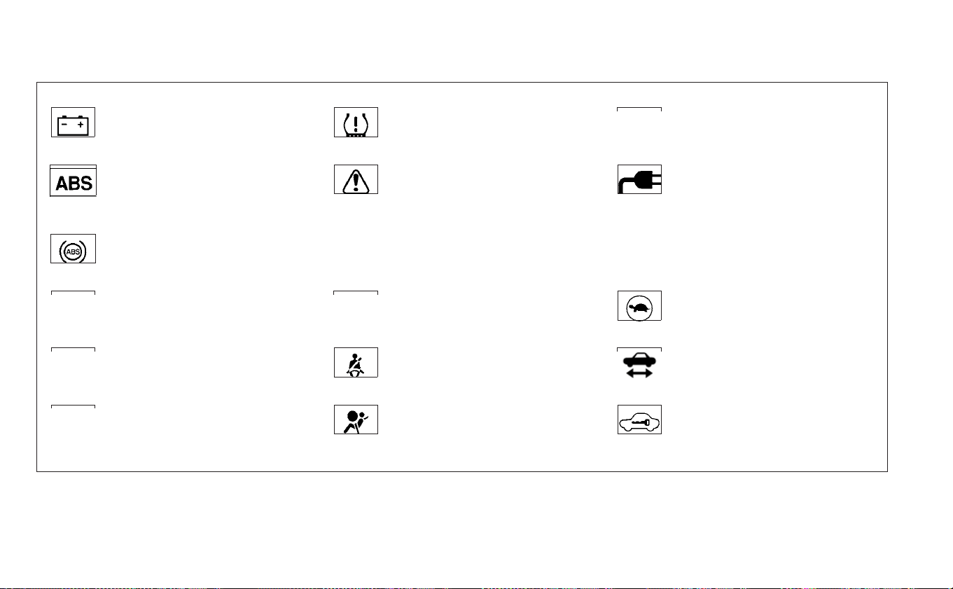
12-volt battery charge warning
light
Low tire pressure warning light High Beam Assist indicator light
(if so equipped)
or
Anti-lock Braking System (ABS)
warning light
Master warning light (red/
yellow)
Plug-in indicator light
Approaching Vehicle Sound for
Pedestrians (VSP) system warn-
ing light
Power steering warning light Power limitation indicator light
Automatic Emergency Braking
(AEB) system warning light (if so
equipped)
Seat belt warning light READY to drive indicator light
Automatic Emergency Braking
(AEB) with Pedestrian Detection
system warning light (if so
equipped)
Supplemental air bag warning
light
Security indicator light
WARNING LIGHTS, INDICATOR LIGHTS
AND AUDIBLE REMINDERS
2-14 Instruments and controls
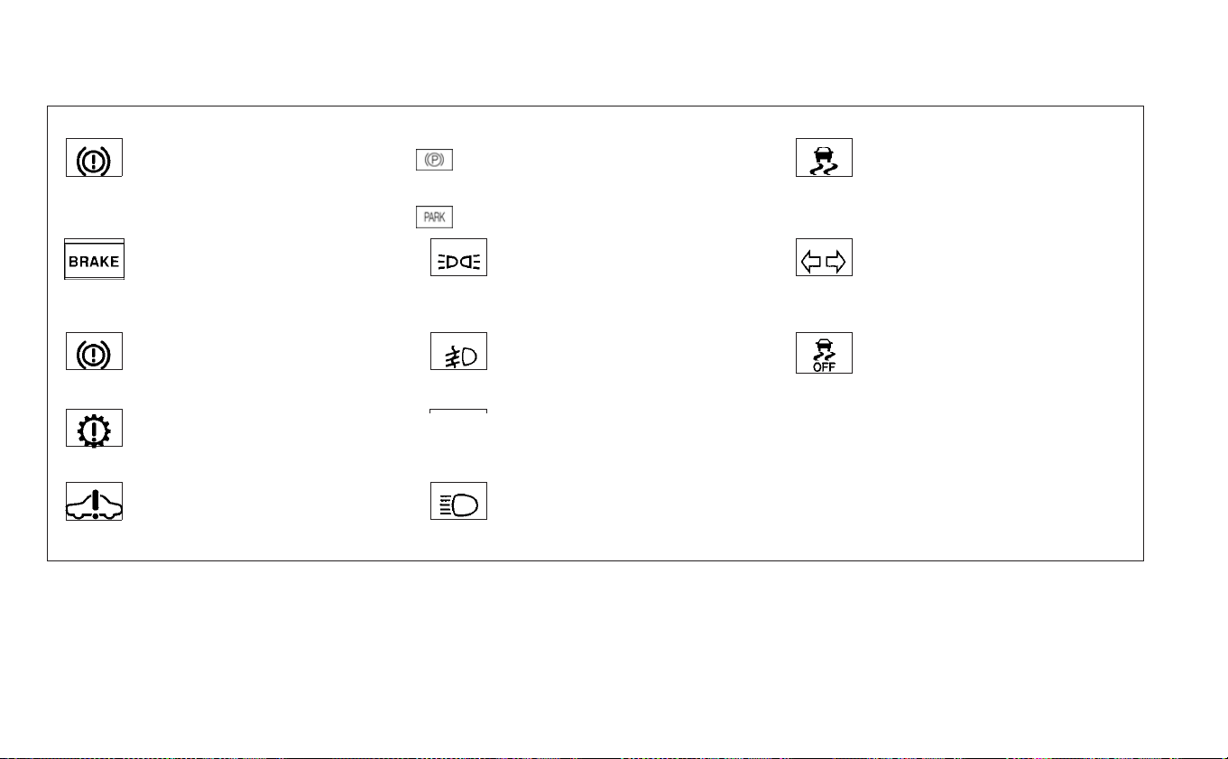
Brake system warning light
(yellow)
or
Electronic parking brake indica-
tor light
Slip indicator light
or
Brake warning light (red)
Ex terior light indicator light Turn signal/hazard indicator
lights
Electronic parking brake system
warning light (yellow)
Front fog light indicator light
(if so equipped)
Vehicle Dynamic Control (VDC)
OFF indicator light
Electric shift control system
warning light
Front passenger air bag status
light
Electric Vehicle (EV) system
warning light
High beam indicator light (blue)
Instruments and controls 2-15
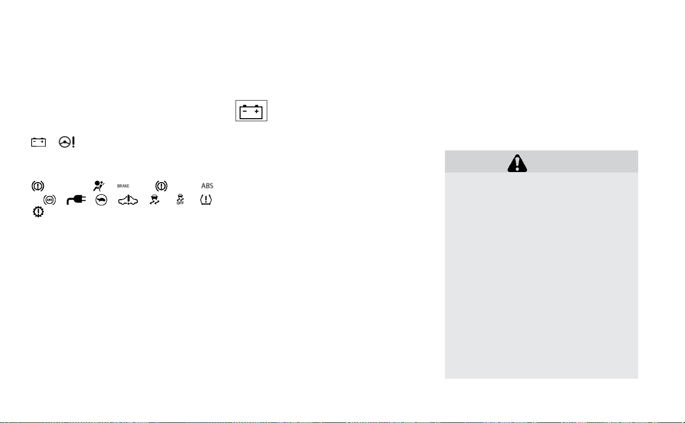
CHECKING LIGHTS
With all doors closed, apply the parking
brake, fasten the seat belts and place the
power switch for LEAF to the ON position
without starting the hybrid system. The fol-
lowing lights (if so equipped) will come on:
,
The following lights (if so equipped) come
on briefly and then turn off:
(yellow), , or (red),
or , , , , , ,
If any light does not come on or operate in
a way other than described, it may indicate
a burned-out bulb and/or a system mal-
function. Have the system checked. It is
recommended that you visit a NISSAN cer-
tified LEAF dealer for this service.
Some indicators and warnings are also dis-
played on the vehicle information display.
For additional information, refer to “Vehicle
information display” in this section.
WARNING LIGHTS
For additional information, refer to “Vehicle
information display” in this section.
12-volt battery charge
warning light
The DC/DC converter converts 400 volt Li-
ion battery voltage to charge the 12-volt
battery.
This light illuminates continuously after the
bulb is checked when the power switch is
in the ON position, and turns off when the
power switch is placed in the READY to
drive position.
When this warning light illuminates, a
chime sounds and the following warnings
are also displayed.
• Master warning (red)
• EV system warning light
The following messages also flash on and
off on the vehicle information display.
If the vehicle is being driven; “Stop the ve-
hicle” and if the vehicle is stopped; “When
parked apply parking brake”. When these
messages flash, immediately stop the ve-
hicle in a safe location, pull the parking
brake switch and push the P (Park) position
switch on the shift lever to place the vehicle
in the P (Park) position. The warning on the
meter and the chime stops when the park-
ing brake is operated or the vehicle is in the
P (Park) position. Have the system checked.
It is recommended that you visit a NISSAN
certified LEAF dealer for this service.
CAUTION
• The DC/DC converter system may
not be functioning properly if the 12-
volt battery charge warning light il-
luminates continuously when the
power switch is in the READY to drive
position. Immediately stop the ve-
hicle in a safe location and have the
system checked. It is recommended
that you visit a NISSAN certified LEAF
dealer for this service.
• The DC/DC converter system may
not be functioning properly if the 12-
volt warning light illuminates con-
tinuously when the power switch is
in the READY to drive position. Do not
charge the 12-volt battery while this
warning light is illuminated. It may
lead to a malfunction of the DC/DC
converter system. Have the system
2-16 Instruments and controls

checked. It is recommended that
you visit a NISSAN certified LEAF
dealer for this service.
NOTE:
• If the vehicle does not go into the READY
to drive position (when the power
switch is pushed and the brake pedal is
depressed), jump-start the vehicle to
place the power switch in the READY to
drive position. For additional informa-
tion, refer to “Jump starting” in the “In
case of emergency” section of this
manual.
• Do not jump-start the vehicle if the con-
ditions below occur. Have the system
checked. It is recommended that you
visit a NISSAN certified LEAF dealer for
this service:
– If the 12-volt charge warning light
turns off when the vehicle is in the
READYto drive mode, the 12-volt bat-
tery may be discharged or there may
be a malfunction in the 12-volt bat-
tery related system.
– If the 12-volt charge warning light
continues to illuminate when the ve-
hicle is in the READY to drive mode,
there may be a malfunction in the
DC/DC converter. Have the system
checked. It is recommended that you
visit a NISSAN certified LEAF dealer
for this service.
or Anti-lock
Braking System
(ABS) warning light
When the power switch is in the ON or
READY to drive position, the Anti-lock Brak-
ing System (ABS) warning light illuminates
and then turns off. This indicates the ABS is
operational.
If the ABS warning light illuminates while
the power switch is in the READY to drive
position, or while driving, it may indicate the
ABS is not functioning properly. Have the
system checked. It is recommended that
you visit a NISSAN certified LEAF dealer for
this service.
If an ABS malfunction occurs, the anti-lock
function is turned off. The brake system
then operates normally, but without anti-
lock assistance. For additional information,
refer to “Brake system” in the “Starting and
driving” section of this manual.
Approaching Vehicle
Sound for Pedestrians
(VSP) system warning light
The Approaching Vehicle Sound for Pedes-
trians (VSP) system warning light is located
on the instrument panel.
This light comes on if there is a malfunction
in the VSP system.
If the VSP system warning light illuminates
while the power switch is in the ON posi-
tion, or in the READY to drive position, it may
indicate the VSP system is not functioning
properly. Have the system checked. It is
recommended that you visit a NISSAN cer-
tified LEAF dealer for this service.
For additional information, refer to “Ap-
proaching Vehicle Sound for Pedestrians
( VSP) system” in the “EV overview” section of
this manual.
Automatic Emergency
Braking (AEB) system
warning light (if so equipped)
This light comes on when the power switch
is placed in the ON position. It turns off after
the hybrid system is started.
Instruments and controls 2-17

This light illuminates when the AEB system
is set to OFF on the meter display.
If the light illuminates when the AEB sys-
tem is on, it may indicate that the system is
unavailable. For additional information, re-
fer to “Automatic Emergency Braking (AEB)”
in the “Starting and driving” section of this
manual.
Automatic Emergency
Braking (AEB) with
Pedestrian Detection system
warning light (if so equipped)
This light comes on when the power switch
is placed in the ON position. It turns off after
the hybrid system is started.
This light illuminates when the AEB with
Pedestrian Detection system is set to OFF
in the vehicle information display.
If the light illuminates when the AEB with
Pedestrian Detection system is on, it may
indicate that the system is unavailable. For
additional information, refer to “Automatic
Emergency Braking (AEB) with Pedestrian
Detection” in the “Starting and driving” sec-
tion of this manual.
Brake system warning
light (yellow)
This light functions for both the coopera-
tive regenerative brake and the electroni-
cally driven intelligent brake systems.
When the power switch is placed in the ON
position or in the READY to drive position,
the light remains illuminated for about 2 or
3 seconds. If the light illuminates at any
other time, it may indicate that the coop-
erative regenerative brake and/or the elec-
tronically driven intelligent brake systems
are not functioning properly. Have the sys-
tem checked. It is recommended that you
visit a NISSAN certified LEAF dealer for this
service.
If the BRAKE warning light (red) also illumi-
nates, stop the vehicle immediately and
have the system checked. It is recom-
mended that you visit a NISSAN certified
LEAF dealer for this service. For additional
information, refer to “Brake system” in the
“Starting and driving” section of this
manual.
WARNING
• Pressing the brake pedal when the
power switch position is not in the
ON or READY to drive position and/or
low brake fluid level may increase
the stopping distance and braking
will require greater pedal effort as
well as pedal travel.
• If the brake fluid level is below the
minimum or MIN mark on the brake
fluid reservoir, do not drive until the
brake system has been checked. It is
recommended that you visit a
NISSAN certified LEAF dealer for this
service.
• The cooperative regenerative brake
system may not be working prop-
erly if the brake system warning
light illuminates when the READY to
drive indicator light is ON. If you
judge it to be safe, drive carefully to
the nearest service station for re-
pairs. Otherwise, have your vehicle
towed because driving could be
dangerous.
2-18 Instruments and controls
or Brake warning
light (red)
When the power switch is placed in the ON
position or in the READY to drive position,
the light remains illuminated for about a
few seconds. If the light illuminates at any
other time, it may indicate that the hydrau-
lic brake system is not functioning properly.
If the BRAKE warning light illuminates, stop
the vehicle immediately and have the sys-
tem checked. It is recommended that you
visit a NISSAN certified LEAF dealer for this
service.
Parking brake indicator:
When the power switch is placed in the ON
position, the light comes on when the park-
ing brake is applied.
Low brake fluid warning light:
When the power switch is in the ON posi-
tion, the light warns of a low brake fluid
level. If this warning light illuminates, the
Vehicle Dynamic Control (VDC) warning
light and the brake system warning light
(yellow) also illuminate.
If the light illuminates while the power
switch is in the READY to drive position with
the parking brake not applied, stop the ve-
hicle and perform the following items.
1. Check the brake fluid level. If brake fluid is
necessary, add fluid and have the sys-
tem checked. It is recommended that
you visit a NISSAN certified LEAF dealer
for this service. For additional informa-
tion, refer to “Brake fluid” in the “Mainte-
nance and do-it-yourself” section of this
manual.
2. If the brake fluid level is correct, have the
warning system checked. It is recom-
mended that you visit a NISSAN certified
LEAF dealer for this service.
WARNING
• Your brake system may not be work-
ing properly if the warning light is
on. Driving could be dangerous. If
you judge the brake system to be
safe, drive carefully to the nearest
service station for repairs. Other-
wise, have your vehicle towed be-
cause driving it could be dangerous.
• Pressing the brake pedal when the
power switch position is not in the
ON or READY to drive position and/or
low brake fluid level may increase
the stopping distance and braking
will require greater pedal effort as
well as pedal travel.
• If the brake fluid level is below the
minimum or MIN mark on the brake
fluid reservoir, do not drive until the
brake system has been checked. It is
recommended that you visit a
NISSAN certified LEAF dealer for this
service.
Electronic brake system
warning light (yellow)
The electronic parking brake system warn-
ing light function for the electronic braking
brake system. When the power switch is
placed in the ON position, the light illumi-
nates for a few seconds. If the warning light
illuminates at any other time, it may indi-
cate that the electronic parking brake sys-
tem is not function properly. Have the sys-
tem checked immediately. It is
recommended that you visit a NISSAN cer-
tified LEAF dealer for this service.
Instruments and controls 2-19
Electric shift control
system warning light
This light illuminates to warn when a mal-
function occurs in the electric shift control
system. When the master warning light illu-
minates, the chime sounds and the mes-
sage, “When parked apply parking brake”, is
displayed on the vehicle information dis-
play.
When the power switch is in the OFF posi-
tion, the chime sounds continuously. Make
sure the parking brake is applied.
Have the system checked. It is recom-
mended that you visit a NISSAN certified
LEAF dealer for this service.
Electric Vehicle (EV)
system warning light
This light illuminates if there is a malfunc-
tion in the following systems. Have the sys-
tem checked. It is recommended that you
visit a NISSAN certified LEAF dealer for this
service.
• Traction motor and inverter system
• Charge port or on board charger
• Li-ion battery system
• Cooling system
• Shift control system
• Emergency shut off system is activated.
For additional information, refer to “Emer-
gency shut-off system” in the “EV over-
view” section of this manual.
Low tire pressure warning
light
Your vehicle is equipped with a Tire Pres-
sure Monitoring System (TPMS) that moni-
tors the tire pressure of all tires.
The low tire pressure warning light warns
of low tire pressure or indicates that the
TPMS is not functioning properly.
After the power switch is placed in the ON
position, this light illuminates for about
1 second and then turns off.
Low tire pressure warning
If the vehicle is being driven with low tire
pressure, the warning light will illuminate.
The “Low Tire Pressure — Add Air” warning
also appears on the vehicle information
display.
When the low tire pressure warning light
illuminates, you should stop and adjust the
tire pressure to the recommended COLD
tire pressure shown on the Tire and Load-
ing Information label. The low tire pressure
warning light does not automatically turn
off when the tire pressure is adjusted. After
the tire is inflated to the recommended
pressure, the vehicle must be driven at
speeds above 16 mph (25 km/h) to activate
the TPMS and turn off the low tire pressure
warning light. Use a tire pressure gauge to
check the tire pressure.
The “Low Tire Pressure — Add Air” warning
appears each time the power switch is
placed in the ON position as long as the low
tire pressure warning light remains illumi-
nated.
For additional information, refer to “Vehicle
information display” in this section, “Tire
Pressure Monitoring System (TPMS)” in the
“Starting and driving” section and “In case
of emergency” section of this manual.
TPMS malfunction
If the TPMS is not functioning properly, the
low tire pressure warning light will flash for
approximately 1 minute when the power
switch is placed in the ON position. The
light will remain on after the 1 minute. Have
2-20 Instruments and controls

the system checked. It is recommended
that you visit a NISSAN certified LEAF dealer
for this service. The “Low Tire Pressure —
Add Air” warning does not appear if the low
tire pressure warning light illuminates to
indicate a TPMS malfunction.
For additional information, refer to “Vehicle
information display” in this section and
“Tire Pressure Monitoring System (TPMS)” in
the “Starting and driving” section of this
manual.
WARNING
• Radio waves could adversely affect
electric medical equipment. Those
who use a pacemaker should con-
tact the electric medical equipment
manufacturer for the possible influ-
ences before use.
• If the light does not illuminate when
the power switch is placed in the ON
position, have the vehicle checked. It
is recommended that you visit a
NISSAN certified LEAF dealer as soon
as possible for this service.
• If the light illuminates while driving,
avoid sudden steering maneuvers
or abrupt braking, reduce vehicle
speed, pull off the road to a safe lo-
cation and stop the vehicle as soon
as possible. Driving with under-
inflated tires may permanently
damage the tires and increase the
likelihood of tire failure. Serious ve-
hicle damage could occur and may
lead to an accident and could result
in serious personal injury or death.
Check the tire pressure for all four
tires. Adjust the tire pressure to the
recommended COLD tire pressure
shown on the Tire and Loading Infor-
mation label to turn the low tire
pressure warning light OFF. If the
light still illuminates while driving
after adjusting the tire pressure, a
tire may be flat or the TPMS may be
malfunctioning. If you have a flat
tire, replace it with a spare tire as
soon as possible. If no tire is flat and
all tires are properly inflated, have
the vehicle checked. It is recom-
mended that you visit a NISSAN cer-
tified LEAF dealer for this service.
• When replacing a wheel without the
TPMS such as a spare tire, the TPMS
will not function and the low tire
pressure warning light will flash for
approximately 1 minute. The light
will remain on after 1 minute. Have
the system checked. It is recom-
mended that you visit a NISSAN cer-
tified LEAF dealer as soon as pos-
sible for tire replacement and/or
system resetting.
• Replacing tires with those not origi-
nally specified by NISSAN could af-
fect the proper operation of the
TPMS.
CAUTION
• The TPMS is not a substitute for the
regular tire pressure check. Be sure
to check the tire pressure regularly.
• If the vehicle is being driven at
speeds of less than 16 mph
(25 km/h), the TPMS may not oper-
ate correctly.
• Be sure to install the specified size of
tires to the four wheels correctly.
Instruments and controls 2-21
Master warning light
(red/yellow)
There are two types of master warning
lights: yellow and red. These lights illumi-
nate if any warning lights or indicator lights
are illuminated or if various vehicle infor-
mation warnings appear in the vehicle in-
formation display.
Yellow master warning light
This light illuminates when a yellow warn-
ing light within the vehicle information dis-
play is illuminated or when a message is
displayed on the vehicle information dis-
play.
Red master warning light
This light illuminates when a red warning
light within the vehicle information display
is illuminated or when a warning is dis-
played on the vehicle information display.
Power steering warning
light
When the power switch is in the ON posi-
tion, the electric power steering warning
light illuminates and turns off when the
power switch is placed in the READY to
drive position. This indicates the electric
power steering system is operational.
If the electric power steering warning light
illuminates while the READY to drive indica-
tor light is ON, it may indicate the electric
power steering system is not functioning
properly and may need servicing. Have the
electric power steering system checked. It
is recommended that you visit a NISSAN
certified LEAF dealer for this service.
When the electric power steering warning
light illuminates while the READY to drive
indicator is ON, the power assist to the
steering will cease operation but you will
still have control of the vehicle. At this time,
greater steering efforts are required to op-
erate the steering wheel, especially in
sharp turns and at low speeds.
For additional information, refer to “Power
steering system” in the “Starting and driv-
ing” section of this manual.
Seat belt warning
light
The light and chime remind you to fasten
your seat belts. The light illuminates when-
ever the power switch is placed in the ON
position, and will remain illuminated until
the driver’s seat belt is fastened. At the
same time, the chime will sound for ap-
proximately 6 seconds unless the driver’s
seat belt is securely fastened.
The seat belt warning light for the front
passenger will illuminate if the seat belt is
not fastened when the front passenger’s
seat is occupied. The front passenger seat
belt warning light does not activate until
5 seconds after the power switch is in the
ON position.
For additional information, refer to “Seat
belts” in the “Safety — Seats, seat belts and
supplemental restraint system” section of
this manual for precautions on seat belt
usage.
Supplemental air bag
warning light
After turning the power switch to the ON
position, the supplemental air bag warning
light will illuminate. The supplemental air
bag warning light will turn off after about
7 seconds if the supplemental front air bag
and supplemental side air bag, curtain
2-22 Instruments and controls
side-impact air bag systems and/or pre-
tensioner seat belt are operational.
If any of the following conditions occur, the
front air bag, side air bag, curtain air bag
and pretensioner systems need servicing
and your vehicle must be taken to your
nearest NISSAN certified LEAF dealer.
• The supplemental air bag warning light
remains on after approximately
7 seconds.
• The supplemental air bag warning light
flashes intermittently.
• The supplemental air bag warning light
does not illuminate at all.
Unless checked and repaired, the Supple-
mental Restraint Systems and/or the pre-
tensioners may not function properly.
For additional information, refer to “Supple-
mental restraint system (SRS)” in the “Safety
— Seats, seat belts and supplemental re-
straint system” section of this manual.
WARNING
If the supplemental air bag warning
light is on, it could mean that the front
air bag, side air bag, curtain air bag
and/or pretensioner systems will not
operate in an accident. To help avoid
injury to yourself or others, have your
vehicle checked. It is recommended
that you visit a NISSAN certified LEAF
dealer as soon as possible for this ser-
vice..
INDICATOR LIGHTS
For additional information, refer to “Vehicle
information display” in this section.
or Electronic parking
brake indicator light
When the power switch is placed in the ON
position, the light comes on when the park-
ing brake is applied.
Exterior light indicator
light
This indicator illuminates when the head-
light switch is turned to the AUTO,
or
position and the front parking lights,
side marker lights, tail and license plate
lights are on. The indicator turns off when
these lights are turned off.
Front fog light indicator light
(if so equipped)
The front fog indicator light illuminates
when the front fog lights are on. For addi-
tional information, refer to “Fog light switch”
in this section.
Front passenger air bag
status light
The front passenger air bag status light
(located on the center of the instrument
panel) will be lit and the passenger front air
bag will be turned off depending on how
the front passenger seat is being used.
For front passenger air bag status light op-
eration, refer to “NISSAN Advanced Air Bag
System (front seats)” in the “Safety — Seats,
seat belts and supplemental restraint sys-
tem” section of this manual.
High Beam Assist indicator
light (if so equipped)
The indicator light illuminates when the
headlights come on while the headlight
switch is in the AUTO position with the high
beam selected. This indicates that the high
Instruments and controls 2-23
beam assist system is operational. For ad-
ditional information, refer to “Headlight
beam select” in this section.
High beam indicator light
(blue)
This light illuminates when the headlight
high beam is on and goes out when the low
beam is selected.
Plug-in indicator
light
This light illuminates when the charge con-
nector is connected to the vehicle and
blinks during charging.
NOTE:
If the charge connector is connected to
the vehicle, the power switch cannot be
placed in the READY to drive position.
Power limitation indicator
light
When the power limitation indicator light is
illuminated, the power provided to the trac-
tion motor is reduced. Therefore the ve-
hicle is not as responsive when the accel-
erator is depressed while the power
limitation light is illuminated.
When this light comes on, the warning dis-
play appears within the vehicle information
display. Follow the instructions provided on
the vehicle information display.
This light illuminates in the following condi-
tions.
• Li-ion battery available charge is ex-
tremely low
• Li-ion battery temperature is very low (ap-
proximately −4°F (−20°C)
• When the temperature of the EV system is
high (motor, inverter, coolant system, Li-
ion battery etc.)
• When the EV system has a malfunction.
If the low battery charge indicator is illumi-
nated, charge the Li-ion battery as soon as
possible.
If this indicator illuminates because the Li-
ion battery is cold due to low outside tem-
peratures, move the vehicle to a warmer
location. The Li-ion battery temperature
may be increased by charging the Li-ion
battery.
If the light illuminates when the EV system
becomes hot due to continuous hill climb-
ing, either continue driving at a slower safe
speed or stop the vehicle in a safe location.
If this indicator does not turn off, have the
system checked. It is recommended that
you visit a NISSAN certified LEAF dealer for
this service.
The indicator illuminates when a part in the
EV system has malfunctioned. If the indica-
tor illuminates in a situation other than
those described above, or if it does not turn
off, there may be a system malfunction.
Have the system checked. It is recom-
mended that you visit a NISSAN certified
LEAF dealer for this service.
WARNING
Power limitation mode can result in re-
duced power and vehicle speed. The
reduced speed may be lower than
other traffic, which could increase the
chance of a collision. Be especially
careful when driving. If the vehicle can-
not maintain a safe driving speed, pull
to the side of the road in a safe area.
Charge the Li-ion battery if the charge
is low or allow the Li-ion battery to
cool.
2-24 Instruments and controls
NOTE:
You can reduce charging time and
keep the Li-ion battery temperature
lower if you:
• Charge more frequently in smaller
amounts, and
• Keep the battery at a higher level of
charge.
READY to drive indicator
light
The READY to drive indicator light illumi-
nates when the EV system is powered and
the vehicle may be driven.
The READY to drive indicator light will turn
off in the following conditions.
• Cer tain EV system malfunctions.
• The READY to drive indicator light turns off
immediately before the Li-ion battery is
completely discharged. If the Li-ion bat-
tery becomes completely discharged, the
vehicle must be charged in order to be
driven. For additional information, refer to
“Low battery charge indicator” in this
section.
Security indicator
light
This light blinks when the power switch is in
the ACC, OFF or LOCK position. This func-
tion indicates the security system
equipped on the vehicle is operational.
If the security system is malfunctioning,
this light will remain on while the power
switch is in the ON position. For additional
information, refer to “Security systems” in
this section.
Slip indicator light
This indicator will blink when the VDC sys-
tem or the traction control system is oper-
ating, thus alerting that the vehicle is near-
ing its traction limits. The road surface may
be slippery.
You may feel or hear the system working;
this is normal. The light will blink for a few
seconds after the VDC system stops limit-
ing wheel spin.
The indicator light also comes on when
you place the power switch in the ON
position.
The light will turn off after approximately
2 seconds if the system is operational. If the
light does not come on, have the system
checked. It is recommended that you visit a
NISSAN certified LEAF dealer for this ser-
vice.
Turn signal/hazard
indicator lights
This light flashes when the turn signal
switch lever or hazard switch is turned on.
Vehicle Dynamic Control
(VDC) OFF indicator light
This light illuminates when the Vehicle Dy-
namic Control (VDC) switch is pushed to
OFF. This indicates that the VDC system is
not operating. For additional information,
refer to “Vehicle Dynamic Control (VDC) sys-
tem” in the “Starting and driving” section of
this manual.
AUDIBLE REMINDERS
Brake pad wear warning
The disc brake pads have audible wear
warnings. When a brake pad requires re-
placement, it will make a high pitched
Instruments and controls 2-25

scraping sound when the vehicle is in mo-
tion. This scraping sound will first occur
only when the brake pedal is depressed.
After more wear of the brake pad, the
sound will always be heard even if the
brake pedal is not depressed. Have the
brakes checked as soon as possible if the
warning sound is heard.
Electric shift control system
reminder chime
If an improper shift operation is performed,
for safety reasons a chime will sound and
at the same time, depending on the condi-
tions, the operation will be canceled or the
shift position will switch to the N (Neutral)
position.
For additional information, refer to “Driving
the vehicle” in the “Starting and driving” sec-
tion of this manual.
Key reminder chime
A chime will sound if the driver's side door is
opened while the power switch is pushed
to the ON or ACC position.
Make sure that the power switch is pushed
to the OFF position, and take the Intelligent
Key with you when leaving the vehicle.
Light reminder chime
The light reminder chime will sound when
the driver side door is opened with the light
switch in the
or position, and
the power switch is in the ACC, OFF or LOCK
position.
Turn the light switch off when you leave the
vehicle.
Parking brake reminder chime
A chime sounds if the parking brake is set
and the vehicle is driven. The chime will
stop if the parking brake is released or the
vehicle speed returns to zero.
Power switch reminder chime
The power switch reminder chime will
sound when the driver's door is opened
while the power switch is in the ON or
READY to drive position. Push the power
switch to the OFF position.
Seat belt warning chime
The seat belt warning chime will sound for
about 6 seconds unless the driver’s seat
belt is securely fastened.
12-volt battery charge warning
chime
If the 12-volt battery charge warning light
illuminates, the chime will sound when a
warning message is displayed in the ve-
hicle information display.
When the chime sounds, immediately stop
the vehicle in a safe location and push the P
(Park) position switch on the shift lever and
apply the parking brake. The 12-volt battery
charge warning light turns off and the
chime will stop when the parking brake is
applied or the vehicle is placed in the P
(Park) position. Have the system checked. It
is recommended that you visit a NISSAN
certified LEAF dealer for this service. For
additional information, refer to “12-volt bat-
tery charge warning light” in this section.
2-26 Instruments and controls

The vehicle information display is located
to the left of the speedometer. It displays
items such as
• Battery information
• Energy economy
• Average vehicle speed
• Driving distance
• Driving time
• Cruise control information
• Intelligent Key information
• Indicators and warnings
HOW TO USE THE VEHICLE
INFORMATION DISPLAY
The vehicle information display can be
changed by using the
and OK switches located on the steer-
ing wheel.
䊊
1
OK
Use this switch to change or
select items.
䊊
2
Use these switches to navigate
the vehicle information display.
䊊
3
Use this switch to return to the
previous menu.
䊊
4
Use these switches to navigate
the vehicle information display.
The OK,
switches
also control audio and control panel func-
tions in some conditions. Most screens and
menus offer instruction prompts of the
steering switches to indicate how to con-
trol the vehicle information display. White
dots appear on the left side of the vehicle
information display when there is more
than one page of menu items. The OK,
and switches change the audio
source and the buttons also control voice
recognition manual mode. For additional
information, refer to the separate
NissanConnect® Manual (for Leaf).
STARTUP DISPLAY
With the vehicle in the ON position, the ve-
hicle information display may display the
following screens:
• Battery information
• Audio
• Navigation
• Energy Economy
• Safety Shield
VEHICLE INFORMATION DISPLAY
Instruments and controls 2-27

• Warnings
• Settings
Warnings will only display if there are any
present. For additional information, refer to
“Vehicle information display warnings and
indicators” in this section.
To control which items display in the ve-
hicle information display, refer to “Meter
settings” in this section.
SETTINGS
The settings mode allows you to change
the information displayed in the vehicle in-
formation display as well as enable and
disable various vehicle features and sys-
tems. The settings include:
• VDC Setting
• Driver Assistance
• Customize Display
• Vehicle Settings
• EV Settings
• TPMS Settings
• Maintenance
• Clock
• Unit/Language
• Factory Reset
VDC Setting
The VDC setting menu allows the user to
the adjust the VDC settings.
Menu Item Result
VDC Setting Allows user to turn the Vehicle Dynamic Control (VDC) system on or off.
2-28 Instruments and controls

Driver Assistance
The driver assistance menu allows the user
to change the settings for driving, parking,
and braking aids.
Menu Item Result
Steering Assist (if so equipped) Allows user to turn the steering assist feature on or off. For additional information, refer to “ProPILOT
TM
Assist” in the “Starting and driving” section of this manual.
Lane Displays the available lane options.
Lane Departure Warning Allows user to turn the Lane Departure Warning on and off. For additional information, refer to “Lane De-
parture Warning (LDW)” in the “Starting and driving” section of this manual.
Lane Departure Prevention Allows user to turn the Lane Departure Warning on and off. For additional information, refer to “Intelligent
Lane Intervention (I-LI)” in the “Starting and driving” section of this manual.
Blind Spot Displays the available blind spot options.
Blind Spot Warning Allows user to turn the Blind Spot Warning on and off. For additional information, refer to “Blind Spot
Warning” in the “Starting and driving” section of this manual.
Side Indicator Brightness Allows user to set the brightness of the side indicator.
Emergency Brake Displays the available emergency brake options.
System Allows user to turn the emergency brake on and off. For additional information, refer to “Automatic Emer-
gency Braking (AEB)” in the “Starting and driving” section of this manual.
Parking Aids Displays the available parking aids.
Moving Object Allows user to turn the Moving Object Detection on and off. For additional information, refer to “Moving
Object Detection” in the “Monitor, climate, audio, phone and voice recognition systems” section of this
manual.
Cross Traffic Allows user to turn the cross traffic alert on and off. For additional information, refer to “Rear Cross Traffic
Alert (RCTA)” in the “Starting and driving” section of this manual.
Driver Attention Alert
(if so equipped)
Allows user to turn the driver attention alert on or off. For additional information, refer to “Intelligent Driver
Alertness (I-DA)” in the “Starting and driving” section of this manual.
Timer Alert Allows user to set or reset an alert at a specific tune interval.
Instruments and controls 2-29

Menu Item Result
Low Temperature Alert Allows user to turn the low temperature alert on or off.
Chassis Control (if so equipped) Displays the available chassis controls.
Active Trace Control Allows user to turn the driver attention alert on or off. For additional information, refer to “Intelligent Trace
Control (I-TC)” in the “Starting and driving” section of this manual.
e-Pedal Displays the available e-Pedal options.
Retain Mode Allows user to turn the retain mode on or off. For additional information, refer to “e-Pedal system” in the
“Starting and driving” section of this manual.
2-30 Instruments and controls

Customize Display
The customize display menu allows the
user to change the settings for the vehicle
information display.
Menu Item Result
Main Menu Selection Displays the available main menu selection options.
Cruise (if so equipped) Allows user to turn the Cruise screen on or off in the vehicle information display.
Driving Aids Allows user to turn the safety shield screen on or off in the vehicle information display.
Status Allows user to turn the status screen on or off in the vehicle information display.
Tire Pressures Allows user to turn the tire pressures screen on or off in the vehicle information display.
Drive Computer Allows user to turn the drive computer screen on or off in the vehicle information display.
Chassis Control Allows user to turn the chassis control screen on or off in the vehicle information display.
ECO Info Settings Displays the available ECO Info Settings.
ECO Drive Report Allows user to turn the ECO drive report on or off.
View History Allows user to view and reset the ECO drive report history.
Navigation Settings Displays the available navigation settings.
Alerts Allows user to turn the navigation alerts on or off.
Cruise Screen Transition (if so equipped) Allows user to turn the Cruise screen transition on or off.
Welcome Effect Displays the available welcome effects.
Gauges Allows user to turn the gauges effect on or off.
Animation Allows user to turn the animation effect on or off.
Instruments and controls 2-31

Vehicle Settings
The vehicle settings menu allows the user
to change the settings for the lights, locks
and wipers.
Menu Item Result
Lighting Displays the available lighting options.
Auto Room Lamp Allows user to turn the auto room lamp on or off
Light Sensitivity Allows user to change when the lights illuminate based on the brightness outside the vehicle.
Light Off Delay Allows user to change the duration of time that the automatic headlights stay on after the
vehicle is shut off.
Locking Displays the available locking options.
Ext. Door Switch Allows user to turn the exterior door switch on or off. When turned on, the request switch on
the door is activated.
Selective Unlock Allows user to turn selective unlock on or off. When turned on, only the current door is un-
locked after the door unlock operation. When the door handle request switch on the driver’s
or front passenger’s side door is pushed to be unlocked, only the corresponding door is un-
locked first. All the doors can be unlocked if the door unlock operation is performed again
within 5 seconds. When this item is turned off, all the doors will be unlocked after the door un-
lock operation is performed once.
Wipers Displays the available wiper settings. For additional information, refer to “Wiper and washer
switch” in this section.
Speed Dependent Allows user to turn the speed dependent feature on or off.
2-32 Instruments and controls

EV Settings
The EV settings menu allows the user to
change the settings for charging the
vehicle.
Menu Item Result
Chg. Connector Lock Allows user to lock or unlock the charging connection.
Charge Timer1 Allows user to set charge timer 1.
Charge Timer2 Allows user to set charge timer 2.
Chg. Timer Only at HOME (if so equipped) Allows user to set charging timer only at home.
Charge Time Screen Allows user to select the display time screen based on charge method.
Climate Control Timer1 Allows user to set climate control timer 1.
Climate Control Timer2 Allows user to set climate control timer 2.
TPMS Settings
The TPMS settings menu allows the user to
change the tire pressure units displayed in
the vehicle information display.
Menu Item Result
TPMS Settings Allows user to select the tire pressure units that will display in the vehicle information display.
Instruments and controls 2-33

Maintenance
The maintenance menu allows the user to
set reminders for various vehicle mainte-
nance items.
Menu Item Result
Maintenance Displays available maintenance reminder options.
Tire Allows user to set a reminder at a specific interval or reset the current one.
Other Allows user to set a reminder at a specific interval or reset the current one.
Clock
Menu Item Result
Clock When selected the following message appears: “Go to the settings menu on the
center display to set clock”. For additional information, refer to the separate
NissanConnect® Manual (for Leaf).
2-34 Instruments and controls

Unit/Language
The unit/language menu allows the user to
change the units shown in the vehicle in-
formation display.
Menu Item Result
Mileage/Energy Allows user to select the preferred mileage/energy unit of measure to display.
Tire Pressures Allows user to select the preferred tire pressure unit of measure to display.
Temperature Allows user to select the preferred temperature unit of measure to display.
Language Allows user to select the preferred language to display.
Factory Reset
The factory reset menu allows the user to
restore the vehicle information display set-
tings to factory status.
Menu Item Result
Factory Reset Allows user to reset the vehicle information display settings to the original fac-
tory settings. Once selected, the user can confirm or deny the reset.
Instruments and controls 2-35

VEHICLE INFORMATION DISPLAY WARNINGS AND INDICATORS
2-36 Instruments and controls

1. Push brake and power switch to drive
2. No Key Detected
3. Key Battery Low
4. EV system operation for discharged In-
telligent Key system indicator
5. Door open
6. Low batter y charge indicator
7. Driver alert
8. Low outside air temperature
9. Low Washer Fluid (if so equipped)
10. Reminder Turn OFF Headlights
11. Tire Pressure Low — Add Air
12. Cruise control indicator (if so equipped)
13. Intelligent Cruise Control (ICC) indica-
tors (if so equipped)
14. Shift to Park
15. Key System Error: See Owner’s Manual
16. Release Parking Brake
17. ProPILOT
TM
Assist indicator (if so
equipped)
18. Not Available Seat Belt Not Fastened (if
so equipped)
19. Malfunction: See Owner’s Manual
20. Indicators for maintenance
21. Steering Assist indicator (if so
equipped)
22. Steering Assist warning (if so equipped)
23. Not Available Front Radar Blocked (if so
equipped)
24. Not Available Visibility is impaired (if so
equipped)
25. Driver Attention Alert Take a Break? (if
so equipped)
26. Driver Attention Alert System Fault (if so
equipped)
27. Unavailable High Cabin Temperature (if
so equipped)
28. Not Available Parking Brake On (if so
equipped)
29. Not Available Poor Road Conditions (if
so equipped)
30. Currently not available (if so equipped)
31. Press Brake Pedal (if so equipped)
32. Lane Departure Warning (LDW)/
Intelligent Lane Intervention (I-LI) indi-
cator (if so equipped)
33. Automatic Emergency Braking (AEB)/
Automatic Emergency Braking (AEB)
with Pedestrian Detection indicator (if
so equipped)
34. Shipping Mode On Push Storage Fuse
35. Blind Spot Warning (BSW)/Rear Cross
Traffic Alert (RCTA) indicator (if so
equipped)
36. Headlight System Error: See Owner ’s
Manual (if so equipped)
37. When Parked Apply Parking Brake
38. T/M system malfunction Visit dealer
39. Check position of shift lever
40. Chassis control system error: See
Owner’s Manual
Instruments and controls 2-37

Push brake and power switch to
drive
This indicator appears while the vehicle is
in the P (Park) position. This indicator
means that the EV system will start when
the power switch is pressed with the brake
pedal depressed.
No Key Detected
This warning appears in either of the fol-
lowing conditions:
No key inside the vehicle:
This warning appears when the door is
closed with the Intelligent Key left outside
the vehicle and the power switch in the
ACC or ON position. Make sure that the
Intelligent Key is inside the vehicle.
Unregistered Intelligent Key:
This warning appears when the power
switch is placed in the ON, ACC or READY to
drive position and the Intelligent Key can-
not be recognized by the system. You can-
not place the power switch in the READY to
drive position with an unregistered key. Use
an Intelligent Key that has been registered.
For additional information, refer to “NISSAN
Intelligent Key® system” in the “Pre-driving
checks and adjustments” section of this
manual.
Key Battery Low
This indicator appears when the Intelligent
Key battery is running out of power.
If this indicator appears, replace the bat-
tery with a new one. For additional infor-
mation, refer to “NISSAN Intelligent Key®
battery replacement” in the “Maintenance
and do-it-yourself” section of this manual.
EV system operation for
discharged Intelligent Key system
indicator
This indicator appears when the Intelligent
Key battery is running out of power and
when the Intelligent Key system and ve-
hicle are not communicating normally.
If this indicator appears, touch the power
switch with the Intelligent Key while de-
pressing the brake pedal. For additional in-
formation, refer to “NISSAN Intelligent Key®
battery discharge” in the “Starting and driv-
ing” section of this manual.
Door open
This warning appears if any of the doors
and/or the rear hatch are open or not
closed securely. The vehicle icon indicates
which door or the rear hatch is open on the
display. Make sure that all of the doors and
the rear hatch are closed.
This warning also appears alternating with
the Shift to Park warning while the driver's
door is opened with the shift position in
any position other than the P (Park) posi-
tion. For additional information, refer to
“Shift to Park” in this section.
Low Battery Charge indicator
This light illuminates when the available Li-
ion battery charge is getting low. Charge as
soon as it is possible, preferably before the
Li-ion batter y available charge gauge
reaches 0%.
NOTE:
The low battery charge indicator
turns off immediately before the Li-
ion battery is completely discharged
2-38 Instruments and controls

and the vehicle will stop. If the Li-ion
battery becomes completely dis-
charged, the vehicle must be charged
in order to be driven.
Driver alert
This warning appears when the previously
set time for a break is reached. You can set
the time for up to 6 hours in the setting
menu. For additional information, refer to
“Vehicle information display” in this section.
Low outside air temperature
The outside air temperature is displayed in
°F or °C in the range of −20°F to 140°F (−30°C
to 60°C).
The outside air temperature mode in-
cludes a low temperature warning feature.
If the outside air temperature is below 37°F
(3°C), the warning is displayed on the
screen.
The outside temperature sensor is located
in front side of the vehicle. The sensor may
be affected by road, wind directions and
other driving conditions. The display may
differ from the actual outside temperature
or the temperature displayed on various
signs or billboards.
Low Washer Fluid (if so equipped)
This warning appears when the washer
tank fluid is at a low level. Add washer fluid
as necessary. For additional information,
refer to “Windshield washer fluid” in the
“Maintenance and do-it-yourself” section.
Reminder Turn OFF Headlights
This warning appears when the power
switch is turned to the OFF position but the
headlight switch is still on. Turn off the
headlight switch.
Tire Pressure Low - Add Air
This warning appears when the low tire
pressure warning light in the meter illumi-
nates and low tire pressure is detected. The
warning appears each time the power
switch is placed in the ON position as long
as the low tire pressure warning light re-
mains illuminated.
If this warning appears, stop the vehicle
and adjust the tire pressure to the recom-
mended COLD tire pressure shown on the
Tire and Loading Information label. For ad-
ditional information, refer to “Low tire pres-
sure warning light” in this section and “Tire
Pressure Monitoring System (TPMS)” in the
“Starting and driving” section of this
manual.
Cruise control indicator (if so
equipped)
This indicator shows the cruise control sys-
tem status.
When cruise control is activated, a green
circle will illuminate to indicate it is set. The
vehicle information display will also display
the speed the cruise control was set at. If
you accelerate past the set speed, the
speed will blink until you either cancel
cruise control or go back to the set speed. If
cruise control is on and canceled, the
speed will be displayed to show the speed
the vehicle will return to if the resume but-
ton is activated.
For additional information, refer to “Cruise
control” in the “Starting and driving” section
of this manual.
Instruments and controls 2-39

Intelligent Cruise Control (ICC)
indicators (if so equipped)
This indicator shows the Intelligent Cruise
Control (ICC) system status. The status is
shown by the color. For additional informa-
tion, refer to “Intelligent Cruise Control (ICC)”
in the “Starting and driving” section of this
manual.
Shift to Park
This warning appears alternately with
door/rear hatch open warning when the
driver's door is opened with the shift posi-
tion in any position other than the P (Park)
position. If this warning appears, push the P
(Park) position switch and place in the P
(Park) position.
For additional information, refer to “Door
open” in this section.
Key System Error: See Owner’s
Manual
After the power switch is pushed to the ON
position, this light comes on for about
2 seconds and then turns off.
The Key System Error message warns of a
malfunction with the Intelligent Key sys-
tem. If the light comes on while the motor is
stopped, it may be impossible to start the
motor.
If the light comes on while the motor is
running, you can drive the vehicle. However,
have it repaired as soon as possible. It is
recommended that you visit a NISSAN cer-
tified LEAF dealer for this service.
Release Parking Brake
This warning appears when the vehicle
speed is above 4 mph (7 km/h) and the
parking brake is applied.
ProPILOT
TM
Assist indicator (if so
equipped)
This indicator appears when the ProPILOT
Assist system is engaged. For additional
information, refer to “ProPILOT
TM
Assist” in
the “Starting and driving” section of this
manual.
Not Available Seat Belt Not
Fastened
This indicator appears when the ProPI-
LOT
TM
Assist system will not engage be-
cause the driver’s seat belt is not fastened.
For additional information, refer to “ProPI-
LOT
TM
Assist” in the “Starting and driving”
section of this manual.
Malfunction: See Owner’s Manual
This warning appears when one or more of
the following systems (if so equipped) is
not functioning properly:
• Lane Departure Warning (LDW)
• Intelligent Lane Intervention (I-LI)
• Blind Spot Warning (BSW)
• Rear Cross Traffic Alert (RCTA)
• ProPILOT
TM
Assist
If one or more of these warning appears,
have the system checked. It is recom-
mended that you visit a NISSAN certified
LEAF dealer for this service.
Indicators for maintenance
These indicators appear when the cus-
tomer set distance comes for replacing
tires or other maintenance items. You can
set or reset the distance for replacing tires
and other maintenance items.
2-40 Instruments and controls

WARNING
The tire replacement indicator is not a
substitute for regular tire checks, in-
cluding tire pressure checks. For addi-
tional information, refer to “Changing
wheels and tires” in the “Maintenance
and do-it-yourself” section of this
manual. Many factors including tire in-
flation, alignment, driving habits and
road conditions affect tire wear and
when tires should be replaced. Setting
the tire replacement indicator for a
certain driving distance does not
mean your tires will last that long. Use
the tire replacement indicator as a
guide only and always perform regular
tire checks. Failure to perform regular
tire checks, including tire pressure
checks could result in tire failure. Seri-
ous vehicle damage could occur and
may lead to a collision, which could re-
sult in serious personal injury or death.
For scheduled maintenance items and in-
tervals, refer to the NISSAN Service and
Maintenance Guide.
Steering Assist indicator (if so
equipped)
This indicator appears when the Steering
Assist system is engaged. For additional
information, refer to “ProPilot
TM
Assist” in
the “Starting and driving” section of this
manual.
Steering Assist warning (if so
equipped)
This message may appear when the Steer-
ing Assist system is engaged.
It will be displayed under the following con-
dition:
• When not holding the steering wheel or
when there is no steering wheel
operation.
Please hold the steering wheel immedi-
ately. When the steering operation is de-
tected, the warning turns off and the steer-
ing assist function is automatically
restored.
Not Available Front Radar Blocked
(if so equipped)
This message appears when one or more
of the following systems become unavail-
able due to an obstruction of the front ra-
dar.
• Intelligent Cruise Control (ICC)
• Automatic Emergency Braking (AEB)
• Automatic Emergency Braking (AEB) with
Pedestrian Detection
For additional information, refer to “Intelli-
gent Cruise Control (ICC)”, “Automatic
Emergency Braking (AEB)”, or “Automatic
Emergency Braking (AEB) with Pedestrian
Detection” in the “Starting and driving” sec-
tion of this manual.
Not Available Visibility is impaired
(if so equipped)
This message may appear when the Intel-
ligent Cruise Control (ICC) (with ProPILOT
TM
Assist) system is engaged.
Under the following conditions, the ICC
(with ProPILOT
TM
Assist) system is auto-
matically canceled:
Instruments and controls 2-41

• The camera area of the windshield is
fogged up or covered with dirt, water, ice,
snow, etc.
• Strong light, such as sunlight or high
beams from oncoming vehicles, enters
the front camera
• When the wiper (HI) operates
The system will be available when the
above conditions no longer exist.
If the warning message continues to ap-
pear, stop the vehicle in a safe location, turn
the hybrid system off and clean the wind-
shield.
Driver Attention Alert Take a
Break? (if so equipped)
This alert appears when the system has
detected the driver may be displaying fa-
tigue or a lack of attention.
Driver Attention Alert System
Fault (if so equipped)
This warning appears when the Intelligent
Driver Alertness (I-DA) system is not func-
tioning properly.
For additional information, refer to “Intelli-
gent Driver Alertness (I-DA)” in the “Starting
and driving” section of this manual.
Unavailable High Cabin
Temperature (if so equipped)
This message appears when the camera
detects an interior temperature of more
than approximately 104°F (40°C).
For additional information, refer to “Lane
Departure Warning (LDW)” in the “Starting
and driving” section of this manual.
Not Available Parking Brake On (if
so equipped)
This message may appear when the Intel-
ligent Cruise Control (ICC) (with ProPILOT
TM
Assist) system is engaged.
Under the following conditions, the ICC
(with ProPILOT
TM
Assist) system is auto-
matically canceled:
• The electronic parking brake is applied.
The above system cannot be used when
the electronic parking brake is activated.
Not Available Poor Road
Conditions (if so equipped)
This message may appear when the Intel-
ligent Cruise Control (ICC) (with ProPILOT
TM
Assist) system or the ICC is engaged.
Under the following conditions, the ICC
(with ProPILOT
TM
Assist) system or the ICC
system is automatically canceled:
• When the VDC operates.
• When a wheel slips.
The above system cannot be used in some
situations (VDC operates and wheel slip.)
Currently not available (if so
equipped)
This message may appear when the Intel-
ligent Cruise Control (ICC) (with ProPILOT
TM
Assist) system or the ICC is engaged.
Under the following conditions, the ICC
(with ProPILOT
TM
Assist) system or the ICC
system is automatically canceled:
• When the VDC operates.
• When a wheel slips.
• When the VDC system is turned off.
2-42 Instruments and controls

The above system cannot be used in some
situations (VDC operates, wheel slip, and
VDC system is off.)
Press Brake Pedal (if so equipped)
This message may appear in the following
situations:
• The driver tries to release the electronic
parking brake manually without depress-
ing the brake pedal.
• The vehicle is stopped on a steep hill; and
there is a possibility of moving backwards,
even if the electronic parking brake is
applied..
• The vehicle moves while the automatic
brake hold is activated.
For additional information, refer to “Elec-
tronic parking brake” in the “Starting and
driving” section of this manual.
Lane Departure Warning
(LDW)/Intelligent Lane
Intervention (I-LI) indicator (if so
equipped)
This indicator shows when the LDW/I-LI
systems are engaged.
For additional information, refer to ”Warn-
ing systems switch” in this section and
“Lane Departure Warning (LDW) system”
and “Intelligent Lane Intervention (I-LI) sys-
tem” in the “Starting and driving” section of
this manual.
Automatic Emergency Braking
(AEB)/Automatic Emergency
Braking (AEB) with Pedestrian
Detection indicator (if so
equipped)
This indicator shows when the AEB or AEB
with Pedestrian Detection system is en-
gaged.
For additional information, refer to “Auto-
matic Emergency Braking (AEB)” or “Auto-
matic Emergency Braking (AEB) with Pe-
destrian Detection” the “Starting and
driving” section of this manual.
Shipping Mode On Push Storage
Fuse
This warning may appear if the ex tended
storage switch is not pushed in. When this
warning appears, push in the extended
storage switch to turn off the warning.
For additional information, refer to “Ex-
tended storage switch” in the “Mainte-
nance and do-it-yourself” section of this
manual.
Blind Spot Warning (BSW)/Rear
Cross Traffic Alert (RCTA) indicator
(if so equipped)
This indicator shows when the BSW and
RCTA systems are engaged.
For additional information, refer to “Blind
Spot Warning (BSW)” and “Rear Cross Traffic
Alert (RCTA)” in the “Starting and driving”
section of this manual.
Headlight System Error: See
Owner’s Manual (if so equipped)
This warning appears when the LED head-
lights are not functioning properly.
If this warning appears, have your system
checked. It is recommended that you visit a
NISSAN certified LEAF dealer for this ser-
vice.
When Parked Apply Parking Brake
This warning appears if there is a malfunc-
tion in the electric shift control system. This
Instruments and controls 2-43

warning appears when the parking brake
is not applied, even after the vehicle has
been parked. The master warning light
(red) also illuminates and the chime
sounds.
If the power switch cannot be placed in the
OFF position, apply the parking brake and
then place the power switch in the OFF
position. The warning turns off and the
chime stops.
If this warning appears, have your system
checked. It is recommended that you visit a
NISSAN certified LEAF dealer for this ser-
vice.
T/M system malfunction Visit
dealer
This warning appears if there is a malfunc-
tion in the electric shift control system but
operation of the electric shift control is still
possible. The master warning light (yellow)
also illuminates and the chime sounds.
When this occurs, check the shift position
indicator by the shift lever or in the vehicle
information display to make sure that
shifting has been performed properly. It is
recommended that you contact a NISSAN
certified LEAF dealer as soon as possible.
Check position of shift lever
This warning appears if the system cannot
detect the shift position. Make sure the ve-
hicle is placed in a position properly.
The master warning light (yellow) also illu-
minates and the chime sounds. Check the
shift position of the vehicle.
Chassis Control System Error: See
Owner’s Manual
This warning appears if the Integrated
Dynamics-control Module detects an error
in the Intelligent Trace Control, Intelligent
Engine Brake, or the Active Ride Control
systems. Have the system checked. It is
recommended that you visit a NISSAN cer-
tified LEAF dealer for this service. For addi-
tional information, refer to “Chassis control”
in the “Starting and driving” section of this
manual.
WARNING INFORMATION DISPLAYS
(MODELS WITH A NAVIGATION
SYSTEM)
Low battery warning
When the low battery charge indicator
and the master warning light (yellow)
illuminate, the system displays a
message on the navigation system screen
that warns the driver that the Li-ion battery
power level is low.
2-44 Instruments and controls

1. The notification is displayed on the up-
per left side of the STATUS screen. Touch
[Show] to display the screen showing
detailed information.
2. The system displays a message screen
and announces the contents of the
message to warn that the Li-ion battery
power level is low. Check the message
displayed on the screen. Touch [Nearby
Stations] to search all charging stations
that are located around the current ve-
hicle position.
3. Touch [BACK] or push the MAP button to
return to the vehicle location screen.
NOTE:
• The low battery warning can be set to
off. Refer to LEAF Electric Vehicle Infor-
mation System Owner's Manual.
• When the battery power level is low, the
system automatically obtains charging
station information.
Instruments and controls 2-45

Your vehicle has two types of security sys-
tems, as follows:
• Vehicle security system
• NISSAN Vehicle Immobilizer System
The security status is shown by the secu-
rity indicator light.
VEHICLE SECURITY SYSTEM
The vehicle security system provides visual
and audio alarm signals if someone opens
the doors, or rear hatch when the system is
armed. It is not, however, a motion detec-
tion type system that activates when a ve-
hicle is moved or when a vibration occurs.
The system helps deter vehicle theft but
cannot prevent it, nor can it prevent the
theft of interior or exterior vehicle compo-
nents in all situations. Always secure your
vehicle even if parking for a brief period.
Never leave your keys in the vehicle, and
always lock it when it is left unattended. Be
aware of your surroundings, and park in
secure, well-lit areas whenever possible.
Many devices offering additional protec-
tion, such as component locks, identifica-
tion markers, and tracking systems, are
available at auto supply stores and spe-
cialty shops. A NISSAN certified LEAF dealer
may also offer such equipment. Check with
your insurance company to see if you may
be eligible for discounts for various theft
protection features.
How to arm the vehicle security
system
1. Close all windows.
The system can be armed even if the
windows are open.
2. Place the power switch in the LOCK or
OFF position and remove the Intelligent
Key from the vehicle.
3. Close all doors. Lock all doors. The doors
can be locked with:
• the LOCK
button on the Intelligent
Key
• any request switch
• the power door lock switch
• the mechanical key
4. Confirm that the security indicator light
illuminates. The security indicator light
stays on for about 30 seconds. The ve-
hicle security system is now pre-armed.
After about 30 seconds the vehicle se-
curity system automatically shifts into
the armed phase. The security light be-
gins to flash once every approximately
3 seconds. If, during this 30-second pre-
arm time period, the door is unlocked, or
SECURITY SYSTEMS
2-46 Instruments and controls

the power switch is placed in the ACC or
ON position, the system will not arm.
Even when the driver and/or passengers
are in the vehicle, the system will acti-
vate with all doors locked and the power
switch in the OFF position. When placing
the power switch to the ACC or ON posi-
tion, the system will be released.
Vehicle security system activation
The vehicle security system will give the
following alarm:
• The headlights blink and the horn sounds
intermittently.
• The alarm automatically turns off after
approximately 50 seconds. However, the
alarm reactivates if the vehicle is tam-
pered with again.
The alarm is activated by:
• Unlocking the door without using the In-
telligent Key, the request switch or the key.
(Even if the door is opened by releasing
the door inside lock knob, the alarm will
activate.)
• Opening the hood.
How to stop an activated alarm
The alarm will stop when a door is un-
locked by pushing the UNLOCK
but-
ton on the Intelligent Key, door handle re-
quest switch or using the mechanical key,
or when the power switch is pushed in the
ACC or ON position.
If the system does not operate as de-
scribed above, have it checked. It is rec-
ommended that you visit a NISSAN certi-
fied LEAF dealer for this service.
NISSAN VEHICLE IMMOBILIZER
SYSTEM
The NISSAN Vehicle Immobilizer System
will not allow the power switch to be placed
in the READY to drive position without the
use of the registered key.
If the power switch fails to place the vehicle
into the READY to drive position using the
registered key, it may be due to interfer-
ence caused by another registered key, an
automated toll road device or automated
payment device on the key ring. Restart the
EV system using the following procedure:
1. Leave the power switch in the ON posi-
tion for approximately 5 seconds.
2. Place the power switch in the OFF posi-
tion and wait approximately 10 seconds.
3. Repeat step 1 and 2 again.
4. Place the power switch in the READY to
drive position while holding the device
(which may have caused the interfer-
ence) separate from the registered key.
If this procedure allows the power
switch to be placed in the READY to drive
mode, NISSAN recommends placing the
registered key on a separate key ring to
avoid interference from other devices.
FCC Notice:
For USA:
This device complies with Part 15 of the
FCC Rules. Operation is subject to the fol-
lowing two conditions: (1) This device
may not cause harmful interference, and
(2) this device must accept any interfer-
ence received, including interference
that may cause undesired operation.
Instruments and controls 2-47
NOTE:
Changes or modifications not expressly
approved by the party responsible for
compliance could void the user’s author-
ity to operate the equipment.
For Canada:
This device complies with Industry
Canada licence-exempt RSS standard(s).
Operation is subject to the following two
conditions: (1) this device may not cause
interference, and (2) this device must ac-
cept any interference, including interfer-
ence that may cause undesired opera-
tion of the device.
Security Indicator Light
The security indicator light is located on
the meter panel. It indicates the status of
the NISSAN Vehicle Immobilizer System.
The light blinks after the power switch was
in the ACC or OFF position. This function
indicates the security systems equipped
on the vehicle are operational.
If the NISSAN Vehicle Immobilizer System is
malfunctioning, this light will remain on
while the power switch is in the ON posi-
tion.
If the light still remains on and/or the
power switch cannot be placed in the
READY to drive position, have the system
checked. It is recommended that you
visit a NISSAN certified LEAF dealer for
this service as soon as possible. Please
bring all registered keys that you have
when visiting a NISSAN certified LEAF
dealer for service.
2-48 Instruments and controls
WARNING
In freezing temperatures the washer
solution may freeze on the windshield
and obscure your vision which may
lead to an accident. Warm the wind-
shield with the defroster before you
wash the windshield.
CAUTION
• Do not operate the washer continu-
ously for more than 30 seconds.
• Do not operate the washer if the
windshield-washer fluid reservoir is
empty.
• Do not fill the windshield-washer
fluid reservoir with windshield-
washer fluid concentrates at full
strength. Some methyl alcohol
based windshield-washer fluid con-
centrates may permanently stain
the grille if spilled while filling the
windshield-washer fluid reservoir.
• Pre-mix windshield-washer fluid
concentrates with water to the
manufacturer’s recommended lev-
els before pouring the fluid into the
windshield-washer fluid reservoir.
Do not use the windshield-washer
fluid reservoir to mix the
windshield-washer fluid concen-
trate and water.
NOTE:
If the windshield wiper operation is in-
terrupted by snow or ice, the wiper may
stop moving to protect its motor. If this
occurs, turn the wiper switch to the OFF
position and remove the snow or ice that
is on and around the wiper arms. In ap-
proximately 1 minute, turn the switch on
again to operate the wiper.
The windshield wiper and washer operates
when the power switch is in the ON posi-
tion.
Push the lever down to operate the wiper
at the following speed:
䊊
1
Intermittent — intermittent operation
can be adjusted by turning the knob
toward
䊊
A
(Slower) or
䊊
B
(Faster). Also,
the intermittent operation speed var-
ies in accordance with the vehicle
speed. (For example, when the vehicle
speed is high, the intermittent opera-
tion speed will be faster.)
䊊
2
Low — continuous low speed opera-
tion.
䊊
3
High — continuous high speed opera-
tion.
䊊
4
MIST — one sweep operation of the
wiper .
The Speed Dependent feature may be
disabled. For additional information, re-
fer to “Vehicle information display” in
this section.
WIPER AND WASHER SWITCH
Instruments and controls 2-49
WASHER OPERATION
To operate the washer, pull the lever to-
ward the back of the vehicle
䊊
5
until the
desired amount of windshield-washer fluid
is spread on the windshield. The wiper will
automatically operate several times.
Drip Wipe
A brief period of time after using the
washer the wiper will perform a one sweep
operation automatically to clear any re-
maining windshield-washer fluid from the
windshield.
REAR WIPER OPERATION
WARNING
In freezing temperatures the
windshield-washer fluid may freeze on
the rear window glass and obscure
your vision. Warm the rear window
with the defroster before you wash the
rear window.
CAUTION
• Do not operate the washer continu-
ously for more than 30 seconds.
• Do not operate the washer if the
windshield-washer fluid reservoir is
empty.
• Do not fill the windshield-washer
fluid reservoir with windshield-
washer fluid concentrates at full
strength. Some methyl alcohol
based windshield-washer fluid con-
centrates may permanently stain
the grille if spilled while filling the
windshield-washer fluid reservoir.
• Pre-mix windshield-washer fluid
concentrates with water to the
manufacturer’s recommended lev-
els before pouring the fluid into the
windshield-washer fluid reservoir.
Do not use the windshield-washer
fluid reservoir to mix the
windshield-washer fluid concen-
trate and water.
NOTE:
If the rear window wiper operation is in-
terrupted by snow etc., the wiper may
stop moving to protect its motor. If this
occurs, turn the wiper switch to the OFF
position and remove the snow etc. on
and around the wiper arms. After about
1 minute, turn the switch on again to op-
erate the wiper.
2-50 Instruments and controls

The rear window wiper and washer oper-
ate when the power switch is in the ON
position.
Turn the switch clockwise from the OFF
position to operate the wiper.
䊊
1
Intermittent (INT) — intermittent opera-
tion (not adjustable)
䊊
2
Low (ON) — continuous low speed op-
eration
Push the switch forward
䊊
3
to operate the
washer. Then the wiper will also operate
several times.
To defrost the rear window glass and out-
side mirrors, place the power switch in the
ON position and push the switch
䊊
1
on. The
indicator light will illuminate. Push the
switch again to turn the defroster off.
It will automatically turn off in approxi-
mately 15 minutes.
CAUTION
When cleaning the inner side of the
rear window, be careful not to scratch
or damage the rear window defroster.
Type A (if so equipped)
Type B (if so equipped)
REAR WINDOW AND OUTSIDE
MIRROR (IF SO EQUIPPED)
DEFROSTER SWITCH
Instruments and controls 2-51
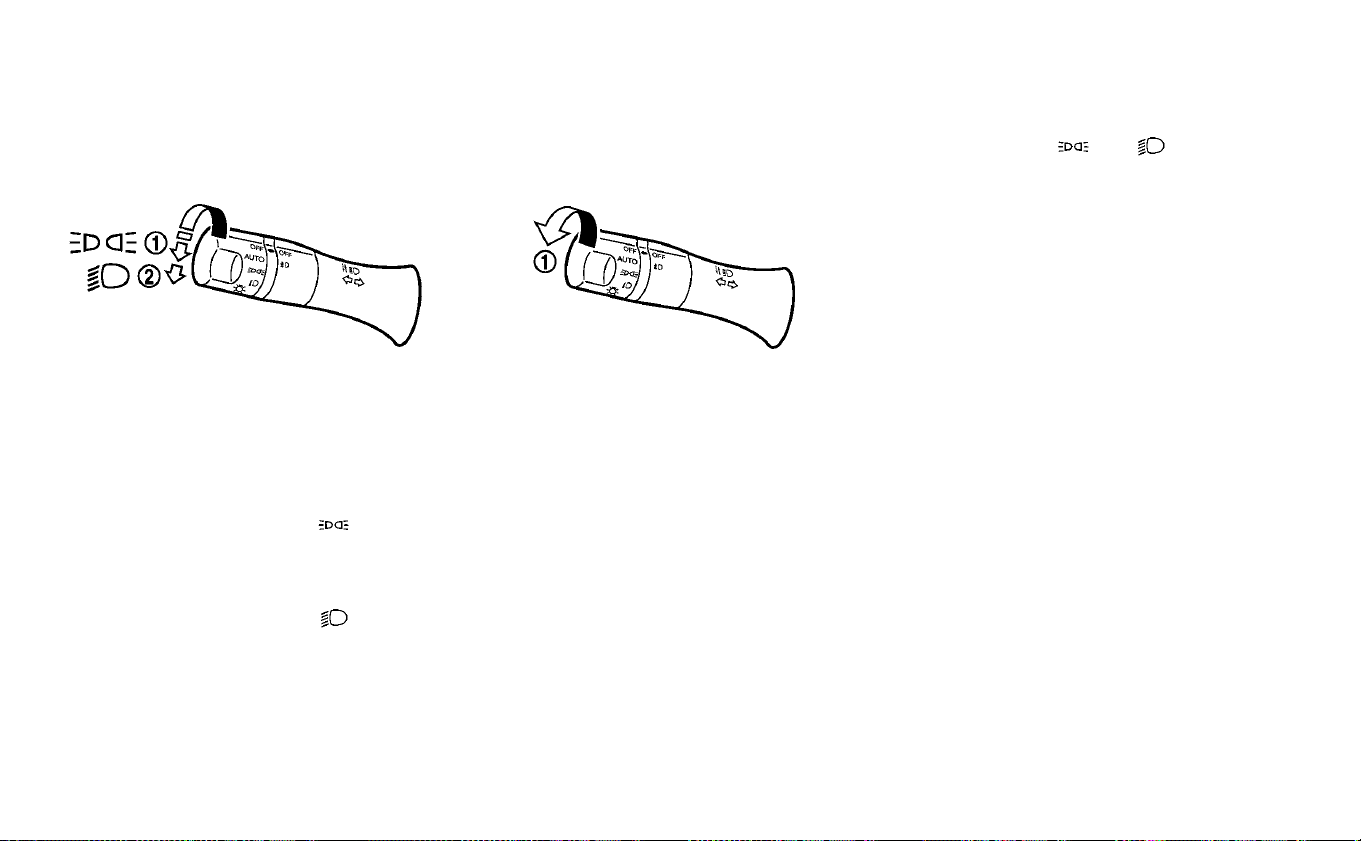
HEADLIGHT SWITCH
Lighting
䊊
1
Rotate the switch to the posi-
tion, the front parking, tail, license
plate, and instrument panel lights
come on.
䊊
2
Rotate the switch to the posi-
tion, the headlights come on and all
the other lights remain on.
Autolight system (if so equipped)
The autolight system allows the headlights
and tail lights to be set so they turn on and
off automatically.
To set the autolight system:
1. Make sure the headlight switch is in the
AUTO position
䊊
1
.
2. Place the power switch in the ON
position.
3. The autolight system automatically
turns the headlights and tail lights on
and off.
To turn the autolight system off, turn the
switch to the OFF,
or position.
The autolight system can turn on the
headlights and tail lights automatically
when it is dark and turn off the headlights
when it is light.
For US models: The headlights and tail
lights will also be turned on automatically
at twilight or in rainy weather (when the
windshield wiper is operated continuously).
If the power switch is placed in the OFF
position and one of the doors is opened
and this condition continues, the head-
lights remain on for 45 seconds.
Automatic headlights off delay:
You can keep the headlights on for up to
180 seconds after you push the power
switch to OFF and open any door then
close all the doors.
You can adjust the period of the automatic
headlights off delay from 0 seconds (OFF)
to 180 seconds. The factory default setting
is 45 seconds.
HEADLIGHT AND TURN SIGNAL
SWITCH
2-52 Instruments and controls
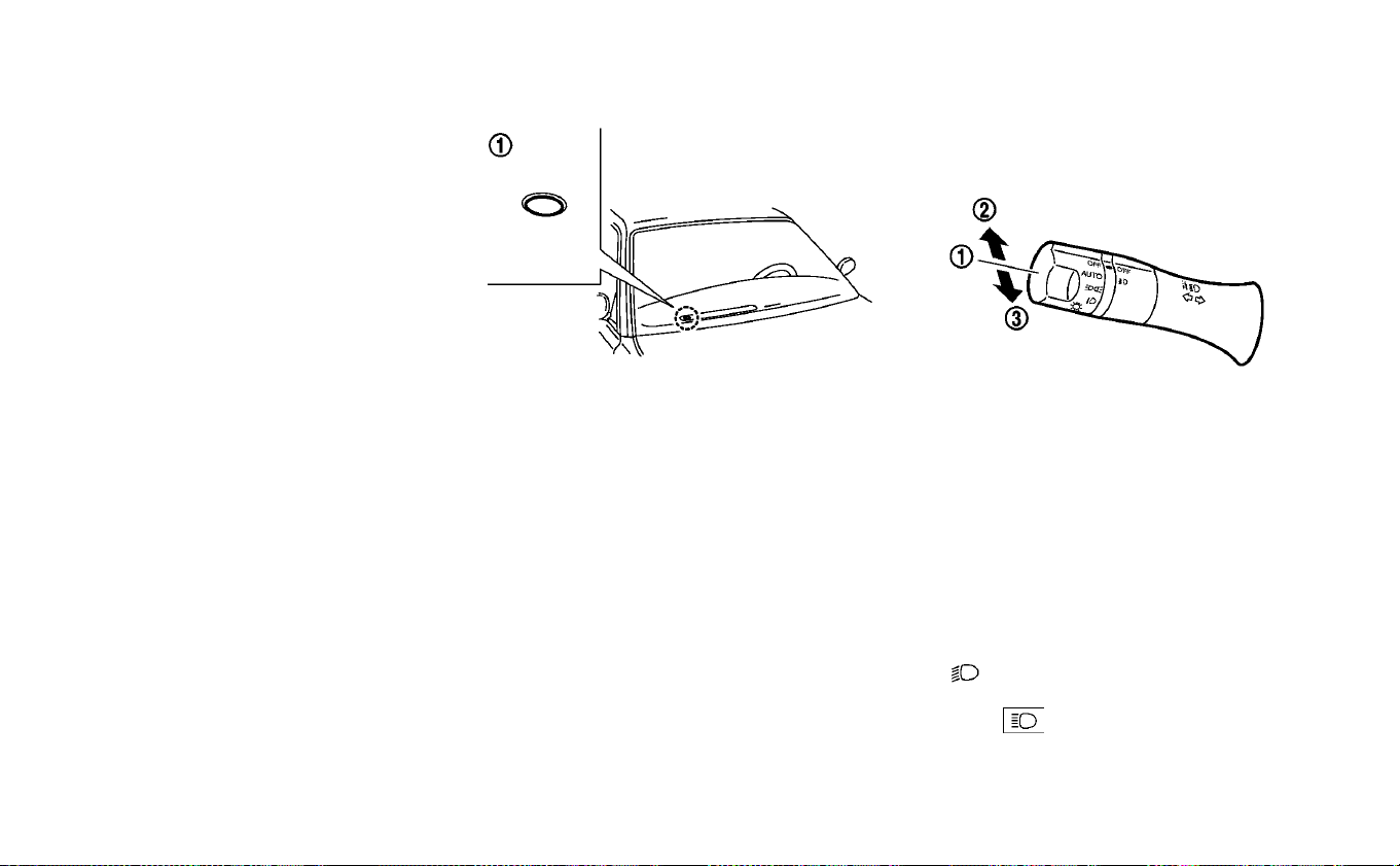
NOTE:
For additional information on adjust-
ing the automatic headlights off de-
lay, refer to “Vehicle information dis-
play” in this section.
Be sure not to put anything on top of the
photo sensor
䊊
1
located on the top of the
instrument panel. The photo sensor con-
trols the autolight; if it is covered, the
photo sensor reacts as if it is dark and
the headlights will illuminate.
Headlight beam select
䊊
1
To select the low beam, have the lever
in the neutral position as shown and
rotate the switch to the desired posi-
tion. For additional information, refer
to “Headlight switch” in this section.
䊊
2
To select the high beam, push the le-
ver forward while the switch is in the
position. The high beams will
come on and the high beam indicator
(blue)
will illuminate. Pull it back
to return to the low beam.
Instruments and controls 2-53

䊊
3
Pulling the lever toward you will flash
the headlight high beam even when
the headlight switch is in the OFF po-
sition.
High Beam Assist (if so equipped)
The High Beam Assist system will operate
when the vehicle is driven at speeds of ap-
proximately 19 mph (30 km/h) and above. If
an oncoming vehicle or leading vehicle ap-
pears in front of your vehicle when the
headlight high beam is on, the headlight
will be switched to the low beam automati-
cally.
Precautions on High Beam Assist:
WARNING
• The High Beam Assist system is a
convenience but it is not a substitute
for safe driving operation. The driver
should remain alert at all times, en-
sure safe driving practices and
switch the high beams and low
beam manually when necessary.
• The high beam or low beam may not
switch automatically under the fol-
lowing conditions. Switch the high
beam and low beam manually.
– During bad weather (rain, fog,
snow, wind, etc.).
– When a light source similar to a
headlight or tail light is in the vi-
cinity of the vehicle.
– When the headlights of the on-
coming vehicle or the leading ve-
hicle are turned off, when the color
of the light is affected due to for-
eign materials on the lights, or
when the light beam is out of po-
sition.
– When there is a sudden, continu-
ous change in brightness.
– When driving on a road that
passes over rolling hills, or a road
that has level differences.
– When driving on a road with many
curves.
– When a sign or mirror-like surface
is reflecting intense light towards
the front of the vehicle.
– When the container, etc. being
towed by a leading vehicle is re-
flecting intense light.
– When a headlight on your vehicle
is damaged or dirty.
– When the vehicle is leaning at an
angle due to a punctured tire, be-
ing towed, etc.
• The timing of switching the low
beam and high beam may change
under the following situations.
– The brightness of the headlights
of the oncoming vehicle or lead-
ing vehicle.
– The movement and direction of
the oncoming vehicle and the
leading vehicle.
– When only one light on the on
coming vehicle or the leading ve-
hicle is illuminated.
– When the oncoming vehicle or the
leading vehicle is a two-wheeled
vehicle.
– Road conditions (incline, curve,
the road surface, etc.).
– The number of passengers and
the amount of luggage.
2-54 Instruments and controls

High Beam Assist operations:
To activate the High Beam Assist system,
turn the headlight switch to the AUTO po-
sition
䊊
1
and push the lever forward
䊊
2
(high beam position). The High Beam Assist
indicator light in the meter will illuminate
while the headlights are turned on.
If the High Beam Assist indicator light does
not illuminate in the above condition, it may
indicate that the system is not functioning
properly. It is recommended that you visit a
NISSAN certified LEAF dealer for this ser-
vice.
When the vehicle speed lowers to less than
approximately 12 mph (20 km/h), the head-
light remains the low beam.
To turn off the High Beam Assist system,
turn the headlight switch to the
posi-
tion or select the low beam position by
placing the lever in the neutral position.
Ambient image sensor maintenance:
The ambient image sensor for the High
Beam Assist system is located above the
inside mirror
䊊
1
. To keep the proper opera-
tion of the High Beam Assist system and
prevent a system malfunction, be sure to
observe the following:
• Always keep the windshield clean.
• Do not attach a sticker (including trans-
parent material) or install an accessory
near the ambient image sensor.
• Do not strike or damage the areas around
the ambient image sensor.
Instruments and controls 2-55
If the ambient image sensor is damaged
due to an accident, it is recommended that
you visit a NISSAN certified LEAF dealer for
this service.
Battery saver system
• When the headlight switch is in the
or position while the power switch is
in the ON position, the lights will automati-
cally turn off 45 seconds after the power
switch has been placed in the OFF
position.
• When the headlight switch remains in the
or position after the lights
automatically turn off, the lights will turn
on when the power switch is placed in the
ON position.
CAUTION
• When you turn on the headlight
switch again after the lights auto-
matically turn off, the lights will not
turn off automatically. Be sure to
turn the light switch to the OFF posi-
tion when you leave the vehicle for
extended periods of time, otherwise
the battery will be discharged.
• Never leave the light switch on when
the power switch is in the OFF, ACC or
ON position for extended periods of
time even if the headlights turn off
automatically.
LED Daytime Running Lights (DRL)
system (if so equipped)
The LED portion of the headlights auto-
matically illuminates at 100% intensity
when the power switch is in the Ready to
Drive position with the parking brake re-
leased. The LED DRL system operates with
the headlight switch in the OFF position.
Turn headlight switch to the
position
for full illumination when driving at night.
If the parking brake is applied before the
power switch is in the Ready to Drive posi-
tion, the LED DRL system does not operate.
The LED DRL system illuminates once the
parking brake is released. The LED DRL sys-
tem will remain on until the power switch is
pushed to the OFF position.
WARNING
When the LED DRL system is active, tail
lights on your vehicle are not on. It is
necessary at dusk to turn on your
headlights. Failure to do so could
cause an accident injuring yourself
and others.
2-56 Instruments and controls
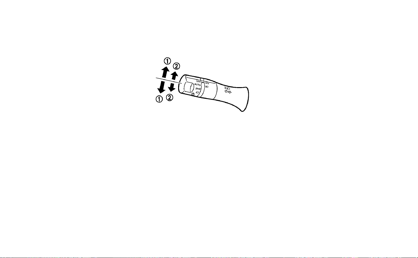
INSTRUMENT BRIGHTNESS
CONTROL
Press the “+” button to increase the bright-
ness of the instrument panel lights.
Press the “-” to decrease the brightness of
the instrument panel lights.
TURN SIGNAL SWITCH
Turn signal
䊊
1
Move the lever up or down until it
latches to signal the turning direction.
When the turn is completed, the turn signal
cancels automatically.
Lane change signal
䊊
2
Move the lever up or down until the turn
signal begins to flash, but the lever does
not latch, to signal a lane change. Hold the
lever until the lane change is completed.
Move the lever up or down until the turn
signal begins to flash, but the lever does
not latch, and release the lever. The turn
signal will automatically flash three times.
Choose the appropriate method to signal
a lane change based on road and traffic
conditions.
Instruments and controls 2-57
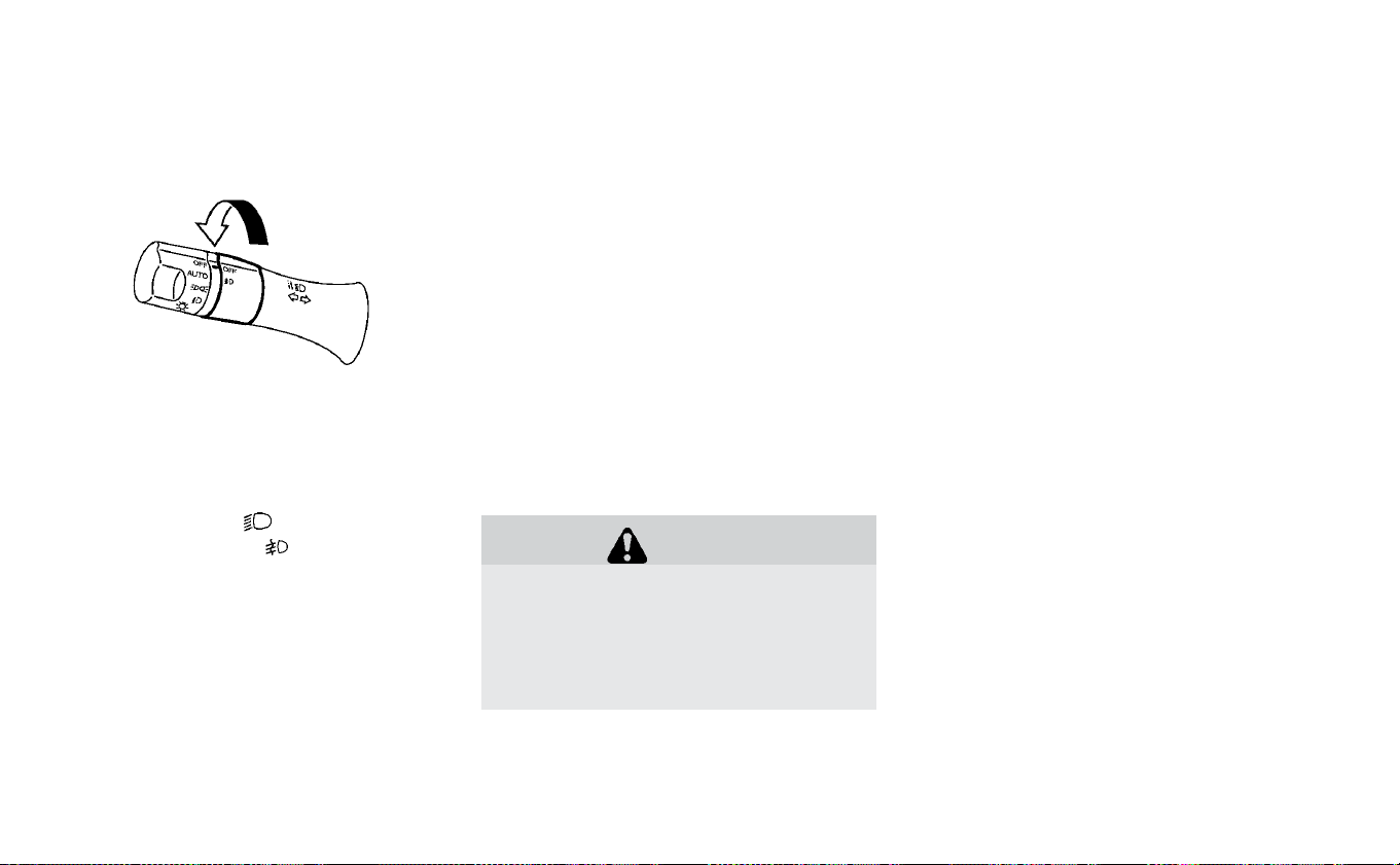
To turn the fog lights on, rotate the head-
light switch to the
position, then ro-
tate the switch to the
position. To turn
them off, rotate the switch to the OFF posi-
tion.
The headlights must be on for the fog
lights to operate.
To sound the horn, push the center pad
area of the steering wheel.
WARNING
Do not disassemble the horn. Doing so
could affect proper operation of the
supplemental front air bag system.
Tampering with the supplemental
front air bag system may result in seri-
ous personal injury.
To turn on the ECO mode, push the ECO
switch. The ECO mode indicator appears
on the meter.
To turn off the ECO mode, push the ECO
switch again. The ECO mode indicator will
turn off.
For additional information, refer to “Electric
shift control system” in the “Starting and
driving” section of this manual
FOG LIGHT SWITCH (IF SO EQUIPPED) HORN ECO SWITCH
2-58 Instruments and controls

The front seats and the rear outboard
seats (if so equipped) can be warmed by
built-in heaters. The switches, located on
the center console and at the side of the
front passenger seatback, can be operated
independently of each other.
1. Place the power switch in the ON
position.
2. Push the LO or HI position of the switch,
as desired, depending on the tempera-
ture. The indicator light in the switch will
illuminate.
3. To turn off the heater, return the switch
to the level position. Make sure the indi-
cator light goes off.
The heater is controlled by a thermostat,
automatically turning the heater on and
off. The indicator light will remain on as long
as the switch is on.
When the vehicle’s interior is warmed, or
before you leave the vehicle, be sure to turn
the switch off.
NOTE:
The heated seats consume less power
than the heater and can be used to either
help extend vehicle range by reducing
heater use or to maximize comfort by
supplementing the heater.
WARNING
Do not use or allow occupants to use
the seat heater if you or the occupants
cannot monitor elevated seat tem-
peratures or have an inability to feel
pain in those body parts in contact
with the seat. Use of the seat heater by
such people could result in serious in-
jury.
Rear
HEATED SEAT SWITCHES (IF SO
EQUIPPED)
Instruments and controls 2-59

CAUTION
• Do not use the seat heater for ex-
tended periods or when no one is
using the seat.
• Do not put anything on the seat
which insulates heat, such as a blan-
ket, cushion, seat cover, etc. Other-
wise, the seat may become over-
heated.
• Do not place anything hard or heavy
on the seat or pierce it with a pin or
similar object. This may result in
damage to the heater.
• Any liquid spilled on the heated seat
should be removed immediately
with a dry cloth.
• When cleaning the seat, never use
gasoline, thinner, or any similar ma-
terials.
• If any malfunctions are found or the
heated seat does not operate, turn
the switch off and have the system
checked. It is recommended that
you visit a NISSAN certified LEAF
dealer for this service.
The heated steering wheel system is de-
signed to operate only when the surface
temperature of the steering wheel is below
approximately 68°F (20°C).
Push the heated steering wheel switch to
warm the steering wheel when the power
switch is in the ACC or ON position. The
indicator light
䊊
1
on the switch will illumi-
nate.
If the surface temperature of the steering
wheel is below approximately 68°F (20°C),
the system will heat the steering wheel and
cycle off and on to maintain a temperature
above 68°F (20°C). The indicator light will
remain on as long as the system is on.
Push the switch again to turn the heated
steering wheel system off manually. The
indicator light turns off.
NOTE:
• If the surface temperature of the steer-
ing wheel is above 68°F (20°C) when the
switch is turned on, the system will not
heat the steering wheel. This is not a
malfunction.
• If the outside temperature is low (ap-
proximately 50°F (10°C) or less) and the
Climate Control Timer or Remote Cli-
mate Control are used, the steering
wheel heater will automatically operate
in the following conditions.
– When using the Climate Control
Timer: Operates from approximately
15 minutes before the set departure
time until the set departure time.
– When using Remote Climate Control:
Operates 15 minutes after Remote
Climate Control starts.
• The heated steering wheel consumes
less power than the heater and can be
used to either help extend vehicle range
by reducing heater use or to maximize
comfort by supplementing the heater.
HEATED STEERING WHEEL SWITCH
(IF SO EQUIPPED)
2-60 Instruments and controls

The E-call (SOS) system switch is used in
combination with a NissanConnect® (for
Leaf) Services subscription to call for assis-
tance in case of an emergency.
Pushing the switch will (with a paid sub-
scription) reach a Response Specialist that
will provide assistance based on the situa-
tion described by the vehicle’s occupant.
For additional information, or to enroll your
vehicle, refer to www.NissanUSA.com/
connect or call 855–426–6628.
To open the charge port lid, push the
charge port lid switch. For additional infor-
mation, refer to “Charge port lid” in the “Pre-
driving checks and adjustments” section of
this manual.
To turn off the charge timer, push the
charge timer OFF switch. For additional in-
formation, refer to “Charging timer” in the
“Charging” section of this manual.
E-CALL (SOS) SWITCH (IF SO
EQUIPPED) CHARGE PORT LID SWITCH CHARGE TIMER OFF SWITCH
Instruments and controls 2-61

The Steering Assist switch is used to turn
on and off the Steering Assist system and
the Intelligent Cruise Control (ICC) system
that is activated using the settings menu of
the vehicle information display.
The Steering Assist system controls the
steering system to help keep your vehicle
near the center of the lane when driving.
The Steering Assist system is combined
with the Intelligent Cruise Control (ICC). For
additional information, refer to “Intelligent
Cruise Control (ICC) with ProPILOT™ Assist)”
in the “Starting and driving” section of this
manual.
CAUTION
• The outlet and plug may be hot dur-
ing or immediately after use.
• Do not use with accessories that ex-
ceed a 12-volt, 120W (10A) power
draw.
• Do not use double adapters or more
than one electrical accessory.
• Use the power outlet with the power
switch is in the ON or Ready to Drive
position to avoid discharging the 12-
volt battery.
STEERING ASSIST SWITCH (IF SO
EQUIPPED) POWER OUTLET
2-62 Instruments and controls
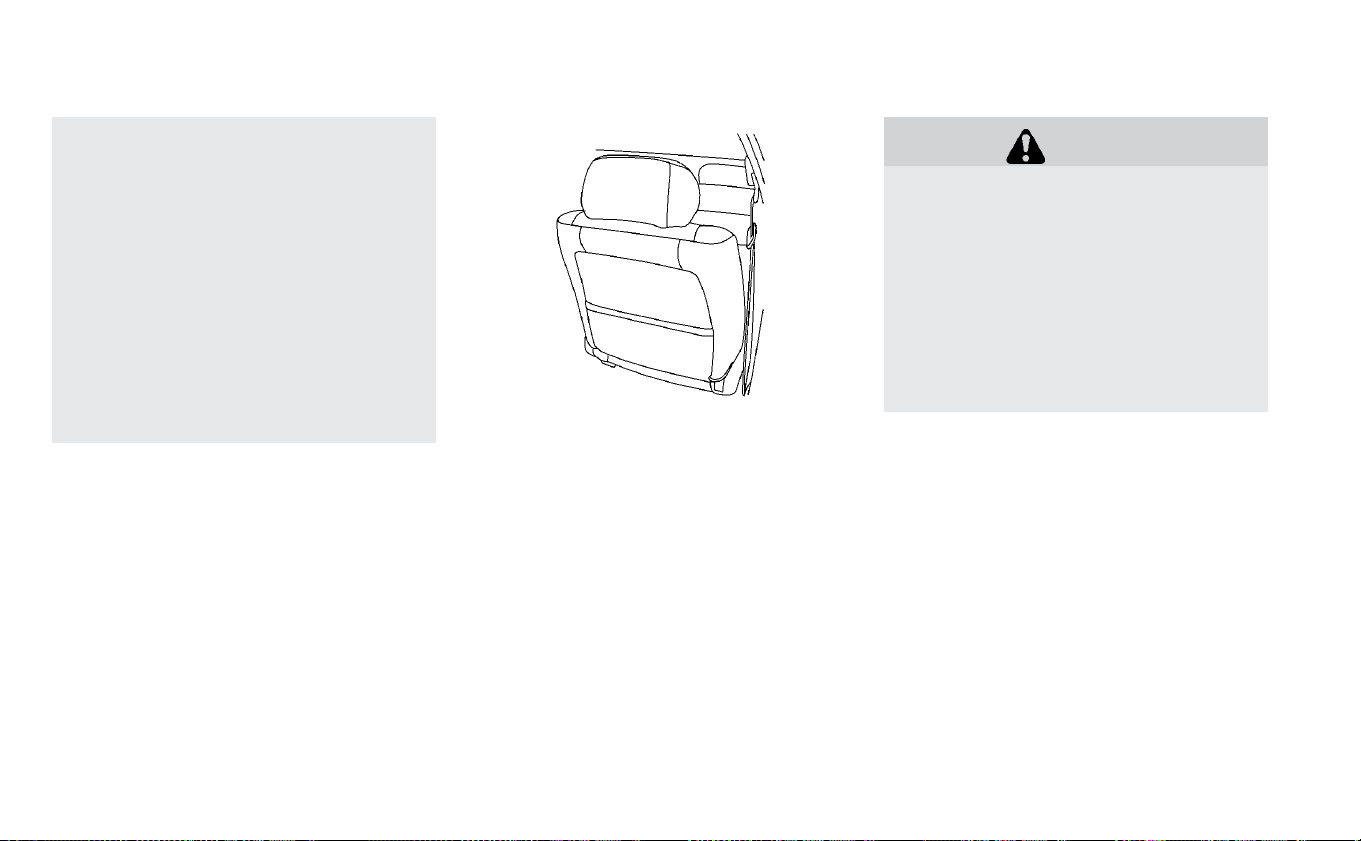
• Avoid using the power outlet when
the air conditioner, headlights or
rear window defroster are on.
• This power outlet is not designed for
use with a cigarette lighter unit.
• Push the plug in as far as it will go. If
good contact is not made, the plug
may overheat or the internal tem-
perature fuse may open.
• Before inserting or disconnecting a
plug, make sure that the electrical
accessory being used is turned OFF.
• When not in use, be sure to close the
cap. Do not allow water to contact
the outlet.
SEATBACK POCKET (IF SO
EQUIPPED)
The seatback pockets may be located on
the driver’s and/or passenger’s seat.. The
pocket can be used to store maps.
WARNING
To ensure proper operation of the pas-
senger’s NISSAN Advanced Air Bag
System, please observe the following
items:
• Do not allow a passenger in the rear
seat to push or pull on the seatback
pocket or head restraint.
• Do not place heavy loads heavier
than 9.1 lbs. (4 kg) on the seatback,
head restraint, or in the seatback
pocket.
STORAGE
Instruments and controls 2-63
STORAGE TRAY
WARNING
Do not place sharp objects in the
tray(s) to help prevent injury in an ac-
cident or sudden stop.
GLOVE BOX
To open the glove box, pull the handle.
To close, push the lid in until it latches.
WARNING
Keep the glove box lid closed while
driving to prevent injury in case of an
accident or a sudden stop.
CONSOLE BOX
To open the console box, pull up the lever
䊊
A
and pull up the lid. To close, push the lid
down until it is latched.
Instrument panel
2-64 Instruments and controls
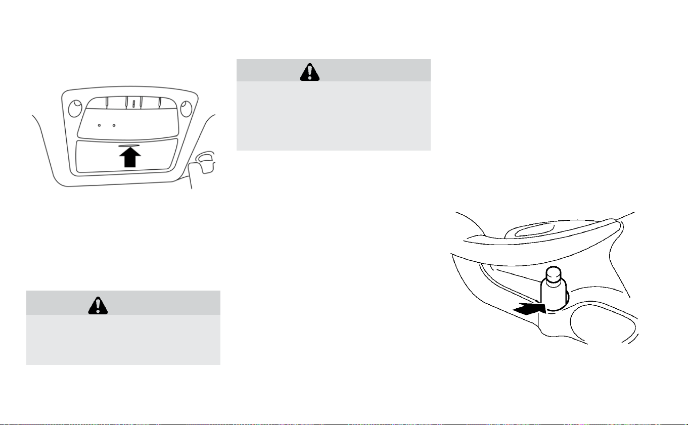
OVERHEAD SUNGLASSES
STORAGE
To open the sunglasses holder, push and
release. Only store one pair of sunglasses
in the holder.
WARNING
Keep the sunglasses holder closed
while driving to avoid obstructing the
driver’s view and to help prevent an
accident.
CAUTION
• Do not use for anything other than
sunglasses.
• Do not leave sunglasses in the sun-
glasses holder while parking in di-
rect sunlight. The heat may damage
the sunglasses.
Cup holders
Front
Soft bottle holder (front)
Instruments and controls 2-65

WARNING
Avoid abrupt starting and braking
when the cup holder is being used to
prevent spilling the drink. If the liquid is
hot, it can scald you or your passenger.
CAUTION
Use only soft cups in the cup holder.
Hard objects can injure you in an acci-
dent.
CAUTION
• Do not use the bottle holder for any
other objects that could be thrown
about in the vehicle and possibly in-
jure people during sudden braking
or an accident.
• Do not use the bottle holder for open
liquid containers.
TONNEAU COVER (IF SO
EQUIPPED)
WARNING
• Never put anything on the tonneau
cover, no matter how small. Any ob-
ject on it could cause an injury in an
accident or sudden stop.
• Do not leave the tonneau cover in
the vehicle with it disengaged from
the holder.
• Properly secure all cargo with ropes
or straps to help prevent it from slid-
ing or shifting. Do not place cargo
higher than the seatbacks. In a sud-
den stop or collision, unsecured
cargo could cause personal injury.
• Properly secure cargo and do not al-
low it to contact the top tether strap
when it is attached to the top tether
anchor. Cargo that is not properly
secured or cargo that contacts the
top tether strap may damage the
top tether strap during a collision. If
the cargo cover contacts the top
tether strap when it is attached to
the top tether anchor, remove the
Soft bottle holder (rear)
2-66 Instruments and controls

cargo cover from the vehicle or se-
cure it on the cargo floor below its
attachment location. If the cargo
cover is not removed, it may damage
the top tether strap during a colli-
sion. Your child could be seriously in-
jured or killed in a collision if the
child restraint top tether strap is
damaged.
The tonneau cover keeps the luggage
compartment contents hidden from the
outside.
To remove the tonneau cover:
1. Remove the straps from the rear hatch.
2. Pull up the tonneau cover.
3. Remove the tonneau cover holders
from the rear pillar.
4. Slide down the tonneau cover along the
rear seat back.
5. Remove the tonneau cover by pulling
either the left or right side backward
away from the pillar.
Instruments and controls 2-67
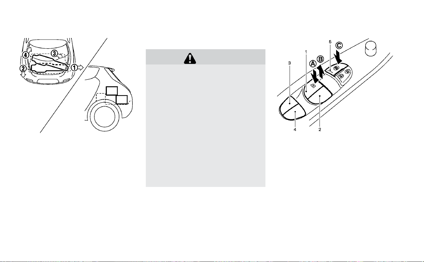
STOWING GOLF BAGS
Normally, two standard golf bags can be
stowed in the cargo area. Insert the top of
the golf bag into the right side of the cargo
area
䊊
1
then rotate the bag backward
䊊
2
.
Insert the top of the second golf bag into
right side of the cargo area
䊊
3
and stow the
bottom of golf bag forward all the way
䊊
4
.
In some cases, you may not be able to stow
two golf bags in your vehicle, depending on
their sizes or types.
POWER WINDOWS
WARNING
• Make sure that all passengers have
their hands, etc. inside the vehicle
while it is in motion and before clos-
ing the windows. Use the window
lock switch to prevent unexpected
use of the power windows.
•
Tohelpavoidriskofinjuryordeath
through unintended operation of the
vehicle or its systems, including en-
trapment in windows or inadvertent
door lock activation, do not leave chil-
dren, people who require the assis-
tance of others, or pets unattended in
your vehicle. Additionally, the tem-
perature inside a closed vehicle on a
warm day can quickly become high
enough to cause a significant risk of
injury or death to people and pets.
The power windows operate when the
power switch is in the ACC or ON position,
or for about 45 seconds after the power
switch is placed in the OFF position. If the
driver’s or front passenger’s door is opened
during this period of about 45 seconds,
power to the windows is canceled.
Main power window switch
(driver's side)
1. Driver side window
2. Front passenger side window
3. Rear left passenger side window
4. Rear right passenger side window
5. Window lock button
To open or close a window, push down
䊊
A
or pull up
䊊
B
the corresponding switch and
hold it. The main switches, on the driver's
side, will open or close all the windows.
WINDOWS
2-68 Instruments and controls
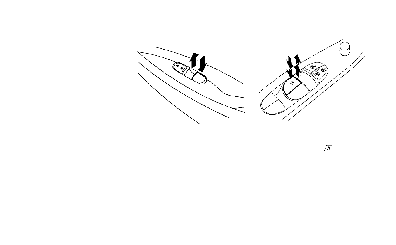
Locking passengers' windows
When the lock button
䊊
C
is pushed in, only
the driver side window can be opened or
closed. Push it in again to cancel.
Passenger side power window
switch
The passenger's side power window
switch will open or close only the corre-
sponding window. To open or close the
window, push down or pull up the switch
and hold it.
Rear power window switch
The rear power window switches open or
close only the corresponding windows. To
open the window, push the switch and hold
it down. To close the window, pull the
switch up.
Automatic operation
The automatic operation is available for
the switch that has an
mark on its
surface.
To fully open or close the window, com-
pletely push down or pull up the switch and
release it; the switch need not be held. The
window will automatically open or close all
the way.To stop the window, just push or lift
the switch in the opposite direction.
A light push or pull on the switch will cause
the window to open or close until the
switch is released.
Instruments and controls 2-69

Auto-reverse function
WARNING
There are some small distances imme-
diately before the closed position
which cannot be detected. Make sure
that all passengers have their hands,
etc., inside the vehicle before closing
the window.
If the control unit detects something
caught in the window as it is closing, the
window will be immediately lowered.
The auto reverse function can be activated
when the window is closed by automatic
operation when the power switch is in the
ON position or for 45 seconds after the
power switch is placed in the OFF position.
Depending on the environment or driv-
ing conditions, the auto reverse function
may be activated if an impact or load
similar to something being caught in the
window occurs.
If the windows do not close
automatically
If the power window automatic function
(closing only) does not operate properly,
perform the following procedure to initial-
ize the power window system.
1. Place the power switch in the ON
position.
2. Close the door.
3. Open the window completely by operat-
ing the power window switch.
4. Pull the power window switch and hold
it to close the window, and then hold the
switch more than 3 seconds after the
window is closed completely.
5. Release the power window switch. Op-
erate the window by the automatic
function to confirm the initialization is
complete.
If the power window automatic function
does not operate properly after perform-
ing the procedure above, have your vehicle
serviced. It is recommended that you visit a
NISSAN certified LEAF dealer for this ser-
vice.
The interior lights can be turned on
䊊
1
re-
gardless of door position. The lights will go
off after a period of time unless the power
switch is placed in the ON position when
any door is opened.
The interior lights can be set to operate
when the doors are opened
䊊
2
. To turn off
the interior lights when a is door open,
push the switch; the interior lights will not
illuminate, regardless of door position.
INTERIOR LIGHTS
2-70 Instruments and controls
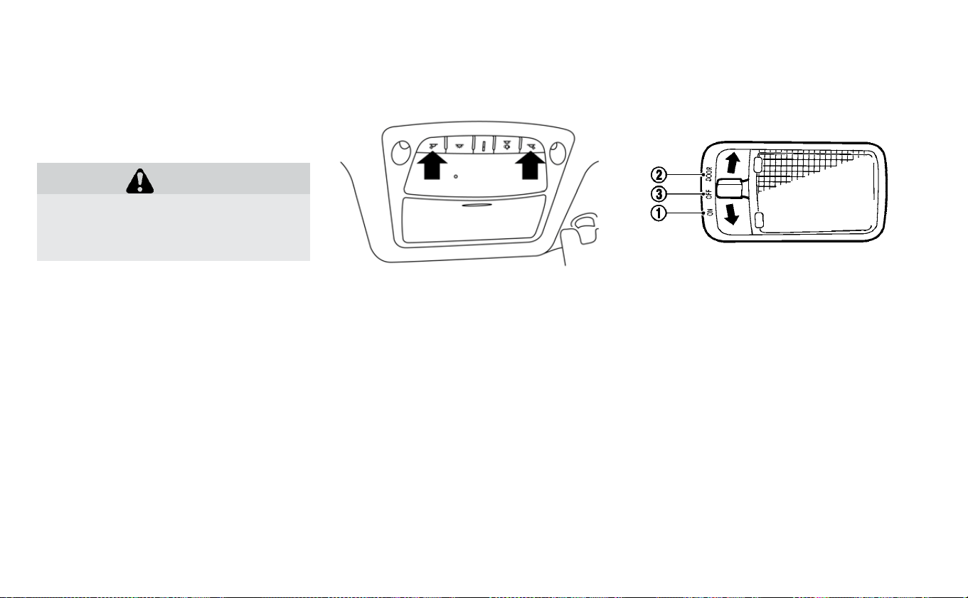
The lights will go off when the power switch
is placed in the ON position, or the driver’s
door is closed and locked. The lights will
also go off after a period of time when the
doors are open.
CAUTION
Do not use for extended periods of
time with the power switch in the OFF
position. This could result in a dis-
charged 12-volt battery.
CONSOLE LIGHT (IF SO EQUIPPED)
The console light will turn on whenever the
parking lights or headlights are illuminated.
The console light brightness can be ad-
justed with the illumination brightness
control in the vehicle information display.
MAP LIGHTS
Press the button to turn the map lights on.
To turn them off, press the button again.
ROOM LIGHT
The room light switch has three positions:
ON, DOOR and OFF.
ON position
When the switch is in the ON position
䊊
1
,
the ceiling light will illuminate.
Instruments and controls 2-71

DOOR position
When the switch is in the DOOR position
䊊
2
,
the ceiling light will illuminate under the
following conditions:
• the power switch is placed in the LOCK
position
– remains on for about 15 seconds.
• doors are unlocked by pushing the
UNLOCK
button or the request
switch, with the power switch in the LOCK
position
– remains on for about 15 seconds.
• any door is opened and then closed with
the power switch in the LOCK position
– remains on for about 15 seconds.
• any door is opened while the power
switch in the ACC or ON position
– remains on while the door is opened.
When the door is closed, the light turns
off.
The light will automatically turn off after
10 minutes when the light remains illu-
minated to prevent the battery from be-
coming discharged.
OFF position
When the switch is in the OFF position
䊊
3
,
the ceiling light will not illuminate, regard-
less of the condition.
CARGO LIGHT
The light illuminates when the rear hatch is
opened. When the rear hatch is closed, the
light goes off. For additional information,
refer to “Exterior and interior lights” in the
“Maintenance and do-it-yourself” section
of this manual.
The HomeLink® Universal Transceiver pro-
vides a convenient way to consolidate the
functions of up to three individual hand-
held transmitters into one built-in device.
HomeLink® Universal Transceiver:
• Will operate most Radio Frequency (RF)
devices such as garage doors, gates,
home and office lighting, entry door locks
and security systems.
• Is powered by the vehicle’s 12-volt battery.
No separate batteries are required. If the
vehicle’s 12-volt batter y is discharged or is
disconnected, HomeLink® will retain all
programming.
Once the HomeLink® Universal Trans-
ceiver is programmed, retain the original
transmitter for future programming pro-
cedures (for example, new vehicle pur-
chases). Upon sale of the vehicle, the
programmed HomeLink® Universal
Transceiver buttons should be erased for
security purposes. For additional infor-
mation, refer to “Programming
HomeLink®” in this section.
HOMELINK® UNIVERSAL
TRANSCEIVER (IF SO EQUIPPED)
2-72 Instruments and controls
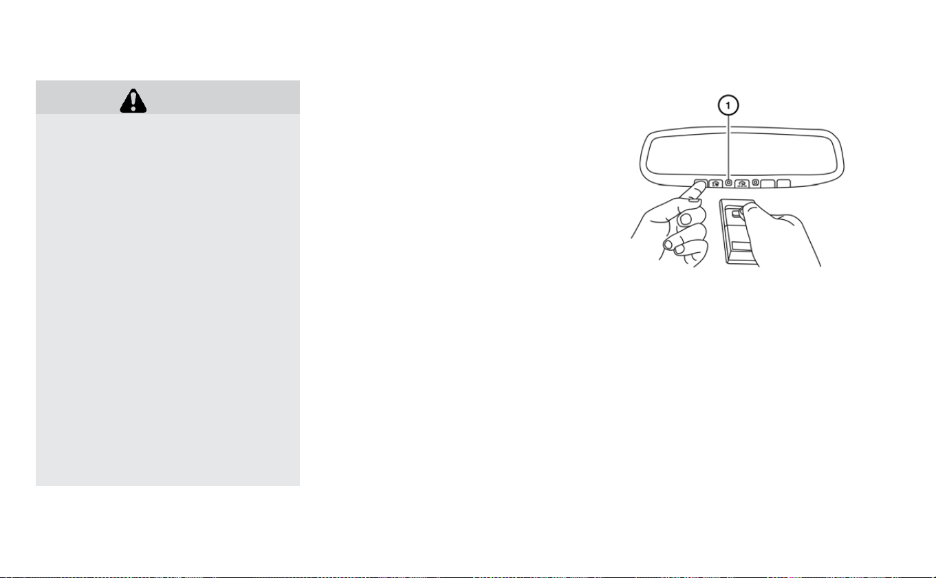
WARNING
• Do not use the HomeLink® Universal
Transceiver with any garage door
opener that lacks safety stop and re-
verse features as required by federal
safety standards. (These standards
became effective for opener models
manufactured after April 1, 1982.) A
garage door opener that cannot de-
tect an object in the path of a closing
garage door and then automatically
stop and reverse, does not meet cur-
rent federal safety standards. Using
a garage door opener without these
features increases the risk of serious
injury or death.
• During the programming procedure,
your garage door or security gate
will open or close (if the transmitter
is within range). Make sure that
people or objects are clear of the ga-
rage door, gate, etc. that you are pro-
gramming.
• Place the power switch in the ACC or
ON position while programming the
HomeLink® Universal Transceiver.
PROGRAMMING HOMELINK®
If you have any questions or are having
difficulty programming your HomeLink®
buttons, refer to the HomeLink® web site at:
www.homelink.com or call 1-800-355-3515.
NOTE:
Place the power switch in the ACC posi-
tion when programming HomeLink®. It is
also recommended that a new battery
be placed in the hand-held transmitter
of the device being programmed to
HomeLink® for quicker programming
and accurate transmission of the
radio-frequency.
1. Position the end of your hand-held
transmitter 1–3 inches (2–8 cm) away
from the HomeLink® surface, keeping
the HomeLink® indicator light
䊊
1
in view.
2. Using both hands, simultaneously press
and hold the desired HomeLink® button
and handheld transmitter button. DO
NOT release until the HomeLink® indica-
tor light
䊊
1
flashes slowly and then rap-
idly. When the indicator light flashes rap-
idly, both buttons may be released. (The
rapid flashing indicates successful
programming.)
Instruments and controls 2-73

NOTE:
Some devices may require you to re-
place Step 2 with the cycling proce-
dure noted in the “Programming
HomeLink® for Canadian customers
and gate openers” section.
3. Press and hold the programmed
HomeLink® button and observe the indi-
cator light.
• If the indicator light
䊊
1
is solid/
continuous, programming is com-
plete and your device should activate
when the HomeLink® button is pressed
and released.
• If the indicator light
䊊
1
blinks rapidly for
two seconds and then turns to a
solid/continuous light, continue with
Steps 4-6 for a rolling code device. A
second person may make the following
steps easier. Please use a ladder or
other device. Do not stand on your ve-
hicle to perform the next steps.
4. At the receiver located on the garage
door opener motor in the garage, locate
the “learn” or “smart” button (the name
and color of the button may vary by
manufacturer but it is usually located
near where the hanging antenna wire is
attached to the unit). If there is difficulty
locating the button, reference the ga-
rage door opener’s manual.
5. Press and release the “learn” or “smart”
button.
6. Return to the vehicle and firmly press
and hold the trained HomeLink® button
for two seconds and release. Repeat the
“press/hold/release” sequence up to
three times to complete the training
process. HomeLink® should now acti-
vate your rolling code equipped device.
7. If you have any questions or are having
difficulty programming your HomeLink®
buttons, refer to the HomeLink® web site
at: www.homelink.com or call
1-800-355-3515.
2-74 Instruments and controls

PROGRAMMING HOMELINK® FOR
CANADIAN CUSTOMERS AND GATE
OPENERS
Canadian radio-frequency laws require
transmitter signals to “time-out” (or quit)
after several seconds of transmission –
which may not be long enough for
HomeLink® to pick up the signal during
training. Similar to this Canadian law, some
U.S. gate operators are designed to “tim-
eout” in the same manner.
If you live in Canada or you are having diffi-
culties training a gate operator or garage
door opener by using the “Training” proce-
dures, replace “Programming HomeLink®”
Step 2 with the following:
NOTE:
When programming a garage door
opener, etc., unplug the device during
the “cycling” process to prevent possible
damage to the garage door opener
components.
1. Refer to “Programming HomeLink®” step
1 in this section.
2. Using both hands, simultaneously press
and hold the desired HomeLink® button
and the hand-held transmitter button.
During training, your hand-held trans-
mitter may automatically stop transmit-
ting. Continue to press and hold the de-
sired HomeLink® button while you press
and re-press (“cycle”) your hand-held
transmitter every two seconds until the
frequency signal has been learned. The
HomeLink® indicator light will flash
slowly and then rapidly after several
seconds upon successful training. DO
NOT release until the HomeLink® indica-
tor light flashes slowly and then rapidly.
When the indicator light flashes rapidly,
both buttons may be released. The rapid
flashing indicates successful training.
Proceed with “Programming HomeLink®”
step 3 to complete.
If the device was unplugged during the
programming procedure, remember to
plug it back in when programming is com-
pleted.
OPERATING THE HOMELINK®
UNIVERSAL TRANSCEIVER
The HomeLink® Universal Transceiver, after
it is programmed, can be used to activate
the programmed device. To operate, sim-
ply press and release the appropriate pro-
grammed HomeLink® Universal Trans-
ceiver button. The amber indicator light will
illuminate while the signal is being trans-
mitted.
For convenience, the hand-held transmit-
ter of the device may also be used at any
time.
PROGRAMMING TROUBLE-
DIAGNOSIS
If HomeLink® does not quickly learn the
hand-held transmitter information, per-
form the following steps.
• Replace the hand-held transmitter bat-
teries with new batteries.
• Position the hand-held transmitter with
its battery area facing away from the
HomeLink® surface.
• Push and hold both the HomeLink® and
hand-held transmitter buttons without
interruption.
• Position the hand-held transmitter 1 to
3 inches (2 to 8 cm) away from the
HomeLink® surface. Hold the transmitter
in that position for up to 15 seconds. If
Instruments and controls 2-75

HomeLink® is not programmed within
that time, try holding the transmitter in
another position while keeping the indica-
tor light in view at all times.
If you continue to have programming diffi-
culties, please contact the NISSAN Con-
sumer Affairs Department. The phone
numbers are located in the Foreword of
this Owner’s Manual.
CLEARING THE PROGRAMMED
INFORMATION
The following procedure clears the pro-
grammed information from both buttons.
Individual buttons cannot be cleared. How-
ever, individual buttons can be repro-
grammed. For additional information, refer
to “Reprogramming a single HomeLink®
button” in this section.
To clear all programming:
1. Press and hold the two outer HomeLink®
buttons until the indicator light begins to
flash in approximately 10 seconds. Do
not hold for longer than 20 seconds.
2. Release both buttons.
HomeLink® is now in the programming
mode and can be programmed at any
time beginning with “Programming
HomeLink®” - Step 1.
REPROGRAMMING A SINGLE
HOMELINK® BUTTON
To reprogram a HomeLink® Universal
Transceiver button, complete the following:
1. Press and hold the desired HomeLink®
button. DO NOT release the button.
2. The indicator light will begin to flash af-
ter 20 seconds. Without releasing the
HomeLink® button, proceed with “Pro-
gramming HomeLink®” - Step 1.
For questions or comments, contact
HomeLink® at: www.homelink.com or
1–800–355–3515.
The HomeLink® Universal Transceiver but-
ton has now been reprogrammed. The
new device can be activated by pushing
the HomeLink® button that was just pro-
grammed. This procedure will not affect
any other programmed HomeLink® but-
tons.
IF YOUR VEHICLE IS STOLEN
If your vehicle is stolen, you should change
the codes of any non-rolling code device
that has been programmed into
HomeLink®. Consult the Owner’s Manual of
each device or call the manufacturer or
dealer of those devices for additional infor-
mation.
When your vehicle is recovered, you will
need to reprogram the HomeLink® Uni-
versal Transceiver with your new trans-
mitter information.
FCC notice:
For USA:
This device complies with Part 15 of the
FCC Rules. Operation is subject to the fol-
lowing two conditions: (1) This device
may not cause harmful interference, and
(2) this device must accept any interfer-
ence received, including interference
that may cause undesired operation.
2-76 Instruments and controls

NOTE:
Changes or modifications not expressly
approved by the party responsible for
compliance could void the user’s author-
ity to operate the equipment.
For Canada:
This device complies with Industry
Canada licence-exempt RSS standard(s).
Operation is subject to the following two
conditions: (1) this device may not cause
interference, and (2) this device must ac-
cept any interference, including interfer-
ence that may cause undesired opera-
tion of the device.
Instruments and controls 2-77

NOTES
2-78 Instruments and controls

3 Pre-driving checks and adjustments
Keys ..............................3-2
NISSAN Intelligent Key® ................3-2
NISSAN Vehicle Immobilizer System keys . . . .3-3
Doors .............................3-4
Locking with key (driver’s side only) ........3-5
Locking with inside lock knob............3-5
Locking with power door lock switch.......3-5
Automatic door locks .................3-6
Child safety rear door lock ..............3-6
NISSAN Intelligent Key® system.............3-6
NISSAN Intelligent Key® operating range of the
door lock/unlock function ..............3-8
Door locks/unlocks precaution...........3-9
NISSAN Intelligent Key® operation .........3-9
12-volt battery saver system ............3-11
Warning signals ....................3-11
Troubleshooting guide ................3-11
How to use remote keyless entry function. . .3-13
Hood .............................3-16
Rear hatch..........................3-17
Secondary rear hatch release ...........3-18
Charge port lid .......................3-19
Opening charge port lid ...............3-19
Charge port cap ....................3-21
Steering wheel .......................3-21
Tilt operation ......................3-22
Sun visors ..........................3-22
Vanity mirror ......................3-23
Mirrors ............................3-23
Inside rearview mirror ................3-23
Manual anti-glare rearview mirror
(if so equipped) ....................3-23
Automatic anti-glare type (if so equipped). . .3-24
Outside mirrors ....................3-24

A key number plate is supplied with your
keys. Record the key number and keep it in
a safe place (such as your wallet), not in the
vehicle. If you lose your keys, it is recom-
mended that you visit a NISSAN certified
LEAF dealer for duplicates by using the key
number. NISSAN does not record any key
numbers so it is very important to keep
track of your key number plate.
A key number is only necessary when you
have lost all keys and do not have one to
duplicate from. If you still have a key, it can
be duplicated without knowing the key
number.
NOTE:
Do not leave the keys inside the vehicle
when leaving the vehicle.
NISSAN INTELLIGENT KEY®
1. Intelligent Key (two sets)
2. Mechanical key (inside Intelligent Key)
3. Key number plate (one plate)
Your vehicle can only be driven with the
Intelligent Keys which are registered to
your vehicle’s Intelligent Key system com-
ponents and NISSAN Vehicle Immobilizer
System components.
As many as four Intelligent Keys can be
registered and used with one vehicle. The
new keys must be registered by a NISSAN
certified LEAF dealer prior to use with the
Intelligent Key system and NISSAN Vehicle
Immobilizer System of your vehicle. Since
the registration process requires erasing all
memory in the Intelligent Key components
when registering new keys, be sure to take
all Intelligent Keys that you have to the
NISSAN certified LEAF dealer.
CAUTION
Be sure to carry the Intelligent Key with
you when driving. The Intelligent Key is
a precision device with a built-in trans-
mitter. To avoid damaging it, please
note the following.
• The Intelligent Key is water resis-
tant; however, wetting may damage
the Intelligent Key. If the Intelligent
Key gets wet, immediately wipe until
it is completely dry.
• Do not bend, drop or strike it against
another object.
• If the outside temperature is below
14°F (-10°C) degrees, the battery of
the Intelligent Key may not function
properly.
• Do not place the Intelligent Key for
an extended period in a place where
temperatures exceed 140°F (60°C).
KEYS
3-2 Pre-driving checks and adjustments
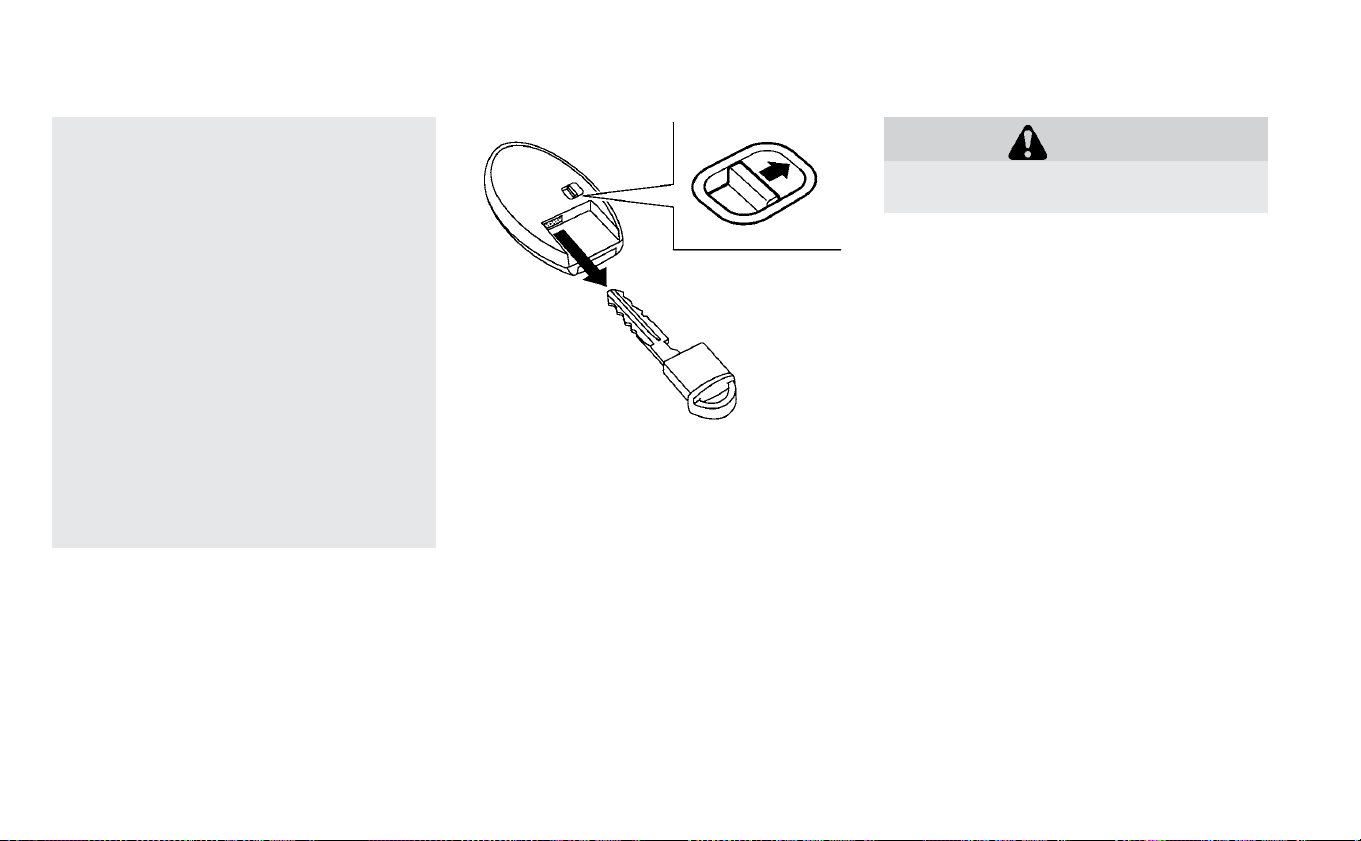
• Do not change or modify the Intelli-
gent Key.
• Do not use a magnet key holder.
• Do not place the Intelligent Key near
an electric appliance such as a tele-
vision set, personal computer or cel-
lular phone.
• Do not allow the Intelligent Key to
come into contact with water or salt
water, and do not wash it in a wash-
ing machine. This could affect the
system function.
If an Intelligent Key is lost or stolen,
NISSAN recommends erasing the ID
code of that Intelligent Key. This will
prevent the Intelligent Key from unau-
thorized use to unlock the vehicle. For
information regarding the erasing pro-
cedure, it is recommended that you
visit a NISSAN certified LEAF dealer.
Mechanical key
To remove the mechanical key, release the
lock knob at the back of the Intelligent Key.
To install the mechanical key, firmly insert it
into the Intelligent Key until the lock knob
returns to the lock position.
Use the mechanical key to lock or unlock
the doors. For additional information, refer
to “Doors” in this section.
CAUTION
Always carry the mechanical key in-
stalled in the Intelligent Key.
NISSAN VEHICLE IMMOBILIZER
SYSTEM KEYS
You can only drive your vehicle using the
master keys which are registered to the
NISSAN Vehicle Immobilizer System com-
ponents in your vehicle. These keys have a
transponder chip in the key head.
The master key can be used for all the
locks.
To protect belongings when you leave a
key with someone, give them the Intelligent
Key only, not the mechanical key.
Never leave these keys in the vehicle.
Additional or replacement keys:
If you still have a key, the key number is not
necessary when you need extra NISSAN
Vehicle Immobilizer System keys. A NISSAN
certified LEAF dealer can duplicate your ex-
isting key. As many as four NISSAN Vehicle
Immobilizer System keys can be used with
one vehicle. You should bring all NISSAN
Pre-driving checks and adjustments 3-3

Vehicle Immobilizer System keys that you
have to the NISSAN certified LEAF dealer for
registration. This is because the registra-
tion process will erase the memory of all
key codes previously registered into the
NISSAN Vehicle Immobilizer System. After
the registration process, these compo-
nents will only recognize keys coded into
the NISSAN Vehicle Immobilizer System
during registration. Any key that is not
given to the dealer at the time of registra-
tion will no longer be able to start your
vehicle.
CAUTION
Do not allow the immobilizer system
key, which contains an electrical tran-
sponder, to come into contact with wa-
ter or salt water. This could affect sys-
tem function.
WARNING
• Always have the doors locked while
driving. Along with the use of seat
belts, this provides greater safety in
the event of an accident by helping
to prevent persons from being
thrown from the vehicle. This also
helps keep children and others from
unintentionally opening the doors,
and will help keep out intruders.
• Before opening any door, always
look for and avoid oncoming traffic.
• To help avoid risk of injury or death
through unintended operation of
the vehicle and or its systems, in-
cluding entrapment in windows or
inadvertent door lock activation, do
not leave children, people who re-
quire the assistance of others or
pets unattended in your vehicle. Ad-
ditionally, the temperature inside a
closed vehicle on a warm day can
quickly become high enough to
cause a significant risk of injury or
death to people and pets.
When the doors are locked using one of the
following methods, the doors cannot be
opened using the inside or outside door
handles. The doors must be unlocked to
open the doors.
DOORS
3-4 Pre-driving checks and adjustments
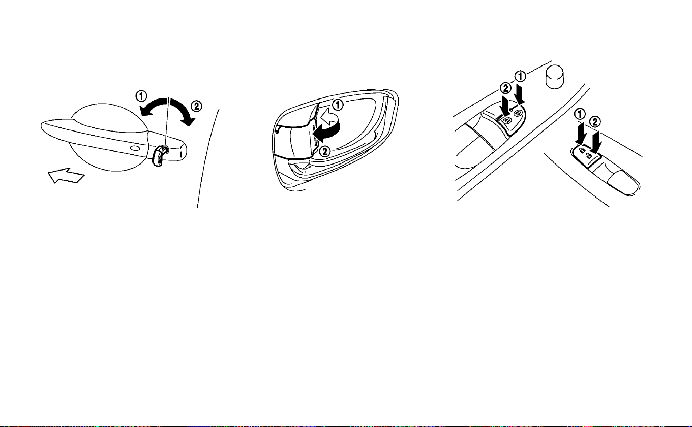
LOCKING WITH KEY (DRIVER’S SIDE
ONLY)
To lock or unlock the vehicle, turn the key as
shown.
Manual
To lock a door, turn the key towards the
front of the vehicle
䊊
1
. To unlock, turn the
key toward the rear of the vehicle
䊊
2
.
LOCKING WITH INSIDE LOCK KNOB
To lock the door without the key, move the
inside lock knob to the lock position
䊊
1
then close the door.
To unlock, move the inside lock knob to the
unlock position
䊊
2
.
When locking the door without a key, be
sure not to leave the key inside the ve-
hicle.
LOCKING WITH POWER DOOR
LOCK SWITCH
Operating the power door lock switch will
lock or unlock all the doors. The switches
are located on the driver’s and front pas-
senger’s door armrests.
To lock the doors, push the power door lock
switch to the lock position
䊊
1
with the driv-
er’s or front passenger’s door open, then
close the door.
When locking the door this way, be sure
not to leave the key inside the vehicle.
Pre-driving checks and adjustments 3-5

To unlock the doors, push the power door
lock switch to the unlock position
䊊
2
.
Lockout protection
When the power door lock switch is moved
to the lock position while any door is open,
all doors will unlock automatically and a
chime will sound after the door is closed.
This function help to prevent the Intelligent
Key from being accidentally locked inside
the vehicle.
AUTOMATIC DOOR LOCKS
• All doors lock automatically when the ve-
hicle speed reaches 15 mph (24 km/h).
NOTE:
The automatic door unlock function can
be changed using the “Vehicle Settings”
of the vehicle information display. For
additional information refer to “Vehicle
information display” in the “Instruments
and controls” section of this manual.
CHILD SAFETY REAR DOOR LOCK
Child safety rear door locks help prevent
the rear doors from being opened acciden-
tally, especially when small children are in
the vehicle.
When the levers are in the lock position
䊊
1
, the rear doors can be opened only
from the outside.
To disengage, move the levers to the un-
lock position
䊊
2
.
WARNING
• Radio waves could adversely affect
electric medical equipment. Those
who use a pacemaker should con-
tact the electric medical equipment
manufacturer for the possible influ-
ences before use.
• The Intelligent Key transmits radio
waves when the buttons are
pressed.The FAA advises that the ra-
dio waves may affect aircraft navi-
gation and communication sys-
tems. Do not operate the Intelligent
Key while on an airplane. Make sure
the buttons are not operated unin-
tentionally when the unit is stored
during a flight.
The Intelligent Key system can operate all
the door and the rear hatch locks by using
the remote control function or pushing the
request switch on the vehicle without tak-
ing the key out from a pocket or purse. The
operating environment and/or conditions
may affect the Intelligent Key system op-
eration.
Be sure to read the following items before
using the Intelligent Key system.
NISSAN INTELLIGENT KEY® SYSTEM
3-6 Pre-driving checks and adjustments
CAUTION
• Be sure to carry the Intelligent Key
with you when operating the ve-
hicle.
• Never leave the Intelligent Key in the
vehicle when you leave the vehicle.
The Intelligent Key is always communicat-
ing with the vehicle because it receives ra-
dio waves. The Intelligent Key system
transmits weak radio waves. Environmen-
tal conditions may interfere with the op-
eration of the Intelligent Key system under
the following operating conditions.
• When operating near a location where
strong radio waves are transmitted, such
as a TV tower, power station or broadcast-
ing station.
• When in possession of wireless equip-
ment, such as a cellular phone, transceiver
or a CB radio.
• When the Intelligent Key is in contact with
or covered by metallic materials.
• When any type of radio wave remote con-
trol is used nearby.
• When the Intelligent Key is placed near an
electric appliance such as a personal
computer.
• When the vehicle is parked near a parking
meter.
In such cases, correct the operating condi-
tions before using the Intelligent Key func-
tion or use the mechanical key.
Although the life of the battery varies de-
pending on the operating conditions, the
battery’s life is approximately two years. If
the battery is discharged, replace it with a
new one.
When the Intelligent Key battery is almost
discharged, firmly apply the foot brake and
touch the power switch with the Intelligent
Key. Then push the power switch while de-
pressing the brake pedal within 10 seconds
after the chime sound.
Since the Intelligent Key is continuously re-
ceiving radio waves, if the key is left near
equipment that transmits strong radio
waves, such as signals from a TV or per-
sonal computer, the battery life may be-
come shorter.
For additional information, refer to “NISSAN
Intelligent Key® battery replacement” in the
“Maintenance and do-it-yourself” section
of this manual.
Pay special attention that the vehicle bat-
tery is not completely discharged.
As many as four Intelligent Keys can be
registered and used with one vehicle. For
information about the purchase and use of
additional Intelligent Keys, it is recom-
mended that you visit a NISSAN certified
LEAF dealer.
CAUTION
• Do not allow the Intelligent Key,
which contains electrical compo-
nents, to come into contact with wa-
ter or salt water.This could affect the
functioning of the system.
• Do not drop the Intelligent Key.
• Do not strike the Intelligent Key
sharply against another object.
• Do not change or modify the Intelli-
gent Key.
• The Intelligent Key may be damaged
if it gets wet. If the Intelligent Key
gets wet, immediately wipe until it is
completely dry.
Pre-driving checks and adjustments 3-7
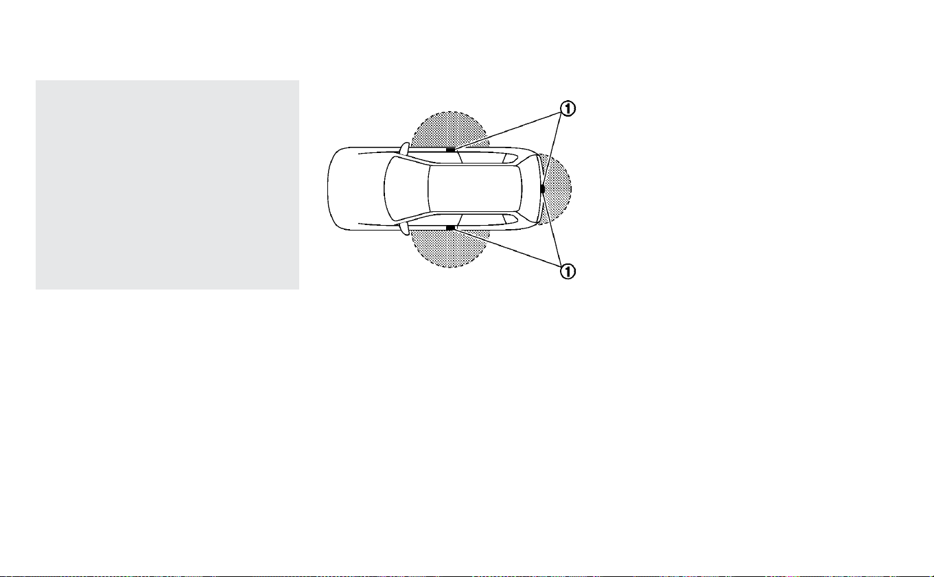
• If the outside temperature is below
14°F (−10°C), the battery of the Intel-
ligent Key may not function prop-
erly.
• Do not place the Intelligent Key for
an extended period in an area where
temperatures exceed 140°F (60°C).
• Do not attach the Intelligent Key to a
key holder that contains a magnet.
• Do not place the Intelligent Key near
equipment that produces a mag-
netic field, such as a TV, audio equip-
ment, personal computer or cellular
phone.
If an Intelligent Key is lost or stolen, NISSAN
recommends erasing the ID code of that
Intelligent Key from the vehicle. This may
prevent the unauthorized use of the Intelli-
gent Key to operate the vehicle. For addi-
tional information, it is recommended that
you visit a NISSAN certified LEAF dealer.
The Intelligent Key function can be dis-
abled. For additional information, it is rec-
ommended that you visit a NISSAN certi-
fied LEAF dealer.
NISSAN INTELLIGENT KEY®
OPERATING RANGE OF THE DOOR
LOCK/UNLOCK FUNCTION
The Intelligent Key functions can only be
used when the Intelligent Key is within the
specified operating range from the request
switch
䊊
1
.
When the Intelligent Key battery is dis-
charged or strong radio waves are present
near the operating location, the Intelligent
Key system’s operating range becomes
narrower, and the Intelligent Key may not
function properly.
The operating range is within 31.50 in
(80 cm) from each request switch
䊊
1
.
If the Intelligent Key is too close to the door
glass, handle or rear bumper, the request
switches may not function.
When the Intelligent Key is within the oper-
ating range, it is possible for anyone who
does not carry the Intelligent Key to push
the request switch to lock/unlock the
doors including the rear hatch.
3-8 Pre-driving checks and adjustments

DOOR LOCKS/UNLOCKS
PRECAUTION
• Do not push the door handle request
switch with the Intelligent Key held in your
hand as illustrated. The close distance to
the door handle will cause the Intelligent
Key system to have difficulty recognizing
that the Intelligent Key is outside the
vehicle.
• After locking with the door handle request
switch, verify the doors are securely
locked by testing them.
• To prevent the Intelligent Key from being
left inside the vehicle, make sure you carry
the key with you and then lock the doors.
• Do not pull the door handle before push-
ing the door handle request switch. The
door will be unlocked but will not open.
Release the door handle once and pull it
again to open the door.
NISSAN INTELLIGENT KEY®
OPERATION
You can lock or unlock the doors without
taking the key out from your pocket or bag.
Pre-driving checks and adjustments 3-9

When you carry the Intelligent Key with you,
you can lock or unlock all doors by pushing
the door handle request switch (driver’s or
front passenger’s)
䊊
A
or rear hatch request
switch
䊊
B
within the range of operation.
When you lock or unlock the doors or the
rear hatch, the hazard indicator will flash
and the horn (or the outside chime) will
sound as a confirmation. For additional in-
formation, refer to “Hazard warning flasher
switch” in the “In case of emergency” sec-
tion of this manual and “Horn” in the “Instru-
ments and controls” section of this manual.
Locking doors
1. Push the power switch into the OFF po-
sition and make sure you carry the Intel-
ligent Key with you.
2. Close all the doors and the rear hatch.
3. Push the door handle request switch
(driver’s or front passenger’s)
䊊
A
or the
rear hatch request switch
䊊
B
while car-
rying the Intelligent Key with you.*1
4. All the doors and the rear hatch will lock.
5. The hazard indicator flashes twice and
the outside chime sounds twice.
*1: Doors will not lock by pushing the door
handle request switch when the Intelligent
Key is left inside the vehicle. A chime
sounds to alert that the Intelligent Key is in
the vehicle. However, when an Intelligent
Key is inside the vehicle, doors can be
locked with another registered Intelligent
Key.
CAUTION
• After locking the door using the re-
quest switch, make sure that the
doors have been securely locked by
operating the door handles.
• When locking the doors using the re-
quest switch, make sure to have the
Intelligent Key in your possession
before operating the request switch
to prevent the Intelligent Key from
being left in the vehicle.
• The request switch is operational
only when the Intelligent Key has
been detected by the Intelligent Key
system.
3-10 Pre-driving checks and adjustments

Unlocking doors
1. Push the door handle request switch
䊊
A
or the rear hatch request switch
䊊
B
once
while carrying the Intelligent Key with
you.
2. The hazard indicator flashes once and
the outside chime sounds once. The
corresponding door or the rear hatch
will unlock.
3. Push the door handle request or the rear
hatch request switch again within one
minute.
4. The hazard indicator flashes once and
the outside chime sounds once again.
All the doors and the rear hatch will
unlock.
All doors will be locked automatically un-
less one of the following operations is per-
formed within one minute after pushing
the request switch while the doors are
locked.
• Opening any door.
• Pushing the power switch.
During this one minute time period, if the
button on the Intelligent Key is
pressed, all doors will be locked automati-
cally after another one minute.
NOTE:
If “Selective Unlock” is turned off in
the “Vehicle Settings,” all doors will
unlock upon first request switch
press.
Opening rear hatch
1. Carry the Intelligent Key.
2. Push the rear hatch opener switch
䊊
C
.
3. The rear hatch will unlock and open.
12-VOLT BATTERY SAVER SYSTEM
When all the following conditions are met
for a period of time, the battery saver sys-
tem will cut off the power supply to prevent
12-volt battery discharge.
• The power switch is in the ACC or ON
position,
• All doors are closed, and
• The vehicle is in the P (Park) position.
WARNING SIGNALS
To help prevent the vehicle from moving
unexpectedly by erroneous operation of
the Intelligent Key listed on the following
chart or to help prevent the vehicle from
being stolen, chime or beep sounds inside
and outside the vehicle and a warning dis-
plays in the vehicle information display.
When a chime or beep sounds or the warn-
ing displays, be sure to check the vehicle
and Intelligent Key.
For additional information, refer to the
”Troubleshooting guide” in this section and
“Vehicle information display” in the “Instru-
ments and controls” section of this manual.
TROUBLESHOOTING GUIDE
Verify the location of all Intelligent Keys that
are programmed for the vehicle. If another
Intelligent Key is in range or inside the ve-
hicle, the vehicle system may respond dif-
ferently than expected.
Pre-driving checks and adjustments 3-11

Symptom Possible cause Action to take
When opening the driver’s door
to get out of the vehicle
The inside warning chime sounds continu-
ously.
The power switch is pushed to the OFF
position while the driver's door is open.
Close the driver's door.
The power switch is in the ACC position.
Push the power switch to the OFF position
then close the driver's door.
When closing the door after get-
ting out of the vehicle
The Key is not detected warning appears on
the display, the outside chime sounds three
times and the inside warning chime sounds
for a few seconds.
The power switch is in the ACC or ON
position.
Push the power switch to the OFF position.
The outside chime sounds continuously.
The power switch is in the ACC or OFF
position, the electric shift control sys-
tem has malfunctioned and the vehicle
cannot be placed in the P (Park) position
when the parking brake is not applied.
Make sure the parking brake is applied.
When closing the door with the
inside lock knob turned to LOCK
The outside chime sounds for a few sec-
onds and all the doors unlock.
The Intelligent Key is inside the vehicle
or cargo area.
Carry the Intelligent Key with you.
When pushing the request
switch or the
button
on the Intelligent Key to lock the
door
The outside chime sounds for a few sec-
onds.
The Intelligent Key is inside the vehicle
or a cargo area.
Carry the Intelligent Key with you.
When pushing the power switch
in the READY to drive position
The Intelligent Key battery discharge indica-
tor appears on the display.
The Intelligent Key battery charge is low.
Replace the battery with a new one. For
additional information, refer to “NISSAN In-
telligent Key® battery replacement” in the
“Maintenance and do-it-yourself” section
of this manual.
The Key is not detected warning appears on
the display and the inside warning chime
sounds for a few seconds.
The Intelligent Key is not in the vehicle. Carry the Intelligent Key with you.
When pushing the power switch
The Intelligent Key system warning indica-
tor appears on the display.
It warns of a malfunction with the Intel-
ligent Key system.
It is recommended that you visit a NISSAN
certified LEAF dealer.
3-12 Pre-driving checks and adjustments

HOW TO USE REMOTE KEYLESS
ENTRY FUNCTION
WARNING
• Radio waves could adversely affect
electric medical equipment. Those
who use a pacemaker should con-
tact the electric medical equipment
manufacturer for the possible influ-
ences before use.
• The Intelligent Key transmits radio
waves when the buttons are
pressed.The FAA advises that the ra-
dio waves may affect aircraft navi-
gation and communication sys-
tems. Do not operate the Intelligent
Key while on an airplane. Make sure
the buttons are not operated unin-
tentionally when the unit is stored
during a flight.
CAUTION
• Do not allow the Intelligent Key,
which contains electrical compo-
nents, to come into contact with wa-
ter or salt water.This could affect the
system function.
• Do not drop the Intelligent Key.
• Do not strike the Intelligent Key
sharply against another object.
• Do not change or modify the Intelli-
gent Key.
• Wetting may damage the Intelligent
Key. If the Intelligent Key gets wet,
immediately wipe until it is com-
pletely dry.
• Do not place the Intelligent Key for
an extended period in an area where
temperatures exceed 140°F (60°C).
• Do not attach the Intelligent Key
with a key holder that contains a
magnet.
• Do not place the Intelligent Key near
equipment that produces a mag-
netic field, such as a TV, audio equip-
ment, personal computers or cellu-
lar phone.
The remote keyless entry function can op-
erate all door locks using the remote key-
less entry function of the Intelligent Key.
The remote keyless entry function can op-
erate at a distance of approximately 33 ft
(10 m) from the vehicle. The operating dis-
tance depends upon the conditions
around the vehicle.
The remote keyless entry function will not
operate:
• When the Intelligent Key is not within the
operational range.
• When the doors are open or not closed
securely.
• When the Intelligent Key battery is
discharged.
CAUTION
When locking the doors using the Intel-
ligent Key, be sure not to leave the key
in the vehicle.
Pre-driving checks and adjustments 3-13

Locking doors
䊊
1
Lock button
䊊
2
Unlock button
䊊
3
Charge port unlock
䊊
4
Panic button
When you lock or unlock the doors, the haz-
ard indicator will flash and the horn will
sound as a confirmation. For additional in-
formation, refer to “Hazard warning flasher
switch” in the “In case of emergency” sec-
tion and “Horn” in the “Instruments and
controls” sections of this manual.
1. Push the power switch to the OFF posi-
tion and make sure you carry the Intelli-
gent Key with you.
2. Carry the Intelligent Key with you.
3. Close all the doors.
4. Press the
button
䊊
1
on the Intelli-
gent Key.
5. All the doors and the rear hatch will lock.
6. The hazard indicator flashes twice and
the horn chirps once.
Operate the door handles to confirm that
the doors have been securely locked.
Unlocking doors
1. Press the button
䊊
2
on the Intelli-
gent Key once.
2. The hazard indicator flashes once. The
driver’s door will unlock.
3. Press the
button on the Intelligent
Key again within one minute.
4. The hazard indicator flashes once again.
All the doors and the rear hatch will
unlock.
All doors will be locked automatically un-
less one of the following operations is per-
formed within one minute after pressing
the
button while the doors are locked.
• Opening any door (including the rear
hatch).
• Pushing the power switch.
During this one minute time period, if the
button on the Intelligent Key is
pressed, all doors will be locked automati-
cally after another one minute.
Opening charge port lid
The charge port lid may be opened by
pressing and holding the
button
䊊
3
.
For additional information, refer to "Open-
ing charge port lid" in this section.
Using panic alarm
If you are near your vehicle and feel threat-
ened, you may activate the alarm to call
attention as follows:
1. Push the
button
䊊
4
on the Intelli-
gent Key for more than 1 second.
2. The panic alarm and headlights will stay
on for a period of time.
3-14 Pre-driving checks and adjustments

3. The panic alarm stops when:
• It has run for a period of time, or
• Any of the buttons on the Intelligent Key
is pushed. (Note: The
button must
be pushed for more than 1 second.)
Setting hazard indicator and horn
mode
This vehicle is set in hazard indicator and
horn mode when you first receive the ve-
hicle.
In hazard indicator and horn mode, when
the
button
䊊
1
is pressed, the hazard
indicator flashes twice and the horn chirps
once. When the
button
䊊
2
is pressed,
the hazard indicator flashes once.
If horns are not necessary, the system can
be switched to the hazard indicator mode.
In hazard indicator mode, when the
button is pressed, the hazard indicator
flashes twice. When the
button is
pressed, neither the hazard indicator nor
the horn operates.
Hazard indicator and horn mode:
Operation DOOR LOCK DOOR UNLOCK
Pushing door handle request switch or rear hatch request
switch
HAZARD - twice
OUTSIDE CHIME - twice
HAZARD - once
OUTSIDE CHIME - once
Pressing
or button
HAZARD - twice
HORN - once
HAZARD - once
HORN - none
Hazard indicator mode:
Operation DOOR LOCK DOOR UNLOCK
Pushing door handle request switch or rear hatch request
switch
HAZARD - twice
OUTSIDE CHIME - none
HAZARD - none
OUTSIDE CHIME - none
Pressing
or button
HAZARD - twice
HORN - none
HAZARD - none
HORN - none
Pre-driving checks and adjustments 3-15
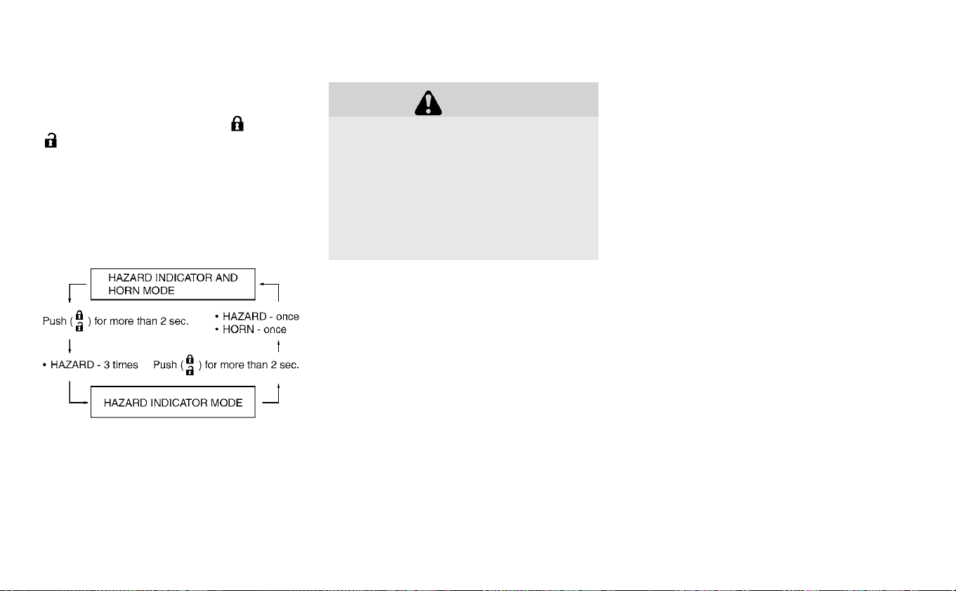
Switching procedure:
To switch the hazard indicator and horn
(chime) operation, press the
䊊
1
and
䊊
2
buttons on the Intelligent Key si-
multaneously for more than two seconds.
• When the hazard indicator mode is set,
the hazard indicator flashes three times.
• When the hazard indicator and horn
mode is set, the hazard indicator flashes
once and the horn chirps once.
WARNING
• Make sure that the hood is com-
pletely closed and latched before
driving. Failure to do so could cause
the hood to open during driving and
result in an accident.
• If steam or smoke is emitting from
the motor compartment, do not
open the hood. Doing so could cause
an injury.
HOOD
3-16 Pre-driving checks and adjustments

When opening the hood:
1. Securely close the charge port door.
2. Pull the hood lock release handle
䊊
1
lo-
cated below the instrument panel. The
hood will then spring up slightly.
3. Locate the lever
䊊
2
in between the hood
and charge port lid, and push the lever
upward with your fingertips.
4. Raise the hood
䊊
3
.
5. Remove the support rod
䊊
4
from the
hood and insert it into the slot
䊊
5
.
Hold the coated part
䊊
A
when removing
or resetting the support rod. Avoid direct
contact with the metal parts because
they may be hot immediately after the
EV system has been stopped.
When closing the hood:
1. Return the support rod to its original
position.
2. Slowly move the hood down to latch the
lock.
3. Push the hood down to lock the hood
securely into place.
WARNING
• Always make sure that the rear
hatch has been closed securely to
prevent it from opening while driv-
ing.
• Do not drive with the rear hatch
open.
• Make sure that all passengers have
their hands, etc. inside the vehicle
before closing the rear hatch.
REAR HATCH
Pre-driving checks and adjustments 3-17

To open the rear hatch, unlock it and push
the rear hatch opener switch
䊊
A
. Pull up the
rear hatch to open.
The rear hatch can be unlocked by:
• Pushing the rear hatch request switch. For
additional information, refer to “NISSAN In-
telligent Key® system” in this section.
• Pressing the
button on the Intelli-
gent Key. For additional information, refer
to “NISSAN Intelligent Key® system” in this
section.
• Pressing the
button on the remote
control. For additional information, refer to
“NISSAN Intelligent Key® system” in this
section.
• Pushing the power door lock switch to the
unlock position.
SECONDARY REAR HATCH
RELEASE
Follow the following steps to unlock the
liftgate when the battery is discharged.
NOTE:
It is recommended that you visit a
NISSAN certified LEAF dealer as soon
as possible for inspection.
3-18 Pre-driving checks and adjustments
Unlocking the rear hatch:
1. Move the cover
䊊
A
by using a screwdriver
or a similar tool available on hand.
2. Then move the inside lever
䊊
B
by using a
screwdriver or similar tool available on
hand. The rear hatch will open.
OPENING CHARGE PORT LID
CAUTION
Make sure that the charge port lid is
completely closed and latched before
driving. Failure to do so could cause the
lid to open suddenly during driving.
Switch
Button
CHARGE PORT LID
Pre-driving checks and adjustments 3-19

When opening the charge port lid perform
one of the following:
• Push the charge port lid opener switch
located on the instrument panel, or
• Press and hold the
button on the
Intelligent Key for more than one second.
When opening the charge port lid:
1. The charging status indicator lights flash
and a chime sounds three times and the
charge port lid will then spring up slightly.
2. Put your hand into the underside of the
lid and open until it is in the fully open
position.
When closing the charge port lid:
1. Slowly move the lid down.
2. Lock it securely into place.
If the charge port lid cannot be unlocked
1. Open the hood.
2. Move the lever behind the charge port
lid in the direction of the arrow using a
flat head screwdriver or suitable tool,
and the port is unlocked.
3-20 Pre-driving checks and adjustments

CHARGE PORT CAP
When opening the charge port cap, press
the tab inward and the cap will spring open.
When the charge port cap is closed to its
previous position, it will lock automatically.
CAUTION
• When charging is finished, be sure to
close the charge port cap. If water or
dust gets inside the charge port, this
may cause a malfunction.
• Pay particular attention when using
the normal charge port as the
charge port lid can be closed even
when the normal charge port cap is
open.
• Close the quick charge (if so
equipped) port cap before closing
the charging lid. The quick charge
port cap can be damaged if it is open
when closing the charge port lid.
WARNING
• Do not adjust the steering wheel
while driving. You could lose control
of your vehicle and cause an acci-
dent.
• Do not adjust the steering wheel any
closer to you than is necessary for
proper steering operation and com-
fort. The driver’s air bag inflates with
great force. If you are unrestrained,
leaning forward, sitting sideways or
out of position in any way, you are at
greater risk of injury or death in a
crash. You may also receive serious
or fatal injuries from the air bag if
you are up against it when it inflates.
Always sit back against the seat-
back and as far away as practical
from the steering wheel. Always use
the seat belts.
STEERING WHEEL
Pre-driving checks and adjustments 3-21

TILT OPERATION
Push the lock lever down
䊊
1
and adjust the
steering wheel up or down
䊊
2
to the de-
sired position.
Pull the lock lever up
䊊
3
to lock the steering
wheel in place.
1. To block out glare from the front, swing
down the sun visor
䊊
1
.
2. To block glare from the side, remove the
sun visor from the center mount and
swing it to the side
䊊
2
.
3. Slide the extension sun visor in or out as
needed
䊊
3
.
CAUTION
• Do not store the sun visor before re-
turning the extension to its original
position.
• Do not pull the extension sun visor
forcedly downward.
SUN VISORS
3-22 Pre-driving checks and adjustments
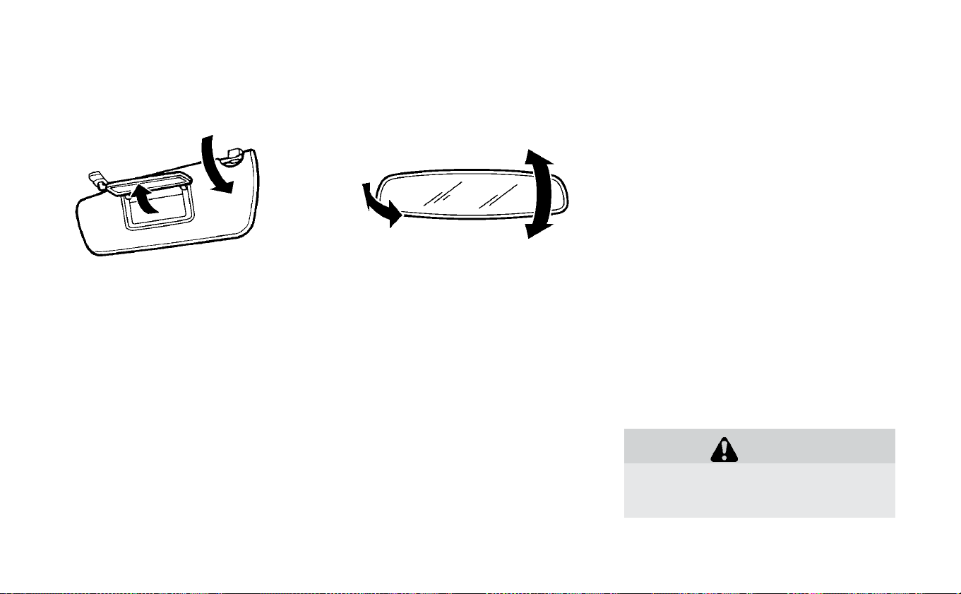
VANITY MIRROR
To use the front vanity mirror, pull down the
sun visor and pull up the cover.
INSIDE REARVIEW MIRROR
Adjust the angle of the inside rearview mir-
ror to the preferred position.
MANUAL ANTI-GLARE REARVIEW
MIRROR (IF SO EQUIPPED)
The night position
䊊
1
reduces glare from
the headlights of vehicles behind you at
night.
Use the day position
䊊
2
when driving in
daylight hours.
WARNING
Use the night position only when nec-
essary, because it reduces rearview
clarity.
MIRRORS
Pre-driving checks and adjustments 3-23
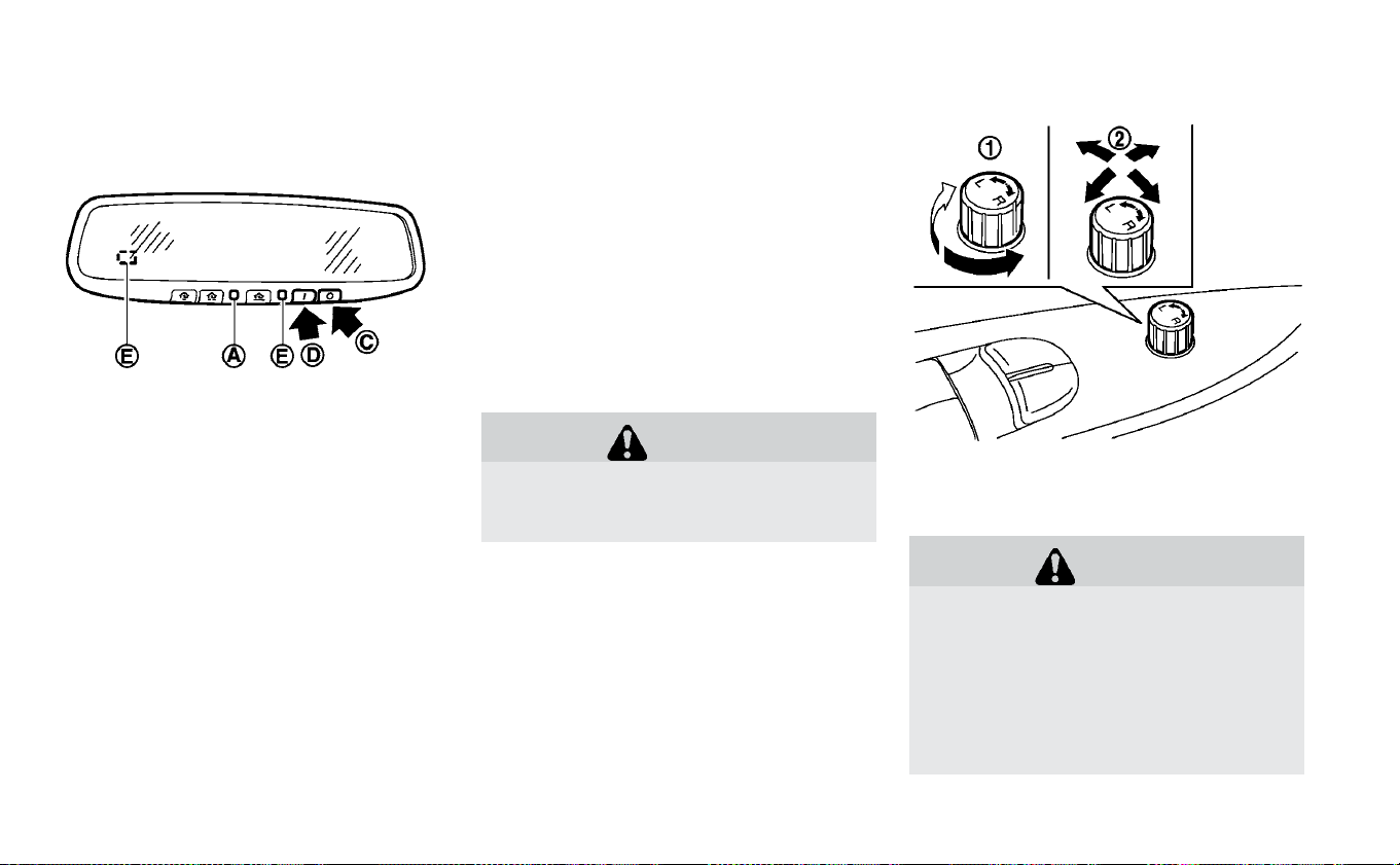
AUTOMATIC ANTI-GLARE TYPE (IF
SO EQUIPPED)
The inside mirror is designed so that it au-
tomatically changes reflection based on
the intensity of the headlights of the vehicle
behind.
When the system is turned on, the indicator
light
䊊
A
will illuminate and excessive glare
from the headlights of the vehicle behind
you will be reduced.
Push the “䡩” switch
䊊
C
to make the inside
rearview mirror operate normally. The indi-
cator light will turn off. Push the “I” switch
䊊
D
to turn the system on.
Do not allow any object to cover the sen-
sors
䊊
E
or apply glass cleaner on them.
Doing so will reduce the sensitivity of the
sensor, resulting in improper operation.
Do not hang any objects on the mirror or
apply glass cleaner to it. Doing so will
reduce the sensitivity of the sensor
䊊
B
,
resulting in improper operation.
WARNING
Use the night position only when nec-
essary, because it reduces rear view
clarity.
OUTSIDE MIRRORS
Adjusting outside mirrors
WARNING
Objects viewed in the outside mirror
on the passenger side are closer than
they appear. Be careful when moving
to the right. Using only this mirror
could cause an accident. Use the inside
mirror or glance over your shoulder to
properly judge distances to other ob-
jects.
3-24 Pre-driving checks and adjustments
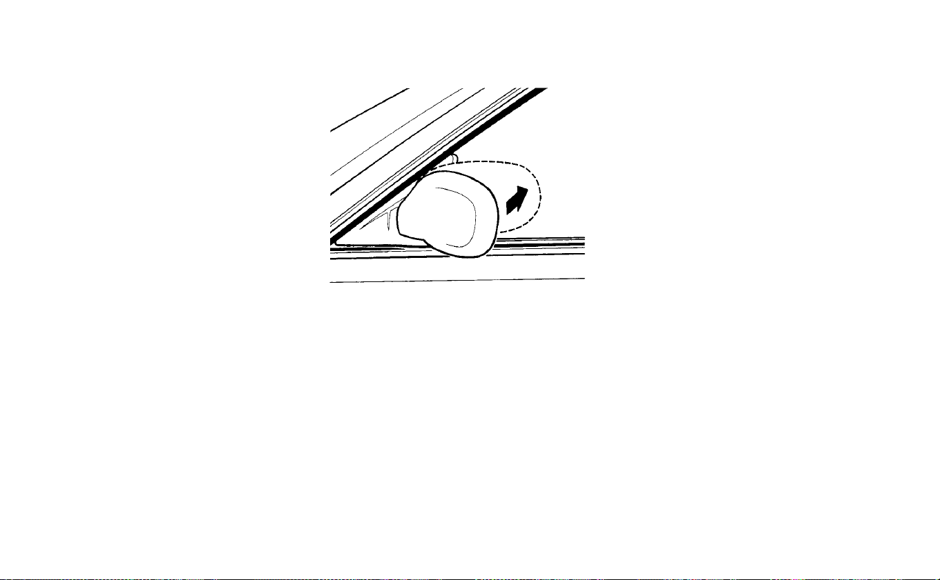
The outside mirror control switch is lo-
cated on the armrest.
The outside mirror will operate only when
the power switch is in the ACC or ON posi-
tion.
Turn the switch right or left to select the
right or left side mirror
䊊
1
, then adjust the
mirror using the control switch
䊊
2
.
Move the switch to the center (neutral) po-
sition to prevent accidentally moving the
mirror.
Defrosting outside mirrors (if so
equipped)
The outside mirrors will be heated when
the rear window defroster switch is oper-
ated. For additional information, refer to
“Rear window and outside mirror (if so
equipped) defroster switch” in the “Instru-
ments and controls” section of this manual.
Folding outside mirrors
Fold the outside mirror by pushing it to-
ward the rear of the vehicle.
Pre-driving checks and adjustments 3-25

NOTES
3-26 Pre-driving checks and adjustments

4 Monitor, climate, audio, phone and
voice recognition systems
NissanConnect® Manual (for Leaf)...........4-3
RearView Monitor (if so equipped) ...........4-4
RearView Monitor system operation .......4-5
How to read the displayed lines ..........4-6
Difference between predicted and actual
distances .........................4-6
How to park with predicted course lines
(models with Navigation System) .........4-8
Adjusting the screen .................4-10
How to turn on and off predicted course lines
(models with navigation) ..............4-11
RearView Monitor system limitations ......4-11
System maintenance ................4-12
I
ntelligent Around View Monitor (if so equipped) . . .4-13
Intelligent Around View Monitor system
operation ........................4-15
Difference between predicted and actual
distances ........................4-18
How to park with predicted course lines . . . .4-19
How to switch the display .............4-20
Adjusting the screen .................4-21
Intelligent Around View Monitor system
limitations........................4-22
System Maintenance ................4-24
Moving Object Detection (if so equipped) .....4-25
MOD system operation ...............4-26
Turning MOD ON and OFF .............4-27
MOD system limitations...............4-27
System maintenance ................4-28
Vents .............................4-29
Heater and air conditioner (automatic).......4-30
Operating tips .....................4-32
In-cabin microfilter ..................4-33
Automatic climate control (models without
Navigation System)..................4-33
Automatic climate control (models with
Navigation System)..................4-37
Climate ctrl. timer...................4-40
Servicing climate control ..............4-44
Audio system (models without Navigation
System) ...........................4-45
Radio ...........................4-45
FM radio reception ..................4-45
AM radio reception ..................4-46
Satellite radio reception...............4-46
Audio operation precautions ...........4-47
FM/AM/SAT radio with compact disc (CD)
player...........................4-54

USB (Universal Serial Bus) connection port . .4-60
iPod® player operation................4-61
Bluetooth® streaming audio............4-64
Aux device player operation ............4-64
CD care and cleaning ................4-65
Steering wheel switch for audio control . . . .4-65
Antenna ...........................4-66
Car phone or CB radio..................4-67
Bluetooth® Hands-Free Phone System without
Navigation System (if so equipped) .........4-67
Regulatory information ...............4-69
Using the system ...................4-69
Control buttons ....................4-70
Connecting procedure ................4-71
Voice commands ...................4-72
Making a call ......................4-73
Receiving a call.....................4-74
During a call ......................4-74
Ending a call ......................4-74
Text messaging (if so equipped) .........4-75
Bluetooth® settings .................4-76
Manual controls ....................4-77
Troubleshooting guide ...............4-78

Refer to the NissanConnect® Manual (for
Leaf) that includes the following informa-
tion.
• EV-Specific functions
• Audio
• Hands-Free Phone
• NissanConnect® EV and Services
• Apple CarPlay
TM
• Android Auto
TM
• Navigation
• Voice recognition
• Information and settings viewable on the
system
NISSANCONNECT® MANUAL (FOR
LEAF)
Monitor, climate, audio, phone and voice recognition systems 4-3
1. CAMERA button (if so equipped)
WARNING
Failure to follow the warnings and in-
structions for proper use of the Rear-
View Monitor system could result in se-
rious injury or death.
• RearView Monitor is a convenience
feature and is not a substitute for
proper backing. Always turn and
look out the windows and check
mirrors to be sure that it is safe to
move before operating the vehicle.
REARVIEW MONITOR (IF SO
EQUIPPED)
4-4 Monitor, climate, audio, phone and voice recognition systems

Always back up slowly.
• The system is designed as an aid to
the driver in showing large station-
ary objects directly behind the ve-
hicle, to help avoid damaging the ve-
hicle.
• The distance guide line and the ve-
hicle width line should be used as a
reference only when the vehicle is on
a level paved surface. The distance
viewed on the monitor is for refer-
ence only and may be different than
the actual distance between the ve-
hicle and displayed objects.
CAUTION
Do not scratch the camera lens when
cleaning dirt or snow from the front of
the camera.
The RearView Monitor system automati-
cally shows a rear view of the vehicle when
the shift lever is shifted into the R (Reverse)
position. The radio can still be heard while
the RearView Monitor is active.
To display the rear view, the RearView Moni-
tor system uses a camera located just
above the vehicle’s license plate
䊊
1
.
REARVIEW MONITOR SYSTEM
OPERATION
With the EV (electric vehicle) system on,
move the shift lever to the R (Reverse) po-
sition or press the CAMERA button (if so
equipped) to operate the RearView
Monitor.
Monitor, climate, audio, phone and voice recognition systems 4-5

HOW TO READ THE DISPLAYED
LINES
Guiding lines which indicate the vehicle
width and distances to objects with refer-
ence to the vehicle body line
䊊
A
are dis-
played on the monitor.
Distance guide lines
Indicate distances from the vehicle body.
• Red line
䊊
1
: approx. 1.5 ft (0.5 m)
• Yellow line
䊊
2
: approx. 3 ft (1 m )
• Green line
䊊
3
: approx. 7 ft (2 m)
• Green line
䊊
4
: approx. 10 ft (3 m )
Vehicle width guide lines
䊊
5
Indicate the vehicle width when backing
up.
Predicted course lines (models with
navigation system)
䊊
6
Indicate the predicted course when back-
ing up. The predicted course lines will be
displayed on the monitor when the shift
lever is in the R (Reverse) position and the
steering wheel is turned. The predicted
course lines will move depending on how
much the steering wheel is turned and will
not be displayed while the steering wheel is
in the straight-ahead position.
The vehicle width guide lines and the width
of the predicted course lines are wider than
the actual width and course.
DIFFERENCE BETWEEN PREDICTED
AND ACTUAL DISTANCES
The displayed guidelines and their loca-
tions on the ground are for approximate
reference only. Objects on uphill or downhill
surfaces or projecting objects will be actu-
ally located at distances different from
those displayed in the monitor relative to
the guidelines (refer to illustrations). When
in doubt, turn around and view the objects
as you are backing up, or park and exit the
vehicle to view the positioning of objects
behind the vehicle.
4-6 Monitor, climate, audio, phone and voice recognition systems
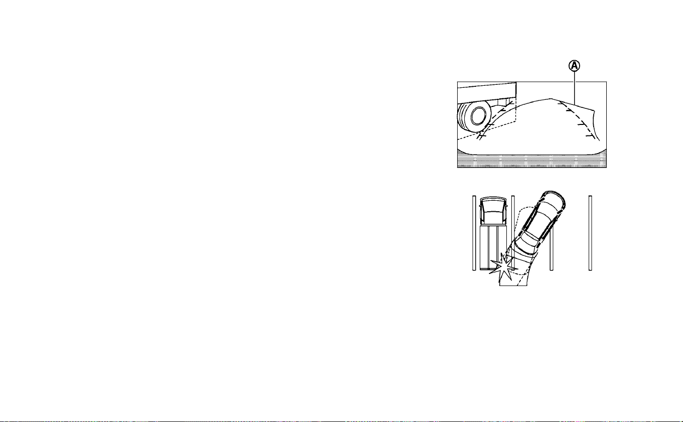
Backing up on a steep uphill
When backing up the vehicle up a hill, the
distance guide lines and the vehicle width
guide lines are shown closer than the ac-
tual distance. Note that any object on the
hill is further than it appears on the
monitor.
Backing up on a steep downhill
When backing up the vehicle down a hill,
the distance guide lines and the vehicle
width guide lines are shown farther than
the actual distance. Note that any object
on the hill is closer than it appears on the
monitor.
Backing up near a projecting
object
The predicted course lines (models with
navigation system)
䊊
A
do not touch the
object in the display. However, the vehicle
may hit the object if it projects over the
actual backing up course.
Monitor, climate, audio, phone and voice recognition systems 4-7

Backing up behind a projecting
object
The position
䊊
C
is shown farther than the
position
䊊
B
in the display. However, the po-
sition
䊊
C
is actually at the same distance as
the position
䊊
A
. The vehicle may hit the
object when backing up to the position
䊊
A
if the object projects over the actual back-
ing up course.
HOW TO PARK WITH PREDICTED
COURSE LINES (MODELS WITH
NAVIGATION SYSTEM)
WARNING
• If the tires are replaced with differ-
ent sized tires, the predicted course
lines may be displayed incorrectly.
• On a snow-covered or slippery road,
there may be a difference between
the predicted course line and the ac-
tual course line.
• If the battery is disconnected or be-
comes discharged, the predicted
course lines may be displayed incor-
rectly. If this occurs, please perform
the following procedures:
- Turn the steering wheel from lock
to lock while the EV (electric vehicle)
system is running.
- Drive the vehicle on a straight road
for more than 5 minutes.
• When the steering wheel is turned
with the power switch in the ACC po-
sition, the predicted course lines
may be displayed incorrectly.
4-8 Monitor, climate, audio, phone and voice recognition systems
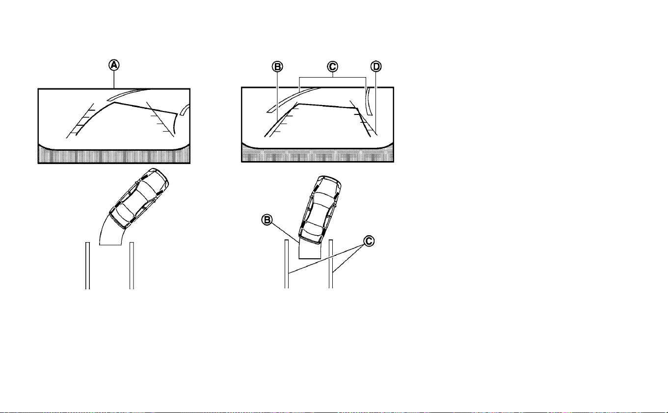
1. Visually check that the parking space is
safe before parking your vehicle.
2. The rear view of the vehicle is displayed
on the screen
䊊
A
when the shift lever is
moved to the R (Reverse) position.
3. Slowly back up the vehicle adjusting the
steering wheel so that the predicted
course lines
䊊
B
enter the parking space
䊊
C
.
4. Maneuver the steering wheel to make
the vehicle width guide lines
䊊
D
parallel
to the parking space
䊊
C
while referring
to the predicted course lines.
5. When the vehicle is parked in the space
completely, move the shift lever to the P
(Park) position and apply the parking
brake.
Monitor, climate, audio, phone and voice recognition systems 4-9

ADJUSTING THE SCREEN
1. While on a RearView Monitor screen,
press the ENTER/SETTING button until
the Brightness or Contrast setting bar is
displayed below the RearView Monitor
screen.
2. Turn the TUNE/SCROLL knob to adjust
the level.
3. To complete the adjustment, press the
ENTER/SETTING button until the Bright-
ness or Contrast setting bar disappears
from the RearView Monitor screen.
NOTE:
Do not adjust any of the display
settings of the RearView Monitor
while the vehicle is moving. Make
sure the parking brake is firmly ap-
plied
1. While on a RearView Monitor screen,
touch the touch-screen display. The
Camera Setting screen will come up.
2. Touch the “Brightness,” “Contrast,” “Tint,”
“Color,” or “Black Level” key.
3. Adjust the item by touching the + or - key
on the touch-screen display.
Models without navigation system Models with navigation system
4-10 Monitor, climate, audio, phone and voice recognition systems

HOW TO TURN ON AND OFF
PREDICTED COURSE LINES
(MODELS WITH NAVIGATION)
To toggle ON and OFF the predicted course
lines while in the P (Park) position:
1. Touch the Settings key.
2. Touch the Camera key.
3. Touch the Predicted Course Lines key to
turn the feature ON or OFF.
To toggle ON and OFF the predicted course
lines while in the R (Reverse) position:
1. Touch the touch-screen display.
2. Touch the Predicted Course Lines key to
turn the feature ON or OFF.
REARVIEW MONITOR SYSTEM
LIMITATIONS
WARNING
Listed below are the system limita-
tions for RearView Monitor. Failure to
operate the vehicle in accordance
with these system limitations could
result in serious injury or death.
• The system cannot completely
eliminate blind spots and may not
show every object.
• Underneath the bumper and the
corner areas of the bumper cannot
be viewed on the RearView Monitor
because of its monitoring range
limitation. The system will not show
small objects below the bumper,
and may not show objects close to
the bumper or on the ground.
• Objects viewed in the RearView
Monitor differ from actual distance
because a wide-angle lens is used.
• Objects in the RearView Monitor will
appear visually opposite compared
to when viewed in the rearview and
outside mirrors.
• Use the displayed lines as a refer-
ence. The lines are highly affected by
the number of occupants, fuel level,
vehicle position, road conditions
and road grade.
• Make sure that the rear hatch is se-
curely closed when backing up.
• Do not put anything on the rearview
camera. The rearview camera is in-
stalled above the license plate.
• When washing the vehicle with high
pressure water, be sure not to spray
it around the camera. Otherwise,
water may enter the camera unit
causing water condensation on the
lens, a malfunction, fire or an electric
shock.
• Do not strike the camera. It is a pre-
cision instrument. Otherwise, it may
malfunction or cause damage re-
sulting in a fire or an electric shock.
The following are operating limitations and
do not represent a system malfunction:
• When the temperature is extremely high
or low, the screen may not clearly display
objects.
• When strong light directly shines on the
camera, objects may not be displayed
clearly.
• Vertical lines may be seen in objects on
the screen. This is due to strong reflected
light from the bumper.
• The screen may flicker under fluorescent
light.
• The colors of objects on the RearView
Monitor may differ somewhat from the
actual color of objects.
Monitor, climate, audio, phone and voice recognition systems 4-11
• Objects on the monitor may not be clear
in a dark environment.
• There may be a delay when switching be-
tween views.
• If dirt, rain or snow accumulate on the
camera, RearView Monitor may not dis-
play objects clearly. Clean the camera.
• Do not use wax on the camera lens. Wipe
off any wax with a clean cloth dampened
with a diluted mild cleaning agent, then
wipe with a dry cloth.
SYSTEM MAINTENANCE
CAUTION
• Do not use alcohol, benzine or thin-
ner to clean the camera. This will
cause discoloration.
• Do not damage the camera as the
monitor screen may be adversely af-
fected.
If dirt, rain or snow accumulates on the
camera
䊊
1
, the RearView Monitor may not
display objects clearly. Clean the camera
by wiping it with a cloth dampened with a
diluted mild cleaning agent and the wiping
it with a dry cloth.
4-12 Monitor, climate, audio, phone and voice recognition systems
1. CAMERA button
WARNING
Failure to follow the warnings and in-
structions for proper use of the Intelli-
gent Around View Monitor system
could result in serious injury or death.
• The Intelligent Around View Monitor
is a convenience feature and is not a
substitute for proper vehicle opera-
tion because it has areas where ob-
jects cannot be viewed. The four cor-
ners of the vehicle in particular, are
INTELLIGENT AROUND VIEW
MONITOR (IF SO EQUIPPED)
Monitor, climate, audio, phone and voice recognition systems 4-13

areas where objects do not always
appear in the bird’s-eye, front, or
rear views. Always check your sur-
roundings to be sure that it is safe to
move before operating the vehicle.
Always operate the vehicle slowly.
• The driver is always responsible for
safety during parking and other ma-
neuvers.
CAUTION
Do not scratch the camera lens when
cleaning dirt or snow from the front of
the camera.
The Intelligent Around View Monitor sys-
tem is designed as an aid to the driver in
situations such as slot parking or parallel
parking. The monitor displays various
views of the position of the vehicle in a split
screen format. Not all views are available at
all times.
Available views:
• Front View
An approximately 150–degree view of
the front of the vehicle.
• Rear View
An approximately 150–degree view of
the rear of the vehicle.
• Bird’s-Eye View
The surrounding views of the vehicle
from above.
• Front-Side View
The view around and ahead of the front
passenger’s side wheel.
• Full screen rear view
The view to the rear of the vehicle (which
is a little wider than the standard rear
view).
To display the multiple views, the Intelligent
Around View Monitor system uses cam-
eras located in the front grille, on the vehi-
cle’s outside mirrors and one just above
the vehicle’s license plates
䊊
1
.
4-14 Monitor, climate, audio, phone and voice recognition systems

INTELLIGENT AROUND VIEW
MONITOR SYSTEM OPERATION
With the EV (electric vehicle) system on,
move the shift lever to the R (Reverse) po-
sition or press the CAMERA button to oper-
ate the Intelligent AroundView Monitor.The
screen displayed on the Intelligent Around
View Monitor will automatically return to
the previous screen 3 minutes after the
CAMERA button has been pressed with the
shift lever in a position other than the R
(Reverse) position.
Available views
WARNING
• The distance guide lines and the ve-
hicle width lines should be used as a
reference only when the vehicle is on
a paved, level surface. The apparent
distance viewed on the monitor may
be different than the actual distance
between the vehicle and displayed
objects.
• Use the displayed lines and the
bird’s eye view as a reference. The
lines and the bird’s-eye view are
greatly affected by the number of
occupants, cargo, fuel level, vehicle
position, road condition and road
grade.
• If the tires are replaced with differ-
ent sized tires, the predicted course
lines and the bird’s-eye view may be
displayed incorrectly.
• When driving the vehicle up a hill,
objects viewed in the monitor are
further than they appear. When driv-
ing the vehicle down a hill, objects
viewed in the monitor are closer
than they appear.
• Objects in the rear view will appear
visually opposite compared to when
viewed in the rear view and outside
mirrors.
• Use the mirrors or actually look to
properly judge distances to other
objects.
• On a snow-covered or slippery road,
there may be a difference between
the predicted course lines and the
actual course line.
• The vehicle width and predicted
course lines are wider than the ac-
tual width and course.
• The displayed lines will appear
slightly off to the right, because the
rearview camera is not installed in
the rear center of the vehicle.
Monitor, climate, audio, phone and voice recognition systems 4-15
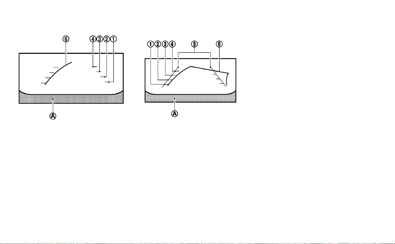
Front and rear view:
Guiding lines that indicate the approximate
vehicle width and distance to objects with
reference to the vehicle body lines
䊊
A
are
displayed on the monitor.
Distance guide lines
Indicate distances from the vehicle body:
• Red line
䊊
1
: approximately 1.5 ft (0.5 m)
• Yellow lines
䊊
2
: approximately 3 ft (1 m)
• Green lines
䊊
3
: approximately 7 ft (2 m)
• Green lines
䊊
4
: approximately 10 ft (3 m)
Vehicle width guide lines
䊊
5
Indicate the approximate vehicle width
when backing up.
Predicted course lines
䊊
6
Indicate the predicted course when oper-
ating the vehicle. The predicted course
lines will be displayed on the monitor when
the steering wheel is turned. The predicted
course lines will move depending on how
much the steering wheel is turned and
may not be displayed while the steering
wheel is in the straight-ahead position. The
front view will not be displayed when the
vehicle speed is above 6 mph (10 km/h).
NOTE:
When the monitor displays the front
view and the steering wheel turns
about 90 degrees or less from the
straight-ahead position, both the
right and left predicted course lines
䊊
6
are displayed. When the steering
wheel turns about 90 degrees or
more, a line is displayed only on the
opposite side of the turn.
Front View Rear View
4-16 Monitor, climate, audio, phone and voice recognition systems
Birds-eye view:
The bird’s-eye view shows the overhead
view of the vehicle, which helps confirm the
vehicle position and the predicted course
to a parking space. The vehicle icon
䊊
1
shows the position of the vehicle. Note that
the apparent distance between objects
viewed in the bird’s-eye view may differ
somewhat from the actual distance to the
vehicle.
The areas that the cameras cannot cover
䊊
2
are indicated in black.
After the EV system is placed in the ON
position, the non-viewable areas
䊊
2
are
highlighted in yellow for several seconds
after the bird’s-eye view is displayed. It will
be shown only the first time after the
power switch is placed in the ON position.
WARNING
• Objects in the bird’s-eye view will
appear further than the actual dis-
tance.
• Tall objects, such as a curb or vehicle,
may be misaligned or not displayed
at the seam of the views.
• Objects that are above the camera
cannot be displayed.
• The view for the bird’s-eye view may
be misaligned when the camera po-
sition alters.
• A line on the ground may be mis-
aligned and is not seen as being
straight at the seam of the views.
The misalignment will increase as
the line proceeds away from the ve-
hicle.
Front-side view:
Guiding lines
Guiding lines that indicate the approximate
width and the front end of the vehicle are
displayed on the monitor.
The front-of-vehicle line
䊊
1
shows the front
part of the vehicle.
The side-of-vehicle line
䊊
2
shows the ap-
proximate vehicle width including the out-
side mirrors.
The extensions
䊊
3
of both the front
䊊
1
and
side
䊊
2
lines are shown with a green dotted
line.
Monitor, climate, audio, phone and voice recognition systems 4-17

DIFFERENCE BETWEEN PREDICTED
AND ACTUAL DISTANCES
The displayed guidelines and their loca-
tions on the ground are for approximate
reference only. Objects on uphill or downhill
surfaces or projecting objects will be actu-
ally located at distances different from
those displayed in the monitor relative to
the guidelines (refer to illustrations). When
in doubt, turn around and view the objects
as you are backing up, or park and exit the
vehicle to view the positioning of objects
behind the vehicle.
Backing up on a steep uphill
When backing up the vehicle up a hill, the
distance guide lines and the vehicle width
guide lines are shown closer than the ac-
tual distance. Note that any object on the
hill is further than it appears on the
monitor.
Backing up on a steep downhill
When backing up the vehicle down a hill,
the distance guide lines and the vehicle
width guide lines are shown farther than
the actual distance. Note that any object
on the hill is closer than it appears on the
monitor.
4-18 Monitor, climate, audio, phone and voice recognition systems
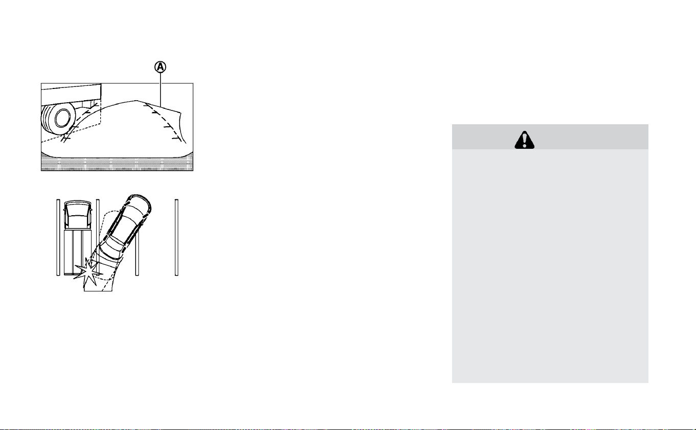
Backing up near a projecting
object
The predicted course lines
䊊
A
do not touch
the object in the display. However, the ve-
hicle may hit the object if it projects over
the actual backing up course.
Backing up behind a projecting
object
The position
䊊
C
is shown farther than the
position
䊊
B
in the display. However, the po-
sition
䊊
C
is actually at the same distance as
the position
䊊
A
. The vehicle may hit the
object when backing up to the position
䊊
A
if the object projects over the actual back-
ing up course.
HOW TO PARK WITH PREDICTED
COURSE LINES
WARNING
• If the tires are replaced with differ-
ent sized tires, the predicted course
lines may be displayed incorrectly.
• On a snow-covered or slippery road,
there may be a difference between
the predicted course line and the ac-
tual course line.
• If the battery is disconnected or be-
comes discharged, the predicted
course lines may be displayed incor-
rectly. If this occurs, please perform
the following procedures:
- Turn the steering wheel from lock
to lock while the EV (electric vehicle)
System is running.
- Drive the vehicle on a straight road
for more than 5 minutes.
• When the steering wheel is turned
with the power switch in the ACC po-
sition, the predicted course lines
may be displayed incorrectly.
Monitor, climate, audio, phone and voice recognition systems 4-19
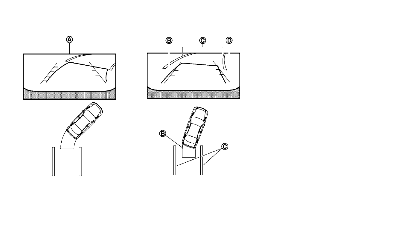
1. Visually check that the parking space is
safe before parking your vehicle.
2. The rear view of the vehicle is displayed
on the screen
䊊
A
when the shift lever is
moved to the R (Reverse) position.
3. Slowly back up the vehicle adjusting the
steering wheel so that the predicted
course lines
䊊
B
enter the parking space
䊊
C
.
4. Maneuver the steering wheel to make
the vehicle width guide lines
䊊
D
parallel
to the parking space
䊊
C
while referring
to the predicted course lines.
5. When the vehicle is parked in the space
completely, move the shift lever to the P
(Park) position and apply the parking
brake.
HOW TO SWITCH THE DISPLAY
With the power switch in the ON position,
press the CAMERA button or move the shift
lever to the R (Reverse) position to operate
the Intelligent Around View Monitor.
The Intelligent Around View Monitor dis-
plays different split screen views depend-
ing on the position of the shift lever. Press
the CAMERA button to switch between the
available views.
If the shift lever is in the R (Reverse) position,
the available views are:
• Rear view/bird’s-eye view split screen
• Rear view/front-side view split screen
4-20 Monitor, climate, audio, phone and voice recognition systems

• Full screen rear view
If the shift lever is in the P (Park) position, the
available views are:
• Front view/bird’s-eye view split screen
• Front view/front-side view split screen
If the shift lever is in the D (Drive) position,
the available views are:
• Front view/front bird’s-eye view split
screen
• Front view/front-side view split screen
The display will switch from the Intelligent
Around View Monitor screen when:
• The shift lever is in the D (Drive) position
and the vehicle speed increases above
approximately 6 mph (10 km/h).
• A different screen is selected.
ADJUSTING THE SCREEN
1. Touch the touch-screen display with the
Intelligent Around View Monitor on.
2. Touch the “Brightness,” “Contrast,” “Tint,”
“Color,” or “Black Level” key.
3. Adjust the item by touching the + or —
key on the touch-screen display.
NOTE:
Do not adjust any of the display set-
tings of the Intelligent Around View
Monitor while the vehicle is moving.
Make sure the parking brake is firmly
applied.
Monitor, climate, audio, phone and voice recognition systems 4-21

INTELLIGENT AROUND VIEW
MONITOR SYSTEM LIMITATIONS
WARNING
Listed below are the system limita-
tions for Intelligent Around View Moni-
tor. Failure to operate the vehicle in ac-
cordance with these system
limitations could result in serious in-
jury or death.
• Do not use the Intelligent Around
View Monitor with the outside mir-
rors in the stored position, and make
sure that the rear hatch is securely
closed when operating the vehicle
using the Intelligent Around View
Monitor.
• The apparent distance between ob-
jects viewed on the Intelligent
Around View Monitor differs from
the actual distance.
• The cameras are installed on the
front grille, the outside mirrors and
above the rear license plate. Do not
put anything on the vehicle that cov-
ers the cameras.
• When washing the vehicle with high
pressure water, be sure not to spray
it around the cameras. Otherwise,
water may enter the camera unit
causing water condensation on the
lens, a malfunction, fire or an electric
shock.
• Do not strike the cameras. They are
precision instruments. Doing so
could cause a malfunction or cause
damage resulting in a fire or an elec-
tric shock.
There are some areas where the system
will not show objects and the system does
not warn of moving objects. When in the
front or rear view display, an object below
the bumper or on the ground may not be
viewed
䊊
1
. When in the bird’s-eye view, a tall
object near the seam
䊊
2
of the camera
viewing areas will not appear in the moni-
tor.
The following are operating limitations and
do not represent a system malfunction:
• There may be a delay when switching be-
tween views.
• When the temperature is extremely high
or low, the screen may not display objects
clearly.
• When strong light directly shines on the
camera, objects may not be displayed
clearly.
• The screen may flicker under fluorescent
light.
4-22 Monitor, climate, audio, phone and voice recognition systems

• The colors of objects on the Intelligent
Around View Monitor may differ some-
what from the actual color of objects.
• Objects on the Intelligent Around View
Monitor may not be clear and the color of
the object may differ in a dark
environment.
• There may be differences in sharpness
between each camera view of the bird’s-
eye view.
• Do not use wax on the camera lens. Wipe
off any wax with a clean cloth that has
been dampened with a diluted mild clean-
ing agent, then wipe with a dry cloth.
System temporarily unavailable
When the “!” icon is displayed on the screen,
there are abnormal conditions in the
Around View® Monitor. This will not hinder
normal driving operation but the system
should be inspected. It is recommended
that you visit a NISSAN certified LEAF dealer
for this service.
When the “[X]” icon is displayed on the
screen, the camera image may be receiv-
ing temporary electronic disturbances
from surrounding devices. This will not hin-
der normal driving operation but the sys-
tem should be inspected if it occurs fre-
quently. It is recommended that you visit a
NISSAN certified LEAF dealer for this
service.
Monitor, climate, audio, phone and voice recognition systems 4-23

SYSTEM MAINTENANCE
CAUTION
• Do not use alcohol, benzine or thin-
ner to clean the camera. This will
cause discoloration.
• Do not damage the cameras as the
monitor screen may be adversely af-
fected.
If dirt, rain or snow accumulates on any of
the cameras
䊊
1
, the Intelligent Around
View Monitor may not display objects
clearly. Clean the camera by wiping with a
cloth dampened with a diluted mild clean-
ing agent and then wiping with a dry cloth.
4-24 Monitor, climate, audio, phone and voice recognition systems

1. CAMERA button
WARNING
• Failure to follow the warnings and
instructions for proper use of the
Moving object Detection (MOD) sys-
tem could result in serious injury or
death.
• The MOD system is not a substitute
for proper vehicle operation and is
not de-signed to prevent contact
with objects surrounding the ve-
hicle. When maneuvering, always
use the outside mirrors and rear-
view mirror and turn and check the
surroundings to ensure it is safe to
maneuver.
MOVING OBJECT DETECTION (IF SO
EQUIPPED)
Monitor, climate, audio, phone and voice recognition systems 4-25

• The system is deactivated at speeds
above 5 mph (8 km/h). It is reacti-
vated at lower speeds.
• The MOD system is not designed to
detect surrounding stationary ob-
jects.
The MOD system can inform the driver of
moving objects near the vehicle when
backing out of garages, maneuvering in
parking lots and in other such instances.
The MOD system detects moving objects
by using image processing technology on
the image shown in the display.
MOD SYSTEM OPERATION
The MOD system will turn on automatically
under the following conditions:
• When the shift lever is in the R (Reverse)
position.
• When vehicle speed decreases below ap-
proximately 5 mph (8 km/h) and the cam-
era screen is displayed.
Front and bird’s-eye views
Rear and bird’s-eye views
Rear and front-side views
Rear-wide view
4-26 Monitor, climate, audio, phone and voice recognition systems

The MOD system operates in the following
conditions when the camera view is dis-
played:
• When the shift lever is in the P (Park) or N
(Neutral) position and the vehicle is
stopped, the MOD system detects moving
objects in the bird’s-eye view. The MOD
system will not operate if the outside mir-
rors are moving in or out, in the stowed
position, or if either front door is opened.
• When the shift lever is in the D (Drive) po-
sition and the vehicle speed is below ap-
proximately 5 mph (8 km/h), the MOD sys-
tem detects moving objects in the front
view.
• When the shift lever is in the R (Reverse)
position and the vehicle speed is below
approximately 5 mph (8 km/h), the MOD
system detects moving objects in the rear
view. The MOD system will not operate if
the rear hatch is open.
The MOD system does not detect moving
objects in the front-side view. The MOD
icon is not displayed on the screen when in
this view.
When the MOD system detects moving ob-
jects near the vehicle, a chime will be heard
and a yellow frame will be displayed on the
view where the objects are detected. While
the MOD system continues to detect mov-
ing objects, the yellow frame continues to
be displayed.
NOTE:
While the Rear Cross Traffic Alert chime
(if so equipped) is beeping, the MOD sys-
tem does not chime.
In the bird’s-eye view, the yellow frame
䊊
1
is
displayed on each camera image (front,
rear, right, left) depending on where mov-
ing objects are detected.
The yellow frame
䊊
2
is displayed on each
view in the front view and rear view modes.
A blue MOD icon
䊊
3
is displayed in the view
where the MOD system is operative. A gray
MOD icon is displayed in the view where the
MOD system is not operative.
If the MOD system is turned off, the MOD
icon
䊊
3
is not displayed.
TURNING MOD ON AND OFF
Some vehicles include the option to allow
the MOD system to be turned on or off in
the vehicle information display.
To turn the MOD system on or off:
1. Using either the
or menu con-
trol switch on the steering wheel to se-
lect “Settings” and press the OK button.
2. Select “Driver Assistance” and press the
OK button.
3. Select “Parking Aids” and press the OK
button.
4. Toggle ON or OFF “Moving Object” using
the OK button.
MOD SYSTEM LIMITATIONS
WARNING
Listed below are the system limita-
tions for MOD. Failure to operate the
vehicle in accordance with these sys-
tem limitations could result in serious
injury or death.
• Do not use the MOD system when
towing a trailer. The system may not
function properly.
• Excessive noise (for example, audio
system volume or open vehicle win-
dow) will interfere with the chime
sound, and it may not be heard.
Monitor, climate, audio, phone and voice recognition systems 4-27

• The MOD system performance will
be limited according to environmen-
tal conditions and surrounding ob-
jects such as:
– When there is low contrast be-
tween background and the mov-
ing objects.
– When there is a blinking source of
light.
– When strong light such as another
vehicle’s headlight or sunlight is
present.
– When camera orientation is not in
its usual position, such as when a
mirror is folded.
– When there is dirt, water drops or
snow on the camera lens.
– When the position of the moving
objects in the display is not
changed.
• The MOD system might detect flow-
ing water droplets on the camera
lens, white smoke from the muffler,
moving shadows, etc.
• The MOD system may not function
properly depending on the speed,
direction, distance or shape of the
moving objects.
• If your vehicle sustains damage to
the parts where the camera is in-
stalled, leaving it misaligned or bent,
the sensing zone may be altered and
the MOD system may not detect ob-
jects properly.
• When the temperature is extremely
high or low, the screen may not dis-
play objects clearly. This is not a
malfunction.
NOTE:
The blue MOD icon will change to orange
if one of the following has occurred:
• When the system is malfunctioning.
• When the component temperature
reaches a high level (icon will blink).
If the icon light continues to illuminate
orange, have the MOD system checked.
It is recommended that you visit a
NISSAN certified LEAF dealer for this
service.
SYSTEM MAINTENANCE
CAUTION
• Do not use alcohol, benzine or thin-
ner to clean the camera. This will
cause discoloration.
• Do not damage the cameras as the
monitor screen may be adversely af-
fected.
If dirt, rain or snow accumulates on any of
the cameras
䊊
1
, the Intelligent Around
View Monitor may not display objects
clearly. Clean the camera by wiping with a
cloth dampened with a diluted mild clean-
ing agent and then wiping with a dry cloth.
4-28 Monitor, climate, audio, phone and voice recognition systems

Open/close the vents by moving the vent
slide in the appropriate direction.
: This symbol indicates that the vents
are closed.
: This symbol indicates that the vents
are open.
Adjust the air flow direction of the vents by
moving the vent slide (up/down) until the
desired position is achieved.
Side vent
Center Vent
VENTS
Monitor, climate, audio, phone and voice recognition systems 4-29
WARNING
• The air conditioning cooling func-
tion operates only when the power
switch is in the ON position or when
the READY to drive indicator light is
ON.
• Do not leave children or adults who
would normally require the assis-
tance of others alone in your vehicle.
Pets should also not be left alone.
They could accidentally injure them-
selves or others through inadver-
tent operation of the vehicle. Also,
on hot, sunny days, temperatures in
a closed vehicle could quickly be-
come high enough to causes severe
or possibly fatal injuries to people or
animals.
• Do not use the recirculation mode
for long periods as it may cause the
interior air to become stale and the
windows to fog up.
NOTE:
• Odors from inside and outside the ve-
hicle can build up in the air conditioner
unit. Odor can enter the passenger
compartment through the vents.
• When parking, set the heater or air con-
ditioner controls to turn off air recircu-
lation to allow fresh air into the passen-
ger compartment. This should help
reduce odors inside the vehicle.
The climate control system (air conditioner
and heater functions) can be operated
when the READY to drive indicator light is
illuminated. However, while charging, the
climate control system can be used when
the power switch is in the ON position.
The fan, heater and air conditioning can be
turned on manually, using the timer func-
tion and using the remote climate control
function.
These functions operate in the following
conditions.
Power switch position LOCK/OFF ACC ON READY to drive
Fan - - Available Available
Heater and air conditioner - - Available*1 Available
Timer (Climate Ctrl. Timer) Available Available - -
Remote control*2 Available Available - -
*1: The climate control system will only start when charging is being performed. After charging is complete, it will continue to operate if the EVSE (Electric Vehicle
Supply Equipment) is connected.
*2: Models with Navigation System.
HEATER AND AIR CONDITIONER
(AUTOMATIC)
4-30 Monitor, climate, audio, phone and voice recognition systems

NOTE:
• A series of operation sounds may be
heard immediately after climate con-
trol ON/OFF operation. This is not a mal-
function.
• Compressor and motor fan may sud-
denly start to operate during charging
operation. This is not a malfunction.
• Condensation forms inside the air con-
ditioning unit when the air conditioner
is running, and is safely discharged un-
derneath your vehicle. Traces of water
on the ground are therefore normal.
Water may drop underneath the vehicle
when climate control is operating.
DISPLAYING CLIMATE CONTROL SYSTEM
STATUS SCREEN (MODELS WITH NAVIGA-
TION SYSTEM)
Touch the Info key on the display screen,
then touch the “Climate Control and Audio”
key to display the climate control system
status on the display screen. For additional
information, please refer to the separate
LEAF Navigation System Owner’s Manual.
NOTE:
• If the READY to drive indicator light is
illuminated and the EVSE (Electric Ve-
hicle Supply Equipment) is connected
to the vehicle, the power switch will
change to the ON position. At the same
time, the climate control system will
stop operating. However, the fan will
continue to operate. If you want to turn
on climate control again, place the
power switch in the OFF position and
then place it in the ON position again
after confirming that the vehicle has
started charging.
• When the power switch is in the ON po-
sition, if the power supply from the EVSE
(Electric Vehicle Supply Equipment) is
interrupted due to an electrical outage,
etc., the system will operate in the fol-
lowing ways.
– If it occurs while charging is being
performed:
The climate control system will stop
once. If the power supply is restored
within approximately 5 minutes, the
climate control system will restart.
However, if more than 5 minutes
have elapsed, the climate control
system will not restart.
– If it occurs after charging has fin-
ished:
The climate control system will stop.
Monitor, climate, audio, phone and voice recognition systems 4-31
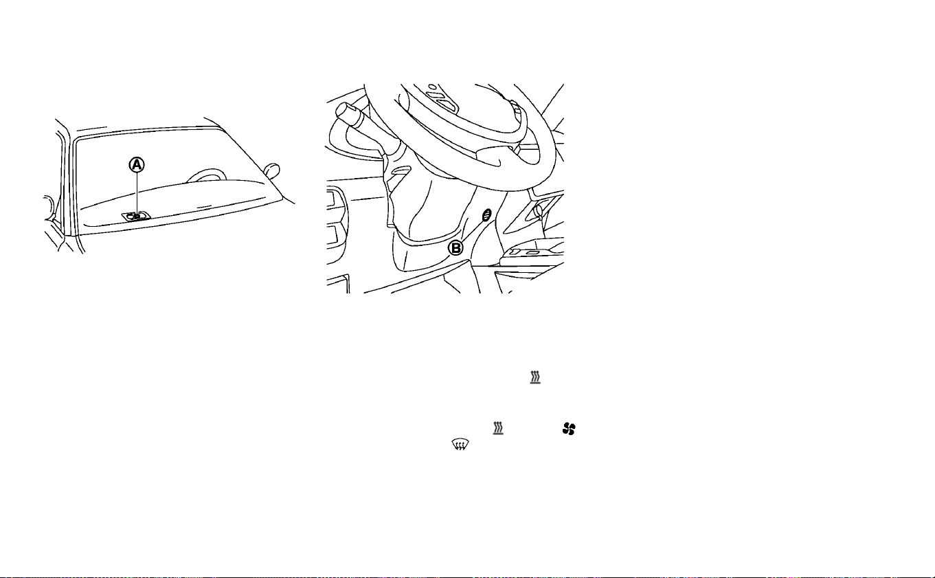
OPERATING TIPS
• The automatic climate control is
equipped with sensors as illustrated. The
sensors
䊊
A
and
䊊
B
help maintain a con-
stant temperature. Do not put anything
on or around these sensors.
•
Power consumption of the climate control
system varies depending on the outside
temperature and the temperature set for
the climate control system. Power con-
sumption increases if the interior tempera-
ture is cooled down too much in summer or
if it warmed up too much in winter. This will
result in a reduced driving range.
• Using the AUTO mode will help reduce the
power consumption of the climate
control.
• When the AUTO button is pressed, the
AUTO indicator illuminates. The
HEAT
button indicator and the A/C button indi-
cator lights turn off.
• If any of the MODE, A/C,
HEAT,
fan speed control,
front defroster is
pushed when the AUTO indicator illumi-
nates, the AUTO indicator will be turned
off.
• If the charge connector is connected to
the vehicle when it is in the READY to drive
mode and the air conditioner or heater is
on, the power switch automatically
changes to the ON position. The climate
control system automatically turns off the
heater or air conditioner and switches to
the air recirculation mode. Place the
power switch in the off position to begin
charging. Turn on the desired climate con-
trol function.
• For normal charge, the climate control
system is operative when charging opera-
tion is complete. For quick charge how-
ever, the climate control system stops op-
erating when charging operation stops.
• The climate control timer or remote cli-
mate control (for models with Navigation
System) may fog up windows depending
on the set temperature (for models with
Navigation System) or outside
temperature.
• When turning on the seat heater switch
prior to operating the climate control
timer or the remote climate control (for
models with Navigation System), the seat
heater will also turn on automatically
when the outside temperature is low.
4-32 Monitor, climate, audio, phone and voice recognition systems

IN-CABIN MICROFILTER
The climate control system is equipped
with an in-cabin microfilter which collects
dirt, dust etc. To make sure the air condi-
tioner heats defogs, and ventilates effi-
ciently, replace the filter regularly. To re-
place the filter, it is recommended that you
visit a NISSAN certified LEAF dealer.
The filter should be replaced if the air
flow decreases significantly or if win-
dows fog up easily when operating the
climate control system.
AUTOMATIC CLIMATE CONTROL
(MODELS WITHOUT NAVIGATION
SYSTEM)
1. fan speed control dial
2.
intake air control button
3.
front defroster button
4. Climate Ctrl. display
5.
Rear window and outside mirror
(if so equipped) defroster switch
6. Temperature control dial
7. AUTO climate control ON button
8. A/C (air conditioner) button
9. MODE (manual air flow control) button
Monitor, climate, audio, phone and voice recognition systems 4-33

10. HEAT button
11. Climate control system OFF button
Automatic operation (AUTO)
The AUTO mode may be used year-round
as the system automatically controls con-
stant temperature, air flow distribution and
fan speed.
1. Press the AUTO button. The AUTO indica-
tor will be illuminated.
2. Turn the temperature control dial to set
the desired temperature.
When any of the following functions are
operated, the AUTO indicator will turn off.
• The
HEAT or A/C button is pressed.
• The fan speed control or ventilator air flow
control is operated.
However, the functions that were not oper-
ated continue operating in AUTO mode.
NOTE:
• If the fan speed control dial, MODE
button, or
intake air control button
is operated while AUTO is in use, all the
other buttons operate in AUTO mode.
• While the AUTO indicator is illuminated,
electric power consumption of the air
conditioner can be economized com-
pared to the amount consumed while
the AUTO indicator is not illuminated.
The HEAT indicator light and the A/C indi-
cator light illuminates according to the op-
eration modes of the climate control sys-
tem.
Operation
mode
A/C
indicator
HEAT
indicator
Cooling
(HEAT off)
ON OFF
Heating (A/C
off)
OFF ON
Manual operation
The manual mode can be used to control
the heater and air conditioner to your de-
sired temperature.
The HEAT indicator light and the A/C indi-
cator light illuminates according to the op-
eration modes.
Operation
mode
A/C
indicator
HEAT
indicator
Cooling
(HEAT off)
ON OFF
Operation
mode
A/C
indicator
HEAT
indicator
Dehumidi-
fied heating
ON ON
Heating (A/C
off)
OFF ON
Ventilation OFF OFF
Cooling:
1. Press the A/C button to illuminate the
A/C indicator light.
2. Press the
HEAT button to turn off
the HEAT indicator light.
• Do not set the temperature higher than
the outside air temperature. Doing so may
prevent the temperature from being con-
trolled properly.
• A visible mist may be seen coming from
the ventilators in hot, humid conditions as
the air is cooled rapidly. This does not indi-
cate a malfunction.
Dehumidified heating:
1. Press the A/C button to illuminate the
A/C indicator light.
2. Press the
HEAT button to illuminate
the HEAT indicator light
4-34 Monitor, climate, audio, phone and voice recognition systems

NOTE:
Electric power consumption of climate
control increases while A/C button indi-
cator and
HEAT button indicator si-
multaneously illuminate. As a result, the
driving range may be decreased.
Heating (A/C off):
1. Press the
HEAT button to illuminate
the HEAT indicator light.
2. Press the A/C button to turn off the A/C
indicator light.
• Do not set temperature lower than the
outside air temperature. Doing so may
prevent the temperature from being con-
trolled properly.
• If the windows fog up, use dehumidified
heating instead of the A/C off heating.
Ventilation:
Press the
HEAT button and A/C but-
ton if the indicator lights are on so that
both indicator lights turn off.
NOTE:
• The ventilation mode requires a lower
power consumption, so cruising dis-
tance will increase.
• In ventilation mode, temperature is not
indicated on the air conditioner display.
Dehumidified defrosting/defogging:
Press the
front defroster button (the
indicator light will illuminate).
• To remove moisture or fog on the front
window quickly, set the temperature to
the high temperature and the fan speed
to their maximum level.
• After the windshield is cleared, press the
front defroster button again (the in-
dicator light will turn off).
• When the
front defroster button is
pressed, the air conditioner will automati-
cally turn on to defog the windshield. The
outside air recirculation mode will be se-
lected to improve the defogging
performance.
Fan speed control:
Turn the
fan speed control dial to
manually control the fan speed.
Press the AUTO button to change the fan
speed to the automatic mode.
Air flow control:
Press the MODE button to change the air
flow mode.
—
Air flows from the center and side
ventilators.
—
Air flows from the center and side
ventilators and foot outlets.
—
Air flows mainly from the foot
outlets.
—
Air flows from the defroster out-
lets and foot outlets.
—
Air flows from the defroster vents.
Temperature control:
Turn the temperature control dial to set the
desired temperature.
Recirculation:
Press the
intake air control button to
change the air circulation mode. When the
indicator light illuminates, the flowing air is
recirculated inside the vehicle.
When the outside temperature exceeds
70°F (21°C) the air conditioning system may
default to air recirculation mode automati-
cally to reduce overall power consumption.
Monitor, climate, audio, phone and voice recognition systems 4-35

To exit air recirculation mode, deselect the
air recirculation button (indicator will turn
off) to enter fresh mode.
Fresh air:
Press the
intake air control button to
change the air circulation mode. When the
indicator light does not illuminate, the flow-
ing air is drawn from outside the vehicle.
Automatic air intake control:
In the AUTO mode, the intake air will be
controlled automatically. When the outside
temperature exceeds 70°F (21°C), the air
conditioning system may default to air re-
circulation mode automatically to reduce
overall power consumption.
To set the automatic control mode, press
and hold the
intake air control button.
The indicator light will blink twice and the
inside/outside circulation will then be con-
trolled automatically. When in automatic
mode, the indicator light will come on when
inside air recirculation is active.
Rear window and outside mirror (if so
equipped) defroster switch:
For additional information, refer to “Rear
window and outside mirror (if so equipped)
defroster switch” in the “Instruments and
controls” section of this manual
To turn the system off
To turn off the climate control, press the
Climate control system OFF button. The
same operating mode (Heater or A/C) that
was active when the system is turned off is
active when system is turned back on.
4-36 Monitor, climate, audio, phone and voice recognition systems

AUTOMATIC CLIMATE CONTROL
(MODELS WITH NAVIGATION
SYSTEM)
1. Temperature control button
2.
HEAT button
3. Climate Ctrl. Timer indicator
4.
front defroster button
5.
fan speed control button
6.
Rear window and outside mirror
defroster switch
7.
intake air control button
8. Climate control system ON·OFF button
9. AUTO climate control ON button
10. MODE (manual air flow control) button
11. A/C (air conditioner) ON·OFF button
Automatic operation (AUTO)
The AUTO mode may be used year-round
as the system automatically controls con-
stant temperature, air flow distribution and
fan speed.
1. Press the AUTO button. The AUTO indica-
tor will be illuminated.
2. Press the temperature control button to
set the desired temperature.
When any of the following functions are
operated, the AUTO indicator will turn off.
• The
HEAT or A/C button is pressed.
• The fan speed control or ventilator air flow
control is operated.
However, the functions that were not oper-
ated continue operating in AUTO mode.
NOTE:
• If the fan speed control button,
MODE button, or
intake air control
button is operated while AUTO is in use,
all the other buttons operate in AUTO
mode.
Monitor, climate, audio, phone and voice recognition systems 4-37

• While the AUTO indicator is illuminated,
electric power consumption of the air
conditioner can be economized com-
pared to the amount consumed while
the AUTO indicator is not illuminated.
The HEAT indicator light and the A/C indi-
cator light illuminates according to the op-
eration modes of the climate control sys-
tem.
Operation
mode
A/C
indicator
HEAT
indicator
Cooling
(HEAT off)
ON OFF
Heating (A/C
off)
OFF ON
Manual operation
The manual mode can be used to control
the heater and air conditioner to your de-
sired temperature.
The HEAT indicator light and the A/C indi-
cator light illuminates according to the op-
eration modes.
Operation
mode
A/C
indicator
HEAT
indicator
Cooling
(HEAT off)
ON OFF
Dehumidi-
fied heating
ON ON
Heating (A/C
off)
OFF ON
Ventilation OFF OFF
Cooling:
1. Press the A/C button to illuminate the
A/C indicator light.
2. Press the
HEAT button to turn off
the HEAT indicator light.
• Do not set the temperature higher than
the outside air temperature. Doing so may
prevent the temperature from being con-
trolled properly.
• A visible mist may be seen coming from
the ventilators in hot, humid conditions as
the air is cooled rapidly. This does not indi-
cate a malfunction.
Dehumidified heating:
1. Press the A/C button to illuminate the
A/C indicator light.
2. Press the
HEAT button to illuminate
the HEAT indicator light
NOTE:
Electric power consumption of climate
control increases while A/C button indi-
cator and
HEAT button indicator si-
multaneously illuminate. As a result, the
driving range may be decreased.
Heating (A/C off):
1. Press the
HEAT button to illuminate
the HEAT indicator light.
2. Press the A/C button to turn off the A/C
indicator light.
• Do not set temperature lower than the
outside air temperature. Doing so may
prevent the temperature from being con-
trolled properly.
• If the windows fog up, use dehumidified
heating instead of the A/C off heating.
Ventilation:
Press the
HEAT button and A/C but-
ton if the indicator lights are on so that
both indicator lights turn off.
4-38 Monitor, climate, audio, phone and voice recognition systems

NOTE:
• The ventilation mode requires a lower
power consumption, so cruising dis-
tance will increase.
• In ventilation mode, temperature is not
indicated on the navigation monitor or
on the air conditioner display.
Dehumidified defrosting/defogging:
Press the
front defroster button (the
indicator light will illuminate).
• To remove moisture or fog on the front
window quickly, set the temperature to
the high temperature and the fan speed
to their maximum level.
• After the windshield is cleared, press the
front defroster button again (the in-
dicator light will turn off).
• When the
front defroster button is
pressed, the air conditioner and heater will
automatically turn on to defog the wind-
shield. The outside air recirculation mode
will be selected to improve the defogging
performance.
Fan speed control:
Press the
fan speed control button to
manually control the fan speed.
Press the AUTO button to change the fan
speed to the automatic mode.
Air flow control:
Press the MODE button to change the air
flow mode.
—
Air flows from the center and
side ventilators.
—
Air flows from the center and
side ventilators and foot outlets.
—
Air flows mainly from the foot
outlets.
—
Air flows from the defroster out-
lets and foot outlets.
—
Air flows from the defroster
vents.
Temperature control:
Press the temperature control buttons to
set the desired temperature.
Air recirculation:
Press the
intake air control button to
change the air circulation mode. When the
indicator light illuminates, the flowing air is
recirculated inside the vehicle.
When the outside temperature exceeds
70°F (21°C) the air conditioning system may
default to air recirculation mode automati-
cally to reduce overall power consumption.
To exit air recirculation mode, deselect the
air recirculation button (indicator will turn
off) to enter fresh mode.
Outside air circulation:
Press the
intake air control button to
change the air circulation mode. When the
indicator light does not illuminate, the flow-
ing air is drawn from outside the vehicle.
Automatic air intake control:
In the AUTO mode, the intake air will be
controlled automatically. When the outside
temperature exceeds 70°F (21°C), the air
conditioning system may default to air re-
circulation mode automatically to reduce
overall power consumption.
To set the automatic control mode, press
and hold the
intake air control button.
The indicator light will blink twice and the
inside/outside circulation will then be con-
trolled automatically. When in automatic
mode, the indicator light will come on when
inside air recirculation is active.
Monitor, climate, audio, phone and voice recognition systems 4-39
Rear window and outside mirror (if so
equipped) defroster switch:
For additional information, refer to “Rear
window and outside mirror (if so equipped)
defroster switch” in the “Instruments and
controls” section of this manual
To turn the system off
To turn off the climate control, press the
Climate control system ON·OFF button.
The same operating mode (Heater or A/C)
that was active when the system is turned
off is active when system is turned back on.
CLIMATE CTRL. TIMER
This function pre-heats or pre-cools the
passenger compartment of the vehicle to
the temperature before driving. This helps
reduce power consumption from the Li-ion
battery.
The Climate Ctrl. Timer operates the air
conditioner using power from the charger
or the Li-ion battery. While the charging
connector is connected to the vehicle,
electric power from the Li-ion battery is not
used.
The Climate Ctrl. Timer function allows two
timer settings.
Once the Climate Ctrl. Timer is set, it will
complete air conditioning by the time that
is set. It is not necessary to set the Climate
Ctrl. Timer every day.
*models with Navigation System
WARNING
Even if the Climate Ctrl. Timer is set, the
temperature in the passenger com-
partment may become high or low if
the system automatically stops. Do not
leave children or adults who would
normally require the support of others
alone in your vehicle. Pets should not
be left alone either. On hot, sunny days,
temperatures in a closed vehicle could
quickly become high enough to cause
severe or possibly fatal injuries to
people or animals. Also on cold days,
temperature in a vehicle could become
low enough to cause severe or pos-
sible fatal injuries to people or animals.
How to set Climate Ctrl. Timer
1. OK button
2.
button
3. Back button
4.
button
4-40 Monitor, climate, audio, phone and voice recognition systems

1. Push the
button to select “Set-
tings” on the vehicle information display.
2. Push the
button to select “EV
Settings” and then push the OK button.
3. Push the
button to select “Cli-
mate Ctrl. Timer1” or “Climate Ctrl.
Timer2” and then push the OK button.
4. Push the
button to select
“Timer” and then push the OK button
and turn on the setting. The indicator
light will turn on when the timer setting
is turned on.
5. Push the
button to select “De-
parture time” and then push the OK button.
6. Push the button to set “Hour”
and then push the OK button.
7. Push the
button to set “Minute”
and then push the OK button. The set-
ting can be changed with an increment
step of 10 minutes.
8. Push the
button to select “Cli-
mate Temperature” and then push the
OK button.
9. Push the
button to set Climate
Temperature and then push the OK
button.
10. * Push the
button to select
"Days" and then push the OK button.
The current day of the week is dis-
played with an underline.
Push the
button to select the
days of the week you wish to activate
the Climate Control system and then
push the OK button. The indicator light
of the selected button will turn on.
11. * After setting the day of the week, push
the Back button and return to the pre-
vious screen.
The set day of the week is lit in white.
12. After the setting is complete, place the
power switch in the OFF position, and
then connect the charge connector to
the vehicle.
* models with Navigation System
INFO
The Climate Ctrl. Timer does not activate if
the charge connector is not connected to
the vehicle. When the “Battery Operation
OK” is turned on and the charging connec-
tor is not connected to the vehicle, the Cli-
mate Ctrl. Timer will activate for 15 minutes.
When the outside temperature is high, the
interior temperature may not reach the set
temperature within the 15 minutes.
Turn "Battery Operation OK" to OFF when it
is not necessar y to operate air condition-
ing timer in order to prevent Li-ion battery
from discharging.
For models without Navigation System, the
Climate Ctrl. Timer operates repeatedly ev-
ery day once it is turned on.
Monitor, climate, audio, phone and voice recognition systems 4-41

Operating tips for using Climate
Ctrl. Timer
• The Climate Ctrl. Timer will only start when
the power switch is in the LOCK/OFF or
ACC position.
• To turn off the Climate Ctrl. Timer function,
turn off the “Climate Ctrl. Timer1” and "Cli-
mate Ctrl. Timer2" setting in the video in-
formation display using the
but-
ton on the steering wheel. The start and
stop time settings will not be deleted even
if the Climate Ctrl. Timer function is turned
off.
• While the Climate Ctrl. Timer is operating,
the Climate Ctrl. Timer indicator and the
charging status indicator lights flash. If the
Climate Ctrl. Timer is set to activate, the
Climate Ctrl. Timer indicator illuminates.*
• If the Climate Ctrl. Timer starts operating
while the vehicle is being charged, the
time required for charging will be longer.
• Operating the Climate Ctrl. Timer or re-
mote climate control in an environment
where the temperature is low may de-
crease the rate of battery charge.
• Timer setting can also be changed while
Climate Ctrl. Timer is operated. When the
power position is switched to OFF, the air
conditioner starts or enters waiting mode
depending on the new timer settings.
• When the difference in temperature be-
tween the air conditioner setting tem-
perature and the temperature outside the
vehicle is large, the temperature inside the
vehicle may not be maintained at the set-
ting temperature.
• The charging status indicator lights illumi-
nate in a specific pattern when the Li-ion
battery warmer operates. The charging
status indicator lights use the same pat-
tern to indicate 12–volt battery charging,
Climate Ctrl. Timer operation or Remote
Climate Control operation. The charging
status indicator lights do not change if the
Li-ion battery warmer operates at the
same time as the above features.
• The temperature in the passenger com-
partment may not be comfortable if en-
tering the vehicle too soon before or too
long after the scheduled time of
departure.
• Air conditioning is limited to the capacity
of the electric power when the charge
connector is connected. Therefore, the
temperature may not reach the set tem-
perature due to limitations in air condi-
tioning performance, if ambient tempera-
ture is excessively high or low, or if the
charge connector is connected to a 120–
volt plug outlet.
• The Climate Ctrl. Timer operates the cli-
mate control function so that a comfort-
able temperature is provided in the pas-
senger compartment at the scheduled
time of departure. The climate control is
set to stop at the scheduled time of
departure.
• Depending on the facilities of charging
station, there may be time when it is not
available for charging. Confirm the avail-
ability of the charging facility before set-
ting the Climate Ctrl. Timer. Be sure that
the power switch of the charger is turned
on when setting the Climate Ctrl. Timer.
• When the power switch is turned OFF af-
ter changing the setting, the new setting
will be applied.
*models with Navigation System
4-42 Monitor, climate, audio, phone and voice recognition systems

Remote climate control
This vehicle incorporates a communica-
tion device that is called a TCU (Telematics
Control Unit). The communication connec-
tion between this unit and Nissan Data
Center allows for various remote function
services.
Even when away from the vehicle, climate
control can be started by accessing the
Nissan Data Center website using a cellular
phone or a personal computer.
When operation is started, or at the set
start time, the Nissan Data Center ac-
cesses the vehicle. When the vehicle re-
ceives a command for remote operation,
the climate control immediately turns ON
and operates for the specified period of
time. Confirmation of the ON/OFF of the
climate control operation can be checked
by accessing the website or by e-mail.
Completing registration for the
NissanConnect® EV and Services is neces-
sary before using the service. For additional
information, refer to the separate LEAF
Navigation System Owner's Manual.
WARNING
• Radio waves could adversely affect
electric medical equipment. For ad-
ditional information, refer to your
electric medical equipment manu-
facturer for the possible effect on
pacemakers before using the re-
mote climate control.
• Even if the remote climate control is
set, the temperature in the passen-
ger room may become high if the
system automatically stops. Do not
leave children or adults who would
normally require the support of oth-
ers alone in your vehicle. Pets should
not be left alone either. On hot,
sunny days, temperatures in a
closed vehicle could quickly become
high enough to cause severe or pos-
sibly fatal injuries to people or ani-
mals.
NOTE:
• To check the Li-ion battery charging
status using an internet enabled smart
phone or personal computer.
– The vehicle must be located in a cel-
lular phone coverage area.
– The cellular phone must be located
in an area with cellular phone cover-
age.
– The computer must be connected to
the internet.
• Some cellular phones are not compat-
ible with this system and cannot be
used to check the Li-ion battery charg-
ing status. Confirm this beforehand.
Operating tips
• When the charge connector is connected,
the climate control operates using electric
power. When the charge connector is dis-
connected from the vehicle, the climate
control operates using vehicle battery
electric power.
• The climate control can be operated for a
maximum of 2 hours when the charge
connector is connected to the vehicle, or a
maximum of 15 minutes when the charge
connector is disconnected.
Monitor, climate, audio, phone and voice recognition systems 4-43

• The remote climate control will only start
to operate when the power switch is in the
LOCK/OFF or ACC position.
• Remote climate control operation is not
available when the vehicle is in an area of
cellular communication range.
• Communication becomes unavailable
when the vehicle is not used for two
weeks or more. When the power switch is
placed in the ON position, communication
with the Nissan Data Center can be
restored.
• Air conditioning is limited to the capacity
of the electric power when the charge
connector is connected to the vehicle.
Therefore, the temperature may not reach
a comfortable level due to performance of
the air conditioning being limited, if the
outside temperature is excessively high or
low, or if the charge connector is con-
nected to a 110 – 120-volt outlet.
• If the power switch is in the ON position or
the charge connector is disconnected,
while the remote climate control is being
operated, remote climate control opera-
tion is automatically stopped and an
e-mail is sent.
• If remote climate control operation is
started while the vehicle is in normal
charge mode, the climate control oper-
ates in climate control priority mode and
charging is continued.
• If remote climate control operation is
started and charging is stopped while the
vehicle is in quick charge mode, climate
control operation is also stopped.
• If the quick charge connector is con-
nected and charging is not performed, re-
mote climate control operation starts us-
ing the battery electric power of the
vehicle.
SERVICING CLIMATE CONTROL
The climate control system in your NISSAN
is charged with a refrigerant designed with
the environment in mind. This refrigerant
will not harm the earth’s ozone layer. Spe-
cial charging equipment and lubricant are
required when servicing your NISSAN cli-
mate control. Using improper refrigerants
or lubricants will cause severe damage to
your climate control system. For additional
information, refer to “Recommended
fluids/lubricants and capacities” in the
“Technical and consumer information” sec-
tion.
It is recommended that you visit a NISSAN
certified LEAF dealer to service your envi-
ronmentally friendly climate control
system.
4-44 Monitor, climate, audio, phone and voice recognition systems

RADIO
Push the power switch to the ACC or ON
position and press the radio band select
button to turn on the radio. If you listen to
the radio while the READY to drive indicator
light is off, the power switch should be
pushed to the ACC position.
Radio reception is affected by station sig-
nal strength, distance from radio transmit-
ter, buildings, bridges, mountains and other
external influences. Intermittent changes
in reception quality normally are caused by
these external influences.
Using a cellular phone in or near the ve-
hicle may influence radio reception qual-
ity.
Radio reception
Your NISSAN radio system is equipped with
state-of-the-art electronic circuits to en-
hance radio reception. These circuits are
designed to extend reception range, and to
enhance the quality of that reception.
However, there are some general charac-
teristics of both FM and AM radio signals
that can affect radio reception quality in a
moving vehicle, even when the finest
equipment is used. These characteristics
are completely normal in a given reception
area and do not indicate any malfunction
in your NISSAN radio system.
Reception conditions will constantly
change because of vehicle movement.
Buildings, terrain, signal distance and inter-
ference from other vehicles can work
against ideal reception. Described below
are some of the factors that can affect your
radio reception.
Some cellular phones or other devices may
cause interference or a buzzing noise to
come from the audio system speakers.
Storing the device in a different location
may reduce or eliminate the noise.
FM RADIO RECEPTION
Range: FM range is normally limited to 25 –
30 mi (40 – 48 km), with monaural (single
channel) FM having slightly more range
than stereo FM. External influences may
sometimes interfere with FM station re-
ception even if the FM station is within
25 mi (40 km). The strength of the FM signal
is directly related to the distance between
the transmitter and receiver. FM signals fol-
low a line-of-sight path, exhibiting many of
the same characteristics as light. For ex-
ample, they will reflect off objects.
AUDIO SYSTEM (MODELS WITHOUT
NAVIGATION SYSTEM)
Monitor, climate, audio, phone and voice recognition systems 4-45

Fade and drift: As your vehicle moves away
from a station transmitter, the signals will
tend to fade and/or drift.
Static and flutter: During signal interfer-
ence from buildings, large hills or due to
antenna position (usually in conjunction
with increased distance from the station
transmitter), static or flutter can be heard.
This can be reduced by adjusting the treble
control to reduce treble response.
Multipath reception: Because of the reflec-
tive characteristics of FM signals, direct and
reflected signals reach the receiver at the
same time. The signals may cancel each
other, resulting in momentary flutter or loss
of sound.
AM RADIO RECEPTION
AM signals, because of their low frequency,
can bend around objects and skip along
the ground. In addition, the signals can be
bounced off the ionosphere and bent back
to earth. Because of these characteristics,
AM signals are also subject to interference
as they travel from transmitter to receiver.
Fading: Occurs while the vehicle is passing
through freeway underpasses or in areas
with many tall buildings. It can also occur
for several seconds during ionospheric tur-
bulence even in areas where no obstacles
exist.
Static: Caused by thunderstorms, electrical
power lines, electric signs and even traffic
lights.
SATELLITE RADIO RECEPTION
When the satellite radio is used for the first
time or the battery has been replaced, the
satellite radio may not work properly. This
is not a malfunction. Wait more than
10 minutes with satellite radio ON and the
vehicle outside of any metal or large build-
ing for satellite radio to receive all of the
necessary data.
No satellite radio reception is available and
“NO SAT” is displayed when the SAT band
option is selected unless optional satellite
receiver and antenna are installed and a
SiriusXM® Satellite Radio service subscrip-
tion is active. Satellite radio is not available
in Alaska, Hawaii and Guam.
Satellite radio performance may be af-
fected if cargo carried on the roof blocks
the satellite radio signal.
If possible, do not put cargo over the satel-
lite antenna.
A build up of ice on the satellite radio an-
tenna can affect satellite radio perfor-
mance. Remove the ice to restore satellite
radio reception.
4-46 Monitor, climate, audio, phone and voice recognition systems
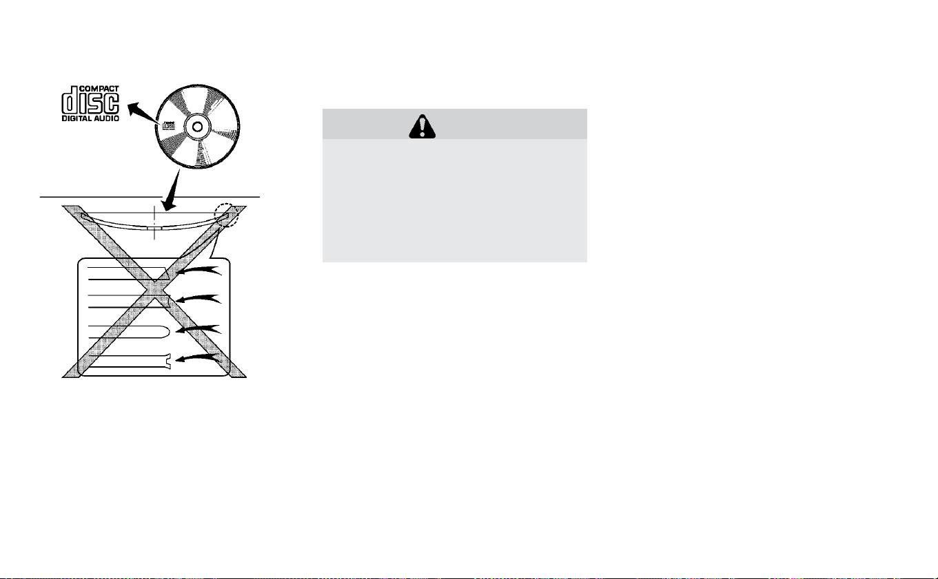
AUDIO OPERATION PRECAUTIONS
Compact disc (CD) player
CAUTION
• Do not force a compact disc into the
CD insert slot. This could damage
the CD and/or CD player.
• Trying to load a CD with the CD door
closed could damage the CD and/or
CD player.
• Only one CD can be loaded into the
CD player at a time.
• Only use high quality 4.7 in (12 cm)
round discs that have the “COMPACT
disc DIGITAL AUDIO” logo on the disc or
packaging.
• During cold weather or rainy days, the
player may malfunction due to the hu-
midity. If this occurs, remove the CD and
dehumidify or ventilate the player
completely.
• The player may skip while driving on
rough roads.
• The CD player sometimes cannot func-
tion when the compartment tempera-
ture is extremely high or low. Decrease/
increase the temperature before use.
• Do not expose the CD to direct sunlight.
• CDs that are in poor condition or are
dirty, scratched or covered with finger-
prints may not work properly.
• The following CDs may not work
properly.
– Copy control compact discs (CCCD)
– Recordable compact discs (CD-R)
– Rewritable compact discs (CD-RW)
• Do not use the following CDs as they
may cause the CD player to
malfunction:
– 3.1 in (8 cm) discs with an adapter
– CDs that are not round
– CDs with a paper label
– CDs that are warped, scratched, or
have abnormal edges
• This audio system can only play prere-
corded CDs. It has no capability to re-
cord or burn CDs.
• If the CD cannot be played, one of the
following messages will be displayed.
CHECK DISC:
• Confirm that the CD is inserted correctly
(the label side is facing up, etc.).
• Confirm that the CD is not bent or
warped and it is free of scratches.
Monitor, climate, audio, phone and voice recognition systems 4-47

PRESS EJECT:
This is an error due to excessive tem-
perature inside the player. Remove the
CD by pressing the EJECT button. After a
short time, reinsert the CD. The CD can be
played when the temperature of the
player returns to normal.
UNPLAYABLE:
The file is unplayable in this audio sys-
tem (only MP3 orWMA(if so equipped)
CD).
Compressed audio files
(MP3/WMA)
Terms
• MP3 — MP3 is short for Moving Pictures
Experts Group Audio Layer 3. MP3 is the
most well-known compressed digital au-
dio file format. This format allows for near
“CD quality” sound, but at a fraction of the
size of normal audio files. MP3 conversion
of an audio track from CD-ROM can re-
duce the file size by approximately a
10:1 ratio with virtually no perceptible loss
in quality. MP3 compression removes the
redundant and irrelevant parts of a sound
signal that the human ear doesn’t hear.
• WMA — Windows Media Audio (WMA)* is a
compressed audio format created by Mi-
crosoft as an alternative to MP3. The WMA
codec offers greater file compression
than the MP3 codec, enabling storage of
more digital audio tracks in the same
amount of space when compared to
MP3s at the same level of quality.
• Bit rate — Bit rate denotes the number of
bits per second used by a digital music file.
The size and quality of a compressed digi-
tal audio file is determined by the bit rate
used when encoding the file.
• Sampling frequency — Sampling fre-
quency is the rate at which the samples of
a signal are converted from analog to digi-
tal (A/D conversion) per second.
• Multisession — Multisession is one of the
methods for writing data to media. Writing
data once to the media is called a single
session, and writing more than once is
called a multisession.
• ID3/WMA Tag — The ID3/WMA tag is the
part of the encoded MP3 or WMA file that
contains information about the digital
music file such as song title, artist, encod-
ing bit rate, track time duration, etc. ID3 tag
information is displayed on the Artist/
song title line on the display.
* Windows® and Windows Media® are reg-
istered trademarks and trademarks in the
United States of America and other coun-
tries of Microsoft Corporation of the USA.
4-48 Monitor, climate, audio, phone and voice recognition systems
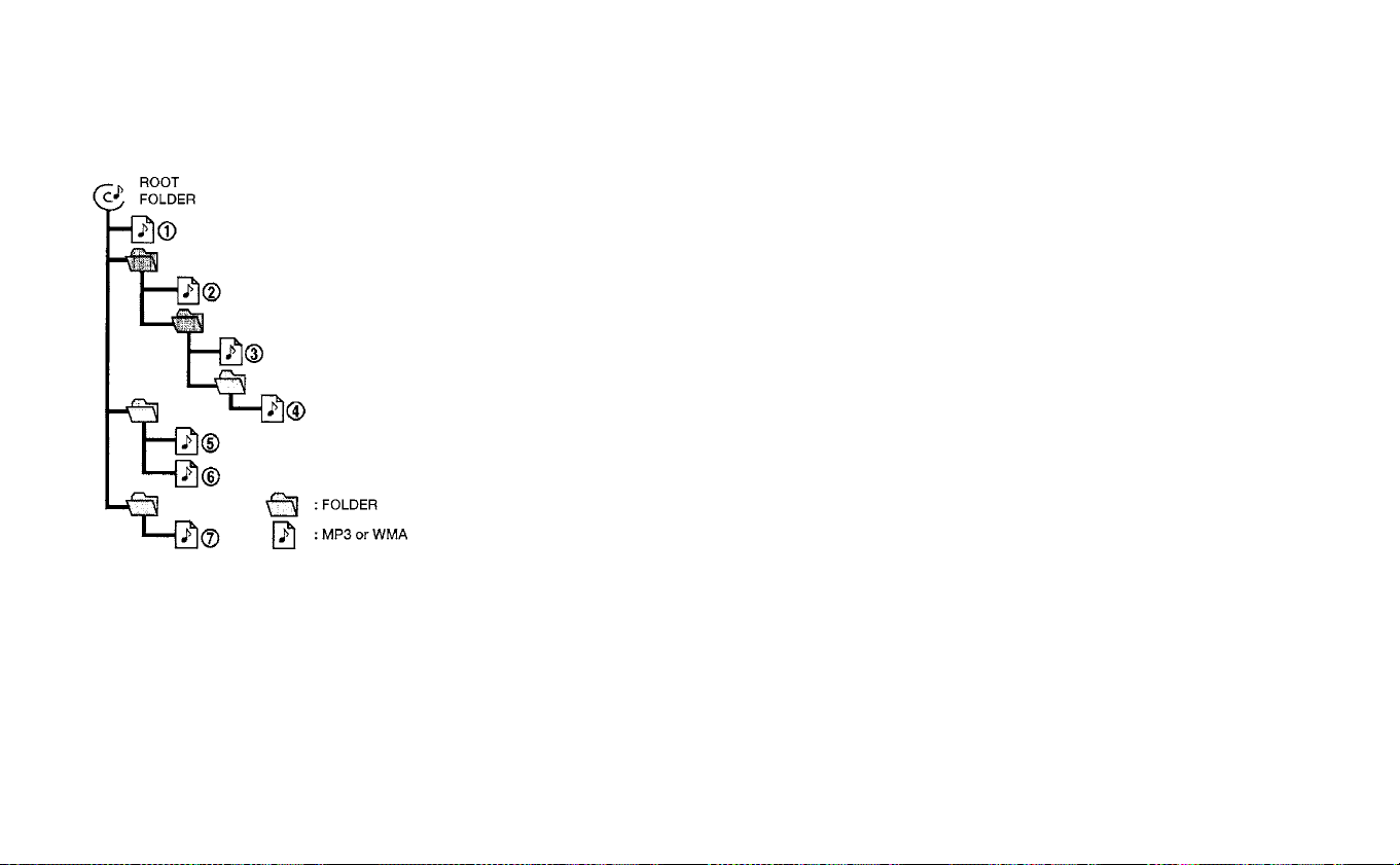
Playback order
Musical playback order of a CD with MP3 or
WMA files is as illustrated.
• The names of folders not containing
MP3 or WMA files are not shown in the
display.
• If there is a file in the top level of the disc,
“Root Folder” is displayed.
• The playback order is the order in which
the files were written by the writing soft-
ware. Therefore, the files might not play in
the desired order.
Playback order chart
Monitor, climate, audio, phone and voice recognition systems 4-49

Specification chart
Supported media CD, CD-R, CD-RW
Supported file systems
ISO9660 LEVEL1, ISO9660 LEVEL2, Apple ISO, Romeo, Joliet * ISO9660 Level 3 (packet writing) is not sup-
ported.
Supported versions*1
MP3
Version MPEG1, MPEG2, MPEG2.5
Sampling fre-
quency
8kHz-48kHz
Bit rate 32 kbps - 320 kbps, VBR
WMA
Version WMA7, WMA8, WMA9
Sampling fre-
quency
32 kHz - 48 kHz
Bit rate 32 kbps - 320 kbps, VBR
Tag information ID3 tag VER1.0, VER1.1, VER2.2, VER2.3 (MP3 only) VER2.4
Folder levels Folder levels: 8, Max folders: 255 (including root folder), Files: 999 (Max. 255 files for one folder)
Displayable character codes*2
01: ASCII, 02: ISO-8859-1, 03: UNICODE (UTF-16 BOM Big Endian), 04: UNICODE (UTF-16 Non-BOM Big En-
dian), 05: UNICODE (UTF-8)
*1 Files created with a combination of
48 kHz sampling frequency and 64 kbps bit
rate cannot be played.
*2 Available codes depend on what kind of
media, versions and information are going
to be displayed.
4-50 Monitor, climate, audio, phone and voice recognition systems

Troubleshooting guide
Symptom Cause and Countermeasure
Cannot play
Check if the disc was inserted correctly.
Check if the disc is scratched or dirty.
Check if there is condensation inside the player. If there is, wait until the condensation is gone (about 1 hour) before using
the player.
If there is a temperature increase error, the CD player will play correctly after it returns to the normal temperature.
If there is a mixture of music CD files (CD-DA data) and MP3/WMA files on a CD, only the music CD files (CD-DA data) will
be played.
Files with ex tensions other than “.MP3”,“.WMA”, “.mp3” or “.wma” cannot be played. In addition, the character codes and
number of characters for folder names and file names should be in compliance with the specifications.
Check if the finalization process, such as session close and disc close, is done for the disc.
Check if the disc is protected by copyright.
Poor sound quality
Check if the disc is scratched or dirty.
Bit rate may be too low.
It takes a relatively long time before
the music starts playing.
If there are many folders or file levels on the MP3/WMA disc, or if it is a multisession disc, some time may be required be-
fore the music starts playing.
Music cuts off or skips The writing software and hardware combination might not match, or the writing speed, writing depth, writing width, etc.,
might not match the specifications. Try using the slowest writing speed.
Skipping with high bit rate files Skipping may occur with large quantities of data, such as for high bit rate data.
Moves immediately to the next song
when playing
When a non-MP3/WMA file has been given an extension of “.MP3”, “.WMA”, .“mp3”or “.wma”, or when play is prohibited by
copyright protection, there will be approximately 5 seconds of no sound and then the player will skip to the next song.
Songs do not play back in the desired
order
The playback order is the order in which the files were written by the writing software. Therefore, the files might not play
in the desired order.
Monitor, climate, audio, phone and voice recognition systems 4-51

USB (Universal Serial Bus)
connection port
WARNING
Do not connect, disconnect or operate
the USB device while driving. Doing so
can be a distraction. If distracted you
could lose control of your vehicle and
cause an accident or serious injury.
CAUTION
• Do not force the USB device into the
USB port. Inserting the USB device
tilted or up-side-down into the port
may damage the port. Make sure
that the USB device is connected
correctly into the USB port.
• Do not grab the USB port cover (if so
equipped) when pulling the USB de-
vice out of the port. This could dam-
age the port and the cover.
• Do not leave the USB cable in a place
where it can be pulled unintention-
ally. Pulling the cable may damage
the port.
The vehicle is not equipped with a USB de-
vice. USB devices should be purchased
separately as necessary. This system can-
not be used to format USB devices. To for-
mat a USB device, use a personal com-
puter. In some states/area, the USB device
for the front seats plays only sound without
images for regulatory reasons, even when
the vehicle is parked.
This system supports various USB
memory devices, USB hard drives and
iPod® players. Some USB devices may not
be supported by this system.
Partitioned USB devices may not play cor-
rectly.
Some characters used in other languages
(Chinese, Japanese, etc.) may not appear
properly in the display. Using English lan-
guage characters with a USB device is rec-
ommended.
General notes for USB use:
For additional information refer to your de-
vice manufacturer’s owner information re-
garding the proper use and care of the
device.
Notes for iPod® use:
iPod® is a trademark of Apple Inc., regis-
tered in the U.S. and other countries.
• Improperly plugging in the iPod® may
cause a checkmark to be displayed on
and off (flickering). Always make sure that
the iPod® is connected properly.
• An iPod® nano (1st Generation) may re-
main in fast forward or rewind mode if it is
connected during a seek operation. In this
case, please manually reset the iPod®.
• An iPod® nano (2nd Generation) will con-
tinue to fast-forward or rewind if it is dis-
connected during a seek operation.
• An incorrect song title may appear when
the Play Mode is changed while using an
iPod® nano (2nd Generation).
• Audiobooks may not play in the same or-
der as they appear on an iPod®.
• Large video files cause slow responses in
an iPod®. The vehicle center display may
momentarily black out, but will soon
recover.
4-52 Monitor, climate, audio, phone and voice recognition systems

• If an iPod® automatically selects large
video files while in the shuffle mode, the
vehicle center display may momentarily
black out, but will soon recover.
Bluetooth® streaming audio
• Some Bluetooth® audio devices may not
be recognized by the in-vehicle audio
system.
• It is necessary to set up the wireless con-
nection between a compatible
Bluetooth® audio device and the in-
vehicle Bluetooth® module before using
the Bluetooth® audio.
• Operating procedure of the Bluetooth®
audio will vary depending on the devices.
Make sure how to operate your audio de-
vice before using it with this system.
• The Bluetooth® audio may be stopped
under the following conditions:
– Receiving a call on the Hands-Free
Phone System.
– Checking the connection to the hands-
free phone.
• Do not place the Bluetooth® audio device
in an area surrounded by metal or far
away from the in-vehicle Bluetooth® mod-
ule to prevent tone quality degradation
and wireless connection disruption.
• While an audio device is connected
through the Bluetooth® wireless connec-
tion, the battery power of the device may
discharge quicker than usual.
• This system supports the Bluetooth® Au-
dio Distribution Profile (A2DP, AVRCP).
BLUETOOTH® is a trademark
owned by Bluetooth SIG, Inc. and licensed
to Visteon.
Monitor, climate, audio, phone and voice recognition systems 4-53

FM/AM/SAT RADIO WITH
COMPACT DISC (CD) PLAYER
1. CD eject button
2. RPT (repeat) button
3. RDM (random) button
4. Display screen
5. SCAN button
6. SEEK/CAT button
7. iPod MENU button
8.
BACK button
9. ENTER/SETTING button / TUNE/
SCROLL knob
10. Station select (1–6) buttons
11.
(power) button /VOL (volume)
control knob
12. DISP button
13. MEDIA button
14. XM button*
15. FM·AM button
*No satellite radio reception is available
when the XM button is pressed to access
satellite radio stations unless optional sat-
ellite receiver and antenna are installed
and a SiriusXM® Satellite radio service sub-
scription is active, Satellite radio is not avail-
able in Alaska, Hawaii, and Guam.
For additional information, refer to “Audio
operation precautions” regarding all opera-
tion precautions in this section.
4-54 Monitor, climate, audio, phone and voice recognition systems

Audio main operation
(Power)/VOL (Volume) control knob
Place the power switch in the ACC or ON
position, and then press the
button
while the system is off to turn on the last
audio source, which was playing immedi-
ately before the system was turned off.
While the system is on, pressing the
button turns the system off.
Turn the VOL control knob to adjust the
volume.
This vehicle may be equipped with speed
sensitive volume. When this feature is ac-
tive, the audio volume changes as the driv-
ing speed changes.
ENTER/SETTING button
When the audio screen is displayed, press
the ENTER/SETTING button to show the
Settings screen on the display. Turn the
TUNE/SCROLL knob to navigate the op-
tions and then press the ENTER/SETTING
button to make a selection.
Monitor, climate, audio, phone and voice recognition systems 4-55

Audio
Bass Adjusts the bass to the desired level.
Treble Adjusts the treble to the desired level.
Balance Adjusts the balance to the desired level. Balance adjusts the sound level between the left and right
speakers.
Fade Adjusts the fade to the desired level. Fade adjusts the sound level between the front and rear
speakers.
Brightness Adjust the brightness to adjust the appearance of the display screen.
Contrast Adjust the contrast to adjust the appearance of the display screen.
Clock Adjust Allows the user to set time manually. To set the clock:
1. Press the ENTER/SETTING button.
2. Turn the TUNE/SCROLL knob to select CLOCK.
3. Press the ENTER/SETTING button.
4. Turn the TUNE/SCROLL knob to select “set time”.
5. Press the ENTER/SETTING button.
6. Rotate the TUNE/SCROLL knob to adjust hours.
7. Press the ENTER/SETTING button.
8. Turn the TUNE/SCROLL knob to adjust minutes.
9. Press the ENTER/SETTING button.
10. Press the
BACK button to finish.
On-Screen Clock Toggles ON or OFF the clock display on the upper right corner of the display screen.
RDS Display Toggles ON or OFF the RDS information displayed on the screen while the radio is playing.
Speed Sens Vol. (Speed Sensitive Volume) Adjusts the speed sensitive volume function, which increases the volume of the audio system as
the speed of the vehicle increases. Set to “OFF” to disable the feature. The higher the setting, the
more the volume increases in relation to vehicle speed.
AUX Vol. Choose a setting from 0 to +3 to control the boost of incoming auxiliar y device volume. A setting of
0 provides no additional boost in volume. A setting of +3 provides the greatest boost in volume.
Language Select Select the desired language for the system from the available options.
4-56 Monitor, climate, audio, phone and voice recognition systems

Bass, treble, balance and fade can also be
adjusted by pressing the ENTER/SETTING
button and turning the TUNE/SCROLL con-
trol knob to select the item to adjust. When
the desired item is shown on the display,
turn the tuning to adjust and then press
the ENTER/SETTING button until the dis-
play returns to the main audio screen. If the
button is not pressed for approximately
10 seconds, the radio or CD display will au-
tomatically reappear.
DISP button
Display of the screen can be canceled by
pressing the DISP button. You can then lis-
ten to music that is being played back. If
you want to display the screen again, either
press the DISP button once more or press
the FM·AM, XM Satellite Radio or CD·AUX
button.
MEDIA button
Pressing the MEDIA button will switch the
displays as follows:
iPod®/USB→Bluetooth
Audio→AUX→CD→iPod®/USB
BACK button
When the BACK button is pressed, it returns
to the previous display.
iPod MENU button
Press the iPod MENU button while the
iPod® is connected to show the iPod® op-
eration menu on the audio display. Scroll
through the menu list using the TUNE/
SCROLL knob. Press the ENTER/SETTING
button to select a menu item.
For additional information, refer to the
iPod® Owner’s Manual.
FM/AM/SAT radio operation
FM∙AM band select
Pressing the radio band select button will
change the band as follows:
AM→FM1→FM2→AM
XM band select
Pressing the XM band select button will
change the band as follows:
XM1→XM2→XM3→XM1
When the XM band select button is pressed
while the power switch is in the ACC or ON
position, the radio will come on at the
channel last played.
The last station played will also come on
when the
button is pressed to radio
ON.
*When the XM button is pressed, the satel-
lite radio mode will be skipped unless a
SiriusXM® Satellite Radio service subscrip-
tion is active. Satellite radio is not available
in Alaska, Hawaii and Guam.
If a compact disc is playing when the XM
button is pressed, the compact disc will
automatically be turned off and the last
radio station played will come on.
TUNE/SCROLL knob (Tuning)
Turn the TUNE/SCROLL knob to the left or
right for manual tuning.
SEEK tuning
Press the SEEK/CAT
or button or
to tune from low to high or high to low
frequencies and to stop at the next broad-
casting station.
SCAN tuning
Press the SCAN button to stop at each
broadcasting station for 5 seconds. SCAN
will appear on the screen while the radio is
scan tuning.
Monitor, climate, audio, phone and voice recognition systems 4-57

Pressing the button again during this
5 second period will stop SCAN tuning and
the radio will remain tuned to that station. If
the SCAN button is not pressed within
5 seconds, SCAN tuning moves to the next
station.
1 to 6 Station memory operations
Six stations can be set for the AM band.
Twelve stations can be set for the FM band
(6 for FM1, 6 for FM2). Eighteen channels can
be set for the satellite radio (6 for XM1, 6 for
XM2, 6 for XM3).
1. Choose the radio band AM, FM1 or
FM2 using the FM·AM select button, or
choose the satellite band XM1, XM2 or
XM3 using the XM button.
2. Tune to the desired station using
manual, SEEK or SCAN tuning. Press and
hold any of the desired station memory
buttons (1 – 6) until the preset number is
updated on the display and the sound is
briefly muted.
3. The channel indicator will then come on
and the sound will resume. Program-
ming is now complete.
4. Other buttons can be set in the same
manner.
If the battery cable is disconnected, or if the
fuse opens, the radio memory will be can-
celed. In that case, reset the desired sta-
tions.
Compact disc (CD) player
operation
Place the power switch in the ACC or ON
position and insert the Compact Disc (CD)
into the slot with the label side facing up.
The CD will be guided automatically into
the slot and start playing.
After loading the CD, the number of tracks
on the CD and the play time will appear on
the display.
If the radio is already operating, it will auto-
matically turn off and the CD will play.
If the system has been turned off while the
CD was playing, pressing the
(power)
button will start the CD.
Do not use 3.1 in (8 cm) discs.
SEEK/CAT buttons
When the FF or REW button is pressed for
more than 1.5 seconds while the CD is be-
ing played, the CD will play while fast for-
warding or rewinding. When the button is
released, the CD will return to normal play
speed.
When the FF or REW button is pressed for
less than 1.5 seconds while the CD is being
played, the next track or the beginning of
the current track on the CD will be played.
Repeat (RPT)
When the RPT play button is pressed while
the CD is played, the play pattern can be
changed as follows:
(CD)
Normal↔1 Track Repeat
(CD with compressed audio files)
Normal→1 Folder Repeat→1 Track Repeat-
→Normal
4-58 Monitor, climate, audio, phone and voice recognition systems

Random (RDM)
When the RDM play button is pressed while
a CD is being played, the play pattern can
be changed as follows:
(CD)
Normal↔1 Disc Random
(CD with compressed audio files)
Normal→1 Disc Random→1 Folder Ran-
dom→Normal
CD eject
When the CD eject button is pressed with a
compact disc loaded, the CD will be
ejected.
When this button is pressed while the CD is
being played, the CD will be ejected.
If the CD comes out and is not removed, it
will be pulled back into the slot to protect it.
AUX IN jack
The AUX IN jack is located beneath the
heater and air conditioner controls. The
AUX IN audio jack accepts any standard
analog audio input such as from a portable
cassette tape/CD player, MP3 player or lap-
top computer.
MEDIA
With a CD loaded, press the MEDIA button
until the CD mode is displayed on the
screen. Pressing the MEDIA button repeat-
edly will maneuver through CD, USB,
Bluetooth® Audio and AUX modes.
CD/MP3 display mode
While listening to an MP3/WMA CD, certain
text may be displayed on the screen if the
CD has been encoded with the text infor-
mation. Depending on how the MP3/WMA
CD is encoded, information such as artist,
song and folder will be displayed.
The track number and total number of
tracks in the current folder or on the cur-
rent disc are displayed on the screen as
well.
TUNE/SCROLL knob (MP3/WMA CD only)
If a MP3/WMA CD with multiple folders is
playing, turn the TUNE/SCROLL knob to
change folders. Turn the knob to the left to
skip back a folder. Turn the knob to the right
to skip ahead a folder.
Additional features
For additional information about the iPod®
player available with this system, refer to
“iPod® player operation” in this section.
For additional information about the USB
(Universal Serial Bus) Connection Port
available with this system, refer to “USB
(Universal Serial Bus) Connection Port Op-
eration” in this section.
For additional information about the
Bluetooth® audio interface available with
this system, refer to “Bluetooth® streaming
audio” in this section.
Monitor, climate, audio, phone and voice recognition systems 4-59
USB (UNIVERSAL SERIAL BUS)
CONNECTION PORT
Connecting a device to the USB
(Universal Serial Bus) connection
port
WARNING
Do not connect, disconnect or operate
the USB device while driving. Doing so
can be a distraction. If distracted you
could lose control of your vehicle and
cause an accident or serious injury.
CAUTION
• Do not force the USB device into the
USB port. Inserting the USB device
tilted or up-side-down into the port
may damage the port. Make sure
that the USB device is connected
correctly into the USB port.
• Do not grab the USB port cover (if so
equipped) when pulling the USB de-
vice out of the port. This could dam-
age the port and the cover.
• Do not leave the USB cable in a place
where it can be pulled unintention-
ally. Pulling the cable my damage
the port.
For additional information, refer to your de-
vice manufacturer’s owner information re-
garding the proper use and care of the
device.
The USB connection port is located be-
neath the heater and air conditioner con-
trols. Insert the USB device into the port.
When a compatible storage device is
plugged into the port, compatible audio
files on the storage device can be played
through the vehicle’s audio system.
Audio file operation
MEDIA button
Place the power switch in the ON or ACC
position and press the MEDIA button to
switch to the USB input mode. If a CD is
playing or another audio source is plugged
in through the AUX input jack, the MEDIA
button toggles among four sources.
SEEK/CAT buttons
When the
or button is pressed
for more than 1.5 seconds while a USB
memory is being played, the USB memory
will play while fast forwarding or rewinding.
When the button is released, the USB
memory will return to normal play speed.
When the
or button is pressed
for less than 1.5 seconds while the USB
memory is being played, the next track or
the beginning of the current track on the
USB memory will be played.
The multi-function controller can also be
used to select tracks when the USB
memory is being played.
4-60 Monitor, climate, audio, phone and voice recognition systems

REPEAT (RPT)
When the RPT button is pressed while the
USB memory is being played, the play pat-
tern can be changed as follows:
To change the play mode, press the RPT
button repeatedly and the mode will
change as follows:
Normal→1 Folder Repeat→1 Track Repeat-
→Normal
RANDOM (RDM)
When the RDM button is pressed while a
USB memory device is being playing, the
play pattern can be changed as follows:
To change the play mode, press the RDM
button repeatedly and the mode will
change as follows:
Normal→All Random→1 Folder Random-
→Normal
TUNE/SCROLL knob
If there are multiple folders with audio files
on the USB device, turn the TUNE/SCROLL
knob to change folders. Turn the knob to
the left to skip back a folder. Turn the knob
to the right to skip ahead a folder. If there is
only one folder of audio files on the USB
device, turning the TUNE/SCROLL knob in
either direction will return to the first track
on the USB device.
BACK button
When the
BACK button is pressed, it
returns to the previous display.
IPOD® PLAYER OPERATION
Connecting iPod®
WARNING
Do not connect, disconnect or operate
the USB device while driving. Doing so
can be a distraction. If distracted you
could lose control of your vehicle and
cause an accident or serious injury.
Monitor, climate, audio, phone and voice recognition systems 4-61

CAUTION
• Do not force the USB device into the
USB port. Inserting the USB device
tilted or up-side-down into the port
may damage the port. Make sure
that the USB device is connected
correctly into the USB port.
• Do not grab the USB port cover (if so
equipped) when pulling the USB de-
vice out of the port. This could dam-
age the port and the cover.
• Do not leave the USB cable in a place
where it can be pulled unintention-
ally. Pulling the cable my damage
the port.
For additional information, refer to your de-
vice manufacturer’s owner information re-
garding the proper use and care of the
device.
To connect an iPod® to the vehicle so that
the iPod® can be controlled with the audio
system controls and display screen, use the
USB connection port located beneath the
heater and air conditioner controls. Connect
the iPod®-specific end of the cable to the
iPod® and the USB end of the cable to the
USB connection port on the vehicle. If your
iPod® supports charging via a USB connec-
tion, its batter y will be charged while con-
nected to the vehicle with the power switch
in the ACC or ON position.
While connected to the vehicle, the iPod®
can only be operated by the vehicle audio
controls.
To disconnect the iPod® from the vehicle,
remove the USB end of the cable from the
USB connection port on the vehicle, then
remove the cable from the iPod®.
*iPod® is a trademark of Apple Inc, regis-
tered in the U.S. and other countries.
Compatibility
The following models are available:
• Third generation iPhone® (Firmware ver-
sion IOS 2.1–4.2.1)
• Fourth generation iPhone® (Firmware ver-
sion IOS 4.0–6.1.3)
• Fifth generation iPhone® (firmware ver-
sion IOS6/6.0)
• Fifth generation iPod® (Firmware version
iOS 6.0.0–6. 1.4)
• First generation iPod Classic® (Firmware
version 1.1.1 or 2.0.1)
• Second generation iPod Classic® (Firm-
ware version 2.0.1)
• First generation iPod touch® (Firmware
version 1.1–2.2.1)
• Second generation iPod touch® (Firmware
version IOS 2.1.1–2.2.1)
• Third generation iPod touch® (Firmware
version IOS 3.1–3.1.3)
• Fourth generation iPod touch® (Firmware
version IOS 4.1–6.1.3)
• Fifth generation iPod touch® (Firmware
version IOS 6.0.0–6. 1.3)
• First generation iPod nano® (Firmware
version 1.3.1)
• Second generation iPod nano® (Firmware
version 1.1.3)
• Third generation iPod nano® (Firmware
version 1.0.0–1.1.3)
• Fourth generation iPod nano® (Firmware
version 1.0.2–1.0.4)
• Fifth generation iPod nano® (Firmware
version 1.0.1–1.0.2)
• Sixth generation iPod nano® (Firmware
version 1.0–1.2)
• Seventh generation iPod nano® (Firmware
version 1.0.0–1.0.1)
4-62 Monitor, climate, audio, phone and voice recognition systems

The iPod touch® may not respond quickly
with the system in some cases.
Make sure that the iPod® firmware is up-
dated.
Audio main operation
Place the power switch in the ACC or ON
position. Then, press the MEDIA button re-
peatedly to switch to the iPod® mode.
If the system has been turned off while the
iPod® was playing, pressing the
(power) button will start the iPod®.
iPod MENU button
Press the iPod MENU button while the
iPod® operation menu on the audio display.
Scroll through the menu list using the
TUNE/SCROLL knob. Press the ENTER but-
ton to select a menu item. Items in the
iPod® menu appear on the display in the
following order:
• Now playing
• Playlists
• Artists
• Albums
• Songs
• Podcasts
• Genres
• Composers
• Audiobooks
• Shuffle songs
For additional information about each iten,
refer to the iPod® Owner’s Manual.
MEDIA button
Place the power switch in the ACC or ON
position. Then, press the MEDIA button to
switch to the iPod® mode.
If another audio source is playing and the
iPod® is connected, pressing the MEDIA
button changes to the iPod® mode.
If the system has been turned off while the
iPod® was playing, pressing the
(power) button will start the iPod®.
When the MEDIA button is pressed while
the iPod® is connected, the interface for
iPod® operation is shown on the audio dis-
play. The items on the menu list can be
scrolled by turning the TUNE/SCROLL dial
while the iPod® is operational. To select an
item, press ENTER/SETTING. Items in the
iPod® menu appear on the display in the
following order:
• Now Playing
• Playlists
• Artists
• Albums
• Songs
• Podcasts
• Genres
• Composers
• Audiobooks
• Shuffle Songs
For additional information, refer to the
iPod® Owner’s Manual.
SEEK/CAT buttons
When the
or button is pressed
for more than 1.5 seconds while the iPod® is
playing, the iPod® will play while fast for-
warding or rewinding. When the button is
released , the iPod® will return to the nor-
mal play speed.
When the
or button is pressed
for less than 1.5 seconds while the iPod® is
playing, the next track or the beginning of
the current track on the iPod® will be
played.
Monitor, climate, audio, phone and voice recognition systems 4-63

REPEAT (RPT)
When the RPT play button is pressed while
a track is being played, the play pattern can
be changed as follows:
Repeat Off→1 Track Repeat→All Repeat-
→Repeat Off
RANDOM (RDM)
When the RDM play button is pressed while
a track is being played, the play pattern can
be changed as follows:
Shuffle Off→Track Shuffle→Album Shuffle-
→Shuffle Off
BACK button
When the
BACK button is pressed, it
returns to the previous display.
BLUETOOTH® STREAMING AUDIO
If you have a compatible Bluetooth® audio
device that is capable of playing audio files,
the device can be connected to the vehi-
cle’s audio system so that the audio files on
the device play through the vehicle’s
speakers. For additional information, refer
to “FM/AM/SAT radio with compact disc
(CD) player” in this section.
NOTE:
For additional information regarding
Bluetooth® Streaming Audio, refer to
the Cellular Phone Owner’s Manual.
Connecting Bluetooth® audio
To connect your Bluetooth® audio device
to the vehicle, follow the procedure below:
1. Press the ENTER/SETTING button.
2. Select “Bluetooth”.
3. Select “Add Phone”. This same screen
can be accessed to remove, replace or
select a different Bluetooth® device.
4. The system acknowledges the com-
mand and asks you to initiate connect-
ing from the phone handset. The con-
necting procedure of the cellular phone
varies according to each cellular phone
model. For additional information, refer
to the cellular phone’s Owner’s Manual.
You can also visit
www.nissanusa.com/bluetooth or
www.nissan.ca/bluetooth for instruc-
tions on connecting NISSAN-
recommended cellular phones.
Audio main operation:
To switch to the Bluetooth® audio mode,
press the MEDIA button repeatedly until the
Bluetooth® audio mode is displayed on the
screen. Use the vehicle audio controls or
the Bluetooth® device’s controls to play,
pause, skip or reverse tracks.
AUX DEVICE PLAYER OPERATION
The AUX input jack is located beneath the
heater and air conditioner controls. The
AUX input jack accepts any standard ana-
log audio input such as from a portable
cassette tape/CD player, MP3 player or lap-
top computer.
NISSAN strongly recommends using a ste-
reo mini plug when connecting your music
device to the audio system. Music may not
play properly when monaural cable is used.
To switch the AUX mode, press the MEDIA
button until the AUX mode is selected,
while the power switch is in the “ON” or
“ACC” position.
4-64 Monitor, climate, audio, phone and voice recognition systems

CD CARE AND CLEANING
• Handle a CD by its edges. Do not bend the
disc. Never touch the surface of the disc.
• Always place the discs in the storage case
when they are not being used.
• To clean a disc, wipe the sur face from the
center to the outer edge using a clean,
soft cloth. Do not wipe the disc using a
circular motion.
• Do not use a conventional record cleaner
or alcohol intended for industrial use.
• A new disc may be rough on the inner and
outer edges. Remove the rough edges by
rubbing the inner and outer edges with
the side of a pen or pencil as illustrated.
STEERING WHEEL SWITCH FOR
AUDIO CONTROL
The audio system can be operated using
the controls on the steering wheel.
1. Volume control switch
2.
Seek/Track switches
3. OK button
Volume control switch
Push the volume control switch to increase
or decrease the volume.
Monitor, climate, audio, phone and voice recognition systems 4-65

OK button
Push the OK button to cycle through audio
options both in the vehicle information dis-
play and on the display screen.
Seek/Track switches
AM and FM:
• Push or hold for less than 1.5 seconds to
increase or decrease the preset station.
• Push or hold for more than 1.5 seconds to
seek up or down to the next station.
XM:
• Push or hold for less than 1.5 seconds to
increase or decrease the preset station.
• Push or hold for more than 1.5 seconds to
go to the next or previous category.
iPod®:
• Push or hold for less than 1.5 seconds to
increase or decrease the track number.
• Push or hold for more than 1.5 seconds to
increase or decrease the folder number.
CD:
• Push or hold for less than 1.5 seconds to
increase or decrease the track number.
• Push or hold for more than 1.5 seconds to
increase or decrease the folder number (if
playing compressed audio files).
USB:
• Push or hold for less than 1.5 seconds to
increase or decrease the track number.
• Push or hold for more than 1.5 seconds to
increase or decrease the folder number.
The vehicle is equipped with a shark fin
antenna and an antenna pattern is printed
inside the rear window.
CAUTION
• Do not place metalized film near the
rear window glass or attach any
metal parts to it. This may cause
poor reception or noise.
• When cleaning the inside of the rear
window, be careful not to scratch or
damage the rear window antenna.
Lightly wipe along the antenna with
a dampened soft cloth.
ANTENNA
4-66 Monitor, climate, audio, phone and voice recognition systems

When installing a CB, ham radio or car
phone in your vehicle, be sure to observe
the following precautions; otherwise, the
new equipment may adversely affect the
EV control system and other electronic
parts.
WARNING
• A cellular phone should not be used
for any purpose while driving so full
attention may be given to vehicle
operation. Some jurisdictions pro-
hibit the use of cellular phones while
driving.
• If you must make a call while your
vehicle is in motion, the hands free
cellular phone operational mode is
highly recommended. Exercise ex-
treme caution at all times so full at-
tention may be given to vehicle op-
eration.
• If you are unable to devote full at-
tention to vehicle operation while
talking on the phone, pull off the
road to a safe location and stop your
vehicle.
CAUTION
• Keep the antenna as far away as
possible from the electronic control
modules.
• Keep the antenna wire more than
20 cm (8 in) away from the electronic
control system harnesses. Do not
route the antenna wire next to any
harness.
• Adjust the antenna standing-wave
ratio as recommended by the manu-
facturer.
• Connect the ground wire from the
CB radio chassis to the body.
• For additional information, it is rec-
ommended that you visit a NISSAN
certified LEAF dealer.
WARNING
• Use a phone after stopping your ve-
hicle in a safe location. If you have to
use a phone while driving, exercise
extreme caution at all times so full
attention may be given to vehicle
operation.
• If you are unable to devote full at-
tention to vehicle operation while
talking on the phone, pull off the
road to a safe location and stop your
vehicle.
CAUTION
To avoid draining the vehicle battery,
use a phone after the READY to drive
indicator light is on.
CAR PHONE OR CB RADIO
BLUETOOTH® HANDS-FREE PHONE
SYSTEM WITHOUT NAVIGATION
SYSTEM (IF SO EQUIPPED)
Monitor, climate, audio, phone and voice recognition systems 4-67

Your NISSAN is equipped with the
Bluetooth® Hands-Free Phone System. If
you have a compatible Bluetooth® enabled
cellular phone, you can set up the wireless
connection between your cellular phone
and the in-vehicle phone module. With
Bluetooth® wireless technology, you can
make or receive a hands-free telephone
call with your cellular phone in the vehicle.
Once your cellular phone is connected to
the in-vehicle phone module, no other
phone connecting procedure is required.
Your phone is automatically connected
with the in-vehicle phone module when
the power switch is placed in the ON posi-
tion with the previously connected cellular
phone turned on and carried in the vehicle.
NOTE:
Some devices require the user to accept
specific connections for certain features
(such as phonebook download). If your
phone does not connect automatically
to the system, consult the phone’s Own-
er’s Manual for details on device
operation.
You can connect up to five different
Bluetooth® cellular phones to the in-
vehicle phone module. However, you can
talk on only one cellular phone at a time.
Before using the Bluetooth® Hands-Free
Phone System, refer to the following notes:
• Set up the wireless connection between a
compatible cellular phone and the in-
vehicle phone module before using the
hands-free phone system.
• Some Bluetooth® enabled cellular phones
may not be recognized or work properly.
Please visit
www.nissanusa.com/bluetooth or
www.nissan.ca/bluetooth for a recom-
mended phone list and connecting
instructions.
• You will not be able to use a hands-free
phone under the following conditions:
– Your vehicle is outside of the cellular
service area.
– Your vehicle is in an area where it is
difficult to receive a cellular signal; such
as in a tunnel, in an underground park-
ing garage, near a tall building or in a
mountainous area.
– Your cellular phone is locked to prevent
it from being dialed.
4-68 Monitor, climate, audio, phone and voice recognition systems

• When the radio wave condition is not ideal
or ambient sound is too loud, it may be
difficult to hear the other person’s voice
during a call.
• Do not place the cellular phone in an area
surrounded by metal or far away from the
in-vehicle phone module to prevent tone
quality degradation and wireless connec-
tion disruption.
• While a cellular phone is connected
through the Bluetooth® wireless connec-
tion, the battery power of the cellular
phone may discharge quicker than usual.
The Bluetooth® Hands-Free Phone Sys-
tem cannot charge cellular phones.
• For additional information, refer to
“Troubleshooting guide” in this section.
You can also visit
www.nissanusa.com/bluetooth or
www.nissan.ca/bluetooth for trouble-
shooting help if the hands-free phone
system seems to be malfunctioning.
• Some cellular phones or other devices
may cause interference or a buzzing noise
to come from the audio system speakers.
Storing the device in a different location
may reduce or eliminate the noise.
• For additional information, refer to the cel-
lular phone Owner’s Manual regarding the
telephone charges, cellular phone an-
tenna and body, etc.
REGULATORY INFORMATION
FCC Regulatory information
CAUTION: To maintain compliance with
FCC’s RF exposure guidelines, use only the
supplied antenna. Unauthorized antenna,
modification, or attachments could dam-
age the transmitter and may violate FCC
regulations.
Operation is subject to the following two
conditions:
1. This device may not cause interference
and
2. this device must accept any interfer-
ence, including interference that may
cause undesired operation of the
device.
IC Regulatory information
• Operation is subject to the following two
conditions: (1) this device may not cause
interference, and (2) this device must ac-
cept any interference, including interfer-
ence that may cause undesired operation
of the device.
• This Class B digital apparatus meets all
requirements of the Canadian
Interference-Causing Equipment
Regulations.
BLUETOOTH® is a trademark
owned by Bluetooth SIG, Inc. and licensed
to Visteon.
USING THE SYSTEM
The NISSAN Voice Recognition system al-
lows hands-free operation of the
Bluetooth® Hands-Free Phone System.
If the vehicle is in motion, some commands
may not be available so full attention may
be given to vehicle operation.
Initialization
When the power switch is placed in the ON
position, NISSAN Voice Recognition is initial-
ized, which takes a few seconds. If the
button is pressed before the initialization
completes, the system will announce
“Hands-free phone system not ready” and
will not react to voice commands.
Monitor, climate, audio, phone and voice recognition systems 4-69

Operating tips
To get the best performance out of the
NISSAN Voice Recognition system, observe
the following:
• Keep the interior of the vehicle as quiet as
possible. Point all vents away from the mi-
crophone area and close the windows to
eliminate surrounding noises (traffic
noises, vibration sounds, etc.), which may
prevent the system from recognizing
voice commands correctly.
• Wait until the tone sounds before speak-
ing a command. Otherwise, the com-
mand will not be received properly.
• Start speaking a command within 5 sec-
onds after the tone sounds.
• Speak in a natural voice without pausing
between words.
Giving voice commands
To operate NISSAN Voice Recognition,
press and release the
button located
on the steering wheel. After the tone
sounds, speak a command.
The command given is picked up by the
microphone, and voice feedback is given
when the command is accepted.
• If you need to hear the available com-
mands for the current menu again, say
“Help” and the system will repeat them.
• If a command is not recognized, the sys-
tem announces, “Command not recog-
nized. Please try again.” Make sure the
command is said exactly as prompted by
the system and repeat the command in a
clear voice.
• If you want to go back to the previous
command, you can say “Go back” or “Cor-
rection” any time the system is waiting for
a response.
• You can cancel a command when the sys-
tem is waiting for a response by saying,
“Cancel” or “Quit.” The system announces
“Cancel” and ends the Voice Recognition
session. You can also press and hold the
button on the steering wheel for
5 seconds at any time to end the Voice
Recognition session. Whenever the Voice
Recognition session is canceled, a double
beep is played to indicate you have exited
the system.
• If you want to adjust the volume of the
voice feedback, press the volume control
switches (+ or -) on the steering wheel
while being provided with feedback. You
can also use the radio volume control
knob.
Voice Prompt Interrupt
In most cases you can interrupt the voice
feedback to speak the next command by
pressing the
button on the steering
wheel. After interrupting the system, wait
for a beep before speaking your command.
One Shot Call
To use the system faster, you may speak
the second level commands with the main
menu command on the main menu. For
example, press the
button and after
the tone say “Call Redial”.
CONTROL BUTTONS
The control buttons for the Bluetooth®
Hands-Free Phone System are located on
the steering wheel.
4-70 Monitor, climate, audio, phone and voice recognition systems

Phone/send
Press the button to initiate a Voice
Recognition session or answer an incom-
ing call.
You can also use the
button to inter-
rupt the system feedback and give a com-
mand at once. For additional information,
refer to “Voice commands” and “During a
call” in this section.
Phone/end
While the Voice Recognition system is ac-
tive, press and hold the
button for
5 seconds to quit the Voice Recognition
system at any time.
Tuning switch (left side)
While using the Voice Recognition system,
push the
or switch on the steer-
ing wheel to manually control the phone
system.
CONNECTING PROCEDURE
NOTE:
The connecting procedure must be per-
formed when the vehicle is stationary. If
the vehicle starts moving during the pro-
cedure, the procedure will be canceled.
1. Press the ENTER/SETTING button.
2. Use the TUNE/SCROLL knob to select
“Bluetooth” and then press the ENTER/
SETTING button.
Monitor, climate, audio, phone and voice recognition systems 4-71

Menu Item Result
Bluetooth ON/OFF Allows user to switch Bluetooth® on and off. Bluetooth® must be turned on in order to connect device.
On Turns Bluetooth® functionality on.
Off Turns Bluetooth® functionality off.
Add Phone or Device Upon pressing this button, a message with a PIN appears on the screen. Operate the Bluetooth® phone to
enter the PIN and complete the connection process.
Replace Phone Replace the phone currently connected to the system. This option allows the user to keep any voicetags
that were recorded using the previous phone if vehicle is equipped with voice recognition.
The connecting procedure varies accord-
ing to each phone. For additional informa-
tion, refer to the phone’s Owner’s Manual.
You can also visit
www.nissanusa.com/bluetooth or
www.nissan.ca/bluetooth or call the
NISSAN Consumer Affairs Department for
instructions on connecting recommended
cellular phones.
VOICE COMMANDS
Voice commands can be used to operate
the Bluetooth® Hands-Free Phone System.
Press the
button to bring up the
phone command menu. The available op-
tions are:
• Call
• Phonebook
• Recent Calls
• Messaging (if so equipped)
• Show Applications (if so equipped)
• Select Phone or Device
“Call”
For additional information, refer to “Making
a call” in this section.
“Phonebook”
The following commands are available un-
der “Phonebook”:
• (a name)
Say a name in the phonebook to bring
up a list of options for a list of options for
that phonebook entry. The system will
say the name it interpreted based on the
voice command provided. If the name is
incorrect, say “Correction” to hear an-
other name.
Once the correct phonebook entry is iden-
tified, say “Dial” to dial the number or “Send
Text” to send a text message to that num-
ber. Say “Record Name” to record a name
for the phonebook entry. Say “Delete Re-
cording” to delete a recorded name for the
phonebook entry.
• List Names
Speak this command to have the sys-
tem list the names in the phonebook
one by one alphabetically. Say “Dial” to
dial the number of the current name or
“Send Text” to send a text message to
that number. Say “Next Entry”, “Previous
Entry” or Help to move through the list
alphabetically. Say “Record Name” to re-
cord a name for the current phonebook
4-72 Monitor, climate, audio, phone and voice recognition systems

entry. Say “Delete Recording” to delete a
recorded name for the current phone-
book entry.
“Recent Calls”
The following commands are available un-
der “Recent Calls”:
• Incoming
Speak this command to list the last five
incoming calls to the vehicle. If the call is
from an entry in the phonebook, the
name will be displayed. Otherwise, the
phone number of the incoming call will
be displayed.
Say “Dial” to call the number or “Send Text”
to send a text message to that number.
Say “Next Entry”, “Previous Entry” or Help to
move through the list of incoming calls.
• Missed
Speak this command to list the last five
missed calls to the vehicle. If the call is
from an entry in the phonebook, the
name will be displayed. Otherwise, the
phone number of the missed call will be
displayed.
Say “Dial” to call the number or “Send Text”
to send a text message to that number.
Say “Next Entry”, “Previous Entry” or Help to
move through the list of missed calls.
• Outgoing
Speak this command to list the last five
outgoing calls from the vehicle. If the call
was to an entry in the phonebook, the
name will be displayed. Otherwise, the
phone number of the outgoing call will
be displayed.
Say “Dial” to call the number or “Send Text”
to send a text message to that number.
Say “Next Entry”, “Previous Entry” or Help to
move through the list of outgoing calls.
• Redial
Speak this command to call the last
number dialed.
• Call back
Speak this command to call the number
of the last incoming call to the vehicle.
“Messaging” (if so equipped)
Speak this command to access text mes-
saging functions. For additional informa-
tion, refer to “Text messaging” in this sec-
tion.
“Show Applications” (if so
equipped)
Speak this command to display list of
smartphone apps available.
“Select Phone or Device”
Speak this command to select a phone to
use from a list of those phones connected
to the vehicle.
MAKING A CALL
To make a call from a phone connected to
the vehicle’s Bluetooth® Hands-Free Phone
System:
1. Press the
button.
2. The system will prompt you for a com-
mand. Say “Call”.
3. Select one of the available voice com-
mands to continue:
• “(a name)” — Speak the name of a
phonebook entry to place a call to that
entry. The system will respond with the
name it interpreted from your com-
mand and will prompt you to confirm
that the name is correct. Say “Yes” to
initiate the call or “No” to hear another
name from the phonebook.
Monitor, climate, audio, phone and voice recognition systems 4-73

• “Number” — Speak this command to
place a call by inputting numbers.
• For 7- and 10-digit phone numbers,
speak the numbers. When finished, say
“Dial” to initiate the call. Say “Correction”
at any time in the process to correct a
misspoken or misinterpreted number.
• For phone numbers with more digits or
special characters, say “Special Num-
ber”, then speak the digits. Up to 24 dig-
its can be entered. Available special
characters are “star”, “pound”, “plus” and
“pause”. When finished, say “Dial” to initi-
ate the call. Say “Correction” at any time
in the process to correct a misspoken
or misinterpreted number or character.
• “Redial” — Speak this command to dial
the number of the last outgoing call.
The system will display “Redialing
<name/number>”. The name of the
phonebook entry will be displayed if it
available, otherwise the number being
redialed will be displayed.
• “Call Back” — Speak this command to
dial the number of the last incoming
call. The system will display “Calling
back <name/number>”. The name of
the phonebook entry will be displayed if
it available, otherwise the number be-
ing called back will be displayed.
RECEIVING A CALL
When a call is received by the phone con-
nected to the vehicle’s Bluetooth® Hands-
Free Phone System, the call information is
displayed on the control panel display.
Press the
button to accept the call.
Press the
button to reject the call.
DURING A CALL
When a call is active, press the button
to access additional options. Speak one of
the following commands.
• “Send” — Speak this command followed by
the digits to enter digits during the phone
call.
• “Mute On” or “Mute Off” — Speak the com-
mand to mute or unmute the system.
• “Transfer Call” — Speak this command to
transfer the call to the handset. To transfer
the call back from the handset to the
Bluetooth® Hands-Free Phone System,
press the
button and confirm when
prompted.
If supported by the phone, the Bluetooth®
Hands-Free Phone System allows for call
waiting functionality. If a call is received
while another call is already active, a mes-
sage will be displayed on the screen. Press
the
button to hold the active call and
switch to the second call. Press the
button to reject the second call.
While the second call is active, pressing the
button will allow the same com-
mands that are available during any calls
as well as two additional commands:
• “Switch Call” — Speak this command to
hold the second call and switch back to
the original call.
• “End Other Call” — Speak this command to
stay with the second call and end the
original call.
Press the
button to accept the call.
Press the
button to reject the call.
ENDING A CALL
To end an active call, press the button.
4-74 Monitor, climate, audio, phone and voice recognition systems

TEXT MESSAGING (IF SO
EQUIPPED)
WARNING
• Laws in some jurisdictions may re-
strict the use of “Text-to-Speech”.
Check local regulations before using
this feature.
• Laws in some jurisdictions may re-
strict the use of some of the applica-
tions and features, such as social
networking and texting. Check local
regulations for any requirements.
• Use the text messaging feature af-
ter stopping your vehicle in a safe
location. If you have to use the fea-
ture while driving, exercise extreme
caution at all times so full attention
may be given to vehicle operation.
• If you are unable to devote full at-
tention to vehicle operation while
using the text messaging feature,
pull off the road to a safe location
and stop your vehicle.
NOTE:
Many phones may require special
permission to enable text messaging.
Check the phone’s screen during
Bluetooth® pairing. For some phones,
you may need to enable ‘Notifica-
tions’ in the phone’s Bluetooth® menu
for text messages to appear on the
headunit. Please consult your phone’s
Owner’s manual. Text message inte-
gration requires that the phone sup-
port MAP (Message Access Profile) for
both receiving and sending text mes-
sages. Some phones may not support
all text messaging features. For addi-
tional information about compatibil-
ity, please visit
www.nissanusa.com/bluetooth or
www.nissan.ca/bluetooth, as well as
your device’s Owner’s manual.
The system allows for the sending and re-
ceiving of text messages through the ve-
hicle interface.
Sending a text message:
1. Press the
button on the steering
wheel.
2. Say “Phone” after the tone.
3. Say “Send Text” after the tone.
4. The system will provide a list of available
commands in order to determine the
recipient of the text message. Choose
from the following:
• (a name)
• Missed Calls
• Incoming Calls
• Outgoing Calls
For additional information, refer to
“Voice commands” in this section.
5. Once a recipient is chosen, the system
prompts for which message to send.
Five predefined messages are available
as well as three custom messages. To
choose one of the predefined mes-
sages, speak one of the following after
the tone:
• “Driving, can’t text”
• “Call me”
• “On my way”
Monitor, climate, audio, phone and voice recognition systems 4-75

• “Running late”
• “Custom message”
To send one of the custom messages,
say “Custom Messages”. If more than
one custom message is stored, the sys-
tem will prompt for the number of the
desired custom message. For addi-
tional information on setting and man-
aging custom text messages, refer to
“Bluetooth® settings” in this section.
Reading a received text message:
1. Press the
button on the steering
wheel.
2. Say “Messaging” after the tone.
3. Say “Read Text” after the tone.
The text message, sender and delivery
time are shown on the screen. Use the tun-
ing switch to scroll through all text mes-
sages if more than one are available. Press
the
button to exit the text message
screen. Press the
button to access the
following options for replying to the text
message:
• Call Back
Speak this command to call the sender
of the text message using the
Bluetooth® Hands-Free Phone System.
• Send Text
Speak this command to send a text
message response to the sender of the
text message.
• Read Text
Speak this command to read the text
message again.
• Previous Text
Speak this command to move to the
previous text message.
• Next Text
Speak this command to move to the
next text message.
NOTE:
Text messages are only displayed if
the vehicle speed is less than 5 mph
(8 km/h).
BLUETOOTH® SETTINGS
To access and adjust the settings for the
Bluetooth® Hands-Free Phone System:
1. Press the ENTER/SETTING button.
2. Use the TUNE/SCROLL knob to select
“Bluetooth” and then press the ENTER/
SETTING button:
• Bluetooth
Select “On” or “Off” to turn the vehicle’s
Bluetooth® system on or off.
• Add Phone or Device
For additional information, refer to “Con-
necting procedure” in this section.
4-76 Monitor, climate, audio, phone and voice recognition systems

• Delete Phone or Device
Select to delete a phone from the dis-
played list. The system will ask to confirm
before deleting the phone.
• Replace Phone
Select to replace a phone from the dis-
played list. When a selection is made, the
system will ask to confirm before pro-
ceeding. The recorded phonebook for
the phone being deleted will be saved as
long as the new phone’s phonebook is
the same as the old phone’s phonebook.
• Select Phone or Device
Select to connect to a previously con-
nected phone from the displayed list.
• Phonebook Download
Select to turn on or off the automatic
download of a connected phone’s
phonebook.
• Show Incoming Calls
Select “Driver Only” to have incoming call
information displayed only in the vehicle
information display. Select “Both” to have
incoming call information displayed in
both the vehicle information display and
the center display screen.
• Text Message (if so equipped)
Select to adjust the volume of the sound
that plays when a new text is received by
a phone connected to the Bluetooth®
Hands-Free Phone System. The setting
all the way to the left indicates that the
new text sound will be muted.
• Show Incoming Text (if so equipped)
Select “Driver Only” to have incoming
text messages displayed only in the ve-
hicle information display. Select “Both” to
have incoming text messages displayed
in both the vehicle information display
and the center display screen. Select
“None” to have no display of incoming
text messages.
• Edit Custom Messages (if so equipped)
Select to set a custom message that will
be available with the standard options
when sending a text message. To set a
custom message, send a text message
to your own phone number while the
phone is connected to the system. Three
custom messages can be set. Custom
messages can only be set while the ve-
hicle is stationary.
• Auto Reply (if so equipped)
Select to turn on or off the Auto Reply
function. When enabled, the vehicle will
automatically send a predefined text
message to the sender when a text
message is received while driving.
• Auto Reply Message
Select to choose the message that is
sent when the Auto Reply function is en-
abled. Choose from “I’m Driving” or one of
the three custom messages stored in
the system.
• Vehicle Signature On/Off
Select to choose whether or not the ve-
hicle signature is added to outgoing text
messages from the vehicle. This mes-
sage cannot be changed or customized.
MANUAL CONTROLS
While using the Voice Recognition system,
it is possible to select menu options by
using the steering wheel controls instead
of speaking voice commands. This can be
especially helpful if the noise of driving
makes it difficult for Voice Recognition sys-
tem to accurately interpret commands.
The manual control mode does not allow
Monitor, climate, audio, phone and voice recognition systems 4-77

dialing a phone number by digits. The user
may select an entry from the Phonebook
or Recent Calls lists. To re-activate Voice
Recognition, exit the manual control mode
by pressing and holding the PHONE/END
button. At the time, pressing the
PHONE/SEND
button will start the
Hands Free Phone System.
TROUBLESHOOTING GUIDE
The system should respond correctly to all
voice commands without difficulty. If prob-
lems are encountered, try the following so-
lutions.
Where the solutions are listed by number,
try each solution in turn, starting with num-
ber 1, until the problem is resolved.
Symptom Solution
System fails to interrupt the command
correctly.
1. Ensure that the command is valid. For additional information, refer to “Voice commands” in this section.
2. Ensure that the command is spoken after the tone.
3. Speak clearly without pausing between words and at a level appropriate to the ambient noise level in the vehicle.
4. Ensure that the ambient noise level is not excessive (for example, windows open or defroster on). NOTE: if it is too noisy
to use the phone, it is likely that the voice commands will not be recognized.
5. If more than one command was said at a time, try saying the commands separately.
6. If the system consistently fails to recognize commands, the voice training procedure should be carried out to improve
the recognition response for the speaker.
The system consistently selects the
wrong entry from the phone book.
1. Ensure that the phone book entry name requested matches what was originally stored. This can be confirmed by us-
ing the “List Names” command. For additional information, refer to “Phonebook” in this section.
2. Replace one of the names being confused with a new name.
3. Say First Name and Last Name of the desired contact to improve recognition.
4-78 Monitor, climate, audio, phone and voice recognition systems

5 Starting and driving
Precautions when starting and driving .......5-4
Tire Pressure Monitoring System (TPMS).....5-4
Avoiding collision and rollover............5-7
Off-roadrecovery ...................5-8
Rapid air pressure loss ................5-8
Drinking alcohol/drugs and driving ........5-9
Push-button power switch ...............5-10
NISSAN Intelligent Key® system ..........5-10
Operating range for EV start function ......5-10
Power switch operation ...............5-11
Power switch positions ...............5-12
Emergency EV shut off................5-12
NISSAN Intelligent Key® battery discharge . . .5-13
NISSAN Vehicle Immobilizer System .......5-13
Before starting the EV system .............5-14
Starting the EV system .................5-14
Driving the vehicle.....................5-15
Electric shift control system ............5-15
Parking brake........................5-19
Pedal type ........................5-19
Switch type (models with electronic parking
brake system) .....................5-20
e-Pedal system ......................5-22
e-Pedal system operation .............5-22
e-Pedal system limitations.............5-24
System malfunction .................5-25
Lane Departure Warning (LDW)
(if so equipped) ......................5-26
LDW system operation ...............5-26
How to enable/disable the LDW system . . . .5-27
LDW system limitations ...............5-27
System temporarily unavailable .........5-29
System malfunction .................5-30
System maintenance ................5-30
Intelligent Lane Intervention (I-LI) (if so
equipped) ..........................5-31
I-LI system operation ................5-32
How to enable/disable the I-LI system .....5-33
I-LI
system
limitations ................5-34
System temporarily unavailable .........5-35
System malfunction .................5-36
System maintenance ................5-36
Blind Spot Warning (BSW) (if so equipped) .....5-37
BSW system operation ...............5-38
How to enable/disable the BSW system . . . .5-39
BSW system limitations ...............5-40
BSW driving situations ................5-41

System temporarily unavailable .........5-44
System maintenance ................5-45
Rear Cross Traffic Alert (RCTA) (if so equipped) . .5-46
RCTA system operation ...............5-47
How to enable/disable the RCTA system . . .5-49
RCTA system limitations ..............5-50
System temporarily unavailable .........5-52
System maintenance ................5-52
Cruise control (if so equipped) ............5-54
Precautions on cruise control ...........5-54
Cruise control operations .............5-54
Intelligent Cruise Control (ICC) (for vehicles without
ProPILOT™ Assist) (if so equipped) ..........5-56
How to select the cruise control mode.....5-58
Vehicle-to-vehicle distance control mode. . .5-58
Vehicle-to-vehicle distance control mode
operation ........................5-59
Vehicle-to-vehicle distance control mode
switches .........................5-61
Vehicle-to-vehicle distance control mode
limitations........................5-67
System temporarily unavailable..........5-71
System maintenance ................5-73
Conventional (fixed speed) cruise control
mode ...........................5-74
ProPILOT™ Assist (if so equipped) ..........5-79
ProPILOT™ Assist system operation .......5-81
Turning the conventional (fixed speed) cruise
control mode on ...................5-84
Operating ProPILOT™ Assist ............5-85
How to enable/disable the Steering Assist . .5-89
Intelligent Cruise Control (ICC) (for vehicles with
ProPILOT™ Assist)...................5-90
Steering Assist.....................5-99
Conventional (fixed speed) cruise control
mode ..........................5-106
Automatic Emergency Braking (AEB) (if so
equipped) .........................5-110
AEB system operation................5-111
Turning the AEB system on/off..........5-112
AEB system limitations ...............5-113
System temporarily unavailable .........5-114
System malfunction.................5-115
System maintenance ................5-115

Automatic Emergency Braking (AEB) with
Pedestrian Detection (if so equipped) .......5-117
AEB with Pedestrian Detection system
operation........................5-118
Turning the AEB with Pedestrian Detection
system on/off ....................5-120
AEB with Pedestrian Detection system
limitations .......................5-120
System temporarily unavailable .........5-123
System malfunction ................5-124
System maintenance................5-124
Intelligent Driver Alertness (I-DA) (if so
equipped) .........................5-126
I-DA system operation ...............5-127
How to enable/disable the I-DA system . . .5-128
I-DA system limitations ..............5-128
Increasing power economy..............5-130
ECO drive report .....................5-131
Parking/parking on hills ................5-132
Power steering system.................5-133
Brake system .......................5-134
Brake precautions ..................5-134
Anti-lock Braking System (ABS) .........5-136
Vehicle Dynamic Control (VDC) system ......5-137
Chassis control ......................5-139
Intelligent Trace Control (I-TC) ..........5-139
Hill start assist system .................5-140
Cold weather driving ..................5-141
Freeing a frozen door lock .............5-141
Antifreeze........................5-141
12-volt battery .....................5-141
Draining of coolant water .............5-142
Tire equipment ....................5-142
Special winter equipment .............5-142
Driving on snow or ice ...............5-142
Freeing a frozen charge port lid .........5-143
Parking brake .....................5-143

WARNING
• Do not leave children or adults who
would normally require the support
of others alone in your vehicle. Pets
should not be left alone either. They
could accidentally injure themselves
or others through inadvertent op-
eration of the vehicle. Also, on hot,
sunny days, temperatures in a
closed vehicle could quickly become
high enough to cause severe or pos-
sibly fatal injuries to people or ani-
mals.
• Properly secure all cargo with ropes
or straps to help prevent it from slid-
ing or shifting. Do not place cargo
higher than the seatbacks. In a sud-
den stop or collision, unsecured
cargo could cause personal injury.
TIRE PRESSURE MONITORING
SYSTEM (TPMS)
Each tire, including the spare (if provided),
should be checked monthly when cold and
inflated to the inflation pressure recom-
mended by the vehicle manufacturer on
the vehicle placard or tire inflation pressure
label. (If your vehicle has tires of a different
size than the size indicated on the vehicle
placard or tire inflation pressure label, you
should determine the proper tire inflation
pressure for those tires.)
As an added safety feature, your vehicle
has been equipped with a Tire Pressure
Monitoring System (TPMS) that illuminates
a low tire pressure telltale when one or
more of your tires is significantly under-
inflated. Accordingly, when the low tire
pressure telltale illuminates, you should
stop and check your tires as soon as pos-
sible, and inflate them to the proper pres-
sure. Driving on a significantly under-
inflated tire causes the tire to overheat and
can lead to tire failure. Under-inflation also
reduces power efficiency and tire tread life,
and may affect the vehicle’s handling and
stopping ability.
Please note that the TPMS is not a substi-
tute for proper tire maintenance, and it is
the driver’s responsibility to maintain cor-
rect tire pressure, even if under-inflation
has not reached the level to trigger illumi-
nation of the TPMS low tire pressure telltale.
Your vehicle has also been equipped with a
TPMS malfunction indicator to indicate
when the system is not operating properly.
The TPMS malfunction indicator is com-
bined with the low tire pressure telltale.
When the system detects a malfunction,
the telltale will flash for approximately one
minute and then remain continuously illu-
minated. This sequence will continue upon
subsequent vehicle start-ups as long as
the malfunction exists. When the malfunc-
tion indicator is illuminated, the system
may not be able to detect or signal low tire
pressure as intended. TPMS malfunctions
may occur for a variety of reasons, includ-
ing the installation of replacement or alter-
nate tires or wheels on the vehicle that
prevent the TPMS from functioning prop-
erly. Always check the TPMS malfunction
telltale after replacing one or more tires or
wheels on your vehicle to ensure that the
replacement or alternate tires and wheels
allow the TPMS to continue to function
properly.
Additional information
• When replacing a wheel without the TPMS
such as the spare tire, the TPMS does not
monitor the tire pressure of the spare tire.
PRECAUTIONS WHEN STARTING AND
DRIVING
5-4 Starting and driving

• The TPMS will activate only when the ve-
hicle is driven at speeds above 16 mph
(25 km/h). Also, this system may not de-
tect a sudden drop in tire pressure (for
example, a flat tire while driving).
• The low tire pressure warning light does
not automatically turn off when the tire
pressure is adjusted. After the tire is in-
flated to the recommended pressure, the
vehicle must be driven at speeds above
16 mph (25 km/h) to activate the TPMS
and turn off the low tire pressure warning
light. Use a tire pressure gauge to check
the tire pressure.
• The “Tire Pressure Low - Add Air” warning
also appears on the vehicle information
display when the low tire pressure warn-
ing light is illuminated and low tire pres-
sure is detected. The “Tire Pressure Low -
Add Air” warning turns off when the low
tire pressure warning light turns off.
• The “Tire Pressure Low - Add Air” warning
appears each time the power switch is
placed in the ON position as long as the
low tire pressure warning light remains
illuminated.
• The “Tire Pressure Low - Add Air” warning
does not appear if the low tire pressure
warning light illuminates to indicate a
TPMS malfunction.
• Tire pressure rises and falls depending on
the heat caused by operation of the ve-
hicle and the outside temperature. Do not
reduce the tire pressure after driving be-
cause the tire pressure rises after driving.
Low outside temperature can lower the
temperature of the air inside the tire,
which can cause a lower tire inflation
pressure. This may cause the low tire
pressure warning light to illuminate. If the
warning light illuminates in low ambient
temperature, check the tire pressure for all
four tires.
• The pressure of all tires can also be
checked on the display screen. The order
of the tire pressure figures displayed on
the screen does not correspond with the
actual order of the tire position.
For additional information, refer to “Low tire
pressure warning light” in the “Instruments
and controls” section and “Tire Pressure
Monitoring System (TPMS)” in the “In case of
emergency” section of this manual.
WARNING
• Radio waves could adversely affect
electric medical equipment. Those
who use a pacemaker should con-
tact the electric medical equipment
manufacturer for the possible influ-
ences before use.
•If
the low tire pressure warning light
illuminates while driving, avoid sud-
den steering maneuvers or abrupt
braking, reduce vehicle speed, pull off
the road to a safe location and stop the
vehicle as soon as possible. Driving
with under-inflated tires may perma-
nently damage the tires and increase
the likelihood of tire failure. Serious ve-
hicle damage could occur and may
lead to an accident and could result in
serious personal injury. Check the tire
pressure for all four tires. Adjust the
tire pressure to the recommended
COLD tire pressure shown on the Tire
and Loading Information label to turn
the low tire pressure warning light off.
If the tire is flat, repair it as soon as
possible. (For additional information,
refer to “Flat tire” in the “In case of
emergency” section of this manual.)
Starting and driving 5-5

• When replacing a wheel without the
TPMS such as the spare tire, TPMS
will not function and the low tire
pressure warning light will flash for
approximately 1 minute. The light
will remain on after 1 minute. Have
your tires replaced and/or TPMS
system reset as soon as possible. It
is recommended that you visit a
NISSAN certified LEAF dealer for this
service.
• Replacing tires with those not origi-
nally specified by NISSAN could af-
fect the proper operation of the
TPMS.
• Do not inject any tire liquid or aero-
sol tire sealant into the tires, as this
may cause a malfunction of the tire
pressure sensors.
CAUTION
• The TPMS may not function properly
when the wheels are equipped with
tire chains or the wheels are buried
in snow.
• Do not place metalized film or any
metal parts (antenna, etc.) on the
windows. This may cause poor re-
ception of the signals from the tire
pressure sensors, and the TPMS will
not function properly.
Some devices and transmitters may tem-
porarily interfere with the operation of the
TPMS and cause the low tire pressure
warning light to illuminate. Some examples
are:
• Facilities or electric devices using similar
radio frequencies that are near the
vehicle.
• If a transmitter set to similar frequencies is
being used in or near the vehicle.
• If a computer (or similar equipment) or a
DC/AC converter is being used in or near
the vehicle.
The low tire pressure warning light may
illuminate in the following cases:
• If the vehicle is equipped with a wheel and
tire without TPMS.
• If the TPMS has been replaced and the ID
has not been registered.
• If the wheel is not originally specified by
NISSAN.
FCC Notice:
For USA:
This device complies with Part 15 of the
FCC Rules. Operation is subject to the fol-
lowing two conditions: (1) This device
may not cause harmful interference, and
(2) this device must accept any interfer-
ence received, including interference
that may cause undesired operation.
NOTE:
Changes or modifications not ex-
pressly approved by the party re-
sponsible for compliance could void
the user’s authority to operate the
equipment.
For Canada:
This device complies with Industry
Canada licence-exempt RSS standard(s).
Operation is subject to the following two
conditions: (1) this device may not cause
5-6 Starting and driving

interference, and (2) this device must ac-
cept any interference, including interfer-
ence that may cause undesired opera-
tion of the device.
TPMS with Easy-Fill Tire Alert
When tire pressure is low, the low tire pres-
sure warning light illuminates.
This vehicle provides visual and audible
signals to help you inflate the tires to the
recommended COLD tire pressure.
Vehicle set-up:
1. Park the vehicle in a safe and level place.
2. Apply the parking brake and push the P
(Park) position switch on the shift lever.
3. Place the power switch in the ON posi-
tion. Do not place in the READY to drive
mode.
Operation:
1. Add air to the tire.
2. After a few seconds, the hazard indica-
tors will start flashing.
3. When the designated pressure is
reached, the horn beeps once and the
hazard indicators stop flashing.
4. Perform the above steps for each tire.
• If the tire is over-inflated more than ap-
proximately 4 psi (30 kPa), the horn beeps
and the hazard indicators flash three
times. To correct the pressure, push the
core of the valve stem on the tire briefly to
release pressure. When the pressure
reaches the designated pressure, the
horn beeps once.
• If the hazard indicator does not flash
within approximately 15 seconds after
starting to inflate the tire, it indicates that
the Easy-Fill Tire Alert is not operating.
• The TPMS will not activate the Easy-Fill Tire
Alert under the following conditions:
– If there is interference from an external
device or transmitter.
– The air pressure from the inflation de-
vice is not sufficient to inflate the tire,
such as those using a power socket.
– If electrical equipment is being used in
or near the vehicle.
– There is a malfunction in the TPMS sys-
tem.
– There is a malfunction in the horn or
hazard indicators.
– If the Easy-Fill Tire Alert does not oper-
ate due to TPMS interference, move the
vehicle about 3 ft (1 m) backward or
forward and try again.
If the Easy-Fill Tire Alert is not working, use a
tire pressure gauge.
AVOIDING COLLISION AND
ROLLOVER
WARNING
Failure to operate this vehicle in a safe
and prudent manner may result in loss
of control or an accident.
Be alert and drive defensively at all times.
Obey all traffic regulations. Avoid excessive
speed, high speed cornering, or sudden
steering maneuvers because these driving
practices could cause you to lose control of
your vehicle. As with any vehicle, a loss of
control could result in a collision with
other vehicles or objects or cause the ve-
hicle to rollover, particularly if the loss of
control causes the vehicle to slide side-
ways. Be attentive at all times, and avoid
driving when tired. Never drive when under
Starting and driving 5-7

the influence of alcohol or drugs (including
prescription or over-the-counter drugs
which may cause drowsiness). Always
wear your seat belt as outlined in “Seat
belts” in the “Safety — Seats, seat belts and
supplemental restraint system” section of
this manual, and also instruct your passen-
gerstodoso.
Seat belts help reduce the risk of injury in
collisions and rollovers. In a rollover crash,
an unbelted or improperly belted person
is significantly more likely to be injured
or killed than a person properly wearing
a seat belt.
OFF-ROAD RECOVERY
While driving, the right side or left side
wheels may unintentionally leave the road
surface. If this occurs, maintain control of
the vehicle by following the procedure be-
low. Please note that this procedure is only
a general guide. The vehicle must be driven
as appropriate based on the conditions of
the vehicle, road and traffic.
1. Remain calm and do not overreact.
2. Do not apply the brakes.
3. Maintain a firm grip on the steering
wheel with both hands and try to hold a
straight course.
4. When appropriate, slowly release the ac-
celerator pedal to gradually slow the
vehicle.
5. If there is nothing in the way, steer the
vehicle to follow the road while the ve-
hicle speed is reduced. Do not attempt
to drive the vehicle back onto the road
surface until the vehicle speed is
reduced.
6. When it is safe to do so, gradually turn
the steering wheel until both tires return
to the road surface. When all tires are on
the road surface, steer the vehicle to
stay in the appropriate driving lane.
• If you decide that it is not safe to return
the vehicle to the road sur face based
on vehicle, road or traffic conditions,
gradually slow the vehicle to a stop in a
safe place off the road.
RAPID AIR PRESSURE LOSS
Rapid air pressure loss or a “blow-out” can
occur if the tire is punctured or is damaged
due to hitting a curb or pothole. Rapid air
pressure loss can also be caused by driving
on under-inflated tires.
Rapid air pressure loss can affect the han-
dling and stability of the vehicle, especially
at highway speeds.
Help prevent rapid air pressure loss by
maintaining the correct air pressure and
visually inspecting the tires for wear and
damage. For additional information, refer
to “Wheels and tires” in the “Maintenance
and do-it-yourself” section of this manual.
If a tire rapidly loses air pressure or “blows-
out” while driving, maintain control of the
vehicle by following the procedure below.
Please note that this procedure is only a
general guide. The vehicle must be driven
as appropriate based on the conditions of
the vehicle, road and traffic.
WARNING
The following actions can increase the
chance of losing control of the vehicle
if there is a sudden loss of tire air pres-
sure. Losing control of the vehicle may
cause a collision and result in personal
injury.
5-8 Starting and driving
• The vehicle generally moves or pulls
in the direction of the flat tire.
• Do not rapidly apply the brakes.
• Do not rapidly release the accelera-
tor pedal.
• Do not rapidly turn the steering
wheel.
1. Remain calm and do not overreact.
2. Maintain a firm grip on the steering
wheel with both hands and try to hold a
straight course.
3. When appropriate, slowly release the ac-
celerator pedal to gradually slow the
vehicle.
4. Gradually steer the vehicle to a safe lo-
cation off the road and away from traffic
if possible.
5. Lightly apply the brake pedal to gradu-
ally stop the vehicle.
6. Turn on the hazard warning flashers and
contact a roadside emergency service
to change the tire. For additional infor-
mation, refer to “Flat tire” in the “In case of
emergency” section of this manual.
DRINKING ALCOHOL/DRUGS AND
DRIVING
WARNING
Never drive under the influence of al-
cohol or drugs. Alcohol in the blood-
stream reduces coordination, delays
reaction time and impairs judgement.
Driving after drinking alcohol in-
creases the likelihood of being in-
volved in an accident injuring yourself
and others. Additionally, if you are in-
jured in an accident, alcohol can in-
crease the severity of the injury.
NISSAN is committed to safe driving. How-
ever, you must choose not to drive under
the influence of alcohol. Every year thou-
sands of people are injured or killed in
alcohol-related accidents. Although the lo-
cal laws vary on what is considered to be
legally intoxicated, the fact is that alcohol
affects all people differently and most
people underestimate the effects of
alcohol.
Remember, drinking and driving don’t mix!
That is true for drugs, too (over-the-
counter, prescription, and illegal drugs). Do
not drive if your ability to operate your ve-
hicle is impaired by alcohol, drugs, or some
other physical condition.
Starting and driving 5-9
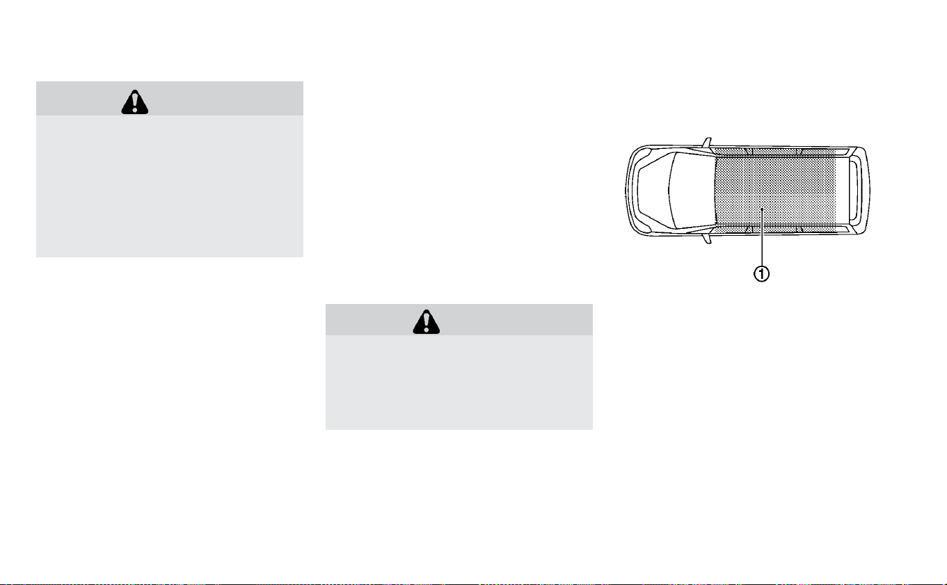
WARNING
Do not operate the power switch while
driving the vehicle except in an emer-
gency. (The EV system shuts down
when the power switch is pushed three
consecutive times or the power switch
is pushed and held for more than 2 sec-
onds.) If the EV system stops while the
vehicle is being driven, this could lead
to a crash and serious injury.
Before operating the power switch, make
sure the vehicle is in the P (Park) position.
NISSAN INTELLIGENT KEY®
SYSTEM
The Intelligent Key system allows the driver
to star t the EV system without taking the
key out of a pocket or purse. The operating
environment and/or conditions may affect
Intelligent Key system operation.
Some indicators and warnings for opera-
tion are displayed on the vehicle informa-
tion display. For additional information, re-
fer to “Vehicle information display” in the
“Instruments and controls” section of this
manual.
CAUTION
• Be sure to carry the Intelligent Key
with you when operating the ve-
hicle.
• Never leave the Intelligent Key inside
the vehicle when you leave the ve-
hicle.
OPERATING RANGE FOR EV START
FUNCTION
The Intelligent Key function can only be
used for starting the EV system when the
Intelligent Key is within the specified oper-
ating range
䊊
1
.
When the Intelligent Key battery is almost
discharged or strong radio waves are pres-
ent near the operating location, the Intelli-
gent Key system’s operating range be-
comes narrower and it may not function
properly.
PUSH-BUTTON POWER SWITCH
5-10 Starting and driving

If the Intelligent Key is within the operating
range, it is possible for anyone, even some-
one who does not carry the Intelligent Key,
to push the power switch to start the EV
system.
• The cargo area is not included in the op-
erating range but the Intelligent Key may
function.
• If the Intelligent Key is placed on the in-
strument panel or inside the glove box or
door pocket, the Intelligent Key may not
function.
• If the Intelligent Key is placed near a door
or window outside the vehicle, the Intelli-
gent Key may not function.
POWER SWITCH OPERATION
Starting and driving 5-11

When the power switch is pushed without
depressing the brake pedal, the power
switch position will change as follows:
• Push once to change to ACC.
• Push two times to change to ON.
• Push three times to change to OFF.
• Push four times to return to ACC.
• Open or close any door to return to LOCK
while in the OFF position.
The power switch illuminates when in the
ACC or ON position.
The power lock is designed so that the
power switch position cannot be switched
to the LOCK position until the vehicle is
placed in the P (Park) position.
When the power switch cannot be placed
in the LOCK position, proceed as follows:
1. Push the P (Park) position switch on the
shift lever to place the vehicle in the P
(Park) position.
2. Push the power switch to the OFF posi-
tion. The power switch will not
illuminate.
3. Open the door. The power switch will
change to the LOCK position.
POWER SWITCH POSITIONS
LOCK (Normal parking position)
The power switch can only be locked in this
position.
The power switch will be unlocked when it
is pushed to the ACC position while the
driver is carrying the Intelligent Key.
ACC (Accessories)
This position activates electrical accesso-
ries, such as the radio, when the EV system
is off.
ON
This position turns on the EV system and
electrical accessories.
READY (Normal operating
position)
This position turns on the EV system and
electrical accessories and the vehicle can
be driven.
OFF
This position turns off the EV system.
The power switch cannot be placed in the
LOCK position until the vehicle is in the P
(Park) position.
CAUTION
Do not leave the vehicle with the power
switch in the ACC position for an ex-
tended period of time. This can dis-
charge the 12-volt battery.
NOTE:
If the power switch is pushed quickly or
is pushed twice quickly, the switch may
not function even if a chime sound is
heard. Push the switch again more
slowly.
EMERGENCY EV SHUT OFF
To shut off the EV system in an emergency
situation while driving, perform the follow-
ing procedure:
• Rapidly push the power switch three con-
secutive times in less than 1.5 seconds, or
• Push and hold the power switch for more
than 2 seconds.
5-12 Starting and driving
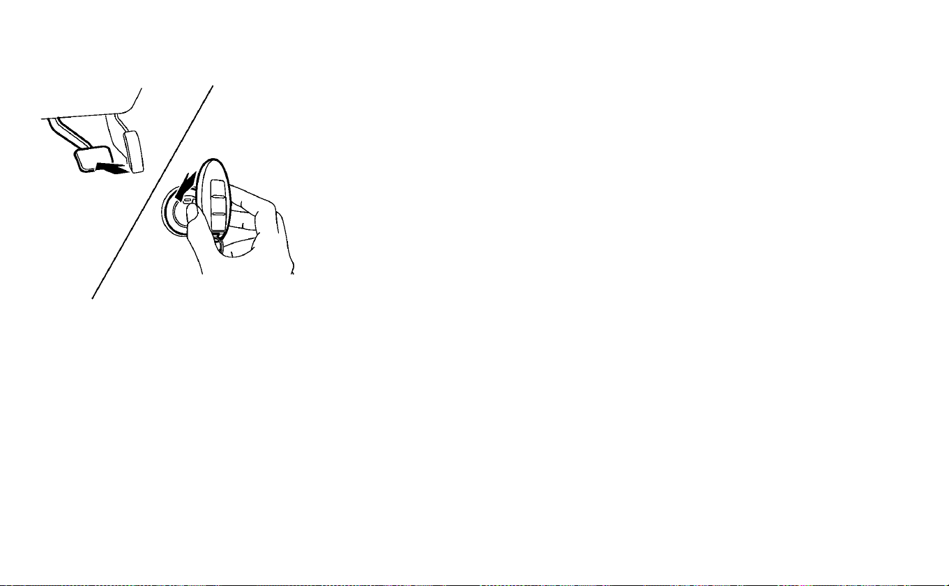
NISSAN INTELLIGENT KEY®
BATTERY DISCHARGE
If the Intelligent Key battery is discharged
or environmental conditions interfere with
the Intelligent Key operation, start the EV
system in the READY to drive mode accord-
ing to the following procedure:
1. Push the P (Park) position switch on the
shift lever.
2. Firmly apply the foot brake.
3. Touch the power switch with the Intelli-
gent Key as illustrated. (A chime will
sound.)
4. Push the power switch while depressing
the brake pedal within 10 seconds after
the chime sounds. The power switch
position changes to the READY to drive
mode.
After step 3 is performed, if the power
switch is pushed without depressing the
brake pedal, the power switch position will
change to ACC.
NOTE:
•
When the power switch is pushed to the
ACC or ON position or READY to drive mode
by the above procedure, the EV system op-
eration for discharged Intelligent Key sys-
tem indicator appears on the vehicle infor-
mation display even if the Intelligent Key is
inside the vehicle. This is not a malfunc-
tion. To stop the warning indicator from
blinking, touch the power switch with the
Intelligent Key again.
•
If the Intelligent Key battery discharge in-
dicator appears on the vehicle informa-
tion display, replace the battery as soon as
possible. For additional information, refer
to “NISSAN Intelligent Key® battery re-
placement” in the “Maintenance and do-
it-yourself” section of this manual.
NISSAN VEHICLE IMMOBILIZER
SYSTEM
The NISSAN Vehicle Immobilizer System
will not allow the power switch to be placed
in the READY to drive position without the
use of the registered key.
If the power switch fails to place the vehicle
into the READY to drive position using the
registered key, it may be due to interfer-
ence caused by another registered key, an
automated toll road device or automated
payment device on the key ring. Restart the
EV system using the following procedure:
1. Leave the power switch in the ON posi-
tion for approximately 5 seconds.
2. Place the power switch in the OFF posi-
tion and wait approximately 10 seconds.
3. Repeat steps 1 and 2 again.
4. Place the power switch in the READY to
drive position while holding the device
(which may have caused the interfer-
ence) separate from the registered key.
If this procedure allows the power
switch to be placed in the READY to drive
mode, NISSAN recommends placing the
registered key on a separate key ring to
avoid interference from other devices.
Starting and driving 5-13

• Make sure that the area around the ve-
hicle is clear.
• Check fluid levels such as coolant, brake
fluid, and windshield-washer fluid as fre-
quently as possible.
• Check that all windows and lights are
clean.
• Visually inspect tires for their appearance
and condition. Also check tires for proper
inflation.
• Check that all doors are closed.
• Position the seat and adjust the head
restraints/headrests.
• Adjust the inside and outside mirrors.
• Fasten seat belts and ask all passengers
to do likewise.
• Check the operation of the warning lights
when the power switch is pushed to the
ON position. For additional information,
refer to “Warning lights, indicator lights
and audible reminders” in the “Instru-
ments and controls” section of this
manual.
1. Confirm the parking brake is applied.
2. Confirm that the vehicle is in the P (Park)
position.
When the power switch is placed in the
ON position, the EV is designed not to
operate unless the shift lever is in the P
(Park) or N (Neutral) positions.
The Intelligent Key must be carried
with you when operating the power
switch.
3. Depress the brake pedal and push the
power switch to place the EV system in
the READY to drive position.
To place the vehicle in the READY to drive
position immediately, push and release
the power switch while depressing the
brake pedal with the power switch in
any position. The READY to drive indica-
tor light
in the meter illuminates.
4. To stop the EV system, push the P (Park)
position switch on the shift lever, and
push the power switch to the OFF
position.
NOTE:
Care should be taken to avoid situa-
tions that can lead to potential bat-
tery discharge and potential no-start
conditions such as:
1. Installation or extended use of elec-
tronic accessories that consume bat-
tery power when the EV system is not
running (phone chargers, GPS, DVD
players, etc.).
2. The vehicle is not driven regularly
and/or only driven short distances.
In these cases, the battery may need to
be charged to maintain battery health.
BEFORE STARTING THE EV SYSTEM STARTING THE EV SYSTEM
5-14 Starting and driving

ELECTRIC SHIFT CONTROL
SYSTEM
This vehicle is electronically controlled to
produce maximum available power and
smooth operation.
The recommended operating procedures
for this vehicle are shown on the following
pages.
Starting the vehicle
1. After placing the vehicle in the READY to
drive position, fully depress the foot
brake pedal before moving the shift lever
to the D (Drive) position.
The shift lever of this vehicle is de-
signed so that the foot brake pedal
must be depressed before shifting
from the P (Park) position to any driv-
ing position while the power switch is
in the ON position.
The shift lever cannot be moved out
of the P (Park) position and into any of
the other positions if the power
switch is placed in the LOCK, OFF or
ACC position or if the key is removed.
2. Keep the foot brake pedal depressed,
and move the shift lever to the D (Drive)
position.
3. Release the parking brake and foot
brake pedal, and then gradually start the
vehicle in motion.
WARNING
• Do not depress the accelerator pedal
while shifting from P (Park) or N
(Neutral) to the R (Reverse) or D
(Drive) position. Always depress the
brake pedal until shifting is com-
pleted. Failure to do so could cause
you to lose control, which could re-
sult in an accident.
• Never shift to the P (Park) or R (Re-
verse) position while the vehicle is
moving forward and the P (Park) or D
(Drive) position while the vehicle is
reversing. This could cause you to
lose control and have an accident.
• Do not shift to the B position
abruptly on slippery roads. This may
cause a loss of control.
CAUTION
• To avoid possible damage to your
vehicle, when stopping the vehicle
on an uphill grade, do not hold the
vehicle by depressing the accelera-
tor pedal. The foot brake should be
used for this purpose.
• Do not hang items on the shift lever.
This may cause an accident due to a
sudden start.
DRIVING THE VEHICLE
Starting and driving 5-15

Shifting
To move the shift lever,
: Slide along the gate while the brake
pedal is depressed.
: After sliding, maintain it in the same
position until the vehicle is placed in the N
(Neutral) position.
: When in the D (Drive) position, slide
along the gate.
NOTE:
• Confirm that the vehicle is in the desired
shift position by checking the shift indi-
cator
䊊
1
located near the shift lever or
the vehicle information display in the
meter.
• To place the vehicle into the D (Drive)
position from the B mode, move the
shift lever into the D (Drive) position.
After placing the vehicle in the READY to
drive position, fully depress the brake pedal,
and move the shift lever to any of the pre-
ferred shift positions.
If the power switch is placed in the OFF or
ACC position for any reason while the shift
position is in any position other than the P
(Park) position, the power switch cannot be
placed in the LOCK position.
If the power switch cannot be placed in the
LOCK position, perform the following steps:
1. Apply the parking brake when the ve-
hicle is stopped.
2. Place the power switch in the ON posi-
tion while depressing the foot brake
pedal.
3. Push the P (Park) position switch and
confirm the vehicle is in the P (Park)
position.
4. Place the power switch in the OFF
position.
NOTE:
The vehicle automatically applies the P
(Park) position when the power switch is
in the OFF position.
WARNING
• The shift lever is always in the center
position when released. When the
power switch is placed in the READY
to drive position, the driver needs to
confirm that the vehicle is in the P
(Park) position. The indicator next to
the “P” by the shift lever is illumi-
nated and the “P” is displayed on the
meter. If the vehicle is in the D (Drive)
position or R (Reverse) position
when the power switch is placed in
the READY to drive position, this may
cause a sudden start which could re-
sult in an accident.
5-16 Starting and driving

• On a hilly road, do not allow the ve-
hicle to roll backwards while in the D
(Drive) position or B position or allow
the vehicle to roll forward while in
the R (Reverse) position. This may
cause an accident.
CAUTION
• Do not slide the shift lever while
pushing the P (Park) position switch.
This may damage the electric motor.
• When switching to the preferred po-
sition by operating the shift lever,
check that the shift lever returns to
the central position by releasing
your hand from the lever. Holding
the shift lever in a mid-way position
may also damage the shift control
system.
• Do not operate the shift lever while
the accelerator pedal is depressed,
except when switching to the B po-
sition. This may cause a sudden
start which could result in an acci-
dent.
• The following operations are not al-
lowed because excessive force
would be applied to the traction mo-
tor and this may result in damage to
the vehicle:
– Moving the shift lever to the R (Re-
verse) position when driving for-
ward
– Moving the shift lever to the D
(Drive) position when reversing
If these operations are attempted, a
chime sounds and the vehicle shifts
to the N (Neutral) position.
P (Park):
Use this shift position when the vehicle is
parked or when placing the vehicle in the
READY to drive position. Make sure that the
vehicle is completely stopped. In order to
switch to the P (Park) position, push the P
(Park) position switch as shown in the
illustration above once the vehicle has
come to a complete stop. If the P (Park)
position switch is pushed while the ve-
hicle is in motion, a chime sounds and
the current shift position is maintained.
After switching to the P (Park) position, ap-
ply the parking brake. When parking on a
Starting and driving 5-17

hill, apply the parking brake first while keep-
ing the foot brake pedal depressed then
push the P (Park) position switch and place
the vehicle in the P (Park) position. For ad-
ditional information, refer to “Parking brake”
in this section.
NOTE:
• While the vehicle is stationary, if the
shift position is placed in any position
other than the P (Park) position when
the power switch is set to OFF, it will
automatically switch to the P (Park) po-
sition.
• If the P (Park) position switch is pushed
while sliding the shift lever, the shift po-
sition will not switch to the P (Park) po-
sition. When pushing the P (Park) posi-
tion switch be sure to first allow the
shift lever to return to its center posi-
tion.
R (Reverse):
Use this position to back up. Make sure that
the vehicle is completely stopped before
selecting the R (Reverse) position. If the ve-
hicle is placed in the D (Drive) position
while reversing,the chime will sound and
the vehicle will switch into the N (Neutral)
position.
N (Neutral):
Neither forward nor reverse gear is en-
gaged. The vehicle can be placed in the
READY to drive position in this position.
Do not shift to the N (Neutral) position while
driving. The regenerative brake system
does not operate in the N (Neutral) position.
However, the vehicle brakes will still stop
the car.
D (Drive):
Use this position for all normal forward
driving. If the vehicle is placed in the D
(Drive) position while reversing, the
chime will sound and the vehicle will
switch into the N (Neutral) position.
B mode:
The B mode engages the regenerative
braking system more aggressively on
downhill slopes, and helps reduce brake
use. It is activated by moving the shift lever
left and down. The shift lever will then re-
turn to the center position. For additional
information, refer to “Brake system” in this
section.
ECO mode:
Use the ECO mode in order to help extend
the driving range.
5-18 Starting and driving
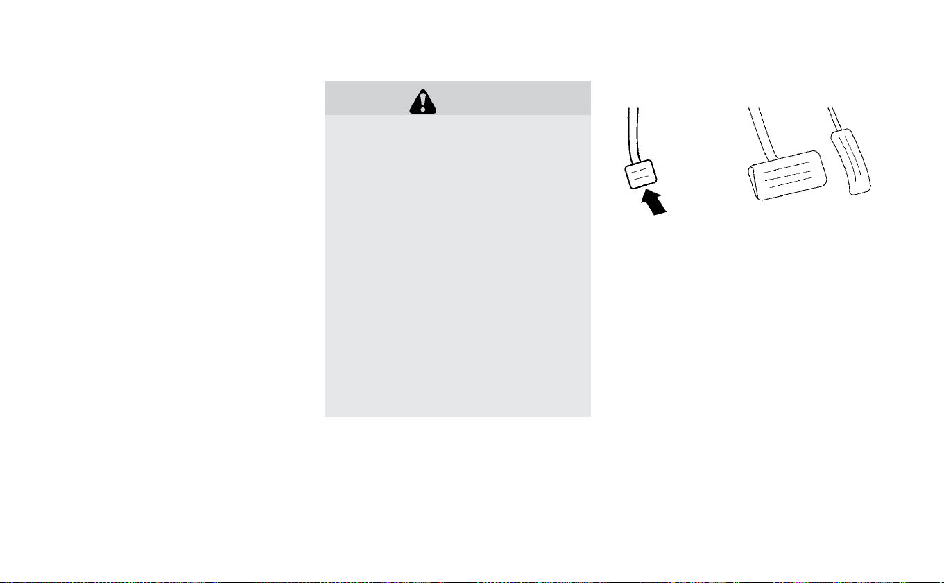
In comparison to the D (Drive) position, the
ECO mode consumes less power for the
traction motor and enables the range of
the vehicle to be extended. To turn on the
ECO mode, push the ECO mode switch lo-
cated near the shift lever. For additional
information, refer to “ECO switch” in the “In-
struments and controls” section of this
manual.
WARNING
• Be sure the parking brake is released
before driving. Failure to do so could
cause brake failure and lead to an
accident.
• Do not release the parking brake
from outside the vehicle.
• To help avoid risk of injury or death
through unintended operation of
the vehicle and/or its systems, do
not leave children, people who re-
quire the assistance of others or
pets unattended in your vehicle. Ad-
ditionally, the temperature inside a
closed vehicle on a warm day can
quickly become high enough to
cause a significant risk of injury or
death to people and pets.
• When leaving the vehicle, apply the
parking brake and push the P (Park)
position switch on the shift lever.
PEDAL TYPE
To engage: Firmly depress the parking
brake.
To release:
1. Firmly apply the foot brake.
2. Move the shift lever to the P (Park)
position.
3. Firmly depress the parking brake pedal
and it will release.
4. Before driving, be sure the brake warn-
ing light goes out.
PARKING BRAKE
Starting and driving 5-19
SWITCH TYPE (MODELS WITH
ELECTRONIC PARKING BRAKE
SYSTEM)
The electronic parking brake can be ap-
plied or released automatically or by oper-
ating the electronic parking brake switch.
Automatic operation
The electronic parking brake is automati-
cally released as soon as the vehicle starts
and the accelerator pedal is depressed.
In order for the electronic parking brake to
disable when the driver pushes the accel-
erator, the driver’s seat belt must be fas-
tened.
WARNING
• The electronic parking brake will not
be automatically applied when the
EV system is stopped without using
the power switch (for example, by EV
system stalling).
• Before leaving the vehicle, move the
shift lever to the P (Park) position
and check that the electronic park-
ing brake indicator light (
or PARK)
is illuminated to confirm that the
electronic parking brake is applied.
The electronic parking brake indica-
tor light (
or PARK) will remain on
for a period of time after the driver’s
door is locked.
CAUTION
When parking in an area where the
outside temperature is below 32°F
(0°C), do not apply the parking brake to
prevent it from freezing.
For safe parking, place the shift lever in
the P (Park) position and securely
block the wheels.
NOTE:
• If a malfunction occurs in the electronic
parking brake system (for example, due
to battery discharge), it is recom-
mended that you visit a NISSAN certi-
fied LEAF dealer.
• If the shift lever is moved to the P (Park)
position when the brake force is main-
tained by the automatic brake hold
function, the electronic parking brake
will apply automatically.
• If the driver’s seat belt is unfastened
when the brake force is maintained by
the automatic brake hold function, the
electronic parking brake will apply au-
tomatically.
• When the ICC system (if so equipped) is
canceled under the following condi-
tions at a standstill, the electronic park-
ing brake is automatically activated:
– Any door is open.
– The driver’s seat belt is not fastened.
5-20 Starting and driving

– Your vehicle has been stopped by
the ICC system for approximately
3 minutes or longer.
– The shift lever is not in the D (Drive)
position or B mode.
– The VDC system is turned off.
– When distance measurement be-
comes impaired due to adhesion of
dirt or obstruction to the sensor.
– When the radar signal is temporarily
interrupted.
Manual operation
The electronic parking brake will not be au-
tomatically applied if the EV system is
stopped without using the power switch
(for example, by EV system stalling). In such
a case, you have to apply the parking brake
manually.
To apply: Pull the switch up
䊊
1
. The indica-
tor light
䊊
A
will illuminate.
To release: With the power switch in the ON
position, depress the brake pedal and push
the switch down
䊊
2
. The indicator light
䊊
A
will turn off.
Before driving, check that the electronic
parking brake indicator light (
or PARK)
goes out. For additional information, refer
to “Warning lights, indicator lights and au-
dible reminders” in the “Instruments and
controls” section of this manual.
NOTE:
• A buzzer will sound if the vehicle is
driven without releasing the parking
brake. For additional information, refer
to “Warning lights, indicator lights and
audible reminders” in the “Instruments
and controls” section of this manual.
• While the electronic parking brake is ap-
plied or released, an operating sound is
heard from the lower side of the rear
seat. This is normal and does not indi-
cate a malfunction.
• When the electronic parking brake is
frequently applied and released in a
short period of time, the parking brake
may not operate in order to prevent the
parking brake system from overheat-
ing. If this occurs, operate the electronic
parking brake switch again after wait-
ing approximately 1 minute.
• If the electronic parking brake must be
applied while driving in an emergency,
pull up and hold the electronic parking
brake switch. When you release the
electronic parking brake switch, the
parking brake will be released.
• While pulling up the electronic parking
brake switch during driving, the parking
brake is applied and a chime sounds.
The electronic parking brake indicator
light (
or PARK) in the meter and in
the electronic parking brake switch illu-
minates. This does not indicate a mal-
function. The electronic parking brake
indicator light (
or PARK) in the me-
ter and in the electronic parking brake
switch turns off when the parking brake
is released.
• When pulling the electronic parking
brake switch up with the power switch
in the OFF or ACC position, the elec-
tronic parking brake switch indicator
light will continue to illuminate for a
short period of time.
Starting and driving 5-21

WARNING
Never rely solely on the e-Pedal sys-
tem, as there is a performance limit to
the system function. Always drive
carefully and attentively. The brake
pedal should be operated to slow or
stop the vehicle, depending on traffic
or road conditions.
The e-Pedal system enables the driver to
slow or stop the vehicle or to keep the ve-
hicle stopped by operating only the accel-
erator pedal. This systems helps to keep
the driver from moving his/her foot be-
tween the accelerator pedal and the brake
pedal.
E-PEDAL SYSTEM OPERATION
1. Acceleration
2. Deceleration (instead of brake pedal)
3. Making a stop (instead of brake pedal
When the e-Pedal system is activated, the
regenerative brake is enhanced and the
driver can adjust the vehicle speed by only
depressing or returning the accelerator
pedal. When you release (take your foot off)
the accelerator pedal, the vehicle slows
down and comes to a stop smoothly with-
out depressing the brake pedal. After a
stop, the vehicle remains at a stop auto-
matically.
E-PEDAL SYSTEM
5-22 Starting and driving

To activate or deactivate the e-Pedal sys-
tem, place the power switch in the ON po-
sition and pull the e-Pedal switch located
on the center console. The e-Pedal system
turns on or off each time the e-Pedal
switch is pulled. (The e-Pedal indicator in
the vehicle information display shows the
status of the e-Pedal system.)
To turn the e-Pedal system off while the
vehicle is stopped by the e-Pedal system,
depress the brake pedal and then pull the
e-Pedal switch.
NOTE:
• When the e-Pedal system is switched
on or off, the degree of vehicle decelera-
tion changes.
• The e-Pedal system automatically turns
off when the EV system restarts.
• To keep the e-Pedal system activated
even after the EV system restarts, turn
on “Retain Mode” in the “Driver Assis-
tance” menu of the vehicle information
display. For additional information, re-
fer to “Vehicle information display” in
the “Instruments and controls” section
of this manual.
• The setting for “Retain Mode” does not
reset after selecting “Factory Reset” in
the “Settings” menu of the vehicle infor-
mation display. For additional informa-
tion, refer to “Vehicle information dis-
play” in the “Instruments and controls”
section of this manual.
When the e-Pedal system is activated, the
characteristics of the accelerator pedal
change significantly and the accelerator
pedal operates differently than a conven-
tional accelerator pedal operates. Be sure
to confirm the status of the e-Pedal system
in the vehicle information display before
driving.
The e-Pedal system provides the following
driving features:
When driving and stopping the vehicle:
• Depressing or returning the accelerator
pedal changes the degree of acceleration
and deceleration accordingly.
• Returning the accelerator pedal gener-
ates more deceleration than normal. (The
maximum deceleration changes accord-
ing to the vehicle speed.)
• Releasing (taking your foot off) the accel-
erator pedal reduces the vehicle speed
until the vehicle comes to a stop.
• The vehicle’s brake lights illuminate when
the deceleration level reaches an ordinary
braking operation.
If the deceleration is not sufficient when the
accelerator pedal is returned or released,
depress the brake pedal. The brake pedal
can be operated to reduce the vehicle
speed in the same way as normal even
when the e-Pedal system is activated.
Starting and driving 5-23

When restarting the vehicle:
• After the vehicle comes to a stop by the
e-Pedal system function, the vehicle re-
mains at a stop as long as the accelerator
pedal is released.
• The vehicle’s brake lights remain illumi-
nated when the vehicle is stopped by the
e-Pedal system.
• Depress the accelerator pedal to start the
vehicle again from a stop.
When the vehicle needs to be stopped for a
certain period of time, place the vehicle in
the P (Park) position and apply the parking
brake.
CAUTION
When the e-Pedal system is turned off,
remember to depress the brake pedal
firmly to prevent the vehicle from mov-
ing with the shift lever in any position
other than P (Park).
When backing up the vehicle:
• With the shift lever in the R (Reverse) posi-
tion, operating the accelerator pedal ad-
justs the vehicle speed (acceleration, de-
celeration, or stopping) in the same way
as the D (Drive) position.
Other driving tips for the e-Pedal
system:
• For smooth deceleration when the
e-Pedal system is activated, it is recom-
mended that you adjust the accelerator
pedal by either depressing or returning,
not releasing, the pedal.
• Moving the shift lever from D (Drive) to B
mode or from B mode to D (Drive) does
not affect the e-Pedal system feature.
• The e-Pedal system does not function un-
der the following conditions:
– When the vehicle is placed in the P
(Park) or N (Neutral) position
– When cruise control (if so equipped),
ProPILOT™ Assist (if so equipped), or
Automatic Emergency Braking (if so
equipped) operates
E-PEDAL SYSTEM LIMITATIONS
WARNING
Listed below are the system limita-
tions for the e-Pedal system. Failure to
operate the vehicle in accordance with
these system limitations could result
in serious injury or death.
• If the “Press brake pedal to prevent
rolling” warning message appears in
the vehicle information display, de-
press the brake pedal. The vehicle
may start moving.
• If the deceleration force provided by
the e-Pedal system is not sufficient,
depress the brake pedal.
• If the vehicle starts to move while it
is stopped by the e-Pedal system,
depress the brake pedal immedi-
ately.
• Under the following conditions,
place the vehicle in the P (Park) posi-
tion and make sure the parking
brake is securely applied. The ve-
hicle may start moving suddenly.
– When getting in and out of the ve-
hicle
– When loading and unloading the
vehicle
5-24 Starting and driving

– When stopping the vehicle for a
long period of time
• Under the following conditions, the
e-Pedal system may not decelerate
or stop the vehicle sufficiently. De-
press the brake pedal whenever
necessary.
– When excessively heavy baggage
is loaded in the vehicle
– When driving on steep downhill
roads
– When driving on icy roads
• On a slope, the e-Pedal system may
not stop the vehicle completely or
may not keep the vehicle stopped.
Depress the brake pedal whenever
necessary.
CAUTION
• Turn the e-Pedal system off and
place the vehicle in the N (Neutral)
position under the following condi-
tions:
– When the vehicle enters an auto-
matic car wash
– When the vehicle is towed
• Be careful not to operate the e-Pedal
switch mistakenly or unintention-
ally.
SYSTEM MALFUNCTION
If the e-Pedal system malfunctions, the “e-
Pedal system failure! Press brake pedal to
slow or stop” warning message appears in
the vehicle information display. When the
warning message appears, the e-Pedal
system will be turned off automatically.
Have the system checked as soon as pos-
sible. It is recommended that you visit a
NISSAN certified LEAF dealer for this ser-
vice.
Starting and driving 5-25

WARNING
Failure to follow the warnings and in-
structions for proper use of the LDW
system could result in serious injury or
death.
• This system is only a warning device
to inform the driver of a potential
unintended lane departure. It will
not steer the vehicle or prevent loss
of control. It is the driver’s responsi-
bility to stay alert, drive safely, keep
the vehicle in the traveling lane, and
be in control of the vehicle at all
times.
The LDW system will operate when the ve-
hicle is driven at speeds of approximately
37 mph (60 km/h) and above, and only
when the lane markings are clearly visible
on the road.
The LDW system monitors the lane mark-
ers on the traveling lane using the camera
unit
䊊
A
located above the inside mirror.
The LDW system warns the driver with an
indicator in the vehicle information display
and a steering vibration that the vehicle is
beginning to leave the driving lane. For ad-
ditional information, refer to “LDW system
operation” in this section.
LDW SYSTEM OPERATION
The LDW system provides a lane departure
warning function when the vehicle is driven
at speeds of approximately 37 mph
(60 km/h) and above and the lane mark-
ings are clear. When the vehicle ap-
proaches either the left or the right side of
the traveling lane, the steering wheel will
vibrate and the LDW indicator in the vehicle
information display will blink to alert the
driver.
The warning function will stop when the
vehicle returns inside of the lane markers.
LANE DEPARTURE WARNING (LDW)
(IF SO EQUIPPED)
5-26 Starting and driving

HOW TO ENABLE/DISABLE THE
LDW SYSTEM
Perform the following steps to enable or
disable the LDW system:
1. Press the
button until “Settings” dis-
plays in the vehicle information display.
Use the
button to select “Driver As-
sistance.” Then press the OK button.
2. Select “Lane” and press the OK button.
3. Select “Lane Departure Warning” and
use the OK button to turn the system on
or off.
LDW SYSTEM LIMITATIONS
WARNING
Listed below are the system limita-
tions for the LDW system. Failure to fol-
low the warnings and instructions for
proper use of the LDW system could
result in serious injury or death.
• The system will not operate at
speeds below approximately 37
mph (60 km/h) or if it cannot detect
lane markers.
Starting and driving 5-27

• Do not use the LDW system under
the following conditions as it may
not function properly:
– During bad weather (rain, fog,
snow, etc.).
– When driving on slippery roads,
such as on ice or snow.
– When driving on winding or un-
even roads.
– When there is a lane closure due to
road repairs.
– When driving in a makeshift or
temporary lane.
– When driving on roads where the
lane width is too narrow.
– When driving without normal tire
conditions (for example, tire wear,
low tire pressure, installation of
spare tire, tire chains, nonstan-
dard wheels).
– When the vehicle is equipped with
non-original brake parts or sus-
pension parts.
– When you are towing a trailer or
other vehicle.
5-28 Starting and driving

• The system may not function prop-
erly under the following conditions:
– On roads where there are multiple
parallel lane markers; lane mark-
ers that are faded or not painted
clearly; yellow painted lane mark-
ers; non-standard lane markers;
or lane markers covered with wa-
ter, dirt, snow, etc.
– On roads where the discontinued
lane markers are still detectable.
– On roads where there are sharp
curves.
– On roads where there are sharply
contrasting objects, such as shad-
ows, snow, water, wheel ruts,
seams or lines remaining after
road repairs. (The LDW system
could detect these items as lane
markers.)
– On roads where the traveling lane
merges or separates.
– When the vehicle’s traveling direc-
tion does not align with the lane
marker.
– When traveling close to the ve-
hicle in front of you, which ob-
structs the lane camera unit de-
tection range.
– When rain, snow, dirt or an object
adheres to the windshield in front
of the lane camera unit.
–
When the headlights are not bright
due to dirt on the lens or if the aim-
ing is not adjusted properly.
– When strong light enters the lane
camera unit (for example, the light
directly shines on the front of the
vehicle at sunrise or sunset).
– When a sudden change in bright-
ness occurs (for example, when
the vehicle enters or exits a tunnel
or under a bridge).
SYSTEM TEMPORARILY
UNAVAILABLE
If the vehicle is parked in direct sunlight
under high temperature conditions (over
approximately 104°F [40°C]) and then
started, the LDW system may be deacti-
vated automatically and the following
message will appear in the vehicle infor-
mation display: “Unavailable: High Cabin
Temp.”
When the interior temperature is reduced,
the LDW system will resume operating au-
tomatically
The LDW system is not designed to warn
under the following conditions:
• When you operate the lane change signal
and change traveling lanes in the direc-
tion of the signal. (The LDW system will
become operable again approximately
2 seconds after the lane change signal is
turned off.)
• When the vehicle speed lowers to less
than approximately 37 mph (60 km/h).
After the above conditions have finished
and the necessary operating conditions
are satisfied, the LDW functions will resume.
Starting and driving 5-29

SYSTEM MALFUNCTION
If the LDW system malfunctions, it will can-
cel automatically and “Malfunction: See
Owner’s Manual” will appear in the vehicle
information display. If “Malfunction: See
Owner’s Manual” appears in the vehicle in-
formation display, pull off the road to a safe
location and stop the vehicle. Place the
shift lever in the P (Park) position and the
power switch in the OFF position and re-
start the EV system. If “Malfunction: See
Owner’s Manual” continues to appear in
the vehicle information display, have the
system checked. It is recommended that
you visit a NISSAN certified LEAF dealer for
this service.
SYSTEM MAINTENANCE
The lane camera unit
䊊
1
for the LDW sys-
tem is located above the inside mirror. To
keep the proper operation of the LDW sys-
tem and prevent a system malfunction, be
sure to observe the following:
• Always keep the windshield clean.
• Do not attach a sticker (including trans-
parent material) or install an accessory
near the camera unit.
• Do not place reflective materials, such as
white paper or a mirror, on the instrument
panel. The reflection of sunlight may ad-
versely affect the camera unit’s capability
of detecting the lane markers.
• Do not strike or damage the areas around
the camera unit. Do not touch the camera
lens or remove the screw located on the
camera unit. If the camera unit is dam-
aged due to an accident, it is recom-
mended that you visit a NISSAN certified
LEAF dealer.
5-30 Starting and driving

WARNING
Failure to follow the warnings and in-
structions for proper use of the I-LI
system could result in serious injury or
death.
• The I-LI system will not steer the ve-
hicle or prevent loss of control. It is
the driver’s responsibility to stay
alert, drive safely, keep the vehicle in
the traveling lane, and be in control
of the vehicle at all times.
• The I-LI system is primarily intended
for use on well-developed freeways
or highways. It may not detect the
lane markers in certain road,
weather, or driving conditions.
The I-LI system must be turned on with the
ProPILOT™ Assist switch on the steering
wheel every time the power switch is
placed in the ON position.
The I-LI system will operate when the ve-
hicle is driven at speeds of approximately
37 mph (60 km/h) and above, and only
when the lane markings are clearly visible
on the road.
The I-LI system warns the driver when the
vehicle has left the center of the traveling
lane with an indicator in the vehicle infor-
mation display and a steering vibration.
The system helps assist the driver to return
the vehicle to the center of the traveling
lane by applying the brakes to the left or
right wheels individually (for a short period
of time).
The I-LI system monitors the lane markers
on the traveling lane using the camera unit
䊊
A
located above the inside mirror.
INTELLIGENT LANE INTERVENTION
(I-LI) (IF SO EQUIPPED)
Starting and driving 5-31

I-LI SYSTEM OPERATION
The I-LI system operates above approxi-
mately 37 mph (60 km/h). When the vehicle
approaches either the left or the right side
of the traveling lane, the steering wheel will
vibrate and the I-LI indicator (orange) in the
vehicle information display will blink to alert
the driver. Then, the I-LI system will auto-
matically apply the brakes for a short pe-
riod of time to help assist the driver to re-
turn the vehicle to the center of the
traveling lane.
To turn on the I-LI system, push the ProPI-
LOT™ Assist switch on the steering wheel.
Push the ProPILOT Assist switch again to
turn off the I-LI system.
5-32 Starting and driving

HOW TO ENABLE/DISABLE THE I-LI
SYSTEM
Perform the following steps to enable or
disable the I-LI system:
1. Press the
button until “Settings” dis-
plays in the vehicle information display.
Use the
button to select “Driver As-
sistance.” Then press the OK button.
2. Select “Lane” and press the OK button.
3. Select “Lane Depar ture Prevention” and
use the OK button to turn the system on
or off.
NOTE:
Turning on the ProPILOT™ Assist sys-
tem (if so equipped) will turn on the
I-LI system at the same time. For ad-
ditional information, refer to “ProPI-
LOT™ Assist” in this section.
Starting and driving 5-33

I-LI SYSTEM LIMITATIONS
WARNING
Listed below are the system limita-
tions for the I-LI system. Failure to fol-
low the warnings and instructions for
proper use of the I-LI system could re-
sult in serious injury or death.
• The I-LI system may activate if you
change lanes without first activat-
ing your turn signal or, for example,
if a construction zone directs traffic
to cross an existing lane marker. If
this occurs you may need to apply
corrective steering to complete your
lane change.
• Because the I-LI may not activate
under the road, weather, and lane
marker conditions described in this
section, it may not activate every
time your vehicle begins to leave its
lane and you will need to apply cor-
rective steering.
• When the I-LI system is operating,
avoid excessive or sudden steering
maneuvers. Otherwise, you could
lose control of the vehicle.
• The I-LI system will not operate at
speeds below approximately
37 mph (60 km/h) or if it cannot de-
tect lane markers.
• Do not use the I-LI system under the
following conditions as it may not
function properly:
– During bad weather (rain, fog,
snow, etc.).
– When driving on slippery roads,
such as on ice or snow.
– When driving on winding or un-
even roads.
– When there is a lane closure due to
road repairs.
– When driving in a makeshift or
temporary lane.
– When driving on roads where the
lane width is too narrow.
– When driving without normal tire
conditions (for example, tire wear,
low tire pressure, installation of
spare tire, tire chains, nonstan-
dard wheels).
– When the vehicle is equipped with
nonoriginal brake parts or sus-
pension parts.
– When you are towing a trailer or
other vehicle.
– On roads where there are multiple
parallel lane markers; lane mark-
ers that are faded or not painted
clearly; yellow painted lane mark-
ers; non-standard lane markers;
or lane markers covered with wa-
ter, dirt, snow, etc.
– On roads where discontinued lane
markers are still detectable.
– On roads where there are sharp
curves.
– On roads where there are sharply
contrasting objects, such as shad-
ows, snow, water, wheel ruts,
seams or lines remaining after
road repairs. (The I-LI system
could detect these items as lane
markers.)
– On roads where the traveling lane
merges or separates.
– When the vehicle’s traveling direc-
tion does not align with the lane
marker.
– When traveling close to the ve-
hicle in front of you, which ob-
structs the lane camera unit de-
tection range.
– When rain, snow or dirt adheres to
the windshield in front of the lane
camera unit.
5-34 Starting and driving

– When the headlights are not
bright due to dirt on the lens or if
the aiming is not adjusted prop-
erly.
– When strong light enters the lane
camera unit (for example, the light
directly shines on the front of the
vehicle at sunrise or sunset).
– When a sudden change in bright-
ness occurs (for example, when
the vehicle enters or exits a tunnel
or under a bridge).
While the I-LI system is operating, you may
hear a sound of brake operation. This is
normal and indicates that the I-LI system is
operating properly.
SYSTEM TEMPORARILY
UNAVAILABLE
Condition A:
The warning and assist functions of the I-LI
system are not designed to work under the
following conditions:
• When you operate the lane change signal
and change the traveling lanes in the di-
rection of the signal. (The I-LI system will
be deactivated for approximately 2 sec-
onds after the lane change signal is
turned off.)
• When the vehicle speed lowers to less
than approximately 37 mph (60 km/h).
After the above conditions have finished
and the necessary operating conditions
are satisfied, the warning and assist func-
tions will resume.
Condition B:
The assist function of the I-LI system is not
designed to work under the following con-
ditions (warning is still functional):
• When the brake pedal is depressed.
• When the steering wheel is turned as far
as necessary for the vehicle to change
lanes.
• When the vehicle is accelerated during I-LI
system operation.
• When the Intelligent Cruise Control (ICC)
approach warning occurs.
• When the hazard warning flashers are
operated.
• When driving on a curve at high speed.
After the above conditions have finished
and the necessary operating conditions
are satisfied, the I-LI system application of
the brakes will resume.
Condition C:
If the following messages appear in the
vehicle information display, a chime will
sound and the I-LI system will be turned off
automatically.
• “Not Available - Poor Road Conditions”:
When the VDC system (except Traction
Control System [TCS] function) or ABS
operates.
• “Currently not available”: When the VDC
system is turned off.
Action to take:
When the above conditions no longer exist,
turn off the I-LI system. Push the ProPILOT™
Assist switch to turn the I-LI system back
on.
Temporary disabled status at high tem-
perature:
If the vehicle is parked in direct sunlight
under high temperature conditions (over
approximately 104°F [40°C]) and then the
I-LI system is turned on, the I-LI system
may be deactivated automatically and the
Starting and driving 5-35

following message will appear on the ve-
hicle information display: “Unavailable: High
Cabin Temperature.” When the interior
temperature is reduced, the system will re-
sume operating automatically.
SYSTEM MALFUNCTION
If the I-LI system malfunctions, it will cancel
automatically. The I-LI system warning light
(orange) will illuminate in the display.
If the I-LI system warning light (orange) illu-
minates in the display, pull off the road to a
safe location and stop the vehicle. Turn the
EV system off and restart the EV system. If
the I-LI system warning light (orange) con-
tinues to illuminate, have the I-LI system
checked. It is recommended that you visit a
NISSAN certified LEAF dealer for this ser-
vice.
SYSTEM MAINTENANCE
The lane camera unit
䊊
1
for the I-LI system
is located above the inside mirror. To keep
the proper operation of the I-LI system and
prevent a system malfunction, be sure to
observe the following:
• Always keep the windshield clean.
• Do not attach a sticker (including trans-
parent material) or install an accessory
near the camera unit.
• Do not place reflective materials, such as
white paper or a mirror, on the instrument
panel. The reflection of sunlight may ad-
versely affect the camera unit’s capability
of detecting the lane markers.
• Do not strike or damage the areas around
the camera unit. Do not touch the camera
lens or remove the screw located on the
camera unit. If the camera unit is dam-
aged due to an accident, it is recom-
mended that you visit a NISSAN certified
LEAF dealer.
5-36 Starting and driving

WARNING
Failure to follow the warnings and in-
structions for proper use of the BSW
system could result in serious injury or
death.
• The BSW system is not a replace-
ment for proper driving procedures
and is not designed to prevent con-
tact with vehicles or objects. When
changing lanes, always use the side
and rear mirrors and turn and look in
the direction your vehicle will move
to ensure it is safe to change lanes.
Never rely solely on the BSW system.
The BSW system helps alert the driver of
other vehicles in adjacent lanes when
changing lanes.
The BSW system uses radar sensors
䊊
1
installed near the rear bumper to detect
other vehicles in an adjacent lane.
The radar sensors can detect vehicles on
either side of your vehicle within the detec-
tion zone shown as illustrated. This detec-
tion zone starts from the outside mirror of
your vehicle and extends approximately
10 ft (3.0 m) behind the rear bumper, and
approximately 10 ft (3.0 m) sideways.
Detection zone
BLIND SPOT WARNING (BSW) (IF SO
EQUIPPED)
Starting and driving 5-37

BSW SYSTEM OPERATION
1. Side BSW/RCTA Indicator Light
2. BSW/RCTA Indicator
The BSW system operates above approxi-
mately 20 mph (32 km/h).
If the radar sensors detect a vehicle in the
detection zone, the side BSW/RCTA indica-
tor light (1) illuminates. If the turn signal is
then activated, the system chimes (twice),
the side BSW/RCTA indicator light flashes,
and the BSW/RCTA indicator (2) illuminates
(yellow) in the vehicle information display.
The side BSW/RCTA indicator light contin-
ues to flash until the detected vehicle
leaves the detection zone.
The side BSW/RCTA indicator light illumi-
nates for a few seconds when the power
switch is placed in the ON position.
The brightness of the side BSW/RCTA indi-
cator light is adjusted automatically de-
pending on the brightness of the ambient
light.
If a vehicle comes into the detection zone
after the driver activates the turn signal,
then only the side BSW/RCTA indicator light
flashes and no chime sounds. For addi-
tional information, refer to “BSW driving
situations” in this section
5-38 Starting and driving

The BSW system automatically turns on
every time the EV system is started, as long
as it is activated using the settings menu
on the vehicle information display.
HOW TO ENABLE/DISABLE THE
BSW SYSTEM
Perform the following steps to enable or
disable the BSW system:
1. Press the
button until “Settings dis-
plays in the vehicle information display.
Use the
button to select “Driver As-
sistance.” Then press the OK button.
2. Select “Blind Spot” and press the OK
button.
3. Select “Blind Spot Warning” and use the
OK button to turn the system on or off.
NOTE:
When enabling/disabling the system,
the system will retain current settings
even if the EV system is restarted.
Starting and driving 5-39

BSW SYSTEM LIMITATIONS
WARNING
Listed below are the system limita-
tions for the BSW system. Failure to op-
erate the vehicle in accordance with
these system limitations could result
in serious injury or death.
• The BSW system cannot detect all
vehicles under all conditions.
• The radar sensors may not be able
to detect and activate BSW when
certain objects are present such as:
– Pedestrian, bicycles, animals.
– Vehicles such as motorcycles, low
height vehicles, or high ground
clearance vehicles.
– Oncoming vehicles.
– Vehicles remaining in the detec-
tion zone when you accelerate
from a stop.
– A vehicle merging into an adja-
cent lane at a speed approxi-
mately the same as your vehicle.
– A vehicle approaching rapidly
from behind.
– A vehicle which your vehicle over-
takes rapidly.
– A vehicle that passes through the
detection zone quickly.
– When overtaking several vehicles
in a row, the vehicles after the first
vehicle may not be detected if
they are traveling close together.
• The radar sensor’s detection zone is
designed based on a standard lane
width. When driving in a wider lane,
the radar sensors may not detect
vehicles in an adjacent lane. When
driving in a narrow lane, the radar
sensors may detect vehicles driving
two lanes away.
• The radar sensors are designed to
ignore most stationary objects;
however, objects such as guardrails,
walls, foliage and parked vehicles
may occasionally be detected. This
is a normal operation condition.
• The following conditions may re-
duce the ability of the radar to de-
tect other vehicles:
– Severe weather
– Road spray
– Ice/frost/dirt/snow build-up on
the vehicle
• Do not attach stickers (including
transparent material), install acces-
sories or apply additional paint near
the radar sensors. These conditions
may reduce the ability of the radar to
detect other vehicles.
• Excessive noise (for example, audio
system volume, open vehicle win-
dow) will interfere with the chime
sound, and it may not be heard.
5-40 Starting and driving

BSW DRIVING SITUATIONS
Indicator on
Indicator off
Indicator flashing
Another vehicle approaching
from behind
Illustration 1: The side indicator light illumi-
nates if a vehicle enters the detection zone
from behind in an adjacent lane.
Illustration 2: If the driver activates the
turn signal when another vehicle is in the
detection zone, then the system chimes
(twice) and the side indicator light flashes.
NOTE:
• The radar sensors may not detect ve-
hicles which are approaching rapidly
from behind.
• If the driver activates the turn signal be-
fore a vehicle enters the detection zone,
the side indicator light will flash but no
chime will sound when the other vehicle
is detected.
Illustration 1 – Approaching from behind
Illustration 2 – Approaching from
behind
Starting and driving 5-41

Overtaking another vehicle
Illustration 3: The side indicator light illu-
minates if you overtake a vehicle and that
vehicle stays in the detection zone for ap-
proximately 2 seconds.
Illustration 4: If the driver activates the
turn signal while another vehicle is in the
detection zone, then the system chimes
(twice) and the side indicator light flashes.
NOTE:
• When overtaking several vehicles in a
row, the vehicles after the first vehicle
may not be detected if they are travel-
ing close together.
• The radar sensors may not detect
slower moving vehicles if they are
passed quickly.
• If the driver activates the turn signal be-
fore a vehicle enters the detection zone,
the side indicator light will flash but no
chime will sound when the other vehicle
is detected.
Illustration3–Overtaking another
vehicle
Illustration4–Overtaking another
vehicle
5-42 Starting and driving

Entering from the side
Illustration 5: The side indicator light illu-
minates if a vehicle enters the detection
zone from either side.
Illustration 6: If the driver activates the
turn signal while another vehicle is in the
detection zone, then the system chimes
(twice) and the side indicator light flashes.
NOTE:
• If the driver activates the turn signal be-
fore a vehicle enters the detection zone,
the side indicator light will flash but no
chime will sound when the other vehicle
is detected.
• The radar sensors may not detect a ve-
hicle which is traveling at about the
same speed as your vehicle when it en-
ters the detection zone.
Illustration 5 – Entering from the side Illustration 6 – Entering from the side
Starting and driving 5-43

SYSTEM TEMPORARILY
UNAVAILABLE
When radar blockage is detected, the sys-
tem will be deactivated automatically. The
BSW/RCTA indicator
䊊
1
will blink (yellow) in
the vehicle information display. The indica-
tor next to “Blind spot” in the “Driving Aids”
menu
䊊
2
will also blink (yellow).
The system is not available until the condi-
tions no longer exist.
The radar sensors may be blocked by tem-
porary ambient conditions such as splash-
ing water, mist or fog. The blocked condi-
tion may also be caused by objects such as
ice, frost or dirt obstructing the radar sen-
sors.
NOTE:
If the BSW system stops working, the
RCTA system (if so equipped) will also
stop working.
Action to take:
When the above conditions no longer exist,
the system will resume automatically.
5-44 Starting and driving

Malfunction
If the BSW system malfunctions, it will turn
off automatically. The BSW/RCTA indicator
will blink (yellow) in the vehicle information
display. The indicator next to “Blind spot” in
the “Driving Aids” menu will also blink (yel-
low).
NOTE:
If the BSW system stops working, the
RCTA system (if so equipped) will also
stop working.
Action to take:
Stop the vehicle in a safe location, place the
vehicle in the P (Park) position, turn the EV
system off and restart the EV system. If the
indicators continue to appear, have the
system checked. It is recommended that
you visit a NISSAN certified LEAF dealer for
this service.
SYSTEM MAINTENANCE
The two radar sensors
䊊
1
for the BSW and
RCTA systems are located near the rear
bumper. Always keep the area near the ra-
dar sensors clean.
The radar sensors may be blocked by tem-
porary ambient conditions such as splash-
ing water, mist or fog.
The blocked condition may also be caused
by objects such as ice, frost or dirt ob-
structing the radar sensors.
Check for and remove objects obstructing
the area around the radar sensors.
Do not attach stickers (including transpar-
ent material), install accessories or apply
additional paint near the radar sensors.
Do not strike or damage the area around
the radar sensors. It is recommended that
you visit a NISSAN certified LEAF dealer if
the area around the radar sensors is dam-
aged due to a collision.
Starting and driving 5-45

Radio frequency statement
For USA
FCC : OAYSRR3B
This device complies with part 15 of the
FCC Rules. Operation is subject to the fol-
lowing two conditions:
(1) This device may not cause harmful
interference, and (2) this device must ac-
cept any interference received, including
interference that may cause undesired
operation.
FCC Warning
Changes or modifications not expressly
approved by the party responsible for
compliance could void the user’s author-
ity to operate the equipment
For Canada
Applicable law: Canada 310
This device complies with Industry
Canada licence-exempt RSS standard(s).
Operation is subject to the following two
conditions: (1) this device may not cause
interference, and (2) this device must ac-
cept any interference, including interfer-
ence that may cause undesired opera-
tion of the device.
Frequency bands: 24.05 – 24.25GHz
Output power: less than 20 milliwatts
WARNING
Failure to follow the warnings and in-
structions for proper use of the RCTA
system could result in serious injury or
death.
• The RCTA system is not a replace-
ment for proper driving procedures
and is not designed to prevent con-
tact with vehicles or objects. When
backing out of a parking space, al-
ways use the side and rear mirrors
and turn and look in the direction
your vehicle will move. Never rely
solely on the RCTA system.
The RCTA system will assist you when
backing out from a parking space. When
the vehicle is in reverse, the system is de-
signed to detect other vehicles approach-
ing from the right or left of the vehicle. If the
system detects cross traffic, it will alert you.
REAR CROSS TRAFFIC ALERT (RCTA)
(IF SO EQUIPPED)
5-46 Starting and driving

RCTA SYSTEM OPERATION
1. Side BSW/RCTA Indicator Light
2. BSW/RCTA Indicator
The RCTA system can help alert the driver
of an approaching vehicle when the driver
is backing out of a parking space.
When the shift position is in R (Reverse) and
the vehicle speed is less than approxi-
mately 5 mph (8 km/h), the RCTA system is
operational.
If the radar detects an approaching vehicle
from either side, the system chimes (once)
and the side BSW/RCTA indicator light (1)
flashes on the side the vehicle is approach-
ing from.
Starting and driving 5-47

The RCTA system uses radar sensors
䊊
1
installed on both sides near the rear bum-
per to detect an approaching vehicle.
The radar sensors
䊊
1
can detect an ap-
proaching vehicle from up to approxi-
mately 66 ft (20 m) away.
5-48 Starting and driving

HOW TO ENABLE/DISABLE THE
RCTA SYSTEM
Perform the following steps to enable or
disable the RCTA system.
1. Press the
button until “Settings” dis-
plays in the vehicle information display.
Use the
button to select “Driver As-
sistance.” Then press the OK button.
2. Select “Parking Aids” and press the OK
button.
3. Select “Cross Traffic” and use the OK but-
ton to turn the system on or off.
NOTE:
When enabling/disabling the system,
the system setting will be retained even
if the EV system is restarted.
Starting and driving 5-49

RCTA SYSTEM LIMITATIONS
WARNING
Listed below are the system limita-
tions for the RCTA system. Failure to
operate the vehicle in accordance with
these system limitations could result
in serious injury or death.
• Always check surroundings and turn
to check what is behind you before
backing up. The radar sensors de-
tect approaching (moving) vehicles.
The radar sensors cannot detect ev-
ery object such as:
– Pedestrians, bicycles, motor-
cycles, animals or child-operated
toy vehicles
– A vehicle that is passing at speeds
greater than approximately
19 mph (30 km/h)
– A vehicle that is passing at speeds
lower than approximately 5 mph
(8 km/h)
• The radar sensors may not detect
approaching vehicles in certain situ-
ations:
– Illustration a: When a vehicle
parked next to you obstructs the
beam of the radar sensor.
5-50 Starting and driving

– Illustration b: When the vehicle is
parked in an angled parking
space.
– Illustration c: When the vehicle is
parked on inclined ground.
– Illustration d: When an approach-
ing vehicle turns into your vehi-
cle’s parking lot aisle.
– Illustration e: When the angle
formed by your vehicle and ap-
proaching vehicle is small.
• The following conditions may re-
duce the ability of the radar to de-
tect other vehicles:
– Severe weather
– Road spray
– Ice/frost/dirt/snow build-up on
the vehicle
• Do not attach stickers (including
transparent material), install acces-
sories or apply additional paint near
the radar sensors. These conditions
may reduce the ability of the radar to
detect other vehicles.
• Excessive noise (e.g., audio system
volume, open vehicle window) will
interfere with the chime sound, and
it may not be heard.
NOTE:
In the case of several vehicles approach-
ing in a row (Illustration 1) or in the oppo-
site direction (Illustration 2), a chime may
not be sounded by the RCTA system af-
ter the first vehicle passes the sensors.
Illustration 1 Illustration 2
Starting and driving 5-51

SYSTEM TEMPORARILY
UNAVAILABLE
When radar blockage is detected, the sys-
tem will be deactivated automatically.
The systems are not available until the
conditions no longer exist.
The radar sensors may be blocked by tem-
porary ambient conditions such as splash-
ing water, mist or fog.
The blocked condition may also be caused
by objects such as ice, frost or dirt ob-
structing the radar sensors.
NOTE:
If the BSW system stops working, the
RCTA system (if so equipped) will also
stop working.
Action to take
When the above conditions no longer exist,
the system will resume automatically.
Malfunction
When the RCTA system malfunctions, it will
turn off automatically.
NOTE:
If the BSW system stops working, the
RCTA system (if so equipped) will also
stop working.
Action to take
Stop the vehicle in a safe location, place the
vehicle in the P (Park) position, turn the EV
system off and restart the EV system. If the
system does not resume automatically,
have the system checked. It is recom-
mended that you visit a NISSAN certified
LEAF dealer for this service.
SYSTEM MAINTENANCE
The two radar sensors
䊊
1
for the BSW and
RCTA systems are located near the rear
bumper. Always keep the area near the ra-
dar sensors clean.
The radar sensors may be blocked by tem-
porary ambient conditions such as splash-
ing water, mist or fog.
The blocked condition may also be caused
by objects such as ice, frost or dirt ob-
structing the radar sensors.
Check for and remove objects obstructing
the area around the radar sensors.
5-52 Starting and driving

Do not attach stickers (including transpar-
ent material), install accessories or apply
additional paint near the radar sensors.
Do not strike or damage the area around
the radar sensors. It is recommended that
you visit a NISSAN certified LEAF dealer if
the area around the radar sensors is dam-
aged due to a collision.
Radio frequency statement
For USA
FCC : OAYSRR3B
This device complies with part 15 of the
FCC Rules. Operation is subject to the fol-
lowing two conditions:
(1) This device may not cause harmful
interference, and (2) this device must ac-
cept any interference received, including
interference that may cause undesired
operation.
FCC Warning
Changes or modifications not expressly
approved by the party responsible for
compliance could void the user’s author-
ity to operate the equipment
For Canada
Applicable law: Canada 310
This device complies with Industry
Canada licence-exempt RSS standard(s).
Operation is subject to the following two
conditions: (1) this device may not cause
interference, and (2) this device must ac-
cept any interference, including interfer-
ence that may cause undesired opera-
tion of the device.
Frequency bands: 24.05 – 24.25GHz
Output power: less than 20 milliwatts
Starting and driving 5-53
1. CANCEL switch
2. RES+ switch
3. SET- switch
4. Cruise control switch
PRECAUTIONS ON CRUISE
CONTROL
• If the cruise control system malfunctions,
it cancels automatically. The cruise
indicator in the vehicle information display
then blinks to warn the driver.
• If the cruise
indicator blinks, turn the
cruise control switch off and have the sys-
tem checked. It is recommended that you
visit a NISSAN certified LEAF dealer for this
service.
• The cruise
indicator may blink when
the cruise control switch is turned on
while pushing the RES+, SET- or CANCEL
switch. To properly set the cruise control
system, use the following procedures.
WARNING
Do not use the cruise control when
driving under the following conditions:
• When it is not possible to keep the
vehicle at a set speed
• In heavy traffic or in traffic that var-
ies in speed
• On winding or hilly roads
• On slippery roads (rain, snow, ice,
etc.)
• In very windy areas
Doing so could cause a loss of vehicle
control and result in an accident.
CRUISE CONTROL OPERATIONS
The cruise control allows driving at a speed
between 25 to 90 mph (40 to 144 km/h)
without keeping your foot on the accelera-
tor pedal.
To turn on the cruise control, push the
cruise control switch on. The cruise
indicator in the vehicle information display
will illuminate.
To set the cruising speed, accelerate the
vehicle to the preferred speed, push the
SET- switch and release it. Take your foot off
the accelerator pedal. The vehicle will
maintain the set speed.
• To pass another vehicle, depress the ac-
celerator pedal. When you release the
pedal, the vehicle will return to the previ-
ously set speed.
• The vehicle may not maintain the set
speed on winding or hilly roads. If this hap-
pens, drive without using the cruise
control.
To cancel the preset speed, use one of the
following methods:
1. Push the CANCEL switch.
2. Tap the brake pedal.
CRUISE CONTROL (IF SO EQUIPPED)
5-54 Starting and driving

3. Turn the cruise control switch off. The
cruise
indicator in the vehicle infor-
mation display will turn off.
• If you depress the brake pedal while push-
ing the RES+ or SET- switch and reset at
the cruising speed, the cruise control will
disengage. Turn the cruise control switch
off once and then turn it on again.
• The cruise control will automatically can-
cel if the vehicle slows more than 8 mph
(13 km/h) below the set speed.
• If you move the shift lever to the N (Neu-
tral) position, the cruise control will be
canceled.
To reset at a faster cruising speed, use
one of the following methods:
• Depress the accelerator pedal. When the
vehicle attains the preferred speed, push
and release the SET- switch.
• Push and hold the RES+ switch. When the
vehicle attains the preferred speed, re-
lease the switch.
• Push, then quickly release the RES+ switch.
Each time you do this, the set speed will
increase by about 1 mph or 1.6 km/h.
To reset at a slower cruising speed, use
one of the following methods:
• Lightly tap the brake pedal. When the ve-
hicle attains the preferred speed, push the
SET- switch and release it.
• Push and hold the SET- switch. Release
the switch when the vehicle slows down
to the preferred speed.
• Push, then quickly release, the SET- switch.
Each time you do this, the set speed will
decrease by about 1 mph or 1km/h.
To resume the preset speed, push and
release the RES+ switch. The vehicle will
resume the last set cruising speed when
the vehicle speed is over 25 mph (40 km/h).
Starting and driving 5-55

WARNING
Failure to follow the warnings and in-
structions for proper use of the ICC
system could result in serious injury or
death.
• The ICC system is only an aid to as-
sist the driver and is not a collision
warning or avoidance device. It is the
driver’s responsibility to stay alert,
drive safely, and be in control of the
vehicle at all times.
• Always observe posted speed limits
and do not set the speed over them.
• Always drive carefully and atten-
tively when using the ICC system.
Read and understand the Owner’s
Manual thoroughly before using the
ICC system. To avoid serious injury or
death, do not rely on the system to
prevent accidents or to control the
vehicle’s speed in emergency situa-
tions. Do not use the ICC system ex-
cept in appropriate road and traffic
conditions.
INTELLIGENT CRUISE CONTROL (ICC)
(FOR VEHICLES WITHOUT
PROPILOT™ ASSIST) (IF SO
EQUIPPED)
5-56 Starting and driving

• In the conventional (fixed speed)
cruise control mode, a warning
chime will not sound to warn you if
you are too close to the vehicle
ahead. Pay special attention to the
distance between your vehicle and
the vehicle ahead of you or a colli-
sion could occur
The ICC system maintains a selected dis-
tance from the vehicle in front of you within
the speed range of 0 to 90 mph (0 to
144 km/h) up to the set speed. The set
speed can be selected by the driver be-
tween 20 to 90 mph (32 to 144 km/h).
The vehicle travels at a set speed when the
road ahead is clear.
The ICC system can be set to one of two
cruise control modes:
• Vehicle-to-vehicle distance control
mode: For maintaining a selected dis-
tance between your vehicle and the ve-
hicle in front of you up to the present
speed
• Conventional (fixed speed) cruise con-
trol mode: For cruising at a preset speed
Push the ICC switch
䊊
A
to choose the
cruise control mode between the vehicle-
to-vehicle distance control mode and the
conventional (fixed speed) cruise control
mode.
Once a control mode is activated, it cannot
be changed to the other cruise control
mode. To change the mode, push the ICC
switch
䊊
A
once to turn the system off. Then
push the ICC switch
䊊
A
again to turn the
system back on and select the desired
cruise control mode.
Always confirm the setting in the ICC sys-
tem display.
For the vehicle-to-vehicle distance control
mode, refer to “Vehicle-to-vehicle distance
control mode” in this section.
For the conventional (fixed speed) cruise
control mode, refer to “Conventional (fixed
speed) cruise control mode” in this section.
Starting and driving 5-57

HOW TO SELECT THE CRUISE
CONTROL MODE
Selecting the vehicle-to-vehicle dis-
tance control mode:
To choose the vehicle-
to-vehicle distance control mode
䊊
1
, quickly
push and release the ICC switch
䊊
A
.
Selecting the conventional (fixed speed)
cruise control mode: To choose the con-
ventional (fixed speed) cruise control mode
䊊
2
, push and hold the ICC switch
䊊
A
for
longer than approximately 1.5 seconds. For
additional information, refer to “Conven-
tional (fixed speed) cruise control mode” in
this section.
VEHICLE-TO-VEHICLE DISTANCE
CONTROL MODE
In the vehicle-to-vehicle distance control
mode, the ICC system automatically main-
tains a selected distance from the vehicle
traveling in front of you according to that
vehicle’s speed (up to the set speed), or at
the set speed when the road ahead is clear.
The ICC system is intended to enhance the
operation of the vehicle when following a
vehicle traveling in the same lane and di-
rection.
5-58 Starting and driving

If the radar sensor
䊊
B
detects a slower
moving vehicle ahead, the system will re-
duce the vehicle speed so that your vehicle
follows the vehicle in front at the selected
distance.
The system automatically controls the
throttle and applies the brakes (up to ap-
proximately 40% of vehicle braking power)
if necessary.
The detection range of the sensor is ap-
proximately 650 ft (200 m) ahead.
VEHICLE-TO-VEHICLE DISTANCE
CONTROL MODE OPERATION
The vehicle-to-vehicle distance control
mode is designed to maintain a selected
distance from the vehicle in front of you
and can reduce the speed to match a
Starting and driving 5-59

slower vehicle ahead. The system will de-
celerate the vehicle as necessary and if the
vehicle ahead comes to a stop, the vehicle
decelerates to a standstill. However, the ICC
system can only apply up to 40% of the
vehicle’s total braking power.
This system should only be used when traf-
fic conditions allow vehicle speeds to re-
main fairly constant or when vehicle
speeds change gradually. If a vehicle
moves into the traveling lane ahead or if a
vehicle traveling ahead rapidly decelerates,
the distance between vehicles may be-
come closer because the ICC system can-
not decelerate the vehicle quickly enough.
If this occurs, the ICC system will sound a
warning chime and blink the system dis-
play to notify the driver to take necessary
action.
The system will cancel and a warning
chime will sound if the speed is below ap-
proximately 15 mph (24 km/h) and a vehicle
is not detected ahead. The system will also
disengage when the vehicle goes above
the maximum set speed.
For additional information, refer to “Ap-
proach warning” in this section.
The following items are controlled in the
vehicle-to-vehicle distance control mode:
• When there are no vehicles traveling
ahead, the vehicle-to-vehicle distance
control mode maintains the speed set by
the driver. The set speed range is between
approximately 20 and 90 mph (32 and
144 km/h).
• When there is a vehicle traveling ahead,
the vehicle-to-vehicle distance control
mode adjusts the speed to maintain the
distance, selected by the driver, from the
vehicle ahead. If the vehicle ahead comes
to a stop, the vehicle decelerates to a
standstill within the limitations of the sys-
tem. The system will cancel once it judges
a standstill with a warning chime.
• When the vehicle traveling ahead has
moved out from its lane of travel, the
vehicle-to-vehicle distance control mode
accelerates and maintains vehicle speed
up to the set speed.
The ICC system does not control vehicle
speed or warn you when you approach
stationary and slow moving vehicles. You
must pay attention to vehicle operation to
maintain proper distance from vehicles
ahead when approaching toll gates or traf-
fic congestion.
When driving on the freeway at a set speed
and approaching a slower traveling vehicle
ahead, the ICC system will adjust the speed
to maintain the distance, selected by the
driver, from the vehicle ahead. If the vehicle
ahead changes lanes or exits the freeway,
the ICC system will accelerate and main-
tain the speed up to the set speed. Pay
attention to the driving operation to main-
tain control of the vehicle as it accelerates
to the set speed.
5-60 Starting and driving

The vehicle may not maintain the set
speed on winding or hilly roads. If this oc-
curs, you will have to manually control the
vehicle speed.
Normally when controlling the distance to
a vehicle ahead, this system automatically
accelerates or decelerates your vehicle ac-
cording to the speed of the vehicle ahead.
Depress the accelerator to properly accel-
erate your vehicle when acceleration is re-
quired for a lane change. Depress the brake
pedal when deceleration is required to
maintain a safe distance to the vehicle
ahead due to its sudden braking or if a
vehicle cuts in. Always stay alert when us-
ing the ICC system.
VEHICLE-TO-VEHICLE DISTANCE
CONTROL MODE SWITCHES
The system is operated by the ICC switch
and four control switches, all mounted on
the steering wheel.
1. CANCEL switch:
Deactivates the system without erasing
the set speed.
2. RES+ switch:
Resumes set speed or increases speed
incrementally.
3. SET- switch:
Sets desired cruise speed or reduces
speed incrementally.
4. DISTANCE switch:
Changes the vehicle’s following dis-
tance:
• Long
• Middle
• Short
5. ICC switch:
Master switch to activate the system.
Starting and driving 5-61

Vehicle-to-vehicle distance
control mode display and
indicators
The display is shown in the vehicle infor-
mation display.
1. Set vehicle speed indicator:
Indicates the set vehicle speed.
For Canadian models, the speed is dis-
played in km/h.
2. This indicator indicators the ICC system
status depending on a color:
• ICC system ON indicator (gray): Indi-
cates that the ICC switch is on.
• ICC system SET indicator (green): Indi-
cates that the cruising speed is set.
• ICC system warning (yellow): Indicates
that there is a malfunction in the ICC
system.
3. Vehicle ahead detection indicator:
Indicates whether it detects a vehicle in
front of you.
4. Set distance indicator:
Displays the selected distance between
vehicles set with the distance switch.
Operating vehicle-to-vehicle
distance control mode
To turn on the cruise control, quickly push
and release the ICC switch
䊊
A
. The ICC sys-
tem ON indicator (gray), set distance indi-
cator and set vehicle speed indicator
䊊
B
come on in a standby state for setting.
5-62 Starting and driving

To set cruising speed, accelerate your ve-
hicle to the desired speed, push the SET–
switch
䊊
C
and release it. The ICC system set
indicator (green), vehicle ahead detection
indicator, set distance indicator and set ve-
hicle speed indicator
䊊
B
will come on. Take
your foot off the accelerator pedal. Your
vehicle will maintain the set speed.
When the SET– switch is pushed under the
following conditions, the system cannot be
set and the ICC indicators will blink for ap-
proximately 2 seconds:
• When traveling below 20 mph (32 km/h)
and a vehicle ahead is not detected
• When the shift lever is not in D (Drive) or B
mode
• When the parking brake is applied
• When the brakes are operated by the
driver
When the SET– switch is pushed under the
following conditions, the system cannot be
set.
A warning chime will sound and a message
will pop up:
• When the VDC system is off (To use the ICC
system, turn on the VDC system. Push the
ICC switch to turn off the ICC system and
reset the ICC switch by pushing the ICC
switch again.)
For additional information about the
VDC system, refer to “Vehicle Dynamic
Control (VDC) system” in this section.
• When ABS or VDC is operating
• When a wheel is slipping (To use the ICC
system, make sure the wheels are no lon-
ger slipping.)
Starting and driving 5-63

1. System set display with vehicle ahead
2. System set display without vehicle
ahead
The driver sets the desired vehicle speed
based on the road conditions. The ICC sys-
tem maintains the set vehicle speed, simi-
lar to standard cruise control, as long as no
vehicle is detected in the lane ahead. The
ICC system displays the set speed.
Vehicle detected ahead
When a vehicle is detected in the lane
ahead, the ICC system decelerates the ve-
hicle by controlling the throttle and apply-
ing the brakes to match the speed of a
slower vehicle ahead. The system then
controls the vehicle speed based on the
speed of the vehicle ahead to maintain the
driver selected distance.
NOTE:
• The stoplights of the vehicle come on
when braking is performed by the ICC
system.
• When the brake operates, a noise may
be heard. This is not a malfunction.
When a vehicle ahead is detected, the ve-
hicle ahead detection indicator comes on.
The ICC system will also display the set
speed and selected distance.
Vehicle ahead not detected
When a vehicle is no longer detected
ahead, the ICC system gradually acceler-
ates your vehicle to resume the previously
set vehicle speed. The ICC system then
maintains the set speed.
When a vehicle is no longer detected, the
vehicle ahead detection indicator turns off.
If a vehicle ahead appears during accelera-
tion to the set vehicle speed or any time the
ICC system is in operation, the system con-
trols the distance to that vehicle.
When a vehicle is no longer detected under
approximately 15 mph (24 km/h), the sys-
tem will be canceled.
5-64 Starting and driving

When passing another vehicle, the set
speed indicator
䊊
B
will flash when the ve-
hicle speed exceeds the set speed. The ve-
hicle detect indicator will turn off when the
area ahead of the vehicle is open. When the
pedal is released, the vehicle will return to
the previously set speed.
Even though your vehicle speed is set in the
ICC system, you can depress the accelera-
tor pedal when it is necessary to accelerate
your vehicle rapidly.
How to change the set vehicle
speed
To cancel the preset speed, use one of the
following methods:
• Push the CANCEL switch. The set vehicle
speed indicator will go out.
• Tap the brake pedal. The set vehicle speed
indicator will go out.
• Turn the ICC switch off. The ICC indicators
will go out.
To reset at a faster cruising speed, use
one of the following methods:
• Depress the accelerator pedal. When the
vehicle attains the desired speed, push
and release the SET– switch.
• Push and hold the RES+ switch. The set
vehicle speed will increase by approxi-
mately 5 mph (5 km/h).
• Push, then quickly release the RES+ switch.
Each time you do this, the set speed will
increase by approximately 1 mph (1 km/h).
To reset at a slower cruising speed, use
one of the following methods:
• Lightly tap the brake pedal. When the ve-
hicle attains the desired speed, push the
SET– switch and release it.
• Push and hold the SET– switch. The set
vehicle speed will decrease by approxi-
mately 5 mph (5 km/h).
• Push, then quickly release the SET– switch.
Each time you do this, the set speed will
decrease by approximately 1 mph
(1 km/h).
To resume the preset speed, push and
release the RES+ switch. The vehicle will
resume the last set cruising speed when
the vehicle speed is over 20 mph (32 km/h).
Starting and driving 5-65

How to change the set distance
to the vehicle ahead
The distance to the vehicle ahead can be
selected at any time depending on the traf-
fic conditions.
Each time the DISTANCE switch
䊊
A
is
pushed, the set distance will change to
long, middle, short and back to long again,
in that sequence.
Distance Approximate dis-
tance at 60 mph
(100 km/h) [ft (m)]
1. Long 200 (60)
2. Middle 150 (45)
3. Short 90 (30)
• The distance to the vehicle ahead will
change according to the vehicle speed.
The higher the vehicle speed, the longer
the distance.
• If the EV system is stopped, the set dis-
tance becomes “long.” (Each time the EV
system is started, the initial setting be-
comes “long.”)
Approach warning
If your vehicle comes closer to the vehicle
ahead due to rapid deceleration of that ve-
hicle or if another vehicle cuts in, the sys-
tem warns the driver with the chime and
ICC system display. Decelerate by depress-
ing the brake pedal to maintain a safe ve-
hicle distance if:
• The chime sounds.
• The vehicle ahead detection indicator
blinks.
The warning chime may not sound in
some cases when there is a short distance
between vehicles. Some examples are:
• When the vehicles are traveling at the
same speed and the distance between
vehicles is not changing.
• When the vehicle ahead is traveling faster
and the distance between vehicles is
increasing.
• When a vehicle cuts in near your vehicle.
5-66 Starting and driving

The warning chime will not sound when:
• The vehicle approaches other vehicles
that are parked or moving slowly.
• The accelerator pedal is depressed, over-
riding the system.
NOTE:
The approach warning chime may sound
and the system display may blink when the
ICC sensor detects objects on the side of
the vehicle or on the side of the road. This
may cause the ICC system to decelerate or
accelerate the vehicle. The ICC sensor may
detect these objects when the vehicle is
driven on winding roads, narrow roads, hilly
roads, or when entering or exiting a curve.
In these cases you will have to manually
control the proper distance ahead of your
vehicle.
Also, the sensor sensitivity can be af-
fected by vehicle operation (steering
maneuver or driving position in the
lane) or traffic or vehicle condition (for
example, if a vehicle is being driven with
some damage).
Automatic cancellation
A chime sounds under the following condi-
tions and the control is automatically can-
celed:
• When the vehicle ahead is not detected
and your vehicle is traveling below the
speed of 15 mph (24 km/h)
• When the system judges the vehicle is at a
standstill
• When the shift lever is not in the D (Drive)
position or B mode
• When the parking brake system is applied
• When the VDC system is turned off
• When ABS or VDC operates
• When distance measurement becomes
impaired due to adhesion of dirt or ob-
struction to the sensor
• When a wheel slips
• When the radar signal is temporarily
interrupted
VEHICLE-TO-VEHICLE DISTANCE
CONTROL MODE LIMITATIONS
WARNING
Listed below are the system limita-
tions for the ICC system. Failure to op-
erate the vehicle in accordance with
these system limitations could result
in serious injury or death.
• The ICC system is primarily intended
for use on straight, dry, open roads
with light traffic. It is not advisable to
use the ICC system in city traffic or
congested areas.
• The ICC system will not adapt auto-
matically to road conditions. This
system should be used in evenly
flowing traffic. Do not use the sys-
tem on roads with sharp curves, or
on icy roads, in heavy rain or in fog.
• As there is a performance limit to the
distance control function, never rely
solely on the ICC system. This sys-
tem does not correct careless, inat-
tentive or absentminded driving, or
overcome poor visibility in rain, fog,
or other bad weather. Decelerate the
vehicle speed by depressing the
Starting and driving 5-67

brake pedal, depending on the dis-
tance to the vehicle ahead and the
surrounding circumstances in order
to maintain a safe distance between
vehicles.
• If the vehicle ahead comes to a stop,
the vehicle decelerates to a stand-
still within the limitations of the sys-
tem. The system will cancel once it
judges that the vehicle has come to
a standstill and sound a warning
chime. To prevent the vehicle from
moving, the driver must depress the
brake pedal.
• Always pay attention to the opera-
tion of the vehicle and be ready to
manually control the proper follow-
ing distance. The ICC system may
not be able to maintain the selected
distance between vehicles (follow-
ing distance) or selected vehicle
speed under some circumstances.
• The system may not detect the ve-
hicle in front of you in certain road or
weather conditions. To avoid acci-
dents, never use the ICC system un-
der the following conditions:
– On roads where the traffic is heavy
or there are sharp curves
– On slippery road surfaces such as
on ice or snow, etc.
– During bad weather (rain, fog,
snow, etc.)
– When rain, snow or dirt adhere to
the bumper around the distance
sensor
–
On steep downhill roads (the vehicle
may go beyond the set vehicle
speed and frequent braking may re-
sult in overheating the brakes)
– On repeated uphill and downhill
roads
– When traffic conditions make it
difficult to keep a proper distance
between vehicles because of fre-
quent acceleration or decelera-
tion
– Interference by other radar
sources.
• Do not use the ICC system if you are
towing a trailer. The system may not
detect a vehicle ahead.
• In some road or traffic conditions, a
vehicle or object can unexpectedly
come into the sensor detection zone
and cause automatic braking. Al-
ways stay alert and avoid using the
ICC system where not recom-
mended in this warning section.
The radar sensor will not detect the follow-
ing objects:
• Stationary and slow moving vehicles
• Pedestrians or objects in the roadway
• Oncoming vehicles in the same lane
• Motorcycles traveling offset in the travel
lane
The sensor generally detects the signals
returned from the vehicle ahead. Therefore,
if the sensor cannot detect the reflection
from the vehicle ahead, the ICC system
may not maintain the selected distance.
The following are some conditions in which
the sensor cannot properly detect a ve-
hicle ahead and the system may not oper-
ate properly:
• When snow or road spray from traveling
vehicles reduces the sensor’s detection.
• When your vehicle is towing a trailer, etc.
• When excessively heavy baggage is
loaded in the rear seat or the liftgate of
your vehicle.
The ICC system is designed to automati-
cally check the sensor’s operation within
the limitations of the system.
5-68 Starting and driving

When the sensor is covered with dirt or is
obstructed, the system will automatically
be canceled. If the sensor is covered with
ice, a transparent or translucent vinyl bag,
etc., the ICC system may not detect them.
In these instances, the vehicle-to-vehicle
distance control mode may not cancel and
may not be able to maintain the selected
following distance from the vehicle ahead.
Be sure to check and clean the sensor
regularly.
The detection zone of the radar sensor is
limited. A vehicle ahead must be in the de-
tection zone for the vehicle-to-vehicle dis-
tance detection mode to maintain the se-
lected distance from the vehicle ahead.
A vehicle ahead may move outside of the
detection zone due to its position within
the same lane of travel. Motorcycles may
not be detected in the same lane ahead if
they are traveling offset from the center
line of the lane. A vehicle that is entering the
lane ahead may not be detected until the
vehicle has completely moved into the
lane.
If this occurs, the ICC system may warn
you by blinking the system indicator and
sounding the chime. The driver may
have to manually control the proper dis-
tance away from the vehicle traveling
ahead.
Starting and driving 5-69

When driving on some roads, such as wind-
ing, hilly, curved, narrow roads, or roads
which are under construction, the ICC sen-
sor may detect vehicles in a different lane,
or may temporarily not detect a vehicle
traveling ahead. This may cause the ICC
system to decelerate or accelerate the ve-
hicle.
The detection of vehicles may also be af-
fected by vehicle operation (steering ma-
neuver or traveling position in the lane, etc.)
or vehicle condition.
If this occurs, the ICC system may warn
you by blinking the system indicator and
sounding the chime unexpectedly. You
will have to manually control the proper
distance away from the vehicle traveling
ahead.
5-70 Starting and driving

SYSTEM TEMPORARILY
UNAVAILABLE
The following are conditions in which the
ICC system may be temporarily unavail-
able. In these instances, the ICC system
may cancel and may not be able to main-
tain the selected following distance from
the vehicle ahead.
Condition A
Under the following conditions, the ICC sys-
tem is automatically canceled. A chime will
sound and the system will not be able to be
set:
• When the VDC system is turned off
• When ABS or VDC is operating
• When a vehicle ahead is not detected and
your vehicle is traveling below the speed
of 15 mph (24 km/h)
• When the system judges the vehicle is at a
standstill
• When the shift lever is not in D (Drive) or B
mode
• When the parking brake is applied
• When a wheel slips
• When the radar signal is temporarily
interrupted
Starting and driving 5-71

Action to take
When the conditions listed above are no
longer present, turn the system off using
the ICC switch. Turn the ICC system back on
to use the system.
Condition B
When the radar sensor area of the front
bumper is covered with dirt or is ob-
structed, the ICC system will automatically
be canceled.
The chime will sound and the “Not Avail-
able: Front Radar Blocked” warning mes-
sage will appear in the vehicle information
display.
When driving on roads with limited road
structures or bridges (for example, long
bridges, deserts, snowfields, driving next to
long walls), the system may illuminate the
system warning light (orange) and display
the “Not Available: Front Radar Blocked”
message.
Action to take
If the warning message appears, stop the
vehicle in a safe place, place the shift lever
in the P (Park) position, and turn the EV
system off. When the radar signal is tempo-
rarily interrupted, clean the sensor area of
the front bumper and restart the EV sys-
tem. If the “Not Available: Front Radar
Blocked” warning message continues to
be displayed, have the system checked. It is
recommended that you visit a NISSAN cer-
tified LEAF dealer for this service.
Condition C
When the ICC system is not operating
properly, a chime sounds and the ICC sys-
tem warning light (orange) will come on.
5-72 Starting and driving

Action to take
If the warning light comes on, park the ve-
hicle in a safe place. Turn the EV system off,
restart the EV system, resume driving and
set the ICC system again.
If it is not possible to set the system or
the indicator stays on, it may indicate
that the system is malfunctioning. Al-
though the vehicle is still drivable under
normal conditions, have the vehicle
checked. It is recommended that you
visit a NISSAN certified LEAF dealer for
this service.
SYSTEM MAINTENANCE
The sensor for the ICC system
䊊
A
is located
on the front of the vehicle.
To keep the ICC system operating properly,
be sure to observe the following:
• Always keep the sensor area clean.
• Do not strike or damage the areas around
the sensor.
• Do not attach a sticker (including trans-
parent material) or install an accessory
near the sensor.This could cause failure or
malfunction.
• Do not attach metallic objects near the
sensor area (brush guard, etc.). This could
cause failure or malfunction.
• Do not alter, remove, or paint the front
bumper. Before customizing or restoring
the front bumper, it is recommended that
you visit a NISSAN certified LEAF dealer.
Radio frequency statement
For USA
FCC ID OAYARS4B
This device complies with Part 15 of the FCC
Rules. Operation is subject to the following
two conditions:
1. This device may not cause harmful inter-
ference, and
2. This device must accept any interfer-
ence received, including interference
that may cause undesired operation.
FCC Warning
Changes or modifications not expressly
approved by the party responsible for
compliance could void the user’s authority
to operate the equipment.
Starting and driving 5-73

For Canada
Model: ARS4–B
IC: 4135A-ARS4B
FCC ID: OAYARS4B
This device complies with Part 15 of the FCC
Rules and with Industry Canada licence-
exempt RSS standard(s). Operation is sub-
ject to the following two conditions:
1. This device may not cause interference,
2. This device must accept any interfer-
ence, including interference that may
cause undesired operation of the
device.
Le présent appareil est conforme aux CNR
d’Industrie Canada applicables aux appar-
eils radio exempts de licence. L’exploitation
est autorisée aux deux conditions suiv-
antes:
1. L’appareil ne doit pas produire de brouil-
lage, et
2. L’utilisateur de l’appareil doit accepter
tout brouillage radio électrique subi,
même si le brouillage est susceptible
d’en compromettre le fonctionnement.
Radio Frequency Radiation Exposure Infor-
mation:
This equipment complies with FCC radia-
tion exposure limits set forth for an uncon-
trolled environment.
This equipment should be installed and
operated with minimum distance of 30 cm
between the radiator and your body.
The transmitter must not be co-located or
operating in conjunction with any other an-
tenna or transmitter.
Cet équipement est conforme aux limites
d’exposition aux rayonnements IC établies
pour un environnement non contrôlé. Cet
équipement doit être installé et utilisé avec
un minimum de 30 cm de distance entre la
source de rayonnement et votre corps.
FCC Notice
Changes or modifications not expressly
approved by the party responsible for
compliance could void the user’s authority
to operate the equipment.
CONVENTIONAL (FIXED SPEED)
CRUISE CONTROL MODE
This mode allows driving at a speed be-
tween 25 to 90 mph (40 to 144 km/h) with-
out keeping your foot on the accelerator
pedal.
WARNING
• In the conventional (fixed speed)
cruise control mode, a warning
chime does not sound to warn you if
you are too close to the vehicle
ahead, as neither the presence of
the vehicle ahead nor the vehicle-to-
vehicle distance is detected.
• Pay special attention to the distance
between your vehicle and the ve-
hicle ahead of you or a collision
could occur.
• Always confirm the setting in the ICC
system display.
• Do not use the conventional (fixed
speed) cruise control mode when
driving under the following condi-
tions:
– When it is not possible to keep the
vehicle at a set speed
– In heavy traffic or in traffic that
varies in speed
5-74 Starting and driving

– On winding or hilly roads
– On slippery roads (rain, snow, ice,
etc.)
– In very windy areas
• Doing so could cause a loss of ve-
hicle control and result in an acci-
dent.
Conventional (fixed speed) cruise
control switches
1. CANCEL switch:
Deactivates the system without erasing
the set speed.
2. RES+ switch:
Resumes set speed or increases speed
incrementally.
3. SET- switch:
Sets desired cruise speed or reduces
speed incrementally.
4. ICC switch:
Master switch to activate the system.
Starting and driving 5-75

Conventional (fixed speed) cruise
control mode display and
indicators
The display is located in the vehicle infor-
mation display.
1. Cruise indicator: This indicator indi-
cates the ICC system status depending
on a color:
• Cruise control ON indicator (gray): In-
dicates that the ICC switch is on.
• Cruise control SET indicator (green):
Indicates that the cruising speed is set.
• Cruise control warning (yellow): Indi-
cates that there is a malfunction in the
ICC system.
2. Set vehicle speed indicator: This indi-
cator indicates the set vehicle speed.
For Canadian models, the speed is dis-
played in km/h.
Operating conventional (fixed
speed) cruise control mode
To turn on the conventional (fixed speed)
cruise control mode, push and hold the ICC
switch
䊊
A
for longer than about 1.5 sec-
onds.
When pushing ICC switch on, the conven-
tional (fixed speed) cruise control mode
display and indicators
䊊
B
are displayed in
the vehicle information display. After you
hold the ICC switch for longer than about
1.5 seconds, the ICC system display turns
off. The cruise indicator appears. You can
5-76 Starting and driving

now set your desired cruising speed. Push-
ing the ICC switch again will turn the sys-
tem completely off. When the power switch
is placed in the OFF position, the system is
also automatically turned off.
To use the ICC system again, quickly push
and release the ICC switch (vehicle-to ve-
hicle distance control mode) or push and
hold it (conventional cruise control mode)
again to turn it on.
CAUTION
To avoid accidentally engaging cruise
control, make sure to turn the ICC
switch off when not using the ICC sys-
tem.
To set cruising speed, accelerate your ve-
hicle to the desired speed, push the SET-
䊊
C
switch and release it. (The color of the
cruise indicator changes to green and set
vehicle speed indicator comes on.) Take
your foot off the accelerator pedal. Your
vehicle will maintain the set speed.
• To pass another vehicle, depress the ac-
celerator pedal. When you release the
pedal, the vehicle will return to the previ-
ously set speed.
• The vehicle may not maintain the set
speed when going up or down steep hills.
If this happens, manually maintain vehicle
speed.
To cancel the preset speed, use any of the
following methods:
1. Push the CANCEL switch. The vehicle
speed indicator will turn off.
2. Tap the brake pedal. The vehicle speed
indicator will turn off.
3. Turn the ICC switch off. Both the cruise
indicator and vehicle speed indicator will
turn off.
To reset at a faster cruising speed, use one
of the following three methods:
1. Depress the accelerator pedal. When the
vehicle attains the desired speed, push
and release the SET- switch.
2. Push and hold the RES+ switch. When
the vehicle attains the desired speed,
release the switch.
3. Push, then quickly release the RES+
switch. Each time you do this, the set
speed will increase by about 1 mph
(1.6 km/h).
Starting and driving 5-77

To reset at a slower cruising speed, use one
of the following three methods:
1. Lightly tap the brake pedal. When the
vehicle attains the desired speed, push
the SET- switch and release it.
2. Push and hold the SET- switch. Release
the switch when the vehicle slows down
to the desired speed.
3. Push, then quickly release the SET-
switch. Each time you do this, the set
speed will decrease by about 1 mph
(1.6 km/h).
To resume the preset speed, push and re-
lease the RES+ switch. The vehicle will re-
sume the last set cruising speed when the
vehicle speed is over 25 mph (40 km/h).
System temporarily unavailable
A chime sounds under the following conditions
and the control is automatically canceled:
• When the vehicle slows down more than
8 mph (13 km/h) below the set speed
5-78 Starting and driving

• When the shift lever is not in the D (Drive)
or B mode
• When the parking brake is applied
• When the VDC operates (including the
traction control system)
• When a wheel slips
When the system is not operating properly,
the chime sounds and the color of the
cruise indicator will change to orange.
Action to take
If the color of the cruise indicator changes
to orange, stop the vehicle in a safe place
and place the shift lever in the P (Park) po-
sition. Turn the EV system off, restart the EV
system, resume driving, and then perform
the setting again.
If it is not possible to set or the indicator
stays on, it may indicate that the system
is malfunctioning. Although the vehicle
is still drivable under normal conditions,
have the vehicle checked. It is recom-
mended that you visit a NISSAN certified
LEAF dealer for this service.
WARNING
Failure to follow the warnings and in-
structions for proper use of the ProPI-
LOT Assist system could result in seri-
ous injury or death.
• ProPILOT Assist is not a self-driving
system. Within the limits of its capa-
bilities, as described in this manual,
it helps the driver with certain driv-
ing activities.
• The ProPILOT Assist system is not a
replacement for proper driving pro-
cedures and is not designed to cor-
rect careless, inattentive or absent-
minded driving. ProPILOT Assist will
not always steer the vehicle to keep
it in the lane. The ProPILOT Assist
system is not designed to prevent
loss of control. It is the driver’s re-
sponsibility to stay alert, drive
safely, keep the vehicle in the travel-
ing lane, and be in control of the ve-
hicle at all times.
• There are limitations to the ProPILOT
Assist system capability. The ProPI-
LOT Assist system does not function
in all driving, traffic, weather, and
road conditions. It is the driver’s re-
sponsibility to stay alert, drive
safely, keep the vehicle in the travel-
ing lane, and be in control of the ve-
hicle at all times.
• The ProPILOT Assist system is only
an aid to assist the driver and is not a
collision warning or avoidance de-
vice.
• The ProPILOT Assist system is for
highway use only and is not in-
tended for city driving. Failure to ap-
ply the brake or steer the vehicle
when necessary may result in a seri-
ous accident.
• Always observe posted speed limits
and do not set the speed over them.
• Never take your hands off the steer-
ing wheel when driving. Always keep
your hands on the steering wheel
and drive your vehicle safely.
• Never unfasten your safety belt
when using ProPILOT Assist. Doing
so automatically cancels the ProPI-
LOT Assist system.
PROPILOT™ ASSIST (IF SO
EQUIPPED)
Starting and driving 5-79

• The ProPILOT Assist system does not
react to stationary and slow moving
vehicles.
• Always drive carefully and atten-
tively when using the ProPILOT As-
sist system. Read and understand
the Owner’s Manual thoroughly be-
fore using the ProPILOT Assist sys-
tem. To avoid serious injury or death,
do not rely on the system to prevent
accidents or to control the vehicle’s
speed in emergency situations. Do
not use the ProPILOT Assist system
except in appropriate road and traf-
fic conditions.
The ProPILOT Assist system is intended to
enhance the operation of the vehicle when
following a vehicle traveling in the same
lane and direction.
The ProPILOT Assist system uses a multi-
sensing front camera unit
䊊
A
installed be-
hind the windshield and a radar sensor lo-
cated on the front of the vehicle
䊊
B
to
measure the distance to the vehicle ahead
in the same lane and to monitor the lane
markers. If the vehicle detects a slower
moving vehicle ahead, the system will re-
duce the vehicle speed so that your vehicle
follows the vehicle in front at the selected
distance.The system will also help keep the
vehicle centered in the traveling lane when
clear lane markings are detected.
5-80 Starting and driving

PROPILOT™ ASSIST SYSTEM
OPERATION
1. Steering-wheel-mounted control (left)
2. Vehicle information display
3. Steering-wheel-mounted control (right)
4. ProPILOT Assist switch
The ProPILOT Assist system has the follow-
ing two functions:
1. Intelligent Cruise Control (ICC)
The ICC system can be set to one of two
cruise control modes:
• Conventional (fixed speed) cruise
control mode: For cruising at a preset
speed
NOTE:
Steering Assist is not available in the
conventional (fixed speed) cruise
control mode.
• Vehicle-to-vehicle distance control
mode: The ICC system maintains a se-
lected distance from the vehicle in front
of you within the speed range of 0 to
90 mph (0 to 144 km/h) up to the set
speed. The set speed can be selected
by the driver between 20 to 90 mph (32
to 144 km/h). When the vehicle ahead
slows to a stop, your vehicle gradually
Starting and driving 5-81

decelerates to a standstill. When the ve-
hicle is stopped, the ICC system main-
tains braking force to keep your vehicle
stopped.
NOTE:
When your vehicle is stopped for less
than 3 seconds and the vehicle ahead
begins to move, your vehicle will start
moving again automatically.
– When the vehicle ahead begins to
move forward, push the RES+ switch
on the steering-wheel-mounted
control or lightly depress the accel-
erator pedal to release the brake.
The ICC system will restart to main-
tain a selected distance from the ve-
hicle in front of you.
– When no vehicle is detected ahead
within the driver selected distance,
the vehicle travels at the speed set
by the driver. The speed must be
above 20 mph (32 km/h) to use this
function.
NOTE:
Even if the Automatic Emergency
Braking (AEB) setting is turned off by
the driver using the “Settings” menu
in the vehicle information display,
AEB will be automatically turned on
when ICC is used.
2. Steering Assist
The Steering Assist function controls
the steering system to help keep your
vehicle within the traveling lane.
When there is no vehicle ahead, Steering
Assist is not available at speeds under
37 mph (60 km/h).
5-82 Starting and driving

ProPILOT™ Assist switches
1. DISTANCE switch:
• Long
• Middle
• Short
2. RES+ switch:
Resumes set speed or increases speed
incrementally
3. CANCEL switch:
Deactivates the ProPILOT Assist system
4. SET- switch:
Sets desired cruise speed or reduces
speed incrementally
5. ProPILOT Assist switch:
Turns the ProPILOT Assist system on or
off
6. Steering Assist switch:
Turns the Steering Assist function on or
off
The ProPILOT™ Assist system
display and indicators
1. Steering Assist indicator
Indicates the status of the Steering As-
sist function by the color of the indicator
• Steering Assist indicator (gray): Steering
Assist standby
• Steering Assist indicator (green): Steer-
ing Assist active
• Steering Assist indicator (orange):
Steering Assist malfunction
Starting and driving 5-83

2. ProPILOT Assist activation
Displays once the ProPILOT Assist sys-
tem is activated
3. Vehicle ahead detection indicator
Indicates whether the system detects a
vehicle in front of you
4. ProPILOT Assist status indicator
Indicates the status of the ProPILOT As-
sist system by the color of the indicator
• ProPILOT Assist status indicator (white):
ProPILOT Assist is on but in standby
• ProPILOT Assist status indicator (blue):
ProPILOT Assist active
5. Lane marker indicator
Indicates whether the system detects
lane markers
• No lane markers displayed: Steering As-
sist is turned off
• Lane marker indicator (gray): No lane
markers detected
• Lane marker indicator (green): Lane
markers detected
• Lane marker indicator (yellow): Lane de-
parture is detected
6. Set distance indicator
Displays the selected distance
7. Steering Assist status
indicator/warning
Displays the status of the Steering As-
sist by the color of the indicator/
warning
• No Steering Assist status indicator dis-
played: Steering Assist is turned off
• Steering Assist indicator (gray): Steering
Assist standby
• Steering Assist indicator (green): Steer-
ing Assist active
• Steering Assist indicator (yellow): Steer-
ing Assist malfunction
8. Speed control status
indicator/warning
Displays the status of speed control by
the color and shape of the indicator/
warning
• Speed control status indicator/warning
(gray): ICC standby
• Speed control status indicator/warning
(solid green
): ICC (distance control
mode) is active (vehicle detected
ahead). Your vehicle matches the speed
of the vehicle ahead.
•
Speed control status indicator/warning
(green outline
): ICC (maintain speed
control mode) is active (no vehicle de-
tected ahead). Your vehicle maintains
the driver-selected set speed.
• Speed control status indicator/warning
(orange): Indicates an ICC malfunction
9. Set vehicle speed indicator
Indicates the set vehicle speed
TURNING THE CONVENTIONAL
(FIXED SPEED) CRUISE CONTROL
MODE ON
NOTE:
ProPILOT™ Assist provides no ap-
proach warnings, automatic braking,
or steering assist in the conventional
(fixed speed) cruise control mode.
To choose the conventional (fixed speed)
cruise control mode, push and hold the
ProPILOT Assist switch for longer than ap-
proximately 1.5 seconds. For additional in-
formation, refer to “Conventional (fixed
speed) cruise control mode” in this section.
5-84 Starting and driving

OPERATING PROPILOT™ ASSIST
1. Push the ProPILOT Assist switch
䊊
A
. This
turns on the ProPILOT Assist system and
displays the status of the ProPILOT As-
sist system on the vehicle information
display
䊊
B
.
2. Accelerate or decelerate your vehicle to
the desired speed.
3. Push the SET- switch
䊊
C
. The ProPILOT
Assist system begins to automatically
maintain the set speed. The ProPILOT
Assist activation indicator
䊊
D
and ProPI-
LOT Assist status indicator
䊊
E
illuminate
(blue). When a vehicle ahead is traveling
at a speed of 20 mph (32 km/h) or below
and the SET- switch is pushed, the set
speed of your vehicle is 20 mph
(32 km/h).
NOTE:
Turning the ProPILOT Assist system on
will turn on the Intelligent Lane Interven-
tion (I-LI) system at the same time. For
additional information, refer to “Intelli-
gent Lane Intervention (I-LI)” in this
section.
When the SET- switch is pushed under the
following conditions, the ProPILOT Assist
system cannot be set and the set vehicle
speed indicator
䊊
1
blinks for approximately
2 seconds:
• When traveling below 20 mph (32 km/h)
and the vehicle ahead is not detected
• When the shift lever is not in the D (Drive)
position or B mode
• When the parking brake is applied
• When the brakes are operated by the
driver
Starting and driving 5-85

• When the VDC system is off. For additional
information, refer to “Vehicle Dynamic
Control (VDC) system” in this section.
• When the VDC system (including the trac-
tion control system) is operating
• When a wheel is slipping
• When any door is open
• When the driver’s seat belt is not fastened
How to change the set vehicle
speed
The set vehicle speed can be adjusted.
To change to a faster cruising speed:
• Push and hold the RES+ switch. The set
vehicle speed increases by approximately
5 mph (5 km/h).
• Push, then quickly release, the RES+
switch. Each time you do this, the set
speed increases by approximately 1 mph
(1 km/h).
To change to a slower cruising speed:
• Push and hold the SET- switch. The set
vehicle speed decreases by approxi-
mately 5 mph (5 km/h).
• Push, then quickly release, the SET- switch.
Each time you do this, the set speed de-
creases by approximately 1 mph (1 km/h).
How to momentarily accelerate or
decelerate
• Depress the accelerator pedal when ac-
celeration is required. Release the accel-
erator pedal to resume the previously set
vehicle speed.
• Depress the brake pedal when decelera-
tion is required. Control by the ProPILOT™
Assist system is canceled. Push the RES+
switch to resume the previously set ve-
hicle speed.
5-86 Starting and driving

WARNING
When the accelerator pedal is de-
pressed and you are approaching the
vehicle ahead, the ICC system will nei-
ther control the brake nor warn the
driver with the chime and display. The
driver must manually control the ve-
hicle speed to maintain a safe distance
to the vehicle ahead. Failure to do so
could result in severe personal injury
or death.
NOTE:
When you accelerate by depressing
the accelerator pedal or decelerate by
pushing the SET- switch and the ve-
hicle travels faster than the speed set
by the driver, the set speed vehicle
indicator will blink.
How to change the set distance
to the vehicle ahead
The distance to the vehicle ahead can be
selected at any time.
Each time the DISTANCE switch
䊊
A
is
pushed, the set distance will change to
long, middle, short and back to long again
in that sequence.
Starting and driving 5-87

Distance Approximate dis-
tance at 60 mph
(100 km/h) [ft (m)]
1. Long 200 (60)
2. Middle 150 (45)
3. Short 90 (30)
• The distance to the vehicle ahead
changes automatically according to the
vehicle speed. The higher the vehicle
speed, the longer the distance.
• If the EV system is stopped, the set dis-
tance becomes “long.” (Each time the EV
system is started, the initial setting be-
comes “long.”)
5-88 Starting and driving

HOW TO ENABLE/DISABLE THE
STEERING ASSIST
1. Steering-wheel mounted control (right)
2. Vehicle information display
3. Steering Assist switch
Use the following methods to enable or
disable the Steering Assist.
Steering Assist switch:
To turn the Steering Assist on or off, push
the Steering Assist switch
䊊
3
on the instru-
ment panel.
NOTE:
• When the Steering Assist switch is used
to turn the system on or off, the system
remembers the setting even if the
power switch is cycled. The switch must
be pushed again to change the setting
to on or off.
• The Steering Assist switch changes the
status of the “Steering Assist” selection
made in the “Settings” screen in the ve-
hicle information display.
Setting in the vehicle information dis-
play:
1. Press the
button on the steering
wheel
䊊
1
until “Settings” displays in the
vehicle information display
䊊
2
and then
press the OK button
䊊
1
.
Starting and driving 5-89
2. Use the button
䊊
1
to select “Driver
Assistance.” Then press the OK button
䊊
1
.
3. Select “Steering Assist” and press the OK
button
䊊
1
.
NOTE:
• When the Cruise screen is displayed on
the vehicle information display, press
the OK button on the steering wheel to
call up the “Driver Assistance” setting
display.
• When enabling/disabling the system
through the vehicle information display
or when pressing the Steering Assist
switch, the system retains the current
settings even if the EV system is re-
started.
How to cancel the ProPILOT™
Assist system
To cancel the ProPILOT Assist system, use
one of the following methods:
• Push the CANCEL switch.
• Tap the brake pedal (except at a standstill).
• Push the ProPILOT Assist switch to turn
the system off. The ProPILOT Assist status
indicator will go out.
When the ProPILOT Assist system is can-
celed while the vehicle is stopped, the elec-
tronic parking brake is automatically acti-
vated.
WARNING
When you leave the vehicle, make sure
to push the ProPILOT Assist switch to
turn the system off, place the shift le-
ver in the P (Park) position, and turn the
EV system off.
INTELLIGENT CRUISE CONTROL
(ICC) (FOR VEHICLES WITH
PROPILOT™ ASSIST)
WARNING
Failure to follow the warnings and in-
structions for proper use of the ICC
system could result in serious injury or
death.
• The ICC system is only an aid to as-
sist the driver and is not a collision
warning or avoidance device. It is for
highway use only and it is not in-
tended for congested areas or city
driving. It is the driver’s responsibil-
ity to stay alert, drive safely, and be
in control of the vehicle at all times.
• There are limitations to the ICC sys-
tem capability. The ICC system does
not function in all driving, traffic,
weather, and road conditions. It is
the driver’s responsibility to stay
alert, drive safely, keep the vehicle in
the traveling lane, and be in control
of the vehicle at all times.
• Always observe posted speed limits
and do not set the speed over them.
• The ICC system does not react to
stationary and slow moving ve-
hicles.
• Always drive carefully and atten-
tively when using the ICC system.
Read and understand the Owner’s
Manual thoroughly before using the
ICC system. To avoid serious injury or
death, do not rely on the system to
prevent accidents or to control the
5-90 Starting and driving

vehicle’s speed in emergency situa-
tions. Do not use the ICC system ex-
cept in appropriate road and traffic
conditions.
ICC system operation
The ICC system is designed to maintain a
selected distance from the vehicle in front
of you and can reduce the speed to match
a slower vehicle ahead. The system decel-
erates the vehicle as necessary and if the
vehicle ahead comes to a stop, the vehicle
decelerates to a standstill. However, the ICC
system can only apply up to 40% of the
vehicle’s total braking power. This system
should only be used when traffic condi-
tions allow vehicle speeds to remain fairly
constant or when vehicle speeds change
gradually. If a vehicle moves into the travel-
ing lane ahead or if a vehicle traveling
ahead rapidly decelerates, the distance be-
tween vehicles may become closer be-
cause the ICC system cannot decelerate
the vehicle quickly enough. If this occurs,
the ICC system sounds a warning chime
and blinks the system display to notify the
driver to take necessary action.
The ICC system cancels and a warning
chime sounds if the speed is below ap-
proximately 15 mph (24 km/h) and a vehicle
is not detected ahead.
The ICC system operates as follows:
• When there are no vehicles traveling
ahead, the ICC system maintains the
speed set by the driver. The set speed
range is between approximately 20 and
90 mph (32 and 144 km/h).
• When there is a vehicle traveling ahead,
the ICC system adjusts the speed to
maintain the distance, selected by the
driver, from the vehicle ahead. If the ve-
hicle ahead comes to a stop, the vehicle
decelerates to a standstill. Once your ve-
hicle stops, the ICC system keeps the ve-
hicle stopped.
• When your vehicle is at a standstill for
more than 3 seconds and the vehicle
ahead begins to accelerate, push the RES+
switch or lightly depress the accelerator
pedal. The ICC system starts to follow the
vehicle ahead.
• When the vehicle traveling ahead moves
to a different traveling lane, the ICC system
accelerates and maintains vehicle speed
up to the set speed.
The ICC system does not control vehicle
speed or warn you when you approach
stationary and slow moving vehicles. You
must pay attention to vehicle operation to
maintain proper distance from vehicles
ahead when approaching toll gates or traf-
fic congestion.
Starting and driving 5-91

When driving on the freeway at a set speed
and approaching a slower traveling vehicle
ahead, the ICC system adjusts the speed to
maintain the distance, selected by the
driver, from the vehicle ahead. If the vehicle
ahead changes lanes or exits the freeway,
the ICC system accelerates and maintains
the speed up to the set speed. Pay atten-
tion to the driving operation to maintain
control of the vehicle as it accelerates to
the set speed.
The vehicle may not maintain the set
speed on winding or hilly roads. If this oc-
curs, you will have to manually control the
vehicle speed.
Normally when controlling the distance to
a vehicle ahead, the system automatically
accelerates or decelerates your vehicle ac-
cording to the speed of the vehicle ahead.
Depress the accelerator to properly accel-
erate your vehicle when acceleration is re-
quired for a lane change. Depress the brake
pedal when deceleration is required to
maintain a safe distance to the vehicle
ahead due to sudden braking or if a vehicle
cuts in. Always stay alert when using the
ICC system.
No vehicle detected ahead
The driver sets the desired vehicle speed
based on the road conditions. The ICC sys-
tem maintains the set vehicle speed, simi-
lar to standard cruise control, as long as no
vehicle is detected in the lane ahead. The
ICC system displays the set speed.
System set display with no vehicle de-
tected ahead
5-92 Starting and driving

Vehicle detected ahead
When a vehicle is detected in the lane
ahead, the ICC system decelerates the ve-
hicle by controlling the throttle and apply-
ing the brakes to match the speed of a
slower vehicle ahead. The ICC system then
controls the vehicle speed based on the
speed of the vehicle ahead to maintain the
driver selected distance.
NOTE:
• The stoplights of the vehicle come on
when braking is performed by the ICC
system.
• When the brake is applied by the sys-
tem, a noise may be heard. This is not a
malfunction.
When the ICC system detects a vehicle
ahead, the vehicle ahead detection indica-
tor and the speed control status indicator
(distance control mode) illuminates (solid
green
).
Vehicle ahead stops
When the vehicle ahead decelerates to
stop, your vehicle decelerates to a stand-
still. Once your vehicle stops, the ICC sys-
tem automatically applies the brakes to
keep the vehicle stopped. When your ve-
hicle is at a standstill, the “(RES+) Press to
start” message is displayed on the vehicle
information display.
NOTE:
When your vehicle stops for less than
3 seconds, your vehicle will automati-
cally follow the vehicle as it acceler-
ates from a stop.
Vehicle ahead accelerates
When your vehicle is stopped and the ve-
hicle ahead begins to accelerate, push the
RES+ switch or lightly depress the accelera-
tor pedal. The ICC system starts to follow
the vehicle ahead.
Vehicle ahead not detected
When a vehicle is no longer detected
ahead, the ICC system gradually acceler-
ates your vehicle to resume the previously
set vehicle speed. The ICC system then
maintains the set speed.
When a vehicle is no longer detected, the
vehicle ahead detection indicator turns off
and the speed control status indicator
(maintain speed control mode) illuminates
(green outline
).
The ICC system gradually accelerates to
the set speed, but you can depress the
accelerator pedal to quickly accelerate.
When a vehicle is no longer detected and
your vehicle is traveling under approxi-
mately 15 mph (24 km/h), the ICC system
automatically cancels.
System set display with vehicle ahead
Starting and driving 5-93

When passing another vehicle, the set
speed indicator
䊊
B
flashes when the ve-
hicle speed exceeds the set speed. The ve-
hicle ahead detection indicator turns off
when the area ahead of the vehicle is open.
When the pedal is released, the vehicle re-
turns to the previously set speed. Even
though your vehicle speed is set in the ICC
system, you can depress the accelerator
pedal when it is necessary to accelerate
your vehicle rapidly.
Approach warning
If your vehicle comes closer to the vehicle
ahead due to rapid deceleration of that ve-
hicle or if another vehicle cuts in, the sys-
tem warns the driver with the chime and
ICC system display. Decelerate by depress-
ing the brake pedal to maintain a safe ve-
hicle distance if:
• The chime sounds.
• The vehicle ahead detection indicator and
set distance indicator blink.
• You judge it necessary to maintain a safe
distance.
The warning chime may not sound in
some cases when there is a short distance
between vehicles. Some examples are:
• When the vehicles are traveling at the
same speed and the distance between
vehicles is not changing.
• When the vehicle ahead is traveling faster
and the distance between vehicles is
increasing.
• When a vehicle cuts in near your vehicle.
The warning chime will not sound when:
• Your vehicle approaches other vehicles
that are parked or moving slowly.
• The accelerator pedal is depressed, over-
riding the system.
NOTE:
The approach warning chime may sound
and the system display may flash when
the radar sensor detects objects on the
side of the vehicle or on the side of the
road. This may cause the ICC system to
decelerate or accelerate the vehicle. The
radar sensor may detect these objects
when the vehicle is driven on winding,
narrow, or hilly roads or when the vehicle
is entering or exiting a curve. In these
cases, you will have to manually control
the proper distance ahead of your
vehicle.
Also, the sensor sensitivity can be af-
fected by vehicle operation (steering
maneuver or driving position in the
lane) or traffic or vehicle conditions (for
example, if a vehicle is being driven with
some damage).
5-94 Starting and driving

ICC system limitations
WARNING
Listed below are the system limita-
tions for the ICC system. Failure to op-
erate the vehicle in accordance with
these system limitations could result
in serious injury or death:
• The ICC system is primarily intended
for use on straight, dry, open roads
with light traffic. It is not advisable to
use the ICC system in city traffic or
congested areas.
• The ICC system will not adapt auto-
matically to road conditions. This
system should be used in evenly
flowing traffic. Do not use the sys-
tem on roads with sharp curves or
on icy roads, in heavy rain or in fog.
• As there is a performance limit to the
distance control function, never rely
solely on the ICC system. This sys-
tem does not correct careless, inat-
tentive or absentminded driving or
overcome poor visibility in rain, fog,
or other bad weather. Decelerate the
vehicle speed by depressing the
brake pedal, depending on the dis-
tance to the vehicle ahead and the
surrounding circumstances in order
to maintain a safe distance between
vehicles.
• When the ICC system automatically
brings the car to a stop, your vehicle
can automatically accelerate if the
vehicle is stopped for less than ap-
proximately 3 seconds. Be prepared
to stop your vehicle if necessary.
• Always pay attention to the opera-
tion of the vehicle and be ready to
manually control the proper follow-
ing distance. The ICC system may
not be able to maintain the selected
distance between vehicles (follow-
ing distance) or selected vehicle
speed under some circumstances.
• The system may not detect the ve-
hicle in front of you in certain road or
weather conditions. To avoid acci-
dents, never use the ICC system un-
der the following conditions:
– On roads with heavy, high-speed
traffic or sharp curves
– On slippery road surfaces such as
on ice or snow, etc.
– During bad weather (rain, fog,
snow, etc.)
– When rain, snow or dirt adhere to
the bumper around the distance
sensor
– On steep downhill roads (the ve-
hicle may go beyond the set ve-
hicle speed and frequent braking
may result in overheating the
brakes)
– On repeated uphill and downhill
roads
– When traffic conditions make it
difficult to keep a proper distance
between vehicles because of fre-
quent acceleration or decelera-
tion
– Interference by other radar
sources
• Do not use the ICC system if you are
towing a trailer. The system may not
detect a vehicle ahead.
• In some road or traffic conditions, a
vehicle or object can unexpectedly
come into the sensor detection zone
and cause automatic braking. Al-
ways stay alert and avoid using the
ICC system where not recom-
mended in this warning section.
Starting and driving 5-95

The ICC system will not detect the following
objects:
• Stationary or slow moving vehicles
• Pedestrians or objects in the roadway
• Oncoming vehicles in the same lane
• Motorcycles traveling offset in the travel
lane
The following are some conditions in which
the radar sensor cannot properly detect a
vehicle ahead and the system may not op-
erate properly:
• When the sensor detection is reduced
(conditions such as rain, snow, fog, dust
storms, sandstorms, and road spray from
other vehicles)
• Driving on a steep downhill slope or roads
with sharp curves
• Driving on a bumpy road surface, such as
an uneven dirt road
• If dirt, ice, snow or other material is cover-
ing the radar sensor area
• A complicated-shaped vehicle such as a
car carrier trailer or flatbed truck/trailer is
near the vehicle ahead
• Interference by other radar sources
• When your vehicle is towing a trailer, etc.
• When excessively heavy baggage is
loaded in the rear seat or cargo area of
your vehicle
The ICC system is designed to automati-
cally check the radar sensor’s operation
within the limitations of the system.
The detection zone of the radar sensor is
limited. A vehicle ahead must be in the de-
tection zone for the ICC system to maintain
the selected distance from the vehicle
ahead. A vehicle ahead may move outside
of the detection zone due to its position
within the same lane of travel. Motorcycles
may not be detected in the same lane
ahead if they are traveling offset from the
center line of the lane. A vehicle that is en-
tering the lane ahead may not be detected
until the vehicle has completely moved into
the lane.
If this occurs, the ICC system may warn you
by blinking the system indicator and
sounding the chime. The driver may have
to manually control the proper distance
away from the vehicle traveling ahead.
The ICC system (with ProPILOT™ Assist)
uses a multi-sensing front camera. The fol-
lowing are some conditions in which the
camera may not properly detect a vehicle
and detection of a vehicle ahead may be
delayed:
• Poor visibility (conditions such as rain,
snow, fog, dust storms, sandstorms, and
road spray from other vehicles)
• The camera area of the windshield is
fogged up or covered with dirt, water
drops, ice, snow, etc.
• Strong light (for example, sunlight or high
beams from oncoming vehicles) enters
the front camera
• Strong light causes the area around the
pedestrian to be cast in a shadow, making
it difficult to see
• A sudden change in brightness occurs (for
example, when the vehicle enters or exits
a tunnel or shaded area or lightning
flashes)
5-96 Starting and driving

When driving on some roads, such as wind-
ing, hilly, curved, narrow roads, or roads
which are under construction, the radar
sensor may detect vehicles in a different
lane, or may temporarily not detect a ve-
hicle traveling ahead. This may cause the
radar system to decelerate or accelerate
the vehicle.
The detection of vehicles may also be af-
fected by vehicle operation (steering ma-
neuver or traveling position in the lane, etc.)
or vehicle condition.
If this occurs, the ICC system may warn you
by blinking the system indicator and
sounding the chime unexpectedly. You will
have to manually control the proper dis-
tance away from the vehicle traveling
ahead.
Automatic cancellation
The following are conditions in which the
ICC system may be temporarily unavail-
able. In these instances, the ICC system
may not cancel and may not be able to
maintain the selected following distance
from the vehicle ahead.
Starting and driving 5-97

Condition A
Under the following conditions, the ICC sys-
tem is automatically canceled. A chime will
sound and the system will not be able to be
set:
• Any door is open.
• The driver’s seat belt is not fastened.
• The vehicle ahead is not detected and
your vehicle is traveling below the speed
of 15 mph (24 km/h).
• Your vehicle has been stopped by the ICC
system for approximately 3 minutes or
longer.
• The shift lever is not in the D (Drive) posi-
tion or B mode.
• The electronic parking brake is applied.
• The VDC system is turned off.
• The AEB applies harder braking.
• VDC (including the traction control sys-
tem) operates.
• A wheel slips.
• When distance measurement becomes
impaired due to adhesion of dirt or ob-
struction to the sensor.
• When the radar signal is temporarily
interrupted.
Action to take:
When the conditions listed above are no
longer present, turn the system off using
the ProPILOT™ Assist switch. Turn the Pro-
PILOT Assist system back on to use the
system.
NOTE:
When the ICC system is canceled un-
der the following conditions at a
standstill, the electronic parking
brake is automatically activated:
• Any door is open.
• The driver’s seat belt is not fastened.
• Your vehicle has been stopped by the
ICC system for approximately 3 minutes
or longer.
• The shift lever is not in the D (Drive) po-
sition or B mode.
• The VDC system is turned off.
• When distance measurement becomes
impaired due to adhesion of dirt or ob-
struction to the sensor.
• When the radar signal is temporarily in-
terrupted.
Condition B
When the radar sensor of the front bumper
is covered with dirt or is obstructed, the ICC
system will automatically be canceled.
The chime will sound and the “Not Avail-
able: Front Radar Blocked” warning mes-
sage will appear in the vehicle information
display.
Action to take:
If the warning message appears, stop the
vehicle in a safe place, place the shift lever
in the P (Park) position, and turn the EV
system off. When the radar signal is tempo-
rarily interrupted, clean the sensor area of
the front bumper and restart the EV sys-
tem. If the “Not Available: Front Radar
Blocked” warning message continues to
be displayed, have the system checked. It is
recommended that you visit a NISSAN cer-
tified LEAF dealer for this service.
5-98 Starting and driving

Condition C
When driving on roads with limited road
structures or buildings (for example, long
bridges, deserts, snowfields, driving next to
long walls), the system may illuminate the
system warning light and display the “Not
Available: Front Radar Blocked” message.
Action to take:
When the above driving conditions no lon-
ger exist, turn the system back on.
ICC system malfunction
If the ICC system malfunctions, it will be
turned off automatically, a chime will
sound, and the speed control status warn-
ing (orange) will illuminate.
Action to take:
If the warning light comes on, stop the ve-
hicle in a safe place. Turn the EV system off,
restart the EV system and set the ICC sys-
tem again. If it is not possible to set the ICC
system or the indicator stays on, it may be
a malfunction. Although the normal driving
can be continued, the ICC system should
be inspected. It is recommended that you
visit a NISSAN certified LEAF dealer for this
service.
ICC sensor maintenance
The radar sensor is located on the front of
the vehicle.
To keep the ICC system operating properly,
be sure to observe the following:
• Always keep the sensor area clean.
• Do not strike or damage the areas around
the sensor.
• Do not attach a sticker (including trans-
parent material) or install an accessory
near the sensor.This could cause failure or
malfunction.
• Do not attach metallic objects near the
sensor area (brush guard, etc.). This could
cause failure or malfunction.
• Do not alter, remove, or paint the front
bumper.
Before customizing or restoring the front
bumper, it is recommended that you visit a
NISSAN certified LEAF dealer.
The camera sensor is located above the
inside mirror.
To keep the proper operation of the sys-
tems and prevent a system malfunction,
be sure to observe the following:
• Always keep the windshield clean.
• Do not attach a sticker (including trans-
parent material) or install an accessory
near the camera unit.
• Do not place reflective materials, such as
white paper or a mirror, on the instrument
panel. The reflection of sunlight may ad-
versely affect the camera unit’s capability
of detecting the lane markers.
• Do not strike or damage the areas around
the camera unit. Do not touch the camera
lens or remove the screw located on the
camera unit.
If the camera unit is damaged due to an
accident, it is recommended that you visit a
NISSAN certified LEAF dealer.
STEERING ASSIST
WARNING
Failure to follow the warnings and in-
structions for proper use of the Steer-
ing Assist could result in serious injury
Starting and driving 5-99

or death.
• The Steering Assist is not a replace-
ment for proper driving procedures
and is not designed to correct care-
less, inattentive or absent-minded
driving. The Steering Assist will not
always steer the vehicle to keep it in
the lane. It is not designed to prevent
loss of control. It is the driver’s re-
sponsibility to stay alert, drive
safely, keep the vehicle in the travel-
ing lane, and be in control of the ve-
hicle at all times.
• As there is a performance limit to the
Steering Assist’s capability, never
rely solely on the system. The Steer-
ing Assist does not function in all
driving, traffic, weather, and road
conditions. Always drive safely, pay
attention to the operation of the ve-
hicle, and manually control your ve-
hicle appropriately.
• The Steering Assist is intended for
use on well-developed freeways or
highways with gentle (moderate)
curves. To avoid risk of an accident,
do not use this system on local or
non-highway roads.
• The Steering Assist only steers the
vehicle to maintain its position in the
center of a lane. The vehicle will not
steer to avoid objects in the road in
front of the vehicle or to avoid a ve-
hicle moving into your lane.
• It is the driver’s responsibility to stay
alert, drive safely, keep the vehicle in
the traveling lane, and be in control
of the vehicle at all times. Never take
your hands off the steering wheel
when driving. Always keep your
hands on the steering wheel and
drive your vehicle safely.
• Always drive carefully and atten-
tively when using the Steering As-
sist. Read and understand the Own-
er’s Manual thoroughly before using
the Steering Assist. To avoid serious
injury or death, do not rely on the
system to prevent accidents or to
control the vehicle’s speed in emer-
gency situations. Do not use the
Steering Assist except in appropri-
ate road and traffic conditions.
Steering Assist operation
The Steering Assist controls the steering
system to help keep your vehicle near the
center of the lane when driving. The Steer-
ing Assist is combined with the Intelligent
Cruise Control (ICC) system. For additional
information, refer to “Intelligent Cruise Con-
trol (ICC) (with ProPILOT™ Assist)” in this
section.
The Steering Assist can be activated when
the following conditions are met:
• The ICC system is activated.
• Lane markers on both sides are clearly
detected.
• A vehicle ahead is detected (when the ve-
hicle is driven at speeds under 37 mph
[60 km/h]).
• The driver grips the steering wheel.
• The vehicle is driven at the center of the
lane.
• The turn signals are not operated.
• The windshield wiper is not operated in
the low (LO) or high (HI) speed operation
(the steering assist function is disabled
after the wiper operates for approxi-
mately 10 seconds).
5-100 Starting and driving

Steering Assist display and
indicators
1. Steering Assist status
indicator/warning
Displays the status of the Steering As-
sist by the color of the indicator/
warning
• Steering Assist indicator (gray): Steering
Assist standby
• Steering Assist indicator (green): Steer-
ing Assist active
• Steering Assist indicator (yellow): Steer-
ing Assist malfunction
2. Steering Assist indicator
Indicates the status of the Steering As-
sist by the color of the indicator
• Steering Assist indicator (gray): Steering
Assist standby
• Steering Assist indicator (green): Steer-
ing Assist active
3. Lane marker indicator
Indicates whether the system detects
the lane marker
• Lane marker indicator (gray): Lane
markers not detected
• Lane marker indicator (green): Lane
markers detected
• Lane marker indicator (yellow): Lane de-
parture is detected
When the Steering Assist is in operation,
the Steering Assist status indicator
䊊
1
, the
Steering Assist indicator
䊊
2
, and the lane
marker indicator
䊊
3
on the vehicle infor-
mation display turn green. A chime sounds
when the Steering Assist initially activates.
When the Steering Assist deactivates, the
Steering Assist status indicator
䊊
1
, the
Steering Assist indicator
䊊
2
, and the lane
marker indicator
䊊
3
on the vehicle infor-
mation display turn gray and a chime
sounds twice.
Intelligent Lane Inter vention (I-LI)
When a curve or strong cross wind exceeds
the capabilities of the Steering Assist and
your vehicle approaches either the left or
the right side of the traveling lane, a warn-
ing chime sounds and the I-LI indicator
light (orange) on the instrument panel
flashes to alert the driver. Then, the I-LI sys-
tem automatically applies the brakes for a
short period of time to help assist the
driver to return the vehicle to the center of
the traveling lane. This action is in addition
to any Steering Assist actions.
Starting and driving 5-101

Hands on detection
When the Steering Assist is activated, it
monitors the driver’s steering wheel opera-
tion.
If the steering wheel is not operated or the
driver takes his/her hands off the steering
wheel for a period of time, the warning
䊊
1
appears in the vehicle information display.
If the driver does not operate the steering
wheel after the warning has been dis-
played, an audible alert sounds and the
warning flashes in the vehicle information
display, followed by a quick brake applica-
tion to request the driver to take control of
the vehicle again.
If the driver still does not respond, the Pro-
PILOT™ Assist turns on the hazard flasher
and slows the vehicle to a complete stop.
The driver can cancel the deceleration at
any time by steering, braking, accelerating,
or operating the ProPILOT Assist switch.
WARNING
Steering Assist is not a system for
hands-free driving. Always keep your
hands on the steering wheel and drive
your vehicle safely. Failure to do so
5-102 Starting and driving

could cause a collision resulting in se-
rious personal injury or death.
NOTE:
If the driver softly touches (instead of
firmly grips) the steering wheel, the
Steering Assist may not detect the
steering wheel operation and the
warning may be displayed. When the
driver holds and operates the steer-
ing wheel again, the warning turns off
and the Steering Assist resumes au-
tomatically.
Steering Assist limitations
WARNING
• In the following situations, the cam-
era may not detect lane markers
correctly or may detect lane mark-
ers incorrectly and the Steering As-
sist may not operate properly:
– When driving on roads where
there are multiple parallel lane
markers, lane markers that are
faded or not painted clearly, non-
standard lane markers, or lane
markers covered with water, dirt,
snow, etc.
– When driving on roads with dis-
continued lane markers
– When driving on roads with a wid-
ening or narrowing lane width
– When driving on roads where
there are multiple lanes or unclear
lane markers due to road con-
struction
– When driving on roads where
there are sharply contrasting ob-
jects, such as shadows, snow, wa-
ter, wheel ruts, seams, or lines re-
maining after road repairs (the
Steering Assist could detect these
items as lane markers)
– When driving on roads where the
traveling lane merges or sepa-
rates
• Do not use the Steering Assist under
the following conditions because
the system may not properly detect
lane markers.Doing so could cause a
loss of vehicle control and result in
an accident.
– During bad weather (rain, fog,
snow, dust, etc.)
– When rain, snow, sand, etc., is
thrown up by the wheels of other
vehicles
– When dirt, oil, ice, snow, water, or
another object adheres to the
camera unit
– When the lens of the camera unit
is foggy
– When strong light (for example,
sunlight or high beams from on-
coming vehicles) shines on the
camera
– When the headlights are not
bright due to dirt on the lens or
the headlights are off in tunnels or
in darkness
– When a sudden change in bright-
ness occurs (for example, when
the vehicle enters or exits a tunnel
or is under a bridge)
– When driving on roads where the
traveling lane merges or sepa-
rates or where there are tempo-
rary lane markers because of road
construction
– When there is a lane closure due to
road repairs
– When driving on a bumpy road
surface, such as an uneven dirt
road
Starting and driving 5-103

– When driving on sharp curves or
winding roads
– When driving on repeated uphill
and downhill roads
• Do not use the Steering Assist under
the following conditions because
the system will not operate properly:
– When driving with a tire that is not
within normal tire conditions (for
example, tire wear, abnormal tire
pressure, installation of a spare
tire, tire chains, nonstandard
wheels)
– When the vehicle is equipped with
non-original brake or suspension
parts
– When an object such as a sticker
or cargo obstructs the camera
– When excessively heavy baggage
is loaded in the rear seat or lug-
gage area of your vehicle
– When the vehicle load capacity is
exceeded
– When towing a trailer or other ve-
hicle
• Excessive noise will interfere with
the warning chime sound, and the
beep may not be heard.
• For the ProPILOT™ Assist system to
operate properly, the windshield in
front of the camera must be clean.
Replace worn wiper blades. The cor-
rect size wiper blades must be used
to help make sure the windshield is
kept clean. Only use Genuine NISSAN
wiper blades, or equivalent wiper
blades, that are specifically de-
signed for use on your vehicle model
and model year. It is recommended
that you visit a NISSAN certified LEAF
dealer for the correct parts for your
vehicle.
Steering Assist temporary
standby
Automatic standby due to driving opera-
tion:
When the driver activates the turn signal,
the Steering Assist is temporarily placed in
a standby mode. (The Steering Assist re-
starts automatically when the operating
conditions are met again.)
Automatic standby:
In the following cases, a warning message
is displayed along with the chime, and the
Steering Assist is placed in a temporary
standby mode. (The Steering Assist re-
starts automatically when the operating
conditions are met again.)
• When lane markers on both sides are no
longer detected
• When a vehicle ahead is no longer de-
tected under approximately 37 mph
(60 km/h)
Steering Assist cancel
Under the following conditions, the Steer-
ing Assist cancels, and the Steering Assist
status indicator and the Steering Assist in-
dicator turn off:
• When unusual lane markers appear in the
traveling lane or when the lane marker
cannot be correctly detected for some
time due to certain conditions (for ex-
ample, a snow rut, the reflection of light on
a rainy day, the presence of several un-
clear lane markers)
• When the windshield wiper operates in
the low (LO) or high (HI) speed operation
(the Steering Assist is disabled when the
wiper operates for more than approxi-
mately 10 seconds)
5-104 Starting and driving

Action to take:
Turn the ICC system off using the CANCEL
switch. When the conditions listed above
are no longer present, turn the ICC system
on again.
Steering Assist malfunction
When the system malfunctions, it turns off
automatically. The Steering Assist status
warning illuminates (orange). A chime may
sound depending on the situation.
Action to take:
Stop the vehicle in a safe location, place the
vehicle in the P (Park) position, turn the EV
system off, restart the EV system, resume
driving, and set the Intelligent Cruise Con-
trol system again. If the warning (orange)
continues to illuminate, the Steering Assist
is malfunctioning. Although the vehicle is
still drivable under normal conditions, have
the system checked. It is recommended
that you visit a NISSAN certified LEAF dealer
for this service.
Steering Assist maintenance
The camera sensor is located above the
inside mirror.
To keep the proper operation of the system
and prevent a system malfunction, be sure
to observe the following:
• Always keep the windshield clean.
• Do not attach a sticker (including trans-
parent material) or install an accessory
near the camera unit.
• Do not place reflective materials, such as
white paper or a mirror, on the instrument
panel. The reflection of sunlight may ad-
versely affect the camera unit’s capability
of detecting the lane markers.
• Do not strike or damage the areas around
the camera unit. Do not touch the camera
lens or remove the screw located on the
camera unit.
If the camera unit is damaged due to an
accident, it is recommended that you visit a
NISSAN certified LEAF dealer.
Radio frequency statement
For USA
FCC ID OAYARS4B
This device complies with Part 15 of the FCC
Rules. Operation is subject to the following
two conditions:
1. This device may not cause harmful inter-
ference, and
2. This device must accept any interfer-
ence received, including interference
that may cause undesired operation.
FCC Warning
Changes or modifications not expressly
approved by the party responsible for
compliance could void the user’s authority
to operate the equipment.
For Canada
Model: ARS4–B
IC: 4135A-ARS4B
FCC ID: OAYARS4B
This device complies with Part 15 of the FCC
Rules and with Industry Canada licence-
exempt RSS standard(s). Operation is sub-
ject to the following two conditions:
1. This device may not cause harmful inter-
ference, and
2. This device must accept any interfer-
ence received, including interference
that may cause undesired operation.
Starting and driving 5-105

Le present appareil est conforme aux CNR
d’Industrie Canada applicables aux appar-
eils radio exempts de licence. L’exploitation
est autorisee aux deux conditions suiv-
antes:
1. L’appareil ne doit pas produire de brouil-
lage, et
2. L’utilisateur de l’appareil doit accepter
tout brouillage radioelectrique subi,
meme si le brouillage est susceptible
d’en compromettre le fonctionnement.
Radio Frequency Radiation Exposure Infor-
mation:
This equipment complies with FCC radia-
tion exposure limits set forth for an uncon-
trolled environment.
This equipment should be installed and
operated with minimum distance of 30 cm
between the radiator and your body.
The transmitter must not be co-located or
operating in conjunction with any other an-
tenna or transmitter.
Cet equipement est conforme aux limites
d’exposition aux rayonnements IC etablies
pour un environnement non controle. Cet
equipement doit etre installe et utilise avec
un minimum de 30 cm de distance entre la
source de rayonnement et votre corps.
FCC Notice
Changes or modifications not expressly
approved by the party responsible for
compliance could void the user’s authority
to operate the equipment.
CONVENTIONAL (FIXED SPEED)
CRUISE CONTROL MODE
NOTE:
ProPILOT™ Assist provides no ap-
proach warnings, automatic braking,
or steering assist in the conventional
(fixed speed) cruise control mode.
This mode allows driving at a speed be-
tween 25 to 90 mph (40 to 144 km/h) with-
out keeping your foot on the accelerator
pedal.
WARNING
• In the conventional (fixed speed)
cruise control mode, a warning
chime does not sound to warn you if
you are too close to the vehicle
ahead, as neither the presence of
the vehicle ahead nor the vehicle-to-
vehicle distance is detected.
• Pay special attention to the distance
between your vehicle and the ve-
hicle ahead of you or a collision
could occur.
• Always confirm the setting in the ICC
system display.
• Do not use the conventional (fixed
speed) cruise control mode when
driving under the following condi-
tions:
– When it is not possible to keep the
vehicle at a set speed
– In heavy traffic or in traffic that
varies in speed
– On winding or hilly roads
– On slippery roads (rain, snow, ice,
etc.)
– In very windy areas
• Doing so could cause a loss of ve-
hicle control and result in an acci-
dent.
5-106 Starting and driving

Conventional (fixed speed) cruise
control switches
1. DISTANCE switch:
• Long
• Middle
• Short
2. RES+ switch:
Resumes set speed or increases speed
incrementally
3. CANCEL switch:
Deactivates the system without erasing
the set speed
4. SET- switch:
Sets desired cruise speed or reduces
speed incrementally
5. ProPILOT™ Assist switch:
Master switch to activate the system
Conventional (fixed speed) cruise
control mode display and
indicators
The display is located in the vehicle infor-
mation display:
1. Cruise indicator:
This indicator indicates the condition of
the ICC system depending on a color.
•
Cruise control ON indicator (gray): Indicates
that the ProPILOT™ Assist switch is on
• Cruise control SET indicator (green): In-
dicates that the cruising speed is set
• Cruise control warning (yellow): Indi-
cates that there is a malfunction in the
ICC system
Starting and driving 5-107

2. Set vehicle speed indicator:
This indicator indicates the set vehicle
speed. For Canadian models, the speed
is displayed in km/h.
Operating conventional (fixed
speed) cruise control mode
To turn on the conventional (fixed speed)
cruise control mode, push and hold the
ProPILOT™ Assist switch
䊊
A
for longer than
about 1.5 seconds.
When pushing the ProPILOT Assist switch
on, the conventional (fixed speed) cruise
control mode display and indicators
䊊
B
are
displayed in the vehicle information dis-
play. After you hold ProPILOT Assist switch
on for longer than about 1.5 seconds, the
ICC system display turns off. The cruise in-
dicator appears. You can now set your de-
sired cruising speed. Pushing the ProPILOT
Assist switch again will turn the system
completely off. When the power switch is
placed in the OFF position, the system is
also automatically turned off.
To use the ICC system again, quickly push
and release the ProPILOT Assist switch
(vehicle-to-vehicle distance control mode)
or push and hold it (conventional cruise
control mode) again to turn it on.
CAUTION
To avoid accidentally engaging cruise
control, make sure to turn the ProPILOT
Assist switch off when not using the
ICC system.
5-108 Starting and driving

To set cruising speed, accelerate your ve-
hicle to the desired speed, push the SET-
䊊
C
switch and release it. (The color of the
cruise indicator changes to green and set
vehicle speed indicator comes on.) Take
your foot off the accelerator pedal. Your
vehicle will maintain the set speed.
• To pass another vehicle, depress the ac-
celerator pedal. When you release the
pedal, the vehicle will return to the previ-
ously set speed.
• The vehicle may not maintain the set
speed when going up or down steep hills.
If this happens, manually maintain vehicle
speed.
To cancel the preset speed, use any of the
following methods:
1. Push the CANCEL switch. The vehicle
speed indicator will turn off.
2. Tap the brake pedal. The vehicle speed
indicator will turn off.
3. Turn the ProPILOT Assist switch off. Both
the cruise indicator and vehicle speed
indicator will turn off.
To reset at a faster cruising speed, use one
of the following three methods:
1. Depress the accelerator pedal. When the
vehicle attains the desired speed, push
and release the SET- switch.
2. Push and hold the RES+ switch. When
the vehicle attains the desired speed,
release the switch.
3. Push, then quickly release the RES+
switch. Each time you do this, the set
speed will increase by about 1 mph
(1.6 km/h).
To reset at a slower cruising speed, use one
of the following three methods:
1. Lightly tap the brake pedal. When the
vehicle attains the desired speed, push
the SET- switch and release it.
2. Push and hold the SET- switch. Release
the switch when the vehicle slows down
to the desired speed.
3. Push, then quickly release the SET-
switch. Each time you do this, the set
speed will decrease by about 1 mph
(1.6 km/h).
To resume the preset speed, push and re-
lease the RES+ switch. The vehicle will re-
sume the last set cruising speed when the
vehicle speed is over 25 mph (40 km/h).
Starting and driving 5-109

WARNING
Failure to follow the warnings and in-
structions for proper use of the AEB
system could result in serious injury or
death.
• The AEB system is a supplemental
aid to the driver. It is not a replace-
ment for the driver’s attention to
traffic conditions or responsibility to
drive safely. It cannot prevent acci-
dents due to carelessness or dan-
gerous driving techniques.
• The AEB system does not function in
all driving, traffic, weather and road
conditions.
The AEB system can assist the driver when
there is a risk of a forward collision with the
vehicle ahead in the traveling lane.
The AEB system uses a radar sensor
䊊
A
located on the front of the vehicle to mea-
sure the distance to the vehicle ahead in
the same lane.
AUTOMATIC EMERGENCY BRAKING
(AEB) (IF SO EQUIPPED)
5-110 Starting and driving

AEB SYSTEM OPERATION
1. Vehicle ahead detection indicator
2. AEB emergency warning indicator
3. AEB system warning light
The AEB system will function when your
vehicle is driven at speeds above approxi-
mately 3 mph (5 km/h).
If a risk of a forward collision is detected,
the AEB system will provide an initial warn-
ing to the driver by both a visual and au-
dible alert.
If the driver applies the brakes quickly and
forcefully after the warning, and the AEB
system detects that there is still the possi-
bility of a forward collision, the system will
automatically increase the braking force. If
the driver does not take action, the AEB
system issues the second visual warning
(red) and audible warning and also applies
partial braking.
If the risk of a collision becomes imminent,
the AEB system applies harder braking au-
tomatically.
NOTE:
The vehicle’s brake lights come on when
braking is performed by the AEB system.
Starting and driving 5-111

Depending on vehicle speed and distance
to the vehicle ahead, as well as driving and
roadway conditions, the system may help
the driver avoid a forward collision or may
help mitigate the consequences of a colli-
sion, should one be unavoidable. If the
driver is handling the steering wheel, accel-
erating or braking, the AEB system will
function later or will not function.
The automatic braking will cease under the
following conditions.
• When the steering wheel is turned as far
as necessary to avoid a collision.
• When the accelerator pedal is depressed.
• When there is no longer a vehicle detected
ahead.
If the AEB system has stopped the vehicle,
the vehicle will remain at a standstill for
approximately 2 seconds before the
brakes are released.
TURNING THE AEB SYSTEM
ON/OFF
Perform the following steps to turn the AEB
system ON or OFF:
5-112 Starting and driving

1. Press the button until “Settings” dis-
plays in the vehicle information display.
Use the
button to select “Driver As-
sistance.” Then press the OK button.
2. Select “Emergency Brake” and press the
OK button.
3. Select “System” and use the OK button
to turn the system on or off.
When the AEB system is turned off, the AEB
system warning light illuminates.
NOTE:
The AEB system will be automatically
turned on when the EV system is
restarted.
AEB SYSTEM LIMITATIONS
WARNING
Listed below are the system limita-
tions for the AEB system. Failure to op-
erate the vehicle in accordance with
these system limitations could result
in serious injury or death.
• The AEB system cannot detect all
vehicles under all conditions.
• The radar sensor does not detect
the following objects:
– Pedestrians, animals or obstacles
in the roadway.
– Oncoming vehicles.
– Crossing vehicles.
• The radar sensor has some perfor-
mance limitations. If a stationary ve-
hicle is in the vehicles’s path, the AEB
system will not function when the
vehicle is driven at speeds over ap-
proximately 50 mph (80 km/h).
• The radar sensor may not detect a
vehicle ahead in the following condi-
tions:
– Dirt, ice, snow or other material
covering the radar sensor.
– Interference by other radar
sources.
– Snow or road spray from traveling
vehicles.
– If the vehicle ahead is narrow (e.g.
motorcycle).
– When driving on a steep downhill
slope or roads with sharp curves.
• In some road or traffic conditions,
the AEB system may unexpectedly
apply partial braking. When accel-
eration is necessary, continue to de-
press the accelerator pedal to over-
ride the system.
• Braking distances increase on slip-
pery surfaces.
• The system is designed to automati-
cally check the sensor’s functional-
ity, within certain limitations. The
system may not detect some forms
of obstructions of the sensor area
such as ice, snow, stickers, etc. In
these cases, the system may not be
able to worn the driver properly. Be
sure that you check, clean and clear
the sensor area regularly.
• Excessive noise will interfere with
the warning chime sound, and the
chime may not be heard.
Starting and driving 5-113

System temporarily unavailable
Condition A
When the radar sensor picks up interfer-
ence from another radar source, making it
impossible to detect a vehicle ahead, the
AEB system is automatically turned off.
The AEB system warning light (orange) will
illuminate.
Action to take
When the above conditions no longer exist,
the AEB system will resume automatically.
Condition B
When the sensor area of the front bumper
is covered with dirt or is obstructed, mak-
ing it impossible to detect a vehicle ahead,
the AEB system is automatically turned off.
The AEB system warning light (orange) will
illuminate and the “Not Available: Front Ra-
dar Blocked” warning message will appear
in the vehicle information display.
5-114 Starting and driving

When driving on roads with limited road
structures or buildings (for example, long
bridges, deserts, snow fields, driving next to
long walls), the system may illuminate the
system warning light (orange) and display
the “Not Available: Front Radar Blocked”
message.
Action to take
If the warning light (orange) comes on, stop
the vehicle in a safe place, place the shift
lever in the P (Park) position and turn the EV
system off. Clean the radar cover on the
lower grille with a soft cloth, and restart the
EV system. If the warning light continues to
illuminate, have the AEB system checked. It
is recommended that you visit a NISSAN
certified LEAF dealer for this service.
SYSTEM MALFUNCTION
If the AEB system malfunctions, it will be
turned off automatically, a chime will
sound, the AEB system warning light (or-
ange) will illuminate and the warning mes-
sage [Malfunction] will appear in the vehicle
information display.
Action to take:
If the warning light (orange) comes on, stop
the vehicle in a safe location, turn the EV
system off and restart the EV system. If the
warning light continues to illuminate, have
the AEB system checked. It is recom-
mended that you visit a NISSAN certified
LEAF dealer for this service
SYSTEM MAINTENANCE
The sensor
䊊
A
is located on the front of the
vehicle.
To keep the system operating properly, be
sure to observe the following:
• Always keep the sensor area of the front
bumper clean.
• Do not strike or damage the areas around
the sensor.
• Do not cover or attach stickers or similar
objects on the front bumper near the sen-
sor area. This could cause failure or
malfunction.
Starting and driving 5-115

• Do not attach metallic objects near the
sensor area (brush guard, etc.). This could
cause failure or malfunction.
• Do not alter, remove or paint the front
bumper. Before customizing or restoring
the front bumper, it is recommended that
you visit a NISSAN certified LEAF dealer.
Radio frequency statement
For USA
FCC ID OAYARS4B
This device complies with Part 15 of the
FCC Rules. Operation is subject to the fol-
lowing two conditions:
1. This device may not cause harmful in-
terference, and
2. This device must accept any interfer-
ence received, including interference
that may cause undesired operation.
FCC Warning
Changes or modifications not expressly
approved by the party responsible for
compliance could void the user’s author-
ity to operate the equipment.
For Canada
Model: ARS4–B
IC: 4135A-ARS4B
FCC ID: OAYARS4B
This device complies with Part 15 of the
FCC Rules and with Industry Canada
licence-exempt RSS standard(s). Opera-
tion is subject to the following two con-
ditions:
1. This device may not cause harmful in-
terference, and
2. This device must accept any interfer-
ence received, including interference
that may cause undesired operation.
Le présent appareil est conforme aux
CNR d’Industrie Canada applicables aux
appareils radio exempts de licence.
L’exploitation est autorisée aux deux
conditions suivantes:
1. L’appareil ne doit pas produire de
brouillage, et
2.
L’utilisateur de l’appareil doit ac- cepter
tout brouillage radioélectrique subi,
même si le brouillage est susceptible
d’en compromettre le fonctionnement.
Radio frequency radiation exposure in-
formation:
This equipment complies with FCC and IC
radiation exposure limits set forth for an
uncontrolled environment.
This equipment should be installed and
operated with minimum distance of
30 cm between the radiator and your
body.
This transmitter must not be co-located
or operating in conjunction with any
other antenna or transmitter.
Cet équipement est conforme aux lim-
ites d’exposition aux rayonnements IC
établies pour un environnement non
contrôlé.
Cet équipement doit être installé et
utilisé avec un minimum de 30 cm de
distance entre la sourcederayonnement
et votre corps.
FCC Notice
Changes or modifications not expressly
approved by the party responsible for
compliance could void the user’s author-
ity to operate the equipment.
5-116 Starting and driving

WARNING
Failure to follow the warnings and in-
structions for proper use of the AEB
with Pedestrian Detection system
could result in serious injury or death.
• The AEB with Pedestrian Detection
system is a supplemental aid to the
driver. It is not a replacement for the
driver’s attention to traffic condi-
tions or responsibility to drive safely.
It cannot prevent accidents due to
carelessness or dangerous driving
techniques.
• The AEB with Pedestrian Detection
system does not function in all driv-
ing, traffic, weather and road condi-
tions.
The AEB with Pedestrian Detection system
can assist the driver when there is a risk of
a forward collision with the vehicle ahead in
the traveling lane or with a pedestrian.
The AEB with Pedestrian Detection system
uses a radar sensor located on the front of
the vehicle
䊊
B
to measure the distance to
the vehicle ahead in the same lane. For
pedestrians, the AEB with Pedestrian De-
tection system uses a camera installed be-
hind the windshield
䊊
A
in addition to the
radar sensor.
AUTOMATIC EMERGENCY BRAKING
(AEB) WITH PEDESTRIAN DETECTION
(IF SO EQUIPPED)
Starting and driving 5-117

AEB WITH PEDESTRIAN
DETECTION SYSTEM OPERATION
1. Vehicle ahead detection indicator
2. AEB emergency warning indicator
3. AEB system warning light
The AEB with Pedestrian Detection system
operates at speeds above approximately
3 mph (5 km/h). For the pedestrian detec-
tion function, the AEB with Pedestrian De-
tection system operates at speeds be-
tween6–37mph(10–60km/h).
If a risk of a forward collision with a vehicle
is detected, the AEB with Pedestrian Detec-
tion system will first provide a warning to
the driver by flashing the vehicle ahead de-
tection indicator and providing an audible
alert. In addition, the AEB with Pedestrian
Detection system applies partial braking. If
the driver applies the brakes quickly and
forcefully, but the AEB with Pedestrian De-
tection system detects that there is still the
possibility of a forward collision, the system
will automatically increase the braking
force.
If the risk of a collision becomes imminent
and the driver does not take action, the AEB
with Pedestrian Detection system issues
the second warning to the driver by flash-
ing the AEB with Pedestrian Detection
5-118 Starting and driving

emergency warning indicator (red), provid-
ing an audible warning, and then automati-
cally applies harder braking.
If a risk of a forward impact with a pedes-
trian is detected, the AEB with Pedestrian
Detection system will provide a warning to
the driver by flashing the AEB with Pedes-
trian Detection emergency warning indica-
tor (red), provides an audible alert and the
system will apply partial braking. If the
driver applies the brakes quickly and force-
fully but the AEB with Pedestrian Detection
system detects that there is still the possi-
bility of a forward impact with a pedestrian,
the system will automatically increase the
braking force. If the risk of collision be-
comes imminent and the driver does not
take action, the AEB with Pedestrian Detec-
tion system automatically applies harder
braking.
NOTE:
The vehicle’s brake lights come on when
any braking is performed by the AEB
with Pedestrian Detection system.
Depending on vehicle speed and distance
to the vehicle or pedestrian ahead, as well
as driving and roadway conditions, the sys-
tem may help the driver avoid a forward
collision or may help mitigate the conse-
quences if a collision should be unavoid-
able. If the driver is handling the steering
wheel, accelerating or braking, the AEB with
Pedestrian Detection system will function
later or will not function.
The automatic braking will cease under the
following conditions:
• When the steering wheel is turned to
avoid a collision.
• When the accelerator pedal is depressed.
• When there is no longer a vehicle or a
pedestrian detected ahead.
If the AEB with Pedestrian Detection sys-
tem has stopped the vehicle, the vehicle
will remain at a standstill for approximately
2 seconds before the brakes are released.
Starting and driving 5-119

TURNING THE AEB WITH
PEDESTRIAN DETECTION SYSTEM
ON/OFF
Perform the following steps to enable or
disable the AEB with Pedestrian Detection
system:
1. Press the
button until “Settings” dis-
plays in the vehicle information display.
Use the
button to select “Driver As-
sistance.” Then press the OK button.
2. Select “Emergency Brake” and press the
OK button.
3. Select “System” and use the OK button
to turn the system on or off.
When the AEB with Pedestrian Detection
system is turned off, the AEB with Pedes-
trian Detection system warning light illumi-
nates.
NOTE:
The AEB with Pedestrian Detection sys-
tem will be automatically turned on
when the EV system is restarted.
AEB WITH PEDESTRIAN
DETECTION SYSTEM LIMITATIONS
5-120 Starting and driving

WARNING
Listed below are the system limita-
tions for the AEB with Pedestrian De-
tection system. Failure to operate the
vehicle in accordance with these sys-
tem limitations could result in serious
injury or death.
• The AEB with Pedestrian Detection
system cannot detect all vehicles or
pedestrians under all conditions.
• The AEB with Pedestrian Detection
system does not detect the follow-
ing objects:
– Small pedestrians (including
small children), animals and cy-
clists.
– Pedestrians in wheelchairs or us-
ing mobile transport such as
scooters, child-operated toys, or
skateboards.
– Pedestrians who are seated or
otherwise not in a full upright
standing or walking position.
– Oncoming vehicles
– Crossing vehicles
– Obstacles on the roadside
• The AEB with Pedestrian Detection
system has some performance limi-
tations.
– If a stationary vehicle is in the ve-
hicle’s path, the AEB with Pedes-
trian Detection system will not
function when the vehicle is
driven at speeds over approxi-
mately 50 mph (80 km/h).
– For pedestrian detection, the AEB
with Pedestrian Detection system
will not function when the vehicle
is driven at speeds over approxi-
mately 37 mph (60 km/h) or below
approximately 6 mph (10 km/h).
• The AEB with Pedestrian Detection
system will not function for pedes-
trians in darkness or in tunnels, even
if there is street lighting in the area.
• The AEB with Pedestrian Detection
system may not function if the ve-
hicle ahead is narrow (for example, a
motorcycle).
• The AEB with Pedestrian Detection
system may not function if speed
difference between the two vehicles
is too small.
• The radar sensor AEB with Pedes-
trian Detection system may not
function properly or detect a vehicle
ahead in the following conditions:
– Poor visibility (conditions such as
rain, snow, fog, dust storms, sand-
storms, and road spray from other
vehicles)
– Driving on a steep downhill slope
or roads with sharp curves.
– Driving on a bumpy road surface,
such as an uneven dirt road.
– If dirt, ice, snow or other material
is covering the radar sensor area.
– Interference by other radar
sources.
– The camera area of windshield is
fogged up, or covered with dirt,
water drops, ice, snow, etc.
– Strong light (for example, sunlight
or high beams from oncoming ve-
hicles) enters the front camera.
Strong light causes the area
around the pedestrian to be cast
in a shadow, making it difficult to
see.
– A sudden change in brightness
occurs (for example, when the ve-
hicle enters or exits a tunnel or a
shaded area or lightning flashes).
– The poor contrast of a person to
the background, such as having
clothing color or pattern which is
similar to the background.
Starting and driving 5-121

– The pedestrian’s profile is par-
tially obscured or unidentifiable
due to the pedestrian transport-
ing luggage, wearing bulky or very
loose fitting clothing or accesso-
ries.
• The system performance may de-
grade in the following conditions:
– The vehicle is driven on a slippery
road.
– The vehicle is driven on a slope.
– Excessively heavy baggage is
loaded in the rear seat or the trunk
room of your vehicle.
• The system is designed to automati-
cally check the sensor’s (radar and
camera) functionality, within certain
limitations. The system may not de-
tect blockage of sensor areas cov-
ered by ice, snow or stickers, for ex-
ample. In these cases, the system
may not be able to warn the driver
properly. Be sure that you check,
clean and clear sensor areas regu-
larly.
• In some road and traffic conditions,
the AEB with Pedestrian Detection
system may unexpectedly apply
partial braking. When acceleration is
necessary, depress the accelerator
pedal to override the system.
• Excessive noise will interfere with
the warning chime sound, and the
chime may not be heard.
5-122 Starting and driving

SYSTEM TEMPORARILY
UNAVAILABLE
Condition A
In the following conditions, the AEB with
Pedestrian Detection system warning light
blinks and the system will be turned off
automatically:
• The radar sensor picks up interference
from another radar source.
• The camera area of windshield is misted
or frozen.
• Strong light is shining from the front.
• The cabin temperature is over approxi-
mately 104°F (40°C) in direct sunlight.
• The camera area of windshield glass is
continuously covered with dirt, etc.
Action to take
When the above conditions no longer exist,
the AEB with Pedestrian Detection system
will resume automatically.
NOTE:
When the inside of the windshield on
camera area is misted or frozen, it will
take a period of time to remove it after
the A/C turns on. If dirt appears on this
area, it is recommended that you visit a
NISSAN certified LEAF dealer.
Starting and driving 5-123

Condition B
In the following conditions, the AEB with
Pedestrian Detection system warning light
will illuminate and the system will be
turned off automatically and the “Not Avail-
able: Front Radar Blocked” warning mes-
sage will appear in the vehicle information
display:
• The sensor area of the front bumper is
covered with dirt or is obstructed.
Action to take
If the warning light (orange) comes on, stop
the vehicle in a safe place, place the shift
lever in the P (Park) position and turn the EV
system off. Clean the radar sensor area of
front bumper or the camera area of wind-
shield with a soft cloth, and restart the EV
system. If the warning light continues to
illuminate, have the AEB with Pedestrian
Detection system checked. It is recom-
mended that you visit a NISSAN certified
LEAF dealer for this service.
SYSTEM MALFUNCTION
If the AEB with Pedestrian Detection sys-
tem malfunctions, it will be turned off auto-
matically, a chime will sound, the AEB with
Pedestrian Detection system warning light
(orange) will illuminate and the warning
message [Malfunction] will appear in the
vehicle information display.
Action to take
If the warning light (orange) comes on, stop
the vehicle in a safe location, turn the EV
system off and restart the EV system. If the
warning light continues to illuminate, have
the AEB with Pedestrian Detection system
checked. It is recommended that you visit a
NISSAN certified LEAF dealer for this ser-
vice.
SYSTEM MAINTENANCE
The radar sensor is located on the front of
the vehicle
䊊
B
. The camera is located on
the upper side of the windshield
䊊
A
.
To keep the AEB with Pedestrian Detection
system operating properly, be sure to ob-
serve the following:
• Always keep sensor areas of the front
bumper and windshield clean.
• Do not strike or damage the areas around
the sensors (e.g., bumper, windshield).
• Do not cover or attach stickers, or install
any accessory near the sensors. This
5-124 Starting and driving

could block sensor signals, and/or cause
failure or malfunction.
• Do not attach metallic objects near the
radar sensor (brush guard, etc.). This could
cause failure or malfunction.
• Do not place reflective materials, such as
white paper or a mirror, on the instrument
panel. The reflection of sunlight may ad-
versely affect the camera unit’s detection
capability.
• Do not alter, remove or paint the front
bumper. Before customizing or restoring
the front bumper, it is recommended that
you visit a NISSAN certified LEAF dealer.
Radio frequency statement
For USA
FCC ID OAYARS4B
This device complies with Part 15 of the
FCC Rules. Operation is subject to the fol-
lowing two conditions:
1. This device may not cause harmful in-
terference, and
2. This device must accept any interfer-
ence received, including interference
that may cause undesired operation.
FCC Warning
Changes or modifications not expressly
approved by the party responsible for
compliance could void the user’s author-
ity to operate the equipment.
For Canada
Model: ARS4–B
IC: 4135A-ARS4B
FCC ID: OAYARS4B
This device complies with Part 15 of the
FCC Rules and with Industry Canada
licence-exempt RSS standard(s). Opera-
tion is subject to the following two con-
ditions:
1. This device may not cause interfer-
ence, and
2. This device must accept any interfer-
ence received, including interference
that may cause undesired operation
of the device.
Le présent appareil est conforme aux
CNR d’Industrie Canada applicables aux
appareils radio exempts de licence.
L’exploitation est autorisée aux deux
conditions suivantes:
1. L’appareil ne doit pas produire de
brouillage, et
2. L’utilisateur de l’appareil doit accepter
tout brouillage radioélectrique subi,
même si le brouillage est susceptible
d’en compromettre le
fonctionnement.
Radio frequency radiation exposure in-
formation:
This equipment complies with FCC and IC
radiation exposure limits set forth for an
uncontrolled environment.
This equipment should be installed and
operated with minimum distance of
30 cm between the radiator and your
body.
This transmitter must not be co-located
or operating in conjunction with any
other antenna or transmitter.
Cet équipement est conforme aux lim-
ites d’exposition aux rayonnements IC
Starting and driving 5-125

établies pour un environnement non
contrôlé.
Cet équipement doit être installé et
utilisé avec un minimum de 30 cm de
distance entre la source de rayonnement
et votre corps.
FCC Notice
Changes or modifications not expressly
approved by the party responsible for
compliance could void the user’s author-
ity to operate the equipment.
WARNING
Failure to follow the warnings and in-
structions for proper use of the I-DA
system could result in serious injury or
death.
• The I–DA system is only a warning to
inform the driver of a potential lack
of driver attention or drowsiness. It
will not steer the vehicle or prevent
loss of control.
• The I–DA system does not detect
and provide an alert of the driver’s
lack of attention or fatigue in every
situation.
• It its the driver’s responsibility to:
– stay alert,
– drive safely,
– keep the vehicle in the traveling
lane,
– be in control of the vehicle at all
times,
– avoid driving when tired,
– avoid distractions (texting, etc.).
The I–DA system helps alert the driver if the
system detects a lack of attention or driv-
ing fatigue.
The system monitors driving style and
steering behavior over a period of time,
and it detects changes from the normal
pattern. If the system detects that driver
attention is decreasing over a period of
time, the system uses audible and visual
warnings to suggest that the driver take a
break.
INTELLIGENT DRIVER ALERTNESS
(I-DA) (IF SO EQUIPPED)
5-126 Starting and driving

I-DA SYSTEM OPERATION
If the system detects driver fatigue or that
driver attention is decreasing, the mes-
sage “Take a break?” appears in the vehicle
information display and a chime sounds
when the vehicle is driven at speeds above
37 mph (60 km/h).
The system continuously monitors driver
attention and can provide multiple warn-
ings per trip.
The system resets and starts reassessing
driving style and steering behavior when
the power switch is cycled from the ON to
the OFF position and back to the ON
position.
Starting and driving 5-127

HOW TO ENABLE/DISABLE THE
I-DA SYSTEM
Perform the following steps to enable or
disable the I–DA system.
1. Press the
button until “Settings” dis-
plays in the vehicle information display.
Use the
button to select “Driver As-
sistance.” Then press the OK button.
2. Select “Driver Attention Alert” and use
the OK button to turn the system on or
off.
NOTE:
The setting will be retained even if the EV
system is restarted.
I-DA SYSTEM LIMITATIONS
WARNING
Listed below are the system limita-
tions for the I–DA system. Failure to op-
erate the vehicle in accordance with
these system limitations could result
in serious injury or death.
• The I-DA system may not operate
properly and may not provide an
alert in the following conditions:
– Poor road conditions such as an
uneven road surface or pot holes.
– Strong side wind.
5-128 Starting and driving

– If you have adopted a sporty driv-
ing style with higher cornering
speeds or higher rates of accel-
eration.
– Frequent lane changes or
changes to vehicle speed.
• The I–DA system will not provide an
alert in the following conditions:
– Vehicle speeds lower than 37 mph
(60 km/h).
– Short lapses of attention.
– Instantaneous distractions such
as dropping an object.
System malfunction
If the Intelligent Driver Alertness system
malfunctions, the system warning mes-
sage will appear in the vehicle information
display and the function will be stopped
automatically.
Action to take
Stop the vehicle in a safe location, place the
vehicle in P (Park) position, turn the EV sys-
tem off and restart the EV system. If the
system warning message continues to ap-
pear, have the system checked. It is recom-
mended that you visit a NISSAN certified
LEAF dealer for this service.
Starting and driving 5-129

The vehicle range varies depending upon
the following factors:
• Speed
• Vehicle load
• Electrical load from vehicle accessories
• Traffic and road conditions
NISSAN recommends the following driv-
ing habits to help maximize vehicle
range:
Before driving:
• Follow the recommended periodic
maintenance.
• Keep tires inflated to the correct pressure.
• Keep wheels in correct alignment.
• Pre-heat or pre-cool the interior cabin
while the vehicle is charging.
• Remove unnecessary cargo from the
vehicle.
While driving:
• Drive in ECO mode.
– The ECO mode helps reduce power
consumption by reducing acceleration
when compared to the same accelera-
tor pedal position in the D (Drive) posi-
tion.
• Drive at a constant speed. Maintain cruis-
ing speeds with a constant accelerator
position or by using cruise control when
appropriate.
• Accelerate slowly and smoothly. Gently
press and release the accelerator pedal
for acceleration and deceleration.
• Drive at moderate speeds on the highway.
• Avoid frequent stopping and braking.
Maintain a safe distance behind other
vehicles.
• Turn off the air conditioner/heater when it
is not necessary.
• Select a moderate temperature setting
for heating or cooling to help reduce
power consumption.
• Use the air conditioner/heater and close
windows to reduce drag when cruising at
a highway speed.
• Release the accelerator pedal to slow
down and do not apply the brakes when
traffic and road conditions allow.
– This vehicle is equipped with a regen-
erative brake system. The primary pur-
pose of the regenerative brake system
is to provide some power to recharge
the Li-ion battery and extend driving
range. A secondary benefit is “engine
braking” that operates based on Li-ion
battery conditions. In the D (Drive) posi-
tion, when the accelerator pedal is re-
leased, the regenerative brake system
provides some deceleration and some
power to the Li-ion battery.
INCREASING POWER ECONOMY
5-130 Starting and driving

The ECO Drive Report appears for approxi-
mately 30 seconds after placing the power
switch in the OFF position, driving the ve-
hicle for more than 0.3 miles (500 m), and
pressing the
button on the steering
wheel.
1. Previous 5 times (History)
Displays the average energy economy
for the previous 5 times
2. Current energy economy
Displays the most recent average en-
ergy economy
3. Best energy economy
Displays the best energy economy of
the past history
4. Regenerated energy (mileage)
Displays the amount of regenerated en-
ergy stored in the Li-ion battery in one
trip in terms of distance
If the vehicle has been driven mostly on
downhill roads, more energy is regener-
ated. This may cause the regenerated en-
ergy (mileage)
䊊
4
to show a longer dis-
tance than the vehicle was driven or the
current energy economy
䊊
2
to show
“99.9 miles/kWh.”
When the
button is pressed while the
ECO Drive Report is shown, the display
switches to the timer display. Either display
will continue to show for another 30 sec-
onds after the button is pressed. If the
doors are locked after placing the power
switch in the OFF position, the display turns
off before the preset time.
In the “Settings” menu, you can program
the ECO Drive Report to not appear when
the power switch is placed in the OFF posi-
tion. For additional information, refer to “Ve-
hicle information display” in the “Instru-
ments and controls” section of this manual.
ECO DRIVE REPORT
Starting and driving 5-131

WARNING
• Do not stop or park the vehicle over
flammable materials such as dry
grass, waste paper or rags. They
may ignite and cause a fire.
• Never leave the vehicle in the READY
to drive mode while the vehicle is
unattended.
• Do not leave children unattended in-
side the vehicle. They could un-
knowingly activate switches or con-
trols. Unattended children could
become involved in serious acci-
dents.
• Safe parking procedures require
that both the parking brake be ap-
plied and the vehicle placed in the
park position. Failure to do so could
cause the vehicle to move unexpect-
edly or roll away and result in an ac-
cident.
• To help avoid risk of injury or death
through unintended operation of
the vehicle and/or its systems, do
not leave children, people who re-
quire the assistance of others or
pets unattended in your vehicle. Ad-
ditionally, the temperature inside a
closed vehicle on a warm day can
quickly become high enough to
cause a significant risk of injury or
death to people and pets.
PARKING/PARKING ON HILLS
5-132 Starting and driving
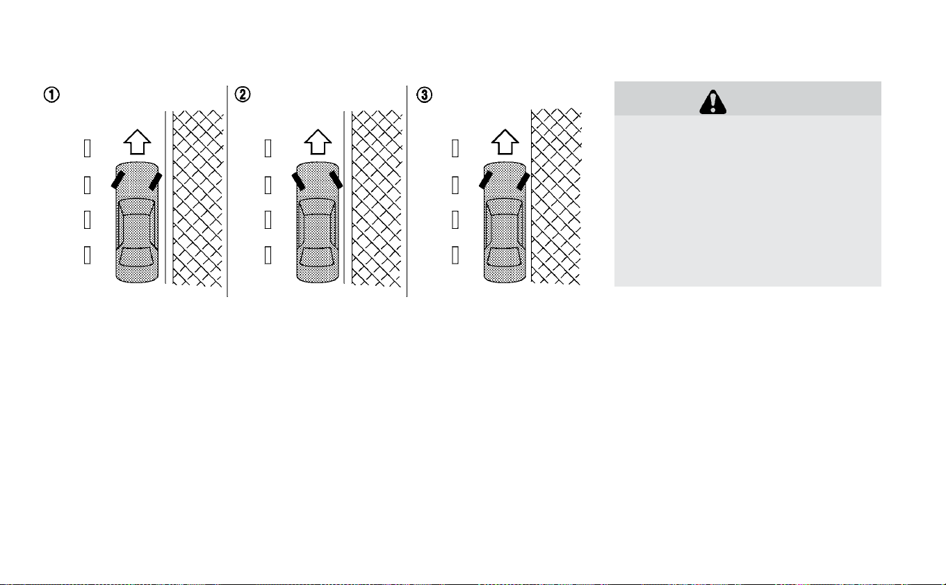
1. Firmly apply the parking brake.
2. Push the P (Park) position switch on the
shift lever.
3. To help prevent the vehicle from rolling
into the street when parked on a slope, it
is a good practice to turn the wheels as
illustrated.
HEADED DOWNHILL WITH CURB
䊊
1
:
Turn the wheels into the curb and move
the vehicle forward until the curb side
wheel gently touches the curb.
HEADED UPHILL WITH CURB
䊊
2
:
Turn the wheels away from the curb and
move the vehicle back until the curb side
wheel gently touches the curb.
HEADED UPHILL OR DOWNHILL, NO CURB
䊊
3
:
Turn the wheels toward the side of the road
so the vehicle will move away from the cen-
ter of the road if it moves.
4. Place the power switch in the OFF
position.
WARNING
• If the READY to drive indicator light is
off while driving, the power assist for
the steering will not work. Steering
will be harder to operate.
• When the power steering warning
light illuminates while the READY to
drive indicator light is on, the power
assist for the steering will cease op-
eration. You will still have control of
the vehicle but the steering will be
harder to operate.
The power steering system is designed to
provide power assistance while driving to
operate the steering wheel with less effort.
When the steering wheel is operated re-
peatedly or continuously while parking or
driving at a very low speed, the power as-
sist for the steering wheel will be reduced.
This is to prevent overheating of the power
steering system and help protect it from
getting damaged. When the power assis-
tance is reduced, steering wheel operation
will become harder. When the temperature
of the power steering system goes down,
the power assistance level will return to
normal. Avoid repeating such steering
POWER STEERING SYSTEM
Starting and driving 5-133

wheel operations that could cause the
power steering system to overheat.
You may hear a noise when the steering
wheel is operated quickly. However, this is
not a malfunction.
If the power steering warning light
illuminates while the READY to drive indica-
tor light is on, it may indicate the power
steering system is not functioning properly
and may need servicing. Have the power
steering system checked. It is recom-
mended that you visit a NISSAN certified
LEAF dealer for this service. For additional
information, refer to “Power steering warn-
ing light” in the “Instruments and controls”
section of this manual.
The power assist for steering stops operat-
ing when both the power steering warning
light and READY to drive indicator light are
illuminated. You will still have control of the
vehicle. However, greater steering effort is
needed, especially in sharp turns and at
low speeds.
BRAKE PRECAUTIONS
This vehicle is equipped with two braking
systems:
1. Hydraulic brake system
2. Regenerative brake system
Hydraulic brake system
The hydraulic brake system is similar to the
brakes used on conventional vehicles.
The brake system has two separate hy-
draulic circuits. If one circuit malfunctions,
you will still have braking at two wheels.
Regenerative brake system
The primary purpose of the regenerative
brake system is to provide some power to
help recharge the Li-ion battery and ex-
tend driving range. A secondary benefit is
“engine braking” that operates based on
battery conditions.
In the D (Drive) range, when the accelerator
is released, the regenerative brake system
provides some deceleration and gener-
ates power for the Li-ion battery. Power is
also generated when the brake pedal is
applied.
When you put the shift lever in the B mode
and take your foot off the accelerator
pedal, more regenerative brake is applied
than in the D (Drive) position. However, dur-
ing high-speed driving you may feel that
regenerative brake provides less decelera-
tion than the engine braking in an ordinary
vehicle. This is normal.
Less deceleration is provided by the regen-
erative brake system when the Li-ion bat-
tery is fully charged. Regenerative brake is
automatically reduced when the Li-ion
battery is fully charged to prevent the Li-ion
battery from becoming overcharged. Re-
generative brake is also automatically re-
duced when the battery temperature is
high/low (indicated by the red/blue zones
on the battery temperature gauge) to pre-
vent Li-ion battery damage.
The brake pedal should be used to slow or
stop the vehicle depending on traffic or
road conditions. The vehicle brakes are not
affected by regenerative brake system op-
eration.
BRAKE SYSTEM
5-134 Starting and driving
NOTE:
• When applying the regenerative brakes,
you may hear a sound coming from the
regenerative brake system. This is a
normal operating characteristic of an
EV.
• If the power switch position is in a posi-
tion other than ON or READY to drive,
you can stop the vehicle by depressing
the brake pedal. However, greater foot
pressure on the brake pedal will be re-
quired to stop the vehicle, and the stop-
ping distance will be longer.
• When depressing the brake pedal, the
brake pedal feel will not be smooth or
may change when the cooperative re-
generative brake system activates.
However, the electronically controlled
brake system is operating normally and
this does not indicate a malfunction.
Using the brakes
Avoid resting your foot on the brake pedal
while driving. This will cause overheating of
the brakes, wearing out of the brake pads
and shoes faster, and will reduce driving
range.
To help reduce brake wear, and to prevent
the brakes from overheating, reduce speed
and select B mode before going down a
slope or long grade. Overheated brakes
may reduce braking performance and
could result in loss of vehicle control.
WARNING
• While driving on a slippery surface,
be careful when braking or acceler-
ating. Abrupt braking or accelerat-
ing could cause the wheels to skid,
which could result in an accident.
• If the brake pedal is depressed with
the EV system OFF, you may feel an
increased brake pedal effort and a
decreased pedal stroke. If the BRAKE
warning light does not illuminate
and the brake pedal feels like it has
returned to its normal state after the
EV system is started, this indicates
that there is no malfunction and the
vehicle can be operated normally.
Wet brakes
When the vehicle is washed or driven
through water, the brakes may get wet. As
a result, the braking distance will be longer
and the vehicle may pull to one side during
braking.
To dry brakes, drive the vehicle at a safe
speed while lightly tapping the brake pedal
to heat up the brakes. Do this until the
brakes return to normal. Avoid driving the
vehicle at high speeds until the brakes
have dried.
Parking brake break-in
Break in the parking brake shoes whenever
the stopping effect of the parking brake is
weakened or whenever the parking brake
shoes and/or drums/rotors are replaced,
in order to assure the best braking perfor-
mance.
This procedure is described in the Genuine
NISSAN Service Manual, and it can be per-
formed by a certified repair facility. It is rec-
ommended that you visit a NISSAN certi-
fied LEAF dealer.
Starting and driving 5-135
ANTI-LOCK BRAKING SYSTEM (ABS)
WARNING
• The ABS is a sophisticated device,
but it cannot prevent accidents re-
sulting from careless or dangerous
driving techniques. It can help main-
tain vehicle control during braking
on slippery surfaces. Remember
that stopping distances on slippery
surfaces will be longer than on nor-
mal surfaces even with ABS. Stop-
ping distances may also be longer
on rough, gravel or snow covered
roads, or if you are using tire chains.
Always maintain a safe distance
from the vehicle in front of you. Ulti-
mately, the driver is responsible for
safety.
• Tire type and condition may also af-
fect braking effectiveness.
– When replacing tires, install the
specified size of tires on all four
wheels.
– For additional information, refer
to “Wheels and tires” in the “Main-
tenance and do-it-yourself” sec-
tion of this manual.
The ABS controls the brakes so the wheels
do not lock during hard braking or when
braking on slippery surfaces. The system
detects the rotation speed at each wheel
and varies the brake fluid pressure to pre-
vent each wheel from locking and sliding.
By preventing each wheel from locking, the
system helps the driver maintain steering
control and helps to minimize swerving
and spinning on slippery surfaces.
Using the system
Depress the brake pedal and hold it down.
Depress the brake pedal with firm steady
pressure, but do not pump the brakes. The
Anti-lock Braking System will operate to
prevent the wheels from locking up. Steer
the vehicle to avoid obstacles.
WARNING
Do not pump the brake pedal. Doing so
may result in increased stopping dis-
tances.
Self-test feature
The Anti-lock Braking System (ABS) in-
cludes electronic sensors, electric pumps,
hydraulic solenoids and a computer. The
computer has a built-in diagnostic feature
that tests the system each time you push
the power switch in the READY to drive po-
sition and move the vehicle at a low speed
in forward or reverse. When the self-test
occurs, you may hear a “clunk” noise
and/or feel a pulsation in the brake pedal.
This is normal and does not indicate a mal-
function. If the computer senses a mal-
function, it switches the ABS off and illumi-
nates the ABS warning light on the
instrument panel. The brake system then
operates normally, but without anti-lock
assistance.
If the ABS warning light illuminates during
the self-test or while driving, have the ve-
hicle checked. It is recommended that you
visit a NISSAN certified LEAF dealer for this
service.
Normal operation
The Anti-lock Braking System (ABS) oper-
ates at speeds above 3 to 6 mph (5 to
10 km/h). The speed varies according to
road conditions.
When the ABS senses that one or more
wheels are close to locking up, the actuator
5-136 Starting and driving

rapidly applies and releases hydraulic pres-
sure. This action is similar to pumping the
brakes very quickly. You may feel a pulsa-
tion in the brake pedal and hear a noise
from under the hood or feel a vibration
from the actuator when it is operating. This
is normal and indicates that the ABS is op-
erating properly. However, the pulsation
may indicate that road conditions are haz-
ardous and extra care is required while
driving.
The VDC system uses various sensors to
monitor driver inputs and vehicle motion.
Under certain driving conditions, the VDC
system helps to perform the following
functions.
• Controls brake pressure to reduce wheel
slip on one slipping drive wheel so power
is transferred to a drive wheel on the same
axle that is not slipping.
• Controls brake pressure and traction mo-
tor output to reduce drive wheel slip
based on vehicle speed (traction control
function).
• Controls brake pressure at individual
wheels and traction motor output to help
the driver maintain control of the vehicle
in the following conditions:
• Understeer (vehicle tends to not follow the
steered path despite increased steering
input).
• Oversteer (vehicle tends to spin due to
certain road or driving conditions).
The VDC system can help the driver main-
tain control of the vehicle, but it cannot
prevent loss of vehicle control in all driving
situations.
When the VDC system operates, the
indicator light in the instrument panel
flashes. When the indicator light flashes,
note the following items:
• The road may be slippery or the system
may determine some action is required to
help keep the vehicle on the steered path.
• You may feel a pulsation in the brake pedal
and hear a noise or vibration from under
the hood. This is normal and indicates
that the VDC system is working properly.
• Adjust your speed and driving according
to the road conditions.
For additional information, refer to “Slip in-
dicator light” and “Vehicle Dynamic Control
( VDC) OFF indicator light” in the “Instru-
ments and controls” section of this manual.
If a malfunction occurs in the system, the
indicator light illuminates in the ve-
hicle information display. The VDC system
automatically turns off when this indicator
light is lit.
The vehicle information display is used to
turn off the VDC system. The VDC OFF indi-
cator light
illuminates to indicate that
the VDC system is off. When the vehicle
VEHICLE DYNAMIC CONTROL (VDC)
SYSTEM
Starting and driving 5-137
information display is used to turn off the
system, the VDC system still operates to
prevent one drive wheel from slipping by
transferring power to a non-slipping wheel.
The
indicator light flashes if this oc-
curs. All other VDC functions are off and the
indicator light will not flash. The VDC
system is automatically reset to on when
the power switch is placed in the OFF posi-
tion then back to the ON position. For addi-
tional information, refer to “Vehicle infor-
mation display” in the “Instruments and
controls” section of this manual.
The computer has a built-in diagnostic fea-
ture that tests the system each time you
start the EV and move the vehicle forward
or in reverse at a slow speed. When the
self-test occurs, you may hear a “clunk”
noise and/or feel a pulsation in the brake
pedal. This is normal and is not an indica-
tion of a malfunction.
WARNING
• The VDC system is designed to help
the driver maintain stability but
does not prevent accidents due to
abrupt steering operation at high
speeds or by careless or dangerous
driving techniques. Reduce vehicle
speed and be especially careful
when driving and cornering on slip-
pery surfaces and always drive care-
fully.
• Do not modify the vehicle’s suspen-
sion. If suspension parts such as
shock absorbers, struts, springs,
stabilizer bars, bushings and wheels
are not NISSAN recommended for
your vehicle or are extremely dete-
riorated the VDC system may not op-
erate properly. This could adversely
affect vehicle handling perfor-
mance, and the
indicator light
may flash or the
indicator
light may illuminate.
• If brake related parts such as brake
pads, rotors and calipers are not
NISSAN recommended or are ex-
tremely deteriorated, the VDC sys-
tem may not operate properly and
the
indicator light may illumi-
nate.
• If traction motor control related
parts are not NISSAN recommended
or are extremely deteriorated, the
indicator light may illuminate.
• When driving on extremely inclined
surfaces such as higher banked cor-
ners, the VDC system may not oper-
ate properly and the
indicator
light may illuminate. Do not drive on
these types of roads.
• When driving on an unstable surface
such as a turntable, ferry, elevator or
ramp, the
indicator light may il-
luminate. This is not a malfunction.
Restart the EV system after driving
onto a stable surface.
• If wheels or tires other than the
NISSAN recommended ones are
used, the VDC system may not oper-
ate properly and the
indicator
light may illuminate.
• The VDC system is not a substitute
for winter tires or tire chains on a
snow covered road.
5-138 Starting and driving

The chassis control is an electric control
module that includes the following func-
tions:
• Intelligent Trace Control
INTELLIGENT TRACE CONTROL
(I-TC)
This system senses driving based on the
driver’s steering and acceleration/braking
patterns, and controls brake pressure at
individual wheels to aid tracing at corners
and help smooth vehicle response.
The I-TC can be set to on (enabled) or off
(disabled) through the vehicle information
display “Settings” page. For additional infor-
mation, refer to “Vehicle information dis-
play” in the “Instruments and controls” sec-
tion of this manual.
When the Vehicle Dynamic Control (VDC)
OFF switch is used to turn off the VDC sys-
tem, the I-TC is also turned off.
When the I-TC is operated and the “Chassis
Control” mode is selected in the vehicle in-
formation display, the I-TC graphics are
shown in the vehicle information display.
For additional information, refer to “Vehicle
information display” in the “Instruments
and controls” section of this manual.
If the “Chassis Control System Error: See
Owner’s Manual” warning message ap-
pears in the vehicle information display, it
CHASSIS CONTROL
Starting and driving 5-139

may indicate that the I-TC is not function-
ing properly. Have the system checked as
soon as possible. It is recommended that
you visit a NISSAN certified LEAF dealer for
this service.
WARNING
The I-TC may not be effective depend-
ing on the driving condition. Always
drive carefully and attentively.
When the I-TC is operating, you may feel a
pulsation in the brake pedal and hear a
noise. This is normal and indicates that the
I-TC is operating properly.
Even if the I-TC is turned off, some functions
will remain on to assist the driver (for ex-
ample, avoidance scenes).
WARNING
• Never rely solely on the hill start as-
sist system to prevent the vehicle
from moving backward on a hill. Al-
ways drive carefully and attentively.
Depress the brake pedal when the
vehicle is stopped on a steep hill. Be
especially careful when stopped on
a hill on frozen or muddy roads. Fail-
ure to prevent the vehicle from roll-
ing backwards may result in a loss of
control of the vehicle and possible
serious injury or death.
• The hill start assist system is not de-
signed to hold the vehicle at a stand-
still on a hill. Depress the brake pedal
when the vehicle is stopped on a
steep hill. Failure to do so may cause
the vehicle to roll backwards and
may result in a collision or serious
personal injury.
• The hill start assist may not prevent
the vehicle from rolling backwards
on a hill under all load or road condi-
tions. Always be prepared to de-
press the brake pedal to prevent the
vehicle from rolling backwards. Fail-
ure to do so may result in a collision
or serious personal injury.
The hill start assist system automatically
keeps the brakes applied to help prevent
the vehicle from rolling backwards in the
time it takes the driver to release the brake
pedal and apply the accelerator when the
vehicle is stopped on a hill.
Hill start assist will operate automatically
under the following conditions:
• The shift lever is placed in the D (Drive), B
mode, or R (Reverse) position.
• The vehicle is stopped completely on a hill
by applying the brake.
The maximum holding time is 2 seconds.
After 2 seconds the vehicle will begin to roll
back and hill start assist will stop operating
completely.
Hill start assist will not operate when the
shift lever is placed in the N (Neutral) or P
(Park) position or on a flat and level road.
HILL START ASSIST SYSTEM
5-140 Starting and driving

CAUTION
To prevent damage to the Li-ion bat-
tery: Do not store the vehicle in tem-
peratures below -13°F (-25°C) for over
seven days. If the outside temperature
is -13°F (-25°C) or less, the Li-ion battery
may freeze and it cannot be charged or
provide power to run the vehicle. Move
the vehicle to a warm location.
NOTE:
• Connect the charger to the vehicle and
place the power switch in the OFF posi-
tion when parking the vehicle if tem-
peratures may go below -4°F (-20°C).
This provides external power to the Li-
ion battery warmer (if so equipped)
when it operates and does not dis-
charge the Li-ion battery. Vehicle driv-
ing range is reduced if the Li-ion battery
warmer (if so equipped) operates (Li-ion
battery temperature approximately
-4°F (-20°C) or colder) while driving the
vehicle. You may need to charge the Li-
ion battery sooner than in warmer tem-
peratures.
• The Li-ion battery requires more time to
charge when the Li-ion battery warmer
(if so equipped) operates.
• The predicted charging time displayed
on the meter and navigation system in-
creases when the Li-ion battery warmer
(if so equipped) operates.
• Vehicle range may be substantially re-
duced in extremely cold conditions (for
example under -4°F (-20°C)).
• Using the climate control system to
heat the cabin when outside tempera-
ture is below 32°F (0°C) uses more elec-
tricity and affects vehicle range more
than when using the heater when the
temperature is above 32°F (0°C).
• Climate control performance is reduced
when using the Climate Ctrl. Timer or
Remote Climate Control while the Li-ion
battery warmer (if so equipped) oper-
ates. Set only the charging timer [End
Time] when charging in cold weather.
The vehicle automatically determines
when to start charging to fully charge
the Li-ion battery, even if the Li-ion bat-
tery warmer operates. Charging ends
before the set end time if the Li-ion bat-
tery is fully charged.
FREEING A FROZEN DOOR LOCK
To prevent a door lock from freezing, apply
deicer through the key hole. If the lock be-
comes frozen, heat the key before inserting
it into the key hole or use the remote key-
less entry key fob.
ANTIFREEZE
In the winter when it is possible that the
outside temperature will drop below 32°F
(0°C), check the antifreeze to ensure proper
winter protection. For additional informa-
tion, refer to “Cooling system” in the “Main-
tenance and do-it-yourself” section of this
manual.
12-VOLT BATTERY
If the 12-volt battery is not fully charged
during extremely cold weather conditions,
the 12-volt battery fluid may freeze and
damage the 12-volt battery. To maintain
maximum efficiency, the 12-volt battery
should be checked regularly. For additional
information, refer to “12-volt battery” in the
COLD WEATHER DRIVING
Starting and driving 5-141

“Maintenance and do-it-yourself” section
of this manual.
DRAINING OF COOLANT WATER
If the vehicle is to be left outside without
antifreeze, drain the cooling system. Refill
before operating the vehicle. For additional
information, refer to “Cooling system” in the
“Maintenance and do-it-yourself” section
of this manual.
TIRE EQUIPMENT
SUMMER tires have a tread designed to
provide superior performance on dry
pavement. However, the performance of
these tires will be substantially reduced in
snowy and icy conditions. If you operate
your vehicle on snowy or icy roads, NISSAN
recommends the use of MUD & SNOW or
ALL SEASON tires on all four wheels. It is
recommended that you visit a NISSAN cer-
tified LEAF dealer for the tire type, size,
speed rating and availability information.
For additional traction on icy roads, stud-
ded tires may be used. However, some U.S.
states and Canadian provinces prohibit
their use. Check local, state and provincial
laws before installing studded tires.
Skid and traction capabilities of studded
snow tires, on wet or dry surfaces, may
be poorer than that of non-studded
snow tires.
Tire chains may be used. For additional in-
formation, refer to “Tire chains” in the “Main-
tenance and do-it-yourself” section of this
manual.
SPECIAL WINTER EQUIPMENT
It is recommended that the following items
be carried in the vehicle during winter:
• A scraper and stiff-bristled brush to re-
move ice and snow from the windows and
wiper blades.
• A shovel to dig the vehicle out of
snow-drifts.
• Extra windshield-washer fluid to refill the
reservoir tank.
DRIVING ON SNOW OR ICE
WARNING
• Wet ice (32°F, 0°C and freezing rain),
very cold snow or ice can be slick and
very hard to drive on. The vehicle will
have much less traction or “grip” un-
der these conditions. Try to avoid
driving on wet ice until the road is
salted or sanded.
• Whatever the conditions, drive with
caution. Accelerate and slow down
with care. If accelerating too fast, the
drive wheels will lose even more
traction.
•
Allow more stopping distance under
these conditions. Braking should be
started sooner than on dry pavement.
• Allow greater following distances on
slippery roads.
• Watch for slippery spots (glare ice).
These may appear on an otherwise
clear road in shaded areas. If a patch
of ice is seen ahead, brake before
reaching it. Try not to brake while on
the ice, and avoid any sudden steer-
ing maneuvers.
• Do not use cruise control on slippery
roads.
5-142 Starting and driving

FREEING A FROZEN CHARGE PORT
LID
When the charge por t is frozen, melt the ice
using a hair dryer.
PARKING BRAKE
CAUTION
When parking in an area where the
outside temperature is below 32°F
(0°C), do not apply the parking brake to
prevent it from freezing.
For safe parking, place the shift lever in
the P (Park) position and securely
block the wheels.
Starting and driving 5-143

NOTES
5-144 Starting and driving

6 In case of emergency
Hazard warning flasher switch .............6-2
Roadside assistance program .............6-2
Emergency EV (Electric Vehicle) shut off .......6-3
Flat tire ............................6-3
Tire Pressure Monitoring System (TPMS).....6-3
Repairing flat tire ....................6-4
Jump starting .......................6-10
If the Li-ion battery becomes completely
discharged .........................6-13
Push starting ........................6-14
Towing your vehicle....................6-14
Towing recommended by NISSAN ........6-15
Vehicle recovery (freeing a stuck vehicle). . . .6-15
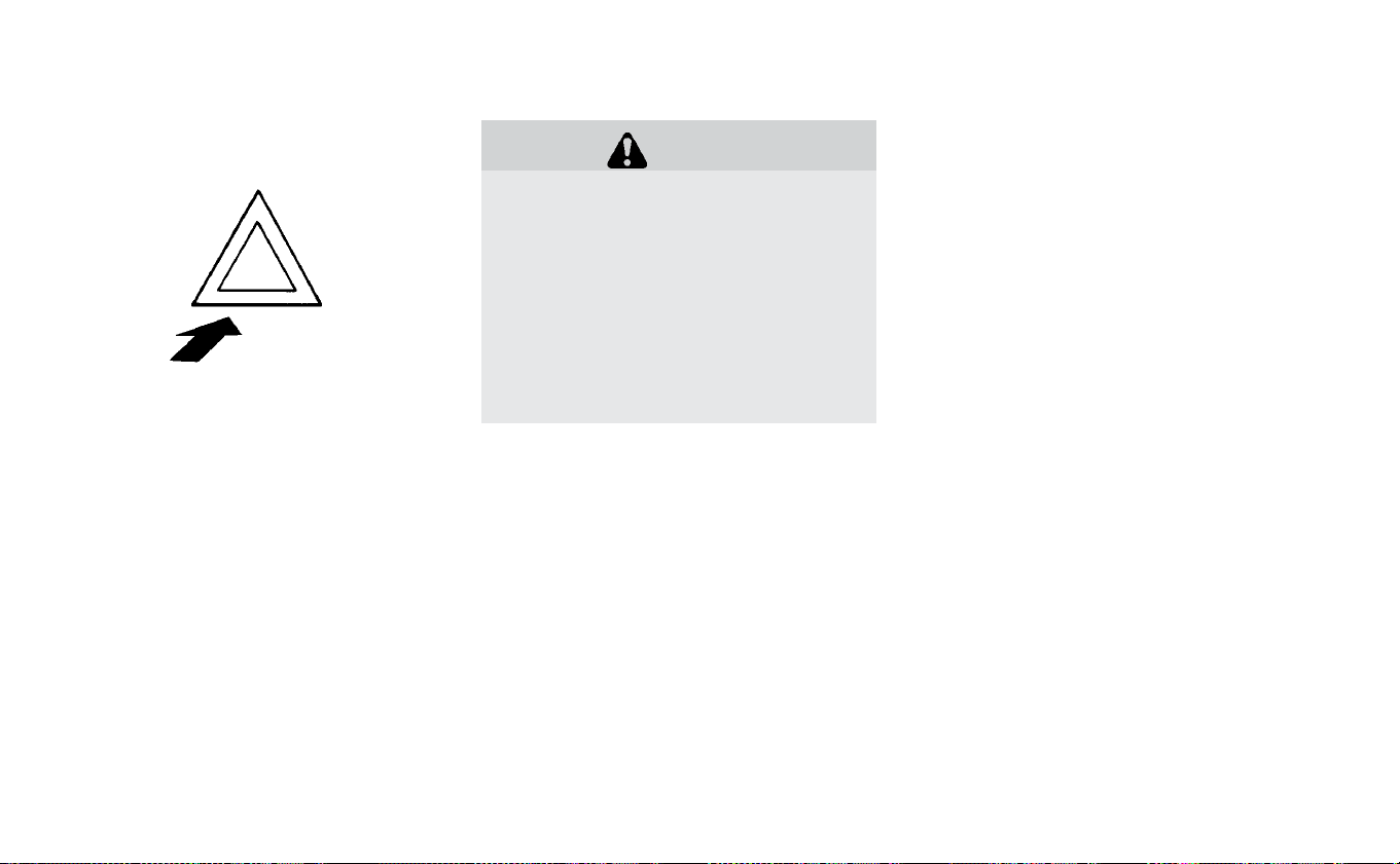
Push the switch on to warn other drivers
when you must stop or park under emer-
gency conditions. All turn signal lights will
flash.
WARNING
• If stopping for an emergency, be
sure to move the vehicle well off the
road.
• Do not use the hazard warning
flashers while moving on the high-
way unless unusual circumstances
force you to drive so slowly that your
vehicle might become a hazard to
other traffic.
• Turn signals do not work when the
hazard warning flasher lights are on.
The flasher can be actuated with the
power switch in any position.
Some jurisdictions may prohibit the use
of the hazard warning flasher switch
while driving.
In the event of a roadside emergency,
Roadside Assistance Service is available to
you. For additional information, please refer
to your Warranty Information Booklet (U.S.)
or Warranty & Roadside Assistance Infor-
mation Booklet (Canada) for details.
HAZARD WARNING FLASHER SWITCH ROADSIDE ASSISTANCE PROGRAM
6-2 In case of emergency
To shut off the EV system in an emergency
situation while driving, perform the follow-
ing procedure.
• Rapidly push the power switch three con-
secutive times in less than 1.5 seconds, or
• Push and hold the power switch for more
than 2 seconds.
TIRE PRESSURE MONITORING
SYSTEM (TPMS)
This vehicle is equipped with TPMS. It moni-
tors tire pressure of all tires. When the low
tire pressure warning light is lit, and the “Tire
Pressure Low — Add Air” warning appears
on the vehicle information display, one or
more of your tires is significantly under-
inflated. If the vehicle is being driven with
low tire pressure, the TPMS will activate and
warn you of it by the low tire pressure warn-
ing light. This system will activate only
when the vehicle is driven at speeds above
16 mph (25 km/h). For additional informa-
tion, refer to “Warning lights, indicator lights
and audible reminders” in the “Instruments
and controls” section and “Tire Pressure
Monitoring System (TPMS)” in the “Starting
and driving” section of this manual.
WARNING
• Radio waves could adversely affect
electric medical equipment. Those
who use a pacemaker should con-
tact the electric medical equipment
manufacturer for the possible influ-
ences before use.
• If the low tire pressure warning light
illuminates while driving, avoid sud-
den steering maneuvers or abrupt
braking, reduce vehicle speed, pull
off the road to a safe location and
stop the vehicle as soon as possible.
Driving with underinflated tires may
permanently damage the tires and
increase the likelihood of tire failure.
Serious vehicle damage could occur
and may lead to an accident and
could result in serious personal in-
jury. Check the tire pressure for all
four tires. Adjust the tire pressure to
the recommended COLD tire pres-
sure shown on the Tire and Loading
Information label to turn the low tire
pressure warning light OFF. If the
light still illuminates while driving
after adjusting the tire pressure, a
tire may be flat. If you have a flat tire,
repair it as soon as possible.
• When replacing a wheel without the
TPMS such as the spare tire, TPMS
will not function and the low tire
pressure warning light will flash for
approximately 1 minute. The light
will remain on after 1 minute. Have
your tires replaced and/or TPMS
system reset as soon as possible. It
EMERGENCY EV (ELECTRIC VEHICLE)
SHUT OFF FLAT TIRE
In case of emergency 6-3

is recommended that you visit a
NISSAN certified LEAF dealer for
these services.
• Replacing tires with those not origi-
nally specified by NISSAN could af-
fect the proper operation of the
TPMS.
• The Genuine NISSAN Emergency Tire
Repair Sealant or equivalent can be
used for temporarily repairing a tire.
Do not inject any other tire liquid or
aerosol tire sealant into the tires, as
this may cause a malfunction of tire
pressure sensors.
• NISSAN recommends using only
NISSAN Genuine Emergency Tire
Sealant provided with your vehicle.
Other tire sealants may damage the
valve stem seal which can cause the
tire to lose air pressure. It is recom-
mended that you visit a NISSAN cer-
tified LEAF dealer as soon as pos-
sible after using tire repair sealant
(for models equipped with the emer-
gency tire puncture repair kit).
REPAIRING FLAT TIRE
WARNING
•
After using Emergency Tire Sealant
to repair a minor tire puncture, do
not drive the vehicle at speeds faster
than 50 mph (80 km/h).
•
Immediately after using the Emer-
gency Tire Sealant to repair a minor
tire puncture, it is recommended
that you visit a NISSAN certified LEAF
dealer. The Emergency Tire Sealant
cannot permanently seal a punc-
tured tire. Continuing operation of
the vehicle without a permanent tire
repair can lead to a crash.
•
If you used the Emergency Tire Seal-
ant to repair a minor tire puncture, it
is recommended that you visit a
NISSAN certified LEAF dealer to re-
place the TPMS sensor in addition to
repairing or replacing the tire.
•
NISSAN recommends using only
NISSAN Genuine Emergency Tire
Sealant provided with your vehicle.
Other tire sealants may damage the
valve stem seal which can cause the
tire to lose air pressure.
This vehicle does not have a spare tire. The
emergency tire puncture repair kit (Emer-
gency Tire Sealant) is supplied with the ve-
hicle instead of a spare tire. It can be used
to temporarily repair minor tire punctures.
If possible, have the vehicle towed to a fa-
cility that can repair or replace the flat tire.
Using the emergency tire puncture repair
kit may cause a malfunction of the tire
pressure sensor and cause the low tire
pressure warning light to illuminate.
CAUTION
•
To avoid the emergency tire punc-
ture kit being damaged during stor-
age or use:
–
Only use the emergency tire punc-
ture repair kit on your vehicle. Do
not use it on other vehicles.
6-4 In case of emergency

–
Only use the kit to inflate the tires
of your vehicle and to check the
vehicle’s tire pressure.
–
Only plug the compressor into a
12-volt DC car power point.
–
Keep the kit free of water and dirt.
–
Do not disassemble or modify the
kit.
–
Do not drop the kit or allow hard
impacts to the kit.
•
Do not use the emergency tire punc-
ture repair kit under the following
conditions. It is recommended that
you visit a NISSAN certified LEAF
dealer or professional road
assistance.
–
when the sealant has passed its
expiration date (shown on the la-
bel attached to the bottle)
–
when the cut or the puncture is
approximately 0.25 in (6 mm) or
longer
–
when the tire sidewall is damaged
–
when the vehicle has been driven
with extremely low tire pressure
–
when the tire has come off the in-
side or the outside of the wheel
–
when the tire wheel is damaged
–
when two or more tires are flat
If you have a flat tire, follow the instructions
below.
Stopping the vehicle
1. Safely move the vehicle off the road and
away from traffic.
2. Turn on the hazard warning flashers.
3. Park on a level surface and apply the
parking brake.
4. Push the P (Park) position switch on the
shift lever to the P (Park) position.
5. Turn off the EV system.
6. Raise the hood to warn other traffic and
to signal professional road assistance
personnel that you need assistance.
7. Have all passengers get out of the ve-
hicle and stand in a safe place, away
from traffic and clear of the vehicle.
WARNING
•
Make sure the parking brake is se-
curely applied and the vehicle is
placed into the P (Park) position.
•
Never repair tires when the vehicle is
on a slope, ice or slippery areas. This
is hazardous.
•
Never repair tires if oncoming traffic
is close to your vehicle. Wait for pro-
fessional road assistance.
In case of emergency 6-5

Getting emergency tire puncture
repair kit
Take out the emergency tire puncture re-
pair kit located in the cargo area. The repair
kit consists of the following items:
䊊
1
Tire sealant bottle
䊊
2
Air compressor*
䊊
3
Speed restriction sticker
* The compressor shape may differ de-
pending on the models.
Before using emergency tire
puncture repair kit
• If any foreign object (for example, a screw
or nail) is embedded in the tire, do not
remove it.
• Check the expiration date of the sealant
(shown on the label attached to the
bottle). Never use a sealant whose expira-
tion date has passed.
Repairing tire:
WARNING
Observe the following precautions
when using the tire repair compound.
•
Swallowing the compound is dan-
gerous. Immediately drink as much
water as possible and seek prompt
medical assistance.
•
Rinse well with lots of water if the
compound comes into contact with
skin or eyes. If irritation persists,
seek prompt medical attention.
•
Keep the repair compound out of the
reach of children.
•
The emergency repair compound
may cause a malfunction of the tire
pressure sensors and cause the low
tire pressure warning light to illumi-
nate. Have the tire pressure sensor
replaced as soon as possible.
6-6 In case of emergency
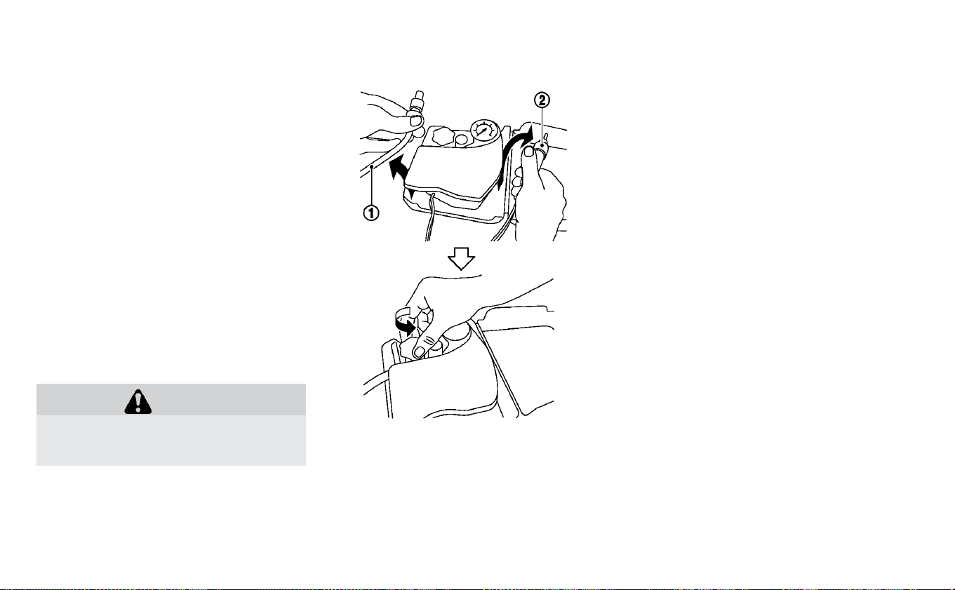
1. Take out the speed restriction sticker
from the air compressor, then put it in a
location where the driver can see it while
driving.
CAUTION
Do not put the speed restriction label
on the steering wheel pad, the speed-
ometer or the warning light locations.
2. Take the hose
䊊
1
and the power plug
䊊
2
out of the air compressor. Remove the
cap of the bottle holder from the air
compressor.
3. Remove the cap from the tire sealant
bottle. Leave the bottle seal intact.
Screw the bottle clockwise into the
bottle holder to pierce the seal of the
bottle.
In case of emergency 6-7
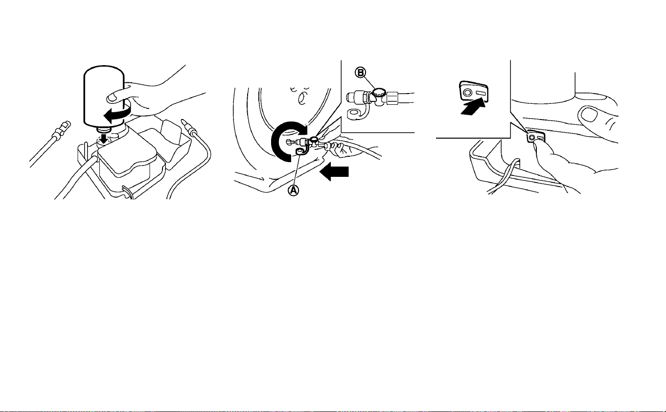
4. Remove the cap from the tire valve on
the flat tire.
5. Remove the protective cap
䊊
A
of the
hose and screw the hose securely onto
the tire valve. Make sure that the pres-
sure release valve
䊊
B
is securely tight-
ened. Make sure that the air compressor
switch is in the OFF (O) position, and
then insert the power plug into the
power outlet in the vehicle.
6. Push the power switch to the ACC posi-
tion. Then turn the compressor switch
to the ON (−) position and inflate the tire
up to the pressure that is specified on
the Tire and Loading Information label
affixed to the driver’s side center pillar if
possible, or to the minimum of 26 psi
(180 kPa). Turn the air compressor off
briefly in order to check the tire pressure
with the pressure gauge.
6-8 In case of emergency

If the tire is inflated to higher than the
specified pressure, lower the tire pres-
sure by releasing air with the pressure
release valve.
NOTE:
The compressor tire pressure gauge
may show a pressure reading of 87 psi
(600 kPa) for about 30 seconds while
inflating the tire. The pressure gauge
is indicating the pressure inside the
sealant can. When the sealant has
been injected into the tire the pres-
sure gauge will drop and indicate ac-
tual tire pressure.
WARNING
To avoid serious personal injury while
using the emergency tire puncture re-
pair kit:
• Securely tighten the compressor
hose to the tire valve. Failure to do so
can cause the sealant to spray into
the air and get into your eyes or on
the skin.
• Do not stand directly beside the dam-
aged tire while it is being inflated be-
cause of the risk of the rupture. If
there are any cracks or bumps, turn
the compressor off immediately.
If the tire pressure does not increase to
26 psi (180 kPa) within 10 minutes, the
tire may be seriously damaged and the
tire cannot be repaired with this tire
repair kit. It is recommended that you
visit a NISSAN certified LEAF dealer.
7. When the tire pressure is at the specified
amount, turn the air compressor off. If
the tire cannot be inflated to the speci-
fied amount, the air compressor can be
turned off at the minimum of 26 psi
(180 kPa). Remove the power plug from
the power outlet and quickly remove the
hose from the tire valve. Attach the pro-
tective cap and valve cap. Properly stow
the emergency tire puncture repair kit in
the cargo area.
CAUTION
To avoid serious personal injury when
stowing the emergency tire puncture
repair kit:
• Keep the sealant bottle screwed into
the compressor. Failure to do so can
cause the sealant to spray into the air
and get into your eyes or on the skin.
8. Immediately drive the vehicle for 10 min-
utes or 2 miles (3 km) at a speed below
50 mph (80 km/h).
9. After driving, make sure that the air
compressor switch is in the OFF posi-
tion, then screw the hose securely onto
the tire valve. Check the tire pressure
with the pressure gauge. Temporary re-
pair is completed if the tire pressure
does not drop.
Make sure the pressure is adjusted to
the pressure that is specified on the Tire
and Loading Information label before
driving.
In case of emergency 6-9

10. If the tire pressure drops, repeat the
steps from 5 to 9. If the pressure drops
again or under 19 psi (130 kPa), the tire
cannot be repaired with this tire re-
pair kit. If the tire cannot be repaired,
the driver should not drive on it any
further. The car should be towed to the
nearest dealership.
The sealant bottle and hose cannot be
reused to repair another punctured tire.
It is recommended that you visit a
NISSAN certified LEAF dealer to pur-
chase replacements.
After repairing tire:
It is recommended that you visit a NISSAN
certified LEAF dealer for tire repair/
replacement as soon as possible.
WARNING
•
After using Emergency Tire Sealant
to repair a minor tire puncture, do
not drive the vehicle at speeds faster
than 50 mph (80 km/h).
•
Immediately after using Emergency
Tire Sealant to repair a minor tire
puncture, it is recommended that
you visit a NISSAN certified LEAF
dealer. The Emergency Tire Sealant
cannot permanently seal a punc-
tured tire. Continuing operation of
the vehicle without a permanent tire
repair can lead to a crash.
• Do not inject any tire liquid or aero-
sol tire sealant into the tires, as this
may cause a malfunction of the tire
pressure sensors.
• If you used the Emergency Tire Seal-
ant to repair a minor tire puncture, it
is recommended that you visit a
NISSAN certified LEAF dealer to re-
place the TPMS sensor in addition to
repairing or replacing the tire.
• NISSAN recommends using only
NISSAN Genuine Emergency Tire
Sealant provided with your vehicle.
Other tire sealants may damage the
valve stem seal which can cause the
tire to lose air pressure.
To start your EV system with a booster bat-
tery, the instructions and precautions be-
low must be followed.
Jump starting provides power to the 12-
volt system to allow the electrical systems
to operate. The electrical systems must be
operating to allow the Li-ion battery to be
charged. Jump starting does not charge
the Li-ion battery. The Li-ion battery must
be charged before the vehicle can be
driven.
WARNING
• If done incorrectly, jump starting can
lead to a 12-volt battery explosion,
resulting in severe injury or death. It
could also damage your vehicle.
• Explosive hydrogen gas is always
present in the vicinity of the 12-volt
battery. Keep all sparks and flames
away from the 12-volt battery.
• Do not allow battery fluid to come
into contact with eyes, skin, clothing
or painted surfaces. Battery fluid is a
corrosive sulfuric acid solution that
can cause severe burns. If the fluid
comes into contact with anything,
JUMP STARTING
6-10 In case of emergency

immediately flush the contacted
area with water.
• Keep the 12-volt battery out of the
reach of children.
• The booster battery must be rated
at 12 volt. Use of an improperly rated
battery can damage your vehicle.
• Whenever working on or near a 12-
volt battery, always wear suitable
eye protectors (for example,
goggles or industrial safety spec-
tacles) and remove rings, metal
bands, or any other jewelry. Do not
lean over the 12-volt battery when
jump starting.
• Do not attempt to jump start a fro-
zen battery. It could explode and
cause serious injury.
• Your vehicle has an automatic cool-
ing fan. It could come on at any time.
Keep hands and other objects away
from it.
WARNING
• Always follow the instructions be-
low. Failure to do so could result in
damage to the DC/DC converter and
cause personal injury.
• Do not attempt to perform a jump
start on the 12-volt battery at the
same time that the Li-ion battery is
being charged. Doing so may dam-
age the vehicle or charging equip-
ment and could cause an injury.
CAUTION
LEAF cannot be used as a booster ve-
hicle because it cannot supply enough
power to start a gasoline engine. How-
ever, a gasoline engine vehicle can be
used to jump start LEAF's 12-volt bat-
tery.
In case of emergency 6-11

1. If the booster battery is in another ve-
hicle
䊊
B
, position the two vehicles (
䊊
A
and
䊊
B
) to bring their 12-volt batteries
into close proximity to each other.
Do not allow the two vehicles to
touch.
2. Apply the parking brake.
If the 12-volt battery is discharged,
the power switch cannot be moved
from the OFF position. Connect the
jumper cables to the booster vehicle
䊊
B
before pushing the power switch.
3. Push the P (Park) position switch to
place the vehicle in the P (Park) position.
4. Switch off all unnecessary electrical sys-
tems (headlights, heater, air conditioner,
etc.).
5. Place the power switch in the OFF
position.
6. Ensure vent caps are level and tight.
7. Connect jumper cables in the sequence
as illustrated (
䊊
1
→
䊊
2
→
䊊
3
→
䊊
4
).
CAUTION
•
Always connect positive (+) to positive
(+) and negative (−) to body ground
(for example, as illustrated), not to the
12-volt battery.
• Make sure the jumper cables do not
touch moving parts in the motor
compartment and that the cable
clamps do not contact any other
metal.
8. Start the engine of the booster vehicle
䊊
B
.
9. While the booster vehicle
䊊
B
engine is
running, place the EV system in the
READY to drive position.
CAUTION
If the system does not start right away,
push the power switch to the OFF po-
sition and wait 10 seconds before try-
ing again.
10. After starting your EV system, carefully
disconnect the negative cable and
then the positive cable (
䊊
4
→
䊊
3
→
䊊
2
→
䊊
1
) and keep in the READY to drive po-
sition over 20 minutes to charge the
12-volt battery.
6-12 In case of emergency

11. If necessary, connect the vehicle to a
charging station or EVSE (Electric Ve-
hicle Supply Equipment) to charge the
Li-ion battery. For additional informa-
tion, refer to the “Charging” section. The
vehicle cannot be driven until the Li-ion
battery is charged.
NOTE:
If it is not possible to turn the system ON
by following this procedure, it is recom-
mended that you visit a NISSAN certified
LEAF dealer immediately.
If the power limitation indicator light
illuminates, the traction motor output is
limited resulting in reduced vehicle speed.
Stop the vehicle in a safe location before
the Li-ion battery becomes completely dis-
charged and no power is available to drive
the vehicle. Contact Roadside assistance;
refer to a NISSAN Warranty Information
Booklet.
If possible, place the power switch in the
OFF position while waiting for assistance to
prevent discharging the 12-volt battery.
NOTE:
If the Li-ion battery becomes completely
discharged:
• The vehicle is automatically placed in
the ON position and it will not be pos-
sible to switch to the READY to drive po-
sition.
• The vehicle is automatically switched to
the N (Neutral) position and it will not be
possible to drive the vehicle.
WARNING
If the vehicle is in the N (Neutral) posi-
tion and the Li-ion battery and the 12-
volt battery become completely dis-
charged, the vehicle cannot be placed
in the P (Park) position. If this occurs,
place suitable blocks at both the front
and back of a wheel to prevent the ve-
hicle from moving. Failure to block a
wheel may allow the vehicle to move
unexpectedly which may result in seri-
ous personal injury or death.
To place the vehicle in the READY to drive
position so the vehicle can be driven,
charge the Li-ion battery until the driving
range on the instrument panel changes
from “---” to a numeric distance.
NOTE:
• Some vibration may occur when the ve-
hicle is stopped in case the Li-ion bat-
tery becomes completely discharged.
This is not the malfunction of the sys-
tem.
• If the Li-ion battery is completely dis-
charged, it is required to charge until
the low battery charge warning light
turns off (white) from on (yellow).
IF THE LI-ION BATTERY BECOMES
COMPLETELY DISCHARGED
In case of emergency 6-13

Do not attempt to start the system by
pushing the vehicle.
CAUTION
An EV cannot be push-started or tow-
started. Attempting to do so may
cause traction motor damage.
When towing your vehicle, all State (Provin-
cial in Canada) and local regulations for
towing must be followed. Incorrect towing
equipment could damage your vehicle.
Towing instructions are available from a
NISSAN certified LEAF dealer. Local service
operators are familiar with the applicable
laws and procedures for towing. To assure
proper towing and to prevent accidental
damage to your vehicle, NISSAN recom-
mends that you have a service operator
tow your vehicle. It is advisable to have the
service operator carefully read the follow-
ing precautions.
WARNING
• Never ride in a vehicle that is being
towed.
• Never get under your vehicle after it
has been lifted by a tow truck.
CAUTION
• When towing, make sure that the ax-
les, steering system and power train
are in working condition. If any unit
is damaged, dollies must be used.
• Always attach safety chains before
towing.
For additional information about towing
your vehicle behind a Recreational Vehicle
(RV), refer to “Flat towing” in the “Technical
and consumer information” section of this
manual.
PUSH STARTING TOWING YOUR VEHICLE
6-14 In case of emergency

TOWING RECOMMENDED BY
NISSAN
NISSAN recommends that your vehicle be
towed with the driving (front) wheels off the
ground or that the vehicle be placed on a
flatbed truck as illustrated.
CAUTION
• Never tow with the front wheels on
the ground or four wheels on the
ground (forward or backward), as
this may cause serious and expen-
sive damage to the motor.
• When towing this vehicle with the
rear wheels on the ground (if you do
not use towing dollies): Always re-
lease the parking brake.
NOTE:
If your vehicle cannot be moved because
the vehicle cannot be shifted to the N
(Neutral) position, please refer to the
LEAF Roadside Assistance Guide which is
located at www.NISSANUSA.com. If your
vehicle cannot be moved because the
parking brake cannot be released, refer
to “Parking brake” in the “Starting and
driving” section of this manual.
VEHICLE RECOVERY (FREEING A
STUCK VEHICLE)
WARNING
To avoid vehicle damage, serious per-
sonal injury or death when recovering
a stuck vehicle:
• Contact a professional towing ser-
vice to recover the vehicle if you
have any questions regarding the
recovery procedure.
• Tow chains or cables must be at-
tached only to main structural
members of the vehicle.
• Do not use the vehicle tie-downs to
tow or free a stuck vehicle.
• Only use devices specifically de-
signed for vehicle recovery and fol-
low the manufacturer’s instructions.
• Always pull the recovery device
straight out from the front of the ve-
hicle. Never pull at an angle.
• Route recovery devices so they do
not touch any part of the vehicle ex-
cept the attachment point.
In case of emergency 6-15

If your vehicle is stuck in sand, snow, mud,
etc., use a tow strap or other device de-
signed specifically for vehicle recovery. Al-
ways follow the manufacturer’s instruc-
tions for the recovery device.
Rocking a stuck vehicle
If the vehicle is stuck in sand, snow, mud,
etc., try to free it by following the procedure
below.
1. Turn off the Vehicle Dynamic Control
( VDC) system.
2. Make sure the area in front and behind
the vehicle is clear of obstructions.
3. Turn the steering wheel left and right to
clear an area around the front tires.
4. Slowly rock the vehicle forward and
backward.
• Shift back and forth between the R (Re-
verse) and D (Drive) positions.
• Apply the accelerator as little as pos-
sible to maintain the rocking motion.
• Release the accelerator pedal before
shifting between R (Reverse) and D
(Drive).
• Do not spin the tires above 35 mph
(55 km/h).
5. If the vehicle cannot be freed after a few
tries, contact a professional towing ser-
vice to remove the vehicle.
6-16 In case of emergency

7 Appearance and care
Cleaning exterior ......................7-2
Washing ..........................7-2
Waxing ...........................7-2
Removing spots.....................7-3
Underbody ........................7-3
Glass ............................7-3
Wheels ...........................7-3
Chromeparts......................7-4
Tire dressing .......................7-4
Cleaning interior ......................7-4
Air fresheners ......................7-5
Floor mats ........................7-5
Seatbelts.........................7-7
Corrosion protection....................7-7
Most common factors contributing to vehicle
corrosion .........................7-7
Environmental factors influence the rate of
corrosion .........................7-7
Protect your vehicle from corrosion ........7-7
In order to maintain the appearance of
your vehicle, it is important to take proper
care of it.
To protect the paint surfaces, wash your
vehicle as soon as you can:
• After a rainfall to prevent possible dam-
age from acid rain.
• After driving on coastal roads.
• When contaminants such as soot, bird
droppings, tree sap, metal particles or
bugs get on the paint surface.
• When dust or mud builds up on the
surface.
Whenever possible, store or park your ve-
hicle inside a garage or in a covered area.
When it is necessary to park outside, park in
a shady area or protect the vehicle with a
body cover.
Be careful not to scratch the paint sur-
face when putting on or removing the
body cover.
WASHING
Wash dirt off the vehicle with a wet sponge
and plenty of water. Clean the vehicle thor-
oughly using a mild soap, a special vehicle
soap or general purpose dishwashing liq-
uid mixed with clean, lukewarm (never hot)
water.
CAUTION
• Do not use car washes that use acid
in the detergent. Some car washes,
especially brushless ones, use some
acid for cleaning. The acid may react
with some plastic vehicle compo-
nents, causing them to crack. This
could affect their appearance, and
also could cause them not to func-
tion properly. Always check with
your car wash to confirm that acid is
not used.
• Do not wash the vehicle with strong
household soap, strong chemical
detergents, gasoline or solvents.
• Do not wash the vehicle in direct
sunlight or while the vehicle body is
hot, as the surface may become
water-spotted.
• Avoid using tight-napped or rough
cloths, such as washing mitts. Care
must be taken when removing
caked-on dirt or other foreign sub-
stances so the paint surface is not
scratched or damaged.
Rinse the vehicle thoroughly with plenty of
clean water.
Inside flanges, seams and folds on the
doors, hatches and hood are particularly
vulnerable to the effects of road salt. There-
fore, these areas must be regularly
cleaned. Make sure that the drain holes in
the lower edge of the door are open. Spray
water under the body and in the wheel
wells to loosen the dirt and wash away
road salt.
Avoid leaving water spots on the paint sur-
face by using a damp chamois to dry the
vehicle.
WAXING
Regular waxing protects the paint surface
and helps retain new vehicle appearance.
Polishing is recommended to remove
built-up wax residue and to avoid a weath-
ered appearance before reapplying wax.
A NISSAN certified LEAF dealer can assist
you in choosing the proper product.
• Wax your vehicle only after a thorough
washing. Follow the instructions supplied
with the wax.
CLEANING EXTERIOR
7-2 Appearance and care

• Do not use a wax containing any abra-
sives, cutting compounds or cleaners that
may damage the vehicle finish.
Machine compound or aggressive polish-
ing on a base coat/clear coat paint finish
may dull the finish or leave swirl marks.
REMOVING SPOTS
Remove tar and oil spots, industrial dust,
insects, and tree sap as quickly as possible
from the paint surface to avoid lasting
damage or staining. Special cleaning prod-
ucts are available at a NISSAN certified
LEAF dealer or any automotive accessory
stores.
UNDERBODY
In areas where road salt is used in winter,
the underbody must be cleaned regularly.
This will prevent dirt and salt from building
up and causing the acceleration of corro-
sion on the underbody and suspension.
Before the winter period and again in the
spring, the underseal must be checked
and, if necessary, re-treated.
GLASS
Use glass cleaner to remove smoke and
dust film from the glass surfaces. It is nor-
mal for glass to become coated with a film
after the vehicle is parked in the hot sun.
Glass cleaner and a soft cloth will easily
remove this film.
CAUTION
When cleaning the inside of the win-
dows, do not use sharp-edged tools,
abrasive cleaners or chlorine-based
disinfectant cleaners. They could dam-
age the electrical conductors, radio
antenna elements or rear window de-
froster elements.
WHEELS
Wash the wheels when washing the vehicle
to maintain their appearance.
• Clean the inner side of the wheels when
the wheel is changed or the underside of
the vehicle is washed.
• Inspect wheel rims regularly for dents or
corrosion. Such damage may cause loss
of pressure or poor seal at the tire bead.
• NISSAN recommends that the road
wheels be waxed to protect against road
salt in areas where it is used during winter.
CAUTION
Do not use abrasive cleaners when
washing the wheels.
Aluminum alloy wheels (if so
equipped)
Wash regularly with a sponge dampened in
a mild soap solution, especially during win-
ter months in areas where road salt is used.
Salt could discolor the wheels if not re-
moved.
CAUTION
Follow the directions below to avoid
staining or discoloring the wheels:
• Do not use a cleaner that uses
strong acid or alkali contents to
clean the wheels.
• Do not apply wheel cleaners to the
wheels when they are hot. The wheel
temperature should be the same as
ambient temperature.
• Rinse the wheel to completely re-
move the cleaner within 15 minutes
after the cleaner is applied.
Appearance and care 7-3

CHROME PARTS
Clean chrome parts regularly with a non-
abrasive chrome polish to maintain the fin-
ish.
TIRE DRESSING
NISSAN does not recommend the use of
tire dressings. Tire manufacturers apply a
coating to the tires to help reduce discolor-
ation of the rubber. If a tire dressing is ap-
plied to the tires, it may react with the coat-
ing and form a compound. This compound
may come off the tire while driving and
stain the vehicle paint.
If you choose to use a tire dressing, take the
following precautions:
• Use a water-based tire dressing. The coat-
ing on the tire dissolves more easily with
an oil-based tire dressing.
• Apply a light coat of tire dressing to help
prevent it from entering the tire tread/
grooves (where it would be difficult to
remove).
• Wipe off excess tire dressing using a dry
towel. Make sure the tire dressing is com-
pletely removed from the tire
tread/grooves.
• Allow the tire dressing to dry as recom-
mended by the tire dressing
manufacturer.
Occasionally remove loose dust from the
interior trim, plastic parts and seats using a
vacuum cleaner or soft bristled brush. Wipe
the vinyl and leather sur faces (if so
equipped) with a clean, soft cloth damp-
ened in mild soap solution, then wipe clean
with a dry soft cloth.
Regular care and cleaning is required in
order to maintain the appearance of the
leather (if so equipped).
Before using any fabric protector, read the
manufacturer’s recommendations. Some
fabric protectors contain chemicals that
may stain or bleach the seat material.
Use a cloth dampened only with water to
clean the meter and gauge lens.
WARNING
Do not use water or acidic cleaners (hot
steam cleaners) on the seat. This can
damage the seat or occupant classifi-
cation sensor (weight sensor). This can
also affect the operation of the air bag
system and result in serious personal
injury.
CLEANING INTERIOR
7-4 Appearance and care

CAUTION
• Never use benzine, thinner, or any
similar material.
• Small dirt particles can be abrasive
and damaging to the leather sur-
faces (if so equipped) and should be
removed promptly. Do not use
saddle soap, car waxes, polishes,
oils, cleaning fluids, solvents, deter-
gents or ammonia-based cleaners
as they may damage the leather’s
natural finish.
• Never use fabric protectors unless
recommended by the manufacturer.
• Do not use glass or plastic cleaner
on meter or gauge lens covers. It
may damage the lens cover.
AIR FRESHENERS
Most air fresheners use a solvent that
could affect the vehicle interior. If you use
an air freshener, take the following precau-
tions:
• Hanging-type air fresheners can cause
permanent discoloration when they con-
tact vehicle interior surfaces. Place the air
freshener in a location that allows it to
hang free and not contact an interior
surface.
• Liquid-type air fresheners typically clip on
the vents. These products can cause im-
mediate damage and discoloration when
spilled on interior surfaces.
Carefully read and follow the manufactur-
er’s instructions before using air freshen-
ers.
FLOOR MATS
WARNING
To avoid potential pedal interference
that may result in a collision, injury or
death:
• NEVER place a floor mat on top of
another floor mat in the driver front
position or install them upside down
or backwards.
• Use only Genuine NISSAN floor mats,
or equivalent floor mats, that are
specifically designed for use in your
vehicle model and model year.
Appearance and care 7-5
• Properly position the mats in the
floorwell using the floor mat posi-
tioning hook. For additional infor-
mation, refer to "Floor mat installa-
tion" in this section.
• Make sure the floor mat does not in-
terfere with pedal operation.
• Periodically check the floor mats to
make sure they are properly in-
stalled.
• After cleaning the vehicle interior,
check the floor mats to make sure
they are properly installed.
The use of Genuine NISSAN floor mats can
extend the life of your vehicle carpet and
make it easier to clean the interior. Mats
should be maintained with regular clean-
ing and replaced if they become exces-
sively worn.
Floor mat installation
Your vehicle is equipped with floor mat po-
sitioning hook(s). The number and shape of
the floor mat positioning hooks for each
seating position varies depending on the
vehicle.
When installing Genuine NISSAN floor mats,
follow the installation instructions provided
with the mat and the following:
1. Position the floor mat in the floorwell so
that the floor mat grommet holes are
aligned with the hook(s).
2. Secure the grommet holes into the
hook(s) and ensure that the floor mat is
properly positioned.
3. Make sure the floor mat does not inter-
fere with pedal operation. With the igni-
tion in the OFF position, the selector le-
ver in the P (Park) position fully apply and
release all pedals. The floor mat must
not interfere with pedal operation or
prevent the pedal from returning to its
normal position.
It is recommended that you visit a NISSAN
certified LEAF dealer for details about in-
stalling the floor mats in your vehicle.
The illustration shows the location of floor
mat positioning hooks.
Positioning hooks
7-6 Appearance and care

SEAT BELTS
The seat belts can be cleaned by wiping
them with a sponge dampened in a mild
soap solution. Allow the belts to dry com-
pletely in the shade before using them.
For additional information, refer to “Seat
belts” in the “Safety—Seats, seat belts and
supplemental restraint system” section of
this manual.
WARNING
Do not allow wet seat belts to roll up in
the retractor. NEVER use bleach, dye, or
chemical solvents to clean the seat
belts, since these materials may se-
verely weaken the seat belt webbing.
MOST COMMON FACTORS
CONTRIBUTING TO VEHICLE
CORROSION
• The accumulation of moisture-retaining
dirt and debris in body panel sections,
cavities, and other areas.
• Damage to paint and other protective
coatings caused by gravel and stone
chips or minor traffic accidents.
ENVIRONMENTAL FACTORS
INFLUENCE THE RATE OF
CORROSION
Moisture
Accumulation of sand, dirt and water on
the vehicle body underside can accelerate
corrosion. Wet floor coverings will not dry
completely inside the vehicle, and should
be removed for drying to avoid floor panel
corrosion.
Relative humidity
Corrosion will be accelerated in areas of
high relative humidity, especially those ar-
eas where the temperatures stay above
freezing, where atmospheric pollution ex-
ists, or where road salt is used.
Temperature
A temperature increase will accelerate the
rate of corrosion to those parts which are
not well ventilated.
Air pollution
Industrial pollution, the presence of salt in
the air in coastal areas, or heavy road salt
use will accelerate the corrosion process.
Road salt will also accelerate the disinte-
gration of paint surfaces.
PROTECT YOUR VEHICLE FROM
CORROSION
• Wash and wax your vehicle often to keep
the vehicle clean.
• Always check for minor damage to the
paint and repair it as soon as possible.
• Keep drain holes at the bottom of the
doors open to avoid water accumulation.
• Check the underbody for accumulation of
sand, dirt or salt. If present, wash with wa-
ter as soon as possible.
CORROSION PROTECTION
Appearance and care 7-7

CAUTION
• NEVER remove dirt, sand or other
debris from the passenger compart-
ment by washing it out with a hose.
Remove dirt with a vacuum cleaner.
• Never allow water or other liquids to
come in contact with electronic
components inside the vehicle as
this may damage them.
Chemicals used for road surface deicing
are extremely corrosive. They accelerate
corrosion and deterioration of underbody
components such as the brake lines, brake
cables, floor pan and fenders.
In winter, the underbody must be
cleaned periodically.
For additional protection against rust and
corrosion, which may be required in some
areas, it is recommended that you consult
a NISSAN certified LEAF dealer.
7-8 Appearance and care

8 Maintenance and do-it yourself
Maintenance requirement ................8-2
Scheduled maintenance ...............8-2
General maintenance .................8-2
Where to go for service ................8-2
General maintenance ...................8-3
Explanation of maintenance items ........8-3
Maintenance precautions ................8-5
Motor compartment check locations ........8-8
Cooling system .......................8-8
Checking coolant level ................8-9
Changing coolant ...................8-10
Reduction gear fluid ...................8-10
Brake fluid ..........................8-11
Windshield-washer fluid .................8-11
12-volt battery .......................8-12
Jump starting .....................8-14
Windshield wiper blades ................8-14
Cleaning .........................8-14
Replacing ........................8-14
Rear window wiper blade ..............8-16
Brakes............................8-16
Brake pad wear warning ..............8-16
Fuses .............................8-17
Motor compartment .................8-17
Passenger compartment .............8-20
Nissan Intelligent Key® battery replacement . . .8-21
Lights.............................8-24
Headlights .......................8-24
Fog lights (if so equipped) .............8-25
Ex terior and interior lights .............8-26
Wheels and tires .....................8-28
Tire pressure ......................8-28
Tire labeling.......................8-32
Types of tires ......................8-34
Tire chains .......................8-35
Changing wheels
and tires.............8-36
Emergency tire puncture repair kit .......8-38

Your new NISSAN has been designed to
have minimum maintenance require-
ments with long service intervals to save
you both time and money. However, some
day-to-day and regular maintenance is es-
sential to maintain your NISSAN’s fine me-
chanical condition, and its Electric Vehicle
(EV ) system performance.
It is the owner’s responsibility to make sure
that the scheduled maintenance, and gen-
eral maintenance, is performed.
As the vehicle owner, you are the only one
who can ensure that your vehicle receives
the proper maintenance care. You are a
vital link in the maintenance chain.
SCHEDULED MAINTENANCE
For your convenience, both required and
optional scheduled maintenance items
are described and listed in your “NISSAN
Service and Maintenance Guide”. You must
refer to that guide to ensure that neces-
sary maintenance is performed on your
NISSAN at regular intervals.
GENERAL MAINTENANCE
General maintenance includes those items
which should be checked during normal
day-to-day operation. They are essential
for proper vehicle operation. It is your re-
sponsibility to perform these procedures
regularly as prescribed.
Performing general maintenance checks
requires minimal mechanical skill and only
a few general automotive tools.
These checks or inspections can be done
by yourself, a qualified technician or, if you
prefer, a NISSAN certified LEAF dealer.
WHERE TO GO FOR SERVICE
If maintenance service is required or your
vehicle appears to malfunction, have the
systems checked and serviced. It is recom-
mended that you visit a NISSAN certified
LEAF dealer for this service.
NISSAN technicians are well-trained spe-
cialists and are kept up-to-date with the
latest service information through techni-
cal bulletins, service tips, and in-dealership
information systems. They are completely
qualified to work on NISSAN vehicles be-
fore work begins.
You can be confident that a NISSAN certi-
fied LEAF dealer’s service department per-
forms the best job to meet the mainte-
nance requirements on your vehicle — in a
reliable and economical way.
MAINTENANCE REQUIREMENT
8-2 Maintenance and do-it yourself

During the normal day-to-day operation of
the vehicle, general maintenance should
be performed regularly as prescribed in
this section. If you detect any unusual
sounds, vibrations or smell, be sure to
check for the cause or have a NISSAN cer-
tified LEAF dealer do it promptly. In addition,
it is recommended that you visit a NISSAN
certified LEAF dealer if you think that re-
pairs are required.
When performing any checks or mainte-
nance work, refer to “Maintenance precau-
tions” in this section.
EXPLANATION OF MAINTENANCE
ITEMS
Additional information on the following
items with “*” is found in this section.
Outside vehicle
The maintenance items listed here should
be performed from time to time, unless
otherwise specified.
Doors and motor hood: Check that all
doors and the motor hood operate prop-
erly. Also ensure that all latches lock se-
curely. Lubricate hinges, latches, latch pins,
rollers and links if necessary. Make sure
that the secondary latch keeps the motor
hood from opening when the primary latch
is released.
When driving in areas using road salt or
other corrosive materials, check lubrica-
tion frequently.
Lights*: Clean the headlights on a regular
basis. Make sure that the headlights, stop
lights, tail lights, turn signal lights and other
lights are all operating properly and in-
stalled securely. Also check the aim of the
headlights.
Road wheel nuts (lug nuts)*: When check-
ing the tires, make sure that no wheel nuts
are missing, and check for any loose wheel
nuts. Tighten if necessary.
Tire rotation*: Tires should be rotated ev-
ery 5,000 miles (8,000 km).
Tires*: Check the pressure with a gauge
often and always prior to long distance
trips. If necessary, adjust the pressure in all
tires to the pressure specified. Check care-
fully for damage, cuts or excessive wear.
Tire Pressure Monitoring System (TPMS)
transmitter components: Replace the
TPMS transmitter grommet seal, valve core
and cap when the tires are replaced due to
wear or age.
Wheel alignment and balance: If the ve-
hicle pulls to either side while driving on a
straight and level road, or if you detect un-
even or abnormal tire wear, there may be a
need for wheel alignment.
If the steering wheel or seat vibrates at
normal highway speeds, wheel balancing
may be needed.
For additional information regarding tires,
refer to “Important Tire Safety Information”
(US) or “Tire Safety Information” (Canada) in
the Warranty Information Booklet.
Windshield: Clean the windshield on a
regular basis. Check the windshield at least
every six months for cracks or other dam-
age. Have a damaged windshield repaired
by a qualified repair facility.
Wiper blades*: Check for cracks or wear if
they do not wipe properly.
Inside vehicle
The maintenance items listed here should
be checked on a regular basis, such as
GENERAL MAINTENANCE
Maintenance and do-it yourself 8-3

when performing scheduled maintenance,
cleaning the vehicle, etc.
Accelerator pedal: Check the pedal for
smooth operation and make sure that the
pedal does not catch or require uneven
effort. Keep the floor mat away from the
pedal.
Brake pedal: Check the pedal for smooth
operation. If the brake pedal suddenly goes
down further than normal, the pedal feels
spongy or the vehicle seems to take longer
to stop, it is recommended that you visit a
NISSAN certified LEAF dealer immediately.
Keep the floor mat away from the pedal.
Brakes: Check that the brakes do not pull
the vehicle to one side when applied.
Electric shift P (Park) position mecha-
nism: On a steep hill, check that the vehicle
is held securely while the vehicle is in the P
(Park) position without applying the brakes.
Parking brake: Check the parking brake
operation regularly. The vehicle should be
securely held on a steep hill with only the
parking brake applied. If the parking brake
cannot keep a vehicle position, it is recom-
mended that you visit a NISSAN certified
LEAF dealer for this service.
Seat: Check seat position controls such as
the seat adjusters, seatback recliners, etc.
to ensure that they operate smoothly and
that all latches lock securely in every posi-
tion. Check that the head restraints/
headrests move up and down smoothly
and that the locks (if so equipped) hold
securely in all latched positions.
Seat belts: Check that all parts of the seat
belt system (for example, buckles, anchors,
adjusters and retractors) operate properly
and smoothly, and are installed securely.
Check the belt webbing for cuts, fraying,
wear or damage.
Steering wheel: Check for changes in the
steering conditions, such as excessive free
play, hard steering or strange noises.
Warning lights and chimes: Make sure
that all warning lights and chimes are op-
erating properly.
Windshield defroster: Check that the air
emits from the defroster outlets properly
and in sufficient quantity when operating
the heater or air conditioner.
Windshield wiper and washer*: Check
that the wipers and washers operate prop-
erly and that the wipers do not streak.
Under hood and vehicle
The maintenance items listed here should
be checked periodically.
12-volt battery (for serviceable battery)*:
Check the fluid level in each cell. The fluid
should be at the bottom of the filler open-
ing. Vehicles operated in high tempera-
tures or under severe conditions require
frequent checks of the 12–volt battery fluid
level.
NOTE:
Care should be taken to avoid situations
that can lead to potential battery dis-
charge and potential no-start conditions
such as:
1. Installation or extended use of elec-
tronic accessories that consume bat-
tery power when the EV system is not
running (Phone chargers, GPS, DVD
players, etc.)
2. Vehicle is not driven regularly and/or
only driven short distances.
8-4 Maintenance and do-it yourself

In these cases, the battery may need to
be charged to maintain battery health.
Brake fluid level*: Make sure that the brake
fluid level is between the “MAX” and “MIN”
lines on the reservoir.
Coolant level*: Check the coolant level
when the motor compartment is cold.
Fluid leaks: Check under the vehicle for
water or other fluid leaks after the vehicle
has been parked for a while. Water dripping
from the air conditioner after use is normal.
If you should notice any leaks, check for
cause and have it corrected immediately.
Radiator and hoses: Check the front of the
radiator and clean off any dirt, insects,
leaves, etc., that may have accumulated.
Make sure that the hoses have no cracks,
deformation, rot or loose connections.
Underbody: The underbody is frequently
exposed to corrosive substances such as
those used on icy roads or to control dust. It
is very important to remove these sub-
stances, otherwise rust will form on the
floor pan and frame. At the end of winter,
the underbody should be thoroughly
flushed with plain water, being careful to
clean those areas where mud and dirt may
accumulate. For additional information, re-
fer to “Cleaning exterior” in the “Appearance
and care” section of this manual.
Windshield-washer fluid*: Check that
there is an adequate amount of fluid in the
reservoir.
When performing any inspection or main-
tenance work on your vehicle, always take
care to prevent serious accidental injury to
yourself or damage to the vehicle. The fol-
lowing are general precautions that should
be closely observed.
WARNING
• The EV system uses high voltage up
to approximately DC 400 volt. The
system can be hot during and after
starting and when the vehicle is shut
off. Be careful of both the high volt-
age and the high temperature. Obey
the labels that are attached to the
vehicle.
• Never disassemble, remove or re-
place high-voltage parts and cables
as well as their connectors. High-
voltage cables are colored orange.
• Disassembling, removing or replac-
ing those parts or cables can cause
severe burns or electric shock that
may result in serious injury or death.
The vehicle high-voltage system has
no user serviceable parts. It is rec-
ommended that you visit a NISSAN
certified LEAF dealer for any neces-
sary maintenance.
MAINTENANCE PRECAUTIONS
Maintenance and do-it yourself 8-5

• Park the vehicle on a level surface,
apply the parking brake securely
and chock the wheels to prevent the
vehicle from moving. Push the P
(Park) position switch on the shift
lever or place the vehicle into the N
(Neutral) position.
• If you must work with the EV (Electric
vehicle) system is turned on, keep
hands, clothing, hair and tools away
from moving fans and any other
moving parts.
• Make sure that the power switch is in
the OFF or LOCK position when per-
forming any part replacement or re-
pairs.
• It is advisable to secure or remove
any loose clothing and remove any
jewelry, such as rings, watches, etc.
before working on your vehicle.
• Always wear eye protection when-
ever you work on your vehicle.
• Never get under the vehicle while it
is supported only by a jack. If it is
necessary to work under the vehicle,
support it with safety stands.
• Keep smoking materials, flames and
sparks away from the 12-volt bat-
tery.
CAUTION
• Do not work under the hood while
the motor compartment is hot. Push
the power switch in the OFF position
and wait until it cools down.
• Avoid direct contact with used cool-
ant. Improperly disposed coolant
and/or other vehicle fluids can dam-
age the environment. Always con-
form to local regulations for the dis-
posal of vehicle fluids.
• Never connect or disconnect the
battery or any transistorized com-
ponent while the power switch is in
the ON position.
• Your vehicle is equipped with an au-
tomatic cooling fan. It may come on
at any time without warning, even if
the power switch is not in the ACC,
ON or READY to drive position. To
avoid injury, always disconnect the
negative 12-volt battery cable be-
fore working near the fan.
• Before performing any electrical
maintenance work on the vehicle
such as the battery, fuses or bulb re-
placement, confirm the following:
– The charge connector is removed
from the vehicle.
– The Climate Ctrl. Timer is not ac-
tive or operating. For additional
information, refer to “Climate Ctrl.
Timer” in the “Monitor, climate, au-
dio, phone and voice recognition
systems” section of this manual.
– The 12-volt battery is not being
charged by the Li-ion battery and
that all charging status indicator
lights are off. For additional infor-
mation, refer to “Charging the 12-
volt battery” in the “EV overview”
section and “Charging status indi-
cator lights” in the “Charging” sec-
tion of this manual.
• The power switch is in the OFF posi-
tion. Place the power switch in the
ON position and then in the OFF po-
sition to prevent the 12-volt battery
automatically being charged by the
Li-ion battery. For additional infor-
mation, refer to “Charging the 12-
volt battery” in the “EV overview”
section of this manual.
The “Maintenance and do-it-yourself” sec-
tion gives instructions regarding only
those items that are relatively easy for an
owner to perform.
8-6 Maintenance and do-it yourself

A Genuine NISSAN Service Manual is also
available. For additional information, refer
to “Owner’s manual/service manual order
information” in the “Technical and con-
sumer information” section of this manual.
You should be aware that incomplete or
improper servicing may result in operating
difficulties and could affect your warranty
coverage. If in doubt about any servicing,
it is recommended that you visit a
NISSAN certified LEAF dealer.
Maintenance and do-it yourself 8-7

1. Fuse/Fusible link holder
2. Brake fluid reservoir
3. 12-volt battery
4. Fuse holder
5. Fuse/Fusible link holder
6. Coolant reservoir cap
7. Windshield-washer fluid reservoir
The cooling system is filled at the factory
with a pre-diluted mixture of 50% Genuine
NISSAN Long Life Antifreeze/Coolant (blue)
and 50% water to provide year-round anti-
freeze and coolant protection. The anti-
freeze solution contains rust and corrosion
inhibitors. Additional cooling system addi-
tives are not necessary.
WARNING
• Never remove the coolant tank cap
when the motor compartment is
hot. Wait until the motor compart-
ment cool down.
• The coolant tank is equipped with a
special type coolant tank cap. To
prevent damage to the motor com-
partment, use only a Genuine
NISSAN coolant tank cap.
CAUTION
• Never use any additives in the cool-
ant such as radiator sealer in the
cooling system. This may cause
damage to electrical equipment
such as the motor and inverter.
MOTOR COMPARTMENT CHECK
LOCATIONS COOLING SYSTEM
8-8 Maintenance and do-it yourself

• When adding or replacing coolant,
be sure to use only a Genuine
NISSAN Long Life Antifreeze/
Coolant (blue) or equivalent. Genu-
ine NISSAN Long Life Antifreeze/
Coolant (blue) is pre-diluted to
provide antifreeze protection to
−34°F (−37°C) . If additional freeze
protection is needed due to the
weather conditions where you oper-
ate your vehicle, add Genuine
NISSAN Long Life Antifreeze/
Coolant (blue) concentrate following
the directions on the container. If
and equivalent coolant other than
Genuine NISSAN Long Life
Antifreeze/Coolant (blue) is used,
follow the coolant manufacture's in-
structions to maintain minimum an-
tifreeze protection to −34°F (−37°C).
The use of other types of coolant so-
lutions other than Genuine NISSAN
Long Life Antifreeze/Coolant (blue)
or equivalent may damage the cool-
ing system.
• The life expectancy of the factory-fill
coolant is 125,000 miles
(200,000 km) or 15 years. Mixing any
other type of coolant other than
Genuine NISSAN Long Life
Antifreeze/Coolant (blue), including
Genuine NISSAN Long Life
Antifreeze/Coolant (green), or the
use of non-distilled water will re-
duce the life expectancy of the
factory-filled coolant. For additional
information, refer to the NISSAN Ser-
vice and Maintenance Guide.
CHECKING COOLANT LEVEL
Check the coolant level in the reservoir
when the high-voltage parts are cold. If
the coolant level is below the MIN level
䊊
B
,
open the reservoir cap and add coolant up
to the MAX level
䊊
A
. If the reservoir is empty,
check the coolant level in the coolant res-
ervoir when the high-voltage parts are
cold. If there is insufficient coolant in the
coolant reservoir, fill the coolant reservoir
with coolant up to the reservoir cap open-
ing and also add it to the reservoir up to the
MAX level
䊊
A
.
Maintenance and do-it yourself 8-9

Tighten the cap securely after adding
coolant.
For additional information on the location
of the coolant reservoir, refer to “Motor
compartment check locations” in this sec-
tion.
If the cooling system frequently requires
coolant, it is recommended that you visit
a NISSAN certified LEAF dealer.
CHANGING COOLANT
It is recommended that major cooling sys-
tem repairs should be performed by a
NISSAN certified LEAF dealer. The service
procedures can be found in the appropri-
ate NISSAN Service Manual.
Improper servicing can result in reduced
heater performance.
WARNING
• To avoid the danger of being
scalded, never change the coolant
when the motor compartment is
hot.
• Never remove the coolant reservoir
cap when the motor compartment is
hot. Serious burns could be caused
by high-pressure fluid escaping
from the radiator.
• Avoid direct skin contact with used
coolant. If skin contact is made,
wash thoroughly with soap or hand
cleaner as soon as possible.
• Keep coolant out of reach of children
and pets.
Coolant must be disposed of properly.
Check your local regulations.
When checking or replacement is required,
it is recommended that you visit a NISSAN
certified LEAF dealer for this service.
CAUTION
• Use only Genuine NISSAN Matic S
ATF. Do not mix with other fluids.
• Using reduction gear fluid other
than Genuine NISSAN Matic S ATF
will cause deterioration in driveabil-
ity and reduction gear durability,
and may damage the reduction
gear, which is not covered by the
NISSAN New Vehicle Limited War-
ranty.
REDUCTION GEAR FLUID
8-10 Maintenance and do-it yourself

For additional brake fluid information, refer
to “Recommended fluids/lubricants and
capacities” in the “Technical and consumer
information” section of this manual.
WARNING
• Use only new fluid from a sealed
container. Old, inferior or contami-
nated fluid may damage the brake
system. The use of improper fluids
can damage the brake system, and
affect the vehicle’s stopping ability.
• Clean the filler cap before removing.
• Brake fluid is poisonous and should
be stored carefully in marked con-
tainers out of the reach of children.
CAUTION
Do not spill the fluid on any painted
surfaces. This will damage the paint. If
fluid is spilled, immediately wash the
surface with water.
Check the fluid level in the reservoir. If the
fluid is below the MIN line
䊊
B
or the brake
warning light illuminates, add Genuine
NISSAN Super Heavy Duty Brake Fluid or
equivalent DOT 3 fluid up to the MAX line
䊊
A
.
If fluid must be added frequently, the sys-
tem should be checked. It is recom-
mended that you visit a NISSAN certified
LEAF dealer for this service.
Except for Canada
To check the fluid level, use your finger to
plug the center hole
䊊
1
of the cap/tube
assembly, then remove it from the reser-
voir. If there is no fluid in the tube, add fluid.
For Canada
Fill the windshield-washer fluid reservoir
periodically. Add windshield-washer fluid
when the “Low Washer Fluid” message ap-
pears on the vehicle information display.
For additional information, refer to “Vehicle
BRAKE FLUID WINDSHIELD-WASHER FLUID
Maintenance and do-it yourself 8-11

information display warnings and indica-
tors” in the “Instruments and controls” sec-
tion of this manual.
To fill the windshield-washer fluid reservoir,
lift the cap
䊊
1
and pour the windshield-
washer fluid into the reservoir opening.
Add a windshield-washer solvent to the
reservoir for better cleaning. In the winter
season, add a windshield-washer anti-
freeze. Follow the manufacturer’s instruc-
tions for the mixture ratio.
Refill the reservoir more frequently when
driving conditions require an increased
amount of windshield-washer fluid.
Recommended fluid:
Genuine NISSAN Windshield-Washer Con-
centrate Cleaner & Antifreeze or equivalent
CAUTION
• Do not substitute antifreeze coolant
for windshield-washer solution. This
may result in damage to the paint.
• Do not fill the windshield-washer
reservoir with windshield-washer
fluid concentrates at full strength.
Some methyl alcohol based
windshield-washer fluid concen-
trates may permanently stain the
grille if spilled while filling the
windshield-washer reservoir.
• Pre-mix windshield-washer fluid
concentrates with water to the
manufacturer’s recommended lev-
els before pouring the fluid into the
windshield-washer reservoir. Do not
use the windshield-washer reser-
voir to mix the windshield-washer
fluid concentrate and water.
• Keep the 12-volt battery surface clean and
dry. Clean the 12-volt battery with a solu-
tion of baking soda and water.
• Make certain the terminal connections
are clean and securely tightened.
NOTE:
Care should be taken to avoid situations
that can lead to potential battery dis-
charge and potential no-start conditions
such as:
1. Installation or extended use of elec-
tronic accessories that consume bat-
tery power when the EV system is not
running (Phone chargers, GPS, DVD
players, etc.)
2. Vehicle is not driven regularly and/or
only driven short distances.
In these cases, the battery may need to
be charged to maintain battery health
WARNING
• Do not expose the 12-volt battery to
flames or electrical sparks. Hydro-
gen gas generated by the 12-volt
battery is explosive. Do not allow 12-
volt battery fluid to contact your
12-VOLT BATTERY
8-12 Maintenance and do-it yourself
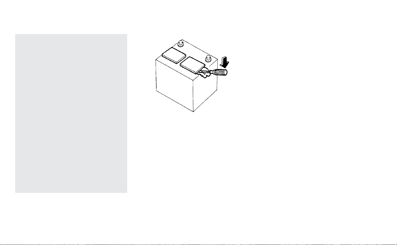
skin, eyes, fabrics or painted sur-
faces. After touching a 12-volt bat-
tery or 12-volt battery cap, do not
touch or rub your eyes. Thoroughly
wash your hands. If the acid con-
tacts your eyes, skin or clothing, im-
mediately flush with water for at
least 15 minutes and seek medical
attention.
• Do not operate the vehicle if the fluid
in the 12-volt battery is low. Low 12-
volt battery fluid can cause a higher
load on the 12-volt battery which
can generate heat, reduce battery
life, and in some cases lead to an
explosion.
• When working on or near a 12-volt
battery, always wear suitable eye
protection and remove all jewelry.
• 12-volt battery posts, terminals and
related accessories contain lead and
lead compounds. Wash hands after
handling.
• Keep the 12-volt battery out of the
reach of children.
1. Remove the vent caps with a screw-
driver as shown. Use a cloth to protect
the battery case.
2. Check the fluid level in each cell. If it is
necessary to add fluid, add only distilled
water to bring the level up to the bottom
of the filler opening. Do not overfill. Re-
install the vent caps.
Maintenance and do-it yourself 8-13

Vehicles operated in high temperatures or
under severe conditions require frequent
checks of the 12-volt battery fluid level.
JUMP STARTING
Jump starting provides power to the 12 volt
system to allow the electrical systems to
operate. The electrical systems must be
operating to allow the Li-ion battery to be
charged. Jump starting does not charge
the Li-ion battery. The Li-ion battery must
be charged before the vehicle can be
driven.
For additional information, refer to “Jump
starting” in the “In case of emergency” sec-
tion of this manual. If the power switch
does not switch to the READY to drive posi-
tion by jump starting, the 12-volt battery
may have to be replaced. It is recom-
mended that you visit a NISSAN certified
LEAF dealer for this service.
CLEANING
If your windshield is not clear after using
the windshield washer or if a wiper blade
chatters when running, wax or other mate-
rial may be on the blade or windshield.
Clean the outside of the windshield with a
washer solution or a mild detergent. Your
windshield is clean if beads do not form
when rinsing with clear water.
Clean each blade by wiping it with a cloth
soaked in a washer solution or a mild de-
tergent. Then rinse the blade with clear wa-
ter. If your windshield is still not clear after
cleaning the blades and using the wiper,
replace the blades.
CAUTION
Worn windshield wiper blades can
damage the windshield and impair
driver vision.
REPLACING
Replace the wiper blades if they are worn.
Pulling up the wiper arm
The wiper arm should be in the up position
when replacing the wiper.
Pull up the wiper arm manually or using the
wiper rise-up function (if so equipped).
Wiper rise-up function (if so equipped):
To pull up the wiper arm, pull the lever
䊊
1
within 1 minute after the power switch is
turned off. The wiper operation stops in
mid-operation and wiper arm can be
pulled up.
To lower the wiper arm, place the wiper
arm in the down position and then push
the lever
䊊
2
up once after the power switch
is turned on.
WINDSHIELD WIPER BLADES
8-14 Maintenance and do-it yourself

CAUTION
Do not operate the windshield wiper
while arm is pulled up. The wiper arm
or hood may be damaged.
Replacing
1. Push the release tab
䊊
A
, and move the
wiper blade down the wiper arm
䊊
B
while pushing the release tab to remove.
2. Insert the new wiper blade onto the
wiper arm until a click sounds.
3. Rotate the wiper blade so that the
dimple is in the groove.
CAUTION
• After wiper blade replacement, re-
turn the wiper arm to its original po-
sition; otherwise it may be damaged
when the hood is opened.
• Make sure the wiper blades contact
the glass; otherwise the arm may be
damaged from wind pressure.
Maintenance and do-it yourself 8-15

Be careful not to clog the washer nozzle
䊊
A
.
This may cause improper windshield
washer operation. If the nozzle is clogged,
remove any objects with a needle or small
pin
䊊
B
. Be careful not to damage the nozzle.
REAR WINDOW WIPER BLADE
It is recommended that you visit a NISSAN
certified LEAF dealer if checking or replace-
ment is required.
If the brakes do not operate properly, have
the brakes checked. It is recommended
that you visit a NISSAN certified LEAF dealer
for this service.
WARNING
Do not adjust the height of the brake
pedal. Doing so could alter the effec-
tiveness of the brakes, which could re-
sult in a serious accident and personal
injury. If adjustment is required, it is
recommended that you visit a NISSAN
certified LEAF dealer for this service.
BRAKE PAD WEAR WARNING
The disc brake pads have audible wear
warnings. When a brake pad requires re-
placement, it will make a high pitched
scraping sound when the vehicle is in mo-
tion. This scraping sound will first occur
only when the brake pedal is depressed.
After more wear of the brake pad, the
sound will always be heard even if the
brake pedal is not depressed. Have the
brakes checked as soon as possible if the
wear warning sound is heard.
Under some driving or climate conditions,
occasional brake squeak, squeal or other
BRAKES
8-16 Maintenance and do-it yourself
noise may be heard. Occasional brake
noise during light to moderate stops is nor-
mal and does not affect the function or
performance of the brake system.
Proper brake inspection intervals should
be followed. For additional information, re-
fer to the maintenance log section of your
NISSAN Service and Maintenance Guide.
MOTOR COMPARTMENT
WARNING
• Never touch, disassemble, remove
or replace the high-voltage parts
and cables, as well as their connec-
tors. High-voltage cables are col-
ored orange. Touching, disassem-
bling, removing or replacing those
parts and cables can cause severe
burns or electric shock that may re-
sult in serious injury or death.
• Never use a fuse of a higher or lower
amperage rating than that specified
on the fuse box cover. This could
damage the electrical system or
electronic control units or cause a
fire.
If any electrical equipment does not oper-
ate, check for an open fuse.
1. Confirm that the power switch and the
headlight switch are turned off.
2. Open the hood.
3. Remove the fuse/fusible link holder
cover by pushing the tab and lifting the
FUSES
Maintenance and do-it yourself 8-17
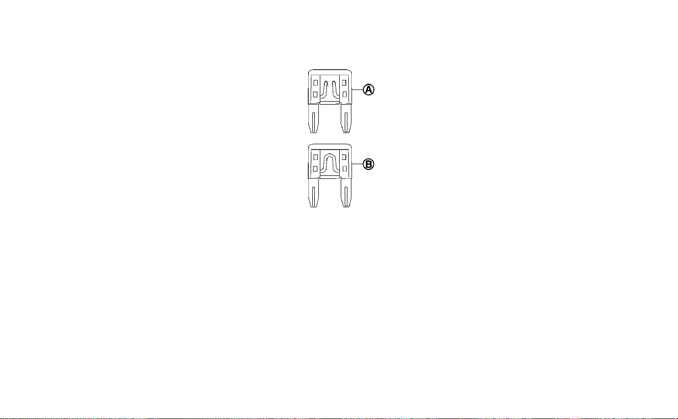
cover from the right side, and then the
left side.
4. Locate the fuse that needs to be
replaced.
5. Remove the fuse using the fuse puller
located in the passenger compartment
fuse box.
6. If the fuse is open
䊊
A
, replace it with a
new fuse
䊊
B
.
7. If a new fuse also opens, have the electri-
cal system checked, and if necessary, re-
paired. It is recommended that you visit a
NISSAN certified LEAF dealer for this
service.
8-18 Maintenance and do-it yourself

Fusible links
If any electrical equipment does not oper-
ate and the fuses are in good condition,
check the fusible links in the holders
䊊
1
,
䊊
2
and
䊊
3
. If any of these fusible links are
melted, replace only with Genuine NISSAN
parts.
For checking and replacing the fusible links
in the holders
䊊
1
,
䊊
2
and
䊊
3
, it is recom-
mended that you visit a NISSAN certified
LEAF dealer for this service.
Maintenance and do-it yourself 8-19
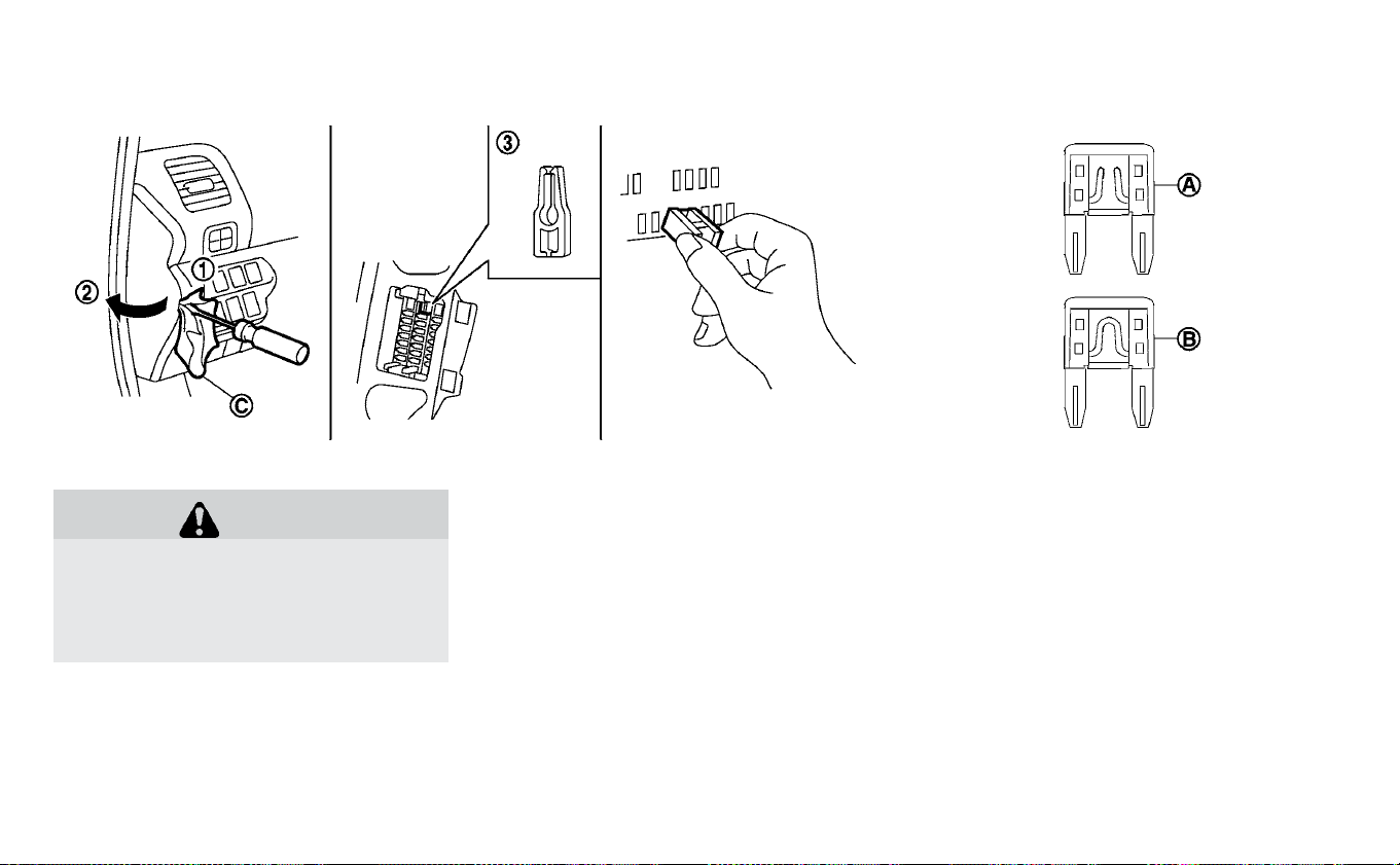
PASSENGER COMPARTMENT
WARNING
Never use a fuse of a higher or lower
amperage rating than that specified
on the fuse box cover. This could dam-
age the electrical system or electronic
control units or cause a fire.
If any electrical equipment does not oper-
ate, check for an open fuse.
1. Make sure that the power switch and the
headlight switch are turned off.
2. Insert a screwdriver wrapped with the
cloth
䊊
C
into the slit
䊊
1
.
Use a cloth
䊊
C
to protect the fuse box
cover.
3. Then pull to remove the fuse box cover
䊊
2
.
4. Remove the fuse with the fuse puller
䊊
3
.
5. If the fuse is open
䊊
A
, replace it with a
new fuse
䊊
B
.
6. If a new fuse also opens, have the elec-
trical system checked, and if necessar y
repaired. It is recommended that you
visit a NISSAN certified LEAF dealer for
this service.
8-20 Maintenance and do-it yourself

Extended storage switch
If any electrical equipment does not oper-
ate, remove the extended storage switch
and check for an open fuse.
NOTE:
The extended storage switch is used
for long term vehicle storage. Even if
the extended storage switch is bro-
ken it is not necessary to replace it.
Replace only the open fuse in the
switch with a new one.
How to replace the ex tended storage
switch:
1. To remove the extended storage switch,
be sure the ignition switch is in the OFF
position.
2. Be sure the headlight switch is in the
OFF position.
3. Remove the fuse box cover.
4. Pinch the locking tabs
䊊
1
and
䊊
2
found
on each side of the storage switch.
5. Pull the storage switch straight out from
the fuse box
䊊
3
.
CAUTION
• Be careful not to allow children to
swallow the battery and removed
parts.
• An improperly disposed battery can
harm the environment. Always con-
firm local regulations for battery
disposal.
• When changing batteries, do not let
dust or oil get on the components.
• There is danger of explosion if the
lithium battery is incorrectly re-
placed. Replace only with the same
or equivalent type.
NISSAN INTELLIGENT KEY® BATTERY
REPLACEMENT
Maintenance and do-it yourself 8-21
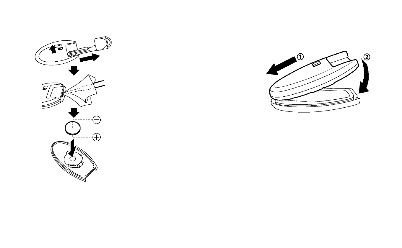
Replace the battery in the Intelligent Key as
follows:
1. Remove the mechanical key from the
Intelligent Key.
2. Insert a small screwdriver into the slit of
the corner and twist it to separate the
upper part from the lower part. Use a
cloth to protect the casing.
3. Replace the battery with a new one.
Recommended battery:
CR2025 or equivalent
• Do not touch the internal circuit and
electric terminals as doing so could
cause a malfunction.
• Hold the battery by the edges. Holding
the battery across the contact points
will seriously deplete the storage ca-
pacity.
• Make sure that the 丣 side faces the
bottom of the case.
4. Align the tips of the upper and lower
parts
䊊
1
, and then push them together
䊊
2
until it is securely closed.
5. Operate the buttons to check that it is
functioning properly.
It is recommended that you visit a NISSAN
certified LEAF dealer for this service.
8-22 Maintenance and do-it yourself

FCC Notice:
For USA:
This device complies with Part 15 of the
FCC Rules. Operation is subject to the fol-
lowing two conditions: (1) This device
may not cause harmful interference, and
(2) this device must accept any interfer-
ence received, including interference
that may cause undesired operation.
NOTE:
Changes or modifications not expressly
approved by the party responsible for
compliance could void the user’s author-
ity to operate the equipment.
For Canada:
This device complies with Industry
Canada licence-exempt RSS standard(s).
Operation is subject to the following two
conditions: (1) this device may not cause
interference, and (2) this device must ac-
cept any interference, including interfer-
ence that may cause undesired opera-
tion of the device.
Maintenance and do-it yourself 8-23

1. Headlight assembly
2. Map light
3. Room light
4. High-mounted stop light
5. Rear combination light
6. Door mirror turn signal
7. Cargo light
8. License plate light
9. Fog light (if so equipped)
Fog may temporarily form inside the lens
of the exterior lights in the rain or in a car
wash. A temperature difference between
the inside and the outside of the lens
causes the fog. This is not a malfunction. If
large drops of water collect inside the lens,
it is recommended that you visit a NISSAN
certified LEAF dealer for this service.
HEADLIGHTS
If headlight bulb replacement is required, it
is recommended that you visit a NISSAN
certified LEAF dealer for this service.
Replacing
Halogen headlight (high-beam):
The headlight high-beam is a semi-sealed
beam type that uses a replaceable head-
light (halogen) bulb.
LIGHTS
8-24 Maintenance and do-it yourself

CAUTION
• Do not leave the bulb out of the
headlight reflector for a long period
of time. Dust, moisture, smoke, etc.
entering the headlight body may af-
fect bulb performance.
• High-pressure halogen gas is sealed
inside the halogen bulb. The bulb
may break if the glass envelope is
scratched or the bulb is dropped.
• Only touch the base when handling
the bulb. Never touch the glass en-
velope. Touching the glass envelope
could significantly affect bulb life
and/or headlight performance.
• Aiming is not necessary after re-
placing the bulb. When aiming ad-
justment is necessary, it is recom-
mended that you visit a NISSAN
certified LEAF dealer for this service.
•
Fog may temporarily form inside the
lens of the exterior lights in the rain or
in a car wash. A temperature differ-
ence between the inside and the out-
side of the lens causes the fog. This is
not a malfunction. If large drops of
water collect inside the lens, it is rec-
ommended that you visit a NISSAN
certified LEAF dealer for this service.
Use the same number and wattage as
originally installed as shown in the chart.
FOG LIGHTS (IF SO EQUIPPED)
If fog light bulb replacement is required, it is
recommended that you visit a NISSAN cer-
tified LEAF dealer for this service.
Maintenance and do-it yourself 8-25

EXTERIOR AND INTERIOR LIGHTS
Item Wattage (W) Bulb No.
Headlight assembly (Type A) (if so equipped)*
High* 60 HB3
Low* 55 H11
Park/Turn signal* 28/8 7444NA
Side marker* — —
Headlight assembly (Type B) (if so equipped)*
High* — —
Low* — —
Daytime running (if so equipped)* — —
Park/Turn signal* 28/8 7444NA
Side marker* — —
Front fog light (if so equipped)* 35 H8
Charge port lid light* — —
Rear combination light
Turn signal 21 WY21W
Stop/Tail* — —
Back-up 16 W16W
Side marker* — —
License plate light* 5 W5W
Map light* — —
Door mirror turn signal light (if so equipped)* — —
High-mounted stop light* — —
Vanity mirror light* 1.4 —
Glove box light* 1.4 —
Room light* 8 —
Cargo light 5 W5W
*It is recommended that you visit a NISSAN certified LEAF dealer for replacement.
NOTE:
Always check with the Parts Department
at a NISSAN certified LEAF dealer for the
latest information about parts.
8-26 Maintenance and do-it yourself
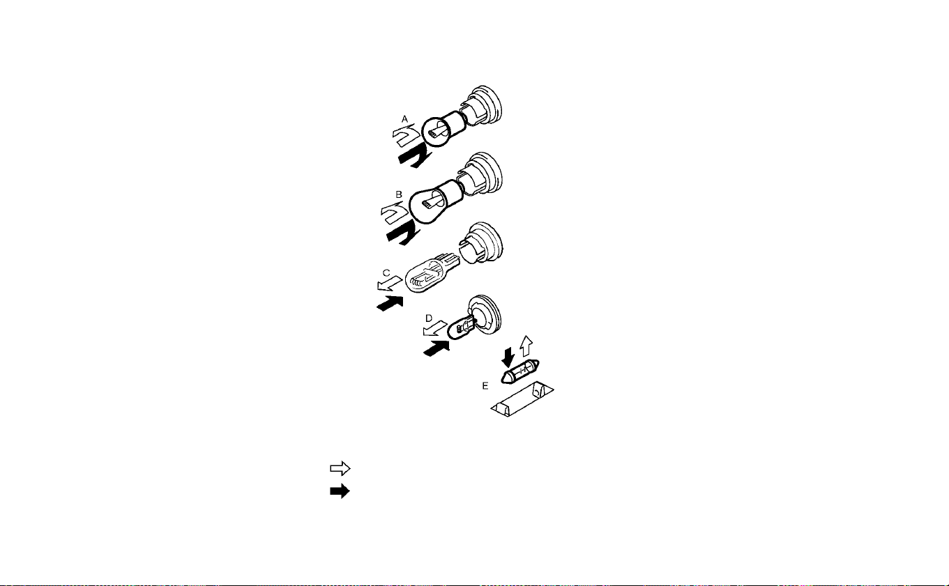
Replacement procedures
All other lights are either type A, B, C, D or E.
When replacing a bulb, first remove the lens
and/or cover.
: REMOVE
: INSTALL
Cargo light
Maintenance and do-it yourself 8-27

1. Remove the rear combination attach-
ment bolts
䊊
1
.
2. Pull the rear combination assembly as
shown in the illustration
䊊
2
.
3. Turn the bulb sockets and then remove
the bulbs
䊊
3
.
If you have a flat tire, refer to “Flat tire” in
the “In case of emergency” section.
TIRE PRESSURE
Tire Pressure Monitoring System
(TPMS)
WARNING
Radio waves could adversely affect
electric medical equipment. Those
who use a pacemaker should contact
the electric medical equipment
manufacturer for the possible influ-
ences before use.
This vehicle is equipped with the Tire
Pressure Monitoring System (TPMS).
It monitors tire pressure of all tires.
When the low tire pressure warning
light is lit, and the CHECK TIRE PRES-
SURE warning appears on the ve-
hicle information display, one or
more of your tires is significantly
under-inflated.
The TPMS will activate only when the
vehicle is driven at speeds above
Rear combination light
WHEELS AND TIRES
8-28 Maintenance and do-it yourself

16 mph (25 km/h). Also, this system
may not detect a sudden drop in tire
pressure (for example a flat tire while
driving).
For additional information, refer to
“Low tire pressure warning light” in
the “Instruments and controls” sec-
tion, “Tire Pressure Monitoring Sys-
tem (TPMS)” in the “Starting and driv-
ing” section and “Tire Pressure
Monitoring System (TPMS)” in the “In
case of emergency” section of this
manual.
Tire inflation pressure
Check the pressure of the tires often
and always prior to long distance
trips. The recommended tire pres-
sure specifications are shown on the
F.M.V.S.S/C.M.V.S.S certification label
or Tire and Loading Information la-
bel under the “Cold Tire Pressure”
heading. The Tire and Loading Infor-
mation label is affixed to the driver
side center pillar. Tire pressures
should be checked regularly be-
cause:
• Most tires naturally lose air over
time.
• Tires can lose air suddenly when
driven over potholes or other ob-
jects or if the vehicle strikes a curb
while parking.
The tire pressures should be
checked when the tires are cold. The
tires are considered COLD after the
vehicle has been parked for 3 or
more hours, or driven less than 1 mile
(1.6 km) at moderate speeds.
The TPMS with Easy-Fill Tire Alert
also provides visual and audible sig-
nals outside the vehicle for inflating
the tires to the recommended COLD
tire pressure. For additional informa-
tion, refer to “TPMS with Easy-Fill Tire
Alert” in the “Starting and driving”
section of this manual.
Incorrect tire pressure, including
under inflation, may adversely af-
fect tire life and vehicle handling.
WARNING
•
Improperly inflated tires can
fail suddenly and cause an ac-
cident.
•
The Gross Vehicle Weight rat-
ing (GVWR) is located on the
F.M.V.S.S./C.M.V.S.S certifica-
tion label. The vehicle weight
capacity is indicated on the
Tire and Loading Information
label. Do not load your vehicle
beyond this capacity. Over-
loading your vehicle may re-
sult in reduced tire life, unsafe
operating conditions due to
premature tire failure, or unfa-
vorable handling characteris-
tics and could also lead to a se-
rious accident. Loading
beyond the specified capacity
Maintenance and do-it yourself 8-29

may also result in failure of
other vehicle components.
•
Before taking a long trip, or
whenever you heavily load
your vehicle, use a tire pressure
gauge to ensure that the tire
pressures are at the specified
level.
•
For additional information re-
garding tires, refer to “Impor-
tant Tire Safety Information”
(US) or “Tire Safety Informa-
tion” (Canada) in the Warranty
Information Booklet.
Tire and Loading Information
label
䊊
1
Seating capacity: The maximum
number of occupants that can
be seated in the vehicle.
䊊
2
Original size: The size of the tires
originally installed on the vehicle
at the factory.
䊊
3
Cold tire pressure: Inflate the
tires to this pressure when the
tires are cold. Tires are consid-
ered COLD after the vehicle has
been parked for 3 or more
hours, or driven less than 1 mile
(1.6 km) at moderate speeds.
The recommended cold tire in-
flation is set by the manufac-
turer to provide the best bal-
ance of tire wear, vehicle
handling, driveability, tire noise,
etc., up to the vehicle’s GVWR.
䊊
4
Tire size — refer to “Tire labeling”
in this section.
䊊
5
Spare tire size or compact
spare tire size (if so equipped)
䊊
6
Vehicle load limit: For additional
information, refer to “Vehicle
loading information” in the
“Technical and consumer infor-
mation” section of this manual.
8-30 Maintenance and do-it yourself

Checking tire pressure
1. Remove the valve stem cap from
the tire.
2. Press the pressure gauge se-
curely onto the valve stem. Do not
press too hard or force the valve
stem sideways, otherwise air will
escape. If the hissing sound of air
escaping from the tire is heard
while checking the pressure, re-
position the gauge to eliminate
this leakage.
3. Remove the gauge.
4. Read the tire pressure on the
gauge stem and compare it to
the specification shown on the
Tire and Loading Information
label.
5. Add air to the tire as necessary. If
too much air is added, press the
core of the valve stem briefly with
the tip of the gauge stem to re-
lease pressure. Recheck the pres-
sure and add or release air as
necessary.
6. Install the valve stem cap.
7. Check the pressure of all of the
tires.
SIZE
COLD TIRE
INFLATION
PRESSURE
FRONT
ORIGINAL
TIRE
P205/55R16
89H
250 kPa,
36 PSI
FRONT
ORIGINAL
TIRE
P215/50R17
90V
250 kPa,
36 PSI
REAR
ORIGINAL
TIRE
P205/55R16
89H
250 kPa,
36 PSI
REAR
ORIGINAL
TIRE
P215/50R17
90V
250 kPa,
36 PSI
Maintenance and do-it yourself 8-31
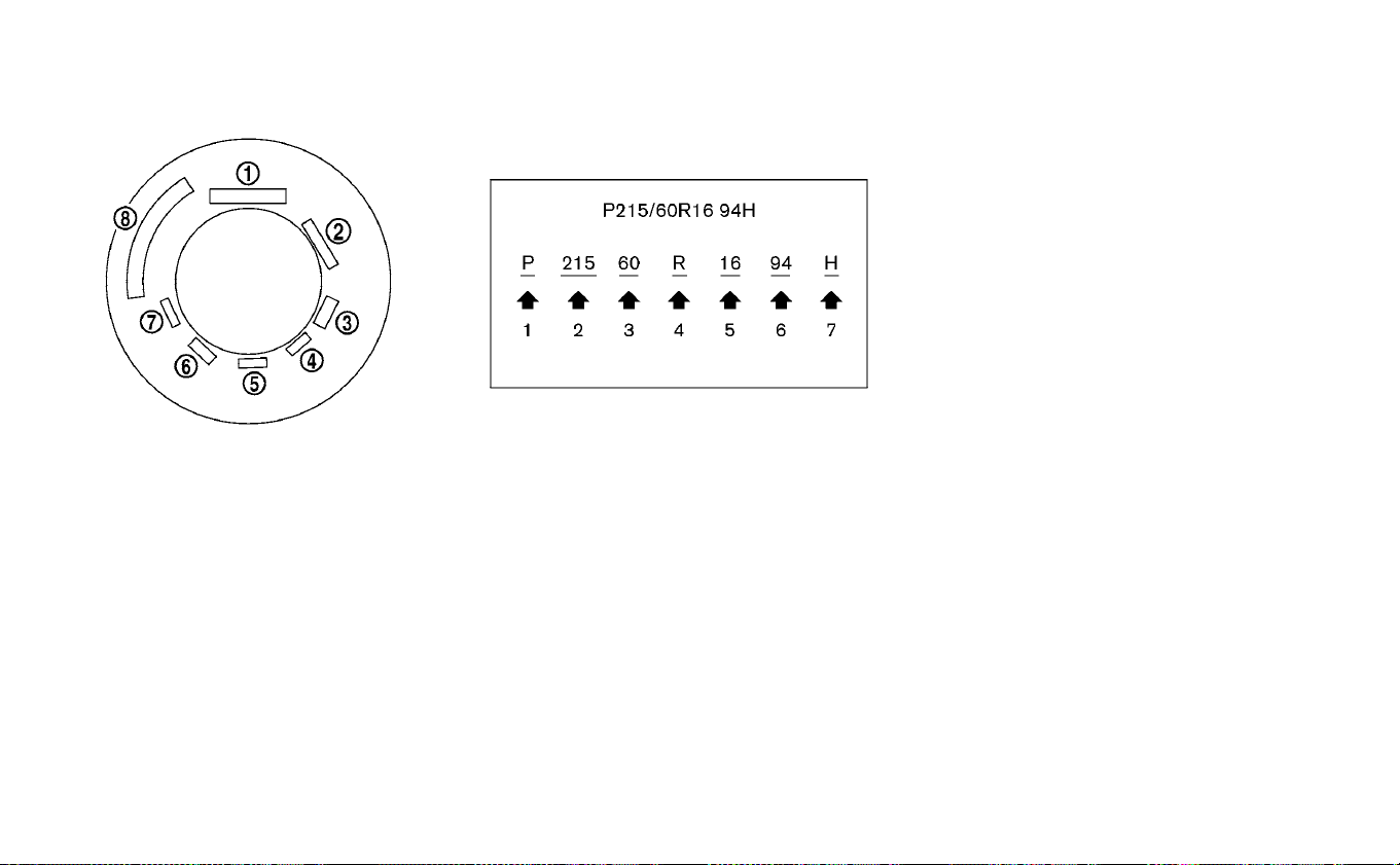
TIRE LABELING
Federal law requires tire manufac-
turers to place standardized infor-
mation on the sidewall of all tires.
This information identifies and de-
scribes the fundamental character-
istics of the tire and also provides the
tire identification number (TIN) for
safety standard certification. The TIN
can be used to identify the tire in
case of a recall.
䊊
1
Tire size (example: P215/
60R16 94H)
1. P: The “P” indicates the tire is de-
signed for passenger vehicles.
(Not all tires have this information.)
2. Three-digit number (215): This
number gives the width in milli-
meters of the tire from sidewall
edge to sidewall edge.
3. Two-digit number (60): This num-
ber, known as the aspect ratio,
gives the tire’s ratio of height to
width.
4. R: The “R” stands for radial.
5. Two-digit number (16): This num-
ber is the wheel or rim diameter in
inches.
6. Two- or three-digit number (94):
This number is the tire’s load in-
dex. It is a measurement of how
much weight each tire can sup-
port. You may not find this infor-
mation on all tires because it is
not required by law.
7. H: Tire speed rating. You should
not drive the vehicle faster than
the tire speed rating.
Example
Example
8-32 Maintenance and do-it yourself

䊊
2
TIN (Tire Identification Number)
for a new tire (example: DOT XX
XX XXX XXXX)
1. DOT: Abbreviation for the “Depart-
ment of Transportation”. The sym-
bol can be placed above, below or
to the left or right of the Tire Iden-
tification Number.
2. Two-digit code: Manufacturer’s
identification mark
3. Two-digit code: Tire size
4. Three-digit code: Tire type code
(Optional)
5. Four numbers represent the
week and year the tire was built.
For example, the numbers
3103 means the 31st week of 2003.
If these numbers are missing,
then look on the other sidewall of
the tire.
䊊
3
Tire ply composition and mate-
rial
The number of layers or plies of
rubber-coated fabric in the tire.
Tire manufacturers also must indi-
cate the materials in the tire,
which include steel, nylon, polyes-
ter, and others.
䊊
4
Maximum permissible inflation
pressure
This number is the greatest
amount of air pressure that
should be put in the tire. Do not
exceed the maximum permissible
inflation pressure.
䊊
5
Maximum load rating
This number indicates the maxi-
mum load in kilograms and
pounds that can be carried by the
tire. When replacing the tires on
the vehicle, always use a tire that
has the same load rating as the
factory installed tire.
Example
Maintenance and do-it yourself 8-33

䊊
6
Term of “tubeless” or “tube type”
Indicates whether the tire requires
an inner tube (“tube type”) or not
(“tubeless”).
䊊
7
The word “radial”
The word “radial” is shown, if the
tire has radial structure.
䊊
8
Manufacturer or brand name
Manufacturer or brand name is
shown.
Other tire-related terminology:
In addition to the many terms that
are defined throughout this section,
Intended Outboard Sidewall is (1) the
sidewall that contains a whitewall,
bears white lettering or bears
manufacturer, brand and/or model
name molding that is higher or
deeper than the same molding on
the other sidewall of the tire, or (2)
the outward facing sidewall of an
asymmetrical tire that has a particu-
lar side that must always face out-
ward when mounted on a vehicle.
TYPES OF TIRES
WARNING
• When changing or replacing tires, be
sure all four tires are of the same
type (Example: Summer, All Season
or Snow) and construction. A NISSAN
certified LEAF dealer may be able to
help you with information about tire
type, size, speed rating and avail-
ability.
• Always use tires of the same type,
size, brand, construction and tread
pattern on all four wheels. Failure to
do so may result in a circumference
difference between tires on the front
and rear axles which can cuase the
VDC system to malfunction resulting
in personal injury or death, exces-
sive tie wear and may damage the
transmission and differential gears.
• Replacement tires may have a lower
speed rating than the factory
equipped tires, and may not match
the potential maximum vehicle
speed. Never exceed the maximum
speed rating of the tire.
• Replacing tires with those not origi-
nally specified by NISSAN could af-
fect the proper operation of the
TPMS.
• For additional information regard-
ing tires, refer to “Important Tire
Safety Information” (US) or “Tire
Safety Information” (Canada) in the
Warranty Information Booklet.
All season tires
NISSAN specifies all season tires on some
models to provide good performance all
year, including snowy and icy road condi-
tions. All Season tires are identified by ALL
SEASON and/or M&S (Mud and Snow) on
the tire sidewall. Snow tires have better
snow traction than All Season tires and
may be more appropriate in some areas.
Summer tires
NISSAN specifies summer tires on some
models to provide superior performance
on dry roads. Summer tire performance is
substantially reduced in snow and ice.
Summer tires do not have the tire traction
rating M&S on the tire sidewall.
8-34 Maintenance and do-it yourself

If you plan to operate your vehicle in snowy
or icy conditions, NISSAN recommends the
use of SNOW tires or ALL SEASON tires on all
four wheels.
Snow tires
If snow tires are needed, it is necessary to
select tires equivalent in size and load rat-
ing to the original equipment tires. If you do
not, it can adversely affect the safety and
handling of your vehicle.
Generally, snow tires will have lower speed
ratings than factory equipped tires and
may not match the potential maximum
vehicle speed. Never exceed the maximum
speed rating of the tire.
If you install snow tires, they must be the
same size, brand, construction and tread
pattern on all four wheels.
For additional traction on icy roads, stud-
ded tires may be used. However, some U.S.
states and Canadian provinces prohibit
their use. Check local, state and provincial
laws before installing studded tires. Skid
and traction capabilities of studded snow
tires, on wet or dry surfaces, may be poorer
than that of non-studded snow tires.
TIRE CHAINS
Use of tire chains may be prohibited ac-
cording to location. Check the local laws
before installing tire chains. When installing
tire chains, make sure they are the proper
size for the tires on your vehicle and are
installed according to the chain manufac-
turer’s suggestions.
Use only SAE Class S chains. Class “S”
chains are used on vehicles with restricted
tire to vehicle clearance. Vehicles that can
use Class “S” chains are designed to meet
the SAE standard minimum clearances be-
tween the tire and the closest vehicle sus-
pension or body component required to
accommodate the use of a winter traction
device (tire chains or cables). The minimum
clearances are determined using the fac-
tory equipped tire size. Other types may
damage your vehicle.
Use chain tensioners when recommended
by the tire chain manufacturer to ensure a
tight fit. Loose end links of the tire chain
must be secured or removed to prevent
the possibility of whipping action damage
to the fenders or underbody. If possible,
avoid fully loading your vehicle when using
tire chains. In addition, drive at a reduced
speed. Otherwise, your vehicle may be
damaged and/or vehicle handling and
performance may be adversely affected.
Tire chains must be installed only on the
front wheels and not on the rear wheels.
Do not use tire chains on dry roads. Driving
with tire chains in such conditions can
cause damage to the various mechanisms
of the vehicle due to some overstress.
Maintenance and do-it yourself 8-35
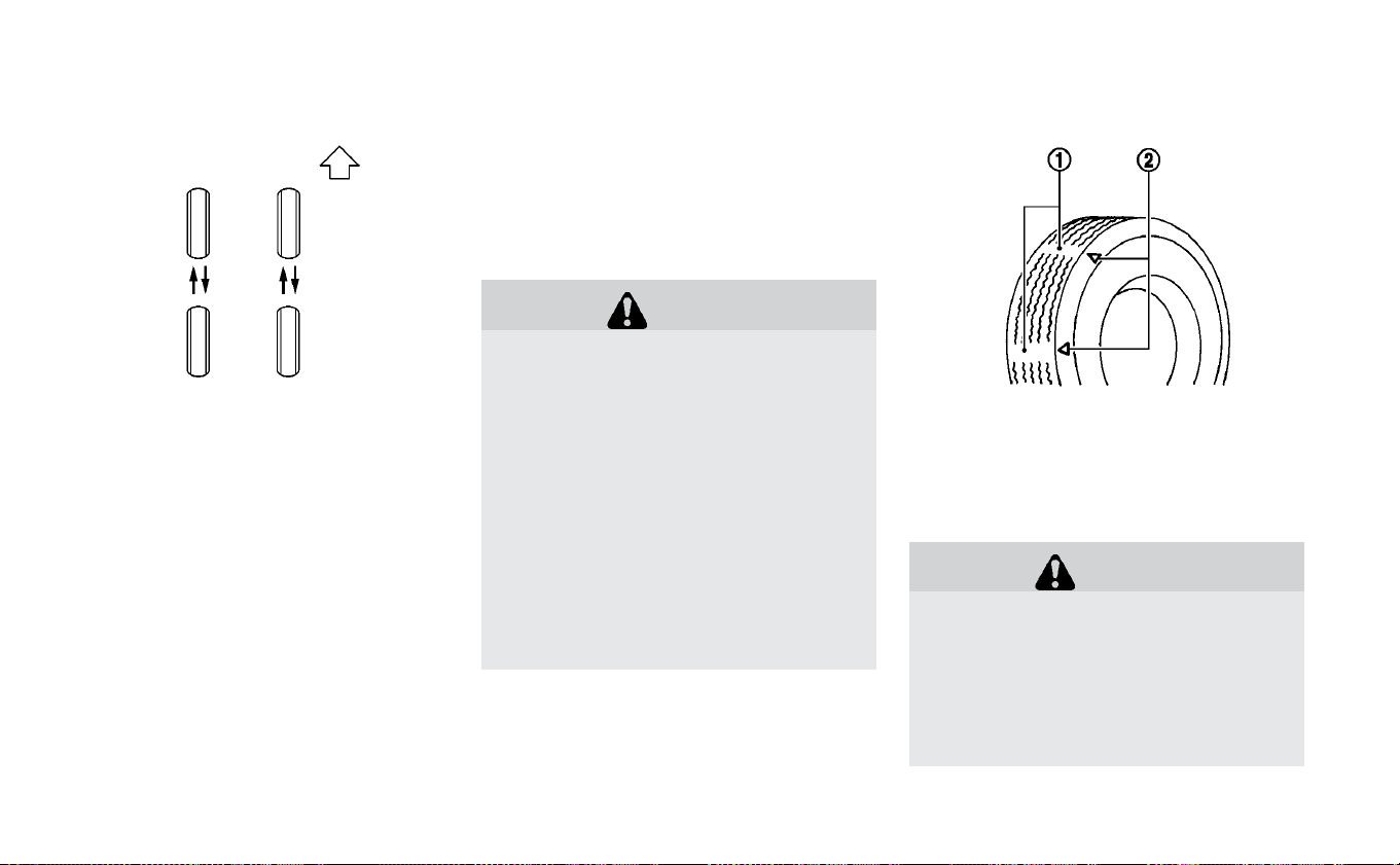
CHANGING WHEELS AND TIRES
Tire rotation
NISSAN recommends rotating the
tires every 5,000 miles (8,000 km).
As soon as possible, tighten the
wheel nuts to the specified torque
using a torque wrench.
Wheel nut tightening torque:
83 ft-lb (112 N·m)
The wheel nuts must be kept tight-
ened to the specification at all
times. It is recommended that
wheel nuts be tightened to the
specification at each tire rotation
interval.
WARNING
•
After rotating the tires, check
and adjust the tire pressure.
•
Retighten the wheel nuts when
the vehicle has been driven for
600 miles (1,000 km) (also in
cases of a flat tire, etc.).
•
For additional information re-
garding tires, refer to “Impor-
tant Tire Safety Information”
(US) or “Tire Safety Informa-
tion” (Canada) in the Warranty
Information Booklet.
Tire wear and damage
1. Wear indicator
2. Wear indicator location mark
WARNING
•
Tires should be periodically in-
spected for wear, cracking,
bulging or objects caught in
the tread. If excessive wear,
cracks, bulging or deep cuts
are found, the tire(s) should be
8-36 Maintenance and do-it yourself

replaced.
•
The original tires have built-in
tread wear indicators. When
wear indicators are visible, the
tire(s) should be replaced.
•
Tires degrade with age and
use. Have tires, over 6 years old
checked by a qualified techni-
cian, because some tire dam-
age may not be obvious. Re-
place the tires as necessary to
prevent tire failure and pos-
sible personal injury.
•
For additional information re-
garding tires, refer to “Impor-
tant Tire Safety Information”
(US) or “Tire Safety Informa-
tion” (Canada) in the Warranty
Information Booklet.
Replacing wheels and tires
When replacing a tire, use the same size,
tread design, speed rating and load carry-
ing capacity as originally equipped. For ad-
ditional information, refer to “Specifica-
tions” in the “Technical and consumer
information” section of this manual for rec-
ommended types and sizes of tires and
wheels.
WARNING
• The use of tires other than those rec-
ommended or the mixed use of tires
of different brands, construction
(bias, bias-belted or radial), or tread
patterns can adversely affect the
ride, braking, handling, Vehicle Dy-
namic Control (VDC) system, ground
clearance, body-to-tire clearance,
tire chain clearance, speedometer
calibration, headlight aim and bum-
per height. Some of these effects
may lead to accidents and could re-
sult in serious personal injury.
• If your vehicle was originally
equipped with four tires that were
the same size and you are only re-
placing two of the four tires, install
the new tires on the rear axle. Plac-
ing new tires on the front axle may
cause loss of vehicle control in some
driving conditions and cause an ac-
cident and personal injury.
• If the wheels are changed for any
reason, always replace with wheels
which have the same off-set dimen-
sion. Wheels of a different off-set
could cause premature tire wear, de-
grade vehicle handling characteris-
tics, affect the VDC system and/or
interference with the brake discs.
Such interference can lead to de-
creased braking efficiency and/or
early brake pad/shoe wear. For ad-
ditional information on wheel-off
set dimensions, refer to “Wheels and
tires” in the “Technical and con-
sumer information” section of this
manual.
• When replacing a wheel without the
TPMS such as the spare tire, the
TPMS will not function when a wheel
is replaced, the TPMS will not func-
tion and the low tire pressure warn-
ing light will flash for approximately
1 minute. The light will remain on af-
ter 1 minute. It is recommended that
you visit a NISSAN certified LEAF
dealer for this service.
• Replacing tires with those not origi-
nally specified by NISSAN could af-
fect the proper operation of the
TPMS.
Maintenance and do-it yourself 8-37

• The TPMS sensor may be damaged if
it is not handled correctly. Be careful
when handling the TPMS sensor.
• When replacing the TPMS sensor,
the ID registration may be required.
It is recommended that you visit a
NISSAN certified LEAF dealer for ID
registration.
• Do not use a valve stem cap that is
not specified by NISSAN. The valve
stem cap may become stuck.
• Be sure that the valve stem caps are
correctly fitted. Otherwise the valve
may be clogged up with dirt and
cause a malfunction or loss of pres-
sure.
• Do not install a damaged or de-
formed wheel or tire even if it has
been repaired. Such wheels or tires
could have structural damage and
could fail without warning.
• The use of retread tire is not recom-
mended.
• For additional information regard-
ing tires, refer to “Important Tire
Safety Information” (US) or “Tire
Safety Information” (Canada) in the
Warranty Information Booklet.
Wheel balance
Unbalanced wheels may affect vehicle
handling and tire life. Even with regular use,
wheels can get out of balance. Therefore,
they should be balanced as required.
Wheel balance service should be per-
formed with the wheels off the vehicle.
Spin balancing the wheels on the vehicle
could lead to mechanical damage.
For additional information regarding tires,
refer to “Important Tire Safety Information”
(US) or “Tire Safety Information” (Canada) in
the Warranty Information Booklet.
Care of wheels
For additional information on care of
wheels, refer to “Cleaning exterior” in the
“Appearance and care” section of this
manual.
EMERGENCY TIRE PUNCTURE
REPAIR KIT
The emergency tire puncture repair kit
(Emergency Tire Sealant) is supplied with
the vehicle instead of a spare tire. It can be
used to temporarily repair minor tire punc-
tures.
If possible, have the vehicle towed to a fa-
cility that can repair or replace the flat tire.
Using the emergency tire puncture repair
kit may cause a malfunction of the tire
pressure sensor and cause the low tire
pressure warning light to illuminate.
For additional information, refer to “Flat tire”
in the “In case of emergency” section of this
manual.
8-38 Maintenance and do-it yourself

9 Technical and consumer information
Recommended fluids/lubricants and
capacities...........................9-2
Air conditioning system refrigerant and
lubricant recommendations ............9-3
Specifications ........................9-4
Charging system ....................9-4
Motor ...........................9-5
Wheels and tires ....................9-5
Dimensions and weights...............9-5
When traveling or registering in another
country ............................9-6
Vehicle identification ...................9-6
Vehicle Identification Number (VIN) plate . . . .9-6
Vehicle identification number
(chassis number) ....................9-6
Traction motor serial number............9-7
F.M.V.S.S./C.M.V.S.S certification label........9-7
Emission control information label ........9-7
Tire and Loading Information label ........9-8
Air conditioner specification label .........9-8
Installing front license plate ...............9-8
Vehicle loading information ...............9-9
Terms ...........................9-9
Vehicle load capacity.................9-10
Loading tips.......................9-12
Measurement of weights ..............9-12
Towing a trailer.......................9-13
Flat towing .........................9-13
Uniform tire quality grading ..............9-13
Treadwear........................9-13
Traction AA, A, B and C ................9-14
Temperature A, B and C ...............9-14
Reporting safety defects ................9-14
Telematics overview (models with Navigation
System) ...........................9-15
Telematic Control Unit Gen2K .............9-17
Event Data Recorders (EDR) ..............9-19
Additional Data Recording (on vehicles
equipped with optional ProPILOT™ Assist) . . .9-20
Owner's Manual/Service Manual order
information
.........................9-20
Charging
information ..................9-21
Cold tire pressures ....................9-22

The following are approximate capacities. The actual refill capacities may be slightly different. When refilling, follow the procedure
that is described in the “Maintenance and do-it-yourself” section to determine the proper refill capacity.
Fluid type
Capacity (approximate)
Recommended Fluids/Lubricants
Metric
Measure
US
Measure
Imperial
Measure
Cooling system
coolant
With reservoir 5.3 L 5-5/8 qt 4-5/8 qt • Pre-diluted Genuine NISSAN Long Life Antifreeze/Coolant
(blue) or equivalent
Reservoir 0.5 L 1/2 qt 1/2 qt
Reduction gear fluid 1.4 L 1-1/2 qt 1-1/4 qt
• Genuine NISSAN Matic S ATF
• Using reduction gear fluid other than Genuine NISSAN Matic S
ATF will cause deterioration in driveability and reduction gear
durability, and may damage the reduction gear, which is not
covered by the NISSAN’s New Vehicle Limited Warranty.
Brake fluid
Refill to the proper level according to the
instructions in the “Maintenance and do-it-
yourself” section.
• Genuine NISSAN Super Heavy Duty Brake Fluid (Available in
mainland U.S.A. through a NISSAN certified LEAF dealer) or
equivalent DOT 3
Multi-purpose grease — — — • NLGI No. 2 (Lithium soap base)
Air conditioning system refrigerant — — —
• HFC-134a (R-134a)
• For additional information, refer to “Air conditioner specifica-
tion label” in this section.
Air conditioning system lubricants — — —
• With heater pump use NISSAN A/C System Oil ND-OIL11 or
equivalent.
• Without heater pump use NISSAN A/C System Oil AE10 or
equivalent.
Windshield washer fluid (US) 2.5 L 5/8 gal 1/2 gal
• Genuine NISSAN Windshield Washer Concentrate Cleaner &
Antifreeze fluid or equivalent
Windshield washer fluid (Canada) 4.5 L 1–1/4 gal 1 gal
• Genuine NISSAN Windshield Washer Concentrate Cleaner &
Antifreeze fluid or equivalent
RECOMMENDED FLUIDS/
LUBRICANTS AND CAPACITIES
9-2 Technical and consumer information

AIR CONDITIONING SYSTEM
REFRIGERANT AND LUBRICANT
RECOMMENDATIONS
The air conditioning system in your
NISSAN vehicle must be charged with the
refrigerant, HFC-134a (R-134a), and the
compressor oil, ND-OIL11 (with heater
pump), AE10 (without heater pump) or
the equivalent.
CAUTION
The use of any other refrigerant or oil
will cause severe damage to the air
conditioning system and will require
the replacement of all air conditioner
system components.
The refrigerant, HFC-134a (R-134a), in your
NISSAN vehicle will not harm the earth’s
ozone layer. Although this refrigerant does
not affect the earth’s atmosphere, certain
governmental regulations require the re-
covery and recycling of any refrigerant dur-
ing automotive air conditioning system
service. A NISSAN certified LEAF dealer has
the trained technicians and equipment
needed to recover and recycle your air con-
ditioning system refrigerant.
It is recommended that you visit a NISSAN
certified LEAF dealer when servicing your
air conditioning system.
Technical and consumer information 9-3

CHARGING SYSTEM
Rated input voltage AC120V (single phase), AC240V (single phase)
Rated input frequency 60Hz
Maximum rated current 30A
Charging modes/Types of connection
Mode 2/ Case B (EVSE)
Mode 3/ Case B/C (charging device, public charging stand)
Mode 4/ Case C (Quick charge)
Required installation (over current protection)
The methods of protection against over current and over voltage shall be in
accordance with national codes. Suitable over current protection devices for
the wiring of houses or buildings shall be installed.
IP Degree IP44: When the Genuine NISSAN EVSE is connected to the charging port
Operating temperature Same as vehicle operating temperature
Storage temperature Same as vehicle storage temperature
Rated input voltage
Rate input frequency
AC220V (single phase), AC240V
(single phase)
60Hz
Applicable standards
SAE J1772: 2010
EN61851-1: 2011
EN61851-21: 2002
IEC61851-1: 2010
IEC61851-21: 2001
EN61000-6-1: 2007
EN61000-6-3: 2007
Adapters
Do not use an extension cable or electrical adaptor except for Nissan Genuine
Adapter.
SPECIFICATIONS
9-4 Technical and consumer information

MOTOR
Model EM57
WHEELS AND TIRES
Road wheel
Type Size Offset in
(mm)
Steel 16 × 6 1/2JJ 1.57 (40)
Aluminum 17 × 6 1/2J 1.77 (45)
Tire
Tire Size
All season P205/55R16 89H
All season P215/50R17 90V
DIMENSIONS AND WEIGHTS
Overall length in (mm) 176.3 (4,478)
Overall length W/Lic Plate in (mm) 176.8 (4,490)
Overall width in (mm) 70.4 (1,789)
Overall width W/OS Mirrors in (mm) 79.9 (2,029)
Overall height(Roof)
16 inch wheels in (mm) 60.6 (1,539)
17 inch wheels in (mm) 60.8 (1,545)
Overall height(Antenna)
16 inch wheels in (mm) 61.5 (1,561)
17 inch wheels in (mm) 61.7 (1,567)
Front tread
16 inch wheels in (mm) 60.6 (1,540)
17 inch wheels in (mm) 60.2 (1,530)
Rear tread
16 inch wheels in (mm) 61.2 (1,555)
17 inch wheels in (mm) 60.8 (1,545)
Wheelbase in (mm) 106.3 (2,700)
lbs. (kg)
Refer to the F.M.V.S.S. or C.M.V.S.S. certifi-
cation label on the driver’s side center
pillar.
Front lbs. (kg)
Rear lbs. (kg)
Technical and consumer information 9-5
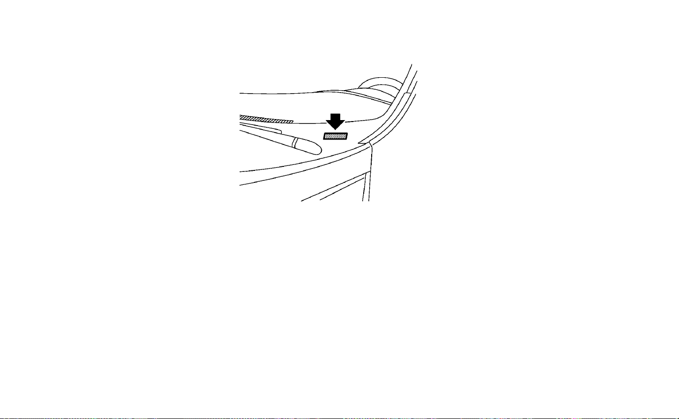
When planning to travel in another coun-
try, you should first find out if the charging
equipment is compatible with that coun-
try's electrical system.
When transferring the registration of
your vehicle to another country, state,
province or district, it may be necessary to
modify the vehicle to meet local laws and
regulations.
The laws and regulations for motor vehicle
safety standards vary according to the
country, state, province or district; there-
fore, vehicle specifications may differ.
When any vehicle is to be taken into an-
other country, state, province or district
and registered, its modifications, trans-
portation, and registration are the re-
sponsibility of the user. NISSAN is not re-
sponsible for any inconvenience that
may result.
VEHICLE IDENTIFICATION NUMBER
(VIN) PLATE
The vehicle identification number plate is
attached as shown. This number is the
identification for your vehicle and is used in
the vehicle registration.
VEHICLE IDENTIFICATION NUMBER
(CHASSIS NUMBER)
The vehicle identification number is lo-
cated as shown.
Remove the cover to access the number.
WHEN TRAVELING OR REGISTERING
IN ANOTHER COUNTRY VEHICLE IDENTIFICATION
9-6 Technical and consumer information
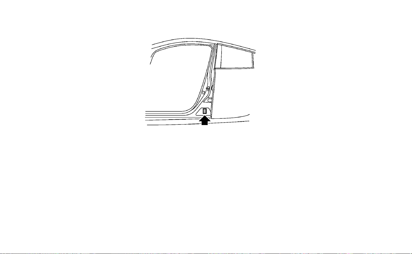
TRACTION MOTOR SERIAL
NUMBER
The serial number of the traction motor is
stamped on the traction motor as shown.
F.M.V.S.S./C.M.V.S.S CERTIFICATION
LABEL
The Federal/Canadian Motor Vehicle
Safety Standards (F.M.V.S.S./C.M.V.S.S.) certi-
fication label is affixed as shown. This label
contains valuable vehicle information, such
as: Gross Vehicle Weight Ratings (GVWR),
Gross Axle Weight Rating (GAWR), month
and year of manufacture, Vehicle Identifi-
cation Number (VIN), etc. Review it carefully.
EMISSION CONTROL
INFORMATION LABEL
The emission control information label is
attached to the underside of the hood as
shown in the illustration.
Technical and consumer information 9-7
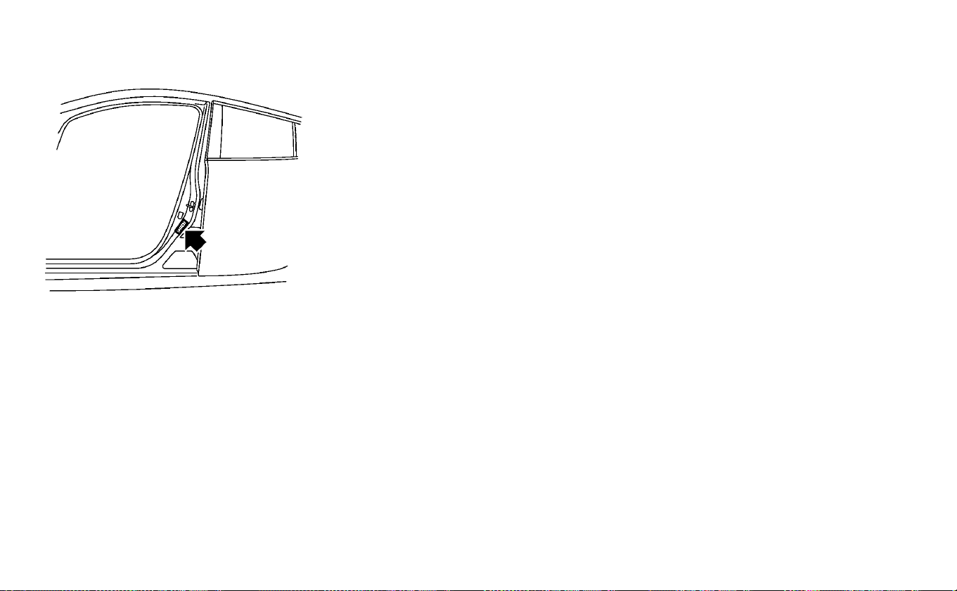
TIRE AND LOADING INFORMATION
LABEL
The cold tire pressure is shown on the Tire
and Loading Information label affixed to
the driver's side center pillar as shown.
AIR CONDITIONER SPECIFICATION
LABEL
The air conditioner specification label is at-
tached to the underside of the hood as
shown in the illustration.
Perform the following procedure to mount
the license plate.
Before mounting the license plate, confirm
that the following parts are enclosed in the
plastic bag.
• License plate bracket
䊊
1
• Screw ×2
1. Adjust the license plate bracket
䊊
1
at the
location (small dimples).
2. Mark along both sides of the mounting
holes and license plate screw holes us-
ing a felt-tip pen.
INSTALLING FRONT LICENSE PLATE
9-8 Technical and consumer information
3. Remove the license plate bracket
䊊
1
and connect the arcs from the ovals.
Mark the point in the center of each oval.
These are the screw installation
locations.
4. Install the license plate with two 0.39 in
(10 mm) screws.
WARNING
•
It is extremely dangerous to
ride in the cargo area inside the
vehicle. In a collision, people
riding in these areas are more
likely to be seriously injured or
killed.
•
Do not allow people to ride in
any area of your vehicle that is
not equipped with seats and
seat belts.
•
Be sure everyone in your ve-
hicle is in a seat and using a
seat belt properly.
TERMS
It is important to familiarize yourself
with the following terms before
loading your vehicle:
• Curb Weight (actual weight of your
vehicle) - vehicle weight including:
standard and optional equipment,
fluids and emergency tools. This
weight does not
include passengers
and cargo.
• GVW (Gross Vehicle Weight) - curb
weight plus the combined weight
of passengers and cargo.
• GVWR (Gross Vehicle Weight Rating)
- maximum total combined weight
of the unloaded vehicle, passen-
gers, luggage, hitch, trailer tongue
load and any other optional equip-
ment. This information is located
on the F.M.V.S.S./C.M.V.S.S. label.
• GAWR (Gross Axle Weight Rating) -
maximum weight (load) limit speci-
fied for the front or rear axle.
• This information is located on the
F.M.V.S.S./C.M.V.S.S. label.
• GCWR (Gross Combined Weight
Rating) - The maximum total
weight rating of the vehicle, pas-
sengers, cargo, and trailer.
• Vehicle Capacity Weight, Load limit,
Total load capacity - maximum to-
tal weight limit specified of the load
VEHICLE LOADING INFORMATION
Technical and consumer information 9-9

(passengers and cargo) for the ve-
hicle. This is the maximum com-
bined weight of occupants and
cargo that can be loaded into the
vehicle. If the vehicle is used to tow
a trailer, the trailer tongue weight
must be included as part of the
cargo load. This information is lo-
cated on the Tire and Loading Infor-
mation label.
• Cargo capacity - permissible
weight of cargo, the subtracted
weight of occupants from the load
limit.
VEHICLE LOAD CAPACITY
Do not exceed the load limit of your
vehicle shown as “The combined
weight of occupants and cargo” on
the Tire and Loading Information la-
bel. Do not exceed the number of
occupants shown as “Seating Ca-
pacity” on the Tire and Loading Infor-
mation label.
To get “the combined weight of oc-
cupants and cargo”, add the weight
of all occupants, then add the total
luggage weight. Examples are
shown in the following illustration.
Steps for determining correct
load limit
9-10 Technical and consumer information
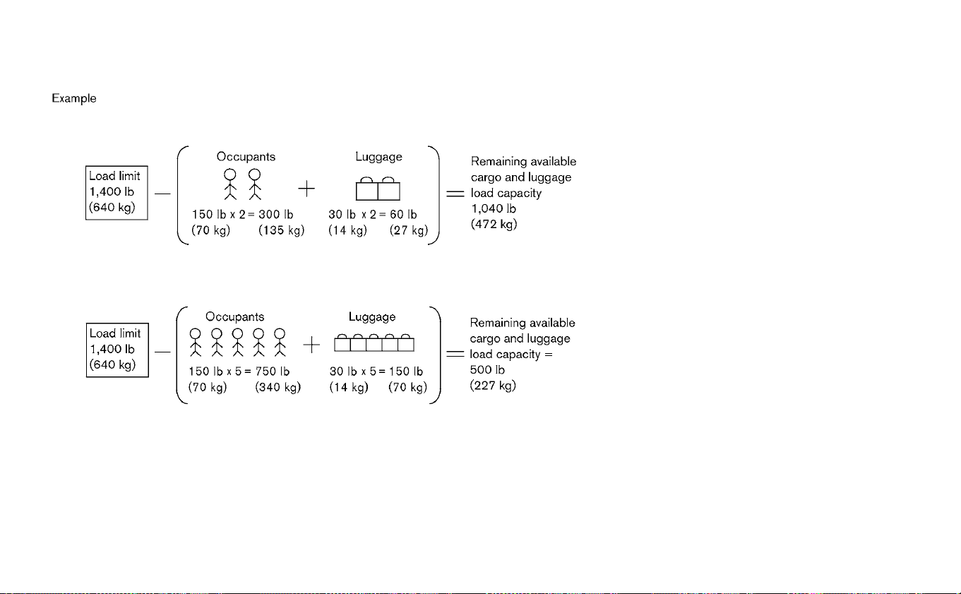
1. Locate the statement “The com-
bined weight of occupants and
cargo should never exceed XXX kg
or XXX lbs.” on your vehicle’s Tire
and Loading Information label.
2. Determine the combined weight
of the driver and passengers that
will be riding in your vehicle.
3. Subtract the combined weight of
the driver and passengers from
XXX kg or XXX lbs.
4. The resulting figure equals the
available amount of cargo and
luggage load capacity. For ex-
ample, if the XXX amount equals
1400 lbs. and there will be five
150 lbs. passengers in your ve-
hicle, the amount of available
cargo and luggage load capacity
is 650 lbs. (1400 − 750 (5 x 150) =
650 lbs.) or (640 − 340 (5 x 70) =
300 kg.)
5. Determine the combined weight
of luggage and cargo being
loaded on the vehicle. That weight
may not safely exceed the avail-
able cargo and luggage load ca-
pacity calculated in Step 4.
Before driving a loaded vehicle, con-
firm that you do not exceed the
Gross Vehicle Weight Rating (GVWR)
or the Gross Axle Weight Rating
Technical and consumer information 9-11

(GAWR) for your vehicle. For addi-
tional information, refer to “Measure-
ment of weights” in this section.
Also check tires for proper inflation
pressures. For additional informa-
tion, refer to “Tire and Loading Infor-
mation label” in this section.
LOADING TIPS
•
The GVW must not exceed the GVWR
or GAWR as specified on the F.M.V.S.S./
C.M.V.S.S. certification label.
• Do not load the front and rear axle
to the GAWR. Doing so will exceed
the GVWR.
WARNING
•
Properly secure all cargo with
ropes or straps to help prevent it
from sliding or shifting. Do not
place cargo higher than the
seatbacks. In a sudden stop or
collision, unsecured cargo could
cause personal injury.
•
Do not load your vehicle any
heavier than the GVWR or the
maximum front and rear
GAWRs. If you do, parts of your
vehicle can break, tire damage
could occur, or it can change
the way your vehicle handles.
This could result in loss of con-
trol and cause personal injury.
•
Overloading not only can
shorten the life of your vehicle
and the tire, but can cause un-
safe vehicle handling and lon-
ger braking distances. This
may cause a premature tire
failure, which could result in a
serious accident and personal
injury. Failures caused by over-
loading are not covered by the
vehicle’s warranty.
MEASUREMENT OF WEIGHTS
Secure loose items to prevent
weight shifts that could affect the
balance of your vehicle. When the ve-
hicle is loaded, drive to a scale and
weigh the front and the rear wheels
separately to determine axle loads.
Individual axle loads should not ex-
ceed either of the Gross Axle Weight
Ratings (GAWR). The total of the axle
loads should not exceed the Gross
Vehicle Weight Rating (GVWR). These
ratings are given on the vehicle cer-
tification label. If weight ratings are
exceeded, move or remove items to
bring all weights below the ratings.
9-12
Technical and consumer information
Do not tow a trailer with your vehicle. Towing your vehicle with all four wheels on
the ground is sometimes called flat towing.
This method is typically used when towing
a vehicle behind a recreational vehicle,
such as a motor home.
CAUTION
• Failure to follow these guidelines
can result in severe reduction gear
damage.
• DO NOT tow this vehicle with all four
wheels on the ground (flat towing).
• For emergency towing procedures
refer to “Towing your vehicle” in the
“In case of emergency” section of
this manual.
DOT (Department Of Transportation) Qual-
ity Grades: All passenger car tires must
conform to federal safety requirements in
addition to these grades.
Quality grades can be found where appli-
cable on the tire sidewall between tread
shoulder and maximum section width. For
example:
Treadwear 200 Traction AA Tempera-
ture A
TREADWEAR
The treadwear grade is a comparative rat-
ing based on the wear rate of the tire when
tested under controlled conditions on a
specified government test course. For ex-
ample, a tire graded 150 would wear one
and one-half (1 1/2) times as well on the
government course as a tire graded 100.
The relative performance of tires depends
upon actual conditions of their use how-
ever, and may depart significantly from the
norm due to variations in driving habits,
service practices and differences in road
characteristics and climate.
TOWING A TRAILER FLAT TOWING UNIFORM TIRE QUALITY GRADING
Technical and consumer information 9-13
TRACTION AA, A, B AND C
The traction grades, from highest to low-
est, are AA, A, B and C. Those grades repre-
sent the tire’s ability to stop on wet pave-
ment as measured under controlled
conditions on specified government test
surfaces of asphalt and concrete. A tire
marked C may have poor traction perfor-
mance.
WARNING
The traction grade assigned to this tire
is based on straight-ahead braking
traction tests, and does not include ac-
celeration, cornering, hydroplaning, or
peak traction characteristics.
TEMPERATURE A, B AND C
The temperature grades A (the highest), B,
and C, representing the tire’s resistance to
the generation of heat and its ability to dis-
sipate heat when tested under controlled
conditions on a specified indoor laboratory
test wheel. Sustained high temperature
can cause the material of the tire to degen-
erate and reduce tire life, and excessive
temperature can lead to sudden tire failure.
The grade C corresponds to a level of per-
formance which all passenger car tires
must meet under the Federal Motor Ve-
hicle Safety Standard No. 109. Grades B and
A represent higher levels of performance
on the laboratory test wheel than the mini-
mum required by law.
WARNING
The temperature grade for this tire is
established for a tire that is properly
inflated and not overloaded. Excessive
speed, under-inflation, or excessive
loading, either separately or in combi-
nation, can cause heat build-up and
possible tire failure.
For USA
If you believe that your vehicle has a
defect which could cause a crash or
could cause injury or death, you
should immediately inform the Na-
tional Highway Traffic Safety Admin-
istration (NHTSA) in addition to noti-
fying NISSAN.
If NHTSA receives similar complaints,
it may open an investigation, and if it
finds that a safety defect exists in a
group of vehicles, it may order a re-
call and remedy campaign. However,
NHTSA cannot become involved in
individual problems between you,
your dealer, or NISSAN.
To contact NHTSA, you may call the
Vehicle Safety Hotline toll-free at
1-888-327-4236
(TTY: 1-800-424-9153);
go to http://www.safercar.gov; or
write to: Administrator, NHTSA,
400 Seventh Street, SW., Washington,
D.C. 20590. You can also obtain other
REPORTING SAFETY DEFECTS
9-14 Technical and consumer information

information about motor vehicle
safety from http://
www.safercar.gov.
You may notify NISSAN by contact-
ing our Consumer Affairs Depart-
ment, toll-free, at 1-800-NISSAN-1.
For Canada
If you believe that your vehicle has a
defect which could cause a crash or
could cause injury or death, you
should immediately inform Trans-
port Canada in addition to notifying
NISSAN.
If Transport Canada receives com-
plaints, it may open an investigation,
and if it finds that a safety defect
exists in a group of vehicles, it may
request that NISSAN conduct a recall
campaign. However, Transport
Canada cannot become involved in
individual problems between you,
your dealer, or NISSAN.
You may contact Transport Cana-
da's Defect Investigations and Re-
calls Division toll free at
1-800-333-0510. You may also report
safety defects online at:
https://wwwapps.tc.gc.ca/ Saf-Sec-
Sur/7/PCDB-BDPP/fc-
cp.aspx?lang=eng (English speak-
ers) or https://wwwapps.tc.gc.ca/
Saf-Sec-Sur/7/PCDB-BDPP/fc-
cp.aspx?lang=fra (French speakers)
Additional information concerning
motor vehicle safety may be ob-
tained from Transport Canada's
Road Safety Information Centre at
1-800-333-0371 or online at
www.tc.gc.ca/roadsafety (English
speakers) or
www.tc.gc.ca/securiteroutiere
(French speakers).
To notify NISSAN of any safety con-
cerns please contact our Consumer
Information Centre toll free at
1-800-387-0122.
In addition to Event Data Recorders (EDRs)
mentioned in this Owner's Manual, this ve-
hicle is equipped with electronic modules
that monitor, control and record data con-
cerning various vehicle systems, including
the motor, batteries, braking and electrical
systems. Other electronic modules record
information concerning driving conditions,
including idling, braking, acceleration, trip
and other related data, information about
your use of the car and its features such as
air conditioner or headlight usage, diag-
nostic trouble codes, vehicle charging, ve-
hicle speed, direction and/or location.
Some of this data is stored by the vehicle
for use during vehicle servicing. Other data
concerning your vehicle's operation and
performance is wirelessly transmitted by
cellular connection through the vehicle on-
board telematics system upon vehicle
start-up or at other intervals to NISSAN.
This data may be used by NISSAN for vari-
ous purposes, including: to provide you
with NissanConnect® EV & Services (For ad-
ditional information, refer to
“NissanConnect® Manual (for Leaf)”.);
TELEMATICS OVERVIEW (MODELS
WITH NAVIGATION SYSTEM)
Technical and consumer information 9-15

troubleshooting; evaluation of your vehi-
cle's quality, functionality and perfor-
mance; analysis and research by NISSAN
designed to, among other things, optimize
performance of future electric vehicles in-
cluding improvements in future battery life;
to offer you new or additional products or
services; and as otherwise may be required
by law. Such data may be shared with
NISSAN's parents, subsidiaries, affiliates,
successors or assignees; authorized
NISSAN certified LEAF dealers; NISSAN's
marketing partners; your fleet company, if
your vehicle is a fleet vehicle; your rental
company, if your vehicle is a rental vehicle;
and third party service providers such as
cellular, information systems and data
management providers.
State and provincial laws allow access and
use of data recorded by vehicle devices
with the consent of the vehicle owner or
pursuant to subscription agreement. While
you are not required to allow such access
and use, if you do not so agree NISSAN may
be unable under applicable law to activate
the vehicle telematics system in your ve-
hicle, and certain features of your vehicle
which are dependent on vehicle telematics
will not operate as intended or designed.
These may include features such as auto-
matic charging station map updates, re-
mote battery state of charge check, charg-
ing complete notice, remote plug in
reminder, remote charging on, remote cli-
mate control on, drive route planning, driv-
ing tips to improve range, driving history,
billing simulation, ECO ranking, ECO forest,
maintenance reminders, etc. Other fea-
tures that may be developed and offered
by NISSAN in the future may also not func-
tion without telematics data transmission.
NissanConnect® EV & Services telematics ser-
vices are provided by NISSAN pursuant to a
subscription services agreement covering
your vehicle. This agreement is necessary for
all owners. This agreement, and an explana-
tion of its terms and conditions, can be found
at the NISSAN Owner’s Portal webpage. Fur-
ther, the operator of the vehicle must also
touch [OK] on the Navi screen to indicate as-
sent each time he or she starts the car. If you
decide at any time that you do not want your
vehicle to transmit data to NISSAN, you can
deactivate the telematics account associ-
ated with this vehicle by canceling the sub-
scription services agreement by visiting the
NISSAN Owner’s Portal Webpage or calling
NISSAN at 1-877-NOGASEV (1-877-664-2738).
The service can be reactivated later upon re-
quest if you choose. Simply visit the same
website or call the number above. Alterna-
tively, you can turn off the transmission of
certain categories of data through the use of
settings found in the navigation system un-
der Menu, NissanConnect® EV & Services, Ve-
hicle Information Sharing with NISSAN. Note,
turning off “Vehicle Information Sharing with
NISSAN” will only disable the automatic shar-
ing of information at vehicle start-up. Certain
categories of data may still be transmitted if
vehicle telematics features are accessed ei-
ther in the vehicle or remotely.
Your agreement to the transmission and
use of data by NISSAN can be provided in
various ways. The vehicle is equipped with
a “pop up” screen on the vehicle navigation
system that will ask for your consent to this
data transfer. A version of the following
message will appear: “Pursuant to sub-
scription agreement, your vehicle wire-
lessly transmits recorded vehicle data to
NISSAN for various purposes, including
NissanConnect® EV & Services, product
evaluation, research and development. By
9-16 Technical and consumer information

touching OK, you consent to the transmis-
sion and use of your vehicle data. See Own-
er's Manual or NISSAN Owner's portal web-
page for terms and details.” If you touch
[OK], your vehicle will transmit data as de-
signed in connection with the vehicle tele-
matics system. If you touch [Decline] your
vehicle will not transmit data. However, the
telematics features referenced above, and
perhaps others, will not be available to you.
The vehicle’s static navigation system will
remain operational, and you will be able to
access your radio and climate controls.
Telematics features are dependent on cel-
lular data transmission. Some areas may
have limited or no cellular connectivity, re-
sulting in a loss or interruption of data
transmission and, as a result, certain fea-
tures may be temporarily unavailable. Even
if areas with good signal reception, cellular
connectivity can be adversely affected by
things such as tall buildings, apartments,
tunnels, underground parking, mountain-
ous areas, etc. Even if the signal strength
bar of the in-vehicle data communication
module indicates good reception, connec-
tivity may be disrupted. This does not indi-
cate a malfunction. Operate the system
again after a few minutes to restore con-
nectivity. NissanConnect® EV & Services
telematics features are offered as a conve-
nience to the vehicle owner. NISSAN is not
responsible for, and owner assumes all risk
of, interruptions in service or errors based
on incomplete or inaccurate data.
NissanConnect® EV & Services communi-
cations may be received at a verified e-mail
address or by SMS/text messaging-
enabled mobile phone. Standard text rates
and/or data usage may apply depending
on your carrier.
If your vehicle’s telematics account is ac-
tive, and you are not the original owner,
please contact NISSAN at the website or
phone number above as soon as possible
to update the telematics enrollment infor-
mation. Upon sale of the vehicle, please
contact NISSAN at the website or phone
number above so that NISSAN’s records
may be updated. NissanConnect® EV &
Services subscription services will auto-
matically terminate at the end of the initial
free term if you do not wish to renew your
subscription agreement at the prices then
in effect.
A. INTRODUCTION
This product Telematic Control Unit Gen2K
incorporates the following software:
1. the software developed by, or developed
for, Ficosa International, S.A. (“Ficosa”),
2. the software owned by third party and
licensed to Ficosa,the software owned
by third party and licensed to Ficosa,
3. the software licensed under the GNU
GENERAL PUBLIC LICENSE, Version 2
(“GPL”),the software licensed under the
GNU GENERAL PUBLIC LICENSE, Version
2 (“GPL”),
4. the software licensed under the GNU LI-
BRARY GENERAL PUBLIC LICENSE, Ver-
sion 2.0 or the GNU LESSER GENERAL
PUBLIC LICENSE, Version 2.1 (collectively
“LGPL”), the Mozilla Public license v2
(“MPL”), the GPL-2.0 license with-
OpenSSL-exception (“GPLOpenSSL”) and
GNU GENERAL PUBLIC LICENSE, Ver-
sion 3 with GCC exception (together with
the GPL software, jointly “Copyleft Soft-
ware”), and/or
5. open sourced software licensed under
terms and conditions other than Copyl-
eft Software.
TELEMATIC CONTROL UNIT GEN2K
Technical and consumer information 9-17

For the software classified as (3) or (4)
above, a copy of the license text is included
with the source code in the URL indicated
below, and please also refer to the terms
and conditions of Copyleft Software li-
censes at the websites listed below:
GPL: http://www.gnu.org/licenses/old-
licenses/gpl-2.0.html
and https://www.gnu.org/licenses/
gpl-3.0.en.html
LGPL:
http://www.gnu.org/licenses/
old-licenses/lgpl-2.1.html
and
http://www.gnu.org/licenses/old-
licenses/lgpl-2.0.html
MPL:
https://www.mozilla.org/en-US/MPL/2.0/
GPL-2.0-with-OpenSSL-exception:
https://gitlab.com/cryptsetup/
cryptsetup/blob/master/COPYING
GPLv3 GCC Exception:
https://www.gnu.org/licenses/
gcc-exception-3.1.en.html
The software classified as (3) and (4) above
are copyrighted by multiple people.
Please refer to the websites below regard-
ing the copyright notices of those people.
https://www.ficosa.com/software/
opensource/
The software licensed under the licenses
indicated in (3) and (4) above (“Copyleft
Software”) is distributed in the hope that it
will be useful, but WITHOUT ANY WARRANTY,
without even the implied warranty of MER-
CHANTABILITY or FITNESS FOR A PARTICU-
LAR PURPOSE.
For at least three (3) years from delivery of a
device embedding the above product, Fi-
cosa will give to any third party who con-
tacts us at the Contact Information pro-
vided below, for a charge no more than our
cost of physically performing source code
distribution, a complete machine-readable
copy of the source code corresponding to
the Copyleft Software indicated above.
When requesting this source code, please
specify Product: Telematic Control Unit
Gen2K and version Cx9.
Furthermore, source code and licenses
corresponding to the Copyleft Software
listed above is freely available to you and
any member of the public at the website
listed below:
https://www.ficosa.com/software/
opensource/
Contact Information
For enquiries about open source software
at FICOSA, please contact Ficosa’s Compli-
ance Officer by email: FOSS@ficosa.com
Please note that we are unable to answer any
queries regarding source code details, etc.
In addition, it is necessary for end users to
provide their own internet connection.
The end user is responsible for any con-
nection or line charges incurred through
browsing websites or downloading.
9-18 Technical and consumer information

B. LICENSING ANC COPYRIGHT NOTICE IN-
FORMATION
The software classified as (5) above con-
tains various open sourced software
(“OSS”) listed in the below website. Please
see the website indicted next for the terms
and conditions of the licenses (OSS Li-
censes) and other information regarding
the OSS contained this Product:
https://www.ficosa.com/software/
opensource/
This vehicle is equipped with an Event Data
Recorder (EDR). The main purpose of an
EDR is to record , in certain crash or near
crash-like situations, such as an air bag
deployment or hitting a road obstacle, data
that will assist in understanding how a ve-
hicle’s systems performed. The EDR is de-
signed to record data related to vehicle dy-
namics and safety systems for a short
period of time, typically 30 seconds or less.
The EDR in this vehicle is designed to re-
cord such data as:
• How various systems in your vehicle were
operating;
• Whether or not the driver and passenger
safety belts were buckled/fastened;
• How far (if at all) the driver was depressing
the accelerator and/or brake pedal; and,
• How fast the vehicle was traveling.
• Sounds are not recorded.
These data can help provide a better un-
derstanding of the circumstances in which
crashes and injuries occur.
NOTE:
EDR data are recorded by your vehicle
only if a nontrivial crash situation occurs;
no data are recorded by the EDR under
normal driving conditions and no per-
sonal data (for example, name, gender,
age and crash location) are recorded.
However, other parties, such as law en-
forcement, could combine the EDR data
with the type of personally identifying
data routinely acquired during a crash
investigation.
To read data recorded by an EDR, spe-
cial equipment is required and access to
the vehicle or the EDR is needed. In ad-
dition to the vehicle manufacturer and
NISSAN certified LEAF dealer, other par-
ties, such as law enforcement, that have
the special equipment, can read the in-
formation if they have access to the ve-
hicle or the EDR. EDR data will only be
accessed with the consent of the ve-
hicle owner or lessee or as otherwise
required or permitted by law.
EVENT DATA RECORDERS (EDR)
Technical and consumer information 9-19

ADDITIONAL DATA RECORDING
(ON VEHICLES EQUIPPED WITH
OPTIONAL PROPILOT™ ASSIST)
If your vehicle is equipped with the optional
ProPILOT Assist, it will also be equipped
with supplemental data recording function
intended to assist in understanding how
ProPILOT Assist performs in certain non-
trival crash or near-crash scenarios. Spe-
cifically, supplemental recording is de-
signed to capture the following:
• Driver operational status of the accelera-
tor, brakes, steering, etc.
• Detection status of a vehicle ahead and
lane markers
• Vehicle information including distance to
vehicle ahead and lateral position
• Information on the operation of the ProPI-
LOT Assist and other crash avoidance
features
• ProPILOT Assist malfunction diagnosis
information
• External images from the multi-sensing
front camera (Available only when the SRS
air bag or IEB system is activated)
The ProPILOT Assist does not record con-
versations, sounds or images of the inside
of the vehicle.
To read this supplemental data, special
equipment is required and access to the
vehicle or the recording unit is needed. This
supplemental data will only be accessed
with the consent of the vehicle owner or
lessee or as otherwise required or permit-
ted by law. If downloaded, NISSAN and third
parties entrusted by
NISSAN may use the data recorded for the
purpose of improving NISSAN’s vehicle
safety performance.
NISSAN and third parties entrusted by
NISSAN will not disclose/provide the re-
corded data to a third party except:
- With the consent of the vehicle owner or
with the consent of the lessee
-
In response to an official request from law
enforcement, court order, governmental
agency, or other legally enforceable request.
- For research purposes after the data is
modified such that it is no longer tied to a
specific vehicle or vehicle owner (anony-
mized)
Genuine NISSAN Service Manuals for this
model year and prior can be purchased. A
Genuine NISSAN Service Manual is the best
source of service and repair information for
your vehicle. This manual is the same one
used by the factory trained technicians
working at a NISSAN certified LEAF dealer.
Genuine NISSAN Owner’s Manuals can also
be purchased.
For USA:
For current pricing and availability of Genu-
ine NISSAN Service Manuals, contact:
www.nissan-techinfo.com
For current pricing and availability of Genu-
ine NISSAN Owner’s Manuals, contact:
1-800-247-5321
For Canada:
To purchase a copy of a Genuine NISSAN Ser-
vice Manual or Owner’s Manual for this model
year and prior, please contact a NISSAN certi-
fied LEAF dealer. For the phone number and
location of a NISSAN certified LEAF dealer in
your area, call the NISSAN Information Center
at 1-800-387-0122 and a bilingual NISSAN rep-
resentative will assist you.
OWNER'S MANUAL/SERVICE
MANUAL ORDER INFORMATION
9-20 Technical and consumer information

CHARGING INFORMATION
Technical and consumer information 9-21

The label is typically located on the driver
side center pillar or on the driver’s door. For
additional information, refer to “Wheels and
tires” in the “Maintenance and do-it-
yourself” section of this manual.
COLD TIRE PRESSURES
9-22 Technical and consumer information

NOTES

NOTES

10 Index
1
12-volt battery .................8-12
A
ABS (Anti-lock Braking System) ......5-136
ADDITIONAL DATA RECORDING
(on vehicles equipped with optional ProPILOT
Assist) ......................9-20
Advanced air bag system ..........1-50
Air bag system...........1-50, 1-52, 1-58
Air bag warning labels ............1-61
Air bag warning light ..........1-61, 2-22
Air conditioner............4-30, 9-3, 9-8
Air conditioner specification label ......9-8
Air conditioning system refrigerant and
lubricant recommendations .........9-3
Alarm, How to stop alarm (refer to, vehicle
security system) ................2-47
Alcohol, drugs and driving ..........5-9
Antenna ....................4-66
Anti-lock Braking System (ABS) ......5-136
Anti-lock braking system (ABS) warning
light .......................2-17
Anti-lock Braking System (ABS) warning
light .......................2-17
Antifreeze ...................5-141
Appearance care..............7-2,7-4
At home after driving ............EV-18
Audible reminders ..............2-25
Audio System (models without Navigation
System) .....................4-45
Autolight switch ................2-52
Autolight system ...............2-52
Automatic ....................3-6
Automatic climate control (models with
Navigation System) ..............4-37
Automatic climate control (models without
Navigation System) ..............4-33
Automatic door locks .............3-6
Automatic Emergency Braking (AEB) . . .5-110
Automatic Emergency Braking (AEB) with
Pedestrian Detection ............5-117
Avoiding collision and rollover ........5-7
B
Battery.........EV-2, 2-8, 2-56, 8-12, 8-21
Battery saver system.............2-56
Before driving your vehicle (models with
navigation system) .............EV-12
Before starting system ............5-14
Blind Spot Warning (BSW) ..........5-37
Bluetooth® hands-free phone system
without navigation system .........4-67
Bluetooth® streaming audio ........4-64
Booster seats .................1-40
Brake. . .2-18, 2-19, 5-20, 5-134, 5-136, 8-11, 8-16
Brake fluid ....................8-11
Brake precautions ..............5-134
Brake system .................5-134
BRAKE system warning light (yellow). . . .2-18
BRAKE warning light (red) ..........2-19
Brakes......................8-16
Bulb replacement...............8-24
C
Car phone or CB radio ............4-67
Care of wheels .................7-3
Ceiling light ...................2-71
Changing coolant ...............8-10
Charge .....................2-61
Charge port lid .................3-19
Charge port lid switch ............2-61
Charge timer OFF switch ..........2-61
Charging. . . .CH-2, CH-8, CH-9, CH-15, CH-22,
CH-29, CH-42, 3-19, 9-4
Charging methods .............CH-35
Charging related indicator light .....CH-42
Charging related remote function . . . .CH-41
Charging status indicator light ......CH-42
Charging the Li-ion battery ........EV-10

Charging troubleshooting guide .....CH-47
Chassis control ................5-139
Checking ..................2-16, 8-9
Checking bulbs .................2-16
Checking coolant level .............8-9
Child restraints ...........1-22, 1-26, 1-40
Child safety ....................1-19
Child safety rear door lock ...........3-6
Child seat belts .................1-19
Circuit breaker, Fusible link ..........8-19
Cleaning ......................7-3
Cleaning aluminum alloy wheels .......7-3
Cleaning exterior and interior.......7-2,7-4
Climate control .................4-44
Climate control operation ..........4-30
Climate control service ............4-44
Climate control system ............4-30
Climate control system refrigerant and
lubricant recommendations .........4-44
Climate Ctrl. Timer ...............4-40
Clock .......................2-12
Clock setting (models without Navigation
System) .....................4-55
Cold weather driving .............5-141
Console box...................2-64
coolant ......................8-8
Coolant ................8-9, 8-10, 9-2
Cooling system .................8-8
Corrosion protection ..............7-7
Cruise control..................5-54
Cup holders ...................2-65
D
Defroster switch, Rear window and outside
mirror defroster switch ............2-51
Dimensions and weights............9-5
Display, vehicle information..........2-27
Door locks ..................3-4, 3-6
Doors .......................3-4
Driving ................5-4, 5-15, 5-141
Driving range ..................2-10
Driving the vehicle ..............EV-15
Driving vehicle..................5-15
e-Pedal ......................2-13
e-Pedal system.................5-22
E
ECO........................2-58
ECO drive report ................5-131
ECO mode ....................2-12
ECO switch ...................2-58
Efficient use of your vehicle ........EV-19
Electric shift control system .........5-15
Electronic parking brake ...........5-20
Emergency charge......CH-9, CH-15, CH-22
Emergency EV (Electric Vehicle) shut
off ......................5-12, 6-3
Emergency shutoff system .........EV-8
Emission control information label ......9-7
EV Characteristics ...............EV-9
EV system ....................EV-2
EV unique information ............EV-21
Event Data Recorder (EDR) ..........9-19
EVSE (Electric Vehicle Supply
Equipment) ..........CH-9, CH-15, CH-22
Ex terior appearance care ...........7-2
F
F.M.V.S.S./C.M.V.S.S. certification label .....9-7
Flashers (Refer to hazard warning flasher
switch).......................6-2
Flat tire ......................6-3
Flat towing ....................9-13
Floor mat cleaning ...............7-5
Fluid................8-8, 8-10, 8-11, 9-2
FM/AM/SAT Radio with Compact Disc (CD)
Player.......................4-54
Fog light switch ................2-58
For Intelligent Key system ...........3-6
Front passenger air bag and status
light ........................1-52
Front-seat mounted side-impact
supplemental air bag system ........1-58
Fuses .......................8-17
Fusible links ...................8-19
10-2 Index

G
Garage door open, HomeLink®
Universal .....................2-72
Gauge ...............2-7, 2-8, 2-9, 2-10
General maintenance ...........8-2, 8-3
Glovebox....................2-64
H
Hazard warning flasher switch ........6-2
Headlight switch ................2-52
Headlights ................2-52, 8-24
Headlights bulb replacement ........8-24
Heated seat switch ..............2-59
Heated seats ..................2-59
Heated steering wheel ............2-60
Heated steering wheel switch ........2-60
Heater ......................4-30
High voltage precautions...........EV-7
HillStart.....................5-140
Hill Start Assist.................5-140
Home charge .................CH-8
HomeLink® universal transceiver ......2-72
Hood release ..................3-16
Horn .......................2-58
How to normal charge ............CH-8
How to quick charge ............CH-29
How to trickle charge
(if so equipped) ........CH-9, CH-15, CH-22
I
Identification number (VIN) ..........9-6
If the Li-ion battery becomes completely
discharged....................6-13
Immediate charge..............CH-40
Immobilizer system ...........2-47, 5-13
Indicator lights .................2-23
Indicators for maintenance .........2-40
Indicators for operation ............2-36
Infants ......................1-20
Injured persons .................1-14
Inside rearview mirror .............3-23
Inside vehicle ...................8-3
Instrument brightness control........2-57
Intelligent Around View Monitor .......4-13
Intelligent Cruise Control (ICC) (for vehicles
without ProPILOT™ Assist) ..........5-56
Intelligent Driver Alertness (I-DA) ......5-126
Intelligent Key battery .............8-21
Intelligent Key system .............3-13
Intelligent Lane Intervention (I-LI) ......5-31
Interior appearance care ............7-4
Interior light replacement ..........8-26
Interior lights ..................2-70
iPod® player operation ............4-61
ISOFIX child restraint ..............1-24
J
Jump starting ..................6-10
K
Key operating range of the door lock/unlock
function ......................3-8
Key operation ..................3-9
Keyless entry ..................3-13
Keys......................3-2, 3-6
L
Labels ............1-61, 8-30, 9-6, 9-7, 9-8
Lane Departure Warning (LDW) .......5-26
Larger children .................1-20
LATCH system..................1-24
Li-ion battery ..................EV-2
Li-ion battery available charge gauge . . .2-10
Li-ion battery status check .........CH-41
Li-ion battery temperature gauge ......2-8
Li-ion battery warmer.............EV-5
License plate, Installing front license
plate ........................9-8
Light .1-61, 2-16, 2-23, 2-52, 2-58, 2-70, 2-71, 8-24
Lights, Exterior and interior light
replacement ..................8-26
Loading information ..............9-9
Index 10-3

Loading information (Refer to vehicle loading
information) ...................9-9
Lock...................3-4, 3-6, 3-17
Low tire pressure warning light .......2-20
Low tire pressure warning system ......5-4
Low tire pressure warning system (Refer to
Tire Pressure Monitoring System (TPMS)) . .5-4
M
Maintenance.....1-19, 2-40, 8-2, 8-3, 8-5, 8-12
Maintenance precautions ...........8-5
Maintenance requirements ..........8-2
Map lights ....................2-71
Mechanical key (Intelligent Key system) . . .3-3
Mirror....................3-23, 3-24
Motor ....................5-14, 9-5
Motor compartment ..............8-8
Motor serial number ..............9-7
Moving Object Detection ...........4-25
N
NISSAN Intelligent Key®
system ..............3-6, 3-8, 3-9, 5-10
NISSAN Vehicle Immobilizer System .2-47, 5-13
NissanConnect® Manual (for Leaf) ......4-3
Normal charge.................CH-8
O
Occasional charge ..............CH-8
Odometer .....................2-7
Off-roadrecovery................5-8
Oil..........................9-2
Opening rear hatch...............3-11
Outside air temperature ............2-11
Outside mirrors.................3-24
Outside vehicle..................8-3
Owner’s Manual/Service Manual order
information ...................9-20
P
Panic alarm ...................3-14
Parking ...............5-19, 5-20, 5-132
Parking brake ..................5-19
Parking brake break-in ............5-135
Parking on hills.................5-132
Power................2-68, 3-4, 5-133
Power door lock .................3-4
Power door lock switch.............3-5
Power economy................5-130
Power meter ...................2-9
Power Meter ...................2-9
Power outlet ..................2-62
Power steering system............5-133
Power switch ...............5-10, 5-11
Power windows ................2-68
Precautions . . .EV-7, EV-8, CH-2, 1-11, 1-22, 1-43,
5-4, 5-54, 5-134, 8-5
Precautions on charging...........CH-2
Precautions on child restraints........1-22
Precautions on seat belt usage........1-11
Precautions on supplemental restraint
system ......................1-43
Precautions when starting and driving . . .5-4
Pregnant women ................1-14
ProPILOT™ Assist ................5-79
Public charge .................CH-8
Pulling up the wiper arm ...........8-14
Push starting ..................6-14
Q
Quick charge .................CH-29
R
Rapid air pressure loss .............5-8
Rear center seat belt ..............1-17
RearCrossTrafficAlert(RCTA)........5-46
Rear door lock, Child safety rear door lock .3-6
Rear hatch ....................3-17
Rear hatch lock .................3-17
Rearseats.....................1-6
Rear window and outside mirror defroster
switch.......................2-51
Rear window wiper and washer switch . .2-50
10-4 Index

Rear window wiper and washer switch . .2-50
Rear window wiper blade ...........8-16
RearView Monitor ................4-4
Recommended fluids/lubricants and
capacities .....................9-2
Reduction gear fluid ..............8-10
Remote charge ................CH-41
Remote climate control............4-43
Remote keyless entry function, For Intelligent
Key system....................3-13
Remote keyless operation ..........3-13
Repairing flat tire.................6-4
Repairing tire ...................6-6
Replacement ..................8-24
Reporting safety defects ...........9-14
Road accident precautions .........EV-8
Roadside assistance program ........6-2
Rollover......................5-7
Roof-mounted curtain side-impact
supplemental air bag system ........1-58
S
Safety....................1-19, 9-14
Scene guide . .EV-10, EV-12, EV-14, EV-15, EV-18
Seat belt cleaning ................7-7
Seat belt extenders...............1-18
Seat belt hook ..................1-18
Seat belt maintenance.............1-19
Seat belt usage .................1-11
Seat belt warning light ............2-22
Seat belt(s)......1-11, 1-14, 1-17, 1-18, 1-19, 1-20,
1-59, 2-22, 7-7
Seatbelts.....................1-11
Seat belts with pretensioners ........1-59
Seat(s), Seats ................1-2, 2-59
Security system ................2-46
Security system (NISSAN Vehicle Immobilizer
System), EV system start ........2-47, 5-13
Servicing climate control ...........4-44
Shifting ......................5-15
Shoulder belt height adjustment.......1-17
Shoulder belt height adjustment, For front
seats........................1-17
Small children ..................1-20
Specifications ..................9-4
Speedometer...................2-7
Starting .............5-4, 5-14, 6-10, 6-14
Starting your vehicle .............EV-14
Status light, Front passenger air bag . . . .1-52
Steering ..............2-60, 3-21, 5-133
Steering wheel switch for audio control . .4-65
Stopping the vehicle ..............6-5
Storage .....................2-63
Stowing golf bags ...............2-68
Sun visors ....................3-22
Supplemental air bag warning labels . . . .1-61
Supplemental air bag warning light. .1-61, 2-22
Supplemental restraint system .......1-43
Switch.....2-51, 2-52, 2-57, 2-58, 2-61, 3-5, 6-2
T
Telematic Control Unit Gen2K ........9-17
Telematics overview ..............9-15
Temperature ...................2-8
Tether strap child restraints .........1-26
Theft (NISSAN Vehicle Immobilizer System),
traction motor start ...........2-47, 5-13
Three-point type ................1-14
Tilt steering column ..............3-21
Tilting steering column ............3-21
Tire........................2-20
Tire and Loading information label......9-8
Tire and Loading Information label .....8-30
Tire chains....................8-35
Tire dressing ...................7-4
Tire pressure ..................8-31
Tire pressure monitoring system (TPMS) . .6-3
Tire Pressure Monitoring System (TPMS) . .5-4
Tire rotation ...................8-36
Tires. . .5-4, 6-3, 7-4, 8-28, 8-30, 8-31, 8-34, 8-35,
8-36, 9-5, 9-8, 9-13
tonneau cover .................2-66
Top........................1-26
Top tether strap.................1-26
Tow truck towing ................6-14
Towing ...................6-14, 9-13
Towing a trailer .................9-13
TPMS, Tire Pressure Monitoring System . . .5-4
TPMS, Tire pressure warning system.....6-3
Traction motor ..................9-7
Index 10-5

Traction motor serial number .........9-7
Trailer towing ..................9-13
Transceiver ...................2-72
Transceiver, HomeLink® Universal ......2-72
Transmitter, With Intelligent Key system
(Refer to Intelligent Key system) .......3-13
Trickle charge .........CH-9, CH-15, CH-22
Turn signal switch ...............2-57
Type of charge and how to charge the Li-ion
battery .....................CH-5
Types of tires ..................8-34
U
Underbody cleaning...............7-3
Uniform tire quality grading..........9-13
Unplugged status ..............CH-41
USB (Universal Serial Bus) connection
port........................4-60
V
Vanity mirror ..................3-23
Vehicle...........2-46, 5-137, 9-5, 9-6, 9-9
Vehicle dynamic control (VDC) system . .5-137
Vehicle identification number (VIN)......9-6
Vehicle information display..........2-27
Vehicle security system ............2-46
Vents .......................4-29
W
Warning........2-14, 2-16, 2-36, 5-4, 6-2, 6-3
Warning and indicator lights .........0-11
Warning labels, Air bag warning labels . . .1-61
Warning light . . .1-61, 2-17, 2-18, 2-19, 2-20, 2-22
Warning lights ..................2-16
Warning lights, indicator lights and audible
reminders ....................2-14
Washer switch ..............2-49, 2-50
Washing ......................7-2
Waxing .......................7-2
Weights (Refer to Dimensions and
weights) ......................9-5
Wheel/tire size ..................9-5
Wheels and tires..............7-3,8-28
When starting and driving ...........5-4
When traveling or registering your vehicle in
another country .................9-6
Window(s)..................2-68, 7-3
Windshield wiper and washer switch. . . .2-49
Windshield-washer fluid ............8-11
Wiper ..........2-49, 2-50, 8-14, 8-15, 8-16
Wiper blades ...............8-14, 8-15
With Intelligent Key system (Refer to Intelligent
Key system) ...................3-13
10-6 Index

2018 LEAF
®
OWNER’S MANUAL
For your safety, read carefully and keep in this vehicle.
2018 NISSAN LEAF
®
ZE1-D
ZE1-D
Printing : November 2017
Publication No.:
Printed in U.S.A.
OM18EA 0ZE1U0
‘18