Loading ...
Loading ...
Loading ...
13
6. For models KEBK171B, KEBK101B, KEBK276B, KEBK206B,
KEBS179B, KEBS109B, KEBS277B, KEBS279B, KEBS207B,
or KEBS209B, see the following instructions.
For all other models, the black front trims can be ordered as
an accessory. Please reference the “Assistance or Service”
section of the Use and Care Guide or contact the dealer from
whom you purchased your built-in oven to order part
numbers:
W10327368 and W10327369 for double ovens.
W10327380 and W10327381 for single ovens.
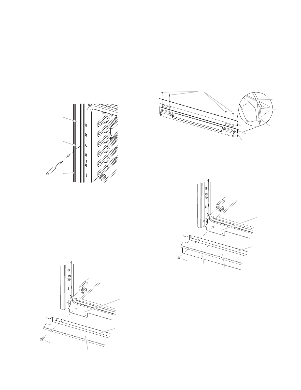
■ Remove the tape from black front trims.
■ Securely fasten the oven to the cabinet using the #8-14 x
¾" screws provided.
■ Insert the screws through hole in black trim aligning with
hole in oven frame. Do not overtighten screws.
7. The bottom vent and bottom vent trim (required when the
oven is installed with the feet in the tall position) are shipped
in the foam packing at the top of the oven.
To install only the bottom vent, see the following instructions.
To install both the bottom vent and the bottom vent trim for
installations with the feet in the tall position, see the
instructions in Step 8.
■ Align vent tab (B) with oven frame (A) as shown.
■ Using one #8-18 x ³⁄₈" screw (D) on each side of the vent
tab (B), fasten the vent securely to the oven.
8. On models with the feet installed in the tall position, the
bottom vent trim must also be installed. See the following
instructions to install.
■ Flex the upper vent piece (C) away from the lower vent
piece (D) to slide the bottom vent trim (B) between them.
Some force may be required to flex the upper vent trim (C)
away from the lower vent trim (D). Some force may also
be required to flex the bottom vent trim (B) and slide it
into position. Make sure screw holes are properly aligned
between the two pieces. See the following illustration.
■ Install the bottom vent trim (B) to the lower vent piece (D)
using two #8-18 x ¹⁄₄" screws on each side.
NOTE: On 27" (68.6 cm) models, only one #8-18 x ¹⁄₄" screw is
used on each side.
■ Align vent tab (B) with oven frame (A) as shown.
■ Using one #8-18 x ³⁄₈" screw (E) on each side of the vent
tab (B), fasten the vent securely to the oven.
9. Replace the oven racks.
10. Replace the oven door. See the “Replace Oven Door(s)”
section.
11. Check that the door is free to open and close. If it is not,
repeat the removal and installation procedures. See the
“Prepare Built-In Oven” section.
12. Repeat for lower oven door.
13. Reconnect power.
14. The display panel will light briefly, and “PF” should appear in
the display.
15. If the display panel does not light, reference the “Assistance
or Service” section of the Use and Care Guide or contact the
dealer from whom you purchased your oven.
A. Oven frame
B. Oven frame hole
C. Black trim piece
A. Oven frame
B. Vent tab
C. Oven vent
D. #8-18 x
³⁄₈
" screws
A
B
C
A
C
D
B
A. #8-18 x
¹⁄₄
" screw
B. Bottom vent trim
C. Upper vent piece
D. Lower vent piece
A. Oven frame
B. Vent tab
C. Oven vent
D. Bottom vent trim
E. #8-18 x
³⁄₈
" screw
D
B
A
C
B
D
C
A
C
D
B
E
Loading ...
Loading ...
Loading ...