E
English
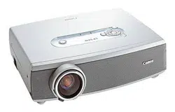
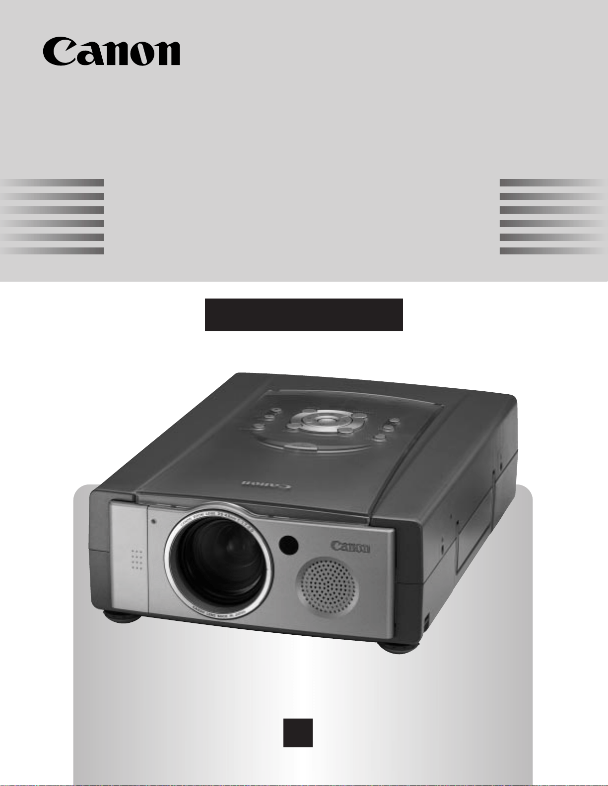
Multimedia Projector
Owner’s Manual
LV-7325U
2
As the owner of a new Multimedia Projector, you are probably eager to try out your new projector. Before you do,
we suggest that your spend a little time reading this manual to familiarize yourself with the operating procedures so
that you will receive maximum satisfaction from the many features included in your new projector.
This owner's manual will acquaint you with your projector's features. Reading it will help us too. Through the
years, we have found that many service requests were not caused by problems with our projectors. They were
caused by problems that could have been prevented, if the owner had followed the instructions in the manual.
You can often correct operating problems yourself. If your projector fails to work properly, see
"TROUBLESHOOTING" section on pages 44 ~ 45 and try the solution marked for each problem.
WARNING:
TO REDUCE THE RISK OF FIRE OR ELECTRIC SHOCK, DO NOT EXPOSE THIS APPLIANCE TO RAIN OR
MOISTURE.
This Projector has a grounding-type AC line plug. This is a safety feature to be sure that the plug will fit
into the power outlet. Do not try to defeat this safety feature.
This projector produces intense light from the projection lens. Do not stare directly into the lens as
possible eye damage could result. Be especially careful that children do not stare directly into the beam.
The Remote Control Unit, supplied to this projector, emits the laser beam as the Laser Pointer function
from the Laser Light Window while pressing the LASER button (for 1 minute). Do not look into the Laser
Light Window or shine the laser beam on yourself or other people. Eye damage may result.
This projector should be set in the way indicated. If not, It may result in fire hazard.
If the projector will not be used for an extended time, unplug the projector from the power outlet.
READ AND KEEP THIS OWNER'S MANUAL FOR LATER USE.
TO THE OWNER
SAFETY PRECAUTIONS
INFORMATION TO THE USER
NOTE :This equipment has been tested and found to comply with the limits for a Class A digital device,
pursuant to Part 15 of FCC Rules. These limits are designed to provide reasonable protection against
harmful interference when the equipment is operated in a commercial environment. This equipment
generates, uses, and can radiate radio frequency energy and, if not installed and used in accordance
with the instruction manual, may cause harmful interference to radio communications. Operation of
this equipment in a residential area is likely to cause harmful interference in which case the user will
be required to correct the interference at his own expense.
CAUTION : TO REDUCE THE RISK OF ELECTRIC SHOCK, DO NOT REMOVE COVER (OR BACK).
NO USER-SERVICEABLE PARTS INSIDE EXCEPT LAMP REPLACEMENT. REFER
SERVICING TO QUALIFIED SERVICE PERSONNEL.
THIS SYMBOL INDICATES THAT
DANGEROUS VOLTAGE CONSTITUTING
A RISK OF ELECTRIC SHOCK IS
PRESENT WITHIN THIS UNIT.
THIS SYMBOL INDICATES THAT THERE
ARE IMPORTANT OPERATING AND
MAINTENANCE INSTRUCTIONS IN THE
OWNER'S MANUAL WITH THIS UNIT.
CAUTION
RISK OF ELECTRIC SHOCK
DO NOT OPEN
3
IMPORTANT SAFETY INSTRUCTIONS
All the safety and operating instructions should be read before
the product is operated.
Read all of the instructions given here and retain them for later
use. Unplug this projector from AC power supply before
cleaning. Do not use liquid or aerosol cleaners. Use a damp
cloth for cleaning.
Do not use attachments not recommended by the
manufacturer as they may cause hazards.
Do not place this projector on an unstable cart, stand, or table.
The projector may fall, causing serious injury to a child or
adult, and serious damage to the projector. Use only with a
cart or stand recommended by the manufacturer, or sold with
the projector. Wall or shelf mounting should follow the
manufacturer's instructions, and should use a mounting kit
approved by the manufacturer.
Do not expose this unit to rain or use near water... for
example, in a wet basement, near a swimming pool, etc...
Slots and openings in the back and bottom of the cabinet are
provided for ventilation, to insure reliable operation of the
equipment and to protect it from overheating.
The openings should never be covered with cloth or other
materials, and the bottom opening should not be blocked by
placing the projector on a bed, sofa, rug, or other similar
surface. This projector should never be placed near or over a
radiator or heat register.
This projector should not be placed in a built-in installation
such as a book case unless proper ventilation is provided.
This projector should be operated only from the type of power
source indicated on the marking label. If you are not sure of
the type of power supplied, consult your authorized dealer or
local power company.
Do not overload wall outlets and extension cords as this can
result in fire or electric shock. Do not allow anything to rest on
the power cord. Do not locate this projector where the cord
may be damaged by persons walking on it.
Never push objects of any kind into this projector through
cabinet slots as they may touch dangerous voltage points or
short out parts that could result in a fire or electric shock.
Never spill liquid of any kind on the projector.
Do not attempt to service this projector yourself as opening or
removing covers may expose you to dangerous voltage or
other hazards. Refer all servicing to qualified service
personnel.
Unplug this projector from wall outlet and refer servicing to
qualified service personnel under the following conditions:
a. When the power cord or plug is damaged or frayed.
b. If liquid has been spilled into the projector.
c. If the projector has been exposed to rain or water.
d. If the projector does not operate normally by following the
operating instructions. Adjust only those controls that are
covered by the operating instructions as improper
adjustment of other controls may result in damage and will
often require extensive work by a qualified technician to
restore the projector to normal operation.
e. If the projector has been dropped or the cabinet has been
damaged.
f. When the projector exhibits a distinct change in
performance-this indicates a need for service.
When replacement parts are required, be sure the service
technician has used replacement parts specified by the
manufacturer that have the same characteristics as the
original part. Unauthorized substitutions may result in fire,
electric shock, or injury to persons.
Upon completion of any service or repairs to this projector, ask
the service technician to perform routine safety checks to
determine that the projector is in safe operating condition.
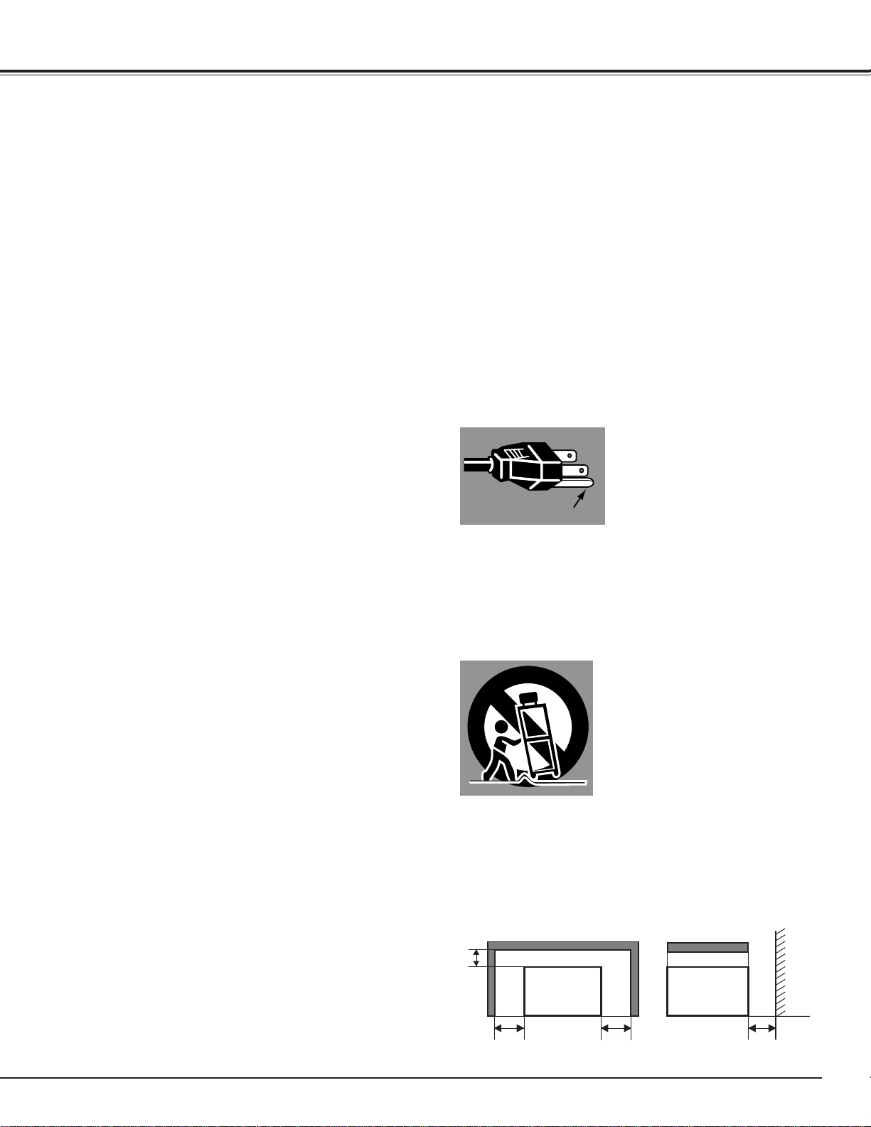
This projector is equipped with a
grounding type AC line plug.
Should you be unable to insert the
plug into the outlet, contact your
electrician. Do not defeat the
safety purpose of this grounding
type plug.
Follow all warnings and instructions marked on the projectors.
For added protection to the projector during a lightning storm,
or when it is left unattended and unused for long periods of
time, unplug it from the wall outlet. This will prevent damage
due to lightning and power line surges.
An appliance and cart combination
should be moved with care. Quick
stops, excessive force, and uneven
surfaces may cause the appliance
and cart combination to overturn.
If the projector is to be built into a compartment or similarly
enclosed, the minimum distances must be maintained.
Do not cover the ventilation slot on the projector.
Heat build-up can reduce the service life of your projector, and
can also be dangerous.
GROUND
20cm
50cm 50cm 50cm
PROJECTOR
(FRONT)
PROJECTOR
(SIDE)
WALL

4
TABLE OF CONTENTS
TRADEMARKS
● Apple, Macintosh, and PowerBook are trademarks or registered trademarks of Apple Computer,Inc.
● IBM and PS/2 are trademarks or registered trademarks of International Business Machines, Inc.
● Windows and PowerPoint are registered trademarks of Microsoft Corporation.
● Each name of corporations or products in the owner's manual is a trademark or a registered trademark of its
respective corporation.
MCI MODE 32
OPERATING THE PC CARD SLOT 32
SELECTING MCI MODE 33
SHOW THE DATA IN THE MEMORY CARD 34
WRITE DATA INTO THE MEMORY CARD 35
PICTURE IMAGE ADJUSTMENT 36
PICTURE POSITION ADJUSTMENT 36
PICTURE SCREEN ADJUSTMENT 37
CF CARD AND PCMCIA ADAPTER 38
FEATURES AND DESIGN 5
BEFORE OPERATION 14
PREPARATION 6
NAME OF EACH PART OF THE PROJECTOR 6
SETTING-UP THE PROJECTOR 7
POSITIONING THE PROJECTOR 7
ADJUSTABLE FEET 7
CONNECTING THE AC POWER CORD 8
VENTILATION 8
MOUNTING LENS COVER 9
MOVING THE PROJECTOR 9
CONNECTING THE PROJECTOR
10
TERMINALS OF THE PROJECTOR 10
CONNECTING TO THE VIDEO EQUIPMENT 11
CONNECTING TO THE COMPUTER 12
OPERATION OF THE REMOTE CONTROL 14
LASER POINTER FUNCTION 14
REMOTE CONTROL BATTERY INSTALLATION 15
TOP CONTROLS AND INDICATORS 16
OPERATING ON-SCREEN MENU 17
HOW TO OPERATE THE ON-SCREEN MENU 17
FLOW OF ON-SCREEN MENU 17
MENU BAR 18
BASIC OPERATION 20
TURNING ON / OFF THE PROJECTOR 20
ADJUSTING THE IMAGE 21
ZOOM ADJUSTMENT 21
FOCUS ADJUSTMENT 21
KEYSTONE ADJUSTMENT 21
BRIGHT SWITCH 22
NO SHOW FUNCTION 22
PICTURE FREEZE FUNCTION 22
SOUND ADJUSTMENT 22
SOUND VOLUME ADJUSTMENT 22
SOUND MUTE ADJUSTMENT 22
COMPUTER MODE 23
VIDEO MODE 30
SETTING 40
APPENDIX 41
SELECTING COMPUTER MODE 23
SELECTING COMPUTER SYSTEM 23
PC ADJUSTMENT 24
COMPATIBLE COMPUTER SPECIFICATION 26
PICTURE IMAGE ADJUSTMENT 27
PICTURE POSITION ADJUSTMENT 28
PICTURE SCREEN ADJUSTMENT 29
SELECTING VIDEO MODE 30
SELECTING COLOR SYSTEM 30
PICTURE SCREEN ADJUSTMENT 30
PICTURE IMAGE ADJUSTMENT 31
SETTING MENU 40
SETTING LANGUAGE 40
OPERATING WIRELESS MOUSE 41
MAINTENANCE 42
TEMPERATURE WARNING INDICATOR 42
AIR FILTER CARE AND CLEANING 42
CLEANING THE PROJECTION LENS 42
LAMP REPLACEMENT 43
LAMP REPLACEMENT MONITOR TIMER 43
TROUBLESHOOTING 44
TECHNICAL SPECIFICATIONS 46

5
FEATURES AND DESIGN
This Multimedia Projector is designed with the most advanced technology for portability, durability, and ease of
use. The projector utilizes built-in multimedia features, a palette of 16.77 million colors, and matrix liquid crystal
display (LCD) technology.
◆ Compatibility
This projector is compatible with many different
types of personal computers and video
devices, including;
● IBM-compatible computers, including
laptops, up to 1280 x 1024 resolution.
● Apple Macintosh and PowerBook
computers up to 1280 x 1024 resolution.
● Various video equipment using any of the
world wide video standards, including
NTSC, NTSC4.43, SECAM, PAL, PAL-M
and PAL-N.
◆ Image Resolution
Picture Image of the computer is projected in
the resolution of 1024 x 768 and it is provided
just as it appears on your computer's monitor.
Screen resolutions between 1024 x 768 and
1280 x 1024 are compressed to 1024 x 768,
and this projector cannot display screen
resolutions above 1280 x 1024. If your
computer's screen resolution is higher than
1280 x 1024, reset it to a lower resolution
before you connect the projector.
◆ Automatic Multiscanning System
This projector automatically tune to the most
personal computers currently distributed by
simply connecting. It is free from complicated
adjustments to project picture images from
most personal computers.
◆ Accessories
This projector comes with the parts listed
below. Check to make sure all are included. If
any parts are missing, contact to a sales
dealer.
● Owner's Manual.
● AC Power Cord.
● Wireless Remote Control Unit.
● Batteries for Remote Control Unit.
● VGA Cable.
● Control Cable for PS/2 Port.
● Media Card Imager for Windows 95
(CD-ROM)
and Owner’s Manual for this software.
● Lens Cover
and Strap for Lens Cover.
● Dust Cover.
◆ Other Features
This projector has Motor Zoom/Focus, No
Show, Picture Freeze, Keystone, Mute
functions.
◆ Portability
This projector is quite compact in size and
weight. Having a sophisticated shape like an
attaché case with a retractable carrying handle,
the projector will help you make powerful
presentations wherever you go.
◆ Multilanguage Menu Display
Operation menu is displayed in; English,
Deutsch, Français, Italiano, Español, or
Japanese
◆ Laser Pointer Function
The Remote Control Unit of this projector
includes the Laser Pointer function providing
the ability to point and highlight during
presentations.
◆ PC CARD SLOT
This projector has a PC CARD SLOT for
easier presentations. Pictures can be
projected just by inserting a memory card
including image data. Presentation data can
be edited by "Media Card Imager" software
(supplied). Refer to the pages 32 ~ 39 of this
manual and the Owner's Manual for Media
Card imager for operations.
◆ Turbo Bright System
Brightness of 1500 ANSI lumens, the highest
abailable in ultra portable models, is achieved.
(1200 ANSI lumens in the standard mode.)
6
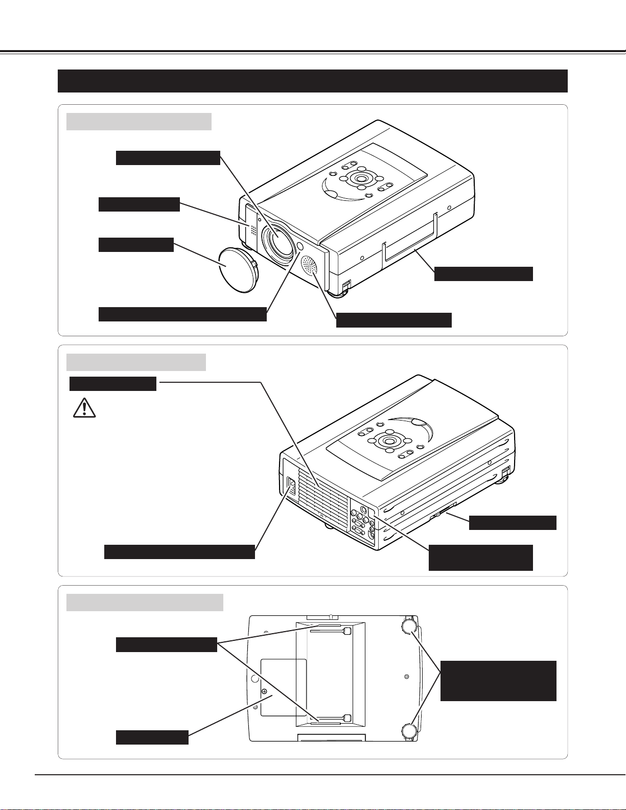
PREPARATION
NAME OF EACH PART OF THE PROJECTOR
These Air Intake Vents
should not be blocked.
BOTTOM OF THE CABINET
BACK OF THE CABINET
CARRY HANDLE
HOT AIR EXHAUSTED !
Air blown from the exhaust vent is hot.
When using or installing the projector,
following attention should be taken.
● Do not put a flammable object near this
vent.
● Keep heat-sensitive objects away from the
exhaust vent.
● Do not touch this area especially screws
and metallic parts. This area will become
hot while the projector is used.
INFRARED
REMOTE RECEIVER
POWER CORD CONNECTOR
EXHAUST VENT
FRONT OF THE CABINET
LAMP COVER
ADJUSTABLE FEET
AND
FEET LOCK LATCHES
PROJECTION LENS
SPEAKER (Monaural)
INFRARED REMOTE RECEIVER
LENS COVER
AIR INTAKE VENTS
PC CARD SLOT
BRIGHT SWITCH
7
PREPARATION
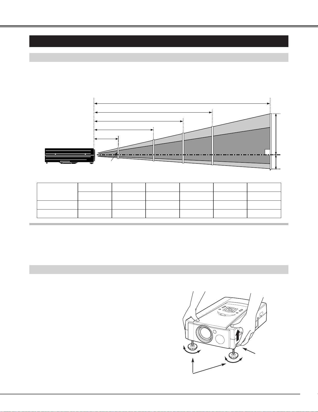
ADJUSTABLE FEET
Picture tilt and projection angle can be adjusted by
rotating the ADJUSTABLE FEET. Projection angle can
be adjusted to 10 degrees.
Lift the front of the projector and pull the FEET LOCK
LATCHES on both sides of the projector.
1
ADJUSTABLE FEET
SETTING-UP THE PROJECTOR
FEET LOCK
LATCHES
Release the FEET LOCK LATCHES to lock the
ADJUSTABLE FEET and rotate the ADJUSTABLE
FEET to fine tune the position and the tilt.
2
To shorten the ADJUSTABLE FEET, lift the front of the
projector and pull and undo the FEET LOCK LATCHES.
The position and the keystone distortion of the image
can also be adjusted using the Menu Operation. (Refer
to pages 21, 29, 30 and 37.)
3
POSITIONING THE PROJECTOR
●This projector is designed to project on a flat projection surface.
●The projector can be focused from 4.6’(1.4m) ~ 35.4’(10.8m).
●Refer to the figure below to adjust the screen size.
H1
H2
300”
231”
200”
154”
150”
115”
100”
77”
40”
35.4’ (10.8m)
24.0’ (7.3m)
18.0’ (5.5m)
11.8’ (3.6m)
4.6’ (1.4m)
Screen Size
(W x H) mm
Height (H1)
30”
Height (H2)
610 x 457
17.1”(435mm)
0.9”(22mm)
60”
1219 x 914
34.3”(870mm)
1.7”(44mm)
100”
2032 x 1524
57.1”(1451mm)
2.9”(73mm)
150”
3048 x 2286
85.7”(2177mm)
4.3”(109mm)
200”
4064 x 3048
114.3”(2903mm)
5.7”(145mm)
300”
6096 x 4572
171.4”(4354mm)
8.6”(218mm)
ROOM LIGHT
The level of brightness in a room has a great influence on picture quality. It is recommended to limit ambient
lighting in order to provide the best image.
30”
8
PREPARATION
●Do not cover the vent slot.
●Keep the rear grill at least 3 feet (1m) away from any
object.
●Keep sides clear of any obstructions. Obstructions
may block cooling air.
This projector is equipped with cooling fans for protection from overheating. Pay attention to the following to
ensure proper ventilation and avoid a possible risk of fire and malfunction.
VENTILATION
AIR INTAKE VENTS
(BOTH SIDES)
EXHAUST VENT
(REAR SIDE)
This projector uses nominal input voltages of 100-120 V
AC. The projector automatically selects the correct
input voltage. It is designed to work with single-phase
power systems having a grounded neutral conductor.
To reduce the risk of electrical shock, do not plug into
any other type of power system.
Consult your authorized dealer or service station if your
are not sure of the type of power supply in use.
Connect the projector with the peripheral equipment
before turning the projector on. (Refer to pages 10 ~ 13
for connection.)
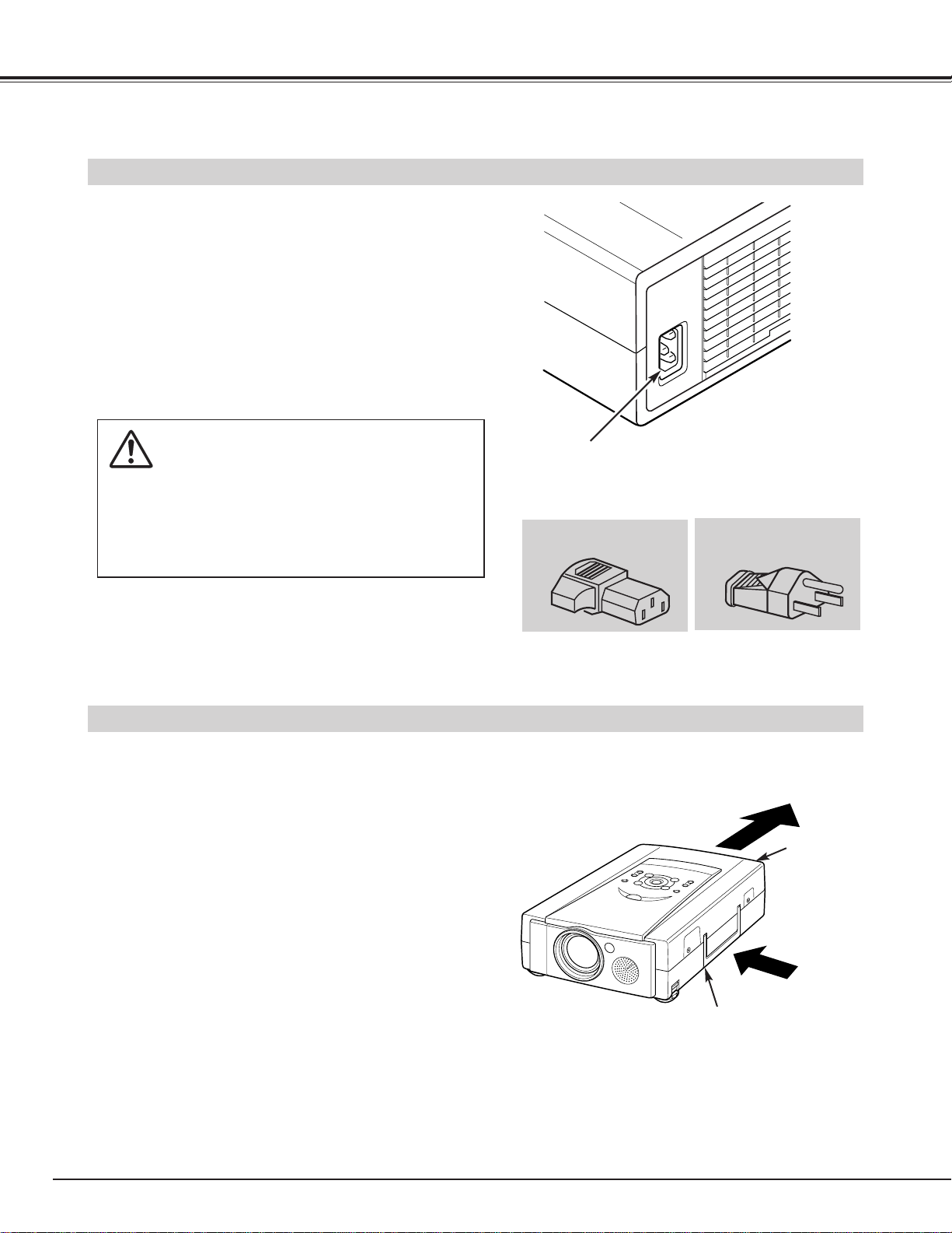
CAUTION
For safety, unplug the AC Power Cord when the
appliance is not in use.
When this projector is connected to the outlet with
the AC Power Cord, the appliance is in Stand-by
Mode and consumes some electric power.
CONNECTING THE AC POWER CORD
Connect the AC power supply cord (supplied) to the
projector.
The socket-outlet must be near this equipment and
must be easily accessible.
Projector side (Female)
AC outlet side (Male)
9
PREPARATION
CAUTION IN CARRYING OR TRANSPORTING THE PROJECTOR
● Do not drop or bump the projector, otherwise damages or malfunctions may result.
● When transporting the projector, use a carrying case recommended by Canon.
● Do not transport the projector by using a courier or transport service in an unsuitable transport case. This
may cause damage to the projector. To transport the projector through a courier or transport service, use
a case recommended by Canon.
● For carrying or transportation cases, contact a Canon authorized dealer.
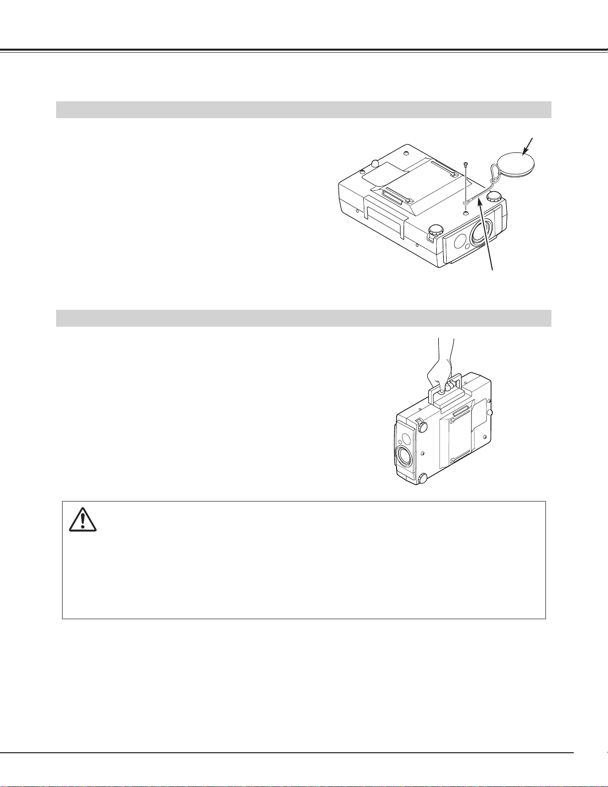
MOVING THE PROJECTOR
Use the Carry Handle when moving the Projector.
When moving the projector, replace the lens cover and
retract the feet to prevent damage to the lens and the
cabinet.
When this projector is not in use for an extended
period, replace the Lens Cover, retract the Adjustable
Feet and cover the unit with the Dust Cover supplied
with this projector.
MOUNTING LENS COVER
When moving this projector, or when it is not used for
an extended period, replace the lens cover.
Secure the Strap for Lens Cover through the hole of the
Lens Cover.
1
Turn the power off, and disconnect the AC power cord
from the AC outlet.
2
Turn the projector upside down. Secure the Strap for
Lens Cover to the hole on the bottom of the projector
with the screw.
3
LENS COVER
STRAP FOR LENS COVER
(Secure to the hole with the screw.)
10
CONNECTING THE PROJECTOR
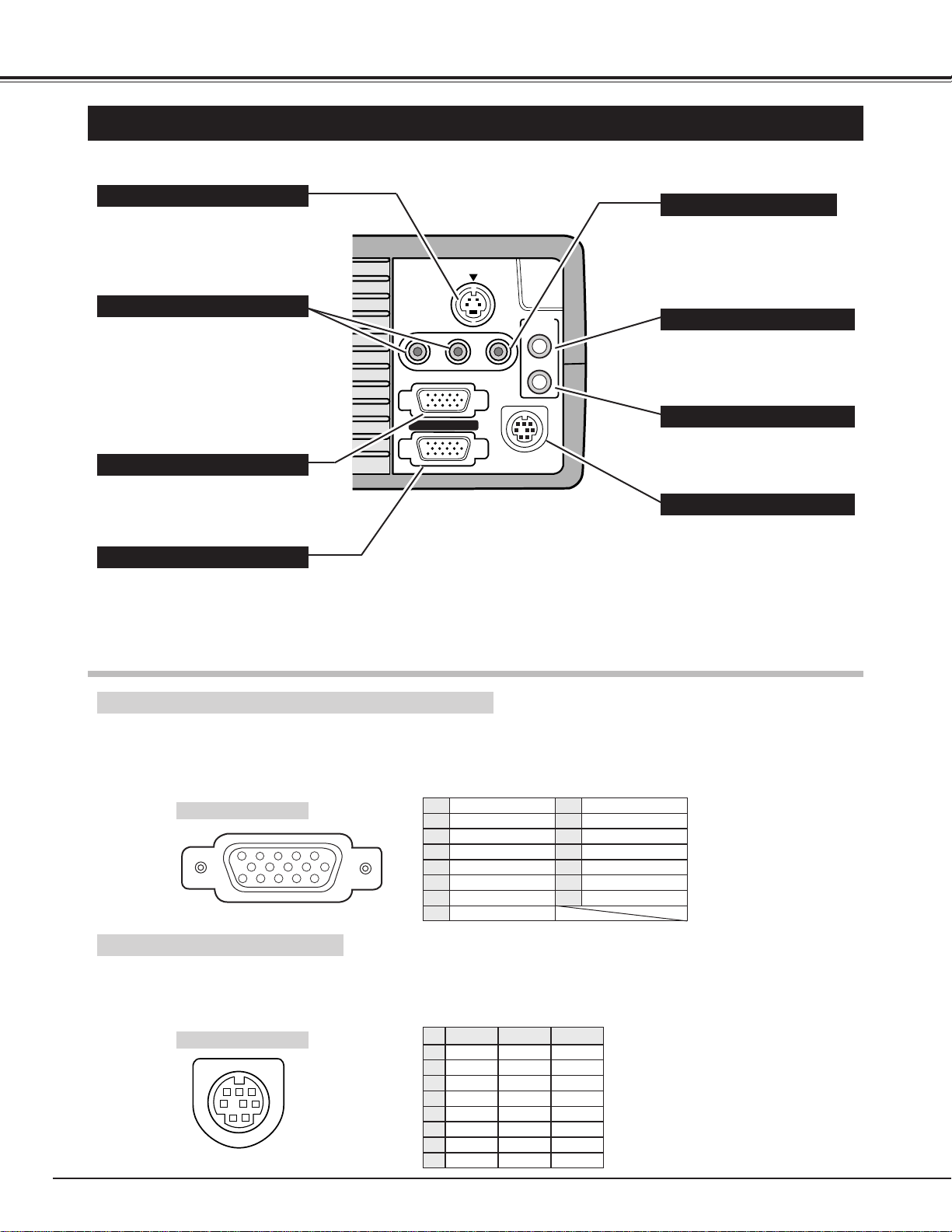
TERMINALS OF THE PROJECTOR
S-VIDEO
R-AUDIO-L
(MONO)
VIDEO
AUDIO
IN
OUT
CONTROL PORT
COMPUTER IN
MONITOR OUT
Connect the computer output to
this terminal.
(Refer to P12, 13.)
When controlling the computer
with the Remote Control of this
projector, connect the mouse
port of your personal computer
to this terminal. It is also used
for write on or read from the
data of the PC CARD SLOT in
MCI mode.
(Refer to P12, 13, 35.)
This terminal outputs the signal
from the COMPUTER IN
terminal. Connect to a monitor
using this terminal.
(Refer to P12, 13.)
Connect the audio amplifier to
this terminal.
(Refer to P12, 13.)
Connect the S-VIDEO output
from the video equipment to this
terminal.
(Refer to P11.)
Connect the audio output from
the computer to this terminal.
(Refer to P12, 13.)
Connect the audio outputs from
the video equipment to these
terminals.
(Refer to P11.)
● When the audio output is
monaural, connect it to the L
(mono) jack.
COMPUTER INPUT TERMINAL
MONITOR OUTPUT TERMINAL
CONTROL PORT CONNECTOR
COMPUTER AUDIO INPUT JACK
AUDIO INPUT JACKS
VIDEO INPUT JACK
S-VIDEO INPUT JACK
AUDIO OUTPUT JACK (STEREO)
Connect the video output from
the video equipment to this
terminal.
(Refer to P11.)
COMPUTER INPUT / MONITOR OUTPUT TERMINAL
Terminal : HDB15-PIN
Connect the display output terminal of the computer to COMPUTER INPUT with the VGA Cable (supplied). And connect
the monitor to MONITOR OUTPUT with the monitor cable (not supplied). When connecting the Macintosh computer, the
MAC Adapter (not supplied) is required.
5
1
2
34
10
9 678
15
14 13
11
12
Red Input
Ground (Horiz.sync.)
Green Input
Sense 2
Blue Input
Ground (Red)
Ground (Green)
Ground (Blue)
1
5
2
4
3
6
7
8
Non Connect
Horiz. sync.
Ground (Vert.sync.)
Sense 1
Sense 0
Vert. sync.
Reserved
9
13
10
12
11
14
15
Pin Configuration
Terminal : Mini DIN 8-PIN
Connect control port (PS/2, Serial or ADB port) on your computer to this terminal with the Control Cable (the Control
Cable for PS/2 port is supplied).
1
2
3
4
5
8 7 6
Pin Configuration
CONTROL PORT CONNECTOR
-----
CLK
DATA
GND
-----
-----
GND
-----
R X D
-----
-----
GND
RTS
T X D
GND
GND
-----
ADB
-----
GND
-----
-----
-----
GND
PS/2 Serial ADB
1
2
3
4
5
6
7
8
S-VIDEO
R-AUDIO-L
(MONO)
VIDEO
AUDIO
IN
OUT
CONTROL PORT
COMPUTER IN
MONITOR OUT
11
CONNECTING THE PROJECTOR
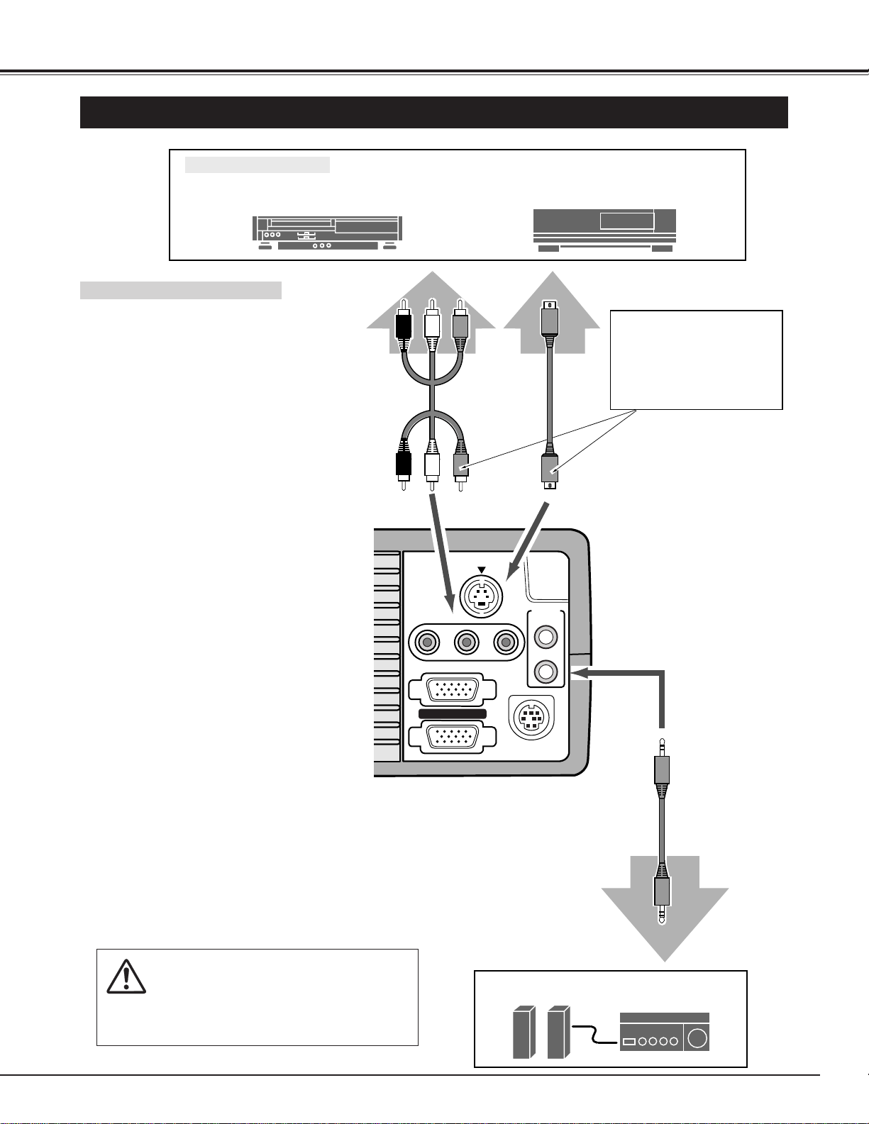
CONNECTING TO THE VIDEO EQUIPMENT
Video Source (example)
Video Cassette Recorder Video Disc Player
Video Audio Cable
✽
S-VIDEO Cable
✽
Audio Amplifier
Audio Speaker
(stereo)
External Audio Equipment
Audio Cable (Stereo)
✽
Terminals
of the Projector
Use either the VIDEO jack
or the S-VIDEO jack.
When the both jacks are
connected, the S-VIDEO
jack has priority over the
VIDEO jack.
Video / Audio Output S-VIDEO Output
Audio Input
• VIDEO CABLE
✽
• S-VIDEO CABLE
✽
• AUDIO CABLE (stereo)
✽
✽
These cables are not supplied
with this projector.
Cables used for connection
NOTE :
When connecting the cable, the power cords of
both the projector and the external equipment
should be disconnected from AC outlet. Turn the
projector and peripheral equipment on before the
computer is switched on.
12
CONNECTING THE PROJECTOR
ON
1
2
3
4
56
DIP
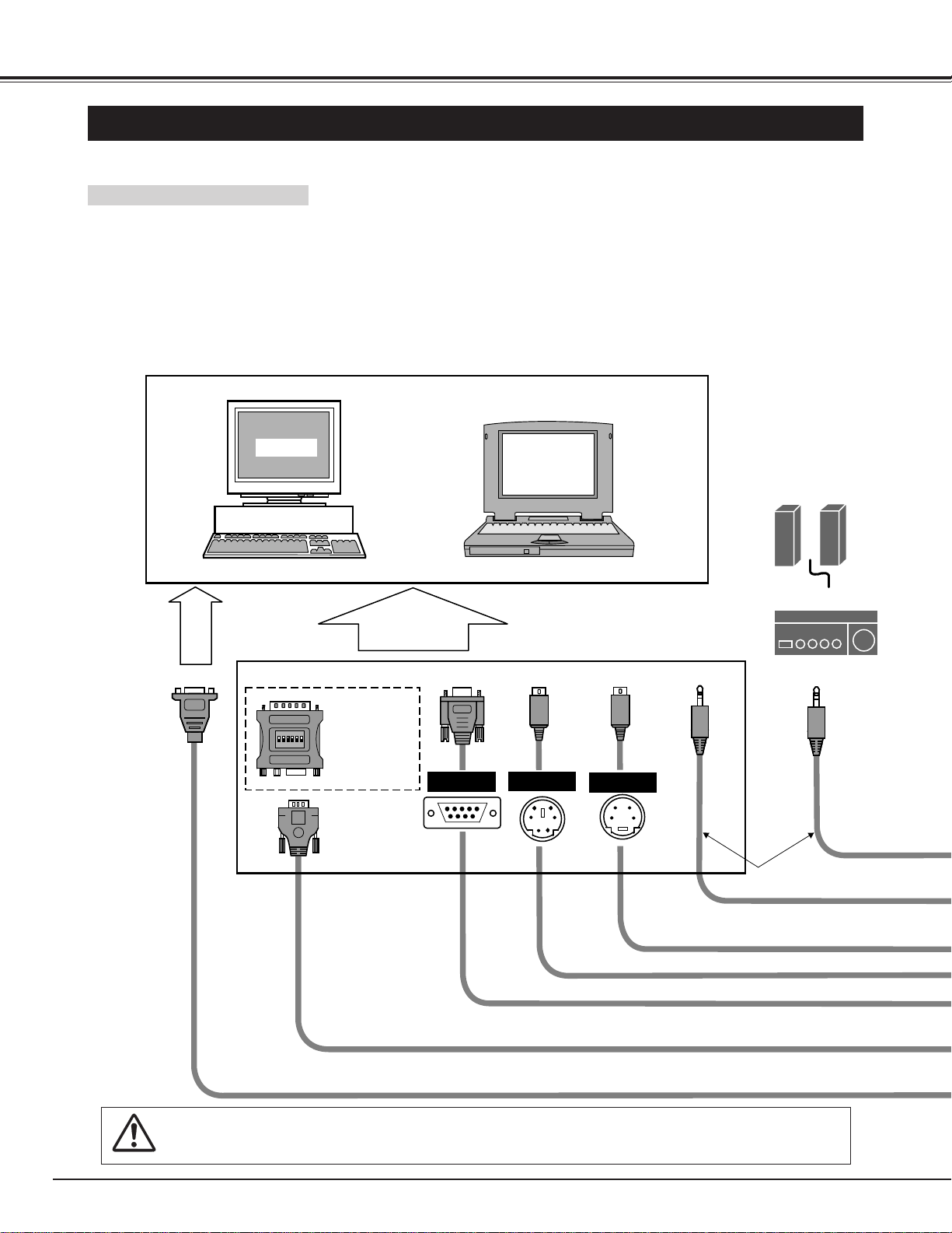
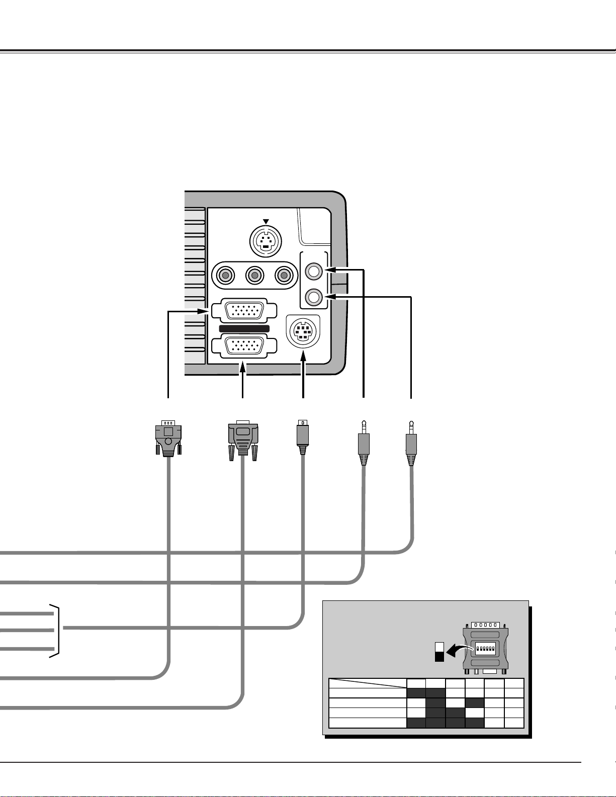
CONNECTING TO THE COMPUTER
To connect to the computer, refer to the figure below.
IBM-compatible computers or Macintosh computers (VGA / SVGA / XGA / SXGA)
VGA Cable
Monitor Output
Desktop type
Laptop type
Monitor
Audio Speaker
(stereo)
Audio Amplifier
Control Cable for Serial Port
✽
Control Cable for PS/2 Port
Audio Cable (stereo)
✽
Monitor Cable
✽
Terminal Terminal
Serial port PS/2 port Audio Output Audio Input
To each terminal of your computer
To the Monitor
NOTE :
When connecting the cable, the power cords of both the projector and the external equipment should be disconnected
from AC outlet. Turn the projector and peripheral equipment on before the computer is switched on.
MAC Adapter
✽
Set the slide
switches following
the chart on the
next page.
Terminal
ADB port
Control Cable for ADB Port
✽
• VGA CABLE
• CONTROL CABLE FOR PS/2 PORT
• CONTROL CABLE FOR SERIAL PORT,or ADB PORT
✽
• MAC ADAPTER
✽
• MONITOR CABLE
✽
• PC AUDIO CABLE (stereo)
✽
✽
These cables are not supplied with this projector.
Cables used for connection
13
CONNECTING THE PROJECTOR
S-VIDEO
R-AUDIO-L
(MONO)
VIDEO
AUDIO
IN
OUT
CONTROL PORT
COMPUTER IN
MONITOR OUT
ON
1
DIP
ON
OFF
2 3 4 5 6
13" MODE (640 x 480)
16" MODE (832 x 624)
19" MODE (1024 x 768)
OFFON ON
ON ON
ON ON
OFF OFF OFF
OFFOFF OFF OFF
OFF OFF OFF OFF
123456
OFF OFFON ONON ON21" MODE (1152 x 870)
CONTROL
PORT
AUDIO
OUT
AUDIO
IN
MONITOR
OUT
COMPUTER
IN
Use one of these Control
Cables corresponding
with the terminal of your
computer.
Set the switches as shown
in the table below depend-
ing on the RESOLUTION
MODE that you want to
use before your turn on the
projector and computer.
◆ MAC ADAPTER (Not supplied)
14
BEFORE OPERATION
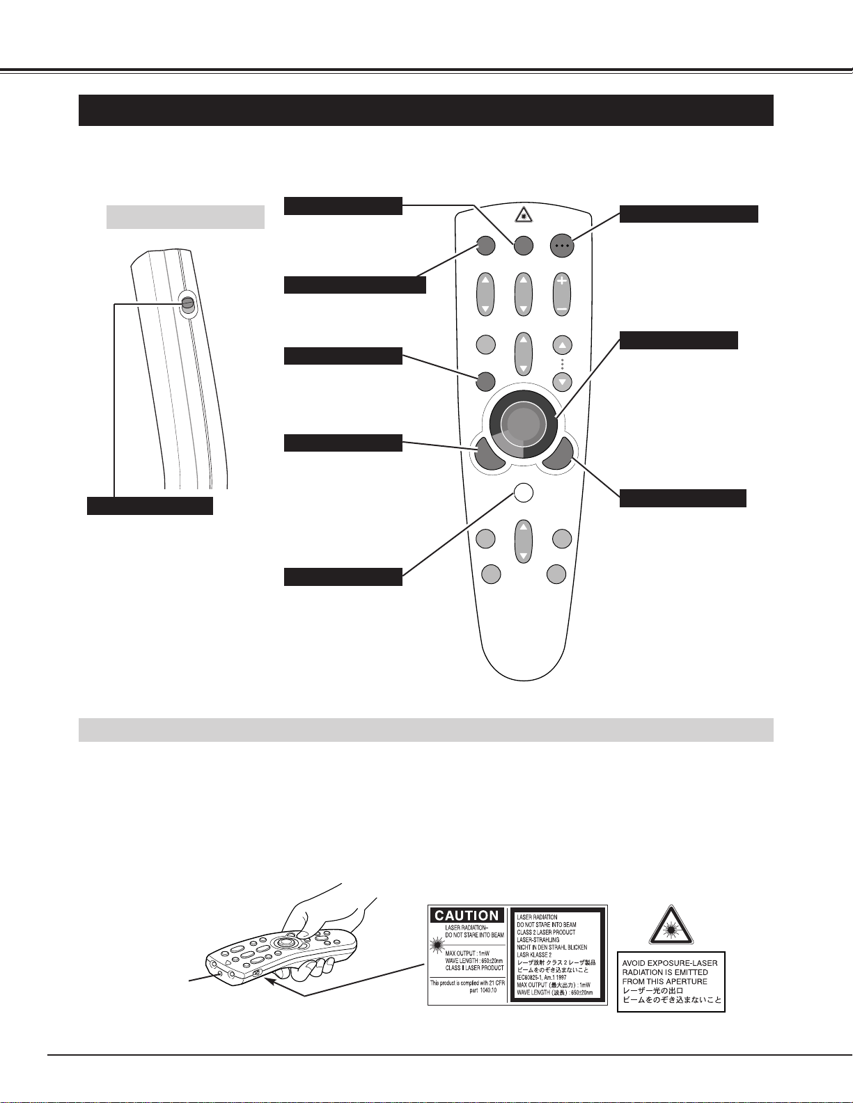
OPERATION OF THE REMOTE CONTROL
VOLUME
POWER
FOCUS
ZOOM
VIDEO
COMPUTER/
MCI
D.ZOOM
MENU
MUTE
LASER
KEYSTONE
NO SHOW
FREEZE
AUTO IMAGE
NORMAL
PAGE
Used to select source either
COMPUTER or MCI mode.
(P23)
Used to select VIDEO
source. (P30)
Used to execute the item
selected or to expand the
image in DIGITAL ZOOM
mode. (P29, 37)
It is also used as a PC mouse
in Wireless Mouse Operation.
(P41)
POWER ON-OFF BUTTON
Used to turn the projector on
or off. (P20)
MENU BUTTON
Used to select MENU
operation. (P17-19)
SELECT BUTTON
ON
ALL OFF
ALL-OFF SWITCH
When using the Remote Control
Unit, turn this switch to “ON” and
turn it “ALL OFF” when it is not
used.
Used to move the pointer on
the MENU, to adjust the item,
or to pan the image in DIGITAL
ZOOM mode. (P29, 37)
It is also used as a PC mouse
in Wireless Mouse Operation.
(P41)
✽ When pressing the center of this
button, it works as the SELECT
button.
VIDEO BUTTON
COMPUTER / MCI BUTTON
POINT BUTTON
LASER BUTTON
Used to operate laser pointer
function. The laser beam is
emitted while pressing this
button within 1 minute. When
using the laser pointer for
more than 1 minute, release
the button and press it again.
This remote control emits a laser beam as the Laser Pointer from the Laser Light Window. When the LASER button is
pressed, the laser light goes on. And when the button is pressed more than 1 minute or the button is released, light goes off.
Laser light is emitted with the RED light which tells the laser beam being emitted.
The laser emitted is a class II laser; therefore, do not look into the Laser Light Window or shine the laser beam on yourself or
other people. The three marks below are the caution labels for the laser beam.
CAUTION : Use of controls or adjustments or performance of procedures other than those specified herein may result in
hazardous radiation exposure.
Laser Light Window
These caution labels are put on the remote control.
Used to compress the image
in DIGITAL ZOOM mode.
(P29, 30, 37)
It is also used as a PC mouse
in Wireless Mouse Operation.
(P41)
RIGHT CLICK BUTTON
LASER POINTER FUNCTION
Left Side
15
BEFORE OPERATION
VOLUME
POWER
FOCUS
ZOOM
VIDEO
COMPUTER/
MCI
D.ZOOM
MENU
MUTE
LASER
KEYSTONE
NO SHOW
FREEZE
AUTO IMAGE
NORMAL
PAGE
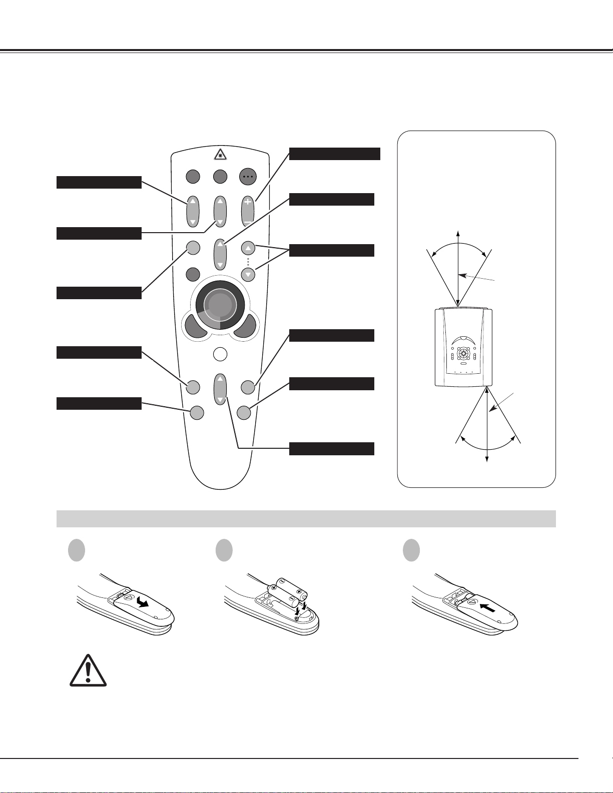
To insure safe operation, please observe the following precautions :
● Use (2) AA type alkaline batteries.
● Replace two batteries at the same time.
● Do not use a new battery with a used battery.
● Avoid contact with water or liquid.
● Do not expose the Remote Control Unit to moisture, or heat.
● Do not drop the remote control unit.
● If batteries have leaked on the remote control, carefully wipe the case clean and install new batteries.
Press the lid down-
ward and slide it.
Remove the battery
compartment lid.
Slide the batteries into the
compartment.
Replace the compartment
lid.
Two AA size batteries
For correct polarity (+
and –), be sure the
battery terminals are in
contact with the pins in
the compartment.
REMOTE CONTROL BATTERY INSTALLATION
1 2 3
MUTE BUTTON
Used to mute sound.(P22)
ZOOM BUTTON
Used to adjust zoom.
(P21)
FOCUS BUTTON
Used to adjust focus.
(P21)
NO SHOW BUTTON
Used to turn the picture
into a black image. (P22)
AUTO IMAGE BUTTON
Use to operate AUTO
IMAGE function. (P28)
VOLUME BUTTON
Used to adjust volume.
(P22)
D.ZOOM BUTTON
Used to turn the projector
into DIGITAL ZOOM
mode. (P29, 37)
KEY STONE BUTTON
Used to correct the key
stone distortion.
(P21, 29, 30, 37)
FREEZE BUTTON
Used to stop the picture.
(P22)
NORMAL BUTTON
Used to reset to normal
picture adjustments preset
by the factory.
(P27, 31, 36)
Operating Range
Point the remote control toward the
projector (Receiver Window) when
pressing the buttons. Maximum
operating range for the remote
control is about 16.4” (5m) and 60°
front and rear of the projector
16.4”
(5 m)
60°
60°
16.4”
(5 m)
Used to move to next /
previous page of the data
in memory card. These
buttons are activated in
MCI mode only. (P34)
PAGE BUTTONS
POWER
NORMAL MENU MODE
AUTO IMAGE
FOCUS
ZOOM
VOLUME PAGE
LAMP
REPLACE
WARNING
TEMP.
READY
LAMP
WIDE
TELE
SELECT
BRIGHT
16
BEFORE OPERATION
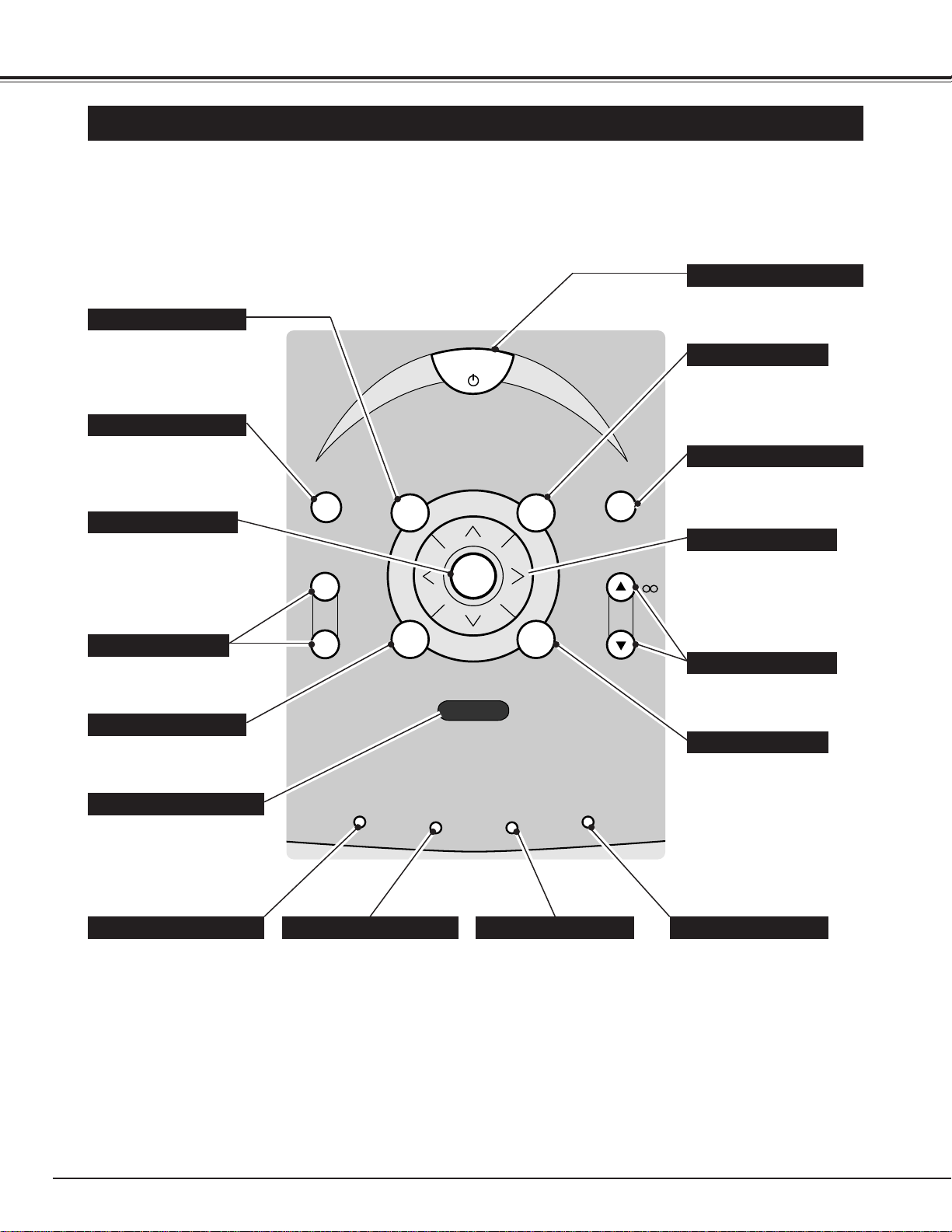
TOP CONTROLS AND INDICATORS
Used to open or close the
MENU operation.
(P17, 19)
MENU BUTTON
AUTO IMAGE BUTTON
READY INDICATOR
POWER ON–OFF BUTTON
WARNING TEMP. INDICATOR
LAMP INDICATOR
LAMP REPLACE INDICATOR
Used to operate AUTO
IMAGE function. (P28)
This indicator is lit in green
when the projector is ready
to be turned on.
This indicator is dim when
the projector is turned on.
And bright when the
projector is in stand-by
mode.
This indicator turns to
yellow when the life of the
projection lamp draws to an
end. (P43)
This indicator flashes red
when internal projector
temperature is too high.
(P42)
Used to turn the projector
on or off. (P20)
Used to select zoom adjust.
(P21)
MODE BUTTON
SELECT BUTTON
FOCUS BUTTONS
NORMAL BUTTON
VOLUME BUTTON
POINT BUTTONS
Used to select input source
among Computer, Video or
MCI. (P23, 30)
Used to select focus adjust.
(P21)
Used to adjust volume.
(P22)
Used to reset to normal
picture adjustment preset
by factory. (P27, 31, 36)
Used to select an item and
adjust the value on the
MENU. It is also used to
pan the image in DIGITAL
ZOOM mode. (P29, 37)
Used to execute the item
selected. It is also used to
expand the image in
DIGITAL ZOOM mode.
(P29, 37)
ZOOM BUTTONS
PAGE BUTTON
Used to move to the next /
previous page of the data in
the memory card plugged
into PC CARD SLOT.
Page buttons are activated
in MCI mode (P34).
BRIGHT SWITCH INDICATOR
This indicator lights when
the BRIGHT SWITCH is set
to BRIGHTER. (P22)
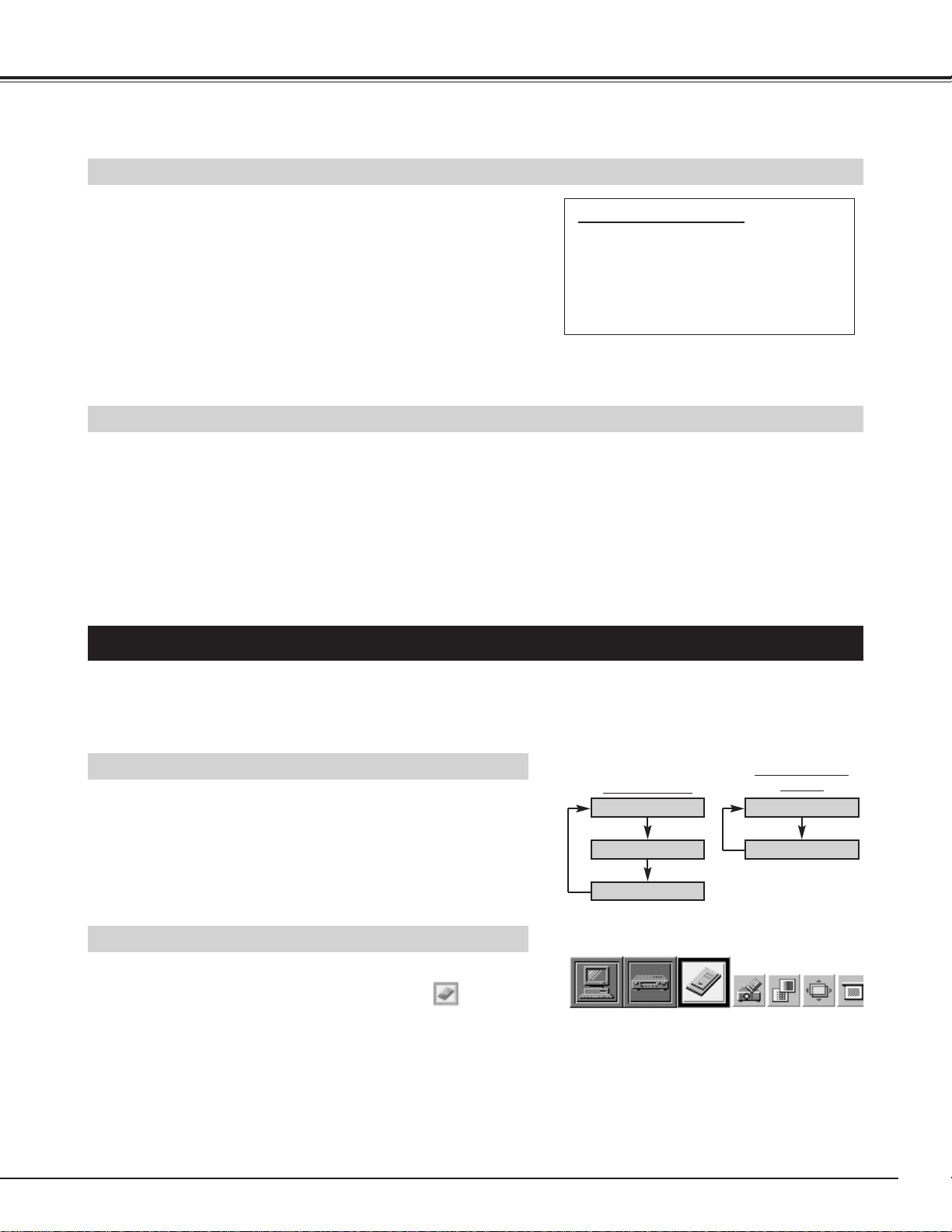
17
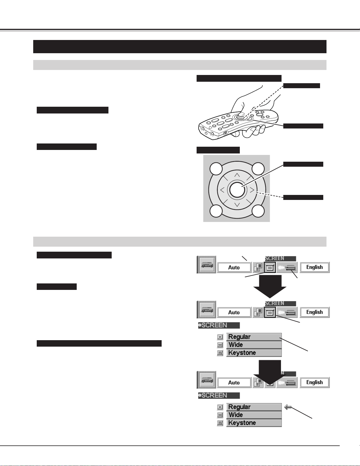
SELECT
BEFORE OPERATION
HOW TO OPERATE ON-SCREEN MENU
FLOW OF ON-SCREEN MENU
Display ON-SCREEN MENU
Press MENU button to display the ON-SCREEN MENU
(MENU BAR). The red frame is the POINTER.
Select the ITEM by pressing SELECT button. The
dialog box of the ITEM appears.
Move the POINTER (red frame) to the ITEM ICON that
you want to select by pressing POINT RIGHT/ LEFT
buttons.
Move the POINTER to the ITEM that you want to adjust
and adjust the ITEM by pressing SELECT button.
Refer to the following pages for details of respective
adjustments.
Move the POINTER downward by pressing POINT
DOWN button. (The shape of the POINTER becomes
an arrow.)
Select the Item
Control and adjust through ON-SCREEN MENU
1
2
3
5
4
You can control and adjust this projector through the
ON-SCREEN MENU. Refer to the following pages to
operate each adjustment on the ON-SCREEN MENU.
1 MOVING THE POINTER
2 SELECT THE ITEM
Move the pointer (see the NOTE below) by pressing POINT
button(s) on the TOP CONTROL or the REMOTE CONTROL.
Select the item by pressing SELECT button.
SELECT
BUTTON
POINT
DOWN
BUTTON
MENU BAR
POINTER
(red frame)
ITEM ICON
POINTER
(red frame)
MENU
POINTER
Used to select the item.
SELECT BUTTON
Used to move the
Pointer UP/ DOWN/
RIGHT/ LEFT.
POINT BUTTONS
Used to select the item.
SELECT BUTTON
Used to move the
Pointer UP/ DOWN/
RIGHT/ LEFT.
POINT BUTTON
WIRELESS REMOTE CONTROL
TOP CONTROL
OPERATING ON-SCREEN MENU
NOTE : Pointer is the icon on the ON-SCREEN Menu to
select the item. See the figures on the section
"FLOW OF ON-SCREEN MENU" below.
18
BEFORE OPERATION
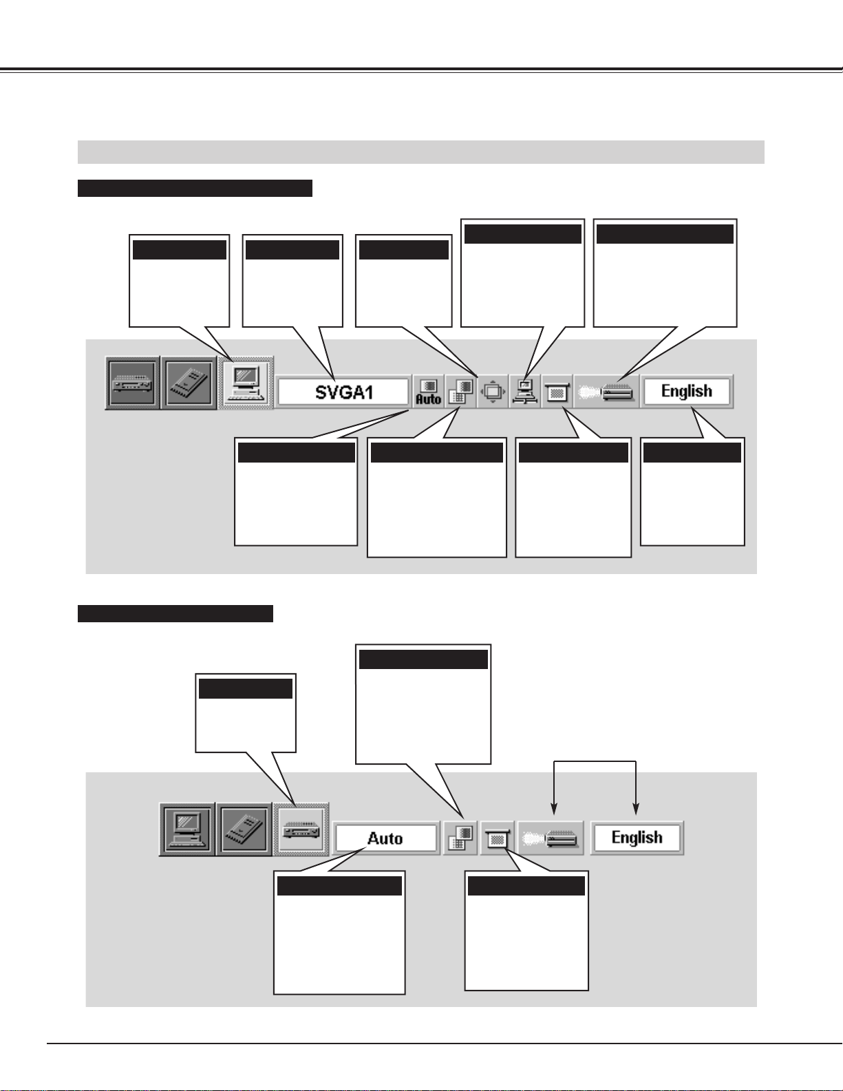
MENU BAR
IMAGE MENU
Used to adjust the
computer image. [Fine
sync. / Total dots /
White Balance /
Contrast / Brightness]
(Refer to P27)
PC ADJUST MENU
Used to adjust the
parameters to
match with the input
signal format.
(Refer to P24, 25)
SETTING MENU
Used to set the Display
Menu and to reset
Lamp Replacement
Monitor Timer.
(Refer to P40)
MODE MENU
Used to select
the Computer
input mode.
(Refer to P23)
SCREEN MENU
Used to adjust the
size of the image
or to correct the
Keystone
distortion.
(Refer to P29)
MENU BAR IN COMPUTER MODE
Press MENU BUTTON while in Computer mode.
SYSTEM MENU
Used to select a
color system among
[
PAL, SECAM, NTSC,
NTSC 4.43, PAL-M and
PAL-N
].
(Refer to P30)
IMAGE MENU
Used to adjust the
picture image. [
Color /
Tint / White Balance /
Contrast / Brightness/
Sharpness
]
(Refer to P31)
SCREEN MENU
Used to set the size
of the image either
Regular or Wide,
or to correct the
Keystone distortion.
(Refer to P30)
MENU BAR IN VIDEO MODE
Press MENU BUTTON while in Video mode.
These icons have the same
function as the Computer Mode.
LANGUAGE MENU
Used to select
the language
used in the
Menu.
(Refer to P40)
MODE MENU
Used to select
the Video input.
(Refer to P30)
POSITION MENU
Used to adjust
the position of
the image.
(Refer to P28)
AUTO IMAGE MENU
Used to adjust Fine
sync., Total dots,
and Picture Position
automatically.
(Refer to P28)
SYSTEM MENU
Used to select
a computer
system.
(Refer to P23)
19
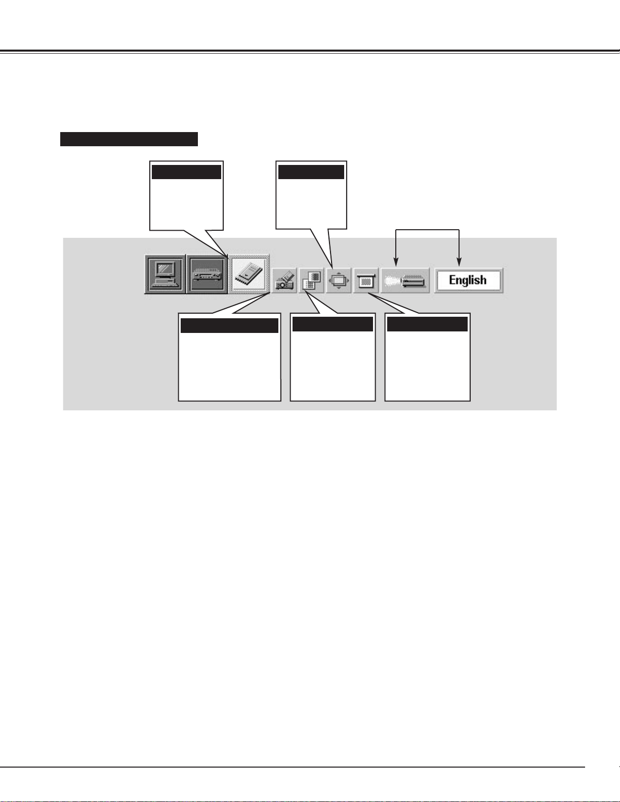
BASIC OPERATION
VIEW MENU
Used to display, read
or write the image data
in a memory card
through the PC CARD
SLOT.
(Refer to P34, 35)
MODE MENU
Used to select
the MCI input
mode.
(Refer to P33)
MENU BAR IN MCI MODE
Press MENU BUTTON while in MCI mode.
These icons have the same
function as the Computer Mode.
IMAGE MENU
Used to adjust
the computer
image. [White
Balance / Contrast
/ Brightness]
(Refer to P36)
POSITION MENU
Used to adjust
the position of
the image.
(Refer to P36)
SCREEN MENU
Used to adjust the
size of the image
or to correct the
Keystone
distortion.
(Refer to P37)
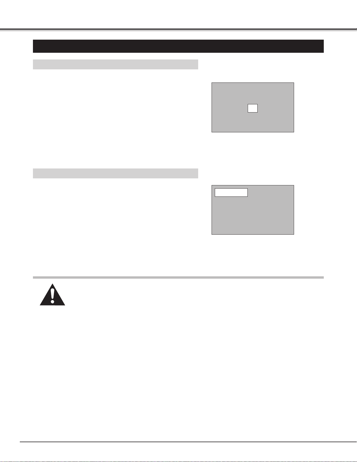
20
BASIC OPERATIONS
TURNING ON THE PROJECTOR
Connect the projector's AC power cord into a wall outlet. The
LAMP indicator lights RED, and the READY indicator lights
GREEN.
Press the power ON-OFF button on the Remote Control Unit or
on the Top Control to ON. The LAMP POWER indicator dims,
and the Cooling Fans start to operate. The Preparation Display
appears on the screen and the count-down starts. The signal
from the source appears after 30 seconds.
2
3
TURNING OFF THE PROJECTOR
Press the power ON-OFF button on the Remote Control Unit or
on the Top Control, and the message "Power off?" appears on
the screen.
Press the power ON-OFF button again to turn off the projector.
The LAMP indicator lights bright and the READY indicator turns
off. The Cooling Fans operate for 90 seconds after the
projector is turned off. (During this "Cooling Down" period, this
appliance cannot be turned on.)
1
2
TO MAINTAIN THE LIFE OF THE LAMP, ONCE YOU TURN IT ON, WAIT AT LEAST 5
MINUTES BEFORE TURNING IT OFF.
Power off?
The message disappears after 4 seconds.
TURNING ON / OFF THE PROJECTOR
When the TEMPERATURE WARNING indicator flashes red, the projector is automatically turned off. Wait
at least 5 minutes before turning the projector on again.
If the TEMPERATURE WARNING indicator continues to flash, follow procedures below:
1. Disconnect the AC power cord from the AC outlet.
2. Check the air filters for dust accumulation.
3. Clean the Air Filter. (See "AIR FILTER CARE AND CLEANING" section on page 42.)
4. Press the power ON-OFF button to ON.
If the TEMPERATURE WARNING indicator still continues to flash, call your authorized dealer or service
station.
1
Complete the peripheral connections (with Computer, VCR,
etc.) before turning on the projector. (Refer to "CONNECTING
TO THE PROJECTOR" on Pages 10~13 for connecting that
equipment.)
3
When cooling the projector has finished, the READY indicator
turns to green again and you can turn the projector on. After
cooling down completely, disconnect the AC power cord.
30
The Preparation Display disappears after 30 seconds.
NOTE: The Cooling Fan may work for cooling while the projector is turned off. When the Cooling
Fan is working, TEMPERATURE WARNING INDICATOR flashes red.
21
BASIC OPERATION
ADJUSTING THE IMAGE
The message disappears after 4 seconds.
The message disappears after 4 seconds.
ZOOM ADJUSTMENT
1
Press the ZOOM WIDE/TELE buttons on the Top Control or the
ZOOM ▲/▼ button on the Remote Control Unit to turn into the
ZOOM mode.
2
Press the ZOOM WIDE button or the ZOOM ▲ button to make
the image larger, and press the ZOOM TELE button or the
ZOOM ▼ button to make the image smaller.
FOCUS ADJUSTMENT
1
Press the FOCUS ▲/▼ button(s) on the Top Control or on the
Remote Control Unit to turn into the FOCUS mode.
2
Adjust the focus of the image by pressing the FOCUS ▲/▼
button(s).
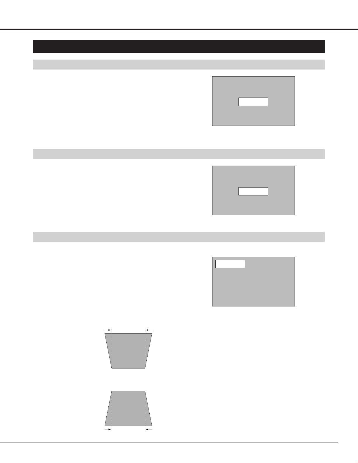
KEYSTONE ADJUSTMENT
1
Press the KEYSTONE ▲/▼ button on the Remote Control Unit
or select the Keystone on the SCREEN menu. (Refer to page
29, 30, 37.) The message “Keystone” is displayed.
2
Correct the Keystone distortion by pressing the KEYSTONE
▲/▼ button or the POINT UP/DOWN button(s). Press the
KEYSTONE ▲ button or the POINT UP button to reduce the
upper part or the image, and press the KEYSTONE ▼ button or
the POINT DOWN button to reduce the lower part.
The message disappears after 4 seconds.
Reduce the upper width with the KEY STONE ▲
button or the POINT UP button.
Reduce the lower width with the KEY STONE ▼
button or the POINT DOWN button.
In the Computer mode, the image can be expanded, compressed,
and panned with the Digital Zoom function. Refer to page 29 and 37
for the Digital Zoom operation.
Zoom
Focus
Keystone
If the picture has keystone distortion, correct image with KEYSTONE adjustment.
22
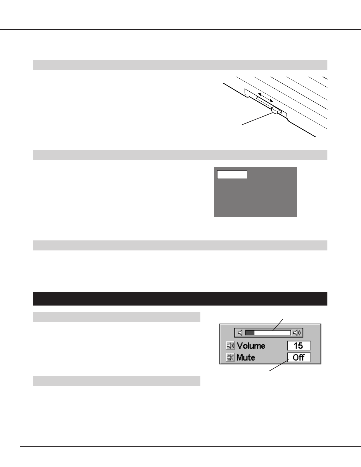
BASIC OPERATION
It indicates the level of the volume.
Press the MUTE button to set
the Mute function On or Off.
The display disappears after 4 seconds.
The message disappears after 4 seconds.
No show
Slide the BRIGHT SWITCH to the BRIGHTER position to enhance
the picture brightness. When the BRIGHT SWITCH is set to the
BRIGHTER position, the BRIGHT SWITCH INDICATOR lights on.
(P16) To return the original image, slide the switch to the
STANDARD position.
✽ When the BRIGHT SWITCH is set to the BRIGHTER position, the
color of image may change slightly.
BRIGHT SWITCH
BRIGHTER
STANDARD
BRIGHT SWITCH (on the side)
Set the switch firmly.
Press the VOLUME button on the Top Control or the VOLUME (+/–)
button on the Remote Control Unit to adjust the volume. The Volume
dialog box appears on the screen for a few seconds.
The POINT UP or VOLUME (+) button increase the volume, and the
POINT DOWN or the VOLUME (–) button decrease the volume.
Press the MUTE button on the Remote Control Unit to mute the
sound. To restore the sound to its previous level, press the MUTE
button again or press Volume button(s).
SOUND ADJUSTMENT
Press the FREEZE button on the Remote Control Unit to freeze the picture on screen. This function is cancelled when
the FREEZE button is pressed again or any other function button is pressed.
Press the NO SHOW button on the Remote Control Unit to black out
the image. This function is cancelled when the NO SHOW button is
pressed again or any other function button is pressed.
NO SHOW FUNCTION
PICTURE FREEZE FUNCTION
SOUND MUTE ADJUSTMENT
SOUND VOLUME ADJUSTMENT
23
COMPUTER / MCI
button
Press the MENU button and the ON-SCREEN MENU will appear.
Press the POINT LEFT/RIGHT buttons to select Computer and
press the SELECT button.
COMPUTER MODE
SELECTING COMPUTER MODE
DIRECT OPERATION
Select COMPUTER mode by pressing the MODE button on the Top
Control or the COMPUTER / MCI button on the Remote Control Unit.
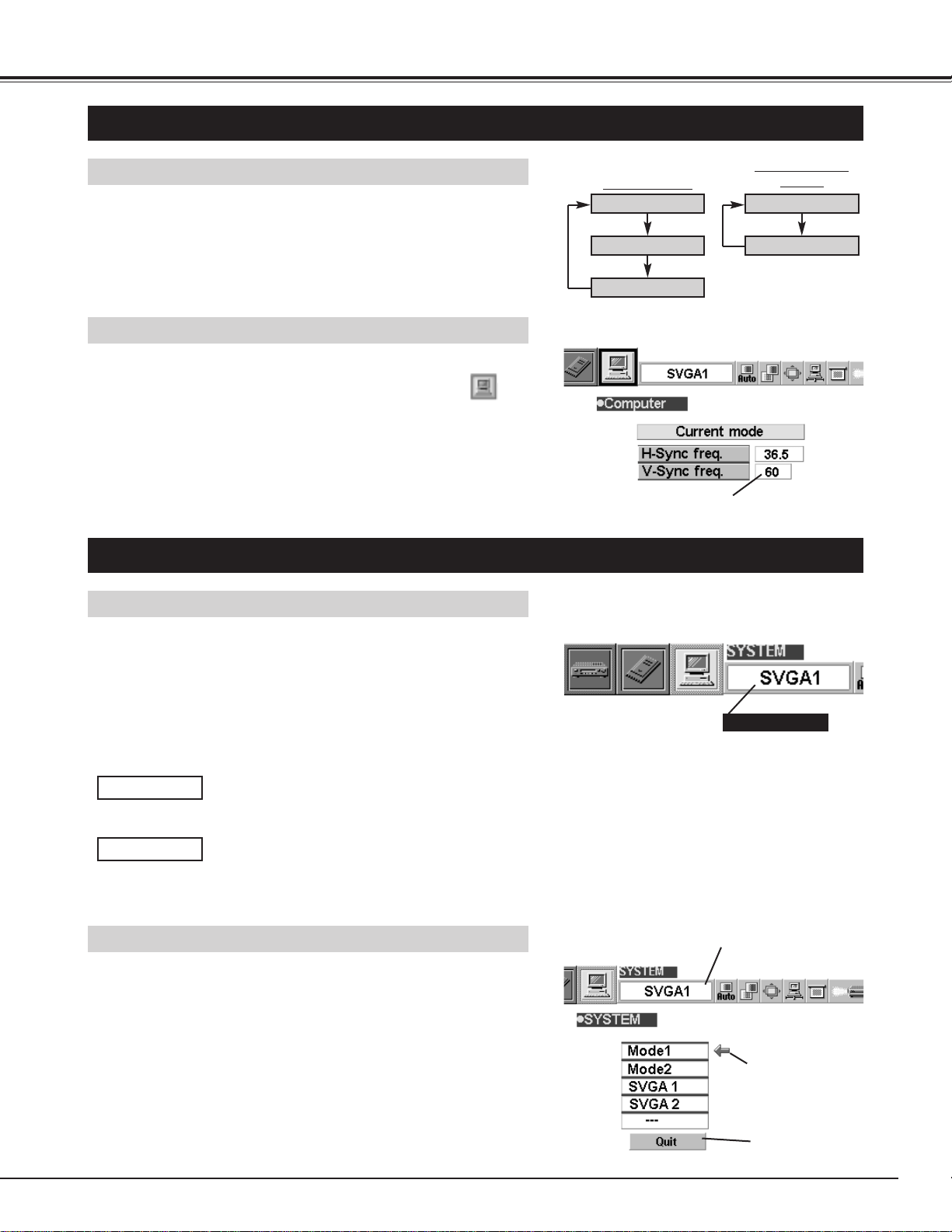
MENU OPERATION
When selecting the Computer Mode, the Current Mode display
appears. It shows the information of the computer of the mode
selected.
CURRENT MODE DISPLAY
Providing the information of the computer detected
by the projector.
SELECTING COMPUTER SYSTEM
AUTOMATIC MULTISCANNING SYSTEM
This projector automatically tunes to most different types of computer
based on VGA, SVGA, XGA or SXGA (refer to “COMPATIBLE
COMPUTER SPECIFICATION” on page 26). When selecting
Computer, this projector automatically tunes to the incoming signal
and projects the proper image without any special setting. (Setting of
the Computer System may be required when connecting some
computers.)
Note : The projector may provide the messages below.
The projector cannot discriminate or detect the
input signal from the computer. Adjust and set the
computer system manually. (Refer to page 24.)
There is no signal input from the computer. Make
sure the connection of the computer and the
projector is set correctly. (Refer to
TROUBLESHOOTING on page 44.)
Go to PC adj.
No signal
SELECT COMPUTER SYSTEM MANUALLY
To set the Computer system manually, select the mode on the ON-
SCREEN MENU.
It displays the SYSTEM
being selected.
SYSTEM BOX
The system being selected.
The systems on this
dialog box can be
selected.
Close the SYSTEM
Menu.
Press the MENU button and the ON-SCREEN MENU will
appear. Press the POINT LEFT/RIGHT buttons to select
SYSTEM and press the SELECT button. Another dialog box
COMPUTER MODE Menu will appear.
Press the POINT DOWN button and a red-arrow icon will
appear. Move the arrow to the system that you want to set,
and then press
SELECT button.
1
2
COMPUTER
MCI
VIDEO
COMPUTER
MCI
MODE button
24
COMPUTER MODE
PC ADJUSTMENT
This Projector can automatically tune to the display signals from most personal computers currently distributed.
However, some computers employ the special signal formats which are different from the standard ones and
may not be tuned by Multiscanning of this projector. If this happens, the projector cannot reproduce a proper
image and the image is recognized as a flickering picture, a non-synchronized picture, a non-centered picture or
a skewed picture.
This projector has PC ADJUSTMENT function, to enable you to precisely adjust several parameters to match
with those exceptional signal formats and the projector has five independent memory areas to memorize those
parameters manually adjusted. This enables you to recall the setting for a specific computer whenever you use
it.
Note : This PC ADJUSTMENT function cannot be operated when “RGB,” “HDTV1035i” or “HDTV1080i” is selected on the
SYSTEM MENU (P23 and 26).
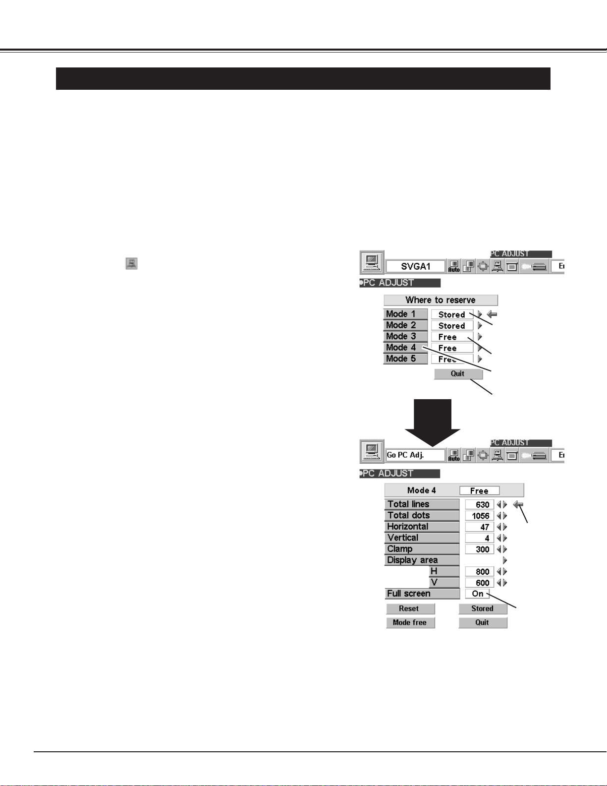
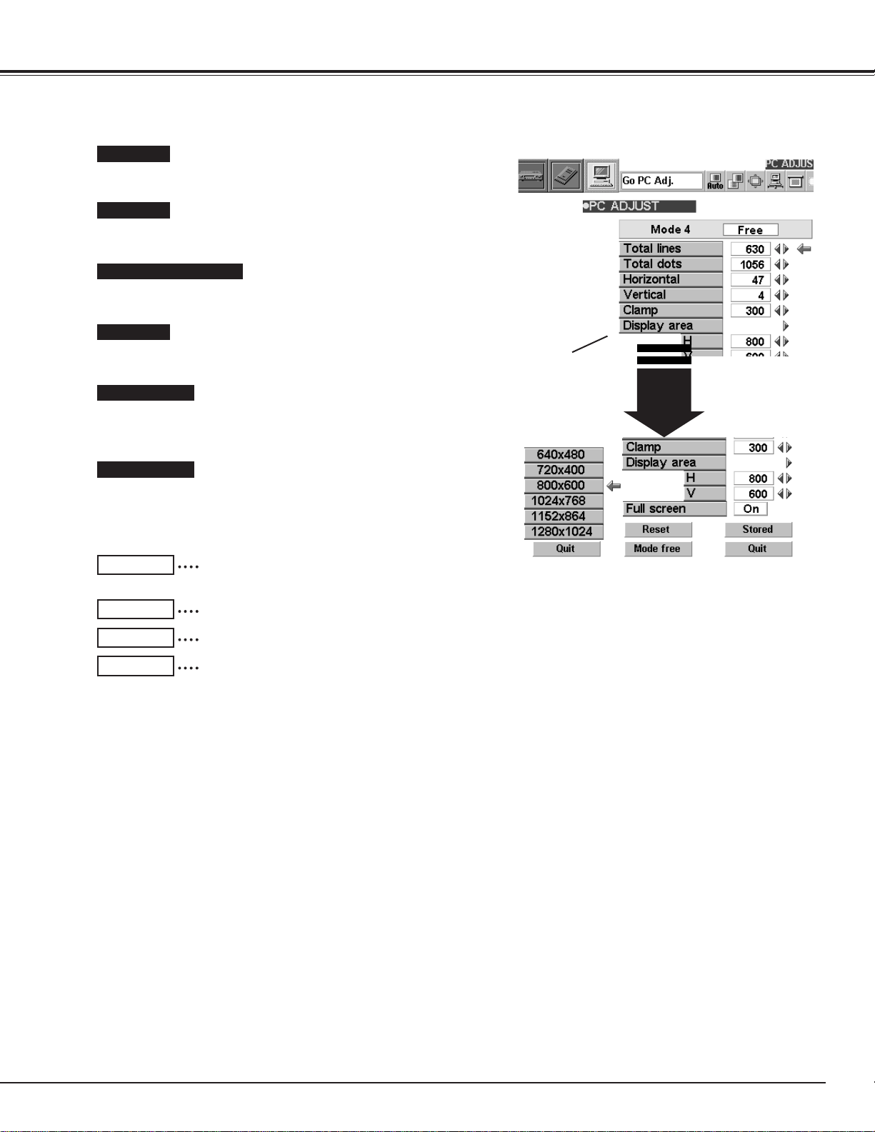
Press the MENU button and the ON-SCREEN MENU will
appear. Press the POINT RIGHT/LEFT buttons to select PC
ADJUST and press the SELECT button. Another dialog
box “Where to reserve” Menu will appear.
In this dialog box, you can store the parameter into the area
from “Mode 1” to “Mode 5.” When memorizing the new
computer parameter, select the Mode with the message of
“Free” by pressing the POINT UP/DOWN buttons and the
SELECT button. To change the parameters of the Mode
previously set, select the Mode with “Stored.”
1
2
When the Mode is selected, Parameter adjustment dialog box
appears. Move the arrow to the item that you want to change
by pressing the POINT UP/DOWN buttons, and adjust each
item to match your computer. To change the value, press
either the POINT RIGHT button or the POINT LEFT button.
Refer to the next page for adjusting each item.
3
Move the arrow to “Stored” and press the SELECT button. The
parameter is memorized in the selected Mode.
4
This Mode has para-
meters being stored.
Close the PC
ADJUSTMENT Menu.
The Vacant Mode.
Manual set Computer
Mode (1 to 5).
Press the POINT
RIGHT/LEFT
button(s) to
adjust the value.
Press the
SELECT button
to set Full screen
function on/off.
To activate the Mode manually adjusted in this PC
ADJUSTMENT Menu, select the Mode at the SYSTEM
SELECT Menu. (Refer to page 23.)
5
25
COMPUTER MODE
The number of the total vertical lines. Adjust the number to match
the image of your personal computer.
Total lines
Recalls the parameter data that was previously
adjusted.
Reset
Stores the parameters in the memory.
Stored
Clears the parameter data previously set .
Mode free
Closes the PC ADJUST Menu.
Quit
The number of the total dots in one horizontal period. Adjust the
number to match the image of your personal computer.
Total dots
Adjustment of the horizontal or vertical picture position. When the
image is not centered on the screen, adjust each of those items.
Horizontal / Vertical
Adjustment of the clamp level. When the image has a dark bar(s),
try this adjustment.
Clamp
Adjustment of the area displayed with this projector. Select the
resolution at the Display area dialog box, or adjust the number at
the column of “H” or “V” to match the resolution of the image.
Display area
Set “On” to resize the image with 4 x 3 aspect ratio to fit the
screen.
Full Screen
Each of the keys operates as follow.
Press the
SELECT button
to select the
typical resolution
of the image.
26
COMPUTER MODE
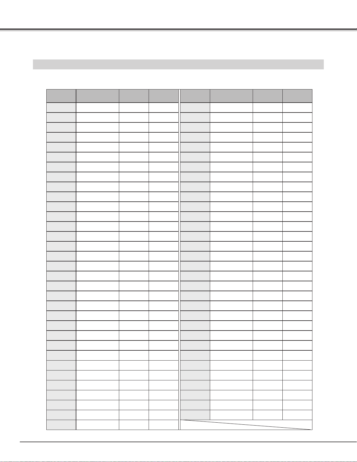
COMPATIBLE COMPUTER SPECIFICATIONS
Basically this projector can accept the signal from all computers with the V, H-Frequency mentioned below and less than
140 MHz of Dot Clock.
NOTE : Specifications are subject to change without notice.
ON-SCREEN
DISPLAY
RESOLUTION
H-Freq.
(kHz)
V-Freq.
(Hz)
VGA 1 640 x 480 31.47 59.88
VGA 2 720 x 400 31.47 70.09
VGA 3 640 x 400 31.47 70.09
VGA 4 640 x 480 37.86 74.38
VGA 5 640 x 480 37.86 72.81
VGA 6 640 x 480 37.50 75.00
MAC LC13
640 x 480 34.97 66.60
MAC 13 640 x 480 35.00 66.67
MAC1 6 832 x 624 49.72 74.55
MAC 19 1024 x 768 60.24 75.08
MAC21 1152 x 870 68.68 75.06
MAC 1280 x 960 75.00 75.08
MAC 1280 x 1024 80.00 75.08
SVGA 1 800 x 600 35.156 56.25
SVGA 2 800 x 600 37.88 60.32
SVGA 3 800 x 600 46.875 75.00
SVGA 4 800 x 600 53.674 85.06
SVGA 5 800 x 600 48.08 72.19
SVGA 6 800 x 600 37.90 61.03
SVGA 7 800 x 600 34.50 55.38
SVGA 8 800 x 600 38.00 60.51
SVGA 9 800 x 600 38.60 60.31
SVGA 11 800 x 600 32.70 51.09
SVGA 12 800 x 600 38.00 60.51
ON-SCREEN
DISPLAY
RESOLUTION
H-Freq.
(kHz)
V-Freq.
(Hz)
XGA 10 1024 x 768
XGA 11 1024 x 768
XGA 12
1024 x 768
(Interlace)
XGA 13 1024 x 768
62.04 77.07
XGA 14 1024 x 768
61.00 75.70
XGA15 1024 x 768
35.522 43.48
46.90 58.20
XGA 8 1024 x 768
47.00 58.30
XGA 9
1024 x 768
(Interlace)
58.03 72.0
SXGA 1 1152 x 864
SXGA 2 1280 x 1024
63.48 79.35
SXGA 3 1280 x 1024
36.00 43.59
SXGA 4 1280 x 1024
64.20 70.40
SXGA 5 1280 x 1024
62.50 58.60
SXGA 6 1280 x 1024
63.90 60.00
SXGA 7 1280 x 1024
63.34 59.98
SXGA 8 1280 x 1024
63.74 60.01
SXGA 11 1152 x 900
71.69 67.19
SXGA 12 1152 x 900
81.13 76.107
SXGA 13
1280 x 1024
(Interlace)
63.98 60.02
SXGA 14
1280 x 1024
(Interlace)
61.20 65.20
71.40 75.60
50.00 43.00
HDTV720p
––––––––
50.00 47.00
45.00 60.00
XGA 1 1024 x 768
XGA 2 1024 x 768
XGA 3 1024 x 768
XGA 4 1024 x 768
48.36 60.00
68.677 84.997
XGA 6 1024 x 768
60.023 75.03
XGA 7 1024 x 768
56.47 70.07
48.50 60.02
44.00 54.58
SXGA 9 1280 x 1024
SXGA 10 1280 x 960
79.976 75.025
60.00 60.00
SXGA 15 1280 x 1024
SXGA 16 1280 x 1024
SXGA 17 1152 x 900
SXGA 18
1280 x 1024
(Interlace)
63.37 60.01
76.97 72.00
61.85 66.00
46.43 43.35
SXGA 19 1280 x 1024 63.79 60.18
XGA 5 1024 x 768 60.31 74.92
VGA 7 640 x 480 43.269 85.00
RGB
––––––––
15.625 25
RGB
––––––––
15.734 30
HDTV1080i
––––––––
33.75 60.00
HDTV1035i
––––––––
33.75 60.00
SVGA 10 800 x 600 47.90 71.92
27
COMPUTER MODE
PICTURE IMAGE ADJUSTMENT
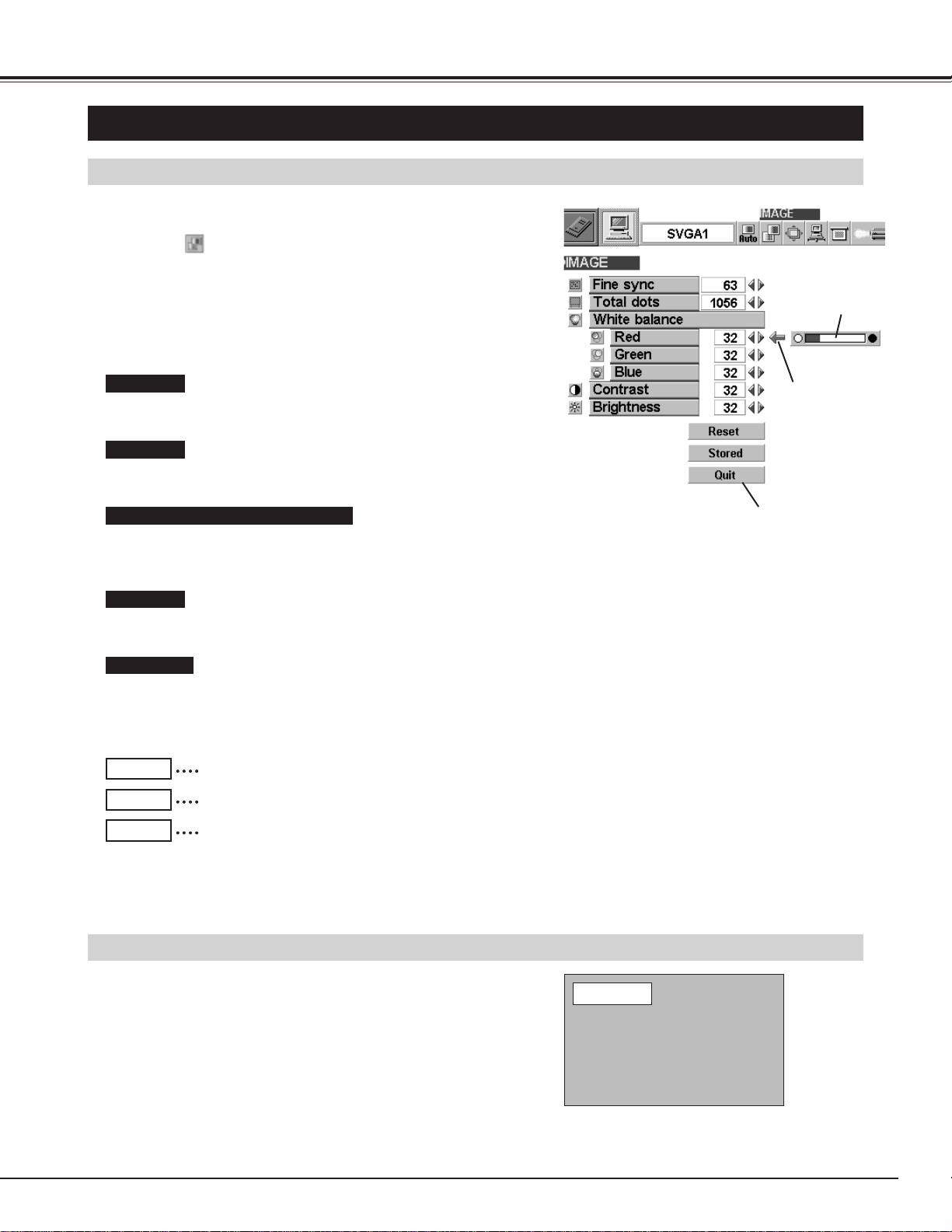
Press the MENU button and the ON-SCREEN MENU will
appear. Press the POINT LEFT/RIGHT buttons to select
IMAGE and press the SELECT button. Another dialog box
PICTURE IMAGE ADJUSTMENT Menu will appear.
Press the POINT DOWN button and a red-arrow icon will
appear. Move the arrow to the item that you want to change by
pressing the POINT UP/DOWN buttons. To change the value,
press either the POINT RIGHT button or the POINT LEFT
button.
1
2
ADJUST PICTURE IMAGE MANUALLY
Adjust the picture as necessary to eliminate flicker from the display.
(From 0 to 255.)
The number of the total dots in one horizontal period. Adjust the
number to match your PC image.
Close the PICTURE
IMAGE ADJUSTMENT
Menu.
Move the arrow to
the item and press
POINT RIGHT /
LEFT button.
It indicates the
level of the item.
Recalls the data previously adjusted.
Reset
Stores the adjusted data in the memory.
Stored
Closes the PICTURE IMAGE ADJUSTMENT Menu.
Quit
Each of the keys operates as follow.
Fine sync.
Total dots
The normal picture level is preset on this projector at the factory and
can be restored anytime you press the NORMAL button (located on
the Top Control or on the Remote Control Unit). The “Normal”
display will be displayed on the screen for a few seconds.
NORMAL FUNCTION
Normal
NOTE : The Fine sync. and the Total dots cannot be fully adjusted
when “RGB,” “HDTV1035i” or “HDTV1080i” is selected on
the SYSTEM MENU (P23 and 26).
Press POINT LEFT button to decrease contrast, and press POINT
RIGHT button to increase contrast. (From 0 to 63.)
Press POINT LEFT button to darken the image, and press POINT
RIGHT button to brighten the image. (From 0 to 63.)
Move the arrow to the color that you want to adjust. Press POINT
LEFT button to lighten the color and press POINT RIGHT button to
deepen the color. (From 0 to 63.)
White balance (Red / Green / Blue)
Contrast
Brightness
28
COMPUTER MODE
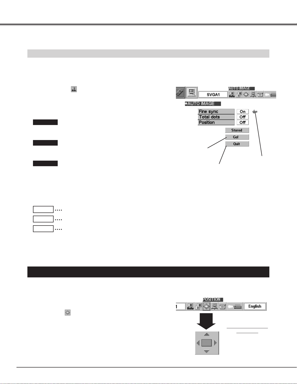
The Auto Image function is provided to automatically adjust Fine
sync., Total dots, and Picture Position for most computers.
Press the MENU button and the ON-SCREEN MENU will
appear. Press the POINT LEFT/RIGHT buttons to select
AUTO IMAGE and press the SELECT button.
Another dialog box AUTO IMAGE Menu will appear.
Move the arrow to an item that you want to adjust by pressing
the POINT UP/DOWN button. Change the setting On or Off by
pressing the SELECT button.
1
2
AUTO IMAGE FUNCTION
Move the arrow to “Go!” and press the SELECT button to start
the Auto Image function.
This adjustment can be executed by pressing AUTO IMAGE
button on the Top Control and the Remote Control Unit.
3
Close the PICTURE IMAGE
ADJUSTMENT Menu.
Move the arrow to
the item and then
press the SELECT
button.
Starts the adjustment
on the item set to "On".
Adjust the picture as necessary to eliminate flicker from the display.
This item can be adjusted manually. (Refer to page 27.)
The number of the total dots in one horizontal period. This item can
be adjusted manually. (Refer to page 27.)
Adjustment of the position of the image. This item can be adjusted
manually. (Refer to page 28.)
Fine sync.
Total dots
Position
Stores the On/Off setting of each item.
Stored
Starts the Auto Image Adjustment.
Go!
Closes the AUTO IMAGE ADJUSTMENT Menu.
Quit
PICTURE POSITION ADJUSTMENT
The position of the image can be adjusted vertically and horizontally through PICTURE POSITION
ADJUSTMENT.
Press the MENU button and the ON-SCREEN MENU will
appear. Press the POINT LEFT/RIGHT buttons to select
POSITION and press the SELECT button. The PICTURE
POSITION dialog box will appear.
Move the image by pressing the POINT UP / DOWN / RIGHT /
LEFT buttons.
1
2
PICTURE POSITION
dialog box
Press the POINT UP /
DOWN / RIGHT / LEFT
buttons to move the image
To cancel POSITION mode, press any button except SELECT,
RIGHT CLICK, POINT, PAGE ▲/▼ or LASER button. To recall the
position previously adjusted, press NORMAL button.
NOTE : The Fine sync. and the Total dots cannot be fully adjusted when “RGB,” “HDTV1035i” or “HDTV1080i” is selected
on the SYSTEM MENU (P23 and 26).
The Fine sync., Total dots, and Picture Position of some computers may not be fully adjusted with the Auto Image
Function. In that case, manual adjustment is required to make fine image. (Refer to page 27 to adjust "Fine sync."
or "Total dots" and page 28 to adjust Picture Position.)
29
COMPUTER MODE
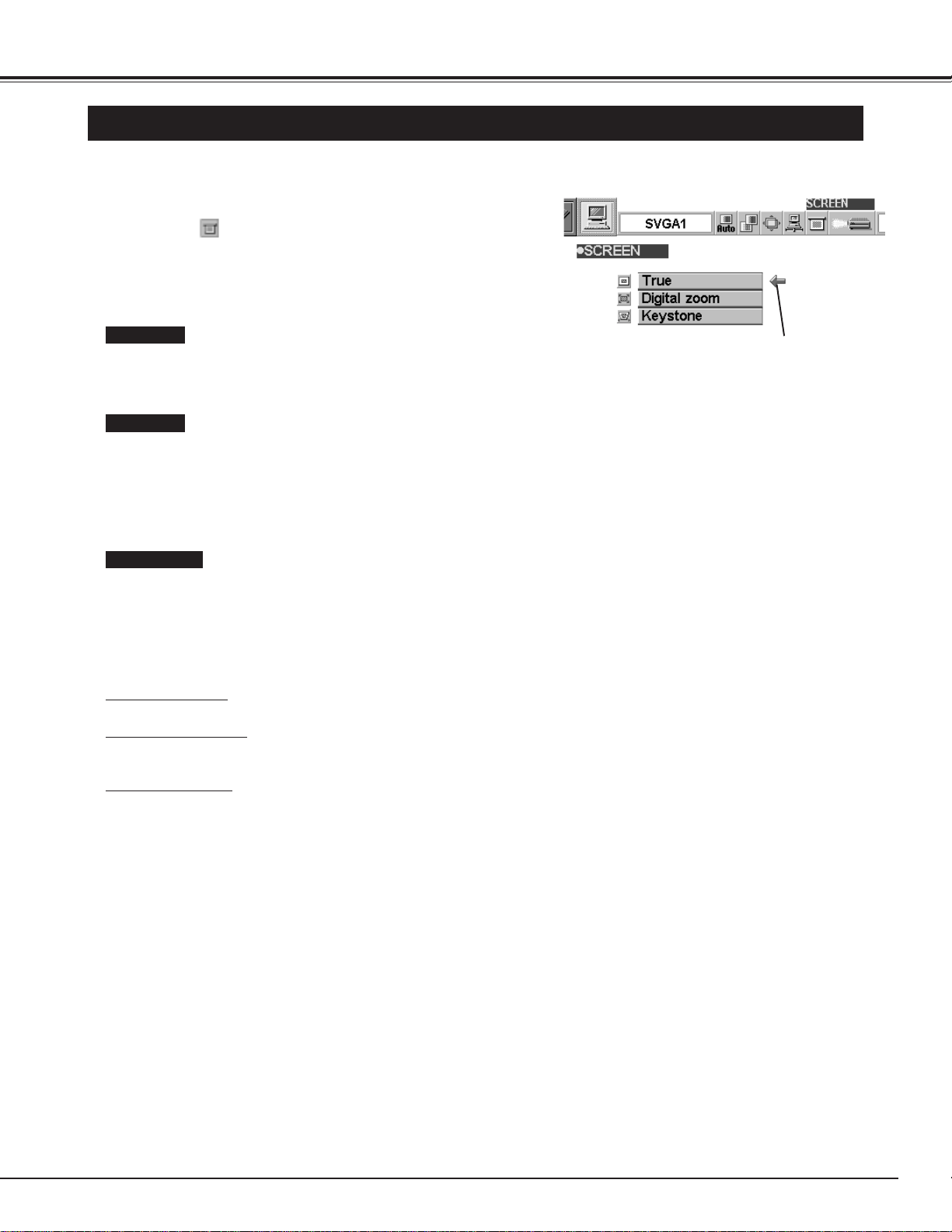
PICTURE SCREEN ADJUSTMENT
This projector has a picture screen resize function, which enables you to display the image in desirable size.
Press the MENU button and the ON-SCREEN MENU will
appear. Press the POINT LEFT/RIGHT buttons to select
SCREEN and press the SELECT button. Another dialog
box PICTURE SCREEN Menu will appear.
1
Move the arrow to the
function and press the
SELECT button.
Press the POINT DOWN button and a red-arrow icon will
appear. Move the arrow to the function that you want to select
and then press SELECT button.
2
To adjust the image size or pan the image, select Digital zoom in
the dialog box. The ON-SCREEN menu and SCREEN ADJUST
menu disappears and the message “D. Zoom” is displayed.
This projector also enters Digital Zoom mode by pressing the
D.ZOOM ▲/▼ button on the Remote Control Unit.
Refer to the following for operation.
● This projector cannot display in any resolution higher than 1280 X 1024. If your computer’s screen resolution is higher
than 1280 X 1024, reset the resolution lower before connecting the projector.
● The image data in other than XGA (1024 x 768) is modified to fit the screen size in the initial mode.
● The normal "Panning Operation" may not function properly if the computer system prepared with the "PC Adjust" is
used.
NOTE : The True and the Digital Zoom cannot be operated when “RGB,” “HDTV1035i” or “HDTV1080i” is selected on
the SYSTEM MENU (P23 and 26).
Expand function
To expand the image size, press the D.ZOOM ▲ button or the SELECT button. The image is magnified by degrees.
Compress function
To compress the image size, press the D.ZOOM ▼ button or the RIGHT CLICK button. The size of image is reduced by
degrees.
Panning function
To pan the image, press the POINT UP/DOWN/LEFT/RIGHT buttons. Panning function can work only when the image
is larger than the screen size.
To cancel Digital Zoom mode, press any button except D.ZOOM ▲/▼, SELECT, RIGHT CLICK, POINT, PAGE ▲/▼ or
LASER button. To adjust the image to the screen size (1024 x 768), press NORMAL button.
To make the image into its original size select True in the dialog
box. When the original image size is larger than the screen size
(1024 x 768), this projector enters Digital Zoom mode automatically.
True
Digital Zoom
Keystone
When the image is distorted vertically, select Keystone in the dialog
box. The ON-SCREEN menu and SCREEN ADJUST menu
disappears and the message “Keystone” is displayed. Correct the
Keystone distortion by pressing the KEYSTONE ▲/▼ button or the
POINT UP/DOWN button(s). Refer to KEYSTONE ADJUSTMENT
on page 21.
30
VIDEO MODE
Press the MENU button and the ON-SCREEN MENU will appear.
Press the POINT LEFT/RIGHT buttons to select Video and
press the SELECT button.
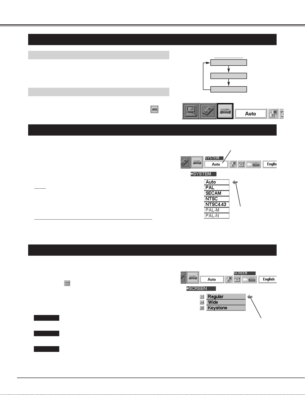
SELECTING VIDEO MODE
DIRECT OPERATION
Select VIDEO mode by pressing the MODE button on the Top
Control or the VIDEO button on the Remote Control Unit.
MENU OPERATION
SELECTING COLOR SYSTEM
Press the MENU button and the ON-SCREEN MENU will
appear. Press the POINT LEFT/RIGHT buttons to select
SYSTEM and press the SELECT button. Another dialog box
VIDEO SYSTEM Menu will appear.
Press the POINT DOWN button and a red-arrow icon will
appear. Move the arrow to "Auto", and then press the
SELECT
button.
1
2
The projector automatically detects the incoming Video system, and
adjusts itself to optimize its performance.
When the Video System is PAL-M or PAL-N, select the system
manually.
Auto
If the projector cannot reproduce the proper video image, it is
required to select a specific broadcast signal format among PAL,
SECAM, NTSC, NTSC 4.43, PAL-M, or PAL-N.
PAL / SECAM / NTSC / NTSC4.43 / PAL-M / PAL-N
Move the arrow to
the Mode and press
the SELECT button.
PICTURE SCREEN ADJUSTMENT
This projector has a picture screen resize function, which enables you to display the image in desirable size.
Press the MENU button and the ON-SCREEN MENU will
appear. Press the POINT LEFT/RIGHT buttons to select
SCREEN and press the SELECT button. Another dialog
box PICTURE SCREEN ADJUSTMENT DISPLAY will appear.
Press the POINT DOWN button and a red-arrow icon will
appear. Move the arrow to the screen size that you want to
set, and then press the
SELECT button.
1
2
Normal Video Image size with 4 x 3 aspect ratio.
Resizes the image for wide screen size with 16 x 9 aspect ratio.
Move the pointer to the function and press
the SELECT button.
Regular
Wide
Keystone
When the image is distorted vertically, select Keystone in the dialog
box. Correct the Keystone distortion by pressing KEYSTONE ▲/▼
button or POINT UP/DOWN button(s). Refer to KEYSTONE
ADJUSTMENT on page 21.
This box indicates the
system being selected.
COMPUTER
MCI
VIDEO
MODE button
31
Each of the keys operates as follow.
VIDEO MODE
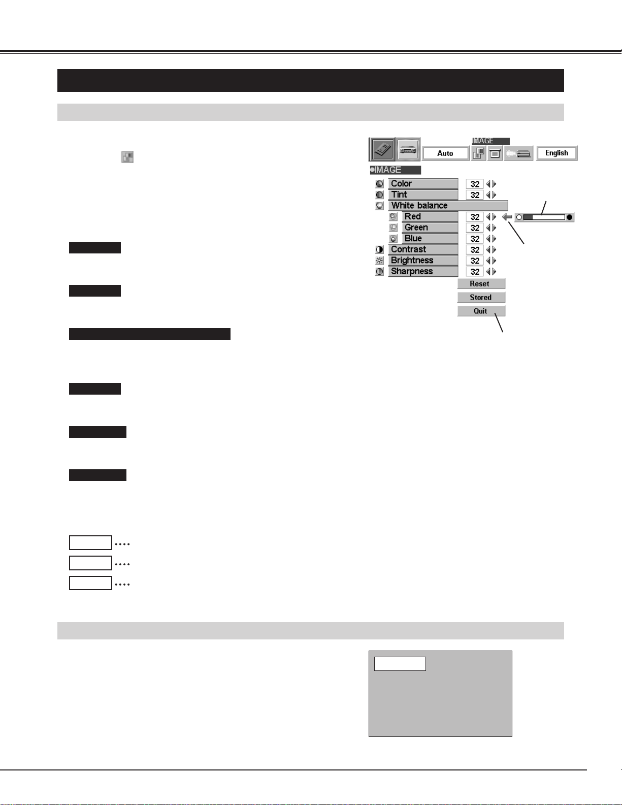
PICTURE IMAGE ADJUSTMENT
Press the MENU button and the ON-SCREEN MENU will
appear. Press the POINT LEFT/RIGHT buttons to select
IMAGE and press the SELECT button. Another dialog box
PICTURE IMAGE ADJUSTMENT Menu will appear.
Press the POINT DOWN button and a red-arrow icon will
appear. Move the arrow to the item that you want to adjust by
pressing the POINT UP/DOWN buttons. To change the value,
press either the POINT RIGHT button or the POINT LEFT
button.
1
2
ADJUSTING THE PICTURE IMAGE
The normal picture level is preset on this projector at the factory and
can be restored anytime you press the NORMAL button (located on
the Top Control or on the Remote Control Unit). The "Normal"
display will be displayed on the screen for a few seconds.
NORMAL FUNCTION
Recalls the data previously adjusted.
Reset
Stores the data in the memory.
Stored
Closes the PICTURE IMAGE ADJUSTMENT Menu.
Quit
Normal
Press POINT LEFT button to lighten the image, and press POINT
RIGHT button to deepen the image. (From 0 to 63.)
Press POINT LEFT button to increase purple, and press POINT
RIGHT button to increase green. (From 0 to 63.)
Press POINT LEFT button to decrease contrast, and press POINT
RIGHT button to increase contrast. (From 0 to 63.)
Press POINT LEFT button to darken the image, and press POINT
RIGHT button to brighten the image. (From 0 to 63.)
Press POINT LEFT button to soften the image, and press POINT
RIGHT button to sharpen the image. (From 0 to 63.)
Color
Tint
Contrast
Brightness
Sharpness
Move the arrow to the color that you want to adjust. Press POINT
LEFT button to lighten the color, and press POINT RIGHT button to
deepen the color. (From 0 to 63.)
White balance (Red / Green / Blue)
Close the PICTURE
IMAGE ADJUSTMENT
Menu.
Move the arrow to
the item and press
POINT RIGHT /
LEFT button.
It indicates the
level of the item.
32
MCI MODE
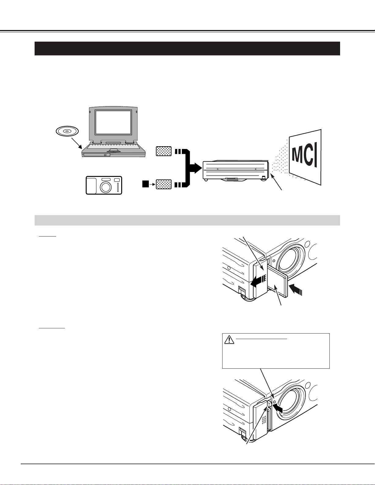
OPERATING THE PC CARD SLOT
This projector has a PC CARD SLOT and the data in a memory card (Compact Flash™ Card with PCMCIA
Adapter or PC card) can be displayed just by inserting the card into it. It is unnecessary to connect with other
input equipment. Media Card Imager (supplied with CD-ROM) can edit the image data and record it into a
memory card for projecting with the projector.
MC I
HOW TO LOAD THE MEMORY CARD INTO THE PROJECTOR
LOAD
Insert PCMCIA Adapter (with Compact Flash™ Card) or PC card into
PC CARD SLOT. Make sure EJECT button pops out.
NOTE : Be sure to insert the memory card with the front side facing
left of the projector. Do not insert the card in the reverse.
The card may be damaged.
PC CARD SLOT
PC CARD SLOT (Front)
PC with Windows 95
Media Card Imager
(CD-ROM)
Digital Camera
Compact Flash™ (with Adapter)
(not supplied)
PC Card
(not supplied)
UNLOAD
Press EJECT button, and the memory card pops out.
NOTE : Do not take the card out of the PC CARD SLOT while the
data is loading. Data and the card can be damaged.
Memory Card
Insert with the front side of the card
to the left side of the projector.
PC CARD INDICATOR
WHEN THIS INDICATOR IS LIT, THE
PROJECTOR IS READING OR WRITING THE
DATA INTO THE MEMORY CARD. DO NOT
REMOVE THE MEMORY CARD. DATA IN
THE MEMORY CARD MAY BE DAMAGED.
EJECT BUTTON
33
MCI MODE
Press the MENU button and the ON-SCREEN MENU will appear.
Press the POINT LEFT/RIGHT buttons to select MCI and press
the SELECT button.
SELECTING MCI MODE
DIRECT OPERATION
Select MCI mode by pressing the MODE button on the Top Control
or the COMPUTER / MCI button on the Remote Control Unit.
MENU OPERATION
COMPUTER / MCI
button
COMPUTER
MCI
VIDEO
COMPUTER
MCI
MODE button
When the memory card is inserted into PC CARD SLOT, the MCI mode is automatically selected and the first
Page of the latest Index is projected onto the screen. To switch to the MCI mode manually, operate as
follows.
AVAILABLE DATA
AVAILABLE CARD
Compact Flash™ Card (with PCMCIA Adapter) or Type || PCMCIA-ATA Card can be used with this projector. (Those
memory cards are not supplied with this projector.)
Refer to CF CARD AND PCMCIA ADAPTER on pages 38 and 39 for operation.
NOTE : Some PCMCIA Adapter or PC Card is not available for this projector and cannot provide the image data. In that
case, use the optional Canon Compact Flash Card and PCMCIA Adapter.
Media Card Imager
Media Card Imager (CD-ROM) is supplied
with this projector to edit the image data
for projecting. Installation of Media Card
Imager is recommended. Refer to
Owner’s Manual of Media Card Imager for
installation and operation.
This projector can project the image data through the PC CARD
SLOT, as follows;
● The data edited by “Media Card Imager.”
● The data of the resolution between VGA (640 X 480) and SXGA
(1280 X 1024) in Bit Map type (BMP) or JPEG type (JPG), such as
Digital Camera data, can be also displayed.
(Some image data in SXGA size may not be displayed properly.
In that case, reset the resolution lower.)
Refer to “SHOW THE DATA IN THE MEMORY CARD” on page 34
to display the image data.
34
MCI MODE
Move the arrow to
each operation and
press the SELECT
button.
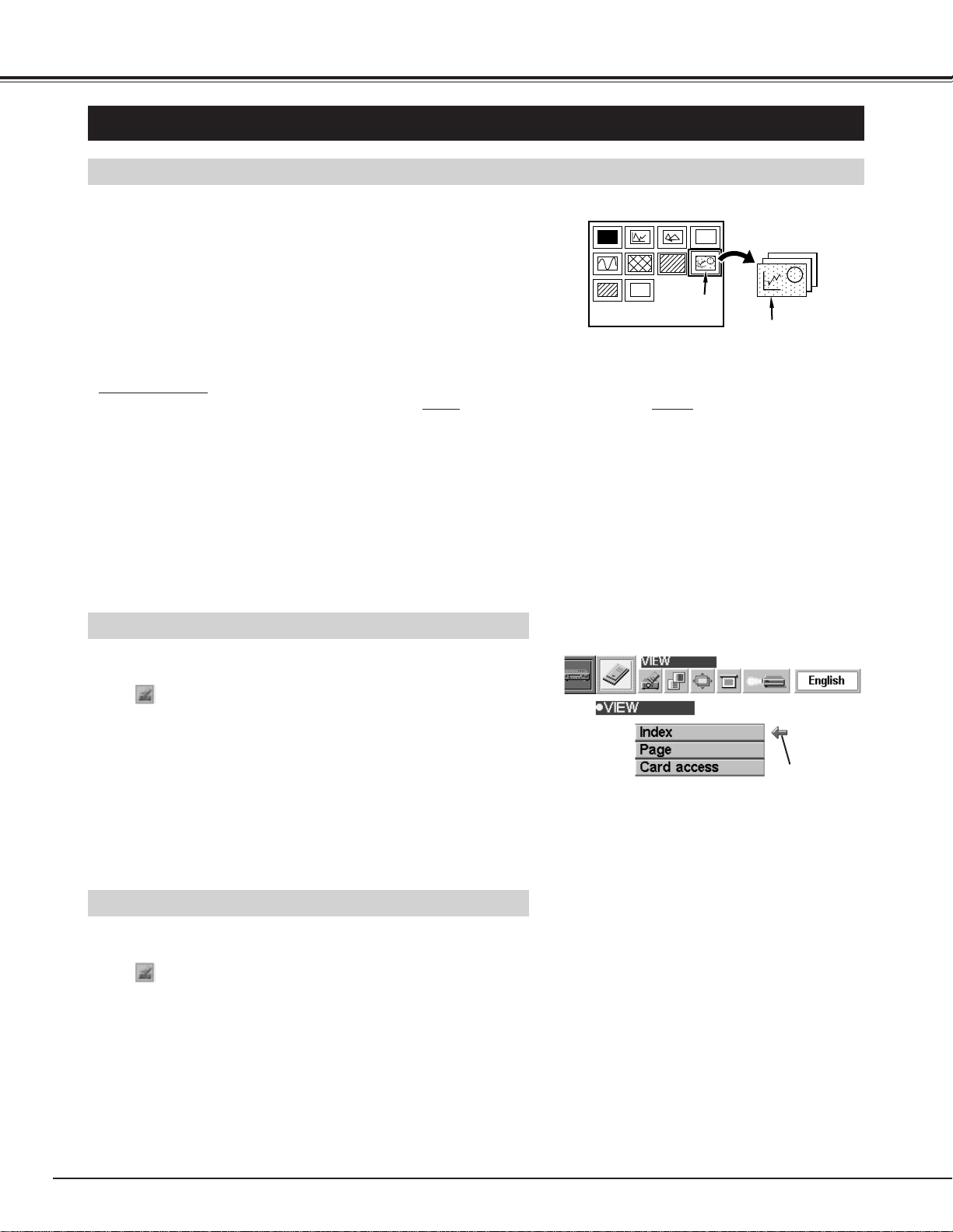
SHOW THE DATA IN THE MEMORY CARD
BASIC OPERATION
Pages in the Index
Index
Select the Index
● This projector can project only image data in Bit Map or in JPEG format or the data edited by Media Card Imager
(supplied) through the PC CARD SLOT. Other data is not compatible and should be edited and written to a memory
card with Media Card Imager before loading into PC CARD SLOT.
(The data in Bit Map or in JPEG format, such as the data captured with a digital camera, can be projected directly
through PC CARD SLOT.)
● If there is the data edited by Media Card Imager and other data (such as in Bit Map type or JPEG type) together in one
memory card, the data edited by Media Card Imager has a priority to be projected with the LCD projector. The other
image data in Bit Map type or JPEG type is not projected. In that case, edit that data and write it to the memory card
with the Media Card Imager.
1
2
Insert the memory card and select the MCI mode. The data in
the memory card is displayed.
To change pages, press the PAGE button on the Top Control
and then press the POINT UP/DOWN buttons. (The pages can
also be changed with the PAGE ▲/▼ button on the Remote
Control.) When the “Display Timer” is set in the image with the
Media Card Imager, the image is changed to another
automatically.
To select Index or Page in the table, follow the instructions of
INDEX SELECTION and PAGE SELECTION below.
Index and Page
The data edited with Media Card Imager is the Index format consisting of several Pages. To project the desirable
image, select the Index and then select the Page in the Index.
INDEX SELECTION
PAGE SELECTION
1
2
Press the MENU button and the ON-SCREEN MENU will
appear. Press the POINT LEFT/RIGHT buttons to select VIEW
and press the SELECT button. Another dialog box VIEW
SETTING menu will appear.
Press the POINT DOWN button and a red-arrow icon will
appear. Move the arrow to "Index", and then press the
SELECT button.
The table of Indexes in the memory card will
appear.
3
Press the POINT UP/DOWN/LEFT/RIGHT buttons to move to
the Index that you want to project and press the SELECT
button. The first Page of the Index selected is displayed.
(Press SELECT button again to display the table of Pages.)
1
2
Press the MENU button and the ON-SCREEN MENU will
appear. Press the POINT LEFT/RIGHT buttons to select VIEW
and press the SELECT button. Another dialog box VIEW
SETTING menu will appear.
Press the POINT DOWN button and a red-arrow icon will
appear. Move the arrow to "Page", and then press the
SELECT button.
The table of pages of the index card will
appear.
3
Press the POINT UP/DOWN/LEFT/RIGHT buttons to move to
the Page that you want to project and press the SELECT
button. The page selected is displayed on the screen.
The table of Pages can be displayed by pressing the SELECT
button when the page is displayed on full screen.
35
MCI MODE
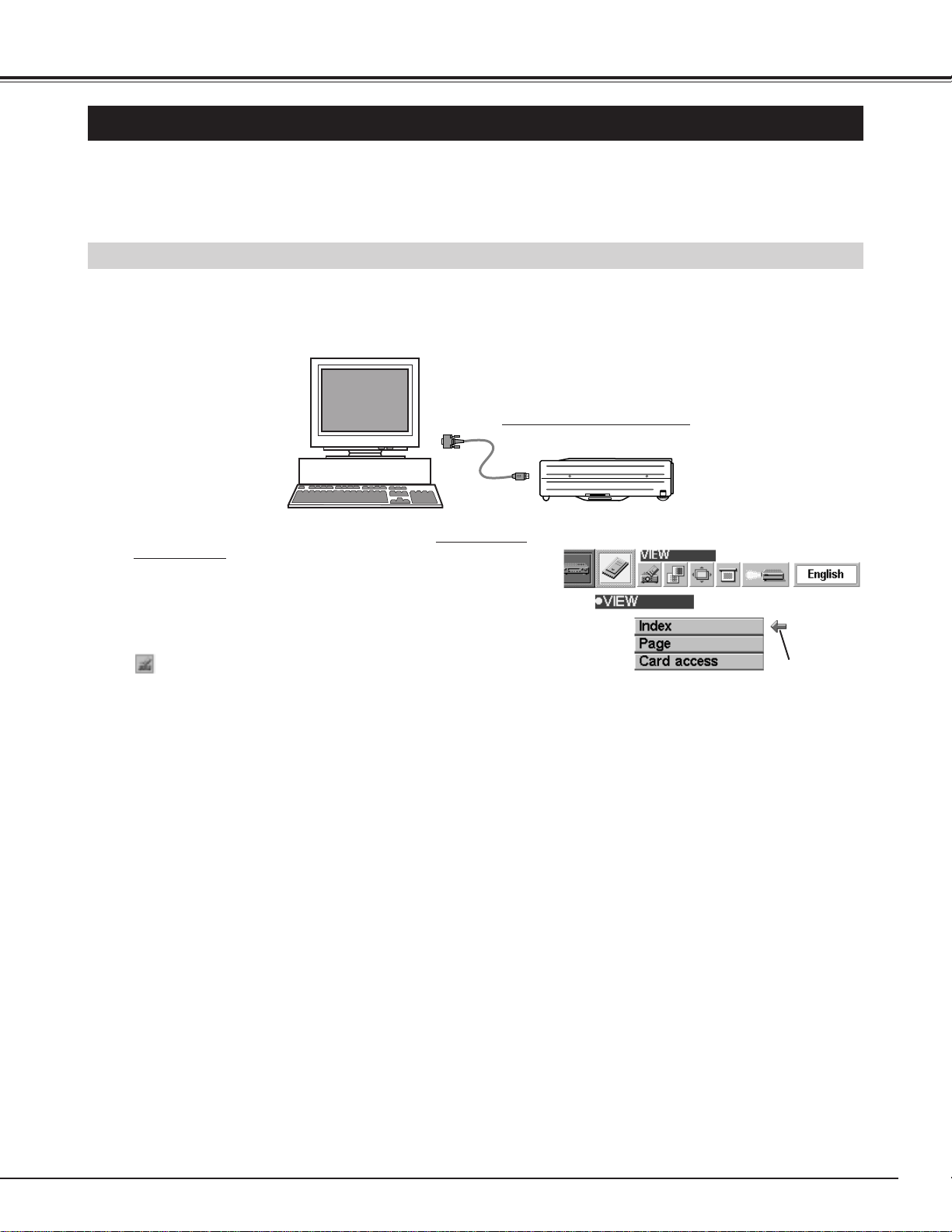
WRITE DATA INTO THE MEMORY CARD
ACCESS TO THE MEMORY CARD THROUGH THE PROJECTOR
If your computer doesn't have the PC card writing equipment, the data can be written or read by connecting
with this projector.
NOTE : This operation can be made only by Media Card Imager in the Personal Computer.
The data edited by Media Card Imager in the computer can be written to or read from the memory card with the
PC Card drive of your Personal Computer or the PC CARD Slot of this projector.
The data edited by Media Card Imager is written in Bit Map type (BMP) or JPEG type (JPG).
NOTE : Connect the projector to the computer with Control Cable
before turning those appliances on.
Do not press any button while read/write operations are in
progress. Those operations are canceled and the data in the
memory card may be damaged.
Connect the projector to the Personal Computer with the
Control Cable for Serial Port
(optionally supplied / refer
to page 12, 13).
Connect the projector to your computer with the Control Cable
for Serial Port (optionally supplied). (Refer to “CONNECTING
COMPUTER” on Page 12, 13.)
Insert the memory card into PC CARD SLOT of the projector.
And then, turn on the projector first and then the computer.
1
2
Press the MENU button and the ON-SCREEN MENU will
appear. Press the POINT LEFT/RIGHT buttons to select VIEW
and press the SELECT button. Another dialog box VIEW
SETTING menu will appear.
3
Press POINT DOWN button and a red arrow will appear. Move
the arrow to Card access by pressing POINT UP/DOWN
button. And then press SELECT button. “Ready to access” is
displayed.
Operate Media Card Imager of your computer to write/read the
data in the PC card. (Refer to Owner's Manual of Media Card
Imager for operation.)
Move the arrow to
“Card access” and
press the SELECT
button.
36
The position of the image can be adjusted vertically and horizontally through PICTURE POSITION
ADJUSTMENT.
MCI MODE
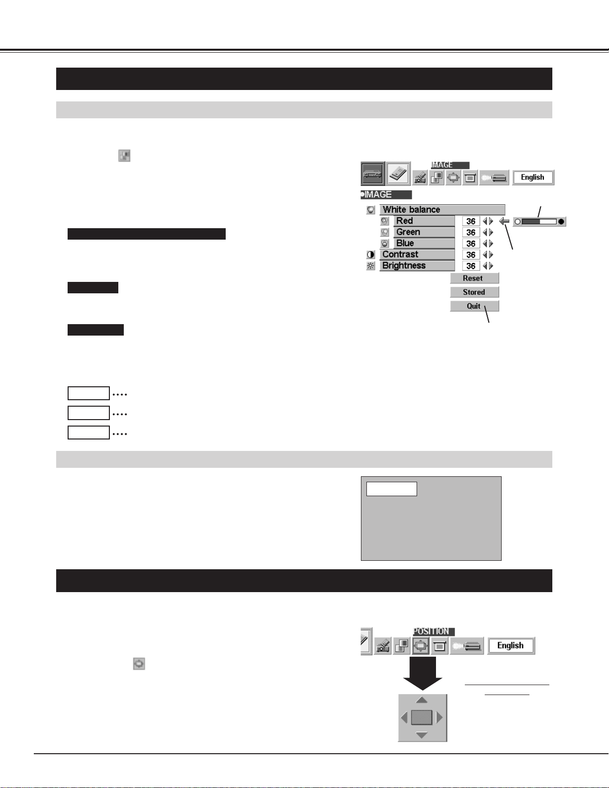
PICTURE IMAGE ADJUSTMENT
ADJUST THE PICTURE IMAGE MANUALLY
The normal picture level is preset on this projector at the factory and
can be restored anytime you press the NORMAL button (located on
the Top Control or on the Remote Control Unit). The "Normal"
display will be displayed on the screen for a few seconds.
NORMAL FUNCTION
Press the MENU button and the ON-SCREEN MENU will
appear. Press the POINT LEFT/RIGHT buttons to select
IMAGE and press the SELECT button. Another dialog box
PICTURE IMAGE ADJUSTMENT Menu will appear.
Press the POINT DOWN button and a red-arrow icon will
appear. Move the arrow to the item by pressing the POINT
UP/DOWN buttons. To change the value press either the
POINT RIGHT button or the POINT LEFT button.
1
2
Recalls the data previously adjusted.
Reset
Stores the adjusted data in the memory.
Stored
Closes the PICTURE IMAGE ADJUSTMENT Menu.
Quit
Each of the keys operates as follow.
Close the PICTURE
IMAGE ADJUSTMENT
Menu.
Move the arrow to
the item and press
POINT RIGHT /
LEFT button.
It indicates the
level of the item.
PICTURE POSITION ADJUSTMENT
Press the MENU button and the ON-SCREEN MENU will
appear. Press the POINT LEFT/RIGHT buttons to select
POSITION and press the SELECT button. The PICTURE
POSITION dialog box will appear.
Move the image by pressing the POINT UP / DOWN / RIGHT /
LEFT buttons.
1
2
PICTURE POSITION
dialog box
Press the POINT UP /
DOWN / RIGHT / LEFT
buttons to move the image
Normal
To cancel POSITION mode, press any button except SELECT,
RIGHT CLICK, POINT, AUTO IMAGE, PAGE ▲/▼ or LASER button.
To recall the position previously adjusted, press NORMAL button.
Press POINT LEFT button to decrease contrast, and press POINT
RIGHT button to increase contrast. (From 0 to 63.)
Press POINT LEFT button to darken the image, and press POINT
RIGHT button to brighten the image. (From 0 to 63.)
Move the arrow to the color that you want to adjust. Press POINT
LEFT button to lighten the color, and press POINT RIGHT button to
deepen the color. (From 0 to 63.)
White balance (Red / Green / Blue)
Contrast
Brightness
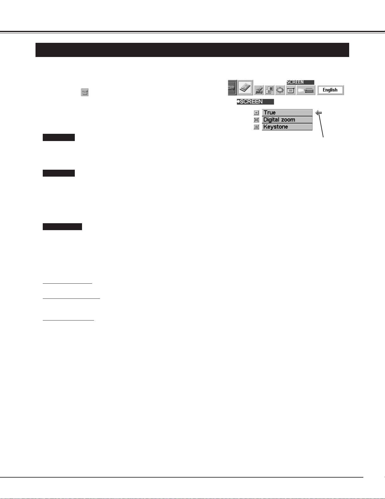
37
MCI MODE
PICTURE SCREEN ADJUSTMENT
This projector has a picture screen resize function, which enables you to display the image in desirable size.
Press the MENU button and the ON-SCREEN MENU will
appear. Press the POINT LEFT/RIGHT buttons to select
SCREEN and press the SELECT button. Another dialog
box PICTURE SCREEN Menu will appear.
To adjust the image size or pan the image, select Digital zoom in
the dialog box. The ON-SCREEN menu and SCREEN ADJUST
menu disappears and the message “D. Zoom” is displayed.
This projector also enters Digital Zoom mode by pressing D.ZOOM
▲/▼ button on the Remote Control Unit.
Refer to the following for operation.
1
● This projector cannot display in any resolution higher than 1280 X 1024. If your computer’s screen resolution is
higher than 1280 X 1024, reset the resolution lower before connecting the projector.
● The image data in other than XGA (1024 x 768) is modified to fit the screen size in the initial mode.
Expand function
To expand the image size, press D.ZOOM ▲ button or SELECT button. The image is magnified by degrees.
Compress function
To compress the image size, press the D.ZOOM ▼ button or the RIGHT CLICK button. The size of image is reduced by
degrees.
Panning function
To pan the image, press POINT UP/DOWN/LEFT/RIGHT buttons. Panning function can work only when the image is
larger than the screen size.
To cancel Digital Zoom mode, press any button except D.ZOOM ▲/▼, SELECT, RIGHT CLICK, POINT, PAGE ▲/▼,
AUTO IMAGE, or LASER button. To adjust the image to the screen size (1024 x 768), press NORMAL button.
To turn the image into its original size select True in the dialog box.
When the original image size is larger than the screen size (1024 x
768), this projector enters Digital Zoom mode automatically.
Move the arrow to the
function and press the
SELECT button.
Press the POINT DOWN button and a red-arrow icon will
appear. Move the arrow to the function that you want to select
and then press SELECT button.
2
True
Digital Zoom
Keystone
When the image is distorted vertically, select Keystone in the dialog
box. The ON-SCREEN menu and SCREEN ADJUST menu
disappears and the message “Keystone” is displayed. Correct the
Keystone distortion by pressing KEYSTONE ▲/▼ button or POINT
UP/DOWN button(s). Refer to KEYSTONE ADJUSTMENT on
page 21.
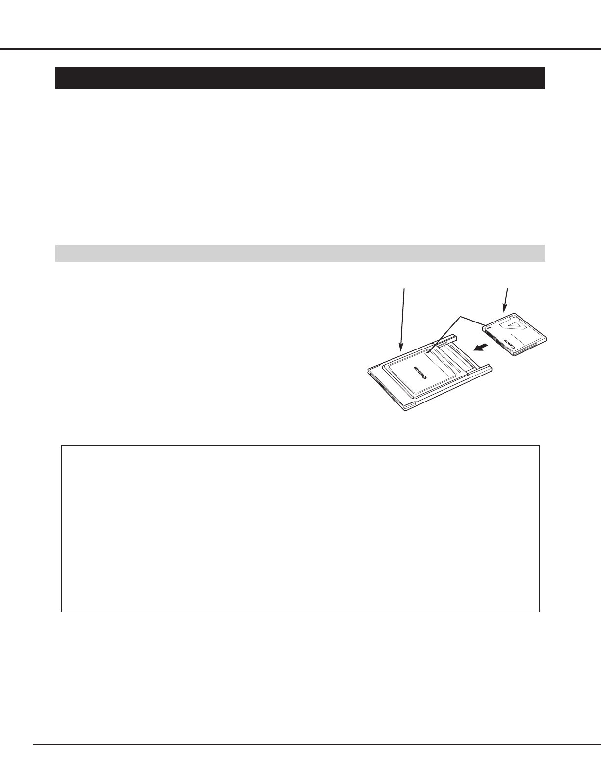
38
MCI MODE
CF CARD AND PCMCIA ADAPTER
IMPORTANT NOTE
Data stored on a CF card may be damaged or lost due to physical damage to the CF card or accidental
erasure. It is recommended that any important data should be copied as a backup onto separate media,
such as a floppy disk, a hard disk or a MO disk, etc. We shall not be liable for any damage or loss of profits
arising from the loss of data caused by the misoperation of or the damage to a CF card or its appliances.
The following may result in damaged or lost data:
• Misoperation of the CF card.
• Turning the LCD projector or the computer power off or removing the CF card / PCMCIA adapter while the
CF card is in access operations (storing, reading or deleting the files).
• Exposure to a strong static electric charge.
• It has reached the end of its life.
● Insert the CF card firmly into the PCMCIA adapter, aligning
the arrows on the CF card and PCMCIA adapter.
● When remove the CF card from the PCMCIA adapter, pull it
straight out .
You can use the optional Canon Compact Flash
TM
Card (CF card) and its PCMCIA adapter designed for the
Canon Digital Camera PowerShot series.
By inserting the CF card into the PCMCIA adapter, it can be loaded into the PC card slot (PCMCIA 2.1/Jeida 4.2
Standard slot) of a computer.
Refer to page 46 for "How to load a CF card into the LCD projector."
Canon Compact Flash
TM
Card for Digital Camera PowerShot series
FC-4MB (capacity 4MB)
FC-8MB (capacity 8MB)
FC-15MB (capacity 15MB)
PCMCIA adapter
F
o
r
C
a
n
o
n
C
o
m
p
a
c
tF
la
s
h
C
a
r
d
PCMCIA ADAPTER
CF-4M
C
O
M
P
A
C
T
F
L
A
S
H
C
A
R
D
PCMCIA adapter
(Not supplied)
Compact Flash
TM
Card
(Not supplied)
Insert the CF card
aligning the arrows.
Inserting / Removing the CF Card

39
MCI MODE
● Do not turn the LCD projector or the computer power off or remove the CF card / PCMCIA adapter while
the CF card is in access operation (storing, reading or deleting files).
● CF cards / PCMCIA adapters are high-precision electronic devices. do not bend, drop, apply strong forces
or shock or place it where a strong static electrical charge may be generated.
● Do not touch the surface of the contact area with your fingers or allow it to be stained with foreign materials.
● Do not attempt to disassemble or alter CF cards.
● Moving CF card rapidly between hot and cold temperatures may cause condensation (water droplets) to
form on it, leading to malfunctions. Avoid this problem by placing the CF card in a plastic bag and letting it
slowly adjust to temperature changes before removing it from the bag. If condensation should occur, main-
tain the CF card at a constant temperature and let the moisture evaporate naturally.
● Store CF cards / PCMCIA adapters in the protective case provided.
● Do not use or store CF cards / PCMCIA adapter in places subject to the following conditions:
strong magnetic fields
abundant dirt or dust
high temperatures, high humidity
Specifications
Interface : PCMCIA / ATA PCMCIA 2.1/ JEIDA 4.2
Card Slot Type : Type II
Dimensions : 1.4 x 1.7 x 0.1 inches / 36.1 x 42.8 x 3.3 mm (CF card only)
3.4 x 2.1 x 0.2 inches / 86 x 54 x 5 mm (with PCMCIA Adapter)
Weight : 0.4 oz / 10g (CF card only)
1.2 oz / 34g (with PCMCIA Adapter)
Subject to change without notice
Weight and dimensions are approximate.
Handling CF Card and PCMCIA Adapter
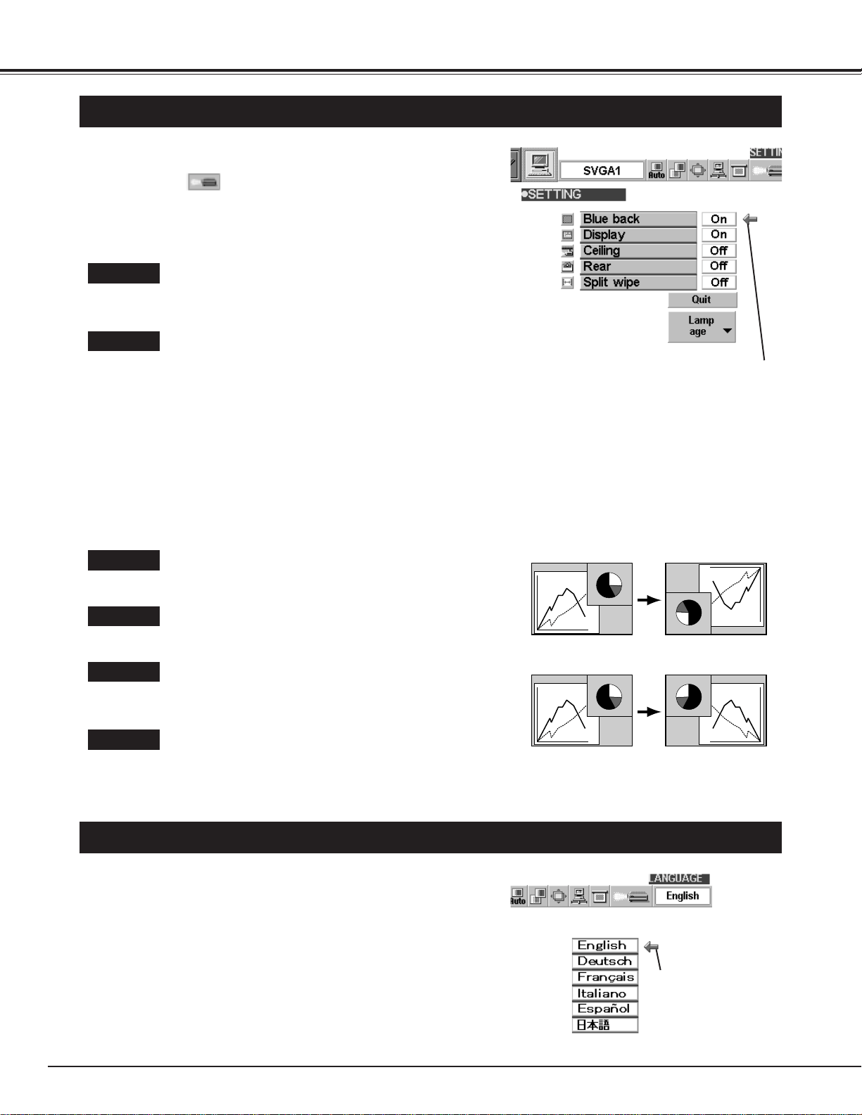
40
SETTING
SETTING MENU
Press the MENU button and the ON-SCREEN MENU will
appear. Press the POINT LEFT/RIGHT buttons to select
SETTING and press the SELECT button. Another
dialog box SETTING Menu will appear.
Press the POINT DOWN button and a red-arrow icon will
appear. Move the arrow to the item that you want to set, and
then press the
SELECT button to set it "On" or "Off".
1
2
Blue back
When this function is in the "On" position, this projector
will produce a blue image instead of the video noise on
the screen when all input sources are unplugged or
turned off.
Display
When this function is in the "On" position, the On-
Screen Displays always appears when adjustments
are made. (The following displays disappear by
switching this function "Off.")
● Preparation Display
(The Number-counting-down Display)
● Mode Display
● Volume/Mute Display
● Zoom Display
● Focus Display
● Normal Display
● No show Display
● Keystone Display
● D.Zoom Display
The Lamp age function is designed to reset the lamp
replacement monitor timer. When replacing the lamp,
reset the lamp replacement monitor timer by using this
function. (Refer to page 43.)
Lamp age
SELECTING LANGUAGE
Press the MENU button and the ON-SCREEN MENU will
appear. Press POINT LEFT/RIGHT buttons to select
LANGUAGE and press the SELECT button. Another dialog
box LANGUAGE Menu will appear.
Press the POINT DOWN button and a red-arrow icon will
appear. Move the arrow to the language that you want to set,
and then press the
SELECT button.
1
2
The language used in the ON-SCREEN MENU is selectable from
among English, German, French, Italian, Spanish and Japanese.
Set the Pointer to the item,
and then press the SELECT
button.
Move the Pointer to the
language that you want
to set, and then press
the SELECT button.
Ceiling
When this function is in the “On” position, the top /
bottom and the left / right reversed picture is provided
to project the image from a ceiling mounted projector.
Rear
When this function is in the “On” position, the left / right
reversed picture is provided to project the image to a
rear projection screen.
Split wipe
Turn this function “On” position in the SETTING menu.
The picture will change into the next one by sliding
black image side ways like drawing the black curtains
when the input source is turned into another one.
Ceiling function
Rear function
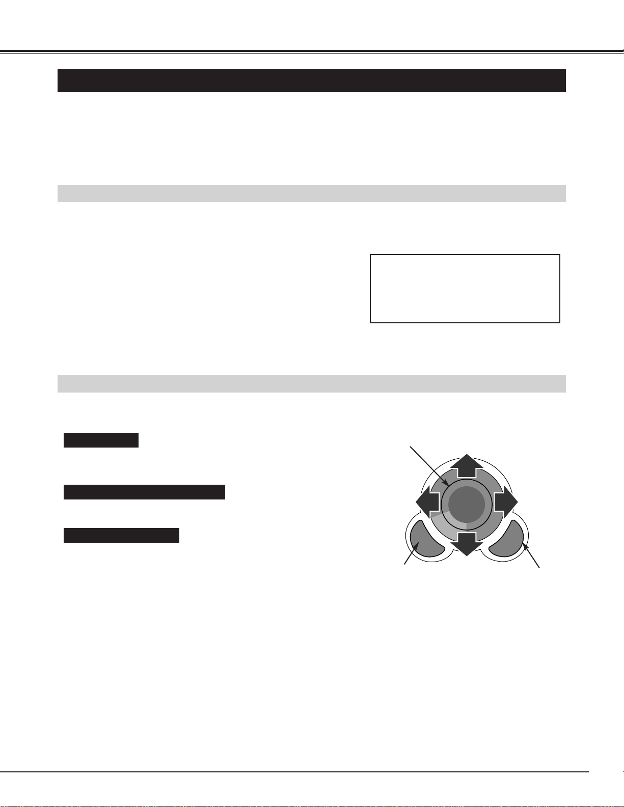
41
APPENDIX
OPERATING WIRELESS MOUSE
INSTALLATION
The Wireless Remote Control Unit is not only able to operate the projector but also can be used as a wireless
mouse for most Personal Computers. The POINT buttons and the two CLICK buttons are used for the wireless
mouse operation.
The wireless mouse is available only when PC mouse pointer is displayed on the screen. When the menu or
the indicator of the projector is displayed on the screen instead of the PC mouse pointer, the wireless mouse
cannot be used.
Connect the mouse port of your computer to the Control Port of
the projector with the Control Cable. (Refer to page 10 to 13 for
connection.)
Turn the projector on first, and then turn on your computer.
When the computer is switched on first, the Wireless Mouse
may not work properly.
1
2
To use the Wireless Remote Control Unit as the Wireless Mouse for a Personal Computer, installation of the
mouse driver (not supplied) is required. Make sure that the mouse driver is properly installed in your
computer. And make sure that the mouse port of the computer connected to Control Port is activated.
OPERATING WIRELESS MOUSE
When controlling the pointer of the computer, operate the Wireless Mouse with POINT button, SELECT
button, and RIGHT CLICK button on the Wireless Remote Control Unit.
Used to move the pointer. The pointer is moved corresponding with
the direction you are pressing.
POINT button
This button has the same function as the left button in a PC mouse.
SELECT (LEFT CLICK) button
This button has the same function as the right button in a PC mouse.
Pressing this button does not affect any operation when in Menu
mode.
RIGHT CLICK button
Note : When the computer has no
mouse port, connect the Serial
Port of the computer to Control
Port of the projector with the
Control Cable for Serial Port.
POINT button (Move the pointer)
SELECT button
(left button of the
mouse)
RIGHT CLICK button
(right button of the mouse)
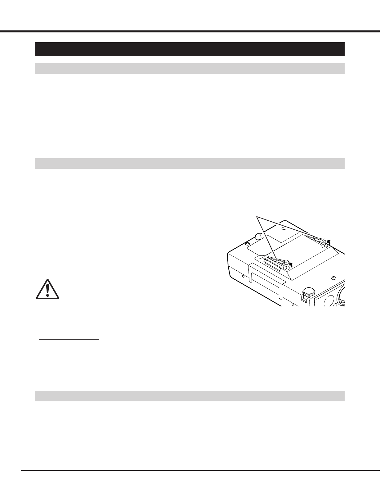
42
APPENDIX
CLEANING THE PROJECTION LENS
Apply a non-abrasive camera lens cleaner to a soft, dry cleaning cloth. Avoid using an excessive amount of cleaner.
Abrasive cleaners, solvents or other harsh chemicals might scratch the lens.
When you are not using the projector, replace the lens cover.
1
3
Lightly wipe the cleaning cloth over the lens.
2
Follow these steps to clean the projection lens:
MAINTENANCE
TEMPERATURE WARNING INDICATOR
The TEMPERATURE WARNING Indicator flashes red when the internal temperature of the projector exceeds
the normal temperature. The Indicator stops flashing when the temperature of the projector becomes normal.
When the TEMPERATURE WARNING Indicator continues to flash, check the item listed below.
The Ventilation slots of the projector may be blocked. In such an event, reposition the appliance so that the
ventilation slots are not obstructed.
Turn the power off, and disconnect the AC power cord from the
AC outlet.
Turn the projector upside down and remove 2 Air Filters by
pulling the latches upward.
1
2
The Removable Air Filters prevent dust from accumulating on the surface of the Projection Lens and the
Projection Mirror. Should the Air Filters become clogged with dust particles, it will reduce the Cooling Fans'
effectiveness and may result in internal heat build up and adversely affect the life of the projector.
Clean the Air Filters following the steps below:
AIR FILTER CARE AND CLEANING
Clean the Air Filters with brush or wash out the dust and
particles.
3
Air filters are clogged with dust particles. Clean the air filters by following AIR FILTER CARE AND CLEANING
below.
1
2
If the TEMPERATURE WARNING Indicator remains on after performing the above checks, the Cooling Fans or the
Internal Circuits may be malfunctioning. Request service from an authorized dealer or service station.
3
Replace the Air Filter. Make sure that the Air Filters are fully
inserted.
4
AIR FILTERS
CAUTION
Do not operate the projector with the Air Filter removed.
Dust may become stuck on the LCD Panel and the Mirror
degrading picture quality.
Do not put small parts into the Air Intake Vents. It may
result in malfunctions of the projector.
The Air Filter is small. Ensure that children don’t eat or
swallow it.
RECOMMENDATION
We recommend to avoid dusty/smoky place for operating the projector. Using in these environments
may cause poor image quality.
When using under dusty or smoky conditions, dust may accumulate on the liquid crystal panel and lens inside, and may
resultantly be projected onto the screen together with the picture.
When the above symptoms are noticed, contact your authorized dealer or service station for the cleaning.
● Replacement Lamp
Type No. : DY4-5798-000
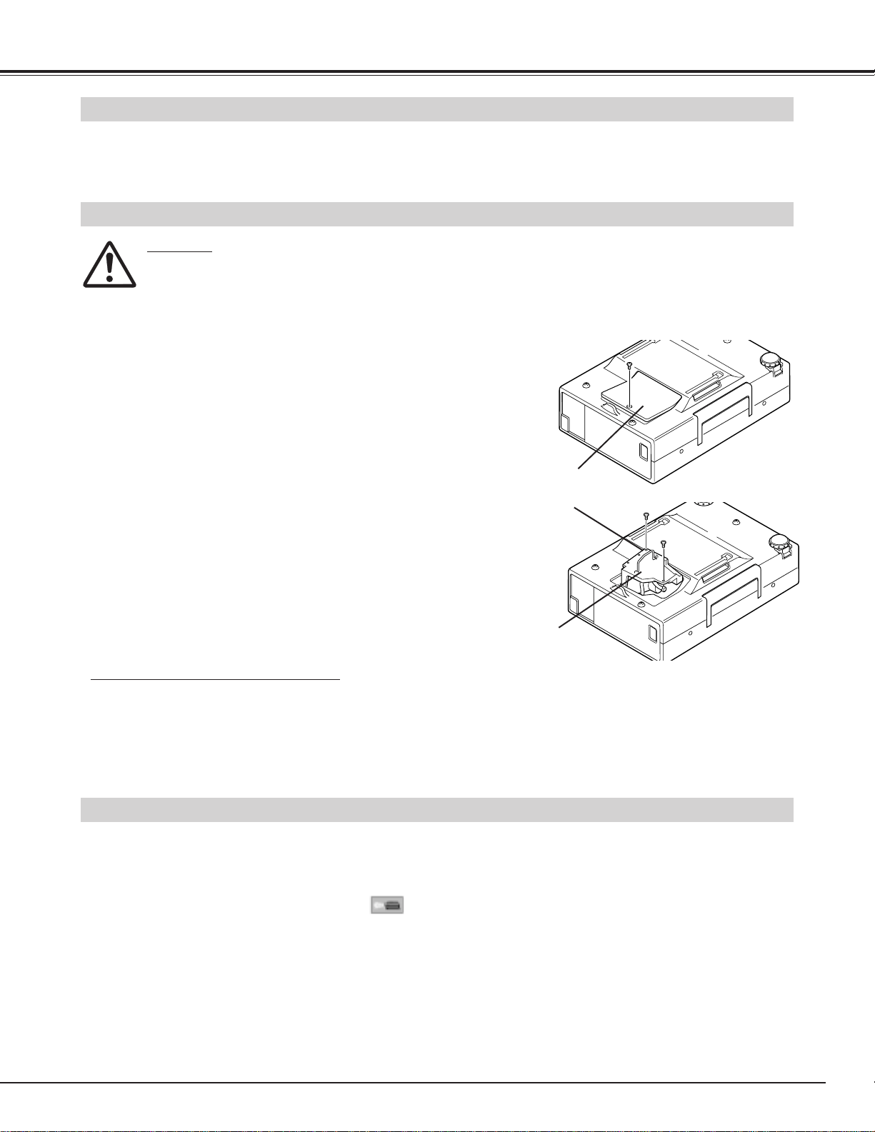
43
APPENDIX
LAMP REPLACEMENT INDICATOR
When the life of the Lamp of this projector draws to an end, the LAMP REPLACEMENT indicator lights red.
When the image becomes dark or the color of the image becomes unnatural, replacement of the Lamp is
required.
Turn off the projector and disconnect the AC plug. Allow the
projector to cool for at least 45 minutes.
Remove 2 screws with a screwdriver and pull out the Lamp
Assembly by grasping the handle.
1
3
LAMP REPLACEMENT MONITOR TIMER
Replace the Lamp Assembly with new one and tighten 2
screws. Make sure that the Lamp Assembly is set properly.
And replace the Lamp Cover and tighten a screw.
4
LAMP REPLACEMENT
Remove a screw with a screwdriver and remove the Lamp
Cover.
2
CAUTION
●For continued safety, replace with a lamp assembly of the same type.
●Allow the projector to cool for at least 45 minutes before you open the lamp cover. The inside of the projector
can become very hot.
●Do not drop the lamp assembly or touch the glass bulb! The glass can shatter and may cause injury.
Be sure to reset the Lamp Replacement Monitor Timer when the Lamp Assembly is replaced. When the
Lamp Replacement Monitor Timer is reset, the LAMP REPLACEMENT indicator stops lighting.
Turn the projector on, and press the MENU button and the ON-SCREEN MENU will appear. Press the POINT
LEFT/RIGHT buttons to select SETTING and press the SELECT button (refer to the page 40). Another
dialog box SETTING MENU will appear.
1
Press the POINT DOWN button and a red-arrow icon will appear. Move the arrow to Lamp age, and then press the
SELECT button. The message "Lamp replace monitor Reset?" is displayed.
2
Do not reset the Lamp Replacement Monitor Timer, except after the lamp is replaced.
Connect the AC Power Cord to the projector and turn the
projector on.
6
Follow these steps to replace the lamp assembly.
Reset the Lamp Replacement Monitor Timer (refer to the
section “Lamp Replacement Monitor Timer” below).
Select [Yes] to reset the Timer.
3
5
LAMP
ASSEMBLY
HANDLE
LAMP COVER
NOTE : Do not reset the LAMP REPLACEMENT MONITOR
TIMER, when the lamp is not replaced.
ORDER REPLACEMENT LAMP
Replacement Lamp can be ordered through your dealer. When ordering the Lamp, give the following
information to the dealer.
● Model No. of your projector : LV-7325U
● Replacement Lamp Type No. : LV-LP05
(Service Parts No. 610 280 6939)
44
APPENDIX
TROUBLESHOOTING
Before calling your dealer or service station for assistance, check the items below once again.
1. Make sure you have connected the projector to your equipment as described in the section "CONNECTING
THE PROJECTOR" on pages 10 ~ 13.
2. Check cable connection. Verify that all computer, video and power cord are properly connected.
3. Verify that all power is switched on.
4. If the projector still does not produce the image, re-start the computer.
5. If the image sill does not appear, unplug the projector from the computer and check the computer monitor's
display. The problem may be with your graphics controller rather than with the projector. (When you
reconnect the projector, remember to turn the computer and monitor off before your power up the projector.
Power the equipment back in order of : Projector and computer.)
6. If the problem still exists, check the following chart.
No power.
● Plug the projector into the AC outlet.
● Be sure READY Indicator light is On.
● Wait 90 seconds after the projector is turned OFF before turning the projector back on.
NOTE : After pressing the power ON-OFF switch to OFF, make sure the projector works
as follow.
1. The LAMP indicator will light and the READY indicator will turn off.
2. After 90 seconds, the READY indicator will light green again and the projector
may be turned on by pressing the power ON-OFF button.
● Check the TEMPERATURE WARNING indicator. If the indicator flashes red, the
projector cannot be turned on.
(See "TURNING ON/OFF THE PROJECTOR" section on page 20.)
● Check the Projection Lamp. (Refer to page 43.)
Image is out of
focus.
● Adjust the focus
● Make sure the projection screen is at least 4.6’ (1.4m) from the projector.
● Check the projection lens to see if it needs cleaning.
NOTE : Moving the projector from a cool temperature location to a warm temperature
location may result in moisture condensation on the lens. In such an event, leave
the projector OFF an d wait until condensation disappears.
Picture is Left/Right
reversed.
● Check Ceiling / Rear feature. (See “SETTING” section on page 40.)
Problem: Try these Solution
Picture is
Top/Bottom
reversed.
● Check Ceiling feature. (See “SETTING” section on page 40.)
Some displays are
not seen during the
Operation.
● Check Display feature.(See “SETTING” section on page 40.)
No image.
● Check the connection between the computer or video equipment and the projector.
● When turning the projector on, it takes about 30 seconds to display the image.
● Check the system that you select is corresponding with the computer or the video
equipment.
● Make sure the temperature is not out of the Operating Temperature (5°C ~ 35°C).
No sound.
● Check audio cable connection from audio input source.
● Adjust the audio source.
● Press VOLUME (+) button.
● Press MUTE button.

45
APPENDIX
WARNING :
High voltages are used to operate this projector. Do not attempt to open the cabinet.
Remote Control Unit
does not work.
● Check the batteries.
● Check the ALL-OFF switch on the Remote Control Unit is set to “ON.”.
● Make sure nothing is between the Remote Receiver and the Remote Control Unit.
● Make sure you are not too far from the projector when using the Remote Control Unit.
Maximum operating range is 16.4’ (5m)..
Problem: Try these Solution
Wireless Mouse
function does not
work.
● Check the cable connection between the projector and the computer.
● Check the mouse setting on your computer.
● Turn the projector on before you turn on the computer.
The image data in
memory card isn’t
displayed.
● Check the memory card is inserted properly into PC CARD SLOT.
● Check a memory card is set properly.
● Check MCI mode is selected.
● Check the image data is recorded in the memory card properly.
● Start the projector again.
The image data can’t
be written in, read
from the memory
card.
● Check the projector is turned on.
● Check “Card access” in VIEW menu is selected.
● Check Control Cable for Serial Port (optional) is connected properly.
● Check the memory card is inserted properly into PC CARD SLOT.
● Check Media Card Imager (supplied) is installed in your computer properly.
● Check the setting in Media Card Imager (like Serial Port Setting) is set properly.
46
APPENDIX
0.9" TFT Active Matrix type, 3 panels
TECHNICAL SPECIFICATIONS
Multi-media Projector
9.48 lbs (4.3 kg)
9.45" x 3.66" x 13.23" (240mm x 93mm x 336mm) (not including Adjustable Feet)
1024 x 768 dots
2,359,296 (1024 x 768 x 3 panels)
PAL, SECAM, NTSC, NTSC4.43, PAL-M and PAL-N
H-sync. 15 ~ 100 KHz, V-sync. 50 ~ 100 Hz
Adjustable from 30” to 300”
800 TV lines
1 speaker, 1.57" x 1.18" (40mm x 30mm)
AC 100 ~ 120 V, 50 / 60 Hz
2.5 A (Max. Ampere)
41 ˚F ~ 95 ˚F (5 ˚C ~ 35 ˚C)
14 ˚F ~ 140 ˚F (-10 ˚C ~ 60 ˚C)
Owner’s Manual
AC Power Cord
Remote Control Transmitter and Batteries
VGA Cable
Control Cable for PS/2 port
Media Card Imager for Windows 95 (CD-ROM)
and Owner's Manual for this software
Dust Cover
Lens Cover, Strap for Lens Cover and Screw
Projector Type
Net Weight
Dimensions
(W x H x D)
Panel Resolution
Number of Pixels
Color System
Scanning Frequency
Projection Image size
(Diagonal)
Horizontal Resolution
Built-in Speaker
Voltage
Power Consumption
Operating Temperature
Storage Temperature
Accessories
LCD Panel System
● The specifications are subject to change without notice.
F 1.7 ~ 2.0 lens with f 33.2mm ~ 43.1mm Motor zoom and focus
4.6’ ~ 35.4’ (1.4 m ~ 10.8 m)
150 W UHP
RCA Type x 1 (Video, Audio R and L) and Mini DIN 4 pin (S-Video) x 1
Projection Lens
Throw Distance
Projection Lamp
AV Input Jacks
(VGA) HDB 15 Terminal x 1
Computer Input Jacks
Mini DIN 8 pin x 1
(VGA) HDB 15 Terminal x 1
Mini Jack (stereo)
Mini Jack (stereo)
1W RMS (Monaural)
Control Port Jack
Monitor Output Jack
Computer Audio Input Jack
Audio Output Jack
Internal Audio Amp
0˚ to 10˚
Feet Adjustment
Power Source : AA Type x 2
Operating Range : 16.4’ (5m) / ±30˚
Dimensions : 2.2” x 1.3” x 7.6” (55mm x 34mm x 192mm)
Net Weight : 0.35 lbs (160 g) (including batteries)
Laser Pointer : Class II Laser
(Max. Output : 1mW / Wave length : 650±20nm)
Remote Control Transmitter
This symbol on the nameplate means the product is Listed by Underwriters
Laboratories Inc. It is designed and manufactured to meet rigid U.L. safety
standards against risk of fire, casualty and electrical hazards.
1500 ANSI lumen (Brighter mode)
1200 ANSI lumen (Standard mode)
Brightness

47
APPENDIX
OPTIONAL PARTS
The parts listed below are optionally supplied. When ordering those parts, give the
name and the Type No. of it to the sales dealer.
● Control Cable for Serial Port Type No. : LV - CA26
● Control Cable for ADB Port Type No. : LV - CA27
● MAC Adapter Type No. : LV - AD02
● Canon Digitizer Type No. : LV - DP10

1AA6P1P2169-- (MB6S)
CANON INC. 30-2, Shimomaruko 3-chome, Ohta-ku, Tokyo 146-8501, Japan
CANON U.S.A., INC. NEW YORK OFFICE
One Canon Plaza, Lake Success, NY 11042-1198, U.S.A.
phone : 516-328-5960
CANON U.S.A., INC. LOS ANGELES OFFICE
15955 Alton Parkway, irvine, CA 92718-3616, U.S.A.
phone : 949-753-4320
CANON CANADA, INC.
6390 Dixie Road Mississauga, Ontario L5T 1P7 Canada
phone : 905-795-1111
©CANON INC. 2000
YT1-1311-000
PRINTED IN JAPAN