Do not use oxygen, combustible gases, or bottled gases as a power source for this tool as tool may explode, possibly causing injury.
Do not use supply sources which can potentially exceed 200 P.S.I.G. as tool may burst, possibly causing injury.
The connector on the tool must not hold pressure when air supply is disconnect- ed. If a wrong fitting is used, the tool can remain charged with air after discon- necting and thus will be able to drive a fastener even after the air line is discon- nected possibly causing injury.
Do not pull trigger or depress contact arm while connected to the air supply as the tool may cycle, possibly causing injury.
Always disconnect air supply:
1.) Before making adjustments;
2.) When servicing the tool;
3.) When clearing a jam;
4.) When tool is not in use;
5.) When moving to a different work area, as accidental actuation may occur, possibly causing injury.
LOADING TOOL
When loading tool:
1.) Never place a hand or any part of body in fastener dis- charge area of tool;
2.) Never point tool at anyone;
3.) Do not pull the trigger or depress the trip as accidental actuation may occur, possibly causing injury.
OPERATION
Always handle the tool with care:
1.) Never engage in horseplay;
2.) Never pull the trigger unless nose is directed toward the work;
3.) Keep others a safe dis- tance from the tool while tool is in operation as accidental actuation may occur, possibly causing injury.
The operator must not hold the trigger pulled on contact arm tools except dur- ing fastening operation as serious injury could result if the trip accidentally con- tacted someone or something, causing the tool to cycle.
Keep hands and body away from the discharge area of the tool. A contact arm tool may bounce from the recoil of driving a fastener and an unwanted second fasten- er may be driven possibly causing injury.
Check operation of the contact arm mechanism frequently. Do not use the tool if the arm is not working correctly as accidental driving of a fastener may result. Do not interfere with the proper operation of the contact arm mechanism.
Do not drive fasteners on top of other fasteners or with the tool at an overly steep angle as this may cause deflection of fasteners which could cause injury.
Do not drive fasteners close to the edge of the work piece as the wood may split, allowing the fastener to be deflected possibly causing injury.
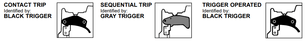
1.TRIGGER OPERATION
A TRIGGER OPERATED tool requires a single action to drive a fastener. Each time the trigger is pulled the tool will drive a fastener. The trigger operated model is intended for use only when a contact trip or sequential trip cannot be used due to the requirements of the application.
2.CONTACT TRIP OPERATION
The CONTACT TRIP MODEL tool contains a contact trip that operates in conjunction with the trigger to drive a fastener. There are two methods of operation to drive fasteners with a contact trip tool.
A.SINGLE FASTENER PLACEMENT: To operate the tool in this manner, first position the contact trip on the work surface, WITHOUT PULLING THE TRIGGER. Depress the contact trip until the nose touches the work surface and then pull the trigger to drive a fastener. Do not press the tool against the work with extra force. Instead, allow the tool to recoil off the work surface to avoid a second unwanted fastener. Remove your finger from the trigger after each operation.
B.RAPID FASTENER OPERATION: To operate the tool in this manner, hold the tool with the contact trip pointing towards but not touching the work surface. Pull the trigger and then tap the contact trip against the work surface using a bouncing motion. Each depression of the contact trip will cause a fastener to be driven.
The operator must not hold the trigger pulled on contact trip tools except during fastening operation, as serious injury could result if the trip accidentally contacted someone or something, causing the tool to cycle.
Keep hands and body away from the discharge area of the tool. A contact trip tool may bounce from the recoil of driving a fastener and an unwanted second fastener may be driven, possibly causing injury.
3.SEQUENTIAL TRIP OPERATION:
The SEQUENTIAL TRIP MODEL contains a contact trip that operates in conjunction with the trigger to drive a fastener. To operate a sequential trip tool, first position the contact trip on the work surface WITHOUT PULLING THE TRIGGER. Depress the contact trip and then pull the trigger to drive a fastener. As long as the contact trip is contacting the work and is held depressed, the tool will drive a fastener each time the trigger is depressed. If the contact trip is allowed to leave the work surface, the sequence described above must be repeated to drive another fastener.
STANLEY-BOSTITCH OFFERS THREE TYPES OF OPERATION FOR THIS SERIES TOOL.
CONTACT TRIP
The common operating procedure on “Contact Trip” tools is for the operator to contact the work to actuate the trip mechanism while keeping the trigger pulled, thus driving a fastener each time the work is contacted. This will allow rapid fastener placement on many jobs, such as sheathing, decking and pallet assembly.
All pneumatic tools are subject to recoil when driving fasteners. The tool may bounce, releasing the trip, and if unintentionally allowed to recontact the work surface with the trigger still actuated (finger still holding trigger pulled) an unwanted second fastener will be driven.
SEQUENTIAL TRIP
The Sequential Trip requires the operator to hold the tool against the work before pulling the trigger. This makes accurate fastener placement easier, for instance on framing, toe nailing and crating applications. The Sequential Trip allows exact fastener location without the possibility of driving a second fastener on recoil, as described under “Contact Trip”. The Sequential Trip Tool has a positive safety advantage because it will not accidentally drive a fastener if the tool is contacted against the work – or anything else – while the operator is holding the trigger pulled.
TRIGGER OPERATED
The Trigger Operated model is cycled by actuation of the trigger only. This model does not have a Contact Arm and is intended for use only where a Contact Arm CANNOT be used to satisfy the requirements of the application. The Trigger Operated tool will cycle each time the trigger is actuated.
MODEL IDENTIFICATION:
Refer to Operation Instructions on page 7 before proceeding to use this tool.
MAINTAINING THE TOOL
When working on air tools note the warnings in this manual and use extra care when evaluating problem tools.
AIR SUPPLY AND CONNECTIONS
Do not use oxygen, combustible gases, or bottled gases as a power source for this tool as tool may explode, possibly causing injury.
FITTINGS:
Install a male plug on the tool which is free flowing and which will release air pressure from the tool when disconnected from the supply source.
HOSES:
Air hoses should have a minimum of 150 p.s.i. (10.6 kg/cm2) working pressure rating or 150 percent of the maximum pressure that could be produced in the air system. The supply hose should contain a fitting that will provide “quick disconnecting” from the male plug on the tool.
SUPPLY SOURCE:
Use only clean regulated compressed air as a power source for this tool. NEVER USE OXYGEN, COMBUSTIBLE GASES, OR BOTTLED GASES, AS A POWER SOURCE FOR THIS TOOL AS TOOL MAY EXPLODE.
REGULATOR:
A pressure regulator with an operating pressure of 0 - 125 p.s.i. (0 - 8.79 KG/CM2) is required to control the operatiing pressure for safe operation of this tool. Do not connect this tool to air pressure which can potentially exceed 200 p.s.i. (14 KG/CM2)as tool may fracture or burst, possibly causing injury.
OPERATING PRESSURE:
Do not exceed recommended maximum operating pressure as tool wear will be greatly increased. The air supply must be capable of maintaining the operating pressure at the tool. Pressure drops in the air supply can reduce the tool’s driving power. Refer to “TOOL SPECIFICATIONS” for setting the correct operating pressure for the tool.
FILTER:
Dirt and water in the air supply are major causes of wear in pneumatic tools. A filter will help to get the best performance and minimum wear from the tool. The filter must have adequate flow capacity for the specific installation. The filter has to be kept clean to be effective in pro- viding clean compressed air to the tool. Consult the manufacturer’s instructions on proper maintenance of your filter. A dirty and clogged filter will cause a pressure drop which will reduce the tool’s performance.
LUBRICATION
Frequent, but not excessive, lubrication is required for best performance. Oil added through the air line connection will lubricate the internal parts. Use STANLEY-BOSTITCH Air Tool Lubricant, Mobil Velocite #10, or equivalent. Do not use detergent oil or additives as these lubricants will cause accelerated wear to the seals and bumpers in the tool, resulting in poor tool performance and frequent tool maintenance.
If no airline lubricator is used, add oil during use into the air fitting on the tool once or twice a day. Only a few drops of oil at a time is necessary. Too much oil will only collect inside the tool and will be noticeable in the exhaust cycle.
COLD WEATHER OPERATION:
For cold weather operation, near and below freezing, the moisture in the air line may freeze and pre- vent tool operation. We recommend the use of STANLEY-BOSTITCH WINTER FORMULA air tool lubricant or permanent antifreeze (ethylene glycol) as a cold weather lubricant.
CAUTION: Do not store tools in a cold weather environment to prevent frost or ice formation on the tools operating valves and mechanisms that could cause tool failure.
NOTE: Some commercial air line drying liquids are harmful to “O”-rings and seals – do not use these low temperature air dryers without checking compatibility.
LOADING THE 400 & 500
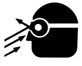
EYE PROTECTION
which conforms to ANSI specifications and provides protection against flying particles both from the FRONT and SIDE should ALWAYS be worn by the operator and others in the work area when loading, operating or servicing this tool. Eye protection is required to guard against flying fasteners and debris, which could cause severe eye injury.
The employer and/or user must ensure that proper eye protection is worn. Eye protection equipment must conform to the requirements of the American National Standards Institute, ANSI Z87.1-1989 and provide both frontal and side protection. NOTE: Non-side shielded spectacles and face shields alone do not provide ade- quate protection.
TO PREVENT ACCIDENTAL INJURIES:
•Never place a hand or any other part of the body in fastener discharge area of tool while
the air supply is connected.
•Never point the tool at anyone else.
•Never engage in horseplay.
•Never pull the trigger unless nose is directed at the work.
•Always handle the tool with care.
•Do not pull the trigger or depress the trip mechanism while loading the tool.
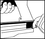
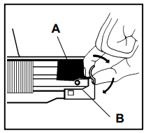
1. Move pusher to rear until latched. Cover will open. Pusher front will drop into notch on top of magazine assembly.
2. Drop staple stick over magazine and slide forward. Repeat until magazine is loaded, allowing enough space for pusher to disengage the magazine and the cover to close. Approximately 1/2" (13mm)
3. Pull and hold top part of knob (A) and depress bottom part of knob (B) in a clockwise direction to release pusher.
NOTE: Use only staples recommended by Stanley-Bostitch for the 400 & 500 Series staplers or staples which meet Stanley-Bostitch specifications.
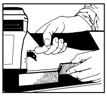
“DIAL-A-DEPTH™” FASTENER CONTROL ADJUSTMENT
The DIAL-A-DEPTH™ Fastener Control adjustment feature provides close control of the fastener drive depth; from flush with the work surface to shallow or deep countersink. First, set the air pressure for consistent drive in the specific work as described on page 5, then use the DIAL-A-DEPTH™ Fastener Control adjustment to give the desired depth of drive.
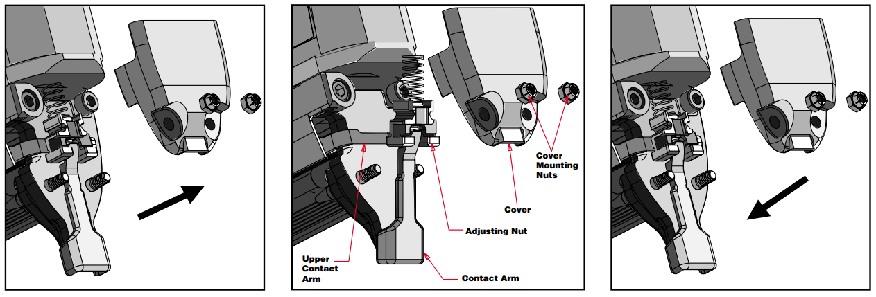
TO ADJUST DIAL-A DEPTH™ FASTENER CONTROL ADJUSTMENT:
1.With air pressure set (refer to Setting the Correct Pressure on (Page 5), drive a few fasteners into a representative material sample to determine if adjustment is necessary.
2.If adjustment is required, disconnect air supply.
3.Remove cover mounting nuts and cover. Tilt out the contact arm assembly. Rotate the adjusting nut to the left to increase fastener drive depth, or to the right to decrease it. Reinstall the contact arm assembly, cover and mounting nuts.
4.Before reconnecting air supply, check that trip mechanism parts operate freely with no binding or sticking.
5.Reconnect air supply.
TOOL OPERATION CHECK:
CAUTION: Remove all fasteners from tool before performing tool operation check.
1.TRIGGER OPERATED TOOL:
A.With finger off the trigger, hold the tool with a firm grip on the handle.
B.Place the nose of the tool against the work surface.
C.Pull the trigger to drive. Release the trigger and cycle is complete.
CAUTION: THE TOOL WILL CYCLE EACH TIME THE TRIGGER IS PULLED!
2.CONTACT TRIP OPERATION:
A.With finger off the trigger, press the contact trip against the work surface. THE TOOL MUST NOT CYCLE.
B.Hold the tool off the work surface, and pull the trigger. THE TOOL MUST NOT CYCLE.
C.With the tool off the work surface, pull the trigger. Press the contact trip against the work surface. THE TOOL MUST CYCLE.
D.Without touching the trigger, press the contact trip against the work surface, then pull the trigger. THE TOOL MUST CYCLE.
3.SEQUENTIAL TRIP OPERATION:
A.Press the contact trip against the work surface, without touching the trigger. THE TOOL MUST NOT CYCLE.
B.Hold the tool off the work surface and pull the trigger. THE TOOL MUST NOT CYCLE.
Release the trigger. The trigger must return to the trigger stop on the frame.
C.Pull the trigger and press the contact trip against the work surface. THE TOOL MUST NOT CYCLE.
D.With finger off the trigger, press the contact trip against the work surface. Pull the trigger. THE TOOL MUST CYCLE.
IN ADDITION TO THE OTHER WARNINGS CONTAINED IN THIS MANU- AL OBSERVE THE FOLLOWING FOR SAFE OPERATION
•Use the STANLEY-BOSTITCH pneumatic tool only for the purpose for which it was designed.
•Never use this tool in a manner that could cause a fastener to be directed toward the user or others in the work area.
•Do not use the tool as a hammer.
•Always carry the tool by the handle. Never carry the tool by the air hose.
•Do not alter or modify this tool from the original design or function without approval from STANLEY-BOSTITCH, INC.
•Always be aware that misuse and improper handling of this tool can cause injury to yourself and others.
•Never clamp or tape the trigger or contact trip in an actuated position.
•Never leave a tool unattended with the air hose attached.
•Do not operate this tool if it does not contain a legible WARNING LABEL.
•Do not continue to use a tool that leaks air or does not function properly. Notify your nearest Stanley-Bostitch representative if your tool continues to experience functional problems.
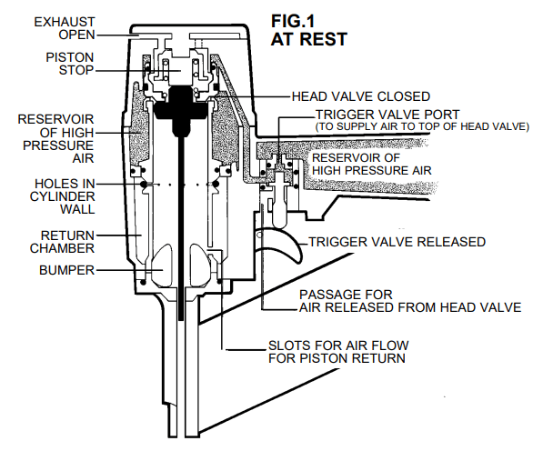
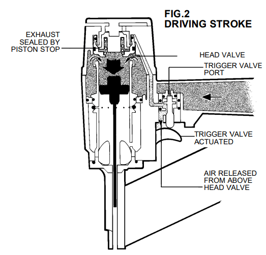
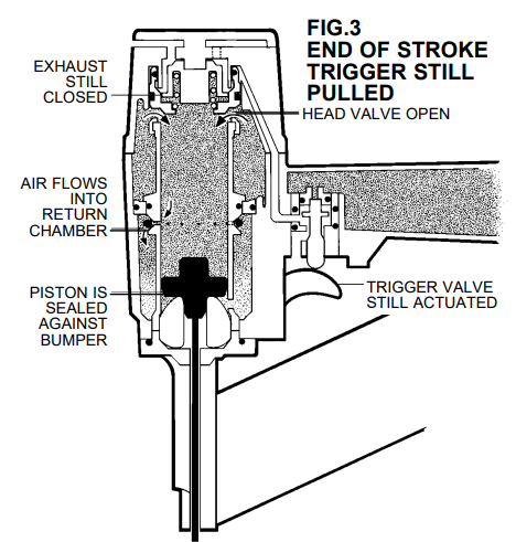
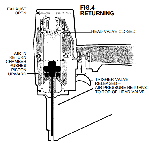
BASIC TOOL OPERATION
Stanley-Bostitch pneumatic tools are cycled by a compressed air operated single piston design. The following illustrations show the four functional cycles that occur when the tool is operated to drive a fastener:
MAINTAINING THE PNEUMATIC TOOL
When working on air tools, note the warnings in this manual and use extra care evaluating problem tools.
CAUTION: Pusher spring (constant force spring). Caution must be used when working with the spring assembly. The spring is wrapped around, but not attached to, a roller. If the spring is extended beyond its length, the end will come off the roller and the spring will roll up with a snap, with a chance of pinching your hand. Also the edges of the spring are very thin and could cut. Care must also be taken to insure no permanent kinks are put in the spring as this will reduce the springs force.
REPLACEMENT PARTS:
STANLEY-BOSTITCH replacement parts are recommended. Do not use modified parts or parts which will not give equivalent performance to the original equipment.
ASSEMBLY PROCEDURE FOR SEALS:
When repairing a tool, make sure the internal parts are clean and lubricated. Use Parker “O”-LUBE or equivalent on all “O”-rings. Coat each “O”-ring with “O”-LUBE before assembling. Use a small amount of oil on all moving surfaces and pivots. After reassembly add a few drops of
STANLEY-BOSTITCH Air Tool Lubricant through the air line fitting before testing.
AIR SUPPLY-PRESSURE AND VOLUME:
Air volume is as important as air pressure. The air volume supplied to the tool may be inadequate because of undersize fittings and hoses, or from the effects of dirt and water in the system.
Restricted air flow will prevent the tool from receiving an adequate volume of air, even though the pressure reading is high. The results will be slow operation, misfeeds or reduced driving power. Before evaluating tool problems for these symptoms, trace the air supply from the tool to the supply source for restrictive connectors, swivel fittings, low points containing water and anything else that would prevent full volume flow of air to the tool.
TROUBLE SHOOTING
PROBLEM
CAUSE
CORRECTION
Trigger valve housing leaks air
O-ring cut or cracked
Replace O-ring
Trigger valve stem leaks air
O-ring/seals cut or cracked
Replace trigger valve assembly
Frame/nose leaks air
Loose nose screws
Tighten and recheck
O-ring or Gasket is cut or cracked
Replace O-ring or gasket
Bumper cracked/worn
Replace bumper
Frame/cap leaks air
Damaged gasket or seal
Replace gasket or seal
Cracked/worn top bumper
Replace bumper
Loose cap
Tighten and recheck
Failure to cycle
Air supply restriction
Check air supply equipment
Tool dry, lack of lubrication
Use STANLEY-BOSTITCH Air Tool Lubricant
Worn head valve O-rings
Replace O-rings
Broken head valve spring
Replace head valve spring
Head valve stuck
Disassemble/Check/Lubricate
Lack of power; slow to cycle
Tool dry, lacks lubrication
Use STANLEY-BOSTITCH Air Tool Lubricant
Broken headvalve spring
Replace spring
O-rings/seals cut or cracked
Replace rings/seals
Exhaust blocked
Check bumper, head valve spring, muffler
Trigger assembly worn/leaks
Replace trigger assembly
Dirt/tar build up on driver
Disassemble nose/driver to clean
Bottom bumper not seated correctly
Disassemble to correct
Head valve dry
Disassemble/lubricate
Air pressure too low
Check air supply equipment
Skipping fasteners; intermittent feed
Worn bumper
Replace bumper
Tar/dirt in driver channel
Disassemble and clean nose and driver
Air restriction/inadequate air flow through quick disconnect socket and plug
Replace quick disconnect fittings
Worn piston ring
Replace ring, check driver
Tool dry, lacks lubrication
Use STANLEY-BOSTITCH Air Tool Lubricant
Damaged pusher spring
Replace spring
Low air pressure
Check air supply system to tool
Loose magazine nose screws
Tighten all screws
Fasteners too short for tool
Use only recommended fasteners
Bent fasteners
Discontinue using these fasteners
Wrong size fasteners
Use only recommended fasteners
Leaking cap gasket
Tighten cap/replace gasket
Trigger valve O-ring cut/worn
Replace O-ring
Broken/chipped driver
Replace driver (check piston ring)
Dry/dirty magazine
Clean/lubricate use STANLEY-BOSTITCH Air Tool Lubricant