
43
1Instructions 4
1.1 General safety instructions 4
1.2 Appliance purpose 8
1.3 Manufacturer liability 8
1.4 This user manual 8
1.5 Identification plate 8
1.6 Disposal 8
1.7 How to read the user manual 9
2 Description 10
2.1 General description 10
2.2 Control panel 12
2.3 Other parts 15
2.4 Available accessories 15
3Use 17
3.1 Instructions 17
3.2 First use 17
3.3 Using the accessories 18
3.4. Using the oven 19
3.5 Cooking advice 22
3.6 Clock function (on some models only) 23
4 Cleaning and maintenance 26
4.1 Instructions 26
4.2 Cleaning the surface 26
4.3 Cleaning the door 26
4.4 Cleaning the oven cavity 28
4.5 Extraordinary maintenance 29
5Installation 31
5.1 Gas connection 31
5.2 Adapting to different types of gas 34
5.3 Electrical connection 38
5.4 Replacement of the cord 38
5.5 Positioning 39
We advise you to read this manual carefully, as it contains all the instructions for maintaining
the appliance’s aesthetic and functional qualities.
For further information on the product: www.smeg.com
TRANSLATION OF THE ORIGINAL INSTRUCTIONS

Instructions
44
1 Instructions
1.1 General safety instructions
Risk of personal injury
• During use the appliance and its
accessible parts become very hot.
Never touch the heating elements
during use.
• Protect your hands by wearing
oven gloves when moving food
inside the oven.
• Never try to put out a fire or flames
with water: turn off the appliance
and smother the flames with a fire
blanket or other appropriate
cover.
• This appliance may be used by
children aged at least 8 and by
people of reduced physical,
sensory or mental capacity, or
lacking in experience in the use of
electrical appliances, provided
that they are supervised or
instructed by adults who are
responsible for their safety.
• Children must never play with the
appliance.
• Keep children under the age of 8
at a safe distance unless they are
constantly supervised.
• Keep children under the age of 8
away from the appliance when it
is in use.
• Cleaning and maintenance must
not be carried out by unsupervised
children.
• Cooking process should always
be kept under control. A short
cooking process must be
continuously surveyed.
• Never leave the appliance
unattended during cooking
operations where fats or oils could
overheat and take fire. Be very
careful.
• Do not pour water directly onto
very hot trays.
• Keep the oven door closed during
cooking.
• If you need to move food or at the
end of cooking, open the door 5
cm for a few seconds, let the
steam come out, then open it fully.
• Do not insert pointed metal objects
(cutlery or utensils) into the slots in
the appliance.

Instructions
45
EN
• Switch off the appliance after use.
• DO NOT USE OR STORE
FLAMMABLE MATERIALS NEAR
THE APPLIANCE.
•DO NOT USE AEROSOLS IN
THE VICINITY OF THIS
APPLIANCE WHILST IT IS IN
USE.
• DO NOT MODIFY THIS
APPLIANCE.
• Have qualified personnel carry out
installation and assistance
interventions according to the
standards in force.
• Do not try to repair the appliance
yourself or without the intervention
of a qualified technician.
• Do not pull the cable to remove
the plug.
Risk of damaging the appliance
• Do not use abrasive or corrosive
detergents (e.g. scouring
powders, stain removers and
metallic sponges) on glass parts.
Use wooden or plastic utensils.
• Do not use rough or abrasive
materials or sharp metal scrapers.
• Do not use cleaning products
containing chlorine, ammonia or
bleach on parts made of steel or
that have metallic surface finishes
(e.g. anodizing, nickel- or
chromium-plating).
• Racks and trays should be inserted
as far as they will go into the side
guides. The mechanical safety
locks that prevent them from being
removed must face downwards
and towards the back of the oven.
• Do not sit on the appliance.
• Do not use steam jets to clean the
appliance.
• Do not spray any spray products
near the appliance.
• Never leave objects on the
cooking surface.
• Do not obstruct ventilation
openings and heat dispersal slots.
• DO NOT USE THE APPLIANCE
TO HEAT ROOMS FOR ANY
REASON.

Instructions
46
• Do not use plastic cookware or
containers for cooking.
• Do not place sealed tins or
containers in the oven cavity.
• Remove all trays and racks which
are not required during cooking.
• Do not cover the bottom of the
oven cavity with aluminium or tin
foil sheets.
• Do not place pans or trays directly
on the bottom of the oven cavity.
• If you wish to use greaseproof
paper, place it so that it will not
interfere with the hot air circulation
inside the oven.
• Do not use the open door to place
pans or trays on the internal
glazing pane.
• Never use the oven door to lever
the appliance into place when
fitting.
• Avoid exerting too much pressure
on the door when open.
• Do not use the handle to lift or
move this appliance.
Installation and maintenance
• THIS APPLIANCE MUST NOT BE
INSTALLED IN A BOAT OR
CARAVAN.
• This appliance must not be
installed on a pedestal.
• Position the appliance into the
cabinet cut-out with the help of a
second person.
• To prevent any possible
overheating, the appliance should
not be installed behind a
decoration door or a panel.
• Have the gas connection
performed by authorised staff.
• Installation using a hose must be
carried out so that the length of the
hose does not exceed 2 metres
when fully extended for steel hoses
and 1.5 metres for rubber hoses.
• The hoses should not come into
contact with moving parts and
should not be crushed in any way.
• If required, use a pressure
regulator that complies with
current regulations.

Instructions
47
EN
• After carrying out any operation,
check that the tightening torque of
gas connections is between
10 Nm and 15 Nm.
• At the end of the installation, check
for any leaks with a soapy
solution, never with a flame.
• Have qualified personnel carry out
installation and assistance
interventions according to the
standards in force.
• Have the electrical connection
performed by authorised
technicians.
• The appliance must be connected
to ground in compliance with
electrical system safety standards.
• Use cables withstanding a
temperature of at least 90 °C.
• The tightening torque of the screws
of the terminal board leads must
be 1.5 - 2 Nm.
• If the power supply cable is
damaged, contact technical
support immediately and they will
replace it.
• Before any operation on the
appliance (installation,
maintenance, positioning or
movement) always wear PPM.
• Before performing any operation
on the appliance, switch off the
power supply.
For this appliance
• Ensure that the appliance is
switched off before replacing the
bulb.
•Do not rest any weight or sit on the
open door of the appliance.
• Take care that no objects are stuck
in the doors.
• Do not install/use the appliance
outdoors.
Instructions
48
1.2 Appliance purpose
• This appliance is intended for
cooking food in the home
environment. Every other use is
considered inappropriate.
• The appliance is not designed to
operate with external timers or with
remote-control systems.
1.3 Manufacturer liability
The manufacturer declines all liability
for damage to persons or property
caused by:
• use of the appliance other than
that specified;
• failure to comply with the
instructions in the user manual;
• tampering with any part of the
appliance;
• the use of non-original spare parts.
1.4 This user manual
This user manual is an integral part of the
appliance and must therefore be kept in its
entirety and within the user’s reach for the
whole working life of the appliance.
Read this user manual carefully before using
the appliance.
1.5 Identification plate
The identification plate bears the technical
data, serial number and brand name of the
appliance. Do not remove the identification
plate for any reason.
1.6 Disposal
This appliance must be disposed
of separately from other waste
(Directives 2002/95/EC,
2002/96/EC, 2003/108/EC).
The appliance does not contain substances
in quantities sufficient to be considered
hazardous to health and the environment,
in accordance with current European
directives.
Instructions
49
EN
To dispose of the appliance:
• Cut the power supply cable and remove
it along with the plug.
• Deliver the appliance to the appropriate
recycling centre for electrical and
electronic equipment waste, or return it to
the retailer when purchasing an
equivalent product, on a one for one
basis.
Our appliances are packaged in non-
polluting and recyclable materials.
• Deliver the packing materials to the
appropriate recycling centre.
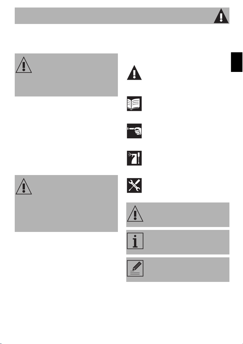
1.7 How to read the user manual
This user manual uses the following reading
conventions:
1. Sequence of instructions for use.
• Standalone instruction.
Power voltage
Danger of electrocution
• Disconnect the mains power supply.
• Unplug the appliance.
Plastic packaging
Danger of suffocation
• Do not leave the packaging or any part
of it unattended.
• Do not let children play with the plastic
bags.
Instructions
General information on this user
manual, on safety and final
disposal.
Description
Description of the appliance and its
accessories.
Use
Information on the use of the
appliance and its accessories.
Cleaning and maintenance
Information for proper cleaning and
maintenance of the appliance.
Installation
Information for the qualified
technician: Installation, operation
and inspection.
Safety instructions
Information
Advice
Description
50
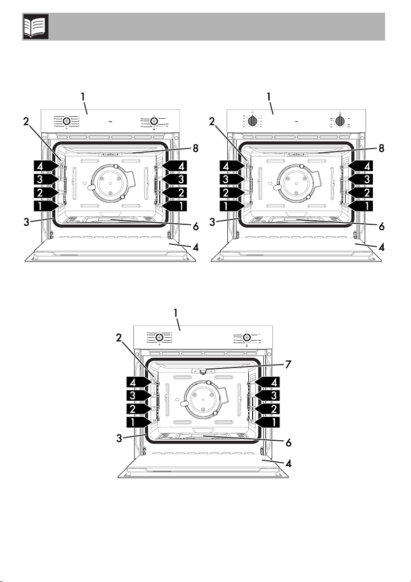
2 Description
2.1 General Description
Gas / Electric grill oven models
Gas / Gas grill oven models
Description
51
EN
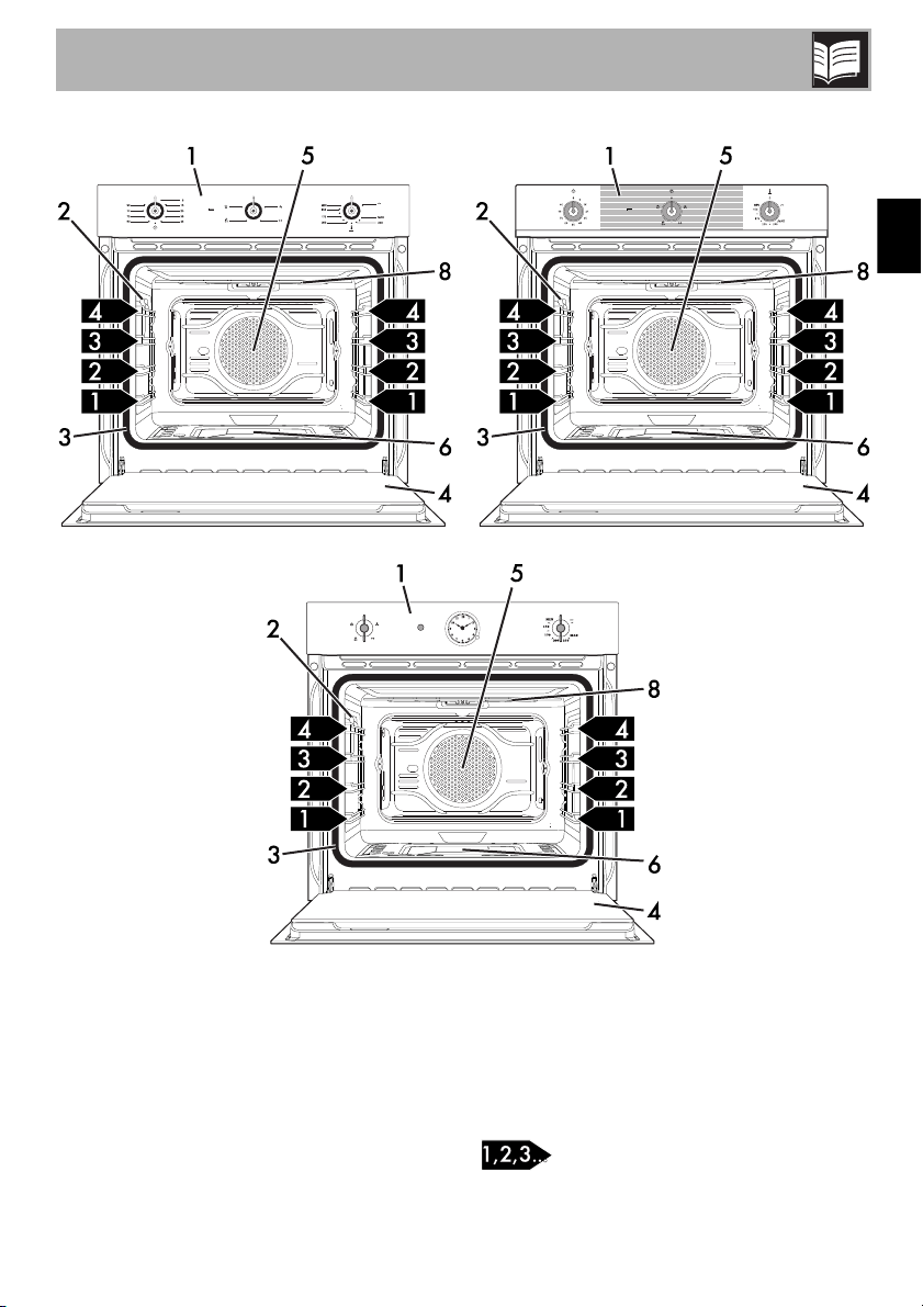
Gas / Electric fan grill oven models
1 Control panel
2 Lamp
3 Seal
4 Door
5 Fan (on some models only)
6 Gas oven
7 Gas grill (on some models only)
8 Electric grill (on some models only)
Frame shelf
Description
52
Fan-assisted models (note for UK market)
Unlike the traditional gas oven that you
usually find in the United Kingdom, where
the hottest part of the cavity is usually
located in the upper area of the oven, the
new fan-assisted gas oven has a European-
style central lower burner which allows you
to get optimal results, thanks to the efficient
zone cooking device.
The oven has a fan that distributes the heat
evenly inside it. However, the lower part is
the hottest area and it allows you to cook in
the same way as in the upper part of a
traditional oven (depending on the mode
selected).
The central areas cook at the temperature
set on the control panel, whereas in the
upper area the heat is distributed to a
slightly lower temperature, which equals the
temperature of the lower shelf of an electric
oven.
Before carrying out a cooking process,
preheat the oven in order to get optimal
results. Moreover, during all cooking
operations the oven door must be closed to
enable the safety device to work properly.
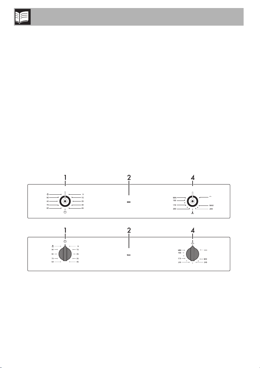
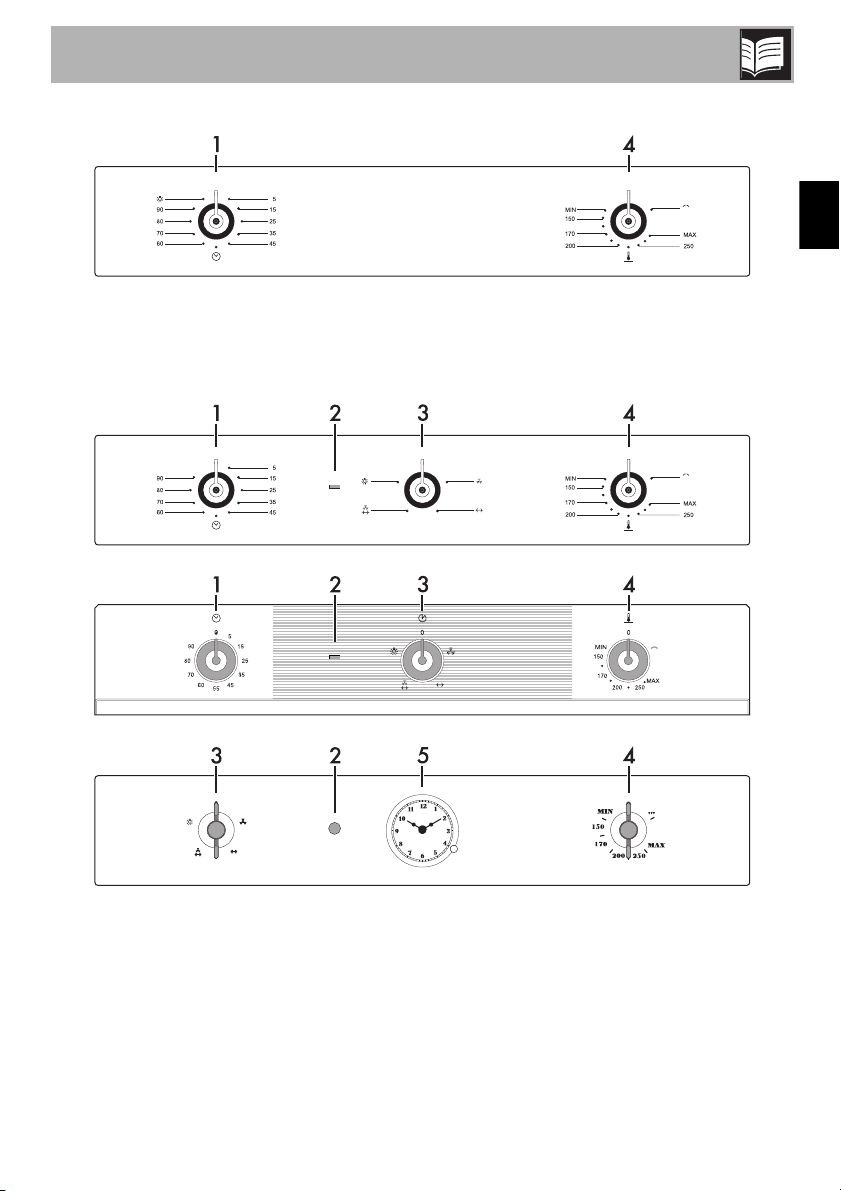
2.2 Control panel
Gas / Electric grill oven models
Description
53
EN
Gas / Gas grill oven models
Gas / Electric fan grill oven models
Description
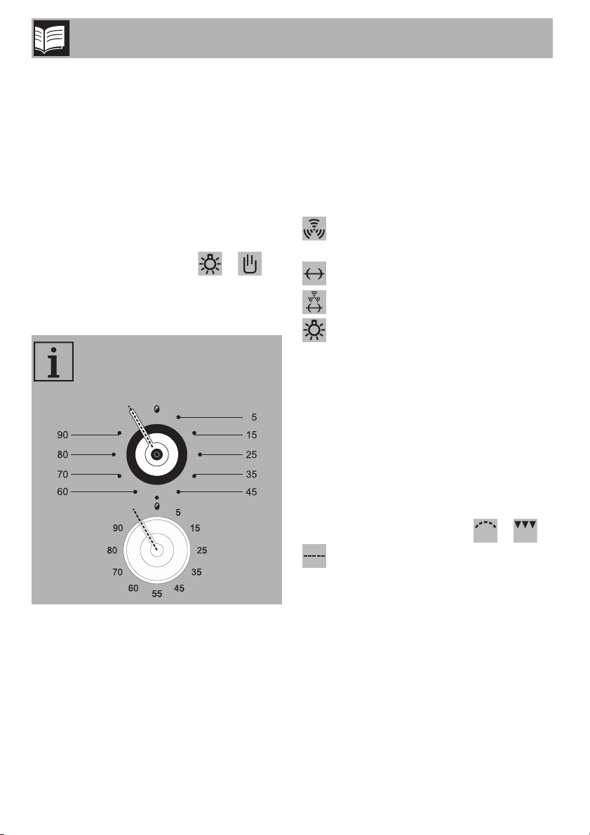
54
1 Electromechanical minute minder timer
knob
In order to use the minute minder timer, the
buzzer must be set by turning the knob
clockwise. The numbers correspond to
minutes (maximum 90 minutes). Adjustment
is progressive and intermediate positions
between the figures can be used.
The end of cooking buzzer does not
interrupt oven operations.
(where present) The position /
enables the light inside the oven cavity to
be switched on during normal operations
(without minute minder).
2 Electric grill heating element bulb
(gas grill models excluded)
It switches on to indicate that the electric
grill is operating.
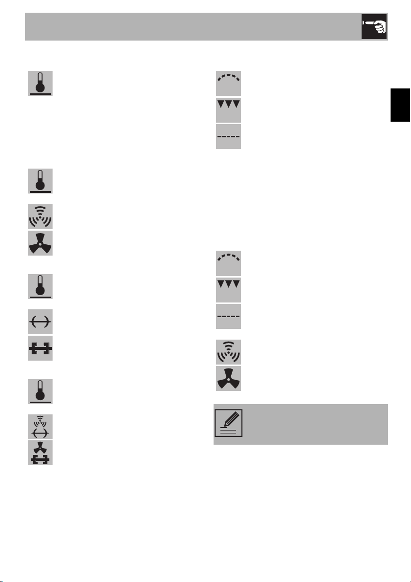
3 Function knob (on some models only)
Turn the function knob to the required
symbol:
switches on the fan inside the
oven cavity;
starts the rotisserie motor;
starts the rotisserie fan and motor;
switches on the light inside the
oven cavity.
4 Temperature knob
Useful for lighting the lower burner or the
electric grill, or the gas grill (depending on
the models).
The cooking temperature is selected by
turning the knob anticlockwise to the
required setting, between MIN and MAX.
To switch on the electric or gas grill, turn the
knob clockwise to the symbol / /
(depending on the models).
5 Clock (on some models only)
Useful for displaying the current time.
In models without printing, when
the minute minder knob is between
90 and 0, no function is activated.
Description
55
EN
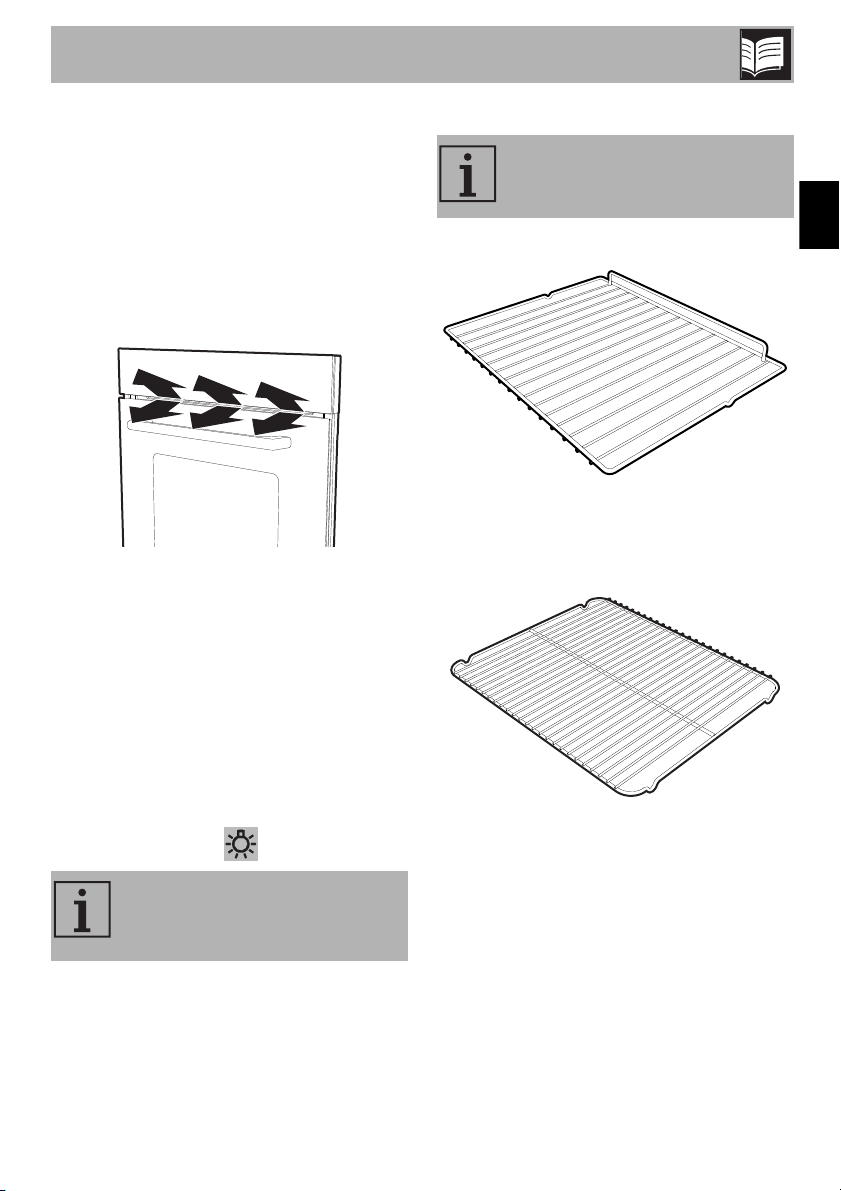
2.3 Other parts
Shelves
The appliance features shelves to position
trays and racks at different heights. The
insertion heights are indicated from the
bottom upwards (see 2.1 General
Description).
Cooling fan
The fan cools the oven and comes into
operation during cooking.
The fan causes a steady outflow of air from
above the door which may continue for a
brief period of time even after the appliance
has been turned off.
Interior lighting
The appliance’s interior lighting comes on:
• when the door is opened:
• when the function is selected.
2.4 Available accessories
Rack
Used for supporting containers with food
during cooking.
Tray rack (on some models only)
To be placed over the top of the tray; for
cooking foods which may drip.
When the door is open, it is not
possible to turn off the interior
lighting.
Some models are not provided
with all accessories.
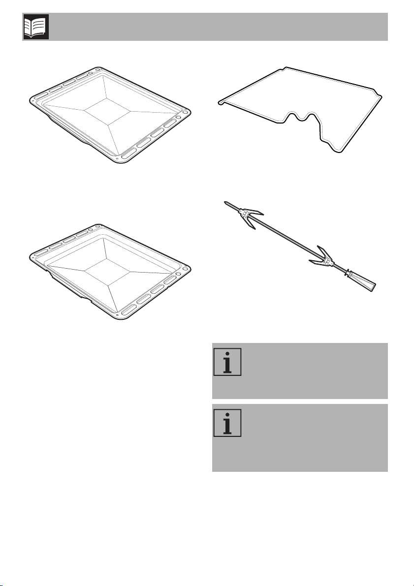
Description
56
Tray (on some models only)
Useful for collecting fat from foods placed
on the rack above.
Deep tray
Useful for collecting fat from foods placed
on the rack above and for cooking pies,
pizzas and baked desserts.
Rotisserie support (on some models only)
To be used to support the rotisserie rod.
Rotisserie rod (on some models only)
Useful for cooking chicken and all foods
that require uniform cooking over their entire
surface.
The oven accessories intended to
come into contact with food are
made of materials that comply with
the provisions of current legislation.
Original supplied and optional
accessories can be requested to
Authorised Assistance Centres.
Use only original accessories
supplied by the manufacturer.
Use
57
EN
3 Use
3.1 Instructions
3.2 First use
1. Remove any protective film from the
outside or inside of the appliance,
including accessories.
2. Remove any labels (apart from the
technical data plate) from the
accessories and from the oven cavity.
3. Remove and wash all the appliance
accessories (see 4 Cleaning and
maintenance).
4. Heat the empty oven at the maximum
temperature for the time required to burn
off any residues left by the manufacturing
process.
Improper use
Risk of damage to surfaces
• Do not cover the bottom of the oven
cavity with aluminium or tin foil sheets.
• If you wish to use greaseproof paper,
place it so that it will not interfere with the
hot air circulation inside the oven cavity.
• Do not place pans or trays directly on
the bottom of the oven cavity.
• Do not pour water directly onto very hot
trays.
High temperature inside the oven
during use
Danger of burns
• Keep the oven door closed during
cooking.
• Protect your hands wearing heat
resistant gloves when moving food
inside the oven.
• Do not touch the heating elements inside
the oven.
• Do not pour water directly onto very hot
trays.
• Do not allow children to approach the
appliance when it is in operation.
High temperature inside the oven
during use
Danger of fire or explosion
• Do not spray any spray products near
the appliance.
• Do not use or leave flammable materials
near the appliance.
•Do not use plastic cookware or
containers for cooking.
• Do not place sealed tins or containers in
the oven cavity.
• Never leave the appliance unattended
during cooking operations where fats or
oils could be released.
• Remove all trays and racks which are
not required during cooking.
Use
58
3.3 Using the accessories
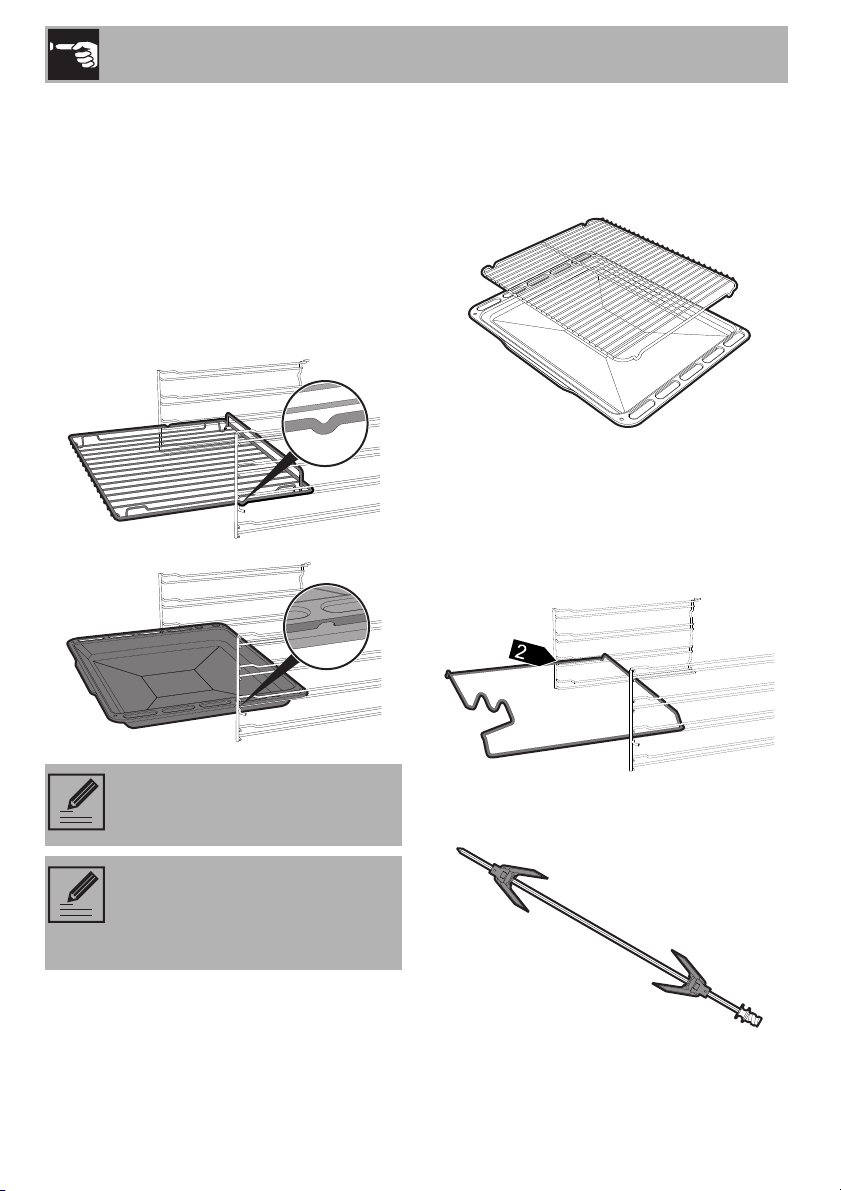
Racks and trays
Racks and trays have to be inserted into the
side guides until they come to a complete
stop.
• The mechanical safety locks that prevent
the rack from being taken out
accidentally have to face downwards
and towards the oven back.
Tray rack (on some models only)
The tray rack has to be inserted into the tray.
In this way fat can be collected separately
from the food which is being cooked.
Rotisserie rod (on some models only)
When cooking with the rotisserie, position
the rotisserie support frame on the second
shelf. Once the rod frame is inserted, the
shaped part must sit facing outwards.
Prepare the rotisserie rod with the food
using the rotisserie rod provided.
Gently insert racks and trays into
the oven until they come to a stop.
Clean the trays before using them
for the first time to remove any
residues left by the manufacturing
process.
Use
59
EN
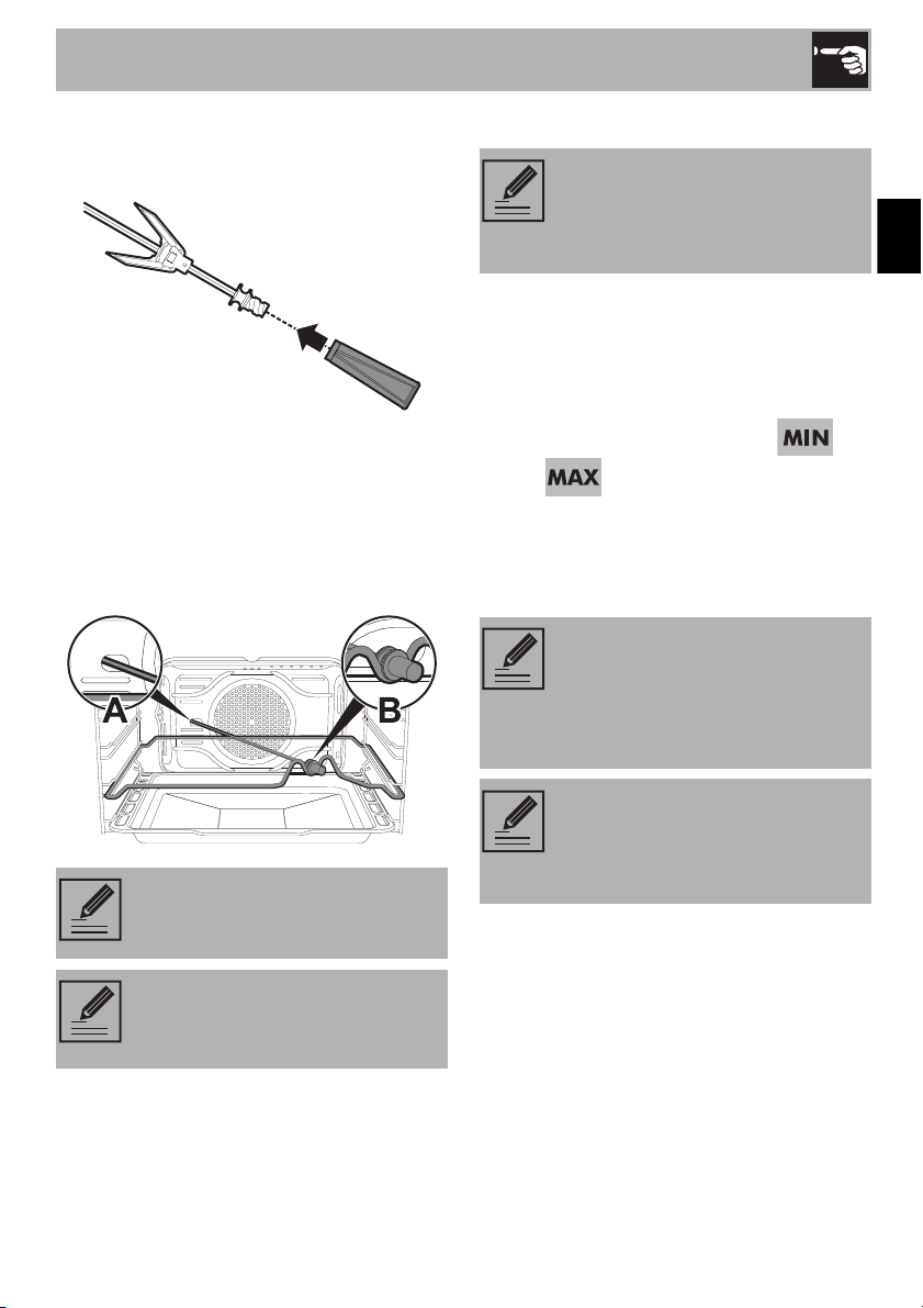
Screw on the handle provided so that you
can handle the rod with the food on it
readily.
Once you have prepared the rotisserie rod,
place it on the rotisserie support.
Insert the rod into the hole A so that it
connects with the rotisserie motor.
Make sure that the pin is
placed correctly on the guide frame B.
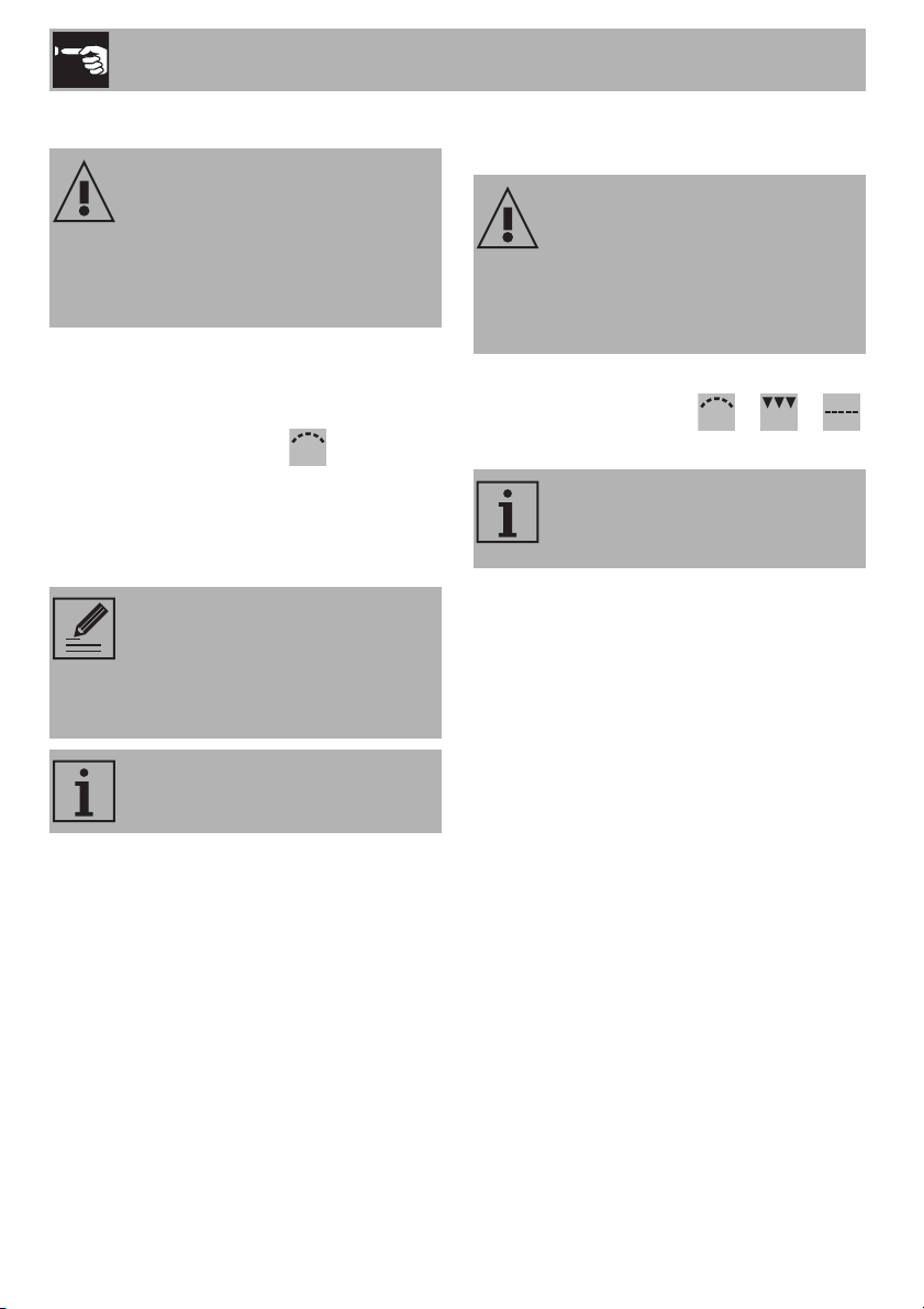
3.4 Using the oven
Using the gas oven
Electronic spark ignition:
1. Open the oven door completely.
2. Press and turn the temperature knob anti-
clockwise between the values
and . The electric spark ignition is
activated automatically.
3. After lighting, keep the knob pressed in
for a few seconds to allow the
thermocouple to heat up.
Remove the handle before closing
the door.
We recommend that you place the
tray on the first shelf to collect fats
more easily.
In the event of a power supply
failure the cooling fan does not
work. Do not light the oven
manually.
If the burner does not ignite after
15 seconds, stop attempting to
light it, leave the oven door open
and do not try to light it again for at
least 60 seconds.
In case of accidental extinguishing,
turn the knob to the off position and
do not try to light the burner again
for at least 60 seconds.
Use
60
Using the gas grill (on some models only)
Electronic spark ignition:
1. Open the oven door completely.
2. Press and turn the temperature knob
clockwise to the symbol . The electric
spark ignition is activated automatically.
3. After lighting, keep the knob pressed in
for a few seconds to allow the
thermocouple to heat up.
Using the electric grill
(on some models only)
Press and turn the temperature knob
clockwise on the symbol / /
(depending on the models).
High temperature inside the oven
during use
Danger of fire or explosion
• Grilling processes must never last more
than 30 minutes.
If the burner does not ignite after
15 seconds, stop attempting to
light it, leave the oven door open
and do not try to light it again for at
least 60 seconds.
The gas oven and the gas grill must
never be used at the same time.
High temperature inside the oven
during use
Danger of fire or explosion
• Grilling processes must never last more
than 60 minutes.
The gas oven and the electric grill
must never be used at the same
time.
Use
61
EN
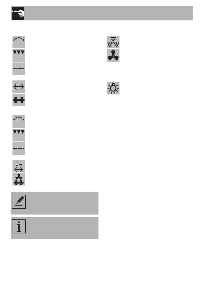
Functions list
Gas burner
The heat coming just from the
bottom allows you to complete the
cooking of foods that require a
higher bottom temperature, without
affecting their browning. Perfect for
cakes, pies, tarts and pizzas.
+
Gas burner + fan
In combination with the gas burner,
the fan distributes the heat evenly.
This function is perfect for slow
cooking operations using a steady
temperature.
+
Gas burner + rotisserie
The rotisserie rotates food while the
gas burner is operating.
+
Gas burner + fan + rotisserie
The rotisserie rotates food while the
fan distributes heat quickly.
Grill
The heat coming from the grill
element or the gas grill burner
(depending on the models) gives
perfect grilling results above all for
thin and medium thickness meat and
in combination with the rotisserie
(where fitted) gives the food an
even browning at the end of
cooking. Perfect for sausages,
spare ribs and bacon. This function
enables large quantities of food,
particularly meat, to be grilled
evenly.
+
Fan with grill
The air produced by the fan softens
the strong heatwave generated by
the grill element, grilling perfectly
even very thick foods. Perfect for
large cuts of meat (e.g. shin of
pork).
Grilling processes must never last
more than 30 minutes.
Use
62
3.5 Cooking advice
General advice
• Use a fan assisted function to achieve
consistent cooking at several levels.
• It is not possible to shorten cooking times
by increasing the temperature (the food
could be overcooked on the outside and
undercooked on the inside).
Advice for cooking meat
• Cooking times vary according to the
thickness and quality of the food and to
consumer taste.
• Use a meat thermometer when roasting
meat, or simply press on the roast with a
spoon. If it is hard, it is ready; If not, it
needs another few minutes cooking.
+
Grill + Rotisserie
The rotisserie works in combination
with the grill element or the gas
burner grill (depending on the
models) and allows food to be
perfectly browned.
+
Fan grill + rotisserie
The rotisserie works in combination
with the grill element allowing food
to be perfectly browned; the fan
distributes heat very quickly.
Combined cooking and grilling
processes must never last more
than 60 minutes.
For safety reasons, the fan does
not work in combination with the
gas burner grill.
Defrost
Rapid defrost is helped by the
switching on of the fan that ensures
uniform distribution of air inside the
oven. (We recommend using the 1
st
or 2
nd
runner).
Light
In this position the oven light can be
turned on during normal operations.

Use
63
EN
Advice for cooking with the Grill and the
Fan grill
• Meat can be grilled even when it is put
into the cold oven or into the preheated
oven if you wish to change the effect of
the cooking.
• With the Fan grill function, we
recommend that you preheat the oven
before grilling.
Advice for cooking desserts/pastries and
biscuits
• Use dark metal moulds: They help to
absorb the heat better.
• The temperature and the cooking time
depend on the quality and consistency
of the dough.
• To check whether the dessert is cooked
right through: at the end of the cooking
time, put a toothpick into the highest point
of the dessert. If the dough does not stick
to the toothpick, the dessert is cooked.
• If the dessert collapses when it comes out
of the oven, on the next occasion reduce
the set temperature by about 10°C,
selecting a longer cooking time if
necessary.
Advice for defrosting and proving
• Place frozen foods without their
packaging in a lidless container on the
first shelf of the oven.
• Avoid overlapping the food.
• To defrost meat, use the rack placed on
the second level and a tray on the first
level. In this way, the liquid from the
defrosting food drains away from the
food.
• The most delicate parts can be covered
with aluminium foil.
• For successful proving, a container of
water should be placed in the bottom of
the oven.
To save energy
• Stop cooking a few minutes before the
time normally used. Cooking will
continue for the remaining minutes with
the heat which has accumulated inside
the oven.
• Reduce any opening of the door to a
minimum to avoid heat dispersal.
• Keep the inside of the appliance clean at
all times.
3.6 Clock (on some models only)
Setting the time
To set the correct time, pull the knob A and
turn it clockwise.
Use
64
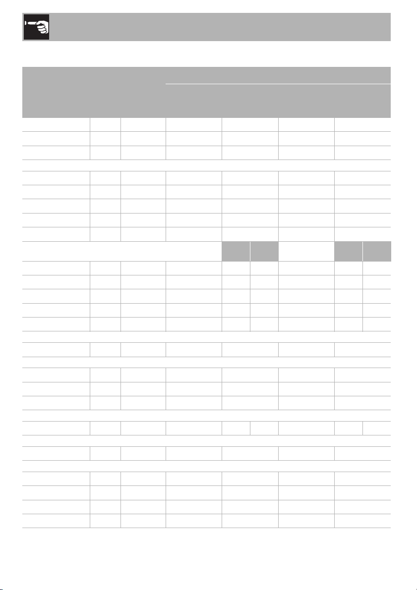
Cooking information table
Food
Weight
(kg)
Runner
position
from the
bottom
Static Oven Fan-assisted Oven
Temperature
(°C)
Time
(minutes)
Temperature
(°C)
Time
(minutes)
Lasagne
5 3 230 - 240 50 - 60 230 - 240 45 - 50
Cannelloni
2.5 2 220 - 230 25 - 30 220 - 230 25 - 30
Pasta bake
2.5 2 220 - 230 25 - 30 220 - 230 25 - 30
Roast chicken
1.2 2 200 - 210 80 - 90 200 - 210 70 - 80
Turkey breast
3 2 200 - 210 90 - 100 200 - 210 90 - 100
Pork loin
1.2 2 210 - 220 70 - 75 200 - 210 70 - 75
Roast rabbit
1.5 2 200 - 210 75 - 80 200 - 210 75 - 80
Lamb
1.5 2 200 - 210 90 - 95 200 - 210 90 - 95
1
nd
surface
2
nd
surface
1
nd
surface
2
nd
surface
Pork chops
1 4 Grill 15 8 Grill 15 8
Hamburgers
1 4 Grill 11 7 Grill 11 7
Sausages
1.5 4 Grill 15 5 Grill 15 5
Spare ribs
1.5 4 Grill 15 5 Grill 15 5
Meat kebabs
1.5 4 Grill 11 10 Grill 11 5
Chicken
1.2 Rotisserie Grill 80 Grill 70
Mackerel
8 2 180 - 190 25 - 30 180 - 190 25 - 30
Salmon trout
1.3 2 180 - 190 35 - 40 180 - 190 35 - 40
Flounder
1 2 180 - 190 25 - 30 180 - 190 25 - 30
Fish kebabs
14 Grill73Grill75
Pizza
1 3 240 12 - 15 240 12 - 15
Biscuits
1 3 190 18 180 18
Chiffon cake
1 2 190 50 - 55 180 55 - 60
Tarts
1 3 190 35 - 40 180 35 - 40
Ring cake
1.2 3 190 45 - 50 180 50 - 55
The times indicated in the table do not include preheating times and are provided only as a guide.
Use
65
EN
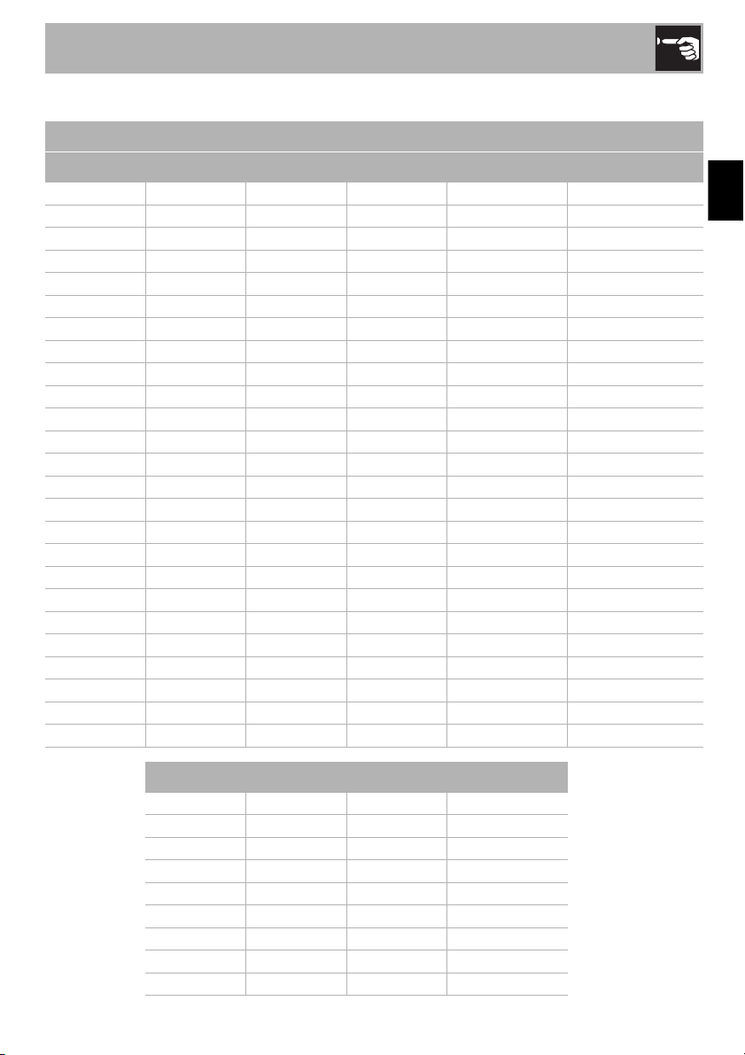
Conversion table
Weight Measurement Volume
Metric Imperial Metric Imperial Metric Imperial
15 g 1/2 oz 5 mm 1/4 in 25 ml 1 fl oz
25 g 1 oz 1 cm 1/2 in 50 ml 2 fl oz
40 g 1 1/2 oz 2.5 cm 1 in 85 ml 3 fl oz
50 g 2 oz 5 cm 2 in 100 ml 3 1/2 fl oz
75 g 3 oz 7.5 cm 3 in 150 ml 5 fl oz (1/4 pint)
100 g 4 oz 10 cm 4 in 200 ml 7 fl oz
150 g 5 oz 12.5 cm 5 in 300 ml 10 fl oz (1/2 pint)
175 g 6 oz 15 cm 6 in 450 ml 15 fl oz (3/4 pint)
200 g 7 oz 18 cm 7 in 600 ml 1 pint
225 g 8 oz 20 cm 8 in 700 ml 1 1/4 pint
250 g 9 oz 23 cm 9 in 900 ml 1 1/2 pint
275 g 10 oz 25 cm 10 in 1 l 1 3/4 pints
350 g 12 oz 30 cm 12 in 1.2 l 2 pints
375 g 13 oz 1.25 l 2 1/4 pints
400 g 14 oz 1.5 l 2 1/2 pints
425 g 15 oz 1.6 l 2 3/4 pints
450 g 1 lb 1.75 l 3 pints
550 g 1 1/4 lb 1.8 l 3 1/4 pints
675 g 1 1/2 lb 2 l 3 1/2 pints
750 g 1 3/4 lb 2.1 l 3 3/4 pints
900 g 2 lb 2.25 l 4 pints
1.5 kg 3 lb 2.75 l 5 pints
1.75 kg 4 lb 3.4 l 6 pints
2.25 kg 5 lb 3.9 l 7 pints
5 l 8 pints (1 gallon)
Temperature
140°C Fan 120°C 275°F Gas 1
150°C Fan 130°C 300°F Gas 2
160°C Fan 140°C 325°F Gas 3
180°C Fan 160°C 350°F Gas 4
190°C Fan 170°C 375°F Gas 5
200°C Fan 180°C 400°F Gas 6
220°C Fan 200°C 425°F Gas 7
230°C Fan 210°C 450°F Gas 8
240°C Fan 220°C 475°F Gas 9
Cleaning and maintenance
66
4 Cleaning and maintenance
4.1 Instructions
4.2 Cleaning the surfaces
To keep the surfaces in good condition,
they should be cleaned regularly after use.
Let them cool first.
Ordinary daily cleaning
Always use specific products only that do
not contain abrasives or chlorine-based
acids.
Pour the product onto a damp cloth and
wipe the surface, rinse thoroughly and dry
with a soft cloth or a microfibre cloth.
Food stains or residues
Do not use steel sponges and sharp
scrapers, as they will damage the surfaces.
Use normal, non-abrasive products and a
wooden or plastic tool, if necessary. Rinse
thoroughly and dry with a soft cloth or a
microfibre cloth.
Do not allow residues of sugary foods (such
as jam) to set inside the oven. If left to set for
too long, they might damage the enamel
lining of the oven.
4.3 Cleaning the door
Removing the door
For easier cleaning it is recommended to
remove the door and place it on a tea
towel.
To remove the door proceed as follows:
Improper use
Risk of damage to surfaces
• Do not use steam jets to clean the
appliance.
• Do not use cleaning products containing
chlorine, ammonia or bleach on parts
made of steel or that have metallic
surface finishes (e.g. anodizing, nickel-
or chromium-plating).
• Do not use abrasive or corrosive
detergents (e.g. scouring powders, stain
removers and metallic sponges) on
glass parts.
• Do not use rough or abrasive materials
or sharp metal scrapers.
We recommend the use of
cleaning products distributed by
the manufacturer.
Cleaning and maintenance
67
EN
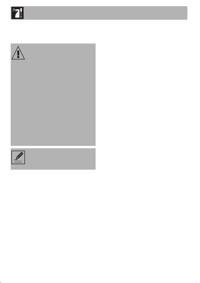
1. Open the door completely and insert two
pins into the holes on the hinges
indicated in the figure.
2. Grasp the door on both sides with both
hands, lift it forming an angle of around
30° and remove it.
3. To reassemble the door, put the hinges in
the relevant slots in the oven, making sure
that grooved sections A are resting
completely in the slots. Lower the door
and once it is in place remove the pins
from the holes in the hinges.
Cleaning the door glazing
The door glazing should always be kept
thoroughly clean. Use absorbent kitchen
roll. In case of stubborn dirt, wash with a
damp sponge and an ordinary detergent.
Removing the internal glass panes
For easier cleaning the internal glazing
panes of the door can be removed.
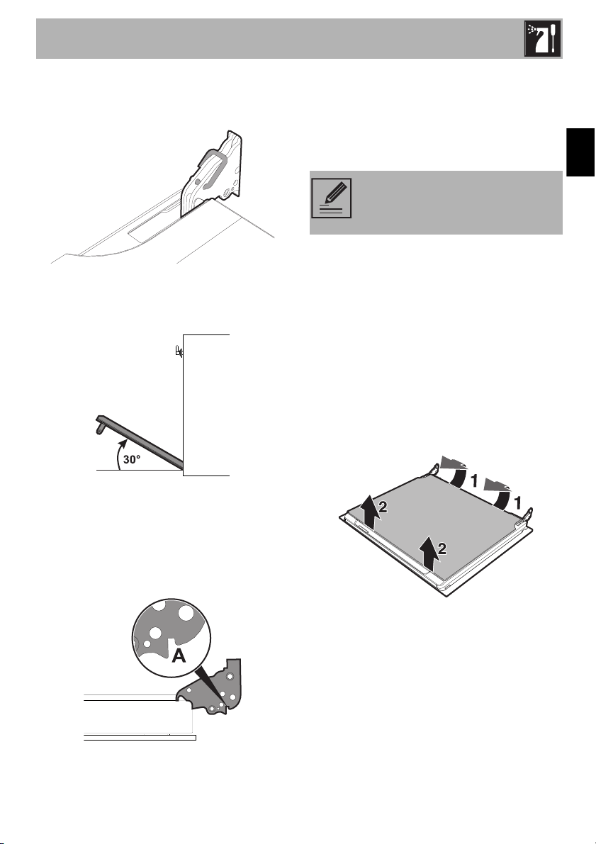
1. Remove the internal glass pane by
pulling the rear part gently upwards,
following the movement indicated by the
arrows (1).
2. Then, pull the front part upwards (2). This
way, the 4 pins attached to the glass
detach from their housings in the oven
door.
We recommend the use of
cleaning products distributed by
the manufacturer.
Cleaning and maintenance
68
3. Some models have an intermediate glass
pane. Remove the intermediate glass
pane by lifting it upwards.
4. Clean the external glazing pane and the
panes removed previously. Use
absorbent kitchen roll. In case of
stubborn dirt, wash with a damp sponge
and neutral detergent.
5. Refit the panes in the reverse order in
which they were removed.
6. Reposition the internal glass pane.
Take care to centre and insert the 4 pins
into their housings in the oven door by
applying slight pressure.
4.4 Cleaning the oven cavity
For the best oven upkeep, clean it regularly
after having allowed it to cool.
Avoid letting food residue dry inside the
oven cavity, as this could damage the
enamel.
Take out all removable parts before
cleaning.
For easier cleaning, we recommend
removing:
•The door;
• The rack/tray support frames;
•The oven seal.
In the event you are using specific
cleaning products, we recommend
running the appliance at maximum
temperature for 15-20 minutes in
order to eliminate any residue.
Cleaning and maintenance
69
EN
Removing racks/trays support frames
Removing the guide frames enables the
sides to be cleaned more easily. This
operation should be performed each time
the automatic cleaning cycle is used
(on some models only).
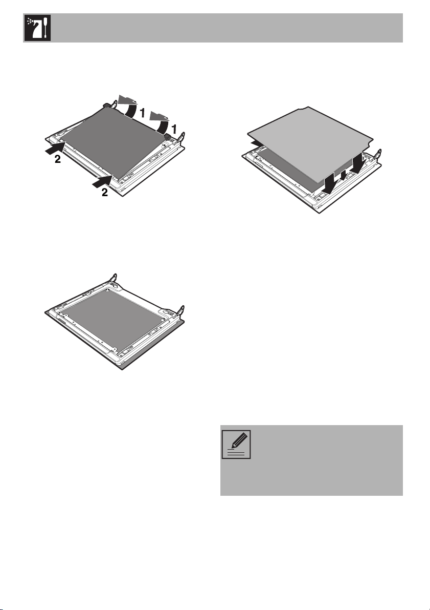
To remove the guide frames, pull the frame
towards the inside of the oven to unhook it
from its groove A, then slide it out of the
seats at the back B.
When cleaning is complete, repeat the
above procedures to put the guide frames
back in.
4.5 Extraordinary maintenance
Removing and installing the oven seal
To remove the oven seal:
• Unhook the clips located in the 4 corners
then pull the oven seal outwards.
To install the oven seal:
• Hook the clips located in the 4 corners
onto the oven seal.
Oven seal maintenance tips
The seal should be soft and elastic.
• To keep the oven seal clean, use a
non-abrasive sponge and wash with
lukewarm water.
Cleaning and maintenance
70
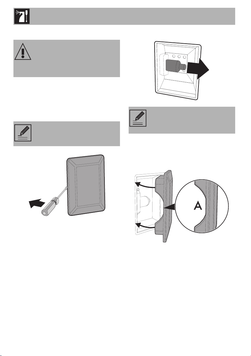
Replacing the internal light bulb
1. Completely remove all accessories from
inside the oven cavity.
2. Remove the rack/tray support frames.
3. Remove the bulb cover using a tool
(e.g. a screwdriver).
4. Slide out and remove the light bulb.
5. Replace the light bulb with one of the
same type (40 W).
6. Refit the cover. Ensure the moulded part
of the glass (A) is facing the door.
7. Press the cover completely down so that
it attaches perfectly to the bulb support.
Live parts
Danger of electrocution
• Unplug the appliance.
Pay attention not to scratch the oven
cavity enamel.
Do not touch the halogen light
bulb directly with your fingers, but
wrap it in insulating material.
Installation
71
EN
5 Installation
5.1 Gas connection
General information
Connection to the gas mains can be
made using a continuous wall steel hose
in compliance with the guidelines
established by the standards in force.
For supplying it with other types of gas,
see chapter “5.2 Adaptation to different
types of gas”. The gas inlet connection is
threaded ½” external gas (ISO 228-1).
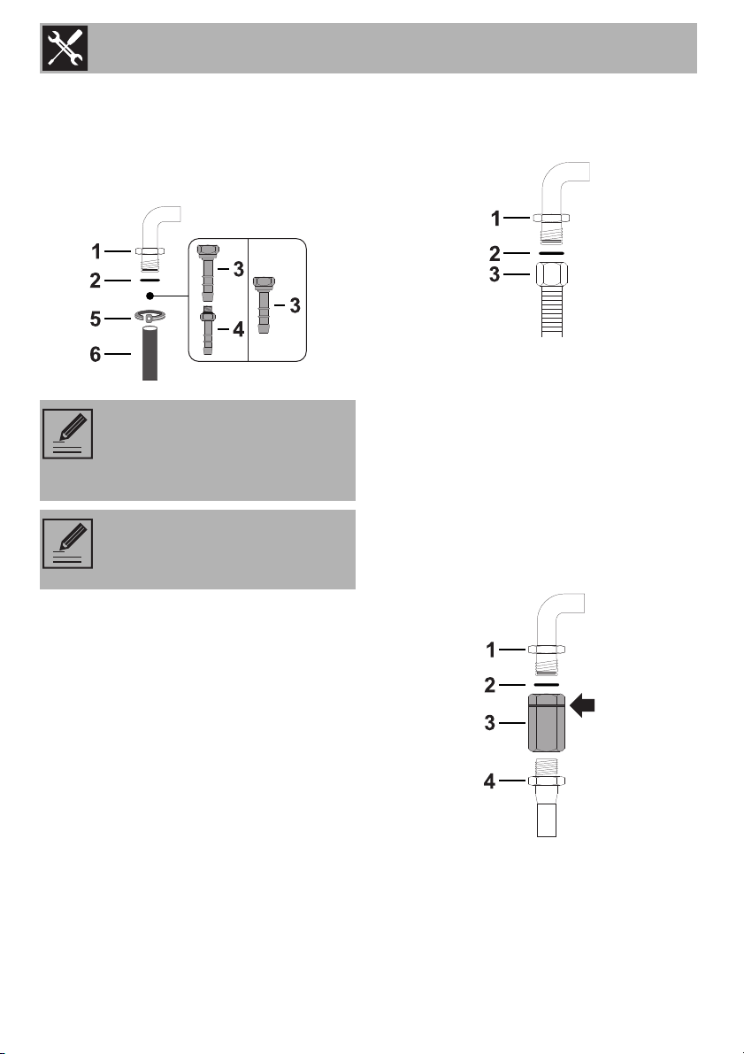
Connection with a rubber hose
Verify that all following conditions are met:
• the hose is fixed to the hose connection
with safety clamps;
• no part of the hose is in contact with hot
walls (max. 50 °C);
• the hose is not under traction or tension
and has no kinks or twists;
• the hose is not in contact with sharp
objects or sharp corners;
• if the hose is not perfectly airtight and
leaks gas, do not try to repair it; replace
it with a new hose.
• verify that the hose is not past its expiry
date (serigraphed on the hose itself).
Make the connection to the gas mains
using a rubber hose whose specifications
comply with current standards (verify that
the reference standard is stamped on the
hose).
Carefully screw the hose connector 3 to the
appliance’s gas connector 1 (½” thread
ISO 228-1), placing the seal 2 between
them. The hose connector 4 can also be
screwed to the hose connector 3,
depending on the diameter of the gas hose
used.
Gas leak
Danger of explosion
• After carrying out any operation, check
that the tightening torque of gas
connections is between 10 Nm and
15 Nm.
• If required, use a pressure regulator that
complies with current regulations.
• At the end of the installation, check for
any leaks with a soapy solution, never
with a flame.
• Installation using a hose must be carried
out so that the length of the hose does
not exceed 2 metres when fully
extended for steel hoses and 1.5 metres
for rubber hoses.
• The hoses should not come into contact
with moving parts and should not be
crushed in any way.
Installation
72
After having tightened the hose
connector(s), push the gas hose 6 onto the
hose connector and secure it with the clamp
5 that is compliant with the standard in
force.
Connection with a steel hose
Make the connection to the gas mains
using a continuous wall steel hose whose
specifications comply with the applicable
standard.
Carefully screw the connector 3 to the gas
connector 1 of the appliance, placing the
seal 2 between them.
Connection with a steel hose with
bayonet fitting
Carry out the connection to the gas mains
using a steel hose with bayonet fitting
compliant with B.S. 669. Apply insulating
material to the thread of the gas hose
connector 4 and then tighten the adapter 3.
Screw the assembly to the movable
connector 1 of the appliance, placing the
supplied seal 2 between them.
Connection using a rubber hose
complying with current standards is
only permitted if the hose can be
inspected along its entire length.
The inside diameter of the hose
must be 8 mm for LPG and 13 mm
for Natural gas and Town gas.
Installation
73
EN
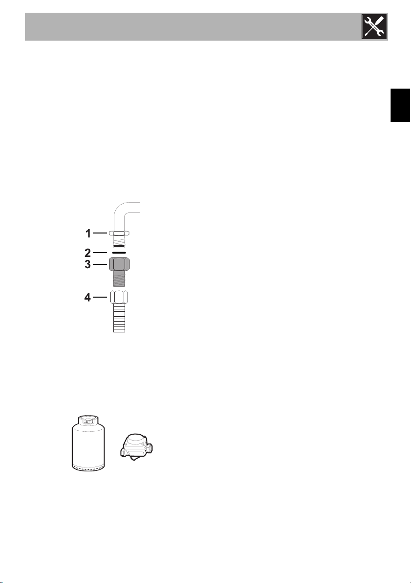
Connection with a steel hose with conical
fitting
Make the connection to the gas mains
using a continuous wall steel hose whose
specifications comply with the applicable
standard.
Carefully screw the hose connector 3 to the
appliance’s gas connector 1 (½” thread
ISO 228-1), placing the supplied seal 2
between them. Apply insulating material to
the thread of connector 3, then tighten the
steel hose 4 to the connector 3.
Connection to LPG
Use a pressure regulator and make the
connection on the gas cylinder following
the guidelines set out in the standards in
force.
The supply pressure must comply with the
values indicated in the table “Burner and
nozzle specifications tables”.
Room ventilation
The appliance should be installed in rooms
that have a permanent air supply in
accordance with the standards in force. The
room where the appliance is installed must
have enough air flow for the regular
combustion of gas and the necessary air
change in the room itself. The air vents,
protected by grilles, must be the right size to
comply with current regulations and
positioned so that no part of them is
obstructed, not even partially.
The room must be kept adequately
ventilated in order to eliminate the heat and
humidity produced by cooking: In
particular, after prolonged use, you are
recommended to open a window or to
increase the speed of any fans.
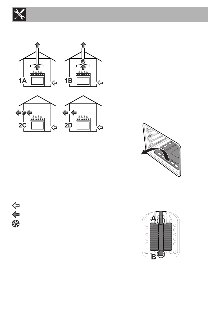
Extraction of the combustion products
The combustion products may be extracted
by means of hoods connected to a natural
draught chimney whose efficiency is certain
or via forced extraction. An efficient
extraction system requires precision
planning by a specialist qualified in this
area and must comply with the positions
and clearances indicated by the applicable
standards.
Installation
74
When the job is complete, the installer must
issue a certificate of conformity.
1 Extraction using a hood
2 Extraction without a hood
A Single natural draught chimney
B Single chimney with extractor fan
C Directly outdoors with wall- or window-
mounted extractor fan
D Directly outdoors through wall
Air
Combustion products
Extractor fan
5.2 Adaptation to different types of
gas
The appliance is preset for natural gas G20
at a pressure of 20 mbar. In case of
operation with other types of gas, the
burner nozzle must be changed and the
gas tap adjusted.
Replacing the nozzle
1. Open the door.
2. Completely remove all accessories from
inside the oven.
3. Lift up the oven surface and pull it
outwards.
4. Loosen the screws A and B.
5. Move away the lock that secures the
thermocouple and igniter to the burner
with screw A.
Installation
75
EN
6. Slide the burner outwards until the nozzle
is accessible.
7. Replace the nozzle using a 7 mm socket
wrench.
Replacing the gas grill nozzle
(on some models only)
1. Open the door.
2. Completely remove all accessories from
inside the oven.
3. Loosen the screw B.
4. Slide the burner outwards until the nozzle
is accessible.
5. Replace the nozzle using a 7 mm socket
wrench.
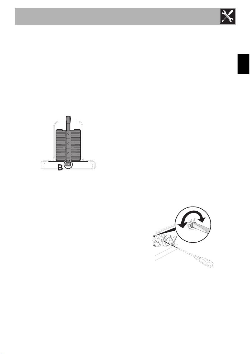
Adjusting the minimum
The oven thermostat is equipped with a
screw for adjusting the minimum. When
changing the type of supplied gas, the
minimum must be adjusted as follows:
1. Disconnect the appliance from the power
supply.
2. Pull the oven slightly out from its seat, take
out the knobs and remove the front panel
by unscrewing the 4 screws (2 top and
2 bottom) that secure it to the rest of the
appliance.
3. Insert the oven thermostat knob and light
the oven burner. Keep it at the maximum
for 10/15 minutes with the door closed.
After this period, move the knob to the
minimum temperature.
4. Slide off the knob and insert a straight
edge screwdriver into the hole to make
the adjustment.
5. If using liquid gas the adjustment screw
must be tightened clockwise to the very
end.
Installation
76
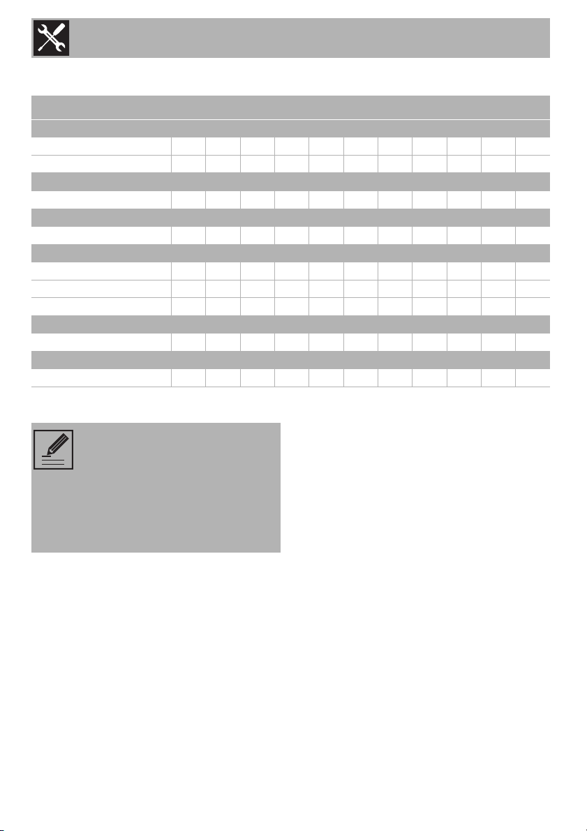
Gas types and Countries
Gas types IT GB-IE FR-BE DE AT NL ES PT SE RU DK
1 Natural gas G20
G20
20 mbar
•• •• •••••
G20/25
20/25 mbar
•
2 Natural gas G25
G25
25 mbar
•
3 Natural gas G25
G25
20 mbar
•
4 LPG G30/31
G30/31
28/37 mbar
•• • •
G30/31
30/37 mbar
••
G30/31
30/30 mbar
•••
5 LPG G30/31
G30/31
50 mbar
••
6 Town gas G110
G110
8 mbar
•••
It is possible to identify the
available gas types based on the
country the appliance is to be
installed in. Refer to the heading
number to identify the correct
values in the “Burner and nozzle
specifications tables”.
Installation
77
EN
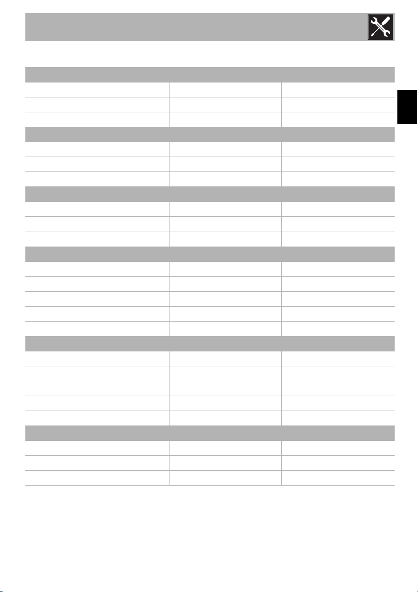
Burner and nozzle specifications tables
1 Natural gas G20 OVEN GRILL
Rated heating capacity (kW)
2.6 2.2
Nozzle diameter (1/100 mm)
120 110
Reduced flow rate (W)
900 -
2 Natural gas G25 OVEN GRILL
Rated heating capacity (kW)
2.6 2.1
Nozzle diameter (1/100 mm)
120 110
Reduced flow rate (W)
900 -
3 Natural gas G25 OVEN GRILL
Rated heating capacity (kW)
2.6 2.3
Nozzle diameter (1/100 mm)
127 127
Reduced flow rate (W)
900 -
4 LPG G30/31 OVEN GRILL
Rated heating capacity (kW)
2.6 2.2
Nozzle diameter (1/100 mm)
76 72
Reduced flow rate (W)
900 -
Capacity G30 (g/h)
189 175
Capacity G31 (g/h)
186 171
5 LPG G30/31 OVEN GRILL
Rated heating capacity (kW)
2.6 2.2
Nozzle diameter (1/100 mm)
68 65
Reduced flow rate (W)
1000 -
Capacity G30 (g/h)
189 175
Capacity G31 (g/h)
186 171
6 Town gas G110 OVEN GRILL
Rated heating capacity (kW)
2.6 2.2
Nozzle diameter (1/100 mm)
230 215
Reduced flow rate (W)
900 -
Installation
78
5.3 Electrical connection
General information
Check the mains characteristics against the
data indicated on the plate.
The identification plate bearing the
technical data, serial number and brand
name is visibly positioned on the appliance.
Do not remove this plate for any reason.
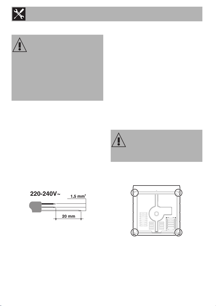
The appliance works at 220-240 V~.
Use a three-pole cable (3 x 1.5 mm
2
internal conductors).
Perform the ground connection using a wire
that is 20 mm longer than the other wires.
Fixed connection
Fit the power line with an all-pole
disconnection switch in compliance with
installation regulations.
The circuit breaker should be located near
the appliance and in an easily reachable
position.
Connection with plug and socket
Make sure that the plug and socket are of
the same type.
Avoid using adapters, gang sockets or
extensions as these could cause
overheating and a risk of burns.
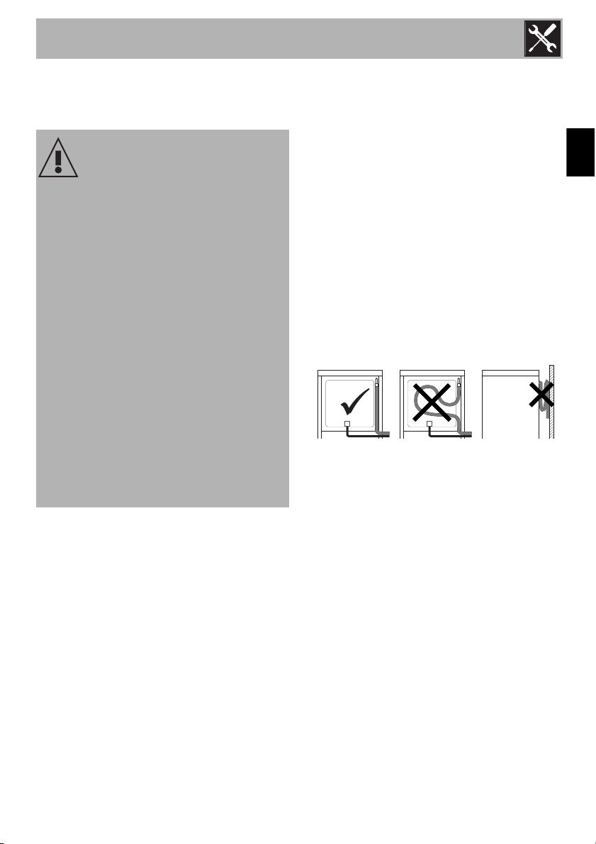
5.4 Cable replacement
1. Unscrew the rear casing screws and
remove the casing to access the terminal
board.
2. Replace the cable.
3. Make sure that the cables (for the oven
or any hob) follow the best route in order
to avoid any contact with the appliance.
Power voltage
Danger of electrocution
• Have the electrical connection
performed by authorised technicians.
• The appliance must be connected to
ground in compliance with electrical
system safety standards.
• Disconnect the mains power supply.
Power voltage
Danger of electrocution
• Disconnect the mains power supply.
Installation
79
EN
5.5 Positioning
Position of the power cable
(rear view)
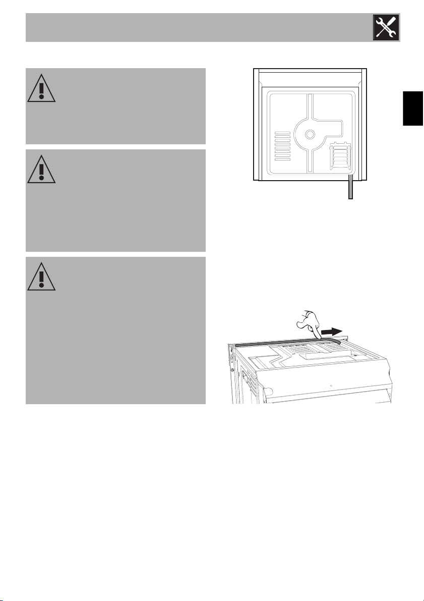
Front panel seal
Glue the supplied seal to the rear part of
the front panel to avoid water or other
liquids from leaking in.
Heavy appliance
Crushing hazard
• Position the appliance into the cabinet
cut-out with the help of a second person.
Pressure on the open door
Risk of damage to the appliance
• Never use the oven door to lever the
appliance into place when fitting.
• Avoid exerting too much pressure on the
door when open.
Heat production during appliance
operation
Risk of fire
• Check that the carcase material is heat
resistant.
• Check that the carcase has the required
slots.
• Do not install the appliance in a recess
which can be closed with a door, or in a
cupboard.

Installation
80
Fastening bushings
1. Remove the bushing covers inserted on
the front of the appliance.
2. Mount the appliance into the recess.
3. Secure the appliance to the piece of
furniture using screws.
4. Cover the bushings with the previously
removed covers.
Appliance overall dimensions (mm)
Installation
81
EN
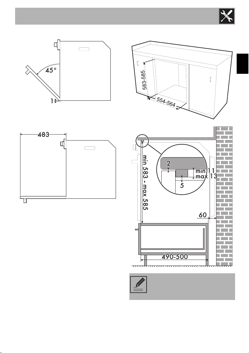
Mounting under worktops (mm)
Make sure that the carcase rear/
bottom section has an opening of
approx. 60 mm.
Installation
82
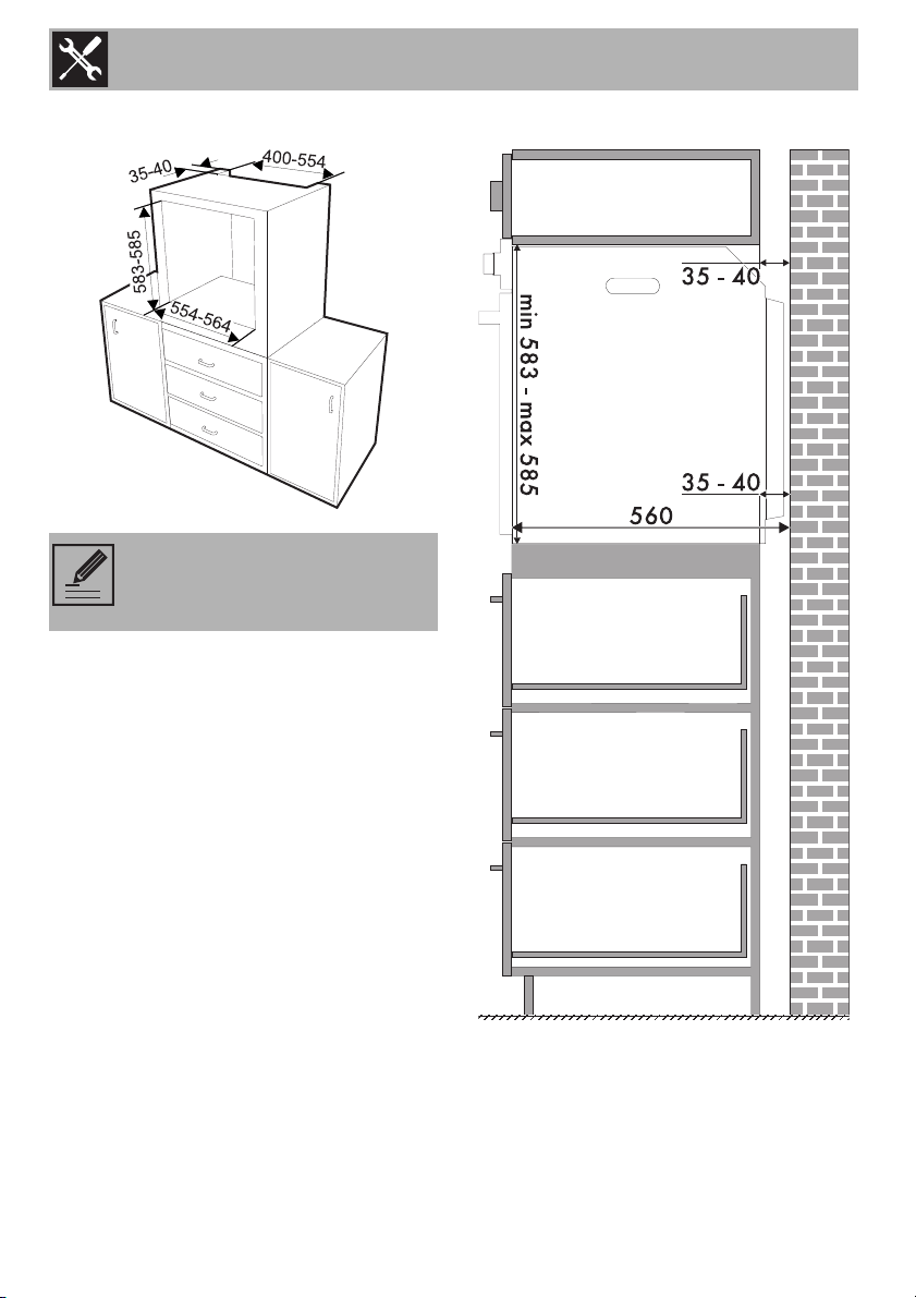
Mounting into a column (mm)
Make sure that the piece of
furniture top/rear part has an
opening approx. 35-40 mm deep.