Incandescent / Halogen, or lighting supplied by Electronic Low-Voltage Transformer (such as incandescent, halogen, or LED)
Important Notes. Please read before installing.
CAUTION: To reduce the risk of overheating and possible damage to other equipment, DO NOT use to control receptacles, fluorescent lighting fixtures, compact fluorescent lamps, motor operated or transformer supplied appliances. Use only to control the primary side of transformer-supplied low-voltage lighting, or in combination with incandescent lamps.
Install in accordance with all national and local electrical codes.
When no “grounding means” exist within the wallbox, the NECR 2011, Article 404.9 allows a dimmer without a grounding connection to be installed as a replacement, as long as a plastic, noncombustible wallplate is used. For this type of installation, twist a wire connector onto the green ground wire or remove the green ground wire on the dimmer and use an appropriate wallplate such as ClaroR or Satin ColorsR series wallplates by Lutron.
This product requires a neutral wire in the wallbox. If a neutral wire is not present, contact a licensed electrician for installation.
Do not paint the dimmers or the companion dimmers.
This dimmer is not compatible with standard 3-way or 4-way switches. Use only with LutronR companion dimmers listed above.
In any 3-way/4-way circuit use only one dimmer with up to 9 companion dimmers.
Do not use where the total load is greater than the rating indicated in the Derating Chart below.
Do not use where total load is less than 5 W / VA.
Operate between 32 °F (0 °C) and 104 °F (40 °C).
For indoor use only.
It is normal for the dimmers to feel warm to the touch during operation.
Recommended minimum wallbox depth is 2` in (64 mm).
Maximum wire length between the dimmers and the farthest companion dimmer is 250 ft (76 m).
Clean with a soft damp cloth only. Do not use any chemical cleaners.
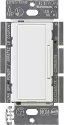
Controls must be mounted vertically. See stamp on control for correct positioning.
DO NOT wire while circuit breaker is on. Permanent damage to the dimmer may result.
In multi-phase applications, it is recommended to use a separate neutral for each phase containing a dimmed circuit.
For new installations, wire a test switch before installing the dimmer.
Multigang Installations
When installing more than one control in the same wallbox, the maximum load capacity is reduced. No derating is required for companion dimmers. Refer to the Derating Chart below.
Derating Chart
Dimmer Operation
Troubleshooting
Symptoms
Cause and Action
Load is OFF and there is no indicator on the dimmer
Power Not Present
• Circuit breaker OFF or tripped. Perform short circuit check.
• FASST is in the OFF position. Move FASST to the ON position by pushing it in.
Wiring Error
• Check wiring to be sure it matches installation instructions and wiring diagrams.
Lamps Burned Out or Not Installed
• Replace or install lamps.
Dimmer indicator is ON but load cannot be turned ON and/or cannot be turned OFF
Wiring Error
• Check wiring to be sure it matches installation instructions and wiring diagrams.
Lamps Burned Out or Not Installed
• Replace or install lamps.
Light turns ON and OFF continuously
Load is Less Than Minimum Load Requirement
• Make sure the connected load meets the minimum load requirement for that control. See Important Note #9.
Improper Load Type
• Check that the load being dimmed is dimmable.
Faceplate is warm
Solid-State Control Heat Dissipation
• Solid-state dimmers internally dissipate about 2% of the total connected load. It is normal for dimmers to feel warm to the touch during operation.
Middle LED flashes twice then OFF, repeat
Over Temperature Condition
• Ensure that the room temperature and maximum load rating are not exceeded.
• Power cycle unit with FASST switch to clear.
All LEDs flashing rapidly
Over Current Protection Mode
• Verify that no bulbs are blown out and/or the product is wired properly.
• Power cycle unit with FASST switch to clear.
Bottom 3 LEDs light on any button press
Load Protect Mode
• Power cycle unit using the FASST switch. If unit goes into same condition after reset, replace device.
Middle LED flashing rapidly
Noisy Power Line / Changing Frequency
• Correct line frequency or noisy problem to within device specification range. Clears automatically when condition is corrected.
Installation
1. Turning Power OFF
Turn power OFF at circuit breaker (or remove fuse).
2. Removing Wallplate and Switch
Remove the wallplate and switch mounting screws.
Carefully remove the switch from the wall (do not remove the wires).
3. Identifying the Circuit Type and Tagging the Wire on the COMMON Terminal of the Switches
3a - Single Location Control
One switch controlling a light fixture:
The switch will have insulated wires connected to two screws of the same color plus a green ground screw.
3b - Two-Location Control
Two switches controlling a light fixture:
Both switches will be 3-way. Each switch will have insulated wires connected to three screws plus a green ground screw. One of these wires is connected to a screw of a different color (not green) or labeled COMMON. Tag this wire on both switches to identify when rewiring.
3c - Three or More-Location Control
Three or more switches controlling a light fixture:
Two switches will be 3-way and any others will be 4-way. Tag the two 3-way switches as in the Two-Location diagram above. The 4-way switch will have insulated wires connected to four screws plus a green ground screw. Tag the two same-color insulated wires that are connected to opposite colored screws. Follow this procedure for each 4-way switch.
4. Disconnecting the Switch Wires
Important Note: The wall switch may have two wires attached to the same screw (see illustrations below for examples). Tape these two wires together before disconnecting. When rewiring, connect wires to the dimmer the same way they were connected to the switch.
One wire in the backwired hole and one to the screw.
When making wire connections, follow the recommended strip lengths and combinations for the supplied wire connector.
Note: All wire connectors provided are suitable for copper wire only. For aluminum wire, consult an electrician.
Trim or strip wallbox wires to the length indicated by the strip gauge on the back of the dimmer.
Wire connector: Use to join 14 AWG (1.5 mm2 ) or 12 AWG (2.5 mm2 ) ground wire to 18 AWG (0.75 mm2 ) dimmer ground wire.
Push-in terminals: Insert wires fully.
Note: Push-in terminals are for use with 14 AWG (1.5 mm2 ) solid copper wire only. DO NOT use stranded or twisted wire.
Screw terminals: Tighten securely.
Note: Screw terminals are for use with 12 AWG (2.5 mm2 ) or 14 AWG (1.5 mm2 ) solid copper wire only. DO NOT use stranded or twisted wire.
For installations involving more than one control in a wallbox, refer to Multigang Installations before beginning.
Use the screw or push-in terminals when making connections on the dimmer or companion dimmer.
Wire all controls before mounting.
5a - Single-Location Control
Wiring the Dimmer:
Connect the green ground wire on the dimmer to the bare copper or green ground wire in the wallbox. See Important Note 3 on other side.
Connect the neutral wire in the wallbox to the silver screw terminal on the dimmer (use LutronR supplied white wire).
Connect either of the remaining wires removed from the switch to the black screw terminal on the dimmer.
Connect the remaining wire removed from the switch to the brass screw terminal on the dimmer.
Tighten the blue screw terminal on the dimmer. It is not used in a single-pole circuit.
Note: If the wires connected to the Black and Brass screws are reversed, the unit will not operate. It may be necessary to swap the connections to ensure that the Brass screw is connected to the load.
5b - Two-Location Control
Note: The dimmer must be installed on the load side of multi-location wiring.
Wiring the Dimmer on the Load Side:
Connect the green ground wire on the dimmer to the bare copper or green ground wire in the wallbox. See Important Note 3 on other side
Connect the neutral wire in the wallbox to the silver screw terminal on the dimmer (use LutronR supplied white wire).
Connect the tagged wire removed from the switch in step 3b to the brass screw terminal on the dimmer.
Connect one of the remaining wires removed from the switch to the black screw terminal on the dimmer.
Connect the remaining wire removed from the switch (note wire color) to the blue screw terminal on the dimmer.
Wiring the Companion Dimmer (MA-R) on the Line Side:
Connect the green ground wire on the companion dimmer to the bare copper or green ground wire in the wallbox. See Important Note 3 on other side.
Connect the wire tagged in step 3b to the black screw terminal on the dimmer or companion dimmer.
Connect the same color wire connected to the blue screw terminal on the dimmer (wire color noted above) to the blue screw terminal on the companion dimmer.
Connect the remaining wire removed from the switch to the brass screw terminal on the companion dimmer.
5c - Three or more-Location Control
One location will be replaced with a dimmer and the others with companion dimmers. Only one dimmer can be used with up to nine companion dimmers.
Replace the 4-way switch(es):
Note: 4-way switches must be replaced with companion dimmers.
Connect the green ground wire on the companion dimmer to the bare copper or green ground wire in the wallbox. (See Important Note 3 on other side.)
Connect both of the wires tagged in step 3c wires (noting their color) to the blue screw terminal on the companion dimmer (one wire to the screw and the other to the push-in terminal).
Connect one of the remaining wires removed from the switch to the black screw terminal on the companion dimmer.
Connect the remaining wire removed from the switch to the brass screw terminal on the companion dimmer.
Wiring the Companion Dimmer (MA-R) on the Line Side:
Connect the green ground wire on the companion dimmer to the bare copper or green ground wire in the wallbox. (See Important Note 3 on other side.)
Connect the wire tagged in step 3b to the black screw terminal on the dimmer or companion dimmer.
Connect the same color wire connected to the blue screw terminal on the dimmer (wire color noted above) to the blue screw terminal on the companion dimmer.
Connect the remaining wire removed from the switch to the brass screw terminal on the companion dimmer.
Wiring the Dimmer on the Load Side:
Connect the green ground wire on the dimmer to the bare copper or green ground wire in the wallbox. (See Important Note 3 on other side.)
Connect the neutral wire in the wallbox to the silver screw terminal on the dimmer (use LutronR supplied white wire).
Connect the wire tagged in step 3b to the brass screw terminal on the dimmer.
Connect the same color wire connected to the blue screw terminal on the dimmer that replaced a 4-way switch (wire color noted above) to the blue screw terminal on the dimmer.
Connect the remaining wire removed from the switch to the black screw terminal on the dimmer.
6. Mounting Dimmers to Wallbox
Form wires carefully into the wallbox, mount and align electronic dimmer (and companion dimmers). Attach ClaroR or Satin ColorsR Wallplate(s) (sold separately).
7. Turning Power ON
Turn power ON at circuit breaker (or replace fuse).