Loading ...
Loading ...
Loading ...
8
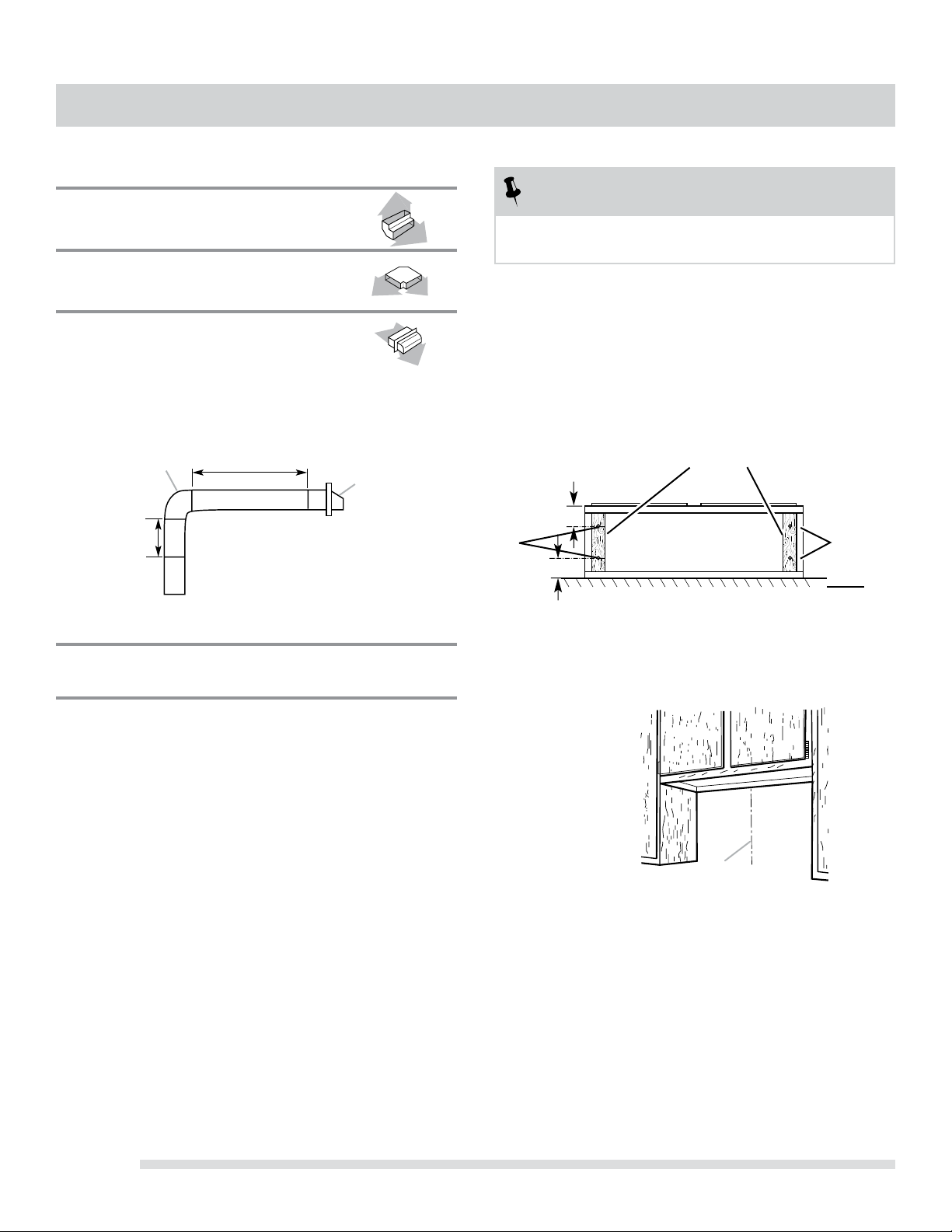
PREPARE THE LOCATION
NOTE
Before making cutouts, make sure there is
proper clearance within the ceiling or wall.
Disconnect power.
Select a at surface for assembling the range hood.
Place covering over that surface.
Lift the range hood and set it upside down onto covered
surface.
If cabinet has recessed bottom, add wood ller strips
on each side. Install screws to attach ller strips in
locations shown.
Determine Wiring Hole Location
Determine and clearly mark a vertical centerline on
the wall and cabinet bottom.
1.
2.
3.
4.
1.
A
A Centerline
VENTING REQUIREMENTS
3¼” x 10” (8.3 cm x 25.4 cm) Vent System
Vent Piece
3¼” x 10” (8.3 cm x 25.4 cm) 5.0 ft
90° elbow (1.5 m)
3¼” x 10” (8.3 cm x 25.4 cm) 12.0 ft
flat elbow (3.7 m)
3¼” x 10” (8.3 cm x 25.4 cm) 0.0 ft
wall cap (0.0 m)
Example Vent System
Maximum Recommended Length = 35 ft (10.7 m)
1 - 90° elbow = 5.0 ft (1.5 m)
8 ft (2.4 m) straight = 8.0 ft (2.4 m)
1 - wall cap = 0.0 ft (0.0 m)
Length of 3¼” x 10” = 13.0 ft (3.9 m)
(8.3 cm x 25.4 cm) system
2 ft
(0.6 m)
3¼” x 10”
(8.3 x 25.4 cm)
elbow
6 ft (1.8 m)
Wall Cap
Wood filler strips
(recessed cabinet
bottoms only)
Wall
Cabinet
bottom
3” (7.6 cm)
3” (7.6 cm)
A. 4 flat head wood screws with
washers and nuts
AA
Loading ...
Loading ...
Loading ...