MULTIMEDIA PROJECTOR
User’s Manual

2
Trademarks
• DLP is a registered trademark of Texas Instruments. BrilliantColor and DynamicBlack are trademarks of Texas
Instruments.
• HDMI, the HDMI logo and High-Definition Multimedia Interface are the trademarks or registered trademarks of
HDMI Licensing, LLC.
• Trademark PJLink is a trademark applied for trademark rights in Japan, the United States of America and other
coun-tries and areas.
• NVIDIA, the NVIDIA logo, and 3D VISION are registered trademarks and/or trademarks of NVIDIA Corporation
in the United States and other countries.
• Each name of corporations or products in this book is either a registered trademark or a trademark of its
respective corporation.

3
Features and Design
This Multimedia Projector is designed with the most advanced technology for portability, durability, and ease of use.
Note:
• The On-Screen Menu and figures in this manual may differ slightly from the product.
• The contents of this manual are subject to change without notice.
Large Screen in Limited Space
Short focus lens allows you to project large images
from short distance. (p.17)
3D Display Function
This projector is capable of displaying 3D video with
the Frame Sequential Format*, and you can view the
dynamic 3D contents by wearing 3D glasses (pp.31,
50-51, 54).
* The compatible 3D image signal is only Frame
Sequential format. The Frame Packing and Side-by-
side formats are not supported. Active Shutter format 3D
glasses are required to view projected images in 3D. (DLP
Link and IR formats are compatible.)
Compact Design
This projector is designed compact in size and
weight, and it can be installed overhead without
interfering with the view, or can be installed on the
floor without much space.
Multilanguage Menu Display
The Operation menu is available in 24 languages:
English, German, French, Italian, Spanish,
Portuguese, Dutch, Swedish, Finnish, Norwegian,
Danish, Polish, Hungarian, Romanian, Russian,
Brazilian Portuguese, Turkish, Arabic, Kazakh,
Simplified Chinese, Traditional Chinese, Korean,
Japanese and Thai. (p.52)
Helpful Maintenance Functions
Lamp and filter maintenance functions provide for
better and proper maintenance of the projector.
Direct Power Off Function
With the Direct Power Off function, you can
disconnect the power cord from the wall outlet or turn
off the breaker even during projection (p.24).
Auto Setup Function
This function enables Auto input and Auto PC
adjustment by simply pressing the AUTO SET button
(pp.28, 53).
Switchable Interface Terminal
The projector provides a switchable interface
terminal. You can use the terminal as computer input
or monitor output conveniently. (p.58)
Digital Zoom (for Computer)
The digital zoom function allows you to focus on
crucial information during a presentation. You can
expand the images approx. 16 times the screen
size and compress them to approximately a
quarter of the screen size. (p.41)
Colorboard Function
At the time of simple projection on colored wall
or school blackboard (The board color is limited
to green.), you can get the close color image to
the color image projected on a white screen by
selecting the similar color to the wall color from the
preset colors. (pp.42, 49)
Power Management Mode
The Power management mode function reduces
power consumption and maintains lamp life. (p.59)
Security Features
The Security function helps you to ensure security
of the projector. With the Key lock function, you
can lock the operation on the top control or remote
controller (p.61). PIN code lock function prevents
unauthorized use of the projector (pp.23, 61–62).
Logo Function
The Logo function allows you to customize the
screen logo. The Logo page identifies the owner of
the projector. (pp.55-57)
Simple Computer System Setting
The projector has a Multi-scan system to conform
to almost all computer output signals quickly.
(p.34)
Closed caption
Closed Caption is a function that displays the
audio portion of a TV program as text on the
screen. The closed captioning service is available
mainly in the U.S. You can turn on the feature and
switch the channels. (p.60)
LAN Network Function
This projector is loaded with the Wired function.
You can manage the projector via network. For
details, refer to the user's manual “Network Set-up
and Operation.”

4
Table of Contents
Features and Design ...................3
Table of Contents ......................4
To the Owner..........................5
Safety Instructions .....................6
Air Circulation 9
Filter Maintenance 9
Moving the Projector 9
Installing the Projector in Proper Position 10
Compliance ..........................11
Part Names and Functions .............12
Front 12
Rear 12
Side Terminal 13
Top Controls and Indicators 14
Remote Controller 15
Remote Controller Battery Installation 16
Remote Controller Operating Range 16
Remote Control Code 16
Installation...........................17
Positioning the Projector 17
Adjustable Feet 17
Connecting to a Computer 18
Connecting to Video Equipment 19
Connecting to Component Video Equipment 20
Connecting the AC Power Cord 21
Basic Operation ......................22
Turning On the Projector 22
Turning Off the Projector 24
How to Operate the On-Screen Menu 25
Main Menu 26
Zoom and Image Position Adjustment 27
Focus Adjustment 27
Auto Setup Function 28
Keystone Correction 28
Sound Adjustment 29
Remote Controller Operation 30
Computer Input ......................32
Input Source Selection
(COMPUTER 1: ANALOG PC) 32
Input Source Selection
(COMPUTER 2: ANALOG PC) 33
Computer System Selection 34
Auto PC adjustment 35
Manual PC adjustment 36
Image Mode Selection 38
Image Adjustment 39
Screen Size Adjustment 40
Video Input ..........................43
Input Source Selection (VIDEO, S-VIDEO) 43
Input Source Selection
(COMPONENT, SCART, HDMI) 44
Image Mode Selection 45
Image Adjustment 46
Screen Size Adjustment 48
3D Display ...........................50
For Viewing 3D Contents 50
Setting ..............................52
Setting 52
Information ..........................65
Input Source Information Display 65
Maintenance and Cleaning .............66
WARNING TEMP. indicator 66
Replacing the Filter 67
Resetting the Filter Counter 67
Cleaning the Projection Window 68
Cleaning the Projector Cabinet 68
Lamp Replacement 69
Resetting the Lamp Counter 70
Appendix ...........................71
Troubleshooting 71
Menu Tree 74
Indicators and Projector Condition 76
Compatible Computer Specifications 77
Technical Specifications 79
Optional Parts 80
PJ Link Notice 80
Configurations of Terminals 81
PIN Code Number Memo 82
Dimensions 83
5
To the Owner
CAUTION:
TO REDUCE THE RISK OF ELECTRIC
SHOCK, DO NOT REMOVE COVER (OR
BACK). NO USER-SERVICEABLE PARTS
INSIDE EXCEPT LAMP REPLACEMENT.
REFER SERVICING TO QUALIFIED
SERVICE PERSONNEL.
THIS SYMBOL INDICATES
THAT DANGEROUS VOLTAGE
CONSTITUTING A RISK OF ELECTRIC
SHOCK IS PRESENT WITHIN THIS
UNIT.
THIS SYMBOL INDICATES THAT
THERE ARE IMPORTANT OPERATING
AND MAINTENANCE INSTRUCTIONS
IN THE USER'S MANUAL WITH THIS
UNIT.
CAUTION
RISK OF ELECTRIC SHOCK
DO NOT OPEN
Before installing and operating this projector, read
this manual thoroughly.
This projector provides many convenient features
and functions.
Operating the projector properly enables you to
manage those features and maintains it in good
condition for many years to come. Improper
operation may result in not only shortening the
product-life, but also malfunctions, fire hazard, or
other accidents.
If your projector seems to operate improperly,
read this manual again, check operations and
cable connections and try the solutions in the
“Troubleshooting” section on pages 71-73 of this
manual. If the problem still persists, contact the
dealer where you purchased the projector or the
service center.
Safety Precaution
DO NOT SET THE PROJECTOR IN GREASY,
WET, OR SMOKY CONDITIONS SUCH AS IN A
KITCHEN TO PREVENT A BREAKDOWN OR
A DISASTER. IF THE PROJECTOR COMES IN
CONTACT WITH OIL OR CHEMICALS, IT MAY
BECOME DETERIORATED.
READ AND KEEP THIS USER'S MANUAL FOR
LATER USE.
WARNING:
THIS APPARATUS MUST BE EARTHED.
TO REDUCE THE RISK OF FIRE OR
ELECTRIC SHOCK, DO NOT EXPOSE
THIS APPLIANCE TO RAIN OR MOISTURE.
– This projector produces intense light from the
projection lens. Do not stare directly into the
lens, otherwise eye damage could result. Be
especially careful that children do not stare
directly into the beam.
– Install the projector in a proper position.
Improper positioning may reduce the lamp life
and result in severe accident or fire hazard.
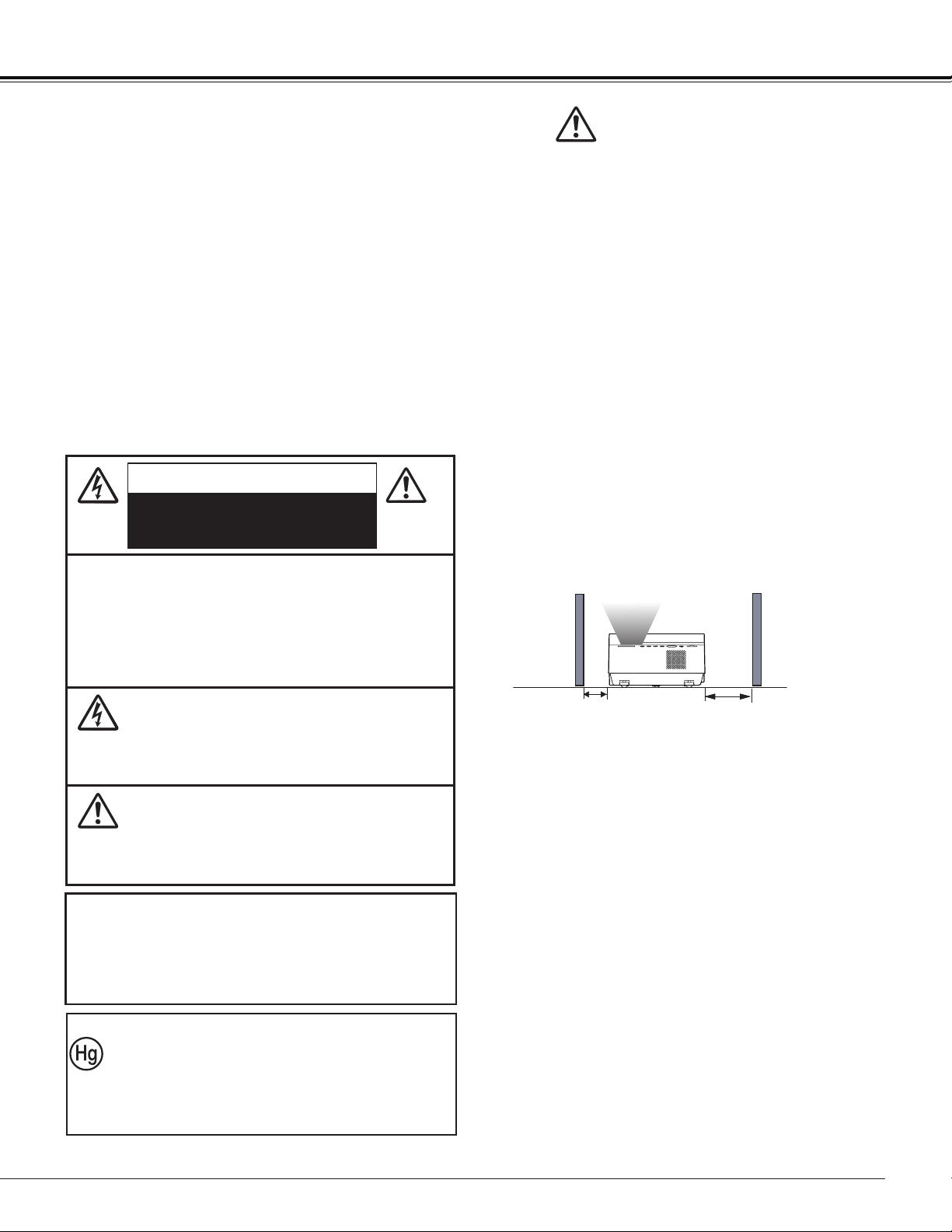
– Allowing the proper amount of space on the
top, sides, and rear of the projector cabinet is
critical for proper air circulation and cooling of
the unit. The dimension shown here indicate the
minimum space required.
If the projector is to be built into a compartment
or similarly enclosed, these minimum distances
must be maintained.
– Do not cover the ventilation slot on the projector.
Heat build-up can reduce the service life of your
projector, and can also be dangerous.
– If the projector is unused for an extended time,
unplug the projector from the power outlet.
CAUTION
Not for use in a computer room as defined in
the Standard for the Protection of Electronic
Computer/Data Processing Equipment, ANSI/
NFPA 75.
1.5' (50 cm)
3' (1 m)
NOTE FOR CUSTOMERS IN THE US
LAMP(S) INSIDE THIS PRODUCT CONTAIN
MERCURY AND MUST BE RECYCLED OR
DISPOSED OF ACCORDING TO LOCAL, STATE
OR FEDERAL LAWS.

6
Safety Instructions
All the safety and operating instructions should be
read before the product is operated.
Read all of the instructions given here and retain them
for later use. Unplug this projector from AC power
supply before cleaning. Do not use liquid or aerosol
cleaners. Use a damp cloth for cleaning.
Follow all warnings and instructions marked on the
projector.
For added protection to the projector during a
lightning storm, or when it is left unattended and
unused for long periods of time, unplug it from the wall
outlet. This will prevent damage due to lightning and
power line surges.
Do not expose this unit to rain or use near water for
example, in a wet basement, near a swimming pool,
etc..
Do not use attachments not recommended by the
manufacturer as they may cause hazards.
Do not place this projector on an unstable cart, stand,
or table. The projector may fall, causing serious
injury to a child or adult, and serious damage to the
projector. Use only with a cart or stand recommended
by the manufacturer, or sold with the projector. Wall
or shelf mounting should follow the manufacturer’s
instructions, and should use a mounting kit approved
by the manufacturers.
An appliance and cart combination
should be moved with care. Quick
stops, excessive force, and uneven
surfaces may cause the appliance
and cart combination to overturn.
Slots and openings in the back and bottom of the
cabinet are provided for ventilation, to ensure reliable
operation of the equipment and to protect it from
overheating.
The openings should never be covered with cloth or
other materials, and the bottom opening should not be
blocked by placing the projector on a bed, sofa, rug,
or other similar surface. This projector should never
be placed near or over a radiator or heat register.
This projector should not be placed in a built-
in installation such as a book case unless proper
ventilation is provided.
Never push objects of any kind into this projector through
cabinet slots as they may touch dangerous voltage points
or short out parts that could result in a fire or electric
shock. Never spill liquid of any kind on the projector.
Do not install the projector near the ventilation duct of air-
conditioning equipment.
This projector should be operated only from the type of
power source indicated on the marking label. If you are not
sure of the type of power supplied, consult your authorized
dealer or local power company.
Do not overload wall outlets and extension cords as this
can result in fire or electric shock. Do not allow anything to
rest on the power cord. Do not locate this projector where
the cord may be damaged by persons walking on it.
Do not attempt to service this projector yourself as
opening or removing Covers may expose you to
dangerous voltage or other hazards. Refer all servicing to
qualified service personnel.
Unplug this projector from wall outlet and refer servicing to
qualified service personnel under the following conditions:
a. When the power cord or plug is damaged or frayed.
b. If liquid has been spilled into the projector.
c. If the projector has been exposed to rain or
water.
d. If the projector does not operate normally by following
the operating instructions. Adjust only those controls
that are covered by the operating instructions as
improper adjustment of other controls may result in
damage and will often require extensive work by a
qualified technician to restore the projector to normal
operation.
e. If the projector has been dropped or the cabinet has
been damaged.
f. When the projector exhibits a distinct change
in performance-this indicates a need for service.
When replacement parts are required, be sure the service
technician has used replacement parts specified by the
manufacturer that have the same characteristics as the
original part. Unauthorized substitutions may result in fire,
electric shock, or injury to persons.
Upon completion of any service or repairs to this projector,
ask the service technician to perform routine safety
checks to determine that the projector is in safe operating
condition.
7
Immediately turn the power off, unplug the projector,
and contact your dealer under the following conditions,
otherwise a fire or an electric shock may result.
– If smoke comes out from it.
– If it emits a strange odor, or makes a strange
noise.
– If lamp goes out with a loud bang.
– If water or any other liquid gets into it.
– If metal or foreign objects get inside it.
– If it is knocked down or dropped and the cabinet is
broken.
WARNING
Follow the instructions below when using the power
cable, otherwise a fire, an electric shock, or injury may
result.
– Do not place heavy objects on the power cord or
position the power cord under the projector. Doing so
may damage the power cord.
– Do not run the power cord under a carpet. As it goes
unnoticed, excessive load may be applied on the cord
unintentionally.
– Do not modify, bend forcibly, twist, or pull the power
cord.
– Do not place the power cord near heat generating
equipment or heat it.
– Do not bend, wind, or bind excessively the power cord
when using it.
– Be sure to connect the projector to a grounded outlet.
Failure to do so may result in an electric shock.
– Do not continue to use a damaged power cord. If the
power cord is damaged, take it to your dealer and
have it replace.
– Use only the supplied power cord.
Follow the instructions below when handling the power
plug or connector, otherwise a fire, an electric shock, or
injury may result.
– Use the projector within the voltage range specified on
the projector (AC 100 V– 240 V).
– Insert the power plug or connector into the power
outlet firmly. Do not use a damaged or loosen power
plug or connector.
– Be sure to hold the power cord plug or connector
when disconnecting it from the power outlet. If the
power cord itself is pulled, it may be damaged.
– Do not plug or unplug the power cord with wet hands.
– Disconnect the power cord from the power outlet
before cleaning the projector.
– Do not stick metal objects into the electrical contacts
of the power plug or connector.
Follow the instructions below to install or handle the
projector. Otherwise, a fire, an electric shock, or injury
may result.
– Do not touch the projector, power cord, or cables when
lighting begins.
– Do not use the projector in a bathroom or shower
room.
– Do not expose the projector to rain, snow, or use near
water.
– Do not insert metal objects into the projector through
the air vents.
– Do not place the containers with water on the
projector.
– Do not install in the locations exposed to oily vapors or
smoke (e.g., near a cooking table or humidifier).
– Before moving the projector, turn the power off and
disconnect the power cord and all cables.
– Do not put spray cans in front of the exhaust vent.
When spray cans are exposed to heat, the pressure in
them will increase and explode.
– Do not open nor remove the cabinet. There are high
voltage components inside the projector. Contact your
dealer for inspection, adjustment, and service.
– Do not attempt to disassemble the projector (including
expendable parts) or remote controller.
– Do not look into the lens while the projector is used.
Strong light may hurt your eyes. Be especially careful
that small children do not look into the lens.
– When an extension cord is necessary, be sure that the
total current load of all equipment connected to the
extension cord does not exceed the specified rating of
the extension cord.
– Periodically unplug the power cord and remove the
dust that builds up on the power cord or connector.
Follow the instructions below when handling the
batteries. Failure to do so may cause explosion, heat
generation, a fire, or leakage of the battery fluid.
– Do not heat or disassemble the batteries, or throw
them into fire.
– Do not attempt to recharge the batteries.
Follow the instructions below when the lamp is replaced
or breaks.
– Always unplug the power cord before replacing the
lamp.
– When the lamp breaks, shards of glass may scatter in
the lamp housing. Contact your dealer for cleaning or
inspecting the projector, or replacing the lamp.
WARNING
WARNING
WARNING
WARNING
WARNING
Safety Instructions

8
– Remove the batteries when they have been
exhausted or not in use for an extended period of
time.
– Be sure to replace both batteries at the same time.
Do not mix batteries of different types.
– Insert batteries correctly according to the “+” and “-“
markings.
– If a fluid from a battery leaks and comes in contact
with your skin, rinse the affected skin thoroughly as
soon as possible.
– Do not place heavy objects or step on the projector.
Be especially careful that small children do not step
on the projector. If not, the projector may drop or
break, causing injury.
– Disconnect the power cord from the power outlet if
the projector is left unused for a long period of time.
Failure to do so may result in a fire.
– Do not bring your hands to the peripheral part of the
exhaust vent on the cabinet. This area becomes hot
during use. Be especially careful that small children
do not touch the area. Failure to do so may result in
burn.
– Do not put metal objects in front of or near the
exhaust vent. They will become hot while projector
is being used.
– Do not place the projector on top of unstable or
slanted surfaces. The projector may fall down and
cause injury.
– Do not attach the lens cover while the projector is
being used or place any objects in front of the lens.
Failure to do so may result in a fire.
– A buildup of dust inside the projector can cause a
fire or damage. Consult your dealer for cleaning.
– When installing the projector to a ceiling, consult
your electrician or dealer. If the projector is not fixed
securely, accidents may result.
– Never take out the lamp soon after the projector
is used. Let the projector cool for at least 1 hour
before taking out the lamp, as burns may result.
– If the lamp replacement icon appears or the LAMP
REPLACE indicator lights orange, immediately
replace the lamp with a new one. Otherwise, the
lamp may burst.
– If the lamp burns out, the gas or dust (containing
mercury) inside the lamp may escape from the air
vents. Immediately open the windows and ventilate
the room. If you inhale the gas or the gas gets into
your eyes or mouth, see a doctor at once.
– Dispose of a lamp containing mercury in the same
manner as fluorescent lamps according to local
regulations.
– This projector is a precision machine. Do not subject
the projector to strong shocks or vibrations or knock
it down. Remove the lens, close the lens mounting
hole with the front cover, and retract the adjustable
feet before placing the projector into the carrying
case. The projector may be damaged if you place it
in the case without retracting the adjustable feet.
– Place the projector into the specified case when
transporting it by courier or any other transportation
service. Consult your dealer for the case.
– Keep space of 1 m or more at the sides of the
projector between the intake/exhaust vents and
walls. Poor ventilation may cause malfunction.
– Do not install the projector in the locations with
heavy dust, high humidity, oily vapors, or cigarette
smoke.
A buildup of dust on the optical elements such as
lens or mirror may degrade image quality.
– Directly touching the lens may cause poor image
quality.
– If the projector is carried from a cold place to a
warm place or the room temperature is raised
rapidly, condensation may form on the lens and
mirror due to the moisture in the atmosphere,
resulting in a blurred picture. Wait until
condensation evaporates and normal picture is
shown.
– Do not install the projector in the locations with
great difference in temperature. Doing so may
cause malfunction. The ranges of the operating and
storage temperatures are as shown below:
Operating temperature: 41˚F–104˚F [5˚C– 40˚C]
Storage temperature: 10˚F–140˚F (-10˚C- 60˚C)
– Do not install the projector near high-voltage electric
power lines or power sources.
– Do not place the projector on a carpet or bed. The
internal temperature will rise, causing malfunction.
– To avoid increase in the internal temperature, do not
block the intake/exhaust vents.
– Position the projector at a proper angle. Incorrect
positioning may cause troubles and accidents. Do
not roll the projector more than 10 degrees from the
horizontal.
– Do not place any heat-sensitive objects on the
projector.
Precaution During Use
CAUTION
CAUTION
Safety Instructions
9
Openings in the cabinet are provided for ventilation.
To ensure reliable operation of the product and to
protect it from overheating, these openings must not
be blocked or covered.
CAUTION
Hot air is exhausted from the exhaust vent. When
using or installing the projector, the following
precautions should be taken.
– Do not put any flammable object or spray can near
the projector, hot air is exhausted from the air vents.
– Keep the exhaust vent at least 3’ (1 m) away from
any objects.
– Do not touch a peripheral part of the exhaust vent,
especially screws and metallic parts. These areas
will become hot while the projector is being used.
– Do not put anything on the cabinet. Objects put on
the cabinet will not only get damaged but also may
cause fire hazard by heat.
Cooling fans are provided to cool down the projector.
The fans’ running speed is changed according to the
temperature inside the projector.
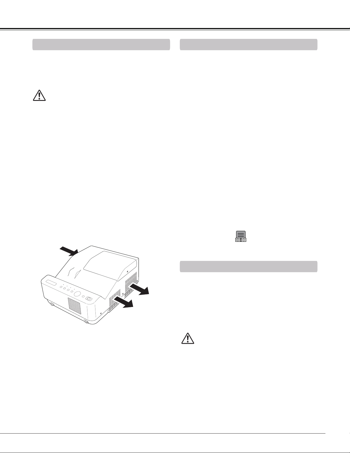
Air Circulation
Air Flow
Exhaust Vent
(Hot air exhaust)
Moving the Projector
CAUTION IN CARRYING OR
TRANSPORTING THE PROJECTOR
– Do not drop or bump the projector, otherwise
damages or malfunctions may result.
– When carrying the projector, use a suitable case.
– Do not transport the projector by courier or any
other transport service in an unsuitable transport
case. This may cause damage to the projector.
For information about transporting the projector by
courier or any other transport service, consult your
dealer.
– Do not put the projector in a case before it is
cooled enough.
When moving the projector, retract adjustable feet to
prevent damage to the cabinet. When the projector is
not in use for an extended period, put it into a suitable
case.
Handle the projector carefully; do not drop, bump,
subject it to strong forces, or put other things on the
cabinet.
Safety Instructions
The projector uses a lamp which generates significant
heat. The cooling fans and air vents are provided to
dissipate the heat by drawing air into the housing and
the filter is located in the intake vents to prevent dust
from getting inside of the projector.
In order to care for the projector appropriately, regular
cleaning is required. Remove any dirt or dust that has
accumulated on the projector.
If the projector reaches a time set in the timer setting,
a Filter warning icon (Fig. 1) appears on the screen,
indicating that the filter replacement is necessary.
Blocking the air vents and leaving the projector
uncleaned for a long time may not only damage the
projector and may require costly repairs but may also
cause accidents or fire.
For maintenance of the filter, refer to “Filter counter”
on page 64 and “Maintenance and Care” on page 67.
Damages to the projector caused by using an
uncleaned filter or improper maintenance will void the
warranty on the projector.
Filter Maintenance
Fig.1 Filter warning icon
10
Install the projector properly. Improper installation may reduce the lamp life and cause fire hazard.
Choose the running speed of cooling fans in the fan control setting according to the altitude in which the
projector is being used (p.63). Failure to do so may affect the projector life.
CAUTION
CAUTION ON CEILING MOUNTING
For ceiling mounting, you need the ceiling mount kit designed for this projector. When not mounted properly,
the projector may fall, causing hazards or injury. For details, consult your dealer. The warranty on this projector
does not cover any damage caused by use of any non-recommended ceiling mount kit or installation of the
ceiling mount kit in an improper location.
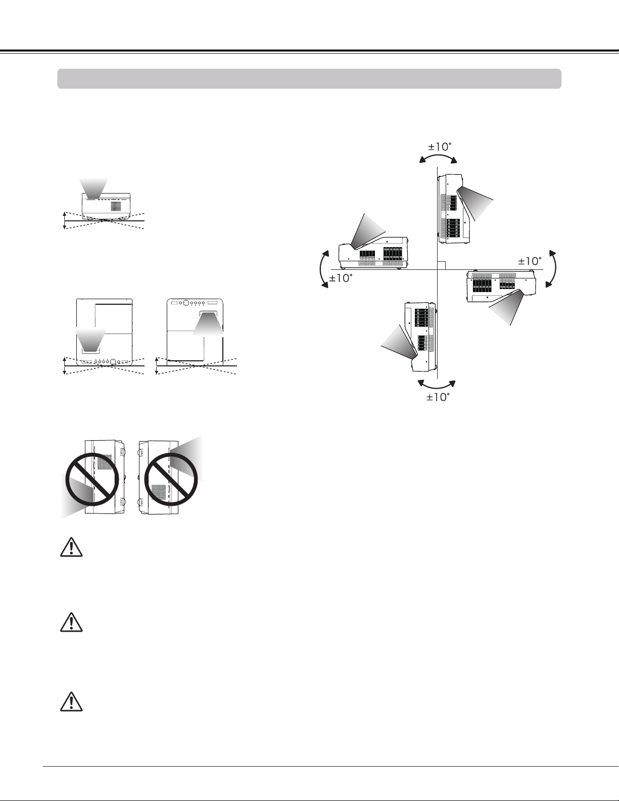
Do not roll the projector more than 10 degrees from
side to side.
Do not put the projector on either side to project an
image.
Note:
• Fix the projector when installing it so that the
projector would not fall down.
Do not roll the projector more than 5 degrees from
side to side when front or rear is downward.
10˚
10˚
5˚
5˚
5˚
5˚
Installing the Projector in Proper Position
Safety Instructions
Cautious use of equipment with laser technology
Do not radiate strong light such as laser light on the projection lens directly, as this may degrade the
functionality of the projector, and will void any applicable warranties.
11
Compliance
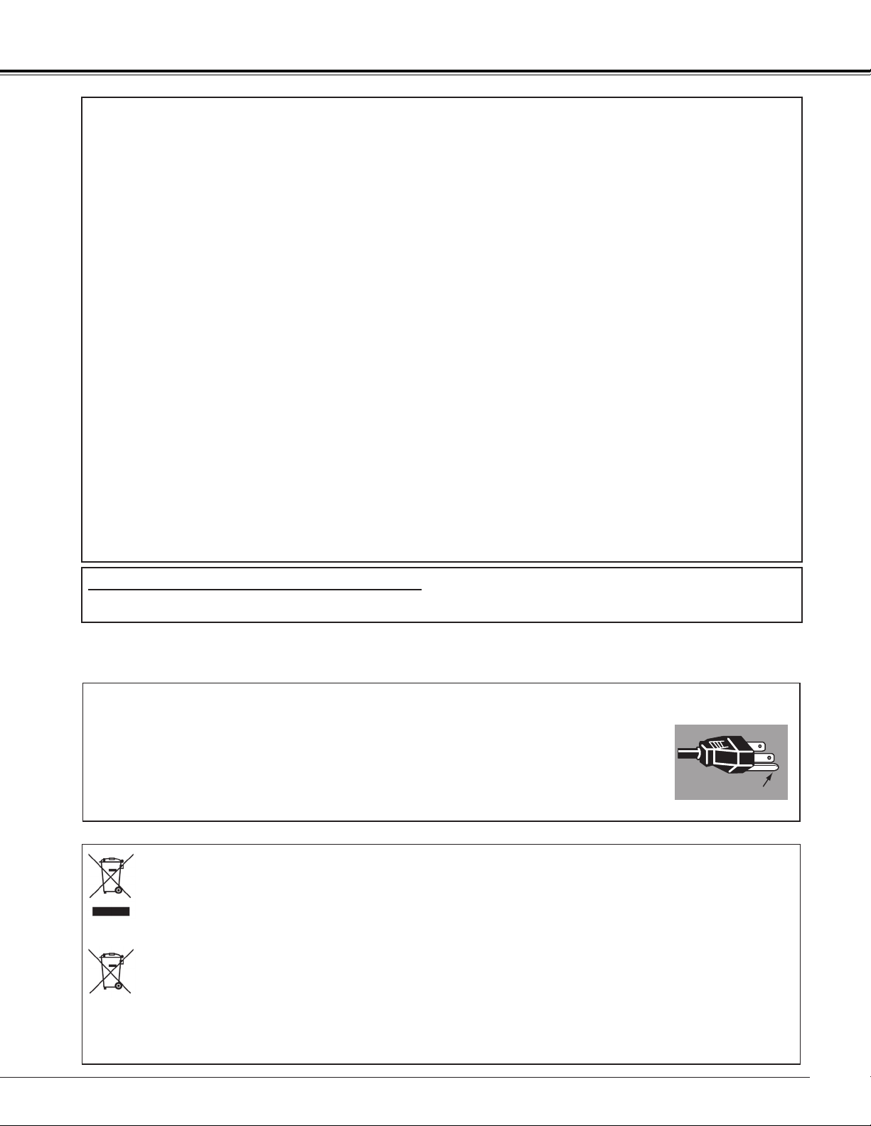
The AC Power Cord supplied with this projector meets the requirement for use in the country you purchased it.
AC Power Cord for the United States and Canada:
AC Power Cord used in the United States and Canada is listed by the Underwriters
Laboratories (UL) and certified by the Canadian Standard Association (CSA).
AC Power Cord has a grounding-type AC line plug. This is a safety feature to be sure that
the plug will fit into the power outlet. Do not try to defeat this safety feature. Should you
be unable to insert the plug into the outlet, contact your electrician.
GROUND
AC POWER CORD REQUIREMENT
Federal Communications Commission Notice
Multimedia Projector, Model: LV-8235 UST
This device complies with Part 15 of the FCC Rules. Operation is subject to the following two conditions:
(1) This device may not cause harmful interference, and
(2) this device must accept any interference received, including interference that may cause undesired
operation.
Note: This equipment has been tested and found to comply with the limits for a Class B digital device, pursuant
to Part 15 of the FCC Rules. These limits are designed to provide reasonable protection against harmful
interference in a residential installation. This equipment generates, uses and can radiate radio frequency energy
and, if not installed and used in accordance with the instructions, may cause harmful interference to radio
communications. However, there is no guarantee that interference will not occur in a particular installation. If
this equipment does cause harmful interference to radio or television reception, which can be determined by
turning the equipment off and on, the user is encouraged to try to correct the interference by one or more of the
following measures:
– Reorient or relocate the receiving antenna.
– Increase the separation between the equipment and receiver.
– Connect the equipment into an outlet on a circuit different from that to which the receiver is connected.
– Consult the dealer or an experienced radio/TV technician for help.
Use of shielded cable is required to comply with class B limits in Subpart B of Part 15 of FCC Rules.
Do not make any changes or modifications to the equipment unless otherwise specified in the instructions. If
such changes or modifications should be made, you could be required to stop operation of the equipment.
Canon U.S.A., Inc.
One Canon Plaza, Lake Success, NY 11042-1198, U.S.A.
Tel No. (516)328-5600
Canadian Radio Interference Regulations
This Class B digital apparatus complies with Canadian ICES-003.
THE SOCKET-OUTLET SHOULD BE INSTALLED NEAR THE EQUIPMENT AND EASILY ACCESSIBLE.
European Union (and EEA) only.
These symbols indicate that this product is not to be disposed of with your household waste, according to the WEEE Directive
(2002/96/EC), the Battery Directive (2006/66/EC) and/or your national laws implementing those Directives.
If a chemical symbol is printed beneath the symbol shown above, in accordance with the Battery Directive, this indicates that a
heavy metal (Hg = Mercury, Cd = Cadmium, Pb = Lead) is present in this battery or accumulator at a concentration above an
applicable threshold specified in the Battery Directive.
This product should be handed over to a designated collection point, e.g., on an authorized one-for-one basis when you buy a new
similar product or to an authorized collection site for recycling waste electrical and electronic equipment (EEE) and batteries and
accumulators. Improper handling of this type of waste could have a possible impact on the environment and human health due to
potentially hazardous substances that are generally associated with EEE.
Your cooperation in the correct disposal of this product will contribute to the effective usage of natural resources.
For more information about the recycling of this product, please contact your local city office, waste authority, approved scheme or
your household waste disposal service or visit www.canon-europe.com/environment.
(EEA: Norway, Iceland and Liechtenstein)
⑤
12
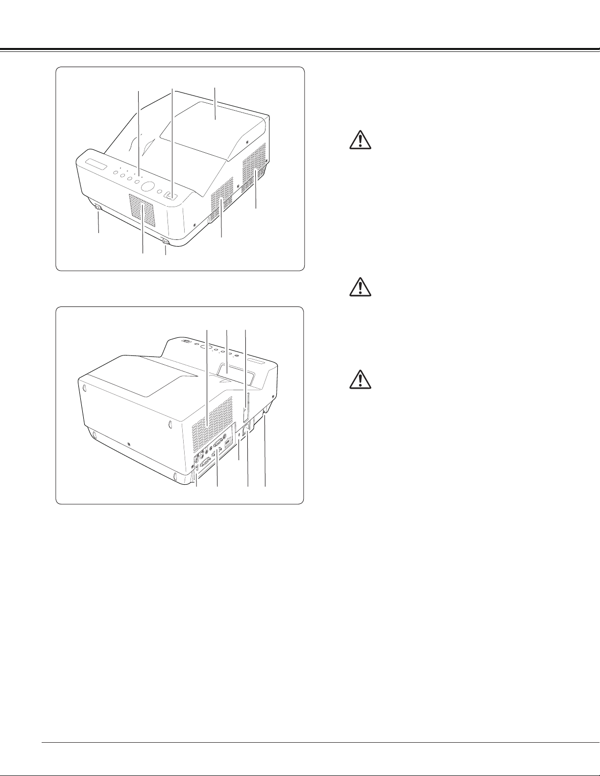
Part Names and Functions
①Top Controls and Indicators
②Infrared Remote Receiver
③Lamp Cover (Lamp and Air Filter)
④Adjustable feet
⑤Speaker
⑥Exhaust vent
⑦Air Intake vent
⑧Projection Window
Note:
Do not touch the projection window, otherwise,
the window may be soiled and the image can be
smudgy.
⑨Focus Lever
⑩LAN Connection Terminal
⑪ Terminals and Connectors
⑫Power Cord Connector
⑬Security Bar
Note:
⑩LAN Connection Terminal is for the Network
function. Refer to the user's manual of “Network
Set-up and Operation”.
Kensington Security Slot
This slot is for a Kensington lock used to deter
theft of the projector.
*
Kensington is a registered trademark of ACCO
Brands Corporation.
Front
Rear
CAUTION
The infrared remote receiver sticks out of the
cabinet surface. If the infrared remote receiver
is put on the wall or floor directly, the infrared
remote receiver may damage.
CAUTION
Hot air is exhausted from the exhaust vent. Do
not put heat-sensitive objects near this side.
②
③
④
④
⑥
⑥
⑪
⑫
⑧
⑨
⑬
⑦
⑩
WARNING
The projection window becomes very hot during
use. Do not put your hand or objects on the
projection window. High temperature from light
beam may damage light-blocking objects and
result in fire hazard.
①
13
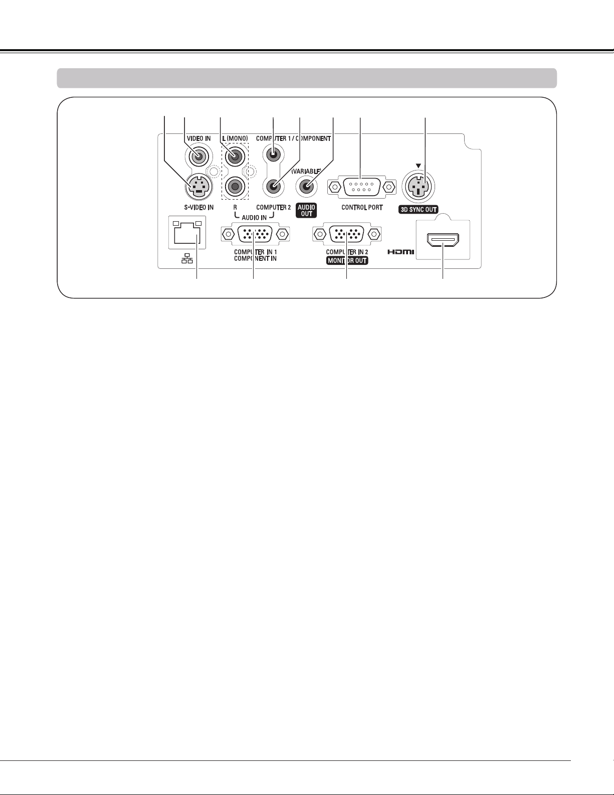
⑦ CONTROL PORT
When controlling the projector with RS-232C,
connect the control equipment to this connector
with the serial control cable.
⑧ 3D SYNC OUT
Connect a 3D sync. signal cable for an IR wireless
emitter to this jack (p.50)
⑨ LAN Connection Terminal
Connect the LAN cable (refer to the user's manual
of "Network Set-up and Operation").
⑩ COMPUTER IN 1/COMPONENT IN
Connect output signal from a computer, RGB scart
21-pin video output or component video output to
this terminal (pp.18, 20).
⑪ COMPUTER IN 2/MONITOR OUT
This terminal is switchable and can be used
for input from a computer or output to the other
monitor.
Set the terminal up as either Computer input or
Monitor output properly. [Used for Monitor out,
this terminal outputs only incoming signal from
COMPUTER IN 1/COMPONENT IN terminal (pp.
18, 58)].
⑫ HDMI
Connect the HDMI signal from computer or video
equipment to this terminal (pp.18, 20).
① S-VIDEO IN
Connect the S-VIDEO output signal from video
equipment to this jack (p.19).
② VIDEO IN
Connect the composite video output signal to this
jack (p.19).
③ AUDIO IN
Connect the audio output signal from video
equipment connected to or to this jack. For
a monaural audio signal (a single audio jack),
connect it to the L (MONO) jack (p.19).
④ COMPUTER 1/COMPONENT AUDIO IN
Connect the audio output (stereo) from a computer
or video equipment connected to ⑩ or ⑫ to this
jack (pp.18, 20).
⑤ COMPUTER 2 AUDIO IN
Connect the audio output (stereo) from a computer
connected to ⑪ to this jack (pp.18, 20).
⑥ AUDIO OUT (VARIABLE)
Connect an external audio amplifier to this jack
(pp.18-20).
This terminal outputs sound from AUDIO IN
terminal (③, ④ or ⑤) or HDMI terminal ⑫ (digital
audio).
Never plug headphones and earphones into
AUDIO OUT jack.
Part Names and Functions
①
Side Terminal
② ③ ④ ⑥⑤ ⑦ ⑧
⑨ ⑩
⑪
⑫
14
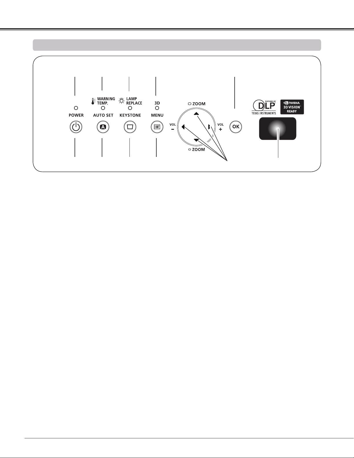
Part Names and Functions
① POWER indicator
– Turn red when the projector is in the stand-by
mode.
– Turn green while the projector is under operation
(pp.22, 76).
– Blink green in the Power management mode
(pp.59, 76)
② WARNING TEMP. indicator
Emit a red light when the projector detects abnor-
mal condition. This also blinks red when the inter-
nal temperature of the projector exceeds the oper-
ating range (pp. 66, 76).
③ LAMP REPLACE indicator
Turn yellow when the life of the projection lamp
draws to an end (pp. 69, 76).
④ 3D indicator
Turn blue when the projector is in 3D mode (pp.
50-51, 76).
⑤ OK button
– Execute the selected item (p.25).
– Zoom in and out the image in the Digital zoom
mode (p.41).
⑥ POWER button
Turn the projector on or off (pp.22-24).
⑦ AUTO SET button
Execute the setting of Auto setup (includes Auto
input function and Auto PC function). (pp.28, 53)
⑧ KEYSTONE button
Correct the keystone distortion (pp.28, 42, 49).
⑨ MENU button
Open or close the On-Screen Menu (p.25).
⑩ Point buttons
– Select an item or adjust the value in the
On-Screen Menu (p.25).
– Pan the image in Digital zoom + mode (p.41).
– Adjust the volume level (with Point buttons)
(p.29).
– Adjust the screen size (with Point buttons)
(p.27).
⑪ Infrared Remote Receiver
The protruding shape allows wide-angle remote
controller signal reception.
Top Controls and Indicators
① ② ③ ④
⑥ ⑦ ⑧ ⑨
⑩
⑤
⑪
15
Part Names and Functions
Note:
To ensure safe operation, please observe the following precautions:
• Do not bend, drop, or expose the remote controller to moisture or heat.
• For cleaning, use a soft dry cloth. Do not apply benzene, thinner, spray, or any chemical material.
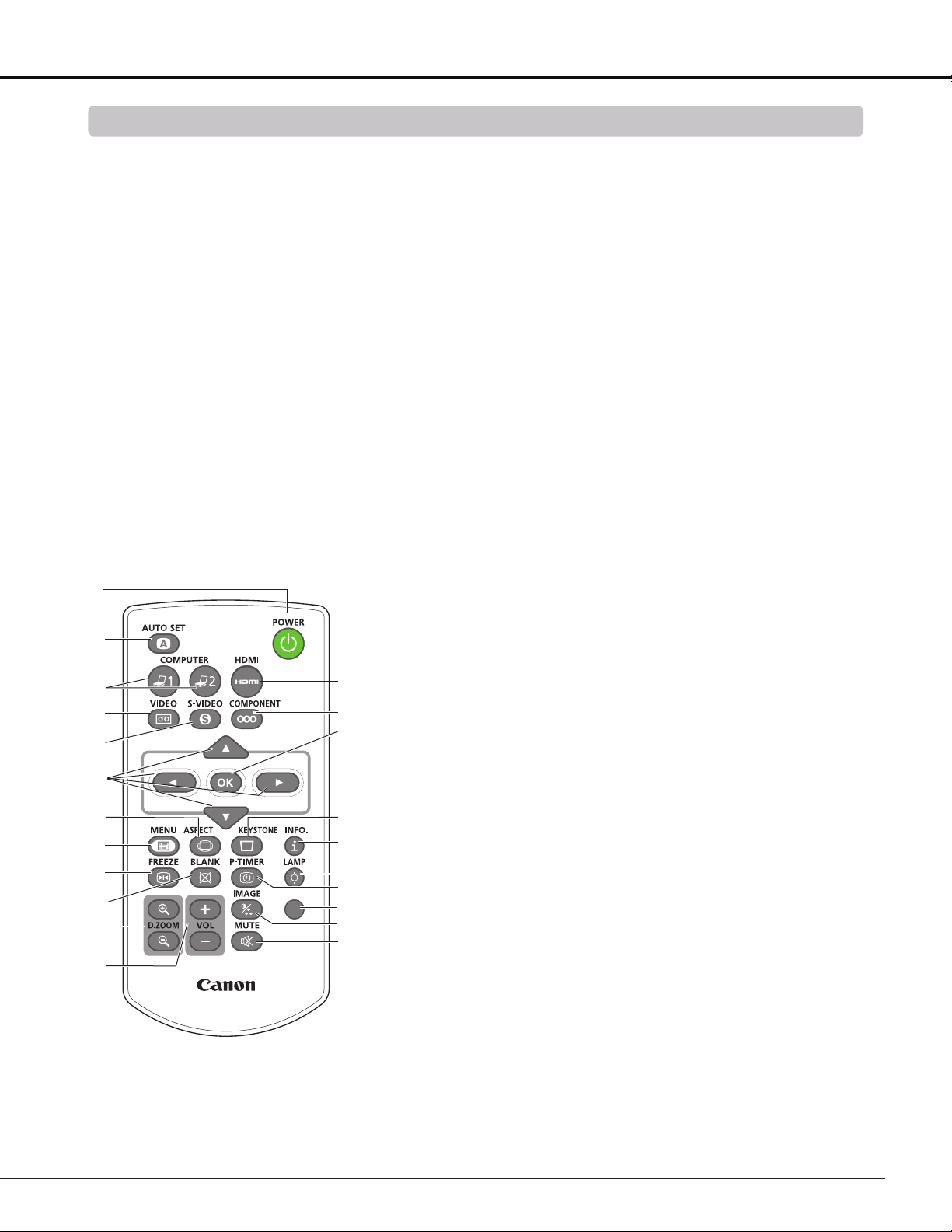
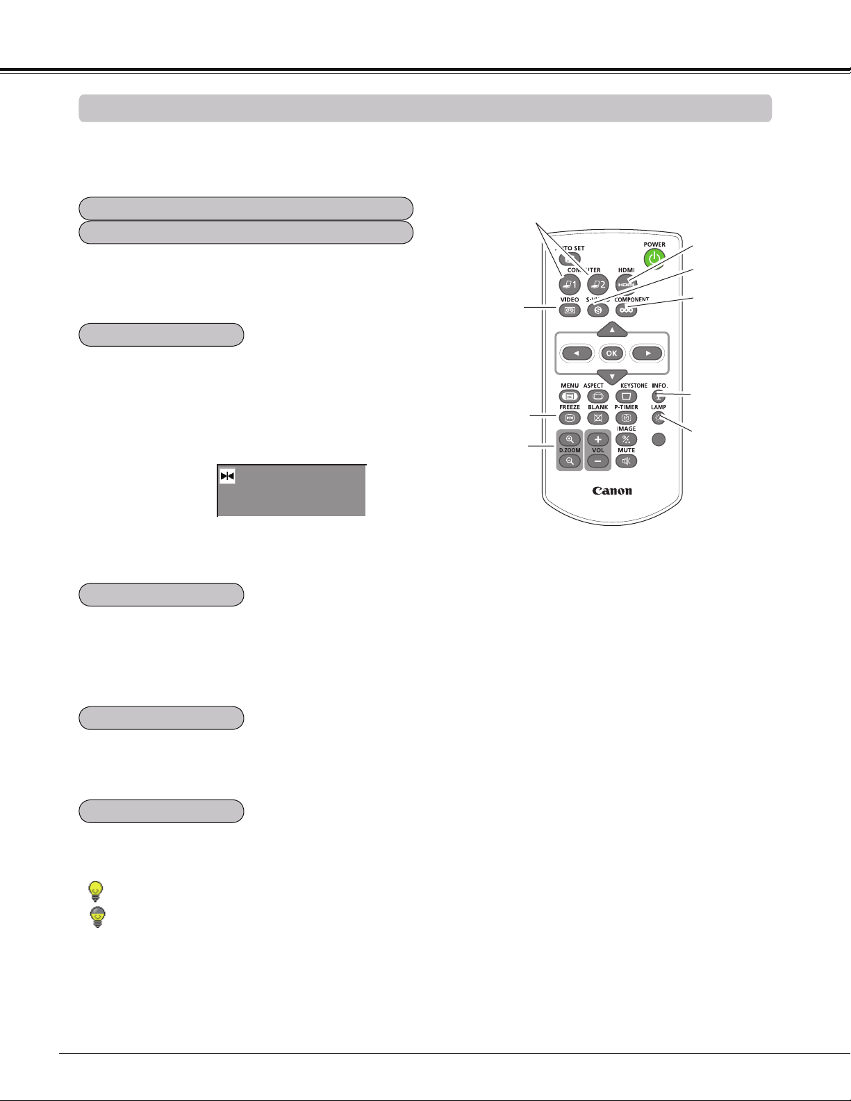
Remote Controller
② AUTO SET button
Execute the setting of Auto setup
(includes Auto input function and
Auto PC function). (pp.28, 53)
⑤ S-VIDEO button
Select the S-VIDEO input source. (p.43)
⑥ Point
buttons
– Select an item or adjust the value in the On-Screen Menu.
(p.25)
– Pan the image in the Digital zoom + mode. (p.41)
⑬
MUTE button
Mute the sound. (p.29)
⑦ SCREEN button
Select a screen mode. (pp.31, 40-42, 48-49)
⑰ P-TIMER button
Operate the P-timer function. (p.31)
⑩ BLANK button
Temporarily turn off the image on the screen. (p.31)
⑯ LAMP button
Select a lamp mode. (pp.30, 60)
⑲ KEYSTONE button
Correct the keystone distortion. (pp.28, 42, 49)
⑳ OK button
– Execute the selected item. (p.25)
– Zoom in and out the image in Digital zoom mode. (p.41)
⑧ MENU button
Open or close the On-Screen Menu. (p.25)
⑨ FREEZE button
Freeze the picture on the screen. (p.30)
⑫ VOLUME +/- buttons
Adjust the volume level. (p.29)
① POWER button
Turn the projector on or off. (pp.22-
24)
③ COMPUTER 1/2 buttons
Select the COMPUTER 1 or
COMPUTER 2 input source.
(pp.32-33, 44)
⑪ D.ZOOM +/- buttons
Zoom in and out the images. (pp.30, 41)
⑭ IMAGE button
Select the image mode. (pp.31, 38)
㉑ COMPONENT button
Select the COMPONENT input source. (p.44)
④ VIDEO button
Select the VIDEO input source.
(p.43)
⑱ INFO. button
Operate the information function. (pp.30, 65)
⑮ 3D button
Operate the 3D function. (pp.31, 50-51)
㉒ HDMI button
Select the HDMI input source. (p.44)
3D
⑦
⑭
⑩
㉑
④
⑲
②
⑧
⑨
⑬
⑰
⑤
⑥
⑪
⑫
⑳
⑯
③
⑱
①
⑮
㉒
16
Part Names and Functions
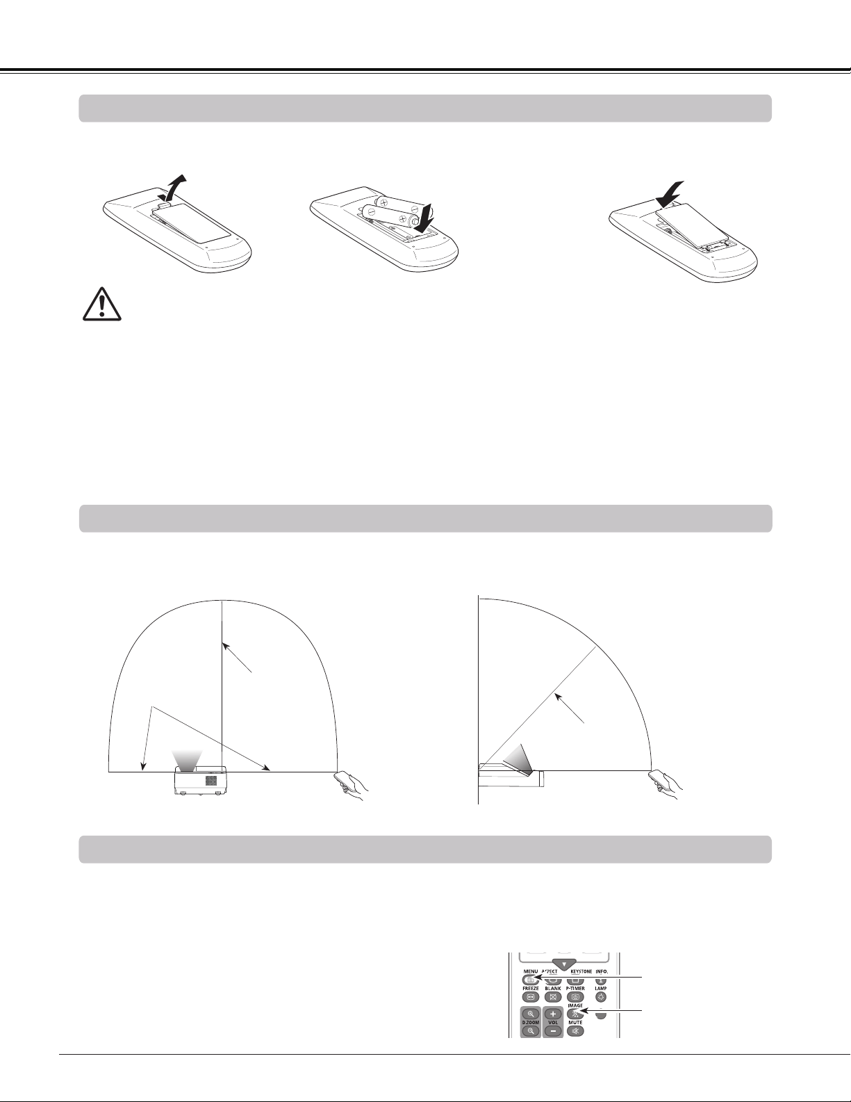
To ensure safe operation, please observe the following precautions :
● Use two (2) AAA type batteries.
● Always replace batteries in sets.
● Do not use a new battery with a used battery.
● Avoid contact with water or liquid.
● Do not expose the remote controller to moisture or heat.
● Do not drop the remote controller.
● If the battery has leaked on the remote controller, carefully wipe the case clean and install new batteries.
● Risk of an explosion if battery is replaced by an incorrect type.
● Dispose of used batteries according to the instructions or your local disposal rule or guidelines.
Open the battery
compartment lid.
Install new batteries
into the compartment.
Replace the
compartment lid.
Two AAA size batteries
For correct polarity
(+ and –), be sure
battery terminals are
in contact with pins in
compartment.
1 2 3
Point the remote controller toward the projector (Infrared Remote Receiver) when pressing the buttons. See the
below figures indicating Maximum operating range for the remote controller.
Remote Controller Operating Range
Remote Controller Battery Installation
Remote Control Code
The two different remote control codes (Code 1-Code 2) are assigned to this projector. Switching the remote
control codes prevents interference from other remote controls when several projectors or video equipment
next to each other are operated at the same time. Change the remote control code for the projector first before
changing that for the remote control. See "Remote control" in the Setting Menu on page 60.
Press and hold the MENU and IMAGE buttons for more
than five seconds to switch between the Code 1 and Code
2. The initial code is set to Code 1.
3D
MENU button
IMAGE button
16.4’
(5 m)
11.5’
(3.5 m)
16.4’
(5 m)
WARNING
A
B
C
E
D
17
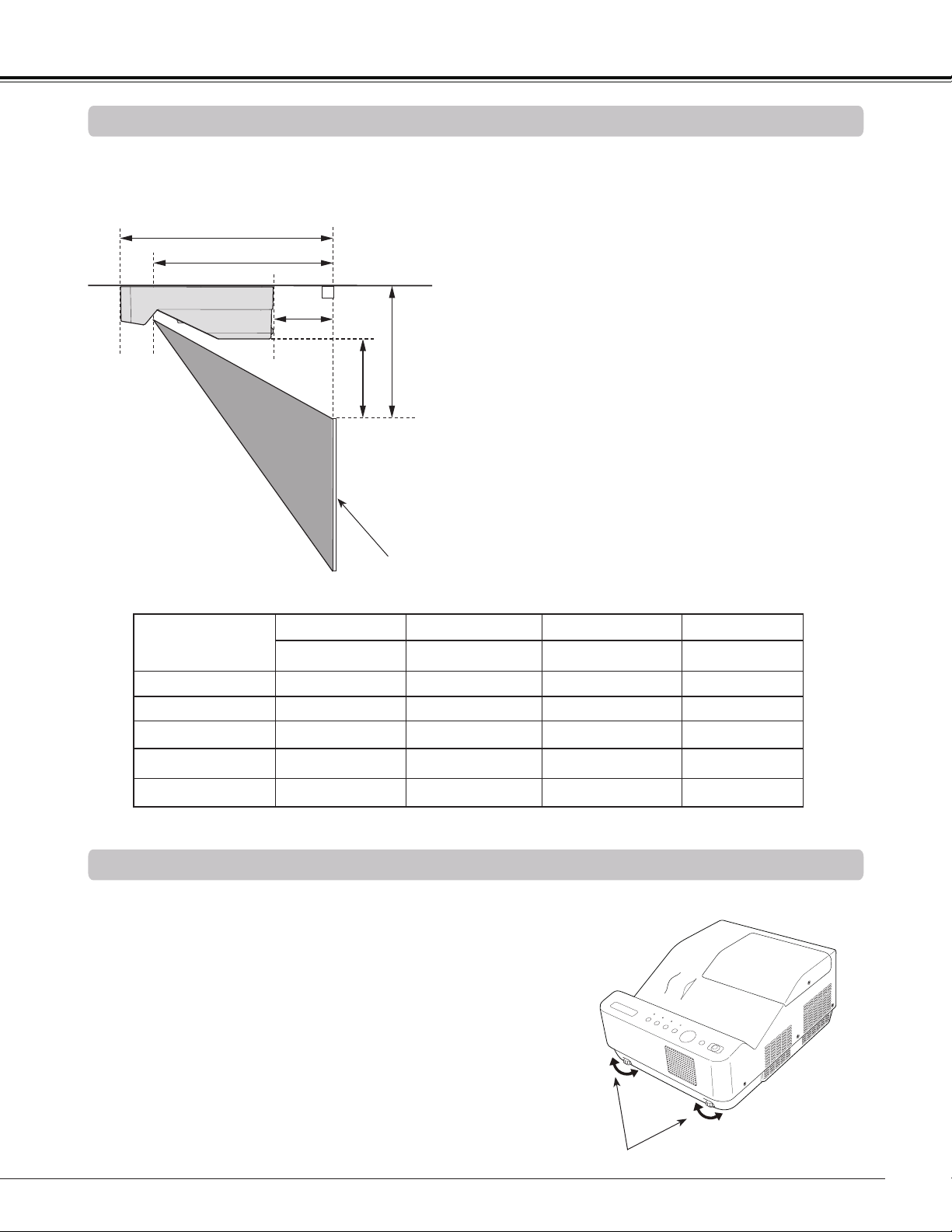
Positioning the Projector
For projector positioning, see the figures below. The projector should be set perpendicularly to the plane of the
screen.
Installation
Note:
• This projector is not equipped with an optical
zoom. To adjust the screen size, change the
throw distance.
• The brightness in the room has a great
influence on picture quality. It is recommended
to limit ambient lighting in order to obtain the
best image.
• All measurements are approximate and may
vary from the actual sizes. Make sure to check
the position of images by projecting images
on the screen before installing the projector
and screen, since each projector shows slight
variations.
• Make sure to project images on a fixed flat
screen.
• When projecting to wall or flat objects, even
slight warpage or irregularities of the screen
may have an effect on the quality of the
projected images.
Adjustable Feet
Projection angle can be adjusted within -1.0 to +1.0 degree
with the adjustable feet.
Rotate the adjustable feet and tilt the projector to the proper
height; to raise the projector, rotate the both feet clockwise.
To lower the projector or to retract the adjustable feet, rotate
the both feet counterclockwise.
To correct keystone distortion, press the KEYSTONE button
on the remote controller or on the top control or select
Keystone from the menu (See pages 28, 42, 49).
Adjustable Feet
Screen
Screen Size
(W x H) mm
16:10 aspect ratio
60"
74.6”
80" 110"
1292 x 808
1608 x 1005
1723 x 1077 2369 x 1481
A
12.60" (32.0 cm) 15.20" (38.6 cm)
16.14" (41.0 cm) 21.46" (54.5 cm)
B
9.06" (23.0 cm)
11.65" (29.6 cm)
12.60" (32.0 cm) 17.91" (45.5 cm)
C
-2.60" (-6.6 cm)
0.00" (0.0 cm)
0.95" (2.4 cm) 6.26" (15.9 cm)
D
8.86" (22.5 cm)
10.00" (25.4 cm)
10.43" (26.5 cm) 12.80" (32.5 cm)
E
1.85" (4.7 cm)
3.00" (7.6 cm)
3.43" (8.7 cm) 5.79" (14.7 cm)
18
Installation
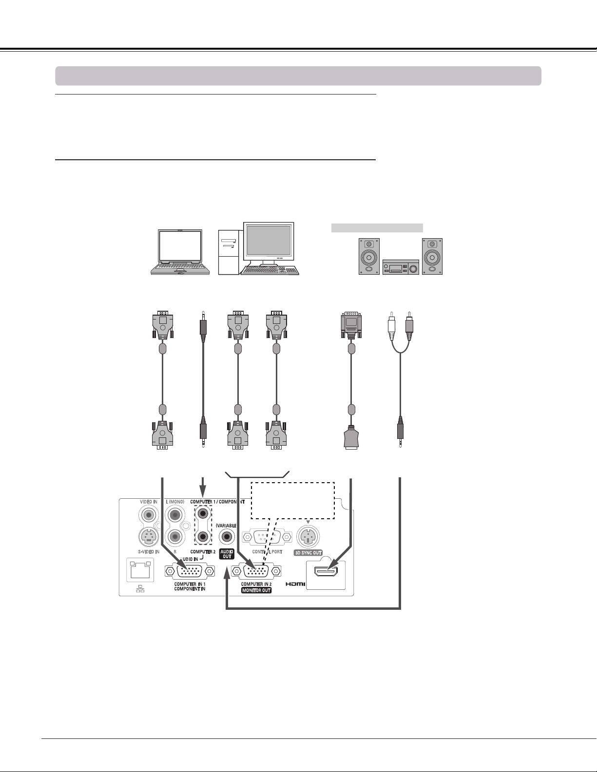
Connecting to a Computer
Cables used for connection
• VGA cables (Mini D-sub 15 pin) *
• Audio cables
• HDMI-DVI cable
(*One cable is supplied; other cables are not supplied with the projector.)
Note:
• Input sound to the COMPUTER 1/COMPONENT AUDIO IN terminal when using the COMPUTER IN 1/COMPONENT IN
terminal as input.
• When the cable is of the longer variety, it is advisable to use the COMPUTER IN 1/COMPONENT IN and not the
COMPUTER IN 2 /MONITOR OUT.
• Analog PC and component signals can be output from the COMPUTER IN 2/MONITOR OUT terminal when using the
COMPUTER IN 2/MONITOR OUT terminal as output.
• When the AUDIO OUT is plugged-in, the projector's built-in speaker is not available.
Note:
Unplug the power cords of both the projector and external equipment from the AC outlet before connecting cables.
External Audio Equipment
Audio
cable
(stereo)
Monitor
Output
AUDIO OUT
(stereo)
VGA
cable
COMPUTER IN 2/
MONITOR OUT
COMPUTER IN 1 /
COMPONENT IN
Monitor Output
or
Monitor Input
VGA
cable
HDMI-DVI
cable
DVI
Output
HDMI
This terminal is switch-
able. Set up the terminal
as COMPUTER IN 2 or
MONITOR OUT (P. 56).
COMPUTER 1/
COMPONENT
AUDIO IN
Audio cable
(stereo)
Audio
Output
Audio
Input
VGA
cable
19
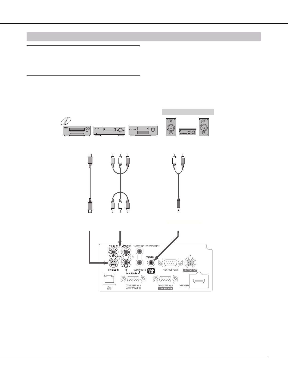
Installation
Connecting to Video Equipment
Cables used for connection
• Video and Audio cable (RCA x 3)
• S-video cable
• Audio cable
(Cables are not supplied with the projector. )
External Audio Equipment
Audio cable
(stereo)
VIDEO IN and AUDIO INS-VIDEO IN
S-video cable
Video and audio
cable
Video and Audio Output
S-video Output
Audio Input
AUDIO OUT (stereo)
(R)(L)(Video)
Note:
• When the AUDIO OUT is plugged-in, the projector's built-in speaker is not available.
Note:
Unplug the power cords of both the projector and external equipment from the AC outlet before connecting cables.
20
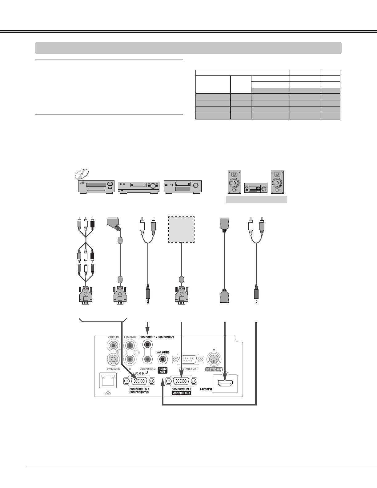
Installation
Connecting to Component Video Equipment
Cables used for connection
• Audio cables
• Scart-VGA cable
• Component cable
• Component-VGA cable
• HDMI cable
(Cables are not supplied with this projector.)
External Audio Equipment
COMPUTER 1/
COMPONENT
AUDIO IN
Audio cable
(stereo)
Audio Input
Component Video
Output
(Y, Pb/Cb, Pr/Cr)
RGB Scart
21-pin Output
Audio Output
Scart-VGA
cable
Component-
VGA cable
Component
cable
COMPUTER IN 1/
COMPONENT IN
HDMI
HDMI Output
HDMI
cable
Audio cable
(stereo)
COMPUTER IN 2/
MONITOR OUT
AUDIO OUT
(stereo)
Refer to
the Monitor
Output Sig-
nal Table.
Input Terminal Monitor Out Cable
COMPUTER 1/
COMPONENT
D-sub15
ANALOG PC YES
Y, Pb/Cb, Pr/Cr YES
SCART NO
COMPUTER 2
D-sub15
ANALOG PC NO
HDMI
HDMI
HDMI NO
S-VIDEO
DIN-4
S-video NO
VIDEO
RCA
Video NO
Monitor Output Signal Table
A cable with one end D-sub 15 and the other end (Black box)
compatible with each equipment is necessary.
Note:
• When the AUDIO OUT is plugged-in, the projector's built-in speaker is not available.
• See page 80 for ordering optional cables.
Note:
Unplug the power cords of both the projector
and external equipment from the AC outlet before
connecting cables.
21
Installation
Connecting the AC Power Cord
This projector uses nominal input voltages of 100–240 V AC
and it automatically selects the correct input voltage. It is
designed to work with single-phase power systems having a
grounded neutral conductor. To reduce the risk of electrical
shock, do not plug into any other type of power system.
If you are not sure of the type of power being supplied,
consult your authorized dealer or service center.
Connect the projector with all peripheral equipment before
turning it on.
Note:
Unplug the AC power cord when the projector is not
in use. When this projector is connected to an outlet
with the AC power cord, it is in Stand-by mode and
consumes a little electric power.
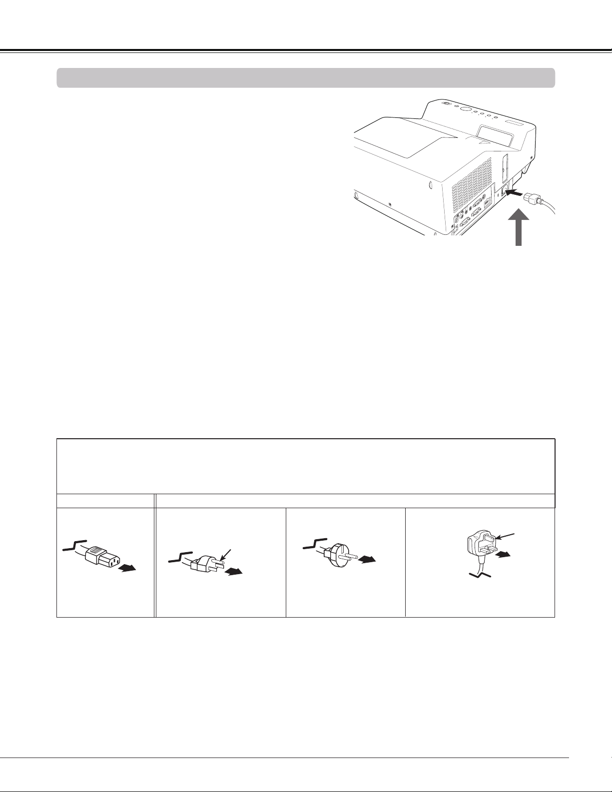
Connect the AC power cord
(supplied) to the projector.
CAUTION
The AC outlet must be near this equipment and must be
easily accessible.
To the AC outlet.
(200 - 240 V AC)
NOTE ON THE POWER CORD
AC power cord must meet requirement of the country where you use the projector.
Confirm the AC plug type with the chart below and proper AC power cord must be used.
If supplied AC power cord does not match your AC outlet, contact your sales dealer.
To power cord
connector on your
projector.
Projector side
AC outlet side
Ground
To the AC outlet.
(120 V AC)
For the U.S.A. and Canada
To the AC outlet.
(200 - 240 V AC)
For the U.K.For Continental Europe
Ground
22
The preparation display will disappear after 30
seconds.
(See page 60 for Lamp mode status.)
Turning On the Projector
Connect the projector’s AC power cord into an AC
outlet. The POWER indicator lights red.
Press the POWER button on the remote controller or
on the top control. The POWER indicator lights green
and the cooling fans start to operate. The preparation
display appears on the screen and the countdown
starts.
2
3
1
4
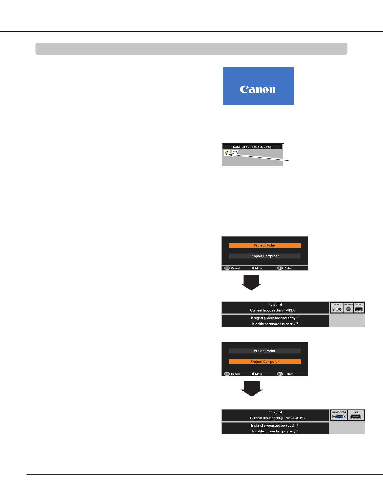
After the countdown, the input source that was
selected the last time and the Lamp mode status icon
(See page 60) appear on the screen.
Complete peripheral connections (with a computer,
VCR, etc.) before turning on the projector.
Selected Input Source and Lamp mode
Note:
• When the Logo select function is set to Off, the logo will
not be shown on the screen. (p.55)
• When Countdown off or Off is selected in the Display
function, the countdown will not be shown on the screen.
(p.55)
• During the countdown period, all operations are invalid.
• When the Auto input function is set to On 2, the input
signal will be searched automatically. (p.53)
• When Off is selected in the Display function, the Video
/PC selection window and the input signal guidance
window are not shown on the screen. (p.55)
Note:
The Filter warning and Lamp replacement
icons may appear on the screen depending
on the usage state of the projector.
Basic Operation
If there is no signal input when start on the projector,
or the current signal is missed while operating the
projector, the Video / PC selection window will be
displayed on the screen, please move the pointer
to input source desired by pressing the Point
buttons and press the OK button. And then follow the
input signal guidance window to correct the signal and
connection.
If the projector is locked with a PIN code, PIN code
input dialog box will appear. Enter the PIN code as
instructed on the next page.
5
Video / PC selection window
Video / PC selection window
Input signal guidance window
Input signal guidance window
Lamp mode status
16
23
What is PIN code?
PIN (Personal Identification Number) code is a security
code that allows the person who knows it to operate the
projector. Setting a PIN code prevents unauthorized use of
the projector.
A PIN code consists of a four-digit number. Refer to the PIN
code lock function in the Setting Menu on pages 61-62 for
locking operation of the projector with your PIN code.
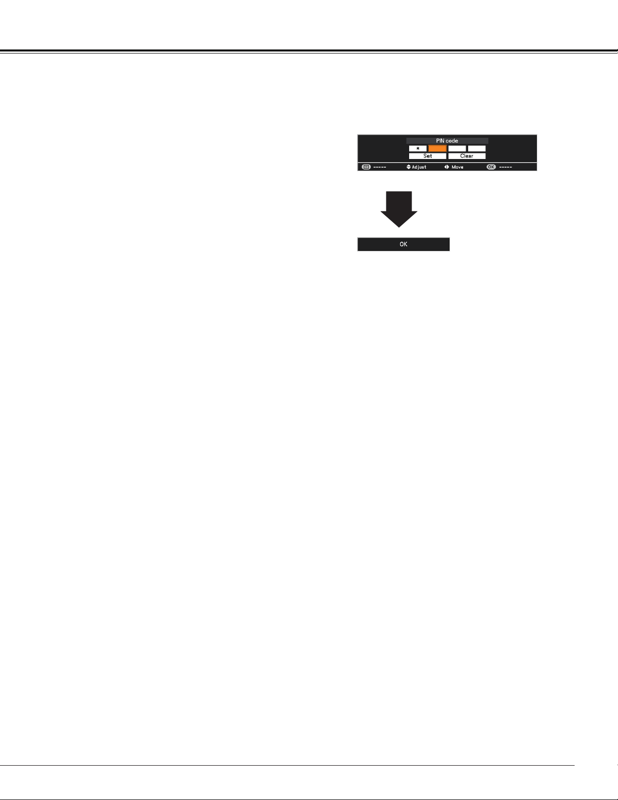
Enter a PIN code
Use the Point buttons to enter a number. Press the
Point button to fix the number and move the red frame
pointer to the next box. The number changes to . If you
fixed an incorrect number, use the Point button to move
the pointer to the number you want to correct, and then
enter the correct number.
Repeat this step to complete entering a four-digit number.
After entering the four-digit number, move the pointer to
"Set". Press the OK button so that you can start to operate
the projector.
If you entered an incorrect PIN code, PIN code and the
number () will turn red for a moment. Enter the
correct PIN code all over again.
CAUTION ON HANDLING PIN CODE
If you forget your PIN code, the projector can no
longer be started. Take a special care in setting
a new PIN code; write down the number as a
reminder.
After the OK icon disappears,
you can operate the projector.
PIN Code Input Dialog Box
Basic Operation
Note:
• If the PIN code number is not entered within three
minutes after the PIN code dialog box appeared, the
projector will be turned off automatically.
• The “1234” is set as the initial PIN code at the factory.

24
TO MAINTAIN THE LIFE OF THE LAMP, ONCE YOU TURN
THE PROJECTOR ON, WAIT AT LEAST FIVE MINUTES
BEFORE TURNING IT OFF.
Power off? disappears after 4 seconds.
Turning Off the Projector
Press the POWER button on the remote controller or
on the top control, and Power off? appears on the
screen.
Press the POWER button again to turn off the projector.
The POWER indicator starts to blink red, and the
cooling fans keep running. (You can select the level of
fans’ quietness and speed. See “Fan” on page 63.) At
this time, you can unplug the AC power cord even if the
fans are still running.
1
2
3
When the projector has cooled down enough, the
POWER indicator stops blinking and you can turn on
the projector.
Note:
• When the Direct power on function is set to On, the
projector will be turned on automatically by connecting
the AC power cord to an AC outlet. (p. 59)
• The running speed of cooling fans is changed according
to the temperature inside the projector.
• Do not put the projector in a case before the projector is
cooled enough.
• If the WARNING TEMP. indicator blinks or lights red,
see “WARNING TEMP. indicator” on page 66.
• While the POWER indicator is blinking, the lamp is
being cooled down and the projector can not be turned
on. Wait until the POWER indicator stops blinking to turn
on the projector again.
• The fan rotation will terminate directly if the AC power
cord is unplugged immediately after the projector is
turned off.
• The projector can be turned on after the POWER
indicator turns red. The waiting time to restart will be
shortened when the normal power-off processing for fan
cooling is completed, compared with the time the AC
power cord is immediately unplugged after the power-
off.
• To protect the component parts inside the projector, the
fans normally start running again in approximately 40
seconds after turning off the projector. This is NORMAL
operation and not a malfunction.
DO NOT OPERATE THE PROJECTOR CONTINUOUSLY
WITHOUT REST. CONTINUOUS USE MAY RESULT
IN SHORTENING THE LAMP LIFE. TURN OFF THE
PROJECTOR AND LET STAND FOR ABOUT AN HOUR IN
EVERY 24 HOURS.
Basic Operation
You can disconnect the power cord from the
wall outlet or turn off the breaker even during
projection without pressing the POWER button.
Note:
• When using the Direct Power Off function,
you can not restart the projector immediately
after the power is disconnected. If the external
power supply is suddenly cut off, the fans
stop immediately. The lamp remains high
temperature and needs to be cooled.
Direct Power Off Function
25
How to Operate the On-Screen Menu
The projector can be adjusted or set via the On-Screen
Menu. The menu has a hierarchical structure, with a main
menu that is divided into submenus, which are further
divided into other submenus. For each adjustment and
setting procedure, refer to respective sections in this
manual.
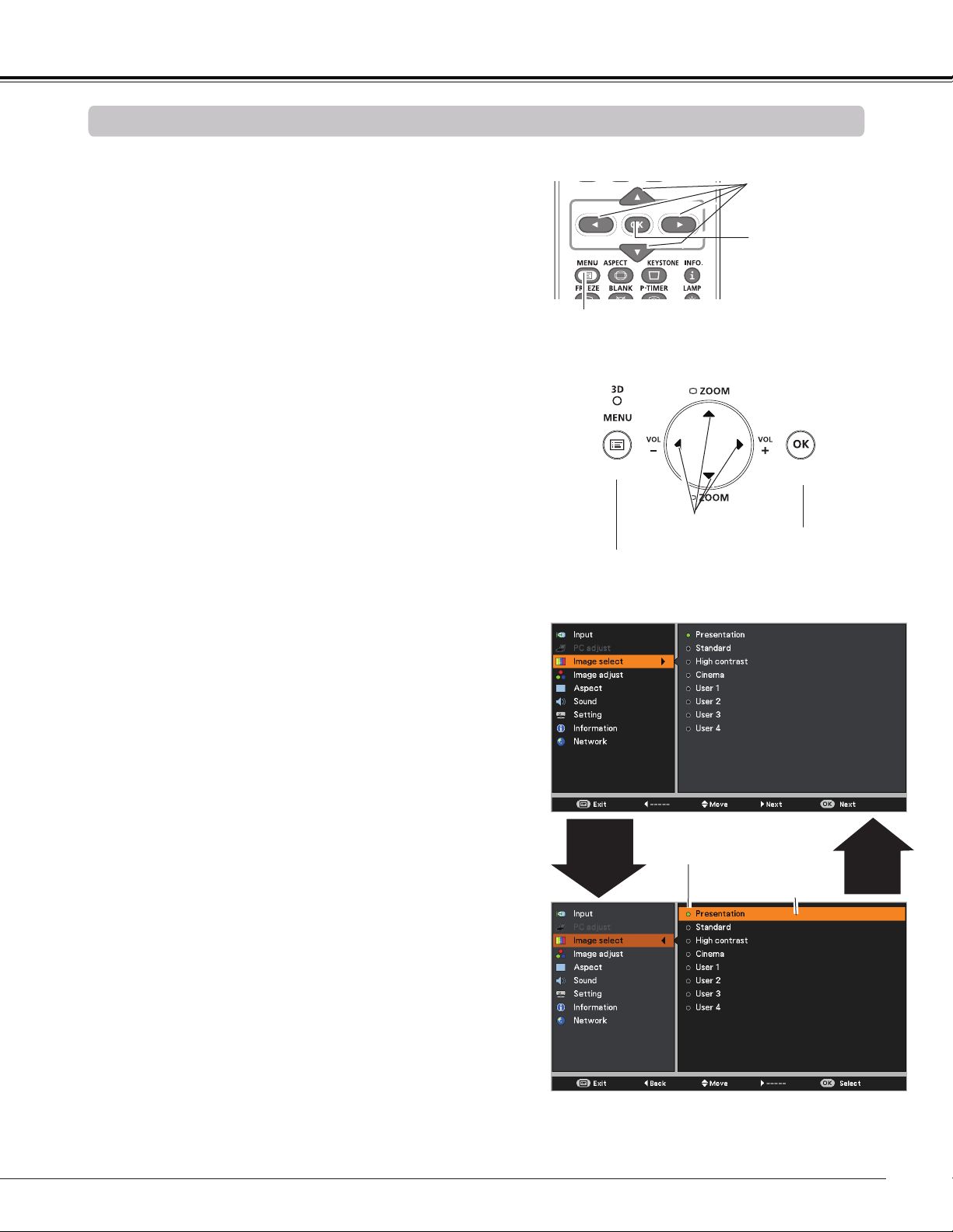
Use the Point buttons to highlight and select a
main menu item. Press the Point or the OK button
to access the submenu items. (The selected item is
highlighted in orange.)
Use the Point buttons to select the desired
submenu item and press the OK button to set or
access the selected item.
Press the MENU button on the remote controller or on
the top control to display the On-Screen Menu.
1
2
3
On-Screen Menu
POINT buttons
(arrowhead)
Top Control
Point or
OK
button
Use the Point buttons to adjust the setting or
switch between each option and press the OK button
to activate it and return to the submenu.
4
Press the Point button to return to the main menu.
Press the MENU button to exit the On-Screen Menu.
5
The currently set item is
marked.
The selected item is
highlighted in orange.
Basic Operation
3D
MENU button
POINT buttons
(arrowhead)
Remote Controller
OK button
MENU button
OK button
Point
◄
button
26
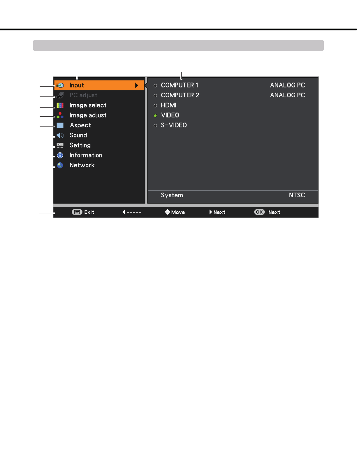
For detailed functions of each menu, see “Menu Tree” on pages 74-75.
①
②
③
④
⑤
⑥
⑦
⑧
Main Menu
Sub-Menu
⑨
⑩
①
Input Used to select an input source from COMPUTER 1, COMPUTER 2, HDMI, VIDEO or
S-VIDEO. (pp.32-33, 43-45)
②
PC adjust Select Auto PC, Fine sync, Total dots, Horizontal position, Vertical position,
Current mode and Clamp to adjust the parameters to match with the PC input signal
format. (pp.35-37)
③
Image select Used to select an image mode from among Presentation, Standard, High contrast,
Cinema and User 1-4. (p.38)
④
Image adjust
For computer source, used to adjust computer image [Contrast, Brightness, Color
temp., White balance (Red/Green/Blue), Sharpness and Gamma]. (p.39)
For video or HDMI source, used to adjust picture image [Contrast, Brightness, Color,
Tint, Color temp., White balance (Red/Green/Blue), Sharpness, Gamma, Noise
reduction and Progressive]. (pp.46-47)
⑤
Aspect
For computer source, used to adjust size of the image [Normal, Full, 16:9, Zoom, True,
Custom, Digital zoom +/–, Keystone, Ceiling, Rear, Screen aspect and Colorboard].
(pp.40-42)
For video or HDMI source, used to set size of image [Normal, Full, 16:9, Zoom,
Natural wide, Custom
, Keystone, Ceiling, Rear, Screen aspect and Colorboard
].
(pp.48-49)
⑥
Sound Used to adjust the volume or mute the sound. (p.29)
⑦
Setting
Used to set the projector’s operating configurations. (pp.52-64)
⑧
Information Display the input source information: Input, H-sync freq., V-sync freq., Aspect,
Language, Lamp status, Lamp counter, Power management mode, Key lock, PIN
code lock, Remote control, and SERIAL NO.. (p.65)
⑨
Network See user's manual of “Network Set-up and Operation”.
⑩
Guide The key operation is displayed.
Basic Operation
Main Menu
27
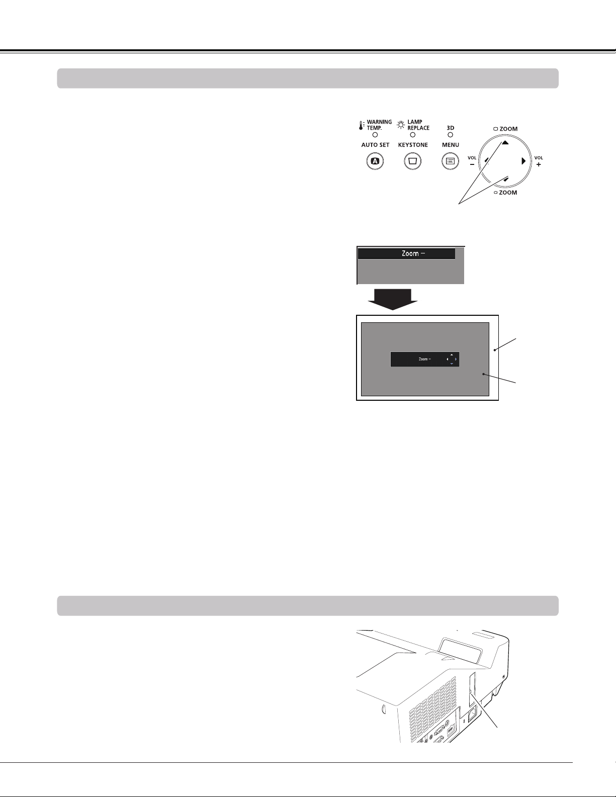
Zoom and Image Position Adjustment
Press the ZOOM +/- buttons on the top control to adjust the
screen size. Screen size can be adjusted 84% to 100% from
its maximum screen size.
It is not available when On-Screen menu is displayed.
Zoom adjustment can be memorized. (p.54)
Focus Adjustment
Adjust the lens focus with the focus lever.
Focus Lever
The image position can be adjusted in the Zoom
Adjustment.
Top Control
ZOOM +/– buttons
1
2
3
Press the ZOOM+ or ZOOM- button on the top control.
While ZOOM+ or ZOOM- is displayed on the screen,
press the OK button. Arrow marks displayed on the
screen.
P
ress the Point
buttons on the top control or
the remote controller to adjust the image position.
Note:
• Zoom and Image Position Adjustment
can not be operated when 4:3 or 16:9
mode is selected in the Screen aspect
menu or Custom is selected in the
Screen menu (pp.40-42, 48-49).
• The image position adjustment can not
be adjusted at ZOOM maximum.
• The white arrows indicate that there is no
correction.
• A blue arrow indicates the direction of
correction.
• An arrow disappears at the maximum
correction.
Basic Operation
ZOOM +/–
disappears after 4
seconds.
ZOOM +/–
Screen
Image
3D
3D
28
Basic Operation
Auto setup function is provided to automatically execute
the setting of Auto setup (includes Auto input and Auto PC
functions) in the Setting Menu by just pressing the AUTO
SET button on the remote controller. Refer to page 53 for
the setting of the Auto setup function.
Note:
Fine sync, Total dots, Horizontal position and Vertical
position of some computers can not be fully adjusted
with the Auto PC adjustment function. When the image
is not provided properly with this operation, manual
adjustments are required. (pp.36-37)
Auto Setup Function
Remote Controller
AUTO SET button
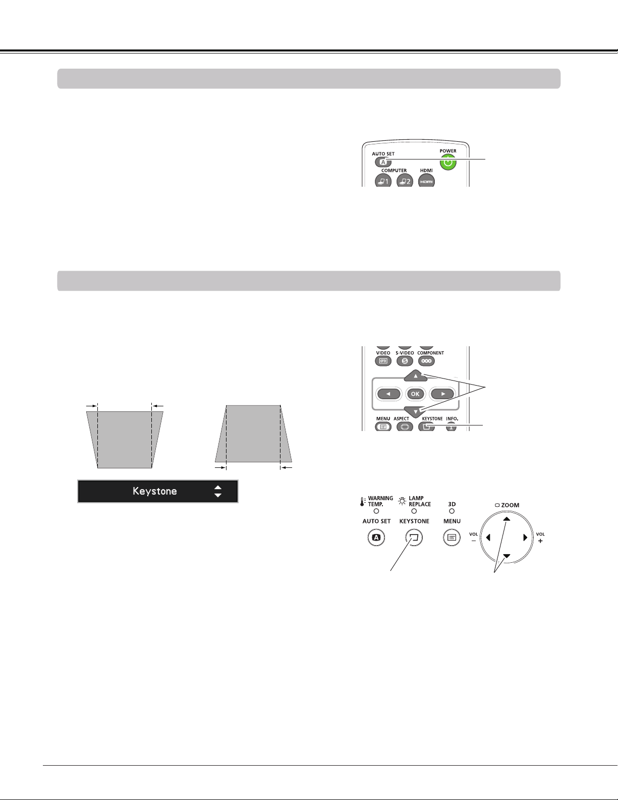
Press the KEYSTONE button on the remote controller or
on the top control. The Keystone dialog box appears. Use
the Point buttons to correct keystone distortion. The
keystone adjustment can be stored (See pages 42, 49).
Reduce the upper width
with the Point button.
Reduce the lower width
with the Point button.
• The white arrows indicate that there is no correction.
• A blue arrow indicates the direction of correction.
• An arrow disappears at the maximum correction.
• If you press the KEYSTONE button on the remote
controller or on the top control once more while the
keystone dialog box is being displayed, the keystone
adjustment will be canceled.
• The adjustable range is limited depending on the
input signal.
Keystone Correction
Remote Controller
POINT buttons
KEYSTONE button
Top Control
KEYSTONE button
POINT buttons
3D
29
Basic Operation
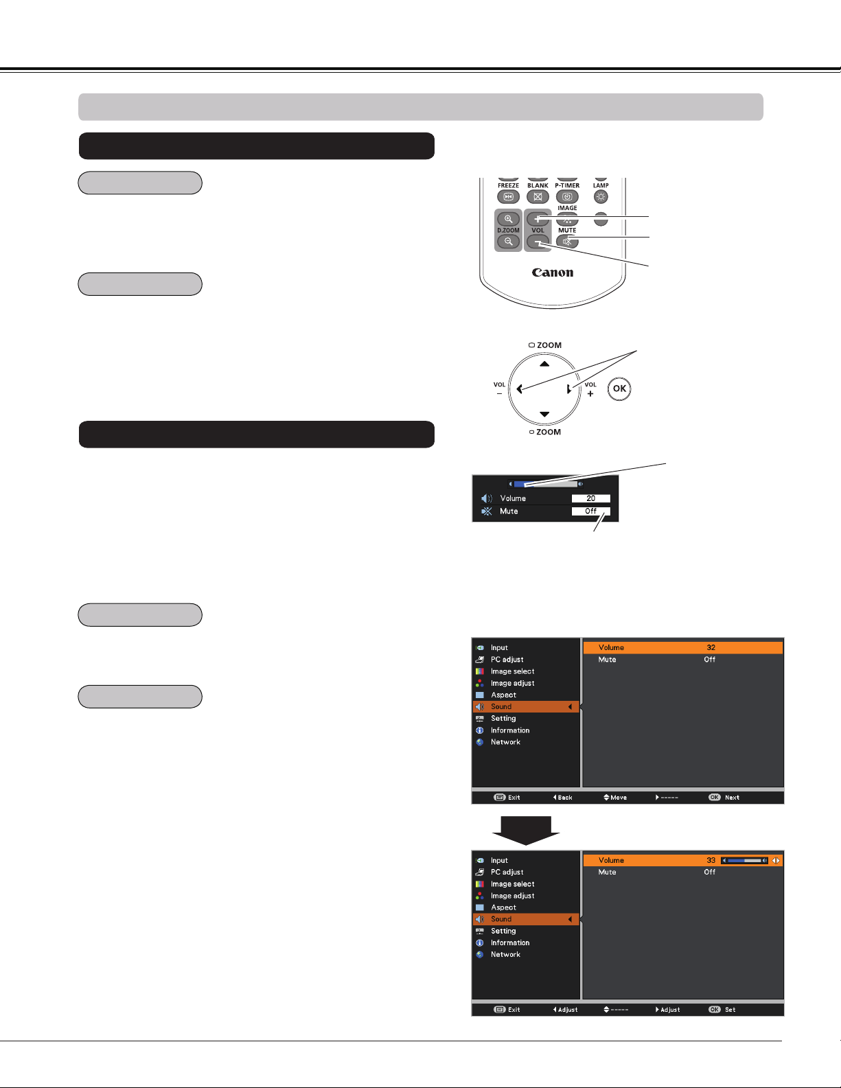
Sound Adjustment
1
2
Press the MENU button to display the On-Screen Menu.
Use the Point buttons to select Sound. Press the
Point or the OK button to access the submenu items.
Press the VOLUME+/– buttons on the remote controller or
on the top control to adjust the volume. The volume dialog
box appears on the screen for a few seconds.
Press the MUTE button on the remote controller to select
On to temporarily turn off the sound. To turn the sound back
on, press the MUTE button again to select Off or press the
VOLUME +/– buttons. The MUTE function is also effective
for the AUDIO OUT jack.
Press the OK button to switch the Mute function On/Off.
When the sound is turned off, On is displayed. Press the
VOLUME +/– buttons again to turn the sound back on.
Use the Point buttons to select the desired submenu
item and press the OK button to access the selected
item.
Press the Point button to turn up the volume; press the
Point button to turn down the volume.
Direct Operation
Menu Operation
Sound Menu
Volume Dialog Box
Remote Controller
VOLUME + button
VOLUME - button
MUTE button
Approximate level
of the volume.
Press the MUTE button to set the
Mute function On or Off. The dialog
box disappears after 4 seconds.
Top Control
VOLUME +/- buttons
Voume
Mute
Voume
Mute
30
Basic Operation
Remote Controller Operation
Using the remote controller for some frequently used operations is advisable. Just pressing one of the buttons
enables you to make the desired operation quickly without calling up the On-Screen Menu.
Press the COMPUTER 1/2, HDMI, VIDEO, S-VIDEO and
COMPONENT buttons on the remote controller to select the
input source. See pages 32-33, 43-44 for details.
Display the input source information: Input, H-sync freq.,
V-sync freq., Aspect, Language, Lamp status, Lamp
counter, Power management mode, Key lock, PIN code
lock, Remote controller and SERIAL NO.. (p.65)
Press the D.ZOOM +/– buttons on the remote controller to
enter to the D. zoom +/– mode. See page 41 for details.
Remote Controller
3D
FREEZE
button
D.ZOOM
buttons
LAMP
button
Note:
See the next page for the description of
other buttons.
COMPUTER 1/2
buttons
VIDEO
button
Press the LAMP button on the remote controller to select
the lamp mode for changing the brightness on the screen.
INFO.
button
S-VIDEO
button
COMPONENT
button
HDMI
button
Press the FREEZE button on the remote controller to freeze
the picture on the screen and turn off the sound. To cancel
the Freeze function, press the FREEZE button again or
press any other button.
Fig.1 will appear on the Screen menu while the Freeze
function is working.
Fig.1
Note:
When use the MUTE button to release the Freeze function,
the mute function can not be operated at the same time.
Normal ..... Normal brightness.
Eco .......... Lower brightness reduces the lamp power
consumption and extends the lamp life.
FREEZE buton
INFO. button
D.ZOOM +/– buttons
LAMP button
COMPUTER 1, COMPUTER 2, HDMI buttons
VIDEO, S-VIDEO, COMPONENT buttons
31
Basic Operation
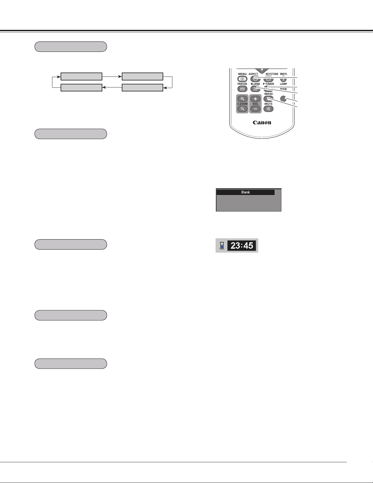
Press the BLANK button on the remote controller to black
out the image. To restore to normal, press the BLANK
button again or press any other button. When the projected
image is captured and is set as User in the Logo selection
(p.55), the screen changes each time you press the BLANK
button as follows.
black out the captured image normal • • • • •
Press the P-TIMER button on the remote controller. The
Timer display “00 : 00” appears on the screen and starts to
count time (00 : 00–59 : 59).
To stop the P-TIMER, press the P-TIMER button.
To cancel the P-TIMER, press the P-TIMER button again.
Press the IMAGE button on the remote controller to select a
desired image mode of the screen. See page 38 for details.
Blank disappears after 4 seconds.
Note:
See the previous page for the description of
other buttons.
3D
IMAGE button
BLANK button
P-TIMER button
ASPECT button
Select the screen size (See pages 40-42, 48-49 for details).
Remote Controller
Note:
When use the MUTE button to release the Blank function,
the mute function can not be operated at the same time.
BLANK button
P-TIMER button
IMAGE button
ASPECT button
BLANK
P-Timer
3D button
Select 3D mode from 3D Off, 3D (Sync. 1) and 3D (Sync.
2) (p.50-51)
3D button
3D Off
3D VISION
3D(Sync 1)
3D(Sync 2)
* The 3D indicator on the control panel emits blue at 3D (Sync 1),
3D(Sync 2) and 3D VISION. (p.50-51)
32
COMPUTER
1
3D
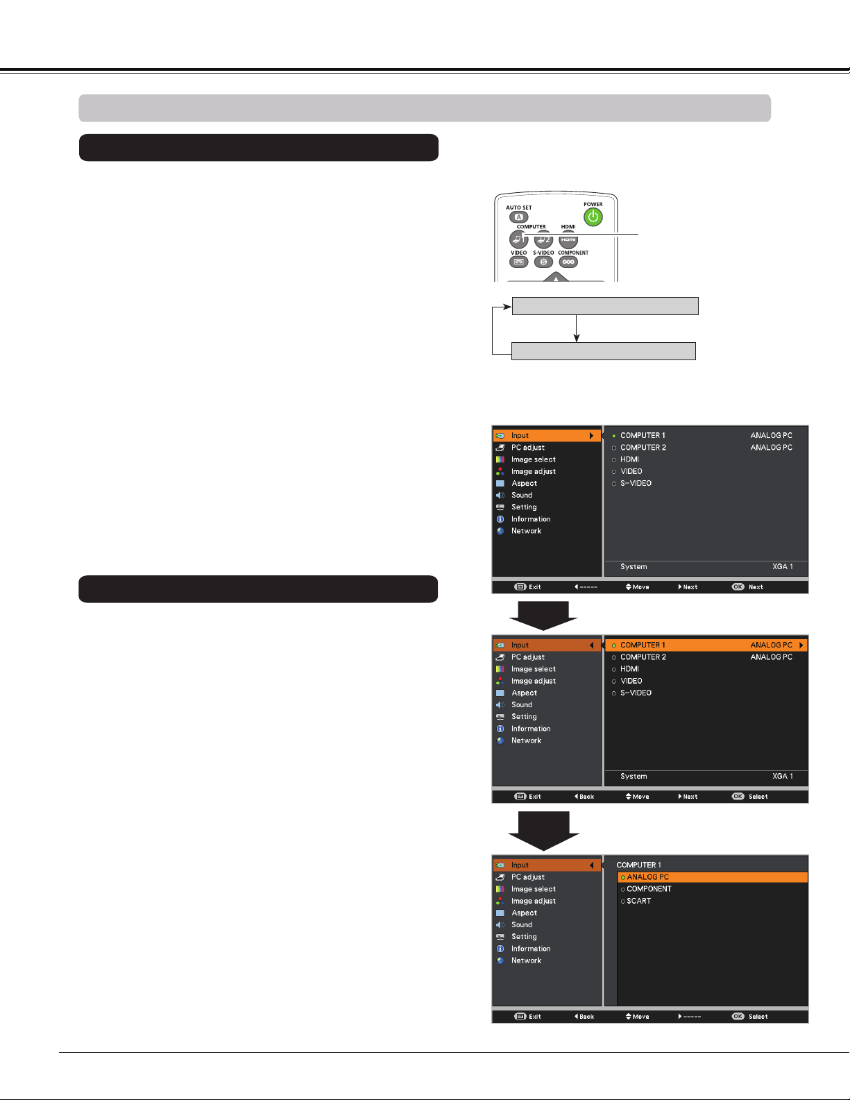
Choose COMPUTER 1(ANALOG PC) by pressing the
COMPUTER 1 button on the remote controller.
Before using these buttons, correct input source should be
selected through Menu operation as described below.
1
Input Menu
2
3
Input Source Selection (COMPUTER 1: ANALOG PC)
Computer Input
COMPUTER 1 button
Note:
When the Auto input function is set to On 1 or On 2 in
the Auto setup function, the input signal will be searched
automatically (p.53).
Remote Controller
Press the MENU button to display the On-Screen
Menu. Use the Point buttons to select Input and
then press the Point
or the OK button.
Use the Point buttons to select COMPUTER 1.
When COMPUTER 1 is selected,
press the Point
to
access the submenu items
. Use the Point buttons
to select the ANALOG PC input source and then press
the OK button.
COMPUTER 1(ANALOG PC)
COMPUTER 1(SCART)
Direct Operation
Menu Operation
33
3D
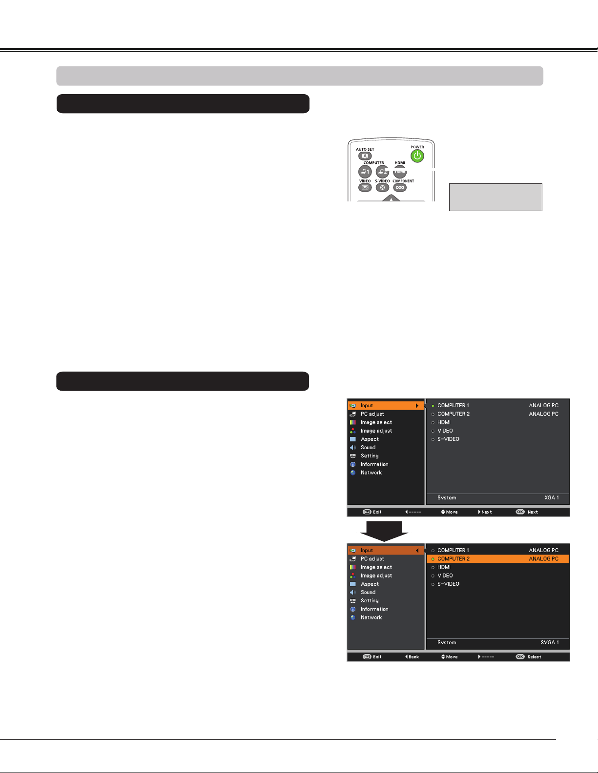
Choose COMPUTER2 (ANALOG PC) by press the
COMPUTER 2 button on the remote controller.
Note:
When the Auto input function is set to On 1 or On 2 in
the Auto setup function, the input signal will be searched
automatically (p.53).
COMPUTER 2 button
Remote Controller
1
2
Press the MENU button to display the On-Screen
Menu. Press the Point buttons, move the highlight
to Input and then press the Point
or the OK button.
Use the Point buttons to select COMPUTER 2 and
then press the OK button.
Input Menu
COMPUTER 2
(ANALOG PC)*
3
When COMPUTER 2 is selected, ANALOG PC input
source will be selected directly.
Input Source Selection (COMPUTER 2: ANALOG PC)
Direct Operation
Menu Operation
Computer Input
Note:
*
COMPUTER 2 can not be selected when
using the COMPUTER IN 2/ MONITOR
OUT terminal as MONITOR OUT.
"Monitor out" message will appear on the
screen when COMPUTER 2 button is
pressed while using the COMPUTER IN
2/ MONITOR OUT terminal as MONITOR
OUT.
34
Computer Input
PC System Menu
PC System Menu
Computer System Selection
This projector automatically tunes to various types of computers with its Multi-scan system and Auto PC
adjustment. If a computer is selected as a signal source, this projector automatically detects the signal format
and tunes to project a proper image without any additional settings. (Signal formats provided in this projector are
shown on pages 77-78.)
One of the following messages may appear when:
When the projector can not recognize the
connected signal conforming to the provided
PC Systems, Auto is displayed on the System
Menu box and the Auto PC adjustment function
works to display proper images. If the image is
not projected properly, a manual adjustment is
required. (pp.36-37)
There is no signal input from the computer.
Check the connection between your computer
and the projector. (See “Troubleshooting” on
page 71.)
Auto
-----
The preset system is manually adjusted in the
PC adjust Menu. The adjusted data can be
stored in Mode 1-10. (pp.36-37)
Mode 1
PC Systems provided in this projector is chosen.
The projector chooses a proper system provided
in the projector and displays it.
XGA 1
* Mode 1 and XGA 1 are examples.
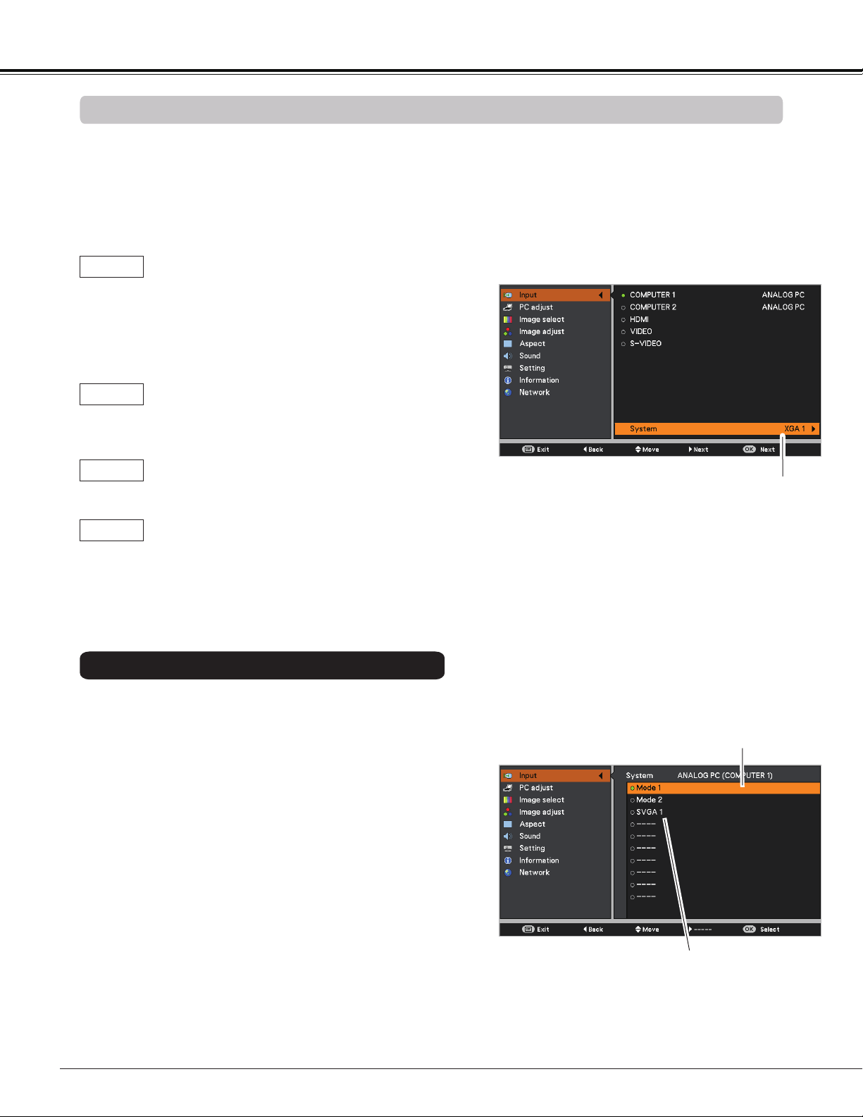
1
2
PC system can also be selected manually.
Press the MENU button to display the On-Screen
Menu. Use the Point buttons to select Input and
then press the Point or the OK button.
Use the Point buttons to select System and then
press the Point or the OK button.
Use the Point buttons to select the desired system
and then press the OK button.
3
Selected system in the PC
System Menu is displayed.
Systems in this dialog box
can be selected.
Customized Mode (1–10)
set in the PC adjust Menu
(pp.36-37).
Selecting Computer System Manually
35
Computer Input
Auto PC adjustment function is provided to automatically adjust Fine sync, Total dots, Horizontal position,
Vertical position and Clamp position to conform to your computer.
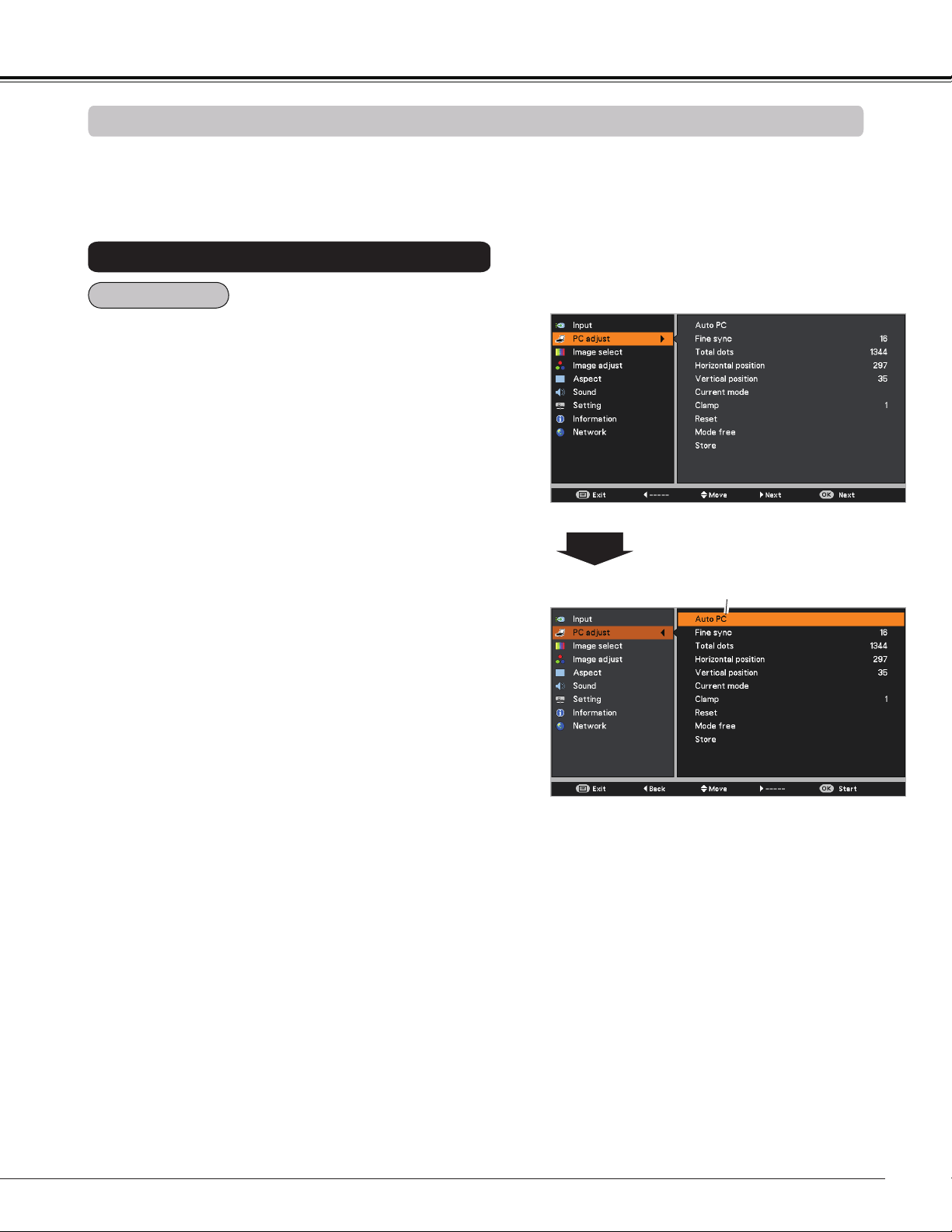
PC adjust Menu
Auto PC adjustment
To store adjustment parameters
The adjusted parameters from the Auto PC adjustment can
be stored in the projector. Once the parameters are stored,
the setting can be done just by selecting a Mode (1–10) in
the PC System Menu (See page 34). See also “Store” on
page 37.
Note:
• Fine sync, Total dots, Horizontal position and
Vertical position of some computers can not be fully
adjusted with the Auto PC adjustment function. When
the image is not provided properly with this operation,
manual adjustments are required (pp.36-37).
• The Auto PC adjustment can not be operated when
480i, 575i, 480p, 575p, 720p or 1080i is selected in the
PC System Menu (p.34) , or when the signal is coming
from the HDMI terminal.
Press the MENU button to display the On-Screen
Menu. Use the Point buttons to select PC adjust
and then press the Point or the OK button.
1
2
Use the Point buttons to select Auto PC and then
press the OK button.
Use Point buttons to select Auto PC
and press the OK button.
Please wait... appears while the Auto PC
adjustment is in process.
Menu Operation
Auto PC
36
Computer Input
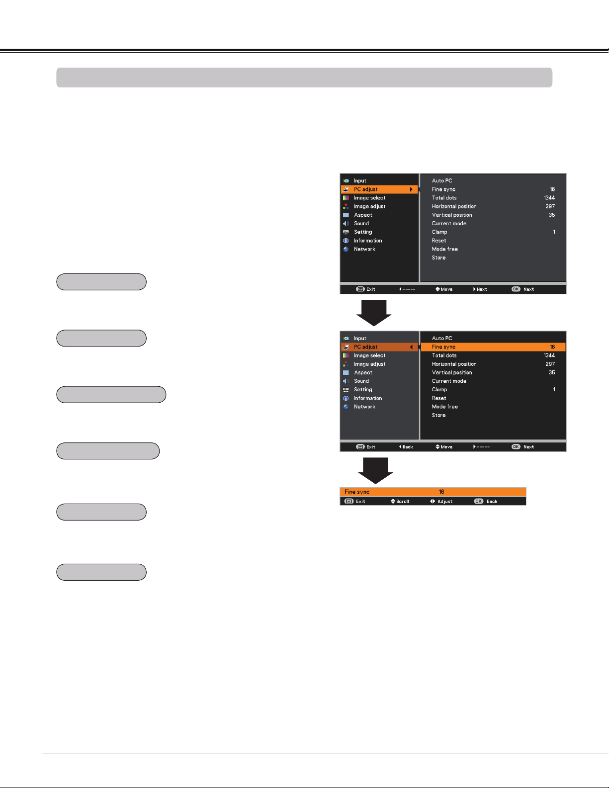
PC adjust Menu
Manual PC adjustment
Some computers employ special signal formats which may not be tuned by Multi-scan system of this projector.
Manual PC adjustment enables you to precisely adjust several parameters to match those signal formats. The
projector has 10 independent memory areas to store those parameters manually adjusted. It allows you to recall
the setting for a specific computer.
1
2
Use the Point buttons to adjust the value, eliminating a
flicker from the image displayed (from 0 to 31).
Use the Point buttons to adjust the number of total dots
in one horizontal period to match your PC image.
Use the Point buttons to adjust the horizontal picture
position.
Use the Point buttons to adjust the vertical picture
position.
Use the Point buttons to adjust the clamp level. When
the image has dark bars, try this adjustment.
Press the MENU button to display the On-Screen
Menu. Use the Point buttons to select PC adjust
and then press the Point or the OK button.
Use the Point buttons to select the desired item
and then press the OK button to display the adjustment
dialog box. Use the Point buttons to adjust the
setting value.
Press the OK button to show H-sync freq. and V-sync freq.
of the connected computer.
Fine sync
Total dots
Vertical position
Current mode
Clamp
Horizontal position
Note:
Fine sync and Total dots cannot be selected when the
input signal is 480i, 480p, 575i, 575p, 720p or 1080i.
37
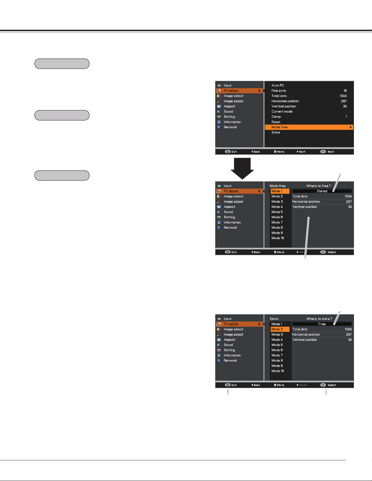
Computer Input
To store the adjusted data, select Store and then press the
Point or the OK button. Move the highlight to one of the
Modes 1 to 10 in which you want to store, and then press
the OK button.
To clear the stored data, select Mode free and then press
the Point or the OK button. Move the highlight to the
Mode that you want to clear and then press the OK button.
Note:
• When input computer signal to the projector, PC adjust
will become available.
To reset the adjusted data, select Reset and press the OK
button. A confirmation box appears and then select Yes. All
adjustments will return to their previous figures.
This Mode has stored
parameters.
Values of Total dots, Horizontal
position, and Vertical position.
Mode free Menu
Vacant
Press OK button to store
adjusted data.
Press MENU button
to close this dialog
box.
Store Menu
Store
Mode free
Reset

38
Computer Input
3D
Image Select Menu
IMAGE button
Presentation
High contrast
User 1
User 2
User 3
Image Mode Selection
User 4
Cinema
Standard
Remote Controller
IMAGE button
Select the desired image mode among Presentation,
Standard, High contrast, Cinema, User 1,User 2,User 3,
and User 4 by pressing the IMAGE button on the remote
controller.
Picture mode with improved halftone for graphics.
Direct Operation
For viewing pictures in a bright room.
Normal picture mode preset on the projector.
For viewing with the user preset image mode in the Image
adjust Menu (See page 39).
1
2
Menu Operation
Press the MENU button to display the On-Screen
Menu. Use the Point buttons to select Image
select and then press the Point or the OK button.
Use the Point buttons to select the desired item
and then press the OK button.
Picture mode adjusted with fine tone.
Standard
High contrast
Cinema
User 1-4
Presentation
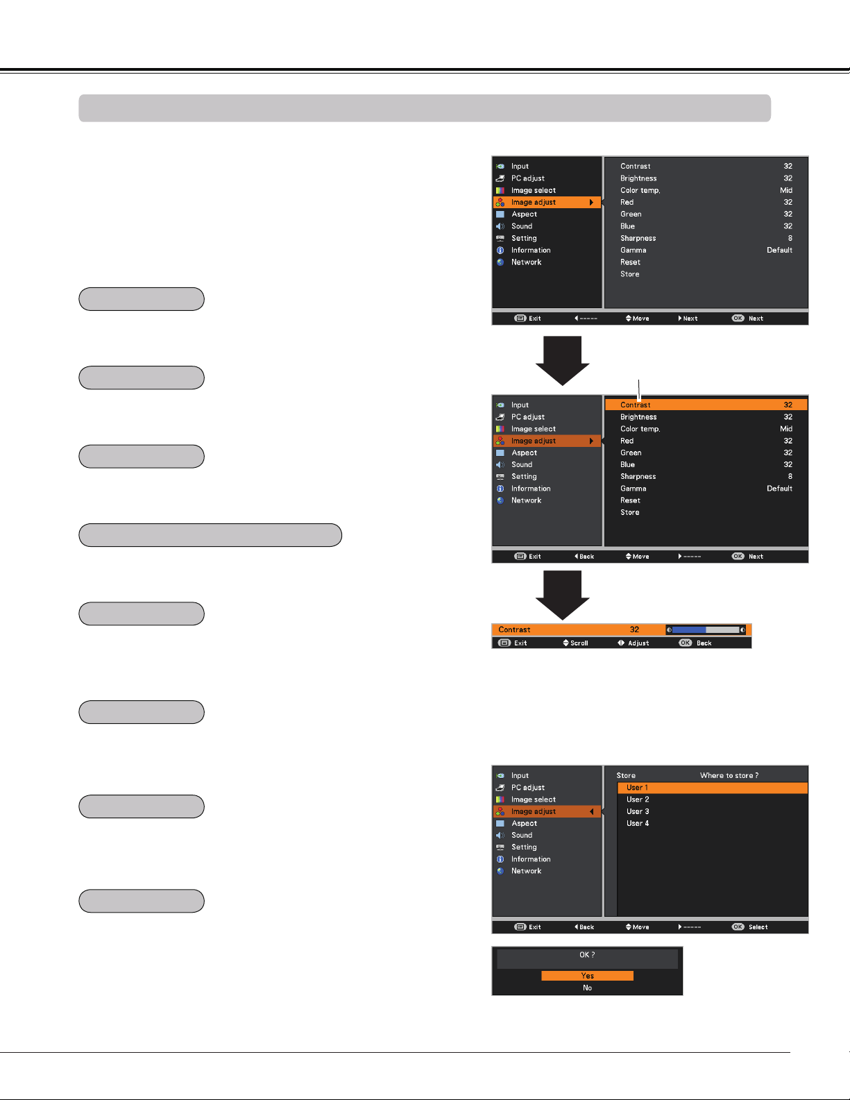
39
Computer Input
Image adjust Menu
Image Adjustment
Press the MENU button to display the On-Screen
Menu. Use the Point buttons to select Image
adjust and then press the Point or the OK button.
1
2
Use the Point buttons select the desired item and
then press the OK button to display the adjustment
dialog box. Use the Point buttons to adjust the
setting value.
Note:
• When White balance Red, Green or Blue is
adjusted, Color temp. will change to User.
Press the Point button to decrease the contrast; press the
Point button to increase the contrast (from 0 to 63).
Press the Point button to decrease the brightness; press
the Point button to increase the brightness (from 0 to 63).
Press the Point button to lighten R/G/B tone; press the
Point button to deepen R/G/B tone (from 0 to 63).
Use the Point buttons to select the desired Color temp.
level (XLow, Low, Mid, or High).
Use the Point buttons to adjust the gamma value to
obtain a better balance of contrast (Default, 1.8, 2.0, 2.2,
2.4, or 2.6).
Press the Point button to decrease the sharpness of the
image; press the Point button to increase the sharpness
of the image (from 0 to 15).
To reset the adjusted data, select Reset and press the OK
button. A confirmation box appears and then select Yes. All
adjustments will return to their previous figures.
Use the Point
buttons to adjust the
setting value.
Selected Image mode
To store the adjusted data, select Store and press the Point
or the OK button. Use the Point buttons to select one
from User 1 to 4 and press the OK button.
A confirmation box appears and then select Yes. Stored
data can be called up by selecting an User (1-4) in the
Image Mode Selection on page 36.
A confirmation box appears and
then select Yes.
Store Menu
Contrast
Brightness
Color temp.
White balance (Red / Green / Blue)
Sharpness
Gamma
Reset
Store
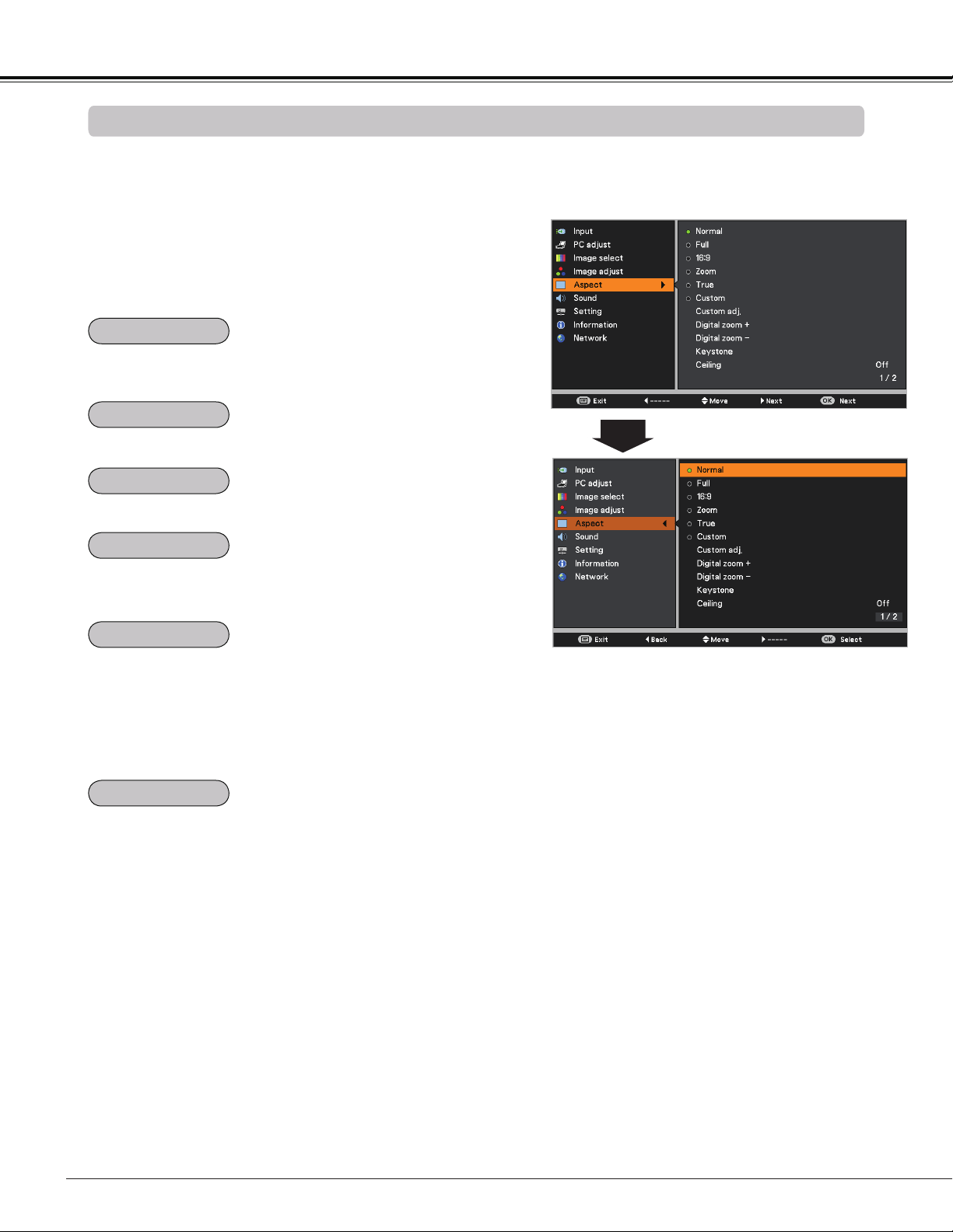
40
Computer Input
Provide the image in its original size. When the original
image size is larger than the panel resolution (DLP chip
1280 x 800 dots), the projector automatically switches to
the panning mode. Use the Point buttons to pan the
image. When adjusted, the arrows turn red. When reached
to the correction limit, the arrows disappear.
Provide the last stored aspect screen image.
True
Custom
This projector has the picture screen resize function, which
enables you to customize the image size.
Screen Menu
Provide the image to fit the screen size while maintaining
the aspect ratio of input signal.
Provide the full screen image.
1
2
Press the MENU button to display the On-Screen
Menu. Use the Point buttons to select Aspect and
then press the Point or the OK button.
Use the Point buttons select the desired item and
then press the OK button .
Note:
• This projector can not display any resolution higher than 1920 x 1200. If your computer’s resolution is higher
than that, lower the resolution before connecting to the projector.
• The image data other than 1280 x 800 is modified to fit the screen size in initial mode.
• True and Digital zoom +/– can not be selected when 480i, 575i, 480p, or 575p is selected in the PC System
Menu (p.34).
• Zoom and Image Position Adjustment (p.27) will be canceled when Custom is selected in the Screen menu.
Scale the image proportionally to fit the entire screen. Either
side of image may go over the screen.
Screen Size Adjustment
Normal
Full
16:9
Provide the image at the 16:9 wide screen ratio.
Zoom
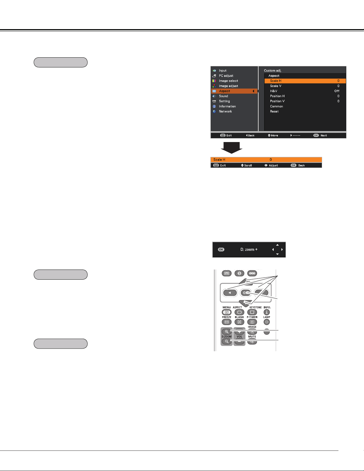
41
Select Digital zoom +. The On-Screen Menu disappears
and D. zoom + appears. Press the OK button to expand the
image size. Use the Point buttons to pan the image.
The Panning function can work only when the image is
larger than the screen size.
A projected image can be also expanded by pressing the
D.ZOOM + or the OK button on the remote controller.
To exit the Digital zoom +/– mode, press any button except
the D.ZOOM +/– and the OK buttons.
Select Digital zoom -. The On-Screen Menu disappears and
D. zoom - appears. Press the OK button to compress image
size.
The projected image can be also compressed by pressing
the D.ZOOM – or the OK button on the remote controller.
To return to the previous screen size, select a screen size
from the Screen Size Adjustment Menu or select an input
source from the Input Source Selection Menu (See pages
32-33) again, or adjust the screen size with the D.ZOOM
+/– buttons.
Note:
• The panning function may not operate
properly if the stored Mode in the PC adjust
Menu is used (p.37).
• The minimum compression ratio is limited
depending on the input signal, when the
Keystone function is working or when
Custom is selected for the screen size.
• True and Digital zoom +/- can not be
selected when 480i, 575i, 480p, or 575p is
selected in the PC System Menu (p.34).
• Digital zoom +/- can not be selected when
True is selected in the Screen menu. (p.40)
3D
Remote Controller
D.ZOOM + button
POINT buttons
OK button
D.ZOOM – button
Adjust the screen scale and position manually with this
function.
Press the Point button at Custom adj. and the Custom
adjustment menu is displayed on the screen, you can use
the Point buttons to choose the item you want to adjust.
Scale H/V .......... Adjust the Horizontal/Vertical screen
scale.
H&V ................... When set to On, the aspect ratio is fixed.
Scale V appears dimmed and becomes
unavailable. Adjust Scale H, then the
screen scale is automatically modified
based on the aspect ratio.
Position H/V ..... Adjust the Horizontal/Vertical screen
position.
Common ........... Save the adjusted scale or position to
all the inputs. Press the OK button at
Common to display a confirmation box.
To save the scale or position, press the
OK button at "Yes". When Custom is
selected, the saved scale or position is
used.
Reset ................. Reset the all adjusted values. Press
the OK button at Reset to display a
confirmation box. To reset, press the OK
button at "Yes".
Note:
• When no signal is detected, Normal is set
automatically and Custom adj. cannot
be selected and the Aspect dialog box
disappears.
• The adjustable range for Scale H/V and
Position H/V is limited depending on the
input signal.
Custom adj. Menu
Custom adj.
Computer Input
Digital zoom +
Digital zoom –
D.ZOOM +/–
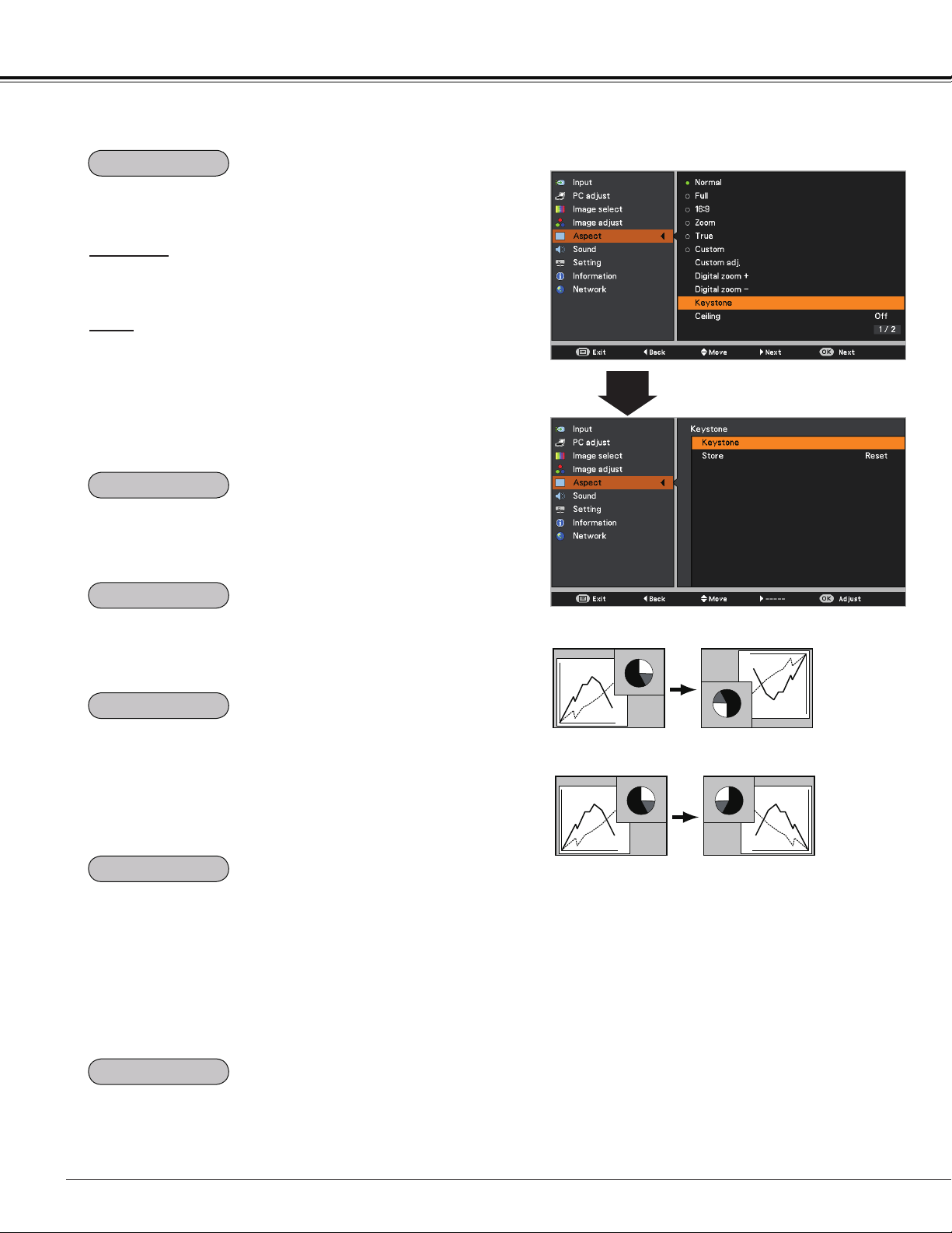
42
Computer Input
Keystone
This function is used to adjust keystone distortion of the
projected image. Use the Point buttons to choose the
item you want to adjust.
Keystone
To correct keystone distortion, press the OK button.
Keystone appears on the screen. Use the Point
buttons to correct keystone distortion (p.28).
Store
To store or reset the keystone correction, press the Point
button.
Store ..... Keep the keystone correction even when the AC
power cord is unplugged.
Reset ..... Release the keystone correction when the AC
power cord is unplugged.
Ceiling
Rear
When this function is set to On, the picture will be top/
bottom and left/right reversed. This function is used to
project the image from a ceiling-mounted projector.
When this function is set to On, the picture will be left/right
reversed. This function is used to project the image from
rear of the screen.
This function is used to project the image to a 4:3 or 16:9
projection screen.
4:3 ...................... Set to a 4:3 projection screen.
16:9 .................... Set to a 16:9 projection screen.
Default(16:10) .... 16:10 is the aspect of the DLP chip. The
original Screen Menu is available.
Note:
• When 4:3 is selected, True is not available
in the PC screen (p.40).
• When 16:9 is selected, 16:9 is not available
in the PC screen (p.40).
• When the screen size is resized by the
ZOOM +/– button on the top control and
then 4:3 or 16:9 is selected, the screen
size will be reset and the Screen aspect is
available.
Press the Point
button at Colorboard, and then use the
Point
buttons to switch the desired item [Red, Blue,
Yellow, Green, Blackboard(Green)] and then press the OK
button.
At the time of simple projection on the colored wall, you can
get the close color image to the color image projected on a
white screen by selecting the similar color to the wall color
from the preset colors.
To reset the adjusted data, select Reset and press the OK
button. A confirmation box appears and then select Yes. All
adjustments will return to their previous figures.
Keystone
Ceiling
Rear
Screen aspect
Colorboard
Reset
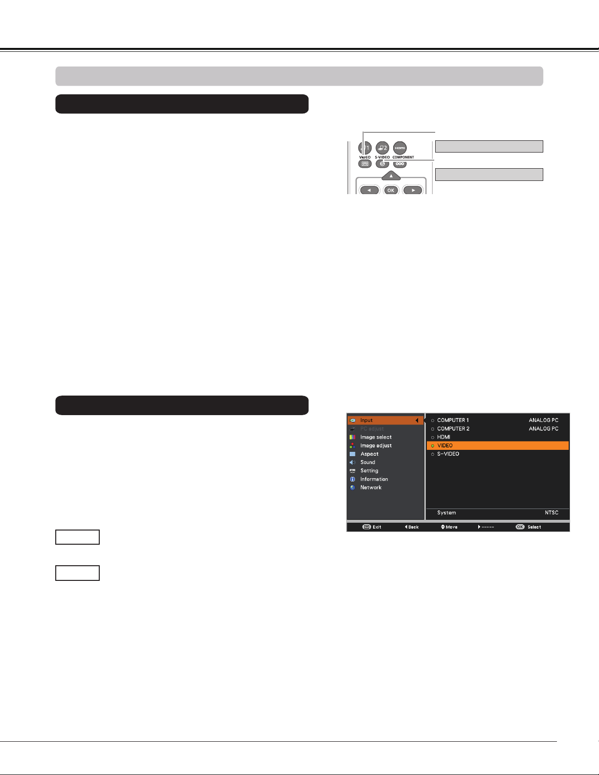
43
Choose VIDEO or S-VODEO by pressing the VIDEO button
or the S-VIDEO button on the remote controller.
1
2
Input Menu
Input Source Selection (VIDEO, S-VIDEO)
Video Input
When video input signal is connected to the
VIDEO jack, select VIDEO.
VIDEO
When video input signal is connected to the
S-VIDEO jack, select S-VIDEO.
S-VIDEO
Note:
When the Auto input function is set to On 1 or On 2 in
the Auto setup function, the input signal will be searched
automatically (p.53).
3D
Remote Controller
VIDEO button
Press the MENU button to display the On-Screen
Menu. Use the Point
buttons to select Input and
then press the Point
or the OK button.
Use the Point
buttons to select either VIDEO or
S-VIDEO and then press the OK button.
S-VIDEO button
VIDEO
S-VIDEO
Direct Operation
Menu Operation
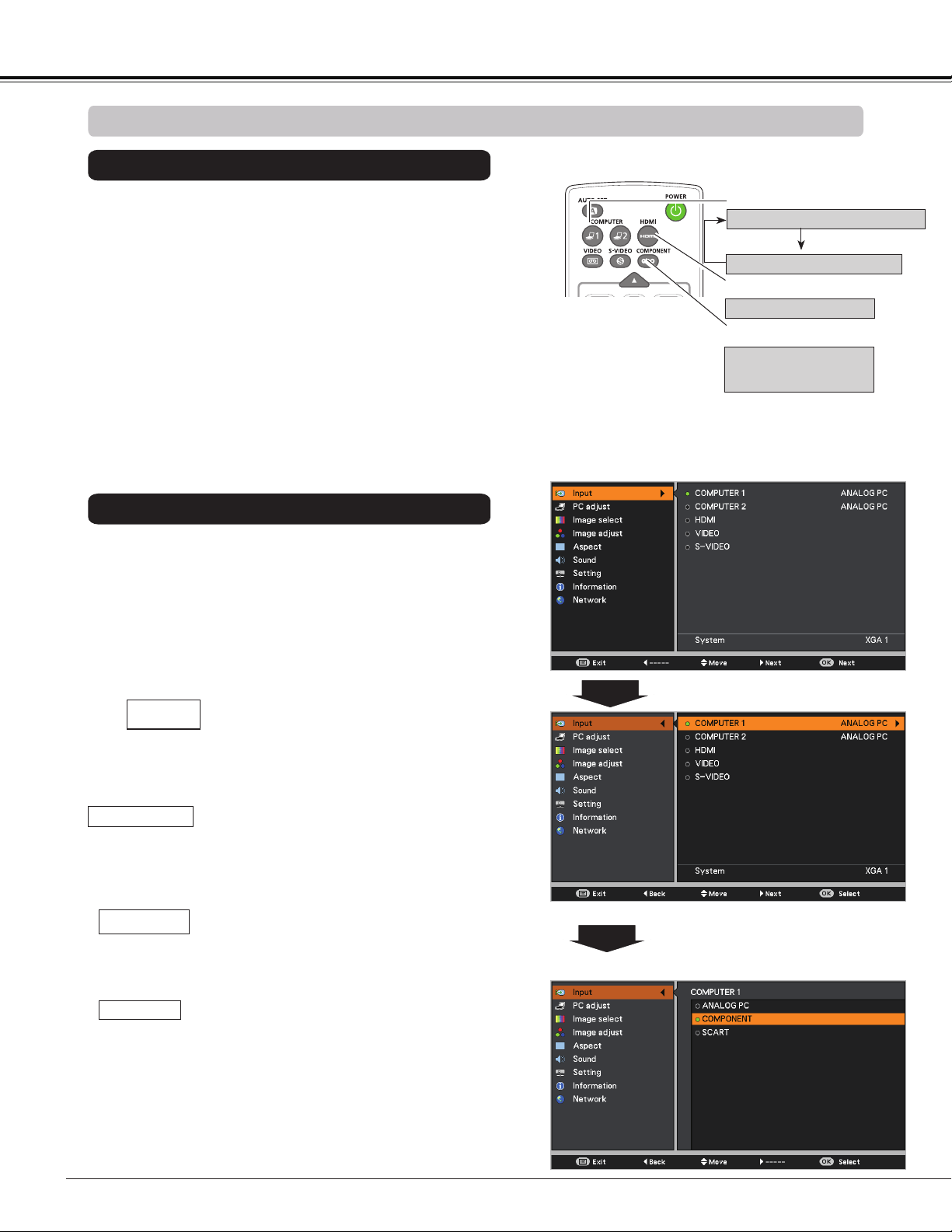
44
Choose COMPUTER 1(COMPONENT) or COMPUTER 1
(SCART) by pressing the the COMPONENT or COMPUTER
1 button on the remote controller; choose HDMI by pressing
the HDMI button on the remote controller.
Before using these buttons, correct input source should be
selected through Menu operation as described below.
1
Input Menu
2
Use the Point buttons to select COMPUTER 1
and
then press the Point button; use the Point
buttons to select ANALOG PC, COMPONENT or
SCART and then press the OK button.
Input Source Selection (COMPONENT, SCART, HDMI)
When the input source is coming from
video equipment connected to the
COMPUTER IN 1/COMPONENT IN terminal
with a Component-VGA Cable, select
COMPONENT.
COMPONENT
When the input source is coming from video
equipment connected to the COMPUTER
IN 1/S-VIDEO IN/COMPONENT IN terminal
with a Scart-VGA Cable, select SCART.
SCART
Press the MENU button to display the On-Screen
Menu. Use the Point buttons to select Input and
then press the Point or the OK button.
Note:
When the Auto input function is set to On 1 or On 2 in
the Auto setup function, the input signal will be searched
automatically (p.53).
3D
COMPUTER 1 button
Remote Controller
Use the Point buttons to select HDMI, and then
press the OK button;
COMPUTER 1 (ANALOG PC)
COMPUTER 1 (SCART)
COMPONENT button
COMPUTER 1
(COMPONENT)
Video Input
HDMI button
HDMI
When the video signal is connected to the
HDMI terminal, select HDMI.
HDMI
Direct Operation
Menu Operation
OR
Press the Point ▲▼ buttons
to select COMPONENT or
SCART.
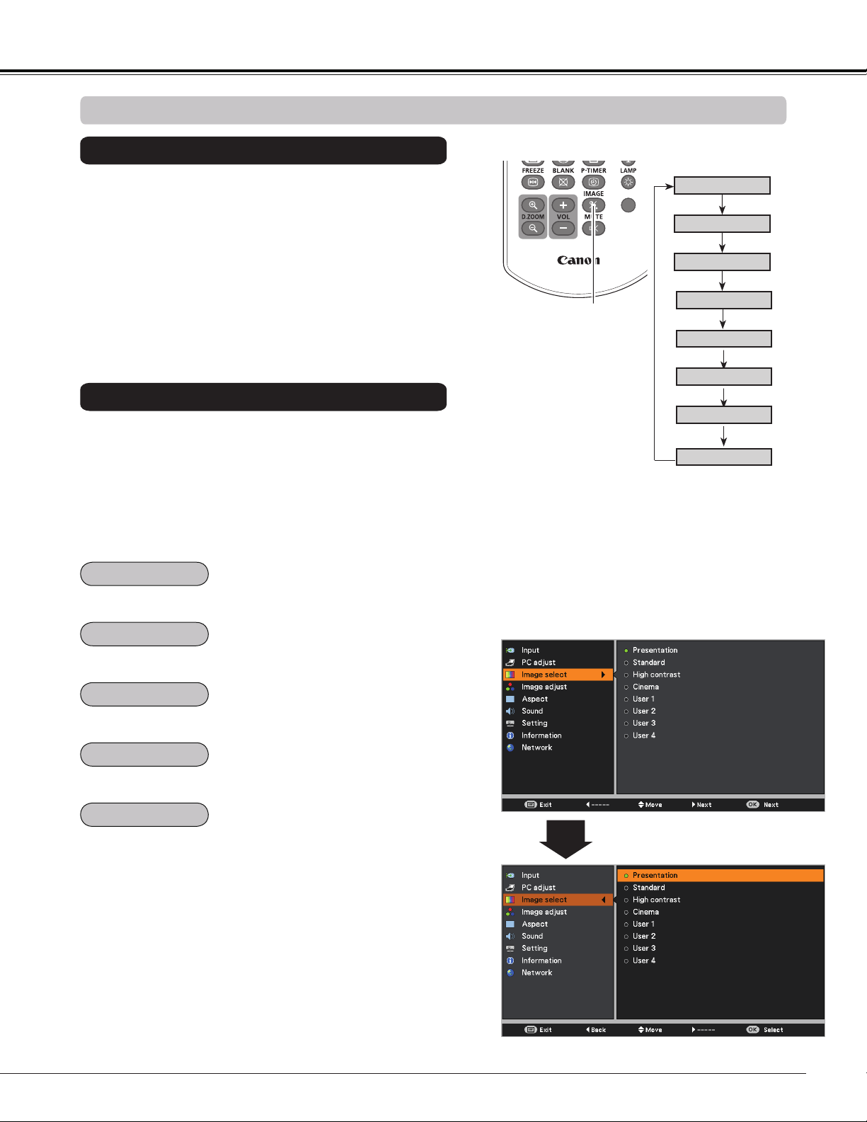
45
Video Input
3D
Image Select Menu
IMAGE button
Presentation
High contrast
User 1
User 2
User 3
Image Mode Selection
User 4
Cinema
Standard
Remote Controller
IMAGE button
Select the desired image mode among Presentation,
Standard, High contrast, Cinema, User 1, User 2, User
3, and User 4 by pressing the IMAGE button on the remote
controller.
Picture mode with improved halftone for graphics.
Direct Operation
For viewing pictures in a bright room.
Normal picture mode preset on the projector.
For viewing with the user preset image mode in the Image
adjust Menu (See pages 46, 47).
1
2
Menu Operation
Press the MENU button to display the On-Screen
Menu. Use the Point buttons to select Image
select and then press the Point or the OK button.
Use the Point buttons to select the desired item
and then press the OK button.
Picture mode adjusted with fine tone.
Standard
High contrast
Cinema
User 1-4
Presentation
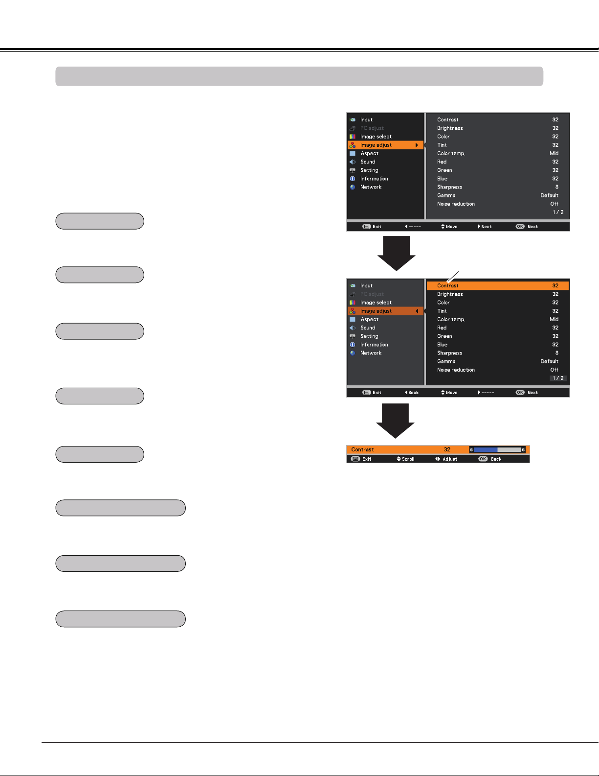
46
Video Input
Image Adjustment
1
2
Press the Point button to decrease the contrast; press the
Point button to increase the contrast (from 0 to 63).
Press the Point button to decrease the brightness; press
the Point button to increase the brightness (from 0 to 63).
Press the Point button to lighten red tone; press the Point
button to deepen red tone (from 0 to 63).
Press the Point button to lighten green tone; press the
Point button to deepen green tone (from 0 to 63).
Press the Point button to lighten blue tone; press the
Point button to deepen blue tone (from 0 to 63).
Use the Point buttons to select the desired Color temp.
level (Xlow, Low, Mid, or High).
Press the Point button decrease the intensity of the color;
press the Point button increase the intensity of the color
(from 0 to 63).
Press the Point buttons to adjust the tint value to get a
proper color balance (from 0 to 63).
Note:
• When the White balance Red, Green, or Blue is adjusted, the Color temp. level will change to User.
• Tint can not be selected when the video system is PAL, SECAM, PAL-M, or PAL-N.
Image adjust Menu
Press the MENU button to display the On-Screen
Menu. Use the Point buttons to select the Image
adjust and then press the Point or the OK button.
Use the Point buttons select the desired item and
then press the OK button to display the adjustment
dialog box. Use the Point buttons to adjust the
setting value.
Selected Image mode
Use the Point
buttons to adjust the
setting value.
Contrast
Brightness
Color
Tint
Color temp.
White balance (Red)
White balance (Green)
White balance (Blue)
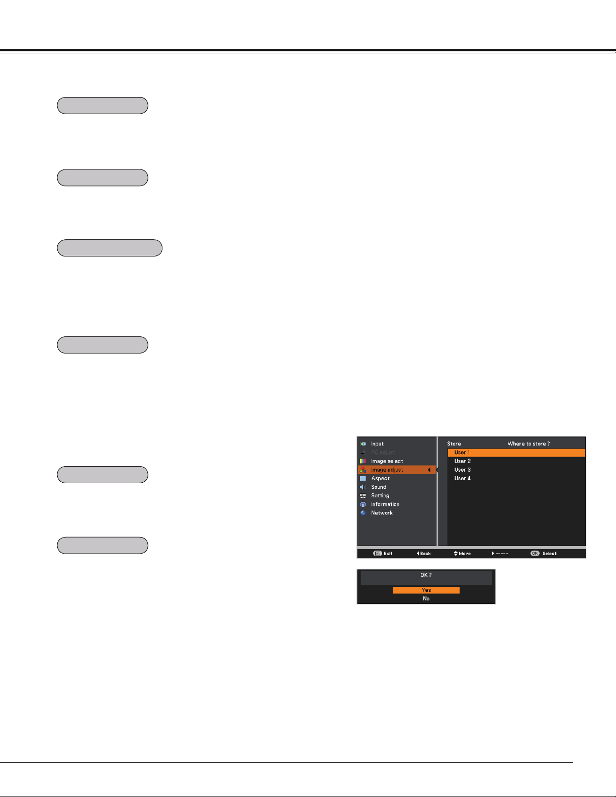
47
Video Input
Use the Point buttons to adjust the gamma value to
obtain a better balance of contrast (Default, 1.8, 2.0, 2.2,
2.4, or 2.6).
Press the Point button to decrease the sharpness of the
image; press the Point button to increase the sharpness
of the image (from 0 to 15).
An interlaced video signal can be displayed in progressive
mode. Select one of the following options.
Off ......... Disabled.
L 1 ......... For an active picture.
L 2 ......... For a still picture.
Film ....... For watching a film. With this function, the
projector reproduces pictures faithful to the
original film quality.
Noise interference on the screen can be reduced. Select
one of the following options to get smoother images.
Off ......... Disabled.
L 1 ......... Lower reduction.
L 2 ......... Higher reduction.
Note:
• Noise reduction and Progressive can not be selected when the input signal is 480p, 575p, 720p or 3D mode
is set to On.
• Film of Progressive cannot be selected when the input signal is 1080i.
• When 480i, 575i, 480p, 575p,720p or 1080i is selected in computer source, the items of Image adjustment
are the same as the items in video source, except for Color and Tint.
To reset the adjusted data, select Reset and press the OK
button. A confirmation box appears and then select Yes. All
adjustments will return to their previous figures.
To store the adjusted data, select Store and press the Point
button or the OK button. Use the Point buttons to
select one from User 1 to 4 and press the OK button.
A confirmation box appears and then select Yes. Stored
data can be called up by selecting an User (1-4) in the
Image Mode Selection on page 45.
Store Menu
A confirmation box
appears and then
select Yes.
Sharpness
Gamma
Noise reduction
Progressive
Reset
Store
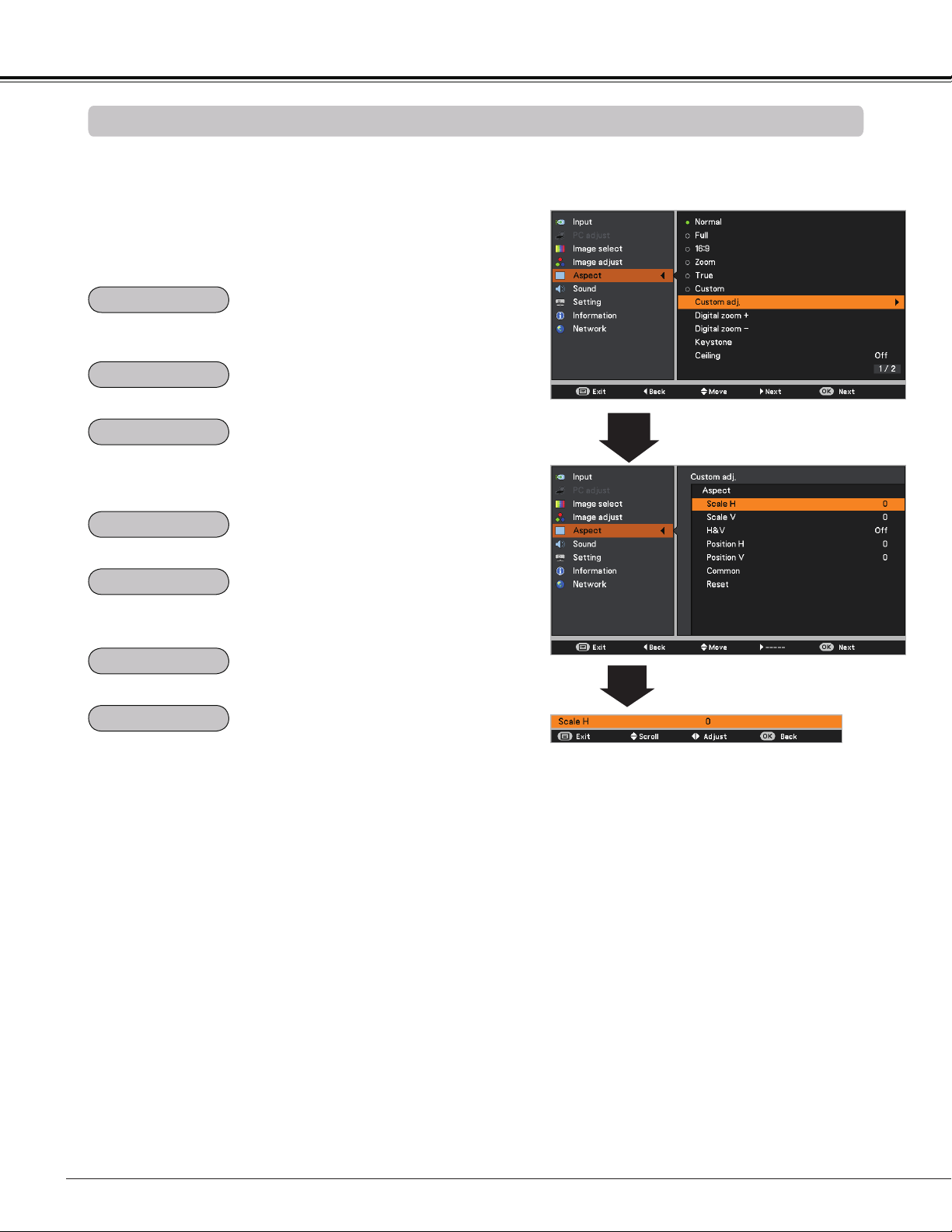
48
Video Input
This projector has the picture screen resize function, which enables you to customize the image size.
Screen Size Adjustment
Aspect Menu
1
2
Adjust the screen scale and position manually with this
function.
Press the Point button at Custom adj. and the Custom
adjustment menu is displayed on the screen, you can use
the Point buttons to choose the item you want to adjust.
Scale H/V ........ Adjust the Horizontal/Vertical screen scale.
H&V ................. When set to On, the aspect ratio is fixed.
Scale V appears dimmed and becomes
unavailable. Adjust Scale H, then the screen
scale is automatically modified based on the
aspect ratio.
Position H/V ... Adjust the Horizontal/Vertical screen
position.
Common ......... Save the adjusted scale or position to all the
inputs. Press the OK button at Common to
display a confirmation box. To save the scale
or position, press the OK button at "Yes",
When Custom is selected, the saved scale
or position is used.
Reset ............... Reset the all adjusted values. Press the OK
button at Reset to display a confirmation
box. To reset, press the OK button at "Yes".
Note:
• When no signal is detected, Normal
is set automatically and the Image
adjustment menu disappears.
• The adjustable range for Scale H/V and
Position H/V is limited depending on the
input signal.
• Natural wide and 16:9 can not be
operated when 720p or 1080i is selected
in the AV System Menu (p.45).
• Natural wide and 16:9 are not available
when the 4:3 or 16:9 is selected in the
Screen aspect (p.49).
Provide the image at the 16:9 wide screen ratio.
Press the MENU button to display the On-Screen
Menu. Use the Point buttons to select Aspect and
then press the Point or the OK button.
Use the Point buttons select the desired item and
then press the OK button.
Provide the image to fit the screen size while maintaining
the aspect ratio of input signal.
Provide the full screen image.
Pan the horizontal direction of the image and cut the vertical
direction of the image to fit the screen size (16:9). Only for 4:3
video aspect ratio signals.
Modify the 4:3 aspect ratio image to fit the screen size (16:9
aspect ratio) by stretching the image to make it look natural.
Provide the last stored aspect screen image.
Normal
Full
Zoom
16:9
Natural wide
Custom
Custom adj.

49
Video Input
Keystone
This function is used to adjust keystone distortion of the
projected image. Use the Point buttons to choose the
item you want to adjust.
Keystone
To correct keystone distortion, press the OK button.
Keystone appears on the screen. Use the Point
buttons to correct keystone distortion (p.28).
Store
To store or reset the keystone correction, press the Point
button.
Store ..... Keep the keystone correction even when the AC
power cord is unplugged.
Reset ..... Release the keystone correction when the AC
power cord is unplugged.
Ceiling
Rear
When this function is set to On, the picture will be top/
bottom and left/right reversed. This function is used to
project the image from a ceiling-mounted projector.
When this function is set to On, the picture will be left/right
reversed. This function is used to project the image from
rear of the screen.
This function is used to project the image to a 4:3 or 16:9
projection screen.
4:3 ...................... Set to a 4:3 projection screen.
16:9 .................... Set to a 16:9 projection screen.
Default(16:10) .... 16:10 is the aspect of the DLP chip. The
original Screen Menu is available.
Note:
• When 4:3 is selected, Natural wide is not
available in the AV screen (p.48).
• When 16:9 is selected,16:9 is not available
in the AV screen (p.48).
• When 16:9 is selected and the input signal
is 720p or 1080i, Natural wide is not
available in the AV screen (pp.45, 48).
• When the screen size is resized by the
ZOOM +/– button on the top control and
then 4:3 or 16:9 is selected, the screen size
will be reset and the Screen aspect will be
available.
Press the Point
button at Colorboard, and then use the
Point
buttons to switch the desired item [Red, Blue,
Yellow, Green, Blackboard(Green)] and then press the OK
button.
At the time of simple projection on the colored wall, you can
get the close color image to the color image projected on a
white screen by selecting the similar color to the wall color
from the preset colors.
To reset the adjusted data, select Reset and press the OK
button. A confirmation box appears and then select Yes. All
adjustments will return to their previous figures.
Keystone
Ceiling
Rear
Screen aspect
Colorboard
Reset
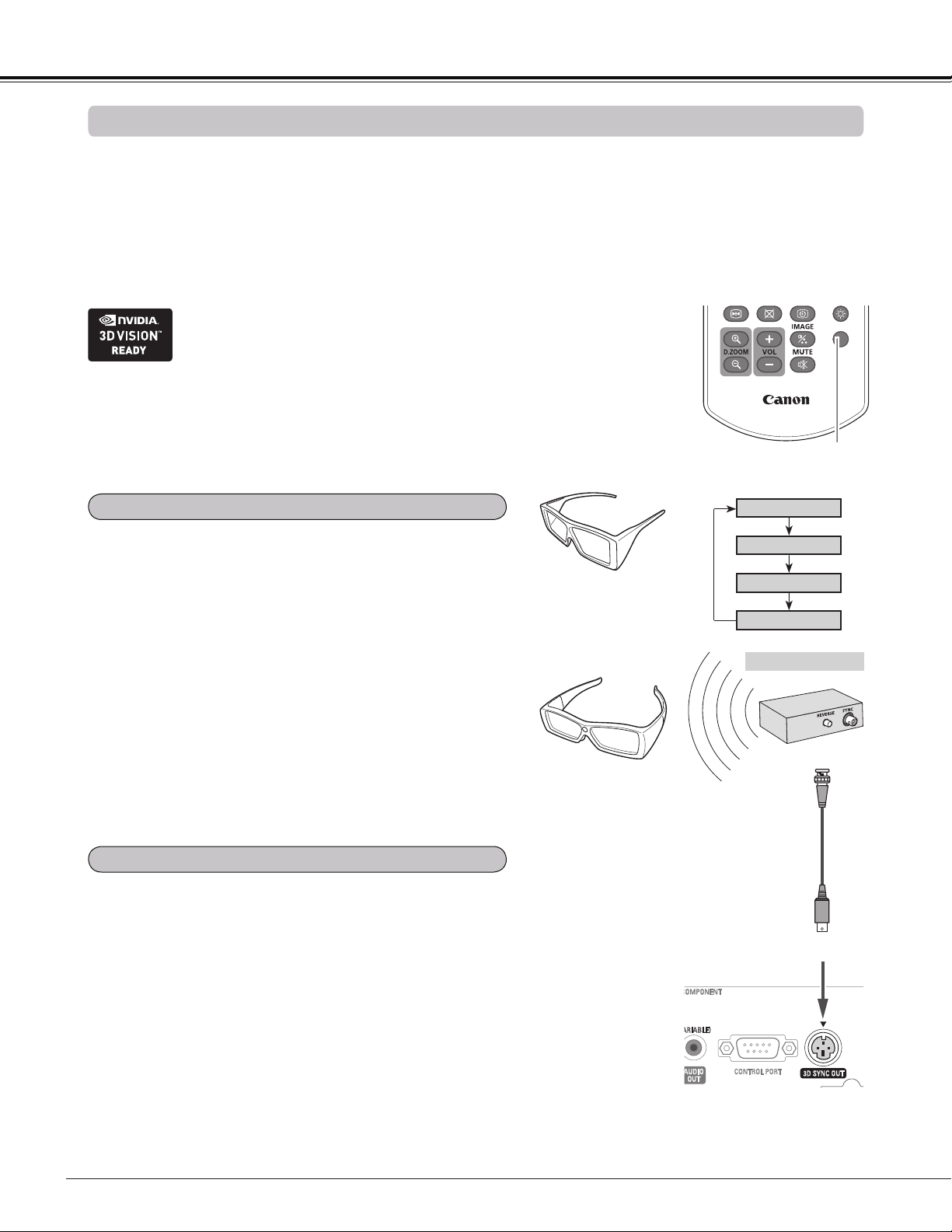
50
3D Display
For Viewing 3D Contents
Note:
Unplug the power cords of both the
projector and external equipment from
the AC outlet before connecting cables.
Infrared Emitter
3D SYNC OUT
Sync Signal Cable
(Supplied with the IR Emitter)
Stereoscopic Wireless
LCD Glasses
3D SYNC Input
When using DLP Link compatible glasses, follow these
steps:
1. Turn on the projector and the 3D glasses.
2. Wear the 3D glasses and press the 3D button on the
remote controller to activate 3D Display function.
When 3D mode is in On, 3D indicator turns blue.
3. If you see a discrete or overlapping image, 3D Sync
Invert function enables you to get the correct image.
Press the 3D button to switch 3D Sync signal from among
"3D Off", "3D (Sync 1)", "3D (Sync 2)" or "3D VISION".
3D setting can also be selected from the menu (p.54).
3D
3D Mode
3D Off
3D (Sync 2)
3D (Sync 1)
Remote Controller
3D button
When using IR emitter system, follow these steps:
1. Turn off the projector.
2. Connect the sync cable for the IR emitter to 3D SYNC
OUT terminal of the projector.
3. Turn on the projector, the IR emitter and the stereoscopic
wireless LCD glasses.
4. Wear the 3D glasses and press the 3D button on the
remote controller to activate 3D Display function.
5. If you see a discrete or overlapping image, press the 3D
button to switch 3D Sync signal from among "3D Off", "3D
(Sync 1)", "3D (Sync 2)" or "3D VISION".
You can also invert the sync signal by using the switch on
the IR emitter.
Using 3D Glasses with DLP Link compatible
Using 3D Glasses with IR wireless emitter
LCD Glasses with DLP
Link compatible
To view 3D images, you need to prepare at least the 3D active shutter glasses, 3D content and 3D reproducing
equipment. For example, as for computer, when transmitting 3D signals from a computer to the projector, you
also need to install the graphic card which has the capability to sequentially output the 3D frames at 120Hz and
software in the computer. The 3D signal type which the projector can accept is frame sequential only. Other 3D
signal types such as frame packing and side-by-side are not supported.
As for 3D glasses, DLP Link format and IR emitter format are compatible with this projector. Compatibility with
any other 3D glasses than the 2 types 3D glasses is not guaranteed.
3D VISION
In a situation of using NVIDIA
®
3D glasses, NVIDIA IR emitter, and
a computer which NVIDIA graphics card is installed, when you want
to view NVIDIA-compatible 3D contents, please set to NVIDIA 3D
VISION mode.
* COMPUTER IN 2/MONITOR OUT terminal is not supported NVIDIA
®
3D VISION™.
Please input the image signals to COMPUTER IN 1/COMPONENT IN or HDMI terminal.
51
- The optimum 3D viewing distance from the screen
is about 3 m or more and your eyes should be level
with the screen.
- Viewing 3D images for an extended period of time or
viewing them from an oblique angle can cause eye
strain.
- Take breaks when viewing 3D images for an
extended period of time. As this may cause eye
fatigue.
- Some image sources can cause pseudoscopic
image problem. Check the 3D settings to get the 3D
effect.
- If the right-eye image and left-eye image are
switched, you may not get the 3D effect, resulting in
eye strain or nausea.
- There are differences in 3D visual perception
between individuals.
- If you get double vision or don’t get the 3D effect,
discontinue using the projector.
- If you experience fatigue or nausea, stop using the
projector.
- After viewing the rotating, swinging, or jumping 3D
images, you may experience 3D motion sickness.
- If you experience such symptom, immediately stop
viewing the 3D images and take a break until the
symptom has subsided.
- If you view 3D images in bright ambient light
environment, you may not able to see them clearly.
Or if you use the 3D glasses in a room which
fluorescent lighting (50Hz), flickering may occur. If
these happen, change the room lighting condition by
making the room dark or turning off the light.
- Children who are six year of age or younger should
not view 3D images.
- Parents should accompany and monitor their
children as children cannot properly express
discomfort with 3D image viewing.
- Photosensitive patients, patients with heart disease,
pregnant women, elderly people, and people with
serious illness and/or with a history of epilepsy
should not view 3D images
- We advise that you should refrain from viewing 3D
images if you are in bad physical condition
- We do not recommend viewing 3D images if you
need sleep or have been drinking alcohol.
Symptoms Possible problems Solution
3D contents appear as 2D. The glasses or the projector are set
to 2D mode.
Change the setting of the glasses or projector.
3D image is inverted. (3D image
is not correct.)
3D mode is out of phase. (The data
for right/left eyes is inverted.)
Reverse the 3D sync phase of the projector
by using 3D button on the remote controller or
through the Setting menu of the projector.
Image of glasses has flicker. Outside of the recommended viewing
zone of the glasses.
Move your position closer to the emitter.
Glasses does not turn on. - The battery of the glasses is
exhausted.
- The projector is not set to 3D mode.
- Recharge the battery.
- Change the setting of the projector.
3D Display
CAUTION FOR PROPERLY VIEWING 3D PICTURES
TROUBLESHOOTING FOR 3D DISPLAY
RESTRICTIONS ON VIEWING 3D IMAGES
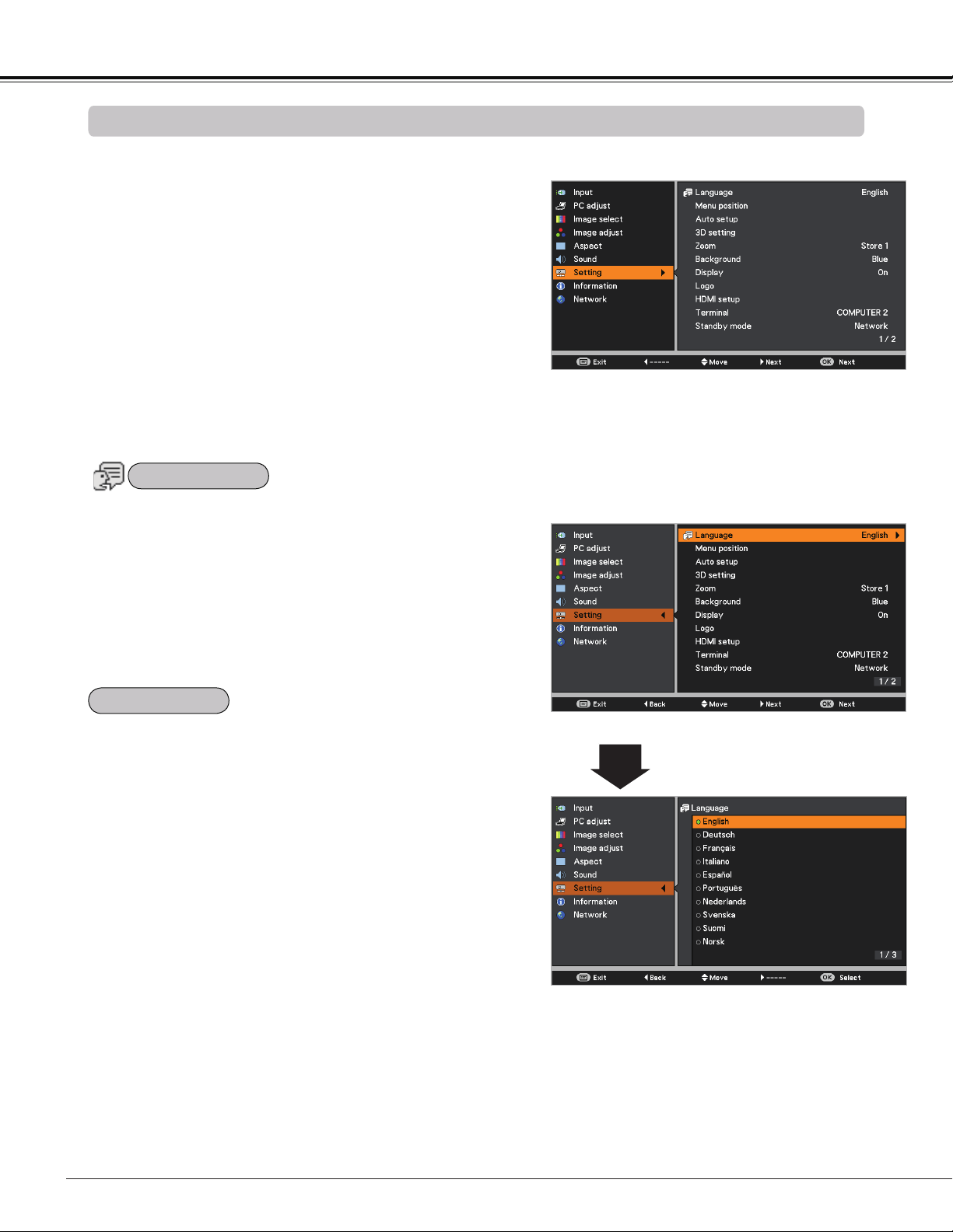
52
The language used in the On-Screen Menu is available in
English, German, French, Italian, Spanish, Portuguese,
Dutch, Swedish, Finnish, Norwegian, Danish, Polish,
Hungarian, Romanian, Russian, Brazilian Portuguese,
Turkish, Arabic, Kazakh, Simplified Chinese, Traditional
Chinese, Korean, Japanese and Thai.
Setting Menu
Setting
Setting
Press the MENU button to display the On-Screen
Menu. Press the Point buttons to select the
Setting and press the Point or the OK button to
access the submenu items.
1
2
Use the Point buttons to select the desired item
and then press the Point or the OK buttons to
access the selected item.
This projector has a Setting Menu that allows you to set up
the other various functions described below.
Language Menu
This function is used to change the position of the On-Screen
Menu. Select Menu position and press the OK button.
The Menu position changes each time you press the OK
button as follows.
the center the bottom left the bottom right the top left
the top right .....
3
Use the Point buttons select the desired item and
then press the OK button.
Menu position
Language
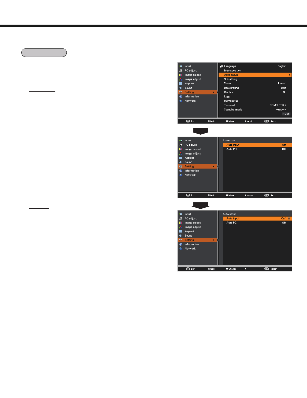
53
Auto input
This function detects the input signal automatically. When
a signal is found, the search will stop. Use the Point
buttons to select one of the following options.
Off ......... Auto input dose not work.
On 1....... Auto input works under the following situation.
– When pressing the AUTO SET button on the
remote controller.
On 2....... Auto input works under the following situation.
– When turning on the projector by pressing the
POWER button.
– When pressing the AUTO SET button on the
remote controller.
– When the current input signal is cut off.*
* If the Blank or Freeze function is active, cancel
it to activate the Auto input. It is also unavailable
when On-Screen Menu is displayed.
Auto PC
On.......Enables Auto PC adjustment when pressing
the AUTO SET button on the remote controller.
Off ......Disables Auto PC adjustment.
Auto setup
Note:
• While Auto input function is set to On 1 or On 2, the status of Input and Lamp are displayed every time the
signal is switched.
• Only the last selected input source can be detected.
• If the COMPUTER 1/2 button, VIDEO, S-VIDEO, COMPONENT or HDMI button on the remote controller, or
POWER or MENU button on the top control is pressed during Auto input is in progress, Auto input will stop
and go back to the previous input signal.
• Auto PC and Auto input functions can not be set Off at the same time.
• Fine sync, Total dots, Horizontal position and Vertical position of some computers can not be fully
adjusted with the Auto PC adjustment function. When the image is not provided properly with this operation,
manual adjustments are required (pp.36-37).
This function enables Auto input and Auto PC adjustment
by pressing the AUTO SET button on the remote controller.
Settings for those functions can be altered as follows:
Setting
Auto setup
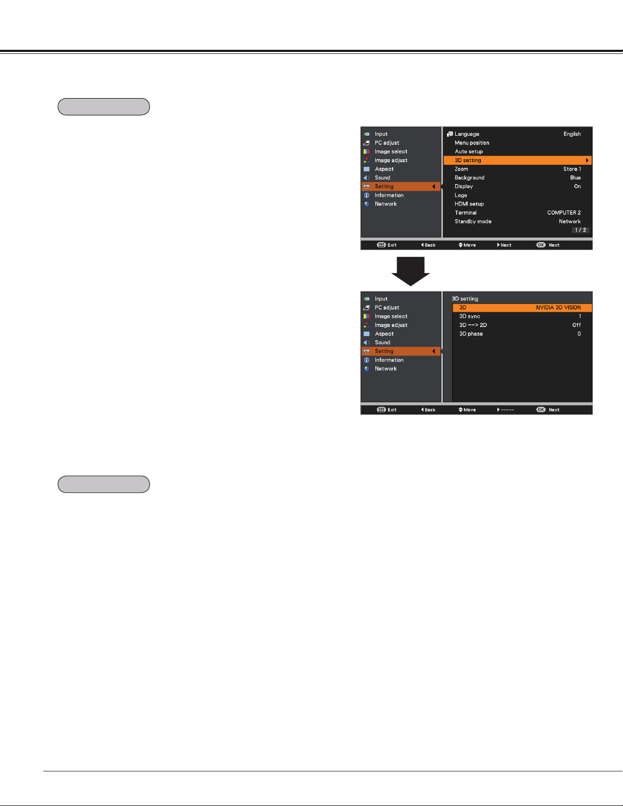
54
This function is used to memorize the Zoom adjustment with
the ZOOM +/- buttons on the top control (p.27).
Press the Point buttons to select Reset, Store1 or
Store2.
Reset ... Reset the Zoom adjustment when the projector is
turned off or the AC power cord is unplugged.
Store1 .. Store the Zoom setting even when the projector
is turned off. Zoom setting is cleared when the
AC power cord is unplugged.
Store2 .. Store the Zoom setting even when the AC power
cord is unplugged.
3D setting
Setting
This function is used to set the 3D display function. (pp.50-
51) Press the Point buttons to switch between each
option.
3D ............. Select among Off, On and NVIDIA 3D VISION
mode.
* When selecting NVIDIA 3D VISION mode, the other
menus 3D sync, 3D->2D, 3D phase setting are not
necessary. (displayed in gray)
3D sync .... If you see a discrete or overlapping image, 3D
Sync Invert function* enables you to get the
correct image. Switch the 3D sync signal to 1 or
2.
3D->2D ..... When viewing the 3D contents without wearing
the 3D glasses, set to "On" to convert 3D
display format to 2D display format.
3D phase
... Adjust the phase of the 3D sync signal when
the 3D SYNC OUT terminal is used. (0 - 31)
* The Frame Sequential Format is a technology that
rapidly alternates between left-eye and right-eye images.
When right-eye image and left-eye image are switched
or you feel like you cannot get 3D effect due to out-of-
synchronization state, first try to synchronize the projector
with the 3D glasses by using 3D SYNC function.
3D setting
Zoom
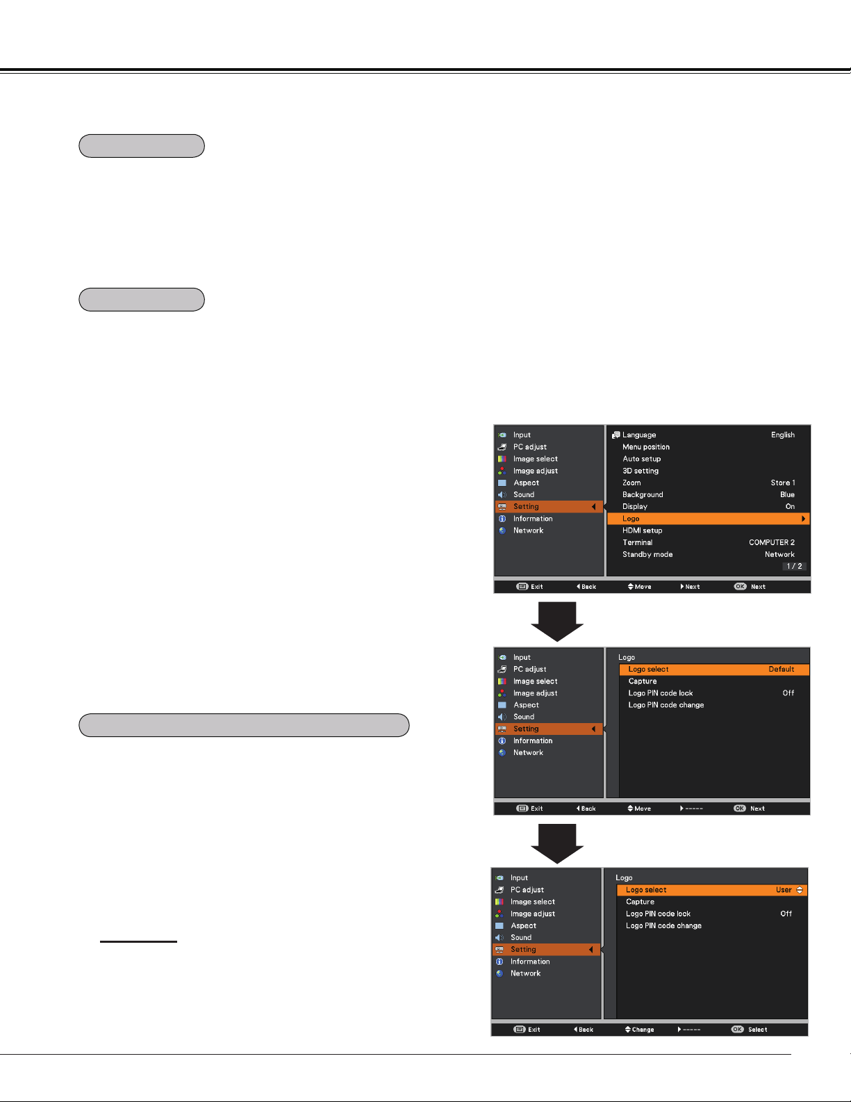
55
This function decides whether to display On-Screen
Displays.
On ........................... Show all the On-Screen displays. Use
this function when you want to project
images after the lamp becomes bright
enough. The factory default setting is
this option.
Countdown off ....... Show the input image instead of
the countdown when turning on the
projector. Use this function when you
want to project the image as early as
possible even when the lamp is not
bright enough.
Off ........................... Hide the On-Screen Displays except;
On-Screen Menu
Power off? (p.24)
No signal for Power management.
(p.59)
Please wait ...
Arrows for the True mode in the
Screen Menu (p.40)
P-Timer
Setting
Select the background screen for when no input signal is
detected. Press the Point
buttons to switch between
each option.
Blue ... Project a blue background.
User ... Project an image captured in the Logo setting.
Black . . Project a black background.
Background
Display
This function allows you to customize the screen logo with
Logo select, Capture, Logo PIN code lock and Logo PIN
code change functions.
Note:
When On is selected in the Logo PIN code lock function,
Logo select and Capture functions can not be selected.
Logo select
This function decides on the starting-up display from
among following options.
Off ........... Show the countdown display only.
Default .... Show the factory-set logo.
User ........ Show the image you captured.
Logo select
Logo (Logo and Logo PIN code lock settings)
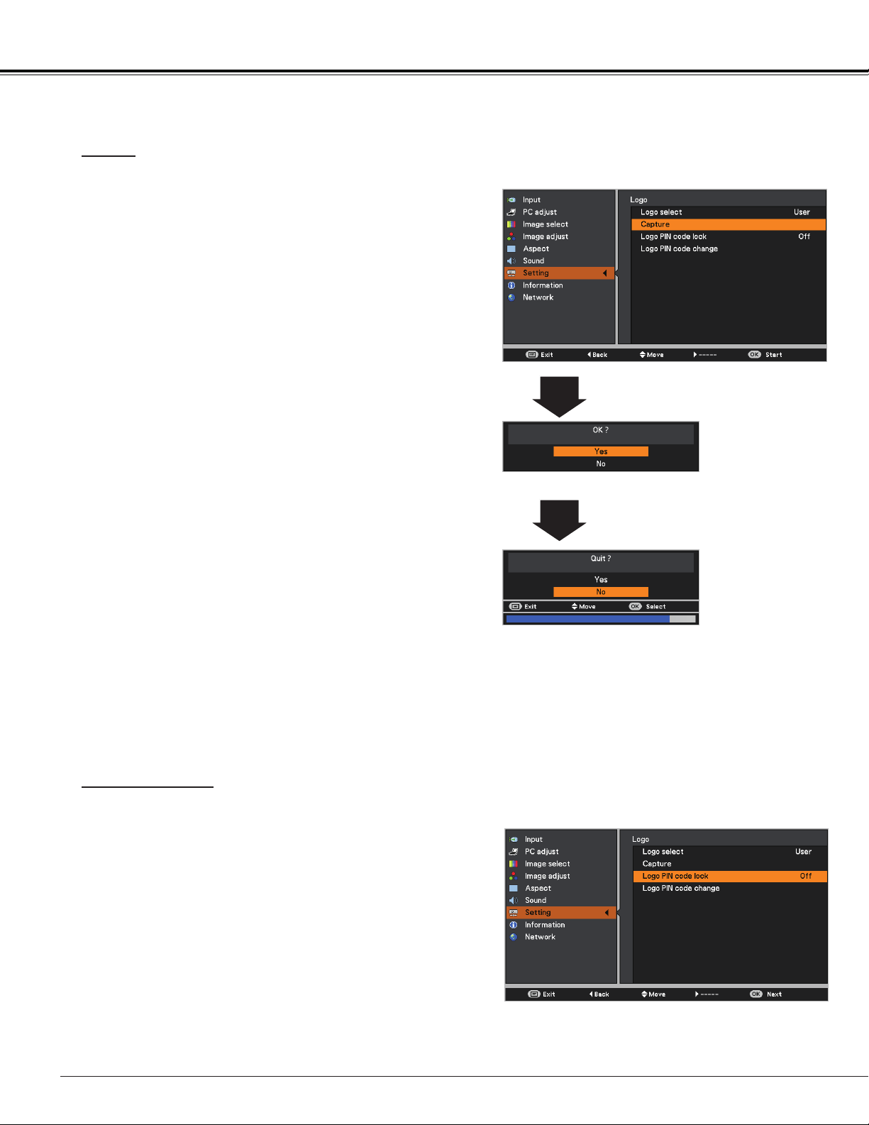
56
Capture
Capture
This function enables you to capture an image being
projected to use it for a starting-up display or interval of
presentations.
Select Capture and press the OK button.
A confirmation box appears and select Yes to capture the
projected image.
After capturing the projected image, go to the Logo select
function and set it to User. Then the captured image will be
displayed the next time you turn on the projector.
To cancel the capture function, select Yes in the "Quit?"
confirmation box.
Note:
• Before capturing an image, select Standard in the
Image select Menu to capture a proper image (p.38).
• The output image resolution from a computer can be
supported up to the panel resolution (DLP chip 1280 x
800 dots).
• When capturing the image that has been adjusted by
the Keystone function, the adjusted data is automatically
reset and the projector captures an image without
keystone correction.
• When Logo PIN code lock function is set to On, Logo
select and Capture can not be selected.
• When starting to capture a new image, the previously
stored image is cleared even if you cancel the capturing.
• When there is no captured image or it is interrupted
while capturing an image, User is not included in Logo
Select Menu, you can only switch between Default and
Off.
Logo PIN code lock
This function prevents an unauthorized person from
changing the screen logo.
Off ........... The screen logo can be changed freely from
the Logo Menu (p.55).
On ........... The screen logo can not be changed without a
Logo PIN code.
If you want to change the Logo PIN code lock setting, press
the OK button and the Logo PIN code dialog box appears.
Enter a Logo PIN code by following the steps below. The
initial Logo PIN code is set to “4321” at the factory.
Logo PIN code lock
Setting
Note:
When Logo PIN code lock function is set to On, Logo
select and Capture can not be selected.
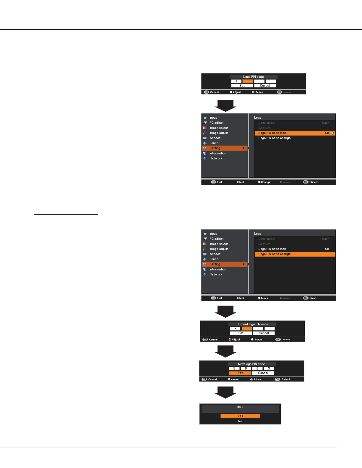
57
Enter a Logo PIN code
Use the Point buttons to enter a number. Press the
Point button to fix the number and move the red frame
pointer to the next box. The number changes to . If
you fixed an incorrect number, use the Point button to
move the pointer to the number you want to correct, and
then enter the correct number.
Repeat this step to complete entering a four-digit
number.
After entering the four-digit number, move the pointer to
Set and press the OK button.
If you entered an incorrect Logo PIN code, Logo PIN
code and the number () will turn red for a
moment. Enter the correct Logo PIN code all over again.
Logo PIN code can be changed to your desired four-digit
number. Press the OK button to select Logo PIN code
change. Current logo PIN code dialog box appears, use
the Point buttons to enter the correct code. The New
Logo PIN code input dialog box appears. Set a new Logo
PIN code, confirmation box appears, choose Yes to set
the new Logo PIN code.
Be sure to note the new Logo PIN code and keep it on
hand. If you lost the number, you could no longer change
the Logo PIN code setting.
Use the Point buttons to switch On or Off, and then
press the OK button to make a choice.
Change the Logo PIN code lock setting
Enter a Logo PIN code
CAUTION:
WHEN YOU HAVE CHANGED THE LOGO PIN CODE,
WRITE DOWN THE NEW PIN CODE AS A REMINDER.
SHOULD THE LOGO PIN CODE BE LOST OR
FORGOTTEN, THE LOGO PIN CODE SETTING CAN
NO LONGER BE CHANGED.
Logo PIN code change
Setting
Logo PIN code change
Note:
If you forget your Logo PIN code and unable to change it,
the Logo PIN code can be reset to the factory default
setting (4321) according to the following procedures.
When you reset the Logo PIN code, the PIN code and Key
lock will be reset, as well.
1. Unplug the AC Power Cord from the AC outlet.
2. Hold down the OK button on the projector and
connect the AC Power Cord into the outlet again.
Keep holding down the OK button until the POWER
indicator lights. The Logo PIN code returns to the
factory default setting while the Logo PIN code lock
state will remain the same as the previous set state.
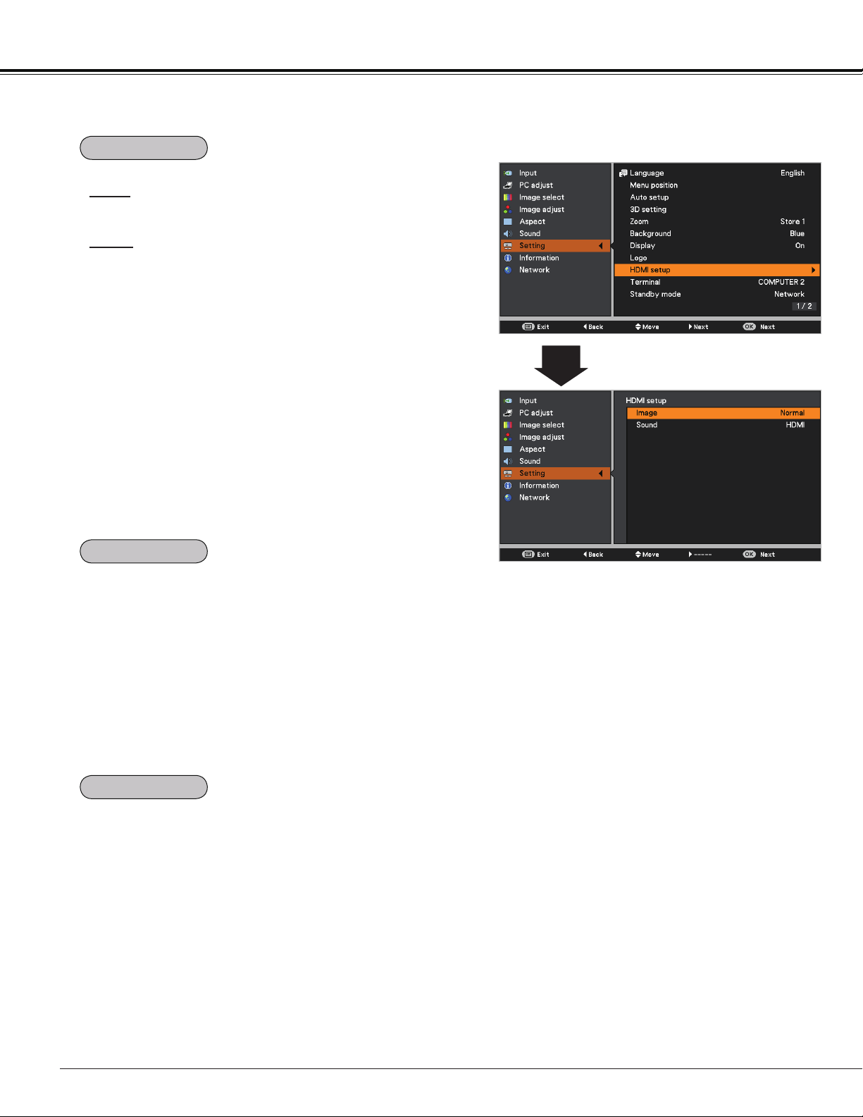
58
Setting
This function is only used for HDMI input source.
Image
Select Normal or Enhanced to match the video range
setting of your HDMI Digital RGB equipment.
Sound
HDMI .......... When using the HDMI cable, select HDMI.
Both video and audio* are transferred and
you need not to connect any additional
cables for audio.
* This HDMI terminal supports Linear PCM (32kHz/44.1kHz/48kHz).
COMPUTER 1 When using the DVI-HDMI cable,
select COMPUTER 1 and connect
the audio cable to COMPUTER 1/
COMPONENT AUDIO IN terminal.
The names for the output setting of Digital RGB vary from
equipment to equipment. For details, refer to the user's
manual of your Digital RGB equipment.
When the black parts of the image are destroyed or stand
out, please switch to Normal or Enhanced, and then switch
the output type of the HDMI Digital RGB output equipment.
HDMI setup
The COMPUTER IN 2/MONITOR OUT terminal on the back
of the projector is switchable for computer input or monitor
output (p.13).
COMPUTER 2……Computer input
Monitor out……Monitor output
Terminal function is not available when COMPUTER 2 to
the input source is selected. Change the input source to the
others (COMPUTER 1, VIDEO, S-VIDEO or HDMI) so that
the Terminal function is available (pp.32-33, 43-44).
This function is available when operating the projector via
network.
Network .... Supply the power to the network function even
after turning off the projector. You can turn on/
off the projector via network, modify network
environment, and receive an e-mail about
projector status while the projector is powered
off.
Eco ............ Select Eco when you do not use the projector
via network. The projector’s network function
will stop when turning off the projector.
Refer to the user's manual of “Network Set-up and
Operation”.
Note:
• Factory default is Network.
• When Eco is selected and the projector
is in Stand-by, the communication of
RS-232C serial port is not available.
Standby mode
Terminal
HDMI setup
Note:
The input/output terminal [Computer
2] does not support EDID. Depending
on the computer used, an adjustment
of the resolution might be necessary
after connection of the terminal. For the
adjustment of the resolution please refer
to the user's manual of the computer.
* EDID (Extended Display Identification
Data): The display ID of the connected
monitor for transmission of the model
name and the setting value to the
computer.
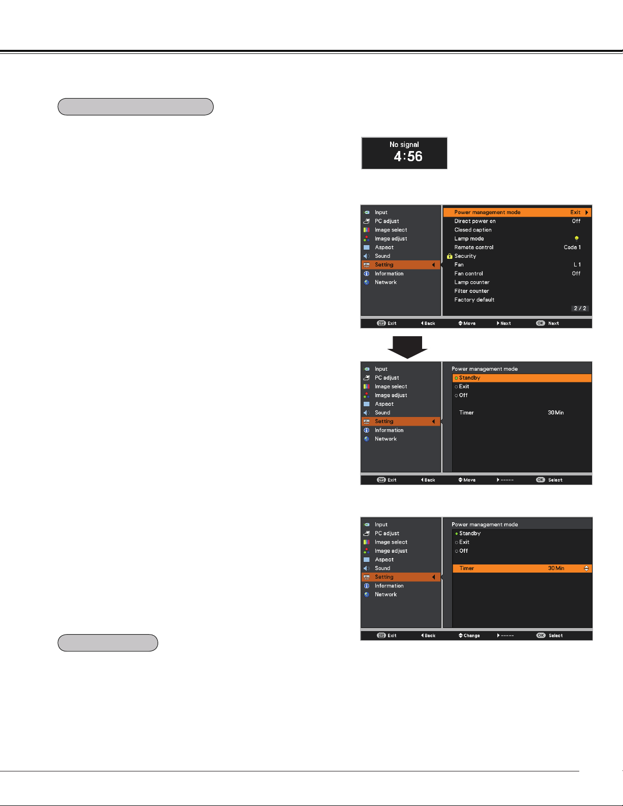
59
Setting
Timer left before Lamp is off.
Power management mode
For reducing power consumption as well as maintaining the
lamp life, the Power management mode function turns off
the projection lamp when the projector is not operated for a
certain period.
Select one of the following options:
Standby .............. When the lamp has been fully cooled
down, the POWER indicator changes
to green blinking. In this condition, the
projection lamp will be turned on if the
input signal is reconnected or any button
on the remote controller is pressed.
Exit ...................... When the lamp has been fully cooled
down, the power will be turned off.
Off ....................... Power management mode function is off.
Timer ................... If the input signal is interrupted and
no button is pressed for more than
30 seconds, the timer display with No
signal appears. It starts the countdown
until the lamp is turned off. Use the Point
buttons to set the Timer(1~30Min).
Note:
Factory default is Exit: 30 Min.
When this function is set to On, the projector will be
automatically turned on just by connecting the AC power
cord to a wall outlet.
Note:
Be sure to turn off the projector properly (see “Turning Off
the Projector” on page 24). If the projector is turned off in
the incorrect sequence, the Direct power on function does
not work properly.
Direct power on
Power management mode
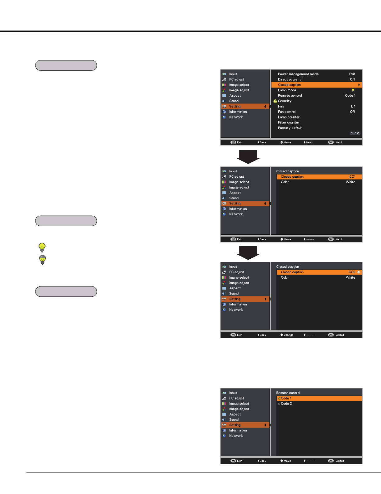
60
Setting
Closed Caption is a function that displays the audio portion
of a TV program as text on the screen. If the input signal
contains Closed captions, you can turn on the feature and
switch the channels. Press
the Point
buttons to select
Off, CC1, CC2, CC3 or CC4.
If the Closed caption is not clear, you can change the text
from Color to White.
Closed caption
Note:
The Closed caption is available only under the situation
below.
• The input signal is NTSC of composite video or S-video.
• The item of Closed caption is displayed in gray while it
is not available.
• The Closed caption is unavailable when On-Screen
Menu or P-Timer is displayed.
Press the Point buttons to
select Off, CC1, CC2, CC3 or CC4,
and then Press OK button.
Remote control
This projector provides two different remote control codes:
the factory-set initial code (Code 1) and the secondary code
(Code 2). This switching function prevents remote controller
interference when operating several projectors or video
equipment at the same time.
When operating the projector in Code 2, both the projector
and the remote controller must be switched to Code 2.
To change the code for the projector:
Select either Code 1 or Code 2 in this Setting Menu.
To change the code for the remote controller:
Press and hold both the MENU and IMAGE buttons
together for 5 seconds or more. After changing the code,
make sure the remote controller operates properly.
Note:
• When different codes are set on the projector and on
the remote controller, any operation cannot be made. In
that case, switch the code on the remote controller to fit
the code on the projector.
• If the batteries are removed from the remote controller
for a long period of time, the remote control code will be
reset.
This function allows you to change brightness of the screen.
Normal ..... Normal brightness.
Eco .......... Lower brightness reduces the lamp power
consumption and extends the lamp life.
Closed caption
Lamp mode
Remote control
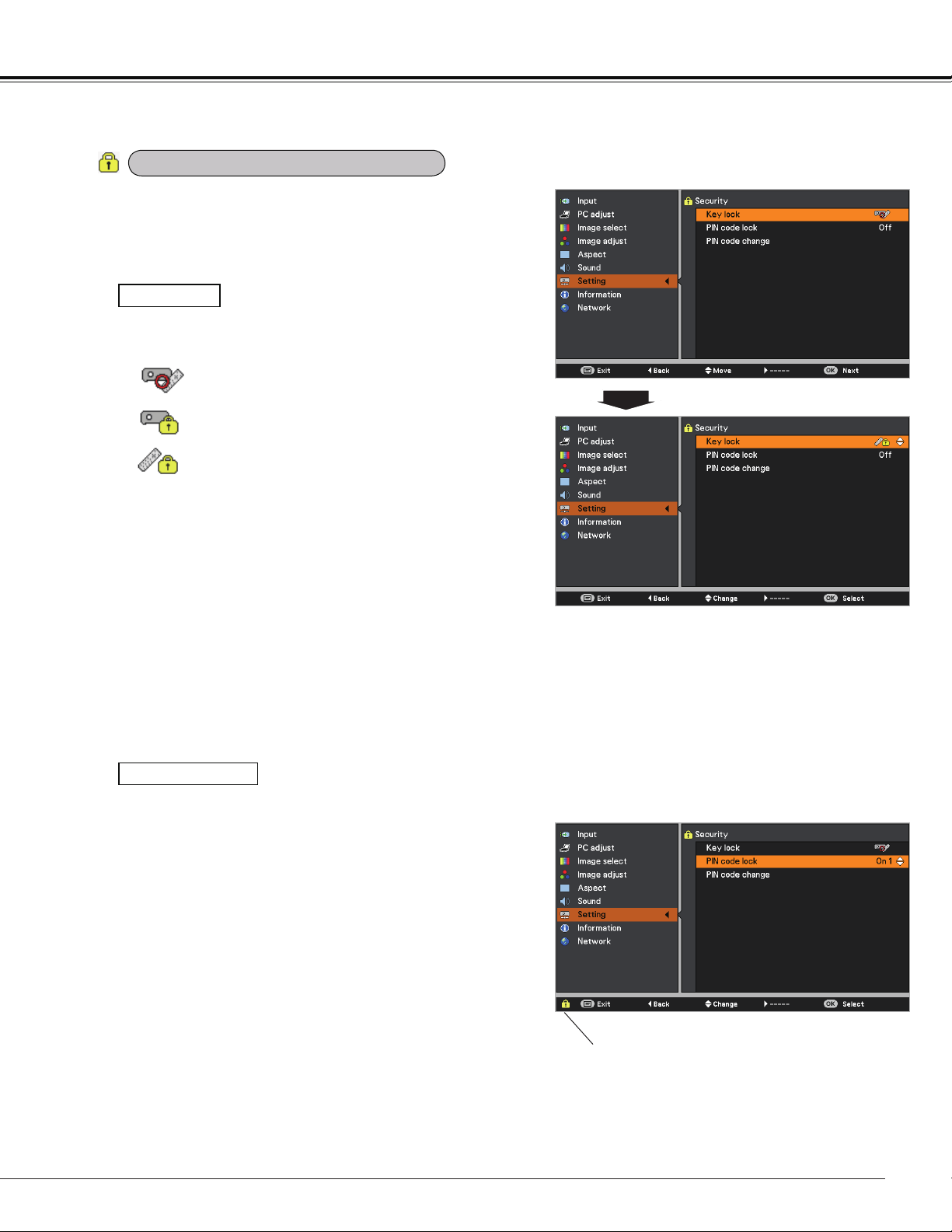
61
Setting
This function allows you to use the Key lock and the PIN
code lock function to set the security for the projector
operation.
Key lock
Key lock
PIN code lock
This function locks the top control and remote controller
buttons to prevent operation by unauthorized persons.
Unlocked.
Lock the operation of the top control.To
unlock, use the remote controller.
Lock the operation of the remote controller. To
unlock, use the top control.
If the top control accidentally becomes locked and you
do not have the remote controller nearby or there is
something wrong with your remote controller, contact the
dealer where you purchased the projector or the service
center.
This function prevents the projector from being operated
by unauthorized persons and provides the following
setting options for security.
Off .....Unlocked.
On 1 .....Enter the PIN code every time turning on
the projector.
On 2 .....Enter the PIN code to operate the projector
once the power cord is disconnected; as
long as the AC power cord is connected,
the projector can be operated without a
PIN code.
Whenever you change the PIN code lock setting or the
PIN code (the four-digit number), you are required to
enter the PIN code. The "1234" is set as the initial PIN
code at the factory.
If you want to change the PIN code lock setting, Press
the OK button and the PIN code dialog box appears.
PIN code lock
Security (Key lock and PIN code lock)
When the projector is locked with the
PIN code, the Security icon appears
on the guide.
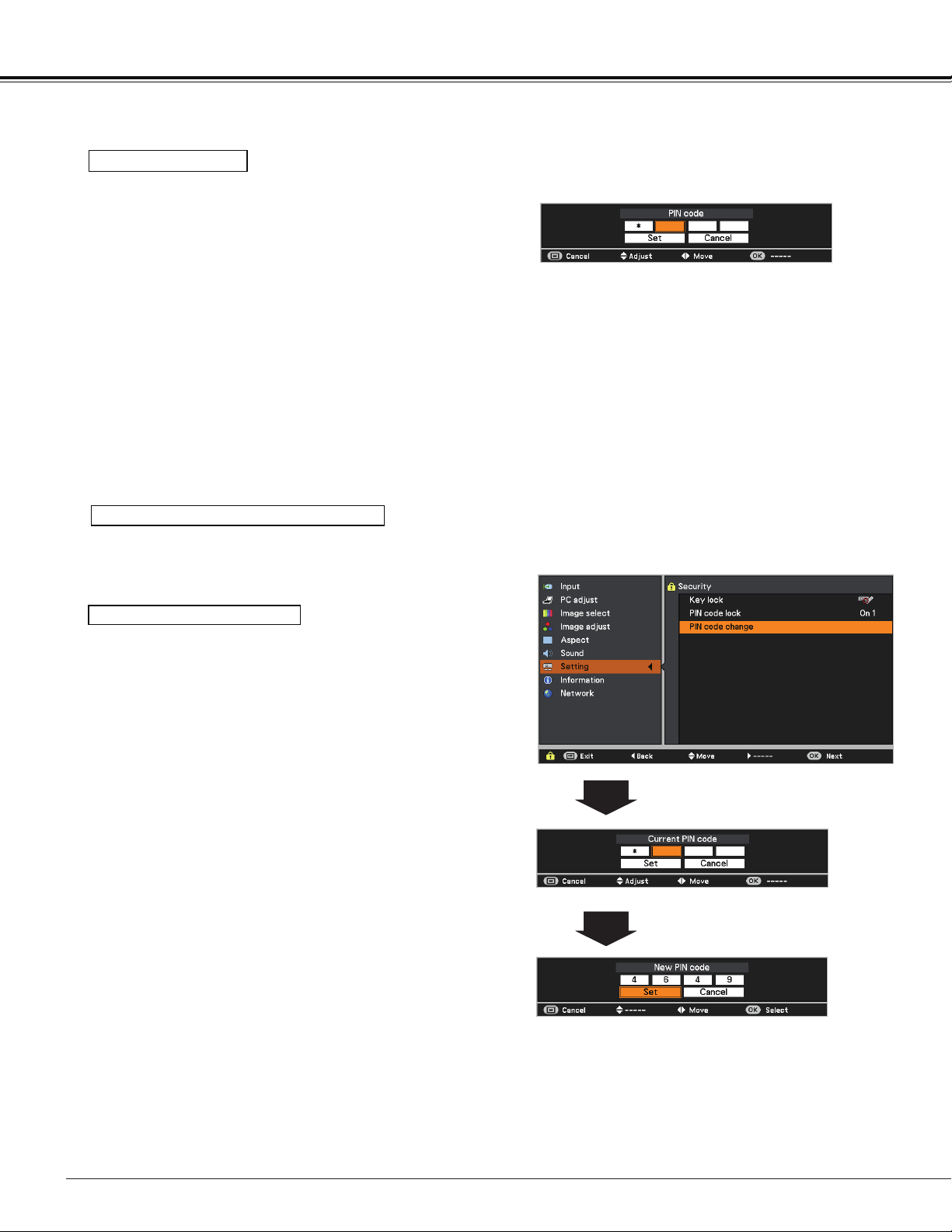
62
Setting
Use the Point buttons to select Off, On 1 or On 2.
Press the OK button to close the dialog box.
Change the PIN code lock setting
Enter a PIN code
Use the Point buttons to enter a number. Press the
Point button to fix the number and move the red frame
pointer to the next box. The number changes to . If you
fixed an incorrect number, use the Point button to move
the pointer to the number you want to correct, and then
enter the correct number.
Repeat this step to complete entering a four-digit number.
After entering the four-digit number, move the pointer to
Set. Press the OK button so that you can start to operate
the projector.
If you entered an incorrect PIN code, PIN code and the
number () will turn red for a moment. Enter the
correct PIN code all over again.
Enter a PIN code
The PIN code can be changed to your desired four-digit
number.
Press the Point button to select PIN code change and
press the OK button. The Current PIN code dialog box
appears.
Use the Point buttons to set the current PIN code. The
New PIN code dialog box appears. Set a new PIN code, the
confirmation box appears, and choose Yes to set the new
PIN code.
Change the PIN code
CAUTION:
WHEN YOU HAVE CHANGED THE PIN CODE, WRITE
DOWN THE NEW PIN CODE AS A REMINDER, IF YOU
FORGET YOUR PIN CODE, THE PROJECTOR CAN NO
LONGER BE STARTED.
PIN code change
Note:
If you forget your PIN code and unable to change it, the
PIN code can be reset to the factory default setting
(1234) according to the following procedures.
When you reset the PIN code, the Logo PIN code and
Key lock will be reset, as well.
1. Unplug the AC Power Cord from the AC outlet.
2. Hold down the OK button on the projector and
connect the AC Power Cord into the outlet again.
Keep holding down the OK button until the POWER
indicator lights. The PIN code returns to the factory
default setting while the PIN code lock state will
remain the same as the previous set state.
63
Setting
This function provides the following options in the cooling
fans’ operation when the projector is turned off (p.22).
L 1 ..... Normal operation
L 2 ..... Slower, lower-sound and longish-time than the
normal operation (L1).
This function is used to display the cumulative lamp
operating time and reset the lamp counter.
When the total lighting time of a lamp exceeds the
recommended total hours of use, the Lamp replacement
icon (Fig.1) will appear on the screen, indicating that the end
of lamp life is reached.
When replacing the projection lamp, reset lamp counter.
See "Resetting the Lamp Counter" on page 70.
This icon appears on the screen when the end of
lamp life is reached.
Fig.1 Lamp replacement icon
Note:
At turning on, the icon (Fig.1) will appear.
Choose the running speed of cooling fans from the following
options according to the ground elevation under which you
use the projector.
Off ........... Normal speed. Set this function to Off when
using the projector in non-high altitude
environment.
On 1 ........ Faster than Off mode. Select this mode when
using the projector in high altitudes (about
1,000 meters or more above the sea level)
where the fans have less cooling effect.
On 2 ........ Faster than On 1 mode. Select this mode
when using the projector in higher altitudes
than above where the fans have lesser cooling
effect.
Note:
• Fan noise becomes louder in On 1 and On 2.
• Failure to set the running speed of cooling
fans properly may affect the projector life.
Note:
The Lamp replacement icon (Fig.1) will not appear when
the Display function is set to Off (p.53), or Freeze (p.30),
or Blank (p.31).
Fan control
Lamp counter
Fan
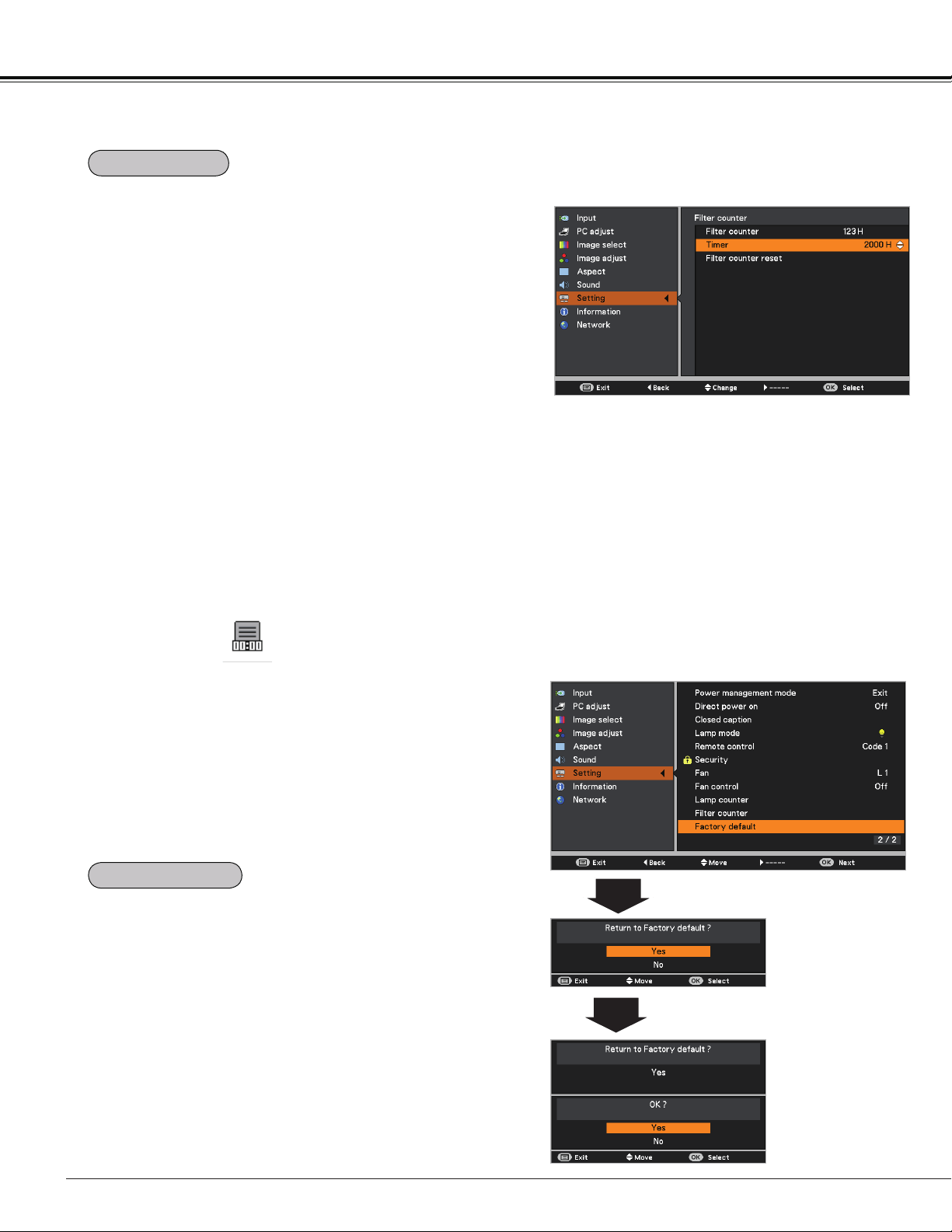
64
This function returns all setting values except for the User
logo, PIN code lock, Logo PIN code lock, Lamp counter
and Filter counter to the factory default settings.
Factory default
Setting
This function is used to set a frequency for the filter
replacement.
Use the Point buttons to select Filter counter and then
press the Point or the OK button to access the submenu
items.
Filter counter......... Show the total accumulated time of the
filter use timer setting.
Timer .................... To set a timer, when the projector
reaches the time, the Filter warning
icon (Fig.1) appears on the screen and
the total accumulated time turns red,
indicating that the filter replacement is
necessary.
Filter counter reset
... After replacing the filter, be sure to reset
the timer. The Filter warning icon will not
turn off until the filter counter is reset.
For details about resetting the timer,
refer to “Resetting the Filter Counter” on
page 67.
Filter counter
Press the OK button to select Timer, and then
use the Point buttons to set the timer. Select
from (Off/ 2000H/ 3000H/ 4000H) depending on
the use environment.
Filter warning icon appears on the screen at a set time
(Off/2000H/3000H/4000H).
Fig.1 Filter warning icon
Note:
• The Filter warning icon (Fig.1) will not appear when the
Display function is set to Off (p.55), or Freeze (p.30), or
Blank (p.31).
• This icon also appears at turning on.
Factory default
Filter counter
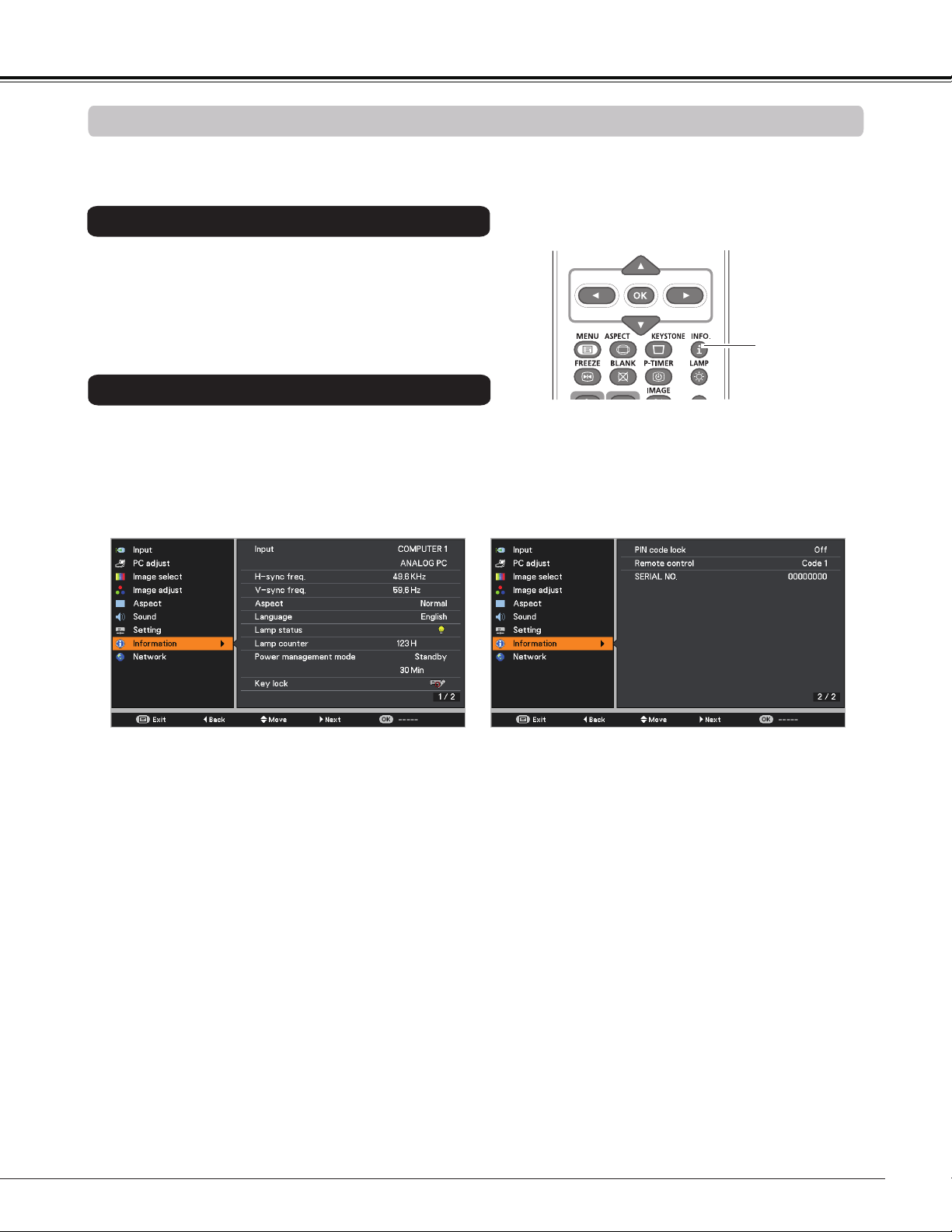
65
Input Source Information Display
The Information Menu is used for checking the status of the image signal being projected and the operation of
the projector.
The information menu changes each time you press the
INFO. button on the remote controller as follows.
page 1/2 page 2/2 hide page 1/2 • • • • •
While the information menu is displayed, press the Point
buttons to display the previous or next page.
3D
INFO. button
Remote Controller
Press the Point
buttons to select the Information. The
Information Menu is displayed.
See below for displayed information.
Information
Direct Operation
Menu Operation
Input
The selected input source is displayed.
H-sync freq.
The horizontal frequency of the input signal is displayed in KHz, or - - - -KHz when
no signal.
V-sync freq.
The vertical frequency of the input signal is displayed in Hz, or - - - - Hz when no
signal. Numbers of Hz doubles when during Interlace.
Screen
The selected screen size is displayed.
Language
The selected language is displayed.
Lamp status
The selected lamp mode is displayed.
Lamp counter
The cumulative lamp operating time is displayed.
Power management mode
Off, Standby, Exit or Timer is displayed.
Key lock
The selected Key lock icon is displayed.
PIN code lock
Off or On 1 or On 2 is displayed.
Remote control
The selected remote code is displayed.
SERIAL NO.
The serial number of the projector is displayed. The serial number is used to service
the projector.
Information Menu
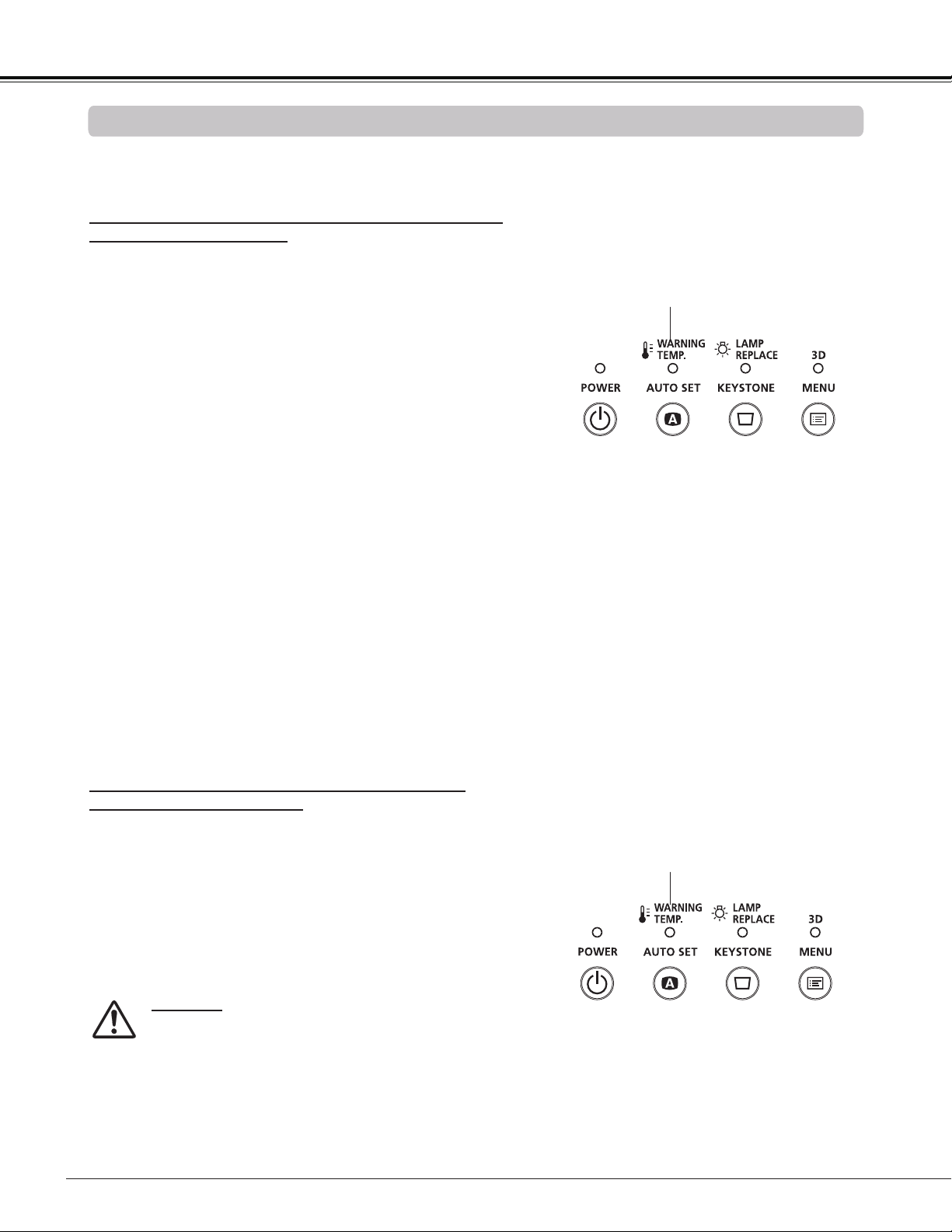
66
The WARNING TEMP. indicator shows the state of the function which protects the projector. Check the state of
the WARNING TEMP. indicator and the POWER indicator to take proper maintenance.
WARNING TEMP. indicator
The projector is shut down and the WARNIN TEMP.
indicator is blinking red.
When the temperature inside the projector reaches a
certain level, the projector will be automatically shut down to
protect the inside of the projector. The POWER indicator is
blinking while the projector is being cooled down. When the
projector has cooled down enough (to its normal operating
temperature), it can be turned on again by pressing the
POWER button.
The projector is shut down and the WARNING
TEMP. indicator lights red.
When the projector detects an abnormal condition, it is
automatically shut down to protect the inside of the projector
and the WARNING TEMP. indicator lights red. In this case,
unplug the AC power cord and reconnect it, and then
turn the projector on once again to verify operation. If the
projector can not be turned on and the WARNING TEMP.
indicator still lights red, unplug the AC power cord and
contact the service center.
CAUTION
DO NOT LEAVE THE PROJECTOR WITH THE
AC POWER CORD CONNECTED UNDER AN
ABNORMAL CONDITION. IT MAY RESULT IN
FIRE OR ELECTRIC SHOCK.
Maintenance and Cleaning
Top Panel
Note:
The WARNING TEMP. indicator continues to blink even
after the temperature inside the projector returns to
normal. When the projector is turned on again, the
WARNING TEMP. indicator stops blinking.
Then check the matters below:
– Did you provide appropriate space for the projector to be
ventilated? Check the installing condition to see if the air
vents of the projector are not blocked.
– Has the projector been installed near an Air-Conditioning/
Heating Duct or Vent? Move the installation of the
projector away from the duct or vent.
– Is the filter clean? Replace the filter with a new one.
Emit a red light
Blinking red
Top Panel
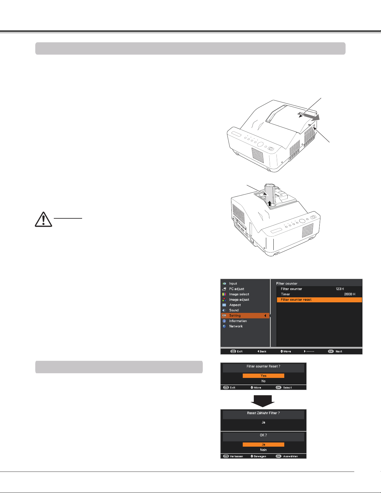
67
Be sure to reset the Filter counter after replacing the Filter .
Resetting the Filter Counter
Maintenance and Cleaning
Turn off the projector, and unplug the AC power cord
from the AC outlet.
First, clean up the dust on the projector and around the
air vents.
1
2
Filter prevents dust from accumulating on the optical elements inside the projector. Should the Filter become
clogged with dust particles, it will reduce cooling fans’ effectiveness and may result in internal heat buildup
and adversely affect the life of the projector. If a “Filter warning” icon appears on the screen, replace the Filter
immediately. Replace the filter by following the steps below.
Loosen the screw and remove the lamp cover and lift
the filter out of the projector.
3
4
CAUTION
- Do not operate the projector with the filter removed.
Dust may accumulate on the optical elements
degrading picture quality.
- Do not put anything into the air vents. Doing so may
result in malfunction of the projector.
- Do not wash the filter with water or any other liquid
matter. Otherwise the filter may be damaged.
RECOMMENDATION
We recommend avoiding dusty/smoky environments
when you operate the projector. Usage in these
environments may cause poor image quality.
When using the projector under dusty or smoky conditions,
dust may accumulate on a lens or optical elements inside
the projector degrading the quality of a projected image.
When the symptoms above are noticed, contact your
authorized dealer or service center for proper cleaning.
Replacing the Filter
Press the MENU button to display the On-Screen
Menu. Use the Point buttons to select Setting and
then press the Point or the OK button.
Use the Point buttons to select Filter counter and
then press the OK button. Use the Point buttons
to select Filter counter reset and then press the OK
button. Filter counter Reset? appears. Select Yes to
continue.
1
2
Filter counter
Filter counter
Reset? appears.
Select Yes, then
another confirmation
box appears.
Select Yes again
to reset the Filter
counter.
Another confirmation dialog box appears, select Yes to
reset the Filter counter.
3
Put the new one back into the position, and close the
lamp cover and secure the screw.
5
Connect the AC power cord to the projector and turn
on the projector.
6
Reset the filter counter.
Lamp Cover
Screw
Filter
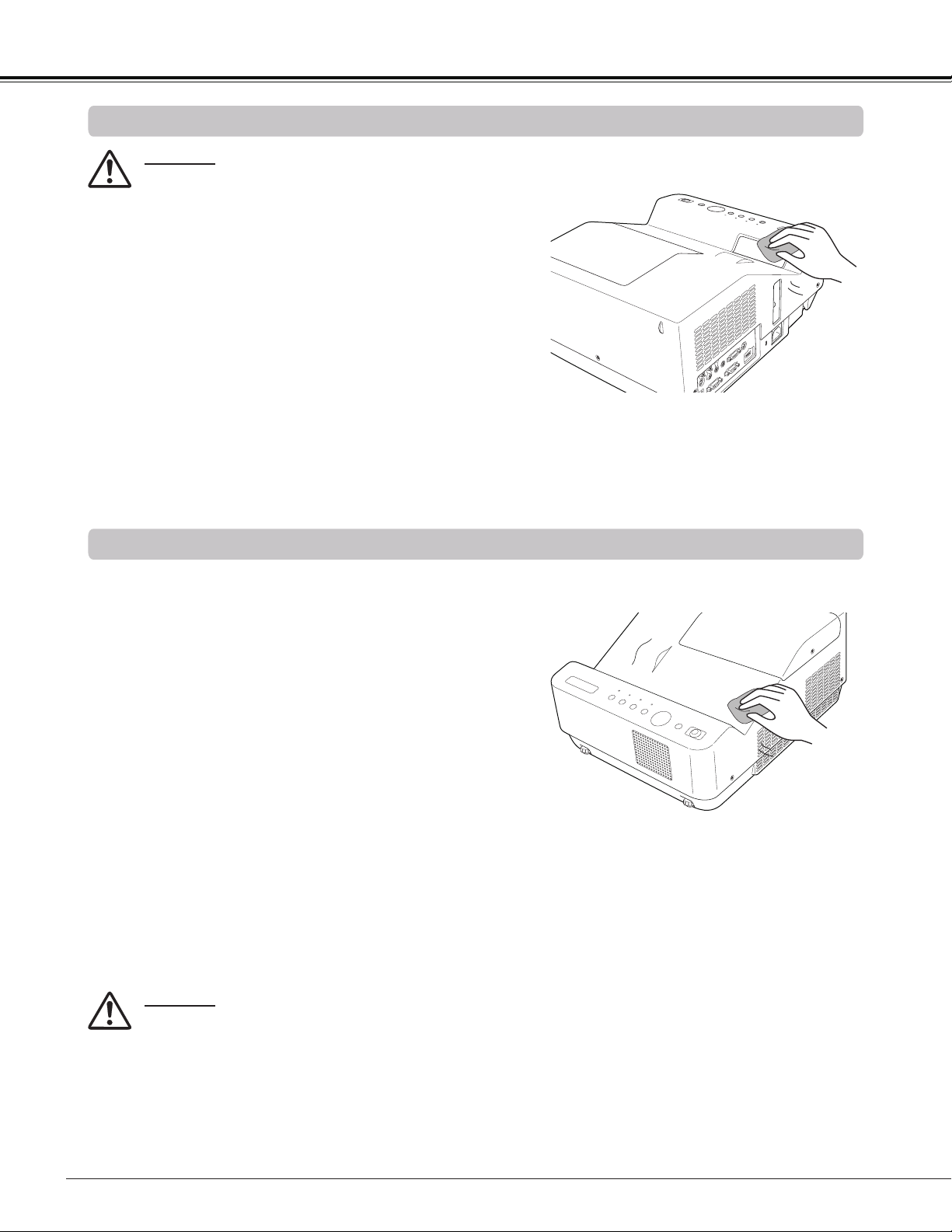
68
Cleaning the Projector Cabinet
Cleaning the Projection Window
Unplug the AC power cord before cleaning.
First, remove the dust with a commercially available air
blower. Then gently wipe the projection window surface.
Use a cleaning paper moistened with methyl alcohol
(methanol). Avoid using an excessive amount of cleaner.
Do not use abrasive cleaners, solvents, or other harsh
chemical cleaners to avoid damaging the projection window.
Unplug the AC power cord before cleaning.
Gently wipe the projector body with a soft dry cleaning cloth.
When the cabinet is heavily soiled, use a small amount of
mild detergent and finish with a soft dry cleaning cloth. Avoid
using an excessive amount of cleaner. Abrasive cleaners,
solvents, or other harsh chemicals might scratch the surface
of the cabinet.
When the projector is not in use, put the projector in
an appropriate carrying case to protect it from dust and
scratches.
Maintenance and Cleaning
CAUTION
Do not use any flammable solvents or air sprays
on the projector and in its vicinity. The explosion
or fire hazard may occur even after the AC power
cord is unplugged because the temperature inside
the projector is extremely high due to the lamps. In
addition, there is a risk that the internal parts may
be damaged not only by the flammable air spray but
also by the cold air.
CAUTION
This projector is equipped with a projection window.
- Do not rub the projection window with a hard fiber
cloth or hit it with a something hard to prevent the
projection window from scratching.
- Do not use a chemical cleaner (liquid and solid) to
avoid deteriorating the projection window.
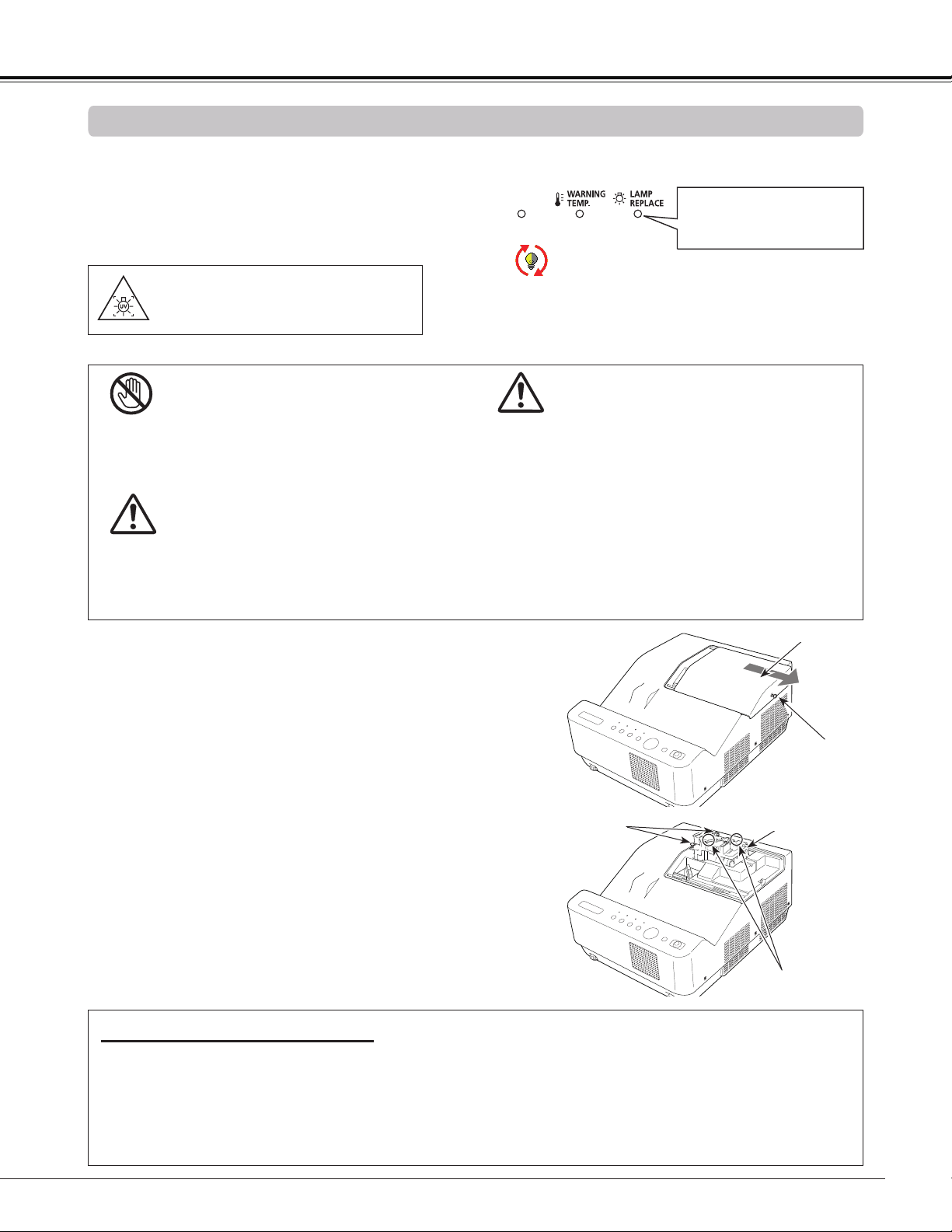
69
When the projection lamp of the projector reaches its end
of life, the Lamp replacement icon appears on the screen
and LAMP REPLACE indicator lights yellow. Replace the
lamp with a new one promptly. The timing when the LAMP
REPLACE indicator should light is depending on the lamp
mode.
For continued safety, replace with a lamp of the
same type. Do not drop a lamp or touch a glass
bulb! The glass can shatter and may cause injury.
Allow a projector to cool for at least one hour
before you open the Lamp Cover. The inside of
the projector can become very hot.
CAUTION
Lamp Replacement
CAUTION
Maintenance and Cleaning
Follow these steps to replace the lamp.
Turn off the projector and unplug the AC power cord.
Let the projector cool for at least one hour.
Loosen the two (2) screws that secure the lamp. Lift
the lamp out of the projector by using the handle.
1
3
Replace the lamp with a new one and secure the two
(2) screws. Make sure that the lamp is set properly.
Close the lamp cover and secure the screw.
4
Loosen the screw and remove the lamp cover.
2
Connect the AC power cord to the projector and turn
on the projector.
6
Reset the lamp counter.
See “Resetting the Lamp Counter” on the next page.
5
Screw
ORDER REPLACEMENT LAMP
Replacement lamp can be ordered through your dealer. When ordering a projection lamp, give the following
information to the dealer.
Model No. of your projector : LV-8235 UST
Replacement Lamp Type No. : LV-LP36
Top Panel
When replacing the lamp because it has stopped
illuminating, there is a possibility that the lamp
may be broken. If replacing the lamp of a projector
which has been installed on the ceiling, you should
always assume that the lamp is broken, and you
should stand to the side of the lamp cover, not
underneath it. Remove the lamp cover gently.
Small pieces of glass may fall out when the lamp
cover is opened. If pieces of glass get into your
eyes or mouth, seek medical advice immediately.
CAUTION
Screws
Handle
Lamp replacement icon
WARNING:
TURN OFF THE UV LAMP BEFORE
OPENING THE LAMP COVER
Note:
The Lamp replacement icon will not appear when
the Display function is set to Off (p.55), during
Freeze (p.30), or Blank (p.31).
This indicator turns yellow
when the projection lamp
reaches the end of its life.
Lamp Cover
Lamp
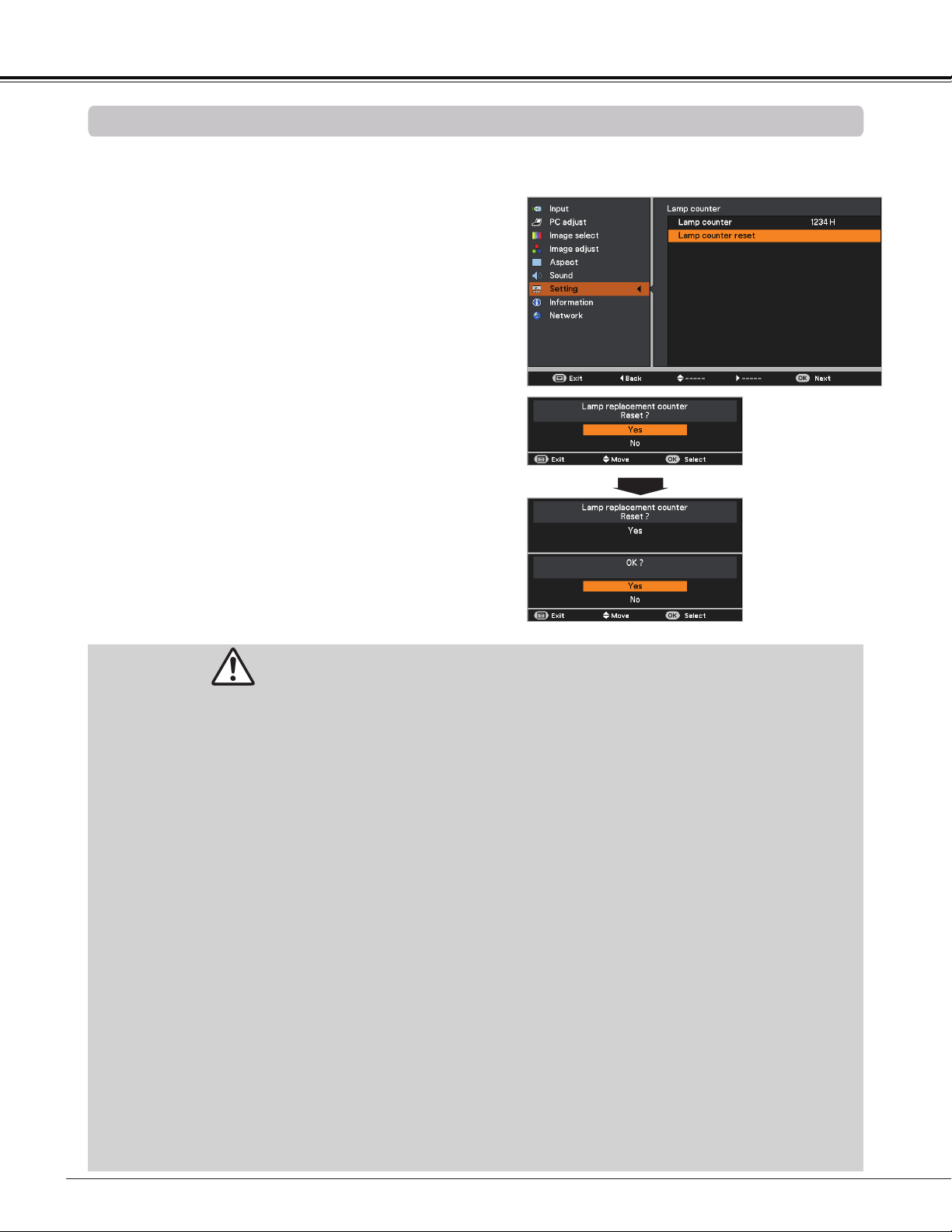
70
This projector uses a high-pressure lamp which must be handled carefully and properly.
Improper handling may result in accidents, injury, or create a fire hazard.
Lamp life may differ from lamp to lamp and according to the environment of use. There is no guarantee
of the same life for each lamp. Some lamps may fail or terminate their life in a shorter period of time than
other similar lamps.
If the projector indicates that the lamp should be replaced, i.e., if the LAMP REPLACE indicator lights
up, replace the lamp with a new one IMMEDIATELY after the projector has cooled down.
(Follow carefully the instructions in the Lamp Replacement section of this manual.) Continuous use of
the lamp with the LAMP REPLACE indicator lighted may increase the risk of lamp explosion.
A Lamp may explode as a result of vibration, shock or degradation as a result of hours of use as its
lifetime draws to an end. Risk of explosion may differ according to the environment or conditions in
which the projector and lamp are being used.
IF A LAMP EXPLODES, THE FOLLOWING SAFETY PRECAUTIONS SHOULD BE TAKEN.
If a lamp explodes, disconnect the projector’s AC plug from the AC outlet immediately. Contact an
authorized service center for a checkup of the unit and replacement of the lamp. Additionally, check
carefully to ensure that there are no broken shards or pieces of glass around the projector or coming out
from the cooling air circulation holes. Any broken shards found should be cleaned up carefully. No one
should check the inside of the projector except those who are authorized trained technicians and who
are familiar with projector service. Inappropriate attempts to service the unit by anyone, especially those
who are not appropriately trained to do so, may result in an accident or injury caused by pieces of broken
glass.
LAMP HANDLING PRECAUTIONS
Maintenance and Cleaning
Resetting the Lamp Counter
Be sure to reset the Lamp counter after the lamp is replaced. When the Lamp counter is reset, the LAMP
REPLACE indicator stops lighting and the Lamp replacement icon disappears.
Note:
Do not reset the Lamp counter without implementing
lamp replacement. Be sure to reset the Lamp counter
only after replacing the lamp.
Lamp replacement
counter Reset?
appears.
Select Yes, then
another confirmation
box appears.
Select Yes again
to reset the Lamp
counter.
Press the MENU button to display the On-Screen
Menu. Use the Point buttons to select Setting
and then press the Point or the OK button.
Use the Point buttons to select Lamp counter
and then press the OK button. Use the Point
buttons to select Lamp counter reset and then
press OK button. Lamp replacement counter
Reset? appears. Select Yes to continue.
1
2
Another confirmation dialog box appears, select Yes
to reset the Lamp counter.
3
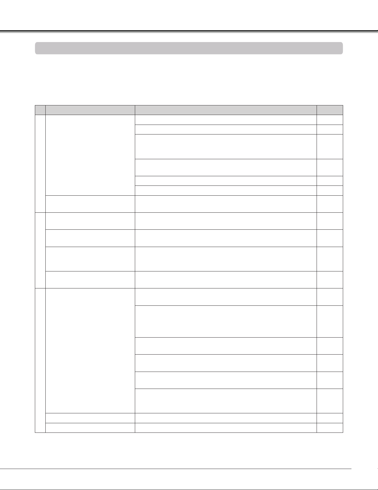
71
Maintenance and Cleaning
Appendix
Troubleshooting
Before calling your dealer or service center for assistance, check the items below once again.
– Make sure you have properly connected the projector to peripheral equipment as described on pages 18-20.
– Make sure all equipment is connected to AC outlet and the power is turned on.
– When the projector does not project an image from the connected computer, restart the computer.
Problem Solutions Pages
Power
No power
Plug the power cord of the projector into the AC outlet.
See if the POWER indicator lights red.
Wait until the POWER indicator stops blinking to turn on the
projector again. The projector can be turned on after the
POWER indicator turns red.
22
Check the WARNING TEMP. indicator. If the WARNING TEMP.
indicator lights red, projector can not be turned on.
66
Check the projection lamp. 69
Unlock the Key lock function for the projector. 61
PIN code dialog box appears at
start-up.
PIN code lock is being set. Enter a PIN code (the “1234” or
numbers you have set.)
23,
61-62
Opening display
The initial display is not shown.
Make sure Off or Countdown off are not chosen at display
function.
55
The initial display is not same
as the default set.
Make sure User or Off are not chosen at Logo (select)
function.
55
Input signal switches automati-
cally. (or does not switch auto-
matically)
Make sure Auto input function is adjusted properly. 53
An icon other than Input mode
or Lamp mode icon appears
That is the Filter warning icon or the Lamp replacement icon. 65, 69
Image
No image
Check the connection between your computer or video
equipment and the projector.
18-20
See if the input signal is correctly output from your computer.
Some laptop computers may need to change the setting for
monitor output when connecting to a projector. See your
computer’s instruction manual for the setting.
It takes about 30 seconds to display an image after turning on
the projector.
22
Check the Input signal, color system, video system or
computer system mode.
Make sure the temperature is not out of the specified
Operating Temperature (41˚F–104˚F [5˚C–40˚C]).
When Blank is operating, the image can not be displayed.
Press the BLANK button or any other button on the remote
controller.
Image is Left/Right reversed.
Check the Ceiling/Rear function. 42, 49
Image is Top/Bottom reversed.
Check the Ceiling function. 42, 49
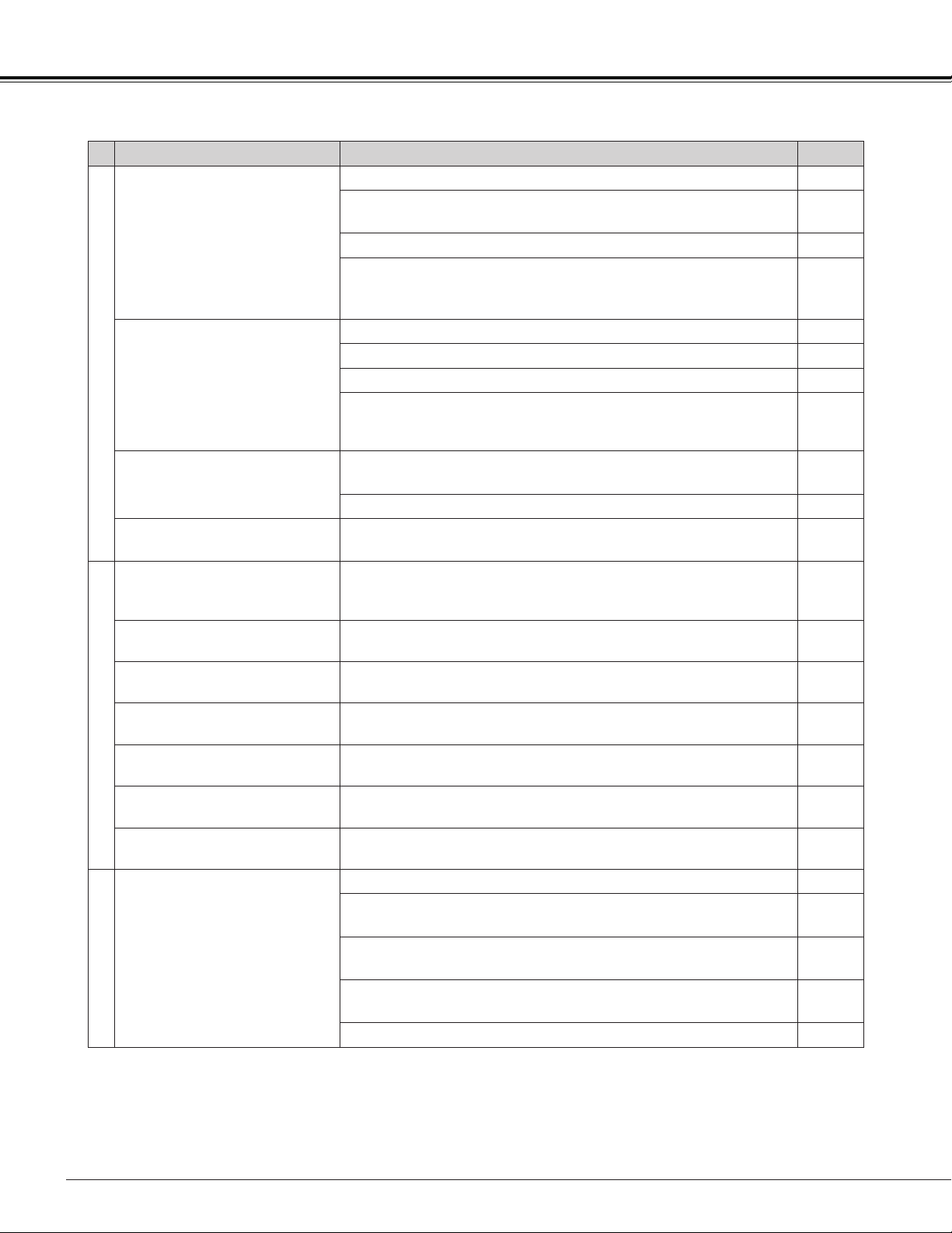
72
Appendix
Problem Solutions Pages
Image
Image is out of focus.
Adjust focus of the projector. 27
Provide proper distance between the projector and the
projection screen.
17
Check the projection window to see if it needs cleaning.
68
Moving the projector from a cool to warm place may result in
moisture condensation on the projection lens. In such cases,
leave the projector off and wait until condensation evaporates.
Picture is not bright enough.
Check if the Contrast or Brightness is adjusted properly. 39, 46
Check if Image mode is selected properly. 38
Check the Lamp mode function. 30, 60
Check the LAMP REPLACE indicator. If it lights, the end of
lamp life is approaching. Replace the lamp with a new one
promptly.
69
The color is strange.
Check the Input signal, color system, video system or
computer system mode.
Make sure the Colorboard is not selected on Screen Menu. 42, 49
The image is distorted or runs
off.
Check PC adjustment Menu or Aspect and adjust them. 36-37,
40-42
Setting and adjustment
Auto PC adjustment function
does not work.
Check the Input signal. Auto PC function can not work when
480p, 575p, 720p, 480i, 575i or 1080i is selected, or when the
digital signal is input into HDMI terminal.
34, 35
Some displays are not seen
during the operation.
Check the Display function. 55
The setting does not remain
after turning off power.
Make sure you selected Store after adjusting setting. Some
settings can not be stored if not registered with "Store".
39, 47
Power management mode
does not work.
Power management mode function can not work while Freeze
or Blank is running.
59
Capture function does not
work.
Check the connection and the input signal to see if there is
signal
56
Auto setup does not work
properly.
Make sure Off is not selected at any function of Auto setup
53
Top control does not work.
The top control is not available if the top control is locked at
Key lock under Security of SETTING section.
61
Remote controller
The remote controller does not
work.
Check the batteries.
Make sure no obstruction is between the projector and remote
controller.
Make sure you are not too far from the projector when using
the remote controller. Maximum operating range is 16.4'(5 m).
Make sure the code of the remote controller is conformed to
the projector’s code.
60
Unlock the Key lock function for the remote controller function. 61
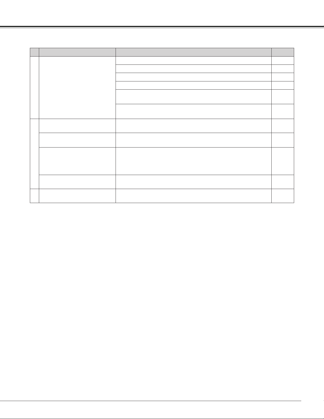
73
Appendix
WARNING :
High voltages are used to operate this projector. Do not attempt to open the cabinet.
If problems still persist after following all operating instructions, contact the dealer where you purchased the
projector or the service center. Specify the model number and explain about the problem. We will advise you
how to obtain service.
Problem Solutions Pages
Sound
No sound
Check the audio cable connection from audio input source.
Adjust the audio source.
Press the Volume + button. 29
Press the Mute button. 29
When the AUDIO OUT is plugged-in, the projector's built-in
speaker is not available.
Is the image projected? You will hear the sound only when the
image is projected.
Others
Indicator blinks or lights.
Check the status of the projector with referring to "Indicators
and projector Condition".
76
COMPUTER 2 can not be
selected
Select COMPUTER 2 in the Terminal function. 58
The terminal function can not
be selected.
The Terminal function cannot be selected after COMPUTER 2
is selected. Select other input source such as COMPUTER 1,
HDMI, S-video or Video so that the Terminal function can be
selected.
32,
42-43,
58
The exclamation mark appears
on the screen.
Your operation is invalid. Operate correctly.
3D
There are some trouble about
3D display function.
The troubleshooting about 3D display function is described on
page 49.
50, 51
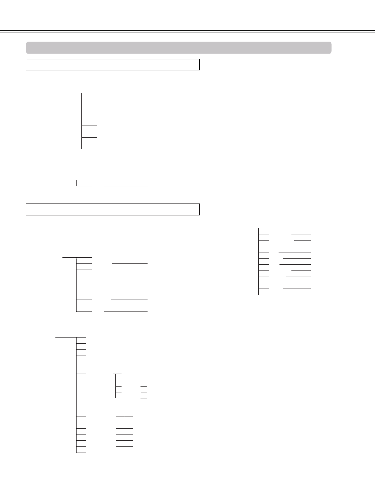
74
Menu Tree
Mode 1
Mode 2
SVGA 1
- - - -
Total dots
Horizontal position
Vertical position
Reset
Computer Input
PC adjust
Mode 1 ~10
Aspect
Yes / No
* Systems displayed in the System
Menu vary depending on an input
signal.
Computer Input/HDMI Input/Video Input
Sound
Volume
Mute On / Off
Sound
0-63
Clamp
Store
Mode free
System (1)
Mode 1 ~10
Scale
H&V
Position
Common
Reset
H / V
H/V
Yes / No
Yes / No
On / Off
Input
COMPUTER 2
VIDEO
ANALOG PC
SCART
COMPUTER 1
COMPONENT
Input
Off / Red / Blue / Yellow / Green / Blackboard(Green)
S-video
Auto PC
Fine sync 0-31
ANALOG PC
Appendix
COMPUTER 2 can not be selected
when using the COMPUTER IN 2/
MONITOR OUT terminal as MONITOR
OUT output.
Normal
Full
Digital zoom –
16:9
Digital zoom +
Custom adj.
Custom
HDMI
Current mode
Zoom
True
Keystone
Ceiling
Rear
Screen aspect
Colorboard
Reset
Store / Reset
Keystone
On / Off
4:3 / 16:9 / Default(16:10)
On / Off
0-63
0-63
Image adjust
Contrast
Brightness
Red
Green
Blue
Sharpness
Reset
Store
Gamma
0-63
0-63
0-63
0-15
Default / 1.8 / 2.0 /
2.2 / 2.4 / 2.6
User 1
Yes/No
User 2
User 3
User 4
Color temp.
High / Mid /
Low / XLow
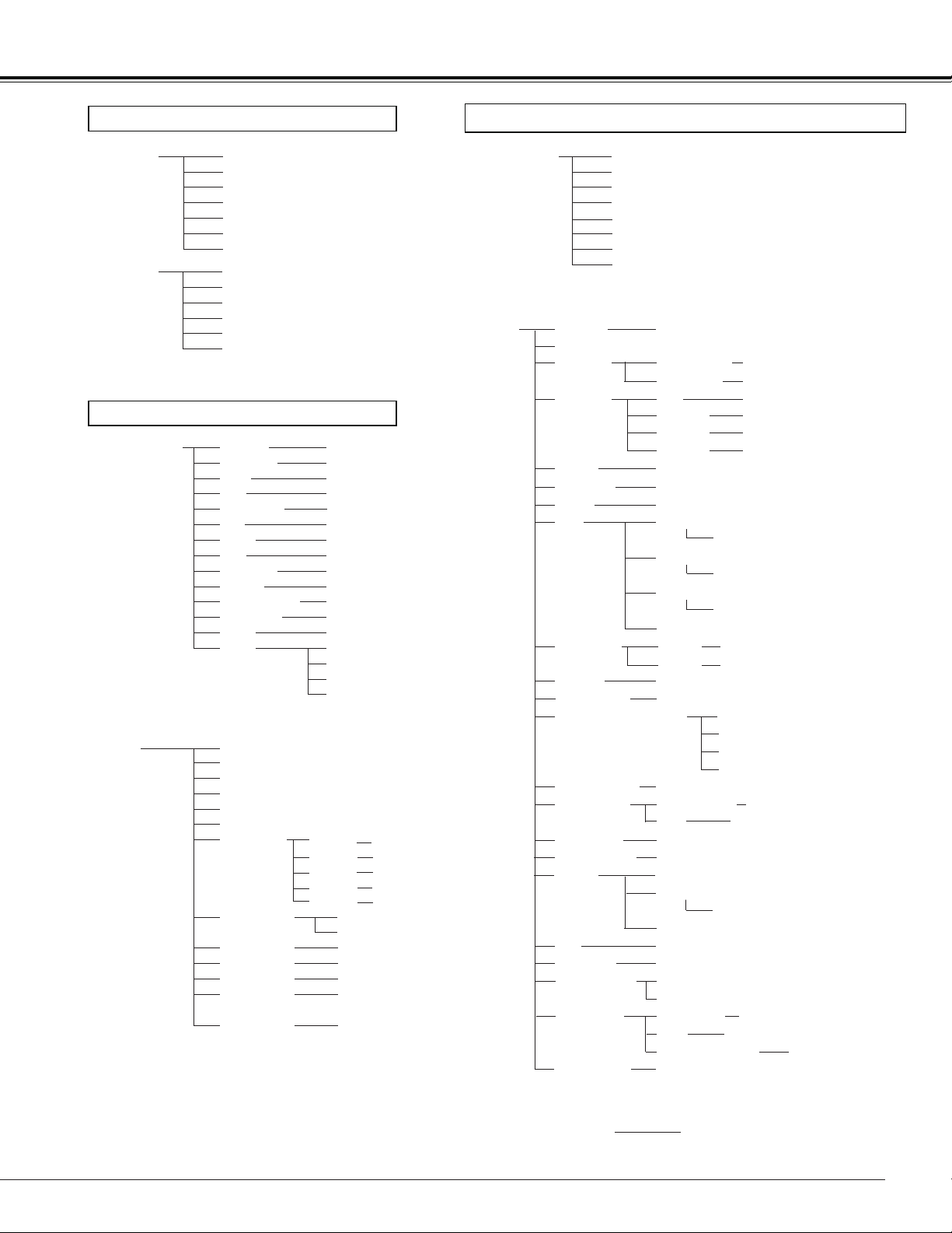
75
PAL
SECAM
NTSC
NTSC 4.43
PAL-M
PAL-N
1080i
720p
575p
480p
575i
480i
Presentation
High contrast
User 1
User 2
User 3
0-63
0-63
Off / L1 / L2 / Film
Image select
System (2)
System (3)
Image adjust
Contrast
Brightness
Color
Tint
Red
Green
Blue
Sharpness
Reset
Store
Gamma
Progressive
0-63
0-63
0-63
0-15
Default / 1.8 / 2.0 / 2.2 / 2.4 / 2.6
User 1
Yes/No
User 4
Language
Setting
24 languages provided.
Blue / User / Black
On / Countdown off / Off
Logo select
Standby
Code 1 - Code 2
Background
Display
Logo
Power management mode
Remote control
Exit
Off
Security
PIN code lock
Timer (1-30 Min)
L 1 / L 2Fan
Standard
Off / L1 / L2Noise reduction
0-63
0-63
User 2
User 3
User 4
Capture
Yes/No
Off / On
Logo PIN code change
Logo PIN code lock
Off / Default / User
Off / On 1 / On 2
PIN code change
On / Off
Closed captionClosed caption
Color temp.
Auto PC
Off / On 1 / On 2 Fan control
HFilter counter
Yes/No
Off/2000H/3000H/4000H
Yes/NoFactory default
Auto input Off / On 1 / On 2Auto setup
Off / CC1 / CC2 / CC3 / CC4
Color Color / White
Lamp mode Normal / Eco
Filter counter
Timer
Filter counter reset
Information
Input Source Information Display
Menu position
Appendix
High / Mid / Low / XLow
Lamp counterLamp counter
Lamp counter reset
3D setting
Normal
Full
Aspect
16:9
Zoom
Natural wide
3D sync
3D
HDMI setup
Sound
Image Normal / Enhanced
HDMI / COMPUTER 1
COMPUTER 2 / Monitor outTerminal
Standby mode Eco / Network
On/Off
Direct power on
Computer Input/HDMI Input/Video Input
Video Input
HDMI Input/Video Input
Key lock
Cinema
On / Off/ NVIDIA 3D VISION
1 / 2
3D -> 2D
On / Off
3D phase
0 - 31
Reset / Store1 / Store2Zoom
Scale
H&V
Position
Common
Reset
H / V
H/V
Yes / No
Yes / No
On / Off
Off / Red / Blue / Yellow / Green /
Blackboard(Green)
Custom adj.
Keystone
Ceiling
Rear
Screen aspect
Colorboard
Reset
Store / Reset
Keystone
On / Off
4:3 / 16:9 / Default(16:10)
On / Off
Custom
Yes / No
1080p
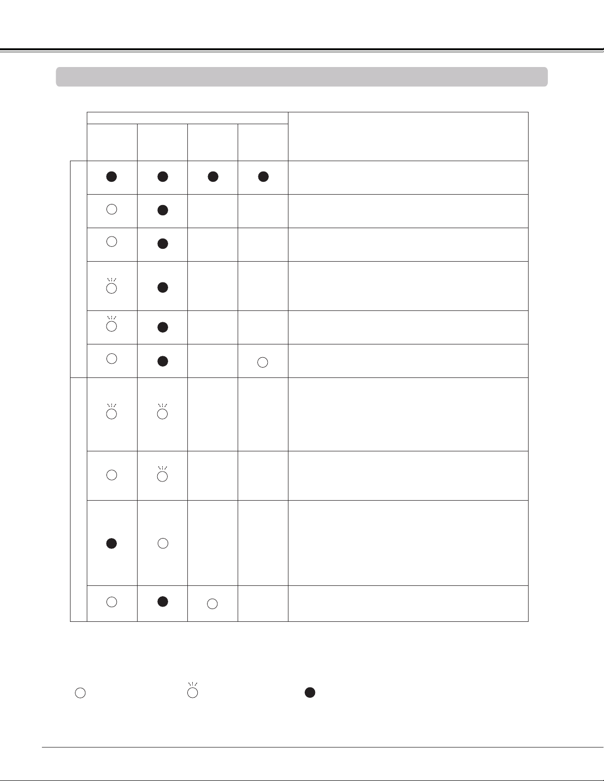
76
Check the indicators for projector condition.
• • • on.
/ • • • Differs according to conditions.
• • • blinking.
Indicators and Projector Condition
Appendix
Indicators
POWER
WARNING
TEMP.
LAMP
REPLACE
3D
Projector Condition
Red/Green Red Yellow Blue
Normal Condition
The projector is off. (The AC power cord is
unplugged.)
The projector is in stand-by mode. Press the POWER
button to turn on the projector.
The projector is operating normally.
The projector is preparing for stand-by or the
projection lamp is being cooled down. The projector
can not be turned on until cooling is completed and
the POWER indicator stops blinking.
The projector is in the Power management mode.
The projector is in 3D display mode.
Abnormal Condition
The temperature inside the projector is abnormally
high. The projector can not be turned on. When the
projector is cooled down enough and the temperature
returns to normal, the POWER indicator stops
blinking and the projector can be turned on. (The
WARNING TEMP. indicator keeps blinking.)
The projector has been cooled down enough and
the temperature returns to normal. When turning on
the projector, the WARNING TEMP. indicator stops
blinking.
The projector detects an abnormal condition and can
not be turned on. Unplug the AC power cord and
plug it again to turn on the projector. If the projector
is turned off again, unplug the AC power cord and
contact the dealer or the service center for service
and checkup. Do not leave the projector on. It may
cause an electric shock or a fire hazard.
The lamp has been used overtime. Replace the lamp
immediately and then reset the lamp counter. The
indicator will be turned off after resetting the counter.
red
green
red
green
red
red
green
green
• • • off
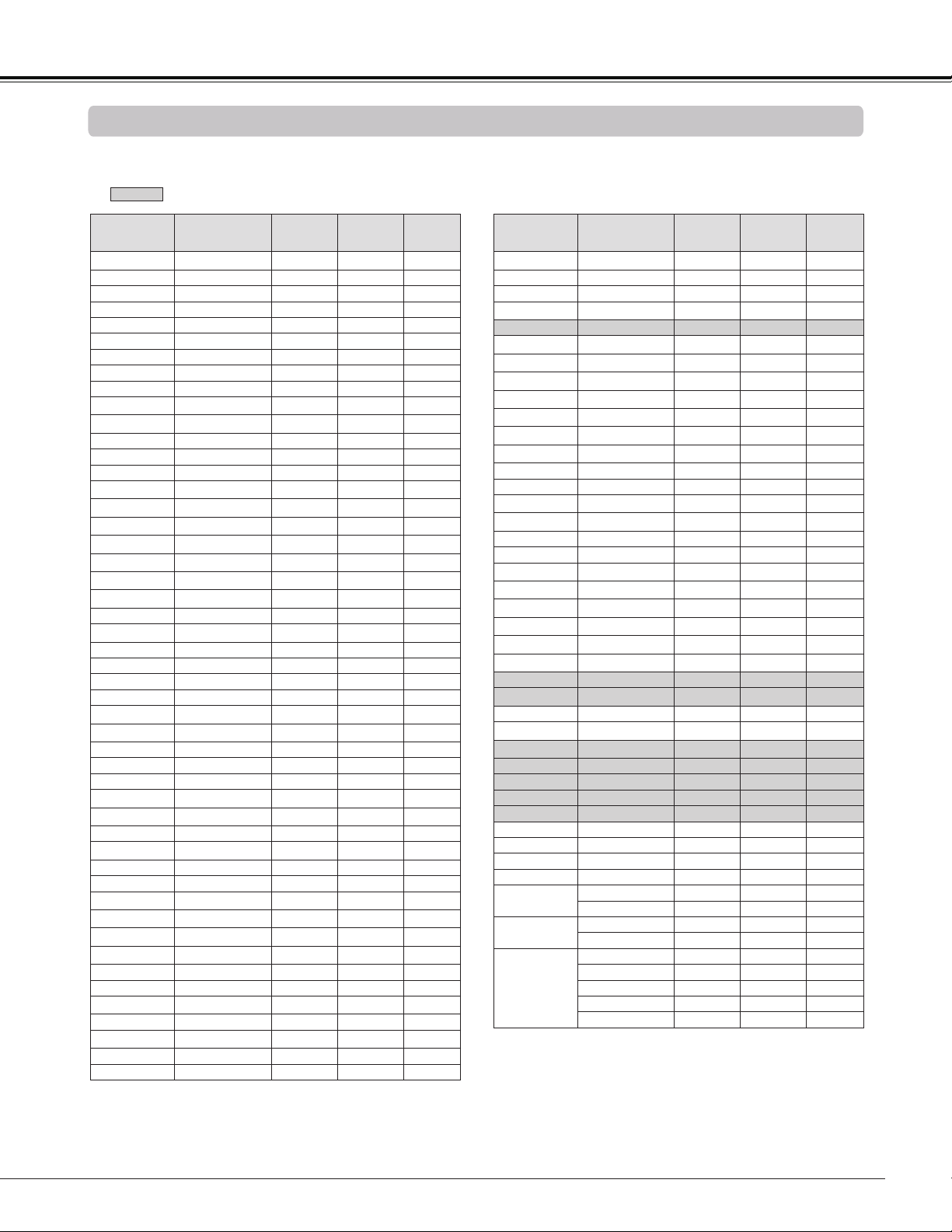
77
Compatible Computer Specifications
Basically this projector can accept the signal from all computers with the V-, H- Frequency mentioned
below and less than 150 MHz of Dot Clock.
When selecting these modes, PC adjustment can be limited.
Note:
• The mark "" indicates that the 3D image can be projected.
• Alphabet letter "i" placed beside some of the resolutions represents interlace signal.
• The specifications are subject to change without notice.
Appendix
ON-SCREEN
DISPLAY
RESOLUTION H-FREQ.
[kHz]
V-FREQ.
[Hz]
3D
DISPLAY
VGA 1 640X480 31.470 59.880
VGA 2 720X400 31.470 70.090 -
VGA 2 640X400 31.470 70.090 -
VGA 4 640X480 37.860 74.380 -
VGA 5 640X480 37.860 72.810 -
VGA 6 640X480 37.500 75.000 -
VGA 7 640X480 43.269 85.000 -
MAC 13 640x480 34.970 66.600 -
MAC 13 640x480 35.000 66.670 -
SVGA 1 800x600 35.156 56.250
SVGA 2 800x600 37.880 60.320
SVGA 3 800x600 46.875 75.000 -
SVGA 4 800x600 53.674 85.060 -
SVGA 5 800x600 48.080 72.190 -
SVGA 6 800x600 37.900 61.030
SVGA 7 800x600 34.500 55.380
SVGA 2 800x600 38.000 60.510
SVGA 9 800x600 38.600 60.310
SVGA 10 800x600 32.700 51.090
SVGA 2 800x600 38.000 60.510
SVGA 12 800x600 76.302 119.972
MAC 16 832x624 49.720 74.550 -
XGA 1 1024x768 48.360 60.000
XGA 2 1024x768 68.677 84.997 -
XGA 3 1024x768 60.023 75.030 -
XGA 4 1024x768 56.476 70.070 -
XGA 5 1024x768 60.310 74.920 -
XGA 1 1024x768 48.500 60.020
XGA 7 1024x768 44.000 54.580
XGA 8 1024x768 68.480 79.350 -
XGA 10 1024x768 62.040 77.070 -
XGA 11 1024x768 61.000 75.700 -
XGA 13 1024x768 46.900 58.200
XGA 13 1024x768 47.000 58.300
XGA 15 1024x768 58.030 72.000 -
XGA 16 1024x768 97.551 119.989
XGA 5 1024x768 60.240 75.080 -
SXGA 1 1152x864 64.200 70.400 -
SXGA 2 1280x1024 62.500 58.600
SXGA 3 1280x1024 63.900 60.000
SXGA 4 1280x1024 63.340 59.980
SXGA 3 1280x1024 63.740 60.010
SXGA 6 1280x1024 71.690 67.190 -
SXGA 7 1280x1024 81.130 76.107 -
SXGA 3 1280x1024 63.980 60.020
SXGA 9 1280x1024 79.976 75.025 -
SXGA 10 1280x960 60.000 60.000
SXGA 11 1152x900 61.200 65.200 -
SXGA 12 1152x900 71.400 75.600 -
ON-SCREEN
DISPLAY
RESOLUTION H-FREQ.
[kHz]
V-FREQ.
[Hz]
3D
DISPLAY
SXGA 4 1280x1024 63.370 60.010
SXGA 16 1280x1024 76.970 72.000 -
SXGA 17 1152x900 61.850 66.000 -
SXGA 3 1280x1024 63.790 60.180
SXGA 20 1280x1024 91.146 85.024 -
SXGA+ 1 1400x1050 63.970 60.190
SXGA+ 2 1400x1050 65.350 60.120
SXGA+ 2 1400x1050 65.120 59.900
SXGA+ 1 1400x1050 64.030 60.010
SXGA+ 5 1400x1050 62.500 58.600
SXGA+ 6 1400x1050 64.744 59.948
SXGA+ 2 1400x1050 65.317 59.978
MAC 21 1152x870 68.680 75.060 -
SXGA 9 1280x1024 80.000 75.080 -
WXGA 3 1376x768 48.360 60.000
WXGA 6 1280x768 47.776 59.870
WXGA 7 1280x768 60.289 74.893 -
WXGA 8 1280x768 68.633 84.837 -
WXGA 9 1280x800 49.600 60.050
WXGA 10 1280x800 41.200 50.000
WXGA 11 1280x800 49.702 59.810
WXGA 13 1360x768 97.533 119.967
WXGA 14 1280x768 97.396 119.798
WXGA 15 1280x800 101.563 119.909
WUXGA 1 1920x1200 74.556 59.885 -
WUXGA 2 1920x1200 74.038 59.950
WSXGA+ 1 1680x1050 65.290 59.954 -
WXGA+ 1 1440x900 55.935 59.887
UXGA 1 1600x1200 75.000 60.000
UXGA 2 1600x1200 81.250 65.000 -
UXGA 3 1600x1200 87.500 70.000 -
UXGA 4 1600x1200 93.750 75.000 -
UXGA 5 1600x1200 106.250 85.000 -
480p 720x480 31.469 59.940 -
575p 768x575 31.250 50.000 -
575i 768x576 i 15.625 50.000 -
480i 640x480 i 15.734 60.000 -
720p
1280x720 45.000 60.000 -
1280x720 37.500 50.000 -
1080i
1920x1080 i 33.750 60.000 -
1920x1080 i 28.125 50.000 -
1080p
1920x1080 33.750 30.000 -
1920x1080 28.125 25.000 -
1920x1080 27.000 24.000 -
1920x1080 67.500 60.000 -
1920x1080 56.250 50.000 -
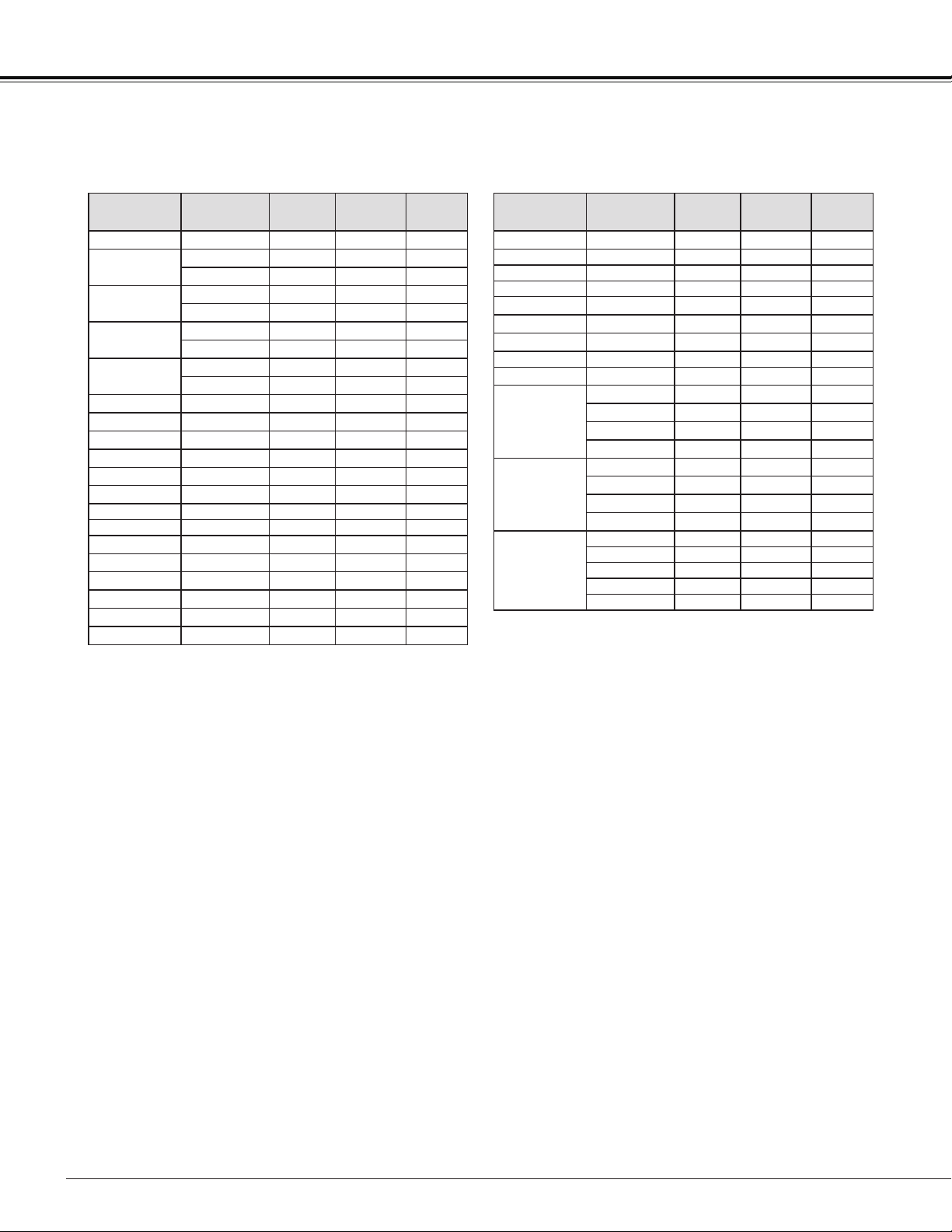
78
Appendix
Note:
• The mark "" indicates that the 3D image can be projected.
• Alphabet letter "i" placed beside some of the resolutions represents interlace signal.
• The specifications are subject to change without notice.
• Depending on your PC settings, the digital signals of your PC may not be projected correctly. In such a
case, confirm your PC settings.
• When you project a DVI signal, connect the cables, turn the projector on, then select the input. Finally,
turn on your PC. Be sure to follow this procedure, otherwise an image may not be projected on the
screen. If an image is not projected correctly, restart your PC.
• Do not disconnect the cable while the projector is running. If the cable has been disconnected and then
reconnected, an image may not be correctly projected.
When the input signal is digital from HDMI terminal, refer to the chart below.
ON-SCREEN
DISPLAY
RESOLUTION
H-FREQ.
[kHz]
V-FREQ.
[Hz]
3D
DISPLAY
D-VGA 640x480 31.469 59.940
D-480i
720x480 i 15.734 59.940
720x480 i 31.469 119.880
D-480p
720x480 31.469 59.940
720x480 62.937 119.880
D-575i
720x575 i 15.625 50.00
720x575 i 31.250 100.00
D-575p
720x575 31.250 50.000
720x575 62.500 100.00
D-SVGA 800x600 37.879 60.320
D-SVGA 800x600 76.302 119.972
D-XGA 1024x768 43.363 60.000
D-XGA 1024x768 97.551 119.989
D-WXGA 3 1376x768 48.360 60.000
D-WXGA 6 1280x768 47.776 59.870
D-WXGA 7 1280x768 60.289 74.893 -
D-WXGA 8 1280x768 68.633 84.837 -
D-WXGA 9 1280x800 49.600 60.050
D-WXGA 10 1280x800 41.200 50.000
D-WXGA 11 1280x800 49.702 59.810
D-WXGA 13 1360x768 97.533 119.967
D-WXGA 14 1280x768 97.396 119.798
D-WXGA 15 1280x800 101.563 119.909
ON-SCREEN
DISPLAY
RESOLUTION
H-FREQ.
[kHz]
V-FREQ.
[Hz]
3D
DISPLAY
D-SXGA 1 1280x1024 63.980 60.020
D-SXGA 2 1280x1024 60.276 58.069 -
D-SXGA+ 2 1400x1050 65.350 60.120 -
D-SXGA+ 2 1400x1050 65.120 59.900 -
D-SXGA+ 5 1400x1050 62.500 58.600
D-SXGA+ 6 1400x1050 64.744 59.948
D-SXGA+ 2 1400x1050 65.317 59.978
D-WSXGA+ 1 1680 x 1050 65.290 59.954 -
D-WXGA+ 1 1440 x 900 55.935 59.887
D-720p
1280x720 45.000 60.000
1280x720 37.500 50.000
1280x720 90.000 120.000
1280x720 75.000 100.000
D-1080i
1920x1080 i 33.750 59.94/60
1920x1080 i 28.125 50.000
1920x1080 i 67.500 119.98/120
1920x1080 i 56.250 100.000
D-1080p
1920x1080 33.750 30.000 -
1920x1080 28.125 25.000 -
1920x1080 27.000 24.000 -
1920x1080 67.500 60.000 -
1920x1080 56.250 50.000 -

79
Technical Specifications
Mechanical Information
Projector Type Multi-media Projector
Dimensions (W x H x D) 12.6" x 6.7" x 15.2" (321.0 mm x 170.0 mm x 385.0 mm) (Not including protrusions)
Net Weight 13.7 lbs (6.2 kg)
Feet Adjustment ±1.0˚
DLP Chip
Projection System 0.65" Single DLP chip, 6 segment Color Wheel
Number of Pixels 1,024,000 pixels (1,280 x 800 dots)
Signal Compatibility
Color System
PAL, SECAM, NTSC, NTSC4.43, PAL-M, and PAL-N
SD/HDTV Signal Component: 480i, 480p, 575i, 575p, 720p ,1080i and 1080p
HDMI; 480p, 575p, 720p, 1080i and 1080p
Input Scanning Frequency H-sync. 15 kHz-93 kHz, V-sync. 50-120 Hz
Optical Information
Projection Image Size (Diagonal) Adjustable from 60” to 110”
Throw Distance 0.75’ - 1.49' (23.0 cm - 45.5 cm)
Projection Lens F 2.5 lens with f 4.83 mm with manual focus
Projection Lamp 275 W
Image Information
Brightness 2500 lm (Lamp mode in “Normal”, Image mode in “Presentation”)
Contrast ratio 2000:1 (Lamp mode in “Normal”, Image mode in “Presentation”)
Uniformity 78%
Interface
Video Input Jack RCA Type x 1
S-Video Input Jack Mini DIN 4 pin x 1
Audio Input Jacks RCA Type x 2
Computer Input 1 / Component Input Terminal
Analog RGB (Mini D-sub 15 pin) Terminal x 1
Computer Input 2 / Monitor Output Terminal
Analog RGB (Mini D-sub 15 pin) Terminal x 1 (In/Out switchable)
Computer 1/ Component Audio Input Jack
Mini Jack (stereo) x 1
Computer 2 Audio Input Jack
Mini Jack (stereo) x 1
Audio Output Jack Mini Jack (stereo) x 1 (Variable)
HDMI HDMI (V.1.3 with Deep Color) x 1
Control port D-sub 9 pin x 1
LAN Connection Terminal RJ-45 x 1
3D Sync Output Mini DIN 3 pin x 1
Audio
Internal Audio Amp 10 W RMS
Built-in Speaker 1 speaker, φ1.46" (37 mm)
Power
Voltage and Power Consumption AC 100–120 V (4.4 A Max. Ampere), 50/60 Hz (The U.S.A and Canada)
AC 100–240 V (4.4 - 2.3 A Max. Ampere), 50/60 Hz (For other countries)
Operating Environment
Operating Temperature 41˚F–104˚F (5 ˚C–40 ˚C)
Storage Temperature 14˚F–140˚F (-10˚C–60 ˚C)
Remote Controller
Battery AAA 1.5V TYPE x 2
Operating Range 16.4' (5 m)/±30˚
Dimensions 2.0" (W) x 0.7" (H) x 4.3" (D) (52 mm x 18 mm x 110 mm)
Net Weight 2.37 oz (67 g) (including batteries)
Accessories
User's Manual( CD-ROM)
Important Information and Quick Start Guide
AC Power Cord
Remote Controller and Batteries
VGA Cable
PIN Code Label
Warranty Card
Appendix
The specifications are subject to change without notice.
DLP chips are manufactured to the highest possible standards. A tiny fraction of pixels may be ineffective or always lit, but this is not a
malfunction.
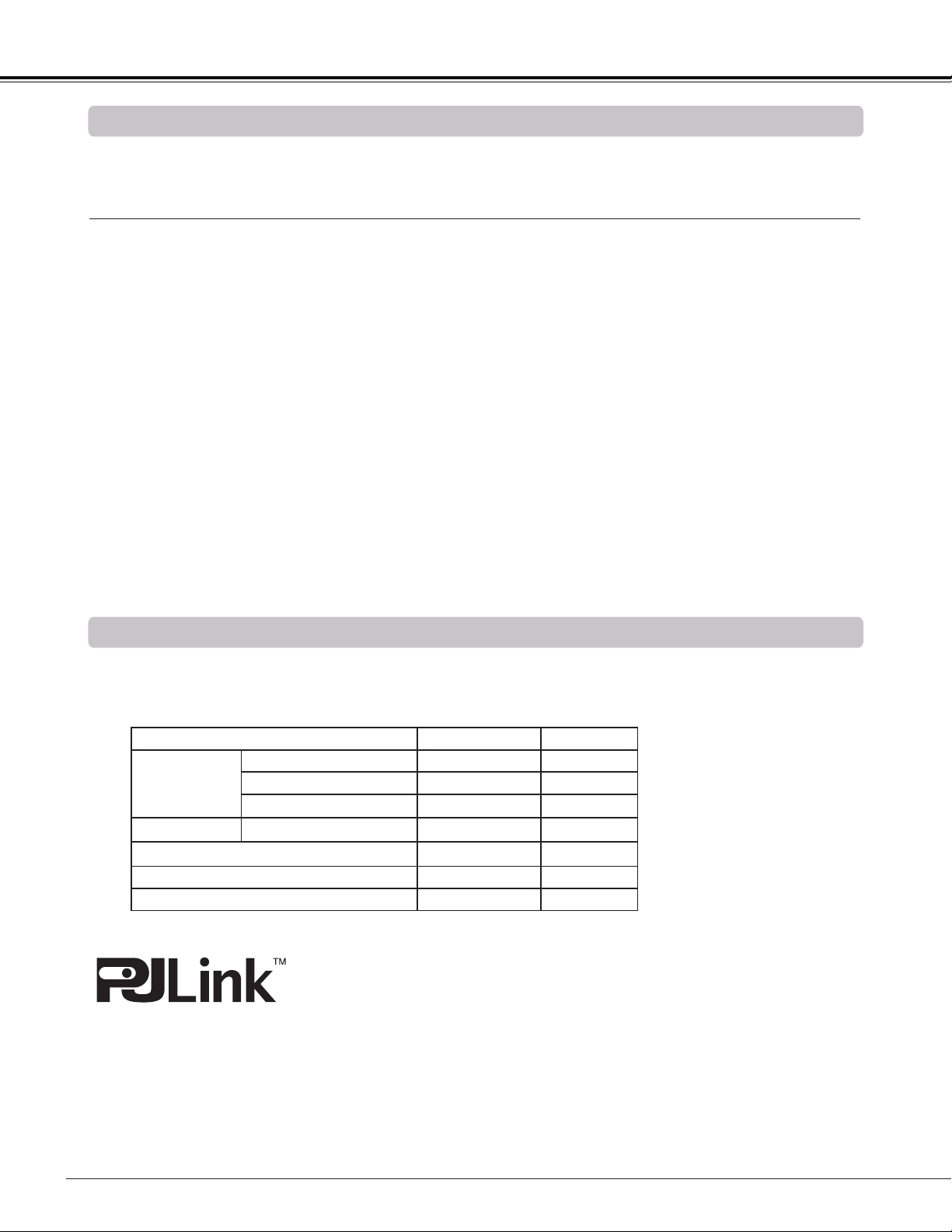
80
Appendix
Model No.
COMPONENT-VGA Cable : LV-CA32
Remote Controller : LV-RC05
Ceiling Attachment : LV-CL20
High Ceiling Attachment : LV-CL21
Wall Attachment : LV-WL01
The parts listed below are optionally available. When ordering those parts, specify the item name and Model No.
to the sales dealer.
Optional Parts
This projector is compliant with PJLink Standard Class 1 of JBMIA (Japan Business Machine and Information
System Industries Association). The projector supports all commands defined by PJLink Class 1 and is verified
conformance with PJLink Standard Class 1.
PJLink is a registered trademark of JBMIA and pending trademark in some countries.
PJ Link Notice
Projector Input PJLink Input Parameter
COMPUTER 1
ANALOG PC RGB 1 11
COMPONENT VIDEO 2 22
SCART RGB 2 12
COMPUTER 2
ANALOG PC RGB 3 13
HDMI (Digital)
DIGITAL 3 33
VIDEO VIDEO 1 21
S-VIDEO VIDEO 5 25
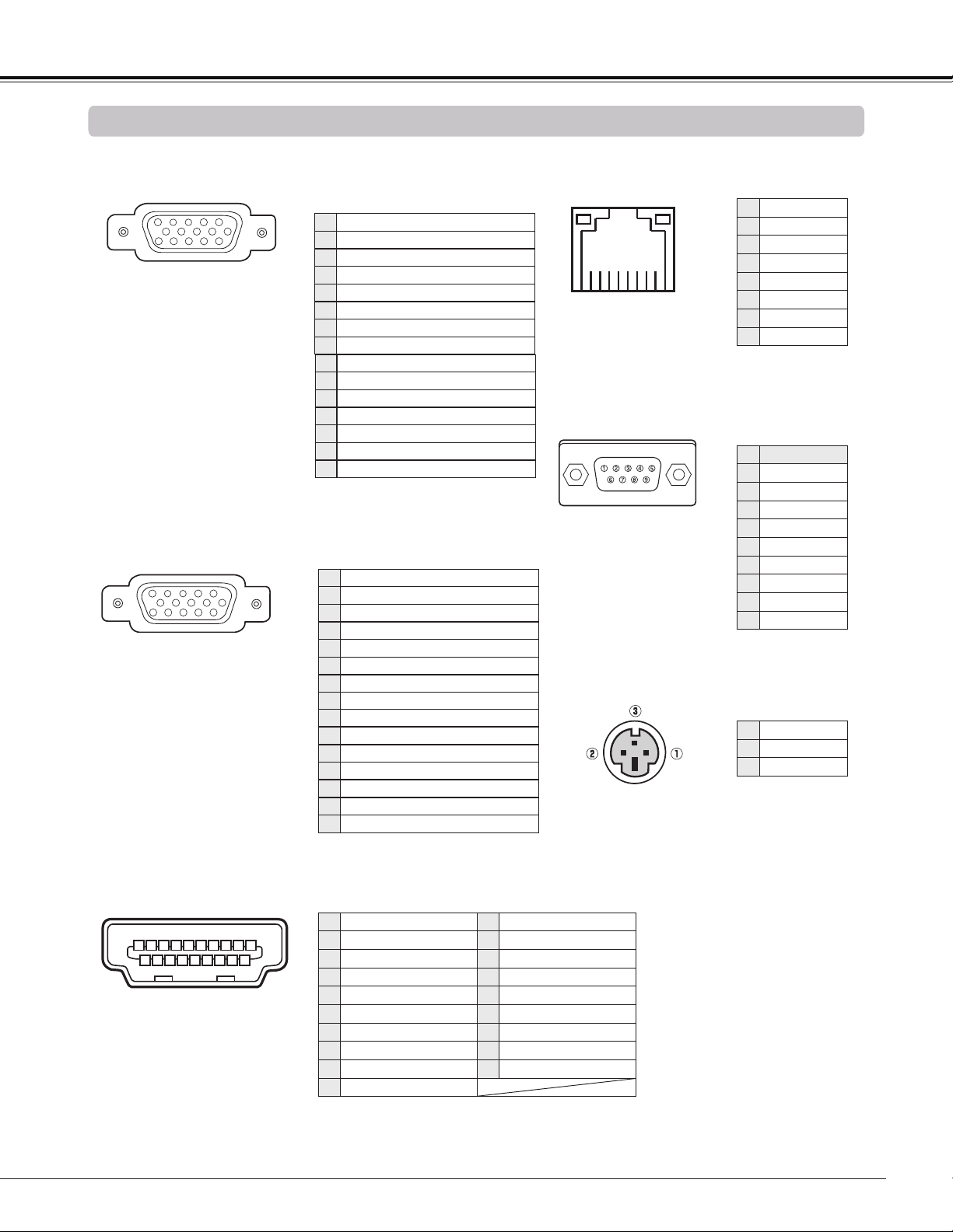
81
COMPUTER IN 1 /COMPONENT IN
(Mini D-sub 15 pin)
5
1
2
34
10
9 678
15
14
13
11
12
Configurations of Terminals
Red(R/Cr) Input
Ground (Horiz.sync.)
Green(G/Y) Input
-----
Blue (B/Cb) Input
Ground (Red)
Ground (Green)
Ground (Blue)
1
5
2
4
3
6
7
8
5V Power
Horiz. sync. Input (Composite H/V sync.)
Ground (Vert.sync.)
DDC Data
Ground
Vert. sync.
DDC Clock
9
13
10
12
11
14
15
8 7 6 5 4 3 2 1
LAN TERMINAL (RJ-45)
CONTROL PORT CONNECTOR (D-sub 9 pin)
Appendix
1 3 5 7 9
11 13 15 17 19
1816141210
8642
TMDS Data 2+ Input
Ground (TMDS Data 1)
Ground (TMDS Data 2)
TMDS Data 1+ Input
TMDS Data 2- Input
TMDS Data 1- Input
TMDS Data 0+ Input
Ground (TMDS Data 0)
1
5
2
4
3
6
7
8
Ground (TMDS Clock)
SCL
TMDS Clock- Input
-----
-----
SDA
Ground (DDC/CEC)
11
15
12
14
13
16
17
TMDS Data 0- Input
TMDS Clock+ Input
9
10
Plug insert detection19
18 +5V Power
HDMI (19 PIN Type A)
COMPUTER IN 2/MONITOR OUT (ANALOG)
(Mini D-sub 15 pin)
5
1
2
34
10
9 678
15
14
13
11
12
Red (R/Cr) Input/Output
Ground (Horiz.sync.)
Green (G/Y) Input/Output
-----
Blue (B/Cb) Input/Output
Ground (Red)
Ground (Green)
Ground (Blue)
1
5
2
4
3
6
7
8
-----
Horiz. sync. Input/Output
Ground (Vert.sync.)
-----
-----
Vert. sync. Input/Output
-----
9
13
10
12
11
14
15
3D SYNC OUT CONNECTOR (Mini DIN 3 pin)
1 +5VDC
2 Ground
3 Stereo Sync
1 TX+
2 TX–
3 RX+
4 - - -
5 - - -
6 RX–
7 - - -
8 - - -
Serial
1 - - -
2 RXD
3 TXD
4 - - -
5 SG
6 - - -
7 - - -
8 - - -
9 - - -
1
TMDS Data 2+ Input
11
Ground (TMDS Clock)
2
Ground (TMDS Data 2)
12
TMDS Clock- Input
3
TMDS Data 2- Input
13
- - -
4
TMDS Data 1+ Input
14
- - -
5
Ground (TMDS Data 1)
15
SCL
6
TMDS Data 1- Input
16
SDA
7
TMDS Data 0+ Input
17
Ground (DDC/CEC)
8
Ground (TMDS Data 0)
18
+5V Power
9
TMDS Data 0- Input
19
Plug insert detection
10
TMDS Clock+ Input
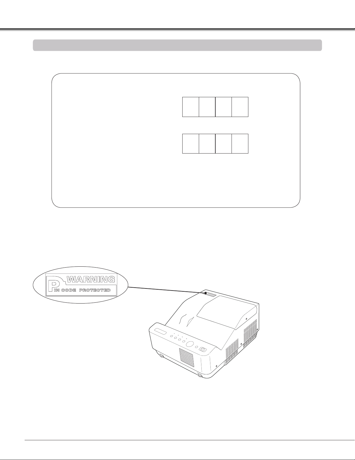
82
Write down the PIN code number in the column below and keep it with this manual securely. If you forgot or lost
the number and unable to operate the projector, contact the service center.
PIN Code Number Memo
Factory default set No: 1 2 3 4*
Factory default set No: 4 3 2 1*
Put the label below (supplied) on in a prominent place of the
projector's body while it is locked with a PIN code.
While the projector is locked with the PIN code.
PIN Code Lock No.
Logo PIN Code Lock No.
*Should the four-digit number be changed,
the factory set number will be invalid.
Appendix
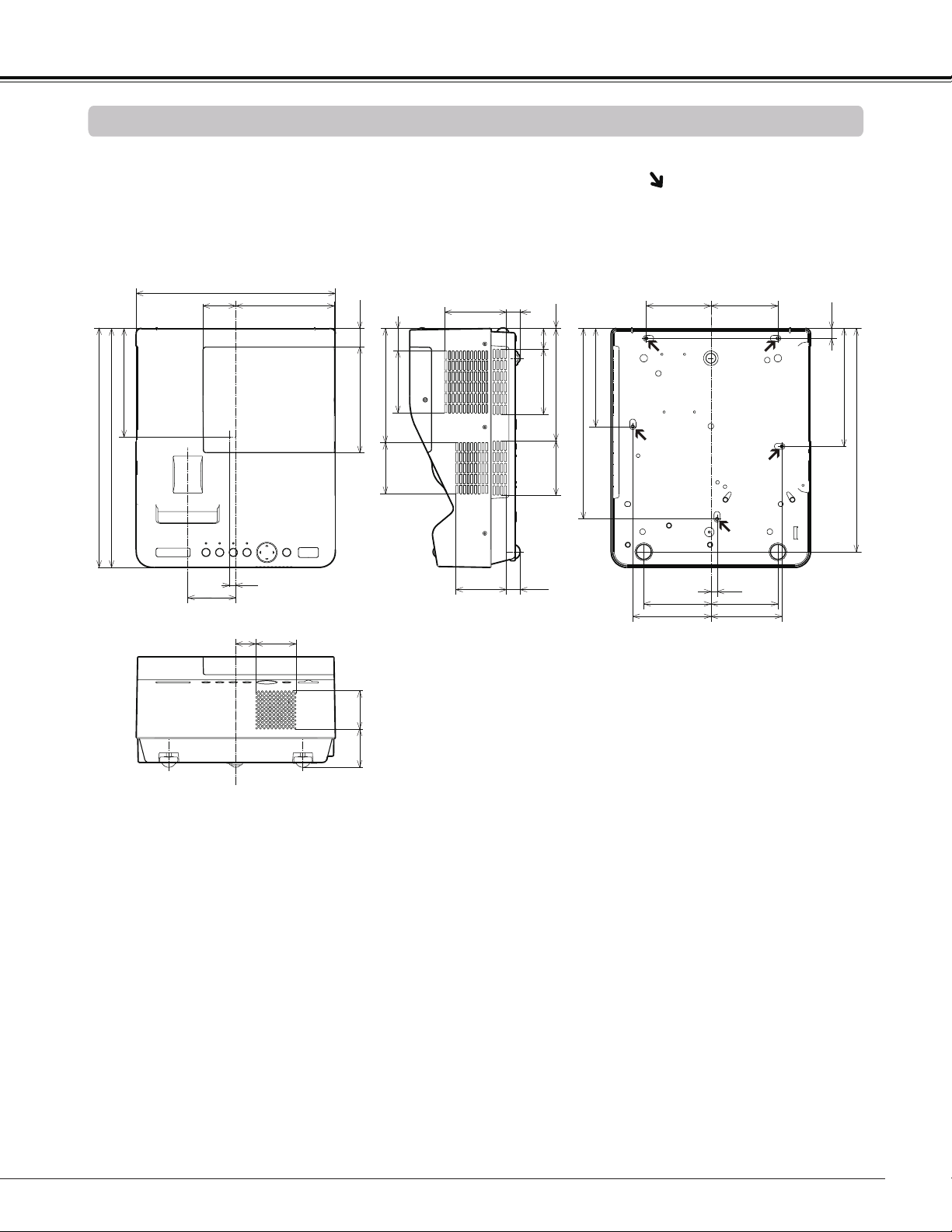
83
Dimensions
Appendix
1.16(29.5)
6.73(171.0)
6.89(175.0)
15.20(386.0)
15.16(385.0)
7.25(184.0)
1.43(36.2)
0.04(1.0)
1.31(33.2)
7.13(181.2)
4.16(105.6)
3.45(87.6)
12.09(307.0)
6.22(158.0)
3.92(99.6)
2.09(53.0)
12.64(321.0)
6.25(158.8)
3.92(99.5)
0.87(22.2)
3.21(81.5)
0.87(22.2)
0.39
2.43(61.6)
2.43(61.6)
3.05(77.5)
0.63(16.0)
7.48(190.0)
14.17(359.9)
4.10(104.2)
4.25(8.0) 4.25(108.0)
0.39(10.0)
4.51(114.5)
4.95(125.8)
4.25(107.9)
3.23(81.9)
1.27(32.2)
2.55(64.7)
Unit: inch(mm)
Screw Holes for Ceiling Mount
Screw: M4
Depth: 0.63(16.0)

CANON INC.
30-2, Shimomaruko 3-chome, Ohta-ku,
Tokyo 146-8501, Japan
U.S.A.
CANON U.S.A. INC.
One Canon Plaza, Lake Success, NY
11042-1198, U.S.A.
For all inquires concerning this product, call
toll free in the U.S. 1-800-OK-CANON
CANADA
CANON CANADA INC. HEADQUARTERS
6390 Dixie Road, Mississauga, Ontario L5T
1P7, Canada
CANON CANADA INC. MONTREAL BRANCH
5990, Cote-de-Liesse, Montreal Quebec H4T
1V7, Canada
CANON CANADA INC. CALGARY OFFICE
2828, 16th Street, N.E. Calgary, Alberta T2E
7K7, Canada
For all inquiries concerning this product, call
toll free in Canada 1-800-OK-CANON
EUROPE, AFRICA & MIDDLE EAST
CANON EUROPE LTD.
3 The Square, Stockley Park, Uxbridge,
Middlesex, UB11 1ET United Kingdom
CANON EUROPA N.V.
Bovenkerkerweg 59-61, 1185 XB Amstelveen,
The Netherlands
CANON FRANCE S.A.S
17, quai du President Paul Doumer, 92414
Courbevoie Cedex, France
CANON UK LTD.
Woodhatch Reigate Surrey RH2 8BF,
United Kingdom
CANON DEUTSCHLAND GmbH
Europark Fichtenhain A10, 47807 Krefeld,
Germany
CANON ITALIA S.p.A.
Via Milano 8 I-20097 San Donato Milanese,
Milano, Italy
CANON Schweiz AG
Geschaftsbereich Wiederverkauf,
Industriestrasse 12, CH-8305 Dietlikon,
Switzerland
CANON GMBH
Zetschegasse 11, A-1230 Wien, Austria
CANON España, S.A.
Av. De Europa, 6 Alcobendas 28108 Madrid, Spain
CANON PORTUGAL S.A.
Rua Alfredo da Silva, 14 Alfragide 2610-016
Amadora, Portugal
CANON Belgium N.V./S.A.
Berkenlaan 3, 1831 Diegem (Mechelen), Belgium
CANON Netherland NV
Neptunusstraat 1, 2132 JA Hoofddorp,
The Netherlands
CANON LUXEMBOURG S.A.
Rue des Joncs 21, L-1818 Howald, Luxembourg
CANON DANMARK A/S
Knud Hoejgaards Vej 1 DK-2860 Soeborg,
Danmark
CANON OY
Huopalahdentie 24 PL 1 00351 Helsinki, Finland
CANON SVENSKA AB
Gustav III:s Boulevard 26 169 88 Solna, Sweden
CANON NORGE as
Hallagerbakken 110, Postboks 33, Holmlia, 1201
Oslo, Norway
CENTRAL & SOUTH AMERICA
CANON LATIN AMERICA, INC.
703 Waterford Way, Ste. 400 Miami, FL 33126,
U.S.A.
ASIA
CANON (China) Co., Ltd.
15F Jinbao Building No.89 Jinbao Street,
Dongcheng District, Beijing 100005, China
CANON HONGKONG CO., LTD.
19/F., The Metropolis Tower, 10 Metropolis Drive,
Hunghom, Kowloon, Hong Kong
CANON SINGAPORE PTE. LTD.
1 HarbourFront Avenue, #04-01 Keppel Bay
Tower, Singapore 098632
CANON KOREA CONSUMER IMAGING INC.
Gangnam Finance Center 17F, 737, Yeoksam-
Dong, Gangnam-gu, Seoul, 135-984, Korea
OCEANIA
CANON AUSTRALIA PTY. LTD.
1 Thomas Holt Drive, North Ryde, N.S.W. 2113,
Australia
CANON NEW ZEALAND LTD.
Akoranga Business Park, Akoranga Drive,
Northcote, Auckland, New Zealand
1
© CANON INC. 2011
KG8PD