Loading ...
Loading ...
3
PLANNING
ELECTRICAL SPECIFICATIONS
Model VDVI600 - Internal Flex:
120 VAC • 60 Hz • 3.0 A
Models VDVE900, VDVE1200 - Exterior
120 VAC • 60 Hz • 6.0 A (max.)
TAKE MEASUREMENTS
DO NOT INSTALL WITH COOKING PRODUCTS THAT HAVE A
GRIDDLE.
Due to its exible design, this downdraft system can be used to
exhaust airborne contaminants when cooking with a variety of gas or
electric cooking appliances - including cooktops, rangetops, slide-in
ranges and free-standing ranges.
It can be mounted in island, peninsula, or conventional wall location. The
blower (purchase separately) and electrical panel can be mounted to the
downdraft unit, inside the cabinet, or in a convenient remote location.
This unit can be easily installed following these basic steps:
• Cut out the countertop opening.
• Mount the unit in the cabinet.
• Install the blower and electrical panel.
• Connect the ductwork and electrical.
• Mount the trim/door.
• Install the cooking appliance.
Note: the high level of air ow of this appliance may effect the gas
ame on some types of gas cooktops. This is NORMAL and will cause
no harm, but can be corrected by lowering the speed of the blower.
PLAN THE DUCTWORK
1. Refer to the cooktop installation instructions for dimensions of
cooktop, countertop cut-out, and cabinet requirements. However,
it is recommended that oversized cabinets be used for easier
installation.
2. Cooktop depth can vary greatly from one to another. This may
cause the t of these two appliances to be rather tight.
Pay special attention to the areas of potential interference highlighted
below. A countertop with (A) a raised lip and/or (B) a backsplash may not
allow enough at countertop for a proper installation. Note that 2-3/4" of
at countertop is required behind cooktop and that 2-1/2" is necessary
between the back edge of the cooktop and the inside of cabinet back.
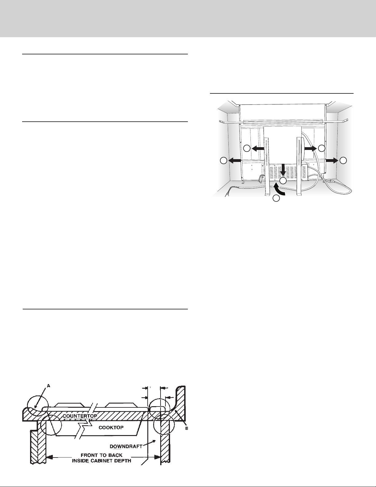
A
B
C
D
E
F
HOUSING
1. The downdraft blower system is designed for use with
8" round ductwork using a ex blower or 10" Round
ductwork using a remote blower. (Purchase blowers
separately.) Six (6) different discharge connections are
available - with side-to-side adjustment for accurate
alignment of ductwork:
A = 8" Round, Left Discharge out of Flex Blower
B = 8" Round, Right Discharge out of Flex Blower
C = 8" Round, Down Discharge out of Flex Blower
(Electrical Box to be mounted remotely)
D = 2" x 19¼", Left Discharge out of Housing
to Remote Blower or Flex Blower in remote
location. Use 2" x 19¼" to 8" round transition,
2" x 19¼" to 10" round transition, or 2" x 19¼"
ductwork as appropriate.
E = 2" x 19¼", Right Discharge out of Housing
to Remote Blower or Flex Blower in remote
location. Use 2" x 19¼" to 8" round transition,
2" x 19¼" to 10" round transition, or 2" x 19¼"
ductwork as appropriate.
F = 2" x 19¼", Rear Discharge out of Housing
to Remote Blower or Flex Blower in remote
location. Use 2" x 19¼" to 8" round transition,
2" x 19¼" to 10" round transition, or 2" x 19¼"
ductwork as appropriate.
2. For best performance: Choose the ducting option which
allows the shortest length of ductwork and a minimum
number of elbows and transitions. Check location of
oor joists, wall studs, electrical wiring or plumbing for
possible interference.
CONTENTS
These parts are included with your downdraft housing:
1 - Parts Bag
4 - Support Legs
1 - Trim Kit
1 - Electrical Panel
2 - Support Brackets
2-3/4"
2-1/2"
FLEX
BLOWER
*
*
Remote blowers use 8" or 10" round remote discharge
plate instead of ex blower.
Note: Remove all protective lm and packaging before op-
eration. In order to remove all protective lm and packag-
ing, raise the ventilator housing and remove the front panel
to access the lter area.
Loading ...
Loading ...
Loading ...