OWNER’S MANUAL
www.lg.com
MFL69491102
Rev.14_060723
AIR CONDITIONER
Read this owner’s manual thoroughly before operating
the appliance and keep it handy for reference at all
times.
Copyright © 2017 - 2023 LG Electronics Inc. All Rights Reserved
If Indoor unit are connected with multi split type, It is not Energy Star certified products
ENGLISH FRANÇAIS ESPAÑOL
TYPE: WALL MOUNTED

TABLE OF CONTENTS
2 TABLE OF CONTENTS
3 SAFETY INSTRUCTIONS
3 IMPORTANT SAFETY INSTRUCTIONS
7 OPERATION
7 Notes for Operation
7 Parts and Functions
8 Wireless Remote Control
13 Restarting the Air Conditioner Automatically
13 Using the Mode Function
15 Using the Jet Mode Function
16 Using the Fan Speed Function
16 Using the Air Flow Direction Function
17 Setting the On/Off Timer
18 Using the Sleep Function (Optional)
18 Using the Simple Timer Function (Optional)
19 Using the Energy Display Function (Optional)
19 Using the Light Off Function (Optional)
19 Using the Comfort Air Function (Optional)
20 Using the Energy Saving Function (Optional)
20 Using the Energy Control Function (Optional)
21 Using Special Functions
23 How to Enter Installer Setting Mode
24 SMART FUNCTIONS
24 LG ThinQ Application
26 Smart Diagnosis
TM
27 MAINTENANCE
29 Clean the Air Filter
30 Clean the Micro Dust and Triple Filter (Optional)
31 TROUBLESHOOTING
35 WARRANTY (USA)
37 WARRANTY (CANADA)
3SAFETY INSTRUCTIONS
ENGLISH
FRANÇAIS ESPAÑOL
SAFETY INSTRUCTIONS
READ ALL INSTRUCTIONS BEFORE USE
Your safety and the safety of others are very important.
We have provided many important safety messages in this manual and on your appliance. Always
read and follow all safety messages.
This is the safety alert symbol.
This symbol alerts you to potential hazards that can kill or injure you and others.
All safety messages will follow the safety alert symbol and either the word WARNING, or
CAUTION.
WARNING
If you do not follow instructions, it could result in death or serious injury.
CAUTION
If you do not follow instructions, it could result in minor or moderate injury or damage to the
product.
All safety messages will tell you what the potential hazard is, tell you how to reduce the chance of
injury, and tell you what may happen if the instructions are not followed.
IMPORTANT SAFETY INSTRUCTIONS
WARNING
To reduce the risk of explosion, fire, death, electric shock, injury or scalding to persons
when using this product, follow basic precautions, including the following:
• Installation or repairs made by unauthorized persons can pose hazards to you and others.
• Installation MUST conform to the local building codes or, in the absence of local codes, the
National Electrical Code NFPA 70/ANSI C1-1003 or current edition and Canadian Electrical Code
Part1 CSA C.22. 1.
• The information contained in the manual is intended for use by a qualified service technician who
is familiar with the safety procedures and equipped with the proper tools and test instruments.
• Failure to read and follow all instructions in this manual can result in equipment malfunction,
property damage, personal injury and/or death.
• When the power cord is to be replaced, the replacement work shall be performed by authorized
personnel using only genuine replacement parts.
• This appliance is not intended for use by persons (including children) with reduced physical,
sensory or mental capabilities, or lack of experience and knowledge, unless they have been given
supervision or instruction concerning use of the appliance by a person responsible for their safety.
Children should be supervised to ensure that they do not play with the appliance.

4 SAFETY INSTRUCTIONS
Installation
• Do not install the air conditioner on an unstable surface or in a place where there is danger of it
falling.
• Contact an authorized service center when installing or relocating the air conditioner.
• Install the panel and the cover of the control box safely.
• Do not install the air conditioner in a place where flammable liquids or gases such as gasoline,
propane, paint thinner, etc., are stored.
• Make sure that the pipe and the power cable connecting the indoor and outdoor units are not
pulled too tight when installing the air conditioner.
• Use standard circuit breaker and fuse that conform to the rating of the air conditioner.
• Do not input air or gas into the system except with the specific refrigerant.
• Use non-flammable gas (nitrogen) to check for leak and to purge air; using compressed air or
flammable gas may cause fire or explosion.
• The indoor/outdoor wiring connections must be secured tightly, and the cable should be routed
properly so that there is no force pulling the cable from the connection terminals. Improper or
loose connections can cause heat generation or fire.
• Install dedicated electric outlet and circuit breaker before using the air conditioner.
• Do not connect the ground wire to a gas pipe, a lightning rod, or a telephone ground wire.
• If the supply cord is damaged, it must be replaced by the manufacturer, its service agent or
similarly qualified person in order to avoid a hazard.
• Do not install the unit in potentially explosive atmospheres.
Operation
• Be sure to use only those parts listed in the service parts list. Never attempt to modify the
equipment.
• Make sure that children do not climb on or hit the outdoor unit.
• Dispose of the batteries in a place where there is no danger of fire.
• Use only the refrigerant specified on the air conditioner label.
• Cut off the power supply if there is any noise, smell, or smoke coming from the air conditioner.
• Do not leave flammable substances such as gasoline, benzene, or thinner near the air conditioner.
• Contact an authorized service center when the air conditioner is submerged by flood waters.
• Do not use the air conditioner for an extended period of time in a small place without proper
ventilation.
• In the event of a gas leak (such as Freon, propane gas, LP gas, etc.) ventilate sufficiently before
using the air conditioner again.
5SAFETY INSTRUCTIONS
ENGLISH
FRANÇAIS ESPAÑOL
• Be sure to ventilate sufficiently when the air conditioner and a heating appliance such as a heater
are used simultaneously.
• Do not block the inlet or outlet of air flow.
• Do not insert hands or other objects through the air inlet or outlet while the air conditioner is
operating.
• Make sure that the power cable is neither dirty, loose, nor broken.
• Never touch, operate, or repair the air conditioner with wet hands.
• Do not place any objects on the power cable.
• Do not place a heater or other heating appliances near the power cable.
• Do not modify or extend the power cable. Scratches or peeling insulation on the power cables
may result in fire or electric shock, and should be replaced.
• Cut off the power supply immediately in the event of a blackout or a thunderstorm.
• Take care to ensure that power cable could not be pulled out or damaged during operation.
• Do not touch refrigerant pipe, water pipe and any internal parts while the unit is operating or
immediately after operation.
Maintenance
• Do not clean the appliance by spraying water directly onto the product.
• Before cleaning or performing maintenance, disconnect the power supply and wait until the fan
stops.
CAUTION
To reduce the risk of minor injury to persons, malfunction, or damage to the product or
property when using this product, follow basic precautions, including the following:
Installation
• Do not install the air conditioner in an area where it is directly exposed to sea wind (salt spray).
• Install the drain hose properly for the smooth drainage of water condensation.
• Exercise caution when unpacking or installing the air conditioner.
• Do not touch the leaking refrigerant during installation or repair.
• Transport the air conditioner with two or more people or use a forklift.
• Install the outdoor unit such that it is protected from direct sunlight. Do not place the indoor unit in
a place where it is directly exposed to sunlight via the windows.
• Safely dispose of packing materials such as screws, nails, plastic bag or batteries using proper
packaging after installation or repair.
• Install the air conditioner in a place where the noise from the outdoor unit or the exhaust fumes will
not inconvenience the neighbors. Failure to do so may result in conflict with the neighbors.

6 SAFETY INSTRUCTIONS
Operation
• Remove the batteries if the remote control is not to be used for an extended period of time.
• Make sure that the filter is installed before operating the air conditioner.
• Be sure to check if there is a refrigerant leak after installing or repairing the air conditioner.
• Follow the standards of the corresponding region or country for handling the refrigerant and the air
conditioner and for disassembling the air conditioner.
• Do not place any object on the air conditioner.
• Never mix different types of batteries, or old and new batteries for the remote control.
• Do not let the air conditioner run for a long time when humidity is very high or when a door or a
window has been left open.
• Stop using the remote control if there is a fluid leak in the battery. If your clothes or skin are
exposed to the leaking battery fluid, wash off with clean water.
• Do not expose people, animals, or plants to the cold or hot wind from the air conditioner for
extended periods of time.
• If the leaking battery fluid has been swallowed, rinse the inside of the mouth thoroughly and
consult a doctor.
• Do not drink the water drained from the air conditioner.
• Do not use the product for special purposes, such as preserving foods, works of art, and etc. It
is an air conditioner for consumer purposes, not a precision refrigeration system. There is risk of
damage or loss of property.
• Do not recharge or disassemble the batteries.
Maintenance
• Never touch the metal parts of the air conditioner when removing the air filter.
• Use a sturdy stool or ladder when cleaning, maintaining, or repairing the air conditioner at a
height.
• Never use strong cleaning agents or solvents when cleaning the air conditioner or spray water.
Use a smooth cloth.
• To clean the interior, contact an authorized service center or dealer. Using harsh detergents may
cause corrosion or damage to the unit.
7OPERATION
ENGLISH
FRANÇAIS ESPAÑOL
OPERATION
Notes for Operation
Suggestion for Energy Saving
• Do not over-cool the space. This may be harmful for your health and may consume more electricity.
• Block sunlight with blinds or curtains while you are operating the air conditioner.
• Keep doors or windows closed tightly while you are operating the air conditioner.
• Adjust the direction of the air flow vertically or horizontally to circulate indoor air.
• Speed up the fan to cool or warm indoor air quickly, within a short period of time.
• Open windows regularly for ventilation. The indoor air quality may deteriorate if the air conditioner is used for
long durations.
• Clean the air filter once every 2 weeks. Dust and impurities collected in the air filter may block the air flow or
reduce the unit performance.
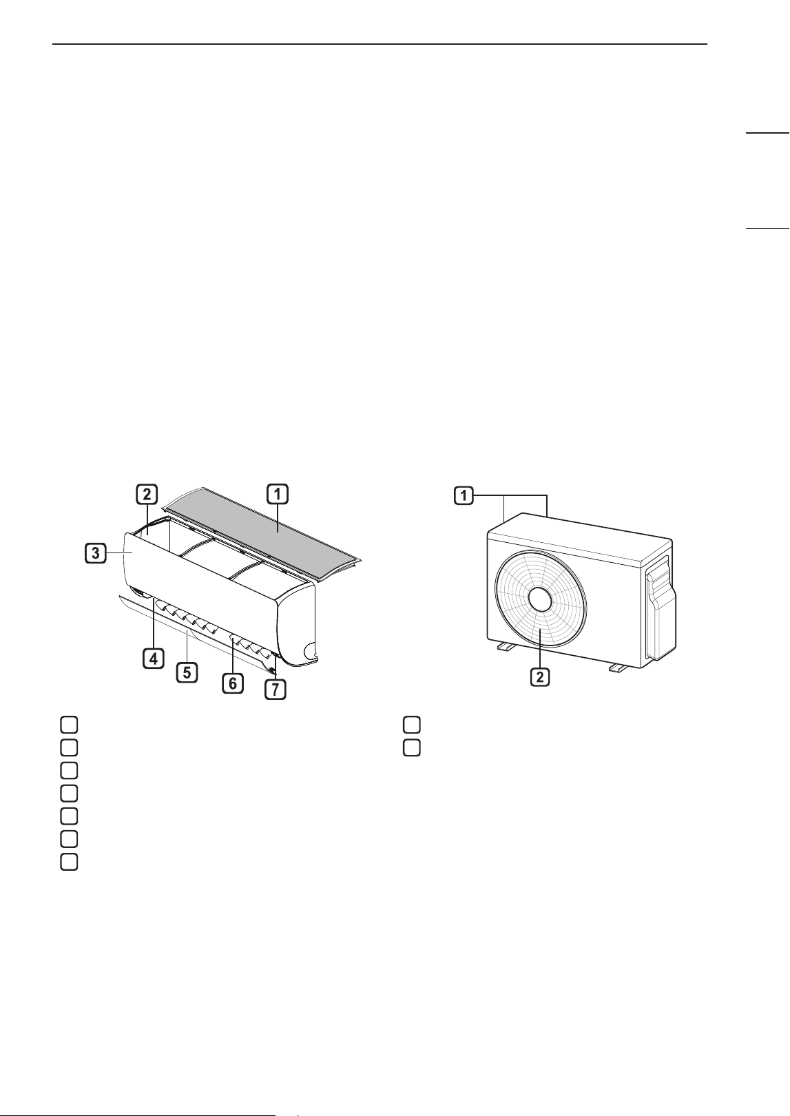
Parts and Functions
Indoor Unit Outdoor Unit
1
Air Filter
2
Air Intake
3
Front Cover
4
Air Outlet
5
Air Deflector (Horizontal Vane)
6
Air Deflector (Vertical Louver)
7
On/Off Button
1
Air Intake Vents
2
Air Outlet Vents
NOTE
• The number and location of operation lamps may vary according to the model of the air conditioner.
• The feature may be changed according to the type of model.
8 OPERATION
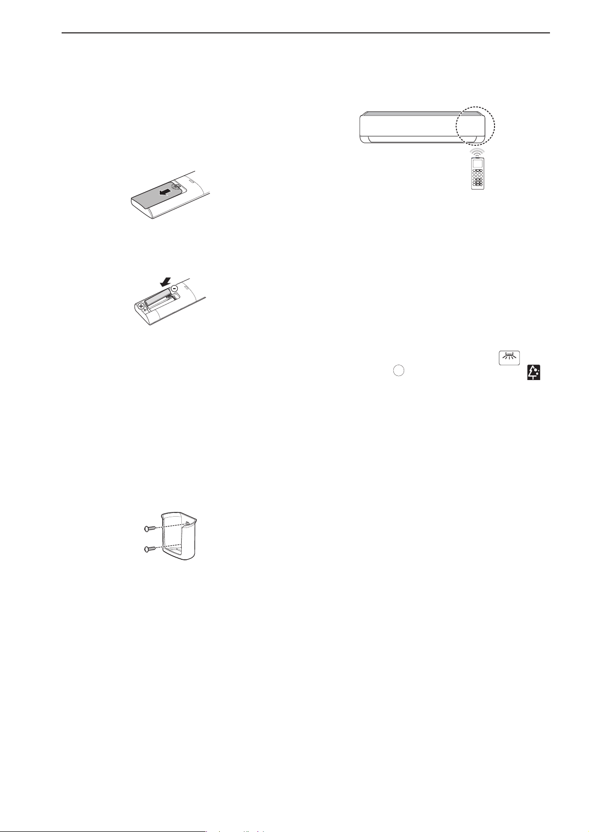
Wireless Remote Control
Inserting Batteries
If the display screen of the remote control begins
to fade, replace the batteries. Insert AAA (1.5 V)
batteries before using the remote control.
1
Remove the battery cover.
2
Insert the new batteries and make sure that the
+ and - terminals of the batteries are installed
correctly.
Installing the Remote Control Holder
(Optional)
To protect the remote control, install the holder where
there is no direct sunlight.
1
Choose a safe and easily accessible location.
2
Fix the holder by fastening 2 screws firmly with a
screwdriver.
Operating Method
Point the remote control towards the signal receiver
at the right side of the air conditioner to operate it.
NOTE
• The remote control may operate other electronic
devices if it is directed towards them. Make sure to
point the remote control towards the air conditioner
signal receiver.
• For proper operation, use a soft cloth to clean the
signal transmitter and receiver.
• In case of a function not provided in the product,
no buzzer sound occurs from the product when
a button for such function on the remote control
is pressed except for Air Flow Direction (
SWING
),
Energy Display (
kW [3 s]
), Air Purification function ( ).
9OPERATION
ENGLISH
FRANÇAIS ESPAÑOL
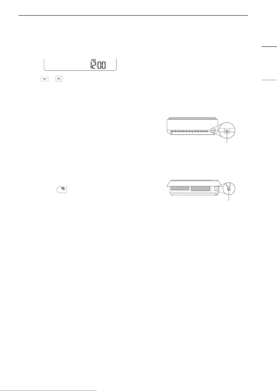
Setting the Current Time
1
Insert batteries.
• The icon below blinks at the bottom of the
display screen.
2
Press or button to select the minutes.
3
Press SET/CANCEL button to finish.
NOTE
• The On/Off Timer is available after setting the
current time.
Using the °C/°F Conversion Function
(Optional)
This function changes unit between °C and °F
• Press and hold
℃↔℉ [5 s]
SWING
button about 5 seconds.
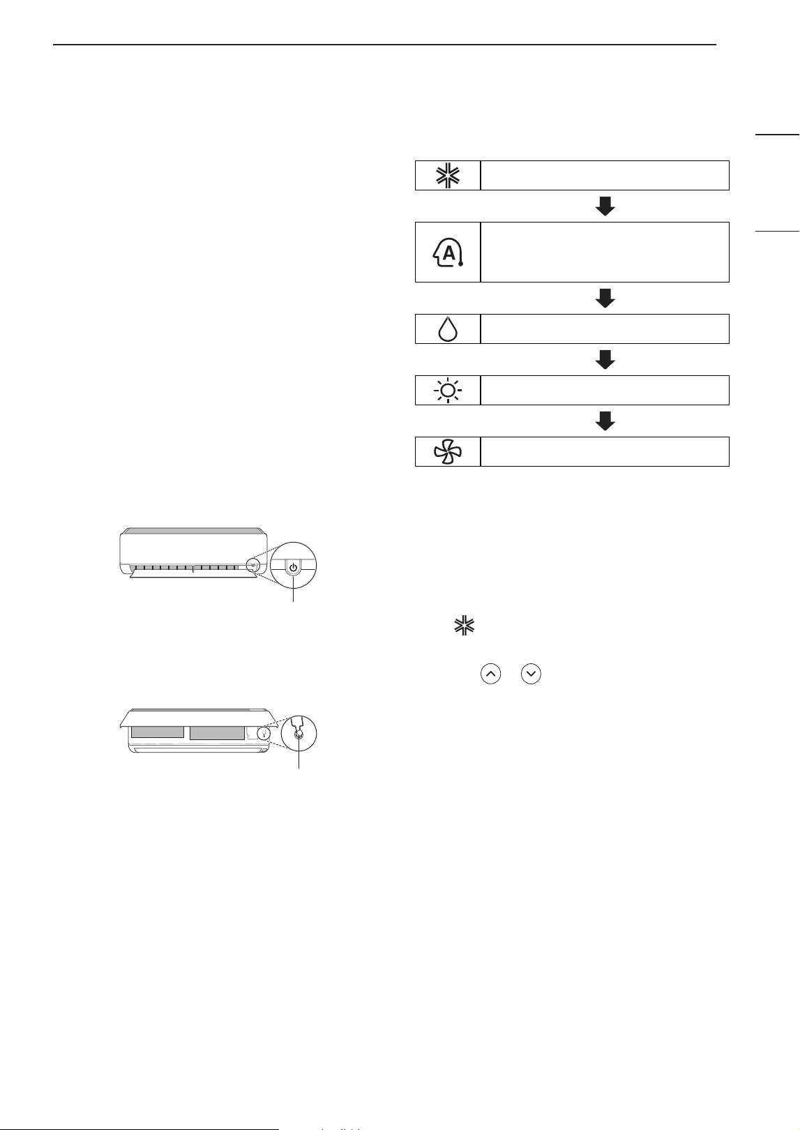
Operating the Air Conditioner without
the Remote Control
You can use the ON/OFF button of the indoor unit to
operate the air conditioner when the remote control is
unavailable.
1
Open the front cover (Type2) or horizontal vane
(Type1).
2
Press the ON/OFF button.
Type1
ON/OFF
Type2
ON/OFF
NOTE
• The stepping motor may be broken, if the horizontal
vane opens rapidly.
• The fan speed is set to high.
• The feature may be changed according to the type
of model.
• The temperature cannot be altered when using this
emergency ON/OFF button.
• For cooling & heating models, the temperature is
set from 22 °C to 24 °C
10 OPERATION
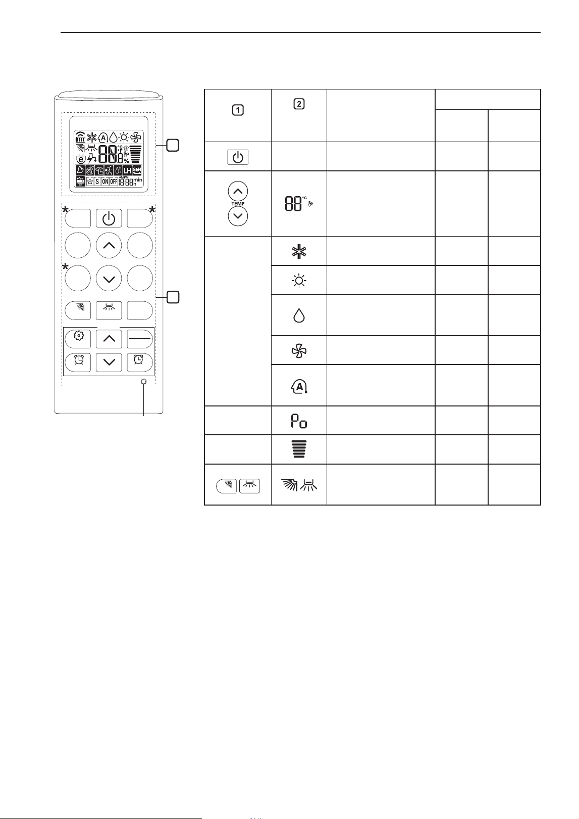
Using Wireless Remote Control
You can operate the air conditioner more conveniently with the remote control.
SWING
kW [3 s]
℃↔℉ [5 s]
DIAGNOSIS [5 s]
SWING
SET UP
ROOM
TEMP
JET
MODE
MODE
TEMP
FAN
SPEED
FUNC.
TIMER CANCEL
SET
CANCEL
1
2
RESET
Button
Display
Screen
Description
Available Function
Single
Split
Multi
-
To turn on/off the air
conditioner.
O O
To adjust the desired
room temperature
in cooling, heating
or auto changeover
mode.
O O
MODE
To select the cooling
mode.
O O
To select the heating
mode.
O O
To select the
dehumidification
mode.
O O
To select the fan
mode.
O O
To select the auto
changeover/auto
operation mode.
O O
JET
MODE
To change room
temperature quickly.
O O
FAN
SPEED
To adjust the fan
speed.
O O
SWING
SWING
To adjust the air flow
direction vertically or
horizontally.
O O
NOTE
• * buttons may be changed according to the type of model.
• When connected to the Multi Outdoor unit, the Energy Display, Energy
Control, Silent and Smart Diagnosis function may not be supported.
11OPERATION
ENGLISH
FRANÇAIS ESPAÑOL
SWING
kW [3 s]
℃↔℉ [5 s]
DIAGNOSIS [5 s]
SWING
SET UP
ROOM
TEMP
JET
MODE
MODE
TEMP
FAN
SPEED
FUNC.
TIMER CANCEL
SET
CANCEL
1
2
RESET
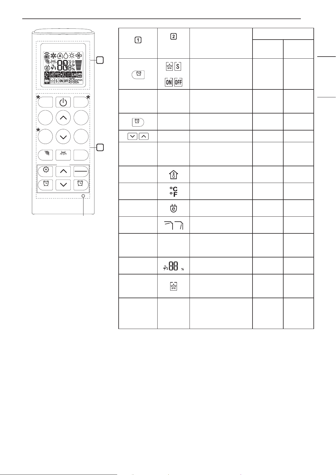
Button
Display
Screen
Description
Available Function
Single
Split
Multi
TIMER
To turn on/off
air conditioner
automatically at
desired time.
O O
SET/
CANCEL
-
To set/cancel the
special functions and
timer.
O O
CANCEL
-
To cancel the timer
settings.
O O
- To adjust time. O O
*LIGHT
OFF
-
To set the brightness
of the display on the
indoor unit.
O O
ROOM
TEMP
To display the room
temperature.
O O
°C↔°F
[5 s]
To change unit
between °C and °F
O O
*ENERGY
SAVING
To minimize power
consumption.
O O
*COMFORT
AIR
To adjust the air flow
to deflect wind.
O O
kW
[3 s]
-
To set whether or not
to display information
regarding energy.
O X
*ENERGY
CTRL.
To bring the effect of
the power saving.
X X
*COMFORT
SLEEP
To make a
comfortable sleeping
environment.
O X
DIAGNOSIS
[5 s]
-
To conveniently
check maintenance
information of a
product.
O O
12 OPERATION
SWING
kW [3 s]
℃↔℉ [5 s]
DIAGNOSIS [5 s]
SWING
SET UP
ROOM
TEMP
JET
MODE
MODE
TEMP
FAN
SPEED
FUNC.
TIMER CANCEL
SET
CANCEL
1
2
RESET
Button
Display
Screen
Description
Available Function
Single
Split
Multi
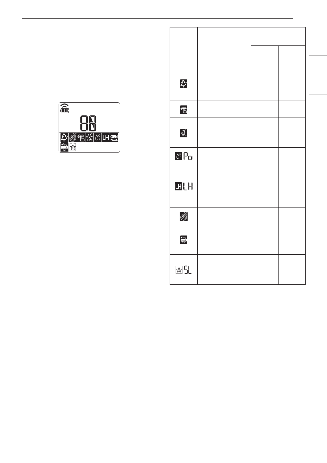
FUNC.
The Ion generator
uses millions of ions
to help improve indoor
air quality.
X X
To reduce noise from
outdoor units.
X X
To keep your skin
moisturized by
generating ion
clusters.
X X
To lower indoor
humidity quickly.
X X
To maintain a
minimum room
temperature and
prevent objects in the
room from freezing.
O
(Optional)
X
To scare away a
mosquito.
X X
To remove moisture
generated inside the
indoor unit.
O O
To make a
comfortable sleeping
environment.
X X
RESET -
To initialize the remote
control settings.
O O
NOTE
• Some functions may not be supported, depending on the model.
• * buttons may be changed according to the type of model.
• Press the SET/CANCEL button to operate the selected FUNC..
13OPERATION
ENGLISH
FRANÇAIS ESPAÑOL
Restarting the Air Conditioner
Automatically
When the air conditioner is turned on again after
a power failure, this function restores the previous
settings.
Disabling Auto Restart
1
Open the front cover (Type2) or horizontal vane
(Type1).
2
Press the ON/OFF button and hold it for 6
seconds, then the unit will beep twice and the
lamp will blink twice 4 times.
• To re-enable the function, press the ON/OFF
button and hold it for 6 seconds. The unit will
beep twice and the lamp will blink 4 times.
Type1
ON/OFF
Type2
ON/OFF
NOTE
• The feature may be changed according to the type
of model.
• If you press and hold the ON/OFF button for 3 – 5
seconds, instead of 6 seconds, the unit will switch
to the test operation. In the test operation, the unit
blows out strong cooling air for 18 minutes and
then returns to factory default settings.
Using the Mode Function
This function allows you to select the desired
function.
Cooling Mode
Auto Changeover Mode / Auto
Operation(AI) Mode
Dehumidification Mode
Heating Mode
Fan Mode
Cooling Mode
1
Turn the appliance on.
2
Press MODE button repeatedly to select the
Cooling Mode.
• is displayed on the display screen.
3
Press or button to set the desired
temperature.
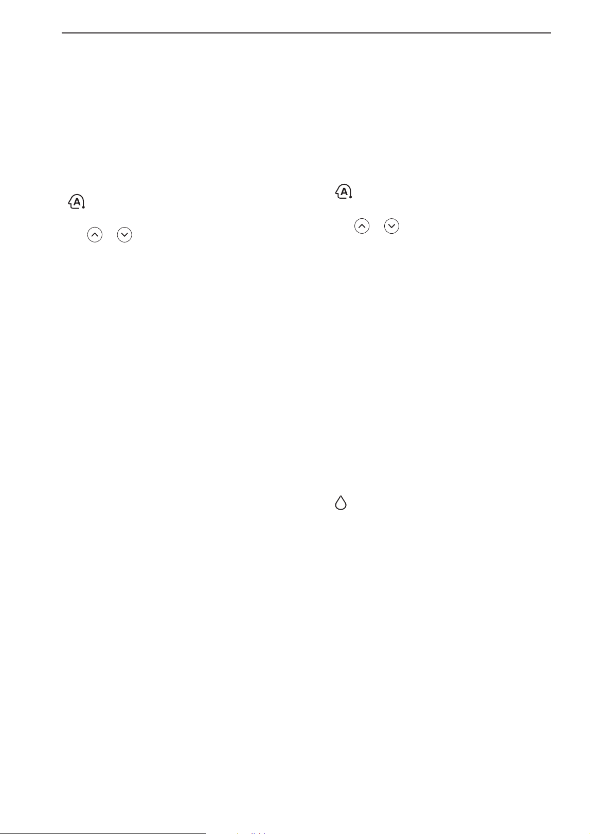
14 OPERATION
Auto Operation (Artificial
Intelligence)
Multi Model
In this operation mode, the system is automatically
operated by the electronic controls.
1
Turn the appliance on.
2
Press MODE button repeatedly to select the Auto
Operation.
• is displayed on the display screen.
3
Press or button to set the desired
temperature.
4
Press FAN SPEED button to adjust the fan
speed.
Auto Changeover Mode
Single Split Model
This mode changes the mode automatically to
maintain the set temperature at ±2 °C
1
Turn the appliance on.
2
Press MODE button repeatedly to select the Auto
Changeover Mode.
• is displayed on the display screen.
3
Press or button to set the desired
temperature.
Dehumidification Mode
This mode removes excess moisture from a highly
humid environment or during the rainy season,
in order to prevent mildew from setting in. This
mode adjusts the room temperature and the fan
speed automatically to maintain the optimal level of
humidity.
1
Turn the appliance on.
2
Press MODE button repeatedly to select the
Dehumidification Mode.
• is displayed on the display screen.
NOTE
• In this mode you cannot adjust the room
temperature, it is adjusted automatically.
• The room temperature is not displayed on the
display screen.
• In the dehumidification mode, compressor and
indoor fan may not operate when the room
temperature is below 24 °C
4
Press FAN SPEED button to adjust the fan
speed.
15OPERATION
ENGLISH
FRANÇAIS ESPAÑOL
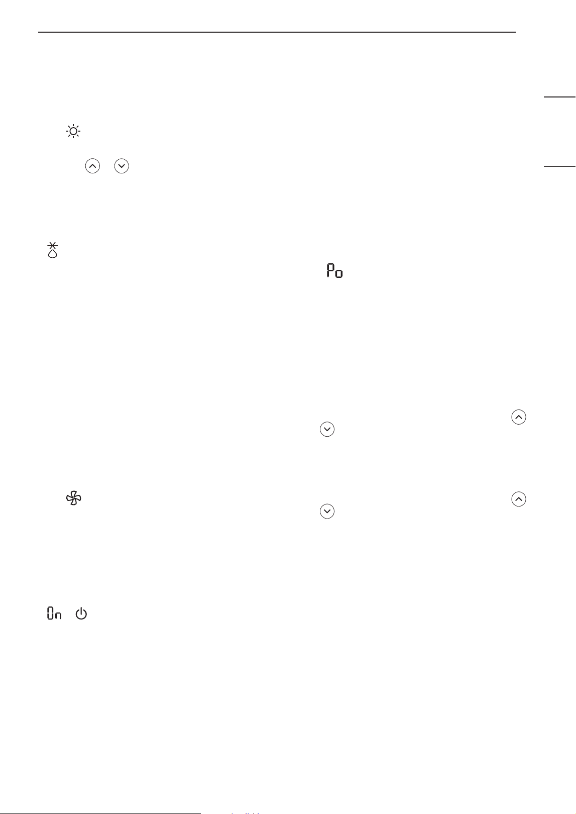
Heating Mode
1
Turn the appliance on.
2
Press MODE button repeatedly to select the
Heating Mode.
• is displayed on the display screen.
3
Press or button to set the desired
temperature.
NOTE
• will be displayed on the indoor unit when
defrosting is operating.
• Furthermore, this indication will be displayed on the
indoor unit:
− When preheating is operating.
− When the room temperature has been reached
to the set temperature.
Fan Mode
This mode only circulates the indoor air without
changing the room temperature.
1
Turn the appliance on.
2
Press MODE button repeatedly to select the Fan
Mode.
• is displayed on the display screen.
3
Press FAN SPEED button to adjust the fan
speed.
NOTE
• or will be displayed on the indoor unit when
fan mode is operating.
Using the Jet Mode Function
Changing Room Temperature
Quickly
This function allows you to cool indoor air quickly
during the summer or warm it quickly during winter.
• The Jet Mode function is available with Cooling,
Heating and Dehumidification Mode.
1
Turn the appliance on.
2
Press MODE button repeatedly to select the
desired mode.
3
Press JET MODE button.
• is displayed on the display screen.
NOTE
• Jet Heating Mode is not available on some models.
• In Jet Cooling Mode, strong air blows out for 30
minutes.
• After 30 minutes later, setting temperature is
maintaining 18 °C
If you want to change the temperature, Press
or button to set the desired temperature.
• In Jet Heating Mode, strong air blows out for 30
minutes.
• After 30 minutes later, setting temperature is
maintaining 30 °C
If you want to change the temperature, Press
or button to set the desired temperature.
• This function may operate differently from the
remote control display.
16 OPERATION
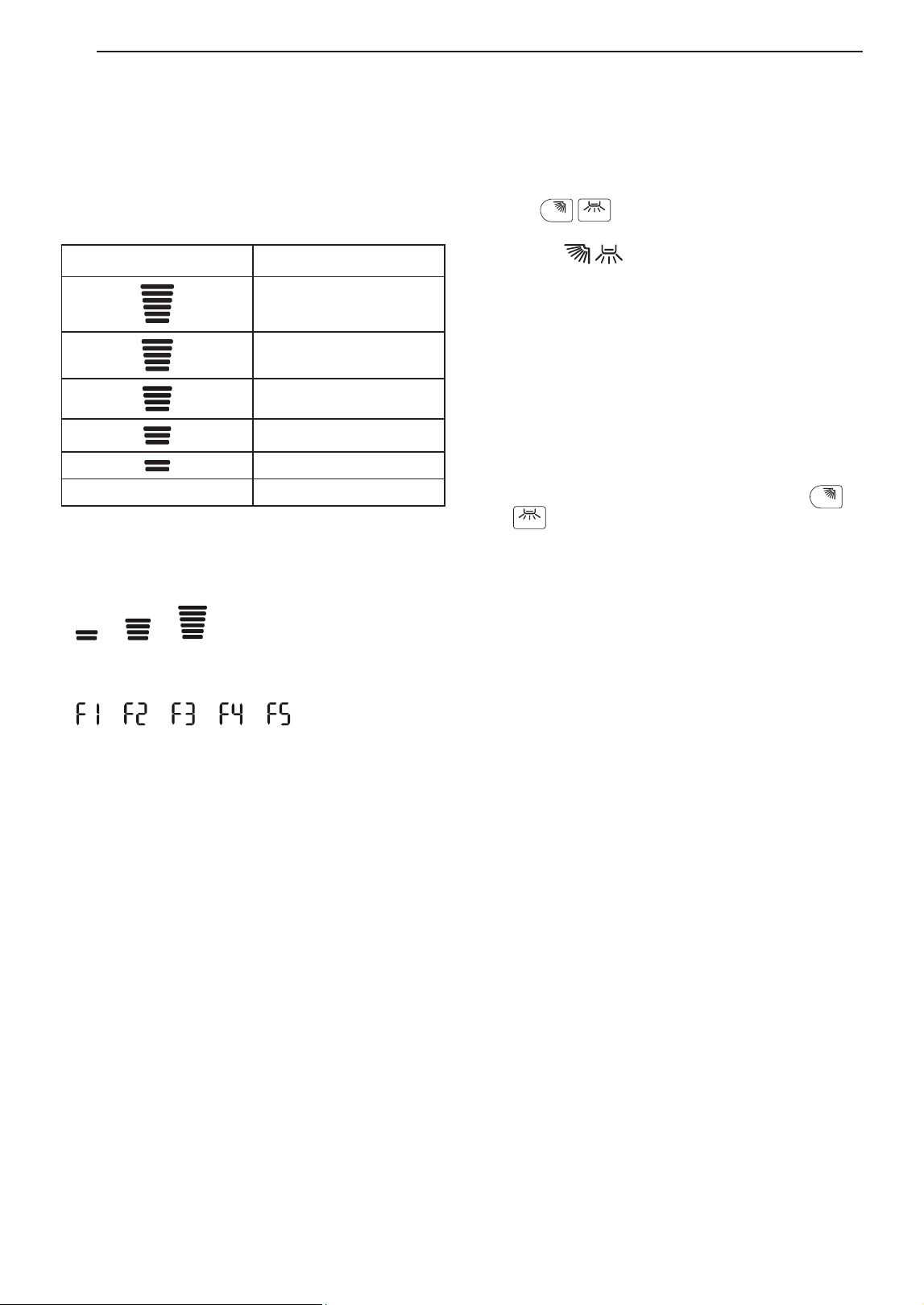
Using the Fan Speed
Function
Adjusting the Fan Speed
• Press FAN SPEED button repeatedly to adjust the
fan speed.
Display Screen Speed
High
Medium - High
Medium
Medium - Low
Low
- Natural Wind
NOTE
• The fan speed of Natural Wind adjusts
automatically.
→ →
• The fan speed icons are displayed on some indoor
units.
→ → → →
• Indoor unit display is displayed only 5 seconds and
return to the setting temperature on some models.
Using the Air Flow Direction
Function
This function adjusts the direction of the air flow
vertically (horizontally).
• Press
SWING
(
SWING
) button repeatedly and select the
desired direction.
− Select ( ) to adjust the direction of the air
flow automatically.
NOTE
• Adjusting the air flow direction horizontally may not
be supported, depending on the model.
• Adjusting the air deflector arbitrarily may cause
product failure.
• If you restart the air conditioner, it starts to operate
with the previously set direction of air flow, so the
air deflector may not match the icon displayed on
the remote control. When this occurs, press
SWING
or
SWING
button to adjust the direction of the air flow
again.
• This function may operate differently from the
remote control display.
17OPERATION
ENGLISH
FRANÇAIS ESPAÑOL
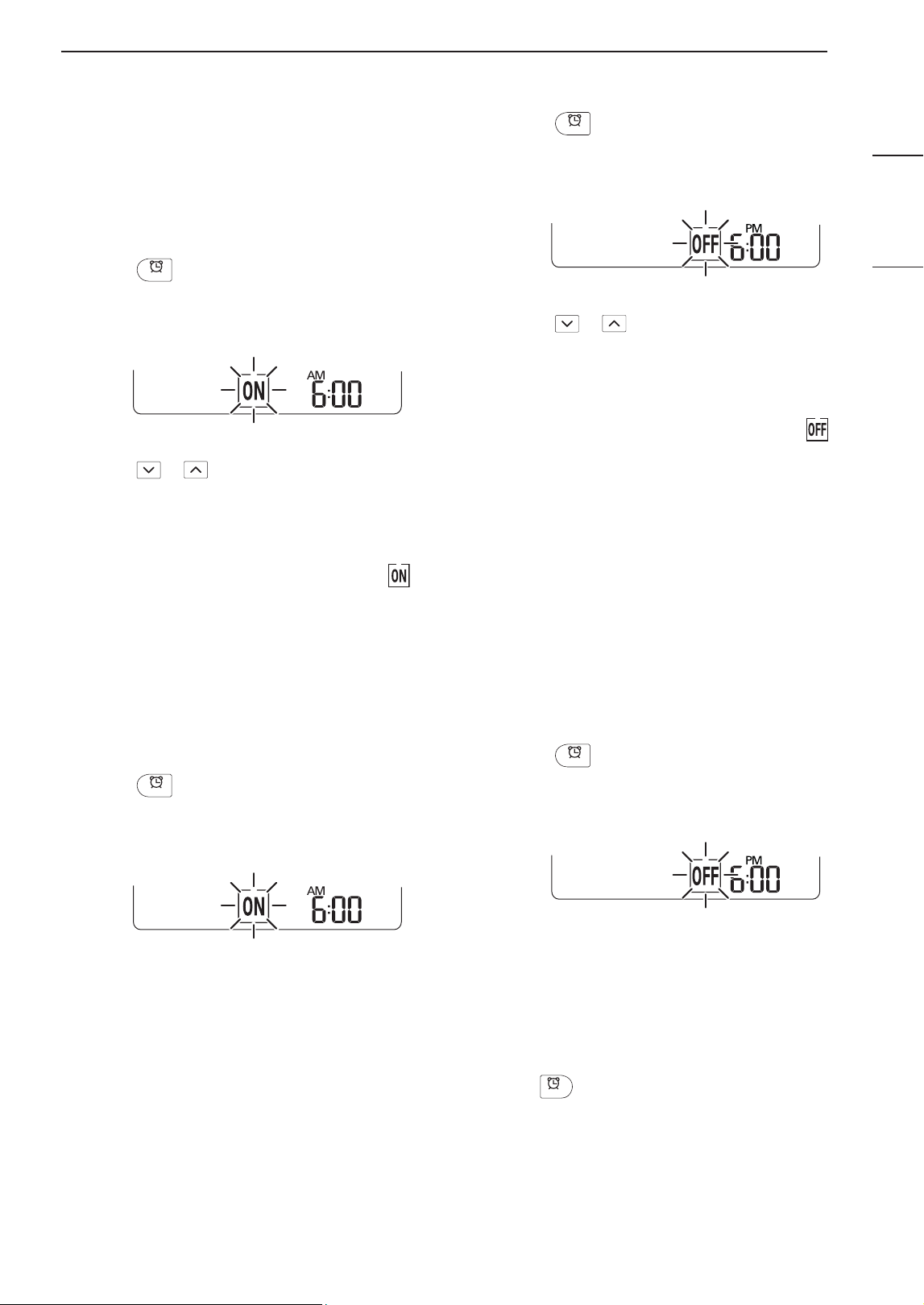
Setting the On/Off Timer
This function sets the air conditioner to turn on/off
automatically at desired time.
On/Off Timer can be set together.
Setting the On Timer
1
Press
TIMER
button repeatedly.
• The icon below blinks at the bottom of the
display screen.
2
Press or button to select the minutes.
3
Press SET/CANCEL button to finish.
• After setting the timer, current time and icon
are displayed on the display screen indicating
that the desired time is set.
Canceling the On Timer
1
Press
TIMER
button repeatedly.
• The icon below blinks at the bottom of the
display screen.
2
Press SET/CANCEL button to cancel the setting.
Setting the Off Timer
1
Press
TIMER
button repeatedly.
• The icon below blinks at the bottom of the
display screen.
2
Press or button to select the minutes.
3
Press SET/CANCEL button to finish.
• After setting the timer, current time and icon
are displayed on the display screen indicating
that the desired time is set.
NOTE
• This function is disabled when you set Simple
Timer.
Canceling the Off Timer
1
Press
TIMER
button repeatedly.
• The icon below blinks at the bottom of the
display screen.
2
Press SET/CANCEL button to cancel the setting.
Canceling the Timer Setting
• Press
CANCEL
button to cancel all timer settings.
18 OPERATION
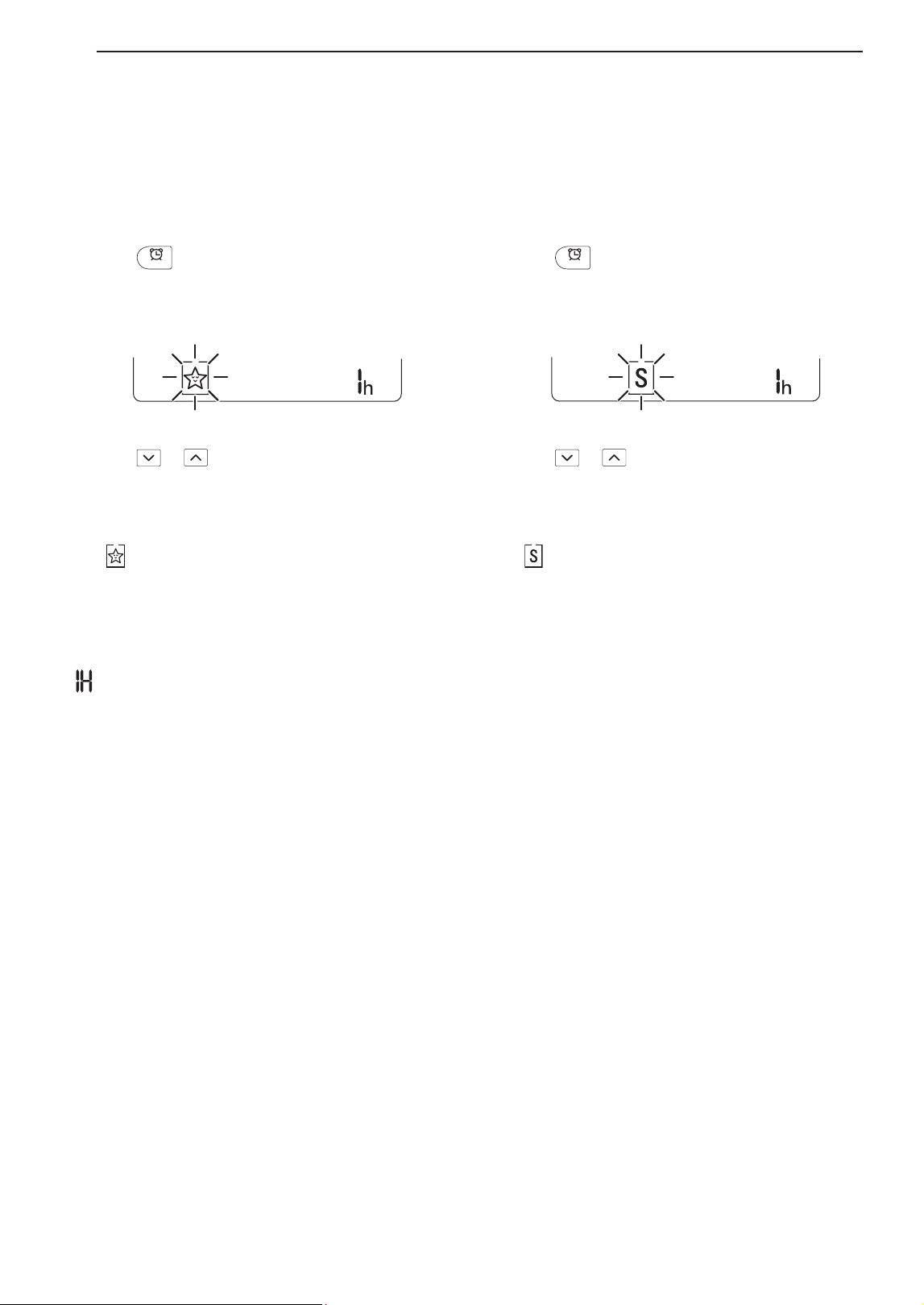
Using the Sleep Function
(Optional)
This function turns off the air conditioner
automatically when you go to sleep.
1
Turn the appliance on.
2
Press
TIMER
button repeatedly.
• The icon below blinks at the bottom of the
display screen.
3
Press or button to select the hour (up to
7 hours).
4
Press SET/CANCEL button to finish.
• is displayed on the display screen.
NOTE
• is displayed on some indoor units.
• Indoor unit display is displayed from 1H to 7H
which is displayed only 5 seconds and then return
to the setting temperature.
• In the Cooling and Dehumidification Mode, the
temperature increases by 1 °C after 30 minutes
and additional 1 °C after another 30 minutes for a
more comfortable sleep.
• The temperature increases up to 2 °C from the
preset temperature.
• Although the remark for fan speed on the display
screen may be changed, the fan speed is adjusted
automatically.
Using the Simple Timer
Function (Optional)
This function turns off the air conditioner
automatically when you go to sleep.
1
Turn the appliance on.
2
Press
TIMER
button repeatedly.
• The icon below blinks at the bottom of the
display screen.
3
Press or button to select the hour (up to
7 hours).
4
Press SET/CANCEL button to finish.
• is displayed on the display screen.
NOTE
• This function is disabled when you set Off Timer.
19OPERATION
ENGLISH
FRANÇAIS ESPAÑOL
Using the Energy Display
Function (Optional)
This function displays the amount of electricity
generated on the indoor display as the product
operates.
Display the Current Energy Usage
1
Turn the appliance on.
2
Press
kW [3 s]
button and hold it about 3 seconds.
• The instantaneous power consumption ( ) is
displayed for a while on some indoor units.
NOTE
• It is not displayed on the wireless remote control.
• The unit of the displayed value is kW.
• If it is more than 99 kW, which is the range of
expression, maintain it as 99 kW.
• Display wattage under 10 kW with 0.1 kW unit, and
display one over 10 kW with 1 kW unit.
• The actual power may differ from the power
displayed.
• When connected to the Multi Outdoor unit, this
function may not be supported.
Using the Light Off Function
(Optional)
Display Screen Brightness
You can set the brightness of the indoor unit display
screen.
• Press LIGHT OFF button.
NOTE
• Turn on/off the Display screen.
• If the brightness of an indoor appliance’s display is
set to OFF, pressing a button on the remote control
automatically turns the display on for a while.
• This function may operate differently, depending on
the model.
Using the Comfort Air
Function (Optional)
Comfort Vane Operation
This function conveniently sets the vane to a preset
position to deflect the supply air away from blowing
directly onto the occupants in the room.
1
Turn the appliance on.
2
Press COMFORT AIR button repeatedly and
select the desired direction.
• or is displayed on the display screen.
NOTE
• or is displayed on some indoor units.
• This function is disabled when you press MODE or
JET MODE button.
• This function is disabled and auto swing of vertical
direction is set up when you press
SWING
button.
• When this function is off, the horizontal vane
operates automatically depending on the set mode.
20 OPERATION
Using the Energy Saving
Function (Optional)
This function minimizes power consumption during
Cooling and increases the set temperature to the
optimal level for a more comfortable environment.
The temperature automatically settles at 22 °C if
desired temperature is below 22 °C The temperature
remains constant if it is above 22 °C
1
Turn the appliance on.
2
Press MODE button repeatedly to select the
Cooling Mode.
3
Press ENERGY SAVING button.
• is displayed on the display screen.
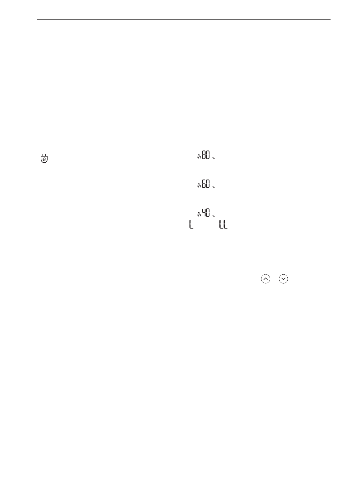
Using the Energy Control
Function (Optional)
1
Turn the appliance on.
2
Press ENERGY CTRL. button.
• Press ENERGY CTRL. button repeatedly to
select each step.
NOTE
• 1 step : The power Input is decreased by 20 %
compared to rated power input.
− is displayed on the display screen.
• 2 step : The power Input is decreased by 40 %
compared to rated power input.
− is displayed on the display screen.
• 3 step (Optional) : The power Input is decreased by
60 % compared to rated power input.
− is displayed on the display screen.
• (1 step), (2 step) is displayed on some indoor
units.
• This function is available with Cooling Mode.
• Capacity may decrease when Energy Control mode
is selected.
• Desired temperature is displayed about 5 seconds
if you press FAN SPEED, or button.
• Room temperature is displayed about 5 seconds if
you press ROOM TEMP button.
21OPERATION
ENGLISH
FRANÇAIS ESPAÑOL
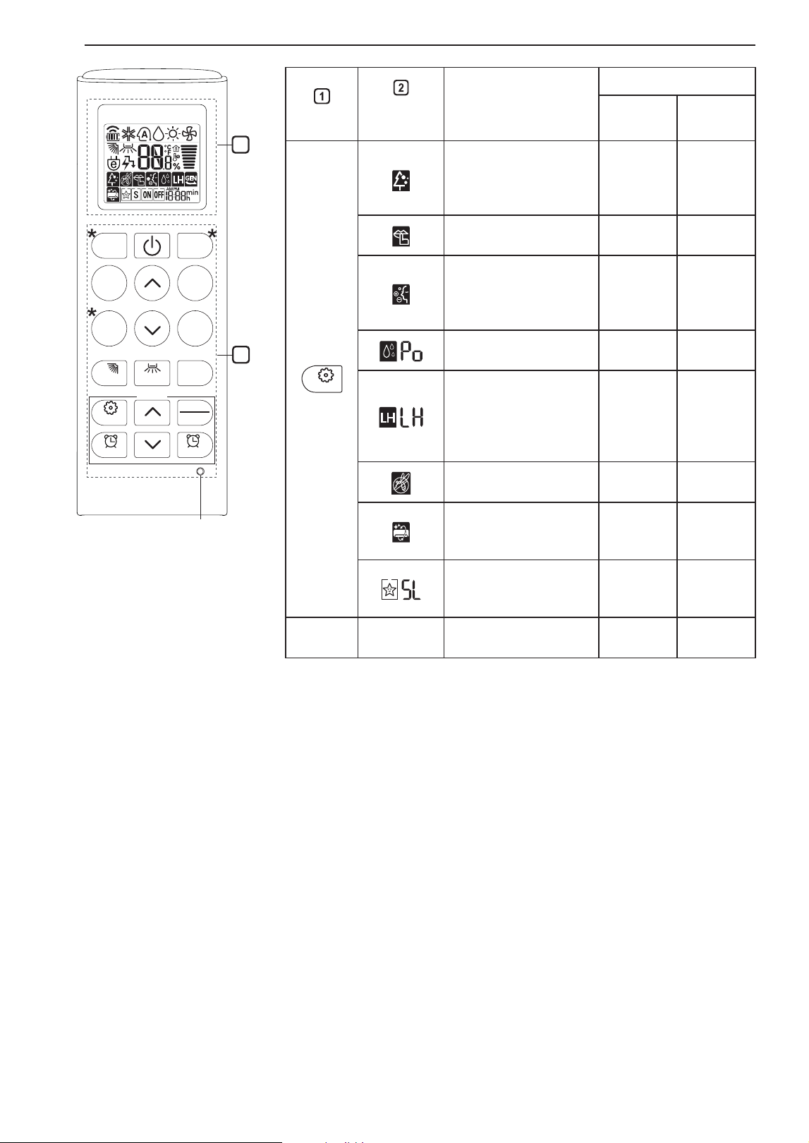
Using Special Functions
1
Turn the appliance on.
2
Press FUNC. button repeatedly to select the
desired function.
3
Press SET/CANCEL button to finish.
Display
Screen
Description
Available
Function
Single
Split
Multi
The Ion generator
uses millions
of ions to help
improve indoor air
quality.
X X
To reduce noise
from outdoor units.
X X
To keep your skin
moisturized by
generating ion
clusters.
X X
To lower indoor
humidity quickly.
X X
To maintain a
minimum room
temperature and
prevent objects
in the room from
freezing.
O
(Optional)
X
To scare away a
mosquito.
X X
To remove
moisture
generated inside
the indoor unit.
O O
To make a
comfortable
sleeping
environment.
X X
NOTE
• Some functions may not be supported, depending
on the model.
• Some functions may operate differently from the
remote control display.
Canceling Special Functions
1
Press FUNC. button repeatedly to select the
desired function.
2
Press SET/CANCEL button to cancel the
function.
22 OPERATION
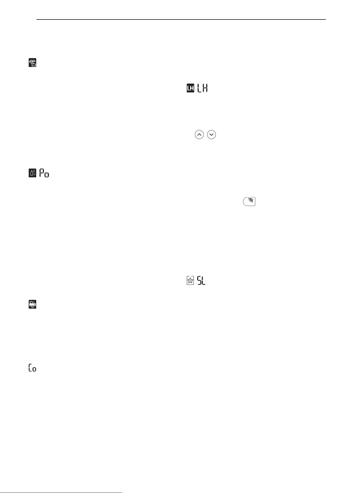
Using the Silent Function (Optional)
This function prevents potential claims by neighbors,
reducing noise from outdoor units.
• is displayed on the display screen.
NOTE
• This function is disabled when you press MODE or
ENERGY CTRL. or JET MODE button.
• This function is available with Cooling, Heating,
Auto Changeover, Auto Operation Mode.
Using the Jet Dry Function (Optional)
This function maximizes the performance of
dehumidification.
• , are displayed on the display screen.
NOTE
• This function is available with Cooling,
Dehumidification, Auto Operation, Fan Mode and
Air Purification function.
• This function is not available with Sleep function.
• This function is disabled when you press MODE
button.
Using the Auto Clean Function
In the Cooling and Dehumidification Mode, moisture
is generated inside the indoor unit. This function
removes such moisture.
• is displayed on the display screen.
NOTE
• Some functions cannot be used while the Auto
Clean function is in operation.
• If you turn off the unit, the fan continues to run for
30 minutes and cleans the inside of the indoor unit.
• is displayed on some indoor units, depending
on the model.
Using the Low Heating Function
(Optional)
This function operates the heating system to maintain
a minimum room temperature and prevent objects in
the room from freezing where there is no permanent
resident, such as a vacation.
• , are displayed on the display screen.
NOTE
• This function is available with Heating Mode.
• During LH operation, when you press buttons such
as , , MODE, FAN SPEED, and then return
to Heating Mode.
• If JET MODE button is pressed during LH
operation, this function is disabled and Power
Heating Mode is operated immediately. (only for
power heating model)
• In case an error occurred, operation can be
interrupted for the protection of the product.
• COMFORT AIR and
SWING
button cannot be used
while the LH function is in operation.
Using the Comfort Sleep Function
(Optional)
This function operates the air conditioner
automatically to make the comfortable sleep
environment.
• , are displayed on the display screen.
NOTE
• This function is available with Cooling Mode.
• The vane stops swing and sets indirect airflow
angle, after 30 minutes from start even though
the room temperature doesn’t decrease to optimal
temperature to sleep.
• It is possible that a comfortable sleep environment
is different according to the people.
23OPERATION
ENGLISH
FRANÇAIS ESPAÑOL
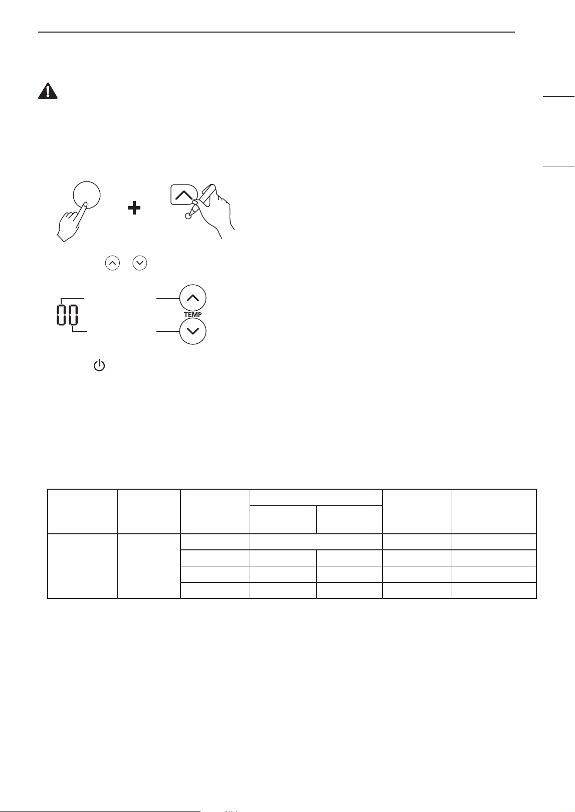
How to Enter Installer Setting Mode
CAUTION
Installer setting mode is to set the detail fuction of the remote controller. If the installer setting mode is not set
correctly, it can cause problem to the product, use injury or property danage. This is must set by an certificated
installer, and any installation or change that is carried out by a non-certificated person should be responsible for
the results.
1
With the JET MODE button pressed, press the reset button.
JET
MODE
2
By using the or button, Set fuction code and setting value. (Please refer the installer setting code table.)
Function code
Setting code
3
Press the button toward the indoor uniut 1 time.
4
Reset the remote controller to use the general operation mode.
Compressor on/off Function (Optional)
• This function is for Setting Compressor on/off value on heating mode as below for indoor unit. (Only for heat
pump model.)
• How to set with remote controller (Code table)
Function
Function
Code
Setting
Code
Setting Temp.
Setting
Code
Remote
controller LCD
Comp On
Comp
Off
Optional
heating
Compressor
on/off
6
0 Default 0 60
1 4 °C 6 °C 1 61
2 2 °C 4 °C 2 62
3 -1 °C 1 °C 3 63
24 SMART FUNCTIONS
SMART FUNCTIONS
LG ThinQ Application
This feature is only available on models with the
or ThinQ logo.
The LG ThinQ application allows you to
communicate with the appliance using a smartphone.
LG ThinQ Application Features
Communicate with the appliance from a smartphone
using the convenient smart features.
Smart Diagnosis
TM
If you experience a problem while using the
appliance, this smart diagnosis feature will help you
diagnose the problem.
Settings
Allows you to set various options on the appliance
and in the application.
NOTE
• If you change your wireless router, internet service
provider, or password, delete the registered
appliance from the LG ThinQ application and
register it again.
• The application is subject to change for appliance
improvement purposes without notice to users.
• Functions may vary by model.
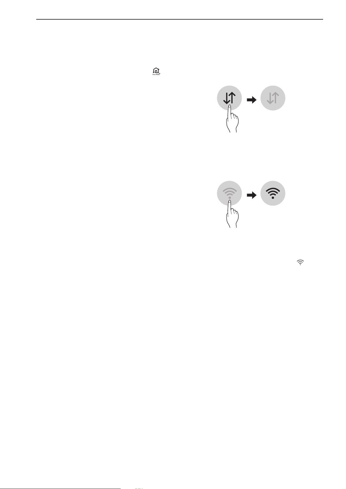
Before Using LG ThinQ Application
1
Check the distance between the appliance and
the wireless router (Wi-Fi network).
• If the distance between the appliance and the
wireless router is too far, the signal strength
becomes weak. It may take a long time to
register or installation may fail.
2
Turn off the Mobile data or Cellular Data on
your smartphone.
3
Connect your smartphone to the wireless router.
NOTE
• To verify the Wi-Fi connection, check that icon
on the control panel is lit.
• The appliance supports 2.4 GHz Wi-Fi networks
only. To check your network frequency, contact your
Internet service provider or refer to your wireless
router manual.
• LG ThinQ is not responsible for any network
connection problems or any faults, malfunctions, or
errors caused by network connection.
• If the appliance is having trouble connecting to the
Wi-Fi network, it may be too far from the router.
Purchase a Wi-Fi repeater (range extender) to
improve the Wi-Fi signal strength.
• The Wi-Fi connection may not connect or may
be interrupted because of the home network
environment.
• The network connection may not work properly
depending on the Internet service provider.
• The surrounding wireless environment can make
the wireless network service run slowly.

25SMART FUNCTIONS
ENGLISH
FRANÇAIS ESPAÑOL
• The appliance cannot be registered due to
problems with the wireless signal transmission.
Unplug the appliance and wait about a minute
before trying again.
• If the firewall on your wireless router is enabled,
disable the firewall or add an exception to it.
• The wireless network name (SSID) should be a
combination of English letters and numbers. (Do
not use special characters.)
• Smartphone user interface (UI) may vary
depending on the mobile operating system (OS)
and the manufacturer.
• If the security protocol of the router is set to
WEP, you may fail to set up the network. Please
change it to other security protocols (WPA2 is
recommended) and register the product again.
Installing the LG ThinQ Application
Search for the LG ThinQ application from the Google
Play Store or Apple App Store on a smartphone.
Follow instructions to download and install the
application.
Open Source Software Notice
Information
To obtain the source code that is contained in this
product, under GPL, LGPL, MPL, and other open
source licenses that have the obligation to disclose
source code, and to access all referred license terms,
copyright notices and other relevant documents
please visit https://opensource.lge.com.
LG Electronics will also provide open source code
to you on CD-ROM for a charge covering the cost
of performing such distribution (such as the cost of
media, shipping, and handling) upon email request
This offer is valid to anyone in receipt of this
information for a period of three years after our last
shipment of this product.

26 SMART FUNCTIONS
Smart Diagnosis
TM
This feature is only available on models with the
or logo.
Use this feature to help you diagnose and solve
problems with your appliance.
NOTE
• For reasons not attributable to LGE’s negligence,
the service may not operate due to external factors
such as, but not limited to, Wi-Fi unavailability,
Wi-Fi disconnection, local app store policy, or app
unavailability.
• The feature may be subject to change without prior
notice and may have a different form depending on
where you are located.
Using LG ThinQ to Diagnose Issues
If you experience a problem with your Wi-Fi equipped
appliance, it can transmit troubleshooting data to a
smartphone using the LG ThinQ application.
• Launch the LG ThinQ application and select the
Smart Diagnosis
TM
feature in the menu. Follow the
instructions provided in the LG ThinQ application.
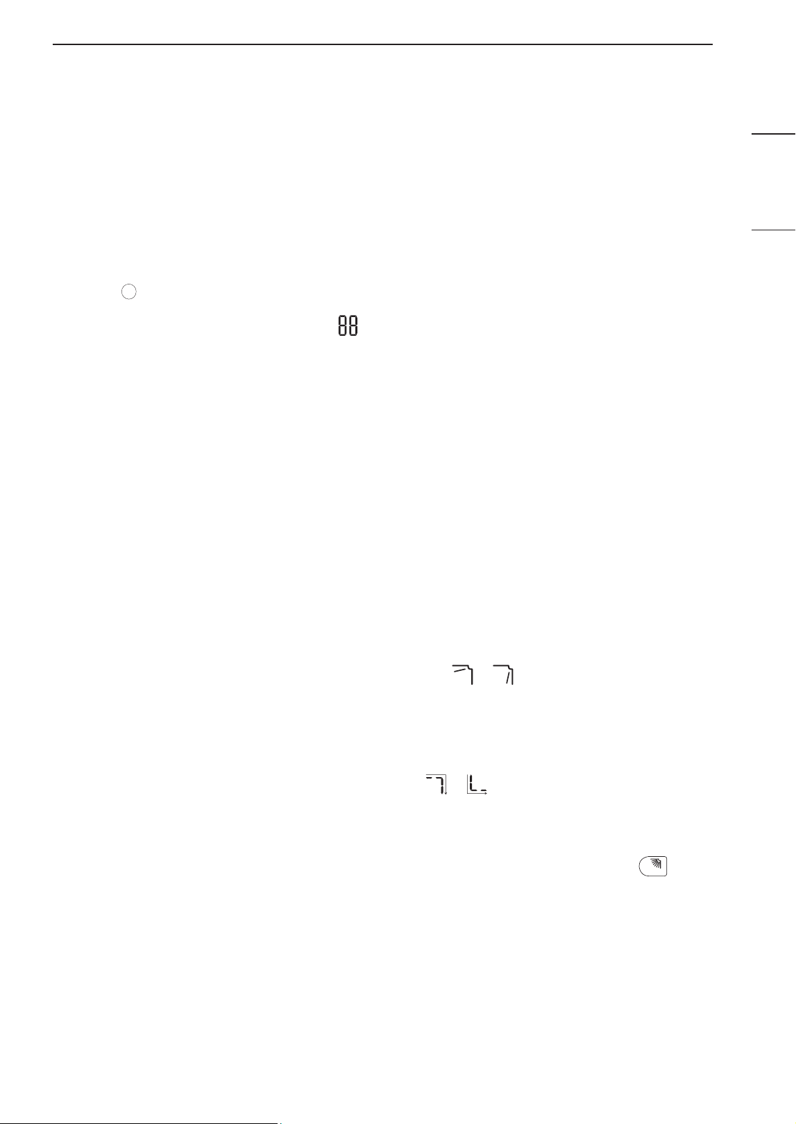
Using Audible Diagnosis to Diagnose
Issues
Follow the instructions below to use the audible
diagnosis method.
• Launch the LG ThinQ application and select the
Smart Diagnosis
TM
feature in the menu. Follow the
instructions for audible diagnosis provided in the
LG ThinQ application.
1
Plug the power plug in the outlet properly.
2
Place the mouthpiece of your smartphone close
to the or logo.
3
Press and hold the DIAGNOSIS [5 s] button for 5
seconds or longer while holding the smartphone
mouthpiece to the logo until the data transfer is
complete.
• Keep the smartphone in place until the data
transfer has finished. Time remaining for data
transfer is displayed.
4
After the data transfer is complete, the diagnosis
will be displayed in the application.
NOTE
• For best results, do not move the phone while the
tones are being transmitted.
• Be sure to keep ambient noise to a minimum or the
phone may not correctly receive the buzzer beeps
from the indoor unit.
27MAINTENANCE
ENGLISH
FRANÇAIS ESPAÑOL
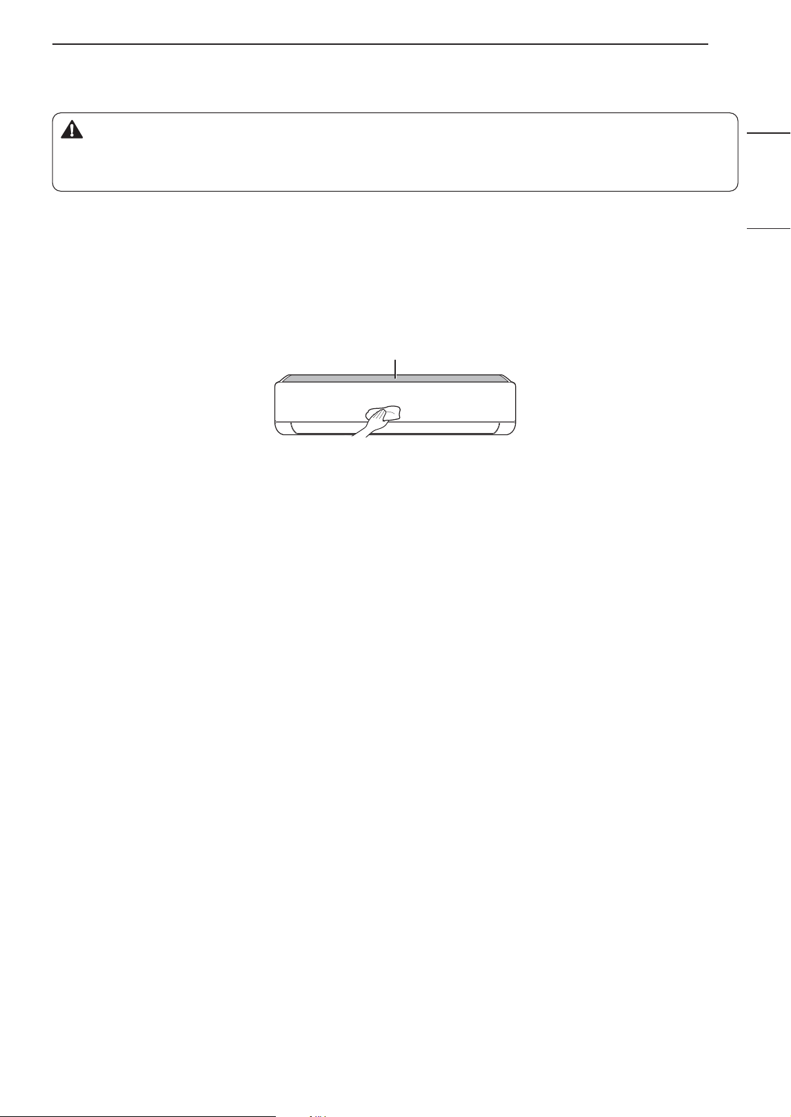
MAINTENANCE
WARNING
• Before cleaning or performing maintenance, disconnect the power supply and wait until the fan
stops.
If the air conditioner will not be used for an extended period of time, dry the air conditioner to maintain it in best
condition. Clean the product regularly to maintain optimal performance and to prevent possible breakdown.
• Dry the air conditioner in Fan mode for 3 to 4 hours and disconnect the power. There may be internal damage
if moisture is left in its components.
• Before using the air conditioner again, dry the inner components of the air conditioner in Fan mode for 3 to 4
hours. This will help to remove the odor generated from moisture.
Air Filter
• The feature may be changed according to the type of model.
28 MAINTENANCE
Type Description Interval
Air Filter Clean with a vacuum or hand wash. 2 weeks
Triple Filter Clean with a vacuum or brush. Every 3 months
Micro Dust Filter Clean with a vacuum or brush. Once a month
Ionizer (Optional) Use dry cotton bud to remove any dust. Every 6 months
Indoor Unit
Clean the indoor unit surface by using a soft, dry cloth. Regularly
Have a professional clean the condensate drain pan. Once a year
Have a professional clean the condensate drain pipe. Every 4 months
Replace the remote control batteries. Once a year
Outdoor Unit
Have a professional clean the heat exchanger coils and the panel
vents. (Consult with technician.)
Once a year
Have a professional clean the fan. Once a year
Have a professional clean the condensate drain pan. Once a year
Have a professional verify that all the fan assembly is firmly
tightened.
Once a year
Clean the electric components with air. Once a year
NOTE
• Never use water that is higher than 40 °C when you clean the filters. It may cause deformation or
discoloration.
• Never use volatile substances when you clean the filters. They may damage the surface of the product.
• Do not wash the micro dust filter with water, because the filter can be damaged (Optional).
• Do not wash the triple filter with water, because the filter can be damaged (Optional).
29MAINTENANCE
ENGLISH
FRANÇAIS ESPAÑOL
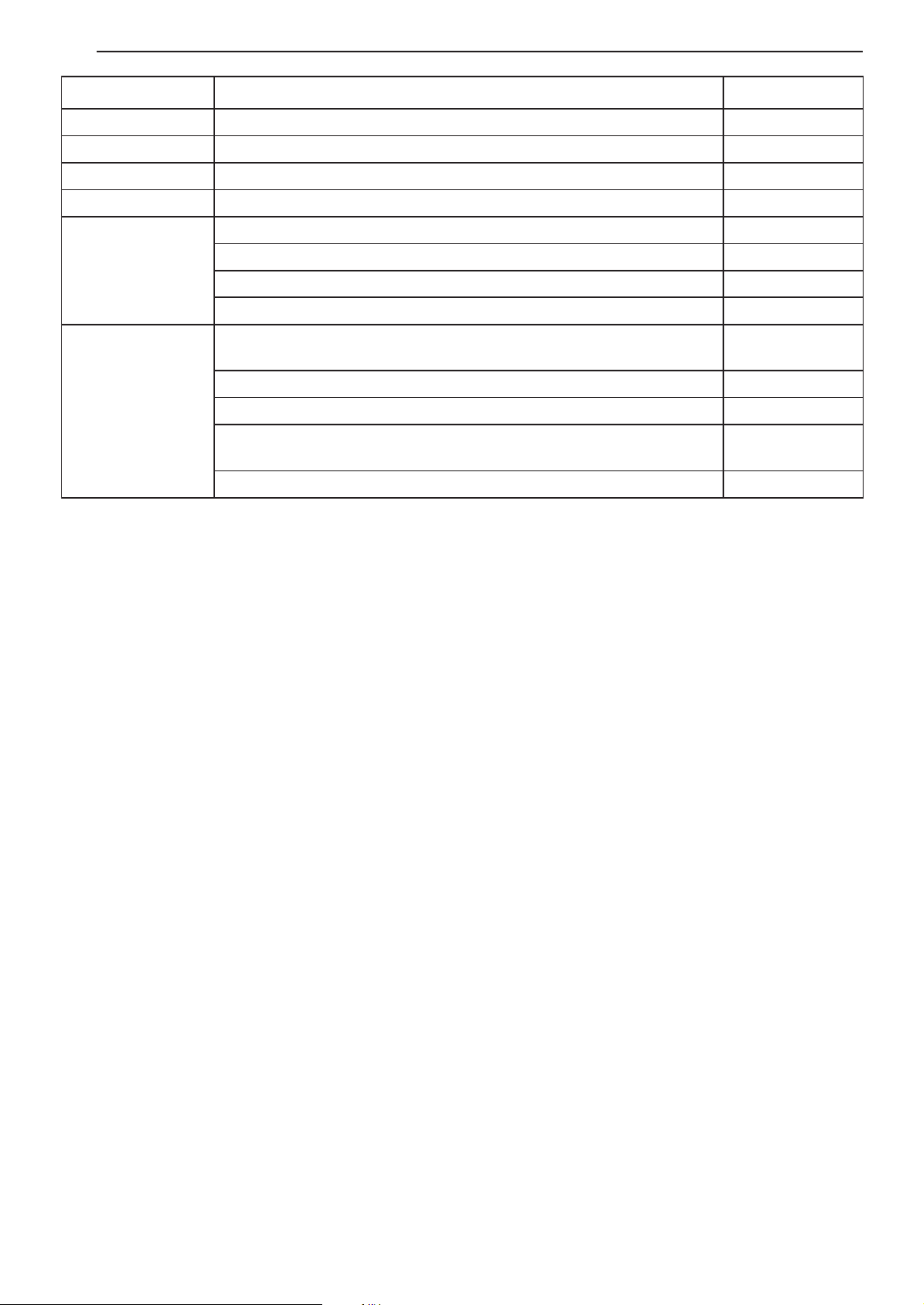
Clean the Air Filter
Clean the air filters once every 2 weeks, or more, if
necessary.
NOTE
• The air filter can be broken when it is bent.
• When the air filter is not assembled correctly, dust
and other substances can enter into the indoor unit.
Type1
If you look at the indoor unit from above it, can
assemble the top filter easily.
1
Turn off the power to the unit.
2
Hold the knobs of the air filter, lift it up slightly.
3
Remove it from the indoor unit.
4
Clean the filter with a vacuum cleaner or with
lukewarm water with neutral detergent.
5
Dry the filter in the shade.
6
Insert the hooks of the air filter into the front
cover.
7
Push down hooks to assemble the air filter.
8
Check the side of the front cover for correct
assembly of the air filter.
Type2
1
Turn off the power to the unit.
2
Open the front cover.
• Lift up both sides of the cover slightly.
3
Hold the knobs of the air filters, pull them down
slightly and remove them from the indoor unit.
4
Clean the filters with a vacuum cleaner or with
lukewarm water with neutral detergent.
5
Dry the filters in the shade.
6
Insert the hooks of the air filters into the front
cover.
7
Check the side of the front cover for correct
assembly of the air filters.
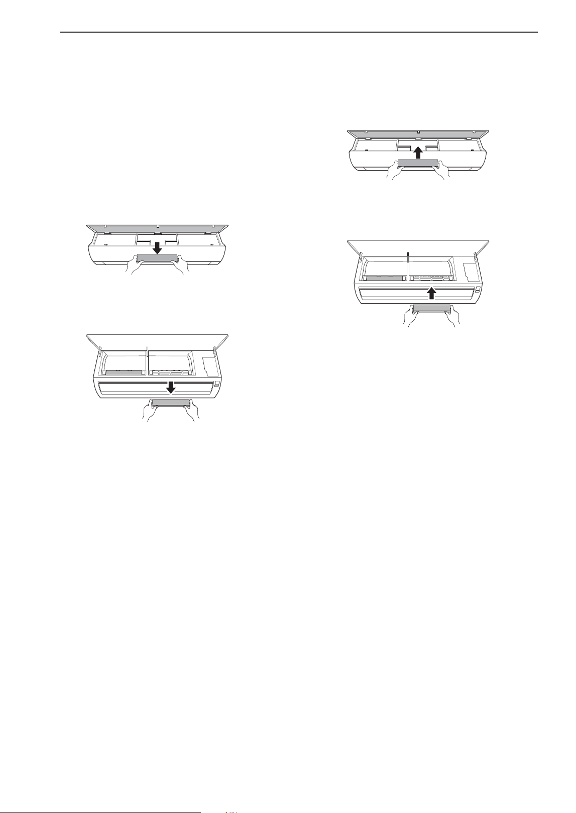
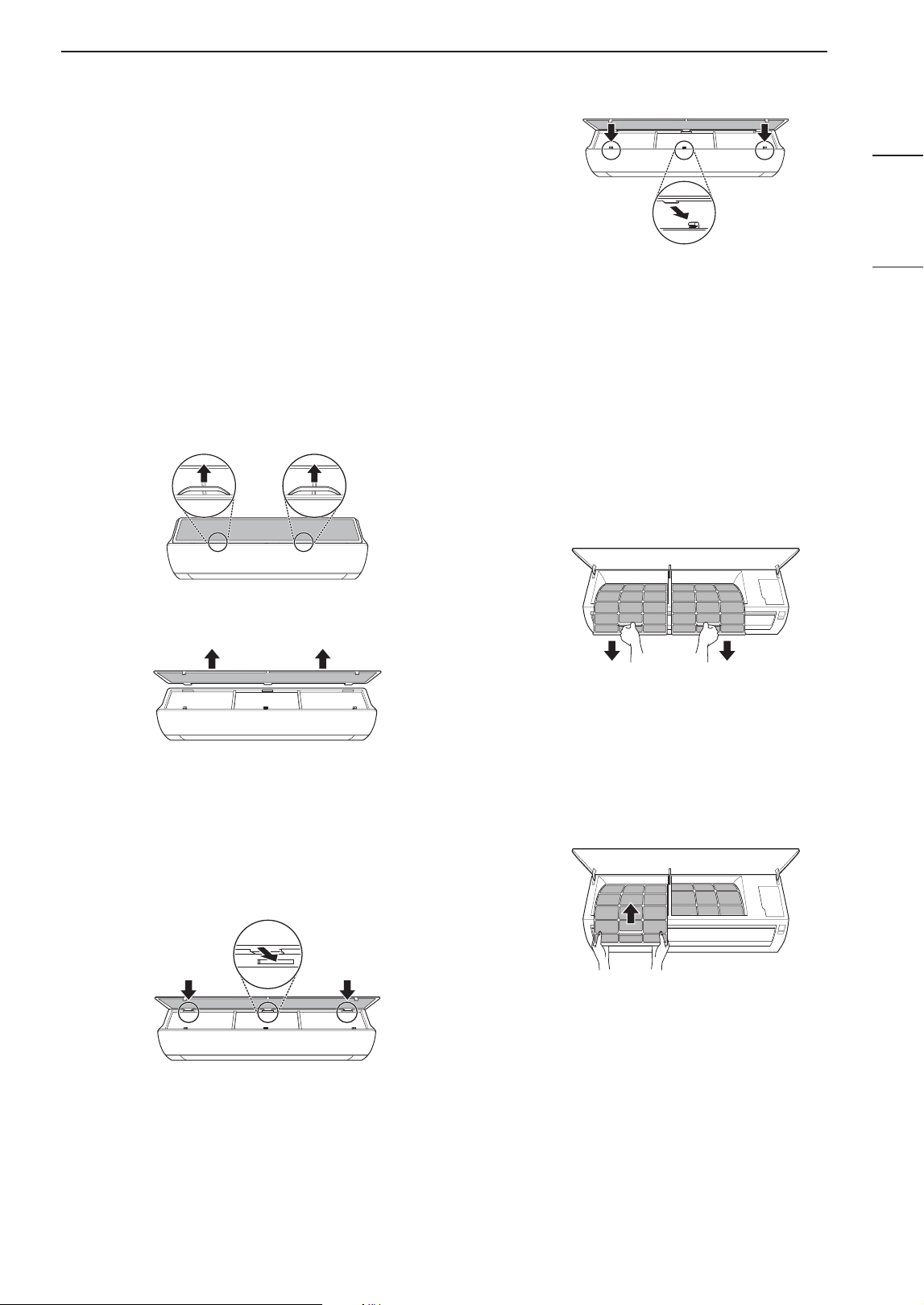
30 MAINTENANCE
Clean the Micro Dust and
Triple Filter (Optional)
1
Turn off the power to the unit.
2
Remove the air filters from the indoor unit.
3
Remove the micro dust and triple filter from the
indoor unit.
Type1
Type2
4
Clean the filter with a vacuum cleaner.
5
Insert the micro dust and triple filter.
Type1
Type2
6
Assemble the air filters.
7
Check the side of the front cover for correct
assembly of the air filters.
NOTE
• The feature and location of micro dust and triple
filter may vary according to the type of model.
31TROUBLESHOOTING
ENGLISH
FRANÇAIS ESPAÑOL
TROUBLESHOOTING
Self-diagnosis Function
This product has a built-in self-diagnosis function. If an error occurs, the lamp of the indoor unit will blink in 2
second intervals. If this occurs, contact your local dealer or service center.
Before Calling for Service
Please check the following before you contact the service center. If the problem persists, contact your local
service center.
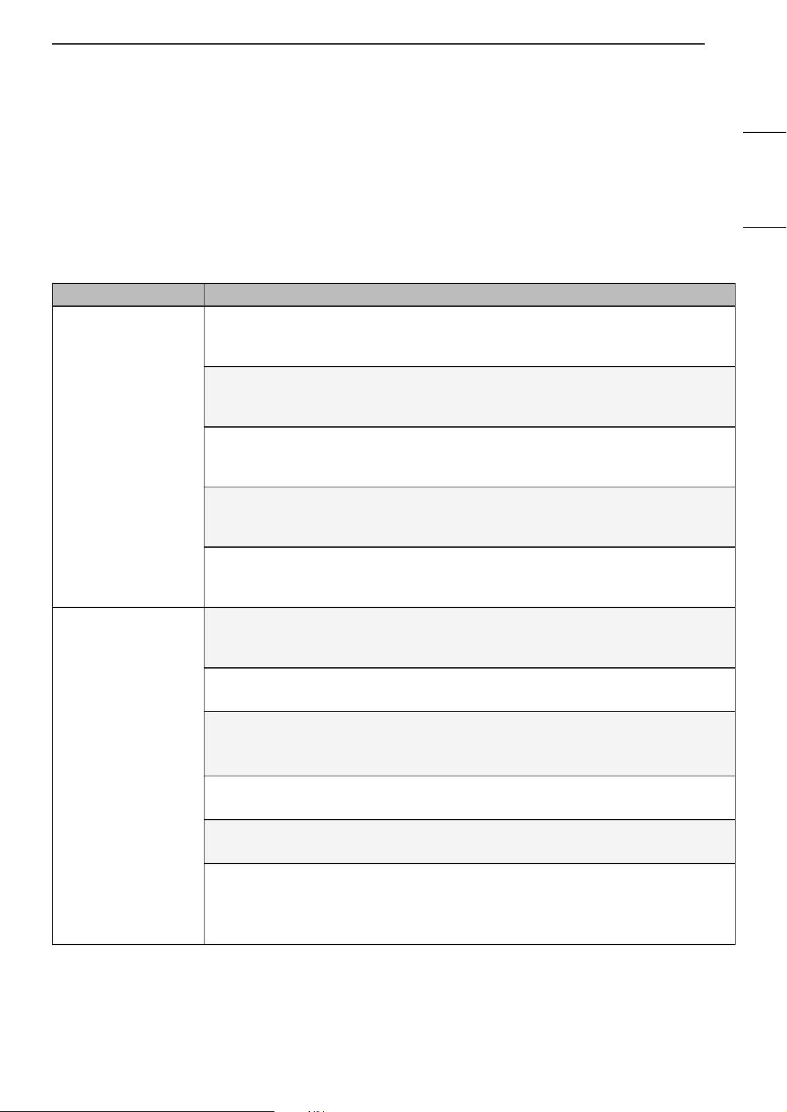
Symptoms Possible Causes & Solution
The air conditioner
does not work
normally.
Burning smell and strange sounds are coming from the unit.
• Turn off the air conditioner, switch OFF, or disconnect the power supply, and
contact the service center.
Water leaks from the indoor unit even when the humidity level is low.
• Turn off the air conditioner, switch OFF, or disconnect the power supply, and
contact the service center.
The power cable is damaged or it is generating excessive heat.
• Turn off the air conditioner, switch OFF, or disconnect the power supply, and
contact the service center.
A switch, a circuit breaker (safety, ground), or a fuse is not operated properly.
• Turn off the air conditioner, switch OFF, or disconnect the power supply, and
contact the service center.
The unit generates an error code from its self-diagnosis.
• Turn off the air conditioner, switch OFF, or disconnect the power supply, and
contact the service center.
The air conditioner
does not work.
The air conditioner is unplugged.
• Check whether the power cord is plugged into the outlet or the power isolators are
switched on.
A fuse exploded, or the power supply is blocked.
• Replace the fuse or check if the circuit breaker has tripped.
A power failure has occurred.
• Turn off the air conditioner when a power failure occurs.
• When the power is restored, wait 3 minutes, and then turn on the air conditioner.
The voltage is too high or too low.
• Check if the circuit breaker has tripped.
The air conditioner was turned off automatically at a preset time.
• Turn the air conditioner on.
The battery setting in the remote controller is incorrect.
• Make sure that the batteries are inserted correctly in your remote controller.
• If the batteries are placed correctly, but the air conditioner still does not operate,
replace the batteries and try again.
32 TROUBLESHOOTING
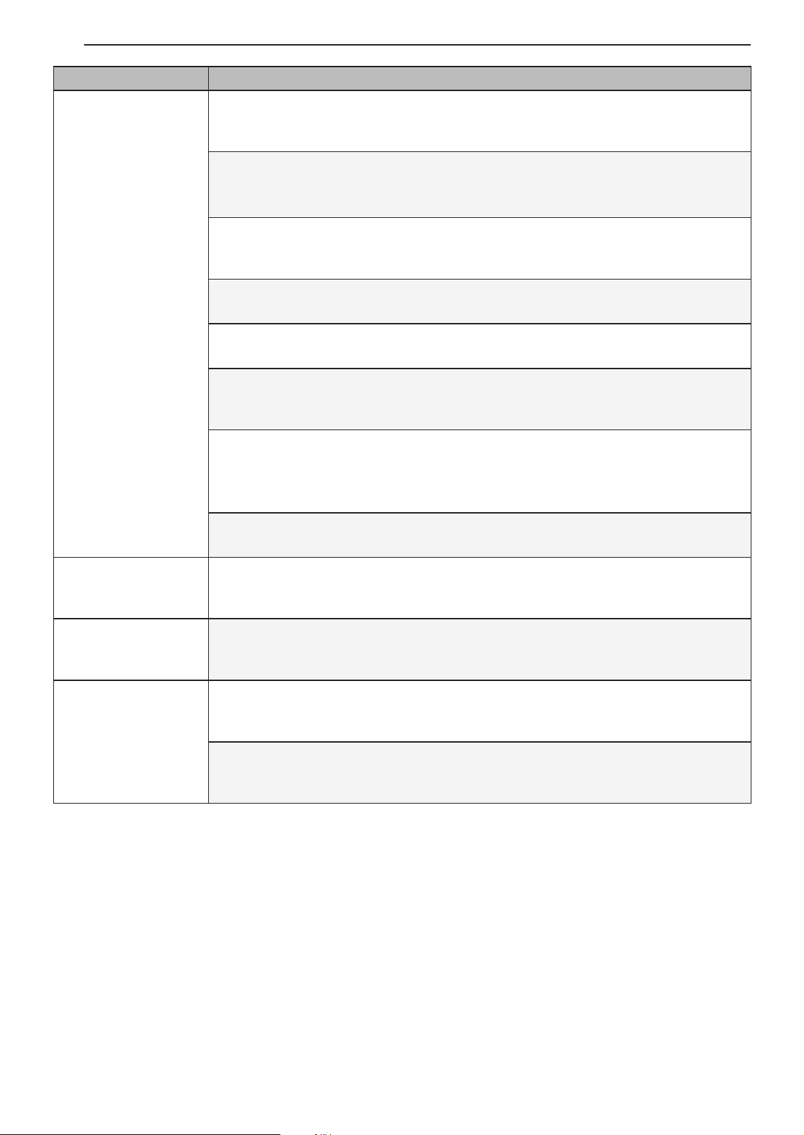
Symptoms Possible Causes & Solution
The air conditioner
does not emit cool
air.
Air is not circulating properly.
• Make sure that there are no curtains, blinds, or pieces of furniture blocking the front
of the air conditioner.
The air filter is dirty.
• Clean the air filter once every 2 weeks.
• See “Clean the Air Filter” for more information.
The room temperature is too high.
• In summer, cooling the indoor air fully may take some time. In this case, select the
Jet Mode to cool the indoor air quickly.
Cold air is escaping from the room.
• Make sure that no cold air is escaping through the ventilation points in the room.
The desired temperature is higher than the current temperature.
• Set the desired temperature to a level lower than the current temperature.
There is a heating source nearby.
• Avoid using heat generators like electric ovens or gas burners while the air
conditioner is in operation.
Fan Mode is selected.
• During Fan Mode, air blows from the air conditioner without cooling or heating the
indoor air.
• Switch the operation mode to cooling operation.
Outside temperature is too high.
• The cooling effect may not be sufficient.
The fan speed
cannot be adjusted.
The Jet Mode, or Auto Operation Mode is selected.
• In some operation modes, you cannot adjust the fan speed. Select an operation
mode in which you can adjust the fan speed.
The temperature
cannot be adjusted.
The Fan Mode or Jet Mode is selected.
• In some operation modes, you cannot adjust the temperature. Select an operation
mode in which you can adjust the temperature.
The air conditioner
stops during
operation.
The air conditioner is suddenly turned off.
• The Timer Function may have timed out, which turns the unit off. Check the timer
settings.
A power failure has occurred during operation.
• Wait for the power to come back. If you have the Auto Restart function enabled,
your unit will resume its last operation several minutes after power is restored.
33TROUBLESHOOTING
ENGLISH
FRANÇAIS ESPAÑOL
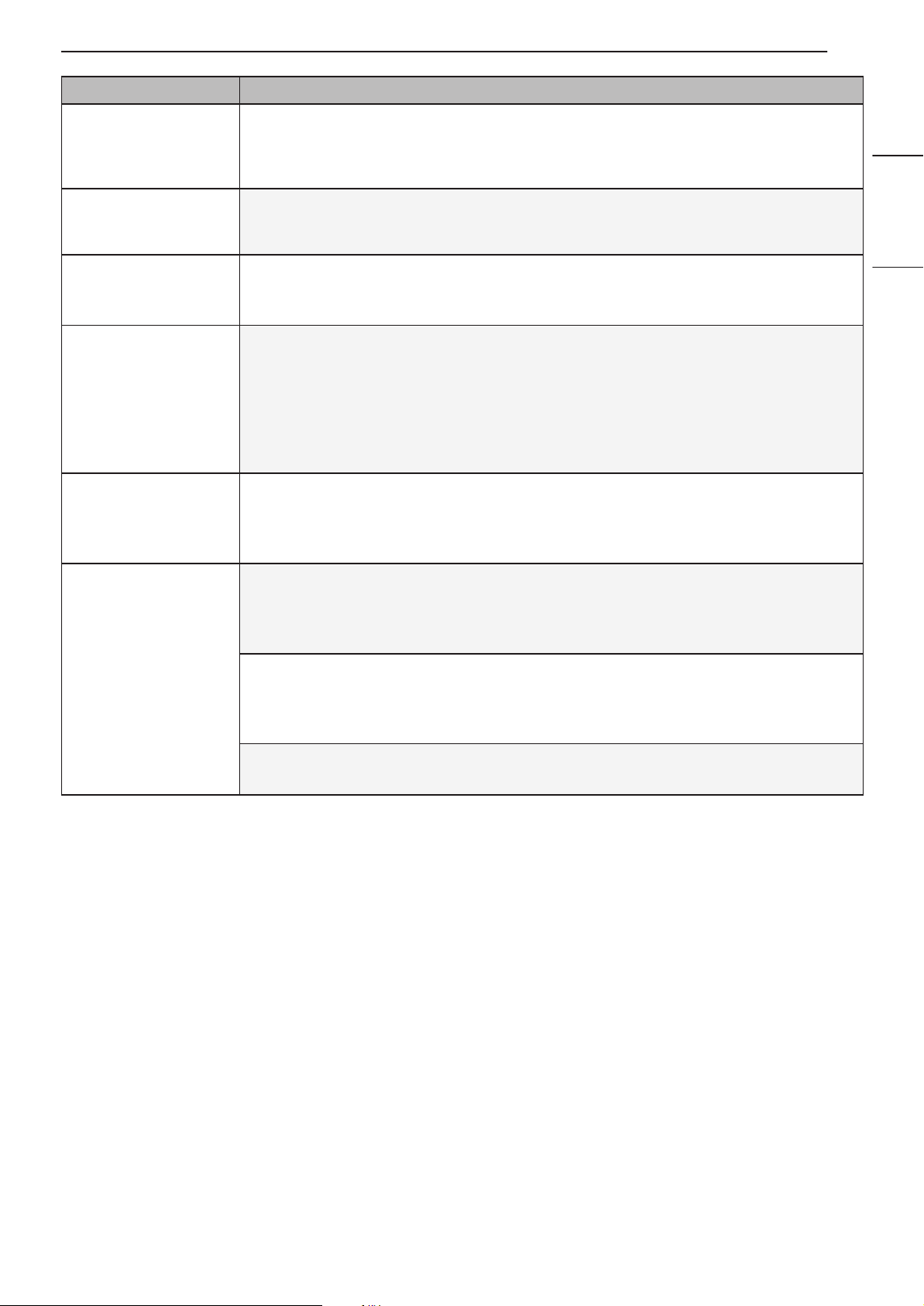
Symptoms Possible Causes & Solution
The indoor unit is
still operating even
when the unit has
been turned off.
The Auto Clean function is being operated.
• Allow the Auto Clean function to continue since it removes any remaining moisture
inside the indoor unit. If you do not want this feature, you can turn the unit off.
The air outlet on
the indoor unit is
discharging mist.
The cooled air from the air conditioner makes mist.
• When the room temperature decreases, this phenomenon will disappear.
Water leaks from the
outdoor unit.
In the heating operations, condensed water drops from the heat exchanger.
• This symptom requires installing a drain hose under the base pan. Contact the
installer.
There is noise or
vibration.
A clicking sound can be heard when the unit starts or stops due to movement
of the reversing valve.
Creaking sound: The plastic parts of the indoor unit creak when they shrink or
expand due to sudden temperature changes.
Flowing or Blowing sound: This is the flow of refrigerant through the air
conditioner.
• These are normal symptoms. The noise will stop.
The indoor unit gives
off an odor.
Odors (such as cigarette smoke) may be absorbed into the indoor unit and
discharged with airflow.
• If the smell does not disappear, you need to wash the filter. If this does not work,
contact the service center to clean your heat exchanger.
The air conditioner
does not emit warm
air.
When Heating Mode starts, the vane is almost closed, and no air comes out,
even though the outdoor unit is operating.
• This symptom is normal. Please wait until the unit has generated enough warm air
to blow through the indoor unit.
The outdoor unit is in Defrosting Mode.
• In Heating Mode, ice/frost is built up on the coils when the outside temperature
falls. This function removes a layer of frost on the coil, and it should finish in
approximately 15 minutes.
Outside temperature is too low.
• The heating effect may not be sufficient.
34 TROUBLESHOOTING
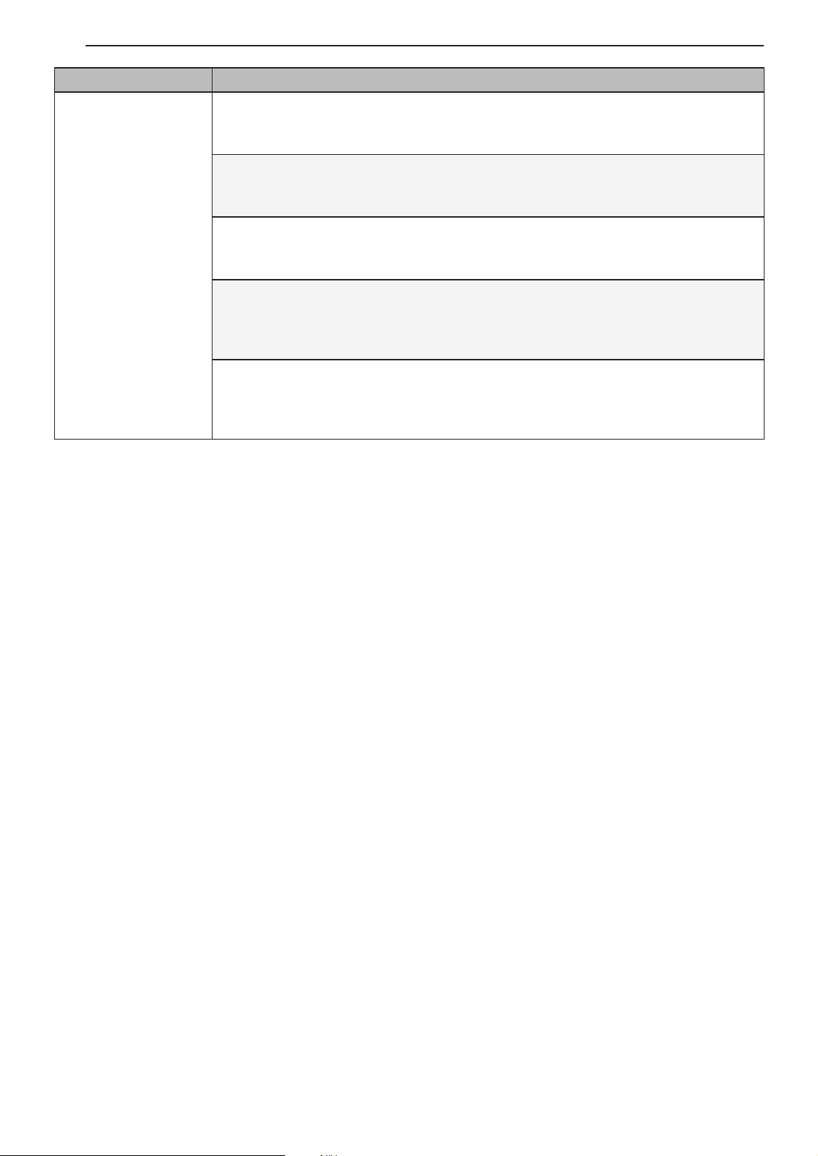
Symptoms Possible Causes & Solution
Your home appliance
and smartphone is
not connected to the
Wi-Fi network.
The password for the Wi-Fi that you are trying to connect to is incorrect.
• Find the Wi-Fi network connected to your smartphone and remove it, then register
your appliance on LG ThinQ.
Mobile data for your smartphone is turned on.
• Turn off the Mobile data of your smartphone and register the appliance using the
Wi-Fi network.
The wireless network name (SSID) is set incorrectly.
• The wireless network name (SSID) should be a combination of English letters and
numbers. (Do not use special characters.)
The router frequency is not 2.4 GHz.
• Only a 2.4 GHz router frequency is supported. Set the wireless router to 2.4 GHz
and connect the appliance to the wireless router. To check the router frequency,
check with your Internet service provider or the router manufacturer.
The distance between the appliance and the router is too far.
• If the distance between the appliance and the router is too far, the signal may be
weak and the connection may not be configured correctly. Move the location of the
router so that it is closer to the appliance.
NOTE
• Some functions may not be supported, depending on the model.

35WARRANTY (USA)
ENGLISH
FRANÇAIS ESPAÑOL
WARRANTY (USA)
ARBITRATION NOTICE: THIS LIMITED WARRANTY CONTAINS AN ARBITRATION PROVISION THAT
REQUIRES YOU AND LG TO RESOLVE DISPUTES BY BINDING ARBITRATION INSTEAD OF IN COURT,
UNLESS YOU CHOOSE TO OPT OUT. IN ARBITRATION, CLASS ACTIONS AND JURY TRIALS ARE NOT
PERMITTED. PLEASE SEE THE SECTION TITLED “PROCEDURE FOR RESOLVING DISPUTES” BELOW.
PROCEDURE FOR RESOLVING DISPUTES:
ALL DISPUTES BETWEEN YOU AND LG ARISING OUT OF OR RELATING IN ANY WAY TO THIS LIMITED
WARRANTY OR THE PRODUCT SHALL BE RESOLVED EXCLUSIVELY THROUGH BINDING ARBITRATION,
AND NOT IN A COURT OF GENERAL JURISDICTION. BINDING ARBITRATION MEANS THAT YOU AND LG
ARE EACH WAIVING THE RIGHT TO A JURY TRIAL AND TO BRING OR PARTICIPATE IN A CLASS ACTION.
Definitions. For the purposes of this section, references to “LG” mean LG Electronics U.S.A., Inc., its parents,
subsidiaries and affiliates, and each of their officers, directors, employees, agents, beneficiaries, predecessors
in interest, successors, assigns and suppliers; references to “dispute” or “claim” shall include any dispute,
claim or controversy of any kind whatsoever (whether based in contract, tort, statute, regulation, ordinance,
fraud, misrepresentation or any other legal or equitable theory) arising out of or relating in any way to the sale,
condition or performance of the product or this Limited Warranty.
Notice of Dispute. In the event you intend to commence an arbitration proceeding, you must first notify LG in
writing at least 30 days in advance of initiating the arbitration by sending a letter to LG at LG Electronics, USA,
Inc. Attn: Legal Department- Arbitration 111 Sylvan Avenue, Englewood Cliffs, NJ 07632. You and LG agree to
engage in good faith discussions in an attempt to amicably resolve your claim. The notice must provide your
name, address, and telephone number; identify the product that is the subject of the claim; and describe the
nature of the claim and the relief being sought. If you and LG are unable to resolve the dispute within 30 days,
either party may proceed to file a claim for arbitration.
Agreement to Binding Arbitration and Class Action Waiver. Upon failure to resolve the dispute during the
30 day period after sending written notice to LG, you and LG agree to resolve any claims between us only by
binding arbitration on an individual basis, unless you opt out as provided below. Any dispute between you and
LG shall not be combined or consolidated with a dispute involving any other person’s or entity’s product or
claim. More specifically, without limitation of the foregoing, any dispute between you and LG shall not under any
circumstances proceed as part of a class or representative action. Instead of arbitration, either party may bring
an individual action in small claims court, but that small claims court action may not be brought on a class or
representative basis.
Arbitration Rules and Procedures. To begin arbitration of a claim, either you or LG must make a written
demand for arbitration. The arbitration will be administered by the American Arbitration Association (“AAA”)
and will be conducted before a single arbitrator under the AAA’s Consumer Arbitration Rules that are in effect
at the time the arbitration is initiated (referred to as the “AAA Rules”) and under the procedures set forth in this
section. The AAA Rules are available online at www.adr.org/consumer. Send a copy of your written demand for
arbitration, as well as a copy of this provision, to the AAA in the manner described in the AAA Rules. You must
also send a copy of your written demand to LG at LG Electronics, USA, Inc. Attn: Legal Department- Arbitration
111 Sylvan Avenue, Englewood Cliffs, NJ 07632. If there is a conflict between the AAA Rules and the rules
set forth in this section, the rules set forth in this section will govern. This arbitration provision is governed
by the Federal Arbitration Act. Judgment may be entered on the arbitrator’s award in any court of competent
jurisdiction. All issues are for the arbitrator to decide, except that issues relating to the scope and enforceability
of the arbitration provision and to the arbitrability of the dispute are for the court to decide. The arbitrator is
bound by the terms of this provision.

36 WARRANTY (USA)
Governing Law. The law of the state of your residence shall govern this Limited Warranty and any disputes
between us except to the extent that such law is preempted by or inconsistent with applicable federal law.
Fees/Costs. You do not need to pay any fee to begin an arbitration. Upon receipt of your written demand for
arbitration, LG will promptly pay all arbitration filing fees to the AAA unless you seek more than $25,000 in
damages, in which case the payment of these fees will be governed by the AAA Rules. Except as otherwise
provided for herein, LG will pay all AAA filing, administration and arbitrator fees for any arbitration initiated in
accordance with the AAA Rules and this arbitration provision. If you prevail in the arbitration, LG will pay your
attorneys’ fees and expenses as long as they are reasonable, by considering factors including, but not limited to,
the purchase amount and claim amount. Notwithstanding the foregoing, if applicable law allows for an award of
reasonable attorneys’ fees and expenses, an arbitrator can award them to the same extent that a court would. If
the arbitrator finds either the substance of your claim or the relief sought in the demand is frivolous or brought for
an improper purpose (as measured by the standards set forth in Federal Rule of Civil Procedure 11(b)), then the
payment of all arbitration fees will be governed by the AAA Rules. In such a situation, you agree to reimburse LG
for all monies previously disbursed by it that are otherwise your obligation to pay under the AAA Rules. Except
as otherwise provided for, LG waives any rights it may have to seek attorneys’ fees and expenses from you if LG
prevails in the arbitration.
Hearings and Location. If your claim is for $25,000 or less, you may choose to have the arbitration conducted
solely on the basis of (1) documents submitted to the arbitrator, (2) through a telephonic hearing, or (3) by
an in-person hearing as established by the AAA Rules. If your claim exceeds $25,000, the right to a hearing
will be determined by the AAA Rules. Any in-person arbitration hearings will be held at a location within the
federal judicial district in which you reside unless we both agree to another location or we agree to a telephonic
arbitration.
Opt Out. You may opt out of this dispute resolution procedure. If you opt out, neither you nor LG can require the
other to participate in an arbitration proceeding. To opt out, you must send notice to LG no later than 30 calendar
days from the date of the first consumer purchaser’s purchase of the product by either: (i) sending an e-mail to
[email protected], with the subject line: “Arbitration Opt Out” or (ii) calling 1-800-980-2973. You must include in
the opt out e-mail or provide by telephone: (a) your name and address; (b) the date on which the product was
purchased; (c) the product model name or model number; and (d) the serial number (the serial number can be
found (i) on the product; or (ii) online by accessing https://www.lg.com/us/support/repair-service/schedule-repair-
continued and clicking on “Find My Model & Serial Number”).
You may only opt out of the dispute resolution procedure in the manner described above (that is, by e-mail or
telephone); no other form of notice will be effective to opt out of this dispute resolution procedure. Opting out of
this dispute resolution procedure will not affect the coverage of the Limited Warranty in any way, and you will
continue to enjoy the full benefits of the Limited Warranty. If you keep this product and do not opt out, then you
accept all terms and conditions of the arbitration provision described above.

37WARRANTY (CANADA)
ENGLISH
FRANÇAIS ESPAÑOL
WARRANTY (CANADA)
ARBITRATION NOTICE: THIS LIMITED WARRANTY CONTAINS AN ARBITRATION PROVISION THAT
REQUIRES YOU AND LG TO RESOLVE DISPUTES BY BINDING ARBITRATION INSTEAD OF IN COURT,
UNLESS THE LAWS OF YOUR PROVINCE OR TERRITORY DO NOT PERMIT THAT, OR, IN OTHER
JURISDICTIONS, IF YOU CHOOSE TO OPT OUT. IN ARBITRATION, CLASS ACTIONS AND JURY TRIALS
ARE NOT PERMITTED. PLEASE SEE THE SECTION TITLED “PROCEDURE FOR RESOLVING DISPUTES”
BELOW.
PROCEDURE FOR RESOLVING DISPUTES:
EXCEPT WHERE PROHIBITED AT LAW, ALL DISPUTES BETWEEN YOU AND LG ARISING OUT OF
OR RELATING IN ANY WAY TO THIS LIMITED WARRANTY OR THE PRODUCT SHALL BE RESOLVED
EXCLUSIVELY THROUGH BINDING ARBITRATION, AND NOT IN A COURT OF GENERAL JURISDICTION.
EXCEPT WHERE PROHIBITED AT LAW, YOU AND LG BOTH IRREVOCABLY AGREE TO WAIVE THE RIGHT
TO A JURY TRIAL AND TO BRING OR PARTICIPATE IN A CLASS ACTION.
Definitions. For the purposes of this section, references to “LG” mean LG Electronics Canada, Inc., its parents,
subsidiaries and affiliates, and each of their officers, directors, employees, agents, beneficiaries, predecessors
in interest, successors, assigns and suppliers; references to “dispute” or “claim” shall include any dispute,
claim or controversy of any kind whatsoever (whether based in contract, tort, statute, regulation, ordinance,
fraud, misrepresentation or any other legal or equitable theory) arising out of or relating in any way to the sale,
condition or performance of the product or this Limited Warranty.
Notice of Dispute. In the event you intend to commence an arbitration proceeding, you must first notify LG in
writing at least 30 days in advance of initiating the arbitration by sending a letter to LGECI Legal Team at 20
Norelco Drive, North York, Ontario, Canada M9L 2X6 (the “Notice of Dispute”). You and LG agree to engage
in good faith discussions in an attempt to amicably resolve your claim. The notice must provide your name,
address, and telephone number; identify the product that is the subject of the claim; and describe the nature
of the claim and the relief being sought. If you and LG are unable to resolve the dispute within 30 days of LG’s
receipt of the Notice of Dispute, the dispute shall be resolved by binding arbitration in accordance with the
procedure set out herein. You and LG both agree that, during the arbitration proceeding, the terms (including any
amount) of any settlement offer made by either you or LG will not be disclosed to the arbitrator until the arbitrator
determines the dispute.
Agreement to Binding Arbitration and Class Action Waiver. Upon failure to resolve the dispute during the
30 day period after LG’s receipt of the Notice of Dispute, you and LG agree to resolve any claims between you
and LG only by binding arbitration on an individual basis, unless you opt out as provided below, or you reside
in a jurisdiction that prevents full application of this clause in the circumstances of the claims at issue (in which
case if you are a consumer, this clause will only apply if you expressly agree to the arbitration). To the extent
permitted by applicable law, any dispute between you and LG shall not be combined or consolidated with a
dispute involving any other person’s or entity’s product or claim. More specifically, without limitation of the
foregoing, except to the extent such a prohibition is not permitted at law, any dispute between you and LG shall
not under any circumstances proceed as part of a class or representative action. Instead of arbitration, either
party may bring an individual action in small claims court, but that small claims court action may not be brought
on a class or representative basis except to the extent this prohibition is not permitted at law in your province or
territory of jurisdiction as it relates to the claims at issue between you and LG.
Arbitration Rules and Procedures. To begin arbitration of a claim, either you or LG must make a written
demand for arbitration. The arbitration will be private and confidential, and conducted on a simplified and
expedited basis before a single arbitrator chosen by the parties under the provincial or territorial commercial
arbitration law and rules of the province or territory of your residence. You must also send a copy of your
written demand to LG at LG Electronics, Canada, Inc., Attn: Legal Department- Arbitration, 20 Norelco Drive,
North York, Ontario M9L 2X6. This arbitration provision is governed by your applicable provincial or territorial
commercial arbitration legislation. Judgment may be entered on the arbitrator’s award in any court of competent
jurisdiction. All issues are for the arbitrator to decide, except that, issues relating to the scope and enforceability
of the arbitration provision and to the arbitrability of the dispute are for the court to decide. The arbitrator is
bound by the terms of this provision.

38 WARRANTY (CANADA)
Governing Law. The law of the province or territory of your purchase shall govern this Limited Warranty and
any disputes between you and LG except to the extent that such law is preempted by or inconsistent with
applicable federal or provincial/territorial law. Should arbitration not be permitted for any claim, action, dispute or
controversy between you and LG, you and LG attorn to the exclusive jurisdiction of the courts of the province or
territory of your purchase for the resolution of the claim, action, dispute or controversy between you and LG.
Fees/Costs. You do not need to pay any fee to begin an arbitration. Upon receipt of your written demand for
arbitration, LG will promptly pay all arbitration filing fees unless you seek more than $25,000 in damages, in
which case the payment of these fees will be governed by the applicable arbitration rules. Except as otherwise
provided for herein, LG will pay all filing, administration and arbitrator fees for any arbitration initiated in
accordance with the applicable arbitration rules and this arbitration provision. If you prevail in the arbitration, LG
will pay your attorneys’ fees and expenses as long as they are reasonable, by considering factors including, but
not limited to, the purchase amount and claim amount. Notwithstanding the foregoing, if applicable law allows
for an award of reasonable attorneys’ fees and expenses, an arbitrator can award them to the same extent
that a court would. If the arbitrator finds either the substance of your claim or the relief sought in the demand
is frivolous or brought for an improper purpose (as measured by the applicable laws), then the payment of all
arbitration fees will be governed by the applicable arbitration rules. In such a situation, you agree to reimburse
LG for all monies previously disbursed by it that are otherwise your obligation to pay under the applicable
arbitration rules. Except as otherwise provided for, LG waives any rights it may have to seek attorneys’ fees and
expenses from you if LG prevails in the arbitration.
Hearings and Location. If your claim is for $25,000 or less, you may choose to have the arbitration conducted
solely (1) on the basis of documents submitted to the arbitrator, (2) through a telephonic hearing, or (3) by an
in-person hearing as established by the applicable arbitration rules. If your claim exceeds $25,000, the right to
a hearing will be determined by the applicable arbitration rules. Any in-person arbitration hearings will be held at
the nearest, most mutually-convenient arbitration location available within the province or territory in which you
reside unless you and LG both agree to another location or agree to a telephonic arbitration.
Severability and Waiver. If any portion of this Limited Warranty (including these arbitration procedures) is
unenforceable, the remaining provisions will continue in full force and effect to the maximum extent permitted by
applicable law. Should LG fail to enforce strict performance of any provision of this Limited Warranty (including
these arbitration procedures), it does not mean that LG intends to waive or has waived any provision or part of
this Limited Warranty.
Opt Out. You may opt out of this dispute resolution procedure. If you opt out, neither you nor LG can require the
other to participate in an arbitration proceeding. To opt out, you must send notice to LG no later than 30 calendar
days from the date of the first consumer purchaser’s purchase of the product by either (i) sending an e-mail to
[email protected], with the subject line: “Arbitration Opt Out;” or (ii) calling 1-800-980-2973. You must include in
the opt out e-mail or provide by telephone: (a) your name and address; (b) the date on which the product was
purchased; (c) the product model name or model number; and (d) the serial number (the serial number can be
found (i) on the product; or (ii) online by accessing https://www.lg.com/ca_en/support/repair-service/schedule-
repair and clicking on “Find My Model & Serial Number”).
In the event that you “Opt Out”, the law of the province or territory of your residence shall govern this Limited
Warranty and any disputes between you and LG except to the extent that such law is preempted by or
inconsistent with applicable federal or provincial/territorial law. Should arbitration not be permitted for any claim,
action, dispute or controversy between you and LG, you and LG agree to attorn to the exclusive jurisdiction
of the courts of the province or territory of your residence for the resolution of the claim, action, dispute or
controversy between you and LG.
You may only opt out of the dispute resolution procedure in the manner described above (that is, by e-mail or
telephone); no other form of notice will be effective to opt out of this dispute resolution procedure. Opting out of
this dispute resolution procedure will not affect the coverage of the Limited Warranty in any way, and you will
continue to enjoy the full benefits of the Limited Warranty. If you keep this product and do not opt out, then you
accept all terms and conditions of the arbitration provision described above.
Conflict of Terms. In the event of a conflict or inconsistency between the terms of this Limited Warranty and the
End User License Agreement (“EULA”) in regards to dispute resolution, the terms of this Limited Warranty shall
control and govern the rights and obligations of the parties and shall take precedence over the EULA.
US
Please call the installing contractor of your product, as warranty service will be
provided by them.
CANADA
Service call Number # : (888) LG Canada, (888) 542-2623
Numéro pour les appels de service : LG Canada, 1-888-542-2623