User Manual
Features
- Modular design. Permits easy access to connection terminals and battery. “Snap-out” design allows the controller to be programmed from any location.
- Remote control ready
- Three independent watering programs
- Three start times per program
- Scheduling flexibility
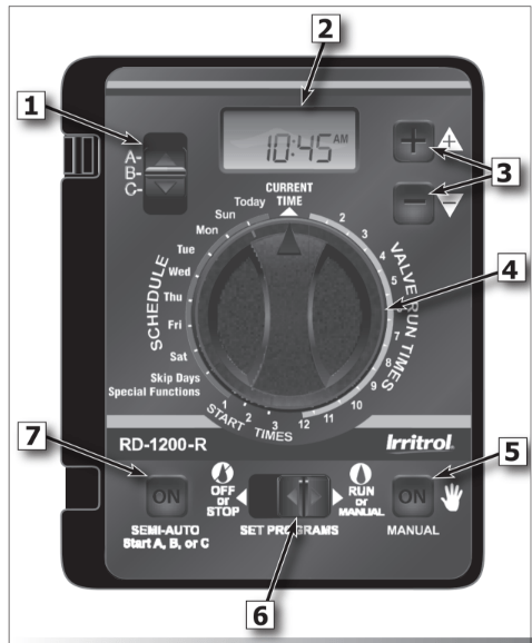
Control Module Interface (see opposite graphic)
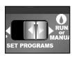
1- Program Switch
Three-position slide switch used to select Program A, B or C for setup, program review and manual operation.
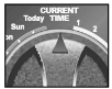
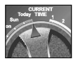
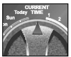
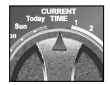
2 - LCD Display
High-contrast LCD panel displays all controller programming and operating information.
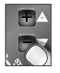
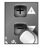
3 - Plus and Minus Buttons
Push buttons used to increase and decrease display values during controller setup, programming and manual operations. Adjusts values incrementally (press and release) or by rapid scrolling (press and hold).
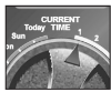
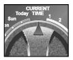
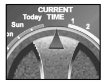
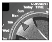
4 - Dial
A 25-position rotary switch used to select stations, start times, watering days and special functions for setup, programming and manual operations.
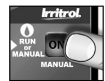
5 - Manual Button
Push button used to start and control manual operations by station. Also serves as a “Next” button to step forward through various setup, programming and manual operations.
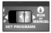
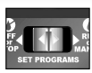
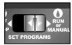
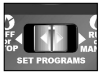
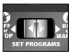
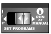
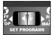
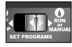
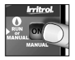
6 - Function Switch
A three-position slide switch used to select one of three controller function modes:
Off or Stop - Stops all current watering operations, and prevents all automatic and manual operations.
Set Programs - Enables automatic watering program setup values to be selected and changed.
Run or Manual - Normal switch position for all automatic and manual watering operations.
7 - Semi-Auto Start Button
Push button used to manually start an automatic watering Program. Also used to initiate the Station Test Run operation.
Battery Installation
Install a 9V battery for two reasons:
- Program the controller from any location.
- Maintain controller time and date during power outages.
Steps:
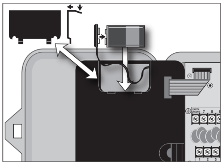
- Open controller door.
- Slide battery compartment cover off.
- Attach the battery clip to a 9V battery.
- Install battery into compartment and replace cover.
- The display will begin flashing 12:00 AM.
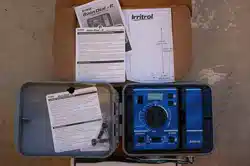
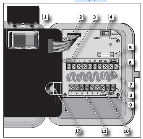
Internal Controller Components
1 - Battery Compartment
Snap-in cover provides easy access to 9V alkaline battery.
2 - Control Module Ribbon Cable
Quick disconnect cable control module from cabinet for Armchair Programming or service.
3 - Earth Ground Terminal
Wire connection terminal for earth ground conductor.
4 - Sensor Bypass Switch
Switch controls (optional) rain/freeze sensor input.
5 - Safety Fuse
2A Slow-blow fuse protects against short- circuit overload on the 24 VAC input power.
6 - Power Transformer Connection Terminals (24 VAC)
Wire connection terminals for 24 VAC plug-in transformer and power connection point for (optional) wireless rain or rain/ freeze sensors.
7 - Valve Common Terminal (VC)
Wire connection terminal for the valve (field) common wire.
8 - Rain Sensor Terminals (Sensor)
Wire connection terminals for (optional) Irritrol RainSensorTM model RS500, RS1000, or RFS1000.
9 - Sensor Terminal Jumper
Sensor terminal jumper wire (removed only when a rain or rain/freeze sensor is connected).
10 - Master Valve/Pump Terminal (MV/Pump)
Wire connection terminal for (optional) master valve or pump start relay.
11 - Valve Station Terminals
Valve connection terminals – one terminal for each valve. (Terminal layout varies by model. station model shown.)
12 - Handheld Remote Control Plug-in Port
Modular connector port required for the Irritrol handheld remote control system model R-100-KIT or CLIMATE LOGI weather sensing system.
Controller Installation
Installing the Controller Cabinet
Select a sheltered location for the indoor model Rain Dial-R such as a garage or service room, preferably within 5’ (1.5m) of a grounded electrical outlet. For outdoor controllers, choose a location that protects against direct exposure to sun and contact with irrigation spray, and is at least 5’ (1.5m) away from any motorized equipment.
- Drive the provided stainless steel screw into a wall stud at a eye-level, leaving 1/4” (6.4mm) of the screw shaft exposed. Note: Use screw anchors when installing on drywall or masonry.
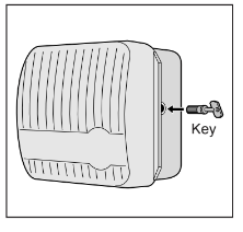
- Hang the controller on the screw using the keyhole-shaped slot.
- To secure the controller, drive one or two screws through the lower mounting holes.
Note: The lower mounting holes in the Outdoor cabinet have a thin veneer that is easily pierced when installing the mounting screw during installation.
Connecting the Valve Control Wiring
For best results, use connection wire cable specifically designed for direct burial for automatic irrigation systems. Use 18-AWG wire for connections up to 800’ from the controller, or heavier 14-AWG (2.0mm2 ) wire for connections up to 2000’. A separate wire for each valve (and relay) connection and at least one common (return) wire is required.
Note: If control wire conduit is required, install it at this time. For conduit installation, use the 3/4” mm) access hole in the indoor cabinet, or the threaded 1.25” NPT opening in the outdoor cabinet.
- Route the control wire from the controller location to the valve(s).
- Attach a separate control wire to either lead of each valve solenoid.
- To provide a common (return) wire, attach the remaining lead of each valve solenoid to a single wire. Note: To prevent corrosion and a possible short circuit, use waterproof wire connectors on all external wire splices. For reference at the controller, note the wire color used for each valve connection and its corresponding watering zone.
- Route the cable through the largest opening in the base of the controller cabinet or through conduit if installed. Remove the cable jacket to expose about 8” of wires. Carefully remove 3/8” of insulation from the end of each wire to be connected.
- Secure each valve wire to numbered terminal in the preferred operating sequence order.
- Connect the common wire to the terminal labeled “VC.”
- If applicable, connect one leg of the master valve or pump start relay control wire to the terminal labeled “MV/PUMP”, and the remaining leg to the valve common wire.
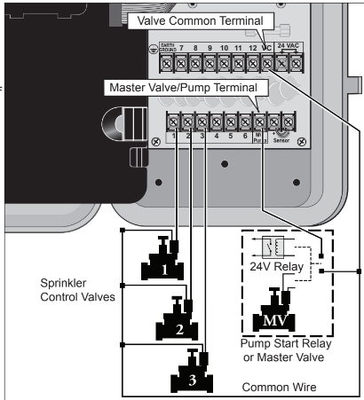
Note: The controller does not supply power to operate a pump. The pump start relay must have a nominal coil voltage of 24 VAC, rated at 0.375A maximum.
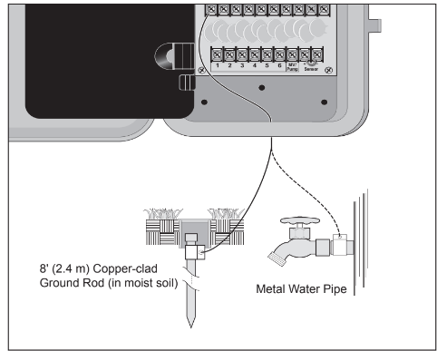
Connecting an Earth Ground Device
Note: In order for the electrical surge components built into your Rain Dial-R to function properly, the controller must be connected to an earth ground device, such as a copper-clad ground rod or metal water pipe, using solid copper wire. This connection is especially important when the controller is installed in a lightning-prone area.
- Connect a 12–16 AWG ( 2mm2– mm2 ) solid- copper wire to the ground device and route into the controller through an access opening in the base of the cabinet.
- Secure the ground wire to the terminal labeled “Earth Ground.”
Connecting the Power Source - Indoor Model
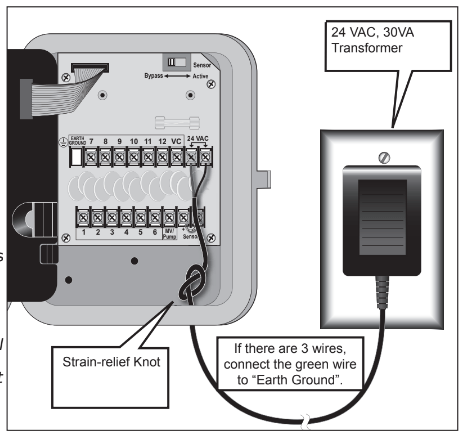
- Route the plug-in transformer cable through the small hole provided in the bottom of the cabinet.
- Tie a knot in the cable to provide a strain relief, and connect the wires to the terminals labeled “24 VAC” (in either order).
- Close the control module and plug the transformer into a wall outlet. The controller is now ready to program and operate.
Note: To immediately test-run the Rain Dial-R irrigation control system, refer to the “Controller Station Test Feature” on page 8. "Connecting the Power Source - Outdoor Models
Warning: All electrical components and connection methods must comply with all applicable national and local electrical codes including installation by qualified personnel. These codes may require a junction box installed on controller’s 1/2” (13 mm) NPT nipple and a means in the fixed wiring of disconnecting AC power having a contact separation of at least 0.120” (3mm) in the line and neutral poles. The connection wire must have insulation rated @ 105° C min.
The controller must be connected to a grounded power source. Do not connect to one phase of a 3-phase power supply used by a pump or other electrical equipment.
Prior to connecting controller wiring, verify that power has been turned off at the source by using an AC volt meter.
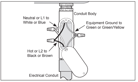
- Install a 1/2” (13mm) NPT conduit body to the transformer threaded fitting. From the conduit body, install electrical conduit routing to the AC power source (per electrical code).
- Pull 14 AWG through the conduit into the conduit body.
- Using twist-on wire connectors, attach the mating wires as shown at right.
- Close and secure the conduit body cover.
- Apply power to the controller and check controller operation. If the controller is not operating, disconnect the power at the source and have a qualified electrician check for possible short circuit.
Caution: For maximum protection of the controller electronic components when installed outdoors, always keep the cabinet cover closed and locked whenever possible. Store the cabinet keys in a safe, convenient location.
Controller Station Test Feature
Run a Station Test to check proper valve operation. The test cycle enables all valve stations to operate in sequence, from 1–10 minutes.
1. Set Function switch to Run.
2. Turn Dial to Skip Days.

3. Push MANUAL button once.

4. Adjust run time.

A 2-minute test run is set by default.

5. Push Semi-Auto to start watering cycle (station 1).

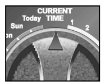
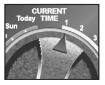
6. Turn Dial to Current Time.
7. Display shows current time and what station is running.

8. Manual advances the station sequence.
Setting Up an Irrigation Schedule
Setting the Current Time and Day
1. Function switch to Set Programs.
2. Turn Dial to Current Time.

3. Set current time.
Pay attention to “AM” and “PM”.

4. Turn Dial to Today.
5. Select the correct day*.
Display shows day abbreviation.

6. Return Dial to Current Time.
7. Function switch back to Run.
Note: If Odd/Even schedule or Monthly Water Budget is used, the current day of the week is preset and cannot be changed.
Setting the Valve Run Time Duration
Each valve station can have an individual run time assignment in each Program. Run time can be set for 1–59 minutes (in 1-minute increments) or 1–5.9 hours (in 1/10-hour increments).
1. Function switch to Set Programs.
2. Select Program A, B, or C.

3. Turn Dial to desired Valve Number.
4. Set valve run time.

Display shows valve run time.

5. Repeat steps 3 and 4 for all valves.
Switch to a different Program. Repeat steps 3 and 4 as needed.
6. Return Dial to Current Time.
Function switch back to Run.

Setting the Program Cycle Start Time(s)
Each Program can have three separate start times. For mature landscapes, one start time per
Program is generally sufficient. For new lawns, two or three start times with short valve run times can provide the additional irrigation required for grow-in.
1. Function switch to Set Programs.
2. Select Program A, B, or C.
(Make sure to use Program A and reset its default values.)

3. Turn Dial to Start Time 1 (or 2 or 3).

4. Set start time.*

Display shows start time.

5. Repeat steps 3 and 4 to set additional start times.
Switch to a different Program. Repeat steps 3 and 4 as needed.
6. Return Dial to Current Time.
7. Function switch back to Run.
*Note: To remove a start time, select Off, displayed between 11:59–12:00 and 5:59–6:00 (AM and PM).
Setting the Program Watering Day Schedule
Watering days can be scheduled for each Program using one of the following methods:
Weekdays: Schedules watering for specific days of the week.
Skip Day: Schedules watering days by interval frequency; e.g., every day (01), every- other-day (02) etc. Skip Days is addressed in the online User Manual.
Odd/Even Date: Schedules watering days based on Odd- or Even- numbered calender days. Odd/Even Date is addressed in the online User Manual.
To set a Weekdays Schedule:
1. Function switch to Set Programs.
2. Select Program A, B, or C.

3. Turn Dial to desired Weekday.
4.
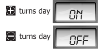
5. Repeat steps 3 and 4 to turn On and Off days as needed.
Switch to a different Program. Repeat steps 3 and 4 as needed.
6. Return Dial to Current Time.
7. Function switch back to Run.
Manual Operations
Semi-Automatic Program Operation
Semi-Automatic Program operation enables an automatic Program watering cycle to be started manually at any time. Once running, the manual advance feature enables you to step through the programmed station sequence.
1. Place the Function switch in the Run position.
2. Turn the Dial to the Current Time position.
3. Select Program A, B, or C.

4. Press the Semi-Auto button to start the watering cycle.

Note: Once started, the station sequence can be manually advanced by placing the Dial to Current Time and pressing the Manual button.
Note: The Manual Advance feature applies to all Automatic, Semi-automatic and Station Test watering operations for the selected Program.
Note: To terminate watering operations, place the Function switch momentarily in the OFF or Stop position.
Manual Station Operation
Manual station operation provides manual control at the individual station level and provides the following four control options:
- Station(s) can be operated for a one-time run duration without altering the station’s set run time in an automatic Program.
- Operation can be limited to only one station running manually or set to allow three stations to run at the same time.
- Works with the Manual Advance feature to move up through the station sequence.

1. Place the Function switch in the Run position.
2. Turn the Dial to the Station Number to be manually operated.
3. Use the /
/ buttons to set a manual operation run time ranging from minute to 5.9 hours.
4. Press the Manual button to start the operation.
5. If this is the only station to be run manually, skip step 6 and continue at step 7 below.
6. To add additional stations to the manual run operation, repeat steps 2 through 4 as needed, then continue at step 7.
7. Turn the Dial to the Current Time position.

Note: Depending upon the Stack/Overlap setting, additional stations selected (beyond the one or three option setting) will register as OFF when entered with the Manual button. However, they will be placed (stacked) in the manual sequence to run.
Note: Once started, the station sequence can be manually advanced by pressing the Manual button.
Note: To terminate manual watering operations, place the Function switch momentarily in the OFF or Stop position.