5
FAMILIARISATION
Familiarisation
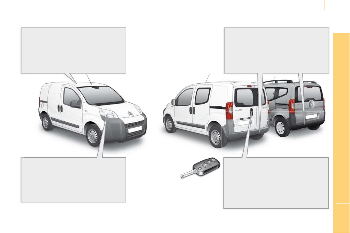
EXTERIOR
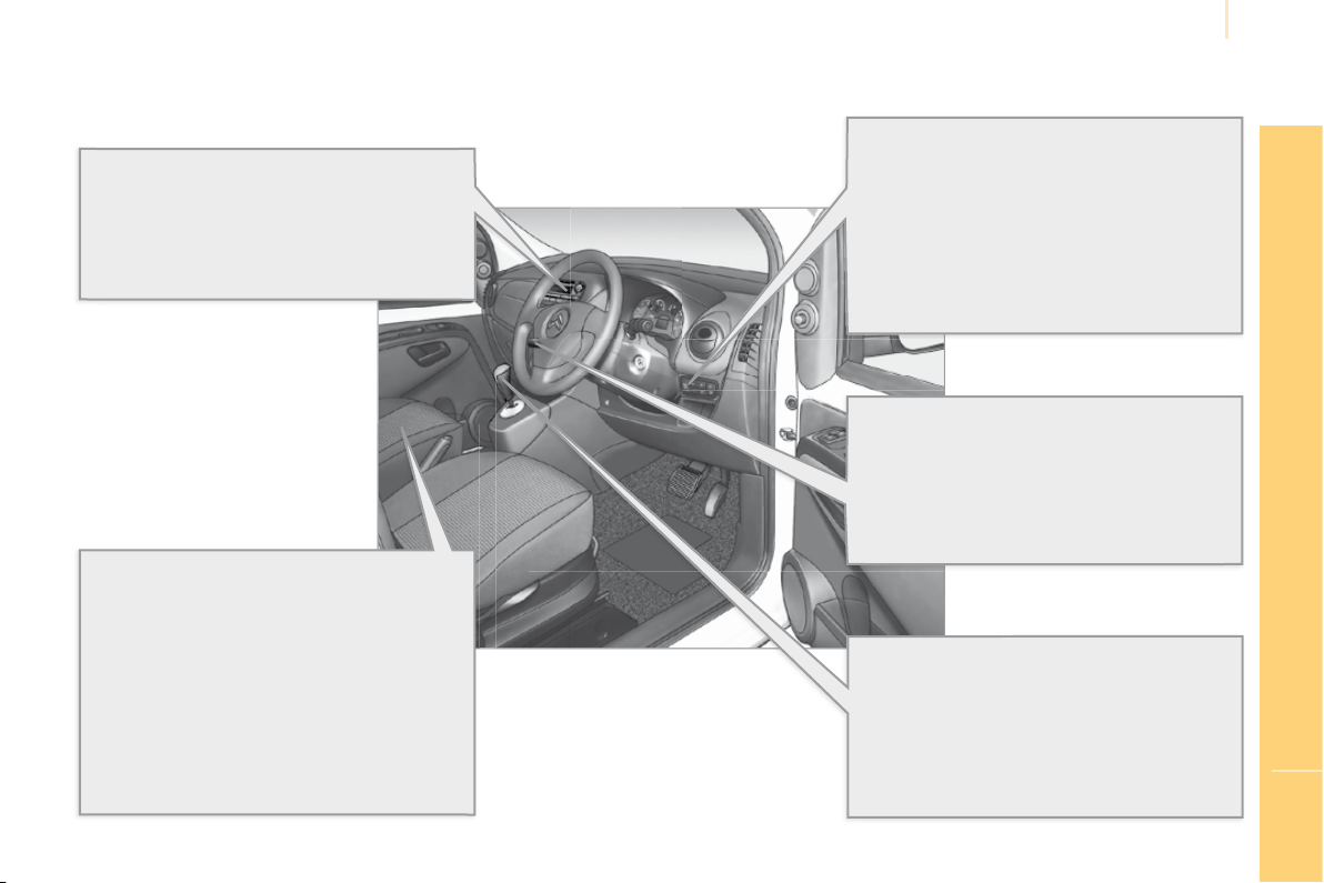
Roof rack and roof bars
Fixing points are provided on each side of the
roof for securing the roof rack or the transverse
roof bars.
109
Opening the hinged rear doors
to 180°
Once the vehicle has been unlocked, the
hinged rear doors can be opened to 180° to
make unloading/loading operations easier.
34
Rear parking assistance
This equipment warns you, by means of an
audible signal, if an obstacle is detected
behind the vehicle when reverse gear is
engaged.
68
"Guide-me-home" lighting
After switching off the ignition, when you leave
your vehicle, the front lamps remain on briefl y.
39
6
Familiarisation
OPEN
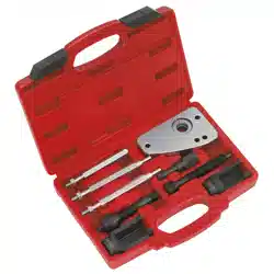
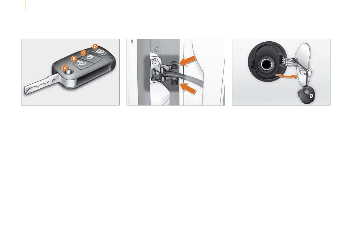
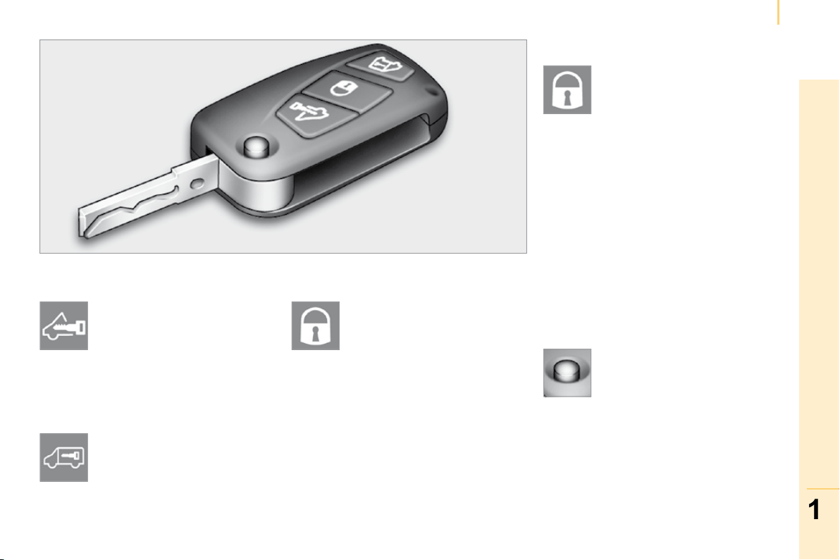
Remote control key
A. Unfolding/Folding of the key.
B. Unlocking of the front doors only (Light
van) or of all of the doors (Combi)
(two fl ashes of the direction indicators).
C. Central locking of the vehicle
(one press; one fl ash of the direction
indicators).
or
Deadlocking of the vehicle
(two consecutive presses; one fl ash of the
direction indicators).
D. Unlocking of the load space (Light van) or
of the hinged rear doors or tailgate only
(Combi).
If a door is open or has not been closed
properly, the failed locking is indicated by three
fl ashes of the direction indicators.
Fuel tank
1. Opening of the fuel fi ller fl ap.
2. Opening and hooking of the fuel tank cap.
Capacity of the tank: approximately 45 litres.
29 129
Opening to 180°
34
Press the catch while opening the door.
7
FAMILIARISATION
Familiarisation
INTERIOR
Trip computer
By means of the MENU button, this system
permits management or consultation of the
various vehicle confi gurations/information such
as the disarming of the passenger air bag, the
automatic locking of the doors, the language,
etc.
64
Retractable multifunction passenger
seat
This equipment enables you to confi gure your
passenger seat in three positions:
- seat for the transportation of a passenger,
- table to accommodate your various
documents,
- retracted for the transportation of long
objects.
76
Audio system
This equipment benefi ts from the latest
technology: MP3 compatible audio equipment
and Bluetooth
®
hands-free kit.
69
Cruise control/speed limiter
These two functions control the speed of the
vehicle in relation to the programmed value.
41, 44
Electronic gearbox system
This equipment guarantees perfect driving
by combining a fully automatic mode and a
manual mode.
50
8
Familiarisation
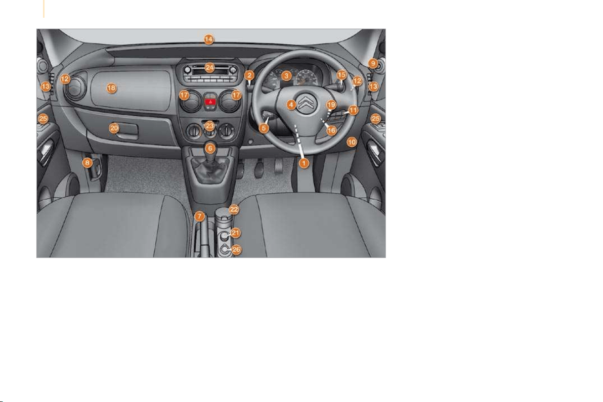
INSTRUMENTS AND CONTROLS
1. Steering wheel adjustment control.
2. Lights and direction indicators controls.
3. Instrument panel.
4. Driver’s air bag.
Horn.
5. Cruise control/speed limiter switches.
6. Gear lever.
7. Handbrake.
8. Bonnet release.
9. Exterior mirror controls.
10. Fuse box.
11. Manual headlamp height adjustment.
12. Side adjustable and closing vent.
13. Front side window demisting vent.
14. Windscreen demisting vent.
15. Steering lock and ignition.
16. Wipers/wash-wipe/trip computer controls.
17. Central adjustable and closing vents.
18. Passenger air bag.
19. MENU button.
20. Glove box.
21. Lighter.
22. Ashtray.
23. Heating/air conditioning controls.
24. Audio equipment.
25. Electric window controls.
26. 12 V accessories socket.
9
FAMILIARISATION
Familiarisation
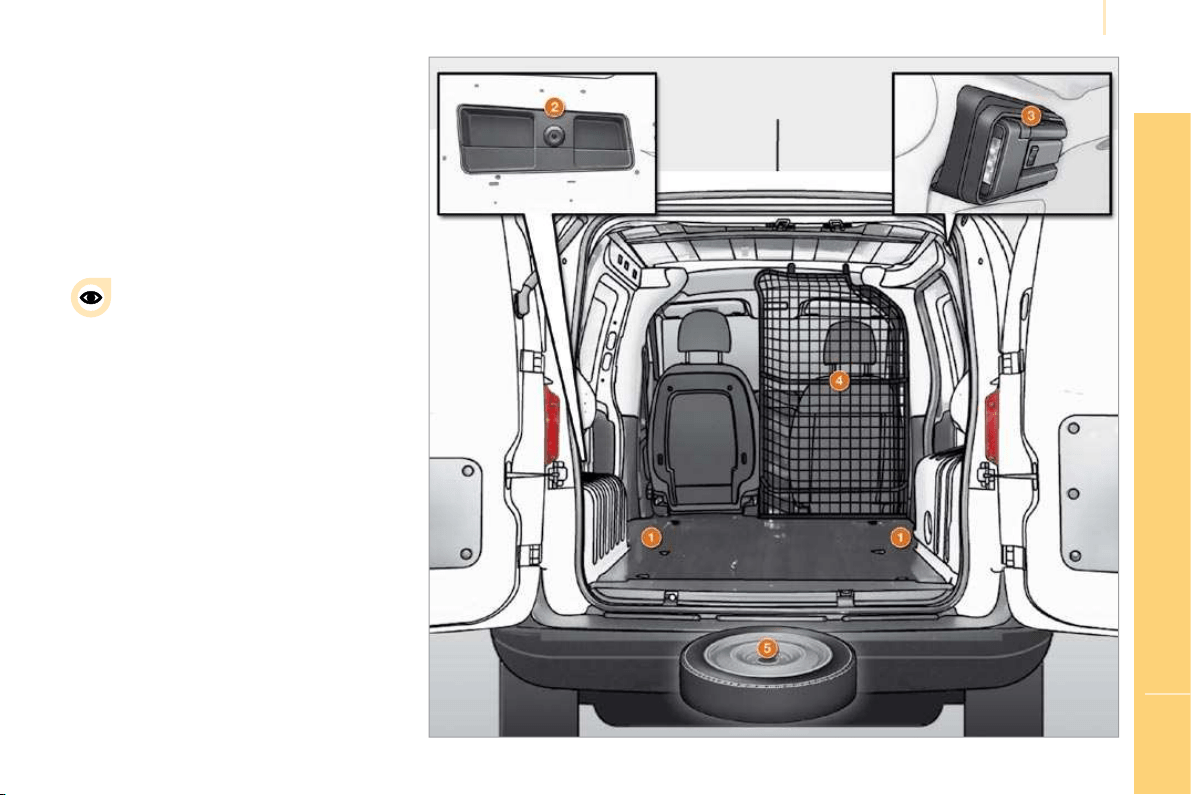
LOAD SPACE (LIGHT VAN)
1. Stowing rings.
2. Storage tray.
3. Torch.
4. Partition.
5. Spare wheel.
82
It is advisable to immobilise the load
by fi xing it securely using the stowing
rings 1 on the fl oor.
10
Familiarisation
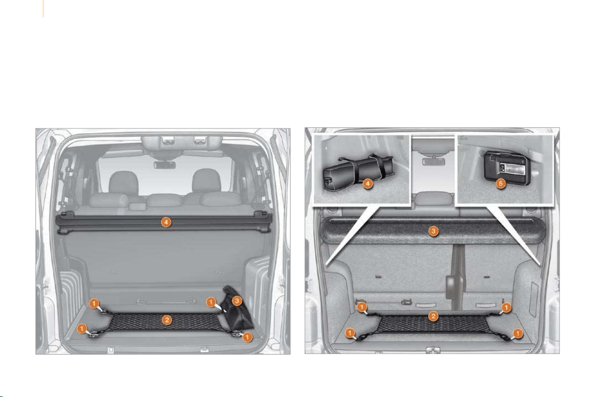
REAR LAYOUT (COMBI)
8 9
With hinged rear doors
1. Stowing rings.
2. Luggage retaining net.
3. Tool kit.
4. Rear shelf.
With tailgate
1. Stowing rings.
2. Luggage retaining net.
3. Rear shelf.
4. Retaining straps/Tool kit.
5. Torch/Boot light.
11
FAMILIARISATION
Familiarisation
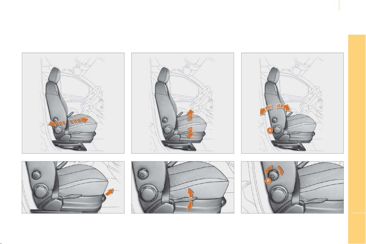
SIT COMFORTABLY
Driver’s seat adjustment
Forwards-backwards Height
Seat back angle (A)
Lumbar support (B)
74
12
Familiarisation
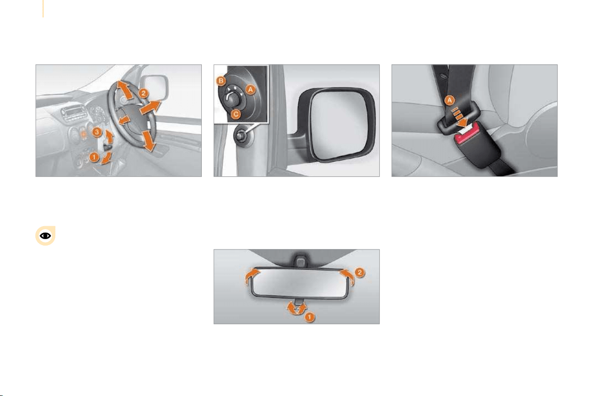
Front seat belts
A. Fastening.
94
SIT COMFORTABLY
Steering wheel adjustment
1. Unlocking of the control.
2. Adjustment of the height and depth.
3. Locking of the control.
As a safety precaution, it is imperative
that these operations are carried out
while stationary.
49
Electric exterior mirror adjustment
A. Selection of the driver’s mirror.
B. Selection of the passenger’s mirror.
C. Adjustment of the position of the mirror.
47
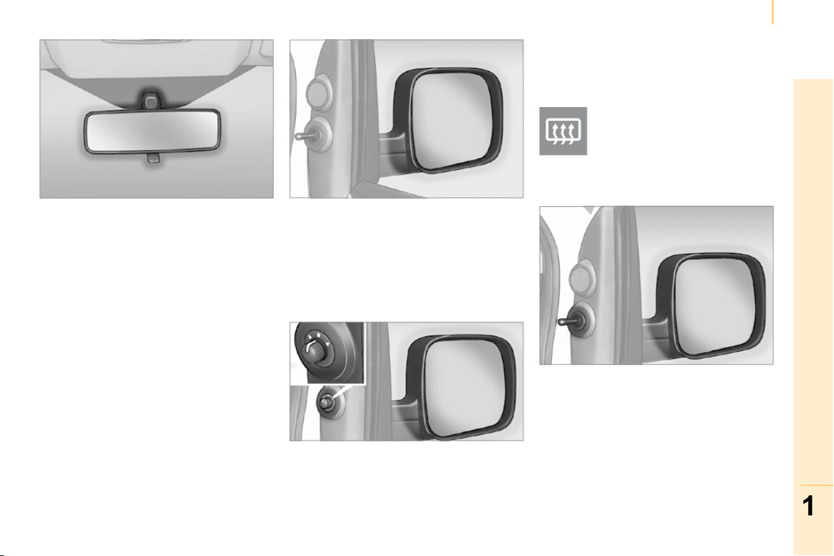
Interior mirror adjustment
1. Selection of the "day/night" position of the
mirror.
2. Directing of the mirror.
47
13
FAMILIARISATION
Familiarisation
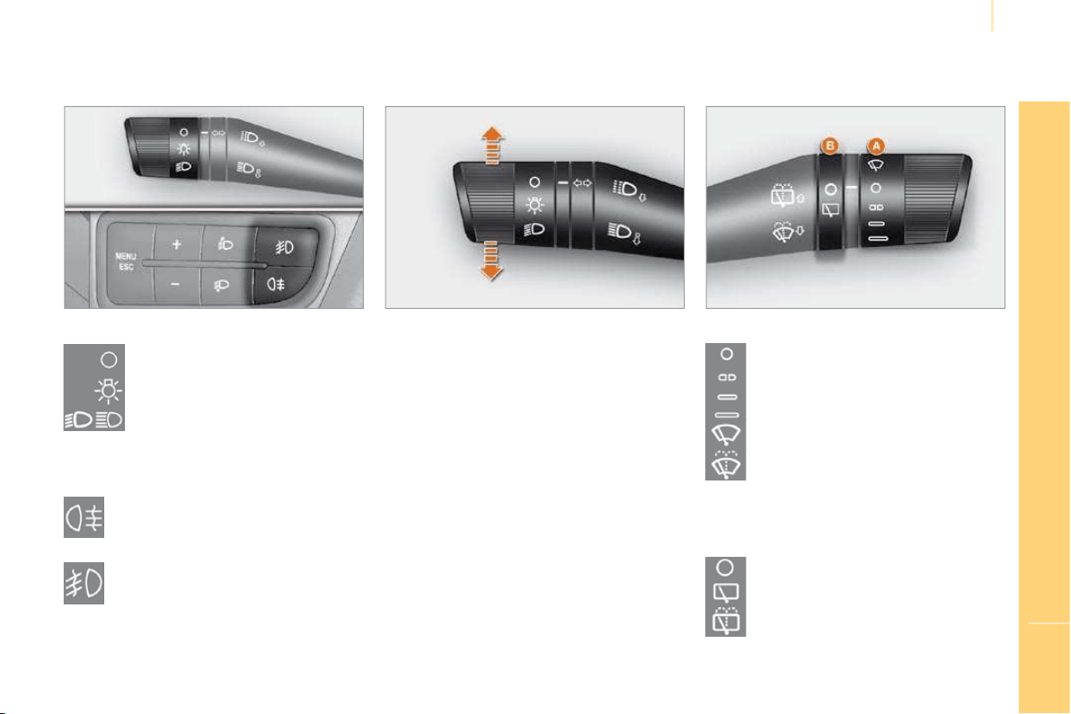
SEE CLEARLY
Ring
Lamps off.
Side lamps.
Dipped/main beam headlamps.
Fog lamps
Rear fog lamp.
or
Front and rear fog lamps.
38
Direction indicators
"Motorway" function
Press the lighting control up or down once,
without passing the point of resistance; the
corresponding direction indicators will fl ash
three times.
38
Wipers
Ring A: windscreen wipers
40
Ring B: rear wiper
40
Single wipe.
Intermittent wipe.
Wash-wipe.
Wash-wipe.
Park.
Lighting
Park.
Intermittent.
Slow continuous.
Rapid continuous.
Raise or lower the lighting control past the
point of resistance; the corresponding direction
indicators will fl ash until the control is moved
out of this position.
14
Familiarisation
81
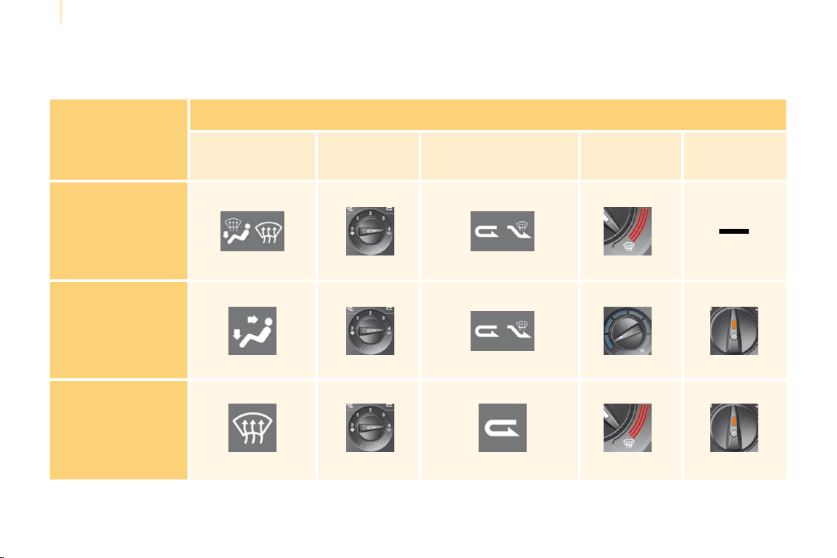
VENTILATION
Recommended interior settings
I require...
Heating or Manual Air Conditioning
Air distribution Air fl ow
Air recirculation/
Intake of outside air
Temperature Manual A/C
HOT
COLD
DEMISTING
DE-ICING
15
FAMILIARISATION
Familiarisation
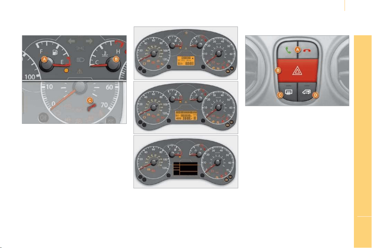
MONITOR THOROUGHLY
Instrument panel Controls panel
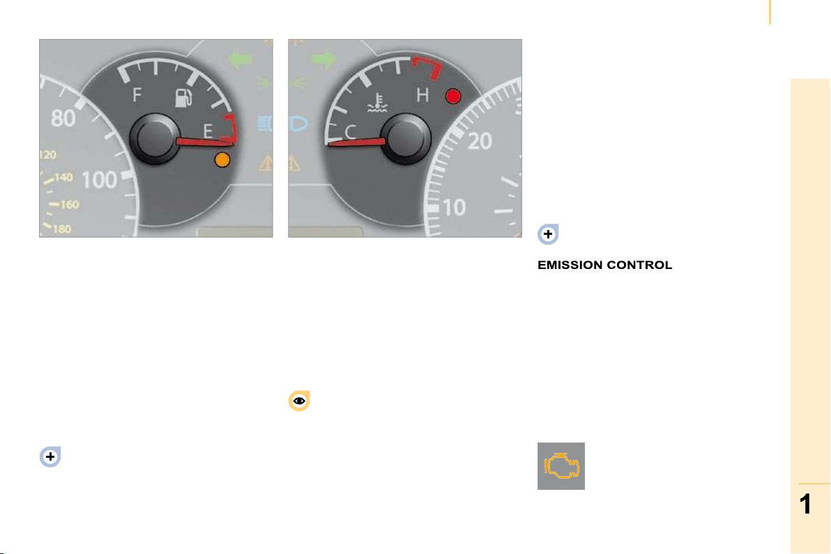
A. With the ignition on, the needle indicates
the level of fuel remaining.
With the engine running, its associated
warning lamp switches off. If it remains on,
this indicates that you have reached the
minimum level in the tank.
B. With the ignition on, the needle indicates
the coolant temperature.
With the engine running, its associated
warning lamp switches off.
C. With the ignition on, the oil level warning
lamp does not remain on.
If the levels are not correct, top up the levels
which are low.
A. Hands-free kit.
72
1. With the ignition on, the orange and red
warning lamps come on.
2. With the engine running, these warning
lamps should switch off.
If warning lamps remain on, refer to the section
concerned.
Warning lamp
21
27
B. Hazard warning lamps.
92
C. Rear screen and mirrors de-icing.
81
D. Locking/Unlocking of the load space
(Light van).
35
16
Familiarisation
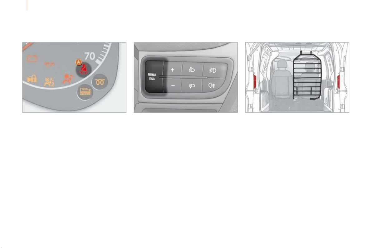
KEEP YOUR PASSENGERS SAFE
Passenger’s front air bag
The passenger’s front air bag is disarmed by
means of the MENU button, located to the right
of the steering wheel.
1. Press the MENU button.
2. Select "Bag" and confi rm by pressing the
MENU button.
3. Select "OFF" and confi rm by pressing the
MENU button.
4. Select "YES" and confi rm by pressing the
MENU button.
Seat belt not fastened
A. Driver’s seat belt not fastened warning
lamp.
94 98
Ladder type vertical partition
(Light van)
A ladder type vertical partition protects the
driver against the risk of load movement.
87
17
FAMILIARISATION
Familiarisation
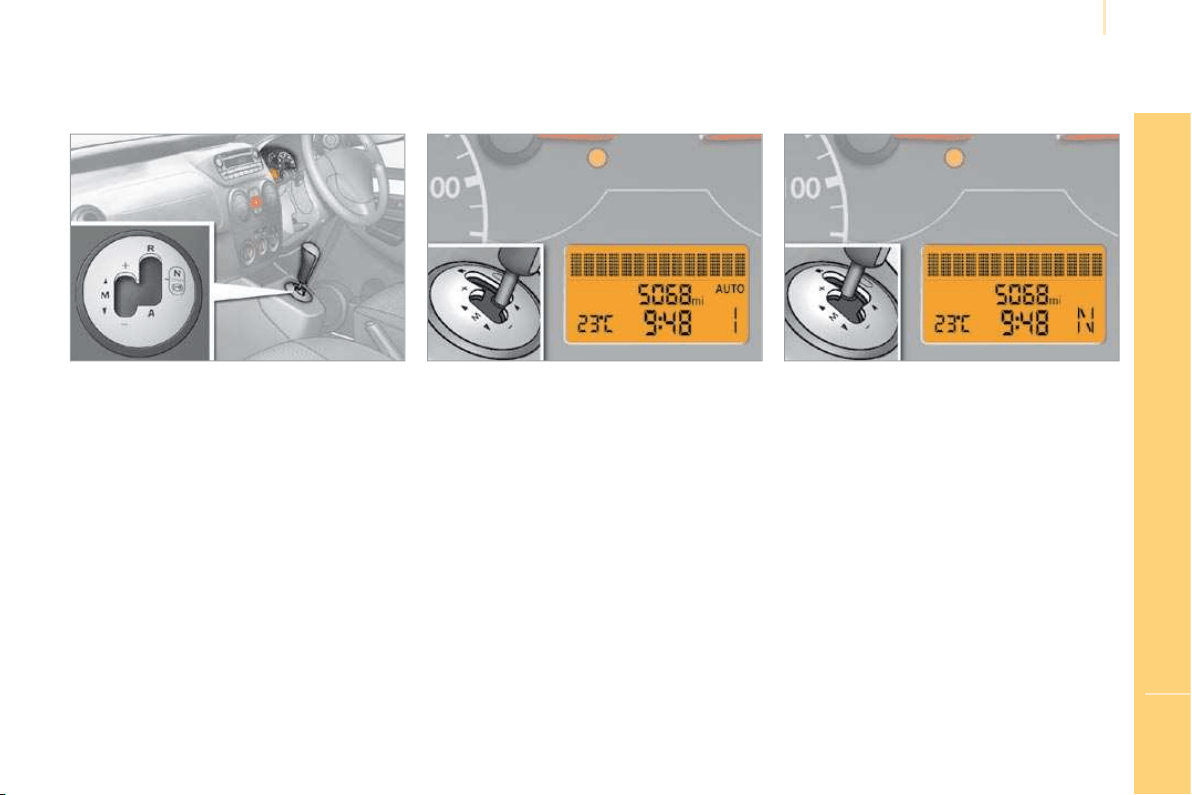
DRIVE SAFELY
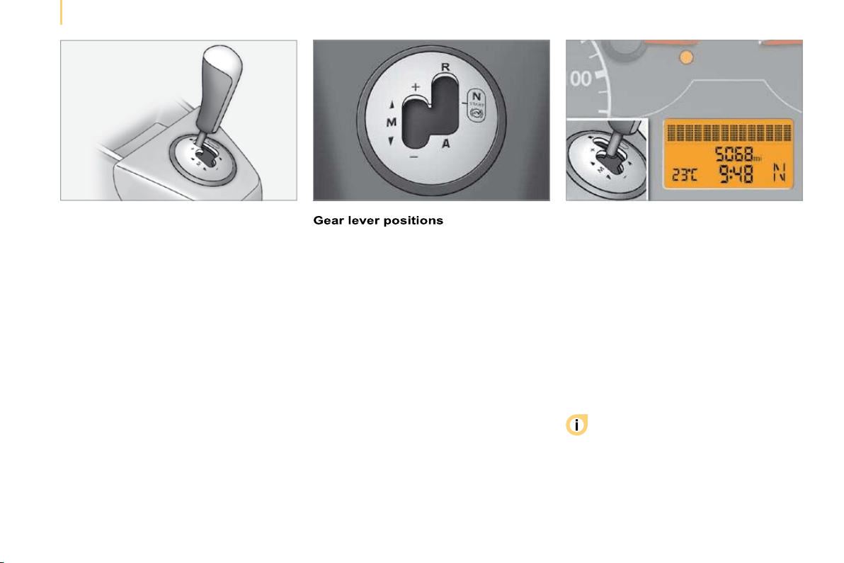
Electronic gearbox system Display on the instrument panel Moving off
50
This fi ve-speed gearbox offers a choice
between the comfort of fully automatic
operation or the pleasure of manual gear
changing.
R. Reverse.
N. Neutral.
A. Automated mode.
M +/-. Sequential mode.
The gear or the driving mode selected appears
on the instrument panel display.
R: reverse gear.
N: neutral.
AUTO: automatic mode.
1 2 3 4 5: gears engaged.
Select position N and press the brake pedal
fi rmly while starting the engine.
Engage fi rst gear (position A or M ) or reverse
(position R ) using the gear lever.
18
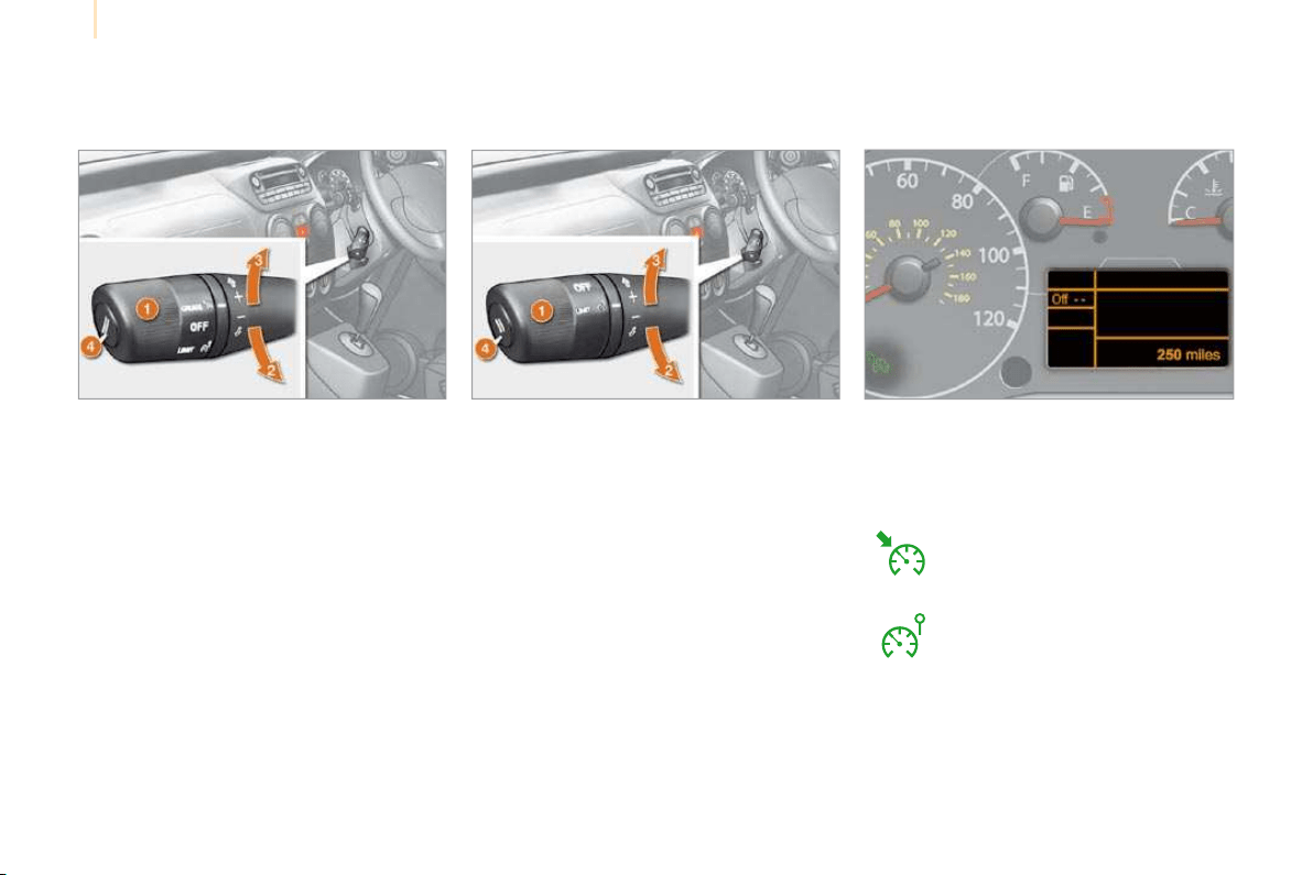
Familiarisation
DRIVE SAFELY
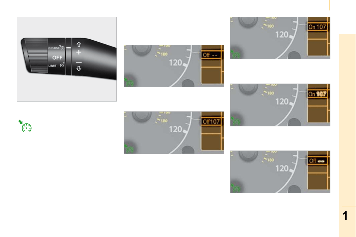
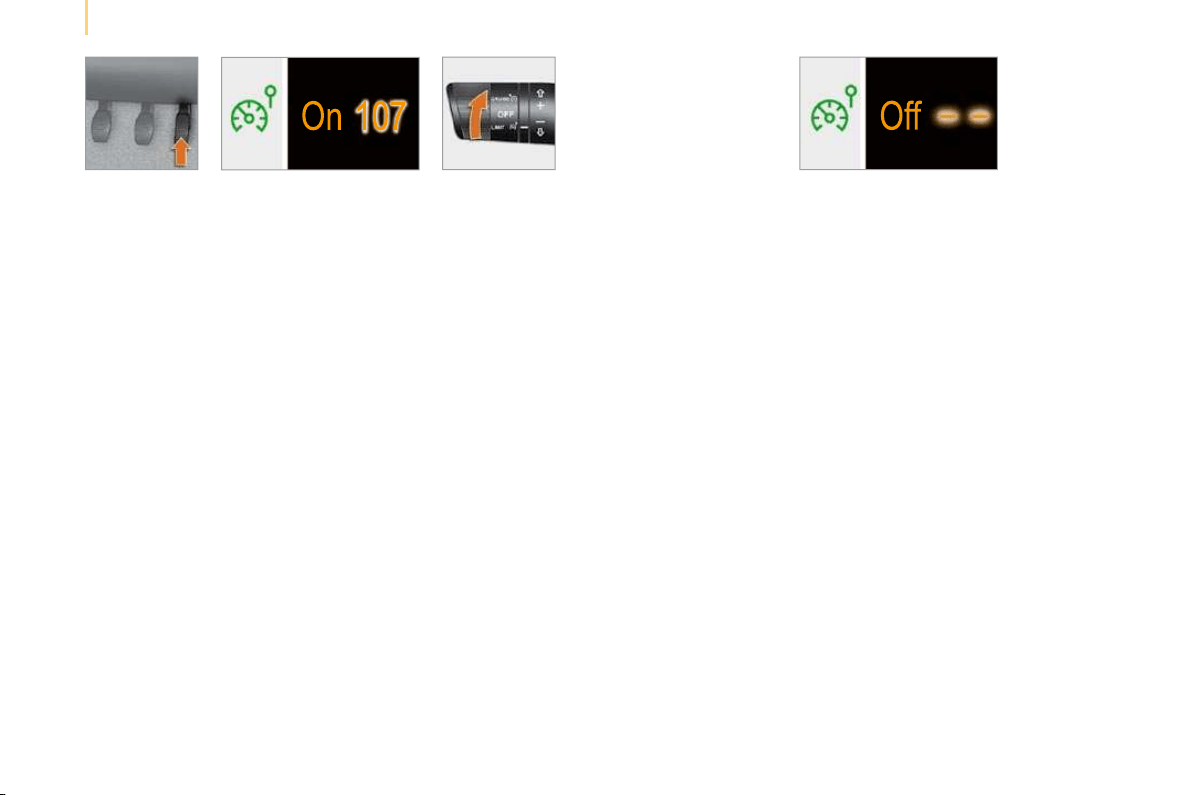
Cruise control "CRUISE"
1. Cruise control mode Selection/Off.
2. Programming of a speed/Decreasing of
the programmed value.
3. Programming of a speed/Increasing of the
programmed value.
4. Cruise control Off/Resume.
In order to be programmed or activated, the
vehicle speed must be higher than 25 mph
(40 km/h), with at least fourth gear engaged on
the manual gearbox (second on the electronic
gearbox system).
41 44
1. Speed limiter mode Selection/Off.
2. Decreasing of the programmed value.
3. Increasing of the programmed value.
4. Speed limiter On/Off.
The values must be set with the engine
running.
Speed limiter "LIMIT"
The cruise control or speed limiter mode
appears on the instrument panel when it is
selected.
Display on the instrument panel
Cruise control
Speed limiter
19
1
READY TO SET OFF
Instruments and controls
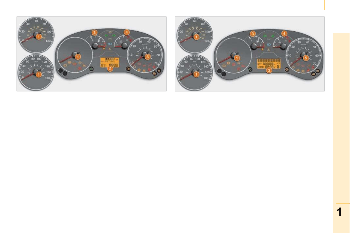
INSTRUMENT PANELS
1. Distance recorder in kilometres/miles.
2. Display.
3. Fuel gauge.
4. Coolant temperature.
5. Rev counter.
Instrument panel with level 1 display
Instrument panel with level 2 display
Instrument panel display level 1
- Time,
- Kilometres/Miles travelled,
- Trip computer/range, consumption,
average speed,
- Headlamp height,
- Programmable overspeed warning,
- Arming or disarming of the passenger air
bag.
Instrument panel display level 2
- Time,
- Date,
- Radio,
- Kilometres/Miles travelled,
- Exterior temperature,
- Modes and gears engaged on the piloted
manual gearbox,
- Trip computer/range, consumption,
average speed
- Headlamp height,
- Programmable overspeed warning,
- Selection of the display language,
- Arming or disarming of the passenger air bag,
- Activation or deactivation of the automatic
locking of the doors while driving.
20
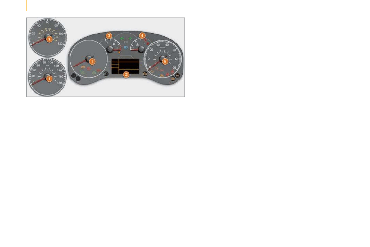
Instruments and controls
Instrument panel with level 3 display
Instrument panel display level 3
- Cruise control/Speed limiter,
- Time,
- Date,
- Radio,
- Kilometres/Miles travelled,
- Exterior temperature,
- Modes and gears engaged on the piloted
manual gearbox,
- Trip computer/range, consumption,
average speed,
- Headlamp height,
- Programmable overspeed warning,
- Selection of the display language,
- Arming or disarming of the passenger air
bag,
- Activation or deactivation of the
automatic locking of the doors while
driving.

21
1
READY TO SET OFF
Instruments and controls
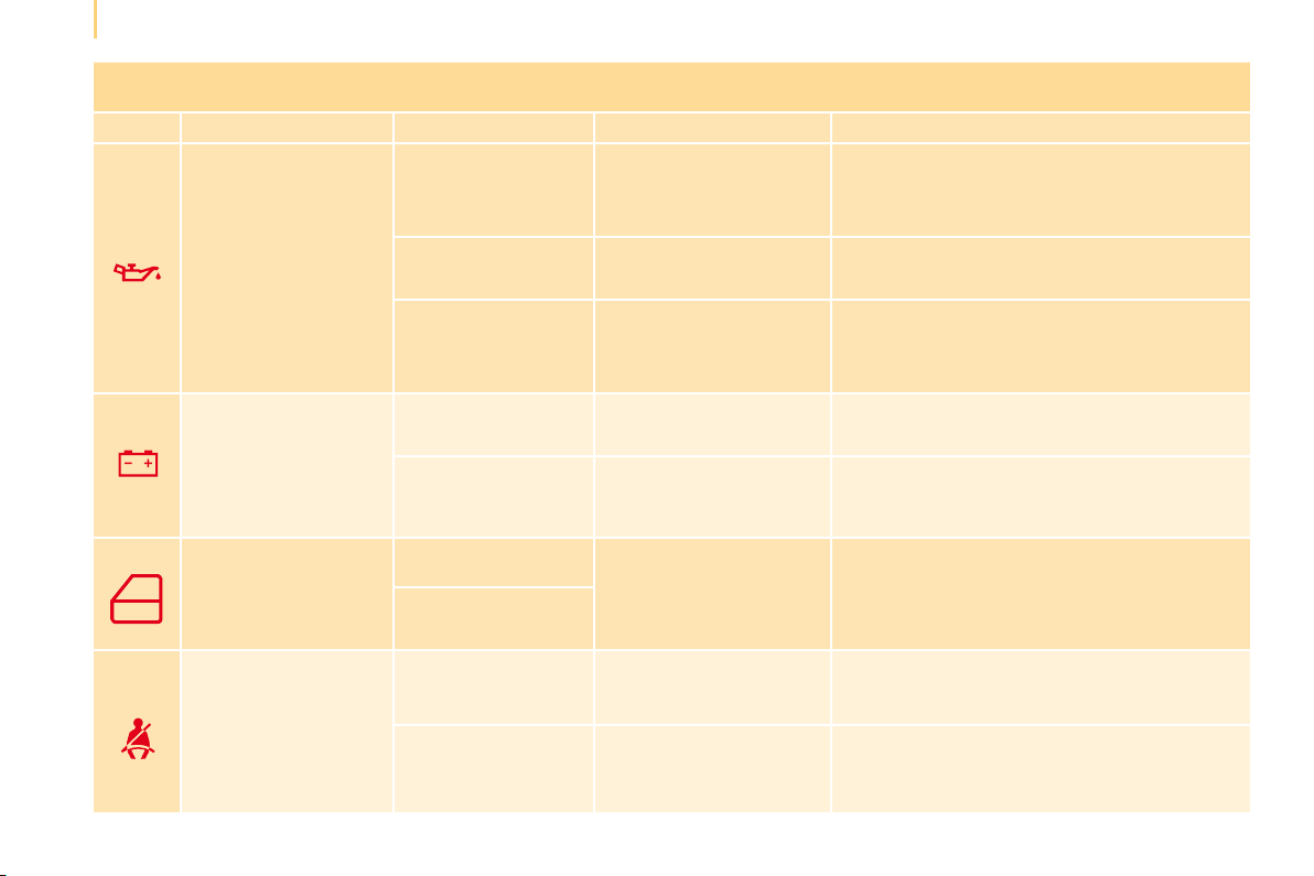
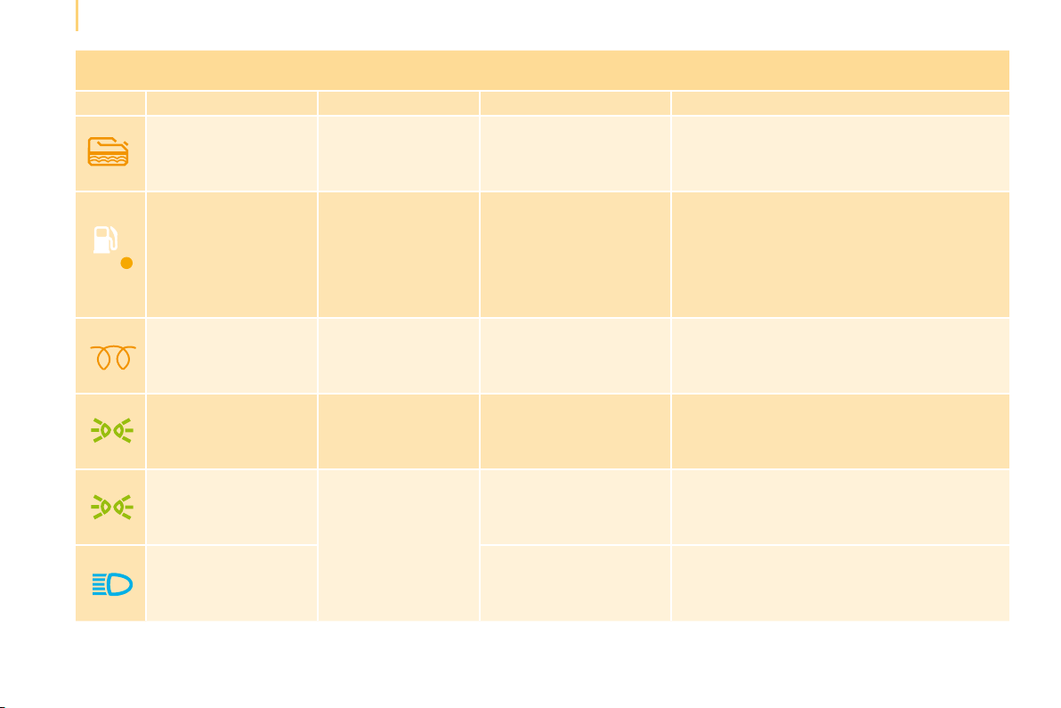
WARNING LAMPS
Each time the engine is started: a series of warning lamps comes on applying a self-checking test. They switch off almost immediately.
When the engine is running: the warning lamp becomes a warning sign if it remains on continuously or flashes. This initial warning may be
accompanied by an audible signal and a message on the display. "Do not ignore these warnings".
Warning lamp
is indicates Solution - action
Service
on temporarily. minor faults. Consult a CITROËN dealer.
continuously on,
accompanied by a
message on the display.
major faults.
Make a note of the warning message and contact
a CITROËN dealer.
Handbrake
Brake fluid level
on.
that the handbrake is applied or
has not been released correctly.
Releasing the handbrake switches off the
warning lamp.
on.
that the fluid level is too
low.
Top up with a fluid recommended by a CITROËN
dealer.
continuously on, even
though the level is
correct.
Stop immediately, park, switch off the
ignition and contact a CITROËN dealer.
Low engine oil level
on.
that the level of oil in the
engine is too low.
Check the engine oil level and contact a
CITROËN dealer.
continuously on, even
though the level is
correct.
Stop immediately, park, switch off the
ignition and contact a CITROËN dealer.
Coolant temperature
on with the needle in
the red zone.
an abnormal increase.
Park and switch off the ignition, allow the circuit
to cool. Visually check the level.
on H in the red zone.
an abnormal increase in
the coolant temperature.
Refer to the "Levels" section of chapter 7.
Consult a CITROËN dealer.
22
Instruments and controls
Warning lamp
is indicates Solution - action
Engine oil pressure
on while driving.
that the pressure is too
low.
Park and switch off the ignition, allow the
lubrication circuit to cool in order to check its
level. Refer to the "Levels" section of chapter 7.
continuously on, even
though the level is correct.
a major fault. Contact a CITROËN dealer.
flashing, for a few
seconds, with a
message on the
display.
that a service will soon
be due.
Refer to the list of checks in the Maintenance
and Warranty Guide then carry out the
CITROËN service.
Battery charge
on.
a fault in the charging
circuit.
Check the battery terminals… Refer to the
"Battery" section of chapter 7.
continuously on, in
spite of the checks.
a circuit fault, an ignition
or injection malfunction.
Contact a CITROËN dealer.
Door open detection
on.
that a door is not closed
correctly.
Check that the front, rear and side doors are
closed.
accompanied by a
message on the display.
Seat belt not fastened
on then flashes.
that the driver has not
fastened his seat belt.
Pull the strap then insert the tongue in the
buckle.
accompanied by an
audible signal then
remains on.
that the vehicle is moving
with the driver’s seat belt
unfastened.
Check that the seat belt is fastened correctly
by pulling the strap. Refer to the "Seat belts"
section of chapter 5.
23
1
READY TO SET OFF
Instruments and controls
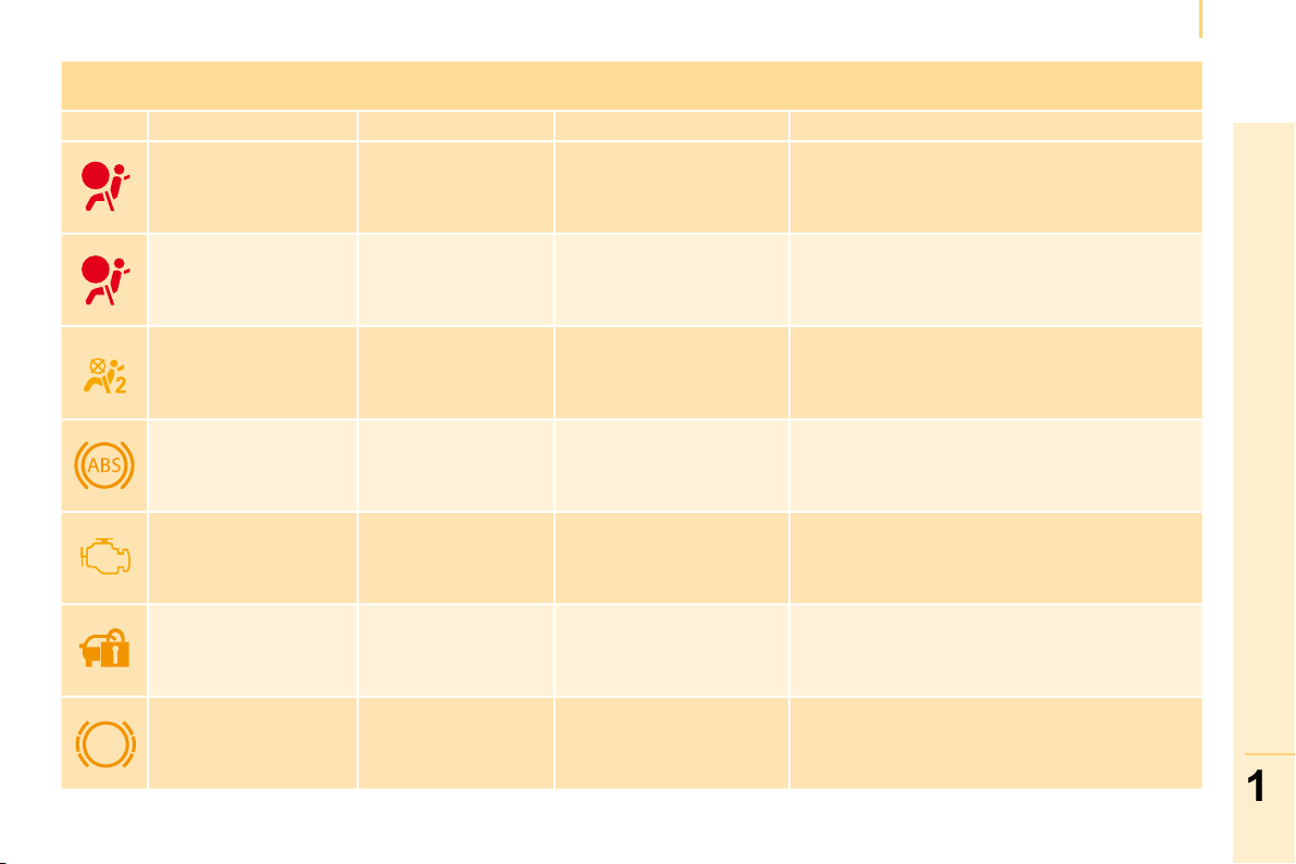
Warning lamp
is indicates Solution - action
Front air bag
flashing or
continuously on.
the failure of an air bag.
Have the system checked by a CITROËN dealer
without delay. Refer to the "Air bags" section of
chapter 5.
Side air bag
flashing or
continuously on.
the failure of an air bag.
Have the system checked by a CITROËN dealer
without delay. Refer to the "Air bags" section of
chapter 5.
Disarming of the
passenger’s front air
bag
on.
that this air bag has been
disarmed intentionally in
the presence of a rear
facing child seat.
Configure via the trip computer MENU menu.
Refer to the "Menu" section of chapter 3.
ABS continuously on. failure of the system.
The vehicle retains conventional braking without
assistance. However, you are advised to stop
and contact a CITROËN dealer.
Emission control
system
flashing or
continuously on.
failure of the system.
Have the system checked by a CITROËN dealer
without delay.
Electronic immobiliser on.
the ignition key inserted is
not recognised.
The vehicle cannot be
started.
Use another key and have the faulty key
checked by a CITROËN dealer. Refer to the
"Access" section of chapter 1.
Front brake pads on. brake pad wear. Have the pads replaced by a CITROËN dealer.
24
Instruments and controls
Warning lamp
is indicates Solution - action
Water in diesel filter
on, accompanied by
a message on the
display.
that there is water in the
diesel fuel filter.
Have the filter bled by a CITROËN dealer. Refer
to the "Checks" section of chapter 7.
Low fuel level
on with the gauge
needle in zone E.
that the fuel reserve is
being used.
Fill up with fuel without delay. The evaluation
of the fuel reserve is a parameter which is
sensitive to the style of driving, the profile of the
road, the time elapsed and the distance travelled
since the warning lamp first came on.
Diesel pre-heating on.
that the weather
conditions impose
pre-heating.
Wait for the warning lamp to switch off before
operating the starter.
Side lamps on. manual selection.
Turn the ring on the lights stalk to the first
position.
Dipped headlamps
on.
manual selection.
Turn the ring on the lights stalk to the second
position.
Main beam headlamps
pulling of the stalk towards
you.
Pull the lights stalk to return to dipped
headlamps.

25
1
READY TO SET OFF
Instruments and controls
Warning lamp
is indicates Solution - action
Direction indicators flashing with buzzer.
a change of direction
using the lights stalk, to
the left of the steering
wheel.
To the Right: press the stalk upwards.
To the Left: press the stalk downwards.
Front fog lamps on.
that the button on the
fascia panel has been
pressed.
Manual selection.
The fog lamps only operate if the side lamps or
dipped headlamps are on.
Rear fog lamps on.
that the button on the
fascia panel has been
pressed.
Manual selection. The fog lamps only operate if
the dipped headlamps are on. When visibility is
normal, please switch the fog lamps off to avoid
breaking the law. This light is a dazzling red.
Faulty bulb
on, accompanied by
a message on the
display.
that one or more bulbs
have blown.
Have the bulb changed.
Refer to the "Changing a bulb" section of
chapter 7 or consult a CITROËN dealer.
Cruise control on.
that the cruise control has
been selected.
Manual selection. Refer to the "Steering wheel
controls" section of chapter 1.
Speed limiter on.
that the speed limiter has
been selected.
Manual selection. Refer to the "Steering wheel
controls" section of chapter 1.

26
Instruments and controls
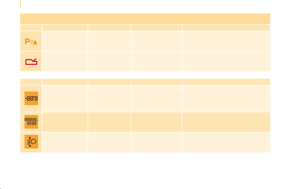
Warning lamp
is indicates Solution - action
Rear parking
assistance
on. failure of the system.
The audible assistance is no longer active.
Have the system checked by a CITROËN
dealer without delay.
Electronic gearbox
system
on, accompanied
by the flashing of
"AUTO".
failure of the gearbox.
Have the system checked by a CITROËN
dealer without delay.
Display displays indicates Solution - action
Exterior temperature
the temperature which
flashes accompanied
by a message on the
display.
weather conditions
which could result in the
presence of ice on the
road.
Be especially vigilant and do not brake
sharply. Refer to the "Driving safety" section of
chapter 5.
Date
11:00:00
a setting:
of the Date.
of the Time.
a configuration via the
MENU menu.
Refer to the "Menu" section of chapter 3.
Headlamp beam height
a headlamp height
setting.
a position from 0 to 3
depending on the load
carried.
Adjust using the control on the fascia panel.
Refer to the "Steering wheel controls" section
of chapter 1.
26
Instruments and controls
Warning lamp
is indicates Solution - action
Rear parking
assistance
on. failure of the system.
The audible assistance is no longer active.
Have the system checked by a CITROËN
dealer without delay.
Electronic gearbox
system
on, accompanied
by the flashing of
"AUTO".
failure of the gearbox.
Have the system checked by a CITROËN
dealer without delay.
Display displays indicates Solution - action
Exterior temperature
the temperature which
flashes accompanied
by a message on the
display.
weather conditions
which could result in the
presence of ice on the
road.
Be especially vigilant and do not brake
sharply. Refer to the "Driving safety" section of
chapter 5.
Date
11:00:00
a setting:
of the Date.
of the Time.
a configuration via the
MENU menu.
Refer to the "Menu" section of chapter 3.
Headlamp beam height
a headlamp height
setting.
a position from 0 to 3
depending on the load
carried.
Adjust using the control on the fascia panel.
Refer to the "Steering wheel controls" section
of chapter 1.
27
1
READY TO SET OFF
Instruments and controls
FUEL GAUGE
The fuel level is tested each time the key is
turned to the "running" position.
The gauge is positioned on:
- F (Full): the capacity of the fuel tank is
approximately 45 litres .
- E (Empty): the reserve is now being
used, the warning light comes on
continuously.
The reserve when the warning first comes
on is approximately 6 litres.
COOLANT TEMPERATURE
The needle is positioned between C
(Cold) and H (Hot): normal operation.
In arduous conditions of use or hot climatic
conditions, the needle may move close to
the red graduations.
- wait approximately 15 minutes to allow
the engine to cool down in order to check
the level and top it up if necessary. The
cooling system is pressurised. In order to
avoid any risk of scalding, unscrew the
cap by two turns to allow the pressure to
drop.
When the pressure has dropped, check the
level and remove the cap to top up.
If the needle remains in the red zone,
contact a CITROËN dealer.
EOBD (European On Board Diagnosis) is
a diagnostics system which complies with,
among others, the standards concerning
authorised emissions of:
- CO (carbon monoxide),
- HC (unburnt hydrocarbons),
- NOx (nitrogen oxides) or particles
detected by oxygen sensors placed
upstream and downstream of the catalytic
converters.
Refer to the "Levels" section of
chapter 7.
Refer to the "Levels" section of
chapter 7.
Therefore, the driver is warned of
any malfunction of this emission
control system by the flashing of
this specific warning light on the
instrument panel.
What you should do if the needle
enters the red zone, or if the warning
light comes on:
- stop immediately, switch off the ignition.
The fan may continue to operate for
a certain time up to approximately
10 minutes.
28
Instruments and controls
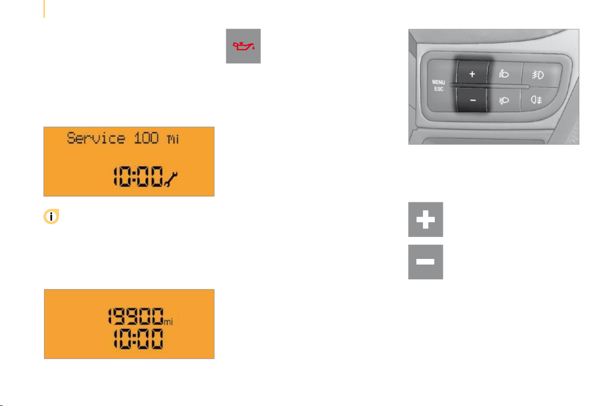
SERVICE INDICATOR
The display on the instrument panel
informs you when the next service is due,
in accordance with the "Manufacturer’s"
servicing schedule indicated in the servicing
booklet. This information is determined in
relation to the distance travelled since the
previous service.
You are warned by flashing of the
engine oil pressure warning light
and the displaying of a message
on the instrument panel each time
the vehicle is started.
In this case, your vehicle must be
serviced as soon as possible.
LIGHTING RHEOSTAT
The rheostat is active when the lights are on.
Refer to the list of checks in the
servicing booklet which was given to
you on delivery of the vehicle.
After a few seconds, the display returns to
its usual functions.
Use the + and - controls to
change the brightness of the
instrument panel lighting.
29
1
READY TO SET OFF
Accesses
Central locking
Folding/unfolding the key
Unlocking of the vehicle
Unlocking the hinged rear doors or
the tailgate
Press this button to release the
key from its housing.
To fold the key, press the button
then fold the key into the housing.
If you do not press the button, the
mechanism may be damaged.
Deadlocking
The deadlocking is deactivated:
- by carrying out the door opening
operation,
- by turning the ignition key to the
RUNNING position.
REMOTE CONTROL
Press this button to unlock the
front doors only (Light van) or all
of the doors (Combi).
Unlocking is confirmed by two
flashes of the direction indicators.
Press this button to unlock the
load space (Light van) or the
hinged rear doors or the tailgate
only (Combi).
Press this button briefly to lock all
of your vehicle’s doors. Locking
is confirmed by a flash of the
direction indicators.
If one of the doors is open or is not closed
correctly, the central locking will not work. In
this case, the failed locking is indicated by
three flashes of the direction indicators.
Press this button twice to change
locking to deadlocking.
Deadlocking renders the exterior
and interior door opening handles
inoperative. Do not leave anyone inside the
vehicle when it is deadlocked. Deadlocking
is confirmed by a flash of the direction
indicators.

30
Accesses
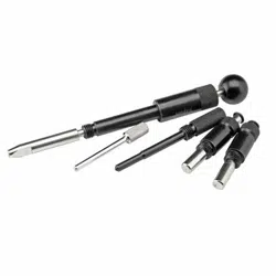
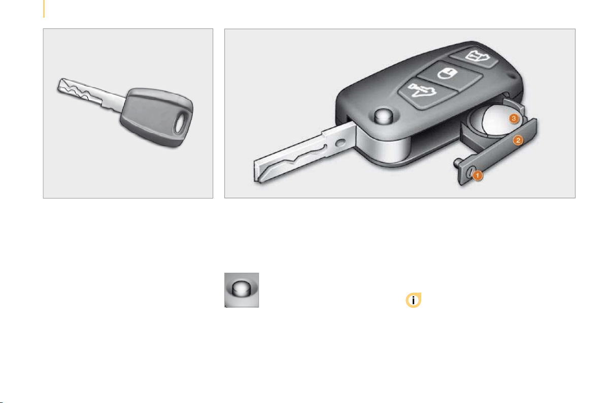
KEY
This locks and unlocks the locks on the
vehicle and starts the engine.
REMOTE CONTROL BATTERY
Reference: CR 2032/3 volts.
- use the screwdriver as a lever to extract
the battery holder housing 2 ,
- remove the housing and change the
battery 3 observing the polarities ,
- put the battery holder housing 2 back
inside the key and secure it by turning the
screw 1 .
Changing the remote control battery
There is a risk of damage if the
replacement battery does not conform.
Only use batteries which are
identical or of an equivalent type to those
recommended by a CITROËN dealer. Take
used batteries to an approved collection
point.
- press the button to eject the
key ,
- turn the screw 1 from the
closed padlock to the open
padlock using a screwdriver
with a thin tip ,

31
1
READY TO SET OFF
Accesses
ELECTRONIC IMMOBILISER
All of the keys contain an electronic
immobiliser device.
This device locks the engine supply system.
It is activated automatically when the key is
removed from the ignition.
After the ignition is switched on, a dialogue
is established between the key and the
electronic immobiliser system.
This warning light is switched off
after the ignition is switched on
and the key has been recognised,
the engine can be started.
If the key is not recognised, the engine
cannot be started. Use another key and
have the faulty key checked by a dealer.
Good practice
Do not make any modifications to the
electronic immobiliser system.
Operating the remote control, even when it
is in your pocket, may result in involuntary
unlocking of the doors.
The simultaneous use of other high
frequency equipment (mobile telephones,
domestic alarms…), may interfere with the
operation of the remote control temporarily.
When purchasing a second-hand vehicle:
- ensure that you are given the confidential
card,
- have the keys memorised by a CITROËN
dealer to ensure that the keys in your
possession are the only ones which can
start the vehicle.
Driving with the doors locked may make
access to the passenger compartment
by the emergency services more diffi cult in an
emergency.
As a safety precaution (with children on
board), remove the key from the ignition when
leaving the vehicle, even for a short time.
ALARM
This provides:
- exterior perimeter protection by means of
detectors on the doors and bonnet and
on the electrical supply,
- interior protection,
- anti-lift protection,
- protection against the unauthorised
insertion of a key in the starter.
The equipment includes a siren.
Activation of the alarm
First ensure that all of the accesses are
closed correctly.
The alarm is activated by pressing
this control, the protection is
active after a few seconds.
While the alarm is monitoring, any
intrusion triggers the siren for approximately
30 seconds, accompanied by lighting of the
direction indicators.
The alarm then returns to monitoring mode.
The alarm is also triggered following an
electrical supply cut-off, when the supply is
restored.

Accesses
Deactivation using the remote control
Deactivation using the key
Unlock the doors using the key and enter
the vehicle. Switch on the ignition to the
RUNNING position, identification of the key
code will switch off the alarm.
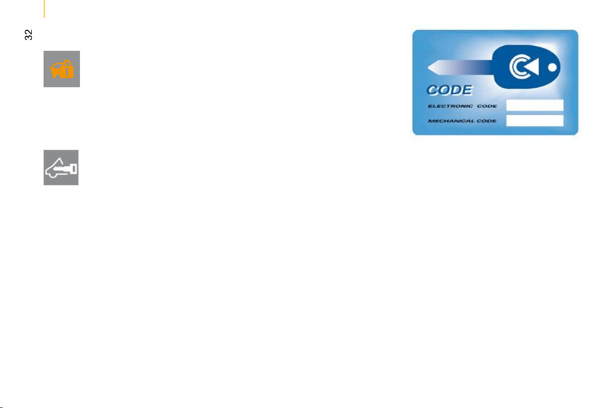
CONFIDENTIAL CARD
This is given to you on delivery of your
vehicle with the duplicate keys.
It contains the identification code necessary
for any work carried out by a dealer on the
electronic immobiliser system. This code is
hidden by a film, which should be removed
only if necessary.
Keep your card in a safe place, never inside
the vehicle.
When undertaking a long trip or journey,
however, it is advisable to take it with you
along with your personal papers.
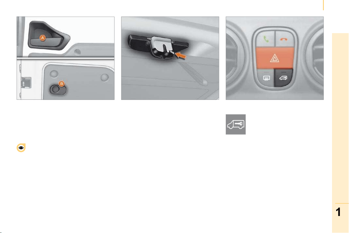
Deactivation of the anti-lift protection
To deactivate the anti-lift protection, press
the button located on the vehicle’s courtesy
light.
Good practice
To quickly deactivate the siren following
unwanted triggering, unlock the vehicle
using the remote control.
To avoid setting the alarm, before washing
the vehicle for example, lock the vehicle
using the key.
When this button is pressed, the
alarm is deactivated when the
vehicle is unlocked.
Signalling of attempted intrusion
When you return to your vehicle,
flashing of the electronic engine
immobiliser warning light or
the appearance of a warning
message on the instrument panel
display indicates an attempted intrusion
during your absence.
30
Accesses
KEY
This locks and unlocks the locks on the
vehicle and starts the engine.
REMOTE CONTROL BATTERY
Reference: CR 2032/3 volts.
- use the screwdriver as a lever to extract
the battery holder housing 2 ,
- remove the housing and change the
battery 3 observing the polarities ,
- put the battery holder housing 2 back
inside the key and secure it by turning the
screw 1 .
Changing the remote control battery
There is a risk of damage if the
replacement battery does not conform.
Only use batteries which are
identical or of an equivalent type to those
recommended by a CITROËN dealer. Take
used batteries to an approved collection
point.
- press the button to eject the
key ,
- turn the screw 1 from the
closed padlock to the open
padlock using a screwdriver
with a thin tip ,

31
1
READY TO SET OFF
Accesses
ELECTRONIC IMMOBILISER
All of the keys contain an electronic
immobiliser device.
This device locks the engine supply system.
It is activated automatically when the key is
removed from the ignition.
After the ignition is switched on, a dialogue
is established between the key and the
electronic immobiliser system.
This warning light is switched off
after the ignition is switched on
and the key has been recognised,
the engine can be started.
If the key is not recognised, the engine
cannot be started. Use another key and
have the faulty key checked by a dealer.
Good practice
Do not make any modifications to the
electronic immobiliser system.
Operating the remote control, even when it
is in your pocket, may result in involuntary
unlocking of the doors.
The simultaneous use of other high
frequency equipment (mobile telephones,
domestic alarms…), may interfere with the
operation of the remote control temporarily.
When purchasing a second-hand vehicle:
- ensure that you are given the confidential
card,
- have the keys memorised by a CITROËN
dealer to ensure that the keys in your
possession are the only ones which can
start the vehicle.
Driving with the doors locked may make
access to the passenger compartment
by the emergency services more diffi cult in an
emergency.
As a safety precaution (with children on
board), remove the key from the ignition when
leaving the vehicle, even for a short time.
ALARM
This provides:
- exterior perimeter protection by means of
detectors on the doors and bonnet and
on the electrical supply,
- interior protection,
- anti-lift protection,
- protection against the unauthorised
insertion of a key in the starter.
The equipment includes a siren.
Activation of the alarm
First ensure that all of the accesses are
closed correctly.
The alarm is activated by pressing
this control, the protection is
active after a few seconds.
While the alarm is monitoring, any
intrusion triggers the siren for approximately
30 seconds, accompanied by lighting of the
direction indicators.
The alarm then returns to monitoring mode.
The alarm is also triggered following an
electrical supply cut-off, when the supply is
restored.

Accesses
Deactivation using the remote control
Deactivation using the key
Unlock the doors using the key and enter
the vehicle. Switch on the ignition to the
RUNNING position, identification of the key
code will switch off the alarm.
CONFIDENTIAL CARD
This is given to you on delivery of your
vehicle with the duplicate keys.
It contains the identification code necessary
for any work carried out by a dealer on the
electronic immobiliser system. This code is
hidden by a film, which should be removed
only if necessary.
Keep your card in a safe place, never inside
the vehicle.
When undertaking a long trip or journey,
however, it is advisable to take it with you
along with your personal papers.
Deactivation of the anti-lift protection
To deactivate the anti-lift protection, press
the button located on the vehicle’s courtesy
light.
Good practice
To quickly deactivate the siren following
unwanted triggering, unlock the vehicle
using the remote control.
To avoid setting the alarm, before washing
the vehicle for example, lock the vehicle
using the key.
When this button is pressed, the
alarm is deactivated when the
vehicle is unlocked.
Signalling of attempted intrusion
When you return to your vehicle,
flashing of the electronic engine
immobiliser warning light or
the appearance of a warning
message on the instrument panel
display indicates an attempted intrusion
during your absence.
31
1
READY TO SET OFF
Accesses
ELECTRONIC IMMOBILISER
All of the keys contain an electronic
immobiliser device.
This device locks the engine supply system.
It is activated automatically when the key is
removed from the ignition.
After the ignition is switched on, a dialogue
is established between the key and the
electronic immobiliser system.
This warning light is switched off
after the ignition is switched on
and the key has been recognised,
the engine can be started.
If the key is not recognised, the engine
cannot be started. Use another key and
have the faulty key checked by a dealer.
Good practice
Do not make any modifications to the
electronic immobiliser system.
Operating the remote control, even when it
is in your pocket, may result in involuntary
unlocking of the doors.
The simultaneous use of other high
frequency equipment (mobile telephones,
domestic alarms…), may interfere with the
operation of the remote control temporarily.
When purchasing a second-hand vehicle:
- ensure that you are given the confidential
card,
- have the keys memorised by a CITROËN
dealer to ensure that the keys in your
possession are the only ones which can
start the vehicle.
Driving with the doors locked may make
access to the passenger compartment
by the emergency services more diffi cult in an
emergency.
As a safety precaution (with children on
board), remove the key from the ignition when
leaving the vehicle, even for a short time.
ALARM
This provides:
- exterior perimeter protection by means of
detectors on the doors and bonnet and
on the electrical supply,
- interior protection,
- anti-lift protection,
- protection against the unauthorised
insertion of a key in the starter.
The equipment includes a siren.
Activation of the alarm
First ensure that all of the accesses are
closed correctly.
The alarm is activated by pressing
this control, the protection is
active after a few seconds.
While the alarm is monitoring, any
intrusion triggers the siren for approximately
30 seconds, accompanied by lighting of the
direction indicators.
The alarm then returns to monitoring mode.
The alarm is also triggered following an
electrical supply cut-off, when the supply is
restored.
Accesses
Deactivation using the remote control
Deactivation using the key
Unlock the doors using the key and enter
the vehicle. Switch on the ignition to the
RUNNING position, identification of the key
code will switch off the alarm.
CONFIDENTIAL CARD
This is given to you on delivery of your
vehicle with the duplicate keys.
It contains the identification code necessary
for any work carried out by a dealer on the
electronic immobiliser system. This code is
hidden by a film, which should be removed
only if necessary.
Keep your card in a safe place, never inside
the vehicle.
When undertaking a long trip or journey,
however, it is advisable to take it with you
along with your personal papers.
Deactivation of the anti-lift protection
To deactivate the anti-lift protection, press
the button located on the vehicle’s courtesy
light.
Good practice
To quickly deactivate the siren following
unwanted triggering, unlock the vehicle
using the remote control.
To avoid setting the alarm, before washing
the vehicle for example, lock the vehicle
using the key.
When this button is pressed, the
alarm is deactivated when the
vehicle is unlocked.
Signalling of attempted intrusion
When you return to your vehicle,
flashing of the electronic engine
immobiliser warning light or
the appearance of a warning
message on the instrument panel
display indicates an attempted intrusion
during your absence.

33
1
READY TO SET OFF
Accesses
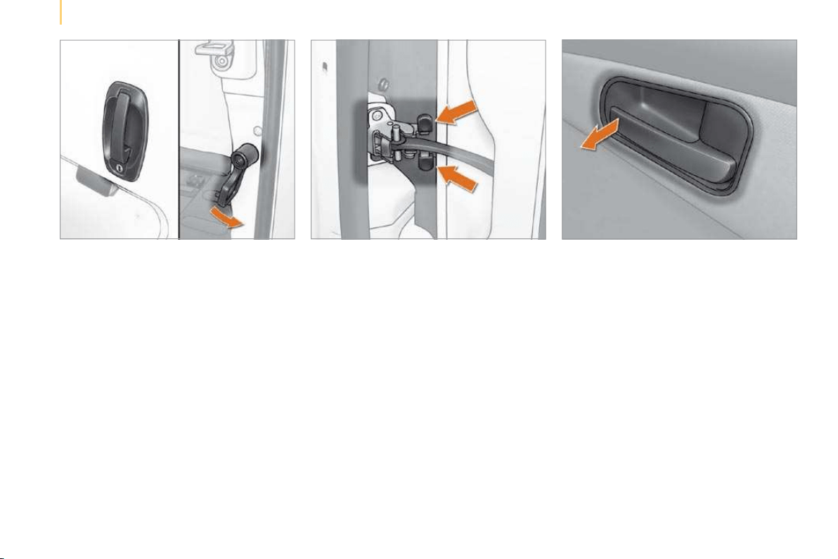
OPENING FROM THE OUTSIDE
Driver’s door
Use the remote control to unlock from the
outside.
Pull the handle towards you.
If the remote control does not work, insert
the metal part of the key in the lock on the
driver’s side.
Sliding side door
Pull the handle towards you then towards
the rear.
Slide the door fully to pass the point of
resistance (Light van) or to trigger the
device which retains the door in the open
position (Combi).
When the fuel filler flap is open,
a safety system checks the sliding of
the side door.
If your vehicle is parked on a slope, guide
the side door as it slides. The door could
open or close more quickly due to the incline
of the ground, risking injury.
As a safety precaution and to guarantee
correct operation, do not drive with the
sliding side door open.
Tailgate (Combi)
After unlocking the vehicle using the remote
control or the key, pull the central handle
and lift the tailgate.

34
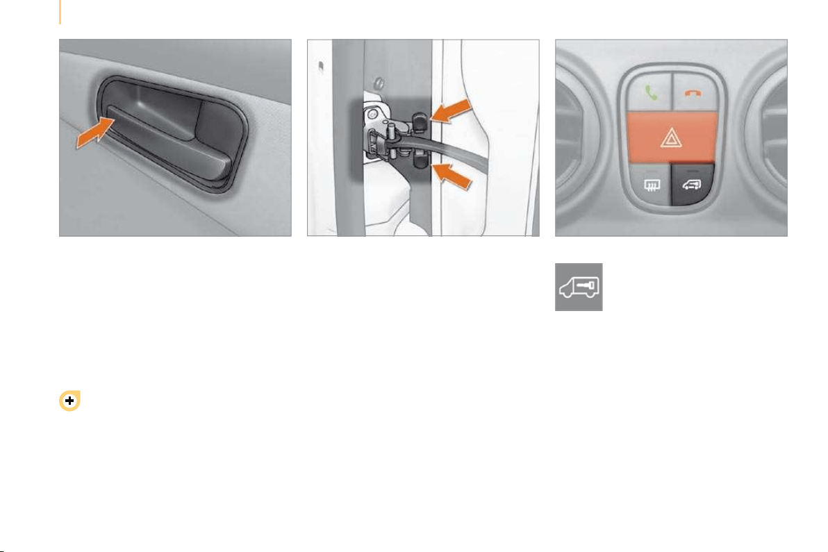
Accesses
OPENING FROM THE INSIDE
Driver’s door
Pull the interior handle to unlock.
Active locking : when the vehicle
speed approaches 12 mph (20 km/h),
a characteristic locking noise indicates that
your vehicle has been locked automatically.
This "AUTOCLOSE" function is activated or
deactivated via the "MENU".
This function is deactivated when the vehicle
is delivered.
Opening to 180°
Press the catch while opening the door.
Hinged rear doors
The 60/40 type asymmetrical hinged rear
doors have four closing points, including a
central closing point.
Pull the handle towards you.
Start by opening the large hinged door, then
unlock by pulling the lever to release and
open the small hinged door.
The two hinged doors open to 90°.
Driving with the small hinged door open is
permitted to make the transportation of long
loads easier. Observe the customary safety
indications, to attract the attention of other
drivers.

35
1
READY TO SET OFF
Accesses
Good practice
When opening, take care not to obstruct the
guide space on the floor to allow the door to
slide correctly.
Do not block traffic.
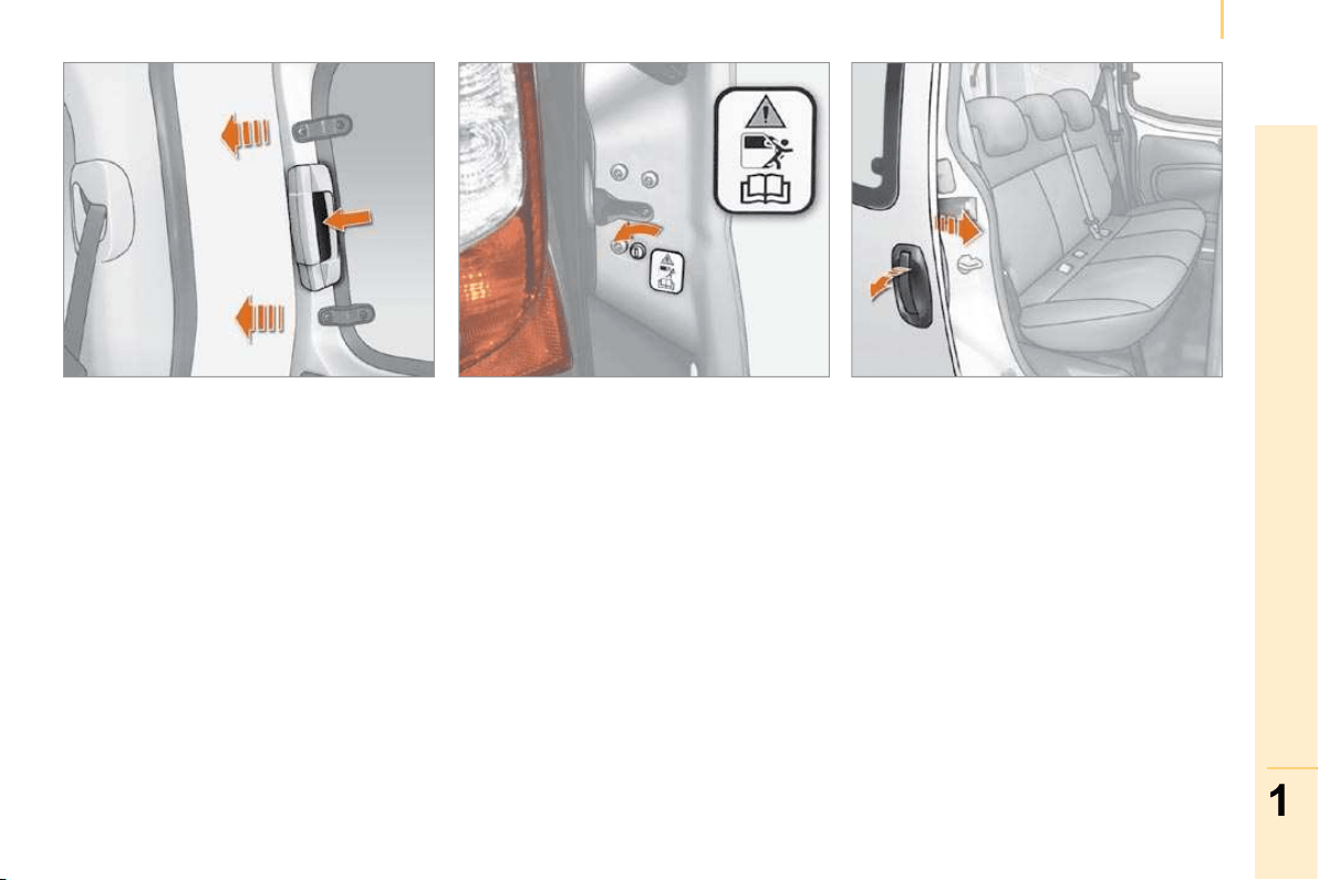
Load space
Sliding side door
Pull the handle A towards the rear, slide
the door fully to pass the point of resistance
(Light van) or to trigger the device which
retains the door in the open position
(Combi).
Hinged rear doors
To open, slide the control B to the right.
If your vehicle is parked on a slope,
guide the side door as it slides. The
door could open or close more quickly due
to the incline of the ground, risking injury.
As a safety precaution and to guarantee
correct operation, do not drive with the
sliding side door open.
Press once to unlock the sliding
side doors and the rear doors
(Light van) from the driving
position.
Tailgate (Combi)
In the event of a battery or central locking
malfunction, the opening of the tailgate can
be released mechanically from inside the
boot.
Open the sliding side door and fold the rear
seats fully.
From inside the boot, press the lever to
release the tailgate.
36
Accesses
CLOSING FROM INSIDE
Central locking
Push the interior handle to lock the entire
vehicle or the door concerned. However,
if one of the doors is open or is not closed
correctly, the central locking does not work.
Always remove the key from the
ignition when leaving the vehicle, even
for a short time.
Closing from 180°
The check strap will re-attach automatically
when the hinged doors are closed, the small
door being closed first.
Load space
Press to lock the sliding side
doors and the rear doors (Light
van) from the driving position.
Protection against attack
When the vehicle is started, the system
locks the driving position and load space
doors automatically when you reach
approximately 12 mph (20 km/h).
This "AUTOCLOSE" function is activated or
deactivated via the "MENU".
If none of the doors are opened during the
journey, the locking remains active.
This function is deactivated when the vehicle
is delivered.
37
1
READY TO SET OFF
Accesses
Sliding side door (Combi)
Press the control to release the door and
pull the handle towards you to close the
door.
Child safety
This prevents either of the rear doors being
opened from inside.
Turn the switch on each rear door a
quarter of a turn using the ignition key.
CLOSING FROM THE OUTSIDE
Sliding side door
Pull the handle towards you then towards
the front to pass the point of resistance
(Light van) or to release the door retaining
device (Combi).
Slide the door fully until it is closed.
Hinged rear doors
Start by closing the small hinged door, this is
secured automatically when closed.
Close the large door using its handle.
Tailgate (Combi)
Lower the tailgate using the interior grab
handle.
33
1
READY TO SET OFF
Accesses
OPENING FROM THE OUTSIDE
Driver’s door
Use the remote control to unlock from the
outside.
Pull the handle towards you.
If the remote control does not work, insert
the metal part of the key in the lock on the
driver’s side.
Sliding side door
Pull the handle towards you then towards
the rear.
Slide the door fully to pass the point of
resistance (Light van) or to trigger the
device which retains the door in the open
position (Combi).
When the fuel filler flap is open,
a safety system checks the sliding of
the side door.
If your vehicle is parked on a slope, guide
the side door as it slides. The door could
open or close more quickly due to the incline
of the ground, risking injury.
As a safety precaution and to guarantee
correct operation, do not drive with the
sliding side door open.
Tailgate (Combi)
After unlocking the vehicle using the remote
control or the key, pull the central handle
and lift the tailgate.
34
Accesses
OPENING FROM THE INSIDE
Driver’s door
Pull the interior handle to unlock.
Active locking : when the vehicle
speed approaches 12 mph (20 km/h),
a characteristic locking noise indicates that
your vehicle has been locked automatically.
This "AUTOCLOSE" function is activated or
deactivated via the "MENU".
This function is deactivated when the vehicle
is delivered.
Opening to 180°
Press the catch while opening the door.
Hinged rear doors
The 60/40 type asymmetrical hinged rear
doors have four closing points, including a
central closing point.
Pull the handle towards you.
Start by opening the large hinged door, then
unlock by pulling the lever to release and
open the small hinged door.
The two hinged doors open to 90°.
Driving with the small hinged door open is
permitted to make the transportation of long
loads easier. Observe the customary safety
indications, to attract the attention of other
drivers.
35
1
READY TO SET OFF
Accesses
Good practice
When opening, take care not to obstruct the
guide space on the floor to allow the door to
slide correctly.
Do not block traffic.
Load space
Sliding side door
Pull the handle A towards the rear, slide
the door fully to pass the point of resistance
(Light van) or to trigger the device which
retains the door in the open position
(Combi).
Hinged rear doors
To open, slide the control B to the right.
If your vehicle is parked on a slope,
guide the side door as it slides. The
door could open or close more quickly due
to the incline of the ground, risking injury.
As a safety precaution and to guarantee
correct operation, do not drive with the
sliding side door open.
Press once to unlock the sliding
side doors and the rear doors
(Light van) from the driving
position.
Tailgate (Combi)
In the event of a battery or central locking
malfunction, the opening of the tailgate can
be released mechanically from inside the
boot.
Open the sliding side door and fold the rear
seats fully.
From inside the boot, press the lever to
release the tailgate.

36
Accesses
CLOSING FROM INSIDE
Central locking
Push the interior handle to lock the entire
vehicle or the door concerned. However,
if one of the doors is open or is not closed
correctly, the central locking does not work.
Always remove the key from the
ignition when leaving the vehicle, even
for a short time.
Closing from 180°
The check strap will re-attach automatically
when the hinged doors are closed, the small
door being closed first.
Load space
Press to lock the sliding side
doors and the rear doors (Light
van) from the driving position.
Protection against attack
When the vehicle is started, the system
locks the driving position and load space
doors automatically when you reach
approximately 12 mph (20 km/h).
This "AUTOCLOSE" function is activated or
deactivated via the "MENU".
If none of the doors are opened during the
journey, the locking remains active.
This function is deactivated when the vehicle
is delivered.

37
1
READY TO SET OFF
Accesses
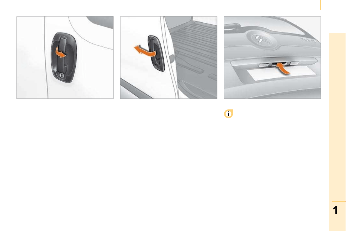
Sliding side door (Combi)
Press the control to release the door and
pull the handle towards you to close the
door.
Child safety
This prevents either of the rear doors being
opened from inside.
Turn the switch on each rear door a
quarter of a turn using the ignition key.
CLOSING FROM THE OUTSIDE
Sliding side door
Pull the handle towards you then towards
the front to pass the point of resistance
(Light van) or to release the door retaining
device (Combi).
Slide the door fully until it is closed.
Hinged rear doors
Start by closing the small hinged door, this is
secured automatically when closed.
Close the large door using its handle.
Tailgate (Combi)
Lower the tailgate using the interior grab
handle.

37
1
READY TO SET OFF
Accesses
Sliding side door (Combi)
Press the control to release the door and
pull the handle towards you to close the
door.
Child safety
This prevents either of the rear doors being
opened from inside.
Turn the switch on each rear door a
quarter of a turn using the ignition key.
CLOSING FROM THE OUTSIDE
Sliding side door
Pull the handle towards you then towards
the front to pass the point of resistance
(Light van) or to release the door retaining
device (Combi).
Slide the door fully until it is closed.
Hinged rear doors
Start by closing the small hinged door, this is
secured automatically when closed.
Close the large door using its handle.
Tailgate (Combi)
Lower the tailgate using the interior grab
handle.
38
Steering wheel controls
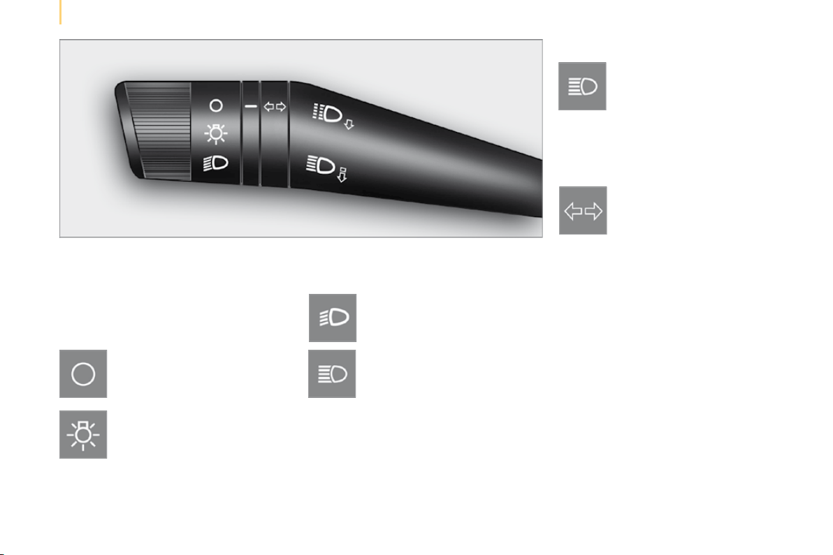
LIGHTING STALK
Selection is by rotation of the white mark
on the ring, when the ignition key is in the
RUNNING position.
All lamps off
Sidelamps on
This is indicated on the instrument
panel by lighting of the warning lamp.
Dipped headlamps/main beam
headlamps on
Dipped headlamps/main beam
headlamps change
Pull the lighting stalk fully towards you.
Headlamp fl ash
Direction indicators
"Motorway" function
System which indicates a change of lane on
high-speed roads.
Press the lighting stalk up or down once,
without passing the point of resistance; the
corresponding direction indicators will flash
three times.
Pull the lighting stalk towards you
gently, regardless of the position
of the ring.
Left: push downwards. The green
direction arrow warning lamp
flashes on the instrument panel.
Right: push upwards. The green
direction arrow warning lamp flashes on the
instrument panel.
Turn the ring into position.
39
1
READY TO SET OFF
Steering wheel controls
Headlamp beam
You are advised to adjust the height of the
headlamp beams in accordance with the
load in your vehicle.
This function can only be accessed in
the main beam headlamps and dipped
headlamps position.
Press these controls, located
on the fascia panel, several
times in succession to adjust the
headlamps.
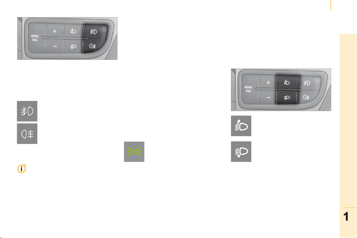
Fog lamps
The controls are located on the fascia panel
control pad.
Front and rear fog lamps
The fog lamps should only be used in
fog or when snow is falling.
In clear weather or in rain, both day and
night, lit rear fog lamps dazzle and are
prohibited.
Do not forget to switch them off when they
are no longer necessary.
Guide-me-home lighting
The temporary maintaining of the dipped
headlamps, after switching off the vehicle’s
ignition, makes the driver’s exit easier when
the light is poor and lights the space in front
of the vehicle.
Activation
With the ignition key in the STOP position
or removed, pull the lighting stalk towards
the steering wheel within 2 minutes after
switching off the engine.
Each time the control is operated,
the duration for which the lamps will
remain on is extended by 30 seconds,
up to a maximum of 210 seconds. Once this
period of time has elapsed, the lamps switch
off automatically.
Deactivation
Pull the lighting stalk towards the steering
wheel for more than 2 seconds.
The front fog lamps operate with
the side lights and the dipped
headlamps.
The rear fog lamps operate with
the dipped headlamps.
Press one of these controls to switch on the
lights.
The warning lamp comes on,
accompanied by a message
on the display, the first time
the control is operated and
remains on until the function is deactivated
automatically.
An indicator light on the display
indicates the adjustment position
selected (0, 1, 2, 3).

39
1
READY TO SET OFF
Steering wheel controls
Headlamp beam
You are advised to adjust the height of the
headlamp beams in accordance with the
load in your vehicle.
This function can only be accessed in
the main beam headlamps and dipped
headlamps position.
Press these controls, located
on the fascia panel, several
times in succession to adjust the
headlamps.
Fog lamps
The controls are located on the fascia panel
control pad.
Front and rear fog lamps
The fog lamps should only be used in
fog or when snow is falling.
In clear weather or in rain, both day and
night, lit rear fog lamps dazzle and are
prohibited.
Do not forget to switch them off when they
are no longer necessary.
Guide-me-home lighting
The temporary maintaining of the dipped
headlamps, after switching off the vehicle’s
ignition, makes the driver’s exit easier when
the light is poor and lights the space in front
of the vehicle.
Activation
With the ignition key in the STOP position
or removed, pull the lighting stalk towards
the steering wheel within 2 minutes after
switching off the engine.
Each time the control is operated,
the duration for which the lamps will
remain on is extended by 30 seconds,
up to a maximum of 210 seconds. Once this
period of time has elapsed, the lamps switch
off automatically.
Deactivation
Pull the lighting stalk towards the steering
wheel for more than 2 seconds.
The front fog lamps operate with
the side lights and the dipped
headlamps.
The rear fog lamps operate with
the dipped headlamps.
Press one of these controls to switch on the
lights.
The warning lamp comes on,
accompanied by a message
on the display, the first time
the control is operated and
remains on until the function is deactivated
automatically.
An indicator light on the display
indicates the adjustment position
selected (0, 1, 2, 3).
40
Steering wheel controls
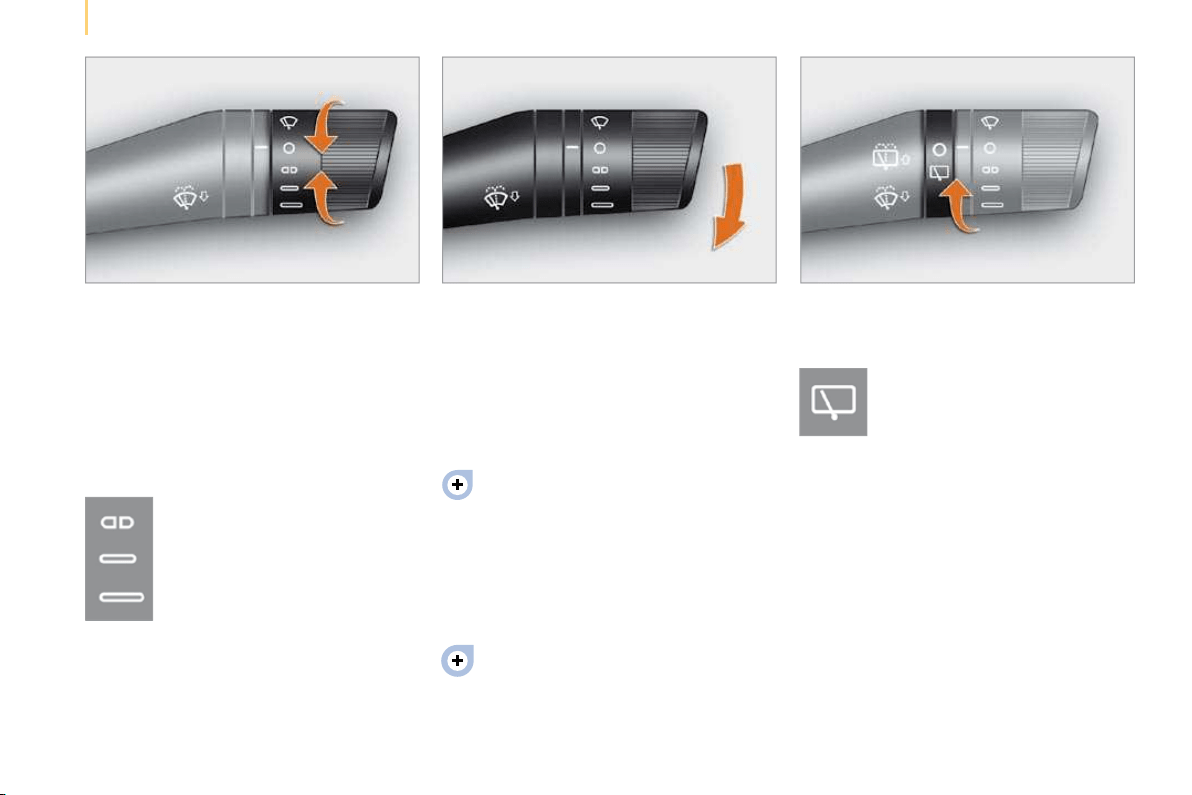
WIPERS STALK
Windscreen wipers
Wiping is only active when the ignition key is
in the RUNNING position.
The stalk may have four different positions.
Three speeds can be selected by turning the
ring.
To change the blades, refer to the
"Changing a wiper blade" section of
chapter 7.
Good practice
Check that the windscreen wiper blades can
operate freely when using the wipers in icy
weather.
Intermittent.
Slow continuous.
Fast continuous.
Single wipe: by pushing up.
Windscreen wash
Push the stalk down, the windscreen wash
alone is activated.
Hold the stalk down, the windscreen wash
is accompanied by a timed sweep of the
wipers.
To top up the levels, refer to the
"Levels" section of chapter 7.
Rear wiper
This is positioned on the window
of the large rear door.
Turn the ring.
Rear screen wash
The rear screen wash is incorporated next to
the third brake light.
Push the stalk up, the rear screen wash
alone is activated.
Hold the stalk up, the rear screen wash is
accompanied by a timed sweep of the wiper.
41
1
READY TO SET OFF
Steering wheel controls
Function selected,
displaying of the "Cruise Control" indicator
light.
Function deactivated,
OFF (example at 107 km/h).
Function activated
(example at 107 km/h).
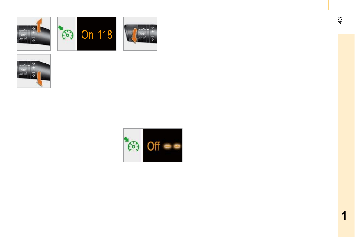
Vehicle speed above (e.g. 118 km/h),
the programmed speed is displayed flashing.
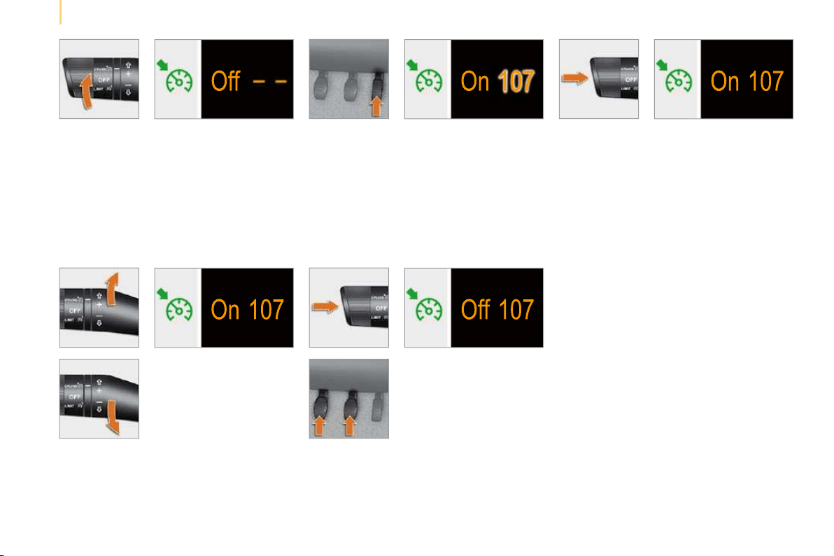
This cruise control shows the function
selection status on the instrument panel and
displays the programmed speed:
CRUISE CONTROL "CRUISE"
"This is the speed at which the
driver wishes to drive".
This aid to driving in free-flowing
traffic enables the vehicle to maintain the
speed programmed by the driver, unless a
steep gradient makes this impossible.
In order for it to be programmed or
activated, the vehicle speed must be greater
than 25 mph (40 km/h) with at least 4th gear
engaged on the manual gearbox (second on
the piloted manual gearbox).
Operating fault detected,
OFF - the dashes flash.
42
Steering wheel controls
Selecting the function
- Place the ring in the CRUISE position.
The cruise control is selected but is
not yet active and no speed has been
programmed.
Temporary exceeding of the speed
It is possible to accelerate and drive
momentarily at a speed greater than the
programmed speed. The value programmed
flashes.
When the accelerator pedal is released, the
vehicle will return to the programmed speed.
Reactivation
- Following deactivation of the cruise
control, press this button.
Your vehicle will return to the last
programmed speed.
Alternatively, you can repeat the "first
activation" procedure.
First activation/
programming a
speed
- Reach the chosen
speed by pressing the
accelerator.
- Move the switch up (+)
or down (-) to memorise
the speed.
This programmes/activates the reference
speed and the vehicle will maintain this speed.
Deactivation (off)
- Press this button or the
brake or clutch pedal.
1
READY TO SET OFF
Steering wheel controls
Changing the
programmed speed
There are two methods
of memorising a speed
higher than the previous
one:
Without using the accelerator:
- Move the switch up (+).
A brief press increases the speed by 1 mph
(km/h).
A maintained press increases the speed in
steps of 5 mph (km/h).
Using the accelerator:
- exceed the memorised speed until the
speed required is reached,
- move the switch up (+) or down (-).
To memorise a speed lower than the
previous one:
- move the switch down (-).
A brief press decreases the speed by
1 mph (km/h).
A maintained press decreases the speed in
steps of 5 mph (km/h).
Switching the function off
- Place the ring in the OFF position or switch
off the ignition to switch everything off.
Cancelling the programmed
reference speed
When the vehicle becomes stationary, after
switching off the ignition, the system no
longer memorises a speed.
Operating fault
The programmed speed is cleared then
replaced by dashes. Contact a CITROËN
dealer to have the system checked.
Good practice
When changing the programmed reference
speed by means of a maintained press,
pay attention as the speed can increase or
decrease rapidly.
Do not use the cruise control on slippery
roads or in heavy traffic.
In the event of a steep slope, the cruise
control cannot prevent the vehicle from
exceeding the programmed speed.
In any event, the cruise control cannot
replace the need to observe the speed
limits, nor can it replace the need for
vigilance and responsibility on the part of the
driver.
It is advisable to leave your feet near the
pedals.
To avoid any jamming under the pedals:
- ensure that the mat and its fixings on the
floor are positioned correctly,
- never place one mat on top of another.
44
Steering wheel controls
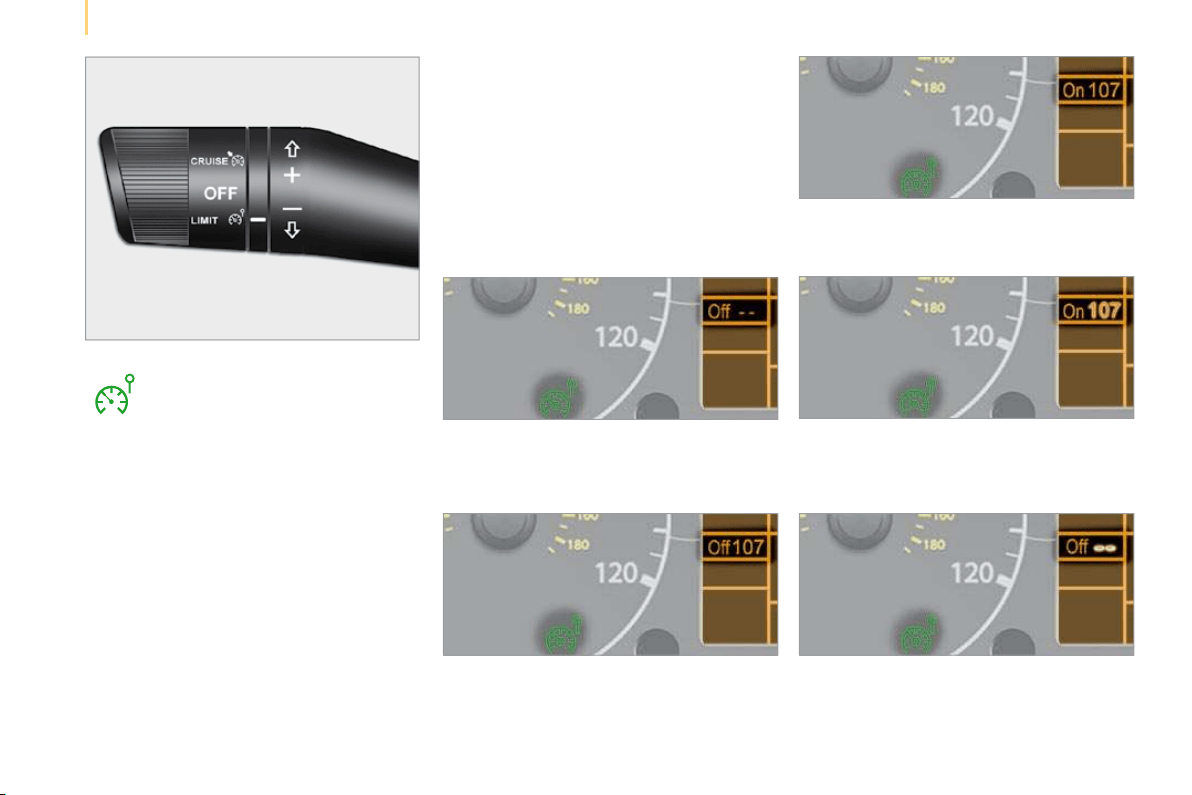
Function selected,
displaying of the "Speed Limiter" indicator light.
Function deactivated,
last programmed speed - OFF
(example at 65 mph (107 km/h)).
Function activated
(example at 65 mph (107 km/h)).
Vehicle speed above
(example 70 mph (118 km/h)),
the programmed speed is displayed flashing.
Operating fault detected,
OFF - the dashes flash.
SPEED LIMITER "LIMIT"
"This is the selected speed which
the driver does not wish to exceed".
This selection is made with the
engine running while stationary or with the
vehicle moving. The minimum speed which
can be programmed is 20 mph (30 km/h).
The speed of the vehicle responds to the
pressure of the driver’s foot as far as the
accelerator pedal point of resistance which
indicates that the programmed speed has
been reached.
However, pressing the pedal beyond this
point of resistance to the floor permits
exceeding of the programmed speed. To
resume use of the limiter, simply reduce
the pressure on the accelerator pedal
gradually and return to a speed below that
programmed.
The operating actions may be carried out
when stationary, with the engine running,
or with the vehicle moving.
This speed limiter shows the function
selection status on the instrument panel and
displays the programmed speed:

45
1
READY TO SET OFF
Steering wheel controls
Selecting the function
- Place the ring in the LIMIT position.
The limiter is selected but is not yet
active. The display indicates the last
programmed speed.
Programming a speed
A speed can be programmed without
activating the limiter but with the engine
running.
To memorise a speed higher than the
previous one:
- move the switch up (+).
A brief press increases the speed by 1 mph
(km/h).
A maintained press increases the speed in
steps of 5 mph (km/h).
To memorise a speed lower than the
previous one:
- move the switch down (-).
A brief press decreases the speed by
1 mph (km/h).
A maintained press decreases the speed in
steps of 5 mph (km/h).
Activation/Deactivation (off)
Pressing this button once activates the
limiter, pressing the button again
deactivates it (OFF).
46
Steering wheel controls
Exceeding the programmed speed
Pressing the accelerator pedal in order to
exceed the programmed speed will have
no effect unless you press the pedal firmly
beyond the point of resistance .
The limiter is deactivated temporarily and
the programmed speed flashes.
To return to the limiter function, reduce your
speed to below the programmed speed.
Flashing of the speed
The speed flashes:
- following forcing of the accelerator point
of resistance,
- when the limiter cannot prevent an
increase in the vehicle speed due to the
profile of the road or on a steep descent,
- in the event of sharp acceleration.
Switching the function off
- Place the ring in the OFF position or
switch off the ignition to switch the
system off.
The last programmed speed remains in the
memory.
Operating fault
The programmed speed is cleared then
replaced by dashes.
Contact a CITROËN dealer to have the
system checked.
Good practice
In any event, the speed limiter cannot
replace the need to observe speed limits,
nor can it replace the need for vigilance and
responsibility on the part of the driver.
Always pay attention to the profile of the
road and sharp acceleration and stay in
complete control of your vehicle.
To avoid any jamming under the pedals:
- ensure that the mat and its fixings on the
floor are positioned correctly,
- never place one mat on top of another.
47
1
READY TO SET OFF
Mirrors and windows
Interior mirror
The lever located on the lower edge moves
the mirror into two positions.
For the day position , the lever is pushed.
For the night position to prevent dazzle,
pull the lever towards you.
Exterior mirrors
The mirror glass is spherical in order to
widen the lateral field of vision. Objects
seen in the mirror are in reality closer than
they appear. Therefore, this must be taken
into account in order to assess the distance
correctly.
Electric controls
The electric control is located on the left-
hand interior side, level with the mirror.
MIRRORS AND WINDOWS
To de-ice the mirrors, press the
rear screen de-icing button.
Select the mirror to be adjusted by turning
the control to the right or to the left, then
move the control in the direction of the
adjustment required.
Manual controls
The right-hand and left-hand manual
controls are located on the interior side of
the base of each mirror.
Move the lever in the direction of the
adjustment required.
48
Mirrors and windows
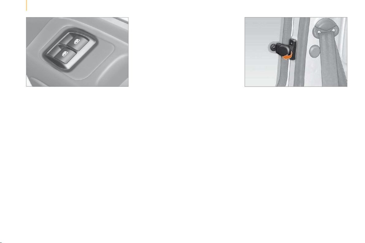
ELECTRIC WINDOWS
Electric controls
The electric windows have a safety auto-
reverse function and are associated with
one-touch controls for lowering and raising.
From the driver’s seat, the controls placed
on the door operate the vehicle’s front
windows.
On the passenger’s side, the control
operates the passenger’s front window.
One-touch controls
An extended press on the control raises or
lowers the window completely.
Press the control again to stop the window.
Press the control briefly to trigger the
movement of the window.
Manual controls
Turn the window winder located on the door
trim pad.
Good practice
Always remove the key from the ignition
when leaving the vehicle, even for a short
time.
If the electric window meets an obstacle
during operation, you must reverse the
movement of the window. To do this, press
the control concerned.
When the driver operates the passenger
electric window controls, he must ensure
that no one is preventing correct closing of
the windows.
The driver must ensure that the passenger
uses the electric window correctly.
Be aware of children when operating the
windows.
REAR WINDOWS (COMBI)
To partially open the rear windows, tilt the
lever and push it fully to lock the windows in
the open position.
49
1
READY TO SET OFF
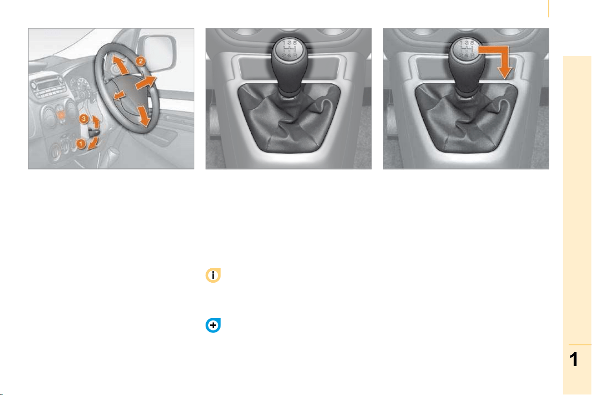
Gearbox and steering wheel
Good practice
To change gear easily, always press the
clutch pedal fully.
To prevent the mat from becoming caught
under the pedal:
- ensure that the mat is positioned correctly,
- never fit one mat on top of another.
Avoid leaving your hand on the gear knob as
the force exerted, even if slight, may wear
the internal components of the gearbox over
time.
STEERING WHEEL ADJUSTMENT
MANUAL GEARBOX
Reverse gear
Never engage reverse gear before the
vehicle is completely stationary.
The lever should be moved slowly to reduce
the noise on engaging reverse gear.
If your vehicle is fitted with parking
assistance, the system comes into
operation when reverse gear is engaged and
an audible signal is heard.
Refer to the "Rear parking assistance"
section of chapter 3.
When the vehicle is stationary, unlock the
steering wheel by pushing the lever down.
Adjust the depth and height of the steering
wheel, then lock by pulling the lever up fully.
50
Gearbox and steering wheel
PILOTED MANUAL GEARBOX
The five-speed piloted manual gearbox
offers a choice between the comfort of
automatic regulation or the pleasure of
manual gear changing.
This gearbox enables you to access two
driving modes:
- an automated mode for automatic control
of the gears by the gearbox and therefore
without any action on the part of the
driver,
- a sequential mode for manual changing
of the gears by the driver using the gear
lever.
It consists of a gear lever 1 on the centre
console for selecting the driving mode,
reverse gear and neutral or for changing
gear in sequential mode.
N : neutral.
With your foot on the brake, select this
position to start.
R : reverse gear.
With the vehicle stationary, keep your foot
on the brake pedal and push the gear lever
upwards.
A : automated mode.
Move the lever downwards to select this
mode.
M +/- : sequential mode with manual gear
changing.
Move the lever downwards, then to the left
to select this mode, then:
- push forward to change up,
- push rearward to change down.
Moving off
Select position N .
Press the brake pedal firmly while
starting the engine.
Start the engine. "N" appears on the
instrument panel display.
Select first gear (position M or A ) or reverse
(position R ).
Release the handbrake.
Release the brake pedal then accelerate.
"AUTO" and "1" or "R" appear on the
instrument panel display.
It is possible to move off in 2nd gear,
in sequential mode only.
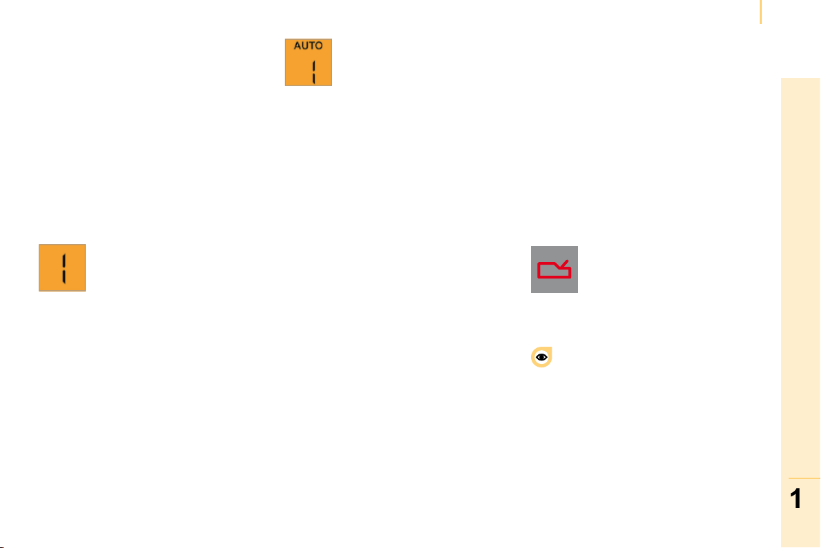
51
1
READY TO SET OFF
Gearbox and steering wheel
Stopping - Starting on a slope
This gearbox is a piloted manual gearbox
which does not have a clutch pedal.
Do not use the accelerator pedal to
immobilise the vehicle on a slope, apply
the handbrake instead.
When moving off on a slope, accelerate
gradually while releasing the handbrake.
Switching to sequential mode
Once you have moved off, you can switch to
sequential mode by selecting position M .
Switching to automated mode
After using the sequential mode, you can
return to the automated mode by selecting
position A .
Stopping the vehicle
Before switching off the engine, you can:
- move to position N to leave the gearbox
in neutral,
- leave a gear engaged, such as first or
reverse.
In both cases, it is imperative that you apply
the handbrake to immobilise the vehicle.
Reinitialisation
Following disconnection of the battery, the
gearbox must be reinitialised:
- switch on the ignition, "AUTO" appears
on the instrument panel display,
- press the brake pedal,
- wait approximately 30 seconds until "N"
or a gear appears on the instrument
panel display,
- release the brake pedal.
The gearbox is operational again.
Operating anomaly
"AUTO" and the gear engaged
appear on the instrument panel
display.
The gearbox then operates in
auto-active mode, without any action on the
part of the driver.
It continuously selects the gear most suited
to the following parameters:
- driving style,
- road characteristics,
- vehicle load.
To optimise driving comfort and obtain the
most suitable gear, avoid sharp variations in
the pressure on the accelerator pedal.
If you press the accelerator pedal beyond
the point of resistance, the gearbox
selects the gear below to permit sharper
acceleration.
"AUTO" disappears and the
gears engaged appear in
succession on the instrument
panel display.
The gear change requests are only carried
out if the engine speed permits it.
Take your foot off the accelerator pedal
gently to engage the gear.
At low speeds, when approaching a stop
or traffic lights for example, the gearbox
changes down to first gear automatically.
With the ignition on, the flashing
of "AUTO" and lighting of this
warning light, accompanied by
an audible signal and a message
on the instrument panel display, indicate a
gearbox malfunction.
Have it checked by a CITROËN dealer.
The brake pedal must be pressed while
starting the engine.
Never select neutral N while the vehicle is
moving.
Only engage reverse gear R with the vehicle
immobilised and the brake pedal pressed.
In all cases, it is imperative that you apply
the handbrake in order to immobilise the
vehicle.
On a steep gradient, it is preferable to
switch to sequential mode.
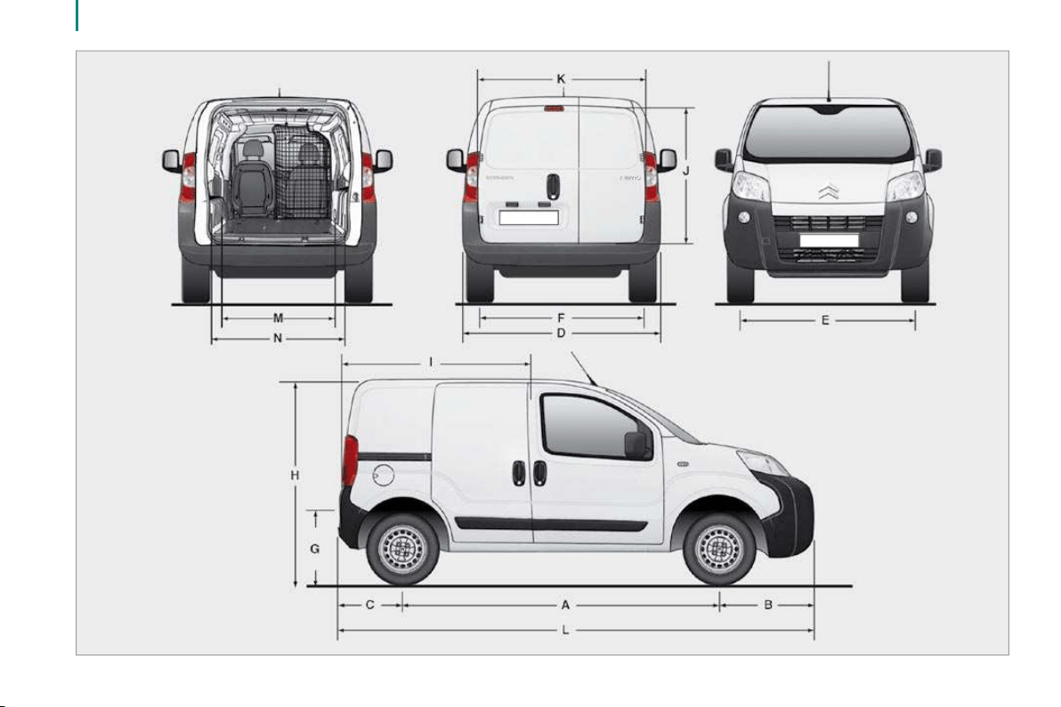
52
Dimensions
2
Dimensions
TECHNICAL DATA
DIMENSIONS
The light van "L1" is the standard model, the "L2 - Worksite Pack" version is a model sold according to country:
Light van (in mm)
L1 L2 (Worksite Pack)
L Overall length 3 864 3 881
H Overall height 1 721 1 742
Height with roof bars 1 782 1 803
A Wheelbase 2 513
B Front overhang 760 777
C Rear overhang 591
D Overall width 2 019
Width (with mirrors folded) 1 816
E Width of front track 1 469 1 464
F Width of rear track 1 465
G Height of load sill 527 544
I Length of interior fl oor 1 523
J Maximum interior load height 1 205
K Maximum interior width (10 cm from the fl oor) 1 473
M Interior width between wheel arches 1 046
Volume (m
3
) 2.5
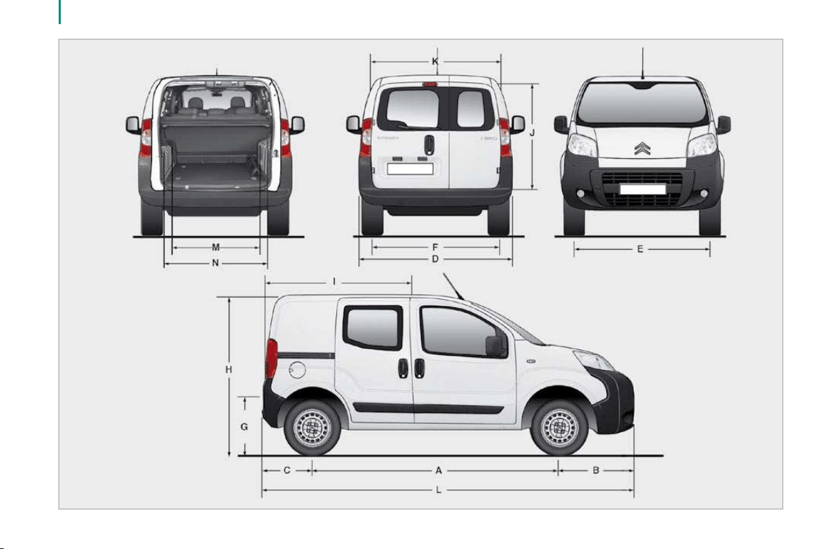
54
Dimensions
2
Dimensions
TECHNICAL DATA
Combi (in mm)
Standard Raised
L Overall length 3 959 3 970
H Overall height 1 721 1 742
Height with roof bars 1 782 1 803
A Wheelbase 2 513
B Front overhang 855 866
C Rear overhang 591
D Overall width 2 019
Width (with mirrors folded) 1 816
E Width of front track 1 464
F Width of rear track 1 465
G Height of load sill 527 544
I Length of interior fl oor (rear bench seat in place) 743
Length of interior fl oor (rear bench seat fully folded) 1 130
J Maximum interior load height (under rear shelf) 592
K Maximum interior width (10 cm from the fl oor) 1 473
M Interior width between wheel arches 1 046
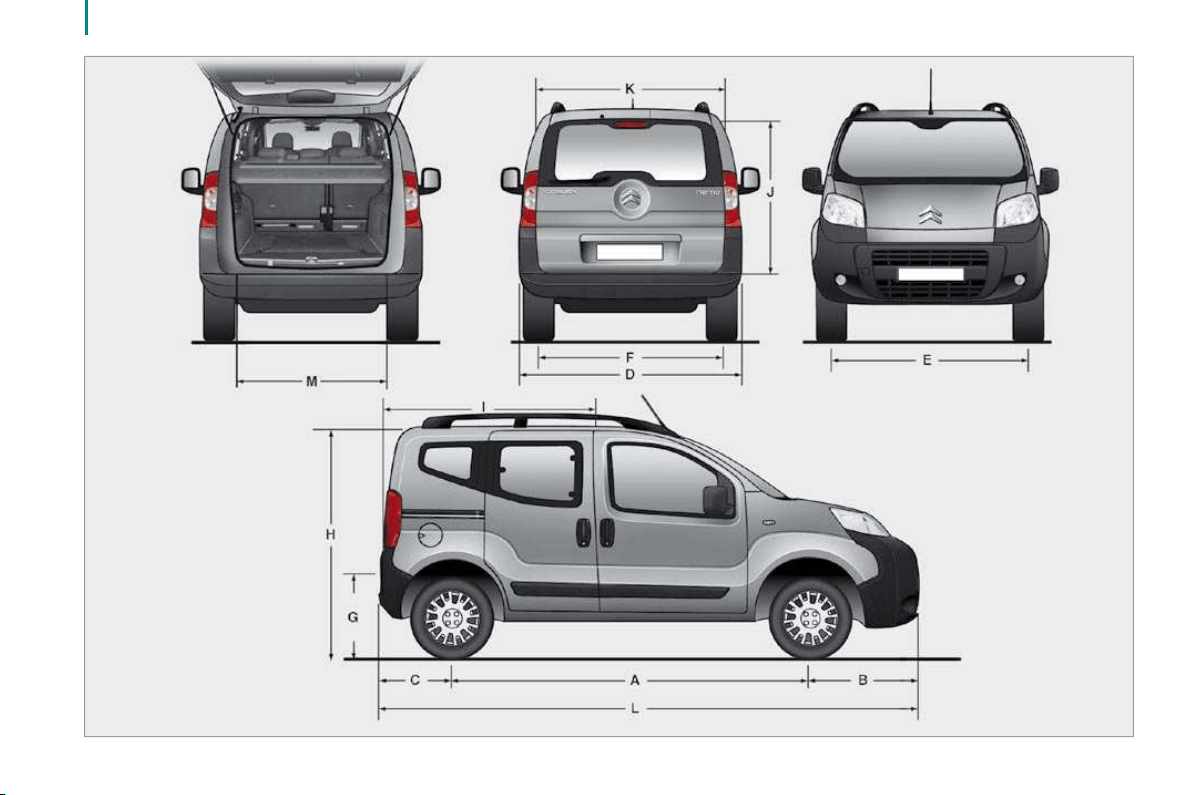
56
Dimensions

2
Dimensions
TECHNICAL DATA
Combi (in mm)
Standard Raised
L Overall length 3 959 3 970
H Overall height 1 721 1 742
Height with roof bars 1 794 1 803
A Wheelbase 2 513
B Front overhang 855 866
C Rear overhang 591
D Overall width 2 019
Width (with mirrors folded) 1 816
E Width of front track 1 464
F Width of rear track 1 465
G Height of load sill 527 544
I Length of interior fl oor (rear bench seat in place) 743
Length of interior fl oor (rear bench seat fully folded) 1 130
J Maximum interior load height (under rear shelf) 592
K Maximum interior width (10 cm from the fl oor) 1 473
M Interior width between wheel arches 1 046
58
Engines
DIESEL ENGINE
1.4 HDi 70 bhp
Gearbox Manual Piloted manual
Gears 5
EU standard maximum power (kW) 50
Cubic capacity (cm
3
) 1 399
Bore x stroke (mm) 73.7 x 82
Max power engine speed (rpm) 4 000
EU standard max torque (Nm) 160
Max torque engine speed (rpm) 1 750
Fuel Diesel
Catalytic converter Yes
Engine oil capacity (in litres) 3.8
59
2
Engines
TECHNICAL DATA
PETROL ENGINE
1.4 l 75 bhp
Gearbox Manual
Gears 5
EU standard maximum power (kW) 54
Cubic capacity (cm
3
) 1 360
Bore x stroke (mm) 75 x 77
Max power engine speed (rpm) 5 200
EU standard max torque (Nm) 118
Max torque engine speed (rpm) 2 600
Fuel Unleaded petrol
Engine oil capacity (in litres) 3.0
Engines
CONSUMPTION
These consumption values were established in accordance with directive 80/1268/EC. They may vary depending on the style of driving, traffi c
conditions, weather conditions, the load in the vehicle, the maintenance of the vehicle and the use of the equipment.
Light van According to directive 80/1268/EC
Engines Gearboxes Model codes
Urban driving
mpg (litres/100 km)
Inter-urban driving
mpg (litres/100 km)
Mixed driving
mpg (litres/100 km)
Emission of CO
2
by mass
(g/km)
1.4 HDi
Manual AA8HSC 49.6 (5.7) 74.3 (3.8) 62.8 (4.5) 119
Electronic AA8HSC/P 51.4 (5.5) 76.3 (3.7) 64.2 (4.4) 116
1.4 l Manual AAKFVC 32.1 (8.8) 47.9 (5.9) 40.9 (6.9) 164
Quality of the fuel used for petrol engines
The petrol engines are perfectly compatible with E5 type petrol biofuels (containing 5 % ethanol), conforming to European standard EN 228.
E85 type fuels (containing up to 85 % ethanol) are reserved exclusively for vehicles marketed for the use of this type of fuel (BioFlex vehicles). The
quality of the ethanol must comply with European standard EN 15376.
For Brazil only, special vehicles are marketed to run on fuels containing up to 100 % ethanol (type E100).
61
2
Engines
TECHNICAL DATA
Combi According to directive 80/1268/EC
Engines Gearboxes Model codes
Urban driving
mpg (litres/100 km)
Inter-urban driving
mpg (litres/100 km)
Mixed driving
mpg (litres/100 km)
Emission of CO
2
by mass
(g/km)
1.4 HDi
Manual
AJ8HSC
AJ8HSL
47.9 (5.9)
49.6 (5.7)
72.0 (3.9)
74.3 (3.8)
61.4 (4.6)
62.8 (4.5)
123
119
Electronic AJ8HSC/P 49.6 (5.7) 74.3 (3.8) 62.8 (4.5) 119
1.4 l Manual AJKFVC 32.1 (8.8) 47.9 (5.9) 40.4 (7.0) 165
Consumption fi gures correct at time of printing.
Quality of the fuel used for Diesel engines
The Diesel engines are perfectly compatible with biofuels which conform to current and future European standards (diesel fuel which complies with
standard EN 590 mixed with a biofuel which complies with standard EN 14214) which can be distributed at the pumps (possible incorporation of 0 to
7 % Fatty Acid Methyl Ester).
The use of any other type of (bio)fuel (vegetable or animal oils, domestic fuel...) is strictly prohibited (risk of damage to the engine and fuel circuit).
62
Weights
WEIGHTS
Consult your registration certifi cate.
In each country, it is imperative that the towed loads permitted by local legislation are complied with. For information regarding your vehicle’s
towing possibilities and its gross train weight, consult a CITROËN dealer.
This table indicates the maximum weight when loaded (GVW) according to the dimensions and names of the vehicle.
Load transfer
If the towing vehicle has not reached the GVW, it is possible to transfer this weight to the trailer.
In all cases, do not exceed the trailer weight and GTW indicated.
Comply with the towing capacities of your vehicle.
Light van
Model codes
AA8HSC AA8HSC/P AAKFVC
Engines 1.4 HDi 1.4 l
Gearboxes Manual
Electronic gearbox system
Manual
Gross vehicle weight 1 700 1 700 1 680
Kerb weight (without driver) 1 090 1 090 1 070
Payload (with driver) 610 610 610
63
2
Weights
TECHNICAL DATA
Combi (with hinged rear doors)
Model codes
AJ8HSC
AJ8HSL
AJ8HSC/P AJKFVC
Engines 1.4 HDi 1.4 l
Gearboxes Manual
Electronic gearbox system
Manual
Gross vehicle weight 1 700 1 700 1 680
Kerb weight (without driver) 1 185 1 185 1 165
Payload (with driver) 515 515 515
Combi (with tailgate)
Model codes
AJ8HSC
AJ8HSL
AJ8HSC/P AJKFVC
Engines 1.4 HDi 1.4 l
Gearboxes Manual
Electronic gearbox system
Manual
Gross vehicle weight 1 710 1 710 1 690
Kerb weight (without driver) 1 200 1 200 1 180
Payload (with driver) 510 510 510
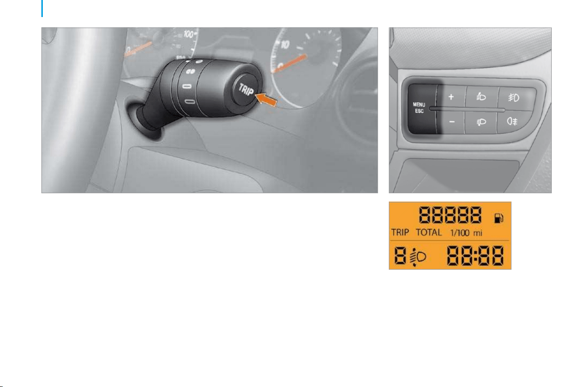
64
Trip computer
TRIP COMPUTER
The TRIP button, located at the end of
the wipers stalk, displays the following
information in succession:
- Range,
- Route A,
- Average consumption A,
- Current consumption A,
- Average speed A,
- Trip duration A.
If TRIP B is activated on MENU :
- Route B,
- Average consumption B,
- Average speed B,
- Trip duration B.
Press the MENU ESC button for more
than two seconds to return to the welcome
screen.
Level 1 display:
- Speed (Speed bleep).
- Hour (Setting of the time).
- Buzz (Volume of the announcements).
- Unit (Unit of measurement).
- Bag p (Passenger air bag).
Refer to the corresponding line of the
configuration - personalisation table on the
following pages.
Zero reset
Press the TRIP button for more than two
seconds to reset the displayed data to zero.
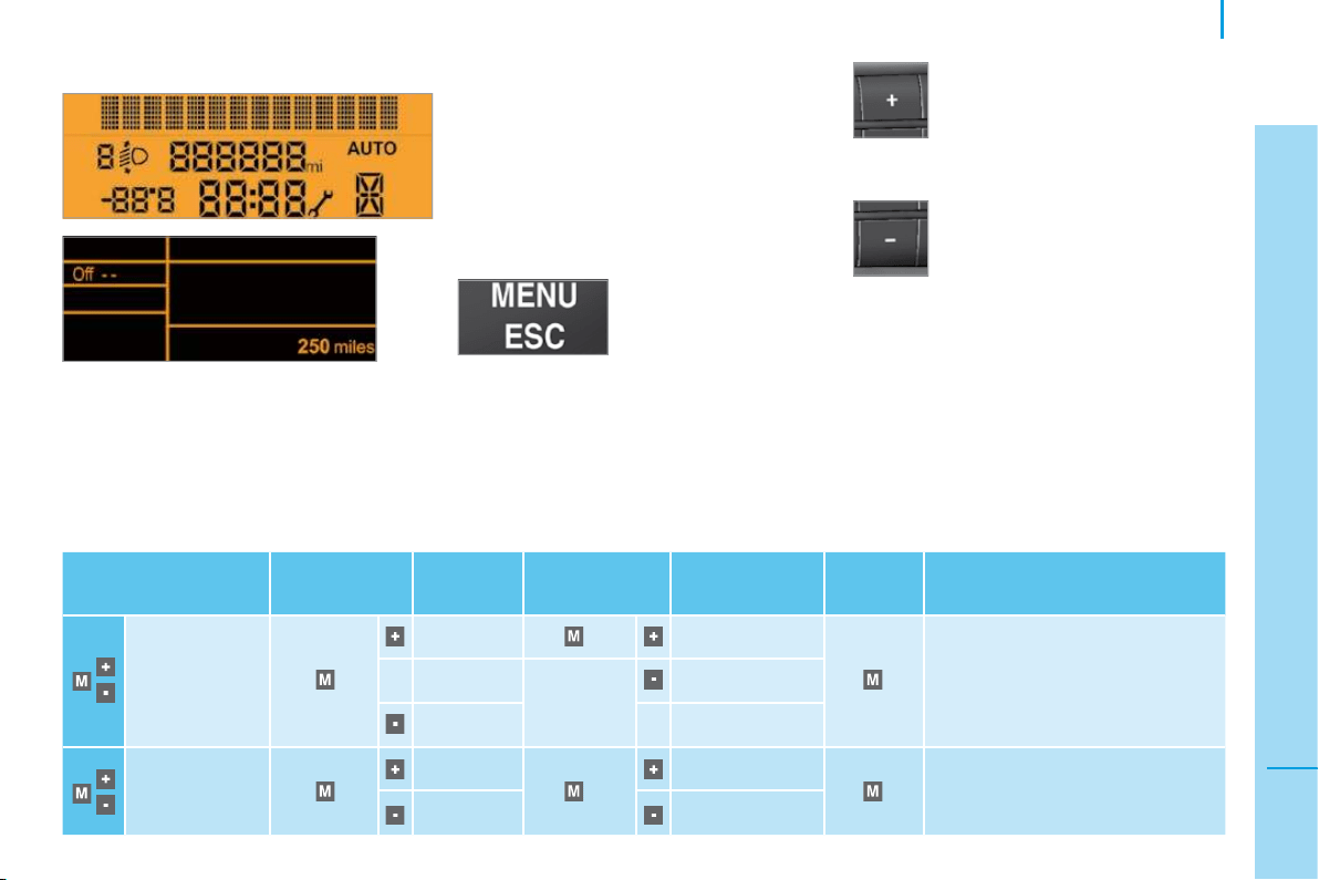
65
3
IN-CAR TECHNOLOGY
Menu
MENU
Eight languages are offered: Italian, English,
German, French, Spanish, Portuguese,
Dutch and Turkish.
As a safety precaution, the menus can only
be accessed when the ignition is off
(engine off).
Refer to the corresponding line of the
configuration - personalisation table on the
following pages.
This button enables you to:
- scroll up through a menu,
- increase a value.
This button enables you to:
- scroll down through a menu,
- decrease a value.
Menu... Press...
Sub-
menu...
Press... Select...
Confirm
and exit
Enables you to...
1 Speed Bleep
ON Increase
Activate/deactivate the audible
signal indicating exceeding of the
programmed speed and select the
speed value.
Decrease
OFF
2 Activate
Trip B
ON Activate
Display a second route "Trip B".
OFF Deactivate
Confi guration - Personalisation
Level 2 and 3 displays:
The control pad located to the left of the
steering wheel provides access to display
menus which permit the personalisation of
some of your equipment.
This button enables
you to:
- access the menus
and sub-menus,
- confirm your selections within a menu,
- exit from the menus.
A long press enables you to return to the
welcome screen.
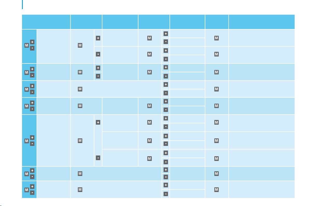
66
Menu
Menu... Press... Sub-menu... Press... Select...
Confirm
and exit
Enables you to...
3 Set the time
Hours
Increase
Set the clock.
Decrease
Format
24 hour
Select the clock display mode.
12 hour
4 Set the date Year/Month/Day
Increase
Set the date.
Decrease
5 See radio
ON
Display the name of the station.
Display the CD track number.
OFF
6 Autoclose While moving
ON
Activate/deactivate the
automatic locking of the doors
above 12 mph (20 km/h) .
OFF
7 Measurement
unit
Distances
Km
Select the distance display unit.
Mi(les)
Temperature
°C
Select the temperature display
unit.
°F
Consumption
km/l
Select the consumption display
unit.
l/100 km
8 Language
List of languages
available
Select the display language.
9
Volume of
announcements
Increase
Increase/decrease the volume of the
signals and warnings (the volume changes
immediately when the button is pressed).
Decrease
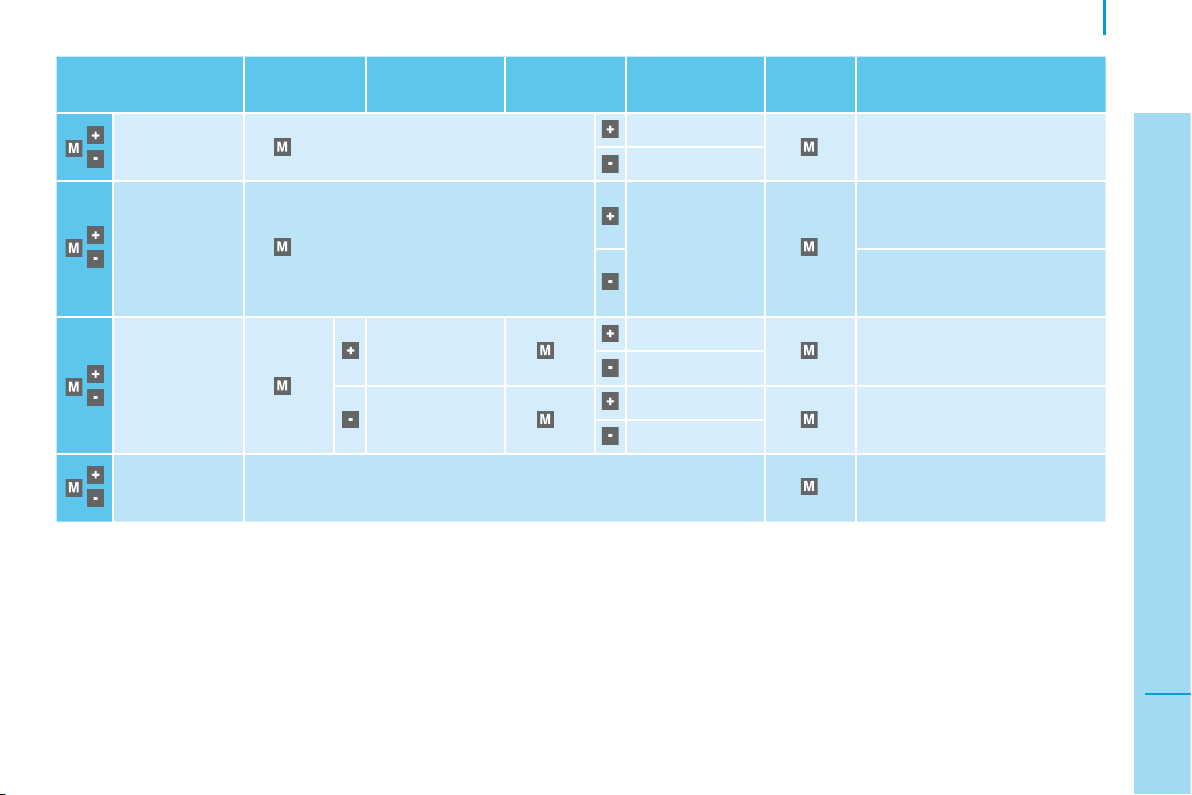
67
3
IN-CAR TECHNOLOGY
Menu
Menu... Press... Sub-menu... Press... Select...
Confirm
and exit
Enables you to...
10 Volume of
the buttons
Increase
Increase/decrease the volume
of the buttons.
Decrease
11 Service
(Km/Miles
before oil
change)
Display the kilometres/miles
remaining before the next oil
change.
Display the oil level.
12 Bag
(passenger
air bag)
ON
Yes
Activate the passenger air bag.
No
OFF
Yes
Disarm the passenger air bag.
No
13 Exit from
menu
Exit from the menu. Press the
arrow at the bottom to go to
the first menu.
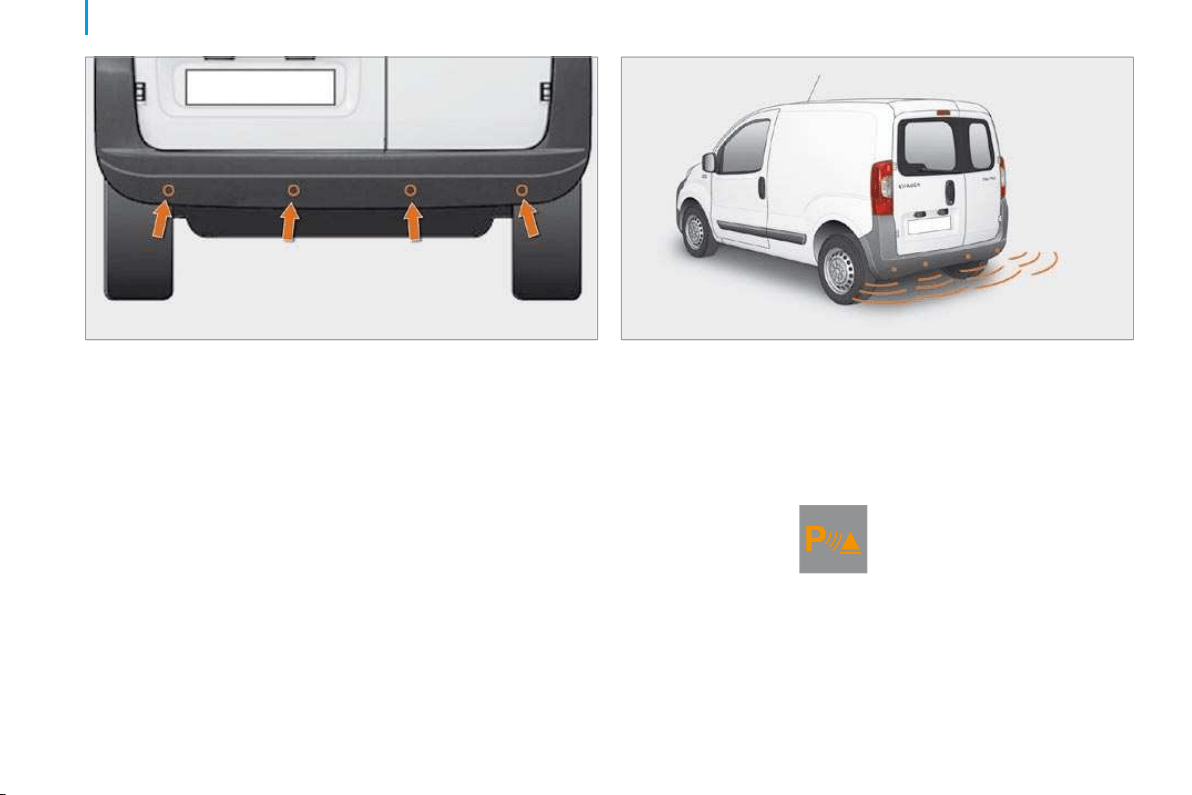
68
Parking assistance
AUDIBLE REAR PARKING ASSISTANCE
The audible system consists of four
proximity sensors, installed in the rear
bumper.
It detects any obstacle which enters the
field: person, vehicle, tree, fence, behind the
vehicle during the manoeuvre.
However, it will not be able to detect
obstacles located immediately below the
bumper.
An object, such as a stake, a roadworks
cone or any other similar object may be
detected at the beginning of the manoeuvre
but may no longer be detected when the
vehicle moves close to it.
This system does not take the place of the
vigilance and responsibility of the driver.
Stop the assistance
Change to neutral.
Operating fault
If this warning light or the service
warning light comes on on the
instrument panel, accompanied
by a message on the display,
contact a CITROËN dealer.
Good practice
In bad weather or in winter, ensure that the
sensors are not covered with mud, ice or
snow.
Engage reverse gear
The proximity information is indicated by an
audible signal which becomes more rapid as
the vehicle approaches the obstacle.
When the distance between the rear of
the vehicle and the obstacle is less than
approximately thirty centimetres, the audible
signal becomes continuous.
This function will be deactivated
automatically if a trailer is being towed.
You are advised to obtain a towbar
recommended by CITROËN and have it
installed by a professional.
If anomalies are detected on engaging reverse
gear, the warning light comes on, possibly
accompanied by a message on the display.
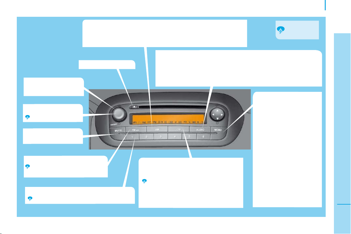
69
3
IN-CAR TECHNOLOGY
Autoradio
Volume increase/
decrease.
On.
Off.
Mute on/off.
Selection of the CD/CD MP3 source.
Use the left/right arrows to select the
previous/next track.
Use the left/right arrows to fast forward/
backward playing of the current track.
In CD MP3 mode: use the up/down arrows
to change folder.
Setting the audio options: bass, treble, fader (front/rear), balance (left/
right), loudness, EQ Preset (equaliser).
Use the up/down arrows to select the option.
Use the left/right arrows to increase or decrease the value of the option
or change the equaliser.
Access to the menu.
Use the up/down arrows to
select one of the following
functions:
AF switching.
Traffic info.
Regional mode.
MP3 display.
Speed volume.
External audio vol.
Radio off.
Restore default.
Use the left/right arrows to
change the setting of the
function selected.
CD eject.
Selection of the FM waveband.
Automatic storing of stations
(autostore AS).
Selection of the AM waveband.
Use the left/right arrows for an automatic station search.
Use the up/down arrows for a manual station search.
1/2/3/4/5/6: selection of the stored station.
Storing of a station.
Requires a
long press.
FIRST STEPS

70
Autoradio
"AUDIO FUNCTIONS" MENU
RDS "AF Switching"
The RDS (Radio Data System) enables you
to continue listening to the same station,
regardless of the frequency that it uses in
your current location. The audio equipment
continuously searches for the transmitter
which offers the best reception for the
station.
Press the " " or " " button to activate (ON)
or deactivate (OFF) the RDS.
On the FM waveband, "AF" appears on
the display if the RDS is activated and the
station is broadcasting with the RDS.
"Traffic Info"
All traffi c information announcements will be given
priority regardless of which source is currently playing.
The EON (Enhanced Other Networks) system links stations
which belong to the same network. It allows you to receive
traffi c information transmitted by a station which belongs to
the same network as the station to which you are listening.
"Regional Mode"
Some stations, organised in a network,
broadcast regional programmes in the
various areas which they serve. The regional
mode allows you to choose to continue
listening to the same programme.
Press the " " or " " button to activate (ON)
or deactivate (OFF) the REG function.
On the FM waveband, "LOC" appears on the
display if the REG function is activated and
the station finds a local frequency.
"MP3 Display"
Press the " " or " " button to display the
track number or the MP3 CD information
(Artist/Album/Folder/File/Title/Time elapsed).
Automatic volume control
"Speed Volume"
Press the " " or " " button to minimise
(LOW), maximise (HIGH) or deactivate
(OFF) the automatic control of the volume in
relation to the vehicle speed.
The volume of the traffic information is
independent of the volume of the other
sources. You can adjust it using the volume
button during traffic announcements;
this setting will be stored for the next
announcement.
Press the " " or " " button to activate (ON)
or deactivate (OFF) the TA function.
On the FM waveband, "TA" appears on the
display if the TA function is activated and
"TPM" appears if the station broadcasts
traffic information.
"External Audio Vol"
Press the " " or " " button to decrease
(down to 0 minimum), increase (up to 40
maximum) or deactivate (OFF) the volume of
the external source (e.g.: hands-free kit).
Programmed switching off
"Radio Off"
Press the " " or " " button to programme
the switch-off time of "00 MIN" or "20 MIN".
This countdown is taken into account with
the doors closed and the key in the STOP
position.
"Restore Default"
Press the " " or " " button to retain the
modified values (NO) or restore the default
values (YES).
"Restoring" appears on the display during
the resetting of the configuration values.
"MP3" appears on the display if the function
is activated and the CD contains tracks in
the MP3 format.
Press the MENU button
on the audio equipment to
gain access to the "Audio
functions" menu.
Press the " " or " " button to
select one of the confi gurable
audio functions below.
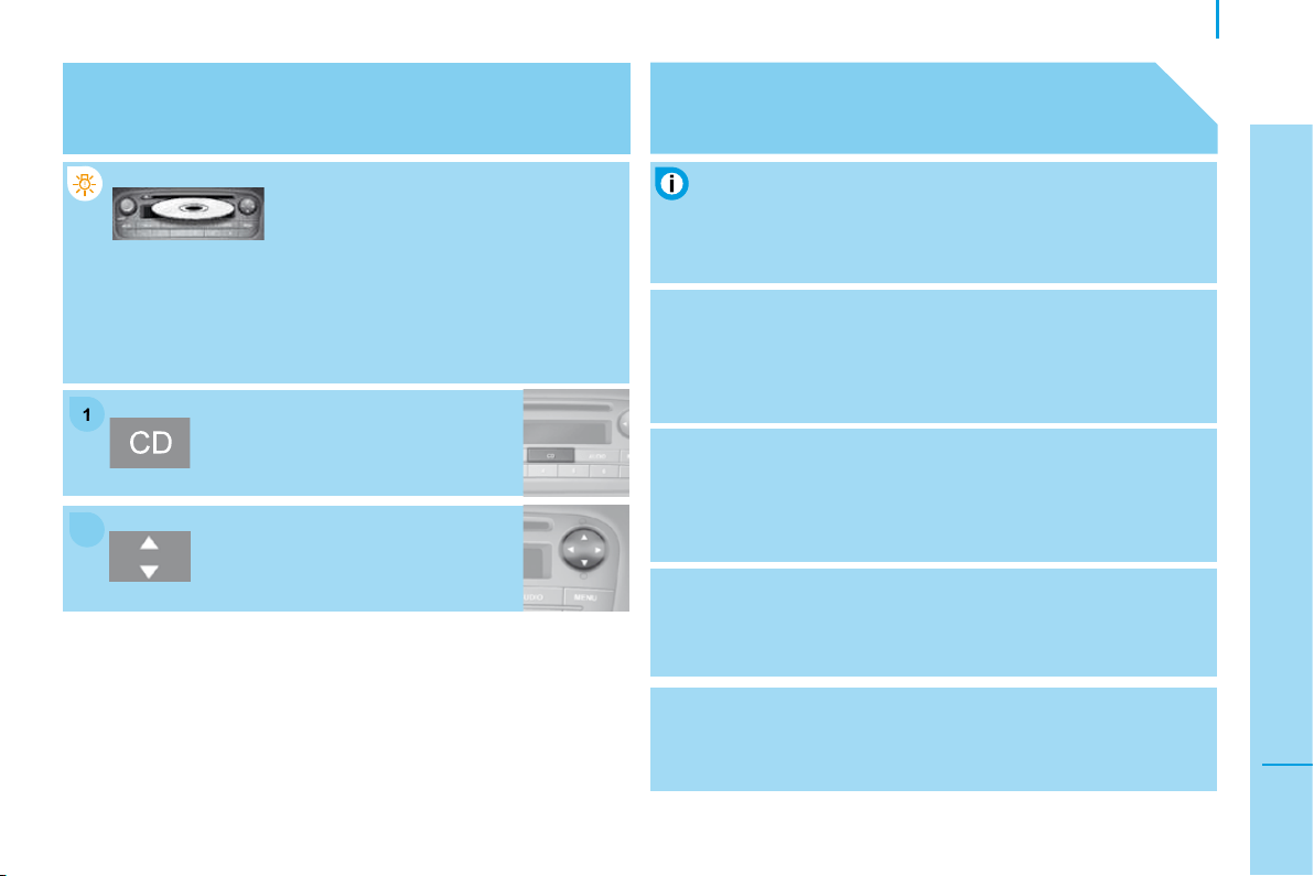
2
2
1
1
71
3
IN-CAR TECHNOLOGY
Autoradio
CD
PLAYING A CD OR AN MP3 COMPILATION
Insert circular compact discs only.
Some anti-pirating systems, on original
discs or CDs copied using a personal
recorder, may cause faults which are no reflection on the
quality of the original player.
Insert a CD or an MP3 compilation in
the player, play begins automatically.
If the player already contains a disc,
press the CD button.
Press one of the buttons to select a
track on the CD.
The MP3 format, an abbreviation of MPEG 1.2 & 2.5 Audio
Layer 3, is an audio compression standard which permits the
recording of several tens of music files on a single disc.
MP3
In order to be able to play a recorded CDR or CDRW, when
recording it is preferable to select standards ISO 9660
level 1.2 or Joliet.
If the disc is recorded in another format, it may not be played
correctly.
It is recommended that the same recording standard is
always used for an individual disc, with as low a speed as
possible (4x maximum) for optimum sound quality.
In the particular case of a multi-session CD, the Joliet
standard is recommended.
The audio equipment will only play files with the extension
".mp3" with a sampling rate of 22.05 KHz or 44.1 KHz.
No other type of file (.wma, .mp4, m3u...) can be played.
It is advisable to restrict file names to 20 characters without
using special characters (e.g.: " " ? ; ) to avoid any playing or
displaying problems.
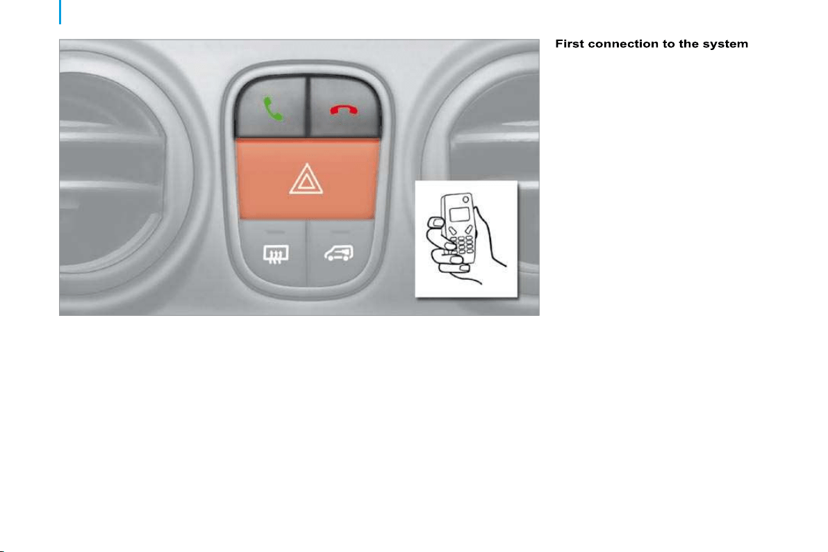
72
Mobile telephone with hands-free function
MOBILE TELEPHONE WITH HANDS-FREE FUNCTION
This new equipment uses wireless
communication technology referred to
as Bluetooth
®
which allows you to make
hands-free telephone calls safely from inside
your vehicle via your Bluetooth
®
compatible
mobile telephone.
An incoming call is picked up by pressing
the button represented by a green
telephone. The sound of the telephone call
is transmitted via the vehicle’s audio system.
The microphone is incorporated in the
courtesy light console.
Hang up by pressing the button represented
by a red telephone.
Turn the ignition key to the RUNNING position.
Switch on your mobile telephone.
Activate the Bluetooth
®
function on
your mobile telephone and search for
the Bluetooth
®
accessories around the
telephone.
Follow the instructions on your mobile
telephone during the matching and the search
between the telephone and the system.
Enter the connection code "1234" and
confirm.
Your mobile telephone is now connected in
Bluetooth
®
mode with the vehicle’s
hands-free system (matching).
Activation of the system
Once your mobile telephone has been
matched with the vehicle’s hands-free
system, simply:
- turn the ignition key to the RUNNING
position,
- switch on your mobile telephone,
- activate the Bluetooth
®
function on your
mobile telephone.
When the connection is established, an
audible signal is heard and the message
"Phone" appears on the audio equipment
display, if it is switched on.
For further information, consult a CITROËN
dealer and your mobile telephone manual.
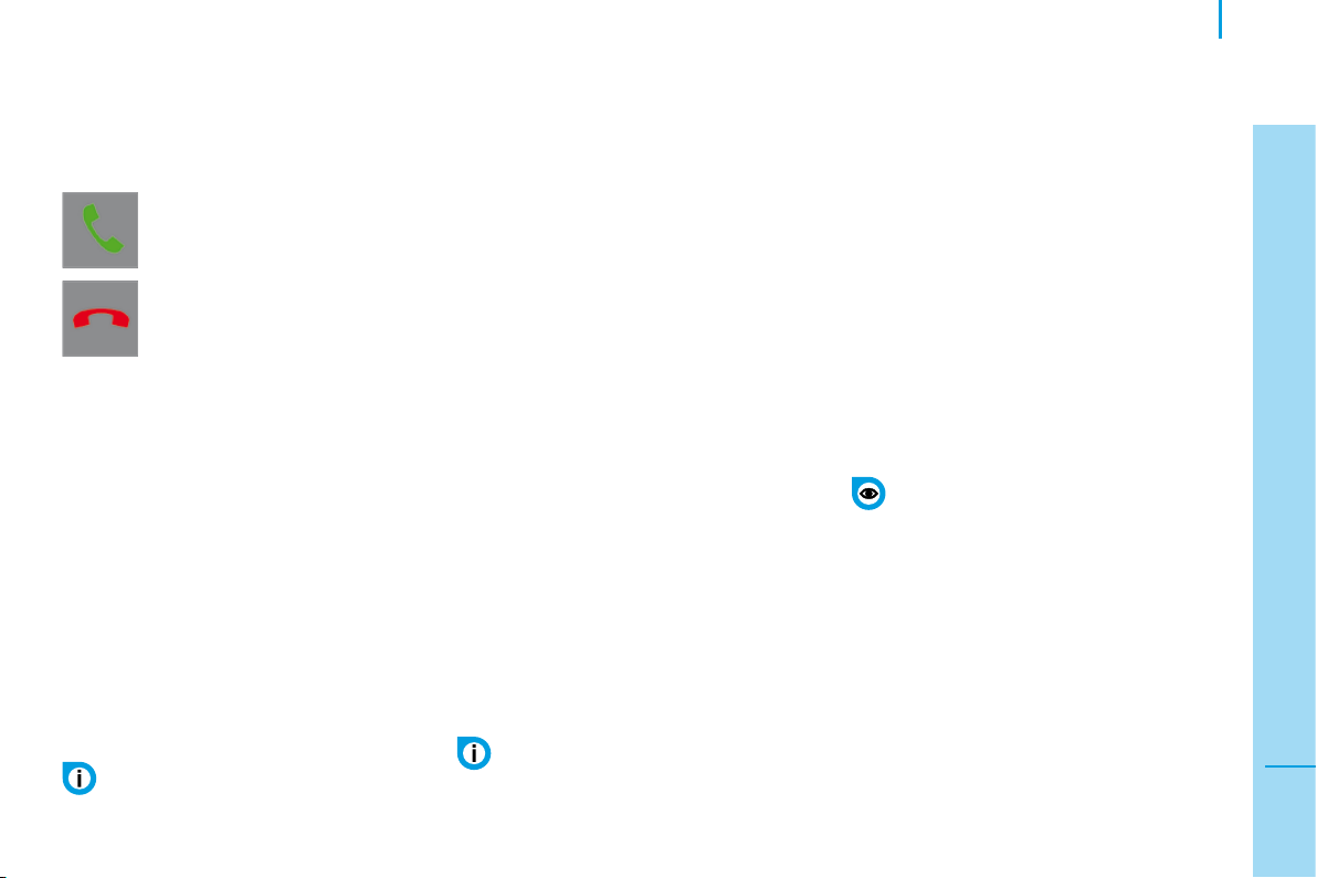
73
3
IN-CAR TECHNOLOGY
Mobile telephone with hands-free function
Managing incoming calls
When an incoming call is received, the
message "Phone" appears on the audio
equipment display, if it is switched on.
Single call
To accept a call, press the green
button.
Call waiting
To accept a second call, press the green
button once.
To switch back to the first call, press the
green button again.
To decline the second call, press the red
button.
To end the call, press the red button again.
To decline or end a call, press the
red button.
To switch the call between the system and
the mobile telephone (secret mode) and vice
versa, press the green button.
Managing outgoing calls
Using the keypad
Dial the number of the person to be called
on the mobile telephone keypad.
Press the "Pick up" button on the mobile
telephone.
Depending on the model of mobile
telephone, the call will be transferred to
hands-free mode automatically, if it is not,
press the green button.
To redial the last number dialled, press and
hold the green button until the number has
been redialled.
Using the voice commands
Press the green button.
Wait for the audible signal and/or the
appearance of the message "Phone" on the
audio equipment display.
Say the vocal identity of the person to be
called.
The system repeats the vocal identity
for confirmation and makes the call
automatically.
If the vocal identity repeated by the system
is not correct, press the red button to cancel
and start the procedure again.
Clearing the system
To clear the contents of the system’s
memory, press the green and red buttons
simultaneously for more than two seconds.
This operation clears all of the matched
mobile telephones and all of the telephone
numbers recorded in the system’s memory.
For the next hands-free call you will have
to repeat the first connection to the system
(matching) procedure.
Good practice
You can match up to three mobile
telephones with the system.
For safety reasons and because they
require prolonged attention on the part
of the driver, the operations for matching the
mobile telephone and the Bluetooth
®
hands-free kit must be carried out with the
vehicle stationary and the ignition on.
In order to use the voice commands,
you must first record a vocal identity
and associate it with the telephone number
to be called; refer to your mobile telephone
manual.
It is only possible for the system to
manage the call waiting function if
the function is activated on the mobile
telephone.
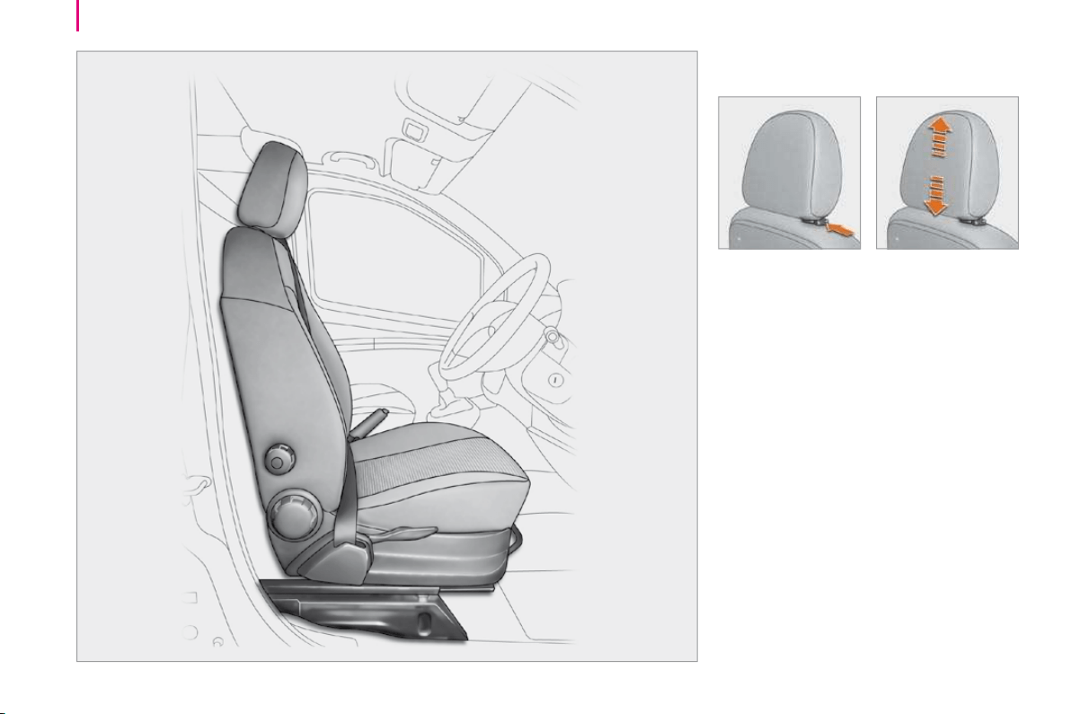
74
Seats
FRONT SEATS
Head restraints
Head restraint height adjustment: to raise or
lower the head restraint, slide it by pressing
the lug.
The adjustment is correct when the upper
edge of the head restraint is level with the
top of the head.
To remove the head restraint, release the
base of the rod to press the tab and raise
the head restraint to the highest position.
To refit the head restraint, press the tab of
the lug and engage the head restraint rods
in the openings keeping them in line with the
seat back.
Never drive with the head restraints
removed. They must be in place and
adjusted correctly.
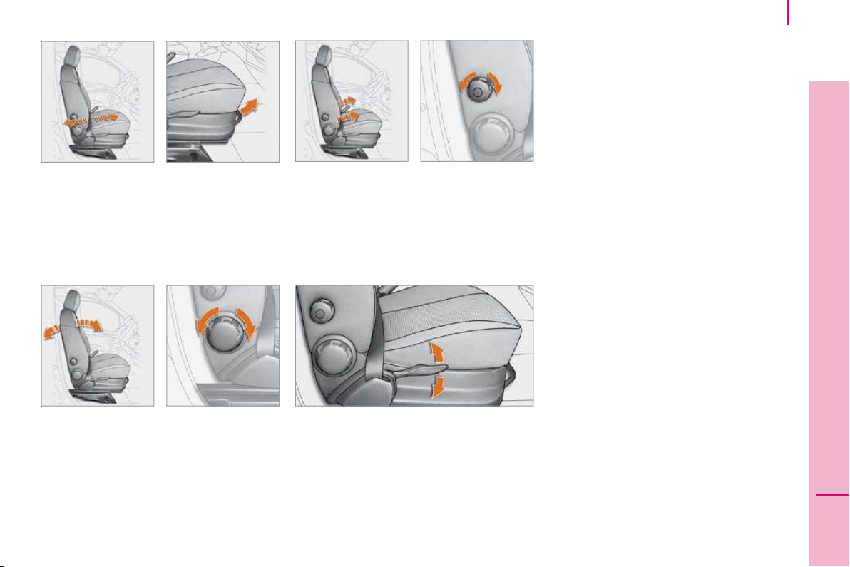
75
4
ERGONOMICS and COMFORT
Seats
Seat cushion height
To adjust the height of the driver’s seat
cushion, pull the control upwards as many
times as necessary to raise.
To lower, push the control downwards as
many times as necessary.
Forwards-backwards adjustment
Lift the control bar and slide the seat
forwards or backwards to the required
position.
Lumbar support
Seat back angle
Turn the control to adjust the angle of the
seat back.
Turn the control.
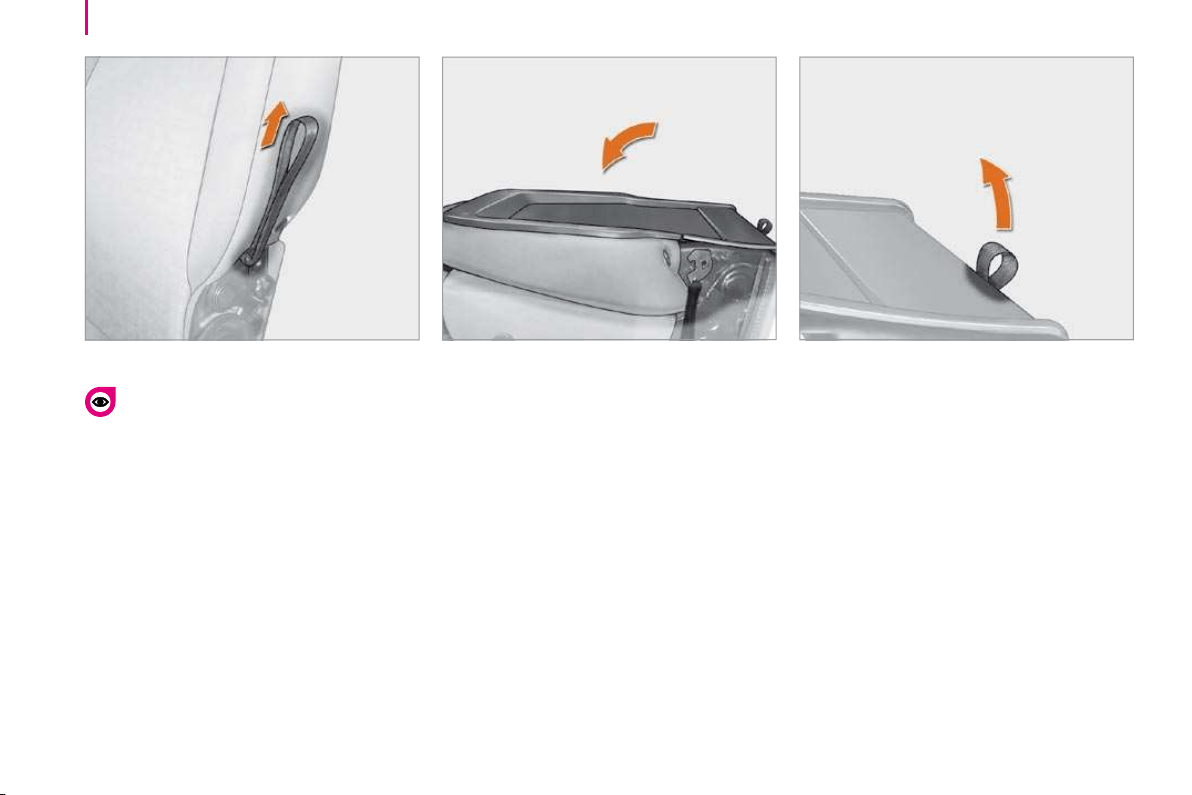
76
Seats
RETRACTABLE PASSENGER SEAT
Table position
Press the head restraint to place it in the
lowest position.
Push one of the controls rearwards, located
on each side of the seat back.
Lower the seat back onto the seat cushion
to the table position.
Retracted position
After placing the seat back in the table
position, pull the seat’s rear strap while
guiding the folded seat back forwards and
towards the floor.
Returning the seat to the sitting
position
Pull the seat’s rear strap to unlock the seat.
Lift the seat from the front and the rear
then guide it forwards to bring it to the table
position.
Push one of the controls rearwards, located
on each side of the seat back while pressing
on the seat back, then place the seat back in
the upright position.
Press on the seat back firmly to trigger the
locking of the seat on the floor.
Adjust the head restraint using the button on
the side.
Only move the seat when the rear
seats are not occupied.
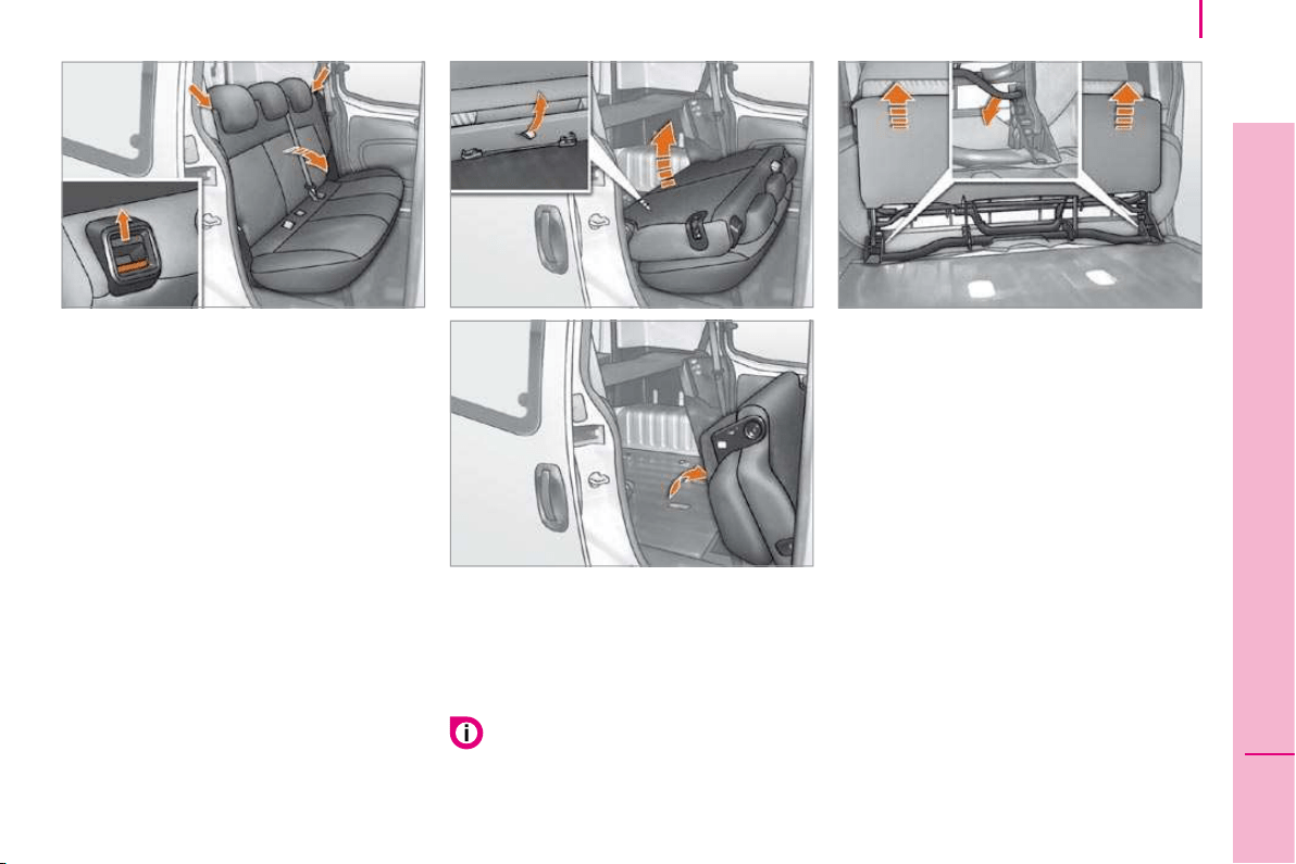
77
4
ERGONOMICS and COMFORT
Seats
ONE-PIECE REAR BENCH SEAT
Table position
Press the head restraint and its lug
simultaneously to place the head restraint in
the low position.
Unlock the seat back by pushing the two
side controls. The red indicator becomes
visible.
Fold the seat back onto the seat cushion.
Fully folded position
After placing the seat back in the table
position, pull the central strap to unlock the
rear feet of the seat.
Lift the seat fully to secure it in the fully
folded position.
While driving, secure the red retaining
strap, located on the back of the bench
seat cushion, to one of the rods of a front
head restraint.
Removing the bench seat
After placing the bench seat in the fully
folded position, lower the transverse bar to
unlock the front feet of the seat.
Lift the bench seat to detach it from its front
anchorages.
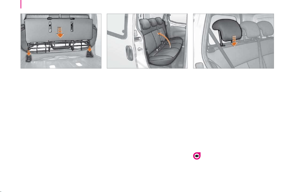
78
Seats
Returning the bench seat to its
position
Put the bench seat in place in its front
anchorages in the fully folded position.
Fold the bench seat to the table position,
the front and rear feet of the seat lock
automatically.
Returning the bench seat to the
sitting position
Lift the bench seat back.
Take care not to trap the seat belts.
Lock the seat back by pushing it fully
towards the rear. The red indicator is no
longer visible.
Rear head restraints
The rear head restraints can be removed
and have two positions:
high, position for use,
low, storage position.
To raise or lower a head restraint, pull it
forwards sliding it at the same time.
To remove it, place it in the high position,
push the lug and pull it forwards and
upwards.
To refit it, engage the head restraint rods
in the holes taking care to remain in the
centreline of the seat back.
Never drive with the head restraints
removed, they must be in place and
correctly adjusted.
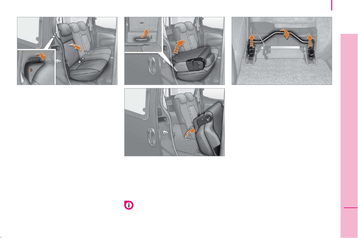
79
4
ERGONOMICS and COMFORT
Seats
SPLIT REAR BENCH SEAT
The left-hand side (2/3) or right-hand side
(1/3) of this bench seat can be folded to
adapt the load space in the boot.
Table position
Press the head restraint and its lug
simultaneously to place the head restraint in
the low position.
Unlock the seat back by pulling the
corresponding side control towards you. The
red indicator becomes visible.
Fold the corresponding seat back onto the
seat cushion.
Fully folded position
After placing the seat back in the table
position, pull the corresponding strap to
unlock the rear feet of the seat.
Lift the seat fully to secure it in the fully
folded position.
Removing the bench seat
After placing the bench seat in the fully
folded position, lower the corresponding
transverse bar to unlock the front feet of
the seat.
Lift the bench seat to detach it from its front
anchorages.
While driving, secure the red retaining
strap, located on the back of the bench
seat cushion, to one of the rods of a
front head restraint.
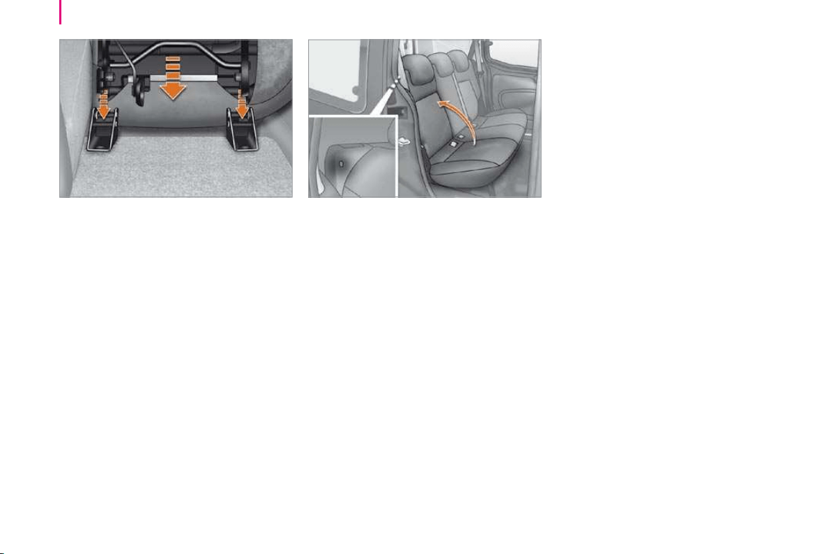
80
Seats
Returning the bench seat to its
position
Put the bench seat in place in its front
anchorages in the fully folded position.
Fold the bench seat to the table position,
the front and rear feet of the seat lock
automatically.
Returning the bench seat to the
sitting position
Lift the bench seat back.
Take care not to trap the seat belts.
Lock the seat back by pushing it fully
towards the rear. The red indicator is no
longer visible.
Repeat all of these operations for the other
part of the rear bench seat.
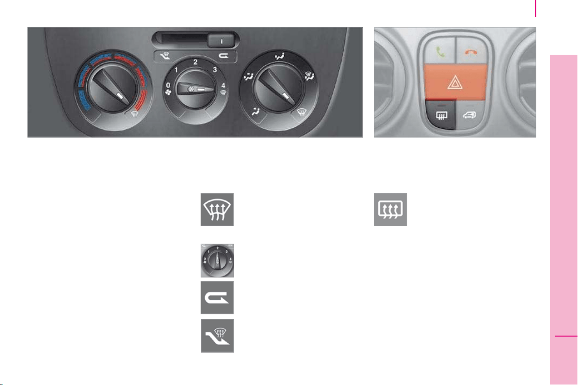
81
4
ERGONOMICS and COMFORT
Ventilation
DE-ICING AND DEMISTING
Windscreen
The ventilation outlets located at the base
of the windscreen and the side vents for the
side windows increase the effectiveness of
the de-icing and demisting. Do not obstruct
these eight air outlets.
The manual air conditioning consists of the
pollen filter and air recirculation.
The pollen filter permits continuous and
effective filtering of dust.
The air recirculation (which can be activated
by the driver or the passenger) isolates the
passenger compartment from the exterior
atmosphere. However, this position should
only be used temporarily, the norm is to
drive with the control positioned with the
exterior air intake open.
Manual mode
Direct the control to this air
distribution setting.
For faster and more effective
de-icing and demisting of the
windscreen:
- increase the air flow setting,
Returning to the exterior air intake
position permits renewal of the air
in the passenger compartment.
Rear screen and mirrors de-icing
This function only operates when
the engine is running. Pressing
this button activates the rapid
demisting/de-icing of the rear
screen and mirrors. This function switches
off automatically to prevent an excessive
consumption of energy. It switches off when
the engine is switched off. Pressing this
button switches the function off.
- move the exterior air intake
control temporarily to air
recirculation.
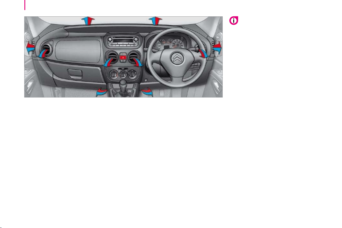
82
Ventilation
CORRECT USE OF THE AIR
CONDITIONING
For even air distribution, ensure that the
exterior air intake grille located at the base of
the windscreen is not obstructed and that the
side and central vents, the air outlets on the
fl oor and the air extractor at the rear are open.
The air conditioning is useful in all seasons as
it eliminates condensation and air humidity.
Operate the air conditioning system for
5 to 10 minutes, once or twice a month,
to keep it in perfect working order.
Have the filter elements (air filter and
passenger compartment filter) replaced
regularly. If you drive in a dusty environment,
have them replaced twice as often.
It is normal that the condensation created by
the air conditioning system results in a flow
of water which may form a puddle under the
vehicle when parked.
If the system does not produce cold air, do
not use it and contact a CITROËN dealer.
VENTS
For optimum distribution and diffusion of hot
or cool air in the passenger compartment,
there are:
- 2 adjustable central vents,
- 2 adjustable and closing side vents,
- 2 vents directed towards the floor of the
vehicle.
In order to be effective, the air conditioning
should only be used with the windows
closed. However, if the interior temperature
remains high after a prolonged period
parked in the sun, do not hesitate to
ventilate the passenger compartment for a
few minutes.
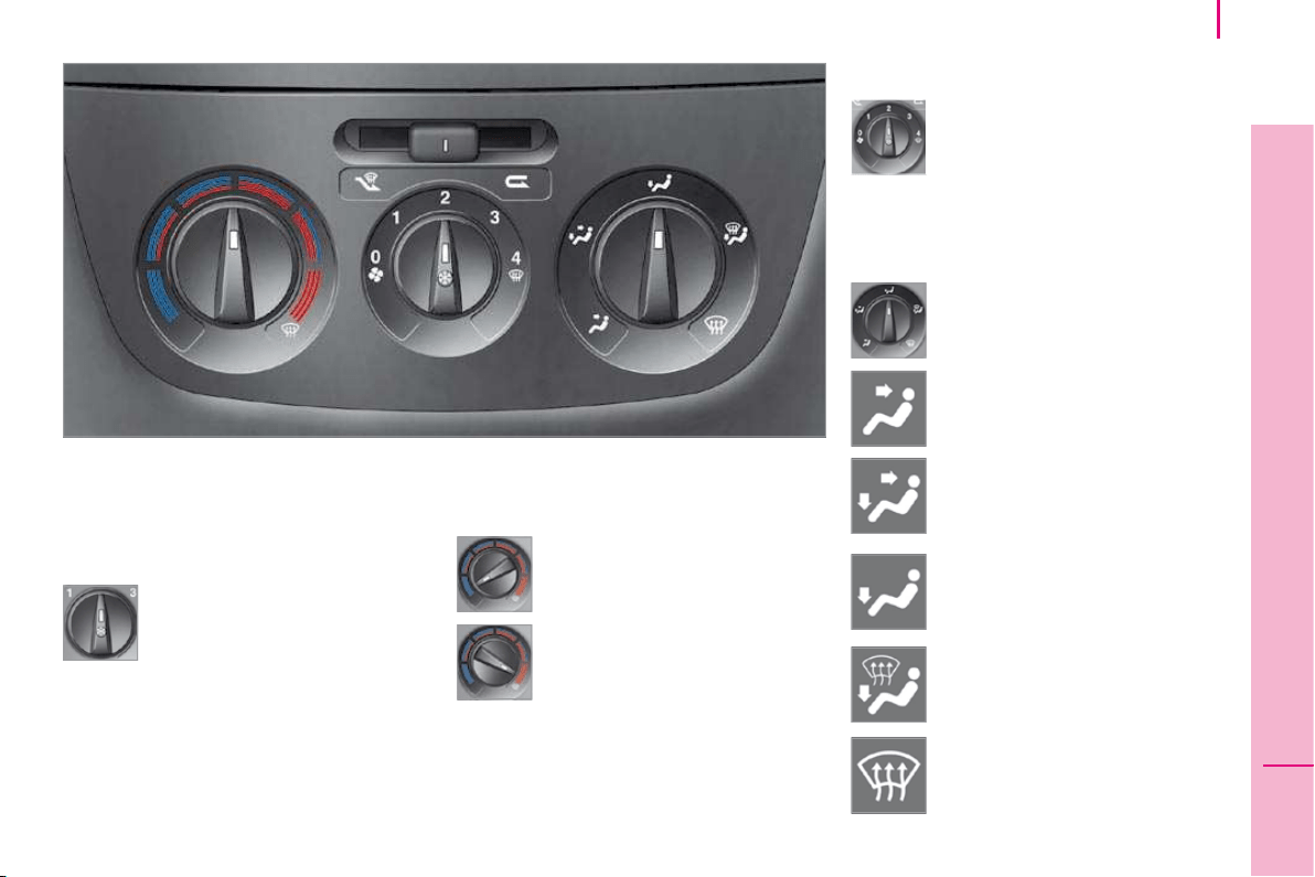
83
4
ERGONOMICS and COMFORT
Ventilation
These controls are located on the centre console.
Air conditioning
The air conditioning mode is operational
when the engine is running. The diode is lit.
Temperature adjustment
Control positioned:
- in the blue zone triggers
cool air,
Air fl ow
The force of the blown air, from
the vents, varies from 1 to the
strongest 4 . Remember to adjust
this control in order to reach the
ambient air comfort level. To switch off the
blower, place the control in position 0 .
The air supply distribution is
directed by the control turned
towards:
the side vents and the central
vents,
the side vents, the central vents
and the footwells,
the footwells,
the windscreen, the front side
windows and the footwells,
the windscreen.
Press the air blower control. The
diode lights.
The air blower control must not
be in position 0 (zero flow) for air
conditioning to be obtained.
Turn the control to the position required.
- in the red zone triggers heating
of the interior ambient air.
Air distribution

84
Ventilation
Intake of exterior air
This is the preferred operating
position.
Recirculation of interior air
This position should only be
temporary.
Used with the air conditioning
switched on and setting of the
force of blown air (from 1 to 4), recirculation
enables you to obtain the required ambient
air comfort level with both hot or cold
settings.
Recirculation temporarily prevents exterior
odours and smoke from entering the
passenger compartment. De-icing is more
rapid in this position.
When your ambient air comfort level has
been reached, return to the intake of exterior
air position to permit renewal of the air in the
passenger compartment and demisting. This
operating mode is preferable.
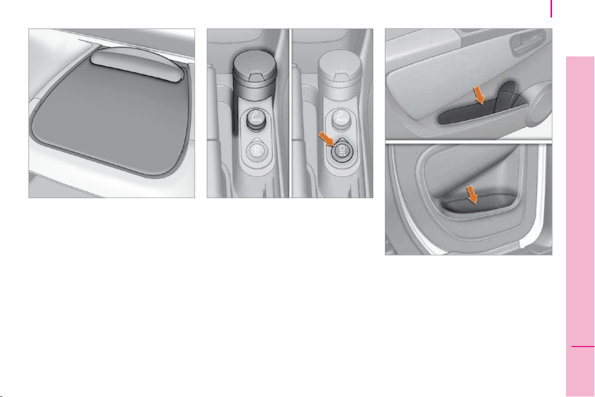
85
4
ERGONOMICS and COMFORT
Practical information
Smoker’s kit
Located at the base of the centre console,
this consists of a lighter and ashtray.
12 volt socket (180 W max)
An accessories socket is provided next to
the lighter.
FRONT LAYOUT
Folding writing table (Light van)
This is located in the centre of the fascia
panel. In the absence of a table, the vehicle
is fitted with a storage compartment.
The clip can be used to secure A5 format
documents, slips, etc.
Pull the top of the table to unfold it, push to
fold it.
Storage compartment in the door
trays
With recess for storing a 1 litre bottle.
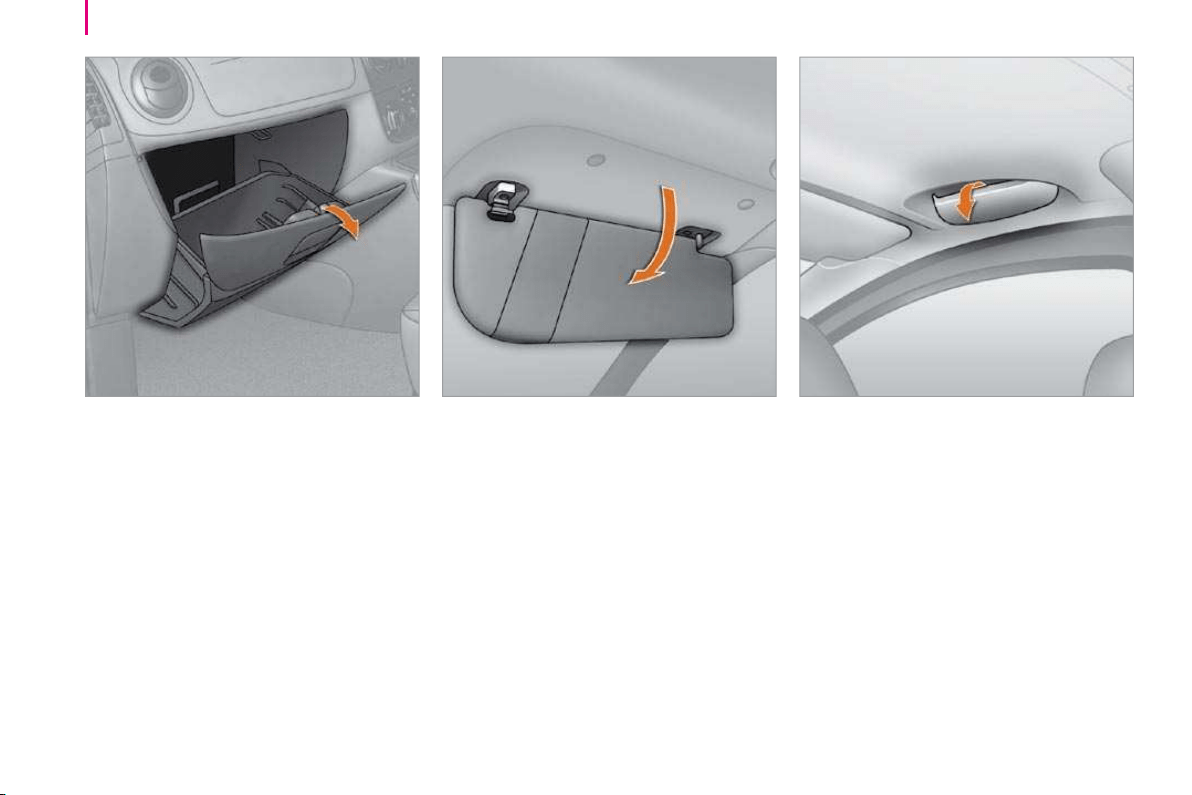
86
Practical information
Sun visor
To avoid glare from ahead, fold and direct
the sun visor down.
Toll cards, tickets, etc. can be slipped into
the sun visor on the driver’s side.
The sun visor on the passenger’s side may
be fitted with a courtesy mirror.
Glove box
This can accommodate a laptop.
It contains the handbook pack.
Spectacles storage (Combi)
There is a spectacles storage compartment
on the driver’s side, above the door.
To open it, unclip the cover pulling at the
centre.
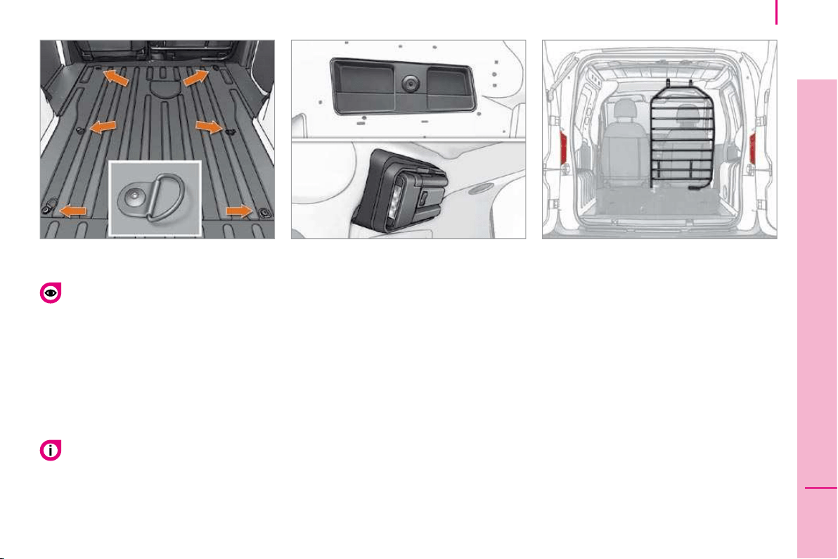
87
4
ERGONOMICS and COMFORT
Practical information
LOAD SPACE LAYOUT
Stowing rings
There are 6 stowing rings on the rear floor to
secure your loads.
As a safety precaution in case of sharp
braking, you are advised to place heavy
objects as far forwards towards the driver’s
seat as possible.
Storage tray
A storage tray is provided at the rear left of
the load space.
Torch
A magnetic torch is provided at the rear
right of the load space.
Remove the torch from its base by
pressing the button then pivoting the torch
downwards by 90 degrees.
To switch on the torch, slide the switch
forwards.
To change the 4 storage batteries (NiMH
type), remove the protective cover from
the torch.
To put the torch back in place, engage
it in the notches on the base and pivot it
upwards.
Ladder type vertical partition
Behind the driver’s seat, a ladder type
vertical partition protects the driver against
the risk of load movement.
Partitions
Panel, glazed and mid-height panel
with grille type partitions are offered to
complement your light van.
The transportation of passengers in the
load space is not permitted.
You are advised to immobilise the load
by securing it firmly using the stowing
rings on the floor.
The torch’s storage batteries recharge
automatically while driving.
An additional light is installed in the centre of
the torch base (refer to the "Interior lighting"
section).
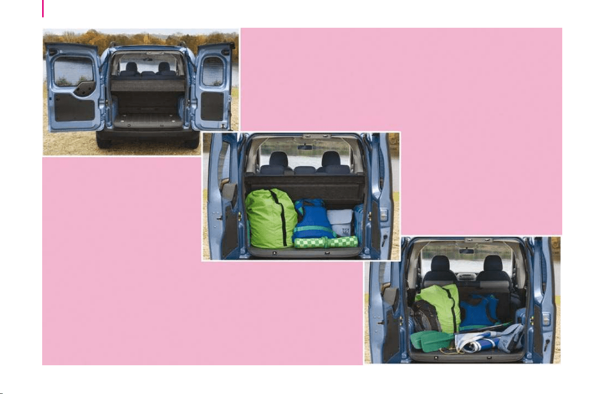
88
Practical information
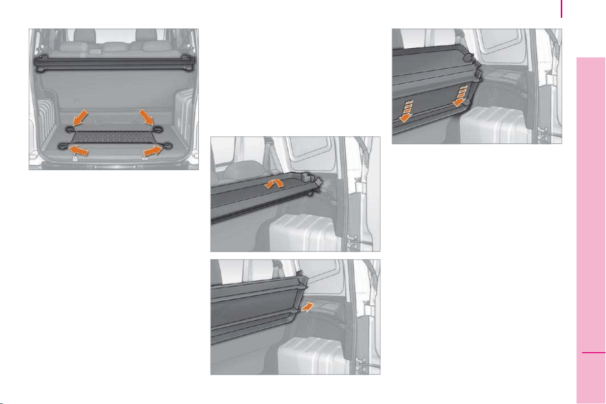
89
4
ERGONOMICS and COMFORT
Practical information
REAR LAYOUT
Stowing rings
There are 4 stowing rings on the rear floor to
secure your luggage.
Luggage retaining net
Hooked onto the stowing rings, this enables
you to secure your luggage.
Rear shelf
Unfold the shelf to conceal the contents of
the boot from sight from the outside.
Fold the shelf back on itself for easier
access to the contents of the boot.
Store the shelf behind the rear bench seat
when loading bulky items vertically.
Removing the shelf
Fold the shelf back on itself.
Lift the shelf to approximately 60°.
Unclip the shelf’s side fixings from its
supports.
Remove the shelf.
Store the folded shelf in the location behind
the rear bench seat.
To put the shelf back in place, carry out
these operations in reverse order.
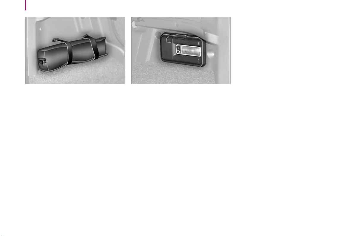
90
Practical information
Retaining straps
There are two retaining straps on the left-
hand side of the boot.
They secure the tool kit.
Torch
A magnetic torch is provided on the right-
hand side of the boot.
Remove the torch from its base by
pressing the button then pivoting the torch
downwards by 90 degrees.
To switch on the torch, slide the switch
forwards.
To change the 4 storage batteries (NiMH
type), remove the protective cover, located
on the torch.
To put the torch back in place, engage
it in the notches on the base and pivot it
upwards.
The torch’s storage batteries recharge
automatically while driving.
A boot lamp is installed in the centre of the
torch base (refer to the "Interior lighting"
section).
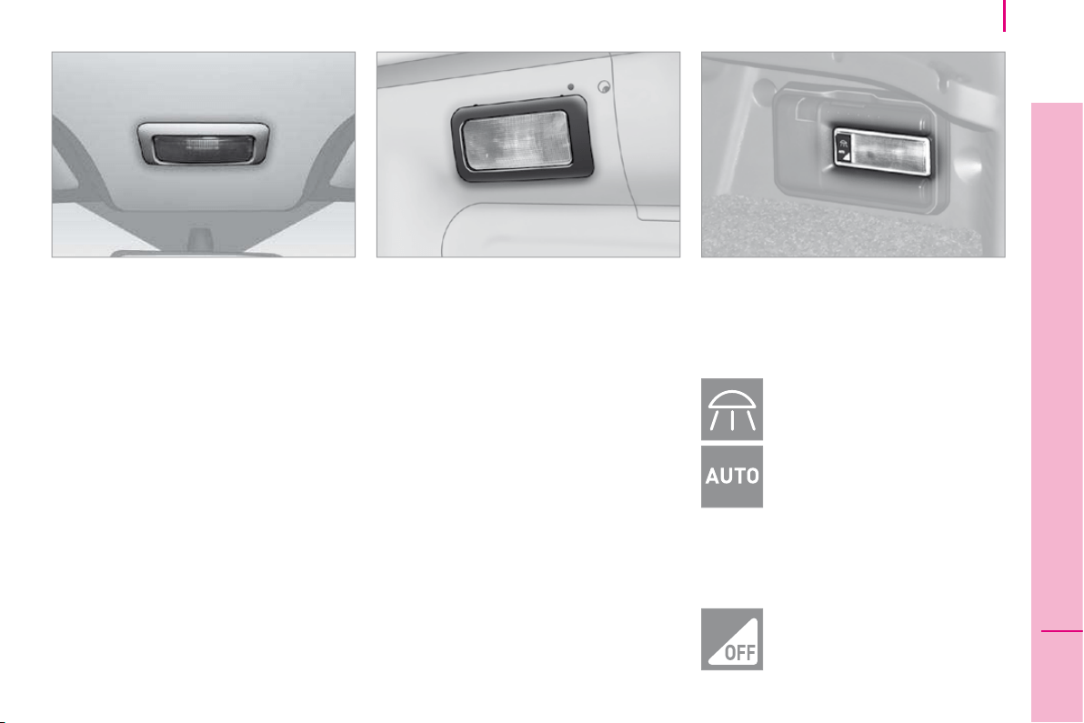
91
4
ERGONOMICS and COMFORT
Practical information
INTERIOR LIGHTING
Front courtesy lamp
This is located in the centre of the roof.
It can be activated by:
- tilting the lens,
- opening or closing a door,
- locking or unlocking the vehicle.
It switches off automatically, after a few
minutes, if the doors remain open, or when
the ignition is switched on.
The courtesy lamp may be fitted with an
alarm sensor, a microphone for the hands-
free kit and reading lights.
The reading lampshave right-hand and left-
hand switches.
Rear courtesy lamp
This is located on the upper part of the rear
right side.
Press the side of the courtesy lamp lens to
switch it on or off.
It comes on automatically when a door is
opened.
Good practice
It switches off automatically:
- if the switch is not pressed down,
- in all cases within approximately
15 minutes if the doors remain open,
- when the ignition is switched on,
- when the vehicle is locked.
Boot lamp
This is located in the centre of the torch
base.
The lamp operates in accordance with the
three positions of the switch below.
Permanently on.
In this "AUTO" position, it comes
on gradually when the vehicle is
unlocked and when a rear door or
the tailgate is opened.
It switches off automatically, after a few
minutes, if a rear door or the tailgate
remains open, or when the ignition is
switched on.
Permanently off.
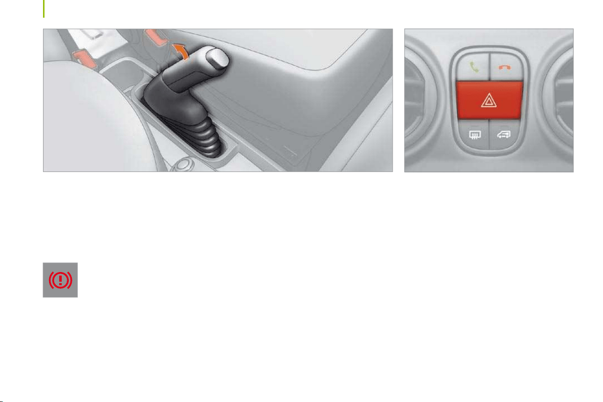
92
Driving safety
HANDBRAKE
Applying
Pull the handbrake to immobilise your
vehicle.
Check that the handbrake is applied firmly
before leaving the vehicle.
If the handbrake is still on or has
not been released properly, this is
indicated by this warning light which
comes on on the instrument panel.
When parking on a slope, direct your wheels
towards the pavement and pull the handbrake.
There is no advantage in engaging a gear
after parking the vehicle, particularly if the
vehicle is loaded.
Releasing
Pull the handle and press the button to lower
the handbrake.
HAZARD WARNING LIGHTS
Press this button, the two direction
indicators flash.
They operate with the ignition off.
When the hazard warning lights are switched
on, the change of direction function, via the
right-hand or left-hand direction indicator,
is deactivated.

93
5
SAFETY
Driving safety
HORN
Press the centre of the steering wheel.
ABS ANTI-LOCK BRAKING SYSTEM
The ABS increases the stability and
manoeuvrability of your vehicle when
braking, particularly on poor or slippery road
surfaces.
Note: when changing wheels (tyres and
rims), make sure that they conform to the
manufacturer’s recommendations.
The anti-lock braking system comes into
operation automatically when there is a risk
of wheel lock.
Normal operation of the ABS may make
itself felt by slight vibrations of the brake
pedal.
In emergency braking, press very firmly
without releasing the pressure.
Good practice
The anti-lock braking system comes into
operation automatically when there is a risk
of wheel lock. It does not permit shorter
braking. On very slippery road surfaces
(ice, oil, etc.) the ABS may lengthen the
braking distances. In emergency braking,
do not hesitate to press the brake pedal
firmly, without releasing the pressure, even
on slippery roads, you will then be able to
continue to manoeuvre the vehicle to avoid
an obstacle.
If the ABS warning light on the
instrument panel comes on, this
indicates a malfunction of the anti-
lock braking system which could
result in a loss of control of the vehicle on
braking.
Stop immediately.
Consult a CITROËN dealer.
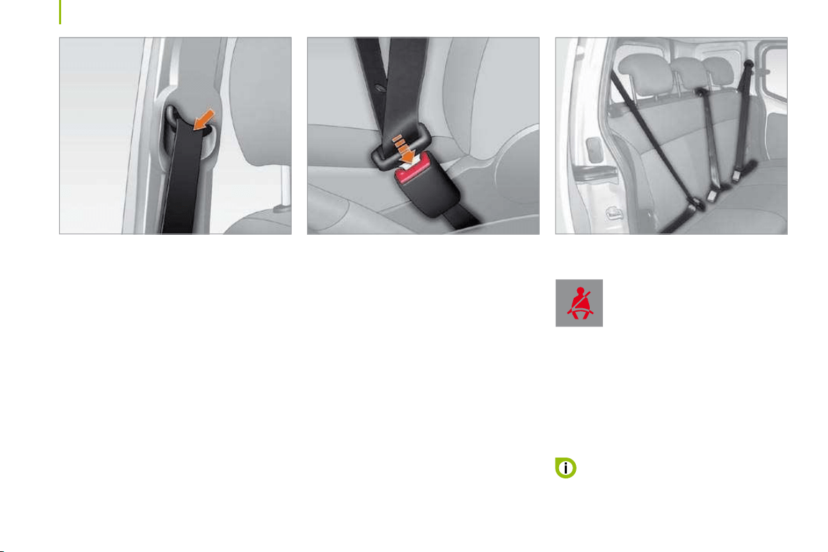
94
Seat belts
FRONT SEAT BELTS
The front seats are fitted with pre-tensioners
and force limiters.
Fastening
Pull the strap, then insert the tongue into the
buckle.
Check that the seat belt is fastened correctly
by pulling the strap.
The lap belt must be positioned as low as
possible on the pelvis. The chest belt must
pass over the hollow of the shoulder.
Inertia reel seat belts
These are fitted with a device which locks
automatically in the event of a collision or
emergency braking.
Safety in the event of a front impact has
been improved by the introduction of
pretensioning and force limiting seat belts.
Depending on the seriousness of the
impact, the pretensioning system instantly
tightens the seat belt against the body of the
occupant.
The pretensioning seat belts are active when
the ignition is on.
The force limiter reduces the pressure of the
seat belt against the body of the occupant in
the event of an accident.
Driver’s seat belt not fastened warning
light
When the vehicle is started,
this warning light comes on if the
driver has not fastened his seat
belt.
REAR SEAT BELTS (COMBI)
The 3-seat bench is fitted with three-point
inertia reel seat belts with force limiter.
The centre seat has a seat belt guide and
inertia reel, integrated with the seat back.
When a seat belt is not in use, you can
store its buckle in the housing provided
in the bench seat cushion.
95
5
SAFETY
Seat belts
Good practice
The driver must ensure that all passengers
fasten their seat belt correctly.
Wherever you are seated in the vehicle,
always fasten your seat belt, even for short
journeys.
The seat belts are fitted with an inertia reel
which automatically adjusts the length of the
strap to your size. The seat belt is rolled up
automatically when not in use.
Ensure that the seat belt is rolled up
correctly after use.
After folding or moving a seat, ensure that
the seat belt is rolled up correctly in its
compartment and that the buckle is ready to
accommodate the tongue.
The inertia reels are fitted with a device
which automatically locks the strap in the
event of a collision or emergency braking or
if the vehicle rolls over.
The air bag warning light comes
on if the pretensioners are
triggered. Consult a CITROËN
dealer.
Depending on the nature and seriousness of
any impact, the pretensioning device may be
triggered before and independently of infl ation
of the air bags. It instantly tightens the seat
belts against the body of the occupants.
The triggering of the pretensioners is
accompanied by a slight discharge of
harmless smoke and a noise, due to the
activation of the pyrotechnic cartridge
incorporated in the system.
The force limiter reduces the pressure of the
seat belt against the body of the occupants.
The equipment fitted to these seat belts is
operational when the ignition is switched on.
In order to be effective, a seat belt must:
- restrain one person only,
- must not be twisted, check by pulling in
front of you with an even movement,
- be tightened as close to the body as
possible.
The upper part of the seat belt should be
positioned in the hollow of the shoulder.
The lap part should be placed as low as
possible on the pelvis.
Do not invert the seat belt buckles as they
will not fulfil their role completely. If the
seats are fitted with armrests, the lap part of
the seat belt should always pass under the
armrest.
Check that the seat belt is fastened correctly
by pulling the strap firmly.
Recommendations for children:
- use a suitable child seat if the passenger
is less than 12 years old or shorter than
one metre fifty,
- never allow a child to travel on your lap,
even with the seat belt fastened.
For further information regarding child
seats, refer to the "Children on board"
section of chapter 5.
In accordance with current safety
regulations, your CITROËN dealer
guarantees all work or any checks, from
testing to maintenance, on your seat belt
equipment.
Have the seat belts checked regularly
(even after a minor impact) by a CITROËN
dealer: they must not show any signs of
wear, cutting or fraying and they must not be
transformed or modified.
Clean the seat belt straps with soapy
water or a textile cleaning product, sold
by a CITROËN dealer.
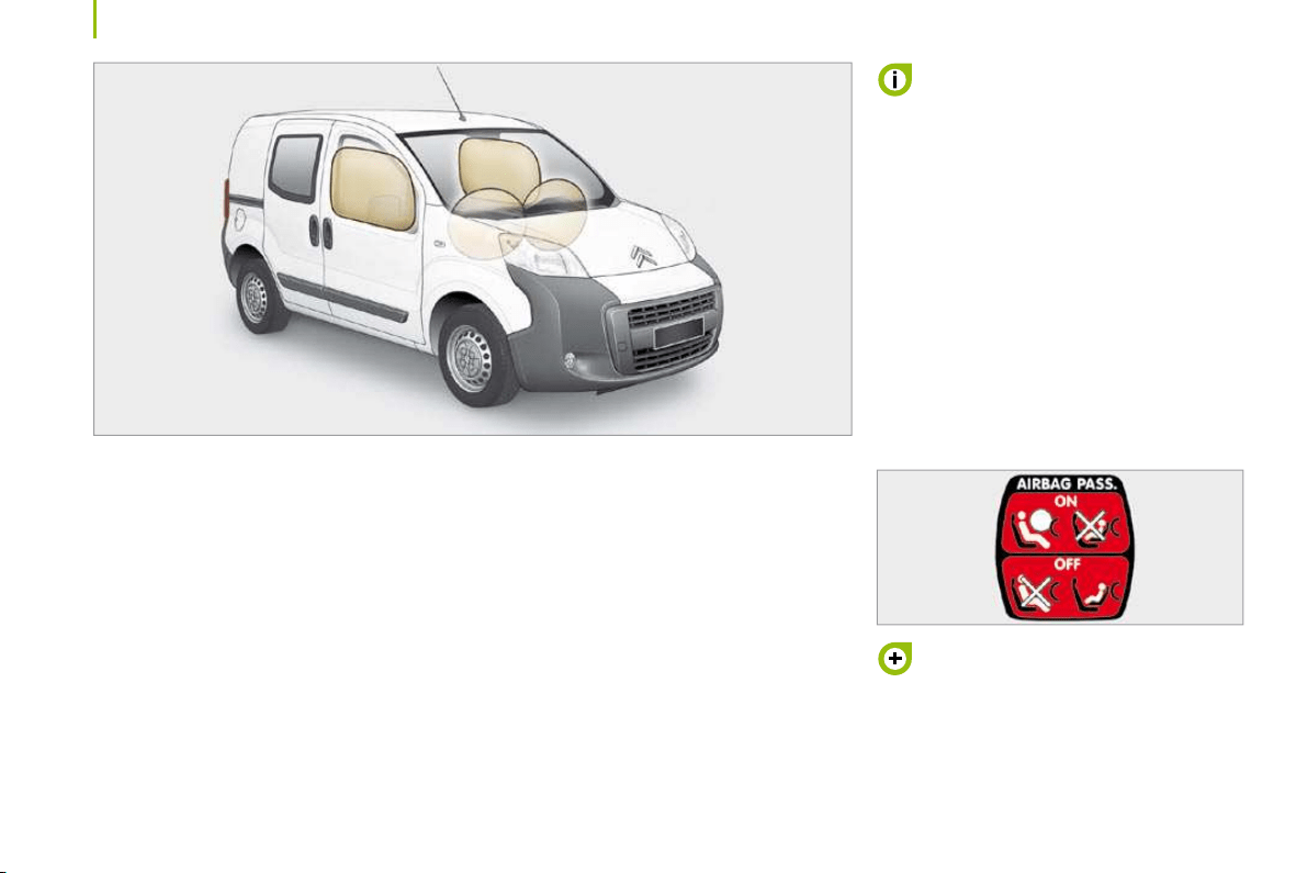
96
Air bags
AIR BAGS
The air bags have been designed to
maximise the safety of the occupants in the
event of a serious collision; they work in
conjunction with the force limiting seat belts.
In the event of a serious collision, the
electronic detectors record and analyse the
front and side impacts suffered in the impact
detection zones:
- in the event of a serious impact, the air
bags inflate instantly and protect the
occupants of the vehicle. Immediately
after the impact, the air bags deflate
rapidly, so that they do not hinder the
visibility of the occupants nor their
possible exit from the vehicle.
- in the event of a minor or rear impact
and in certain roll-over conditions, the air
bags will not be deployed; the seat belt
alone is sufficient to provide maximum
protection in these situations.
The seriousness of the collision depends on
the nature of the obstacle and the speed of
the vehicle at the moment of impact.
Air bags only operate when the
ignition is switched on.
This equipment only operates once. If a
second impact occurs (during the same or
a subsequent accident), the air bag will not
operate.
The triggering of an air bag or air bags
is accompanied by a slight discharge of
harmless smoke and a noise, due to the
activation of the pyrotechnic cartridge
incorporated in the system.
This smoke is not harmful, but sensitive
individuals may experience some irritation.
The noise of the detonation may result in a
slight loss of hearing for a short time.
It is imperative that the passenger
air bag is disarmed if a child seat is
installed facing rearwards. Refer to the
"Children on board" section of chapter 5.
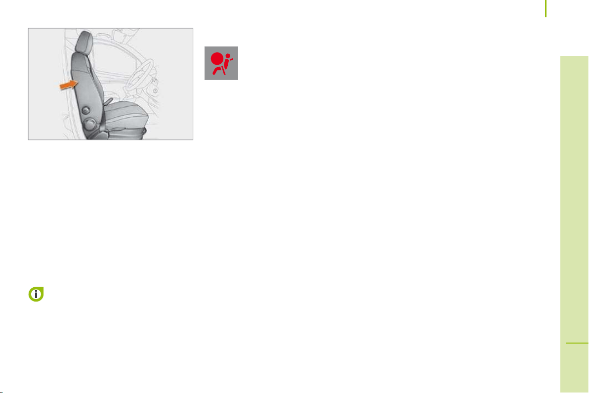
97
5
SAFETY
Air bags
SIDE AIR BAGS
Activation
It is triggered unilaterally in the event of a
serious side impact, perpendicular to the
longitudinal centreline of the vehicle on
a horizontal plane and directed from the
outside towards the inside of the vehicle.
The side air bag inflates between the
front occupant of the vehicle and the
corresponding door trim pad.
In the event of a minor impact or bump
on the side of the vehicle or if the
vehicle rolls over, the air bag may not be
triggered.
Operating fault
If this warning light comes on on
the instrument panel, consult a
CITROËN dealer without delay to
have the system checked. The air
bags may no longer be triggered
in the event of a serious impact.

99
5
SAFETY
Air bags
For the air bags to be fully effective,
observe the following safety rules:
Sit in a normal upright position.
Wear a correctly adjusted seat belt.
Do not leave anything between the
occupants and the air bags (a child, pet,
object...). This could hamper the operation
of the air bags or injure the occupants.
After an accident or if the vehicle has been
stolen or broken into, have the air bag
systems checked.
All work on the air bag systems is strictly
forbidden unless it is carried out by the
qualified personnel of a CITROËN dealer.
Even if all of the precautions mentioned are
observed, a risk of injury or of slight burns
to the head, chest or arms when an air bag
is triggered cannot be ruled out. In fact,
the bag inflates almost instantly (within a
few milliseconds) then deflates within the
same time, discharging the hot gas through
openings provided for this purpose.
Front air bags
Do not drive holding the steering wheel
by its spokes or resting your hands on the
centre part of the wheel.
Passengers must not place their feet on the
fascia.
Smoke as little as possible as deployment of
the air bags can cause burns or the risk of
injury from a cigarette or pipe.
Never remove or pierce the steering wheel
or hit it violently.
Side air bags
Only put approved covers on the seats.
These will not hinder the triggering of the
side air bags. Consult a CITROËN dealer.
Do not fix or glue anything to the seat backs.
This could cause injury to the chest or arms
when the side air bag inflates.
Do not sit with the upper part of the body
any nearer to the door than necessary.

96
Air bags
AIR BAGS
The air bags have been designed to
maximise the safety of the occupants in the
event of a serious collision; they work in
conjunction with the force limiting seat belts.
In the event of a serious collision, the
electronic detectors record and analyse the
front and side impacts suffered in the impact
detection zones:
- in the event of a serious impact, the air
bags inflate instantly and protect the
occupants of the vehicle. Immediately
after the impact, the air bags deflate
rapidly, so that they do not hinder the
visibility of the occupants nor their
possible exit from the vehicle.
- in the event of a minor or rear impact
and in certain roll-over conditions, the air
bags will not be deployed; the seat belt
alone is sufficient to provide maximum
protection in these situations.
The seriousness of the collision depends on
the nature of the obstacle and the speed of
the vehicle at the moment of impact.
Air bags only operate when the
ignition is switched on.
This equipment only operates once. If a
second impact occurs (during the same or
a subsequent accident), the air bag will not
operate.
The triggering of an air bag or air bags
is accompanied by a slight discharge of
harmless smoke and a noise, due to the
activation of the pyrotechnic cartridge
incorporated in the system.
This smoke is not harmful, but sensitive
individuals may experience some irritation.
The noise of the detonation may result in a
slight loss of hearing for a short time.
It is imperative that the passenger
air bag is disarmed if a child seat is
installed facing rearwards. Refer to the
"Children on board" section of chapter 5.
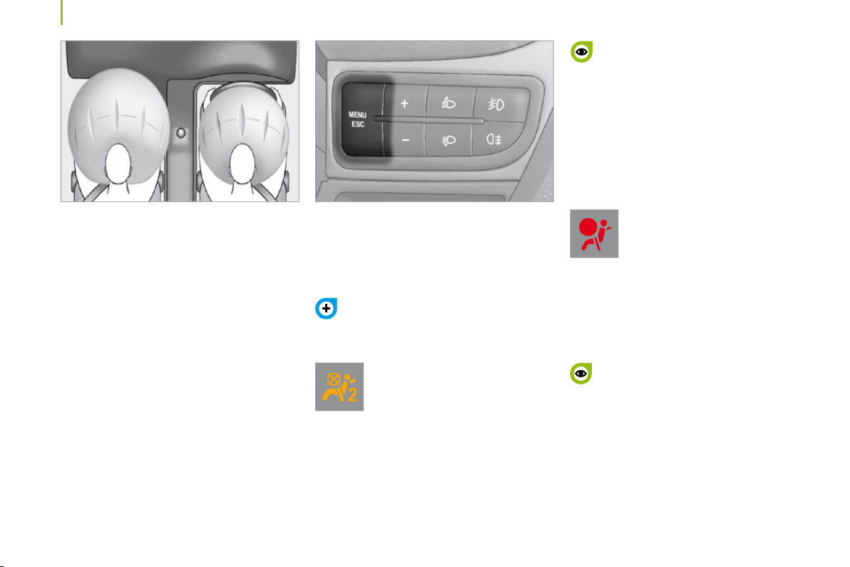
98
Air bags
FRONT AIR BAGS
The front air bags are incorporated in the
centre of the steering wheel for the driver
and in the fascia for the front passenger.
Activation
They are deployed simultaneously, unless
the passenger’s front air bag has been
disarmed, in the event of a serious front
impact.
The front air bag inflates between the front
occupant of the vehicle and the fascia to
cushion his forward movement.
Disarming
The passenger’s front air bag alone can be
disarmed. The air bag is disarmed from the
trip computer.
The air bag warning light on the
instrument panel is lit throughout
the period of disarming.
To ensure the safety of your child,
it is essential to disarm the passenger
air bag when you install a rear-facing child
seat on the front passenger seat. Otherwise,
the child would risk being killed or seriously
injured if the air bag were to inflate.
Refer to the "MENU" section of chapter 3,
then select OFF on the "Passenger air
bag" menu.
Operating fault
If the two air bag warning lights are lit
continuously, do not install a rear-
facing child seat. Consult a CITROËN
dealer.
If this warning light comes
on on the instrument panel,
accompanied by an audible signal
and a message on the display,
consult a CITROËN dealer without delay
to have the system checked. The air bags
may no longer be triggered in the event of a
serious impact.

99
5
SAFETY
Air bags
For the air bags to be fully effective,
observe the following safety rules:
Sit in a normal upright position.
Wear a correctly adjusted seat belt.
Do not leave anything between the
occupants and the air bags (a child, pet,
object...). This could hamper the operation
of the air bags or injure the occupants.
After an accident or if the vehicle has been
stolen or broken into, have the air bag
systems checked.
All work on the air bag systems is strictly
forbidden unless it is carried out by the
qualified personnel of a CITROËN dealer.
Even if all of the precautions mentioned are
observed, a risk of injury or of slight burns
to the head, chest or arms when an air bag
is triggered cannot be ruled out. In fact,
the bag inflates almost instantly (within a
few milliseconds) then deflates within the
same time, discharging the hot gas through
openings provided for this purpose.
Front air bags
Do not drive holding the steering wheel
by its spokes or resting your hands on the
centre part of the wheel.
Passengers must not place their feet on the
fascia.
Smoke as little as possible as deployment of
the air bags can cause burns or the risk of
injury from a cigarette or pipe.
Never remove or pierce the steering wheel
or hit it violently.
Side air bags
Only put approved covers on the seats.
These will not hinder the triggering of the
side air bags. Consult a CITROËN dealer.
Do not fix or glue anything to the seat backs.
This could cause injury to the chest or arms
when the side air bag inflates.
Do not sit with the upper part of the body
any nearer to the door than necessary.
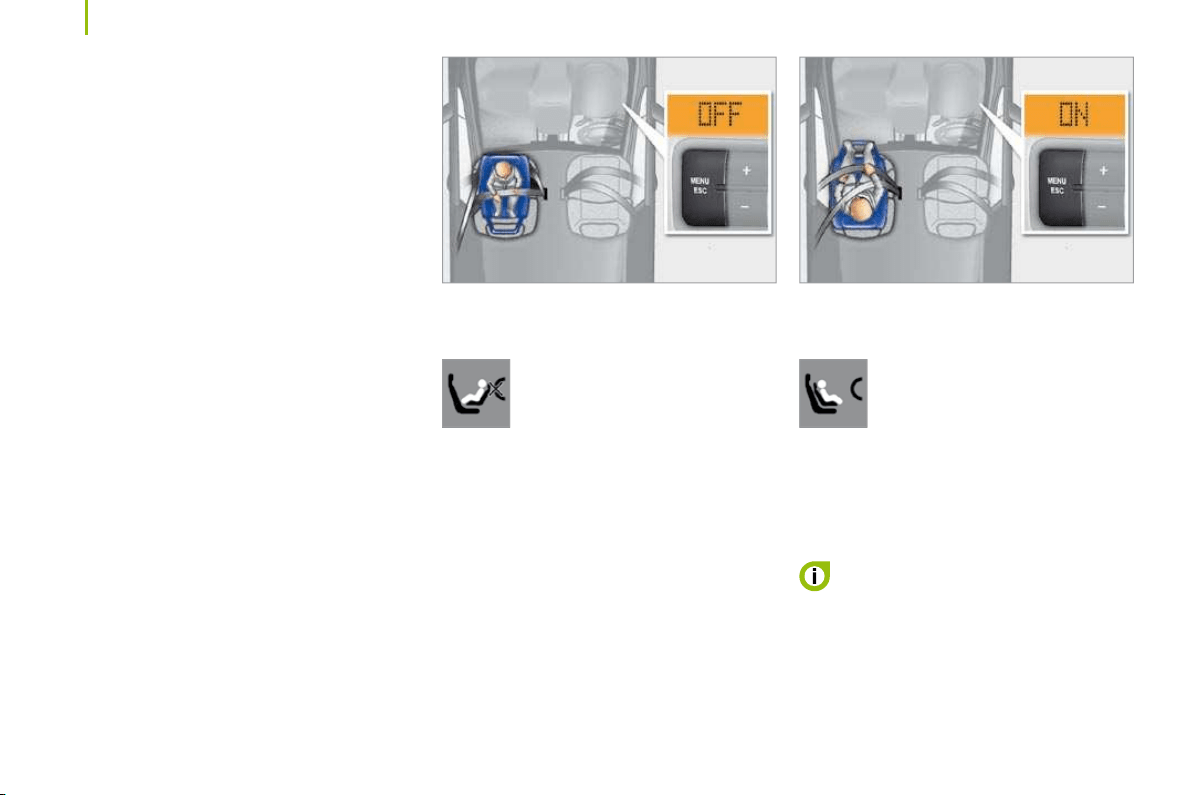
100
Child safety
GENERAL POINTS RELATING TO CHILD
SEATS
Although one of CITROËN’s main criteria
when designing your vehicle, the safety of
your children also depends on you.
For maximum safety, please follow these
precautions:
- in accordance with European regulations,
all children under the age of 12 or less
than one metre fifty tall must travel in
approved child seats suited to their
weight , on seats fitted with a seat belt or
ISOFIX mountings.
- statistically, the safest seats in your
vehicle for the transportation of
children are the rear seats,
- a child weighing less than 9 kg must
travel in the "rearwards-facing"
position in the front.
CITROËN recommends that children should
travel in the rear seats of your vehicle:
- "rearwards-facing" up to the age of 2 ,
- "forwards-facing"from the age of 2.
INSTALLING A CHILD SEAT USING A THREE POINT SEAT BELT
"Rearwards-facing"
Do not forget to disarm the air
bag before installing the child.
When a "rearwards-facing" child
seat is installed on the front
passenger seat , it is essential that the
passenger air bag is disarmed. Otherwise,
the child would risk being seriously
injured or killed if the air bag were to
inflate .
"Forwards-facing"
When a "forwards-facing" child
seat is installed on the front
passenger seat , leave the
passenger air bag armed.
The rules for transporting children are
specific to each country. Consult the current
legislation in your country.
Please consult the list of seats
approved in your country. The Isofix
mountings, the rear seats, the passenger air
bag and the disarming of this air bag depend
on the version sold.
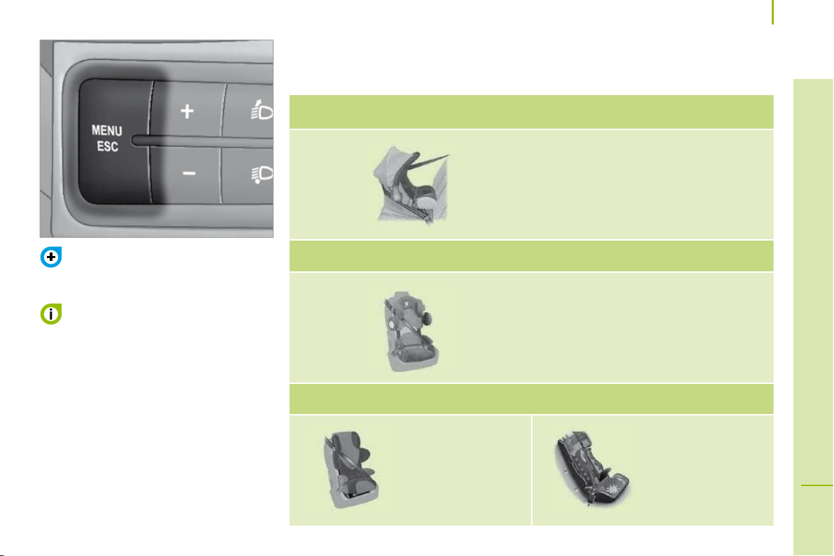
101
5
SAFETY
Child safety
To disarm or activate the passenger air
bag, refer to Chapter 3, "MENU".
CHILD SEATS RECOMMENDED BY CITROËN
CITROËN offers a complete range of recommended child seats which are secured using a
three point seat belt :
The child seats function is shared by
the entire CITROËN range. However,
each individual model has its own special
features.
If your vehicle is fitted with this function, the
passenger air bag must be disarmed using
the trip computer MENU button.
If your vehicle is not fitted with the
passenger air bag disarming function, the
installation of a "rear-facing" child seat on
the vehicle’s front seat is strictly prohibited.
The passenger must not travel with a child
on his lap.
Group 0: from birth to 10 kg
Group 0+: from birth to 13 kg
L1
"ROMER Baby-Safe Plus"
Installed in the rear-facing position .
Groups 1, 2 and 3: from 9 to 36 kg
L2
"KIDDY Life"
The use of the restraining cushion is
compulsory for transporting young children
(from 9 to 18 kg).
Groups 2 and 3: from 15 to 36 kg
L3
"RECARO Start".
L4
"KLIPPAN Optima"
From the age of
6 years
(approximately 22 kg),
the booster is used
on its own.
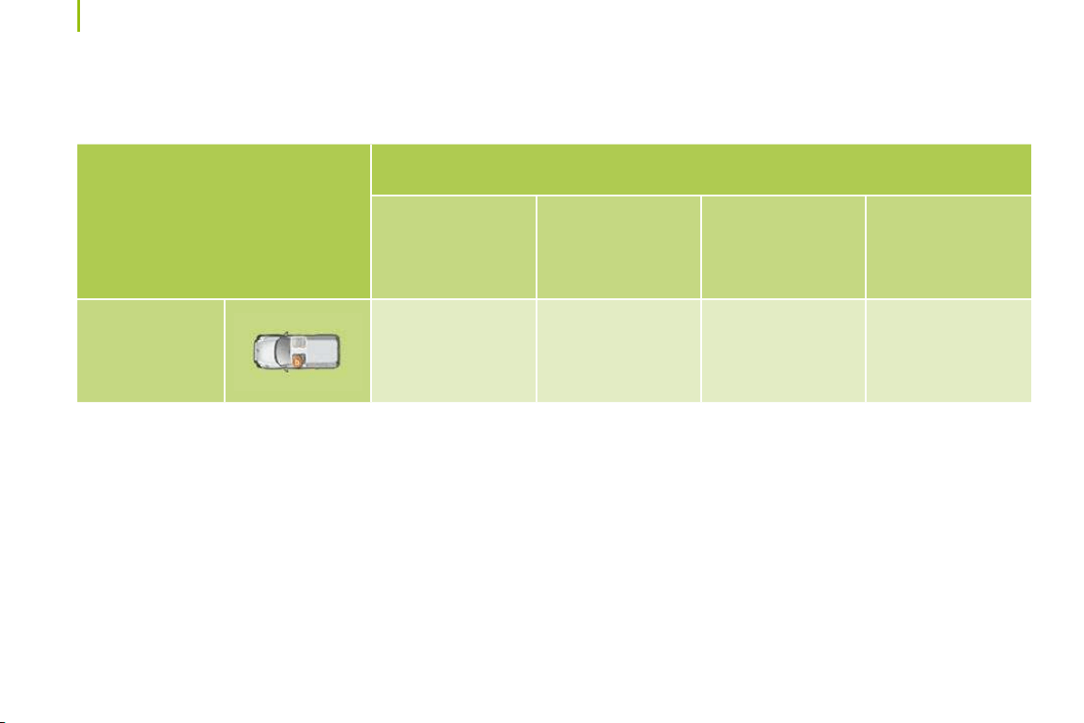
102
Child safety
INSTALLING CHILD SEATS ATTACHED USING THE SEAT BELT (LIGHT VAN)
In accordance with European regulations, this table indicates the options for installing child seats secured using a seat belt and universally
approved in accordance with the weight of the child and the seat in the vehicle.
Weight of the child and indicative age
Seat
Under 13 kg
(groups 0 ( a ) and 0+)
Up to approx 1 year
From 9 to 18 kg
(group 1)
1 to 3 years approx
From 15 to 25 kg
(group 2)
3 to 6 years approx
From 22 to 36 kg
(group 3)
6 to 10 years approx
Front passenger
seat ( b )
U U U U
a : Group 0: from birth to 10 kg. Infant car seats and "car cots" cannot be installed on the front passenger seat.
b : consult the legislation in force in your country before installing your child on this seat.
U : seat suitable for the installation of a child seat secured using a seat belt and universally approved, "rear facing" and/or "forward facing".
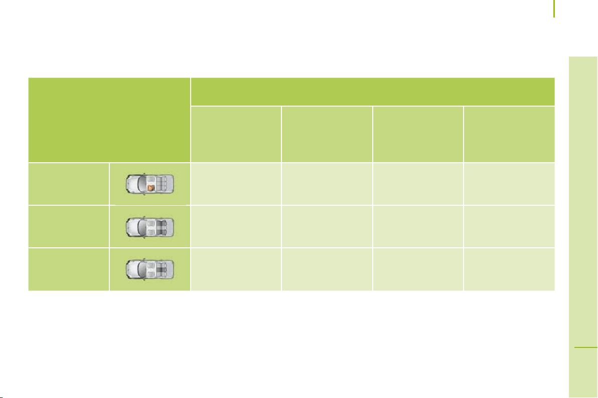
103
5
SAFETY
Child safety
INSTALLING CHILD SEATS ATTACHED USING THE SEAT BELT (COMBI)
In accordance with European regulations, this table indicates the options for installing child seats secured using a seat belt and universally
approved in accordance with the weight of the child and the seat in the vehicle.
Weight of the child and indicative age
Seat
Under 13 kg
(groups 0 ( a ) and 0+)
Up to approx 1 year
From 9 to 18 kg
(group 1)
1 to 3 years approx
From 15 to 25 kg
(group 2)
3 to 6 years approx
From 22 to 36 kg
(group 3)
6 to 10 years approx
Front passenger
seat ( b )
U U U U
Rear side seats U U U U
Rear centre seat U U U U
a : Group 0: from birth to 10 kg. Infant car seats and "car cots" cannot be installed on the front passenger seat.
b : consult the legislation in force in your country before installing your child on this seat.
U : seat suitable for the installation of a child seat secured using a seat belt and universally approved, "rear facing" and/or "forward facing".

104
Child safety
ADVICE ON CHILD SEATS
Installing a booster seat
The chest part of the seat belt must be
positioned on the child’s shoulder without
touching the neck.
Ensure that the lap part of the seat belt
passes correctly over the child’s thighs.
CITROËN recommends the use of a booster
seat which has a back, fitted with a seat belt
guide at shoulder level.
As a safety precaution, do not leave:
- one or more children alone and
unsupervised in a vehicle,
- a child or an animal in a vehicle which
is exposed to the sun, with the windows
closed,
- the keys within reach of children inside
the vehicle.
To prevent accidental opening of the doors,
use the "Child lock".
Children under the age of 10 must not travel
in the "forward facing" position on the front
passenger seat, unless the rear seats are
already occupied by other children, cannot
be used or are absent.
Disarm the passenger air bag when a "rear
facing" child seat is installed on the front
seat.
Otherwise, the child would risk being
seriously injured or killed if the air bag were
to inflate.
The incorrect installation of a child seat in a
vehicle compromises the child’s protection in
the event of an accident.
Remember to fasten the seat belts or the
child seat harnesses keeping the slack in
relation to the child’s body to a minimum ,
even for short journeys.
For optimum installation of the "forward
facing" child seat, ensure that the back of
the child seat is in contact with the back of
the vehicle’s seat and that the head restraint
does not cause any discomfort.
If the head restraint has to be removed,
ensure that it is stored or attached securely
to prevent it from being thrown around the
vehicle in the event of sharp braking.
To protect young children from the sun, fit
side blinds on the rear windows.
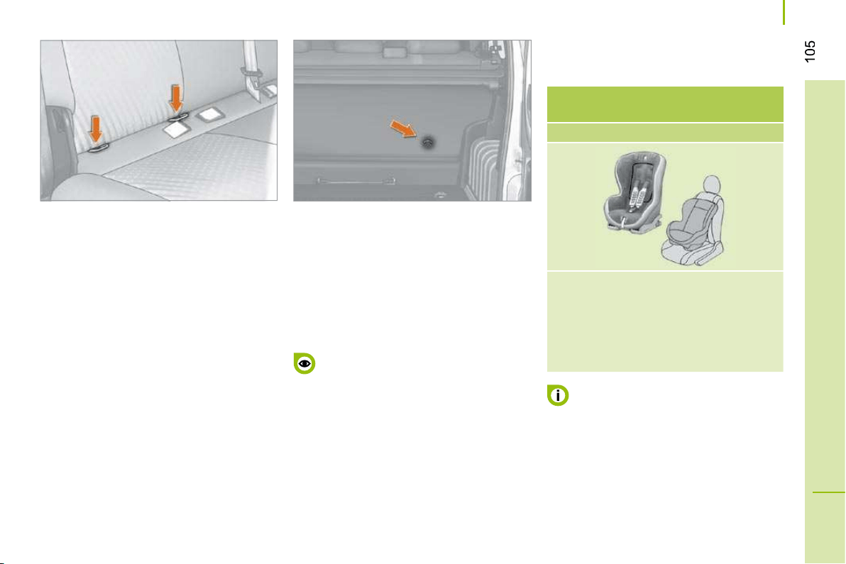
5
SAFETY
Child safety
"ISOFIX" MOUNTINGS
Some also have an upper strap which is
attached to the rear ring.
To attach this strap, raise the vehicle seat’s
head restraint then pass the hook between
its rods. Then fix the hook on the rear ring
and tighten the upper strap.
ISOFIX RÖMER Duo Plus
(size category B1 )
Group 1: from 9 to 18 kg
Installed in the forward facing position.
Fitted with an upper strap to be secured
on the ISOFIX upper ring,
referred to as the TOP TETHER.
Three seat body angles: sitting,
reclining, lying.
This child seat can also be used on
seats which are not fitted with ISOFIX
mountings.
In this case, it must be attached to the
vehicle seat using the three point seat belt.
Follow the instructions for fitting
the child seat given in the seat
manufacturer’s installation guide.
The incorrect installation of a child seat
in a vehicle compromises the child’s
protection in the event of an accident.
ISOFIX CHILD SEAT RECOMMENDED BY
CITROËN AND APPROVED FOR YOUR
VEHICLE
Your vehicle has been approved in
accordance with the new ISOFIX regulation.
The mountings comprise three rings for each
rear bench side seat:
- two front rings, located between the
vehicle seat back and cushion,
- a rear ring, for securing the upper strap
referred to as the TOP TETHER.
This ISOFIX mounting system guarantees
you fast, reliable and safe fitting of the child
seat in your vehicle.
The ISOFIX child seats are fitted with two
locks which are secured easily on the two
front rings.

106
Child safety
SUMMARY TABLE FOR THE INSTALLATION OF ISOFIX CHILD SEATS (COMBI)
In accordance with European regulations, this table indicates the options for the installation of ISOFIX child seats on the vehicle seats fitted
with ISOFIX mountings.
In the case of the universal and semi-universal ISOFIX child seats, the child seat’s ISOFIX size category, determined by a letter from A to G ,
is indicated on the child seat next to the ISOFIX logo.
IUF: seat suitable for the installation of an I sofix U niversal seat, " F orward facing" and secured using the "Top Tether" upper strap.
IL-SU: seat suitable for the installation an I sofix S emi- U niversal seat which is:
- "rear facing" fitted with a "Top Tether" upper strap or a stay,
- "forward facing" fitted with a stay,
For the securing of the "Top Tether" upper strap, refer to the "Isofix Mountings" section.
X: seat which is not suitable for the installation of an ISOFIX seat of the size category indicated.
Weight of the child /indicative age
Less than
10 kg
(group 0)
Up to 6 months
approx
Less than 10 kg
(group 0)
Less than 13 kg
(group 0+)
Up to 1 year approx
From 9 to 18 kg (group 1)
From 1 to 3 years approx
Type of ISOFIX child seat
Infant car
seat *
"rear facing" "rear facing" "forward facing"
ISOFIX size category F G C D E C D A B B1
Universal and semi-universal ISOFIX child
seats which can be installed on the rear
side seats
X IL-SU IL-SU IUF
* Infant car seats and "car cots" cannot be installed on the front passenger seat.
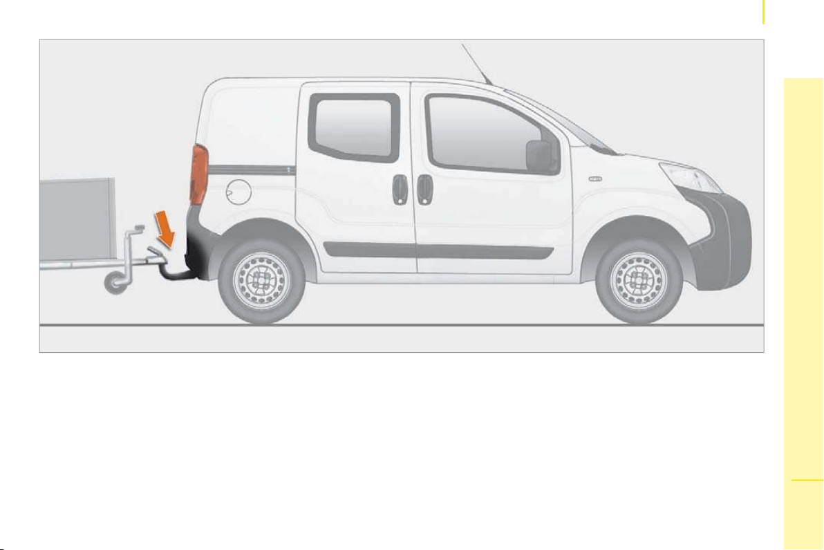
107
6
ACCESSORIES
Towing a trailer
TOWING A TRAILER, CARAVAN, BOAT, ETC...
Driving advice
As the fan is electrically controlled, its
cooling capacity is not dependent on the
engine speed.
On the contrary, use a high gear to lower the
engine speed and reduce your speed.
In all cases, pay attention to the coolant
temperature.
A towed vehicle must free wheel: gearbox in
neutral.
Cooling: towing a trailer on a slope
increases the coolant temperature.
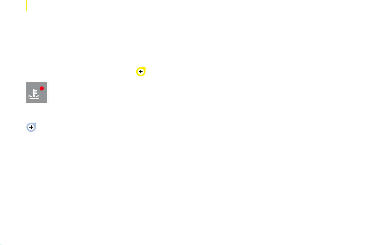
108
Towing a trailer
In certain cases of particularly arduous
use (towing the maximum load up a steep
slope in high temperatures), the engine
automatically limits its power. In this
case, the automatic cutting off of the air
conditioning allows the engine power to be
recovered.
If the coolant temperature
warning light comes on, stop the
vehicle and switch off the engine
as soon as possible.
See the "Levels" section of chapter 7.
Tyres: check the tyre pressures of the
towing vehicle (see the "Identification
features" section of chapter 7) and of
the trailer, observing the recommended
pressure.
Brakes: towing increases the braking
distance. Drive at a moderate speed,
change down early and brake gradually.
Side wind: sensitivity to side wind is
increased. Drive smoothly and at a
moderate speed.
ABS: the system only controls the vehicle,
not the trailer.
Rear parking assistance: the
assistance will be deactivated
automatically when an original CITROËN
towbar is used (see the "Rear parking
assistance" section of chapter 4).
Towbar
We recommend the use of original
CITROËN towbars and their harnesses,
which have been tested and approved from
the design stage of your vehicle, and that
the fitting of this equipment is entrusted to a
CITROËN dealer.
If this equipment is not fitted by a CITROËN
dealer, it is essential that it is fitted using
the electrical pre-equipment located at the
rear of the vehicle in accordance with the
manufacturer’s instructions.
The operation of the sensors is deactivated
automatically when the pin of the trailer
cable is inserted in the towbar socket.
When the trailer cable pin is removed, the
sensors are re-activated.
Distribution of loads
Distribute the load in the trailer so that the
heaviest objects are as close as possible
to the axle and the nose weight is close to
the maximum authorised without, however,
exceeding it. The air density decreases with
altitude, so reducing the performance of
the engine. The maximum towed load must
be reduced by 10 % for each 1 000 metres
of altitude. Refer to the "Technical data"
chapter for details of the weights and towed
loads applicable to your vehicle and also to
the administrative documents
(V5 registration document, ...).
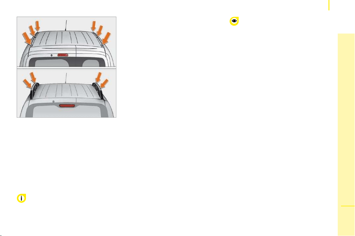
109
6
ACCESSORIES
Equipment
ROOF RACK AND ROOF BARS
To install the transverse roof bars or a
roof rack, use the fixings provided for this
purpose.
Maximum loads:
- on the roof rack: 80 kg,
- on the 3 transverse roof bars: 90 kg,
- on the 2 transverse roof bars fitted on the
longitudinal bars: 90 kg.
OTHER ACCESSORIES
A wide range of accessories and original
parts is offered by the CITROËN network.
These accessories and parts, having been
tested and approved for reliability and
safety, are all adapted to your vehicle.
They all benefit from CITROËN’s
recommendation and warranty.
Never exceed the gross vehicle weight
(GVW).
Range of professional equipment
The replacement parts department publishes
an accessories catalogue offering various
equipment and fittings, such as:
Towbars, 7/13 pin, 7/7 pin, 13 pin towbar
harness: trailer towbar which must be fitted
by a CITROËN dealer.
Roof bars, set of transverse roof bars,
loading roller.
Protective wood floor, non-slip wood floor,
wood side protection, window protection
grille.
The fitting of electrical equipment
or accessories which are not
recommended by Automobiles CITROËN
may result in the failure of your vehicle’s
electronic system.
Please note this specific warning. You
are advised to contact a representative
of the Marque to be shown the range of
recommended equipment and accessories.
Depending on the country in which the
vehicle is sold or operated, it is compulsory
to have a high visibility safety jacket,
warning triangle and replacement bulbs
available in the vehicle.
You are advised to contact a CITROËN
dealer before installing accessory
radiocommunication transmitters with
external aerial on your vehicle. Your
CITROËN dealer will inform you of the
characteristics (frequency band, maximum
output power, aerial position, specific
installation conditions) of the transmitters
which can be fitted, in accordance with the
Motor Vehicle Electromagnetic Compatibility
Directive (2004/104/EC).
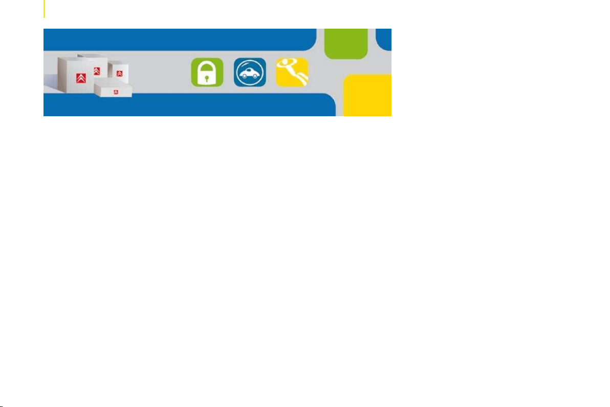
110
Equipment
Private vehicle accessories
Another range is also available from the
CITROËN network; this is structured around
5 groups:
"Protection":
anti-theft alarm, window engraving, first aid
kit, high visibility safety jacket, rear parking
assistance, warning triangle, snow chains...
"Touring":
seat covers compatible with the side air
bags, boot tray, rubber mats, carpet mats,
3D mats, net on rear door, set of transverse
bars on longitudinal bars...
To avoid any risk of jamming of the pedals:
- ensure that the mat is positioned
correctly,
- never fit one mat on top of another.
"In-car technology":
audio equipment, hands-free kit, speakers,
navigation...
"Styling":
trims...
"Universal":
screenwash, interior and exterior cleaning
and maintenance products, replacement
bulbs...
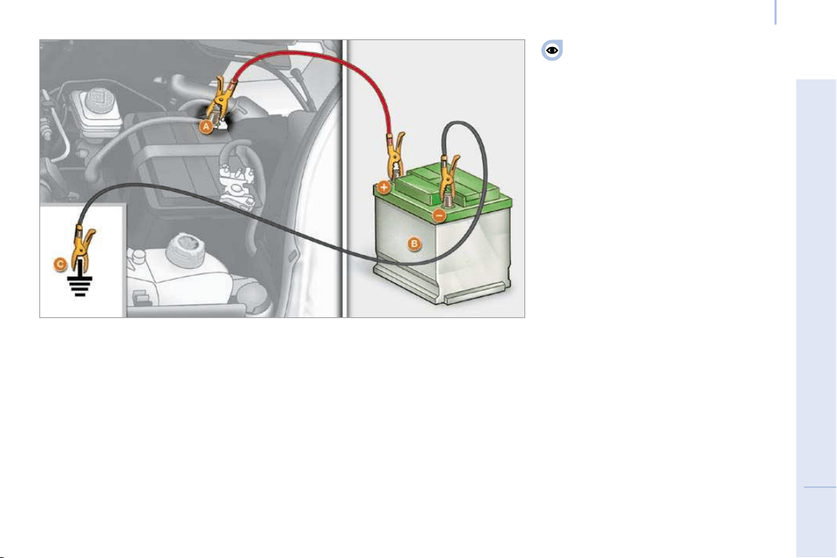
111
7
TROUBLESHOOTING
Battery
BATTERY
A. Positive metal point on your vehicle
B. Slave battery
C. Earth on your vehicle
CHARGING THE BATTERY USING
A CHARGER
- disconnect the battery,
- follow the instructions for use given by
the battery charger manufacturer,
- reconnect starting with the negative (-)
terminal,
- check that the terminals and connectors
are clean. If they are covered with
sulphate (white or greenish deposit),
disconnect them and clean them.
The charging operation must be carried
out in a ventilated area away from
naked flames or any possible sources of
sparks to eliminate the risk of explosion and
fire.
Do not attempt to charge a frozen battery: it
must first be thawed to eliminate the risks of
explosion. If the battery has frozen, before
charging it have it checked by a specialist
who will check that the internal components
have not been damaged and that the
container is not cracked, which could mean
that there is a risk of a leak of toxic and
corrosive acid.
STARTING FROM ANOTHER BATTERY
- connect the red cable to the metal point
A then to the positive (+) terminal of the
slave battery B ,
- connect one end of the green or black
cable to the negative (-) terminal of the
slave battery B ,
- connect the other end of the green or
black cable to the earth point C on your
vehicle,
- operate the starter, let the engine run,
- wait for the engine to return to idle, then
disconnect the cables.

112
Battery
The batteries contain
harmful substances such as sulphuric
acid and lead. They must be discarded in
accordance with the provisions of the law
and must not, in any circumstances, be
discarded with household waste.
Take used batteries to a special collection
point.
Before disconnecting the battery, you must
wait for 2 minutes after switching off the
ignition.
Never disconnect a terminal when the
engine is running.
Never charge a battery without first
disconnecting the terminals.
Close the windows and doors before
disconnecting the battery.
After every reconnection of the battery,
switch on the ignition and wait 1 minute
before starting to allow the electronic
systems to be initialised. If slight difficulties
are experienced after this, please consult a
CITROËN dealer.
It is advisable to disconnect the battery
if the vehicle is not to be used for a
period of more than one month.
If the battery has been disconnected
for some time, it may be necessary to
reinitialise the following functions:
- the display parameters (date, time,
language, distance unit and temperature
unit),
- the radio stations,
- the central locking.
Some settings are cleared and must be
reprogrammed, consult a CITROËN dealer.
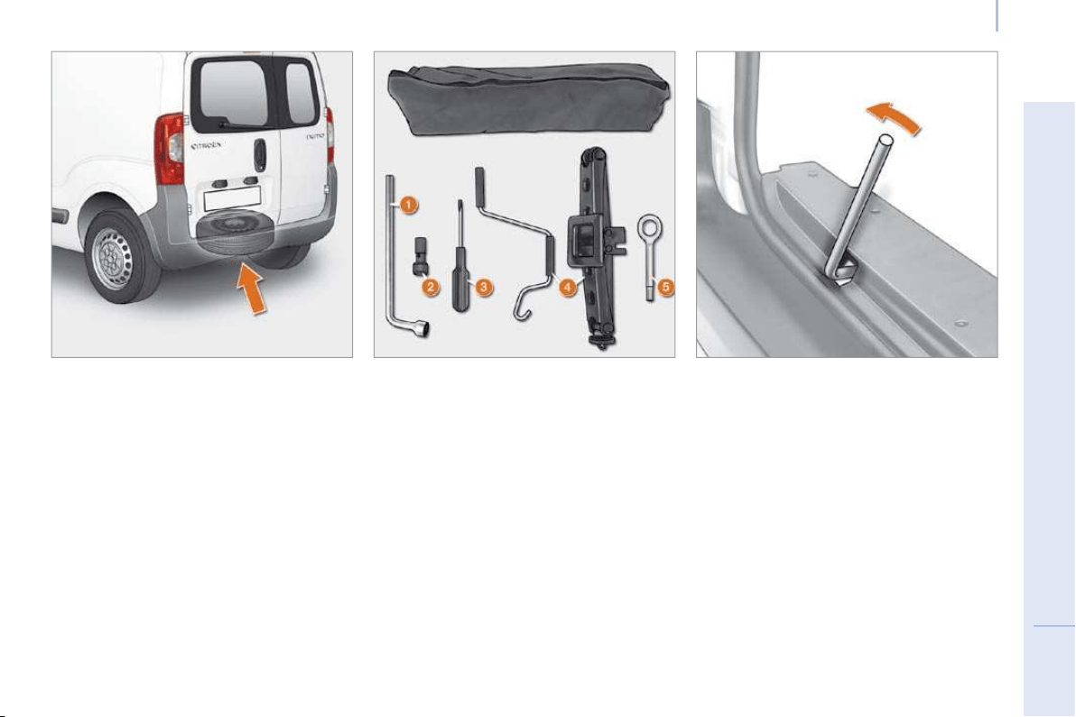
113
7
TROUBLESHOOTING
Changing a wheel
CHANGING A WHEEL
Parking the vehicle
As far as possible, park the vehicle on level,
stable and non-slippery ground.
Apply the handbrake, switch off the ignition
and engage first gear (on a hill).
It is imperative that you ensure that the
occupants get out of the vehicle and wait in
a safe location.
If possible, place a chock under the
wheel diagonally opposite the wheel to be
changed.
Tools
The tools required are stored in a tool kit
located behind the driver’s seat (Light van)
or behind the rear bench seat (Combi).
1. Wheelbrace.
2. Centring guide.
3. Screwdriver.
4. Jack with handle.
5. Removable towing eye.
The jack and all of the tools are specific
to your vehicle. Do not use them for other
purposes.
Never go underneath the vehicle when it is
raised only by the jack; use an axle stand.
Taking out the spare wheel
The spare wheel retaining bolt is located on
the rear left part of the loading sill.
1. Slacken the wheel retaining bolt using the
wheelbrace.
2. Unscrew fully to unwind the winch cable.
3. Take out the spare wheel using the
wheelbrace.
4. Raise the cover A .
5. Remove the cable B from its housing.
6. Release the spare wheel and place it
near the wheel to be changed.
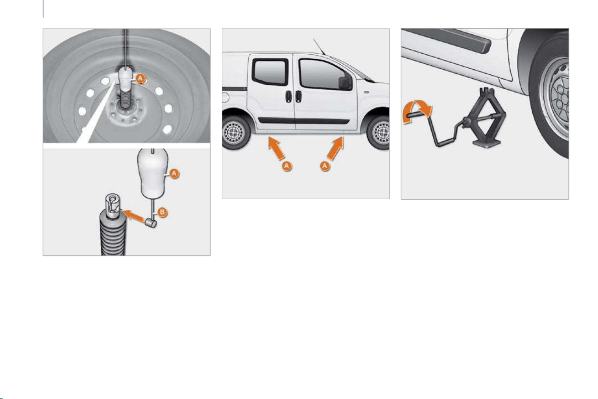
114
Changing a wheel
Removing
1. Park the vehicle on level, stable and non-
slippery ground. Apply the handbrake.
Switch off the ignition and engage first
gear or reverse, depending on the slope.
2. Detach the trim (large model) using
the wheelbrace 1 , pulling at the valve
passage.
Slide the screwdriver 3 into the notch on
the trim (small model) and use the tool as
a lever, pressing to unclip the trim.
3. Slacken the wheel bolts using the
wheelbrace.
4. Position the jack underneath the body,
in accordance with the illustration, at
the mark A (in the side member recess)
as close as possible to the wheel to be
changed.
5. Extend the jack 4 until its base is in
contact with the ground. Ensure that the
centreline of the jack base is vertical in
relation to the location used.
6. Raise the vehicle.
7. Remove the bolts and detach the wheel.
Putting the wheel back in place
1. Install the support on the wheel.
2. Place the cable B in position.
3. Lower the cover A .
4. Position the wheel.
5. Turn the wheelbrace clockwise to raise
the spare wheel completely.
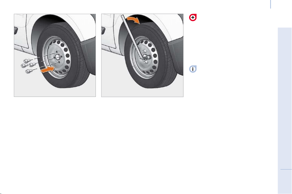
115
7
TROUBLESHOOTING
Changing a wheel
Refitting the wheel
6. Put the trim back in place, starting by
placing its notch facing the valve, and
press with the palm of your hand.
7. Stow the tools and the wheel.
8. Check the wheel inflation pressure
(see "Identification") and have the
balance checked.
Refer to the "Identification features"
section of chapter 8 to locate the tyre
label.
Have the tightening of the bolts and the
pressure of the spare wheel checked by a
CITROËN dealer without delay.
1. Put the wheel in place using the centring
guide 2 to assist you.
2. Screw in the 3 bolts by hand and remove
the centring guide. Position the 4th bolt.
3. Pre-tighten using the wheelbrace 1 .
4. Fold the jack 4 and detach it.
5. Tighten the wheel bolts using the
wheelbrace.
Also, have the original wheel repaired
and refitted by a CITROËN dealer as
soon as possible.
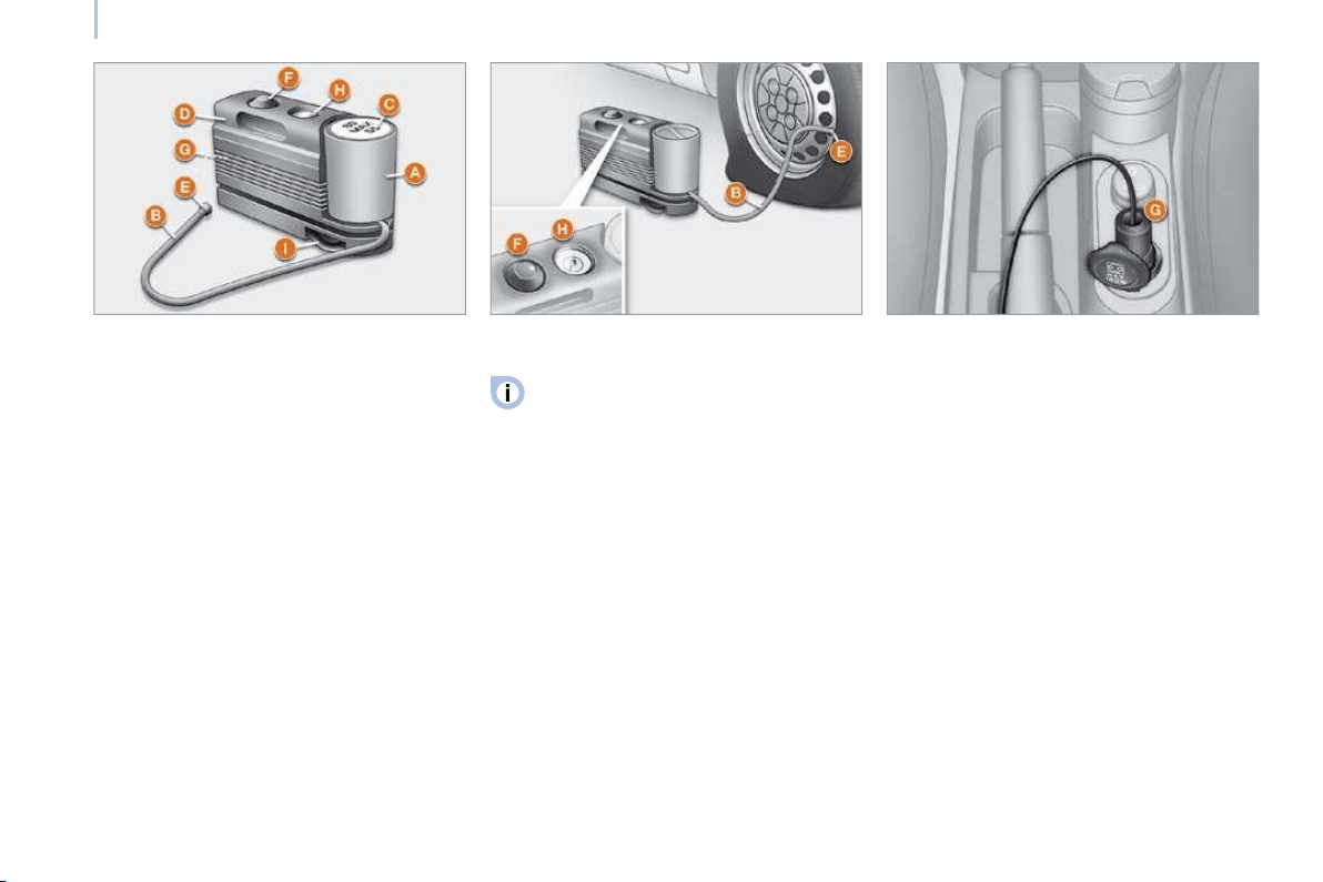
116
Changing a wheel
PUNCTURE REPAIR KIT
This kit is located at the front of the
passenger compartment. It consists of:
- a repair cartridge A , containing the filling
fluid, equipped with:
a fi lling pipe B ,
a sticker C indicating "max. 80 km/h",
which the driver must affi x to the fascia in
a visible position after repairing the tyre,
- a compressor D equipped with a pressure
gauge and unions,
- adaptors for the inflation of various items,
- a pair of protective gloves,
- a quick guide to use of the puncture
repair kit.
Repair procedure
- Apply the handbrake and place the gear
lever in neutral.
- Unscrew the valve cap of the tyre to be
repaired.
- Take out the filling pipe B and screw the
ring E onto the tyre valve.
- Check that the on/off switch F on the
compressor is in position "0" (off).
- Start the engine.
- Insert the connector G in the nearest
12 V accessories socket in the vehicle.
- Place the compressor’s on/off switch F in
position "1" (on).
- Inflate the tyre to a pressure of 3 bars.
To obtain a more accurate reading, you are
advised to check the pressure value on the
pressure gauge H , with the compressor off.
This temporary repair kit is available
from CITROËN dealers.
It is provided for the repair of holes of
a maximum diameter of 4 mm, located
exclusively on the tread or side wall of the
tyre. Avoid removing any foreign bodies
which have penetrated into the tyre.
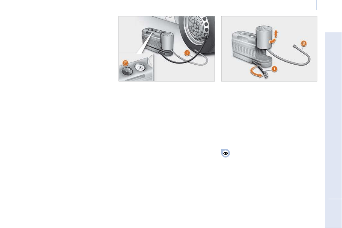
117
7
TROUBLESHOOTING
Changing a wheel
- If a pressure of at least 1.5 bars is not
reached within 5 minutes :
disconnect the compressor from the
valve and from the 12 V accessories
socket,
move the vehicle forward by
approximately 10 metres to distribute the
fi lling fl uid inside the tyre,
then repeat the infl ation operation.
- If a pressure of at least 1.8 bars is not
reached within 10 minutes :
stop the repair procedure; the tyre has
suffered too much damage and cannot
be repaired,
contact a CITROËN dealer.
- If the tyre has been inflated to a pressure
of 3 bars , set off again immediately.
After driving for approximately 10 minutes,
stop and check the pressure of the tyre
again.
Re-inflate the tyre to the correct pressure if
necessary and contact a CITROËN dealer
as soon as possible.
It is imperative that you inform the technician
that you have repaired the tyre using the
temporary puncture repair kit and give him
its instructions.
Checking and correcting the
pressure
The compressor must be used to check and
correct the pressure of a tyre, as follows:
- disconnect the pipe I ,
- connect it directly to the tyre valve,
the cartridge will then be connected to the
compressor and the filling fluid will not be
injected.
Replacing the repair cartridge
Disconnect the pipe I .
Turn the empty cartridge anticlockwise and
lift it.
Insert the new cartridge and turn it
clockwise.
Reconnect the pipe I and connect the pipe B
in its location.
The repair cartridge contains ethylene-
glycol, a product which is harmful if
swallowed and which causes irritation to the
eyes.
Keep this product out of reach of children.
After use, do not discard the used cartridge
carelessly, take it to a CITROËN dealer or to
an organisation responsible for its collection.
If the tyre has to be deflated:
- connect the pipe I to the tyre valve,
- press the yellow button, located in the
centre of the switch F on the compressor.
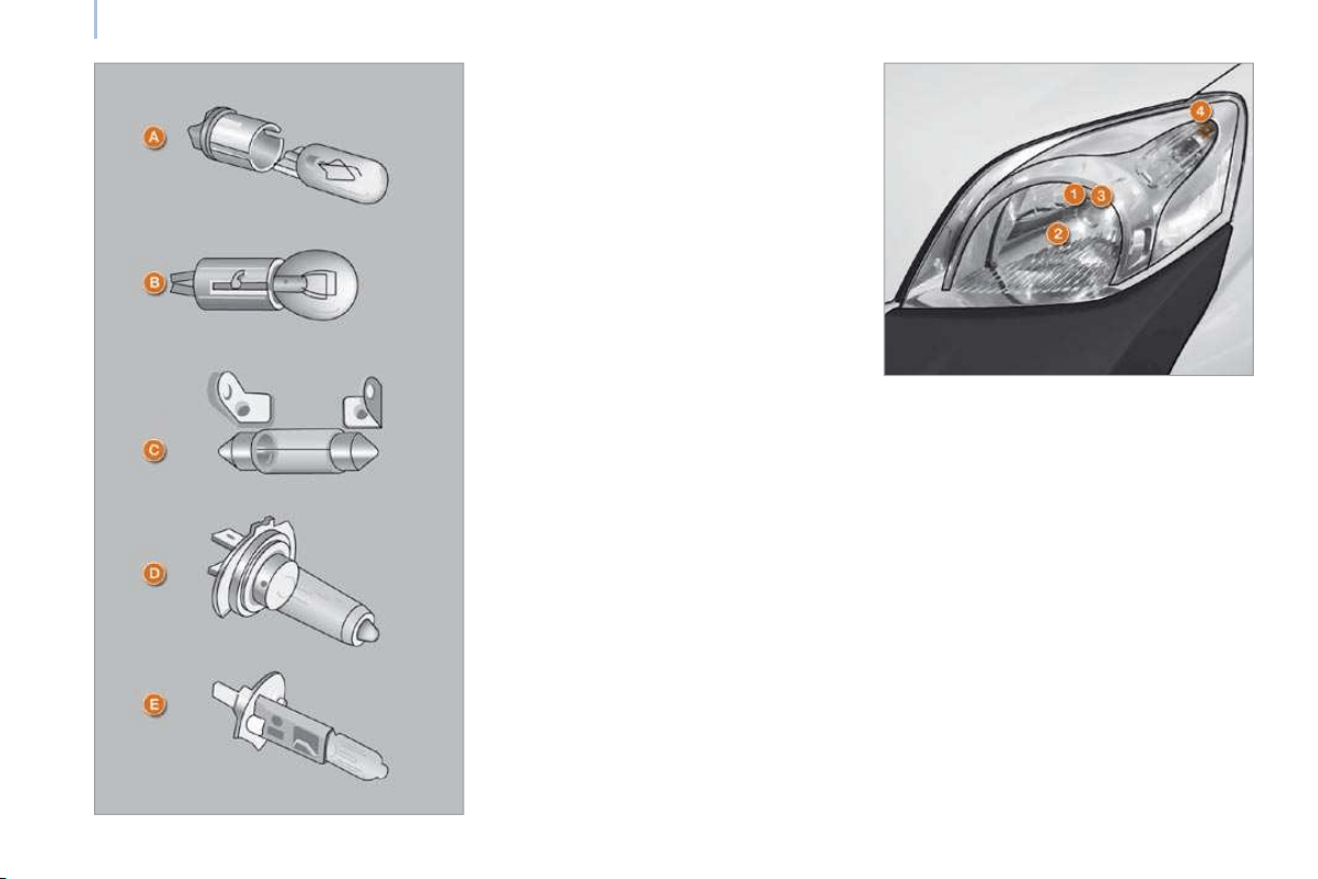
118
Changing a bulb
Front lamps
Open the bonnet. To access the bulbs, reach
behind the headlamp unit.
Remove the protective covers to gain
access to the bulbs.
Carry out the operations in reverse order to
refit each bulb.
CHANGING A BULB
Types of bulb
Various types of bulb are fitted on your
vehicle.
To remove them:
1. Type A
Entirely glass bulb: pull gently as it is
fitted by pressure.
2. Type B
Bayonet bulb: press on the bulb then turn
it anticlockwise.
3. Type C
Cylindrical bulb: move aside the contacts.
4. Type D -E
Halogen bulb: release the retaining
spring from its housing.
High pressure washing
When using this type of washing on
stubborn dirt, do not persist very long on
the headlamps, or on other lamps and their
surrounds to avoid damaging their coating
and their seal.
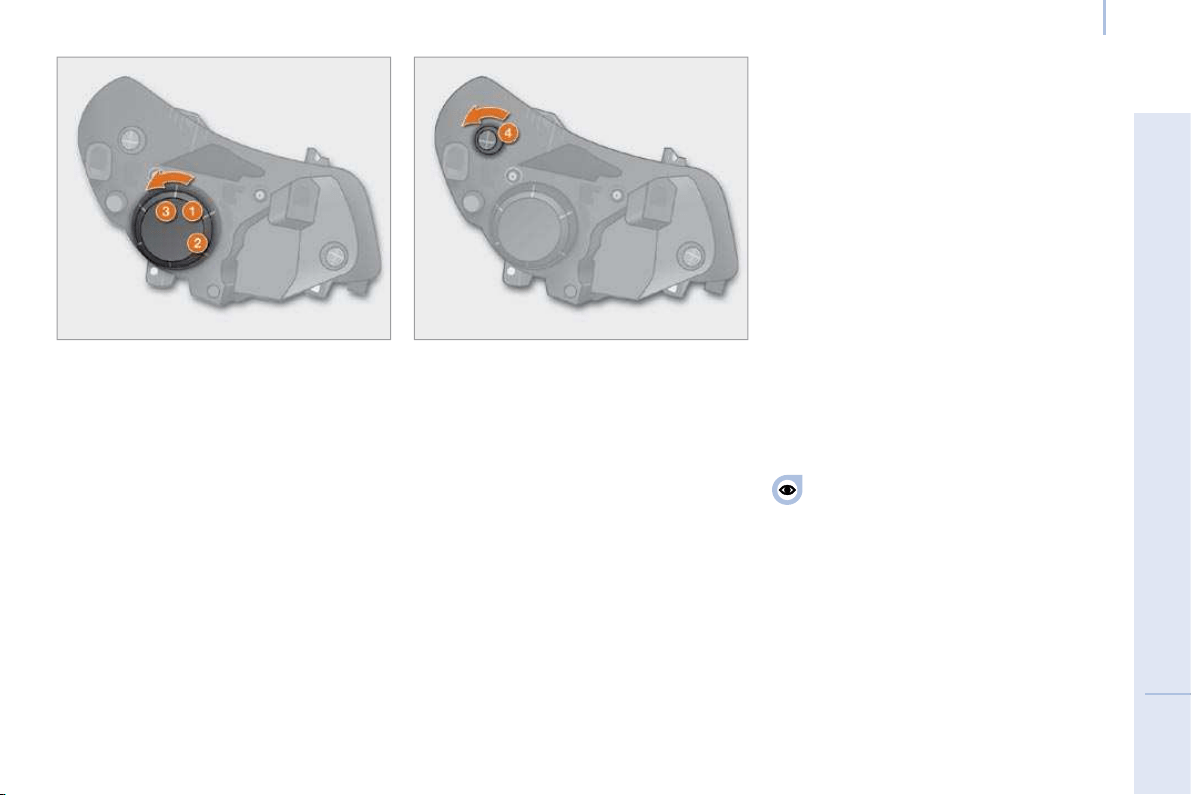
119
7
TROUBLESHOOTING
Changing a bulb
1 - Dipped headlamp
Type D , H4 - 55 W
- Remove the cover by turning it
anticlockwise.
- Disconnect the electrical connector.
- Release the retaining spring by pressing
on the two clips.
- Change the bulb taking care to align the
metal part with the grooves on the light.
2 - Sidelamp
Type A , W 5 W - 5 W
- Remove the cover by turning it
anticlockwise.
- Pull the bulb holder to gain access to the
bulb.
- Change the bulb.
3 - Main beam headlamp
Type D , H4 - 55 W
- Remove the cover by turning it
anticlockwise.
- Disconnect the electrical connector.
- Release the retaining spring by pressing
on the two clips.
- Remove the bulb holder.
- Change the bulb taking care to align the
metal part with the groove on the light.
4 - Direction indicators
Type B , PY 21 W - 21 W amber
- Turn the bulb holder a quarter turn
anticlockwise.
- Remove the bulb by pressing it lightly
while turning it anticlockwise.
- Change the bulb.
If you encounter any difficulty, consult a
CITROËN dealer.
When each operation has been
completed, check the operation of the
lights.
5 - Foglamps
Type E , H1 - 55 W
Consult a CITROËN dealer.

120
Changing a bulb
Front/rear courtesy lamps
Type C , 12 V 10 W - 10 W
- Release the courtesy lamp using a
screwdriver.
- Remove the cover to gain access to the
bulb.
- Change the bulb moving aside the two
contacts.
- Ensure that the new bulbs are secured
correctly between the two contacts.
- Close the protective flap.
- Fix the courtesy light in its housing and
ensure that it is secured correctly.
Direction indicator side repeater
Type A , WY 5 W - 5 W amber
- Push the repeater rearwards and release it.
- Support the connector and turn the bulb
holder a quarter of a turn to the left.
- Turn the bulb a quarter of a turn to the
left.
- Pull the bulb then change it.
- When refitting, engage the repeater
rearwards then move it forwards.
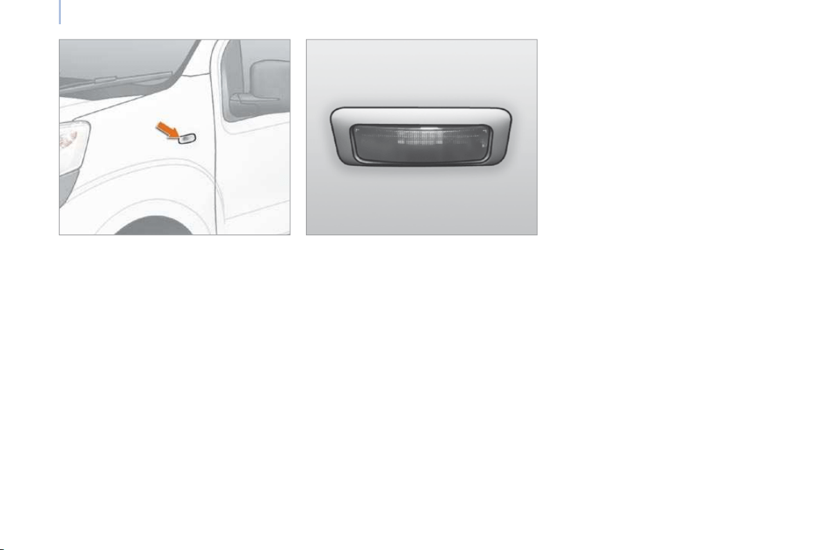
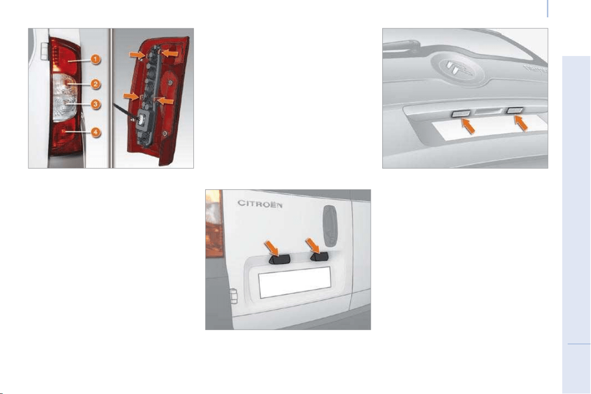
121
7
TROUBLESHOOTING
Changing a bulb
Rear lamps
- Identify the faulty bulb then open the rear
doors.
- Unscrew the two screws using the
screwdriver supplied in the tool kit
(behind the driver’s seat) and extract the
bulb holder.
- Release the lamp unit.
- Disconnect the electrical connector.
- Remove the support by moving aside the
tabs.
- Change the bulb.
Number plate lamps
Type A, C 5 W - 5 W
- Unclip the transparent cover using
the screwdriver supplied in the tool kit
(behind the driver’s seat) and extract the
bulb holder.
- Change the bulb by moving aside the two
contacts.
- Ensure that the new bulbs are secured
correctly between the two contacts.
- Replace the plastic lens and press on it.
For further information concerning the bulbs,
refer to the table "Types of bulb".
1. Brake lamps
Type B , P 21 W - 21 W
2. Direction indicators
Type B, PY 21 W - 21 W amber
3. Reversing lamps
Type B, P 21 W - 21 W
4. Sidelamps/Foglamps
Type B , P4/21 W - 4 W/21 W
On the hinged rear doors
On the tailgate
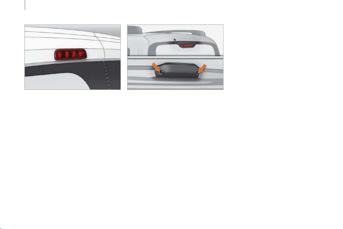
122
Changing a bulb
Third brake lamp
On the hinged rear doors
Type B , W 5 W - 5 W (4 bulbs)
- Unclip the transparent cover using the
screwdriver located in the tool kit.
- Disconnect the electrical connector.
- Remove the bulb holder by squeezing the
two tabs.
- Remove the faulty bulb.
- Change the bulb.
On the tailgate
Type B, W 5 W - 5 W (5 bulbs)
- Open the tailgate.
- Remove the two cover retaining screws,
then the cover.
- Remove the bulb holder by squeezing the
two tabs.
- Remove the faulty bulb.
- Change the bulb.
If you encounter any difficulty, consult a
CITROËN dealer.
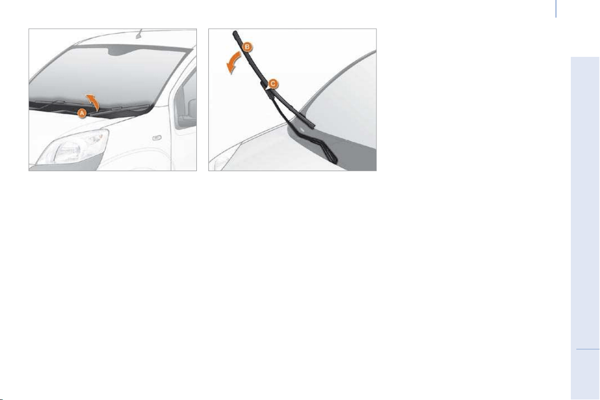
123
7
TROUBLESHOOTING
Changing a wiper blade
CHANGING A WIPER BLADE
Changing a front or rear wiper blade
Instructions for removing the blade:
Lift the wiper arm A off the windscreen.
Turn the blade B 90° around the pivot C on
the end part of the arm.
Remove the pivot from the blade C .
Instructions for fitting the blade:
Fit the pivot C in the hole in the central part
of the blade B .
Place the arm with the blade on the
windscreen.
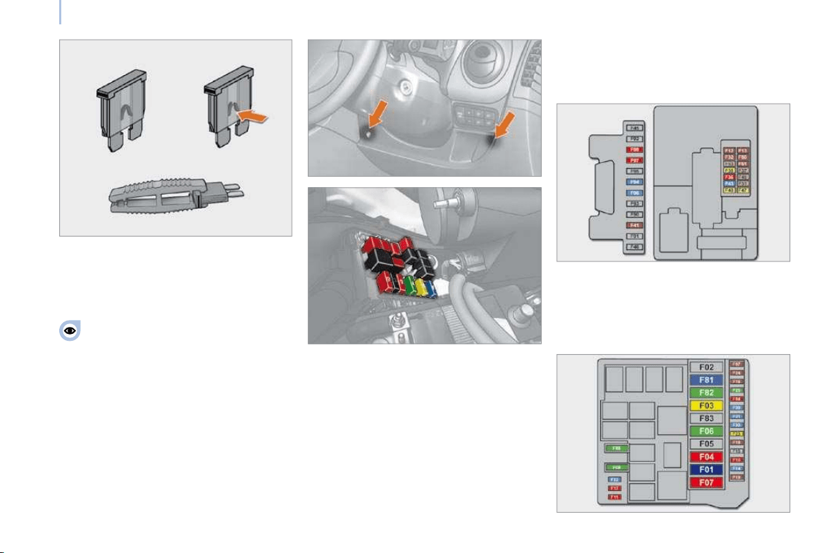
124
Changing a fuse
CHANGING A FUSE
The two fuse boxes are placed on the fascia
panel on the driver’s side and under the
bonnet.
Removing and fitting a fuse
Before changing a fuse, the cause of the
fault must be found and rectified. The fuse
numbers are indicated on the fuse box.
Always replace a faulty fuse with a fuse
of the same rating.
- To gain access to the fascia panel fuses,
remove the 2 screws using the ignition
key and tilt the box.
- To gain access to the fuses under the
bonnet, remove the battery negative
cable and the front left light connector,
then unclip the fuse box cover.
CITROËN will not accept responsibility
for the cost incurred in repairing your
vehicle or for rectifying the malfunctions
resulting from the installation of accessories
not supplied and not recommended by
the CITROËN dealer and not installed in
accordance with its instructions, in particular
when the combined consumption of all of the
additional equipment connected exceeds
10 milliamperes.

126
Changing a fuse
FUSES IN THE ENGINE
Identifi cation mark
Amperage Functions
F01 60 A Control unit
F03 20 A Starter supply
F04 40 A ABS hydraulic block pump supply
F06 30 A Single speed fan assembly control
F07 40 A High speed fan assembly control
F08 30 A Air conditioning unit pump
F10 10 A Horn
F11 10 A Engine management secondary charge supply
F14 15 A Main beam headlamps
F16 7.5 A Engine management control unit - piloted manual gearbox control unit
F17 15 A Supply for ignition coil, injectors, engine management central unit
F18 7.5 A Engine management control unit (1.4 HDi)
F19 7.5 A Air conditioning compressor
F20 30 A Supply for heated rear screen, electric exterior mirrors de-icing heaters
F21 15 A 1.4 petrol engine management, T09 (HDi) relay coil
F22 20 A Engine management control unit (1.4 HDi), petrol pump
F23 20 A ABS hydraulic block solenoid valves supply
F24 7.5 A ABS
F30 15 A Fog lamps
F81 60 A Pre-heat unit
F82 30 A Piloted manual gearbox pump - piloted manual gearbox supply
F84 10 A Piloted manual gearbox control unit and solenoid valves
F85 30 A Lighter - 12 V accessories socket
F87 7.5 A Reversing lights - water in diesel sensor

124
Changing a fuse
CHANGING A FUSE
The two fuse boxes are placed on the fascia
panel on the driver’s side and under the
bonnet.
Removing and fitting a fuse
Before changing a fuse, the cause of the
fault must be found and rectified. The fuse
numbers are indicated on the fuse box.
Always replace a faulty fuse with a fuse
of the same rating.
- To gain access to the fascia panel fuses,
remove the 2 screws using the ignition
key and tilt the box.
- To gain access to the fuses under the
bonnet, remove the battery negative
cable and the front left light connector,
then unclip the fuse box cover.
CITROËN will not accept responsibility
for the cost incurred in repairing your
vehicle or for rectifying the malfunctions
resulting from the installation of accessories
not supplied and not recommended by
the CITROËN dealer and not installed in
accordance with its instructions, in particular
when the combined consumption of all of the
additional equipment connected exceeds
10 milliamperes.

125
7
TROUBLESHOOTING
Changing a fuse
DRIVER’S SIDE FASCIA PANEL FUSES
Identifi cation mark
Amperage Functions
F12 7.5 A Right-hand dipped headlamp supply
F13 7.5 A Left-hand dipped headlamp supply - headlamp height adjuster
F31 5 A Engine control unit supply switch
F32 7.5 A Front light - front courtesy light - rear courtesy light lamp
F36 10 A Audio equipment - mobile telephone pre-equipment - air conditioning control panel - EODB diagnostic socket
F37 5 A Brake light - instrument panel
F38 20 A Locking of the doors
F43 15 A Wipers pump
F47 20 A Driver’s electric window motor supply
F48 20 A Passenger’s electric window motor supply
F49 5 A Parking assistance control unit - rear lighting switch - electric exterior mirrors
F50 7.5 A Air bags control unit
F51 5 A Switch on brake pedal - switch on clutch pedal
F53 5 A Instrument panel - rear fog lamps
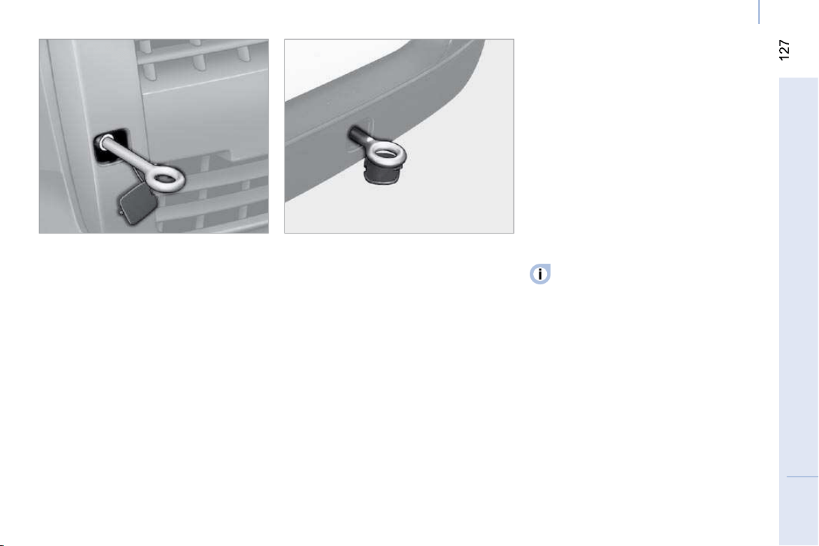
7
TROUBLESHOOTING
Having your vehicle towed
BEING TOWED
Without lifting (four wheels on the ground)
You must always use a towbar.
The removable towing eye is located in the
tool kit behind the driver’s seat (Light van) or
behind the rear bench seat (Combi).
From the front
Unclip the cover on the right using a flat tool.
Screw the removable towing eye in fully.
Then hook the towbar on the towing eye.
From the rear
Unclip the cover at the bottom using a flat
tool.
Screw the removable towing eye in fully.
Then hook the towbar on the towing eye.
With lifting (2 wheels only on the ground)
It is preferable to lift the vehicle using
professional lifting equipment.
When being towed with the engine
off, there is no braking or steering
assistance.
On the towed vehicle, the gear lever must be
put in neutral; failure to observe this special
condition may result in damage to certain
braking components and the absence of
braking assistance when the engine is
started.
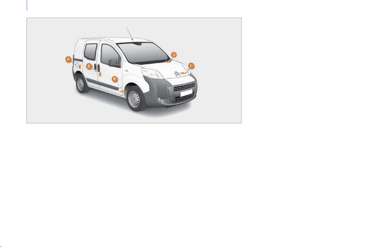
128
Identification features
IDENTIFICATION FEATURES
A. Manufacturer’s plate
1. VF Type serial number.
2. Gross vehicle weight (GVW).
3. Gross train weight (GTW).
4. Maximum weight on front axle.
5. Maximum weight on rear axle.
B. Serial number on the body
C. Paint reference
D. Serial number on the fascia
E. Tyre pressures

129
7
TROUBLESHOOTING
Fuel
FILLING WITH FUEL
Low fuel level
When the minimum fuel tank
level is reached, this warning
light comes on. At this moment,
you have approximately 6 litres
remaining. Fill up without delay to avoid
running out of fuel.
The fuel tank must be filled with the engine
off.
- Open the fuel filler flap.
- Support the cap with one hand.
- With the other hand, insert the key, then
turn it a third of a turn.
- Remove the cap.
When the fuel filler flap is open, a
safety system prevents sliding of the
side door.
A label affixed to the inside of the flap
reminds you of the type of fuel to be used.
When filling the fuel tank, do not continue
after the 3rd cut-off of the nozzle. This could
cause malfunctions.
The capacity of the fuel tank is
approximately 45 litres.
After filling the fuel tank, lock the cap and
close the flap.
FUEL CIRCUIT DEACTIVATED
In the event of a serious collision, a device
automatically cuts off the fuel supply to the
engine and the vehicle’s electrical supply.
It also triggers the automatic unlocking of
the doors and switching on of the courtesy
lights. A message appears on the instrument
panel display according to version.
Turn the key to the STOP position to prevent
discharging of the battery.
Check that there is no smell or leak of fuel
outside the vehicle.
Re-activation
To set off again, restore the fuel supply and
the electrical supply manually:
- with the key in the STOP position, turn
the key to the RUNNING position,
- push the direction indicators control up
fully,
- place it in the "Off" position,
- press the direction indicators control
down fully,
- return it to the "Off" position,
- push it up fully again,
- return it to the "Off" position,
- press it down fully again,
- return it to the "Off" position,
- turn the key to the STOP position.

131
7
TROUBLESHOOTING
Opening the bonnet
OPENING THE BONNET
On the inside
Pull the lever under the fascia panel towards
you.
On the outside
Raise the bonnet slightly, placing your hand
flat under the bonnet to make the operation
easier.
Push the lever to the left, then open the
bonnet fully.
While holding the bonnet open, check that the
locking control A is engaged by pressing it.
To close
Lift the bonnet slightly and pull the release
control A to release it.
Lower the bonnet and release it at the end
of its travel. Check that the bonnet is locked.
Avoid manoeuvring the bonnet in strong
winds.
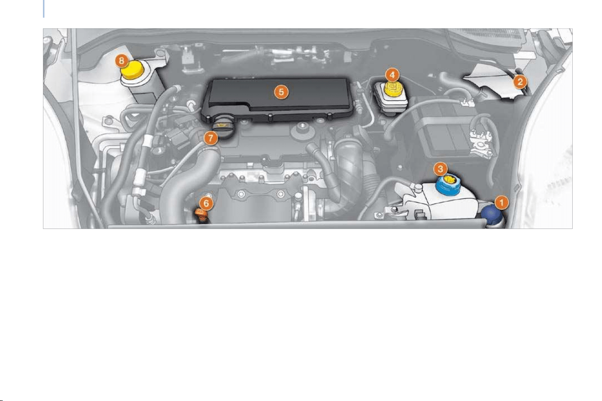
132
Under the bonnet
Diesel engine
UNDER THE BONNET
4. Brake and clutch fluid reservoir.
5. Air filter.
6. Dipstick.
7. Engine oil filler cap.
8. Power steering fluid reservoir.
1. Windscreen wash reservoir.
2. Fuse box.
3. Engine coolant reservoir.
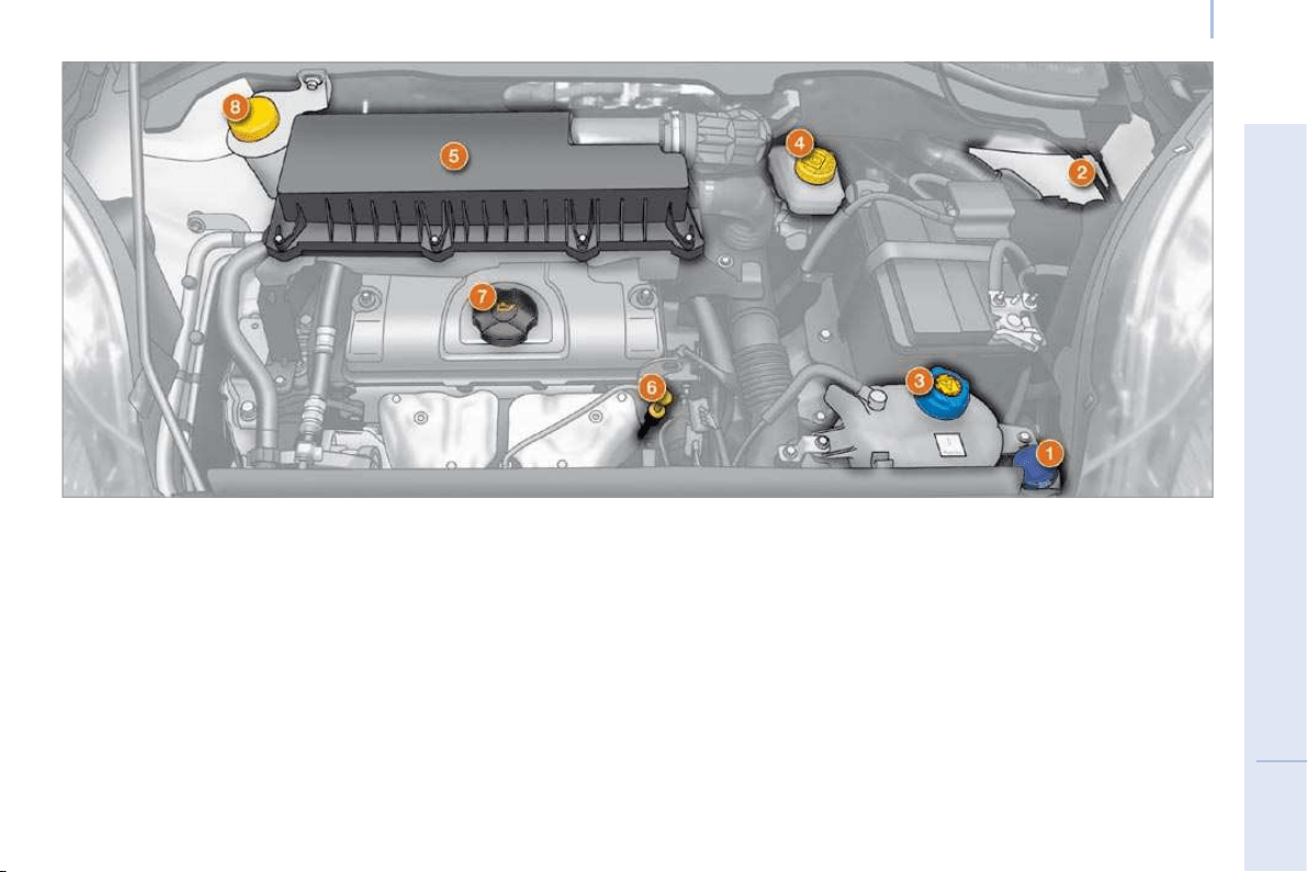
133
7
TROUBLESHOOTING
Under the bonnet
Petrol engine
UNDER THE BONNET
4. Brake and clutch fluid reservoir.
5. Air filter.
6. Dipstick.
7. Engine oil filler cap.
8. Power steering fluid reservoir.
1. Windscreen wash reservoir.
2. Fuse box.
3. Engine coolant reservoir.
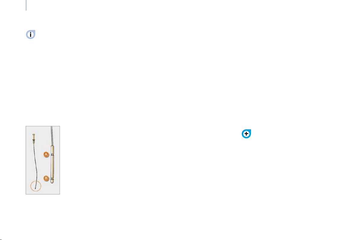
134
Levels
These regular maintenance operations
will keep your vehicle in good
running order. Consult the instructions at
a dealership or in the servicing booklet
enclosed in the handbook pack.
LEVELS
Oil level
Check the level regularly and top up
between changes. The maximum
consumption is 0.5 l per 600 miles
(1 000 km). Check the level with the vehicle
level, engine cold, using the dipstick.
Dipstick
There are two marks on the
dipstick:
A = maximum
If you fill past this mark,
consult a dealer.
B = minimum
Never allow the level to fall
below this mark.
To maintain the reliability of engines and
emission control systems, the use of
additives in engine oil is prohibited.
Oil change
It is imperative that this is carried out at the
intervals specified and the viscosity grade of
the oil selected must fulfil the requirements
in accordance with the manufacturer’s
servicing schedule. Consult the instructions
at a dealership.
Remove the dipstick before filling.
Check the level after filling (never exceed
the maximum mark).
Screw the cap back onto the sump before
closing the bonnet.
Changing the brake fluid
The brake fluid must be changed at
the intervals stated, according to the
manufacturer’s servicing schedule.
Use fluids recommended by the
manufacturer, which fulfil DOT4 standards.
The level must be between the MIN and
MAX marks on the reservoir.
If fluid has to be added frequently, this
indicates a failure which must be checked by
a CITROËN dealer as soon as possible.
Warning lights
Checking by means of the warning
lights on the instrument panel is
described in chapter 1, refer to the
"Instruments and controls" section.

135
7
TROUBLESHOOTING
Levels
Cooling system
Only use the fluid recommended by the
manufacturer. Otherwise, you risk seriously
damaging your engine. When the engine
is warm, the temperature of the coolant is
controlled by the engine fan. As this fan can
operate with the ignition key removed and
because the cooling system is pressurised,
wait for at least one hour after the engine
has stopped before carrying out any work.
Topping up
The level must be between the MIN and
MAX marks on the expansion bottle. If
more than 1 litre of fluid is required to top
up the level, have the system checked by a
CITROËN dealer.
Power steering fluid level
The vehicle must be parked on level ground with
the engine cold. Unscrew the cap integrated with
the gauge and check the level which must be
between the MIN and MAX marks.
Windscreen wash level
For best quality cleaning and for your safety,
we would advise that you use products of
the CITROËN Universal range.
Capacity of the reservoir: approximately
5.5 litres.
Used oil
Avoid prolonged contact of used oil with the
skin.
Brake fluid is harmful to health and very
corrosive.
Do not dispose of used oil, brake fluid or
coolant into drains or into the ground but
into the containers dedicated to this use at a
dealership.
Slacken the cap by two turns to release the
pressure to prevent any risk of scalding.
When the pressure has dropped, remove the
cap and top up the level with coolant.
If fluid has to be added frequently, this
indicates a failure which must be checked by
a dealer as soon as possible.

136
Checks
CHECKS
Bleeding the water contained in the
diesel filter
If this warning light comes on,
bleed the filter, otherwise bleed
regularly each time the engine is
drained.
To evacuate the water, unscrew the bleed
screw or the water in diesel sensor, located
at the base of the filter. Operate until all
of the water has been drained out. Then
tighten the bleed screw or the water sensor.
HDi engines use advanced technology. All
work requires a special qualification which is
guaranteed by a CITROËN dealer.
Battery
At the start of winter, have it checked by a
CITROËN dealer.
Air fi lter and passenger compartment fi lter
A clogged passenger compartment filter
may reduce the performance of the
air conditioning system and generate
undesirable odours. The replacement
intervals for these components are indicated
in the servicing booklet.
Depending on the environment (dusty
atmosphere...) and the use of the vehicle
(urban driving...), change them twice as
often if necessary, refer to the "Under the
bonnet" section of chapter 7.
Brake pads
Brake pad wear depends on the style of
driving, in particular for vehicles which are
used in town, over short distances. It may
be necessary to check the thickness of the
pads, even between services.
Unless there is a leak on the circuit, a drop
in the brake fluid level indicates that the
brake pads are worn.
Brake disc/drum wear status
For any information relating to checking
the brake disc/drum wear status, consult a
CITROËN dealer.
Handbrake
Where the handbrake travel is too great
or there is a reduction in the performance
of the system, the handbrake should be
adjusted, even between services.
Have it checked by a CITROËN dealer.
Oil filter
Change the filter regularly, in accordance
with the servicing schedule.
Manual gearbox
Have the level checked in accordance with
the manufacturer’s servicing schedule.
To check the main levels and certain
components, in accordance with the
manufacturer’s servicing schedule, refer
to the pages of the servicing booklet which
correspond to your vehicle’s engine.
Only use products recommended by
CITROËN or products of equivalent quality
and characteristics.
In order to optimise the operation of units as
important as the braking circuit, CITROËN
selects and offers specific products.
In order to avoid damaging the electrical
units, high pressure washing to clean the
engine compartment is strictly prohibited.