OWNER´S MANUAL
Vehicle and Infotainment
ŠKODA KAROQ
Documentation of vehicle delivery
Date vehicle handover
a)
ŠKODA Partner
Stamp and signature of the vendor
I confirm that I have taken delivery of the specified vehicle in good condi-
tion, have received information on how to operate it correctly, and have
had the terms of the warranty explained to me.
Signature of the customer
Has the vehicle an extended warranty? Yes
No
Limitations of the ŠKODA extended warranty
b)
Years: or km/mile-
age:
or
Miles:
a)
Due to the requirements of generally binding country-specific regulations, the
date of first registration can be specified instead of the date the vehicle hand-
over.
b)
Depending on which comes first.
57A012720AA
1st vehicle owner
This vehicle with the official registration
number
(filled in by the vendor)
belongs to:
Title, Name/Company:
Address:
Telephone:
ŠKODA partner
Service consultant:
Telephone:
2nd vehicle owner
This vehicle with the official registration
number
belongs to:
Title, Name/Company:
Address:
Telephone:
ŠKODA partner
Service consultant:
Telephone:
57A012720AA

Useful links
Before starting off
Adjusting the seat » page 81
Adjusting the steering wheel » page 20
Exterior mirrors » page 79
Headlights/lights » page 69
Windscreen wipers and washers » page 77
Heating and ventilation » page 112
Heated windscreen » page 76
Instrument cluster
Warning lights » page 39
Display operation » page 50
Set the time » page 49
Unlocking and opening
Keyless unlocking (KESSY) » page 57
Luggage compartment lid » page 61
Power windows » page 64
Bonnet » page 261
Connectivity
Online Services – ŠKODA Connect » page 13
SmartLink+ » page 170
Infotainment connection to the Internet » page 166
Hotspot (WLAN) » page 168
Making a call » page 156
Configuration wizard » page 127
Driving
Automatic gearbox » page 205
Braking and stabilisation systems » page 210
START-STOPSystem » page 199
Adaptive cruise control » page 229
Lane Assist » page 240
Offroad mode » page 212
Parking
Electric parking brake » page 201
Parking the vehicle » page 203
Parking aid » page 215
Reversing camera » page 221
Care and maintenance
Service intervals » page 54
Tyre pressure » page 268
Washing vehicle » page 253
Folding down windscreen wiper arms securely » page 285
Inspecting and replenishing
Filling up with fuel » page 257
AdBlue
®
» page 259
Engine oil » page 262
Windscreen washer fluid » page 262
Emergencies
emergency call » page 15
Tool kit in vehicle » page 273
Changing a lamp » page 290
Changing a fuse » page 286
Changing a wheel » page 273
Jump-starting » page 279
Towing the vehicle » page 280
Interesting tips
Electronic version of the Owner's Manual » page 10
Tutorial videos » page 11

Table of Contents
Liability for defects and ŠKODA warranty for
new cars 6
Accident data recorder (Event Data
Recorder) 8
Radio equipment - Information on Directive
2014/53 / EU 9
About the Owner's Manual
Introductory information 10
General 10
Printed Owner's Manual 10
Electronic version of the Owner's Manual
10
Tutorial videos
11
MyŠKODA App application
11
Notes
12
Online Services
ŠKODA Connect
13
Service package ŠKODA Connect
13
ŠKODA Connect website
13
User and vehicle registration, activation of
online services 13
Managing online services 14
Emergency call
15
Care Connect Services 16
Infotainment Online services
17
Safety
Passive Safety 18
General information
18
Correct and secure seating position 18
Seat belts 21
Using seat belts 21
Inertia reel and belt tensioners 23
Airbag system 24
Description of the airbag system 24
Airbag deactivation 27
Transporting children safely
28
Child seat 28
Fastening systems 32
Operation
Cockpit 37
Overview
36
Instruments and warning lights
38
Instrument cluster
38
Warning lights 39
Information system
48
Driver information system
48
Operation of the information system
50
Driving data (Multifunction display)
51
Menus in the display of the instrument
cluster
53
Service intervals
54
Personalization 55
Unlocking and opening
56
Unlocking and locking 56
Anti-theft alarm system 60
Manually operated tailgate
61
Electric boot lid 62
Window operation
64
Panoramic tilt / slide sunroof 66
Lights and visibility 69
Light
69
Interior lighting 73
Viisibility 75
Windscreen wipers and washers 76
Rear view mirror 78
Seats and head restraints 81
Front seats 81
Rear seats 84
VarioFlex rear seats
84
Headrests 88
Seat heaters 89
Heated steering wheel 89
Practical features 90
Passenger compartment features 90
Electrical sockets
99
Ashtray and cigarette lighter
101
Tablet holder 101
Transport of cargo
103
Luggage compartment
103
Variable loading floor in the luggage
compartment (Estate) 111
Transportation on the roof rack 111
Heating and ventilation
112
Heating, manual air conditioning system,
Climatronic
112
Auxiliary heating (auxiliary heating and
ventilation)
117
Infotainment
Introductory information
120
Important information 120
Infotainment Overview
120
Infotainment operation 123
Infotainment operation 123
Voice control
128
Updating the Infotainment software 130
3
Table of Contents

Infotainment settings - Columbus, Amundsen,
Bolero 131
Infotainment system settings 131
Radio menu settings 134
Media menu settings 135
Image menu settings 135
Video DVD menu settings 135
Settings
135
SmartLink+ menu settings 136
Navigation menu settings 137
Infotainment settings - Swing 139
Infotainment system settings 139
Radio menu settings
140
Media menu settings
141
Import contactsTelephone menu settings 141
SmartLink+ menu settings
141
Radio
142
service
142
Media
145
service 145
Audio sources
147
Images
151
Image viewer
151
Video DVD
153
video player 153
Media Command 154
Operation
154
Telephone 156
Introductory information
156
Pairing and connecting 157
Use the SIM card in the external module 161
Telephone functions
161
Text messages (SMS) 164
Data connection 166
Internet connection 166
Establishing a connection using the CarStick
device 167
Establishing a connection using a SIM card in
the external module 167
Establishing a connection using the Bluetooth
®
rSAP profile
168
Establishing a connection using WLAN 168
SmartLink 170
Introductory information 170
Android Auto 171
Apple CarPlay
171
MirrorLink
®
172
ApplicationŠKODA OneApp 173
Navigation
174
Introductory information
174
Search for destination and enter
177
Saved destinations
181
Import your own goals 182
Map
184
Route guidance
187
Route
190
Waypoint mode
192
Traffic reports
194
Vehicle systems 196
CAR - Vehicle settings
196
Driving
Starting-off and Driving 197
Starting and stopping the engine 197
START-STOP-System 199
Brakes and Parking
201
Manual gear changing and pedals 204
Automatic transmission
204
Running in the engine and economical
driving 207
Avoiding damage to your vehicle 208
Assist systems 209
General information 209
Braking and stabilisation systems 210
Offroadmode
212
Parking aid (ParkPilot) 215
Rear traffic alert and wizard for “Blind
spot”Monitoring 218
Reversing camera 221
Park Assist 222
Cruise Control System
226
Speed limiter
227
Adaptive Cruise Control (ACC) 229
Front Assist
235
Select the driving mode (Driving Mode
Selection)
237
Proactive passenger protection (Crew Protect
Assist) 239
Spurhalteassistent (Lane Assist)
240
Traffic jam assistant
242
Assistant for emergencies
242
Traffic sign recognition
243
Fatigue detection system 245
Tyre pressure monitoring 245
Towing device and trailer
247
Hitch 247
Using hitch
248
General Maintenance
Care and maintenance 251
Service work, adjustments and technical
alterations 251
Cleaning and care
252
4
Table of Contents

Inspecting and replenishing 257
Fuel 257
AdBlue
®
and its refilling 259
Engine compartment 260
Engine oil 262
Coolant 263
Brake fluid 265
Vehicle battery
265
Wheels 268
Wheels and tyres 268
Operating in winter conditions 270
Do-it-yourself
Emergency equipment and self-help
272
Emergency equipment
272
Changing a wheel 273
Puncture repair kit
277
Jump-starting
279
Towing the vehicle
280
Remote control and removable light -
changing the battery 282
Emergency unlocking / locking of doors
283
Replacing windscreen wiper blades
284
Fuses and light bulbs
286
Fuses
286
Bulbs 290
Technical data
Technical data
294
Basic vehicle data 294
Vehicle-specific details per engine type
298
Index
5
Table of Contents

Liability for defects and ŠKODA warranty for new cars
Materials defect liability
Your ŠKODA Partner, as a vendor, is liable to you for material damage to your
new ŠKODA car, ŠKODA Genuine Parts or ŠKODA Genuine Accessories in ac-
cordance with statutory regulations and the purchase agreement.
ŠKODA warranty for new cars
As well as the materials defect liability, ŠKODA AUTO a.s. grants you the
ŠKODA warranty for new cars (hereinafter referred to as “ŠKODA warranty),”
according to the conditions described below.
As part of the ŠKODA warranty, ŠKODA AUTO will ensure the following serv-
ices.
▶
Free repair of faulty components or vehicle defects that occur within two
years from the start of the ŠKODA warranty.
▶
Free repair of paintwork defects on your vehicle that occur within three
years from the start of the ŠKODA warranty.
▶
Free repair of rust perforation to the bodywork of your vehicle that occurs
within twelve years from the start of the warranty. Only rust perforation of
body panels from the inside to the outside is included in the definition of rust
perforation on bodywork and covered by the ŠKODA warranty.
The start of warranty is the date on which the first buyer purchases the new
cars from the ŠKODA Partner
1)
. This date must be noted accordingly by the
ŠKODA Partner in the Owner´s Manual for your vehicle » Documentation of
vehicle handover.
Vehicle repairs may be carried out either by replacing the faulty part or by re-
pairing it. Replaced parts become the property of the ŠKODA Service Partner.
There shall be no further claims arising from the ŠKODA warranty. In particu-
lar, there shall be no claims for replacement, cancellation, provision of a cour-
tesy vehicle for the duration of repairs or compensation for damages.
The ŠKODA warranty is valid at any ŠKODA service partner.
One of the conditions for service from the ŠKODA warranty is that all service
work has been carried out in a timely and adequate manner and in accordance
with ŠKODA AUTO provisions. It must be proven that service work has been
carried out properly and in accordance with the ŠKODA AUTO provisions
when raising a claim from the ŠKODA warranty. In the event of a missed serv-
ice or failure to carry out a service according to the ŠKODA AUTO provisions,
you may still be entitled to warranty claims as long as you can prove that the
missed service or the failure to carry out a service according to the ŠKODA
AUTO provisions was not the cause of the defect.
Natural wear and tear to your vehicle is not covered by the ŠKODA warranty.
The ŠKODA warranty also does not cover faults to bodywork, installations or
conversions provided by third-parties, or vehicle faults caused as a result. The
same applies to accessories that are not factory installed and/or delivered.
In addition, this warranty does not apply if the defect was caused by one of the
following:
▶
Unauthorized use, improper handling (e.g. use in racing competitions or over-
loading), improper care and maintenance or unapproved modification to your
vehicle.
▶
Non-compliance with provisions in the Owner's Manual or other factory-sup-
plied instructions.
▶
External causes or influences (e.g. accidents, hail, flooding etc.).
▶
Parts fitted or connected on or in the vehicle whose use has not been ap-
proved by ŠKODA AUTO, or modification of the vehicle in a manner not ap-
proved by ŠKODA AUTO (e.g. tuning).
▶
Damage caused by you that was not immediately seen to by a specialist ga-
rage or was not rectified properly.
It is the customer's responsibility to prove that it was not the cause.
This ŠKODA warranty does not affect the purchaser's statutory rights from
materials defect liability from the vehicle vendor and other potential claims
from product liability laws.
Mobility warranty
The mobility warranty provides a sense of security when travelling in your ve-
hicle.
1)
Due to the requirements of generally binding country-specific regulations,
the date of first registration can be specified instead of the date the vehicle
handover.
6
Liability for defects and ŠKODA warranty for new cars

If your vehicle should break down during a journey due to an unexpected de-
fect, you can claim services to ensure your continued mobility under the terms
of the mobility warranty, including the following services: Breakdown assis-
tance at the site of the breakdown and towing to a ŠKODA Service Partner,
technical assistance on the phone or on-site commissioning.
If your vehicle is not repaired on the same day, the ŠKODA Service Partner
may provide further services as required, such as replacement transportation
(bus, train etc.) or a courtesy vehicle etc.
More information regarding terms and conditions for the provision of a mobili-
ty warranty for your vehicle can be obtained from your ŠKODA Partner. They
will also provide you with detailed terms and conditions for the mobility war-
ranty with respect to your vehicle. In the event that there is no mobility war-
ranty coverage available for your vehicle, you should check with any ŠKODA
Service Partner about the possibility of a subsequent agreement.
Optional ŠKODA extended warranty
If you opted for a ŠKODA extended warranty when purchasing your new car,
the two-year ŠKODA warranty with regards to all free warranty repairs is ex-
tended by the period you chose or until the chosen mileage limit has been
reached, whichever occurs first.
The previously mentioned paint warranty and the warranty against rust perfo-
ration are unaffected by the ŠKODA extended warranty.
The ŠKODA extended warranty does not apply to external and internal foils.
The information on the detailed conditions of the ŠKODA extended warranty
is provided by your ŠKODA partner.
Note
The ŠKODA extended warranty is only available in some countries.
7
Liability for defects and ŠKODA warranty for new cars

Accident data recorder (Event Data Recorder)
The vehicle is equipped with a device that serves as an accident data recorder
(referred to solely as “EDR” from this point). The main purpose of the EDR is
data recording during a traffic accident or other exceptional traffic conditions
(referred to solely as “accident” from this point), where the restraint systems
are activated.
The EDR records the accident in a short time (approximately 10 s), by showing
the following information, for example:
▶
The function of certain vehicle systems,
▶
The driver and passenger seat belt status,
▶
The actuation of the brake and accelerator pedal,
▶
The speed of the vehicle at the time of the accident.
The recorded data helps with the analysis of how the vehicle systems were be-
having shortly before, during and shortly after the accident, thereby ensuring
better information regarding the circumstances under which the accident oc-
curred, which lead to material damage and possibly to personal injury.
The data relating to assist systems in the vehicle is then also recorded. In addi-
tion to the information on whether the affected systems were switched on or
off at the relevant time, whether these were only partially available or were in-
active, there is also the possibility of tracking whether these vehicle functions
controlled, accelerated or braked the vehicle during the accident. Depending
on the vehicle equipment, these functions may include, for example:
▶
Adaptive Cruise Control (ACC)
▶
Lane Assist
▶
Park Assist
▶
Parking aid
▶
Emergency brake function (Front Assist)
EDR data is only recorded if an accident causes the restraint systems to be ac-
tivated. Under normal driving conditions there is no data recording and there is
no audio or video recording of the vehicle interior or the vehicle environment.
Personal data such as name, gender, age or place where the accident occurred
is also not stored in the EDR. However, third parties such as law enforcement
authorities may use certain resources to connect EDR content to other data
sources, and therefore deduce the identification of some of the people in-
volved in the accident when investigating the causes of the accident.
Reading out the EDR requires special equipment with specific access authori-
zation and a legally prescribed diagnostic connection in the vehicle “on-board
diagnostics”), and the ignition will need to be switched on.
ŠKODA AUTO will not read or otherwise process any accident data from the
EDRwithout the approval of the vehicle owner or other person authorised for
use of the vehicle. Exceptions are specified in the contractual arrangements, or
these are subject to generally binding regulations.
Due to the legal requirements, ŠKODA AUTO is required to monitor the quali-
ty and safety of its products, meaning that it is only entitled to use data from
the EDR for monitoring the product on the market, for further research and
development, and to improve the quality of the vehicle's safety systems. For
the purpose of research and development, ŠKODA AUTO will also make data
available to third parties. This is done exclusively in anonymous form, i.e. with-
out any connection to the specific vehicle, the vehicle owner or other author-
ised user.
8
Accident data recorder (Event Data Recorder)

Radio equipment - Information on Directive 2014/53 / EU
Fig. 1
ŠKODA websites
Your vehicle has various radio systems.
The manufacturers of these radio systems declare that these systems comply
with the requirements of Directive 2014/53 / EU.
To display the appropriate Declaration of Conformity proceed as follows.
1. Read the QR-Code » Fig. 1 or Enter the following address in your web
browser.
http://go.skoda.eu/owners-manuals
The web page with a model overview of the ŠKODA brand is opened.
2. Select the desired model - a menu with the manuals is displayed.
3. Select the construction period as well as the language.
4. The Declaration of Conformity file in the pdfFormat.
9
Radio equipment - Information on Directive 2014/53 / EU
About the Owner's Manual
Introductory information
General
Read this Owner's Manual carefully, because the operation in accordance with
these instructions is a prerequisite for proper use of the vehicle.
When using the vehicle, the universally applicable country-specific legal re-
quirements (e.g. for transporting children, deactivating the airbag, tyre use,
road traffic etc.) must always be observed.
Always pay attention when driving! As the driver, you are fully responsible for
road safety.
The Owner's Manual applies to all body variants of the vehicle, all related
model versions as well as all equipment levels.
The Owner's Manual describes all possible equipment variants without identi-
fying them as special equipment, model variants or market-dependent equip-
ment. Consequently, this vehicle does not contain all of the equipment com-
ponents described in the Owner's Manual.
The level of equipment in your vehicle refers to your purchase contract for the
vehicle. For any questions regarding the scope of equipment, please contact a
ŠKODA Partner.
The pictures in the Owner's Manual are for illustrative purposes only. The illus-
trations can differ in minor details from your vehicle; they are only intended to
provide general information.
ŠKODA AUTO pursues a policy of ongoing product and model development
with all vehicles. Changes in terms of supply scope are possible at any time
with regard to design, equipment and technology. The information listed in the
Owner's Manual corresponds to the information available at the time of going
to press.
Therefore legal claims cannot be made based on the technical data, illustra-
tions and information contained in the Owner's Manual.
We recommend that the web pages that are referred to in the Owner's Man-
ual are displayed using the classic view. If the web pages are displayed using
the mobile view, they may not contain all necessary information.
Printed Owner's Manual
The printed Owner's Manual includes the most important information relating
to vehicle operation. For complete information, see the electronic version of
the Owner's Manual.
Electronic version of the Owner's Manual
Fig. 2
ŠKODA websites
The electronic version of the Owner's Manual includes full information regard-
ing vehicle operation.
The electronic version of the Owner's Manual is available on the ŠKODA web-
site and in the MyŠKODA App mobile application.
Displaying the electronic version of the Owner's Manual
›
Read the QR-Code » Fig. 2 or Enter the following address in your web
browser.
http://go.skoda.eu/owners-manuals
›
Select the desired model.
›
Select the construction period as well as the language.
›
Select the desired Owner's Manual.
10
About the Owner's Manual
Tutorial videos
Fig. 3
Tutorial videos
Operation of some vehicle functions can be displayed in the form of tutorial
videos.
Show menu with tutorial videos
›
Read the QR-Code » Fig. 3 or Enter the following address in your web
browser.
http://go.skoda.eu/owners-manuals-videos
Note
The tutorial videos are only available in some language versions.
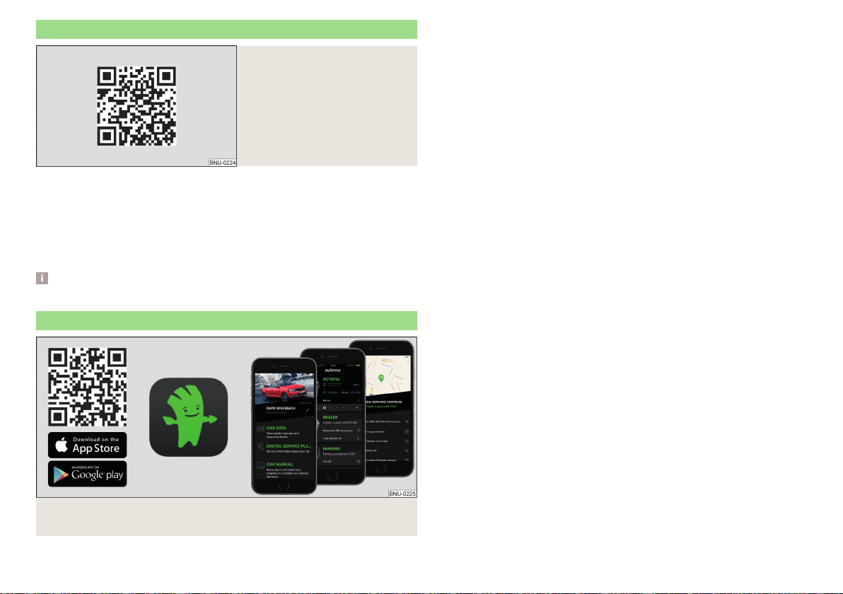
MyŠKODA App application
Fig. 4 The MyŠKODA App application is available for devices with the
Android (Google) or iOS (Apple) system.
The application MyŠKODA App contains e.g. the electronic version of the
Owner's Manual, quick tips in relation to solving certain situations related to
the vehicle or a description of Simply Clever solutions.
it is possible to get in touch with a ŠKODA partner and to use their services or
to access the service quickly using the application.
The application can also be used as an RSS reader of preferred Internet pages.
Installing the MyŠKODA App application
›
Scan the QR code » Fig. 4 .
11
Introductory information

Notes
Terms used
- Workshop - a workshop that carries out specialist service tasks
for ŠKODA vehicles. A specialist can be a ŠKODA Partner, a ŠKODA
Service Partner, or an independent workshop.
- A workshop that has been contractually author-
ised by ŠKODA AUTO or its distribution partner to perform service
work on ŠKODA vehicles and to sell ŠKODA Genuine Parts.
- A company that has been authorised by ŠKODA AUTO or
its distribution partner to sell new ŠKODA vehicles and, when applicable,
to service them using ŠKODA Genuine Parts and sell ŠKODA Genuine
Parts.
Text notes
- Short press (e.g. a button) within 1 s
- Long press (e.g. a button) for more than 1 s
Direction indications
All direction indications such as “left”, “right”, “front”, “rear” relate to the for-
ward direction of travel of the vehicle.
Explanation of symbols
→ Marker to the next operation step
WARNING
Texts with this symbol draw attention to threats of a serious accident, in-
jury or loss of life.
CAUTION
Texts with this symbol draw attention to the risk of vehicle damage or possible
inoperability of some systems.
Note
Texts with this symbol contain additional information.
“Specialist”
“ŠKODA Service Partner”
“ŠKODA Partner”
“Press”
“Hold”
12
About the Owner's Manual
Online Services
ŠKODA Connect
Service package ŠKODA Connect
The ŠKODA Connect online services expand the vehicle as well as Infotain-
ment functions with Care Connect and Infotainment Online service packages.
Care Connect
Care Connect services include the following features.
▶
Emergency, information and breakdown call.
▶
Proactive service offering to connect to your ŠKODA service partner.
▶
Remote access to the vehicle using the ŠKODA Connect application.
In order for the Care Connect services to work, a mobile network must be
available.
Infotainment Online
Infotainment Online services expand Infotainment functions e.g. with the fol-
lowing functions.
▶
Weather forecast.
▶
Petrol station search with information on fuel prices.
▶
Online traffic information.
▶
Online destination search.
The Infotainment must be connected to the Internet for the Infotainment
Online Services to work» page 166.
Terms of use and availability of services
Current “Conditions for the use of the user account” incl. “Declaration on
the protection of personal data” can be found in the user profile on the
ŠKODA Connect Portal website.
Availability of services is dependent on the type of vehicle and on the type of
Infotainment system the vehicle has been outfitted with. Some services are
available only in certain countries.
Note
The availability of the services listed always refers to the period of validity of
the contract. During this interim period of validity, content changes of these
services are possible.
ŠKODA Connect website
Fig. 5 Information about the Online Services
The ŠKODA Connect website contains information about online services and
their functions, access to the ŠKODA Connect Portal As well as the option to
download ŠKODA Connect App application.
The ŠKODA Connect website can be opened by scanning the QR code » Fig. 5
or after entering the following address into the web browser.
http://go.skoda.eu/connectivity
User and vehicle registration, activation of online services
ŠKODA Connect website portal
Fig. 6
Start of ŠKODA Connect Portal
The use of the ŠKODA Connect online service requires prior user registration
and vehicle registration on the ŠKODA Connect portal internet site as well as
activation of the online service.
The ŠKODA Connect portal website can be opened by scanning the QR code
» Fig. 6 or after entering the following address into the web browser.
http://go.skoda.eu/connectivity
13
ŠKODA Connect
Information on registration and activation of online services
Fig. 7 Instructional video on registration and activation of services
Fig. 8
Electronic version of the instructions for registration and service
activation
Instructional video on registration and activation of services
Registration and activation are carried out according to the video tutorial.
The tutorial video can be opened by scanning the QR code » Fig. 7 or after en-
tering the following address into the web browser.
http://go.skoda.eu/connect-video
Electronic version of the instructions for registration and service activation
Current information on registration and activation of Online Services can be
found in the electronic version of the manual for the Online Services on the
ŠKODA Connect website.
The electronic version of the manual can be opened by scanning the QR code
» Fig. 8 or after entering the following address into the web browser.
http://go.skoda.eu/skoda-connect/connect-manual
Note
For help with registration, activation as well as Internet connection, you can
contact a ŠKODA service partner.
Activation of online services in Infotainment
›
Turn on the ignition and switch on Infotainment.
›
Tap the
sensor field and then the function surface →
ŠKODA Connect
(online services)
→
Registration
.
›
Enter the PIN code received when registering the user and vehicle on the
ŠKODA Connect Portal website and confirm.
›
The
Registration complete.
message is displayed, wait (can take several minutes)
and confirm the message.
Delete / change the vehicle user
Delete the user
›
Turn on the ignition and switch on Infotainment.
›
Tap the
sensor field and then the function surface
→
ŠKODA Connect
(online services)
→
Registration
.
›
Tap the
Delete main user
→
delete
function surface and confirm deletion.
Changing user
›
Turn on the ignition and switch on Infotainment.
›
Tap the
sensor field and then the function surface
→
ŠKODA Connect
(online services)
→
Registration
.
›
Tap the
New owner
→
Transfer ownership
function surface.
›
Enter the PIN code received when registering the new user and when regis-
tering the vehicle on the ŠKODA Connect Portal website and confirm.
›
If required, confirm the user change by tapping the
Change main user
function
surface.
Note
By deleting the registered vehicle in the user account on the ŠKODA Connect
Portal website, the user is deleted in Infotainment.
Managing online services
Display of service management
In service management, it is possible to display information about online serv-
ices, the validity of their license, or to switch the services on / off.
›
Turn on the ignition and switch on Infotainment.
›
Tap the
sensor field and then the function surface →
ŠKODA Connect
(online services)
→
Services Management
.
14
Online Services
›
Select the desired service to display designations and service status.
›
For detailed information about the service, tap the function surface .
›
To the Switch on / off services, tap the function surface with the “check-
box”.
Enable / disable online services in Infotainment
Information on how to turn the services on/off is also displayed in the user ac-
count on the ŠKODA Connect Portal website and in the ŠKODA Connect ap-
plication.
Turning
Private mode
function on / off
By turning on the
Private mode
function services will be switched off in relation
to sending vehicle information and personal data which are indispensable for
the provision of services.
›
Tap the
sensor field and then the function surface
→
ŠKODA Connect
(online services)
→
Services Management
→
Private mode
.
Switching Care Connect services on / off
By switching off Care Connect services, services will be switched off in rela-
tion to sending vehicle information and personal data which are indispensable
for the provision of services.
›
Tap the
sensor field and then the function surface
→
ŠKODA Connect
(online services)
→
Services Management
→
Care Connect
.
Switching Infotainment Online services on / off
›
Tap the
sensor field and then the function surface
→
ŠKODA Connect
(online services)
→
Services Management
→
Infotainment Online
.
Note
Theemergency call remains fully functional after switching on the
Private mode
function or after switching off Care Connect. Information and emergency call
functions are restricted.
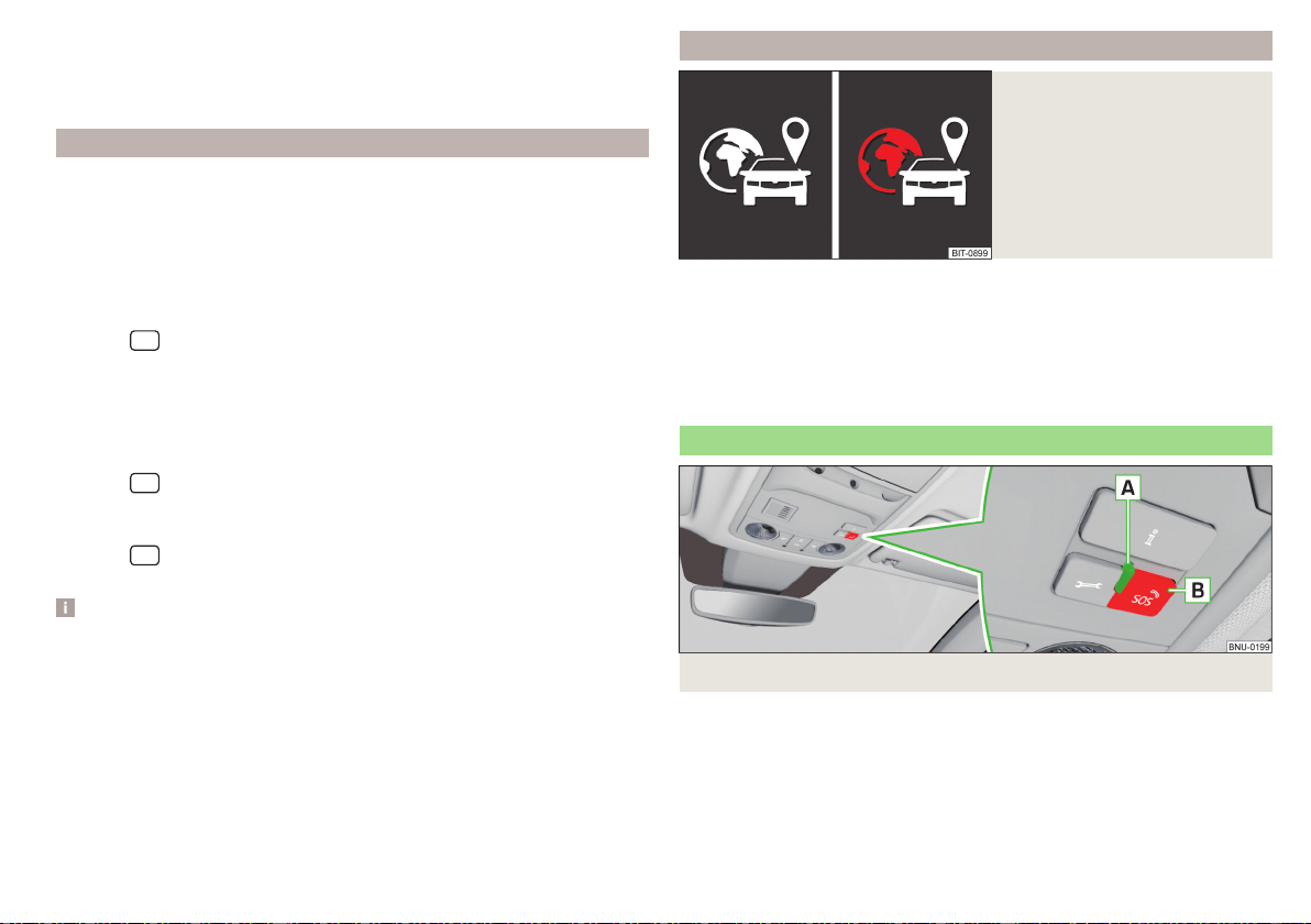
Enabled localisation services
Fig. 9
Symbols of enabled localisation
services
For the complete functionality of some online services, enabled localisation
services are required.
Localisation services include e.g. information on last parking position, area no-
tification or speed notification.
When localisation services are enabled, one of the following icons is displayed
in the status line in the Infotainment screen » Fig. 9.
Emergency call
Fig. 10
Emergency call button
Serious accident
In the event of an accident with an air bag or belt tensioner release, connection
to the emergency call centre is established Automatically. The emergency call
centre simultaneously receives information on the accident, e.g. the location
and severity of the accident, the number of occupants with fastened seatbelts
and the vehicle identification number (VIN).
15
ŠKODA Connect
Minor accident
The option for establishing a connection to the emergency call centre or to the
breakdown service appears in the Infotainment screen.
Manual connection to the emergency call centre
›
Press and hold down the
B
» Fig. 10 button.
›
In the Infotainment screen or on the instrument cluster, confirm the connec-
tion setup.
Manual connection setup can be used, for example, when you report an acci-
dent to which you are not directly involved.
The system status is displayed after the ignition is switched on, by the illumi-
nation of warning lamp
A
» Fig. 10.
▶
Green - the system is functional.
▶
Red - there is a fault in the system.
Note
The emergency service is functional even without user registration and activa-
tion of services.
Care Connect Services
Proactive service
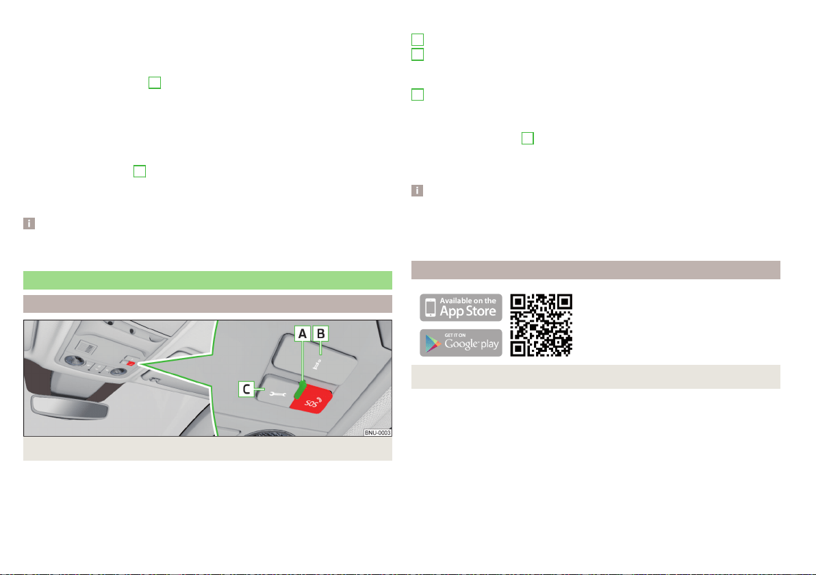
Fig. 11
Care Connect service buttons and indicator lights
The proactive service provides an overview of the technical status of your ve-
hicle and on any due service events. A connection to the emergency call or
breakdown call centre can also be made.
Buttons and control lights of Care Connect services » Fig. 11
Indicator light for system status.
A connection is established to the information telephone number by
pressing the button in the event of problems with Online Services or for
information regarding the products and services offered by ŠKODA.
Pressing the button connects you breakdown number in the event of
breakdown.
The system status is displayed after the ignition is switched on, by the illumi-
nation of warning lamp
A
» Fig. 11.
▶
Green - the system is functional.
▶
Red - there is a fault in the system.
Note
The availability of the services listed always refers to the period of validity of
the contract. During this interim period of validity, content changes of these
services are possible. Current information can be found on the ŠKODA
Connect website» page 13.
Remote access to the vehicle
Fig. 12 ŠKODA Connect application
With the remote access to the vehicle service, you can access some vehicle
functions via the ŠKODA Connect Portal or the ŠKODA Connect application
installed on your mobile phone.
Installing the ŠKODA Connect mobile application
›
Scan the QR code » Fig. 12 .
remote access to the vehicle comprises e.g. the following services.
▶
Journey data.
▶
Vehicle condition.
▶
Last parking position.
A
B
C
16
Online Services

Note
The availability of the services listed always refers to the period of validity of
the contract. During this interim period of validity, content changes of these
services are possible. Current information can be found on the ŠKODA
Connect website» page 13.
Infotainment Online services
Main menu and overview of services
Applies to Infotainment Columbus, Amundsen.
Fig. 13
Main menu
These services extend the functionality of the Internet-connected Infotain-
ment.
To display the main menu » Fig. 13, tap the
sensor field and then tap the
function surface
.
News from the RSS channels set in the user profile on the ŠKODA
Connect Portal website
Online search for filling stations with information on fuel prices » page 180
Online search for car parks with information on free parking spaces
» page 180
Weather forecast near the vehicle position, the destination of the route or
in the vicinity of the selected location
Online POI search » page 178
Import of the destinations created in the user profile on the ŠKODA
Connect Portal website » page 184
Import of the routes created in the user profile on the ŠKODA Connect
Portal website » page 191
Online updating of the navigation data (valid for the infotainment Colum-
bus) and import of POI Categories » page 175
Conditions for the use of online services
Settings of Online Services » page 133
For more information on the available services, see the ŠKODA Connect web-
site» page 13.
Note
The availability of the services listed always refers to the period of validity of
the contract. During this interim period of validity, content changes of these
services are possible. Current information can be found on the ŠKODA
Connect website» page 13.
17
ŠKODA Connect

Safety
Passive Safety
General information
Introduction
This section of the manual includes important information on the subject of
passive safety. We have combined everything here which you should be famili-
ar with, for example, regarding seat belts, airbags, safety of children and any-
thing similar.
Other important safety information can also be found in the following chap-
ters of this Owner´s Manual. The Owner´s Manual should therefore always be
in the vehicle.
Before setting off
For your own safety and the safety of the people travelling with you, please
pay attention to the following points before setting off.
▶
Check the function of the lighting and turn signal systems.
▶
Check the function of the wipers and check the wiper blades for wear.
Check the windscreen washer fluid level.
▶
Ensure that all of the windows offer good visibility to the outside.
▶
Adjust the rear-view mirror so that vision to the rear is guaranteed. Ensure
that the mirrors are not covered.
▶
Check the tyre inflation pressure.
▶
Check the engine oil, brake fluid and coolant level.
▶
Secure all items of luggage.
▶
Do not exceed the permissible axle loads and permissible gross weight of the
vehicle.
▶
Close all doors as well as the bonnet and boot lid.
▶
Ensure that no parts and components are visibly loose in the vehicle.
▶
Ensure that no objects can obstruct the pedals.
▶
Protect children by using a suitable child seat» page 28, Transporting chil-
dren safely.
▶
Adopt the correct seated position. Instruct your passengers to assume the
correct seated position» page 18, Correct and secure seating position.
Driving safety
In the interests of traffic safety, the following information must be observed.
▶
Do not become distracted from concentrating on the traffic situation, (e.g.
by your passengers or mobile phone calls).
▶
Never drive when your driving ability is impaired, (e.g. due to medication, al-
cohol or drugs).
▶
Keep to the traffic regulations and the permissible speed limit.
▶
Always adjust the driving speed to the road, traffic and weather conditions.
▶
Take regular breaks on long journeys (at least every two hours).
Correct and secure seating position
Introduction
Always assume the correct seated position before setting off and do not
change this position while driving. Also advise your passengers to adopt the
correct seated position and not to change this position while the car is moving.
The following list contains instructions for the Passenger which, if not ob-
served, may cause serious injuries or death.
▶
Do not lean against the dash panel.
▶
Do not put your feet on the dash panel.
The following list contains instructions for all Passengers which, if not ob-
served, may cause serious injuries or death.
▶
Do not sit only on the front part of the seat.
▶
Do not sit facing to the side.
▶
Do not lean out of the window.
▶
Do not put your limbs out of the window.
▶
Do not put your feet on the seat cushion.
18
Safety
WARNING
■
The adjustable seats and all head restraints must be adjusted to match
the body size at all times and the seat belt must always be fastened proper-
ly to provide the most effective levels of protection to the passengers.
■
Each occupant must correctly fasten the seat belt belonging to the seat.
Children must be fastened » page 28, Transporting children safely with a
suitable restraint system.
■
The seat backrests must not be tilted too far back when driving, as this
will impair the function of the seat belts and of the airbag system – risk of
injury!
WARNING
By sitting incorrectly, the occupant is risking life-threatening injuries.
Driver’s correct seated position
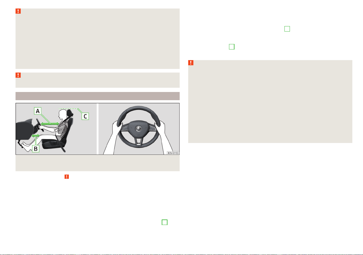
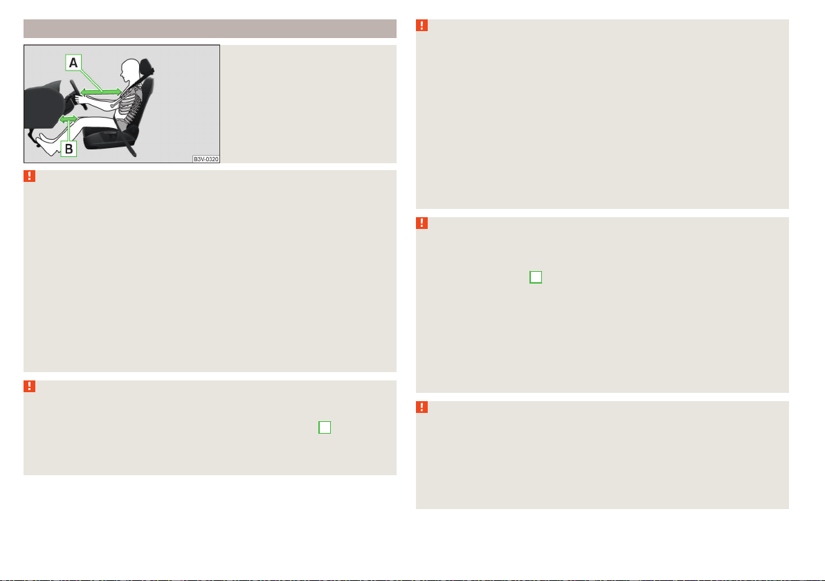
Fig. 14
Correct seated position for the driver/correct steering wheel
position
Read and observe on page 19 first.
For your own safety and to reduce the risk of injury in the event of an accident,
the following instructions must be observed.
Adjust the driver’s seat in the forward/back direction so that the pedals
can be fully depressed with slightly bent legs.
For vehicles equipped with driver knee airbags, adjust the driver's seat in a
forward/back direction so that there is a gap of at least 6 cm between the
legs and the dashboard in the vicinity of the knee airbag » Fig. 14 -
B
.
Adjust the seat backrest so that the highest point of the steering wheel
can be reached with your arms at a slight angle.
Adjust the steering wheel so that the distance between the steering wheel
and your chest is at least 25 cm » Fig. 14 -
A
.
Adjust the headrest so that the top edge of the headrest is at the same
level as the upper part of your head (not for seats with integrated headr-
ests) » Fig. 14 -
C
.
Correctly fasten the seat belt » page 21, Using seat belts.
WARNING
■
Maintain a distance of at least 25 cm from the steering wheel, and a dis-
tance of at least 6 cm between the legs and the dashboard at the height of
the knee airbag. Not maintaining this minimum distance will mean that the
airbag system will not be able to properly protect you - hazard!
■
When driving, hold the steering wheel with both hands firmly on the out-
er edge in the “9 o'clock” and “3 o'clock” position » Fig. 14. Never hold the
steering wheel in the “12 o'clock” position or in any other way (e.g. in the
middle, inner edge of the steering wheel or similar). Otherwise, in the event
of airbag deployment, you could suffer serious injury to the arms, hands
and head.
■
Ensure that no objects are located in the driver's footwell, as they could
lodge in the pedal system whilst driving. You would then no longer be able
to operate the clutch, brake or acceleration pedals.
19
Passive Safety
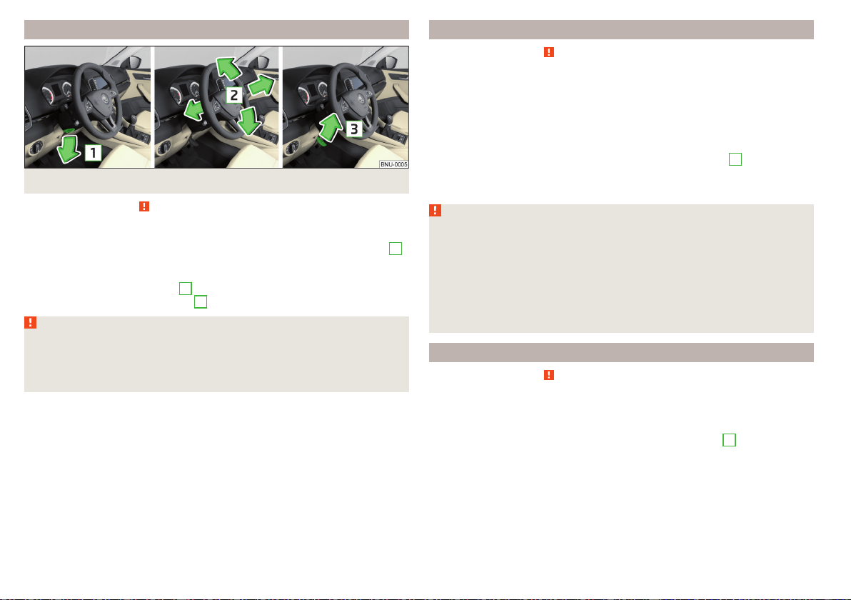
Adjusting the steering wheel position
Fig. 15 Adjusting the steering wheel position
Read and observe on page 19 first.
The height and forward/back position of the steering wheel can be adjusted.
›
Swing the safety lever under the steering wheel in the direction of arrow
1
» Fig. 15.
›
Adjust the steering wheel to the desired position. The steering wheel can be
adjusted in direction of arrow
2
.
›
Pull the holder in arrow direction
3
until the stop.
WARNING
■
Never adjust the steering wheel when the vehicle is moving only when
the vehicle is stationary!
■
The safety lever must always be locked after adjusting so that the steer-
ing wheel cannot accidentally change position – risk of accident!
Passenger’s correct seating position
Read and observe on page 19 first.
For passenger safety and to reduce the risk of injury in an accident, the follow-
ing instructions must be observed.
Position the front passenger seat back as far as possible. The front pas-
senger must maintain a distance of at least 25 cm to the dash panel so
that the airbag offers the greatest possible safety if it is deployed.
Adjust the headrests so that the top edge of the headrest is at the same
level as the upper part of your head » Fig. 14 on page 19 -
C
(not for seats
with integrated headrests).
Correctly fasten the seat belt » page 21, Using seat belts.
WARNING
■
Ensure a distance of at least 25 cm to the dashboard, otherwise the air-
bag system will not be able to protect you properly - risk of death!
■
Always keep your feet in the footwell when the car is being driven – nev-
er place your feet on the instrument panel, out of the window or on the
surface of the seats! You will be exposed to increased risk of injury if it be-
comes necessary to apply the brake or in the event of an accident. If an air-
bag is deployed, you could suffer fatal injuries by adopting an incorrect
seated position!
Passengers’ correct seating position on the rear seats
Read and observe
on page 19 first.
For passenger safety on the rear seats and to reduce the risk of injury in the
event of an accident, the following information must be observed.
Adjust the headrests so that the top edge of the headrest is at the same
level as the upper part of the head » Fig. 14 on page 19 -
C
.
Correctly fasten the seat belt » page 21, Using seat belts.
20
Safety
Seat belts
Using seat belts
Introduction
Seat belts that are fastened correctly offer good protection in the event of an
accident. They reduce the risk of an injury and increase the chance of survival
in the event of a major accident.
The seat belts reduce the kinetic energy considerably. They also prevent un-
controlled movements which, in turn, may well result in severe injuries.
When transporting children, observe the following information» page 28,
Transporting children safely.
WARNING
■
Put the seat belt on before starting any journey! This also applies to other
passengers - there is a danger of injury!
■
Maximum seat belt protection is only achieved if you are correctly seated
» page 18, Correct and secure seating position.
■
The seat backrests of the front seats must not be tilted too far to the rear
otherwise the seatbelts can lose their effectiveness.
WARNING
Information on dealing with the safety belts
■
The belt webbing must not be jammed in-between at any point or twis-
ted, or chafe against any sharp edges.
■
Make sure you do not catch the seat belt in the door when closing it.
WARNING
Information on the proper use of safety belts
■
Adjust the height of the belt in such a way that the shoulder part of the
belt is roughly positioned across the middle of your shoulder - on no ac-
count across your neck.
■
No two persons (also not children) should ever use a single seat belt to-
gether.
WARNING (Continued)
■
The lock tongue should only be inserted into the lock which is the correct
one for your seat. Wrong use of the safety belt will reduce its capacity to
protect and the risk of injury increases.
■
Many layers of clothing and loose clothing (e. g. a winter coat over a jack-
et) do not allow you to be correctly seated and impairs proper operation of
the seat belts.
■
Do not use clamps or other objects to adjust seat belts (e.g. for shorten-
ing the belts for smaller persons).
■
The seat belts for the rear seats can only fulfil their function reliably when
the seat backrests are correctly locked into position » page 84.
WARNING
Information on the care and maintenance of safety belts
■
The belt webbing must always be kept clean. Soiled belt webbing may im-
pair the proper operation of the inertia reel » page 256.
■
The seat belts must not be removed or changed in any way. Do not at-
tempt to repair the seat belts yourself.
■
Check the condition of all the seat belts on a regular basis. If parts of the
belt system become damaged (e.g. the belt webbing, the belt connections,
the inertia reel, the locking part etc.), the respective seat belt must be re-
placed by a specialist garage immediately.
■
Seat belts which have been subjected to stress in an accident must be re-
placed by a specialist garage. Also check the seat belt anchors.
Correct routing of seat belt
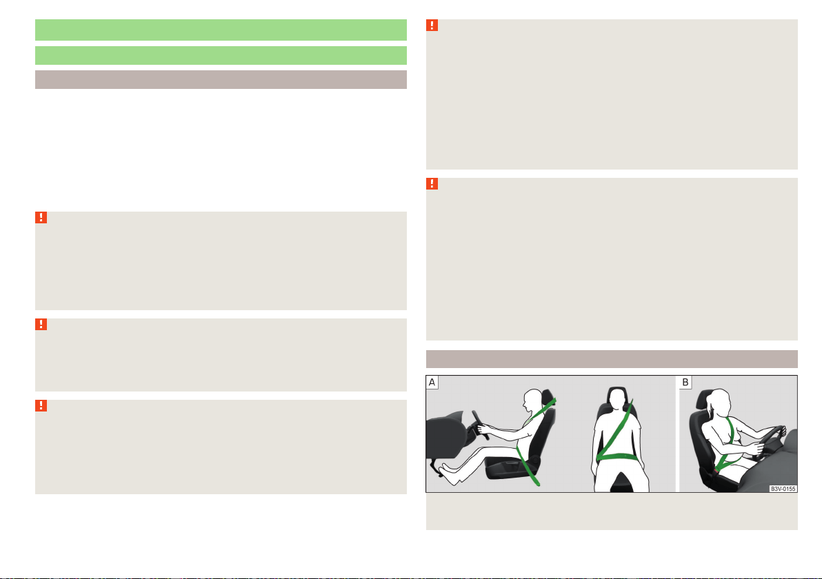
Fig. 16
Routing of belt webbing over the shoulders and the lap
belt/Routing of belt webbing for an expectant mother
21
Seat belts
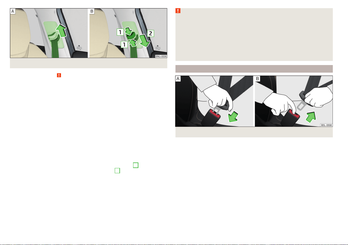
Fig. 17 Seat belt height adjusters for front seats
Read and observe on page 21 first.
It is important that the belt is properly routed to ensure seat belts offer the
maximum protection.
The shoulder part of the belt must run approximately over the middle of your
shoulder (never across your neck) and fit well against your upper body » Fig. 16
-
.
The lap part of the belt must run lap part of the belt must run in front of the
pelvis (must never run across your stomach) and must always fit snugly
» Fig. 16 -
.
In the case of pregnant women, the lap part of the belt must be positioned as
low as possible on the pelvis to avoid exerting any pressure on the lower abdo-
men » Fig. 16 - .
Seat belt height adjusters for front seats
›
Push the seat belt guide loop upwards in the direction of arrow» Fig. 17 -
.
›
Or: push together the mechanism in the direction of arrows
1
and push the
return pulley downwards in the direction of arrow
2
» Fig. 17 - .
›
Then pull firmly on the belt to ensure that the seat belt height adjuster has
correctly locked in place.
WARNING
■
Always ensure that the webbing of the seat belts is properly routed. Seat
belts which are not correctly adjusted can themselves cause injuries even in
minor accidents.
■
A seat belt which is hanging too loose can result in injuries as your body is
moved forward by the kinetic energy produced in an accident and is then
suddenly held firm by the belt.
■
The belt webbing must not run across solid or fragile objects (e.g. specta-
cles, ball-point pens, keys, etc.). Such objects can cause injury.
Fastening and unfastening seat belts
Fig. 18
Fastening/unfastening the seat belt
22
Safety
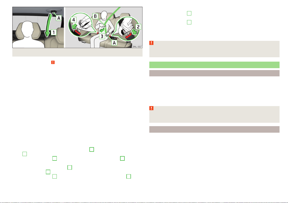
Fig. 19 Fastening/unfastening the seatbelt on the middle VarioFlex seat
Read and observe on page 21 first.
Before fastening
›
Adjust the headrest properly (does not apply to seats with integrated headr-
ests).
›
Adjust the seat (applies for the front seats and the rear Varioflex seats).
›
Adjust the belt height (applies to the front seats).
Fasten
›
Use the lock tongue to slowly pull the webbing over your chest and pelvis.
›
Insert the lock tongue into the belt buckle for the seat » Fig. 18 -
until it
audibly clicks into place.
›
Pull on the belt to check that it has engaged correctly in the lock.
Release
›
Hold the lock tongue and press the red button in the belt buckle » Fig. 18 -
.
The lock tongue pops out.
›
Feed the belt back manually so that the seat belt is not twisted and the belt
webbing rolls up completely.
Setting up middle VarioFlex seat
›
Slowly pull down the belt on the lock tongue
A
» Fig. 19 in the arrow direc-
tion
1
.
›
Insert the lock tongue
A
into the lock in the direction of arrow
2
until it
clicks.
›
Pull the belt on the lock tongue
B
slowly across the chest and pelvis in the
direction of arrow
3
.
›
Insert the lock tongue
B
in the other lock in the direction of arrow
4
stuck,
until it clicks.
›
Pull on the belt to check that it has engaged correctly in the lock.
Fastening middle VarioFlex seat
›
Grip the lock tongue
A
» Fig. 19and press the red button in the lock tongue,
the lock tongue pops out.
›
Grip the lock tongue
B
and press the red button in the seat belt buckle; the
lock tongue pops out.
›
Guide the belt back by hand so that the seat belt does not twist and the seat
belt strap rolls up fully.
WARNING
The slot of the belt tongue must not be blocked, otherwise the belt tongue
will not lock in place properly.
Inertia reel and belt tensioners
Inertia reels
Each seat belt is equipped with an inertia reel.
When pulling slowly on the seat belt, the belt can move freely. When pulling
sharply on the seat belt, the movement is locked by the inertia reel. The belts
also lock when full braking, when the car accelerates, when driving downhill
and when cornering.
WARNING
If the seat belt does not lock when pulling sharply on it, have the inertia reel
inspected immediately by a specialist garage.
Belt tensioners
The safety for the driver, front passenger and passengers on the outer rear
seats who are wearing their seat belts, is enhanced by the belt tensioners fit-
ted to the inertia reels on the front and rear external seat belts.
If there is a collision with a certain severity the seat belts are tightened by the
belt tensioner so that unwanted body motion is prevented.
Belt tensioners are not activated in the event of minor collisions, in the case of
a roll-over and also not in accidents in which no major forces are produced.
23
Seat belts
WARNING
■
Any work on the belt tensioner system, including the removal and installa-
tion of system components because of other repair work, must only be car-
ried out by a specialist garage.
■
If the belt tensioners have been deployed, it is then necessary to replace
the entire system.
Note
■
The belt tensioners can also be deployed if the seat belts are not fastened.
■
Smoke is generated when the belt tensioners are deployed. This is not an in-
dication of a fire in the vehicle.
Reversible belt tensioners
As part of the proactive passenger protection system, reversible seat belts in-
crease the safety of the belted up driver and front passenger.
In critical driving situations the seat belt is tensioned tightly over the body and
then released again be the reversible belt tensioner.
Further information » page 239, Proactive passenger protection (Crew
Protect Assist).
Airbag system
Description of the airbag system
Introduction
As a supplement to the seat belts, the airbag system provides additional pas-
senger protection in the event of severe frontal and side collisions.
The best possible protective effect of the airbag can only be achieved if the
seat belts are applied properly. The airbag is not a substitute for the seat
belts.
The status of the airbag system is indicated by the warning light in the in-
strument cluster » page 43.
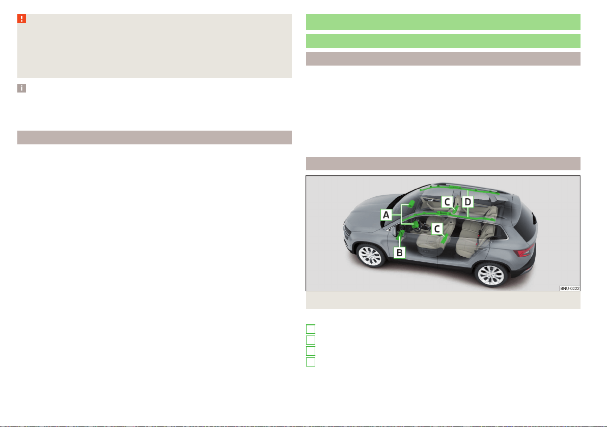
System description
Fig. 20 Airbag installation points
Airbag installation points » Fig. 20
Front airbags
Driver’s knee airbag
Front side airbags
Head airbags
A
B
C
D
24
Safety
The forward movement of the body is cushioned when it makes contact with
the fully inflated airbag and the risk of injury to the remaining body parts is
thus reduced.
▶
Front airbags - head and upper body. The airbags can be identified by the
lettering featured on the steering wheel and on the dash panel on the
passenger side.
▶
Driver's knee airbag - Legs. The airbag features the lettering on the
dashboard on the driver's side.
▶
Front side airbags - for the entire upper body (chest, stomach, pelvis) on the
side next to the door. The air bags can be identified by a label with the letter-
ing marked on the front seat backrests.
▶
Head airbags - head and neck. The airbags are provided with the lettering
marked on the B-pillar cladding.
Depending on the vehicle equipment, the airbag system consists of the
following parts.
▶
Individual airbags.
▶
Warning light
in the instrument cluster» page 43.
▶
Key switch for the front passenger airbag » page 27.
▶
Warning light for the front passenger airbag in the middle of the dash panel
» page 27.
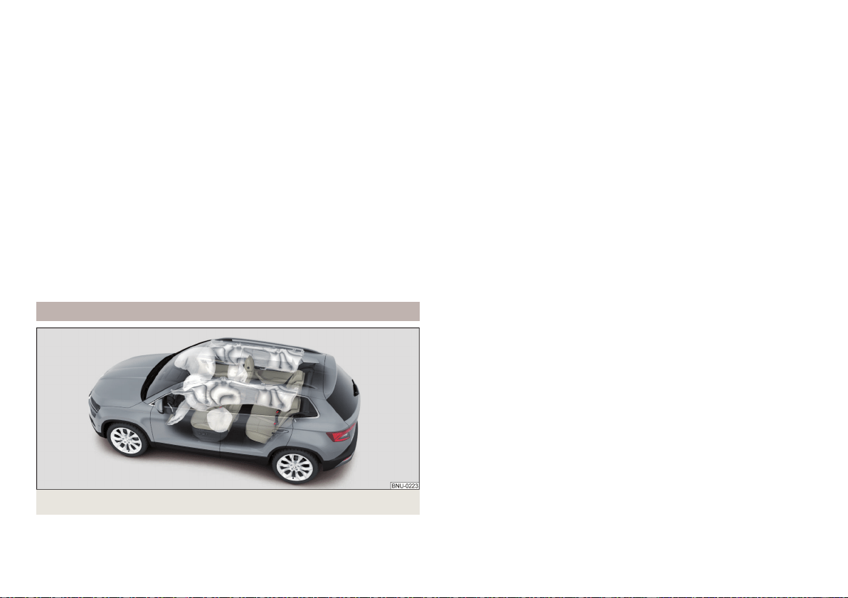
Airbag deployment
Fig. 21
Inflated airbags
The airbag system is only functional when the ignition is switched on.
When triggered, the airbag is filled with gas and unfolds. The inflation of the
airbag is carried out in a fraction of a second.
Upon inflation of the airbag, smoke is released. This is not an indication of a
fire in the vehicle.
Triggering conditions
It is not possible to generally determine which deployment conditions apply to
the airbag system in every situation. Important here is the hardness of the ob-
ject on which the vehicle impacts, the impact angle, the vehicle speed, etc.
The deceleration plays an important role in the deployment of the airbags. If
the vehicle deceleration which occurs and is measured during the collision re-
mains below the prescribed reference values specified in the control unit, the
airbags are not deployed although the vehicle may well suffer severe damage
to the bodywork as a consequence of the accident.
The following airbags will be deployed in the event of a severe frontal
collision.
▶
Driver’s front airbag.
▶
Front passenger airbag.
▶
Driver’s knee airbag.
The following airbags will be deployed in the event of a severe side
collision.
▶
Front side airbag.
▶
Head airbag.
When an airbag is deployed, the following events occur.
▶
The hazard warning lights are switched on.
▶
All doors are unlocked.
▶
The fuel supply to the engine is interrupted.
▶
The interior light comes on (if the automatic operation of the interior light is
switched on - switch ).
When there is no air bag deployment?
With minor frontal and side collisions, rear collision, overturning of the vehicle
or vehicle roll-over there is no airbag deployment.
25
Airbag system
Safety instructions
Fig. 22
Safe distance from the steering
wheel and the dashboard
WARNING
General information
■
The seat belts and the airbag system can only offer proper protection
if the driver and passengers are seated properly » page 18.
■
The airbag develops considerable forces when triggered, which can lead
to serious injuries or even death if the correct seating position or seated
position is not observed. This applies in particular to children who are trans-
ported without using a suitable child safety seat » page 30.
■
If there is a fault, have the airbag system checked immediately by a spe-
cialist garage. Otherwise, there is a risk of the airbag not being activated in
the event of an accident.
■
The airbag system must be replaced if it has been deployed.
■
In the area of the front airbag and the knee airbag, the surface of the
steering wheel and the dashboard should be cleaned using only a dry cloth
or one that has been dampened with water.
WARNING
Information about front airbags
■
For the driver and passenger, it is important to maintain a distance of at
least 25 cm from the steering wheel or dashboard » Fig. 22 -
A
. If this dis-
tance is not maintained, the airbag system cannot protect you - hazard! The
front seats and the head restraints must always be correctly adjusted to
match the body size of the occupant.
WARNING (Continued)
■
The front passenger airbag must be deactivated if using a rear-facing
child seat on the front passenger seat » page 27, Airbag deactivation. If
this is not done, there is a risk of the child suffering severe or even fatal in-
juries if the front passenger airbag is deployed.
■
No other persons, animals or objects may be positioned in front of the oc-
cupants on the front seats in the deployment area of the front air bags.
■
The steering wheel and the surface of the dashboard on the front passen-
ger side must not have stickers attached, covered or modified in any other
way. No parts (e.g. cup holders, mobile phone mounts etc.( should be
mounted in the vicinity of the airbag installation locations and in the airbag
deployment area.
■
Never place objects on the surface of the dashboard on the front passen-
ger side.
WARNING
Information about knee airbags
■
Adjust the driver's seat in a forward/back direction so that there is a gap
of at least 6 cm between the legs and the dashboard in the vicinity of the
knee airbag » Fig. 22 -
B
. If it is not possible to meet this requirement due
to your body size, visit a specialist garage.
■
The surface of the airbag module in the lower part of the dash panel be-
low the steering column not have stickers attached, be covered or modi-
fied in any other way. Nothing may be attached to the cover of the airbag
module or located within the immediate vicinity.
■
Do not attach any bulky and heavy objects (bunch of keys etc.) to the ig-
nition key. These can be ejected by the knee airbag when it is deployed and
can cause injuries.
WARNING
Information about for side and head airbags
■
No objects (e.g. sun visors turned towards the windows) should be loca-
ted in the deployment area of the side and head airbags. No accessories
(e.g. cup holders etc.) should be fitted to the doors - risk of injury!
■
Hang only light clothing on clothes hooks in the vehicle. Do not leave any
heavy or sharp objects in the pockets of the clothing. Do not use clothes
hangers to hang the clothing.
26
Safety

WARNING (Continued)
■
The airbag system operates using pressure sensors located in the front
doors. For this reason, no adjustments may be carried out to the doors or
door panels (e.g. installation of additional loudspeakers). Further informa-
tion » page 252.
■
No excessive forces, such as knocks, kicks etc., should be exerted on the
seat backrests - there is a risk of damage to the side air bags. The side air-
bags would not be deployed in such a case!
■
Any seat or protective covers which you fit to the driver or front passen-
ger seats must only be of the type expressly authorized by ŠKODA AUTO.
In view of the fact that the airbag inflates out of the backrest of the seat,
use of non-approved seat or protective covers would considerably impair
the protective function of the side airbag.
■
Have any damage to the original seat covers or stitching at the installa-
tion point of the side airbags repaired immediately by a specialist garage.
WARNING
Information on the use of the airbag system
■
Any work on the airbag system including the installation and removal of
system components due to other repair work (e.g. removal of the seat)
must only be carried out by a specialist garage. Further information
» page 252.
■
No modifications should be made to parts of the airbag system, to the
front bumper or to the body.
■
Do not manipulate individual parts of the airbag system, as this might re-
sult in the airbag being deployed.
Airbag deactivation
Deactivating airbags
The front passenger airbag can be switched off with the key-operated switch
» Fig. 23 on page 27 - .
We recommend that you ask a ŠKODA service partner to deactivate any other
airbags.
The airbag deactivation is displayed by the warning light » page 43.
Deactivating an airbag should be considered in cases such as the ones
below.
▶
A child seat is mounted on the front passenger seat, in which the child is
transported with its back to the direction of travel » page 28.
▶
Despite correct adjustment of the driver's seat, the distance of at least
25 cm between the middle of the steering wheel and chest cannot be main-
tained.
▶
Additional controls for drivers with a physical disability are installed in the ve-
hicle.
▶
Special seats (e.g. orthopaedic seats without side airbags) are installed in the
vehicle.
WARNING
If an airbag is deactivated upon the sale of the vehicle, the buyer must be
informed of this!
Deactivating the front passenger airbag
Fig. 23 Key-operated switch for the front passenger airbag / warning
light for front passenger airbag
Positions of the key switch » Fig. 23 -
The front passenger airbag is deactivated - after the ignition is switched
on, the indicator light » Fig. 23 illuminates
The front passenger airbag is activated - after the ignition is switched on,
the indicator light illuminates for 65 seconds
Switch off
›
Switch off the ignition.
›
Open the passenger door.
›
Fold the key bit out completely for the radio key » .
27
Airbag system

›
Carefully insert the key into the slot in the key switch as far as the stop.
›
Use the key to turn the slot of the key switch carefully into the position .
›
Pull the key out of the slot in the key switch » .
›
Close the front passenger door.
›
Check that the warning light illuminates after the ignition is switched
on.
Switching on
›
Switch off the ignition.
›
Open the passenger door.
›
Fold the key bit out completely for the radio key » .
›
Carefully insert the key into the slot in the key switch as far as the stop.
›
Use the key to turn the slot of the key switch carefully into the position .
›
Pull the key out of the slot in the key switch » .
›
Close the front passenger door.
›
Check that the warning light
illuminates after the ignition is switched
on.
WARNING
■
The driver is responsible for whether the airbag is switched on or switch-
ed off.
■
Only switch off the airbag when the ignition is switched off! Otherwise a
fault can occur in the system for deactivating the airbag.
■
If the warning lights flash, the front passenger airbag will not
be deployed in the event of an accident! Have the airbag system checked
by a specialist garage immediately.
CAUTION
An insufficiently folded out key bit can damage the key switch!
Transporting children safely
Child seat
Introduction
To reduce the risk of injury in the event of an accident, children must be trans-
ported in child seats!
The information in this Owner´s Manual as well as the instructions of the child
seat manufacturer must be observed when installing and using the child seat.
For safety reasons, we recommend that you always transport child seats on
the rear seats. Children should be transported on the front passenger seat only
in exceptional circumstances.
Child seats complying with the ECE-R 44 Economic Commission for Europe
standard must be used.
Child seats that comply with the ECE-R 44 standard are identified with a test
mark that cannot be removed: large E in a circle with the test number under-
neath
WARNING
■
One should never carry children, and also not babies! - on one's lap.
■
When leaving the vehicle, do not leave children unattended in the vehicle.
Children might not be capable of leaving the vehicle or helping themselves
independently in the event of an emergency. Very high or low tempera-
tures can be fatal!
■
The child must be secured in the vehicle during the entire journey! Other-
wise, the child would be thrown through the vehicle in the event of an acci-
dent, causing fatal injuries to both the child and other occupants.
■
Children are exposed to an increased risk of injury in the event of an acci-
dent if they lean forward or adopt an incorrect seated position when the
vehicle is moving. This particularly applies to children who are transported
on the front passenger seat as they can suffer severe, or even fatal injuries
if the airbag system is deployed!
28
Safety
WARNING (Continued)
■
Pay particular attention to the information provided by the manufacturer
of the child safety seat regarding the correct routing of the belt. Seat belts
which are not correctly adjusted can themselves cause injuries even in mi-
nor accidents.
■
Safety belts must be checked to ensure that they are running properly.
One should also ensure that the belt is not damaged by sharp-edged fit-
tings.
■
When installing the child seat on the back seat, the corresponding front
seat must be adjusted so that there is no contact between the front seat
and the child seat or the child being transported in a child seat.
■
When installing a child seat in which the child faces forward, adjust the
head restraints so that they are as high as possible.
■
If the head restraints still prevent the child seat from being installed, even
in the lowest position, you will need to remove them » page 88. After re-
moving the child seat, refit the head restraints.
■
When using a separate child seat cushion, set the headrest so that the
child's head is flush to the height of the headrest upper edge, but does not
protrude above this » Fig. 14 on page 19
C
.
Note
We recommend that you use child seats from ŠKODA Original Accessories.
These child seats were developed and also tested for use in ŠKODA vehicles.
They meet the ECE-R 44 standard.
Use of a child seat on the front passenger seat (variant 1)
Does not apply to Taiwan
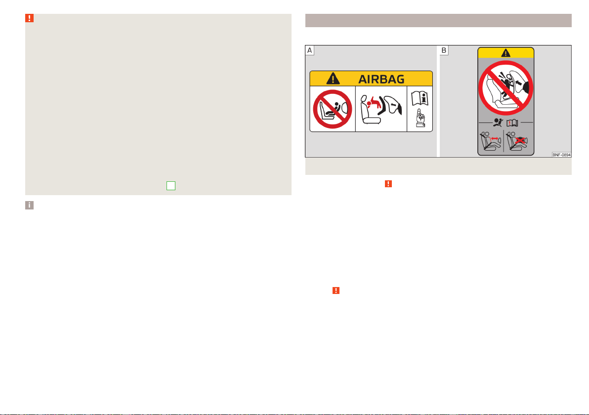
Fig. 24
Warning labels
Read and observe
on page 28 first.
Never use a rearward-facing child restraint system on a seat which is pro-
tected by an active airbag. This could cause serious injury to the child, or
even death.
This is indicated also on stickers that are located at the following positions.
▶
On the front passenger's sun visor » Fig. 24 -
.
▶
On the B-pillar on the front passenger side » Fig. 24 –
.
The following instructions must be followed when using a child seat on the
front passenger seat.
▶
The front passenger airbag must be deactivated if using a rear-facing child
seat »
.
▶
If possible, adjust the front passenger seat backrest so that it is as vertical, so
as to ensure secure contact between the passenger seat backrest and the
back of the child seat.
▶
If possible, move the front passenger seat backwards so that there is no con-
tact between the front passenger seat and the child seat behind it.
▶
Set the height-adjustable front passenger seat as high up as possible.
29
Transporting children safely
▶
Set the front passenger seat belt as high up as possible.
▶
With child safety seats in groups 1, 2 and 3, make sure that the loop-around
fittings attached to the child seat headrest is positioned in front of or at the
same height as the loop-around fittings on the B pillar on the passenger side.
Adjust the height of the front passenger seat belt so that the belt does not
“jam” in the return pulley. In the event of an accident, there is the risk of in-
jury to the neck of the child carried due to the seat belt!
WARNING
■
Never use a rear-facing child seat on the front passenger seat if the pas-
senger airbag is activated. This child safety seat is positioned in the deploy-
ment area of the front passenger airbag. The airbag may cause the child se-
vere, or even fatal injuries, in the event of it being deployed.
■
As soon as the child seat, in which the child is transported with their back
in the direction of travel, is no longer used in the front passenger seat, the
front passenger airbag should be switched on again.
Use of a child seat on the front passenger seat (variant 2)
Applies to Taiwan
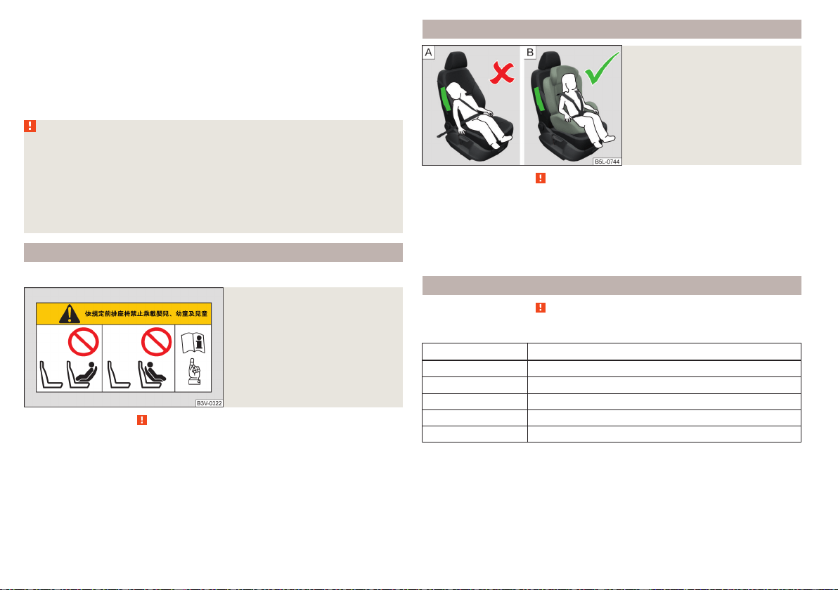
Fig. 25
Warning stickers
Read and observe on page 28 first.
No babies, infants or children to be carried on the passenger seat.
A sticker to this effect can also be found on the front passenger's sun visor
» Fig. 25.
Child safety and the side airbag
Fig. 26
Incorrect seated position of a
child who is not properly se-
cured – risk from the side air-
bag/Child properly protected by
safety seat
Read and observe on page 28 first.
The child must not be positioned in the deployment area of the side airbag
» Fig. 26 -
.
There must be sufficient room between the child and the area into which the
side airbag will deploy to allow the airbag to provide as much protection as
possible » Fig. 26 -
.
Classification of child seats
Read and observe on page 28 first.
Classification of child seats according to the ECE-R 44 standard.
Group Weight of the child
0 up to 10 kg
0+ up to 13 kg
1 9-18 kg
2 15-25 kg
3 22-36 kg
30
Safety

Use of child safety seats which are secured with a safety belt
Never use a rear-facing child seat on the front passenger seat if the passenger airbag is activated. This child safety seat is positioned in the deployment area of
the front passenger airbag. The airbag may cause the child severe, or even fatal injuries, in the event of it being deployed.
Read and observe on page 28 first.
Overview of the usability of child seats secured with a seat belt on seats in accordance with the ECE-R 16 standard.
Group
Passenger seat with activated
front airbag
Passenger seat with deactivated
front airbag
Rear seats
Outside
Rear seat
Centre
a)
0
up to 10 kg
X U
b)
U U
0
up to 13 kg
X U
b)
U U
1
9-18 kg
UF U U U
2
15-25 kg
UF U U U
3
22-36 kg
UF U U U
a)
It is forbidden to install a child seat with a support base on the middle rear seat.
b)
Set the height-adjustable front passenger seat as high up as possible.
U The seat is suitable for the use of approved child seats in this weight group category “Universal”.
UF The seat is suitable for the use of approved forward-facing child seats in the “Universal” weight group category.
X The seat is not suitable for children in this weight group.
31
Transporting children safely
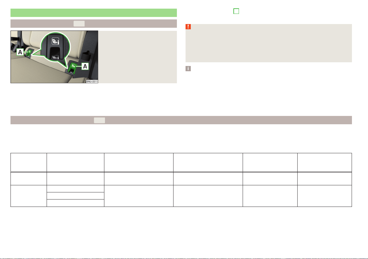
Fastening systems
attachment points of the system
Fig. 27
Labels of the system
is a system for securing child seats quickly and safely.
Two locking eyes are located between the seat backrest and the seat cushion
of the outer rear seats and front passenger seat for fixing the
system
child seat in place.
First, remove the caps
A
in order to access the locking eyes» Fig. 27. After
removing the child seat, replace he caps.
WARNING
■
Always refer to the instructions of the manufacturer of the child seat
when installing and removing a child seat with the system.
■
Never attach other child seats, belts or objects to the attachment points
intended for the installation of a child seat with the system – risk of
death!
Note
■
A child seat fitted with the system can only be mounted in a vehicle fit-
ted with a system if the child seat has been approved for this type of ve-
hicle. Further information is available from a ŠKODA Partner.
■
Child seats with the system can be purchased from ŠKODA Original Ac-
cessories.
Use of child safety seats with the system
Never use a rear-facing child seat on the front passenger seat if the passenger airbag is activated. This child safety seat is positioned in the deployment area of
the front passenger airbag. The airbag may cause the child severe, or even fatal injuries, in the event of it being deployed.
Overview of the usability of child seats fastened with the system on each of the seats in accordance with the ECE-R 16 standard.
Group
Size class of
the child seat
a)
Front passenger seat
with activated front air bag
b)
Front passenger seat
with front airbag switched
off
b)
Rear seats
Outside
c)
Rear seat
Centre
0
up to 10 kg
E X X IL X
0+
up to 13 kg
E
X X IL XD
C
32
Safety
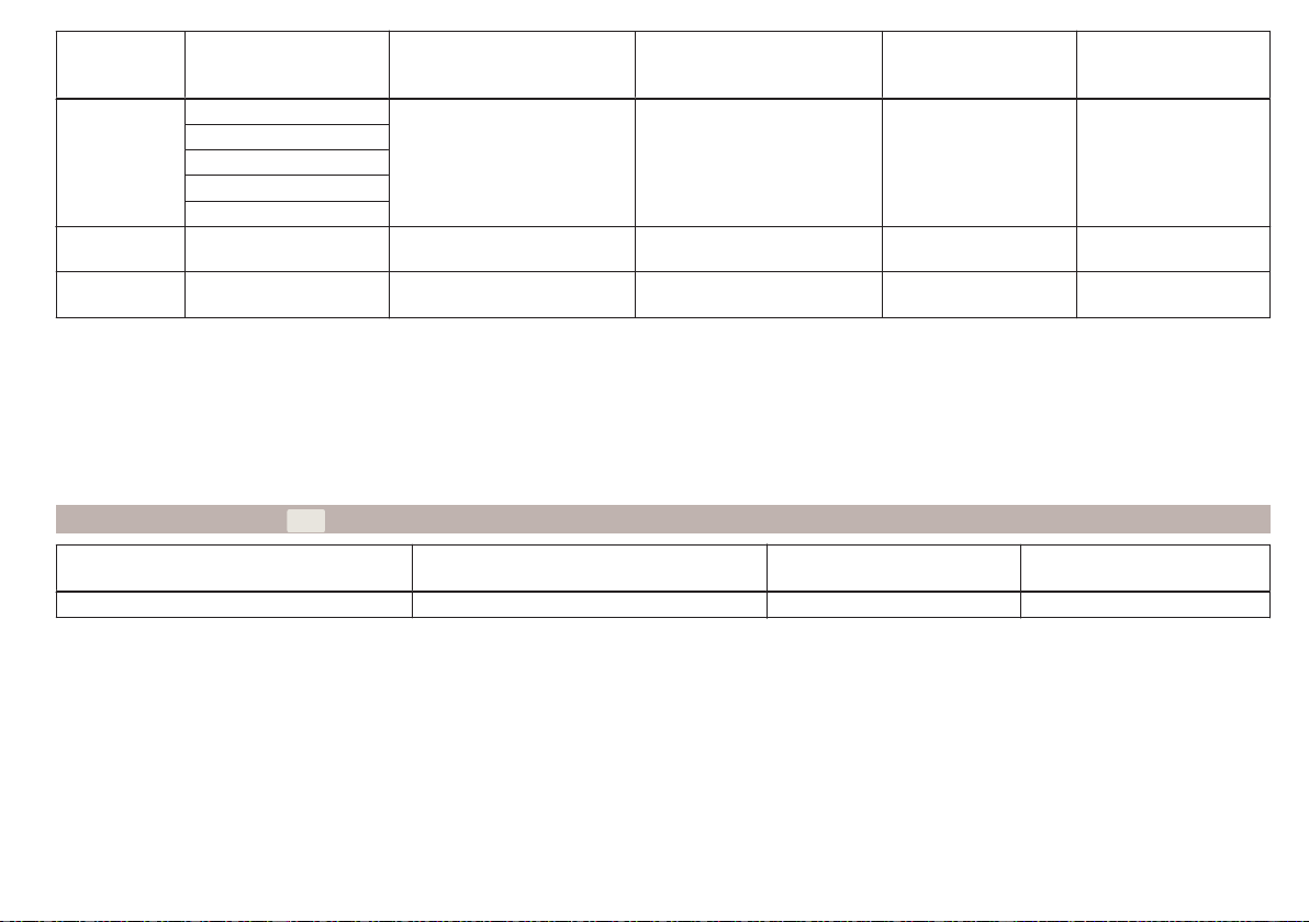
Group
Size class of
the child seat
a)
Front passenger seat
with activated front air bag
b)
Front passenger seat
with front airbag switched
off
b)
Rear seats
Outside
c)
Rear seat
Centre
1
9-18 kg
D
X X
IL
IUF
X
C
B
B1
A
2
15-25 kg
- X X IL X
3
22-36 kg
- X X IL X
a)
The size category is shown on the label attached to the child seat.
b)
If the front passenger seat is fitted with
system attachment points, it is suitable for the installation of an
child seat with “Semi-Universal” approval.
c)
The seat is suitable for the
fixing system.
IL The seat is suitable for installation of a child seat with the “Semi-Universal” approval. The “Semi-Universal” category means that the child seat with
the system is approved for your vehicle. Observe the list of vehicles that comes with the child seat.
IUF The seat is suitable for the use of forward-facing child seats approved in this weight group.
X The seat is not fitted with system attachment points.
Using child seats with the
system
Front passenger seat
with activated front air bag
Front passenger seat
with front airbag switched off
Rear seats outside Rear seat middle
X X i-U X
The seat is suitable for forward and backward facing child seats of
the category “Universal”.
The seat is not suitable for the child seat of the category “Universal”.
i-U
X
33
Transporting children safely
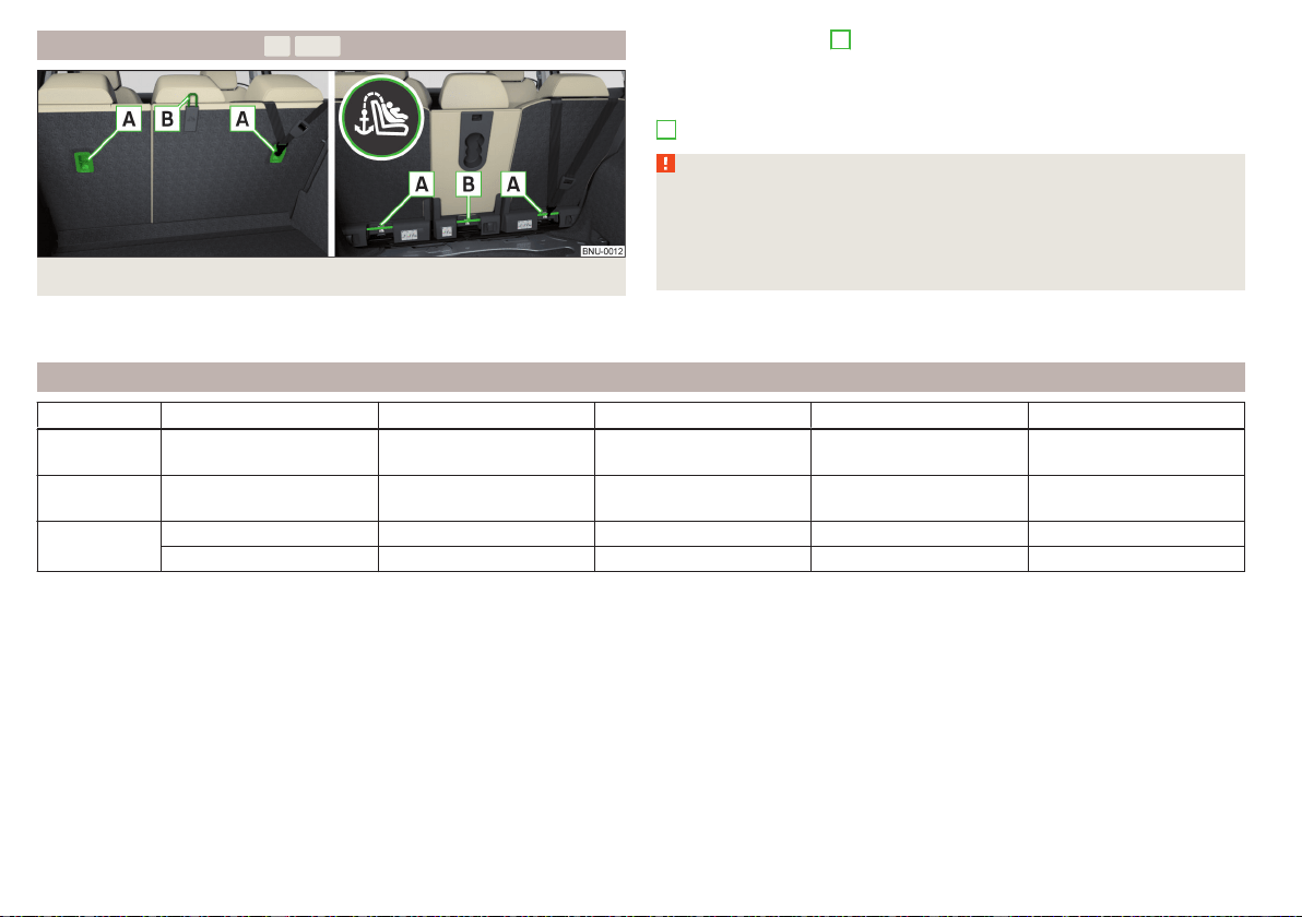
Attachment points of the system
Fig. 28 Attachment points of the system Version 1/version 2
is an attachment system that restricts the movement of the upper
part of the child seat.
The attachment points
A
for attaching the belt of a child seat with the
system are located on the rear side of the rear seat backrests
» Fig. 28.
Some country-specific models can also be fitted with an attachment point
B
» Fig. 28.
WARNING
■
Always refer to the instructions from the manufacturer of the child seat
when installing and removing a child seat with the system.
■
Only use child seats with the system on the seats with the at-
tachment points provided with the logo.
■
Only ever attach one belt from the child seat to a locking eye.
Recommended child seats
Group Manufacturer Type Attachment Order number Approval number (E1 ...)
0
up to 13 kg
Britax Römer Baby Safe Plus Isofix base frame 1ST019907 04 301146
1
9-18 kg
Britax Römer Duo Plus TT and DDA000006 04 301133
2-3
15-36 kg
Britax Römer Kidfix XP
a)
000019906K 04 301198
Britax Römer Kidfix II XP 000019906L 04 301323
a)
For optimum protection, especially in the case of a side collision, it is recommended to use this child seat together with back part.
34
Safety

35
Transporting children safely
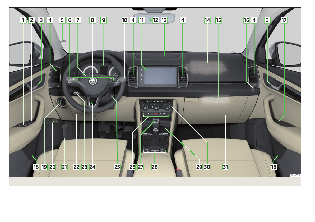
Fig. 29 Cockpit example for LHD
36
Operation

Operation
Cockpit
Overview
Electric power windows 64
Electric exterior mirror adjustment
79
Door opening lever 59
Air outlet vents 116
Ticket holder 91
Operating lever (depending on equipment):
▶
Indicator light and high-beam headlight 70
▶
Speed regulating system
226
▶
Speed limiter 227
▶
Headlight assist
71
Steering wheel with horn/with driver's front airbag
24
Buttons for operating the information system
48
Instrument cluster
38
Operating lever:
▶
Windscreen wipers and washers
76
▶
Information system
48
Infotainment
120
Interior rear-view mirror
79
Storage compartment on the dash panel 93
Front passenger airbag 24
External infotainment module (in the front passenger storage
compartment) 122
Key switch for front passenger airbag deactivation (on the dash-
board side)
27
Electric power window in the front passenger door 65
Storage compartment
91
Light switch 69
Button for the boot lid
62
Bonnet release lever 261
Storage compartment 91
1
2
3
4
5
6
7
8
9
10
11
12
13
14
15
16
17
18
19
20
21
22
Operating lever for adaptive cruise control 232
Steering wheel locking lever 20
Depending on equipment fitted:
▶
Ignition lock 198
▶
Starter button 198
Bar with buttons and warning lights (depending on the equip-
ment fitted):
▶
START-STOP
199
▶
Park Assist 222
▶
Parking aid 215
▶
Hazard lights 73
▶
Central locking system 58
▶
/ Warning lights for the front seat passenger air-
bag 27
Depending on equipment fitted:
▶
Gearshift lever (manual gearbox)
204
▶
Selector lever (automatic gearbox)
205
Bars with buttons (depending on the equipment fitted):
▶
Selection of travel mode 237
▶
Auto Hold
202
▶
Electric parking brake
201
▶
Stabilisation control ESC / Traction control TCS
210, 211
▶
Offroad mode
212
Storage compartment
92
Depending on equipment fitted:
▶
Phonebox
92
▶
12-volt outlet
99
▶
Cigarette lighter 101
▶
Ashtrays
101
▶
USB input
93
Controls for heating/air conditioning 113
Storage compartment on the front passenger side
96
Note
The layout of the controls on right-hand drive vehicles differs partially from
that shown in » Fig. 29.
23
24
25
26
27
28
29
30
31
37
Cockpit
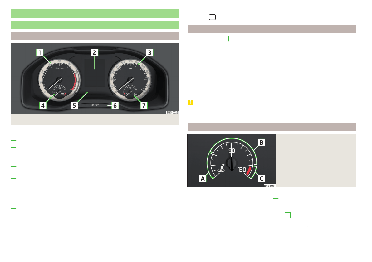
Instruments and warning lights
Instrument cluster
Introduction
Fig. 30
Instrument cluster
Engine revolutions counter » page 38
▶
with warning lights » page 39
Display » page 48
Speedometer
▶
with warning lights » page 39
Coolant temperature display » page 38
Bar with warning lights » page 39
Operation key:
▶
Set the time » page 49
▶
Reset counter for distance travelled (trip) » page 48
▶
Displaying the distance and days until the next service interval
» page 54
Fuel gauge » page 39
The brightness of the instrument illumination is set automatically depending
on the ambient lighting throughout. If the visibility is poor and the lights are
not on, the brightness of the instrument lighting reduces to alert the driver to
switch on the lights in due time.
1
2
3
4
5
6
7
The brightness of the instrument lighting can be adjusted in Infotainment in
the menu
/ → →
Light
.
Engine revolutions counter
The tachometer
1
» Fig. 30 on page 38 shows the actual engine speed per
minute.
The beginning of the tachometer red scale range indicates the maximum per-
mitted speed for an engine that has been driven-in and has reached operating
temperature.
You should shift into the next highest gear before the red scale of the revolu-
tion counter is reached, or select mode D/S on the automatic gearbox.
The gear recommendation is important to note in order to maintain the opti-
mum engine speed » page 49.
CAUTION
The pointer of the engine revolutions counter must reach the red area for only
a short time - there is a risk of engine damage!
Coolant temperature gauge
Fig. 31
Coolant temperature gauge
The display » Fig. 31 only works if the ignition is switched on.
Cold range - The pointer is in the range
A
, the engine has not yet reached its
operating temperature. Avoid high speeds and high engine loads.
Operating range - The pointer is in the range
B
.
High temperature range - The pointer is in the range
C
. The coolant temper-
ature is too high. The warning light illuminates in the instrument clus-
ter» page 45.
38
Operation
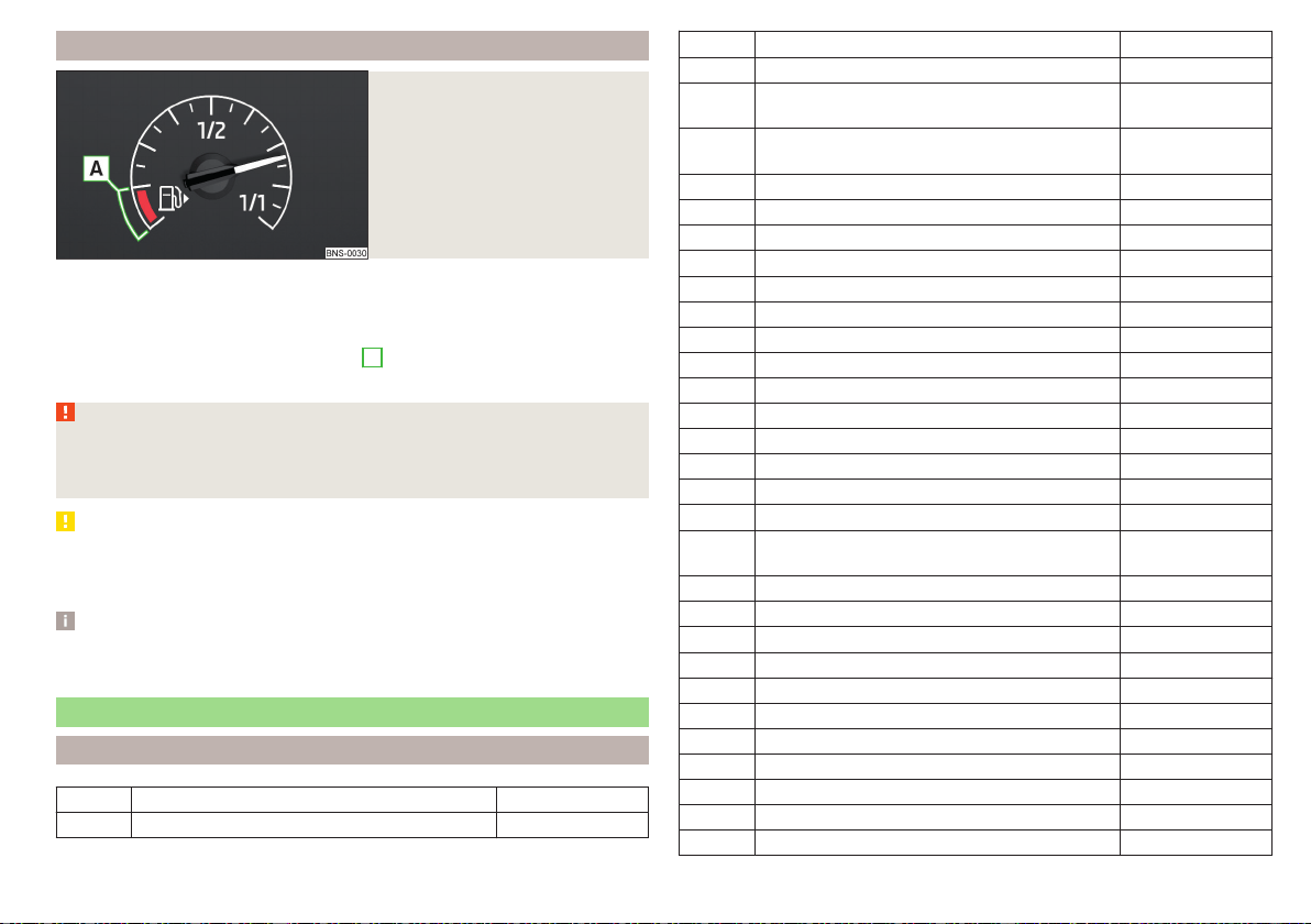
Fuel gauge
Fig. 32
Fuel gauge
The display » Fig. 32 only works if the ignition is switched on.
The capacity of the fuel tank is approximately 50 litres for vehicles with front-
wheel drive, and approximately 55 litres for vehicles with four-wheel drive.
If the fuel level reaches the reserve level
A
» Fig. 32, the warning light
illumi-
nates in the instrument cluster» page 44.
WARNING
For the vehicle systems to function correctly, and thus for safe driving,
there must be sufficient fuel in the tank. Never drain the fuel tank com-
pletely – risk of accident!
CAUTION
Never drive until the fuel tank is completely empty! The irregular supply of fuel
can cause misfiring, which can result in damage to parts of the engine and the
exhaust system.
Note
The arrow next to the symbol within the fuel gauge displays the installa-
tion location of the fuel filler on the right side of the vehicle.
Warning lights
Introduction
Parking brake » page 40
Brake system » page 40
Front seat belt warning light » page 41
Adaptive Cruise Control (ACC) » page 41
Power steering
Steering lock (KESSY system)
» page 41
Stabilisation control (ESC)
Traction control (ASR)
» page 42
Traction control (ASR) deactivated » page 42
Antilock brake system (ABS) » page 42
Rear fog light » page 42
Exhaust control system » page 42
Glow plug system (diesel engine) » page 42
EPC fault light (petrol engine) » page 43
Safety systems » page 43
Tyre pressure » page 43
Brake pads » page 44
Fuel reserve » page 44
Lane Assist » page 240
Turning signal system » page 44
Trailer turn signal lights » page 44
Fog lights » page 44
Speed regulating system
Speed limiter
» page 44
Brake pedal (automatic gearbox) » page 44
Auto Hold function » page 44
High beam » page 45
Automatic gearbox » page 45
Rear seat belt warning light » page 45
Alternator » page 45
Coolant » page 45
Engine oil pressure » page 46
Engine oil level » page 46
AdBlue
®
level too low (diesel engine) » page 46
AdBlue
®
error (diesel engine) » page 46
39
Instruments and warning lights
Bulb failure » page 46
Diesel particle filter (diesel engine) » page 46
Windscreen washer fluid level » page 47
High-beam headlight assist » page 47
START-STOP system » page 199
Display of a low temperature » page 47
Water in fuel filter (diesel engine) » page 47
Adaptive Cruise Control (ACC) » page 229
Distance warning (Front Assist) » page 47
Front Assist » page 48
emergency call » page 48
Economy mode » page 48
Offroad mode » page 48
Service » page 48
The warning lights in the instrument cluster indicate certain functions or faults.
Some warning lights can be accompanied by acoustic signals and messages in
the display of the instrument cluster.
After switching on the ignition, some warning lights light up briefly as a func-
tion test. If the tested systems are OK, the corresponding warning lights go
out a few seconds after switching on the ignition or after starting the engine.
The warning lights are located at the following positions in the instrument
cluster » Fig. 30 on page 38.
▶
Engine revolutions counter
1
▶
Display
2
▶
Speedometer
3
▶
Bar with warning lights
5
Warning lights in the display
Depending on the importance the warning light (danger) or (warning) illu-
minate along with some of the warning lights in the list with the warning lights.
Depending on vehicle equipment, some indicator lights can be displayed in col-
our on the display. For example. the coolant warning lamp may be represented
as follows.
▶
- monochrome (“black and white”) display
▶
- coloured display
WARNING
■
Ignoring illuminated warning lights and related messages or instructions
in the display of the instrument cluster may lead to serious personal injury
or damage to the vehicle.
■
If you have to stop for technical reasons, then park the vehicle at a safe
distance from the traffic, switch off the engine and switch on the hazard
warning lights » page 73. Place the warning triangle at the prescribed dis-
tance.
■
The engine compartment of your car is a hazardous area. While working
in the engine compartment, be sure to observe the following warnings
» page 260.
Parking brake
Read and observe on page 40 first.
illuminates - the parking brake is switched on.
Parking brake error
Illuminates
Message:
Fault: Electric parking brake
▶
Seek help from a specialist garage.
Parking on a slope that is too steep
Illuminates
Message:
Parking brake: Gradient too steep. Log book!
▶
Find a parking space on a flat surface or on a slope that is not so steep.
Brake system
Read and observe
on page 40 first.
lights up – the brake fluid level in the brake system is too low.
▶
Stop the vehicle, switch off the engine, and check the level of the brake fluid
» page 265.
40
Operation

WARNING
■
If the warning light lights up at the same time as warning light
» page 42, Anti-lock braking system (ABS), do not continue your
journey! Seek help from a specialist garage.
■
A fault to the ABS system or the braking system can increase the vehi-
cle's braking distance – risk of accident!
Front seat belt warning light
Read and observe on page 40 first.
lights up - the driver or front passenger has not fastened their seat belt.
At a speed of more than approximately 30 km/h, the warning light flashes
and an audible warning sounds at the same time.
If the seat belt is not fastened by the driver or front passenger during the next
approx. 2 minutes, the warning signal is deactivated and the warning light
illuminates permanently.
Adaptive cruise control (ACC)
Read and observe on page 40 first.
illuminates – the ACC delay is not sufficient.
▶
Apply the brake.
For more information about the ACC system » page 229.
Power steering / steering lock (KESSY system)
Read and observe on page 40 first.
Fault in the power steering
lights up – this indicates a complete failure of the power steering and the
steering assist is no longer working (significantly higher steering forces).
lights up – this indicates a partial failure of the power steering and the
steering forces can be higher.
▶
Switch off the ignition, start the engine again and travel a short distance.
▶
If the warning light does not go off, stop the vehicle, do not continue
your journey. Seek help from a specialist garage.
▶
If the warning light does not go off, you can drive on, exercising appropri-
ate caution. Seek assistance from a specialist garage immediately.
Steering lock defect (KESSY system)
An audible signal sounds as a warning.
flashes
Message:
Steering column lock faulty. Stop!
▶
Park the vehicle, stop driving! After switching off the ignition, it is no lon-
ger possible to lock the steering, to activate the electrical components (e.g.
Infotainment ), to switch on the ignition again and to start the engine. Seek
help from a specialist garage.
flashes
Message:
Steering lock: Workshop!
▶
You can drive on, exercising appropriate caution. Seek assistance from a spe-
cialist garage immediately.
Steering column lock not unlocked (System KESSY)
flashes
Message:
Steering lock: Workshop!
▶
Move the steering wheel slightly back and forth, thereby facilitating unlock-
ing the steering lock.
▶
If the steering does also not unlock then, the help of a specialist garage is re-
quired.
Disconnecting the vehicle battery
If the vehicle's battery has been disconnected and reconnected, the indicator
light comes on after switching on the ignition.
The warning light should go out after driving a short distance.
If, after the motor is restarted and a short drive, the indicator light does not go
out, there is a system error.
▶
You can drive on, exercising appropriate caution. Seek assistance from a spe-
cialist garage immediately.
41
Instruments and warning lights

Stability Control (ESC) / traction control (ASR)
Read and observe on page 40 first.
flashes – the ESC or TCS is currently active.
lights up – there is an ESC or TCS fault.
▶
You can drive on, exercising appropriate caution. Seek assistance from a spe-
cialist garage immediately.
If the warning light comes on after starting the engine, the TCS may be
switched off for technical reasons.
▶
Switch the ignition off and on again.
If the warning light does not illuminate after you switch the engine back on,
the TCS is fully functional again.
Disconnecting the vehicle battery
If the vehicle's battery has been disconnected and reconnected, the indicator
light
comes on after switching on the ignition.
The warning light should go out after driving a short distance.
If, after a short drive, the indicator light does not go out, there is a system er-
ror.
▶
You can drive on, exercising appropriate caution. Seek assistance from a spe-
cialist garage immediately.
For more information on the ESC system » page 210 or TCS system
» page 211.
Traction control (ASR) deactivated
Read and observe
on page 40 first.
lights up – the TCS system is deactivated.
Anti-lock braking system (ABS)
Read and observe on page 40 first.
lights up – there is an ABS fault.
The vehicle will only be braked by the normal brake system without the ABS.
▶
You can drive on, exercising appropriate caution. Seek assistance from a spe-
cialist garage immediately.
WARNING
■
If the warning light lights up at the same time as warning light
» page 40, Brake system, do not continue your journey! Seek help
from a specialist garage.
■
A fault to the ABS system or the braking system can increase the vehi-
cle's braking distance – risk of accident!
Rear fog light
Read and observe
on page 40 first.
lights up – the rear fog light is switched on.
Emission control system
Read and observe on page 40 first.
lights up – there is a fault in the emission control system. The system makes
it possible to drive on in emergency mode – there may be a noticeable reduc-
tion in engine performance.
▶
You can drive on, exercising appropriate caution. Seek assistance from a spe-
cialist garage immediately.
Preheating unit (diesel)
Read and observe on page 40 first.
flashes – there is a fault in the engine management system. The system
makes possible operation emergency mode - there may be a noticeable reduc-
tion in engine performance.
There is a fault in the glow plug system if the warning light does not come
on or illuminates continuously.
▶
You can drive on, exercising appropriate caution. Seek assistance from a spe-
cialist garage immediately.
42
Operation

EPC warning light (petrol)
Read and observe on page 40 first.
lights up – there is a fault in the engine management system. The system
makes it possible to drive on in emergency mode – there may be a noticeable
reduction in engine performance.
▶
You can drive on, exercising appropriate caution. Seek assistance from a spe-
cialist garage immediately.
Safety systems
Read and observe
on page 40 first.
System fault
lights up – there is a fault in the airbag system.
Message:
Error: airbag
▶
Seek help from a specialist garage.
The front passenger airbag has been disabled with the key switch
lights up for around 4 seconds after the ignition has been switched on.
One of the airbags or a belt tensioner has been disabled by the diagnostic
tool
lights up for around 4 seconds after the ignition is switched on and then
flashes for approximately 12 seconds.
Message:
Airbag/belt tensioner deactivated.
ProActive passenger protection
illuminates and the following message is shown in the information cluster
display.
Message:
Proactive occupant protection unavailable.
or
Message:
ProActive passenger protection: funct. restricted.
The seat belt for the driver and front passenger needs to be replaced.
▶
Seek help from a specialist garage.
WARNING
When a fault in the airbag system occurs, there is a risk of the system not
being triggered in the event of an accident. Therefore, this must be
checked immediately by a specialized garage.
Tyre pressure
Read and observe on page 40 first.
Change of tyre pressure values
lights up – there was a pressure change in one of the tyres.
An audible signal sounds as a warning.
▶
Immediately reduce speed and avoid sudden steering and braking manoeu-
vres.
▶
Stop the vehicle, turn the ignition off and check the tyres and their inflation
pressures » page 268.
▶
Correct the tyre pressure if necessary or replace the affected wheel
» page 273 or use the repair kit » page 277.
▶
Save the tyre pressure values in the system » page 246.
System fault
flashes for approximately 1 minute and remains lit – there may be a fault in
the tyre pressure monitoring system.
▶
Stop the vehicle, turn the ignition off and start the engine again.
If the warning light
flashes after starting the engine again, there is a system
error.
▶
You can drive on, exercising appropriate caution. Seek assistance from a spe-
cialist garage immediately.
Disconnecting the vehicle battery
If the vehicle's battery has been disconnected and reconnected, the indicator
light comes on after switching on the ignition.
The warning light should go out after driving a short distance.
If, after a short drive, the indicator light does not go out, there is a system er-
ror.
▶
You can drive on, exercising appropriate caution. Seek assistance from a spe-
cialist garage immediately.
43
Instruments and warning lights

Other incidents
The illumination of the warning light can have the following reasons.
▶
The vehicle is loaded on one side. Distribute the load evenly.
▶
The wheels of one axle are loaded more heavily (e.g. when towing a trailer or
when driving uphill or downhill).
▶
Snow chains are mounted.
▶
A wheel has been changed.
CAUTION
Under certain circumstances (e.g. sporty style of driving, wintry or unpaved
roads) the warning light can be delayed or does not light up at all.
Brake linings
Read and observe on page 40 first.
illuminates - the brake pads are worn.
▶
It is possible to continue driving with due caution. Seek assistance from a
specialist garage immediately.
Fuel reserve
Read and observe on page 40 first.
lights up – the fuel level in the fuel tank is at the reserve level (approximately
6 litres).
An audible signal sounds as a warning.
▶
Fill up with fuel » page 257.
Note
The text in the display goes out after refuelling and driving a short distance.
Turn signal system
Read and observe
on page 40 first.
flashes – the left turn signal is turned on.
flashes – the right turn signal is turned on.
If there is a fault in the turn signal system, the warning light flashes at twice its
normal rate (does not apply when towing).
When the hazard warning light system is switched on, this will cause all of the
turn signal lights as well as both warning lights to flash.
Trailer turn signal lights
Read and observe on page 40 first.
flashes – the trailer turn signal lights are switched on.
If a trailer is hitched and the warning light is not flashing, one of the trailer
turn signal lights has failed.
▶
Check the trailer bulbs.
Fog lights
Read and observe on page 40 first.
lights up – the fog lights are switched on.
Speed regulating system / speed limiter
Read and observe on page 40 first.
lights up – the vehicle speed is limited by the speed regulating system or
the adaptive cruise control or by the speed limiter.
flashes – the speed set with the speed limiter has been exceeded.
Brake pedal (automatic gearbox)
Read and observe
on page 40 first.
lights up – apply the brake.
Auto Hold function
Read and observe on page 40 first.
illuminates - the Auto Hold function is activated.
For more information about the Auto-Hold Function » page 202.
44
Operation

Main beam
Read and observe on page 40 first.
lights up – the main beam or the headlight flasher is switched on.
Automatic gearbox
Read and observe on page 40 first.
Gearbox overheated
Illuminates
Message:
Gearbox overheated. You can drive on.
Transmission overheated. You can drive on, exercising appropriate caution.
lights up
Message:
Gearbox overheated. Stop! Log book!
▶
Do not drive the vehicle! Stop the vehicle and turn off the engine.
You can continue your journey as soon as the warning light disappears.
▶
If the warning light do not go out,
stop driving! Seek help from a specialist
garage.
Transmission problem
Illuminates
Message:
Gearbox faulty. Stop the vehicle safely!
Illuminates
Message:
Gearbox in emergency mode. No reverse gear.
Illuminates
Message:
Error: gearbox. Speed is limited.
▶
It is possible to continue driving with due caution. Seek assistance from a
specialist garage immediately.
Rear seat belt warning light
Read and observe on page 40 first.
lights up – a rear seat belt is not fastened.
lights up – a rear seat belt is fastened.
When the seat belt is fastened/unfastened, the particular light lights up briefly
and indicates the current belt status!
Generator
Read and observe on page 40 first.
lights up – the battery is not being charged whilst the engine is running.
CAUTION
If in addition to the light the light lights up while driving, stop driving -
risk of engine damage! Switch off the engine and seek assistance from a spe-
cialist garage.
Coolant
Read and observe on page 40 first.
Coolant level too low
lights up
Message:
Please check the coolant level. Log book!
▶
Stop the vehicle, switch off the engine and let it cool.
▶
Check the coolant level » page 264.
If the coolant level is within the specified range and the warning light
lights
up again, then there may be a malfunction of the cooling fan.
▶
Switch off the ignition.
▶
Check the fuse for the radiator fan, replace if necessary.
If the coolant level and fan fuse are both OK but the warning light lights up
again, stop driving!
▶
Seek help from a specialist garage.
Coolant temperature too high
lights up
Message:
Engine overheat. Stop! Check the log book.
▶
Stop the vehicle, switch off the engine and let it cool.
▶
Continue your journey only after the warning light has disappeared.
45
Instruments and warning lights

Engine oil pressure
Read and observe on page 40 first.
flashes – the engine oil pressure is too low.
▶
Stop the vehicle, switch off the engine, and check the engine oil level.
▶
If the warning light flashes, stop driving, even if the oil level is OK! Also do
not leave the engine running at an idling speed.
▶
Seek help from a specialist garage.
CAUTION
If it is not possible to top up with engine oil under the given conditions, stop
driving - there is a risk of engine damage! Switch off the engine and seek as-
sistance from a specialist garage.
Engine oil level
Read and observe
on page 40 first.
Engine oil level too low
lights up
Message:
Please add engine oil.
▶
Stop the vehicle, switch off the engine, and check the engine oil level, top up
if necessary.
The warning light will go out if the bonnet is left open for more than 30 sec-
onds. If the engine oil is not replenished, the warning light will come on again
after driving about 100 km.
Engine oil level too high
lights up
Message:
Please reduce oil level.
▶
Stop the vehicle, switch off the engine, and check the engine oil level.
▶
If the oil level is too high, you can driven on, exercising appropriate caution.
Seek assistance from a specialist garage immediately.
Fault on the engine oil level sensor
lights up
Message:
Oil sensor: Please consult a workshop.
▶
It is possible to continue driving with due caution. Seek assistance from a
specialist garage immediately.
CAUTION
If it is not possible to top up with engine oil under the given conditions, stop
driving - there is a risk of engine damage! Switch off the engine and seek as-
sistance from a specialist garage.
AdBlue
®
level too low (diesel engine)
Read and observe on page 40 first.
Illuminates - AdBlue
®
level too low.
▶
Add AdBlue
®
» page 259.
AdBlue
®
error (diesel engine)
Read and observe on page 40 first.
illuminates – there is a fault in the AdBlue
®
system.
▶
Seek help from a specialist garage.
Lamp failure
Read and observe on page 40 first.
lights up – one of the lamps is faulty.
A message will appear in the display about the affected lamp.
Diesel particle filter (diesel)
Read and observe
on page 40 first.
The diesel particulate filter separates and burns soot particles from the ex-
haust.
lights up – the filter is clogged with soot.
46
Operation

To clean the filter, and where traffic conditions permit » , drive as follows for
at least 15 minutes or until the indicator light goes out.
4th or 5th gear engaged (automatic transmission: position D / S).
Vehicle speed at least 70 km/h.
Engine speed between 1800 - 2500 rpm.
If the filter is properly cleaned, the warning light extinguishes.
If the filter is not properly cleaned, the warning light does not go out and
the warning light begins to flash.
▶
You can drive on, exercising appropriate caution. Seek assistance from a spe-
cialist garage immediately.
WARNING
■
Always adjust the speed and driving style to the actual weather, road, ter-
rain and traffic conditions.
■
The diesel particulate filter reaches very high temperatures - there is a
fire hazard and serious injury could be caused. Therefore, never stop the
vehicle at places where the underside of your vehicle can come into con-
tact with flammable materials, such as dry grass, undergrowth, leaves, spil-
led fuel or the like.
CAUTION
■
As long as the warning light illuminates, one must take into account an
increased fuel consumption and a power reduction of the engine.
■
Using diesel fuel with an increased sulphur content can considerably reduce
the life of the diesel particle filter. A ŠKODA partner will be able to tell you
which countries use diesel fuel with a high sulphur content.
Note
We encourage you to avoid constant short journeys. This will improve the
combustion process of the soot particles in the diesel particulate filter.
Windscreen washer fluid level
Read and observe
on page 40 first.
lights up – the windscreen washer fluid level is too low.
▶
Top up the windscreen washer fluid » page 262.
High-beam assistant
Read and observe on page 40 first.
illuminates – headlight assist is activated » page 71, Light Assist.
Display of a low temperature
Read and observe on page 40 first.
lights up – the outside temperature is below +4 °C.
WARNING
Even at temperatures around +4 °C, black ice may still be on the road sur-
face! Do not only rely upon the information given on the outside tempera-
ture display that there is no ice on the road.
Water in the fuel filter (diesel engine)
Read and observe
on page 40 first.
The fuel filter with water separator, filters out dirt and water from the fuel.
If too much water is present in the separator, the following information ap-
pears on the instrument cluster display.
Illuminates
Message:
Water in fuel filter. Log book!
▶
It is possible to continue driving with due caution. Seek assistance from a
specialist garage immediately.
Front Assist
Read and observe on page 40 first.
lights up – the safe distance to the vehicle in front is below the mini-
mum.
Information on the Front Assist system» page 235.
47
Instruments and warning lights

Front assist
Read and observe on page 40 first.
Illuminates
▶
Front Assist has recognised the risk of a collision or automatically triggered
an emergency braking manoeuvre » page 235.
▶
An automatic deactivation of Front Assist took place with ESC Sport activa-
ted » page 210 and with ASR activated» page 211.
▶
Front Assist is not available » page 237.
Illuminates with the lettering - Front Assist is deactivated » page 237.
emergency call
Read and observe
on page 40 first.
lights up – there is a fault in the emergency call system.
▶
Seek help from a specialist garage.
Economy mode
Read and observe on page 40 first.
illuminates - the vehicle is in economy mode due to the intervention of the
active cylinder management or due to the neutral position of the automatic
gearbox.
Offroad mode
Read and observe on page 40 first.
illuminates - the Offroad mode is enabled.
illuminates - the hill descent assistant is activated.
flashes (stronger) – the hill descent assistant is engaged at the moment.
Service
Read and observe on page 40 first.
lights up – information regarding a service appointment that is due
» page 54, Displaying the distance and days until the next service interval.
Information system
Driver information system
Display in the instrument cluster
Fig. 33
Display overview
Depending on the vehicle's equipment, the information system uses the dis-
play in the instrument cluster to provide the following information » Fig. 33.
Time / symbols of the Infotainment voice control
Engaged gear / gear recommendation
Selector lever positions for the automatic gearbox
Warning lights of the START-STOP system
Compass display
Detected traffic signs
Driving data (multifunction display)
Warning lights
Information messages
Door alarm
Eco tips
Service interval display
Outside temperature
Cruise control / speed limiter
Total distance travelled
Distance travelled by resetting the memory (trip)
Door, luggage compartment and bonnet alarm
When the door or luggage compartment / bonnet is open, a graphic warning
appears in the display.
1
2
3
4
5
6
48
Operation
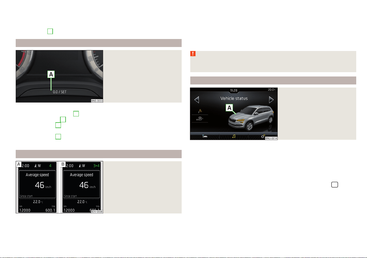
An acoustic signal will also sound if you drive the vehicle above 6 km/h when a
door is open.
Reset counter for distance travelled (trip)
›
Press button
A
» Fig. 34 on page 49.
Setting the time
Fig. 34
Button in the instrument cluster
›
Switch on the ignition.
›
Press and hold the button
A
» Fig. 34until the
Time
is shown in the display.
›
Release the button
A
and the system switches to the hour setting function.
›
Press the button
A
again and set the hours.
›
Wait 4 seconds, the system switches to the minutes setting.
›
Press the button
A
again and set the minutes.
›
Wait 4 seconds, the system switches to the initial setting.
Gear recommendation
Fig. 35
Information on the selected
gear / Gear recommendation
A suitable engaged gear or, where appropriate, a recommended gear is dis-
played, with the aim of conserving the life of the engine and increasing driving
efficiency.
Display » Fig. 35
Optimal gear engaged
Gear recommendation (e.g. means that it is advantageous to switch
from 3rd to 4th gear)
For vehicles with automatic transmission the recommended gear will be
shown provided the mode for manual switching (Tiptronic) is selected.
WARNING
The driver is always responsible for selecting the correct gear in different
driving situations, such as overtaking.
Vehicle condition
Fig. 36
Vehicle condition
Certain functions and conditions of individual vehicle systems are checked
continuously when the ignition is switched on. If there is a fault in the system,
the following message will appear in the display of the instrument cluster.
While the operational faults remain unrectified, the messages are always indi-
cated again. After the message is displayed for the first time, the warning
lights (danger) or (warning) continue to be displayed.
The vehicle condition can be displayed in Infotainment in the menu
/ →
→
Vehicle status
.
In the screen, information regarding vehicle condition or function of the tyre
pressure monitor is displayed.
›
Using the function surfaces select the menu item Vehicle status.
49
Information system
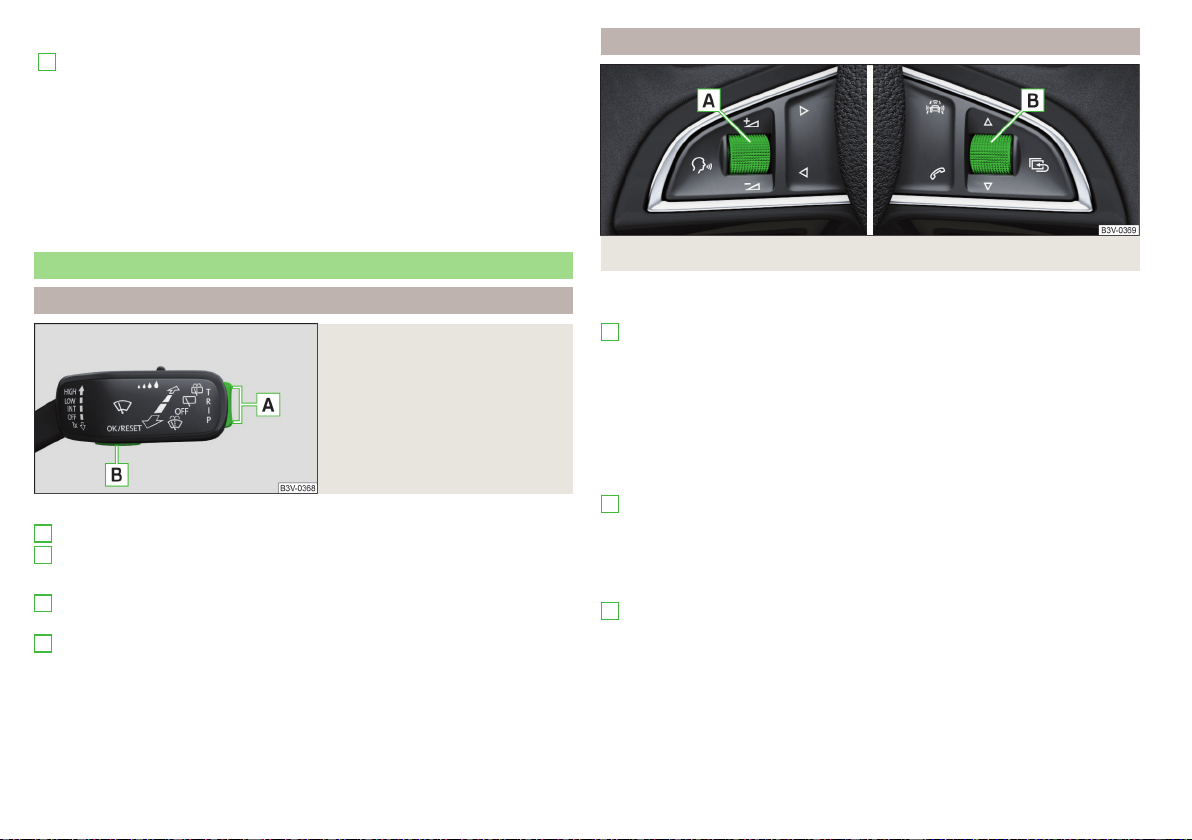
Function surfaces and screen display » Fig. 36
A
Vehicle representation (the zones of the vehicle are shown in different
colours, corresponding to any warning messages that occur. The warn-
ing messages are displayed once you touch the “vehicle”)
No message/warning messages relating to vehicle status and the num-
ber (if there is only one message, one warning message text is dis-
played)
Display information about the status of the START-STOP system
Activation / deactivation of notes relating to START-STOP-Sys-
tem messages in another screen display
Operation of the information system
Operation using the control lever
Fig. 37
Buttons on the operating lever
Operating the multifunction display
Press (up or down) - select data / set values
Press - display / confirm indication
Operation of the display menus
Press (up or down) - move to the selected menu
Hold (up or down) - display main menu
Press - confirm selected menu item
A
B
A
B
Operation using the multifunctional steering wheel
Fig. 38 Buttons/dials: on the multifunction steering wheel
Buttons/dials on the multifunction steering wheel
Switch on/off voice control
Turn - sets the volume
Press - sound on / off
Skip to next track/station
Switch to previous track/station
Display the assistance systems menu
Press - the Telephone menu, accept/end the call; call selected contact
Hold - repeat last call; reject call
Operating the multifunction display
Turn - select data / set values
Press - display / confirm indication
Operation of the display menus
Hold - display main menu
Press - return to a previous level in the menu
Turn - move in the selected menu
Press - confirm selected menu item
A
B
B
50
Operation

Driving data (Multifunction display)
Introduction
The driving data display is only possible with the ignition switched on. After
the ignition is switched on, the function that was last selected before switch-
ing off the ignition is displayed.
If the journey data in the instrument cluster display after switching on the igni-
tion, select the menu item
Journey data
in the main menu and confirm
» page 53.
The units can be adjusted in Infotainment in the menu
/ → →
Units
.
The journey data can be set/reset in Infotainment in the menu
/ → →
Instrument cluster
.
Note
The setting of the information display is stored in the active user account per-
sonalisation » page 55.
Information Overview
Overview of driving data (depending on the vehicle equipment).
Range - drive distance in km which can be covered with the existing tank ca-
pacity and with the same driving style. If you drive more efficiently this value
can increase.
AdBlue
®
range - drive distance in km which can be covered with the existing
AdBlue
®
tank capacity and with the same driving style. If you drive more effi-
ciently this value can increase.
Average fuel consumption - is calculated continuously since the last time the
memory was deleted. After erasing the memory, no data will appear for the
first 100 m driven.
Current fuel consumption - when the vehicle is stationary or slowly moving,
the fuel consumption is displayed in l/h (--,- km/l appears on models for some
countries).
Oil temperature - if the temperature is lower than 50 °C or if there is a fault in
the system for checking the oil temperature, the symbols are displayed.
Warning when the preset speed is exceeded - allows the setting of a speed
limit where, if exceeded, an acoustic warning signal and a warning message ap-
pears on the display of the instrument cluster.
Dynamic Road Sign Display - traffic signs display » page 243, Traffic sign rec-
ognition.
Current speed - digital speedometer.
Average speed - is calculated continuously since the last time the memory
was deleted. After erasing the memory, no data will appear for the first 300 m
driven.
Driving route - distance driven since the last time the memory was deleted.
Driving time - driving time since the last time the memory was deleted.
Convenience consumers - information about the total consumption of the
comfort consumers in l/h and a list of three consumers (e.g. air conditioning
etc.), which have the largest share of fuel consumption.
Infotainment display
Fig. 39
Journey data
›
In Infotainment in the menu
/ Tap on function surface →
Driving data
.
Screen display » Fig. 39
Distance travelled
Driving time
Average speed
Average fuel consumption
Transit point rating (
DriveGreen
Function)
A
B
C
D
E
51
Information system

Graphic fuel level display (if the estimated range is less than 300 km, the
vehicle starts to approach the symbol )
Approximate range
Use the function surfaces to select one of the following preset lists.
▶
Since start - Driving data for the individual trip
▶
Long-term - Long-term journey data
▶
Since refuel - Data since refuelling
Warning when exceeding the set speed
The system offers the possibility to set a speed limit beyond which an acoustic
warning signal will sound and the following warning message appears in the
display of the instrument cluster.
Adjust the speed limit while the vehicle is stationary
›
Select the menu item
Warning at
and confirm.
›
Set the desired speed limit is 5 km/h steps.
›
Confirm the set value, or wait several seconds; your settings will be saved
automatically.
Adjusting the speed limit while the vehicle is moving
›
Select the menu item
Warning at
and confirm.
›
Drive at the desired speed.
›
Confirm the current speed as the speed limit.
The set speed limit can be manually adjusted later if needed.
Reset the speed limit
›
Select the menu item
Warning at
and confirm.
›
By confirming the stored value, the speed limit is reset.
The speed limit set mode is stored even after the ignition is switched off and
on. After a gap between driving exceeding 2 hours, the pre-set speed limit is
deactivated.
F
G
Memory
Fig. 40
Memory display
The system saves the data in the three memories described below which are
displayed at the position
A
» Fig. 40.
Since start
In the memory, driving data is saved for the time between switching on and
switching off the ignition. New data will also flow into the calculation of the
current driving information if the trip is continued within 2 hours after switch-
ing off the ignition.
If the trip is interrupted for more than 2 hours, the memory is automatically
erased.
Long-term
The memory gathers driving data from any number of individual journeys up to
a total of 99 hours and 59 minutes driving time or 9999 kilometres driven.
The indicator is automatically set back to zero if one of the indicated values is
exceeded.
Since refuel
The driving data is stored in the memory since the last fuel refuelling.
The memory is erased automatically the next time you fill up.
›
For the Storage choice, repeatedly confirm the selected indication and se-
lect the desired memory.
›
For Deleting the memory for the selected information, hold down the but-
ton confirming the specification.
The following driving data are stored.
▶
Average fuel consumption
▶
Distance travelled
52
Operation

▶
Average speed
▶
Driving time
Note
Disconnecting the vehicle battery will delete all memory data.
Menus in the display of the instrument cluster
Introduction
The instrument cluster is a user interface which, depending on the equipment
configuration, provides information about the Infotainment, the multifunction
display, the assistance systems etc.
The menus with details can be operated and displayed using the buttons on
the operating lever or the multifunction steering wheel » page 50.
Main menu items (depending on vehicle equipment)
■
Driving data
» page 51
■
Assist systems
» page 54
■
Navigation
» page 53
■
Audio
» page 53
■
Telephone
» page 53;
■
Vehicle
» page 49
Note
■
If warning messages are displayed, these messages must first be confirmed
to access the main menu.
■
The display language can be set in Infotainment» page 132 and » page 139.
Navigation
menu item
The following information is displayed in the
Navigation
menu item.
▶
Driving recommendations
▶
Compass
▶
Last destinations
audio
menu item
The following information is displayed in the
Audio
menu item.
Radio
▶
Currently playing station (name/frequency).
▶
The selected frequency range (e.g. FM) optionally with the number of the
station button (e.g. FM3), if the station is stored in the memory list.
▶
List of available stations (if more than 5 stations can be received).
▶
TP traffic announcements.
Media
▶
Name of the track being played, if necessary, further information regarding
title (e.g. artist, album name), if this information is stored as a so called ID3
tag on the audio source.
Telephone
menu item
The call list with the following symbols is displayed in the
Telephone
menu item.
Incoming call
Outgoing call
Missed call
Symbols in the display
Telephone battery charge (this function is only supported by some mobile
phones)
Signal strength (this function is only supported by some mobile phones)
A telephone connected to the Infotainment system
Missed calls (if there are several missed calls, the number of calls is shown
next to the symbol)
Switch-off microphone
Apple CarPlay
An external device connected to the Infotainment system via Apple CarPlay
can be operated via the multifunction steering wheel as well as via menus in
the instrument cluster display.
The following symbols are displayed in the
Telephone
menu option.
Answer the incoming call
Reject incoming call / end call
Activate / deactivate microphone (applies for the infotainment Swing)
53
Information system
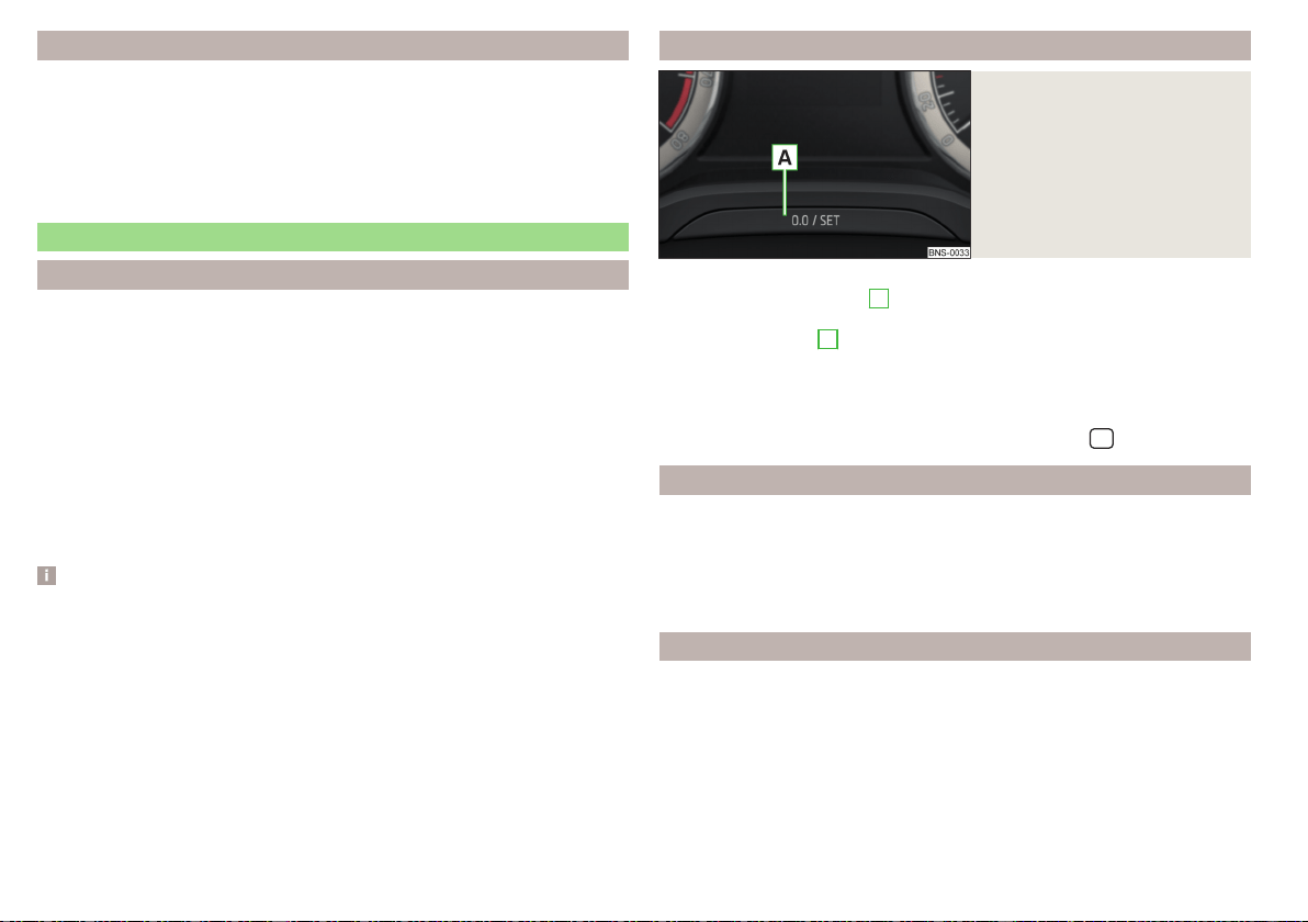
Assist systems
menu item
The following systems are activated/deactivated in the
Assist systems
menu
item.
▶
Lane Assist
▶
Assist system for blind spot monitoring
▶
Rear Traffic Alert
▶
Front Assist
Service intervals
Introduction
Compliance with service intervals is of crucial importance for the service
life and the maintenance of the vehicle. Never exceed the service date.
The specialist company will notify you about the type of service interval, the
option to change it, and the scope of service.
You will be informed of the service interval display in the display of the instru-
ment cluster.
Service record
A specialist garage confirms the corresponding service evidence in the service
information system called Digital Service Plan.
We recommend that you always print out the respective proof of service.
Note
The customer is responsible for covering the cost of all services including
changing or replenishing the oil, even during the warranty period, unless stated
otherwise in the ŠKODA AUTO. warranty terms or other binding agreements.
Displaying the distance and days until the next service interval
Fig. 41
Button in the instrument cluster
›
Switch on the ignition.
›
Press and hold the button
A
» Fig. 41 until the
Service
menu item is shown in
the display.
›
Release the button
A
.
In the display, the symbol
appears for 4 seconds along with the following
message for the kilometres or days to the next service appointment.
The details regarding the remaining kilometres or days until the next scheduled
service can also be displayed in Infotainment in the menu
/
→
→
Service
.
Service messages
Before the next service date has been reached, the symbol
as well as a
message about the mileage or days until the next service event appears in the
display after switching on the ignition.
Once the service interval is reached, the symbol
appears in the display after
the ignition is switched on, together with the message.
Resetting the service interval display
Have the display reset by a specialist company.
We recommend that you do not reset the service interval display yourself. In-
correctly setting the service interval display can cause problems with the vehi-
cle.
Variable service interval
For vehicles with variable service intervals, after resetting the oil change serv-
ice display in a specialist garage, the values of the new service interval are dis-
played, which are based on the previous operating conditions of the vehicle.
54
Operation

These values are then continuously matched according to the actual operating
conditions of the vehicle.
Personalization
Introduction
Thanks to the personalisation, more drivers have the opportunity to use a vehi-
cle with individually set system functions by means of a user account which is
assigned to the respective vehicle key.
WARNING
Make all adjustments when the vehicle is stationary - otherwise there is the
risk of accident!
Operating principle
Fig. 42
Switch to a different user account
Read and observe on page 55 first.
After unlocking the vehicle and opening the driver's door, all the personalised
functions are adjusted according to the user account that is assigned to the
key which was used to unlock the vehicle.
Any change to the set personalised functions is automatically stored in the ac-
tive user account.
As part of the personalisation, three default user accounts as well as a
Guest
account are provided.
Switch to a different user account
You can switch to a different user account in the instrument cluster display
» Fig. 42 within 10 seconds after turning on the ignition.
An account can be changed at a later time in Infotainment in the menu
/
→ →
Vehicle status
→ (if the
Tyre Pressure Monitoring System
is displayed first
of all, then use the arrow or switch to
Vehicle status
).
If an account is selected in which not all of the points required by the system
are set, a configuration wizard can be automatically displayed on the Infotain-
ment screen » page 127.
Electrically adjustable driver's seat (referred to only as seat in the
following)
The seated position adjustment is carried out in the following cases.
▶
After unlocking the vehicle and opening the driver's door (valid in this case:
before vehicle locking, an account with a particular seat setting was selected.
After vehicle unlocking, an account is activated to which a different seat set-
ting is assigned).
▶
After switching to a different user account and at a speed less than 5 km/h.
The seat adjustment can be terminated as follows.
▶
By tapping on the function surface
Cancel
on the Infotainment screen.
▶
By pressing any key on the seat » page 82.
Note
Vehicles with the personalisation function are provided with three vehicle
keys.
Overview of some personalized functions
Read and observe on page 55 first.
▶
Driving mode - the last selected mode, mode setting
Individual
▶
Setting the electrically adjustable driver's seat.
▶
Exterior mirror adjustment.
▶
Assistance systems - Lane Assist, parking aid (ParkPilot).
▶
Light - ambient lighting, convenience turn signal, COMING HOME / LEAVING
HOME.
▶
Climatronic - temperature in each individual area, fan speed, recirculation
mode.
▶
Infotainment settings - brightness level of the screen, keyboard arrange-
ment.
▶
Radio - sound settings, station sorting.
▶
Media - shuffle / repeat title, selected video format.
55
Information system

▶
Voice control - acoustic signals.
▶
Navigation - home address, alternative routes, recommended route, reminder
of the lack of fuel.
Note
The scope of the personalisation functions is dependent on the type of Info-
tainment package.
Setting the personalization
Read and observe on page 55 first.
›
In Infotainment in the menu
/ Tap on function surface →
Personalisa-
tion
.
The following menu items are displayed.
Personalisation
Active
- activate/deactivate the personalisation
Select a user account
A list of user accounts with the option to manage user accounts and to switch
to another account.
■
- Account management with the following options:
■
Rename user account
- rename the user account (not applicable to the
Guest
account)
■
Copy settings to another account
- copy the settings of an active user account
to another user account
■
Reset user account
- reset the selected user account to factory settings
Settings
■
Key assignment:
- Options for assigning the vehicle key to the user account:
■
Manual
- detected vehicle key must be assigned to the active user account
manually
■
Automatic
- detected vehicle key automatically assigned to a different ac-
count of the active user account
■
Assign vehicle key to current user account
- manual assignment of the detected ve-
hicle key to the active user account - follow the instructions on the Infotain-
ment screen
■
Reset all
- reset the personalisation and the user accounts to factory settings
Unlocking and opening
Unlocking and locking
Introduction
The vehicle is equipped with a central locking system which makes it possible
to unlock / lock all the doors, the fuel filler flap and boot lid simultaneously.
The door unlocking can be adjusted individually » page 59.
The unlocking of the vehicle is displayed by the turn signal lights flashing
twice.
If you unlock the vehicle and do not open a door or the boot lid within the next
45 seconds, the vehicle will lock again automatically.
The locking of the vehicle is displayed by the turn signal lights flashing once.
If the driver's door has been opened, the vehicle cannot be locked.
If the doors or the boot lid remain open after the vehicle has been locked, the
turn signal lights do not flash until they have been closed.
WARNING
■
Never leave the key in the vehicle when you exit the vehicle. Unauthorized
persons (e.g. children) could lock the car, turn on the ignition or start the
engine - there is a danger of injury and accidents!
■
When leaving the vehicle, never leave people who are not completely in-
dependent, such as children, unattended in the vehicle. These individuals
might not be able to leave the vehicle on their own or to help themselves.
Can be fatal at very high or very low temperatures!
CAUTION
■
Each key contains electronic components; therefore it must be protected
against moisture and severe shocks.
■
Keep the keyway clean. Impurities (textile fibres, dust etc.) have a negative
effect on the functionality of the locking cylinder and ignition lock.
56
Operation
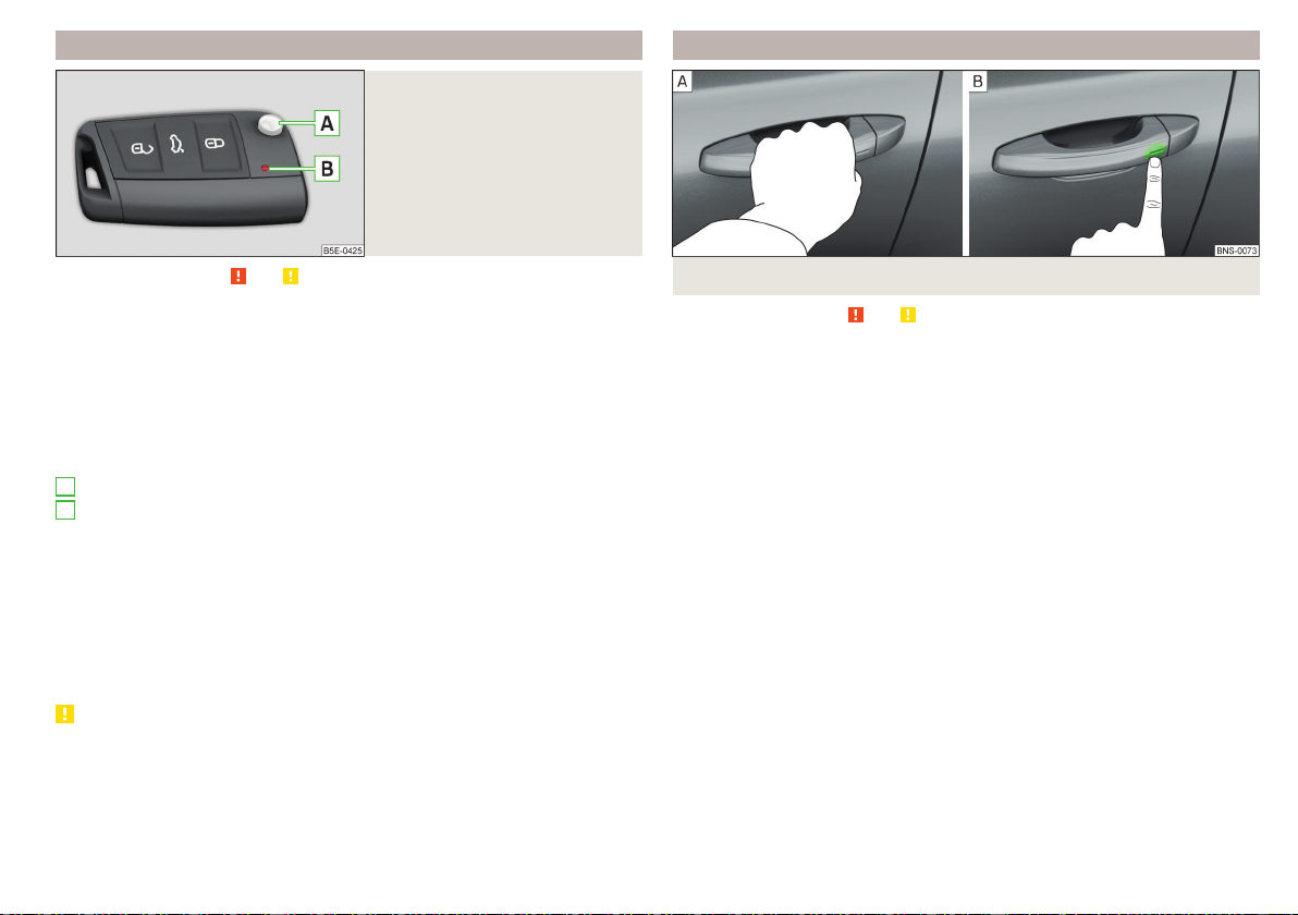
Unlocking/locking with the remote control key
Fig. 43
Key with pop-out key bit
Read and observe and on page 56 first.
Description of the key » Fig. 43
Unlock button
Lock button
Depending on equipment fitted:
▶
Unlock/unlatch the boot lid (vehicles fitted with manual folding opera-
tion)
▶
Open/close/ the boot lid Stop movement of the boot lid (vehicles with
electric folding operation)
Locking button for folding the key bit in/out
Warning light for the battery charge - if the warning light does not flash
when a button on the key is pressed, the battery is discharged.
Unlock/unlatch the boot lid (vehicles fitted with manual folding operation)
By pressing the button
, the lid is unlocked.
By holding the button , the lid is unlocked and unlatched (partially open).
If the lid is unlocked or unlatched using the button, then the lid is automati-
cally locked after closing. The period after which the lid is locked can be set
» page 62.
CAUTION
■
The remote control may be affected by signal superposition of transmitters
that are in the vicinity of the vehicle.
■
The range of the remote control key is about 30 m. The battery must be re-
placed if the central locking only reacts to the remote control at a distance of
less than approximately 3 m away » page 282.
A
B
Locking / unlocking - KESSY
Fig. 44 Vehicle unlocking / vehicle locking
Read and observe and on page 56 first.
The KESSY system (Keyless Entry Start Exit System) enables unlocking and
locking of the vehicle without actively using the remote control key.
›
Grip the door handle to unlock » Fig. 44 -
the vehicle.
›
Touch the sensor on the door handle with your finger to lock » Fig. 44 -
the vehicle.
When unlocking/locking the vehicle, the key must be at a maximum distance
of approximately 1.5 m from the front door handle.
Information on locking
On vehicles fitted with automatic gearbox, the selector lever must be moved
into the position P before unlocking.
With the ignition on, the vehicle cannot be locked from the outside.
After locking the vehicle, it is not possible to unlock within the next 2 seconds
by touching the door handle. This can be used to check whether the vehicle is
locked.
Protection against inadvertently locking the key in the vehicle
If one of the doors is closed after the vehicle has been locked and the key with
which the vehicle was locked remains in the passenger compartment, the vehi-
cle will be automatically unlocked. After automatically unlocking, the turn sig-
nal lights will flash four times. If no door is opened within 45 seconds, the vehi-
cle is automatically locked again.
57
Unlocking and opening
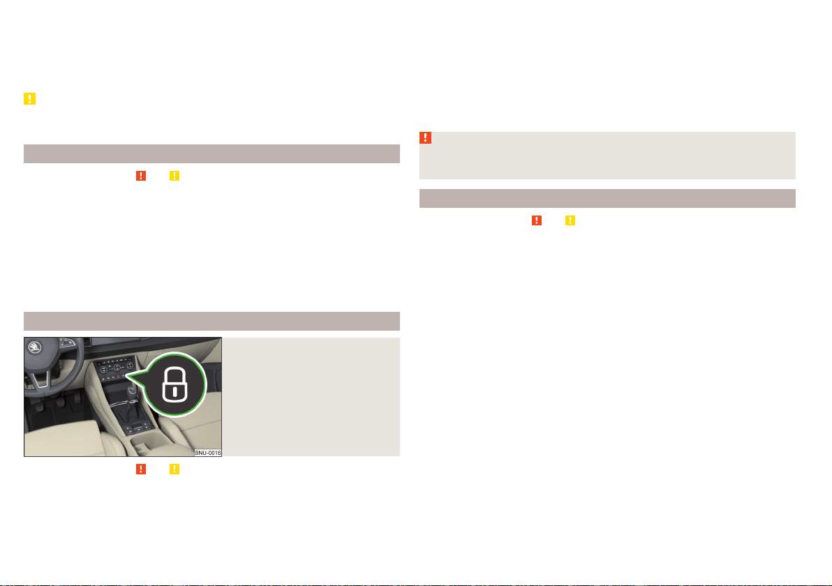
If the boot lid is closed after locking the vehicle and the key with which the
vehicle was locked remains in the luggage compartment, the lid is automatical-
ly unlatched (partially opened). After automatically unlocking, the turn signal
lights will flash four times. The boot lid remains unlatched (partially opened);
the other doors remain locked.
CAUTION
Some types of gloves can affect the unlocking or locking device via the sen-
sors in the door handle.
Deactivating KESSY
Read and observe and on page 56 first.
›
Lock the vehicle with the button on the key.
›
Within 5 s, touch the sensor on the door handle with your finger » Fig. 44 on
page 57 -
. Deactivation is confirmed by a single flash of the direction indi-
cators.
›
To check deactivation, wait at least 10 seconds and then pull the door han-
dle. The door must remain locked.
The KESSY system is activated again automatically after the vehicle is un-
locked.
Locking/unlocking the vehicle with the central locking button
Fig. 45
Central locking button
Read and observe and on page 56 first.
Conditions for the locking/unlocking using the central locking button.
The vehicle is not locked from the outside.
All doors are closed.
›
To lock, press the » Fig. 45 button.
Locking is displayed in the button by the illumination of the symbol in the
button.
The following applies after locking.
▶
Opening the doors and the boot lid from the outside is not possible.
▶
The doors can be unlocked and opened from the inside by a single pull on the
opening lever of the respective door.
WARNING
Doors locked from the inside make it difficult for rescuers to get into the
vehicle in an emergency – risk to life!
SafeLock
Read and observe
and on page 56 first.
SafeLock prevents the doors from behind opened from inside as well as win-
dow operation. This makes it more difficult for anyone to break into the vehi-
cle.
Switching on
SafeLock switches on when the vehicle is locked.
This function is pointed out by the following message on the display of the in-
strument cluster after the ignition is switched off.
Check SAFELOCK! Owner's manual!
Switch-on display
With the activated SafeLock, the warning light in the driver´s door flashes for
2 seconds in rapid succession, this then starts to flash at longer intervals.
Switching off
▶
By locking twice within 2 seconds.
▶
or: By deactivating the interior monitor and the towing protection
» page 61.
The warning light in the driver´s door flashes fast for about 2 seconds, goes
out and starts to flash at longer intervals after about 30 seconds.
If the vehicle is locked and the safe securing system is switched off, the door
can be opened separately from the inside by a single pull on opening lever.
The safelock switches on the next time the vehicle is locked.
58
Operation
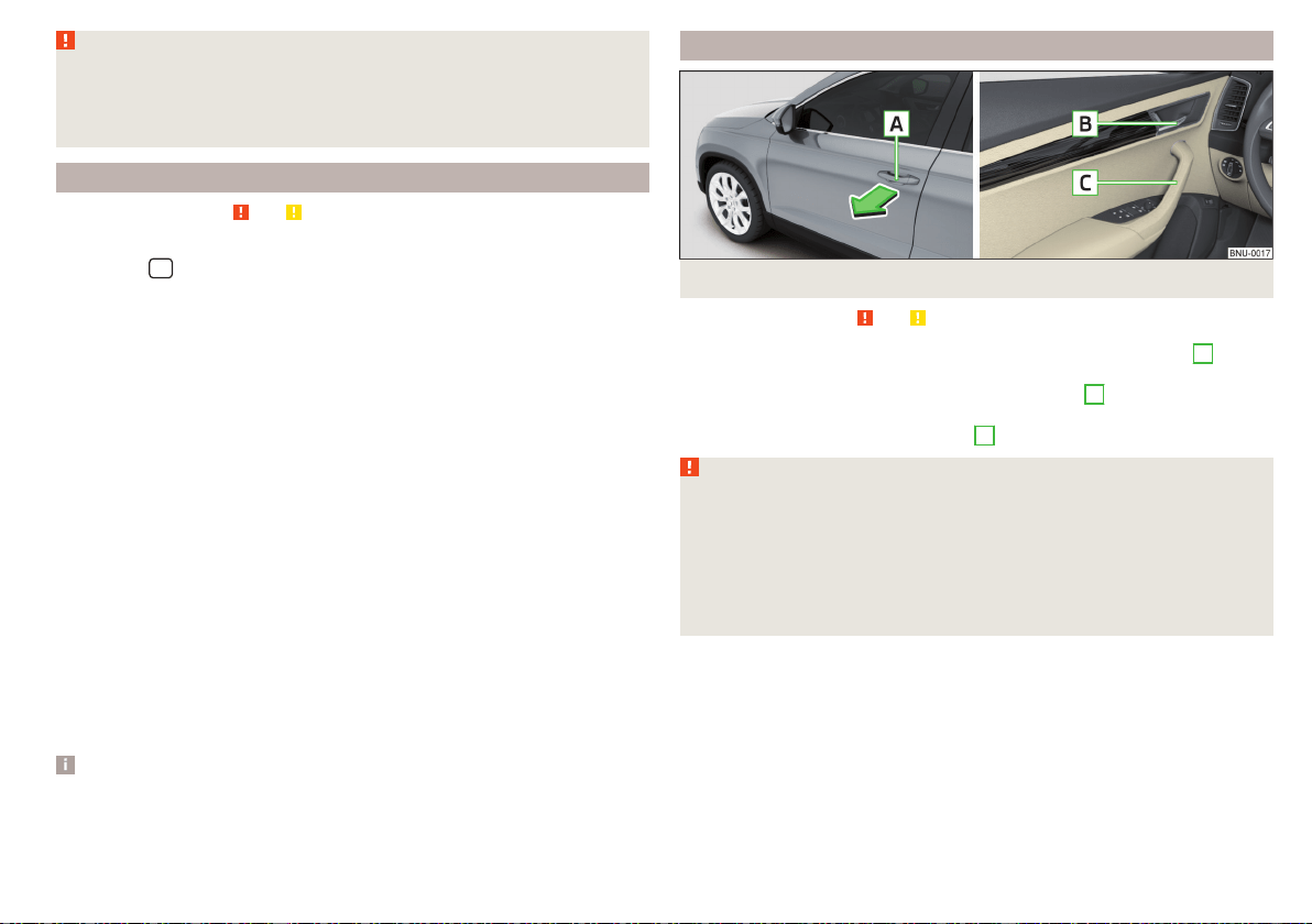
WARNING
If the car is locked and the safe securing system activated, no people must
remain in the car as it will then not be possible to either unlock a door or
open a window from the inside. The locked doors make it more difficult for
rescuers to get into the vehicle in an emergency – risk to life!
Individual settings
Read and observe
and on page 56 first.
The following central locking functions can be set individually in Infotainment
in the menu
/ → →
Opening and closing
.
All doors
The function allows you to unlock all doors, the boot lid and the fuel filler flap.
Single door
The function allows you to unlock only the driver's door and the fuel filler flap
with the radio remote control. KESSY allows the unlocking of a single door
which is in the vicinity of the key, as well as the fuel filler flap. The other doors
and the boot lid are only unlocked once the door handle is unlocked or
touched.
Doors on a vehicle side
This function enables you to unlock both doors on the driver's side and the fuel
filler flap with the radio remote control unit. KESSY allows the unlocking of
both doors which are in the vicinity of the key, as well as the fuel filler flap. The
other doors and the boot lid are only unlocked once the door handle is un-
locked or touched.
Automatic locking/unlocking
This function enables the locking of all doors and the boot lid from a speed of
15 km/h. Opening the doors and the boot lid from the outside is not possible.
The renewed unlocking of the doors and the boot lid is carried out when the
ignition key is removed or when the door is opened from inside (depending on
the individual setting for the central locking system).
Note
The individual adjustment of the central locking system is stored (depending
on the Infotainment type) in the active user account personalisation » page 55.
Opening / closing door
Fig. 46 Door handle/door opening lever
Read and observe and on page 56 first.
›
To open from outside, unlock the vehicle and pull the door handle
A
in the
direction of arrow » Fig. 46.
›
To open from inside, pull on the door opening lever
B
and push the door
away from you.
›
To close from inside, grip the handle
C
and close the door.
WARNING
■
The door must be closed properly, otherwise it could open whilst driving -
risk of death!
■
Only open and close the door when no one is located in the opening/clos-
ing range – risk of injury!
■
Never drive with the doors open - it can be fatal!
■
An opened door can close automatically if there is a strong wind or the
vehicle is on an incline – risk of injury!
59
Unlocking and opening
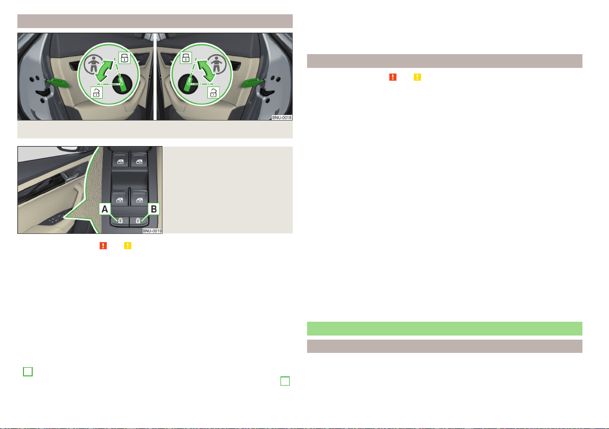
Child safety lock
Fig. 47 Rear door: Child safety system switch on / off
Fig. 48
Child safety lock with electric
operation
Read and observe and on page 56 first.
The child safety lock can be operated manually or electrically depending on
equipment.
The child safety lock prevents the rear door from being opened from the in-
side. The door can only be opened from the outside.
Manually controlled parental settings
›
To switch on, turn the parental control with the vehicle key in position
» Fig. 47.
›
To switch off, turn the parental control with the vehicle key in position .
Child safety lock with electric operation
›
To switch on/off the child safety lock in the left rear door, press the button
A
in the driver's door » Fig. 48.
›
To switch on/off the child safety lock in the right rear door, press button
B
in the driver's door.
Locking is displayed in the button by the illumination of the symbol .
When with electric operation in addition to the electric window is blocked in
the respective door.
Malfunctions
Read and observe and on page 56 first.
Synchronising the remote control
If the buttons on the remote control key have been operated several times be-
yond the effective range of the system or the battery in the remote control
key has been replaced and the vehicle cannot be unlocked using the remote
control, the key must be synchronised.
›
Press any button on the remote control key.
›
Unlock the door with the key in the lock cylinder within 1 minute of pressing
the button.
Fault with the central locking
If the warning light in the driver's door initially flashes quickly for around 2 sec-
onds, and then illuminates for 30 seconds without interruption before flashing
again slowly, you will need to seek the assistance of a specialist garage.
A fault in the central locking system means the vehicle doors and the boot lid
cannot be emergency locked or emergency unlocked» page 283.
Failure of the system KESSY
If there is a fault in the KESSY system, the appropriate error message is dis-
played in the instrument cluster.
Low voltage of the key battery
If the voltage of the key battery is too low, a message appears in the display of
the instrument cluster referring to the need to replace the battery. Replace
the battery » page 282.
Anti-theft alarm system
Introduction
The alarm system triggers audible and visual signals if an attempt is made to
break into the vehicle (hereafter referred to as alarm).
60
Operation

The alarm system is activated automatically approximately 30 seconds after
the vehicle is locked. This is automatically disabled after release.
CAUTION
Before leaving the vehicle, it must be checked that all of the windows, doors
and the sliding/tilting roof are locked in order to ensure the full functionality of
the anti-theft alarm system.
Note
The alarm system has its own power source, the service life of which is 5
years. In order to ensure functionality of the alarm system, we recommend
that you get the alarm checked after this time by a specialist garage.
Alarm trigger
Read and observe on page 61 first.
The alarm is triggered when one of the following unauthorised actions is acti-
vated on the vehicle with an activated warning system.
▶
Opening the bonnet.
▶
Opening the boot lid.
▶
Opening the doors.
▶
Manipulation of the ignition lock.
▶
Towing the vehicle.
▶
Movement in the vehicle.
▶
Sudden and significant voltage drop of the electrical system.
▶
Uncoupling the trailer.
An alarm is triggered also when the driver's door is unlocked and opened by
the lock cylinder.
The alarm is switched off by pressing the button on the key or switching on
the ignition.
Interior monitor and towing protection
Read and observe on page 61 first.
The interior monitor detects movements inside the locked vehicle and then
triggers the alarm.
The anti-towing detects tilts in the locked vehicle and then triggers the alarm.
These functions should be deactivated if there is a possibility that the alarm
will be triggered by movements (e.g. by people or animals) within the vehicle
interior or if the vehicle has to be transported (e.g. by train or ship) or towed.
Deactivation
The functions can be deactivated simultaneously in the Infotainment menu
/ → →
Opening and closing
.
Safelock is switched off during deactivation.
CAUTION
The opened glasses storage compartment reduces the effectiveness of the in-
terior monitor. To ensure the full functionality of the interior monitor, the
glasses storage compartment must always be closed before locking the vehi-
cle.
Manually operated tailgate
Introduction
WARNING
■
Never drive with the boot lid open or ajar, as otherwise exhaust gases
may get into the interior of the vehicle – risk of poisoning!
■
Ensure that the lock is properly engaged after closing the lid. Otherwise,
the lid might open suddenly while the vehicle is moving, even if the lid was
locked – risk of accident!
■
Make sure that when closing the boot lid, no body parts are crushed -
there is danger of injury!
■
Do not press on the rear window when closing the boot lid, it can crack -
risk of injury!
61
Unlocking and opening
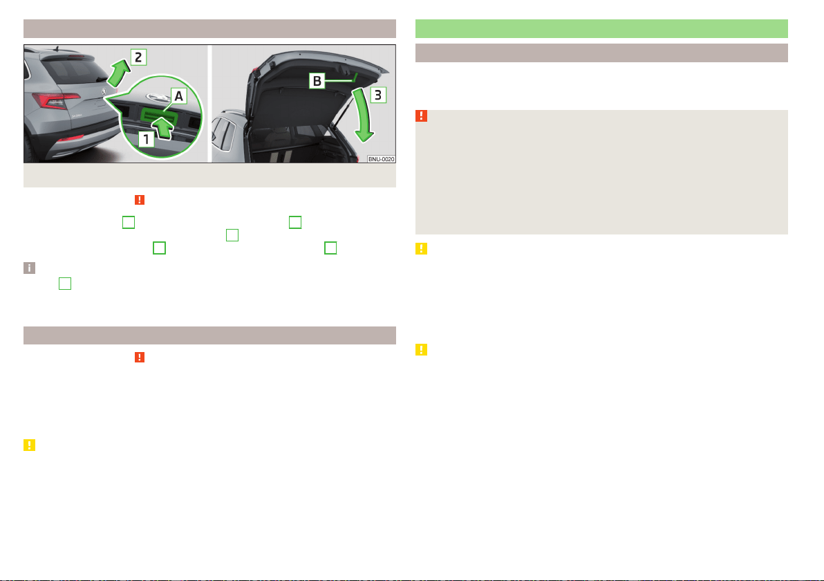
Open/close boot lid
Fig. 49 Opening / closing tailgate
Read and observe on page 61 first.
›
To open, press the
A
button in the direction of arrow
1
» Fig. 49.
›
Raise the lid in the direction of the arrow
2
.
›
To close, grab the mount
B
and pull in the direction of arrow
3
.
Note
Button
A
» Fig. 49 is deactivated when starting or at a speed of more than 5
km/h. The button is activated again after the vehicle has stopped and a door is
opened.
Setting the delayed locking of the boot lid
Read and observe
on page 61 first.
If the boot lid is unlocked with the
button on the key, the lid is automatical-
ly locked again after closing.
The period after which the boot lid is locked automatically can be extended by
a specialist garage.
CAUTION
There is a risk of unwanted entry into the vehicle before the boot lid is locked
automatically.
Electric boot lid
Introduction
The boot lid (hereinafter as lid) can be operated electrically and manual in the
event of an emergency » page 64.
WARNING
■
Ensure that the lock is properly engaged after closing the lid. Otherwise,
the lid might open while the vehicle is moving - risk of accident.
■
Never drive with the lid open or unlatched, as otherwise exhaust gases
may get into the interior of the vehicle – risk of poisoning!
■
Only open and close the lid when no one is located in the opening/closing
range – risk of injury!
■
Make sure that no limbs are caught or crushed when closing the lid - risk
of injury!
CAUTION
■
Do not attempt to close the lid manually during the electrical closing process
- there is a risk of damaging the electric lid operation.
■
When washing the vehicle in a car wash, we recommend that you lock the
vehicle (with the central locking button). In some car washes the boot lid
might open automatically due to the pressure action of the washing brushes -
there is a risk of damage to the vehicle interior.
CAUTION
■
Check that no objects are located in the opening/closing area which could
hinder the movement (e.g. cargo on the roof rack or on the trailer etc.) - there
is a risk of damage to the lid!
■
In certain circumstances, if the lid is loaded (e.g. by a thick layer of snow), the
opening process of the lid can be interrupted. Remove the snow from the lid
to re-enable the electrical operation.
■
If the lid closes automatically (e.g. under load of snow), you will hear an inter-
mittent beep.
■
The flap is always to be close before disconnecting the battery.
62
Operation

Description of operation
Fig. 50
Lid operation
Read and observe
and on page 62 first.
Ways to open the lid
▶
By pressing the handle
A
» Fig. 50.
▶
By pulling the button
C
.
▶
By holding the button
D
on the key.
If the lid hits an obstacle when closing, it stops and an audible signal sounds.
Ways to close the lid
▶
Press pressing the button
B
» Fig. 50.
▶
By holding the button
D
on the key (applies to vehicles with KESSY). The
key must be located at a maximum distance of 2 m from the lid.
▶
By pressing the handle
A
.
▶
By pulling and holding the button
C
. The opening process stops when one
releases the button.
▶
By briefly pressing the lid downwards.
If the flap meets an obstacle when it is closed, it stops, an acoustic signal
sounds and the flap moves back a few centimetres.
Ways to stop the lid movement
▶
By pressing the button
B
» Fig. 50.
▶
By pulling on the button
C
or by releasing the button.
▶
By holding the button
D
on the key.
▶
By pressing the handle
A
.
Audible signals
An acoustic signal is sounded when opening/closing the lid by means of the
button
C
or
D
.
Note
■
Button
A
» Fig. 50 is deactivated when starting or at a speed of more than 5
km/h. The button is activated again after the vehicle has stopped and a door is
opened.
■
If you rapidly enter the vehicle during the opening or closing process of the
lid, the whole vehicle may jerk and, as a result, the movement of the lid can be
interrupted.
Set the top position of the lid
Read and observe and on page 62 first.
The top position of the lid can be adjusted (e.g. in a limited space to open the
lid due to the garage height or for a more comfortable operation, depending
on the height of the person).
Adjusting the top position of the lid
›
Stop the lid in the desired position.
›
Press and hold button
B
» Fig. 50 on page 63 until you hear an acoustic sig-
nal.
Adjusting the top starting position of the lid
›
Carefully raise the flap manually to the limit.
›
Press and hold button
B
» Fig. 50 on page 63 until you hear an acoustic sig-
nal.
Note
The top position which is reached when the lid opens automatically, is always
lower than the maximum top position which can be reached when the lid is
opened manually.
63
Unlocking and opening
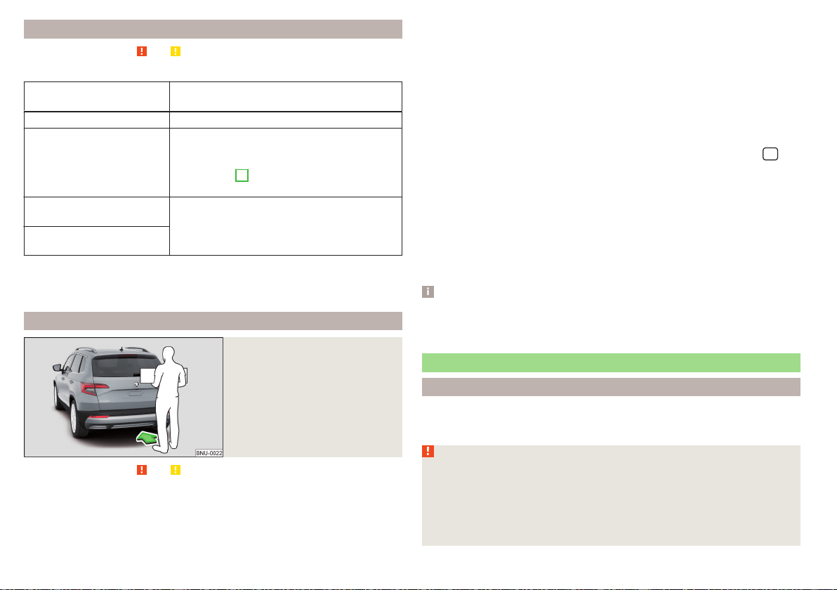
Malfunctions
Read and observe and on page 62 first.
Examples of operational malfunctions
Description of the malfunc-
tion
Remedy
The lid cannot be opened Unlocking the lid » page 284
The lid does not react to an
opening signal
Removing a possible obstacle (e.g. snow), re-
opening the lid » page 63
Press handle
A
» Fig. 50 on page 63 and pull
the lid upwards
The lid remains in the top
position
Manual closing of the lid
The lid is open and the bat-
tery was disconnected
Close manually
Close the door slowly, push down the lid, push in the lock on the centre of the
edge, above the ŠKODA logo.
Operating contactless boot lid
Fig. 51
Opening the boot lid
Read and observe and on page 62 first.
Depending on equipment the boot lid can be operated without contact.
The ignition must be switched off and you have to have the vehicle key on
your person.
›
To open/close, move one foot in the sensor area below the rear bumper
quickly in the direction of the arrow » Fig. 51.
The brake light in the rear window illuminates and the lid opens/closes auto-
matically. An acoustic signal is sounded when opening/closing the lid.
If the lid does not move, then repeat the operating process after a few sec-
onds.
The lid movement can be stopped by a rapid swinging of the foot. Swinging
the foot again will continue the lid movement.
The function can be deactivated/activated in Infotainment in the menu
/
→ →
Opening and closing
are activated/deactivated.
We recommend that the function is deactivated in the following cases:
▶
Installation of a roof rack.
▶
Connecting a trailer (accessory) to the towbar.
▶
Manual vehicle wash.
▶
Maintenance and repair work in the back of the vehicle.
When connecting a device to the trailer socket the deactivation of the func-
tion takes place.
Note
With heavy rain or a dirty rear bumper, under certain circumstances that there
may be limitations, or the automatic deactivation of the contactless opening
function of the boot lid may occur.
Window operation
Introduction
The windows in the doors can be operated electrically using the buttons on
the doors.
WARNING
■
Always close the window carefully and controlled. Otherwise, you may
cause considerable crushing injuries to yourself or fellow passengers.
■
The system is fitted with a force limiter » page 66. If there is an obsta-
cle (e.g. If a body part gets trapped), the closing process is stopped and the
window goes down by several centimetres. However, the windows should
be closed carefully – risk of injury.
64
Operation

CAUTION
■
Keep the windows clean to ensure the correct functionality of the electric
power windows.
■
Always close the windows before disconnecting the battery.
Note
If the windows are opened, dust and other dirt can get into the vehicle and the
wind noise is more at certain speeds.
Open / close Window
Fig. 52
Electric window buttons
Fig. 53
Button of the window lifter on
the passenger side
Read and observe and on page 64 first.
All windows can be operated from the driver's seat. The window in the front
passenger door and the windows in the rear doors are operated via the button
in each door.
Power window buttons » Fig. 52
Front door left
Front door right
Rear door, left
Rear door, right
Deactivate/activate the buttons in the rear doors (the deactivation may be
advantageous if, for example, children are transported on the rear seats)
Deactivation / activation of the key in the rear door left (part of the child
safety lock with electric operation)
Deactivation / activation of the key in the back door right (part of the child
safety lock with electric operation)
Opening/closing window
›
To open, lightly press the appropriate button down and hold it until the win-
dow has moved into the desired position.
›
or: Press the button to the stop, the window automatically opens fully. Re-
newed pressing of the button causes the window to stop.
›
To close, pull gently on the top edge of the corresponding button and hold
until the window has moved into the desired position.
›
or: Pull the button briefly to the stop, the window automatically closes fully.
Renewed pulling of the button causes the window to stop immediately.
Disable / enable buttons in the rear doors
›
To deactivate/activate the buttons in the rear doors, press the
E
button. If
the buttons in the rear doors are deactivated, the warning light
illuminates
in the
E
button.
›
or: On vehicles with child safety lock with electric operation, press the re-
spective key
F
or
G
. If the buttons in the rear doors are deactivated, the
warning light illuminates in the respective button
F
or
G
.
Note
■
After switching off the ignition, the windows can still open and close for
about 10 minutes.
■
After the driver or front passenger door is opened, the operation of the win-
dow is only possible with the button
A
» Fig. 52, in which case this is pressed
or pulled for approx. 2 seconds.
A
B
C
D
E
F
G
65
Unlocking and opening

Force limiter
Read and observe and on page 64 first.
The electrical power windows are fitted with a force limiter.
If there is an obstacle, the closing process is stopped and the window goes
down by several centimetres.
If the obstacle prevents the window from being closed during the next 10 sec-
onds, the closing process is interrupted once again and the window goes down
by several centimetres.
If you attempt to close the window again within 10 seconds of the window be-
ing moved down for the second time, even though the obstacle was not yet
been removed, the closing process is only stopped. During this time it is not
possible to automatically close the window. The force limiter is still switched
on.
The force limiter is only not operational if you attempt to close the window
again within the next 10 seconds – the window will now close with full force!
If you wait longer than 10 seconds, the force limiter is switched on again.
Window convenience operation
Read and observe and on page 64 first.
The convenience operation for the window offers the option to open/close all
the windows at once (or only the window in the driver's door). The conven-
ience operation function can be adjusted individually in Infotainment in the
menu
/ → →
Opening and closing
.
Opening
›
Press and hold the button on the key.
›
or: Switch off the ignition, open the driver's door and hold the key
A
until it
stops in the open position » Fig. 52 on page 65.
Closing
›
Press and hold the button on the key.
›
or: Switch off the ignition, open the driver's door and hold the key
A
until it
stops in the closed position » Fig. 52 on page 65.
›
In the KESSY system, hold your finger on the sensor on the outside of the
door handle of the front door » Fig. 44 on page 57.
The convenience operation will only function correctly if all the windows auto-
matically open/close properly.
Convenience opening or closing the window using the key in the driver's door
locking cylinder is only possible within 45 seconds of locking the vehicle.
The movement of the window is stopped immediately when the respective
button is released.
Note
The settings for the window convenience operation are stored (depending on
the Infotainment type) in the active user account personalisation » page 55.
Malfunctions
Read and observe
and on page 64 first.
Repeatedly opening and closing the window can cause the window mechanism
to overheat and become temporarily blocked. You will be able to operate the
window again as soon as the operating mechanisms has cooled down.
After disconnecting the vehicle battery, automatic opening / closing of the
window can be deactivated. In this case, the system must be activated as fol-
lows.
Activate window operation
›
Switch-on the ignition.
›
Pull the top edge of the button and close the window.
›
Release the button.
›
Pull up the respective button and hold for 1 second.
Panoramic tilt / slide sunroof
Introduction
The panorama sliding/tilting roof (hereinafter referred to as sliding/tilting roof)
can only be operated when the ignition is turned on and when the outdoor
temperature is no lower than -20 °C.
The sliding/tilting roof can still be operated for approx. 10 minutes after
switching the ignition off. After opening the driver or front passenger door, it
is no longer possible to operate the sliding/tilting roof.
66
Operation
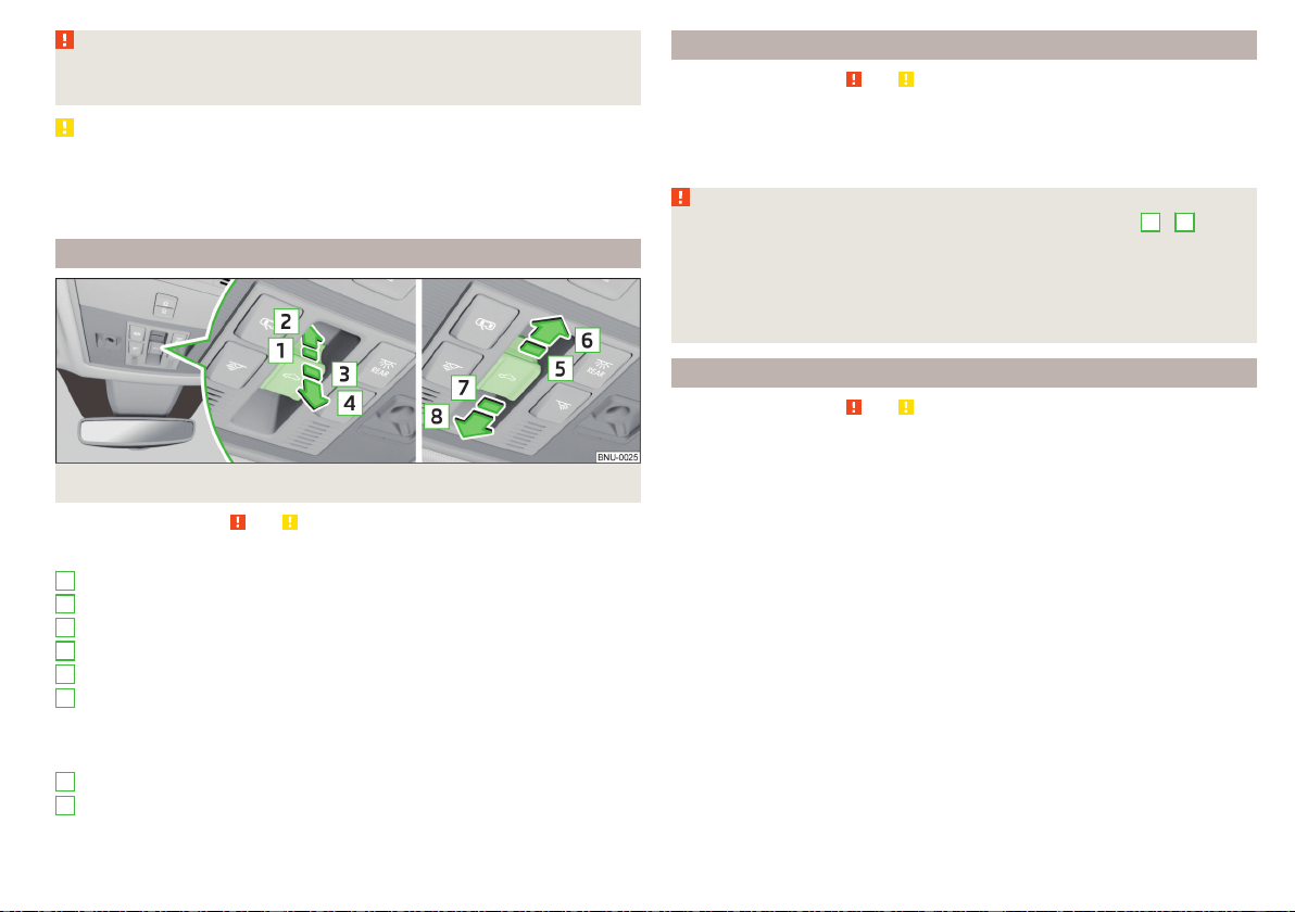
WARNING
When operating the sliding/tilting roof and the sunshade, proceed with
caution to avoid causing crushing injuries – risk of injury!
CAUTION
■
During the winter, remove any ice and snow in the vicinity of the sliding/tilt-
ing roof before opening it if required, to prevent any damage to the opening
mechanism.
■
Always close the sliding/tilting roof before disconnecting the battery.
Operation
Fig. 54
Operation of the tilting / sliding sunroof
Read and observe and on page 67 first.
Operation of the sliding/tilting roof » Fig. 54
Gradual opening
Complete opening
Gradually reset
Fully reset
Gradual opening
Fully opening
After the first press, the sliding/tilting roof stops in the position where the
intensity of the wind noise is low (at speeds of approx. less than 80 km/h).
Press again and the sliding/tilting roof goes to the stop.
Gradual closing
Complete closing
1
2
3
4
5
6
7
8
Force limiter
Read and observe and on page 67 first.
The sliding/tilting roof is fitted with a force limiter.
If there is an obstacle, the closing process is stopped and the glass pane re-
tracts by several centimetres.
WARNING
If the sliding/tilting roof is closed by holding down the switch
7
/
8
,
» Fig. 54 on page 67and the closing process is hindered by an obstacle, then
when attempting to close for a third time, the force limiter is rendered in-
operable (if the period of 5 s is not reached between the individual at-
tempts to close). The sliding/tilting roof closes with full force - it may cause
injury.
Convenience operation of the sliding / tilting roof
Read and observe and on page 67 first.
The convenience operation makes it possible to open or close the sliding/tilt-
ing roof using the key or the KESSY system via the sensor in the door handle
of the front door.
›
To open out, press and hold the
button on the key.
›
To close, press and hold the button (with KESSY, hold your finger on the
sensor on the outside of the door handle of the front door).
By interrupting the locking process, the closing operation is interrupted.
67
Unlocking and opening
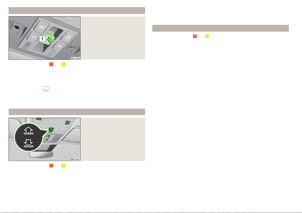
Activate operation of the sliding/tilting roof
Fig. 55
Operation of the sliding/tilting
roof
Read and observe
and on page 67 first.
If the operation of the sliding/tilting roof is deactivated (e.g. after disconnect-
ing and connecting the battery), then operation will have to be activated.
›
Switch on the ignition, pull the switch on the recess all the way down in the
direction of arrow
1
» Fig. 55 and hold.
The sliding/tilting roof opens/closes again after around 10 seconds.
›
Release the lever.
Electrically operated sunblind
Fig. 56
Button for operating the sun-
shade
Read and observe and on page 67 first.
Operation of the sunshade » Fig. 56
Open - by pressing (press again - sunshade stops moving)
Close - by pressing (press again - sunshade stops moving)
The sunshade can also be operated by pressing and holding the appropriate
button (starts movement of the sunshade) and releasing it when the sunshade
reaches the desired position.
Activating operation of the sunshade
Read and observe and on page 67 first.
If the operation of sunshade is deactivated (e.g. after disconnecting and con-
necting the battery), then the operation will have to be activated.
›
Switch on the ignition, press and hold the » Fig. 56 on page 68 button.
The sunshade opens and closes again after around 10 seconds.
›
Release the button.
68
Operation
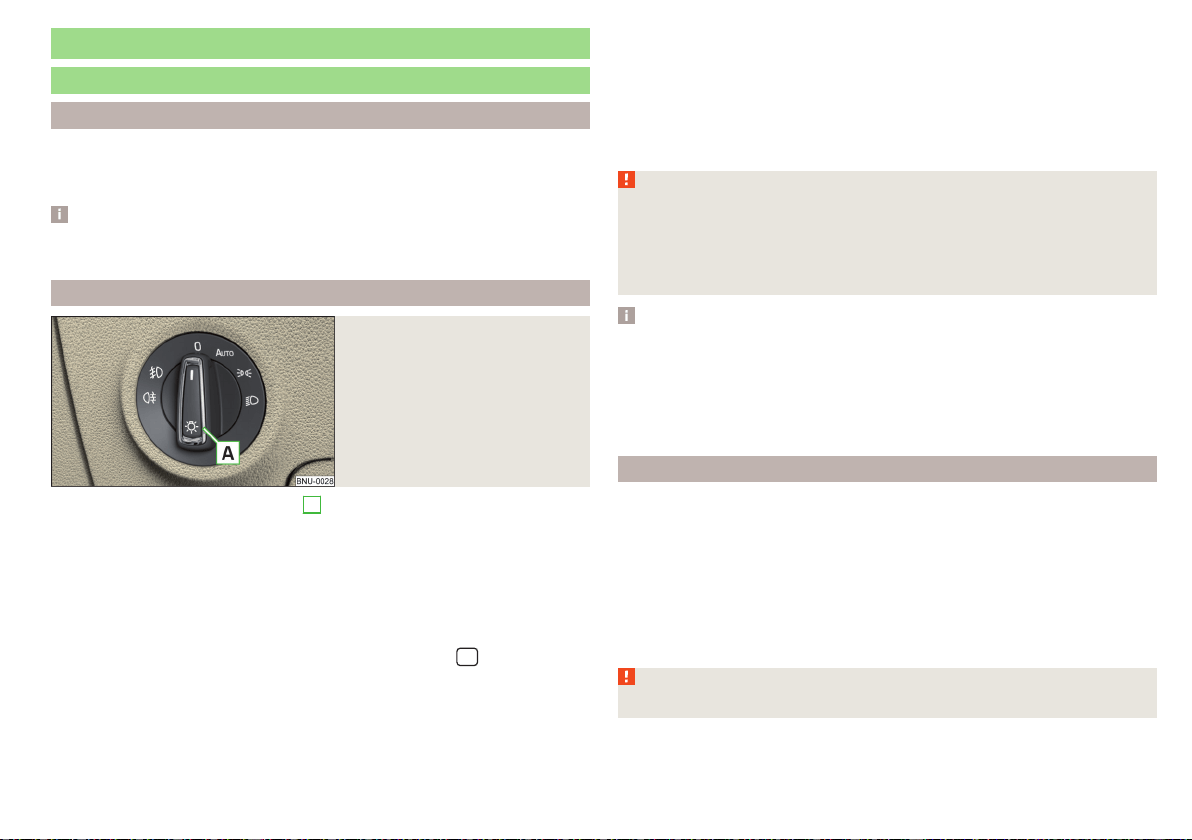
Lights and visibility
Light
Introduction
Unless otherwise stated, the lights only work when the ignition is switched on.
For the basic position of the light switch, use the position.
Note
The headlights may mist up temporarily. When the light is switched on, the
light-emitting surface demists after a short period of time.
Operating the lights
Fig. 57
Light switch
To switch on/off the lights, turn the
A
» Fig. 57 switch to one of the follow-
ing positions (equipment-dependent).
Switching off lights (except daytime running lights)
Switching the light on/off automatically » page 70
Switching on the parking lights or parking lights on both sides » page 73
Switching on the low beam
Headlight range control of the Halogen headlights
The headlight range can be set in Infotainment in the menu
/ → →
Light
.
The range of the halogen headlights can be set on the screen, in accordance
with the vehicle load, to the following basic settings.
Front seats occupied, boot empty
All seats occupied, boot empty
All seats occupied, boot loaded
Driver seat occupied, boot loaded
In the event of another vehicle loading condition, the setting for positions . .
can be used.
The Full LEDFront headlights s utomatically adjust to vehicle loading and driv-
ing conditions, so they do not have manual headlight range control.
WARNING
Always adjust the headlight range control to comply with the following
conditions and prevent accidents.
■
The vehicle does not dazzle other road users, especially oncoming vehi-
cles.
■
The beam range is sufficient for safe driving.
Note
■
If, with a dipped beam, the ignition is turned off, then the dipped beam will
automatically switch off and the parking lights will come on. Does not apply to
the position , as long as the conditions are met for the COMING HOME
function . The parking lights are switched off when the ignition key is removed
(for vehicles with the KESSY system, after opening the driver's door).
■
If there is a fault in the light switch, the low beam comes on automatically.
Daytime running lights
The daytime running lights illuminate the area in front of and to the rear of the
vehicle (only applicable for some countries).
The lights are switched on automatically if the following conditions are
met.
The ignition is switched on.
The light switch is in the position
or
.
or: The light switch is in the position , and visibility has not become
worse.
WARNING
Always switch on the low beam when visibility is poor.
69
Lights and visibility
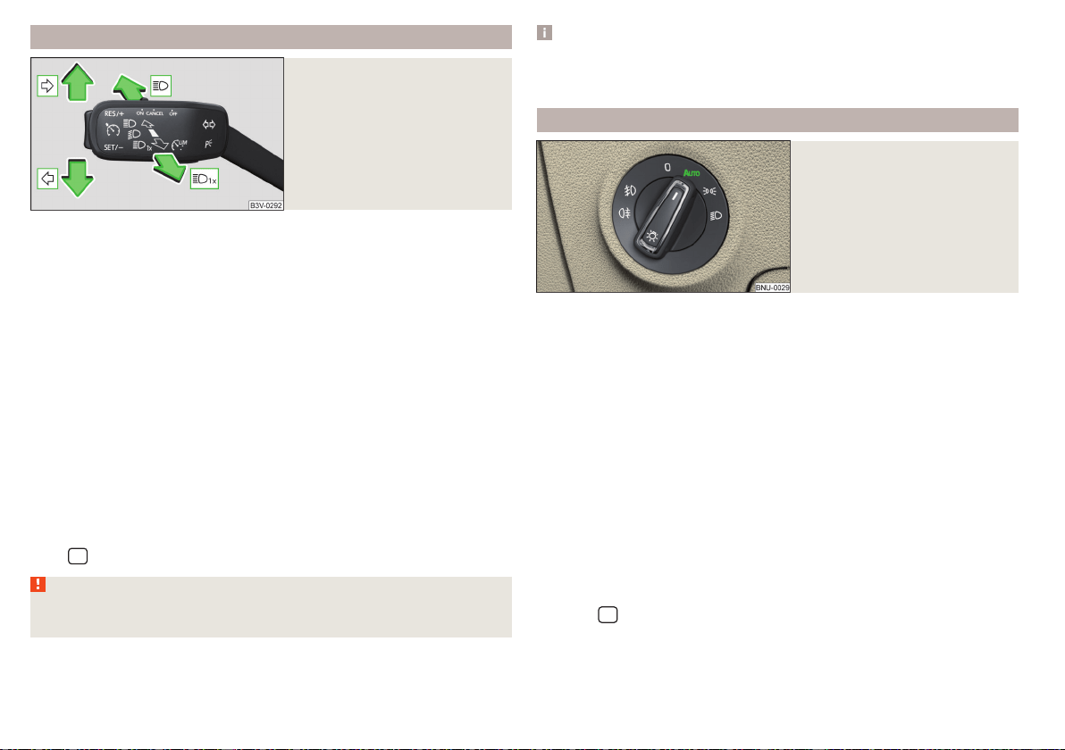
Turn signal and main beam
Fig. 58
Operating lever: Turn signal and
main beam operation
Control stalk positions » Fig. 58
Switch on the right turn signal
Switch on the left turn signal
Switch on main beam (spring-tensioned position)
Switch off main beam / headlight flasher on (spring-tensioned position)
The main beam can only be switched on when the low beam lights are on.
The headlight flasher can be used even if the ignition is switched off.
The turn signal switches off automatically depending on the steering angle af-
ter turning.
Use the control stalk to switch on/off the headlight assistant» page 71.
Comfort flashing
When the control talk is pressed slightly up or down, the respective turn signal
indicates three times.
If during comfort signalling the operating lever is pressed in the opposite di-
rection, the indicating will stop.
Convenience signalling can be activated/deactivated in Infotainment in the
menu
/ → →
Light
.
WARNING
Only turn on the main beam or the headlight flasher if other road users will
not be dazzled.
Note
The setting (activation/deactivation) of the convenience turn signal is stored
(depending on the Infotainment type) in the active user account personalisa-
tion » page 55.
Automatic driving light control
Fig. 59
Light switch: position
The light switch is in position
» Fig. 59 then depending on the equipment
the automatic switch on / off the lights corresponding to the light or weather
conditions (rain) takes place.
If the light switch is in position
, the lettering
illuminates next to the
light switch. If the light is switched on automatically, the symbol also illumi-
nates next to the light switch.
Automatic driving light control in the rain (referred to as function in the
following)
The dipped beam is switched on automatically if the following conditions are
met.
The function is activated.
The light switch is in the position .
The windscreen wipers are on for more than 30 s.
The light turns off automatically about 4 minutes after turning off the wipers.
Setting, activation/deactivation
The following functions can be set or activated/deactivated in Infotainment in
the menu
/ → →
Light
.
▶
Sensitivity adjustment of the sensor for determining the lighting conditions
for automatic driving light control
▶
Automatic driving light control during rain
70
Operation
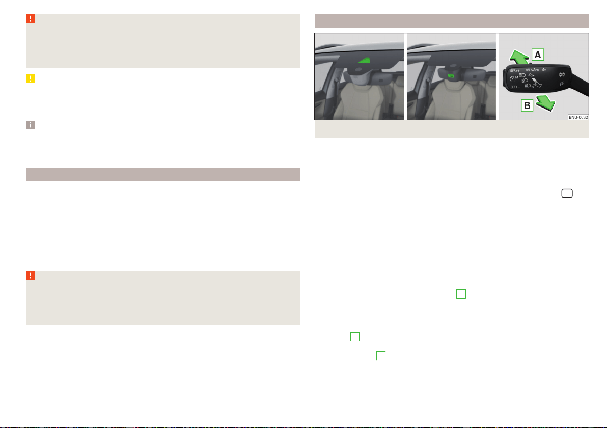
WARNING
The automatic driving lamp control (position only operates as a sup-
port and does not release the driver from his responsibility to check the
light and, if necessary, to switch on the light depending on the prevailing
light conditions.
CAUTION
Poorer visibility is detected by a sensor mounted below the windscreen in the
holder of the inside mirror or in the control panel, if required. Do not cover the
sensor - the system can be affected.
Note
The setting (activate/deactivate) of the automatic driving light control during
rain is stored (depending on the Infotainment type) in the active user account
personalisation » page 55.
FullLED headlights
The Full LED headlights (hereinafter referred to as just system) use the journey
data to automatically ensure the best possible light cone in front of the vehicle.
The system operates automatically in the following modes: Urban, extra-urban,
motorway and bad weather.
A component of the system is the static side light. This light is used in some
light modes, e.g. for bend illumination during reversing.
The system works as long as the light switch is in position
.
WARNING
If there is a system malfunction the headlights are automatically lowered to
the emergency position, which prevents a possible dazzling of oncoming
traffic. This reduces the cone of light in front of the vehicle. Seek help from
a specialist garage.
Light Assist
Fig. 60 Installation location versions of the sensor / system on/off
The system automatically switches the high beam on/off in accordance with
the existing traffic (other vehicles) and environmental conditions (e.g. driving
through a lit village).
The high beam on/off is controlled by a sensor or a camera » Fig. 60.
The system can be activated/deactivated in Infotainment in the menu
/
→ →
light
→
Light Assist
,
Conditions for the system function
The system is activated.
The light switch is in the position
.
The vehicle speed is over 60 km/h or for some countries more than 40
km/h.
The windscreen is clean in the sensor area.
Switch on the system
›
Push the lever into the sprung position
A
» Fig. 60. The following indicator
light lights up in the instrument cluster display.
Switch off the system
›
If the high beam is switched on automatically, move the lever into the sprung
position
B
. The warning light goes out. The high beam turns off.
›
If the high beam is is not switched on automatically, move the lever into the
sprung position
A
. The warning light goes out. The high beam turns on.
The high beam switches off automatically when the speed falls below 30 km/h
(but the system remains switched on).
71
Lights and visibility
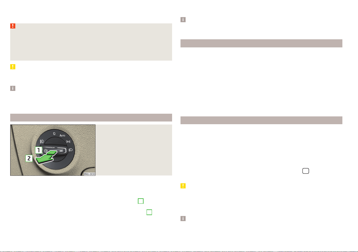
If there is a fault, the error message will appear in the instrument cluster dis-
play. Seek help from a specialist garage.
WARNING
The system is used only for support, thus the driver is not released from his
obligation to manually adjust the main or low beam according to the given
ambient conditions (e.g. in unfavourable lighting and weather conditions, as
when passing poorly lit road users, if necessary, when the area in front of
the sensor is covered by an obstacle).
CAUTION
Do not cover the sensor and keep the front screen clean - system functionality
can be impaired.
Note
The setting for the high-beam assistant in Infotainment is stored (depending
on the Infotainment type) in the active user account for personalisation
» page 55.
Fog lights/rear fog light
Fig. 61
Light switch – switch on front
and rear fog lights
Switching on the fog lights/rear fog lights is possible under the following
conditions.
The lights switch is in position , or » Fig. 61.
›
To switch on the fog lights, turn the light switch to position
1
; the warning
light illuminates in the instrument cluster.
›
To switch on the rear fog lights, pull the light switch to position
2
; the
warning light illuminates in the instrument cluster.
If the vehicle is not equipped with fog lights, the rear fog lights can be switch-
ed on by pulling the light switch to the only possible setting.
Switch off the fog lights/rear fog lights in reverse order.
Note
If an accessory is connected to the trailer socket, the rear fog lamp does not
light up on the vehicle.
Fog lights with CORNER function
The CORNER function automatically switches on the fog lights on the respec-
tive side of the vehicle (e.g. when turning off or cornering), if the following
conditions are met.
The turn signal is turned on or the front wheels are severely locked (in the
event of conflict between the two versions, has turn signal has the higher
priority).
The vehicle speed is below 40 km/h.
The low beam is switched on.
The fog lights are not switched on.
The two fog lights are switched on when you shift into the reverse gear.
COMING HOME / LEAVING HOME
The function COMING HOME ensures that the vehicle's environment is illumi-
nated after switching off the ignition and opening the driver's door.
The function LEAVING HOME ensures that the vehicle's environment is illumi-
nated after unlocking the vehicle with the radio remote control unit.
The function switches the light on only if there is poorer visibility and the light
switch is in the position .
The two functions can be used in Infotainment in the menu
/ → →
Light
(activated/deactivated and adjusted).
CAUTION
■
Poorer visibility is evaluated by a sensor mounted below the windscreen in
the holder of the rear-view mirror. Do not cover the sensor - the system can
be affected.
■
If this option is always enabled, then the battery is heavily loaded.
Note
The setting of the two functions is stored (depending on the Infotainment
type) in the active user account personalisation » page 55.
72
Operation
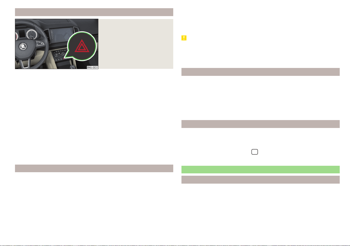
Hazard warning light system
Fig. 62
Button for hazard warning light
system
›
To switch on/off, press the button» Fig. 62.
When switching on, all the turn signal lights as well as the warning light
in
the button flash simultaneously with the control lights
in the instrument
cluster.
The hazard warning light system can also be operated if the ignition is switch-
ed off.
If one of the airbags is deployed, the hazard warning light system will switch
on automatically.
The automatic activation of hazard warning lights can take place during a
heavy braking. After starting or accelerating the hazard warning system is au-
tomatically switched off.
When the hazard warning system is on and the turn signal is switched on, the
hazard warning lights are switched off temporarily and only the turn signal
flashes on the relevant side of the vehicle.
Parking light
The side light is provided for lighting of the parked vehicle.
Switching on the side light on one side
›
Switch off the ignition.
›
Press the control lever all the way into position or until it stops » Fig. 58
on page 70.
The parking lights on the respective side of the vehicle are turned on.
Switching on the side light on both sides
›
Turn the ignition on and turn the light switch to position » page 69.
›
Switch off the ignition and lock the car.
After removing the ignition key and opening the driver's door, an audible warn-
ing sounds. After a few seconds, or after closing the driver's door, the acoustic
warning signal stops.
CAUTION
■
Turning on the parking light means the battery is heavily loaded.
■
The parking lights may switch off automatically due to a low battery charge.
If the two-sided parking lights are switched on when the ignition is off, the
parking lights will not switch on automatically.
Entry space lighting
The lighting is positioned on the lower edge of the exterior mirror and illumi-
nates the entry area of the front door.
The lighting switches on after unlocking or opening the vehicle door (depend-
ing on the lighting conditions).
The lighting switches off after around 30 seconds after closing the front door
or switching on the ignition.
Driving abroad
When driving in countries with opposing traffic system (traffic on the
left/right), your headlights may dazzle oncoming traffic.
Therefore, the Full LEDFront headlight setting must be adapted by turning on
travel mode in infotainment in the
/
→
→
Light
menu. In this mode, no
automatic beam adjustment is made ahead of the vehicle.
Interior lighting
Introduction
The inner lighting also works if the ignition is switched off. With the ignition
off (or after a door is opened),the lights will automatically switch off after ap-
proximately 10 minutes.
73
Lights and visibility
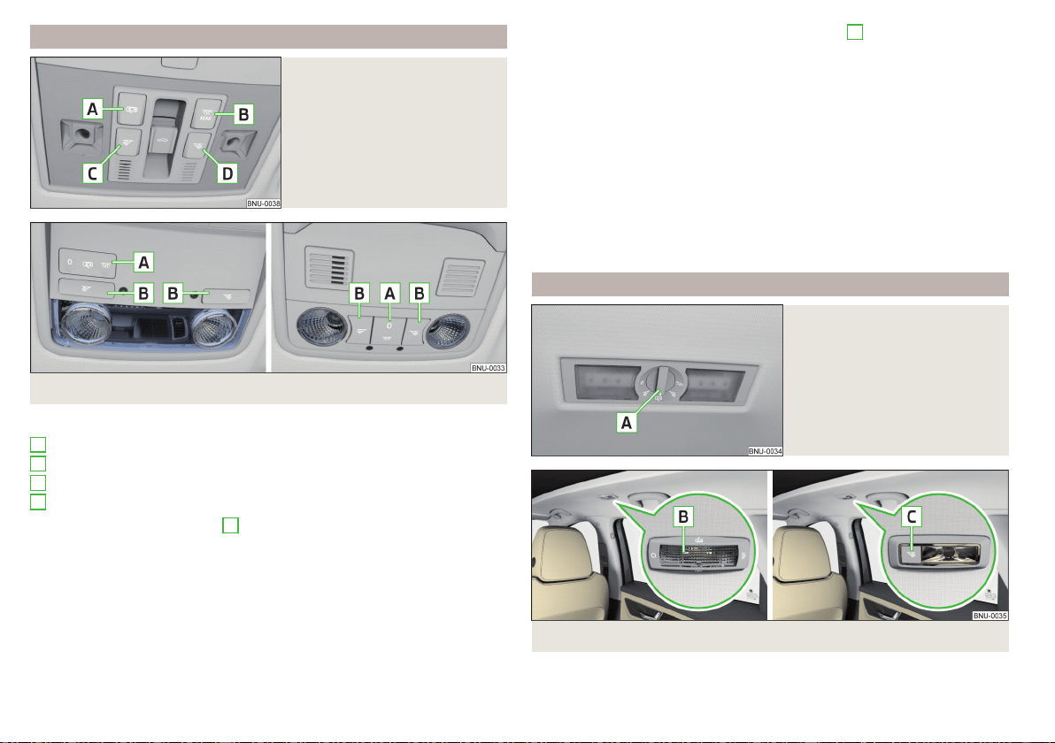
Operation of the lights from the front seats
Fig. 63
Operation of the lights from the
front seats: Variant 1
Fig. 64
Operation of the front light: Version 2/version 3
Switching on/off (by pressing the relevant switch) - version 1 » Fig. 63
Automatic operation
Rear lighting
Reading lamp left
Reading lamp right
Positions of the rocker switch
A
- versions 2 and 3 » Fig. 64
Switching on
Automatic operation (centre position)
Switching off
There is no icon available for the centre position (automatic operation) in ver-
sion 3.
A
B
C
D
Switching on/off (by pressing the relevant switch
B
version 2 and 3)
» Fig. 64
Reading lamp left
Reading lamp right
Automatic operation - switch or position
The system is turned on when any of the following is present.
▶
The vehicle is unlocked.
▶
One of the doors is opened.
▶
The ignition key is removed.
The system is turned off when any of the following is present.
▶
The vehicle is locked.
▶
The ignition is switched on.
▶
About 30 seconds after all the doors have been closed.
Interior light, rear
Fig. 65
Interior lights at the rear: Variant
1
Fig. 66
Interior lights at the rear: Version 2/version 3
74
Operation

Version 1 - (turning the switch
A
) » Fig. 65
Switching off
Reading lamp left
Automatic operation (the light is switched on/off automatically together
with the front light)
Reading lamp right
Switching on
Version 2: operation (by moving the spreader disc
B
) » Fig. 66
Switching on
Switching off
Automatic operation (the light is switched on/off automatically together
with the front light)
Version 3 - switching on/off (by pressing the relevant switch
B
) » Fig. 66
Reading lamp left
Reading lamp right
The rear light (variant 3) is switched on/off automatically together with the
front light. When the front interior lighting is switched off, the rear interior
lighting can be turned on/off as required.
Ambient lighting
Fig. 67
Setting the ambient lighting
The ambient lighting illuminates the dashboard and front side door trim panels
in colour, and the footwell in white.
The switching on of the lighting takes place automatically after opening the
door, switching off occurs automatically after the locking of the vehicle or 30
seconds after the closing of the door with the ignition switched off.
The ambient lighting can be adjusted in Infotainment in the menu
/ →
→
Background lighting
.
Description of the function surfaces » Fig. 67
Enable / disable the background lighting
Activating of the brightness setting for all areas at the same time
Enabling brightness setting for the left dashboard area
Enabling brightness setting for the right dashboard area
Activating the brightness setting for the footwell area
Enabling brightness setting for the front door area
Choice of colour options / brightness adjustment
Function surfaces for selecting lighting colour / brightness adjustment
To display
B
.
C
.
D
E
and
F
, tap on the function surface
.
Note
The adjustment of the ambient lighting is stored (depending on Infotainment
type) in the active user account personalisation » page 55.
Viisibility
Introduction
WARNING
No objects should be attached to the sun visors, which could limit the view
or endanger the vehicle occupants during sudden braking or should the ve-
hicle collide.
A
B
C
D
E
F
G
H
75
Lights and visibility
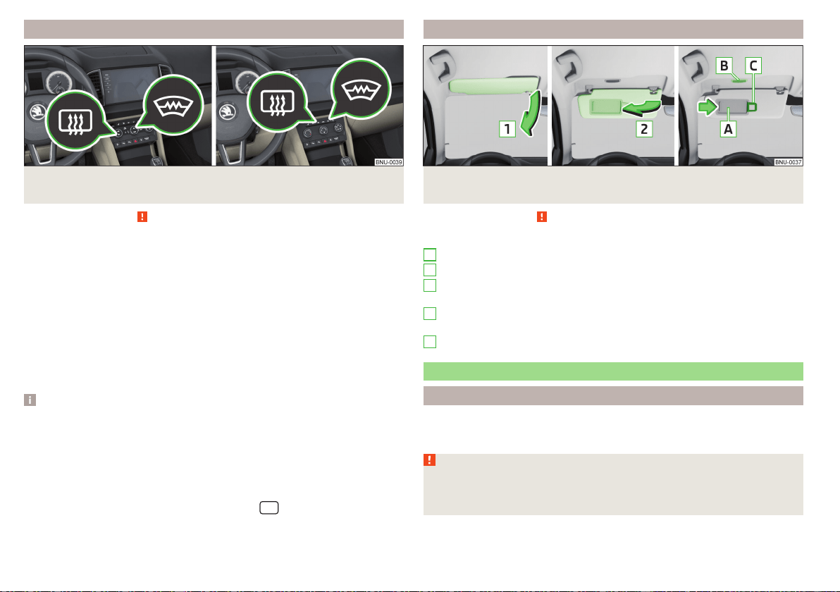
Windscreen and rear window heater
Fig. 68 Buttons for the front and rear window heater: Climatronic /
manual air conditioning
Read and observe on page 75 first.
The heating for quick defrosting and ventilation of the front /and rear window.
The heating only works when the engine is running.
Buttons for the heating (depending on vehicle equipment) » Fig. 68
Switching the windscreen heater on/off
Switch on/off the rear window heater
When the heating is switched on, a light illuminates inside or below the button.
The heating automatically switches off after ten minutes.
If the engine is switched off when the heating is on and turned back on again
within 10 minutes, the heating is continued.
Note
■
If the on-board voltage decreases, the heating switches off automatically
» page 265, Automatic consumer shutdown - Discharge protection of the ve-
hicle battery.
■
If the lighting inside or below the button flashes, the heater will not work be-
cause of the low charge of the battery.
■
If the Climatronic recognises that the windshield could fog up, the windshield
heating is automatically switched on. This function can be activated/deactiva-
ted on the Climatronic control panel in the menu
→
Front sun visor
Fig. 69 Fold down flap / flip up flap / make-up mirror and parking per-
mit holder
Read and observe on page 75 first.
Operation and description of the sun visor » Fig. 69
Swivel the visor towards the windscreen
Swivel cover towards the door
Make-up mirror with cover (the cover can be pushed in the direction of
the arrow)
Light (turns on when the cover of the make-up mirror is pushed to one
side)
Parking ticket holder
Windscreen wipers and washers
Introduction
The windscreen wipers and the wash system only operate if the ignition is
switched on and the bonnet and boot are closed.
WARNING
Do not use the windscreen washer system at low temperatures, without
heating the windscreen beforehand. The window washer fluid could other-
wise freeze on the windscreen and restrict the view to the front.
1
2
A
B
C
76
Operation
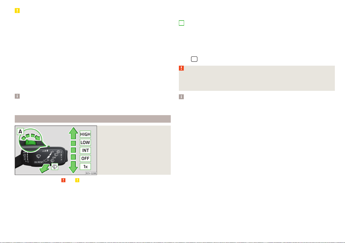
CAUTION
■
If the windscreen wipers are in rest position, they cannot be folded out from
the windscreen. The wipers must be set to the service position to raise them
off the windscreen » page 285.
■
In cold temperatures and during the winter, check before switching on the
ignition that the wiper blades are not frozen to the windscreen. If the wind-
screen wipers are switched on when the blades are frozen to the windscreen,
this may damage both the blades and windscreen wiper motor.
■
Carefully release the frozen-on windscreen wiper blades from the wind-
screen and remove snow and ice.
■
Handle the windscreen wipers with care - there is the risk of damaging the
windscreen with the windscreen wiper arms.
■
Do not switch on the ignition when the front windscreen wiper arms are fol-
ded down - there is the danger of damaging the bonnet by the windscreen
wiper arms.
Note
The windscreen washer nozzles for the windscreen are heated when the en-
gine is running and the outside temperature is less than +10 °C.
Front wipers and washers
Fig. 70
Operating the windscreen wip-
ers and washing system at the
front
Read and observe and on page 76 first.
The lever can be moved to the following positions » Fig. 70
Fast disk wiping
Slow disk wiping
Depending on equipment fitted:
▶
Intermittent wipe of the windscreen
▶
Automatic windscreen wiping in the rain
Wipers and washers off
Single windscreen wipe (sprung position)
Setting of windscreen wiper interval for the position – by setting the
switch in the direction of the arrow, the windscreen wipers will wipe more
often
Spraying and wiping the disc (spring-loaded position) - after releasing the
operating lever the wipers continue for another 2 to 3 strokes
Automatic windscreen wiping in the rain can be used in Infotainment in the
menu
/ → →
Mirrors and wipers
(activated/deactivated).
WARNING
Automatic wiping during rain is only a support. The driver is not released
from the responsibility to set the function of the windscreen wipers man-
ually depending on the visibility conditions.
Note
■
If the wiping is carried out without interruption, the wiping speed varies de-
pending on the vehicle speed.
■
The setting (activation/deactivation) of the automatic windscreen wiping in
the rain is stored (depending on the Infotainment type) in the active user ac-
count personalisation » page 55.
A
77
Lights and visibility
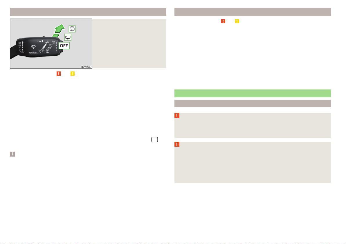
Rear wipers and washers / reversing camera cleaning system
Fig. 71
Operating the windscreen wip-
ers and washing system
Read and observe
and on page 76 first.
The lever can be moved to the following positions » Fig. 71
Spraying and wiping the windscreen (sprung position) - after releasing the
control stalk, the wipers perform another 2 to 3 wiper strokes
Spraying the rear view camera (sprung position)
Windscreen wiping
Wipers and washers off
Automatic rear wiper
If the windscreen wiping is performed without interruption, then the automat-
ic regular intermittent wiping of the rear window takes place.
This function can be activated/deactivated in Infotainment in the menu
/
→
→
Mirrors and wipers
.
Note
■
The rear window is wiped automatically if the windscreen wipers are on
when reverse gear is selected.
■
The setting (activation/deactivation) of the automatic rear window wiping in
the rain is stored (depending on the Infotainment type) in the active user ac-
count personalisation » page 55.
Headlight cleaning system
Read and observe and on page 76 first.
Headlights are cleaned under the following conditions.
The ignition is switched on.
The low beam is switched on.
The outside temperature is about -12° C to +39° C.
To clean the headlights, the headlamp is also sprayed after every ten squirts.
The adjustment of the spray interval can be adjusted by a specialist garage
(maximum after every twentieth spraying of the windscreen).
To ensure the correct functioning of the system, even in winter, this needs to
be regularly cleared of snow and ice (e.g. using the de-icing spray).
Rear view mirror
Introduction
WARNING
Exterior mirrors increase the field of view, however, make objects appear
smaller and further away. Therefore, use the rear-view mirror to determine
the distances to the following vehicles.
WARNING
■
The mirrors with automatic dimming contain electrolyte fluid which may
leak if the mirror glass is broken - this can irritate skin, eyes and the respira-
tory system.
■
If your eyes or skin come into contact with the electrolytic fluid, immedi-
ately wash the affected area for a few minutes long with a lot of water.
Seek medical assistance if required.
78
Operation
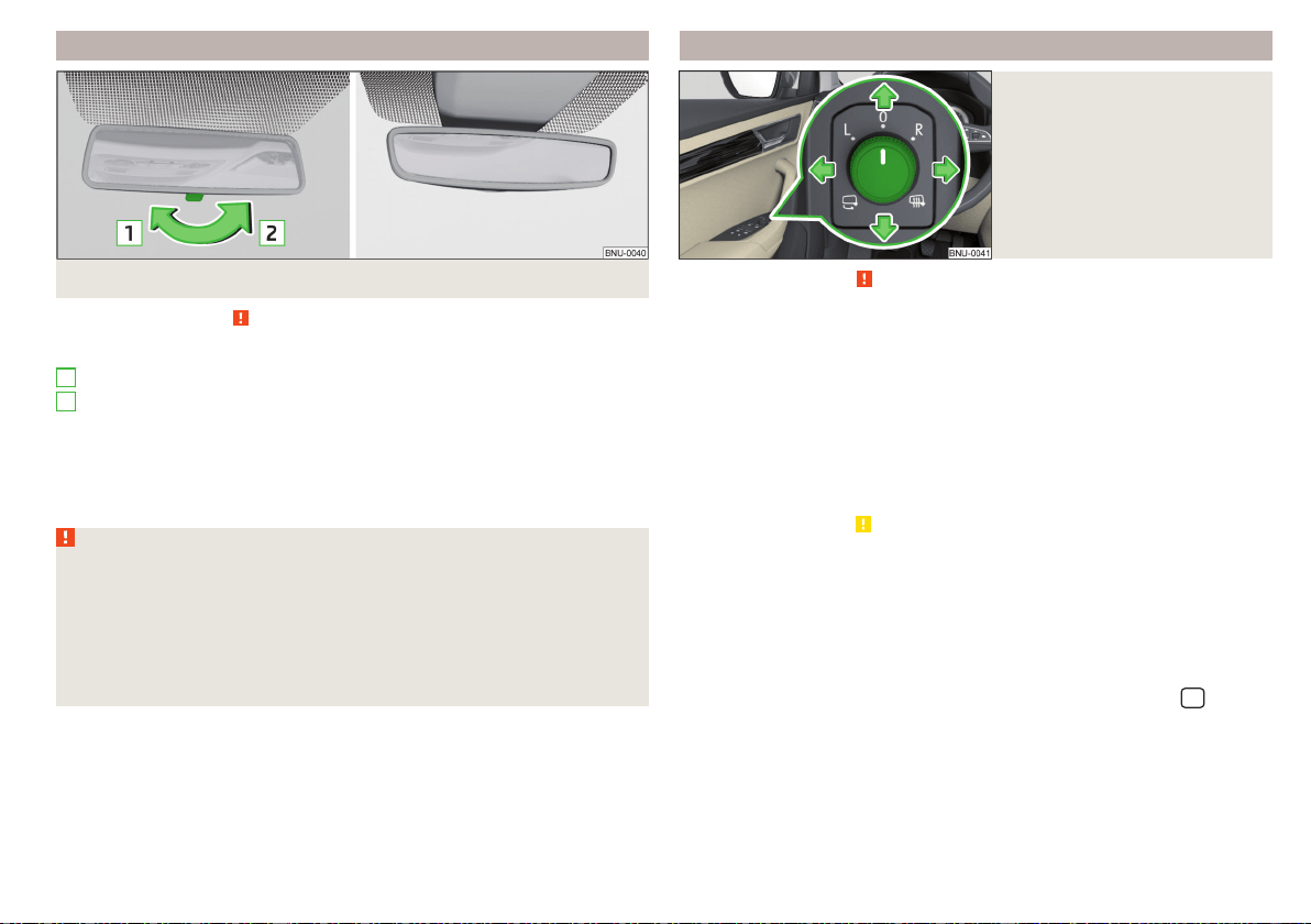
Interior mirror dimming
Fig. 72 Interior rear-view mirror manual dimming/auto-darkening
Read and observe on page 78 first.
Mirrors with manual dimming » Fig. 72
Basic position of the mirror (not dimmed)
Mirror blackout
Mirror with automatic dimming
The mirror dimming » Fig. 72 is automatically controlled after the engine start.
When the interior lights are switched on or the reverse gear is engaged, the
mirror moves back into the basic position (not dimmed).
WARNING
■
Attach external devices (e.g. navigation system) not in the vicinity of the
mirror with automatic dimming. The illuminated display of an external de-
vice can affect the function of the rear-view mirror - it could cause an acci-
dent.
■
Automatic mirror dimming only operates correctly if the light striking the
sensor is not affected by other objects. The sensors are located on the
front and back of the mirror.
1
2
Exterior mirrors
Fig. 73
Exterior mirror operation
Read and observe on page 78 first.
The exterior mirrors can (depending on vehicle equipment) have a manual or
electric fold-in function, automatic dimming and memory function.
The rotary knob can be moved into the following positions (depending on
vehicle equipment)
Adjusting the left-hand mirror area
Switch off mirror control
Adjusting the right-hand mirror area
Mirror heating (only works when the engine is running)
Folding in the mirrors electrically (to fold back, move the rotary knob to
another position) »
Setting the mirror area
›
Move the rotary knob in the direction of arrows » Fig. 73.
If the mirror setting fails at any time, the mirrors can be adjusted manually by
pressing on the edge of the mirror area.
Setting the mirror surfaces synchronously
This function allows the simultaneous adjustment of the two mirror areas. The
function can be activated/deactivated in Infotainment in the menu
/ →
→
Mirrors and wipers
.
›
Turn the knob for the mirror control to the position for the driver mirror ad-
justment.
›
Adjust the mirror areas to the desired position.
79
Lights and visibility

Manual folding mirrors
The mirror can be manually folded towards the side windows. To put it back to
its original position, it should be folded back from the side window until it audi-
bly clicks into place.
Automatic folding in/back of both mirrors
The exterior mirrors are automatically collapsed after locking the vehicle in the
park position. After unlocking the vehicle, the mirrors are folded back to the
driving position » .
This function can be activated/deactivated in Infotainment in the menu
/
→ →
Mirrors and wipers
.
Mirror with automatic dimming
The exterior mirror dimming is controlled together with the automatic rear-
view mirror dimming » page 79.
Memory function for mirror (vehicles with electrically adjustable driver's
seat)
It is possible to save the current setting of the exterior mirror when saving the
driver's seat position with » page 82, Memory Function of the electrically ad-
justable seator » page 82, Memory function of the remote control key.
Tilting the mirror area of the front passenger mirror (vehicles with
electrically adjustable driver's seat)
The front passenger mirror area can be tilted to the stored position to improve
the view to the curb when reversing.
Operating conditions
The function can be activated in Infotainment in the menu
/
→
→
Mirrors and wipers
.
The setting of the mirror area has been previously stored » page 82,
Memory Function of the electrically adjustable seat or. » page 82, Mem-
ory function of the remote control key.
The reverse gear is engaged.
The knob for the mirror control is in the position for the passenger mirror
adjustment.
The mirror area returns to its initial position after the rotary knob is set to an-
other position or if the speed is greater than 15 km/h.
WARNING
Do not touch the exterior mirror surfaces, if the exterior mirror heating is
switched on - hazard of burning.
CAUTION
■
Never manually fold in/out the electrically folding exterior mirrors - there is a
risk of damage to the mirror!
■
When the mirror is swung by external influences (due to impact during ma-
noeuvring, for example), then first fold-in the mirror by turning the knob and
wait for a loud clapping noise.
Note
The setting of the mirror functions is stored in Infotainment (depending on the
Infotainment type) in the active user account personalisation » page 55.
80
Operation

Seats and head restraints
Front seats
Introduction
WARNING
■
Only adjust the driver's seat when the vehicle is stationary – risk of acci-
dent!
■
Caution when adjusting the seat! You may suffer injuries or bruises as a
result of adjusting the seat without paying proper attention.
Manual adjustment
Fig. 74
Control elements on the seat
Read and observe on page 81 first.
The seats can be adjusted by the respective operating element being pulled,
pressed or turned in the direction of the arrows » Fig. 74.
Adjusting the seat in the longitudinal direction (after releasing the control
lever must lock audibly)
Adjusting height of seat
Adjust the tilt of the backrest (do not lean on the backrest when adjusting)
Setting the extent of the curvature of the lumbar support
Note
After a certain time, play can develop within the adjustment mechanism of the
backrest angle.
A
B
C
D
Electrical adjustment
Fig. 75 Control elements on the seat
Read and observe on page 81 first.
The seats can be adjusted by the respective operating element being pressed
in the direction of area of the arrow » Fig. 75.
seat adjustment
▶
1 - Move in the longitudinal direction
▶
2 - Change in inclination
▶
3 - Change in height
Adjusting the seat backrest
▶
4 - Change in inclination
Adjusting lumbar support
▶
5 - Change curvature
▶
6 - The degree of curvature change
WARNING
The electric front seat adjustment is functional even with the ignition off.
Therefore, when leaving the vehicle, never leave people who are not com-
pletely independent, such as children, unattended in the vehicle - there is a
danger of injury!
A
B
C
81
Seats and head restraints
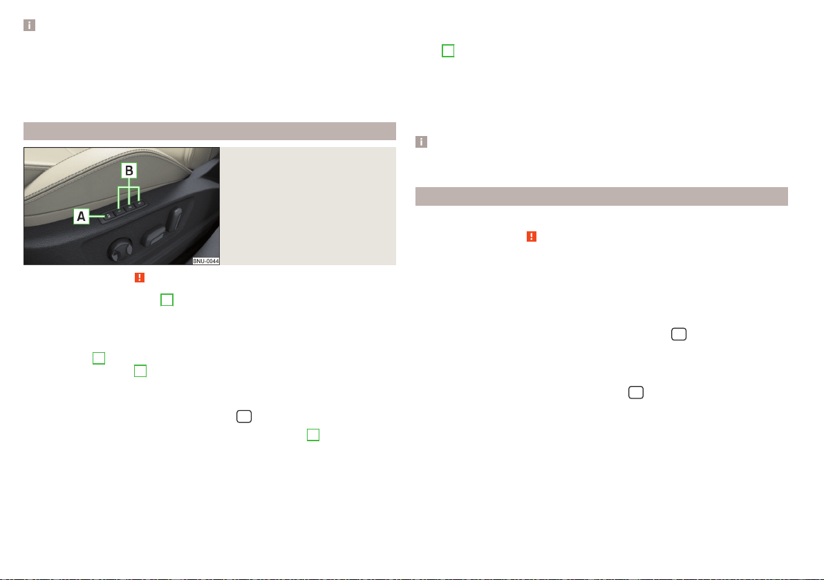
Note
■
If the inclination angle of the seat backrest relative to the seat surface is
greater than approx. 110°, then it is not possible for safety reasons to save this
setting in the memory of the electrically adjustable seats or the remote control
key.
■
On vehicles with personalisation, the driver's seat setting is stored in the ac-
tive user account personalisation » page 55.
Memory Function of the electrically adjustable seat
Fig. 76
SET button and memory but-
tons
Read and observe on page 81 first.
Among the memory buttons
B
on the driver's seat, a setting for the driver´s
seat and exterior mirror position can be saved » Fig. 76.
Storing driver's seat and exterior mirror settings for the forwards drive
›
Switch on the ignition, adjust the seat and the exterior mirrors, as required.
›
Press the
A
» Fig. 76 button and then, within 10 seconds, press the de-
sired memory button
B
. Storing is confirmed by an acoustic signal.
Storing front passenger´s exterior mirror settings for reversing
The function for lowering the front passenger's mirror area during reversing
can be activated in Infotainment in the menu
/ → →
Mirrors and wipers
.
›
Turn on the ignition and press the desired memory button
B
» Fig. 76.
›
Turn the rotary knob for the exterior mirror control to the position for the
front passenger mirror area » page 79.
›
Engage reverse gear.
›
Adjust the front passenger's mirror to the desired position.
›
Disengage reverse gear. The set position of the exterior mirror is stored.
Retrieving the saved setting
›
With the ignition off and open driver's door, press the desired memory but-
ton
B
.
›
In other cases (e.g. if the ignition is switched on or the driver's door closed),
hold the button.
Stopping the ongoing adjustment
›
Press any button on the driver's seat or the button on the remote control
key.
Note
Every time you save new seat and exterior mirror settings for driving forwards,
you must also save the front passenger mirror setting for reversing again.
Memory function of the remote control key
Applies to vehicles that do not have the personalisation function.
Read and observe on page 81 first.
Every time the vehicle is locked, the driver´s seat and exterior mirror settings
are saved and assigned to the key with which the vehicle was locked.
After the following unlocking of the vehicle with the same key and opening the
driver’s door, the driver´s seat and exterior mirrors that are saved to this key
will be adopted.
This function can be used in Infotainment in the menu
/ → →
Seats
(ac-
tivated/deactivated).
Storing front passenger´s exterior mirror settings for reversing
The function for lowering the front passenger's mirror area during reversing
can be activated in Infotainment in the menu
/ → →
Mirrors and wipers
.
›
Unlock the vehicle with the remote control key and switch on the ignition.
›
Turn the rotary knob for the exterior mirror control to the position for the
front passenger mirror area » page 79.
›
Engage reverse gear.
›
Adjust the front passenger's mirror to the desired position.
›
Disengage reverse gear. The adjusted position of the exterior mirror is stored
in the remote control key memory.
82
Operation
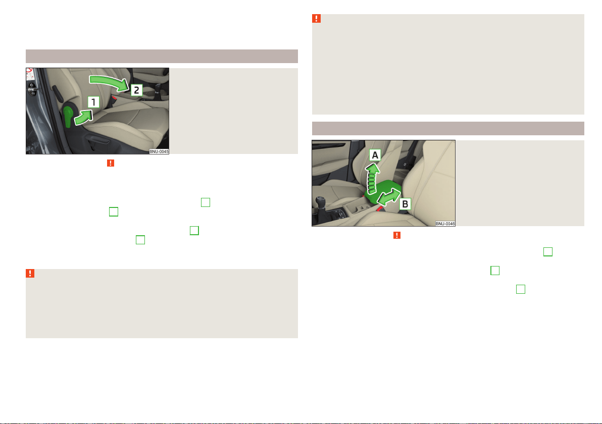
Stopping the ongoing adjustment
›
Press any button on the driver's seat or the button on the remote control
key.
Folding front passenger seat
Fig. 77
Folding the front passenger seat
forward
Read and observe on page 81 first.
The front passenger seat can, (depending on vehicle equipment fitted), be fol-
ded forward into a horizontal position.
›
To fold down, pull the lever in direction of arrow
1
, fold the seat backrest in
the direction of arrow
2
» Fig. 77. The locking mechanism must audibly snap
into place.
›
To fold up, pull the lever in direction of arrow
1
, fold back the seat backrest
against the direction of arrow
2
. The locking mechanism must audibly snap
into place.
›
Check this by pulling on the seat and on the seat backrest.
WARNING
■
If the seat backrest is folded down, only the seat behind the driver´s seat
can be used to transport passengers.
■
Switch off the front passenger airbag when transporting objects on the
seat which was folded forwards » page 27.
■
Do not adjust the seat backrest while driving - it can cause injury and ac-
cidents!
WARNING (Continued)
■
When moving the seat backrest, keep limbs out of the area between the
seat and seat backrest – risk of injury!
■
Never transport the following items on the seat backrest when folded
forwards.
■
Objects that could restrict the driver's view.
■
Objects which make it impossible for the driver to control the vehicle,
e.g. if they roll under the pedals, or could protrude into the driver's zone.
■
Objects which could lead to injury to passengers due to a change of di-
rection or braking manoeuvre when accelerating sharply.
Armrest setting
Fig. 78
Adjust armrest
Read and observe on page 81 first.
›
To adjust the height, lift the armrest in the direction of the arrow
A
into one
of the locking positions » Fig. 78.
›
To close, lift the armrest in the direction of arrow
A
past the stop and then
fold down again.
›
To Set the armrest lengthways in the direction of arrow
B
Move to the de-
sired position.
83
Seats and head restraints
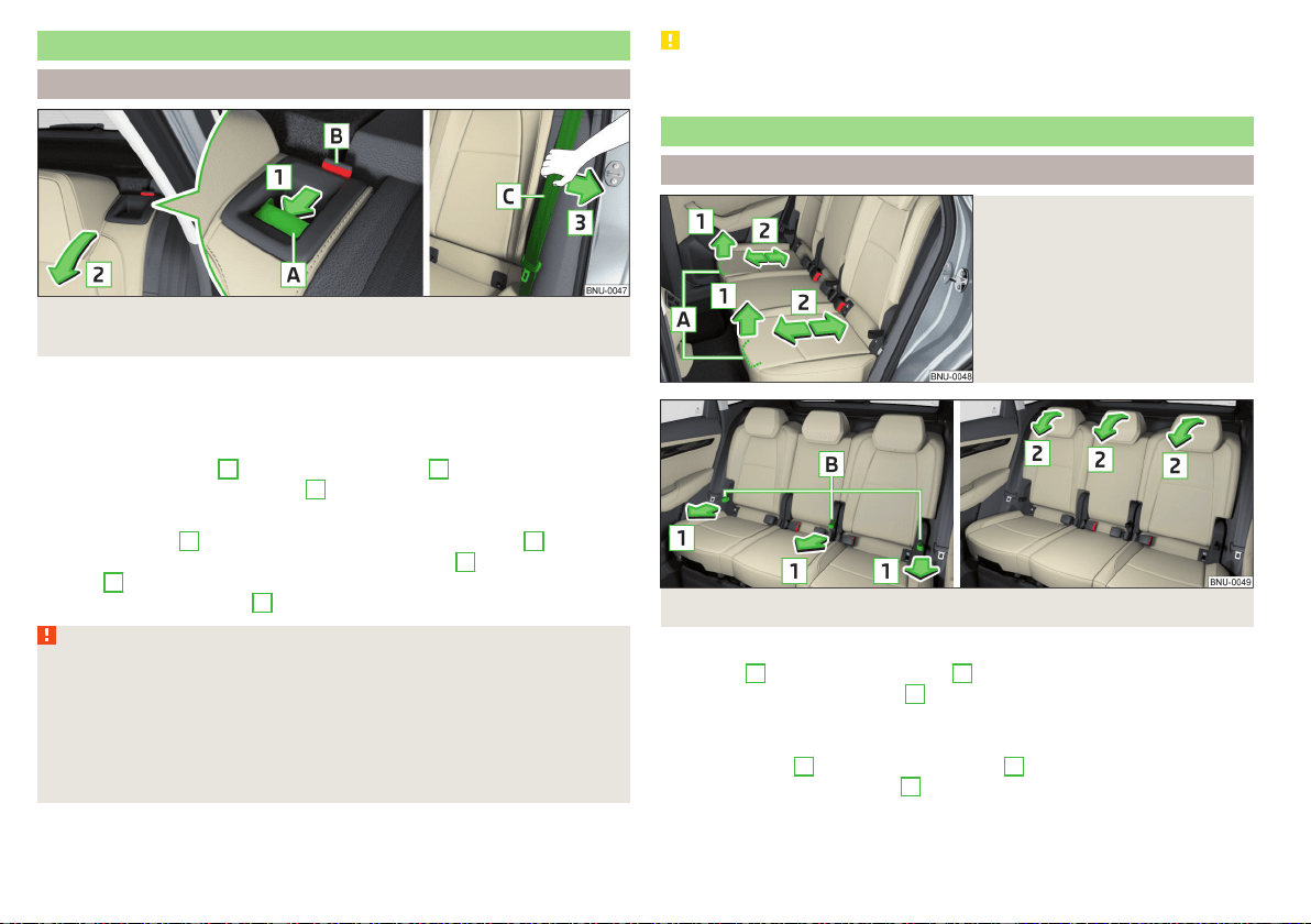
Rear seats
Seat backrests
Fig. 79 Folding the seat backrest forwards / inserting the belt into the
opening in the side panel
Before folding the seat backrests forwards, adjust the position of the front
seats in such a way that they are not damaged by the seat backrests. If neces-
sary, remove the rear head restraints » page 88.
Folding forward
›
Push the release lever
A
in the direction of arrow
1
and fold down the seat
backrest in the direction of arrow
2
» Fig. 79.
Folding backwards
›
Pull the seat belt
C
for the side panel in the direction of arrow
3
» Fig. 79.
›
Raise the seat backrest against the direction of arrow
2
until the release
handle
A
audibly locks. Check this by pulling on the seat backrest.
›
Make sure that the red pin
B
is hidden.
WARNING
■
The seat backrests in the occupied rear seats must be properly engaged.
■
When transporting objects in the luggage compartment that has been en-
larged by folding the backrest forward, ensure the safety of the passengers
transported on the rear seat.
■
The seat backrests must be securely latched in position so that no objects
from the luggage compartment can slip into the passenger compartment
under sudden braking – risk of injury.
CAUTION
When operating the seat backrests, the seat belts must not be pinched - there
is a risk of damage to the seat belts.
VarioFlex rear seats
Adjusting the seats
Fig. 80
Adjusting seats in forward/back
direction
Fig. 81
Adjusting the angle of the seat backrest
Move in the longitudinal direction
›
Pull lever
A
in the direction of arrow
1
and move the seat to the desired po-
sition in the direction of arrow
2
» Fig. 80. After releasing the control lever
the latch must engage audibly.
Adjusting the angle of the seat backrest
›
Pull on the loop
B
in the direction of arrow
1
» Fig. 81 and press the seat
backrest in direction of arrow
2
. The locking mechanism must audibly snap
into place.
84
Operation

›
To adjust the seat backrest to upright position, pull on the loop in the direc-
tion of arrow
1
and hold the arm in the forward movement until the lock
clicks.
Folding the seat backrest forwards
Fig. 82
Position the safety position of the belt / seat backrest
Fold forward outer seat backrest
›
Insert the belt buckle
A
of the seat belt into the opening in the side pan-
el» Fig. 82.
›
Move the seats backwards until the stop » Fig. 80 on page 84.
›
Pull on the loop
B
in the direction of arrow
1
and fold the seat backrests
forwards in direction of arrow
2
» Fig. 82.
Fold forward middle seat backrest
›
Removing the headrest.
›
Pull on the loop
B
next to the centre seat in the direction of arrow
1
and
fold the seat backrest forwards in direction of arrow
2
» Fig. 82. The seat
backrest can be used as an armrest.
WARNING
■
When transporting objects in the luggage compartment that has been en-
larged by folding the backrest forward, ensure the safety of the passengers
transported on the remaining rear seats.
■
The seat backrests must be securely latched in position so that no objects
from the luggage compartment can slip into the passenger compartment
under sudden braking – risk of injury.
CAUTION
When operating the seat backrests, the seat belts must not be pinched - there
is a risk of damage to the seat belts.
Fold up the outer seats
Fig. 83
Fold up the outer seat
Before folding up
›
Switch the seat heating off - there is a risk of damage to the contacts in the
socket under the seat!
›
Move the seat back as far as it will go and fold the seat back.
Folding up
›
Pull the lever
A
» Fig. 83 in the direction of the arrow
1
and fold the seat
up in the direction of arrow
2
.
Note
If the seat is folded up when the seat is heated, the heater is interrupted. The
heating can be switched on again after switching the ignition on and off.
85
Seats and head restraints
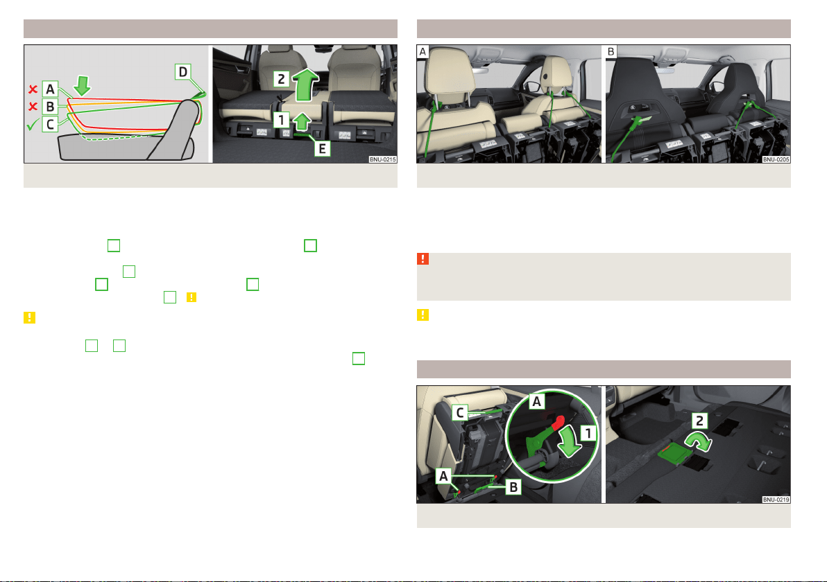
Folding up the middle seat
Fig. 84 Folding up the middle seat
Before folding up
›
Remove the headrest and fold the seat backrest forwards.
Folding up
›
Pull on the loop
D
and push the seat backrest in position
C
about 4 cm
deep into the seat » Fig. 84.
›
Let go off the loop
D
.
›
Pull the lever
E
in the direction of the arrow
1
and carefully fold the seat
up in the direction of arrow
2
» .
CAUTION
If the seat touches the center console when the lift is raised, the seat backrest
is in position
A
or
B
- there is a risk of damage to the centre console. The
seat must be folded back and the seat backrest pressed into position
C
.
Fold up the upholstered seats
Fig. 85 Fold up the upholstered seats
›
Fold up the upholstered seats with the fastening strap on the headrest guide
bar » Fig. 85 -
.
›
For seats with an integrated head restraint, fasten the strap to the loop at
the back of the seat backrest » Fig. 85 -
.
WARNING
If one of the rear seats is folded up, no persons may be carried on the re-
maining seats - there is a risk of injury!
CAUTION
Leave the seats in the raised position for as long as required - there is a risk of
damage to the front seat backrests.
Unlocking and removing the seat
Fig. 86
Unlocking the seat / closing the cover
86
Operation
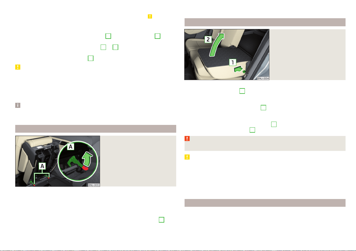
Before unlocking
›
Move the outer seat backwards as far as it will go and fold up » .
›
On the centre seat, remove the headrest and fold up the seat » page 86.
Unlock and remove
›
Unlock the seat by pressing the seat locks
A
in direction of arrow
1
» Fig. 86.
›
Remove the seat on the carrying handle
B
or
C
.
›
When the middle seat has been removed, close the cover for the socket in
the floor in the direction of arrow
2
.
CAUTION
■
The outer seat must be at the back of the unit before it is folded up - there is
a risk of damage to the locking mechanism when the seat is unlocked and re-
moved.
■
The socket in the floor must be protected with the cover after removing the
middle seat - there is the risk of damage to the socket.
Note
The outer seats are not mutually interchangeable. The left seat in the rear area
is marked with the letter L and the right seat with the letter R.
Adjusting seats in crosswise direction
Fig. 87
Locking seats
›
Remove the middle seat and close the cover for the socket in the floor
» Fig. 86 on page 86.
›
Fold the outer seat up and unlock.
›
Move seat on the guide rods towards the middle of the vehicle up to the
stop.
›
Lock the seat at the end of the guide rods by pressing the seat locks
A
in
the direction of arrow » Fig. 87.
Folding back into the starting position is accomplished in the reverse order.
Folding back seats
Fig. 88
Folding the seat backrest back
into position
›
If the seat has been removed, first position it on the guide rods and lock it in
place with the seat locks
A
» Fig. 87 on page 87. Pull the seat upwards to
ensure that the seat is locked correctly.
›
Before inserting the middle seat, open the cap for the socket in the ground
opposite the direction of the arrow
2
» Fig. 86 on page 86.
›
Fold the seat in the horizontal position until it audibly click in place. Check
that the seat can no longer be lifted by pulling it up.
›
Pull on the loop in the direction of arrow
1
» Fig. 88 and fold back the seat
backrest in direction of arrow
2
. Check this by pulling on the seat backrest.
WARNING
The seat backrests in the occupied rear seats must be properly engaged.
CAUTION
■
Be sure to check the plugs on the bottom of the seats and the plugs under
the seats for soiling before inserting or folding the seats forwards - there is a
risk of functions being restricted » page 87.
■
Before tilting the centre seat forwards, the cover for the socket in the floor
must be opened - there is a risk of damage to the plug on the underside of the
seat.
Plugs and sockets under the seats
On vehicles with seat belt heating or seat heating, there are plugs on the un-
derside of the seats and sockets under the seats.
87
Seats and head restraints
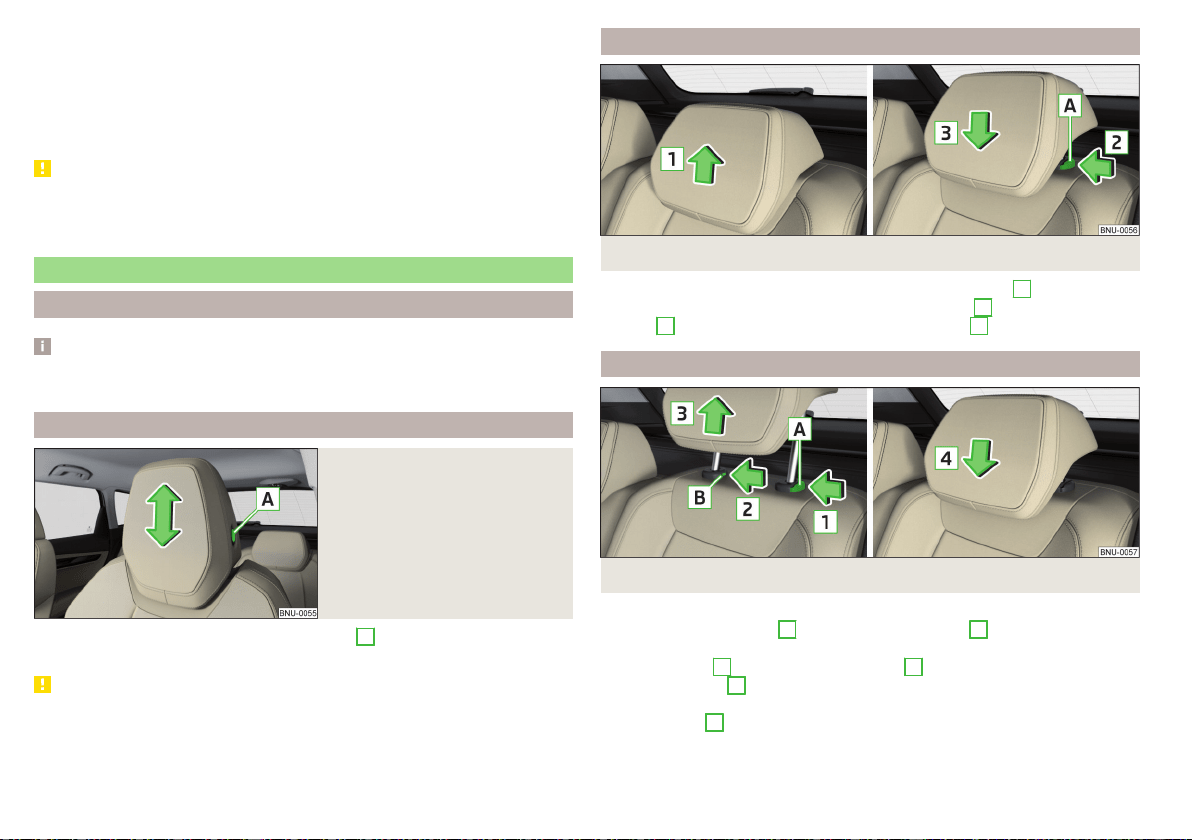
The plugs and sockets can be soiled with upholstered or removed seats. This
can lead to functions being restricted.
Cleaning
›
Clean the connectors with a cloth moistened with spirits.
›
Carefully remove dirt from the sockets with a vacuum cleaner.
›
Clean the contacts in the sockets with a cloth moistened with spirits.
CAUTION
If the seats are folded up or removed, store them carefully in the luggage com-
partment and do not load the sockets punctiform - there is a risk of damage to
the sockets.
Headrests
Introduction
Note
In sports seats, the headrests are integrated into the seat backrests and can-
not be adjusted in height.
Adjust height of front head restraint
Fig. 89
Setting the height of the head-
rest
›
To adjust the height, hold the locking button
A
and move the rest in the de-
sired direction » Fig. 89.
CAUTION
If the tablet holder adapter is secured to the guide rods of the headrests
» page 102, do not push the headrests down to the stop – risk of damaging
the headrests.
Adjusting the height of the rear headrests
Fig. 90 Setting the height of the rear headrest
›
Hold the rest and move upwards in the direction of arrow
1
» Fig. 90.
›
To move the restraint down, hold the locking button
A
in the direction of
arrow
2
and push the rest in the direction of arrow
3
.
Removing/inserting the rear headrests
Fig. 91
Removing/inserting the rear headrest
›
To remove, pull the rest out of the seat backrest up to the stop.
›
Hold the locking button
A
in the direction of arrow
1
, at the same time us-
ing a flat screwdriver with a max. width of 5 mm to press the locking button
in the opening
B
in the direction of arrow
2
and pull out the rest in the di-
rection of arrow
3
» Fig. 91.
›
To insert the headrest, push the headrest into the seat backrest in the direc-
tion of arrow
4
until the locking button clicks into place.
88
Operation
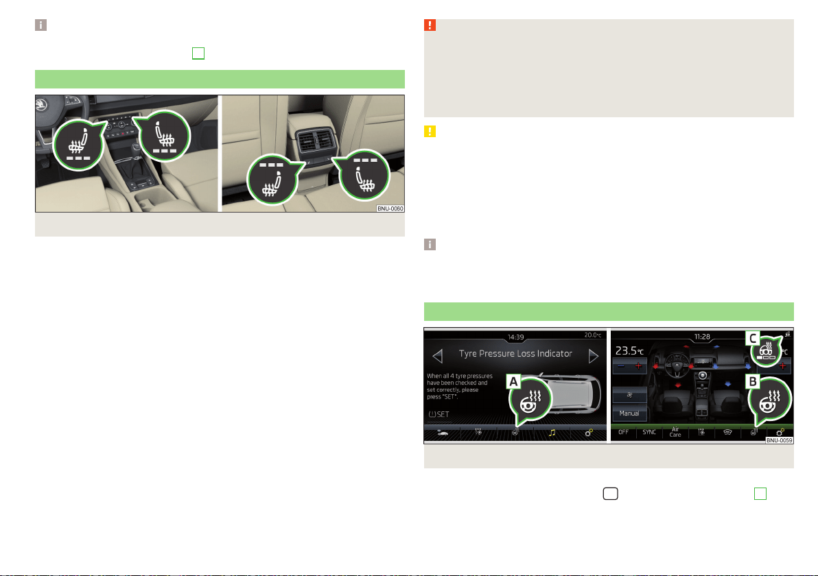
Note
For VarioFlex, the extended headrest can only be removed from the middle
seat only when the safety button
A
» Fig. 91 is held.
Seat heaters
Fig. 92
Buttons for heating the front seats/rear seats
The seat backrests and surfaces of the front seats and the outer rear seats can
be heated electrically.
Seat heating buttons » Fig. 92
Left seat heating
Right seat heating
›
To turn on the heating to max, press the key
or
button.
With repeated pressing of the button, the level is down-regulated until it
switches off . The level of the seat heating is indicated by the number of illu-
minated warning lights underneath / in the button.
The seat heating only operates when the engine is running.
When the ignition is switched off, the seat heating / ventilation is also switch-
ed off. if the engine is started again within 10 minutes, then the driver's seat
heating / ventilation is switched on again automatically according to the set-
ting before switching off the ignition.
WARNING
If you have a limited pain and / or temperature sensitivity, e.g. due to medi-
cation, paralysis or because of chronic illness (e.g. diabetes), we recom-
mend that you do not use the seat heating. If the seat heating is used, we
recommend to make regular breaks in your journey when driving long dis-
tances, so that the body can recuperate from the stress of the journey.
Please consult your doctor, who can evaluate your specific condition.
CAUTION
The following instructions must be observed to avoid damage to the seats.
■
Do not kneel on the seats or otherwise apply concentrated pressure to them.
■
Do not heat seats that do not contain occupants.
■
Do not heat seats in which objects are secured or resting (e.g. children´s
seat, a bag etc.).
■
Do not heat seats on which additional slipcovers or protective covers are fit-
ted.
Note
If the on-board voltage decreases, the seat heating switches off automatically
» page 265, Automatic consumer shutdown - Discharge protection of the ve-
hicle battery.
Heated steering wheel
Fig. 93
Steering wheel heating: Manual air conditioning / Climatronic
Switching heating on/off (applies to the manual air conditioning)
›
In the Infotainment system, in menu
/ tap the function surface
A
» Fig. 93.
89
Seats and head restraints

Switching heating on/off (applies to Climatronic)
›
Press the button on the Climatronic, then tap the function surface
B
» Fig. 93.
When the heating is switched on, the symbol in the function surface
B
is or-
ange.
Setting the heating power (applies to the Climatronic)
›
Press the button on the Climatronic, then tap the function surface →
Steering wheel heating on the Infotainment screen.
›
Setting the heating power.
The heating power is displayed by the number of segments in the indicator
light
C
» Fig. 93.
Steering wheel heating together with the driver's seat heating (applies to
the Climatronic)
›
To activate / deactivate the heated steering wheel with the driver's seat
heating, press the button
on the Climatronic, then tap the function sur-
face
→
Link seat/steering wheel heating
in the Infotainment screen.
›
To switch on / off the heated steering wheel, press the button for the driver
seat heating.
If the heated steering wheel is turned on together with the driver's seat heat-
ing, then the function surface
is displayed on the Infotainment screen. This
can be used to switch the heated steering wheel off/on.
Note
■
The heated steering wheel only works when the engine is running.
■
If the on-board voltage decreases, the heated steering wheel switches off
automatically.
Practical features
Passenger compartment features
Introduction
WARNING
■
Do not place anything on the dashboard. These objects might slide or fall
down when driving and may distract you from concentrating on the traffic
– risk of accident!
■
Make sure that while driving no objects can enter the driver's footwell -
cause an accident!
■
Do not carry any objects on the front passenger seat except objects de-
signed for this purpose (e.g. child seats) – risk of accident!
■
No objects should be placed in the storage compartments nor in the
drinks holders; the vehicle occupants could be endangered if there is sud-
den braking or the vehicle collides with something.
■
For safety reasons, lockable storage compartments must be closed while
driving - there is a risk of injury from the opened cover or from the items in
the compartment.
■
Make sure that no objects protrude from the compartments - there is
danger of injury!
■
Do not exceed the permissible load for the storage compartments and
pockets - it may cause injury or there is the risk of damaging the compart-
ments and pockets!
■
Ash, cigarettes, cigars and the like may only be placed in the ashtray - risk
of fire!
■
The storage compartments and the waste containers are not a substitute
for the ashtray and must also not be used for such purposes – risk of fire!
CAUTION
No not place large or sharp objects in the storage compartments and pockets
- there is a risk of damage to the compartments and pockets.
90
Operation

Parking ticket holder
Fig. 94
Parking ticket holder
Read and observe and on page 90 first.
The parking ticket holder » Fig. 94 is provided for the attachment of e.g. park-
ing tickets.
Storage compartment on the driver's side
Fig. 95 Opening the storage compartment / card holder
Read and observe
and on page 90 first.
›
To open, lift the handle and fold out the compartment in the direction of the
arrow » Fig. 95 .
›
To close, swing the lid against the direction of the arrow until it audibly clicks
into place.
A card holder is located in the storage compartment » Fig. 95 .
The maximum permissible load of the storage compartment is 0.5 kg.
Storage compartments in the doors
Fig. 96 Storage compartments: in the front door/in the rear door
Read and observe and on page 90 first.
Storage compartments » Fig. 96
Storage compartment
Bottle holder with a capacity of max. 1.5 l
Rubber band for storing newspapers
The reflective vest can be stowed in the storage compartments in the door
» page 272.
WARNING
The storage compartment
A
» Fig. 96n the front door is to be used exclu-
sively for storing objects which do not protrude - there is the danger of
limiting the operating range of the side airbags.
A
B
C
91
Practical features
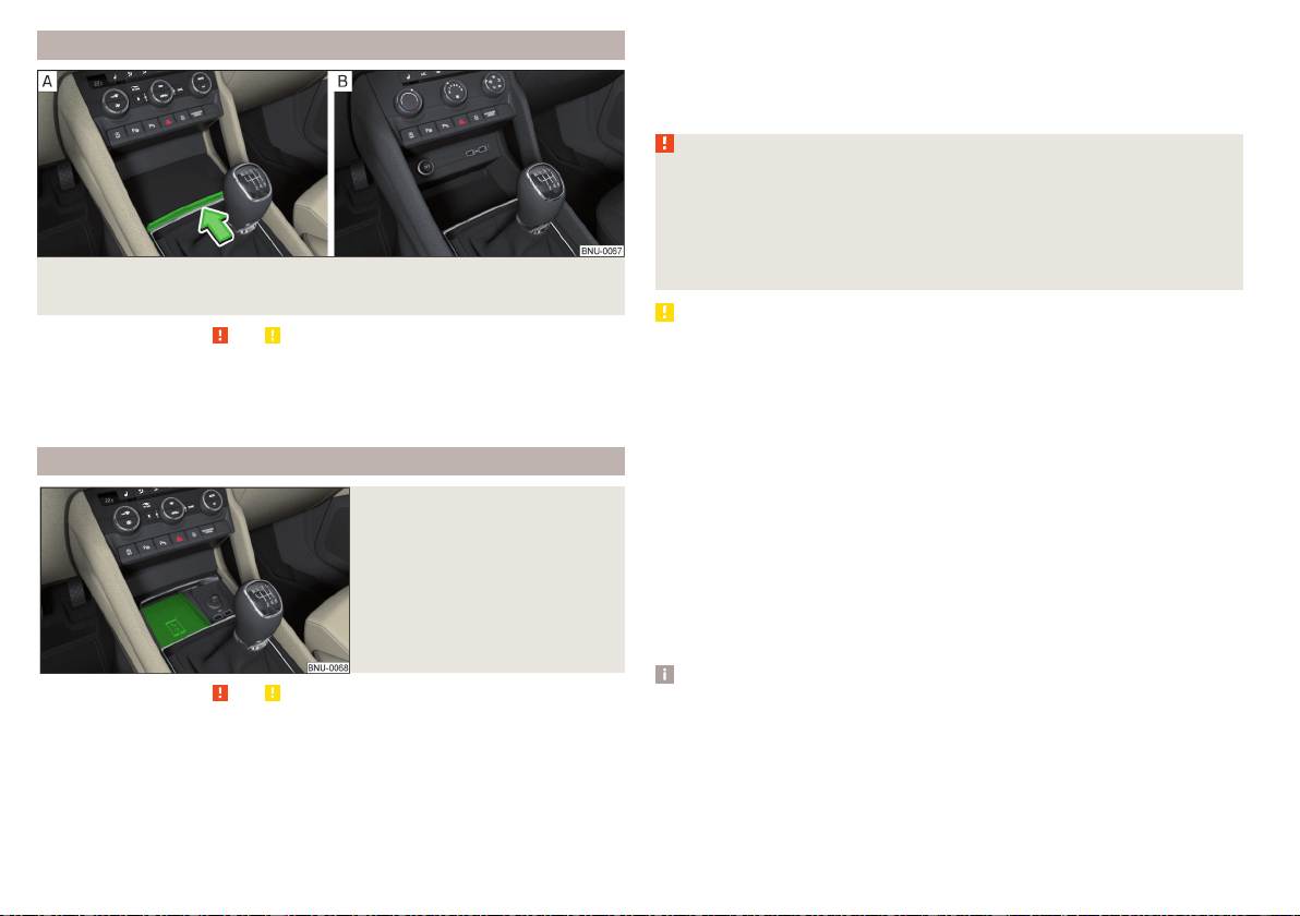
Storage compartment in the front centre console
Fig. 97 Opening storage compartment/ non-lockable storage compart-
ment
Read and observe and on page 90 first.
›
To open, press the ridge in the direction of arrow » Fig. 97 -
.
›
To close, pull on the ridge against the direction of the arrow.
Certain models do not have a storage compartment lid» Fig. 97 -
.
Phonebox
Fig. 98
Phonebox
Read and observe and on page 90 first.
The storage compartment in the front centre console can be equipped with
the Phonebox function.
If a phone is placed face down on the pad in the storage compartment
» Fig. 98, the phone signal is amplified by the roof antenna.
Telephones that support the Qi standard for wireless charging, can also be
charged wirelessly in the storage compartment.
While wireless charging is taking place, no objects may be between the pad
and the telephone being charged.
WARNING
■
The phone may become warm during wireless charging, so it should be
removed carefully from the tray.
■
Metal objects between the pad and the phone to be charged can become
hot due to the action of the induction field - this is a risk of injury. If there is
a metal object in the storage compartment that has become hot, then take
out the telephone and let the object cook in the storage compartment!
CAUTION
■
Metal objects between the pad and the phone to be charged can become hot
due to the action of the induction field - this is a risk of damage to the tele-
phone.
■
With some phones, the charging process can be interrupted or the phone
can switch off due to heating up.
■
Do not insert any electronic or magnetic storage media (e.g. SD cards, USB
sticks, cards with magnetic strips or chips) between the pad and the phone to
be charged- there is a risk of data loss and damage to these data carriers.
■
If a message appears in the Infotainment screen that the phone cannot be
charged, then proceed as follows.
■
Check that there is no object between the support and the phone to be
charged. If this is the case, then take out the object and the phone. Place the
phone centrally on the phone symbol on the pad again.
■
Check if the position of the phone to be charged has not changed during
the journey. If this is the case, then take out the phone and put it back cen-
trally on the phone symbol on the pad.
Note
■
At the start of the wireless charging, the appropriate message appears on
the Infotainment screen.
■
For the optimum phone signal strength and uninterrupted wireless charging,
we recommend position the phone in the storage compartment without the
protective sleeve, if possible.
■
Place a max. 160x80 mm phone in the storage compartment.
92
Operation
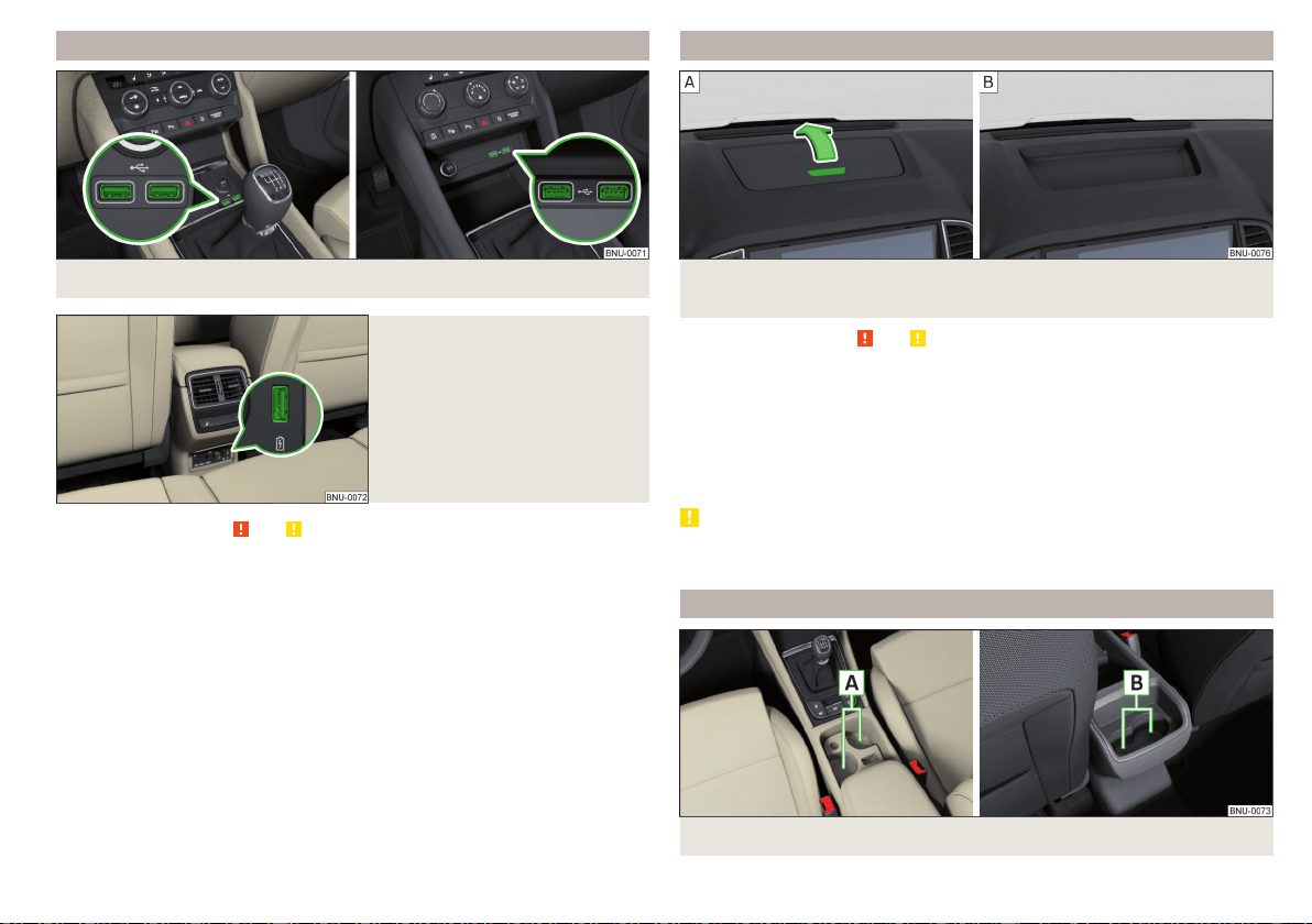
USB inputs
Fig. 99 USB front inputs
Fig. 100
USB input on the back
Read and observe and on page 90 first.
One or two USB inputs are located in the lockable storage compartment or
above the non-lockable storage compartment in the front centre console
» Fig. 99,
The USB input is also in the rear centre console depending on the equipment
fitted » Fig. 100.
The USB inputs in the front centre console can be used for charging and for
data transfer. The USB inputs in the rear centre console can only be used for
charging.
Information for use » page 148, USB input.
Storage compartment on the dash panel
Fig. 101 Opening storage compartment/ non-lockable storage compart-
ment
Read and observe and on page 90 first.
›
To open press the button » Fig. 101 -
the cover opens in the direction of
arrow.
›
To close, swing the lid against the direction of the arrow until it audibly clicks
into place.
On some vehicles, the storage compartment does not have a lid » Fig. 101 -
,
or a loudspeaker grille is installed instead of the storage compartment.
CAUTION
Do not put any heat-sensitive objects in the storage compartment - in the
event of high temperatures there is risk of damage.
Cup holders
Fig. 102 Cup holder in front/rear centre console
93
Practical features
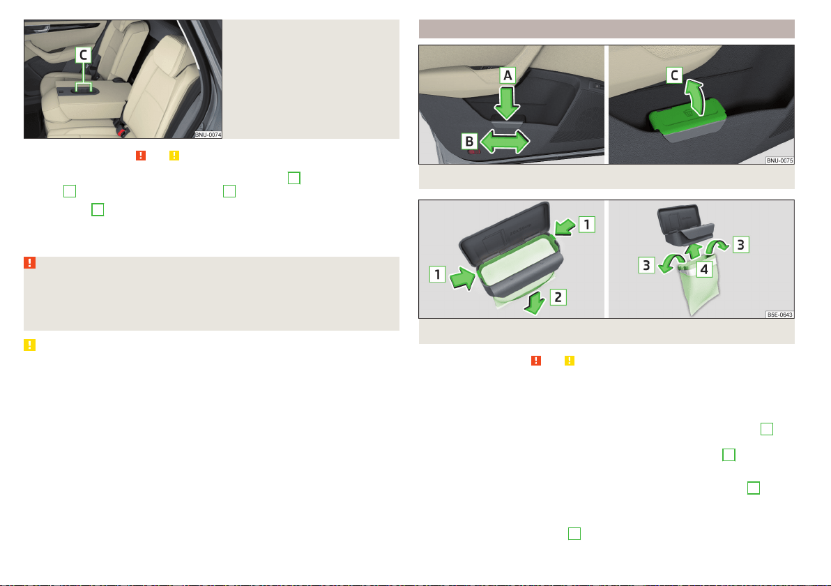
Fig. 103
Beverage holder on the middle
rear seat backrest
Read and observe
and on page 90 first.
The cup holders are located in the front centre console
A
, the rear centre
console
B
» Fig. 102 and on the backrest
C
» Fig. 103.
In the holders
A
, a beverage container can be opened with one hand by push-
ing the container into the holder and turning the lid.
The cup holder is also located in the folding table » page 97.
WARNING
■
Do not use any cups or beakers which are made of brittle material (e.g.
glass, porcelain). This could lead to injuries in the event of an accident.
■
Never put hot beverage containers in the cup holder. If the vehicle moves,
they may spill – risk of scalding!
CAUTION
Do not leave open beverage containers in the cup holder during the journey.
There is a risk of spilling e.g. when braking which may cause damage to the
electrical components or seat upholstery.
Waste container
Fig. 104 Waste container: inserting and moving/opening
Fig. 105
Replace bags
Read and observe
and on page 90 first.
The waste container can be inserted into the slot in the door.
Insert waste container
›
Position the waste container at the front edge of the slot.
›
Push the waste container in the rear area in the direction of the arrow
A
» Fig. 104.
›
If required, push the waste container in the direction of arrow
B
.
Remove the waste container
›
Remove the waste container in the opposite direction to the arrow
A
» Fig. 104.
Open/close waste container
›
Lift the cover in the direction
C
» Fig. 104.
94
Operation
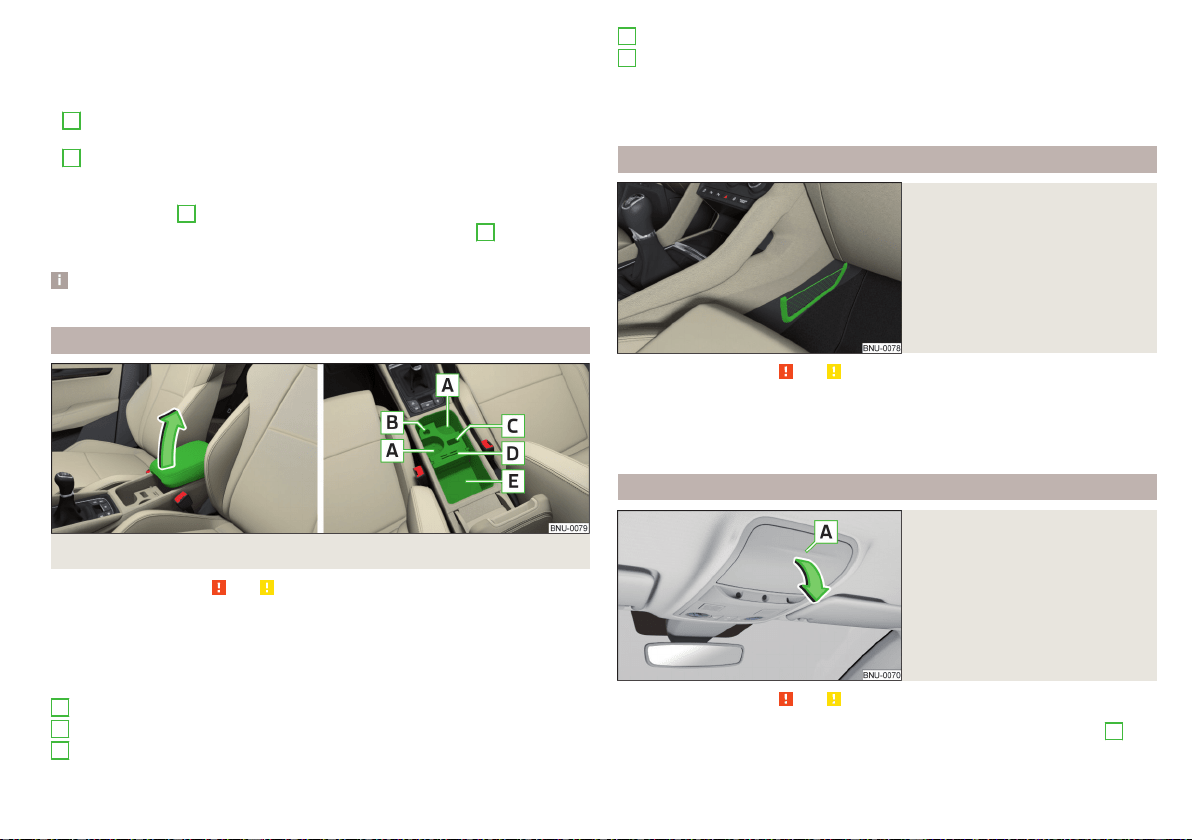
Closing takes place in reverse order.
Replace bags
›
Remove the waste container from the slot.
›
Press the two locking lugs on the frame in the direction of arrow
1
» Fig. 105.
›
Pull the bag together with the frame downwards in the direction of arrow
2
.
›
Remove the bag from the frame.
›
Pull the new bag through the frame and pull it over the bag frame in the di-
rection of arrow
3
.
›
Insert the bag containing the frame in the direction of arrow
4
into the con-
tainer body, so that the two lugs engage audibly with the frame.
Note
We recommend that you use 20 x 30 cm bags.
Storage compartment underneath the front armrest
Fig. 106
Open storage compartment / interior of the compartment
Read and observe and on page 90 first.
›
To open the storage compartment, lift the armrest in the direction of arrow
until it stops » Fig. 106.
›
To close, fold the armrest down again against the direction of the arrow.
Interior of the compartment » Fig. 106;
Cup holder
Storage compartment for storing the cover of the 12-volt power outlet
Storage compartment for storing the vehicle key
A
B
C
Storage compartment for storing two coins and a card
Storage compartment
The part with the cup holder can be removed or rotated. By removing, the in-
terior of the storage compartment is increased, turning creates an additional
tray.
Storage net in the front centre console
Fig. 107
Storage net
Read and observe and on page 90 first.
The storage nets» Fig. 107 are intended for the storage of e.g. maps, maga-
zines, etc.
The maximum permissible load of the net is 0.5 kg.
Glasses storage box
Fig. 108
Opening the glasses storage
box
Read and observe and on page 90 first.
›
To open, press on the outer edge of the glasses compartment in area
A
.
The compartment folds in the direction of the arrow » Fig. 108.
D
E
95
Practical features

›
To close, swivel the compartment against the direction of the arrow until it
audibly clicks into place.
The maximum permissible load of the glasses compartment is 250 g.
CAUTION
■
Do not put any heat-sensitive objects in the glasses storage box - with high
temperatures there is risk of damage.
■
The box must be closed before leaving and locking the vehicle – risk of im-
pairment to the functions of the anti-theft alarm system.
Storage compartment on the front passenger side
Fig. 109
Open storage compartment / close storage compartment and
open air supply
Read and observe
and on page 90 first.
Storage compartment
The storage compartment is fitted with with an interior light (the light is on
when opening the storage compartment) equipped, a pen, card holder, with
storage compartments for storing coins, an SD card and an air outlet.
›
To open, press the -- button. The cover folds in the direction of arrow
1
» Fig. 109.
›
To close, swivel the cover in the direction of arrow
2
until it audibly clicks
into place.
Air supply
›
To open, turn the rotary switch until it stops in the position » Fig. 109.
›
To close, turn the rotary switch until it stops in the position .
Opening the air supply when the air conditioning system is switched on allows
cooled air to flow into the storage compartment.
Opening the air inlet when the air conditioning system is on causes fresh or in-
terior air to flow into the storage compartment.
The maximum permissible load of the storage compartment is 3 kg.
Storage compartment for an umbrella
Fig. 110
Opening the storage compart-
ment
Read and observe and on page 90 first.
›
To open, pull the handle in direction of arrow
1
pull and open the compart-
ment in the direction of arrow
2
» Fig. 110.
›
To close, screw in the lid in the opposite direction of arrow
2
until it audibly
clicks into place.
Clothes hook
Fig. 111
Clothes hooks
Read and observe and on page 90 first.
The clothes hooks are located on the middle door pillars of the vehicle and on
the handle of the headliner above each of the rear doors » Fig. 111.
96
Operation
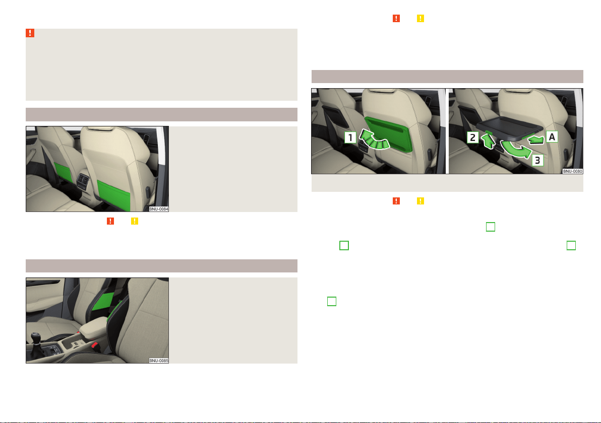
The maximum permissible load of each of the hooks is 2 kg.
WARNING
■
Never leave any heavy or sharp-edged objects in the pockets of the items
of clothing hung up.
■
To hang the clothes do not use hangers - there is a risk of limiting the ef-
fectiveness of head airbags.
■
Ensure that any clothes hanging from the hooks do not impair your vision
to the outside.
Storage pockets on the backs of the front seats
Fig. 112
Map pockets
Read and observe and on page 90 first.
The storage pockets » Fig. 112 are intended for the storage of maps, maga-
zines, etc.
Storage pockets at the inner sides of the front seats
Fig. 113
Storage pocket
Read and observe and on page 90 first.
The storage pockets are located on the inside of the front seats » Fig. 113 and
are used to store small and light objects (e.g. mobile phones).
The maximum permissible load of each of the pockets is 200 g.
Folding table on the front seat rest
Fig. 114
Table fold up / fold down table and slide out cup holders
Read and observe
and on page 90 first.
Folding up/folding down
›
To fold up, lift the table in the direction of arrow
1
» Fig. 114.
›
To fold down or adjust tilt press the locking button in the direction of the
arrow
2
and adjust the tilt or fold down the table the direction of arrow
3
until stop.
The maximum permissible load for the table is 8.5 kg.
Cup holder
With the table folded up, the cup holder can be slid out in the direction of ar-
row
A
» Fig. 114.
Insertion takes place in the reverse order.
97
Practical features
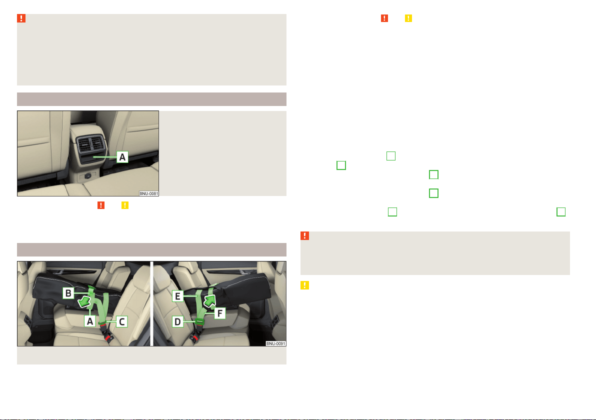
WARNING
■
During the trip to the table must be in folded-down - otherwise there is
danger of injury.
■
Do not use any cups or beakers which are made of brittle material (e.g.
glass, porcelain). This could lead to injuries in the event of an accident.
■
Never put hot beverage containers in the cup holder. If the vehicle moves,
they may spill – risk of scalding!
Storage compartment in rear centre console
Fig. 115
Non-lockable storage compart-
ment
Read and observe and on page 90 first.
Depending on equipment, a non-lockable storage compartment is located in
the rear center console » Fig. 115.
Removable through-loading bag
Fig. 116
Securing the through-loading bag
Read and observe and on page 90 first.
The removable through-loading bag (hereinafter referred to as through-load-
ing bag) is used exclusively for transporting skis and poles (max. 2 pairs).
Stowing through-loading bag and skis
›
Fold the middle rear seat backrest forwards until it rests on the seat
» page 85.
›
Place the empty through-loading bag in such a way that the end of the bag
with the zip is in the boot.
›
Push the skis and poles with the tips backwards into the through-loading
bag and secure the bag.
Securing through-loading bag and skis
›
Pull the belt with both lock tongues out of the pocket of the through-loading
bag.
›
Tighten the drawstring
A
around the skis in front of the tie base and at the
free end
B
in the direction of the arrow.
›
Plug the safety tape locking tongue
C
into the lock on the left side of the
middle seat until you can hear it click into place.
›
Plug the safety tape locking tongue
D
into the lock on the right side of the
middle seat until you can hear it click into place.
›
Tighten the safety tape
e
between the base and the tip at the free end
F
in the direction of the arrow.
WARNING
■
The total weight of the skis which are transported must not exceed 10 kg.
■
Always stow and secure the skis and the bag securely - otherwise there is
a risk of injury or accident!
CAUTION
Carefully handle the sack and skis - there is a risk of damage to the armrest.
98
Operation
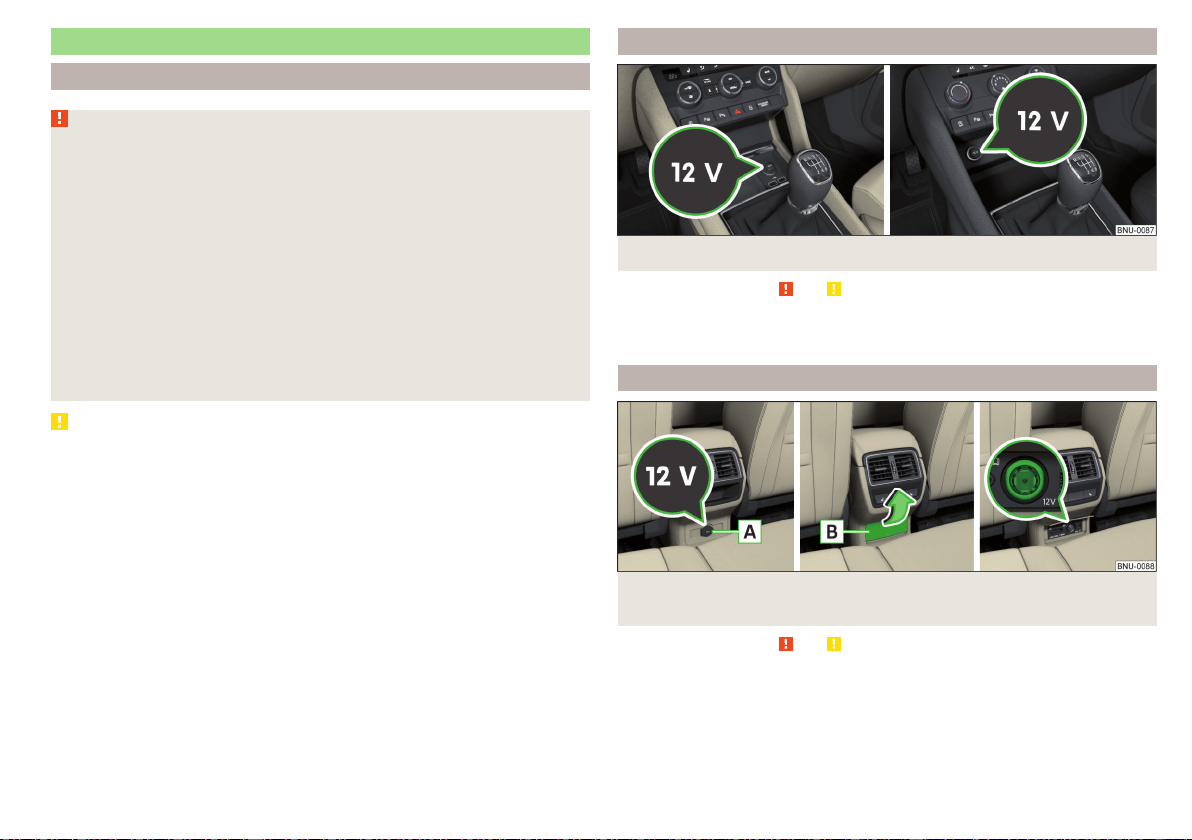
Electrical sockets
Introduction
WARNING
■
Do not place anything on the dashboard. These objects might slide or fall
down when driving and may distract you from concentrating on the traffic
– risk of accident!
■
Make sure that while driving no objects can enter the driver's footwell -
cause an accident!
■
Safely stow all devices during the journey to prevent them from being
thrown around the interior in the event of a sudden braking manoeuvre or
an accident – risk of death!
■
The devices may warm up during operation – risk of injury or fire!
■
Improper use of the power sockets and the electrical accessories can
cause fires, burns and other serious injuries.
■
The 12-Volt sockets also work if the ignition is switched off. When leav-
ing the vehicle, never leave persons who are not completely independent,
such as children, unattended in the vehicle.
CAUTION
When using the 12 volt power outlets the following notes are to be observed.
■
The sockets can only be used for the connection of approved electrical ac-
cessories with a total power consumption of up to 120 watts, otherwise the
electrical system of the vehicle may be damaged.
■
Connecting appliances when the engine is not running will drain the battery
of the vehicle!
■
Before switching the ignition on / off or before starting the engine, switch
off the devices which are connected to the sockets - there is a risk of damage
to the equipment due to voltage fluctuations.
12-volt socket in the front centre console
Fig. 117 Cover of the 12 volt power outlet
Read and observe and on page 99 first.
›
To use, open the storage compartment, remove the cover of the socket
» Fig. 117 and plug the electrical appliance plug into the socket.
12 volt socket in the rear centre console
Fig. 118
Cover of the 12 volt outlet / Open the cover of the 12 volt out-
let
Read and observe and on page 99 first.
›
Connect the plug for the electrical appliance to the socket.
99
Practical features
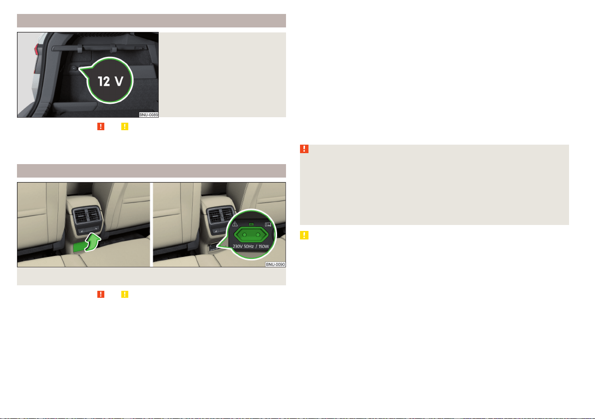
12 volt socket in luggage compartment
Fig. 119
Cover of the 12 volt power out-
let
Read and observe
and on page 99 first.
›
To use, open the cover of the socket » Fig. 119 and plug the electrical appli-
ance plug into the socket.
230-volt socket in the rear centre console
Fig. 120 Open the cover of the 230 volt outlet / 230 volt outlet
Read and observe
and on page 99 first.
The 230-volt socket has a child safety lock. When inserting the plug, the fuse
is released, the socket is activated and the warning light above the socket is
illuminates green (if this flashes red, then the socket is deactivated).
The socket works with the engine running (in STOP mode in vehicles with the
START-STOP system) and for about 10 minutes after the engine is switched
off, provided an appliance was still connected prior to switching off the engine
(the warning light flashes green)).
›
To use, fold up the cover of the socket in the direction of arrow » Fig. 120
and plug the electrical appliance plug into the socket.
An automatic deactivation of the socket can take place, for example, for
the following reasons.
▶
Excessive current.
▶
Low state of charge of the battery.
▶
High outlet temperature.
If disabling reasons no longer exist, the automatic activation of the socket can
be done.
Should no automatic activation of the socket take place, the connected devi-
ces must be disconnected from the power outlet and reconnect after a short
time.
WARNING
■
Make sure that no liquid or moisture enters into the socket - it can be fa-
tal! If fluid does manage to get into the power socket, completely dry out
the socket before reuse.
■
The child lock on the power socket is unlocked when using adapters and
extension cables which carry volts – risk of injury!
■
Do no insert any objects (e.g. knitting needles) into the contacts of the
power socket – risk of death!
CAUTION
■
The power socket can only be used for connecting approved electrical ac-
cessories with a two-pin 230V plug, with a total power uptake of up to
150 watt.
■
The plug of the electrical appliance must be plugged in up to the stop, other-
wise the child safety lock can be unlocked and the socket may be activated
but the electric appliance is still not receiving power.
■
Do not connect bulbs with neon tubes in the socket - there is a risk of dam-
aging the lamp.
■
For appliances with an independent power source (e.g. such as notebooks),
first connect the power source itself and only after that connect the appliance.
100
Operation
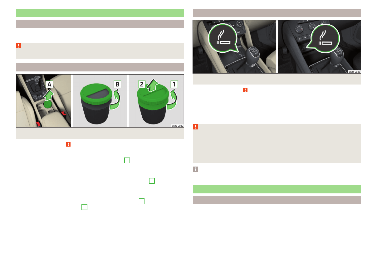
Ashtray and cigarette lighter
Introduction
The ashtray can be used for disposing of ash, cigarettes, cigars and the like etc
WARNING
Never place hot or flammable objects in the ashtray – risk of fire!
Ashtray
Fig. 121
Remove / open / disassemble ashtray
Read and observe on page 101 first.
Removing/inserting
›
Remove the ashtray in the direction of the arrow
A
» Fig. 121. Insertion
takes place in reverse order.
Open/close
›
To open the ashtray, turn the cover in the direction of arrow
B
. Closing
takes place in reverse order.
Disassembling / assembling
›
To the disassmble turn the entire cover in the direction
1
until it stops and
remove in direction of arrow
2
. Assembling takes place in reverse order.
Cigarette lighter
Fig. 122 Cigarette lighter
Read and observe on page 101 first.
›
To use, open the respective storage compartment and push in the lighter un-
til it stops » Fig. 122.
›
Wait until the glowing lighter protrudes, remove it immediately and use.
›
Put the lighter back in the socket and close the storage compartment.
WARNING
■
The cigarette lighter also works if the ignition is switched off. When leav-
ing the vehicle, never leave people who are not completely independent,
such as children, unattended in the vehicle - there is a risk of burning, fire or
damage to the vehicle interior.
■
Be careful when using the cigarette lighter - it can cause burns.
Note
The cigarette lighter socket can also be used as a 12 volt socket.
Tablet holder
Introduction
External devices (e.g. tablet, smartphone etc.) measuring min. 122 mm and
max. 195 mm can be secured in the holder.
The maximum permissible load of the compartment is 750 g.
101
Practical features
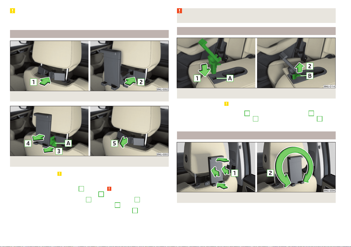
CAUTION
Never exceed the maximum permissible load of the holder - there is a risk of
damage or functional impairment.
Attaching the rear headrests
Fig. 123
Inserting: Adapter/Holder
Fig. 124 Removal: Holder / adapter
Read and observe on page 102 first.
›
Toinsert, attach the opened adapter to the guide rods of the front headrest
and clip in the direction of arrow
1
» Fig. 123 » .
›
Clip in the holder in the direction of arrow
2
into the adapter.
›
To remove, pull on the securing tab
A
in direction of arrow
3
and take the
holder out of the adapter in the direction of arrow
4
» Fig. 124.
›
Press the adapter and remove in the direction of the arrow
5
from the
guide rods of the headrest.
WARNING
Be careful with the adapter- otherwise there is a risk of finger injury.
Attach in the opening in the middle backrest
Fig. 125
Inserting holder / Removing holder
Read and observe
on page 102 first.
›
Insert the holder in the opening
A
in the direction of the arrow
1
» Fig. 125.
›
To remove, pull on the securing tab
B
in the direction of the arrow
2
and
remove the holder.
Handling the holder
Fig. 126 Tilting and rotating the holder
102
Operation
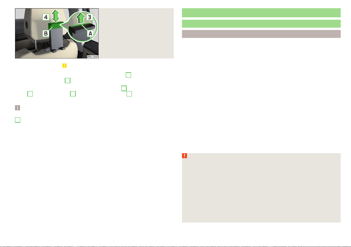
Fig. 127
Adjusting the holder size
Read and observe on page 102 first.
The holder may be by 30° in the direction of the arrow
1
tipped and by 360°
in the direction of arrow
2
turned » Fig. 126.
›
To adjust the holder size, pull out the securing tab
A
in the direction of ar-
row
3
and push the part
B
in the direction of arrow
4
to the desired posi-
tion » Fig. 127.
Note
If there is no external device in the holder, then we recommend that the part
B
is moved down fully. Otherwise, irritating noise may occur at certain
speeds.
Transport of cargo
Luggage compartment
Introduction
When transporting heavy objects, the driving characteristics change due to
the shift in centre-of-gravity. Therefore, adjust the speed and driving mode ac-
cordingly.
When transporting cargo the following the instructions must be adhered to
▶
Distribute the load evenly in the luggage compartment and secure it with
suitable lashing straps to the lashing eyes or securing nets so that they can-
not slip.
▶
Place heavy objects as far forward as possible.
▶
Tyre pressure is to match the load.
In the event of an accident, even small and light objects gain so much kinetic
energy that they can cause severe injuries.
The magnitude of the kinetic energy is dependent on the speed at which the
vehicle is travelling and the weight of the object.
Luggage compartment light
The light switches on/off when the boot lid is opened or closed.
If the boot lid is open and the ignition switched off, the light will extinguish au-
tomatically after around 10 minutes.
WARNING
■
Never exceed the maximum permissible load of the respective fasteners,
nets, hooks etc. Heavy objects were not secured sufficiently – risk of injury!
■
Do not exceed the permissible axle loads and permissible gross weight of
the vehicle – risk of accident!
■
An unfixed or improperly fixed load can slip during a sudden manoeuvre
or an accident - danger of injury!
■
Loose cargo could hit a deployed airbag and injure occupants – danger of
death!
■
When transporting loads in the luggage compartment that has been en-
larged by folding the rear seats forward, ensure the safety of the passen-
gers transported on the other rear seats .
103
Transport of cargo
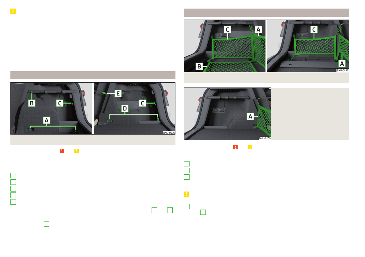
CAUTION
■
Never exceed the maximum permissible load of the respective fasteners,
nets, hooks etc. - these could be damaged.
■
Make sure that the heating elements of the rear window heater or the fila-
ments of the antenna built into the rear are not damaged by abrasive items.
■
Do not place sharp objects in the nets and storage compartments in the lug-
gage compartment - there is a risk of damage to the net as well as the com-
partments.
■
Put the items in the storage compartments carefully and not load these
punctiform - there is a risk of damage to the compartments.
Fastening elements
Fig. 128 Fastening elements: Version 1/version 2
Read and observe and on page 103 first.
The fasteners are located on both sides of the luggage compartment.
Overview of the fastening elements » Fig. 128
Lashing eyes for fastening cargo and fastening nets
Mounting bar with integrated hook only for fixing mounting networks
Hook only for fastening fixing nets
Lashing eyes for fastening the load
Lashing eyes only for fastening fixing nets
The maximum permissible static load for the individual lashing eyes
A
and
D
is 350 kg.
The lashing eye
e
ss behind the hinged backrest (does not apply to the
VarioFlexseats).
A
B
C
D
E
Fixing nets
Fig. 129 Fastening examples for nets: Version 1/version 2
Fig. 130
Fastening examples for nets:
Variant 3
Read and observe and on page 103 first.
Fastening examples for nets » Fig. 129 and » Fig. 130
Horizontal pocket
Floor net
Vertical pocket
The maximum permissible load of each of the nets is 1.5 kg.
CAUTION
For vehicles with the variable loading floor, only the crossbar can be fastened
A
» Fig. 130 behind the seats (the net can be in the lower area at the front
eyelets
D
» Fig. 128 on page 104).
A
B
C
104
Operation
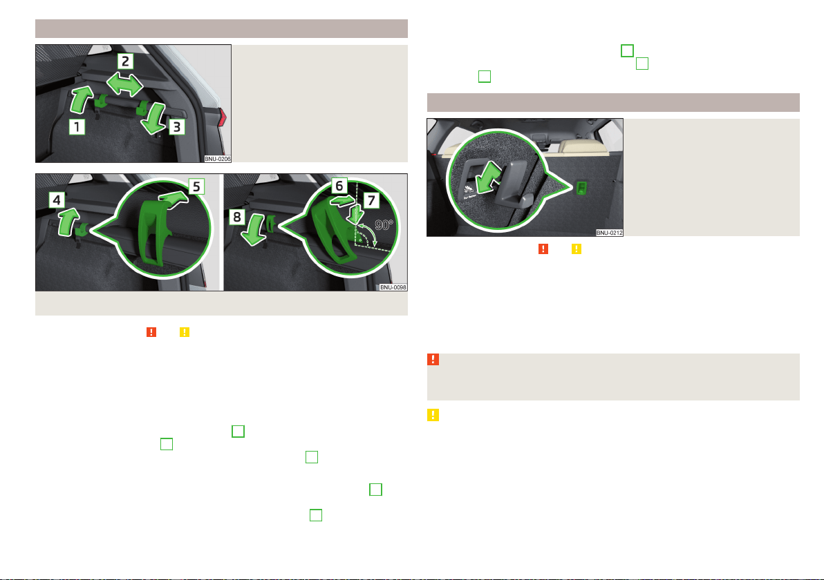
Fastening strip with moveable hook
Fig. 131
Move the hook over the fasten-
ing strip
Fig. 132
Removing/inserting hook
Read and observe and on page 103 first.
The fastening strip with movable hooks for hanging small items of luggage
(e.g. bags etc.) is located on one or both luggage compartment sides depend-
ing on the equipment fitted.
The maximum permissible load of each of the hooks is 5 kg.
Moving the hook
›
Hold hook upward in direction of arrow
1
and move to the desired position
in the direction of arrow
2
» Fig. 131.
›
Fold down the hook until it stops in the arrow direction
3
.
Removing hooks
›
Move the hook into the vertical position in the direction of the arrow
4
» Fig. 132.
›
Press and remove the hook in the direction of the arrow
5
.
Inserting hook
›
Place the hook in the direction of the slant on the fastening strip and
straighten in the direction of the arrow
6
» Fig. 132.
›
Press in the hook in the direction of arrow
7
and fold down in the direction
of arrow
8
.
Hooks
Fig. 133
Inserting hook
Read and observe and on page 103 first.
The hook can be attached to the locking eye of the
system. This is
intended to be used for holding small items of luggage (e.g. bags or similar).
›
Hang the hook on the locking eye in the direction of the arrow » Fig. 133.
Removing takes place in reverse order.
The maximum permissible load of the hook is 5 kg.
WARNING
Remove the hook before folding the rear seat backrests - there is a risk of
injury.
CAUTION
Remove the hook before folding the rear seat backrests - there is a risk of
damage to the hook as well as to the transported load.
105
Transport of cargo
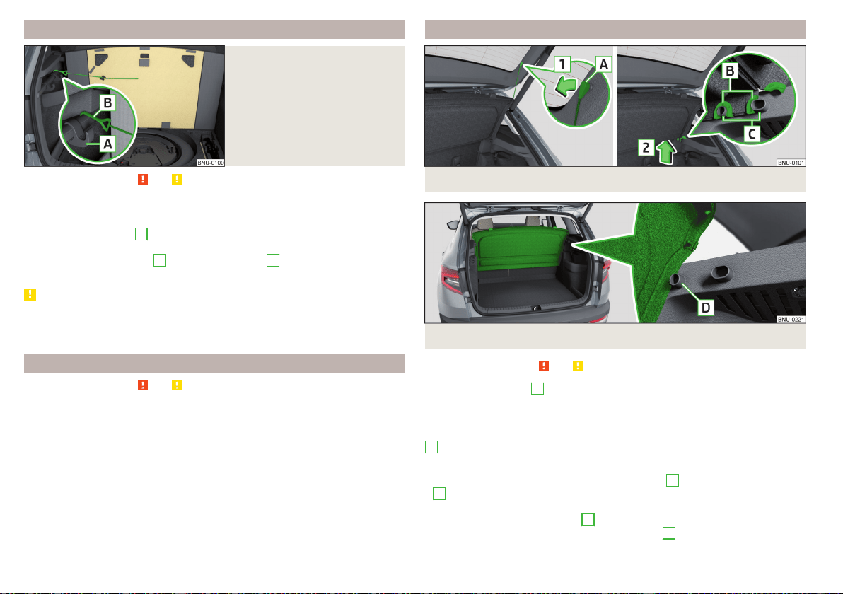
Fasten the flooring
Fig. 134
fixing the floor covering
Read and observe and on page 103 first.
The flooring can be fastened with the hook to the strip on the left side of the
luggage compartment.
›
Move the front hook
A
as far forward as possible and fold it down as far as
it will go » Fig. 134.
›
Fasten the flooring hook
B
in front of the hook
A
that has been folded
down.
CAUTION
The flooring covering may be only fastened to this strip with the boot open.
Before closing the lid, check that the flooring is not fastened to the strip -
there is a risk of damage to the luggage compartment cover.
Floor covering on both sides
Read and observe
and on page 103 first.
A double-sided floor covering can be fitted in the luggage compartment. One
side is made of fabric, the other side is washable (suitable for transporting wet
or dirty items ).
Luggage compartment cover
Fig. 135 Remove the luggage compartment cover
Fig. 136
Luggage compartment cover stowed behind the rear seats
Read and observe and on page 103 first.
If the retaining straps
A
» Fig. 135 are attached to the boot lid, then opening
the lid will also raise the luggage compartment cover (hereafter only referred
to as "cover").
The cover may be removed from the vehicle or stored in front of the bracket
D
» Fig. 136.
Removing
›
On both sides of the boot lid, unhook the straps
A
in the direction of arrow
1
» Fig. 135.
›
Hold the raised cover and press on the two sides on the underside of the
cover in the area of the recess
C
.
›
Remove the cover in the direction of the arrow
2
.
106
Operation
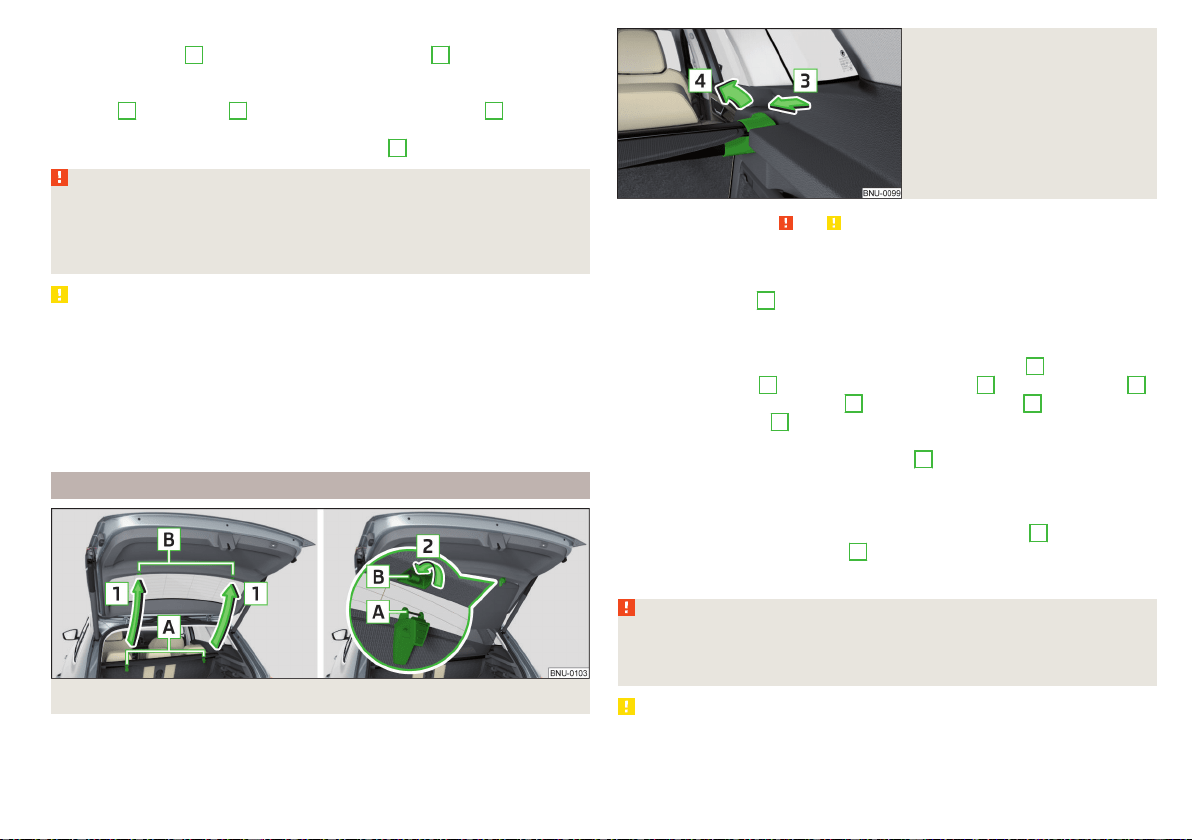
Fitting
›
Place the fixtures
B
on the cover above the brackets
C
on the side trim
» Fig. 135.
›
Press on the two sides to the upper side of the cover in the region of the
mounts
C
. The fixtures
B
must lock into place of the recess
C
on both
sides of the luggage compartment.
›
On both sides of the boot lid unhook the straps
A
.
WARNING
■
During the trip there must be no objects on the cover - risk of injury in the
event of sudden braking or a vehicle collision!
■
The luggage compartment cover stowed behind the rear seats restricts
the driver's rear view.
CAUTION
■
Observe the following instructions to avoid canting and the subsequent
damage to the cover or the side trim.
■
The cover must be inserted properly and the load must not exceed the
height of the cover.
■
The cover must not be jammed in the surrounding seal of the luggage com-
partment lid when it is in the raised position.
■
There must be no object in the gap between the cover in the raise position
and the rear backrest.
Roll-up cover
Fig. 137
Fastening roll-up cover to luggage compartment flap
Fig. 138
Removing the roll-up cover
Read and observe and on page 103 first.
The roll-up cover (hereinafter only referred to as cover) can be attached to the
luggage compartment flap.
If the cover detents
A
» Fig. 137 are fastened to the luggage compartment
flap, the cover is also pulled out simultaneously when the flap is opened.
Fastening/ releasing
›
to fasten, pull out the cover in the direction of the arrows
1
Pull out and
fasten the detents
A
in the direction of the arrow
2
in the attachments
B
.
›
To detach, unhook the detents
A
From the attachments
B
against the di-
rection of the arrow
2
.
›
Hold the cover in such a way that it can roll up slowly and without any dam-
age away from the direction of the arrow
1
.
Removing/inserting
The rolled-up cover can be removed.
›
Press on the side of the cross bar in the direction of arrow
3
and remove
the cover in the arrow direction
4
» Fig. 138.
Insertion takes place in reverse order.
WARNING
No objects should be placed on the roll-up cover - there is a risk of damage
to the cover and a risk of injury in the event of a sudden stop or a vehicle
collision!
CAUTION
Do not place sharp objects under the cover - there is a risk of damage to the
cover.
107
Transport of cargo
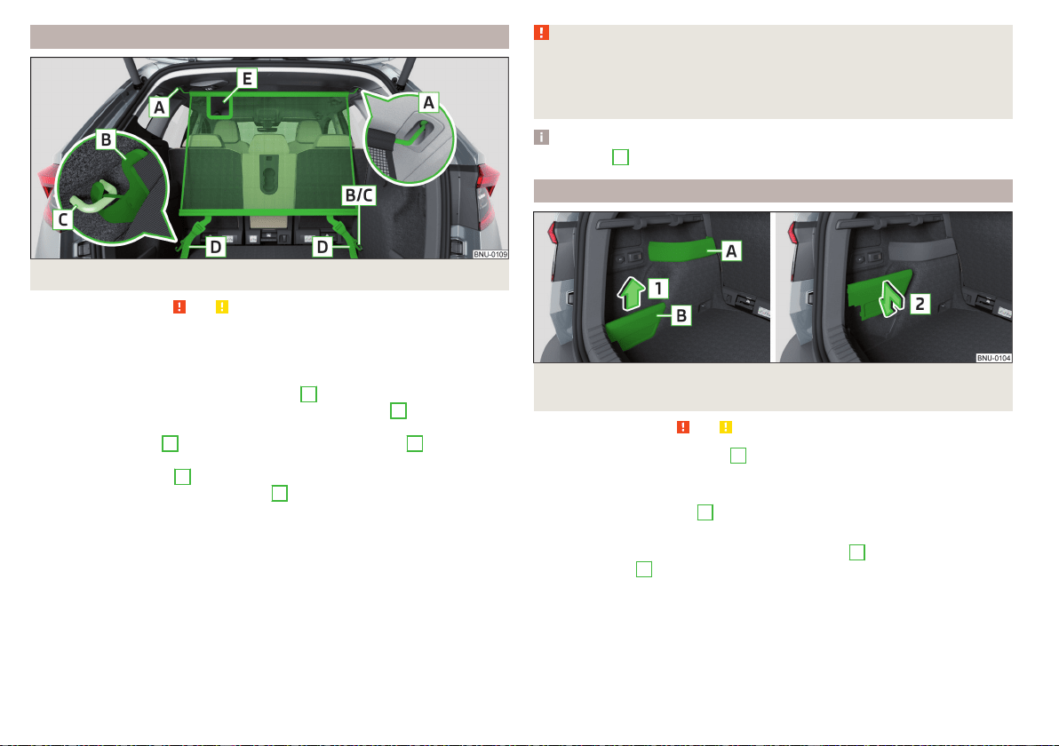
Net partition
Fig. 139
Net partition behind the rear seats
Read and observe and on page 103 first.
The net partition can either fitted behind the front seats or behind the rear
seats.
Fitting/removing net partition behind the rear seats
›
To the install the cross rod into the mount
A
, first insert it at side and then
press it forward. Insert the transverse rod into the mount
A
on the other
side of the vehicle in the same way » Fig. 139.
›
Latch the carabines
B
at the belt ends into the lashing eyes
C
.
›
In the case of vehicles with the variable loading floor,lock the carabiners into
the front lashing eyes
D
» Fig. 128 on page 104,
›
Pull the straps at the free ends tightly
D
» Fig. 139.
Removingis carried out in the reverse order.
Fitting/removing net partition behind the front seats
The process is analogous to that for behind the rear seats.
The lashing eyes for hooking the carabiner are located under the central body
pillars.
WARNING
Depending on the equipment fitted, a “safety loop” can be on the net parti-
tion belts. Never try to detach the “loop”. In the event of an accident, the
net partition could become detached and thus occupants sustaining inju-
ries.
Note
The opening
D
in the net partition is for passing the seat belt through.
Storage compartments in the luggage compartment
Fig. 140
Storage compartments, removing the cover / inserting the
cover
Read and observe
and on page 103 first.
The fixed storage compartment
A
» Fig. 140 can be on the left or right side of
the luggage compartment and is intended for placing small items up to a total
weight of 1.5 kg.
The storage compartment
B
is on both sides of the luggage compartment
and is designed for storing small objects of up to 2.5 kg. in weight in total.
The cover can be removed in the direction of arrow
1
and inserted in the di-
rection of arrow
2
.
108
Operation
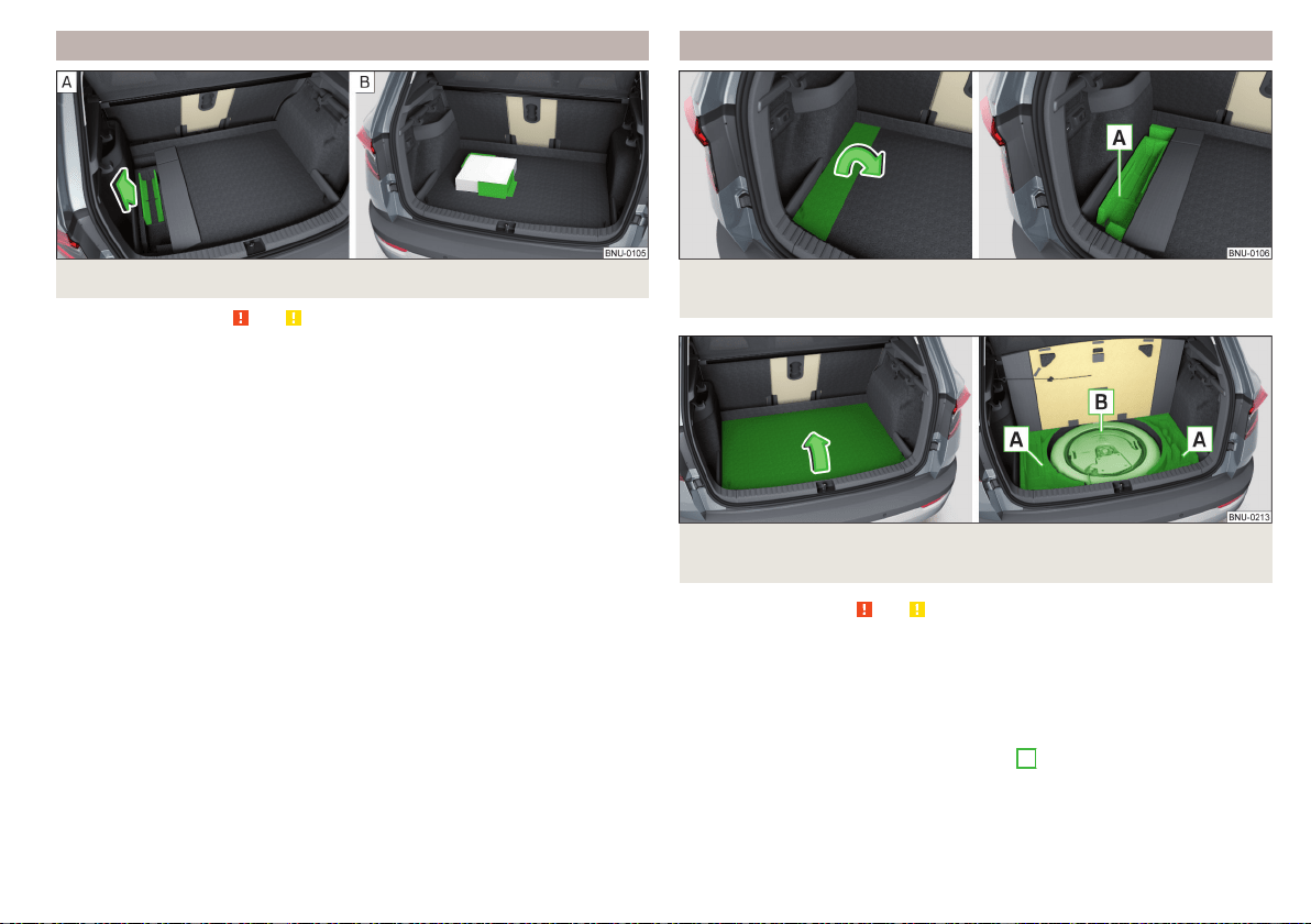
Cargo Elements
Fig. 141 Removing cargo element / Load fastening example
Read and observe and on page 103 first.
Depending on the equipment fitted, Cargo elements can be stored under the
floor in the boot.
The cargo elements are designed for mounting and securing loads with a maxi-
mum gross weight of 8 kg.
›
To reach the CargoElements, first fold the left part of the floor covering
» Fig. 142 on page 109.
›
Before use, remove theCargo elements in the direction of arrow» Fig. 141 -
.
›
Use the cargo elements to secure the load as close as possible to the rear
seats » Fig. 141 .
›
After use, stow the Cargoelements in their original position.
Storage compartments under the floor covering
Fig. 142 Variant 1: Fold floor covering/storage compartment under the
floor covering
Fig. 143
Variant 2: Lift floor covering/storage compartments under the
floor covering
Read and observe and on page 103 first.
There are storage compartments for storage of items up to a total weight of
15 kg » Fig. 142 or. » Fig. 143 under the luggage compartment flooring.
Using the storage compartments - variant 1
›
To reach the storage compartment, fold the left part of the floor covering in
the direction of the arrow » Fig. 142.
›
Stow the load in the storage compartment
A
.
›
Fold back the flooring opposite the direction of the arrow.
109
Transport of cargo

Using the storage compartments - variant 2
›
Raise the floor of the luggage compartment in the direction of the arrow and
hook the hook on the bar, on the left side of the luggage compartment
» Fig. 143.
›
Stow the cargo in the storage compartments
A
.
›
Unhook the hook and fold back the flooring opposite the direction of the ar-
row.
Depending on the equipment fitted, a storage compartment can be in area
B
.
Removable light
Fig. 144
Removable light
Fig. 145
Removing light/inserting light
Read and observe and on page 103 first.
The light is located on the left side of the luggage compartment and is used to
light the luggage compartment or as a portable light.
The lamp is fitted with magnets. As a result, this can, for example, be fitted to
the vehicle body.
Description of the light » Fig. 144
Button to turn the light that has been removed on / off
Part that lights up when the lamp is in the mount
Part that lights up when the lamp is not in the mount
If the light is in the mount, this will illuminate when the boot lid is opened.
›
To remove, hold the light in the area
D
and swivel in the direction of arrow
1
» Fig. 145.
›
To switch on the removed light, press button
A
» Fig. 144. Pressing the light
again will switch it off.
›
To insert, first of all insert the light with the rear part
E
into the mount
» Fig. 145 and then push the light in the direction of arrow
2
until it audibly
clicks into place.
If the light is not switched off and is correctly inserted in the mount, the LED
diodes in the front part of the light
C
» Fig. 144 are automatically switched off.
If the lamp is not correctly inserted into the holder, this does not light up when
the boot lid is opened and the rechargeable batteries are not charged.
Lamp charges
The lamp is supplied by three rechargeable type NiMH AAA batteries (voltage
1.2 V). The batteries are charged continuously with the engine running (to fully
charge the battery takes approximately 3 hours).
Replace batteries » page 283.
CAUTION
The light is not waterproof, so it must be protected from humidity - otherwise
there is risk of damage.
A
B
C
110
Operation
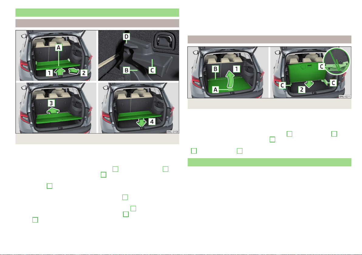
Variable loading floor in the luggage compartment (Estate)
Positions of the variable loading floor
Fig. 146
Adjusting the variable loading floor
The variable loading floor can be adjusted to the upper, lower position, or a flat
surface can be formed with the seat backrests that have been folded for-
wards.
›
Raise the variable loading floor by the handle
A
in direction of arrow
1
and
move partially in the direction of arrow
2
» Fig. 146.
›
To set in the upper position, position the variable loading floor in the front
area on edge
C
.
›
To set to the lower position Lay the variable loading floor on the luggage
compartment flooring and the front area on edge
B
.
›
To form a flat surface with seat backrests that have been folded forwards,
lay the variable loading floor in the front area on edge
D
.
›
Lay the variable loading floor in direction of arrow
3
up to the latch and the
arrow
4
.
The area under the variable loading floor can be used to stow small objects.
The maximum permissible load of the variable loading floor in the upper posi-
tion is 75 kg. For the transport of heavy loads, adjust the variable loading floor
in the lower position.
“Parking position”
Fig. 147
Adjustment options for the variable loading floor
For instance, to reach the spare wheel more easily, the variable loading floor
can be set to the “parking position”.
›
Set the variable loading floor to the upper position.
›
Lift the variable loading floor using the handle
A
in the direction of
1
. The
variable loading floor is kinked in area
B
“” » Fig. 147.
›
Push the variable loading floor that is “kinked” in the direction of the arrow
2
into the side panel
C
.
Transportation on the roof rack
The roof cross beams can be attached to the roof rail depending on the equip-
ment fitted.
Mounting and dismounting of the roof bars is carried out according to the in-
structions provided.
Roof load
The maximum permitted weight of the load incl. carriers is 75 kg.
111
Transport of cargo

WARNING
For road safety when transporting cargo on the roof rack, observe the fol-
lowing instructions.
■
Always distribute the load on the roof rack evenly and secure properly us-
ing suitable lashing straps or tensioning straps.
■
When transporting heavy objects or objects which take up a large area on
the roof rack system, the handling of the car may change as a result of the
displacement of the centre of gravity. The style of driving and speed must
therefore be adapted to the current circumstances.
■
The permissible roof load, permissible axle loads and permissible total ve-
hicle weight must not be exceeded under any circumstances – risk of acci-
dent!
CAUTION
■
Make sure that the sliding / tilting roof or the boot lid does not collide with
the roof load when opened.
■
Ensure the roof aerial is not impaired by the load being transported.
Note
We recommend that you use a roof rack from ŠKODA Original Accessories.
Heating and ventilation
Heating, manual air conditioning system, Climatronic
Introduction
The heating heats and ventilates the vehicle interior. The air conditioning sys-
tem also cools and dehumidifies the vehicle interior.
The heating effect is dependent upon the coolant temperature, thus full heat
output only occurs when the engine has reached its operating temperature.
The cooling system works under the following conditions.
The cooling system is switched on.
The engine is running.
The outside temperature is below 2 ° C.
The blower is switched on.
Fogging is prevented when the cooling system is switched on.
It is possible to boost the effectiveness of the cooling system by briefly acti-
vating the air recirculation system » page 115.
Health protection
To reduce health risks (e.g. common colds), the following instructions for the
use of the cooling system are to be observed.
▶
The difference between the indoor temperature and the outdoor air temper-
ature should not be greater than about 5 ° C.
▶
The cooling system should be turned off about 10 minutes before the end of
the journey.
▶
Once a year, the air conditioning should be disinfected by a specialist garage.
WARNING
■
The blower should always be on to prevent the windows from misting.
Otherwise there could be an accident.
■
Under certain circumstances, air at a temperature of about 5 °C can flow
out of the vents when the cooling system is switched on.
112
Operation
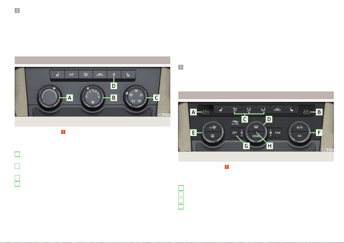
Note
■
The air inlet in front of the windscreen must be free of e.g. ice, snow or
leaves to ensure that the heating and cooling system operates properly.
■
After switching on the cooling Condensation from the evaporator of the air
conditioning may drip down and form a puddle below the vehicle. This is not a
leak!
■
If the coolant temperature is too high, the cooling system is switched off to
ensure that the engine cools down.
Heating and manual air conditioning
Fig. 148
Controls of the heating / air conditioning
Read and observe
on page 112 first.
Individual functions can be set or switched on by turning the dial or pressing
the corresponding button » Fig. 148.
Setting temperature
▶
Reduce the temperature/
Increase the temperature
Set the blower speed (Level 0: Adjust the fan speed (level 0: fan off; level
6: highest speed)
Set the direction of the air outlet » page 116
Depending on equipment fitted:
▶
Auxiliary heating and ventilation on / switch off » page 118
▶
Switching the windscreen heater on/off » page 76
Switch the cooling system on/off
Switch the rear window heating on/off » page 76
Switch recirculation on/off » page 115
A
B
C
D
When the function is switched on, the indicator lamp below the button lights
up.
Information on the cooling system
After pressing the button , the warning light underneath the button illumi-
nates even if not all conditions are met for the cooling system. The cooling
system starts to work as soon as the following conditions have been met
» page 112.
When the air distribution control is turned to position the cooling system is
activated.
Note
To ensure adequate thermal comfort, during operation of the manual air condi-
tioning there could be an increase in the engine idle speed in some circumstan-
ces.
Climatronic (automatic air conditioning)
Fig. 149 Controls the Climatronic
Read and observe on page 112 first.
Individual functions can be set or switched on by turning the dial or pressing
the corresponding button » Fig. 149.
Display the temperature setting for the left side
Display the temperature setting for the right side
Set the direction of the air outlet » page 116
Adjust fan speed (the setting is indicated by the number of illuminated
control lamps shown in the knob)
▶
Turn to the left: Reduce speed up to turning off the Climatronic
▶
Turn to the right: Increase speed
A
B
C
D
113
Heating and ventilation
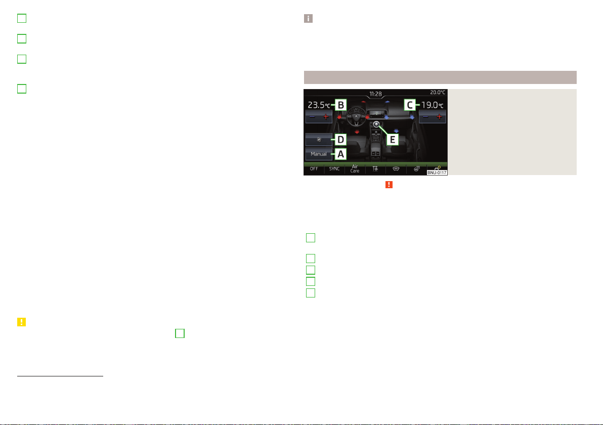
Adjust the temperature for the left side (or for both sides)
1)
▶
Reduce the temperature/ Increase the temperature
Adjust the temperature for the right side (or for both sides)
2)
▶
Reduce the temperature/ Increase the temperature
Depending on equipment fitted:
▶
Auxiliary heating and ventilation on / switch off » page 118
▶
Switching the Climatronic system off
Interior temperature sensor
Switch recirculation on/off » page 115
Intense air flow to the windscreen on / off (when switching on, the air
flow to the windows and is also switched on)
Switch the rear window heating on/off » page 76
Switching the windscreen heater on/off » page 76
Setting Climatronic in Infotainment (also operate with some functions)
Synchronize the temperature inside the entire vehicle according to the
temperature setting on the driver's side
Switching automatic mode on » page 115
Switch the cooling system on/off
When the function is switched on, an indicator lamp lights up inside or below
the button.
Setting temperature
The temperature can be set on the Climatronic control unit or in Infotain-
ment» page 114. In the range between 16 ° C to 29.5 ° C, an automatic tem-
perature control takes place.
At a temperature setting below 16°C, lights up in the temperature display,
the Climatronic functions with maximum cooling performance.
At a temperature setting over 29.5°C, lights up in the temperature display,
the Climatronic functions with maximum heating output.
CAUTION
Do not cover the interior temperature sensor
H
» Fig. 149 - the function of
the Climatronic could be affected.
E
F
G
H
Note
■
In order to ensure adequate thermal comfort, there may be an increase in en-
gine idle speed during operation of the Climatronic in some circumstances.
■
The setting of the Climatronic is stored in the active user account personali-
sation » page 55.
Operate Climatronic in Infotainment
Fig. 150
Infotainment: Example display
of the main Climatronic menu
Read and observe on page 112 first.
›
To display the main menupress the button
on the Climatronic control
unit.
Function surfaces and screen display » Fig. 150.
A
Displays the current operation mode (or set the operation mode) of
the Climatronic
B
Set the desired temperature, front - left side
C
Set the desired temperature, front - right side
D
Setting the power in operation
E
Switching on/off and adjusting the fan speed, cooling system, air dis-
tribution and air recirculation
a)
Colour representation of the air flow from the air vents at the front
(Blue colour - temperature reduction / red colour - temperature in-
crease)
Switching on/off the Climatronic
1)
Applies to left-hand drive vehicles.
2)
Applies to right-hand drive vehicles.
114
Operation

Switch the temperature synchronisation on/off throughout the entire
interior of the vehicle according to the temperature setting on the
driver's side
a)
Switch Air Care function on/off
Set the auxiliary heater and ventilation
Switch the windscreen heating on/off
a)
Turn on / off the steering wheel heater
a)
Other Climatronic settings
a)
When function is switched on, the symbol in the function surface is green.
Other Climatronic settings
Press the button on the Climatronic control panel → tap the function sur-
face
on the Infotainment screen.
■
AC profile
- Setting the operating performance
during operation (applies
to the Infotainment Swing)
■
Automatic air recirculation
- Automatic re-circulated air mode on/off
■
Automatic supplementary heater
- Quick interior heating on/off
■
Automatic windscreen heating
- Activates/deactivates the automatic windscreen
heating
Climatronic - automatic operation
Read and observe on page 112 first.
The automatic mode is used in order to maintain a constant temperature and
to demist the windows in the interior of the car.
›
To turn on, press the » Fig. 149 on page 113 .
›
To
turn off, press any button for the air distribution or change the blower
speed. The temperature regulation is continued.
Holding the button will turn on automatically.
Operating modes
Automatic mode works in three modes - moderate, medium, and intensive.
Setting the different modes is carried out via the function surface
D
» Fig. 150
on page 114.
After the automatic mode is switched on, Climatronic works in the last selec-
ted mode. The currently selected mode is displayed on the Infotainment
screen.
Air distribution control
Read and observe on page 112 first.
The recirculation mode prevents contaminated outside air getting into the In-
terior of the vehicle. In recirculated air mode air is sucked out of the interior of
the vehicle and then fed back into the interior.
›
To switch on, press the button. The warning light below the button lights
up.
›
To switch off, press the button again. The warning light below the button
goes out.
Heating and manual air conditioning system
If the air distribution control is set to position when the recirculation modes
is switched on, the recirculated-air mode is switched off. By pressing the
button, the air recirculation also in this position can be switched on again.
When the cooling system (button
) is switched on and the temperature reg-
ulator is “turned” to the left, the recirculated-air mode is switched on.
Climatronic
The Climatronic can have a sensor that measures the air recirculation mode
and automatically turns on if there is an increased concentration of pollutants
in the incoming air.
When the pollutant concentration decreases to the normal level, the recircula-
ted air mode is automatically switched off.
Automatic switch-on/switch-off of the air recirculation function can be set on
the Infotainment screen, by pressing the
button on the Climatronic and by
then pressing the function surfaces →
Automatic air recirculation
on the Infotain-
ment screen.
A shut-off of the air recirculation function is carried out by pressing the
button, possibly depending on the moisture conditions in the vehicle interior.
WARNING
The air recirculation cannot be switched on for a longer period of time be-
cause there is no supply of fresh air from the outside. “Stale air” may result
in fatigue in the driver and occupants, reduce attention levels and also
cause the windows to mist up. As soon as the windows mist up, turn the air
recirculation mode off immediately - there is a risk of accident!
115
Heating and ventilation
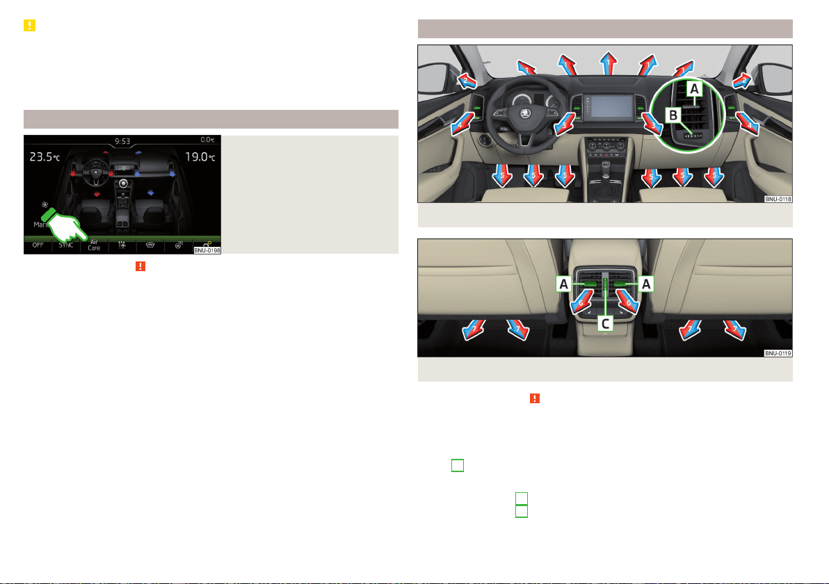
CAUTION
We recommend not smoking in the vehicle when the recirculating air opera-
tion is switched on. The smoke sucked from inside the vehicle is deposited on
the evaporator of the air conditioner. This produces a permanent odour when
the air conditioning system is operating which can only be eliminated through
considerable effort and expense (replacement of compressor).
Climatronic - Air Care function
Fig. 151
Example display of the Air Care
function
Read and observe on page 112 first.
The Air CareFunction reduces pollutant penetration contained in the outside
air into the vehicle.
When the function is activated, the air in the vehicle is circulated and cleaned
at the same time. The cleaning process is displayed by the zones displayed in
the Infotainment screen.
›
To switch on/off, press the
key on the Climatronic control panel, and
then tap the function surface
→
Active
on the Infotainment screen
» Fig. 151.
To ensure correct Air Care functioning, all doors and windows including the
panoramic sliding/tilting roof must be closed.
When opening a door or a window, the corresponding message is displayed in
the Infotainment screen.
Air outlet vents
Fig. 152
Air outlet vents
Fig. 153 Air vents at the rear
Read and observe
on page 112 first.
The direction of airflow can be adjusted using the air outlet vents 3, 4
» Fig. 152 and 6 » Fig. 153, and the vents can be opened and closed individually.
The setting of the airflow direction is carried out by moving the adjustment el-
ement
A
» Fig. 152 or » Fig. 153 in the desired direction.
Opening
›
Turn the regulator
B
» Fig. 152 downwards.
›
Turn the regulator
C
» Fig. 153 upwards.
116
Operation
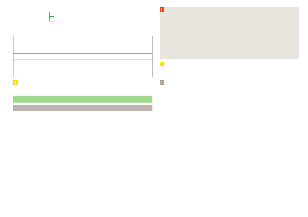
Closing
›
Turn the regulator
B
» Fig. 152 downwards.
›
Turn the regulator
C
» Fig. 153 downwards.
Depending on the setting of the air distribution, the air stream comes out of
the following air vents.
Set the direction of the air
outlet
Air vents » Fig. 152 and » Fig. 153
1, 2, 4
1, 2, 4, 5. 7
3, 4, 6
4, 5, 7
3, 4, 5, 6. 7
CAUTION
Do not cover the air vents - the air distribution could be compromised.
Auxiliary heating (auxiliary heating and ventilation)
Introduction
The auxiliary heating heats the vehicle interior as well as the engine. For heat-
ing, fuel is consumed from the fuel tank.
The auxiliary ventilation enables fresh air to flow into the vehicle interior with
the engine switched off, whereby the interior temperature is effectively de-
creased (e.g. with the vehicle parked in the sun).
The auxiliary heating (auxiliary heating and ventilation) (referred to just as auxil-
iary heating in the following) ensures the heating / ventilation depending on
the setting of the air conditioning and the air outlet vents before switching off
the ignition.
WARNING
■
The auxiliary heating must never be operated in closed rooms (e.g. garag-
es) – risk of poisoning!
■
The auxiliary heating must not be allowed to run during refuelling – risk of
fire.
■
The exhaust pipe of the auxiliary heating is located on the underside of
the vehicle. If you want to use the auxiliary heating, do not park the car in
places where the exhaust fumes can come into contact with flammable
materials such as dry grass, undergrowth, leaves, spilled fuel etc. - risk of
fire.
CAUTION
The air inlet in front of the windscreen must be free (e.g. of ice, snow or
leaves) to ensure that the auxiliary heating operates properly.
Note
■
The auxiliary heating only switches the blower on, if it has achieved a coolant
temperature of approx. 50 °C.
■
In the engine compartment, water vapour may form during the operation of
the heater.
117
Heating and ventilation
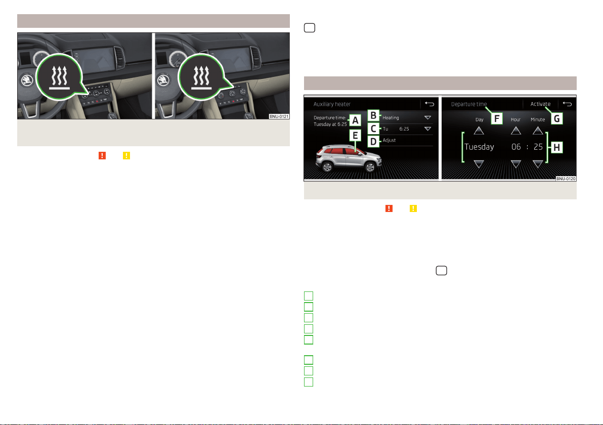
Power on / off
Fig. 154 Button for switching on / off (Climatronic / manual air condi-
tioning)
Read and observe and on page 117 first.
Functional requirements of the auxiliary heating.
The charge state of the vehicle battery is sufficient.
The fuel supply is adequate (the warning light
is not illuminated in the
instrument cluster).
Manual on / off
▶
Using the
button on the operating part of the air conditioning» Fig. 154.
▶
Using the
(switch on) /
(switch off) button on the remote control opera-
tion.
Automatic on / off
▶
Via an automatically programmed and activated pre-set time in Infotainment.
▶
According to the environmental conditions.
Switching off the auxiliary heating takes place automatically when there is a
lack of fuel (warning light in the instrument cluster lights up).
After switching off the system, the coolant pump and the auxiliary heating will
continue running a little while longer in order to burn the remaining fuel in the
heating.
Setting automatic on / off
Climatronic: On the Climatronic, press the button → tap the function
surface on the Infotainment screen. There will be a display of the last set oper-
ating mode with the option to change this.
Individually controlled air conditioning: In the Infotainment system, in menu
/ tap die function surface.
Then follow the instructions on the Infotainment screen.
When automatic switching on is activated, the warning light in the symbol
button lights up for about 10 seconds after the ignition is turned off » Fig. 154.
Operation in Infotainment
Fig. 155
Auxiliary heater: Main menu/set preset time
Read and observe and on page 117 first.
Call up the main menu
›
On the Climatronic, press the button
→ Tap the function surface
in the
Infotainment screen.
Or vehicles with manual air conditioning:
›
In the Infotainment system, in menu
/ tap die function surface.
Function surfaces and screen display » Fig. 155
Departure time - Day and time when the vehicle is to be ready for use
Setting the operating mode (heating / ventilation)
List of pre-selected times, activation / deactivation of the preset time
Set the preset times 1-3 and the duration (10-60 minutes)
When heating the windows are shown in red / with continuous aeration,
the windows are shown in blue
Currently displayed preset time
Activation of the currently displayed preset time
Setting the departure time: Day, hour, minute
A
B
C
D
E
F
G
H
118
Operation
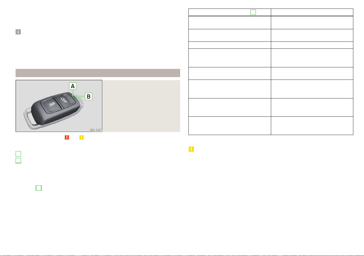
Only one preset time can be active. The activated preset time will be deactiva-
ted again after it has started automatically. For the next start, activate one of
the preset times.
Note
■
In the selection of the day in the preset time, there is an option between
Sunday and Monday without the specified day. If this setting is selected, the
vehicle will be ready for use at the selected time, regardless of the current day.
■
If a different time is set, the activated preset time is automatically deactiva-
ted. The preset time must be reactivated.
Radio remote control
Fig. 156
Radio remote control
Read and observe and on page 117 first.
Description of the remote control » Fig. 156
Warning light
Aerial
Switch on the auxiliary heating
Switch off the auxiliary heating
To switch the remote control on or off, hold the remote control vertically, with
the aerial
B
» Fig. 156 pointing upwards. Do not cover the antenna with the
fingers or the palm of the hand.
The auxiliary heating can only be switched on/off safely using the remote con-
trol if the distance between the radio remote control and the vehicle is at least
2 m.
A
B
Display warning light
A
Meaning
Lights up green for 2 seconds.
The auxiliary heating has been switch-
ed on.
Lights up red for 2 seconds.
The auxiliary heating has been switch-
ed off.
Slowly flashes green for 2 seconds. The ignition signal was not received.
Quickly flashes green for 2 seconds.
The auxiliary heating is blocked, e.g.
because the tank is nearly empty or
there is a fault in the auxiliary heating.
Flashes red for 2 seconds.
The switch off signal was not re-
ceived.
Lights up orange for 2 seconds, then
green or red.
The battery is weak, however the
switching on or off signal was re-
ceived.
Lights up orange for 2 seconds, then
flashes green or red.
The battery is weak, however the
switching on or off signal was not re-
ceived.
Flashes orange for 5 seconds.
The battery is discharged, however
the switching on or off signal was not
received.
Replace the battery
» page 283.
CAUTION
■
The remote control must be protected against moisture, severe shocks and
direct sunlight - Otherwise, there is a risk of damage to the remote control.
■
The range of the remote control with a charged battery is a few hundred me-
tres (depending on obstructions between the remote control and the vehicle,
weather conditions, the battery condition etc.).
119
Heating and ventilation
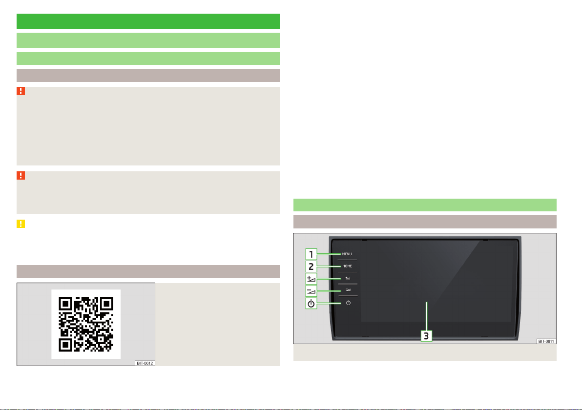
Infotainment
Introductory information
Important information
Introduction to the subject
WARNING
■
Only use Infotainment in such a way that you have control of the vehicle
in every traffic situation (e.g. Do not write text messages while driving, do
not link or connect the telephone, do not work with the contact list, do not
enter any destinations, do not connect WLAN or SmartLink etc.)- Other-
wise there is a risk of an accident!
■
Always route the connection cable of the external device such that is
does not restrict you when driving.
WARNING
■
Adjust the volume to ensure that acoustic signals from outside the vehi-
cle, e.g. sirens from emergency vehicles, can be heard at all times.
■
High volumes can cause hearing damage!
CAUTION
In some countries, some Infotainment functions can no longer be selected
when the vehicle is running faster than a certain speed. This is not a malfunc-
tion, but complies with the national legal regulations.
Mobile devices and applications
Fig. 157
QR code with reference to web
pages for checking the compati-
bility of devices
The availability of some of the functions described in this Owner's Manual
depends on the type of device to be connected and the applications instal-
led in it.
Compatibility
On the ŠKODA pages, check to see if Infotainment is compatible with the se-
lected mobile devices. This verification is carried out by reading the QR code
» Fig. 157 or after typing the following address into the web browser.
http://go.skoda.eu/compatibility
Applications
Applications can be installed in external devices (e.g. Mobile, tablet) making it
possible to display additional information on the Infotainment screen or to op-
erate Infotainment.
Due to the variety of applications as well as their ongoing development, the
available applications may not work in all external devices. ŠKODA AUTO can
accept no liability for their proper function.
The range of available applications and their functionality is dependent on the
Infotainment model, vehicle and region.
Infotainment Overview
Description - Infotainment Columbus
Fig. 158 Infotainment Columbus
120
Infotainment
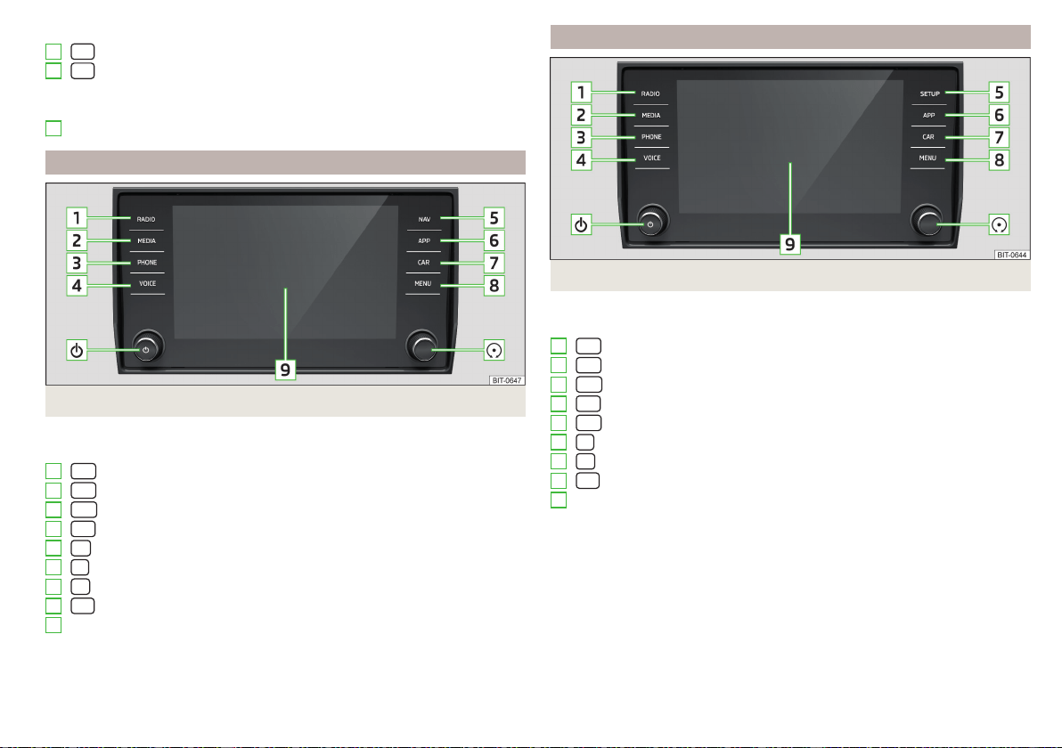
Switches Infotainment on/off
- Overview of Infotainment menus » page 126
- Display of the main screen “HOME” » page 127
Volume up
Volume down
Touchscreen » page 122
Description - Infotainment Amundsen
Fig. 159
Infotainment Amundsen
Left control dial for switching Infotainment on and off; volume adjustment
Control dial for calls and confirmations
- Radio menu » page 142
- Media menu » page 145
- Telephone menu » page 156
Voice control » page 128
- Navigation menu » page 174
- SmartLink menu » page 170
- Vehicle system settings » page 196
- Overview of Infotainment menus » page 126
Touchscreen » page 122
1
2
3
1
2
3
4
5
6
7
8
9
Description - Infotainment Bolero
Fig. 160
Infotainment Bolero
Left control dial for switching Infotainment on and off; volume adjustment
Control dial for calls and confirmations
- Radio menu » page 142
- Media menu » page 145
- Telephone menu » page 156
- Voice control » page 128
- Infotainment settings » page 131
- SmartLink menu » page 170
- Vehicle system settings » page 196
- Overview of Infotainment menus » page 126
Touchscreen » page 122
1
2
3
4
5
6
7
8
9
121
Introductory information
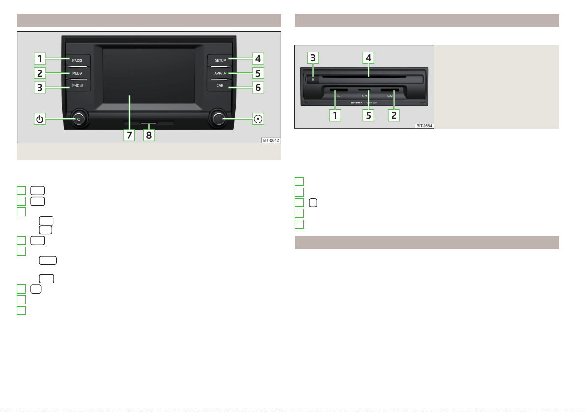
Description - Infotainment Swing
Fig. 161
Infotainment Swing
Left control dial for switching Infotainment on and off; volume adjustment
Control dial for calls and confirmations
- Radio menu » page 142
- Media menu » page 145
Depending on equipment fitted:
▶
- Telephone menu » page 156
▶
- Muting
- Infotainment settings » page 139
Depending on equipment fitted:
▶
- Menu SmartLink (Press)/turn on/off the voice control function
SmartLink (hold) » page 170
▶
- Sound settings » page 139
Vehicle system settings » page 196
Touchscreen » page 122
SD card slot » page 148
1
2
3
4
5
6
7
8
External module
Does not apply to Infotainment Swing.
Fig. 162
Example of an external module
Depending on the vehicle configuration and infotainment type, all the follow-
ing elements must not be included in the external module.
The external module is located in the storage compartment on the front pas-
senger side.
SD1 card slot
SD2 card slot
- CD / DVD eject button
CD / DVD case
SIM card slot
Touch screen
The Infotainment can be operated by lightly touching the screen with your
fingers.
The brightness level of the screen can be set by » page 131 or » page 139.
To protect the screen, a suitable protective film for touch screens can be used.
The screen can be cleaned with a soft cloth, spirits if necessary.
1
2
3
4
5
122
Infotainment
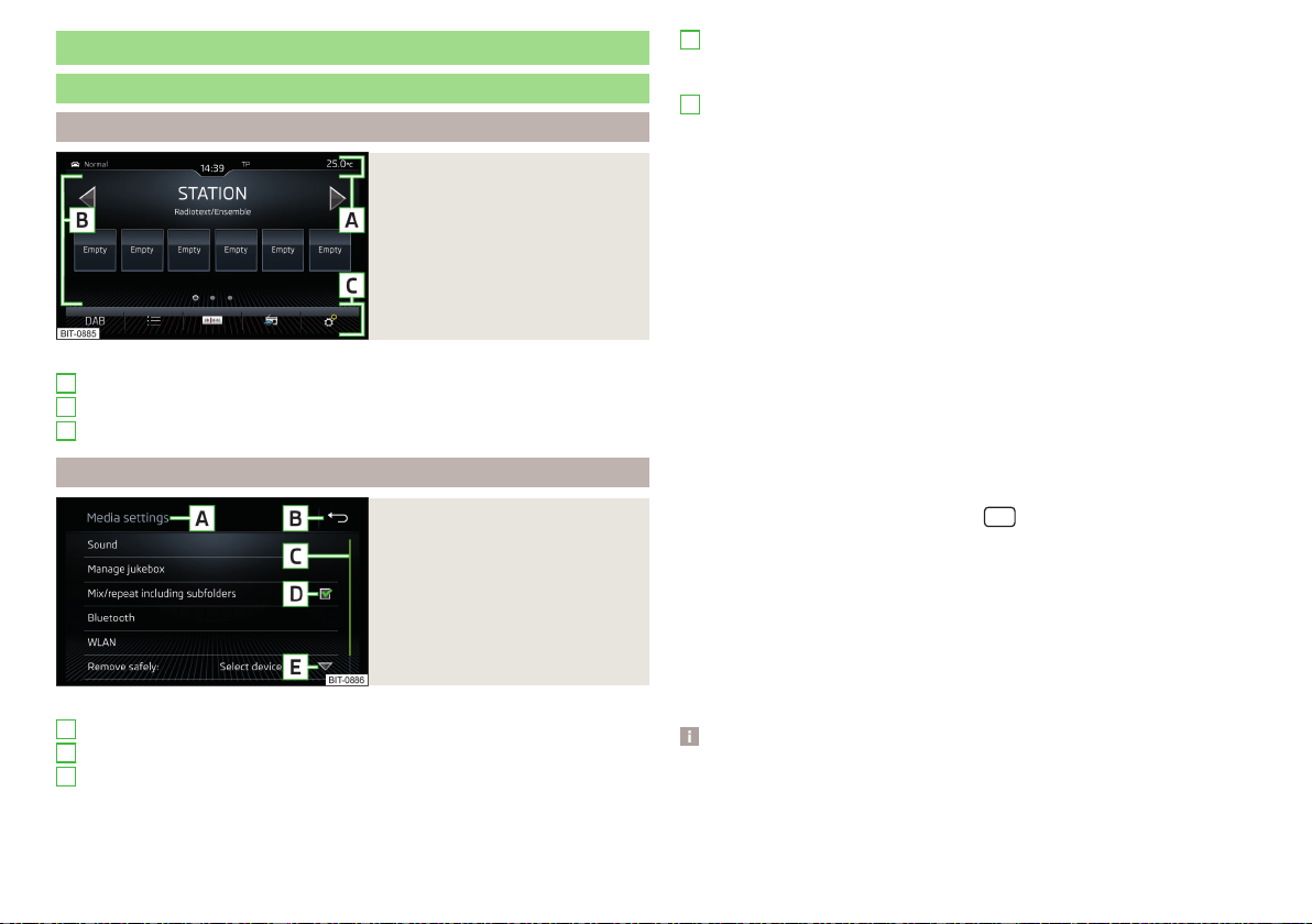
Infotainment operation
Infotainment operation
Screen areas
Fig. 163
Screen areas
Description of the display » Fig. 163
Status line with time and outdoor temperature data and other information
Information and the operation of the current menu
Function surfaces of the current menu
Operation principles
Fig. 164
Screen display
Description of the display » Fig. 164
Identification of the current menu
Return to the higher-level menu
Scroll symbol – moving in the menu is possible by moving fingers up or
down on the scroll symbol
A
B
C
A
B
C
Menu item with “Checkbox”
▶
- Function is switched on
▶
- Function is switched off
Opens a sub-menu of the menu item with a “pop-up window”
Functional surfaces
The screen areas which confirm a function or a menu are called “function sur-
faces”.
▶
White text - the surface is active and thus selectable
▶
Grey text - the surface is inactive and therefore not selectable
▶
Green frame - currently selected surface
Selecting menu/menu item/function
▶
Drag your finger over the screen in the required direction.
▶
By moving your finger over the slider
▶
Turning the knob
(not applicable to Infotainment Columbus).
Confirm menu/menu item/function
▶
By tapping on the function surface.
▶
By pressing the knob
(not applicable to Infotainment Columbus).
Returning to higher-level menu
▶
By tapping on the function surface
.
▶
By tapping on the screen outside of the “pop-up window”.
▶
By pressing the corresponding button next to the screen (e.g. in the Media
menu, by pressing the sensor field/the
button) (not applicable to Info-
tainment Columbus).
Select the menu item / function value
▶
- Selected menu item/function value
▶
- Deselected menu item/function value
Set value
▶
By tapping on the function surface or in the bottom of the screen.
▶
By touching or moving your finger over the scale.
▶
Turning the knob (not applicable to Infotainment Columbus).
Note
Depending on the equipment fitted, Infotainment can also be operated using
the buttons on the multifunction steering wheel. Further information
» page 50.
D
E
123
Infotainment operation
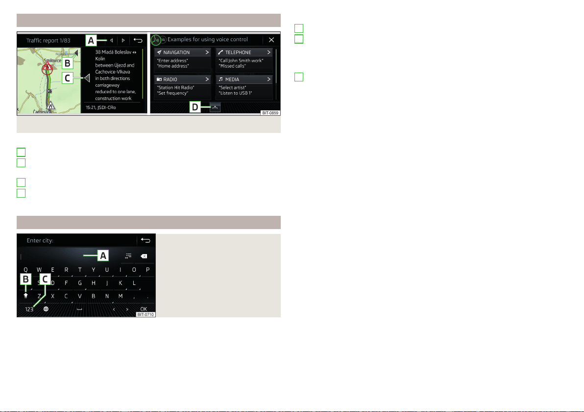
Operating the menus
Fig. 165 Operating the menus
Operating the menus » Fig. 165
Browse the menu- List entries
Enlargement/reduction of the menu window (applies to the infotainment
Columbus)
Expand/reduce the menu window (applies to Infotainment Amundsen)
Open/close the menu window (does not apply to Infotainment Swing)
Close the menu window
Alphanumeric keyboard
Fig. 166
Example of the keyboard display
The alphanumeric keypad is used to enter for letters, numbers and characters.
A
B
C
D
Description of the alphanumeric keyboard » Fig. 166
Input line
Context-dependent:
▶
- Switch from upper case to lower case and vice versa
▶
- Switch to special characters
▶
- Switch to numbers
Context-dependent:
▶
- Switch to numbers
▶
- Switch to Latin letters
▶
- Switch to Cyrillic letters
- Display of visited entries (the number of visited entries is displayed in the
function surface)
Erase the entered characters
By holding the variants of each type are displayed.
Switch between keyboards with specific characters of the selected
languages » page 132 or » page 139
Enters a blank
Move the cursor within the input line to the left
Move the cursor within the input line to the right
Confirmation of the entered number
Search
While entering characters, a search is made for corresponding entries.
The entry such as a telephone contact to be searched for must be entered
along with the special characters (diacritics).
By tapping on the function surface a list of matching entries opens.
A
B
C
124
Infotainment
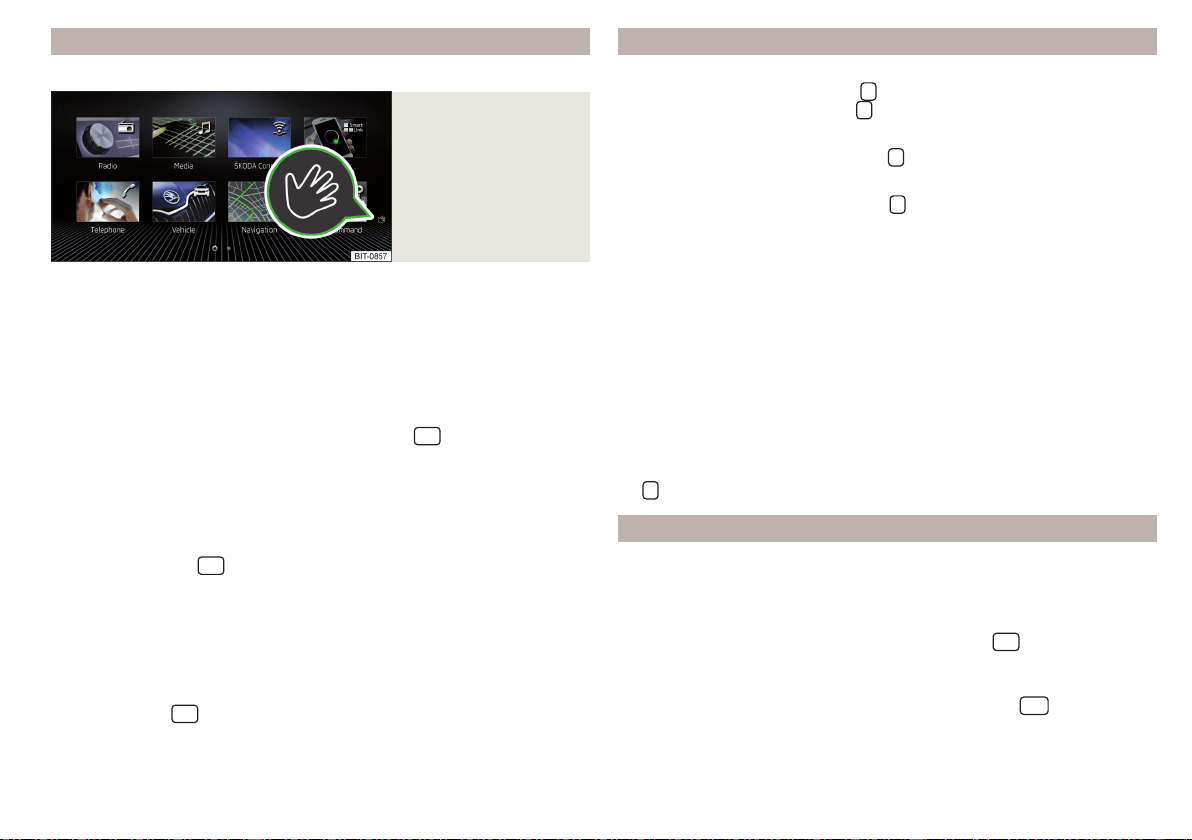
Gesture control
Only valid for Infotainment Columbus.
Fig. 167
Example of a menu with
gesture control
Some menus of Infotainment Columbus can be operated by means of hand
gestures by slowly moving the hand back and forth approximately 8 cm above
the Infotainment screen.
The menus with gesture control feature the symbol
in the lower right-hand
corner » Fig. 167.
Switching the function on / off
The gesture control function is switched on at the factory.
›
To switch the function on/off, tap the sensor field
and then the func-
tion surface
→
Screen
→
Hand gesture
.
Acoustic confirmation of gesture
When the function is switched on, Infotainment indicates that a gesture has
been recognised by means of an acoustic signal.
›
To activate/deactivate the acoustic confirmation of a recognised gesture,
tap the sensor field
and then the function surface →
Screen
→
Audible
hand gesture feedback
.
Visual confirmation of the gesture
When the function is switched on and a gesture has been recognised, Infotain-
ment shows an animation with the bottom bar moving in the direction of the
hand movement.
›
To activate/deactivate the visual confirmation of a recognised gesture, tap
the sensor field
and then the function surface →
Screen
→
Visual hand
gesture feedback
.
Restart Infotainment Switching Infotainment on / off
Only valid for Infotainment Columbus.
›
To switch on Infotainment, press
.
›
To switch off Infotainment, hold
.
Applies to Infotainment Amundsen, Bolero, Swing
›
To switch on/off Infotainment, press
.
Automatic switch-on of Infotainment
If Infotainment was not turned off with
before the ignition was turned off,
it will automatically switch on when the ignition is switched on.
Automatic switch-off of Infotainment
If the vehicle key is pulled out of the ignition lock while Infotainment is switch-
ed on, Infotainment will switch off automatically.
If the vehicle is fitted with the starter button, Infotainment will switch off au-
tomatically after the engine is switched off and the door is opened.
With the ignition off, Infotainment will automatically turn off after about 30
minutes.
Infotainment turns off automatically under certain circumstances. Infotain-
ment informs of this via a text message on the Infotainment display.
Restart of Infotainment
If Infotainment does not respond (if it “freezes”) This can be restarted by hold-
ing
for longer than 10 s.
Show time and date on the screen
Standby mode
With the ignition off and infotainment (standbyMode), it is possible to display
the time and date in the Infotainment screen.
Applies to Infotainment Columbus, Amundsen, Bolero
▶
To switch the time and date display on/off, press the
sensor field and
then tap the function surface →
Screen
→
Show clock in standby mode
.
Applies to Infotainment Swing
▶
To activate / deactivate the time and date display button
press, then the
function surface
screen
→
Show clock in standby mode
Tap.
The display mode can be changed by moving your finger sideways across the
screen (does not apply to Infotainment Swing).
125
Infotainment operation
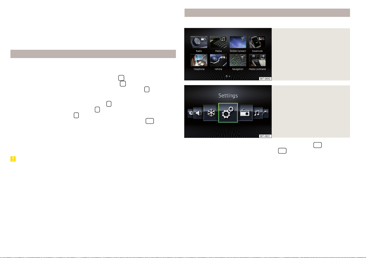
"Screen off" mode
With the ignition on and functions
Switch off screen (in 10 seconds)
and
Display clock
when screen is off
» page 131 enabled, it is possible to display the time and date
when the Infotainment screen is switched off.
The display type depends on the display mode selected in standby mode (does
not apply to the Infotainment Swing).
Adjusting the volume
Every change in volume is displayed on the screen.
Only valid for Infotainment Columbus.
›
To increase the volume, tap the function surface
.
›
To decrease the volume, tap the function surface
.
›
To activate/deactivate the mute setting, tap the sensor field
.
Applies to Infotainment Amundsen, Bolero, Swing
›
To increase the volume, turn the controller
clockwise.
›
To reduce volume, turn the controller
anticlockwise.
›
To mute, turn the controller
to the left to 0.
›
or: To activate/deactivate the mute setting, press the button
(applies
to Infotainment Swing).
The following symbol appears on the screen when the sound is muted
.
If, at the time of muting, sound is being played from a source in the Media
menu, then the playback is stopped.
CAUTION
■
High volumes can cause sound resonance in the vehicle.
■
When changing or connecting an audio source, this may cause sudden
changes in volume. Reduce the volume before changing or connecting an au-
dio source.
Infotainment menus
Applies to Infotainment Columbus, Amundsen, Bolero.
Fig. 168
Overview of Infotainment me-
nus: Grid display
Fig. 169
Overview infotainment menus:
horizontal display
›
To display the overview of Infotainment menus, press the
sensor field.
›
To set the display mode, press the button
sensor field and then tap the
function surface
→
Screen
→
Menu:
.
›
Select the
Grid display
» Fig. 168 or
Horizont. display
» Fig. 169 option.
Overview of Infotainment menus
Radio menu » page 142
Media menu » page 145
ŠKODA Connect Online Services » page 13
SmartLink menu » page 170
With a connection established to an external device, the current con-
nection is shown instead of a symbol
▶
Android Auto
» page 171
▶
-
Apple CarPlay
» page 171
▶
-
MirrorLink®
» page 172
Telephone menu » page 156
126
Infotainment
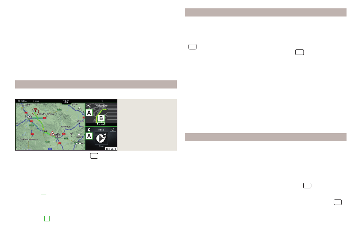
Vehicle system settings » page 196
Navigation menu » page 174 (Applies to Infotainment Columbus, Amund-
sen)
List of traffic reports (TMC) (applies to Infotainment Columbus, Amund-
sen) » page 194
Media Command menu (applies to Infotainment Columbus, Amundsen)
» page 154
Images menu » page 151
Sound settings » page 131
Air conditioning menu » page 114
Infotainment settings » page 131
Main screen “HOME”
Only valid for Infotainment Columbus.
Fig. 170
HOME main screen
›
To display the information, tap the
sensor field.
The “HOME” main screen contains three windows.
In the left window » Fig. 170 the navigation map is always displayed. By tapping
the screen within this window, the Navigation main menu is displayed.
The contents of the window to the right can be changed. By holding the func-
tion surface
A
, the list of selectable menus is displayed.
By tapping the function surface
A
or by double-finger tapping on the screen
within each window, the appropriate main menu is displayed.
If there are other pages in the window, then the associated symbols are dis-
played in area
B
. By moving your finger across the screen within each win-
dow, it is possible to display these pages.
Configuration wizard
The configuration wizard is automatically displayed if there are at least two
non-selected menu items after turning on Infotainment, or if a new personali-
sation user account is selected.
›
For manual display in Infotainment Columbus, Amundsen and Bolero, tap the
sensor field and then tap on the function surface →
Configuration wizard
.
›
For manual displayin Infotainment Swing, press the
button, then tap the
function surface
Configuration wizard
.
The Configuration wizard allows you to set the following menu items in se-
quence.
Identification of personalisation user account » page 55
Time and date format
Storing the radio transmitter with the reception signal that is currently
the strongest
Pairing and connecting a phone to Infotainment
Home address (applies to Infotainment Columbus, Amundsen)
Setting the online services ŠKODA Connect
The selected menu item is provided with the
symbol.
Operating using an application in the external device
Some Infotainment functions can be operated using an application in the sup-
ported external device.
For complete application functionality, external devices data transmission
must be activated and, if necessary, the Infotainment control system must be
approved using the application.
Applies to Infotainment Columbus, Amundsen, Bolero
›
Activate data transfer in Infotainment. To do so, tap the
sensor field and
then the function surface →
Mobile device data transfer
→
Activate data transfer
for ŠKODA apps
.
›
Release Infotainment operation using the application. To do so, tap the
sensor field and then the function surface →
Mobile device data transfer
→
Op-
eration via apps:
→
Confirm
/
Allow
.
›
Connect Infotainment to an external device via WLAN» page 168.
›
In the external device, launch an application for Infotainment operation (e.g.
ŠKODA Media Command).
127
Infotainment operation
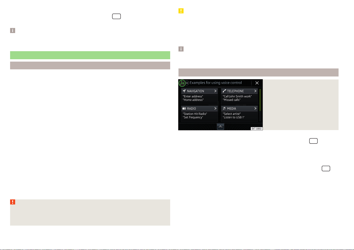
Applies to Infotainment Swing
›
Activate data transfer in Infotainment. Press the
button and then tap on
the function surface
Activate data transfer for ŠKODA apps
.
Note
The description of Infotainment operation ŠKODA Media Command is part of
the application.
Voice control
Introduction to the subject
Applies to Infotainment Columbus, Amundsen, Bolero.
The navigation, telephone, radio and media menu can be operated by voice
commands.
The voice control system can be used either by the driver or by the front pas-
senger.
Function requirements for voice control
Infotainment is switched on.
There will be no telephone call using a phone connected to Infotainment.
The parking aid is not active.
Requirements for optimum voice command recognition
▶
The voice commands must only be issued when the
symbol is displayed on
the Infotainment screen and the input tone has completely faded.
▶
Speak at your normal volume without intonation and long pauses.
▶
Avoid bad pronunciation.
▶
Close the doors and windows in order to avoid disturbing environmental in-
fluences on the function of the voice commands.
▶
You are recommended to speak louder at higher speeds, so that the sound of
your voice is not drowned out by the increased ambient noise.
▶
During voice control, limit additional noise in the vehicle, e.g. passengers talk-
ing at the same time.
WARNING
The emergency number should be dialled manually. Your voice commands
may not be recognised in such situations. The telephone connection may
not be established or the connection may take too much time to complete.
CAUTION
■
The messages are generated by Infotainment. Flawless clarity (e.g. road or
city name) cannot always be guaranteed.
■
For some Infotainment languages, there is no voice control available. Info-
tainment indicates this fact through a text message that is displayed on the
screen after setting the Infotainment language.
Note
During voice control, no nav. announcements and traffic announcements are
played.
Voice control on / off
Fig. 171
Voice control: Main menu
Switching on
›
Press the button
on the multifunction steering wheel or the
sensor
field on the Infotainment (does not apply to Infotainment Columbus).
the main menu is displayed » Fig. 171.
Switching off
›
Press the button twice on the multifunction steering wheel or the
sensor field on the Infotainment twice (does not apply to Infotainment Co-
lumbus).
›
or: Issue the voice command “End voice control”.
128
Infotainment
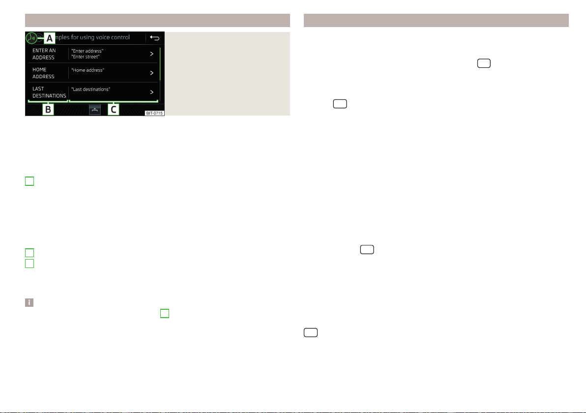
Operation principle
Fig. 172
Example of screen display
In the voice control main menu » Fig. 171 on page 128 There are basic voice
commands for the individual menus.
Other voice commands are displayed by tapping the respective function sur-
face, if required, by issuing the name of respective command (e.g. navigation).
The screen shows the following » Fig. 172.
Context-dependent:
▶
The system is waiting for a voice command
▶
The system recognises a voice command
▶
The system plays a message
▶
Voice command entry was stopped
Available list entries
Possible voice commands
Display other possible voice commands
Voice commands that can be issued, are indicated in “quotation marks”.
Note
The display of the voice control symbols
A
» Fig. 172 are dependent of the
equipment fitted also on the display of the instrument cluster.
A
B
C
Voice commands
Enter
The voice command must only be issued when the symbol is displayed
and the input tone has completely faded on the Infotainment screen. The in-
put tone can be switched on / off. To do so, tap the
sensor field and then
the function surface →
Voice control
.
It is not necessary to wait for the end of message playback when Infotainment
is playing a message. The Infotainment message can be acknowledged by tap-
ping the
sensor field (does not apply to Infotainment Columbus) or press-
ing the button on the multifunction steering wheel. Then a voice command
can be issued. The voice control is hereby much faster.
Stop
This allows for more time for input of the voice command (e.g. in the list of
visited contacts).
The process for the voice command input can be stopped by moving a finger
up/down across the screen or by turning the controller
(not applicable to In-
fotainment Columbus).
When stopping, the symbol changes from
.
Restore
The procedure for voice command input can be restarted in one of the follow-
ing ways.
▶
By tapping on the function surface
.
▶
By tapping the
sensor field on the Infotainment (does not apply to Info-
tainment Columbus).
▶
By pressing the key on the multifunction steering wheel.
Not recognising a voice command
If a voice command is not detected three times in succession from Infotain-
ment, then the voice control is stopped.
Correction of a voice command input
A voice command can be corrected, modified or re-entered by tapping the
sensor field (does not apply to Infotainment Columbus) or pressing the
button on the multifunction steering wheel. However, this is only possible
as long as the symbol appears on the screen.
You do not have to wait until the voice command is recognised by Infotain-
ment.
129
Infotainment operation
Voice commands can be used during voice control
Voice command Operation
“Back” Return to the previous menu
“Help”
reproducing and displaying possible voice com-
mands
Voice commands that can be used while browsing the list entries
Voice command Operation
“Next page”
Browse menu / list / directory
“Previous page”
“First page”
“Last page”
Additional Information
Navigation - applies to Infotainment Columbus
If the set Infotainment language matches with the language of the currently
selected country when entering the destination, then the destination address
is entered in one step.
The voice command “Navigate” and immediately the city, street and street
number (if it is included in the navigation data) Interest (POI) or a contact with
the previously stored address, can be issued.
Navigation - applies to Infotainment Amundsen
To the destination, you are first required to issue the command“enter ad-
dress” and then follow Infotainment instructions.
It is not necessary to spell city and street names if the entered destination is
located in a country that has no voice control available for the language.
Online POI search – applies to Infotainment Columbus, Amundsen
When Infotainment Online » page 17 services are activated, a POI search can
also be carried out online by issuing the voice command “Find online POI”.
Radio
In order for a radio station can be selected using voice command, the station
must be stored in the list of available stations » page 143 or in the preset list
» page 143.
Updating the Infotainment software
Fig. 173
Available software updates on
the ŠKODA websites
The software update ensures optimum operation of Infotainment (e.g. Com-
patibility with new phones).
Information on Infotainment compatibility can be found on the following
ŠKODA Internet pages. This is carried out by reading the QR code » Fig. 173 or
after entering the following address into the web browser.
http://go.skoda.eu/updateportal
Applies to Infotainment Columbus, Amundsen, Bolero
▶
To determine the software version, tap the
sensor field and then the
function surface
→
System information
.
▶
To start the software update, tap the
sensor field and then tap the
function surface
→
System information
→
Update software
.
Applies to Infotainment Swing
▶
To determine the software version, press the
button, then tap on the
System information
function surface.
▶
To determine the software version, press the
button, then tap on the
System information
→
Update software
function surface.
130
Infotainment

Infotainment settings - Columbus, Amundsen, Bolero
Infotainment system settings
sound settings
›
Tap the
sensor field and then the function surface .
■
Volume
- Volume settings
■
Radio announcements
- Volume adjustment of traffic announcements (TP)
■
Navigation announcements
- Volume adjustment of navigation announcements
(does not apply to infotainment Bolero)
■
Voice control
- volume setting for voice output
■
Maximum switch-on volume
- Setting the maximum volume when switching on
Infotainment
■
Speed-dependent Volume adjustment
- increases the volume as speed increases
■
Bluetooth audio:
- Volume setting of the device connected via Bluetooth
®
au-
dio profile
■
Quiet
- Low volume
■
Medium
- Medium volume
■
Loud
- High volume
■
Entertainment fading while parking
- Lowers the audio volume (e.g. radio volume)
when the parking aid is activated
■
Entertainment fading (nav. announcements)
- Lowers the audio volume (e.g. radio
volume) in the event of a navigation announcement
■
Bass - Mid - Treble
- Setting the equalizer
■
Balance - Fader
- Sets the balance between left and right, front and rear
■
CANTON Equaliser
- Setting the equaliser
■
Individual
- Adjustment of treble, mid and bass
■
Profile
- Setting of the profile (e.g.
Rock
,
Classical
and so on.)
■
CANTON Optimisation
-Setting the optimum room sound perception
■
All areas
- Setting optimised for the whole vehicle interior
■
Front
- Setting optimised for the front seats
■
Driver
- Setting optimised for the driver
■
CANTON Surround
- Setting the surround sound level (“-9 ”Stereo / “+9”full sur-
round)
■
Subwoofer
- Subwoofer volume settings
■
Sound focus
-Setting the optimum room sound perception
■
All areas
- Setting optimised for the whole vehicle interior
■
Driver
- Setting optimised for the driver
■
Touchscreen tone
- Switch on/off audible tone when touching the screen
■
No navigation announcements during calls
- Switching on / off the nav. announce-
ments during a telephone call (not applicable to Infotainment Bolero)
Display settings
›
Tap the
sensor field and then the function surface →
Screen
.
■
Menu:
Setting the Infotainment menu display
■
Horizont. Display
- Horizontal display » Fig. 169 on page 126
■
Grid display
- Grid display » Fig. 168 on page 126
■
Switch off screen (in 10 seconds)
- Enable/disable the automatic power off func-
tion
■
Display clock when screen is off
- Time and date display when the screen is
switched off
■
Brightness:
- Adjusts the brightness of the screen
■
Touchscreen tone
- Switch on/off audible tone when touching the screen
■
Menu button tone
- Enable/disable the audible tone when pressing a button next
to the screen (applies to Infotainment Columbus)
■
Hand gesture
- Enable/disable the gesture control using hand movements via
the Infotainment screen (applies to Infotainment Columbus)
■
Visual hand gesture feedback
- Enable/disable the animation when a gesture is
recognised (applies to Infotainment Columbus)
■
Audible hand gesture feedback
- Enable/disable acoustic signal when a gesture is
recognised (applies to Infotainment Columbus)
■
Animation when finger near screen
- Turn the proximity sensors on/off (When the
function is on, e.g.Navigation will be shown in the main menu when moving a
finger towards the bottom bar with the function surfaces on the screen)
■
Show clock in standby mode
- Time and date displayed on the screen when the
ignition is switched on and Infotainment is switched off
Time and date settings
›
Tap the
sensor field and then the function surface →
Time and date
.
■
Clock time source:
- Setting the time source: manual/GPS (applies to Infotain-
ment Columbus, Amundsen)
■
Time:
- Time settings
■
Summer time
- Switches summer time on/off
■
Automatic summer time
- Switches the automatic switch to summer time on/off
■
Time zone:
- Select the time zone
■
Time format:
- Set the time format
131
Infotainment settings - Columbus, Amundsen, Bolero

■
Date:
- Date settings
■
Date format:
- Set the date format
Setting the Infotainment language
›
Tap the
sensor field and then the function surface →
Language
.
›
Select the Infotainment language.
In some languages, after selecting the function surface
Female
and
Male
are dis-
played for the choice of voice prompts for Infotainment.
Note
■
When a language is selected which does not support voice control, Infotain-
ment will indicate this with a message on the screen.
■
The messages are generated by Infotainment. Flawless clarity (e.g. road or
city name) cannot always be guaranteed.
Additional keypad language settings
›
Tap the
sensor field and then the function surface
→
Additional keypad
languages
.
In this menu, a keyboard language set can be added to allow characters other
than those in the currently selected language to be entered.
Unit settings
›
Tap the
sensor field and then the function surface
→
Units
.
■
Distance:
- Distance units
■
Speed:
- Speed units
■
Temperature:
- Temperature units
■
Volume:
- Volume units
■
Fuel consumption:
- Consumption units
■
Pressure:
- Pressure units for tyre pressure
Settings for data transfer
Activated data transfer enables data transfer between the Infotainment sys-
tem and the external device or the operation of some Infotainment functions
using the applications of the external device (e.g. ŠKODA Media Command).
›
Tap the
sensor field and then the function surface →
Mobile device data
transfer
.
■
Activate data transfer for ŠKODA apps
- Turning data transfer on and off
■
Operation via apps:
- Setting Infotainment operation via the applications of the
external device (applies to Infotainment Columbus, Amundsen)
■
Deactivate
- Deactivation of Infotainment operation via an external device
■
Confirm
- Infotainment operation with required confirmation
■
Allow
- Infotainment operation without required confirmation
Voice control settings
›
Tap the
sensor field and then the function surface →
Voice control
.
■
Example commands (infotainment system)
- Turn on/off display of the menu con-
taining basic voice commands when voice control is activated
■
Voice control session start tone
- Switch on/off the audible signal when turning on
the voice control
■
Voice control session end tone
- Switch on/off the audible signal when voice con-
trol ends
■
Input tone in voice dialogue
- Switch on/off the audible signal for the voice input
■
End tone in voice dialogue
- Switch on/off the audible signal for the voice input
Safe removal of the external device
›
Tap the
sensor field and then the function surface
→
Remove safely:
and
select the external device to be removed.
Reset to factory settings
›
Tap the
sensor field and then the function surface →
Factory settings
.
In this menu, all or only chosen settings can be restored.
Bluetooth
®
Settings
›
Tap the
sensor field and then the function surface →
Bluetooth
.
■
Bluetooth
- Switch on/off Bluetooth
®
function
■
Visibility:
Switch the visibility of the Bluetooth
®
device for other Bluetooth
®
de-
vices on/off
■
Name:
- Change the name of the Bluetooth
®
unit
■
Paired devices
- Display the list of paired Bluetooth
®
devices
132
Infotainment

■
Find devices
- Search for available Bluetooth
®
devices
■
Bluetooth audio (A2DP/AVRCP)
- Activate/deactivate the ability to connect a
Bluetooth
®
audio device (e.g. MP3 player, tablet etc...)
Wireless settings
Applies to Infotainment Columbus, Amundsen.
›
Tap the
sensor field and then the function surface →
WLAN
.
■
WLAN
- List of available hotspots of external devices
■
WLAN
- Turn on / off Infotainment wireless
■
WPS quick connection (WPS button)
- Establishing a secure connection to the
hotspot of the external device using WPS (applies to Infotainment Amund-
sen)
■
Manual settings
- Setting the parameters for search and connection to the
hotspot of the external device
■
Network name
- Enter the Hotspot name
■
Network key
- Setting the access password
■
Security level:
- Security setting (WPA2 always set)
■
Connect
- Connection establishment
■
Find
- Search / Restore the list of available hotspots
■
Mobile hotspot
- Setting Infotainment hotspot (in the function surface the sym-
bol
is displayed in the function surface with the number of connected ex-
ternal devices)
■
Mobile hotspot
- Switching on / off Infotainment hotspot
■
WPS quick connection (WPS button)
- Establishing a secure connection to the In-
fotainment hotspot via WPS (applies to Amundsen)
■
Hotspot (WLAN) settings
- Setting the parameters for the connection to Info-
tainment hotspot
■
Security level:
- Security setting (WPA2 always set)
■
Network key
- Input of the access password
■
SSID: ...
- Name of the infotainment hotspot
■
Do not send network name (SSID)
-Turn Infotainment hotspot visibility on/off
■
Store
- Storage of Infotainment hotspot parameters
Network settings
Applies to the infotainment Columbus with seated in the external module SIM
card as well as for the Infotainment Amundsen with the connected Carstick-
Device.
›
Tap the
sensor field and then the function surface →
Network
.
■
Network settings
- Setting of the data connection from the associated tele-
phone service provider (APN settings)
■
Access point name: ...
- Access point name setting
■
User name: …
- User name setting
■
Passkey: …
- Password setting
■
Authentication:
- Setting the verification type
■
Normal
- Without verification
■
Secure
- Verification required
■
Reset access point (APN)
- Delete the parameters for the network setting
■
Store
- Storage of the parameters for the network setting
■
Network provider: ...
- Selection of the network provider (the menu item is visi-
ble when the SIM card is inserted in the external module or CarStick device)
■
Data roaming
- Enable / disable the use of data roaming connection
■
Current connection details
- Display of information on data downloaded (by tap-
ping the function button
Reset
the data information is deleted)
■
Data connection:
- Usage settings for the data connection (Internet connection)
of the SIM card inserted in the external module or CarStick device
■
Off
- Use of the data connection is not possible
■
Ask
- Use of the data connection is only possible after it has been confirmed
■
On
- Use of the data connection is possible at any time
ŠKODA Connect Online Services settings
›
Tap the
sensor field and then the function surface →
ŠKODA Connect
(online services)
.
■
Services Management
- Information on licensing of the respective online serv-
ices and the option to switch them on / off
■
Registration
- Enter the activation PIN code for online services (in the user pro-
file on the website ŠKODA Connect Portal receive)
System information
›
Tap the
sensor field and then the function surface →
System information
.
133
Infotainment settings - Columbus, Amundsen, Bolero

The information available will be displayed, for example regarding the Infotain-
ment hardware and software, the Bluetooth
®
software version, the navigation
database version, etc.
›
To Update the Infotainment software, Bluetooth
®
software version, etc., tap
on the function surface
Update software
.
›
To Update the navigation database and the POI categories created in the
user profile on the ŠKODA Connect Portal website, tap on the function sur-
face
Online update
.
The information on available software updates is obtained from a ŠKODA
partner or from the following ŠKODA Internet pages.
http://go.skoda.eu/updateportal
Radio menu settings
Settings for all broadcasting ranges
›
In the main Radio menu, tap the function surface
.
■
Sound
- Sound settings
■
Scan
- Automatic playback of short portions of all available stations in the
current frequency range
■
Arrow buttons:
- Set the function of the function surfaces
■
Preset list
- Change between stations stored under the preset buttons
■
Station list
- Change between all available stations of the selected broadcast-
ing range
■
Traffic programme (TP)
- Switches TP traffic programme on/off
■
Delete presets
- Deletes station buttons
■
Station logos
- Manual management of station logos
■
Radio text
- Switching the text display radio (FM and DAB) on and off
■
Advanced settings
- Other settings that are different depending on the selected
broadcasting range (FM and DAB)
Advanced settings (FM)
›
Select the FM band in the Radio main menu and tap on the function surface
→
Advanced settings
.
■
Autostore station logos
- Automatic storage of the station logos
■
Region for station logo:
- Setting the region for station logos
■
Automatic frequency control (AF)
- Activates/deactivates the search for alterna-
tive frequencies of the station currently being played
■
Radio Data System (RDS)
- enable/disable RDS function (receiving additional in-
formation from the station)
■
RDS Regional:
- Switch on/off the automatic tracking of related regional sta-
tions
■
Fixed
- Maintains the selected regional station continuously. When the sig-
nal is lost, another station must be set manually.
■
Automatic
- Auto-selects the station with the best reception at the moment.
If you lose reception in the given the region, Infotainment will automatically
set another available region.
Advanced settings (DAB)
›
In the Radio main menu, select the DAB range and tap on the function sur-
face
→
Advanced settings
.
■
Autostore station logos
- Automatic storage of the station logos
■
DAB traffic announcements
- Switch on/off DAB traffic messages
■
Other DAB announcements
- Switch on/off other announcements (e.g., warnings,
regional weather, sports reports, financial news)
■
DAB - DAB station tracking
- Switch on/off automatic DAB station tracking on
another frequency or in other station groups
■
Automatic DAB - FM switching
- Switch on/off auto-switching from DAB to the
FM broadcasting range if the DAB signal is lost
■
Switch to a similar station
- Activate/deactivate automatic switching to another
station with similar content in the event of signal loss (applies to Infotain-
ment Columbus)
■
L-band
- Activate/deactivate the availability of the L-band
Automatic change from DAB to FM
In the event of bad DAB reception, the device tries to find an FM station.
The station name is followed by () while the station is being received on the
FM band. When the corresponding DAB station is received again, the system
automatically switches from FM to DAB.
If a DAB station is also not available in the FM band due to poor reception, In-
fotainment will be switched to mute.
134
Infotainment

L-band
For the DAB radio reception in different countries, different broadcasting
ranges are used. In some countries the DAB radio reception is only possible in
the what is known as the L-band.
If no L-band DAB radio reception is possible in the country then we recom-
mend turning off the L-band. The channel scan is therefore faster.
Media menu settings
›
Tap the function surface in the Media main menu .
■
Sound
- sound settings
■
Manage jukebox
- Managing (record / delete) supported files (audio / video) in
the internal Infotainment memory (applies to Infotainment Columbus)
■
Mix/repeat including subfolders
- Switching the title display including subfolders
■
Bluetooth
- Settings for the Bluetooth
®
function
■
WLAN
- Wi-Fi settings (applies to Infotainment Columbus, Amundsen)
■
Video (DVD) settings
- Setting the parameters of the DVD video (applies to Info-
tainment Columbus)
■
Remove safely:
- Safe removal of the external device
■
Traffic programme (TP)
- Switches traffic programme on/off
Image menu settings
›
In the Images main menu, tap on the function surface
.
■
Image view:
- Image view settings
■
Full
- Display the maximum image size while retaining the aspect ratio
■
Automatic
- Full screen display
■
Display time:
- Set the display time for the slideshow
■
Repeat slideshow
- Switching on/off the slideshow repeat
Video DVD menu settings
Only valid for Infotainment Columbus.
›
In the Video DVD main menu, tap on the function surface .
Depending on the DVD, some of the following menu items are displayed.
■
Format:
- Set the screen width/height ratio
■
Audio channel:
- Select the audio channel
■
Subtitles:
- Subtitle selection
■
Enter/change PIN for parental settings
- Management of the PIN code for parental
control
■
Parental settings:
- Parental control settings
Settings
›
In the Telephone main menu, tap on the function surface .
■
Hands-free
- Switch a call to the telephone/back to Infotainment (the menu
item is displayed during a call)
■
Select mobile phone
- Search for available telephones/list of paired tele-
phones/select telephone
■
Bluetooth
- Bluetooth
®
settings » page 132
■
User profile
- User profile settings
■
Manage favourites
- Set the function surfaces for your favourite contacts
■
Mailbox number:
- Enter the mailbox phone number
■
Network selection:
- Select the service provider of the SIM card inserted in the
external module (applies to Infotainment Columbus with the SIM card slot
in the external module)
■
Priority:
- Select the phone service priority of the SIM card inserted in the
external module (applies to Infotainment Columbus with the SIM card slot
in the external module)
■
Automatic
- Depending on the telephone service provider
■
Telephone call
- Telephone calls are preferred
■
Data transfer
- A data connection is preferred
■
Sort by:
- Arrangement of telephone contact list
■
Surname
- Sort by contact name
■
Forename
- Sort by contact's first name
■
Profile name:
Rename the profile of the SIM card inserted in the external
module (applies to Infotainment Columbus with the SIM card slot in the ex-
ternal module)
■
Import contacts:
- Import telephone contacts
■
Select device contacts
- Open the paired phones menu (applies to Infotain-
ment Columbus with the SIM card slot in the external module - if the SIM
card is inserted in the external module)
■
Select ring tone
- Select the ring tone (depending on the connected phone)
■
Reminder: Remember your mobile
- Turn on/off the warning mode before for-
getting the phone in the vehicle (if the phone was connected to the device)
■
Show pictures for contacts
- Switch on/off the display of the image assigned to
the contact
■
Conference call
- Activates/deactivates conference calls
135
Infotainment settings - Columbus, Amundsen, Bolero

■
Call settings:
- Setting the phone functions of the SIM card inserted in the ex-
ternal module during a call (applies to Infotainment Columbus with the SIM
card slot in the external module)
■
Hold call:
- Switch on/off the display of the option for answering an incoming
call during a call, determining the current divert setting
■
On
- Turn on the display
■
Off
- Turn off the display
■
Request status
- Check the settings of the SIM card function
■
Send own number:
- Setting the display of caller ID to call recipient
■
On
- Turn on the display
■
Off
- Turn off the display
■
Network dependent
- Display depending the telephone service provider
■
Request status
- Check the settings of the SIM card function
■
Delete calls
- Delete the selected call type performed via the SIM card inserted
into the external module or via a telephone connected to Infotainment by the
Bluetooth
®
profile rSAP (applies to Infotainment Columbus with the SIM card
slot in the external module)
■
All areas
- Delete all calls
■
Missed calls
- Delete list of missed calls
■
Dialled numbers
- Delete outgoing calls
■
Received calls
- Delete list of received calls
■
Text message settings
- Text message settings for the sim card inserted in the
external module or in the telephone connected to Infotainment by the Blue-
tooth
®
profile rSAP (applies to Infotainment Columbus with the SIM card slot
in the external module)
■
Standard account
- Setting for the use of text messages (only visible when the
SIM card is only used for data services while a telephone is connected to
the Infotainment that supports the Bluetooth
®
profile MAP)
■
No standard account
- Without priority (selection of the SIM card or the con-
nected telephone required)
■
SIM
- A list of text messages on the SIM card
■
MAP
- A list of text messages of the connected telephone
■
Service centre number:
Setting the number of SMS services of the telephone
service provider
■
Store sent text messages
- Enable / disable the storage of the text message on
the SIM card
■
Period of validity:
- Adjustment of the period in which the telephone service
provider will try to deliver a text message (for example, if the recipient is
not available or Infotainment is switched off.)
■
Delete text messages
- Delete the data stored on the SIM card text messages
■
All
- Delete all text messages
■
Inbox
- Delete the text messages received
■
Outbox
- Delete draft text messages
■
Sent
- Delete sent text messages
■
Telephone interface “Business”
- Turn on / off the phone function of the external
module (applies to Infotainment Columbus with the SIM card slot in the ex-
ternal module)
■
Use SIM card only for data connection
- Switch on - Activating only the data serv-
ices / Switch off - Activating the data and telephone services of the SIM
card inserted in the external module (applies to Infotainment Columbus with
the SIM card slot in the external module)
■
Network
- Setting of the telephone service provider for the sim card inserted
in the external module or in the telephone connected to Infotainment by the
Bluetooth
®
profile rSAP (applies to Infotainment Columbus with the SIM card
slot in the external module)/the SIM card inserted in the CarStick device (ap-
plies to Infotainment Amundsen) » page 133
■
!PIN setup
- Setting the PIN code of the SIM card inserted in the external mod-
ule (applies to Infotainment Columbus with the SIM card slot in the external
module)
■
Automatic PIN entry
- Activate/deactivate storage of the SIM card PIN code
■
Change PIN
- Change the PIN code of the SIM card
■
Add PIN 2
- Enter the second PIN code of the SIM card (when the function
Automatic PIN entry
is on or when the SIM card supports another telephone
service provider)
■
Forward calls
- Setting forwarding of incoming calls (valid for Infotainment Co-
lumbus with the SIM card slot in the external module)
■
All calls
- Forward all incoming calls
■
If engaged
- Forwarding incoming calls during a telephone call
■
Not available
- Forwarding the incoming calls when the vehicle is outside the
range of the telephone service provider signal
■
If no answer
- Redirecting incoming calls when the incoming call is not an-
swered
SmartLink+ menu settings
›
In the main SmartLink menu, tap on function surface .
136
Infotainment

■
Activate data transfer for ŠKODA apps
- Activate/deactivate data transfer for
ŠKODA applications
■
MirrorLink® - Settings of the system MirrorLink
®
■
Allow MirrorLink® notification to be shown
- Activate/deactivate the display of
Mirror link
®
application messages on the Infotainment screen
Navigation menu settings
Route options
›
In the Navigation main menu, tap the function surface →
Route options
.
■
Suggest 3 alternative routes
- Switch on/off the menu for alternative routes (eco-
nomical, fast, short)
■
Route:
- Setting the preferred route
■
Freq. Routes
- Show/hide the menu of the most frequent routes in the split
screen
■
Dynamic route
- Switch on/off dynamic route recalculation due to TMC traffic
reports or online traffic reports
■
Avoid motorways
- Switch on/off the non-use of motorways in the route cal-
culation
■
Avoid ferries and motorail trains
- Switch on/off the non-use of ferries and mo-
torail trains in the route calculation
■
Avoid toll roads
- Switch on/off use of toll roads for route calculation
■
Avoid tunnels
- Switch on/off use of tunnels for route calculation
■
Avoid routes requiring toll stickers
- Switch use of routes requiring toll stickers
on/off for route calculation
■
Show available toll stickers
- Selection of countries for which a valid toll sticker is
required (routes requiring toll stickers are used for route calculation)
■
Include trailer
- Activate/deactivate the setting to include the trailer in route
calculation » page 188
Map
›
In the Navigation main menu, tap the function surface →
Map
.
■
Show road signs
- Switch on/off the display of traffic signs
■
Lane guidance
- Display of lane guidance on/off
■
Google Earth™ settings
- Enable / disable display of special destinations in the
Google Earth
™
map (applies to Columbus Infotainment when displaying the
Google Earth
™
map)
■
Information on POIs
- Enable / disable the display of information on POIs
■
Information on businesses
- Enable / disable the display of information on busi-
nesses
■
Wikipedia information
- Turn on / off the display of the Wikipedia information
■
Show favourites
- Switch on/off the display of favourites
■
Show POIs
- Switch on/off the display of POIs
■
Select categories for POIs
- Selection of the displayed category POIs
■
Show brand logos for POIs
- Switch on/off the company logos available for the
POIs shown
■
Traffic flow settings
- Setting the display of a traffic obstruction received from
online traffic
■
Display free-moving traffic
- Enable / disable the display of routes with free-
moving transport
■
Display congestion
- Enable / disable the display of routes with heavy traffic
■
Display traffic disruptions
- Enable / disable the display of routes with a traffic
incident
Manage memory
›
In the Navigation main menu, tap the function surface
→
Manage memory
.
■
Sort contacts:
- Setting the configuration of the phone book
■
By surname
- Sorting by the contact surname
■
By first name
- Sorting by the contact first name
■
Define home address
- Enter the home address
■
Delete "My POIs"
- Deleting own POI categories (Personal POI)
■
Update "My POIs" (SD/USB)
- Import / update your own POI categories (Personal
POI)
■
Retrieve "My POIs" (online)
- Online import / update of the user profile on the
website ŠKODA Connect Portal started own POI categories
■
Import destinations (SD/USB)
- Import destinations in vCard format
■
Delete user data
- Delete user data (by pressing the function surface
Delete
and
confirm the deletion)
■
Last destinations
- Delete the last destinations
■
Dest. memory
- Delete the stored destinations
■
Online destinations
- Delete the stored online dests
■
Routes
- Delete saved routes
■
My points of interest (Personal POI)
- Delete the custom POIs
137
Infotainment settings - Columbus, Amundsen, Bolero

■
Entered cities
- Delete the history of places already entered via the address
■
Home address
- Delete the stored home address
■
Flagged destination
- Delete the flagged destination
■
Waypoints
- Delete item in the Waypoint mode menu (applies to Infotain-
ment Columbus)
■
Freq. Routes
- Delete the most travelled routes
nav. announcements
›
In the Navigation main menu, tap the function surface →
Navigation announce-
ments
.
■
Volume
- Volume control of the nav. announcements
■
Entertainment fad. (Navigation)
- Adjust the fading of the audio volume (e.g. radio
volume) when navigation announcements are being made
■
Navigation announcements:
- Setting the playback method for navigation an-
nouncements (applies to Infotainment Columbus)
■
Comprehensive
- All nav. announcements
■
Brief
- Short nav. announcements
■
Congestion only
- Only nav. announcements when a route is changed
■
No navigation announcements during calls
- Activate/ deactivate non-playback of
nav. announcements during a telephone call
■
Note: “My POIs”
- Activate/deactivate an audible indication when approaching a
custom POI (if supported by the imported custom POI)
Top speeds
›
In the Navigation main menu, tap the function surface
→
Speed limits
.
The maximum speed limits for the current country are displayed.
When this function is activated
Note: National border crossed
» page 138, Ad-
vanced settings, display the country-specific speed limits when crossing inter-
national borders.
Fuel options
›
In the Navigation main menu, tap the function surface →
Fuel options
.
■
Select preferred fuel station
- Select your preferred fuel station brand (the selec-
ted station brand will be displayed in the first three positions of the list)
■
Fuel warning
-Turn on- / Off the display of a warning message with the option
to visit the nearest petrol station when the fuel level reaches the reserve
area
Version information
›
In the Navigation main menu, tap the function surface →
Version information
.
A list of countries is displayed that exist for the navigation data, together with
the date of the last update.
An update of the navigation data can be carried out by tapping the function
surface
Update (SD/USB)
or
Update (online)
(applies to Infotainment Columbus).
The information on updating the navigation data is to be obtained from a
ŠKODA partner or on the following ŠKODA Internet pages.
http://go.skoda.eu/updateportal
Advanced settings
›
In the Navigation main menu, tap the function surface
→
Advanced settings
.
■
Time display:
- Select the time display in the status line
■
- Estimated arrival time at destination
■
- Estimated travelling time to the destination
■
Status line:
- Selection of the target type, for which the status line, the route
and travel time are displayed (Here it is also determined which destination
type after selecting
→
)
■
- Route destination
■
- Next stopover
■
Note: National border crossed
- Switching the display of information on country-
specific speed limits when crossing a national border on/off
■
Demo mode
- Switch on/off guidance in demo mode
■
Define demo mode starting point
- Specifying the start point of the route guidance
in the demo mode by entering the address or the current vehicle position
138
Infotainment

Infotainment settings - Swing
Infotainment system settings
Sound settings
›
Press the
or
button, then tap the function surface
Sound
.
■
Volume
- Volume settings
■
Maximum switch-on volume
- Setting the maximum volume when switching on
Infotainment
■
Announcements
- Adjustment of traffic announcements volume (TP)
■
Volume adjustment
- Volume increases as speed increases
■
Entertainment fading (parking)
- Lowers the audio volume (e.g. radio volume)
with activated parking aid
■
Entertainment fad. (Navigation)
- Lowers the audio volume (e.g. radio volume) in
the event of a navigation announcement
■
Bluetooth audio:
- Volume setting of the device connected via Bluetooth
®
au-
dio profile
■
Balance - Fader
- Sets the balance between left and right, front and rear
■
Bass - Mid - Treble
- Setting the equalizer
■
Touchscreen tone
- Switch on/off audible tone when touching the screen
Display settings
›
Press the
button, then tap the function surface
Screen
.
■
Switch off screen (in 10 seconds)
- Enable/disable the automatic power off func-
tion
■
Display clock when screen is off
- Time and date display when the screen is
switched off
■
Brightness:
- Adjusts the brightness of the screen
■
Touchscreen tone
- Switch on/off audible tone when touching the screen
■
Show clock in standby mode
- Time and date displayed on the screen when the
ignition is switched on and Infotainment is switched off
Time and date settings
›
Press the
button, then tap the function surface
Time and date
.
■
Time:
- Time settings
■
Time format:
- Set the time format
■
Summer time
- Switches summer time on/off
■
Automatic summer time
- Switches the automatic switch to summer time on/off
■
Date:
- Date settings
■
Date format:
- Set the date format
Setting the Infotainment language
›
Press the
button, then tap the function surface
Language
.
›
Select the Infotainment language.
Additional keypad language settings
›
Press the
button, then tap the function surface
Additional keypad languages
.
In this menu, a keyboard language set can be added to allow the entering of
characters other than those in the currently selected language.
Unit settings
›
Press the
button, then tap the function surface
Units
.
■
Distance:
- Distance units
■
Speed:
- Speed units
■
Temperature:
- Temperature units
■
Volume:
- Volume units
■
Fuel consumption:
- Fuel consumption units
■
Pressure:
- Pressure units for tyre pressure
Setting data transfer
Activated data transfer enables data transfer between the Infotainment and an
external device.
›
Press the
button and then tap on the function surface
Activate data trans-
fer for ŠKODA apps
.
Safe removal of the data source
›
The key
press, then the function surface
Remove safely
Tap and select the
device to be removed outside.
139
Infotainment settings - Swing

Restore factory settings
›
Press the
button, then tap the function surface
Factory settings
.
In this menu, individual settings or all settings can be restored at the same
time.
Bluetooth
®
settings
›
Press the
button, then tap the function surface
Bluetooth
.
■
Bluetooth
- Switch on/off Bluetooth
®
function
■
Visibility:
Switch the visibility of the Bluetooth
®
device for other Bluetooth
®
de-
vices on/off
■
Forename
- Change the name of the Bluetooth
®
unit
■
Paired devices
- Display the list of paired Bluetooth
®
devices
■
Find devices
- Search for available Bluetooth
®
devices
■
Bluetooth audio (A2DP/AVRCP)
- Activate/deactivate the ability to connect a
Bluetooth
®
audio device (e.g. MP3 player, tablet etc...)
Settings of online services ŠKODA Connect
›
The key
press, then the function surface
ŠKODA Connect (online services)
Tap.
■
Services Management
- Information on licensing of the respective online serv-
ices and the option to switch them on / off
■
Registration
- Enter the activation PIN code for online services (in the user pro-
file on the website ŠKODA Connect Portal receive)
System information
›
Press the
button, then tap the function surface
System information
.
The information available will be displayed, for example regarding the Infotain-
ment hardware and software, Bluetooth
®
software version, etc.
›
To Update the Infotainment software, Bluetooth
®
software version, etc., tap
on the function surface
Update software
.
The information on available software updates is obtained from a ŠKODA
partner or from the following ŠKODA Internet pages.
http://go.skoda.eu/infotainment
Radio menu settings
Settings for all broadcasting ranges
›
In the main Radio menu, tap the function surface .
■
Scan
- Automatic playback of short portions of all available stations in the
current frequency range
■
Sound
- Sound settings
■
Arrow buttons:
- Set the function of the function surfaces
■
Presets
- Switch between stations stored under the preset buttons
■
Stations
- Switch between all available stations of the selected broadcasting
range
■
Traffic programme (TP)
- Switches traffic programme on/off
■
Radio text
- Switching the text display radio (FM and DAB) on and off
■
Sort station list:
- Sort types of radio stations in the station list
■
Group
- Sort by transmitted program type
■
Alphabetically
- Alphabetical sorting according to station name
■
Station logos
- Manual management of station logos
■
Delete presets
- Delete the stations stored under station buttons
■
Advanced settings
- Other settings that are different depending on the selected
broadcasting range (FM and DAB)
Advanced settings (FM)
›
Select the FM band in the Radio main menu and tap on the function surface
→
Advanced settings
.
■
RDS Regional:
- Switch on/off the automatic tracking of related regional sta-
tions
■
Automatic
- Auto-selects the station with the best reception at the moment.
If you lose reception in the given the region, Infotainment will automatically
set another available region.
■
Fixed
- Maintains the selected regional station continuously. When the sig-
nal is lost, another station must be set manually.
■
Automatic frequency control (AF)
- Activates/deactivates the search for alterna-
tive frequencies of the station currently being played
■
Radio Data System (RDS)
- enable/disable RDS function (receiving additional in-
formation from the station)
140
Infotainment

■
Sort station list:
- Sort types of radio stations in the station list
■
Group
- Sort by transmitted program type
■
Alphabetically
- Alphabetical sorting according to station name
Advanced settings (DAB)
›
In the Radio main menu, select the DAB range and tap on the function sur-
face →
Advanced settings
.
■
DAB traffic announcements
- Turn on / off DAB messages
■
Other DAB announcements
- Switch on/off other announcements (e.g., warnings,
regional weather, sports reports, financial news)
■
DAB - DAB station tracking
- Activate/deactivate automatic DAB station tracking
on another frequency or in other station groups
■
Automatic DAB - FM switching
- Enable/disable auto-switching from DAB to the
FM frequency band if the DAB signal is lost
DAB program tracking
When a DAB transmitter is a part of several broadcast stations and if the cur-
rent station group is not available on any other frequency, then when the signal
is poor, the same station will be searched in another station group.
Automatic change from DAB to FM
In the event of bad DAB reception, the device tries to find an FM station.
The station name is followed by (
) while the station is being received on the
FM band. When the corresponding DAB station is received again, the system
automatically switches from FM to DAB.
If a DAB station is also not available in the FM band due to poor reception, In-
fotainment will be switched to mute.
Media menu settings
›
Tap the function surface in the Media main menu .
■
Sound
- sound settings
■
Mix/repeat including subfolders
- Switching the title display including subfolders
■
Bluetooth
- Settings for the Bluetooth
®
function
■
Traffic programme (TP)
- Switches traffic programme on/off
■
Remove safely:
- Safe removal of the external device
Import contactsTelephone menu settings
›
In the Telephone main menu, tap on the function surface .
■
Hands-free
- Switch a call to the telephone/back to Infotainment (the menu
item is displayed during a call)
■
Select mobile phone
- Search for available telephones/list of paired tele-
phones/select telephone
■
Find
- search for available phones
■
Bluetooth
- Bluetooth
®
settings » page 140
■
User profile
- User profile settings
■
Manage favourites
- Set the function surfaces for your favourite contacts
■
Sort by:
- Arrangement of telephone contact list
■
Surname
- Sort by contact name
■
Forename
- Sort by contact's first name
■
Import contacts
- Import phone contacts
■
Select ring tone
- Select the ring tone (depending on the connected phone)
■
Reminder: Remember your mobile
- Turn on/off the warning mode before forget-
ting the phone in the vehicle (if the phone was connected to the device)
■
Simultaneous calls
- Enable/disable the option to hold two concurrent calls
SmartLink+ menu settings
›
In the main SmartLink menu, tap on function surface
.
■
Activate data transfer for ŠKODA apps
- Activate/deactivate data transfer for
ŠKODA applications
■
MirrorLink® - Settings of the system MirrorLink
®
■
Connect automatically via Bluetooth
- Activate/deactivate the option of pairing
and connecting the external device via Bluetooth
®
■
Allow MirrorLink® notification to be shown
- Activate/deactivate the display of
Mirror link
®
application messages on the Infotainment screen
141
Infotainment settings - Swing
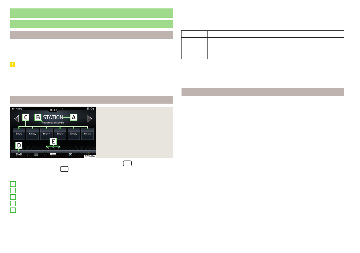
Radio
service
Introduction to the subject
Depending on the vehicle equipment fitted and the Infotainment type, ana-
logue FM and AM frequency bands can be received as well as digital radio re-
ception DAB.
CAUTION
■
For vehicles with window antennas do not stick foil or metal coated stickers
to the window - Radio signal reception could be affected.
■
Car parks, tunnels, tall buildings or mountains can interfere with the radio
signal even causing it to fail completely.
main menu
Fig. 174
Radio: Main Menu (DAB)
›
To display the main menu, press the sensor field/the
button.
›
or tap the sensor field
and then the function surface .
Main menu » Fig. 174
The selected radio station (description or frequency)
Radio text (FM) / Description of the group (DAB)
Preset station buttons for favourite channels
Choice of radio range (FM / AM / DAB)
Choice of storage group for the preferred station
Changing the station
List of available stations
Manual / semi-automatic station search
A
B
C
D
E
Radio text display (DAB) / image presentation (DAB)
Settings of menu Radio » page 134 or » page 140
Information symbol in the status line
Symbol Meaning
Traffic signal is available
Traffic signal is not available
Signal is not available (DAB)
If the displayed station name continuously changes (dynamic text), then it is
possible to fix the current text by holding your finger on the device screen in
the station name area. By holding your finger in the area of the station name
again, the station name is displayed in its entirety again.
Search stations and select frequency
Find stations
›
Tap on the function surface in the Radio main menu
or
.
Depending on the setting
→
Arrow buttons:
, an available station from the Sta-
tion list or a station stored to the Preset buttons for the currently selected
radio frequency range is set.
Select frequency
›
To display the value of the currently chosen frequency, tap the function sur-
face in the Radio main menu
.
›
To Set the desired frequency value in Infotainment Swing, use the slider or
the function surfaces
in the bottom area of the screen, if necessary, turn
the controller (not applicable to Infotainment Columbus)
Scan through the stations one after the other (scan)
The function scans through all the available stations in the current frequency
range in succession, for a few seconds each.
›
To start automatic scanning of the available stations, go to the main Radio
menu and tap on the function surface →
Scan
.
›
To end autoplay, tap the function surface .
142
Infotainment
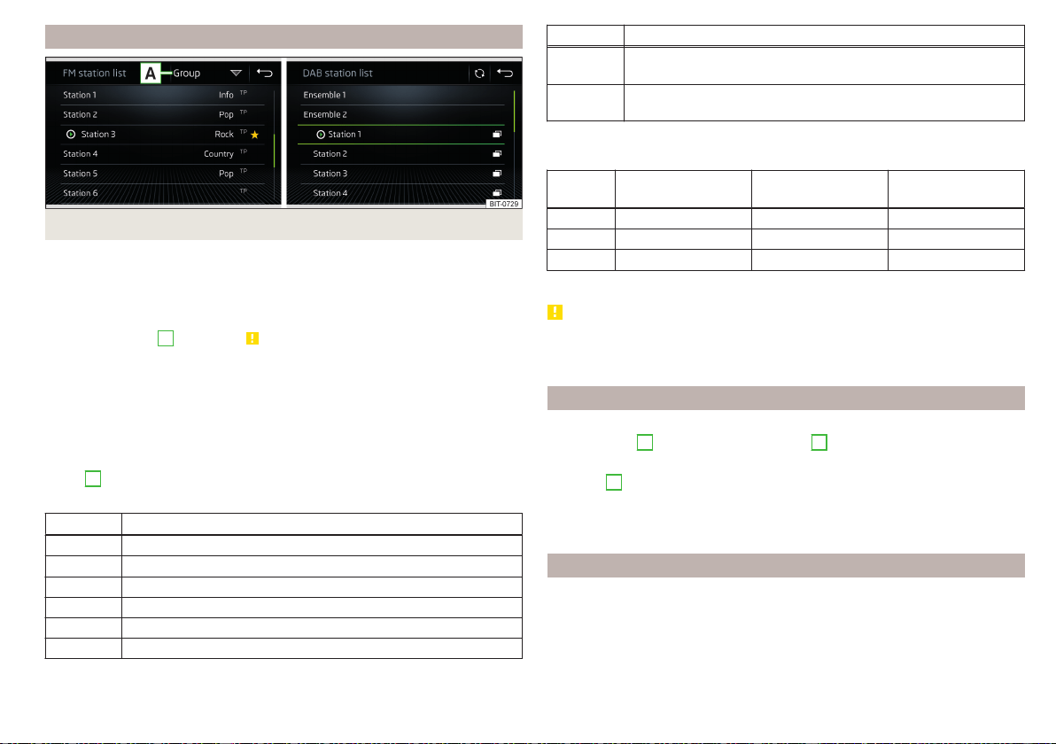
List of available stations
Fig. 175 Example, the list of available FM/DAB stations
Applies to Infotainment Columbus, Amundsen, Bolero
›
To display the list of available stations of the currently selected broadcasting
area, tap the function surface in the Radio main menu
.
›
To play, tap on the function surface of the desired station.
›
To Sort (FM) the stations in alphabetical order, by group or genre, tap on the
function surface
A
» Fig. 175 » .
Applies to Infotainment Swing
›
To display the list of available stations of the currently selected broadcasting
area, tap the function surface in the Radio main menu
.
›
To play, tap on the function surface of the desired station.
›
To filter the stations based on the program type (e.g. Music, Sport etc.) in
the FM station list (with activated RDS function) and the DAB station list
(with alphabetical sorting of the channel list selected), tap the function sur-
face
A
» Fig. 175.
Information symbols
Symbol Meaning
Radio station, which is stored on a preset button
Currently played stations
Traffic information station
(e.g.) Type of program being broadcast (FM)
(e.g.) Type the regional broadcast (FM)
Signal reception is not available (DAB)
Symbol Meaning
The transmitter reception is not secure (DAB) (applies to Info-
tainment Amundsen, Bolero, Swing)
Stations with image broadcasting (DAB) (does not apply to info-
tainment Swing)
Refresh list
Depending on Infotainment, the station list update takes place as follows:
Frequen-
cy
Columbus Amundsen, Bolero Swing
FM automatically automatically automatically
AM automatically manually manually
DAB automatically manually manually
▶
To manually update, tap on the function surface
» Fig. 175 .
CAUTION
To sort the stations according to genre, the RDS and AF functions must be
switched on. These functions can be set in the Radio main menu in the FM
band by tapping the function surface →
Advanced settings
.
Preset buttons for your favourite channels
In every broadcasting range, there are station buttons available to store pre-
ferred stations
C
That are split into groups
E
» Fig. 174 on page 142 or .
›
To save a station on the main menu Radio, hold down the desired function
surface
C
until an acoustic signal sounds.
›
To
save a station in the station list, keep the function surface of the desired
station held down, select the memory group, and then tap the desired station
button.
Station logos - Columbus, Amundsen, Bolero
Station logos are stored in the Infotainment memory which are assigned auto-
matically by the device when storing the stations under preset buttons.
Assign station logo automatically
›
to Disable / Enable in the Radio main menu, tap on the function surface →
Advanced settings
→
Autostore station logos
.
143
Radio

Assign station logo manually
›
Tap on the function surface in the Radio main menu →
Station logos
.
›
Tap on an occupied station button and select the data carrier (SD card, USB).
›
Search for and select the desired station logo on the respective data carrier.
Remove channel logo manually
›
Tap on the function surface in the Radio main menu →
Station logos
.
›
Tap on the station button from which you wish to remove a logo.
Note
■
The following image formats are supported: jpg, gif, png, bmp.
■
We recommend a resolution of up to 500x500 pixels.
Station logos - Swing
The station button of a preferred station can contain the name and the station
logo.
Assign a station logo
›
Tap on the function surface in the Radio main menu →
Station logos
.
›
Tap on an occupied station button and select the data carrier (SD card, USB).
›
Search for and select the desired station logo on the respective data carrier.
Remove station logo
›
Tap on the function surface in the Radio main menu
→
Station logos
.
›
Tap on the station button from which you wish to remove a logo.
›
or: Tap on the function surface
All areas
to delete the logos of all the station
buttons simultaneously.
›
Confirm / cancel the removal.
Note
■
The following image formats are supported: Jpg, png.
■
We recommend a resolution of up to 400x240 pixels.
TP Traffic program
›
To switch on/off traffic monitoring in the main menu Radio, tap on the func-
tion surface →
Traffic programme (TP)
.
During a traffic announcement, it is possible to cancel the current announce-
ment if necessary by deactivating traffic monitoring.
Note
■
If the station that is currently set does not transmit traffic reports or the sig-
nal is not available, then Infotainment automatically searches in the back-
ground for another TP station.
■
During playback in the Media menu or a station in the AM radio range, traffic
news is received from the previously selected FM radio range.
144
Infotainment
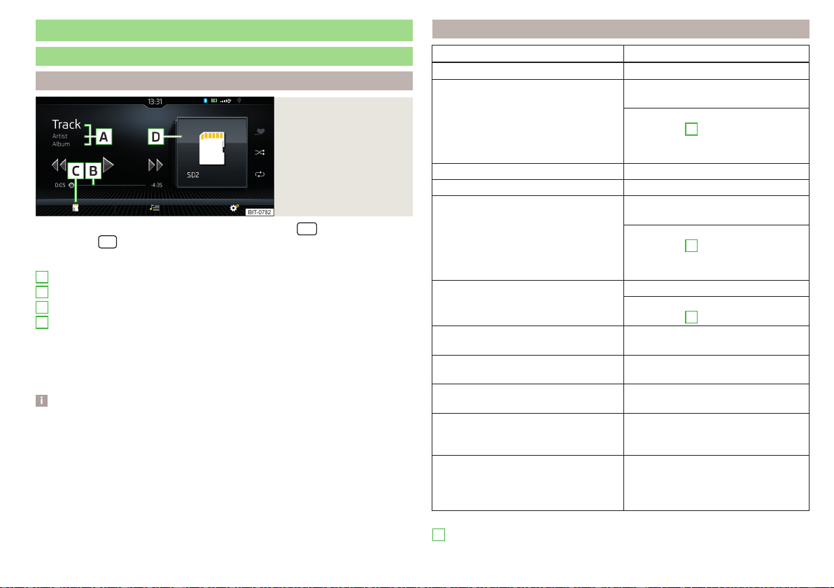
Media
service
Main menu
Fig. 176
Media: Display example
of the main menu
›
To display the main menu, press the sensor field/the
button.
›
or: Tap the
sensor field and then the function surface
.
Main menu » Fig. 176
Information on playing track
Playback timeline with a slider
Select the audio source
Selected audio source / album image / album overview
Depending on the audio source type:
▶
Folder/Title list
▶
Multimedia Database
Settings of menu Media » page 135 or » page 141
Note
■
Information concerning the track being played appears on the screen, if it is
stored as a so-called ID3 Tag on the audio source. If no ID3 tag is available, on-
ly the title name is displayed.
■
The remaining playback time indicated does not correspond to the actual re-
maining playback time for titles with variable bitrates.
■
When an audio source is connected or plugged in, the Infotainment Colum-
bus searches the local Gracenote
®
database for information on the track being
played (e.g. album name, artist name, genre, album image etc.). If the informa-
tion is not available and the Infotainment Online » page 17 service is active, In-
fotainment will search for this information in the Gracenote
®
online database.
A
B
C
D
Playback control - Columbus, Amundsen, Bolero
Operation Action
Play / Pause Tap
Plays the current track from the start
Tap after 3 s from the start of the
track playback
Finger movement to the right of the
screen area
A
» Fig. 176 on page 145
after 3 seconds from the start of the
track playback
Fast-reverse within the title Press and hold
Fast-forward within the title Press and hold
Play the previous title
Tap within 3 seconds from the
start of the track playback
Finger movement to the right of the
screen area
A
» Fig. 176 on page 145
(Within 3 s after the start of the
track playback)
Play back the next title
Tap
Finger movement to the left of the
screen area
A
» Fig. 176 on page 145
Switch on/off the random playback
from the current album or folder
Tap
Switch on/off the repeat playback
from the current album or folder
Tap
Switch on/off repeat playback of spe-
cific track
Tap
Search (applies to sources with dis-
playable multimedia database) (applies
to Infotainment Columbus)
Tap
Turn on / off playback of similar tracks
according to information from what is
called the ID3-Tag (applies to Infotain-
ment Columbus)
Tap
Movement within the track is possible by touching your finger on the timeline
B
» Fig. 176 on page 145.
145
Media
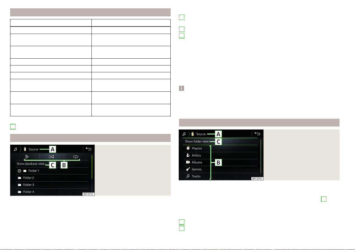
Playback control - Swing
Operation Action
Play / Pause Tap
Play the previous title
Tap within 3 seconds from the
start of the track playback
Plays the current track from the start
Tap after 3 s from the start of the
track playback
Fast-reverse within the title Press and hold
Fast-forward within the title Press and hold
Play back the next title Tap
Switch on/off the random playback
from the current album or folder
Tap
Switch on/off the repeat playback
from the current album or folder
Tap
Switch on/off repeat playback of spe-
cific track
Tap
Movement within the track is possible by touching your finger on the timeline
B
» Fig. 176 on page 145.
Folder / track list
Fig. 177
Folder/Title list
›
To display the folder / track list on the Media main menu, tap on the function
surface
(if this display is supported by the currently selected source).
›
To playback select a title.
Folder/track list » Fig. 177
Selected audio source / audio source folder (movement within the folder
takes place by pressing the function surface for the folder)
Options folder/track playback
Display of multimedia database (only available in the source directory) (not
applicable to the Infotainment Swing)
Select the audio source
Folder
Playlist
Currently playing title / track playback stopped
The title cannot be played (tapping on the function surface shows the
cause).
Note
■
In the list, the first 1000 entries (titles, directories etc.) are displayed with the
oldest creation date.
■
The scanning speed of the folder / track list depends on the connection
speed and volume of data.
Multimedia Database
Fig. 178
Multimedia Database
›
To display the multimedia database, in the Media main menu tap on the func-
tion surface
(if this display is supported by the currently selected source).
The audio files are sorted by their properties into individual categories
B
.
›
To playback, select the category and then the title.
Multimedia database » Fig. 178
Selected audio source / Selected category / folder of the audio source
Sorting categories
A
B
C
A
B
146
Infotainment
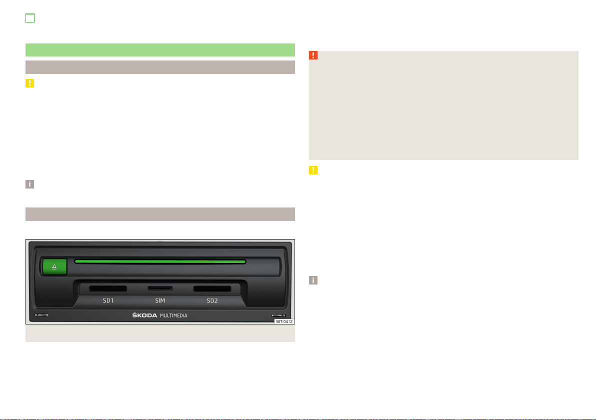
Display of files/track list (only available in the bibliography)
Select the audio source
Audio sources
Introduction to the subject
CAUTION
■
Do not save any important data or that which has not been backed up on the
connected audio sources. ŠKODA assumes no responsibility for lost or dam-
aged files or connected audio sources.
■
When changing or connecting an audio source, this may cause sudden
changes in volume. Reduce the volume before changing or connecting an au-
dio source.
■
When connecting an external audio source, the external source information
messages can be displayed. These messages must be observed and if necessa-
ry confirmed (e.g. enabling data transfer etc).
Note
The national copyright laws that apply in your country must be observed.
CD / DVD
Only valid for Infotainment Columbus.
Fig. 179
CD / DVD case
The CD/DVD» Fig. 179 slot is located in an external module in the storage com-
partment on the front passenger side.
›
To insert a CD/DVD, with the labelled side facing up, press into the CD slot
until it is automatically drawn in.
C
›
To eject, press the button The CD/DVD is moved to the starting position.
If the ejected CD/DVD is not removed within 10 seconds, it is retracted again
for safety reasons. However, the unit will not change to the CD/DVD source.
WARNING
■
The CD/DVD player is a laser product.
■
This laser product was classified as a Class 1 laser product on the date of
manufacture in accordance with national/international standards DIN EN
60825-1: 2008-05 and DHHS Rules 21 CFR, Sub-chapter J. The laser used
in this class 1 laser product is so weak that there is no risk of danger when
operated correctly.
■
This product is designed such that the laser is restricted to the inside of
Infotainment. However, the installed laser could be classified in a higher
class were the housing to be removed. For this reason, never remove the
Infotainment housing.
CAUTION
■
Be sure to remove the CD/DVD before you try to insert a new CD/DVD. Oth-
erwise you can damage the drive inside Infotainment.
■
Only insert in the CD/DVD drive original Audio CDs/video DVDs or standard
CD-R/RWs or DVD±R/RWs.
■
Do not affix anything to the CD/DVDs!
■
If the ambient temperature is too high or too low, the CD / DVD playback
may not work.
■
Damp (condensation) may affect Infotainment in cold weather or high hu-
midity. This can cause the CD to jump or impair the play function. Once the
moisture has dissipated, playback is fully functional again.
Note
■
After pressing the button it takes a few seconds for the CD / DVD to be
ejected.
■
On uneven or unpaved roads, playback jumps may occur.
■
If the CD/DVD is physically damaged, is not readable or is inserted incorrect-
ly the following message is displayed
Error: CD/DVD
.
■
It is possible that CD/DVDs protected by copyright cannot be played back at
all or only in certain circumstances.
147
Media
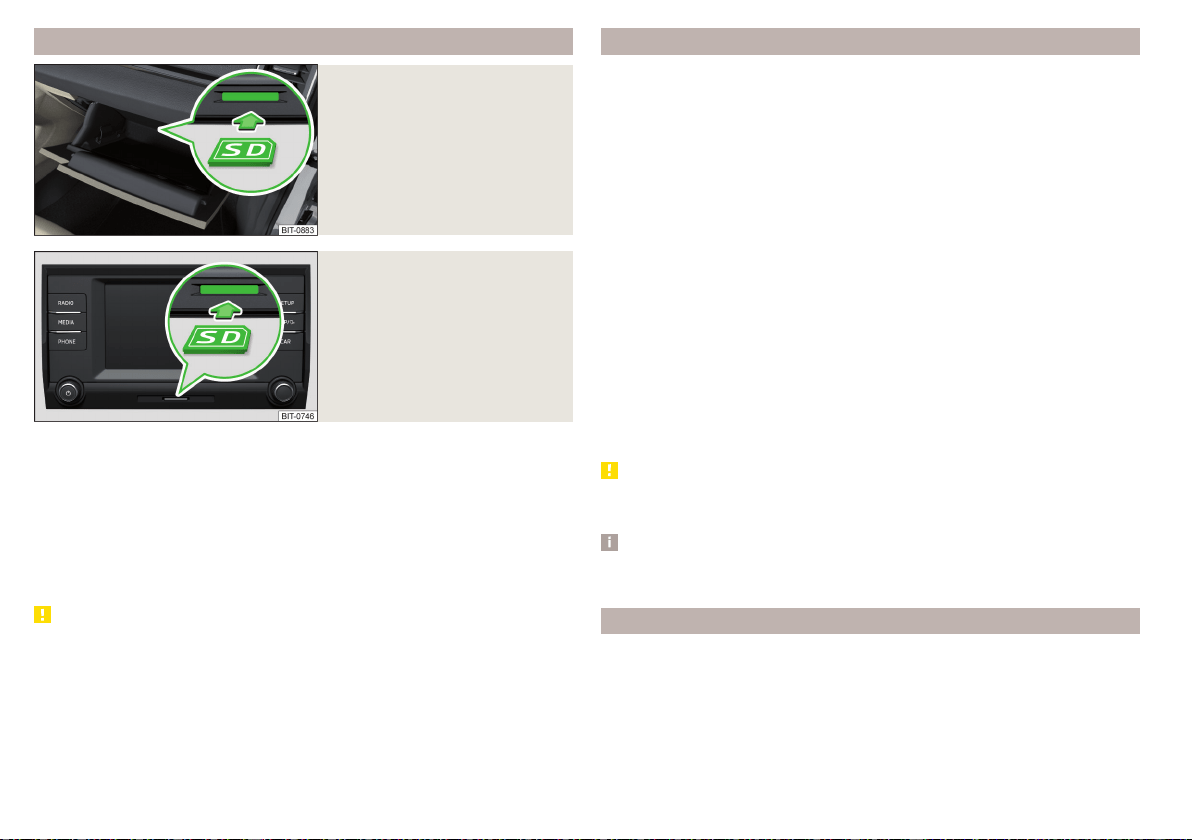
SD card
Fig. 180
Columbus, Amundsen, Bolero:
Insert SD card
Fig. 181
Swing: insert SD card
Inserting
›
Insert the SD card in the slot in the direction of arrow (with the cut end fac-
ing right), until it “locks” » Fig. 180 or » Fig. 181.
Removing
›
Before removing the SD card, tap the function surface in the Media main
menu
→ Tap on
Remove safely
.
›
Press on the inserted SD memory card. The SD card “jumps” into the eject
position.
CAUTION
■
Do not use an SD card with a broken write protection “slide” - there is a risk
of damage to the SD card reader!
■
When using an SD card with an adapter, vehicle vibrations might cause the
card to fall out of the adapter.
USB input
Installation location of the USB input and information regarding its use
» page 93.
The USB input audio source can be connected directly or via a connecting ca-
ble.
›
To connect, insert the USB audio source into the appropriate input.
›
To disconnect the USB, tap on the Media main menu function surface →
Tap on
Remove safely
.
›
Disconnect the audio source from the corresponding USB input.
Load USB audio source
With the ignition, the charging process starts automatically after the USB au-
dio source is connected (applies to audio sources where charging via the USB
connector is possible).
The charging efficiency can differ compared to charging from the usual mains
power supply.
Depending on the type of the connected external device and the frequency of
use, the charging current may not be sufficient to charge the battery of the
connected device.
Some connected audio sources may not be recognised and cannot be charged.
CAUTION
USB extension cords, or reducers may impair the function of the connected
audio source.
Note
We recommend that you use extension cords from ŠKODA Original Accesso-
ries.
Bluetooth
®
player
Infotainment allows audio files of a connected Bluetooth
®
player to play using
the A2DP and AVRCP audio profile.
With Infotainment, multiple devices can be paired using Bluetooth
®
, but only
one of them can be used as a Bluetooth
®
player.
148
Infotainment

Connect / disconnect
›
To connect the Bluetooth
®
player with Infotainment- follow the same in-
structions as for pairing Infotainment with a telephone» page 158.
›
To disconnect the Bluetooth
®
player, end the connection in the list of paired
external devices » page 160.
Replace Bluetooth
®
player (applies to Infotainment Amundsen, Bolero)
If you would like to replace a Bluetooth
®
-Player which is connected to Infotain-
ment as a phone at the same time, , then a relevant information message ap-
pears on the Infotainment screen.
›
End the connection to the currently connected Bluetooth
®
player and repeat
the pairing procedure » page 160, Managing paired external devices.
CAUTION
If an external device is connected to Infotainment using Apple CarPlay or
Android Auto, then it cannot be connected using Bluetooth
®
.
Jukebox
Only valid for Infotainment Columbus.
In the Jukebox (in the Infotainment internal memory), supported audio / video
files can be imported from connected external devices.
Import files
›
Tap the function surface in the Media main menu →
Manage jukebox
→
Import
.
›
Select the desired source.
›
Select the desired folders or files.
›
Tap the function surface
.
Delete files
›
Tap the function surface in the Media main menu →
Manage jukebox
→
Delete
.
›
Select the desired folder or files in the selected category.
›
Tap the function surface →
Delete
.
Show level of Infotainment memory
›
Tap the function surface in the Media main menu
Manage jukebox
.
information about the occupied and free space of the Infotainment memory
and the number of files that cannot be imported is displayed.
Note
■
Files that have already been copied are recognised and cannot be copied
again (shown in grey).
■
It is not possible to copy files while simultaneously playing back audio/video
files in the CD/DVD drive.
WLAN
Applies to Infotainment Columbus, Amundsen.
Infotainment allows you to play audio files from one of the external devices
connected to the Infotainment WLAN.
›
Connect an external device that supports the DLNA (Digital Living Network
Alliance), with Infotainment WLAN» page 168.
›
If necessary use the UPnP application (Universal Plug and Play) in the con-
nected device, which allows playback to start.
›
Select the audio source
WLAN
.
149
Media

Supported audio sources and file formats - Columbus, Amundsen,
Bolero
Supported audio sources
Source Interface Type Specification
File sys-
tem
Map SD reader Standard size SD, SDHC, SDXC
FAT16
FAT32
exFAT
NTFS
USB
devices
USB 1.x; 2.x
and 3.x or
higher with
support of
USB 2.x
MSC
USB stick;
HDD (without
any special soft-
ware);
USB devices sup-
porting MSC
mode
MTP
Devices with the
Android operat-
ing system or
Windows mobile
(mobile phone,
tablet)
Apple
Devices with the
iOS operating
system (iPhone,
iPod, iPad)
CD/DVD
Applies to
Infotain-
ment Co-
lumbus.
CD/DVD
Drive
Audio CD (Up to 80
min);
CD-R / RW (Up to
700 MB);
DVD±R/RW;
DVD audio.
DVD-Video
ISO9660;
Joliet (Level 1,2,3)
;
UDF 1.x;
UDF 2.x
-
Supported audio file formats
Codec type
(File formats)
File suffix
Max bit
rate
Maximum
sampling
rate
Multi
channels
a)
Playlists
Windows Media
Audio
9 and 10
wma
384 kbit /
s
96 kHz
no
m3u
pls
wpl
m3u8
asx
WAV wav
Defined by
the format
(approx.
1.5 Mbit/s)
MPEG-1;2 and
2.5
Layer 3
mp3
320 kbit /
s
48 kHz
MPEG-2 and 4
aac; mp4;
m4a
yes
FLAC;
OGG-Vorbis
flac; ogg
Defined by
the format
(approx.
5.5 Mbit/s)
a)
Applies to the CANTON sound system.
The GPT standards (GUID partition table) method structured audio sources
are not supported by Infotainment.
Files that are protected by Digital Rights Management (DRM) technology can-
not be played back by Infotainment.
150
Infotainment

Supported audio sources and file formats - Swing
Supported audio sources
Source Interface Type Specification File system
Map SD reader
Standard
size
SD, SDHC, SDXC
FAT16
VFAT
FAT32
exFAT
USB
devices
USB 1.x; 2.x
and 3.x or
higher with
support of
USB 2.x
MSC
USB stick;
HDD (without any spe-
cial software);
USB devices supporting
MSC mode
MTP
Devices with the An-
droid operating system
or Windows mobile
(mobile phone, tablet)
Apple
Devices with the iOS
operating system
(iPhone, iPod, iPad)
Blue-
tooth
®
-
Player
- -
Bluetooth protocols
A2DP and AVRCP (1.0 -
1.4)
-
Supported audio file formats
Codec type
(File formats)
File suffix Max bit rate
Maximum
sampling
rate
Playlists
Windows Media
Audio 9 and 10
wma 384 kbit / s 96 kHz
m3u
pls
wpl
asx
MPEG-1; 2 and 2.5
(Layer-3)
mp3 320 kbit / s 48 kHz
The GPT standards (GUID partition table) method structured audio sources
are not supported by Infotainment.
Files that are protected by Digital Rights Management (DRM) technology can-
not be played back by Infotainment.
Images
Image viewer
main menu
Applies to Infotainment Columbus, Amundsen, Bolero.
Fig. 182
Images: main menu
›
To display the main menu, tap the
sensor field and then tap the function
surface
.
Main menu » Fig. 182
Select the image source
Folder / Image List
Display the previous image
Switching on the slideshow
Switching off the slideshow
Display of the next image
Images menu settings » page 135
Rotate the image 90° anticlockwise
Rotate the image 90° clockwise
Display the initial image size while retaining the aspect ratio
Guidance to GPS coordinates (Amundsen; the display only occurs if the
image contains GPS coordinates) (applies to Infotainment Columbus,
Amundsen) » page 184
A
151
Images
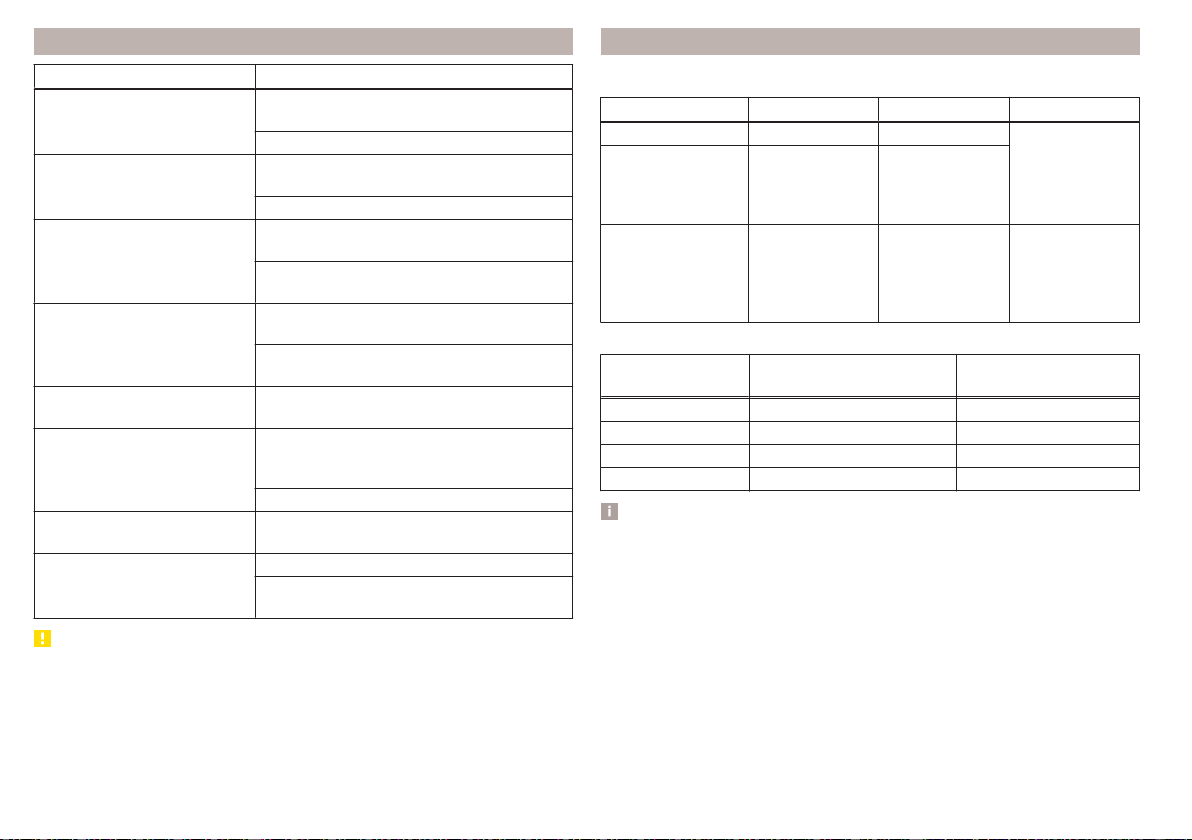
Control viewed images
Operation Action
Display of the next image
Moving your finger across the screen to the
left (with initial representation)
Tap
Display the previous image
Moving your finger across the screen to the
right (with initial representation)
Tap
Increase the image size
Touch screen using two fingers and pull
apart
Turning the knob to the right (not applica-
ble to Infotainment Columbus)
Reduce the image size
Touch screen using two fingers and close to-
gether
Turning the knob to the left (not applica-
ble to Infotainment Columbus)
Moving the image with an en-
larged display
Drag your finger over the screen in the re-
quired direction
Rotate by 90 °
Touch screen using two fingers and move
clockwise or counter clockwise (only availa-
ble with start representation)
Tap or
Maximum magnification of
representation
Double finger tap on the screen
Display the initial image size
while retaining the aspect ratio
Double tap on the screen again
Pressing the knob (not applicable to Info-
tainment Columbus)
CAUTION
Viewing images on the Infotainment screen is not supported by connected Ap-
ple devices.
Supported image file formats and sources
Supported image sources
Source Type Specification File system
Map Standard size SD, SDHC, SDXC
FAT16
VFAT
FAT32
exFAT
NTFS
USB devices
USB stick;
HDD (without
any special soft-
ware)
USB 1.x; 2.x and
3.x or higher with
support of USB
2.x
CD / DVD (Applies
to Infotainment Co-
lumbus)
CD-R / RW (Up
to 700 MB);
DVD±R/RW
ISO9660;
Joliet (Level 1,2,3)
;
UDF 1.x;
UDF 2.x
-
Supported file formats
Codec type
(File formats)
File suffix
Max. resolution
(Megapixels)
BMP bmp 4
JP (E) G jpg; jpeg 4; 64
GIF gif 4
PNG png 4
Note
■
The max. supported image size is 20 MB.
■
The GPT standards (GUID partition table) method structured images sources
are not supported by Infotainment.
152
Infotainment
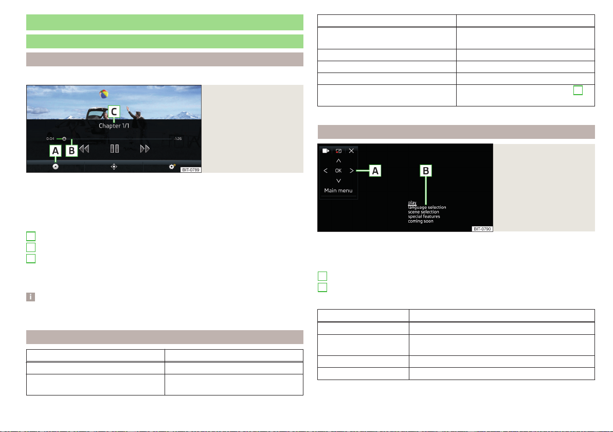
Video DVD
video player
main menu
Only valid for Infotainment Columbus.
Fig. 183
Video DVD: main menu
›
to display the main menu, insert a CD / DVD in the corresponding slot in the
external module.
›
or: In the main menu Media, select the video source, display the folder/track
list and start the video file.
Main menu » Fig. 183
Select a video source
Reproduction time axis
Information for the selected video file (e.g., video title, chapter)
Display the Video DVD menu
Menu settings Video DVD » page 135
Note
For safety reasons, the image display is switched off at speeds over 5 km/h.
Only the sound continues. The respective message appears on the screen.
Control playback
Operation Action
Play / Pause Tap /
Play the previous video
Tap within 3 s from the start of the
track playback
A
B
C
Operation Action
Play the current video from the start
Tap after 3 s after the start of the
playback
Fast rewind Press and hold
a)
Play the next video Tap
Fast forward Press and hold
a)
Forward / rewind the video at the de-
sired time
Tapping the playback timeline
B
» Fig. 183 on page 153
a)
The longer the function surface is held, the faster the fast forward/reverse.
DVD menu
Fig. 184
DVD menu
›
To display the DVD menu, in the main menu Video DVD, tap the function sur-
face
» Fig. 183 on page 153 .
Description of the DVD menu » Fig. 184
Operating surface
Example of the displayed menu
Function surfaces on the operating surface
Symbol Operation
/ Move the operating surface left / right
/ Show / hide full screen display of the operating sur-
face
Close the operating surface
Movement in the EPG/teletext
A
B
153
Video DVD
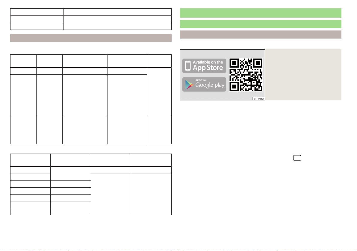
Symbol Operation
Confirmation
Main menu
Return to Video DVD main menu
Supported video sources and file formats
Supported video sources
Source Interface Type Specification
File sys-
tem
Map SD reader Standard size SD, SDHC, SDXC
FAT16
VFAT
FAT32
exFAT
NTFS
USB
devices
USB 1.x; 2.x
and 3.x or
higher with
support of
USB 2.x
MSC
USB stick;
HDD (without
any special soft-
ware);
USB devices sup-
porting MSC
mode
CD/DVD
CD/DVD
Drive
CD-R / RW (Up to
700 MB);
DVD±R/RW;
default DVD;
DVD video;
ISO9660;
Joliet (Level 1,2,3)
;
UDF 1.x;
UDF 2.x
-
Supported video file formats
Codec type
(File formats)
File suffix
Max. frames per
second
Max. resolution
MPEG-1
.mpeg
30 352 x 288
MPEG-2
25 720 x 576
MPEG-4 .mp4
QuickTime .mov
Matroska .mkv
DivX; XviD
.avi
MJPEG
Media Command
Operation
Introduction to the subject
Applies to Infotainment Columbus, Amundsen.
Fig. 185
ŠKODA Media Command appli-
cation
The Media Command function allows playback of audio files or videos in up to
two TabletsThat are connected to Infotainment via WLAN, to control Info-
tainment.
The function Media Command enables operation of tablets with the Android
operating system or iOS.
The prerequisite for the Media Command function is enabled data transfer as
well as the authorised Infotainment operation using the application » page 127.
Connect tablet with Infotainment
›
Switch on the infotainment hotspot (the sensor field)
and then the func-
tion area →
WLAN
→
Mobile hotspot
→
Mobile hotspot
).
›
Turn on WLAN in the tablet.
›
Establish a WLAN connection in the tablet » page 168, Establishing a con-
nection using WLAN.
›
In the tablet, start the application ŠKODA Media Command.
ŠKODA Media Command application
The application is available in the App Store and Google Play online shops.
Information regarding the application and the option to download the applica-
tion can be found on a website that can be opened by reading the QR code
» Fig. 185 .
154
Infotainment
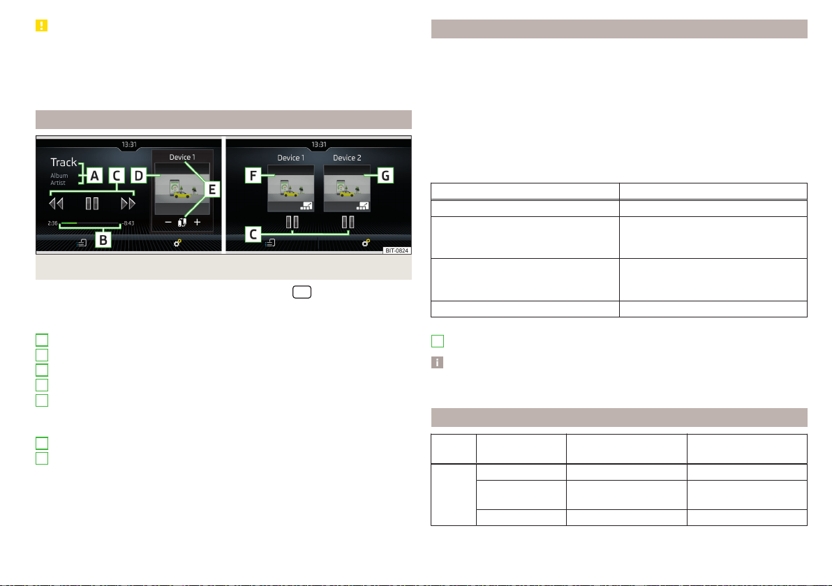
CAUTION
■
If several devices are connected to the infotainment using WLAN, there is
the risk of the WLAN overloading and thus also Media Command being ren-
dered inoperable.
■
High-definition video playback (such as HD) can cause playback problems or
problems connecting the tablets to infotainment.
Main menu
Fig. 186
One tablet / two tablets
›
To display the main Media Command menu, tap the
sensor field and
then tap the function surface
.
Main menu » Fig. 186
Information on playing track
Playback timeline with a slider
Playback control
Image from the video being played back
Name of the tablet used/Switch to main menu of two tablets (when icon
displayed )
Increase/decrease the tablet volume
Display of main menu and operation of first tablet (symbol )
Display of main menu and operation of second tablet (symbol
)
Selection of the playback source
WLAN settings » page 133
A
B
C
D
E
F
G
Select source and control playback
›
To select the playback source tap the function surface in the main menu
and select the source tablet.
›
To playback, select the category and then the title.
If two tablets are connected, the title playback starts in the two tablets at the
same time.
Playback can be controlled via Infotainment or on each tablet, and are inde-
pendent from each other. This means there is an option to playback different
titles on the tablets at the same time.
Playback control
Operation Action
Play / Pause Tap
Plays the current track from the start
Tap
after 3 s from the start of the track
playback
Play the previous title
Tap
within 3 seconds from the start of the
track playback
Play back the next title Tap
Movement within the track is possible by touching your finger on the timeline
B
» Fig. 186 on page 155.
Note
Some tablet types allow playback of audio files or videos by an inserted SD
card in the tablet. Playback of these tracks may be limited.
Supported file formats
Type Format
Operating system
Android
Operating system
iOS
Video
MPEG-4 Part 2
MPEG-4 Part 10
(H264)
XVID
155
Media Command
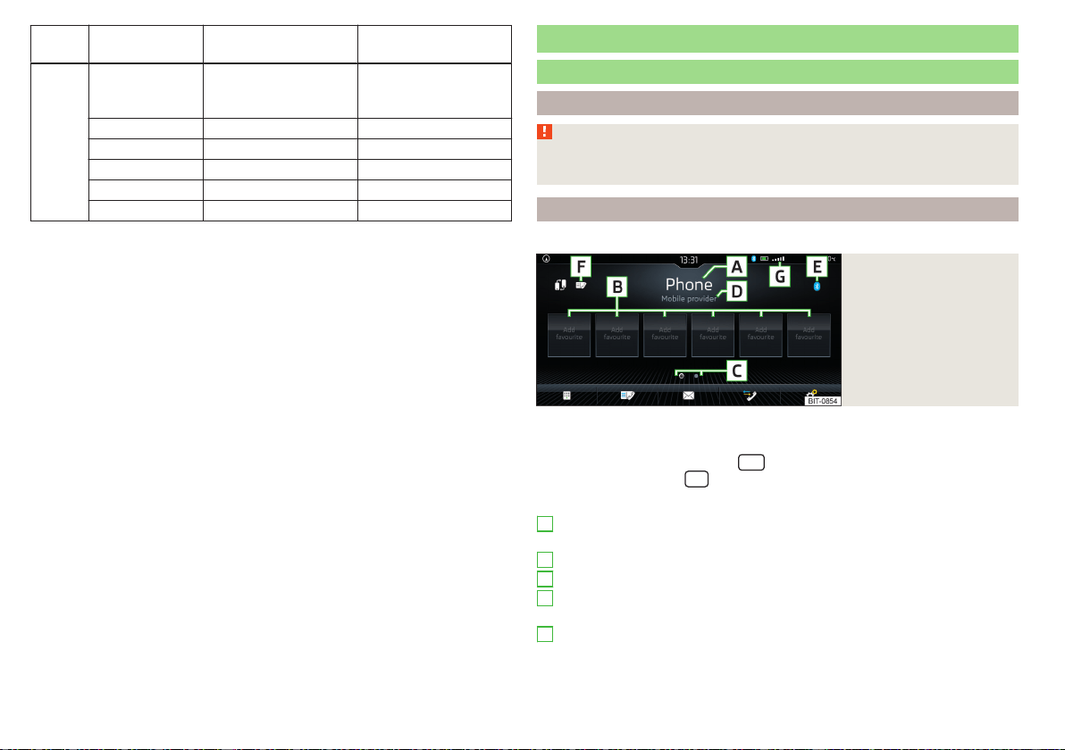
Type Format
Operating system
Android
Operating system
iOS
Audio
MPEG-1;2 and
2.5
Layer 3 (mp3)
AAC (4,1+)
M4A (4,1+)
OGG
FLAC
WAV (4,1+)
Telephone
Introductory information
Introduction to the subject
WARNING
The general binding country-specific regulations for operating mobile
phones in the vehicle must be observed.
Telephone
Applies to Infotainment Columbus, Amundsen, Bolero.
Fig. 187
Telephone: Main menu
The Telephone main menu is displayed if a phone or a SIM card with activated
phone service on the external module is connected to Infotainment.
›
To display, tap the sensor field
.
›
or tap the sensor field
and then the function surface .
Main menu » Fig. 187
Name of the connected phone (by tapping the list of paired phones dis-
played)
Preset station buttons for favourite contacts
Choice of storage group for the preferred contacts
Name of the telephone service provider (with active roaming, the symbol
appears before the name )
Main telephone icon
▶
- a telephone connected via Bluetooth
®
▶
- a SIM card with activated telephone services, inserted in the exter-
nal module
A
B
C
D
E
156
Infotainment
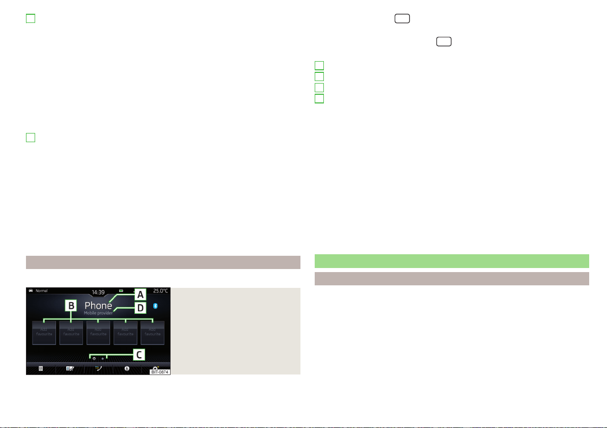
List of connected telephones, which are available as the source of tele-
phone contacts
▶
- no telephone is connected for telephone contacts
▶
- a telephone is connected for telephone contacts
Change the main phone to the extension telephone
Enter the telephone number
List of contacts
Menu with text messages (SMS)
Call list
Settings for the Telephone menu » page 135
Symbols in the status bar
Signal strength of the telephone network, data connection type if re-
quired
A telephone connected via Bluetooth
®
(applies to Infotainment Colum-
bus)
Charge status of the telephone battery
Missed call
Current call
Incoming SMS
ID of the telephone's wireless charging function » page 92 (applies to In-
fotainment Columbus)
The SIM card PIN code was not entered
Telephone
Applies to Infotainment Swing.
Fig. 188
Telephone: Main menu
The Telephone main menu appears when a telephone is connected to Infotain-
ment.
F
G
›
To display, press the
button.
If another, menu id displayed which was open last, to display the Telephone
main menu, press the button again
.
Main menu » Fig. 188
Name of the main telephone (tap to display the list of paired telephones)
Preset station buttons for favourite contacts
Choice of storage group for the preferred contacts
Name of the telephone service provider (with active roaming, the sym-
bol appears before the name )
Enter the telephone number
List of contacts » page 162
Call list (missed calls, in addition to the function surface, the number of
calls when missed is displayed)
Starting voice control of the connected phone (e.g. Apple Siri, Google
Voice)
Settings for the Telephone menu » page 141
Symbols in the status bar
Signal strength of the telephone service network
Charge status of the telephone battery
Missed call
Current call
Pairing and connecting
Introduction to the subject
To connect a telephone with Infotainment, the two devices must be paired via
Bluetooth
®
.
Depending on the Infotainment model, up to 20 external devices can be paired
with the device. After reaching the maximum number, the pairing of the next
external device will replace that of the device that has not been used for the
longest period of time.
The connection to a phone that is already paired is established automatically
after switching on the ignition. Or it is sufficient to search for the phone in the
list of paired devices.
A
B
C
D
157
Telephone

The range of the connection to Infotainment is limited to the passenger com-
partment.
Compatibility and update
By reading the QR code » Fig. 157 on page 120 or after typing the following
address into the web browser, information about the compatibility of phones
and updates are available for Infotainment Bluetooth
®
can be displayed.
http://go.skoda.eu/compatibility
conditions for pairing
The ignition is switched on.
The Bluetooth
®
function of the infotainment and the telephone is switched
on.
The visibility of the infotainment and the telephone is switched on.
The telephone is within range of the Bluetooth
®
signal of Infotainment.
The telephone is compatible with the infotainment.
There is no external device connected to Infotainment using Apple
CarPlay.
Pairing and connection process
Pair the telephone with Infotainment
›
Search available Bluetooth
®
devices in your telephone.
›
Select the Infotainment name.
The name of the Infotainment system can be determined in the Telephone
main menu if you tap the function surface
→
Bluetooth
in the
Name:
main
menu .
›
Confirm the PIN code (enter and confirm if necessary).
The phone is either connected to the Infotainment or just linked, depending on
the number of already connected external devices and on the use of the SIM
card inserted in the external module (applies to Infotainment Columbus)
» page 159.
Pair Infotainment with the telephone
›
If no telephone is connected to the Infotainment system, press the but-
ton/sensor field
and then tap the
Find mobile phone
function surface or
press the
sensor field, and then tap the function surface →
Find mobile
phone
.
›
If one telephone is connected to the infotainment system, then, in the Tele-
phone main menu, tap on the →
Find mobile phone
function surface.
›
If a SIM card with activated telephone services is inserted in the external
module of infotainment Columbus, then, in the Telephone main menu, tap on
the →
Find mobile phone
function surface.
›
Select the desired telephone from the list of visited external Bluetooth
®
devi-
ces.
›
Confirm the PIN code (enter and confirm if necessary).
WARNING
Do not Pair and connect a telephone to Infotainment when the vehicle is in
motion - there is risk of an accident!
Connect phone using the rSAP profile
Applies to Infotainment Columbus with the SIM card slot in the external mod-
ule.
A phone that has been connected via the Bluetooth
®
rSAP profile (remote
transfer of SIM data) can be used for phone and data services.
Pair the phone with Infotainment
›
Turn on the ignition and switch on Infotainment.
›
In the Telephone main menu, switch on the →
Business phone “interface”
.
›
Switch on Bluetooth
®
visibility in the phone and allow the connection via the
Bluetooth
®
rSAP profile.
›
Search for a phone and connect to the device » page 158, Pair Infotainment
with the telephone.
If the Bluetooth
®
rSAP profile is supported by the telephone to be connected,
then the infotainment system tries to connect to the phone using this profile
with priority.
Functional impairment
In the following cases, the phonecannot be connected to Infotainment via the
Bluetooth
®
rSAP profile.
▶
The SIM card is plugged into the external module.
▶
An external device is connected to Infotainment using Apple CarPlay or
Android Auto.
158
Infotainment

Note
Vehicle antennas are used to receive the mobile radio signal of the connected
phone.
Possible connection types
Depending on the number of connected Bluetooth
®
devices, connection type, as well as the use of the SIM card in the external module, the following functions
are available.
Only valid for Infotainment Columbus.
Connec-
tion
variant
The first device (main phone) The second device (additional phone)
Third device Fourth device
Telephone
SIM card
(In the external mod-
ule)
Telephone
SIM card
(In the external mod-
ule)
1st
rSAP
incoming / outgoing
Calls, text messages,
Telephone contacts,
Data connection,
Bluetooth
®
player
a)
-
HFP (incoming calls),
Bluetooth
®
player
a)
- Bluetooth
®
player
a)
-
2.
HFP (Incoming / out-
going
calls), text messages,
Telephone contacts,
Bluetooth
®
player
a)
-
HFP (incoming calls),
Bluetooth
®
player
a)
Data connection Bluetooth
®
player
a)
-
3.
HFP (Incoming / out-
going
calls), text messages,
Telephone contacts,
Bluetooth
®
player
a)
- -
Incoming calls,
text messages
Data connection
Bluetooth
®
player
a)
-
4. -
incoming / outgoing
Calls, text messages,
Phone contacts
b)
,
Data connection
HFP (incoming calls),
text messages
Bluetooth
®
player
a)
-
Phone contacts
b)
,
Bluetooth
®
player
a)
Bluetooth
®
player
a)
a)
In every connection variant, there is an option to only connect an external device as a Bluetooth connection
®
player with Infotainment.
b)
If phone contacts from the third device are imported into infotainment, the telephone contacts of the SIM card inserted in the external module cannot be used.
159
Telephone

Applies to Infotainment Amundsen, Bolero
The first device (main phone)
The second device (additional
phone)
HFP (Incoming / outgoing calls), SMS,
telephone contacts,
Bluetooth
®
player
a)
HFP (incoming calls),
Bluetooth
®
player
a)
a)
Only an external device can be connected to Infotainment as a Bluetooth
®
player.
Applies to Infotainment Swing
The first device (main phone)
The second device (additional
phone)
HFP (Incoming / outgoing calls),
telephone contacts,
Bluetooth
®
player
a)
Bluetooth
®
player
a)
a)
Only an external device can be connected to Infotainment as a Bluetooth
®
player.
Managing paired external devices
›
In the Telephone main menu, tap on the function surface
→
Bluetooth
→
Paired devices
.
In the list of paired external devices, the following symbols may appear for the
individual external devices.
Applies to Infotainment Columbus, Amundsen, Bolero
Symbol
Symbol
colour
Operation
grey External device can be connected as telephone
Green External device is connected as telephone
grey
External device can be connected as Bluetooth
®
play-
er
White External device is connected as Bluetooth
®
player
Applies to Infotainment Columbus with SIM card inserted in external mod-
ule
Symbol
Symbol
colour
Operation
grey
External device can be connected to use telephone
contacts and the text message function from this ex-
ternal device
blue
External device is connected and telephone contacts
and the text message function from this external de-
vice can be used
Applies to Infotainment Swing
Symbol
Symbol
colour
Operation
White External device can be connected as telephone
Green External device is connected as telephone
White
External device can be connected as Bluetooth
®
play-
er
Green External device is connected as Bluetooth
®
player
Connection set-up
▶
Select the desired external device from the list of paired external devices.
▶
Select the desired profile from the list of available Bluetooth
®
profiles - .
If external Bluetooth
®
devices are already connected to Infotainment, then dur-
ing the Infotainment connection process, messages and options for the possi-
ble connection type (e.g. replacement of the connected external Bluetooth
®
device) are displayed.
Disconnection
▶
Select the desired external device from the list of paired external devices.
▶
Select the desired profile from the list of available Bluetooth
®
profiles - .
Delete the paired external device
▶
To delete, tap on one of the following function surfaces.
- Delete all external devices
- Delete the desired external device
▶
Confirm the deletion by tapping on the function surface
Delete
.
Delete all
or
All areas
160
Infotainment
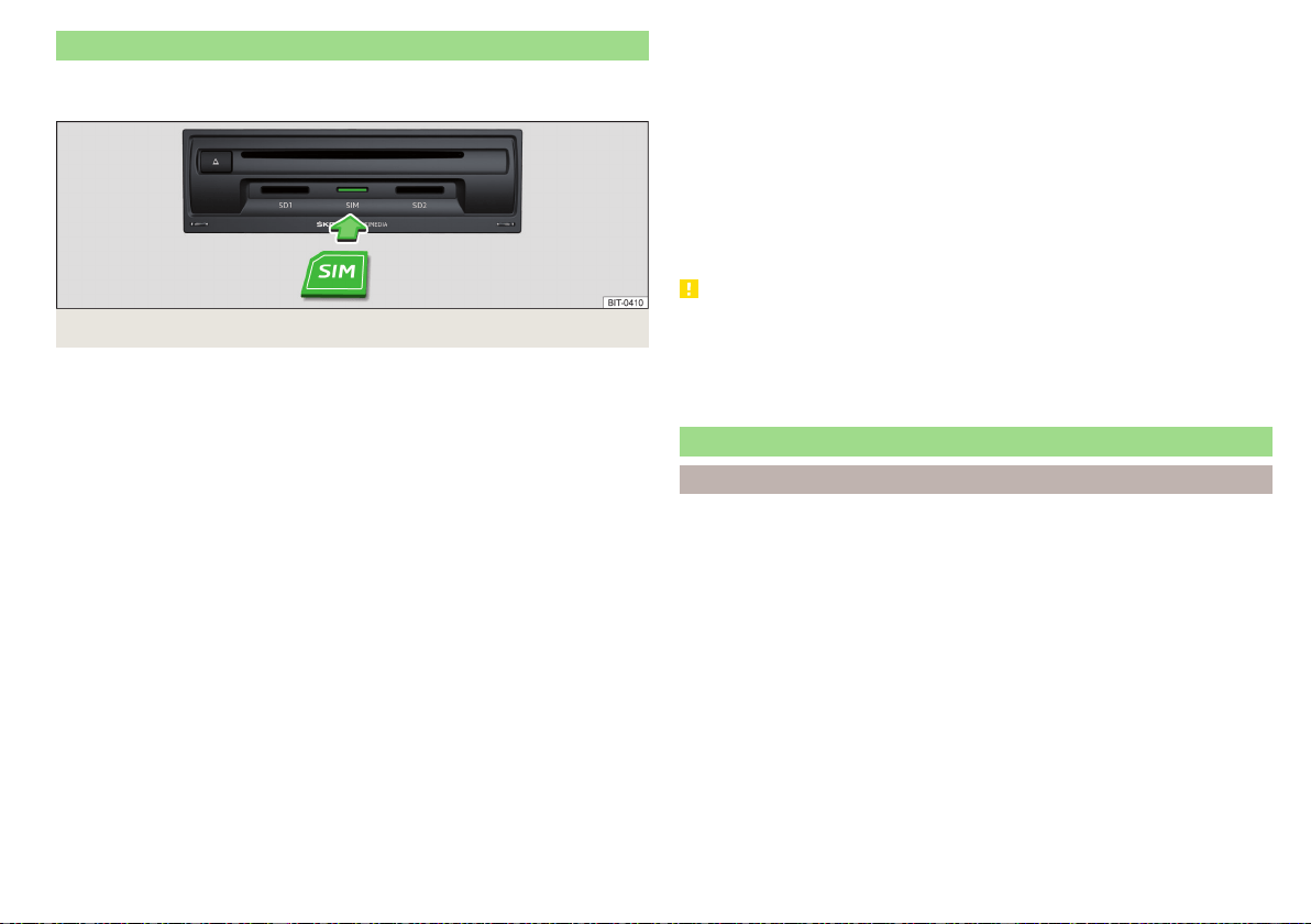
Use the SIM card in the external module
Applies to Infotainment Columbus with the SIM card slot in the external mod-
ule.
Fig. 189
Insert SIM card in the external module
A SIM card size “mini” (standard size 25x15 mm) must be used.
The SIM card can be used for phone and data services.
The SIM card slot is located in an external module in the storage compartment
on the front passenger side » Fig. 189.
Switching SIM card use on / off in the external module
›
In the Telephone main menu, switch on the
→
Business phone “interface”
.
Insert SIM card
›
Insert the SIM card into the appropriate slot » Fig. 189 With the beveled cor-
ner on the left and the contacts facing downwards until it “locks”.
Use the SIM card for the first time
When using the SIM card in the external module, select the use type.
Calls too
- enabling data and phone services.
Only data connections
- enabling data services only.
Set the network parameters for Internet connection if required » page 167.
By using the SIM card for phone services, the connection to the connected
phones is terminated.
Enter the PIN code and save
›
If the SIM card is protected by a PIN code, then the PIN code must be en-
tered.
›
Confirm the entered PIN code by tapping confirm.
›
or: Tap the function surface to save the PIN code and confirm it.
Change PIN code
›
The PIN code can be changed in the Telephone main menu, in the →
PIN
setup
→
Change PIN
menu item
Changing SIM card usage
›
In the Telephone main menu, tap on the function surface →
Use SIM card only
for data connection
function surface.
see SIM card
›
Press the inserted SIM card and remove it.
CAUTION
■
When inserting an incorrectly sized SIM card, there is a risk of damage to the
external module.
■
Avoid using an adapter for the SIM card as the SIM card may fall out while
driving due to vehicle vibrations - There is the risk of damage to the external
module.
Telephone functions
Enter telephone number and select
Enter a telephone number and dial
›
In the Telephone main menu, tap on the function surface .
Function surfaces of the numerical keyboard
Enter the last dialled number / dial the telephone number entered
Emergency call (Only applies to some countries)
Breakdown call in case of breakdown
Information call (for information regarding the products and services of
the brand ŠKODA )
Choosing the mailbox number (the function is not supported for Info-
tainment Swing)
Delete the last number entered
Display of function surfaces for movement of the cursor in the input
line
Search for a contact using the numeric keypad
The numeric keypad can also be used for a contact search.
161
Telephone
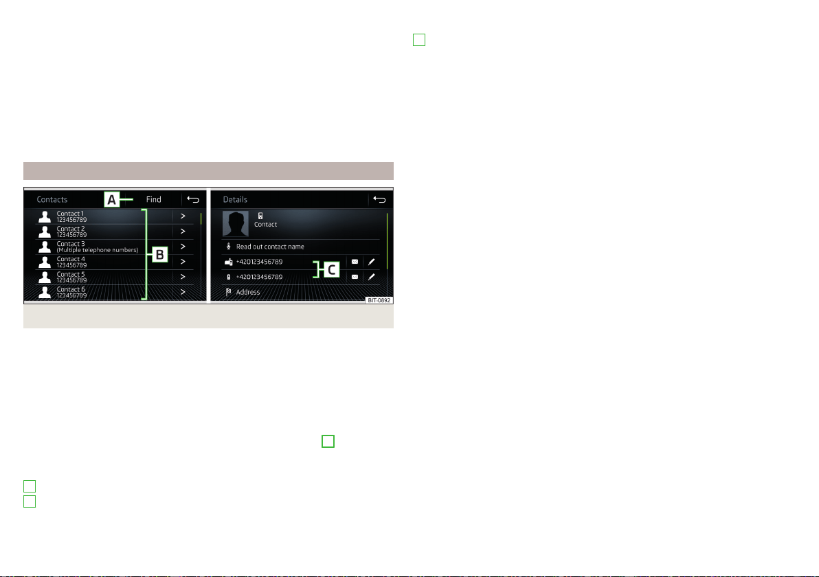
For example, if you enter 32, the unit will display contacts with the letter se-
quence DA, FA, EB, etc. next to the numerical keypad.
Voicemail box (does not apply to Infotainment Swing)
▶
To select the voice mailbox number, tap the function surface .
If not import the voicemail number or was not imported or entered, then this
can be entered or changed as follows.
▶
In the Telephone main menu, tap on the function surface →
User profile
→
Mailbox number:
.
▶
Enter the number of your voicemail box.
List of telephone contacts
Fig. 190
List of telephone contacts / contact details
›
In the Telephone main menu, tap on the function surface
and a list of tele-
phone contacts will be displayed » Fig. 190.
The main telephone is connected to Infotainment, the telephone contacts
from the telephone are used.
If there is a SIM card with activated telephone services located in the external
module of Infotainment Columbus, then the SIM card telephone contacts will
be available. It may also be possible to select another external device for im-
porting the telephone contacts by tapping the function surface
F
» Fig. 187
on page 156.
Functional surfaces
Contact search
Dial a number in the telephone contact list (if a telephone contact contains
several telephone numbers, a menu containing the telephone numbers as-
signed to this contact is displayed after the contact is selected)
A
B
Display the contact details
Select the telephone number in the contact details
Edit the telephone number of the contact before dialling
Infotainment Columbus, Amundsen, Bolero:
The contact name can be read out by Infotainment’s generated voice
Open the menu for sending a text message (SMS)
Infotainment Columbus, Amundsen:
Start the route guidance to the contact address
Import list
After the primary telephone and/or the SIM card (applies to Infotainment Co-
lumbus) connects to the infotainment system for the first time, the import of
the telephone contacts to the infotainment memory starts. The import can
take several minutes.
In the infotainment phonebook, there are 4000 (applies to Infotainment Co-
lumbus) and 2000 (applies to Infotainment Amundsen, Bolero, Swing) free
storage locations for imported telephone contacts. Each contact can contain
up to 5 telephone numbers.
The number of imported contacts can be determined in the menu item
→
User profile
→
Import contacts:
or.
Import contacts
being determined.
If an error occurs during the import, an appropriate message appears on the
screen.
Refresh list
When the telephone reconnects with Infotainment, the list is automatically up-
dated.
The update can be carried out manually as follows.
▶
In the Telephone main menu, tap on the function surface →
User profile
→
Import contacts:
or tap on
Import contacts
C
162
Infotainment
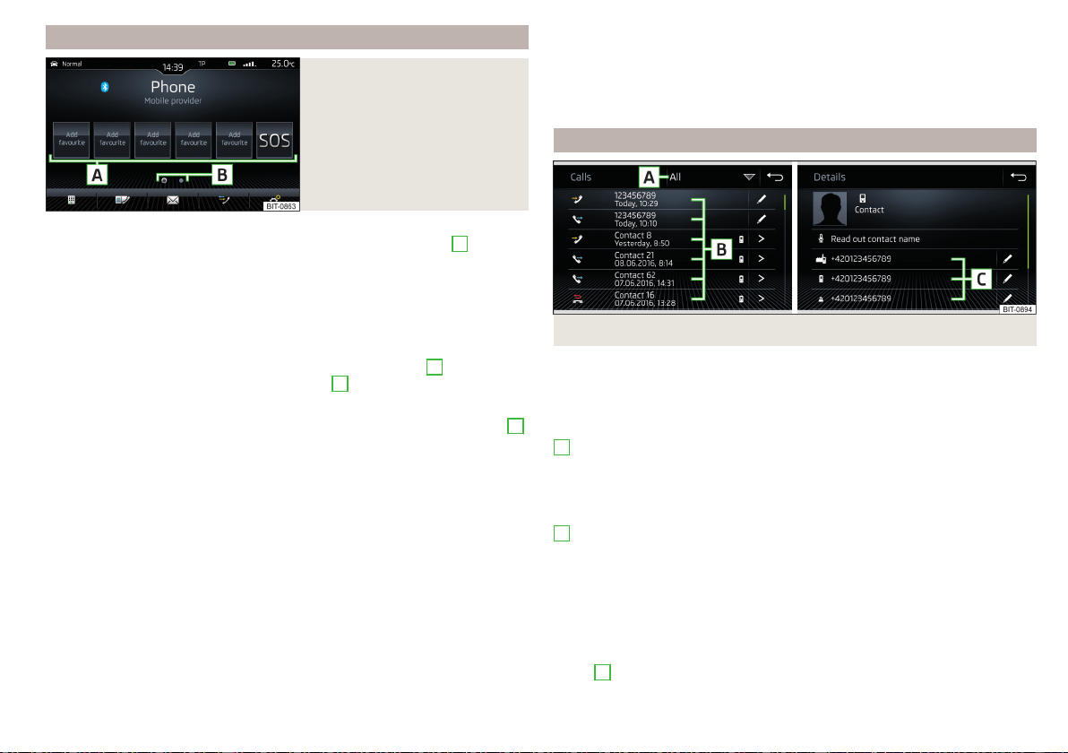
Management of preferred contacts (favourites)
Fig. 191
Favourite contacts
Assigning favourites
›
In the main menu Telephone, tap on the desired function surface
A
» Fig. 191.
›
Select the desired contact (if required, one of the contact numbers).
Connecting to a favourite
The function surfaces of preferred contacts allow the contact telephone num-
bers to be dialled immediately.
The favourites are available in two storage groups.
›
To the change Storage Group tap on the functional surface
B
» Fig. 191.
›
To choose tap on the assigned function area
A
» Fig. 191.
Change allocated favourites
›
In the main Telephone menu, press and hold the desired function surface
A
» Fig. 191.
›
Select the desired contact (if required, one of the contact numbers).
Delete a favourite
›
In the Telephone main menu, tap on function surface →
User profile
→
Manage
favourites
.
›
Press the desired function surface of the preferred contact and confirm the
deletion.
You can delete all contacts by tapping on the function surface
Delete all
/
All
areas
and confirm the deletion process.
Function surface for emergency call
If the vehicle is not equipped with the buttons for the Care Connect service
» page 16, the position of the first function surface in the first group of favour-
ites will show the function surface for an emergency call . In some coun-
tries, this function may not be available.
The function surface can be assigned a different number for the preferred
contact.
To restore the emergency number, it is necessary to remove the telephone
from the list of paired external devices » page 160 and then to pair and con-
nect again.
Call list
Fig. 192
Call history / Contact details
›
In the Telephone main menu, tap on the function surface and a call list will
be displayed » Fig. 192.
The call list can also be displayed during a telephone call.
Functional surfaces
Setting the display depending on the type of call
▶
All areas
- List of all calls
▶
Missed calls
/
Missed calls
- List of missed calls
▶
Dialled numbers
- List of dialled numbers
▶
Received calls
/
Received calls
- list of received calls
Dial the contact number/telephone number
Call type symbols
▶
- Answered call
▶
- Outgoing call
▶
- Missed call
Edit the phone number before dialling (not applicable to Infotainment
Swing)
Display the contact details » Fig. 192
▶
C
- Dial the contact number
A
B
163
Telephone

Phone call
Depending on the conversation context, the following functions can be carried
out.
End dialling / reject incoming call / end call
Accept incoming call / return to held call
Switch on/off ringer
Hold a call
Switch off/on microphone
Infotainment Columbus, Amundsen, Bolero:
Set up a conference call
Show caller details (if the contact is stored in the list)
Switch on/off hands-free (call to the telephone / switch to Infotainment)
▶
To switch off the hands-free system, in the Telephone main menu, tap on the
function surface
→
Hands-free
during a call.
▶
To switch off the hands-free system, tap on the function surface
during a
call.
Conference
Applies to Infotainment Columbus, Amundsen, Bolero.
The conference call is a shared call with between three and six participants.
Start a conference call/invite additional participants
›
During a call/conference call, carry out the next call.
›
or: Take the new incoming call by tapping the function surface .
›
To initiate conference call or return to the conference call, tap on the func-
tion surface .
Ongoing conference call
During an ongoing conference call, the call duration is displayed on the screen.
Depending on the context, the following functions can be selected.
Hold a conference call - leave the conference call temporarily (the con-
ference call continues in your absence)
Return to the held conference call
Switch off/on microphone
End conference call
Display conference call
Conference details
▶
During the ongoing conference call, press the function surface .
A list of other conference participants is displayed. The following functions
can be selected depending on the type of telephone.
Display details of participant
Talk to a participant separately from the conference call
End the call to a conference participant
Text messages (SMS)
Main menu
Applies to Infotainment Columbus, Amundsen, Bolero.
Fig. 193
Main menu text messages
›
In the Telephone main menu, tap on the function surface
and the main
menu for text messages will be displayed » Fig. 193.
›
If required, select whether the SIM card inserted in the external module or
the telephone (applies to Infotainment Columbus) is to be used as the source
of the text messages.
Depending on your model of connected telephone, you can perform the fol-
lowing functions.
Opening a list of templates for quick answers
New text message
- Creating and sending the message
Inbox
- Open a list of received messages
Sent
- Open a list of sent messages
Outbox
- Open a list of messages not sent
A
164
Infotainment

Drafts
- Open a list of drafts (messages in progress)
Deleted
- Open a list of deleted messages
Send contact details
- Send contact details (business card) (applies to Info-
tainment Columbus)
Select source of text messages (applies to Infotainment Columbus)
Display for the selection of the source of text messages (this applies to the
Infotainment Columbus with the SIM card slot in the external module)
If a SIM card used only for data services is located in the external module and if
a phone that supports the Bluetooth
®
profile MAP is connected to Infotain-
ment, then it is possible to adjust the source from which a text message menu
will be displayed after tapping on the function surface in the main Tele-
phone menu.
▶
In the Telephone main menu, tap on the function surfaces
→
Text message
settings
→
Standard account
.
▶
Select the desired menu item.
New text message
Creating and sending the message
›
In the main menu of the text messages, tap on the function surface
» Fig. 193 on page 164.
›
Write a text message and confirm. A view of the text message is displayed.
›
Tap the function surface
.
›
Select the recipient of the message from the displayed contact list or tap on
the
and enter the telephone number.
›
To add additional recipients, tap on the function surface
.
›
To send the text message, tap the function surface .
Viewing the text message
After opening the view message function, the following functions can be exe-
cuted.
The text can be read out by the device's generated voice
The text can be stored as a draft
Open a list of templates with the option to replace the recorded text with
the selected template
Open the contact list
The message can be edited, as long as the text range is within the entered
view.
Contact list
After the list has been opened the following functions can be executed.
Insert a contact in the recipient list
Enter the telephone number
Return to view the message
Tap on the
Find
function surface to open a list of available telephone contacts.
After selecting the contact number or entering the telephone number, the re-
cipient list will be displayed in the screen.
Recipient list
The following functions can be executed by tapping on one of the functional
surfaces.
Display contact list with the option of adding/removing additional re-
cipients (tap on the function surface to return to the recipient list
)
Removal of the contact from the recipient list
Sending the message
Return to view the message
Received text message
When you receive a new message, the number of new messages received is
displayed in the function surface
and at the same time the symbol
is dis-
played in the status bar.
›
To open a list of received messages, go to the Telephone main menu and
tap on function surface
→
.
›
Select a message.
The message content and the following menu is displayed.
The text can be read out by the device's generated voice
Display a menu with additional options
▶
Reply with template
- Reply using a template
▶
Delete current text message
- Distance of displayed text message (applies to
Infotainment Columbus, when the SIM card is inserted in the external
module or the phone is connected via the Bluetooth
®
profile RSAP)
▶
Display numbers
- Recognition of telephone numbers in the message in-
cluding the contact number (recognised numbers can be dialled directly
or edited before dialling, or may be sent to this message)
165
Telephone
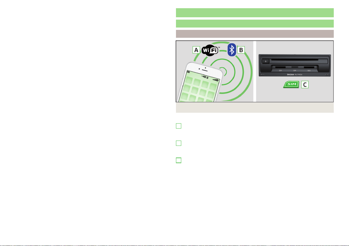
Forwarding a message with the option to edit the message before sending
Reply to the sender via a message
Data connection
Internet connection
Infotainment Columbus
Fig. 194
WLAN / Bluetooth® / SIM card
Possible connection types » Fig. 194,
Using WLAN, by connecting Infotainment with the external device hot
spot » page 168, Connect Infotainment to the hotspot of the external de-
vice.
By connecting to a mobile phone (it is connected to the Internet) using the
Bluetooth
®
rSAP profile » page 168, Establishing a connection using the
Bluetooth
®
rSAP profile.
Using a SIM Card with a data tariff » page 167, Establishing a connection
using a SIM card in the external module.
A
B
C
166
Infotainment
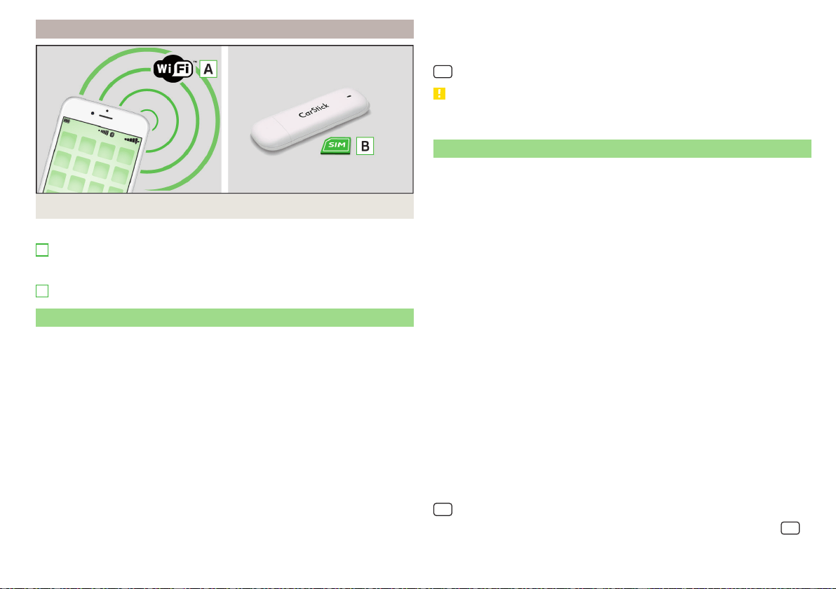
Infotainment Amundsen
Fig. 195
WLAN/Carstick
Possible connection types » Fig. 195,
Using WLAN, by connecting Infotainment with the external device hot
spot » page 168, Connect Infotainment to the hotspot of the external de-
vice.
Using the CarStick » page 167 USB device.
Establishing a connection using the CarStick device
Applies to Infotainment Amundsen.
The Carstick USB device can be purchased from the original accessories.
›
Insert a SIM card with enabled data services into the CarStick unit.
The required SIM card dimension can be found in the manual enclosed for the
original ŠKODA Carstick accessory.
›
Turn on the ignition and switch on Infotainment.
›
Insert the Carstick Into the USB input at the front » Fig. 99 on page 93,
›
Wait approximately one minute until the red light on Carstick stays continu-
ously lit (if the red lights up, then disconnect and re-insert the Carstick ).
›
If the SIM card is protected by a PIN code, then the PIN code must be en-
tered.
›
Confirm the entered PIN code by tapping confirm.
›
or: Tap the function surface to save the PIN code and confirm it.
›
Set of the data service provider’s required network if necessary.
A
B
If your data provider is not available in the list, ask your provider whether one
of the displayed providers can be used.
The parameters of the telephone service provider network can be set in the
→ →
Network
→
Network settings
menu item.
CAUTION
When inserting an incorrectly sized SIM card or in the wrong direction, there is
a risk of damage to the CarStick device.
Establishing a connection using a SIM card in the external module
Applies to Infotainment Columbus with the SIM card slot in the external mod-
ule.
A SIM card size “mini” (standard size 25x15 mm) mit enabled data services
must be used.
›
Turn on the ignition and switch on Infotainment.
›
In the Telephone main menu, switch on the
→
Business phone “interface”
.
›
Insert a SIM card into the corresponding slot into the external module in the
storage compartment on the passenger's side » Fig. 189 on page 161.
Insert the SIM card with the bevelled corner on the left and the contacts
facing downwards until it “locks”.
›
Select the SIM card usage type:
Calls too
- enabling data and telephone services.
Only data connections
- enabling of data services only.
›
If the SIM card is protected by a PIN code, then the PIN code must be en-
tered.
›
Confirm the entered PIN code by tapping confirm.
›
or: Tap the function surface to save the PIN code and confirm it.
›
Set the data service provider’s required network and confirm the Internet
connection.
If your data provider is not available in the list, ask your provider whether one
of the displayed providers can be used.
The parameters of the telephone service provider network can be set in the
→ →
Network
→
Network settings
menu item.
The data connection setting using the SIM card can be configured in the
→
→
Network
→
Data connection:
menu item .
167
Data connection

CAUTION
When inserting an incorrectly sized SIM card or in the wrong direction, there is
a risk of damage to the external module.
Establishing a connection using the Bluetooth
®
rSAP profile
Applies to Infotainment Columbus with the SIM card slot in the external mod-
ule.
The prerequisite for establishing an Internet connection is using a telephone
with a SIM card with active data services.
›
Turn on the ignition and switch on Infotainment.
›
Switch on the “Business” function in Infotainment, the sensor field
and
then the function surface → →
"Business" telephone “interface”
.
›
Switch on Bluetooth
®
, the sensor field
and then the function surface
→
Bluetooth
→
Bluetooth
.
›
Turn on Infotainment visibility (tap the
sensor field and then tap the
function surface →
Bluetooth
→
Visibility:
→
Visible
.
›
Switch on Bluetooth
®
and its visibility in the phone.
›
Connect and pair the phone with Infotainment » page 157.
Establishing a connection using WLAN
Introduction to the subject
Applies to Infotainment Columbus, Amundsen.
WLAN can be used to connect to the Internet, to playback audio files in the
menu media or for operating Infotainment using an application in the external
device (e.g. ŠKODA Media Command).
It is possible to connect up to 8 external devices to the Infotainment hotspot
and at the same time to connect Infotainment with another hotspit.
Switch the Infotainment hotspot on / off
›
Switch on the ignition.
›
Switch the hotspot on/off in the
→ →
WLAN
→
Mobile hotspot
→
Mobile
hotspot
menu item.
Set infotainment hotspot
The infotainment hotspot is factory-set.
The setting can be changed in the
→ →
WLAN
→
Mobile hotspot
→
Hotspot
(WLAN) settings
menu item.
■
Security level:
- Type of access protection (always set to WPA2)
■
Network key
- access password
■
SSID: ...
- Hotspot name
■
Do not send network name (SSID)
-Turn hotspot visibility on/off
▶
To save the configured parameters, tap the
Store
function surface.
Connect the external device to the infotainment hotspot
›
Switch on the ignition.
›
Switch on the WLAN in the external device and search for the Infotainment
hotspot.
›
Select the Infotainment hotspot (and enter the required password).
›
Confirm the connection.
Note
The name of the Infotainment hotspot (SSID) and the access password can be
found in the
→ →
WLAN
→
Mobile hotspot
→
Hotspot (WLAN) settings
menu
item.
Connect Infotainment to the hotspot of the external device
Fig. 196
Infotainment WLAN main menu
Infotainment can only be connected to a hotspot with WPA2 access pro-
tection.
›
Switch on the ignition.
168
Infotainment

›
If Infotainment WLAN is not activated, then switch this on in the
→ →
WLAN
→
WLAN
→
WLAN
menu item.
A list of available or previously connected hotspots is displayed in area
A
» Fig. 196.
The hotspot list can be updated by tapping the function surface
B
.
›
Select the hotspot and enter the password.
If the hotspot is not visible, connection to it can be established manually.
›
Tap the
Manual settings
function surface.
›
Set the required hotspot parameters.
›
Tap the function surface
Connect
.
Symbols, and function surfaces in the list of available hotspots
A
» Fig. 196
Connected hotspot
Signal strength of the connected hotspot
Delete the hotspot connection parameters
Note
It is not possible to connect Infotainment to the hotspot of the external device
as long as a SIM card with enabled data services is in the external module of
Infotainment Columbus or a phone s connected to Infotainment via the Blue-
tooth
®
rSAP profile.
WPS connection
Applies to Infotainment Amundsen.
The access password does not need to be entered for connection using WPS.
Connect Infotainment to the hotspot of the external device
›
Switch on the ignition.
›
In the external device, turn on the hotspot, its visibility, and the WPS connec-
tion option.
›
In Infotainment, switch on the WLAN in the
→ →
WLAN
→
WLAN
→
WLAN
menu item.
›
Tap the → WLAN → WLAN →
WPS quick connection (WPS button)
function sur-
face.
Connect the external device to the Infotainment hotspot
›
Switch on the ignition.
›
Switch the Infotainment hotspot on/off in the
→ →
WLAN
→
Mobile hot-
spot
→
Mobile hotspot
menu item.
›
Tap the → WLAN → WLAN →
WPS quick connection (WPS button)
function sur-
face.
›
In the external device, switch on the WPS connection option.
169
Data connection
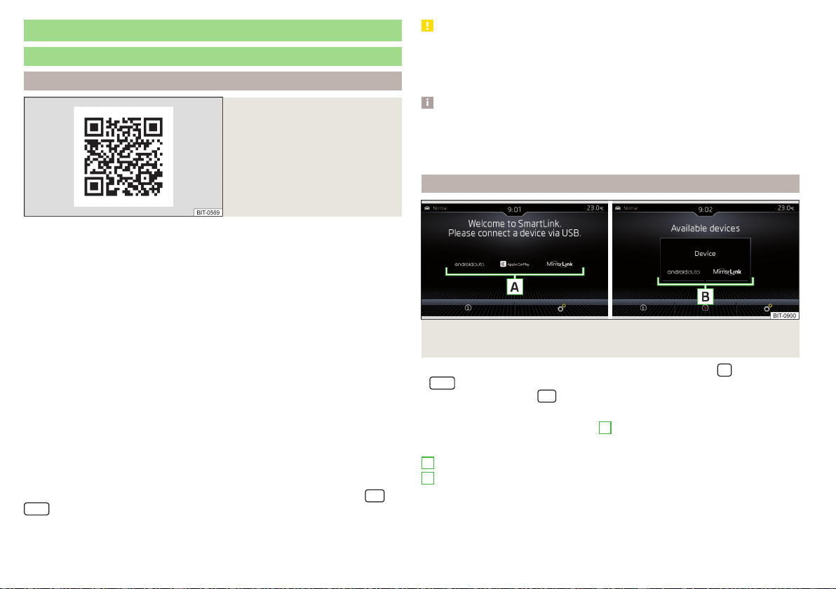
SmartLink
Introductory information
Introduction to the subject
Fig. 197
Information on SmartLink on the
ŠKODA websites
SmartLink offers the option to display certified applications on an external de-
vice equipped with a USB device on the Infotainment screen and to operate
them.
SmartLink supports the following communication systems.
▶
Android Auto
▶
Apple CarPlay
▶
MirrorLink
®
Using the applications in the connected external device, you can use navigation
to make a call and to listen to music.
For reasons of safety, the operation of some applications while driving is not
possible or only limited.
Read in the QR code» Fig. 197orenter the following address in the web brows-
er to open the website with information on the SmartLink system.
http://go.skoda.eu/connectivity-smartlink
Depending on the model of the connected external device, some applications
can be operated using Infotainment , voice or using the buttons on the multi-
function steering wheel.
To activate voice control for the connected external device, hold down
or
or hold down the button on the multifunction steering wheel.
CAUTION
To establish the connection, it is necessary that the date and time in Infotain-
ment are set correctly. If the date and time setting is based on the GPS signal,
then problems may arise with establishing a connection with a poor GPS signal
reception.
Note
■
We recommend that you use extension cords from ŠKODA Original Acces-
sories.
■
With some connected devices, it is necessary that the connected external
device is unlocked for trouble-free functioning of the SmartLink function“”.
Main menu
Fig. 198 Supported communication systems / example of available
communication systems for the connected external device
›
to display the SmartLink main menu, tap on the sensor field
or press the
button.
›
or tap the sensor field
and then the function surface .
If no external device is connected, then a menu with supported SmartLink
communication systems is displayed
A
» Fig. 198,
Main menu » Fig. 198
Supported communication systems
Available communication systems for the connected external device
Display of information about SmartLink
Disconnection of the active connection
Settings of the SmartLink » page 136 menu or » page 141
A
B
170
Infotainment
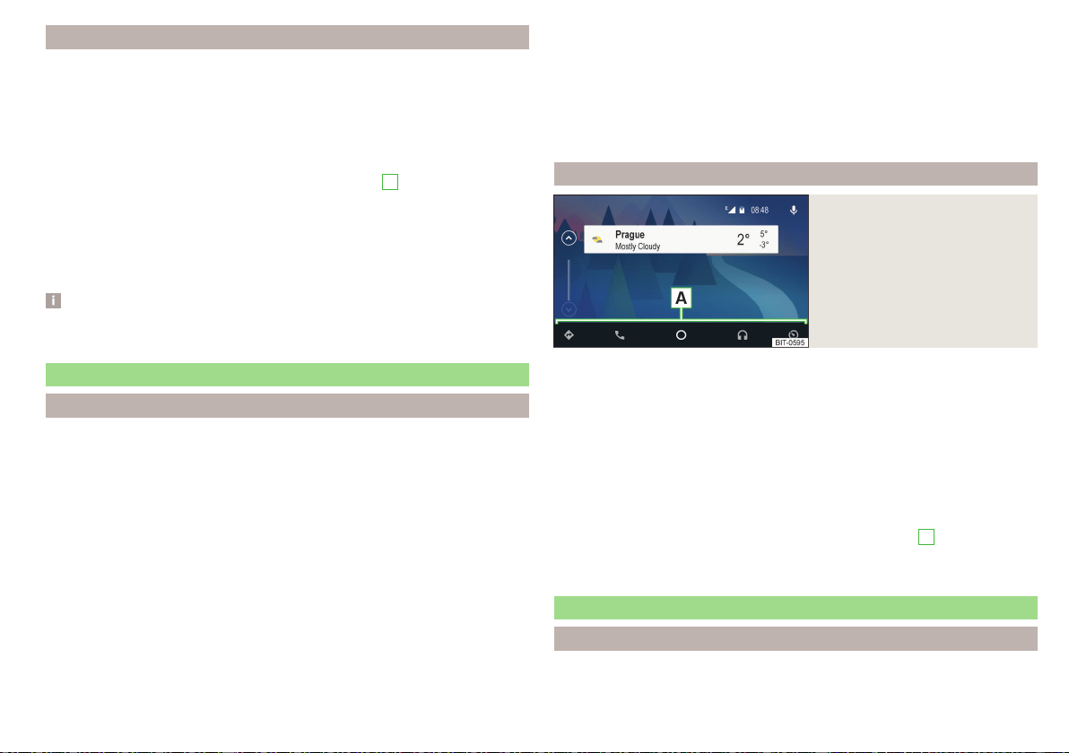
Connection / disconnection
Connection set-up
›
Switch on the ignition.
›
Switch on Infotainment.
›
Switch on the external device.
›
Switch to connect via Apple CarPlay, data connection, as well as voice con-
trol (Siri) in the connected external device.
›
Connect the external device to the USB input via a cable» page 93.
›
Select the type of supported communication system
B
» Fig. 198 on
page 170,
Disconnection of the active connection
›
In the main SmartLink menu, tap on function surface .
›
or: Disconnect the cable from the USB input (the external device will be con-
nected automatically when reconnected).
Note
Some applications require the data connection in the connected external de-
vice to be switched on.
Android Auto
Introduction to the subject
A connection can only be established with a supported external device with
the Android Auto application installed.
By connecting the external device with Android Auto, all currently connected
Bluetooth
®
devices and the external device are automatically connected as the
main phone.
During the duration of connection, Bluetooth devices cannot be connected to
Infotainment. The SIM card inserted in the external module can only be used
for data connection.
During the duration of connection, the external device cannot be used as an
audio source in the Media menu.
If route guidance is taking place at this moment in Infotainment, then there
is the option to start the route guidance in the Android Auto application. And
vice versa, if route guidance is currently taking place in the Android Auto ap-
plication , Then there is the possibility that this is terminated by Infotainment
due to route guidance starting.
A list external of devices, supported regions and applications that the Android
Auto connection supports can be found on the websites of Google Inc..
main menu
Fig. 199
Android Auto: main menu
Main menu » Fig. 199
Navigation applications
Telephone applications
Overview regarding current applications, telephone calls, accepted text
messages, tasks in the working directory, weather or similar.
Music applications
Display of other available applications as well as the option of returning to
the SmartLink main menu
Turn on voice control (Google Voice)
The symbol appears next to the function surface in the area
A
appears and
then, after tapping on this function surface again, a list of new applications is
displayed.
Apple CarPlay
Introduction to the subject
A connection can only be established with an external device that supports the
Apple CarPlay communication system.
171
SmartLink
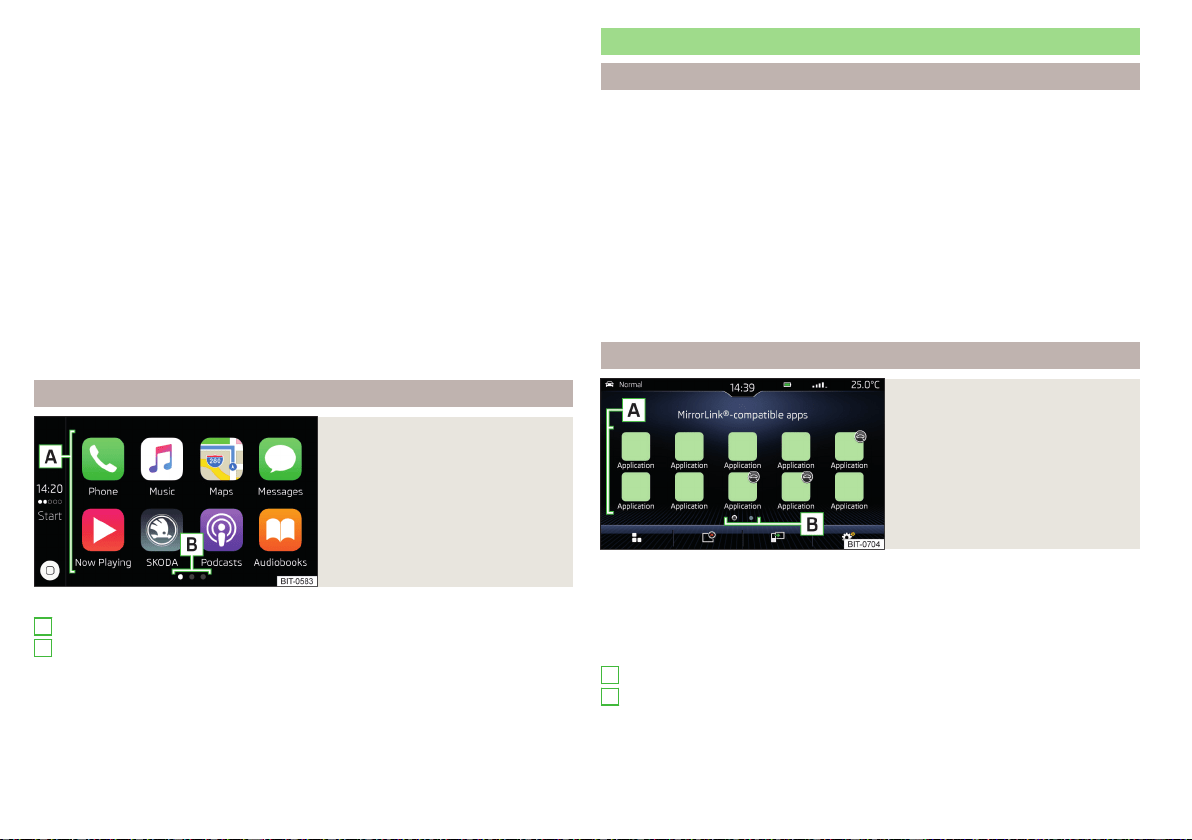
By connecting the external device to Apple CarPlay, all currently connected
Bluetooth
®
devices are disconnected.
During the duration of connection, Bluetooth devices cannot be connected to
infotainment. The SIM card inserted in the external module can only be used
for data services.
During the duration of connection, the external device cannot be used as an
audio source in the Media menu.
Some phone features of the connected external device can be operated in the
instrument cluster display » page 53.
If route guidance is taking place at this moment using Infotainment, then this
is terminated by starting the route guidance in the Apple CarPlay application.
And vice versa, if route guidance is currently taking place in the Apple
CarPlay application , Then this is terminated by Infotainment due to route
guidance starting.
A list external of devices, supported regions and applications that the Apple
CarPlay connection supports can be found on the websites of Apple Inc..
main menu
Fig. 200
Apple CarPlay: main menu
Main menu » Fig. 200
List of available applications
More pages with applications
Depending on how long the function surface is pressed:
▶
Tap - Return to main menu Apple CarPlay
▶
Hold - Switching on voice control
A
B
MirrorLink
®
Introduction to the subject
A connection can only be established with an external device that supports the
MirrorLink
®
communication system.
Applies to Infotainment Columbus, Amundsen, Bolero: If you would like to
connect the device in the phone menu, the external device must be paired and
connected before establishing a connection » page 157.
Applies to Infotainment Swing. By connecting the external device, all currently
connected Bluetooth
®
devices and the external device are automatically con-
nected as the main phone. Depending on the device to be connected, a con-
nection confirmation may be required.
During the duration of connection, the external device cannot be used as an
audio source in the Media menu.
main menu
Fig. 201
MirrorLink®: Main menu
Main menu » Fig. 201
Return to SmartLink main menu » page 170
List of running applications
Display the contents of the connected external device
Settings of the SmartLink » page 136 menu or » page 141
List of applications
More pages with applications
The applications cannot be operated while driving
A
B
172
Infotainment

Displays function surfaces during the running application
Return to MirrorLink
®
main menu
Show function surfaces at the top/bottom (applies to Infotainment
Amundsen, Bolero)
Move the functional surfaces in the desired corner of the screen
(applies to the infotainment Swing)
To show / hide the function buttons, press the controller (applies to Info-
tainment Amundsen, Bolero).
function problems
If problems occur with the MirrorLink
®
connection, then one of the following
messages may occur on the screen.
■
Fault: Transfer
- Disconnect and reconnect the external device
■
MirrorLink® audio is unavailable.
- Disconnect and reconnect the external device
■
MirrorLink® availability on this mobile device is restricted.
The connected device can-
not be used when driving or if the device is conditionally available (applies to
Infotainment Swing)
■
The mobile device is locked. Please unlock the mobile device to use MirrorLink®
- “unlock”
the connected external device
■
Unable to start app or app not working.
- Disconnect and reconnect the external
device
ApplicationŠKODA OneApp
Introductory information
Fig. 202
Information on the ŠKODA
OneApp application on the
ŠKODA websites
A mobile telephone connected to the Infotainment system allows you to edit
and evaluate driving data in the ŠKODA One App application.
The ŠKODA OneApp application is available in the App Store and Google Play
online shops.
Scan the QR code » Fig. 202 or enter the following address in your web
browser to open the website with information on the ŠKODA OneApp appli-
cation.
http://go.skoda.eu/infotainment
For the full functionality of the ŠKODA One App application, data transfer
from external devices must be activated.
Applies to Infotainment Columbus, Amundsen, Bolero
▶
To activate data transfer from external devices , tap the
centre field
and then tap the function surface →
Mobile device data transfer
→
Activate data
transfer for ŠKODA apps
.
Applies to Infotainment Swing
▶
To activate data from external devices, press the
button, then tap on
function surface →
Activate data transfer for ŠKODA apps
.
Note
Some application functions are not available in all countries or there is a func-
tion restriction while driving » page 120, Mobile devices and applications.
Connecting to Infotainment
The mobile telephone can be connected to the infotainment system using the
SmartLink function or via WLAN.
Connection by SmartLink
›
Switch on the ignition.
›
The connection means SmartLink (e.g.. MirrorLink
®
) build up » page 170,
›
In the list of available applications, select the ŠKODA One App application.
Depending on the model of the connected external device, some applications
can be started using voice activation, via the Infotainment screen, using the
operating elements on Infotainment, or using the buttons on the multi-func-
tion steering wheel.
Once connected, the contents of the application in the infotainment screen
may be displayed.
173
SmartLink

A possible connection between the mobile telephone and the Infotainment
system via WLAN will be terminated after a connection is established using
SmartLink.
Connection via WLAN (applies to Infotainment Columbus, Amundsen)
›
Switch on the ignition.
›
Establish the WLAN connection » page 168.
›
In the mobile telephone, start the ŠKODA OneApp application.
Disconnect the connection
The connection can be switched off in one of the following ways.
›
Switch off the ignition for longer than 5 seconds (for vehicles with a starter
button, switch off the engine and open the driver's door).
›
End the connection in the ŠKODA OneApp application.
›
Disconnect the mobile telephone from the USB port or terminate the WLAN
connection.
Navigation
Introductory information
Navigation - function sequence
Applies to Infotainment Columbus, Amundsen.
Route guidance is started as follows.
›
Search for/ enter a new destination or Select one of the stored destinations.
›
Confirm the route calculation in the destination details or if necessary, adjust
the route options.
›
Select the preferred route type, if this is requested by Infotainment.
A route calculation occurs and route guidance starts.
The route guidance is provided by graphical driving recommendations and nav.
announcements.
The is an option to add additional destinations during route guidance, or to
adapt the route.
If a traffic radio station is available, information concerning traffic delays is
evaluated by Infotainment and, if necessary, an alternative route is offered.
If you deviate from the route, then a new route calculation is carried out.
GPS satellite signal
Infotainment uses the GPS (Global Positioning System) satellite signal for
route guidance.
Outside the range of the GPS satellite signal (e.g. in dense vegetation, in tun-
nels, parking garages, etc.), Infotainment navigates only with restrictions using
vehicle sensors.
The unit offers the possibility to show in the split screen display the following
Position
» Fig. 205 on page 177 information about the current geographical po-
sition of the vehicle and the satellite signal.
Geographical longitude
Geographical latitude
Elevation
Number of received/available satellites
174
Infotainment

If no GPS satellite signal is available, no values are displayed.
Navigation data
Navigation data source Columbus
The navigation data is stored in the Infotainment memory.
Navigation data source Amundsen
The navigation data is stored on an Original SD Card.
In order to ensure the function of the navigation, the Original SD card, with the
navigation data, must be inserted in the respective slot in the external module
» page 122.
If the original SD card is damaged or lost, a new original SD card can be pur-
chased from the ŠKODA Original Accessories.
With a Non-original SD Card, navigation does not work.
Determining the version of the navigation data
›
In the Navigation main menu, tap the function surface
→
Version information
.
Update navigation data
We recommend that you update the navigation data on a regular basis (e.g.
Due to newly developed roads and changed traffic signs).
The information on updating the navigation data is to be obtained from a
ŠKODA partner or on the following ŠKODA Internet pages.
http://go.skoda.eu/updateportal
Update navigation data online
When activated online services Infotainment Online » page 13 can the naviga-
tion data for the infotainment Columbus Updating online » page 175, Naviga-
tion data and POI categories Import / Update online,
If an update of the navigation data for the current vehicle position or the desti-
nation of the route is available, which in this regard from a Infotainment auto-
matic Note issued and offered an upgrade option.
An online update of navigation data is also manually feasible as follows.
▶
In the Navigation main menu, tap the function surface →
Version information
→ →
Update (online)
→
Maps
.
▶
The Select / the desired country / region.
▶
Tap on the function surface
Retrieve
.
During the upgrade process, infotainment is usable without limitation.
To complete the update of the navigation data, the ignition must be switched
off for at least 30 min.
Navigation data and POI categories Import / Update online
When Infotainment Online » page 13 online services are activated, there is the
option of downloading/updating navigation data (applies to Infotainment Co-
lumbus) or of downloading POI categories created in the user profile on the
ŠKODA Connect Portal website.
▶
In the main Navigation menu, tap the function surface →
Version information
→
Update (online)
→
Retrieve
.
▶
or: Tap the
sensor field and then the function surface → .
A menu for importing/updating the navigation data and POI categories is dis-
played.
▶
Tap the function surface
and select one of the following menu items.
■
All
- Import all the available navigation data
■
Favourites
- Import of navigation data preferably countries / regions (applies
to the infotainment Columbus)
■
POIs
- Import of the POI category created in the user profile on the ŠKODA
Connect Portal website » page 183
■
Maps
- Import of the navigation data available for the respective countries/re-
gions (applies to Infotainment Columbus) » page 175, Update navigation data
online
▶
Select the desired list entries.
▶
Tap the function surface
Retrieve
and confirm the deletion.
During the upgrade process, infotainment is usable without limitation.
175
Navigation
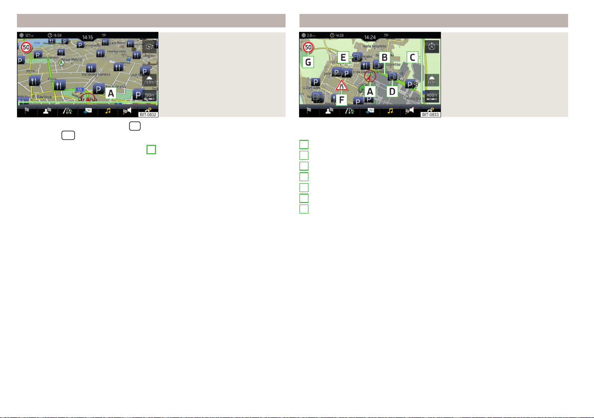
Main menu
Fig. 203
Navigation: Main menu
›
To display, tap the sensor field
.
›
or: Tap the
sensor field and then the function surface .
Description of the function surfaces
A
» Fig. 203
Context-dependent:
Route guidance is deactivated - Search / enter a new destination
Route guidance is enabled - The following menu is displayed:
▶
Route details
- Displays the route details » page 190
▶
Change route in map
- Displays a menu for the route change in the map
(applies to Infotainment Columbus) » page 191
▶
Congestion ahead
- Manually adjusts traffic conditions » page 195
▶
Enter destination
- Search for/enter a new destination/stopover
» page 177
▶
Stop route guidance
- Stops route guidance » page 189
The following menu is displayed:
▶
Store Current position
- Store the current vehicle position as a flagged des-
tination » page 181
▶
Routes
- Displays the list of saved routes » page 191
▶
Destinations
- Displays the list of stored destinations » page 181
▶
Last destinations
- Displays the list of recent destinations to which route
guidance was carried out » page 181
▶
Home address
- Route guidance to your home address » page 182
Search for POIs in categories , and
Map display options » page 184
Operation of Media/Radio playback
Display for the volume setting of the navigation announcements/repeti-
tion of the navigation announcement » page 189
Navigation settings » page 137
Map
Fig. 204
Card description
The following information and function surfaces can be displayed in the
map. » Fig. 204
Vehicle position
Route
Function surfaces for card use » page 184
Function surface of the POI
Function surface for the POI list
Function surface for displaying a traffic incident » page 195
Information on the maximum permitted speed
Destination position
Intermediate destination position
Destination position
Home address
Favourite position
Information in the status line
Street name / street number of the current vehicle position
Distance to destination
Route to the stopover
Estimated travelling time to the destination
Estimated travel time to the stopover
Estimated time of arrival at destination / stopover
A
B
C
D
E
F
G
176
Infotainment
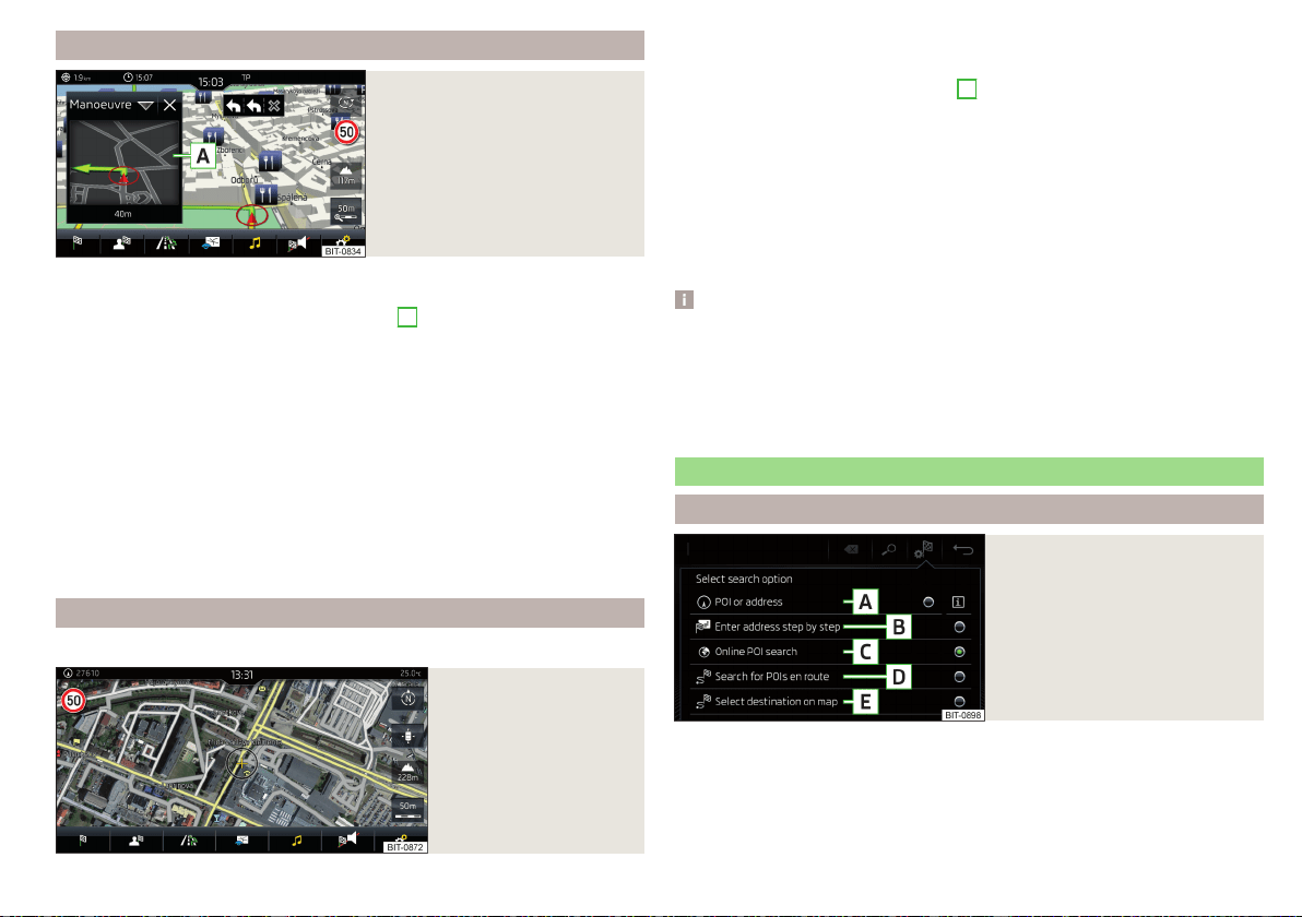
additional window
Fig. 205
Split screen
›
To switch on/offin the main menu Navigation, tap on the function surface
→
Split screen
.
›
To select content of the additional window
A
» Fig. 205 tap the function
surface
and select one of the following menus, depending on the context.
■
Audio
- Operation of
Radio
/
Media
playback
■
Compass
- Displays the current vehicle location in relation to the compass di-
rections
■
Freq. Routes
- Display the three most frequently travelled routes (if route guid-
ance is disabled) » page 189
■
Manoeuvre
- Displays graphical driving recommendations (if route guidance is
enabled) » page 189
■
Position
- Displays the geographical coordinates of the current vehicle loca-
tion
■
Map
- Displays the preview map (applies to Infotainment Columbus)
» page 186
Google Earth
™
online map
Only valid for Infotainment Columbus.
Fig. 206
Google Earth™ map
In the Google Earth
™
Card is represented by the map of the downloaded from
the Internet pictures.
›
To display, tap the function surface
F
» page 184, Options for map display,
The map and symbol display in the Google Earth
™
map is dependent on the
provider, American company Google, Inc.
To display the Google Earth
™
map, the following conditions are required.
The Infotainment Online online services are activated» page 13.
Internet connection » page 166.
The signal from the data service provider network for the data connection
is available.
Note
■
In the Google Earth
™
Display is possible no insertion of the symbols of the
POI categories.
■
When driving through a tunnel changes the 3D representation of the Google
Earth
™
Card automatically in the 2D display.
■
The speed of the Google Earth
™
display depends on the Internet connection
speed.
Search for destination and enter
Select the type of destination search / destination entry
Fig. 207
Select the type of destination
search / destination entry
›
Route guidance is disabled - From the Navigation main menu, the function
surface
→ .
›
Route guidance is enabled - From the main Navigation menu, tap the func-
tion surface
→
Enter destination
→ .
177
Navigation

Function surfaces » Fig. 207
Searching for a destination or POI (point of interest) by name » page 178
Destination entry by address » page 179
Online POI search » page 178
Search for a point along the route (only works with active route guidance)
» page 178
Destination input via the map point or using the GPS coordinates
» page 179
Search POI destination /
Fig. 208
Menu for destination search
Fig. 209
List of destinations found: in the navigation data/online
The feature allows a full text search of locations or points of interest (POI) by
entering keywords.
Show menu
›
Route guidance is disabled - From the Navigation main menu, the function
surface
→ .
A
B
C
D
E
›
Route guidance is enabled - From the main Navigation menu, tap the func-
tion surface → Tap
Enter destination
›
Then tap the function area of one of the menu items for the destination
search
A
.
C
or
D
» Fig. 207 on page 177.
function surfaces » Fig. 208 and » Fig. 209
Input line
Depending on the search mode, the following symbols are displayed
- Display of destinations found in the navigation database
- Display of destinations found online
- Selecting destination search / destination entry » page 177
List of last destinations (if no character is entered) / list of visited destina-
tions
Keypad
Status of online services
Find destination
▶
Enter the POI name or the POI category (POI) and, if required, the place and
street name or house number/postal code.
In the
D
» Fig. 208 A list of destinations searched for is displayed.
▶
Select the desired destination destination details are displayed.
▶
or: tap function surface
B
» Fig. 208.
A map with the following symbols and a list of destinations search for is dis-
played.
Destinations searched for in navigation data » Fig. 209 -
.
Destinations searched for online » Fig. 209 - .
▶
Select the desired destination destination details are displayed.
A
B
C
D
E
F
178
Infotainment
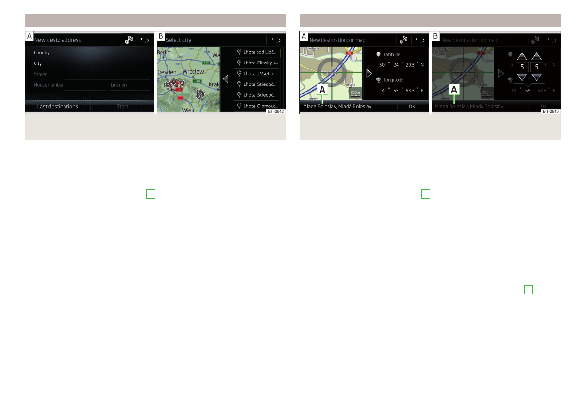
Enter destination using the address
Fig. 210 Enter destination using the address: Main menu/list of places
found
Show menu
›
Route guidance is disabled - From the Navigation main menu, the function
surface
.
›
Route guidance is enabled - From the main Navigation menu, tap the func-
tion surface
→ Tap
Enter destination
›
Then tap the function surface
→
B
» Fig. 207 on page 177.
Enter destination
›
Enter the destination address and then confirm. » Fig. 210 -
.
›
Tap the function surface
Destination details are displayed.
Relevant names (e.g. Place/street names) are offered in the entry line during
entry, depending on the context. The location of the proposed destination can
be displayed by tapping the
map
function surface.
Depending on the number of places searched for, a map with a list of places
searched for can be displayed automatically » Fig. 210 - .
The map with the list of visited locations can be displayed manually by tapping
the function area .
Enter destination on the map and using GPS coordinates
Fig. 211 Enter destination: via the map point / using the GPS coordi-
nates
Show menu
›
Route guidance is disabled - From the Navigation main menu, the function
surface
.
›
Route guidance is enabled - From the main Navigation menu, tap the func-
tion surface
→ Tap
Enter destination
›
Then tap the function surface
→
E
» Fig. 207 on page 177.
Enter destination via the map point
›
By sliding the screen move the desired destination into the cross-hair
» Fig. 211 -
.
›
Tap the function surface Destination details are displayed.
through via coordinates
›
Touch and adjust the GPS coordinate values one at a time » Fig. 211 -
,
›
Tap the function surface Destination details are displayed.
If information is available about the point entered in the navigation data, then
these will be displayed instead of the GPS coordinates (e.g. address
A
» Fig. 211).
179
Navigation
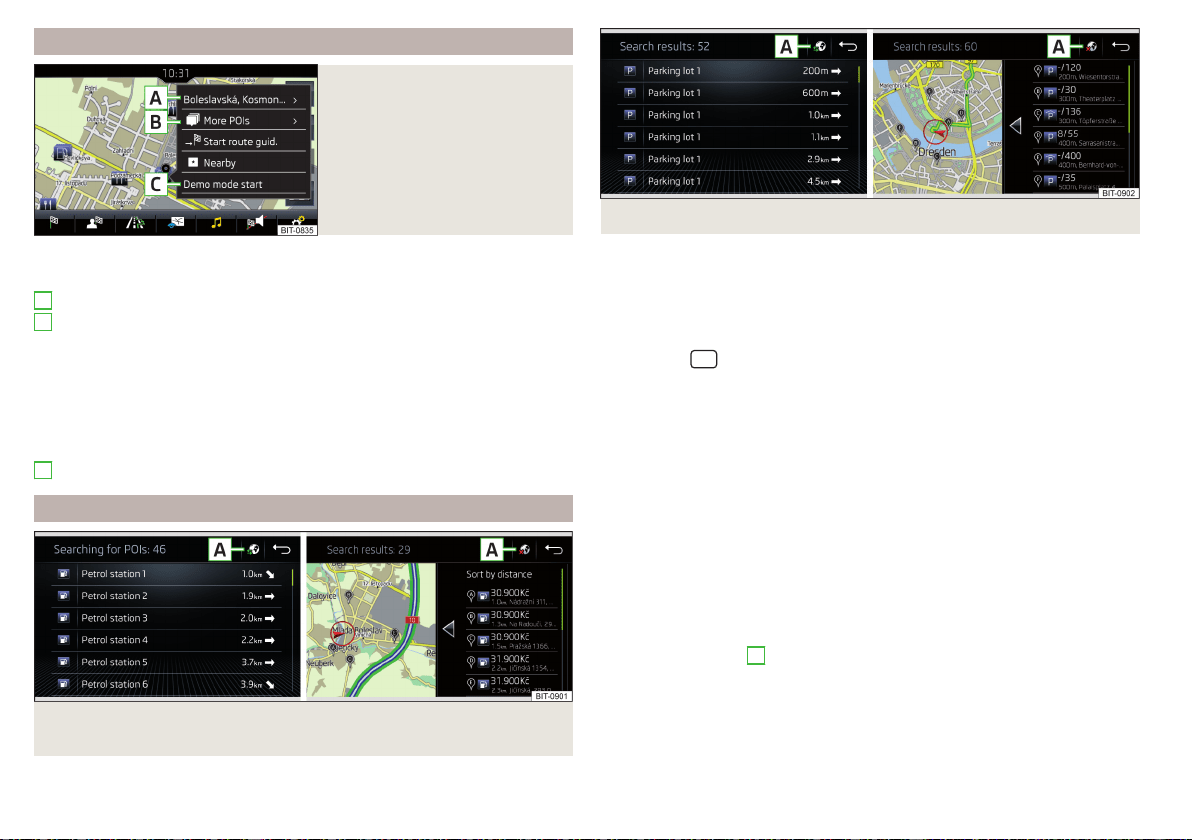
Entering a destination via the map coordinates
Fig. 212
Menu after tapping the map
point
Tap on the map to display the symbol and a menu with the following menu
items (depending on the context) » Fig. 212.
Display the destination details » page 187
Display the POI details/display the POI list (function surface)
)
Start route guidance to the selected point
Paste the selected point as the next destination in the current route
guidance
Start route guidance to the favourite
Start route guidance to the home address
Destination search in the vicinity of the selected point » page 178
Define the starting point for demo mode (if it is turned on) » page 188
Search for a petrol station, restaurant or car park
Fig. 213
List of petrol stations searched for: In the navigation data / on-
line
A
B
C
Fig. 214 List of car parks searched for: In the navigation data / online
Infotainment allows for a quick search of petrol stations, restaurants or car
parks in the navigation data as well as an online search of petrol stations and
car parks.
›
In the Navigation main menu, tap the function surface
or
.
›
The function surface of the desired category button.
›
or: Tap the
sensor field and then the function surface
→
or
.
Search destination in the navigation data
Depending on the context below a list be examined POIs in the selected cate-
gory is displayed.
▶
No route guidance is taking place - The nearest destinations in a radius of
200 km from the current vehicle position are displayed.
▶
Route guidance is taking place - Destinations on the route or near the route
are displayed.
Find Target online
When Infotainment Online » page 13 services are activated, a list of POIs from
the selected category in a radius around the current vehicle position is dis-
played, regardless of whether or not route guidance is taking place.
After performing destination search, it is possible to switch between the list of
visited in the navigation data or online goals by one of the following functional
areas on the position
A
» Fig. 213 or. » Fig. 214 is tapped.
Displays the list of visited in the navigation data targets.
Displays list of last destinations
180
Infotainment
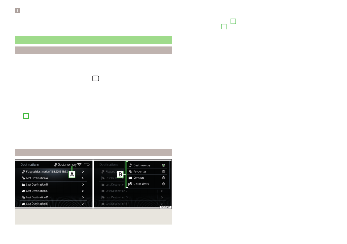
Note
With activated function →
Fuel options
→
Select preferred fuel station
function ac-
tivated, the preferred fuel stations are displayed in the first three positions
during the fuel station search.
Saved destinations
Last destinations
List of last destinations
›
In the Navigation main menu, tap the function surface →
Last destinations
.
Details of the last destination (not applicable to Infotainment Columbus)
›
In the main Navigation menu, tap the
sensor field.
If route guide is disabled, then the details of the last destination are displayed
to where the route guidance was carried out. If route guidance is enabled,
Then the details of the final destinations are displayed.
Last destinations menu for destination / POI search
In the destination search menu, a short list of last destinations is show in the
area
D
» Fig. 208 on page 178.
Function surfaces in the list of last destinations
- Destination search by name (the function surface is displayed with
more than 5 entries available)
- Display the details of the selected destination » page 187
target memory
Fig. 215 Select list of stored destinations / categories of saved destina-
tions
Find
List of stored destinations
›
In the Navigation main menu, tap the function surface →
Destinations
.
›
Select function surface
A
» Fig. 215 and one of the following categories of
saved destinations
B
» Fig. 215.
All saved destinations
▶
- Flagged destination (vehicle position at the time of storage)
▶
- Stored destination (manually saved destination/destination impor-
ted in vCard format)
▶
- Favourite (destination with additional favourite property)
Favourites (the favourite location is shown in the map by the symbol ).
Telephone contact addresses of the connected phone or the inserted SIM
card.
Online destinations created in the user profile on the ŠKODA Connect
Portal website or in the ŠKODA Connect application » page 184
Function surfaces in the list of stored destinations
- Destination search by name (the function surface is displayed if there
are several entries on the next page of the list)
- Display of the destination details » page 187
Store target
▶
In the Navigation main menu, tap the function surface
→
Last destinations
.
▶
Tap the function surface
at the desired destination to display the destina-
tion details.
▶
Tap on the function surface
Store
.
▶
Rename the destination if necessary and confirm storage.
“Flagged destination” Save (current vehicle position)
▶
In the Navigation main menu, tap the function surface
→
Store
→
Current po-
sition
.
▶
By then pressing the function surface
Rename
the flagged destination can be
renamed and stored as a destination in the dest. memory.
By storing the next flagged destination, the last flagged destination will be
overwritten. To maintain the existing flagged destination, this destination must
be stored in the Infotainment memory.
Save as a favourite / cancel
It is not possible to store a contact, a vCard or target image as a favourite.
▶
In the Navigation main menu, tap the function surface
→
Destinations
.
▶
Tap the function surface and select the desired list of destinations.
Find
181
Navigation
▶
Show the destination details by tapping on the function surface at the de-
sired destination.
▶
Tap the function surface
Edit
.
▶
Tap the function surface
Favourite
.
Delete destination
▶
In the Navigation main menu, tap the function surface →
Destinations
.
▶
Tap the function surface and select the desired list of destinations.
▶
Show the destination details by tapping on the function surface at the de-
sired destination.
▶
Tap the function surface
Edit
.
▶
Tap the function surface
Delete
and confirm the deletion.
Home address
Define home address
When your home address is not entered, then proceed as follows.
›
In the Navigation main menu, tap the function surface
→
Home address
.
›
Defining the home address using the current vehicle position or by entering
the address.
Change the home address
›
In the Navigation main menu, tap the function surface
→
Manage memory
→
Define home address
.
›
Tap the function surface
Edit
.
›
Edit the home address or set one up using the current vehicle position or by
entering the address.
Delete home address
›
In the
Navigation main menu, tap the function surface →
Manage memory
→
Delete user data
→
Home address
.
›
Tap the function surface
Delete
and confirm the deletion.
Import your own goals
Introduction to the subject
Fig. 216
MyDestination application on
the ŠKODA websites
Fig. 217
Websites ŠKODA Connect
In this chapter, destinations are described which can be imported into the Info-
tainment memory.
The own objectives by means of ŠKODA-Application “MyDestination”, In the
user profile on the website ŠKODA Connect Portal or in the application
ŠKODA Connect to be created.
By reading the QR code » Fig. 216 or after typing the following address in the
web browser, more information on the “MyDestination”application is dis-
played.
http://go.skoda.eu/my-destination
Access to the ŠKODA Connect Portal is the website ŠKODA Connect refer to.
This is carried out by reading the QR code » Fig. 217 or after entering the fol-
lowing address into the web browser.
http://go.skoda.eu/connectivity
182
Infotainment

Goals in vCard format
In the Infotainment memory, a custom destination can be imported in the
vCard format (*.vcf) from an SD card or a USB source.
Import
›
Insert the SD card into the exernal module or connect a USB source with the
file of the custom destination.
›
In the Navigation main menu, tap the function surface →
Manage memory
→
Import destinations (SD/USB)
.
›
Select the source and confirm the import.
Route guidance
›
In the Navigation main menu, tap the function surface
→
Destinations
→ →
.
›
Search for and select the desired imported destination.
Delete own destination
›
In the Navigation main menu, tap the function surface
→
Destinations
→
→
.
›
Tap the function surface
Tap on the desired custom destination.
›
In the destination details, tap the function surface
Edit
→
Delete
and confirm
the deletion.
In the application “MyDestination” created POI categories
Import / update
›
Insert the SD card into the external module or connect a USB source with
the POI categories.
›
In the Navigation main menu, tap the function surface →
Manage memory
→
Update "My POIs" (SD/USB)
.
If there is already the same POI category name in the Infotainment memory,
then it will be overwritten during the import.
Show POIs in the map
›
In the Navigation main menu, tap the function surface →
Map
→
Select cate-
gories for POIs
→
My points of interest (Personal POI)
.
›
Select the desired POI category.
The insertion of the symbols of the POI categories in the Google Earth
™
Card is
not possible.
Guidance to an online destination
›
Tip on the traffic obstruction icon in the map.
There are details of the selected target appears » page 187,
Clear all own POI categories
›
In the Navigation main menu, tap the function surface →
Manage memory
→
Delete "My POIs"
.
›
Tap the function surface
Delete
and confirm the deletion.
In user profile “ŠKODA Connect Portal” created POI categories
The in the user profile on the website ŠKODA Connect Portal started own POI
categories can be imported into the infotainment memory.
The requirement for importing a POI category is that Infotainment Online
» page 13 services are activated.
Import POI categories
In the Navigation main menu, tap the function surface
→
Version information
→
Update (online)
.
›
or: Tap the
sensor field and then the function surface
→
.
A menu for importing/updating the navigation data and POI categories is dis-
played.
›
Tap the function surface
→
POIs
→
Retrieve
.
Are new POI categories available, their number and the file size is displayed on
the Infotainment.
›
Tap the function surface
Start
to start route guidance.
›
To complete the import, tap the function surface
Next
and confirm the im-
port.
Show POIs in the map
›
In the Navigation main menu, tap the function surface →
Map
→
Select cate-
gories for POIs
→
My points of interest (Personal POI)
.
›
Select the desired POI category.
The insertion of the symbols of the POI categories in the Google Earth
™
Card is
not possible.
Route guidance to a destination of imported POI category
›
Tip on the traffic obstruction icon in the map.
183
Navigation
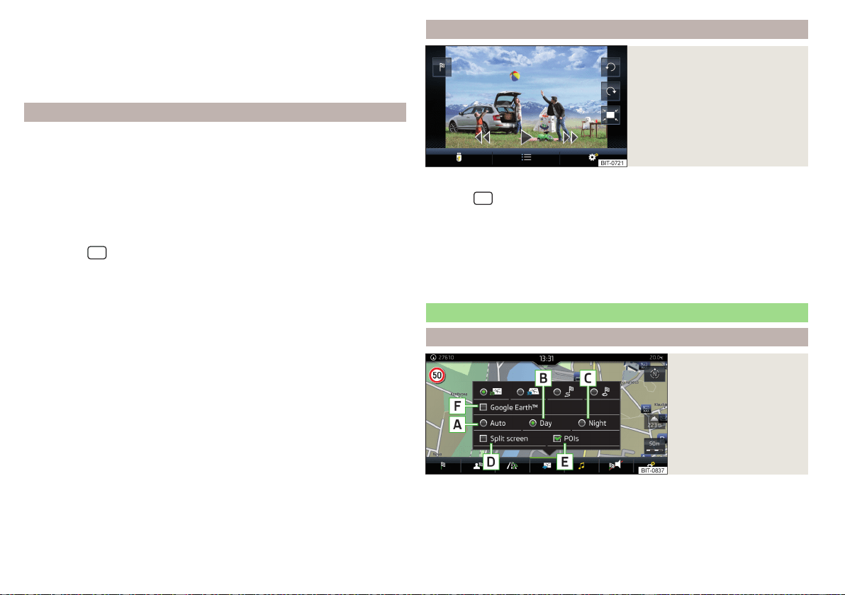
There are details of the selected target appears » page 187,
Clear all own POI categories
›
In the Navigation main menu, tap the function surface →
Manage memory
→
Delete "My POIs"
.
›
Tap the function surface
Delete
and confirm the deletion.
In user profile “ŠKODA Connect Portal” objectives created
The in the user profile on the website ŠKODA Connect Portal or in the applica-
tion ŠKODA Connect drawn objects can be imported to the infotainment
memory.
The requirement for importing the destinations is that Infotainment Online
» page 13 services are activated.
import goals
›
In the Navigation main menu, tap the function surface
→
Destinations
→
→
.
›
or: Tap the
sensor field and then the function surface
→
.
›
Tap on the function surface
Update
.
›
Are new targets available, then confirm the import.
If the user profile on the website ŠKODA Connect Portal or in the application
ŠKODA Connect creates an object and sent to the infotainment, after switch-
ing on the ignition in the infotainment screen displays a message regarding a
new destination with the option to import this displayed.
Guidance to an online destination
›
In the Navigation main menu, tap the function surface
→
Destinations
→
→
.
›
In the list of online dests to visit and select the desired destination.
Delete online dests
›
to delete all Online destinations in the main menu Navigation the function
surface →
Manage memory
→
Delete user data
→
Online destinations
.
›
to delete one Online destination in the main menu Navigation the function
surface
→
Destinations
→ → → →
Edit
→
Delete
.
Image with GPS coordinates
Fig. 218
Image with GPS coordinates
Infotainment enables guidance to the GPScoordinate data stored in the image.
›
Tap the
sensor field and then the function surface
Images
.
›
Select the connected source and open the image with GPS coordinates.
›
Tap the function surface
» Fig. 218 in the image and a menu will open with
the option to start route guidance.
The image can be obtained from an external device in which GPS coordinates
were stored at the time of image creation. This could be created in the
“MyDestination” application and imported » Fig. 216 on page 182.
Map
Options for map display
Fig. 219
Map options
›
In the Navigation main menu, tap the function surface
.
The following function surfaces are displayed » Fig. 219.
2D - Two-dimensional map display
3D - Three-dimensional map display
184
Infotainment
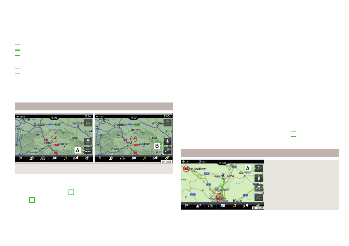
Display of the route from the current vehicle location to the destination
Presentation of the destination or the next interim destination in the map
(depending on the menu item setting) →
Advanced settings
→
Status line:
)
Automatic map display in day or night mode (depending on the currently
active vehicle lighting)
Daytime map display
Night-time map display
Switch the split screen display on/off » page 177
Switch the display of selected POI categories on/off » page 180, Entering
a destination via the map coordinates
Switch the display of Google Earth
™
online map on/off » page 177
If the map scale of the 2D Map or 3D Map is greater than 10 km (5 miles), then
the map is automatically displayed as 2D and aligned in the direction of north.
If the scale is increased beyond this value, then the map is switched back to
the original representation.
Map scale
Fig. 220 Function surfaces for the map scale change
It is possible to change the map scale manually or to turn on the automatic
change of scale.
›
Tap the function surface
A
» Fig. 220.
In area
B
» Fig. 220, function surfaces for changing the map scale are dis-
played.
A
B
C
D
E
F
Types of manual scale change
▶
Touching the screen with two fingers and pulling them apart or closing them
together.
▶
Turn the control knob (not applicable to Infotainment Columbus)
Switch on/off the automatic change of scale
If the automatic scale is active, the map scale will change automatically de-
pending on the type of roads travelled (motorway - smaller map scale / town
larger map scale) and from the manoeuvre to be carried out.
▶
To switch on the automatic scale change, go to the Navigation main menu
and tap on function surface → .
Tap the function surface is highlighted in green.
The automatic scale is only active as long as the map is centred on the vehicle
position (the function surface
is hidden).
▶
To switch off the automatic scale change, go to the Navigation main menu
and tap on function surface
→
.
The function surface
is highlighted in white.
The turning off occurs likewise when the map is moved or the map scale is
changed manually.
Map view in reduced scale
▶
In the Navigation main menu, tap on function surface
A
→
.
The map scale is reduced for a few seconds and then restored.
Change map orientation
Fig. 221
Change the map orientation
Changing map orientation is possible under the following conditions.
185
Navigation
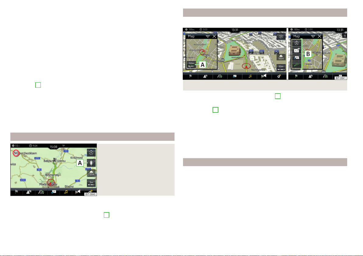
The map is in the 2D display.
The map is centred (the function surface is hidden).
The map scale is max. 10 km away.
With a larger map scale than 10 km, the map is automatically oriented towards
north.
A change of map orientation is only possible in the 2D display when the map is
centred on the vehicle position (the function surface is hidden » page 186,
Map alignment).
With a larger map scale than 10 km, the map is automatically oriented towards
north.
›
to Change the map orientation From the main menu Navigation the function
surface
A
» Fig. 221.
The map is oriented to the north
The symbol
for the vehicle position rotates, the map and the polar star sym-
bol
do not rotate.
Map oriented to the direction of travel
The map and the Polar Star Symbol
rotate, the vehicle position symbol
does not rotate.
Map alignment
Fig. 222
Map centring
The moved map can be centred/aligned to the vehicle, destination or route po-
sition.
›
To centre the map, tap function surface
A
» Fig. 222.
Options for map display in the split screen
Only valid for Infotainment Columbus.
Fig. 223 Map in split screen
›
In the split screen, tap on function surface
A
» Fig. 223.
Depending on the context, some of the following function surfaces will be dis-
played in area
B
.
Map display with the route from the current vehicle location to the desti-
nation
Change the map orientation
2D - Two-dimensional map display
3D - Three-dimensional map display
Switch on/off the automatic change of scale
POIs display
The Infotainment system offers the possibility of displaying POI symbols on
the map on the Infotainment screen.
›
To activate/deactivate the display, go to the main Navigation menu and tap
on the function surface
→
POIs
.
›
To select the POIs to be displayed, go to the main Navigation menu and tap
on the function surface →
Map
→
Select categories for POIs
and select the de-
sired categories (max. 10).
186
Infotainment
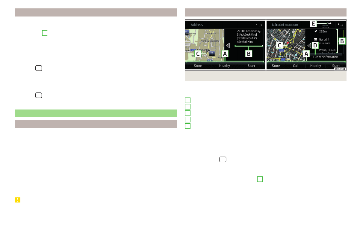
Road sign display
Infotainment offers the option of displaying the traffic signs stored in the navi-
gation data or detected by the front camera during guidance on the Infotain-
ment screen
G
» Fig. 204 on page 176.
›
To switch on/off the road sign display in the main menu Navigation, tap on
the function surface →
Map
→
Show road signs
.
For some vehicles it is possible to set an alert when exceeding the permitted
speed limited set by a road sign.
›
Tap the
sensor field and then the function surface →
Driver assistance
→
Speed warning:
.
For trailer towing, We recommend that you activate recognition of road signs
relevant to trailers.
›
Tap the
sensor field and then the function surface
→
Driver assistance
→
Show road signs relevant to trailers
.
Route guidance
Introduction to the subject
A route is created by starting route guidance to a destination. Additional inter-
mediate destinations can be added to the route.
The route guidance takes place as follows
▶
Through graphical driving instructions on the Infotainment screen and in the
display of the instrument cluster.
▶
With nav. announcements.
Infotainment tries to allow for continued guidance even if the navigation data
is incomplete or there is no data at all for the given area.
The route is recalculated each time if you ignore driving recommendations or
change the route.
CAUTION
The nav. announcements provided may vary from the actual situations, e.g. due
to out-of-date navigation data.
Destination details
Fig. 224 Details of: destination found in the navigation data/online
The following menu items and information are displayed in the destination de-
tails» Fig. 224.
Area with function surfaces
Detailed destination information
Destination position in the map
Detailed target information (if available)
Status of online services
Display the destination details
The destination details can be displayed in one of the following ways.
▶
While entering a destination.
▶
By tapping on the function surface in the destination list.
▶
By tapping the
sensor field in the Navigation main menu (not applicable
to Infotainment Columbus), the details of the last destination are displayed.
Functional surfaces
Using function surfaces in the field
A
the following functions can be per-
formed, depending on the context.
▶
Start / stop route guidance.
▶
Searching for a nearby destination » page 178.
▶
Setting route options.
▶
Store destination.
▶
Edit destination (the object can be deleted, renamed or saved).
▶
Dial the POI phone number (if Infotainment is connected to a
phone» page 157, Pairing and connecting).
A
B
C
D
E
187
Navigation
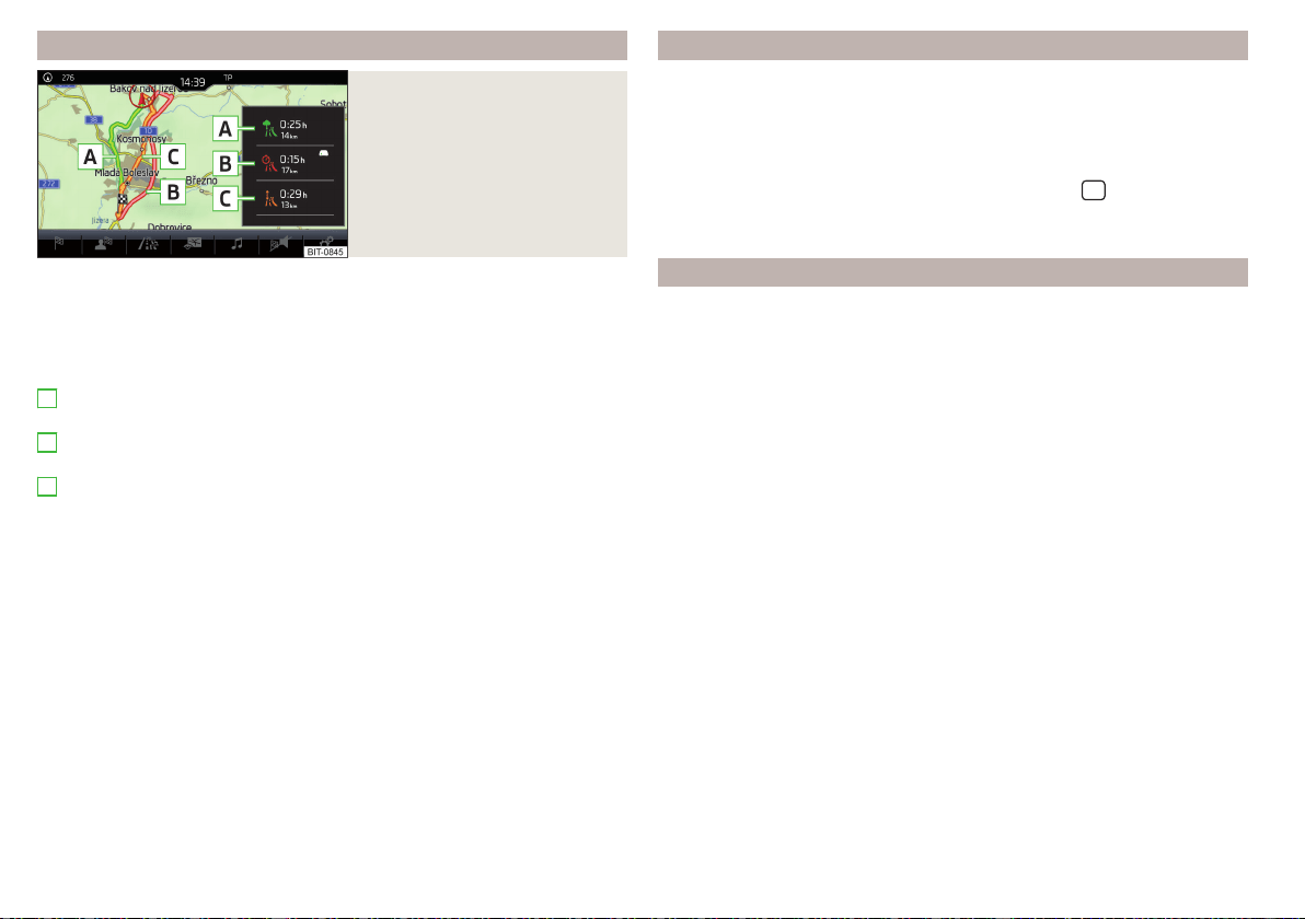
Route calculation and start route guidance
Fig. 225
Alternative routes
Route calculation is done on the basis of the set route options. The route op-
tions can be set: →
Route options
.
Alternative routes
With selection of alternative routes turned on, the following menu is displayed
after the calculation of a new route » Fig. 225.
- calculate the most economical route with the shortest driving time
and shortest distance travelled – the route is highlighted green
- calculate the fastest route to the destination, even if a detour is nec-
essary –the route is highlighted in red
- calculate the shortest route to the destination, even if a longer driving
time is required – the route is highlighted in orange
In the function surfaces of the alternative routes, information on the route
length and the estimated travel time and the following symbols are displayed
(applies to Infotainment Columbus).
Use of a toll motorway
Use of a train / ferry
Using a tunnel
Use of a toll road
Using a vignette duty highway
It is possible to select an already calculated alternative route before the calcu-
lation of the remaining routes is completed.
Selecting the type of route will start the route guidance.
If no route selection is made within 30 s after the calculation of all routes, the
route guidance is automatically started according to the preferred route type.
A
B
C
Route calculation for the trailer
When driving with a trailer or any other accessory connected to the trailer
socket, we recommend that you switch on the trailer recognition, if necessary
to set the maximum speed for towing a trailer.
›
For calculating the route for towing a trailer, tap the function surface in the
main Navigation menu →
Route options
→ .
›
To set the maximum speed for towing a trailer, tap the
sensor field and
then the function surface →
Driver assistance
→ Trailer recognition →
Maximum
speed for trailer
.
Demo mode
The Demo mode provides a travel simulation to the entered destination. The
function offers the option to travel through the calculated route “virtually”.
When the Demo mode is turned on, a menu for route guidance in the Demo
mode or in normal operation is displayed before the start of route guidance.
›
To switch on/offin the main menu Navigation, tap on the function surface
→
Advanced settings
→
Demo mode
.
When the Demo mode is switched on, the route starting point can be defined.
›
In the Navigation main menu, tap the function surface
→
Advanced settings
→
Define demo mode starting point
.
›
Define the starting point by entering the address or the current vehicle posi-
tion.
›
The Demo mode starting point can also be set provided demo mode is
turned on by tapping on the desired map location and selecting the menu
item
Define demo mode starting point
» page 180, Entering a destination via the
map coordinates.
188
Infotainment
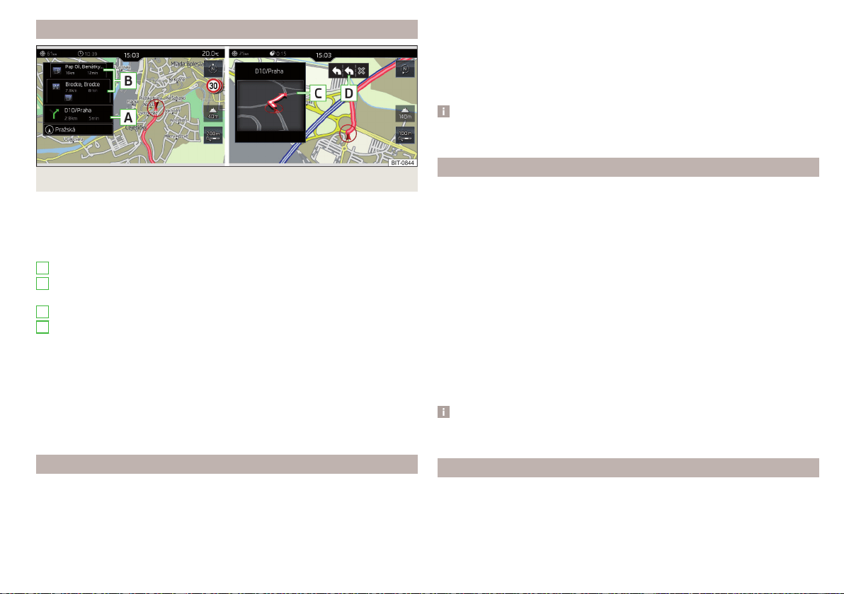
Graphical driving recommendations
Fig. 226 Driving recommendations / travel recommendation detail
The display of the graphical driving recommendations is in the split screen
Ma-
noeuvre
as well as the display of the instrument cluster.
In the split screen
Manoeuvre
the following driving recommendations are shown
» Fig. 226.
Street name / street number of the current vehicle position
Driving recommendations with street names / road numbers, with the
route and the travel time to the manoeuvre location
Details of driving recommendation (is displayed near the manoeuvre)
Lane guidance
In the split screen
Manoeuvre
, Infotainment also announces TMC traffic obstruc-
tions and on motorways, car parks, petrol stations or restaurants.
Speed limits
With activated function →
Advanced settings
→
Note: National border crossed
, dis-
play the country-specific speed limits when crossing international borders.
These speed limits can be displayed by tapping the function surface →
Speed
limits
in the main Navigation menu.
Nav. announcements
Infotainment issues nav. announcements during route guidance.
The nav. announcements are generated by the instrument system. Flawless
clarity of the message (e.g., road or city name) cannot always be guaranteed.
A
B
C
D
The last navigation announcement can be repeated in the main Navigation
menu by tapping on the function surface → .
The timing of the nav. announcement is dependent on the type of road and on
the driving speed.
The type of nav. announcements can be set: →
Navigation announcements
.
Note
Route guidance on the most frequently travelled route takes place without
navigation announcements.
Most common routes
The most frequently travelled routes are automatically saved by Infotainment.
Of these, up to 3 routes can be offered, which best match the current time,
day of the week as well as the vehicle position.
A route guidance to one of the routes used most frequently can be started as
long as no route guidance takes place.
›
To display the menu with the most frequently travelled routes, tap on func-
tion surface
Freq. routes
→
Show on map
.
›
Select the desired route.
Then a selected route is calculated and the route guidance starts.
The menu display in the split screen can be turned on/off in the main menu
Navigation by tapping the function surface →
Route options
→
Freq. Routes
.
The stored most frequent routes can be deleted in the main menu Navigation
by tapping the function surface
→
Manage memory
→
Delete user data
→
Freq.
Routes
.
Note
Route guidance on the most frequently travelled route takes place without
navigation announcements.
Finish route guidance
The route guidance can be finished in one of the following ways.
›
The final destination is reached.
›
In the main menu Navigation by tapping the function surface
→
Stop route
guidance
.
189
Navigation
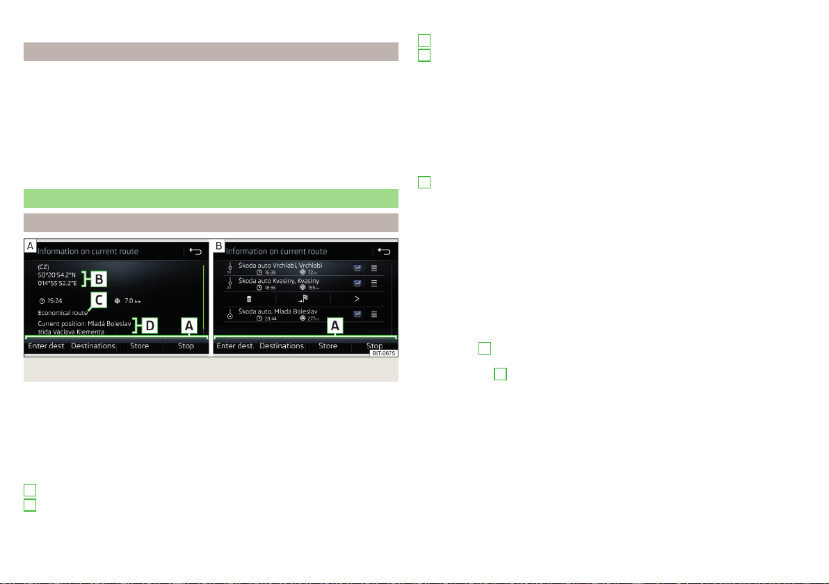
›
By turning off the ignition for longer than 120 minutes.
Abort route guidance
If the ignition is switched off and on again, then the route guidance is contin-
ued depending on the stop time in one of the following ways.
▶
Within 15 min. - route guidance continues to take the calculated route into
account.
▶
From 15 min to 120 min - after confirming the message on the infotainment
screen, the route guidance continues, taking into account the calculated
route.
▶
After 120 min - the route guidance is cancelled.
Route
Route details
Fig. 227 Route details: a route destination/several route destinations
During route guidance, the Route details (Information about the current route)
can be displayed.
›
In the Navigation main menu, tap the function surface
→
Route details
.
A route destination
In the route plan, the following information is displayed at the destina-
tion» Fig. 227 - .
Area with function surfaces
Destination information
Estimated time of arrival at destination / remaining driving time to desti-
nation
A
B
Remaining distance to the destination
Chosen route type (economic, fastest, shortest)
Current vehicle position (address / GPS coordinates)
The display of the arrival time or the remaining driving time can be adjusted as
follows.
▶
In the Navigation main menu, tap the function surface →
Advanced settings
→
Time display:
) .
Several route destinations
In the route plan, the following information is displayed at the respective desti-
nations» Fig. 227 - .
Area with function surfaces
Stopover (with sequential number)
Final destination
Estimated time of arrival at destination / stopover
Driving distance to destination / stopover
Change destinations with each other
Delete the destination
Continuation of the route guidance from the selected target (previous
waypoints are skipped)
Display the destination details » page 187
Insert destination into the route
▶
In the area
A
, tap on the function surface
Enter destination
and enter a new
destination.
▶
or: In the area
A
, tap on function surface
Destinations
and select a destination
from the list of stored destinations.
Each additional destination is added to the list as the first subsequent destina-
tion route.
Change positions of destinations with each other
▶
The relevant function surface and move the destination to the desired po-
sition.
With destinations on the route already reached the note
Destination reached
is
displayed below the destination name. It is not possible to change the position
of these destinations with each other.
C
D
A
190
Infotainment
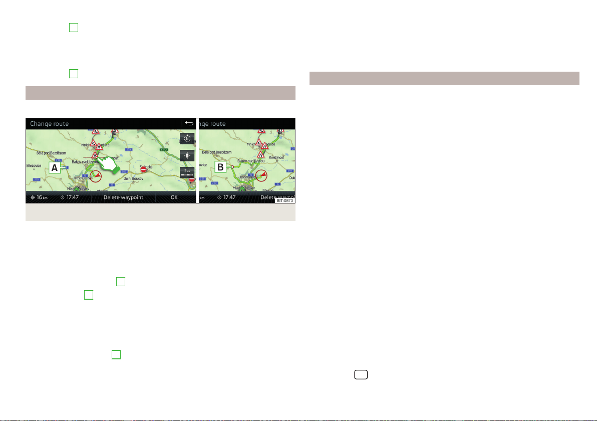
Store route
▶
In the area
A
, tap the function surface
Save
.
▶
Save the edited route as a new route or replace the existing saved route.
The route is stored in the route list » page 191.
Stop route guidance
▶
In the area
A
, tap the function surface
Stop
.
Route change in the map
Only valid for Infotainment Columbus.
Fig. 228
Route change in the map / route transit point
A route in which no waypoints are contained, can be changed during route
guidance by adding a transit point.
Add a transit point
›
In the Navigation main menu, tap the function surface
→
Change route in map
.
›
Touch the screen in the route field and move the cross-point to the desired
location on the map, e.g.
A
, move » Fig. 228).
The transit point
B
is added to the route » Fig. 228.
›
Tap the function surface .
Then a route is recalculated and the route guidance starts.
Customise transit point
›
In the Navigation main menu, tap the function surface
→
Change route in map
.
›
Touch the transit point
B
and move to a different location on the map.
›
Tap the function surface .
Then a route is recalculated and the route guidance starts.
Remove transit point
›
In the Navigation main menu, tap the function surface →
Change route in map
.
›
Tap on function surface
Delete waypoint
.
›
Tap the function surface .
Then a route is recalculated and the route guidance starts.
route list
In the route list, it is possible to create routes, save, delete, or start navigation.
New route
›
In the Navigation main menu, tap the function surface →
Routes
→
New
route
.
Insert a route destination in one of the following ways.
›
Tap on the function surface
Enter destination
and enter a new destination.
›
or: Tap on the function surface
Destinations
and select a destination from the
list of saved destinations.
›
To save the created route, tap the function surface
Store
.
›
Tap the function surface
Start
to start route guidance.
route import
A prerequisite for importing the route is that the Infotainment Online
» page 13 services are activated.
A route that has been created in the user profile on the ŠKODA Connect Portal
website and sent to the Infotainment system can be imported into the Info-
tainment memory even before switching on the ignition .
If the route was created when the ignition was switched on and sent to Info-
tainment, the route is not imported by Infotainment until after switching off
(for at least 15 minutes) and after switching the ignition back on again.
›
Switch on the ignition. When a new route is available, a message regarding
the option to import this route appears in the Infotainment screen automati-
cally .
If the user opts not to import the route immediately, the route can be impor-
ted later manually as follows.
›
In the Navigation main menu, tap the function surface
→
Routes
Tap to
check if a new route is available.
›
or: Tap the
sensor field and then the function surface → .
›
The function surface
Import routes
Tap.
191
Navigation
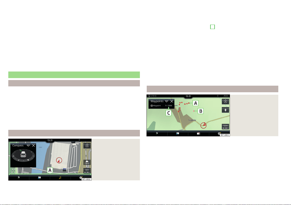
If a new route available, then a message is displayed on the Infotainment.
›
Tap the function surface
Retrieve
to start route guidance.
After being successfully imported, the route is displayed in the list of saved
routes.
Managing saved routes
›
In the Navigation main menu, tap the function surface →
Routes
.
›
Choose the desired route, and then select one of the following functions.
Clear saved route
- Edit the route » page 190, Route details
- Calculate the route and start route guidance » page 188, Route calcula-
tion and start route guidance
Waypoint mode
Introduction to the subject
Only valid for Infotainment Columbus.
This mode is suitable for off-road navigation or for areas where maps are not
available.
Infotainment allows the recording of waypoint tours driven using automatic of
manually entered waypoints.
Then there is the possibility to start route guidance to the stored waypoint
tour or to save the waypoint tour on the SD card.
Main menu
Fig. 229
Waypoint mode: Main
menu
›
In the Navigation main menu, tap the function surface →
Waypoint mode
.
Delete
Edit
Start
The main menu is displayed» Fig. 229.
Any ongoing route guidance is terminated after the selection of this way-
point mode menu.
Description of the function surfaces
A
» Fig. 229
Context-dependent:
▶
No route guidance is taking place - Start recording a waypoint
tour/display saved waypoint tour management/exit menu
▶
A waypoint tour is being recorded - Stop recording a waypoint
tour/manually adjust waypoint/exit menu
▶
Route guidance is taking place - Stop route guidance/skip the next
waypoint/exit menu
Setting the map display / show / hide the additional window / switch on /
off the display of special destinations on the map
Operation of
Radio
/
Media
playback
Setting Navigation is not available in theWaypoint mode menu
Record waypoints
Fig. 230
Recording a waypoint
tour
Start recording a waypoint tour
▶
In the Waypoint mode main menu, tap on the function surface
→
Record
waypoint tour
.
Select one of the following recording types.
■
Select on map
- Enter destination on the map and start recording waypoints
■
Start recording
- Start recording waypoints without entering a destination
Recording a waypoint tour
After starting the recording of a waypoint tour the following contextual infor-
mation may be displayed » Fig. 230.
192
Infotainment
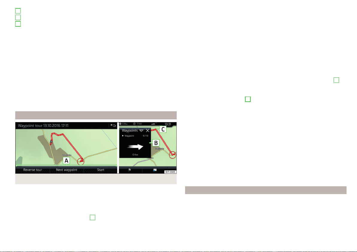
Automatically set waypoints
Manually set waypoints
Split screen
Waypoints
with the number of already set waypoints / maxi-
mum number of waypoints
Add waypoint manually
▶
In the Waypoint mode main menu, tap on the function surface →
Add way-
point manually
.
Stop recording
▶
In the Waypoint mode main menu, tap on the function surface →
Stop re-
cording
.
The recording also stops when the waypoint mode menu is exited.
The recorded waypoints are merged to a waypoint tour and stored in the way-
point memory after completion of the recording.
The recording cannot be continued once it has been stopped. A new recording
must be started.
Guide along a saved waypoint tour
Fig. 231 Display a waypoint / Guide along a waypoint tour
Start guidance
›
In the Waypoint mode main menu, tap on the function surface
→
Waypoint
memory
.
›
Select the desired route from the displayed list.
›
Tap the function surface .
›
Select one of the following menus
A
» Fig. 231.
A
B
C
■
Reverse tour
- Reverse the order of waypoints (suitable for guiding along a
waypoint tour in the reverse direction)
■
Next. Waypoint.
- Skip to the next waypoint
■
Start
- starts route guidance
Route guidance
During the guidance along a waypoint tour, no nav. announcements are made
by Infotainment.
When driving along the waypoint tour shown, follow as closely as possible the
information shown on the Infotainment screen.
While driving along a waypoint tour, the split screen shows the
Waypoints
and
the direction to drive as well as the distance to the next waypoint, the se-
quence number of the next waypoint and the total number of waypoints
B
» Fig. 231.
The waypoint tour from the vehicle position to the next waypoint “reduces”
continuously while driving “ ”
C
» Fig. 231 .
If you drive past but very close to the next waypoint, the route guidance will
continue with the subsequent waypoint.
If you drive past a waypoint and this does “not disappear” from the waypoint
tour (e.g. because the distance to this waypoint is too large), then there is the
possibility to “skip” over this waypoint and continue the guidance to the next
waypoint.
▶
In the Waypoint mode main menu, tap on the function surface
→
Skip way-
point
.
Stop route guidance
▶
In the Waypoint mode main menu, tap on the function surface
→
Stop route
guidance
.
The guidance also stops when waypoint mode is exited.
Manage waypoint tour memory
›
to display a list of saved and imported waypoint tours, from main menu
Waypoint mode, tap the function surface
→
Waypoint memory
.
The name of the waypoint tour, the date and time of storage and the number
of waypoints appears in the function surface for the waypoint tour.
193
Navigation
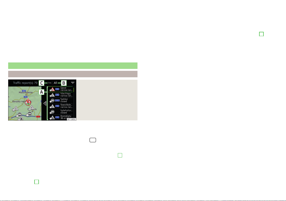
›
Choose the desired waypoint tour, and then select one of the following menu
items.
Store the waypoint tour on the SD card
Delete the waypoint tour
Rename the waypoint tour
Display the waypoint tour » Fig. 231 on page 193
Import waypoint tour from the SD card
▶
In the Waypoint mode main menu, tap on the function surface →
Waypoint
memory
→
Import
.
▶
Select the source of the waypoint tour recording and confirm the import.
Traffic reports
List of traffic reports
Fig. 232
List of traffic reports
The Infotainment system enables the reception of traffic reports, which in-
clude information regarding traffic congestion, using TMC (Traffic Message
Channel) or online (when Infotainment Online» page 13 services are activated).
›
To display the list of traffic reports, tap on the
sensor field and then tap
the function surface .
In the list of traffic messages and the map, a max. of 6 messages are displayed,
that have a letter and the traffic obstruction symbol (e.g. , , )
A
» Fig. 232.
At present on the route traffic information is taken by using a nav. announce-
ment.
Source of Traffic Information
On the position
C
» Fig. 232 can the following symbols are displayed.
TMC Traffic Information (with strikethrough icon, the Infotainment is out
of range of any traffic information provider)
Online traffic report
Display options
▶
Route guidance is disabled - All traffic messages are displayed.
▶
Route guidance is taking place - After tapping the function surface
B
» Fig. 232 in the displayed menu all traffic messages can be selected by tap-
ping the function surface
All areas
, or by tapping the function surface
route
On-
ly the traffic messages present on the route can be selected.
A traffic report may contain some of the following information.
▶
Symbol of the traffic obstruction
▶
Number of road affected
▶
Name of the location affected
▶
Description of the traffic obstruction
Distinguish the importance of a TMC message traffic obstruction using
colour
The symbol for traffic obstruction (e.g.
,
,
) precedes the obstruction and
the length of the obstruction is shown in the map on the right along the route.
Depending on the context, the symbol for the obstruction is displayed in one
of the following ways.
No route guidance is taking place
▶
Red - All traffic obstructions
Route guidance is not taking place
▶
Grey - The traffic obstruction is not on the route
▶
Red - The traffic obstruction is on the route, the route will not be recalcula-
ted and the route passes through the traffic obstruction
▶
Orange - The traffic obstruction is on the route, the route is recalculated and
an alternative route is available
Distinguish the importance of a TMC message traffic obstruction using
colour
The colour differentiation of traffic conditions on the provider of the online
traffic reports depends.
to Change the map orientation From the main menu Navigation the function
surface →
Map
→
Traffic flow settings
.
194
Infotainment

Update
The list of traffic reports will be updated by Infotainment on a continuous ba-
sis.
Detail of the traffic report
Fig. 233
Details of the traffic report
The display of traffic report details is dependent on whether the respective
traffic report is based on a TMC source or an online source.
›
To display this, select the desired traffic report from the list of traffic re-
ports.
›
or: Tap on the traffic obstruction icon in the map.
Depending on the context, the following information and functional surfaces
are displayed » Fig. 233.
Map of the affected location
Description of the traffic obstruction
Reception timing and information relating to the traffic report provider
(is ŠKODA Connect the provider, it is an online traffic report)
Symbol of the traffic obstruction
Length of the traffic obstruction
Dynamic route
Infotainment allows an evaluation of the traffic reports received during the
route guidance. In fulfilling the following conditions, a bypass route is calcula-
ted, and the appropriate announcement is issued.
A
B
C
D
E
The dynamic route function is turned on.
The traffic congestion included in the traffic information is on the route.
The traffic obstruction will be evaluated by Infotainment as of great im-
portance.
›
To switch on/offin the main menu Navigation, tap on the function surface
→
Route options
→
Dynamic route
.
enter / remove traffic conditions on your route manually
If a traffic obstruction is detected during route guidance (e.g. traffic jam), this
traffic obstruction be manually entered into the route.
After entering, Infotainment calculates and provides an alternative route.
Enter traffic obstruction
›
In the Navigation main menu, tap the function surface
→
Congestion ahead
.
›
Adjust the length of the traffic obstruction.
The traffic obstruction will be displayed in red in the map to the right along the
route.
Remove traffic obstruction
The traffic obstruction is removed from the route after completion of the
route guidance or can manually be removed as follows.
›
In the Navigation main menu, tap the function surface
→
Delete "congestion
ahead"
.
195
Navigation
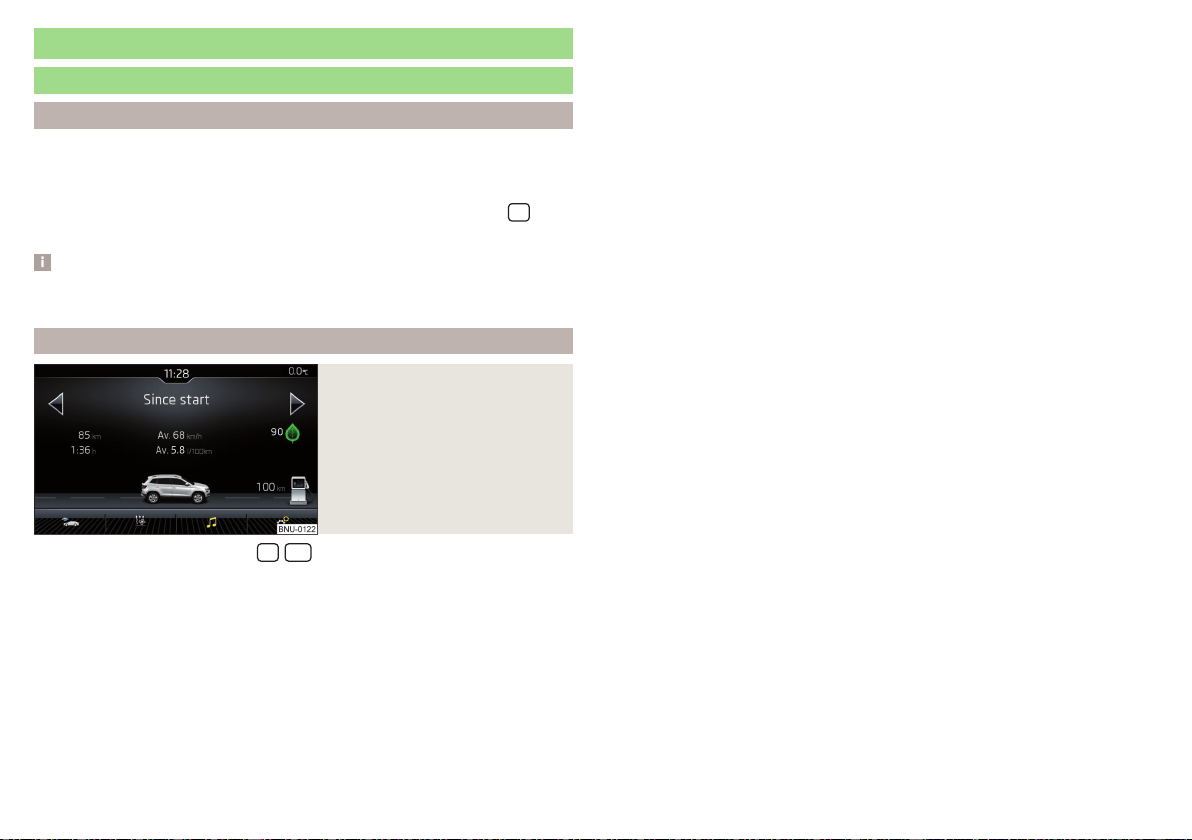
Vehicle systems
CAR - Vehicle settings
Introduction to the subject
In the menu CAR , journey data and vehicle information can be displayed and
some vehicle systems can be set.
Reset to factory settings
You can reset to factory settings in the Infotainment system in menu
/ →
→
Factory settings
.
Note
Settings relating to the vehicle systems can only be made when the ignition is
switched on.
Main menu
Fig. 234
Function surfaces in the main
menu
›
Tap on the button/sensor field
/
→ to display the main menu with
the following function surfaces » Fig. 234.
Selecting the following menu points
▶
Offroad
▶
Convenience consumers
▶
Journey data
▶
DriveGreen
▶
Vehicle status
Playback control - Radio / Media
Depending on the vehicle equipment with manual air conditioning: Set-
ting the auxiliary heating and ventilation / operating the heated wind-
screen
Operation of the steering wheel heating
Vehicle system settings
196
Infotainment

Driving
Starting-off and Driving
Starting and stopping the engine
Introduction
Depending on equipment fitted, it is possible to switch the ignition on/off and
start/stop the engine with the key in the ignition or using the starter button.
WARNING
■
Never switch off the engine before the vehicle is stationary – risk of acci-
dent!
■
The ignition must always be switched during the journey when the engine
is idling. Otherwise, the steering may lock - danger of an accident!
■
Do not withdraw the ignition key from the ignition lock until the vehicle
has come to a stop » page 203, Parking. Otherwise, the steering may lock -
danger of an accident!
■
Never leave the vehicle unattended with the engine running - there is a
risk of theft, accident etc.!
■
Never run the engine in an enclosed space (e.g. in garages) - there is the
danger of poisoning and death!
CAUTION
■
Only start the engine when the engine and the vehicle are stationary - there
is a danger of starter and engine damage!
■
Do not push-start the engine – there is a risk of damaging the engine and the
catalytic converter! The battery from another vehicle can be used as a push-
start aid.
■
On vehicles with the starter button, pay attention to where the key is loca-
ted. The system can recognize the valid key, even if it has been accidentally
left on the vehicle roof - there is danger of loss or damage to the key!
Note
Do not warm up the engine while the vehicle is stationary. If possible, start
your journey as soon as the engine has started. The engine will reach its oper-
ating temperature faster.
Electronic immobiliser and steering lock
Read and observe and on page 197 first.
The electronic immobiliser (hereinafter referred to as immobiliser) makes it
more difficult for someone to attempt to steal or use your vehicle without au-
thorisation.
Immobilizer
The immobilizer enables the engine start exclusively using the original vehicle
keys.
Malfunction of the immobilizer
If the immobiliser components in the key fail, it is not possible to start the en-
gine. A message appears in the display of the instrument cluster to explain that
the immobiliser is active.
To start, use the other vehicle key or seek help from a specialist garage.
Steering lock - lock
›
On vehicles with ignition lock, remove the key and turn the steering wheel
until the steering lock engages.
›
On vehicles with a starter button, switch off the ignition and open the driv-
er's door. If the driver's door is opened and the ignition is switched off after-
wards, the steering is only locked automatically after the vehicle has been
locked.
Steering lock - unlock
›
On vehicles with ignition lock, insert the key into the ignition and turn on the
ignition. If this is not possible, move the steering wheel slightly back and
forth and thereby unlock the steering lock.
›
On vehicles with
starter button, get into the car and close the driver's door.
Under certain circumstances, the steering lock can be unlocked only when
the ignition is switched on or the engine is started.
WARNING
Never let the vehicle roll with locked steering lock - there is a risk of acci-
dent!
197
Starting-off and Driving
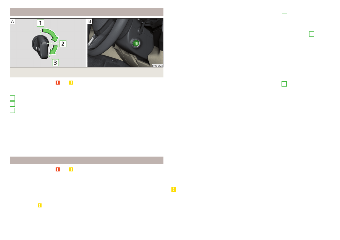
Switching the ignition on/off
Fig. 235 Positions of the vehicle key in the ignition lock / starter button
Read and observe and on page 197 first.
Positions of the vehicle key in the ignition lock » Fig. 235 -
Ignition switched off, engine switched off
Ignition switched on
Starting engine
Switching on /off ignition in vehicles with starter button
›
Press the » Fig. 235 -
button, the ignition is turned on / off.
On vehicles with manual transmission the pedal must not be depressed to
switch on / off the ignition, otherwise the engine will start.
On vehicles with automatic transmission, the brake pedal must not be de-
pressed to switch on / off the ignition, otherwise the engine will start.
Starting engine / Stopping
Read and observe and on page 197 first.
Before starting the engine
›
Switch on the parking brake.
›
For vehicles with manual transmission, shift gear stick to neutral, depress
the clutch pedal and hold it there until the engine starts.
›
For vehicles with automatic transmission, place the selector lever in position
P or N and » depress the brake pedal until the engine starts.
1
2
3
Starting the engine
›
On vehicles with Ignition lock, turn the key to position
3
and the engine
starts» Fig. 235 on page 198 . Release the key, the engine will start auto-
matically.
If the engine does not start within 10 seconds, turn the key to position
1
. Re-
peat the starting process after 30 seconds.
›
On vehicles with starter button, press the button briefly » Fig. 235 on
page 198 - , the motor will start automatically.
For vehicles with Diesel engines the glow plug warning light illuminates
during starting. The engine can be started after the indicator light goes out.
Stopping the engine
›
Stopping the vehicle.
›
On vehicles with ignition lock, turn the key to position
1
» Fig. 235 on
page 198
.
›
On vehicles with starter button, press the button » Fig. 235 on page 198 -
,
The engine and the ignition will be switched off simultaneously.
For vehicles with automatic transmission, the ignition key can only be removed
if the selector lever is in position P (this only applies to a few countries).
Do not switch the engine off immediately at the end of your journey after the
engine has been running for a prolonged period at high loads. Leave it to run at
an idling speed for about 1 minute. This prevents any possible accumulation of
heat when the engine is switched off.
Emergency shutdown of the engine in vehicles with starter button
The system is equipped with a protective device against accidental switching
off, the engine can only be shut off while driving in the event of an emergency.
›
Keep the knob pressed
» Fig. 235 on page 198 - or press it twice within 1
second.
After the emergency stop of the engine, the steering lock will remain un-
locked.
CAUTION
When the outdoor temperature is below -10 ° C, the selector lever when start-
ing must always be in P mode.
198
Driving
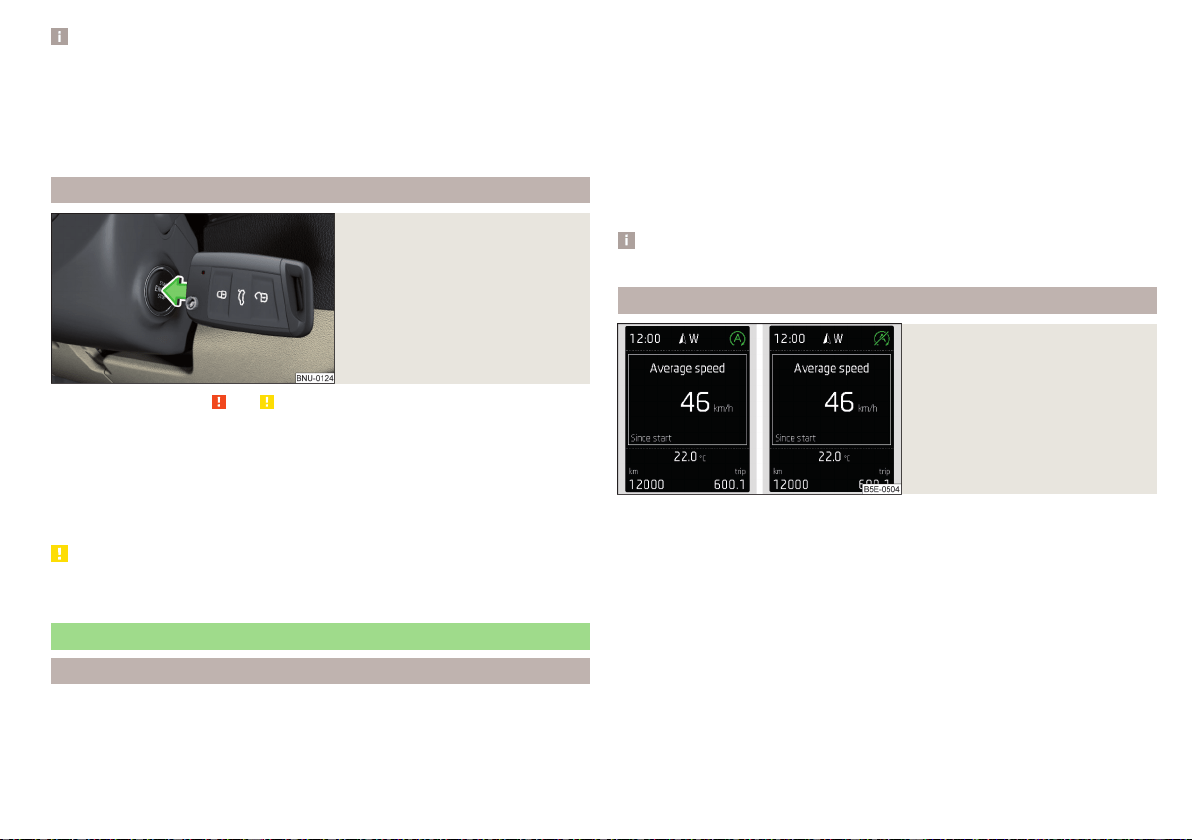
Note
■
The engine running noises may be louder at first for a short time after start-
ing the cold engine.
■
You should not switch on any major electrical components during the heat-
ing period, otherwise the vehicle battery will be drained unnecessarily.
■
After switching off the ignition, the radiator fan may intermittently continue
to run for approx. 10 minutes (also continuously).
Problems with the engine start - vehicles with starter button
Fig. 236
Engine start - hold key on but-
ton
Read and observe and on page 197 first.
If no engine start is possible and the display of the instrument cluster shows a
message that the key could not be detected by the system or there is a sys-
tem fault, then try to start the engine as follows.
›
Press the starter button with the key » Fig. 236.
If the engine does not start, the help of a specialist garage is required.
CAUTION
The key may not be detected by the system if the battery in the key is running
out of charge or the signal fails.
START-STOP-System
Introduction
The START-STOPsystem (hereinafter referred to as the system) reduces
CO
2
emissions and harmful emissions, and saves fuel.
If the system determine that the engine is not needed when the vehicle stops
or is at a standstill (e.g. at the traffic lights), it turns off the engine and starts it
again when moving off.
The system function depends on many factors. Some of them are down to the
driver, while others are systemic and can neither be influenced nor identified.
For this reason, the system may react differently in situations which seem
identical from the driver's perspective.
The system is automatically activated every time the ignition is switched on
(even when it has previously been manually deactivated with the button).
Note
If the engine has stopped due to the system, the ignition remains switched on.
operation
Fig. 237
Display
Vehicles with manual transmission
The engine is automatically switched off as soon as the vehicle comes to a
halt, the shift lever is moved into neutral and the clutch pedal is released.
The engine is automatically started as soon as the clutch pedal is depressed.
Vehicles with automatic transmission
The engine is automatically switched off as soon as the vehicle comes to a
halt and the brake pedal is operated.
The engine is automatically started as soon as the accelerator pedal is de-
pressed or the brake pedal is released (with deactivated Auto Hold function).
199
Starting-off and Driving
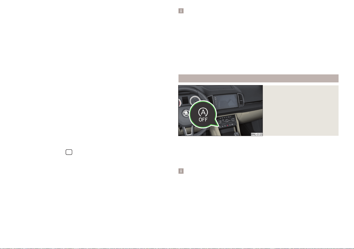
Requirements for the system to function correctly
The following conditions must be met for the system to function correctly.
The driver's door is closed.
The driver has fastened the seat belt.
The driving speed was higher than 4 km/h after the last stop.
System status
The system status is shown in the display when the vehicle comes to a halt
» Fig. 237.
The engine is switched off automatically; when moving off, the ignition
process will be initiated automatically.
The engine is not switched off automatically.
When stopping, the engine will not switch off for the following reasons,
among others.
▶
The engine temperature for the proper function of the system has not yet
been reached.
▶
The charge state of the vehicle battery is too low.
▶
The current consumption is too high.
▶
High air conditioning or heating output (high blower speed, big difference
between the desired and actual interior temperature).
If the engine is shut down automatically and the system detects that the en-
gine is required, such as when the brake pedal is pressed repeatedly, then the
system automatically starts the engine.
More information about the current system status can be displayed in the In-
fotainment screen in menu
/
→
→
display Vehicle status
.
If there is a system fault, the following message will appear in the display of
the instrument cluster. Seek help from a specialist garage.
Note
■
If the driver's seat belt is removed for more than approx. 30 seconds or the
driver's door is opened during automatic stop mode, the engine will have to be
started manually.
■
No automatic engine shut-down takes place when a vehicle with automatic
transmission is moving at low speed (e.g. during a traffic jam) and remains sta-
tionary after pressing the brake pedal lightly. Automatic engine shut-down
takes place if you press the brake pedal down with more force.
■
For vehicles with automatic transmission there is no automatic engine shut-
down when the system detects a manoeuvring action due to a large steering
angle.
manually activate/deactivate system
Fig. 238
Button for the START-STOP
system
›
To deactivate/activate, press the button
» Fig. 238.
When the system is deactivated, the symbol
illuminates in the button.
If the system is deactivated, it will be reactivated automatically after the igni-
tion has been switched off and on.
Note
If the system is deactivated when the engine is turned off automatically, then
the automatic start process takes place.
200
Driving
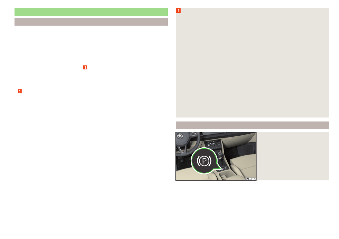
Brakes and Parking
Introduction
The wear of the brake pads is dependent on the operating conditions and driv-
ing style. Under difficult conditions (e.g. urban, sporty driving style) the condi-
tion of the brakes should also be checked by a specialist garage between the
service intervals.
The performance of the brakes can be delayed if the brakes are damp, iced up
in winter or if covered in a layer of salt. The brakes are cleaned and dried by
applying the brakes several times » .
Corrosion on the brake discs and dirt on the brake pads occur if the vehicle
has been parked for a long period and if you do not make much use of the
braking system. The brakes are cleaned by applying the brakes several times
» .
Before travelling a long distance with a steep gradient, reduce speed and
shift into the next lowest gear. As a result, the braking effect of the engine will
be used, reducing the load on the brakes. If you do have to brake, this should
be carried out at intervals.
Emergency braking display - when an emergency braking is performed, the
automatic flashing of the brake lights are used to alert the traffic behind.
New brake pads must first be “worn in” because these do not initially have the
best possible braking effect. Drive especially carefully for the first 200 km or
so.
A too low brake fluid level can cause faults in the braking system, the warn-
ing light illuminates in the instrument cluster» page 40, Brake system. If
the warning light does not illuminate and an extended stopping distance is re-
quired, then driving should be adapted according to the unknown cause of
fault and restricted braking effect - seek the assistance of a specialist garage
immediately.
The brake booster increases the pressure generated with the brake pedal. The
brake booster only operates when the engine is running.
WARNING
■
Greater physical effort is required for braking when the engine is switch-
ed off – risk of accident!
■
During the braking procedure on a vehicle with manual transmission,
when the vehicle is in gear and at low revs, press the clutch pedal. Other-
wise, the functionality of the brake system may be impaired – risk of acci-
dent!
■
Do not press the brake pedal if braking is now required. This causes the
brakes to overheat and can also result in a longer braking distance and ex-
cessive wear - risk of accident!
■
Braking for the purpose of drying and cleaning the brake discs should be
carried out only if the traffic conditions permit. Do not place any other road
users in jeopardy.
■
Recommendations for new brake pads have to be observed.
■
When stopping and parking, the parking brake should always be on, oth-
erwise the vehicle could move off - there is the risk of an accident!
■
If a front spoiler, full wheel trim, etc. is mounted retrospectively, it must
be ensured that the air supply to the front wheel brakes is not reduced.
Otherwise, the functionality of the brake system may be impaired – risk of
accident!
Electric parking brake
Fig. 239
Parking brake button
201
Starting-off and Driving
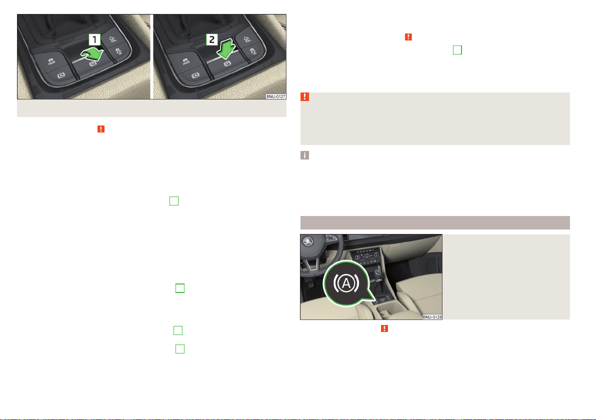
Fig. 240 Parking brake operation
Read and observe on page 201 first.
The electric parking brake (hereinafter referred as a parking brake) replaces
the handbrake. This secures the vehicle when stopping and parking against un-
wanted movement.
The parking brake can be used when the ignition is on or off.
Switching on
›
Pull the button in the direction of arrow
1
» Fig. 240 and hold until the
symbol in the button and warning light
illuminate in the instrument cluster.
Automatic shut-off
The parking brake switches off automatically when starting, as long as the
driver's door is closed and the driver has fastened the seat belt.
Should the vehicle start to roll away when starting on a downhill slope, step on
the accelerator or switch on the parking brake.
Turning off the parking brake can be prevented if, before starting, the but-
ton is pulled and held in the direction of arrow
1
» Fig. 240. The parking brake
turns off after releasing the button.
Manual shut-down
›
With the ignition switched on, press the brake pedal and at the same time
push the button in the direction of arrow
2
» Fig. 240.
›
With the engine running, press either the brake or accelerator pedal and
press the button in the direction of arrow
2
.
The symbol in the button and the warning light in the instrument cluster
go out.
Emergency braking function
If, while driving, a fault occurs in the brake system, the parking brake can be
used as an emergency brake » .
›
Pull the button in the direction of arrow
1
and » Fig. 240 hold (you hear
an audible signal), the vehicle starts to brake strongly.
The braking process is interrupted when the key is released or the accelerator
pedal is actuated.
WARNING
■
The emergency brake is to be used only in an emergency when the vehi-
cle cannot be stopped with the brake pedal.
■
Do not place any objects in the recessed grip for the finger in front of the
parking brake key - the parking brake button could be blocked!
Note
■
If the vehicle battery is discharged, it is not possible to release the parking
brake. First connect the vehicle first to a power source, such as the battery of
another vehicle » page 279, Jump-starting and then turn off the parking brake.
■
Noise when switching on and off the parking brake is normal and therefore
harmless.
Auto Hold function
Fig. 241
The Auto-Hold function button
Read and observe on page 201 first.
The Auto Hold function (hereinafter referred to only as system) prevents the
vehicle from rolling unintentionally when stopped. It is, for example, not neces-
sary to secure the vehicle with the brake pedal or parking brake at traffic
lights.
202
Driving

For the activation, deactivation and correct functioning of the system, the
following basic conditions are required.
The driver's door is closed.
The engine is running (or has been switched off automatically by the
START-STOP system).
On vehicles with automatic transmission the selector lever is not in mode
N (in this mode, the system is not available).
Stopping and starting
When stopping the system prevents the vehicle from rolling away. The warn-
ing light illuminates in the instrument cluster. The brake pedal can be re-
leased.
The vehicle's brakes are released at the moment of stating off. The warning
light
in the instrument cluster goes out.
Should the vehicle start to roll away when starting on a downhill slope, step on
the accelerator or switch on the parking brake.
If the vehicle is secured by the system and the driver's door is opened or the
ignition is turned off, the vehicle is secured by the parking brake to prevent un-
wanted movement.
In this case, the indicator light turns off
in the instrument cluster and the
warning light
illuminates.
Activation/deactivation
The system is activated/deactivated by means of the
» Fig. 241 button.
When the system is activated, the symbol
illuminates.
After switching off and switching on the ignition, the system remains either
activated or deactivated depending on the last setting.
WARNING
The increased stopping and starting comfort brought by the system must
not tempt you to take any safety risks.
■
The system is not able to stop the vehicle under all circumstances, such
as on icy or otherwise slippery ground, or on gradients.
■
When stopping and parking always make sure that the vehicle is correctly
secured » page 203, Parking.
CAUTION
In some washing systems it is necessary that the vehicle can roll freely. There-
fore, the system must be deactivated before driving through a car wash.
Note
The system is able to secure the vehicle for about 10 minutes, after which the
vehicle will be automatically secured by the parking brake.
Parking
Read and observe
on page 201 first.
When stopping and parking, look for a place with a suitable surface » .
Only carry out the activities while parking in the specified order.
›
Bring the vehicle to a stop and depress the brake pedal.
›
The parking brake switch.
›
On vehicles with automatic transmission place the selector lever in the P
position.
›
Switch off the engine.
›
For vehicles with manual transmission, select 1st gear or reverse gear R.
›
Release the brake pedal.
If the parking brake is turned on while on a steep slope, the following message
may be displayed in the instrument cluster. Search for a car park with less of
an inclination.
WARNING
■
The exhaust system components can become very hot. Therefore, never
stop the vehicle in places where the underside of your vehicle could come
into contact with flammable materials (e.g. dry grass, leaves, spilled fuel
etc.) There is a risk of a fire and could result in severe injuries!
■
When leaving the vehicle, never leave people who could, for example, lock
the vehicle or release the brake, unattended in the vehicle - risk of accident
and injury!
203
Starting-off and Driving

Manual gear changing and pedals
Introduction
CAUTION
When stopping on a slope, never try to hold the vehicle using the accelerator
pedal – this may lead to gear damage.
Manual gear changing
Fig. 242
The shift pattern
Read and observe on page 204 first.
The gearshift pattern for the individual gear positions is shown on the gear lev-
er » Fig. 242.
The gear shift indicator should be observed when changing gear » page 49.
Always depress the clutch pedal all the way down. This prevents uneven wear
on the clutch.
Engage reverse gear
›
Stop the vehicle.
›
The clutch pedal is fully depressed.
›
Switch the gear lever to N.
›
Push the shift lever downwards fully to the left and then forward into
R» Fig. 242.
The reversing lights will come on once reverse gear is engaged, provided the
ignition is on.
WARNING
Never engage reverse gear when driving – risk of accident!
CAUTION
If not in the process of changing gear, do not leave your hand on the gear shift
lever while driving. The pressure from the hand can cause the gear shift mech-
anism to wear excessively.
Pedals
Read and observe
on page 204 first.
The operation of the pedals must not be hindered under any circumstances!
In the driver's footwell, only a footmat (supplied by the factory or from the
ŠKODA Original Accessories) which is secured on the respective attachment
points should be used.
WARNING
No objects should be located in the driver's footwell, otherwise the pedal
operation could be disabled - risk of accident!
Automatic transmission
Introduction
The automatic transmission performs an automatic gear change irrespective
of the engine load, the operation of the accelerator, the vehicle speed and the
selected driving mode.
The modes of the automatic transmission can be adjusted by the driver by
means of the selector lever.
WARNING
■
Do not use the throttle if the forwards mode has been set using the se-
lector lever prior to starting up - risk of accident!
■
Never move the selector lever to mode R or P when driving – risk of acci-
dent!
204
Driving
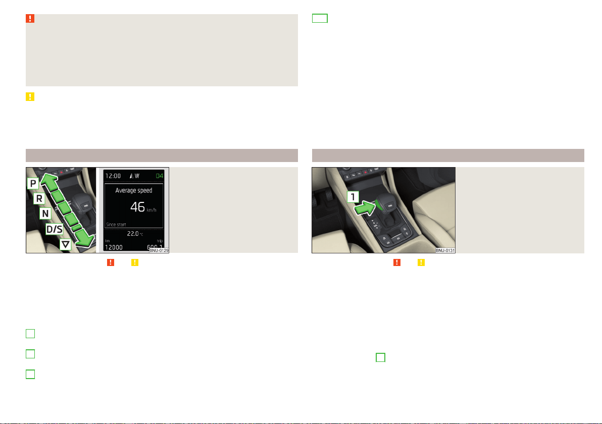
WARNING (Continued)
■
If the vehicle stalls, with engine running, in the D, S, R or Tiptronic mode,
then the vehicle must be prevented from rolling away using the brake ped-
al, or using the Auto Hold function. Even when the engine is idling, the pow-
er transmission is never interrupted - the vehicle creeps.
■
When leaving the vehicle, the selector lever must always be set to P .
Otherwise, the vehicle could start to move - risk of accident.
CAUTION
■
If you want to move the selector lever from position N to position D / S
whilst driving, the engine must be running at idling speed.
■
When stopping on a slope, never try to hold the vehicle using the accelerator
pedal – this may lead to gear damage.
Select selector lever position
Fig. 243
Selector lever settings / display
Read and observe and on page 204 first.
Move the selector lever to change to the following positions » Fig. 243. In
some positions you have to push the locking button » page 205, Selector lever
lock.
When the ignition is switched on, the gearbox mode and the currently selected
gear are indicated in the display » Fig. 243.
Parking - the position can be set only when the vehicle is at a standstill
The drive wheels are mechanically locked.
Reverse gear - the position can be set only when the vehicle is at a stand-
still and the engine is at idling speed.
Neutral (idle position) - the power transmission to the drive wheels is in-
terrupted.
P
R
N
Forward mode / sports programme - the gear change takes place in the
position S at higher engine speeds than in mode D
(Sprung position) - choice between positions D and S
If the Sport driving mode is selected with the engine running » page 237, Se-
lect the driving mode (Driving Mode Selection) , the transmission is automati-
cally set in the S mode.
E – Economical driving mode
If the driving mode Eco or Individual (engine - Eco) » page 237 is selected and
the selection lever is in the setting D/S, the transmission is automatically set to
mode E. This mode cannot be selected with the selector lever.
The forwards mode is switched up or down automatically in mode E at lower
engine speeds than in mode D.
Selector lever lock
Fig. 244
Shift lock button
Read and observe and on page 204 first.
The selector lever is locked in mode P and N to prevent that the forward driv-
ing is selected accidentally, thereby setting the vehicle in motion.
The selector lever is locked only when the vehicle is stationary and at speeds
up to 5 km/h.
The selector lever lock is indicated by the illumination of the warning light.
Disengage selector lever from P mode or N
›
Press the brake pedal and, at the same time, push the lock button in the di-
rection of arrow
1
» Fig. 244.
To move the selector lever from mode N to D / S only the brake pedal is
pressed.
D/S
205
Starting-off and Driving
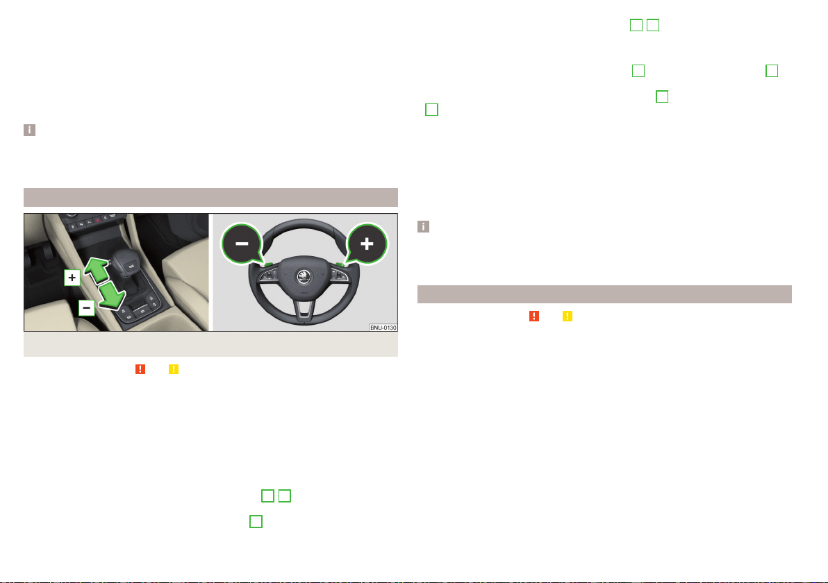
The selector lever is not locked when quickly moving across the position N
(e.g. from R to D/S). This, for example, helps to rock out a vehicle that is stuck,
e.g. in a bank of snow. The selector lever lock will engage if the lever is in posi-
tion N for more than approx. 2 seconds without the brake pedal being de-
pressed.
If it is not possible to release the gear selector from mode P in the usual man-
ner, then this can be emergency unlocked » page 284.
Note
If you want to switch the selector lever from mode P to mode D/S or vice ver-
sa, move the selector lever quickly. This prevents that you accidentally select
mode R or N.
Manual shifting of gears (Tiptronic)
Fig. 245
Selector lever/multi function steering wheel
Read and observe and on page 204 first.
Tiptronic mode makes it possible to manually shift gears with the selector lev-
er or multifunction steering wheel.
Switching to manual shifting using the selector lever
›
Push the gear selector from position D/S towards the right, or left in a right-
hand drive vehicle. The current gear is maintained.
Switching to manual shifting by using the rocker switches under the
multifunction steering wheel
›
To change gear, pull one of the rocker switches
-
/
+
briefly towards the
steering wheel » Fig. 245.
›
To cancel manual shift, pull the rocker switch
+
towards the steering wheel
for more than 1 s.
If you do not pull one of the rocker switches
-
/
+
for a certain time, manual
shifting of the gears is deactivated automatically.
Changing gear
›
To shift up, tap the selector lever forwards
+
or pull the rocker switch
+
briefly towards the steering wheel » Fig. 245.
›
To shift down, tap the selector lever backwards
-
or pull the rocker switch
-
briefly towards the steering wheel » Fig. 245.
The currently selected gear is indicated in the display » Fig. 243 on page 205.
The gear shift indicator should be observed when changing gear » page 49.
When accelerating, the gearbox automatically shifts up into the higher gear
just before the maximum permissible engine speed is reached. If a lower gear
is selected, the gearbox does not shift down until there is no risk of the engine
over revving.
Note
It may be beneficial, for example, when travelling downhill, to use manual shift-
ing of gears. Shifting to a lower gear reduces the load on the brakes and hence
the wear of the brakes.
Start and drive
Read and observe
and on page 204 first.
Starting and temporarily pausing
›
Firmly depress and hold the brake pedal.
›
Start the engine.
›
Press the locking button and move the selector lever to the desired position
» page 205.
›
Release the brake pedal and accelerate.
The selector lever position N does not have to be selected if stopping for a
short time, such as at cross roads. However, you must apply the brake pedal in
order to prevent the vehicle from rolling away.
Accelerate to max. speed during the journey (kickdown function)
The kickdown function is applied when the accelerator pedal is pressed down
in the forward mode.
The gear change is adjusted accordingly to reach the maximum acceleration.
206
Driving
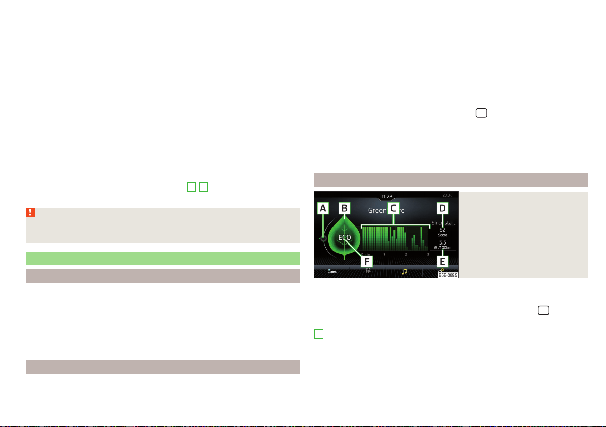
Accelerate to maximum speed when starting (launch control function)
The launch control function is available in mode S or Tiptronic.
›
Disable the TCS » page 210, Braking and stabilisation systems.
›
Fully depress and hold the brake pedal with your left foot.
›
Fully depress the accelerator pedal with your right foot.
›
Release the brake pedal - the vehicle is running at maximum acceleration.
Driving in neutral (“coasting”)
When releasing the accelerator pedal, the vehicle moves without the braking
effect of the engine.
Operating conditions
▶
The selector lever is in the D/S position.
▶
Driving mode Eco or Individual (Drive - Eco) is selected» page 237, Select
the driving mode (Driving Mode Selection).
▶
The vehicle is travelling at more than 20 km/h.
▶
No trailer or other accessory is connected to the trailer socket.
The gear is selected again automatically, when you depress the accelerator or
brake pedal or pull one of the rocker switches
-
/
+
towards the steering
wheel » page 206, Manual shifting of gears (Tiptronic).
WARNING
Rapid acceleration, particularly on slippery roads, can lead to loss of control
of the vehicle – risk of accident!
Running in the engine and economical driving
Run in engine
During the first 1,500 km, the driving manner determines the quality of the
running in process on a new engine.
During the first 1,000 km, the engine should not be charged with more than
3/4 of the maximum permitted engine revs and without the trailer.
In the area of 1,000 to 1,500 kilometres, the engine load can be increased up
to the maximum permitted engine speed.
Tips for economical driving
The fuel consumption depends on the driving style, road condition, weather
conditions and the like.
For an economical driving style, the following instructions must be observed.
▶
Avoid unnecessary acceleration and braking.
▶
Observe the recommended gear » page 49.
▶
Avoid full throttle and high speeds.
▶
Reduce idling.
▶
Avoid short distances.
▶
Ensure the correct tyre inflation pressure is maintained» page 268.
▶
Avoid unnecessary ballast.
▶
Remove the roof rack when it is not needed.
▶
Only switch on electrical consumers (e.g. seat heating) for as long as they are
needed. In the infotainment system, in menu
/ → →
Convenience con-
sumers
: it is possible to display up to three consumers that are currently mak-
ing up the largest share of fuel consumption.
▶
Before switching on, ventilate the cooling system briefly and do not use the
cooling system with open windows.
▶
Do not leave windows open at high speed.
DriveGreen function
Fig. 246
Display in Infotainment screen
The DriveGreen function (hereinafter referred to as DriveGreen) evaluates the
driving efficiency based on the information respecting the driving style.
DriveGreen can be displayed in the infotainment screen in menu
/ →
→
DriveGreen
.
A
driving liquid display
With the driving is fluid, the display is located in the middle (near the green
dot). When accelerating, the display moves down, and upwards when braking.
207
Starting-off and Driving
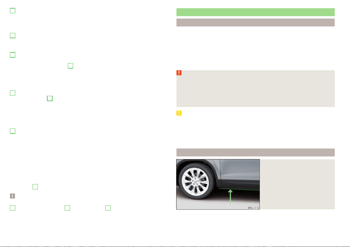
B
“Green leaf”
The greener the leaf, the more economic the driving style. With less economi-
cal driving, the leaf is presented without any green colouring or it can be com-
pletely hidden.
C
bar graph
The higher the green bars, the more economical the driving style. Each bar
shows the driving efficiency in 5-second steps, the current bar is on the left.
D
scoring (0 - 100)
The higher the indicated value, the more economical the driving style. When
you tap the function surface
D
, a detailed assessment showing the driving ef-
ficiency during the last 30 minutes is displayed.
If the trip lasts less than 30 minutes from the start, then the overview will add
the assessment from the previous journey (the bars are shown in dark green).
E
the average fuel consumption from the start
When you tap the
E
function surface, a detailed overview of the average fuel
consumption during the last 30 minutes is shown.
If the trip lasts less than 30 minutes from the start, then the overview will add
the overview of the average fuel consumption from the previous journey (the
bars are shown in dark green).
F
symbols
The display may show the following four symbols, which give information on
the current driving style.
Economical driving style
The current speed has a negative effect on fuel consumption.
The journey does not take place in a free-flowing manner, avoid unneces-
sary acceleration and braking
Recommended gear
Tips for economical driving
Tap on the
B
leave to display tips for economical driving.
Note
When resetting the single-trip memory “from start”; the average consumption
E
, the driving assessment
D
, and the diagram
C
are also reset.
Avoiding damage to your vehicle
Driving Tips
Only drive on such roads and in such terrain that match the vehicle parameters
» page 294, Technical data as well as your driving skills.
The driver is always responsible for deciding whether the vehicle can handle
travelling in the given terrain.
When travelling off paved roads, we recommend activating Offroad mode
» page 212.
WARNING
■
Adjust the speed and driving style to the current visibility, weather, road
and traffic conditions. Too high a speed or an erroneous manoeuvre may
cause serious injury and damage to the vehicle.
■
Combustible objects such as dry leaves or twigs caught under the base of
the vehicle could ignite on hot vehicle parts - risk of fire!
CAUTION
■
Pay attention to the ground clearance of the vehicle! When driving over ob-
jects which are larger than the ground clearance, the vehicle can get damaged.
■
Any objects that get trapped under the vehicle floor must be removed as
soon as possible. These items can cause damage to the vehicle (e.g. on parts of
the fuel system or the brake system).
Driving through water
Fig. 247
Maximum permissible water lev-
el when driving through water
The following must be observed to avoid damage to the vehicle when driving
through bodies of water (e.g. flooded roads).
208
Driving
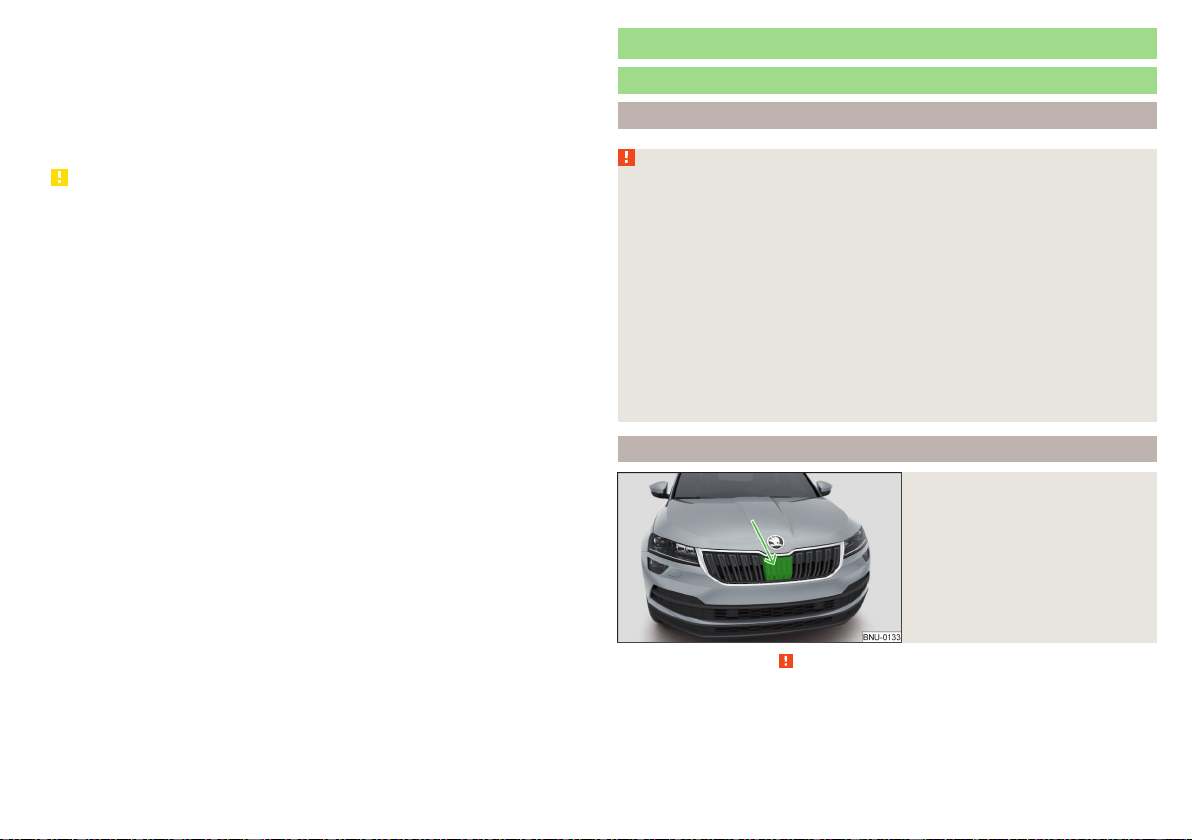
›
Therefore determine the depth of the water before driving through bodies of
water. The water level must not reach above the lower edge of the lower
brace » Fig. 247.
›
Drive at a maximum speed of walking pace, otherwise a shaft may form in
front of the vehicle which could enable water to enter the vehicle system
(e.g. in the air induction system of the engine).
›
Never stop in the water, do not reverse and do not switch the engine off.
CAUTION
■
Water entering the vehicle systems (e.g. the air induction system of the en-
gine) can cause serious damage to the vehicle!
■
Oncoming vehicles can generate water waves which can exceed the permis-
sible water level for your vehicle.
■
Do not drive through salt water, as the salt can cause corrosion. An vehicle
coming into contact with salt water is to be thoroughly rinsed with fresh wa-
ter.
Assist systems
General information
Introduction
WARNING
■
The assistance systems only serve to support the driver and do not re-
lieve the driver of the responsibility for driving the vehicle.
■
The increased safety provision, as well as the increased occupant protec-
tion provided by the assistance systems must not tempt you to take risks -
risk of accident!
■
Adjust the speed and driving style to the current visibility, weather, road
and traffic conditions.
■
The assistance systems have physical and system-related limitations. For
this reason, the driver may experience some undesired or delayed system
responses in certain situations. You should therefore always be alert and
ready to intervene!
■
Only enable, disable or set the assistance systems when you have the car
fully under control, in every traffic situation - risk of accident!
Radar sensor
Fig. 248
Installation location of the radar
sensor
Read and observe on page 209 first.
The radar sensor (hereinafter referred to only sensor) uses electromagnetic
waves to capture the traffic situation ahead of the vehicle. The radar is located
under a cover » Fig. 248.
209
Assist systems
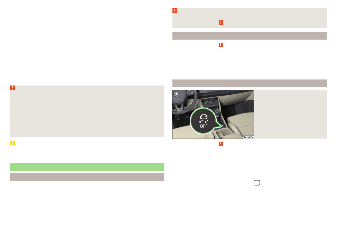
The sensor is part of the ACC » page 229 and Front Assist » page 235sys-
tems.
The sensor function may be impaired in the event of one of the following sit-
uations arising.
▶
The sensor cover is soiled (e.g. with mud, snow and the like).
▶
The area in front of and around the sensor cover is obscured (e.g. by labels,
auxiliary headlights and the like(.
▶
When visibility is poor (e.g. fog, heavy rain, thick snowfall).
▶
In exceptional cases, the sensor may be covered in the area beneath the cov-
er, e.g. due to snow.
If the sensor cover or the sensor is dirty or covered, a message to that effect
from the ACC system » page 234, Malfunctions or Front Assist » page 237,
Malfunctions system appears in the instrument cluster display.
WARNING
■
If you suspect that the sensor is damaged, deactivate the ACC system
and Front Assist system» page 232, » page 237. Have the sensor checked
by a specialist garage.
■
A collision or damage in the front or lower area of the vehicle could affect
the sensor function - there is risk of accident! Have the sensor checked by
a specialist garage.
■
Do not cover the area in front of and around the sensor cover. This can
lead to impaired function of the sensor - risk of accident!
CAUTION
Remove snow with a brush and ice with a solvent-free de-icer from the sensor
cover.
Braking and stabilisation systems
Introduction
The brake and stabilization systems are automatically activated each time the
ignition is switched on, unless otherwise indicated.
The error display is in Chapter » page 39, Warning lights.
WARNING
The general information relating to the use of assistance systems must be
observed » page 209, in section Introduction.
Stability Control (ESC)
Read and observe on page 210 first.
ESC improves vehicle stability in critical driving situations (e.g. if the vehicle
starts to skid) by the braking the individual wheels to maintain the direction.
During an ECS intervention, the warning light flashes in the instrument clus-
ter.
ESC Sport
Fig. 249
ESC Sport / ASR system button
Read and observe on page 210 first.
ESC Sport allows for a sportier driving style. With ESC Sport activated, no
ESC intervention takes place when the vehicle slightly oversteers and under-
steers, and ASR is so limited that the drive wheels can be spun.
Activation
›
Press and hold down the » Fig. 249 button.
›
or: In the Infotainment system, in menu
/ tap on function surface →
ESC system:
→
ESC Sport
.
With activation the warning light lights up in the instrument cluster and an
appropriate message is displayed in the instrument cluster.
Deactivation
›
Press the » Fig. 249 button.
210
Driving

›
or: In the Infotainment system, in menu
/ tap on function surface →
ESC system:
→
Activated
.
With deactivation the warning light extinguishes in the instrument cluster
and an appropriate message is displayed in the instrument cluster.
Anti-blocking system (ABS)
Read and observe on page 210 first.
ABS prevents the wheels locking when braking. Thus helping the driver to
maintain control of the vehicle.
The intervention of the ABS is noticeable from the pulsating movements of
the brake pedal which is accompanied by noises.
When the ABS system is active, do not brake periodically or reduce the pres-
sure on the brake pedal.
Engine drag torque control (MSR)
Read and observe on page 210 first.
The MSR prevents the blocking tendency of the drive wheels when shifting
down or with an abrupt deceleration (e.g. on icy or otherwise slippery road
surfaces).
If the drive wheels lock, the engine speed is automatically increased. This re-
duces the braking effect of the engine, and the wheels can rotate freely again.
Traction control (ASR)
Read and observe on page 210 first.
The ASR prevents spinning of the drive wheels. TCS reduces the drive power
transmitted to the wheels in the case of slipping wheels. Thus, for example,
driving on road surfaces with low grip is made easier.
During a TCS intervention, the indicator light flashes in the instrument clus-
ter.
Deactivation
›
Press the » Fig. 249 on page 210 button.
›
or: In the Infotainment system, in menu
/ tap on function surface →
ESC system:
→
ASR off
.
With deactivation the warning light lights up in the instrument cluster and
an appropriate message is displayed in the instrument cluster.
Activation
›
Press the » Fig. 249 on page 210 button.
›
or: In the Infotainment system, in menu
/ tap on function surface →
ESC system:
→
Activated
.
With activation the warning light is extinguished and an appropriate mes-
sage is displayed in the instrument cluster.
The TCS should normally always be enabled. The system should be deactivated
only in the following situations, for example.
▶
When driving with snow chains.
▶
When driving in deep snow or on a very loose surface.
▶
When it is necessary to “rock” a car free when it has become stuck.
Electronic Differential Lock (EDL and XDS+)
Read and observe on page 210 first.
EDL prevents the turning of the respective wheel of the driven axle. EDL
brakes the spinning wheel, if necessary, and transmits the driving force to the
other driving wheel. Driving becomes easier on road surfaces with different
traction under each wheel of the driven axle.
EDL switches off automatically to avoid excessive heat generation on the
brake of the wheel being braked. Once the brakes have cooled down, there is
an automatic re-activation of EDL.
XDS+ is an extension to the electronic differential lock (EDL). XDS+ responds
by engaging a brake on the curved inner wheel of the driven axle to take pres-
sure off of the wheels during fast cornering. By decelerating the individual
wheels, this prevents the vehicle over-steering or understeering. This has a
positive effect on the driving stability and steerability of the vehicle.
Active steering assist (DSR)
Read and observe
on page 210 first.
In critical situations, the DSR provides the driver with a steering recommenda-
tion in order to stabilise the vehicle. DSR is activated, for example, on the right
and left vehicle side when braking sharply on different road surfaces.
211
Assist systems

Brake Assist (HBA)
Read and observe on page 210 first.
The HBA increases the braking effect and helps to reduce the braking dis-
tance.
The HBA is activated by very quick operation of the brake pedal. In order to
achieve the shortest possible braking distance, the brake pedal must be ap-
plied firmly until the vehicle has come to a standstill.
The HBA function is automatically deactivated when the brake pedal is re-
leased.
Uphill start assist
Read and observe
on page 210 first.
When driving on slopes, the uphill start assist (hereinafter only referred to as
system) allows you to move your foot from the brake pedal to the accelerator
pedal without the vehicle rolling downhill on its own.
The vehicle is braked by the system for about 2 seconds after releasing the
brake pedal.
The system is active as of a 5 % slope, if the driver door is closed. The system
is always active on slopes when in forward or reverse start off.
Multicollision brake (MCB)
Read and observe on page 210 first.
MCB helps to decrease speed after a collision by means of automatic braking
interventions and to stabilise the vehicle. This reduces the risk of a subsequent
crash due to uncontrolled vehicle movement.
The automatic brake interventions can take place only if the following condi-
tions are met.
There was a front, side and rear-end collision of a certain severity.
The impact speed was greater than approx. 10 km/h.
The brakes, the ESL and other required electrical systems remain function-
al after impact.
The accelerator pedal is not actuated.
Trailer stabilisation system (TSA)
Read and observe on page 210 first.
The TSA helps the combination stable in situations where the trailer sways and
then the whole trailer combination.
TSA brakes the individual wheels of the towing vehicle in order to damp the
rocking motion of the entire vehicle combination.
The following conditions are required for the correct TSA function.
The trailer was shipped from the factory or purchased from the ŠKODA
genuine accessories.
The trailer is electrically connected to the towing vehicle via the trailer
socket.
The parking aid is activated.
The speed is greater than 60 km/h.
Further information » page 247, Towing device and trailer.
Offroadmode
Introduction
Offroad mode includes functions that help to overcome routes that are diffi-
cult to navigate when travelling on non-paved roads.
But even with offroad mode activated, your vehicle is never a true SUV.
WARNING
Please take note of the general points relating to the use of assistance sys-
tems » page 209, in section Introduction.
CAUTION
■
Offroad mode is not designed for use on common roads.
■
All four wheels must be fitted with the same tyres approved by
ŠKODA AUTO to ensure Offroad mode operates correctly.
212
Driving
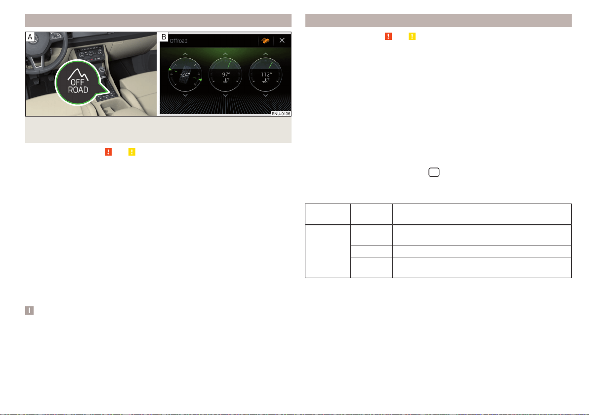
Function
Fig. 250 Offroad button / Infotainment screen: Display with automatic
activation
Read and observe and on page 212 first.
Offroad mode intervenes at a speed up to 30 km/h.
We recommend that you activate the Offroad mode for every trip on non-
paved roads.
›
To activate/deactivate press the button » Fig. 250 - .
During activation the warning light for Offroad mode
in the instrument
cluster and for the Hill Descent Assistant
illuminate, In the Infotainment
screen display, the Offroad mode indication is displayed » Fig. 250 -
.
The following functions are integrated into Offroad mode.
▶
Hill Descent Assistant » page 213
▶
ESC Offroad » page 214
▶
ASR Offroad » page 214
▶
EDS Offroad » page 214
▶
ABS Offroad » page 214
Note
If the engine is “stalled” while travelling in Offroad mode, you should check af-
ter engine re-start to see if Offroad mode is still enabled. This may need to be
re-enabled.
Hill Descent Assist
Read and observe and on page 212 first.
The hill descent assistant (hereinafter referred to as assist system), with its au-
tomatic braking action on all wheels, ensures a constant speed is maintained
on a steep slope when driving forwards and reversing.
During an intervention, the white warning light in the instrument cluster
lights up.
The assist system is automatically engaged under the following conditions.
The engine is running.
Offroad mode is activated.
The slope is at least 10%.
Neither the accelerator nor the brake pedal is pressed.
Assistant off / on in Infotainment
In the Infotainment system, in menu
/
tap on function surface
.
The state of the assist system is indicated by the colour of the function sur-
face
in the Infotainment screen.
Function
surface
Colour Meaning
Grey
Assist system is not active (Offroad mode is not
enabled)
White Assist system off (with Offroad mode enabled)
Orange
Assist system is ready to intervene (with Offroad
mode enabled)
Driving speed
Initiate the downhill descent at a reasonable speed of approx. 2 - 30 km / h,
the assist system constantly maintains this speed as you travel downhill.
If a forwards or reverse gear is engaged on vehicles with a manual transmis-
sion, the speed must be high enough to avoid “stalling the engine”.
The driving speed can be changed by pressing the brake or accelerator pedal.
Engagement of the assist system is resumed after the pedal is released.
213
Assist systems
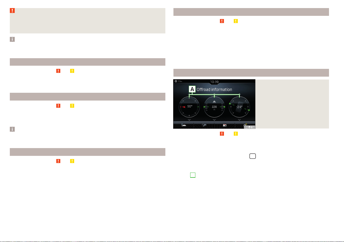
WARNING
For the correct operation of the assistant the road surface must be suffi-
ciently adherent. The assistant cannot properly fulfil its function on slushy
soil due to physical reasons (e.g. ice or mud). - there is a risk of an accident!
Note
When the wizard brakes the vehicle automatically, then the brake light does
not come on.
ESC Offroad
Read and observe and on page 212 first.
ESC Offroad makes driving on dirt roads easier, as no ESC interventions occur
when the vehicle is slightly over or under steered.
ASR Offroad
Read and observe and on page 212 first.
TCS Offroad makes starting and driving on an unpaved surface easier as it par-
tially allows wheel-spin.
Note
When disabled, TCS » page 211 Offroad mode works without the support of
TCS Offroad.
EDS Offroad
Read and observe
and on page 212 first.
EDS Offroad supports the driver when driving on a surface with different grip
under the drive wheels or when driving over bumps.
A spinning wheel or wheels are braked earlier and with more force than with
the intervention of the standard EDS system.
ABS Offroad
Read and observe and on page 212 first.
ABS Offroad supports the driver when braking on an unpaved surface (e.g.
gravel, snow etc.).
The system generated by a controlled locking of the wheels braked wheel be-
fore a “wedge” of piled material, which shortens the braking distance.
Maximum system efficiency is achieved when the front wheels are in the
straight ahead position.
Offroad in Infotainment
Fig. 251
Offroad Infotainment display
Read and observe and on page 212 first.
The display of Offroad mode in Infotainment is used to evaluate the current
driving situation.
›
To display in the Infotainment menu
/ Tap on the function surface →
→
Offroad
.
A swipe of the finger vertically across the screen allows three of the following
displays
A
to be shown » Fig. 251.
▶
Compass (applies to the Amundsen and Columbus Infotainment)
▶
Altimeter (applies to the Amundsen and Columbus Infotainment)
▶
Steering angle display
▶
Coolant temperature gauge
▶
Oil temperature display
214
Driving
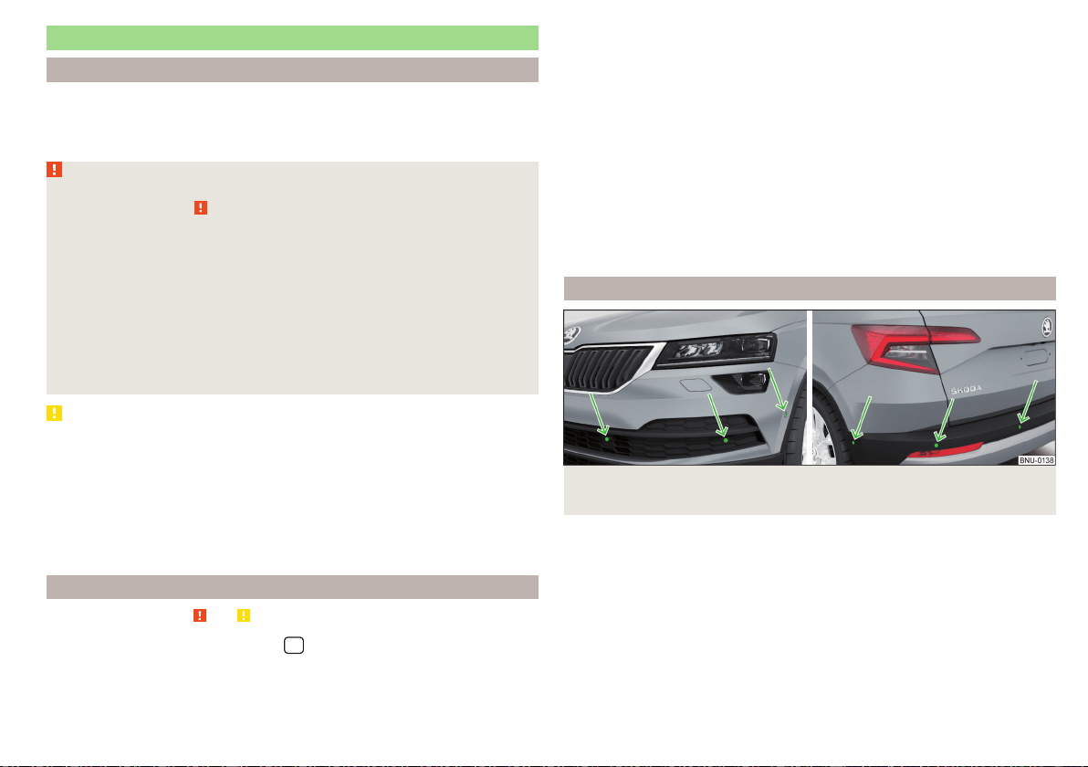
Parking aid (ParkPilot)
Introduction
The parking aid (hereinafter referred to as system) uses acoustic signals or In-
fotainment screen when manoeuvring around obstacles in the vicinity of the
vehicle.
WARNING
■
The general information relating to the use of assistance systems must be
observed » page 209, in section Introduction.
■
Moving persons or objects may not be recognized by the system sensors.
■
Under certain circumstances, surfaces of certain objects and types of
clothing cannot reflect the system signals. There is a danger that such ob-
jects or people may not be recognised by the system sensors.
■
External noise sources may affect the signals of the system sensors.
There is a danger that obstacles may not be detected by the system sen-
sors.
■
Before reversing, make sure that there are is not any small obstacle, such
as a rock, thin post etc., in front of or behind your vehicle. Such obstacles
may not be recognised by the system sensors.
CAUTION
■
Keep the system sensors » Fig. 252 on page 215 clean, snow-and ice-free
and do not cover with any objects of any kind, otherwise the system function-
ing may be impaired.
■
Under adverse weather conditions (heavy rain, water vapour, very low or high
temperatures, etc.), the system function may be limited - “incorrect recogni-
tion of obstacle”.
■
Accessories fitted to the vehicle rear, such as bicycle carriers, can impair the
system function.
Settings in Infotainment
Read and observe
and on page 215 first.
›
In the infotainment system, in menu
/ tap on function surface →
Park-
ing and manoeuvring
.
■
ParkPilot - Settings for the parking aid
■
Activate automatically
- Activate/deactivate the compact parking aid display
(when driving forward)
■
Front volume
- Adjust the volume of the beeps for obstacle detection in front
■
Front tone setting
- Setting the pitch of the beeps for obstacle detection in
front
■
Rear volume
- Set the volume level of the beeps for the rear obstacle detec-
tion
■
Rear tone setting
- Setting the pitch of the beeps for the rear obstacle detec-
tion
■
Entertainment fading while parking
– Lowers the audio volume (e.g. radio vol-
ume) with activated parking aid
■
Manoeuvre braking
- Activation / deactivation of the automatic emergency
braking
Operation
Fig. 252
Installation location of the sensors on the left side of the vehi-
cle: front/rear
215
Assist systems
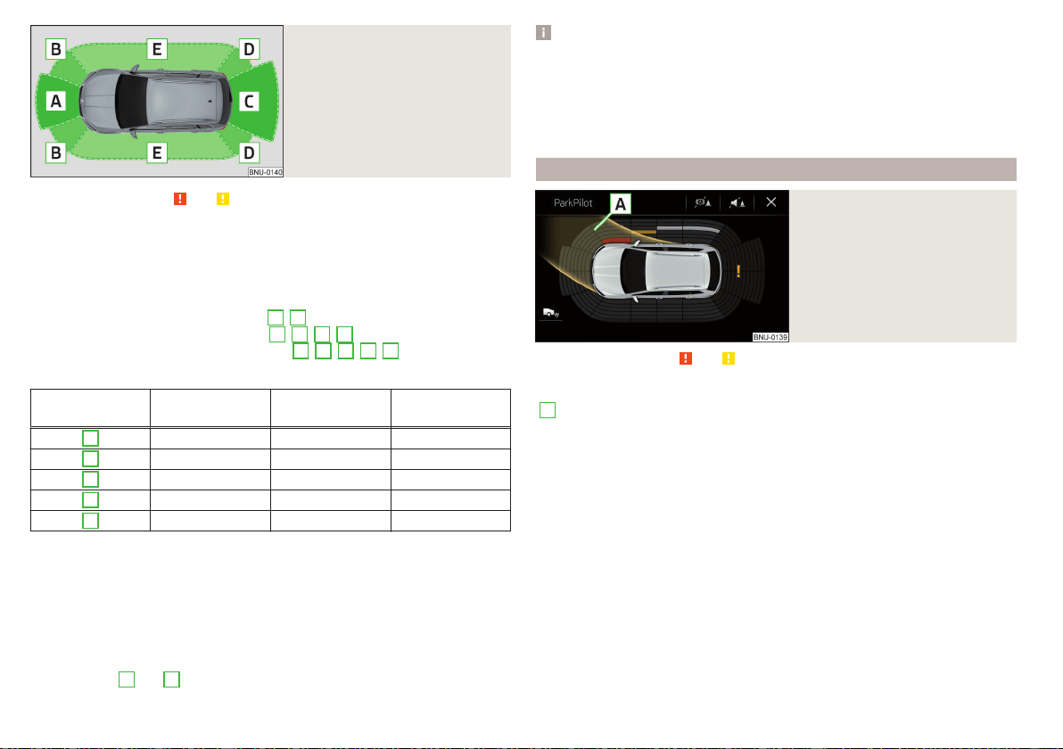
Fig. 253
Sampled areas and range of the
sensors
Read and observe
and on page 215 first.
The system uses ultrasound waves to calculate the distance between the
bumper and an obstacle. The ultrasonic sensors are, depending on vehicle
equipment,, located in the back or in the front bumper » Fig. 252.
Depending on the equipment, the following system versions are possible
» Fig. 253.
▶
Variant 1: warns of obstacles in areas
C
,
D
.
▶
Variant 2: warns of obstacles in areas
A
,
B
,
C
,
D
.
▶
Variant 3: warns of obstacles in the areas
A
,
B
,
C
,
D
,
E
.
Approximate range of sensors (in cm)
Area » Fig. 253
Variant 1
(4 sensors)
Variant 2
(8 sensors)
Variant 3
(12 sensors)
A
- 120 120
B
- 60 90
C
160 160 160
D
60 60 90
E
- - 90
Audible signals
The interval between the acoustic signals becomes shorter as the clearance is
reduced. At a distance of approx. 30 cm a continuous tone starts to sound -
danger area. Stop driving in the direction of the obstacle.
The acoustic signals can be set in Infotainment » page 215.
Towing a trailer
When towing, or when another accessory is connected to the trailer socket,
only the areas
A
and
B
» Fig. 253 are active in the system.
Note
■
If with Version 3 vehicles not all fields around the vehicle silhouette are ac-
tive after activation, the vehicle should be moved forwards or backwards.
■
The signal tones for front obstacle recognition are factory-set to be higher
than for rear obstacle recognition.
■
The setting of the acoustic signals is stored (depending on Infotainment
type) in the active user account personalisation » page 55.
Display Infotainment screen
Fig. 254
Screen display
Read and observe and on page 215 first.
Function surfaces and warnings » Fig. 254
A
Road display.
Depending on the Infotainment type: Switching off park assistant dis-
play.
Switching audible parking signals on/off.
Disable / enable the automatic emergency braking.
Change to rear-view camera display .
There is an obstacle in the collision area (the distance to the obstacle
is less than 30 cm). Stop moving in the direction of the obstacle!
There is an obstacle in the road (the distance to the obstacle is great-
er than 30 cm).
An obstacle is located outside of the road (the distance to the obsta-
cle is greater than 30 cm).
System failure (there is no indication of obstacles).
216
Driving
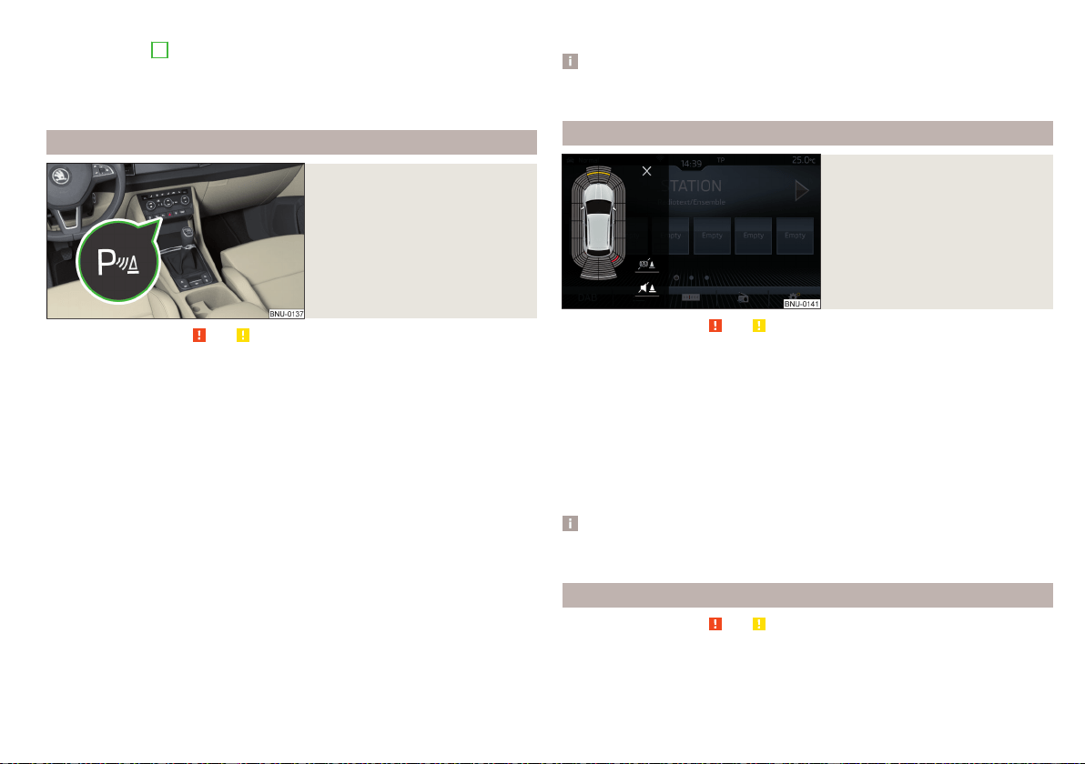
Road display
The road display
A
» Fig. 254 indicates the road on which the vehicle would
take the current steering wheel and shift / selector lever position.
The shift lever is in the neutral position and the gear selector is in mode N. the
road display is at the front.
Activation / deactivation
Fig. 255
System key (option 2, 3)
Read and observe and on page 215 first.
Activation
To activate the system, engage reverse gear and, on vehicles with version 2
and 3, also press the
» Fig. 255 button.
When activating, an alarm sounds and the symbol
illuminates in the button.
Deactivation
On vehicles with Version 1, the system can be deactivated by moving out of
reverse gear.
For vehicles with version 2 and 3, the system is automatically deactivated by
pressing the button or at a speed above 15 km/h (the symbol in the but-
ton goes out).
Displaying an error
Vehicles with Variant 1
▶
After system activation an acoustic signal sounds for approx. 3 seconds
(there is no obstacle near the vehicle).
Vehicles with the Variants 2 and 3
▶
After system activation, the symbol flashes in the button.
▶
In the display of the instrument cluster a message about an error of the Park-
Pilot system appears (at the same time there is an audible signal).
Seek help from a specialist garage.
Note
The system can only be activated with the button at a speed of below 15
km/h.
Automatic system activation when moving forward
Fig. 256
Infotainment screen: Display
with automatic activation
Read and observe and on page 215 first.
The automatic system activation occurs when moving forward at a speed be-
low 10 km/h when the vehicle approaches an obstacle.
After activation, the following is shown in the left pane of Infotainment display
» Fig. 256.
Acoustic signals are sounded as of a distance from the obstacle of around
50 cm.
The automatic display can be activated / deactivated in Infotainment
» page 215.
Note
The setting (activate / deactivate) of the automatic display is stored (depend-
ing on Infotainment type) in the active user account personalisation » page 55.
Automatic emergency braking
Read and observe
and on page 215 first.
If the system detects a collision risk when travelling forwards or reversing at a
speed up to 8 km/h, there is an automatic emergency braking to reduce the
impact consequences.
217
Assist systems
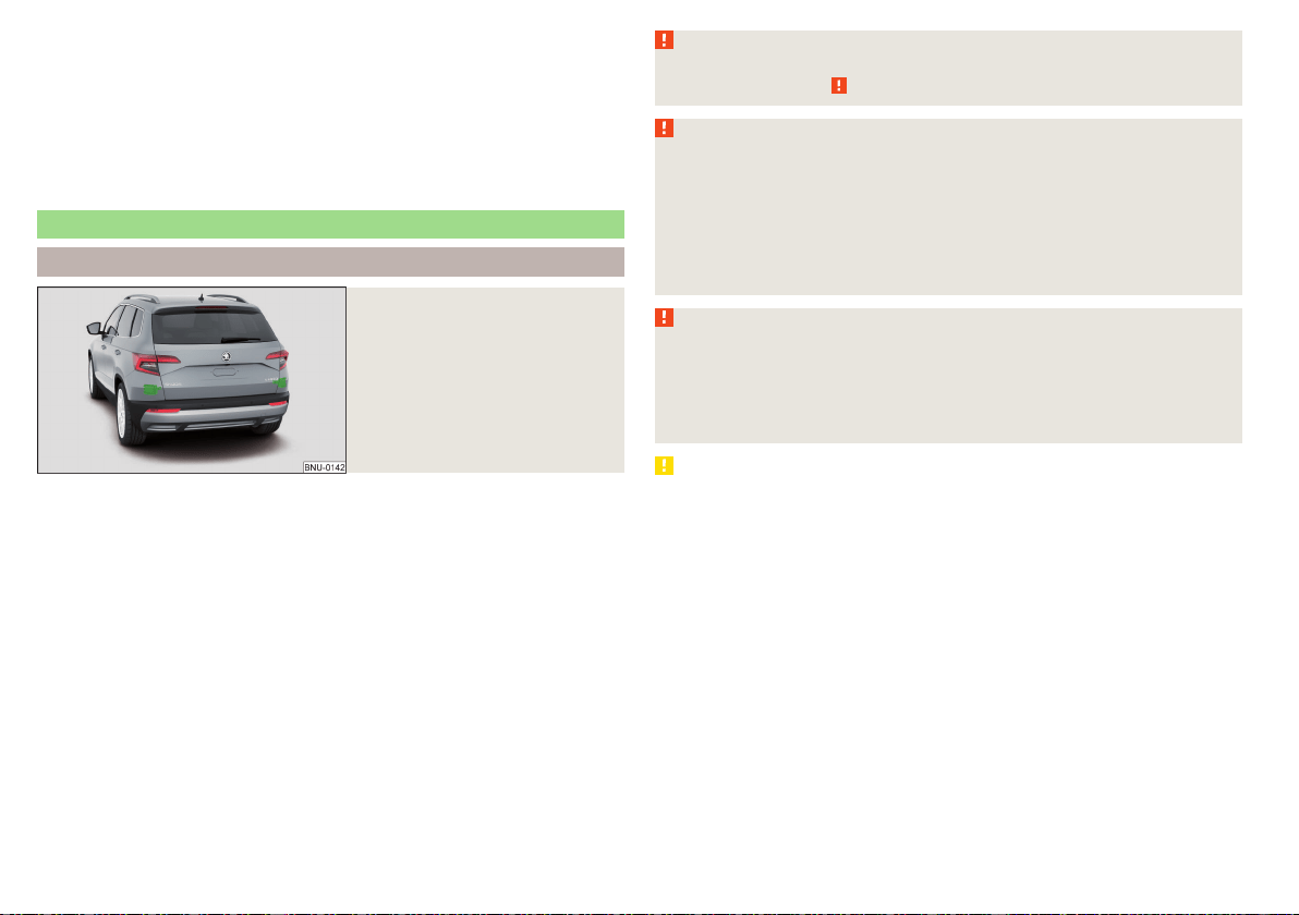
Disable / Enable
The brake function can be enabled / disabled in the Infotainment in the menu
Parking and manoeuvring
» page 215.
After switching the ignition on and off, the systems remains activated / deacti-
vated depending on the setting prior to switching off the ignition.
The brake function can also be deactivated once with the function surface
» Fig. 254 on page 216.
Rear traffic alert and wizard for “Blind spot”Monitoring
Introduction
Fig. 257
Installation location of the radar
sensors
The Rear Traffic Alert and Wizard for “blind spot” monitoring works based on
the information from the radar sensors in the rear bumper » Fig. 257. The radar
sensors are not visible from the outside.
Rear Traffic Alert
The Rear Traffic Alert (hereinafter referred to as system) warns when leaving a
parking space from a transverse parking space about any approaching vehi-
cles.
If necessary, the system tries to avoid a collision with automatic braking, or at
least to mitigate the consequences.
Wizard for “blind spot”monitoring
The wizard for“blind spot monitoring” (hereafter referred to as system) draws
attention to vehicles travelling in the same direction in the next lane in the so-
called blind spots.
The “blind spot” is an area that is not easily visible in a rear-view mirror or even
directly from the vehicle.
WARNING
The general information relating to the use of assistance systems must be
observed » page 209, in section Introduction.
WARNING
■
In the case of a collision or damage to the rear of the vehicle, the function
of the systems may be affected - risk of accident! Have the vehicle
checked by a specialist garage.
■
Do not cover the sensor area - the function of the systems could be limi-
ted.
■
Remove snow, ice and such obstacles from the sensor environment im-
mediately.
WARNING
The wizard for “blind spot”monitoring is limited by physical and system-re-
lated limits. Therefore, in the following situations the system can be de-
layed in drawing attention (or not at all) to a vehicle in the next land.
■
When a vehicle is approaching at a very high speed.
■
When passing through a very sharp curve or a roundabout.
CAUTION
■
If a trailer or other accessory is to be connected to the trailer socket, then
the two systems are not available.
■
In adverse weather conditions (heavy rain, water vapour, very low or high
temperatures, etc.), the system function may be limited - “failure to recognise
a vehicle”.
■
Accessories additionally installed on the vehicle rear, such as bicycle carriers,
can impair the system function.
218
Driving
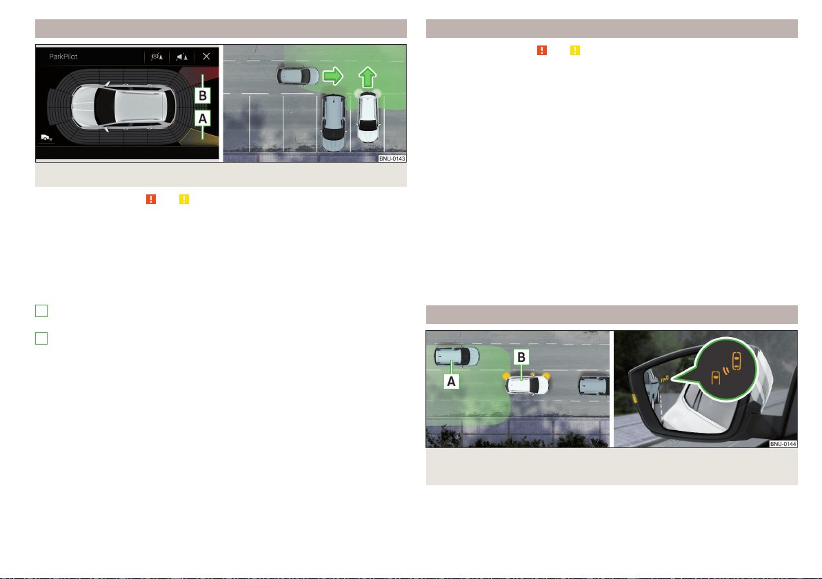
Rear Traffic Alert- Operation
Fig. 258 Infotainment screen: warning indicator/driving situation
Read and observe and on page 218 first.
With the ignition switched on, the area next to and behind the vehicle is moni-
tored by the radar sensors of the system. If an approaching vehicle is detected
from the rear of the vehicle » Fig. 258, the system warns of this fact.
Warning - vehicles with parking aid
You will hear a continuous tone and one of the following warning levels ap-
pears on the Infotainment screen » Fig. 258.
An oncoming vehicle is detected. Do not continue driving backwards and
check around the vehicle.
A vehicle in the collision region is detected. Do not continue driving back-
wards .
Warning - vehicles without parking sensors
An acoustic signal is sounded and information for the driver to observe the
traffic behind is shown in the instrument cluster.
Automatic emergency braking
If the driver does not react to the warning and the system detects an impend-
ing collision, then this can trigger an automatic braking at a speed up to 10
km/h. A corresponding message is shown in the information cluster display.
A
B
Wizard for “Blind Spot”Monitoring - Operation
Read and observe and on page 218 first.
At a speed over 15 km/h, the area alongside and behind the vehicle is moni-
tored by the system. At the same time, the distance and the difference in
speed between your vehicle and the other vehicles in the monitored area can
be measured.
When driving, the sensors monitor an area to the left and right to the extent of
a normal lane width.
If a vehicle is detected in the “blind spot” area, the system indicates this vehi-
cle by the indicator light
in the exterior mirror.
System constraint
The system is unable to recognise the specific lane width by means of sensors.
Therefore this can e.g. in the following cases respond to a vehicle in a further
lane.
▶
When driving on a road with narrow lanes or on the lane edge.
▶
Driving around a bend.
The system may also respond to objects on the roadside such as crash barri-
ers, noise barriers or similar objects.
Wizard for “Blind Spot”Monitoring - driving situations and warnings
Fig. 259
Driving situation / indicator light in the left outside mirror indi-
cates the driving situation
219
Assist systems
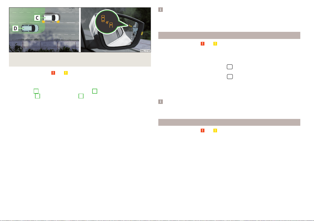
Fig. 260 Driving situation / indicator light in the right outside mirror in-
dicates the driving situation
Read and observe
and on page 218 first.
In the following situations, the indicator light in the outside mirror indicates a
vehicle in the “blind spot”.
▶
You vehicle
B
is being overtaken by vehicle
A
» Fig. 259.
▶
Your vehicle
C
is overtaking vehicle
D
at a speed of max. 10 km high-
er» Fig. 260. If the speed during the overtaking is even higher, then there is
no warning by the warning light.
The warning display is always in the exterior mirror on the side of the vehicle
where a vehicle is detected in the “blind spot”.
The greater the speed difference between the two vehicles, the earlier the
warning (by means of the warning light) regarding the vehicle that is overtak-
ing you takes place.
Two warning levels
light up - a vehicle has been detected in the “blind spot”.
flash - a vehicle has been detected in the “blind spot” and the turn signal is
switched on.
An advanced warning for vehicles with Lane Assist
flash also if the steering wheel is turned in the direction of the vehicle in
the “blind spot” . Therefore the Lane Assist » page 240 must be enabled and
the boundary line between the vehicles detected.
If in this case your vehicle indicates crossing the boundary line, with a short vi-
bration of the steering wheel.
Note
The brightness of the indicator light is dependent on the setting of the vehi-
cle lighting. With the low or high beam on the brightness of the light will be
lower.
Activation / deactivation
Read and observe
and on page 218 first.
The activation or deactivation of the system can be carried out in one of the
following ways.
▶
In the instrument cluster display » page 54,
Assist systems
menu item.
▶
In the infotainment system, in menu
/ → →
Driver assistance
(Applies to
the “blind spot” monitoring assistant).
▶
In the Infotainment system, in menu
/
→
→
Parking and manoeuvring
(Applies to Rear Traffic Alerts).
After switching off and switching on the ignition, depending on the setting pri-
or to switching off the ignition, the systems remains activated / deactivated.
Note
When activating the wizard for “blind spot” monitoring, the warning lights
illuminate briefly in the two exterior mirrors.
Malfunctions
Read and observe and on page 218 first.
If the systems are not available, an appropriate message appears in the display
of the instrument cluster.
Sensor covered / dirty
If the sensor is dirty or covered, a message indicating that there is no sensor
view appears. Clean or remove the obstructing object from the sensor envi-
ronment » Fig. 257 on page 218.
Systems unavailable
If the systems are unavailable, a message regarding unavailability appears. Stop
the vehicle, switch off the engine and then start it again. If the systems are still
not available, seek the assistance of a specialist garage.
220
Driving
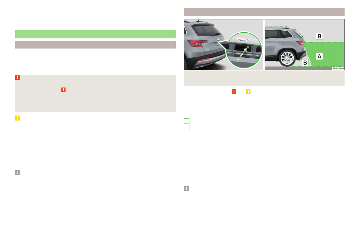
System fault
In the case of a system fault, an error message appears. Seek help from a spe-
cialist garage.
Reversing camera
Introduction
The rear view camera (following as system) helps the driver when parking and
manoeuvring by displaying the area behind the vehicle on Infotainment screen
(hereinafter only known as screen).
WARNING
■
Please take note of the general points relating to the use of assistance
systems » page 209, in section Introduction.
■
The camera may not be soiled or obscured, otherwise the system func-
tion will be significantly affected - there is a risk of accident. For informa-
tion on cleaning » page 254.
CAUTION
■
The camera image is distorted by contrast with eyesight. For this reason, the
screen display is only of limited use for estimating distances to following vehi-
cles.
■
Some items, such as thin posts, chain link fences, grilles or uneven road sur-
faces may not be properly displayed in terms of screen resolution.
■
In a crash or damage the vehicle's rear camera can possibly deviate from the
correct position. If this is the case, have the sensor checked by a specialist ga-
rage.
Note
The camera can be equipped with a cleaning system » page 78. The spraying is
carried out automatically when the rear window is sprayed.
Operating principle
Fig. 261 Installation location of the camera / scanned area behind the
vehicle
Read and observe and on page 221 first.
The camera for capturing the area behind the vehicle is in the grip of the boot
lid » Fig. 261.
Area behind the vehicle » Fig. 261
Detection range of the camera
Area outside the detection range of the camera
The system can assist the driver when parking and manoeuvring under the fol-
lowing basic conditions.
The ignition is switched on.
The reverse gear is engaged.
The luggage compartment lid is completely closed.
The vehicle is travelling at less than 15 km/h.
The area behind the vehicle is clearly visible.
The selected parking / manoeuvring area is clear and even.
Note
■
The screen display can be interrupted by pressing the symbol button
» Fig. 255 on page 217.
■
After disengaging reverse gear, automatic screen display of the parking aid is
carried out (variant 2, 3) » page 215.
A
B
221
Assist systems

Guidelines and function surfaces
Fig. 262 Infotainment screen: Orientation lines / function interfaces
Read and observe and on page 221 first.
On the screen, orientation lines are shown along with the monitored area be-
hind the vehicle.
Distance of the orientation lines behind the vehicle » Fig. 262
The distance is about 40 cm (safety distance limit).
The distance is about 100 cm.
The distance is about 200 cm.
The distance may vary slightly depending on the load of the vehicle and the
road inclination.
The distance between the side lines corresponds approximately to the vehicle
width including mirrors.
Function surfaces » Fig. 262
Depending on the Infotainment type: Turns off the display of the area
behind the vehicle
Screen settings - brightness, contrast, colour
Switching on/off audible parking signals
Switching on/off the reduced park assistance display
Change to park assistance display
CAUTION
The objects shown on the screen can be closer or even further away than they
appear. This is especially the case in the following situations.
■
Protruding objects, such as the rear of a truck and the like.
A
B
C
■
When driving from a horizontal surface into a slope or a depression.
■
When driving from a slope or a depression onto a horizontal surface.
Park Assist
Introduction
Park Assist (following referred to system) helps drivers park in suitable parallel
and perpendicular parking places or also to manoeuvre out of parallel parking
spaces.
The system takes over the steering movements only when parking or leaving a
parking space. The driver operates the brake, accelerator or clutch pedal and
the shift / selector lever.
The state in which the steering wheel is operated by the system, is referred to
as parking operation.
The Park Assist is an extension of the parking aid » page 215 and operates on
the basis of data collected by the ultrasonic sensors.
For this reason, the chapter on the parking aid is to be read carefully and
the safety notes are to be observed.
WARNING
■
The general information relating to the use of assistance systems must be
observed » page 209, in section Introduction.
■
During the parking process, the system automatically performs rapid
steering movements. While it is doing so, do not place your hands between
the steering wheel – risk of injury!
■
During a parking manoeuvre on loose or slippery surfaces (gravel, snow,
ice, etc.) you may stray from the calculated road. It is therefore recommen-
ded that you do not use the system in such situations.
CAUTION
The correct evaluation of the parking space and the parking procedure de-
pends on the circumference of the wheels on the vehicle.
■
The system only works correctly if the vehicle is fitted with the wheel size
approved by ŠKODA AUTO.
222
Driving
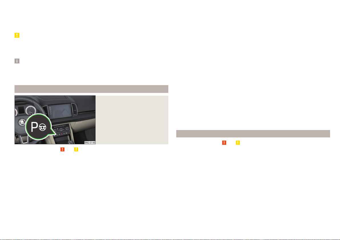
■
Do not use the system if snow chains or an emergency wheel are fitted.
■
If wheels other than those approved by ŠKODA AUTO are fitted, the result-
ing position of the vehicle in the parking space can differ slightly. This can be
avoided by readjusting the system at a specialist garage.
CAUTION
If other vehicles are parked behind or on the kerb, the system can drive your
vehicle over the kerb or up to the kerb - there is a risk of damage to the
wheels. Intervene in good time if necessary.
Note
■
We recommend performing the parking at a safe speed to about 5 km/h.
■
The parking procedure can be stopped at any time by pressing the
» Fig. 263 on page 223 button or by a steering intervention.
Operation
Fig. 263
System button
Read and observe and on page 222 first.
The system support is provided in the following manner.
▶
While the parking space search is going on, a measurement and evaluation of
the parking space size is completed.
▶
The display of the instrument cluster (hereinafter only display) shows suita-
ble parking spaces and a parking mode is recommended.
▶
The display shows instructions and information before the start and during
the parking.
▶
Based on the calculated road surface, the front wheels will be automatically
rotated during the parking.
Conditions for the system function
The system can look for a parking space only if the following basic conditions
are met.
The system is activated.
The vehicle is travelling at less than 40 km/h.
The vehicle is travelling at less than 20 km/h.
The distance to a number of parked vehicles is approximately 0.5 - 1.5 m.
TCS is activated » page 211.
The system can only carry out the parking procedure if the following basic
conditions are met.
The vehicle is travelling at less than 7 km/h.
The parking procedure takes less than 6 minutes.
There is no driver intervention in the automatic steering operation.
TCS is activated » page 211.
The TCS does not engage.
No trailer or other accessory is connected to the trailer socket.
Activation/deactivation
The system can be activated/deactivated by pressing the
button» Fig. 263.
When the system is activated, the
symbol illuminates in the button.
Search for parking space
Read and observe and on page 222 first.
The system searches for a parking space in a number of parallel and transverse
parked vehicles on the passenger or driver's side.
Process with the parking space search
›
Slowly drive past a row of parked vehicles.
›
Activate the system with the
button» Fig. 263 on page 223.
The system will automatically search for a parking space on the passenger
side.
If the system finds a parking space, the recommended parking mode is dis-
played » Fig. 265 on page 224 or » Fig. 266 on page 224 - .
Activate the turn signal on the driver's side if you wish to look for a parking
space on this side of the road. The display changes and the system searches
for a parking space on the driver's side.
223
Assist systems
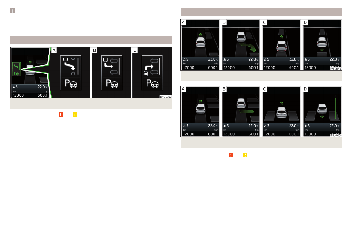
Note
If the symbol (km / h) is shown in the display while you are looking for a
parking space, the vehicle speed should be reduced below 40 km / hr (parallel
parking) or below 20 km / hr (Transverse parking).
Switch to park mode
Fig. 264
Menus with the parking modes: Display
Read and observe and on page 222 first.
While the parking space search is going on and before the start of the parking,
a menu may appear showing other suitable parking modes.
Parking modes » Fig. 264
To park backwards in a parallel parking space
To park backwards in a traverse parking space
To park forwards in a traverse parking space
The parking mode can be changed by pressing the
» Fig. 263 on page 223
button.
After switching through all parking modes offered, an additional press of the
button deactivates the system.
If you want to return to the originally recommended parking mode, press the
button again.
Parking
Fig. 265 To park in a parallel parking space: Display
Fig. 266
To park in a traverse parking space: Display
Read and observe
and on page 222 first.
The system supports the driver when reverse parking in the parking space
found in a number of traverse and parallel parked vehicles.
Display view » Fig. 265 or » Fig. 266
Parking space recognised with the information to drive on
Parking space recognised with the information to reverse
Note to drive on to the parking space
Note to reverse to the parking space
Process for reverse parking
The parking space found is shown in the display » Fig. 265 - or » Fig. 266 -
.
224
Driving

›
Continue driving forwards until appears in the display.
›
Stop and ensure that the vehicle does not continue to move forward until the
parking procedure starts.
›
Select reverse gear or move the selector lever into position R.
›
As soon as the following message is shown in the display:
Steering int. active. Be
mindful of your surroundings
, let go of the steering wheel and the steering is tak-
en over by the system.
›
Observe the direct vicinity of the vehicle and reverse carefully.
If necessary, the parking procedure can be continued with further steps.
›
If the arrow in the information display is flashing to the front , engage
1st gear or move the selector lever into the position D/S.
The display shows the icon (brake pedal).
›
Depress the brake pedal and wait until the steering wheel automatically ro-
tates into the required position, the symbol
goes out.
›
Carefully drive forwards.
›
If the backwards arrow is flashing in the display -
, select reverse gear again
or move the selector lever into position R.
The display shows the
icon (brake pedal).
›
Depress the brake pedal and wait until the steering wheel automatically ro-
tates into the required position, the symbol
goes out.
›
Carefully move backwards.
You can repeat these steps several times in succession.
As soon as the parking procedure is complete, an audible signal sounds and the
following message appears in the display.
Parking forwards
Fig. 267
To park forwards in a traverse parking space: Display
Read and observe and on page 222 first.
The system supports the driver when parking forward in the parking space
found in a number parallel parked vehicles.
As soon as the system finds a parking space, select the » Fig. 263 on
page 223 button for forwards parking mode » Fig. 264 on page 224 - .
» Fig. 267 Is shown in the display.
The further procedure is analogous to that for reverse parking.
›
Follow the system instructions shown in the display.
As soon as the parking procedure is complete, an audible signal sounds and the
following message appears in the display.
The system is activated by pressing the
button and this is also possible if the
vehicle has already been partially moved to a suitable parking space.
Leaving a parallel parking space
Read and observe and on page 222 first.
The system supports the driver when leaving a parking space of a parallel
parking space.
Leaving a parking space process
›
Press the
» Fig. 263 on page 223 button.
The following message is displayed:
Please indicate and engage reverse gear.
›
Activate the turn signal for side of the vehicle where the parking space is out
of which you wish to manoeuvre.
›
Select reverse gear or move the selector lever into position R.
The further procedure is analogous to that for reverse parking.
›
Follow the system instructions shown in the display.
As soon as the parking procedure is complete, an audible signal sounds and the
following message appears in the display.
If the parking space is too small, it is not possible to use the system to leave
the parking space. A corresponding message is shown in the information clus-
ter display.
225
Assist systems
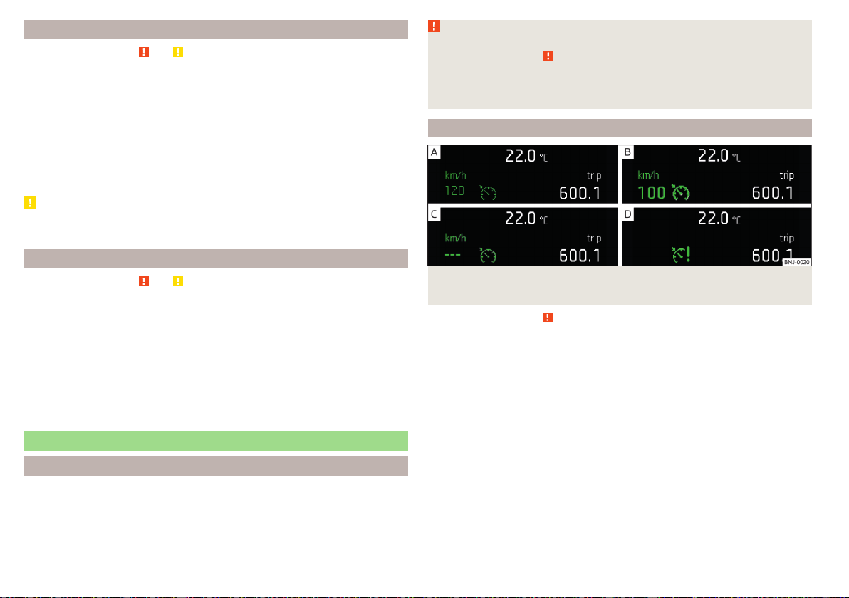
Automatic brake assist
Read and observe and on page 222 first.
Automatic brake assist when speeding
If a velocity of 7 km / h is exceeded during the parking manoeuvre for the first
time, the speed will be automatically reduced by the system to less than 7 km /
h. This prevents the parking manoeuvre from aborting.
Automatic emergency braking
If the system detects a risk of collision during parking, automatic emergency
braking takes place to prevent a collision.
The parking is terminated by the emergency braking.
CAUTION
The automatic emergency braking is not triggered by the system when the
parking process stops due to the speed of 7 km / hr being exceeded!
Malfunctions
Read and observe and on page 222 first.
If the system is not available, an appropriate message appears in the display of
the instrument cluster.
System unavailable
If the system is not available because the vehicle has a fault, a message ap-
pears concerning the unavailability. Seek help from a specialist garage.
System fault
In the case of a system fault, an error message appears. Seek help from a spe-
cialist garage.
Cruise Control System
Introduction
The Cruise Control System (CCS) maintains a set speed without you having to
actuate the accelerator pedal. The state where the CCS maintains the speed is
referred to hereinafter as the control.
WARNING
■
The general information relating to the use of assistance systems must be
observed » page 209, in section Introduction.
■
After pressing the clutch pedal, no interrupted control occurs! For exam-
ple, if a different gear is engaged and the clutch pedal is released, control is
continued.
Operation
Fig. 268
Instrument cluster display: Examples of status displays the
CCS
Read and observe
on page 226 first.
CCS status displays » Fig. 268
Speed is set, control is inactive (in the colour display the digits of speed
limits is shown in grey).
Control active (in the colour display the digits of the speed limits are high-
lighted).
No speed set.
System fault - seek assistance from a specialist garage immediately.
Basic requirements for start of control
The CCS is activated.
On vehicles with a manual transmission, the second gear or higher is en-
gaged.
On vehicles with an automatic transmission, the selector lever is in the
D/S position or in the Tiptronic position.
The current speed is greater than approx. 20 km/h.
226
Driving
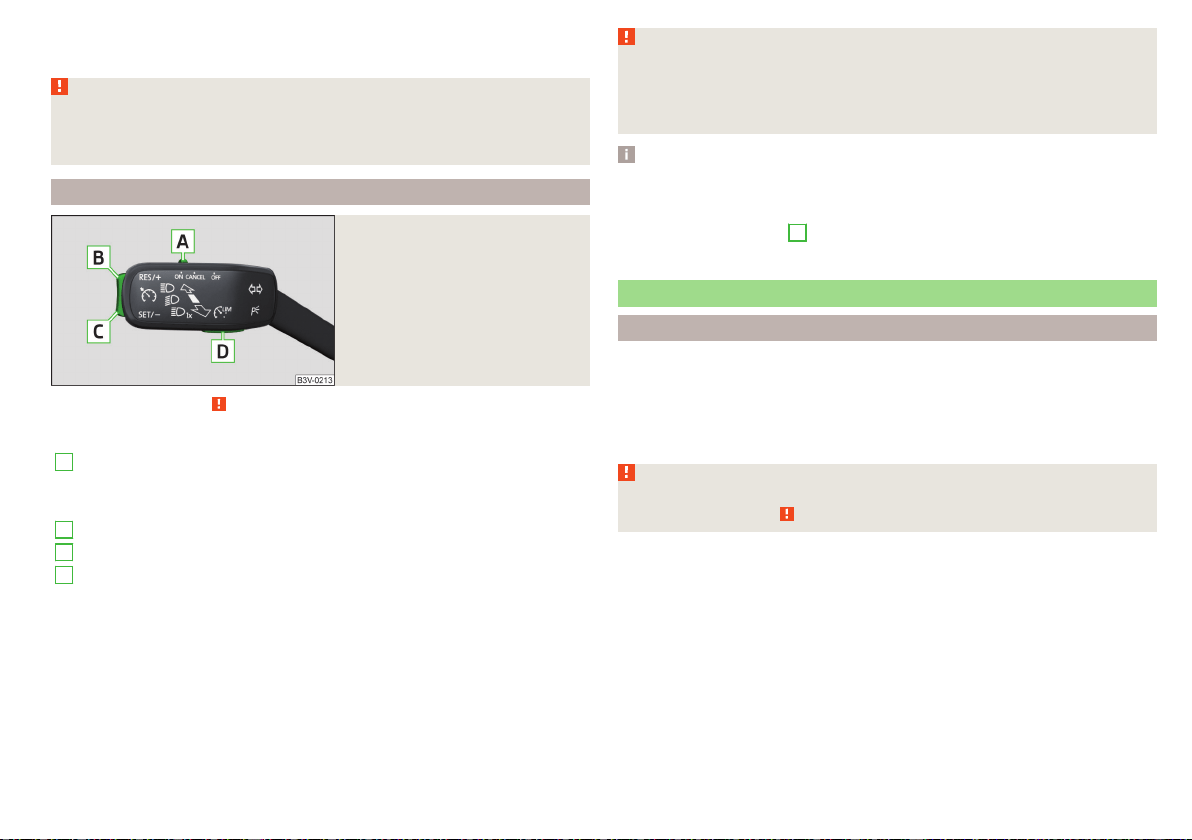
This is only possible within the range which is permitted by the power output
and braking power of the engine.
WARNING
If the engine power and engine braking effect is insufficient in order to
maintain the set speed, the acceleration and brake pedals must be taken
over!
Operation description
Fig. 269
Cruise control system controls
Read and observe on page 226 first.
Overview of the CCS controls » Fig. 269
A
Activate CCS (regulation deactivated)
Interrupt control (sprung position)
Deactivate CCS (delete set speed)
B
Take control again
a)
/ Increase speed
C
Launch control / reduce speed
D
Switching between CCS and speed limiter » page 227
a)
If no speed is set the current speed is adopted.
After the start of the regulation, the CCS regulates the vehicle to the current
speed and the warning light illuminates in the instrument cluster.
The automatic control interruption occurs if any of the following conditions
are met.
▶
The brake pedal is operated.
▶
When one of the brake assist systems (e.g. ESC) intervenes.
▶
Through an airbag deployment.
WARNING
■
Always deactivate the cruise control system after use to prevent the sys-
tem being switched on unintentionally.
■
The control does not resume if the set speed for the existing traffic con-
ditions is too high.
Note
■
During control, speed can be increased by pressing the accelerator pedal. Re-
leasing the accelerator pedal will cause the speed to drop again to the set
speed.
■
By pressing the button
D
» Fig. 269 during the control procedure this is can-
celled and the Speed Limiter is activated.
Speed limiter
Introduction
The Speed Limiter limits the maximum driving speed to the set speed limit.
The speed limit can only be exceeded by depressing the accelerator pedal fully.
The condition in which the Speed Limiter prevents a potential set speed limit
excess is referred to as Regulation.
WARNING
The general information relating to the use of assistance systems must be
observed » page 209, in section Introduction.
227
Assist systems
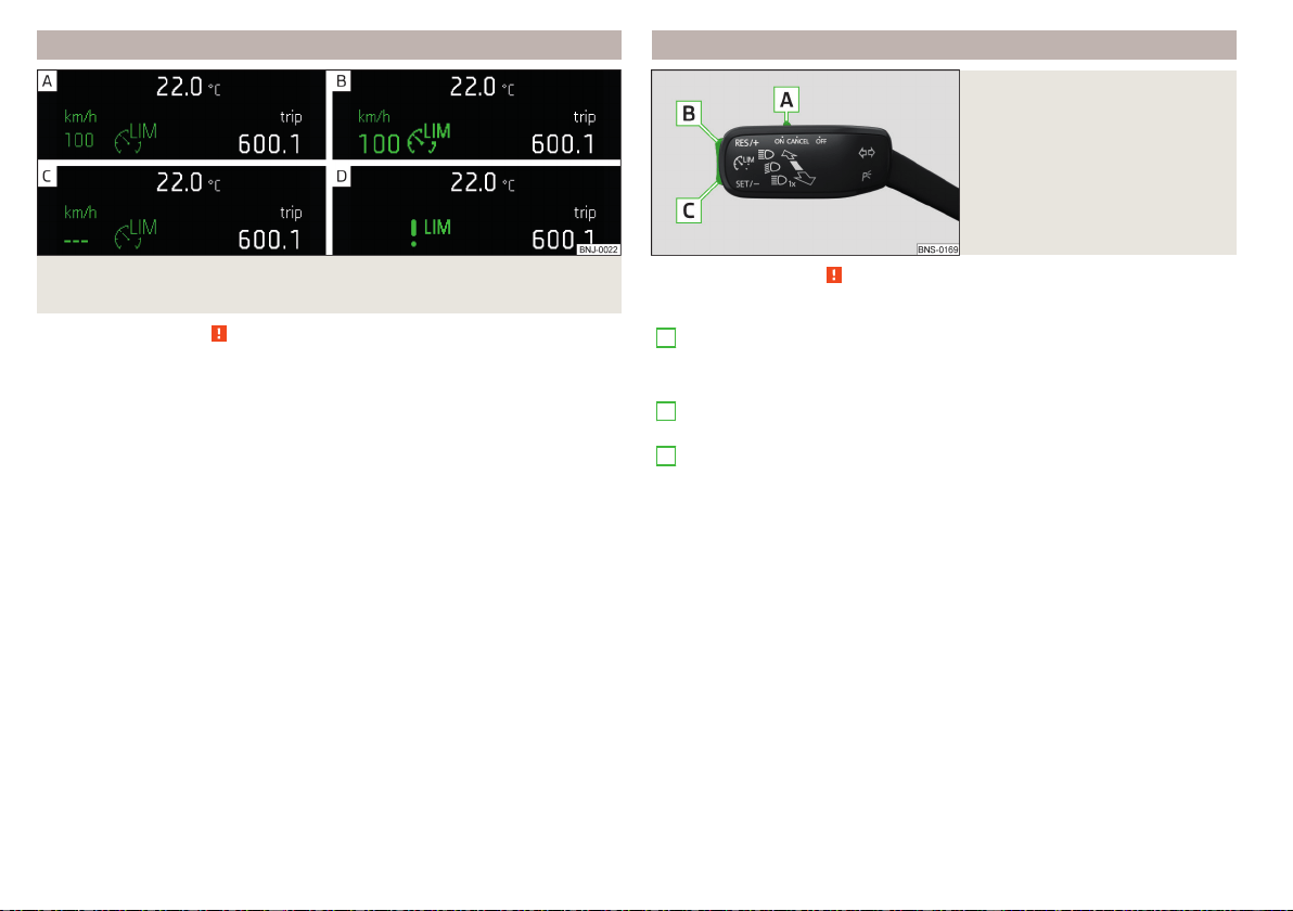
Function
Fig. 270 Instrument cluster display: Examples of Speed Limiter status
displays
Read and observe on page 227 first.
Speed limiter status displays » Fig. 270
Speed limit is set, control is inactive (in the colour display the digits of
speed limits is shown in grey).
Control active (in the colour display the digits of the speed limits are high-
lighted).
No speed limit set.
System fault - seek assistance from a specialist garage immediately.
Basic requirements for start of control
The Speed Limiter is activated.
The current speed is greater than approx. 30 km/h.
After starting the system, the current speed is set as the speed limit, the warn-
ing light lights up in the instrument cluster.
Exceeding the speed limit during the regulation
If, during the control, it is necessary to exceed the speed limit (e.g. to over-
take), the accelerator pedal must be pressed fully.
When exceeding the speed limit (e.g. driving down a hill), an acoustic signal
sounds and the warning light flashes in the instrument cluster.
The regulation is resumed once the speed has fallen below the set limit.
Operation description - Variant without CCS
Fig. 271
Controls of the speed limiter
(version without CCS)
Read and observe
on page 227 first.
Overview of the speed limiter controls » Fig. 271
A
Activate speed limiters
Interrupt control (spring-tensioned position)
Disable speed Limiter (delete set limit )
B
Take control again
a)
/ increase speed limit - press (in increments
of 1 km/h), hold (in increments of 10 km/h)
C
Start control/ reduce speed limit - press (in increments of 1 km/h),
hold (in increments of 10 km/h)
a)
If no speed limit is set, the current speed is set as the speed limit.
228
Driving
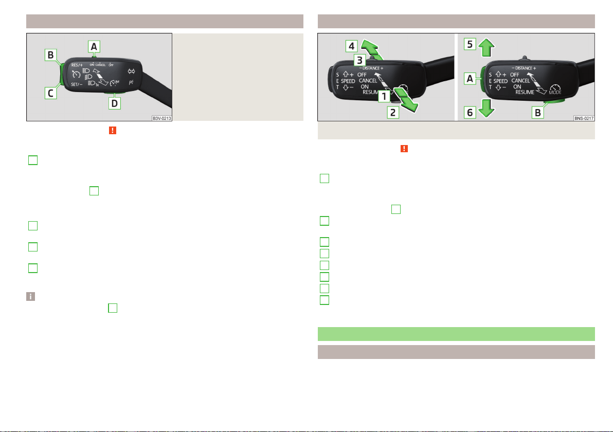
Operation description - Variant with GRA
Fig. 272
Controls the speed limiter (ver-
sion with GRA)
Read and observe
on page 227 first.
Overview of the control elements of the speed limiter » Fig. 272
A
Activate CCS (required condition for the subsequent activation of
the speed limiter)
To activate the speed limiter, set the switch to position , then
press
D
.
Interrupt control (spring-tensioned position)
Disable speed Limiter (delete set limit )
B
Take control again
a)
/ increase speed limit - press (in increments
of 1 km/h), hold (in increments of 10 km/h)
C
Start control/ reduce speed limit - press (in increments of 1 km/h),
hold (in increments of 10 km/h)
D
Switching between CCS and speed limiter
a)
If no speed limit is set, the current speed is set as the speed limit.
Note
By pressing the button
D
» Fig. 272 during the regulation this is cancelled and
the CCS is activated.
Operation description - Variant with ACC
Fig. 273 Controls the speed limiter (version with ACC)
Read and observe on page 227 first.
Overview of the control elements of the speed limiter » Fig. 273
1
Activate ACC (required condition for the subsequent activation
of the speed limiter)
To activate the speed limiter, set the lever to position , then
press
B
to operate.
2
Resume control
a)
/ increase speed limit by 1 km/h at a time
(sprung position)
3
Interrupt control (sprung position)
4
Disable speed Limiter (delete set limit )
5
Increase speed limit by 10 km/h at a time
6
Decrease speed limit by 10 km/h at a time
A
Start control / reduce speed limit in increments of 1 km/h
B
Switching between ACC and speed limiter
a)
If no speed limit is set, the current speed is set as the speed limit.
Adaptive Cruise Control (ACC)
Introduction
Adaptive Cruise Control (hereinafter referred to as ACC) maintains the set
speed, and the distance to the vehicle ahead at the same time without the ac-
celerator or brake pedal being pressed.
229
Assist systems
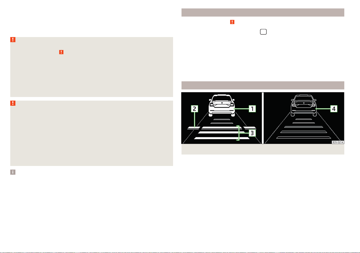
The front of the vehicle and the distance to the vehicle ahead is monitored by
a radar sensor » page 209.
The state in which the ACC maintains the speed or the proximity is described
as control from here on.
WARNING
■
The general information relating to the use of assistance systems must be
observed » page 209, in section Introduction.
■
The driver must always be ready to take over the operation of the accel-
erator and brake pedal.
■
The ACC does not react when approaching a stationary obstacle, such as
traffic jams, vehicle breakdowns or vehicles waiting at a traffic light.
■
The ACC does not respond to crossing or oncoming objects.
■
If the ACC does not decelerate fast enough, immediately apply the vehi-
cle's foot brake.
WARNING
For safety reasons, do not use the ACC under the following conditions.
■
When driving in turning lanes, motorway exits or construction sites, to
avoid an unwanted acceleration to the stored speed.
■
When visibility is poor, (e.g. fog, heavy rain, thick snowfall).
■
When road conditions are poor (e.g. ice, slippery road, gravel, dirt road).
■
Driving in “sharp” corners or in steep gradients / on steep inclines.
■
When driving through places where metal objects (such as metal build-
ings, railway tracks, etc.) can be found.
■
When driving through very divided and enclosed spaces (such as large-
capacity garages, car ferries, tunnels and the like.).
Note
■
The ACC is designed primarily for use on motorways.
■
The ACC reduces the speed by automatically releasing the accelerator or by
means of a braking procedure as appropriate. If the brakes are used for an au-
tomatic speed reduction at any moments, then the brake light illuminates.
■
In case of failure of more than one brake light on the vehicle or on the con-
nected trailer, the ACC becomes unavailable.
■
The control automatically cancels the engagement of the brake supportive
assistance systems (e.g. ESC) or when the maximum permitted engine speed is
exceeded.
Settings in Infotainment
Read and observe on page 230 first.
›
In the infotainment system, in menu
/ tap on function surface →
Driv-
er assistance
.
■
ACC - Setting for ACC (adaptive cruise control)
■
Driving programme:
- Adjustment of vehicle acceleration when ACC is activa-
ted (this setting is made for vehicles with driving mode selection
» page 237)
■
Last distance selected
- Last selected distance level on/off
■
Distance:
- Set the distance to the vehicles ahead
Operation
Fig. 274
Instrument cluster display: Examples of ACC displays
230
Driving
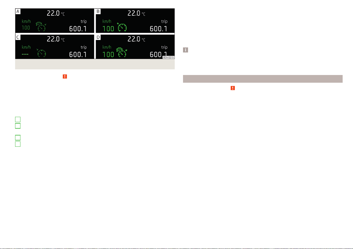
Fig. 275 Instrument cluster display: Examples of ACC status displays
Read and observe on page 230 first.
The ACC makes it possible to set a speed of 30-160 or 30-210 km/h (depend-
ing on equipment fitted) as well as the distance to preceding vehicles.
The ACC can detect a vehicle that is up to approx. 150 m ahead using the radar
sensor.
ACC displays » Fig. 274
Vehicle detected (control active)
Line showing the displacement of the distance when setting. » page 233,
Set the distance
Set distance to the vehicle ahead
Vehicle detected (control deactivated)
ACC status displays » Fig. 275
Regulation is inactive (in the colour display the digits of speed limits is
shown in grey).
Regulation active - no vehicle detected (in the colour display the digits of
the speed limits are highlighted).
Regulation deactivated - no speed stored.
Regulation active - vehicle detected (in the colour display the digits of the
speed limits are highlighted).
Note to reduce speed
If the delay of the ACC is insufficient in relation to the vehicle in front, the
warning light lights up in the instrument cluster and the display shows a
message to engage the brake pedal.
1
2
3
4
Regulation according to the vehicle in the adjacent lane
During regulation your vehicle may be regulated according to the vehicle in the
adjacent lane.
This could occur at speeds above about 80 km/h when your vehicle is moving
faster than the vehicle in the adjacent lane on the driver's side. The display
shows the detected vehicle is in the adjacent lane.
Note
Some ACC notifications in the display of the instrument cluster may be hidden
by notifications for other functions. An ACC notification automatically appears
for a brief moment when there is a change in status of the ACC.
Automatic stopping and starting
Read and observe on page 230 first.
Vehicles with an automatic transmission can decelerate to a standstill and
start moving again using the ACC.
Decelerate to a standstill
If a vehicle ahead decelerates to a standstill, the ACC will also decelerate your
vehicle to a standstill.
Starting to drive again after a holding period
As soon as the vehicle ahead starts moving again after a holding period, your
vehicle will also move and the speed will continue to be regulated.
If the vehicle in front starts moving again after a long break, press the acceler-
ator pedal or set the lever to position
in order to continue control
» page 232.
231
Assist systems
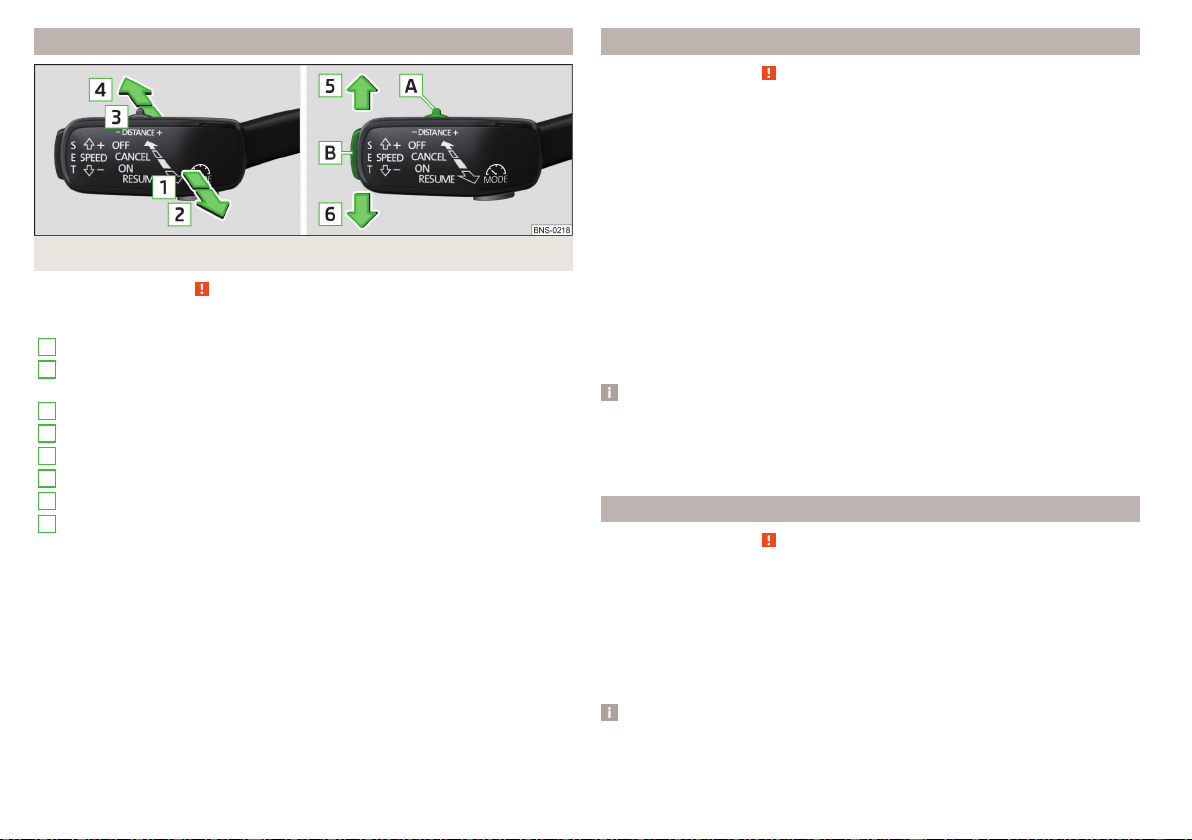
Operation overview
Fig. 276 Operating lever
Read and observe on page 230 first.
Overview of ACC functions operated with the lever » Fig. 276
1
Activate ACC (regulation deactivated)
2
Start control (resume) / increase speed by 1 km/h at a time
(sprung position)
3
Interrupt control (sprung position)
4
Deactivate ACC
5
Increase speed by 10 km/h at a time
6
Decrease speed by 10 km/h at a time
A
Set proximity level
B
Start control / reduce speed in increments of 1 km/h
If the lever is set from the position directly into the sprung position
the current speed is stored and the control process is started.
Start control
Read and observe on page 230 first.
Basic requirements for start of control
The ACC is activated.
On vehicles with manual transmission, the second gear or a higher gear is
selected and the current speed is greater than 30 km/h.
On vehicles with automatic transmission, the selector lever is in the D/S
position or in the Tiptronic position.
Start control
›
Press the button » Fig. 276 on page 232 .
›
or: Set the lever into the sprung position » Fig. 276 on page 232 .
The ACC takes the current driving speed and performs the control, the warn-
ing light
illuminates in the instrument cluster.
If the control is started by moving the lever to the position
and if the
speed is already stored, the ACC adopts this speed and carries out the control.
Note
If control is started at a speed of less than 30 km/h on vehicles with an auto-
matic transmission, the speed of 30 km/h is stored. The speed increases auto-
matically to 30 km/h or is regulated with respect to the speed of the vehicle
ahead.
Stop/resume control
Read and observe on page 230 first.
Stop control
›
Set the lever into the sprung position » Fig. 276 on page 232 .
›
or: Apply the brake.
Control stops, the speed remains stored.
Resume control
›
Start control » page 232, Start control.
Note
Control is also stopped when the clutch pedal is held down for longer than 30
s or the TCS is deactivated.
232
Driving
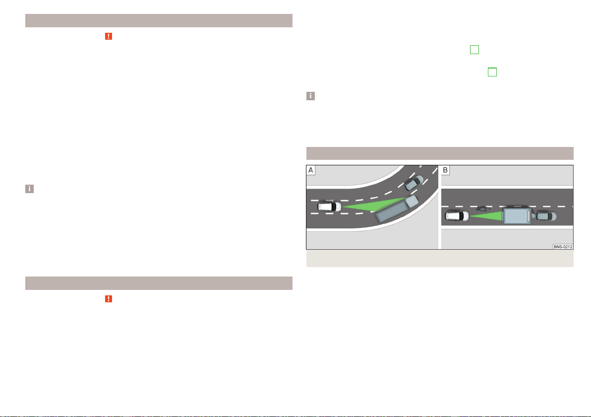
Set/change desired speed
Read and observe on page 230 first.
The desired speed can be set or changed using the control lever » Fig. 276 on
page 232.
Setting/changing the speed by increments of 10 km/h at a time () - re-
quirements
The ACC is activated.
Increasing/reducing the speed by increments of 1 km/h at a time (/
- requirements
The ACC is activated.
Vehicle control takes place.
Changing the speed by adopting the current speed (
) - requirements
The ACC is activated.
The vehicle is moving at a speed other than that which is stored.
Note
■
If during control the speed is increased by pressing the accelerator, control is
temporarily stopped. Upon releasing the accelerator, control is automatically
resumed.
■
If during control the speed is reduced by applying the brake, control is stop-
ped. Control needs to be restarted in order to resume » page 232.
■
If the vehicle is controlled by a lower speed than the stored speed, then
the current speed is stored by pressing the button again and the speed is
reduced in increments of 1 km/h.
Set the distance
Read and observe
on page 230 first.
The ACC makes it possible to set five distance levels to the preceding vehicle.
The distance is adjustable in a range of 1 to 3.6 s.
Adjust distance in Infotainment
›
In Infotainment menu, select the
Distance:
menu item in the ACC menu: and
set the distance » page 230, Settings in Infotainment.
Set the distance with the lever
›
Set the switch Adjust in the spring-tensioned position or » Fig. 276
on page 232.
The display of the instrument cluster shows line
2
» Fig. 274 on page 230,
which indicates the proximity.
›
Using the switch on the lever, adjust the line
2
to the desired dis-
tance.
Note
■
If the distance is changed in Infotainment, the change will only come into ef-
fect after a subsequent activation of the ACC.
■
The distance setting is stored (depending on Infotainment model) in active
user account personalisation » page 55.
Special driving conditions
Fig. 277
Cornering / narrow vehicles or vehicles travelling side by side
233
Assist systems
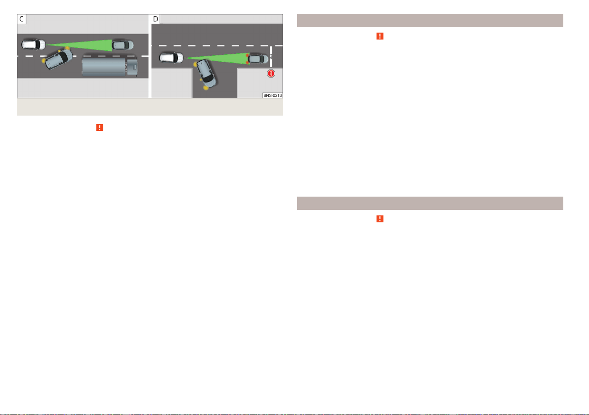
Fig. 278 Lane changes of other vehicles / stationary vehicles
Read and observe on page 230 first.
The following (and similar) situations require special attention and possibly the
intervention of the driver (braking, accelerating etc.).
When cornering
When driving into or driving out of long corners, it could be that a vehicle is
travelling in the adjacent lane and is scanned by the radar » Fig. 277 -
. The
host vehicle is then controlled according to this vehicle.
Narrow vehicles or vehicles travelling side by side
A narrow or offset vehicle driving can only be recognized by the ACC if this is
located in the scanning range of the radar » Fig. 277 -
.
Other vehicles changing lanes
Vehicles that change onto the lane with a small distance » Fig. 278 - may not
be detected by ACC in good time.
Stationary vehicles
The ACC does not detect stationary objects! When a vehicle detected by the
ACC turns or sheers off and there is a stationary vehicle in front of this vehicle,
» Fig. 278 - the ACC does not respond to the stationary vehicle.
Vehicles with special load or special body parts
Other vehicles with a load or with body parts protruding from the sides, back
or top of the vehicle contour may not be detected by the ACC.
Overtaking and towing
Read and observe on page 230 first.
When overtaking
When your vehicle is being controlled at a speed that is lower than the set
speed and the turn signal is operated, ACC assesses this situation as meaning
that the driver wishes to overtake. The ACC automatically accelerates the ve-
hicle, thereby reducing the proximity to a vehicle ahead.
If your vehicle changes to the overtaking lane and no vehicle is detected
ahead, ACC accelerates until the set speed is reached and then keeps it con-
stant.
Acceleration can be cancelled at any time by touch on the brake pedal or
pressing the button
on the lever » Fig. 276 on page 232.
Towing a trailer
When towing, or if another accessory is connected to the trailer socket, ACC
control is set with a lower rate. The manner of driving should therefore be
adapted to this limitation.
Malfunctions
Read and observe on page 230 first.
If ACC is not available, the warning light
appears in the display of the instru-
ment cluster and an appropriate message is shown.
Sensor covered / dirty
If the sensor cover or the sensor is dirty or covered, a message appears on the
instrument cluster display stating there is no sensor view. Clean the sensor
cover or remove the obstacles » Fig. 248 on page 209.
If there is no sensor view in the winter, the snow on the sensor under the cov-
er could be the reason. The ACC is functional again after the snow melts away
from the sensor.
ACC not available
If the ACC is unavailable, a message concerning the unavailability appears.
Stop the vehicle, switch off the engine and then start it again. If ACC continues
to be unavailable, seek the assistance of a specialist garage.
234
Driving
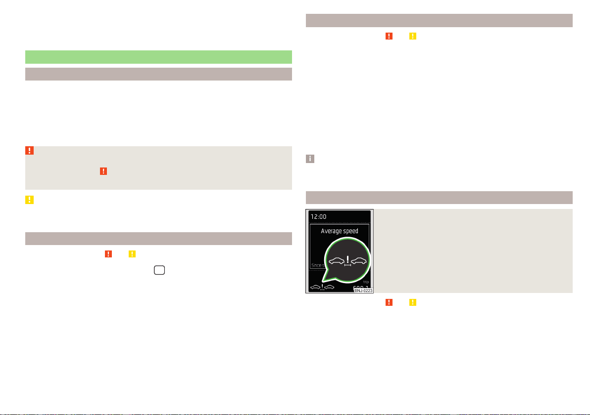
ACC fault
With an ACC fault, an error message appears. Seek help from a specialist ga-
rage.
Front Assist
Introduction
The Front Assist (hereinafter referred to as the system) warns you of the dan-
ger of a collision with a vehicle or another obstacle in front of the vehicle, and
tries to avoid a collision or mitigate its consequences by automatically applying
the brakes where necessary.
The area in front of the vehicle is monitored by a radar sensor» page 209.
WARNING
■
Please take note of the general points relating to the use of assistance
systems» page 209, in section Introduction.
■
The system does not respond vehicles that are crossing or oncoming.
CAUTION
In case of failure of more than one brake light on the vehicle or on the electri-
cally connected trailer, the system becomes unavailable.
Settings in Infotainment
Read and observe and on page 235 first.
›
In the infotainment system, in menu
/ tap on function surface →
Driv-
er assistance
.
■
Front Assist (ambient traffic monitor. sys.) - Set the assistant for distance
monitoring to the vehicles ahead
■
Active
- Activate/deactivate the assistant
■
Advance warning
- Activating/deactivating and setting the distance level at
which a warning occurs
■
Display distance warning
- Activate/deactivate distance warnings
Operation
Read and observe and on page 235 first.
The system support is provided in the following manner.
▶
Alerts you about a dangerous proximity to the vehicle ahead.
▶
Warns you of an impending collision.
▶
Assists with a brake action triggered by the driver.
▶
If the driver fails to respond to a detected danger, an automatic braking ac-
tion is performed.
The system can work only if the following basic conditions are met.
The system is activated.
TCS is activated » page 211.
The vehicle is travelling forwards at a speed of more than approx. 5 km/h.
Note
The system can be impaired or may not be available, for example when driving
in “sharp ”curves or with an ESC engagement » page 210.
Distance warning
Fig. 279
Instrument cluster display: Distance warning
Read and observe and on page 235 first.
If a safe distance from the vehicle ahead is fallen short of, the warning light ap-
pears in the display » Fig. 279.
Immediately increase the proximity if the current traffic situation allows
you to do so!
The proximity at which the warning is displayed depends on the current speed.
The warning may occur when driving between about 60 km/h and 210 km/h.
235
Assist systems

Warning and automatic braking
Fig. 280
Instrument cluster display: Warning or emergency
braking at low speed
Read and observe
and on page 235 first.
Emergency braking at low speed
If there is a risk of collision in a vehicle speed range of about 5 km/h to 50
km/h, the system triggers an automatic braking.
With automatic braking, the warning light appears in the display
» Fig. 280.
Advance warning
If the system detects a risk of collision, the warning light appears on the dis-
play
» Fig. 280 and an audible signal is emitted.
The pre-warning display can occur in the following situations.
▶
If there is a risk of collision with a moving obstacle in a speed range of ap-
proximately 30 km/h to 210 km/h.
▶
If there is a risk of collision with a stationary obstacle in a speed range of ap-
proximately 30 km/h to 80 km/h.
With a warning the brake pedal must be pressed or the moving obstacle is
to be avoided!
Immediate warning and automatic braking - a moving obstacle
If the driver does not react to the advance warning when in danger of a colli-
sion with a moving obstacle, the system briefly applies the brake automatically
via an active brake intervention to draw attention to the potential danger of a
collision again.
If the driver does not respond to acute warning, the system begins to auto-
matically brake the vehicle.
Automatic braking - a stationary obstacle
If the driver does not respond to the advance warning of the risk of a collision
with a stationary obstacle in a speed range of approximately 30 km/h to 60
km/h, the system initiates automatic braking.
Information on automatic braking
If an automatic brake intervention is triggered by the system, the pressure in
the brake system increases and the brake pedal cannot be operated with the
normal pedal stroke.
The automatic braking interventions can be cancelled by pressing the acceler-
ator pedal or by means of a steering intervention.
Brake assist
If the driver brakes inadequate with an impending collision, the system auto-
matically increases braking force.
The braking assistance only occurs as long as the brake pedal is being firmly
pressed down.
Pedestrian recognition
Read and observe and on page 235 first.
The pedestrian recognition can help to prevent accidents with crossing pedes-
trians or to mitigate the consequences of an accident.
The system warns of an imminent collision, prepares the vehicle for an emer-
gency braking, supports during braking or performs an automatic braking.
Emergency braking at low speed
If there is a risk of collision in a vehicle speed range of about 5 km/h to 30
km/h, the system triggers an automatic braking.
With automatic braking, the warning light appears in the display » Fig. 280
on page 236.
Advance warning and automatic braking
If the system detects a risk of collision in a vehicle speed range of 30 km / h to
65 km / h, the warning light appears on the display » Fig. 280 on page 236
and an audible signal is emitted.
With a warning the brake pedal must be pressed or the moving obstacle is
to be avoided!
236
Driving

If the driver does not respond to the advance warning, the system begins to
automatically brake the vehicle.
Disable/enable
Read and observe and on page 235 first.
▶
In the instrument cluster display, in the
Assist systems
menu item.
▶
In Infotainment, in the Front Assist (ambient traffic monitor. sys.) menu, in
the
Active
» page 235, Settings in Infotainment menu item.
The system is automatically activated each time the ignition is switched on.
The system should only be disabled in exceptional cases » .
WARNING
In the following situations, Front Assist should be switched off for safety
reasons.
■
When the vehicle is being towed away.
■
When the vehicle is on a rolling test bench.
■
If an unfounded warning or a system action was taken.
■
When on a truck, or a car ferry service or similar.
Malfunctions
Read and observe and on page 235 first.
If the system is not available, an appropriate message appears in the display of
the instrument cluster.
Sensor covered / dirty
If the sensor cover or the sensor is dirty or covered, a message appears on the
instrument cluster display stating there is no sensor view. Clean the sensor
cover or remove the obstacles » Fig. 248 on page 209.
If there is no sensor view in the winter, the snow on the sensor under the cov-
er could be the reason. The system is functional again after the snow melts
away from the sensor.
System unavailable
If the system is unavailable, a message concerning unavailability appears. Stop
the vehicle, switch off the engine and then start it again. If the system still is
not available, seek the assistance of a specialist garage.
Select the driving mode (Driving Mode Selection)
Introduction
By selecting the driving mode, the driving behaviour can be adapted to the de-
sired mode of operation.
The following modes of operation are available
Eco
,
Normal
,
Sport
,
Individual
and
Snow
.
Snow
mode is only available for all-wheel drive vehicles.
WARNING
Please take note of the general points relating to the use of assistance sys-
tems » page 209, in section Introduction.
Mode
Eco
Read and observe on page 237 first.
This mode is suitable for a relaxed style of driving and helps to save fuel.
Selecting this mode primarily affects the function of the following systems.
Drive
Vehicle acceleration is more relaxed than in
Normal
mode.
The recommended gear is controlled such to achieve the lowest possible fuel
consumption » page 49.
If the START-STOP system is deactivated manually» page 200, this will be au-
tomatically activated.
The automatic gearbox is set automatically to mode E » page 205.
Adaptive Cruise Control (ACC)
Acceleration occurs more relaxed than in
Normal
» page 229mode with distance
control.
Air conditioning (Climatronic)
The air conditioning is controlled so as to save energy. For this reason, for ex-
ample, it may take longer to reach the desired interior temperature in mode
Normal
.
237
Assist systems
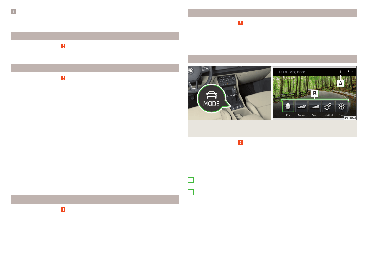
Note
The maximum vehicle acceleration (kick down function) is possible also in driv-
ing mode
Eco
.
Mode
normal
Read and observe on page 237 first.
This mode is suitable for a conventional driving.
Mode
Sport
Read and observe on page 237 first.
This mode is suitable for a sporty driving.
Selecting this mode primarily affects the function of the following systems.
Steering
The power steering is reduced slightly, i.e., the driver needs to exert more
force for steering .
Drive
The vehicle acceleration is more dynamic than in
Normal
mode.
Adaptive Cruise Control (ACC)
The acceleration is quicker than in
Normal
mode with distance control
» page 229.
Full LED headlights
The headlamps adapt to the driving style more dynamically than in mode
Nor-
mal
» page 71.
ProActive passenger protection
The first level of protection is deactivated » page 239.
mode
individual
Read and observe on page 237 first.
In the mode
Individual
each system can be set independently » page 239, Indi-
vidual mode
settings
.
Mode
Snow
Read and observe on page 237 first.
The mode is suitable for driving on slippery or snow-covered roads.
The driving profile
Snow
does not allow the automatic transmission to be set to
S mode.
Mode selection and Infotainment display
Fig. 281
Button for selecting the driving mode / Display in Infotainment
screen
Read and observe on page 237 first.
Display of the driving mode menu
›
Press the
» Fig. 281 button.
The following function surfaces are displayed on the Infotainment screen
» Fig. 281.
Information on setting the currently selected mode
Setting the
Individual
mode
Driving mode menu
The driving mode selection is performed in one of the following ways.
▶
By repeatedly pressing the button .
▶
By tapping the appropriate function surface on the Infotainment screen
» Fig. 281.
After switching the ignition off and on, the drive is set to
Normal
in the current
driving mode. To change the drive setting, select the relevant driving mode
again.
A
B
238
Driving

Note
■
The currently selected driving mode is displayed in the infotainment system
in the status bar next to the symbol .
■
The selected driving mode and the setting of the mode
Individual
is stored in
the active user account personalisation » page 55.
Individual mode
settings
Read and observe on page 237 first.
In the
Individual
mode, the following menu items can be set.
■
Steering:
- Set the power steering characteristics
■
Drive:
- Set the driving characteristics
■
ACC:
- Set the vehicle acceleration when adaptive cruise control is activated
■
Dynamic Cornering light:
- Set the characteristics of the Full LED headlights
■
Air conditioning:
- Set the Climatronic characteristics
■
Reset mode
- Setting for all menu items in the
Individual
mode to
Normal
■
Cancel
- Keep the current settings
■
Reset
- cancels all menu items in the
Normal
mode
Proactive passenger protection (Crew Protect Assist)
Introduction
ProActive passenger protection (following known as system) increases pas-
senger protection in the front seats in situations that could lead to vehicle im-
pact or overturning.
WARNING
Please take note of the general points relating to the use of assistance sys-
tems » page 209, in section Introduction.
Note
■
The system component service life is monitored electronically. Further infor-
mation » page 43, Safety systems.
■
If the front passenger front airbag is deactivated, the belt tensioning func-
tion for the front passenger seat is switched off.
Function
Read and observe on page 239 first.
In critical driving situations (e.g. during emergency braking or a sudden change
in direction), the following steps can be taken separately or combined in order
to reduce the risk of serious injury.
▶
The front passenger's and driver's seatbelts, if worn, are automatically ten-
sioned closely over the body.
▶
Opened electrically powered door windows are closed automatically up to a
gap of about 5 cm from the edge.
▶
The sliding/tilting roof is closed.
Once the critical driving situation has passed, the tension on the seatbelts will
be released again.
The system operates at two levels of protection.
The first level of protection
The system already intervenes in situations that may occur during dynamic
driving. As a result, this primarily helps to keep the driver and the passenger in
the correct seated position.
The first protection level can be deactivated in one of the following ways.
▶
In the infotainment system, in menu
/
tap on function surface
→
Driv-
er assistance
.
▶
Deactivating the TCS» page 211.
▶
By selecting the driving mode
Sport
» page 238.
Provided that the driving mode
Sport
is not selected, the system is activated
over the two levels of protection after switching the ignition off and on again.
The second level of protection
The system intervenes only if the situation is evaluated as critical, such as
when panic braking at high speeds.
This level of protection cannot be deactivated.
Vehicles with the Front Assist system
Using this information, a system intervention may also occur when there is the
danger of a collision with an obstacle detected in front of the vehicle.
239
Assist systems
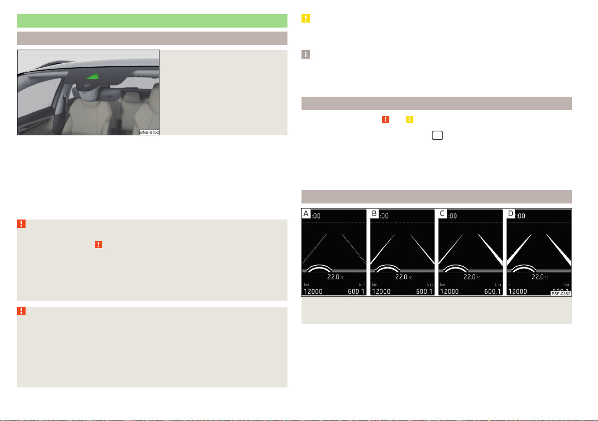
Spurhalteassistent (Lane Assist)
Introduction
Fig. 282
Sensor for Lane Assist
The lane departure warning (following known as system) helps to keep the ve-
hicle between the boundary lines of a lane.
The system recognises the boundary lines of the lane using a sensor » Fig. 282.
When the vehicle approaches a detected line between lanes, the system
makes a light movement of the steering wheel in the opposite direction to the
boundary line. This corrective steering intervention can be manually overridden
at any time.
WARNING
■
Please take note of the general points relating to the use of assistance
systems » page 209, in section Introduction.
■
Lane Assist can help you keep the vehicle within the lane. However, it
does not steer the vehicle for you. The driver retains full responsibility for
steering at all times.
■
Some objects or markings on the road can be recognised as the boundary
lines - an erroneous steering intervention may be the result.
WARNING
The system may not be able to recognise the boundary line, or recognise it
incorrectly, for example, in the following situations.
■
When visibility is poor, (e.g. fog, heavy rain, thick snowfall).
■
When driving in “sharp” bends.
■
The sensor is blinded by the sun or oncoming traffic.
■
The field of view of the sensor is limited by an obstacle or a preceding ve-
hicle.
CAUTION
Do not attach any stickers or similar objects in front of the sensor on the wind-
screen to avoid impairing the functions of the system.
Note
■
The system is designed for driving on motorways and roads with adequate
longitudinal markings.
■
The system can detect both continuous and broken lines.
Settings in Infotainment
Read and observe and on page 240 first.
›
In the infotainment system, in menu
/ tap on function surface →
Driv-
er assistance
.
■
Lane Assist (lane departure warning system) - Settings for Lane Assist
■
Active
- Activate/deactivate the assistant
■
Adaptive lane guidance
- Activate/deactivate adaptive lane guidance
Operation
Fig. 283 Monochromatic display of the instrument cluster: Examples of
system indications
240
Driving
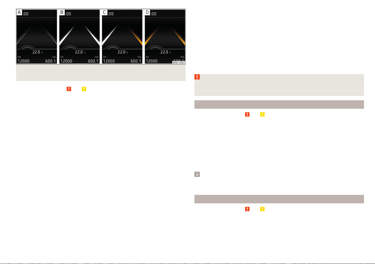
Fig. 284 Colour display of the instrument cluster: Examples of system
indications
Read and observe and on page 240 first.
System displays » Fig. 283 and » Fig. 284
The system is active, but not ready to intervene.
The system is active and ready to intervene.
The system intervenes when approaching the right-hand boundary lane.
Adaptive tracking takes place.
The system can intervene when the following basic conditions are present.
The system is activated.
The vehicle speed is higher than about 65 km/h (not applicable to vehicles
with the traffic jam assistant » page 242).
The boundary line of at least one side of the lane is detected.
The driver's hands are on the steering wheel.
The lane is more than 2.5 m in width.
If the turn signal is switched on (e.g. when turning), no steering intervention
takes place when the vehicle approaches the boundary line. The system re-
gards the situation as an intended lane change.
Warning lights in the instrument cluster
The system is active, but not ready to intervene.
The system is active and ready to intervene or is currently intervening.
Adaptive lane guidance
Adaptive tracking helps to keep the vehicle in the position between the boun-
dary lines selected by the driver, by means of steering intervention.
If the position within the lane is changed, the system quickly adapts and holds
the newly-selected position.
Steering wheel vibrations
In the following situations, it may occasionally be the case that due to the
steering wheel vibrations the syst4em indicates that a driver steering interven-
tion is required.
▶
The system is not able to keep the vehicle by a within the lane due to a steer-
ing intervention.
▶
During an intense system-related steering intervention, the system suddenly
cannot recognize the boundary lines.
WARNING
The system function may be restricted if, for example there is danger due
to ruts on a downhill road or in a crosswind.
Activation / deactivation
Read and observe and on page 240 first.
The activation/deactivation of the system can be carried out in one of two
ways.
▶
In the instrument cluster display » page 54,
Assist systems
menu item.
▶
In Infotainment » page 240, Settings in Infotainment.
Adaptive tracking can also be enabled or disabled In Infotainment.
After switching off and switching on the ignition, the system setting is re-
tained.
Note
The system setting is stored (depending on Infotainment type) in the active
user account personalisation » page 55.
Malfunctions
Read and observe and on page 240 first.
If the system is not available, an appropriate message appears in the display of
the instrument cluster.
241
Assist systems

Sensor covered / dirty
If the windscreen is dirty, iced or misted up in the sensor area, a message ap-
pears indicating that there is no sensor view. Clean the windscreen or remove
the obstacles from the sensor area.
System unavailable
If the system is unavailable, a message concerning the unavailability appears.
Try to re-activate the machine. If the system still is not available, seek the as-
sistance of a specialist garage.
System fault
In the case of a system fault, an error message appears. Seek help from a spe-
cialist garage.
Request to take over steering
If the system detects that there are no hands are on the steering wheel, this
will not work properly. You will be prompted to take over steering. Place your
hands on the steering wheel.
Traffic jam assistant
Introduction
WARNING
■
Please take note of the general points relating to the use of assistance
systems » page 209, in section Introduction.
■
The driver must always have hands on the steering wheel and be ready to
take over steering of the vehicle himself (accelerate or brake).
Note
The system is designed primarily for use on motorways.
Function
Read and observe on page 242 first.
The traffic jam assistant (referred to as system) helps to keep the vehicle with-
in the lane at speeds below 65 km/h while keeping the distance to the vehicle
ahead.
The system is only available for vehicles with Automatic transmission.
The traffic jam assistant is an extension of the systems Lane Assist » page 240
and ACC » page 229 and works by using the functions of these two systems.
For this reason, the chapters on System Lane Assist and ACC are to be
read carefully and the safety notes are to be observed.
Operating conditions
Read and observe on page 242 first.
The system activation occurs automatically whilst fulfilling the following
basic conditions.
Lane Assist with the adaptive tracking is enabled, the boundary lines on
both sides are recognized lane » page 240.
ACC is activated and the regulation » page 229 follows.
The vehicle speed is below 65 km/h.
Assistant for emergencies
Introduction
WARNING
■
Please take note of the general points relating to the use of assistance
systems » page 209, in section Introduction.
■
The system is intended for emergency situations when the driver is sud-
denly unable to take over the steering task. Therefore, never try to test out
the system - there is a risk of an accident!
Function
Read and observe on page 242 first.
The assistant for emergencies (following known as system) detects inactivity
of the driver, which for example can be caused by a sudden loss of conscious-
ness. The system then performs measures as safely as possible to decelerate
the vehicle to a stop.
The system is only available for vehicles with Automatic transmission.
242
Driving

The assistant for emergencies is an extension of the systems Lane Assist
» page 240 and ACC » page 229 and works by using the functions of these
two systems.
For this reason, the chapters on System Lane Assist and ACC are to be
read carefully and the safety notes are to be observed.
System intervention
If the system detects the driver's inactivity, it draws attention to this fact by a
beep and a message on the display of the instrument cluster. It keeps the vehi-
cle in its lane.
If the driver does not take over the steering even after a repeated warning, the
system automatically brakes the vehicle and after it has come to a standstill
the parking brake switch on.
With automatic braking, the hazard warning system is switched on.
The automatic braking interventions can be cancelled by pressing the acceler-
ator pedal or by means of a steering intervention.
Operating conditions
Read and observe on page 242 first.
The system can intervene when the following basic conditions are present.
Lane Assist is activated and the boundary line is detected at least on one
side of the lane » page 240.
ACC is activated and the regulation » page 229 follows.
Traffic sign recognition
Introduction
The traffic sign recognition (following known as system) shows certain traffic
signs (e.g. speed limits) on the display of the instrument cluster and if necessa-
ry warns against excessive speeds.
WARNING
■
Please take note of the general points relating to the use of assistance
systems » page 209, in section Introduction.
■
Vertical traffic signs must always take precedence over the traffic signs
shown in the display. The driver is always responsible for correctly assess-
ing the traffic situation.
■
The speed specifications in the displayed road signs refer to the custom-
ary national speed units. For example, the display may relate to km/h or
mph depending on the country in question.
WARNING
The traffic signs may not be displayed or displayed incorrectly in the sys-
tem e.g. in the following situations.
■
When visibility is poor, (e.g. fog, heavy rain, thick snowfall).
■
The sensor is blinded by the sun or oncoming traffic.
■
The field of view of the sensor is limited by an obstacle or a preceding ve-
hicle.
■
Travelling at high speed.
■
The traffic signs are covered (e.g. by trees, snow or dirt).
■
The traffic signs are not standard (round with a red border) or are dam-
aged.
■
The traffic signs are attached to flashing neon signs.
■
The traffic signs were changed (the navigation data are out of date).
Note
The system is only available in some countries.
Settings in Infotainment
Read and observe on page 243 first.
›
In the infotainment system, in menu
/ tap on function surface →
Driv-
er assistance
.
■
Dynamic Road Sign Display - Settings for the Dynamic Road Sign Display
■
Show in instrument cluster
- Activation/deactivation of the additional traffic
signs in the display of the instrument cluster
■
Speed warning:
- Setting a warning when the speed limit is exceeded
■
Warning at over
- Setting warning timing with the option to exceed the speed
limit in a range from 0 to 20 km / h
243
Assist systems
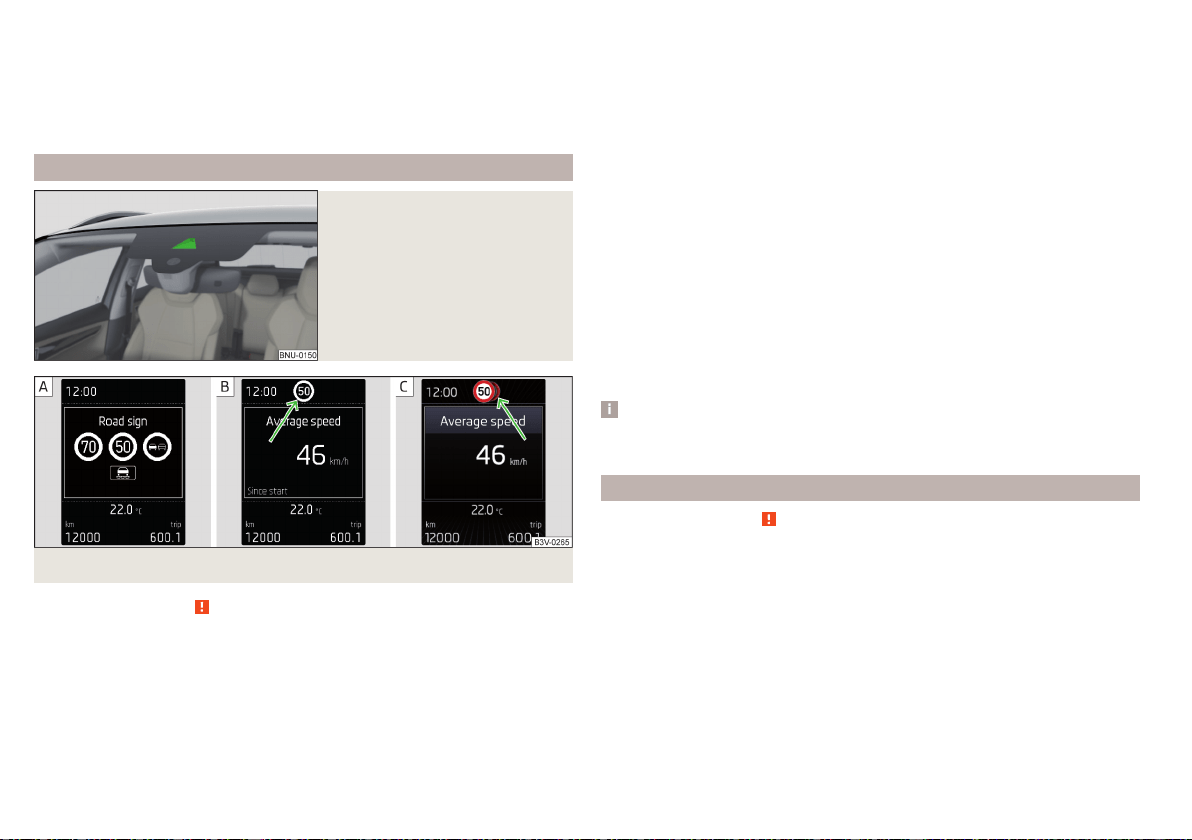
■
Trailer recognition
■
Show road signs relevant to trailers
- Activating / deactivating the display of road
signs relevant to trailers
■
Use for route calculation
- Activation / deactivation taking trailers in account
for route calculation in navigation
■
Maximum speed for trailer
- Set the top speed for towing a trailer
Operation
Fig. 285
Sensor for traffic sign recogni-
tion
Fig. 286 Instrument cluster display: Display examples
Read and observe on page 243 first.
Description of indications and displayed traffic signs
Display » Fig. 286
Display of detected traffic signs » page 51, Driving data (Multifunction
display)
Additional display (monochromatic display)
Additional display (colour display)
The system can display the following (vertical) traffic signs where identified.
▶
Speed limit.
▶
Overtaking prohibited.
Additional signs, such as 'when wet' or signs which only apply for a limited time
can also be displayed.
The system displays only traffic signs that are in the “viewing area” of the sen-
sor » Fig. 285.
Data from the sensor is supplemented by information from the Infotainment
Navigation. This is the reason why traffic signs with maximum speeds can also
be shown on sections of roads which do not have any traffic signs.
Warning when exceeding the speed limit
The warning when exceeding the permissible speed (based on the detected
traffic sign) can be activated and set in Infotainment» page 243.
Mode when towing a trailer
For vehicles with a factory-fitted towing device, in Infotainment it is possible
to enable or disable the relevant traffic signs for trailer operation and the top
speed for towing a trailer » page 243, Settings in Infotainment.
Note
If, for example, you are on a motorway without speed limits, then a road sign
relating to the end of all limits is shown in the instrument cluster display.
Additional display
Read and observe on page 243 first.
If the menu item Road sign is currently not shown » Fig. 286 on page 244 - ,
the road sign with the speed limit will appear in the upper display area of the
instrument cluster » Fig. 286 on page 244 - , .
If several traffic signs are detected simultaneously, in some cases the next
traffic sign will also be displayed in the colour display - » Fig. 286 on page 244
- .
All detected traffic signs can be displayed via the multifunction display in the
menu item Traffic Sign Recognition » Fig. 286 on page 244 - .
The additional display can be activated / deactivated in Infotain-
ment» page 243.
244
Driving

Note
The setting (activation/deactivation) of the auxiliary display will be saved (de-
pending on Infotainment type) in the active user account personalisation
» page 55.
Malfunctions and information messages
Read and observe
on page 243 first.
If the system is not available, an appropriate message appears in the display of
the instrument cluster.
Sensor dirty/covered
If a note appears in relation to the cleaning of the windscreen, clean the wind-
screen or remove the obstruction from the sensor area.
System fault
If an error message appears, seek assistance from a specialist garage.
System limitation
The system displays a message about system limitation in the following cases.
▶
The map documents are not up to date.
▶
The vehicle is located in an area for which no map documents are present.
Fatigue detection system
The fatigue detection system (following known as system) recommends the
driver taking a break from driving when, because of the driver's steering be-
haviour, driver fatigue can be detected.
The system evaluates the steering behaviour at speeds of 60-200 km/h.
Conditions under which a break from driving is detected by the system
▶
The vehicle is stopped and the ignition switched off.
▶
The vehicle is stopped, the seat belt removed and the driver's door opened.
▶
The vehicle is stopped for more than 15 minutes.
If none of these conditions are met or if the driving style is not changed, the
system recommends a driving break again after 15 minutes.
The system can be activated/deactivated in menu
/ → →
Driver assis-
tance
.
Pause recommendation
The icon appears and the following message for a few seconds in the display
of the instrument cluster and a message about the detected fatigue. An au-
dible signal is also emitted.
WARNING
■
Please take note of the general points relating to the use of assistance
systems » page 209, in section Introduction.
■
For the driving ability is always the driver's responsibility. Never drive if
you feel tired.
■
The system may not detect all cases where a break is needed.
■
Therefore, take regular, sufficient breaks during long trips.
■
There will be no system warning during the so-called micro-sleep.
Note
■
In some situations, the system can evaluate the steering behaviour incorrect-
ly and therefore falsely display a break recommendation.
■
The system is designed primarily for use on motorways.
Tyre pressure monitoring
Introduction
The tyre pressure monitoring function (following known as system) monitors
the tyre pressure while driving.
If the tyre inflation pressure changes, the warning light
lights up in the in-
strument cluster and an audible signal sounds» page 43.
The system can only function properly if the tyres have the prescribed inflation
pressure and these pressure values are stored in the system.
Always save the tyre pressure values in the system if one of the following
events occurs.
▶
Change of tyre pressure values.
▶
Change one or more wheels.
▶
Change in position of a wheel on the vehicle.
▶
The warning light in the instrument cluster.
245
Assist systems
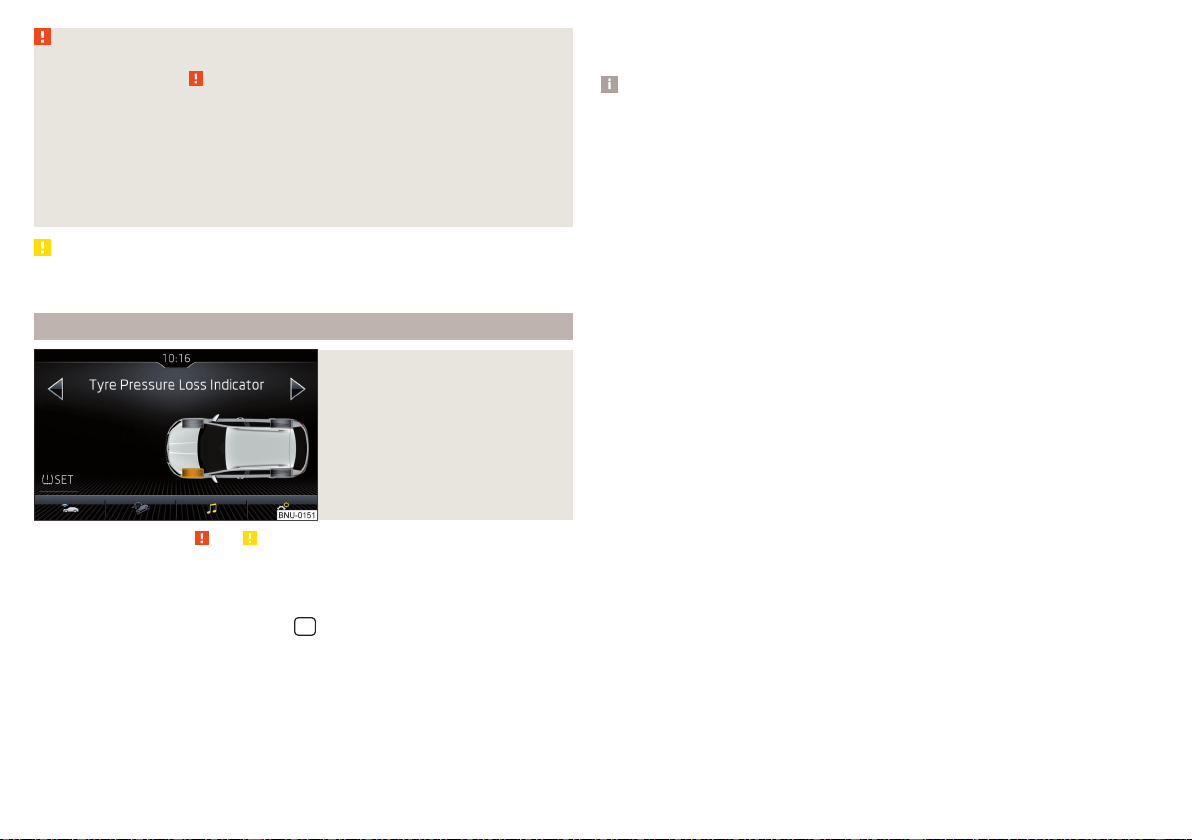
WARNING
■
Please take note of the general points relating to the use of assistance
systems » page 209, in section Introduction.
■
Having the correct tyre inflation pressure is always the driver's responsi-
bility. Tyre pressure should be checked regularly » page 268.
■
The system cannot warn in case of very rapid tyre inflation pressure loss,
e.g. in case of sudden tyre damage.
■
Before storing the pressures, the tyres must be inflated to the specified
inflation pressure » page 268. If the wrong pressure valuesare stored, the
system may not issue any warnings, even if the tyre pressure is too low.
CAUTION
To ensure proper system function, the tyre pressure values must be stored ev-
ery 10,000 km or 1x a year.
Storing the tyre pressure values and Infotainment display
Fig. 287
Button for storage/example of
the screen: a change in the front
left tyre pressure is indicated
Read and observe and on page 246 first.
Procedure for storing the tyre pressure values
›
Inflate all the tyres to the specified pressure.
›
Turn on the ignition and switch on Infotainment.
›
In the infotainment system, in menu
/ tap on function surface Tap
→
Vehicle status
.
›
Use the function surfaces
to select menu item Tyre Pressure Loss Indi-
cator.
›
Tap the function surface » Fig. 287.
In addition, follow the instructions that appear on the screen.
A message on the screen informs about the storage of the tyre pressure val-
ues.
Note
When a warning light in the instrument cluster appears, the affected tyre
can be displayed on the infotainment » Fig. 287.
246
Driving
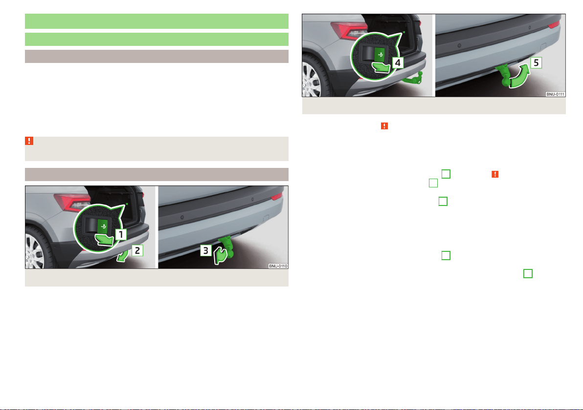
Towing device and trailer
Hitch
Introduction
The maximum trailer load is dependent on the engine and the vehicle equip-
ment. The valid specification for your vehicle is to be found in the technical ve-
hicle documentation, the Declaration of Conformity (what is known as a COC
document) or can be requested from a ŠKODA partner.
Other data (e.g. shown on the nameplate of the hitch) on provides information
about the test values of the device .
WARNING
Do not use the towing device if it is damaged or if there are parts missing.
Swinging in and out the tow bar
Fig. 288 Ball rod: swing out
Fig. 289 Ball rod: swing in
Read and observe on page 247 first.
The pivotable tow bar cannot be removed. Its correct latching in both posi-
tions is indicated by a warning light.
Swing out the tow bar
›
Pull the switch in the direction of arrow
1
» Fig. 288 » . The tow bar
swings out in the direction of arrow
2
and the indicator light
in in the
switch flashes.
›
Press the tow bar in direction of arrow
3
until it audibly clicks into place.
The indicator light
inside the switch illuminates,
Swivel tow bar
No trailer or other accessory is connected to the tow bar. A socket or adapter
may not be plugged into the 13-pin socket.
›
Pull the switch in the direction of arrow
4
» Fig. 289 . The tow bar is un-
locked and the indicator light inside the switch flashes.
›
Swing in the tow bar under the bumper in the direction of arrow
5
until it
audibly clicks into place. The indicator light inside the switch illuminates,
Check latching
If the tow bar is incorrectly locked, the warning light inside the switch flashes
red, after the ignition is switched on an acoustic signal is sounded and an ap-
propriate message appears in the instrument cluster.
247
Towing device and trailer
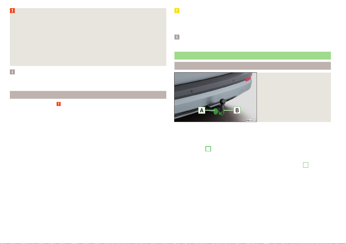
WARNING
■
Take care with the towing device - it may cause injury.
■
When swinging out the ball rod away from the central area of the rear
bumper, there is a danger of injury to the legs.
■
Do not manipulate the switch while a trailer or another accessory is cou-
pled to the tow bar. The tow bar could come loose - risk of accident and
injury.
■
If the indicator light it supplied the switch does not light or flashes, or if
the tow bar can not engage, then do not use this. Seek help from a special-
ist garage.
Note
When not using the towing device, always swing the tow bar under the bump-
er.
Vertical load with mounted accessories
Read and observe on page 247 first.
When using the accessories (e.g. bicycle carrier), the maximum length and the
permissible total weight including load must be considered.
The maximum length of the mounted accessories (from the ball of the towing
device) is 70 cm.
The permissible total weight of the installed accessories including the load
complies to the maximum trailer load on trailers, but may not exceed 75 kg.
This also applies if the maximum trailer load on trailers is e.g. 80 kg.
This value applies when the centre of gravity of the load is a max. of 30 cm
from the ball head of the tow bar.
If the distance of the load’s centre of gravity from the ball head of the tow-
ing device increases, the permissible total weight of the accessory, includ-
ing the load, decreases approximately by half (e.g. at a distance of 60 cm
from the ball head).
CAUTION
Never exceed the permissible total weight of the accessories incl. load and
maximum length of the accessories - There is a risk of damage to the towing
device.
Note
We recommend that you use accessories from ŠKODA Original Accessories.
Using hitch
Trailer (accessory) connect and disconnect
Fig. 290
Housing of the 13 pin socket,
safety eyelet
Connect / disconnect
›
Swing out the tow bar » page 247.
›
Place the trailer (the accessory) onto the ball head.
›
Open the socket cap and insert the plug of the trailer (accessories) into the
13-pin socket
A
» Fig. 290. (If the trailer / accessories have a 7-pin connec-
tor, use a corresponding reduction piece from the ŠKODA Original Accesso-
ries).
›
Suspend the breakaway cable of the trailer at the safety eyelet
B
(the
breakaway cable must sag in all trailer settings in view of the vehicle).
Uncoupling takes place in reverse order.
Exterior mirrors
You should have additional exterior mirrors fitted if you are not able to see the
traffic behind the trailer using the standard rear-view mirrors.
248
Driving
Headlights
The front of the vehicle may lift up when a trailer (accessory) is being towed
and the headlights may dazzle other road users. Set the range of the headlights
» page 69, Operating the lights
1)
.
Power supply of the trailer / accessory power system
In the electrical connection between the vehicle and trailer (accessory), the
trailer (accessories) is supplied with power from the vehicle (with ignition
switched on and off).
With the engine switched off, the vehicle battery is discharged by the connec-
ted consumers.
At low charge state of the vehicle battery, the power supply to the trailer (ac-
cessories) is interrupted.
WARNING
■
An improperly connected electrical installation of the trailer (accessories)
may result in an accident or serious injury from electrical shock.
■
Do not make any adjustments to the electrical installation of the vehicle
and the trailer (accessories) - risk of an accident or serious injury from elec-
trical shock.
WARNING (Continued)
■
After the electrical connection between the vehicle and trailer (accesso-
ry) the trailer / accessory lights should be checked for function.
■
Never use the securing eye to tow - risk of accident!
CAUTION
■
An improperly connected electrical installation of the trailer (accessories) can
lead to the inoperability of the vehicle electronics.
■
The total power consumption of all the connected loads to the trailer power
supply must not exceed 350 watts, otherwise there is a risk of damage to the
electrical system of the vehicle.
Loading a trailer
Correct the tyre inflation pressure on the vehicle for “full load”» page 268.
Distribution of the cargo
Distribute the cargo in the trailer in such a way that heavy items are located as
close to the trailer axle as possible. Secure the load from slipping.
The distribution of the weight is very poor if your vehicle is unladen and the
trailer is laden. Drive with particular caution if you cannot avoid driving with
this combination.
WARNING
Sliding cargo can significantly adversely affect stability and driving safety -
risk of accident!
Trailer load
The permissible trailer load must not be exceeded under any circumstances.
Permissible trailer load
Engine Transmission
Permissible trailer weight, braked (kg)
with gradients up to 12%.
Permissible trailer load, unbraked (kg)
1.0 l/85 kW TSI MG 1200 660
1.5 l/110 kW TSI ACT DSG 1500 / 1200
a)
690
1)
Applies to vehicles with Full LED headlights.
249
Towing device and trailer
Engine Transmission
Permissible trailer weight, braked (kg)
with gradients up to 12%.
Permissible trailer load, unbraked (kg)
1.6 l/85 kW TDI CR MG 1500 710
2.0 l/110 kW TDI CR
MG 4x4 2000 750
DSG 4x4 2000 750
a)
The valid valve for your vehicle is to be found in the technical vehicle documentation, as well as the Declaration of Conformity (what is known as a COC document) or can be requested from a ŠKODA partner.
Towing a trailer
Driving speed
For safety reasons, do not drive faster than 100 km/h when hitching a trailer.
Immediately reduce your speed as soon as even the slightest swaying of the
trailer is detected. Never attempt to stop the trailer from “swaying” by accel-
erating.
Brakes
Apply the brakes in good time! If the trailer is fitted with a trailer brake, apply
the brakes gently at first, then brake firmly. This will avoid brake jolts resulting
from the trailer wheels locking.
On downhill sections shift down a gear in good time to also use the engine as a
brake.
WARNING
Always drive particularly carefully with the trailer.
CAUTION
With frequent towing, the vehicle is excessively loaded so this must also be
checked between service intervals.
Anti-theft alarm system
The alarm is triggered if, with a vehicle with activated anti-theft alarm (herein-
after only warning system), the electrical connection to the trailer (accessory)
is interrupted.
Always switch off the anti-theft alarm system before a trailer (accessory) is
coupled or uncoupled » page 60.
Conditions for including a trailer (accessory) in the anti-theft alarm system.
The vehicle is factory-fitted with an anti-theft alarm system and a towing
device.
The trailer (accessory) is electrically connected to the towing vehicle by
means of the trailer socket.
The electrical system of the vehicle and trailer (accessory) is functional.
The vehicle is locked and the anti-theft alarm system is activated.
The trailer (accessory) is not equipped with LED taillights.
250
Driving

General Maintenance
Care and maintenance
Service work, adjustments and technical alterations
Introduction
The instructions and guidelines from ŠKODA AUTO must be observed when
carrying out any modifications, repairs or technical alterations to your vehicle.
Adhering to these instructions and guidelines helps ensure road safety and
helps keep your vehicle in a good technical condition.
WARNING
■
Adjustments, repairs and technical changes to the vehicle are to be car-
ried out only by a specialist garage. Improperly conducted work (including
work on the electronic components and their software) can cause faults -
there is a risk of accidents and increased wear on parts!
■
We advise you only to use ŠKODA Original Accessories and ŠKODA Orig-
inal Parts which have been expressly approved for use on your vehicle. Reli-
ability, safety and suitability for your vehicle are guaranteed with these.
■
ŠKODA AUTO cannot assume any liability for products which have not
been approved by ŠKODA even though these may be products with a type
approval or have been approved by a nationally recognised testing labora-
tory.
Vehicle operating under different weather conditions
Read and observe on page 251 first.
If you would like to operate your vehicle in countries other than those with the
intended weather conditions, you should contact a ŠKODA partner. They will
advise you if certain precautions need to be taken to ensure the full function-
ing of the vehicle or to prevent damage (e.g. coolant / battery replacement
etc.).
ŠKODA Service Partner
Read and observe on page 251 first.
All ŠKODA Service Partners operate according to the most recent guidelines
and instructions from ŠKODA AUTO . All service and repair work is therefore
carried out on time and at the appropriate quality. Adhering to these instruc-
tions and guidelines helps ensure road safety and helps keep your vehicle in a
good technical condition.
We therefore advise you to have all modifications, repairs and technical altera-
tions to your vehicle carried out by a ŠKODA Service Partner.
ŠKODA Original parts
Read and observe
on page 251 first.
We recommend the use of ŠKODA Original Parts for your vehicle, as these
parts are approved by ŠKODA AUTO. These parts correspond exactly to the
ŠKODA AUTO regulations and are identical to the parts used in series produc-
tion.
ŠKODA AUTO is able to warrant the safety, suitability, and long life of these
products.
ŠKODA Service Partners are liable for any defects of ŠKODA Genuine Parts
for a period of 2 years after sale in accordance with the materials defect liabili-
ty, unless agreed otherwise in the purchase agreement.
ŠKODA Original accessories
Read and observe on page 251 first.
If you wish to fit accessories to your vehicle, you should remember the follow-
ing.
We recommend that you use ŠKODA Genuine Accessories in your vehicle.
ŠKODA AUTO has selected such accessories to ensure that they are reliable,
safe and suitable for your particular vehicle. Although we constantly monitor
the market, we are not able to assess or vouch for other products, even
though in some instances such parts may have operational approval or may
have been approved by a nationally recognised testing laboratory.
251
Care and maintenance

ŠKODA Service Partners are liable for any defects of ŠKODA Genuine Acces-
sories for a period of 2 years after installation or delivery in accordance with
the materials defect liability, unless agreed otherwise in the purchase agree-
ment or any other agreements.
Spoiler
Read and observe on page 251 first.
WARNING
If your vehicle is equipped with an original spoiler on the front bumper in
combination with the spoiler on the boot lid, the following instructions
must be observed - otherwise there is a risk of accidents and serious inju-
ries!
■
The vehicle must always be equipped with a spoiler on the front bumper
only in combination with the corresponding spoiler on the boot lid.
■
This kind of spoiler cannot be left on the front bumper either on its own,
in combination with another spoiler not on the luggage compartment lid or
in combination with an unsuitable spoiler on the luggage compartment lid.
■
We recommend that you consult the ŠKODA Service Partner for any re-
pairs to or replacement, addition or removal of spoilers.
■
Improperly conducted work on the spoilers of your vehicle may result in
malfunction.
Component protection
Read and observe
on page 251 first.
Some electronic vehicle components (such as the instrument cluster) are fac-
tory-equipped with component protection. This ensures the functional limita-
tion of these components in a non-legitimate installation in another vehicle
(e.g. after a theft) or operation outside the vehicle.
Airbags
Read and observe on page 251 first.
WARNING
■
Modifications, repairs and technical alterations that have been carried out
unprofessionally can cause damage and operational faults, and can also se-
riously impair the effectiveness of the airbag system – risk of accident and
fatal injury!
■
A change to the vehicle's wheel suspension, including the use of non-ap-
proved wheels and tyre combinations, can alter the functioning of the air-
bag system - risk of accident and fatal injury!
WARNING
■
No changes may be made to parts of the airbag system, the front bumper
and the body.
■
Any work on the airbag system including the installation and removal of
system components due to other repair work (e.g. removal of the steering
wheel) must only be carried out by a specialist garage.
■
Do not manipulate individual parts of the airbag system, as this might re-
sult in the airbag being deployed.
■
If the airbag is triggered, the airbag system must be exchanged.
WARNING
The airbag system operates using pressure sensors located in the front
doors. For this reason, no adjustments may be carried out to the doors or
door panels (e.g. installation of additional loudspeakers). The resulting dam-
age can negatively affect the function of the airbag system - there is a risk
of accidents and fatal injuries! The following guidelines must be observed.
■
Any work on the front doors and their door panels must be carried out by
a specialist garage.
■
Never drive with removed inner door panels or openings in the panels.
Cleaning and care
Introduction
Regular and thorough care retains the value of your vehicle.
252
General Maintenance

When using the care product, always observe the instructions on the packag-
ing. We recommend that you use the preservative from the ŠKODA Original
Accessories.
WARNING
■
Vehicle care products may be harmful to your health if not used accord-
ing to the instructions.
■
Always keep the vehicle care products safe from people who are not
completely independent, e.g. children - there is a danger of poisoning!
CAUTION
■
Do not use any insect sponges, rough kitchen sponges or similar cleaning
products – risk of damaging the paintwork surface.
■
Do not use aggressive cleaning agents or chemical solvents - there is a dan-
ger of damaging the material that is to be cleaned.
Note
We recommend that the vehicle is cleaned and cared for by a ŠKODA Service
Partner.
Washing the vehicle
Read and observe and on page 253 first.
The best way to protect your vehicle against harmful environmental influences
is frequent washing.
The longer insect residues, bird droppings, road salt and other aggressive de-
posits remain on the paintwork of your vehicle, the more detrimental their de-
structive effect can be. High temperatures, such as those caused by intensive
sun's rays, accentuate this caustic effect.
It is essential to also thoroughly clean the underside of the vehicle at the end
of the winter.
Washing by hand
Wash the vehicle from top to bottom, if necessary, wash using a soft sponge
or washing mitt and plenty of water with appropriate detergents. Wash out
the sponge or washing glove thoroughly at short intervals.
Use a different sponge for the wheels, door sills and lower vehicle areas.
Give the vehicle a good rinse after washing it and dry it off using a chamois
leather.
Automatic car washes
The usual precautionary measures must be taken before washing the vehicle in
an automatic car wash system (e.g. closing the windows and the sliding/tilting
roof etc.).
If your vehicle is fitted with any particular attached parts, such as a spoiler,
roof rack system, two-way radio aerial etc., it is best to consult the operator of
the car wash system beforehand.
After an automatic wash with wax treatment, the blades of the wipers should
be cleaned with cleaning agents specially designed for the purpose, and then
degreased.
Pressure washer
When washing the vehicle with a high-pressure cleaner, the instructions for
use of the equipment must be observed. This particularly applies to informa-
tion with respect to the pressure and spray distance from the vehicle surface.
WARNING
■
When washing your vehicle in the winter: Water and ice in the braking
system can affect the braking efficiency – risk of accident!
■
Take care when cleaning the underbody or the inside of the wheel wells -
there is a risk of injury on sharp metal parts!
CAUTION
■
Do not wash the vehicle in direct sunlight, do not exert pressure on the body
while washing. The temperature of the washing water should be max. 60 ° C -
otherwise there is a risk of damaging the vehicle paint.
■
Before driving through a car wash, fold in the exterior mirrors - there is a risk
of damage.
CAUTION
Washing the vehicle using pressure washers
■
Do not wash the films using pressure washers - there is a risk of damage .
■
Do not aim the water jet directly at the lock cylinders or the door or opening
joints when washing the vehicle in the winter – there is a risk of freezing.
253
Care and maintenance
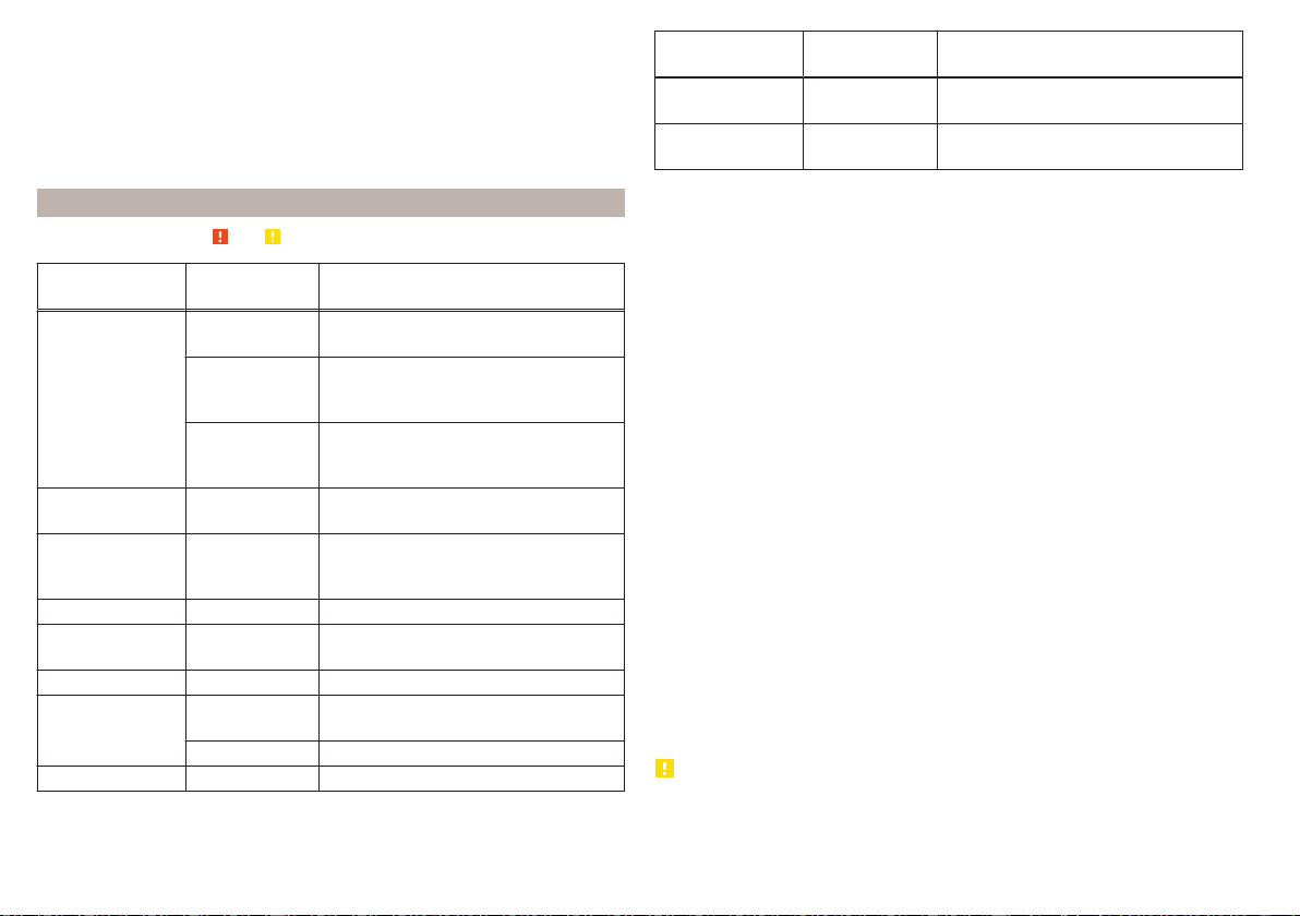
■
During cleaning, always keep a sufficiently large spraying distance in particu-
lar from the parking sensors, the reversing camera lens, the external decora-
tive and protective plastic parts (e.g. roof racks, spoilers, protective strips) and
other vehicle parts made of non-metallic materials, such as rubber hoses or in-
sulation materials – otherwise there is a risk of damage.
■
When washing the vehicle, do not point the water jet directly at the tow bar
or the trailer socket - there is a risk of seal damage or washing out the grease.
Caring for the outside of the vehicle
Read and observe
and on page 253 first.
Vehicle compo-
nent
Facts of the
matter
Remedy
Paint
Spilled fuel
Clear water, cloth, (clean as soon as
possible)
No water drop-
lets form on the
paint
Use hard wax (min. twice a year), apply
wax to clean and dry body
Matt paint
Use polish, then preserve (if the polish
does not contain any preservative in-
gredients)
Plastic parts Soiling
Clear water, cloth / sponge provided
for the intended cleaning agent
Chromed
and anodised
parts
Soiling
Clear water, cloth or cleaning agent
provided for this purpose, then polish
with a soft dry cloth
Foils Soiling soft sponge and mild soap solution
a)
Windows
and door mirrors
Soiling
Wash with clean water and dry using
the intended cloth
Headlights/lights Soiling soft sponge and mild soap solution
a)
Reversing camera
Soiling
Wash with clean water and dry with a
soft cloth
Snow / ice Hand brush / de-icer
Door lock cylinder Snow / ice De-icer
Vehicle compo-
nent
Facts of the
matter
Remedy
Wiper / wiper
blades
Soiling Glass cleaner, sponge or cloth
Wheels Soiling
Clear water, then coat with appropriate
conservation solution
a)
A mild soap solution consisting of 2 tablespoons of natural soap to 1 litre of lukewarm water.
The jack is maintenance-free. If necessary, the moving parts of the jack should
be lubricated with a suitable lubricant.
The towing device is maintenance-free. Coat the ball head of the towing de-
vice with a suitable grease whenever necessary.
Protection of hollow spaces
All the hollow spaces on your vehicle which are at risk from corrosion are pro-
tected for life by a layer of protective wax applied in the factory.
If any small amount of wax flow out of the cavities at high temperatures, these
must be removed with a plastic scraper and the stains cleaned using a petrole-
um cleaner.
Underbody protection
The underside of your vehicle is already permanently protected by the factory
against chemical and mechanical influences.
We recommend having the protective coating underneath the vehicle and the
chassis checked — preferably before the beginning of winter and at the end of
winter.
Product life of the films
Environmental influences (e.g. sunlight, humidity, air pollution, rockfall) affect
the life of the films. Films will age and become brittle – this is entirely normal:
this is not a fault.
Sunlight may also affect the strength of the film colour.
When transporting a load on the roof rack (e.g. roof box or similar), there is an
increased risk of film damage (e.g. of chipping from the secured load).
CAUTION
■
Vehicle paint
■
Damaged areas should be repaired as soon as possible.
■
Do not treat painted parts with or hard waxes.
254
General Maintenance
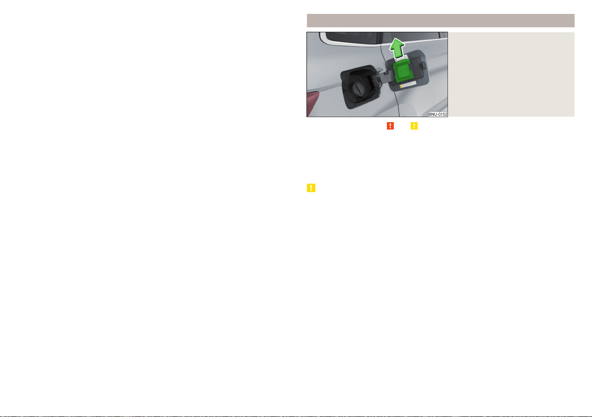
■
Do not polish the paintwork in a dusty environment - risk of paint scratch-
es.
■
Do not apply any paint care products to door seals or window guides.
■
Plastic parts
■
Do not use paint care products.
■
Chromed and anodised parts
■
Do not polish the chrome parts in a dusty environment - risk of surface
scratches.
■
Foils
The following instructions must be observed, otherwise there is a risk of foil
damage.
■
Do not clean with dirty cloths or sponges.
■
To remove ice and snow, do not use a scraper or other means.
■
Do not polish the foils
■
Do not use a pressure washer to clean the foils
■
Rubber seals
■
Do not treat the door seals and window guides with any products - the pro-
tective lacquer layer could be affected.
■
Windows and external mirror glass
■
Do not clean the inside of the windows with sharp objects - there is a risk
of damage to the filaments or glass antenna.
■
Do not use a cloth, which was used to polish the body - this could soil the
window and reduce visibility.
■
Headlights/lights
■
Do not dry off the headlights/lights, do not use sharp objects - there is a
risk of damage to the protective coating and subsequent cracking of the
headlight glass.
■
Reversing camera
The following instructions must be observed, otherwise there is a risk of
camera damage.
■
Do not remove snow / ice with warm / hot water.
■
To wash, never use a pressure washer or steam jet.
■
For cleaning, do not use abrasive cleaners.
■
Door lock cylinder
■
Make sure that as little water as possible gets into the locking cylinder
when washing the vehicle - there is a risk of freezing the lock cylinder!
■
Wheels
■
Heavy contamination of the wheels can affect the balance of the wheels -
this can result in vibrations and, under some circumstances, can cause pre-
mature wear of the steering wheel.
Removing snow and ice from the windscreens
Fig. 291
Installation location of the ice
scraper, removing the scraper
Read and observe
and on page 253 first.
Use a plastic ice scraper for removing snow and ice from the windows and
mirrors. This can be on the inside of the fuel filler flap.
›
Open the fuel filler flap and slide the scraper in the direction of arrow
» Fig. 291.
CAUTION
■
Move the scraper in one direction only, otherwise there is a risk of damage to
the glass surface.
■
Do not remove snow / ice on the surface that is soiled (e.g. pea gravel, sand,
road salt) - there is a risk of damaging the surface.
■
Remove snow / ice carefully, otherwise there is a risk of damaging the labels
that have been fitted by the factory.
255
Care and maintenance
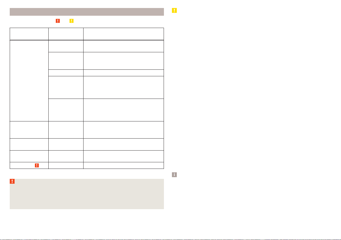
Caring for the interior
Read and observe and on page 253 first.
Vehicle compo-
nent
Facts of the
matter
Remedy
Natural leather /
Faux leather /
Alcantara
®
/
Material
Dust, surface
contamination
Vacuum cleaner
Pollution (fresh)
Water, slightly damp cotton / wool
cloth, if necessary, mild soap solution
a)
,
then wipe with a soft cloth
Stubborn stains Specially prepared detergent
Care (natural
leather)
Treat the leather periodically with a
suitable leather protector and use a
care cream with light blocker and im-
pregnation after each cleaning.
Care (Alcan-
tara
®
/ fabric)
Remove stubborn hairs using a “clean-
ing glove”
Remove pills from materials with a
brush
Plastic parts Soiling
Water, slightly damp cloth or sponge,
or cleaning agent provided for this pur-
pose
Windows Soiling
Wash with clean water and dry using
the intended cloth
Covers of electri-
cally heated seats
Soiling Specially provided cleaning agent
Seat belts » Soiling soft cloth and mild soap solution
a)
a)
A mild soap solution consisting of 2 tablespoons of natural soap to 1 litre of lukewarm water.
WARNING
■
Never clean the seat belts chemically as chemical cleaning products could
destroy the fabric.
■
Air fresheners and scents can be hazardous to heath when the tempera-
ture inside the vehicle is high.
CAUTION
■
Natural leather / Faux leather / Alcantara
®
/ material
■
In lengthy periods in bright sunlight, it might be sensible to cover these ma-
terials in order to avoid bleaching.
■
Fresh stains (e.g. from pens, lipstick, shoe polish etc.) should be removed as
soon as possible.
■
Ensure that no part of the leather is soaked through during cleaning and
that no water gets into the seams.
■
Do not clean the roof panelling with a brush – risk of damage to the surface
of the panelling.
■
Do not use solvents, floor wax, shoe cream, stain remover or similar agents
on Alcantara
®
seat upholstery.
■
Some clothing fabrics (e.g. dark denim) do not have sufficient colour fast-
ness - this may leave evident marks on upholstery. This is not a defect in the
fabric.
■
Sharp objects on garments (e.g. zips, rivets, sharp- edged belts) can dam-
age the upholstery fabrics in the vehicle. Such damage cannot be subse-
quently recognised as a justified complaint.
■
Plastic parts
■
Do not attach scents or air fresheners to the dashboard – there is a risk of
damage to the dashboard.
■
Windows
■
Do not attach any stickers to the filaments or glass antenna - there is risk
of damage.
■
Covers of electrically heated seats
■
Do not clean with water or other liquids - there is a risk of damage to the
heating system.
■
Do not dry by switching on the heating.
■
Seat belts
■
Allow to dry before rolling up the seat belts.
Note
During vehicle use, the leather and Alcantara
®
parts may show minor changes
(e.g. folds, discolouration).
256
General Maintenance
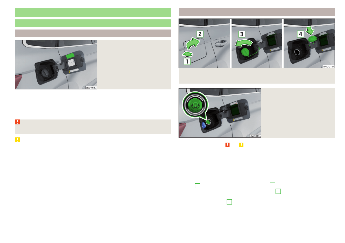
Inspecting and replenishing
Fuel
Introduction
Fig. 292
Stickers with prescribed fuel
The correct fuel for your vehicle is specified on the inside of the fuel filler flap
» Fig. 292.
The fuel capacity for vehicles with front wheel drive is about 50 litres, and for
vehicles with four-wheel drive about 55 litres, with about 6 litres as reserve.
WARNING
Fuel vapours are explosive - can be fatal!
CAUTION
■
Never drive until the fuel tank is completely empty! The irregular supply of
fuel can cause misfiring, which can result in damage to parts of the engine and
the exhaust system.
■
Immediately remove any fuel that has spilled onto the vehicle's paintwork –
risk of paint damage.
■
If you would like to operate your vehicle in countries other than those with
the intended weather conditions, please contact a ŠKODA partner. They will
tell you whether the fuel specified by the manufacturer is offered in the ac-
companying country or whether it is permissible to operate the vehicle with
another fuel.
Petrol and diesel refuelling
Fig. 293 Open fuel filler flap/unscrew tank cap/place the tank cap on
the fuel filler flap
Fig. 294
Fuel filler tube on vehicles with
diesel engines
Read and observe and on page 257 first.
Perform the refuelling under the following conditions.
The vehicle is unlocked.
The ignition is switched off.
The auxiliary heating and ventilation is switched off.
›
Press the fuel filler flap in direction of arrow
1
and fold in the direction of
arrow
2
» Fig. 293.
›
Unscrew the tank cap in the direction of arrow
3
.
›
Remove the tank cap and place in the recess on top of the fuel filler flap in
the direction of arrow
4
.
›
Insert the pump nozzle into the fuel filler neck as far as it will go, and refuel.
The fuel tank is full just as soon as the pump nozzle switches off for the first
time. Not continue refuelling.
257
Inspecting and replenishing

›
Remove the pump nozzle from the fuel filler neck and put it back in the
pump.
›
Place the filler cap onto the fuel filler neck and turn it in the opposite direc-
tion to the arrow until it securely engages
3
.
›
Close the fuel filler flap until it clicks into place.
Incorrect refuelling guard on vehicles with diesel engines
The fuel filler tube on vehicles with diesel engines has been fitted with an in-
correct refuelling guard » Fig. 294.
If the diesel pump nozzle does not sit directly in the fuel filler tube, move it to
and fro with slight pressure to insert it correctly.
The diameter of the diesel pump nozzle can be identical to that of the petrol
pump nozzle in some countries. When driving in these countries, the incorrect
fuelling protection should be removed by a specialist company.
Unleaded petrol
Read and observe and on page 257 first.
The correct fuel for the vehicle is specified on the inside of the fuel filler flap
» Fig. 292 on page 257.
The vehicle can only be operated with unleaded petrol containing maximum
10% bioethanol (E10).
Unleaded petrol must correspond to the European Standard EN 228 (in Ger-
many DIN 51626-1 or E10 for unleaded petrol with octane number 95 and 91
or DIN 51626-2 or E5 for unleaded petrol with octane number 95 and 98).
Prescribed fuel 95/min. 92 and 93 RON
We recommend using petrol 95 RON.
Optionally, the petrol 92 or. 93 RON can be used (slight power loss, a slightly
increased fuel consumption).
In an emergency petrol 91 RON can be used (slight power loss, slightly in-
creased fuel consumption) » .
Unleaded petrol min. 95 RON / ROZ
Use at least 95 ROZ petrol.
In an emergency petrol 91, 92 or 93 RON can be used (slight loss, a slightly
increased fuel consumption) »
.
Prescribed petrol 98/(95) RON / ROZ
We recommend using petrol 98 RON.
Optionally, petrol 95 RON can be used (slight power loss, a slightly increased
fuel consumption).
In an emergency petrol 91, 92 or 93 RON can be used (slight loss, a slightly
increased fuel consumption) » .
CAUTION
The following instructions must be observed, otherwise there is a risk of en-
gine damage and damage to the exhaust system.
■
If gasoline is used which is lower than the prescribed octane number, then
continue driving at medium engine speeds and minimum engine load. Refuel
using petrol of the prescribed octane number as soon as possible.
■
Petrol with a lower Octane count than 91 should not even be used in an
emergency!
■
If a fuel other than unleaded fuel which complies to the above mentioned
standards (e.g. leaded petrol) is put in the tank by mistake, do not start the en-
gine or switch on the ignition.
CAUTION
Petrol additives (additives)
■
The unleaded petrol in accordance with the prescribed standards meets all
the conditions for a smooth running engine. Therefore, we recommend that
you do not add any fuel additives to the petrol - there is a risk of engine dam-
age or damage to the exhaust system.
■
The following additives and auxiliary products may not be used - there is a
risk of engine damage or damage to the exhaust system!
■
Additives with metal components (metallic additives), in particular with
manganese and iron content.
■
Fuels with metallic content (e.g. LRP - lead replacement petrol).
Note
■
Unleaded petrol that has a higher octane number than that required by the
engine can be used without limitations.
■
The use of petrol with an octane rating higher than 95 RON in does not re-
sult in either a noticeable increase in power nor lower fuel consumption in ve-
hicles for which unleaded petrol 95/min 92 or 93 RON is specified.
■
On vehicles using prescribed petrol of min. 95 RON, the use of petrol with a
higher octane number than 95 RON can increase the power and reduce fuel
consumption.
258
General Maintenance

Diesel fuel
Read and observe and on page 257 first.
The correct fuel for the vehicle is specified on the inside of the fuel filler flap
» Fig. 292 on page 257.
Your vehicle can only be operated with diesel fuel that complies with the Eu-
ropean Standard EN 590 (also standard DIN 51628 in Germany, standard
ÖNORM C 1590 in Austria, GOST R 52368-2005/EN 590:2004 in Russia).
The diesel fuel may contain maximum 7% biodiesel (B7 - In Germany in ac-
cordance with DIN 52638, in Austria ÖNORM C 1590, in France EN 590).
Operating under different weather conditions
Use only diesel in accordance with the current or expected weather condi-
tions. Ask the petrol station personnel whether the diesel fuel offered corre-
sponds to these conditions.
CAUTION
The following instructions must be observed, otherwise there is a risk of en-
gine damage and damage to the exhaust system.
■
If a different fuel other than diesel fuel, which complies to the above men-
tioned standards (e.g. petrol) is put into the tank, do not start the engine or
switch on the ignition!
■
The biofuel RME must not be used!
CAUTION
Diesel fuel additives
■
The diesel fuel in accordance with the prescribed standards meets all the
conditions for a smooth running engine. Therefore, we recommend that you
do not add any fuel additives to the diesel - - there is a risk of engine damage
or damage to the exhaust system.
AdBlue
®
and its refilling
Introduction
In order to reduce pollutant emissions from vehicles with diesel engines and
the SCR catalyst, a urea - AdBlue
®
solution is injected into the exhaust system.
Only use AdBlue
®
that corresponds to the standard ISO 22241-1. Do not add
additives to AdBlue
®
.
The AdBlue
®
-consumption depends on driving style, the operating tempera-
ture of the system and on the weather conditions.
The AdBlue
®
tank filling is about 12 litres.
WARNING
AdBlue
®
can cause skin, eye and respiratory irritation. If your eyes or skin
come into contact with the AdBlue
®
fluid, immediately wash the affected
area with water. Seek medical assistance if required.
CAUTION
AdBlue
®
attacks the surface of some materials (e.g. as painted parts, plastics,
fabrics). Clean the areas affected with AdBlue
®
using a damp cloth and plenty
of cold water. Remove any dried AdBlue
®
with warm water and a sponge.
Note
■
The AdBlue
®
solution freezes at a temperature of -11° C and lower. The sys-
tem has an automatic heater to ensure operability at low temperatures.
■
We recommend purchasing AdBlue
®
refill bottles from the ŠKODA original
parts.
■
The working life of the AdBlue
®
solution is 4 years. If the tank contents are
not used within this period, then this is to be replaced by a specialist garage.
When toppig up, do not use AdBlue
®
for which the shelf life has expired.
■
AdBlue
®
is a registered trademark of the VDA. AdBlue
®
is also known as AUS
32 (Aqueous Urea Solution) or DEF (Diesel Exhaust Fluid).
Check level
Read and observe
and on page 259 first.
The AdBlue
®
level is automatically monitored.
If the available travel distance that can be completed with the remaining AdBl-
ue
®
tank capacity drops to about 2400 km, the warning appears on the in-
strument cluster and a request for replenishment of AdBlue
®
appears.
An indication also appears in the instrument cluster showing the maximum and
minimum AdBlue
®
tank capacity.
259
Inspecting and replenishing
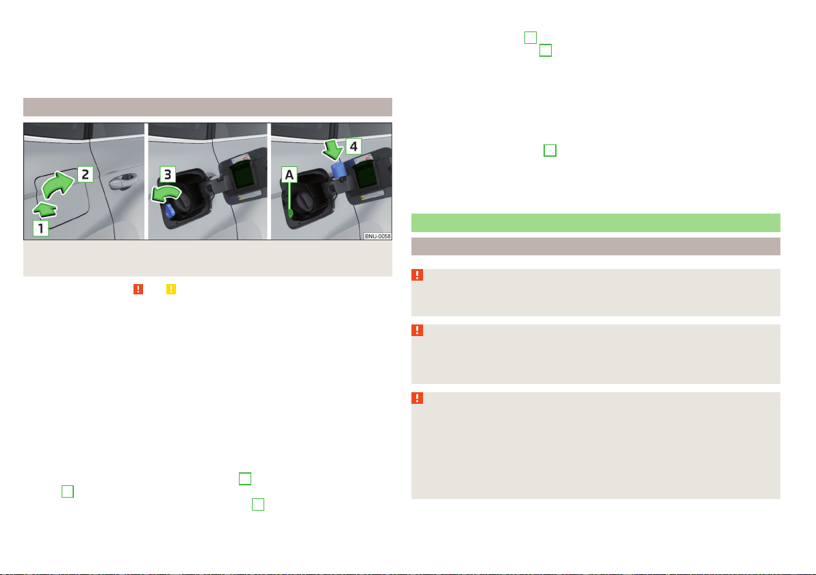
If the available travel distance that can be driven with the existing AdBlue
®
-
tank capacity drops down to 0 km, then no motor start is possible. In this
case, if possible, top up AdBlue
®
to the maximum fill level.
The distance which can still be driven with the remaining AdBlue
®
, can be de-
termined using the travel data» page 51.
AdBlue
®
Refill
Fig. 295
Open fuel filler flap/unscrew tank cap/place the tank cap on
the fuel filler flap
Read and observe and on page 259 first.
AdBlue
®
You can even top up using a fuel nozzle at a gas station or a refill bot-
tle, if necessary at a specialist garage.
We recommend when refilling using refill bottles that you use refill bottles
from ŠKODA Original Accessories.
When adding AdBlue
®
take note of the minimum and maximum AdBlue
®
tank
capacity shown in the display of the instrument cluster together with warning
light .
Refill AdBlue
®
under the following conditions.
The vehicle is on a horizontal surface.
The ignition is switched off.
Refilling
›
Press the fuel filler flap in direction of arrow
1
and fold in the direction of
arrow
2
» Fig. 295.
›
Unscrew the tank cap in the direction of arrow
3
.
›
Remove the tank cap and place in the recess on top of the fuel filler flap in
the direction of arrow
4
.
›
Refill AdBlue
®
in the neck
A
by means of a refill or a fuel nozzle refill (follow
the instructions on the container or the instructions of the petrol station op-
erator).
The AdBlue
®
- tank is full when no AdBlue
®
flows from the refill bottle or as
soon as the correctly operated pump cuts out for the first time. Do not contin-
ue refilling AdBlue
®
.
›
After refilling AdBlue
®
put the cap on the fuel filler neck and turn in the oppo-
site direction of the arrow
3
until it engages.
›
Close the fuel filler flap until it clicks into place.
Before continuing your journey, switch on just the ignition for 30 s so that
the refilling can be recognized by the system. Only then start the engine.
Engine compartment
Introduction
WARNING
Never cover the engine with additional insulation material (e.g. with a cov-
er) – risk of fire!
WARNING
When working in the engine compartment, the following instructions must
be observed - risk of injury or fire. The engine compartment of your car is a
hazardous area!
WARNING
Instructions before beginning work in the engine compartment
■
Stop the engine and remove the ignition key, on vehicles with the KESSY
system, open the driver's door.
■
Switch on the parking brake.
■
For vehicles with manual transmission the lever into the neutral position.
On vehicles with automatic transmission, place the selector lever in the P
position.
260
General Maintenance
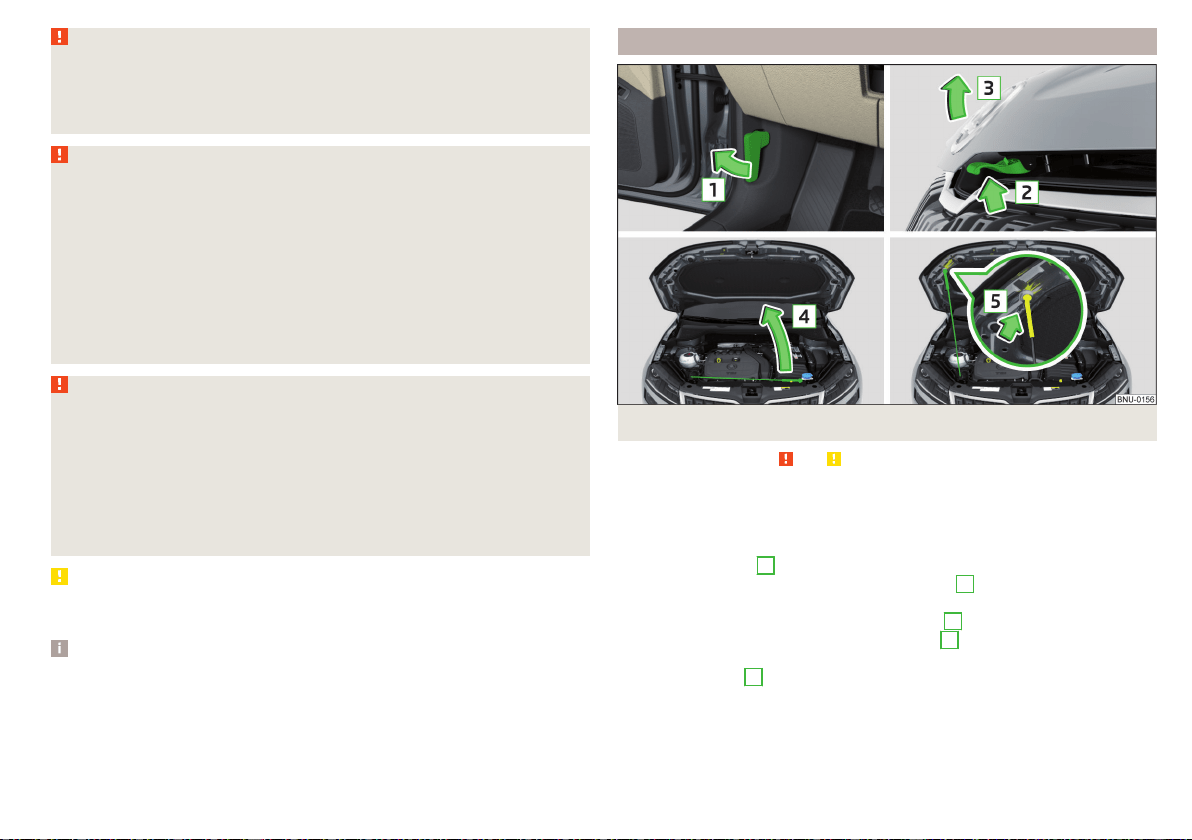
WARNING (Continued)
■
Allow the engine to cool.
■
Never open the bonnet if you can see steam or coolant flowing out of the
engine compartment – risk of scalding! Wait until the steam or coolant has
stopped escaping.
WARNING
Information for working in the engine room
■
Keep everyone away from the engine compartment.
■
Do not touch any hot engine parts – risk of burns!
■
Never touch the radiator fan. The radiator fan suddenly switch on approx.
10 minutes after switching off the ignition!
■
Do not smoke or use open flames in the vicinity of the engine.
■
Do not leave any items (e.g. cloths or tools) in the engine compartment.
This presents a fire hazard and the risk of engine damage.
■
Read and observe the information and warning instructions on the fluid
containers.
WARNING
Information for working in the engine compartment with the engine run-
ning
■
If it is necessary to work on the engine compartment with the engine run-
ning, then observe the rotating engine parts and electrical plants - it can
be fatal!
■
Never touch the electric wiring on the ignition system.
■
Avoid short circuits in the electrical system, particularly on the vehicle's
battery.
CAUTION
Refill only operating fluids of the correct specification - danger of damaging
the vehicle!
Note
■
Fluids with the proper specifications can be purchased from the ŠKODA
Original Accessories or from the ŠKODA Genuine Parts ranges.
■
We recommend you have the battery replaced by a specialist garage.
Open the bonnet and close
Fig. 296
Opening the bonnet
Read and observe
and on page 260 first.
Open flap
›
Make sure that the windscreen wiper arms are not folded away from the
windscreen - there is a risk of damage to the bonnet.
›
Open the front door and pull the release lever below the dash panel in the
direction of arrow
1
» Fig. 296.
›
Press the release lever in the direction of arrow
2
and the bonnet will be un-
locked.
›
Raise the bonnet in the direction of the arrow
3
.
›
Remove the lid prop in the direction of arrow
4
from the holder.
›
Secure the open flap inserting the end of the post into the opening in the di-
rection of arrow
5
.
Close the bonnet lid
›
Lift the bonnet.
›
Decouple the bonnet support and press into the holder designed to hold it.
261
Inspecting and replenishing
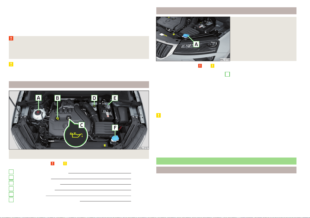
›
Let the engine compartment door drop from about 20 cm in height for it to
lock into place securely.
›
Check that the lid is closed.
If the bonnet lid is not properly closed, the display of the instrument cluster
will show this.
WARNING
■
Never drive if the bonnet is open - could cause an accident!
■
Make sure that when closing the engine compartment lid, no body parts
are crushed - there is danger of injury!
CAUTION
Close the engine compartment door “Do not push” - there is a risk of damag-
ing the door.
Engine compartment overview
Fig. 297
Arrangement example in the engine compartment
Read and observe
and on page 260 first.
Coolant expansion reservoir 264
Engine oil dipstick 263
Engine oil filler opening 263
Brake fluid reservoir 265
Vehicle battery
265
Windscreen washer fluid reservoir
262
A
B
C
D
E
F
Windscreen washer fluid
Fig. 298
Windscreen washer fluid reser-
voir
Read and observe
and on page 260 first.
The windscreen washer fluid reservoir
A
is located in the engine compart-
ment » Fig. 298.
The capacity of the reservoir is about 3 litres or about 5 litres on vehicles that
have a headlight cleaning system.
Use a suitable windscreen washer fluid in accordance with the current or ex-
pected weather conditions. We recommend that you use accessories from
ŠKODA Original Accessories.
CAUTION
■
If the vehicle is equipped with a headlight cleaning system, then only use
windscreen washer fluid types that do not attack the polycarbonate coating of
the headlights - otherwise there is a risk of damage to headlights.
■
Do not remove the filter from the windscreen washer fluid reservoir when
replenishing it with liquid otherwise the liquid transportation system can be-
come contaminated, which can cause the windscreen washer system to mal-
function.
Engine oil
Specification
If you would like to know which type of engine oil you can use for your vehicle,
contact a specialist company.
If this oil is not available, other oils can also be replenished. To prevent engine
damage, a maximum of 0.5 l of engine oil with the following specifications
may be used until the next oil change:
262
General Maintenance
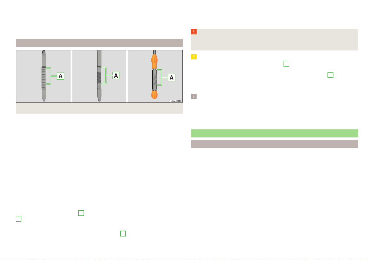
▶
Petrol engines: VW 504 00, VW 502 00, VW 508 00, ACEA A3/ACEA B4 or
API SN, (API SM);
▶
Diesel engines: VW 507 00, ACEA C3 or API CJ-4.
Engine oil VW 505 01 can optionally be used in diesel engines without a DPF.
Check and refill
Fig. 299
Dipstick variants
Depending on the driving style and operating conditions, the engine uses some
oil (up to 0.5 l / 1 000 km). Consumption may be slightly higher than this dur-
ing the first 5 000 km.
Have the oil change carried out by a specialist company as part of the inspec-
tion.
Check the oil under the following conditions and refill.
The vehicle is standing on a horizontal surface.
The engine operating temperature is reached.
The engine is turned off.
Checking the level
›
Wait a few minutes until the engine oil flows back into the oil trough.
›
Remove the dipstick and wipe with a clean cloth.
›
Push the dipstick to the stop and pull out again.
›
Read the oil level and push in the dipstick.
The oil level must be in range
A
» Fig. 299. If the oil level is below the range
A
, refill the oil.
Refilling
›
Unscrew the cap of the engine oil filler opening
C
» Fig. 297 on page 262.
›
Add oil of the correct specification in increments of 0.5 litres » page 262.
›
Check the oil level .
›
Screw the lid of the engine oil filler closed carefully.
WARNING
The following warning instructions must be followed at all times when
working in the engine compartment » page 260.
CAUTION
■
The oil level must never fall outside range
A
» Fig. 299 - otherwise there is a
risk of damaging the engine and the exhaust system.
■
If a top up with oil is not possible or the oil level is above range
A
, stop
driving! Switch off the engine and seek assistance from a specialist garage.
■
Do not add additives to the engine oil - risk of engine damage.
Note
■
Too low engine oil level is shown in the instrument cluster by the warning
light illuminating and also indicated by the message » page 46. Nevertheless,
we recommend to check the oil level on a regular basis with the dipstick.
■
We recommend that you use oils from ŠKODA Original Accessories.
Coolant
Introduction
The coolant cools the engine and consists of water and coolant additive (with
additives that protect the cooling system against corrosion and prevents fur-
ring).
The coolant additive level in the coolant must between 40 and 60 %.
The correct mixing ratio of water and coolant additive should be checked if
necessary by a specialist garage or corrected if necessary.
263
Inspecting and replenishing
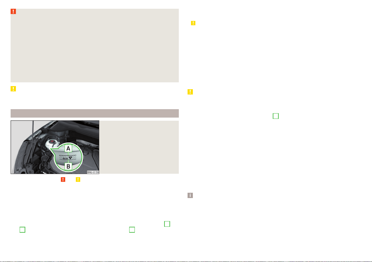
WARNING
■
The following warning instructions must be followed at all times when
working in the engine compartment » page 260.
■
Never open the end cover of the coolant expansion reservoir while the
engine is still warm. The cooling system is pressurized - risk of scalding or
injury from being splashed with coolant!
■
To protect against coolant splashes, cover the cap with a cloth when
opening.
■
Coolant and coolant fumes are harmful - avoid contact with the coolant.
If your eyes or skin come into contact with the coolant, immediately wash
the affected area for a few minutes long with a lot of water and seek medi-
cal advice if required.
CAUTION
Do not cover the radiator or fit any parts (e.g. auxiliary lights) in front of the air
intakes - there is a risk of the engine overheating.
Checking and refilling
Fig. 300
Coolant expansion reservoir
Read and observe and on page 264 first.
Check the coolant under the following conditions and refill.
The vehicle is on a horizontal surface.
The engine is not warm (if the engine is warm, the test results could be in-
accurate).
The engine is turned off.
Check the coolant level - the coolant level must be between the marks
A
and
B
» Fig. 300. If the coolant level is below the mark
B
, refill the coolant.
Refilling
The coolant expansion tank must always contain a small amount of coolant
» .
›
Place a cloth over the cap of the coolant expansion tank and unscrew the cap
carefully.
›
Always top up using the correct specification of fluids.
›
Turn the cap until it clicks into place.
The specification of the coolant is shown on the coolant expansion reser-
voir» Fig. 300.
If no specified coolant is available, use only distilled or demineralised water and
have the mixing ratio of water and coolant additive corrected by a specialist
garage as soon as possible.
CAUTION
■
If the expansion tank is empty, do not top up with coolant. The system could
aerate - risk of damaging the engine! Do not drive the vehicle. Switch off
the engine and seek assistance from a specialist garage.
■
Do not fill the coolant above the mark
A
» Fig. 300. When it heats up, the
coolant could press out of the cooling system - there is a risk of damage to the
engine parts.
■
If it is not possible to add coolant, stop driving! Switch off the engine and
seek assistance from a specialist garage.
■
A coolant additive which does not correspond to the correct specification
can reduce the anti-corrosion effect of the cooling system - there is a risk of
damage to the cooling system and the engine.
■
If water other than distilled (demineralised) water is used, then have the
coolant replaced by a specialist garage - there is a risk of engine damage.
■
A loss of coolant could be due to leaks in the cooling system - there is a risk
of engine damage. Switch off the engine and seek assistance from a specialist
garage.
Note
A coolant level which is too low is indicated in the instrument cluster by the
warning light and shown by the relevant message » page 45. We still recom-
mend inspecting the coolant level directly at the reservoir from time to time.
264
General Maintenance
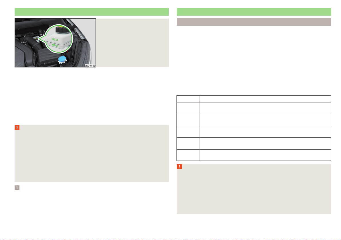
Brake fluid
Fig. 301
Brake fluid reservoir
Check the brake fluid under the following conditions.
The vehicle is on a horizontal surface.
The engine is turned off.
Check brake fluid level - the brake fluid level must be between the markings
“MIN” and “MAX”» Fig. 301.
Specification - the brake fluid must comply with VW 501 14 standard (this
standard meets the requirements of FMVSS 116 DOT4).
The Braking fluid change is carried out as part of the inspection.
WARNING
■
If the date to change the braking fluid is exceeded, it can lead to steam
bubbles forming in the braking system when braking hard. This can impair
the efficiency of the brakes – risk of accident!
■
The following warning instructions must be followed at all times when
working in the engine compartment » page 260.
■
There may be an indication of a leak in the brake system, however, if the
fluid level drops significantly within a short time or if it drops below the
“MIN” » Fig. 301 marking. Stop driving – There is a risk of an accident!
Seek help from a specialist garage.
Note
A low brake fluid level which is too low is indicated by the warning light be-
ing shown on the display of the instrument cluster as well as the correspond-
ing message» page 40. We therefore recommend that you check the coolant
level directly at the reservoir from time to time.
Vehicle battery
Introduction
The vehicle battery represents a power source for the motor to start and for
the supply of electrical consumers in the car.
Automatic consumer shutdown - Discharge protection of the vehicle
battery
The on-board power supply tries as follows to avoid draining the vehicle bat-
tery when it is heavily loaded.
▶
By increasing the engine idle speed.
▶
By limiting the power of certain consumers.
▶
By turning off some consumers (heated seats, heated rear window) for as
long as necessary.
Warning symbols on the vehicle battery
Symbol Meaning
Always wear eye protection.
Battery acid is severely caustic. Always wear gloves and eye pro-
tection.
Keep fire, sparks, open flames and lit cigarettes well clear of the
vehicle battery.
When charging the vehicle battery, a highly explosive gas mixture
is produced.
Keep children away from the vehicle battery.
WARNING
Battery acid is highly corrosive - risk of injury, irritation or poisoning! Corro-
sive vapours in the air irritate and damage the respiratory tract and the
eyes. The following guidelines must be observed.
■
Always wear protective gloves, eye and skin protection when handling
the vehicle battery.
■
If your eyes or skin come into contact with the electrolytic fluid, immedi-
ately wash the affected area for a few minutes long with a lot of water.
Seek medical assistance if required.
265
Inspecting and replenishing
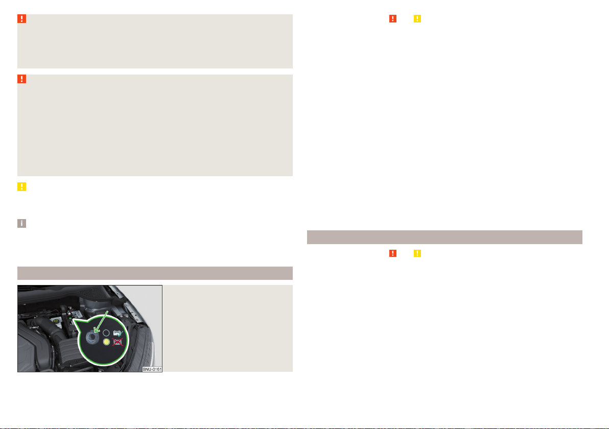
WARNING (Continued)
■
Keep the vehicle battery away from people who are not completely inde-
pendent, especially children.
■
Do not tilt the battery otherwise battery electrolyte may flow out of the
battery vent openings.
WARNING
When working on the car battery, there is the risk of explosion, fire, injury
or irritation! The following guidelines must be observed.
■
Avoid smoking, the use of open flames or light and any activities that
could cause sparks.
■
A discharged vehicle battery can freeze slightly. Never charge up a fro-
zen or thawed vehicle battery. Replace a frozen vehicle battery.
■
Never use a damaged vehicle battery – risk of explosion!
■
Do not connect the battery terminals with each other by bridging the two
poles of a short circuit.
CAUTION
Ensure that battery acid does not come into contact with the bodywork – risk
of damage to the paintwork.
Note
■
We recommend having all work on the vehicle battery carried out by a spe-
cialist garage.
■
You should replace batteries older than 5 years.
Checking the condition
Fig. 302
Vehicle battery: Electrolyte level
indicator
Read and observe and on page 265 first.
The battery condition is checked regularly by a specialist garage as part of the
inspection service.
Check the acid level
For car batteries with acid level indicator, use the colouration of the display to
check the acid level. In vehicle batteries with the designation “AGM” there is
no acid level examination.
Air bubbles can influence the colour of the indicator. For this reason carefully
tap on the indicator before carrying out the check » Fig. 302.
Black colour - electrolyte level is correct.
Colourless or light yellow colour - electrolyte level too low, the battery must
be replaced.
Battery discharge
Frequent short journeys will not sufficiently recharge the car battery.
The battery capacity decreases at low temperatures.
If the vehicle is not used for longer than 3 to 4 weeks, then disconnect the
negative terminal
or charge the battery constantly with a very low charging
current.
Charging
Read and observe and on page 265 first.
Only charge the vehicle battery when the ignition and all consumers are
switched off.
Refer to the instructions of the charger manufacturer.
Charging
›
For vehicles with START-STOP system or auxiliary heating, connect the
terminal of the charger on the pole of the battery, the terminal of the
charger to the earth point of the engine » page 279.
›
For vehicles without START-STOP system or auxiliary heating, connect the
terminals of the charger to the corresponding battery poles ( at . at
).
›
Plug the mains cable of the charger into the power socket and switch on the
device.
266
General Maintenance
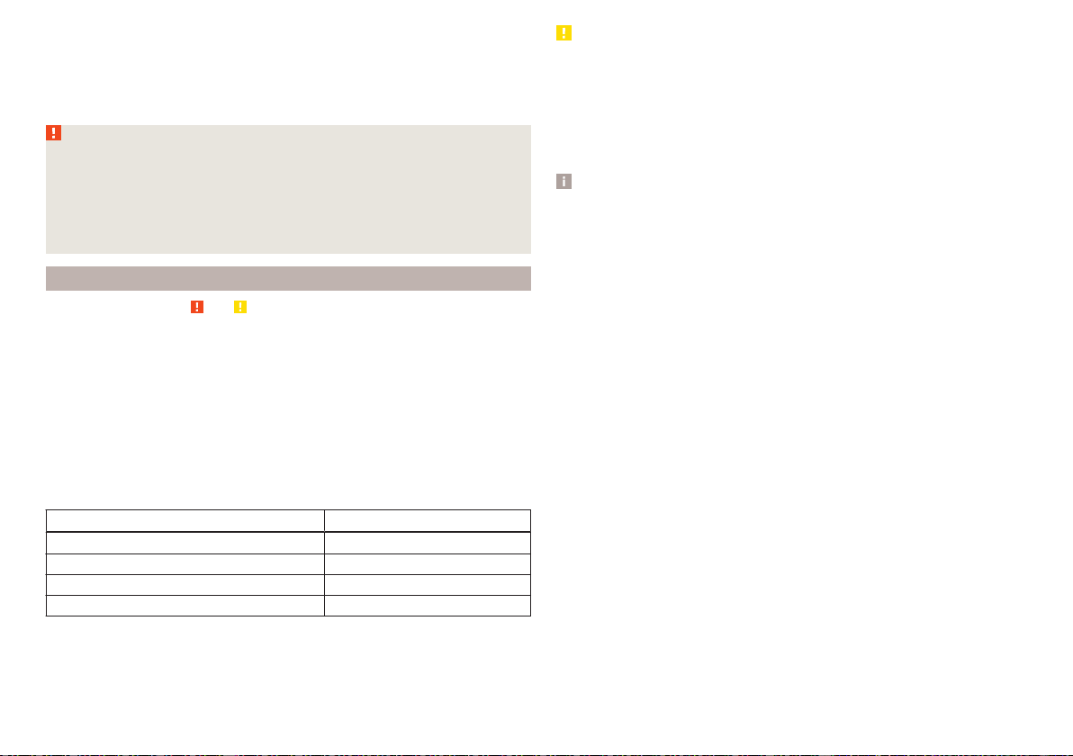
›
After charging has been successful: Switch off the charger and remove the
mains cable from the power socket.
›
Disconnect the terminals of the charger from the vehicle battery.
A charging current of 0.1 multiple of the total vehicle battery capacity (or low-
er) must be used until full charging is achieved.
WARNING
■
When charging the vehicle battery, hydrogen is released - risk of explo-
sion. An explosion can be caused from sparks or connection or releasing
the cable plug while the ignition is on.
■
The so-called “quick charging” of the vehicle battery is dangerous and re-
quires a special charger and specialist knowledge. Therefore, have “Quick
loading” carried out by a specialist garage.
Disconnect/reconnect and change
Read and observe and on page 265 first.
The new vehicle battery must have the same capacity, voltage, current and the
same size as the original Battery.
We recommend you have the battery replaced by a specialist garage.
›
To disconnect the battery, switch off the ignition and disconnect first the
negative terminal , and only after this the positive .
›
To connect the battery, first connect the positive terminal
, and only after
this the negative terminal
.
After disconnecting and re-connecting the vehicle battery, the following func-
tions or devices are partially or completely inoperative.
Function / device Operating measure
Power windows » page 66
Panorama sliding/tilting roof » page 68
Sun screen » page 68
Time setting » page 49
CAUTION
■
Disconnect the vehicle battery only with the ignition turned off - there is a
risk of damaging the electrical system of the vehicle.
■
Before disconnecting the battery, close the electric tailgate, all the windows,
the sliding / tilting roof and the electric sunshade - otherwise malfunctions of
equipment elements may occur.
■
Under no circumstances must the connection cables be connected incor-
rectly – risk of fire.
Note
After disconnecting and re-connecting the vehicle battery, we recommend
having the vehicle checked by a specialist to ensure that the full functionality
of all electrical systems is guaranteed.
267
Inspecting and replenishing
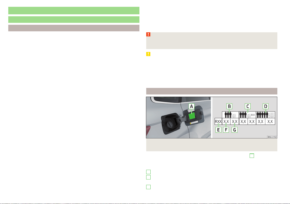
Wheels
Wheels and tyres
Advice on tyre/wheel usage
New tyres, during the first 500 km, new tyres do not offer optimum grip and
appropriate care should therefore be taken when driving.
Always fit tyres with a greater profile depth on the front wheels.
Wheels and bolts are matched to each other in terms of design. We recom-
mend that you use wheel rims and wheel bolts from ŠKODA Original Accesso-
ries.
Always store wheels or tyresin a cool, dry and, where possible, dark place. The
tyres themselves should be stored standing.
Tyre life
Tyres age and lose their original characteristics, even if they are not being
used. Do not use tyres that are older than 6 years.
The manufacturing date is indicated on the tyre sidewall (possibly on the in-
side). E.g. DOT ... 10 17... means that the tyres were produced in the 10th week
of the year 2017.
Tyre damage
We recommend checking your tyres and wheel rims for damage (punctures,
cuts, splits and bulges, etc.) on a regular basis.
Remove any foreign objects in the tyre tread immediately (e.g. small stones).
Foreign bodies which have penetrated into the tyre (e.g. screws or nails)
should not be removed. Seek help from a specialist garage.
Installation of new tyres
Only fit radial tyres of the same type, size (rolling circumference) and the same
tread pattern on one axle on all 4 wheels.
When mounting new tires the tires have to be replaced axle by axle.
Unidirectional tyres
Some tires may be directional. The direction of rotation of the tyres is marked
by arrows on the wall of the tyre.
The specified running direction must be strictly adhered to, otherwise the fol-
lowing tyre characteristics may be degraded.
▶
Driving stability.
▶
Traction.
▶
Tyre noise and tyre wear.
WARNING
Never use damaged tyres or tyres that are older than 6 years old – risk of
accident.
CAUTION
■
The tyres must be protected from contact with substances such as oil,
grease and fuel, which could damage them. If the tyres come into contact with
these substances, then we recommend you have this checked out in a special-
ist workshop.
■
Do not use rims with ground or polished surface in winter conditions - there
is a risk of wheel damage (e.g. from the road grit).
Tyre pressure
Fig. 303 Label with a table of tyre sizes and tyre pressure value / inflate
tyres
The prescribed tyre inflation is on the sticker with pictograms
A
» Fig. 303
(for some countries, the pictograms are replaced with a text).
Tyre pressure is always to match the load.
Inflation pressure for half load
Inflation pressure for environmentally friendly operation (slightly lower
fuel consumption and emissions)
Inflation pressure for full load
B
C
D
268
General Maintenance
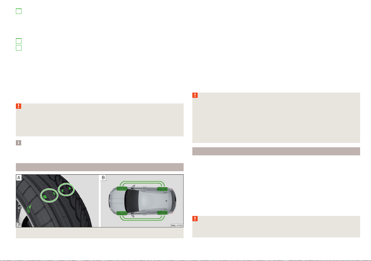
Tyre diameter in inches
This information serves merely as information for the prescribed tyre
pressure. This is not a list of shared tyre sizes for your vehicle. These are in
the vehicle's technical documentation, as well as in the declaration of con-
formity (in so-called COC document).
Tyre pressure value on the front axle
Tyre pressure value on the rear axle
Check tyre pressures
Check the tyre pressure (including that of the emergency or spare wheel) at
least once a month and also before setting off on a long journey.
Always check the inflation pressure when the tyres are cold. Do not reduce
the higher pressure of warm tyres.
In vehicles with tyre pressure monitoring, tyre pressure values must be saved
each time the pressures are changed » page 245.
WARNING
■
Do not drive with an incorrect tyre pressure - risk of accident.
■
In the event of very fast pressure loss, e.g. in the event of sudden tyre
damage, an attempt should be made to bring the vehicle carefully to a stop
without sudden steering movements and without any hard braking.
Note
The declaration of conformity (the so-called. COC document) can be obtained
from a ŠKODA Partner (only valid for some countries and some models).
Tyre wear and wheel change
Fig. 304 Tyre wear indicator / wheel change
E
F
G
The tyre wear increases in the following circumstances.
▶
Incorrect tyre pressure.
▶
Driving style (e.g. fast cornering, rapid acceleration / deceleration).
▶
Incorrect balancing of wheels (have the wheels balanced after changing
tyres / repair or with “restlessness” on the steering).
▶
Wheel alignment error.
Wear indicators are located in the profile of the tyres which display the per-
missible minimum tread depth » Fig. 304 - . A tyre is to be regarded as worn
out when this indicator is flush with the tread. Markings on the walls of the
tyres with the letters “TWI” or other symbols (e.g. ) indicate the position of
the wear indicators.
For uniform wear on all tyres, we recommend that you change the wheels ev-
ery 10 000 km according to the schedule » Fig. 304 - .
WARNING
■
Change when they are worn down to the wear indicators at the latest -
risk of accident.
■
Improper wheel alignment affects the driving behaviour - there is an acci-
dent.
■
Unusual vibrations or “pulling” of the vehicle to one side could be a sign of
tyre damage. Reduce speed and stop! If no tyre damage is evident, seek the
assistance of a specialist garage.
Spare wheel
A fully-fledged spare wheel Is identical to the wheels mounted on the vehicle.
A spare wheel that is not fully-fledged is provided with a warning label, which
is displayed on the rim. Only use this to reach the nearest specialist garage
since it is not intended for permanent use.
Instructions for using an spare wheel that is not fully-fledged
▶
Do not cover the signs.
▶
Be particularly observant when driving.
Inflate the spare wheel with the max. prescribed inflation pressure » page 268,
WARNING
An incomplete spare wheel can only be used for a short time in the event of
a breakdown and while driving carefully.
269
Wheels
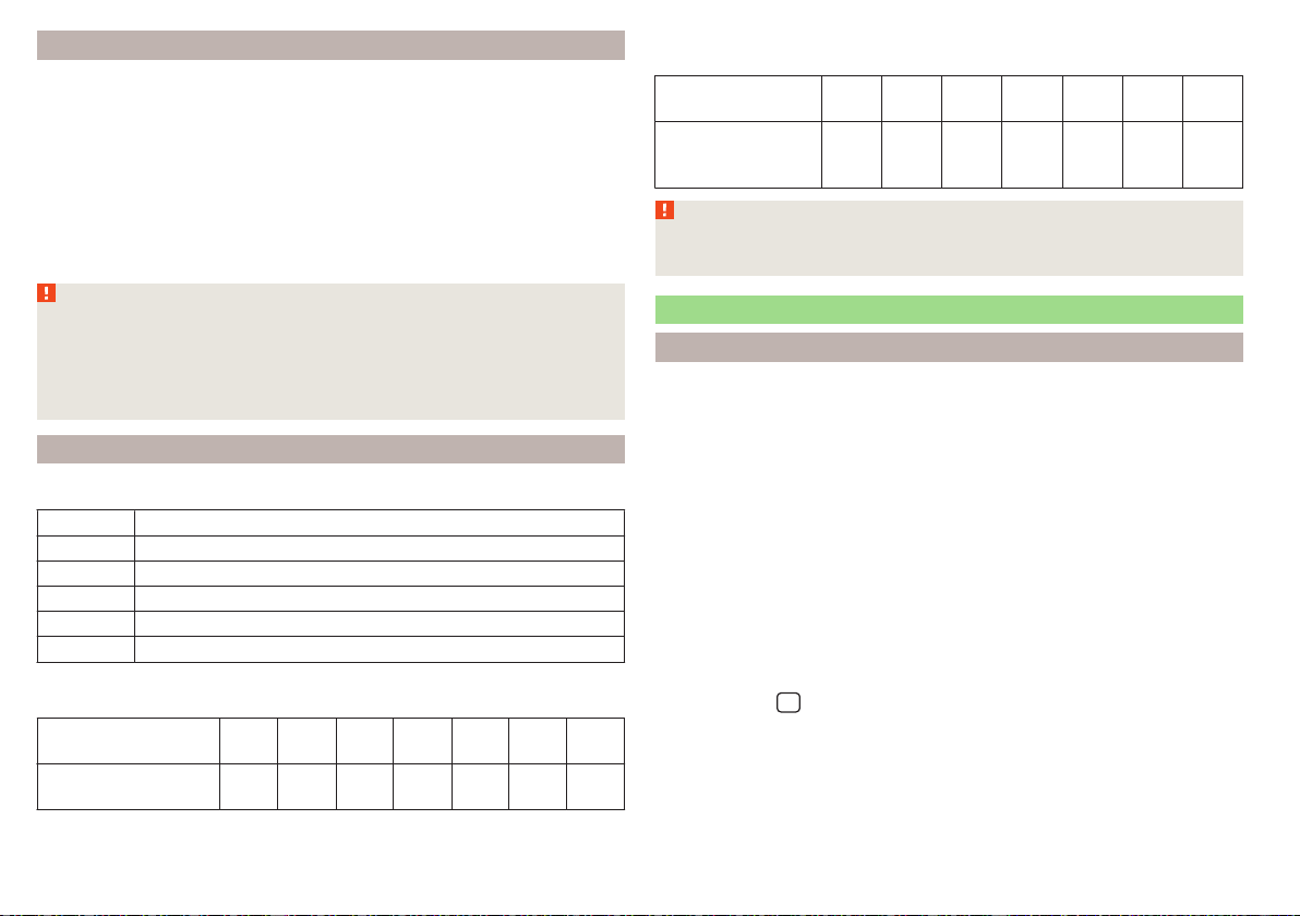
Spare wheel
A warning label is displayed on the rim of the temporary spare wheel. Only use
this to reach the nearest specialist garage since it is not intended for perma-
nent use.
The emergency wheel is significantly narrower than the wheels mounted
ex-factory.
Instructions for using an emergency wheel
▶
Do not cover the signs.
▶
Be particularly observant when driving.
▶
The tyre inflation pressure of the spare wheel R 18 is 4.2 bar.
WARNING
■
Observe instructions on the warning sign of the emergency wheel.
■
Do not drive with more than one spare wheel mounted!
■
When driving with the temporary spare wheel at full throttle acceleration,
avoid sharp braking and fast cornering.
■
Do not use snow chains on the temporary spare wheel.
Tyre marking
Explanation of tyre markings - e.g. 215/55 R 17 94 V
215 Tyre width in mm
55 Height/width ratio in %
R Code letter for the type of tyre – Radial
17 Diameter of wheel in inches
94 load index
V Speed symbol
Load index - indicates the maximum permissible load for each individual
tyre
load index
92 93 94 95 97 98 99
Load
(In kg)
630 650 670 690 730 750 775
Speed symbol - indicates the maximum permissible speed for a vehicle fit-
ted with tyres in the category concerned
speed
symbol
S T U H V W Y
Maximum
speed
(in km/h)
180 190 200 210 240 270 300
WARNING
Never exceed the maximum permissible load bearing capacity and speed
for the tyres fitted – risk of accident.
Operating in winter conditions
All-year (or “winter”) tyres
All-year or “winter” tyres (indicated by an M+S or a mountain peak/snowflake
symbol
) to improve the performance of the vehicle in winter conditions.
For the best possible handling, use all-season or “winter” tyres on all four
wheels with a minimum tread depth of 4 mm.
If using “winter” tyres, fit the summer tyres on again in good time as they pro-
vide better handling properties, a shorter braking distance, less tyre noise, and
reduced tyre wear on roads which are free of snow and ice as well as at tem-
peratures above 7 °C.
Speed symbol
All-season or “winter” tyres (marked with M+S and a peak/snowflake symbol
) of a lower speed category than stated in the technical vehicle documenta-
tion can be used, provided the permissible maximum speed of these tyres is
not exceeded even if the possible maximum speed of the vehicle is higher.
The speed limit for all-season or “winter” tyres can be set in the infotainment
system in menu
/ → →
Tyres
.
If the vehicle has all-season or “winter” tires of a lower speed category then
the specified maximum speed of the vehicle (referring to tyres that have not
been delivered by the factory, a warning label with the maximum value of the
speed category provided for the mounted tyres must be fixed in the interior of
the vehicle in a constantly visible place in the driver’s field of vision. The warn-
ing label (sticker) can be replaced by setting the maximum value of the speed
270
General Maintenance

category specified for the mounted tyres in Infotainment (only applies to cer-
tain countries). This specification defines the maximum vehicle speed with
mounted all-season or “winter”tyres that may not be exceeded.
Snow chains
The snow chains improve driving in wintry road conditions.
Before fitting the snow chains, remove the full wheel trims.
Only fit snow chains with links and locks no larger than 12 mm.
Front-wheel drive
Snow chains must only be fitted on the front wheels and are applicable only to
the following wheel / tyre combinations.
Rim size Impression depth D Tyre size
6J x 16 43 mm 215/60 R16
All-wheel drive
Snow chains can be mounted on the wheels on the front and rear axles.
It is only permissible to fit snow chains on the front wheels with the following
wheel/tyre combinations.
Rim size Impression depth D Tyre size
6J x 16 43 mm 215/60 R16
WARNING
Do not use chains on snow- and ice-free routes - the driving behaviour may
be affected and there is a risk of a puncture.
271
Wheels
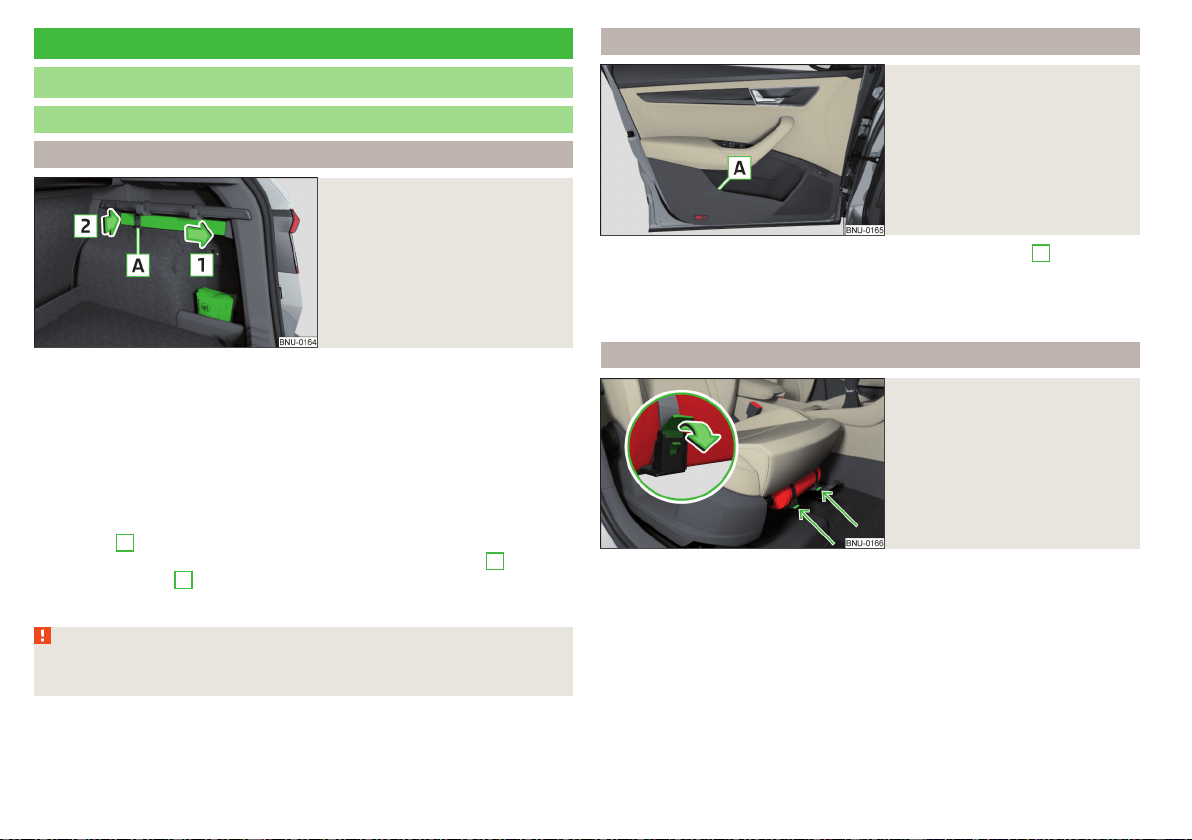
Do-it-yourself
Emergency equipment and self-help
Emergency equipment
Placement of the first aid kit and warning triangle
Fig. 305
Placing of the first-aid kit and
the warning triangle
The following information applies for the first aid kit and warning triangle from
the ŠKODA Original Accessories.
Placing the first-aid kit
The first-aid box can be attached by a strap to the right-hand side of the boot
» Fig. 305.
Placement of the warning triangle
The first-aid box can be fastened to the right-hand side of the boot » Fig. 305.
›
Insert one end of the warning triangle into the attachment in the direction of
the arrow
1
.
›
Insert the other end into the recess in the direction of the arrow
2
and se-
cure with the tape
A
.
To remove, the safety device on the tape must first be detached.
WARNING
Properly secure the first aid kit and the warning triangle, or there is a risk of
injury in the event of sudden braking or a vehicle collision.
Placement of reflective vest
Fig. 306
Stowage compartment for the
reflective vest in the front door
The reflective vest can be stowed in the storage compartment
A
inside the
storage compartment of the front door » Fig. 306.
It is possible to store the reflective vests for the passengers on the rear seat in
the storage compartment in the rear doors.
Fire extinguisher
Fig. 307
Release the fire extinguisher
The fire extinguisher is attached by two straps in a bracket under the front
passenger's seat.
›
To remove the fire extinguisher, release the safety catches on the two belts
in the direction of arrow » Fig. 307 and remove the fire extinguisher.
›
To secure, place the fire extinguisher back in the mount and secure with the
belts.
The Owner´s Manual is fitted next to the fire extinguisher.
Pay attention to the expiration date of the fire extinguisher. After this date, the
correct function of the device is not guaranteed.
272
Do-it-yourself
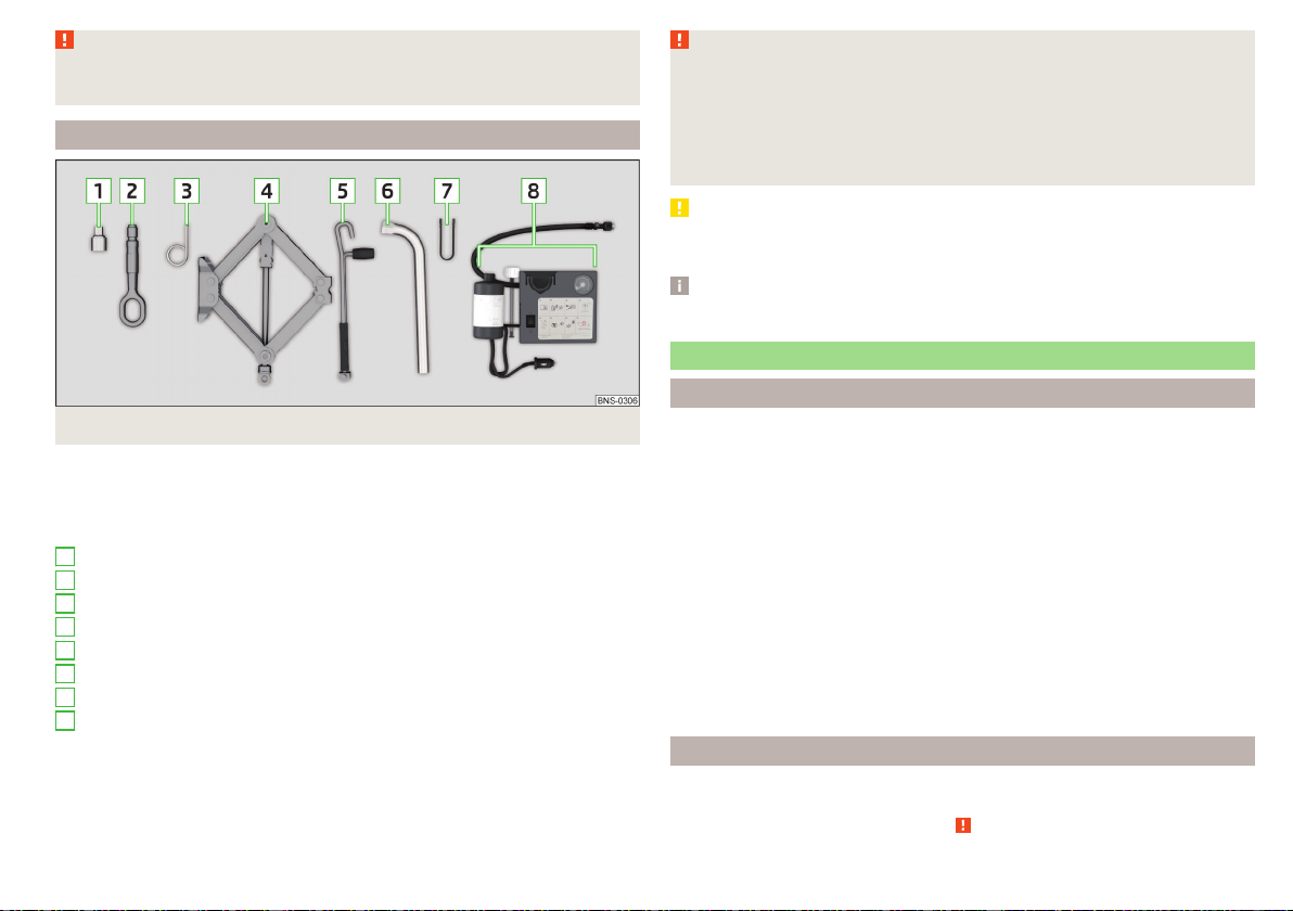
WARNING
Always properly secure the fire extinguisher, there is a risk of injury in the
event of sudden braking or a vehicle collision.
Vehicle tool kit
Fig. 308
Vehicle tool kit
The box with the vehicle tool kit is in the emergency or spare wheel area. The
vehicle tool kit may stored in a bag in the luggage compartment.
Depending on the vehicle configuration, it may not contain all the compo-
nents listed in the on-board tool kit.
Adapter for anti-theft wheel bolts
Towing eye
Clamps for removing the wheel trims
Jack with sign
Crank for the jack
Wheel wrench
Extraction pliers for the wheel bolt caps
Breakdown kit
1
2
3
4
5
6
7
8
WARNING
■
The factory-supplied lifting jack is only intended for your model of vehi-
cle. Under no circumstances attempt to lift other vehicles or loads with this
– there is a risk of injury.
■
Always place the tool securely into the recesses in the storage compart-
ment in the emergency or spare wheel area, or in the pocket. This is stored
in the luggage compartment.
CAUTION
Screw the jack into its starting position prior to putting it back in its box -Oth-
erwise, there is a risk of damage to the box.
Note
The declaration of conformity is included with the jack or the log folder.
Changing a wheel
Preliminary work
For safety's sake, the following instructions must be observed before
changing a wheel on the road.
›
As far as possible, park the vehicle far away from the traffic flow - find a
place with a flat and firm surface.
›
Switch off the engine.
›
For vehicles with manual transmission, select 1st gear.
›
For vehicles with automatic transmission, place the selector lever in the P
position.
›
Switch on the parking brake.
›
Position the hazard warning system and the warning triangle at the prescri-
bed distance.
›
All the occupants should get out of the vehicle. The passengers should not
stand on the road (instead they should remain behind a crash barrier, for in-
stance) while the wheel is being changed.
›
Uncouple any trailers.
Changing a wheel
›
Take out the emergency or spare wheel » page 274.
›
Remove the full wheel trim » page 275 or caps » page 275.
›
Loosen the wheel bolts » page 276 » .
273
Emergency equipment and self-help

›
Jack up the vehicle» page 276 until the wheel that needs changing is clear of
the ground.
›
Unscrew the wheel bolts and place them on a clean surface (cloth, paper,
etc.).
›
Remove the wheel carefully.
›
Attach the spare wheel and slightly screw on the wheel bolts.
›
Lower the vehicle.
›
Tighten the wheel bolts opposite each other using the wheel wrench (“alter-
nating crosswise”)» page 276.
›
Replace the wheel trim » page 275and the caps » page 275.
When fitting a wheel with unidirectional tyres, ensure that the direction of ro-
tation is correct » page 268.
All bolts must be clean and must turn easily. If the screws are corroded and
difficult to move, then these must be replaced.
WARNING
■
Undo the wheel bolts just a little (about one turn) while the vehicle is not
jacked up. Otherwise, the wheel could come off and fall down – there is a
risk of injury.
■
Under no circumstances grease or oil the wheel bolts - risk of accident!
Subsequent steps
After changing the wheel, the following work must be carried out.
›
Place the replaced wheel in the trough under the flooring of the luggage
compartment and secure with a locking screw (insert the support base for
the luggage floor back into the screw).
›
Stow the vehicle tool kit in the space provided.
›
Check and, if necessary, adjust the tyre pressure on the assembled wheel,
and, for vehicle with tyre pressure monitoring, save the tyre pressure values
in the system » page 245.
›
Have the tightening torque of the wheel bolts checked with a torque wrench
as soon as possible. The prescribed tightening torque is 140 Nm.
Replace the damaged tyre. It is not recommended to repair the tyre.
WARNING
A tightening torque which is too high can damage the bolts and threads
and this can result in permanent deformation of the contact surfaces on
the rim. Too low tightening torque, the wheels may fall off while driving -
risk of an accident. Therefore, drive cautiously and only at a moderate
speed until the tightening torque has been checked.
Removing/stowing the emergency or spare wheel
Fig. 309
Take out the wheel
The spare wheel is located in a well under the floor covering in the luggage
compartment and is fixed in place with a fastening screw » Fig. 309.
Take out the wheel
›
Lift up the floor in the luggage compartment.
›
Remove the support base for the luggage floor in the direction of the arrow
1
and the locking screw in the direction of the arrow
2
» Fig. 309.
Store wheel away
›
Place the wheel into the wheel well with the wheel rim pointing downward.
›
Tighten the locking screw in the opposite direction of arrow
2
until it stops
» Fig. 309.
›
Re-insert the support base in the luggage floor in the opposite direction to
arrow
1
.
›
Fold back the floor in the luggage compartment.
274
Do-it-yourself
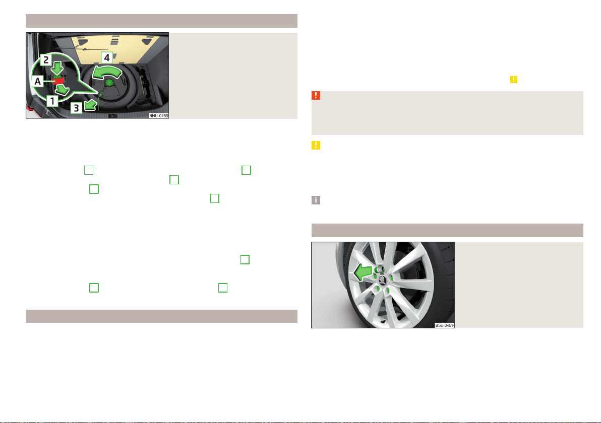
Removing/stowing wheel in vehicles with sound system
Fig. 310
Take out the wheel
The spare wheel is located in a well under the floor covering in the luggage
compartment and is fixed in place with a fastening screw.
Take out the wheel
›
Lift up the floor in the luggage compartment.
›
Press the latch
A
on the holder in the direction of the arrow
1
» Fig. 310.
›
Press the latch in the direction of arrow
2
and pull out the holder in the di-
rection of arrow
3
.
›
Remove the locking screw in the direction of arrow
4
.
›
Remove the bass loudspeaker.
›
Remove the wheel.
Store wheel away
›
Place the wheel into the wheel well with the wheel rim pointing downward.
›
Insert the bass loudspeaker.
›
Tighten the locking screw in the opposite direction of arrow
4
until it stops
» Fig. 310.
›
Insert the connector in the bass loudspeaker.
›
Secure the latch
A
in the opposite direction to arrow
1
.
›
Fold back the floor in the luggage compartment.
Full wheel trim
Removing the trim
›
Hang the clamps for removing the full wheel trims at the edge of one of the
ventilation openings in the full wheel trim.
›
Push the wheel wrench through the clamp, support on the tyre and pull off
the wheel trim.
Installing the trim
›
Press the wheel trim onto the wheel rim at the designated valve opening.
›
Then press the trim into the wheel rim until its entire circumference locks
correctly in place.
The back of the wheel trim supplied by the factory or from the ŠKODA Origi-
nal Accessories shows the position for the anti-theft wheel bolt. When using
the anti-theft wheel bolt, this is to be fitted in this point » .
WARNING
We recommend that you use hub caps from ŠKODA Original Accessories.
A sufficient air supply may not be able to be guaranteed with other wheel
trims to cool the braking system – Otherwise there is a risk of an accident.
CAUTION
■
If the wheel trim is set outside the position marked for the anti-theft wheel
bolt, there is a risk of damaging the wheel trim.
■
Use only manual pressure and do not hit the full wheel trim – otherwise there
is a risk of damaging the trim.
Note
We recommend that you use hub caps from ŠKODA Original Accessories.
Wheel bolts
Fig. 311
Remove the cap
›
To remove the cap, insert the extraction pliers up to the stop on the cap and
pull this in the direction of the arrow » Fig. 311.
›
To install, insert the cap up to the stop on the wheel bolt.
275
Emergency equipment and self-help
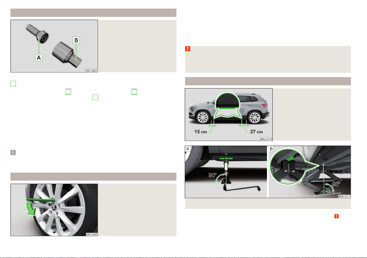
Anti-theft wheel bolts
Fig. 312
Anti-theft wheel bolt and upper
section
The anti-theft wheel bolts protect the wheels from theft. The upper section
B
» Fig. 312 must be used to loosen/tighten these.
›
Insert the upper section
B
on the anti-theft wheel bolt
A
until it stops.
›
Insert the wrench on the attachment
B
until it stops and loose/tighten the
wheel bolt.
›
Removing the upper section.
The attachment for the anti-theft wheel bolts must always be kept in the
vehicle in case of a possible wheel change!
For wheel trims supplied ex-factory or from ŠKODA Original Accessories, the
anti-theft wheel bolt should be installed in the position marked on the back of
the wheel trim.
Note
We recommend that you retain the label with the code number. A replace-
ment upper section can be acquired from ŠKODA original parts based on this.
Loosening/tightening wheel bolts
Fig. 313
Loosening the wheel bolts
›
Push the wheel wrench onto the wheel bolt to the stop. Use the associated
upper section for the anti-theft wheel bolts » Fig. 312 on page 276.
›
To loosen the screws, hold the wrench end and turn the screw about one
turn in the direction of arrow » Fig. 313.
›
To tighten the screws, hold the wrench end and turn the screw against the
direction of the arrow » Fig. 313, until it is tight.
WARNING
If it proves difficult to undo the bolts, carefully apply pressure to the end of
the wrench with your foot. Keep hold of the vehicle when doing so, and
make sure you keep your footing - risk of accident.
Raising the vehicle
Fig. 314
Jacking points for the jack
Fig. 315 Attach lifting jack
Before the vehicle is raised, the safety instructions must be observed » .
Use the jack from the tool kit to raise the vehicle. Position the jack at the jack-
ing point closest to the flat tyre.
276
Do-it-yourself
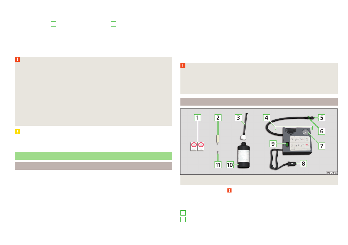
Jacking points for the car jack are directly under the marking on the bottom
beam panel» Fig. 315 - ,
›
Insert the crank
5
into the mount on the jack
4
» page 273.
›
Support the base plate of the jack with its full area resting on level ground
and ensure that the jack is located in a vertical position at the jacking point
» Fig. 315 - .
›
Use the crank to raise the jack until its claw encloses the bar » Fig. 315 - .
›
Continue to lift the vehicle until the wheel is just off the floor.
WARNING
Observe the following instructions, otherwise there is risk of injury.
■
Secure the vehicle from unexpectedly rolling away.
■
Always ensure the base plate of the lifting jack cannot slip.
■
Provide a wide and stable base under the jack on loose surfaces (e.g.
such as gravel).
■
Create a non-slip base (e.g. a rubber floor mat) under the jack on a
smooth surface (e.g. cobblestones).
■
Always raise the vehicle with the doors closed.
■
Never position any body parts, such as arms or legs, under the vehicle,
while the vehicle is raised with a lifting jack.
■
When the vehicle is raised, never start the engine.
CAUTION
It is important to ensure that the jack is correctly attached to the bar of the
lower beam – otherwise there is a risk of damage to the vehicle.
Puncture repair kit
Introduction
The following information applies to the factory-fitted puncture repair kit.
Use the puncture repair kit to seal tyre punctures with a diameter of up to
about 4 mm.
Performing a repair with the breakdown kit not at all intended to replace a
permanent repair on the tyre. Its purpose is to get you to the nearest specialist
garage.
Immediately replace the tyre that was repaired using the puncture repair kit, or
consult a specialist garage about repair options.
Do not remove foreign bodies which have penetrated into the tyre (e.g. nails
etc.).
Do not use the puncture repair kit in the following instances.
▶
The rim is damaged.
▶
The outdoor temperature is below the minimum temperature indicated in
the instruction manual of the tyre filling bottle with sealant.
▶
Tyre punctures of more than 4 mm.
▶
There is damage to the tyre wall.
▶
The expiration date (see inflation bottle) has passed.
WARNING
■
If the sealant comes into contact with skin, wash the affected area imme-
diately.
■
Observe the instructions provided in the puncture repair kit manufactur-
er's instructions for use.
Description of puncture repair kit
Fig. 316
Description of puncture repair kit
Read and observe on page 277 first.
The kit is located in a box under the floor covering in the luggage compart-
ment.
Sticker with speed designation “max. 80 km/h”/“max. 50 mph”
Valve remover
1
2
277
Emergency equipment and self-help
Inflation hose with plug
Air compressor (the layout of the controls may be different depending on
the type of air compressor delivered with the vehicle)
Tyre inflation hose
Button for the tyre pressure reduction
Tyre inflation pressure indicator
12 volt cable connector
ON and OFF switch
Tyre inflation bottle with sealing agent
Replacement valve core
Note
The declaration of conformity is included with the air compressor or the log
folder.
Preparing to use the puncture repair kit
Read and observe on page 277 first.
For safety's sake, the following instructions must be observed before
performing a wheel repair the road.
›
As far as possible, park the vehicle far away from the traffic flow - find a
place with a flat and firm surface.
›
Switch off the engine.
›
For vehicles with manual transmission, select 1st gear.
›
For vehicles with automatic transmission, place the selector lever in the P
position.
›
Switch on the parking brake.
›
Position the hazard warning system and the warning triangle at the prescri-
bed distance.
›
All the occupants should get out of the vehicle. The passengers should not
stand on the road (instead they should remain behind a crash barrier, for in-
stance) while the wheel is being repaired.
›
Uncouple any trailers.
3
4
5
6
7
8
9
10
11
Sealing and inflating tyres
Read and observe on page 277 first.
Sealing
›
Unscrew the valve cap from the damaged tyre.
›
Insert the valve remover
2
» Fig. 316 on page 277 on the valve insert, so that
the valve insert fits into the slot of the valve remover.
›
Unscrew the valve insert and lay it on a clean surface (e.g. cloth, paper etc.).
›
Forcefully shake bottle
10
several times.
›
Firmly screw the inflation hose
3
onto the tyre inflater bottle
10
. The film
on the cap is pierced automatically.
›
Remove the plug from the inflation hose
3
and plug the open end fully onto
the tyre valve.
›
Hold the bottle
10
with the bottom facing upwards and fill all of the sealing
agent from the tyre inflator bottle into the tyre.
›
Remove the filler plug from the tyre valve.
›
Screw in the valve insert using the valve remover
2
.
Inflating
›
Screw the air compressor tyre inflation hose
5
» Fig. 316 on page 277 firmly
onto the tyre valve.
›
For vehicles with manual transmission, set the lever in the neutral position.
›
On vehicles with automatic transmission, place the selector lever in the P
position.
›
Start the engine.
›
Plug the connector
8
into 12 volt socket » page 99.
›
Switch on the air compressor with the ON and OFF switch
9
.
›
Once a tyre inflation pressure of 2.0-2.5 bar is reached, turn off the air com-
pressor. Observe the maximum running time of the air compressor according
to the instructions of the repair kit manufacturer » .
›
If you cannot reach an air pressure of 2.0 - 2.5 bar, unscrew the tyre inflation
hose
5
from the tyre valve.
›
Drive the vehicle approx. 10 metres forwards or backwards to allow the seal-
ing agent to “distribute” in the tyre.
›
Firmly screw the tyre inflation hose
5
back onto the tyre valve and repeat
the inflation process.
›
Stick the corresponding sticker
1
on the dashboard in the driver's field of
view.
278
Do-it-yourself

Once a tyre inflation pressure of 2.0 – 2.5 bar is achieved, continue the journey
at a maximum speed of 80 km/h (50 mph).
WARNING
■
If the tyre does not inflate to at least 2.0 bar, the damage is too great. The
sealing agent cannot be used to seal the tyre. Do not drive the vehicle.
Seek help from a specialist garage.
■
The tyre inflation hose and air compressor may get hot as the tyre is be-
ing inflated – risk of burning.
CAUTION
Switch off the air compressor at the latest after the running time according to
the instructions of the repair kit manufacturer has elapsed – otherwise there is
the risk of compressor damage! Allow the air compressor to cool a few mi-
nutes before switching it on again.
Information for driving with repaired tyres
Read and observe on page 277 first.
The inflation pressure of the repaired tyre must be checked after driving for 10
minutes.
If the tyre inflation pressure is 1.3 bar or less
›
The tyre cannot be properly sealed with the breakdown kit.
Do not drive
the vehicle! Seek help from a specialist garage.
If the tyre inflation pressure is 1.3 bar or more
›
Set the tyre pressure back to the correct value » page 268.
›
Continue driving carefully to the nearest specialist garage at a maximum
speed of 80 km/h (50 mph).
WARNING
A tyre filled with sealant has the same driving characteristics as a standard
tyre. The following guidelines must be observed.
■
Do not drive faster than 80 km/h (50 mph).
■
Avoid accelerating at full throttle, sharp braking and fast cornering.
Jump-starting
Introduction
WARNING
■
The following instructions must be followed at all times when working on
the engine compartment » page 260.
■
When handling the vehicle battery, the following warnings must be ob-
served » page 265.
■
A discharged vehicle battery may already freeze at temperatures just be-
low 0 °C. If the battery is frozen, do not carry out a jump start with the bat-
tery of another vehicle – risk of explosion!
■
Never jump-start vehicle batteries with an acid level that is too low – risk
of explosion and caustic burns!
Jump-starting using the battery from another vehicle
Fig. 317 Jump-starting: - Discharged battery, - power-supplying
battery/ground point of the engine for the START-STOP system
Read and observe on page 279 first.
If it is not possible to start the engine due to a discharged vehicle battery, the
battery of another vehicle can be used to start the engine. Only use jump-start
cables which have an adequately large cross-section and insulated terminal
clamps.
The rated voltage of the two batteries must be 12V. The capacity (Ah) of the
current-giving battery must not be significantly less than the capacity of the
discharged battery in your vehicle.
279
Emergency equipment and self-help
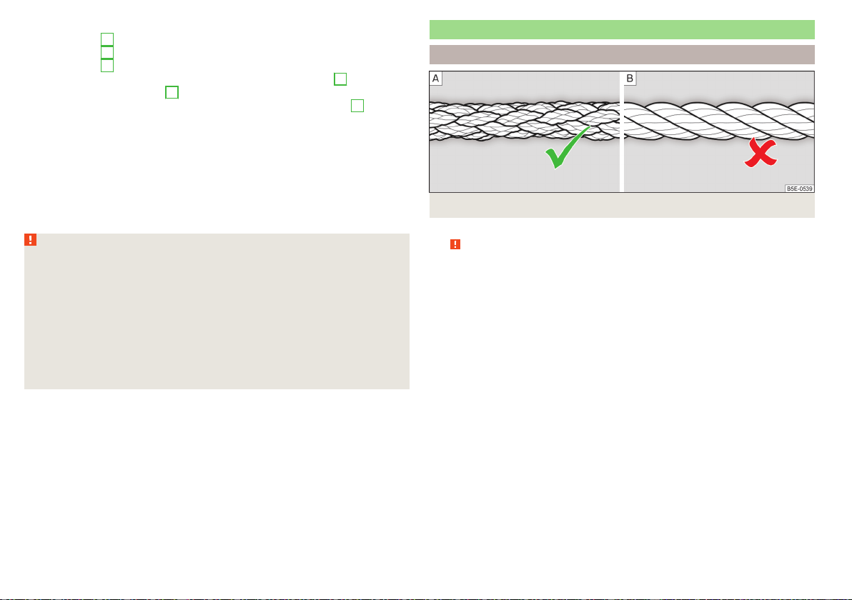
The jump-start cables must be attached in the following sequence.
›
Attach clamp
1
to the positive terminal of the discharged battery.
›
Attach clamp
2
to the positive terminal of the current-giving battery.
›
Attach clamp
3
to the negative terminal of the current-giving battery.
›
For vehicles with the START-STOP system, secure the clamp
4
to the
ground point of the engine
A
» Fig. 317.
›
For vehicles without the START-STOP system, secure the clamp
4
to a sol-
id metal part that is firmly attached to the engine block or secure to the en-
gine block directly.
Starting engine
›
Start the engine on the vehicle providing the power and allow it to idle.
›
Start the engine in the vehicle with the discharged battery.
›
If the engine does not start within 10 s, then cancel the starting procedure
and repeat after half a minute.
›
Remove the jump start cables in the reverse order as attachment.
WARNING
■
Never clamp the jump-start cable to the negative terminal of the dis-
charged battery - danger of explosion.
■
The non-insulated parts of the terminal clamps must never touch each
other – risk of short circuit!
■
The jump-start cable connected to the positive terminal of the battery
must not come into contact with electrically conducting parts of the vehi-
cle – risk of short circuit!
■
Route the jumper cables so that they cannot be caught in rotating parts in
the engine compartment - danger of injuries and the risk of vehicle dam-
age.
Towing the vehicle
Information about the towing process
Fig. 318 Braided tow rope / Spiral tow rope
For towing using a tow rope, use only a braided synthetic fibre rope » Fig. 318 -
» .
Attach the tow rope or the tow bar to thetowing eyes at the front
» page 281, towing eyes at the rear» page 281or to thetowing device of the
trailer device » page 247.
Conditions for towing.
Cars with automatic gearboxes must not be towed with the rear
wheels raised - there is a risk of gearbox damage!
If the gearbox has no oil, your vehicle must be towed with the front axle
raised clear of the ground or on a breakdown vehicle or trailer.
The maximum towing speed is 50 km/h.
The vehicle must be transported on a special breakdown vehicle or trailer
if it is not possible to tow in the vehicle in the way described or if the tow-
ing distance is greater than 50 km.
Driver of the tow vehicle
›
On vehicles with manual transmission, engage gear slowly when starting.
›
On vehicles with automatic transmission, accelerate with particular care.
›
Only then approach correctly when the rope is taut.
280
Do-it-yourself
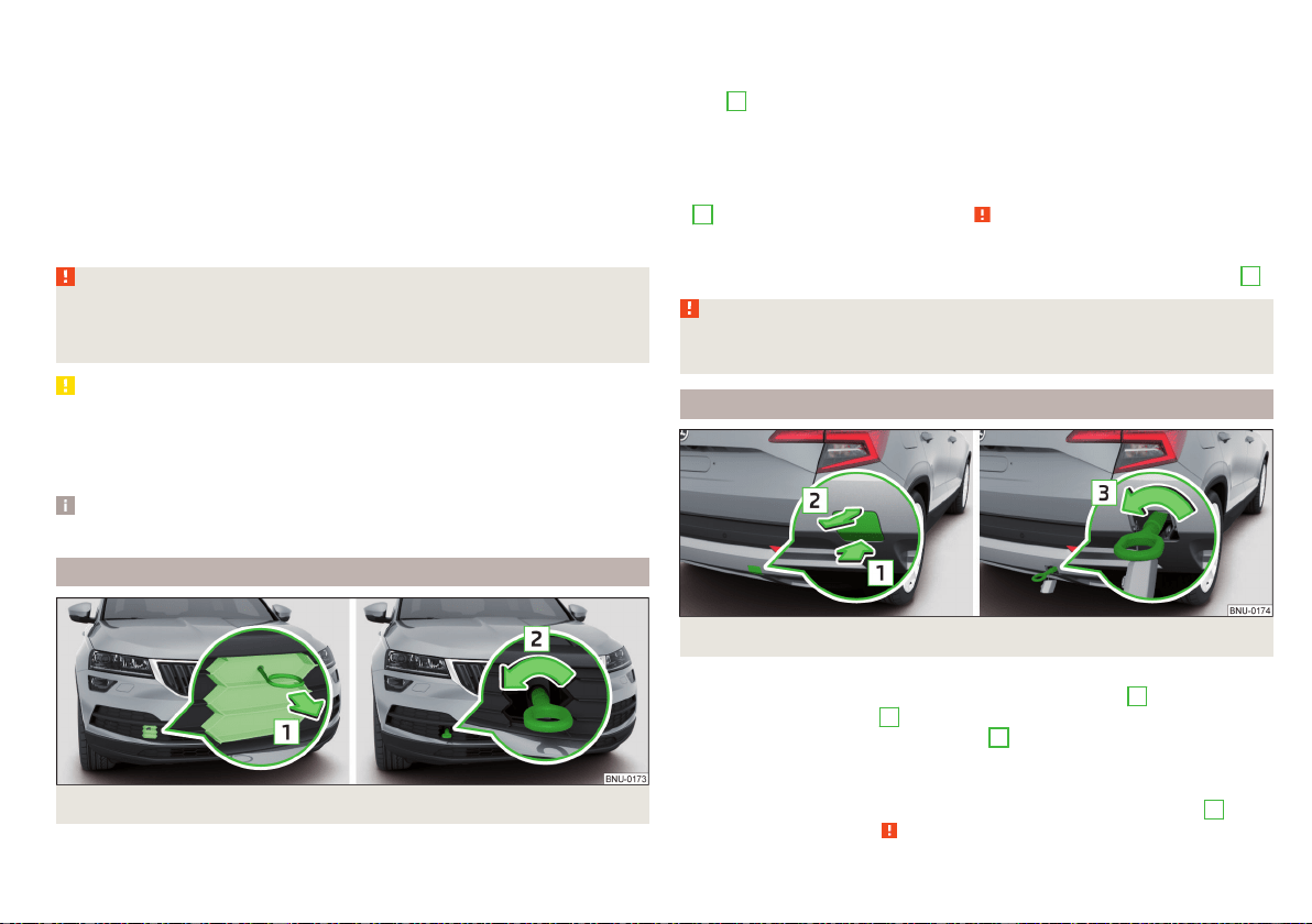
Driver of the towed vehicle
›
If possible, the vehicle should be towed with the engine running. Operate the
brake booster and power steering only if the engine is running, otherwise the
brake pedal must be depressed more strongly and more power has to be di-
rected to the steering.
›
If it is not possible to start the engine, switch on the ignition so that the
steering wheel is not locked and so that the turn signal lights, windscreen
wipers and windscreen washer system can be used.
›
Take the vehicle out of gear or move the selector lever into position N if the
vehicle is fitted with an automatic gearbox.
›
Always keep the tow rope taut during the towing procedure.
WARNING
■
Wound tow ropes must not be used for towing » Fig. 318- , the towing
eye may unscrew out of the vehicle - risk of accident.
■
Ensure tow rope is not twisted - risk of accident.
CAUTION
■
Do not tow-start the engine – risk of damaging the engine! The battery from
another vehicle can be used as a jump-start aid » page 279, Jump-starting.
■
In the case of off-road towing manoeuvres, for both vehicles there is the risk
that the fastening parts could be overloaded and damaged.
Note
We recommend that you use the tow rope from ŠKODA Original Accessories.
Front towing eye
Fig. 319 Remove protective grille / install towing eye
Removing/inserting protective grille
›
To remove, insert the clamp for taking off the full wheel trims in the recess
in the protective grille and remove the protective grille in the direction of ar-
row
1
» Fig. 319.
›
To insert, insert the protective grille in the opening and push in gently. The
protective grille must engage firmly.
Removing/installing the towing eye
›
To fit, screw in the towing eye by hand in the direction of the arrow
2
» Fig. 319 until it clicks into place » .
›
Tighten the towing eye using a wheel wrench or similar object. To do this,
insert the wheel wrench through the eye.
›
To remove it, unscrew the towing eye in the opposite direction to arrow
2
.
WARNING
The towing eye must always be tightened, otherwise the towing eye may
break during the towing.
Towing eye rear
Fig. 320 Remove cap / install towing eye
Remove/insert cap
›
To remove, press on the cap in the direction of the arrow
1
and remove this
in the direction of arrow
2
» Fig. 320.
›
To insert, insert the cap in arrow range
1
and then press on the opposite
edge of the cap. The cap must engage firmly.
Removing/installing the towing eye
›
To install, screw in the towing eye by hand in the direction of arrow
3
» Fig. 320 until the stop» .
281
Emergency equipment and self-help
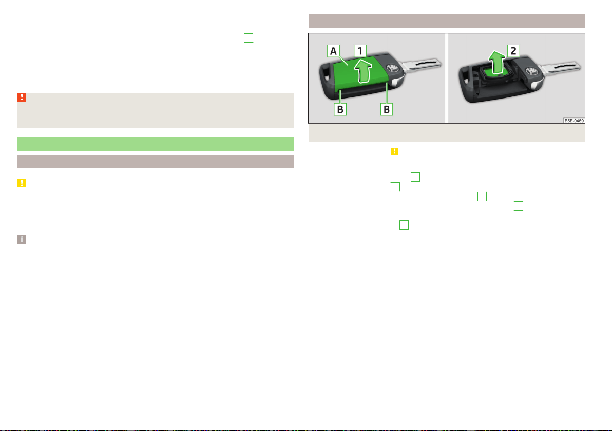
›
Tighten the towing eye using a wheel wrench or similar object. To do this,
insert the wheel wrench through the eye.
›
To remove, unscrew the towing against the direction of arrow
3
.
Vehicles with a tow hitch
For vehicles with factory-fitted towing device, at the back there is no mount
for a screw-in towing eye. Use the detachable ball rod for towing » page 247,
Hitch.
WARNING
The towing eye must always be tightened, otherwise the towing eye may
break during the towing.
Remote control and removable light - changing the battery
Introduction
CAUTION
■
The replacement battery/batteries must comply with the original specifica-
tion.
■
Pay attention to the correct polarity when changing the rechargeable batter-
ies.
Note
■
We recommend having the faulty battery/batteries replaced by a specialist
garage.
■
If a key has an affixed decorative cover, this will be destroyed when the bat-
tery is replaced. A replacement cover can be purchased from a ŠKODA Part-
ner.
Key with fold-out key bit
Fig. 321 Open the cover/remove the battery
Read and observe
on page 282 first.
›
Fold out the key bit.
›
Press off the battery cover
A
» Fig. 321 with your thumb or by using a flat
screwdriver in region
B
.
›
Open the battery in the direction of the arrow
1
.
›
Remove the discharged battery in the direction of arrow
2
and install a new
battery.
›
Insert the battery cover
A
and press it down until it clicks audibly into place.
The key has to be synchronised if the vehicle cannot be unlocked or locked
with the key after replacing the battery » page 60.
282
Do-it-yourself
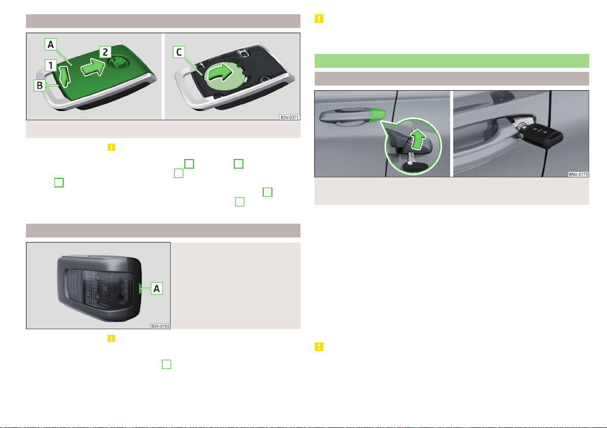
Remote control of the auxiliary heating
Fig. 322 Open the cover/remove the battery
Read and observe on page 282 first.
›
Use a thin screwdriver to remove the cover
A
in the area
B
» Fig. 322.
›
Open the cover in the direction of arrow
1
and push out in the direction of
arrow
2
.
›
Use the screwdriver to remove and replace the battery in the area
C
.
›
Insert the battery cover in the opposite direction to arrow
2
until it audibly
clicks into place.
Removable light
Fig. 323
Locking clip on the battery cov-
er
Read and observe on page 282 first.
›
Lever off the cover for the rechargeable batteries with a narrow and pointed
object from the area of the lock clips
A
» Fig. 323.
›
Replace the batteries.
›
Insert the cover for the rechargeable batteries and press it down until it
clicks into place.
CAUTION
If an incorrect battery type is used or a non-rechargeable battery, there is a
risk of damaging the light and the vehicle's electrical system.
Emergency unlocking / locking of doors
Unlocking/locking the driver's door
Fig. 324
Handle on the driver's door: Open lock cover / lock cylinder
with key
The driver's door can be emergency unlocked / emergency locked using the
key via the lock cylinder.
›
Pull on the door handle and hold.
›
Insert the key into the recess on the lower side of the cover and fold up the
cover in the direction of arrow » Fig. 324.
›
Release the door handle.
›
For vehicles withLHD,insert the key with the fold-out key bit with the but-
tons facing upwards » Fig. 324 into the lock cylinder and unlock/lock the ve-
hicle.
›
For vehicles with RHD, insert the key with the fold-out key bit with the but-
tons facing downwards into the lock and unlock/lock the vehicle.
›
Pull on the door handle and hold.
›
Replace the cover.
CAUTION
Make sure you do not damage the paint when performing an emergency lock-
ing/unlocking.
283
Emergency equipment and self-help
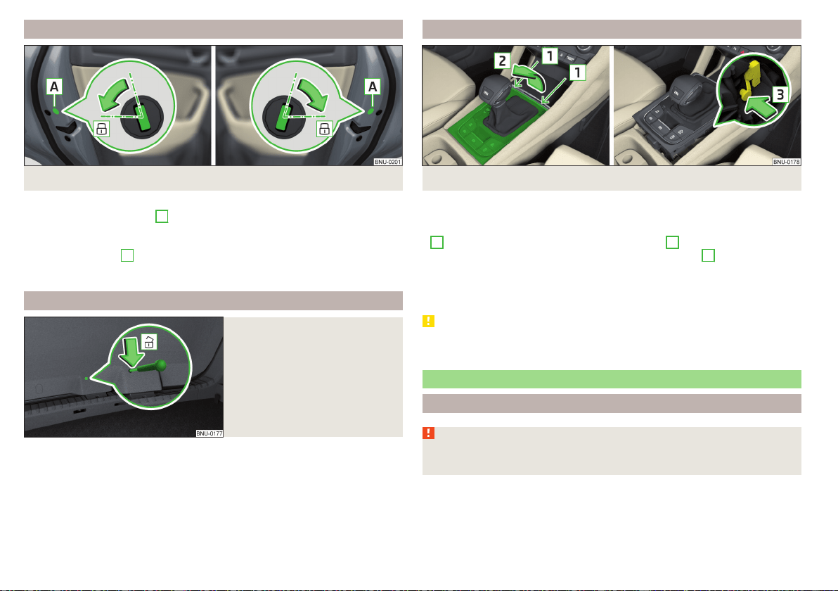
Locking the door without locking cylinders
Fig. 325 Left door/right door
›
Open the respective door.
›
In vehicles with the panel
A
, remove this panel » Fig. 325.
›
Insert the key into the slot and turn in the direction of the arrow (sprung po-
sition).
›
Replace the cover
A
.
After closing, the door is locked.
Unlock the boot lid
Fig. 326
Unlocking the door
The boot lid can be unlocked manually from inside.
›
Insert a screwdriver or similar tool into the opening in the trim » Fig. 326 as
far as the latch.
›
Unlock the lid by moving it in the direction of the arrow.
Selector lever emergency release
Fig. 327 Remove / release the selector lever
›
Switch on the parking brake.
›
Open the stowage compartment in the front centre console.
›
Insert a slotted screwdriver or similar tool into the gap in the area of arrow
1
» Fig. 327 and lift the cover in arrow direction
2
.
›
Press on the yellow plastic part in the direction of arrow
3
, simultaneously
press the lock button in the selector lever handle and put the lever in position
N.
If the selector lever is moved again to position P, it is once again blocked.
CAUTION
Make sure when lifting not to damage cover parts by the screwdriver in the
shift lever environment.
Replacing windscreen wiper blades
Introduction
WARNING
Replace the windscreen wiper blades once or twice a year for safety rea-
sons.
284
Do-it-yourself
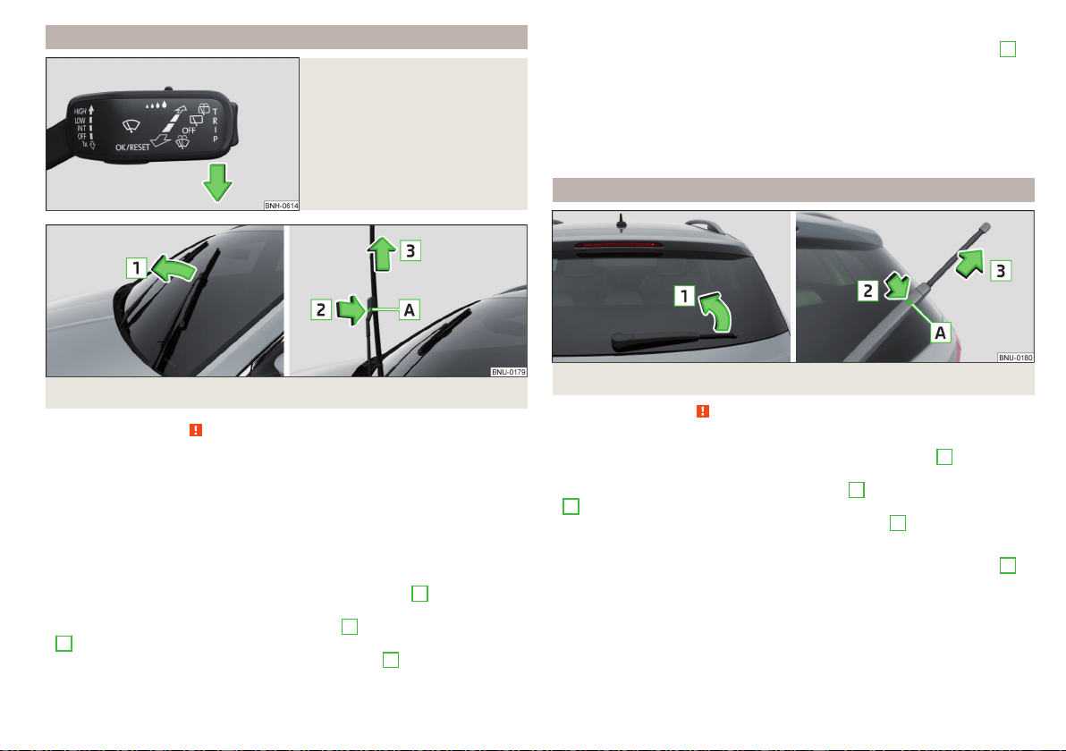
Replacing the windscreen wiper blades
Fig. 328
Setting the service position for
the wiper arms
Fig. 329
Replace windscreen wiper blade
Read and observe on page 284 first.
Before replacing the windscreen wiper blade, put the windscreen wiper arms
into the service position.
Setting the service position
›
Switch the ignition on and off again.
›
Within 10 seconds, push the lever in the direction of arrow » Fig. 328 and
hold for approximately 2 seconds.
Removing the wiper blade
›
Lift the wiper arm from the windscreen in the direction of
1
» Fig. 329.
›
Tilt the wiper blade to the stop in the same direction.
›
Hold the wiper arm and press the safety catch
A
in the direction of arrow
2
.
›
Remove the wiper blade in the direction of the arrow
3
.
Attaching the windscreen wiper blade
›
Push the windscreen wiper blade in the opposite direction of the arrow
3
until it locks into place. Check that the windscreen wiper blade is correctly
attached.
›
Fold the windscreen wiper arm back to the windscreen.
›
Turn on the ignition and press the lever into the direction of the arrow
» Fig. 328.
Move the windscreen wiper arms into the home position.
Replacing the rear window wiper blade
Fig. 330
Replace the rear window wiper blade
Read and observe on page 284 first.
Removing the wiper blade
›
Lift the wiper arm from the window in the direction of arrow
1
» Fig. 330.
›
Tilt the wiper blade to the stop in the same direction.
›
Hold the wiper arm and press the safety catch
A
in the direction of arrow
2
.
›
Remove the wiper blade in the direction of the arrow
3
.
Attaching the windscreen wiper blade
›
Push the windscreen wiper blade in the opposite direction of the arrow
3
until it locks into place. Check that the windscreen wiper blade is correctly
attached.
›
Fold the windscreen wiper arm back to the windscreen.
285
Emergency equipment and self-help
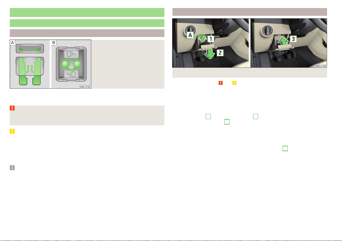
Fuses and light bulbs
Fuses
Introduction
Fig. 331
Blown fuse
Individual electrical circuits are protected by fuses. A blown fuse is recognisa-
ble by the molten metal strip » Fig. 331
/
.
WARNING
Always read and observe the warnings before completing any work in the
engine compartment » page 260.
CAUTION
■
Replace the faulty fuse with a new one of the same amperage.
■
If a newly inserted fuse blows after a short time, then seek the assistance of
a specialist garage.
■
Do “not repair” the fuses and do not replace them with stronger ones - it can
cause a fire and could damage parts of the electrical system.
Note
■
We recommend always carrying replacement fuses in the vehicle.
■
There can be several power consuming devices for one fuse. Multiple fuses
may exist for a single power consuming device.
Fuses in the dashboard - LHD
Fig. 332 Storage compartment on the driver's side
Read and observe and on page 286 first.
The fuse box is located behind the storage compartment on the driver's side.
Changing a fuse
›
Remove the ignition key, turn off the lights and all electrical consumers.
›
Open the storage box on the driver's side.
›
Press the latch
A
in direction of arrow
1
» Fig. 332 open the compartment
in the direction of arrow
2
.
›
Remove the plastic clip under the cover of the fuse box in the engine com-
partment » Fig. 335 on page 289.
›
Use the clip to pull out the faulty fuse and then insert a new fuse.
›
Stow the clip back in the original position.
›
Close the compartment by pressing in arrow direction
3
until you hear it
click.
286
Do-it-yourself
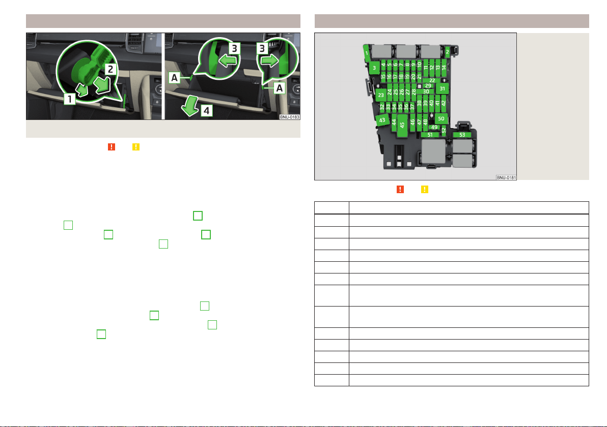
Fuses in the dashboard - RHD
Fig. 333 Storage compartment on the front passenger side
Read and observe and on page 286 first.
The fuse box is located behind the storage compartment on the front passen-
ger side.
Fold down the storage compartment and replace the fuse
›
Remove the ignition key, turn off the lights and all electrical consumers.
›
Open the storage compartment on the front passenger side.
›
Unlock the brake rod in the direction of arrow
1
and remove in the direction
of arrow
2
» Fig. 333.
›
Unlock the stop pad
A
in the direction of arrow
3
and the compartment
folds down in the direction of arrow
4
.
›
Remove the plastic clip under the cover of the fuse box in the engine com-
partment » Fig. 335 on page 289.
›
Use the clip to pull out the faulty fuse and then insert a new fuse.
›
Stow the clip back in the original position.
Fold back the storage compartment
›
Raise the tray in the opposite direction of arrow
4
.
›
Overcome resistance of stop pad
A
.
›
Insert the brake rod against the direction of arrow
2
and lock against the
direction of arrow
1
.
›
The compartment closes (increased force is required to close it) until it clicks
into place.
Fuse assignment in the dashboard
Fig. 334
Fuses
Read and observe and on page 286 first.
No. Consumer
1 SCR (AdBlue
®
)
2 Heated steering wheel
3 Not assigned
4 Not assigned
5 Databus
6 Sensor Alarm
7
Air conditioning, receiver for the remote control for the auxiliary
heating, heated rear window, automatic gearbox
8
Light switch, rain sensor, parking brake, background lighting, front
headlights
9 Operating lever underneath the steering wheel
10 Infotainment screen
11 Light - left
12 Infotainment
13 Left side belt tensioner
287
Fuses and light bulbs

No. Consumer
14 Air blower for air conditioning,heating
15 Electric steering lock
16 USB ports, diagnostics connector, Phonebox
17 Instrument cluster, emergency call
18 Reversing camera
19 KESSY system
20 SCR (AdBlue
®
)
21 All-wheel drive
22 Towing hitch
23 Panoramic slide / tilt sunroof
24 Light - right
25
Central locking- front and rear door left, power window - left, exte-
rior mirrors left - heating, fold-in function, setting the mirror sur-
face
26 Heated front seats
27 Interior lighting
28 Towing hitch
29 Not assigned
30 Not assigned
31 Not assigned
32 Parking aid (Park Assist)
33 airbag
34
Air conditioning, reversing light switch, mirror with automatic dim-
ming, seat heating, parking brake, light switches, bar with buttons,
USB ports
35
Diagnostics connector, front camera, distance monitoring system
(e.g. ACC, Front Assist)
36 AFS headlights - right
37 AFS headlights - left
38 Towing hitch
No. Consumer
39
Central locking- front and rear door right, power window - right,
exterior mirrors right - heating, fold-in function, setting the mirror
surface
40 12-volt power outlets
41 Right side belt tensioner
42
Luggage compartment lock, rear door lock, tank flap lock, headlight
cleaning system, front and rear windscreen washer system
43 Music amplifier
44 Towing hitch
45 Electrical operation of driver's seat
46 230-Volt power socket
47 Rear window wiper
48 “Blind spot” detection
49 Engine starting, clutch pedal switch
50 Opening the boot lid
51 Heating of the rear seats
52 Not assigned
53 Heated rear window
288
Do-it-yourself

Fuses in the engine compartment
Fig. 335 Fuse box cover: Removing cover / plastic clip for fuses
Read and observe and on page 286 first.
Changing a fuse
›
Remove the ignition key, turn off the lights and all electrical consumers.
›
Simultaneously press the lock buttons of the cover together in the direction
of arrow
1
and remove the cover in the direction of arrow
2
» Fig. 335.
›
Remove the plastic clip under the cover of the fuse box » Fig. 335.
›
Use the clip to pull the fuse out, then insert a new fuse.
›
Replace the clamp in the original position.
›
Replace the cover, push the lock buttons of the cover together and lock.
CAUTION
The cover of the fuse box in the engine compartment must always be used
correctly, otherwise water may penetrate into the fuse box – there is a danger
of damage to the vehicle!
Fuse assignment in engine compartment
Fig. 336
Fuses
Read and observe and on page 286 first.
No. Consumer
1 ESC, parking brake
2 ESC
3 Engine control system
4
Radiator fan, oil level and oil temperature sensor, additional electric
heating system, SCR (AdBlue
®
), engine components
5 Engine components
6 Brake sensor
7 Coolant pump, exhaust flap, engine components
8 Lambda sensor, NOx sensor
9 Preheating system, air mass meter, Motor components
10 Fuel pump
11 Electrical auxiliary heating system
12 Electrical auxiliary heating system
13 Automatic gearbox
14 Heated windscreen
15 Horn
16 Not assigned
17 ESC, engine control unit, main relay coil
289
Fuses and light bulbs
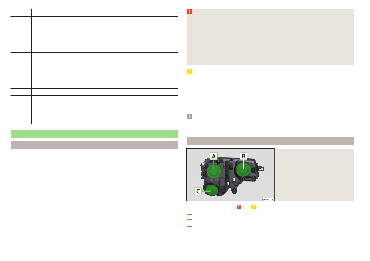
No. Consumer
18 Databus, battery data module
19 Windscreen wipers
20 Anti-theft alarm
21 Not assigned
22 Engine control system
23 Starter
24 Electrical auxiliary heating system
31 Vacuum pump
32 Not assigned
33 Oil pump for automatic gearbox
34 Not assigned
35 Not assigned
36 Not assigned
37 Aux. heating
38 Not assigned
Bulbs
Introduction
This Owner's Manual only describes the replacement of bulbs where it is possi-
ble to replace the bulbs on your own without any complications arising. Other
bulbs or LED lights must be replaced by a specialist garage.
For this reason, we recommend having bulbs replaced by a specialist garage or
seeking other expert help in the event of any uncertainties.
▶
Switch off the ignition and all of the lights before replacing a bulb.
▶
Faulty bulbs must only be replaced with the same type of bulbs. The designa-
tion is located on the light socket or the glass bulb.
We recommend having the headlight settings checked by a specialist garage
after replacing a bulb in the low, high or fog beam.
WARNING
■
Always read and observe the warnings before completing any work in the
engine compartment » page 260.
■
Accidents can be caused if the road in front of the vehicle is not suffi-
ciently illuminated and the vehicle cannot or can only be seen with difficulty
by other road users.
■
H7 and H8 bulbs are pressurised and may burst when changing the bulb -
risk of injury! We therefore recommended wearing gloves and safety
glasses when changing a bulb.
CAUTION
■
Do not take hold of the glass bulb with naked fingers (even the smallest
amount of dirt reduces the working life of the light bulb). Use a clean cloth,
napkin, or similar.
■
The cap of the filament bulb must always be seated correctly in the head-
light, otherwise this may allow water and debris to enter the headlight - risk of
damage to the headlights.
Note
We recommend that a box of replacement bulbs always be carried in the vehi-
cle.
Bulb arrangement in the halogen headlights
Fig. 337
Left headlight
Read and observe and on page 290 first.
Low beam
Main beam, turn signal and parking light
Fog lights
A
B
C
290
Do-it-yourself
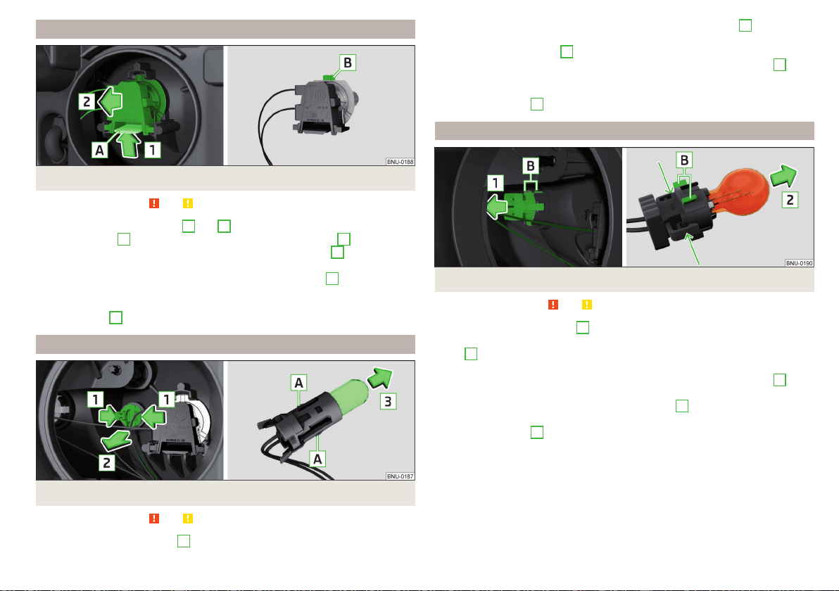
Removing bulbs for low and main beam
Fig. 338 Removing bulbs for low and main beam
Read and observe and on page 290 first.
›
Remove the protective caps
A
and
B
» Fig. 337 on page 290.
›
Press the latch
A
on the holder in the direction of the arrow
1
» Fig. 338.
›
Remove the connector to the bulb in the direction of arrow
2
.
›
Remove the connector.
›
Plug the connector into the new bulb so that the fixing lug
B
on the bulb
points upwards.
›
Insert the connector, with the bulb, into the headlight opposite to the direc-
tion of arrow
2
until you feel it lock into place.
Change the light bulb for the parking light
Fig. 339
Change the light bulb for the parking light
Read and observe and on page 290 first.
›
Remove the protective cap
B
» Fig. 337 on page 290.
›
Press the attachment securing lugs in the direction of arrows
1
, and care-
fully pull out the bulb holder with the bulb.
›
Grasp the holder in area
A
.
›
Remove the faulty bulb from the holder in the direction of the arrow
2
.
›
Insert a new bulb in the holder until it stops.
›
Insert the holder with bulb into the headlight again.
›
Fit protective cap
B
» Fig. 337 on page 290.
Changing the bulb for the front turn signal light
Fig. 340
Changing the bulb for the front turn signal light
Read and observe and on page 290 first.
›
Remove the protective cap
B
» Fig. 337 on page 290.
›
Remove the holder with the bulb by jiggling it out in the direction of the ar-
row
1
» Fig. 340.
›
Hold the holder with the bulb at the position shown by the arrows.
›
Remove the faulty bulb from the holder in the direction of the arrow
2
.
›
Insert a new bulb in the holder until it stops.
›
Slide the holder with the bulb with the fixing lug
B
upwards so that it fits
into the recess on the reflector.
›
Fit protective cap
B
» Fig. 337 on page 290.
291
Fuses and light bulbs
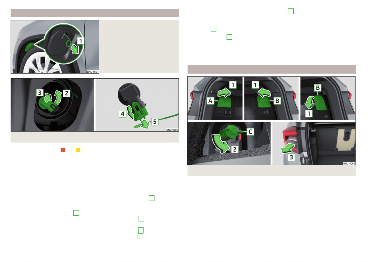
Changing the bulbs for fog lights
Fig. 341
Remove plastic cover
Fig. 342
Changing light bulbs for fog lights
Read and observe and on page 290 first.
To replace the bulb for the fog lists, remove the cover of the front wheel arch.
Remove the cover
›
Set the front wheels so that the respective cover in the front wheel arch is
accessible » Fig. 341.
›
Insert the clamp for removing the full wheel covers into the recess in the
cover.
›
Remove the cover by pulling the hook in the direction of arrow
1
.
Replacing the light bulb
›
Remove the protective cap
C
» Fig. 337 on page 290.
›
Turn the holder with the bulb in the direction of the arrow
2
as far as the
stop » Fig. 342.
›
Remove the holder with the bulb in the direction of arrow
3
.
›
Undo the latch on the connector in the direction of arrow
4
.
›
Remove the key in the direction of the arrow
5
.
›
Attach the connector to the new holder with the light bulb.
›
Insert a new holder with the bulb in the headlamp and turn it in the direction
of arrow
2
as far as the stop.
Fit protective cap
C
» Fig. 337 on page 290.
Insert cover
›
Insert and push the cover into the corresponding opening » Fig. 341. The cov-
er must engage securely.
Removing/installing tail light
Fig. 343
Removing the pop-up version for the cap / light
292
Do-it-yourself

Fig. 344
Removing the plug / installing the light
Read and observe and on page 290 first.
Removing
›
Open the boot lid.
›
Open the respective cap
A
or
B
in the direction of arrow
1
» Fig. 343. The
pop-up versions for the right cap
B
are different depending on equipment
fitted.
›
Remove screw
C
in the direction of arrow
2
. The screw remains in the
body, which is fitted with an anti-fall device.
›
Hold the light and carefully remove in the direction of arrow
3
.
›
Press the latch
D
on the holder in the direction of the arrow
4
» Fig. 344.
›
Press the securing lug in the direction of arrow
5
and pull out the plug in the
direction of arrow
6
.
Fitting
›
Slide the plug in the opposite direction of the arrow
6
» Fig. 344 into the
light.
›
Secure the latch
D
in the opposite direction to arrow
4
.
›
Carefully insert the lamp with the strips
F
into the guide grooves
G
in the
body and the lamp to the stop in the direction of the arrow
7
» .
›
Tighten screw
C
in the opposite direction to arrow
2
» Fig. 343.
›
Close the cap
A
or.
B
in the opposite direction of arrow
1
and insert into
the respective opening.
CAUTION
■
Ensure that when re-inserting the light the wiring harness between the body
and the light is not jammed and the seal
E
» Fig. 344 is correctly inserted -
Otherwise there is a risk of water ingress and damage to the electrical installa-
tion.
■
Ensure that the vehicle paintwork and the tail lamp are not damaged when
removing and installing the tail lamp.
Changing the bulbs in the taillight (turn signal and reversing lights)
Fig. 345
Outer part of the lamp/holder with bulbs
Read and observe and on page 290 first.
›
Unlock the bulb holder at the areas marked with arrows » Fig. 345 and re-
move from the light.
›
Remove the faulty bulb from the holder in the direction of the arrow
1
.
›
Insert a new bulb into the holder in the opposite direction to arrow
1
.
The lamp holder for the indicator is provided with the lettering
.
The lamp holder for the reversing lamp is provided with the lettering .
›
Insert the bulb holder into the light » . The holder must engage securely.
CAUTION
■
Before inserting the bulb holder into the light , check that the connector
A
» Fig. 345 is fitted correctly between the light and the bulb holder.
■
Make sure that when refitting the bulb holder into the light, the wiring har-
ness
B
is not pinched - otherwise there is a risk of damage to the electrical
installation.
293
Fuses and light bulbs
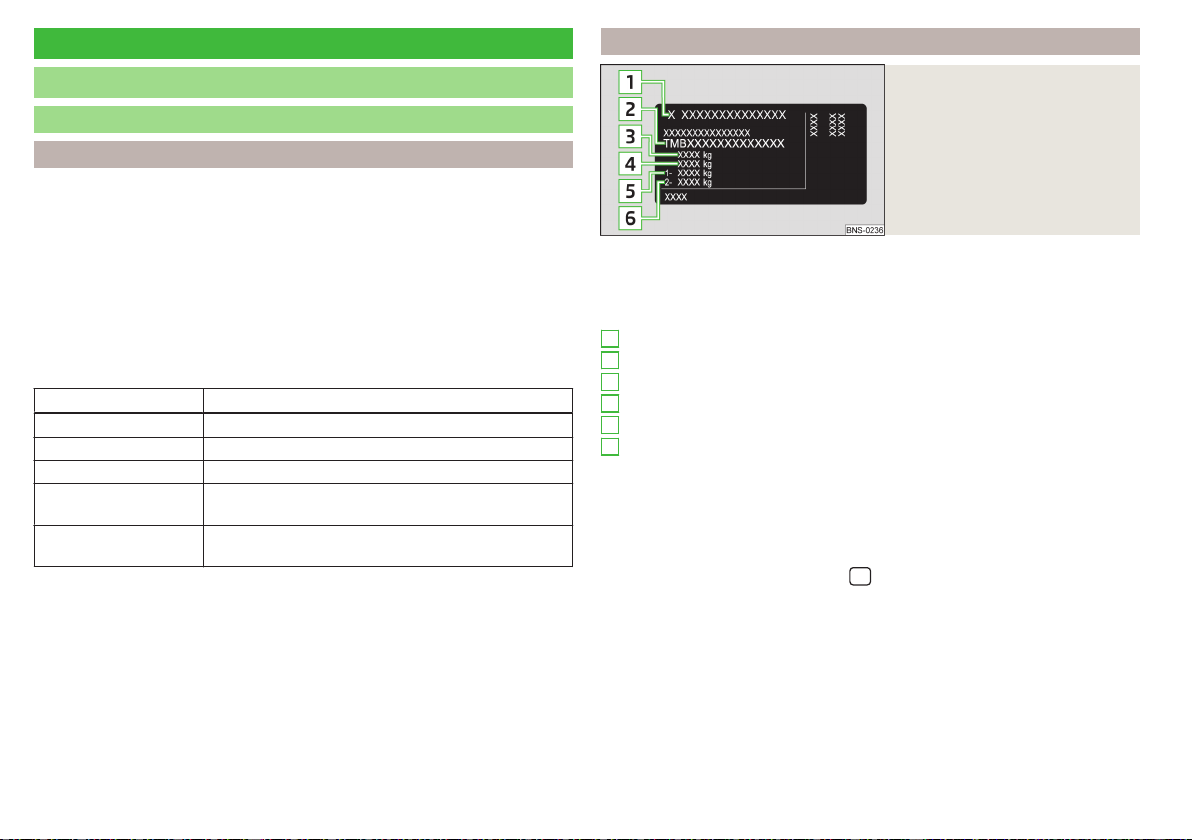
Technical data
Technical data
Basic vehicle data
Introduction
The details given in the vehicle's technical documentation always take prece-
dence over the details in the Owner's Manual.
The listed performance values were determined without performance-reduc-
ing equipment, e.g. air conditioning system.
The values given have been determined in accordance with the rules and con-
ditions specified in statutory or technical regulations for determining opera-
tional and technical data for motor vehicles.
The values listed are for the basic model without any optional equipment.
Abbreviations used
Abbreviation Meaning
ACT Active Cylinder Management
DSG Automatic double clutch gearbox
MG Manual gearbox
TDI CR
Diesel engine with turbo-charging and common rail
injection system
TSI
Petrol engine with turbo charging and direct injec-
tion
Vehicle identification data
Fig. 346
Rating plate
Type plate
The type plate » Fig. 346 is located at the bottom of the B-pillar on the right-
hand driver's side.
The type plate contains the following data.
Vehicle manufacturers
Vehicle identification number (VIN)
Maximum permissible gross weight
Maximum permissible towed weight (towing vehicle and trailer)
Maximum permissible front axle load
Maximum permissible rear axle load
Vehicle identification number (VIN)
The vehicle identification number - VIN (vehicle body number) is stamped into
the engine compartment on the right hand suspension strut dome. This num-
ber is also located on a sign on the lower left hand edge below the windscreen
(together with a VIN bar code), and on the type plate.
The VIN can also be displayed in the
/ → →
Events
.
Engine number
The engine number is embossed in the engine block.
Maximum permissible towed weight
The listed maximum allowable trailer weight is only valid for altitudes up to
1000 m above sea level.
The engine output falls as altitude increases, as does the vehicle's climbing
power. Therefore, for every additional 1000 m in height (or part), the maxi-
mum permissible towed weight must be reduced by 10%.
1
2
3
4
5
6
294
Technical data
The towed weight is made up of the actual weights of the loaded towing vehi-
cle and the loaded trailer.
WARNING
Do not exceed the specified maximum permissible weights – risk of acci-
dent and damage!
Operating weight
This value is only a guide value and corresponds to the lowest possible operat-
ing weight without any equipment added that would also increase the weight
(e.g. emergency or spare wheel etc.). This includes 75 kg driver's weight, the
weight of the operating fluids and the on-board tool kit and a fuel tank filled to
min. 90%.
Operating weight
Engine Transmission Operating weight (kg)
1.0 l/85 kW TSI MG 1340
1.5 l/110 kW TSI ACT DSG 1393
1.6 l/85 kW TDI CR MG 1426
2.0 l/110 kW TDI CR
MG 4x4 1561
DSG 4x4 1591
Note
If required, you can find out the precise weight of your vehicle at a specialist
garage.
Payload
It is possible to calculate the approximate maximum payload from the differ-
ence between the permissible total weight and the operating weight.
The payload consists of the following weights.
▶
The weight of the passengers.
▶
The weight of all items of luggage and other loads.
▶
The weight of the roof load including the roof rack system.
▶
The weight of the equipment that is excluded from the operating weight.
▶
Trailer bearing load for trailer towing » page 247.
Measurement of fuel consumption and CO
2
emissions according to
ECE Regulations and EU Directives
The data on fuel consumption and CO
2
emissions were not available at the
time of going to press.
The data on fuel consumption and CO
2
emissions are given on the ŠKODA
websites or in the sales and technical vehicle documentation.
The measurement of the intra-urban cycle begins with a cold start of the en-
gine. Afterwards urban driving is simulated.
In the extra-urban driving cycle, the vehicle is accelerated and decelerated in
all gears, corresponding to daily routine driving conditions. The driving speed
varies between 0 and 120 km/h.
The calculation of the combined fuel consumption considers a weighting of
about 37 % for the intra-urban cycle and 63 % for the extra-urban cycle.
Note
■
The fuel consumption and emission levels given on the ŠKODA websites or
in the commercial and technical vehicle documentation have been established
in accordance with rules and under conditions that are set out by legal or tech-
nical rules for the determination of operational and technical data of motor ve-
hicles.
■
Depending on the extent of the equipment, the driving style, traffic condi-
tions, weather influences and vehicle condition, consumption values can in
practice result in fuel economy figures in the use of the vehicle that differ
from the fuel consumption valueslisted on the ŠKODA websites or in the com-
mercial and technical vehicle documentation.
295
Technical data
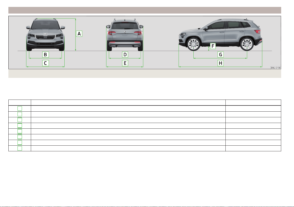
Dimensions
Fig. 347
Vehicle dimensions
The vehicle dimensions given in the vehicle's technical documentation always take precedence over the details in the Owner's Manual.
The dimensions listed below are for the basic model without any optional equipment.
Vehicle dimensions for operating weight without driver (in mm)
» Fig. 347 Specification Value
A
Height 1603/1607
a)
B
Front track 1576
C
Width 1841
D
Rear track 1541/1547
a)
E
Width including exterior mirrors 2025
F
Clearance 172/176
a)
G
Wheelbase 2638/2630
a)
H
Length 4382
a)
Applies to vehicles with a 2.0 l / 110 kW TDI CR engine.
296
Technical data

Overhang angle
Fig. 348
Overhang angle
Angle » Fig. 348
Approach angle
Departure angle
The values shown indicate the maximum incline of an embankment, up which
the vehicle can drive at a slow speed without collision of the bumper or under-
body. The values listed represent the maximum axle load at the front and rear.
Overhang angle (°)
Overhang angle, front Overhang angle, rear
18.4/18.8
a)
18.7/19.5
a)
a)
Applies to vehicles with a 2.0 l / 110 kW TDI CR engine
A
B
297
Technical data

Vehicle-specific details per engine type
Introduction
The values given have been determined in accordance with the rules and conditions specified in statutory or technical regulations for determining operational
and technical data for motor vehicles.
The exhaust gas standard is specified in the vehicle's technical documentation, as well as in the declaration of conformity (in so-called COC document). The
declaration of conformity (the so-called. COC document) can be obtained from a ŠKODA Partner (only valid for some countries and some models).
1.0 l./85 kW TSI engine
Output (kW at 1/min) 85/5000-5500
Maximum torque (Nm at 1/min) 200/2000-3500
Number of cylinders/displacement (cm
3
) 3/999
Transmission MG
Speed limits (km/h) 187
Acceleration 0-100 km/h (s) 10.6
1.5 l/110 kW TSI ACT engine
Output (kW at 1/min) 110/5000-6000
Maximum torque (Nm at 1/min) 250/1500-3500
Number of cylinders/displacement (cm
3
) 4/1498
Transmission DSG
Speed limits (km/h) 203
Acceleration 0-100 km/h (s) 8.6
1.6 l/85 kW TDI CR engine
Output (kW at 1/min) 85/3250-4000
Maximum torque (Nm at 1/min) 250/1500-3200
Number of cylinders/displacement (cm
3
) 4/1598
Transmission MG
Speed limits (km/h) 188
Acceleration 0-100 km/h (s) 10.7
298
Technical data

2.0 l/110 kW TDI CR engine
Output (kW at 1/min) 110/3500-4000
Maximum torque (Nm at 1/min) 340/1750-3000
Number of cylinders/displacement (cm
3
) 4/1968
Transmission MG 4x4 DSG 4x4
Speed limits (km/h) 196 195
Acceleration 0-100 km/h (s) 8.7 9.3
299
Technical data

Index
A
A2DP/AVRCP 160
Abort route guidance 190
ABS 42, 211
ACC
see Automatic Distance Control 229
Accessories 251
ACT 294
Activation of Online Services 14
Active steering assist (DSR) 211
Adaptive cruise control
Set/change desired speed 233
Warning light 41
Adaptive Cruise Control
automatic stopping and starting
231
Malfunctions 234
Operation 230
Operation overview 232
Overtaking
234
Radar sensor 209
Set the distance 233
Special driving conditions 233
Start control 232
Stop/resume control
232
Trailer towing
234
AdBlue 259
Check level 259
indicator light 46
refill 260
Additional keyboard languages
132, 139
additional window 177
Additional windows
Manoeuvre 189
Adjusting
Steering wheel
20
Adjusting the seats manually 81
Advice on tyre/wheel usage 268
aim
Favourite 181
Flagged destination 181
Online goals 181
own goal 183
saved destination 181
search 178
Telephone contact 181
vCard 181
Air-conditioning system
Air outlet vents 116
Airbag 24
Adjustments and impairments on the airbag
system 252
Deactivation 27
Deployment 25
Warning light
43
Airbag system 24
Air conditioning 112
Air Care 116
Air distribution control 115
Climatronic
113
Manual air conditioning 113
Air conditioning system 120
Air distribution control 115
Air outlet vents 116
Alarm 60
Trailer
250
All season tyres 270
Alphanumeric keyboard 124
Alternative routes 137
Ambient lighting 75
Amundsen
external module
122
infotainment Description 121
Android Auto 171
Anti-blocking system (ABS) 211
Anti-theft alarm system 60
Trailer 250
Anti-theft wheel bolts 276
APN 133, 161
Apple CarPlay 171
applications
Disclaimer 120
Armrest
Front 83
Ashtray 101
ASR 42, 211
Assistant for emergencies 242
Assist systems 209
AT THE 142
Audio source 147
Auto Check Control
Vehicle condition 49
Auto Hold
44, 202
Auto Hold function 44, 202
Automatic consumer shutdown 265
Automatic Distance Control 229
Settings in Infotainment 230
Automatic drive
Selector lever
205
Automatic driving light control 70
Automatic gearbox
Disengage selector lever 205
Kickdown 206
Launch control
207
Malfunction 45
Manual shifting on the multifunction steering
wheel 206
Selector lever lock 205
Start and drive
206
Tiptronic 206
Warning light 45
Automatic switch-off of Infotainment 125
300
Index

Automatic transmission 204
Selector lever emergency release 284
Auxiliary heating (auxiliary heating and ventila-
tion) 117
In infotainment 118
set to 118
Auxiliary heating (heating and ventilation)
Radio remote control 119
Avoiding damage to your vehicle 208
B
Basstöner 131
Battery
Changing batteries for the removable light
283
Changing in key
282
Replace the battery in the remote control in
the auxiliary heating 283
Belts 21
Belt tensioners 23
reversible
24
Blind spot monitoring assistant
Activation / deactivation 220
Bluetooth
A2DP / AVRCP 132
Name
132
on / off 132
Paired external devices 132
Profile 160
rSAP 158
Set 140
set to
132, 135
Set to 132
Switch on/off 140
Update 130, 133
Updates 140
Visibility
132, 140
Bluetooth Player 148
Bluetooth® update 158
bolero
external module 122
infotainment Description 121
Bonnet 261
Boot
Hooks 105
Boot lid 62
Automatic locking 62
Open/close 62, 63
See boot lid 62
Brake Assist (HBA) 212
Brake booster 201
Brake fluid 265
Check 265
specification 265
Brake linings
Warning light 44
Brake pads
new
201
Brake pedal (automatic gearbox)
Warning light 44
Brakes
Brake booster 201
Brake fluid
265
Braking and stabilisation systems 210
Information on braking 201
Parking brake 201
Run in 207
Warning light 40
Brake system
210
Breakdown call 161
Broadcasting 142
Bulbs
Replacing 290
Buttons on the driver door
Electric windows
65
C
Call list
Call list 163
CAR 196
Car battery
Automatic consumer shutdown 265
Disconnecting and reconnecting 267
Replacing 267
Car care
Interior 256
Car computer
see multifunction display 51
Care and maintenance
251
Care Connect
16
Cargo element 109
Car park 180
Carrier 111
CarStick 167
CD
147
cellphone
Disclaimer 120
Central locking 56
Problems 60
Central locking button
58
Changing
Batteries for the removable light 283
Battery 282
Wheels 273
Windscreen wiper blades 285
Changing a wheel
273
Changing gear
Selector lever 205
Tiptronic 206
Charging a vehicle battery 266
301
Index

Check
Brake fluid 265
Engine oil 263
Oil level 263
Checking
Battery condition 266
Coolant 264
Children and safety 28
Child safety lock 60
Child seat 28
Classification 30
I-Size 33
Installation location 31, 32, 33
ISOFIX 32
on the front passenger seat 29, 30
TOP TETHER 34
Cigarette lighter 101
Cleaning the vehicle
Interior
256
Outside 254
Washing 253
Climatronic 112
air distribution control 115
Automatic operation
115
Operate in Infotainment 114
Operating elements 113
Clock
Change display 125
Clothes hook 96
Cockpit
37
Lighting 73
Columbus
external module 122
infotainment Description 120
Comfort flashing
70
COMING HOME 72
compartments 90
Compatible sources
DVD video 154
Pictures 152
Component protection 252
Computer
see multifunction display 51
Conditions for pairing 158
Conference call 164
Configuration wizard 127
Connect
hotspot 168
WLAN 168
Connect Infotainment to the hotspot of the
external device 168
Connect the external device to the Infotain-
ment hotspot 168
Connect WLAN
to the hotspot 168
Convenience operation
Tilting / sliding sunroof
67
Coolant 263
Checking 264
Refilling 264
Temperature display
38
Warning light 45
CORNER
See Fog lights with CORNER function 72
Correct routing of seat belt
21
Correct seating position
18, 20
Crew Protect Assist 239
Cruise Control System 226
Cup holders 93
D
DAB 142
additional information 142
Radio Text and images presentation 142
Set 134, 141
DAB Slideshow 142
Data connection
Amundsen 167
CarStick 167
Internet 166
rSAP 168
Data Connection
Columbus
166
SIM card
167
Data roaming 133
Data transfer of external devices 127
Date 131, 139
DAY LIGHT
See Daytime running lights
69
Daytime running lights 69
Dazzle 76
De-icing the windscreen and rear window 76
Deactivation
Airbag
27
default settings 196
Delayed locking of the boot lid
See boot lid 62
Delete destination 187
Demo mode 138, 188
Destination
Enter destination using the address
179
Favourite 187
final destinations 181
Home address 182
Image with GPS
184
Memory 187
Types of destination search / destination input 177
302
Index

Destination details 187
Destination management
Destination details 187
Favourite 187
Storage 187
Destination on the map
Destination entered in map 179
Diesel 259
Diesel fuel 259
Diesel particle filter (DPF) 46
Digital clock 49
Digital service plan 54
Dipped beam 69
Dipstick 263
Directive 2014/53 / EU 9
Disclaimer
applications 120
external devices 120
Mobile phones
120
Display
Coolant temperature 38
Fuel level 39
Gear changes 49
In the instrument cluster
48
Display of a low temperature 47
Display of the instrument cluster
Menus in the display of the instrument cluster 53
Distance warning 235
Diverting calls 135
Door
Child safety lock
60
Emergency locking 284
Emergency locking of the driver's door 283
Opening/ Closing 59
Door alarm
48
Drive
Driving through water 208
DriveGreen 207
Driver information system 48
Driving
Emissions 295
Fuel consumption 295
Maximum speed 298
through water 208
Driving mode 237
Eco 237
Individual 238
Individual mode settings 239
Mode selection and Infotainment display 238
Normal 238
Snow 238
Sport 238
Driving Mode Selection 237
DSG 294
DSR 211
DVD 147
DVD-Video
main menu
153
menu 153
Select video source 153
DVD video
Compatible sources
154
Supported file formats 154
Dynamic Road Sign Display
Additional display 244
Operation 244
Dynamic route 195
E
Economical driving 207
Economy mode
Warning light 48
Edit route 190
EDR
8
EDS 211
Electrical boot lid
set the top position of the lid 63
Electrical power windows 66
Electric boot lid
Force limiter 62
Manual operation 62
Open/close 63
Electric parking brake 201
Electric power windows 64
Malfunctions 66
Electric tailgate
Malfunctions 64
Electric windows
Buttons on the driver door 65
Electronic Differential Lock (EDL, XDS+) 211
Electronic immobiliser 197
Elevation 174
emergency
Jump-starting
279
Starting the engine / stopping at the push of a
button 199
Emergency
Changing a wheel 273
Hazard warning light system
73
Jump-starting 279
selector lever release 284
Starting the engine / stopping the push of a
button 198
Towing the using the tow hitch 282
Towing the vehicle
280
Tyre repair 277
Unlocking/locking the door 283
Unlocking / locking the door 284
Emergency call 15, 161
Emergency equipment
Fire extinguisher
272
First aid kit 272
Jack 273
Reflective vest 272
303
Index

Vehicle tool kit 273
Warning triangle 272
Emergency spare
Removing / stowing 274
Emission control system 42
Emissions 295
Engine
Information messages 45
Run in 207
Engine compartment 260
Brake fluid 265
Coolant 263
Engine oil 262
Overview 262
Vehicle battery 265
Windscreen washer fluid 262
Engine drag torque control (MSR) 211
Engine number 294
Engine oil
262
Check 263
Oil changing 262
Refilling 263
Specification 262
Warning light
46
Engine revolutions counter 38
Enter destination 179
EPC 43
equalizer 131
ESC
ESC Sport
210
Operation 210
Event Data Recorder 8
External device data transfer 132, 139
External devices
Disclaimer
120
External module 122
CD / DVD 147
SD card 148
SIM card 161
Video DVD 153
F
Factory settings 132, 140
Familiarising yourself with the vehicle 2
Fastening elements 104
Fatigue detection system 245
Fatigue detection system 245
Favourite 181, 187
file formats
media 150
Requirements and Restrictions 150
File formats
DVD video 154
Pictures 152
Finish route guidance
189
Fire extinguisher 272
First aid kit 272
Flagged destination 181
Flashing 70
Floor covering in the luggage compartment
106
Flooring in the luggage compartment 106
Floor mats 204
See Floor mats 204
FM 142
Set 134, 140
Fog lights
72
Warning light 44
Fog lights/rear fog light 72
Fog lights with CORNER function 72
Foils 254
Folding table
97
Force limiter
Electric boot lid 62
Sliding/tilting roof 67
Window 66
Front assist
Warning light 47, 48
Front Assist 235
Disable/enable 237
Distance warning 235
Malfunctions 237
Operation 235
Pedestrian recognition 236
Radar sensor 209
Settings in Infotainment 235
Warning and automatic braking 236
Front head restraints
Adjust height 88
Front seats 81
Fuel
257
Diesel 259
Fuel gauge 39
refer to Fuel 257
Refuelling 257
Unleaded petrol
258
Warning light 44
Fuel consumption 295
Fuel filter 47
Fuel options 138
Fuel reserve 44
Functional surfaces
123
Fuses 286
in the engine compartment 289
in the switchboard 286, 287
Plastic clip 289
G
Gearbox
Information messages 45
304
Index

Gear change
Gear recommendation 49
Information on the selected gear 49
Gear changing
lever 204
Genuine parts 251
Glasses storage box 95
Google Earth™ 177
Google Earth ™ 184
GPS 174
Graphical driving recommendations 189
H
hand gestures 125
Hazard warning light system
73
HBA 212
Headrests 88
Heating 112, 113
Air distribution control 115
Mirrors
79
Seats 89
Steering wheel 89
Windscreen and rear window 76
High-beam assistant 47
High beam
Light Assist
71
Hill Descent Assist 213
Hill Descent Assistant 48
hitch 248
Hitch 247
home address
137
Home address 182
HOME button 127
HOME main screen 127
Hooks 105
Horn
37
I
I-PAD holder 101
I-Size 33
Ignition lock 198
Images
Display 135
main menu 151
Operation 152
safe removal of the data source 132
Select Image Source 151
Set to 135
Image viewer 151
Immobiliser
197
import
Destinations (online)
184
Objectives (vCard) 183
POI categories 183
POI categories (online) 175, 183
Routes (online)
191
Import contacts 135
Inertia reels 23
Information about the towing process 280
Information call 161
Information system
48
Gear recommendation 49
Menus in the display of the instrument cluster 53
Multifunction display 51
Service interval display 54
infotainment Description
Amundsen
121
bolero 121
Columbus 120
swing 122
Infotainment gesture control 125
Infotainment language
132, 139
Infotainment menus
Grid display 126
Horizontal display 126
Infotainment Online 17
Infotainment operation 123
Infotainment screen 123
Infotainment operation using an application in
the external device 127
Infotainment Overview 120
Infotainment Restart 125
Infotainment screen 131, 139
Areas 123
Important information 122
keyboard 124
Maintenance 122
Operation 123
service 123
Input screen
Language characters 139
Input screen with keyboard 124
Instrument cluster 38
Vehicle condition
49
Warning lights 39
interior light 74
Interior lighting 74
Interior lights
Ambient lighting
75
Interior monitor 61
Intermediate target 187
Internet 166
Amundsen 167
CarStick 167
Columbus
166
rSAP 168
SIM card 167
ISOFIX 32
J
Jack 273
- fit 276
Journey 51
305
Index

Jukebox 149
Jump-starting 279
K
KESSY
deactivating 58
Starting engine / Stopping 198
Switching the ignition on/off 198
Unlocking / locking 57
key
Starting engine / Stopping 198
Key
Changing battery 282
Switching the ignition on/off
198
keyboard
124
key CAR 196
L
L-band 135
Lamp failure 46
Lamps
Warning light
46
Lane Assist 240
Malfunctions 241
Settings in Infotainment 240
Lane Departure Warning
Activation / deactivation 241
Operation 240
Lane recommendation 189
Language characters 132
Last destinations 181
Latitude
174
LEAVING HOME 72
LED headlights 71
Lever
ACC 232
Cruise control
227
Operation of the information system 50
Speed limiter with ACC 229
Speed limiter with CCS 228
Speed limiter with GRA 229
Turn signal/main beam 70
Windscreen wipers 77, 78
Liability for defects 6
Light 69
Cockpit 73
COMING HOME / LEAVING HOME 72
Daytime running lights 69
Flash 70
Fog lights/rear fog light 72
Fog lights with CORNER function 72
Hazard warning light system 73
Headlight cleaning system 78
LED headlights 71
Light Assist 71
Parking light 73
Replacing bulbs
290
Turn signal/main beam 70
Light Assist 71
See Light Assist 71
Lighting
Ambient lighting
75
Entry space 73
Interior lighting 73
Luggage compartment 103
Lights
Automatic driving light control 70
Dipped beam
69
Driving abroad 73
Headlight range control 69
Parking lights 69
Switching on and off 69
Warning lights
39
List
of available stations 143
of telephone contacts 162
With folder / track list 146
Liste gekoppelter externer Geräte 160
List of available hotspots 168
List of traffic reports 194
Load 295
localisation services 15
Lock
Individual settings 59
KESSY 57
Locking
Central locking button 58
in case of emergency 284
Remote control 57
Lock steering lock 197
Longitude 174
Luggage compartment 103
Cargo Elements 109
Cover 106
Fastening elements 104
Fastening the flooring
106
Fixing nets 104
Floor covering on both sides 106
Lighting 103
Net partition 108
Removable light
110
Roll-up cover 107
Storage compartments under the floor cover-
ing 109
unlock manually 284
Unlock the boot lid 284
Variable loading floor
111
Luggage compartment cover 106
Roll-up cover 107
Luggage Storage
Storage compartments 108
M
Main beam 70
Warning light 45
306
Index

main menu
Android car 171
Apple carplay 172
Images 151
MirrorLink® 172
radio 142
Video DVD 153
Main menu
Media 145
Media Command 155
Navigation 176
SmartLink 170
SMS 164
Waypoint mode 192
WLAN 168
Make up mirror 76
Manage favourites 141
Manage Favourites 135
Manage memory
137
Management of online services 15
Management of online services ŠKODA Con-
nect 140
Management of ŠKODA Connect Online Serv-
ices
133
Managing saved routes 191
Manoeuvre
Graphical driving recommendations 189
Nav. announcements 189
Manual air conditioning
Air distribution control
115
Controls 113
Manual gear changing
See Gear changing 204
map
display options
184
Google Earth ™ 184
Map
Automatic scale 185
Display 176
Display of traffic signs 137
Display options in the split screen 186
Fast Map 185
Google Earth™ 177
Lane guidance 137
Main menu 176
Manual scale 185
Map alignment 186
Operation 176
POI display 137
Road Signs 187
Show POIs 180
|Alignment 185
Maximum speed 298
MCB 212
media
Compatible sources 150
file formats 150
Multimedia Database
146
Requirements and Restrictions 150
serve 145
USB 93, 148
Media
Audio source
147
Bluetooth Audio 148
Browser 146
CD / DVD 147
Jukebox 149
List 146
Main menu
145
Playback control 145
safe removal of the data source 132
Safe removal of the data source 139
SD card 148
Set to
135, 141
Voice control 128
WLAN 149
Media Command
Control 155
Main menu 155
Supported formats 155
Memory 52
Memory Function for the seat 82
Menu DVD-Video 153
Menus in the display of the instrument cluster 53
Apple CarPlay 53
audio menu item 53
Main menu 53
navigation menu item 53
Operation 50
phone Menu item 53
wizard menu item 54
MG 294
Mirror 76, 78
MirrorLink® 172
MODE button
See driving mode
237
Modes of the automatic transmission 205
Modifications and technical alterations 251
Most common routes 189
MSR
211
Multicollision brake (MCB) 212
Multifunctional steering wheel 50
Multifunction display
Functions 51
Information Overview 51
Memory
52
multimedia
see media 145
Multimedia Database 146
Mute 126
MyŠKODA App application
11
N
Nameplate 294
307
Index

navigation
additional window 177
Contacts 181
Demo mode 188
destination search 178
Favourites 181
Map orientation 185
obstruction of traffic 195
Options for map display 184
route display 184
route list 191
Start the route guidance 188
target import 183
target memory 181
target representation 184
Update navigation data online 175
Working with the navigation 174
Navigation
Abort route guidance
190
Advanced settings 138
Alternative routes 137
Demo mode 138
Destination address 179
Destination details
187
Destination on the map 179
Destination presentation in the split screen 186
Dynamic route 137
Edit route 190
Final destinations 181
Finish route guidance
189
Foreword 174
Fuel options 138
GPS 174
Graphical driving recommendations 189
Home address
182
Image with GPS 184
Imported destinations 137
Intermediate target 187
Main menu 176
Manage memory
137
Map 137
Map alignment 186
Map scale 185
Most common routes 189
Navigation data 175
Navigation data update 175
nav. announcements 138
Nav. announcements 189
Options for map display in the split screen 186
Preferred type of route 137
Route 187
Route calculation 188
Route change 191
Route details 190
Route display in the split screen 186
Route guidance 187
Route information 190
Route options 137
Set to
137
Status line 138
Top speeds 138
Trailer towing 188
Transit point 191
Types of destination search / target destina-
tion
177
Update the navigation data 138
Version information 138
Voice control 128
Waypoint mode 192
navigation data
175
Navigation data 175
Navigation data update 175
nav. announcements 138
Nav. announcements 189
Net in the front centre console
95
Net partition 108
Nets 104
Network
Data connection 133
Data roaming 133
setting 133
set to 135
Values of the downloaded data 133
New route 191
Notes 12
O
obstruction of traffic 195
Offroad 48, 212
Hill Descent Assist 213
Infotainment display
214
Offroad mode
See Offroad
212
oil
see Engine oil 263
Oil changing
Engine oil
262
On-board computer
see multifunction display 51
On-line
destination search 178
Detail of the traffic report
195
Import POI categories 175, 183
route import 191
target import 181, 184
Update navigation data 175
Online
Destinationdetails
187
List of traffic reports 194
map Google Earth™ 177
Navigation data update 175
Search for a car park 180
Search for petrol station
180
Online goals 181
308
Index

Online services
Change the user 14
Delete the user 14
Electronic manual 14
instructions video 14
localisation services 15
Private mode 15
Services Management 15
Online Services 13
Activation in Infotainment 14
Care Connect 16
Infotainment Online 17
proactive service 16
Remote access to the vehicle 16
Service package 13
ŠKODA Connect website 13
ŠKODA Connect website portal 13
Online services ŠKODA Connect
enable service
140
Opening/closing
contactless boot lid 64
opening/closing contactless boot lid 64
Operating the Infotainment menus 124
Operating weight
295
Operation
Images 152
Telephone 156, 157
Original accessories 251
Overhang angle 297
Overview
Cockpit
37
Engine compartment 262
Fuses 286
Warning lights 39
Own POI categories
183
P
Pairing process 158
Park
Rear traffic alert 218
Park assist
Parking 224
Park Assist 222
Automatic brake assist 226
Leaving a parallel parking space 225
Malfunctions 226
Operation 223
Parking 225
Search for parking space 223
Switch to park mode 224
Park assistant
Activation/deactivation 220
Parking 203
Park Assist 222
Parking aid 215
Parking aid 215
Automatic emergency braking
217
Automatic system activation when moving for-
ward 217
Operation 215
Settings in Infotainment 215
Parking assistance
Activation / deactivation
217
Parking brake 201
Warning light 40
Parking lights 69
Parking sensors
Display Infotainment screen
216
Parking the vehicle
see Parking 203
Parking ticket holder 91
ParkPilot 215
Part replacement
251
Passive safety
Before setting off 18
Driving safety 18
Passive Safety 18
Pedals 204
Floor mats 204
Personalisation
Configuration wizard 127
Personalization 55
Operating principle 55
Overview of some personalized functions 55
Set 56
Petrol 258
Petrol station 180
Petrol station logo 137
phone
connect to the infotainment 157
couple 157
Phone
Adjust text messages 135
Bluetooth® update 158
Clear calls
135
Compatibility 158
Diverting calls 135
Import contacts 135
Introductory information 156
Manage Favourites
135
Phone call 164
Premium 135
rSAP 158
Settings call 135
set to 135
User profile
135
Voice control 128
Phonebox 92
Phone call 164
Phone compatibility 158
Phone Premium
SIM card
161
Pictures
Compatible sources 152
File formats 152
309
Index

Requirements and restrictions 152
Supported file formats 152
Pin code
set to 135
Playback
Media 145
Video DVD 153
Pockets 97
POI 180, 183
Pop-up window
Map 186
Power limit
Tilt / slide sunroof 67
Power steering 41
Practical equipment
230-volt socket 100
Practical features
12-volt socket in the interior 99
12 volt socket in luggage compartment
100
Ashtray 101
Cigarette lighter 101
Glasses storage box 95
Parking ticket holder 91
Pockets
97
Reflective vest 272
Storage compartment 90
Storage compartment for umbrella 96
Waste container 94
Preferred contacts 163
Preheating unit
42
Principles of Infotainment Operation 123
Private mode 15
Proactive passenger protection 239
Proactive passenger protection warning light 43
Proactive service
16
Puncture repair kit 277
R
radio
Broadcasting 142
L-band 135
main menu 142
Radio stations Logo 143, 144
scan 142
serve 142
Radio
List of available stations 143
Set 134, 140
Traffic programme (TP) 144
Voice control 128
Radio equipment
Information on Directive 2014/53 / EU 9
Radio remote control
Auxiliary heating (heating and ventilation) 119
Radio station 143
Preset buttons
143
Radio station logos 143, 144
Update 133
radio stations
Select channels and search 142
Raising the vehicle
276
Rear fog light 72
Warning light 42
Rear headrests
Adjusting the height 88
Removing/inserting 88
Rear seats
84
Rear traffic alert 218
Rear Traffic Alert
Malfunctions 220
Operation 219
Rear view mirror
78
Rear window - heating 76
Record waypoints 192
Refill
Windscreen washer fluid 262
refilling
AdBlue 259
Refilling
Coolant 264
Engine oil 263
Reflective vest 272
Refuelling 257
Fuel 257
Register online services
settings 133, 140
Registration of online services
Electronic manual 13, 14
tutorial video 13, 14
Regulation
Headlight beam 69
Remote access to the vehicle 16
Remote control
Changing battery
282
Synchronisation process 60
Unlocking/locking 57
Remote transfer of SIM data 158
Removable light
110
Changing batteries 283
Removable through-loading bag 98
Repairs and technical alterations 251
Replace
Battery 283
Replacing
Bulbs
290
Fuses 286
Windscreen wiper blades 285
Reset counter for distance driven (trip) 48
Restaurant
180
Reversible belt tensioners 24
Rims 268
310
Index

Road Signs
infotainment display 187
Roller blind
see Luggage compartment cover 107
Roof
Load 111
Roof racks 111
route
new route 191
Online Route Import 191
route list 191
Route 187
Store route 190
Route calculation 188
Trailer towing 188
Route details 190
Route information 190
route list 191
Route options
137
rSAP 158
Data connection 168
Run-in
Engine 207
Running in
Brake pads
201
Tyres 268
S
SafeLock
58
Safe removal of the data source 132, 139
safety
Correct seating position
18
Safety 18
Airbag 24
Child safety 28
Child seats
28
Headrests 88
I-Size 33
ISOFIX 32
TOP TETHER 34
SAFE, SAFELOCK
See SafeLock 58
Save radio
Save channel 143
Saving electrical energy 207
Saving fuel 207
Scraper 255
Screen
see Infotainment screen 122
Screen display 123
SD card 148
Safe removal 139
search
aim 178
Online goals 178
Types of destination search / destination input 177
Search
Car park
180
Petrol station 180
Restaurant 180
Seat belt
height adjustment
21
Warning light 41, 45
Seat belts 21
Belt tensioners 23
fastening and unfastening 22
Inertia reels
23
Seat electrical adjustment 81
Seats
Electrical adjustment 81
Folding front passenger seat 83
Front
81
Front armrest 83
Headrests 88
Heating 89
Memory Function of the electrically adjustable
seat 82
Rear 84
Rear seat backrests 84
Setting 81
Storing in memory of remote control key 82
see Instrument cluster
see Instrument cluster 38
Selector lever 205
Selector lever control 205
Selector lever lock 44
service
media 145
radio 142
Service 251
Service interval display 54
Warning light 48
Service Interval 54
Service interval display
54
Service intervals 54
Service plan 54
set
hotspot 168
Setting
Headrests
88
Mirror 79
Positions of the variable loading floor 111
Seat belt height 21
Seats 81
Time
49
settings
Basstöner 131
equalizer 131
Images 135
infotainment
131, 139
Infotainment language 132, 139
Infotainment screen 131, 139
Reset to factory settings 196
Software Update 130
311
Index

sound 131
sound system 131
surround 131
system information 130
ŠKODA Connect 140
vehicle 196
Video DVD 135
Settings
Additional keyboard languages 132, 139
Advanced settings 138
APN 133, 161
Bluetooth 132, 135, 140
Codecs 135
Configuration wizard 127
DAB 134, 141
Data connection 133
External device data transfer 132, 139
FM 134, 140
Fuel options
138
Information regarding the version of the navi-
gation data 138
Manage favourites 163
Manage memory 137
Map
137
Media 135, 141
Navigation 137
Nav. announcements 138
Network 133
Phone 135
Pin code
135
Radio 134, 140
Reset to factory settings 132
Restore factory settings 140
Route options 137
SmartLink+
136, 141
Software updates 140
Sound 139
System information 133, 140
ŠKODA Connect 133
Telephone 141
Time and date 131, 139
Top speeds 138
Units 132, 139
Update software 133
User profile 163
Voice control 132
Volume 126
WLAN 133
Settings Call
Clear calls SettingsText messages 135
Set to
Auxiliary heating (auxiliary heating and ventila-
tion) 118
Show POIs in the map 180
SIM card
Change PIN code 161
Data Connection 167
Insert
161
PIN code 161
Remove 161
Sliding/tilting roof
Activate operation 68
Activating operation of the sunshade
68
SmartLink+ 170
Android Auto 171
Apple CarPlay 171
Introduction to the subject 170
Main menu 170
MirrorLink®
172
Set 136, 141
ŠKODA OneApp application 173
SMS
Main menu 164
New message
165
Received message 165
Snow chains 271
Sockets
12-volt socket in the interior 99
12 volt socket in luggage compartment 100
230 V 100
Software Update 130, 133
Software updates 140
SOS button 15
sound 131
Sound 139
sound system 131
Spare wheel 269, 270
Removing / stowing 274
Removing / stowing (sound system) 275
Speed limitations 189
Speed limiter 44, 227
Speed regulating system
Warning light 44
Speed symbol 270
Spoiler
252
Spurhalteassistent 240
SSID 133
Stabilisation system 210
Stability Control (ESC) 42, 210
Standby
125
START-STOP 199
Jump-starting 279
manually activate/ deactivate system 200
operation 199
START-STOP system 199
Start engine
198
Immobiliser 197
Jump-starting 279
starter button
Starting engine / Stopping 198
Starter button
Lock / unlock the steering lock
197
Problems with the engine start 199
Switching the ignition on/off 198
312
Index

Starting the engine
Jump-starting 279
Start the route guidance 188
Status bar 123
status line
Navigation 138
Status line 176
Telephone 156, 157
Steering lock (KESSY system) 41
Steering wheel
Buttons 50
Heating 89
Proper posture 19
Setting 20
Stop engine 198
Stopping
see Parking 203
Storage 90
Storage compartments
see Practical features
90
Storage net 95
Stored destinations
Final destinations 181
target memory
181
Store destination 187
Storing
seats 82
Sunblind for the tilt / slide sunroof 68
Sun visor 76
Supported sources
media
150
surround 131
swing
infotainment Description 122
Switch
Car battery
267
Switching off the ignition 198
Switching on the ignition 198
Switching the lights on and off 69
Switch off
Alarm 61
switch on / offTraffic
dynamic route 195
system information 130
System information 133, 140
T
Tablet holder
101
Tailgate 61
target memory 181
TDI CR 294
Technical data
294
Telefon
Bluetooth-Profile
160
telephone
conditions for pairing 158
Telephone
Additional telephone
159
Breakdown call 161
Call list 163
Conference call 164
Connection types 159
Dialling the telephone number
161
Emergency call 161
Enter telephone number 161
Functions 161
Import contacts 141
Information service 161
Main menu
156, 157
Main telephone 159
Manage favourites 141
Operation 156, 157
Pairing process 158
Preferred contacts
163
rSAP 159
Set 141
SIM card 159
Telephone 156, 157
Telephone book 162
Text messages (SMS) 164
User profile 141
Voicemail 161
Telephone book 162
Telephone connection types 159
Telephone functions 161
Telephone number 161
Telephone Premium
rSAP 158
Text messages 164
Through-loading bag 98
Tilt / slide sunroof
Operation 67
Sunblind 68
Time 49, 131, 139
Time and date display in the Infotainment
screen
125
Tiptronic 206
TMC
Detail of the traffic report 195
dynamic route
195
List of traffic reports 194
Tools 273
Top speeds 138
TOP TETHER 34
Touch screen 122
Towing
280, 281
Towing a trailer 250
Towing device
Accessories 248
Vertical load 247
Towing eye
281
Towing protection 61
Towing the vehicle 280
Traction control (ASR) 42, 211
313
Index

traffic
Detail of the traffic report 195
Traffic
List of traffic reports 194
Traffic Information (TMC) 195
Traffic jam assistant 242
Traffic programme (TP) 144
Traffic program (TP) 144
Traffic reports (TMC) 194
Traffic sign recognition 243
Traffic Sign Recognition
dysfunction 245
Information messages 245
Settings in Infotainment 243
Traffic signs
see Traffic sign recognition 243
Trailer
Connect and disconnect 248
loading
249
Towing a trailer 250
Trailer stabilisation system (TSA) 212
Trailer towing 247
navigation 188
Trailer towing device
Handling
247
Warning message 247
Transit point 191
transmitter
See main menu 142
Transport
Luggage compartment
103
Roof racks 111
Towing device and trailer 247
Transporting children 28
Triangle
272
TSA 212
TSI 294
Turning off Infotainment 125
Turning on Infotainment 125
Turn signal 70
Turn signal system
Warning light 44
Tutorial videos 11
Tyre
Wear indicator 269
Tyre load capacity 270
Tyre pressure 268
Warning light 43
Tyre pressure monitor
refer to the tyre pressure monitoring 245
Tyre pressure monitoring 245
Warning light 43
Tyre Pressure Monitoring
Storing the tyre pressure values and Infotain-
ment display 246
Tyre repair 277
Tyres
268
damage 268
Explanation of the label 270
new 268
Tyre pressure 268
Tyre size
270
U
Units 132, 139
Unlatch
KESSY 57
Unlock
Individual settings
59
Unlocking
Central locking button 58
In case of emergency 283
Remote control 57
Unlocking and locking
56
Unlock steering lock 197
Update navigation data 175
Update the navigation data 138
Uphill start assistant 212
USB 93, 148
Safe removal 139
Useful equipment
Clothes hook 96
Cup holders 93
Removable through-loading bag 98
Useful links 2
User account
Configuration wizard 127
User profile 135, 141
V
Variable loading floor 111
VarioFlex
rear seats 84
vCard 181, 183
Vehicle - Settings 196
Vehicle battery
charging
266
Checking the condition 266
Safety instructions 265
Warning light 45
Winter operation
266
Vehicle care 252
Exterior 255
Outside 254
Vehicle cleaning 252
Exterior 255
Windscreens
255
Vehicle condition
Auto Check Control 49
Vehicle dimensions 296
Vehicle height 296
Vehicle identification number (VIN)
294
Vehicle length 296
vehicle systems 196
314
Index

Vehicle tool kit 273
Vehicle width 296
Verwaltung gekoppelter Geräte 160
Vest 272
Video DVD
Playback 153
Set to 135
video player 153
VIN
Vehicle identification number 294
Virtual pedal
see operating contactless boot lid 64
Visibility 75
Voice control 128
Commands 129
Correction of a voice command input 129
Help 129
Not recognising a voice command 129
on / off
128
Operation principle 129
Settings 132
Stop / restore command 129
Voicemail 161
Volume
126
Volume setting 126
W
Waiter
Voice control 129
Warning lights 39
Warning symbols
see Warning lights
39
Warning triangle 272
Warning when speeding 52
Warranty 6
Washing the vehicle
253
Waste container 94
Water in the fuel filter 47
Waypoint mode 192
Main menu 192
Record waypoints 192
Set waypoint manually 192
Waypoint tour memory 193
Waypoint tour memory 193
Weather conditions 251
Weights 294, 295
Wheel bolts
Anti-theft wheel bolts 276
Caps 275
Loosening and tightening 276
Wheels 268
Changing 273
Full trim 275
Load Index 270
Snow chains 271
Speed symbol 270
Tyre age
268
Tyre damage 268
Tyre pressure 268
Tyre storage 268
Unidirectional tires 268
Winter tyres
270
Window
operation 64
Window convenience operation 66
Window operation 64
Windscreen - heating 76
Windscreen washer fluid
Refill
262
Warning light 47
Windscreen washing systems 76
Windscreen wipers and washers 76
Activation
77
Replacing the windscreen wiper blade 285
Replacing the windscreen wiper blades 285
Service position of the windscreen wiper arms 285
Winter operation 270
All season tyres 270
Diesel fuel 259
Snow chains 271
Vehicle battery 266
Winter tyres 270
Winter tyres 270
Wipers and washer
Warning light for windscreen washer fluid level 47
Wipers and washers
Actuate 78
Refill fluid 262
Wipers and Washers
automatic rear window wiper 78
Wiping interval 77
Wireless Internet Hotspot
set to 133
Wizard for blind spot monitoring 218
Driving situations and warnings
219
Operation 219
WLAN 149, 168
client 168
Set the hotspot 168
Switch the hotspot on / off
168
WPS 133, 169
WLAN client 168
set to 133
WPS 133, 169
X
XDS+ 211
Other Characters
ŠKODA Connect
register 140
Register 133
see Online Services
13
services Manager 140
315
Index


317
Index

318
Index

319
Index

Reprinting, duplicating, translating and any other use, either in whole or in part,
is not permitted without the written consent of ŠKODA AUTO a.s.
ŠKODA AUTO a.s. expressly reserves all rights relating to copyright laws.
Subject to change.
Issued by: ŠKODA AUTO a.s.
© ŠKODA AUTO a.s. 2017


www.skoda-auto.com
Návod k obsluze
Karoq anglicky 07.2017
57A012720AA
57A012720AA