
i
CONTENTS
1 GENERAL INTRODUCTION .......................................................................................... 1
FUNCTIONAL DESCRIPTION ................................................................................................. 1
TECHNICAL SPECIFICATIONS ............................................................................................... 2
WIRELESS COMMUNICATION ............................................................................................... 3
POWER SOURCE ............................................................................................................... 3
2 GETTING STARTED ...................................................................................................... 4
POWERING UP .................................................................................................................. 4
FUNCTION BUTTONS .......................................................................................................... 6
NAVIGATION BUTTONS ....................................................................................................... 7
3 MY VEHICLE .................................................................................................................. 8
4 HEALTH CHECK ............................................................................................................ 9
5 DIAGNOSTICS ............................................................................................................. 12
NAVIGATION .................................................................................................................... 12
DIAGNOSIS ...................................................................................................................... 14
6 EOBD............................................................................................................................ 17
GENERAL PROCEDURE ..................................................................................................... 17
EXITING DIAGNOSTICS...................................................................................................... 19
7 SERVICE ...................................................................................................................... 21
OIL RESET SERVICE ........................................................................................................ 21
BATTERY MANAGEMENT SYSTEM (BMS) SERVICE .............................................................. 21
8 HISTORY ...................................................................................................................... 23
9 REPAIR REPORTS ...................................................................................................... 24
10 MALL ............................................................................................................................ 25
PURCHASE VEHICLE DIAGNOSTIC DATA PACKAGE ................................................................. 25
11 ME ................................................................................................................................ 27
ORDER MANAGER............................................................................................................ 27
DELETE VEHICLE ............................................................................................................. 27
DATA LOGGING................................................................................................................ 27
VCI CONNECTION ............................................................................................................ 28
VCI MANAGER ................................................................................................................ 28
SETTINGS ....................................................................................................................... 28

ii
USER MANUAL ................................................................................................................ 28
12 PRODUCT TROUBLESHOOTING ............................................................................... 29
VEHICLE LINKING ERROR .................................................................................................. 29
13 WARRANTY AND SERVICE ........................................................................................ 30
LIMITED ONE YEAR WARRANTY ......................................................................................... 30
1
1 General Introduction
The MaxiAP AP200H is a handy vehicle diagnostic dongle with health check function to
give health rating and current health status of the test vehicle. It scans 4 main systems
and performs BMS Reset and Oil Reset for all vehicle makes and models. Use the
MaxiAP AP200H to check vehicle health status for your daily maintenance.
The MaxiAP AP200H package includes a Bluetooth (BT) dongle and a MaxiAP200 app.
It is used to connect to a vehicle's OBDII port and connect with an Android or iOS device
for intensive health report. It is almost compatible with all vehicle models of European,
Asian, and U.S. vehicles, 1996 and newer.
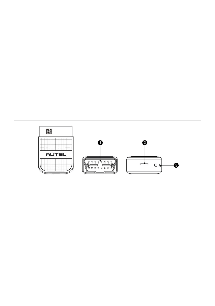
Functional Description
1. Vehicle Data Connector (16-pin) – connects the MaxiAP AP200H to the vehicle's 16-
pin OBDII port directly.
2. Power LED – indicates system status.
The power LED displays green, blue, and red depending on power level and operating
state.
A. Green
Lights solid green when the MaxiAP AP200H is plugged in and not connected
with the device.
B. Blue
Lights solid blue when the device is connected with the MaxiAP AP200H via
Bluetooth.
Figure 1-1 Product View
2
Flashes blue when the device is communicating with the MaxiAP AP200H, for
example, when the device is reading Engine DTCs.
C. Red
Lights solid red when the MaxiAP AP200H is updating the firmware or when the
update failed, or when the MaxiAP AP200H is locked.
Flashed red fast when the communication failed between the device and the
dongle via Bluetooth. Please restart the dongle until it works properly.
3. Strap Hole – attach the strap to the MaxiAP AP200H.
NOTE
When the MaxiAP AP200H has lost connection from the device for more than 10 minutes,
the LED goes off and the AP200H enters power saving standby mode. The power LED
will light when reconnected.
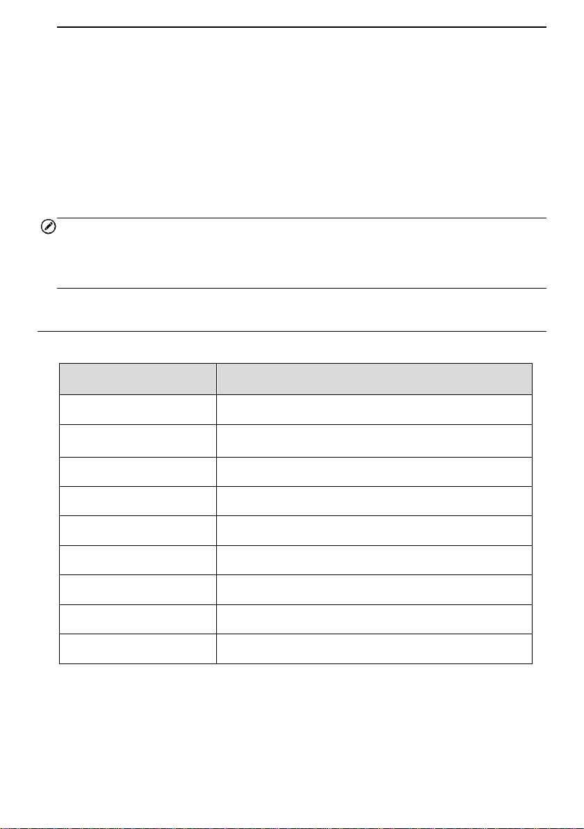
Technical Specifications
Table 1-1 Specifications
Item
Description
Communications
BL 4.2 Dual-Mode
Wireless Frequency
2.4 GHz
Input Voltage Range
9 VDC to 26 VDC
Supply Current
100 mA@12 V
Sleep Mode Current
3 mA@12 V
Operating Temp.
0°C to 50°C
Storage Temp.
-20°C to 70°C
Dimensions (L*W*H)
59 mm (2.32'') * 44 mm (1.73'') * 21.5mm (0.85'')
Weight
32.1g (0.07 lb.)

3
Wireless Communication
The MaxiAP AP200H uses BT communication. It can transmit vehicle data to your
Android or iOS device. The working range for BT communication is about 33 feet (about
10 m). Signal lost due to moving out of range will automatically be restored once the
device is brought within transmission range to the MaxiAP AP200H connector.
Power Source
The MaxiAP AP200H operates on 12-volt vehicle power that it receives through the
vehicle data connection port. The unit powers on whenever it is connected to an OBDII/
EOBD compliant data link connector (DLC).

4
2 Getting Started
NOTE
The images and illustrations depicted in this manual may differ slightly from the actual
ones. The user interfaces for iOS & Android devices might be slightly different. This
manual uses UI for iOS devices as an example.
Powering Up
1. Download & install app
Scan the QR code or search for MaxiAP200 in App Store or Google Play to
download and install the app to your device.
2. Register & log in
Open the MaxiAP200 app and tap Register near the top right of the screen.
Follow the on-screen instructions to complete the registration.
Log in with your registered email address and password.
3. Bind VCI with device
On the Bind VCI interface, scan the QR code imprinted on the Bluetooth dongle to
automatically retrieve the serial number. Ensure the email information is correct. Tap
Bind to pair dongle with device.
4. Purchase & install software
Tap Mall below the list to purchase and install the software selected. Full OBDII
functions included at no charge. One vehicle-line is included free through Mall after
successfully pairing the dongle for the first time (For iOS devices, the purchased
software will display in the list, tap it to another application for diagnosis).
5. Plug the connector of the MaxiAP200H Bluetooth dongle into the vehicle's OBDII
5
port.
The vehicle's OBDII port is generally located under the vehicle dashboard
(Consult vehicle user manual for specific location).
6. Turn the vehicle ignition to Key On, Engine Off position.
The LED on the dongle will light solid green when connected.
7. VCI Connection
For Android devices, tap Me > VCI Connection or the VCI button near the top right
of the Home screen.
For iOS devices, tap Setting > Bluetooth on your iOS device to open the Bluetooth
function.
Tap the Bluetooth name on the screen to pair it with the device. The Bluetooth name
starts with AP, followed by the serial number of the dongle.
Ensure your device's Bluetooth is turned on.
When the device is successfully paired with the dongle, the LED will light solid
blue.
NOTE
For iOS devices, once a dongle is paired with device via Bluetooth, it cannot be searched
by other devices. When multiple dongles paired to the same device via Bluetooth, only
the first connected dongle lights blue, others will light green.
8. Your MaxiAP200H is now ready for use.
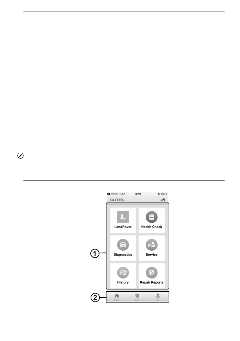
Figure 2-1 Sample MaxiAP200H Job Menu
6
① Application Buttons
② Navigation Buttons
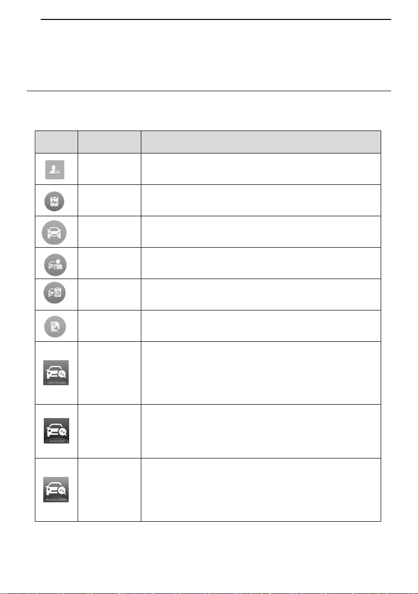
Function Buttons
The table below briefly describes each of the applications in the AP200H system.
Table 2-1 Applications Buttons
Button
Name
Description
My Vehicle
Accesses the function to manually add vehicle makes.
Health
Check
Accesses health check function to carry out vehicle health
reports.
Diagnostics
Accesses vehicle diagnostic functions.
Service
Accesses service functions menu.
History
Accesses diagnosis and service records with vehicle
information and DTCs included.
Repair
Reports
Accesses repair reports for EOBD, diagnostic, and
maintenance sessions.
AP200H_
USA
For iOS devices, this icon will display on the device's
desktop after purchasing and installing the U.S. and
European vehicle diagnostic data package. Tap on the icon
to start the diagnosis.
AP200H_
Asia
For iOS devices, this icon will display on the device's
desktop after purchasing and installing the Asian vehicle
and Audi diagnostic data package. Tap on the icon to start
the diagnosis.
AP200H_
Dms
For iOS devices, this icon will display on the device's
desktop after purchasing and installing the Domestic and
Benz diagnostic data package. Tap on the icon to start the
diagnosis.
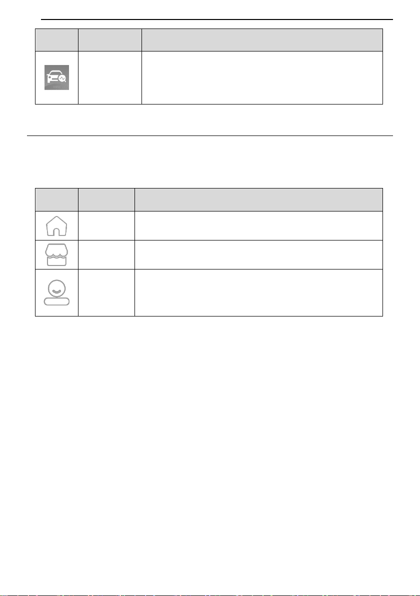
7
Button
Name
Description
AP200H_
BMW
For iOS devices, this icon will display on the device's
desktop after purchasing and installing the BMW vehicle
diagnostic data package. Tap on the icon to start the
diagnosis.
Navigation Buttons
Operations of the Navigation buttons at the bottom of the screen are described in the
table below:
Table 2-2 Navigation Buttons
Button
Name
Description
Home
Returns to the Home screen.
Mall
Purchase maintenance software.
Me
Displays list of functions, including Order Manager, Delete
Vehicle, Data Logging, VCI Connection, VCI Manager,
Settings and User Manual.

8
3 My Vehicle
The My Vehicle application is uniquely designed to serve as a digital garage on your
smartphone to give you a comprehensive view of all your vehicles. Add vehicle makes
into My Vehicle prior to performing health check, diagnostic, and maintenance functions
of AP200H. Manually select a vehicle line by following the on-screen instructions, enter
the manufacturer name into the search bar on the top of the screen or simply choose
from the list of brand lines sorted by alphabet.
NOTE
Prior to performing diagnostic, maintenance, and health check applications, it is required
to add your vehicle makes into My Vehicle. After selecting a specific vehicle but without
downloading the vehicle software, the EOBD diagnosis function is available. Additional
functions can be performed with in-app purchase.
To perform the My Vehicle function
1. Tap the My Vehicle button on the main home screen.
2. Tap the arrow icon to manually select a vehicle make.
3. After selecting, input the vehicle makes into the search bar, or manually select
the vehicle makes from the list of brand lines sorted by alphabet.
4. Tap OK.
5. The vehicle make is successfully added.
NOTE
Before applying health check, diagnostic, and service functions, manually select a
current vehicle in My Vehicle.

9
4 Health Check
The easy-to-use Health Check application is used to identify health state of your car. This
function gives health rating, generates corresponding reports, and allows users to gain a
quick grasp on vehicle health conditions and status.
This application scans 4 main systems, including Engine, Transmission, Airbags (SRS),
and Antilock brake (ABS) systems for DTCs. It is not only an excellent function to use
before obtaining an emission test certificate, but also great for your everyday monitor of
vehicle health and status.
Tap Health Check on the top of the main home screen. If the current vehicle make in My
Vehicle has not been downloaded, a prompt will show up on the screen.
If select the No button, the device will automatically retrieve the DTC information and I/M
status of EOBD.
If select the Yes button, the device will download the specific vehicle software with in-app
purchase and directs to the manufacturer-related diagnosis. There are two methods to
conduct the vehicle identification procedure.
a) Via the Automatic selection button:
Input VIN manually or tap the Read button to acquire VIN.
Tap OK to view the test vehicle profile.
On the Confirmation page, tap Yes to proceed to Auto Scan.
A snapshot of the vehicle health state will display on the screen.
b) Via the Manual Selection button:
Follow the on-screen instructions and select the vehicle information like the year
and model type to identify the vehicle and enter the Auto Scan interface.
After all available systems are scanned automatically, the snapshot of the
vehicle health state will display.
Tap the View report button at the bottom of the screen to view report.
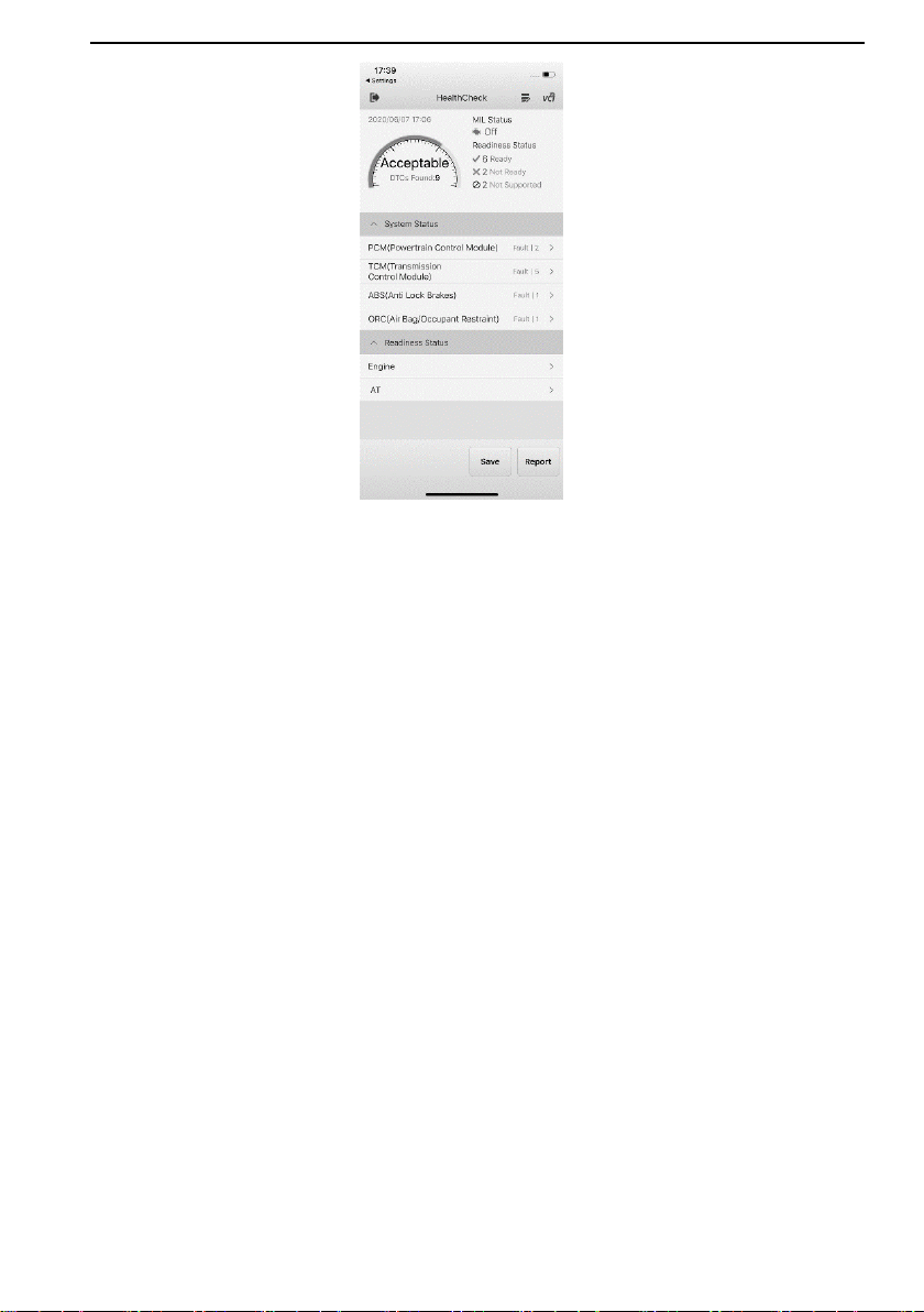
Simply follow the on-screen instructions to open the health check page, where you view a
snapshot contains information on System status, readiness status, MIL status, and DTCs
detected. An overall health rating will also be presented, along with the total number of
DTCs found.
10
Figure 4-1 Sample Health Check Screen
Health Check Report contains the following four types of health rating options:
1. Good – The vehicle is in fine health state with no fault codes detected.
2. Acceptable – The vehicle is in fair health condition with some fault codes detected.
3. Bad – The vehicle is in poor health status with some fault codes detected.
4. Unknown – The vehicle's health state is unidentified with unknown number of fault
codes.
On the top left corner, a dashboard with specific health rating and the total number of
DTCs found will display. MIL status indicates if the Check Engine Light (MIL) is on or off.
On the right side, the readiness status checks I/M (Inspection/Maintenance) readiness and
shows the numbers of monitors that are ready, not ready, and not supported.
The middle of the screen consists of two sections. The first section varies according to the
following different diagnosis types.
The EOBD diagnosis consists of the following sections:
1. DTCs status – lists all the DTCs detected during the EOBD diagnosis.
2. Readiness status – reports the readiness status of the vehicle. Tap the
○
>
button to view readiness status of specific systems.
The manufacturer-related health check consists of the following sections:

11
1. System status – displays the scanned systems along with the total number of
DTCs detected.
2. Readiness status – reports the readiness status of the vehicle. Tap the
○
>
button to view readiness status of specific systems.
At the bottom of the health check interface, two functional buttons are available:
Save – tap to save the check result of the test vehicle.
Report – tap to open the corresponding health check report page.
On the specific DTCs interface, there is one button at the bottom of the screen:
Save – tap this option to save the health check result.
NOTE
Prior to first use of the application, it is required to perform auto or manual vehicle
selection. The test vehicle profile will be automatically saved after first use, and you will
be able to skip the vehicle confirmation step next time when applying the health check
function.

12
5 Diagnostics
The MaxiAP AP200H scans 4 main systems for vehicle diagnosis. The Diagnostics
application can retrieve ECU information, read & erase DTCs, and view live data. This
application accesses the electronic control unit (ECU) for various vehicle control systems,
including Engine, Transmission, Antilock brake (ABS), and Airbag (SRS) systems.
Automatic Selection
The Auto VIN Scan can be selected after selecting the test vehicle manufacturer.
To perform Automatic Selection
1. Tap the Diagnostics application button from the Main Job Menu. The Vehicle
Menu displays.
2. Tap the manufacturer button of the test vehicle.
3. Tap Automatic Selection and the VIN information will be automatically
acquired. Follow the on-screen instruction to display the diagnostic screen.
Manual Selection
When the vehicle's VIN is not automatically retrievable through the vehicle's ECU, or the
specific VIN is unknown, the vehicle can be manually selected.
This mode of vehicle selection is menu driven, repeat the first two steps from the
automatic selection operation and tap Manual Selection. Through a series of on-screen
prompts and selections, the test vehicle is chosen. If needed, press the ESC button at
the bottom right corner of the screen to return to the previous screen.
Navigation
Navigating the Diagnostics interface and selecting test are discussed in this section.
Diagnostics Screen Layout
The diagnostic screen typically includes two sections.
13
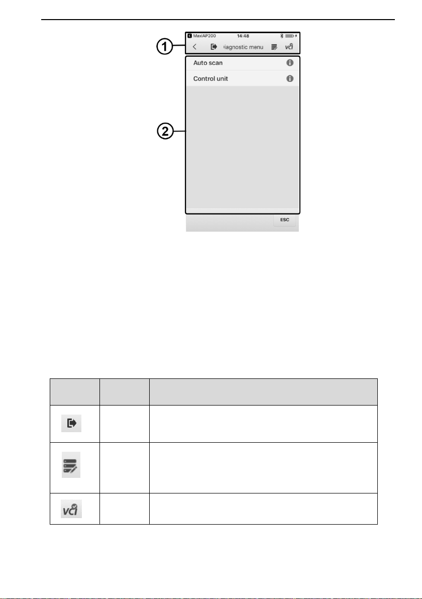
Figure 5-1 Sample Diagnostics Menu Screen
1. Diagnostics Toolbar
2. Diagnosis Section
Diagnostics Toolbar
The Diagnostics Toolbar contains a number of buttons such as Home and Data Logging.
The table below provides a brief description of the operations of the Diagnostics Toolbar
buttons.
Table 5-1 Diagnostics Toolbar Buttons
Button
Name
Description
Home
Returns to the AP200H Job Menu.
Data
Logging
Records the test vehicle information and user contact
information.
VCI Icon
Displays the communication status of the VCI.
14
Diagnosis
There are two options available when accessing the Diagnosis section:
1. Auto Scan – starts auto scanning for all the systems on the vehicle.
2. Control Units – displays a selection menu of all available control units of the test
vehicle.
After a section is made and the VCI establishes communication with the vehicle, the
corresponding function menu or selection menu displays.
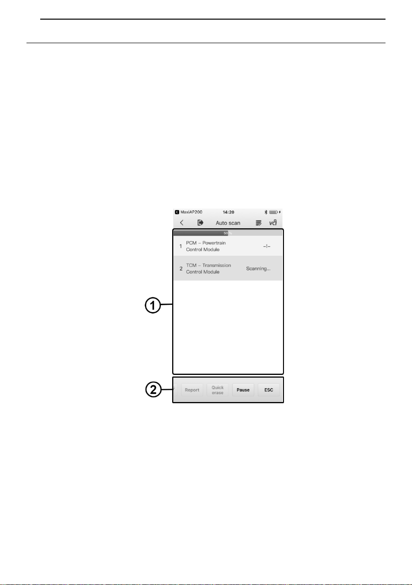
Auto Scan
The Auto Scan function performs a comprehensive scanning over all the ECUs in the
vehicle to locate systems' faults and retrieve DTCs.
Figure 5-2 Sample Auto Scan Operation Screen
1. Main Section
2. Functional Buttons
Main Section
The Main Section displays the sequence numbers, the scanned systems, and the
diagnostic indicators describing test results.
These indicators are defined as follows:
15
-!-: Indicates that the scanned system may not support the code reading function,
or there is a communication error between the Display Tablet and the control
system.
-?-: Indicates that the vehicle control system has been detected, but the Display
Tablet cannot accurately locate it.
Fault(s) | #: Fault(s) indicates there is/are detected fault code(s) present; “#”
indicates the number of the detected faults.
Pass | No Fault: Indicates the system has passed the scanning process and no
fault has been detected.
To perform further diagnosis or testing on a specific system item, tap the
○
> button to
the right of that item. A Function Menu screen will display.
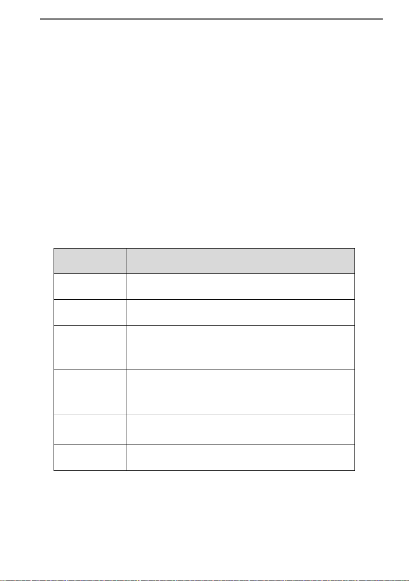
Functional Buttons
A brief description of the operations of the Auto Scan's Functional Buttons' are displayed
in the table below. Please slide the buttons left and right to see the complete buttons.
Table 5-2 Functional Buttons in Auto Scan
Name
Description
Save
Tap to save vehicle report as PDF.
Report
Displays the diagnostic data in the report form.
Quick Erase
Deletes codes. A warning message screen will display to
inform you of possible data loss when this function is
selected.
OK
Confirms the test result. Continues to the system
diagnosis after the required system is selected by
tapping the item in the Main Section.
Pause
Suspends scanning and it will change to Continue
button after tapping.
ESC
Returns to the previous screen or exits Auto Scan.

16
Control Units
The AP200H device provides accesses to all available systems, which are integrated
into categories such as Engine, Transmission, Airbags and ABS systems. Manually
locate a required control system for testing through a series of selection choices.
The Function Menu options vary slightly for different vehicles. The function menu may
include:
ECU Information – provides the retrieved ECU information in detail. An information
screen opens upon selection.
Read Codes – displays detailed information of DTC records retrieved from the test
vehicle's ECU.
Erase Codes – erases DTC records and other data from the test vehicle's ECU.
Live Data – retrieves and displays live data and parameters from the test vehicle's
ECU.
ECU Information
This function retrieves and displays the specific information for the tested control unit,
including unit type, version numbers and other specifications.
Read Codes
This function retrieves and displays the DTCs from the vehicle's control system. The
Read Codes screen varies for each vehicle being tested. On some vehicles, freeze frame
data can also be retrieved for viewing.
Erase Codes
After reading the retrieved codes and making appropriate vehicle repairs, use this
function to erase vehicle codes.
Live Data
When this function is selected, the screen displays the data list for the selected module.
The items available for any control module vary from one vehicle to another. The
parameters display in the order that they are transmitted by the ECM, so expect variation
between vehicles.

17
6 EOBD
The OBD II/EOBD diagnosis is available to be downloaded through Mall. This option
presents a quick way to check for DTCs, isolate the cause of an illuminated malfunction
indicator lamp (MIL), check monitor status prior to emissions certification testing, verify
repairs, and perform a number of other services that are emissions-related. The OBD
direct access option is also used for testing OBD II/EOBD compliant vehicles that are not
included in the Diagnostics database.
General Procedure
To access the OBD II/EOBD diagnostics functions
1. Tap the Diagnostics button on the main home screen. Tap No button to start
vehicle's EOBD diagnosis. There are two options to establish communication
with the vehicle.
Auto Scan – when this option is selected the diagnostic tool attempts to
establish communication using each protocol in order to determine which
one the vehicle is broadcasting on.
Protocol – when this option is selected the screen opens a submenu of
various protocols. A communication protocol is a standardized way of data
communication between an ECM and a diagnostic tool. Global OBD may
use several different communication protocols.
2. Select a specific protocol under the Protocol option. Wait for the OBD II
Diagnostic Menu to display.
3. Select a function option to continue.
DTC & FFD
I/M Readiness
Live Data
On-Board Monitor
Component Test
Vehicle Information
Vehicle Status
NOTE
Some functions are supported only on certain vehicle makes.
This section describes the various functions of each diagnostic option:

18
DTC & FFD
When this function is selected, the screen displays a list of Stored Codes and Pending
Codes. When the Freeze Frame data of certain DTCs are available for viewing, a
snowflake button will display on the right side of the DTC item.
The erase codes function can be applied by tapping the Clear DTC button at the bottom
of the screen.
Stored Codes
Stored codes are the current emission related DTCs from the ECM of the vehicle.
OBD II/EOBD Codes have a priority according to their emission severity, with higher
priority codes overwriting lower priority codes. The priority of the code determines
the illumination of the MIL and the codes erase procedure. Manufacturers rank
codes differently, so expect to see differences between makes.
Pending Codes
These are codes whose setting conditions were met during the last drive cycle, but
need to be met on two or more consecutive drive cycles before the DTC actually
sets. The intended use of this service is to assist the service technician after a
vehicle repair and after clearing diagnostic information, by reporting test results after
a driving cycle.
a) If a test failed during the driving cycle, the DTC associated with that test is
reported. If the pending fault does not occur again within 40 to 80 warm-up
cycles, the fault is automatically cleared from memory.
b) Test results reported by this service do not necessarily indicate a faulty
component or system. If test results indicate another failure after additional
driving, then a DTC is set to indicate a faulty component or system, and the MIL
is illuminated.
Freeze Frame
In most cases the stored frame is the last DTC that occurred. Certain DTCs, which
have a greater impact on vehicle emission, have a higher priority. In these cases,
the top prioritized DTC is the one for which the freeze frame records are retained.
Freeze frame data includes a “snapshot” of critical parameter values at the time the
DTC is set.
Clear DTC
This option is used to clear all emission related diagnostic data such as, DTCs,
freeze frame data and manufacturer specific enhanced data from the vehicle’s ECM.
A confirmation screen displays when the clear codes option is selected to prevent
accidental loss of data. Select Yes on the confirmation screen to continue or No to
exit.

19
I/M Readiness
This function is used to check the readiness of the monitoring system. It is an excellent
function to use prior to having a vehicle inspected for compliance to a state emissions
program. Selecting I/M Readiness opens a submenu with two choices:
Since DTCs Cleared – displays the status of monitors since the last time the DTCs
are erased.
This Driving Cycle – displays the status of monitors since the beginning of the
current drive cycle.
Live Data
This function displays the real time PID data from ECU. Displayed data includes analog
inputs and outputs, digital inputs and outputs, and system status information broadcast
on the vehicle data stream.
Live data can be displayed in various modes.
On-Board Monitor
This option allows you to view the results of On-Board Monitor tests. The tests are useful
after servicing or after erasing a vehicle's control module memory.
Component Test
This service enables bi-directional control of the ECM so that the diagnostic tool is able
to transmit control commands to operate the vehicle systems. This function is useful in
determining whether the ECM responds to a command well.
Vehicle Information
The option displays the vehicle identification number (VIN), the calibration identification,
and the calibration verification number (CVN), and other information of the test vehicle.
Vehicle Status
This item is used to check the current condition of the vehicle, including communication
protocols of OBD II modules, retrieved codes amount, status of the Malfunction Indicator
Light (MIL), and other additional information.
Exiting Diagnostics
The Diagnostics application remains open as long as there is an active communication
with the vehicle. You must exit the diagnostics operation to stop all communications with
the vehicle before closing the Diagnostics application.

20
NOTE
Damage to the vehicle electronic control module (ECM) may occur if communication is
disrupted. Make sure the wireless connection is properly connected at all times during
testing. Exit all tests before disconnecting the test connection or powering down the tool.

21
7 Service
The Service section is specially designed to provide you with quick access to the vehicle
systems for various scheduled service and maintenance performances. The typical
service operation screen is a series of menu driven executive commands. By following
the on-screen instructions to select appropriate execution options, enter correct values
or data, and perform necessary actions, the system will guide you through the complete
performance for various service operations.
The service will be listed on the Service section after purchasing. Tap the corresponding
service to select the vehicle makes you need for service operations.
The most commonly performed service functions in AP200H include:
Oil Reset Service
BMS Service
Oil Reset Service
This function allows you to perform reset for the Engine Oil Life system, which calculates
an optimal oil life change interval depending on the vehicle driving conditions and climate.
The Oil Life Reminder must be reset every time the oil is changed, so the system can
calculate when the next oil change is required.
IMPORTANT
Always reset the engine oil life to 100% after every oil change.
NOTE
All required work must be carried out before the service indicators are reset. Failure to
do so may result in incorrect service values and cause DTCs to be stored by the relevant
control module.
Battery Management System (BMS) Service
The BMS (Battery Management System) allows the scan tool to evaluate the battery
charge state, monitor the close-circuit current, register the battery replacement, and
activate the rest state of the vehicle.
NOTE
1. This function is not supported by all vehicles. The screens shown in this section are
examples.
2. The sub functions and actual test screens of the BMS may vary for different test

22
vehicles, please follow the on-screen instructions to make correct option selection.
The vehicle may use either a sealed lead-acid battery or an AGM (Absorbed Glass Mat)
battery. Lead acid battery contains liquid sulphuric acid and can spill when overturned.
AGM battery (known as VRLA battery, valve regulated lead acid) also contains sulphuric
acid, but the acid is contained in glass mats between terminal plates.
It is recommended that the replacement aftermarket battery has the same specifications,
such as capacity and type, with the battery used in the vehicle. If the original battery is
replaced with a different type of battery (e.g. a lead-acid battery is replaced with an AGM
battery) or a battery with a different capacity (mAh), the vehicle may require
reprogramming the new battery type in addition to performing the battery reset. Consult
the vehicle manual for additional vehicle-specific information.
Register Battery Replacement
This option allows displaying the mileage reading of last battery replacement, registering
the battery replacement after replacing a new battery and informing the power
management system that a new battery has been fitted to the vehicle.
If the battery change is not registered, the power management system will not function
properly, which may not provide the battery with enough charging power to operate the
car and limit the functions of individual electrical equipment.
The vehicle has the correct spec engine oil.
The oil for diesel is not contaminated.
IMPORTANT
Before diagnosing a problem vehicle and attempting to perform an emergency
regeneration, it is important to obtain a full diagnostic log and read out relevant measured
value blocks.
NOTE
1. The DPF will not regenerate if the engine management light is on, or there is a faulty
EGR valve.
2. The ECU must be re-adapted when replacing the DPF and when topping up the fuel
additive Eolys.
3. If the vehicle needs to be driven in order to perform a DPF service, ALWAYS have
a second person help you. One person should drive the vehicle while the other
person observes the screen on the Tool. Trying to drive and observe the Scan Tool
at the same time is dangerous, and could cause a serious traffic accident.
23
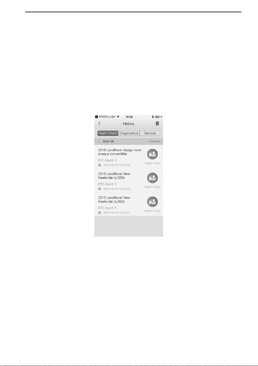
8 History
This function stores records of test vehicle history, including vehicle health state, vehicle
information and the retrieved DTCs from previous diagnostic and service sessions, and
displays all information in an easy-to-check table list, on which you can view summarized
details and manually input other information about the test vehicle and diagnostic testing
performed, etc. The History application also provides direct access to the previously tested
vehicle and allows you to restart a diagnostic/service session without the need to do vehicle
identification again.
Figure 8-1 Sample History Screen
24
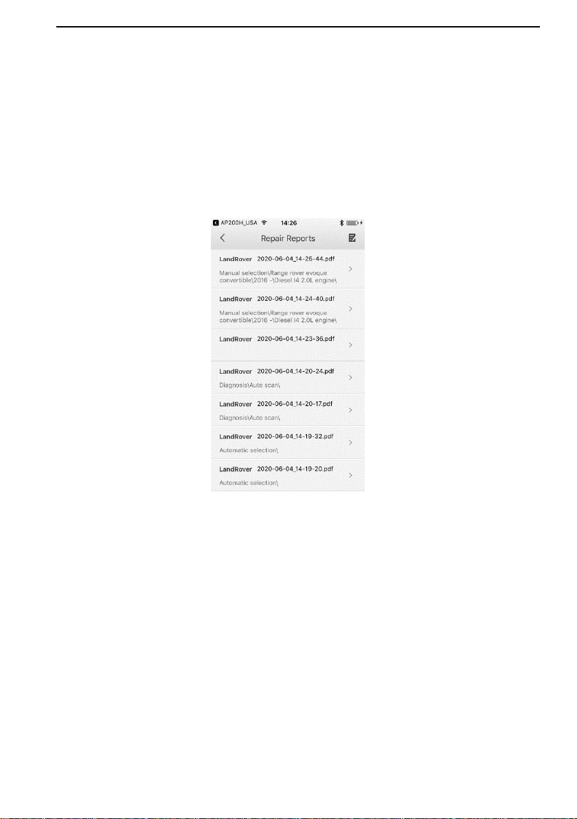
9 Repair Reports
The MaxiAP AP200 app can save repair report for diagnostic and maintenance service
sessions. A PDF can also be generated for easy viewing, sharing, and printing.
After finishing vehicle diagnosis and maintenance service, tap Save to create a repair
report. The repair report is saved under Repair Reports.
Figure 9-1 Sample Repair Reports Screen
25
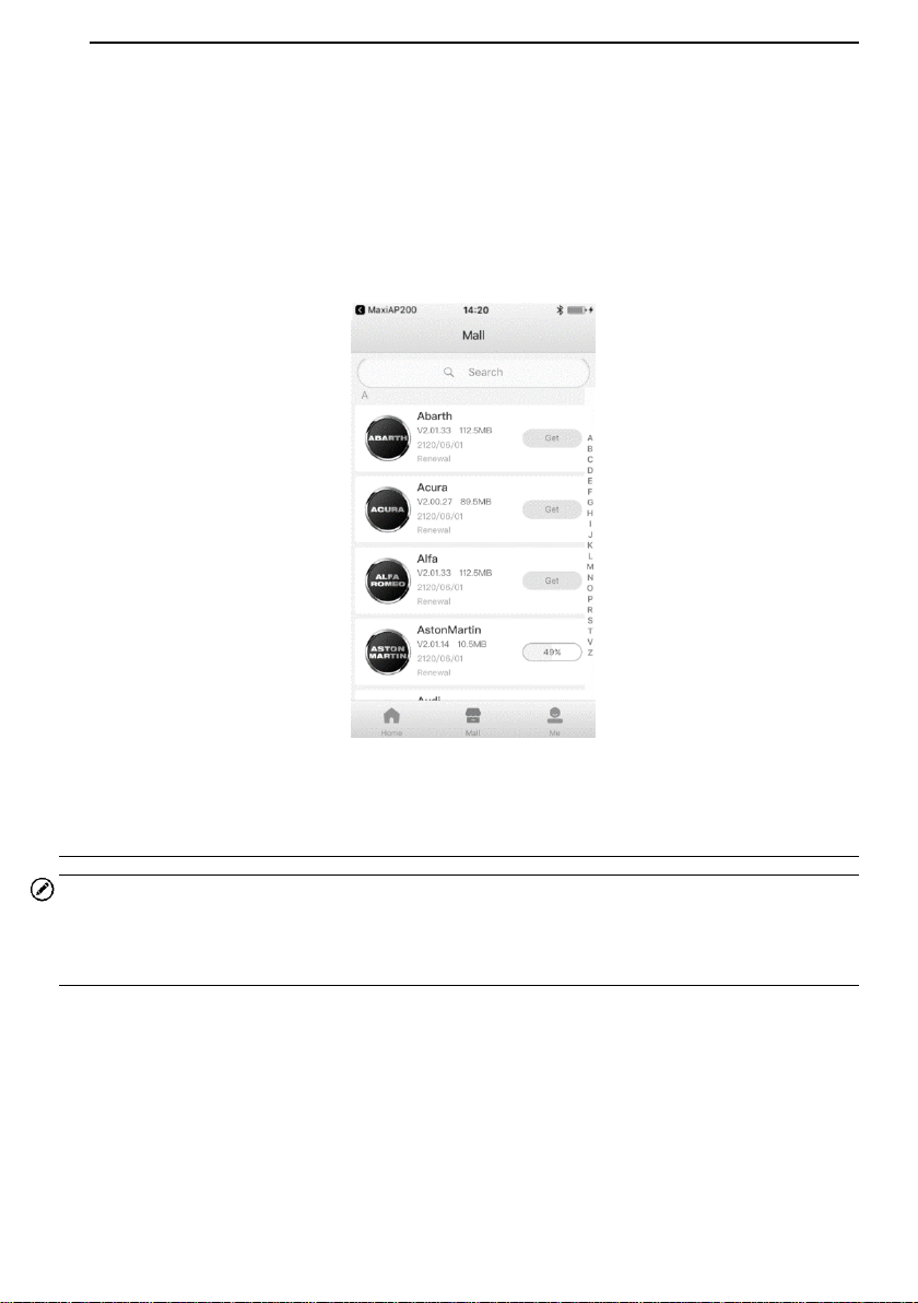
10 Mall
This function button provides you a quick entrance to access app built-in mall and
purchase the vehicle brand of your choice. Follow the instructions to download one free
vehicle-line of your chosen brand. All brand lines are valid for up to a year.
Figure 10-1 Sample Mall Screen
Purchase vehicle diagnostic data package
NOTE
Before purchasing vehicle diagnostic data package, you have to log in your Autel ID and
bind the MaxiAP AP200H device with your account. One vehicle-line is free and valid for up
to a full year, you can get it through Mall after successfully binding VCI for the first time.
1. Tap the Mall button on the Home screen, a list of brand lines sorted by alphabet will
display.
2. The corresponding price of each software is displayed on the right side of the
software.
3. Tap the price of wanted software and jump to the detail screen. You can see a
detailed introduction of this software.
4. Tap Buy Now to purchase the software selected immediately.

26
NOTE
The purchased software is available for one year. You can renew it after expiration.
27
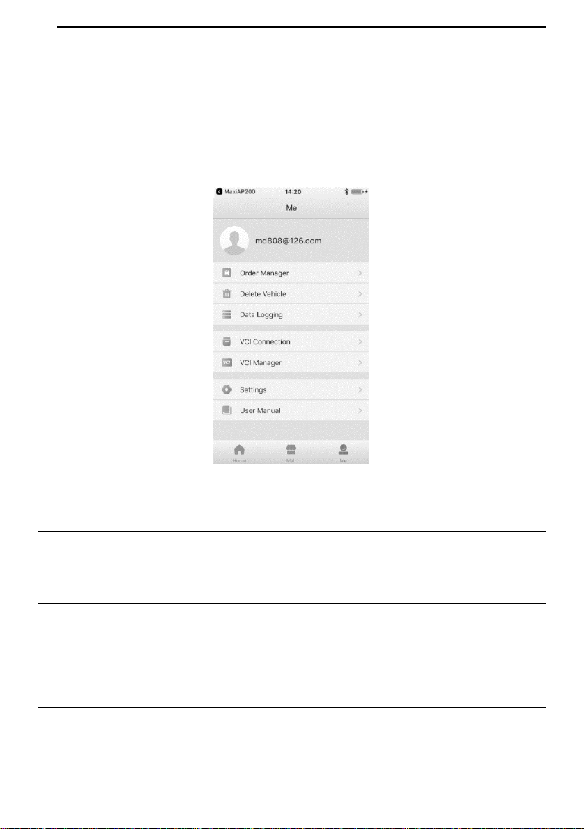
11 Me
Tap the Me button, a list of functions displayed, including Order Manager, Delete Vehicle,
Data Logging, VCI Connection, VCI Manager, Settings and User Manual.
Figure 11-1 Sample Me Screen
Order Manager
This function can help you manage orders efficiently.
Delete Vehicle
Tap the Delete Vehicle option, a list of installed Apps will display. There is a Trash icon
on the top right of the screen. Tap on the icon of unwanted Apps to select and tap Trash
icon to delete.
Data Logging
The Data Logging section allows you to launch Support platform directly to view all
records of all sent or unsent (saved) data logging on the system.

28
VCI Connection
Be sure that the VCI is connected before performing the diagnostics function. For detailed
operation, please see Powering Up on page 4.
VCI Manager
Tap the VCI Manager, the information of Serial Number, Bind Date, Bind Account and
Firmware Version will display. Tap Detect Firmware button to check the new version of
firmware and upgrade it.
Settings
Select the Settings application to open a setup screen to adjust the default setting and
view information about the MaxiAP AP200H system. Tap the Log Out button to log out
of your account. There are four system settings.
Unit: This option allows you to adjust the measurement unit. You can tap English
or Metric to switch between these two measurement units.
Tips Reset: Tap to reset user guide.
Clear Cache: Tap to clear cache.
About: Tap to displays the current version of the app, date and time of build ID, and
user terms/privacy policy.
Log out
User Manual
This option allows you to view the User Manual of MaxiAP AP200H. The user manual
contains safety instructions, operation instructions, product troubleshooting, service, and
etc.

29
12 Product Troubleshooting
This chapter describes problems that you may encounter while using the MaxiAP
AP200H.
Vehicle Linking Error
A communication error occurs if the MaxiAP AP200H fails to communicate with the
vehicle's control module when performing diagnostic procedures.
Please do the following check-ups:
Verify that the ignition is ON.
Check that the MaxiAP AP200H connector is securely connected to the vehicle's
DLC.
Turn the ignition off and wait for about 10 seconds. Then turn the ignition back on
and continue the operation.
Verify the control module is not defective.

30
13 Warranty and Service
Limited One Year Warranty
Autel Intelligent Technology Corp., Ltd. (the Company) warrants to the original retail
purchaser of this Autel device that should this product or any part thereof during normal
usage and under normal conditions be proven defective in material or workmanship that
results in product failure within one year from the date of purchase, such defect(s) will be
repaired, or replaced (with new or rebuilt parts) with Proof of Purchase, at the Company’s
option, without charge for parts or labor directly related to the defect(s).
The Company shall not be liable for any incidental or consequential damages arising
from the use, misuse, or mounting of the device. Some states do not allow limitation on
how long an implied warranty lasts, so the above limitations may not apply to you.
This warranty does not apply to:
1) Products subjected to abnormal use or conditions, accident, mishandling, neglect,
unauthorized alteration, misuse, improper installation or repair or improper storage;
2) Products whose mechanical serial number or electronic serial number has been
removed, altered or defaced;
3) Damage from exposure to excessive temperatures or extreme environmental
conditions;
4) Damage resulting from connection to, or use of any accessory or other product not
approved or authorized by the Company;
5) Defects in appearance, cosmetic, decorative or structural items such as framing and
non-operative parts.
6) Products damaged from external causes such as fire, dirt, sand, battery leakage,
blown fuse, theft or improper usage of any electrical source.
IMPORTANT
All data on the product may be deleted during the repair process. You should create a
back-up copy of all your data on your product before shipping it for warranty service.