Loading ...
Loading ...
Loading ...
DRIVING WITH VARIABLE SPEED
The technique is to start slowly, increasing the
speed as the screw runs down. Set the screw
snug ly by slowing to a stop. Prior to driving
screws, pilot and clearance holes should be
drilled.
Always hold the machine straight on the bolt
to be tightened.
The best method to determine the right
impacting/tightening duration is by means of a
trial. For small screws, the right
impacting/tightening duration can be reached
in less then 0.5 Sec. Therefore, work with low
RPM and switch the machine off immediately
when the screw is tight and the impacting
sound can be heard.
For screwing larger, longer wood screws into
hard material, pre-drilling is the best method.
TIGHTENING TORQUE
The tightening torque depends on the duration
of the impacting/tightening action. The largest
tightening torque is achieved after approx. 6 to
10 Sec. impacting/tightening action.
The torque build-up depends on the
following factors:
• Hardness of the bolts/nuts.
• Type of washer (disk washer, spring washer,
seal).
• Hardness of the material to be joined.
• Lubricating effect at the surfaces of the
junction.
This leads to the following application cases:
Hard case: The joining of metal to metal with
a disk washer. The maximum torque is
reached after a relative short impacting/
tightening action.
Medium case: The joining of metal to metal
where spring ring washer, disk spring washer,
stud bolts or bolts/nuts with conical seats are
used.
Soft case: The joining of e.g. metal to wood
or insulation material.
For middle or soft joining cases, the maximum
tightening torque is less as for hard cases.
Therefore, a longer impacting/tightening action
is necessary to arrive at the maximum
tightening torque.
FASTENING WITH SCREWS
This procedure shown in (Fig. 7) will enable
you to fasten ma terials together with your tool
without stripping, splitting or separating the
material.
First, clamp the pieces together and drill the
first hole 2/3 the diam eter of the screw. If the
material is soft, drill only 2/3 the proper
Operating Tips
-10-
B
UILT IN WORK LIGHT
Your tool is also equipped with a light that turns
on automatically when the switch is activated,
for better visibility when drilling/driving (Fig. 1).
BATTERY CHARGE CONDITION
INDICATOR LIGHTS
Your tool is equipped with charge condition
indicator lights (Fig. 1). The indicator lights
shows the charge condition of the battery for a
f
ew second when the On/Off trigger is pressed
halfway or fully.
LED Capacity
Continuous lighting 3 x green > 2/3
Continuous lighting 2 x green > 1/3
Continuous lighting 1 x green < 1/3
Flashing light 1 x green reserve
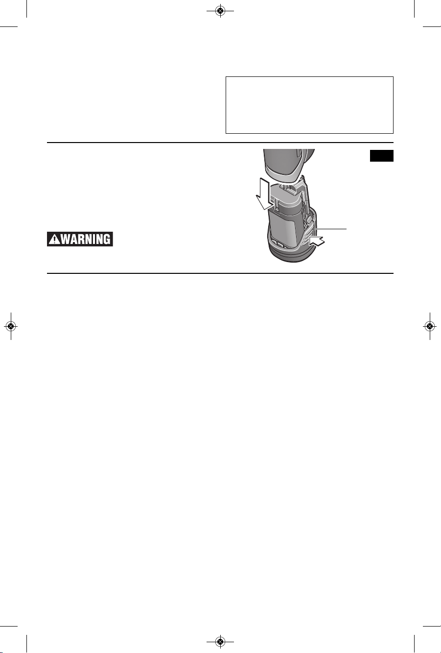
INSERTING AND RELEASING
BATTERY PACK
Release battery pack from tool by pressing on
both sides of the battery release tabs and pull
downward (Fig. 4).
To insert battery, align battery and slide
battery pack into tool until it locks into position.
Do not force.
If battery release tabs are
cracked or otherwise
damaged, do not insert into tool. Battery can
fall out during operation.
BATTERY
RELEASE
TABS
FIG. 4
2610051964_PS41 1/16/19 10:59 AM Page 10
Loading ...
Loading ...
Loading ...